NASA MISSI 1 2 Report 7231TM Ther Mark White Paper
User Manual: 7231TM
Open the PDF directly: View PDF ![]() .
.
Page Count: 30
1
MARKING TESTS TO CERTIFY PART
IDENTIFICATION MARKING PROCESSES FOR USE IN
LOW EARTH ORBIT (LEO)
OCTOBER 11, 2005
Donald L. Roxby
2
ABSTRACT
Prior to the Space Shuttle Program, space-borne vehicles launched into space were
expended; consequently their part identifiers were applied using marking processes designed for
use in ground operations. With the advent of reusable space transportation vehicles and
retrievable satellites, NASA needed to rethink how part identification markings are applied to
their space borne vehicles. Markings applied to reusable spacecraft need to survive the extreme
environments encountered in space. To support this new requirement, NASA approached RVSI
(now Siemens) to assist with a marking program to certify marking(s) for use in Low Earth Orbit
(LEO).
An experiment was designed to identify
part identification methods and techniques that
might survive the rigors of space. The experiment
was to be designed to expose both human and
machine-readable markings to LEO environments.
These include, but are not limited to, vacuum,
solar UV radiation, micrometeoroids and space
debris, atomic oxygen (AO) and deep thermal
cycles. Two specimen packages were
assembled. The first package was incorporated
into MISSE 1 and 2 (one year orbital experiments)
and consisted of currently approved marking processes and number of newly developed Laser
Additive marking techniques deemed safe for use in safety critical applications. The second
package contained a series of more robust intrusive marking technique that utilized higher-
powered laser markers. These specimens were incorporated in MISSE 3 and 4, which was
scheduled to fly in orbit for three years. This report describes the results of the MISSE 1 and 2
marking experiments.
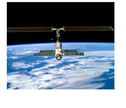
International Space Station In Low Earth Orbit
3
INTRODUCTION
Working with the Boeing Phantom Works, Siemens’s (formally RVSI) Symbology
Research Center applied markings to test coupons made of materials commonly utilized in the
construction of the external components used on space transportation vehicles, satellites and
space stations. The materials included structural components (anodized and painted aluminum),
thermal protection system (TPS) blankets (beta cloth) and glass (windows, mirrors, lenses).
TPS tile markings were not included, having been previously tested by an RVSI Researcher on a
previous space shuttle program. The test coupons incorporated into MISSE 1 and 2 consisted of
17 marked 0.995-inch diameter disks. These coupons were marked using currently approved
marking processes (Dot Peen and Electro-Chemical coloring) and new additive laser marking
processes. These included laser inducted vapor deposition (LIVD), Laser Bonding to both metal
and glass, Gas Assisted Laser Etch (GALE) and a Laser Coat and Remove process that involved
the use of Vacuum Arc Vapor Deposition (VAVD). Additional intrusive laser marking processes
designed for survivability on longer duration mission were incorporated into MISSE 3 and 4.
These included Direct Laser Etch, Laser Shot Peening and Laser Induced Surface Improvement
(LISI). MISSI 3 & 4 also include marking processes for thermal blankets and a 6-inch plate
marked with containing symbol of different sizes to be used to establish the minimum data cell
size to be used in LEO applications.
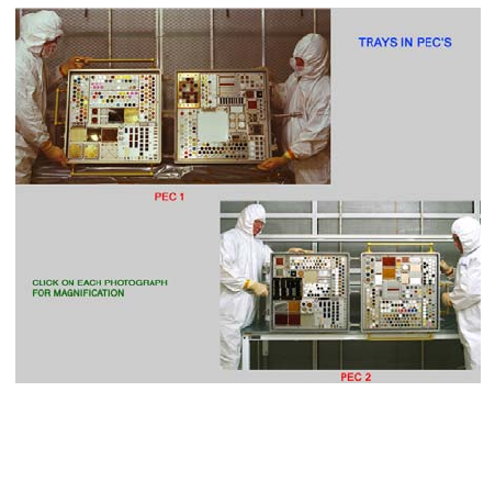
The marked material test coupons were affixed to spaces provided on test panels, which
were then installed onto trays identified as Material - International Space Station - Experiment
(MISSE). These experiments were then installed into two suitcase like structures, called Passive
Experiment Containers (PECs). MISSE 1 and 2 where were attached to the International Space
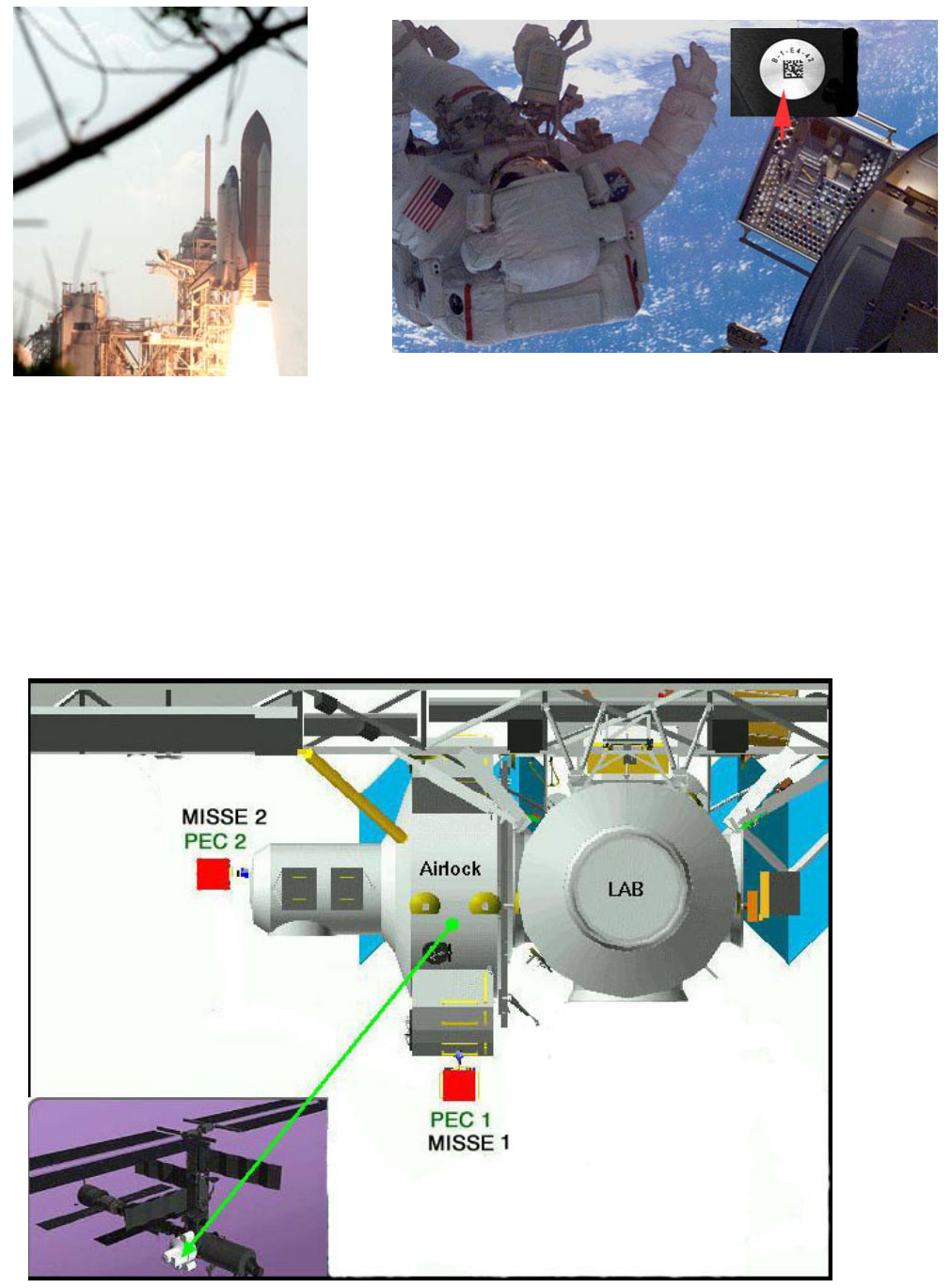
Station (ISS) by Astronaut Patrick G. Forrester during a space walk conducted during the STS-
105 Mission, which was launched on August 10, 2001.
4
PEC-1 was positioned on the lower portion of the ISS Airlock so that it would be exposed
to the maximum amount of ultra-violet (UV) radiation and atomic oxidation (AO). PEC-2 was
positioned on the side of the ISS Airlock to receive UV radiation, but minimal amount exposure
to atomic oxygen.
STS-105 (Discovery) Launch on
August 10, 2001
MISSE Positioned on Exterior of the International Space
Station by Mission Specialist Patrick Forrester on August
16, 2001
5
The original plan called for MISSE 1 and 2 to be retrieved after 1 year. After their
recovery, MISSE 3 and 4 were to be launched into LEO and retrieved after 3 years. The
Columbia incident, however, delayed retrieval of the MISSE 1 and 2 experiments until the
second mission following return to flight (STS-115). Both of these experiments were recovered
early during the STS-114 mission. Astronaut Stephen Robinson retrieved MISSE 1 and 2 on
July 30, 2005 when an opportunity presented itself during his record-breaking six hours 50
minutes space walk. The experiments were subjected to a total 1443 days of LEO exposure, or
just 17 days short of 4 years.
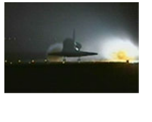
MISSE 1 and MISSE 2 were returned to earth on August 10, 2005. As a result of bad
weather (low cloud cover) at the Kennedy Space
Center (KSC), Discovery was forced to make a night
Landing at the Dryden Flight Research Center
(DFRC), Edwards Air Force Base (EAFB),
California. The orbiter touched down on Runway
22 at 5:11 a.m. (8:11 ET) and was towed to the
Mate/Demate facility where technicians performed
inspections, drained and purged the fuel systems
and loaded the orbiter onto NASA’s modified 747
carrier aircraft for the return flight to KSC.
The Orbiter arrived at KSC on August 20,2005 and was towed from the Shuttle Landing
Facility to the Orbiter Processing Facility August 22, 2005. The payload bay doors were opened
to offload the materials brought back from the International Space Station on August 23, 2005.
MISSE 1 and 2 were then packaged and returned to the Atmospheric Systems Development
Labortory at NASA's Langley Research Center (LARC), Hampton, Virginia, where the PEC’s
were inspected, disassembled and photographed. The marked coupons were then hand carried
back to the Siemens Symbology Research Center where mark quality was analyzed and decoding
tests conducted to qualify identification processes for future retrievable spacecraft and satellites.
Columbia Lands At EAFB at end of the
STS-114 Mission
6
Data from this in-orbit experiment has been
added to NASA-STD-6002 Revision C,
“Applying Data Matrix Identification Symbols
On Aerospace Parts” and NASA-HDBK-6003
Revision C, ” Application Of Data Matrix
Identification Symbols To Aerospace Parts
Using Direct Part Marking Methods/Techniques
“ The standard updates were also provided to
the USAF for possible inclusion into MIL-STD-
130, “Identification Marking Of U.S. Military
Property .”
MARKING PROCESSES TESTED
Six different marking processes were utilized in the MISSE 1 and 2 experiments. These
included Dot Peening, Electro-Chemical Coloring, Gas Assisted Laser Etch (GALE), Laser
Bonding, Laser Engraving used in conjunction with Vacuum Arc Vapor Deposition (VAVD)
coatings and Laser Inducted Vapor Deposition (LIVD). These processes are explained as follow:
Dot Peen - Dot peening is achieved by striking a carbide or diamond-tipped marker
stylus against the surface of the material being marked. Symbol size is controlled by the size and
tip angle of the stylus, dot spacing, or by altering the number of strikes per data cell. Single
strikes are used to create small symbols. Multiple strikes may be used to create larger symbols
Electro-Chemical Coloring - Electro-chemical coloring marks are produced using an
electro-chemical process used in conjunction with a stencil to form a marking. In this process,
metal is removed and replaced using an alternating current passed through a chemical that
oxidizes (discolors) the metal. No pigments are added in this process. The penetration of
coloration into the metal is controlled by the amplitude and frequency of the AC potential. The
resulting color is determined by the chemical properties of the metal and the electrolyte used.
PEC’s Prior to Disassembly
7
Laser Bonding - Laser bonding is an additive process that involves the bonding of a
material to the substrate surface using the heat generated by an Nd:YAG, YVO4, or carbon
dioxide (CO2) laser. The materials used in this process are commercially available, and generally
consist of a glass-frit powder or ground metal oxides mixed with inorganic pigment, and a liquid
carrier (usually water or mineral oil). The pigment can be painted or sprayed onto the surface to
be marked, or transferred via pad printer, screen printer, or coating roller. Adhesive-backed
tapes coated with an additive are also used in this process. Laser bonding can also be performed
using a CO2 laser and ink foils for less harsh environments. This is accomplished using heat
levels that have no noticeable effect on metal or glass substrates and are safe for use in safety-
critical applications. The markings produced using this technique (dependent on the material
used), are resistant to high heat, unaffected by salt fog/spray, and are extremely durable.
Laser Coat (VAVD) and Remove - Laser engraving is acceptable in safety-critical
applications when used in conjunction with a “coat and remove” process. This process
involves the coating of a part with a medium of contrasting color that is subsequently
removed by the laser to expose the underlying material. The coatings used in the MISSE 1
and 2 experiments were applied using a new Vacuum Arc Vapor Deposition (VAVD)
process developed by Siemens and Vacuum Arc Technologies (VAT) under a Space Act
Agreement with the Marshal Space Flight Center (MSFC) . In this process, a thin film is
produced by injecting a small amount of inert gas, such as argon, into the chamber to serve
as the ionization medium that allows an arc to be sustained in the vacuum environment.
After the flow of gas is released, a high-current, low voltage arc is produced between the
slightly separated coating material and an electrode to create a jet of fully ionized metal
vapor plasma at minute hot spots on the charge. The resulting plasma is accelerated onto
the item to be marked to form an amorphous film that can range in thickness from
angstroms to several thousandths of an inch, depending upon the length of the firing time.
8
Laser Inducted Vapor Deposition (LIVD) – The LIVD process, developed by Siemens, is used
to apply part identification markings, heating and defrosting strips, antennas, circuitry, and sun
shields to transparent materials. This is accomplished by vaporizing material from a marking
media trapped under a transparent part using heat generated from a visible spectrum laser. The
gaseous vapors and droplets resulting from the heat buildup condense on the cooler transparent
surface to form a hard uniform coating that is applied in a prescribed pattern. The process is
accomplished under normal office conditions without the need for high heat or seal gas/vacuum
chambers.
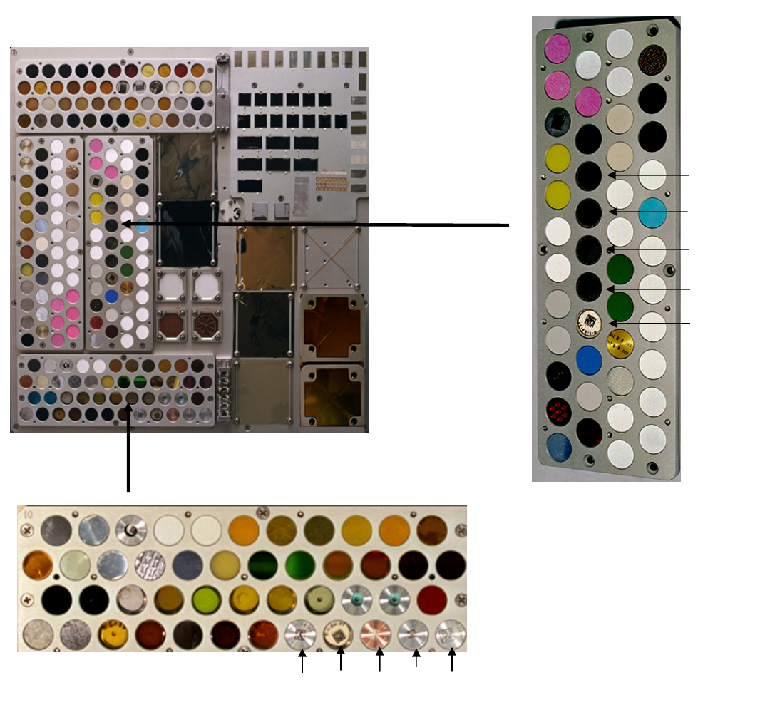
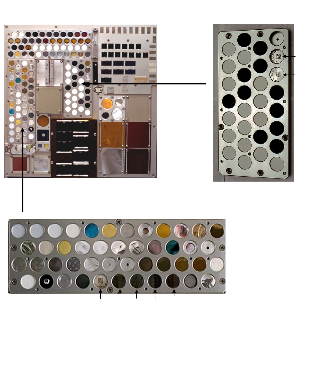
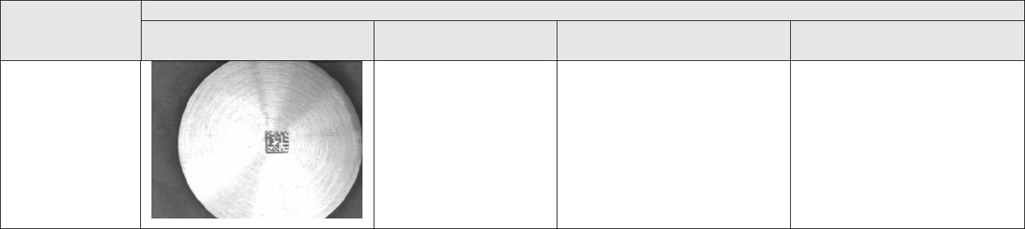
TEST COUPON CONFIGURATIONS
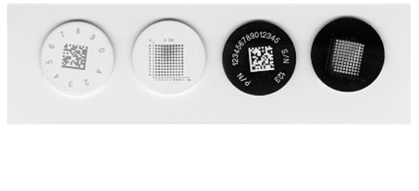
Data Matrix Symbols and line pattern test markings were applied to seventeen 0.995-
inch diameter coupons as illustrated below.
Table 1 defines the substrate materials used in the construction of the 0.995-inch disks. It
also includes the marking process, marking device, marking media and protective coatings used
in their identification. The table also includes the technical contacts associated with the marking
of each of the disks.
Sample 0.995-Inch Diameter Coupons Created To Test Marking
Processes
9
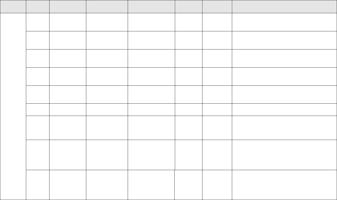
Table 1 - Part Identification Markings Generated for MISSE 1 through 4
Marking
Category Coupon
No. Marking
Method Marking Device Marking Media Substrate
Material Protective
Coating Technical Contacts
Disk 1 Laser Bonding CO2 Laser Cerdec LMM-6000
Metal Coating Anodized
AL None Don Roxby, CiMatrix - (256) 830-8123,
Andy Axtell, Cerdec - (724) 250-5501 &
Jennifer Bunis, Synrad - (800) 796-7231
Disk 2 Laser Bonding LVO4 Laser Cerdec LMM-6000
Metal Coating Anodized
AL None Don Roxby, CiMatrix - (256) 830-8123,
Andy Axtell, Cerdec - (724) 250-5501 &
Mark Villand, LMT - (303) 664-9000 ext 624
Disk 3 Laser Bonding Nd:YAG Laser Cerdec LMM-6000
Metal Coating Anodized
AL None Don Roxby, CiMatrix - (256) 830-8123 &
Andy Axtell, Cerdec - (724) 250-5501
Eva Tang, Rofin-Sinar Laser – (480) 777-1199
Disk 4 Laser Bonding CO2 Laser Ink – Markem 2700
Heat Cure (Black) Anodized
AL VAVD –
Aluminum
Oxide
Don Roxby, CiMatrix – (256) 830-8123 &
Lisa Siewierski, Markem – (603) 352-1130 Ext.
2219.
Dusk 5 Ink Jet Domino Ink Jet Ink – Domino
262BK & 211WT
(UV curable)
Anodized
AL VAVD –
AL Oxide Don Roxby, CiMatrix – (256) 830-8123 &
Lyle Zickuhr, Domino – (847) 244-2501 x1128
Disk 6 Stencil – Ink Intermec Silk
Screen Generator Ink –Standard Silk
Screen Ink Anodized
AL VAVD –
AL Oxide Don Roxby, CiMatrix – (256) 830-8123 &
Ron Pickman, Intermec – (203) 264-9476
Disk 7 Stencil –
VAVD Laser Cut Vinyl
Stencil Gold Anodized
AL
None Don Roxby, CiMatrix – (256) 830-8123,
Leonard Adcock, UAH – (256) 890-6020 &
Jack L Weeks, VAT - (256) 582-5484
Disk 8 Laser Bonding CO2 Laser Cerdec LMM-6000
Metal Coating AZ93
Coating None Don Roxby, CiMatrix – (256) 830-8123,
Jennifer Bunis, Synrad – (800) 796-7231,
Andy Axtell, Cerdec - (724) 250-5501 &
Richard Mell, AZTek – (256) 837-9877, ext.
135
Additive
Marking
Disk 9 Laser Bonding LVO4 Laser Cerdec LMM-6000
Metal Coating AZ93
Coating None Don Roxby, CiMatrix – (256) 830-8123,
Andy Axtell, Cerdec - (724) 250-5501,
Mark Villand, LMT – (303) 664-9000 ext 624
Richard Mell, AZTek – (256) 837-9877, ext.
135

10
Table 1 - Part Identification Markings Generated for MISSE 1 Through 4 Continued
Marking
Category
Coupon
No. Marking
Method Marking Device Marking Media Substrate
Material Protective
Coating Technical Contacts
Disk 10 Laser Bonding Nd:YAG Laser Cerdec LMM-6000
Metal Coating AZ93
Coating None Don Roxby, CiMatrix – (256) 830-8123,
Eva Tang, Rofin-Sinar Laser – (480) 777-1199,
Andy Axtell, Cerdec - (724) 250-5501 &
Richard Mell, AZTek – (256) 837-9877, ext.
135
Disk 11 Laser Bonding CO2 Laser Ink – Markem 2700
Heat Cure (Black) AZ93
Coating VAVD –
Aluminum
Oxide
Don Roxby, CiMatrix - (256) 830-8123,
& Lisa Siewierski, Markem - (603) 352-1130
ext. 2219 & Richard Mell, AZTek – (256) 837-
9877, ext. 135.
Disk 12 Ink Spray Ink Jet Marker Ink – Domino
262BK & 211WT
(UV curable)
AZ93
Coating VAVD –
Aluminum
Oxide
Don Roxby, CiMatrix - (256) 830-8123,
Lyle Zickuhr, Domino - (847) 244-2501 ext.
1128 & Richard Mell, AZTek – (256) 837-
9877
Disk 13 Stencil – Ink Laser Cut Vinyl
Stencil Ink – Standard Silk
Screen Ink AZ93
Coating VAVD –
Aluminum
Oxide
Don Roxby, CiMatrix - (256) 830-8123,
Richard Mell, AZTek – (256) 837-9877, ext.
135 & Eva Tang, Rofin-Sinar Laser – (480)
777-1199
Disk 14 Stencil -
VAVD Intermec Silk
Screen Generator Gold AZ93
Coating None Don Roxby, CiMatrix - (256) 830-8123,
Jack L Weeks, VAT - (256) 582-5484,
Ron Pickman, Intermec - (203) 264-9476 &
Richard Mell, AZTek – (256) 837-9877, ext.
135
Additive
Markings
Disk 15 Label Printing Computype TBD Computye Dye
Sublimation Ink Beta Cloth None Don Roxby, CiMatrix - (256) 830-8123 &
Dian Ferrell, Computype - (727) 726-5594
11
Table 1 - Part Identification Markings Generated for MISSE 1 Through 4 Continued
Marking
Category
Coupon
No. Marking
Method Marking Device Marking Media Substrate
Material Protective
Coating Technical Contacts
Disk 16 LIVD Nd:YAG laser Tin PPG Glass None Don Roxby, Acuity CiMatrix - (256) 830-8123,
Eva Tang, Rofin-Sinar Laser – (480) 777-1199
& Guy Griffith, PPG - (256) 859-2500 Ext.
2211
Disk 17 Laser Etch CO2 Laser VAVD - Material
Gold Anodized
AL None Don Roxby CiMatrix - (256) 830-8123,
Jack L Weeks, VAT - (256) 582-5484
Disk 18 Laser Etch LVO4 Laser VAVD - Material
Gold Anodized
AL None Don Roxby CiMatrix - (256) 830-8123,
Jennifer Bunis, Synrad, (800) 796-7231 &
Jack L Weeks, VAT - (256) 582-5484
Dusk 19 Laser Etch Nd:YAG Laser VAVD - Material
Gold Anodized
AL None Don Roxby, CiMatrix - (256) 830-8123 &
Jack L Weeks, VAT - (256) 582-5484
Coat &
Mark
Disk 20 Laser Etch Nd:YAG Laser VAVD - Material
Gold AZ93
Coating None Don Roxby, CiMatrix - (256) 830-8123 &
Jack L Weeks, VAT - (256) 582-5484
Disk 21 Laser Etch Nd:YAG Laser VAVD - Material
Gold Corning
Glass None Don Roxby, CiMatrix - (256) 830-8123,
Jack L Weeks, VAT - (256) 582-5484 &
Guy Griffith, PPG - (256) 859-2500 Ext. 2211
Disk 22 Dot Peen Dot Peen Marker Dot Peen Bare AL None Don Roxby, CiMatrix - (256) 830-8123 &
Richard Pentz, DAPRA - (800) 442-6275
Disk 23 Laser Etch Nd:YAG Laser None Bare AL None Don Roxby, CiMatrix - (256) 830-8123 & Eva
Tang, Rofin-Sinar Laser – (480) 777-1199
Disk 24 Electro-Chem
Etch Standard Pwr.
Unit Electrolyte Bare AL None Don Roxby, CiMatrix - (256) 830-8123 &
Sy Haeri, lectro-Chem Etch Metal Marking,
Inc. (714) 671-7744
Disk 25 GALE LVO4 Laser Marking Gas TBD Bare AL None Don Roxby, CiMatrix - (256) 830-8123,
Mary Helen McCay, UTSI - (931) 393-7473 &
Mark Villand, LMT - (303) 664-9000 ext 624
Direct
Part
Marking
Disk 26 LISI Nd:YAG Laser TBD Bare AL None Don Roxby, CiMatrix - (256) 830-8123,
Mary Helen McCay, UTSI - (931) 393-7473 &
Eva Tang, Rofin-Sinar Laser – (480) 777-1199
12
Table 1 - Part Identification Markings Generated for M-ISS-E 1 Through 4 Continued
Marking
Category Coupon
No. Marking
Method Marking Device Marking Media Substrate
Material Protective
Coating Technical Contacts
Laser Etch Nd:YAG Laser None Bare AL None Don Roxby, CiMatrix - (256) 830-8123 & Eva
Tang, Rofin-Sinar Laser – (480) 777-1199
Direct
Part
Marking
Bar 1
Laser Etch Nd:YAG Laser None Bare AL Clear
Anodize Don Roxby, CiMatrix - (256) 830-8123 & Eva
Tang, Rofin-Sinar Laser – (480) 777-1199
13
TEST COUPON POSTIONING ON THE EXPERIMENT TRAYS
The marked disks selected for flight were installed onto Experiment Holders EOIM 3 and
EOIM 4 on the top side of the Atomic Oxygen (AO) and Solar Tray 1, MISSE 1, PEC 1 and
onto Experiment Holders EOIM 10 and D2 on the top side of the Ultra Violet (UV) Tray 2,
MISSE 2, PEC 2.
MISSE 1, Tray 1, Top
EOIM 3 Holder
E3-31
E3-30
E3-29
E3-28
E3-27
EOIM 4 Holder
E4-42
E4-43
E4
-
44
E4-45
E4-46
14
MISSE 2, Tray 2, Top
EOIM 10 Holder (Flipped Horizontally)
D2 Holder
E16-42
E16-43
E10-07
E10-06
E10
-
05
E10-04
E10-05
15
PRE-FLIGHT GRADING
Each marked coupon to be flown was photographed under using a normal lens and under
magnification prior to flight. These prints were stored to compare against samples after being
exposed to the LEO environments. The Data Matrix Symbols were read and graded using
RVSI’s mark quality verification system and all scored “A.” The Pre-flight grades follow:
16
Table 2 – Pre-Flight Marking Grades Continued – MISSE 1 And 2
Specimen
Number Base
Material Marking
Method Marking
Material Encoded
Info. Planned
Orbit
Duration
Color of
Mark Pre Flight
Grade Marking
Equipment
B-1-E10-06 Glass VAVD Copper Line
Pattern 1 yr. Dark
Gray Good
Contrast Rofin-Sinar
Nd:YAG Laser
B-1-E3-27 Glass LIVD Brass Line Pattern 1 yr. Dark
Brown Good
Contrast Rofin-Sinar
Nd:YAG Laser
B-1-E3-28 Glass LIVD Tin Line
Pattern 1 yr. Black Good
Contrast
Rofin-Sinar
Nd:YAG Laser
B-1-E3-29 Glass Laser
Bonding Cerdec
RD-6005 Line
Pattern 1 yr. Gray-
Black Excellent
Contrast Rofin-Sinar
Nd:YAG Laser
B-1-E3-30 Glass VAVD Copper Line
Pattern 1 yr. Dark
Gray Good
Contrast Rofin-Sinar
Nd:YAG Laser
B-1-E3-31 Glass LIVD Tin B1E331 1 yr. Black A Rofin-Sinar
Nd:YAG Laser
B-1-E4-42 Aluminum Laser
Bonding Cerdec RD-
6000 B1E442 1 yr. Black A Rofin-Sinar
Nd:YAG Laser
B-1-E4-43 Glass Laser
Bonding Cercec
RD-6005 B1E443 1 yr. Black A Rofin-Sinar
Nd:YAG Laser
B-1-E4-44 Aluminum VAVD Copper B1E444 1 yr. White A Rofin-Sinar
Nd:YAG Laser
B-1-E4-45 Aluminum GALE Argon Gas CiMatx 1 yr. Dark
Gray A LMT Diode-
Pumped Laser
B-1-E4-46 Aluminum Chemical
Etching SCE-4 B1E446 1 yr. Gray A Electo-Chem
Etch Machine
B-1-E10-03 Glass LIVD Brass Line
Pattern 1 yr. Dark
Brown Good
Contrast Rofin-Sinar
Nd:YAG Laser
B-1-E10-04 Glass LIVD Tin Line
Pattern 1 yr. Black Good
Contrast Rofin-Sinar
Nd:YAG Laser
B-1-E10-05 Glass Laser
Bonding Cerdec
RD-6005 Line
Pattern 1 yr. Gray-
Black Excellent
Contrast Rofin-Sinar
Nd:YAG Laser
B-1-E10-07 Glass LIVD Brass B1E107 1 yr. Dark
Brown A Rofin-Sinar
Nd:YAG Laser

17
Table 3- Pre-Flight Marking Grades – MISSE 3 And 4
Specimen
Number
Base
Material Marking
Method Marking
Material Encod
ed
Info.
Planned
Orbit
Duration
Color of
Mark Pre Flight
Grade Marking
Equipment
B-1-B9 Aluminum
Plate Laser
Etching N/A 12345
6 3 yrs. Gray A Rofin-Sinar
Nd:YAG Laser
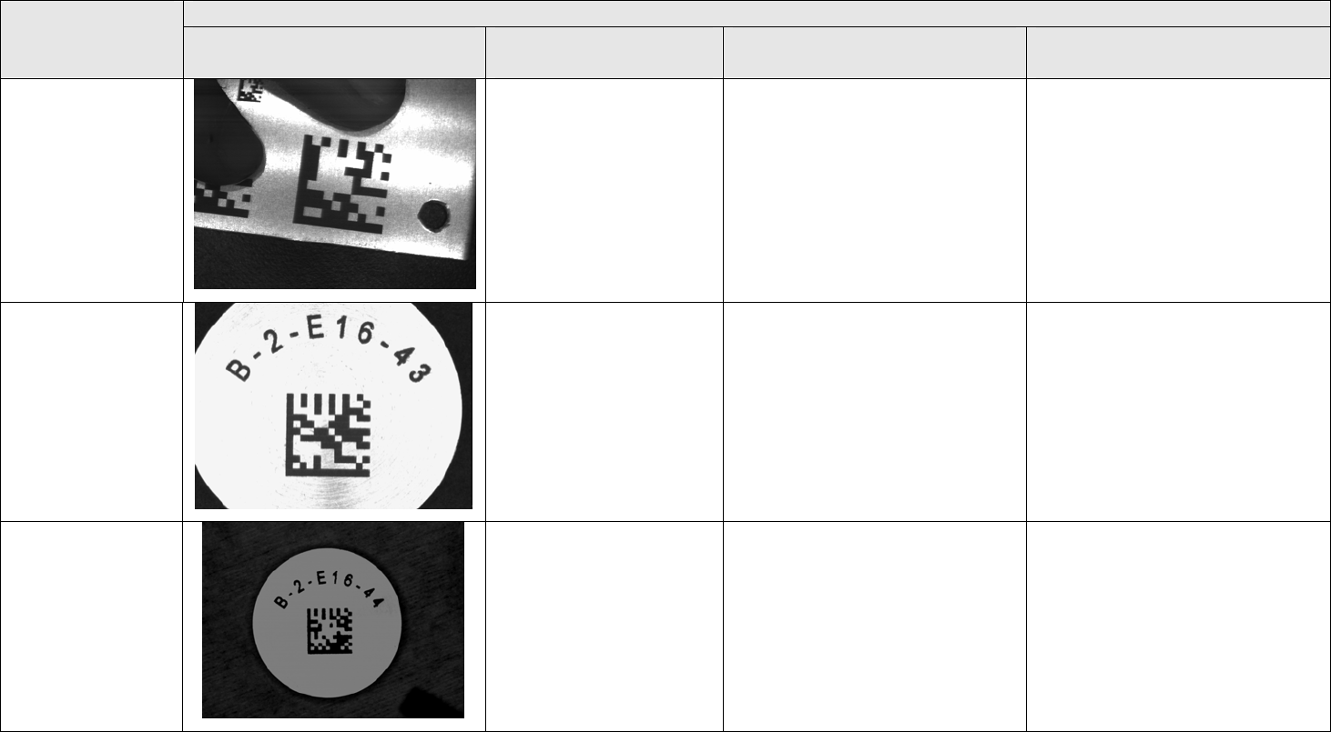
B-2-E16-42 Aluminum Dot Peen N/A 2E164
2 3 yrs. White A
Telesis TMP
6000 Pinstamp
B-2-E16-43 Aluminum Laser
Etching N/A 2E164
3 3 yrs. Dark Gray A Rofin-Sinar
Nd:YAG Laser
B-2-E16-44 Aluminum LISI Metallic
Powders 2E164
4 3 yrs. Dark Gray A Rofin-Sinar
Nd:YAG Laser
B-2-E16-45
Aluminum Laser Shot
Peening
N/A
2E164
5
3 yrs.
White
B Neodymium-Doped
glass laser
B-2-E16-46 7980 Glass
(Corning) LIVD Tin 2E164
6 3 yrs. Black A Rofin-Sinar
Nd:YAG Laser

18
IN ORBIT OBSERVATIONS
Shuttle Astronauts visited the MISSE experiments to make observations and to take photographs
while MISSE 1 and 2 were in orbit. These Extra Vehicular Activities (EVA’s) were made to the
experiments in September, October and December of 2001; February, April and October 2002;
and March, April and August of 2003. The part identification markings included in the MISSE
experiments were clearly visible in many of the photographs and appeared to be readable.
August 2003 EVA Photograph
Data Matrix Symbols Still Clearly
Visible
19
POST-FLIGHT GRADING
The flown MISSE 1 and 2 samples were evaluated under magnification and compared to the
preflight photographs. Attempts were made to read the machine-readable symbols and where
found to be readable, were graded in accordance with NASA-STD-6002 Revision A. The results
of these evaluations and reading tests are recorded in Table 3 and discussed in the summary
section.
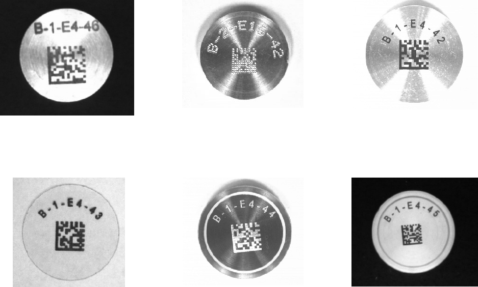
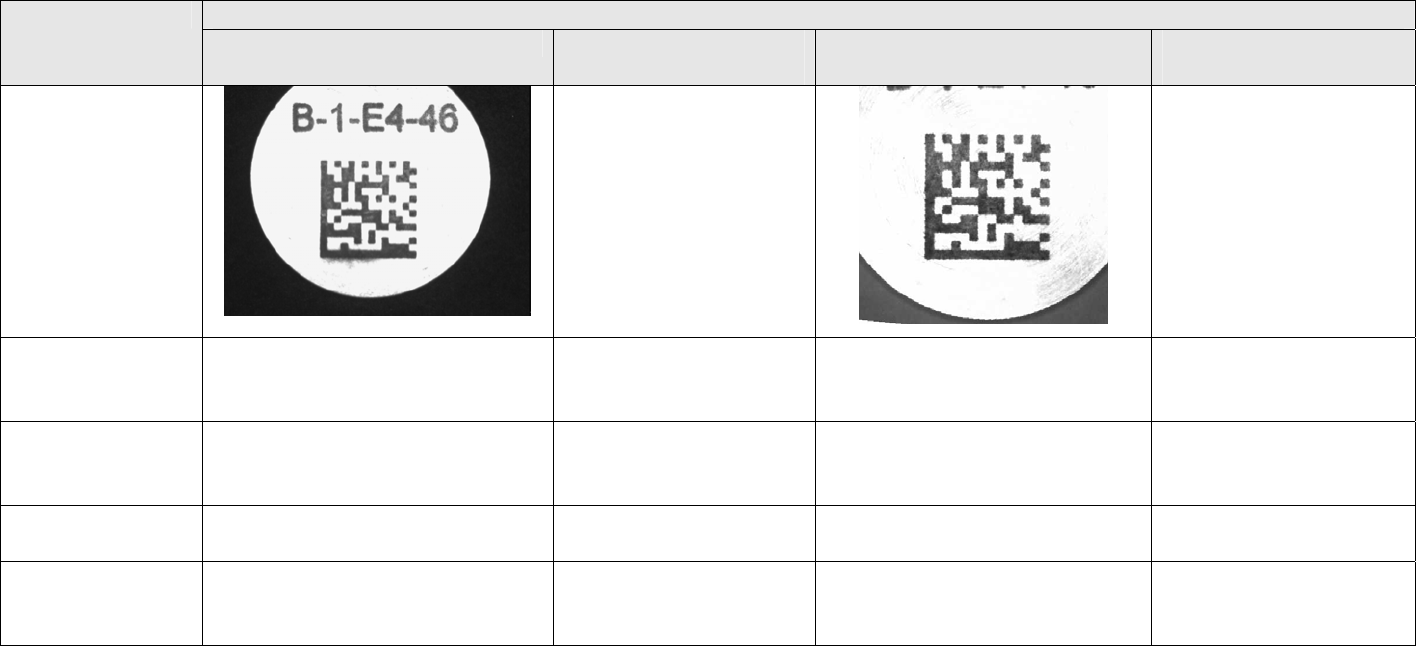
Photographs Of Marked Coupons – After 4 Years in Low Earth Orbit
Elec. Chem Coloring
B-1-E4-46
Dot Peen
B-2-E16-42
Laser Bonding
B-1-E4-42
Laser Bonding on Glass
B-1-E4-43
Laser Coat & Remove
B-1-E4-44
GALE
B-1-E4-45
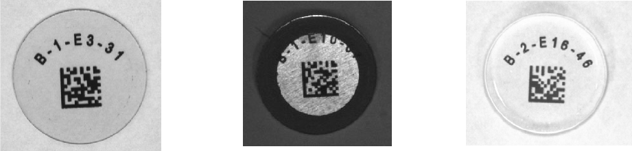
20
LIVD - Tin
B-1-E3-31
LIVD - Brass
B-1-E10-07
LIVD - Tin
B-2-E16-46
21
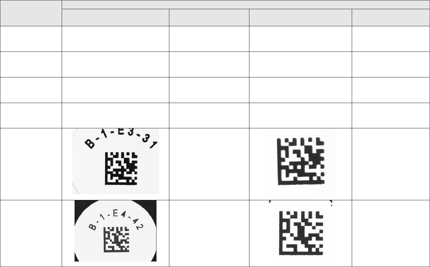
Table 3 – Pre-Flight/Post Flight Marking Comparison - MISSE 1 & 2
Marking Comparison Sample Number Pre Flight Mark Photograph Pre Fight
Verification Grade Post Flight Mark Photograph Post Fight
Verification Grade
B-1-E3-27
LIVD - Brass Line Pattern Good Contrast –
Excellent Line
Resolution
Sample being Evaluated by
Boeing Phantom Works
N/A
B-1-E3-28
LIVD - Tin Line Pattern Good Contrast –
Excellent Line
Resolution
Sample being Evaluated by
Boeing Phantom Works N/A
B-1-E3-29
Laser Bonding Line Pattern Good Contrast –
Excellent Line
Resolution
Sample being Evaluated by
Boeing Phantom Works N/A
B-1-E3-30
VAVD - Copper
Line Pattern Good Contrast –
Excellent Line
Resolution
Sample being Evaluated by
Boeing Phantom Works N/A
B-1-E3-31
LIVD - Tin
% Contrast A
Axial Uniformity A
Print Growth A
Error Correction A
Overall Grade A
% Contrast A
Axial Uniformity A
Print Growth A
Error Correction A
Overall Grade A
B-1-E4-42
Laser Bonding
% Contrast A
Axial Uniformity A
Print Growth A
Error Correction A
Overall Grade A
% Contrast A
Axial Uniformity A
Print Growth A
Error Correction A
Overall Grade A
22
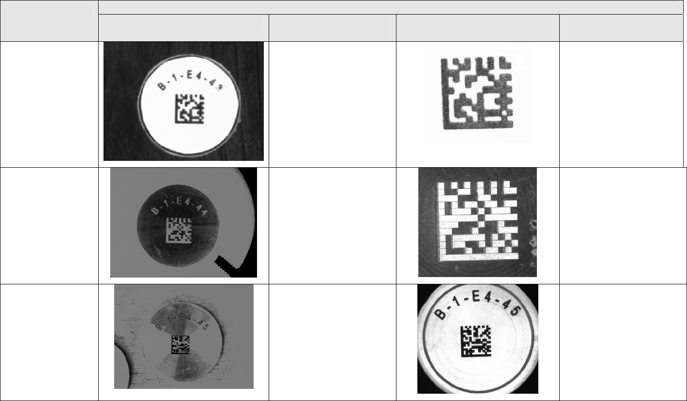
Table 3 – Pre-Flight/Post Flight Marking Comparison - MISSE 1 & 2
Marking Comparison Sample Number Pre Flight Mark Photograph Pre Fight
Verification Grade Post Flight Mark Photograph Post Fight
Verification Grade
B-1-E4-43
Laser Bonding % Contrast A
Axial Uniformity A
Print Growth A
Error Correction A
Overall Grade A
% Contrast B
Axial Uniformity A
Print Growth A
Error Correction A
Overall Grade B
B-1-E4-44
Laser Coat &
Remove - VAVD
% Contrast A
Axial Uniformity A
Print Growth A
Error Correction A
Overall Grade A
% Contrast A
Axial Uniformity A
Print Growth A
Error Correction A
Overall Grade A
B-1-E4-45
GALE
% Contrast A
Axial Uniformity A
Print Growth A
Error Correction A
Overall Grade A
% Contrast A
Axial Uniformity A
Print Growth A
Error Correction A
Overall Grade A
23
Table 3 – Pre-Flight/Post Flight Marking Comparison - MISSE 1 & 2
Marking Comparison Sample Number Pre Flight Mark Photograph Pre Fight
Verification Grade Post Flight Mark Photograph Post Fight Verification
Grade
B-1-E4-46
Electro-Chemical
Coloring
% Contrast A
Axial Uniformity A
Print Growth A
Error Correction A
Overall Grade A
% Contrast A
Axial Uniformity A
Print Growth A
Error Correction A
Overall Grade A
B-1-E10-03
LIVD - Brass Line Pattern Good Contrast –
Excellent Line
Resolution
Sample being Evaluated by
Boeing Phantom Works N/A
B-1-E10-04
LIVD - Tin Line Pattern Good Contrast -
Excellent Line
Resolution
Sample being Evaluated by
Boeing Phantom Works N/A
B-1-E10-05
Laser Bonding Line Pattern Excellent Contrast
And Line Resolution Sample being Evaluated by
Boeing Phantom Works N/A
B-1-E10-06
VAVD - Copper Line Pattern Good Contrast –
Excellent Line
Resolution
Sample being Evaluated by
Boeing Phantom Works N/A
24
B-1-E10-07
LIVD - Brass
% Contrast A
Axial Uniformity A
Print Growth B
Error Correction A
Overall Grade B
% Contrast B
Axial Uniformity A
Print Growth B
Error Correction A
Overall Grade B
Table 3 – Pre-Flight/Post Flight Marking Comparison - MISSE 1 & 2
Marking Comparison Sample Number Pre Flight Mark Photograph Pre Fight
Verification Grade Post Flight Mark Photograph Post Fight Verification
Grade
B-2-E16-42
Dot Peen
% Contrast A
Axial Uniformity A
Print Growth A
Error Correction A
Overall Grade A
% Contrast A
Axial Uniformity A
Print Growth A
Error Correction A
Overall Grade A
B-2-E16-43
LIVD
Note: Position
reassigned after
marking. ID’s as
B-2-E16-46,
flown in position
B-2-E16-43
% Contrast A
Axial Uniformity A
Print Growth A
Error Correction A
Overall Grade A
% Contrast A
Axial Uniformity A
Print Growth A
Error Correction A
Overall Grade A
25
Table 4 – Pre-Flight/Post Flight Marking Comparison Continued – MISSE 3 and 4
Marking Comparison Sample Number Pre Flight Mark Photograph Pre Flight
Verification Grade Post Fight Mark Photograph Post Fight
Verification Grade
B-1-B9
Small - Bare
Laser Etch
Data Cell Size
Study
% Contrast A
Axial Uniformity A
Print Growth A
Error Correction A
Overall Grade A
B-1-B9
Small - Anodized
Laser Etch
Data Cell Size
Study
% Contrast A
Axial Uniformity A
Print Growth A
Error Correction A
Overall Grade A
B-9-B9
Large - Laser Etch
Data Cell Size
Study
% Contrast A
Axial Uniformity A
Print Growth A
Error Correction A
Overall Grade A
26
Table 4 – Pre-Flight/Post Flight Marking Comparison Continued – MISSE 3 and 4
Marking Comparison Sample Number Pre Flight Mark Photograph Pre Flight
Verification Grade Post Fight Mark Photograph Post Fight
Verification Grade
B-1-B9
Large - Anodized
Laser Etch
Data Cell Size
Study
% Contrast A
Axial Uniformity A
Print Growth A
Error Correction A
Overall Grade A
B-2-E16-43
Laser Etch
% Contrast A
Axial Uniformity A
Print Growth A
Error Correction A
Overall Grade A
B-2-E16-44
LISI
% Contrast A
Axial Uniformity A
Print Growth A
Error Correction A
Overall Grade A
27
Table 4 – Pre-Flight/Post Flight Marking Comparison Continued – MISSE 3 and 4
Marking Comparison Sample Number Pre Flight Mark Photograph Pre Flight
Verification Grade Post Fight Mark Photograph Post Fight
Verification Grade
B-2-E16-45
Laser Shotpeen
% Contrast A
Axial Uniformity A
Print Growth B
Error Correction A
Overall Grade B
28
SUMMARY
Siemens personal at the SRC marked two sets of samples to support this program. One
set was retained at the SRC as control specimens and the second set was incorporated into
MISSE 1 and 2, which were subsequently flown in earth orbit for four (4) years. A detail
comparison was performed between these control specimens and flown specimens on October
11, 2005 and the following observations were made.
All of the Data Matrix symbols flown received passing grades as defined by International
Standard Organization (ISO) document ISO-15415 as amended by NASA-STD-6002B. Only
one (1) of the flown symbols showed signs of degradation. This was specimen number B-1-E4-
43 (Laser Bonding marking process), which showed a slight decrease in contrast, falling from an
A grade (≥0.50 percent) to a B grade (≥0.40 percent). This was attributed to a combination of
exposure to strong UV light and atomic oxidation. The B grade is acceptable per the standard,
which requires an A or B grade at point of manufacture and remarking in the field after the mark
quality verification grade levels fall to a C grade.
The mark quality of specimen number B-1-E4-44 (Laser Coat and Remove – VAVD)
improved over the 4 years in orbit. The contrast levels for this specimen increased as the copper
colored coating darken to a dark green as a result of oxidation. This specimen was the only
specimen to show signs of micro-partial impact during flight. The impact sites could only be
viewed under high magnification and did not have an affect on decoding. This specimen also
showed signs of discoloration outside of the marking area, which was attributed to marking
process deficiencies caused by contamination in the coating sprayed or on metal at time of
coating. This contamination resulted in coating discoloration after exposure to the LEO
environment.
The MISSE 1and 2 marking program exceeded all expectations and meet 100 percent of
the SRC’s Principle Investigators objectives.
29
RECOMMENDATIONS
Based on the results of this experiment, Siemens recommends the following ground rules
for in-orbit part identification marking:
1. Identify and test other Laser Coat and Discolor and Laser Coat and Remove materials and
complementing substrate coloring and clear coat materials.
2. Require the use of matt finished clear coats in conjunction with Laser Bonding and Laser Coat
and Remove marking processes.
3. Require that markings applied to glass substrates using Laser Inducted Vapor Deposition
(LIVD) process be applied to the interior (unexposed) side of the item.
4. Replace the electro-chemical coloring (AC current) process tested as part of this experiment
with a deep electro-chemical etch process (DC current) to form a recessed marking that is
enhanced using a coloring agent to improve contrast. This marking, protected with a matte
finished clear coat, will be more durable and easier to read.
5. Explore means to backfill dot peen markings to improve readability using hand-held readers.
6. Implement a Rocket Engine Marking Development and Test Program (high temperature
applications). Spin off from this program would benefit the automotive, aircraft, pipe,
catalytic converter and other commercial industries.
30
REFERENCES
1. D. L. Roxby, USAF Aging Landing Gear Life Extension Program Marking Test
Report, March 29, 2001
2. Robert M. Beggs , U.S. Army Aviation Parts Marking Demonstration Final Report,
September 7, 2001
3. Roxby, D. L.; USCG Flight Safety Critical Aircraft Parts Direct Part Marking (DPM)
Verification Program Report, January 15, 2004
4. Coates, J.; USAF Landing Gear Life Extension Program Reports GA-C23527, GA-
C24577, GA-C24578, GA-C24623, GA-C24624 and GA-C24688
5. Roxby, D. L.; National Center for Manufacturing Sciences (NCMS)/DoD Retrofit
Parts Marking Project Final Report, September 30, 2004
6. MIL-STD-130, Identification Marking Of U.S. Military Property
7. NASA-STD-6002, Applying Data Matrix Identification Symbols On Aerospace Parts
8. NASA-HDBK-6003, Application Of Data Matrix Identification Symbols To
Aerospace Parts Using Direct Part Marking Methods/Techniques
9. More information related to the MISSE 1 and 2 Experiments can be obtained on Web
Site: http://misseone.larc.nasa.gov/
