Thrust10_datasheet_English Thrust 10 Data Sheet
User Manual: Thrust 10 Data Sheet
Open the PDF directly: View PDF ![]() .
.
Page Count: 7

www.PrecisionAerobatics.com
Copyrights ©2007 Precision Aerobatics. All rights reserved
Precision Aerobatics Thrust 10 Brushless motor with RotorKool® technology
The development of our new PA Thrust® motors has followed our traditional design philosophy employed in our
aircraft; which is doing things better. Thrust® motor is one of the coolest running high performance, high-torque
and high efficiency brushless motor ever produced to date. The design incorporates our latest innovation,
RotorKool® which keeps the stator core material, the low resistance windings, highly permeable stator plates,
high quality NMB Japan triple bearings and powerful neodymium magnets at optimum operating temperatures
regardless of duration or the number of consecutive flights made*.
*provided sufficient airflow is permitted.
Motor specs
Outside Diameter 28mm
Length 31.7mm
Weight (gr/oz) 41.2gr / 1.45oz
Motor Shaft Dia. 3.0mm
Mounting Bolts Dia. M3
Max efficiency Current A * 6-12A
Peak current A (15 sec)* 16A
Battery pack range ** 2~3 LiPo / 6-10 NiCd
Poles 14
KV rpm/V 975
Recommended ESC PA Quantum 18
Peak Watts 185 watts
* Unrestricted airflow and air scoops are mandatory to ensure long service life and long term performance
consistency. Extended Continuous Operation without the required cooling provisions may be detrimental to the
coils and magnets and will void warranty.
** PA 3cells (11.1V) 1000mAh pack is recommended
Propeller selection with PA1000 20C-40C V2 Packs
APC 9x4.7SF - Very nice propeller allowing good flight duration with excellent thrust due to the higher
RPM. The larger pitch allows high speed maneuvers while maintaining the thrust for 3D.
Good prop for both indoor and outdoor 3D/Freestyle flying
VOX 10x4 - Excellent overall propeller for 3D, freestyle aerobatics with excellent thrust and longer
flight duration comparing to the APC 9x4.7SF due to the efficiency built into the prop
design. An excellent alternative to the APC 9X4.7SF with an additional bonus of added
prop wash & thrust for better slow speed handling.
APC 10x3.8SF - This is the higher range propeller for the Thrust 10 with more thrust than the other
propellers. It slows down the plane nicely for close-in, hardcore 3D flying (excellent for
low rolling harriers) and provides lots of instantaneous thrust for quick recoveries and
exits. This is our recommended propeller for the PA Electric Shock. NOTE: Adequate
airflow to cool down the motor and ESC is required as well as a good throttle
management.
We recommend getting a few different size propellers with your Thrust 10 motor. Swapping a propeller is an
easy task so you may want to experiment and feel the difference to fit different style of flying. Also in a hot
summer day you may want to use a smaller propeller while in a cooler day you can run the motor with a larger
propeller.

www.PrecisionAerobatics.com
Copyrights ©2007 Precision Aerobatics. All rights reserved
Note :- Actual flight duration is dependent on the individual’s flying style and the extent of throttle management
used. To make initial flight duration estimates, refer to the dynamic flight testing graphs on the following pages
to set the flight duration in accordance to the propeller used. This will be the conservative flight duration
estimates whereby the actual flight duration specific to each individual can be then refined by taking note of the
remaining battery capacities after the flight session to establish the consistent capacity draw. Due to the
relatively flat nature of the discharge curve found on high grade, high performance batteries where it provides
consistent performance throughout 90% of the pack’s capacity, the drop in power at the last 10-20% of the
pack’s capacity sometimes goes unnoticed. As such it indirectly encourages the modeler to fly for an extended
period and run the risk of encroaching into sudden ESC unexpected LVC (Low Voltage Cutoff). To avoid this, as
a rule of thumb, set your flight timer to allow at least 15% spare capacity as a contingency measure to account
for weather conditions, inconsistencies in routines and other eventualities you may have not anticipated.
A little background
For a number of years, modelers have accepted the notion that in order to attain top notch performance, one
has to run outrunner motors to the extreme limit with the risk of overheating. In fact, heat has become
inevitable part of contemporary high performance Brushless Motors and nothing much could be done about it.
However heat is one of the main contributors to premature magnet deterioration and bearing failures leading to
permanent performance degradation over time or even dangerous and catastrophic destruction due to thrown
magnets.
In order to avoid unwanted heat damaging the motor, some modelers have resorted to over sizing their motors.
This in turn increases the all up weight and thereby affecting wing loading and flight performance. There seems
to be a no win situation and the only way to enjoy this wonderful hobby is to accept the seemingly hopeless
compromise.
Motor power has always been quoted in Watts, but heat is Watts too. So, the real question is “Are all the quoted
Watts being used to drive the motor, or is there a significant amount of Watts wasted in heat? To answer that
just touch your motor immediately after flight and if it is hot enough to burn your finger, THAT is where the
Watts went as opposed to driving your airplane, therefore, quoted watts are essentially meaningless when
evaluating a motor (because it does not indicate the efficiency). The propeller’s RPM is the most important
performance factor.
We at PA understood that without effectively eliminating heat, all the good motor attributes already available in
our motors and as well as others, contributes very little to the motor’s overall performance in service because
heat building up under load means loss of efficiency and eventually leads to detrimental effects in the electro-
magnetic properties of the motor. These effects cause significant deterioration of power, thrust and eventually
flight times.
We set a target to make a high performance, extreme thrust motor, which is light, runs cool and efficient for
maximum flight time, is made of highest grade materials and features precision engineering and machining.
This led to rethinking the design of current brushless outrunners, their strengths and limitations and thus led to
the development of a completely new line of PA Thrust® motors.
About the design
Some of the common brushless outrunner manufacturers have gone as far as incorporating high temperature
magnets and exotic adhesives to circumvent the effects of the heat problem. There are myriad of crude and
inefficient cooling techniques ranging from a multitude of holes, to fins, to bolt-on fans and impellers.
Unlike those, the new PA Thrust® cooling design took a complete departure in the current thinking by
engineering a High Velocity Force Cool Ventilation (HVFCV) into the rotor end bell as well as taking full
advantage of thermodynamic properties of the stock material itself. HVFCV is achieved through a set of solid
metal turbine impeller blades painstakingly CNC milled as an integral part of the rotor end bell assembly, which
not only provides the positive force cool ventilation by drawing fresh cool air through the stator and magnets,
but also doubles up as a heat pump to first draw excess heat from the rotor assembly itself and then act as a
heat exchanger by expelling it through the air stream contacting the solid metal turbine blades as it spins at high
velocity. Micro ridges, intentionally CNC cut into the rotor, further multiples the end bell’s surface area and serve
as radiators to further boost thermal dissipation achieving unparallel cooling and henceforth having the ability to
swing larger propellers than other conventional outrunner motors of similar class while remaining considerably
cooler and more efficient.
There is more to the “Cool” look of the CNC exterior casing than meets the eye, and looks can be deceiving.
Under the hood, is where serious engineering comes into play. With only the highest quality materials and
components used in the manufacture, the new PA Thrust® motors are manufactured with the tightest tolerance
making it possible to maintain the smallest air gap between the stator and shaped neodymium magnets,
significantly boosting torque and thrust. The relatively silent and vibration-free operation of the motor is a
testament to the tight tolerance manufacturing regime we have adopted specifically to harness the maximum
power produced by the motor (within the limits of today’s technology) for the sole purpose of swinging the prop.

www.PrecisionAerobatics.com
Copyrights ©2007 Precision Aerobatics. All rights reserved
This allows the motor to swing propellers of at least one size larger than any contemporary motors in its class
and keeping cool and efficient in the process.
The iPAs Drive Test Methodology:- An Engineered Approach to Testing
Through hundreds of hours of flight testing our airframe designs, we have established that there is a direct
correlation between the airframe and drive system and one affects the other with consequences to the desired
aerodynamic performance. We designed our power plants with the airframe that promotes efficient cooling. The
idea behind the design was to allow the power plant and airframe to work in harmony in order to achieve
optimum performance, that could never be easily achieved with a mix and match approach. Every step of the
design from the airframe, motor, speed controller through to the matching power packs have been done in a
very careful and measured fashion with the sole propose to achieve the maximum aerodynamic performance
without compromising flight time. We call the result iPAs, PA Integrated Performance Airframe-Drive System,
allowing any modeler to get it right the first time in the simplest and shortest way; the completely hassle free
buy, fix, fly and forget method.
What iPAs means to you, the modeler? iPAs provides a pre-matched, optimum gear setup derived from hundreds
of hours of flight testing that would make your PA model perform as advertised out of the box. This also means
you will no longer need to try and figure out by experiments what gear best matches the airframe and the
desired flight performance.
Below we will tell you a bit about the task of testing the gear to confirm the performance results.
While this may sound easy, it is actually a very complex test that should be done carefully. Any variations with
the type of ESC set up, ESC brand, type of battery, charging of the battery pack (can even vary between same
brand and type of pack), type of chargers, climate (environment temperature) and testing gear will derive
different results. Even the duration of the bench run will change the reads due to the battery voltage drop
caused by the internal resistance of the battery as well as the age of the battery. All those factors can create A
LOT of read variations.
We conducted multiple tests (both static and dynamic tests) on each of our motors in different
climates/temperature, using different testing equipment, changed ESC and batteries to determine the real
performance of the motor. We also had the model flown by multiple test pilots to obtain different individual
flying styles.
We believe that drive system testing should not be purely based on bench testing, because those are clinical test
done in controlled environments that are completely different from actual flight conditions. Interactions of
external environmental factors such as cooling, prop loading, G-Force etc. can not be accurately simulated on
the bench. The real performance data comes from actual flights because this is where it counts the most.
Therefore, we have taken the approach to conduct actual live test to acquire our data, i.e. flying the actual
aircraft and performing actual 3D maneuvers, like any other experienced modeler would for real. We do not
simply fly straight and level circuits and performing simple aerobatic maneuvers during our flight test but we
actually fly our aircraft to the maximum limits of their aerodynamic performance envelope.
We strongly recommend going over the graphs below since they are the real dynamic test we’ve conducted with
the motor.
Static Bench Testing Results
iPAs Gear: PA Thrust 10, Quantum 18, PA1000mah 20C-40C V2
Prop Type Battery
Voltage
(V)
Current
(A)
RPM Watts
(W)
Static Thrust
(oz)
Static Thrust
(gr)
VOX 10x4 11.76 12.06 8436 141.8 32.16 911.7
APC 9X4.7SF 11.35 12.7 8340 144 31.04 880.0
APC 10X5E 11.29 13.7 7875 155 29.76 843.7
APC 10X3.8SF 11.13 16.3 7035 181 33.60 952.5
In 3D flights, thrust and power usually require the immediate power for few seconds to get out of a maneuver.
We have based our static tests on this datum. We used 4 different brands of testing gear to verify the results
and accuracy of reads. Test results may vary depend on your set up of your ESC, climate, altitude, duration of
run etc.
www.PrecisionAerobatics.com
Copyrights ©2007 Precision Aerobatics. All rights reserved
Dynamic Flight Testing Results
The dynamic test is real time data acquisition by onboard data loggers installed on the actual aircraft which the
gear is designed for. These airplanes are deliberately flown by advanced pilots executing actual advanced
maneuvers to simulate the real world performance conditions where these airplanes are expected to be flown.
We have included several graphs to cover as many advanced freestyle and 3D routines as possible especially
maneuvers that places the most demand on the drive system. The graphs also show the actual motor cooling
performance as it goes through each different maneuver and air speeds.
You may also want to look at all the temperature traces on the graph that indicates a fairly constant operating
temperature throughout the flight in relation to the dynamic loads imposed by the propeller. This is where our
exclusive Rotorkool® feature comes into action to keep motor core temperature considerably below the critical
temperature limits of the neodymium magnets allowing our Thrust® motors to provide consistent performance
far longer than any other motor.
iPAs Dynamic Flight Test Results
Gear used: PA Thrust 10, PA Quantum 18, PA V2 1000mah 20C- 40C (General Freestyle/Hardcore 3D Maneuvers)
Engineering Units
Current = Amps, Voltage = Volts, Power = Watts, Temperature = Deg C., RPM = RPM, Battery Capacity = mAh.
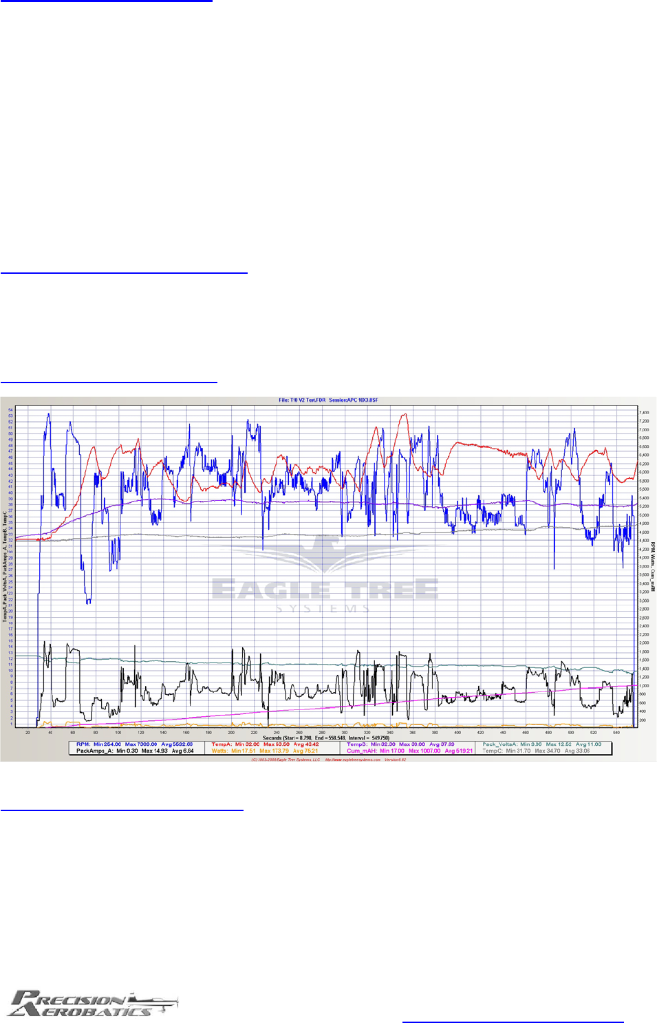
Test Flight 1 APC 10X3.8SF
Graph interpretation & Flight Report:
Dynamic test conducted in a hot summer day with ambient Air temperature of 32 Deg C (89.6F). The intent to
conduct this test during the hottest summer period as opposed to during the winter is deliberately aimed to
induce the maximum thermal loads on the motor and in order to demonstrate the capabilities and effectiveness
of the Rotorkool® design.
The flight began with a full throttle take off into a hover followed by a vertical climb, inverted flat spins and into
an inverted harrier. The drive system was deliberately stressed with the resultant temperature peak of 53.5 Deg
C (128.3F) after initial stressing.
www.PrecisionAerobatics.com
Copyrights ©2007 Precision Aerobatics. All rights reserved
The red line (Temp A) shows the motor operating temperature throughout most of the fight was between
38.5-49.0 Deg C (101.3– 120.2F) rising and dropping corresponding to the loads being imposed.
The temperature remained in this range in-spite of the additional loads imposed by the 11X3.8SF prop with a
peak current drawn of 14.93A. The ESC temperature purple line (Temp B) shows the relatively constant
operating temperature of the Quantum 18 remained between 37.5 to 39 Deg C (99.5- 102.2F) in-spite the loads
being imposed by the Thrust 10.
The green line (battery voltage) shows how well the battery is coping with the additional loads imposed on
the motor. Throughout 95% of the flight the battery voltage never dropped below 10.0V and so provided a safe
LVC-free (Low Voltage Cutoff) flight with excellent and consistent motor output. Note that the pack was driven
very hard (173.5W) yet the voltage remained in the safe range and the battery temperature grey line (Temp
C) remained between 33-34 Deg C (91.4-93.2 F) throughout the entire flight. Most lower quality packs would
have exhibit a drop in punch under considerable loads towards the end of the flight, but despite stressing the
motor in this flight, the maximum current drawn was kept below the battery discharge rates and maintained
performance with no risk of LVC throughout the flight. The drive drew at a maximum rate of 15C from the
1000mAH pack and remained cool after the flight indicating an optimum match of the drive to the pack.
The cumulative battery capacity (pink line) indicated that 100.1% of its capacity after this hard 9 minute flight
was consumed.
The Quantum 18 ESC performed very well and the throttle response was smooth, direct with no hesitation and
remained within the ESC’s design temperatures in-spite of the abuse. Throttle response was instantaneous with
surplus reserves for punch-out during torque rolls and hover-recovery right up to the end of the flight
demonstrates the superior capabilities of the PA1000mah V2 in maintaining a very consistent high voltage
output throughout the entire flight that translates to the ability to provide a very consistent flight performance
end to end and does not impose a constraint on any maneuver being performed anytime during the flight.
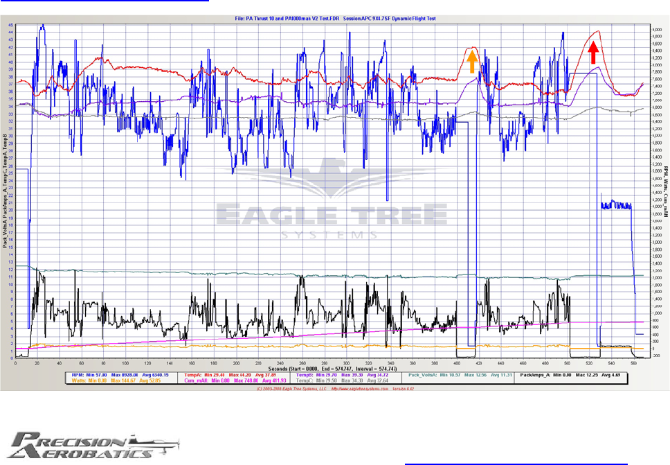
Test Flight 2 APC 9X4.7SF

www.PrecisionAerobatics.com
Copyrights ©2007 Precision Aerobatics. All rights reserved
Graph interpretation & Flight Report:
Dynamic test was deliberately conducted in a very hot summer day with ambient Air temperature of 32.9 Deg C
(91.2F). The intent to conduct this test during the hottest summer period as opposed to during the winter is
deliberately aimed to induce the maximum thermal loads on the motor and in order to demonstrate the
capabilities and effectiveness of the Rotorkool® design as well as the cooling efficiency of the Quantum 18 and
the tested airframe.
This is a consecutive flight from Test Flight 1 where the motor was still hot 37.5 Deg C (99.5 F) after the flight
and quickly cooled off to 35.5 Deg C (95.9 F) after the motor started up at the 20 second mark despite the
model executing a vertical climb. This demonstrate the Thrust 10 self cooling capabilities.
The flight began with a full throttle take off into a hover followed by a vertical climb, inverted flat spins and into
an inverted harrier. The drive system was deliberately stressed with the resultant temperature peak of 40.5 Deg
C (104.9F) right after.
The red line (Temp A) shows the motor operating temperature throughout most of the fight was between
36.5-40.5 Deg C (97.7–104.9F) rising and dropping corresponding to the loads being imposed. At the 400
second mark (Orange arrow), the aircraft landed and the motor was shut-off for 15 seconds to allow the
residual temperature to increase to 42 Deg C (107.6 F). The motor was restarted and the model took off at the
418 second mark and the temperature quickly dropped back to approximately 37 Deg C (98.6 F) demonstrating
the effectiveness of the RotorKool® design. A further demonstration of the effectiveness of the RotorKool®
design is repeated at the 500 second mark (Red Arrow) where the model landed and the motor was stopped
again for 25 seconds to allow the motor temperature to rise to 44.5 Deg C (112.1 F). The motor was then
restarted and left running at half throttle for 30 seconds and the motor temperature quickly dropped to 35.5 Deg
C (95.9F).
The ESC temperature purple line (Temp B) shows the relatively constant operating temperature of the
Quantum 18 being between 34.5 to 35.5 Deg C (94.1- 95.9F) in spite of the loads being imposed by the Thrust
10. At the 400 second mark where the motor was stopped (Orange arrow) the temperature of the Quantum 18
also rose to peak at 38 Deg C (100 F) which it then dropped back down to between 34.5 to 35.5 Deg C (94.1-
95.9F ) also demonstrates the heat dissipation features of the Quantum 18 efficient heat sink.
The green line (battery voltage) shows how well the battery is coping with the additional loads imposed on the
motor. Throughout 95% of the flight the battery voltage never dropped below 10.57V and thus provides a very
consistent flight performance throughout. Note that the pack was driven very hard (144.6W) yet the voltage
remained in the safe range and the battery temperature grey line (Temp B) remained between 33.5-33 Deg C
(91.4-92.5 F) throughout the entire flight.
The cumulative battery capacity (pink line) indicated that 74.8% of its capacity after this hard 8.3 minute flight
was consumed.
The Quantum 18 ESC performed very well and the throttle response was smooth, direct with no hesitation and
remained within the ESC’s design temperatures in-spite of the abuse. Throttle response was instantaneous with
surplus reserves for punch-out during torque rolls and hover-recovery right up to the end of the flight
demonstrates the superior capabilities of the PA1000mah V2 in maintaining a very consistent high voltage
output throughout the entire flight that translates to the ability to provide a very consistent flight performance
end to end and does not impose a constraint on any maneuver being performed anytime during the flight.
www.PrecisionAerobatics.com
Copyrights ©2007 Precision Aerobatics. All rights reserved
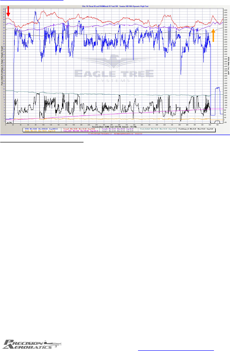
Test Flight 3 VOX 10X4
Graph interpretation & Flight Report:
Dynamic test was deliberately conducted in a hot summer day with ambient Air temperature of 33 Deg C
(91.4F).The intent to conduct this test during the hottest summer period as opposed to during the winter is
deliberately aimed to induce the maximum thermal loads on the motor and in order to demonstrate the
capabilities and effectiveness of the Rotorkool® design.
This is a consecutive flight from Test Flight 2 where the motor was at about 39.7 Deg C (103.4F) and still hot
after the previous flight and quickly cooled off after the motor started up at the 20 second mark (Red arrow)
despite the model executing a vertical climb.
The flight began with a full throttle take off into a hover followed by a vertical climb, inverted flat spins, inverted
harrier and into a set of harrier rolls and back into a full throttle vertical climb. The drive system was deliberately
stressed with the resultant temperature peak of 42.5 Deg C (108.5F) right after.
The red line (Temp A) shows the motor operating temperature throughout most of the fight was between
37.7-42.5 Deg C (99.8– 108.5F) rising and dropping corresponding to the loads being imposed.
The temperature remained in this range in-spite of the additional loads imposed by the big 10x4 wood prop with
a peak current drawn of only 11.64A and well within the operating limits of the Quantum 18 and the Thrust 10.
The ESC temperature purple line (Temp B) shows the relatively constant operating temperature of the
Quantum 18 remained between 35 to 37.8 Deg C (95-100F ) in spite the loads being imposed by the Thrust 10
indicating the operation within the Quantum 18’s limits mentioned above.
The green line (battery voltage) shows how well the battery is coping with the additional loads imposed on the
motor. Throughout 100% of the flight the battery voltage never dropped below 10.39V and so provided an
excellent and consistent motor output without the need to make any compromises on the aerobatic maneuvers.
Note that the pack was driven very hard (130.5W) yet the voltage remained in the safe LVC-free range and the
battery temperature grey line (Temp B) remained cool between 32.9-36.1 Deg C ( 91.2-96.9 F) throughout
the entire flight.
The cumulative battery capacity (pink line) indicated that 89.4% of its capacity after this hard 9 minute flight
was consumed.
The Quantum 18 ESC performed very well and the throttle response was smooth, direct with no hesitation and
remained within the ESC’s design temperatures in-spite of the abuse. Throttle response was instantaneous with
surplus reserves for punch-out during torque rolls and hover-recovery right up to the end of the flight
demonstrates the superior capabilities of the PA1000mah V2 in maintaining a very consistent high voltage
output throughout the entire flight that translates to the ability to provide a very consistent flight performance
end to end and does not impose a constraint on any maneuver being performed anytime during the flight.
