Tim Cox Raspberry Pi For Python Programmers Cookbook
User Manual: Tim-Cox-Raspberry-Pi-for-Python-Programmers-Cookbook
Open the PDF directly: View PDF ![]() .
.
Page Count: 494 [warning: Documents this large are best viewed by clicking the View PDF Link!]
- Contents
- Preface
- Chapter 1: Start with Raspberry Pi Computer
- Introduction
- Connecting the Raspberry Pi
- Using NOOBS to set up your Raspberry Pi SD card
- Networking and connecting your Raspberry Pi to the Internet via the LAN connector
- Using built-in Wi-Fi and Bluetooth on the Raspberry Pi
- Configuring your network manually
- Networking directly to a laptop or computer
- Networking and connecting your Raspberry Pi to the Internet via a USB Wi-Fi dongle
- Connecting to the Internet through a proxy server
- Connecting remotely to the Raspberry Pi over the network using VNC
- Connecting remotely to the Raspberry Pi over the network using SSH (and X11
- Forwarding)
- Sharing the home folder of the Raspberry Pi with SMB
- Keeping the Raspberry Pi up to date
- Chapter 2: Python Strings, Files & Menus
- Chapter 3: Using Python for Automation and Productivity
- Chapter 4: Games & Graphics
- Chapter 5: 3D Graphics
- Chapter 6: Drive Hardware
- Chapter 7: Sense & display Real-World Data
- Chapter 8: Raspberry Pi Camera Module
- Chapter 9: Building Robots
- Chapter 10: Interfacing with Technology
- Hardware & Software List
- Index

Raspberry Pi for
Python Programmers
Cookbook
Second Edition
Over 60 recipes that harness the power of the Raspberry
Pi together with Python programming and create
enthralling and captivating projects
Tim Cox
BIRMINGHAM - MUMBAI
Raspberry Pi for Python Programmers
Cookbook
Second Edition
Copyright © 2016 Packt Publishing
All rights reserved. No part of this book may be reproduced, stored in a retrieval system, or
transmitted in any form or by any means, without the prior written permission of the publisher,
except in the case of brief quotations embedded in critical articles or reviews.
Every effort has been made in the preparation of this book to ensure the accuracy of the
information presented. However, the information contained in this book is sold without
warranty, either express or implied. Neither the author, nor Packt Publishing, and its dealers
and distributors will be held liable for any damages caused or alleged to be caused directly or
indirectly by this book.
Packt Publishing has endeavored to provide trademark information about all of the companies
and products mentioned in this book by the appropriate use of capitals. However, Packt
Publishing cannot guarantee the accuracy of this information.
First published: April 2014
Second edition: September 2016
Production reference: 1270916
Published by Packt Publishing Ltd.
Livery Place
35 Livery Street
Birmingham B3 2PB, UK.
ISBN 978-1-78528-832-6
www.packtpub.com
i
Table of Contents
Preface v
Chapter 1: Getting Started with a Raspberry Pi Computer 1
Introduction 1
Connecting the Raspberry Pi 6
Using NOOBS to set up your Raspberry Pi SD card 10
Networking and connecting your Raspberry Pi to the Internet via the
LAN connector 23
Using built-in Wi-Fi and Bluetooth on the Raspberry Pi 24
Conguring your network manually 27
Networking directly to a laptop or computer 31
Networking and connecting your Raspberry Pi to the Internet via a
USB Wi-Fi dongle 40
Connecting to the Internet through a proxy server 45
Connecting remotely to the Raspberry Pi over the network using VNC 48
Connecting remotely to the Raspberry Pi over the network using SSH
(and X11 Forwarding) 50
Sharing the home folder of the Raspberry Pi with SMB 55
Keeping the Raspberry Pi up to date 57
Chapter 2: Starting with Python Strings, Files, and Menus 61
Introduction 61
Working with text and strings 62
Using les and handling errors 72
Creating a boot-up menu 76
Creating a self-dening menu 80
Chapter 3: Using Python for Automation and Productivity 85
Introduction 85
Using Tkinter to create graphical user interfaces 86

ii
Table of Contents
Creating a graphical application – Start menu 91
Displaying photo information in an application 96
Organizing your photos automatically 105
Chapter 4: Creating Games and Graphics 111
Introduction 111
Using IDLE3 to debug your programs 112
Drawing lines using a mouse on Tkinter Canvas 116
Creating a bat and ball game 118
Creating an overhead scrolling game 126
Chapter 5: Creating 3D Graphics 137
Introduction 137
Starting with 3D coordinates and vertices 138
Creating and importing 3D models 147
Creating a 3D world to roam in 153
Building 3D maps and mazes 158
Chapter 6: Using Python to Drive Hardware 173
Introduction 173
Controlling an LED 178
Responding to a button 184
A controlled shutdown button 190
The GPIO keypad input 197
Multiplexed color LEDs 203
Writing messages using Persistence of Vision 214
Chapter 7: Sense and Display Real-World Data 225
Introduction 225
Using devices with the I2C bus 226
Reading analog data using an analog-to-digital converter 236
Logging and plotting data 243
Extending the Raspberry Pi GPIO with an I/O expander 252
Capturing data in an SQLite database 259
Viewing data from your own webserver 267
Sensing and sending data to online services 275
Chapter 8: Creating Projects with the Raspberry Pi Camera Module 283
Introduction 283
Getting started with the Raspberry Pi camera module 284
Using the camera with Python 288
Generating a time-lapse video 296
Creating a stop frame animation 306
Making a QR code reader 316

iii
Table of Contents
Discover and experiment with OpenCV 322
Color detection with OpenCV 328
Performing motion tracking with OpenCV 338
Chapter 9: Building Robots 349
Introduction 349
Building a Rover-Pi robot with forward driving motors 350
Using advanced motor control 369
Building a six-legged Pi-Bug robot 376
Controlling servos directly with Servoblaster 387
Using an Infra-Red Remote Control with your Raspberry Pi 395
Avoiding objects and obstacles 402
Getting a sense of direction 410
Chapter 10: Interfacing with Technology 421
Introduction 421
Automating your home with remote sockets 422
Using SPI to control an LED matrix 435
Communicating using a serial interface 449
Controlling the Raspberry Pi over Bluetooth 464
Controlling USB devices 469
Appendix: Hardware and Software List 481
Index 483

v
Preface
Since the release of the Raspberry Pi computer in February 2012, millions of people have
been introduced to a new way of computing. Modern home computers, tablets, and phones
are typically focused on providing content to the user to consume, either as a passive viewer
or through basic interaction via games and activities.
However, the Raspberry Pi turns this concept on its head. The idea is that the user provides
the input and the imagination, and the Raspberry Pi becomes an extension of their creativity.
The Raspberry Pi provides a simple, low-cost platform that you can use to experiment with and
play with your own ideas. It won't feed you information; it will let you discover it rsthand.
This book takes everything I have found exciting and interesting with the Raspberry Pi and
puts it in an easy-to-follow format.
I hope that people will read this book and start their own Raspberry Pi journey; it has so much
to offer, and the book is aimed squarely at showing off what you can achieve with it.
Like any good cookbook, the pages should be worn and used, and it should be something
that is always being pulled off the shelf to refer to. I hope it will become your own, personal,
go-to reference.
What this book covers
Chapter 1, Getting Started with a Raspberry Pi Computer, introduces the Raspberry Pi and
explores the various ways that it can be set up and used, including how it can be used on a
network and connected to remotely with another computer.
Chapter 2, Starting with Python Strings, Files, and Menus, guides us on how to take our rst
steps using Python 3, start with the basics, manipulate text, use les, and create menus to
run our programs.
Chapter 3, Using Python for Automation and Productivity, explains the use of graphical user
interfaces to create our own applications and utilities.

Preface
vi
Chapter 4, Creating Games and Graphics, explains how to create a drawing application and
graphical games using the Tkinter Canvas.
Chapter 5, Creating 3D Graphics, discusses how we can use the hidden power of the
Raspberry Pi's graphical processing unit to learn about 3D graphics and landscapes and
produce our very own 3D maze for exploration.
Chapter 6, Using Python to Drive Hardware, establishes the fact that to experience the
Raspberry Pi at its best, we really have to use it with our own electronics. It discusses how
to create circuits with LEDs and switches, and use them to indicate the system status and
provide control. Finally, it shows us how to create our own game controller, light display and a
persistence of vision text display.
Chapter 7, Sense and Display Real-World Data, explains the use of an analog-to-digital
convertor to provide sensor readings to the Raspberry Pi. We discover how to store and graph
the data in real time, as well as display it on an LCD text display. Next we record the data in a
SQL database and display it in our own webserver. Finally, we transfer the data to the Internet,
which will allow us to view and share the captured data anywhere in the world.
Chapter 8, Creating Projects with the Raspberry Pi Camera Module, teaches us how to use
the Raspberry Pi camera module, creating our own applications to produce time-lapse videos,
stop-frame animations, and a bedtime book reader controlled with QR codes. Additionally
we make use of the immensely powerful image processing library OpenCV to perform color
recognition and object (or in this case, a tortoise) tracking.
Chapter 9, Building Robots, takes you through building two different types of robots
(a Rover- Pi and a Pi-Bug), plus driving a servo-based robot arm. We look at motor and
servo control methods, using sensors, and adding a compass sensor for navigation.
Chapter 10, Interfacing with Technology, teaches us how to use the Raspberry Pi to
trigger remote mains sockets, with which we can control household appliances. We learn
how to communicate with the Raspberry Pi over a serial interface and use a smartphone to
control everything using Bluetooth. Finally, we look at creating our own applications to control
USB devices.
Appendix, Hardware and Software List, provides us with the full list of the hardware
components and modules used in the book, along with suitable places to purchase them
from. A full list of the software used is also provided, along with links to documentation.
What you need for this book
This book focuses on using the Raspberry Pi with Python 3; therefore, a basic Raspberry
Pi setup is required. Chapters 1 to 5 of this book make use of the Raspberry Pi only; no
additional hardware is required beyond a standard setup.

Preface
vii
The standard setup will consist of a Raspberry Pi (Model A or Model B, Version 1, 2 or 3); an
SD card installed with Raspbian; a suitable micro USB power supply; and an HDMI-compatible
screen, keyboard, and mouse. You will also be required to download and install various
software packages; therefore, the Raspberry Pi should have a working internet connection.
Chapter 1, Getting Started with a Raspberry Pi Computer, also describes how to use the
screen/keyboard/mouse of a laptop or another computer to access the Raspberry Pi (you just
need a network cable and power).
Chapter 6, Using Python to Drive Hardware, and Chapter 7, Sense and Display Real-World
Data, show how electronic components can be connected to the Raspberry Pi's interfaces.
These components will be needed in order to complete these chapters.
Chapter 8, Creating Projects with the Raspberry Pi Camera Module, requires the Raspberry
Pi camera module for each of the projects (although a compatible USB webcam could be
substituted by adjusting the code).
Chapter 9, Building Robots, uses a range of hardware and electronics to build your own
robots. You can either use your own parts or a suitable kit for this.
Chapter 10, Interfacing with Technology, shows how additional hardware can be connected to
the interfaces of the Raspberry Pi using various modules and kits.
A full list of the hardware used (and the possible places to purchase it from) has been
provided in the Appendix, Hardware and Software List.
Who this book is for
This book is intended for anyone who wants to make the most of the Raspberry Pi experience.
The book gradually introduces Python, starting with the basics and moving towards more
advanced topics, such as using 3D graphics and interfacing with hardware.
Although you do not need to be familiar with Python, the Raspberry Pi, or electronics, this
book touches on a wide range of topics. Ideally, you should give each chapter a try, see what
you enjoy, and use that as a starting point to discover and learn more.
Each example in the book consists of full setup instructions, complete code listings, and
a walk-through of what you did and why. This will allow you to get results quickly, and most
importantly, understand how you achieved them.
All the examples are written using Python 3, with clear and detailed explanations of how
everything works so that you can adapt and use all the information in your own projects.
As you progress through the book, it will explain how to structure and develop your
code efciently, building on the various techniques that can be applied as you progress.
By the end, you will have a toolset of skills that you can apply to whatever your imagination
inspires you to do.

Preface
viii
Safety and using electronics
This book encourages you to experiment and connect your own circuits to the general-purpose
input/output Raspberry Pi GPIO pins. This is an excellent way to learn about electronics and
software at the same time. However, it is important to remember that the GPIO pins are
unprotected, and if wired incorrectly, can easily be damaged or even cause the Raspberry Pi
to stop working altogether. Therefore, care should be taken to correctly follow the instructions
and wiring diagrams and check everything carefully before switching the Raspberry Pi on.
All the circuits, modules, and components described in this book are intended as
demonstration examples only. They have not been tested for extended use and should not
be left unattended or should not be used in safety-critical applications without adequate
safeguards in place. Remember that all electronics must undergo rigorous safety testing to
ensure that in the event of failure, there will be no risk of harm to people or property.
You should never attempt to modify or alter devices that are connected to mains electricity
without proper training, and you must never directly connect any homemade devices to the
mains supply.
Sections
In this book, you will nd several headings that appear frequently (Getting ready, How to do it,
How it works, There's more, and See also).
To give clear instructions on how to complete a recipe, we use these sections as follows:
Getting ready
This section tells you what to expect in the recipe, and describes how to set up any software or
any preliminary settings required for the recipe.
How to do it…
This section contains the steps required to follow the recipe.
How it works…
This section usually consists of a detailed explanation of what happened in the
previous section.

Preface
ix
There's more…
This section consists of additional information about the recipe in order to make the reader
more knowledgeable about the recipe.
See also
This section provides helpful links to other useful information for the recipe.
Conventions
In this book, you will nd a number of styles of text that distinguish between different kinds of
information. Here are some examples of these styles, and an explanation of their meaning.
Code words in text, database table names, folder names, lenames, le extensions,
pathnames, dummy URLs, user input, and Twitter handles are shown as follows: "On a freshly
formatted or new SD card, copy the contents of the NOOBS_vX.zip le."
A block of code is set as follows:
network={
ssid="theSSID"
key_mgmt=NONE
}
Any command-line input or output is written as follows:
sudo mount –t vfat /dev/mmcblk0p1 ~/recovery
New terms and important words are shown in bold. Words that you see on the screen, in
menus or dialog boxes for example, appear in the text like this: "For OS X or Linux, click on
Terminal to open a connection to the Raspberry Pi."
Warnings or important notes appear in a box like this.
Tips and tricks appear like this.

Preface
x
Reader feedback
Feedback from our readers is always welcome. Let us know what you think about this book—
what you liked or disliked. Reader feedback is important for us as it helps us develop titles
that you will really get the most out of.
To send us general feedback, simply e-mail feedback@packtpub.com, and mention the
book's title in the subject of your message.
If there is a topic that you have expertise in and you are interested in either writing or
contributing to a book, see our author guide at www.packtpub.com/authors.
Customer support
Now that you are the proud owner of a Packt book, we have a number of things to help you to
get the most from your purchase.
Downloading the example code
You can download the example code les for this book from your account at http://
www.packtpub.com. If you purchased this book elsewhere, you can visit http://www.
packtpub.com/support and register to have the les e-mailed directly to you.
You can download the code les by following these steps:
1. Log in or register to our website using your e-mail address and password.
2. Hover the mouse pointer on the SUPPORT tab at the top.
3. Click on Code Downloads & Errata.
4. Enter the name of the book in the Search box.
5. Select the book for which you're looking to download the code les.
6. Choose from the drop-down menu where you purchased this book from.
7. Click on Code Download.
You can also download the code les by clicking on the Code Files button on the book's
webpage at the Packt Publishing website. This page can be accessed by entering the book's
name in the Search box. Please note that you need to be logged in to your Packt account.

Preface
xi
Once the le is downloaded, please make sure that you unzip or extract the folder using the
latest version of:
fWinRAR / 7-Zip for Windows
fZipeg / iZip / UnRarX for Mac
f7-Zip / PeaZip for Linux
The code bundle for the book is also hosted on GitHub at https://github.com/
PacktPublishing/Raspberry-Pi-for-Python-Programmers-Cookbook-Second-
Edition. We also have other code bundles from our rich catalog of books and videos
available at https://github.com/PacktPublishing/. Check them out!
Errata
Although we have taken every care to ensure the accuracy of our content, mistakes do happen.
If you nd a mistake in one of our books—maybe a mistake in the text or the code—we would be
grateful if you could report this to us. By doing so, you can save other readers from frustration
and help us improve subsequent versions of this book. If you nd any errata, please report
them by visiting http://www.packtpub.com/submit-errata, selecting your book,
clicking on the Errata Submission Form link, and entering the details of your errata. Once your
errata are veried, your submission will be accepted and the errata will be uploaded to our
website or added to any list of existing errata under the Errata section of that title.
To view the previously submitted errata, go to https://www.packtpub.com/books/
content/support and enter the name of the book in the search eld. The required
information will appear under the Errata section.
Piracy
Piracy of copyrighted material on the Internet is an ongoing problem across all media. At
Packt, we take the protection of our copyright and licenses very seriously. If you come across
any illegal copies of our works in any form on the Internet, please provide us with the location
address or website name immediately so that we can pursue a remedy.
Please contact us at copyright@packtpub.com with a link to the suspected pirated material.
We appreciate your help in protecting our authors and our ability to bring you valuable content.
Questions
If you have a problem with any aspect of this book, you can contact us at questions@
packtpub.com, and we will do our best to address the problem.

1
1
Getting Started with a
Raspberry Pi Computer
In this chapter, we will cover the following recipes:
fConnecting the Raspberry Pi
fUsing NOOBS to set up your Raspberry Pi SD card
fNetworking and connecting your Raspberry Pi to the Internet via the LAN connector
fUsing built-in Wi-Fi and Bluetooth on the Raspberry Pi
fConguring your network manually
fNetworking directly to a laptop or computer
fNetworking and connecting your Raspberry Pi to the Internet via a USB Wi-Fi dongle
fConnecting to the Internet through a proxy server
fConnecting remotely to the Raspberry Pi over the network using VNC
fConnecting remotely to the Raspberry Pi over the network using SSH
(and X11 Forwarding)
fSharing the home folder of the Raspberry Pi with SMB
fKeeping the Raspberry Pi up to date
Introduction
This chapter introduces the Raspberry Pi and the process to set it up for the rst time. We
will connect the Raspberry Pi to a suitable display, power, and peripherals. We will install an
operating system on an SD card. This is required for the system to boot. Next, we will ensure
that we can connect successfully to the Internet through a local network.
Getting Started with a Raspberry Pi Computer
2
Finally, we will make use of the network to provide ways to remotely connect to and/or control
the Raspberry Pi from other computers and devices, as well as to ensure that the system is
kept up to date.
Once you have completed the steps within this chapter, your Raspberry Pi will be ready
for you to use for programming. If you already have your Raspberry Pi set up and running,
ensure that you take a look through the following sections as there are many helpful tips.
Introducing the Raspberry Pi
The Raspberry Pi is a single-board computer created by the Raspberry Pi Foundation, a
charity formed with the primary purpose of reintroducing low-level computer skills to children
in the UK. The aim was to rekindle the microcomputer revolution of the 1980s, which
produced a whole generation of skilled programmers.
Even before the computer was released at the end of February 2012, it was clear that the
Raspberry Pi had gained a huge following worldwide and, at the time of writing this book, has
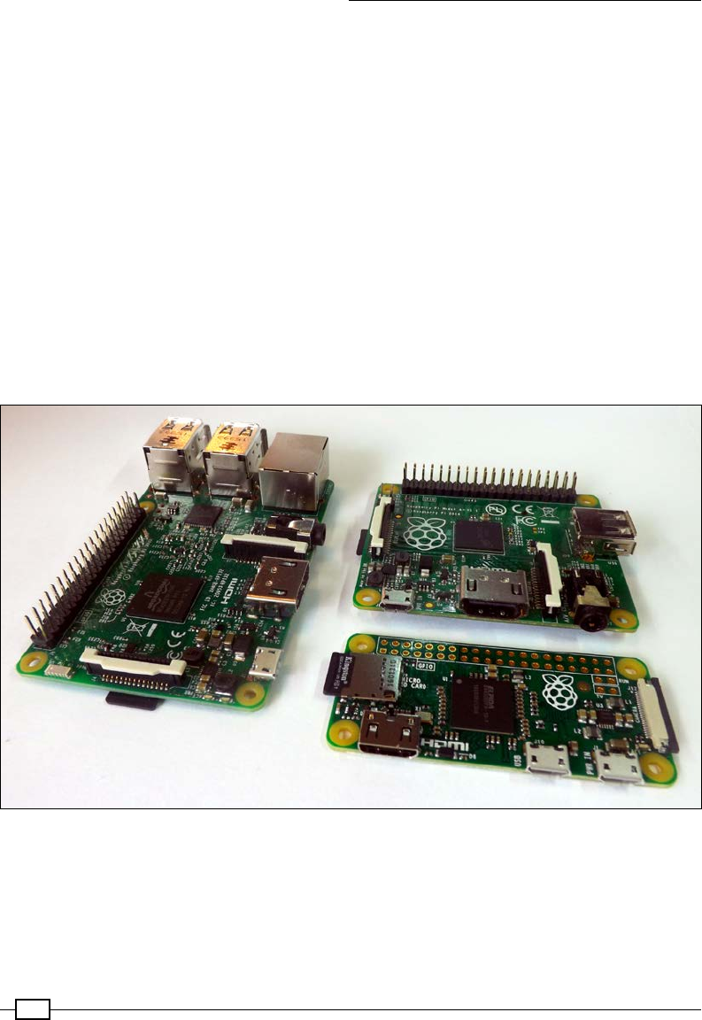
sold over 10 million units. The following image shows several different Raspberry Pi Models:
Raspberry Pi Model 3B, Model A+, and Pi Zero
What is with the name?
The name, Raspberry Pi, was the combination of the desire to create an alternative
fruit-based computer (such as Apple, BlackBerry, and Apricot) and a nod to the original
concept of a simple computer that can be programmed using Python (shortened to Pi).

Chapter 1
3
In this book, we will take this little computer, nd out how to set it up, and then explore its
capabilities chapter by chapter using the Python programming language.
Why Python?
It is often asked, "Why has Python been selected as the language to use on the Raspberry Pi?"
The fact is that Python is just one of the many programming languages that can be used on
the Raspberry Pi.
There are many programming languages that you can choose, from high-level graphical block
programming, such as Scratch, to traditional C, right down to BASIC, and even raw Machine
Code Assembler. A good programmer often has to be code multilingual to be able to play
to the strengths and weaknesses of each language in order to best meet the needs of their
desired application. It is useful to understand how different languages (and programming
techniques) try to overcome the challenge of converting "what you want" into "what you get" as
this is what you are trying to do as well while you program.
Python has been selected as a good place to start when learning about programming, by
providing a rich set of coding tools while still allowing simple programs to be written without
fuss. This allows beginners to gradually be introduced to the concepts and methods on which
modern programming languages are based without requiring them to know it all from the
start. It is very modular with lots of additional libraries that can be imported to quickly extend
the functionality. You will nd that over time, this encourages you to do the same, and you will
want to create your own modules that you can plug into your own programs, thus taking your
rst steps into structured programming.
Like all programming languages, Python isn't perfect; things such as adding a space at the
start of a line will often break your code (indents matter a lot in Python; they dene how
blocks of code are grouped together). Generally, Python is slow; since it is interpreted, it
takes time to create a module while it is running the program. This can be a problem if you
need to respond to time critical events. However, you can precompile Python or use modules
written in other languages to overcome this. It hides the details; this is both an advantage and
disadvantage. It is excellent for beginners but can be difcult when you have to second-guess
aspects such as data-types. However, this in turn forces you to consider all the possibilities,
which can be a good thing.
Python 2 and Python 3
A massive source of confusion for beginners is that there are two versions of Python on the
Raspberry Pi (Version 2.7 and Version 3.4), which are not compatible with one another, so
code written for Python 2.7 may not run with Python 3.4 (and vice versa).
The Python Software Foundation is continuously working to improve and move forward
with the language, which sometimes means they have to sacrice backward compatibility in
order to embrace new improvements (and importantly, remove redundant and legacy ways
of doing things).

Getting Started with a Raspberry Pi Computer
4
Supporting both Python 2 or Python 3
There are many tools that will ease the transition from Python 2 to
Python 3, including converters such as 2to3, which will parse and
update your code to use Python 3 methods. This process is not perfect,
and in some cases, you'll need to manually rewrite sections and fully
retest everything. You can write the code and libraries that will support
both. The import __future__ statement allows you to import the
friendly methods of Python 3 and run them using Python 2.7.
Which version of Python should you use?
Essentially, the selection of which version to use will depend on what you intend to do. For
instance, you may require Python 2.7 libraries, which are not yet available for Python 3.4.
Python 3 has been available since 2008, so these tend to be older or larger libraries that have
not been translated. In many cases, there are new alternatives to legacy libraries; however,
their support can vary.
In this book, we have used Python 3.4, which is also compatible with Python 3.3 and 3.2.
The Raspberry Pi family – a brief history of Pi
Since its release, the Raspberry Pi has come in various iterations, featuring both small and
large updates and improvements to the original Raspberry Pi Model B unit. Although it can
be confusing at rst, there are three basic types of Raspberry Pi available (and one special
model).
The main agship model is called Model B. This has all the connections and features, as
well as the maximum RAM and the latest processor. Over the years, there have been several
versions, most notably Model B (which had 256 MB and then 512 MB RAM) and then Model
B+ (which increased the 26-pin GPIO to 40 pins, switched to using a micro SD card slot, and
had four USB ports instead of two). These original models all used the Broadcom BCM2835
SOC (short for System On Chip), consisting of a single core 700 MHz ARM11 and VideoCore IV
GPU (short for Graphical Processing Unit).
The release of the Raspberry Pi 2 Model B (also referred to as 2B) in 2015 introduced a new
Broadcom BCM2836 SOC, providing a quad-core 32-bit ARM Cortex A7 1.2 GHz processor
and GPU, with 1 GB of RAM. The improved SOC added support for Ubuntu and Windows 10
IoT. Finally we had the latest Raspberry Pi 3 Model B, using another new Broadcom BCM2837
SOC, which provides a quad-core 64-bit ARM Cortex-A53 and GPU, alongside adding on-board
Wi-Fi and Bluetooth.

Chapter 1
5
Model A has always been targeted as a cut-down version. While having the same SOC as
Model B, there are limited connections consisting of a single USB port and no wired network
(LAN). Model A+ again added more GPIO pins and a micro SD slot. However, the RAM was
later upgraded to 512 MB of RAM and again only a single USB port/no LAN. The Broadcom
BCM2835 SOC on Model A has not been updated so far (so is still a single core ARM11);
however, a Model 3A (most likely using the BCM2837) is expected 2016/2017.
The Pi Zero is an ultra-compact version of the Raspberry Pi intended for embedded
applications where cost and space are a premium. It has the same 40-pin GPIO and micro
SD card slot as the other models, but lacks the on-board display (CSI and DSI) connection. It
does still have HDMI (via a mini-HDMI) and a single micro USB OTG (on-the-go) connection.
Although not present in the rst revision of the Pi Zero, the most recent model also includes a
CSI connection for the on-board camera.
The Pi Zero was famously released in 2015 by being given away with
the Raspberry Pi foundations magazine The MagPi, giving the magazine
the kudos of being the rst magazine to give away a computer on its
cover! This did make me rather proud since (as you may have read in
my biography at the start of this book) I was one of the founders of the
magazine.
The special model is known as the compute module. This takes the form of a 200-pin
SO-DIMM card. It is intended for industrial use or within commercial products, where all the
external interfaces would be provided by a host/motherboard, into which the module would
be inserted. Example products include the Slice media player (http://fiveninjas.com)
and the Otto camera. The current module uses the BCM2835, although an updated compute
module (CM3) is expected in 2016.
The Raspberry Pi Wikipedia page provides a full list of the all different variants and their
specications:
https://en.wikipedia.org/wiki/Raspberry_Pi#Specifications
Which Pi to choose?
All sections of this book are compatible will all current versions of the Raspberry Pi, but
Model 3B is recommended as the best model to start with. This offers the best performance
(particularly useful for the GPU examples in Chapter 5, Creating 3D Graphics, and the OpenCV
examples used in Chapter 8, Creating Projects with the Raspberry Pi Camera Module), lots of
connections, and built-in Wi-Fi, which can be very convenient.
The Pi Zero is recommended for projects where you want low power usage or reduced
weight/size but do not need the full processing power of Model 3B. However, due to
its ultra-low cost, the Pi Zero is ideal for deploying a completed project after you have
developed it.
Getting Started with a Raspberry Pi Computer
6
Connecting the Raspberry Pi
There are many ways to wire up the Raspberry Pi and use the various interfaces to view and
control content. For typical use, most users will require power, display (with audio), and a
method of input such as keyboard and mouse. To access the Internet, refer to the Networking
and connecting your Raspberry Pi to the Internet via the LAN connector or Using built-in Wi-Fi
and Bluetooth on the Raspberry Pi recipes.
Getting ready
Before you can use your Raspberry Pi, you will need an SD card with an operating system
installed or with the New Out Of Box System (NOOBS) on it, as discussed in the Using NOOBS
to set up your Raspberry Pi SD card recipe.
The following section will detail the types of devices you can connect to the Raspberry Pi and,
importantly, how and where to plug them in.
As you will discover later, once you have your Raspberry Pi set up, you may decide to connect
remotely and use it through a network link, in which case you only need power and a network
connection. Refer to the following sections: Connecting remotely to the Raspberry Pi over the
network using VNC and Connecting remotely to the Raspberry Pi over the network using SSH
(and X11 Forwarding).
How to do it…
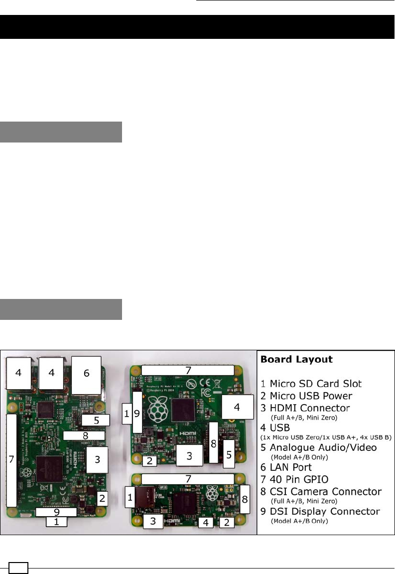
The layout of the Raspberry Pi is shown in the following gure:
The Raspberry Pi connection layout (Model 3 B, Model A+, and Pi Zero)
Chapter 1
7
The description of the preceding gure is as follows:
fDisplay: The Raspberry Pi supports the following three main display connections; if
both HDMI and Composite video are connected, it will default to HDMI only.
HDMI
For best results, use a TV or monitor that has an HDMI connection, thus
allowing the best resolution display (1080p) and also digital audio output.
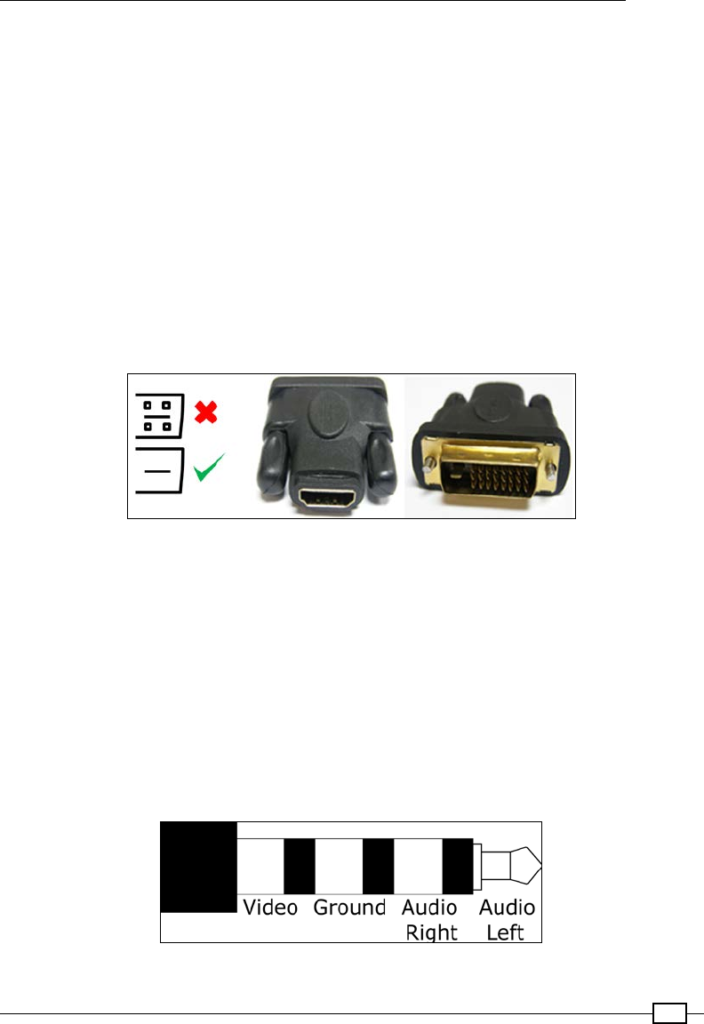
If your display has a DVI connection, you may be able to use an adapter to
connect through the HDMI. There are several types of DVI connections; some
support analogue (DVI-A), some digital (DVI-D), and some both (DVI-I). The
Raspberry Pi is only able to provide a digital signal through the HDMI, so
an HDMI-to-DVI-D adapter is recommended (shown with a tick mark in the
following screenshot). This lacks the four extra analogue pins (shown with a
cross mark in the following screenshot), thus allowing it to t into both DVI-D
and DVI-I type sockets:
HDMI-to-DVI connection (DVI-D adaptor)
If you wish to use an older monitor (with a VGA connection), an additional
HDMI-to-VGA converter is required. The Raspberry Pi also supports a
rudimentary VGA adaptor (VGA Gert666 Adaptor), which is driven directly
off of the GPIO pins. However, this does use up all but 4 pins of the 40-pin
header (older 26-pin models will not support the VGA output).
Analogue
An alternative display method is to use the analogue composite video
connection (via the phono socket); this can also be attached to an S-Video
or European SCART adapter. However, the analogue video output has a
maximum resolution of 640 x 480 pixels, so it is not ideal for general use.
3.5mm phono analogue connections

Getting Started with a Raspberry Pi Computer
8
When using the RCA connection or a DVI input, audio has to be provided
separately by the analogue audio connection. To simplify the manufacturing
process (by avoiding through-hole components), the Pi Zero does not have
analogue audio or an RCA socket for analogue video (although they can be
added with some modications).
Direct Display DSI
A touch display produced by the Raspberry Pi Foundation will connect directly
into the DSI socket. This can be connected and used at the same time as the
HDMI or analogue video output to create a dual display setup.
fStereo Analogue Audio (all except Pi Zero): This provides an analogue audio output
for headphones or amplied speakers. The audio can be switched via the Raspberry
Pi conguration tool on the desktop between analog (Stereo Socket) and digital
(HDMI), or via the command line using amixer or alsamixer.
To find out more information about a particular command in the terminal,
you can use the following man command before the terminal reads the
manual (most commands should have one):
man amixer
Some commands also support the --help option for more concise help,
shown as follows:
amixer --help
fNetwork (excluding models A and Pi Zero): The network connection is discussed
in the Networking and connecting your Raspberry Pi to the Internet via the LAN
connector recipe later in this chapter. If we use the Model A Raspberry Pi, it is
possible to add a USB network adapter to add wired or even wireless networking
(refer to the Networking and connecting your Raspberry Pi to the Internet via a USB
Wi-Fi dongle recipe).
fOnboard Wi-Fi and Bluetooth (Model 3 B only):
fThe Model 3 B has built-in 802.11n Wi-Fi and Bluetooth 4.1; see the Using the built-in
Wi-Fi and Bluetooth on the Raspberry Pi recipe.
fUSB (x1 Model A/Zero, x2 Model 1 B, x4 Model 2 B and 3 B)—using a keyboard
and mouse:
The Raspberry Pi should work with most USB keyboards and mice available. You can
also use wireless mice and keyboards, which use RF Dongles. However, additional
conguration is required for items that use the Bluetooth dongles.
If there is a lack of power supplied by your power supply or the devices are drawing
too much current, you may experience the keyboard keys appearing to stick, and in
severe cases, corruption of the SD card.

Chapter 1
9
USB power can be more of an issue with the early Model B revision 1
boards that were available prior to October 2012. They included additional
Polyfuses on the USB output and tripped if an excess of 140 mA was drawn.
The Polyfuses can take several hours or days to recover completely, thus
causing unpredictable behavior to remain even when the power is improved.
You can identify a revision 1 board as it lacks the four mounting holes that
are present the later models.
Debian Linux (upon which Raspbian is based) supports many common USB devices,
such as ash storage drives, hard disk drives (external power may be required),
cameras, printers, Bluetooth, and Wi-Fi adapters. Some devices will be detected
automatically while others will require drivers to be installed.
fMicro USB Power: The Raspberry Pi requires a 5V power supply that can comfortably
supply at least 1000 mA (1,500 mA or more is recommended, particularly with the
more power-hungry Model 2 and 3) with a micro USB connection. It is possible to
power the unit using portable battery packs, such as the ones suitable for powering
or recharging tablets. Again, ensure that they can supply 5V at 1000 mA or over.
You should aim to make all other connections to the Raspberry Pi before connecting the
power. However, USB devices, audio, and network may be connected and removed while
it is running without problems.
There's more…
In addition to the standard primary connections you would expect to see on a computer, the
Raspberry Pi also has a number of other connections.
Secondary hardware connections
Each of the following connections provides additional interfaces for the Raspberry Pi:
f20 x 2 GPIO pin header (Model A+, B+, 2 B, 3 B, and Pi Zero): This is the main
40-pin GPIO header of the Raspberry Pi used for interfacing directly with hardware
components. We use this connection in Chapters 6, 7, 9, and 10. The recipes in this
book are also compatible with older models of the Raspberry Pi that have a 13 x 2
GPIO pin header.
fP5 8 x 2 GPIO pin header (Model 1 B revision 2.0 only): We do not use this in
the book.
fReset connection: This is present on later models (no pins tted). A reset is triggered
when Pin 1 (reset) and Pin 2 (GND) are connected together. We use this in the A
controlled shutdown button recipe in Chapter 6, Using Python to Drive Hardware.

Getting Started with a Raspberry Pi Computer
10
fGPU/LAN JTAG: The Joint Test Action Group (JTAG) is a programming and debugging
interface used to congure and test processors. These are present on newer models
as surface pads. A specialist JTAG device is required to use this interface. We do not
use this in the book.
fDirect camera CSI: This connection supports the Raspberry Pi Camera module (as
used in Chapter 8, Creating Projects with the Raspberry Pi Camera Module). Note
that the Pi Zero has a smaller CSI connector than the other models, so it requires a
different ribbon connector.
fDirect display DSI: This connection supports a directly connected display, a 7-inch
800 x 600 capacitive touch screen.
Using NOOBS to set up your Raspberry Pi SD
card
The Raspberry Pi requires the operating system to be loaded onto an SD card before it starts
up. The easiest way to set up the SD card is to use NOOBS; you may nd that you can buy an
SD card with NOOBS already loaded on it.
NOOBS provides an initial start menu that provides options to install several of the available
operating systems onto your SD card.
Getting ready
Since NOOBS creates a RECOVERY partition to keep the original installation images, an
8-GB SD card or larger is recommended. You will also need an SD card reader (experience
has shown that some built-in card readers can cause issues, so an external USB type reader
is recommended).
If you are using an SD card that you have used previously, you may need to reformat it to
remove any previous partitions and data. NOOBS expects the SD card to consist of a single
FAT32 partition. If using Windows or Mac OS X, you can use the SD association's formatter, as
shown in the following screenshot (available at https://www.sdcard.org/downloads/
formatter_4/):
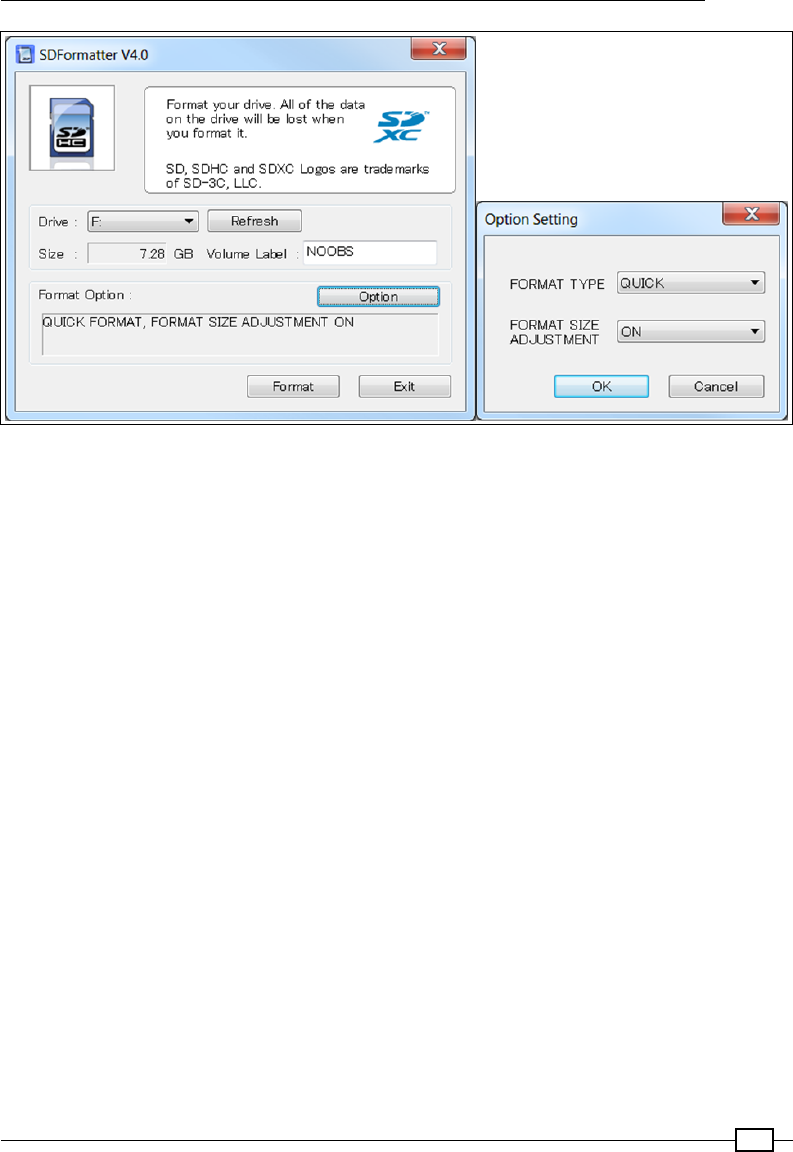
Chapter 1
11
Get rid of any partitions on the SD card using SD formatter
From the Option Setting dialog box, set Format Size Adjustment. This will remove all the SD
card partitions that were created previously.
If using Linux, you can use gparted to clear any previous partitions and reformat it as a
FAT32 partition.
The full NOOBS package (typically just over 1 GB) contains the Raspbian, the most popular
Raspberry Pi operating system image built in. A lite version of NOOBS is also available that
has no preloaded operating systems (although a smaller initial download of 20 MB and a
network connection on the Raspberry Pi are required to directly download the operating
system you intend to use).
NOOBS is available at http://www.raspberrypi.org/downloads, with the
documentation available at https://github.com/raspberrypi/noobs.
Getting Started with a Raspberry Pi Computer
12
How to do it…
By performing the following steps, we will prepare the SD card to run NOOBS. This will then
allow us to select and install the operating system we want to use:
1. Get your SD card ready.
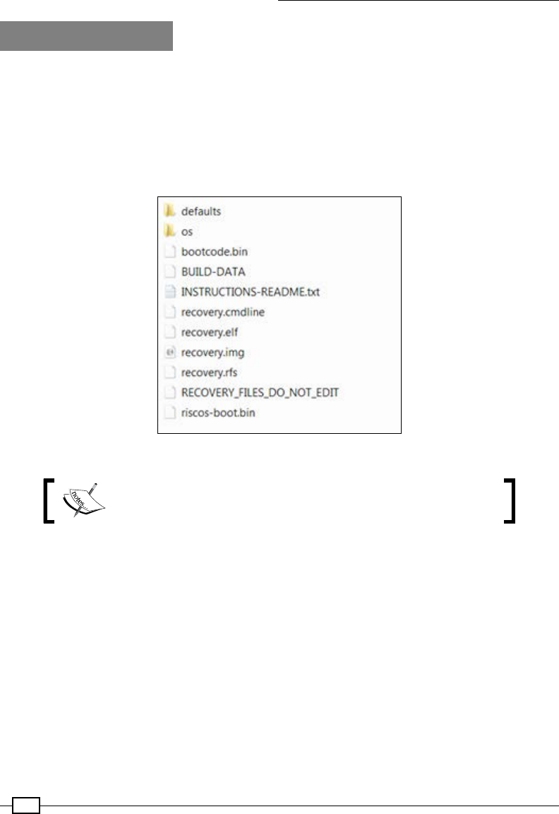
2. On a freshly formatted or new SD card, copy the contents of the NOOBS_vX.zip le.
When it has nished copying, you should end up with something like the following
screenshot of the SD card:
NOOBS files extracted onto the SD card
The files may vary slightly with different versions of NOOBS, and
the icons displayed may be different on your computer.
3. You can now put the card into your Raspberry Pi, connect it to a keyboard and display,
and turn the power on. Refer to the Connecting up the Raspberry Pi recipe for details
on what you need and how to do this.

Chapter 1
13
By default, NOOBS will display via the HDMI connection. If you have another type of screen (or
you don't see anything), you will need to manually select the output type by pressing 1, 2, 3, or
4 according to the following functions:
fKey 1 stands for the Standard HDMI mode (the default mode)
fKey 2 stands for the Safe HDMI mode (alternative HDMI settings if the output has not
been detected)
fKey 3 stands for Composite PAL (for connections made via the RCA analogue
video connection)
fKey 4 stands for Composite NTSC (again, for connections via the RCA connector)
This display setting will also be set for the installed operating system.
After a short while, you will see the NOOBS selection screen that lists the available
distributions (the ofine version only includes Raspbian). There are many more distributions
that are available, but only the selected ones are available directly through the NOOBS
system. Click on Raspbian as this is the operating system being used in this book.
Press Enter or click on Install OS, and conrm that you wish to overwrite all the data on
the card. This will overwrite any distributions previously installed using NOOBS but will not
remove the NOOBS system; you can return to it at any time by pressing Shift when you turn
the power on.
It will take around 20 to 40 minutes to write the data to the card depending on its speed.
When it completes and the Image Applied Successfully message appears, click on OK and
the Raspberry Pi will start to boot into the Raspberry Pi Desktop.
How it works…
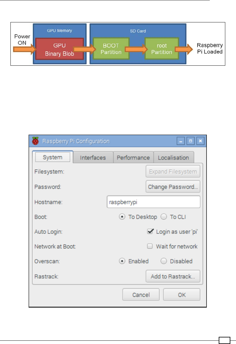
The purpose of writing the image le to the SD card in this manner is to ensure that the SD
card is formatted with the expected lesystem partitions and les required to correctly boot
the operating system.
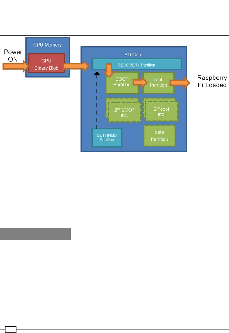
When the Raspberry Pi powers up, it loads some special code contained within the GPU's
internal memory (commonly referred to as binary blob by the Raspberry Pi Foundation). The
binary blob provides the instructions required to read the BOOT Partition on the SD card,
which (in the case of a NOOBS install) will load NOOBS from the RECOVERY partition. If at this
point Shift is pressed, NOOBS will load the recovery and installation menu. Otherwise, NOOBS
will begin loading the OS as specied by the preferences stored in the SETTINGS Partition.
Getting Started with a Raspberry Pi Computer
14
When loading the operating system, it will boot via the BOOT partition using the settings
dened in config.txt and options in cmdline.txt to nally load to the desktop on the
root Partition. Refer to the following diagram:
NOOBS creates several partitions on the SD card to allow installation of multiple
operating systems and provide recovery
NOOBS allows the user to optionally install multiple operating systems on the same card and
provides a boot menu to select between them (with an option to set a default value in the
event of a time-out period).
If you later add, remove, or reinstall an operating system, ensure rst that you make a copy of
any les, including system settings you wish to keep, as NOOBS may overwrite everything on
the SD card.
There's more…
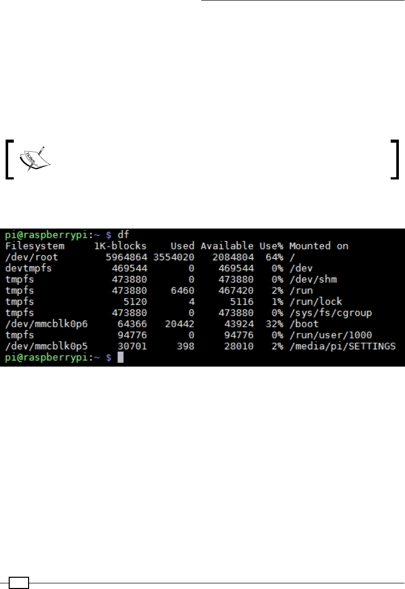
When you power up the Raspberry Pi for the rst time, it will start directly with the desktop.
You can now congure the system settings using the Raspberry Pi Conguration program
(under the Preferences menu on the Desktop or via the sudo raspi-config command),
which will allow you to perform changes to your SD card and set up your general preferences.
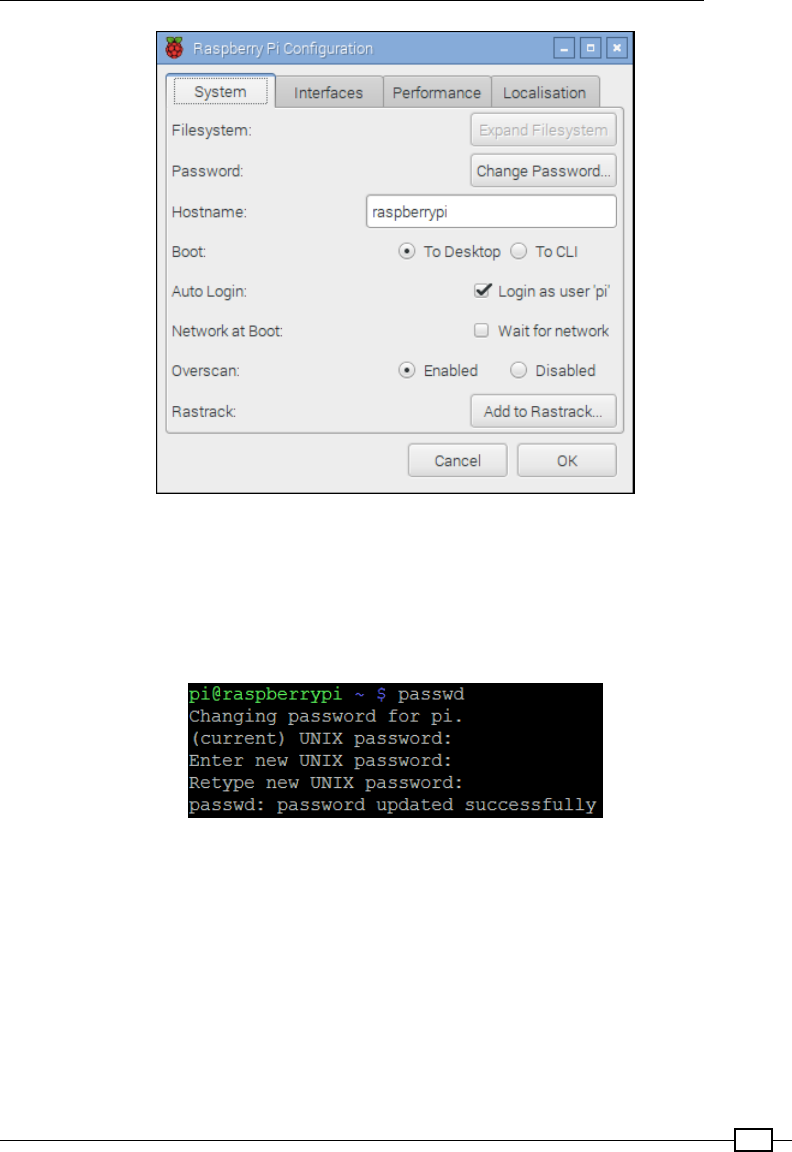
Chapter 1
15
Raspberry Pi Configuration program
Changing the default user password
Ensure that you change the default password for the pi user account once you have logged
in, as the default password is well known. This is particularly important if you connect to public
networks. You can do this with the passwd command, as shown in the following screenshot:
Setting a new password for the pi user
This gives greater condence because if you later connect to another network, only you will be
able to access your les and take control of your Raspberry Pi.
Ensuring that you shut down safely
To avoid any data corruption, you must ensure that you correctly shut down the Raspberry Pi
by issuing a shutdown command, as follows:
sudo shutdown –h now

Getting Started with a Raspberry Pi Computer
16
Or use this one:
sudo halt
You must wait until this command completes before you remove power from the Raspberry Pi
(wait for at least 10 seconds after the SD card access light has stopped ashing).
You can also restart the system with the reboot command, as follows:
sudo reboot
Preparing an SD card manually
An alternative to using NOOBS is to manually write the operating system image to the SD card.
While this was originally the only way to install the operating system, some users still prefer
it. It allows the SD cards to be prepared before they are used in the Raspberry Pi. It can also
provide easier access to startup and conguration les, and it leaves more space available for
the user (unlike NOOBS, a RECOVERY partition isn't included).
The default Raspbian image actually consists of two partitions, BOOT and SYSTEM, which will
t into a 2 GB SD card (4 GB or more is recommended).
You need a computer running Windows/Mac OS X/Linux (although it is possible to use
another Raspberry Pi to write your card, be prepared for a very long wait).
Download the latest version of the operating system you wish to use. For the purpose of this
book, it is assumed you are using the latest version of Raspbian available at http://www.
raspberrypi.org/downloads.
Perform the following steps depending on the type of computer you plan to use to write to the
SD card (the .img le you need is sometimes compressed, so before you start, you will need
to extract the le).
The following steps are for Windows:
1. Ensure that you have downloaded the Raspbian image, as previously detailed, and
extracted it to a convenient folder to obtain an .img le.
2. Obtain the Win32DiskImager.exe le available at http://www.sourceforge.
net/projects/win32diskimager.
3. Run Win32DiskImager.exe from your downloaded location.
4. Click on the folder icon and navigate to the location of the .img le and click
on Save.
5. If you haven't already done so, insert your SD card into your card reader and plug it
into your computer.
6. Select the Device drive letter that corresponds to your SD card from the small
drop-down box. Double-check that this is the correct device (as the program will
overwrite whatever is on the device when you write the image).
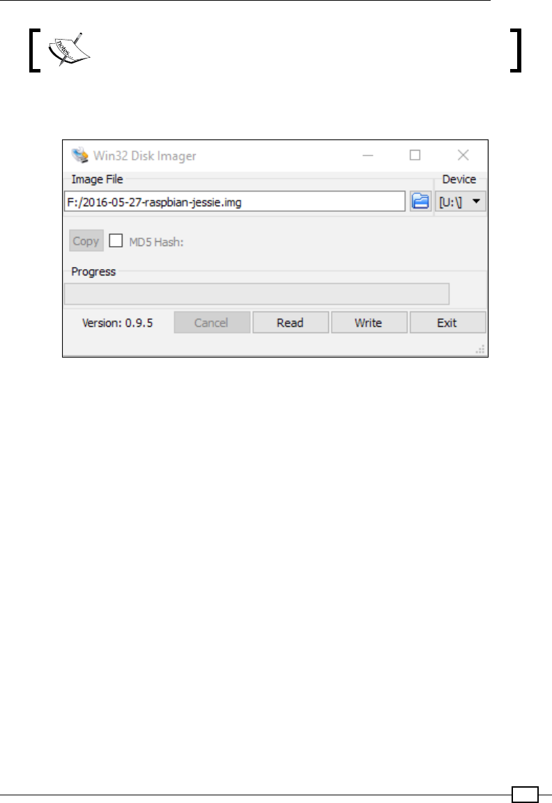
Chapter 1
17
The drive letter may not be listed until you select a source image file.
7. Finally, click on the Write button and wait for the program to write the image to the
SD card, as shown in the following screenshot:
Manually write operating system images to the SD card using Disk Imager
Once completed, you can exit the program. Your SD card is ready!
The following steps should work for the most common Linux distributions, such as Ubuntu
and Debian:
1. Using your preferred web browser, download the Raspbian image and save it in a
suitable place.
2. Extract the le from the le manager or locate the folder in the terminal and unzip the
.img le with the following command:
unzip filename.zip
3. If you haven't already done so, insert your SD card into your card reader and plug it
into your computer.
4. Use the df –h command and identify the sdX identier for the SD card. Each
partition will be displayed as sdX1, sdX2, and so on, where X will be a, b, c, d, and so
on for the device ID.
5. Ensure that all the partitions on the SD card are unmounted using the
umount /dev/sdXn command for each partition, where sdXn is the partition
being unmounted.

Getting Started with a Raspberry Pi Computer
18
6. Write the image le to the SD card with the following command:
sudo dd if=filename.img of=/dev/sdX bs=4M
7. The process will take some time to write to the SD card, returning to the terminal
prompt when complete.
8. Unmount the SD card before removing it from the computer using the following
command:
umount /dev/sdX1
The following steps should work for most of the versions of OS X:
1. Using your preferred web browser, download the Raspbian image and save it
somewhere suitable.
2. Extract the le from the le manager or locate the folder in the terminal and unzip the
.img le with the following command:
unzip filename.zip
3. If you haven't already done so, insert your SD card into your card reader and plug it
into your computer.
4. Use the diskutil list command and identify the disk# identier for the SD card.
Each partition will be displayed as disk#s1, disk#s2, and so on, where # will be 1, 2,
3, 4, and so on for the device ID.
If rdisk# is listed, use this for faster writing (this uses a raw path
and skips data buffering).
5. Ensure that the SD card is unmounted using the unmountdisk /dev/diskX
command, where diskX is the device being unmounted.
6. Write the image le to the SD card with following command:
sudo dd if=filename.img of=/dev/diskX bs=1M
7. The process will take some time to write to the SD card, returning to the terminal
prompt when complete.
8. Unmount the SD card before removing it from the computer using the
following command:
unmountdisk /dev/diskX
Chapter 1
19
Refer to the following image:
The boot process of a manually installed OS image
Expanding the system to t in your SD card
A manually written image will be of a xed size (usually made to t the smallest-sized SD card
possible). To make full use of the SD card, you will need to expand the system partition to ll
the remainder of the SD card. This can be achieved using the Raspberry Pi Conguration tool.
Select Expand Filesystem, as shown in the following screenshot:
The Raspberry Pi Configuration tool
Getting Started with a Raspberry Pi Computer
20
Accessing the RECOVERY/BOOT partition
Windows and Mac OS X do not support the ext4 format, so when you read the SD card,
only the File Allocation Table (FAT) partitions will be accessible. In addition, Windows only
supports the rst partition on an SD card, so if you've installed NOOBS, only the RECOVERY
partition will be visible. If you've written your card manually, you will be able to access the
BOOT partition.
The data partition (if you installed one via NOOBS) and the root partition are in ext4 format
and won't usually be visible on non-Linux systems.
If you do need to read les from the SD card using Windows, a freeware
program, Linux Reader (available at www.diskinternals.com/linux-
reader) can provide read-only access to all of the partitions on the SD card.
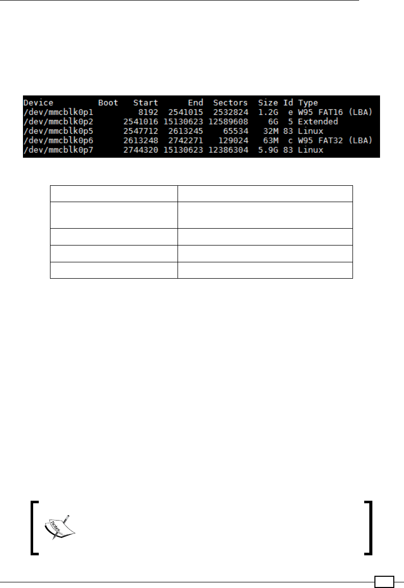
Access the partitions from the Raspberry Pi. To view the currently mounted partitions, use df,
as shown in the following screenshot:
The result of the df command
To access the BOOT partition from within Raspbian, use the following command:
cd /boot/
Chapter 1
21
To access the RECOVERY or data partition, we have to mount it by performing the
following steps:
1. Determine the name of the partition as the system refers to it by listing all the
partitions, even the unmounted ones. The sudo fdisk -l command lists the
partitions, as shown in the following screenshot:
The partition table of a NOOBS install of Raspbian and data partition
mmcblk0p1 (vfat) RECOVERY
mmcblk0p2 (Extended partition)
contains (root, data, BOOT)
mmcblk0p5 (ext4) root
mmcblk0p6 (vfat) BOOT
mmcblk0p7 (ext4) SETTINGS
If you have installed additional operating systems on the same card, the partition
identiers shown in the preceding table will be different.
2. Create a folder and set it as the mount point for the partition, as follows:
For the RECOVERY partition, use the following command:
mkdir ~/recovery
sudo mount –t vfat /dev/mmcblk0p1 ~/recovery
To ensure that they are mounted each time the system is started, perform the following steps:
1. Add the sudo mount commands to /etc/rc.local before exit 0. If you have a
different username, you will need to change pi to match:
sudo nano /etc/rc.local
sudo mount -t vfat /dev/mmcblk0p1 /home/pi/recovery
2. Save and exit by pressing Ctrl + X, Y, and Enter.
Commands added to /etc/rc.local will be run for any user
who logs on to the Raspberry Pi. If you only want the drive to be
mounted for the current user, the commands can be added to
.bash_profile instead.
Getting Started with a Raspberry Pi Computer
22
If you have to install additional operating systems on the same card, the partition identiers
shown here will be different.
Using the tools to back up your SD card in case of failure
You can use Win32 Disk Imager to make a full backup image of your SD card by inserting
your SD card into your reader, starting the program, and creating a lename to store the
image in. Simply click on the Read button instead to read the image from the SD card and
write it to a new image le.
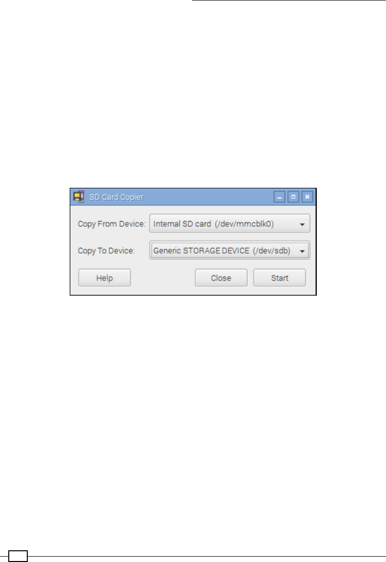
To make a backup of your system, or to clone to another SD card using the Raspberry Pi, use
the SD Card Copier (available from the desktop menu via the Accessories | SD Card Copier).
Insert an SD card into a card reader into a spare USB port of the Raspberry Pi and select the
new storage device, as shown in the following screenshot:
SD Card Copier program
Before continuing, the SD Card Copier will conrm that you wish to format and overwrite the
target device and, if there is sufcient space, make a clone of your system.
The dd command can similarly be used to back up the card, as follows:
fFor Linux, replacing sdX with your device ID, use this command:
sudo dd if=/dev/sdX of=image.img.gz bs=1M
fFor OS X, replacing diskX with your device ID, use the following command:
sudo dd if=/dev/diskX of=image.img.gz bs=1M
fYou can also use gzip and split to compress the contents of the card and split them
into multiple les if required for easy archiving, as follows:
sudo dd if=/dev/sdX bs=1M | gzip –c | split –d –b 2000m – image.
img.gz
fTo restore the split image, use the following command:
sudo cat image.img.gz* | gzip –dc | dd of=/dev/sdX bs=1M

Chapter 1
23
Networking and connecting your Raspberry
Pi to the Internet via the LAN connector
The simplest way to connect the Raspberry Pi to the Internet is by using the built-in LAN
connection on the Model B. If you are using a Model A Raspberry Pi, a USB-to-LAN adapter can
be used (refer to the There's more… section of the Networking and connecting your Raspberry
Pi to the Internet via a USB Wi-Fi dongle recipe for details on how to congure this).
Getting ready
You will need access to a suitable wired network, which will be connected to the Internet, and
a standard network cable (with an RJ45 type connector for connecting to the Raspberry Pi).
How to do it…
Many networks connect and congure themselves automatically using Dynamic Host
Conguration Protocol (DHCP), which is controlled by the router or switch. If this is the case,
simply plug the network cable into a spare network port on your router or network switch (or
wall network socket if applicable).
Alternatively, if a DHCP server is not available, you shall have to congure the settings
manually (refer to the There's more… section for details).
You can conrm this is functioning successfully with the following steps:
1. Ensure that the two LEDs on either side of the Raspberry Pi light up (the left orange
LED indicates a connection and the green LED on the right shows activity by ashing).
This will indicate that there is a physical connection to the router and the equipment
is powered and functioning.
2. Test the link to your local network using the ping command. First, nd out the IP
address of another computer on the network (or the address of your router perhaps,
often 192.168.0.1 or 192.168.1.254). Now, on the Raspberry Pi terminal,
use the ping command (the -c 4 parameter is used to send just four messages;
otherwise, press Ctrl + C to stop) to ping the IP address as follows:
sudo ping 192.168.1.254 -c 4
3. Test the link to the Internet (this will fail if you usually connect to the Internet through
a proxy server) as follows:
sudo ping www.raspberrypi.org -c 4

Getting Started with a Raspberry Pi Computer
24
4. Finally, you can test the link back to the Raspberry Pi by discovering the
IP address using hostname -I on the Raspberry Pi. You can then use the ping
command on another computer on the network to ensure it is accessible (using
the Raspberry Pi's IP address in place of www.raspberrypi.org). The Windows
version of the ping command will perform ve pings and stop automatically, and will
not need the -c 4 option.
If the aforementioned tests fail, you will need to check your connections and then conrm the
correct conguration for your network.
There's more…
If you nd yourself using your Raspberry Pi regularly on the network, you won't want to have to
look up the IP address each time you want to connect to it.
On some networks, you may be able to use the Raspberry Pi's hostname instead of its IP
address (the default is raspberrypi). To assist with this, you may need some additional
software such as Bonjour to ensure hostnames on the network are correctly registered. If you
have an OS X Mac, you will have Bonjour running already. On Windows, you can either install
iTunes (if you haven't got it) which also includes the service, or you can install it separately
(via the Apple Bonjour Installer available from https://support.apple.com/kb/DL999).
Then you can use the hostname, raspberrypi or raspberrypi.local, to connect to the
Raspberry Pi over the network. If you need to change the hostname, then you can do so in the
Raspberry Pi conguration tool, shown previously.
Alternatively, you may nd it helpful to x the IP address to a known value by manually setting
the IP address. However, remember to switch it back to use DHCP when connecting on
another network.
Some routers will also have an option to set a Static IP DHCP address, so the same address
is always given to the Raspberry Pi (how this is set will vary on the router itself).
Knowing your Raspberry Pi's IP address or using the hostname is particularly useful if you
intend to use one of the remote access solutions described later on, which avoids the need
for a display.
Using built-in Wi-Fi and Bluetooth on the
Raspberry Pi
Many home networks provide a wireless network over Wi-Fi; if you have a Raspberry Pi 3, then
you can make use of the on-board Broadcom Wi-Fi to connect to it. The Raspberry Pi 3 also
supports Bluetooth, so you can connect most standard Bluetooth devices and use them like
you would on any other computer.

Chapter 1
25
This method should also work for any supported USB Wi-Fi and Bluetooth devices, see the
Networking and connecting your Raspberry Pi to the Internet via a USB Wi-Fi dongle recipe for
extra help on identifying device and installing rmware (if required).
Getting ready
The latest version of Raspbian includes helpful utilities to quickly and easily congure your
Wi-Fi and Bluetooth through the graphical interface.
Note: If you need to congure the Wi-Fi via the command line, then
see the Networking and connecting your Raspberry Pi to the Internet
via a USB Wi-Fi dongle recipe for details.
Wi-Fi and Bluetooth configuration applications
You can use the built-in Bluetooth to connect a wireless keyboard, a mouse or even wireless
speakers. This can be exceptionally helpful for projects where additional cables and wires
are an issue, such as robotic projects, or when the Raspberry Pi is installed in hard-to-reach
locations (acting as a server or security camera).
How to do it…
Connecting to your Wi-Fi network
To congure your Wi-Fi connection, click on the networking symbol to list the local available
Wi-Fi networks:
Wi-Fi listing of the available access points in the area
Getting Started with a Raspberry Pi Computer
26
Select the required network (for example, Demo) and if required enter your password (also
known as Pre Shared Key):
Providing the password for the access point
After a short while, you should see that you have connected to the network and the icon
will change to a Wi-Fi symbol. If you encounter problems, ensure you have the correct
password/key.
Successful connection to an access point
That is it, as easy as that!
You can now test your connection and ensure it is working by using the web browser to
navigate to a website or by using the following command in the terminal:
sudo ping www.raspberrypi.com
Connecting to Bluetooth devices
To start, we need to put the Bluetooth device into discoverable mode, by clicking on the
Bluetooth icon and selecting Make Discoverable. You will also need to make the device you
want to connect to discoverable and ready to pair; this may vary from device to device (such
as pressing a pairing button).
Set the Bluetooth as discoverable
Chapter 1
27
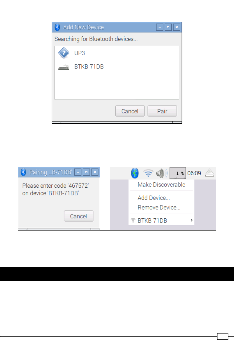
Next, select Add Device... and select the target device and Pair:
Select and pair the required device
The pairing process will then start; for example, the BTKB-71DB keyboard will need the
pairing code 467572 to be entered onto the keyboard for the pairing to complete. Other
devices may use default pairing codes, often set to 0000, 1111, 1234, or similar.
Follow the instructions to pair the device with the required pairing code
Once the process has completed, the device will be listed and will connect automatically each
time the devices are present and booted.
Conguring your network manually
If your network does not include a DHCP server or it is disabled (typically, these are built
into most modern ADSL/cable modems or routers), you may need to congure your network
settings manually.

Getting Started with a Raspberry Pi Computer
28
Getting ready
Before you start, you will need to determine the network settings for your network.
You will need to nd out the following information from your router's settings or another
computer connected to the network:
fIPv4 address: This address will need to be selected to be similar to other
computers on the network (typically, the rst three numbers should match, that is,
192.168.1.X if netmask is 255.255.255.0), but it should not already be used
by another computer. However, avoid x.x.x.255 as the last address since this is
reserved as a broadcast address.
fSubnet mask: This number determines the range of addresses the computer will
respond to (for a home network, it is typically 255.255.255.0, which allows up to
254 addresses). This is also sometimes referred to as the netmask.
fDefault gateway address: This address is usually your router's IP address, through
which the computers connect to the Internet.
fDNS servers: The DNS server (Domain Name Service) converts names into IP
addresses by looking them up. Usually, they will already be congured on your
router, in which case you can use your router's address. Alternatively, your Internet
Service Provider (ISP) may provide some addresses, or you can use Google's
public DNS servers at the addresses 8.8.8.8 and 8.8.4.4. These are also called
nameservers in some systems.
For Windows, you can obtain this information by connecting to the Internet and running the
following command:
ipconfig /all

Chapter 1
29
Locate the active connection (usually called Local Area Connection 1 or similar if you are
using a wired connection, or if you are using Wi-Fi, it is called wireless network connection)
and nd the information required, as follows:
The ipconfig/all command shows useful information about your network settings
For Linux and Mac OS X, you can obtain the required information with the following command
(note that it is ifconfig rather than ipconfig):
ifconfig
The DNS servers are called nameservers and are usually listed in the resolv.conf le. You
can use the less command as follows to view its contents (press Q to quit when you have
nished viewing it):
less /etc/resolv.conf
How to do it…
To set the network interface settings, edit /etc/network/interfaces using the
following code:
sudo nano /etc/network/interfaces

Getting Started with a Raspberry Pi Computer
30
Now, perform the following steps:
1. We can add the details for our particular network, the IP address number we want
to allocate to it, the netmask address of the network, and the gateway address,
as follows:
iface eth0 inet static
address 192.168.1.10
netmask 255.255.255.0
gateway 192.168.1.254
2. Save and exit by pressing Ctrl + X, Y, and Enter.
3. To set the nameservers for DNS, edit /etc/resolv.conf using the following code:
sudo nano /etc/resolv.conf
4. Add the addresses for your DNS servers as follows:
nameserver 8.8.8.8
nameserver 8.8.4.4
5. Save and exit by pressing Ctrl + X, Y, and Enter.
There's more…
You can congure the network settings by editing cmdline.txt in the BOOT partition and
adding settings to the startup command line with ip.
The ip option takes the following form:
ip=client-ip:nfsserver-ip:gw-ip:netmask:hostname:device:autoconf
fThe client-ip option is the IP address you want to allocate to the Raspberry Pi
fThe gw-ip option will set the gateway server address if you need to set it manually
fThe netmask option will directly set the netmask of the network
fThe hostname option will allow you to change the default raspberrypi hostname
fThe device option allows you to specify a default network device if more than one
network device is present
fThe autoconf option allows the automatic conguration to be switched on or off
Chapter 1
31
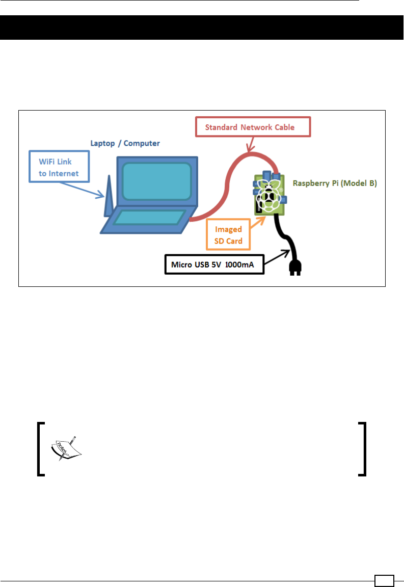
Networking directly to a laptop or computer
It is possible to connect the Raspberry Pi LAN port directly to a laptop or computer using a
single network cable. This will create a local network link between the computers, allowing all
the things you can do if connected to a normal network without the need for a hub or router,
including connection to the Internet, if Internet Connection Sharing (ICS) is used as follows:
Make use of the Raspberry Pi with just a network cable, a standard imaged SD card, and power
ICS allows the Raspberry Pi to connect to the Internet through another computer. However,
some additional conguration is required for the computers in order to communicate across
the link, as the Raspberry Pi does not automatically allocate its own IP address.
We will use the ICS to share a connection from another network link, such as a built-in Wi-Fi
on a laptop. Alternatively, we can use a direct network link (refer to the Direct network link
section under the There's more… section) if the Internet is not required or if the computer has
only a single network adapter.
Although this setup should work for most of the computers,
some setups are more difcult than the others. For additional
information, see www.pihardware.com/guides/
direct-network-connection.
Getting Started with a Raspberry Pi Computer
32
Getting ready
You will need the Raspberry Pi with power and a standard network cable.
The Raspberry Pi Model B LAN chip includes Auto-MDIX (Automatic
Medium-Dependent Interface Crossover). Removing the need to use
a special crossover cable (a special network cable wired so that the
transmit lines connect to receive lines for direct network links), the
chip will decide and change the setup as required automatically.
It may also be helpful to have a keyboard and monitor available to perform additional testing,
particularly if this is the rst time you have tried this.
To ensure that you can restore your network settings to their original values, you should check
whether it has a xed IP address or the network is congured automatically.
To check the network settings on Windows 10, perform these steps:
1. Open Settings from the start menu, then select Network & Internet, then Ethernet,
and click on Change adapter options from the list of Related Settings.
To check the network settings on Windows 7 and Vista, perform the following steps:
1. Open Network and Sharing Center from the Control Panel and click on Change
adapter settings on the left-hand side.
2. To check the network settings on Windows XP, open Network Connections from the
Control Panel.
3. Find the item that relates to your wired network adapter (by default, this is usually
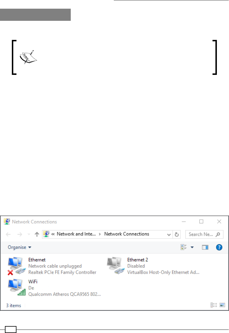
called Ethernet or Local Area Connection, as shown in the following screenshot):
Locating your wired network connection
Chapter 1
33
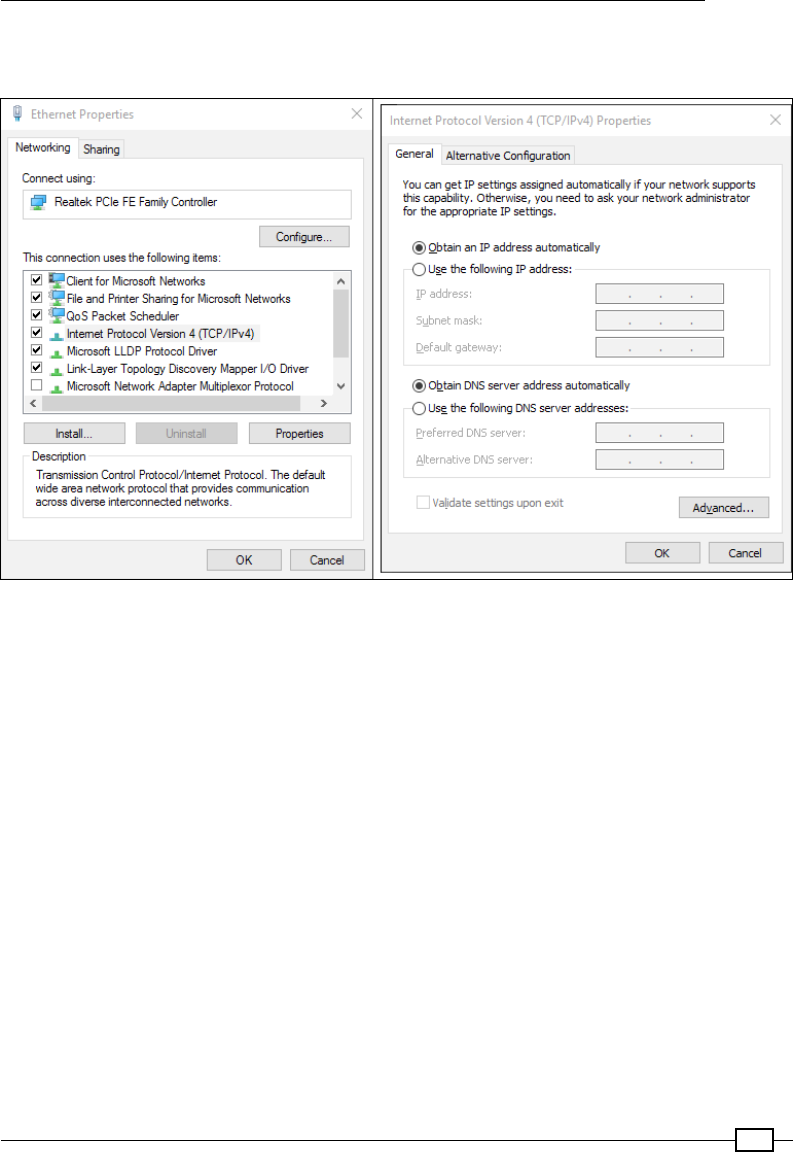
4. Right-click on its icon and click on Properties. A dialog box will appear, as shown in
this screenshot:
Selecting the TCP/IP properties and checking the settings
5. Select the item called Internet Protocol (TCP/IP) or Internet Protocol Version
4 (TCP/IPv4) if there are two versions (the other is Version 6), and click on the
Properties button.
6. You can conrm that your network is set by using automatic settings or a specic IP
address (if so, take note of this address and the remaining details as you may want to
revert the settings at a later point).
Getting Started with a Raspberry Pi Computer
34
To check the network settings on Linux, perform the following steps:
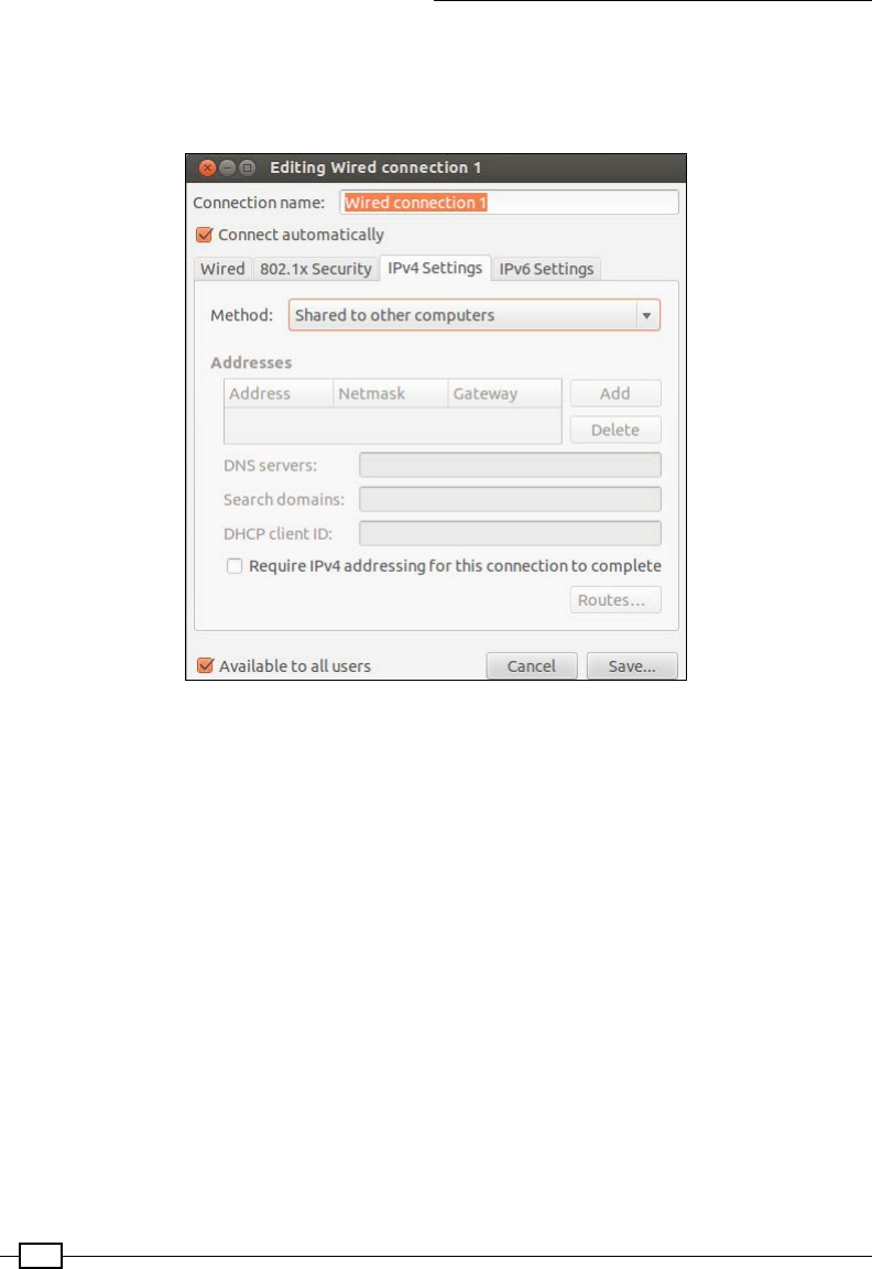
1. Open up the Network Settings dialog box and select Congure Interface. Refer to
the following screenshot:
Linux Network Settings dialog box
2. Ensure that if any settings are manually set, you take note of them so that you can
restore them later if you want.
To check the network settings on Mac OS X, perform the following steps:
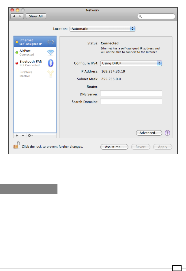
1. Open System Preferences and click on Networks. You can then conrm whether the
IP address is allocated automatically (using DHCP) or not.
2. Ensure that if any settings are manually set you take note of them so you can restore
them later if you want to. Refer to the following screenshot:
Chapter 1
35
OS X Network Settings dialog box
If you just need to access or control the Raspberry Pi without an Internet connection, refer to
the Direct network link section in the There's more…section.
How to do it…
First, we need to enable ICS on our network devices. In this case, we will be sharing
the Internet, which is available on Wireless Network Connection through the Ethernet
connection to the Raspberry Pi.
Getting Started with a Raspberry Pi Computer
36
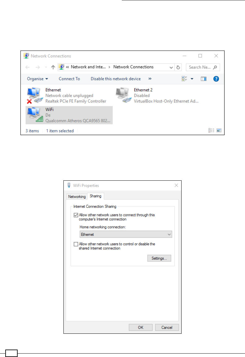
For Windows, perform these steps:
1. Return to the list of network adapters, right-click on the connection that links
to the Internet (in this case, the WiFi or Wireless Network Connection device),
and click on Properties.
Right-click on your wireless device and select Properties
2. At the top of the window, select the second tab (in Windows XP, it is called
Advanced; in Windows 7 and Windows 10, it is called Sharing), as shown
in the following screenshot:
Selecting the TCP/IP properties and noting the allocated IP address

Chapter 1
37
3. In the Internet Connection Sharing section, check the box for Allow other network
users to connect through this computer's Internet connection (if present, use the
drop-down box to select the Home networking connection: option as Ethernet or
Local Area Connection). Click on OK and conrm whether you previously had a xed
IP address set for Local Area Connection.
For Mac OS X, to enable the ICS, perform the following steps:
1. Click on System Preferences and then click on Sharing.
2. Click on Internet Sharing and select the connection from which we want to share the
Internet (in this case, it will be the Wi-Fi AirPort). Then select the connection that we
will connect the Raspberry Pi to (in this case, Ethernet).
For Linux to enable the ICS, perform the following steps:
1. From the System menu, click on Preferences and then on Network Connections.
Select the connection you want to share (in this case, Wireless) and click on Edit or
Congure. In the IPv4 Settings tab, change the Method option to Shared to other
computers.
The IP address of the network adapter will be the Gateway IP address to be used on the
Raspberry Pi, and be assigned an IP address within the same range (matching except the last
number). For instance, if the computer's wired connection now has 192.168.137.1, the
Gateway IP of the Raspberry Pi will be 192.168.137.1 and its own IP address might be set
to 192.168.137.10.
Fortunately, thanks to updates in the operating system, Raspbian will now automatically
allocate a suitable IP address to join the network and set the gateway appropriately. However,
unless we have a screen attached to the Raspberry Pi or scan for devices on our network, we
do not know what IP address the Raspberry PI has given itself.
Fortunately (as mentioned in the Networking and connecting your Raspberry Pi to the Internet
via the LAN connector recipe in the There's more… section), Apple's Bonjour software will
automatically ensure hostnames on the network are correctly registered. As stated previously,
if you have an OSX Mac you will have Bonjour running already. On Windows you can either
install iTunes, or you can install it separately (available from https://support.apple.
com/kb/DL999). By default, the hostname raspberrypi can be used.
We are now ready to test the new connection, as follows:
1. Connect the network cable to the Raspberry Pi and the computer's network port, and
then power up the Raspberry Pi, ensuring that you have reinserted the SD card if
you previously removed it. To reboot the Raspberry Pi if you edited the le there, use
sudo reboot to restart it.
2. Allow a minute or two for the Raspberry Pi to fully power up. We can now test
the connection.

Getting Started with a Raspberry Pi Computer
38
3. From the connected laptop or computer, test the connection by pinging with the
hostname of the Raspberry Pi, as shown in the following command (on Linux or OS X,
add -c 4 to limit to four messages or press Ctrl + C to exit):
ping raspberrypi
Hopefully, you will nd you have a working connection and receive replies from the
Raspberry Pi.
If you have a keyboard and screen connected to the Raspberry Pi, you can perform the
following steps:
1. You can ping the computer in return (for example, 192.168.137.1) from the
Raspberry Pi terminal as follows:
sudo ping 192.168.137.1 -c 4
2. You can test the link to the Internet by using ping to connect to a well-known website
as follows, assuming you do not access the Internet through a proxy server:
sudo ping www.raspberrypi.org -c 4
If all goes well, you will have full Internet available through your computer to the Raspberry Pi,
allowing you to browse the web as well as update and install new software.
If the connection fails, perform the following steps:
1. Repeat the process, ensuring that the rst three sets of numbers match with the
Raspberry Pi and the network adapter IP addresses.
2. You can also check that when the Raspberry Pi powers up, the correct IP address is
being set using the following command:
hostname -I
3. Check your rewall settings to ensure it is not blocking internal network connections.
How it works…
When we enable ICS on the primary computer, the operating system will automatically allocate
a new IP address to the computer. Once connected and powered up, the Raspberry Pi will
set itself to a compatible IP address and use the primary computer IP address as an Internet
Gateway.
By using Apple Bonjour, we are able to use the raspberrypi hostname to connect to the
Raspberry Pi from the connected computer.
Finally, we check whether the computer can communicate over the direct network link to the
Raspberry Pi, back the other way, and also through to the Internet.
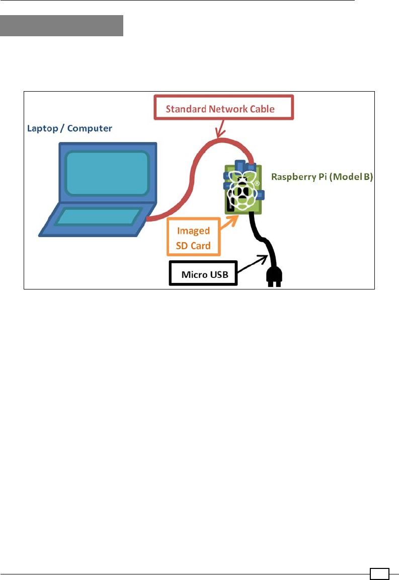
Chapter 1
39
There's more…
If you do not require the Internet on the Raspberry Pi, or your computer only has a single
network adapter, we can still connect the computers together through a direct network link.
Refer to the following diagram:
Connecting and using the Raspberry Pi with just a network cable, a standard imaged SD card, and power
Direct network link
For a network link to work between two computers, they need to be using the same address
range. The allowable address range is determined by the subnet mask (for example,
255.255.0.0 or 255.255.255.0 would mean all IP addresses should be the same except
for the last two or just the last number in the IP address; otherwise, they will be ltered).
To use a direct link without enabling ICS, check the IP settings of the adapter you are
going to connect to and determine whether it is automatically allocated or xed to a
specic IP address.
Most PCs connected directly to another computer will allocate an IP address in the range
169.254.X.X (with a subnet mask of 255.255.0.0). However, we must ensure that the
network adaptor is set to Obtain an IP address automatically.
For the Raspberry Pi to be able to communicate through the direct link, it needs to have an IP
address in the same address range, 169.254.X.X. As mentioned before, the Raspberry Pi
will automatically give itself a suitable IP address and connect to the network.
Therefore, assuming we have Apple Bonjour (see previously for details), we only need to know
the hostname given to the Raspberry Pi (raspberrypi).

Getting Started with a Raspberry Pi Computer
40
See also
If you don't have a keyboard or screen connected to the Raspberry Pi, you can use this
network link to remotely access the Raspberry Pi just as you would on a normal network (just
use the new IP address you have set for the connection). Refer to the Connecting remotely to
the Raspberry Pi over the network using VNC and Connecting remotely to the Raspberry Pi
over the network using SSH (and X11 Forwarding) recipes.
There is lots of additional information available on my website, https://pihw.wordpress.
com/guides/direct-network-connection, including additional troubleshooting tips
and several other ways to connect to your Raspberry Pi without needing a dedicated screen
and keyboard.
Networking and connecting your Raspberry
Pi to the Internet via a USB Wi-Fi dongle
By adding a USB Wi-Fi dongle to the Raspberry Pi's USB port, even models without built-in Wi-
Fi can connect to and use the Wi-Fi network.
Getting ready
You will need to obtain a suitable USB Wi-Fi dongle; and in some cases, you may require a
powered USB hub (this will depend on the hardware version of the Raspberry Pi you have and
the quality of your power supply). General suitability of USB Wi-Fi dongles will vary depending
on the chipset that is used inside and the level of Linux support available. You may nd that
some USB Wi-Fi dongles will work without installing additional drivers (in which case you can
jump to conguring it for the wireless network).
A list of supported Wi-Fi adapters is available at http://elinux.org/RPi_USB_Wi-Fi_
Adapters.
You will need to ensure that your Wi-Fi adapter is also compatible with your intended network;
for example, it supports the same types of signals 802.11bgn and the encryptions WEP,
WPA, and WPA2 (although most networks are backward compatible).
You will also need the following details of your network:
fService set identier (SSID): This is the name of your Wi-Fi network and should be
visible if you use the following command:
sudo iwlist scan | grep SSID
fEncryption type and key: This value will be None, WEP, WPA, or WPA2, and the key
will be the code you normally enter when you connect your phone or laptop to the
wireless network (sometimes, it is printed on the router).

Chapter 1
41
You will require a working internet connection (that is, wired Ethernet) in order to download
the required drivers. Otherwise, you may be able to locate the required rmware les (they
will be the .deb les), and copy them to the Raspberry Pi (that is, via a USB ash drive; the
drive should be automatically mounted if you are running in desktop mode). Copy the le to a
suitable location and install it with the following command:
sudo apt-get install firmware_file.deb
How to do it…
This task has two stages; rst, we identify and install rmware for the Wi-Fi adapter, and then
we need to congure it for the wireless network.
We will try to identify the chipset of your Wi-Fi adapter (the part that handles the connection);
this may not match the actual manufacturer of the device.
An approximate list of supported rmware can be found with this command:
sudo apt-cache search wireless firmware
This will produce results similar to the following output (disregarding any results without
firmware in the package title):
atmel-firmware - Firmware for Atmel at76c50x wireless networking chips.
firmware-atheros - Binary firmware for Atheros wireless cards
firmware-brcm80211 - Binary firmware for Broadcom 802.11 wireless cards
firmware-ipw2x00 - Binary firmware for Intel Pro Wireless 2100, 2200 and
2915
firmware-iwlwifi - Binary firmware for Intel PRO/Wireless 3945 and
802.11n cards
firmware-libertas - Binary firmware for Marvell Libertas 8xxx wireless
cards
firmware-ralink - Binary firmware for Ralink wireless cards
firmware-realtek - Binary firmware for Realtek wired and wireless network
adapters
libertas-firmware - Firmware for Marvell's libertas wireless chip series
(dummy package)
zd1211-firmware - Firmware images for the zd1211rw wireless driver
To nd out the chipset of your wireless adapter, plug the Wi-Fi-adapter into Raspberry Pi, and
from the terminal, run the following command:
dmesg | grep 'Product:\|Manufacturer:'

Getting Started with a Raspberry Pi Computer
42
This command stitches together two commands into one. First, dmesg
displays the message buffer of the kernel (this is an internal record of system
events that have occurred since power on, such as detected USB devices).
You can try the command on its own to observe the complete output.
The | (pipe) sends the output to the grep command, grep
'Product:\|Manuf' checks it and only returns lines that contain
Product or Manuf (so we should get a summary of any items that are listed
as Product and Manufacturer). If you don't nd anything or want to see
all your USB devices, try grep 'usb' instead.
This should return something similar to the following output (in this case, I've got a ZyXEL
device, which has a ZyDAS chipset (a quick Google search reveals that zd1211-firmware is
for ZyDAS devices):
[ 1.893367] usb usb1: Product: DWC OTG Controller
[ 1.900217] usb usb1: Manufacturer: Linux 3.6.11+ dwc_otg_hcd
[ 3.348259] usb 1-1.2: Product: ZyXEL G-202
[ 3.355062] usb 1-1.2: Manufacturer: ZyDAS
Once you have identied your device and the correct rmware, you can install it, as you
would for any other package available through apt-get (where zd1211-firmware can be
replaced with your required rmware). This is shown in the following command:
sudo apt-get install zd1211-firmware
Remove and reinsert the USB Wi-Fi dongle to allow it to be detected and the drivers loaded.
We can now test if the new adapter is correctly installed with ifconfig. The output is shown
as follows:
wlan0 IEEE 802.11bg ESSID:off/any
Mode:Managed Access Point: Not-Associated Tx-Power=20 dBm
Retry long limit:7 RTS thr:off Fragment thr:off
Power Management:off
The command will show the network adapters present on the system. For Wi-Fi,
this is usually as wlan0, or wlan1, or so on if you have installed more than one. If not,
double-check the selected rmware, and perhaps try an alternative or check on the
site for troubleshooting tips.

Chapter 1
43
Once we have the rmware installed for the Wi-Fi adapter, we will need to congure it for the
network we wish to connect. We can use the GUI as shown in the previous recipe, or we can
manually congure it through the terminal as shown in the following steps:
1. We will need to add the wireless adapter to the list of network interfaces, which is set
in /etc/network/interfaces, as follows:
sudo nano -c /etc/network/interfaces
Using the previous wlan# value in place of wlan0 if required, add the following
command:
allow-hotplug wlan0
iface wlan0 inet manual
wpa-conf /etc/wpa_supplicant/wpa_supplicant.conf
When the changes have been made, save and exit by pressing Ctrl + X, Y, and Enter.
2. We will now store the Wi-Fi network settings of our network in the wpa_
supplicant.conf le (don't worry if your network doesn't use the wpa encryption;
it is just the default name for the le):
sudo nano -c /etc/wpa_supplicant/wpa_supplicant.conf
It should include the following:
ctrl_interface=DIR=/var/run/wpa_supplicant GROUP=netdev
update_config=1
country=GB
The network settings can be written within this le as follows (that is, if the SSID is set
as theSSID):
If no encryption is used, use this code:
network={
ssid="theSSID"
key_mgmt=NONE
}
With the WEP encryption (that is, if the WEP key is set as theWEPkey), use
the following code:
network={
ssid="theSSID"
key_mgmt=NONE
wep_key0="theWEPkey"
}

Getting Started with a Raspberry Pi Computer
44
For the WPA or WPA2 encryption (that is, if the WPA key is set as theWPAkey),
use the following code:
network={
ssid="theSSID"
key_mgmt=WPA-PSK
psk="theWPAkey"
}
3. You can enable the adapter with the following command (again, replace wlan0
if required):
sudo ifup wlan0
Use the following command to list the wireless network connections:
iwconfig
You should see your wireless network connected with your SSID listed as follows:
wlan0 IEEE 802.11bg ESSID:"theSSID"
Mode:Managed Frequency:2.442 GHz Access Point:
00:24:BB:FF:FF:FF
Bit Rate=48 Mb/s Tx-Power=20 dBm
Retry long limit:7 RTS thr:off Fragment thr:off
Power Management:off
Link Quality=32/100 Signal level=32/100
Rx invalid nwid:0 Rx invalid crypt:0 Rx invalid frag:0
Tx excessive retries:0 Invalid misc:15 Missed
beacon:0
If not, adjust your settings and use sudo ifdown wlan0 to switch off the network
interface, and then sudo ifup wlan0 to switch it back on.
This will conrm that you have successfully connected to your Wi-Fi network.
4. Finally, we will need to check whether we have access to the Internet. Here,
we have assumed that the network is automatically congured with DHCP and no
proxy server is used. If not, refer to the Connecting to the Internet through a proxy
server recipe.
Unplug the wired network cable, if still connected, and see if you can ping the
Raspberry Pi website, as follows:
sudo ping www.raspberrypi.org

Chapter 1
45
If you want to quickly know the IP address currently in use by the
Raspberry Pi, you can use hostname -I. Or to nd out which adapter
is connected to which IP address, use ifconfig.
There's more…
The Model A version of the Raspberry Pi does not have a built-in network port; so in order to
get a network connection, a USB network adapter will have to be added (either a Wi-Fi
dongle, as explained in the preceding section, or a LAN-to-USB adapter, as described
in the following section).
Using USB wired network adapters
Just like USB Wi-Fi, the adapter support will depend on the chipset used and the drivers
available. Unless the device comes with Linux drivers, you may have to search the Internet to
obtain the suitable Debian Linux drivers.
If you nd a suitable .deb le, you can install it with the following command:
sudo apt-get install firmware_file.deb
Also check using ifconfig, as some devices will be supported automatically, appear as
eth1 (or eth0 on Model A), and be ready for use immediately.
Connecting to the Internet through a proxy
server
Some networks, such as workplaces or schools, often require you to connect to the Internet
through a proxy server.
Getting ready
You will need the address of the proxy server you are trying to connect to, including the
username and password if one is required.
You should conrm that the Raspberry Pi is already connected to the network and that you
can access the proxy server.
Use the ping command to check this as follows:
ping proxy.address.com -c 4
If this fails (you get no responses), you will need to ensure your network settings are correct
before continuing.

Getting Started with a Raspberry Pi Computer
46
How to do it…
Create a new le using nano as follows (if there is already some content in the le, you can
add the code at the end):
sudo nano -c ~/.bash_profile
To allow basic web browsing through programs such as midori while using a proxy server, you
can use the following script:
function proxyenable {
# Define proxy settings
PROXY_ADDR="proxy.address.com:port"
# Login name (leave blank if not required):
LOGIN_USER="login_name"
# Login Password (leave blank to prompt):
LOGIN_PWD=
#If login specified - check for password
if [[ -z $LOGIN_USER ]]; then
#No login for proxy
PROXY_FULL=$PROXY_ADDR
else
#Login needed for proxy Prompt for password -s option hides input
if [[ -z $LOGIN_PWD ]]; then
read -s -p "Provide proxy password (then Enter):" LOGIN_PWD
echo
fi
PROXY_FULL=$LOGIN_USER:$LOGIN_PWD@$PROXY_ADDR
fi
#Web Proxy Enable: http_proxy or HTTP_PROXY environment variables
export http_proxy="http://$PROXY_FULL/"
export HTTP_PROXY=$http_proxy
export https_proxy="https://$PROXY_FULL/"
export HTTPS_PROXY=$https_proxy
export ftp_proxy="ftp://$PROXY_FULL/"
export FTP_PROXY=$ftp_proxy
#Set proxy for apt-get
sudo cat <<EOF | sudo tee /etc/apt/apt.conf.d/80proxy > /dev/null
Acquire::http::proxy "http://$PROXY_FULL/";
Acquire::ftp::proxy "ftp://$PROXY_FULL/";
Acquire::https::proxy "https://$PROXY_FULL/";
EOF
#Remove info no longer needed from environment
unset LOGIN_USER LOGIN_PWD PROXY_ADDR PROXY_FULL
echo Proxy Enabled
Chapter 1
47
}
function proxydisable {
#Disable proxy values, apt-get and git settings
unset http_proxy HTTP_PROXY https_proxy HTTPS_PROXY
unset ftp_proxy FTP_PROXY
sudo rm /etc/apt/apt.conf.d/80proxy
echo Proxy Disabled
}
Once done, save and exit by pressing Ctrl + X, Y, and Enter.
The script is added to the user's own .bash_profile le, which is
run when that particular user logs in. This will ensure that the proxy
settings are kept separately for each user. If you want all users to
use the same settings, you can add the code to /etc/rc.local
instead (this le must have exit 0 at the end).
How it works…
Many programs that make use of the Internet will check for the http_proxy or HTTP_PROXY
environment variables before connecting. If they are present, they will use the proxy settings
to connect through. Some programs may also use the HTTPS and FTP protocols, so we can
set the proxy setting for them here too.
If a username is required for the proxy server, a password will be
prompted for. It is generally not recommended to store your passwords
inside scripts unless you are condent that no one else will have access
to your device (either physically or through the Internet).
The last part allows any programs that execute using the sudo command to use the proxy
environment variables while acting as the super user (most programs will try accessing
the network using normal privileges rst, even if running as a super user, so it isn't
always needed).
Getting Started with a Raspberry Pi Computer
48
There's more…
We also need to allow the proxy settings to be used by some programs, which use super user
permissions while accessing the network (this will depend on the program; most don't need
this). We need to add the commands into a le stored in /etc/sudoers.d/ by performing
the following steps:
It is important to use visudo here, as it ensures the permissions of
the le are created correctly for the sudoers directory (read only by
the root user).
1. Use the following command to open a new sudoer le:
sudo visudo -f /etc/sudoers.d/proxy
2. Enter the following text in the le (on a single line):
Defaults env_keep += "http_proxy HTTP_PROXY https_proxy HTTPS_
PROXY ftp_proxy FTP_PROXY"
3. Once done, save and exit by pressing Ctrl + X, Y, and Enter; don't change the
proxy.tmp lename (this is normal for visudo; it will change it to proxy
when nished).
4. If prompted What now?, there is an error in the command. Press X to exit without
saving and retype the command!
5. After a reboot (using sudo reboot), you will be able to use the following commands
to enable and disable the proxy respectively:
proxyenable
proxydisable
Connecting remotely to the Raspberry Pi
over the network using VNC
Often, it is preferable to remotely connect to and control the Raspberry Pi across the network,
for instance, using a laptop or desktop computer as a screen and keyboard, or while the
Raspberry Pi is connected elsewhere, perhaps even connected to some hardware it needs to
be close to.
VNC is just one way in which you can remotely connect to the Raspberry Pi. It will create a new
desktop session that will be controlled and accessed remotely. The VNC session here
is separate from the one that may be active on the Raspberry Pi's display.

Chapter 1
49
Getting ready
Ensure that your Raspberry Pi is powered up and connected to the Internet. We will use the
Internet connection to install a program using apt-get. This is a program that allows us
to nd and install applications directly from the ofcial repositories.
How to do it…
First, we need to install the TightVNC server on the Raspberry Pi with the following
commands. It is advisable to run an update command rst to get the latest version of the
package you want to install as follows:
sudo apt-get update
sudo apt-get install tightvncserver
Accept the prompt to install and wait until it completes. To start a session, use the following
command to start a session:
vncserver :1
The rst time you run this, it will ask you to enter a password (of no more than eight
characters) to access the desktop (you will use this when you connect from your computer).
The following message should conrm that a new desktop session has been started:
New 'X' desktop is raspberrypi:1
If you do not already know the IP address of the Raspberry Pi, use hostname –I and take
note of it.
Next, we need to run a VNC client, VNC Viewer is suitable program, which is available at
http://www.realvnc.com/ and should work on Windows, Linux, and OS X.
When you run VNC Viewer, you will be prompted for the Server address and Encryption type.
Use the IP address of your Raspberry Pi with :1. That is, for the IP address 192.168.1.69, use
the 192.168.1.69:1 address.
You can leave the Encryption type as Off or Automatic.
Depending on your network, you may be able to use the hostname; the default is raspberrypi,
that is raspberrypi:1.
You may have a warning about not having connected to the computer before or having no
encryption. You should enable encryption if you are using a public network or if you are
performing connections over the Internet (to stop others from being able to intercept your data).

Getting Started with a Raspberry Pi Computer
50
There's more…
You can add options to the command line to specify the resolution and also the color depth
of the display. The higher the resolution and color depth (can be adjusted to use 8 to 32 bits
per pixel to provide low or high color detail), the more data has to be transferred through the
network link. If you nd the refresh rate a little slow, try reducing these numbers as follows:
vncserver :1 –geometry 1280x780 –depth 24
To allow the VNC server to start automatically when you switch on, you can add the
vncserver command to .bash_profile (this is executed each time the Raspberry Pi
starts).
Use the nano editor as follows (the -c option allows the line numbers to be displayed):
sudo nano -c ~/.bash_profile
Add the following line to the end of the le:
vncserver :1
The next time you power up, you should be able to remotely connect using VNC from
another computer.
Connecting remotely to the Raspberry Pi
over the network using SSH (and X11
Forwarding)
An SSH (Secure SHell) is often the preferred method for making remote connections, as it
allows only the terminal connections and typically requires fewer resources.
An extra feature of SSH is the ability to transfer the X11 data to an X Windows server
running on your machine. This allows you to start programs that would normally run on
the Raspberry Pi desktop, and they will appear in their own Windows on the local computer,
as follows:
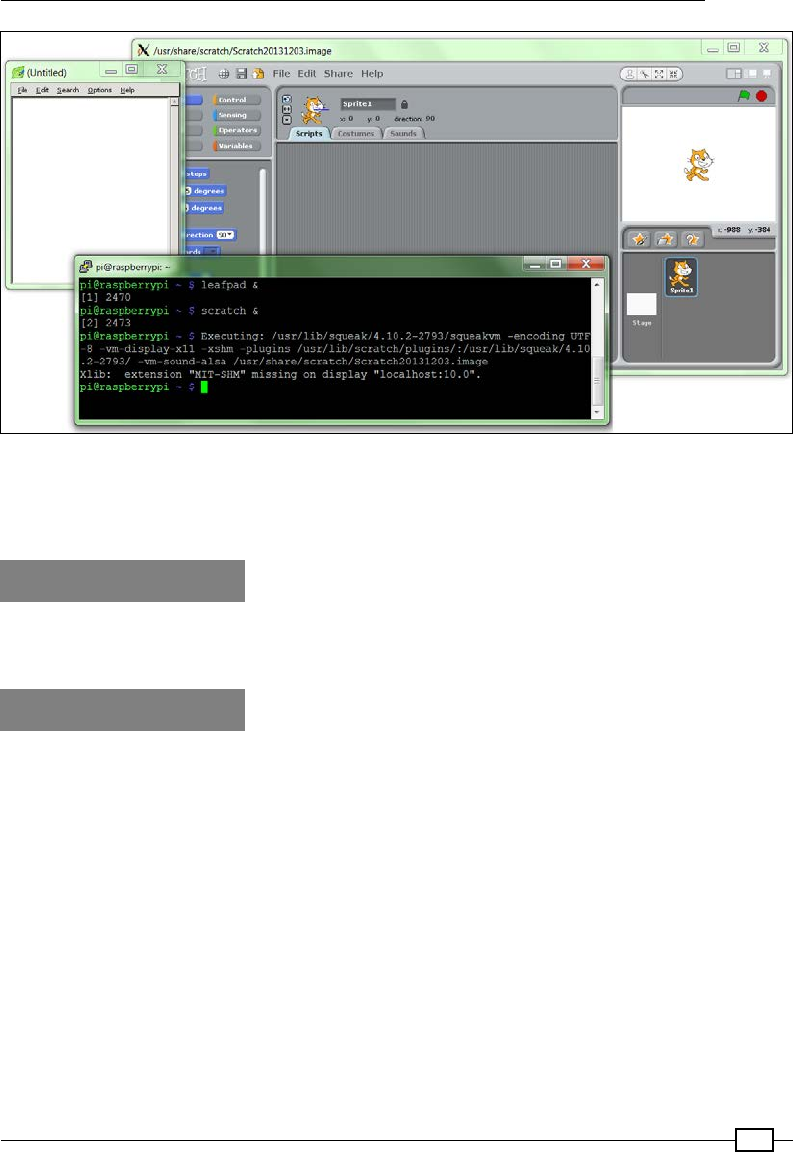
Chapter 1
51
X11 Forwarding on a local display
X Forwarding can be used to display applications, which are running on the Raspberry Pi, on a
Windows computer.
Getting ready
If you are running the latest version of Raspbian, SSH and X11 Forwarding will be enabled by
default (otherwise, double-check the settings explained in the How it works… section).
How to do it…
Linux and OS X have built-in support for X11 Forwarding; but if you are using Windows, you will
need to install and run the X Windows server on your computer.
Download and run xming from the Xming site (http://sourceforge.net/projects/
xming/).
Install xming, following the installation steps, including the installation of PuTTY if you don't
have it already. You can also download PuTTY separately from http://www.putty.org/.
Next, we need to ensure that the SSH program we use has X11 enabled when we connect.
For Windows, we shall use PuTTY to connect to the Raspberry Pi.
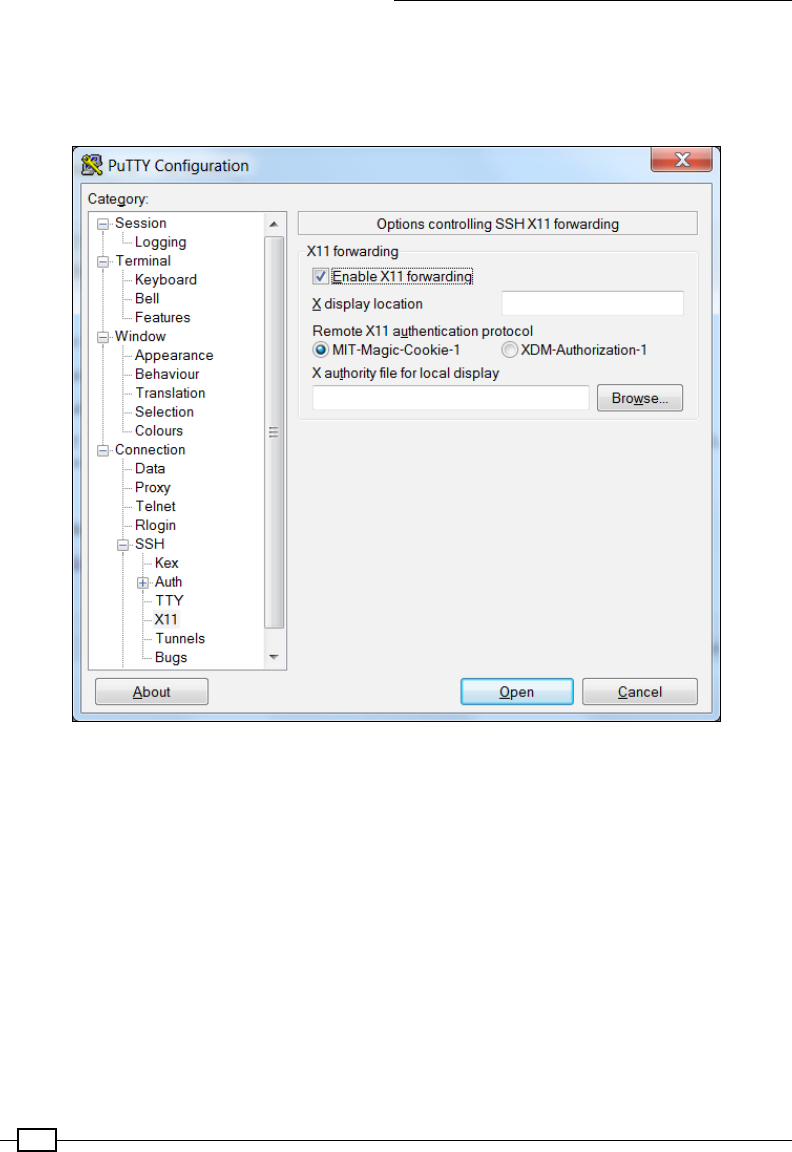
Getting Started with a Raspberry Pi Computer
52
In the PuTTY Conguration dialog box, navigate to Connection | SSH | X11 and tick the
checkbox for X11 Forwarding. If you leave the X display location option blank, it will assume
the default Server 0:0 as follows (you can conrm the server number by moving your
mouse over the Xming icon in the system tray when it is running):
Enabling X11 Forwarding within the PuTTY configuration
Enter the IP address of the Raspberry Pi in the Session settings (you may also nd that you
can use the Raspberry Pi's hostname here instead; the default hostname is raspberrypi).
Save the setting using a suitable name, RaspberryPi, and click on Open to connect to your
Raspberry Pi.
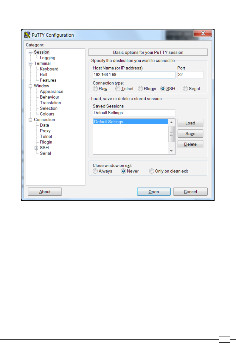
Chapter 1
53
You are likely to see a warning message pop up stating you haven't connected to the computer
before (this allows you to check whether you have everything right before continuing).
Opening an SSH connection to the Raspberry Pi using PuTTY
For OS X or Linux, click on Terminal to open a connection to the Raspberry Pi.
To connect with the default pi username, with an IP address of 192.168.1.69, use the
following command; the -X option enables X11 Forwarding:
ssh -X pi@192.168.1.69
All being well, you should be greeted with a prompt for your password (remember the default
value for the pi user is raspberry).
Ensure that you have Xming running by starting the Xming program from your computer's Start
menu. Then, in the terminal window, type a program that normally runs within the Raspberry
Pi desktop, such as leafpad or scratch. Wait a little while and the program should appear
on your computer's desktop (if you get an error, you have probably forgotten to start Xming, so
run it and try again).
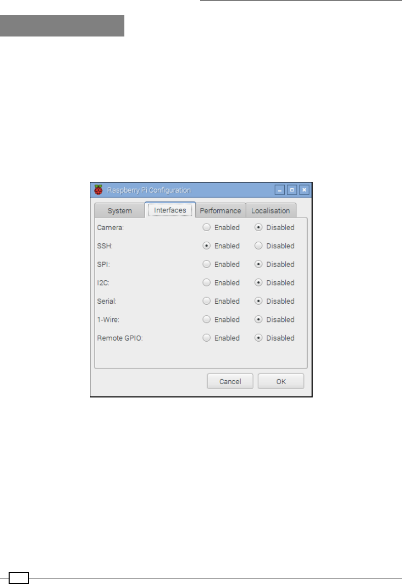
Getting Started with a Raspberry Pi Computer
54
How it works…
X Windows and X11 is what provides the method by which the Raspberry Pi (and many other
Linux-based computers) can display and control graphical Windows as part of a desktop.
For X11 Forwarding to work over a network connection, we need both SSH and X11
Forwarding enabled on the Raspberry Pi. Perform the following steps:
1. To switch on (or off) SSH, you can access the Raspberry Pi Conguration
program under the Preferences menu on the Desktop and click on SSH within
the Interfaces tab, as shown in the following screenshot (SSH is often enabled by
default for most distributions to help allow remote connections without needing a
monitor to congure it):
The Interfaces tab in the Raspberry Pi Configuration tool
2. Ensure that X11 Forwarding is enabled on the Raspberry Pi (again most distributions
now have this enabled by default).
3. Use nano with the following command:
sudo nano /etc/ssh/sshd_config
4. Look for a line in the /etc/ssh/sshd_config le that controls X11 Forwarding and
ensure that it says yes (with no # sign before it), as follows:
X11Forwarding yes

Chapter 1
55
5. Save if required by pressing Ctrl + X, Y, and Enter and reboot (if you need to change
it) as follows:
sudo reboot
There's more…
SSH and X 11 Forwarding is a convenient way to control the Raspberry Pi remotely; we will
explore some additional tips on how to use it effectively in the following sections.
Running multiple programs with X11 Forwarding
If you want to run an X program, but still be able to use the same terminal console for other
stuff, you can run the command in the background with & as follows:
leafpad &
Just remember that the more programs you run, the slower everything will get. You can switch
to the background program by typing fg and check for background tasks with bg.
Running as a desktop with X11 Forwarding
You can even run a complete desktop session through X11, although it isn't particularly
user-friendly and VNC will produce better results. To achieve this, you have to use lxsession
instead of startx (in the way you would normally start the desktop from the terminal).
An alternative is to use lxpanel, which provides the program menu bar from which you can
start and run programs from the menu as you would on the desktop.
Running PyGame and Tkinter with X11 Forwarding
You can get the following error (or similar) when running the PyGame or Tkinter scripts:
_tkinter.TclError: couldn't connect to display "localhost:10.0"
In this case, use the following command to x the error:
sudo cp ~/.Xauthority ~root/
Sharing the home folder of the Raspberry Pi
with SMB
When you have the Raspberry Pi connected to your network, you can access the home folder
by setting up le sharing; this makes it much easier to transfer les and provides a quick and
easy way to back up your data. Server Message Block (SMB) is a protocol that is compatible
with Windows le sharing, OS X, and Linux.

Getting Started with a Raspberry Pi Computer
56
Getting ready
Ensure that you have the Raspberry Pi powered and running with a working connection to
the Internet.
You will also need another computer on the same local network to test the new share.
How to do it…
First, we need to install samba, a piece of software that handles folder sharing in a format
that is compatible with Windows sharing methods.
Ensure that you use update as follows to obtain the latest list of available packages:
sudo apt-get update
sudo apt-get install samba
The install will require around 20 MB of space and take a few minutes.
Once the install has completed, we can make a copy of the conguration le as follows to
allow us to restore to defaults if needed:
sudo cp /etc/samba/smb.conf /etc/samba/smb.conf.backup
sudo nano /etc/samba/smb.conf
Scroll down and nd the section named Authentication; change the # security =
user line to security = user.
As described in the le, this setting ensures that you have to enter your username and
password for the Raspberry Pi in order to access the les (this is important for shared
networks).
Find the section called Share Definitions and [homes], and change the read only =
yes line to read only = no.
This will allow us to view and also write les to the shared home folder. Once done, save and
exit by pressing Ctrl + X, Y, and Enter.
If you have changed the default user from pi to something else,
substitute it in the following instructions.
Now, we can add pi (the default user) to use samba:
sudo pdbedit -a -u pi

Chapter 1
57
Now, enter a password (you can use the same password as your login or select a different
one, but avoid using the default Raspberry password, which would be very easy for someone
to guess). Restart samba to use the new conguration le, as follows:
sudo /etc/init.d/samba restart
[ ok ] Stopping Samba daemons: nmbd smbd.
[ ok ] Starting Samba daemons: nmbd smbd.
In order to test, you will need to know either the Raspberry Pi's hostname (the default
hostname is raspberrypi) or its IP address. You can nd both of these with the
following command:
hostname
For the IP address, add -I:
hostname –I
On another computer on the network, enter the \\raspberrypi\pi address in the
explorer path.
Depending on your network, the computer should locate the Raspberry Pi on the network and
prompt for a username and password. If it can't nd the share using the hostname, you
can use the IP address directly, where 192.168.1.69 should be changed to match the
IP address \\192.168.1.69\pi.
Keeping the Raspberry Pi up to date
The Linux image used by the Raspberry Pi is often updated to include enhancements, xes,
and improvements to the system, as well as adding support for new hardware or changes
made to the latest board. Many of the packages that you install can be updated too.
This is particularly important if you plan on using the same system image on another
Raspberry Pi board (particularly a newer one) as older images will lack support for any wiring
changes or alternative RAM chips. New rmware should work on older Raspberry Pi boards,
but older rmware may not be compatible with the latest hardware.
Fortunately, you need not reash your SD card every time there is a new release, since you
can update it instead.
Getting ready
You will need to be connected to the Internet in order to update your system. It is always
advisable to make a backup of your image rst (and at a minimum, take a copy of your
important les).

Getting Started with a Raspberry Pi Computer
58
You can check your current version of rmware with the uname -a command, as follows:
Linux raspberrypi 4.4.9-v7+ #884 SMP Fri May 6 17:28:59 BST 2016 armv7l
GNU/Linux
The GPU rmware can be checked using the /opt/vc/bin/vcgencmd version command,
as follows:
May 6 2016 13:53:23
Copyright (c) 2012 Broadcom
version 0cc642d53eab041e67c8c373d989fef5847448f8 (clean) (release)
This is important if you are using an older version of firmware (pre-
November 2012) on a newer board since the original Model B board was only
254 MB RAM. Upgrading allows the firmware to make use of the extra memory
if available.
The free -h command will detail the RAM available to the main processor (the total RAM is
split between the GPU and ARM cores) and will give the following output:
total used free shared buffers cached
Mem: 925M 224M 701M 7.1M 14M 123M
-/+ buffers/cache: 86M 839M
Swap: 99M 0B 99M
You can then recheck the preceding output following a reboot to conrm that they have been
updated (although they may have already been the latest).
How to do it…
Before running any upgrades or installing any packages, it is worth ensuring you have the
latest list of packages in the repository. The update command gets the latest list of available
software and versions:
sudo apt-get update
If you just want to obtain an upgrade of your current packages, upgrade will bring them all up
to date:
sudo apt-get upgrade
To ensure that you are running the latest release of Raspbian, you can run dist-upgrade
(be warned; this can take an hour or so depending on the amount that needs to be upgraded).
This will perform all the updates that upgrade will perform but will also
remove redundant packages and clean up:
sudo apt-get dist-upgrade

Chapter 1
59
Both methods will upgrade the software, including the rmware used at boot and startup
(bootcode.bin and start.elf).
There's more…
You will often nd that you will want to perform a clean installation of your setup; however,
this will mean you will have to install everything from scratch. To avoid this, I developed the
Pi-Kitchen project (https://github.com/PiHw/Pi-Kitchen), based on the groundwork
of Kevin Hill. This aims to provide a exible platform for creating customized setups that can
be automatically deployed to an SD card.
Pi Kitchen allows the Raspberry Pi be configured before powering up
The Pi-Kitchen allows a range of avors to be congured, which can be selected from the
NOOBS menu. Each avor consists of a list of recipes, each providing a specic function or
feature to the nal operating system. Recipes can range from setting up custom drivers for
Wi-Fi devices, to mapping shared drives on your network, to providing a fully functional web
server out of the box, all combining to make your required setup.
This project is in beta, developed as a proof of concept, but once you have everything
congured, it can be incredibly useful to deploy fully working setups directly onto an SD card.
Ultimately, the project could be combined with Kevin Hill's advanced version of NOOBS, called
PINN (short for PINN Is Not NOOBS), which aims to allow extra features for advanced users,
such as allowing operating systems and congurations to be stored on your network or on an
external USB memory stick.

61
Starting with Python
Strings, Files,
and Menus
In this chapter, we will cover the following topics:
fWorking with text and strings
fUsing les and handling errors
fCreating a boot-up menu
fCreating a self-dening menu
Introduction
In this chapter, we discuss how to use Python to perform some basic encryption by scrambling
letters. This will introduce some basic string manipulation, user input, progressing on to
creating reusable modules, and graphical user interfaces.
To follow, we will create some useful Python scripts that can be added to run as the
Raspberry Pi boots or an easy-to-run command that will provide quick shortcuts to common or
frequently-used commands. Taking this further, we will make use of threading to run multiple
tasks and introduce classes to dene multiple objects.
As it is customary to start any programming exercise with a Hello World example, we will kick
off with that now.
2
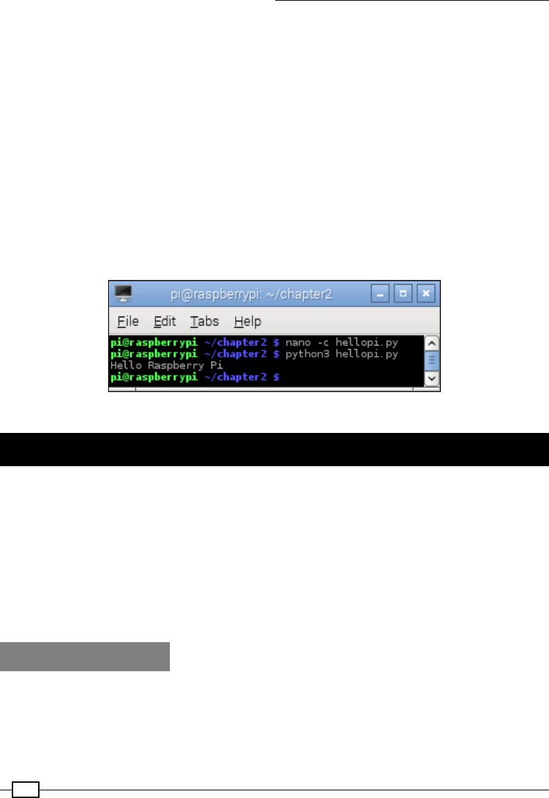
Starting with Python Strings, Files, and Menus
62
Create the hellopi.py le using nano, as follows:
nano -c hellopi.py
Within our hellopi.py le, add the following code:
#!/usr/bin/python3
#hellopi.py
print ("Hello Raspberry Pi")
When done, save and exit (Ctrl + X, Y, and Enter). To run the le, use the following command:
python3 hellopi.py
Congratulations, you have created your rst program!
Your result should be similar to the following screenshot:
The Hello Raspberry Pi output
Working with text and strings
A good starting point for Python is to gain an understanding of basic text handling and strings.
A string is a block of characters stored together as a value. As you will learn, they can be
viewed as a simple list of characters.
We will create a script to obtain the user's input, use string manipulation to switch around
the letters, and print out a coded version of the message. We will then extend this example
by demonstrating how encoded messages can be passed between parties without revealing
the encoding methods, while also showing how to reuse sections of the code within other
Python modules.
Getting ready
You can use most text editors to write Python code. They can be used directly on the
Raspberry Pi or remotely through VNC or SSH.
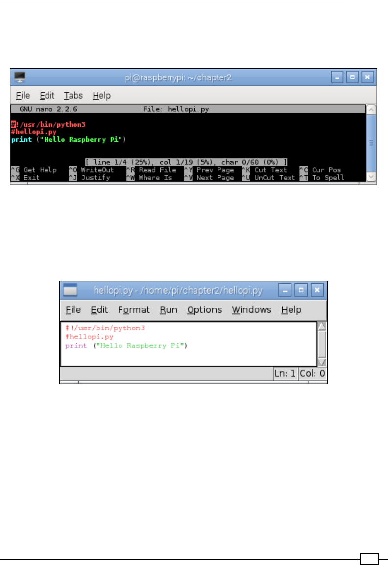
Chapter 2
63
The following are a few text editors that are available with the Raspberry Pi:
fnano: This text editor is available at the terminal and includes syntax highlighting and
line numbers (with the -c option). Refer to the following screenshot:
The nano command-line editor
fIDLE3: This Python editor includes the syntax highlighting feature, context help,
and will run scripts directly from the editor (on pressing F5). This program requires
X-Windows (the Debian desktop) or X11-forwarding to run remotely. We will be using
Python 3 throughout the book, so ensure that you run IDLE3 (rather than IDLE), which
will use Python 3 to run the scripts, as shown in the following screenshot:
The IDLE3 Python editor
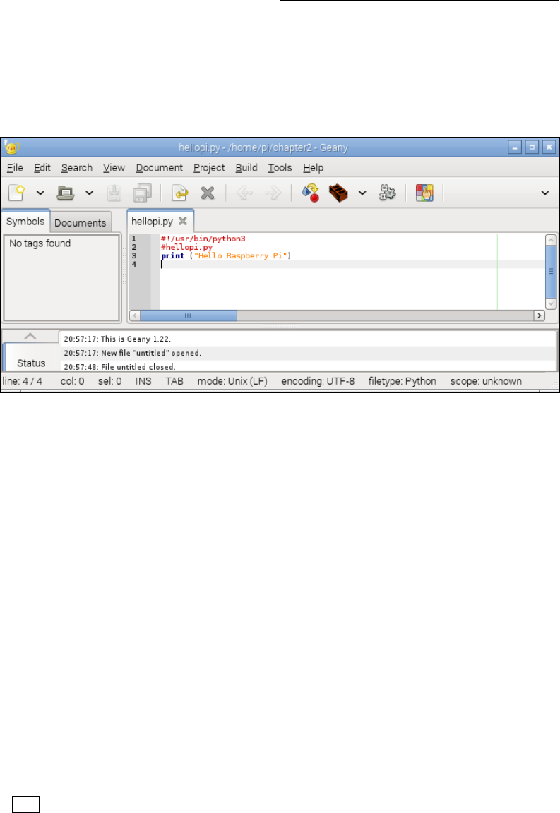
Starting with Python Strings, Files, and Menus
64
fGeany: This text editor provides an Integrated Development Environment (IDE) that
supports a range of programming languages, syntax highlighting, auto completion,
and easy code navigation. This is a feature-rich editor, but can be difcult to use for
beginners and may sometimes be slow when running on the Raspberry Pi. Again, you
will need to run this editor with the Debian desktop or X11-forwarding. Refer to the
following screenshot:
The Geany IDE
To install Geany, use the following command and then run Geany from the
Programming menu item:
sudo apt-get install geany
To ensure Geany uses Python 3 when you click on the Execute button (to run your
scripts), you will need to change the build commands. Load hellopi.py and
then click on the Build menu and select Set Build Commands. In the window that
appears, as shown in the following screenshot, change python to python3 in the
Compile and Execute sections. Python is always compiled automatically when it
is run (producing the temporary .pyc les), so you don't need to use the Compile
button, except maybe to check the syntax of the code:
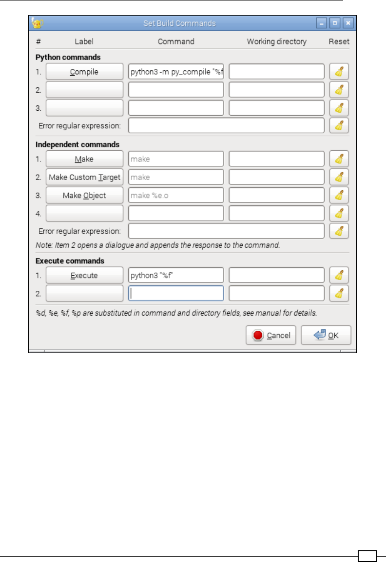
Chapter 2
65
The Geany Build command settings for Python 3
If you have the home directory of the Raspberry Pi shared across the network (refer to Sharing
the home folder of the Raspberry Pi with SMB recipe in Chapter 1, Getting Started with a
Raspberry Pi Computer), you can edit les on another computer. However, note that if you use
Windows, you must use an editor that supports Linux line endings, such as Notepad++ (you
should not use the standard Notepad program).
To create a space for your Python scripts, we will add a python_scripts folder to your home
directory with the following command:
mkdir ~/python_scripts
Starting with Python Strings, Files, and Menus
66
Now you can open this folder and list the les whenever you need to, using the following
commands:
cd ~/python_scripts
ls
You can use the Tab key to help complete commands in the terminal,
for example, typing cd ~/pyt and then pressing the Tab key will nish
the command for you. If there are multiple options that start with pyt,
pressing the Tab key again will list them.
To repeat or edit older commands, use the up and down arrow keys to
switch between older and newer commands as required.
How to do it…
Create the encryptdecrypt.py script as follows:
#!/usr/bin/python3
#encryptdecrypt.py
#Takes the input_text and encrypts it, returning the result
def encryptText(input_text,key):
input_text=input_text.upper()
result = ""
for letter in input_text:
#Ascii Uppercase 65-90 Lowercase 97-122 (Full range 32-126)
ascii_value=ord(letter)
#Exclude non-characters from encryption
if (ord("A") > ascii_value) or (ascii_value > ord("Z")):
result+=letter
else:
#Apply encryption key
key_value = ascii_value+key
#Ensure we just use A-Z regardless of key
if not((ord("A")) < key_val < ord("Z")):
key_val = ord("A")+(key_val-ord("A"))\
%(ord("Z")-ord("A")+1)
#Add the encoded letter to the result string
result+=str(chr(key_value))
return result
#Test function
def main():
Chapter 2
67
print ("Please enter text to scramble:")
#Get user input
try:
user_input = input()
scrambled_result = encryptText(user_input,10)
print ("Result: " + scrambled_result)
print ("To un-scramble, press enter again")
input()
unscrambled_result = encryptText(scrambled_result,-10)
print ("Result: " + unscrambled_result)
except UnicodeDecodeError:
print ("Sorry: Only ASCII Characters are supported")
main()
#End
Within the There's more… section of this recipe, we will change main()
to the following code:
if __name__=="__main__":
main()
If you want to skip the section, ensure that you include this change in the
encryptdecrypt.py le, as we will use it later.
How it works…
The preceding script implements a very basic method to scramble the text using a simple form
of character substitution called the Caesar cipher. Named after the Roman emperor Julius
Caesar, who originally used this method to send secret orders to his armies.
The le denes two functions, encryptText() and main().
When the script is running, the main() function obtains the user's input using the input()
command. The result is stored as a string in the user_input variable (the command will wait
until the user has pressed the Enter key before continuing), as follows:
user_input = input()
The input() function will not handle non-ASCII characters, so we use try…
except to handle this case, which will cause UnicodeDecodeError to
be raised. For more information about using try…except, refer to the Using
les and handling errors recipe of this chapter.

Starting with Python Strings, Files, and Menus
68
We will call the encryptText() function with two arguments, the text to be encrypted, and
the key. After the text has been encrypted, the result is printed:
scrambled_result = encryptText(user_input,10)
print ("Result: " + scrambled_result)
Finally, we will use input() to wait for the user input again (in this case, a prompt to press
Enter; any other input is ignored). Now, we will unscramble the text by reversing the encryption
by calling encryptText() again, but with a negative version of the key, and displaying the
result, which should be the original message.
The encryptText() function performs a simple form of encryption by taking the letters
in the message and substituting each letter with another in the alphabet (determined by
counting from the number of letters specied by the encryption key). In this way, the letter A
will become C when the encryption key is 2.
To simplify the process, the function converts all characters to uppercase. This allows us to
use the ASCII character set to translate each character into numbers easily; the letter A is
represented by 65 and Z by 90. This is achieved with input_text=input_text.upper()
and then by using ord(letter) to convert to an ASCII value, which gives us a number
representation of the character. ASCII is a standard that maps the numbers 0 to 254 (an 8-bit
value) and commonly used characters and symbols:
A B C D E F G H I J K L M
65 66 67 68 69 70 71 72 73 74 75 76 77
N O P Q R S T U V W X Y Z
78 79 80 81 82 83 84 85 86 87 88 89 90
ASCII table for upper case letters
Next, we will ensure that we have an empty string where we can build our result (result =
"") and we will also set our encryption key to our key value.
The input_text variable contains our string, which is stored as a list (this is similar to an
array) of letters. We can access each item in the list using input_text[0] for the rst item
and so on; however, Python also allows us to loop through a list using for…in, accessing
each item in turn.
The for letter in input_text: line allows us to break up input_text by looping
through it for each item inside (in this case, the letters in the string) and also setting the
letter equal to that item. So if input_text equaled HELLO, it would run all the code that is
indented under the command ve times; each time, the letter variable would be set to H,
E, L, L, and nally O. This allows us to read each letter separately, process it, and add the new
encrypted letter to the result string.

Chapter 2
69
The next part, if (ord("A") > ascii_value) or (ascii_value > ord("Z")):,
checks to see if the character we are looking at is not between A and Z, which means it is
probably a number or punctuation mark. In this case, we will exclude the character from the
encryption (passing the character directly to the result string unchanged).
If the letter is between A and Z, we can add the value of our encryption key to the value of our
letter to obtain our new encoded letter. That is, for an encryption key of 10, we end up with
the following set of letters in the output:
Input Letter: A B C D E F G H I J K L M N O P Q R S T U V W X Y Z
Output Letter: K L M N O P Q R S T U V W X Y Z A B C D E F G H I J
As we want the encrypted message to be easy to write out, we have limited the output to
be between A and Z. So, if the letter starts as X, we want to it to wrap around and continue
counting from A. We can achieve this by using the % (modulus) function, which gives us the
remainder value if we divide a number by another. So, if X is 24 and we add 10, we get 34.
The value of 34%26 (where 26 is the total number of letters) is 8. Counting 8 from A, we
reach H.
However, in ASCII, the letter A is the number 65, so we will remove this offset from key_
value and then add it back once we have the modulus value. The following code ensures
that we limit the ASCII values to be between A and Z:
#Ensure we just use A-Z regardless of key
if not((ord("A")) < key_value < ord("Z")):
key_value = ord("A")+(key_value-ord("A"))\
%(ord("Z")-ord("A")+1)
Essentially, if the value is not between the values for A or Z, then we will allow the value to
wrap around (by calculating the modulus using the total number of letters between A and Z,
which is 26). This also works if the key is larger than 26 and if we are counting the opposite
way too, for instance, if the encryption key was negative, and therefore, the decryption key
positive.
Finally, we can convert key_value back into a letter by using the chr() and str()
functions and adding it to the result string.
Note that we use \ to split the code into another line, it doesn't affect the
calculation. Python can be very fussy about splitting lines, in some cases
you can nd a natural break in the code and separate the line with a
carriage return, however other times we have to force a line break using the
\ symbol.
Of course, given very little time, such a simple encryption method could easily be broken.
Remember that there are only 25 possible combinations to choose from before the result of
the encryption is repeated (multiples of 26 will result in no encryption at all).
Starting with Python Strings, Files, and Menus
70
There's more…
You can try this simple experiment. Currently, with this basic form of encryption, you will
supply the method and key to anyone you wish to read your message. However, what happens
if you want to send a secure transmission without sending the method and key?
The answer is to send the same message back and forth three times as demonstrated in the
following diagram:
We do not need to exchange encryption keys with the other person
The rst time, we will encrypt it and send it over to the other party. They will then encrypt it
again with their own encryption and send it back. The message at this stage has two layers
of encryption applied to it. We can now remove our encryption and return it. Finally, they will
receive the message with just their encryption, which they can remove and read the message.
Just remember that there are only 25 useful encryption combinations with the Caesar cipher,
so it is possible that they could decrypt the message by accident.
We can make use of our previous le as a module using the import command as follows:
import encryptdecrypt as ENC

Chapter 2
71
This will allow access to any function inside the encryptdecrypt le using ENC as the
reference. When such a le is imported, it will run any code that would normally be run; in this
case, the main() function.
To avoid this, we can change the call to main() only to occur when
the le is run directly.
If the le is run directly, Python will set __name__ to the "__main__" global attribute. By
using the following code, we can reuse the functions in this Python script in other scripts
without running any other code:
if __name__=="__main__":
main()
Create the keypassing.py script using the following code in the same directory as
encryptdecrypt.py:
#!/usr/bin/python3
#keypassing.py
import encryptdecrypt as ENC
KEY1 = 20
KEY2 = 50
print ("Please enter text to scramble:")
#Get user input
user_input = input()
#Send message out
encodedKEY1 = ENC.encryptText(user_input,KEY1)
print ("USER1: Send message encrypted with KEY1 (KEY1): " +
encodedKEY1)
#Receiver encrypts the message again
encodedKEY1KEY2 = ENC.encryptText(encodedKEY1,KEY2)
print ("USER2: Encrypt with KEY2 & returns it (KEY1+KEY2): " +
encodedKEY1KEY2)
#Remove the original encoding
encodedKEY2 = ENC.encryptText(encodedKEY1KEY2,-KEY1)
print ("USER1: Removes KEY1 & returns with just KEY2 (KEY2): " +
encodedKEY2)
#Receiver removes their encryption
message_result = ENC.encryptText(encodedKEY2,-KEY2)
print ("USER2: Removes KEY2 & Message received: " + message_result)
#End

Starting with Python Strings, Files, and Menus
72
On running the preceding script, we can see that the other person doesn't need to know the
encryption key that we are using, and anyone who intercepts the message will not be able to
see its contents. The script produces the following output:
Please enter text to scramble:
"A message to a friend."
USER1: Send message encrypted with KEY1 (KEY1): U GYMMUAY NI U ZLCYHX.
USER2: Encrypt with KEY2 & returns it (KEY1+KEY2): S EWKKSYW LG S XJAWFV.
USER1: Removes KEY1 & returns with just KEY2 (KEY2): Y KCQQYEC RM Y
DPGCLB.
USER2: Removes KEY2 & Message received: A MESSAGE TO A FRIEND.
This method is known as the three-pass protocol, developed by Adi Shamir in 1980
(http://en.wikipedia.org/wiki/Three-pass_protocol). One particular
disadvantage of this method is that it is possible for a third party to intercept the messages
(the so-called man-in-the-middle attack) and characterize the encryption method by inserting
known values and analyzing the responses.
Using les and handling errors
In addition to easy string handling, Python allows you to read, edit, and create les easily. So,
by building upon the previous scripts, we can make use of our encryptText() function to
encode complete les.
Reading and writing to les can be quite dependent on factors that are outside of the direct
control of the script, such as whether the le that we are trying to open exists or the lesystem
has space to store a new le. Therefore, we will also take a look at how to handle exceptions
and protect operations that may result in errors.
Getting ready
The following script will allow you to specify a le through the command line, which will be
read and encoded to produce an output le. Create a small text le named infile.txt
and save it so that we can test the script. It should include a short message similar to
the following:
This is a short message to test our file encryption program.
How to do it…
Create the fileencrypt.py script using the following code:
#!/usr/bin/python3
#fileencrypt.py

Chapter 2
73
import sys #Imported to obtain command line arguments
import encryptdecrypt as ENC
#Define expected inputs
ARG_INFILE=1
ARG_OUTFILE=2
ARG_KEY=3
ARG_LENGTH=4
def covertFile(infile,outfile,key):
#Convert the key text to an integer
try:
enc_key=int(key)
except ValueError:
print ("Error: The key %s should be an integer value!" % (key))
#Code put on to two lines
else:
try:
#Open the files
with open(infile) as f_in:
infile_content=f_in.readlines()
except IOError:
print ("Unable to open %s" % (infile))
try:
with open(outfile,'w') as f_out:
for line in infile_content:
out_line = ENC.encryptText(line,enc_key)
f_out.writelines(out_line)
except IOError:
print ("Unable to open %s" % (outfile))
print ("Conversion complete: %s" % (outfile))
finally:
print ("Finish")
#Check the arguments
if len(sys.argv) == ARG_LENGTH:
print ("Command: %s" %(sys.argv))
covertFile(sys.argv[ARG_INFILE], sys.argv[ARG_OUTFILE], sys.
argv[ARG_KEY])
else:
print ("Usage: fileencrypt.py infile outfile key")
#End

Starting with Python Strings, Files, and Menus
74
To run the script, use the following command (here, infile can be any text le we want to
encrypt, outfile is our encrypted version, and key is the key value we wish to use):
python3 fileencrypt.py infile outfile key
For example, to encrypt infile.txt and output it as encrypted.txt using 30 as the key,
use the following command:
python3 fileencrypt.py infile.txt encrypted.txt 30
To view the result, use less encrypted.txt. Press Q to exit.
To decrypt encrypted.txt and output it as decrypted.txt using -30 as the key, use the
following command:
python3 fileencrypt.py encrypted.txt decrypted.txt -30
To view the result, use less decrypted.txt. Press Q to exit.
How it works…
The script requires us to use arguments that are provided on the command line. We will
access them by importing the Python module called sys. Just like we did earlier, we will also
import our encryptdecrypt module using the import command. We will use the as part to
allow us to reference it using ENC.
Next, we will set values to dene what each command-line argument will represent. When you
run it, you will see that sys.argv[] is a list of values shown in the following array:
['fileencrypt.py', 'infile.txt', 'encrypted.txt', '30']
So, the input le is at the index 1 in the list (indexing always starts at 0), then the output le,
and nally, the key, with the total number of arguments being ARG_LENGTH=4.
Next, we will dene the convertFile() function, which we will call in a minute from the next
block of code.
To avoid errors, we will check whether the length of the sys.argv value matches the
expected number of arguments from the command line. This will ensure that the user has
supplied us with enough, and we don't try to reference items in the sys.argv[] list that
don't exist. Otherwise, we will return a short message explaining what we are expecting.
We will now call the convertFile() function using the command-line values and making
use of Python's built-in exception handling features to ensure that errors are responded to
accordingly.
The try…except code allows you to try running some code and handle any exceptions
(errors) within the program itself, rather than everything coming to a sudden stop.

Chapter 2
75
The try code is accompanied by the following four optional sections:
fexcept ValueError: – When an error occurs, a specic type of exception can be
specied and handled with the action, depending on the error we wish to handle (that
is, for ValueError, we could check whether the value is a oat value and convert
it to an integer or prompt for a new one). Multiple exceptions can be caught using
except (ValueError,IOError) as required.
fexcept: – This is a catch-all case where any other exceptions that we haven't
handled can be dealt with. For situations where the code may be called from other
places, we may also want to raise the exception again using the raise command
so that it can be dealt with by other parts of the program (for instance, as part of the
GUI, we can warn the user that the input was not correct without needing to do so at
this stage). Typically, you should either deal with a specic exception or ensure that
you raise it again so that the particular error is visible on a failure; if not handled at
all, Python will report it on the terminal along with the trace to the function where
it occurred.
felse: – This section of code is always executed if the try code was successful and
there was no exception raised; however, any errors in this code will not be handled by
the try…except section it is part of.
ffinally: – This code is always executed, regardless of whether an exception was
raised or the try code ran without problems.
If you are familiar with other languages, you will nd try…except similar to try…catch, and
raise and throw as equivalents. Dealing with exceptions can be quite an art form; however,
making your code able to handle problems gracefully and effectively is all part of good
design. In many cases, catching the situations where things go wrong is just as important as
performing the intended function successfully.
If there is no problem with converting the key argument into an integer, we will continue to
open the input le specied and read the contents into the infile_content list. This will
contain the contents of the le split into separate lines as a list.
In this example, we will use a slightly different method to display values within
the print statement.
Consider the following code as an example:
print ("Error: The key %s should be an integer value!" %(key))
This allows us to use the %s symbol to determine where the key value is
printed and also to specify the format (%s is a string). For numerical values,
such as oats and integers, we can use %d to display integers, %f for oats,
or even %.4f to limit the value to four decimal places.

Starting with Python Strings, Files, and Menus
76
You may have noticed that we opened the le using the with…as…: section. This is a special
way to open a le, which will ensure that it is closed once it has nished (even if there is an
error). Refer to the following code:
try:
#Open the files
with open(infile) as f_in:
infile_content=f_in.readlines()
except IOError:
print ("Unable to open %s" % (infile))
This is equivalent to the following:
try:
f_in = open(infile)
try:
infile_content=f_in.readlines()
finally:
f_in.close()
except IOError:
print ("Unable to open %s" % (infile))
If there is an exception in opening the le (if it doesn't exist, for example, it will raise
IOError), we can ag to the user that there was a problem with the lename/path provided.
We will also use except: on its own to deal with any other problems that we may have with
the le, such as the encoding type or non-text based les.
Next, we will open a le for our output using 'w' to open it as a writable le. If it doesn't exist,
it will create a new le; otherwise, it will overwrite the le. We will also have the option to
append to the le instead, using 'a'. We will step through each item in infile_content,
converting each line by passing it through our ENC.encryptText() function and writing the
line to the f_out le. Once again, when we nish the with…as…: section, the le is closed
and the conversion is complete.
Creating a boot-up menu
We will now apply the methods introduced in the previous scripts and reapply them to create a
menu that we can customize to present a range of quick-to-run commands and programs.

Chapter 2
77
How to do it…
Create the menu.py script using the following code:
#!/usr/bin/python3
#menu.py
from subprocess import call
filename="menu.ini"
DESC=0
KEY=1
CMD=2
print ("Start Menu:")
try:
with open(filename) as f:
menufile = f.readlines()
except IOError:
print ("Unable to open %s" % (filename))
for item in menufile:
line = item.split(',')
print ("(%s):%s" % (line[KEY],line[DESC]))
#Get user input
running = True
while(running):
user_input = input()
#Check input, and execute command
for item in menufile:
line = item.split(',')
if (user_input == line[KEY]):
print ("Command: " + line[CMD])
#call the script
#e.g. call(["ls", "-l"])
commands = line[CMD].rstrip().split()
print (commands)
running = False
#Only run command is one if available
if len(commands):
call(commands)
if (running==True):
print ("Key not in menu.")
print ("All Done.")
#End

Starting with Python Strings, Files, and Menus
78
Create a menu.ini le that will contain the following menu items and commands:
Start Desktop,d,startx
Show IP Address,i,hostname -I
Show CPU speed,s,cat /sys/devices/system/cpu/cpu0/cpufreq/scaling_cur_
freq
Show Core Temperature,t,sudo /opt/vc/bin/vcgencmd measure_temp
Exit,x,
You can add your own commands to the list, creating your own custom start-up menu. The script
will assume the menu.ini le is formatted correctly, so if you experience an error (for example
ErrorIndex) it may be because the le is not as expected (such as missing commas or blank
lines). We could use except ErrorIndex: to handle any errors, however we are better off
highlighting there is a problem within the input le so that it can be xed instead.
How it works…
In order to execute other programs from within a Python script, we need to use the call
command. This time, we only wish to use the call part of the subprocess module, so we
can simply use from subprocess import call. This just imports the part we need.
We will open the le and read all the lines into a menufile list. We can then process each
item (or line of the le) using item.split(','), which will create a new list consisting of
each section of the line divided by the ',' symbol, as follows:
line = ['Start Desktop', 'd', 'startx\n']
As shown by the print statement, we can now access each section independently, so we can
print the key we need to press for a specic command and the description of the command.
Once we have printed the entire menu of commands, we will wait for the user's input. This is
done inside a while loop; it will continue to run until we set the condition inside running
to False. This means that if an invalid key is pressed, we can enter another key until a
command is selected or the exit item is used. We will then check the input key to see if it
matches the allocated key for the menu item, as follows:
user_input == line[KEY]
If there is a match, we will extract the command we wish to call. The call command
requires a command and its arguments to be a list, so we will use .split() to break up the
command part into a list (where each space in the command is a new item in the list). Also
note that there is /n after startx, this is the end of the line character from the menu.ini
le. We will remove this rst using .rstrip(), which removes any whitespace (spaces, tabs,
or line endings) from the end of a string.

Chapter 2
79
Once the command is formatted into a list of arguments, we will set running to False (so
the while loop will not enter another loop), execute our command, and nish the script. If
the user selects x, there will be no commands set, allowing us to exit the menu without calling
anything. The script produces a small menu of options, as shown in the following:
Start Menu:
(d):Start Desktop
(i):Show IP Address
(s):Show CPU speed
(t):Show Core Temperature
(x):Exit
g
Key not in menu.
i
Command: hostname -I
['hostname', '-I']
All Done.
There's more…
To make the script run each time, we will start the Raspberry Pi; we can call it from
.bash_profile, which is a bash script that runs when the user's prole is loaded.
Create or edit the le as follows:
nano -c ~/.bash_profile
Add the following commands (assuming menu.py is located in the /home/pi/python_
scripts directory):
cd /home/pi/python_scripts
python3 menu.py
When done, save and exit (Ctrl + X, Y, and Enter).
The next time you power up your Raspberry Pi, you will have a menu to run your favorite
commands from, without needing to remember them.

Starting with Python Strings, Files, and Menus
80
You can also run Python scripts directly, without the python3 command,
making them executable, as follows:
chmod +x menu.py
Now type ./menu.py and the script will run using the program dened
within the le by the rst line, as follows:
#!/usr/bin/python3
Creating a self-dening menu
While the previous menu is very useful for dening the most common commands and
functions we may use when running the Raspberry Pi, we will often change what we are doing
or develop scripts to automate complex tasks.
To avoid the need to continuously update and edit the menu.ini le, we can create a menu
that can list the installed scripts and dynamically build a menu from it, as shown in the
following screenshot:
A menu of all the Python scripts in the current directory
How to do it…
Create the menuadv.py script using the following code:
#!/usr/bin/python3
#menuadv.py
import os
from subprocess import call
SCRIPT_DIR="." #Use current directory
SCRIPT_NAME=os.path.basename(__file__)
print ("Start Menu:")

Chapter 2
81
scripts=[]
item_num=1
for files in os.listdir(SCRIPT_DIR):
if files.endswith(".py"):
if files != SCRIPT_NAME:
print ("%s:%s"%(item_num,files))
scripts.append(files)
item_num+=1
running = True
while (running):
print ("Enter script number to run: 1-%d (x to exit)" %
(len(scripts)))
run_item = input()
try:
run_number = int(run_item)
if len(scripts) >= run_number > 0:
print ("Run script number:" + run_item)
commands = ["python3",scripts[run_number-1]]
print (commands)
call(commands)
running = False
except ValueError:
#Otherwise, ignore invalid input
if run_item == "x":
running = False
print ("Exit")
#End
How it works…
This script allows us to take a different approach. Rather than predening a list of commands
or applications, we can simply keep a folder of useful scripts and scan it to create a list to pick
from. In this case, the menu will just list Python scripts and call them without any command-
line options.
To be able to access the list of les in a directory, we can use the os module's
os.listdir() function. This function allows us to specify a directory and it will return a list
of the les and directories within it.
Using SCRIPT_DIR="." will allow us to search the current directory (the one the script
is being run from). We can specify an absolute path (that is, "//home/pi/python_
scripts"), a relative path (that is, "./python_scripts_subdirectory"), or navigate
from the current directory to others in the structure (that is, "../more_scripts", where the
.. symbol will move up a level from the current directory and then into the more_scripts
directory if it existed).
Starting with Python Strings, Files, and Menus
82
If the directory does not exist, an exception (OSError) will be raised.
Since this menu is intended to simply run and display the list, we are
better off letting the exception cause an error and stop the script. This will
encourage the user to x the directory rather than try to handle the error
(perhaps by prompting for another path each time). It will also be easier
for the user to locate and correct the path when the script isn't running.
We will also get the name of the script using os.path.basename(__file__), this allows
us to later exclude the menuadv.py script from the list options.
We will create an empty scripts list and ensure that we initialize item_num to 1. Now, we
will call os.listdir(SCRIPT_DIR) directly within a for…in loop so that we can process
each directory or lename returned by it. Next, we can check the end of each item using the
endswith() function (another useful string function), which allows us to look for a specic
ending to the string (in this case, the ending for Python scripts). At this point, we can also
exclude the menuadv.py script from the list, if found.
We print the name of the script along with item_num and add it to the script list, nally
incrementing item_num so that it is correct for the next item.
We will now prompt the user to enter the relevant script number (between 1 and the total
number of scripts) and wait for the user input from input(). The script will check for a
valid input. If it is a number, it will stay in the try section, and we can then check whether
the number is in the correct range (one of the listed script numbers). If correct, the script is
called using ['python3', 'scriptname.py'] and the call() function as before. If the
input is not a number (for example, x), it will raise the ValueError exception. Within the
ValueError exception, we can check whether x was pressed and exit the while loop by
setting running to False (otherwise, the loop will reprint the prompt and wait for new input).
The script is now complete.
You can adjust the preceding script to support other types of scripts, if
required. Simply add other le extensions, such as .sh, to the scripts
list and call using sh or bash instead of python3.
There's more…
We can extend this example further by placing all our useful scripts in a single place and
adding the menu script to the path.

Chapter 2
83
Alternative script locations
While not entirely necessary (by default, the script will look in the current directory), it will be
useful to create a suitable location to keep your scripts that you would like to use with the
menu. This can be a location within your home folder (~ is short for the home folder path,
which is /home/pi by default). An example is shown in the following command line:
mkdir ~/menupy
cd ~/menupy
To copy les, you can use cp sourcefile targetfile. If you use
the -r option, it will also create the directory if it doesn't exist. To move or
rename the les, use mv sourcefile targetfile. To delete the les,
use rm targetfile. You must use the -r option to delete a directory.
Just ensure that if the script is not within the same location, the path is updated for
SCRIPT_DIR to refer to the required location.
Adding scripts to PATH
As before, we could add this script to a start-up le, such as .bash_profile, and have
the menu appear when the user logs in to the Raspberry Pi. Alternatively, we can place such
scripts into a folder such as /home/pi/bin, in which we can include the global value call
PATH. The PATH settings are a list of directories that scripts and programs will check when
trying to locate a le that isn't in the current directory (typically, installed programs and
software, but also common conguration les and scripts).
This will allow us to run the script regardless of what directory we are currently in.
We can see the current PATH settings using the following command:
echo $PATH
/usr/local/sbin:/usr/local/bin:/usr/sbin:/usr/bin:/sbin:/bin:/usr/local/
games:/usr/games
The actual contents of the PATH setting will depend on the initial settings of the distribution
you are using and also on the applications you have installed.
If /home/pi/bin isn't included, we can temporarily add to this until the next boot with the
following command:
PATH=/home/pi/bin:$PATH
We can also add this to .bash_profile to set it every time for the current user, as follows:
PATH=$HOME/bin:$PATH
export PATH

Starting with Python Strings, Files, and Menus
84
The next time we reboot, the PATH settings will be (for a user with the name pi) as follows:
/home/pi/bin:/usr/local/sbin:/usr/local/bin:/usr/sbin:/usr/bin:/sbin:/
bin:/usr/local/games:/usr/games
When items are automatically located through PATH, it can be difcult
to nd a specic version of a le or program. To overcome this, use
whereis before the lename/command, and it will list all the locations
where it can be found.
Finally, if you do move the script to the bin directory, ensure that you update the path in
os.listdir("//home/pi/bin") to locate and list the scripts you wish to display in
the menu.

85
3
Using Python for
Automation and
Productivity
In this chapter, we will cover the following topics:
fUsing Tkinter to create graphical user interfaces
fCreating a graphical Start menu application
fDisplaying photo information in an application
fOrganizing your photos automatically
Introduction
Until now, we have focused purely on command-line applications; however, there is much
more to the Raspberry Pi than just the command line. By using graphical user interfaces
(GUIs), it is often easier to obtain input from a user and provide feedback in a more natural
way. After all, we continuously process multiple inputs and outputs all the time, so why limit
ourselves to the procedural format of the command line when we don't have to?

Using Python for Automation and Productivity
86
Fortunately, Python can support this. Much like other programming languages, such as Visual
Basic and C/C++/C#, this can be achieved using prebuilt objects that provide standard
controls. We will use a module called Tkinter which provides a good range of controls (also
referred to as widgets) and tools for creating graphical applications.
First, we will take our previous example, the encryptdecrypt.py module discussed in the
How to do it… section in the Working with text and strings recipe in Chapter 2, Starting with
Python Strings, Files, and Menus, and demonstrate how useful modules can be written and
reused in a variety of ways. This is a test of good coding practice. We should aim to write code
that can be tested thoroughly and then reused in many places.
Next, we will extend our previous examples by creating a small graphical Start menu
application to run our favorite applications from.
Then, we will explore using classes within our applications to display and then to
organize photos.
Using Tkinter to create graphical user
interfaces
We will create a small GUI to allow the user to enter information, and the program can then be
used to encrypt and decrypt it.
Getting ready
You will need to ensure that you have completed the instructions in the There's more… section
of the Working with text and strings recipe in Chapter 2, Starting with Python Strings, Files,
and Menus, where we created the reusable encryptdecrypt.py module. You must ensure
that this le is placed in the same directory as the following script.

Chapter 3
87
Since we are using Tkinter (one of many available add-ons of Python), we
need to ensure that it is installed. It should be installed by default on the
standard Raspbian image. We can conrm it is installed by importing it from
the Python prompt, as follows:
python3
>>> import tkinter
If it is not installed, an ImportError exception will be raised, in which case
you can install it using the following command (use Ctrl + Z to exit the Python
prompt):
sudo apt-get install python3-tk
If the module did load, you can use the following command to read more
about the module (use Q to quit when you are done reading):
>>>help(tkinter)
You can also get information about all the classes, functions, and methods
within the module using the following command:
>>>help(tkinter.Button)
The following dir command will list any valid commands or variables that are
in the scope of the module:
>>>dir(tkinter.Button)
You will see that our own modules will have the information about the
functions marked by triple quotes; this will show up if we use the help
command.
The command line will not be able to display the graphical displays created in this chapter,
so you will have to start the Raspberry Pi desktop (using the command startx), or if you are
using it remotely, ensure you have X11 Forwarding enabled and an X server running (see
Chapter 1, Getting Started with a Raspberry Pi Computer).
How to do it…
We will use the tkinter module to produce a GUI for the encryptdecrypt.py script we
wrote in the previous chapter.
To generate the GUI we will create the following tkencryptdecrypt.py script:
#!/usr/bin/python3
#tkencryptdecrypt.py
import encryptdecrypt as ENC
import tkinter as TK
def encryptButton():

Using Python for Automation and Productivity
88
encryptvalue.set(ENC.encryptText(encryptvalue.get(),
keyvalue.get()))
def decryptButton():
encryptvalue.set(ENC.encryptText(encryptvalue.get(),
-keyvalue.get()))
#Define Tkinter application
root=TK.Tk()
root.title("Encrypt/Decrypt GUI")
#Set control & test value
encryptvalue = TK.StringVar()
encryptvalue.set("My Message")
keyvalue = TK.IntVar()
keyvalue.set(20)
prompt="Enter message to encrypt:"
key="Key:"
label1=TK.Label(root,text=prompt,width=len(prompt),bg='green')
textEnter=TK.Entry(root,textvariable=encryptvalue,
width=len(prompt))
encryptButton=TK.Button(root,text="Encrypt",command=encryptButton)
decryptButton=TK.Button(root,text="Decrypt",command=decryptButton)
label2=TK.Label(root,text=key,width=len(key))
keyEnter=TK.Entry(root,textvariable=keyvalue,width=8)
#Set layout
label1.grid(row=0,columnspan=2,sticky=TK.E+TK.W)
textEnter.grid(row=1,columnspan=2,sticky=TK.E+TK.W)
encryptButton.grid(row=2,column=0,sticky=TK.E)
decryptButton.grid(row=2,column=1,sticky=TK.W)
label2.grid(row=3,column=0,sticky=TK.E)
keyEnter.grid(row=3,column=1,sticky=TK.W)
TK.mainloop()
#End
Run the script using the following command:
python3 tkencryptdecrypt
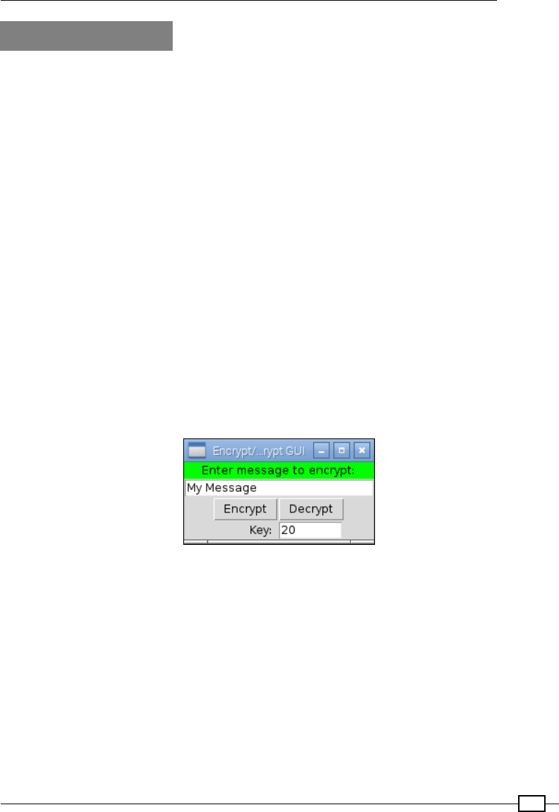
Chapter 3
89
How it works…
We start by importing two modules; the rst is our own encryptdecrypt module and the
second is the tkinter module. To make it easier to see which items have come from where,
we use ENC/TK. If you want to avoid the extra reference, you can use from <module_name>
import * to refer to the module items directly.
The encryptButton() and decryptButton() functions will be called when we click on
the Encrypt and Decrypt buttons; they are explained in the following sections.
The main Tkinter window is created using the Tk() command, which returns the main window
where all the widgets/controls can be placed.
We will dene six controls as follows:
fLabel: This displays the prompt Enter message to encrypt:
fEntry: This provides a textbox to receive the user's message to be encrypted
fButton: This is an Encrypt button to trigger the message to be encrypted
fButton: This is a Decrypt button to reverse the encryption
fLabel: This displays the Key: eld to prompt the user for an encryption key value
fEntry: This provides a second textbox to receive values for the encryption keys
These controls will produce a GUI similar to the one shown in the following screenshot:
The GUI to encrypt/decrypt messages
Let's take a look at the rst label1 denition:
label1=TK.Label(root,text=prompt,width=len(prompt),bg='green')
All controls must be linked to the application window; hence, we have to specify our Tkinter
window root. The text used for the label is set by text; in this case, we have set it to a string
named prompt, which has been dened previously with the text we require. We also set the
width to match the number of characters of the message (while not essential, it provides a
neater result if we add more text to our labels later), and nally, we set the background color
using bg='green'.

Using Python for Automation and Productivity
90
Next, we dene the text Entry box for our message:
textEnter=TK.Entry(root,textvariable=encryptvalue,
width=len(prompt))
We will dene textvariable—a useful way to link a variable to the contents of the box—
which is a special string variable. We could access the text directly using textEnter.
get(), but we shall use a Tkinter StringVar() object instead to access it indirectly. If
required, this will allow us to separate the data we are processing from the code that handles
the GUI layout. The enycrptvalue variable automatically updates the Entry widget it is
linked to whenever the .set() command is used (and the .get() command obtains the
latest value from the Entry widget).
Next, we have our two Button widgets, Encrypt and Decrypt, as follows:
encryptButton=TK.Button(root,text="Encrypt",command=encryptButton)
decryptButton=TK.Button(root,text="Decrypt",command=decryptButton)
In this case, we can set a function to be called when the Button widget is clicked by setting
the command attribute. We can dene the two functions that will be called when each button
is clicked. In the following code snippet, we have the encryptButton() function, which
will set the encryptvalue StringVar that controls the contents of the rst Entry box.
This string is set to the result we get by calling ENC.encryptText() with the message
we want to encrypt (the current value of encryptvalue) and the keyvalue variable. The
decrypt() function is exactly the same, except we make the keyvalue variable negative to
decrypt the message:
def encryptButton():
encryptvalue.set(ENC.encryptText(encryptvalue.get(),
keyvalue.get()))
We then set the nal Label and Entry widgets in a similar way. Note that textvariable
can also be an integer (numerical value) if required, but there is no built-in check to ensure
that only numbers can be entered. You will get a ValueError exception when the .get()
command is used.
After we have dened all the widgets to be used in the Tkinter window, we have to set the
layout. There are three ways to dene the layout in Tkinter: place, pack, and grid.
The place layout allows us to specify the positions and sizes using exact pixel positions. The
pack layout places the items in the window in the order that they have been added in. The
grid layout allows us to place the items in a specic layout. It is recommended that you avoid
the place layout wherever possible since any small change to one item can have a knock-on
effect on the positions and sizes of all the other items; the other layouts account for this by
determining their positions relative to the other items in the window.
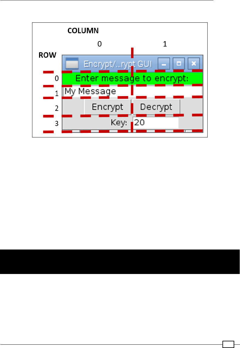
Chapter 3
91
We will place the items as laid out in the following screenshot:
Grid layout for the Encrypt/Decrypt GUI
The positions of rst two items in the GUI are set using the following code:
label1.grid(row=0,columnspan=2,sticky= TK.E+TK.W)
textEnter.grid(row=1,columnspan=2,sticky= TK.E+TK.W)
We can specify that the rst Label and Entry box will span both columns (columnspan=2),
and we can set the sticky values to ensure they span right to the edges. This is achieved by
setting both the TK.E for the east and TK.W for the west sides. We'd use TK.N for the north
and TK.S for the south sides if we needed to do the same vertically. If the column value is
not specied, the grid function defaults to column=0. The other items are similarly dened.
The last step is to call TK.mainloop(), which allows Tkinter to run; this allows the buttons to
be monitored for clicks and Tkinter to call the functions linked to them.
Creating a graphical application – Start
menu
The example in this recipe shows how we can dene our own variations of the Tkinter objects
to generate custom controls and dynamically construct a menu with them. We will also take a
quick look at using threads to allow other tasks to continue to function while a particular task
is being executed.

Using Python for Automation and Productivity
92
Getting ready
To view the GUI display, you will need a monitor displaying the Raspberry Pi desktop, or need
to be connected to another computer running the X server.
How to do it…
To create a graphical Start menu application, create the following graphicmenu.py script:
#!/usr/bin/python3
# graphicmenu.py
import tkinter as tk
from subprocess import call
import threading
#Define applications ["Display name","command"]
leafpad = ["Leafpad","leafpad"]
scratch = ["Scratch","scratch"]
pistore = ["Pi Store","pistore"]
app_list = [leafpad,scratch,pistore]
APP_NAME = 0
APP_CMD = 1
class runApplictionThread(threading.Thread):
def __init__(self,app_cmd):
threading.Thread.__init__(self)
self.cmd = app_cmd
def run(self):
#Run the command, if valid
try:
call(self.cmd)
except:
print ("Unable to run: %s" % self.cmd)
class appButtons:
def __init__(self,gui,app_index):
#Add the buttons to window
btn = tk.Button(gui, text=app_list[app_index][APP_NAME],
width=30, command=self.startApp)
btn.pack()
self.app_cmd=app_list[app_index][APP_CMD]
def startApp(self):
print ("APP_CMD: %s" % self.app_cmd)
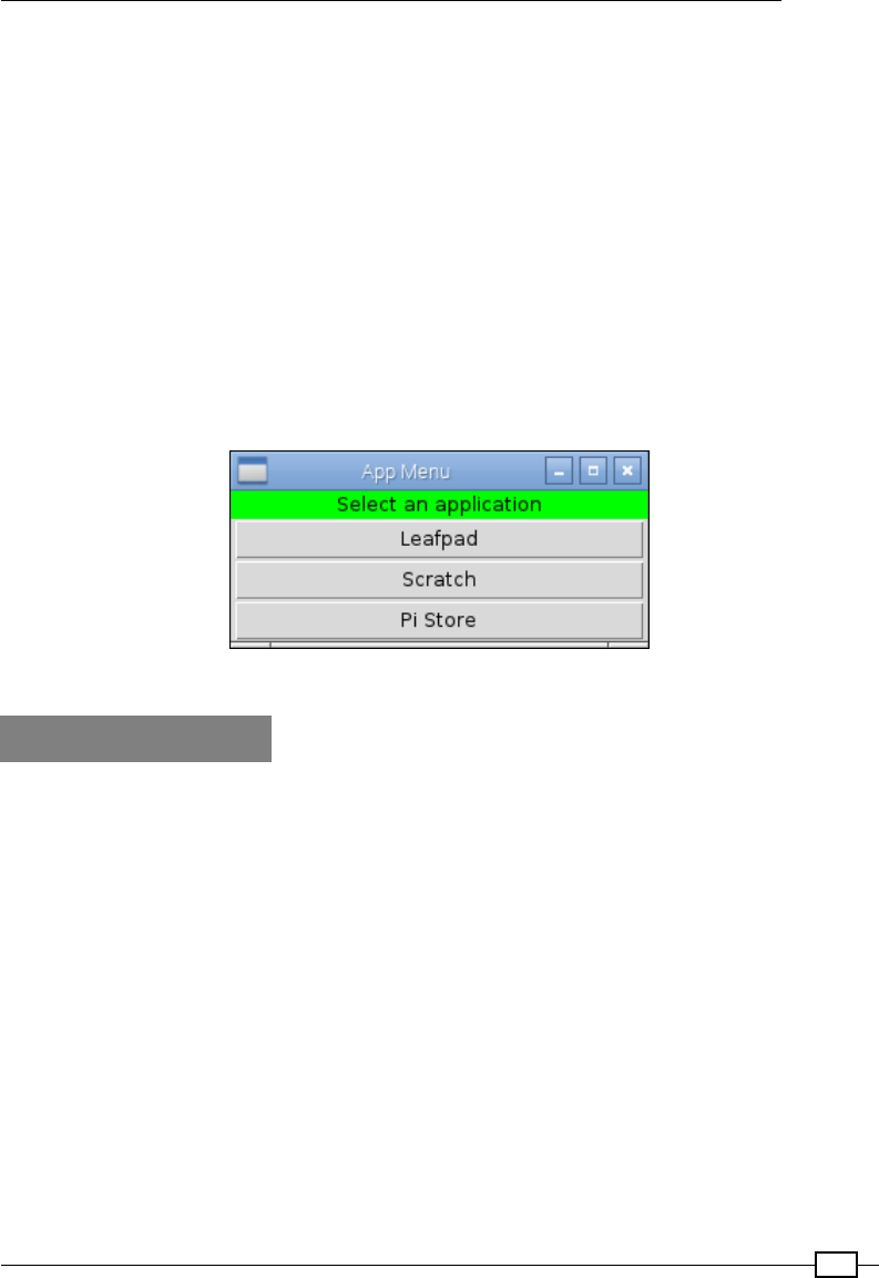
Chapter 3
93
runApplictionThread(self.app_cmd).start()
root = tk.Tk()
root.title("App Menu")
prompt = ' Select an application '
label1 = tk.Label(root, text=prompt, width=len(prompt), bg='green')
label1.pack()
#Create menu buttons from app_list
for index, app in enumerate(app_list):
appButtons(root,index)
#Run the tk window
root.mainloop()
#End
The previous code produces the following application:
The App Menu GUI
How it works…
We create the Tkinter window as we did before; however, instead of dening all the items
separately, we create a special class for the application buttons.
The class we create acts as a blueprint or specication of what we want the appButtons
items to include. Each item will consist of a string value for app_cmd, a function called
startApp(), and an __init__() function. The __init__() function is a special function
(called a constructor) that is called when we create an appButtons item; it will allow us to
create any setup that is required.
In this case, the __init__() function allows us to create a new Tkinter button with the text
to be set to an item in app_list and the command to be called in the startApp() function
when the button is clicked. The self keyword is used so that the command called will be the
one that is part of the item; this means that each button will call a locally dened function that
has access to the local data of the item.

Using Python for Automation and Productivity
94
We set the value of self.app_cmd to the command from app_list and make it ready for
use by the startApp() function. We now create the startApp() function. If we run the
application command here directly, the Tkinter window will freeze until the application we
have opened is closed again. To avoid this, we can use the Python Threading module, which
allows us to perform multiple actions at the same time.
The runApplicationThread() class is created using the threading.Thread class
as a template—this inherits all the features of the threading.Thread class in a new class.
Just like our previous class, we provide an __init__() function for this as well. We rst
call the __init__() function of the inherited class to ensure it is set up correctly, and then
we store the app_cmd value in self.cmd. After the runApplicationThread() function
has been created and initialized, the start() function is called. This function is part of
threading.Thread, which our class can use. When the start() function is called, it will
create a separate application thread (that is, simulate running two things at the same time),
allowing Tkinter to continue monitoring button clicks while executing the run() function
within the class.
Therefore, we can place the code in the run() function to run the required application
(using call(self.cmd)).
There's more…
One aspect that makes Python particularly powerful is that it supports the programming
techniques used in Object-Orientated Design (OOD). This is commonly used by modern
programming languages to help translate the tasks we want our program to perform into
meaningful constructs and structures in code. The principle of OOD lies in the fact that we
think of most problems consisting of several objects (a GUI window, a button, and so on)
that interact with each other to produce a desired result.
In the previous section, we found that we can use classes to create standardized objects that
can be reused multiple times. We created an appButton class, which generated an object
with all the features of the class, including its own personal version of app_cmd that will be
used by the startApp() function. Another object of the appButton type will have its own
unrelated [app_cmd] data that its startApp() function will use.
You can see that classes are useful to keep together a collection of related variables and
functions in a single object, and the class will hold its own data in one place. Having multiple
objects of the same type (class), each with their own functions and data inside them, results
in better program structure. The traditional approach would be to keep all the information in
one place and send each item back and forth for various functions to process; however, this
may become cumbersome in large systems.
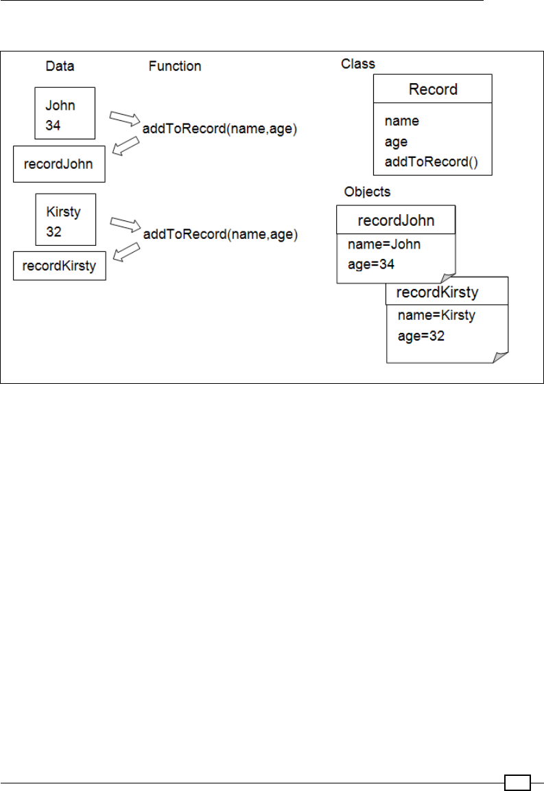
Chapter 3
95
The following diagram shows the organization of related functions and data:
Related functions and data can be organized into classes and objects
So far, we have used Python modules to separate parts of our programs into different
les; this allows us to conceptually separate different parts of the program (an interface,
encoder/decoder, or library of classes, such as Tkinter). Modules can provide code to
control a particular bit of hardware, dene an interface for the Internet, or provide a library
of common functionality; however, its most important function is to control the interface (the
collection of functions, variables, and classes that are available when the item is imported).
A well implemented module should have a clear interface that is centered around how it is
used, rather than how it is implemented. This allows you to create multiple modules that can
be swapped and changed easily since they share the same interface. In our previous example,
imagine how easy it would be to change the encryptdecrypt module for another one just
by supporting encryptText(input_text,key). Complex functionality can be split into
smaller, manageable blocks that can be reused in multiple applications.
Python makes use of classes and modules all the time. Each time you import a library, such
as sys or Tkinter, or convert a value using value.str() and iterate through a list using
for...in, you can use them without worrying about the details. You don't have to use
classes or modules in every bit of code you write, but they are useful tools to keep in your
programmer's toolbox for times when they t what you are doing.
We will understand how classes and modules allow us to produce well-structured code that is
easier to test and maintain by using them in the examples of this book.

Using Python for Automation and Productivity
96
Displaying photo information in an
application
In this example, we shall create a utility class to handle photos that can be used by other
applications (as a module) to access photo metadata and display preview images easily.
Getting ready
The following script makes use of Python Image Library (PIL); a compatible version for
Python 3 is Pillow.
Pillow has not been included in the Raspbian repository (used by apt-get); therefore, we will
need to install Pillow using a Python Package Manager called PIP.
To install packages for Python 3, we will use the Python 3 version of PIP (this requires 50 MB
of available space).
The following commands can be used to install PIP:
sudo apt-get update
sudo apt-get install python3-pip
Before you use PIP, ensure that you have installed libjpeg-dev to allow Pillow to handle
JPEG les. You can do this using the following command:
sudo apt-get install libjpeg-dev
Now you can install Pillow using the following PIP command:
sudo pip-3.2 install pillow
PIP also makes it easy to uninstall packages using uninstall instead of install.
Finally, you can conrm that it has installed successfully by running python3:
>>>import PIL
>>>help(PIL)
You should not get any errors and see lots of information about PIL and its uses (press Q to
nish). Check the version installed as follows:
>>PIL.PILLOW_VERSION
You should see 2.7.0 (or similar).

Chapter 3
97
PIP can also be used with Python 2 by installing pip-2.x using the following
command:
sudo apt-get install python-pip
Any packages installed using sudo pip install will be installed just
for Python 2.
How to do it…
To display photo information in an application, create the following photohandler.py script:
##!/usr/bin/python3
#photohandler.py
from PIL import Image
from PIL import ExifTags
import datetime
import os
#set module values
previewsize=240,240
defaultimagepreview="./preview.ppm"
filedate_to_use="Exif DateTime"
#Define expected inputs
ARG_IMAGEFILE=1
ARG_LENGTH=2
class Photo:
def __init__(self,filename):
"""Class constructor"""
self.filename=filename
self.filevalid=False
self.exifvalid=False
img=self.initImage()
if self.filevalid==True:
self.initExif(img)
self.initDates()
def initImage(self):
"""opens the image and confirms if valid, returns Image"""
try:
img=Image.open(self.filename)
self.filevalid=True
except IOError:

Using Python for Automation and Productivity
98
print ("Target image not found/valid %s" %
(self.filename))
img=None
self.filevalid=False
return img
def initExif(self,image):
"""gets any Exif data from the photo"""
try:
self.exif_info={
ExifTags.TAGS[x]:y
for x,y in image._getexif().items()
if x in ExifTags.TAGS
}
self.exifvalid=True
except AttributeError:
print ("Image has no Exif Tags")
self.exifvalid=False
def initDates(self):
"""determines the date the photo was taken"""
#Gather all the times available into YYYY-MM-DD format
self.filedates={}
if self.exifvalid:
#Get the date info from Exif info
exif_ids=["DateTime","DateTimeOriginal",
"DateTimeDigitized"]
for id in exif_ids:
dateraw=self.exif_info[id]
self.filedates["Exif "+id]=
dateraw[:10].replace(":","-")
modtimeraw = os.path.getmtime(self.filename)
self.filedates["File ModTime"]="%s" %
datetime.datetime.fromtimestamp(modtimeraw).date()
createtimeraw = os.path.getctime(self.filename)
self.filedates["File CreateTime"]="%s" %
datetime.datetime.fromtimestamp(createtimeraw).date()
def getDate(self):
"""returns the date the image was taken"""
try:
date = self.filedates[filedate_to_use]
except KeyError:

Chapter 3
99
print ("Exif Date not found")
date = self.filedates["File ModTime"]
return date
def previewPhoto(self):
"""creates a thumbnail image suitable for tk to display"""
imageview=self.initImage()
imageview=imageview.convert('RGB')
imageview.thumbnail(previewsize,Image.ANTIALIAS)
imageview.save(defaultimagepreview,format='ppm')
return defaultimagepreview
The previous code denes our Photo class; it is of no use to us until we run it in the There's
more… section and in the next example.
How it works…
We dene a general class called Photo; it contains details about itself and provides
functions to access Exchangeable Image File Format (EXIF) information and generate
a preview image.
In the __init__() function, we set values for our class variables and call self.
initImage(), which will open the image using the Image() function from the PIL. We then
call self.initExif() and self.initDates() and set a ag to indicate whether the le
was valid or not. If not valid, the Image() function would raise an IOError exception.
The initExif() function uses PIL to read the EXIF data from the img object, as shown in
the following code snippet:
self.exif_info={
ExifTags.TAGS[id]:y
for id,y in image._getexif().items()
if id in ExifTags.TAGS
}
The previous code is a series of compound statements that result in self.exif_info being
populated with a dictionary of tag names and their related values.
ExifTag.TAGS is a dictionary that contains a list of possible tag names linked with their IDs,
as shown in the following code snippet:
ExifTag.TAGS={
4096: 'RelatedImageFileFormat',
513: 'JpegIFOffset',
514: 'JpegIFByteCount',
40963: 'ExifImageHeight',
…etc…}

Using Python for Automation and Productivity
100
The image._getexif() function returns a dictionary that contains all the values set by the
camera of the image, each linked to their relevant IDs, as shown in the following code snippet:
Image._getexif()={
256: 3264,
257: 2448,
37378: (281, 100),
36867: '2016:09:28 22:38:08',
…etc…}
The for loop will go through each item in the image's EXIF value dictionary and check for its
occurrence in the ExifTags.TAGS dictionary; the result will get stored in self.exif_info.
The code for this is as follows:
self.exif_info={
'YResolution': (72, 1),
'ResolutionUnit': 2,
'ExposureMode': 0,
'Flash': 24,
…etc…}
Again, if there are no exceptions, we set a ag to indicate that the EXIF data is valid, or if there
is no EXIF data, we raise an AttributeError exception.
The initDates() function allows us to gather all the possible le dates and dates from
the EXIF data so that we can select one of them as the date we wish to use for the le. For
example, it allows us to rename all the images to a lename in the standard date format. We
create a self.filedates dictionary that we populate with three dates extracted from the
EXIF information. We then add the lesystem dates (created and modied) just in case no EXIF
data is available. The os module allows us to use os.path.getctime() and os.path.
getmtime() to obtain an epoch value of the le creation—it can also be the date and time
when the le was moved—and le modication—when it was last written to (for example,
it often refers to the date when the picture was taken). The epoch value is the number of
seconds since January 1, 1970, but we can use datetime.datetime.fromtimestamp()
to convert it into years, months, days, hours, and seconds. Adding date() simply limits it to
years, months, and days.
Now if the Photo class was to be used by another module, and we wished to know the
date of the image that was taken, we could look at the self.dates dictionary and pick
out a suitable date. However, this would require the programmer to know how the self.
dates values are arranged, and if we later changed how they are stored, it would break their
program. For this reason, it is recommended that we access data in a class through access
functions so the implementation is independent of the interfaces (this process is known as
encapsulation). We provide a function that returns a date when called; the programmer does
not need to know that it could be one of the ve available dates or even that they are stored
as epoch values. Using a function, we can ensure that the interface will remain the same no
matter how the data is stored or collected.

Chapter 3
101
Finally, the last function we want the Photo class to provide is previewPhoto(). This
function provides a method to generate a small thumbnail image and save it as a Portable
Pixmap Format (PPM) le. As we will discover in a moment, Tkinter allows us to place images
on its Canvas widget, but unfortunately, it does not support JPGs (and only supports GIF or
PPM) directly. Therefore, we simply save a small copy of the image we want to display in the
PPM format—with the added caveat that the image pallet must be converted to RGB too—and
then get Tkinter to load it onto the Canvas when required.
To summarize, the Photo class we have created is as follows:
Operations Description
__init__(self,filename) This is the object initialization function
initImage(self) This returns img, a PIL-type image object
initExif(self,image) This extracts all the EXIF information, if any is present
initDates(self) This creates a dictionary of all the dates available from
the file and photo information
getDate(self) This returns a string of the date when the photo was
taken/created
previewPhoto(self) This returns a string of the filename of the previewed
thumbnail
The properties and their respective descriptions are as follows:
Properties Description
self.filename The filename of the photo
self.filevalid This is set to True if the file is opened successfully
self.exifvalid This is set to True if the photo contains EXIF information
self.exif_info This contains the EXIF information from the photo
self.filedates This contains a dictionary of the available dates from the file and
photo information
To test the new class, we will create some test code to conrm that everything is working as
we expect; see the following section.
There's more…
We previously created the Photo class. Now we can add some test code to our module to
ensure that it functions as we expect. We can use the __name__ ="__main__" attribute
as before to detect whether the module has been run directly or not.
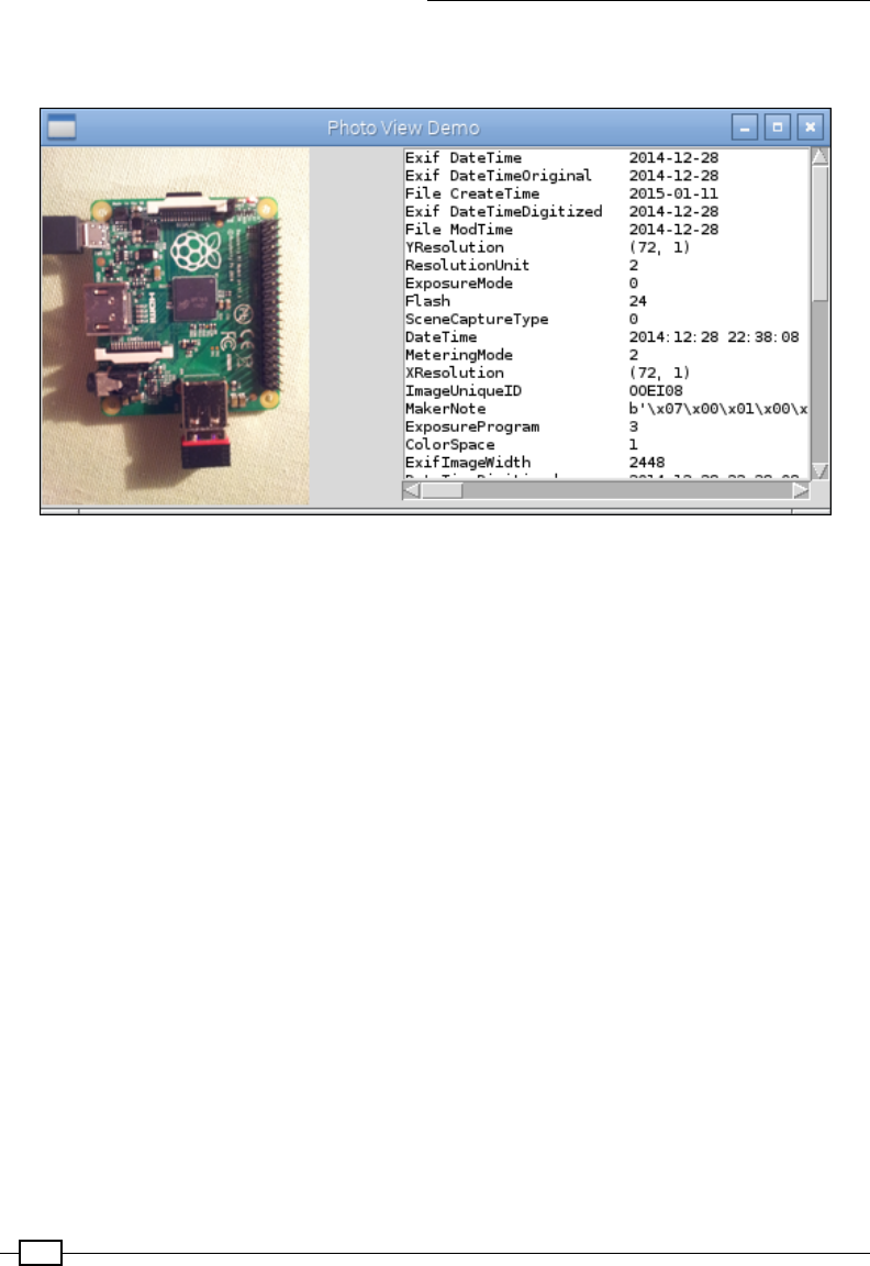
Using Python for Automation and Productivity
102
We can add the subsequent section of code at the end of the photohandler.py script to
produce the following test application, which looks as follows:
The Photo View Demo application
Add the following code at the end of photohandler.py:
#Module test code
def dispPreview(aPhoto):
"""Create a test GUI"""
import tkinter as TK
#Define the app window
app = TK.Tk()
app.title("Photo View Demo")
#Define TK objects
# create an empty canvas object the same size as the image
canvas = TK.Canvas(app, width=previewsize[0],
height=previewsize[1])
canvas.grid(row=0,rowspan=2)
# Add list box to display the photo data
#(including xyscroll bars)
photoInfo=TK.Variable()
lbPhotoInfo=TK.Listbox(app,listvariable=photoInfo,
height=18,width=45,
font=("monospace",10))
yscroll=TK.Scrollbar(command=lbPhotoInfo.yview,
orient=TK.VERTICAL)

Chapter 3
103
xscroll=TK.Scrollbar(command=lbPhotoInfo.xview,
orient=TK.HORIZONTAL)
lbPhotoInfo.configure(xscrollcommand=xscroll.set,
yscrollcommand=yscroll.set)
lbPhotoInfo.grid(row=0,column=1,sticky=TK.N+TK.S)
yscroll.grid(row=0,column=2,sticky=TK.N+TK.S)
xscroll.grid(row=1,column=1,sticky=TK.N+TK.E+TK.W)
# Generate the preview image
preview_filename = aPhoto.previewPhoto()
photoImg = TK.PhotoImage(file=preview_filename)
# anchor image to NW corner
canvas.create_image(0,0, anchor=TK.NW, image=photoImg)
# Populate infoList with dates and exif data
infoList=[]
for key,value in aPhoto.filedates.items():
infoList.append(key.ljust(25) + value)
if aPhoto.exifvalid:
for key,value in aPhoto.exif_info.items():
infoList.append(key.ljust(25) + str(value))
# Set listvariable with the infoList
photoInfo.set(tuple(infoList))
app.mainloop()
def main():
"""called only when run directly, allowing module testing"""
import sys
#Check the arguments
if len(sys.argv) == ARG_LENGTH:
print ("Command: %s" %(sys.argv))
#Create an instance of the Photo class
viewPhoto = Photo(sys.argv[ARG_IMAGEFILE])
#Test the module by running a GUI
if viewPhoto.filevalid==True:
dispPreview(viewPhoto)
else:
print ("Usage: photohandler.py imagefile")
if __name__=='__main__':
main()
#End

Using Python for Automation and Productivity
104
The previous test code will run the main() function, which takes the lename of a photo to
use and create a new Photo object called viewPhoto. If viewPhoto is opened successfully,
we will call dispPreview() to display the image and its details.
The dispPreview() function creates four Tkinter widgets to be displayed: a Canvas to load
the thumbnail image, a Listbox widget to display the photo information, and two scroll bars
to control the Listbox. First, we create a Canvas widget the size of the thumbnail image
(previewsize).
Next, we create photoInfo, which will be our listvariable parameter linked to the
Listbox widget. Since Tkinter doesn't provide a ListVar() function to create a suitable
item, we use the generic type TK.Variable() and then ensure we convert it to a tuple type
before setting the value. The Listbox widget gets added; we need to make sure that the
listvariable parameter is set to photoInfo and also set the font to monospace. This will
allow us to line up our data values using spaces, as monospace is a xed width font, so each
character takes up the same width as any other.
We dene the two scroll bars, linking them to the Listbox widget, by setting the Scrollbar
command parameters for vertical and horizontal scroll bars to lbPhotoInfo.yview and
lbPhotoInfo.xview. Then, we adjust the parameters of the Listbox using the following
command:
lbPhotoInfo.configure(xscrollcommand=xscroll.set,
yscrollcommand=yscroll.set)
The configure command allows us to add or change the widget's parameters after it has
been created, in this case linking the two scroll bars so the Listbox widget can also control
them if the user scrolls within the list.
As before, we make use of the grid layout to ensure that the Listbox widget has the two
scroll bars placed correctly next to it and the Canvas widget is to the left of the Listbox
widget.
We now use the Photo object to create the preview.ppm thumbnail le (using the aPhoto.
previewPhoto() function) and create a TK.PhotoImage object that can then be added to
the Canvas widget with the following command:
canvas.create_image(0,0, anchor=TK.NW, image=photoImg)
Finally, we use the date information that the Photo class gathers and the EXIF information
(ensuring it is valid rst) to populate the Listbox widget. We do this by converting each item
into a list of strings that are spaced out using .ljust(25)—it adds a left justication to
the name and pads it out to make the string 25 characters wide. Once we have the list, we
convert it to a tuple type and set the listvariable (photoInfo) parameter.
As always, we call app.mainloop() to start the monitoring for events to respond to.

Chapter 3
105
Organizing your photos automatically
Now that we have a class that allows us to gather information about photos, we can apply
this information to perform useful tasks. In this case, we will use the le information to
automatically organize a folder full of photos into a subset of folders based on the dates
the photos were taken on. The following screenshot shows the output of the script:
The application will use the photo's information to sort pictures into folders by the date on which they were taken
Getting ready
You will need a selection of photos placed in a folder on the Raspberry Pi. Alternatively, you
can insert a USB memory stick or a card reader with photos on it—they will be located in /
mnt/. However, please make sure you test the scripts with a copy of your photos rst, just in
case there are any problems.
How to do it…
Create the following script in filehandler.py to automatically organize your photos:
#!/usr/bin/python3
#filehandler.py
import os

Using Python for Automation and Productivity
106
import shutil
import photohandler as PH
from operator import itemgetter
FOLDERSONLY=True
DEBUG=True
defaultpath=""
NAME=0
DATE=1
class FileList:
def __init__(self,folder):
"""Class constructor"""
self.folder=folder
self.listFileDates()
def getPhotoNamedates(self):
"""returns the list of filenames and dates"""
return self.photo_namedates
def listFileDates(self):
"""Generate list of filenames and dates"""
self.photo_namedates = list()
if os.path.isdir(self.folder):
for filename in os.listdir(self.folder):
if filename.lower().endswith(".jpg"):
aPhoto = PH.Photo(os.path.join(self.folder,filename))
if aPhoto.filevalid:
if (DEBUG):print("NameDate: %s %s"%
(filename,aPhoto.getDate()))
self.photo_namedates.append((filename,
aPhoto.getDate()))
self.photo_namedates = sorted(self.photo_namedates,
key=lambda date: date[DATE])
def genFolders(self):
"""function to generate folders"""
for i,namedate in enumerate(self.getPhotoNamedates()):
#Remove the - from the date format
new_folder=namedate[DATE].replace("-","")
newpath = os.path.join(self.folder,new_folder)
#If path does not exist create folder
if not os.path.exists(newpath):

Chapter 3
107
if (DEBUG):print ("New Path: %s" % newpath)
os.makedirs(newpath)
if (DEBUG):print ("Found file: %s move to %s" %
(namedate[NAME],newpath))
src_file = os.path.join(self.folder,namedate[NAME])
dst_file = os.path.join(newpath,namedate[NAME])
try:
if (DEBUG):print ("File moved %s to %s" %
(src_file, dst_file))
if (FOLDERSONLY==False):shutil.move(src_file, dst_file)
except IOError:
print ("Skipped: File not found")
def main():
"""called only when run directly, allowing module testing"""
import tkinter as TK
from tkinter import filedialog
app = TK.Tk()
app.withdraw()
dirname = TK.filedialog.askdirectory(parent=app,
initialdir=defaultpath,
title='Select your pictures folder')
if dirname != "":
ourFileList=FileList(dirname)
ourFileList.genFolders()
if __name__=="__main__":
main()
#End
How it works…
We shall make a class called FileList; it will make use of the Photo class to manage
the photos within a specic folder. There are two main steps for this: we rst need to nd all
the images within the folder, and then generate a list containing both the lename and the
photo date. We will use this information to generate new subfolders and move the photos into
these folders.
When we create the FileList object, we will create the list using listFileDates(). We
will then conrm that the folder provided is valid and use os.listdir to obtain the full list
of les within the directory. We will check that each le is a .jpg le and obtain each photo's
date (using the function dened in the Photo class). Next, we will add the lename and date
as a tuple to the self.photo_namedates list.

Using Python for Automation and Productivity
108
Finally, we will use the built-in sorted function to place all the les in order of their date.
While we don't need to do this here, this function would make it easier to remove duplicate
dates if we were to use this module elsewhere.
The sorted function requires the list to be sorted, and in this case, we want
to sort it by the date values.
sorted(self.photo_namedates,key=lambda date: date[DATE])
We will substitute date[DATE] with lambda date: as the value to sort by.
Once the FileList object has been initialized, we can use it by calling genFolders().
First, we convert the date text into a suitable format for our folders (YYYYMMDD), allowing
our folders to be easily sorted in order of their date. Next, it will create the folders within
the current directory if they don't already exist. Finally, it will move each of the les into the
required subfolder.
We end up with our FileList class that is ready to be tested:
Operations Description
__init__(self,folder) This is the object initialization function
getPhotoNamedates(self) This returns a list of the filenames of the dates of the
photos
listFileDates(self) This creates a list of the filenames and dates of the
photos in the folder
genFolders(self) This creates new folders based on a photo's date and
moves the files into them
The properties are listed as follows:
Properties Description
self.folder The folder we are working with
self.photo_namedates This contains a list of the filenames and dates
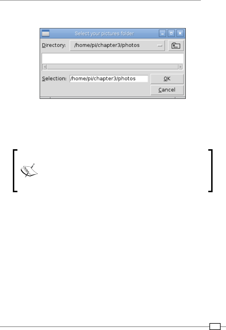
Chapter 3
109
The FileList class encapsulates all the functions and the relevant data together, keeping
everything in one logical place:
Tkinter filediaglog.askdirectory() is used to select the photo directory
To test this, we use the Tkinter filedialog.askdirectory() widget to allow us to select
a target directory of pictures. We use app.withdrawn() to hide the main Tkinter window
since it isn't required this time. We just need to create a new FileList object and then call
genFolders() to move all our photos to new locations!
Two additional ags have been dened in this script that provide an
extra control for testing. DEBUG allows us to enable or disable extra
debugging messages by setting them to either True or False.
Furthermore, from this, FOLDERSONLY when set to True only
generates the folders and doesn't move the les (this is helpful for
testing whether the new subfolders are correct).
Once you have run the script, you can check if all the folders have been created correctly.
Finally, change FOLDERSONLY to True, and your program will automatically move and
organize your photos according to their dates the next time. It is recommended that you
only run this on a copy of your photos, just in case you get an error.

111
4
Creating Games
and Graphics
In this chapter, we will cover the following topics:
fUsing IDLE3 to debug your programs
fDrawing lines using a mouse on a Tkinter Canvas
fCreating a bat and ball game
fCreating an overhead scrolling game
Introduction
Games are often a great way to explore and extend your programming skills as they present
an inherent motivating force to modify and improve your creation, add new features, and
create new challenges. They are also great for sharing your ideas with others, even if they
aren't interested in programming.
This chapter focuses on using the Tkinter Canvas widget to create and display objects on
screen for the user to interact with. Using these techniques, a wide variety of games and
applications can be created that are limited only by your own creativity.
We also take a quick look at using the debugger built into IDLE, a valuable tool for testing and
developing your programs without the need to write extensive test code.
The rst example demonstrates how we can monitor and make use of the mouse to create
objects and draw directly on the Canvas widget. Next, we create a bat and ball game, which
shows how the positions of objects can be controlled and how interactions between them can
be detected and responded to. Finally, we take things a little further and use Tkinter to place
our own graphics onto the Canvas widget to create an overhead view treasure hunt game.
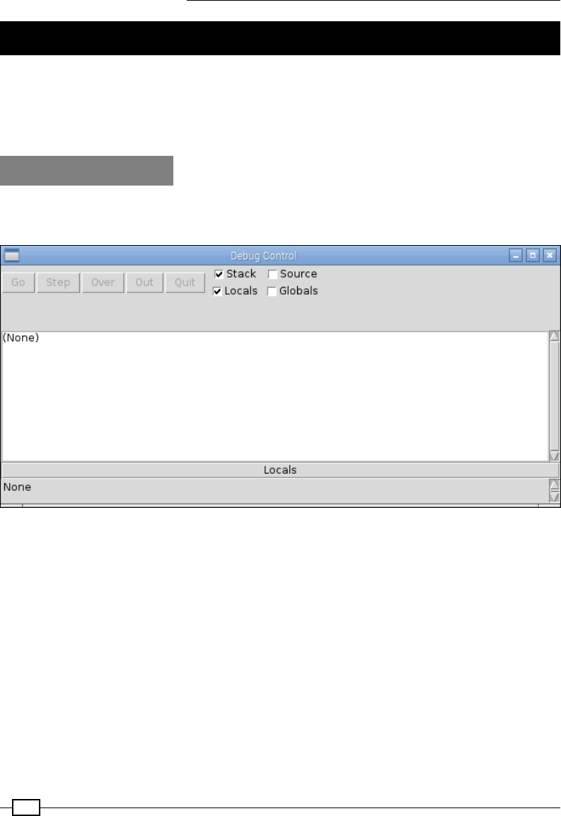
Creating Games and Graphics
112
Using IDLE3 to debug your programs
A key aspect of programming is being able to test and debug your code, and a useful tool to
achieve this is a debugger. The IDLE editor (make sure you use IDLE3 to support the Python 3
code we use in this book) includes a basic debugger. It allows you to step through your code,
observe the values of local and global variables, and set breakpoints.
How to do it…
To enable the debugger, start IDLE3 and select Debugger from the Debug menu; it will open
up the following window (if you are currently running some code, you will need to stop it rst):
The IDLE3 debugger window
Open up the code you want to test (via File | Open…) and try running it (F5). You will nd
that the code will not start, since the debugger has automatically stopped at the rst line.
The following screenshot shows the debugger has stopped on the rst line of code in
filehandler.py, which is line 3: import os:
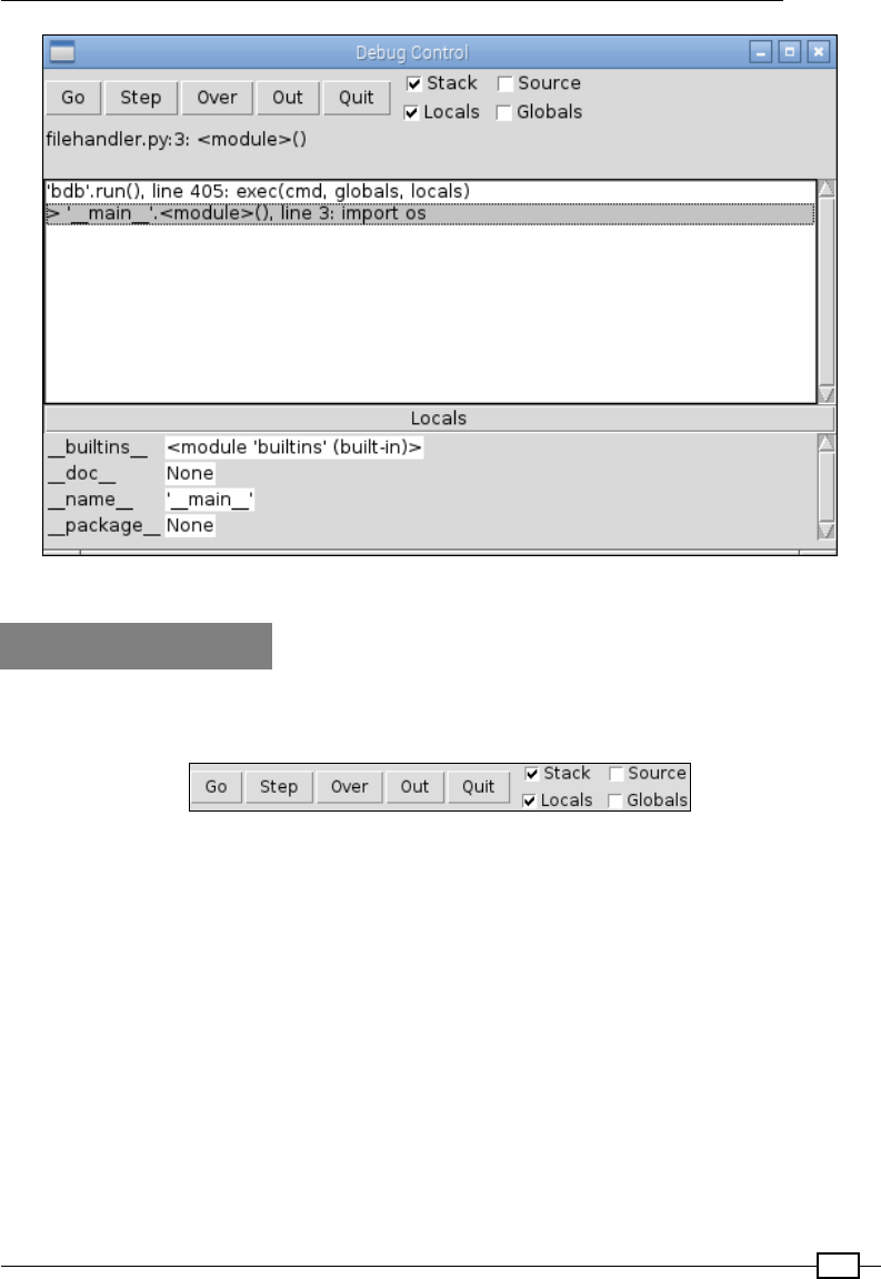
Chapter 4
113
The IDLE3 debugger at the start of the code
How it works…
The control buttons shown in the following screenshot allow you to run and/or jump through
the code:
Debugger controls
The functions of the control buttons are as follows:
fGo: This button will execute the code as normal.
fStep: This button will execute the line of code one step at a time and then stop again.
If a function is called, it will enter that function and allow you to step through that too.
fOver: This button is like the Step command, but if there is a function call, it will
execute the whole function and stop at the following line.
fOut: This button will keep executing the code until it has completed the function it is
currently in, continuing until you come out of the function.
fQuit: This button ends the program immediately.
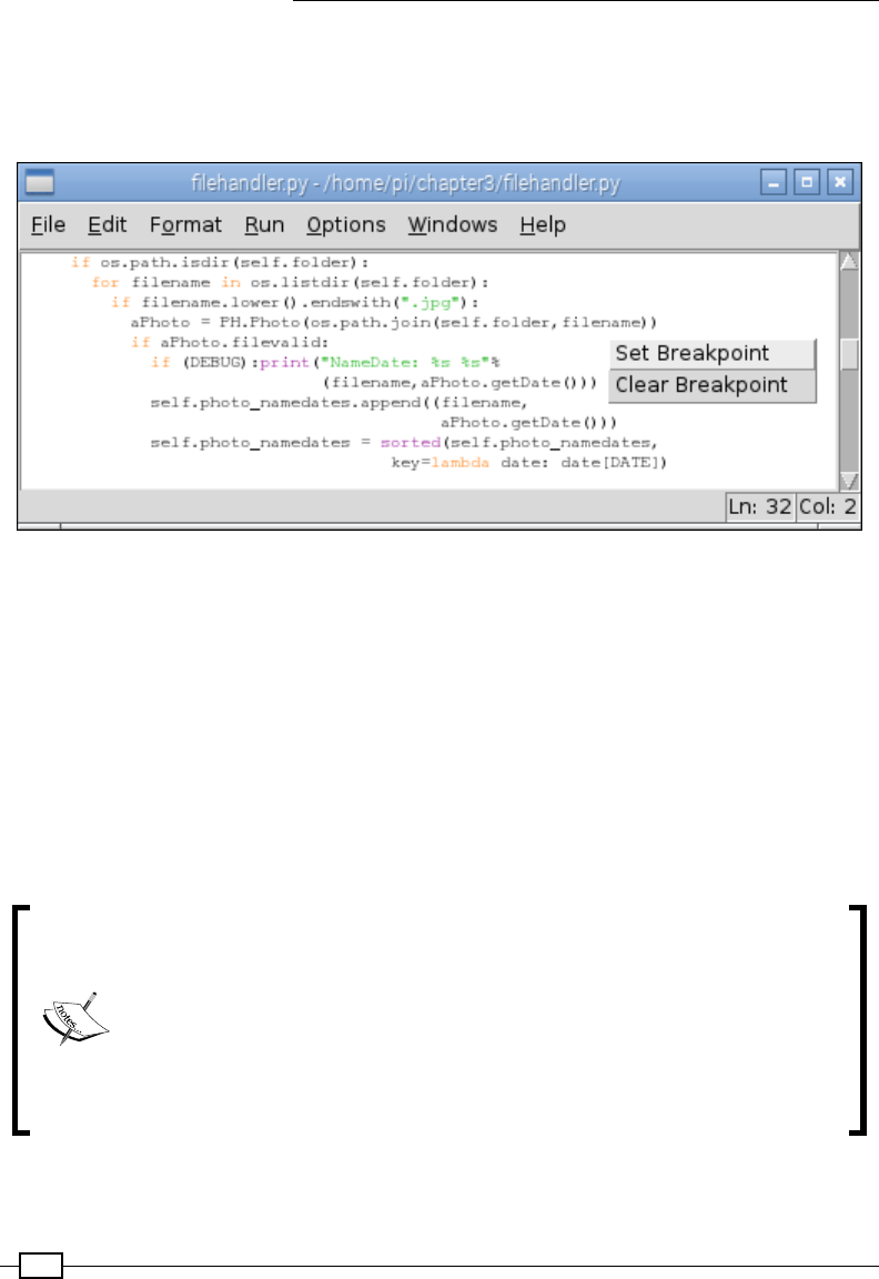
Creating Games and Graphics
114
In addition to the previously mentioned controls, you can Set Breakpoint and Clear
Breakpoint directly within the code. A breakpoint is a marker that you can insert in the code
(by right-clicking on the editor window), which the debugger will always break on (stop at)
when it is reached, as shown in the following screenshot:
Set and clear breakpoints directly in your code
The checkboxes (on the right-hand side of the control buttons) allow you to choose what
information to display when you step through the code or when the debugger stops
somewhere due to a breakpoint. Stack is shown in the main window, which is similar to
what you would see if the program hit an unhandled exception. The Stack option shows all
the function calls made to get to the current position in the code, right up to the line it has
stopped at. The Source option highlights the line of code currently being executed and, in
some cases, the code inside the imported modules too (if they are non-compiled libraries).
You can also select whether to display Locals and/or Globals. By default, the Source and
Globals options are usually disabled as they can make the process quite slow if there is a lot
of data to display.
Python uses the concept of local and global variables to dene the scope
(where and when the variables are valid). Global variables are dened at the
top level of the le and are visible from any point in the code after it has been
dened. However, in order to alter its value from anywhere other than the top
level, Python requires you to use the global keyword rst. Without the global
keyword, you will create a local copy with the same name (the value of which
will be lost when you exit the function). Local variables are dened when you
create a variable within a function; once outside of the function, the variable
is destroyed and is not visible anymore.
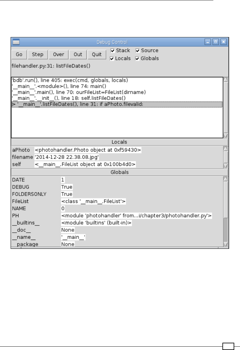
Chapter 4
115
Below Stack data are the Locals, in this case aPhoto, filename, and self. Then (if
enabled), we have all the global values that are currently valid providing useful details about
the status of the program (DATE = 1, DEBUG = True, FOLDERSONLY = True, and so on):
The Stack, Locals, and Globals options within the debugger
The debugger isn't particularly advanced, as it does not allow you to expand complex objects
such as the photohandler.Photo object to see what data it contains. However, if required,
you can adjust your code and assign the data you want to observe to some temporary
variables during testing.
It is worth learning how to use the debugger as it is a much easier way to track down
particular problems and check whether or not things are functioning as you expect them to.
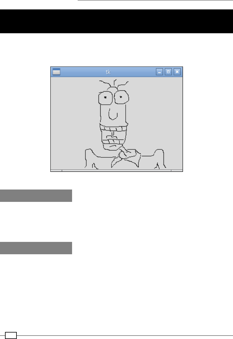
Creating Games and Graphics
116
Drawing lines using a mouse on Tkinter
Canvas
The Tkinter Canvas widget provides an area to create and draw objects on. The following
script demonstrates how to use mouse events to interact with Tkinter. By detecting the mouse
clicks, we can use Tkinter to draw a line that follows the movement of the mouse:
A simple drawing application using Tkinter
Getting ready
As before, we need to have Tkinter installed and either the Raspbian desktop running
(startx from the command line) or an SSH session with X11 Forwarding and an X server
running (see Chapter 1, Getting Started with a Raspberry Pi Computer). We will also need a
mouse connected.
How to do it…
Create the following script, painting.py:
#!/usr/bin/python3
#painting.py
import tkinter as TK
#Set defaults
btn1pressed = False

Chapter 4
117
newline = True
def main():
root = TK.Tk()
the_canvas = TK.Canvas(root)
the_canvas.pack()
the_canvas.bind("<Motion>", mousemove)
the_canvas.bind("<ButtonPress-1>", mouse1press)
the_canvas.bind("<ButtonRelease-1>", mouse1release)
root.mainloop()
def mouse1press(event):
global btn1pressed
btn1pressed = True
def mouse1release(event):
global btn1pressed, newline
btn1pressed = False
newline = True
def mousemove(event):
if btn1pressed == True:
global xorig, yorig, newline
if newline == False:
event.widget.create_line(xorig,yorig,event.x,event.y,
smooth=TK.TRUE)
newline = False
xorig = event.x
yorig = event.y
if __name__ == "__main__":
main()
#End
How it works…
The Python code creates a Tkinter window that contains a Canvas object called
the_canvas. We use the bind function here, which will bind a specic event that occurs
on this widget (the_canvas) to a specic action or key press. In this case, we bind the
<Motion> function of the mouse plus the click and release of the rst mouse button
(<ButtonPress-1> and <ButtonRelease-1>). Each of these events are then used to call
the mouse1press(), mouse1release(), and mousemove() functions.
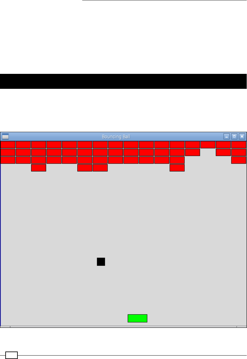
Creating Games and Graphics
118
The logic here is as follows. We track the status of the mouse button using the
mouse1press() and mouse1release() functions.
If the mouse has been clicked, the mousemove() function will check to see whether we
are drawing a new line (we set new coordinates for this) or continuing an old one (we draw a
line from the previous coordinates to the coordinates of the current event that has triggered
mousemove()). We just need to ensure that we reset to the newline command whenever
the mouse button is released to reset the start position of the line.
Creating a bat and ball game
A classic bat and ball game can be created using the drawing tools of canvas and by
detecting the collisions of the objects. The user will be able to control the green paddle
using the left and right cursor keys to aim the ball at the bricks and hit them until they
have all been destroyed.
Control the bat to aim the ball at the bricks

Chapter 4
119
Getting ready
This example requires graphical output, so you must have a screen and keyboard attached
to the Raspberry Pi or use X11 Forwarding and X server if connected remotely from another
computer.
How to do it…
Create the following script, bouncingball.py.
1. First, import the tkinter and time modules, and dene constants for the
game graphics:
#!/usr/bin/python3
# bouncingball.py
import tkinter as TK
import time
VERT,HOREZ=0,1
xTOP,yTOP = 0,1
xBTM,yBTM = 2,3
MAX_WIDTH,MAX_HEIGHT = 640,480
xSTART,ySTART = 100,200
BALL_SIZE=20
RUNNING=True
2. Next, create functions for closing the program, moving the paddle right and left, and
for calculating the direction of the ball:
def close():
global RUNNING
RUNNING=False
root.destroy()
def move_right(event):
if canv.coords(paddle)[xBTM]<(MAX_WIDTH-7):
canv.move(paddle, 7, 0)
def move_left(event):
if canv.coords(paddle)[xTOP]>7:
canv.move(paddle, -7, 0)
def determineDir(ball,obj):
global delta_x,delta_y
if (ball[xTOP] == obj[xBTM]) or (ball[xBTM] ==
obj[xTOP]):

Creating Games and Graphics
120
delta_x = -delta_x
elif (ball[yTOP] == obj[yBTM]) or (ball[yBTM] ==
obj[yTOP]):
delta_y = -delta_y
3. Set up the tkinter window and dene the canvas:
root = TK.Tk()
root.title("Bouncing Ball")
root.geometry('%sx%s+%s+%s' %(MAX_WIDTH, MAX_HEIGHT, 100, 100))
root.bind('<Right>', move_right)
root.bind('<Left>', move_left)
root.protocol('WM_DELETE_WINDOW', close)
canv = TK.Canvas(root, highlightthickness=0)
canv.pack(fill='both', expand=True)
4. Add the borders, ball, and paddle objects to the canvas:
top = canv.create_line(0, 0, MAX_WIDTH, 0, fill='blue',
tags=('top'))
left = canv.create_line(0, 0, 0, MAX_HEIGHT, fill='blue',
tags=('left'))
right = canv.create_line(MAX_WIDTH, 0, MAX_WIDTH, MAX_HEIGHT,
fill='blue', tags=('right'))
bottom = canv.create_line(0, MAX_HEIGHT, MAX_WIDTH, MAX_HEIGHT,
fill='blue', tags=('bottom'))
ball = canv.create_rectangle(0, 0, BALL_SIZE, BALL_SIZE,
outline='black', fill='black',
tags=('ball'))
paddle = canv.create_rectangle(100, MAX_HEIGHT - 30, 150, 470,
outline='black',
fill='green', tags=('rect'))
5. Draw all the bricks and set up the ball and paddle positions:
brick=list()
for i in range(0,16):
for row in range(0,4):
brick.append(canv.create_rectangle(i*40, row*20,
((i+1)*40)-2, ((row+1)*20)-2,
outline='black', fill='red',
tags=('rect')))
delta_x = delta_y = 1
xold,yold = xSTART,ySTART
canv.move(ball, xold, yold)

Chapter 4
121
6. Create the main loop for the game to check for collisions and handle the movement
of the paddle and ball:
while RUNNING:
objects = canv.find_overlapping(canv.coords(ball)[0],
canv.coords(ball)[1],
canv.coords(ball)[2],
canv.coords(ball)[3])
#Only change the direction once (so will bounce off 1st
# block even if 2 are hit)
dir_changed=False
for obj in objects:
if (obj != ball):
if dir_changed==False:
determineDir(canv.coords(ball),canv.coords(obj))
dir_changed=True
if (obj >= brick[0]) and (obj <= brick[len(brick)-1]):
canv.delete(obj)
if (obj == bottom):
text = canv.create_text(300,100,text="YOU HAVE MISSED!")
canv.coords(ball, (xSTART,ySTART,
xSTART+BALL_SIZE,ySTART+BALL_SIZE))
delta_x = delta_y = 1
canv.update()
time.sleep(3)
canv.delete(text)
new_x, new_y = delta_x, delta_y
canv.move(ball, new_x, new_y)
canv.update()
time.sleep(0.005)
#End
How it works…
We create a Tkinter application that is 640 x 480 pixels and bind the <Right> and
<Left> cursor keys to the move_right() and move_left() functions. We use root.
protocol('WM_DELETE_WINDOW', close) to detect when the window is closed so that
we can cleanly exit the program (via close(), which sets RUNNING to False).
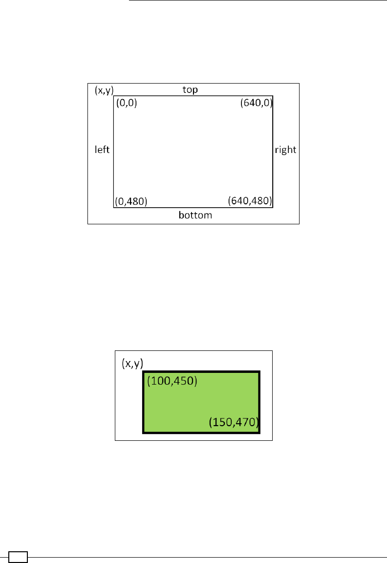
Creating Games and Graphics
122
We then add a Canvas widget to the application that will hold all our objects. We create
the following objects: top, left, right, and bottom. These make up our bounding sides
for our game area. The canvas coordinates are 0,0 in the top-left corner and 640,480 in the
bottom-right corner, so the start and end coordinates can be determined for each side (using
canv.create_line(xStart, yStart, xEnd, yEnd)).
The coordinates of the Canvas widget
You can also add multiple tags to the objects; tags are often useful for dening specic
actions or behaviors of objects. For instance, they allow for different types of event to occur
when specic objects or bricks are hit. We see more uses of tags in the next example.
Next, we dene the ball and paddle objects, which are added using canv.create_
rectangle(). This requires two sets of coordinates that dene the opposite corners of the
Incorrect image, should be the following image with the 4x16 bricks on objects (in this case,
the top-left and bottom-right corners).
A tkinter rectangle is defined by the coordinates of the two corners.
Finally, we can create the bricks!
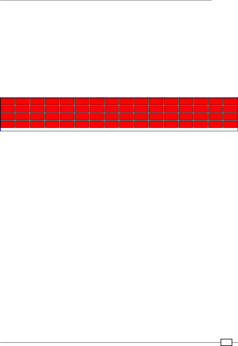
Chapter 4
123
We want our bricks to be 40 x 20 pixels wide so we can t 16 bricks across our game area
of 640 pixels (in four rows). We can create a list of brick objects with their positions dened
automatically, as shown in the following code:
brick=list()
for i in range(0,16):
for row in range(0,4):
brick.append(canv.create_rectangle(i*40, row*20,
((i+1)*40)-2, ((row+1)*20)-2, outline='black',
fill='red', tags=('rect')))
A brick-like effect is provided by making the bricks slightly smaller (-2) to create a small gap.
Four rows of 16 bricks are generated at the top of Canvas
We now set the default settings before starting the main control loop. The movement of the
ball will be governed by delta_x and delta_y, which are added to or subtracted from the
ball's previous position in each cycle.
Next, we set the starting position of the ball and use the canv.move() function to move the
ball by that amount. The move() function will add 100 to the x and y coordinates of the ball
object, which was originally created at position 0,0.
Now that everything is set up, the main loop can run; this will check that the ball has not hit
anything (using the canv.find_overlapping() function), make any adjustments to the
delta_x or delta_y values, and then apply them to move the ball to the next location.
The sign of delta_x and delta_y determines the direction of the ball. Positive values will
make the ball travel diagonally downwards and towards the right, while -delta_x will make
it travel towards the left, either downwards or upwards depending on whether delta_y is
positive or negative.
After the ball has been moved, we use canv.update() to redraw any changes made to the
display, and time.sleep() allows a small delay before checking and moving the ball again.
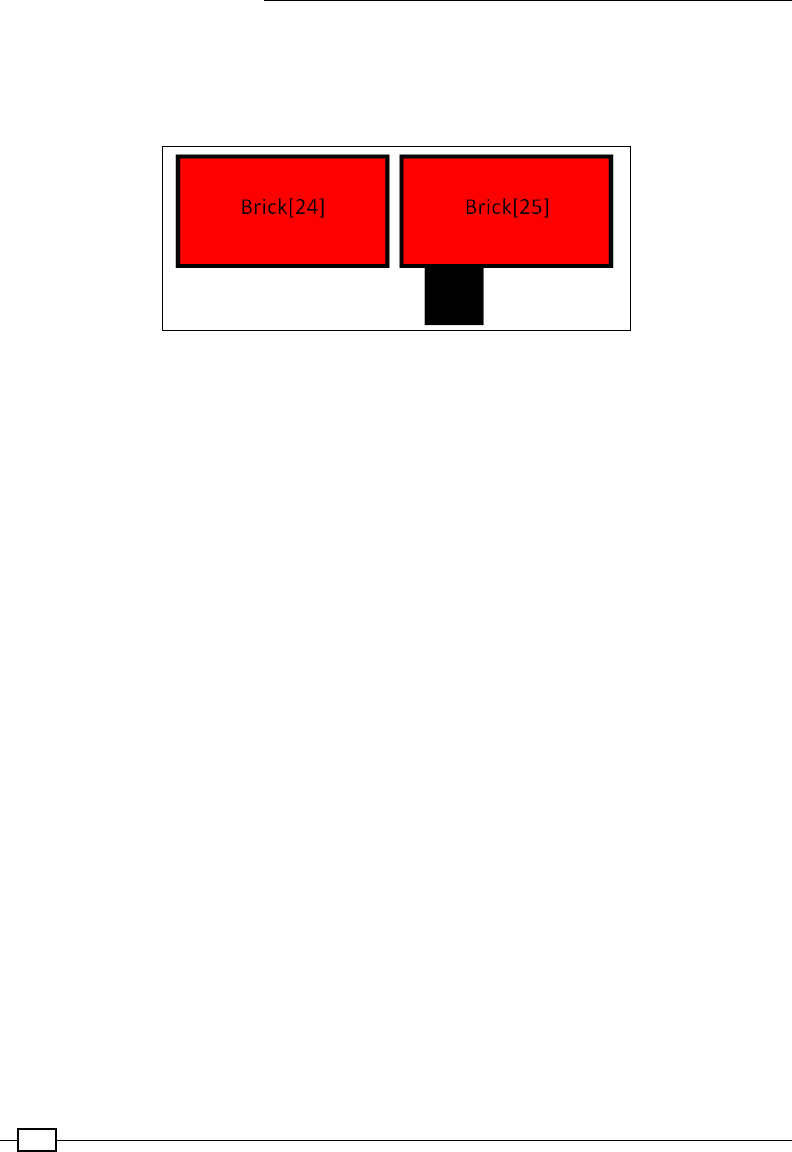
Creating Games and Graphics
124
Object collisions are detected using the canv.find_overlapping() function. This returns
a list of canvas objects that are found to be overlapping the bounds of a rectangle dened
by the supplied coordinates. For example, in the case of the square ball, are any of the
coordinates of the canvas objects within the space the ball is occupying?
The objects are checked to detect if they overlap each other
If the ball is found to be overlapping another object, such as the walls, the paddle, or one or
more of the bricks, we need to determine which direction the ball should next travel in. Since
we are using the coordinates of the ball as the area within which to check, the ball will always
be listed so that we ignore them when we check the list of objects.
We use the dir_changed ag to ensure that if we hit two bricks at the same time, we do
not change direction twice before we move the ball. Otherwise, this would cause the ball to
continue moving in the same direction even though it has collided with the bricks.
So if the ball is overlapping something else, we can call determineDir() with the
coordinates of the ball and the object to work out what the new direction should be.
When the ball collides with something, we want the ball to bounce off it; fortunately, this
is easy to simulate as we just need to change the sign of either delta_x or delta_y
depending on whether we have hit something on the sides or the top/bottom. If the ball hits
the bottom of another object, it means we were travelling upwards and should now travel
downwards. However, we will continue to travel in the same direction on the x axis (be it left or
right or just up). This can be seen from the following code:
if (ball[xTOP] == obj[xBTM]) or (ball[xBTM] == obj[xTOP]):
delta_x = -delta_x

Chapter 4
125
The determineDir() function looks at the coordinates of the ball and the object, and
looks for a match between either the left and right x coordinates or the top and bottom y
coordinates. This is enough to say whether the collision is on the sides or top/bottom, and we
can set the delta_x or delta_y signs accordingly, as can be seen in the following code:
if (obj >= brick[0]) and (obj <= brick[-1]):
canv.delete(obj)
Next, we can determine if we have hit a brick by checking whether the overlapping object ID is
between the rst and last ID bricks. If it was a brick, we can remove it using canv.delete().
Python allows the index values to wrap around rather than access
the invalid memory, so an index value of -1 will provide us with
the last item in the list. We use this to reference the last brick as
brick [-1].
We also check to see whether the object being overlapped is the bottom line (in which case,
the player has missed the ball with the paddle), so a short message is displayed briey. We
reset the position of the ball and delta_x/delta_y values. The canv.update() function
ensures that the display is refreshed with the message before it is deleted (3 seconds later).
Finally, the ball is moved by the delta_x/delta_y distance and the display is updated. A
small delay is added here to reduce the rate of updates and the CPU time used. Otherwise,
you will nd that your Raspberry Pi will become unresponsive if it is spending 100 percent of
its effort running the program.
When the user presses the cursor keys, the move_right() and move_left() functions are
called. They check the position of the paddle object, and if the paddle is not at the edge, the
paddle will be moved accordingly. If the ball hits the paddle, the collision detection will ensure
that the ball bounces off, just as if it has hit one of the bricks.
You can extend this game further by adding a score for each block destroyed, allowing the
player a nite number of lives that are lost when they miss the ball, and even writing some
code to read in new brick layouts.
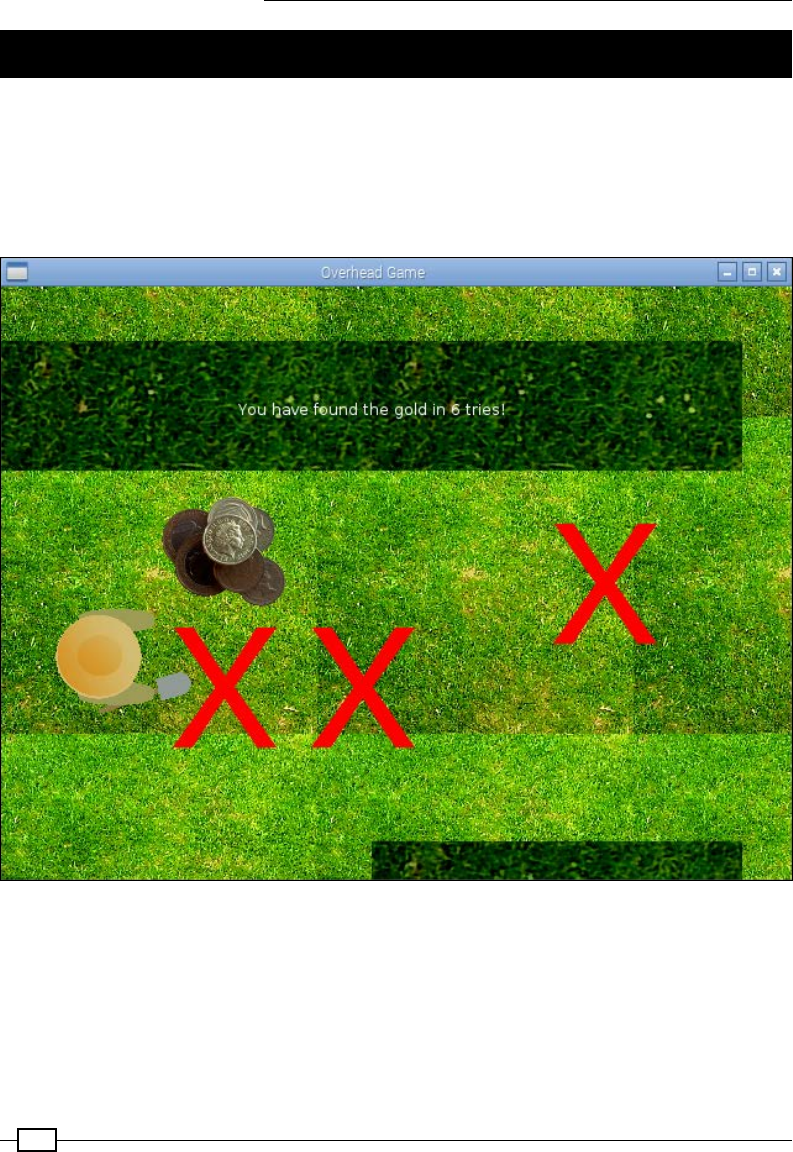
Creating Games and Graphics
126
Creating an overhead scrolling game
By using objects and images in our programs, we can create many types of 2D graphical games.
In this recipe, we will create a treasure hunt game where the player is trying to nd buried
treasure (by pressing Enter to dig for it). Each time the treasure has not been found, the player
is given a clue to how far away the treasure is; they can then use the cursor keys to move
around and search until they nd it.
Dig for treasure in your own overhead scrolling game!
Although this is a basic concept for a game, it could easily be extended to include multiple
layouts, traps, and enemies to avoid, perhaps even additional tools or puzzles to solve. With a
few adjustments to the graphics, the character could be exploring a dungeon, a spaceship, or
hopping through the clouds collecting rainbows!

Chapter 4
127
Getting ready
The following example uses a number of images; these are available as part of the book's
resources. You will need to place the nine images in the same directory as the Python script.
The required image les can be seen in the code bundle of this chapter.
How to do it…
Create the following script, scroller.py:
1. Begin by importing the required libraries and parameters:
#!/usr/bin/python3
# scroller.py
import tkinter as TK
import time
import math
from random import randint
STEP=7
xVAL,yVAL=0,1
MAX_WIDTH,MAX_HEIGHT=640,480
SPACE_WIDTH=MAX_WIDTH*2
SPACE_HEIGHT=MAX_HEIGHT*2
LEFT,UP,RIGHT,DOWN=0,1,2,3
SPACE_LIMITS=[0,0,SPACE_WIDTH-MAX_WIDTH,
SPACE_HEIGHT-MAX_HEIGHT]
DIS_LIMITS=[STEP,STEP,MAX_WIDTH-STEP,MAX_HEIGHT-STEP]
BGN_IMG="bg.gif"
PLAYER_IMG=["playerL.gif","playerU.gif",
"playerR.gif","playerD.gif"]
WALL_IMG=["wallH.gif","wallV.gif"]
GOLD_IMG="gold.gif"
MARK_IMG="mark.gif"
newGame=False
checks=list()
2. Provide functions to handle the movement of the player:
def move_right(event):
movePlayer(RIGHT,STEP)
def move_left(event):
movePlayer(LEFT,-STEP)
def move_up(event):
movePlayer(UP,-STEP)

Creating Games and Graphics
128
def move_down(event):
movePlayer(DOWN,STEP)
def foundWall(facing,move):
hitWall=False
olCoords=[canv.coords(player)[xVAL],
canv.coords(player)[yVAL],
canv.coords(player)[xVAL]+PLAYER_SIZE[xVAL],
canv.coords(player)[yVAL]+PLAYER_SIZE[yVAL]]
olCoords[facing]+=move
objects = canv.find_overlapping(olCoords[0],olCoords[1],
olCoords[2],olCoords[3])
for obj in objects:
objTags = canv.gettags(obj)
for tag in objTags:
if tag == "wall":
hitWall=True
return hitWall
def moveBackgnd(movement):
global bg_offset
bg_offset[xVAL]+=movement[xVAL]
bg_offset[yVAL]+=movement[yVAL]
for obj in canv.find_withtag("bg"):
canv.move(obj, -movement[xVAL], -movement[yVAL])
def makeMove(facing,move):
if facing == RIGHT or facing == LEFT:
movement=[move,0] #RIGHT/LEFT
bgOffset=bg_offset[xVAL]
playerPos=canv.coords(player)[xVAL]
else:
movement=[0,move] #UP/DOWN
bgOffset=bg_offset[yVAL]
playerPos=canv.coords(player)[yVAL]
#Check Bottom/Right Corner
if facing == RIGHT or facing == DOWN:
if (playerPos+PLAYER_SIZE[xVAL]) < DIS_LIMITS[facing]:
canv.move(player, movement[xVAL], movement[yVAL])
elif bgOffset < SPACE_LIMITS[facing]:
moveBackgnd(movement)
else:
#Check Top/Left Corner
if (playerPos) > DIS_LIMITS[facing]:

Chapter 4
129
canv.move(player, movement[xVAL], movement[yVAL])
elif bgOffset > SPACE_LIMITS[facing]:
moveBackgnd(movement)
def movePlayer(facing,move):
hitWall=foundWall(facing,move)
if hitWall==False:
makeMove(facing,move)
canv.itemconfig(player,image=playImg[facing])
3. Add functions to check how far the player is from the hidden gold:
def check(event):
global checks,newGame,text
if newGame:
for chk in checks:
canv.delete(chk)
del checks[:]
canv.delete(gold,text)
newGame=False
hideGold()
else:
checks.append(
canv.create_image(canv.coords(player)[xVAL],
canv.coords(player)[yVAL],
anchor=TK.NW, image=checkImg,
tags=('check','bg')))
distance=measureTo(checks[-1],gold)
if(distance<=0):
canv.itemconfig(gold,state='normal')
canv.itemconfig(check,state='hidden')
text = canv.create_text(300,100,fill="white",
text=("You have found the gold in"+
" %d tries!"%len(checks)))
newGame=True
else:
text = canv.create_text(300,100,fill="white",
text=("You are %d steps
away!"%distance))
canv.update()
time.sleep(1)
canv.delete(text)
def measureTo(objectA,objectB):
deltaX=canv.coords(objectA)[xVAL]-\

Creating Games and Graphics
130
canv.coords(objectB)[xVAL]
deltaY=canv.coords(objectA)[yVAL]-\
canv.coords(objectB)[yVAL]
w_sq=abs(deltaX)**2
h_sq=abs(deltaY)**2
hypot=math.sqrt(w_sq+h_sq)
return round((hypot/5)-20,-1)
4. Add functions to help nd a location to hide the gold in:
def hideGold():
global gold
goldPos=findLocationForGold()
gold=canv.create_image(goldPos[xVAL], goldPos[yVAL],
anchor=TK.NW, image=goldImg,
tags=('gold','bg'),
state='hidden')
def findLocationForGold():
placeGold=False
while(placeGold==False):
goldPos=[randint(0-bg_offset[xVAL],
SPACE_WIDTH-GOLD_SIZE[xVAL]-bg_offset[xVAL]),
randint(0-bg_offset[yVAL],
SPACE_HEIGHT-GOLD_SIZE[yVAL]-bg_offset[yVAL])]
objects = canv.find_overlapping(goldPos[xVAL],
goldPos[yVAL],
goldPos[xVAL]+GOLD_SIZE[xVAL],
goldPos[yVAL]+GOLD_SIZE[yVAL])
findNewPlace=False
for obj in objects:
objTags = canv.gettags(obj)
for tag in objTags:
if (tag == "wall") or (tag == "player"):
findNewPlace=True
if findNewPlace == False:
placeGold=True
return goldPos
5. Create the Tkinter application window and bind the keyboard events:
root = TK.Tk()
root.title("Overhead Game")
root.geometry('%sx%s+%s+%s' %(MAX_WIDTH,
MAX_HEIGHT,
100, 100))

Chapter 4
131
root.resizable(width=TK.FALSE, height=TK.FALSE)
root.bind('<Right>', move_right)
root.bind('<Left>', move_left)
root.bind('<Up>', move_up)
root.bind('<Down>', move_down)
root.bind('<Return>', check)
canv = TK.Canvas(root, highlightthickness=0)
canv.place(x=0,y=0,width=SPACE_WIDTH,height=SPACE_HEIGHT)
6. Initialize all the game objects (the background tiles, the player, the walls, and
the gold):
#Create background tiles
bgnImg = TK.PhotoImage(file=BGN_IMG)
BGN_SIZE = bgnImg.width(),bgnImg.height()
background=list()
COLS=int(SPACE_WIDTH/BGN_SIZE[xVAL])+1
ROWS=int(SPACE_HEIGHT/BGN_SIZE[yVAL])+1
for col in range(0,COLS):
for row in range(0,ROWS):
background.append(canv.create_image(col*BGN_SIZE[xVAL],
row*BGN_SIZE[yVAL], anchor=TK.NW,
image=bgnImg,
tags=('background','bg')))
bg_offset=[0,0]
#Create player
playImg=list()
for img in PLAYER_IMG:
playImg.append(TK.PhotoImage(file=img))
#Assume images are all same size/shape
PLAYER_SIZE=playImg[RIGHT].width(),playImg[RIGHT].height()
player = canv.create_image(100,100, anchor=TK.NW,
image=playImg[RIGHT],
tags=('player'))
#Create walls
wallImg=[TK.PhotoImage(file=WALL_IMG[0]),
TK.PhotoImage(file=WALL_IMG[1])]
WALL_SIZE=[wallImg[0].width(),wallImg[0].height()]
wallPosH=[(0,WALL_SIZE[xVAL]*1.5),
(WALL_SIZE[xVAL],WALL_SIZE[xVAL]*1.5),
(SPACE_WIDTH-WALL_SIZE[xVAL],WALL_SIZE[xVAL]*1.5),
(WALL_SIZE[xVAL],SPACE_HEIGHT-WALL_SIZE[yVAL])]

Creating Games and Graphics
132
wallPosV=[(WALL_SIZE[xVAL],0),(WALL_SIZE[xVAL]*3,0)]
wallPos=[wallPosH,wallPosV]
wall=list()
for i,img in enumerate(WALL_IMG):
for item in wallPos[i]:
wall.append(canv.create_image(item[xVAL],item[yVAL],
anchor=TK.NW, image=wallImg[i],
tags=('wall','bg')))
#Place gold
goldImg = TK.PhotoImage(file=GOLD_IMG)
GOLD_SIZE=[goldImg.width(),goldImg.height()]
hideGold()
#Check mark
checkImg = TK.PhotoImage(file=MARK_IMG)
7. Finally, start the mainloop() command to allow Tkinter to monitor for events:
#Wait for actions from user
root.mainloop()
#End
How it works…
As before, we create a new Tkinter application that contains a Canvas widget so that we can
add all of the game objects. We ensure that we bind the right, left, up, down and Enter keys,
which will be our controls in the game.
First, we place our background image (bg.gif) onto the Canvas widget. We calculate the
number of images we can t along the length and width to tile the whole canvas space, and
locate them using suitable coordinates.
Next, we create the player image (by creating playImg, a list of Tkinter image objects for each
direction the player can turn in) and place it on the canvas.
We now create the walls, the positions of which are dened by the wallPosH and wallPosV
lists. These could be dened using the exact coordinates, perhaps even read from a le to
provide an easy method to load different layouts for levels if required. By iterating through the
lists, the horizontal and vertical wall images are put in position on the canvas.
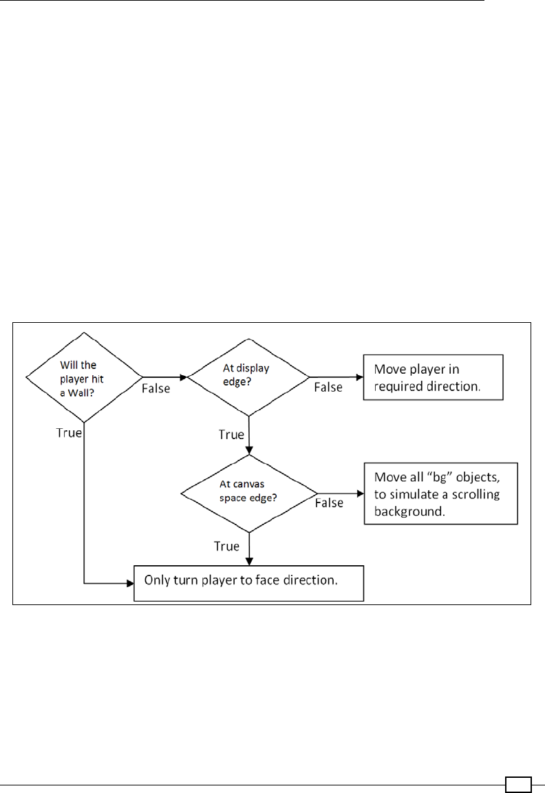
Chapter 4
133
To complete the layout, we just need to hide the gold somewhere. Using the
hideGold() function, we randomly determine a suitable place to locate the gold. Within
findLocationForGold(), we use randint(0,value) to create a pseudo-random
number (it is not totally random but good enough for this use) between 0 and value. In our
case, the value we want is between 0 and the edge of our canvas space minus the size of
the gold image and any bg_offset that has been applied to the canvas. This ensures it is
not beyond the edge of the screen. We then check the potential location using the find_
overlapping() function to see whether any objects with wall or player tags are in the
way. If so, we pick a new location. Otherwise, we place the gold on the canvas but with the
state="hidden" value, which will hide it from view.
We then create checkImg (a Tkinter image) and use it while checking for gold to mark the
area we have checked. Finally, we just wait for the user to press one of the keys.
The character will move around the screen whenever one of the cursor keys is pressed. The
player's movement is determined by the movePlayer() function; it will rst check whether
the player is trying to move into a wall, then determine (within the makeMove() function) if
the player is at the edge of the display or canvas space.
Every time a cursor key is pressed, we use the logic shown in the diagram to determine what to do
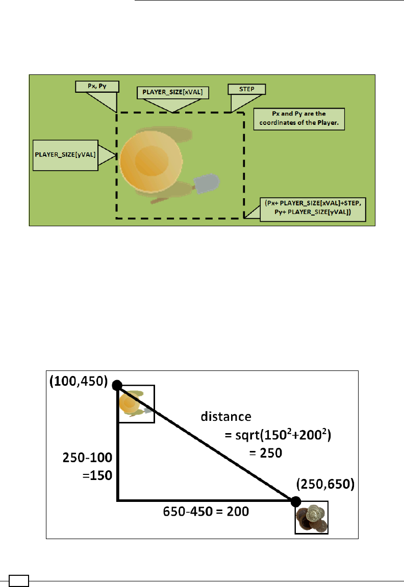
Creating Games and Graphics
134
The foundWall() function works out whether the player will hit a wall by checking for any
objects with wall tags within the area being covered by the player image, plus a little extra
for the area that the player will be moving to next. The following diagram shows how the
olCoords coordinates are determined:
The coordinates to check for objects that overlap (olCoords) are calculated
The makeMove() function checks if the player will be moving to the edge of the display (as
dened by DIS_LIMITS) and whether they are at the edge of the canvas space (as dened
by SPACE_LIMITS). Within the display, the player can be moved in the direction of the cursor,
or all the objects tagged with bg within the canvas space are moved in the opposite direction,
simulating scrolling behind the player. This is done by the moveBackground() function.
When the player presses Enter, we'll want to check for gold in the current location. Using the
measureTo() function, the position of the player and the gold are compared (the distance
between the x and y coordinates of each is calculated).
The distance between the player and the gold is calculated

Chapter 4
135
The result is scaled to provide a rough indication of how far away the player is from the gold.
If the distance is greater than zero, we display how far away the player is from the gold and
leave a cross to show where we have checked. If the player has found the gold, we display a
message saying so and set newGame to True. The next time the player presses Enter, the
places marked with a cross are removed and the gold is relocated somewhere new.
With the gold hidden again, the player is ready to start again!

137
5
Creating 3D Graphics
In this chapter, we will cover the following topics:
fStarting with 3D coordinates and vertices
fCreating and importing 3D models
fCreating a 3D world to roam in
fBuilding 3D maps and mazes
Introduction
The chip at the heart of the original Raspberry Pi (a Broadcom BCM2835 processor) was
originally designed to be a Graphical Processing Unit (GPU) for mobile and embedded
applications. The ARM core that drives most of the Raspberry Pi's functionality was added
because some extra space was available on the chip; this enabled this powerful GPU to be
used as a System-On-Chip (SoC) solution.
As you can imagine, if that original ARM core (ARM1176JZF-S, which is the ARMv6
architecture) consisted of only a small part of the chip on the Raspberry Pi, you would
be right in thinking that the GPU must perform rather well.
The processor at the heart of the Raspberry Pi 3 has been upgraded
(to a Broadcom BCM2837 processor); it now contains four ARM
cores (Cortex A53 ARMv8A), each of which are more powerful than
the original ARMv6. Coupled with the same GPU from the previous
generation, the Raspberry Pi 3 is far better equipped to perform the
calculations required to build 3D environments. However, although the
Raspberry Pi 3 will load the examples faster, once the 3D models are
generated, both versions of the chip perform just as well.

Creating 3D Graphics
138
The VideoCore IV GPU consists of 48 purpose-built processors, with some providing support
for 1080p high-denition encoding and decoding of video, while others support OpenGL
ES 2.0, which provides fast calculations for 3D graphics. It has been said that its graphics
processing power is equivalent to that of an Apple iPhone 4s and also the original Microsoft
Xbox. This is even more apparent if you run Quake 3 or OpenArena on the Raspberry Pi (go to
http://www.raspberrypi.org/openarena-for-raspberry-pi for details).
In this chapter, I hope to show you that while you can achieve a lot by performing operations
using the ARM side of the Raspberry Pi, if you venture into the side where the GPU is hidden,
you may see that there is even more to this little computer than rst appears.
The Pi3D library created by the Pi3D team (Patrick Gaunt, Tom Swirly, Tim Skillman, and
others) provides a way to put the GPU to work by creating 3D graphics.
The Pi3D wiki and documentation pages can be found at the following link:
http://pi3d.github.io/html/index.html
The support/development group can be found at the following link:
https://groups.google.com/forum/#!forum/pi3d
The library contains many features, so it will not be possible to cover everything that is
available in the following examples. It is recommended that you also take some time to try out
the Pi3D demos. To discover more options for the creation and handling of the 3D graphics,
you can have a look through some of the Python modules, which make up the library itself
(described in the documentation or the code on GitHub at https://github.com/pi3d/
pi3d.github.com). It is hoped that this chapter will introduce you to enough concepts to
illustrate some of the raw potential available to you.
Starting with 3D coordinates and vertices
The world around us is three-dimensional, so in order to simulate parts of the world, we can
create a 3D representation and display it on our 2D screen.
The Raspberry Pi enables us to simulate a 3D space, place 3D objects within it, and observe
them from a selected viewpoint. We will use the GPU to produce a representation of the 3D
view as a 2D image to display it on the screen.
The following example will show how we can use Pi3D (an OpenGL ES library for the Raspberry
Pi) to place a single 3D object and display it within the 3D space. We will then allow the
mouse to rotate the view around the object.
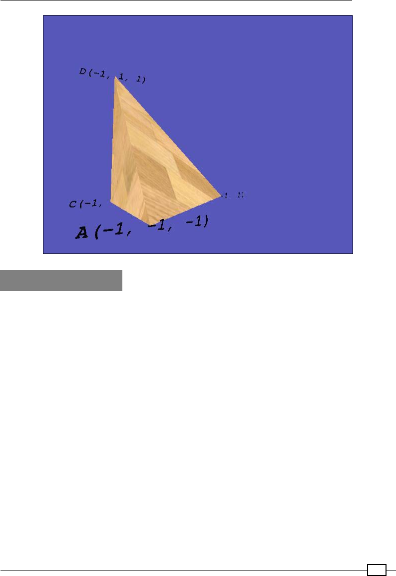
Chapter 5
139
Getting ready
The Raspberry Pi must be directly connected to a display, either via the HDMI or an analog
video output. The 3D graphics rendered by the GPU will only be displayed on a local display,
even if you are connecting to the Raspberry Pi remotely over a network. You will also need
to use a locally connected mouse for control (however, keyboard control does work via a
SSH connection).
The rst time we use Pi3D, we will need to download and install it with the following steps:
1. The Pi3D library uses Pillow, a version of the Python Imaging Library that is
compatible with Python 3, to import graphics used in models (such as textures
and backgrounds).
The installation of Pillow has been covered in the Getting ready section of Chapter 3,
Using Python for Automation and Productivity.
The commands for the installation are shown in the following code (if you've installed
them before, it will skip them and continue):
sudo apt-get update
sudo apt-get install python3-pip
sudo apt-get install libjpeg-dev
sudo pip-3.2 install pillow

Creating 3D Graphics
140
2. We can now use PIP to install Pi3D using the following command:
sudo pip-3.2 install pi3d
The Pi3D team is continuously developing and improving the library; if
you are experiencing problems, it may mean that a new release is not
compatible with the previous ones.
You can also check in the Appendix, Hardware and Software List, to
confirm which version of Pi3D you have and, if required, install the same
version listed. Alternatively, contact the Pi3D team on the Google group;
they will be happy to help!
Obtain Pi3D demos from the GitHub site, as shown in the following
command lines. You will need around 90 MB of free space to download
and extract the files:
cd ~
wget https://github.com/pi3d/pi3d_demos/archive/
master.zip
unzip master.zip
rm master.zip
You will nd that the demos have been unpacked to pi3d_demos-master.
By default, the demos are expected to be located at home/pi/pi3d; therefore,
we will rename this directory pi3d, as shown in the following command:
mv pi3d_demos-master pi3d
3. Finally, check the Raspberry Pi memory split. Run raspi-cong (sudo raspi-
config) and ensure that your memory split is set to 128. (You should only need to
do this if you have changed it in the past, as 128 MB is the default.) This ensures that
you have plenty of RAM allocated for the GPU, so it will be able to handle lots of 3D
objects if required.
4. Test if everything is working properly. You should now be able to run any of the scripts
in the pi3d_demos-master directory. See the Pi3D wiki pages for details of how
they function (http://pi3d.github.io/html/ReadMe.html). To get the best
performance, it is recommended that the scripts are run from the command prompt
(without loading the desktop):
cd pi3d
python3 Raspberry_Rain.py

Chapter 5
141
Many of the demos require mouse and keyboard control.
Although it would be perfectly reasonable to use the methods from
Chapter 4, Creating Games and Graphics, for mouse and keyboard input
using Tkinter, many of the demos in the Pi3D library use pi3d.Keyboard
and pi3d.Mouse objects to provide additional support for joysticks and
gamepads. The pi3d.Keyboard object also supports keyboard control via
SSH (see the Connecting remotely to the Raspberry Pi over the network
using SSH (and X11 Forwarding) section of Chapter 1, Getting Started with a
Raspberry Pi Computer).
Configure the setup for your own scripts. Since we will use some of the
textures and models from the demos, it is recommended that you create
your scripts within the pi3d directory. If you have a username that's
different from the default Pi account, you will need to adjust /pi3d/demo.
py. Replace the USERNAME part with your own username by editing the file:
nano ~/pi3d/demo.py
import sys
sys.path.insert(1, '/home/USERNAME/pi3d')
If you want to relocate your les somewhere else, ensure that you add a copy of
demo.py in the folder with the correct path to any resource les you require.
How to do it…
Create the following 3dObject.py script:
#!/usr/bin/python3
""" Create a 3D space with a Tetrahedron inside and rotate the
view around using the mouse.
"""
from math import sin, cos, radians
import demo
import pi3d
KEY = {'ESC':27,'NONE':-1}
DISPLAY = pi3d.Display.create(x=50, y=50)
#capture mouse and key presses
mykeys = pi3d.Keyboard()
mymouse = pi3d.Mouse(restrict = False)
mymouse.start()
def main():

Creating 3D Graphics
142
CAMERA = pi3d.Camera.instance()
tex = pi3d.Texture("textures/stripwood.jpg")
flatsh = pi3d.Shader("uv_flat")
#Define the coordinates for our shape (x,y,z)
A = (-1.0,-1.0,-1.0)
B = (1.0,-1.0,1.0)
C = (-1.0,-1.0,1.0)
D = (-1.0,1.0,1.0)
ids = ["A","B","C","D"]
coords = [A,B,C,D]
myTetra = pi3d.Tetrahedron(x=0.0, y=0.0, z=0.0,
corners=(A,B,C,D))
myTetra.set_draw_details(flatsh,[tex])
# Load ttf font and set the font to black
arialFont = pi3d.Font("fonts/FreeMonoBoldOblique.ttf",
"#000000")
mystring = []
#Create string objects to show the coordinates
for i,pos in enumerate(coords):
mystring.append(pi3d.String(font=arialFont,
string=ids[i]+str(pos),
x=pos[0], y=pos[1],z=pos[2]))
mystring.append(pi3d.String(font=arialFont,
string=ids[i]+str(pos),
x=pos[0], y=pos[1],z=pos[2], ry=180))
for string in mystring:
string.set_shader(flatsh)
camRad = 4.0 # radius of camera position
rot = 0.0 # rotation of camera
tilt = 0.0 # tilt of camera
k = KEY['NONE']
omx, omy = mymouse.position()
# main display loop
while DISPLAY.loop_running() and not k == KEY['ESC']:
k = mykeys.read()
mx, my = mymouse.position()
rot -= (mx-omx)*0.8
tilt += (my-omy)*0.8
omx = mx

Chapter 5
143
omy = my
CAMERA.reset()
CAMERA.rotate(-tilt, rot, 0)
CAMERA.position((camRad * sin(radians(rot)) *
cos(radians(tilt)),
camRad * sin(radians(tilt)),
-camRad * cos(radians(rot)) *
cos(radians(tilt))))
#Draw the Tetrahedron
myTetra.draw()
for string in mystring:
string.draw()
try:
main()
finally:
mykeys.close()
mymouse.stop()
DISPLAY.destroy()
print("Closed Everything. END")
#End
To run the script, use python3 3dObject.py.
How it works…
We import the math modules (for angle calculations—used to control the view based on
mouse movements). We also import the demo module, which just provides the path to the
shaders and textures in this example.
We start by dening some key elements that will be used by Pi3D to generate and display our
object. The space in which we shall place our object is the pi3d.Display object; this denes
the size of the space and initializes the screen to generate and display OpenGL ES graphics.
Next, we dene a pi3d.Camera object, which will allow us to dene how we view the
object within our space. To render our object, we dene a texture to be applied to the surface
and a shader that will apply the texture to the object. The shader is used to apply all the
effects and lighting to the object, and it is coded to use the GPU's OpenGL ES core instead of
the ARM processor.

Creating 3D Graphics
144
We dene the keyboard and mouse object using pi3d.keyboard() and pi3d.mouse()
so that we can respond to the keyboard and mouse input. The restrict ag of the mouse
object allows the absolute mouse position to continue past the screen limits (so we can
continuously rotate our 3D object). The main loop, when running, will check if the Esc key is
pressed and then close everything down (including calling DISPLAY.destroy() to release
the screen). We use the try: finally: method to ensure that the display is closed
correctly even if there is an exception within main().
The mouse movement is collected in the main display loop using mymouse.position(),
which returns the x and y coordinates. The difference in the x and y movement is used to
rotate around the object.
The mouse movements determine the position and angle of the camera. Any adjustment to
the forward/backward position of the mouse is used to move it over or under the object and
change the angle of the camera (using tilt) so it remains pointing at the object. Similarly,
any sideways movement will move the camera around the object using the CAMERA.reset()
function. This ensures that the display updates the camera view with the new position,
CAMERA.rotate(), to change the angle and uses CAMERA.position() to move the
camera to a position around the object, camRad units away from its center.
We will draw a three-dimensional object called a tetrahedron, a shape made up of four
triangles to form a pyramid with a triangular base. The four corners of the shape (three around
the base and one at the top) will be dened by the three-dimensional coordinates A, B, C, and
D, as shown in the following gure:
The tetrahedron placed within the X, Y, and Z axes

Chapter 5
145
The pi3d.Tetrahedron object is dened by specifying coordinates to position it in the
space and then specify the corners that will be joined to form the four triangles that make up
the shape.
Using set_draw_details(flatsh,[text]), we apply the shader(s) we wish to use and
the texture(s) for the object. In our example, we are just using a single texture, but some
shaders can use several textures for complex effects.
To help highlight where the coordinates are, we will add some pi3d.String objects by
setting the string text to specify the ID and coordinates next to them and placing it at the
required location. We will create two string objects for each location, one facing forward and
another facing backwards (ry=180 rotates the object by 180 degrees on the y axis). The
pi3d.String objects are single-sided, so if we only had one side facing forward, it wouldn't
be visible from behind when the view was rotated and would just disappear (plus, if it was
visible, the text would be backwards anyway). Again, we use the flatsh shader to render it
using the set_shader() string object.
All that is left to do now is to draw our tetrahedron and the string objects while checking for
any keyboard events. Each time the while loop completes, DISPLAY.loop_running() is
called, which will update the display with any adjustments to the camera as required.
There's more…
In addition to introducing how to draw a basic object within the 3D space, the preceding
example makes use of the following four key elements used in 3D graphics programming.
Camera
The camera represents our view in the 3D space; one way to explore and see more of the
space is by moving the camera. The Camera class is dened as follows:
pi3d.Camera.Camera(at=(0, 0, 0), eye=(0, 0, -0.1),
lens=None, is_3d=True, scale=1.0)
The camera is dened by providing two locations, one to look at (usually the object we wish
to see—dened by at) and another to look from (the object's position—dened by eye). Other
features of the camera, such as its eld of view (lens) and so on, can be adjusted or used
with the default settings.
If we didn't dene a camera in our display, a default one will be created that
points at the origin (the center of the display, that is, 0,0,0), positioned
slightly in front of it (0,0,-0.1).
See the Pi3D documentation regarding the camera module for more details.

Creating 3D Graphics
146
Shaders
Shaders are very useful as they allow a lot of the complex work required to apply textures and
lighting to an object by ofoading the task to the more powerful GPU in the Raspberry Pi. The
Shader class is dened as follows:
class pi3d.Shader.Shader(shfile=None, vshader_source=None,
fshader_source=None)
This allows you to specify a shader le (shfile) and specic vertex and fragment shaders (if
required) within the le.
There are several shaders included in the Pi3D library, some of which allow multiple textures
to be used for reections, close-up details, and transparency effects. The implementation of
the shader will determine how the lights and textures are applied to the object (and in some
cases, such as uv_flat, the shader will ignore any lighting effects).
The shader les are listed in the pi3d\shaders directory. Try experimenting with different
shaders, such as mat_reflect, which will ignore the textures/fonts but still apply the
lighting effects; or uv_toon, which will apply a cartoon effect to the texture.
Each shader consists of two les, vs (vertex shader) and fs (fragment shader), written
in C-like code. They work together to apply the effects to the object as desired. The vertex
shader is responsible for mapping the 3D location of the vertices to the 2D display. The
fragment shader (or sometimes called the pixel shader) is responsible for applying lighting
and texture effects to the pixels themselves. The construction and operation of these shaders
is well beyond the scope of this chapter, but there are several example shaders that you can
compare, change, and experiment with within the pi3d\shaders directory.
Lights
Lighting is very important in a 3D world; it could range from simple general lighting (as used
in our example) to multiple lights angled from different directions providing different strengths
and colors. How lights interact with objects and the effects they produce will be determined by
the textures and shaders used to render them.
Chapter 5
147
Lights are dened by their direction, their color and brightness, and also by an ambient light to
dene the background (non-directional) light. The Light class is dened as follows:
class pi3d.Light (lightpos=(10, -10, 20),
lightcol=(1.0, 1.0, 1.0),
lightamb=(0.1, 0.1, 0.2))
By default, the display will dene a light that has the following properties:
flightpos=(10, -10, 20): This is a light that shines from the
front of the space (near the top-left side) down towards the back of
the space (towards the right).
flightcol=(1.0, 1.0, 1.0): This is a bright, white,
directional light (the direction is defined in the preceding
dimension, and it is the color defined by the RGB values 1.0,
1.0, 1.0).
flightamb=(0.1, 0.1, 0.2): This is overall a dull, slightly
bluish light.
Textures
Textures are able to add realism to an object by allowing ne detail to be applied to the
object's surface; this could be an image of bricks for a wall or a person's face to be displayed
on the character. When a texture is used by the shader, it can often be re-scaled and reection
can be added to it; some shaders even allow you to apply surface detail.
We can apply multiple textures to an object to combine them and produce
different effects; it will be up to the shader to determine how they are applied.
Creating and importing 3D models
Creating complex shapes directly from code can often be cumbersome and time consuming.
Fortunately, it is possible to import prebuilt models into your 3D space.

Creating 3D Graphics
148
It is even possible to use graphical 3D modeling programs to generate models and then
export them as a suitable format for you to use. This example produces a Newell Teapot
in the Raspberry Pi theme, as shown in the following screenshot:
Newell Raspberry Pi teapot
Getting ready
We shall use 3D models of a teapot (both teapot.obj and teapot.mdl) located in
pi3d\models.
Modeling a teapot is the traditional 3D equivalent of displaying Hello World.
Computer graphics researcher Martin Newell rst created the Newell Teapot in
1975 as a basic test model for his work. The Newell Teapot soon became the
standard model to quickly check if a 3D rendering system is working correctly
(it even appeared in Toy Story and a 3D episode of The Simpsons).
Other models are available in the pi3d\models directory (monkey.obj/
mdl, which has been used later on, is available in the book's resource les).
How to do it…
Create and run the following 3dModel.py script:
#!/usr/bin/python3
""" Wavefront obj model loading. Material properties set in

Chapter 5
149
mtl file. Uses the import pi3d method to load *everything*
"""
import demo
import pi3d
from math import sin, cos, radians
KEY = {'ESC':27,'NONE':-1}
# Setup display and initialise pi3d
DISPLAY = pi3d.Display.create()
#capture mouse and key presses
mykeys = pi3d.Keyboard()
mymouse = pi3d.Mouse(restrict = False)
mymouse.start()
def main():
#Model textures and shaders
shader = pi3d.Shader("uv_reflect")
bumptex = pi3d.Texture("textures/floor_nm.jpg")
shinetex = pi3d.Texture("textures/stars.jpg")
# load model
#mymodel = pi3d.Model(file_string='models/teapot.obj', z=10)
mymodel = pi3d.Model(file_string='models/monkey.obj', z=10)
mymodel.set_shader(shader)
mymodel.set_normal_shine(bumptex, 4.0, shinetex, 0.5)
#Create environment box
flatsh = pi3d.Shader("uv_flat")
ectex = pi3d.loadECfiles("textures/ecubes","sbox")
myecube = pi3d.EnvironmentCube(size=900.0, maptype="FACES",
name="cube")
myecube.set_draw_details(flatsh, ectex)
CAMERA = pi3d.Camera.instance()
rot = 0.0 # rotation of camera
tilt = 0.0 # tilt of camera
k = KEY['NONE']
omx, omy = mymouse.position()
while DISPLAY.loop_running() and not k == KEY['ESC']:
k = mykeys.read()
#Rotate camera - camera steered by mouse
mx, my = mymouse.position()
rot -= (mx-omx)*0.8

Creating 3D Graphics
150
tilt += (my-omy)*0.8
omx = mx
omy = my
CAMERA.reset()
CAMERA.rotate(tilt, rot, 0)
#Rotate object
mymodel.rotateIncY(2.0)
mymodel.rotateIncZ(0.1)
mymodel.rotateIncX(0.3)
#Draw objects
mymodel.draw()
myecube.draw()
try:
main()
finally:
mykeys.close()
mymouse.stop()
DISPLAY.destroy()
print("Closed Everything. END")
#End
How it works...
Like the 3dObject.py example, we dene the DISPLAY shader (this time using uv_
reflect) and some additional textures—bumptex (floor_nm.jpg) and shinetex
(stars.jpg)—to use later. We dene a model that we want to import, placing it at z=10 (if
no coordinates are given, it will be placed at (0,0,0). Since we do not specify a camera
position, the default will place it within the view (see the section regarding the camera for
more details).
We apply the shader using the set_shader() function. Next, we add some textures and
effects using bumptex as a surface texture (scaled by 4). We apply an extra shiny effect
using shinetex and apply a reection strength of 0.5 (the strength ranges from 0.0, the
weakest, to 1.0, the strongest) using the set_normal_shine() function. If you look closely
at the surface of the model, the bumptex texture provides additional surface detail and the
shinetex texture can be seen as the reection on the surface.
To display our model within something more interesting than a default blue space, we create
an EnvironmentCube object. This denes a large space that has a special texture applied
to the inside space (in this instance, it will load the sbox_front/back/bottom/left and
sbox_right images from the textures\ecubes directory), so it effectively encloses the
objects within. The result is that you get a pleasant backdrop for your object.

Chapter 5
151
Again, we dene a default CAMERA object with rot and tilt variables to control the
view. Within the DISPLAY.loop_running() section, we can control the view of the
CAMERA object using the mouse and rotate the model on its axis at different rates to let it
spin and show all its sides (using the RotateIncX/Y/Z() function to specify the rate of
rotation). Finally, we ensure that the DISPLAY is updated by drawing the model and the
environment cube.
There's more…
We can create a wide range of objects to place within our simulated environment. Pi3D
provides methods to import our own models and apply multiple textures to them.
Creating or loading your own objects
If you wish to use your own models in this example, you shall need to create one in the correct
format; Pi3D supports obj (wavefront object les) and egg (Panda3D).
An excellent, free, 3D modeling program is called Blender (available at http://www.
blender.org). There are lots of examples and tutorials on their website to get you started
with basic modeling (http://www.blender.org/education-help/tutorials).
Pi3D model support is limited and will not support all the features that Blender can embed
in an exported model, for example, deformable meshes. Therefore, only basic multipart
models are supported. There are a few steps required to simplify the model so it can be
loaded by Pi3D.
To convert an .obj model to use with Pi3D, proceed with the following steps:
1. Create or load a model in Blender—try starting with a simple object before attempting
more complex models.
2. Select each Object and switch to Edit mode (press Tab).
3. Select all vertices (press A) and uv-map them (press U and then select Unwrap).
4. Return to Object mode (press Tab).
5. Export it as obj—from the File menu at the top, select Export and then Wavefront
(.obj). Ensure that Include Normals is also checked in the list of options in the
bottom-left list.
6. Click on Save and place the .obj and .mtl les in the pi3d\models directory, and
ensure that you update the script with the model's lename, as follows:
mymodel = pi3d.Model(file_string='models/monkey.obj',
name='monkey', z=4)

Creating 3D Graphics
152
When you run your updated script, you will see your model displayed in the 3D space. For
example, the monkey.obj model is shown in the following screenshot:
A monkey head model created in Blender and displayed by Pi3D
Changing the object's textures and .mtl les
The texture that is applied to the surface of the model is contained within the .mtl le of the
model. This le denes the textures and how they are applied as set by the modeling software.
Complex models may contain multiple textures for various parts of the object.
If no material is dened, the rst texture in the shader is used (in our example, this is the
bumptex texture). To add a new texture to the object, add (or edit) the following line in the
.mtl le (that is, to use water.jpg):
map_Kd ../textures/water.jpg
More information about .mtl les and .obj les can be found at the following
Wikipedia link:
https://en.wikipedia.org/wiki/Wavefront_.obj_file

Chapter 5
153
Taking screenshots
The Pi3D library includes a useful screenshot function to capture the screen in a .jpg or
.png le. We can add a new key event to trigger it and call pi3d.screenshot("filename.
jpg") to save an image (or use a counter to take multiple screenshots), as shown in the
following code:
shotnum = 0 #Set counter to 0
while DISPLAY.loop_running()
...
if inputs.key_state("KEY_P"):
while inputs.key_state("KEY_P"):
inputs.do_input_events() # wait for key to go up
pi3d.screenshot("screenshot%04d.jpg"%( shotnum))
shotnum += 1
...
Creating a 3D world to roam in
Now that we are able to create models and objects within our 3D space, as well as
generate backgrounds, we may want to create a more interesting environment within
which to place them.
3D terrain maps provide an elegant way to dene very complex landscapes. The terrain is
dened using a grayscale image to set the elevation of the land. The following example shows
how we can dene our own landscape and simulate ying over it, or even walk on its surface:
A 3D landscape generated from a terrain map

Creating 3D Graphics
154
Getting ready
You will need to place the Map.png le (available in the book resource les) in the pi3d/
textures directory of the Pi3D library. Alternatively, you can use one of the elevation maps
already present—replace the reference to Map.png with another one of the elevation maps,
such as testislands.jpg.
How to do it…
Create the following 3dWorld.py script:
#!/usr/bin/python3
from __future__ import absolute_import, division
from __future__ import print_function, unicode_literals
""" An example of generating a 3D environment using a elevation map
"""
from math import sin, cos, radians
import demo
import pi3d
KEY = {'R':114,'S':115,'T':116,'W':119,'ESC':27,'NONE':-1}
DISPLAY = pi3d.Display.create(x=50, y=50)
#capture mouse and key presses
mykeys = pi3d.Keyboard()
mymouse = pi3d.Mouse(restrict = False)
mymouse.start()
def limit(value,min,max):
if (value < min):
value = min
elif (value > max):
value = max
return value
def main():
CAMERA = pi3d.Camera.instance()
tex = pi3d.Texture("textures/grass.jpg")
flatsh = pi3d.Shader("uv_flat")
# Create elevation map
mapwidth,mapdepth,mapheight = 200.0,200.0,50.0
mymap = pi3d.ElevationMap("textures/Map.png",
width=mapwidth, depth=mapdepth, height=mapheight,
divx=128, divy=128, ntiles=20)

Chapter 5
155
mymap.set_draw_details(flatsh, [tex], 1.0, 1.0)
rot = 0.0 # rotation of camera
tilt = 0.0 # tilt of camera
height = 20
viewhight = 4
sky = 200
xm,ym,zm = 0.0,height,0.0
k = KEY['NONE']
omx, omy = mymouse.position()
onGround = False
# main display loop
while DISPLAY.loop_running() and not k == KEY['ESC']:
CAMERA.reset()
CAMERA.rotate(-tilt, rot, 0)
CAMERA.position((xm,ym,zm))
mymap.draw()
mx, my = mymouse.position()
rot -= (mx-omx)*0.8
tilt += (my-omy)*0.8
omx = mx
omy = my
#Read keyboard keys
k = mykeys.read()
if k == KEY['W']:
xm -= sin(radians(rot))
zm += cos(radians(rot))
elif k == KEY['S']:
xm += sin(radians(rot))
zm -= cos(radians(rot))
elif k == KEY['R']:
ym += 2
onGround = False
elif k == KEY['T']:
ym -= 2
ym -= 0.1 #Float down!
#Limit the movement
xm = limit(xm,-(mapwidth/2),mapwidth/2)
zm = limit(zm,-(mapdepth/2),mapdepth/2)
if ym >= sky:
ym = sky
#Check onGround
Creating 3D Graphics
156
ground = mymap.calcHeight(xm, zm) + viewhight
if (onGround == True) or (ym <= ground):
ym = mymap.calcHeight(xm, zm) + viewhight
onGround = True
try:
main()
finally:
mykeys.close()
mymouse.stop()
DISPLAY.destroy()
print("Closed Everything. END")
#End
How it works…
Once we have dened the display, camera, textures, and shaders that we are going to use, we
can dene the ElevationMap object.
It works by assigning a height to the terrain image based on the pixel value of selected points
of the image. For example, a single line of an image will provide a slice of the ElevationMap
object and a row of elevation points on the 3D surface:
Mapping the map.png pixel shade to the terrain height

Chapter 5
157
We create an ElevationMap object by providing the lename of the image we will use for the
gradient information (textures/Map.png), and we also create the dimensions of the map
(width, depth, and height—which is how high the white spaces will be compared to the
black spaces):
The light parts of the map will create high points and the dark ones will create low points
The Map.png texture provides an example terrain map, which is converted into a
three-dimensional surface.
We also specify divx and divy, which determine how much detail of the terrain map is used
(how many points from the terrain map are used to create the elevation surface). Finally,
ntiles species that the texture used will be scaled to t 20 times across the surface.
Within the main DISPLAY.loop_running() section, we will control the camera, draw
ElevationMap, respond to inputs, and limit movements in our space.

Creating 3D Graphics
158
As before, we use a Keyboard object to capture mouse movements and translate them to
control the camera. We will also use mykeys.read() to determine if W, S, R, and T have
been pressed, which allow us to move forward and backwards, as well as rise up and down.
To allow easy conversion between the values returned from the Keyboard
object and their equivalent meaning, we will use a Python dictionary:
KEY = {'R':114,'S':115,'T':116,'W':119,'ESC':27,'NO
NE':-1}
The dictionary provides an easy way to translate between a given value
and the resulting string. To access a key's value, we use KEY['W']. We
also used a dictionary in Chapter 3, Displaying Photo Information in an
Application, to translate between the image Exif TAG names and IDs.
To ensure that we do not fall through the surface of the ElevationMap object when
we move over it, we can use mymap.calcHeight() to provide us with the height of
the terrain at a specic location (x,y,z). We can either follow the ground by ensuring the
camera is set to equal this, or y through the air by just ensuring that we never go below it.
When we detect that we are on the ground, we ensure that we remain on the ground until
we press R to rise again.
Building 3D maps and mazes
We've seen that the Pi3D library can be used to create lots of interesting objects and
environments. Using some of the more complex classes (or by constructing our own),
whole custom spaces can be designed for the user to explore.
In the following example, we use a special module called Building, which has been designed
to allow you to construct a whole building using a single image le to provide the layout:
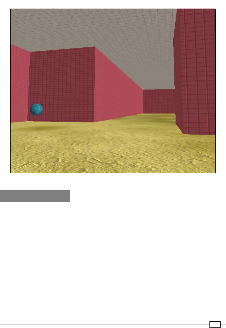
Chapter 5
159
Explore the maze and find the sphere that marks the exit
Getting ready
You will need to ensure that you have the following les in the pi3d/textures directory:
fsquareblocksred.png
ffloor.png
finside_map0.png, inside_map1.png, inside_map2.png
These les are available as part of the book's resources placed in Chapter05\resource\
source_files\textures.

Creating 3D Graphics
160
How to do it…
Let's run the following 3dMaze.py script by performing the following steps:
1. First, we set up the keyboard, mouse, display, and settings for the model using the
following code:
#!/usr/bin/python3
"""Small maze game, try to find the exit
"""
from math import sin, cos, radians
import demo
import pi3d
from pi3d.shape.Building import Building, SolidObject
from pi3d.shape.Building import Size, Position
KEY = {'A':97,'D':100,'H':104,'R':114,'S':115,'T':116,
'W':119,'ESC':27,'APOST':39,'SLASH':47,'NONE':-1}
# Setup display and initialise pi3d
DISPLAY = pi3d.Display.create()
#capture mouse and key presses
mykeys = pi3d.Keyboard()
mymouse = pi3d.Mouse(restrict = False)
#Load shader
shader = pi3d.Shader("uv_reflect")
flatsh = pi3d.Shader("uv_flat")
# Load textures
ceilingimg = pi3d.Texture("textures/squareblocks4.png")
wallimg = pi3d.Texture("textures/squareblocksred.png")
floorimg = pi3d.Texture("textures/dunes3_512.jpg")
bumpimg = pi3d.Texture("textures/mudnormal.jpg")
startimg = pi3d.Texture("textures/rock1.jpg")
endimg = pi3d.Texture("textures/water.jpg")
# Create elevation map
mapwidth = 1000.0
mapdepth = 1000.0
#We shall assume we are using a flat floor in this example
mapheight = 0.0
mymap = pi3d.ElevationMap(mapfile="textures/floor.png",
width=mapwidth, depth=mapdepth, height=mapheight,
divx=64, divy=64)
mymap.set_draw_details(shader,[floorimg, bumpimg],128.0, 0.0)

Chapter 5
161
levelList = ["textures/inside_map0.png","textures/inside_map1.
png",
"textures/inside_map2.png"]
avhgt = 5.0
aveyelevel = 4.0
MAP_BLOCK = 15.0
aveyeleveladjust = aveyelevel - avhgt/2
PLAYERHEIGHT = (mymap.calcHeight(5, 5) + avhgt/2)
#Start the player in the top-left corner
startpos = [(8*MAP_BLOCK),PLAYERHEIGHT,(8*MAP_BLOCK)]
endpos = [0,PLAYERHEIGHT,0] #Set the end pos in the centre
person = SolidObject("person", Size(1, avhgt, 1),
Position(startpos[0],startpos[1],startpos[2]), 1)
#Add spheres for start and end, end must also have a solid object
#so we can detect when we hit it
startobject = pi3d.Sphere(name="start",x=startpos[0],
y=startpos[1]+avhgt,z=startpos[2])
startobject.set_draw_details(shader, [startimg, bumpimg],
32.0, 0.3)
endobject = pi3d.Sphere(name="end",x=endpos[0],
y=endpos[1],z=endpos[2])
endobject.set_draw_details(shader, [endimg, bumpimg], 32.0, 0.3)
endSolid = SolidObject("end", Size(1, avhgt, 1),
Position(endpos[0],endpos[1],endpos[2]), 1)
mazeScheme = {"#models": 3,
(1,None): [["C",2]], #white cell : Ceiling
(0,1,"edge"): [["W",1]], #white cell on edge next
# black cell : Wall
(1,0,"edge"): [["W",1]], #black cell on edge next
# to white cell : Wall
(0,1):[["W",0]]} #white cell next
# to black cell : Wall
details = [[shader, [wallimg], 1.0, 0.0, 4.0, 16.0],
[shader, [wallimg], 1.0, 0.0, 4.0, 8.0],
[shader, [ceilingimg], 1.0, 0.0, 4.0, 4.0]]
arialFont = pi3d.Font("fonts/FreeMonoBoldOblique.ttf",
"#ffffff", font_size=10)

Creating 3D Graphics
162
2. We then create functions to allow us to reload the levels and display messages to the
player using the following code:
def loadLevel(next_level):
print(">>> Please wait while maze is constructed...")
next_level=next_level%len(levelList)
building = pi3d.Building(levelList[next_level], 0, 0, mymap,
width=MAP_BLOCK, depth=MAP_BLOCK, height=30.0,
name="", draw_details=details, yoff=-15, scheme=mazeScheme)
return building
def showMessage(text,rot=0):
message = pi3d.String(font=arialFont, string=text,
x=endpos[0],y=endpos[1]+(avhgt/4),
z=endpos[2], sx=0.05, sy=0.05,ry=-rot)
message.set_shader(flatsh)
message.draw()
3. Within the main function, we set up the 3D environment and draw all the objects
using the following code:
def main():
#Load a level
level=0
building = loadLevel(level)
lights = pi3d.Light(lightpos=(10, -10, 20),
lightcol =(0.7, 0.7, 0.7),
lightamb=(0.7, 0.7, 0.7))
rot=0.0
tilt=0.0
#capture mouse movements
mymouse.start()
omx, omy = mymouse.position()
CAMERA = pi3d.Camera.instance()
while DISPLAY.loop_running() and not \
inputs.key_state("KEY_ESC"):
CAMERA.reset()
CAMERA.rotate(tilt, rot, 0)
CAMERA.position((person.x(), person.y(),
person.z() - aveyeleveladjust))
#draw objects

Chapter 5
163
person.drawall()
building.drawAll()
mymap.draw()
startobject.draw()
endobject.draw()
#Apply the light to all the objects in the building
for b in building.model:
b.set_light(lights, 0)
mymap.set_light(lights, 0)
#Get mouse position
mx, my = mymouse.position()
rot -= (mx-omx)*0.8
tilt += (my-omy)*0.8
omx = mx
omy = my
xm = person.x()
ym = person.y()
zm = person.z()
4. Finally, we monitor for key presses, handle any collisions with objects, and move
within the maze as follows:
#Read keyboard keys
k = mykeys.read()
if k == KEY['APOST']: #' Key
tilt -= 2.0
elif k == KEY['SLASH']: #/ Key
tilt += 2.0
elif k == KEY['A']:
rot += 2.0
elif k == KEY['D']:
rot -= 2.0
elif k == KEY['H']:
#Use point_at as help - will turn the player to face
# the direction of the end point
tilt, rot = CAMERA.point_at([endobject.x(), endobject.y(),
endobject.z()])
elif k == KEY['W']:
xm -= sin(radians(rot))
zm += cos(radians(rot))
elif k == KEY['S']:

Creating 3D Graphics
164
xm += sin(radians(rot))
zm -= cos(radians(rot))
NewPos = Position(xm, ym, zm)
collisions = person.CollisionList(NewPos)
if collisions:
#If we reach the end, reset to start position!
for obj in collisions:
if obj.name == "end":
#Required to remove the building walls from the
# solidobject list
building.remove_walls()
showMessage("Loading Level",rot)
DISPLAY.loop_running()
level+=1
building = loadLevel(level)
showMessage("")
person.move(Position(startpos[0],startpos[1],
startpos[2]))
else:
person.move(NewPos)
try:
main()
finally:
mykeys.close()
mymouse.stop()
DISPLAY.destroy()
print("Closed Everything. END")
#End
How it works...
We dene many of the elements we used in the preceding examples, such as the display,
textures, shaders, font, and lighting. We also dene the objects, such as the building itself,
the ElevationMap object, as well as the start and end points of the maze. We also use
SolidObjects to help detect movement within the space. See the Using SolidObjects to detect
collisions subsection in the There's more… section of this recipe for more information.

Chapter 5
165
Finally, we create the actual Building object based on the selected map image (using the
loadLevel() function) and locate the camera (which represents our rst-person viewpoint)
at the start. See the The Building module subsection in the There's more… section of this
recipe for more information.
Within the main loop, we draw all the objects in our space and apply the lighting effects. We
will also monitor for movement in the mouse (to control the tilt and rotation of the camera) or
the keyboard to move the player (or exit/provide help).
The controls are as follows:
fMouse movement: This changes the camera tilt and rotation.
f' or / key: This changes the camera to tilt either downwards or upwards.
fA or D: This changes the camera to rotate from left to right or vice versa.
fW or S: This moves the player forwards or backwards.
fH: This helps the player by rotating them to face the end of the maze. The useful
CAMERA.point_at() function is used to quickly rotate and tilt the camera's
viewpoint towards the provided coordinates (the end position).
Whenever the player moves, we check if the new position (NewPos) collides with another
SolidObject using CollisionList(NewPos). The function will return a list of any other
SolidObjects that overlap the coordinates provided.
If there are no SolidObjects in the way, we make the player move; otherwise, we check to see
if one of the SolidObject's names is the end object, in which case we have reached the end of
the maze.
When the player reaches the end, we remove the walls from the old Building object and
display a loading message. If we don't remove the walls, all the SolidObjects belonging to the
previous Building will still remain, creating invisible obstacles in the next level.

Creating 3D Graphics
166
We use the showMessage() function to inform the user that the next level will be loaded
soon (since it can take a while for the building object to be constructed). We need to ensure
that we call DISPLAY.loop_running() after we draw the message. This ensures it is
displayed on screen before we start loading the level (after which the person will be unable
to move while loading takes place). We need to ensure that the message is always facing
the player regardless of which of their sides collides with the end object by using the camera
rotation (rot) for its angle.
When the exit ball is found, the next level is loaded
When the next level in the list has been loaded (or the rst level has been loaded again when
all the levels have been completed), we replace the message with a blank one to remove it
and reset the person's position back to the start.
You can design and add your own levels by creating additional map les (20 x 20 PNG
les with walls marked out with black pixels and walkways in white) and listing them in
levelList. The player will start at the top-left corner of the map, and the exit is placed at
the center.
You will notice that loading the levels can take quite a long time; this is the relatively slow ARM
processor in the Raspberry Pi performing all the calculations required to construct the maze
and locate all the components. As soon as the maze has been built, the more powerful GPU
takes over, which results in fast and smooth graphics as the player explores the space.
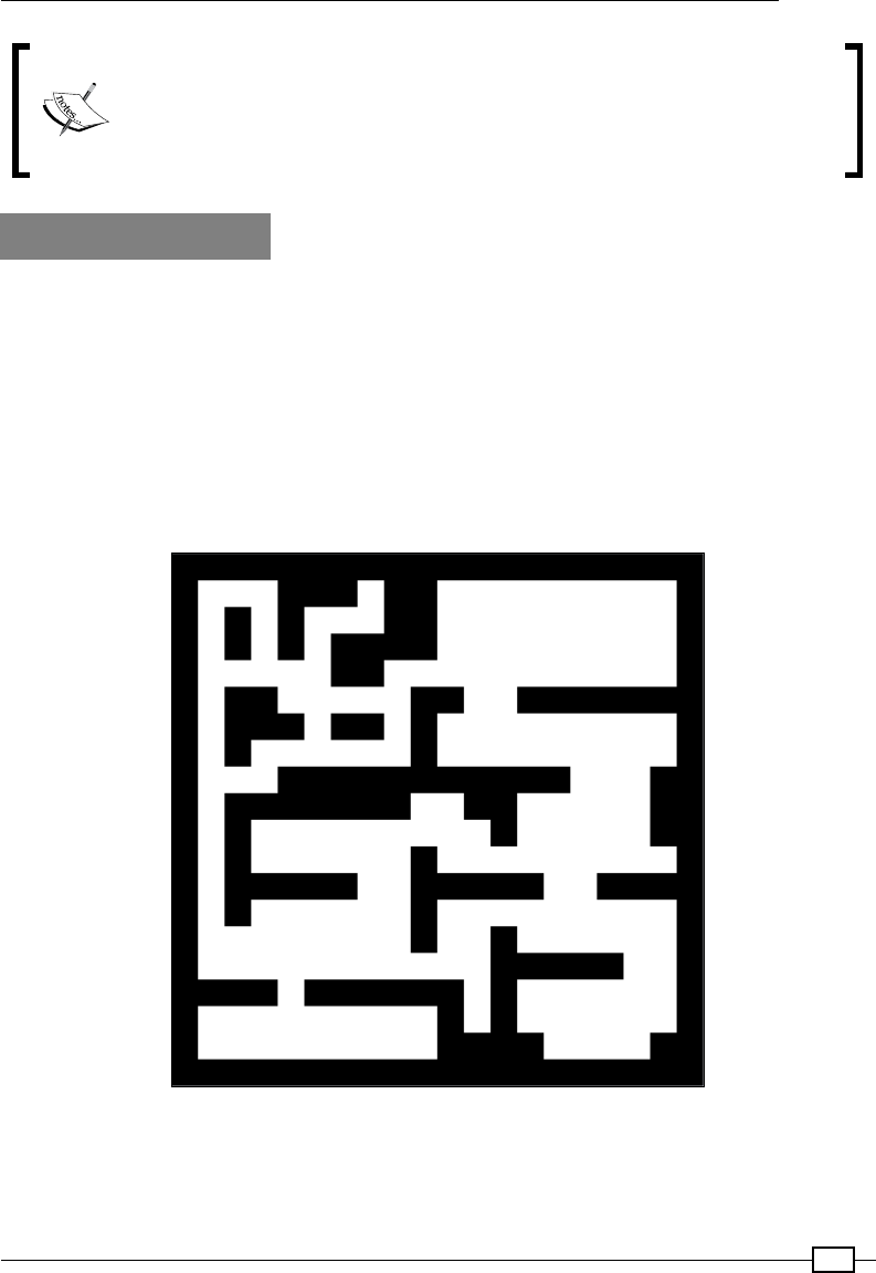
Chapter 5
167
This recipe demonstrates the difference between the original Raspberry Pi
processor and the Raspberry Pi 2. The Raspberry Pi 2 takes around 1 minute
20 seconds to load the rst level, while the original Raspberry Pi can take up
to 4 minutes 20 seconds. The Raspberry Pi 3 takes a stunning 4 seconds to
load the same level.
There's more...
The preceding example creates a building for the player to explore and interact with. In
order to achieve this, we use the Building module of Pi3D to create a building and use
SolidObject to detect collisions.
The Building module
The pi3d.Building module allows you to dene a whole level or oor of a building using
map les. Like the terrain maps used in the preceding example, the color of the pixels will be
converted into different parts of the level. In our case, black is for the walls and white is for
the passages and halls, complete with ceilings:
The building layout is defined by the pixels in the image

Creating 3D Graphics
168
The sections built by the Building object are dened by the Scheme used. The Scheme
is dened by two sections, by the number of models, and then by the denitions for various
aspects of the model, as seen in the following code:
mazeScheme = {"#models": 3,
(1,None): [["C",2]], #white cell : Ceiling
(0,1,"edge"): [["W",1]], #white cell on edge by black cell : Wall
(1,0,"edge"): [["W",1]], #black cell on edge by white cell : Wall
(0,1):[["W",0]]} #white cell next to black cell : Wall
The rst tuple denes the type of cell/square that the selected model should be applied to.
Since there are two pixel colors in the map, the squares will either be black (0) or white (1).
By determining the position and type of a particular cell/square, we can dene which models
(wall, ceiling, or roof) we want to apply.
We dene three main types of cell/square location:
fA whole square (1,None): This is a white cell representing open space in
the building.
fOne cell bordering another, on the edge (0,1,"edge"): This is a black cell next to
a white one on the map edge. This also includes (1,0,"edge"). This will represent
the outer wall of the building.
fAny black cell that is next to a white cell (0,1): This will represent all the internal
walls of the building.
Next, we allocate a type of object(s) to be applied for that type (W or C):
fWall (W): This is a vertical wall that is placed between the specied cells (such as
between black and white cells).
fCeiling (C): This is a horizontal section of the ceiling to cover the current cell.
fRoof (R): This is an additional horizontal section that is placed slightly above the
ceiling to provide a roong effect. It is typically used for buildings that may need to be
viewed from the outside (this is not used in our example).
fCeiling Edge (CE): This is used to join the ceiling sections to the roof around the
edges of the building (it is not used in our example since ours is an indoor model).
Finally, we specify the model that will be used for each object. We are using three models in
this example (normal walls, walls on an edge, and the ceiling), so we can dene the model
used by specifying 0, 1, or 2.
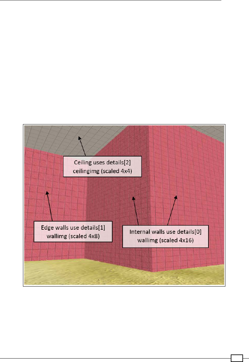
Chapter 5
169
Each of the models are dened in the details array, which allows us to set the required
textures and shaders for each one (this contains the same information that would normally be
set by the .set_draw_details() function), as shown in the following code:
details = [[shader, [wallimg], 1.0, 0.0, 4.0, 16.0],
[shader, [wallimg], 1.0, 0.0, 4.0, 8.0],
[shader, [ceilingimg], 1.0, 0.0, 4.0, 4.0]]
In our example, the inside walls are allocated to the wallimg texture (textures/
squareblocksred.png) and the ceilings are allocated to the ceilingimg texture
(textures/squareblocks4.png). You may be able to note from the following screenshot
that we can apply different texture models (in our case, a slightly different scaling) to the
different types of blocks. The walls that border the outside of the maze (with the edge
identier) will use the wallimg model texture scaled by 4x8 (details[1]) while the same
model texture will be scaled 4x16 for the internal walls (details[0]):
The outward facing wall on the left has a different scaling applied compared to the other walls
Both scheme and draw_details are set when the pi3d.Building object is created, as
shown in the following code:
building = pi3d.Building(levelList[next_level], 0, 0, mymap,
width=MAP_BLOCK, depth=MAP_BLOCK, height=30.0, name="",
draw_details=details, yoff=-15, scheme=mazeScheme)
Creating 3D Graphics
170
Using the map le (levelList[next_level]), the scheme (mazeScheme), and draw details
(details), the entire building is created within the environment:
An overhead view of the 3D maze we created
Although we use just black and white in this example, other colored
pixels can also be used to dene additional block types (and therefore
different textures, if required). If another color (such as gray) is added,
the indexing of the color mapping is shifted so that black blocks are
referenced as 0, the new colored blocks as 1, and the white blocks as 2.
See the Silo example in the Pi3D demos for details.
We also need to dene an ElevationMap object—mymap. The
pi3d.Building module makes use of the ElevationMap object's
calcHeight() function to correctly place the walls on top of the
ElevationMap object's surface. In this example, we will apply a basic
ElevationMap object using textures/floor.png, which will
generate a at surface that the Building object will be placed on.

Chapter 5
171
Using SolidObjects to detect collisions
In addition to the Building object, we will dene an object for the player and also dene two
objects to mark the start and end points of the maze. Although the player's view is the rst-
person viewpoint (that is, we don't actually see them since the view is effectively through their
eyes), we need to dene a SolidObject to represent them.
A SolidObject is a special type of invisible object that can be checked to determine if the
space that would be occupied by one SolidObject has overlapped another. This will allow us
to use person.CollisionList(NewPos) to get a list of any other SolidObjects that the
person object will be in contact with at the NewPos position. Since the Building class
denes SolidObjects for all the parts of the Building object, we will be able to detect when
the player tries to move through a wall (or, for some reason, the roof/ceiling) and stop them
from moving through it.
We also use SolidObjects for the start and end locations in the maze. The place where the
player starts is set as the top-left corner of the map (the white-space pixel from the top left of
the map) and is marked by the startpos object (a small pi3d.Sphere with the rock1.jpg
texture) placed above the person's head. The end of the maze is marked with another pi3d.
Sphere object (with the water.jpg texture) located at the center of the map. We also dene
another SolidObject at the end so that we can detect when the player reaches it and collides
with it (and load the next level!).

173
6
Using Python to Drive
Hardware
In this chapter, we will cover the following topics:
fControlling an LED
fResponding to a button
fA controlled shutdown button
fThe GPIO keypad input
fMultiplexed color LEDs
fWriting messages using Persistence of Vision
Introduction
One of the key features of a Raspberry Pi computer that sets it apart from most other
home/ofce computers is that it has the ability to directly interface with other hardware.
The hardware General Purpose Input/Output (GPIO) pins on the Raspberry Pi can control a
wide range of low-level electronics, from Light Emitting Diodes (LEDs) to switches, sensors,
motors, servos, and even extra displays.
This chapter will focus on connecting the Raspberry Pi with some simple circuits and getting to
grips with using Python to control and respond to the connected components.
The Raspberry Pi hardware interface consists of 40 pins located along one side of the board.
Using Python to Drive Hardware
174
The GPIO pins and their layout will vary slightly according to the particular
model you have.
The Raspberry Pi 2 and the Raspberry Pi 1 Model A Plus and B Plus all
have the same 40-pin layout.
The older Raspberry Pi 1 models (non-plus types) have a 26-pin header,
which is the same as the 1-26 pins of the newer models.
Raspberry Pi 2 and Raspberry Pi Model Plus GPIO header pins (pin functions)
The layout of the connector is shown in the previous diagram; the pin numbers are shown as
seen from pin 1 of the GPIO header.
Chapter 6
175
Pin 1 is at the end that is nearest to the SD card, as shown in the following image:
The Raspberry Pi GPIO header location
Care should be taken when using the GPIO header, since it also includes power pins (3V3
and 5V) as well as ground pins (GND). All of the GPIO pins can be used as standard GPIO, but
several also have special functions; these are labeled and highlighted with different colors.
It is common for engineers to use a 3V3 notation to specify values
in schematics to avoid using decimal places that could easily be
missed (using 33V rather than 3.3V would cause severe damage).
The same can applied to other values such as resistors, so for
example, 1.2k ohms can be written as 1k2 ohms.
There are TX and RX pins that are used for serial RS232 communications, and with the
aid of a voltage level convertor, information can be transferred via a serial cable to another
computer or device.
We have SDA and SCL pins that are able to support a two-wire bus communication protocol
called I2C (on Model Plus and Raspberry Pi 2 boards there are two I2C channels: channel 1
ARM is for general use while channel 0 VC is typically used for identifying Hardware Attached
on Top (HAT) modules). There are also the SPI MOSI, SPI MISO, SPI SCLK, SPI CE0, and SPI
CE1 pins, which support another type of bus protocol called SPI for high-speed data. Finally,
we have PWM0/1, which allows a pulse width modulation signal to be generated, which is
useful for servos and generating analog signals.
Using Python to Drive Hardware
176
However, we will focus on using just the standard GPIO functions in this chapter. The GPIO pin
layout is shown in the following diagram:
Raspberry Pi GPIO header pins (GPIO.BOARD and GPIO.BCM)
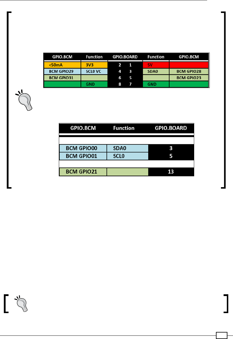
Chapter 6
177
The Raspberry Pi Rev 2 (pre-July 2014) has the following differences to the
Raspberry Pi 2 GPIO layout:
f26 GPIO pins header (matching the first 26 pins)
fAn additional secondary set of eight holes (P5) located next to the
pin header. The details are as follows:
Raspberry Pi Rev 2 P5 GPIO header pins
The original Raspberry Pi Rev 1 (pre-Oct 2012) has only 26 GPIO pins in
total (matching the rst 26 pins of the current Raspberry Pi, except for the
following details):
Raspberry Pi Rev 1 GPIO header differences
The RPi.GPIO library can reference the pins on the Raspberry Pi using one of two systems.
The numbers shown in the center are the physical position of the pins and are also the
numbers referenced by RPi.GPIO when in the GPIO.BOARD mode. The numbers on the
outside (GPIO.BCM) are the actual references for the physical ports of the processor to which
the pins are wired (which is why they are not in any specic order). They are used when the
mode is set to GPIO.BCM and allow control of the GPIO header pins and also any peripherals
connected to other GPIO lines. This includes the LED on the add-on camera on BCM GPIO
4 and the status LED on the board. However, this can also include the GPIO lines used for
reading/writing to the SD card, which would cause serious errors if interfered with.
If you use other programming languages to access the GPIO pins, the numbering scheme may
be different, so it will be helpful if you are aware of the BCM GPIO references, which refer to
the physical GPIO port of the processor.
Be sure to check out the Appendix, Hardware and Software List, which lists
all the items used in this chapter and the places you can obtain them from.
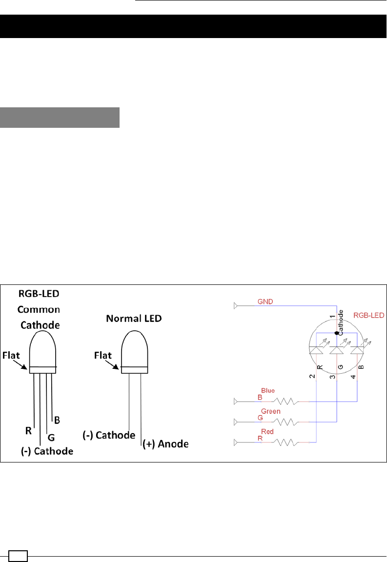
Using Python to Drive Hardware
178
Controlling an LED
The hardware equivalent of hello world is an LED ash, which is a great test to ensure that
everything is working and that you have wired it correctly. To make it a little more interesting,
I've suggested using an RGB LED (it has red, green, and blue LEDs combined into a single
unit), but feel free to use separate LEDs if that is all you have available.
Getting ready
You will need the following equipment:
f4 x DuPont female to male patch wires
fMini breadboard (170 tie points) or a larger one
fRGB LED (common cathode)/3 standard LEDs (ideally red/green/blue)
fBreadboarding wire (solid core)
f3 x 470 ohm resistors
Each of the previous components should only cost a few dollars and can be reused for other
projects afterwards. The breadboard is a particularly useful item that allows you to try out your
own circuits without needing to solder them.
The diagrams of an RGB LED, standard LED, and RGB circuit

Chapter 6
179
The following diagram shows the breadboard circuitry:
The wiring of an RGB LED/standard LEDs connected to the GPIO header
There are several variations of RGB LEDs available, so check the datasheet
of your component to conrm the pin order and type you have. Some are
Red, Blue, and Green (RBG), so ensure that you wire accordingly or adjust
the RGB_ pin settings in the code. You can also get common anode variants,
which will require the anode to be connected to 3V3 (GPIO-Pin1) for it to light
up (and require RGB_ENABLE and RGB_DISABLE to be set to 0 and 1).
The breadboard and component diagrams of this book have been created using a free tool
called Fritzing (www.fritzing.org); it is great for planning your own Raspberry Pi projects.

Using Python to Drive Hardware
180
How to do it…
Create the ledtest.py script as follows:
#!/usr/bin/python3
#ledtest.py
import time
import RPi.GPIO as GPIO
# RGB LED module
#HARDWARE SETUP
# GPIO
# 2[======XRG=B==]26[=======]40
# 1[=============]25[=======]39
# X=GND R=Red G=Green B=Blue
#Setup Active States
#Common Cathode RGB-LED (Cathode=Active Low)
RGB_ENABLE = 1; RGB_DISABLE = 0
#LED CONFIG - Set GPIO Ports
RGB_RED = 16; RGB_GREEN = 18; RGB_BLUE = 22
RGB = [RGB_RED,RGB_GREEN,RGB_BLUE]
def led_setup():
#Setup the wiring
GPIO.setmode(GPIO.BOARD)
#Setup Ports
for val in RGB:
GPIO.setup(val,GPIO.OUT)
def main():
led_setup()
for val in RGB:
GPIO.output(val,RGB_ENABLE)
print("LED ON")
time.sleep(5)
GPIO.output(val,RGB_DISABLE)
print("LED OFF")
try:
main()
finally:
GPIO.cleanup()
print("Closed Everything. END")
#End
Chapter 6
181
The RPi.GPIO library will require sudo permissions to access the GPIO pin hardware, so you
will need to run the script using the following command:
sudo python3 ledtest.py
When you run the script, you should see the red, green, and blue parts of the LED (or each
LED, if using separate ones) light up in turn. If not, double-check your wiring or conrm the
LED is working by temporarily connecting the red, green, or blue wire to the 3V3 pin (pin 1 of
the GPIO header).
The sudo command is required for most hardware-related scripts
because it isn't normal for users to directly control hardware at such a
low level. For example, setting or clearing a control pin that is part of the
SD card controller could corrupt data being written to it. Therefore, for
security purposes, super user permissions are required to stop programs
from using hardware by accident (or with malicious intent).
How it works…
To access the GPIO pins using Python, we import RPi.GPIO, which allows direct control of the
pins through the module functions. We also require the time module to pause the program
for a set number of seconds.
We dene values for the LED wiring and active states (see Controlling the GPIO current in the
There's more… section of this recipe).
Before the GPIO pins are used by the program, we need to set them up by specifying the
numbering method (GPIO.BOARD) and the direction—GPIO.OUT or GPIO.IN (in this case, we
set all the RGB pins to outputs). If a pin is congured as an output, we will be able to set the
pin state; similarly, if it is congured as an input, we will be able to read the pin state.
Next, we control the pins using GPIO.ouput() by stating the number of the GPIO pin and
the state we want it to be in (1 = high/on and 0 = low/off). We switch each LED on, wait 5
seconds, and then switch it back off.
Finally, we use GPIO.cleanup() to return the GPIO pins back to their original default state
and release control of the pins for use by other programs.
There's more…
Using the GPIO pins on the Raspberry Pi must be done with care since these pins are directly
connected to the main processor of the Raspberry Pi without any additional protection.
Caution must be used, as any incorrect wiring will probably damage the Raspberry Pi
processor and cause it to stop functioning altogether.
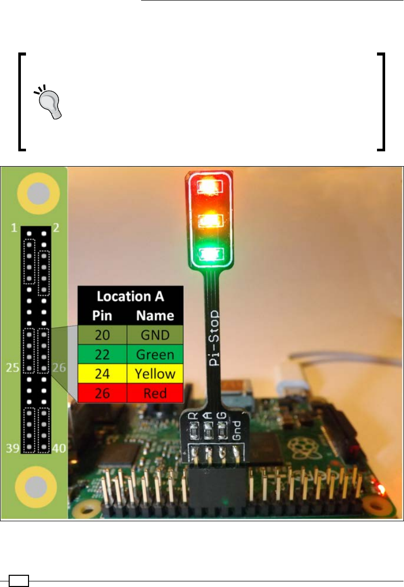
Using Python to Drive Hardware
182
Alternatively, you could use one of the many modules available that plug directly into the GPIO
header pins (reducing the chance of wiring mistakes).
For example, the Pi-Stop is a simple pre-built LED board that
simulates a set of trafc lights, designed to be a stepping stone for
those interested in controlling hardware but want to avoid the risk of
damaging their Raspberry Pi. After the basics have been mastered, it
also makes an excellent indicator to aid debugging.
Just ensure you update the LED CONFIG pin references in the
ledtest.py script to reference the pin layout and location used for
the hardware you are using.
See the Appendix, Hardware and Software List, for a list of Raspberry Pi hardware retailers.
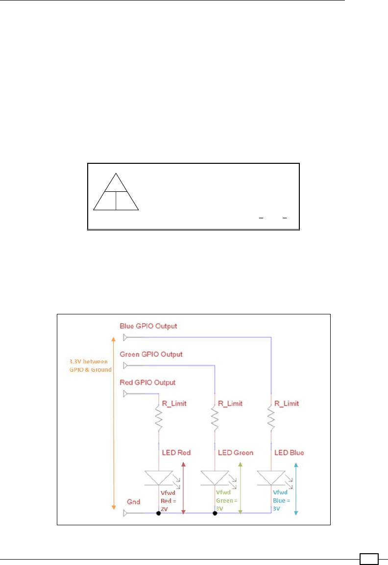
Chapter 6
183
Controlling the GPIO current
Each GPIO pin is only able to handle a certain current before it will burn out (not greater than
16 mA from a single pin or 30 mA in total), and similarly, the RGB LED should be limited to
no more than 100 mA. By adding a resistor before or after an LED, we will be able to limit the
current that will be passed through it and also control how bright it is (more current will equal
a brighter LED).
Since we may wish to drive more than one LED at a time, we typically aim to set the current as
low as we can get away with while still providing enough power to light up the LED.
We can use Ohm's law to tell us how much resistance to use to provide a particular current.
The law is as shown in the following diagram:
I (current through the components, amperes)
R (resistance of the component, ohms)
V (voltage across the component, volts)
The triangle shows:V=IxR I=V R=V
RI
V
IR
Ohm's law describes the relationship between the current, resistance, and voltage in electrical circuits
We will aim for a minimum current (3 mA) and maximum current (16 mA), while still producing
a reasonably bright light from each of the LEDs. To get a balanced output for the RGB LEDs, I
tested different resistors until they provided a near white light (when viewed through a card). A
470 ohm resistor was selected for each one (your LEDs may differ slightly).
Resistors are needed to limit the current that passes through the LEDs
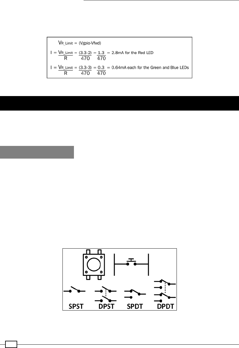
Using Python to Drive Hardware
184
The voltage across the resistor is equal to the GPIO voltage (Vgpio = 3.3V) minus the voltage
drop on the particular LED (Vfwd); we can then use this resistance to calculate the current
used by each of the LEDs, as shown in the following diagram:
We can calculate the current drawn by each of the LEDs
Responding to a button
Many applications using the Raspberry Pi require that actions are activated without a
keyboard and screen attached to it. The GPIO pins provide an excellent way for the Raspberry
Pi to be controlled by your own buttons and switches without a mouse/keyboard and screen.
Getting ready
You will need the following equipment:
f2 x DuPont female to male patch wires
fMini breadboard (170 tie points) or a larger one
fPush button switch (momentary close) or a wire connection
to make/break the circuit
fBreadboarding wire (solid core)
f1k ohm resistor
The switches are as seen in the following diagram:
The push button switch and other types of switch

Chapter 6
185
The switches used in the following examples are single pole single throw
(SPST) momentary close push button switches. Single pole (SP) means that
there is one set of contacts that makes a connection. In the case of the push
switch used here, the legs on each side are connected together with a single
pole switch in the middle. A double pole (DP) switch acts just like a single
pole switch, except that the two sides are separated electrically, allowing you
to switch two separate components on/off at the same time.
Single throw (ST) means the switch will make a connection with just one
position; the other side will be left open. Double throw (DT) means both
positions of the switch will connect to different parts.
Momentary close means that the button will close the switch when pressed
and automatically open it when released. A latched push button switch will
remain closed until it is pressed again.
The layout of the button circuit
We will use sound in this example, so you will also need speakers or headphones attached to
the audio socket of the Raspberry Pi.
You will need to install a program called flite using the following command, which will let us
make the Raspberry Pi talk:
sudo apt-get install flite
After it has been installed, you can test it with the following command:
sudo flite -t "hello I can talk"
If it is a little too quiet (or too loud), you can adjust the volume (0-100 percent) using the
following command:
amixer set PCM 100%

Using Python to Drive Hardware
186
How to do it…
Create the btntest.py script as follows:
#!/usr/bin/python3
#btntest.py
import time
import os
import RPi.GPIO as GPIO
#HARDWARE SETUP
# GPIO
# 2[==X==1=======]26[=======]40
# 1[=============]25[=======]39
#Button Config
BTN = 12
def gpio_setup():
#Setup the wiring
GPIO.setmode(GPIO.BOARD)
#Setup Ports
GPIO.setup(BTN,GPIO.IN,pull_up_down=GPIO.PUD_UP)
def main():
gpio_setup()
count=0
btn_closed = True
while True:
btn_val = GPIO.input(BTN)
if btn_val and btn_closed:
print("OPEN")
btn_closed=False
elif btn_val==False and btn_closed==False:
count+=1
print("CLOSE %s" % count)
os.system("flite -t '%s'" % count)
btn_closed=True
time.sleep(0.1)
try:
Chapter 6
187
main()
finally:
GPIO.cleanup()
print("Closed Everything. END")
#End
How it works…
As in the previous recipe, we set up the GPIO pin as required, but this time as an input, and
we also enable the internal pull-up resistor (see Pull-up and pull-down resistor circuits in the
There's more… section of this recipe for more information) using the following code:
GPIO.setup(BTN,GPIO.IN,pull_up_down=GPIO.PUD_UP)
After the GPIO pin is set up, we create a loop that will continuously check the state of BTN
using GPIO.input(). If the value returned is false, the pin has been connected to 0V
(ground) through the switch, and we will use flite to count out loud for us each time the
button is pressed.
Since we have called the main function from within a try/finally condition, it will still call
GPIO.cleanup() even if we close the program using Ctrl + Z.
We use a short delay in the loop; this ensures that any noise from the
contacts on the switch is ignored. This is because when we press the
button, there isn't always perfect contact as we press or release it, and it
may produce several triggers if we press it again too quickly. This is known
as software debouncing; we ignore the bounce in the signal here.
There's more…
The Raspberry Pi GPIO pins must be used with care; voltages used for inputs should be
within specic ranges, and any current drawn from them should be minimized using
protective resistors.
Safe voltages
We must ensure that we only connect inputs that are between 0 (Ground) and 3.3V. Some
processors use voltages between 0 and 5V, so extra components are required to interface
safely with them. Never connect an input or component that uses 5V unless you are certain it
is safe, or you will damage the GPIO ports of the Raspberry Pi.
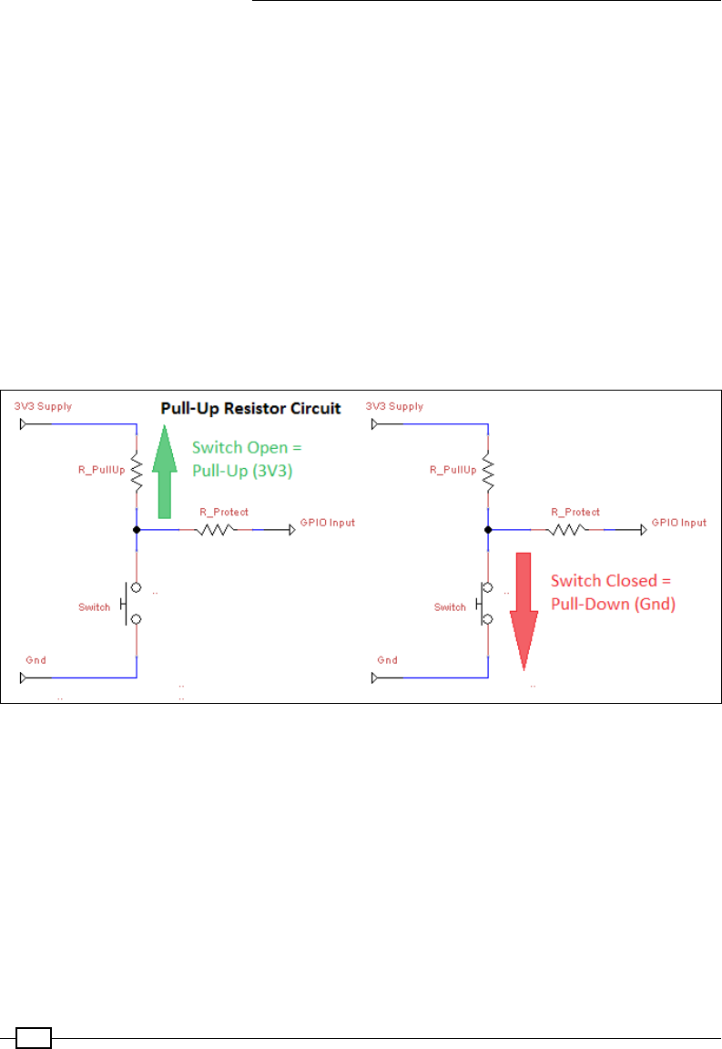
Using Python to Drive Hardware
188
Pull-up and pull-down resistor circuits
The previous code sets the GPIO pins to use an internal pull-up resistor. Without a
pull-up resistor (or pull-down resistor) on the GPIO pin, the voltage is free to oat somewhere
between 3.3V and 0V, and the actual logical state remains undetermined (sometimes 1 and
sometimes 0).
Raspberry Pi's internal pull-up resistors are 50k ohm-65k ohm and the pull-down resistors are
50k ohm-65k ohm. External pull-up/pull-down resistors are often used in GPIO circuits (as
shown in the following diagram), typically using 10k ohm or larger for similar reasons (giving a
very small current draw when not active).
A pull-up resistor allows a small amount of current to ow through the GPIO pin and
will provide a high voltage when the switch isn't pressed. When the switch is pressed, the
small current is replaced by the larger one owing to 0V, so we get a low voltage on the GPIO
pin instead. The switch is active low and logic 0 when pressed. It works as shown in the
following diagram:
A pull-up resistor circuit
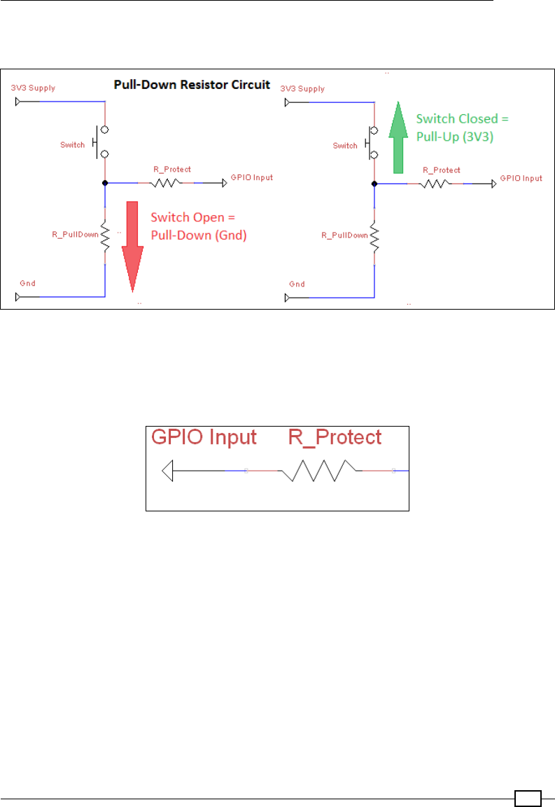
Chapter 6
189
Pull-down resistors work in the same way, except the switch is active high (the GPIO pin is logic
1 when pressed). It works as shown in the following diagram:
A pull-down resistor circuit
Protection resistors
In addition to the switch, the circuit includes a resistor in series with the switch to protect the
GPIO pin, as shown in the following diagram:
A GPIO protective current-limiting resistor
The purpose of the protection resistor is to protect the GPIO pin if it is accidentally set as
an output rather than an input. Imagine, for instance, that we have our switch connected
between the GPIO and ground. Now the GPIO pin is set as an output and switched on (driving
it to 3.3V) as soon as we press the switch; without a resistor present, the GPIO pin will directly
be connected to 0V. The GPIO will still try to drive it to 3.3V; this would cause the GPIO pin to
burn out (since it would use too much current to drive the pin to the high state). If we use a 1k
ohm resistor here, the pin is able to be driven high using an acceptable amount of current (I =
V/R = 3.3/1k = 3.3mA).
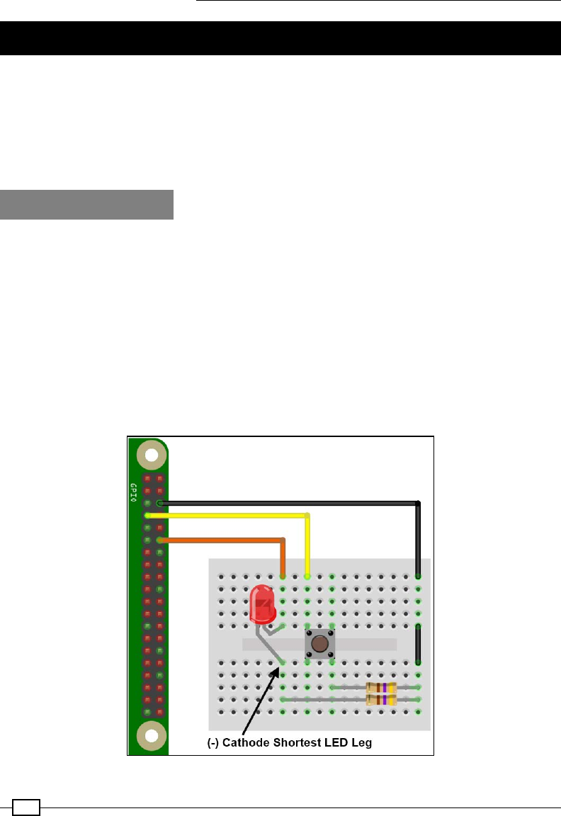
Using Python to Drive Hardware
190
A controlled shutdown button
The Raspberry Pi should always be shut down correctly to avoid the SD card being corrupted
(by losing power while performing a write operation to the card). This can pose a problem if
you don't have a keyboard or screen connected (if you are running an automated program or
controlling it remotely over a network and forget to turn it off) as you can't type the command
or see what you are doing. By adding our own buttons and LED indicator, we can easily
command a shutdown, reset, and startup again to indicate when the system is active.
Getting ready
You will need the following equipment:
f3 x Dupont female to male patch wires
fMini breadboard (170 tie points) or a larger one
fPush button switch (momentary close)
fGeneral purpose LED
f2 x 470-ohm resistors
fBreadboarding wire (solid core)
The entire layout of the shutdown circuit will look as shown in the following gure:
The controlled shutdown circuit layout

Chapter 6
191
How to do it…
Create the shtdwn.py script as follows:
#!/usr/bin/python3
#shtdwn.py
import time
import RPi.GPIO as GPIO
import os
# Shutdown Script
DEBUG=True #Simulate Only
SNDON=True
#HARDWARE SETUP
# GPIO
# 2[==X==L=======]26[=======]40
# 1[===1=========]25[=======]39
#BTN CONFIG - Set GPIO Ports
GPIO_MODE=GPIO.BOARD
SHTDWN_BTN = 7 #1
LED = 12 #L
def gpio_setup():
#Setup the wiring
GPIO.setmode(GPIO_MODE)
#Setup Ports
GPIO.setup(SHTDWN_BTN,GPIO.IN,pull_up_down=GPIO.PUD_UP)
GPIO.setup(LED,GPIO.OUT)
def doShutdown():
if(DEBUG):print("Press detected")
time.sleep(3)
if GPIO.input(SHTDWN_BTN):
if(DEBUG):print("Ignore the shutdown (<3sec)")
else:
if(DEBUG):print ("Would shutdown the RPi Now")
GPIO.output(LED,0)
time.sleep(0.5)
GPIO.output(LED,1)
if(SNDON):os.system("flite -t 'Warning commencing power down 3 2
1'")
if(DEBUG==False):os.system("sudo shutdown -h now")
if(DEBUG):GPIO.cleanup()

Using Python to Drive Hardware
192
if(DEBUG):exit()
def main():
gpio_setup()
GPIO.output(LED,1)
while True:
if(DEBUG):print("Waiting for >3sec button press")
if GPIO.input(SHTDWN_BTN)==False:
doShutdown()
time.sleep(1)
try:
main()
finally:
GPIO.cleanup()
print("Closed Everything. END")
#End
To get this script to run automatically (once we have tested it), we can place the script in
~/bin (we can use cp instead of mv if we just want to copy it) and add it to crontab with
the following code:
mkdir ~/bin
mv shtdwn.py ~/bin/shtdwn.py
crontab –e
At the end of the le, we add the following code:
@reboot sudo python3 ~/bin/shtdwn.py
How it works…
This time, when we set up the GPIO pin, we dene the pin connected to the shutdown button
as an input and the pin connected to the LED as an output. We turn the LED on to indicate
that the system is running.
By setting the DEBUG ag to True, we can test the functionality of our script without causing
an actual shutdown (by reading the terminal messages); we just need to ensure to set DEBUG
to False when using the script for real.
We enter a while loop and check every second to see whether the GPIO pin is set to LOW (the
switch has been pressed); if so, we enter the doShutdown() function.
Chapter 6
193
The program will wait for 3 seconds and then test again to see whether the button is still
being pressed. If the button is no longer being pressed, we return to the previous while loop.
However, if it is still being pressed after 3 seconds, the program will ash the LED and
trigger the shutdown (also providing an audio warning using flite).
When we are happy with how the script is operating, we can disable the DEBUG ag (by setting
it to False) and add the script to crontab. Crontab is a special program that runs in the
background and allows us to schedule (at specic times, dates, or periodically) programs
and actions when the system is started (@reboot). This allows the script to be started
automatically every time the Raspberry Pi is powered up. When we press and hold the
shutdown button for more than 3 seconds, it safely shuts down the system and enters a low
power state (the LED switches off just before this, indicating it is safe to remove the power
shortly after). To restart the Raspberry Pi, we briey remove the power; this will restart the
system, and the LED will light up when the Raspberry Pi has loaded.
There's more…
We can extend this example further using the reset header by adding extra functionality and
making use of additional GPIO connections (if available).
Resetting and rebooting Raspberry Pi
The Raspberry Pi has holes for mounting a reset header (marked RUN on the Raspberry
Pi 2 / 3 and P6 on the Raspberry Pi 1 Model B Rev 2 and Model As). The reset pin allows
the device to be reset using a button rather than removing the micro USB connector each
time to cycle the power:
Raspberry Pi reset headers – on the left, Raspberry Pi Model A/B (Rev2), and on the right, Raspberry Pi 2
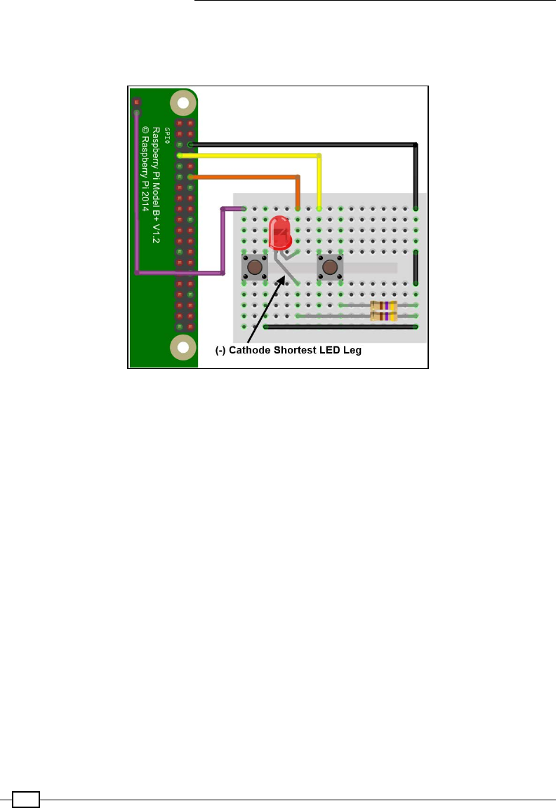
Using Python to Drive Hardware
194
To make use of it, you will need to solder a wire or pin header to the Raspberry Pi and connect
a button to it (or briey touch a wire between the two holes each time). Alternatively, we can
extend our previous circuit, as shown in the following diagram:
The controlled shutdown circuit layout and reset button
We can add this extra button to our circuit, which can be connected to the reset header (this
is the hole nearest the middle on the Raspberry Pi 2 or closest to the edge on other models).
This pin, when temporarily pulled low by connecting to ground (such as the hole next to it or by
another ground point such as pin 6 of the GPIO header), will reset the Raspberry Pi and allow
it to boot up again following a shutdown.
Adding extra functions
Since we now have the script monitoring the shutdown button all the time, we can add extra
buttons/switches/jumpers to be monitored at the same time. This will allow us to trigger
specic programs or set up particular states just by changing the inputs. The following
example allows us to easily switch between automatic DHCP networking (the default
networking setup) and using a direct IP address, as used in the Networking directly
to a laptop or computer recipe of Chapter 1, Getting Started with a Raspberry Pi Computer,
for direct LAN connections.
Add the following components to the previous circuit:
fA 470-ohm resistor
fTwo pin headers with a jumper connector (or optionally a switch)
fBreadboarding wire (solid core)

Chapter 6
195
After adding the previous components, our controlled shutdown circuit now looks as follows:
The controlled shutdown circuit layout, reset button, and jumper pins
In the previous script, we add an additional input to detect the status of the LAN_SWA pin
(the jumper pins we added to the circuit) using the following code:
LAN_SWA = 11 #2
Ensure that it is set up as an input (with a pull-up resistor) in the gpio_setup() function
using the following code:
GPIO.setup(LAN_SWA,GPIO.IN,pull_up_down=GPIO.PUD_UP)
Add a new function to switch between the LAN modes, and read out the new IP address. The
doChangeLAN() function checks if the status of the LAN_SWA pin has changed since the last
call, and if so, it sets the network adaptor to DHCP or sets the direct LAN settings accordingly
(and uses flite to speak the new IP setting if available). Finally, the LAN being set for direct
connection causes the LED to ash slowly while that mode is active. Use the following code to
do so:
def doChangeLAN(direct):
if(DEBUG):print("Direct LAN: %s" % direct)
if GPIO.input(LAN_SWA) and direct==True:
if(DEBUG):print("LAN Switch OFF")
cmd="sudo dhclient eth0"

Using Python to Drive Hardware
196
direct=False
GPIO.output(LED,1)
elif GPIO.input(LAN_SWA)==False and direct==False:
if(DEBUG):print("LAN Switch ON")
cmd="sudo ifconfig eth0 169.254.69.69"
direct=True
else:
return direct
if(DEBUG==False):os.system(cmd)
if(SNDON):os.system("hostname -I | flite")
return direct
Add another function, flashled(), which will just toggle the state of the LED each time it is
called. The code for this function is as follows:
def flashled(ledon):
if ledon:
ledon=False
else:
ledon=True
GPIO.output(LED,ledon)
return ledon
Finally, we adjust the main loop to also call doChangeLAN() and use the result to decide
whether we call flashled() using ledon to keep track of the LED's previous state each
time. The main() function should now be updated as follows:
def main():
gpio_setup()
GPIO.output(LED,1)
directlan=False
ledon=True
while True:
if(DEBUG):print("Waiting for >3sec button press")
if GPIO.input(SHTDWN_BTN)==False:
doShutdown()
directlan= doChangeLAN(directlan)
if directlan:
flashled(ledon)
time.sleep(1)

Chapter 6
197
The GPIO keypad input
We have seen how we can monitor inputs on the GPIO to launch applications and control the
Raspberry Pi; however, sometimes we need to control third-party programs. Using the uInput
library, we can emulate key presses from a keyboard (or even mouse movement) to control
any program, using our own custom hardware.
For more information about using uInput, visit http://tjjr.fi/sw/python-uinput/.
Getting ready
Perform the following steps to install uInput:
1. First, we need to download uInput.
You will need to download the uInput Python library from Github (~50 KB) using the
following commands:
wget https://github.com/tuomasjjrasanen/python-uinput/archive/
master.zip
unzip master.zip
The library will unzip to a directory called python-uinput-master.
Once completed, you can remove the ZIP le using the following command:
rm master.zip
2. Install the required packages (if you have installed them already, the apt-get
command will ignore them) using the following commands:
sudo apt-get install python3-setuptools python3-dev
sudo apt-get install libudev-dev
3. Compile and install uInput using the following commands:
cd python-uinput-master
sudo python3 setup.py install
4. Finally, we load the new uinput kernel module using the following command:
sudo modprobe uinput
To ensure it is loaded on startup, we can add uinput to the modules le using the
following command:
sudo nano /etc/modules
Put uinput on a new line in the le and save it (Ctrl + X,Y).
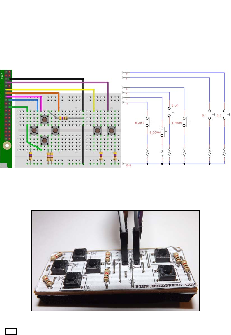
Using Python to Drive Hardware
198
5. Create the following circuit using the following equipment:
Breadboard (half-sized or larger)
7 x Dupont female to male patch wires
Six push buttons
6 x 470-ohm resistors
Breadboarding wire (solid core)
GPIO keypad circuit layout
The keypad circuit can also be built into a permanent circuit by soldering the
components into a Vero prototype board (also known as a stripboard), as shown
in the following image:
GPIO keypad Pi hardware module

Chapter 6
199
This circuit is available as a solder-yourself kit from PiHardware.com.
6. Connect the circuit to the Raspberry Pi GPIO pins as follows:
Button GPIO pin
GND 6
v B_DOWN 22
< B_LEFT 18
^ B_UP 15
> B_RIGHT 13
1 B_1 11
2 B_2 7
How to do it…
Create a gpiokeys.py script as follows:
#!/usr/bin/python3
#gpiokeys.py
import time
import RPi.GPIO as GPIO
import uinput
#HARDWARE SETUP
# GPIO
# 2[==G=====<=V==]26[=======]40
# 1[===2=1>^=====]25[=======]39
B_DOWN = 22 #V
B_LEFT = 18 #<
B_UP = 15 #^
B_RIGHT = 13 #>
B_1 = 11 #1
B_2 = 7 #2
DEBUG=True
BTN = [B_UP,B_DOWN,B_LEFT,B_RIGHT,B_1,B_2]

Using Python to Drive Hardware
200
MSG = ["UP","DOWN","LEFT","RIGHT","1","2"]
#Setup the DPad module pins and pull-ups
def dpad_setup():
#Set up the wiring
GPIO.setmode(GPIO.BOARD)
# Setup BTN Ports as INPUTS
for val in BTN:
# set up GPIO input with pull-up control
#(pull_up_down can be:
# PUD_OFF, PUD_UP or PUD_DOWN, default PUD_OFF)
GPIO.setup(val, GPIO.IN, pull_up_down=GPIO.PUD_UP)
def main():
#Setup uinput
events = (uinput.KEY_UP,uinput.KEY_DOWN,uinput.KEY_LEFT,
uinput.KEY_RIGHT,uinput.KEY_ENTER,uinput.KEY_ENTER)
device = uinput.Device(events)
time.sleep(2) # seconds
dpad_setup()
print("DPad Ready!")
btn_state=[False,False,False,False,False,False]
key_state=[False,False,False,False,False,False]
while True:
#Catch all the buttons pressed before pressing the related keys
for idx, val in enumerate(BTN):
if GPIO.input(val) == False:
btn_state[idx]=True
else:
btn_state[idx]=False
#Perform the button presses/releases (but only change state once)
for idx, val in enumerate(btn_state):
if val == True and key_state[idx] == False:
if DEBUG:print (str(val) + ":" + MSG[idx])
device.emit(events[idx], 1) # Press.
key_state[idx]=True
elif val == False and key_state[idx] == True:
if DEBUG:print (str(val) + ":!" + MSG[idx])

Chapter 6
201
device.emit(events[idx], 0) # Release.
key_state[idx]=False
time.sleep(.1)
try:
main()
finally:
GPIO.cleanup()
#End
How it works…
First, we import uinput and dene the wiring of the keypad buttons. For each of the buttons
in BTN, we enable them as inputs with internal pull-ups enabled.
Next, we set up uinput, dening the keys we want to emulate and adding them to the
uinput.Device() function. We wait a few seconds to allow uinput to initialize, set the
initial button and key states, and start our main loop.
The main loop is split into two sections: the rst part checks through the buttons and records
the states in btn_state, and the second part compares the btn_state with the current
key_state array. This way, we can detect a change in btn_state and call device.emit()
to toggle the state of the key.
To allow us to run this script in the background, we can run it with & as shown in the
following command:
sudo python3 gpiokeys.py &
The & character allows the command to run in the background, so we can
continue with the command line to run other programs. You can use fg
to bring it back to the foreground, or %1, %2, and so on if you have several
commands running. Use jobs to get a list.
You can even put a process/program on hold to get to the command
prompt by pressing Ctrl + Z and then resume it with bg (which will let it
run in the background).
You can test the keys using the game created in the Creating an overhead
scrolling game recipe in Chapter 4, Creating Games and Graphics, which
you can now control using your GPIO directional pad. Don't forget that if
you are connecting to the Raspberry Pi remotely, any key presses will only
be active on the locally connected screen.

Using Python to Drive Hardware
202
There's more…
We can do more using uinput to provide hardware control for other programs, including
those that require mouse input.
Generating other key combinations
You can create several different key mappings in your le to support different programs. For
instance, the events_z80 key mapping would be useful for a Spectrum Emulator such as
fuze (browse to http://raspi.tv/2012/how-to-install-fuse-zx-spectrum-
emulator-on-raspberry-pi for details). The events_omx key mappings are suitable for
controlling video played through the OMX Player using the following command:
omxplayer filename.mp4
You can get a list of keys supported by omxplayer by using the -k parameter.
Replace the line that denes the events list with a new key mapping, and select different
ones by assigning them to events using the following code:
events_dpad = (uinput.KEY_UP,uinput.KEY_DOWN,uinput.KEY_LEFT,
uinput.KEY_RIGHT,uinput.KEY_ENTER,uinput.KEY_ENTER)
events_z80 = (uinput.KEY_Q,uinput.KEY_A,uinput.KEY_O,
uinput.KEY_P,uinput.KEY_M,uinput.KEY_ENTER)
events_omx = (uinput.KEY_EQUAL,uinput.KEY_MINUS,uinput.KEY_LEFT,
uinput.KEY_RIGHT,uinput.KEY_P,uinput.KEY_Q)
You can nd all the KEY denitions in the input.h le; you can view it using the less
command (press Q to exit) as shown in the following command:
less /usr/include/linux/input.h
Emulating mouse events
The uinput library can emulate mouse and joystick events as well as keyboard presses. To
use the buttons to simulate a mouse, we can adjust the script to use mouse events (as well as
dening mousemove to set the step size of the movement) using the following code:
MSG = ["M_UP","M_DOWN","M_LEFT","M_RIGHT","1","Enter"]
events_mouse=(uinput.REL_Y,uinput.REL_Y, uinput.REL_X,
uinput.REL_X,uinput.BTN_LEFT,uinput.BTN_RIGHT)
mousemove=1

Chapter 6
203
We also need to modify the button handling to provide continuous movement, as we don't
need to keep track of the state of the keys for the mouse. To do so, use the following code:
#Perform the button presses/releases
#(but only change state once)
for idx, val in enumerate(btn_state):
if MSG[idx] == "M_UP" or MSG[idx] == "M_LEFT":
state = -mousemove
else:
state = mousemove
if val == True:
device.emit(events[idx], state) # Press.
elif val == False:
device.emit(events[idx], 0) # Release.
time.sleep(0.01)
Multiplexed color LEDs
The next example in this chapter demonstrates that some seemingly simple hardware can
produce some impressive results if controlled with software. We return to using some RGB
LEDs that are wired so that we only need to use eight GPIO pins to control the red, green,
and blue elements of ve RGB LEDs using a method called hardware multiplexing (see the
Hardware multiplexing subsection in the There's more… section of this recipe).

Using Python to Drive Hardware
204
Getting ready
You will need the RGB LED module shown in the following image:
The RGB LED module from PiHardware.com
As you can see in the preceding image, the RGB LED module from PiHardware.com comes
with GPIO pins and a Dupont female to female cable for connecting it. Although there are two
sets of pins labelled 1 to 5, only one side needs to be connected.
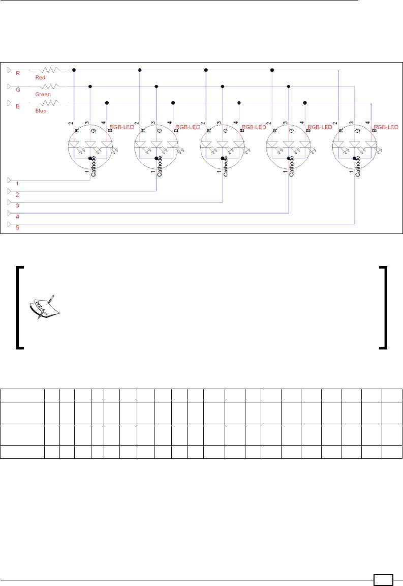
Chapter 6
205
Alternatively, you can recreate your own with the following circuit using ve common cathode
RGB LEDs, 3 x 470-ohm resistors, and a Vero prototype board (or large breadboard). The
circuit will look as shown in the following diagram:
Circuit diagram for the RGB LED module
Strictly speaking, we should use 15 resistors in this circuit (one for each
RGB LED element), which will avoid interference from LEDs sharing the
same resistor and would also prolong the life of the LEDs themselves
if switched on together. However, there is only a slight advantage,
particularly since we intend to drive each RGB LED independently of the
other four to achieve multicolor effects.
You will need to connect the circuit to the Raspberry Pi GPIO header as follows:
RGB LED 1 2 3 4
Rpi GPIO
Pin
2 4 6 8 10 12 14 16 18 20 22 24 26 28 30 32 34 36 38 40
Rpi GPIO
Pin
1 3 5 7 9 11 13 15 17 19 21 23 25 27 29 31 33 35 37 39
RGB LED 5 R G B

Using Python to Drive Hardware
206
How to do it…
Create the rgbled.py script and perform the following steps:
1. Import all the required modules and dene values to be used with the help of the
following code:
#!/usr/bin/python3
#rgbled.py
import time
import RPi.GPIO as GPIO
#Setup Active states
#Common Cathode RGB-LEDs (Cathode=Active Low)
LED_ENABLE = 0; LED_DISABLE = 1
RGB_ENABLE = 1; RGB_DISABLE = 0
#HARDWARE SETUP
# GPIO
# 2[=====1=23=4==]26[=======]40
# 1[===5=RGB=====]25[=======]39
#LED CONFIG - Set GPIO Ports
LED1 = 12; LED2 = 16; LED3 = 18; LED4 = 22; LED5 = 7
LED = [LED1,LED2,LED3,LED4,LED5]
RGB_RED = 11; RGB_GREEN = 13; RGB_BLUE = 15
RGB = [RGB_RED,RGB_GREEN,RGB_BLUE]
#Mixed Colors
RGB_CYAN = [RGB_GREEN,RGB_BLUE]
RGB_MAGENTA = [RGB_RED,RGB_BLUE]
RGB_YELLOW = [RGB_RED,RGB_GREEN]
RGB_WHITE = [RGB_RED,RGB_GREEN,RGB_BLUE]
RGB_LIST = [RGB_RED,RGB_GREEN,RGB_BLUE,RGB_CYAN,
RGB_MAGENTA,RGB_YELLOW,RGB_WHITE]
2. Dene functions to set up the GPIO pins using the following code:
def led_setup():
'''Setup the RGB-LED module pins and state.'''
#Set up the wiring
GPIO.setmode(GPIO.BOARD)
# Setup Ports
for val in LED:
GPIO.setup(val, GPIO.OUT)
for val in RGB:
GPIO.setup(val, GPIO.OUT)
led_clear()

Chapter 6
207
3. Dene our utility functions to help control the LEDs using the following code:
def led_gpiocontrol(pins,state):
'''This function will control the state of
a single or multiple pins in a list.'''
#determine if "pins" is a single integer or not
if isinstance(pins,int):
#Single integer - reference directly
GPIO.output(pins,state)
else:
#if not, then cycle through the "pins" list
for i in pins:
GPIO.output(i,state)
def led_activate(led,color):
'''Enable the selected led(s) and set the required color(s)
Will accept single or multiple values'''
#Enable led
led_gpiocontrol(led,LED_ENABLE)
#Enable color
led_gpiocontrol(color,RGB_ENABLE)
def led_deactivate(led,color):
'''Deactivate the selected led(s) and set the required
color(s) will accept single or multiple values'''
#Disable led
led_gpiocontrol(led,LED_DISABLE)
#Disable color
led_gpiocontrol(color,RGB_DISABLE)
def led_time(led, color, timeon):
'''Switch on the led and color for the timeon period'''
led_activate(led,color)
time.sleep(timeon)
led_deactivate(led,color)
def led_clear():
'''Set the pins to default state.'''
for val in LED:
GPIO.output(val, LED_DISABLE)
for val in RGB:
GPIO.output(val, RGB_DISABLE)
def led_cleanup():

Using Python to Drive Hardware
208
'''Reset pins to default state and release GPIO'''
led_clear()
GPIO.cleanup()
4. Create a test function to demonstrate the functionality of the module:
def main():
'''Directly run test function.
This function will run if the file is executed directly'''
led_setup()
led_time(LED1,RGB_RED,5)
led_time(LED2,RGB_GREEN,5)
led_time(LED3,RGB_BLUE,5)
led_time(LED,RGB_MAGENTA,2)
led_time(LED,RGB_YELLOW,2)
led_time(LED,RGB_CYAN,2)
if __name__=='__main__':
try:
main()
finally:
led_cleanup()
#End
How it works…
To start with, we dene the hardware setup by dening the states required to Enable and
Disable the LED depending on the type of RGB LED (common cathode) used. If you are using
a common anode device, just reverse the Enable/Disable states.
Next, we dene the GPIO mapping to the pins to match the wiring we did previously.
We also dene some basic color combinations by combining red, green, and/or blue together,
as shown in the following diagram:
LED color combinations
We dene a series of useful functions, the rst being led_setup(), which will set the GPIO
numbering to GPIO.BOARD and dene all the pins used to be outputs. We also call a function
named led_clear(), which will set the pins to the default state with all the pins disabled.
Chapter 6
209
This means the LED pins, 1-5 (the common cathode on each LED),
are set to HIGH, while the RGB pins (the separate anodes for each
color) are set to LOW.
We create a function called led_gpiocontrol() that will allow us to set the state of one or
more pins. The isinstance() function allows us to test a value to see whether it matches
a particular type (in this case, a single integer); then we can either set the state of that single
pin or iterate through the list of pins and set each one.
Next, we dene two functions, led_activate() and led_deactivate(), which will
enable and disable the specied LED and color. Finally, we dene led_time(), which will
allow us to specify an LED, color, and time to switch it on for.
We also create led_cleanup() to reset the pins (and LEDs) to the default values and call
GPIO.cleanup() to release the GPIO pins in use.
This script is intended to become a library le, so we will use the if __name__=='__
main__' check to only run our test code when running the le directly:
By checking the value of __name__, we can determine whether the le
was run directly (it will equal __main__) or whether it was imported by
another Python script.
This allows us to dene special test code that is only executed when we
directly load and run the le. If we include this le as a module in another
script, then this code will not be executed.
We have used this technique previously in the There's more… section in
the Working with text and strings recipe of Chapter 2, Starting with Python
Strings, Files, and Menus.
As before, we will use try/finally to allow us to always perform
cleanup actions, even if we exit early.
To test the script, we will set the LEDs to light up in various colors one after another.
There's more…
We can create a few different colors by switching on one or more parts of the RGB LED at a
time. However, with some clever programming, we can create a whole spectrum of colors.
Also, we can display different colors on each LED, seemingly at the same time.

Using Python to Drive Hardware
210
Hardware multiplexing
An LED requires a high voltage on the anode side and a lower voltage on the cathode side
to light up. The RGB LEDs used in the circuit are common cathode, so we must apply a high
voltage (3.3V) on the RGB pins and a low voltage (0V) on the cathode pin (wired to pins 1 to 5
for each of the LEDs).
The cathode and RGB pin states are as follows:
Cathode and RGB pin states
Therefore, we can enable one or more of the RGB pins but still control which of the LEDs
are lit. We enable the pins of the LEDs we want to light up and disable the ones we don't.
This allows us to use far fewer pins than we would need to control each of the 15 RGB lines
separately.
Displaying random patterns
We can add new functions to our library to produce different effects, such as generating
random colors. The following function uses randint() to get a value between 1 and the
number of colors. We ignore any values that are over the number of the available colors so
that we can control how often the LEDs may be switched off. Perform the following steps to
add the required functions:
1. Add the randint() function from the random module to the rgbled.py script
using the following code:
from random import randint
2. Now add led_rgbrandom() using the following code:
def led_rgbrandom(led,period,colors):
''' Light up the selected led, for period in seconds,
in one of the possible colors. The colors can be
1 to 3 for RGB, or 1-6 for RGB plus combinations,
1-7 includes white. Anything over 7 will be set as
OFF (larger the number more chance of OFF).'''

Chapter 6
211
value = randint(1,colors)
if value < len(RGB_LIST):
led_time(led,RGB_LIST[value-1],period)
3. Use the following commands in the main() function to create a series of
ashing LEDs:
for i in range(20):
for j in LED:
#Select from all, plus OFF
led_rgbrandom(j,0.1,20)
Mixing multiple colors
Until now, we have only displayed a single color at a time on one or more of the LEDs. If you
consider how the circuit is wired up, you might wonder how can we get one LED to display one
color and another a different one at the same time? The simple answer is that we don't need
to—we just do it quickly!
All we need to do is display one color at a time but change it very quickly back and forth, so
fast the color looks like a mix of the two (or even a combination of the three red/green/blue
LEDs). Fortunately, this is something that computers such as the Raspberry Pi can do very
easily, even allowing us to combine the RGB elements to make multiple shades of colors
across all ve LEDs. Perform the following steps to mix the colors:
1. Add combo color denitions to the top of the rgbled.py script, after the denition of
the mixed colors, using the following code:
#Combo Colors
RGB_AQUA = [RGB_CYAN,RGB_GREEN]
RGB_LBLUE = [RGB_CYAN,RGB_BLUE]
RGB_PINK = [RGB_MAGENTA,RGB_RED]
RGB_PURPLE = [RGB_MAGENTA,RGB_BLUE]
RGB_ORANGE = [RGB_YELLOW,RGB_RED]
RGB_LIME = [RGB_YELLOW,RGB_GREEN]
RGB_COLORS = [RGB_LIME,RGB_YELLOW,RGB_ORANGE,RGB_RED,
RGB_PINK,RGB_MAGENTA,RGB_PURPLE,RGB_BLUE,
RGB_LBLUE,RGB_CYAN,RGB_AQUA,RGB_GREEN]
The preceding code will provide the combination of colors to create our shades, with
RGB_COLORS providing a smooth progression through the shades.
2. Next, we need to create a function called led_combo() to handle single or multiple
colors. The code for the function will be as follows:
def led_combo(pins,colors,period):
#determine if "colors" is a single integer or not
if isinstance(colors,int):
#Single integer - reference directly

Using Python to Drive Hardware
212
led_time(pins,colors,period)
else:
#if not, then cycle through the "colors" list
for i in colors:
led_time(pins,i,period)
3. Now we can create a new script, rgbledrainbow.py, to make use of the new
functions in our rgbled.py module. The rgbledrainbow.py script will be
as follows:
#!/usr/bin/python3
#rgbledrainbow.py
import time
import rgbled as RGBLED
def next_value(number,max):
number = number % max
return number
def main():
print ("Setup the RGB module")
RGBLED.led_setup()
# Multiple LEDs with different Colors
print ("Switch on Rainbow")
led_num = 0
col_num = 0
for l in range(5):
print ("Cycle LEDs")
for k in range(100):
#Set the starting point for the next set of colors
col_num = next_value(col_num+1,len(RGBLED.RGB_COLORS))
for i in range(20): #cycle time
for j in range(5): #led cycle
led_num = next_value(j,len(RGBLED.LED))
led_color = next_value(col_num+led_num,
len(RGBLED.RGB_COLORS))
RGBLED.led_combo(RGBLED.LED[led_num],
RGBLED.RGB_COLORS[led_color],0.001)
print ("Cycle COLORs")
for k in range(100):
#Set the next color
col_num = next_value(col_num+1,len(RGBLED.RGB_COLORS))
for i in range(20): #cycle time
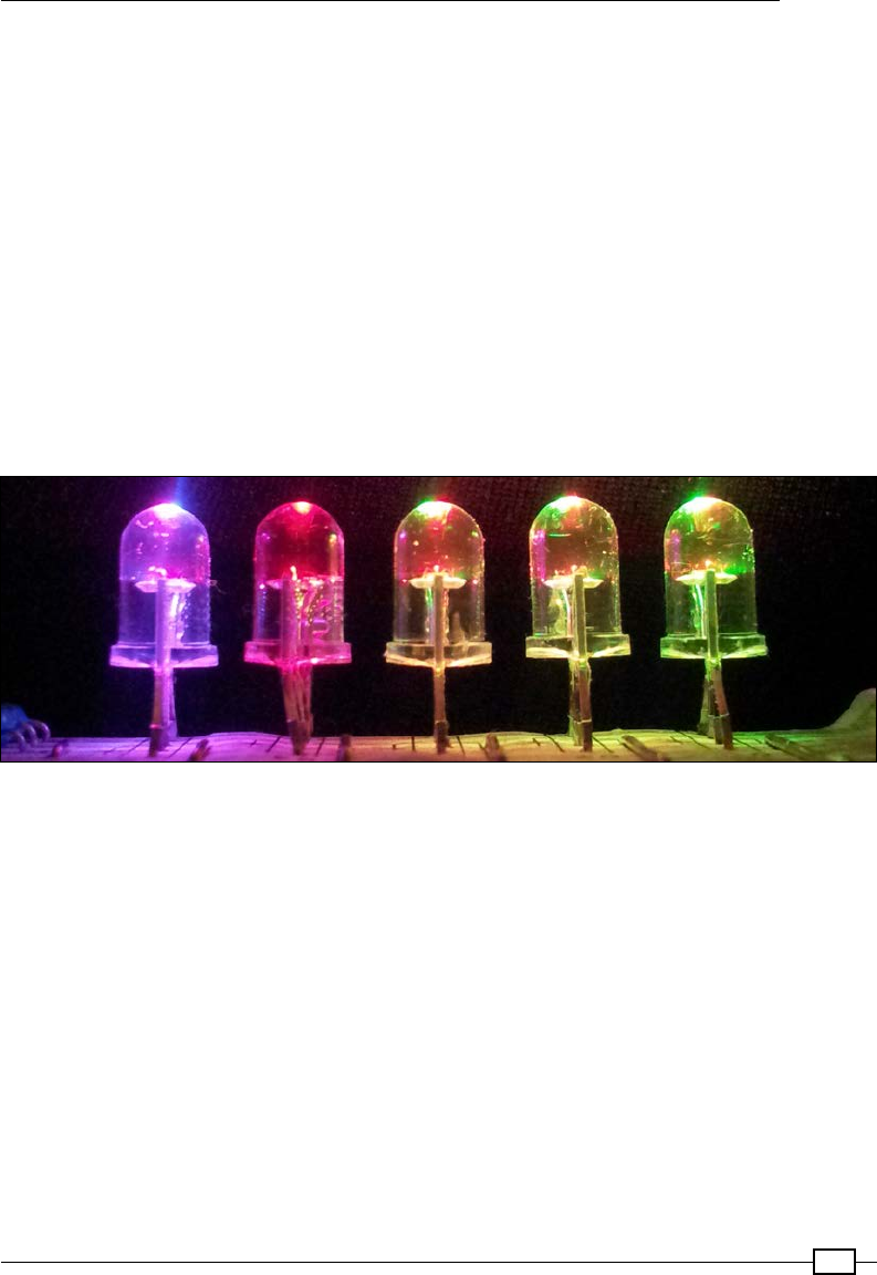
Chapter 6
213
for j in range(5): #led cycle
led_num = next_value(j,len(RGBLED.LED))
RGBLED.led_combo(RGBLED.LED[led_num],
RGBLED.RGB_COLORS[col_num],0.001)
print ("Finished")
if __name__=='__main__':
try:
main()
finally:
RGBLED.led_cleanup()
#End
The main() function will rst cycle through the LEDs, setting each color from the
RGB_COLORS array on all the LEDs. Then, it will cycle through the colors, creating a
rainbow effect over the LEDs:
Cycle through multiple colors on the five RGB LEDs
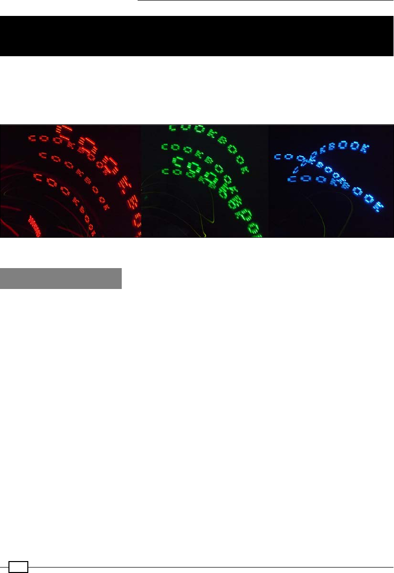
Using Python to Drive Hardware
214
Writing messages using Persistence of
Vision
Persistence of Vision (POV) displays can produce an almost magical effect, displaying images
in the air by moving a line of LEDs back and forth very quickly or around in circles. The effect
works because your eyes are unable to adjust fast enough to separate out the individual
ashes of light, and so you observe a merged image (the message or picture being displayed).
Persistence of vision using RGB LEDs
Getting ready
This recipe also uses the RGB LED kit used in the previous recipe; you will also need the
following additional items:
fBreadboard (half-sized or larger)
f2 x Dupont female to male patch wires
fTilt switch (ball-bearing type is suitable)
f1 x 470 ohm resistor (R_Protect)
fBreadboarding wire (solid core)
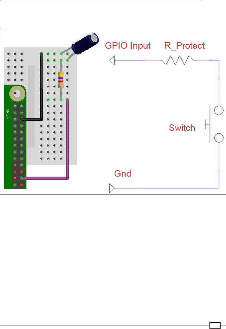
Chapter 6
215
The tilt switch should be added to the RGB LED (as described in the Getting ready section of
the Multiplexed color LEDs recipe). The tilt switch is wired as follows:
Tilt switch is connected to GPIO Input (GPIO pin 24) and Gnd (GPIO pin 6)
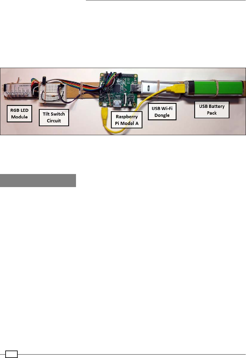
Using Python to Drive Hardware
216
To reproduce the POV image, you will need to be able to quickly move the LEDs and tilt switch
back and forth. Note how the tilt switch is mounted angled to the side, so the switch will
open when moved to the left. It is recommended that the hardware is mounted onto a length
of wood or similar. You can even use a portable USB battery pack along with a Wi-Fi dongle
to power and control the Raspberry Pi through a remote connection (see Chapter 1, Getting
Started with a Raspberry Pi – Connecting Remotely to the Raspberry Pi over the Network
using SSH (and X11 Forwarding), for details):
Persistence of Vision hardware setup
You will also need the completed rgbled.py le, which we will extend further in the How to
do it… section.
How to do it…
Create a script called tilt.py to report the state of the tilt switch:
#!/usr/bin/python3
#tilt.py
import RPi.GPIO as GPIO
#HARDWARE SETUP
# GPIO
# 2[===========T=]26[=======]40
# 1[=============]25[=======]39
#Tilt Config
TILT_SW = 24
def tilt_setup():
#Setup the wiring
GPIO.setmode(GPIO.BOARD)
#Setup Ports
GPIO.setup(TILT_SW,GPIO.IN,pull_up_down=GPIO.PUD_UP)
def tilt_moving():

Chapter 6
217
#Report the state of the Tilt Switch
return GPIO.input(TILT_SW)
def main():
import time
tilt_setup()
while True:
print("TILT %s"% (GPIO.input(TILT_SW)))
time.sleep(0.1)
if __name__=='__main__':
try:
main()
finally:
GPIO.cleanup()
print("Closed Everything. END")
#End
You can test the script by running it directly with the following command:
sudo python3 tilt.py
Add the following rgbled_pov() function to the rgbled.py script we created previously;
this will allow us to display a single line of our image:
def rgbled_pov(led_pattern,color,ontime):
'''Disable all the LEDs and re-enable the LED pattern in the
required color'''
led_deactivate(LED,RGB)
for led_num,col_num in enumerate(led_pattern):
if col_num >= 1:
led_activate(LED[led_num],color)
time.sleep(ontime)
We will now create the following le, called rgbledmessage.py, to perform the required
actions to display our message. First we will import the modules used, the updated rgbled
module, the new tilt module, and the python os module. Initially, we set DEBUG to True so
the Python terminal will display additional information while the script is running:
#!/usr/bin/python3
# rgbledmessage.py
import rgbled as RGBLED
import tilt as TILT
import os
DEBUG = True

Using Python to Drive Hardware
218
Add a readMessageFile() function to read the content of the letters.txt le and
then add processFileContent() to generate a Python dictionary of the LED patterns
for each letter:
def readMessageFile(filename):
assert os.path.exists(filename), 'Cannot find the message file: %s'
% (filename)
try:
with open(filename, 'r') as theFile:
fileContent = theFile.readlines()
except IOError:
print("Unable to open %s" % (filename))
if DEBUG:print ("File Content START:")
if DEBUG:print (fileContent)
if DEBUG:print ("File Content END")
dictionary = processFileContent(fileContent)
return dictionary
def processFileContent(content):
letterIndex = [] #Will contain a list of letters stored in the file
letterList = [] #Will contain a list of letter formats
letterFormat = [] #Will contain the format of each letter
firstLetter = True
nextLetter = False
LETTERDIC={}
#Process each line that was in the file
for line in content:
# Ignore the # as comments
if '#' in line:
if DEBUG:print ("Comment: %s"%line)
#Check for " in the line = index name
elif '"' in line:
nextLetter = True
line = line.replace('"','') #Remove " characters
LETTER=line.rstrip()
if DEBUG:print ("Index: %s"%line)
#Remaining lines are formatting codes
else:
#Skip firstLetter until complete
if firstLetter:
firstLetter = False
nextLetter = False
lastLetter = LETTER
#Move to next letter if needed
if nextLetter:

Chapter 6
219
nextLetter = False
LETTERDIC[lastLetter]=letterFormat[:]
letterFormat[:] = []
lastLetter = LETTER
#Save the format data
values = line.rstrip().split(' ')
row = []
for val in values:
row.append(int(val))
letterFormat.append(row)
LETTERDIC[lastLetter]=letterFormat[:]
#Show letter patterns for debugging
if DEBUG:print ("LETTERDIC: %s" %LETTERDIC)
if DEBUG:print ("C: %s"%LETTERDIC['C'])
if DEBUG:print ("O: %s"%LETTERDIC['O'])
return LETTERDIC
Add a createBuffer() function, which will convert a message into a series of LED patterns
for each letter (assuming the letter is dened by the letters.txt le):
def createBuffer(message,dictionary):
buffer=[]
for letter in message:
try:
letterPattern=dictionary[letter]
except KeyError:
if DEBUG:print("Unknown letter %s: use _"%letter)
letterPattern=dictionary['_']
buffer=addLetter(letterPattern,buffer)
if DEBUG:print("Buffer: %s"%buffer)
return buffer
def addLetter(letter,buffer):
for row in letter:
buffer.append(row)
buffer.append([0,0,0,0,0])
buffer.append([0,0,0,0,0])
return buffer
Next, we dene displayBuffer() to display the LED patterns using the rgbled_pov()
function in the rgbled module:
def displayBuffer(buffer):
position=0
while(1):

Using Python to Drive Hardware
220
if(TILT.tilt_moving()==False):
position=0
elif (position+1)<len(buffer):
position+=1
if DEBUG:print("Pos:%s ROW:%s"%(position,buffer[position]))
RGBLED.rgbled_pov(buffer[position],RGBLED.RGB_GREEN,0.001)
RGBLED.rgbled_pov(buffer[position],RGBLED.RGB_BLUE,0.001)
Finally, we create a main() function to perform each of the required steps:
1. Set up the hardware components (RGB LEDs and the tilt switch).
2. Read the letters.txt le.
3. Dene the dictionary of LED letter patterns.
4. Generate a buffer to represent the required message.
5. Display the buffer using the rgbled module and control it with the tilt module:
def main():
RGBLED.led_setup()
TILT.tilt_setup()
dict=readMessageFile('letters.txt')
buffer=createBuffer('_COOKBOOK_',dict)
displayBuffer(buffer)
if __name__=='__main__':
try:
main()
finally:
RGBLED.led_cleanup()
print("Closed Everything. END")
#End
Create the following le, called letters.txt, to dene the LED patterns needed to display
the example '_COOKBOOK_' message. Note, this le only needs to dene a pattern for each
unique letter or symbol in the message:
#COOKBOOK
"C"
0 1 1 1 0
1 0 0 0 1
1 0 0 0 1
"O"
0 1 1 1 0
1 0 0 0 1
1 0 0 0 1
0 1 1 1 0

Chapter 6
221
"K"
1 1 1 1 1
0 1 0 1 0
1 0 0 0 1
"B"
1 1 1 1 1
1 0 1 0 1
0 1 0 1 0
"_"
0 0 0 0 0
0 0 0 0 0
0 0 0 0 0
0 0 0 0 0
0 0 0 0 0
How it works…
The rst function, readMessageFile(), will open and read the contents of a given
le (as we did previously in Chapter 2, Starting with Python Strings, Files, and Menus;
see the Using les and handling errors recipe for more details). This will then use
processFileContent() to return a Python dictionary containing corresponding patterns
for the letters dened in the le provided. Each line in the le is processed, ignoring any line
with a # character in and checking for " characters to indicate the name for the LED pattern
that follows after. After the le has been processed, we end up with a Python dictionary that
contains LED patterns for the '_', 'C', 'B', 'K' and 'O' characters:
'_': [[0, 0, 0, 0, 0], [0, 0, 0, 0, 0], [0, 0, 0, 0, 0], [0, 0, 0, 0,
0], [0, 0, 0, 0, 0]]
'C': [[0, 1, 1, 1, 0], [1, 0, 0, 0, 1], [1, 0, 0, 0, 1]]
'B': [[1, 1, 1, 1, 1], [1, 0, 1, 0, 1], [0, 1, 0, 1, 0]]
'K': [[1, 1, 1, 1, 1], [0, 1, 0, 1, 0], [1, 0, 0, 0, 1]]
'O': [[0, 1, 1, 1, 0], [1, 0, 0, 0, 1], [1, 0, 0, 0, 1], [0, 1, 1, 1,
0]]
Now that we have a selection of letters to choose from, we can create a sequence of LED
patterns using the createBuffer() function. As the name suggests, the function will build
up a buffer of LED patterns by looking up each letter in the message and adding the related
pattern row by row. If a letter isn't found in the dictionary, then a space will be used instead.
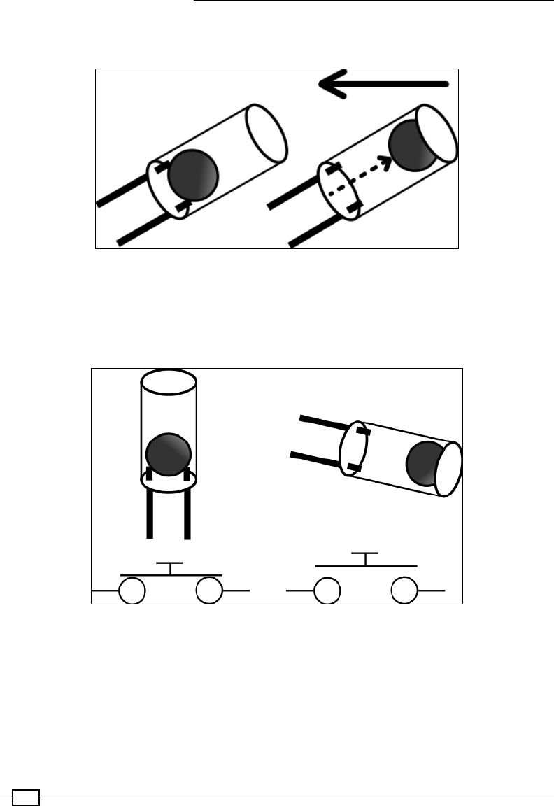
Using Python to Drive Hardware
222
Finally, we now have a list of LED patterns ready to display. To control when we start the
sequence, we will use the TILT module and check the status of the tilt switch:
The tilt switch position when not moving (left) and moving (right)
The tilt switch consists of a small ball bearing enclosed in a hollow insulated cylinder; the
connection between the two pins is closed when the ball is resting at the bottom of the
cylinder. The tilt switch is open when the ball is moved to the other end of the cylinder,
out of contact of the pins:
The tilt switch circuit, switch closed and switch open
The tilt switch circuit shown previously will allow GPIO pin 24 to be connected to the ground
when the switch is closed, then if we read the pin it will return False when it is at rest. By
setting the GPIO pin as an input and enabling the internal pull-up resistor, when the tilt switch
is open it will report True.

Chapter 6
223
If the tilt switch is open (reporting True) then we will assume the unit is being moved and
begin displaying the LED sequences, incrementing the current position each time we display
a row of the LED pattern. Just to make the pattern a little more colorful (just because we can!)
we repeat each row in another color. As soon as the TILT.tilt_moving() function reports
we have stopped moving or we are moving in the opposite direction, we will reset the current
position, ready to start the whole pattern over again:
The message is displayed by the RGB LEDs – here using Green and Blue together
When the RGB LED module and tilt switch are moved back and forth, we should see the
message displayed in the air!
Try experimenting with different color combinations, speeds, and arm waviness to see what
effects you can produce. You could even create a similar setup mounted on a wheel to
produce a continuous POV effect.

225
7
Sense and Display
Real-World Data
In this chapter, we will cover the following topics:
fUsing devices with the I2C bus
fReading analog data using an analog-to-digital converter
fLogging and plotting data
fExtending the Raspberry Pi GPIO with an I/O expander
fCapturing data in an SQLite database
fViewing data from your own webserver
fSensing and sending data to online services
Introduction
In the previous chapter, we made use of the Raspberry Pi GPIO to directly control and respond
to the attached hardware by controlling or reading the GPIO pins. In this chapter, we will learn
how to collect analog data from the real world and process it so we can display, log, graph,
and share the data and make use of it in our programs.
We will extend the capabilities of the Raspberry Pi by interfacing with Analog-to-Digital
Converters (ADCs), LCD alphanumeric displays, and digital port expanders using Raspberry
Pi's GPIO connections.
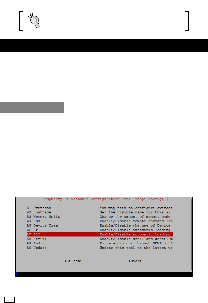
Sense and Display Real-World Data
226
Be sure to check out Appendix, Hardware and Software List,
which lists all the items used in this chapter and the places
you can obtain them from.
Using devices with the I2C bus
The Raspberry Pi can support several higher-level protocols that a wider range of devices
can easily be connected to. In this chapter, we shall focus on the most common bus, called
I2C (I-squared-C). It provides a medium-speed bus for communicating with devices over two
wires. In this section, we shall use I2C to interface with an 8-bit ADC. This device will measure
an analog signal, convert it to a relative value between 0 and 255, and send the value as a
digital signal (represented by 8 bits) over the I2C bus to the Raspberry Pi.
Getting ready
The I2C bus is not enabled in all Raspberry Pi images; therefore, we need to enable the
module and install some supporting tools. Newer versions of Raspbian use Device Trees to
handle hardware peripherals and drivers.
In order to make use of the I2C bus, we need to enable the ARM I2C in the \boot\config.
txt le.
You can do this automatically using the following command:
sudo raspi-config
As shown in the following screenshot, select Advanced Options from the menu and then I2C.
When asked, select Yes to enable the interface and Yes to load the module by default.

Chapter 7
227
From the menu select I2C and select Yes to enable the interface and to load the module
by default.
The raspi-config program enables the I2C_ARM interface by altering
/boot/config.txt to include dtparam=i2c_arm=on. The other bus
(I2C_VC) is typically reserved for interfacing with Raspberry Pi HAT add-on
boards (to read the conguration information from the on-board memory
devices); however, you can enable this using dtparam=i2c_vc=on.
You can also enable the SPI using raspi-config list if you wish, which is another type of
bus that can be seen in Chapter 10, Interfacing with Technology.
Next, we should include the I2C module to be loaded on power up, as follows:
sudo nano /etc/modules
Add the following on separate lines and save (Ctrl + X, Y, Enter):
i2c-dev
i2c-bcm2708
Similarly, we can also enable the SPI module by adding spi-bcm2708.
Next, we will install some tools to use I2C devices directly from the command line, as follows:
sudo apt-get update
sudo apt-get install i2c-tools
Finally, shut down the Raspberry Pi before attaching the hardware in order to allow the
changes to be applied, as follows:
sudo halt
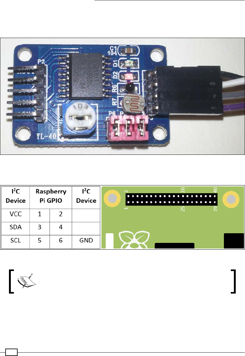
Sense and Display Real-World Data
228
You will need a PCF8591 module (retailers of these are listed in Appendix, Hardware and
Software List) or you can obtain the PCF8591 chip separately and build your own circuit (see
the There's more… section for details of the circuit).
The PCF8591 ADC and sensor module from dx.com
Connect the GND, VCC, SDA, and SCL pins to the Raspberry Pi GPIO header as follows:
I2C connections on the Raspberry Pi GPIO header
You can use the same I2C tools/code with other I2C devices by studying
the datasheet of the device to nd out what messages to send/read and
which registers are used to control your device.
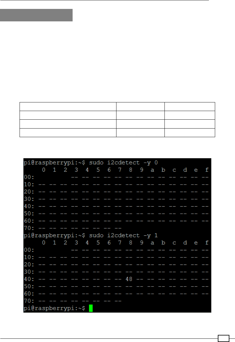
Chapter 7
229
How to do it...
Detect the I2C device by using i2cdetect (the --y option skips any warnings about possible
interference with other hardware that could be connected to the I2C bus) using the following
commands to scan both buses:
sudo i2cdetect -y 0
sudo i2cdetect -y 1
Depending on your Raspberry Pi board revision, the address of the device should be listed on
bus 0 (for Model B Rev1 boards) or bus 1 (for Raspberry Pi 2 & 3, Raspberry Pi 1 Model A and
Model B Rev 2). By default, the PCF8591 address is 0x48.
I2C bus number to use Bus 00 Bus 11
Raspberry Pi 2 & 3 HAT ID (I2C_VC) GPIO (I2C_ARM)
Model A and Model B Revision 2 P5 GPIO
Model B Revision 1 GPIOGPIO n/a
The following screenshot shows the output of i2cdetect:
The PCF8591 address (48) is displayed here on bus 1

Sense and Display Real-World Data
230
If nothing is listed, shut down and double-check your connections (the ADC module from
www.dx.com will have a red LED showing when powered).
If you receive an error that the /dev/i2c1 bus doesn't exist, you can
perform the following checks.
Ensure that the /etc/modprobe.d/raspi-blacklist.conf le is
empty (that is, the modules haven't been blacklisted), using the following
command to view the le:
sudo nano /etc/modprobe.d/raspi-blacklist.conf
If there is anything in the le (such as blacklist i2c-bcm2708),
remove it and save.
Check /boot/config and ensure there isn't a line that has device_
tree_param= (this will disable support for the new device tree
congurations and disable support for some Raspberry Pi HAT add-on
boards).
Check whether the modules have been loaded by using lsmod and look
for i2c-bcm2708 and i2c_dev.
Using the detected bus number (0 or 1) and the device address (0x48) use i2cget to read
from the device (after a power up or channel change you will need to read the device twice to
see the latest value), as follows:
sudo i2cget -y 1 0x48
sudo i2cget -y 1 0x48
To read from channel 1 (this is the temperature sensor on the module), we can use i2cset
to write 0x01 to the PCF8591 control register. Again, use two reads to get a new sample from
channel 1, as follows:
sudo i2cset -y 1 0x48 0x01
sudo i2cget -y 1 0x48
sudo i2cget -y 1 0x48
To cycle through each of the input channels, use i2cset to set the control register to 0x04,
as follows:
sudo i2cset -y 1 0x48 0x04
We can also control the AOUT pin using the following command to set it fully on (lighting up
the LED D1):
sudo i2cset -y 1 0x48 0x40 0xff
Finally, we can use the following command to set it fully off (switching off the LED D1):
sudo i2cset -y 1 0x48 0x40 0x00

Chapter 7
231
How it works...
The rst read from the device after power on will return 0x80 and will also trigger the new
sample from channel 0. If you read a second time, it will return the sample previously read
and generate a fresh sample. Each reading will be an 8-bit value (ranging from 0 to 255),
representing the voltage 0 to VCC (in this case, 0V to 3.3V). On the www.dx.com module,
channel 0 is connected to a light sensor, so if you cover up the module with your hand and
resend the command, you will observe a change in the values (darker means a higher value
and lighter means a lower one). You will nd the readings are always one behind; this is
because as it returns the previous sample, it captures the next sample.
We use the following command to specify a particular channel to read:
sudo i2cset -y 1 0x48 0x01
This changes the channel that is read to channel 1 (this is marked as AIN1 on the module).
Remember, you will need to perform two reads before you will see data from the newly
selected channel. The following table shows the channels and pin names as well as which
jumper connectors enable/disable each of the sensors:
Channel 0 1 2 3
Pin Name AIN0 AIN1 AIN2 AIN3
Sensor Light Dependent Resistor Thermistor External Pin Potentiometer
Jumper P5 P4 P6
Next, we control the AOUT pin by setting the analog output enable ag (bit 6) of the control
register and use the next value to set the analog voltage (0V-3.3V 0x00-0xFF), as follows:
sudo i2cset -y 1 0x48 0x40 0xff
Finally, you can set bit 2 (0x04) to auto-increment and cycle through the input channels
as follows:
sudo i2cset -y 1 0x48 0x04
Each time you run i2cget -y 1 0x48, the next channel will be selected, starting with
channel AIN0, then AIN1 through to AIN3, and back to AIN0 again.
Sense and Display Real-World Data
232
To understand how to set a particular bit in a value, it helps to look at the
binary representation of a number. The 8-bit value 0x04 can be written as
b0000 0100 in binary (0x indicates the value is written in hexadecimal or
hex, and b indicates a binary number).
Bits within binary numbers are counted from right to left, starting with 0, that
is, MSB 7 6 5 4 3 2 1 0 LSB.
Bit 7 is known as the Most Signicant Bit (MSB) and bit 0 as the Least
Signicant Bit (LSB). Therefore, by setting bit 2, we end up with b0000
0100 (which is 0x04).
There's more...
The I2C bus allows us to easily connect multiple devices using only a few wires. The PCF8591
chip can be used to connect your own sensors to the module or just the chip.
Using multiple I2C devices
All commands on the I2C bus are addressed to a specic I2C device (many have the option to
set some pins high or low to select additional addresses and allow multiple devices to exist on
the same bus). Each device must have a unique address so that only one device will respond
at any one time. The PCF8591 starting address is 0x48, with additional addresses selectable
by the three address pins to 0x4F. This allows up to eight PCF8591 devices to be used on the
same bus.
If you decide to use the I2C_VC bus that is located on GPIO pins
27 and 2828 (or on the P5 header on Model A and Rev2 Model B
devices), you may need to add a 1k8 ohm pull-up resistor between
the I2C lines and 3.3V. These resistors are already present on the I2C
bus on the GPIO connector. However, some I2C modules, including
the PCF8591 module, have their own resistors tted, so it will work
without the extra resistors.
I2C bus and level shifting
The I2C bus consists of two wires, one data (SDA) and one clock (SCL). Both are passively
pulled to VCC (on the Raspberry Pi, this is 3.3V) with pull-up resistors. The Raspberry Pi will
control the clock by pulling it low every cycle and the data line can be pulled low by Raspberry
Pi to send commands or by the connected device to respond with data.
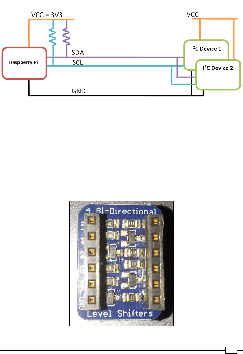
Chapter 7
233
The Raspberry Pi I2C pins include pull-up resistors on SDA and SCL
Since the slave devices can only pull the data line to GND, the device may be powered by 3.3V
or even 5V without the risk of driving the GPIO pins too high (remember that the Raspberry Pi
GPIO is not able to handle voltages over 3.3V). This should work as long as the I2C bus of the
device will recognize logic high at 3.3V instead of 5V. The I2C device must not have its own
pull-up resistors tted, as this will cause the GPIO pins to be pulled to the supply voltage of the
I2C device.
Note the PCF8591 module used in this chapter has resistors tted; therefore, we must only
use VCC=3V3. A bidirectional logic level converter can be used to overcome any issues with
logic levels. One such device is the Adafruit I2C bidirectional logic level translator, shown in
the following image:
Adafruit I2C Bi-directional logic level translator module
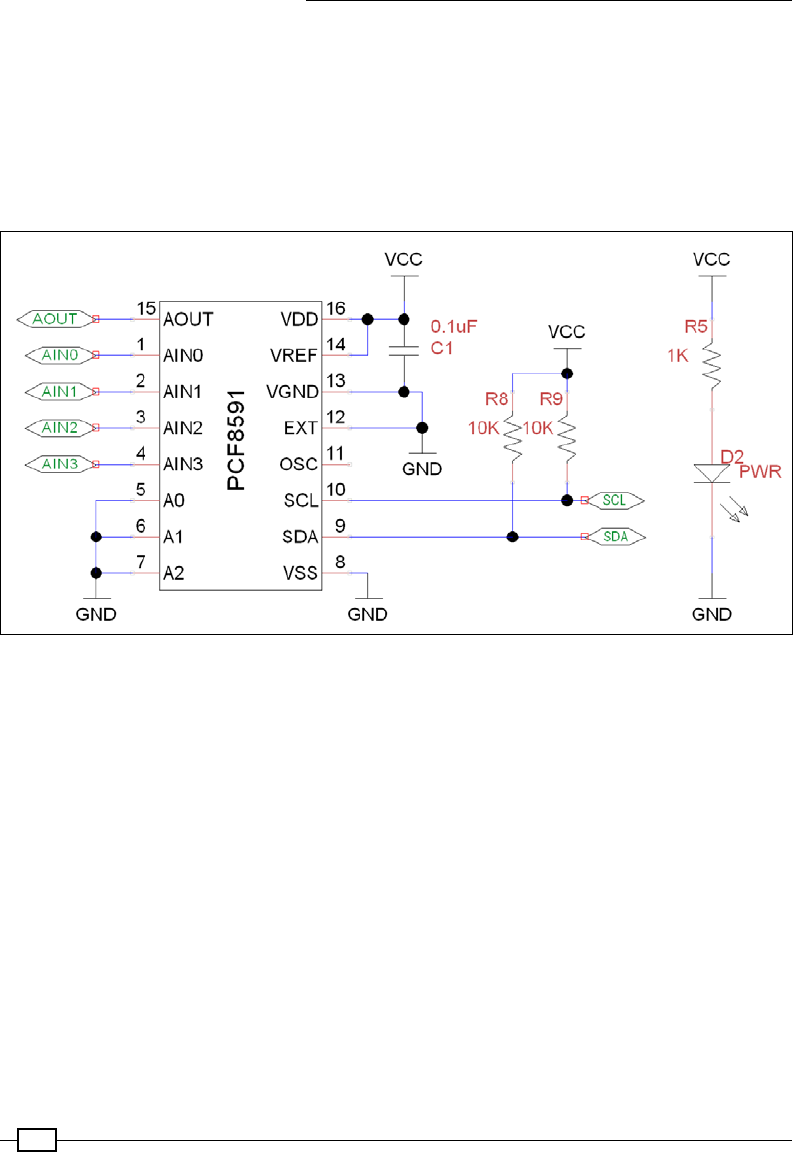
Sense and Display Real-World Data
234
In addition to ensuring that any logic voltages are at suitable levels for the device you are
using, it will allow the bus to be extended over longer wires (the level shifter will also act
as a bus repeater).
Using just the PCF8591 chip or adding alternative sensors
A circuit diagram of the PCF8591 module without the sensors attached is shown in the
following diagram:
The PCF8591 ADC circuit – VCC, GND, SCL, and SDA are connected to the Raspberry Pi as before
As you can see, excluding the sensors, there are only ve additional components. We have a
power-ltering capacitor (C1) and the power-indicating LED (D2) with a current-limiting resistor
(R5), all of which are optional.
It should be noted that the module includes two 10k pull-up resistors (R8 and R9) for SCL and
SDA signals. However, since the GPIO I2C connections on the Raspberry Pi also include pull-
up resistors, these are not needed on the module (and could be removed). It also means we
should only connect this module to VCC=3.3V (if we use 5V, then voltages on SCL and SDA will
be around 3.56V, which is too high for the Raspberry Pi GPIO pins).
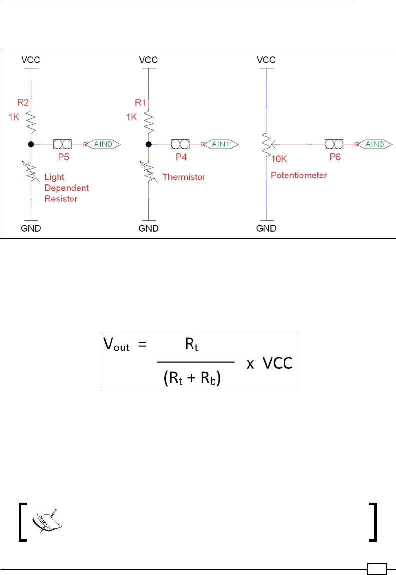
Chapter 7
235
The sensors on the PCF891 module are all resistive, so the voltage level that is present on
analog input will change between GND and VCC as the resistance of the sensor changes.
A potential divider circuit is used to provide a voltage proportional to the sensor's resistance
The module uses a circuit known as a potential divider. The resistor at the top balances
the resistance provided by the sensor at the bottom to provide a voltage that is somewhere
between VCC and GND.
The output voltage (Vout) of the potential divider can be calculated as follows:
The Rt and Rb are the resistance values at the top and bottom respectively, and VCC is the
supply voltage.
The potentiometer in the module has the 10k ohm resistance split between top and bottom
depending on the position of the adjuster. So, halfway, we have 5k ohm on each side and an
output voltage of 1.65V; a quarter of the way (clockwise), we have 2.5k ohm and 7.5k ohm,
producing 0.825V.
I've not shown the AOUT circuit, which is a resistor and LED. However,
as you will nd, an LED isn't suited to indicate an analog output (except
to show the on/off states).

Sense and Display Real-World Data
236
For more sensitive circuits, you can use more complex circuits such as a Wheatstone bridge
(which allows the detection of very small changes in resistance), or you can use dedicated
sensors that output an analog voltage based on their readings (such as a TMP36 temperature
sensor). The PCF891 also supports the differential input mode, where one channel can be
compared to the input of another (the resultant reading will be the difference between the two).
For more information on the PCF8591 chip, refer to the datasheet at http://www.nxp.
com/documents/data_sheet/PCF8591.pdf.
Reading analog data using an
analog-to-digital converter
The I2CTools (used in the previous section) are very useful for debugging I2C devices on the
command line, but they are not practical for use within Python, as they would be slow and
require signicant overhead to use. Fortunately, there are several Python libraries that provide
I2C support, allowing efcient use of I2C to communicate with connected devices and provide
easy operation.
We will use such a library to create our own Python module that will allow us to quickly and
easily obtain data from the ADC device and use it in our programs. The module is designed in
such a way that other hardware or data sources may be put in its place without impacting the
remaining examples.
Getting ready
To use the I2C bus using Python 3, we will use Gordon Henderson's wiringPi2
(see http://wiringpi.com/ for more details).
The easiest way to install wiringPi2 is by using PIP for Python 3. PIP is a package manager
for Python that works in a similar way to apt-get. Any packages you wish to install will be
automatically downloaded and installed from an online repository.
To install PIP, use the following command:
sudo apt-get install python3-dev python3-pip
Then install wiringPi2 with the following command:
sudo pip-3.2 install wiringpi2
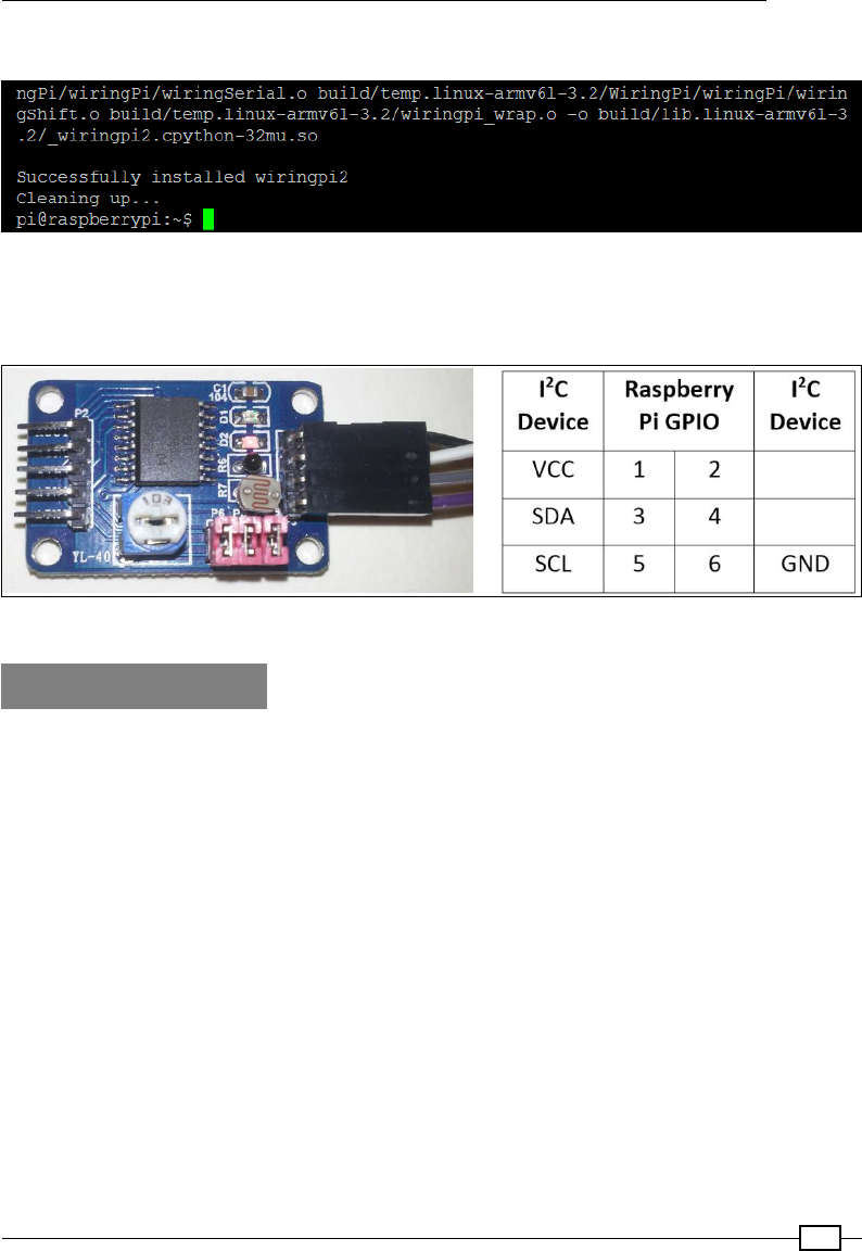
Chapter 7
237
Once the install has completed, you should see the following, indicating success:
Successfully installed wiringPi2
You will need the PCF8591 module wired as before to the I2C connections of the
Raspberry Pi.
The PCF8591 module and pin connections to the Raspberry Pi GPIO connector (as used in the previous section)
How to do it...
In the next section, we shall write a script to allow us to gather data that we will then use later
on in this chapter.
Create the following script, data_adc.py, as follows:
1. First, import the modules and create the variables we will use, as follows:
#!/usr/bin/env python3
#data_adc.py
import wiringpi2
import time
DEBUG=False
LIGHT=0;TEMP=1;EXT=2;POT=3
ADC_CH=[LIGHT,TEMP,EXT,POT]
ADC_ADR=0x48
ADC_CYCLE=0x04
BUS_GAP=0.25
DATANAME=["0:Light","1:Temperature",
"2:External","3:Potentiometer"]

Sense and Display Real-World Data
238
2. Create the class called device with a constructor to initialize it, as follows:
class device:
# Constructor:
def __init__(self,addr=ADC_ADR):
self.NAME = DATANAME
self.i2c = wiringpi2.I2C()
self.devADC=self.i2c.setup(addr)
pwrup = self.i2c.read(self.devADC) #flush powerup value
if DEBUG==True and pwrup!=-1:
print("ADC Ready")
self.i2c.read(self.devADC) #flush first value
time.sleep(BUS_GAP)
self.i2c.write(self.devADC,ADC_CYCLE)
time.sleep(BUS_GAP)
self.i2c.read(self.devADC) #flush first value
3. Within the class, dene a function to provide a list of channel names as follows:
def getName(self):
return self.NAME
4. Dene another function (still as part of the class) to return a new set of samples from
the ADC channels as follows:
def getNew(self):
data=[]
for ch in ADC_CH:
time.sleep(BUS_GAP)
data.append(self.i2c.read(self.devADC))
return data
5. Finally, after the device class, create a test function to exercise our new device class
as follows. This is only to be run when the script is executed directly:
def main():
ADC = device(ADC_ADR)
print (str(ADC.getName()))
for i in range(10):
dataValues = ADC.getNew()
print (str(dataValues))
time.sleep(1)
if __name__=='__main__':
main()
#End

Chapter 7
239
You can run the test function of this module using the following command:
sudo python3 data_adc.py
How it works...
We start by importing wiringpi2 so we can communicate with our I2C device later on. We
will create a class to contain the required functionality to control the ADC. When we create
the class, we can initialize wiringPi2 in such a way that it is ready to use the I2C bus (using
wiringpi2.I2C()), and we set up a generic I2C device with the chip's bus address (using
self.i2c.setup(0x48)).
wiringPi2 also has a dedicated class to use with the PCF8591
chip; however, in this case, it is more useful to use the standard
I2C functionality to illustrate how any I2C device can be controlled
using wiringPi2. By referring to the device datasheet, you can
use similar commands to communicate to any connected I2C device
(whether it is directly supported or not).
As before, we perform a device read and congure the ADC to cycle through the channels,
but instead of i2cget and i2cset, we use the wiringPi2 read and write functions of
the I2C object. Once initialized, the device will be ready to read the analog signals on
each of the channels.
The class will also have two member functions. The rst function, getName(), returns a
list of channel names (which we can use to correlate our data to its source) and the second
function, getNew(), returns a new set of data from all the channels. The data is read from
ADC using the i2c.read() function and, since we have already put it into cycle mode, each
read will be from the next channel.
As we plan to reuse this class later on, we will use the if __name__ test to allow us to dene
some code to run when we execute the le directly. Within our main() function, we create
ADC, which is an instance of our new device class. We can choose to select a non-default
address if we need to; otherwise, the default address for the chip will be used. We use the
getName() function to print out the names of the channels and then we can collect data
from the ADC (using getNew()) and display them.
There's more...
The following allows us to dene an alternative version of the device class in data_adc.py
so it can be used in place of the ADC module. This will allow the remaining sections of the
chapter to be tried without needing any specic hardware.

Sense and Display Real-World Data
240
Gathering analog data without hardware
If you don't have an ADC module available, there is a wealth of data available from within
Raspberry Pi that you can use instead.
Create the following script, data_local.py:
#!/usr/bin/env python3
#data_local.py
import subprocess
from random import randint
import time
MEM_TOTAL=0
MEM_USED=1
MEM_FREE=2
MEM_OFFSET=7
DRIVE_USED=0
DRIVE_FREE=1
DRIVE_OFFSET=9
DEBUG=False
DATANAME=["CPU_Load","System_Temp","CPU_Frequency",
"Random","RAM_Total","RAM_Used","RAM_Free",
"Drive_Used","Drive_Free"]
def read_loadavg():
# function to read 1 minute load average from system uptime
value = subprocess.check_output(
["awk '{print $1}' /proc/loadavg"], shell=True)
return float(value)
def read_systemp():
# function to read current system temperature
value = subprocess.check_output(
["cat /sys/class/thermal/thermal_zone0/temp"],
shell=True)
return int(value)
def read_cpu():
# function to read current clock frequency
value = subprocess.check_output(
["cat /sys/devices/system/cpu/cpu0/cpufreq/"+
"scaling_cur_freq"], shell=True)

Chapter 7
241
return int(value)
def read_rnd():
return randint(0,255)
def read_mem():
# function to read RAM info
value = subprocess.check_output(["free"], shell=True)
memory=[]
for val in value.split()[MEM_TOTAL+
MEM_OFFSET:MEM_FREE+
MEM_OFFSET+1]:
memory.append(int(val))
return(memory)
def read_drive():
# function to read drive info
value = subprocess.check_output(["df"], shell=True)
memory=[]
for val in value.split()[DRIVE_USED+
DRIVE_OFFSET:DRIVE_FREE+
DRIVE_OFFSET+1]:
memory.append(int(val))
return(memory)
class device:
# Constructor:
def __init__(self,addr=0):
self.NAME=DATANAME
def getName(self):
return self.NAME
def getNew(self):
data=[]
data.append(read_loadavg())
data.append(read_systemp())
data.append(read_cpu())
data.append(read_rnd())
memory_ram = read_mem()
data.append(memory_ram[MEM_TOTAL])
data.append(memory_ram[MEM_USED])
data.append(memory_ram[MEM_FREE])

Sense and Display Real-World Data
242
memory_drive = read_drive()
data.append(memory_drive[DRIVE_USED])
data.append(memory_drive[DRIVE_FREE])
return data
def main():
LOCAL = device()
print (str(LOCAL.getName()))
for i in range(10):
dataValues = LOCAL.getNew()
print (str(dataValues))
time.sleep(1)
if __name__=='__main__':
main()
#End
The preceding script allows us to gather system information from the Raspberry Pi using
the following commands (the subprocess module allows us to capture the results and
process them):
fCPU speed:
cat /sys/devices/system/cpu/cpu0/cpufreq/scaling_cur_freq
fCPU load:
awk '{print $1}' /proc/loadavg
fCore temperature (scaled by 1,000):
cat /sys/class/thermal/thermal_zone0/temp
fDrive info:
df
fRAM info:
free
Each data item is sampled using one of the functions. In the case of the drive and RAM
information, we split the response into a list (separated by spaces) and select the items that
we want to monitor (such as available memory and used drive space).
This is all packaged up to function in the same way as the data_adc.py le and the device
class (so you can choose to use either in the following examples just by swapping the data_
adc include with data_local).
Chapter 7
243
Logging and plotting data
Now that we are able to sample and collect a lot of data, it is important that we can capture
and analyze it. We will make use of a Python library called matplotlib, which includes lots
of useful tools for manipulating, graphing, and analyzing data. We will use pyplot (which
is a part of matplotlib) to produce graphs of our captured data. For more information on
pyplot, go to http://matplotlib.org/users/pyplot_tutorial.html.
Getting ready
To use pyplot, we will need to install matplotlib.
Due to a problem with the matplotlib installer, performing the
installation using pip-3.2 doesn't always work correctly. The method that
follows will overcome this problem by performing all the steps PIP does
manually; however, this can take over 30 minutes to complete.
To save time, you can try the PIP installation, which is much quicker. If it
doesn't work, you can install it using this manual method.
Try installing matplotlib using PIP with the following commands:
sudo apt-get install tk-dev python3-tk libpng-dev
sudo pip-3.2 install numpy
sudo pip-3.2 install matplotlib
You can conrm matplotlib has installed by running python3 and trying to import it from
the Python terminal, as follows:
import matplotlib
If the installation failed, it will respond with the following:
ImportError: No module named matplotlib
Otherwise, there will be no errors.
Use the following steps to install matplotlib manually:
1. Install the support packages as follows:
sudo apt-get install tk-dev python3-tk python3-dev libpng-dev
sudo pip-3.2 install numpy
sudo pip-3.2 install matplotlib

Sense and Display Real-World Data
244
2. Download the source les from the Git repository (the command should be a single
line) as follows:
wget https://github.com/matplotlib/matplotlib/archive/master.zip
3. Unzip and open the matplotlib-master folder created, as follows:
unzip master.zip
rm master.zip
cd matplotlib-master
4. Run the setup le to build (this will take a while) and install it as follows:
sudo python3 setup.py build
sudo python3 setup.py install
5. Test the installation in the same way as the automated install.
We will either need the PCF8591 ADC module (and wiringPi2 installed as before), or we
can use the data_local.py module from the previous section (just replace data_adc with
data_local in the import section of the script). We also need to have data_adc.py and
data_local.py in the same directory as the new script, depending on which you use.
How to do it...
1. Create the following script, log_adc.py:
#!/usr/bin/python3
#log_adc.c
import time
import datetime
import data_adc as dataDevice
DEBUG=True
FILE=True
VAL0=0;VAL1=1;VAL2=2;VAL3=3 #Set data order
FORMATHEADER = "\t%s\t%s\t%s\t%s\t%s"
FORMATBODY = "%d\t%s\t%f\t%f\t%f\t%f"
if(FILE):f = open("data.log",'w')
def timestamp():
ts = time.time()
return datetime.datetime.fromtimestamp(ts).strftime(
'%Y-%m-%d %H:%M:%S')
def main():

Chapter 7
245
counter=0
myData = dataDevice.device()
myDataNames = myData.getName()
header = (FORMATHEADER%("Time",
myDataNames[VAL0],myDataNames[VAL1],
myDataNames[VAL2],myDataNames[VAL3]))
if(DEBUG):print (header)
if(FILE):f.write(header+"\n")
while(1):
data = myData.getNew()
counter+=1
body = (FORMATBODY%(counter,timestamp(),
data[0],data[1],data[2],data[3]))
if(DEBUG):print (body)
if(FILE):f.write(body+"\n")
time.sleep(0.1)
try:
main()
finally:
f.close()
#End
2. Create a second script, log_graph.py, as follows:
#!/usr/bin/python3
#log_graph.py
import numpy as np
import matplotlib.pyplot as plt
filename = "data.log"
OFFSET=2
with open(filename) as f:
header = f.readline().split('\t')
data = np.genfromtxt(filename, delimiter='\t', skip_header=1,
names=['sample', 'date', 'DATA0',
'DATA1', 'DATA2', 'DATA3'])
fig = plt.figure(1)
ax1 = fig.add_subplot(211)#numrows, numcols, fignum
ax2 = fig.add_subplot(212)
ax1.plot(data['sample'],data['DATA0'],'r',
label=header[OFFSET+0])
ax2.plot(data['sample'],data['DATA1'],'b',
label=header[OFFSET+1])
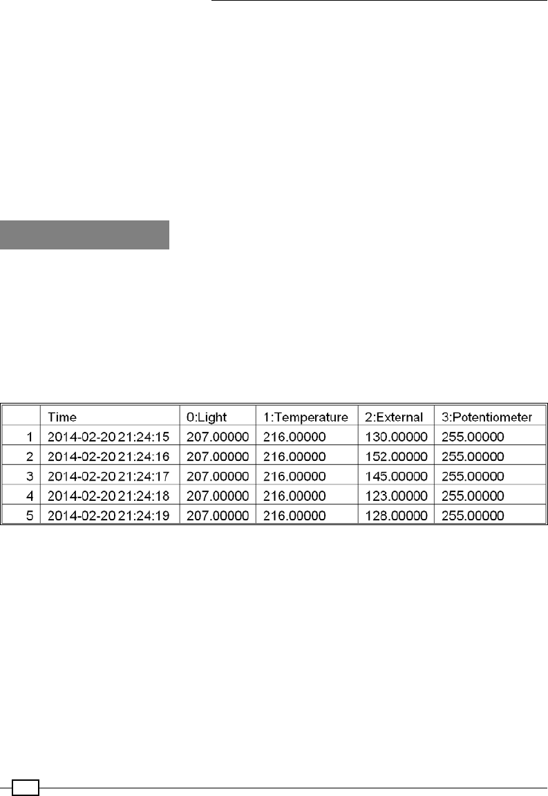
Sense and Display Real-World Data
246
ax1.set_title("ADC Samples")
ax1.set_xlabel('Samples')
ax1.set_ylabel('Reading')
ax2.set_xlabel('Samples')
ax2.set_ylabel('Reading')
leg1 = ax1.legend()
leg2 = ax2.legend()
plt.show()
#End
How it works...
The rst script, log_adc.py, allows us to collect data and write it to a logle.
We can use the ADC device by importing data_adc as dataDevice or we can import data_
local to use the system data. The numbers given to VAL0 through VAL3 allow us to change
the order of the channels (and if using the data_local device, select the other channels).
We also dene the format string for the header and each line in the logle (to create a le with
data separated by tabs) using %s, %d, and %f to allow us to substitute strings, integers, and
oat values, as shown in the following table:
The table of data captured from the ADC sensor module
If logging in to the le (when FILE=True), we open data.log in write mode using the 'w'
option (this will overwrite any existing les; to append to a le, use 'a').
As part of our data log, we generate timestamp using time and datetime to get the current
Epoch time (this is the number of milliseconds since Jan 1, 1970) using the time.time()
command. We convert the value into a more friendly year-month-day hour:min:sec
format using strftime().
The main() function starts by creating an instance of our device class (we made this in the
previous example), which will supply the data. We fetch the channel names from the data
device and construct the header string. If DEBUG is set to True, the data is printed to screen;
if FILE is set to True, it will be written to le.

Chapter 7
247
In the main loop, we use the getNew() function of the device to collect data and format it to
display on screen or log to the le. The main() function is called using the try: finally:
command, which will ensure that when the script is aborted the le will be correctly closed.
The second script, log_graph.py, allows us to read the logle and produce a graph of the
recorded data, as shown in the following gure:
Graphs produced by log_graph.py from the light and temperature sensors
We start by opening up the logle and reading the rst line; this contains the header
information (which we can then use to identify the data later on). Next, we use numpy, a
specialist Python library that extends how we can manipulate data and numbers. In this case,
we use it to read in the data from the le, split it up based on the tab delimiter, and provide
identiers for each of the data channels.
We dene a gure to hold our graphs, adding two subplots (located in a 2 x 1 grid and
positions 1 and 2 in the grid – set by the values 211 and 212). Next, we dene the values we
want to plot, providing the x values (data['sample']), the y values (data['DATA0']), the
color value ('r' which is Red or 'b' for Blue), and label (set to the heading text we read
previously from the top of the le).
Finally, we set a title, x and y labels for each subplot, enable legends (to show the labels), and
display the plot (using plt.show()).

Sense and Display Real-World Data
248
There's more...
Now that we have the ability to see the data we have been capturing, we can take things even
further by displaying it as we sample it. This will allow us to instantly see how the data reacts
to changes in the environment or stimuli. We can also calibrate our data so that we can assign
the appropriate scaling to produce measurements in real units.
Plotting live data
Besides plotting data from les, we can use matplotlib to plot sensor data as it is sampled.
To achieve this, we can use the plot-animation feature, which automatically calls a
function to collect new data and update our plot.
Create the following script, live_graph.py:
#!/usr/bin/python3
#live_graph.py
import numpy as np
import matplotlib.pyplot as plt
import matplotlib.animation as animation
import data_local as dataDevice
PADDING=5
myData = dataDevice.device()
dispdata = []
timeplot=0
fig, ax = plt.subplots()
line, = ax.plot(dispdata)
def update(data):
global dispdata,timeplot
timeplot+=1
dispdata.append(data)
ax.set_xlim(0, timeplot)
ymin = min(dispdata)-PADDING
ymax = max(dispdata)+PADDING
ax.set_ylim(ymin, ymax)
line.set_data(range(timeplot),dispdata)
return line
def data_gen():
while True:
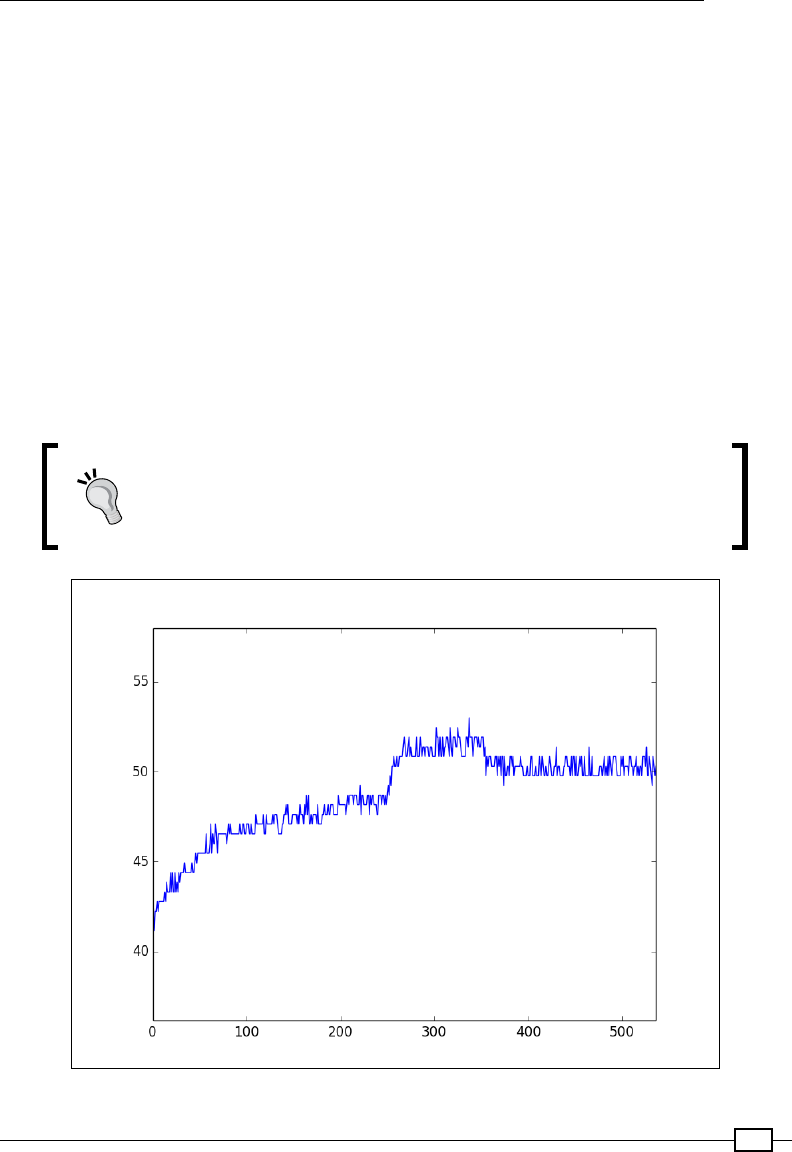
Chapter 7
249
yield myData.getNew()[1]/1000
ani = animation.FuncAnimation(fig, update,
data_gen, interval=1000)
plt.show()
#End
We start by dening our dataDevice object and creating an empty array, dispdata[],
which will hold all the data collected. Next, we dene our subplot and the line we are going
to plot.
The FuncAnimation() function allows us to update a gure (fig) by dening an update
function and a generator function. The generator function (data_gen()) will be called every
interval (1,000 ms) and will produce a data value.
This example uses the core temperature reading that, when divided by 1,000, gives the actual
temperature in degC.
To use the ADC data instead, change the import for dataDevice to
data_adc and adjust the following line to use a channel other than
[1] and apply a scaling that is different from 1,000:
yield myData.getNew()[1]/1000
The Raspberry Pi plotting in real time (core temperature in degC versus time in seconds)

Sense and Display Real-World Data
250
The data value is passed to the update() function, which allows us to add it to our
dispdata[] array that will contain all the data values to be displayed in the plot. We adjust
the x axis range to be near the min and max values of the data, as well as adjust the y axis to
grow as we continue to sample more data.
The FuncAnimation() function requires the data_gen() object to be a
special type of function called generator. A generator function produces
a continuous series of values each time it is called, and can even use its
previous state to calculate the next value if required. This is used to perform
continuous calculations for plotting; this is why it is used here. In our case, we
just want to run the same sampling function (new_data()) continuously, so
each time it is called, it will yield a new sample.
Finally, we update the x and y axes data with our dispdata[] array (using the set_data()
function), which will plot our samples against the number of seconds we are sampling. To use
other data, or to plot data from the ADC, adjust the import for dataDevice and select the
required channel (and scaling) in the data_gen() function.
Scaling and calibrating data
You may have noticed that it can sometimes be difcult to interpret data read from an ADC,
since the value is just a number. A number isn't much help except to tell you it is slightly hotter
or slightly darker than the previous sample. However, if you can use another device to provide
comparable values (such as the current room temperature), you can then calibrate your
sensor data to provide more useful real-world information.
To obtain a rough calibration, we shall use two samples to create a linear t model that can
then be used to estimate real-world values for other ADC readings (this assumes the sensor
itself is mostly linear in its response). The following gure shows a linear t using two readings
at 25 and 30 degrees Celsius, providing estimated ADC values for other temperatures:
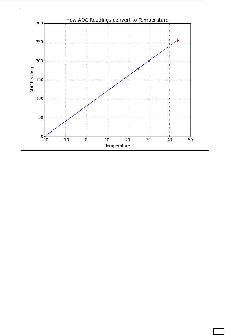
Chapter 7
251
Samples are used to linearly calibrate temperature sensor readings
We can calculate our model using the following function:
def linearCal(realVal1,readVal1,realVal2,readVal2):
#y=Ax+C
A = (realVal1-realVal2)/(readVal1-readVal2)
C = realVal1-(readVal1*A)
cal = (A,C)
return cal
This will return cal, which will contain the model slope (A) and offset (C).
We can then use the following function to calculate the value of any reading by using the
calculated cal values for that channel:
def calValue(readVal,cal = [1,0]):
realVal = (readVal*cal[0])+cal[1]
return realVal
For more accuracy, you can take several samples and use linear interpolation between the
values (or t the data to other more complex mathematical models), if required.
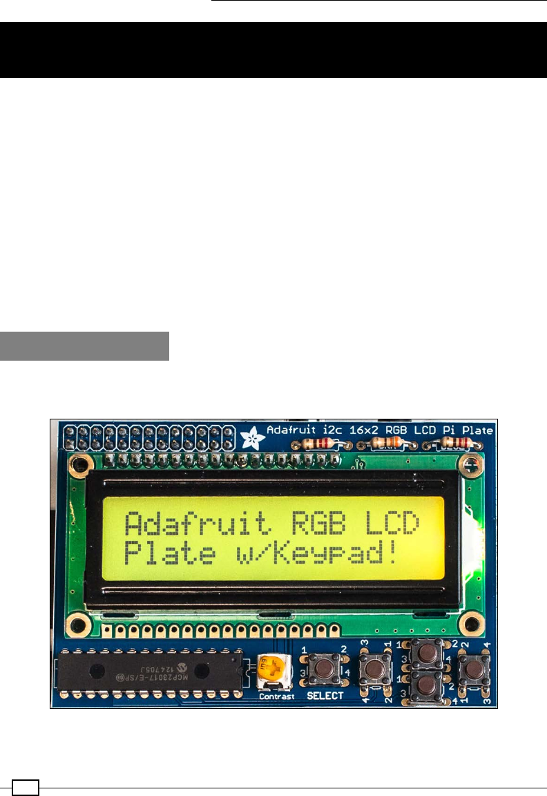
Sense and Display Real-World Data
252
Extending the Raspberry Pi GPIO with an I/O
expander
As we have seen, making use of the higher-level bus protocols allows us to connect to more
complex hardware quickly and easily. The I2C can be put to great use by using it to expand
the available I/O on the Raspberry Pi as well as providing additional circuit protection (and, in
some cases, additional power to drive more hardware).
There are lots of devices available that provide I/O expansion over the I2C bus (and also SPI),
but the most commonly used is a 28-pin device, MCP23017, which provides 16 additional
digital input/output pins. Being an I2C device, it only requires the two signals (SCL and SDA
connections plus ground and power) and will happily function with other I2C devices on the
same bus.
We shall see how the Adafruit I2C 16x2 RGB LCD Pi Plate makes use of one of these chips to
control an LCD alphanumeric display and keypad over the I2C bus (without the I/O expander,
this would normally require up to 15 GPIO pins).
Getting ready
You will need the Adafruit I2C 16x2 RGB LCD Pi Plate (which also includes ve keypad buttons),
and is shown in the following image:
Adafruit I2C 16x2 RGB LCD Pi Plate with keypad buttons

Chapter 7
253
The Adafruit I2C 16x2 RGB LCD Pi Plate directly connects to the GPIO connector of
Raspberry Pi.
As before, we can use the PCF8591 ADC module or use the data_local.py module from
the previous section (use data_adc or data_local in the import section of the script). The
les data_adc.py and data_local.py should be in the same directory as the new script.
The LCD Pi Plate only requires ve pins (SDA, SCL, GND, and 5V); it
connects over the whole GPIO header. If we want to use it with other
devices, such as the PCF8591 ADC module, then something similar to a
TriBorg from PiBorg (which splits the GPIO port into three) can be used.
How to do it...
1. Create the following script, lcd_i2c.py:
#!/usr/bin/python3
#lcd_i2c.py
import wiringpi2
import time
import datetime
import data_local as dataDevice
AF_BASE=100
AF_E=AF_BASE+13; AF_RW=AF_BASE+14; AF_RS=AF_BASE+15
AF_DB4=AF_BASE+12; AF_DB5=AF_BASE+11; AF_DB6=AF_BASE+10
AF_DB7=AF_BASE+9
AF_SELECT=AF_BASE+0; AF_RIGHT=AF_BASE+1; AF_DOWN=AF_BASE+2
AF_UP=AF_BASE+3; AF_LEFT=AF_BASE+4; AF_BACK=AF_BASE+5
AF_GREEN=AF_BASE+6; AF_BLUE=AF_BASE+7; AF_RED=AF_BASE+8
BNK=" "*16 #16 spaces
def gpiosetup():
global lcd
wiringpi2.wiringPiSetup()
wiringpi2.mcp23017Setup(AF_BASE,0x20)
wiringpi2.pinMode(AF_RIGHT,0)
wiringpi2.pinMode(AF_LEFT,0)
wiringpi2.pinMode(AF_SELECT,0)
wiringpi2.pinMode(AF_RW,1)
wiringpi2.digitalWrite(AF_RW,0)

Sense and Display Real-World Data
254
lcd=wiringpi2.lcdInit(2,16,4,AF_RS,AF_E,
AF_DB4,AF_DB5,AF_DB6,AF_DB7,0,0,0,0)
def printLCD(line0="",line1=""):
wiringpi2.lcdPosition(lcd,0,0)
wiringpi2.lcdPrintf(lcd,line0+BNK)
wiringpi2.lcdPosition(lcd,0,1)
wiringpi2.lcdPrintf(lcd,line1+BNK)
def checkBtn(idx,size):
global run
if wiringpi2.digitalRead(AF_LEFT):
idx-=1
printLCD()
elif wiringpi2.digitalRead(AF_RIGHT):
idx+=1
printLCD()
if wiringpi2.digitalRead(AF_SELECT):
printLCD("Exit Display")
run=False
return idx%size
def main():
global run
gpiosetup()
myData = dataDevice.device()
myDataNames = myData.getName()
run=True
index=0
while(run):
data = myData.getNew()
printLCD(myDataNames[index],str(data[index]))
time.sleep(0.2)
index = checkBtn(index,len(myDataNames))
main()
#End
2. With the LCD module connected, run the script as follows:
sudo python3 lcd_i2c.py
Select the data channel you want to display using the left and right buttons and press the
SELECT button to exit.

Chapter 7
255
How it works...
The wiringPi2 library has excellent support for I/O expander chips, like the one used for
the AdaFruit LCD Character module. To use the Adafruit module, we need to set up the pin
mapping for all the pins of MCP23017 PortA, as shown in the following table (then we set up
the I/O expander pins with an offset of 100):
Name SELECT RIGHT DOWN UP LEFT GREEN BLUE RED
MCP23017
PortA
A0 A1 A2 A3 A4 A6 A7 A8
WiringPiPin 100 101 102 103 104 106 107 108
The pin mapping for all the pins of MCP23017 PortB are as follows:
Name DB7 DB6 DB5 DB4 E RW RS
MCP23017
PortB
B1 B2 B3 B4 B5 B6 B7
WiringPiPin 109 110 111 112 113 114 115
To set up the LCD screen, we initialize wiringPiSetup() and the I/O expander,
mcp23017Setup(). We then specify the pin offset and bus address of the I/O expander.
Next, we set all the hardware buttons as inputs (using pinMode(pin number,0)), and
the RW pin of the LCD to an output. The wiringPi2 LCD library expects the RW pin to
be set to LOW (forcing it into read-only mode), so we set the pin to LOW (using
digitalWrite(AF_RW,0)).
We create an lcd object by dening the number of rows and columns of the screen, and
whether we are using 4- or 8-bit data mode (we are using 4 of the 8 data lines, so it is the
4-bit mode). We also provide the pin mapping of the pins we are using (the last four are
set to 0 since we are only using four data lines).
Now we create a function called PrintLCD(), which will allow us to send strings to show on
each line of the display. We use lcdPosition() to set the cursor position on the lcd object
for each line and then print the text for each line. We also add some blank spaces at the end
of each line to ensure the full line is overwritten.
The next function, checkBtn() briey checks the left/right and select buttons to see if they
have been pressed (using the digitalRead() function). If the left/right button has been
pressed, then the index is set to the previous or next item in the array. If the SELECT button is
pressed, then the run ag is set to False (this will exit the main loop, allowing the script to
nish).
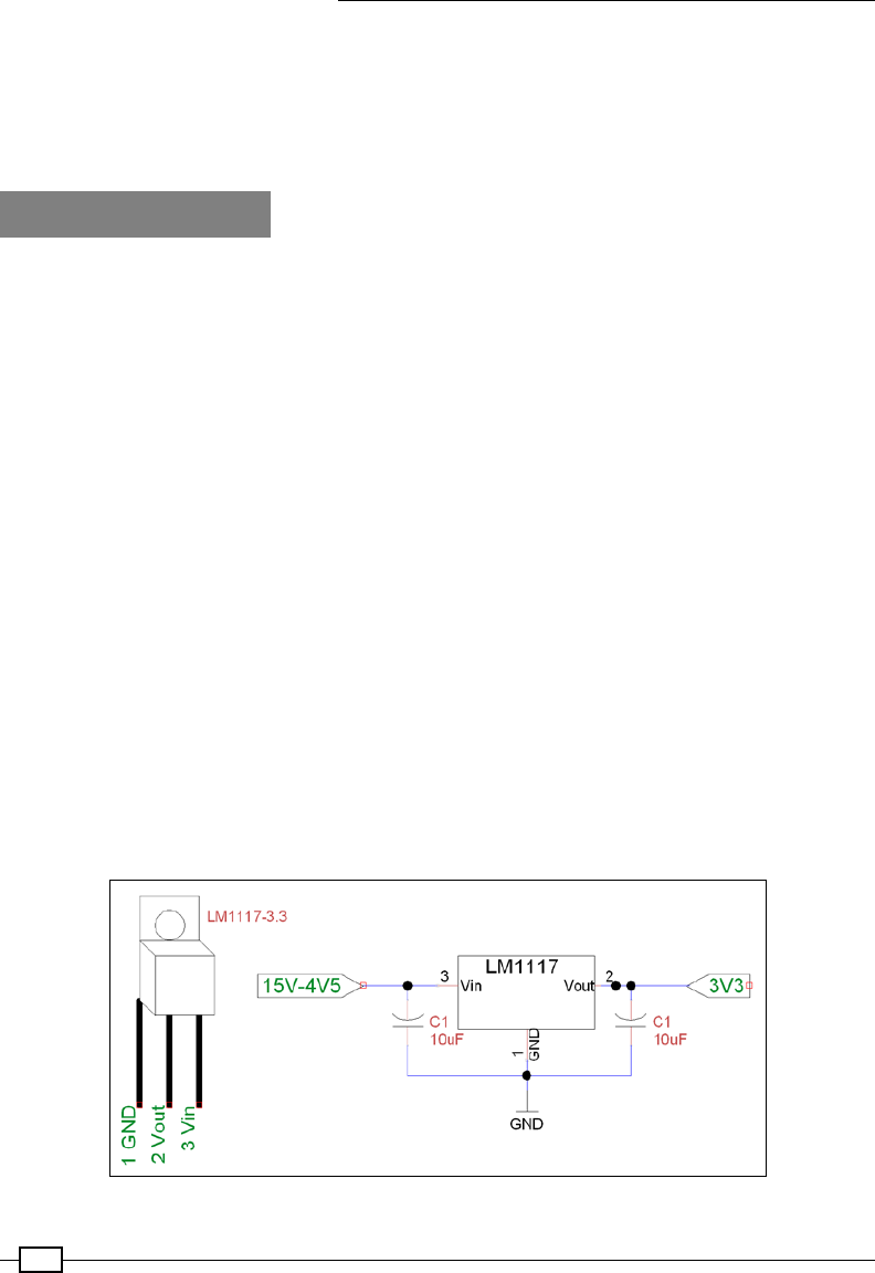
Sense and Display Real-World Data
256
The main() function calls gpiosetup() to create our lcd object; then we create our
dataDevice object and fetch the data names. Within the main loop, we get new data; then
we use our printLCD() function to display the data name on the top line and the data value
on the second line. Finally, we check to see whether the buttons have been pressed and set
the index to our data as required.
There's more…
Using an expander chip such as the MCP23017 provides an excellent way to increase the
amount of hardware connectivity to the Raspberry Pi while also providing an additional layer
of protection (it is cheaper to replace the expander chip Raspberry Pi).
I/O expander voltages and limits
The port expander only uses a small amount of power when in use, but if you are powering
it using the 3.3V supply, then you will still only be able to draw a maximum of 50 mA in total
from all the pins. If you draw too much power, then you may experience system freezes or
corrupted read/writes on the SD card.
If you power the expander using the 5V supply, then you can draw up to the maximum the
expander can support (around 25 mA maximum per pin and 125 mA total) as long as your
USB power supply is powerful enough.
We must remember that if the expander is powered with 5V, the inputs/outputs and interrupt
lines will also be 5V and should never be connected back to the Raspberry Pi (without using
level shifters to translate the voltage down to 3.3V).
By changing the wiring of the address pins (A0, A1, and A2) on the expander chip, up to eight
modules can be used on the same I2C bus simultaneously. To ensure there is enough current
available for each, we would need to use a separate 3.3V supply. A linear regulator such as
LM1117-3.3 would be suitable (this would provide up to 800 mA at 3.3V, 100 mA for each),
and only needs the following simple circuit:
The LM1117 linear voltage regulator circuit
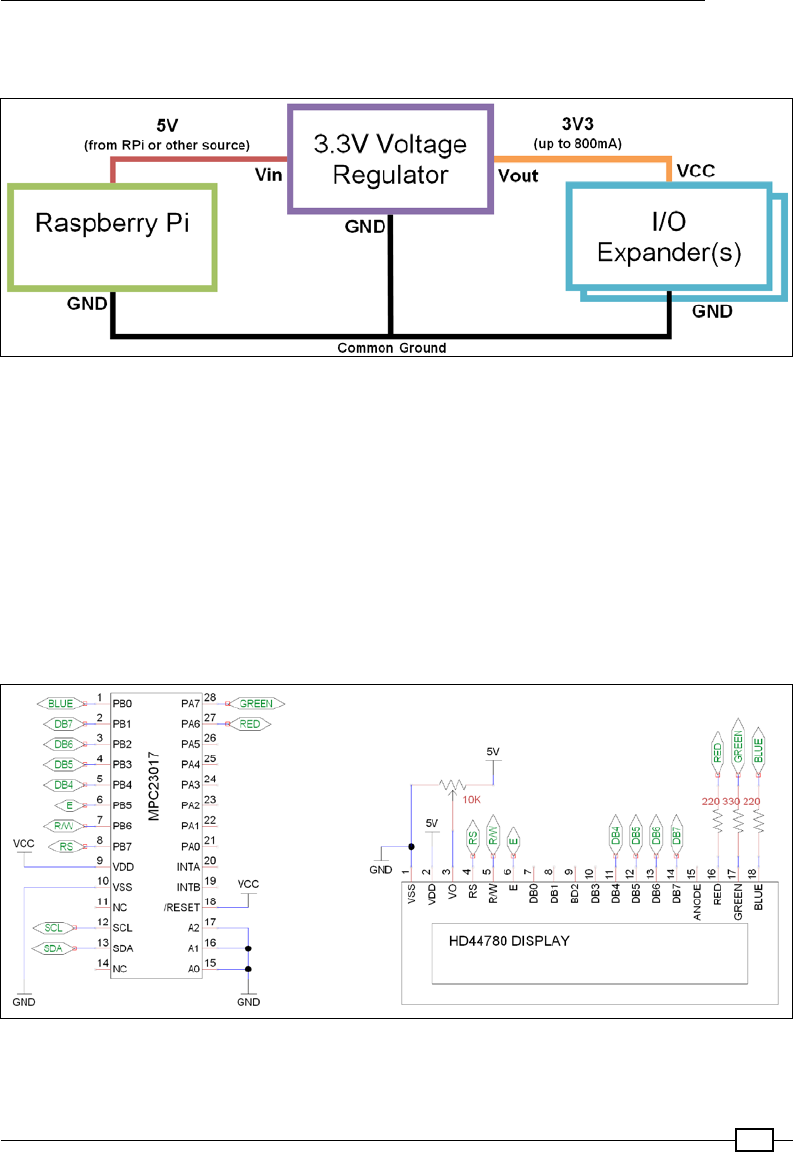
Chapter 7
257
The following diagram shows how a voltage regulator can be connected to the I/O expander
(or other device) to provide more current for driving extra hardware:
Using a voltage regulator with the Raspberry Pi
The input voltage (Vin) is provided by the Raspberry Pi (for example, from the GPIO pin header,
such as 5V pin 2). However, Vin could be provided by any other power supply (or battery pack)
as long as it is between 4.5V and 15V and able to provide enough current. The important
part is ensuring that the ground connections (GND) of the Raspberry Pi, the power supply (if
a separate one is used), the regulator, and the I/O expander are all connected together (as a
common ground).
Using your own I/O expander module
You can use one of the I/O expander modules that are available (or just the MCP23017 chip
in the following circuit) to control most HD44780-compatible LCD displays:
The I/O expander and a HD44780-compatible display

Sense and Display Real-World Data
258
The D-Pad circuit, which is explained in the recipe The GPIO keypad input in Chapter 6, Using
Python to Drive Hardware, can also be connected to the remaining Port A pins of the expander
(PA0 to Button 1, PA1 to Right, PA2 to Down, PA3 to Up, PA4 to Left, and PA5 to Button 2).
As in the previous example, the buttons will be PA0 to PA4 (WiringPiPin number 100 to 104);
apart from these, we have the second button added to PA5 (WiringPiPin number 105).
Directly controlling an LCD alphanumeric display
Alternatively, you can also drive the screen directly from the Raspberry Pi with the following
connections:
LCD VSS VDD V0 RS RW E DB4 DB5 DB6 DB7
LCD Pin 1 2 3 4 5 6 11 12 13 14
Raspberry
Pi GPIO
6
(GND)
2 (5V) Contrast 11 13
(GND)
15 12 16 18 22
The preceding table lists the connections required between the Raspberry Pi and the
HD44780-compatible alphanumeric display module.
The contrast pin (V0) can be connected to a variable resistor as before (with one side on 5V
and the other on GND); although, depending on the screen, you may nd you can connect
directly to GND/5V to obtain the maximum contrast.
The wiringPi2 LCD library assumes that the RW pin is connected to GND (read only); this
avoids the risk that the LCD will send data back if connected directly to the Raspberry Pi (this
would be a problem since the screen is powered by 5V and would send data using 5V logic).
Ensure you update the code with the new AF_XX references and refer to the physical pin
number by changing the setup within the gpiosetup() function. We can also skip the setup
of the MCP23017 device.
Have a look at the following commands:
wiringpi2.wiringPiSetup()
wiringpi2.mcp23017Setup(AF_BASE,0x20)
Replace the preceding commands with the following command:
wiringpi.wiringPiSetupPhys()
You can see that we only need to change the pin references to switch between using the I/O
expander and not using it, which shows how convenient the wiringPi2 implementation is.

Chapter 7
259
Capturing data in an SQLite database
Databases are a perfect way to store lots of structured data while maintaining the ability to
access and search for specic data. Structured Query Language (SQL) is a standardized
set of commands to update and query databases. For this example, we will use SQLite (a
lightweight self-contained implementation of an SQL database system).
In this chapter, we will gather raw data from our ADC (or local data source) and build our own
database. We can then use a Python library called sqlite3 to add data to a database and
then query it.
## Timestamp 0:Light 1:Temperature 2:External
3:Potentiometer
0 2015-06-16 21:30:51 225 212 122
216
1 2015-06-16 21:30:52 225 212 148
216
2 2015-06-16 21:30:53 225 212 113
216
3 2015-06-16 21:30:54 225 212 137
216
4 2015-06-16 21:30:55 225 212 142
216
5 2015-06-16 21:30:56 225 212 115
216
6 2015-06-16 21:30:57 225 212 149
216
7 2015-06-16 21:30:58 225 212 128
216
8 2015-06-16 21:30:59 225 212 123
216
9 2015-06-16 21:31:02 225 212 147
216
Getting ready
To capture data in our database, we will install SQLite ready to use with Python's sqlite3
built-in module. Use the following command to install SQLite:
sudo apt-get install sqlite3
Next, we will perform some basic operations with SQLite to see how to use SQL queries.

Sense and Display Real-World Data
260
Run SQLite directly, creating a new test.db database le with the following command:
sqlite3 test.db
SQLite version 3.7.13 2012-06-11 02:05:22
Enter ".help" for instructions
Enter SQL statements terminated with a ";"
sqlite>
This will open a SQLite console within which we enter SQL commands directly. For example,
the following commands will create a new table, add some data, display the content, and then
remove the table:
CREATE TABLE mytable (info TEXT, info2 TEXT,);
INSERT INTO mytable VALUES ("John","Smith");
INSERT INTO mytable VALUES ("Mary","Jane");
John|Smith
Mary|Jane
DROP TABLE mytable;
.exit
You will need the same hardware setup as the previous recipe, as detailed in the Getting
ready section of the Using devices with the I2C bus recipe.
How to do it...
Create the following script, mysqlite_adc.py:
#!/usr/bin/python3
#mysql_adc.py
import sqlite3
import datetime
import data_adc as dataDevice
import time
import os
DEBUG=True
SHOWSQL=True
CLEARDATA=False
VAL0=0;VAL1=1;VAL2=2;VAL3=3 #Set data order
FORMATBODY="%5s %8s %14s %12s %16s"
FORMATLIST="%5s %12s %10s %16s %7s"

Chapter 7
261
DATEBASE_DIR="/var/databases/datasite/"
DATEBASE=DATEBASE_DIR+"mydatabase.db"
TABLE="recordeddata"
DELAY=1 #approximate seconds between samples
def captureSamples(cursor):
if(CLEARDATA):cursor.execute("DELETE FROM %s" %(TABLE))
myData = dataDevice.device()
myDataNames=myData.getName()
if(DEBUG):print(FORMATBODY%("##",myDataNames[VAL0],
myDataNames[VAL1],myDataNames[VAL2],
myDataNames[VAL3]))
for x in range(10):
data=myData.getNew()
for i,dataName in enumerate(myDataNames):
sqlquery = "INSERT INTO %s (itm_name, itm_value) "
%(TABLE) + \
"VALUES('%s', %s)" \
%(str(dataName),str(data[i]))
if (SHOWSQL):print(sqlquery)
cursor.execute(sqlquery)
if(DEBUG):print(FORMATBODY%(x,
data[VAL0],data[VAL1],
data[VAL2],data[VAL3]))
time.sleep(DELAY)
cursor.commit()
def displayAll(connect):
sqlquery="SELECT * FROM %s" %(TABLE)
if (SHOWSQL):print(sqlquery)
cursor = connect.execute (sqlquery)
print(FORMATLIST%("","Date","Time","Name","Value"))
for x,column in enumerate(cursor.fetchall()):
print(FORMATLIST%(x,str(column[0]),str(column[1]),
str(column[2]),str(column[3])))
def createTable(cursor):
print("Create a new table: %s" %(TABLE))
sqlquery="CREATE TABLE %s (" %(TABLE) + \
"itm_date DEFAULT (date('now','localtime')), " + \

Sense and Display Real-World Data
262
"itm_time DEFAULT (time('now','localtime')), " + \
"itm_name, itm_value)"
if (SHOWSQL):print(sqlquery)
cursor.execute(sqlquery)
cursor.commit()
def openTable(cursor):
try:
displayAll(cursor)
except sqlite3.OperationalError:
print("Table does not exist in database")
createTable(cursor)
finally:
captureSamples(cursor)
displayAll(cursor)
try:
if not os.path.exists(DATEBASE_DIR):
os.makedirs(DATEBASE_DIR)
connection = sqlite3.connect(DATEBASE)
try:
openTable(connection)
finally:
connection.close()
except sqlite3.OperationalError:
print("Unable to open Database")
finally:
print("Done")
#End
If you do not have the ADC module hardware, you can capture local
data by setting the dataDevice module as data_local. Ensure you
have data_local.py (from the There's more… section in the Reading
analog data using an analog-to-digital converter recipe) in the same
directory as this script:
import data_local as dataDevice
This will capture the local data (RAM, CPU activity, temperature, and so
on) to the SQLite database instead of ADC samples.

Chapter 7
263
How it works...
When the script is rst run, it will create a new SQLite database le called mydatabase.db,
which will add a table named recordeddata. The table is generated by createTable(),
which runs the following SQLite command:
CREATE TABLE recordeddata
(
itm_date DEFAULT (date('now','localtime')),
itm_time DEFAULT (time('now','localtime')),
itm_name,
itm_value
)
The new table will contain the following data items:
Name Description
itm_date Used to store the date of the data sample. When the data record is created
the current date (using date('now','localtime')) is applied as the
DEFAULT value.
itm_time Used to store the time of the data sample. When the data record is created
the current time (using time('now','localtime')) is applied as the
DEFAULT value.
itm_name Used to record the name of the sample.
itm_value Used to keep the sampled value.
We then use the same the method to capture ten data samples from the ADC as we did in the
Logging and plotting data recipe previously (as shown in the function captureSamples()).
However, this time we will then add the captured data into our new SQLite database table,
using the following SQL command (applied using cursor.execute(sqlquery)):
INSERT INTO recordeddata
(itm_name, itm_value) VALUES ('0:Light', 210)

Sense and Display Real-World Data
264
The current date and time will be added by default to each record as it is created. We end up
with a set of 40 records (four records for every cycle of ADC samples captured), which are now
stored in the SQLite database.
Eight ADC samples have been captured and stored in the SQLite database
After the records have been created we must remember to call cursor.commit(), which
will save all the new records to the database.
The last part of the script calls displayAll(), which will use the following SQL command:
SELECT * FROM recordeddata
This will select all of the data records in the recordeddata table, and we use cursor.
fetch() to provide the selected data as a list we can iterate through:
for x,column in enumerate(cursor.fetchall()):
print(FORMATLIST%(x,str(column[0]),str(column[1]),
str(column[2]),str(column[3])))
This allows us to print out the full contents of the database, displaying the captured data.

Chapter 7
265
Notice that here we use the try, except, and finally constructs in
this script to attempt to handle the mostly likely scenario users will face
when running the script.
First we ensure that if the database directory doesn't exist, we create
it. Next we try opening the database le; this process will automatically
create a new database le if one doesn't already exist. If either of these
initial steps fail (due to not having read/write permissions, for example)
we cannot continue so we report that we cannot open the database and
simply exit the script.
Next, we try to open the required table within the database and display it;
if the database le is brand new this operation will always fail as it will be
empty. However, if this occurs we just catch the exception and create the
table before continuing with the script to add our sampled data to the table
and display it.
This allows the script to gracefully handle potential problems, take
corrective action and then continue smoothly. The next time the script is
run, the database and table will already exist, so we won't need to create
them a second time and we can append the sample data to the table
within the same database le.
There's more…
There are many variants of SQL servers available (such as MySQL, Microsoft SQL Server,
or PostgreSQL); however, they should at least have the following primary commands (or
equivalent):
CREATE, INSERT, SELECT, WHERE, UPDATE, SET, DELETE, and DROP
You should nd that even if you choose to use a different SQL server to the SQLite one used
here, the SQL commands will be relatively similar.
CREATE
The CREATE TABLE command is used to dene a new table by specifying the column names
(and also to set DEFAULT values if desired):
CREATE TABLE table_name (
column_name1 TEXT,
column_name2 INTEGER DEFAULT 0,
column_name3 REAL )
The previous SQL command will create a new table called table_name, containing three
data items. One column would contain text, another integers (for example, 1, 3, -9) and nally
one column for real numbers (for example, 5.6, 3.1749, 1.0).

Sense and Display Real-World Data
266
INSERT
The INSERT command will add a particular entry to a table in the database:
INSERT INTO table_name (column_name1name1, column_name2name2, column_
name3)name3)
VALUES ('Terry'Terry Pratchett', 6666, 27.082015)082015)
This will enter the values provided into the corresponding columns in the table.
SELECT
The SELECT command allows us to specify a particular column or columns from the database
table, returning a list of records with the data:
SELECT column_name1, column_name2 FROM table_name
Or to select all items, use this command:
SELECT * FROM table_name
WHERE
The WHERE command is used to specify specic entries to be selected, updated, or deleted:
SELECT * FROM table_name
WHERE column_name1= 'Terry Pratchett'
This will SELECT any records where the column_name1 matches 'Terry Pratchett'.
UPDATE
The UPDATE command will allow us to change (SET) the values of data in each of the specied
columns. We can also combine this with the WHERE command to limit the records the change
is applied to:
UPDATE table_name
SET column_name2=49name2=49,column_name3=30name3=30.111997
WHERE column_name1name1= 'Douglas Adams'Adams';
DELETE
The DELETE command allows any records selected using WHERE to be removed from the
specied table. However, if the whole table is selected, using DELETE * FROM table_name
will delete the entire contents of the table:
DELETE FROM table_name
WHERE columncolumn_name2=9999
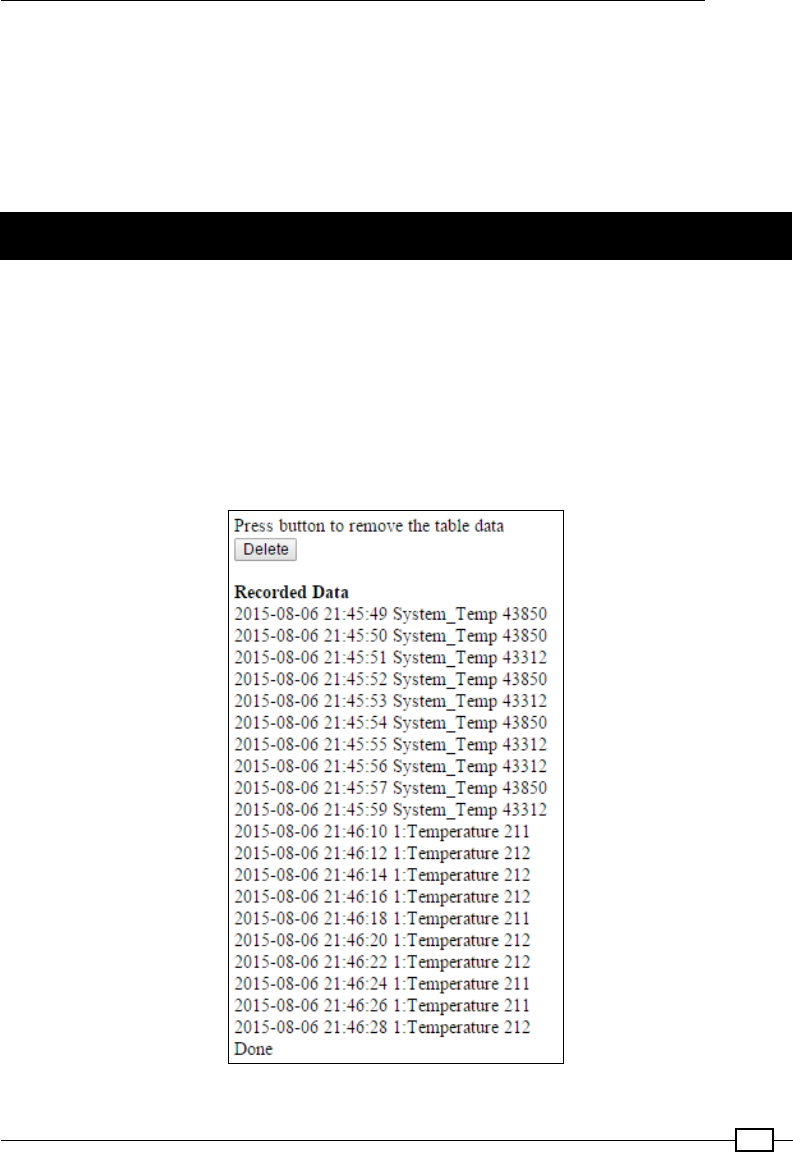
Chapter 7
267
DROP
The DROP command allows a table to be removed completely from the database:
DROP table_name
Be warned that this will permanently remove all the data that was stored in the specied table
and the structure.
Viewing data from your own webserver
Gathering and collecting information into databases is very helpful, but if it is locked inside
a database or a le it isn't much use. However, if we allow the stored data to be viewed via a
web page it will be far more accessible; not only can we view the data from other devices, we
can also share it with others on the same network.
We shall create a local web server to query and display the captured SQLite data and allow
it to be viewed through a PHP web interface. This will allow the data to be viewed, not only
via the web browser on the Raspberry, Pi but also on other devices, such as cell phones or
tablets, on the local network:
Data captured in the SQLite database displayed via a web-page

Sense and Display Real-World Data
268
Using a web server to enter and display information is a powerful way to allow a wide range of
users to interact with your projects. The following example demonstrates a web server setup
that can be customized for a variety of uses.
Getting ready
Ensure you have completed the previous recipe so that the sensor data has been collected
and stored in the SQLite database. We need to install a web server (Apache2) and enable
PHP support to allow SQLite access.
Use these commands to install a web server and PHP:
sudo apt-get update
sudo aptitude install apache2 php5 php5-sqlite
The /var/www/ directory is used by the web server; by default it will load index.html (or
index.php), otherwise it will just display a list of the links to the les within the directory.
To test the web server is running, create a default index.html page. To do this you will need
to create the le using sudo permissions (the /var/www/ directory is protected from changes
made by normal users). Use the following command:
sudo nano /var/www/index.html
Create index.html with the following content:
<h1>It works!</h1>
Close and save the le (using Ctrl + X, Y and Enter).
If you are using the Raspberry Pi with a screen, you can check it is working by loading
the desktop:
startx
Then, open the web browser (epiphany-browser) and enter http://localhost as the
address. You should see the following test page, indicating the web server is active:
Raspberry Pi browser displaying the test page, located at http://localhost
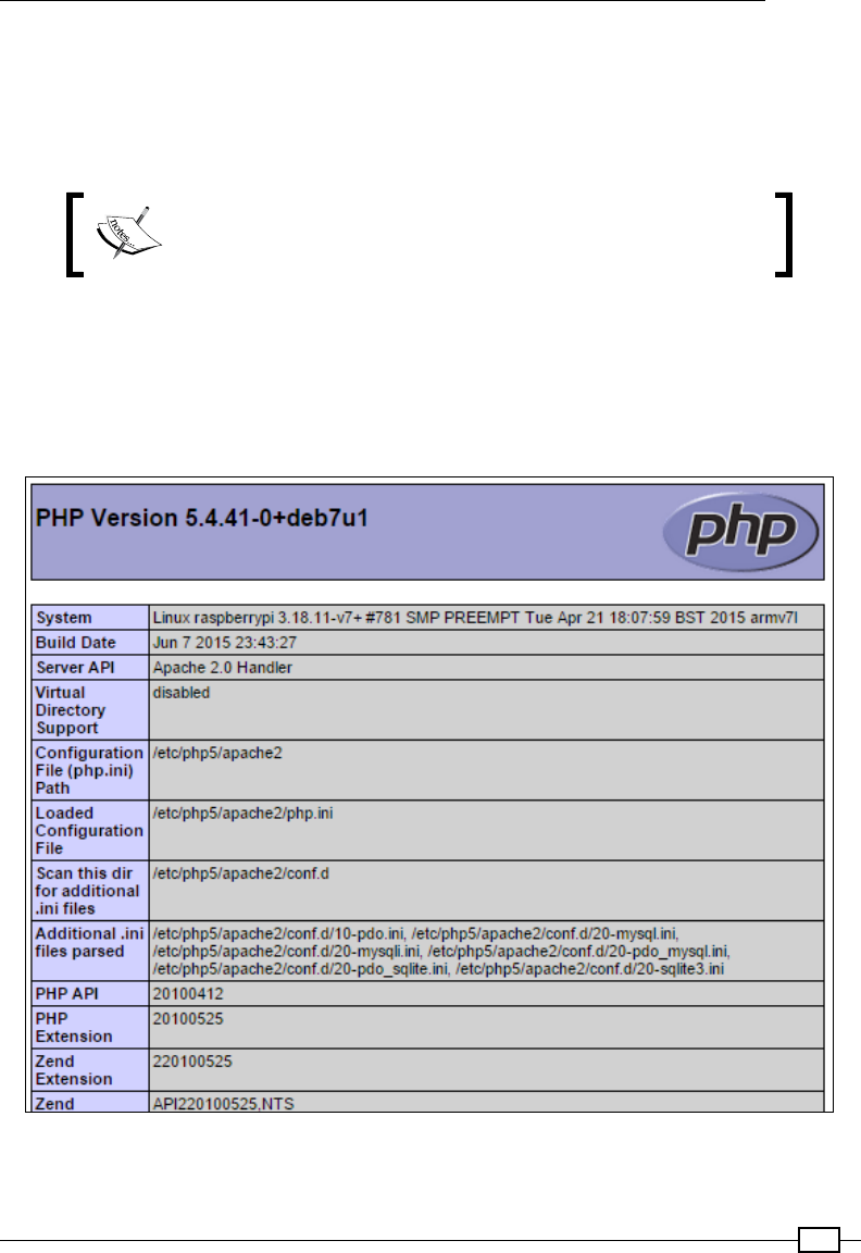
Chapter 7
269
If you are using the Raspberry Pi remotely or it is connected to your network, you should also
be able to view the page on another computer on your network. First, identify the IP address of
the Raspberry Pi (using sudo hostname -I) and then use this as the address in your web
browser. You may even nd you can use the actual hostname of the Raspberry Pi (by default
this is http://raspberrypi/).
If you are unable to see the web page from another computer,
ensure that you do not have a rewall enabled (on the computer
itself or on your router) that could be blocking it.
Next, we can test that PHP is operating correctly. We can create the following web page,
test.php, and ensure it is located in the /var/www/ directory:
<?php
phpinfo();
?>;
View the test.php page at the following location: http://localhost/test.php
We are ready to write our own PHP web page to view the data in the SQLite database.

Sense and Display Real-World Data
270
How to do it...
Create the following PHP les and save them in the webserver directory, /var/www/./.
Use the following command to create the PHP le:
sudo nano /var/www/show_data_lite.php
The show_data_lite.php le should contain:
<head>
<title>DatabaseDatabase Data</title>
<meta http-equiv="refresh" content="10" >
</head>
<body>
Press button to remove the table data
<br>
<input type="button" onclick="location.href = 'del_data_lite.php';"
value="Delete">
<br><br>
<b>Recorded Data</b><br>
<?php
$db = new PDO("sqlite:/var/databases/datasitedatasite/mydatabase.db");
//SQL query
$strSQL = "SELECT * FROM recordeddatarecordeddata WHERE itmitm_name
LIKE '%'%temp%'";
//Excute the query
$response = $db->query($strSQL);
//Loop through the response
while($column = $response->fetch())
{
//Display the content of the response
echo $column[0] . " ";
echo $column[1] . " ";
echo $column[2] . " ";
echo $column[3] . "<br />";
}
?>
Done
</body>
</html>

Chapter 7
271
Use the following command to create the PHP le:
sudo nano /var/www/del_data_lite.php
<html>
<body>
Remove all the data in the table.
<br>
<?php
$db = new PDO("sqlite:/var/databases/datasitedatasite/mydatabase.db");
//SQL query
$strSQL = "DROPDROP TABLErecordeddata recordeddata";
//ExecuteExecute the query
$response = $db->query($strSQL);
if ($response == 1)
{
echo "Result: DELETED DATA";
}
else
{
echo "Error: Ensure table exists and database directory is owned by
www-data";
}
?>
<br><br>
Press button to return to data display.
<br>
<input type="button" onclick="location.href = 'show'show_data_lite.php';"
value="Return">
</body>
</html>

Sense and Display Real-World Data
272
Note: In order for the PHP code to delete the table within the database,
it needs to be writable by the web server. Use the following command
to allow it to be writable:
sudo chown www-data /var/databases/datasite -R
show_data_lite.php will appear as a web page if you open it in a web browser by using
the following address:
http://localhost/showshow_data_lite.php
Alternatively, you can open the web page (including on another computer within your network)
by referencing the IP address of the Raspberry Pi (use hostname -I to conrm the IP
address):
http://192.168.1.101/showshow_data_lite.php
You may be able to use the hostname instead (by default, this would make the address
http://raspberrypi/show_data_lite.php). However, this may depend upon your
network setup.
If there is no data present, ensure you run the mysqlite_adc.py script to capture
additional data.
To make the show_data_lite.php page display automatically when you visit the web
address of your Raspberry Pi (instead of the "It works!" page), we can change the index.
html to the following:
<meta http-equiv="refresh" content="0; URL='show_data_lite.php' " />
This will automatically redirect the browser to load our show_data_lite.php page.
How it works...
The show_data_lite.php le shall display the temperature data that has been stored
within the SQLite database (either from the ADC samples or local data sources).
The show_data_lite.php le consists of standard HTML code as well as a special PHP
code section. The HTML code sets ACD Data as the title on the head section of the page and
uses the following command to make the page automatically reload every 10 seconds:
<meta http-equiv="refresh" content="10" >
Next, we dene a Delete button, which will load the del_data_lite.php page
when clicked:
<input type="button" onclick="location.href = 'del_data_lite.php';"
value="Delete">

Chapter 7
273
Finally, we use the PHP code section to load the SQLite database and display the
Channel 0 data.
We use the following PHP command to open the SQLite database we have previously stored
data in (located at /var/databases/testsites/mydatabase.db):
$db = new PDO("sqlite:/var/databases/testsite/mydatabase.db");
Next, we use the following SQLite query to select all the entries where the zone includes 0: in
the text (for example, 0:Light):
SELECT * FROM recordeddatarecordeddata WHERE itm_namename LIKE '%temp%''
Notice that even though we are now using PHP, the queries we
use with the SQLite database are the same as we would use when
using the SQLite3 Python module.
We now collect the query result in the $response variable:
$response = $db->query($strSQL);
Allowing us to use fetch() (like we used cursor.fetchall() previously)
to list all the data columns in each of the data entries within the
response.
while($column = $response->fetch())
{
//Display the content of the response
echo $column[0] . " ";
echo $column[1] . " ";
echo $column[2] . " ";
echo $column[3] . "<br />";
}
?>
The del_data_lite.php le is fairly similar; it starts by reopening the mydatabase.db le
as before. It then executes the following SQLite query:
DROP TABLE recordeddata
As described in the There's more… DROP section, this will remove the table recordeddata
from the database. If the response isn't equal to 1, the action was not completed. The most
likely reason for this is that the directory that contains the mydatabase.db le isn't writable
by the web server (see the note in the How to do it section about changing the le owner to
www-data).
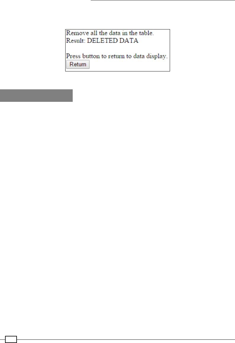
Sense and Display Real-World Data
274
Finally, we provide another button that will take the user back to the show_data_lite.php
page (which will show that the recorded data has now been cleared).
The del_data_lite.php page includes a button to return to the data display page (show_data_lite.php)
There's more…
You may have noticed that this recipe has focused more on HTML and PHP than Python (yes,
check the cover, this is still a book for Python programmers!). However, it is important to
remember that a key part of engineering is integrating and combining different technologies
to produce desired results.
By design, Python lends itself well to this kind of task since it allows easy customization and
integration with a huge range of other languages and modules. We could just do it all in
Python… but why not make use of the existing solutions instead? After all, they are usually
well documented, have undergone extensive testing, and are often industry standards.
Security
SQL databases are used in many places to store a wide range of information from product
information to customer details. In such circumstances, users may be required to enter
information which is then formed into SQL queries. In a poorly implemented system, a
malicious user may be able to include additional SQL syntax in their response, allowing them
to compromise the SQL database (such as access sensitive information, alter it, or simply
delete it).
For example, when asking for a username within a web page, the user could enter the
following text:
John; DELETE FROM Orders
If this was used directly to construct the SQL query, we would end up with the following:
SELECT * FROM Users WHERE UserName = John; DELETE FROM CurrentOrders
The result is we have just allowed the attacker to delete everything in the CurrentOrders
table!
Using user input to form part of SQL queries means we have to be careful what commands we
allow to be executed. In this example, the user may be able to wipe out potentially important
information, which could be very costly for a company and its reputation.

Chapter 7
275
This technique is called SQL injection and is easily protected against by using the parameters
option of the SQLite execute() function. We can replace our Python SQLite query with a
safer version, as follows:
sqlquery = "INSERT INTO %s (itm_name, itm_value) VALUES(?, ?)"
%(TABLE)
cursor.execute(sqlquery, (str(dataName), str(data[i]))
Instead of blindly building the SQL query, the SQLite module will rst check that the provided
parameters are valid values to enter into the database, then it will ensure that no additional
SQL actions will result from inserting them into the command. Finally, the value of the
dataName and data[i] parameters will be used to replace the ? characters to generate the
nal safe SQLite query.
Using MySQL instead
SQLite, used in this recipe, is just one of many SQL databases available. It is helpful for small
projects that only require relatively small databases and minimal resources. However, for
larger projects that require additional features (such user accounts to control access and
additional security), you can use alternatives such as MySQL.
To use a different SQL database, you will need to adjust the Python code we used to capture
the entries using a suitable Python module.
For MySQL (mysql-server) we can use a Python 3 compatible library called PyMySQL to
interface with it. See the PyMySQL website (https://github.com/PyMySQL/PyMySQL) for
additional information about how to use this library.
To use PHP with MySQL, you will also need PHP MySQL (php5-mysql); for more information,
see the excellent resource on W3 Schools (http://www.w3schools.com/php/php_
mysql_connect.asp).
You will notice that although there are small differences between SQL implementations, the
general concepts and commands should now be familiar to you whichever one you select.
Sensing and sending data to online services
In this section, we shall make use of an online service called Xively; the service allows us to
connect, transmit, and view data online. Xively makes use of a common protocol that is used
for transferring information over HTTP called REpresentational State Transfer (REST). REST is
used by many services, such as Facebook and Twitter, using various keys and access tokens
to ensure data is transferred securely between authorized applications and veried sites.
You can perform most REST operations (methods such as POST, GET, SET, and so on)
manually using a Python library called requests (http://docs.python-requests.org).
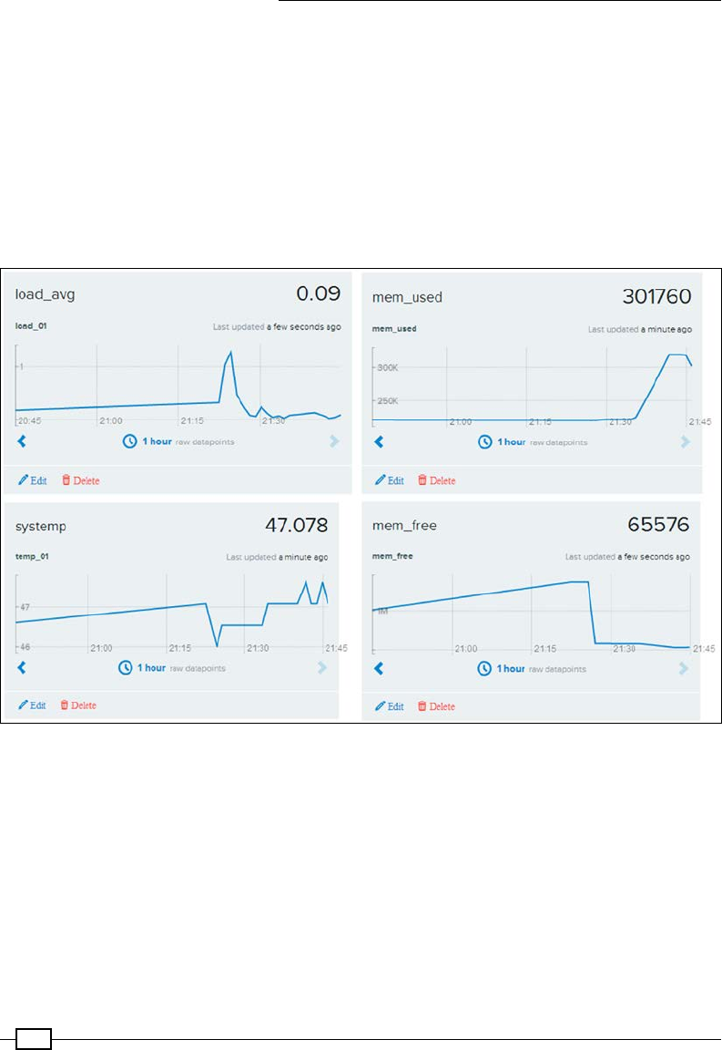
Sense and Display Real-World Data
276
However, it is often easier to make use of specic libraries available for the service you intend
to use. They will handle the authorization process; provide access functions; and, if the
service changes, the library can be updated rather than your code.
We will use the xively-python library, which provides Python functions to allow us to easily
interact with the site.
For details about the xively-python library, refer to http://xively.github.io/
xively-python/.
The data collected by Xively is shown in the following screenshot:
Xively collects and graphs data transferred using REST

Chapter 7
277
Getting ready
You will need to create an account on www.xively.com, which we will use to receive our
data. Go to the site and sign up for a free developer account (via the Developer section,
https://personal.xively.com/signup).
Sign up and create a Xively account
Once you have registered and veried your account, you can follow the instructions that
will take you through a test drive example. This will demonstrate linking to data from your
smartphone (gyroscopic data, location, and so on), which will give you a taste of what we can
do with the Raspberry Pi.
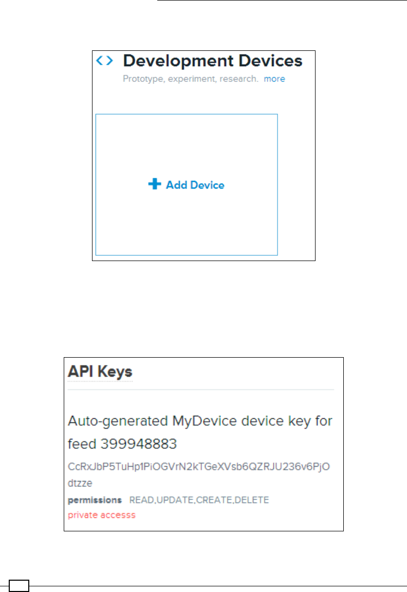
Sense and Display Real-World Data
278
When you log in, you will be taken to the Development Devices dashboard (located in the
WebTools drop-down menu):
Adding a new device
Select +Add Device and ll in the details, giving your device a name and setting Device
as Private.
You will now see the control page for your remote device, which contains all the information
you need to connect and also where your data will be displayed.
Example API Key and feed number (this will be unique for your device)

Chapter 7
279
Although there is a lot of information on this page, you only need two parts of it:
fThe API Key (which is the long code in the API Keys section), as follows:
API_KEY = CcRxJbP5TuHp1PiOGVrN2kTGeXVsb6QZRJU236v6PjOdtzze
fThe feed number (referred to in the API Keys section and also listed at the top of
the page), as follows:
FEED_ID = 399948883
Now that we have the details we need to connect with Xively, we can focus on the Raspberry
Pi side of things.
We will use pip-3.2 to install Xively, as follows:
sudo pip-3.2 install xively-python
Ensure that the install reports the following:
Successfully installed xively-python requests
You are now ready to send some data from your Raspberry Pi.
How to do it...
Create the following script, xivelyLog.py. Ensure you set FEED_ID and API_KEY within
the code to match the device you created:
#!/usr/bin/env python3
#xivelylog.py
import xively
import time
import datetime
import requests
from random import randint
import data_local as dataDevice
# Set the FEED_ID and API_KEY from your account
FEED_ID = 399948883
API_KEY = "CcRxJbP5TuHp1PiOGVrN2kTGeXVsb6QZRJU236v6PjOdtzze"
api = xively.XivelyAPIClient(API_KEY) # initialize api client
DEBUG=True
myData = dataDevice.device()
myDataNames=myData.getName()
def get_datastream(feed,name,tags):

Sense and Display Real-World Data
280
try:
datastream = feed.datastreams.get(name)
if DEBUG:print ("Found existing datastream")
return datastream
except:
if DEBUG:print ("Creating new datastream")
datastream = feed.datastreams.create(name, tags=tags)
return datastream
def run():
print ("Connecting to Xively")
feed = api.feeds.get(FEED_ID)
if DEBUG:print ("Got feed" + str(feed))
datastreams=[]
for dataName in myDataNames:
dstream = get_datastream(feed,dataName,dataName)
if DEBUG:print ("Got %s datastream:%s"%(dataName,dstream))
datastreams.append(dstream)
while True:
data=myData.getNew()
for idx,dataValue in enumerate(data):
if DEBUG:
print ("Updating %s: %s" % (dataName,dataValue))
datastreams[idx].current_value = dataValue
datastreams[idx].at = datetime.datetime.utcnow()
try:
for ds in datastreams:
ds.update()
except requests.HTTPError as e:
print ("HTTPError({0}): {1}".format(e.errno, e.strerror))
time.sleep(60)
run()
#End
How it works...
First, we initialize the Xively API client, to which we supply API_KEY (this authorizes us to send
data to the Xively device we created previously). Next, we use FEED_ID to link us to the
specic feed we want to send the data to. Finally, we request the datastream to connect to (if
it doesn't already exist in the feed, the get_datastream() function will create one for us).

Chapter 7
281
For each datastream in the feed, we supply a name function and tags (these are keywords
that help us identify the data; we can use our data names for this).
Once we have dened our datastreams, we enter the main loop; here, we gather our data
values from dataDevice. We then set the current_value function and also the timestamp
of the data for each data item and apply it to our datastream objects.
Finally, when all the data is ready, we update each of the datastreams and the data is sent to
Xively, appearing within a few moments on the dashboard for the device.
We can log in to our Xively account and view data as it comes in, using a standard web
browser. This provides the means to send data and remotely monitor it anywhere in the
world (perhaps from several Raspberry Pis at once if required). The service even supports
the creation of triggers that can send additional messages back if certain items go out of
expected ranges, reach specic values, or match set criteria. The triggers can in turn be used
to control other devices or raise alerts, and so on.
See also
The AirPi Air Quality and Weather project (http://airpi.es) shows you how to add your
own sensors or use their AirPi kit to create your own air quality and weather station (with data
logging to your own Xively account). The site also allows you to share your Xively data feeds
with others from around the world.

283
8
Creating Projects
with the Raspberry Pi
Camera Module
In this chapter, we will cover the following topics:
fGetting started with the Raspberry Pi camera module
fUsing the camera with Python
fGenerating a time-lapse video
fCreating a stop frame animation
fMaking a QR code reader
fDiscovering and experimenting with OpenCV
fColor detection with OpenCV
fPerforming motion tracking with OpenCV
Introduction
The Raspberry Pi camera module is a special add-on of the Raspberry Pi that makes use of
the Camera Serial Interface (CSI) connector. This connects directly to the GPU core of the
Raspberry Pi processor, allowing images to be captured directly on the unit.
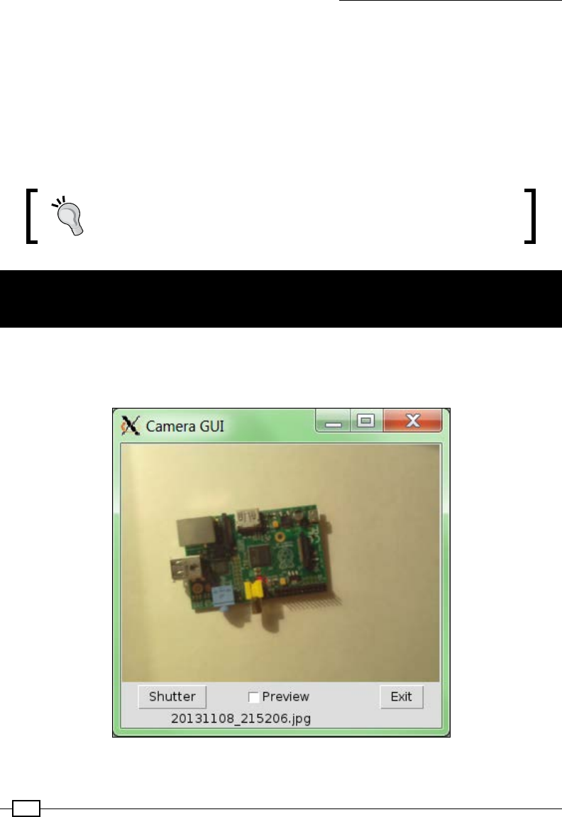
Creating Projects with the Raspberry Pi Camera Module
284
We shall create a basic graphical user interface (GUI) using the tkinter library we
used in Chapter 3, Using Python for Automation and Productivity, and Chapter 4, Creating
Games and Graphics. This will form the basis of the following three examples where we
extend the GUI with additional controls so that we can put the camera to various uses for a
range of different projects.
Finally, we set up the powerful Open Computer Vision (OpenCV) library to perform some
advanced image processing. We will learn the basics of OpenCV and use it to track objects
based on their color or detect movement.
This chapter uses the Raspberry Pi camera module, which is available
from most retailers listed in the Makers, hobbyists, and Raspberry Pi
specialists section of the Appendix, Hardware and Software List.
Getting started with the Raspberry Pi
camera module
We will start by installing and setting up the Raspberry Pi camera module; then we will create
a small camera GUI that enables us to preview and take photos. The rst GUI we will create is
shown in the following image:
A basic camera GUI for the Raspberry Pi camera module
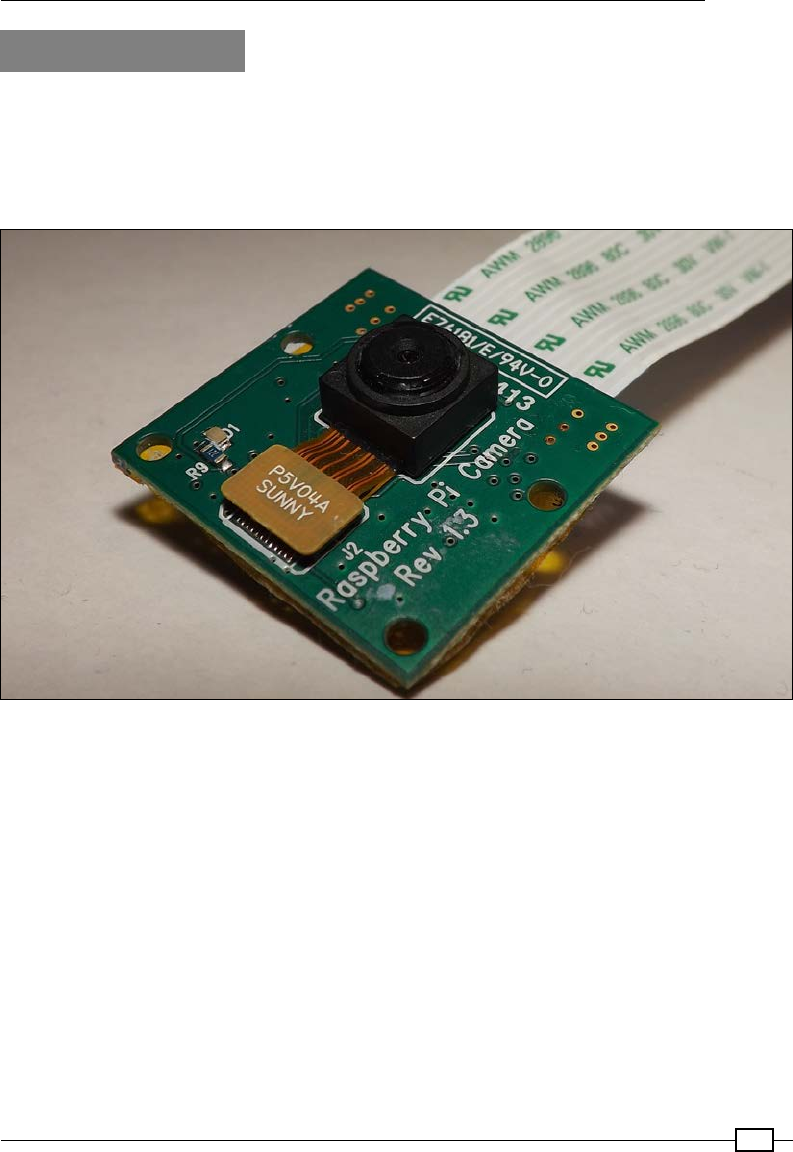
Chapter 8
285
Getting ready
The Raspberry Pi camera module consists of a camera mounted on a small Printed Circuit
Board (PCB) attached to a small ribbon cable. The ribbon cable can be attached directly
to the CSI port of the Raspberry Pi board (marked as S5, the port is located between the
USB and the HDMI port on the Raspberry Pi). The following image shows the Raspberry Pi
camera module:
The Raspberry Pi camera module
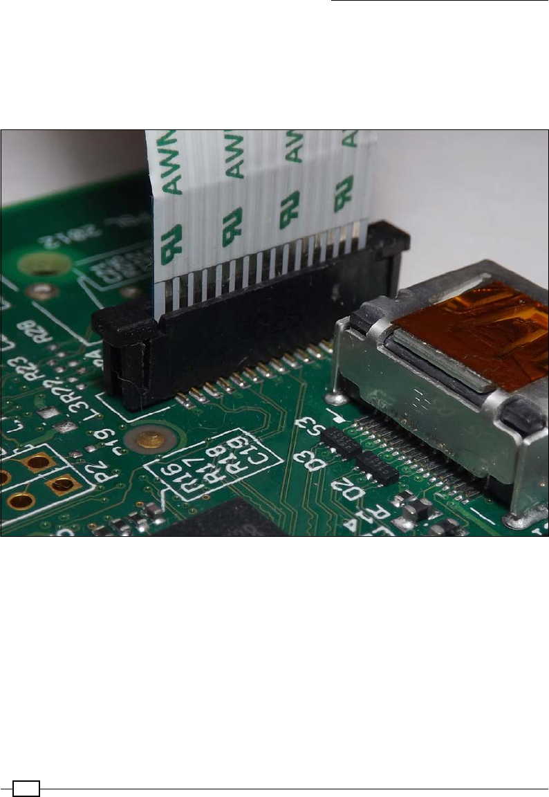
Creating Projects with the Raspberry Pi Camera Module
286
The Raspberry Pi Foundation provides detailed instructions (and a video) on how to
install the camera at http://www.raspberrypi.org/archives/3890; carry out
the following steps:
1. First, t the camera as shown in the following image (ensure that you have
disconnected the Raspberry Pi from any power sources rst):
The ribbon connector for the camera module is located next to the HDMI socket
To t the ribbon cable into the CSI socket, you need to gently lift up and loosen the
tab of the ribbon socket. Insert the ribbon into the slot with the metal contacts facing
towards the HDMI port. Take care not to bend or fold the ribbon cable, and ensure
that it is seated rmly and level in the socket before pushing the tab back into place.
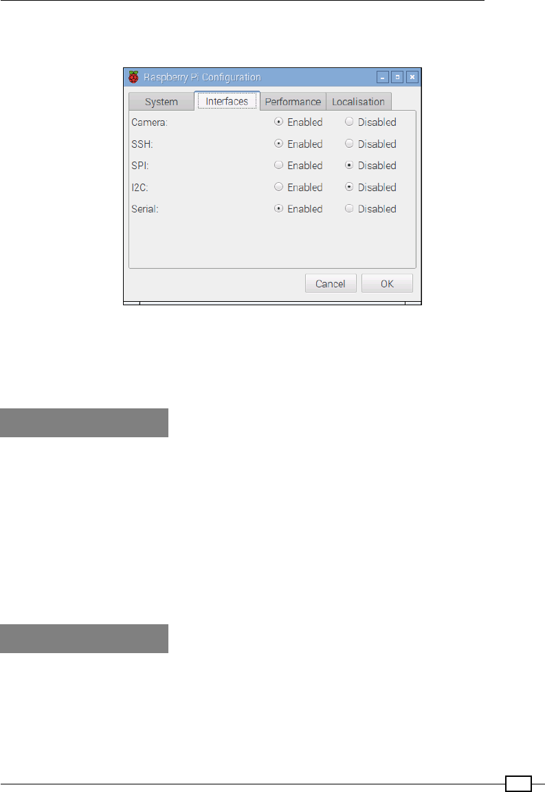
Chapter 8
287
2. Finally, enable the camera. You can do this via the Raspberry Pi Conguration GUI on
the Raspbian desktop (open this via the Interfaces menu).
Enable the Raspberry Pi camera via the Interfaces tab in the Raspberry Pi Configuration screen
Alternatively, you can do this via the command line, using raspi-config. Use sudo
raspi-config to run it, nd the menu entry for Enable Camera, and enable it. You will be
prompted to reboot afterwards.
How to do it…
You can use two programs that are also installed as part of the upgrade—raspivid and
raspistill—to test the camera.
To take a single picture, use the following command (-t 0 takes the picture immediately):
raspistill -o image.jpg -t 0
To take a short, 10-second video in the H.264 format, use the following command (the -t
value is in milliseconds):
raspivid -o video.h264 -t 10000
How it works…
The full documentation of the camera and the raspivid and raspistill utilities is
available on the Raspberry Pi site at http://www.raspberrypi.org/wp-content/
uploads/2013/07/RaspiCam-Documentation.pdf.

Creating Projects with the Raspberry Pi Camera Module
288
To get more information on each of the programs, you can use the
less command to view the instructions (use q to quit) as shown:
raspistill > less
raspivid > less
Each command provides full control of the camera settings, such as
exposure, white balance, sharpness, contrast, brightness, and the
resolution.
Using the camera with Python
The camera module on the Raspberry Pi is more than just a standard webcam. Since we have
full access to the controls and settings from within our own programs, it allows us to take
control and create our own camera applications.
In this chapter, we will use the Python module called picamera created by Dave Hughes to
control the camera module, which performs all the functions raspivid and raspistill
support.
See http://picamera.readthedocs.org for additional documentation and lots of
useful examples.
Getting ready
The Raspberry Pi camera module should be connected and installed as detailed in the
previous section.
In addition, we will also need to install the Python 3 Pillow Library (the details of how to
do this have been covered in the Displaying photo information in an application recipe in
Chapter 3, Using Python for Automation and Productivity).
Now, install picamera for Python 3 using the following command:
sudo apt-get install python3-picamera
How to do it…
1. Create the following cameraGUI.py script that shall contain the main class for
the GUI:
#!/usr/bin/python3
#cameraGUI.py
import tkinter as TK
from PIL import Image

Chapter 8
289
import subprocess
import time
import datetime
import picamera as picam
class SET():
PV_SIZE=(320,240)
NORM_SIZE=(2592,1944)
NO_RESIZE=(0,0)
PREVIEW_FILE="PREVIEW.gif"
TEMP_FILE="PREVIEW.ppm"
class cameraGUI(TK.Frame):
def run(cmd):
print("Run:"+cmd)
subprocess.call([cmd], shell=True)
def camCapture(filename,size=SET.NORM_SIZE):
with picam.PiCamera() as camera:
camera.resolution = size
print("Image: %s"%filename)
camera.capture(filename)
def getTKImage(filename,previewsize=SET.NO_RESIZE):
encoding=str.split(filename,".")[1].lower()
print("Image Encoding: %s"%encoding)
try:
if encoding=="gif" and previewsize==SET.NO_RESIZE:
theTKImage=TK.PhotoImage(file=filename)
else:
imageview=Image.open(filename)
if previewsize!=SET.NO_RESIZE:
imageview.thumbnail(previewsize,Image.ANTIALIAS)
imageview.save(SET.TEMP_FILE,format="ppm")
theTKImage=TK.PhotoImage(file=SET.TEMP_FILE)
except IOError:
print("Unable to get: %s"%filename)
return theTKImage
def timestamp():
ts=time.time()
tstring=datetime.datetime.fromtimestamp(ts)
return tstring.strftime("%Y%m%d_%H%M%S")
def __init__(self,parent):
self.parent=parent

Creating Projects with the Raspberry Pi Camera Module
290
TK.Frame.__init__(self,self.parent)
self.parent.title("Camera GUI")
self.previewUpdate = TK.IntVar()
self.filename=TK.StringVar()
self.canvas = TK.Canvas(self.parent,
width=SET.PV_SIZE[0],
height=SET.PV_SIZE[1])
self.canvas.grid(row=0,columnspan=4)
self.shutterBtn=TK.Button(self.parent,text="Shutter",
command=self.shutter)
self.shutterBtn.grid(row=1,column=0)
exitBtn=TK.Button(self.parent,text="Exit",
command=self.exit)
exitBtn.grid(row=1,column=3)
previewChk=TK.Checkbutton(self.parent,text="Preview",
variable=self.previewUpdate)
previewChk.grid(row=1,column=1)
labelFilename=TK.Label(self.parent,
textvariable=self.filename)
labelFilename.grid(row=2,column=0,columnspan=3)
self.preview()
def msg(self,text):
self.filename.set(text)
self.update()
def btnState(self,state):
self.shutterBtn["state"] = state
def shutter(self):
self.btnState("disabled")
self.msg("Taking photo...")
self.update()
if self.previewUpdate.get() == 1:
self.preview()
else:
self.normal()
self.btnState("active")
def normal(self):
name=cameraGUI.timestamp()+".jpg"
cameraGUI.camCapture(name,SET.NORM_SIZE)
self.updateDisp(name,previewsize=SET.PV_SIZE)
self.msg(name)
def preview(self):
cameraGUI.camCapture(SET.PREVIEW_FILE,SET.PV_SIZE)
self.updateDisp(SET.PREVIEW_FILE)

Chapter 8
291
self.msg(SET.PREVIEW_FILE)
def updateDisp(self,filename,previewsize=SET.NO_RESIZE):
self.msg("Loading Preview...")
self.myImage=cameraGUI.getTKImage(filename,previewsize)
self.theImage=self.canvas.create_image(0,0,
anchor=TK.NW,
image=self.myImage)
self.update()
def exit(self):
exit()
#End
2. Next, create the following cameraGUI1normal.py le to use the GUI:
#!/usr/bin/python3
#cameraGUI1normal.py
import tkinter as TK
import cameraGUI as GUI
root=TK.Tk()
root.title("Camera GUI")
cam=GUI.cameraGUI(root)
TK.mainloop()
#End
3. Run the example with the following command:
python3 cameraGUI1normal.py
How it works…
In the cameraGUI.py le, we use a class called SET to contain the settings for the
application (you will see in the following example why this is particularly helpful and
allows us to keep all of the references to the settings in one place).
We will dene a base class called cameraGUI (so we can attach Tkinter objects to it),
which inherits a TK.Frame class. The cameraGUI class will contain all the methods
to create the Tkinter application, including laying out the controls and providing all the
required functions.
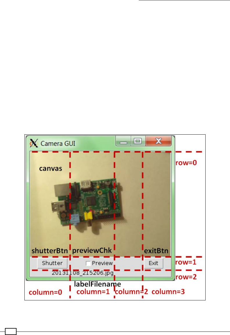
Creating Projects with the Raspberry Pi Camera Module
292
We dene the following three utility functions for the class to use:
frun(): This function will allow us to send commands to be run on the command line
using subprocess.call (we will use subprocess.call in the following examples
to perform video encoding and other applications).
fgetTKImage(): This function will allow us to create a TK.PhotoImage object
suitable to display on the Tkinter canvas. The Tkinter canvas is unable to directly
display JPG images, so we use the Pillow library (PIL) to resize it for display and
convert it into a PPM le (the Portable PixMap format, which supports more colors
than GIF). Since this conversion and resize process can take a few seconds, we will
use GIF images to provide a quick camera preview images.
ftimestamp(): This function will allow us to generate a timestamp string that we can
use to automatically name any images we take.
Within the class initializer (__init__()), we dene all the control variables, generate all
the GUI objects and controls we want to use, and use the grid() functions to position the
objects. The layout of the GUI is shown in the following image:
The layout of the camera GUI

Chapter 8
293
We dene the following control variables:
fself.previewUpdate: This is linked to the status of the Preview checkbox
(previewChk)
fself.filename: This is linked to text displayed by the labelFilename widget
We also link the Shutter button (shutterBtn) to self.shutter(), which will be called
whenever the Shutter button is pressed, and the Exit button (exitBtn) to the self.
exit() function.
Finally, in the __init__() function, we call self.preview(), which will ensure that
Camera GUI takes a picture and displays it as soon as the application has started.
When the Shutter button is pressed, self.shutter() is called. This calls this.
btnState("disabled") to disable the Shutter button while we are taking new pictures.
This prevents any pictures being taken while the camera is already in use. When the rest
of the actions have been completed, this.btnState("active") is used to re-enable
the button.
The self.shutter() function will call either the self.normal() or self.preview()
function, depending on the status of the Preview checkbox (by getting the value of self.
previewUpdate).
The cameraGUI.camCapture() function uses pycamera to create a camera object, set
the resolution, and capture an image using the required lename. The self.preview()
function takes an image called PREVIEW_FILE with a resolution of PV_SIZE as dened in
the SET class.
Next, self.updateDisp(PREVIEW_FILE) is called and will use cameraGUI.
getTKImage() to open the generated PREVIEW.gif le as a TK.PhotoImage object and
apply it to the Canvas object in the GUI. We now call self.update(), which is a function
inherited from the TK.Frame class; self.update() will allow the Tkinter display to be
updated (in this case, with the new image). Finally, the self.preview() function will also
call self.msg(), which will update the self.filename value with the lename of the
image being displayed (PREVIEW.gif). Again, this also uses self.update() to update
the display.
If the Preview checkbox is unchecked, then the self.shutter() function will call self.
normal(). However, this time it will take a much larger 2,592 x 1,944 (5 megapixel)
JPG image with the lename set to the latest <timestamp> value obtained from self.
timestamp(). The resultant image is also resized and converted to a PPM image so it can
be loaded as a TK.PhotoImage object that will be displayed in the application window.

Creating Projects with the Raspberry Pi Camera Module
294
There's more…
The camera application makes use of class structures to organize the code and make it easy
to extend. In the following sections, we explain the types of methods and functions we have
dened to allow this.
The Raspberry Pi can also make use of standard USB cameras or webcams. Alternatively,
we can use additional Video4Linux drivers to allow the camera module to work like a
standard webcam.
Class member and static functions
The cameraGUI class has two types of function dened. First, we dene some static methods
(run(), getTKImage(), and timestamp()). These methods are tied to the class rather
than to a specic instance; this means that we can use them without referring to a particular
cameraGUI object but to the class itself. This is useful to dene utility functions that are
related to the class, since they may be useful in other parts of the program as well and may
not need to access the data/objects contained within a cameraGUI object. The functions can
be called using cameraGUI.run("command").
Next, we dene the class member functions that, as in the previous classes we have used,
include a reference to self. This means that they are only accessible to instances of the
class (objects of the type cameraGUI) and can use the data contained within the object
(using the self reference).
Using a USB webcam instead
The Raspberry Pi camera module is not the only way you can add a camera to the Raspberry
Pi; in most cases, you can use a USB webcam as well. The current Raspberry Pi Raspbian
image should detect the most common webcam devices automatically when you plug them in;
however, the support can vary.
To determine if your webcam has been detected, check to see if the following device le has
been created on your system by running the following command:
ls /dev/video*
If detected successfully, you will see /dev/video0 or something similar, which is the
reference you will use to access your webcam.
Install a suitable image capture program, such as fswebcam, using the following command:
sudo apt-get install fswebcam
You can test it with the following command:
fswebcam -d /dev/video0 -r 320x240 testing.jpg

Chapter 8
295
Or alternatively, you can test it using dd as follows:
dd if=/dev/video0 of=testing.jpeg bs=11M count=1
Webcams can require additional power from the USB ports of the Raspberry
Pi; if you get errors, you may nd that using a powered USB hub helps. For a
list of supported devices and for troubleshooting, see the Raspberry Pi wiki
page at http://elinux.org/RPi_USB_Webcams.
In the previous example, change the following functions in the cameraGUI class as follows:
1. Remove camCapture() and remove import picamera as picam from the start
of the le.
2. Within normal(), replace cameraGUI.camCapture(name,SET.NORM_SIZE)
with the following:
cameraGUI.run(SET.CAM_PREVIEW+SET.CAM_OUTPUT+
SET.PREVIEW_FILE)
3. Within preview(), replace cameraGUI.camCapture(SET.PREVIEW_FILE,SET.
PV_SIZE) with the following:
cameraGUI.run(SET.CAM_NORMAL+SET.CAM_OUTPUT+name)
4. Within the SET class, dene the following variables:
CAM_OUTPUT=" "
CAM_PREVIEW="fswebcam -d /dev/video0 -r 320x240"
CAM_NORMAL="fswebcam -d /dev/video0 -r 640x480"
By making the previous changes to the cameraGUI class, the connected USB webcam will
take the images instead.
Additional drivers for the Raspberry Pi camera
Video4Linux drivers are available for the Raspberry Pi camera module. While these additional
drivers are not quite ofcial yet, it is likely that they will be included in the Raspbian image
when they are. For more details, see http:// http://www.linux-projects.org/
uv4l/.
The driver will allow you to use the camera module like you would a USB webcam, as a
/dev/video* device, although you will not need this for the examples in this chapter.

Creating Projects with the Raspberry Pi Camera Module
296
Perform the following steps to install the additional drivers:
1. First, download the apt keys and add the source to the apt sources list. You can do
this with the following commands:
wget http://www.linux-projects.org/listing/uv4l_repo/lrkey.asc
sudo apt-key add ./lrkey.asc
sudo nano /etc/apt/souces.list
2. Add the following into the le (on a single line):
deb http://www.linux-projects.org/listing/uv4l_repo/raspbian/
wheezy main
3. Install the drivers with the following commands:
sudo apt-get update
sudo apt-get install uv4l uv4l-raspicam
4. To use the uv4l driver, load it using the following command (on a single line):
uv4l --driver raspicam --auto-video_nr --width 640 –height480
--encoding jpeg
The Raspberry Pi will then be accessible through /dev/video0 (depending on whether you
have other video devices installed). It can be used with standard webcam programs.
See also
For more examples on using the Tkinter library, see Chapter 3, Using Python for Automation
and Productivity, and Chapter 4, Creating Games and Graphics.
Generating a time-lapse video
Having a camera attached to a computer provides us with a great way to take pictures at
controlled intervals and automatically process them into a video to create a time-lapse
sequence. The pycamera Python module has a special capture_continuous() function
that will create a series of images. For the time-lapse video, we will specify the time between
each image and the total number of images that need to be taken. To help the user, we will
also calculate the overall duration of the video to provide an indication of how long it will take.
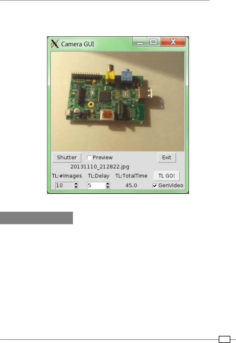
Chapter 8
297
We shall add to our previous GUI interface to provide controls to run time lapses and also
automatically generate a video clip from the results. The GUI will now look similar to the
following screenshot:
The time-lapse application
Getting ready
You will need everything set up as it was for the previous example, including the cameraGUI.
py le that we created in the same directory and pycamera, which we installed. We shall also
use mencoder, which will allow us to take the time-lapse images and combine them into a
video clip.
To install mencoder, use apt-get, as shown in the following command:
sudo apt-get install mencoder
An explanation of the command-line options can be found in the mencoder man pages.

Creating Projects with the Raspberry Pi Camera Module
298
How to do it…
Create timelapseGUI.py in the same directory as cameraGUI.py by performing the
following steps:
1. Start by importing the supporting modules (including cameraGUI) as shown in the
following code snippet:
#!/usr/bin/python3
#timelapseGUI.py
import tkinter as TK
from tkinter import messagebox
import cameraGUI as camGUI
import time
2. Extend the cameraGUI.SET class with settings for the time lapse and encoding
as follows:
class SET(camGUI.SET):
TL_SIZE=(1920,1080)
ENC_PROG="mencoder -nosound -ovc lavc -lavcopts"
ENC_PROG+=" vcodec=mpeg4:aspect=16/9:vbitrate=8000000"
ENC_PROG+=" -vf scale=%d:%d"%(TL_SIZE[0],TL_SIZE[1])
ENC_PROG+=" -o %s -mf type=jpeg:fps=24 mf://@%s"
LIST_FILE="image_list.txt"
3. Extend the main cameraGUI class with an additional function to perform the time
lapse as follows:
class cameraGUI(camGUI.cameraGUI):
def camTimelapse(filename,size=SET.TL_SIZE,
timedelay=10,numImages=10):
with camGUI.picam.PiCamera() as camera:
camera.resolution = size
for count, name in \
enumerate(camera.capture_continuous(filename)):
print("Timelapse: %s"%name)
if count == numImages:
break
time.sleep(timedelay)
4. Add the extra controls for the time-lapse GUI as shown in the following code snippet:
def __init__(self,parent):
super(cameraGUI,self).__init__(parent)
self.parent=parent
TK.Frame.__init__(self,self.parent,background="white")
self.numImageTL=TK.StringVar()

Chapter 8
299
self.peroidTL=TK.StringVar()
self.totalTimeTL=TK.StringVar()
self.genVideoTL=TK.IntVar()
labelnumImgTK=TK.Label(self.parent,text="TL:#Images")
labelperoidTK=TK.Label(self.parent,text="TL:Delay")
labeltotalTimeTK=TK.Label(self.parent,
text="TL:TotalTime")
self.numImgSpn=TK.Spinbox(self.parent,
textvariable=self.numImageTL,
from_=1,to=99999,
width=5,state="readonly",
command=self.calcTLTotalTime)
self.peroidSpn=TK.Spinbox(self.parent,
textvariable=self.peroidTL,
from_=1,to=99999,width=5,
command=self.calcTLTotalTime)
self.totalTime=TK.Label(self.parent,
textvariable=self.totalTimeTL)
self.TLBtn=TK.Button(self.parent,text="TL GO!",
command=self.timelapse)
genChk=TK.Checkbutton(self.parent,text="GenVideo",
command=self.genVideoChk,
variable=self.genVideoTL)
labelnumImgTK.grid(row=3,column=0)
self.numImgSpn.grid(row=4,column=0)
labelperoidTK.grid(row=3,column=1)
self.peroidSpn.grid(row=4,column=1)
labeltotalTimeTK.grid(row=3,column=2)
self.totalTime.grid(row=4,column=2)
self.TLBtn.grid(row=3,column=3)
genChk.grid(row=4,column=3)
self.numImageTL.set(10)
self.peroidTL.set(5)
self.genVideoTL.set(1)
self.calcTLTotalTime()
5. Add supporting functions to calculate the settings and handle the time lapse
as follows:
def btnState(self,state):
self.TLBtn["state"] = state
super(cameraGUI,self).btnState(state)
def calcTLTotalTime(self):
numImg=float(self.numImageTL.get())-1
peroid=float(self.peroidTL.get())

Creating Projects with the Raspberry Pi Camera Module
300
if numImg<0:
numImg=1
self.totalTimeTL.set(numImg*peroid)
def timelapse(self):
self.msg("Running Timelapse")
self.btnState("disabled")
self.update()
self.tstamp="TL"+cameraGUI.timestamp()
cameraGUI.camTimelapse(self.tstamp+'{counter:03d}.jpg',
SET.TL_SIZE,
float(self.peroidTL.get()),
int(self.numImageTL.get()))
if self.genVideoTL.get() == 1:
self.genTLVideo()
self.btnState("active")
TK.messagebox.showinfo("Timelapse Complete",
"Processing complete")
self.update()
6. Add supporting functions to handle and generate the time-lapse video as follows:
def genTLVideo(self):
self.msg("Generate video...")
cameraGUI.run("ls "+self.tstamp+"*.jpg > "
+SET.LIST_FILE)
cameraGUI.run(SET.ENC_PROG%(self.tstamp+".avi",
SET.LIST_FILE))
self.msg(self.tstamp+".avi")
#End
7. Next, create the following cameraGUI2timelapse.py script to use the GUI:
#!/usr/bin/python3
#cameraGUI2timelapse.py
import tkinter as TK
import timelapseGUI as GUI
root=TK.Tk()
root.title("Camera GUI")
cam=GUI.cameraGUI(root)
TK.mainloop()
#End
We import timelapseGUI instead of cameraGUI; this will add the timelapseGUI module
to the cameraGUI script.
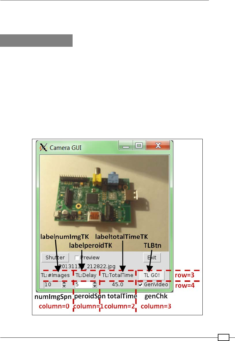
Chapter 8
301
Run the example with the following command:
python3 cameraGUI2timelapse.py
How it works…
The timelapseGUI.py script allows us to take the classes dened in cameraGUI.py and
extend them. The previous cameraGUI class inherits all of the content of the TK.Frame
class, and using the same technique we can also inherit the SET and cameraGUI classes in
our application.
We add some additional settings to the SET class to provide the settings for mencoder (to
encode the video).
We shall extend the basic cameraGUI class by inheriting from camGUI.cameraGUI and
dening a new version of __init__() for the class. Using super(), we can include the
functionality from the original __init__() function and then dene the extra controls we
want to add to the GUI. The extended GUI is shown in the following screenshot:
The time-lapse GUI layout that extends the base camera GUI

Creating Projects with the Raspberry Pi Camera Module
302
We dene the following control variables:
fself.numImageTL: This is linked to the value of the numImgSpn spinbox control to
specify the number of images we want to take in our time lapse (and also provide the
numimages value for camTimelapse).
fself.peroidTL: This is linked to the value of the peroidSpn spinbox control; it
determines how many seconds there should be between the time-lapse images (and
also provides the timedelay value for camTimelapse).
fself.totalTimeTL: This is linked to the totalTime label object. It is calculated
using the number of images and the timedelay time between each to indicate how
long the time lapse will run for.
fself.genVideoTL: This controls the state of the genChk checkbox control. It is
used to determine whether the video has been generated after the time-lapse images
have been taken.
We link both of the spinbox controls to self.calcTLTotalTime() so that when they are
changed, the totalTimeTL value is also updated (although it is not called if they are edited
directly). We link genChk to self.genVideoChk() and TLBtn to self.timelapse().
Finally, we specify the positions of the controls using grid() and set some defaults for the
time-lapse settings.
The self.genVideoChk() function is called when the genChk checkbox is ticked or
cleared. This allows us to inform the user of the effect that this checkbox has by generating a
pop-up message box to say if the video will be generated at the end of the time lapse or if just
images will be created.
When the TL GO! button is pressed (TLBtn), self.timelapse() is called; this will disable
the Shutter and TL GO! buttons (since we have also extended the self.btnState()
function). The self.timelapse() function will also set the self.tstamp value so the
same timestamp can be used for the images and the resulting video le (if generated).
The time lapse is run using the camTimelapse() function as shown in the following code:
def camTimelapse(filename,size=SET.TL_SIZE,
timedelay=10,numImages=10):
with camGUI.picam.PiCamera() as camera:
camera.resolution = size
for count, name in \
enumerate(camera.capture_continuous(filename)):
print("Timelapse: %s"%name)
if count == numImages:
break
time.sleep(timedelay)
Chapter 8
303
We create a new PiCamera object, set the image resolution, and start a for…in loop for
capture_continuous(). Each time an image is taken, we print the lename and then wait
for the required timedelay value. Finally, when the required number of images have been
taken, we break out of the loop and continue.
Once this is complete, we check the value of self.genVideoTL to determine if we want to
generate the video (which is handled by genTLVideo()).
To generate the video, we rst run the following command to create an image_list.txt le
of the images:
ls <self.tstamp>*.jpg > image_list.txt
Then we run mencoder with the suitable settings (see the mencoder man pages for what
each item does) to create an MPEG4-encoded (8 Mbps) AVI le with 24 frames per
second (fps) from the list of time-lapse images. The equivalent command (dened by
ENC_PROG) is as follows:
mencoder -nosound -ovc lavc \
-lavcopts vcodec=mpeg4:aspect=16/9:vbitrate=8000000 \
-vf scale=1920:1080 -o <self.tstamp>.avi \
-mf type=jpeg:fps=24 mf://@image_list.txt
Long commands can be split into several lines on the command
terminal by using the \ character. This allows you to continue writing
the command on another line, only executing it when you nish a line
without the \ character.
There's more…
This chapter uses methods such as class inheritance and function overriding to structure
and reuse our code in a number of different ways. When used correctly, these methods
could enable us to design complex systems in a logical and exible way.
Additionally, when generating your own time-lapse sequences, you can opt to switch off the
LED on the camera module or make use of the low-light version of the Raspberry Pi camera:
the NoIR camera.
Class inheritance and function overriding
In the previous example, we used some clever coding in order to reuse our original
cameraGUI class and create a plugin le that extends its features.
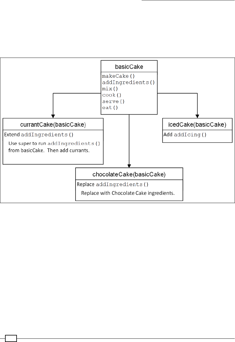
Creating Projects with the Raspberry Pi Camera Module
304
The class name does not have to be the same as cameraGUI (we just use it in this case so
we can swap out the additional GUI components just by changing the le we import). In fact,
we could dene one basic class that contains several general functions and then extend
the class by inheritance into a number of subclasses; here, each subclass denes specic
behaviors, functions, and data. The extending and structuring of the subclasses is shown in
the following diagram:
This diagram shows how classes can be extended and structured
To illustrate this, we will take a non-code example in which we have written a general recipe
for preparing a cake. You can then extend the basicCake recipe by inheriting all the
basicCake elements and add some additional steps (equivalent code functions) to perhaps
add icing/frosting on top to make an icedCake(basicCake) class. We did this with our SET
class by adding additional items to an existing class (we just chose not to change the name).
We can also add in some additional elements to the existing steps (add some currants at the
addIngredients step and create currantCake(basicCake)). We have done this using
the super() function in our code by adding additional parts to the __init__() function. For
example, we would use super(basicCake.self).addIngredients() to include all the
steps in the addIngredients() function dened in the basicCake class, and then add an
extra step to include currants. The advantage is if we then change the basic cake ingredients,
it will also ow through to all the other classes.

Chapter 8
305
You could even override some of the original functions by replacing them with new ones;
for instance, you could replace the original recipe for basicCake with one to make
chocolateCake(basicCake) while still using the same instructions to cook, and so on. We
can do this by dening replacement functions with the same names without using super().
Using structured design in this way can become very powerful since we can easily create
many variants of the same sort of object but have all the common elements dened in the
same place. This has many advantages when it comes to testing, developing, and maintaining
large and complex systems. The key here is to take an overall view of your project and try to
identify the common elements before you begin. You will nd that the better the structure you
have, the easier it is to develop and improve it.
For more information on this, it is worth reading up on object-oriented design methods
and how to use Unied Modelling Language (UML) to help you describe and understand
your system.
Disabling the camera LED
If you want to create time-lapse videos at night or next to windows, you may notice that the red
camera LED (which lights up for every shot) adds unwanted light or reections. Fortunately,
the camera LED can be controlled through the GPIO. The LED is controlled using GPIO.BCM
Pin 5; unfortunately, there isn't an equivalent GPIO.BOARD pin number for it.
To add it to a Python script, use the following code:
import RPi.GPIO as GPIO
GPIO.cleanup()
GPIO.setmode(GPIO.BCM)
CAMERALED=5 #GPIO using BCM numbering
GPIO.setup(CAMERALED, GPIO.OUT)
GPIO.output(CAMERALED,False)
Alternatively, you could use the LED for something else, for example, as an indicator as part
of a delay timer that provides a countdown and warning that the camera is about to take
an image.
Pi NoIR – taking night shots
There is also a variant of the Raspberry Pi camera module available called Pi NoIR. This
version of the camera is the same as the original, except that the internal infrared lter has
been removed. Among other things, this allows you to use infrared lighting to illuminate areas
at night time (just like most night security cameras do) and see everything that is happening
in the dark!
The MagPi Issue 18 (https://www.raspberrypi.org/magpi/) has published an excellent
feature explaining the other uses of the Pi NoIR camera module.

Creating Projects with the Raspberry Pi Camera Module
306
Creating a stop frame animation
Stop frame (or stop motion) animation is the process of taking a series of still images of items,
while making very small movements (typically of an easily moveable object such as a doll
or plasticine model) in each frame. When the frames are assembled into a video, the small
movements combine to produce an animation.
Multiple images can be combined into an animation
Traditionally, such animations were made by taking hundreds or even thousands of individual
photos on a lm camera (such as a Cine Super 8 movie camera) and then sending the lm
off to be developed and playing back the results some weeks later. Despite the inspiring
creations by Nick Park at Aardman Animations, including Wallace and Gromit (which are full-
length, stop frame animation lms), this was a hobby that was a little out of reach for most.
In the modern digital age, we can take multiple images quickly and easily with the luxury of
reviewing the results almost instantly. Now anyone can try their hand at their own animated
masterpieces with very little cost or effort.
We will extend our original Camera GUI with some extra features that will allow us to create
our own stop frame animations. It will allow us to take images and try them out in a sequence
before generating a nished video for us.
Getting ready
The software setup for this example will be the same as the previous time-lapse example.
Again, we will need mencoder to be installed and we need the cameraGUI.py le in the
same directory.

Chapter 8
307
You will also need something to animate, ideally something you can put in different poses, like
the two dolls shown in the following image:
Two potential stars for our stop frame animation
How to do it…
Create animateGUI.py in the same directory as cameraGUI.py by performing the
following steps:
1. Start by importing the supporting modules (including cameraGUI), as shown in the
following code:
#!/usr/bin/python3
#animateGUI.py
import tkinter as TK
from tkinter import messagebox
import time
import os
import cameraGUI as camGUI

Creating Projects with the Raspberry Pi Camera Module
308
2. Extend the cameraGUI.SET class with settings for the image size and encoding
as follows:
class SET(camGUI.SET):
TL_SIZE=(1920,1080)
ENC_PROG="mencoder -nosound -ovc lavc -lavcopts"
ENC_PROG+=" vcodec=mpeg4:aspect=16/9:vbitrate=8000000"
ENC_PROG+=" -vf scale=%d:%d"%(TL_SIZE[0],TL_SIZE[1])
ENC_PROG+=" -o %s -mf type=jpeg:fps=24 mf://@%s"
LIST_FILE="image_list.txt"
3. Extend the main cameraGUI class with the functions required for the animation
as follows:
class cameraGUI(camGUI.cameraGUI):
def diff(a, b):
b = set(b)
return [aa for aa in a if aa not in b]
def __init__(self,parent):
super(cameraGUI,self).__init__(parent)
self.parent=parent
TK.Frame.__init__(self,self.parent,
background="white")
self.theList = TK.Variable()
self.imageListbox=TK.Listbox(self.parent,
listvariable=self.theList,
selectmode=TK.EXTENDED)
self.imageListbox.grid(row=0, column=4,columnspan=2,
sticky=TK.N+TK.S+TK.E+TK.W)
yscroll = TK.Scrollbar(command=self.imageListbox.yview,
orient=TK.VERTICAL)
yscroll.grid(row=0, column=6, sticky=TK.N+TK.S)
self.imageListbox.configure(yscrollcommand=yscroll.set)
self.trimBtn=TK.Button(self.parent,text="Trim",
command=self.trim)
self.trimBtn.grid(row=1,column=4)
self.speed = TK.IntVar()
self.speed.set(20)
self.speedScale=TK.Scale(self.parent,from_=1,to=30,
orient=TK.HORIZONTAL,
variable=self.speed,
label="Speed (fps)")
self.speedScale.grid(row=2,column=4)
self.genBtn=TK.Button(self.parent,text="Generate",
command=self.generate)
self.genBtn.grid(row=2,column=5)

Chapter 8
309
self.btnAniTxt=TK.StringVar()
self.btnAniTxt.set("Animate")
self.animateBtn=TK.Button(self.parent,
textvariable=self.btnAniTxt,
command=self.animate)
self.animateBtn.grid(row=1,column=5)
self.animating=False
self.updateList()
4. Add functions to list the images that were taken and remove them from the list using
the following code snippet:
def shutter(self):
super(cameraGUI,self).shutter()
self.updateList()
def updateList(self):
filelist=[]
for files in os.listdir("."):
if files.endswith(".jpg"):
filelist.append(files)
filelist.sort()
self.theList.set(tuple(filelist))
self.canvas.update()
def generate(self):
self.msg("Generate video...")
cameraGUI.run("ls *.jpg > "+SET.LIST_FILE)
filename=cameraGUI.timestamp()+".avi"
cameraGUI.run(SET.ENC_PROG%(filename,SET.LIST_FILE))
self.msg(filename)
TK.messagebox.showinfo("Encode Complete",
"Video: "+filename)
def trim(self):
print("Trim List")
selected = map(int,self.imageListbox.curselection())
trim=cameraGUI.diff(range(self.imageListbox.size()),
selected)
for item in trim:
filename=self.theList.get()[item]
self.msg("Rename file %s"%filename)
#We could delete os.remove() but os.rename() allows
#us to change our minds (files are just renamed).
os.rename(filename,

Creating Projects with the Raspberry Pi Camera Module
310
filename.replace(".jpg",".jpg.bak"))
self.imageListbox.selection_clear(0,
last=self.imageListbox.size())
self.updateList()
5. Include functions to perform the test animation using the image list as follows:
def animate(self):
print("Animate Toggle")
if (self.animating==True):
self.btnAniTxt.set("Animate")
self.animating=False
else:
self.btnAniTxt.set("STOP")
self.animating=True
self.doAnimate()
def doAnimate(self):
imageList=[]
selected = self.imageListbox.curselection()
if len(selected)==0:
selected=range(self.imageListbox.size())
print(selected)
if len(selected)==0:
TK.messagebox.showinfo("Error",
"There are no images to display!")
self.animate()
elif len(selected)==1:
filename=self.theList.get()[int(selected[0])]
self.updateDisp(filename,SET.PV_SIZE)
self.animate()
else:
for idx,item in enumerate(selected):
self.msg("Generate Image: %d/%d"%(idx+1,
len(selected)))
filename=self.theList.get()[int(item)]
aImage=cameraGUI.getTKImage(filename,SET.PV_SIZE)
imageList.append(aImage)
print("Apply Images")
canvasList=[]
for idx,aImage in enumerate(imageList):
self.msg("Apply Image: %d/%d"%(idx+1,
len(imageList)))
canvasList.append(self.canvas.create_image(0, 0,
anchor=TK.NW,

Chapter 8
311
image=imageList[idx],
state=TK.HIDDEN))
self.cycleImages(canvasList)
def cycleImages(self,canvasList):
while (self.animating==True):
print("Cycle Images")
for idx,aImage in enumerate(canvasList):
self.msg("Cycle Image: %d/%d"%(idx+1,
len(canvasList)))
self.canvas.itemconfigure(canvasList[idx],
state=TK.NORMAL)
if idx>=1:
self.canvas.itemconfigure(canvasList[idx-1],
state=TK.HIDDEN)
elif len(canvasList)>1:
self.canvas.itemconfigure(
canvasList[len(canvasList)-1],
state=TK.HIDDEN)
self.canvas.update()
time.sleep(1/self.speed.get())
#End
6. Next, create the following cameraGUI3animate.py le to use the GUI:
#!/usr/bin/python3
#cameraGUI3animate.py
import tkinter as TK
import animateGUI as GUI
#Define Tkinter App
root=TK.Tk()
root.title("Camera GUI")
cam=GUI.cameraGUI(root)
TK.mainloop()
#End
7. Run the example with the following command:
python3 cameraGUI3animate.py
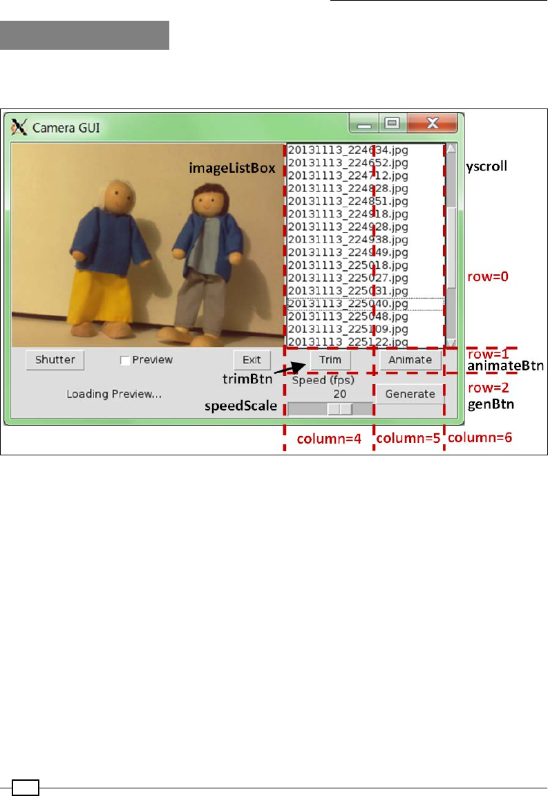
Creating Projects with the Raspberry Pi Camera Module
312
How it works…
Once again, we create a new class based on the original cameraGUI class. This time, we
dene the following GUI with six extra controls:
The animation GUI layout
We create a listbox control (imageListbox) that will contain a list of the .jpg images in the
current directory (self.theList). This control has a vertical scroll bar (yscroll) linked to
it to allow easy scrolling of the list, and selectmode=TK.EXTENDED is used to allow multiple
selections using Shift and Ctrl (for block and group selections).
Next, we add a Trim button (timeBtn) that will call self.trim(). This will remove any items
that have not been selected in the list. We use curselection() to get a list of the currently
selected items from the imageListbox control. The curselection() function normally
returns a list of indexes that are numerical strings, so we use map(int,...) to convert the
result into a list of integers.
We use this list to get all the indexes that have not been selected using our utility diff(a,b)
function. The function compares a full list of indexes against the selected ones and returns
any that haven't been selected.

Chapter 8
313
The self.trim() function uses os.rename() to change the lename extensions
from .jpg to .jpg.bak for all the non-selected images. We could delete them using
os.remove(), but we only really want to rename them to stop them from appearing in the
list and nal video. The list is repopulated using self.updateList(), which updates self.
theList with a list of all the .jpg les available.
We add a scale control (speedScale) that is linked to self.speed and is used to control
the playback speed of the animation test. As earlier, we add a Generate button (genBtn) that
calls self.generate().
Finally, we add the Animate button (animateBtn). The text for the button is linked to self.
btnAniTxt (making it easy to change within our program), and when pressed, the button
calls self.animate().
We override the original shutter() function from the original cameraGUI
script by adding a call to self.updateList(). This ensures that after
an image has been taken, the list of images is updated with the new
image automatically. Again, we use super() to ensure that the original
functionality is also performed.
The animate() function (called by clicking on the Animate button) allows us to test a
selection of images to see whether they will make a good animation or not. When the button
is clicked on, we change the text of the button to STOP, the self.animating ag to True (to
indicate that the animation mode is running), and call doAnimate().
The doAnimate() function rst gets a list of currently selected images in the
imageListbox control, generates a list of TK.PhotoImage objects, and attaches them to
the self.canvas object in the GUI. However, if only one image has been selected, we display
it directly using self.updateDisp(). Alternatively, if no images have been selected, it will
try to use them all (unless the list is empty, in which case it will inform the user that there are
no images to animate). When we have more than one TK.PhotoImage object linked to the
canvas, we can loop through them using the cycleImages() function.
The TK.PhotoImage objects are all created with their states set to TK.HIDDEN,
which means they are not visible on the canvas. To produce the animation effect, the
cycleImages() function will set each image to TK.NORMAL and then TK.HIDDEN again,
allowing each frame to be displayed for 1 divided by self.speed (the fps value set by the
Scale control) seconds before showing the next.
The cycleImages() function will perform the animation as long as self.animating is
True, that is, until the animateBtn object is clicked on again.
Once the user is happy with their animation, they can generate the video using the Generate
button (genBtn). The generate() function will call mencoder to generate the nal video of
all the images in the imageListbox control.
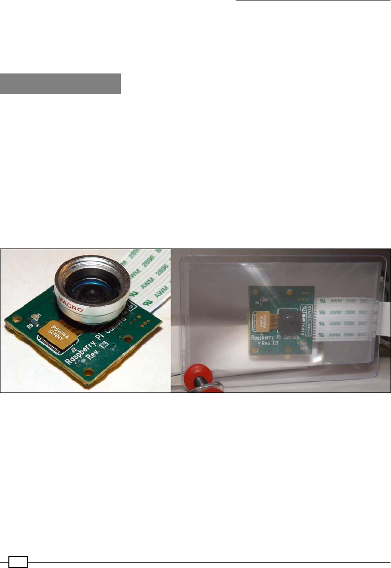
Creating Projects with the Raspberry Pi Camera Module
314
If you really want to get into producing animations, you should consider adding some extra
features to help you, such as the ability to duplicate and reorder frames. You may want to add
some manual adjustments for the camera to avoid white balance and lighting uctuations
caused by the automatic settings of the camera.
There's more…
The camera module is ideal for close-up photography due to its small size and ability to be
remotely controlled. By using small lenses or adding hardware controls, you could make a
purpose-built animation machine.
Improving the focus
The Raspberry Pi camera lens has been designed mainly for middle to long distance
photography, and it therefore has trouble focusing on objects that are closer than 25 cm
(10 inches). However, using some basic lenses, we can adjust the effective focal length and
make it more suitable for macro photography. You can use add-on lenses that are available
for mobile phones or credit card-style magnier lenses to adjust the focus, as shown in the
following images:
An add-on macro lens (right) and a credit card magnifier (left) can improve the focus of close-up items
Creating a hardware shutter
Of course, while it is useful to have a display available to review the images taken, it is often
useful to be able to simply press a physical button to take an image. Fortunately, this is just a
matter of attaching a button (and resistor) to a GPIO pin, as we have done previously (see the
Responding to a button recipe in Chapter 6, Using Python to Drive Hardware), and creating
suitable GPIO control code to call our cameraGUI.camCapture() function. The code for this
is as follows:
#!/usr/bin/python3
#shutterCam.py
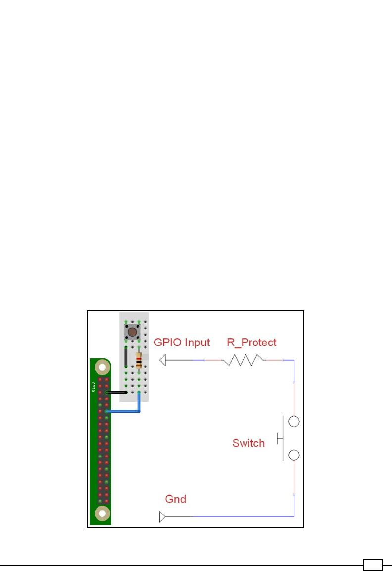
Chapter 8
315
import RPi.GPIO as GPIO
import cameraGUI as camGUI
import time
GPIO.setmode(GPIO.BOARD)
CAMERA_BTN=12 #GPIO Pin 12
GPIO.setup(CAMERA_BTN,GPIO.IN,pull_up_down=GPIO.PUD_UP)
count=1
try:
while True:
btn_val = GPIO.input(CAMERA_BTN)
#Take photo when Pin 12 at 0V
if btn_val==False:
camGUI.cameraGUI.camCapture("Snap%03d.jpg"%count,
camGUI.SET.NORM_SIZE)
count+=1
time.sleep(0.1)
finally:
GPIO.cleanup()
#End
The previous code will take a picture when the button is pressed. The following diagram shows
the connections and circuit diagram required to achieve this:
The button (and 1K ohm resistor) should be connected between pins 12 and 6 (GND)
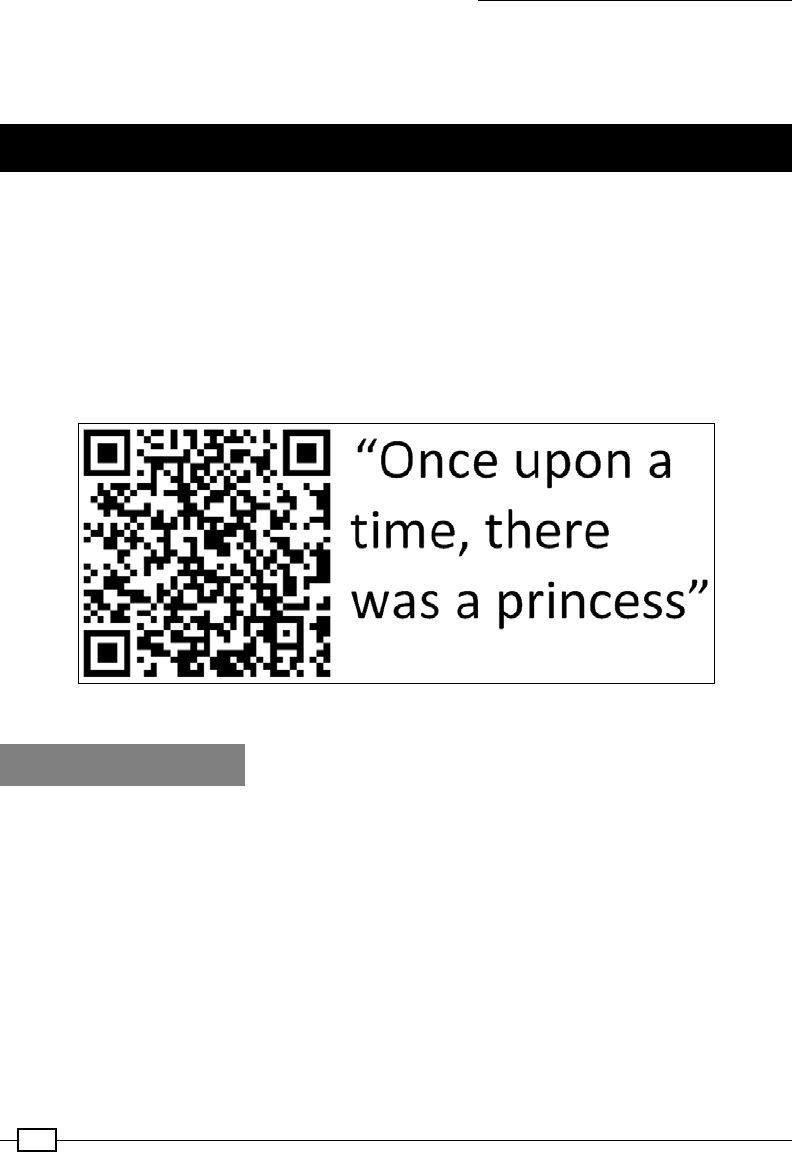
Creating Projects with the Raspberry Pi Camera Module
316
You don't even have to stop here since you can add buttons and switches for any of
the controls or settings for the camera if you want to. You can even use other hardware
(such as infrared sensors and so on) to trigger the camera to take an image or video.
Making a QR code reader
You have probably seen QR codes in various places, and perhaps even used a few to pick up
links from posters or adverts. However, they can be far more useful if you make your own.
The following example discusses how we can use the Raspberry Pi to read QR codes and the
hidden content (or even link to an audio le or video).
This could be used to create your own personalized Raspberry Pi QR code jukebox, perhaps as
an aid for children to provide solutions to math problems, or even to play an audio le of you
reading your kid's favorite book as they follow along page by page. The following screenshot is
an example of a QR code:
You can use QR codes to make magical self-reading books
Getting ready
This example requires a setup similar to the previous examples (except we won't need
mencoder this time). We will need to install ZBar, which is a cross-platform QR code and
barcode reader, and ite (a text-to-speech utility that we used in Chapter 6, Using Python to
Drive Hardware).
To install ZBar and ite, use apt-get as shown in the following command:
sudo apt-get install zbar-tools flite

Chapter 8
317
There are Python 2.7 libraries available for Zbar, but they are not
currently compatible with Python 3. Zbar also includes a real-time
scanner (zbarcam) that uses video input to detect barcodes and
QR codes automatically. Unfortunately, this isn't compatible with the
Raspberry Pi camera either.
This isn't a big problem for us since we can use the zbarimg program
directly to detect the QR codes from images taken with picamera.
Once you have the software installed, you will need some QR codes to scan (see the There's
more… section in Generating QR codes) and some suitably named MP3 les (these could be
recordings of you reading the pages of a book or music tracks).
How to do it…
Create the following qrcodeGUI.py script in the same directory as cameraGUI.py:
#!/usr/bin/python3
#qrcodeGUI.py
import tkinter as TK
from tkinter import messagebox
import subprocess
import cameraGUI as camGUI
class SET(camGUI.SET):
QR_SIZE=(640,480)
READ_QR="zbarimg "
class cameraGUI(camGUI.cameraGUI):
def run_p(cmd):
print("RunP:"+cmd)
proc=subprocess.Popen(cmd,shell=True,stdout=subprocess.PIPE)
result=""
for line in proc.stdout:
result=str(line,"utf-8")
return result
def __init__(self,parent):
super(cameraGUI,self).__init__(parent)
self.parent=parent
TK.Frame.__init__(self,self.parent,background="white")
self.qrScan=TK.IntVar()
self.qrRead=TK.IntVar()
self.qrStream=TK.IntVar()

Creating Projects with the Raspberry Pi Camera Module
318
self.resultQR=TK.StringVar()
self.btnQrTxt=TK.StringVar()
self.btnQrTxt.set("QR GO!")
self.QRBtn=TK.Button(self.parent,textvariable=self.btnQrTxt,
command=self.qrGet)
readChk=TK.Checkbutton(self.parent,text="Read",
variable=self.qrRead)
streamChk=TK.Checkbutton(self.parent,text="Stream",
variable=self.qrStream)
labelQR=TK.Label(self.parent,textvariable=self.resultQR)
readChk.grid(row=3,column=0)
streamChk.grid(row=3,column=1)
self.QRBtn.grid(row=3,column=3)
labelQR.grid(row=4,columnspan=4)
self.scan=False
def qrGet(self):
if (self.scan==True):
self.btnQrTxt.set("QR GO!")
self.btnState("active")
self.scan=False
else:
self.msg("Get QR Code")
self.btnQrTxt.set("STOP")
self.btnState("disabled")
self.scan=True
self.qrScanner()
def qrScanner(self):
found=False
while self.scan==True:
self.resultQR.set("Taking image...")
self.update()
cameraGUI.camCapture(SET.PREVIEW_FILE,SET.QR_SIZE)
self.resultQR.set("Scanning for QRCode...")
self.update()
#check for QR code in image
qrcode=cameraGUI.run_p(SET.READ_QR+SET.PREVIEW_FILE)
if len(qrcode)>0:
self.msg("Got barcode: %s"%qrcode)
qrcode=qrcode.strip("QR-Code:").strip('\n')
self.resultQR.set(qrcode)
self.scan=False
found=True
else:
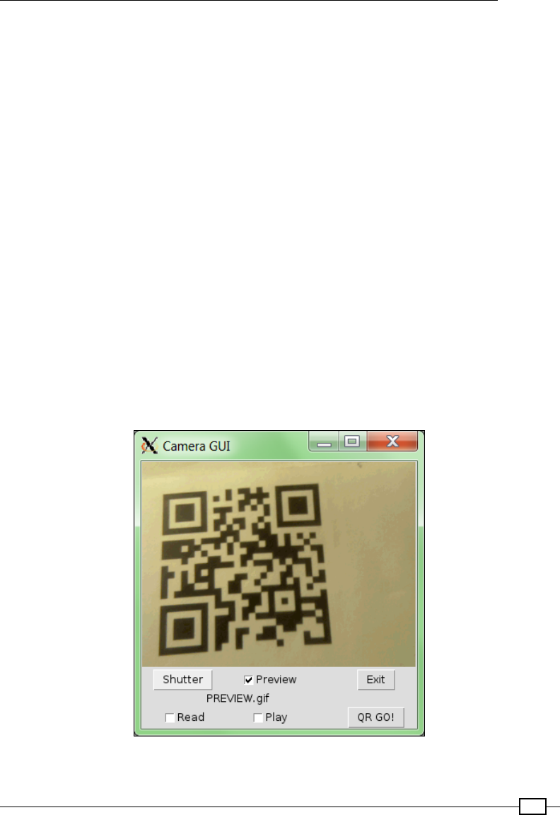
Chapter 8
319
self.resultQR.set("No QRCode Found")
if found:
self.qrAction(qrcode)
self.btnState("active")
self.btnQrTxt.set("QR GO!")
self.update()
def qrAction(self,qrcode):
if self.qrRead.get() == 1:
self.msg("Read:"+qrcode)
cameraGUI.run("sudo flite -t '"+qrcode+"'")
if self.qrStream.get() == 1:
self.msg("Stream:"+qrcode)
cameraGUI.run("omxplayer '"+qrcode+"'")
if self.qrRead.get() == 0 and self.qrStream.get() == 0:
TK.messagebox.showinfo("QR Code",self.resultQR.get())
#End
Next, create a copy of cameraGUItimelapse.py or cameraGUIanimate.py and call
it cameraGUIqrcode.py. Again, make sure you import the new le for the GUI using the
following code:
import qrcodeGUI as GUI
The GUI with QR code will look as shown in the following screenshot:
The QR code GUI

Creating Projects with the Raspberry Pi Camera Module
320
How it works…
The new qrcodeGUI.py le adds the Read and Play checkbox controls and a button control
to start scanning for QR codes. When QR GO! is clicked on, self.qrGet() will start a cycle
of taking images and checking the result with zbarimg. If zbarimg nds a QR code in the
image, then the scanning will stop and the result will be displayed. Otherwise, it will continue
to scan until the STOP button is clicked on. While the scanning is taking place, the text for
QRBtn is changed to STOP.
In order to capture the output of zbarimg, we have to change how we run the command
slightly. To do this, we dene run_p(), which uses the following code:
proc=subprocess.Popen(cmd,shell=True,stdout=subprocess.PIPE)
This returns stdout as part of the proc object, which contains the output of the zbarimg
program. We then extract the resulting QR code that was read from the image (if one was
found).
When Read is selected, flite is used to read out the QR code, and if Play is selected,
omxplayer is used to play the le (assuming the QR code contains a suitable link).
For the best results, it is recommended that you take a preview shot rst to ensure that you
have lined up the target QR code correctly before running the QR scanner.
Example QR code page markers (page001.mp3 and page002.mp3)
The previous QR codes contain page001.mp3 and page002.mp3. These QR codes allow
us to play les with the same name if placed in the same directory as our script. You can
generate your own QR codes by following the instructions in the There's more… section
in this recipe.
You could even use the book's ISBN barcode to select a different directory of MP3s based on
the barcode read; the barcode allows you to reuse the same set of page-numbered QR codes
for any book you like.

Chapter 8
321
There's more…
To make use of the previous example, you can use the example in the next section to generate
a range of QR codes to use.
Generating QR codes
You can create QR codes using PyQRCode (see https://pypi.python.org/pypi/
PyQRCode for more information).
You can install PyQRCode using the PIP Python manager as follows (see the Getting ready
section of the Displaying photo information in an application recipe in Chapter 3, Using
Python for Automation and Productivity):
sudo pip-3.2 install pyqrcode
To encode QR codes in the PNG format, PyQrCode uses PyPNG (https://github.com/
drj11/pypng), which can be installed with the following command:
sudo pip-3.2 install pypng
Use the following generateQRCodes.py script to generate QR codes to link to les, such as
the page001.mp3 and page002.mp3 les that you have recorded:
#!/usr/bin/python3
#generateQRCodes.py
import pyqrcode
valid=False
print("QR-Code generator")
while(valid==False):
inputpages=input("How many pages?")
try:
PAGES=int(inputpages)
valid=True
except ValueError:
print("Enter valid number.")
pass
print("Creating QR-Codes for "+str(PAGES)+" pages:")
for i in range(PAGES):
file="page%03d"%(i+1)
qr_code = pyqrcode.create(file+".mp3")
qr_code.png(file+".png")
print("Generated QR-Code for "+file)
print("Completed")
#End

Creating Projects with the Raspberry Pi Camera Module
322
Run this code using the following command:
python3 generateQRCodes.py
The previous code will create a set of QR codes that can be used to activate the required MP3
le and read the page out loud (or play the le that you have linked to it).
See also
The Open Source Computer Vision (OpenCV) project is a very powerful image and video
processing engine; more details are available at http://opencv.org.
By combining the camera with OpenCV, the Raspberry Pi is able to recognize and interact with
its environment.
An excellent example of this is Samuel Matos's RS4 OpenCV Self-balancing Robot
(http://roboticssamy.blogspot.pt) that can seek out and respond to various
custom signs; the camera module can be used to navigate and control the robot.
Discover and experiment with OpenCV
The OpenCV library is an extensive library aimed at providing real-time computer vision
processing across multiple platforms. Essentially, if you want to do any serious image
processing, object recognition, or analysis, then OpenCV is a perfect place to get started.
Fortunately, the latest release of OpenCV (version 3) has added support for
interfacing via Python 3. Although performing real-time video processing can often
require a computer with a powerful CPU, it will run on relativity limited devices such as
the original Raspberry Pi (version 1). Using the more powerful Raspberry Pi 2 is highly
recommended for the following recipes.
The concepts and underlying methods behind image and video processing can get
rather complicated. This rst recipe shall demonstrate how to work with OpenCV and
most importantly provide an easy way to visualize various stages that may be used for
processing images.
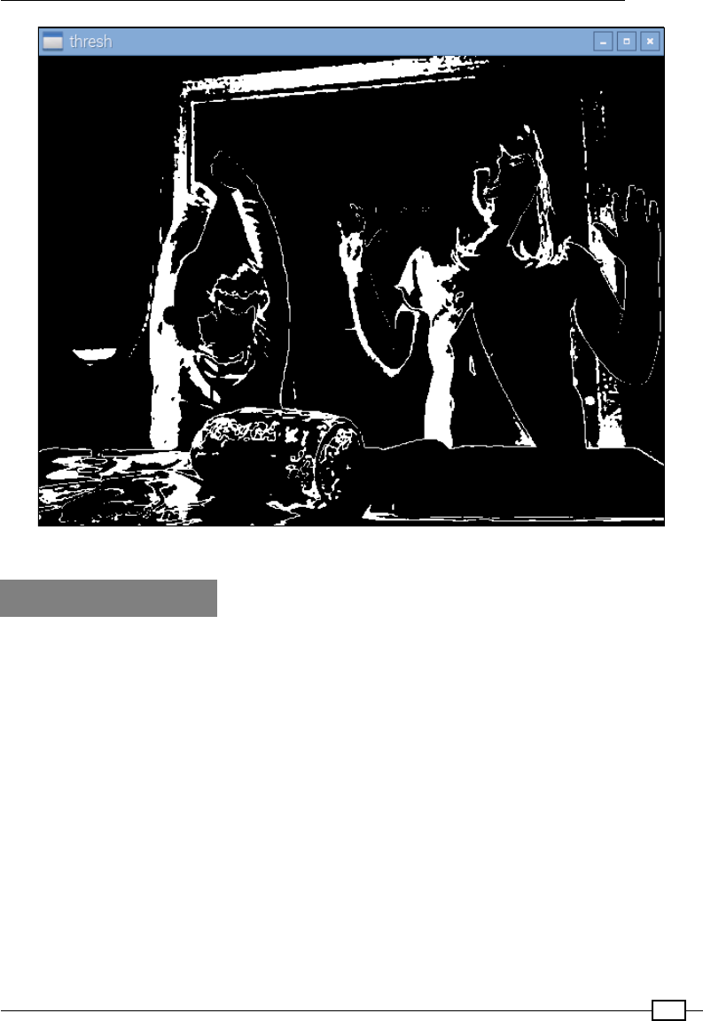
Chapter 8
323
When performing tests with the camera ensure you have suitable test subjects available
Getting ready
The OpenCV library is written in C++ and needs to be compiled before we can use it on the
Raspberry Pi. To do this, we will need to install all the required packages and then download a
release from the OpenCV Git repository. OpenCV can require around 2.5 GB of space while it
compiles; however, a standard installation of Raspbian from NOOBS can use around 5.5 GB.
This means there may be insufcient space available on an 8 GB SD card. It may be possible
to squeeze OpenCV onto a smaller SD card (by installing a custom Raspbian image or utilizing
a USB ash device); however, to avoid complications, it is recommended you use at least a 16
GB SD card to compile and install OpenCV on.
Additionally, while the majority of recipes in this book can be run using SSH and X11-
forwarding over a network connection, the OpenCV display window appears to function far
more effectively if you are connected to a local screen (via HDMI) and controlled directly with
a local input devices.

Creating Projects with the Raspberry Pi Camera Module
324
Installing OpenCV is quite a long process, but I feel the results are well worth the effort:
1. Ensure that the Raspberry Pi is as up to date as possible, using the following commands:
sudo apt-get update
sudo apt-get upgrade
sudo rpi-update
2. And perform a reboot to apply the changes:
sudo reboot
3. Before we compile OpenCV, we need to install a number of dependencies to support
the build process:
sudo apt-get install build-essential cmake pkg-config
sudo apt-get install python2.7-dev python3-dev
4. We also need to install a number of supporting libraries and packages used by
OpenCV (we may not use all of these, but they form part of the build process). These
will also provide support for a wide range of image and video formats from within
OpenCV:
sudo apt-get install libjpeg-dev libtiff5-dev libjasper-dev
libpng12-dev
sudo apt-get install libavcodec-dev libavformat-dev libswscale-dev
libv4l-dev
sudo apt-get install libxvidcore-dev libx264-dev
sudo apt-get install libgtk2.0-dev
5. We can also install NumPy, which is very useful when manipulating image arrays
within OpenCV, Automatically Tuned Linear Algebra Software (ATLAS), and
GFortran for additional mathematic functionality:
sudo apt-get install python3-numpy
sudo apt-get install libatlas-base-dev gfortran
6. Now that we have the supporting packages, we can download OpenCV and OpenCV
Contributed (extra modules) directly from GitHub. We will also create a build location
ready for the next step:
cd ~
wget -O opencv.zip https://github.com/Itseez/opencv/
archive/3.0.0.zip
unzip opencv.zip
wget -O opencv_contrib.zip https://github.com/Itseez/opencv_
contrib/archive/3.0.0.zip
Chapter 8
325
unzip opencv_contrib.zip
cd opencv-3.0.0
mkdir build
cd build
Note: You can download the latest version using the following links
and selecting a specific release tag; however, you may find you require
additional dependencies or modules for the package to compile
successfully. Ensure you select the same release for OpenCV and the
contributed modules.
https://github.com/Itseez/opencv/
https://github.com/Itseez/opencv_contrib/
7. The make le can be created using the following commands. This takes around 10
minutes to nish (see the following screenshot):
cmake -D CMAKE_BUILD_TYPE=RELEASE \
-D CMAKE_INSTALL_PREFIX=/usr/local \
-D INSTALL_C_EXAMPLES=ON \
-D INSTALL_PYTHON_EXAMPLES=ON \
-D OPENCV_EXTRA_MODULES_PATH=~/opencv_contrib-3.0.0/modules \
-D BUILD_EXAMPLES=ON ..
Ensure that the Python 2.7 and Python 3 sections match this screenshot
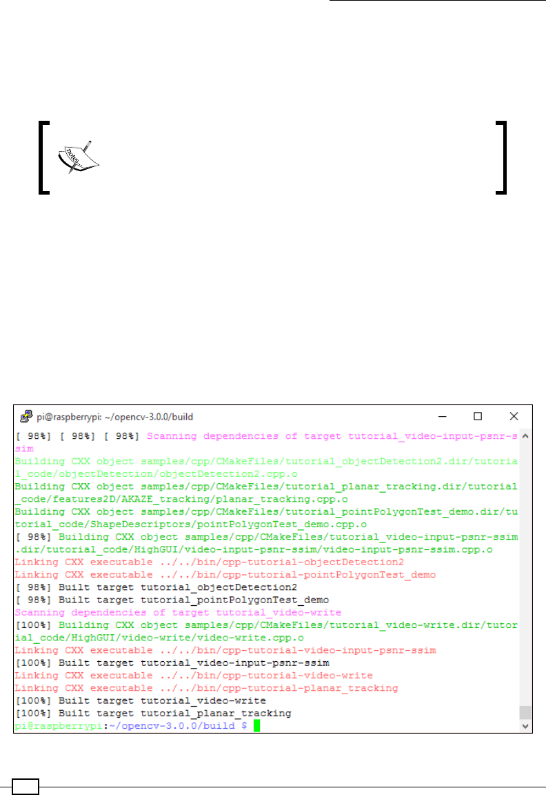
Creating Projects with the Raspberry Pi Camera Module
326
8. We are now ready to compile OpenCV; be warned this will take a considerable
amount of time to complete. Fortunately, if you have to stop the process or if there
is a problem, you can resume the make command, checking and skip ping any
components that have already been completed. To restart the make from the start,
use make clean to clear the build and start afresh.
Note: By using all four processing cores on the Raspberry Pi 2, the
build time can be reduced to just over an hour. Use the –j4 switch
to enable the four cores, which will allow multiple jobs to be run
during the build process.
The build can take almost three hours to complete. If you have the Raspbian desktop
loaded or you are running other tasks in the background, it is recommended you log out
to the command line and stop any additional jobs, otherwise the process may take even
longer to complete.
For a Raspberry Pi 1, use a single-threaded make job with the following command:
make
For a Raspberry Pi 2, enable up to four simultaneous jobs by using the following command:
make -j4
A completed build should look like this

Chapter 8
327
With OpenCV compiled successfully, it can be installed:
sudo make install
Now that is all completed, we can quickly test that OpenCV is now available to use with
Python 3. Run the following command to open the Python 3 terminal:
python3
At the Python 3 terminal, enter the following:
import cv2
cv2.__version__
This will display the version of the OpenCV you have just installed!
Note: The OpenCV library is updated regularly, which can cause problems
with the build process. Therefore, if you have issues, the Py Image Search
website (http://www.pyimagesearch.com) is an excellent resource
that contains the latest guides and video tutorials for installing OpenCV on
the Raspberry Pi.
How to do it…
For our rst OpenCV test, we will use it to display a captured image. Create the following
openimage.py le:
#!/usr/bin/python3
#openimage.py
import cv2
# Load a color image in grayscale
img = cv2.imread('testimage.jpg',0)
cv2.imshow('Frame',img)
cv2.waitKey(0)
cv2.destroyAllWindows()
Ensure before you run the script, that you capture an image to display using the following
command:
raspistill -o testimage.jpg -w 640 -h 480
Run the script with the following command:
python3 openimage.py
Creating Projects with the Raspberry Pi Camera Module
328
How it works…
The simple test program starts by importing OpenCV (cv2) and loading the image using cv2.
imread(). We then use cv2.imshow() to display our image (img) in an image box with
the title 'Frame'. We then wait for a press of any key (cv2.waitKey(0)) before closing the
display window.
The image is displayed in a standard frame as a grayscale image
Color detection with OpenCV
We shall begin experimenting with OpenCV by performing some basic operations on live
image data. In this recipe, we shall perform some basic image processing to allow detection of
different colored objects and track their location on screen.
Chapter 8
329
Getting ready
In addition to the setup from the previous recipe, you will need a suitable colored object to
track. For example, a small colored ball, a suitable colored mug, or a pencil with a square
of colored paper taped to it is ideal. The example should allow you to detect the location
(indicated by a color spot) of blue, green, red, magenta (pink) or yellow objects.
We can use OpenCV to detect colored objects in an image
How to do it…
Create the following opencv_display.py script:
#!/usr/bin/python3
#opencv_display.py
from picamera.array import PiRGBArray
from picamera import PiCamera
import time
import cv2
import opencv_color_detect as PROCESS
def show_images(images,text,MODE):
# show the frame
cv2.putText(images[MODE], "%s:%s" %(MODE,text[MODE]), (10,20),

Creating Projects with the Raspberry Pi Camera Module
330
cv2.FONT_HERSHEY_SIMPLEX, 0.5, (255,255,255), 2)
cv2.imshow("Frame", images[MODE])
def begin_capture():
# initialize the camera and grab a reference to the raw camera
capture
camera = PiCamera()
camera.resolution = (640, 480)
camera.framerate = 50
camera.hflip = True
rawCapture = PiRGBArray(camera, size=(640, 480))
# allow the camera to warmup
time.sleep(0.1)
print("Starting camera...")
MODE=0
# capture frames from the camera
for frame in camera.capture_continuous(rawCapture, format="bgr",
use_video_port=True):
# capture any key presses
key = cv2.waitKey(1) & 0xFF
# grab the raw NumPy array representing the image
images, text = PROCESS.process_image(frame.array,key)
#Change display mode or quit
if key == ord("m"):
MODE=MODE%len(images)
elif key == ord("q"):
print("Quit")
break
#Display the output images
show_images(images,text,MODE)
# clear the stream in preparation for the next frame
rawCapture.truncate(0)
begin_capture()
#End

Chapter 8
331
Create the following opencv_color_detect.py script in the same directory as
opencv_display.py:
#!/usr/bin/python3
#opencv_color_detect.py
import cv2
import numpy as np
BLUR=(5,5)
threshold=0
#Set the BGR color thresholds
THRESH_TXT=["Blue","Green","Red","Magenta","Yellow"]
THRESH_LOW=[[80,40,0],[40,80,0],[40,00,80],[80,0,80],[0,80,80]]
THRESH_HI=[[220,100,80],[100,220,80],[100,80,220],[220,80,220],[80,22
0,220]]
def process_image(raw_image,control):
global threshold
text=[]
images=[]
#Switch color threshold
if control == ord("c"):
threshold=(threshold+1)%len(THRESH_LOW)
#Display contour and hierarchy details
elif control == ord("i"):
print("Contour: %s"%contours)
print("Hierarchy: %s"%hierarchy)
#Keep a copy of the raw image
text.append("Raw Image %s"%THRESH_TXT[threshold])
images.append(raw_image)
#Blur the raw image
text.append("with Blur...%s"%THRESH_TXT[threshold])
images.append(cv2.blur(raw_image, BLUR))
#Set the color thresholds
lower = np.array(THRESH_LOW[threshold],dtype="uint8")
upper = np.array(THRESH_HI[threshold], dtype="uint8")
text.append("with Threshold...%s"%THRESH_TXT[threshold])
images.append(cv2.inRange(images[-1], lower, upper))
#Find contours in the threshold image

Creating Projects with the Raspberry Pi Camera Module
332
text.append("with Contours...%s"%THRESH_TXT[threshold])
images.append(images[-1].copy())
image, contours, hierarchy = cv2.findContours(images[-1],
cv2.RETR_LIST,
cv2.CHAIN_APPROX_
SIMPLE)
#Display contour and hierarchy details
if control == ord("i"):
print("Contour: %s"%contours)
print("Hierarchy: %s"%hierarchy)
#Find the contour with maximum area and store it as best_cnt
max_area = 0
best_cnt = 1
for cnt in contours:
area = cv2.contourArea(cnt)
if area > max_area:
max_area = area
best_cnt = cnt
#Find the centroid of the best_cnt and draw a circle there
M = cv2.moments(best_cnt)
cx,cy = int(M['m10']/M['m00']), int(M['m01']/M['m00'])
if max_area>0:
cv2.circle(raw_image,(cx,cy),8,(THRESH_HI[threshold]),-1)
cv2.circle(raw_image,(cx,cy),4,(THRESH_LOW[threshold]),-1)
return(images,text)
#End
To run the example, use the following command:
python3 opencv_display.py
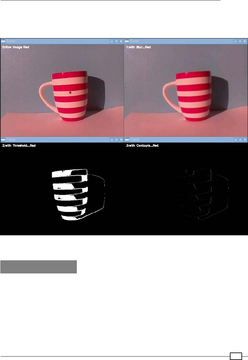
Chapter 8
333
Use the M key to cycle through the available display modes, the C key to change the particular
color we want to detect (blue, green, red, magenta or yellow), and the I key to display
information about the detected contours and hierarchy data.
The raw image (top left) is processed with Blur (top right), Threshold (bottom left)
and Contour (bottom right) operations.
How it works…
The rst script (opencv_display.py) provides us with a common base for running our
OpenCV examples from. The script consists of two functions, begin_capture() and
show_images().
The begin_capture() function sets up the PiCamera to take continuous frames (at 50 fps
and a resolution of 640x480), converting them into a raw image format suitable for OpenCV
to process. We use relatively low resolution images here since we do not need a lot of detail
to perform the kind of processing we are aiming for. In fact, the smaller the images the less
memory they use and the less intensive the processing that we need to perform is.

Creating Projects with the Raspberry Pi Camera Module
334
By using the camera.capture_continuous() function of the PiCamera library, we will
get an image frame ready for us to process. We shall pass each new frame to the process_
image() function, which will be provided by the opencv_color_detect.py le along with
any captured key presses (to allow the user a little control). The process_image() function
(which we will go through in further detail later on) returns two arrays (images and text).
We pass both the images and text arrays to the show_images() function, along with the
selected MODE (which is controlled by the user pressing the M key to cycle through them).
Within the show_images() function we use the text for the given MODE and use putText()
to add it to the image we are displaying (again, whichever image corresponds to the selected
MODE). Finally, we display the image in a separate window using cv2.imshow().
The raw image is displayed by the script (including the tracking marker)
All the real fun is contained within the opencv_color_detect.py script, which performs
all the required image processing to our raw video stream. The aim is to simplify the source
image and then identify the middle of any area that matches our required color.

Chapter 8
335
Note: The script purposely retains each stage of the processing so you
can see the effect of each step on the previous image yourself. This is
by far the best way to understand how we can go from a standard video
image to something that the computer is able to comprehend. To achieve
this, we use an array to collect the images as we produce them (using
images.append() to add each new image and we use a Pythonic
way to refer to the last item in an array, the [-1] notation. In other
programming languages this would produce an error, but with Python it is
perfectly acceptable to use negative numbers to count backwards from
the end of an array (so it follows -1 is the rst item from the end of the
array, and -2 would be the second from the end).
The process_image() image function shall produce four different images (which we provide
references to in our images array). In the rst image we simply keep a copy of our raw image
(displayed as 0: Raw Image [Color]). Since this is a full color untouched image, this shall
be the image with which we shall show the location of the detected object (this is added at the
end of function).
The next image we produce is a blurred version of the original (displayed as 1: with Blur…
[Color]) by using the cv2.blur() function with the BLUR tuple to specify the amount on
the (x,y) axes. By slightly blurring the image, we hope to eliminate any unnecessary detail or
erroneous noise in the image; this is ideal since we are only interested in large blocks of color,
so ne detail is irrelevant.
The third image (displayed as 2:with Threshold…[color]) is the result of applying the
given upper and lower threshold using the cv2.inRange() function. This produces a simple
black and white image, where any parts of the image that are between the upper and lower
color thresholds are displayed in white. Hopefully, you will be able to clearly see your test
object as you move it in front of the camera as a large white patch. You can check this image
to ensure that your background is not confused with your target object. If the threshold image
is mostly white then try a different color target, moving the camera to a different location, or
adjusting the colors used in the threshold arrays (THRESH_LOW/HI).
Note: The color mapping used in this example is OpenCV's BGR format.
This means that the pixel colors are stored as an array of three integers,
for Blue, Green, and Red. The color thresholds are therefore specied
in this format; this is contrary to the more typical RGB color format used
for example in HTML web colors.
The last image provides the nal piece of the puzzle; displayed as 3:with Contours...
[color], it shows the result of the cv2.findContours() function. OpenCV will calculate
the contours in the image. This will discover all the edges of the shapes that were in the
threshold image and return them in a list (contours). Each individual contour is an array of the
(x,y) coordinates of the boundary points of each shape in the image.
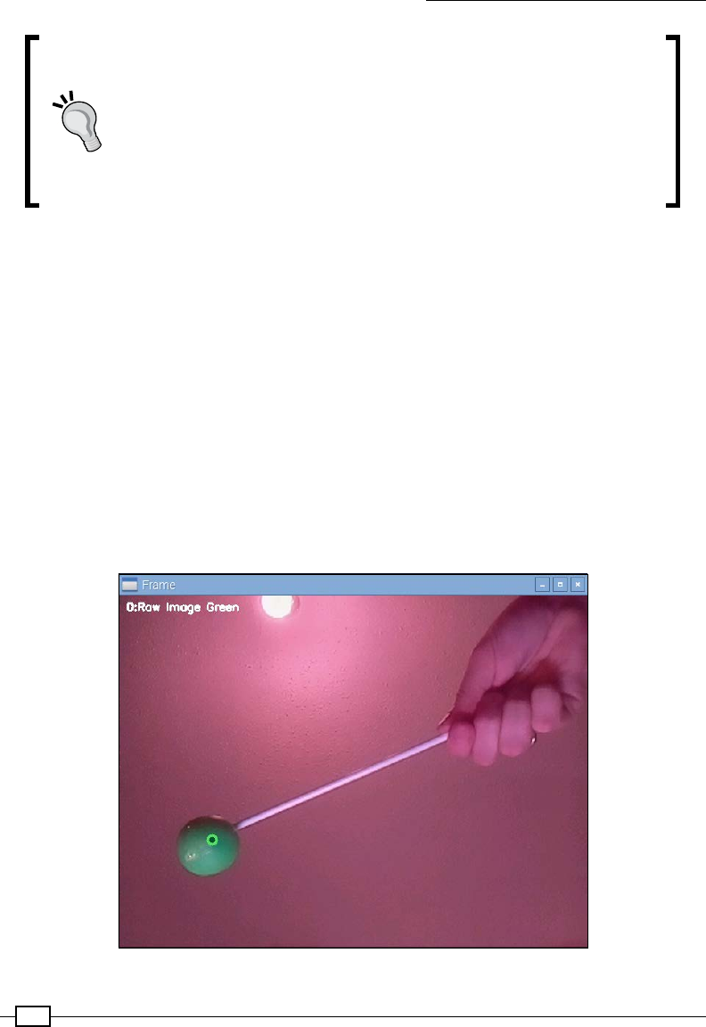
Creating Projects with the Raspberry Pi Camera Module
336
Note: The contours are applied directly to the supplied image by the
cv2.findContours() function, which is why we make a copy of the
threshold image (using images[-1].copy()) so we can see both
steps in our process. We also use cv2.CHAIN_APPROX_SIMPLE,
which attempts to simplify the stored coordinates so any points that
aren't needed are skipped (for example, any along a straight line can be
removed as long as we have the start and end points). Alternatively, we
could use cv2.CHAIN_APPROX_NONE, which keeps all the points.
We can use the list of contours to determine the area of each; in our case, we are most
interested in the largest one (which will hopefully contain the object we are tracking as the
largest area of the image that has colors within the given thresholds). We shall use cv2.
contourArea() on each contour discovered to calculate the area and keep whichever one
ends up being the largest.
Finally, we can list the moments, which are a list of numbers that provide a mathematical
approximation of the shape. The moments provide us with a simple calculation to obtain the
centroid of the shape. The centroid is like the center of mass of the shape; for example, if it
was made out of a at solid piece of material, it would be the point at which you could balance
it on the end of your nger.
cx, cy = M['m10'] / M['m00'], M['m01'] / M['m00'])
We display a small marker (consisting of the upper and lower threshold colors) using the
calculated coordinates to indicate the detected location of the object.
The location of the object is marked with a colored spot as it tracked within the image
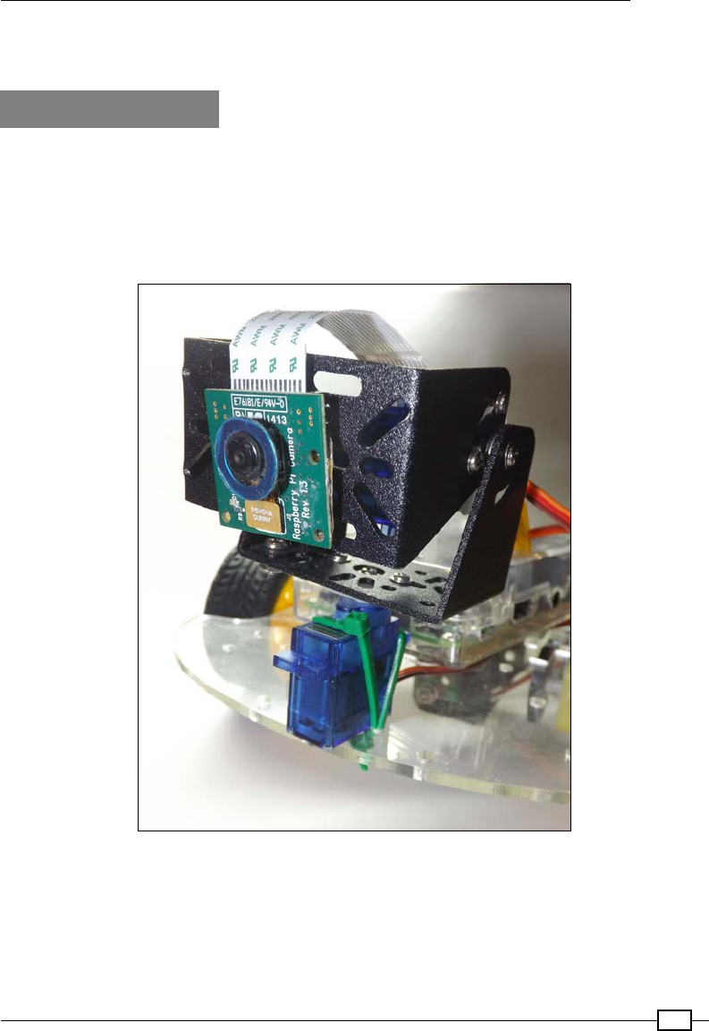
Chapter 8
337
For additional information about OpenCV's contours and moments, see OpenCV-Python
Tutorials (http://goo.gl/eP9Cn3).
There's more…
This recipe allows us to track an object by detecting the required colors within the camera
frame, which will provide a relative x and y position of the object.
We can mount the Raspberry Pi camera on a movable platform, for example a rover/bug robot
platform (like the ones described in Chapter 9) or by using a servo-controlled tilt and pan
camera mount (as shown in the following image).
The Raspberry Pi camera can be controlled using a servo mount
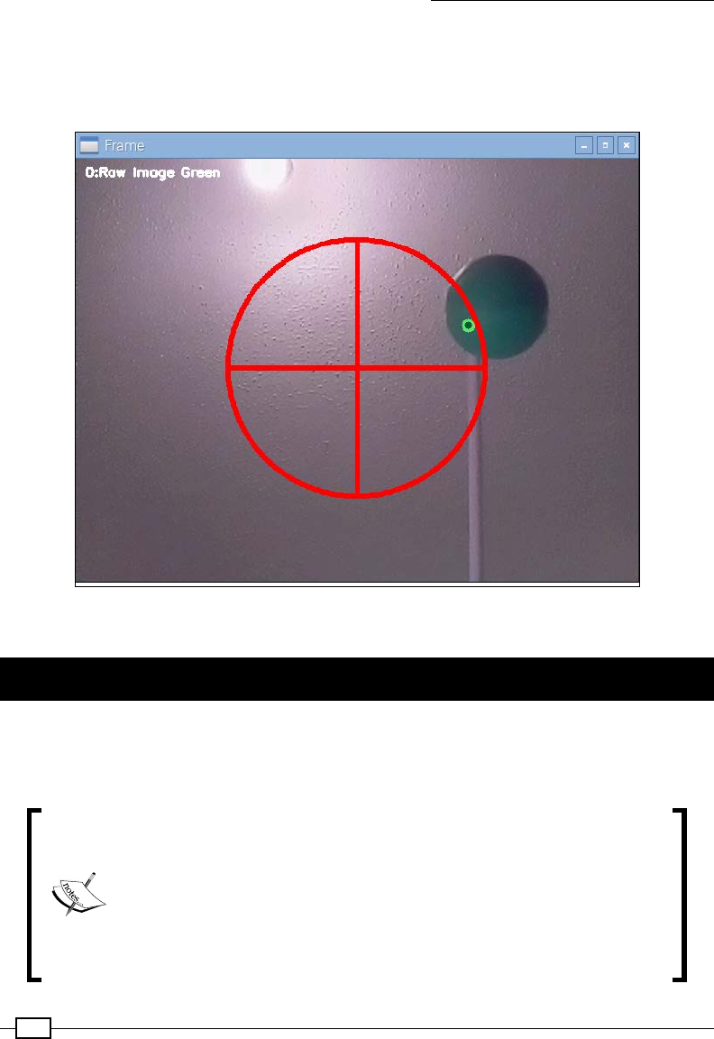
Creating Projects with the Raspberry Pi Camera Module
338
By combining the camera input and the object coordinates, we can make the Raspberry Pi
track the object wherever it goes. If we detect that the object has moved to one side of the
camera frame, we can use the Raspberry Pi hardware control to re-center the object within
the camera frame (either by steering the robot or tilting and panning the camera).
The object has been detected in the top-right of the screen, so turn the camera to the right
and up to follow the object
Performing motion tracking with OpenCV
While it is useful to be able to track objects of a specic color, sometimes we are just
interested in the actual motion taking place. This is particularly true when the objects
we wish to track could blend in with the background.
Note: Security cameras often use IR detectors to act as triggers; however,
these rely upon detecting a change in detected heat across the sensor.
This means they will not work if the object does not give off additional
heat relative to the background and they will not track the direction of
the motion.
https://learn.adafruit.com/pir-passive-infrared-
proximity-motion-sensor/how-pirs-work
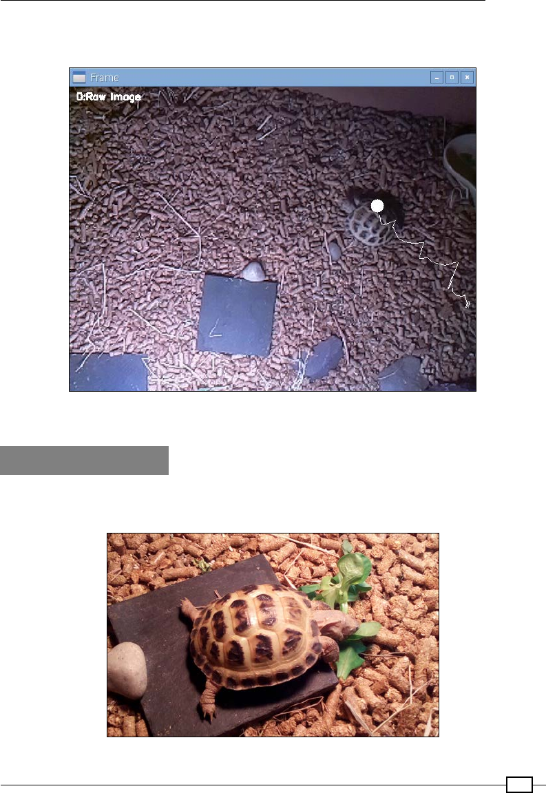
Chapter 8
339
The following recipe will demonstrate how OpenCV can be used to detect motion and also
provide a record of where the object has been over a period of time.
The motion of an object within the frame is traced on screen, allowing the pattern
of movement to be recorded and studied
Getting ready
The following script will allow us to track an object and display its path on the screen. For this
task, I have volunteered our family tortoise; however, any object that moves can be used.
Our tortoise made an excellent test subject; it was very interesting to see where she wandered during the day

Creating Projects with the Raspberry Pi Camera Module
340
The setup in this case works particularly well for the following reasons. Firstly, since the
tortoise is of a similar color to the background we can't use the previous method of color
detection (unless we stuck some markers on her). Secondly, the tortoise house has a useful
shelf above it, allowing the Raspberry Pi and camera to be mounted directly above it. Finally,
the enclosure is articially lit, so other than the movement of the tortoise, the image observed
should remain relatively constant during our testing. When performing this task with external
factors such as natural light, you may nd that they interfere with the moment detection
(making it difcult to determine what is changes due to movement compared to changes in
the environment – see the There's more... section for tips on overcoming this).
The rest of the setup will be the same as the previous OpenCV recipe (see Color detection
with OpenCV).
How to do it…
Create the following script, called opencv_detect_motion.py:
#!/usr/bin/python3
#opencv_motion_detect.py
import cv2
import numpy as np
GAUSSIAN=(21,21)
imageBG=None
gray=True
movement=[]
AVG=2
avgX=0
avgY=0
count=0
def process_image(raw_image,control):
global imageBG
global count,avgX,avgY,movement,gray
text=[]
images=[]
reset=False
#Toggle Gray and reset background
if control == ord("g"):
if gray:

Chapter 8
341
gray=not gray
reset=True
print("Toggle Gray")
#Reset the background image
elif control == ord("r"):
reset=True
#Clear movement record and reset background
if reset:
print("Reset Background")
imageBG=None
movement=[]
#Keep a copy of the raw image
text.append("Raw Image")
images.append(raw_image)
if gray:
raw_image=cv2.cvtColor(raw_image,cv2.COLOR_BGR2GRAY)
#Blur the raw image
text.append("with Gaussian Blur...")
images.append(cv2.GaussianBlur(raw_image, GAUSSIAN))
#Initialise background
if imageBG is None:
imageBG=images[-1]
text.append("with image delta...")
images.append(cv2.absdiff(imageBG,images[-1]))
text.append("with threshold mask...")
images.append(cv2.threshold(images[-1], 25, 255,
cv2.THRESH_BINARY)[1])
text.append("with dilation...")
images.append(cv2.dilate(images[-1],None, iterations=3))
#Find contours
if not gray:
#Require gray image to find contours
text.append("with dilation gray...")
images.append(cv2.cvtColor(images[-1],cv2.COLOR_BGR2GRAY))
text.append("with contours...")

Creating Projects with the Raspberry Pi Camera Module
342
images.append(images[-1].copy())
aimage, contours, hierarchy = cv2.findContours(images[-1],
cv2.RETR_LIST,
cv2.CHAIN_APPROX_
SIMPLE)
#Display contour and hierarchy details
if control == ord("i"):
print("Contour: %s"%contours)
print("Hierarchy: %s"%hierarchy)
#Determine the area of each of the contours
largest_area=0
found_contour=None
for cnt in contours:
area = cv2.contourArea(cnt)
#Find which one is largest
if area > largest_area:
largest_area=area
found_contour=cnt
if found_contour != None:
#Find the centre of the contour
M=cv2.moments(found_contour)
cx,cy=int(M['m10']/M['m00']),int(M['m01']/M['m00'])
#Calculate the average
if count<AVG:
avgX=(avgX+cx)/2
avgY=(avgY+cy)/2
count=count+1
else:
movement.append((int(avgX),int(avgY)))
avgX=cx
avgY=cy
count=0
#Display
if found_contour != None:
cv2.circle(images[0],(cx,cy),10,(255,255,255),-1)
if len(movement) > 1:
for i,j in enumerate(movement):
if i>1:
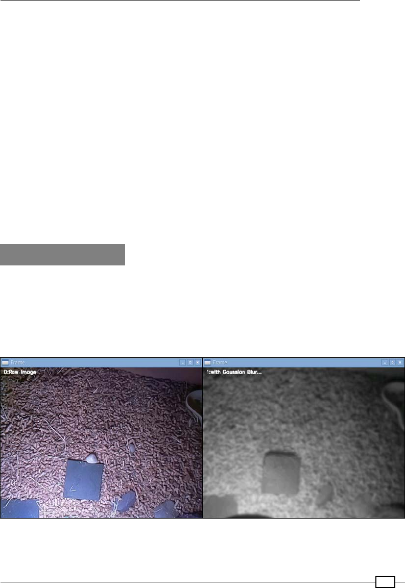
Chapter 8
343
cv2.line(images[0],movement[i-1],movement[i],(255,255,255))
return(images,text)
#End
Next, nd the following line in the opencv_display.py le (from the previous recipe):
import opencv_color_detect as PROCESS
to the following:
import opencv_motion_detect as PROCESS
To run the example, use the following command:
python3 opencv_display.py
Use the M key to cycle through the available display modes, the G key to toggle gray scale
mode, the I key to display information about the detected contours and hierarchy data, and
the B key to reset the image we set as the background.
How it works…
The principle behind this motion detection method is elegantly simple. First, we take an initial
image as our golden image (where no moment is taking place); we shall treat this as our
static background. Now we simply compare any subsequent image to this original background
image. If there is any signicant difference from the rst image, we assume the difference
is due to movement. Once we have detected motion, we will then generate a trace of the
movement over time and display it on the frame.
The golden image (right) is a gray-scale version of the raw image (left) with a Gaussian blur applied
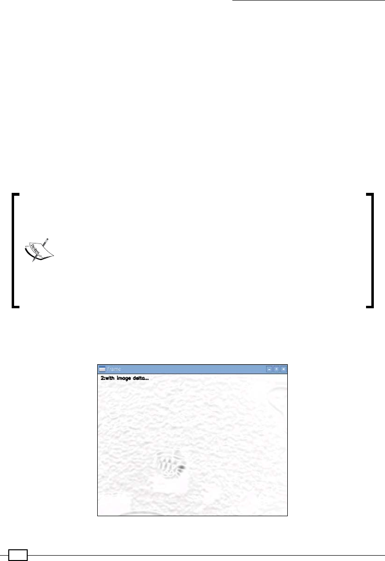
Creating Projects with the Raspberry Pi Camera Module
344
When the script is run we ensure that the reset ag is set to True, which ensures we use
the rst image captured as the golden image (also, if the user presses R we allow the golden
image to be refreshed with a new image). We also detect if the user presses G, which will
switch between processing the image in grayscale or in color. The default is grayscale since
this is more efcient to process and the colors do not matter when detecting motion (but it is
interesting to see the result of the same processing when the images are still in color too).
Just like the previous recipe, we will keep a copy of each image to allow better understanding
of each stage in the process. The rst image that is displayed is 0:Raw Image, which is a
direct copy of the camera image (we will overlay the detected motion on this image).
In the next image, 1:with Gaussian Blur…, we use cv2.GaussianBlur(raw_image,
GAUSSIAN, 0), providing a smoothed out version of the original (hopefully removing Gaussian
noise from the image). Like the blur function, we provide the image to be processed and the x,y
magnitudes (which for the Gaussian algorithm have to be positive and odd).
Note: You can compare the Gaussian Blur with the standard blur method
by inserting the following code (just before the Gaussian Blur section) and
cycling between the modes:
text.append("with Low Blur...")
images.append(cv2.blur(raw_image, (5,5))
text.append("with High Blur...")
images.append(cv2.blur(raw_image, (30,30))
The background image is set using this blurred image (if it has not been
set previously or it has been reset).
We use cv2.absdiff(imageBG,images[-1]) to determine what differences there are
between the imageBG (the original background image) and the latest Gaussian blurred image
to provide 2:with image delta....
This image (inverted here to make it clearer) shows the difference from the golden image.
The tortoise has moved near the middle of the image
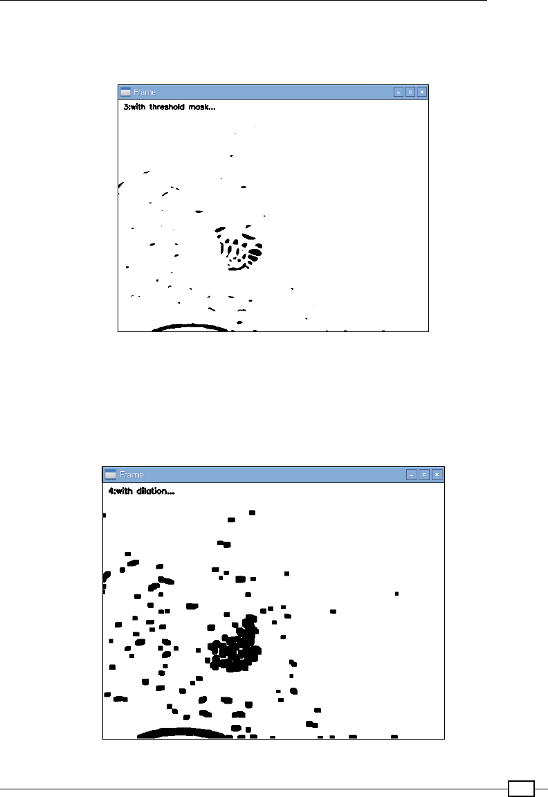
Chapter 8
345
Next, we apply a binary threshold mask (displayed as 3:with threshold mask…), which
will set any pixel between the upper (255) and lower (25) threshold to 255, resulting in a
black and white image displaying the main areas of movement.
A threshold filter is applied to the delta image, highlighting the largest changes in the image
Now, we dilate the threshold image (displayed as 4:with dilation…) using cv2.
dilate(images[-1], None, iterations=3). The dilate operation works by growing
the white section of the image by a pixel in each iteration. By using None as the second
parameter, we are setting the kernel to use a default value (alternatively, an array of 0s and
1s can be used to fully control how the dilation is applied).
The dilated image grows the spots of detected movement
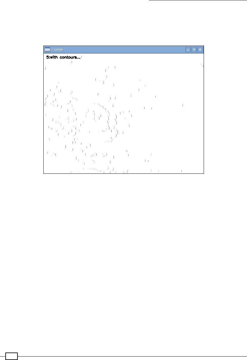
Creating Projects with the Raspberry Pi Camera Module
346
We use the cv2.contours() function, like we did in the previous recipe, to detect the
outline of the detected shapes; the result is displayed as 5:with contours…. We must
convert the image to grayscale, if it isn't already, since this function works best with a binary
image (an image that is black and white).
The area of the contours are calculated and used to determine the location of the main area of movement
As before, we calculate the area of each contour and discover which is the largest by using
cv2.contourAera(). Then we determine the coordinates of the middle of the selected
contour by nding the moments (via cv2.moments()). Finally, we add these coordinates to
the moment array so we can display a trace of the detected movement on our original image.
Additionally, to trace relatively slow-moving objects we can also average several of the
detected coordinates to provide a smoother trace of movement.
As mentioned at the start, external factors can interfere with this simple algorithm where even
subtle changes in the environment can cause errors in the movement detection. Fortunately,
techniques such as applying long term averaging to the background image (rather than a
single onetime snapshot) will cause any gradual changes, such as lighting, to be incorporated
into the background image.

Chapter 8
347
There's more…
Although we have only briey touched on a small aspect of the OpenCV library, it should be
clear that it is perfect for use with the Raspberry Pi. We have seen OpenCV provides some
very powerful processing with relative ease and the Raspberry Pi (particularly the Raspberry Pi
model 2) is an ideal platform on which to run it.
As you can imagine, it simply isn't practical to cover everything OpenCV is able to do within
a few examples, but I hope it has at least whetted your appetite (and provided you with a
ready-to-go setup from which you can experiment with and create your own projects).
Fortunately, not only are there lots of tutorials and guides available online, but there are also
several books that cover OpenCV in great detail; in particular, the following Packt books are
recommended:
fOpenCV Computer Vision with Python by Joseph Howse
fRaspberry Pi Computer Vision Programming by Ashwin Pajankar
In the last two examples, I've attempted to keep the code as brief as possible while ensuring it
is easy to observe the inner workings behind the recipe. It should be very easy to adapt them
or add your own simply by importing different modules with your own process_images()
function in.
For more ideas and projects, there is an excellent list on the following site:
http://www.intorobotics.com/20-hand-picked-raspberry-pi-tutorials-in-
computer-vision/
349
9
Building Robots
In this chapter, we will cover the following topics:
fBuilding a Rover-Pi robot with forward driving motors
fUsing advanced motor control
fBuilding a six-legged Pi-Bug robot
fControlling servos directly with ServoBlaster
fAvoiding objects and obstacles
fGetting a sense of direction
Introduction
A little computer with a "brain the size of a planet" (to quote Douglas Adams, the author
of Hitchhikers Guide to the Galaxy) is perfect to be the brain of your own robotic creation.
In reality, the Raspberry Pi probably provides far more processing power than a little robot
or rover would need; however, its small size, excellent connectivity, and fairly low-power
requirements mean that it is ideally suited.
This chapter will focus on exploring the various ways in which we can combine motors or
servos to produce robotic movement and use sensors to gather information and allow our
creation to act upon it.
Be sure to check out the Appendix, Hardware and Software List; it lists all
the items used in this chapter and the places you can obtain them from.

Building Robots
350
Building a Rover-Pi robot with forward
driving motors
Creating robots does not need to be an expensive hobby. A small, rover-type robot can be
constructed using household items for the chassis (the base everything is attached to), and a
couple of small driving motors can be used to move it.
The Rover-Pi robot is a small, buggy-type robot that has just two wheels and a skid or caster at
the front to allow it to turn. One such robot is shown in the following image:
A home-built Rover-Pi robot
While it may not be in the same league as a Mars Exploration Rover, as you will see, there is
plenty for you to experiment with.
You can also purchase many inexpensive robot kits that contain most of what you need in a
single package (see the There's more… section at the end of this example).
Chapter 9
351
Getting ready
The Rover we are building will need to contain the elements shown in the following diagram:
The separate parts of the Rover-Pi robot

Building Robots
352
The elements are discussed in detail as follows:
fChassis: This example uses a modied, battery-operated push nightlight (although
any suitable platform can be used). Remember that the larger and heavier your robot
is, the more powerful the driving motors will need to be to move it. Alternatively, you
can use one of the chassis kits listed in the There's more… section. A suitable push
nightlight is shown in the following image:
This push nightlight forms the basic chassis of a Rover-Pi robot
Chapter 9
353
fFront skid or caster: This can be as simple as a large paper clip (76 mm/3 inches)
bent into shape, or a small caster wheel. A skid works best when it is on a smooth
surface, but it may get stuck on the carpet. A caster wheel works well on all surfaces,
but sometimes, it can have problems turning.
fWheels, motors, and gears: The wheel movement of the Rover-Pi robot is a
combination of the motor, gears, and wheels. The gears are helpful as they allow a
fast-spinning motor to turn the wheels at a slower speed and more force (torque); this
will allow better control of our robot. A unit that combines the wheels, motors, and
gears in a single unit is shown in the following image:
These wheels with built-in geared motors are ideal for small rovers

Building Robots
354
fBattery/power source: The Rover-Pi robot will be powered using 4 x AA batteries
tted into the bay of the chassis. Alternatively, a standard battery holder can be used,
or even a long wire connected to suitable power supply. It is recommended that you
power the motors from a supply independent from the Raspberry Pi. This will help
avoid a situation in which the Raspberry Pi suddenly loses power when driving the
motors, which requires a big jump in current to move. Alternatively, you can power
the Raspberry Pi with the batteries using a 5V regulator. The following image shows a
chassis with 4 x AA batteries:
4x AA batteries provide a power source to drive the wheels
fMotor driver/controller: Motors will require a voltage and current greater than the
GPIO can handle. Therefore, we will use a Darlington array module (which uses a
ULN2003 chip). See the There's more… section at the end of this example for more
details on how this particular module works. The following image shows a Darlington
array module:
Chapter 9
355
This Darlington array module, available at dx.com, can be used to drive small motors
fSmall cable ties or wire ties: This will allow us to attach items such as the motors or
a controller to the chassis. The following image shows the use of cable ties:
We use cable ties to secure the motors and wheels to the chassis
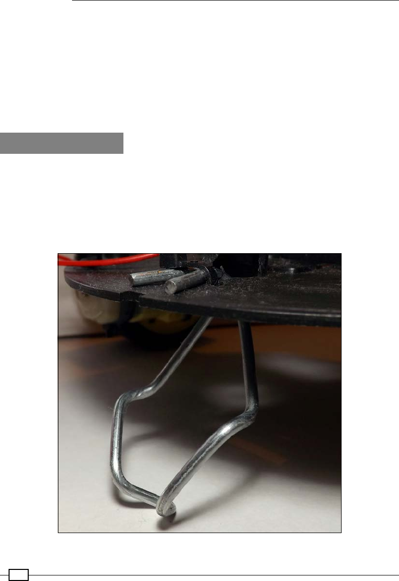
Building Robots
356
fThe Raspberry Pi connection: The easiest setup is to attach the control wires to the
Raspberry Pi using long cables, so you can easily control your robot directly using an
attached screen and keyboard. Later, you can consider mounting the Raspberry Pi
on the robot and controlling it remotely (or even autonomously if you include sensors
and intelligence to make sense of them).
In this chapter, we will use the WiringPi2 Python library to control the GPIO; see Chapter 7,
Sense and Display Real-World Data, for details on how to install it using PIP (a Python package
manager).
How to do it…
Perform the following steps to create a small Rover-Pi robot:
1. At the front of the chassis, you will need to mount the skid by bending the
paperclip/wire into a V shape. Attach the paperclip/wire to the front of the chassis by
drilling small holes on either side, and thread cable ties through the holes around the
wire and pull tight to secure. The tted wire skid should look similar to the one shown
in the following image:
Wire skid fitted to the front of the Rover-Pi robot
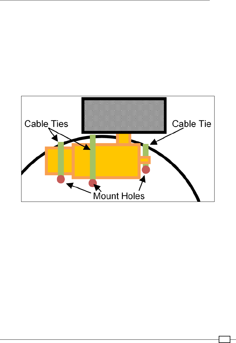
Chapter 9
357
2. Before you mount the wheels, you need to work out the approximate center of gravity
of the chassis (do this with the batteries tted in the chassis as they will affect the
balance). Get a feel of where the center is by trying to balance the unit on two ngers
on either side, and nd out how far forward or backward the chassis tilts. For my unit,
this was about 1 cm (approximately one-third of an inch) back from the center. You
should aim to place the wheel axles slightly behind this so that the Rover will rest
slightly forward on the skid. Mark the location of the wheels on the chassis.
3. Drill three holes on each side to mount the wheels using the cable ties. If the cable
ties aren't long enough, you can join two together by pulling the end of one through
the end of the other (only pull through far enough for the tie to grip so that it extends
the tie). The following diagram shows how you can use the cable ties:
Securely fix the motors to the chassis
4. Next, test the motors by inserting the batteries into the unit; then, disconnect the
wires that originally connected to the bulb and touch them to the motor contacts.
Determine which connection on the motor should be positive and which should be
negative for the motor to move the robot forward (the top of the wheel should move
forward when the robot is facing forwards). Connect red and black wires to the motor
(on mine, black equals negative at the top and red equals positive at the bottom
of the motor), ensuring that the wires are long enough to reach anywhere on the
chassis (around 14 cm, that is, approximately 5 and a half inches is enough for the
nightlight).

Building Robots
358
The Rover-Pi robot components should be wired up as shown in the following diagram:
The wiring layout of the Rover-Pi robot
To make the connections, perform the following steps:
1. Connect the black wires of the motors to the OUT 1 (left) and OUT 2 (right) output
of the Darlington module, and connect the red wires to the last pin (the COM
connection).
2. Next, connect the battery wires to the GND/V- and V+ connections at the bottom of
the module.
3. Finally, connect the GND from the GPIO connector (Pin 6) to the same GND connection.
4. Test the motor control by connecting 3.3V (GPIO Pin 1) to IN1 or IN2 to simulate a
GPIO output. When happy, connect GPIO Pin 16 to IN1 (for left) and GPIO Pin 18 to
IN2 (for right).
The wiring should now match the details given in the following table:
Raspberry Pi GPIO Darlington module
Pin 16: Left IN1
Pin 18: Right IN2
Pin 6: GND GND/V- (marked with "–")
Motor 4 x AA battery Darlington module
Positive side of battery V+ (marked with "+")
Negative side of battery GND/V- (marked with "–")
Motors

Chapter 9
359
Raspberry Pi GPIO Darlington module
Left motor: black wire OUT 1 (top pin in white socket)
Right motor: black wire OUT 2 (second pin in white socket)
Both motors: red wires COM (last pin in white socket)
Use the following rover_drivefwd.py script to test the control:
#!/usr/bin/env python3
#rover_drivefwd.py
#HARDWARE SETUP
# GPIO
# 2[==X====LR====]26[=======]40
# 1[=============]25[=======]39
import time
import wiringpi2
ON=1;OFF=0
IN=0;OUT=1
STEP=0.5
PINS=[16,18] # PINS=[L-motor,R-motor]
FWD=[ON,ON]
RIGHT=[ON,OFF]
LEFT=[OFF,ON]
DEBUG=True
class motor:
# Constructor
def __init__(self,pins=PINS,steptime=STEP):
self.pins = pins
self.steptime=steptime
self.GPIOsetup()
def GPIOsetup(self):
wiringpi2.wiringPiSetupPhys()
for gpio in self.pins:
wiringpi2.pinMode(gpio,OUT)
def off(self):
for gpio in self.pins:
wiringpi2.digitalWrite(gpio,OFF)
def drive(self,drive,step=STEP):

Building Robots
360
for idx,gpio in enumerate(self.pins):
wiringpi2.digitalWrite(gpio,drive[idx])
if(DEBUG):print("%s:%s"%(gpio,drive[idx]))
time.sleep(step)
self.off()
def cmd(self,char,step=STEP):
if char == 'f':
self.drive(FWD,step)
elif char == 'r':
self.drive(RIGHT,step)
elif char == 'l':
self.drive(LEFT,step)
elif char == '#':
time.sleep(step)
def main():
import os
if "CMD" in os.environ:
CMD=os.environ["CMD"]
INPUT=False
print("CMD="+CMD)
else:
INPUT=True
roverPi=motor()
if INPUT:
print("Enter CMDs [f,r,l,#]:")
CMD=input()
for idx,char in enumerate(CMD.lower()):
if(DEBUG):print("Step %s of %s: %s"%(idx+1,len(CMD),char))
roverPi.cmd(char)
if __name__=='__main__':
try:
main()
finally:
print ("Finish")
#End
Remember that WiringPi2 should be installed before running the scripts
in this chapter (see Chapter 7, Sense and Display Real-world Data).

Chapter 9
361
Run the previous code using the following command:
sudo python3 rover_drivefwd.py
The script will prompt you with following message:
Enter CMDs [f,r,l,#]:
You can enter a series of commands to follow, for example:
ffrr#ff#llff
The previous command will instruct the Rover-Pi robot to perform a series of movements—
forward (f), right (r), pause (#), and left (l).
How it works…
Once you have built the robot and wired up the wheels to the motor controller, you can
discover how to control it.
Start by importing time (which will allow you to put pauses in the motor control) and
wiringpi2 to allow control of the GPIO pins. Use wiringpi2 here since it makes it much
easier to make use of IO expanders and other I2C devices if you want to later on.
Dene values to use for setting the pins ON/OFF, for the direction IN/OUT, as well as the
duration of each motor STEP. Also, dene which PINS are wired to the motor controls and our
movements FWD, RIGHT, and LEFT. The movement is dened in such a way that by switching
both motors ON, you will move forward or, by switching just one motor ON, you will turn. By
setting these values at the start of the le using variables, our code is easier to maintain and
understand.
We dene a motor class that will allow us to reuse it in other code or easily swap it with
alternative motor classes so we can use other hardware if we want to. We set the default
pins we are using and our steptime value (the steptime object denes how long we drive
the motor(s) for each step). However, both can still be specied when initializing the object
if desired.
Next, we call GPIOsetup(); it selects the physical pin numbering mode (so we can refer to
the pins as they are located on the board). We also set all of the pins we are using to output.

Building Robots
362
Finally, for the motor class, we dene the following three functions:
fThe rst function we dene (called off()) will allow us to switch off the motors, so
we cycle through the pins list and set each GPIO pin to low (and therefore switch the
motors off).
fThe drive() function allows us to provide a list of drive actions (a combination of ON
and OFF for each of the GPOI pins). Again, we cycle through each of the pins and set
them to the corresponding drive action, wait for the step time, and then switch off the
motors using the off() function.
fThe last function we dene (called cmd()) simply allows us to send char (a single
character) and use it to select the set of drive actions we want to use (FWD, RIGHT, or
LEFT, or wait (#)).
For testing, main() allows us to specify a list of actions that need to be performed from the
command line using the following command:
sudo CMD=f#lrr##fff python3 rover_drivefwd.py
Using os.environ (by importing the os module so we can use it), we can check for CMD in
the command and use it as our list of drive actions. If no CMD command has been provided,
we can use the input() function to prompt for a list of drive actions directly. To use the
motor class, we set roverPi=motor(); this allows us to call the cmd() function (of the
motor class) with each character from the list of drive actions.
There's more…
Your robot should only be limited by your own creativity. There are lots of suitable chassis
you can use, other motors, wheels, and ways to control and drive the wheels. You should
experiment and test things to determine which combinations work best together. That is all
part of the fun!
Darlington array circuits
Darlington transistors are a low-cost way to drive higher powered devices, such as motors or
even relays. They consist of two transistors arranged in a series, where one feeds the other
(allowing the gain in the current to be multiplied). That is, if the rst transistor has a gain of
20, and the second also has a gain of 20, together they will provide an overall gain of 400.
This means that 1 mA on the base pin (1) will allow you to drive up to 400 mA through the
Darlington transistor. The Darlington transistor's electrical symbol is shown in the following
diagram:

Chapter 9
363
The electrical symbol for a Darlington transistor shows how two transistors are packaged together
The ULN2003 chip is used in the previous module and provides 7 NPN Darlington transistors
(an 8-way version ULN2803 is also available if more output is required or to use with two
stepper motors). The following diagram shows how a Darlington array can be used to
drive motors:
A Darlington array being used to drive two small motors

Building Robots
364
Each output from the chip can supply a maximum of 500 mA at up to 50V (enough to
power most small motors). However, with extended use, the chip may overheat, so a heat
sink is recommended when driving larger motors. An internal diode connected across each
Darlington for protection is built into the chip. This is needed because when the motor moves
without being driven (this can occur due to the natural momentum of the motor), it will act like
a generator. A reverse voltage called back EMF is created, which would destroy the transistor
if it wasn't dissipated back through the diode.
One disadvantage of the chip is that the positive supply voltage must always be connected to
the common pin (COM), so each output is only able to sink current. That is, it will only drive
the motor in one direction, with the positive voltage on COM and the negative voltage on the
OUT pins. Therefore, we will need a different solution if we wish to drive our Rover-Pi robot in
different directions (see the next example in the Using advanced motor control recipe).
These chips can also be used to drive certain types of stepper motors. One of the modules
from dx.com includes a stepper motor as a part of the kit. Although the gearing is for very
slow movement at around 12 seconds per rotation (too slow for a rover), it is still interesting to
use (for a clock perhaps).
Transistor and relay circuits
Relays are able to handle much more highly powered motors since they are mechanical
switches controlled by an electromagnetic coil that physically moves the contacts together.
However, they require a reasonable amount of current to be turned on and usually more than
3.3V. To switch even small relays, we need around 60 mA at 5V (more than is available from
the GPIO), so we will still need to use some additional components to switch it.
We can use the Darlington array (as used previously) or a small transistor (any small
transistor, such as the 2N2222, will be ne) to provide the current and voltage required to
switch it. The following circuit will allow us to do this:
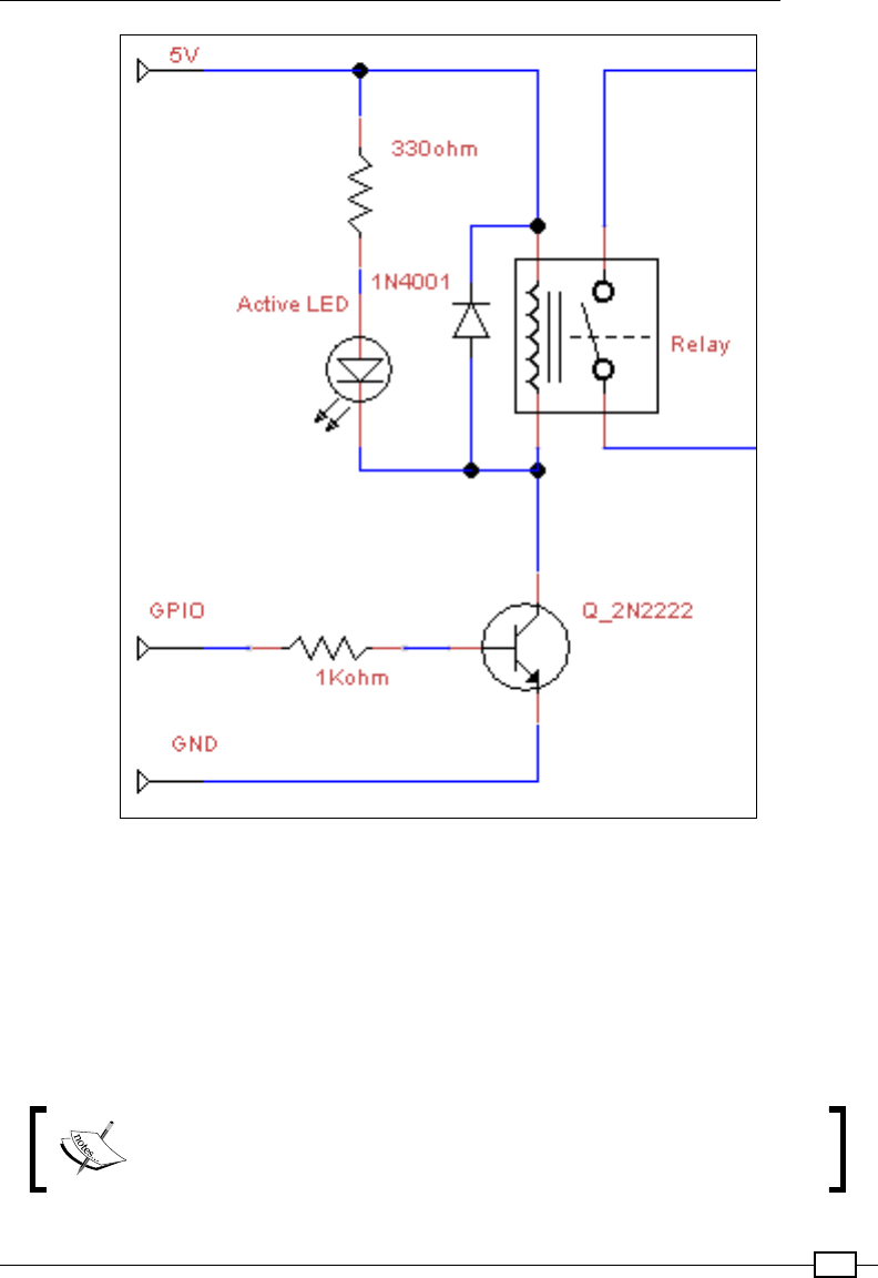
Chapter 9
365
The transistor and relay circuit used to drive external circuits
Much like a motor, a relay can also generate EMF spikes, so a protection diode is also needed
to avoid any reverse voltage on the transistor.
This is a very useful circuit, not just for driving motors but for any external circuit as well; the
physical switch allows it to be independent and electrically isolated from the Raspberry Pi
controlling it.
As long as the relay is rated correctly, you can drive DC or AC devices through it.
You can use some relays to control items powered by the mains. However,
this should be done only with extreme caution and proper electrical
training. Electricity from the mains can kill or cause serious harm.

Building Robots
366
PiBorg has a ready-made module named the PicoBorg that will allow the switching of up
to four relays. It uses devices called MOSFETs that are essentially high-power versions of
transistors that function with the same principle as discussed previously.
Tethered or untethered robots
An important choice when designing your own Rover-Pi robot is to decide if you want to
make it fully self-contained or if you are happy to have a tether (a long control/power cable
connected to the Rover-Pi). Using a tether, you can keep the weight of the Rover-Pi robot down,
which means the small motors will be able to move the unit with ease. This will allow you to
keep the Raspberry Pi separate from the main unit so it can remain connected to a screen
and keyboard for easy programming and debugging. The main disadvantage is that you will
need a long, umbilical-like connection to your Rover-Pi robot (with a wire for each control
signal) that may impede its movement. However, as we will see later, you may only need three
or four wires to provide all the control you need (see the Using I/O expanders section in the
next recipe).
If you intend to mount the Raspberry Pi directly on the Rover-Pi robot, you will need a suitable
power supply, such as a phone charger battery pack. If the battery pack has two USB ports,
then you may be able to use it as a power source to drive both the Raspberry Pi and the
motors. The unit must be able to maintain the supplies independently as any power spike
caused by driving the motors could reset the Raspberry Pi.
Remember that if the Raspberry Pi is now attached to the robot, you will need a means to
control it. This can be a USB Wi-Fi dongle that will allow a remote connection via SSH and so
on, or a wireless keyboard (that uses RF/Bluetooth), or even the GPIO D-Pad from Chapter 6,
Using Python to Drive Hardware, can be used for direct control.
However, the more you mount on the chassis, the harder the motors will need to work to
move. You may nd that stronger motors are required, rather than the little ones used here. A
Rover-Pi robot powered by a USB battery pack is shown in the following image:
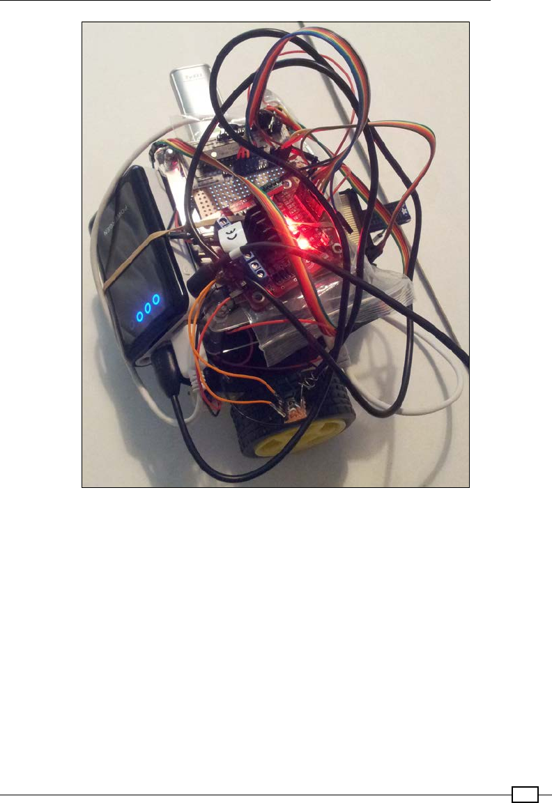
Chapter 9
367
A battery-powered Raspberry Rover-Pi robot being controlled via Wi-Fi (cable management is optional)
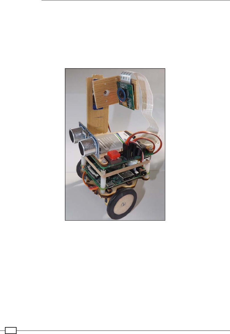
Building Robots
368
Rover kits
If you don't fancy making your own chassis, there are also a number of pre-made rover chassis
available that can be used. They are as follows:
f2WD Magician Robot Chassis from SparkFun
f4 Motor Smart Car Chassis from DX.com
f2 Wheel Smart Car Model DX.com
The Tiddlybot show how multiple components can be integrated together within a single platform,
as shown in my modified version
A particularly nice robot setup is the Tiddlybot (from PiBot.org), which combines multiple
sensors, continuous servos, an onboard battery pack, and the Raspberry Pi camera. The
SD card is set up so the TiddlyBot acts as a Wi-Fi hotspot hosting a simple drag and drop
programming platform with a remote control interface. This shows how simple components
such as the ones described in this chapter can be combined into a complete system.
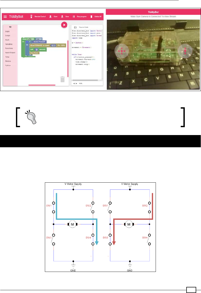
Chapter 9
369
The Tiddlybot GUI provides a cross-platform drag and drop interface as well as Python support
Be sure to check out the Appendix, Hardware and Software List;
it lists all the items used in this chapter and the places you can
obtain them from.
Using advanced motor control
The previous driving circuits are not suitable for driving motors in more than one direction
(as they only switch the motor on or off). However, using a circuit named an H-bridge, you
can switch and control the motor's direction too. The switch combinations are shown in the
following diagram:
The direction of the motor can be controlled by different switch combinations
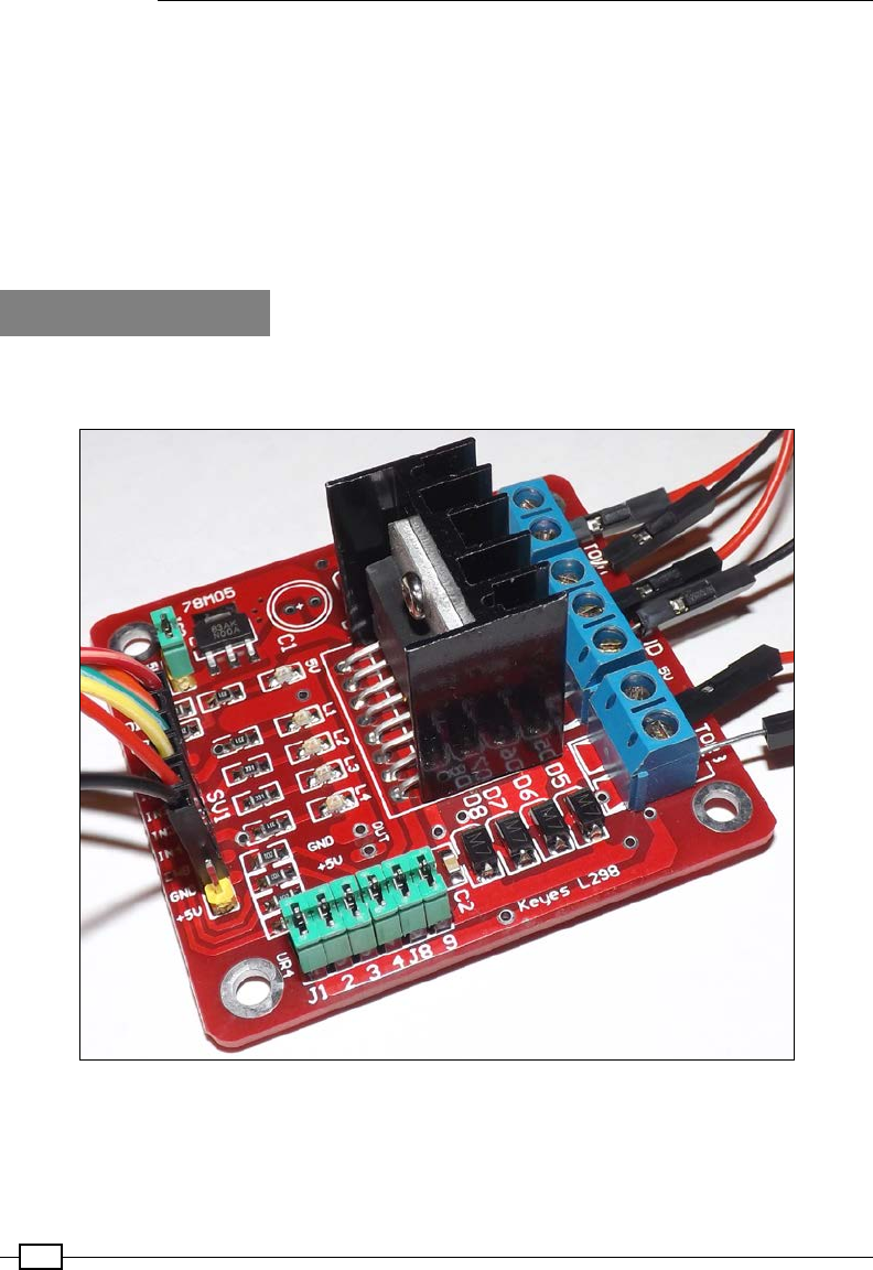
Building Robots
370
Using a different combination of switching, we can change the direction of the motor by
switching the positive and negative supply to the motor (SW1 and SW4 activate the motor,
and SW2 and SW3 reverse the motor). However, not only do we need four switching devices
for each motor, but since the ULN2X03 devices and PiBorg's PicoBorg module can only sink
current, equivalent devices would be required to source current (to make up the top section of
switches).
Fortunately, there are purpose-built H-bridge chips, such as L298N, that contain the previous
circuit inside them to provide a powerful and convenient solution to control motors.
Getting ready
We shall replace the previous Darlington array module with the H-bridge motor controller
shown in the following image:
The H-bridge motor controller allows directional control of motors
There is some detailed information about this unit available at http://www.geekonfire.
com/wiki/index.php?title=Dual_H-Bridge_Motor_Driver.
Chapter 9
371
The datasheet of L298N is available at http://www.st.com/resource/en/datasheet/
l298.pdf.
How to do it…
The unit will need to be wired as follows (this will be similar for other H-bridge type controllers,
but check with the relevant datasheet if unsure).
The following table shows how the motors and motor power supply connect to the H-bridge
controller module:
The motor side of the module – connecting to the battery and motors
Motor A VMS GND 5V OUT Motor B
Left motor
Red wire
Left motor
Black wire
Battery
positive
Battery
GND
None Right motor
Red wire
Right motor
Black wire
The following table shows how the H-bridge controller module connects to the Raspberry Pi:
Control side of the module – connecting to the Raspberry Pi GPIO header
ENA IN1 IN2 IN3 IN4 ENB GND 5V
None Pin 15 Pin 16 Pin 18 Pin 22 None Pin 6 None
It is recommended that you keep the pull-up resistor jumpers on (UR1-UR4) and allow the
motor supply to power the onboard voltage regulator, which in turn will power the L298N
controller (jumper 5V_EN). The on-board regulator (the 78M05 device) can supply up to 500
mA, enough for the L298N controller plus any additional circuits, such as an IO expander
(see the There's more… section for more information). Both the ENA and ENB pins should be
disconnected (the motor output will stay enabled by default).
You will need to make the following changes to the previous rover_drivefwd.py script (you
can save it as rover_drive.py).
At the top of the le, redene PINS as follows:
PINS=[15,16,18,22] # PINS=[L_FWD,L_BWD,R_FWD,R_BWD]
And update the control patterns as follows:
FWD=[ON,OFF,ON,OFF]
BWD=[OFF,ON,OFF,ON]
RIGHT=[OFF,ON,ON,OFF]
LEFT=[ON,OFF,OFF,ON]
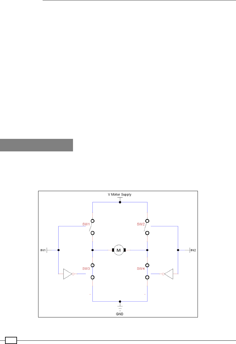
Building Robots
372
Next, we need to add the backwards command to cmd() as follows:
def cmd(self,char,step=STEP):
if char == 'f':
self.drive(FWD,step)
elif char == 'b':
self.drive(BWD,step)
elif char == 'r':
self.drive(RIGHT,step)
elif char == 'l':
self.drive(LEFT,step)
elif char == '#':
time.sleep(step)
Finally, we can update the prompt that we have within the main() function to include b
(backwards) as an option, as follows:
print("Enter CMDs [f,b,r,l,#]:")
How it works…
The H-bridge motor controller recreates the previous switching circuit with additional circuitry
to ensure that the electronic switches cannot create a short circuit (by not allowing SW1
and SW3 or SW2 and SW4 to be enabled at the same time). The H-bridge motor controller's
switching circuit is as shown in the following diagram:
An approximation of the H-bridge switching circuit (in Motor off state)
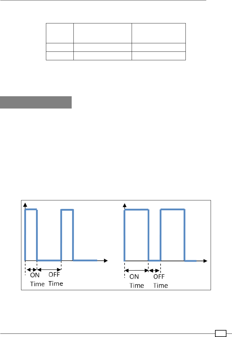
Chapter 9
373
The input (IN1 and IN2) will produce the following action on the motors:
IN1
IN2
0 1
0 Motor off Motor backwards
1 Motor forwards Motor off
As we did in the previous recipe, we can move forward by driving both motors forward;
however, now we can drive them both backwards (to move backwards) as well as in opposite
directions (allowing us to turn the Rover-Pi robot on the spot).
There's more…
We can achieve ner control of the motors using a pulse width modulated (PWM) signal and
expand the available input/output using an IO expander.
Motor speed control using PWM control
Currently, the Rover-Pi robot motors are controlled by being switched on and off; however,
if the robot is moving too fast (for example, if you have tted bigger motors or used higher
gearing), we could make use of the ENA and ENB input on the controller. If these are set
low, the motor output is disabled, and if set high, it is enabled again. Therefore, by driving
them with a PWM signal, we can control the speed of the motors. We could even set slightly
different PWM rates (if required) to compensate for any differences in the motors/wheels or
surface to drive them at slightly different speeds, as shown in the following diagram:
A PWM signal controls the ratio of the ON and OFF times

Building Robots
374
A PWM signal is a digital on/off signal that has different amounts of ON time compared to
OFF time. A motor driven with a 50:50, ON:OFF signal would drive a motor with half the power
of an ON signal at 100 percent and would therefore run more slowly. Using different ratios, we
can drive the motors at different speeds.
We can use the hardware PWM of the Raspberry Pi (GPIO Pin 12 can use the PWM driver).
The PWM driver normally provides one of the audio channels of
the analog audio output. Sometimes, this generates interference;
therefore, it is suggested that you disconnect any devices
connected to the analog audio socket.
The hardware PWM function is enabled in wiringpi2 by setting the pin mode to 2 (which is
the value of PWM) and specifying the on time (represented as ON_TIME) as follows:
PWM_PIN=12; PWM=2; ON_TIME=512 #0-1024 Off-On
def GPIOsetup(self):
wiringpi2.wiringPiSetupPhys()
wiringpi2.pinMode(PWM_PIN,PWM)
wiringpi2.pwmWrite(PWM_PIN,ON_TIME)
for gpio in self.pins:
wiringpi2.pinMode(gpio,OUT)
However, this is only suitable for joint PWM motor control (as it is connected to both ENA and
ENB) since there is only the one available hardware PWM output.
Another alternative is to use the software PWM function of wiringpi2. This creates a crude
PWM signal using software; depending on your requirements, this may acceptable. The code
for generating a software PWM signal on GPIO Pin 7 and GPIO Pin 11 is as follows:
PWM_PIN_ENA=7;PWM_PIN_ENA=11;RANGE=100 #0-100 (100Hz Max)
ON_TIME1=20; ON_TIME2=75 #0-100
ON_TIME1=20 #0-100
def GPIOsetup(self):
wiringpi2.wiringPiSetupPhys()
wiringpi2.softPwmCreate(PWM_PIN_ENA,ON_TIME1,RANGE)
wiringpi2.softPwmCreate(PWM_PIN_ENB,ON_TIME2,RANGE)
for gpio in self.pins:
wiringpi2.pinMode(gpio,OUT)

Chapter 9
375
The previous code sets both pins to 100 Hz, with GPIO Pin 7 set to an on time of 2 ms (and an
off time of 8 ms) and GPIO Pin 11 set to 7.5 ms/2.5 ms.
To adjust the PWM timings, use wiringpi2.softPwmWrite(PWM_PIN_ENA,ON_TIME2).
The accuracy of the PWM signal may be interrupted by other system processes, but it can
control a small micro servo, even if it's slightly jittery.
Using I/O expanders
As we have seen previously (in Chapter 7, Sense and Display Real-World Data), wiringpi2
allows us to easily adjust our code to make use of I/O expanders using I2C. In this case, it can
be useful to add additional circuits, such as sensors and LED status indicators, perhaps even
displays and control buttons to assist with debugging and controlling the Rover-Pi robot as you
develop it.
It can be particularly helpful if you intend to use it as a tethered device, since you will only
require three wires to connect back to the Raspberry Pi (I2C Data GPIO Pin 3, I2C Clock GPIO
Pin 5, and Ground GPIO Pin 6), with I2C VCC being provided by the motor controller 5V output.
As done earlier, add denes for the I2C address and pin base as follows:
IO_ADDR=0x20
AF_BASE=100
Then, in gpiosetup(), set up the MCP23017 device using the following code:
wiringpi2.mcp23017Setup(AF_BASE,IO_ADDR)
Ensure that any pin references you make are numbered 100-115 (to refer to the I/O expander
pins A0-7 and B0-7) with AF_BASE added (which is the pin offset for the I/O expander).
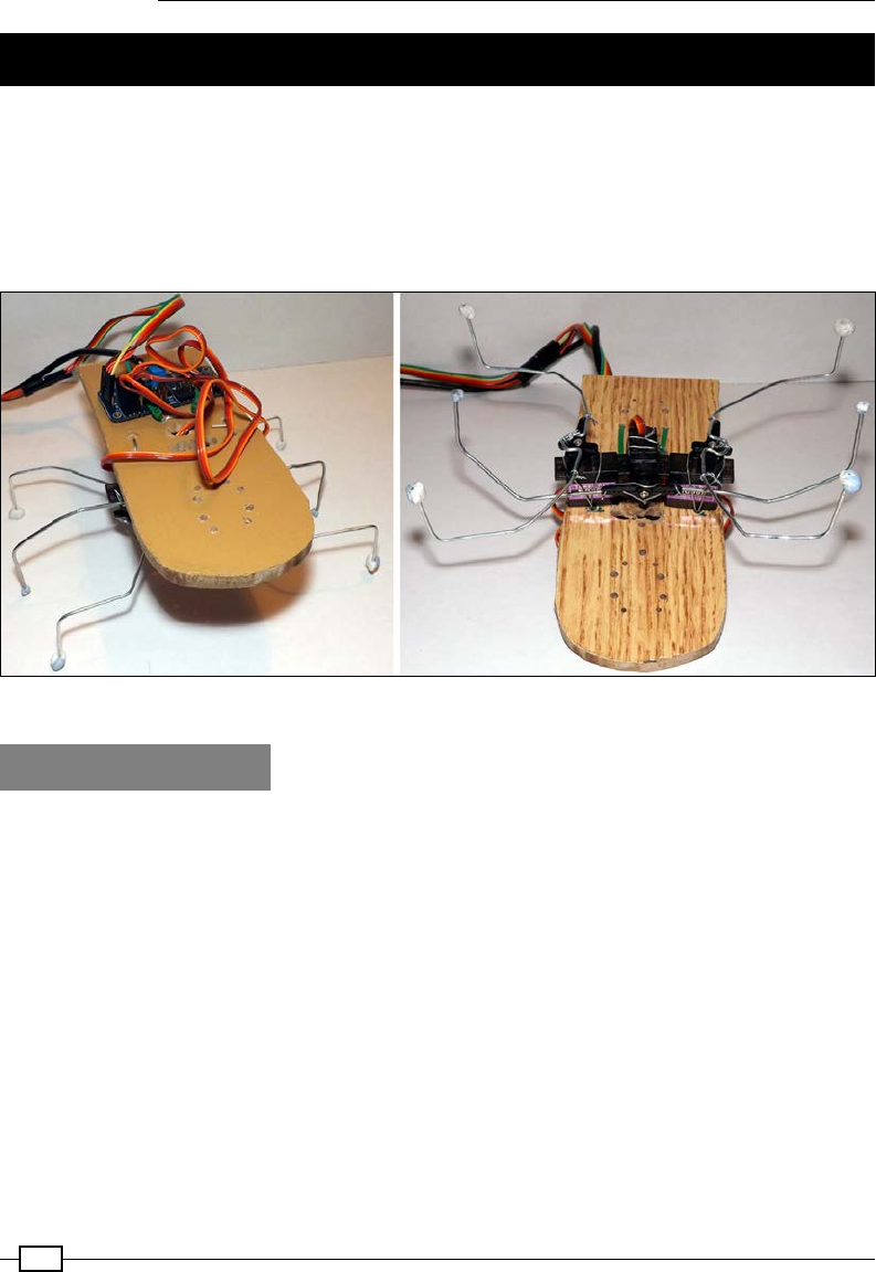
Building Robots
376
Building a six-legged Pi-Bug robot
Controlling motors is very useful for creating vehicle-like robots, but creating more naturally
behaving robot components such as servos can provide excellent results. There are many
creative designs of insect-like robots, or even biped designs (with humanoid-like legs), that
use servos to provide natural joint movements. The design in this example uses three servos,
but these principles and concepts can easily be applied to far more complex designs, to
control legs/arms that use multiple servos. The Pi-Bug robot is shown in the following image:
The six-legged Pi-Bug robot uses a servo driver to control three servos to scuttle around
Getting ready
You will need the following hardware:
fA PWM driver module: A driver module such as the Adafruit 16-Channel 12-bit PWM/
Servo Driver will be needed. This uses a PCA9685 device; see the datasheet at
http://www.adafruit.com/datasheets/PCA9685.pdf for details.
f3 x micro servos: The MG90S 9g Metal Gear Servos provide a reasonable amount of
torque at a low cost.
fA heavy gauge wire: This will form the legs; three giant paper clips (76 mm/3 inches)
are ideal for this.
fA light gauge wire / cable ties: These will be used to connect the legs to the servos
and to mount the servos to the main board.
fA small section of plywood or berboard: Holes can be drilled into this, and the
servos can be mounted on it.

Chapter 9
377
You will need to have wiringPi2 installed to control the PWM module, and it will be useful to
install the I2C tools for debugging. See Chapter 7, Sense and Display Real-world Data, for
details on how to install WiringPi2 and the I2C tools. The I2C connections are as shown in the
following diagram:
I2C connections on the Raspberry Pi GPIO header
How to do it…
The Pi-Bug robot uses three servos, one on either side and one in the middle. Mount each
servo by drilling a hole on either side of the servo body, loop a wire or cable ties through it,
and pull to hold the servo tightly.
Bend the paper clip wire into a suitable shape to form the Pi-Bug robot's legs, and add a small
kink that will allow you to wire the legs securely to the servo arms. It is recommended that you
run the program rst, with the Pi-Bug robot set to the home position h before you screw the
servo arms in place. This will ensure that the legs are located in the middle.
The following diagram shows the components on the Pi-Bug robot:
The layout of components on the Pi-Bug robot

Building Robots
378
Create the following servoAdafruit.py script to control the servos:
#!/usr/bin/env python3
#servoAdafruit.py
import wiringpi2
import time
#PWM Registers
MODE1=0x00
PRESCALE=0xFE
LED0_ON_L=0x06
LED0_ON_H=0x07
LED0_OFF_L=0x08
LED0_OFF_H=0x09
PWMHZ=50
PWMADR=0x40
class servo:
# Constructor
def __init__(self,pwmFreq=PWMHZ,addr=PWMADR):
self.i2c = wiringpi2.I2C()
self.devPWM=self.i2c.setup(addr)
self.GPIOsetup(pwmFreq,addr)
def GPIOsetup(self,pwmFreq,addr):
self.i2c.read(self.devPWM)
self.pwmInit(pwmFreq)
def pwmInit(self,pwmFreq):
prescale = 25000000.0 / 4096.0 # 25MHz / 12-bit
prescale /= float(pwmFreq)
prescale = prescale - 0.5 #-1 then +0.5 to round to
# nearest value
prescale = int(prescale)
self.i2c.writeReg8(self.devPWM,MODE1,0x00) #RESET
mode=self.i2c.read(self.devPWM)
self.i2c.writeReg8(self.devPWM,MODE1,
(mode & 0x7F)|0x10) #SLEEP
self.i2c.writeReg8(self.devPWM,PRESCALE,prescale)
self.i2c.writeReg8(self.devPWM,MODE1,mode) #restore mode
time.sleep(0.005)

Chapter 9
379
self.i2c.writeReg8(self.devPWM,MODE1,mode|0x80) #restart
def setPWM(self,channel, on, off):
on=int(on)
off=int(off)
self.i2c.writeReg8(self.devPWM,
LED0_ON_L+4*channel,on & 0xFF)
self.i2c.writeReg8(self.devPWM,LED0_ON_H+4*channel,on>>8)
self.i2c.writeReg8(self.devPWM,
LED0_OFF_L+4*channel,off & 0xFF)
self.i2c.writeReg8(self.devPWM,LED0_OFF_H+4*channel,off>>8)
def main():
servoMin = 205 # Min pulse 1ms 204.8 (50Hz)
servoMax = 410 # Max pulse 2ms 409.6 (50Hz)
myServo=servo()
myServo.setPWM(0,0,servoMin)
time.sleep(2)
myServo.setPWM(0,0,servoMax)
if __name__=='__main__':
try:
main()
finally:
print ("Finish")
#End
Create the following bug_drive.py script to control the Pi-Bug robot:
#!/usr/bin/env python3
#bug_drive.py
import time
import servoAdafruit as servoCon
servoMin = 205 # Min pulse 1000us 204.8 (50Hz)
servoMax = 410 # Max pulse 2000us 409.6 (50Hz)
servoL=0; servoM=1; servoR=2
TILT=10
MOVE=30
MID=((servoMax-servoMin)/2)+servoMin
CW=MID+MOVE; ACW=MID-MOVE
TR=MID+TILT; TL=MID-TILT
FWD=[TL,ACW,ACW,TR,CW,CW]#[midL,fwd,fwd,midR,bwd,bwd]

Building Robots
380
BWD=[TR,ACW,ACW,TL,CW,CW]#[midR,fwd,fwd,midL,bwd,bwd]
LEFT=[TR,ACW,CW,TL,CW,ACW]#[midR,fwd,bwd,midL,bwd,fwd]
RIGHT=[TL,ACW,CW,TR,CW,ACW]#[midL,fwd,bwd,midR,bwd,fwd]
HOME=[MID,MID,MID,MID,MID,MID]
PINS=[servoM,servoL,servoR,servoM,servoL,servoR]
STEP=0.2
global DEBUG
DEBUG=False
class motor:
# Constructor
def __init__(self,pins=PINS,steptime=STEP):
self.pins = pins
self.steptime=steptime
self.theServo=servoCon.servo()
def off(self):
#Home position
self.drive(HOME,step)
def drive(self,drive,step=STEP):
for idx,servo in enumerate(self.pins):
if(drive[idx]==servoM):
time.sleep(step)
self.theServo.setPWM(servo,0,drive[idx])
if(drive[idx]==servoM):
time.sleep(step)
if(DEBUG):print("%s:%s"%(gpio,drive[idx]))
def cmd(self,char,step=STEP):
if char == 'f':
self.drive(FWD,step)
elif char == 'b':
self.drive(BWD,step)
elif char == 'r':
self.drive(RIGHT,step)
elif char == 'l':
self.drive(LEFT,step)
elif char == 'h':
self.drive(HOME,step)
elif char == '#':
time.sleep(step)
def main():

Chapter 9
381
import os
DEBUG=True
if "CMD" in os.environ:
CMD=os.environ["CMD"]
INPUT=False
print("CMD="+CMD)
else:
INPUT=True
bugPi=motor()
if INPUT:
print("Enter CMDs [f,b,r,l,h,#]:")
CMD=input()
for idx,char in enumerate(CMD.lower()):
if(DEBUG):print("Step %s of %s: %s"%(idx+1,len(CMD),char))
bugPi.cmd(char)
if __name__ == '__main__':
try:
main()
except KeyboardInterrupt:
print ("Finish")
#End
How it works…
We explain how the previous script functions by exploring how the servos are controlled using
a PWM. Next, we see how the servo class provides the methods to control the PCA9685
device. Finally, we look at how the movements of the three servos combine to produce forward
and turning motions for the Pi-Bug robot itself.
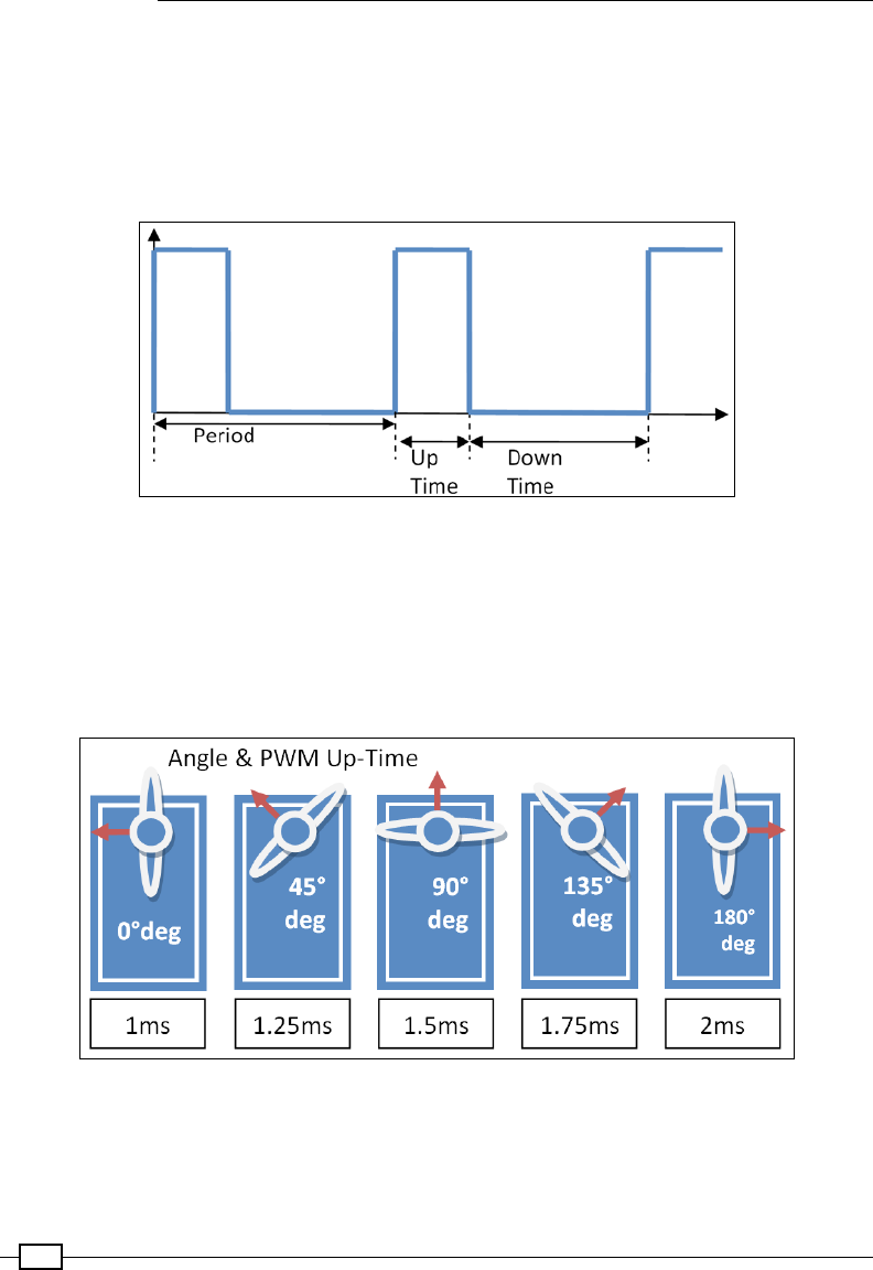
Building Robots
382
Controlling the servos
To control the servos used for the Pi-Bug robot, we require a special control signal that will
determine the angle that the servo is required to move to. We will send the servo a PWM
signal where the duration of the on time will allow us to control the angle of the servo arm
(and thereby allow us to control the Pi-Bug robot's legs). The following diagram shows how a
PWM signal can be used to control the angle of the servo:
The angle of the servo is controlled by the duration of the Up Time of the PWM signal
Most servos will have an angular range of approximately 180 degrees and the mid-position of
90 degrees. A PWM frequency of 50 Hz will have a period of 20 ms, and the mid-position of
90 degrees typically corresponds to an Up Time of 1.5 ms, with a range of +/- 0.5 ms to 0.4
ms for near 0 degrees and near 180 degrees. Each type of servo will be slightly different, but
you should be able to adjust the code to suit if required. The following diagram shows how you
can control the servo angle using different PWM Up Times:
The servo angle is controlled by sending a PWM Up-Time between 1 ms and 2 ms
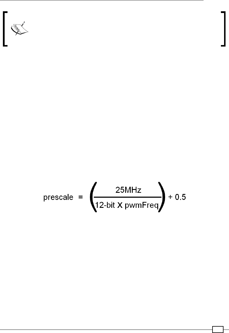
Chapter 9
383
Another type of servo is called a continuous servo (not used here). It allows
you to control the rotation speed instead of the angle, and will rotate at a
constant speed, depending on the PWM signal that has been applied. Both
servo types have internal feedback loops that will continuously drive the servo
until the required angle or speed is reached.
Although it is theoretically possible to generate these signals using software, you will nd that
any tiny interruption by other processes on the system will interfere with the signal timing; this,
in turn, will produce an erratic response from the servo. This is why we use a hardware PWM
controller, which only needs to be set with a specic up and down time, to then generate the
required signal automatically for us.
The servo class
The servo code is based on the PWM driver that Adafruit uses for their module; however, it
is not Python 3 friendly, so we need to create our own version. We will use Wiringpi2's I2C
driver to initialize and control the I2C PWM controller. We dene the registers that we will need
to use (see the datasheet for the PCA9685 device) as well as its default bus address 0x40
(PWMADR) and the PWM frequency of 50 Hz (PWMHZ).
Within our servo class, we initialize the I2C driver in wiringpi2 and set up our devPWM
device on the bus. Next, we initialize the PWM device itself (using pwmInit()). We have to
calculate the prescaler required for the device to convert the onboard 25 MHz clock to a 50
Hz signal to generate the PWM frequency we need; we will use the following formula:
The prescale register value sets the PWM frequency using a 12-bit value to scale the 25 MHz clock
The prescale value is loaded into the device, and a device reset is triggered to enable it.
Next, we create a function to allow the PWM ON and OFF times to be controlled. The ON and
OFF times are 12-bit values (0-4096), so each value is split into upper and lower bytes (8
bits each) that need to be loaded into two registers. For the L (low) registers, we mask off the
upper 8 bits using &0xFF, and for the H (high) registers, we shift down by 8 bits to provide
the higher 8 bits. Each PWM channel will have two registers for the on time and two for the
off time, so we can multiply the addresses of the rst PWM channel registers by 4 and the
channel number to get the addresses of any of the others.

Building Robots
384
To test our servo class, we dene the minimum and maximum ranges of the servos, which
we calculate as follows:
fThe PWM frequency of 50 Hz has a 20 ms period (T=1/f)
fThe ON/OFF times range from 0-4,096 (so 0 ms to 20 ms)
Now, we can calculate the control values for 0 degrees (1 ms) and 180 degrees (2 ms)
as follows:
f1 ms (servo min) is equal to 4,096/20 ms, which is 204.8
f2 ms (servo max) is equal to 4,096/10 ms, which is 409.6
We round the values to the nearest whole number.
Learning to walk
The Pi-Bug robot uses a common design that allows three servos to be used to create a small,
six-legged robot. The servos at the two ends provide forward and backward movement, while
the servo in the middle provides the control. The following image shows the mounted servos:
The servos are mounted upside down on the underside of the board
The following table assumes that the left and right servos are mounted upside down on the
underside of the board, with the middle servo tted vertically. You shall have to adjust the
code if mounted differently.
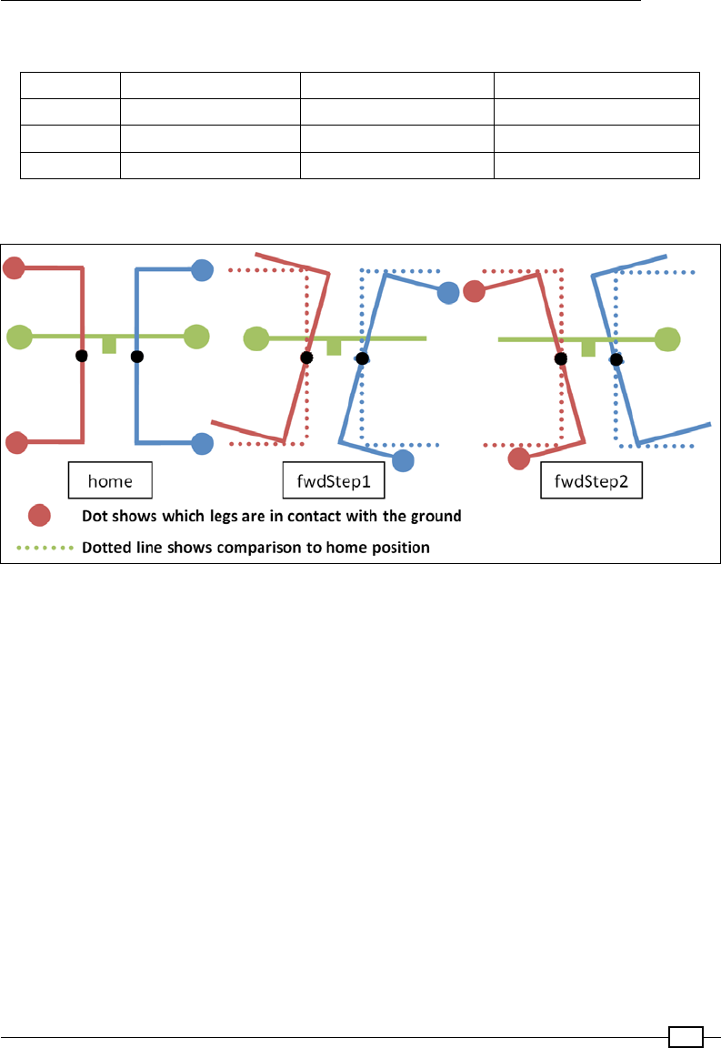
Chapter 9
385
The following table shows the servo movements used to walk forward:
Direction Middle (servoM) Left (servoL) Right (servoR)
home MID/Middle MID/Middle MID/Middle
fwdStep1 TR/Right side up ACW/Legs forward ACW/Legs backward
fwdStep2 TL/Left side up CW/Legs backward CW/Legs forward
The following diagram shows how the movement makes the Pi-Bug robot step forward:
The Pi-Bug robot moving forward
While it may seem a little confusing at rst, when you see the robot moving, it should make
more sense.
For the rst forward step, we move the middle servo (servoM) clockwise so that the left side
of the Pi-Bug robot is lifted off the ground by the movement of the remaining middle leg.
We can then move the left servo (servoL) to move the legs on the left side forward (ready
for movement later, they are not touching the ground at this point). Now by moving the right
servo (servoR), we can move the legs on the right backwards (allowing the Pi-Bug robot to be
pushed forward on that side).
The second forward step is the same, except that we use the middle servo (servoM) to lift the
right side off the ground. Again, we move the legs that are off the ground forward (ready for
next time) and then move the legs on the other side backward (allowing that side of the Pi-Bug
robot to move forward). By repeating the forward steps, the Pi-Bug robot will move forward,
or by swapping the sides that are being lifted up by the middle servo (servoM), it will move
backward. The result is a rather bug-like scuttle!
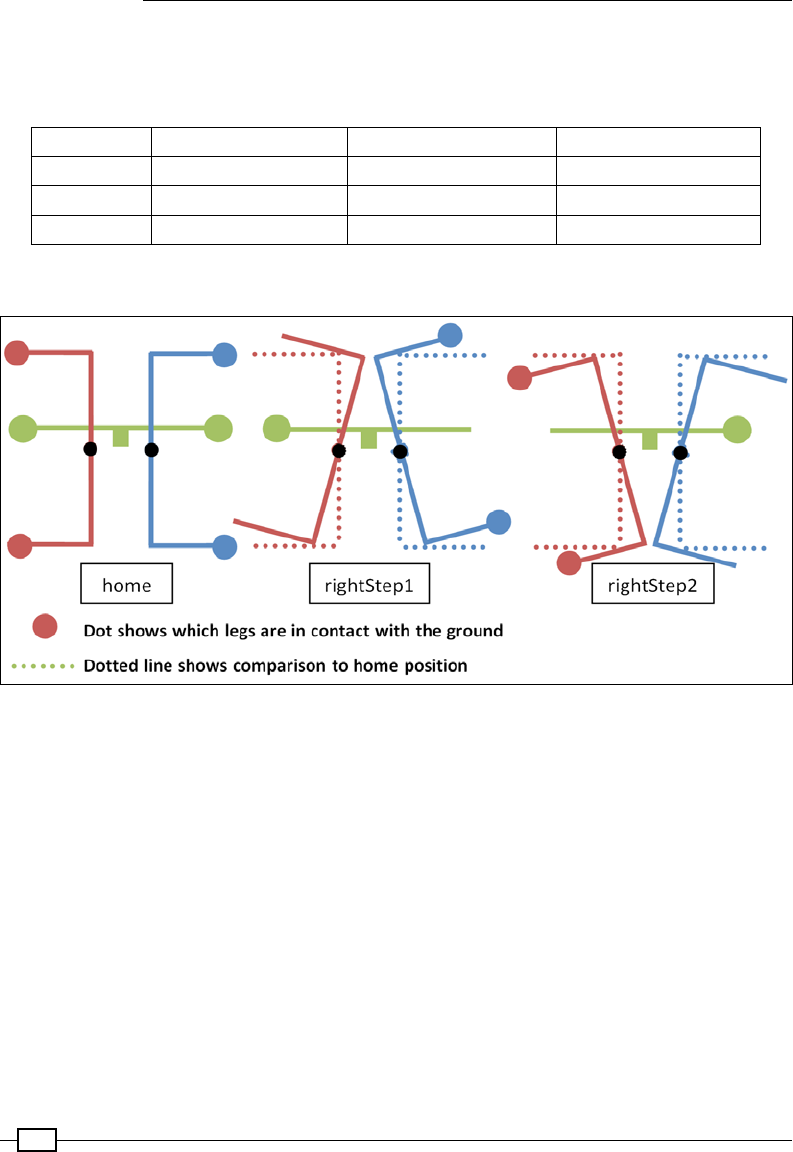
Building Robots
386
To make the Pi-Bug robot turn, we perform a similar action, except that just like the advanced
motor control for the Rover-Pi robot, we move one side of the robot forward and the other side
backward. The following table shows the servo movements used to turn right:
Direction Middle (servoM) Left (servoL) Right (servoR)
home MID/Middle MID/Middle MID/Middle
rightStep1 TL/Left side up CW/Legs backward ACW/Legs backward
rightStep2 TR/Right side up ACW/Legs forward CW/Legs forward
The steps to turn the Pi-Bug robot to the right are shown in the following diagram:
The Pi-Bug robot making a right turn
To turn right, we lift the left side of the Pi-Bug robot off the ground, but this time, we move the
legs on both sides backward. This allows the right side of the Pi-Bug robot to move forward.
The second half of the step lifts the right side off the ground, and we move the legs forward
(which will push the left side of the Pi-Bug robot backward). In this manner, the bug will turn
as it steps; again, just by swapping the sides that are being lifted, we can change the direction
that the Pi-Bug robot will turn in.

Chapter 9
387
The Pi-Bug code for walking
The code for the Pi-Bug robot has been designed to provide the same interface as the Rover-
Pi robot so that they can be interchanged easily. You should notice that each class consists
of the same four functions (__init__(), off(), drive(), and cmd()). The __init__()
function denes the set of pins we will control, the steptime value of the walking action (this
time, the gap between movements), and the previously dened servo module.
Once again, we have an off() function that provides a function that can be called to set
the servos in their middle positions (which is very useful for when you need to t the legs
in position, as described previously in the home position). The off() function uses the
drive() function to set each servo to the MID position. The MID value is halfway between
servoMin and servoMax (1.5 ms to give a position of 90 degrees).
The drive() function is just like the previous motor control version; it cycles through each
of the actions required for each servo as dened in the various movement patterns (FWD,
BWD, LEFT, and RIGHT) we discussed previously. However, to reproduce the required pattern
of movement, we cycle through each servo twice, while inserting a small delay whenever
we move the middle servo (servoM). This allows time for the servo to move and provide the
necessary tilt to lift the other legs off the ground before allowing them to move.
We dene each of the servo commands as a clockwise (CW) or anticlockwise/
counterclockwise (ACW) movement of the servo arm. Since the servos are mounted upside
down, an anticlockwise (clockwise if viewed from above) movement of the left servo (servoL)
will bring the legs forwards, while the same direction of movement on the right servo
(servoR) will move the legs backward (which is fwdStep1 in the previous diagram). In this
way, each of the patterns can be dened.
Once again, we provide a test function using the following command that allows a list of
instructions to either be dened from the command line or directly entered at the prompt:
sudo CMD=fffll##rr##bb##h python3 bug_drive.py
This includes the addition of h to return to the home position, if desired.
Controlling servos directly with Servoblaster
The previous recipe demonstrated using a dedicated servo controller to handle the control of
the servos used by the PiBug. This has the advantage that any disturbances in the processing
taking place on the Raspberry Pi does not cause interference with the delicate servo control
(since the controller will continue to send the correct signals).
However, the Raspberry Pi is also capable of direct servo control. To achieve this we will make
use of Richard Hurst's Servoblaster, which is a multiple servo driver.
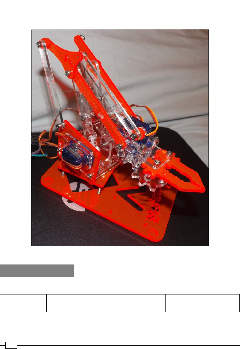
Building Robots
388
In this recipe, we will control four servos attached to the MeArm, a simple laser-cut robot arm;
however, you can choose to t servos to whatever device you like.
The MeArm is a simple robot arm powered by four miniature servos
Getting ready
Most common servos will have three wires and a three pin connector as follows:
Black/Brown Red Orange/White/Yellow/Blue
Ground Positive Supply (Typically 5V for small servos) Signal
Chapter 9
389
While it is usually possible to power the servos directly from the Raspberry Pi 5V pins on the
GPIO header, they can draw a signicant amount of current when moving. Unless you have
a very good power supply, this can cause the Raspberry Pi to reset unexpectedly, risking
corrupting the SD card. Therefore it is recommended that you power them separately, for
example, with an additional USB power supply and cable connected to the ground and
positive supply.
By default the servos can be wired as follows:
Servo 0 1 2 3 4 5 6 7 All GND All Power
Raspberry Pi
GPIO Pin 711 12 13 15 16 19 22 6 No Connect
5V Power Supply GND +5V
We will assume we are controlling four servos (0, 1, 2 and 3) that will be tted later to the
MeArm or similar device.
To install Servoblaster, start by downloading the source les from the Git repository:
cd ~
wget https://github.com/richardghirst/PiBits/archive/master.zip
Unzip and open the matplotlib-master folder, as follows:
unzip master.zip
rm master.zip
cd PiBits-master/ServoBlaster/user
We will use the user space daemon (which is located in the user directory) that is called
servod. Before we can use it, we should compile it with this command:
make servod
There should be no errors, showing the following text:
gcc -Wall -g -O2 -o servod servod.c mailbox.c -lm
For usage information use the following command:
./servod --help
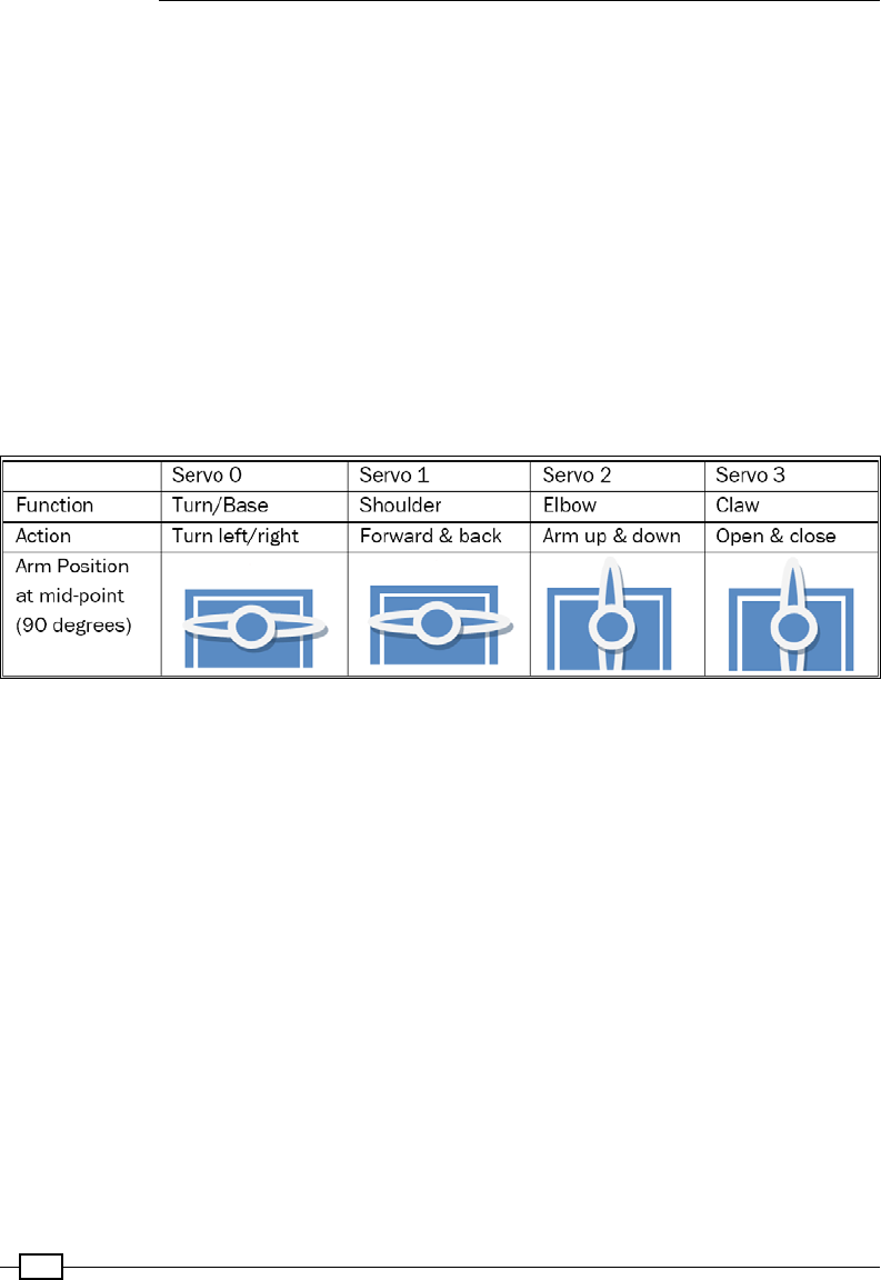
Building Robots
390
Now we can test a servo, rst start the servod daemon (with a timeout of 2,000ms to switch
off the servo off after it has moved):
sudo servod --idle-timeout=2000
You can move the servo's position to 0% of the servo's range:
echo 0=0% > /dev/servoblaster
Now update the servo to 50%, causing the servo to rotate to 90 degrees (servo mid-point):
echo 0=50% > /dev/servoblaster
As recommended by the MeArm build instructions, the servos should be connected and
calibrated before building the arm, to ensure that each servo is able to move the arm in its
correct range. This is done by ensuring each servo is powered up and commanded to its
mid-point position (50%/90 degrees) and the servo-arm tted at the expected orientation:
Each of the servos should be calibrated in the correct position before you fit them on the MeArm
You can now set each of the MeArm servos (0, 1, 2 and 3) to their mid-points (by commanding
each in turn to 50%) before building and tting them to completed arm.
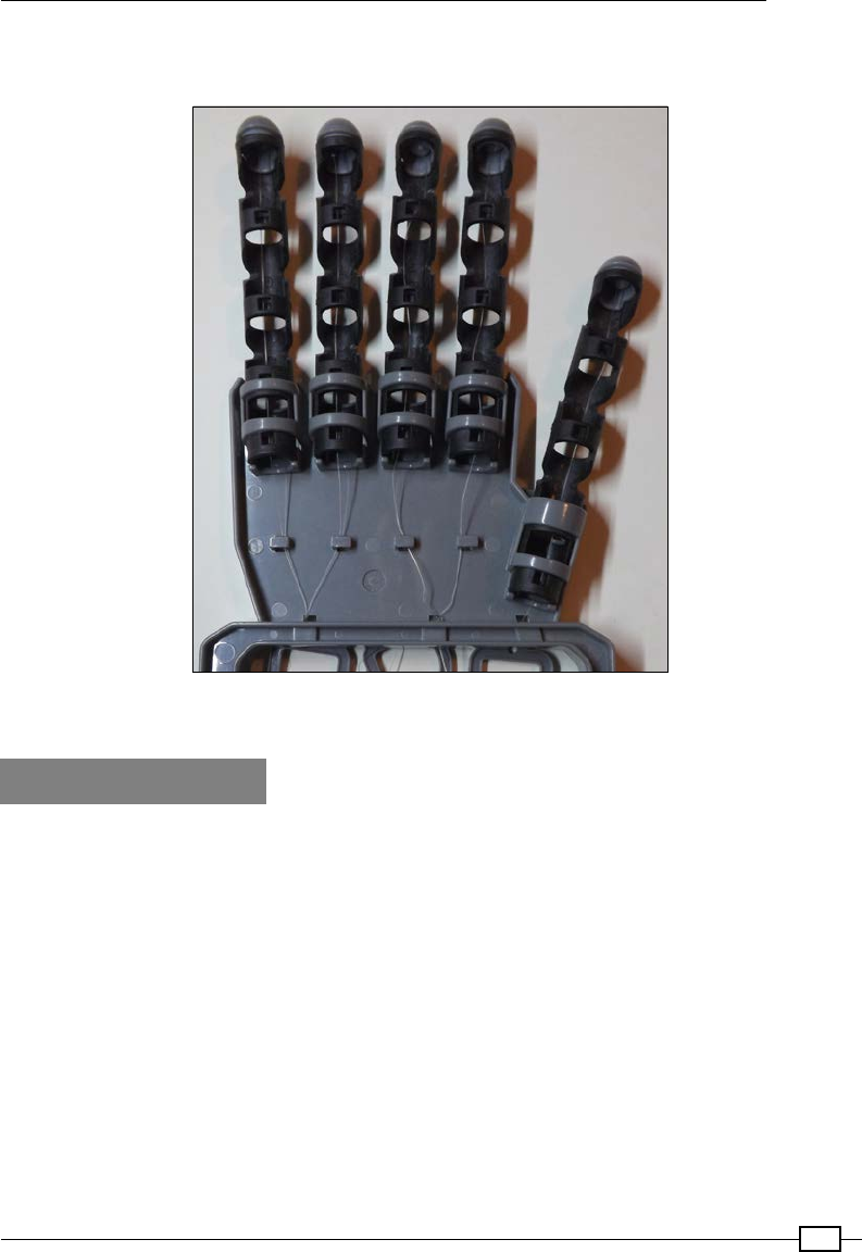
Chapter 9
391
The servos could be used to control a wide range of alternative devices other than the MeArm,
but your servos will probably need to be calibrated in a similar manor.
The precision control of servos means they can be used for a variety of applications.
For example, controlling simulated hands
How to do it…
Create the following servo_control.py script:
#!/usr/bin/env python3
#servo_control.py
import curses
import os
#HARDWARE SETUP
# GPIO
# 2[=VX==2=======]26[=======]40
# 1[===013=======]25[=======]39
# V=5V X=Gnd
# Servo 0=Turn 1=Shoulder 2=Elbow 3=Claw
name=["Turn","Shoulder","Elbow","Claw"]
CAL=[90,90,90,90]

Building Robots
392
MIN=[0,60,40,60]; MAX=[180,165,180,180]
POS=list(CAL)
KEY_CMD=[ord('c'),ord('x')]
#Keys to rotate counter-clockwise
KEY_LESS={ord('d'):0,ord('s'):1,ord('j'):2,ord('k'):3}
#Keys to rotate clockwise
KEY_MORE={ord('a'):0,ord('w'):1,ord('l'):2,ord('i'):3}
STEP=5; LESS=-STEP; MORE=STEP #Define control steps
DEG2MS=1.5/180.0; OFFSET=1 #mseconds
IDLE=2000 #Timeout servo after command
SERVOD="/home/pi/PiBits-mater/ServoBlaster/user/servod" #Location of
servod
DEBUG=True
text="Use a-d, w-s, j-l and i-k to control the MeArm. c=Cal x=eXit"
def initialize():
cmd=("sudo %s --idle-timeout=%s"%(SERVOD, IDLE))
os.system(cmd)
def limitServo(servo,value):
global text
if value > MAX[servo]:
text=("Max %s position %s:%s"%(name[servo],servo,POS[servo]))
return MAX[servo]
elif value < MIN[servo]:
text=("Min %s position %s:%s"%(name[servo],servo,POS[servo]))
return MIN[servo]
else:
return value
def updateServo(servo,change):
global text
POS[servo]=limitServo(servo,POS[servo]+change)
setServo(servo,POS[servo])
text=str(POS)
def setServo(servo,position):
ms=OFFSET+(position*DEG2MS)
os.system("echo %d=%dus > /dev/servoblaster" %(servo, ms/1000))
def calibrate():
global text

Chapter 9
393
text="Calibrate 90deg"
for i,value in enumerate(CAL):
POS[i]=value
setServo(i,value)
def main(term):
term.nodelay(1)
term.addstr(text)
term.refresh()
while True:
term.move(1,0)
c = term.getch()
if c != -1:
if c in KEY_MORE:
updateServo(KEY_MORE[c],MORE)
elif c in KEY_LESS:
updateServo(KEY_LESS[c],LESS)
elif c in KEY_CMD:
if c == ord('c'):
calibrate()
elif c == ord('x'):
exit()
if DEBUG:term.addstr(text+" ")
if __name__=='__main__':
initialize()
curses.wrapper(main)
#End
Run the script:
python3 servo_control.py
You can control the servos tted to the MeArm (or whatever you are using) as prompted:
Use a-d, w-s, j-l and i-k to control the MeArm. c=Cal x=eXit
How it works…
The script starts by importing the curses and os modules. A standard python input()
command would require the Enter key to be pressed after each key press before we could
act upon it. However, as we will see shortly, the curses module simply allows us to scan
for keyboard presses and respond to them immediately. We use the os module to call the
servoblaster commands, as we would via the terminal.

Building Robots
394
First, we dene our setup, such as the servo mappings, calibration positions, min/max
ranges, our control keys and the STEP size in degrees for each control command. We also
dene our parameters for our requested angle (in degrees) to target PWM signal up-time (in
milliseconds) calculation.
Note: For these particular servos an up-time of 1 ms is equal to 0 degrees
and 2.5 ms is 180 degrees, so we have an offset (OFFSET) of 1 ms and a
scale (DEG2MS) of 180 degrees/1.5 ms.
Therefore, our required up-time (in milliseconds) can be calculated as OFFSET +
(degrees*DEG2MS). Finally, we dene the SERVOD command line and servo IDLE timeout
to initialize the servoblaster user daemon. Within initialize () we use os.system() to
start the servod daemon as we did before.
In order to detect keypresses, we call the main() function of the script from curses.
wrapper(), allowing term to control the terminal input and output. We use term.
nodelay(1) so when we do check for any keypresses (using term.getch()) execution
will continue normally. We use term.addstr(text) to show the user the control keys and
then update the display via term.refresh(). The remaining script checks the terminal for
keypresses and the result assigned to c. If no key was pressed, then term.getch() returns
-1, otherwise the ASCII equivalent value is returned and we can check for it in each of the
dictionaries we dened for control keys. We will use KEY_MORE and KEY_LESS to change
the servo positions and KEY_CMD (c or x) to allow us to set all the servos to their calibrated
position or to exit cleanly. Finally, we display any useful debugging information (if DEBUG is set
to True) using term.addstr() and ensure it is displayed at (1,0) in the terminal (one line
down from the top).
For normal control, the position of the servos will be controlled using the updateServo()
function, which adjusts the current position (stored in the POS array) by the required change
(either +STEP or –STEP). We ensure the new position is within the MAX/MIN limits dened
and report if we've hit them. The servo is then instructed to move to the required position
using setServo() specifying the needed PWM up-time in micro seconds.
The last function, calibrate(), called when c is pressed, simply sets each of the servos to
the angle dened in the CAL array (using setServo()) and ensures the current position is
kept up to date.
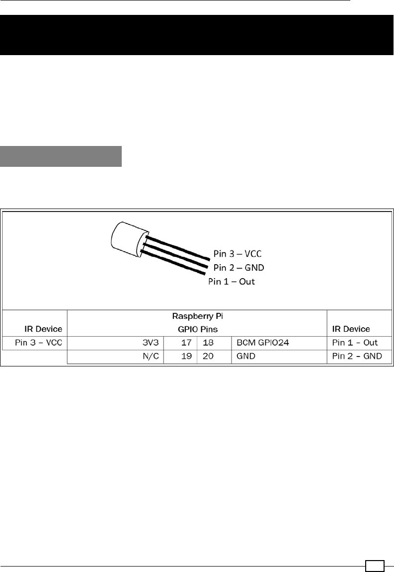
Chapter 9
395
Using an Infra-Red Remote Control with your
Raspberry Pi
It is often useful to control robots remotely. An easy way to add additional input is to make
use of an IR (infra-red) receiver and a standard remote control. Fortunately, the receiver is
well supported.
We will use a module called LIRC to capture and decode IR signals from a standard
remote control.
Getting Ready
LIRC supports many types of IR detectors, such as Energenie's PiMote IR board; however,
since we only need to receive IR signals, we can use a simple (TSOP38238) IR detector.
The three pins of the TSOP38238 IR Receiver can fit directly onto the Raspberry Pi header
Install the following packages using apt-get:
sudo apt-get install lirc lirc-x
Add the following to /boot/config.txt. This will enable the driver and dene the pin the
receiver is tted on (BCM GPIO24):
dtoverlay=lirc-rpi,gpio_in_pin=23
Perform a restart of the Raspberry Pi so that the conguration takes effect:
sudo reboot

Building Robots
396
We should now nd that the IR device is located at /dev/lirc0. We can observe the output
of the receiver if we point a remote control at it and press some buttons after using the
following command (use Ctrl + Z to exit):
mode2 –d /dev/lirco0
Note: If the lirc0 resource is reported as busy:
mode2: could not open /dev/lirc0
mode2: default_init(): Device or resource busy
We will need to stop the lirc service:
sudo /etc/init.d/lirc stop
Which will give the following response:
[ ok ] Stopping lirc (via systemctl): lirc.service
When you are ready, you can start the service again:
sudo /etc/init.d/lirc start
This will give the following response:
[ ok ] Starting lirc (via systemctl): lirc.service
You will see output similar to the following (if not ensure you have connected the receiver
connected to the correct pins on the Raspberry Pi GPIO):
space 16300
pulse 95
space 28794
pulse 80
space 19395
pulse 83
...etc…
Now that we know our device is working, we can congure it.
Chapter 9
397
How to do it…
The global LIRC congurations are stored in /etc/lirc. We are interested in the following
les:
hardware.conf Defines where our IR sensor is installed and overall setting for our
sensor.
lircd.conf The remote control configuration file; this contains the recorded
outputs for your remote control's keys and maps them to specific
key symbols. You can often obtain pre-recorded files from lirc.
sourceforge.net/remotes or we can record a custom one as
shown next.
lircrc This file provides mapping of each of the key symbols to specific
commands or keyboard mappings.
Note: All the LIRC congurations stored in /etc/lirc are available for all
users; however, if required, different congurations can be dened for each
user by placing them in specic home folders, for example /home/pi/.
config/, allowing the defaults to be overridden.
There are three parts steps setting up the sensor, one for each of the LIRC conguration les:
1. First, ensure hardware.conf is set up. For our sensor, we must ensure the following
is set:
LIRCD_ARGS="--uinput"
DRIVER="default"
DEVICE="/dev/lirc0"
MODULES="lirc_rpi"
2. Next, obtain a lircd.conf le, or if you do not have one for your remote, we can
generate it. The following process will now take you through detecting each of the
individual keys on the remote. For the purpose of this recipe, we only need to map
eight keys (to control the four servos from the previous recipe).
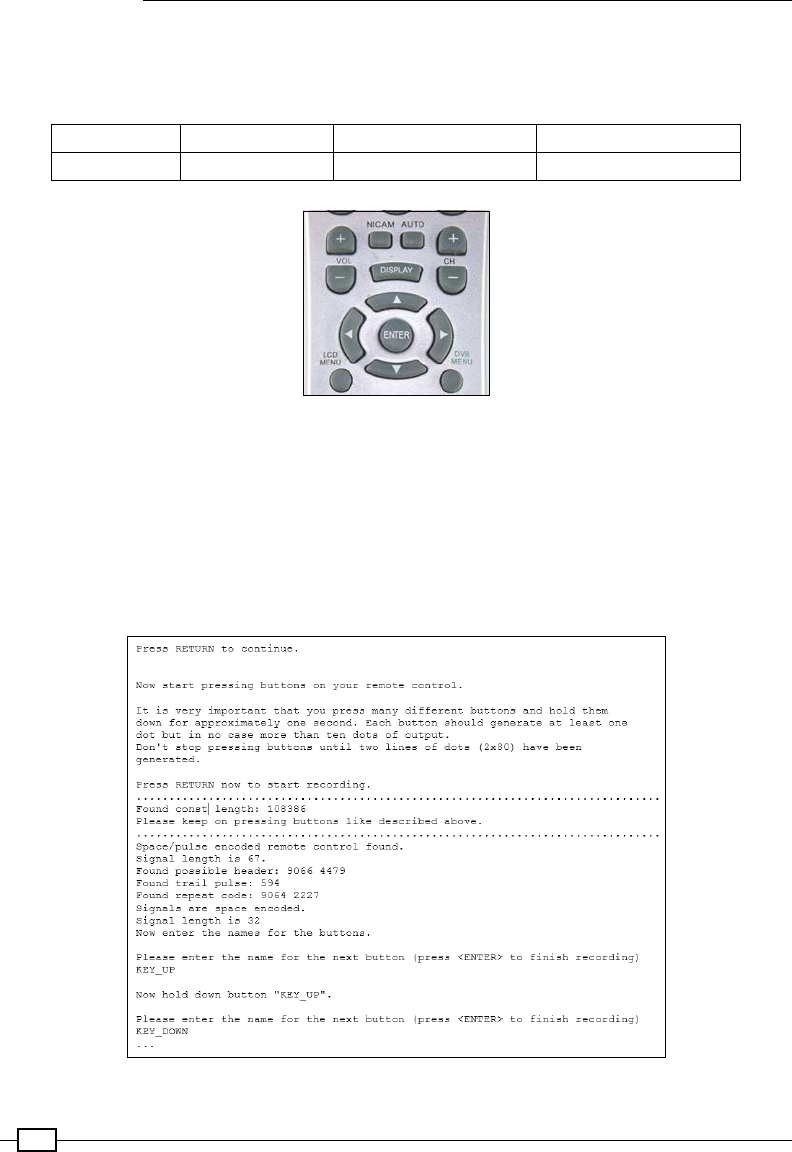
Building Robots
398
3. If you want map additional keys, use the following command to nd out the full list of
valid key symbols:
irrecord --list-namespace
KEY_UP KEY_RIGHT KEY_VOLUMEUP KEY_CHANNELUP
KEY_DOWN KEY_LEFT KEY_VOLUMEDOWN KEY_CHANNELDOWN
We can use the volume, channel, and direction buttons on this Goodmans remote as our MeArm controller
First, we will need to stop the lirc service, which, if it was running would be using the /dev/
lirc0 device:
sudo /etc/init.d/lirc stop
Next, start the capture process using the following commands:
irrecord –d /dev/lirc0 ~/lircd.conf
Record each button on the remote using the irrecord tool
Chapter 9
399
Now that we have captured the required keys, we ensure the name of the remote is set (by
default it will be set to name of the lirc.conf le when the buttons are captured):
nano ~/lircd.conf
Set the name of the remote in the le, for example, Goodmans:
...
begin remote
name Goodmans
bits 16
...
Finally, we can replace the conguration in the /etc/lirc folder:
sudo cp ~/lircd.conf /etc/lirc/lirc.conf
Note: We can conrm the key symbols which are mapped to the
remote using the irw program as follows:
irw
This will report the details of the key pressed and the remote control as dened:
0000000000fe7a85 00 KEY_UP Goodmans
0000000000fe7a85 01 KEY_UP Goodmans
0000000000fe6a95 00 KEY_DOWN Goodmans
0000000000fe6a95 01 KEY_DOWN Goodmans
...
Now we can map the keys to specic commands; in this case we will map them to the keys we
used for controlling the MeArm servos. Create a new /etc/lirc/lircrc le:
sudo nano /etc/lirc/lircrc
Replace with the following content:
begin
prog=irxevent
button=KEY_UP
config=Key w CurrentWindow
end
begin
prog=irxevent
button=KEY_DOWN
config=Key s CurrentWindow
end

Building Robots
400
begin
prog=irxevent
button=KEY_LEFT
config=Key a CurrentWindow
end
begin
prog=irxevent
button=KEY_RIGHT
config=Key d CurrentWindow
end
begin
prog=irxevent
button=KEY_VOLUMEUP
config=Key i CurrentWindow
end
begin
prog=irxevent
button=KEY_VOLUMEDOWN
config=Key k CurrentWindow
end
begin
prog=irxevent
button=KEY_CHANNELUP
config=Key l CurrentWindow
end
begin
prog=irxevent
button=KEY_CHANNELDOWN
config=Key j CurrentWindow
end
To apply the conguration, you may need to restart the service (or if that doesn't work, try
restarting the Raspberry Pi):
sudo /etc/init.d/lirc restart
When we run the servo_control.py script in the previous recipe, the remote should
control the arm directly.

Chapter 9
401
There's more…
LIRC supports several helper programs, of which irxevent is just one:
remote By default, LIRC supports some simple controls, for example:
prog=remote
button=KEY_UP
config=UP
This will provide simple cursor control from a remote (UP, DOWN, LEFT, RIGHT
and also ENTER) that are perfect for simple menu control.
http://www.lirc.org/html/configure.html#lircrc_format
irxevent Emulates button clicks and key presses within X applications. You can specify
that the key event occurs in the CurrentWindow or in a specific window by
name, that is, leafpad. This only works if you are running from the graphical
desktop environment (or using X-forwarding).
http://www.lirc.org/html/irxevent.html
irpty Converts infrared remote commands into key strokes for controlling a particular
program:
rog=irpty
button=KEY_EXIT
config=x
Start it by specifying the lircrc configuration and program you want to control:
irpty /etc/lirc/lircrc -- leafpad
http://www.lirc.org/html/irpty.html
irexec Allows commands to be run directly from the remote control:
prog=irexec
button=KEY_POWER
config=sudo halt #Power Down
http://www.lirc.org/html/irexec.html
You can test any part of the lircrc le by using ircat with the required prog:
ircat irxevent
The preceding command will report the following:
Key k CurrentWindow
Key i CurrentWindow
Building Robots
402
Finally, if you have suitable IR Transmitter LED attached (including protective resistor/
switching transistor) you can also use LIRC to send infra-red signals from the Raspberry Pi. For
this you can use the irsend command, for example:
irsend SEND_ONCE Goodmans KEY_PROGRAMUP
The IR output channel is enabled within the /boot/config.txt le (assuming connected to
GPIO Pin 19):
dtoverlay=lirc-rpi,gpio_in_pin=24,gpio_out_pin=19
Avoiding objects and obstacles
To avoid obstacles, you can place sensors around the robot's perimeter to activate whenever
an object is encountered. Depending on how you want your robot to behave, one avoidance
strategy is to just reverse any action (with an additional turn for forward/backward actions)
that was last taken that caused one of the sensors to be activated.
Getting ready
You need some micro switches to be triggered when there is an impact with objects.
Depending on the type you have, you need to place enough switches to detect any object
around the outside (if required, you can use an additional length of wire to extend the reach of
the switch). Shown in the following image are two possible sensors that will cause the switch
to activate when the spring or the metal arm hits an object. You need to determine which
contacts of the switch open or close the circuit (this will depend on the device).
Small micro switches can be used as collision sensors
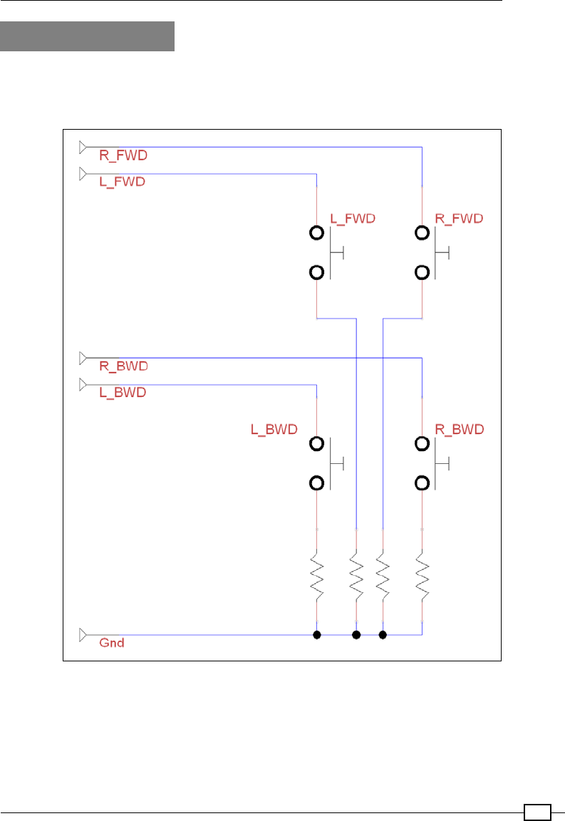
Chapter 9
403
How to do it…
Connect the switches to the GPIO using a method similar to the one we used previously in
Chapter 6, Using Python to Drive Hardware, for the D-Pad controller. A circuit diagram of the
switches is as follows:
The switches should include current limiting resistors (1K ohm is ideal)
Building Robots
404
How you connect to the Raspberry Pi's GPIO will depend on how your motor/servo drive is
wired up. For example, a Rover-Pi robot with the H-bridge motor controller can be wired
up as follows:
Control side of the module – connecting to the Raspberry Pi GPIO header
ENA IN1 IN2 IN3 IN4 ENB GND 5V
None Pin 15 Pin 16 Pin 18 Pin 22 None Pin 6 None
Four additional proximity/collision sensors can be connected to the Raspberry Pi GPIO
as follows:
Proximity/collision sensors – connecting to the Raspberry Pi GPIO header
R_FWD L_FWD R_BWD L_BWD GND
Pin 7 Pin 11 Pin 12 Pin 13 Pin 6
If you wired it differently, you can adjust the pin numbers within the code as required. If you
require additional pins, then any of the multipurpose pins, such as RS232 RX/TX (pins 8 and
10) or the SPI/I2C, can be used as normal GPIO pins too; just set them as input or output as
normal. Normally, we just avoid using them as they are often more useful for expansion and
other things, so it is sometimes useful to keep them available.
You can even use a single GPIO pin for all your sensors if you are just using the following
example code, since the action is the same, regardless of which sensor is triggered. However,
by wiring each one separately, you can adjust your strategy based on where the obstacle
is around the robot or provide additional debug information about which sensor has been
triggered.
Create the following avoidance.py script:
#!/usr/bin/env python3
#avoidance.py
import rover_drive as drive
import wiringpi2
import time
opCmds={'f':'bl','b':'fr','r':'ll','l':'rr','#':'#'}
PINS=[7,11,12,13] # PINS=[L_FWD,L_BWD,R_FWD,R_BWD]
ON=1;OFF=0
IN=0;OUT=1
PULL_UP=2;PULL_DOWN=1
class sensor:
# Constructor

Chapter 9
405
def __init__(self,pins=PINS):
self.pins = pins
self.GPIOsetup()
def GPIOsetup(self):
wiringpi2.wiringPiSetupPhys()
for gpio in self.pins:
wiringpi2.pinMode(gpio,IN)
wiringpi2.pullUpDnControl(gpio,PULL_UP)
def checkSensor(self):
hit = False
for gpio in self.pins:
if wiringpi2.digitalRead(gpio)==False:
hit = True
return hit
def main():
myBot=drive.motor()
mySensors=sensor()
while(True):
print("Enter CMDs [f,b,r,l,#]:")
CMD=input()
for idx,char in enumerate(CMD.lower()):
print("Step %s of %s: %s"%(idx+1,len(CMD),char))
myBot.cmd(char,step=0.01)#small steps
hit = mySensors.checkSensor()
if hit:
print("We hit something on move: %s Go: %s"%(char,
opCmds[char]))
for charcmd in opCmds[char]:
myBot.cmd(charcmd,step=0.02)#larger step
if __name__ == '__main__':
try:
main()
except KeyboardInterrupt:
print ("Finish")
#End

Building Robots
406
How it works…
We import rover_drive to control the robot (if we are using a Pi-Bug robot, bug_drive can
be used) and wiringpi2 so that we can use the GPIO to read the sensors (dened as PINS).
We dene opCmds, which uses a Python dictionary to allocate new commands in response to
the original command (using opCmds[char], where char is the original command).
We create a new class called sensor and set up each of the switches as GPIO input (each
with an internal pull-ups set). Now, whenever we make a movement (as earlier, from the list
of requested commands in the main() function), we check to see if any of the switches have
been triggered (by calling mySensor.checkSensor()).
If a switch was tripped, we stop the current movement and then move in the opposite
direction. However, if we are moving forward when one of the sensors is triggered, we move
backward and then turn. This allows the robot to gradually turn away from the object that is
blocking its path and continue its movement in another direction. Similarly, if we are moving
backwards and a sensor is triggered, we move forward and then turn. By combining simple
object avoidance with directional information, the robot can be commanded to navigate
around as desired.
There's more…
There are also ways to detect objects that are near the robot without actually making physical
contact with it. One such way is to use ultrasonic sensors, commonly used for vehicle
reversing/parking sensors.
Ultrasonic reversing sensors
Ultrasonic sensors provide an excellent way to measure the distance of the robot from
obstacles (providing a measurement of between 2 cm and 20 cm) and are available at
most electrical hobby stores (see the Appendix, Hardware and Software List). The ultrasonic
module functions by sending a short burst of ultrasonic pulses and then measures the time
it takes for the receiver to detect the echo. The module then produces a pulse on the echo
output that is equal to the time measured. This time is equal to the distance travelled divided
by the speed of sound (340.29 m/sec or 34,029 cm/s), which is the distance from the sensor
to the object and back again. An ultrasonic module is shown in the following image:
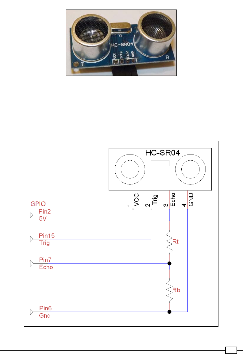
Chapter 9
407
The HC-SR04 ultrasonic sensor module
The sensor requires 5V to power it; it has an input that will receive the trigger pulse and an
output that the echo pulse will be sent on. While the module works with a 3.3V trigger pulse,
it responds with a 5V signal on the echo line; so, it requires some extra resistors to protect the
Raspberry Pi's GPIO.
The following circuit diagram shows the connection of the sensor output:
The sensor echo output must be connected to the Raspberry Pi via a potential divider

Building Robots
408
The resistors Rt and Rb create a potential divider; the aim is to drop the echo voltage from 5V
to around 3V (but not less than 2.5V). Use the following equation from Chapter 7, Sense and
Display Real-world Data, to obtain the output voltage:
The output voltage (Vout) of the potential divider is calculated using this equation
This means that we should aim for an Rt to Rb ratio of 2:3 to give 3V (and not lower than 1:1,
which would give 2.5V); that is, Rt equals 2K ohm and Rb equals 3K ohm, or 330 ohm and
470 ohm will be ne.
If you have a voltage meter, you can check it (with everything else disconnected). Connect the
top of the potential divider to GPIO Pin 2 (5V), the bottom to GPIO Pin 6 (GND), and measure
the voltage from the middle (it should be around 3V).
Create the following sonic.py script:
#!/usr/bin/python3
#sonic.py
import wiringpi2
import time
import datetime
ON=1;OFF=0; IN=0;OUT=1
TRIGGER=15; ECHO=7
PULSE=0.00001 #10us pulse
SPEEDOFSOUND=34029 #34029 cm/s
def gpiosetup():
wiringpi2.wiringPiSetupPhys()
wiringpi2.pinMode(TRIGGER,OUT)
wiringpi2.pinMode(ECHO,IN)
wiringpi2.digitalWrite(TRIGGER,OFF)
time.sleep(0.5)
def pulse():
wiringpi2.digitalWrite(TRIGGER,ON)
time.sleep(PULSE)
wiringpi2.digitalWrite(TRIGGER,OFF)
starttime=time.time()
stop=starttime

Chapter 9
409
start=starttime
while wiringpi2.digitalRead(ECHO)==0 and start<starttime+2:
start=time.time()
while wiringpi2.digitalRead(ECHO)==1 and stop<starttime+2:
stop=time.time()
delta=stop-start
print("Start:%f Stop:%f Delta:%f"%(start,stop,delta))
distance=delta*SPEEDOFSOUND
return distance/2.0
def main():
global run
gpiosetup()
while(True):
print("Sample")
print("Distance:%.1f"%pulse())
time.sleep(2)
if __name__ == '__main__':
try:
main()
except KeyboardInterrupt:
print ("Finish")
#End
First, we dene the pins TRIGGER and ECHO, the length of the trigger pulse, and also the
speed of sound (340.29 m/s). The TRIGGER pin is set as an output and the ECHO as an input
(we will not need a pull-up or pull-down resistor since the module already has one).
The pulse() function will send a short trigger pulse (10 microseconds); then it will time
the duration of the echo pulse. We then calculate the total distance travelled by dividing the
duration by the speed of sound (the distance to the object is just half of this value).
Unfortunately, the sensor can get confused with certain types of objects; it will either detect
echoes that bounce off a nearby object before being reected back or not pick up narrow
items such as chair legs. However, combined with localized collision sensors, the ultrasonic
sensor can aid with the general navigation and avoidance of the larger objects.
An improvement to this setup would be to mount the sonic sensor on top of a servo, thereby
allowing you to make a sensor sweep of the robot's surroundings. By making multiple sweeps,
taking distance measurements, and tracking the angle of the servo, you could build an
internal map of the robot's surroundings.
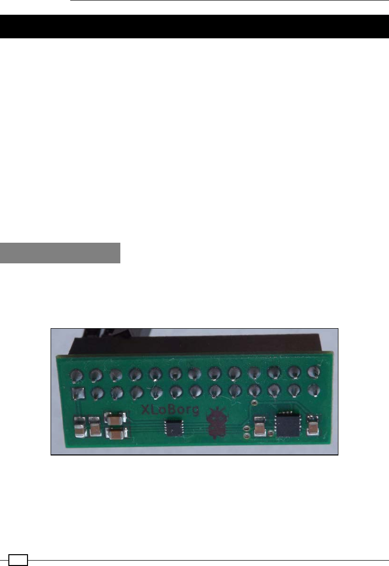
Building Robots
410
Getting a sense of direction
In order to navigate your robot around the environment, you will need to keep track of which
way your robot is facing. You can estimate the angle that your robot turns at by measuring the
angle that it turned at in a xed time period. For wheeled robots, you can also measure the
rotation of each wheel using a rotary encoder (a device that provides a count of the wheel's
rotations). However, as you make the robot take multiple turns, the direction the robot is
facing becomes more and more uncertain as differences in the surfaces and the grip of the
wheels or legs cause differences in the angles that the robot is turning at.
Fortunately, we can use an electronic version of a compass; it allows us to determine the
direction that the robot is facing by providing an angle from magnetic North. If we know
which direction the robot is facing, we can receive commands requesting a particular angle
and ensure that the robot moves towards it. This allows the robot to perform controlled
movements and navigate as required.
When given a target angle, we can determine which direction we need to turn towards, until
we reach it.
Getting ready
You need a magnetometer device such as the PiBorg's XLoBorg module (which is a
combined I2C magnetometer and accelerometer). In this example, we focus on the
magnetometer (the smaller chip on the left) output only. The XLoBorg module looks
as shown in the following image:
The PiBorg XLoBorg module contains a 3-axis magnetometer and accelerometer
This device can be used with both types of robot, and the angle information received from the
module can be used to determine which direction the robot needs to move in.
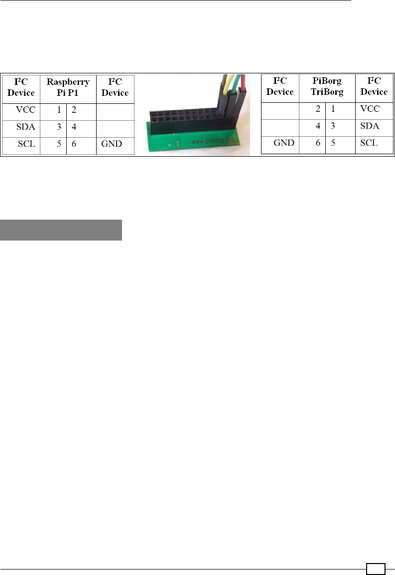
Chapter 9
411
The module is designed to connect directly to the GPIO header, which will block all the
remaining pins. So in order to use other GPIO devices, a GPIO splitter (such as the PiBorg
TriBorg) can be used. Alternatively, you can use Dupont female to male patch wires to connect
just the I2C pins. The connections to be made are shown in the following diagram:
Connections to manually wire the XLoBorg module to the Raspberry Pi (using standard I2C connections)
When viewed from the underside, the PiBorg XLoBorg pins are mirrored compared to the
Raspberry Pi GPIO header.
How to do it…
Create a Python 3-friendly version of the XLoBorg library (XLoBorg3.py) using wiringpi2
as follows:
#!/usr/bin/env python3
#XLoBorg3.py
import wiringpi2
import struct
import time
def readBlockData(bus,device,register,words):
magData=[]
for i in range(words):
magData.append(bus.readReg16(device,register+i))
return magData
class compass:
def __init__(self):
addr = 0x0E #compass
self.i2c = wiringpi2.I2C()
self.devMAG=self.i2c.setup(addr)
self.initCompass()
def initCompass(self):
# Acquisition mode

Building Robots
412
register = 0x11 # CTRL_REG2
data = (1 << 7) # Reset before each acquisition
data |= (1 << 5) # Raw mode, do not apply user offsets
data |= (0 << 5) # Disable reset cycle
self.i2c.writeReg8(self.devMAG,register,data)
# System operation
register = 0x10 # CTRL_REG1
data = (0 << 5) # Output data rate
# (10 Hz when paired with 128 oversample)
data |= (3 << 3) # Oversample of 128
data |= (0 << 2) # Disable fast read
data |= (0 << 1) # Continuous measurement
data |= (1 << 0) # Active mode
self.i2c.writeReg8(self.devMAG,register,data)
def readCompassRaw(self):
#x, y, z = readCompassRaw()
self.i2c.write(self.devMAG,0x00)
[status, xh, xl, yh, yl,
zh, zl, who, sm, oxh, oxl,
oyh, oyl, ozh, ozl,
temp, c1, c2] = readBlockData(self.i2c,self.devMAG, 0, 18)
# Convert from unsigned to correctly signed values
bytes = struct.pack('BBBBBB', xl, xh, yl, yh, zl, zh)
x, y, z = struct.unpack('hhh', bytes)
return x, y, z
if __name__ == '__main__':
myCompass=compass()
try:
while True:
# Read the MAG Data
mx, my, mz = myCompass.readCompassRaw()
print ("mX = %+06d, mY = %+06d, mZ = %+06d" % (mx, my, mz))
time.sleep(0.1)
except KeyboardInterrupt:
print("Finished")
#End

Chapter 9
413
How it works…
The script is based on the XLoBorg library available for the XLoBorg module, except that we
use WiringPi2, which is Python 3-friendly, to perform the I2C actions. Just like our motor/servo
drivers, we also dene it as a class so that we can drop it into our code and easily replace it
with alternative devices if required.
We import wiringpi2, time, and also a library called struct (which allows us to quickly
unpack a block of data read from the device into separate items).
We create the compass class, which will include the __init__(), initCompass(), and
readCompassRaw() functions. The readCompassRaw() function is the equivalent of the
standard XLoBorg ReadCompassRaw() function provided by their library.
The __init__() function sets up the I2C bus with wiringpi2 and registers the degMAG
device on the bus address 0x0E. The initCompass() function sets the CTRL_REG1 and
CTRL_REG2 registers of the device with the settings required to quickly get raw readings from
the device.
More details on the MAG3110 registers are available at http://www.freescale.com/
files/sensors/doc/data_sheet/MAG3110.pdf.
The readCompassRaw() function reads the data registers of the device in a single block
(using the custom function readBlockData()). It reads all the 18 registers of the device
(0x00 through to 0x11). The sensor readings we need are contained within the registers
0x01 to 0x06, which contain the x, y, and z readings split into upper and lower bytes (8-bit
values). The struct.pack() and struct.unpack() functions provide an easy way to
package them together and resplit them as separate words (16-bit values).
We can test our script by creating a myCompass object from the compass class and reading
the sensor values using myCompass.readCompassRaw(). You will see the raw x, y, and z
values from the device, just as you would from the standard XLoBorg library.
As you will nd, these values aren't much use on their own since they are uncalibrated
and only give you RAW readings from the magnetometer. What we need is a far more useful
angle relative to magnetic North (see the following There's more… section for details on how
to do this).
There's more…
So far, the basic library allows us to see the strength of the magnetic eld on each of the three
axes around the sensor (up/down, left/right, and forward/backward). While we can see that
these values will change as we move the sensor around, this is not enough to steer our robot.
First, we need to calibrate the sensor and then determine the direction of the robot from the
readings of the x and y axes.

Building Robots
414
Calibrating the compass
The compass needs to be calibrated in order to report values that are centered and equalized.
This is needed because there are magnetic elds all around, so by calibrating the sensor, we
can cancel out the effect of any localized elds.
By measuring the readings of the compass on all axes, we can determine the minimum
and maximum values for each axis. This will allow us to calculate both the midpoint of the
readings and also the scaling so that each axis will read the same value whenever it is facing
the same way.
Add the following code at the top of the le (after the import statements):
CAL=100 #take CAL samples
Add the following code to __init__(self) of the compass class:
self.offset,self.scaling=self.calibrateCompass()
if DEBUG:print("offset:%s scaling:%s"%(str(self.offset),
str(self.scaling)))
Add a new function named calibrateCompass() within the compass class as follows:
def calibrateCompass(self,samples=CAL):
MAXS16=32768
SCALE=1000.0
avg=[0,0,0]
min=[MAXS16,MAXS16,MAXS16];max=[-MAXS16,-MAXS16,-MAXS16]
print("Rotate sensor around axis (start in 5 sec)")
time.sleep(5)
for calibrate in range(samples):
for idx,value in enumerate(self.readCompassRaw()):
avg[idx]+=value
avg[idx]/=2
if(value>max[idx]):
max[idx]=value
if(value<min[idx]):
min[idx]=value
time.sleep(0.1)
if DEBUG:print("#%d min=[%+06d,%+06d,%+06d]"
%(calibrate,min[0],min[1],min[2])
+" avg[%+06d,%+06d,%+06d]"
%(avg[0],avg[1],avg[2])
+" max=[%+06d,%+06d,%+06d]"
%(max[0],max[1],max[2]))
offset=[]
scaling=[]
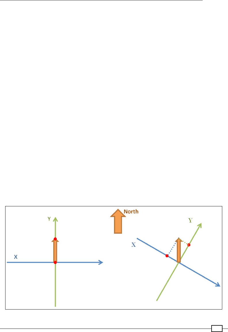
Chapter 9
415
for idx, value in enumerate(min):
magRange=max[idx]-min[idx]
offset.append((magRange/2)+min[idx])
scaling.append(SCALE/magRange)
return offset,scaling
Add another new function named readCompass() in the compass class as follows:
def readCompass(self):
raw = self.readCompassRaw()
if DEBUG:print("mX = %+06d, mY = %+06d, mZ = %+06d"
% (raw[0],raw[1],raw[2]))
read=[]
for idx,value in enumerate(raw):
adj=value-self.offset[idx]
read.append(adj*self.scaling[idx])
return read
If you look closely at the readings (if you use readCompass()), you will now nd that all the
readings have the same range and are centered around the same values.
Calculating the compass bearing
The XLoBorg library only provides access to the RAW values of the MAG3110 device, which
provides a measure of how strong the magnetic eld is on each of the axes. To determine
the direction of the sensor, we can use the readings from the x and y axes (assuming we
have mounted and calibrated the sensor horizontally). The readings of the x and y axes
are proportional to the magnetic eld in each direction around the sensor, as shown in the
following diagram:
The magnetometer measures the strength of the magnetic field on each axis

Building Robots
416
The angle at which we turned away from the north can be calculated with the formula shown
in the following diagram:
The angle we are pointing towards that is relative to magnetic North
can be calculated using the measurements Rx and Ry
We can now obtain the compass angle by adding the following readCompassAngle()
function to our compass class, as follows:
def readCompassAngle(self,cal=True):
if cal==True:
read = self.readCompass()
else:
read = self.readCompassRaw()
angle = math.atan2 (read[1],read[0]) # cal angle in radians
if (angle < 0):
angle += (2 * math.pi) # ensure positive
angle = (angle * 360)/(2*math.pi); #report in degrees
return angle
We also need to add the following import with the other import statements:
import math
We use the math function, math.atan2(), to calculate our angle (atan2 will return with the
angle relative to the x axis of the coordinates read[1] and read[2]—the angle we want).
The angle is in radians, which means one full turn is dened as 2Pi rather than 360 degrees.
We convert it back to degrees by multiplying it by 360 and dividing by 2Pi. Since we wish to
have our angle between the range of 0 to 360 degrees (rather than -180 to 180 degrees),
we must ensure that it is positive by adding the equivalent of a full circle (2Pi) to any negative
values.

Chapter 9
417
With the sensor calibrated and the angle calculated, we should now have proper compass
bearing to use on our robot. To compare, you can see the result of using the uncalibrated
value in our calculation by calling the function with readCompassAngle (cal=False).
Saving the calibration
Having calibrated the sensor once in its current position, it would be inconvenient to have
to calibrate it each and every time that you run the robot. Therefore, you can add the
following code to your library to automatically save your calibration and read it from a le
the next time you run your robot. To create a new calibration, either delete or rename mag.
cal (which is created in the same folder as your script) or create your compass object with
compass(newCal=True).
Add the following code near the top of the le (after the imports statements):
FILENAME="mag.cal"
Change __init__(self) to __init__(self,newCal=False).
Also, consider the following line:
self.offset,self.scaling=self.calibrateCompass()
Change the previous line to the following line:
self.offset,self.scaling=self.readCal(newCal)
Add readCal() to the compass class as follows:
def readCal(self,newCal=False,filename=FILENAME):
if newCal==False:
try:
with open(FILENAME,'r') as magCalFile:
line=magCalFile.readline()
offset=line.split()
line=magCalFile.readline()
scaling=line.split()
if len(offset)==0 or len(scaling)==0:
raise ValueError()
else:
offset=list(map(float, offset))
scaling=list(map(float, scaling))
except (OSError,IOError,TypeError,ValueError) as e:
print("No Cal Data")
newCal=True
pass
if newCal==True:

Building Robots
418
print("Perform New Calibration")
offset,scaling=self.calibrateCompass()
self.writeCal(offset,scaling)
return offset,scaling
Add writeCal() to the compass class as follows:
def writeCal(self,offset,scaling):
if DEBUG:print("Write Calibration")
if DEBUG:print("offset:"+str(offset))
if DEBUG:print("scaling:"+str(scaling))
with open(FILENAME,'w') as magCalFile:
for value in offset:
magCalFile.write(str(value)+" ")
magCalFile.write("\n")
for value in scaling:
magCalFile.write(str(value)+" ")
magCalFile.write("\n")
Driving the robot using the compass
All that remains for us to do now is to use the compass bearing to steer our robot to the
desired angle.
Create the following compassDrive.py script:
#!/usr/bin/env python3
#compassDrive.py
import XLoBorg3 as XLoBorg
import rover_drive as drive
import time
MARGIN=10 #turn until within 10degs
LEFT="l"; RIGHT="r"; DONE="#"
def calDir(target, current, margin=MARGIN):
target=target%360
current=current%360
delta=(target-current)%360
print("Target=%f Current=%f Delta=%f"%(target,current,delta))
if delta <= margin:

Chapter 9
419
CMD=DONE
else:
if delta>180:
CMD=LEFT
else:
CMD=RIGHT
return CMD
def main():
myCompass=XLoBorg.compass()
myBot=drive.motor()
while(True):
print("Enter target angle:")
ANGLE=input()
try:
angleTarget=float(ANGLE)
CMD=LEFT
while (CMD!=DONE):
angleCompass=myCompass.readCompassAngle()
CMD=calDir(angleTarget,angleCompass)
print("CMD: %s"%CMD)
time.sleep(1)
myBot.cmd(CMD)
print("Angle Reached!")
except ValueError:
print("Enter valid angle!")
pass
if __name__ == '__main__':
try:
main()
except KeyboardInterrupt:
print ("Finish")
#End

Building Robots
420
We import the modules that we previously created: XLoBorg3, rover_drive (for the Rover-
Pi robot or the alternative bug_drive, as required), and time. Next, we create a function that
will return LEFT, RIGHT, or DONE based on the given target angle (requested by the user) and
the current angle (read from the compass class). If the compass angle is within 180 degrees
less than the target angle, then we turn LEFT. Similarly, if it is within 180 degrees, we turn
RIGHT. Finally, if the compass angle is within the margin (+10 degrees/-10 degrees), then
we are DONE. By using angle%360 (which gives us the remainder from dividing the angle by
360), we ensure the angles are all 0-360 (that is, -90 becomes 270).
For the main() function, we create myCompass (an XLoBorg.compass object) and myBot
(a drive.motor() object); these allow us to determine the direction we are facing in and
provide us with a way to drive in the desired direction. Within the main loop, we prompt for
a target angle, nd the current angle that our robot is facing at, and then continue to turn
towards the required angle until we reach it (or reach somewhere near enough).

421
10
Interfacing with
Technology
In this chapter, we will cover the following topics:
fAutomating your home with remote sockets
fUsing SPI to control an LED matrix
fCommunicating using a serial interface
fControlling the Raspberry Pi over Bluetooth
fControlling USB devices
Introduction
One of the key aspects of the Raspberry Pi that differentiates it from an average computer
is its ability to interface with and control hardware. In this chapter, we use the Raspberry
Pi to control remotely activated mains sockets, send commands over serial connections
from another computer, and control the GPIO remotely. We make use of SPI (another useful
protocol) to drive an 8 x 8 LED matrix display.
We also use a Bluetooth module to connect with a smartphone, allowing information to be
transferred wirelessly between devices. Finally, we take control of USB devices by tapping into
the commands sent over USB.
Be sure to check out the Hardware list section in the Appendix, Hardware and
Software List; it lists all the items used in this chapter and the places you can
obtain them from.
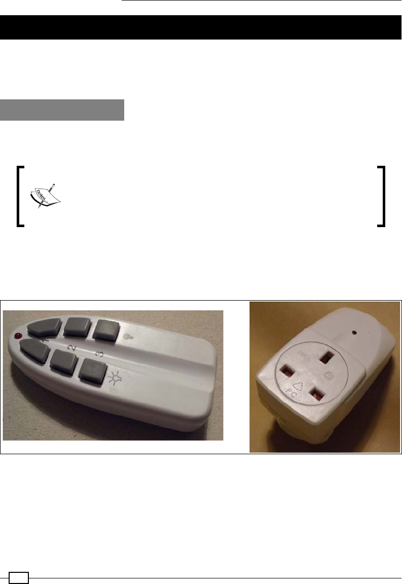
Interfacing with Technology
422
Automating your home with remote sockets
The Raspberry Pi can make an excellent tool for home automation by providing accurate
timing, control, and the ability to respond to commands, button inputs, environmental
sensors, or messages from the Internet.
Getting ready
Great care must be taken when controlling devices that use electricity from the mains since
high voltages and currents are often involved.
Never attempt to modify or alter devices that are connected to mains
electricity without proper training. You must never directly connect any
homemade devices to the mains supply. All electronics must undergo
rigorous safety testing to ensure that there will be no risk or harm to
people or property in the event of a failure.
In this example, we will use remote controlled radio frequency (RF) plug-in sockets; these
use a separate remote unit to send a specic RF signal to switch any electrical device that is
plugged into it on or off. This allows us to modify the remote control and use the Raspberry Pi
to activate the switches safely, without interfering with dangerous voltages:
Remote control and remote mains socket
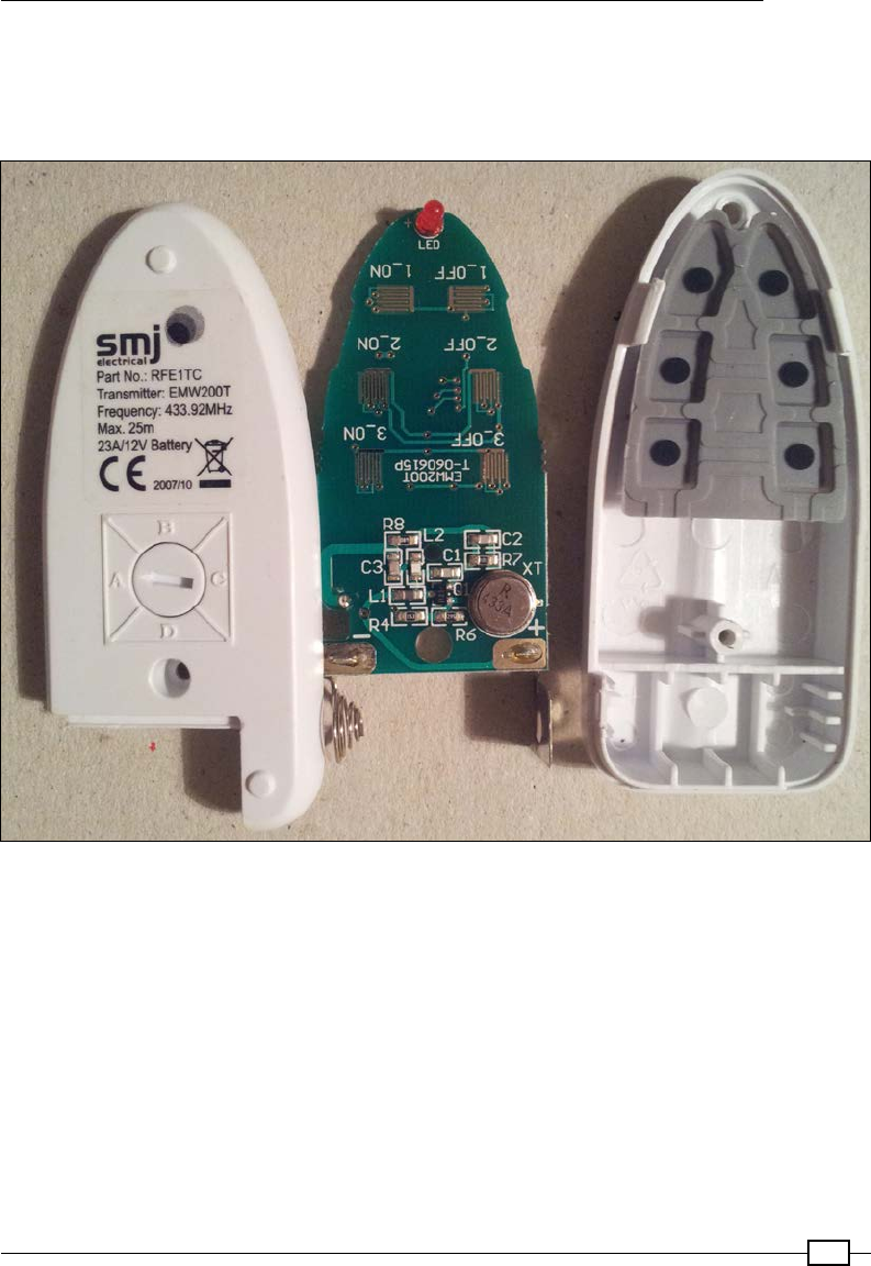
Chapter 10
423
The particular remote control used in this example has six buttons on it to directly switch
three different sockets on or off and is powered by a 12V battery. It can be switched into four
different channels, which would allow you to control a total of 12 sockets (each socket has a
similar selector that will be used to set the signal it will respond to).
Inside the remote control
The remote buttons, when pressed, will broadcast a specic RF signal (this one uses a
transmission frequency of 433.92 MHz). This will trigger any socket(s) that is set to the
corresponding channel (A, B, C, or D) and number (1, 2, or 3).
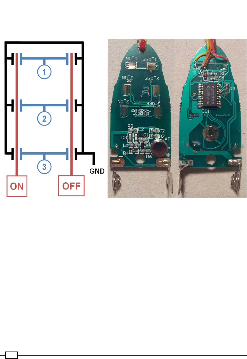
Interfacing with Technology
424
Internally, each of the buttons connects two separate signals to ground, the number (1, 2,
or 3), and state (on or off). This triggers the correct broadcast that is to be made by the
remote control.
Connect the wires to ON, OFF, 1, 2, 3, and GND at suitable points on the remote's PCB (only ON, OFF, 1,
and GND are connected in the image)
It is recommended that you do not connect anything to your sockets that could cause a
hazard if switched on or off. The signals sent by the remote are not unique (there are only
four different channels available). This therefore makes it possible for someone else nearby
who has a similar set of sockets to unknowingly activate/deactivate one of your sockets. It is
recommended that you select a channel other than the default, A, which will slightly reduce
the chance of someone else accidentally using the same channel.
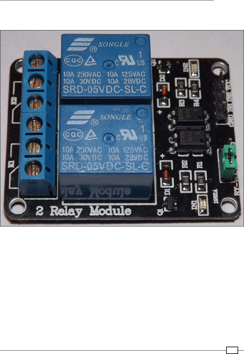
Chapter 10
425
To allow the Raspberry Pi to simulate the button presses of the remote, we will need ve
relays to allow us to select the number (1, 2, or 3) and state (on or off).
A prebuilt Relay Module can be used to switch the signals
Alternatively, the transistor and relay circuit from Chapter 9, Building Robots, can be used to
simulate the button presses.

Interfacing with Technology
426
Wire the relay control pins to the Raspberry Pi GPIO and connect the socket remote control to
each relay output as follows:
The socket remote control circuit
Although the remote socket requires both the number (1, 2, or 3)
and the state (on or off) to activate a socket, it is the state signal that
activates the RF transmission. To avoid draining the remote's battery,
we must ensure that we have turned off the state signal.
How to do it...
Create the following socketControl.py script:
#!/usr/bin/python3
# socketControl.py
import time
import RPi.GPIO as GPIO
#HARDWARE SETUP

Chapter 10
427
# P1
# 2[V=G====XI====]26[=======]40
# 1[=====321=====]25[=======]39
#V=5V G=Gnd
sw_num=[15,13,11]#Pins for Switch 1,2,3
sw_state=[16,18]#Pins for State X=Off,I=On
MSGOFF=0; MSGON=1
SW_ACTIVE=0; SW_INACTIVE=1
class Switch():
def __init__(self):
self.setup()
def __enter__(self):
return self
def setup(self):
print("Do init")
#Setup the wiring
GPIO.setmode(GPIO.BOARD)
for pin in sw_num:
GPIO.setup(pin,GPIO.OUT)
for pin in sw_state:
GPIO.setup(pin,GPIO.OUT)
self.clear()
def message(self,number,state):
print ("SEND SW_CMD: %s %d" % (number,state))
if state==MSGON:
self.on(number)
else:
self.off(number)
def on(self,number):
print ("ON: %d"% number)
GPIO.output(sw_num[number-1],SW_ACTIVE)
GPIO.output(sw_state[MSGON],SW_ACTIVE)
GPIO.output(sw_state[MSGOFF],SW_INACTIVE)
time.sleep(0.5)
self.clear()
def off(self,number):
print ("OFF: %d"% number)
GPIO.output(sw_num[number-1],SW_ACTIVE)
GPIO.output(sw_state[MSGON],SW_INACTIVE)
GPIO.output(sw_state[MSGOFF],SW_ACTIVE)
time.sleep(0.5)
self.clear()
def clear(self):
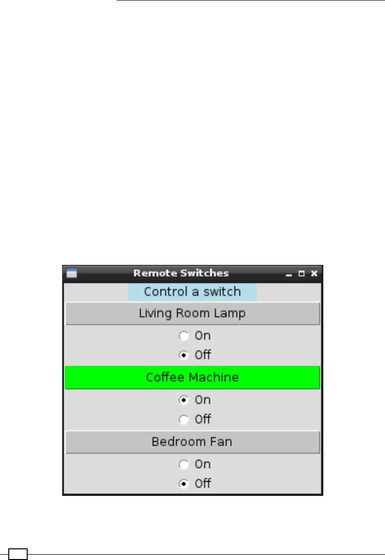
Interfacing with Technology
428
for pin in sw_num:
GPIO.output(pin,SW_INACTIVE)
for pin in sw_state:
GPIO.output(pin,SW_INACTIVE)
def __exit__(self, type, value, traceback):
self.clear()
GPIO.cleanup()
def main():
with Switch() as mySwitches:
mySwitches.on(1)
time.sleep(5)
mySwitches.off(1)
if __name__ == "__main__":
main()
#End
The socket control script performs a quick test by switching the rst socket on for 5 seconds
and then turning it off again.
To control the rest of the sockets, create a GUI menu as follows:
Remote Switches GUI

Chapter 10
429
Create the following socketMenu.py script:
#!/usr/bin/python3
#socketMenu.py
import tkinter as TK
import socketControl as SC
#Define Switches ["Switch name","Switch number"]
switch1 = ["Living Room Lamp",1]
switch2 = ["Coffee Machine",2]
switch3 = ["Bedroom Fan",3]
sw_list = [switch1,switch2,switch3]
SW_NAME = 0; SW_CMD = 1
SW_COLOR=["gray","green"]
class swButtons:
def __init__(self,gui,sw_index,switchCtrl):
#Add the buttons to window
self.msgType=TK.IntVar()
self.msgType.set(SC.MSGOFF)
self.btn = TK.Button(gui,
text=sw_list[sw_index][SW_NAME],
width=30, command=self.sendMsg,
bg=SW_COLOR[self.msgType.get()])
self.btn.pack()
msgOn = TK.Radiobutton(gui,text="On",
variable=self.msgType, value=SC.MSGON)
msgOn.pack()
msgOff = TK.Radiobutton(gui,text="Off",
variable=self.msgType,value=SC.MSGOFF)
msgOff.pack()
self.sw_num=sw_list[sw_index][SW_CMD]
self.sw_ctrl=switchCtrl
def sendMsg(self):
print ("SW_CMD: %s %d" % (self.sw_num,
self.msgType.get()))
self.btn.configure(bg=SW_COLOR[self.msgType.get()])
self.sw_ctrl.message(self.sw_num,
self.msgType.get())
root = TK.Tk()
root.title("Remote Switches")
prompt = "Control a switch"

Interfacing with Technology
430
label1 = TK.Label(root, text=prompt, width=len(prompt),
justify=TK.CENTER, bg='lightblue')
label1.pack()
#Create the switch
with SC.Switch() as mySwitches:
#Create menu buttons from sw_list
for index, app in enumerate(sw_list):
swButtons(root,index,mySwitches)
root.mainloop()
#End
How it works...
The rst script denes a class called Switch; it sets up the GPIO pins required to control
the ve relays (within the setup function). It also denes the __enter__ and __exit__
functions, which are special functions used by the with..as statement. When a class is
created using with..as, it uses __enter__ to perform any extra initialization or setup (if
required), and then it performs any cleanup by calling __exit__. When the Switch class
has been executed, all the relays are switched off to preserve the remote's battery and GPIO.
cleanup() is called to release the GPIO pins. The parameters of the __exit__ function
(type, value, and traceback) allow the handling of any specic exceptions that may have
occurred when the class was being executed within the with..as statement (if required).
To control the sockets, create two functions that will switch the relevant relays on or off to
activate the remote control to send the required signal to the sockets. Then, shortly after, turn
the relays off again using clear(). To make controlling the switches even easier, create a
message function that will allow a switch number and state to be specied.
We make use of the socketControl.py script by creating a Tkinter GUI menu. The menu
is made up of three sets of controls (one for each of the switches) that are dened by the
swButtons class.
The swButtons class creates a Tkinter button and two Radiobutton controls. Each
swButtons object is given an index and a reference to the mySwitches object. This allows
us to set a name for the button and control a particular switch when it is pressed. The socket
is activated/deactivated by calling message(), with the required switch number and state set
by the Radiobutton controls.
There's more...
The previous example allows you to rewire the remotes of most remote controlled sockets, but
another option is to emulate the signals to control it directly.
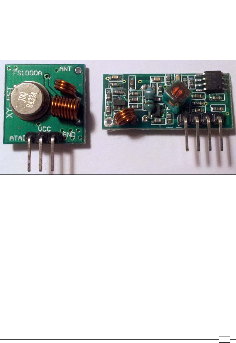
Chapter 10
431
Sending RF control signals directly
Instead of rewiring the remote control, you can replicate the remote's RF signals using
a transmitter that uses the same frequency as your sockets (these particular units use
433.94 MHz). This will depend on the particular sockets and sometimes your location—some
countries prohibit the use of certain frequencies—as you may require certication before
making your own transmissions:
The 433.94 MHz RF transmitter (left) and receiver (right)
The signals sent by the RF remote control can be recreated using 433Utils created by
http://ninjablocks.com. The 433Utils uses WiringPi and are written in C++, allowing
high speed capture and replication of the RF signals.
Obtain the code using the following command:
cd ~
wget https://github.com/ninjablocks/433Utils/archive/master.zip
unzip master.zip
Next, we need to wire up our RF transmitter (so we can control the switches) and RF receiver
(so we can determine the control codes) to the Raspberry Pi.
The transmitter (the smaller square module) has three pins, which are power (VCC),
ground (GND), and data out (ATAD). The voltage supplied on the power pin will govern the
transmission range (we will use 5V supply from the Raspberry Pi, but you could replace this
with 12V, as long as you ensure you connect the ground pin to both your 12V supply and the
Raspberry Pi).

Interfacing with Technology
432
Although the receiver has four pins, there is a power pin (VCC), ground pin (GND), and two
data out pins (DATA), which are wired together, so we only need to connect three wires to the
Raspberry Pi.
RF Tx RPi GPIO pin RF Rx RPi GPIO pin
VCC (5V) 2 VCC (3V3) 1
Data out 11 Data in 13
GND 6 GND 9
Before we use the programs within the RPi_Utils, we will make a few adjustments to
ensure our RX and TX pins are set correctly.
Locate codesend.cpp in 433Utils-master/RPi_utils/ to make the required changes:
cd ~/433Utils-master/RPi_utils
nano codesend.cpp -c
Change int PIN = 0; (located at around line 24) to int PIN = 11; (RPi physical
pin number).
Change wiringPi to use physical pin numbering (located around line 27) by replacing
wiringPiSetup() with wiringPiSetupPhy(). Otherwise, the default is WiringPi GPIO
numbers; for more details, see http://wiringpi.com/reference/setup/. Find the
following line:
if (wiringPiSetup () == -1) return 1;
Change it to this:
if (wiringPiSetupPhys () == -1) return 1;
Save and exit nano using Ctrl + X, Y.
Make similar adjustments to RFSniffer.cpp:
nano RFSniffer.cpp -c
Find the following line (located at around line 25):
int PIN = 2;
Change it to this:
int PIN = 13; //RPi physical pin number
Find the following line (located at around line 27:
if(wiringPiSetup() == -1) {

Chapter 10
433
Change it to this:
if(wiringPiSetupPhys() == -1) {
Save and exit nano using Ctrl + X, Y.
Build the code using the following command:
make all
This should build without errors, as shown here:
g++ -c -o codesend.o codesend.cpp
g++ RCSwitch.o codesend.o -o codesend -lwiringPi
g++ -c -o RFSniffer.o RFSniffer.cpp
g++ RCSwitch.o RFSniffer.o -o RFSniffer -lwiringPi
Now that we have our RF modules connected to the Raspberry Pi and our code ready, we can
capture the control signals from our remote. Run the following command and take note of the
reported output:
sudo ./RFSniffer
Get the output by pressing Button 1 OFF with the remote set to channel A (note we may get a
few that pick up random noise):
Received 1381716
Received 1381716
Received 1381716
Received 1381717
Received 1398103
We can now send out the signals using the sendcode command to switch the sockets OFF
(1381716) and ON (1381719):
sendcode 1381716
sendcode 1381719
You could even set up the Raspberry Pi to use the receiver module to detect signals from the
remote (on an unused channel) and act upon them to start processes, control other hardware,
or perhaps trigger a software shutdown/reboot.
Extending the range of the RF Transmitter
The range of the transmitter is very limited when it is powered by 5V and without an additional
antenna. However, it is worth testing everything before you make any modications.

Interfacing with Technology
434
Simple wire antenna can be made from 25 cm of single core wire, 17 mm side connected to
the antenna solder point, then 16 turns (made using a thin screwdriver shaft or similar) and
the remaining wire on top (approximately 53 mm). This is described in more detail at .
The transmitter range is vastly improved with a simple antenna
Determining the structure of the remote control codes
Recording the codes this for each of the buttons, we can determine the codes for each (and
break down the structure):
1 2 3
ON OFF ON OFF ON OFF
A0x15 15 57
(1381719)
0x15 15 54
(1381716)
0x15 45 57
(1394007)
0x15 45 54
(1394004)
0x15 51 57
(1397079)
0x15 51 54
(1397076)
B0x45 15 57
(4527447)
0x45 15 54
(4527444)
0x45 45 57
(4539735)
0x45 45 54
(4539732)
0x45 51 57
(4542807)
0x45 51 54
(4542804)
C0x51 15 57
(5313879)
0x51 15 54
(5313876)
0x51 45 57
(5326167)
0x51 45 54
(5326164)
0x51 51 57
(5329239)
0x51 51 54
(5329236)
D0x54 15 57
(5510487)
0x54 15 57
(5510487)
0x54 45 57
(5522775)
0x54 45 54
(5522772)
0x54 51 57
(5525847)
0x54 51 54
(5526612)
A B C D 1 2 3 na na na na ON/OFF
01 01 01 01 01 01 01 01 01 01 01 11/00
The different codes are shown in hex format to help see the structure; the sendcode
command uses the decimal format (shown within the parentheses)
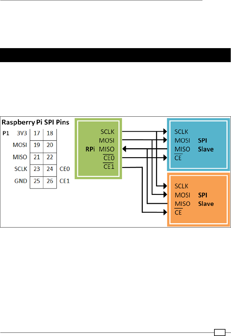
Chapter 10
435
To select channel A, B, C, or D, set the two bits to 00. Similarly, for button 1, 2, or 3, set the
two bits to 00 to select that button. Finally, set the last two bits to 11 for ON or 00 for OFF.
See https://arduinodiy.wordpress.com/2014/08/12/433-mhz-system-for-
your-arduino/, which analyses these and other similar RF remote controls.
Using SPI to control an LED matrix
In Chapter 7, Sense and Display Real-World Data, we connected to devices using a bus
protocol called I2C. The Raspberry Pi also supports another chip-to-chip protocol called SPI
(Serial Peripheral Interface). The SPI bus differs from I2C because it uses two single direction
data lines (where I2C uses one bidirectional data line). Although SPI requires more wires (I2C
uses two bus signals, SDA and SCL), it supports the simultaneous sending and receiving of
data and much higher clock speeds than I2C.
General connections of SPI devices with the Raspberry Pi
The SPI bus consists of the following four signals:
fSCLK: This provides the clock edges to read/write data on the input/output lines; it
is driven by the master device. As the clock signal changes from one state to another,
the SPI device will check the state of the MOSI signal to read a single bit. Similarly, if
the SPI device is sending data, it will use the clock signal edges to synchronize when
it sets the state of the MISO signal.
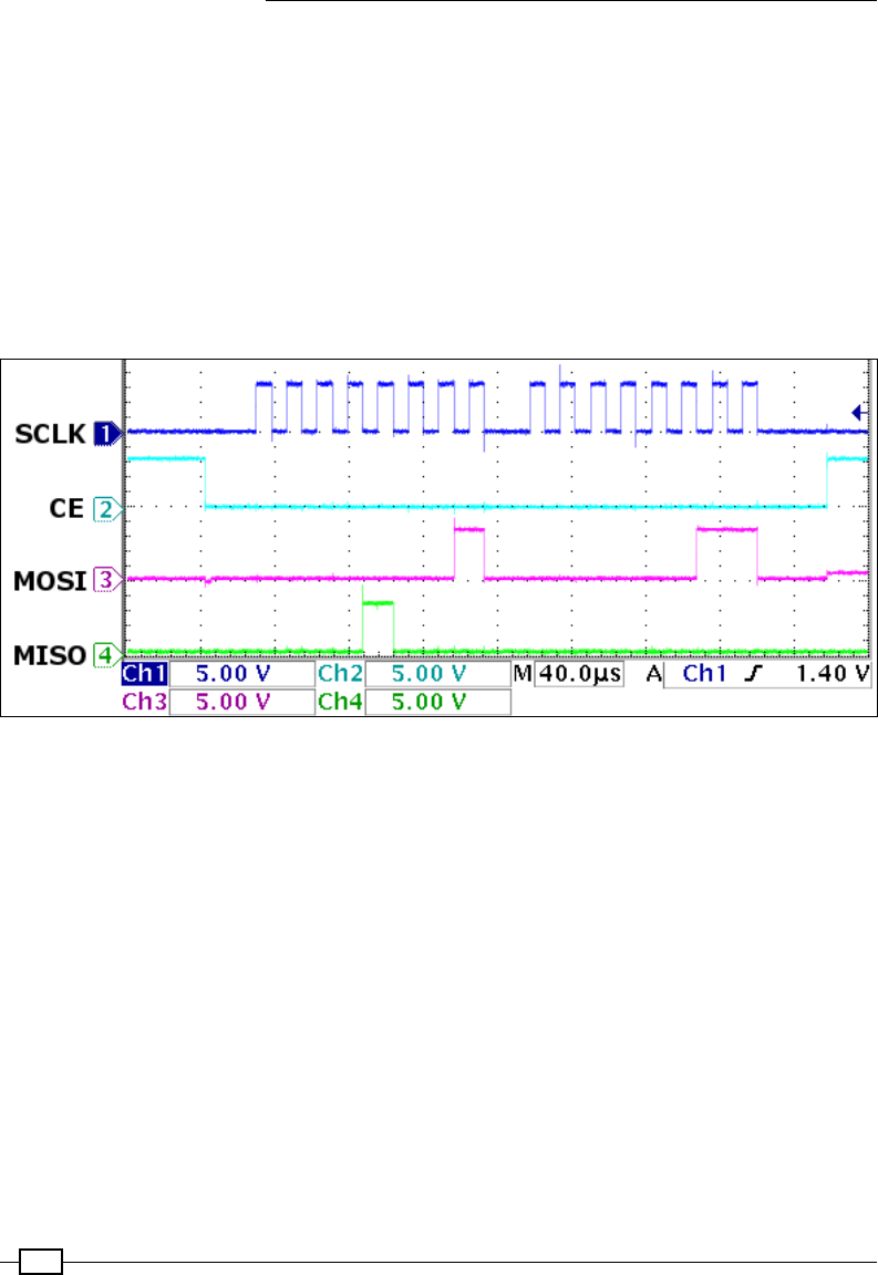
Interfacing with Technology
436
fCE: This refers to Chip Enable (typically, a separate Chip Enable is used for each slave
device on the bus). The master device will set the Chip Enable signal to low for the
device that it wants to communicate with. When the Chip Enable signal is set to high,
it ignores any other signals on the bus. This signal is sometimes called Chip Select
(CS) or Slave Select (SS).
fMOSI: This stands for Master Output, Slave Input (it connects to Data Out of the
master device and Data In of the slave device).
fMISO: This stands for Master Input, Slave Output (it provides a response from
the slave).
The following diagram shows each of the signals:
The SPI signals: SCLK (1), CE(2), MOSI(3), and MISO(4)
The previous scope trace shows two bytes being sent over SPI. Each byte is clocked into the
SPI device using the SCLK (1) signal. A byte is signied by a burst of eight clock cycles (a low
and then high period on the SCLK (1) signal), where the value of a specic bit is read when
the clock state changes. The exact sample point is determined by the clock mode; in the
following diagram, it is when the clock goes from low to high:
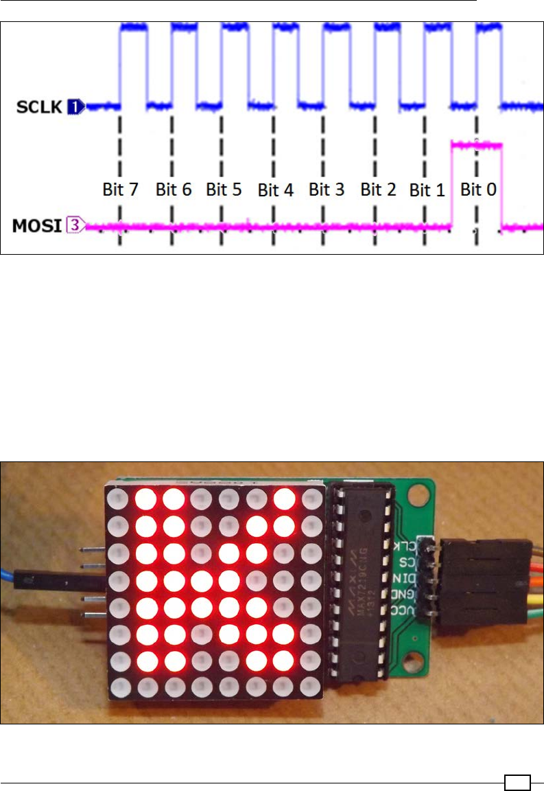
Chapter 10
437
The first data byte sent by the Raspberry Pi to the SPI device on the MOSI(3) signal
The rst byte sent is 0x01 (all the bits are low, except Bit 0) and the second sent is 0x03 (only
Bit 1 and Bit 0 are high). At the same time, the MOSI (4) signal returns data from the SPI
device—in this case, 0x08 (Bit 3 is high) and 0x00 (all the bits are low). The SCLK (1) signal is
used to sync everything, even the data being sent from the SPI device.
The CE (2) signal is held low while the data is being sent to instruct that particular SPI device
to listen to the MOSI (4) signal. When the CE (2) signal is set to high again, it indicates to the
SPI device that the transfer has been completed.
The following is an image of an 8 x 8 LED matrix that is controlled via the SPI Bus:
An 8 x 8 LED module displaying the letter K

Interfacing with Technology
438
Getting ready
The wiringPi library that we used previously for I2C also supports SPI. Ensure that wiringPi
is installed (see Chapter 7, Sense and Display Real-World Data, for details) so that we can use
it here.
Next, we need to enable SPI if we didn't do so when we enabled I2C previously:
sudo nano /boot/config.txt
Remove the # before #dtparam=spi=on to enable it, so it reads, and save (Ctrl + X, Y, Enter):
dtparam=spi=on
You can conrm that the SPI is active by listing all the running modules using the following
command and locating spi_bcm2835:
lsmod
You can test the SPI with the following spiTest.py script:
#!/usr/bin/python3
# spiTest.py
import wiringpi
print("Add SPI Loopback - connect GPIO Pin19 and Pin21")
print("[Press Enter to continue]")
input()
wiringpi.wiringPiSPISetup(1,500000)
buffer=str.encode("HELLO")
print("Buffer sent %s" % buffer)
wiringpi.wiringPiSPIDataRW(1,buffer)
print("Buffer received %s" % buffer)
print("Remove the SPI Loopback")
print("[Press Enter to continue]")
input()
buffer=str.encode("HELLO")
print("Buffer sent %s" % buffer)
wiringpi.wiringPiSPIDataRW(1,buffer)
print("Buffer received %s" % buffer)
#End
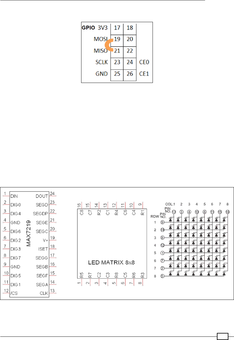
Chapter 10
439
Connect inputs 19 and 21 to create an SPI loopback for testing.
The SPI loopback test
You should get the following result:
Buffer sent b'HELLO'
Buffer received b'HELLO'
Remove the SPI Loopback
[Press Enter to continue]
Buffer sent b'HELLO'
Buffer received b'\x00\x00\x00\x00\x00'
The example that follows uses an LED 8 x 8 matrix display that is being driven by an
SPI-controlled MAX7219 LED driver:
An LED Controller MAX7219 pin-out, LED matrix pin-out, and LED matrix internal wiring (left to right)
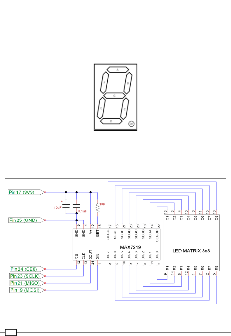
Interfacing with Technology
440
Although the device has been designed to control eight separate 7-segment LED digits,
we can use it for our LED matrix display. When used for digits, each of the seven segments
(plus a decimal place) is wired to one of the SEG pins, and the COM connection of each of
the digits is wired to the DIG pins. The controller then switches each of the segments on as
required, while setting the relevant digit COM low to enable it. The controller can quickly cycle
through each of the digits using the DIG pin fast enough that all eight appear to be lit at the
same time:
A 7-segment LED digit uses segments A to G, plus DP (decimal place)
We use the controller in a similar way, except each SEG pin will connect to a column in the
matrix and the DIG pins will enable/disable a row.
We use an 8 x 8 module connected to the MAX7219 chip as follows:
The MAX7219 LED controller driving an 8 x 8 LED matrix display

Chapter 10
441
How to do it…
To control an LED matrix connected to an SPI MAX7219 chip, create the following
matrixControl.py script:
#!/usr/bin/python3
# matrixControl.py
import wiringpi
import time
MAX7219_NOOP = 0x00
DIG0=0x01; DIG1=0x02; DIG2=0x03; DIG3=0x04
DIG4=0x05; DIG5=0x06; DIG6=0x07; DIG7=0x08
MAX7219_DIGIT=[DIG0,DIG1,DIG2,DIG3,DIG4,DIG5,DIG6,DIG7]
MAX7219_DECODEMODE = 0x09
MAX7219_INTENSITY = 0x0A
MAX7219_SCANLIMIT = 0x0B
MAX7219_SHUTDOWN = 0x0C
MAX7219_DISPLAYTEST = 0x0F
SPI_CS=1
SPI_SPEED=100000
class matrix():
def __init__(self,DEBUG=False):
self.DEBUG=DEBUG
wiringpi.wiringPiSPISetup(SPI_CS,SPI_SPEED)
self.sendCmd(MAX7219_SCANLIMIT, 8) # enable outputs
self.sendCmd(MAX7219_DECODEMODE, 0) # no digit decode
self.sendCmd(MAX7219_DISPLAYTEST, 0) # display test off
self.clear()
self.brightness(7) # brightness 0-15
self.sendCmd(MAX7219_SHUTDOWN, 1) # start display
def sendCmd(self, register, data):
buffer=(register<<8)+data
buffer=buffer.to_bytes(2, byteorder='big')
if self.DEBUG:print("Send byte: 0x%04x"%
int.from_bytes(buffer,'big'))
wiringpi.wiringPiSPIDataRW(SPI_CS,buffer)
if self.DEBUG:print("Response: 0x%04x"%
int.from_bytes(buffer,'big'))
return buffer
def clear(self):
if self.DEBUG:print("Clear")

Interfacing with Technology
442
for row in MAX7219_DIGIT:
self.sendCmd(row + 1, 0)
def brightness(self,intensity):
self.sendCmd(MAX7219_INTENSITY, intensity % 16)
def letterK(matrix):
print("K")
K=(0x0066763e1e366646).to_bytes(8, byteorder='big')
for idx,value in enumerate(K):
matrix.sendCmd(idx+1,value)
def main():
myMatrix=matrix(DEBUG=True)
letterK(myMatrix)
while(1):
time.sleep(5)
myMatrix.clear()
time.sleep(5)
letterK(myMatrix)
if __name__ == '__main__':
main()
#End
Running the script (python3 matrixControl.py) displays the letter K.
We can use a GUI to control the output of the LED matrix using matrixMenu.py:
#!/usr/bin/python3
#matrixMenu.py
import tkinter as TK
import time
import matrixControl as MC
#Enable/Disable DEBUG
DEBUG = True
#Set display sizes
BUTTON_SIZE = 10
NUM_BUTTON = 8
NUM_LIGHTS=NUM_BUTTON*NUM_BUTTON
MAX_VALUE=0xFFFFFFFFFFFFFFFF
MARGIN = 2
WINDOW_H = MARGIN+((BUTTON_SIZE+MARGIN)*NUM_BUTTON)
WINDOW_W = WINDOW_H

Chapter 10
443
TEXT_WIDTH=int(2+((NUM_BUTTON*NUM_BUTTON)/4))
LIGHTOFFON=["red4","red"]
OFF = 0; ON = 1
colBg = "black"
def isBitSet(value,bit):
return (value>>bit & 1)
def setBit(value,bit,state=1):
mask=1<<bit
if state==1:
value|=mask
else:
value&=~mask
return value
def toggleBit(value,bit):
state=isBitSet(value,bit)
value=setBit(value,bit,not state)
return value
class matrixGUI(TK.Frame):
def __init__(self,parent,matrix):
self.parent = parent
self.matrix=matrix
#Light Status
self.lightStatus=0
#Add a canvas area ready for drawing on
self.canvas = TK.Canvas(parent, width=WINDOW_W,
height=WINDOW_H, background=colBg)
self.canvas.pack()
#Add some "lights" to the canvas
self.light = []
for iy in range(NUM_BUTTON):
for ix in range(NUM_BUTTON):
x = MARGIN+MARGIN+((MARGIN+BUTTON_SIZE)*ix)
y = MARGIN+MARGIN+((MARGIN+BUTTON_SIZE)*iy)
self.light.append(self.canvas.create_rectangle(x,y,
x+BUTTON_SIZE,y+BUTTON_SIZE,
fill=LIGHTOFFON[OFF]))
#Add other items
self.codeText=TK.StringVar()
self.codeText.trace("w", self.changedCode)
self.generateCode()

Interfacing with Technology
444
code=TK.Entry(parent,textvariable=self.codeText,
justify=TK.CENTER,width=TEXT_WIDTH)
code.pack()
#Bind to canvas not tk (only respond to lights)
self.canvas.bind('<Button-1>', self.mouseClick)
def mouseClick(self,event):
itemsClicked=self.canvas.find_overlapping(event.x,
event.y,event.x+1,event.y+1)
for item in itemsClicked:
self.toggleLight(item)
def setLight(self,num):
state=isBitSet(self.lightStatus,num)
self.canvas.itemconfig(self.light[num],
fill=LIGHTOFFON[state])
def toggleLight(self,num):
if num != 0:
self.lightStatus=toggleBit(self.lightStatus,num-1)
self.setLight(num-1)
self.generateCode()
def generateCode(self):
self.codeText.set("0x%016x"%self.lightStatus)
def changedCode(self,*args):
updated=False
try:
codeValue=int(self.codeText.get(),16)
if(codeValue>MAX_VALUE):
codeValue=codeValue>>4
self.updateLight(codeValue)
updated=True
except:
self.generateCode()
updated=False
return updated
def updateLight(self,lightsetting):
self.lightStatus=lightsetting
for num in range(NUM_LIGHTS):
self.setLight(num)
Chapter 10
445
self.generateCode()
self.updateHardware()
def updateHardware(self):
sendBytes=self.lightStatus.to_bytes(NUM_BUTTON,
byteorder='big')
print(sendBytes)
for idx,row in enumerate(MC.MAX7219_DIGIT):
response = self.matrix.sendCmd(row,sendBytes[idx])
print(response)
def main():
global root
root=TK.Tk()
root.title("Matrix GUI")
myMatrixHW=MC.matrix(DEBUG)
myMatrixGUI=matrixGUI(root,myMatrixHW)
TK.mainloop()
if __name__ == '__main__':
main()
#End
The Matrix GUI allows us to switch each of the LEDs on/off by clicking on each of the squares
(or by directly entering the hexadecimal value) to create the required pattern.
The Matrix GUI to control the 8 x 8 LED matrix
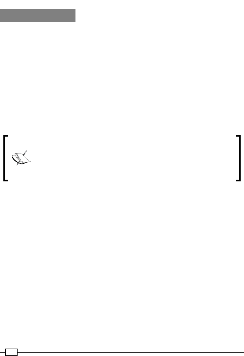
Interfacing with Technology
446
How it works...
Initially, we dened addresses for each of the control registers used by the MAX7219 device.
View the datasheet at for more information.
We created a class called matrix that will allow us to control the module. The __init__()
function sets up the SPI of the Raspberry Pi (using SPI_CS as pin 26 CS1 and SPI_SPEED as
100 kHz).
The key function in our matrix class is the sendCmd() function; it uses wiringpi.
wiringPiSPIDataRW(SPI_CS,buff) to send buffer (which is the raw byte data that
we want to send) over the SPI bus (while also setting the SPI_CS pin low when the transfer
occurs). Each command consists of two bytes: the rst species the address of the register,
and the second sets the data that needs to be put into it. To display a row of lights, we send
the address of one of the ROW registers (MC.MAX7219_DIGIT) and the bit-pattern we want to
display (as a byte).
After the wiringpi.wiringPiSPIDataRW() function is called, buffer
contains the result of whatever is received on the MISO pin (which is read
simultaneously as the data is sent via the MOSI pin). If connected, this will
be the output of the LED module (a delayed copy of the data that was sent).
Refer to the following There's more… section regarding daisy-chained SPI
congurations to learn how the chip output can be used.
To initialize the MAX7219, we need to ensure that it is congured in the correct mode. First,
we set the Scan Limit eld to 7 (which enables all the DIG0 - DIG7 outputs). Next, we disable
the built-in digit decoding since we are using the raw output for the display (and don't want it
to try to display digits). We also want to ensure that the MAX7219_DISPLAYTEST register is
disabled (if enabled, it would turn on all the LEDs).
We ensure the display is cleared by calling our own clear() function, which sends 0
to each of the MAX7219_DIGIT registers to clear each of the rows. Finally, we use the
MAX7219_INTENSITY register to set the brightness of the LEDs. The brightness is controlled
using a PWM output to make the LEDs appear brighter or darker according to the brightness
that is required.
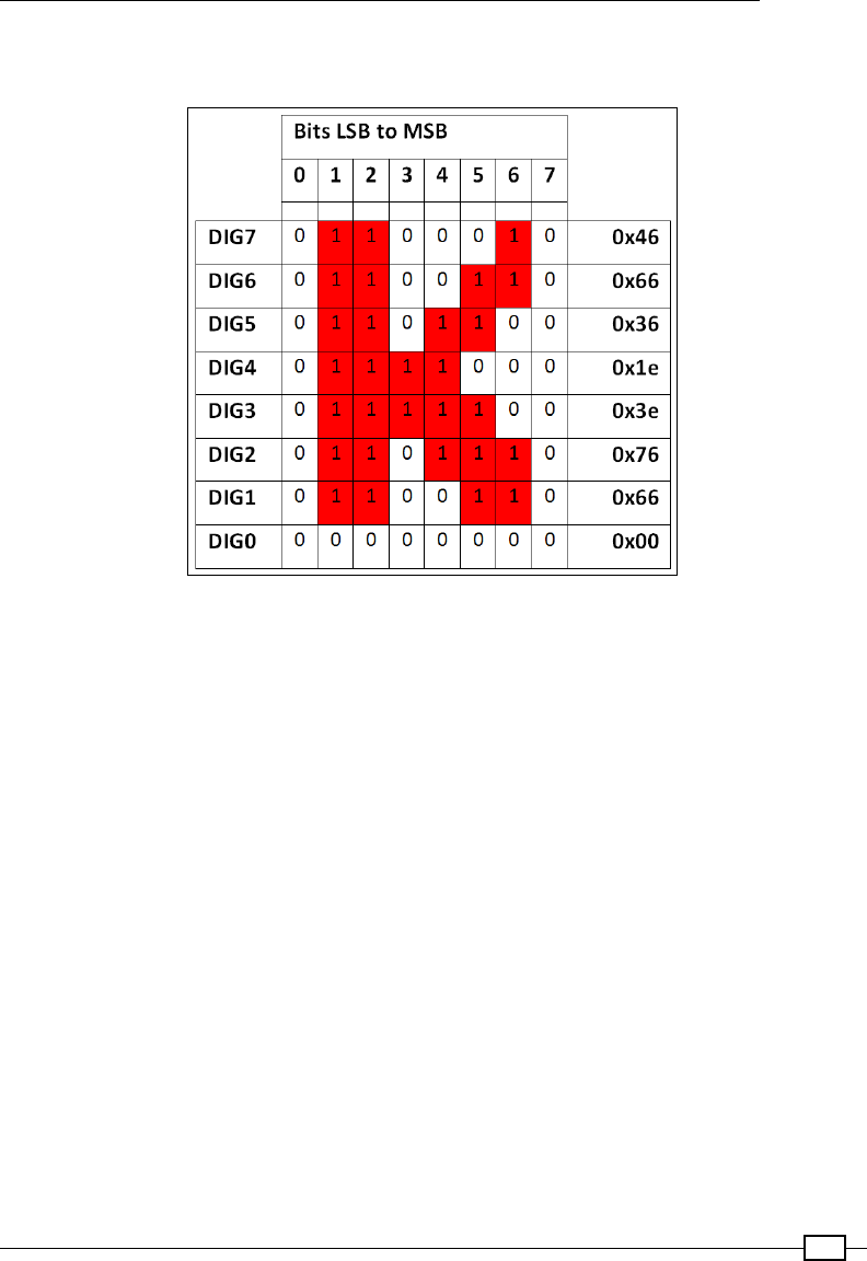
Chapter 10
447
Within the main() function, we perform a quick test to display the letter K on the grid by
sending a set of 8 bytes (0x0066763e1e366646).
Each 8 x 8 pattern consists of 8 bits in 8 bytes (one bit for each column, making each byte a row in the display)
The matrixGUI class creates a canvas object that is populated with a grid of rectangle
objects to represent the 8 x 8 grid of LEDs we want to control (these are kept in self.
light). We also add a text entry box to display the resulting bytes that we will send to the
LED matrix module. We then bind the <Button-1> mouse event to the canvas so that
mouseClick is called whenever a mouse click occurs within the area of the canvas.
We attach a function called changedCode() to the codeText variable using trace, a
special Python function, which allows us to monitor specic variables or functions. If we use
the 'w' value with the trace function, the Python system will call the callback function
whenever the value is written to.
When the mouseClick() function is called, we use the event.x and event.y coordinates
to identify the object that is located there. If an item is detected, then the ID of the item is
used (via toggleLight()) to toggle the corresponding bit in the self.lightStatus
value, and the color of the light in the display changes accordingly (via setLight()).
The codeText variable is also updated with the new hexadecimal representation of the
lightStatus value.

Interfacing with Technology
448
The changeCode() function allows us to use the codeText variable and translate it into
an integer. This allows us to check whether it is a valid value. Since it is possible to enter text
here freely, we must validate it. If we are unable to convert it to an integer, the codeValue
text is refreshed using the lightStatus value. Otherwise, we check if it is too large, in which
case we perform a bit-shift by four to divide it by 16 until it is within a valid range. We update
the lightStatus value, the GUI lights, the codeText variable, and also the hardware (by
calling updateHardware()).
The updateHardware() function makes use of the myMatrixHW object that was created
using the MC.matrix class. We send the bytes that we want to display to the matrix hardware
one byte at a time (along with the corresponding MAX7219_DIGIT value to specify the row).
There's more...
The SPI bus allows us to control multiple devices on the same bus by using the Chip
Enable signal. Some devices, such as the MAX7219, also allow what is known as a
daisy-chain SPI conguration.
Daisy-chain SPI conguration
You may have noticed that the matrix class also returns a byte when we send the data on
the MOSI line. This is the data output from the MAX7219 controller on the DOUT connection.
The MAX7219 controller actually passes all the DIN data through to DOUT, which is one set of
instructions behind the DIN data. In this way, the MAX7219 can be daisy-chained (with each
DOUT feeding into the next DIN). By keeping the CE signal low, multiple controllers can be
loaded with data by being passed though one another. The data is ignored while CE is set to
low, the outputs will only be changed when we set it high again. In this way, you can clock in
all the data for each of the modules in the chain and then set CE to high to update them:
The daisy-chain SPI configuration
We need to do this for each row that we wish to update (or use MAX7219_NOOP if we want to
keep the current row the same). This is known as a daisy-chain SPI conguration, supported
by some SPI devices, where data is passed through each device on the SPI bus to the next
one, which allows the use of three bus control signals for multiple devices.
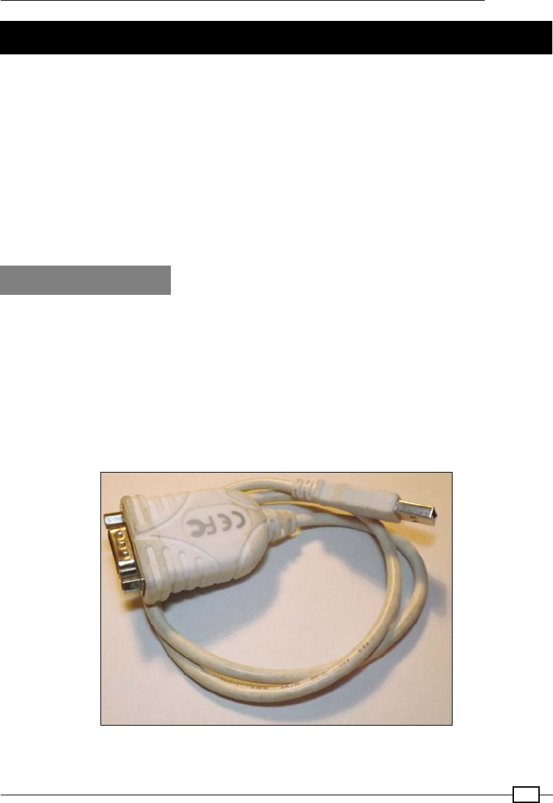
Chapter 10
449
Communicating using a serial interface
Traditionally, serial protocols such as RS232 are a common way to connect devices such
as printers and scanners as well as joysticks and mouse devices to computers. Now,
despite being superseded by USB, many peripherals still make use of this protocol for
internal communication between components, to transfer data, and to update rmware. For
electronics hobbyists, RS232 is a very useful protocol for debugging and controlling other
devices while avoiding the complexities of USB.
The two scripts in this example allow for the control of the GPIO pins to illustrate how we
can remotely control the Raspberry Pi through the serial port. The serial port could be
connected to a PC, another Raspberry Pi, or even an embedded microcontroller (such as
Arduino, PIC, or similar).
Getting ready
The easiest way to connect to the Raspberry Pi via a serial protocol will depend on whether
your computer has a built-in serial port or not. The serial connection, software, and test setup
are described in the following three steps:
1. Create an RS232 serial connection between your computer and the Raspberry Pi. For
this, you need one of the following setups:
If your computer has a built-in serial port available, you can use
a Null-Modem cable with an RS232 to USB adaptor to connect to
the Raspberry Pi:
USB for an RS232 adaptor

Interfacing with Technology
450
A Null-Modem is a serial cable/adaptor that has the TX and RX wires crossed
over so that one side is connected to the TX pin of the serial port, whereas
the other side is connected to the RX pin:
A PC serial port connected to the Raspberry Pi via a Null-Modem cable and an RS232 to USB adaptor
A list of supported USB to RS232 devices is available at the following link:
http://elinux.org/RPi_VerifiedPeripherals#USB_UART_
and_USB_to_Serial_.28RS-232.29_adapters
Refer to the There's more… section for details on how to set them up.
If you do not have a serial port built into your computer, you can use another
USB to RS232 adaptor to connect to the PC/laptop, converting the RS232 to
the more common USB connection.
If you do not have any available USB ports on the Raspberry Pi, you can use
the GPIO serial pins directly with either a Serial Console Cable or a Bluetooth
serial module (refer to the There's more… section for details). Both of these
will require some additional setup.
For all cases, you can use an RS232 loopback to confirm that everything is
working and set up correctly (again, refer to the There's more… section).
2. Next, prepare the software you need for this example.
You will need to install pySerial so we can use the serial port with Python
3. Install pySerial with the following command (you will also need PIP installed; refer to
Chapter 3, Using Python for Automation and Productivity, for details):
sudo pip-3.2 install pyserial
Refer to the pySerial site for further documentation: https://pyserial.
readthedocs.io/en/latest/.
In order to demonstrate the RS232 serial control, you will require some example
hardware attached to the Raspberry Pi's GPIO pins.
The serialMenu.py script allows the GPIO pins to be controlled through commands
sent through the serial port. To fully test this, you can connect suitable output devices
(such as LEDs) to each of the GPIO pins. You can ensure that the total current is kept
low using 470 ohm resistors for each of the LEDs so that the maximum GPIO current
that the Raspberry Pi can supply is not exceeded:
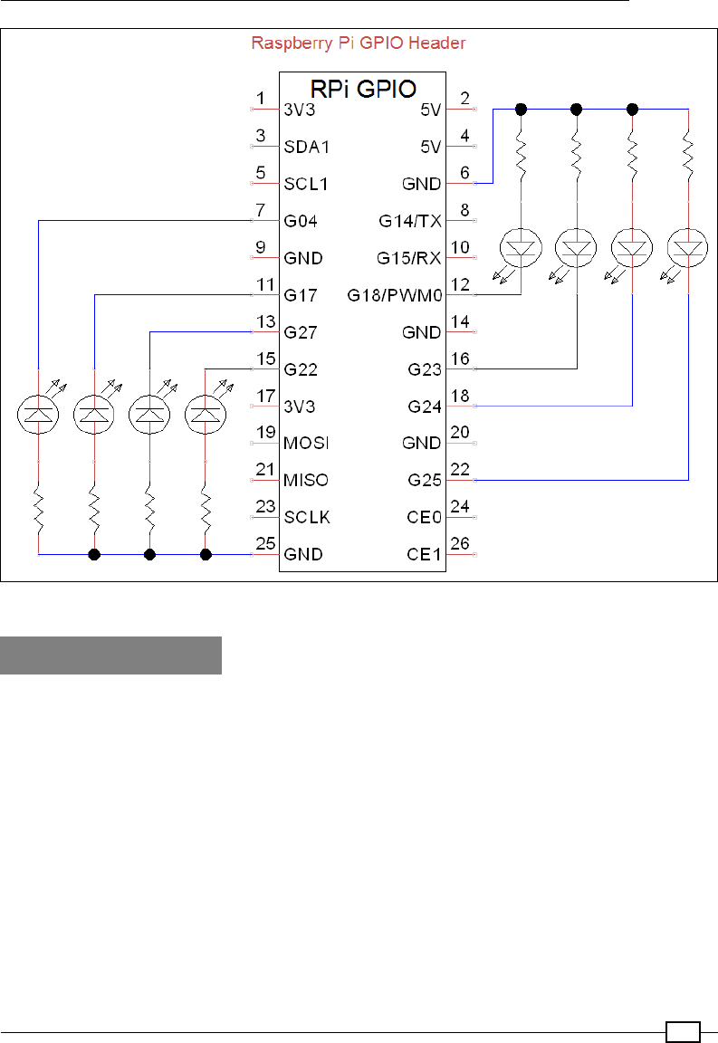
Chapter 10
451
A test circuit to test the GPIO output via serial control
How to do it...
Create the following serialControl.py script:
#!/usr/bin/python3
#serialControl.py
import serial

Interfacing with Technology
452
import time
#Serial Port settings
SERNAME="/dev/ttyUSB0"
#default setting is 9600,8,N,1
IDLE=0; SEND=1; RECEIVE=1
def b2s(message):
'''Byte to String'''
return bytes.decode(message)
def s2b(message):
'''String to Byte'''
return bytearray(message,"ascii")
class serPort():
def __init__(self,serName="/dev/ttyAMA0"):
self.ser = serial.Serial(serName)
print (self.ser.name)
print (self.ser)
self.state=IDLE
def __enter__(self):
return self
def send(self,message):
if self.state==IDLE and self.ser.isOpen():
self.state=SEND
self.ser.write(s2b(message))
self.state=IDLE
def receive(self, chars=1, timeout=5, echo=True,
terminate="\r"):
message=""
if self.state==IDLE and self.ser.isOpen():
self.state=RECEIVE
self.ser.timeout=timeout
while self.state==RECEIVE:
echovalue=""
while self.ser.inWaiting() > 0:
echovalue += b2s(self.ser.read(chars))
if echo==True:
self.ser.write(s2b(echovalue))
message+=echovalue

Chapter 10
453
if terminate in message:
self.state=IDLE
return message
def __exit__(self,type,value,traceback):
self.ser.close()
def main():
try:
with serPort(serName=SERNAME) as mySerialPort:
mySerialPort.send("Send some data to me!\r\n")
while True:
print ("Waiting for input:")
print (mySerialPort.receive())
except OSError:
print ("Check selected port is valid: %s" %serName)
except KeyboardInterrupt:
print ("Finished")
if __name__=="__main__":
main()
#End
Ensure that the serName element is correct for the serial port we want to use (such as /dev/
ttyAMA0 for the GPIO pins or /dev/ttyUSB0 for a USB RS232 adaptor).
Connect the other end to a serial port on your laptop or computer (the serial port can be
another USB to RS232 adaptor).
Monitor the serial port on your computer using a serial program such as HyperTerminal or
RealTerm () for Windows or Serial Tools for OS X. You will need to ensure that you have the
correct COM port set and a baud rate of 9600 bps (Parity=None, Data Bits=8, Stop
Bits=1, and Hardware Flow Control=None).
The script will send a request for data from the user and wait for a response.
To send data to the Raspberry Pi, write some text on the other computer and press Enter to
send it over to the Raspberry Pi.
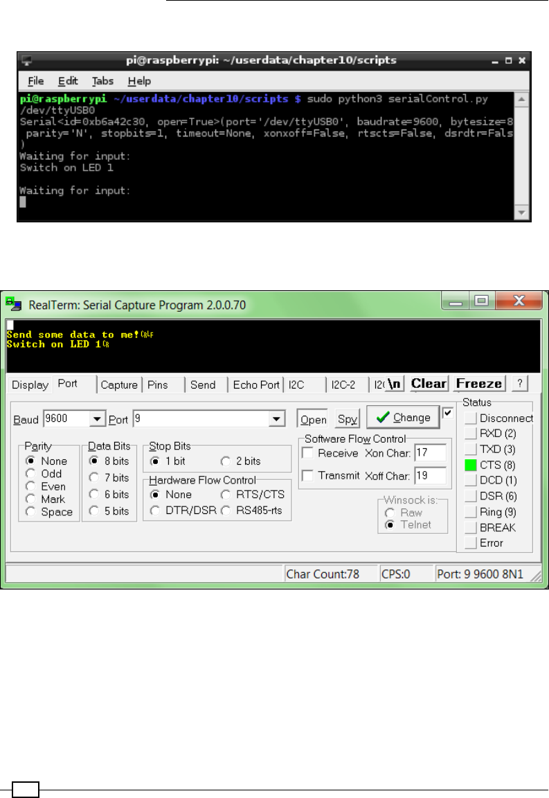
Interfacing with Technology
454
You will see output similar to the following on the Raspberry Pi terminal:
The text "Switch on LED 1" has been sent via a USB to RS232 cable from a connected computer
You will also see output similar to the following on the serial monitoring program:
RealTerm displaying typical output from the connected serial port
Press Ctrl + C on the Raspberry Pi to stop the script.
Now, create a GPIO control menu. Create serialMenu.py:
#!/usr/bin/python3
#serialMenu.py
import time
import RPi.GPIO as GPIO

Chapter 10
455
import serialControl as SC
SERNAME = "/dev/ttyUSB0"
running=True
CMD=0;PIN=1;STATE=2;OFF=0;ON=1
GPIO_PINS=[7,11,12,13,15,16,18,22]
GPIO_STATE=["OFF","ON"]
EXIT="EXIT"
def gpioSetup():
GPIO.setmode(GPIO.BOARD)
for pin in GPIO_PINS:
GPIO.setup(pin,GPIO.OUT)
def handleCmd(cmd):
global running
commands=cmd.upper()
commands=commands.split()
valid=False
print ("Received: "+ str(commands))
if len(commands)==3:
if commands[CMD]=="GPIO":
for pin in GPIO_PINS:
if str(pin)==commands[PIN]:
print ("GPIO pin is valid")
if GPIO_STATE[OFF]==commands[STATE]:
print ("Switch GPIO %s %s"% (commands[PIN],
commands[STATE]))
GPIO.output(pin,OFF)
valid=True
elif GPIO_STATE[ON]==commands[STATE]:
print ("Switch GPIO %s %s"% (commands[PIN],
commands[STATE]))
GPIO.output(pin,ON)
valid=True
elif commands[CMD]==EXIT:
print("Exit")
valid=True
running=False
if valid==False:
print ("Received command is invalid")
response=" Invalid:GPIO Pin#(%s) %s\r\n"% (
str(GPIO_PINS), str(GPIO_STATE))
else:
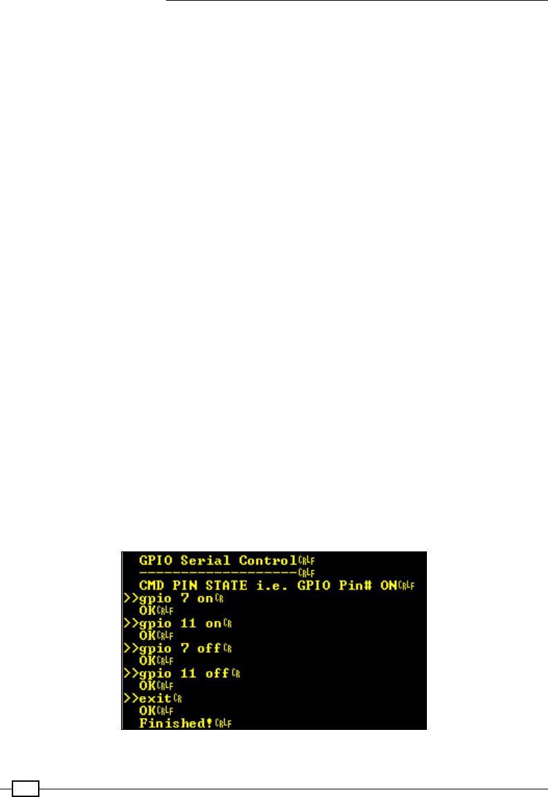
Interfacing with Technology
456
response=" OK\r\n"
return (response)
def main():
try:
gpioSetup()
with SC.serPort(serName=SERNAME) as mySerialPort:
mySerialPort.send("\r\n")
mySerialPort.send(" GPIO Serial Control\r\n")
mySerialPort.send(" -------------------\r\n")
mySerialPort.send(" CMD PIN STATE "+
"[GPIO Pin# ON]\r\n")
while running==True:
print ("Waiting for command...")
mySerialPort.send(">>")
cmd = mySerialPort.receive(terminate="\r\n")
response=handleCmd(cmd)
mySerialPort.send(response)
mySerialPort.send(" Finished!\r\n")
except OSError:
print ("Check selected port is valid: %s" %serName)
except KeyboardInterrupt:
print ("Finished")
finally:
GPIO.cleanup()
main()
#End
When you run the script (sudo python3 serialMenu.py), type the control messages
within the serial monitoring program:
The GPIO Serial Control menu
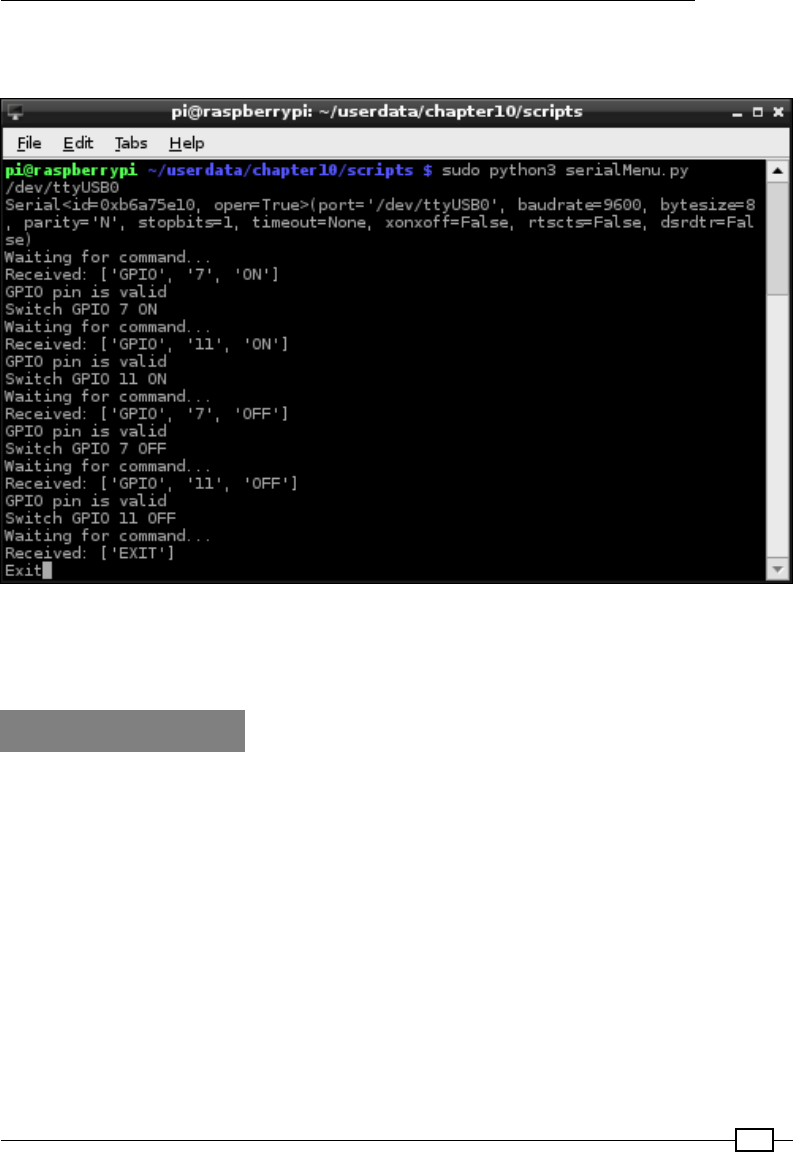
Chapter 10
457
The terminal output on the Raspberry Pi will be similar to the following screenshot, and the
LEDs should respond accordingly:
The GPIO Serial Control menu
The Raspberry Pi validates the commands received from the serial connection and switches
the LEDs connected to the GPIO pins 7 and 11 on and then off.
How it works...
The rst script, serialControl.py, provides us with a serPort class. We dene the class
with the following functions:
f__init__(self,serName="/dev/ttyAMA0"): This function will create a new
serial device using serName—the default of "/dev/ttyAMA0" is the ID for the GPIO
serial pins (see the There's more... section). After it is initialized, information about
the device is displayed.
f__enter__(self): This is a dummy function that allows us to use the with…as
method.
fsend(self,message): This is used to check that the serial port is open and not
in use; if so, it will then send a message (after converting it to raw bytes using the
s2b() function).

Interfacing with Technology
458
freceive(self, chars=1, echo=True, terminate="\r"): After checking
whether the serial port is open and not in use, this function then waits for data
through the serial port. The function will collect data until the terminate characters
are detected, and then the full message is returned.
f__exit__(self,type,value,traceback): This function is called when the
serPort object is no longer required by the with…as method, so we can close the
port at this point.
The main() function in the script performs a quick test of the class by sending a prompt for
data through the serial port to a connected computer and then waiting for input that will be
followed by the terminate character(s).
The next script, serialMenu.py, allows us to make use of the serPort class.
The main() function sets up the GPIO pins as outputs (via gpioSetup()), creates a new
serPort object, and nally, waits for commands through the serial port. Whenever a new
command is received, the handleCmd() function is used to parse the message to ensure
that it is correct before acting on it.
The script will switch a particular GPIO pin on or off as commanded through the serial port
using the GPIO command keyword. We could add any number of command keywords and
control (or read) whatever device (or devices) we attached to the Raspberry Pi. We now have a
very effective way to control the Raspberry Pi using any devices connected via a serial link.
There's more...
In addition to the serial transmit and receive, the RS232 serial standard includes several
other control signals. To test it, you can use a serial loopback to conrm if the serial ports
are set up correctly.
Conguring a USB to RS232 device for the Raspberry Pi
Once you have connected the USB to RS232 device to the Raspberry Pi, check to see if
a new serial device is listed by typing the following command:
dmesg | grep tty
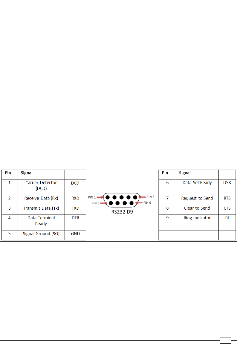
Chapter 10
459
The dmesg command lists events that occur on the system; using grep, we can lter any
messages that mention tty, as shown in the following code:
[ 2409.195407] usb 1-1.2: pl2303 converter now attached to ttyUSB0
This shows that a PL2303-based USB-RS232 device was attached (2,409 seconds after
startup) and allocated the ttyUSB0 identity. You will see that a new serial device has been
added within the /dev/ directory (usually /dev/ttyUSB0 or something similar).
If the device has not been detected, you can try steps similar to the ones used in Chapter 1,
Getting Started with a Raspberry Pi Computer, to locate and install suitable drivers (if they
are available).
RS232 signals and connections
The RS232 serial standard has lots of variants and includes six additional control signals.
The Raspberry Pi GPIO serial drivers (and the Bluetooth TTL module used in the following
example) only support RX and TX signals. If you require support for other signals, such as
DTR that is often used for a reset prior to the programming of AVR/Arduino devices, then
alternative GPIO serial drivers may be needed to set these signals via other GPIO pins. Most
RS232 to USB adaptors should support the standard signals; however, ensure that anything
you connect is able to handle standard RS232 voltages:
The RS232 9-Way D Connector pin-out and signals
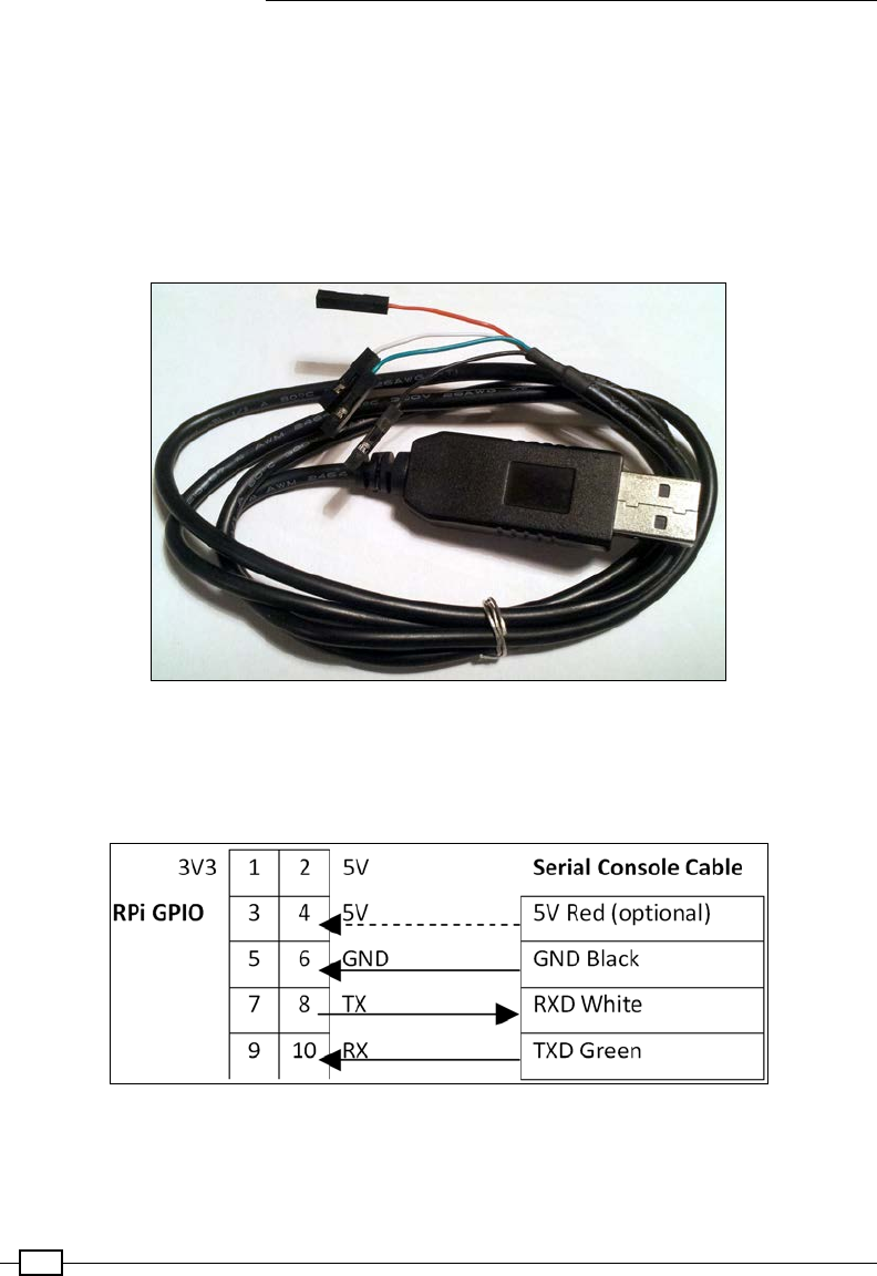
Interfacing with Technology
460
For more details on the RS232 serial protocol and to know how these signals are used, visit
the following link http://en.wikipedia.org/wiki/Serial_port:
Using the GPIO built-in serial pins
Standard RS232 signals can range from -15V to +15V, so you must never directly connect
any RS232 device to the GPIO serial pins. You must use an RS232 to TTL voltage-level
converter (such as a MAX232 chip) or a device that uses TTL-level signals (such as another
microcontroller or a TTL serial console cable):
A USB to TTL serial console cable
The Raspberry Pi has TTL-level serial pins on the GPIO header that allow the connection of a
TTL serial USB cable. The wires will connect to the Raspberry Pi GPIO pins, and the USB will
plug in to your computer and be detected like a standard RS232 to USB cable.
Connection of a USB to TTL serial console cable to the Raspberry Pi GPIO

Chapter 10
461
It is possible to provide power from the USB port to the 5V pin; however, this will bypass
the built-in polyfuse, so it is not recommended for general use (just leave the 5V wire
disconnected and power as normal through the micro-USB).
By default, these pins are set up to allow remote terminal access, allowing you to connect
to the COM port via PuTTY and create a serial SSH session.
A serial SSH session can be helpful if you want to use the Raspberry Pi
without a display attached to it.
However, a serial SSH session is limited to text-only terminal access since
it does not support X10 Forwarding, as used in the Connecting remotely to
Raspberry Pi over the network using SSH (and X11 Forwarding) section of
Chapter 1, Getting Started with a Raspberry Pi Computer.
In order to use it as a standard serial connection, we have to disable the serial console so it is
available for us to use.
First, we need to edit /boot/cmdline.txt to remove the rst console and kgboc options
(do not remove the other console=tty1 option, which is the default terminal when you
switch on):
sudo nano /boot/cmdline.txt
dwc_otg.lpm_enable=0 console=ttyAMA0,115200 kgdboc=ttyAMA0,115200
console=tty1 root=/dev/mmcblk0p2 rootfstype=ext4 elevator=deadline
rootwait
The previous command line becomes the following (ensure that this is still a single
command line):
dwc_otg.lpm_enable=0 console=tty1 root=/dev/mmcblk0p2 rootfstype=ext4
elevator=deadline rootwait
We also have to remove the task that runs the getty command (the program that handles
the text terminal for the serial connection) by commenting it out with #. This is set in /etc/
inittab as follows:
sudo nano /etc/inittab
T0:23:respawn:/sbin/getty -L ttyAMA0 115200 vt100
The previous command line becomes the following:
#T0:23:respawn:/sbin/getty -L ttyAMA0 115200 vt100
To reference the GPIO serial port in our script, we use its name, /dev/ttyAMA0.
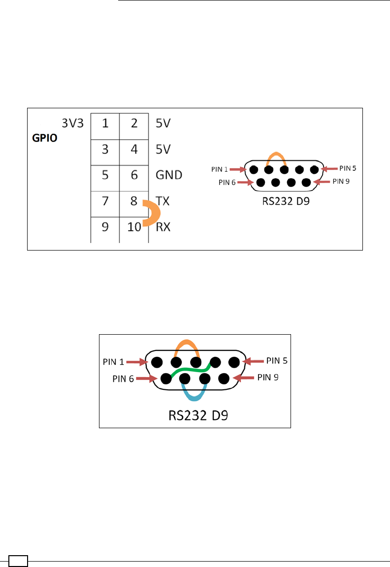
Interfacing with Technology
462
The RS232 loopback
You can check whether the serial port connections are working correctly using a
serial loopback.
A simple loopback consists of connecting RXD and TXD together. These are pins 8 and 10 on
the Raspberry Pi GPIO header, or pins 2 and 3 on the standard RS232 D9 connector on the
USB-RS232 adaptor:
Serial loopback connections to test the Raspberry Pi GPIO (left) and RS232 9-Way D Connector (right)
An RS232 full loopback cable also connects pin 4 (DTR) and pin 6 (DSR) as well as pin 7
(RTS) and pin 8 (CTS) on the RS232 adaptor. However, this is not required for most situations,
unless these signals are used. By default, no pins are allocated on the Raspberry Pi
specically for these additional signals.
RS232 full loopback
Create the following serialTest.py script:
#!/usr/bin/python3
#serialTest.py
import serial
import time
WAITTIME=1
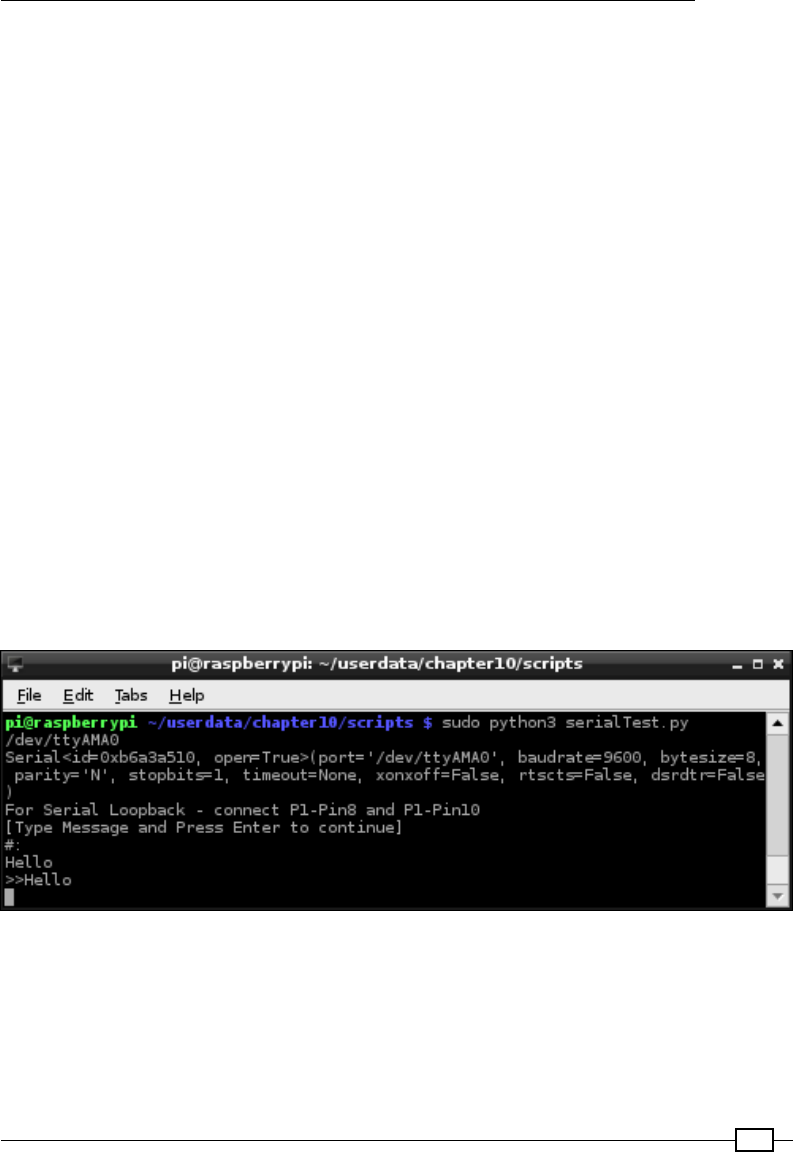
Chapter 10
463
serName="/dev/ttyAMA0"
ser = serial.Serial(serName)
print (ser.name)
print (ser)
if ser.isOpen():
try:
print("For Serial Loopback - connect GPIO Pin8 and Pin10")
print("[Type Message and Press Enter to continue]")
print("#:")
command=input()
ser.write(bytearray(command+"\r\n","ascii"))
time.sleep(WAITTIME)
out=""
while ser.inWaiting() > 0:
out += bytes.decode(ser.read(1))
if out != "":
print (">>" + out)
else:
print ("No data Received")
except KeyboardInterrupt:
ser.close()
#End
When a loopback is connected, you will observe that the message is echoed back to the
screen (when removed, No data Received will be displayed):
An RS232 loopback test on GPIO serial pins
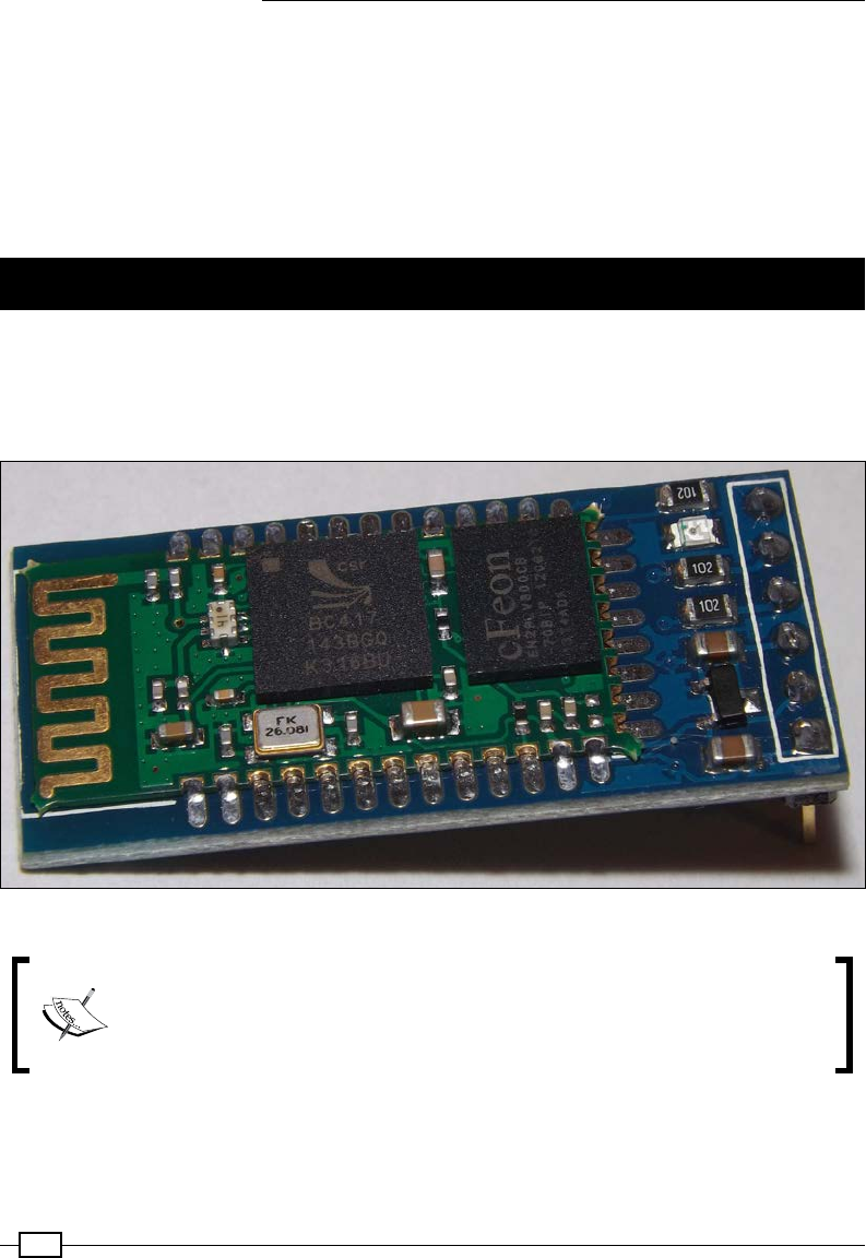
Interfacing with Technology
464
If we require non-default settings, they can be dened when the serial port is initialized (the
pySerial documentation at https://pyserial.readthedocs.io/en/latest/ provides
full details of all the options), as shown in the following code:
ser = serial.Serial(port=serName, baudrate= 115200,
timeout=1, parity=serial.PARITY_ODD,
stopbits=serial.STOPBITS_TWO,
bytesize=serial.SEVENBITS)
Controlling the Raspberry Pi over Bluetooth
Serial data can also be sent through Bluetooth by connecting a HC-05 Bluetooth module that
supports the Serial Port Prole (SPP) to the GPIO serial RX/TX pins. This allows the serial
connection to become wireless, which allows Android tablets or smartphones to be used to
control things and read data from the Raspberry Pi:
The HC-05 Bluetooth module for the TLL serial
While it is possible to achieve a similar result using a USB Bluetooth dongle,
additional conguration would be required depending on the particular dongle
used. The TTL Bluetooth module provides a drop-in replacement for a physical
cable, requiring very little additional conguration.
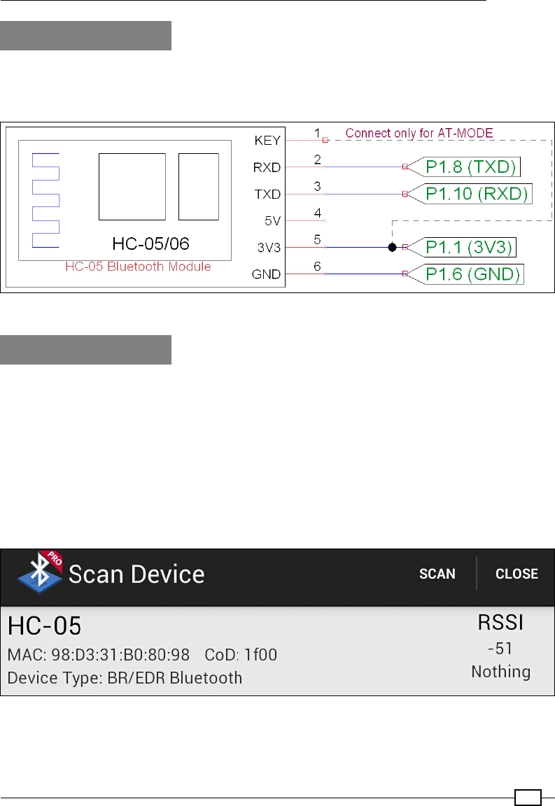
Chapter 10
465
Getting ready
Ensure that the serial console has been disabled (see the previous There's more… section).
The module should be connected using the following pins:
Connection to a Bluetooth module for the TLL serial
How to do it...
With the Bluetooth module congured and connected, we can pair the module with a laptop
or smartphone to send and receive commands wirelessly. Bluetooth SPP Pro provides an
easy way to use a serial connection over Bluetooth to control or monitor the Raspberry Pi for
Android devices.
Alternatively, you may be able to set up a Bluetooth COM port on your PC/laptop and use it in
the same way as the previous wired example:
1. When the device is connected initially, the LED ashes quickly to indicate that it is
waiting to be paired. Enable Bluetooth on your device and select the HC-05 device:
The HC-05 Bluetooth module viewable in Bluetooth SPP Pro
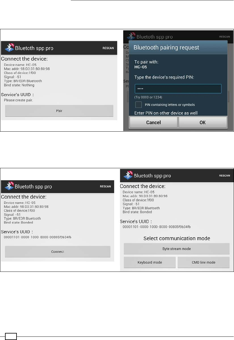
Interfacing with Technology
466
2. Click on the Pair button to begin the pairing process and enter the device's PIN (the
default is 1234):
Pair the Bluetooth device with the PIN code (1234)
3. If the pairing was successful, you will be able to connect with the device and send
and receive messages to and from the Raspberry Pi:
Connect to the device and select the control method
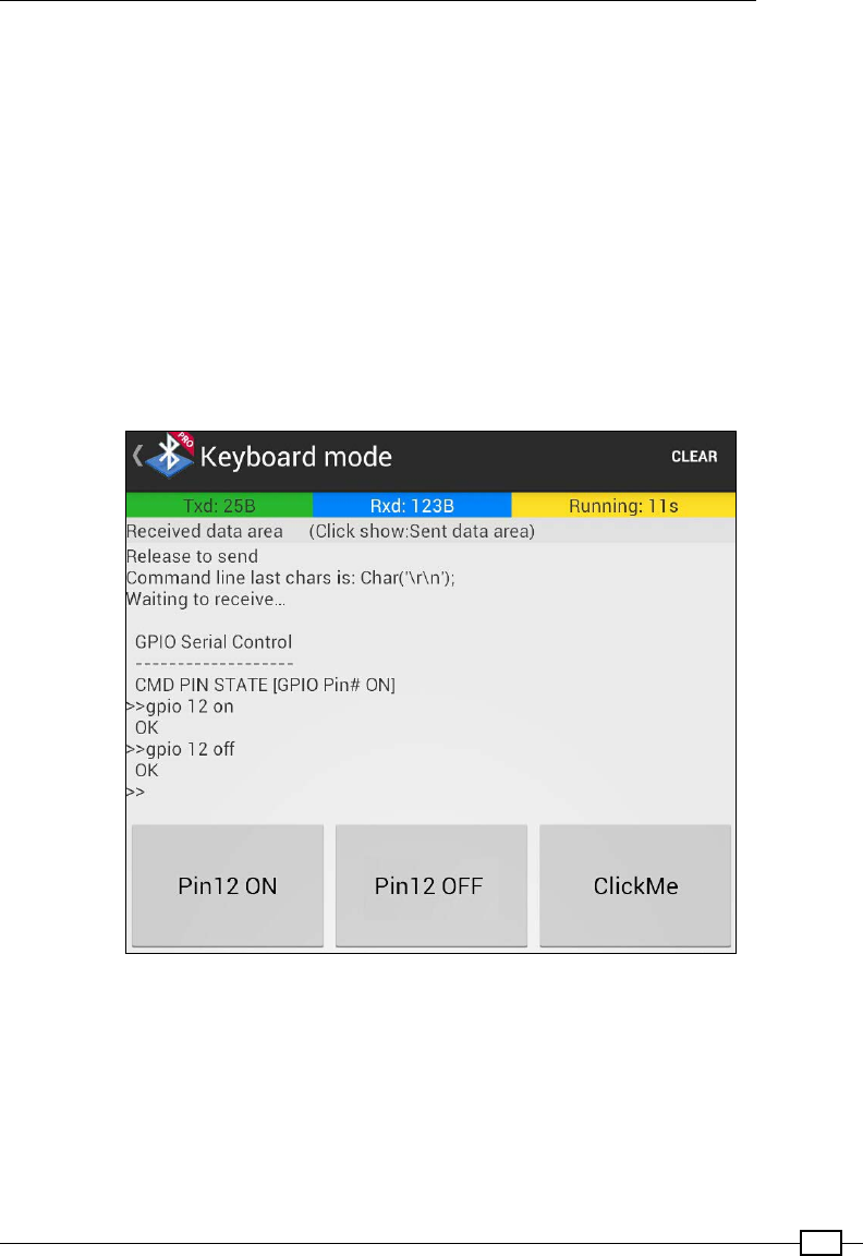
Chapter 10
467
4. In Keyboard mode, you can dene actions for each of the buttons to send suitable
commands when pressed.
For example, Pin12 ON can be set to send gpio 12 on, and Pin12 OFF can be set
to send gpio 12 off.
5. Ensure that you set the end ag to \r\n via the menu options.
6. Ensure that menuSerial.py is set to use the GPIO serial connection:
serName="/dev/ttyAMA0"
7. Run the menuSerial.py script (with the LEDs attached):
sudo python3 menuSerial.py
8. Check that the Bluetooth serial app displays the GPIO Serial Control menu as
shown in the following screenshot:
GPIO control over Bluetooth
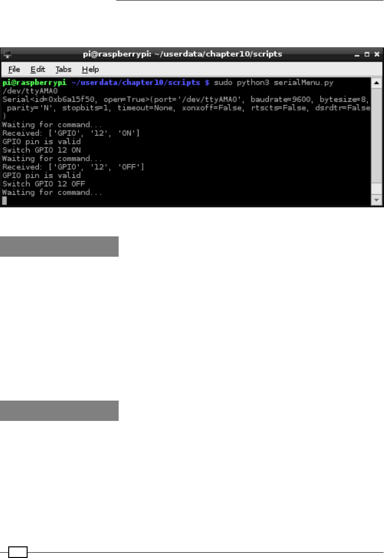
Interfacing with Technology
468
We can see from the output in the following screenshot that the commands have been
received and the LED connected to pin 12 has been switched on and off as required.
The Raspberry Pi receiving GPIO control over Bluetooth
How it works...
By default, the Bluetooth module is set up to act like a TTL serial slave device, so we can
simply plug it in to the GPIO RX and TX pins. Once the module is paired with a device, it will
transfer the serial communication over the Bluetooth connection. This allows us to send
commands and receive data via Bluetooth and control the Raspberry Pi using a smart phone
or PC.
This means you can attach a second module to another device (such as an Arduino) that
has TTL serial pins and control it using the Raspberry Pi (either by pairing it with another
TTL Bluetooth module or suitably conguring a USB Bluetooth dongle). If the module is
set up as a master device, then you will need to recongure it to act as a slave (see the
There's more… section).
There's more...
Now, let's understand how to congure the Bluetooth settings.
Conguring Bluetooth module settings
The Bluetooth module can be set in two different modes using the KEY pin.
In a normal operation, serial messages are sent over Bluetooth; however, if we need to change
the settings of the Bluetooth module itself, we can do so by connecting the KEY pin to 3V3
and putting it into AT mode.

Chapter 10
469
AT mode allows us to directly congure the module, allowing us to change the baud rate, the
pairing code, the device name, or even set it up as a master/slave device.
You can use miniterm, which is part of pySerial, to send the required messages, as shown in
the following code:
python3 -m serial.tools.miniterm
The miniterm program, when started, will prompt for the port to use:
Enter port name: /dev/ttyAMA0
You can send the following commands (you will need to do this quickly, or paste them, as the
module will time out if there is a gap and respond with an error):
fAT: This command should respond with OK.
fAT+UART?: This command will report the current settings as UART=<Param1>,<Par
am2>,<Param3>. The output of this command will be OK.
fTo change the current settings, use AT+UART=<Param1>,<Param2>,<Param3>,
that is, AT+UART=19200,0,0.
HC-05 AT mode AT+UART command parameters
For details on how to congure modules as paired master and slave devices (for example,
between two Raspberry Pi devices), Zak Kemble has written an excellent guide. It is available
at the following link: http://blog.zakkemble.co.uk/getting-bluetooth-modules-
talking-to-each-other/.
For additional documentation on the HC-05 module, visit the following link: http://www.
robotshop.com/media/files/pdf/rb-ite-12-bluetooth_hc05.pdf.
Controlling USB devices
The Universal Serial Bus (USB) is used extensively by computers to provide additional
peripherals and expansion through a common standard connection. We will use the
PyUSB Python library to send custom commands to connected devices over USB.

Interfacing with Technology
470
The following example controls a USB toy missile launcher, which in turn allows it to be
controlled by our Python control panel. We see that the same principle can be applied to
other USB devices, such as a robotic arm, using similar techniques, and the controls can be
activated using a sensor connected to the Raspberry Pi GPIO:
The USB Tenx Technology SAM missile launcher
Getting ready
We will need to install PyUSB for Python 3 using pip-3.2 as follows:
sudo pip-3.2 install pyusb

Chapter 10
471
You can test whether PyUSB has installed correctly by running the following:
python3
> import usb
> help (usb)
> exit()
This should allow you to view the package information if it was installed correctly.
How to do it...
We will create the following missileControl.py script, which will include two classes and a
default main() function to test it:
1. Import the required modules as follows:
#!/usr/bin/python3
# missileControl.py
import time
import usb.core
2. Dene the SamMissile() class, which provides the specic commands for the USB
device, as follows:
class SamMissile():
idVendor=0x1130
idProduct=0x0202
idName="Tenx Technology SAM Missile"
# Protocol control bytes
bmRequestType=0x21
bmRequest=0x09
wValue=0x02
wIndex=0x01
# Protocol command bytes
INITA = [ord('U'), ord('S'), ord('B'), ord('C'),
0, 0, 4, 0]
INITB = [ord('U'), ord('S'), ord('B'), ord('C'),
0, 64, 2, 0]
CMDFILL = [ 8, 8,
0, 0, 0, 0, 0, 0, 0, 0,
0, 0, 0, 0, 0, 0, 0, 0,
0, 0, 0, 0, 0, 0, 0, 0,
0, 0, 0, 0, 0, 0, 0, 0,
0, 0, 0, 0, 0, 0, 0, 0,
0, 0, 0, 0, 0, 0, 0, 0,

Interfacing with Technology
472
0, 0, 0, 0, 0, 0, 0, 0]#48 zeros
STOP = [ 0, 0, 0, 0, 0, 0]
LEFT = [ 0, 1, 0, 0, 0, 0]
RIGHT = [ 0, 0, 1, 0, 0, 0]
UP = [ 0, 0, 0, 1, 0, 0]
DOWN = [ 0, 0, 0, 0, 1, 0]
LEFTUP = [ 0, 1, 0, 1, 0, 0]
RIGHTUP = [ 0, 0, 1, 1, 0, 0]
LEFTDOWN = [ 0, 1, 0, 0, 1, 0]
RIGHTDOWN = [ 0, 0, 1, 0, 1, 0]
FIRE = [ 0, 0, 0, 0, 0, 1]
def __init__(self):
self.dev = usb.core.find(idVendor=self.idVendor,
idProduct=self.idProduct)
def move(self,cmd,duration):
print("Move:%s %d sec"% (cmd,duration))
self.dev.ctrl_transfer(self.bmRequestType,
self.bmRequest,self.wValue,
self.wIndex, self.INITA)
self.dev.ctrl_transfer(self.bmRequestType,
self.bmRequest,self.wValue,
self.wIndex, self.INITB)
self.dev.ctrl_transfer(self.bmRequestType,
self.bmRequest, self.wValue,
self.wIndex, cmd+self.CMDFILL)
time.sleep(duration)
self.dev.ctrl_transfer(self.bmRequestType,
self.bmRequest, self.wValue,
self.wIndex, self.INITA)
self.dev.ctrl_transfer(self.bmRequestType,
self.bmRequest, self.wValue,
self.wIndex, self.INITB)
self.dev.ctrl_transfer(self.bmRequestType,
self.bmRequest, self.wValue,
self.wIndex, self.STOP+self.CMDFILL)
3. Dene the Missile() class, which allows us to detect the USB device and provide
command functions, as follows:
class Missile():
def __init__(self):
print("Initialize Missiles")
self.usbDevice=SamMissile()
if self.usbDevice.dev is not None:

Chapter 10
473
print("Device Initialized:" +
" %s" % self.usbDevice.idName)
#Detach the kernel driver if active
if self.usbDevice.dev.is_kernel_driver_active(0):
print("Detaching kernel driver 0")
self.usbDevice.dev.detach_kernel_driver(0)
if self.usbDevice.dev.is_kernel_driver_active(1):
print("Detaching kernel driver 1")
self.usbDevice.dev.detach_kernel_driver(1)
self.usbDevice.dev.set_configuration()
else:
raise Exception("Missile device not found")
def __enter__(self):
return self
def left(self,duration=1):
self.usbDevice.move(self.usbDevice.LEFT,duration)
def right(self,duration=1):
self.usbDevice.move(self.usbDevice.RIGHT,duration)
def up(self,duration=1):
self.usbDevice.move(self.usbDevice.UP,duration)
def down(self,duration=1):
self.usbDevice.move(self.usbDevice.DOWN,duration)
def fire(self,duration=1):
self.usbDevice.move(self.usbDevice.FIRE,duration)
def stop(self,duration=1):
self.usbDevice.move(self.usbDevice.STOP,duration)
def __exit__(self, type, value, traceback):
print("Exit")
4. Finally, create a main() function, which provides a quick test of our
missileControl.py module if the le is run directly, as follows:
def main():
try:
with Missile() as myMissile:
myMissile.down()
myMissile.up()
except Exception as detail:
time.sleep(2)
print("Error: %s" % detail)
if __name__ == '__main__':
main()
#End
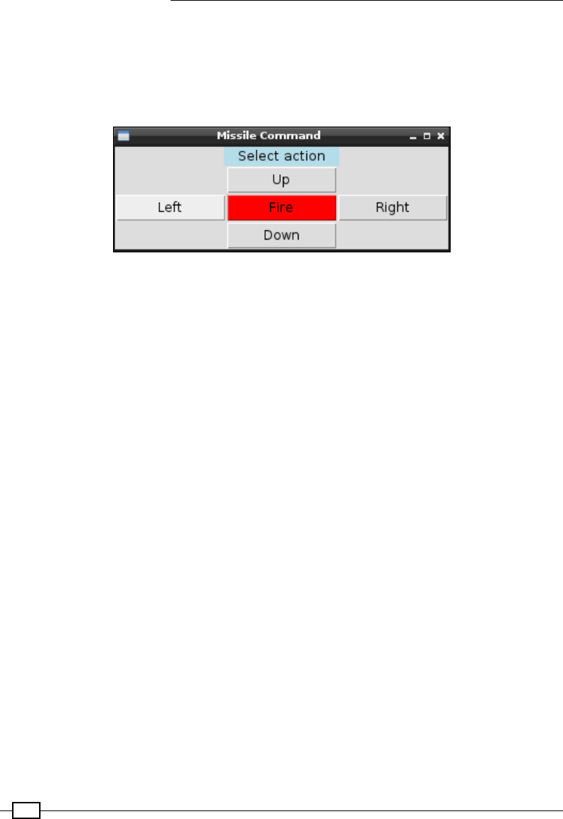
Interfacing with Technology
474
When the script is run using the following command, you should see the missile launcher
move downwards and then up again:
sudo python3 missileControl.py
To provide easy control of the device, create the following GUI:
The Missile Command GUI
Although simple commands have been used here, you could use a series of preset commands
if desired.
Create the GUI for the missileMenu.py missile command:
#!/usr/bin/python3
#missileMenu.py
import tkinter as TK
import missileControl as MC
BTN_SIZE=10
def menuInit():
btnLeft = TK.Button(root, text="Left",
command=sendLeft, width=BTN_SIZE)
btnRight = TK.Button(root, text="Right",
command=sendRight, width=BTN_SIZE)
btnUp = TK.Button(root, text="Up",
command=sendUp, width=BTN_SIZE)
btnDown = TK.Button(root, text="Down",
command=sendDown, width=BTN_SIZE)
btnFire = TK.Button(root, text="Fire",command=sendFire,
width=BTN_SIZE, bg="red")
btnLeft.grid(row=2,column=0)
btnRight.grid(row=2,column=2)
btnUp.grid(row=1,column=1)
btnDown.grid(row=3,column=1)

Chapter 10
475
btnFire.grid(row=2,column=1)
def sendLeft():
print("Left")
myMissile.left()
def sendRight():
print("Right")
myMissile.right()
def sendUp():
print("Up")
myMissile.up()
def sendDown():
print("Down")
myMissile.down()
def sendFire():
print("Fire")
myMissile.fire()
root = TK.Tk()
root.title("Missile Command")
prompt = "Select action"
label1 = TK.Label(root, text=prompt, width=len(prompt),
justify=TK.CENTER, bg='lightblue')
label1.grid(row=0,column=0,columnspan=3)
menuInit()
with MC.Missile() as myMissile:
root.mainloop()
#End
How it works...
The control script consists of two classes: one called Missile that provides a common
interface for the control, and another called SamMissile that provides all the specic
details of the particular USB device being used.
In order to drive a USB device, we need a lot of information about the device, such as its USB
identication, its protocol, and the control messages it requires to be controlled.

Interfacing with Technology
476
The USB ID for the Tenx Technology SAM missile device is determined by the vendor
ID (0x1130) and the product ID (0x0202). This is the same identication information
you would see within Device Manager in Windows. These IDs are usually registered with
www.usb.org; therefore, each device should be unique. Again, you can use the dmesg |
grep usb command to discover these.
We use the device IDs to nd the USB device using usb.core.find; then, we can send
messages using ctrl_transfer().
The USB message has ve parts:
fRequest type (0x21): This denes the type of the message request, such as the
message direction (Host to Device), its type (Vendor), and the recipient (Interface)
fRequest (0x09): This is the set conguration
fValue (0x02): This is the conguration value
fIndex (0x01): This is the command we want to send
fData: This is the command we want to send (as described next)
The SamMissile device requires the following commands to move:
fIt requires two initialization messages (INITA and INITB).
fIt also requires the control message. This consists of the CMD, which includes one of
the control bytes that has been set to 1 for the required component. The CMD is then
added to CMDFILL to complete the message.
You will see that the other missile devices and the robot arm (see the following There's more…
section) have similar message structures.
For each device, we created the __init__() and move() functions and dened values
for each of the valid commands, which the missile class will use whenever the left(),
right(), up(), down(), fire(), and stop() functions are called.
For the control GUI for our missile launcher, we create a small Tkinter window with ve
buttons, each of which will send a command to the missile device.
We import missileControl and create a missile object called myMissile that will be
controlled by each of the buttons.

Chapter 10
477
There's more...
The example only shows how to control one particular USB device; however, it is possible to
extend this to support several types of missile devices and even other USB devices in general.
Controlling similar missile-type devices
There are several variants of USB missile-type devices, each with their own USB IDs and USB
commands. We can add support for these other devices by dening their own classes to
handle them.
Use lsusb -vv to determine the vendor and product ID that matches your device.
For Chesen Electronics/Dream Link, we have to add the following code:
class ChesenMissile():
idVendor=0x0a81
idProduct=0x0701
idName="Chesen Electronics/Dream Link"
# Protocol control bytes
bmRequestType=0x21
bmRequest=0x09
wValue=0x0200
wIndex=0x00
# Protocol command bytes
DOWN = [0x01]
UP = [0x02]
LEFT = [0x04]
RIGHT = [0x08]
FIRE = [0x10]
STOP = [0x20]
def __init__(self):
self.dev = usb.core.find(idVendor=self.idVendor,
idProduct=self.idProduct)
def move(self,cmd,duration):
print("Move:%s"%cmd)
self.dev.ctrl_transfer(self.bmRequestType,
self.bmRequest,
self.wValue, self.wIndex, cmd)
time.sleep(duration)
self.dev.ctrl_transfer(self.bmRequestType,
self.bmRequest, self.wValue,
self.wIndex, self.STOP)

Interfacing with Technology
478
For Dream Cheeky Thunder, we need the following code:
class ThunderMissile():
idVendor=0x2123
idProduct=0x1010
idName="Dream Cheeky Thunder"
# Protocol control bytes
bmRequestType=0x21
bmRequest=0x09
wValue=0x00
wIndex=0x00
# Protocol command bytes
CMDFILL = [0,0,0,0,0,0]
DOWN = [0x02,0x01]
UP = [0x02,0x02]
LEFT = [0x02,0x04]
RIGHT = [0x02,0x08]
FIRE = [0x02,0x10]
STOP = [0x02,0x20]
def __init__(self):
self.dev = usb.core.find(idVendor=self.idVendor,
idProduct=self.idProduct)
def move(self,cmd,duration):
print("Move:%s"%cmd)
self.dev.ctrl_transfer(self.bmRequestType,
self.bmRequest, self.wValue,
self.wIndex, cmd+self.CMDFILL)
time.sleep(duration)
self.dev.ctrl_transfer(self.bmRequestType,
self.bmRequest, self.wValue,
self.wIndex, self.STOP+self.CMDFILL)
Finally, adjust the script to use the required class as follows:
class Missile():
def __init__(self):
print("Initialize Missiles")
self.usbDevice = ThunderMissile()

Chapter 10
479
Robot arm
Another device that can be controlled in a similar manner is the OWI Robotic Arm with a
USB interface.
The OWI Robotic Arm with a USB interface (image courtesy of Chris Stagg)
This has featured in The MagPi magazine several times, thanks to Stephen Richards'
articles on Skutter; the USB control has been explained in detail in issue 3 (page 14)
at https://issuu.com/themagpi/docs/the_magpi_issue_3_final/14. It can also
be found at https://www.raspberrypi.org/magpi/issues/3/.
The robotic arm can be controlled using the following class. Remember that you will also need
to adjust the commands from UP, DOWN, and so on when calling the move() function, as
shown in the following code:
class OwiArm():
idVendor=0x1267
idProduct=0x0000
idName="Owi Robot Arm"
# Protocol control bytes
bmRequestType=0x40
bmRequest=0x06
wValue=0x0100
wIndex=0x00
# Protocol command bytes

Interfacing with Technology
480
BASE_CCW = [0x00,0x01,0x00]
BASE_CW = [0x00,0x02,0x00]
SHOLDER_UP = [0x40,0x00,0x00]
SHOLDER_DWN = [0x80,0x00,0x00]
ELBOW_UP = [0x10,0x00,0x00]
ELBOW_DWN = [0x20,0x00,0x00]
WRIST_UP = [0x04,0x00,0x00]
WRIST_DOWN = [0x08,0x00,0x00]
GRIP_OPEN = [0x02,0x00,0x00]
GRIP_CLOSE = [0x01,0x00,0x00]
LIGHT_ON = [0x00,0x00,0x01]
LIGHT_OFF = [0x00,0x00,0x00]
STOP = [0x00,0x00,0x00]
Taking USB control further
The theory and method of control used for the USB missile device can be applied to very
complex devices such as the Xbox 360's Kinect (a special 3D camera add-on for the Xbox
game console) as well.
Adafruit's website has a very interesting tutorial written by Limor Fried (also known as
Ladyada) on how to analyze and investigate USB commands; access it at http://learn.
adafruit.com/hacking-the-kinect.
This is well worth a look if you intend to reverse engineer other USB items.

481
Hardware and
Software List
Software required (With version) Hardware specifications OS required
Samba 4.x Server Software Common Unix Printing System Windows
Python 3.4 N/A Windows
Raspberry Pi Model 3 B, Model A+, and Pi Zero Windows
NOOBS N/A Windows
Tkinter N/A
IDLE 3
Raspberry Pi camera module N/A
Please note that a detailed list of software and hardware used (along
with the technical specications and version) is available on the book's
home page. You can refer it for an in-depth coverage of the same.

483
Index
A
Adafruit 233
additional drivers, Raspberry Pi
camera 295, 296
advanced motor control
using 369-373
AirPi Air Quality
reference 281
alternative sensors
adding 234, 235
analog data
gathering, without hardware 240, 242
reading, analog-to-digital
converter used 236-239
Analog-to-Digital Converters (ADCs) 225
application
photo information, displaying 96-104
used, for reading analog data 236-239
Arduino
433 MHz system, URL 435
Auto-MDIX (Automatic Medium-Dependent
Interface Crossover) 32
B
back EMF 364
BASIC 3
bat and ball game
creating 118-125
BGR format 335
binary blob 13
Bit 7 232
Bluetooth
module settings, conguring 468, 469
module settings, URL 469
Raspberry Pi, controlling 464-468
Bluetooth devices
connecting to 26, 27
Bonjour 24
BOOT Partition 13
boot-up menu
creating 76-80
Building module 170
built-in Bluetooth
using, on Raspberry Pi 24, 25
built-in Wi-Fi
using, on Raspberry Pi 24, 25
C
Caesar cipher 67
cameraGUI class
class member 294
static functions 294
camera LED
disabling 305
camera module
about 284
focus, improving 314
hardware shutter, creating 314-316
reference 286
using, with Python 288-293
working 285, 286, 287, 288
Chip Select (CS) 436
class inheritance 303-305
collisions
detecting, SolidObjects used 171
color
detecting, with OpenCV 328-336
color mapping 335
compass
calibrating 414, 415
calibration, saving 417, 418

484
used, for driving robot 418, 420
compass bearing
calculating 415-417
compute module 5
constructor 93
continuous servo 383
controlled shutdown button
functions, adding 195
CREATE command 265
D
daisy-chain SPI
conguration 448
Darlington array circuits 362, 363, 364
data
calibrating 250, 251
capturing, to SQLite
database 259, 260, 263, 264
logging 243-247
plotting 243-247
scaling 250, 251
sending, to online services 275-280
sensing 275-280
viewing, from webserver 267-273
DELETE command 266
desktop
running, with X11 Forwarding 55
devices
using, with I2C bus 226-231
Device Trees 226
direct network link 39
display, Raspberry Pi
analogue 7, 8
Direct Display DSI 8
HDMI 7
DNS server (Domain Name Service) 28
DROP command 267
Dynamic Host Conguration
Protocol (DHCP) 23
E
elements, Rover-Pi robot
battery/power source 354
caster 353
chassis 352
front skid 353
gears 353
motor driver/controller 354
motors 353
Raspberry Pi connection 356
small cable ties/wire ties 355
wheels 353
encapsulation 100
epiphany-browser 268
Epoch time 246
error handling 72-76
Exchangeable Image File Format (EXIF) 99
F
File Allocation Table (FAT) 20
FileList class
genFolders(self) method 108
getPhotoNamedates(self) method 108
__init__(self,folder) method 108
listFileDates(self) method 108
self.folder property 108
self.photo_namedates property 108
les
using 72-76
ite 316
forward driving motors
Rover-Pi robot, building with 350-362
function overriding 303-305
fuze
URL 202
G
Geany 64
GPIO built-in serial pins
using 460, 461
GPIO keypad input
controlling, with uInput library 197-202
graphical application
Start menu, creating 91-95
graphical user interfaces (GUIs)
about 85
creating, Tkinter used 86-91

485
H
hardware multiplexing 203
HC-05 module
URL, for documentation 469
Hello World example
writing 61, 62
helper programs, LIRC
irexec 401
irpty 401
irxevent 401
remote 401
home automation
remote control code structure,
determining 434, 435
RF control signals, sending 431-433
RF Transmitter range, extending 433
with remote sockets 422-430
home folder of Raspberry Pi
sharing, with Server Message
Block (SMB) 55-57
I
I2C bus
about 226
and level shifting 232, 233
devices, using with 226-231
IDLE3
about 63
used, for debugging 112-115
Infra-Red Remote Control
using, with Raspberry Pi 395-400
INSERT command 266
Integrated Development
Environment (IDE) 64
Internet Connection Sharing (ICS) 31
Internet Service Provider (ISP) 28
I/O expander module
limits 256, 257
using 257
voltages 256, 257
I/O expanders
using 375
Raspberry Pi GPIO, extending with 252-255
ip option
autoconf option 30
client-ip option 30
device option 30
gw-ip option 30
hostname option 30
netmask option 30
IR detectors
reference 338
irexec helper program
reference 401
irpty helper program
reference 401
irxevent helper program
reference 401
I-squared-C. See I2C
J
Joint Test Action Group (JTAG) 10
L
L298N datasheet
reference 371
LAN connector
used, for connecting Raspberry Pi
to Internet 23
LCD alphanumeric display
controlling, directly 258
Least Signicant Bit (LSB) 232
LED matrix
controlling, Serial Peripheral Interface (SPI)
used 435-448
lines
drawing, with mouse on
Tkinter Canvas 116, 118
Linux Reader
reference 20
LIRC
helper programs 401
live data
plotting 248-250
M
Machine Code Assembler 3
MAG3110 registers
reference 413

486
MAX7219 LED driver 439
messages
writing, with Persistence of
Vision (POV) 214-223
midori 46
missile-type devices
controlling 477, 478
Model A 5
Model B 4
MOSFETs 366
Most Signicant Bit (MSB) 232
motion tracking
performing, with OpenCV 338-346
motor speed
controlling, PWM control used 373-375
multiple I2C devices
using 232
multiple programs
running, with X11 Forwarding 55
multiplexed color LEDs
controlling 203-209
hardware, multiplexing 210
multiple colors, mixing 211-213
random patterns, displaying 210, 211
MySQL
reference 275
using 275
N
nameservers 28
nano text editor 63
netmask 28
network
conguring, manually 27-30
networking
directly, to laptop or computer 31-38
New Out Of Box System (NOOBS)
about 6
references 11
used, for setting up Raspberry Pi
SD card 10-14
O
Object Orientated Design (OOD) 94
objects
avoiding 402, 404, 406
obstacles
avoiding 402, 404, 406
online services
data, sending to 275-280
OpenCV
about 322
color, detecting with 328-336
installing 323-327
motion tracking, performing with 338-346
references 325
working 328
OpenCV-Python Tutorials
reference 337
OpenCV Self-balancing Robot
reference 322
Open Source Computer Vision (OpenCV)
about 322
reference 322
overhead scrolling game
creating 126-134
P
PCF8591 chip
reference 236
using 234, 236
Persistence of Vision (POV)
about 214
messages, writing 214-223
Photo class
getDate(self) method 101
initDates(self) method 101
initExif(self,image) method 101
initImage(self) method 101
__init__(self,lename) method 101
previewPhoto(self) method 101
self.exif_info property 101
self.exifvalid property 101
self.ledates property 101
self.lename property 101
self.levalid property 101
photos
information, displaying in application 96-104
organizing, automatically 105-109
Pi-Bug code
for walking 387
PicoBorg 366

487
Pi-Kitchen project
about 59
reference 59
Pillow 96
Pillow library (PIL) 292
Pi NoIR 305
PIP 96
Pi Zero 5
Polyfuses 9
Portable Pixmap Format (PPM) le 101, 292
prescaler 383
Printed Circuit Board (PCB) 285
proxy server
used, for connecting to Internet 45-48
pulse width modulated (PWM) signal 373
PWM control
used, for controlling motor speed 373-375
PyGame
running, with X11 Forwarding 55
PyMySQL
reference 275
pyplot
reference 243
PyPNG
reference 321
pySerial
installing 450
URL 450
Python
camera module, using with 288-293
need for 3
version, selecting 4
Python 2
versus Python 3 3, 4
Python dictionary 218, 221
Python Image Library (PIL) 96
Python Package Manager 96
Python Software Foundation 3
PyUSB 469
Q
QR code reader
making 316-320
QR codes
generating 321, 322
R
radio frequency (RF) 422
Raspberry Pi
about 2
built-in Bluetooth, using on 24, 25
built-in Wi-Fi, using on 24, 25
camera module 284-288
connecting 6
connecting, remotely over network
with SSH 50-55
connecting, remotely over network
with VNC 48, 49
controlling, over Bluetooth 464-468
default user password, modifying 15
display 7
history 4
Infra-Red Remote Control,
using with 395-400
keeping up to date 57, 58
layout 7-9
Micro USB Power 9
network 8
Onboard Wi-Fi and Bluetooth 8
RECOVERY/BOOT partition, accessing 20-22
SD card, preparing manually 16-19
secondary hardware connections 9
selecting 5
shutting down, correctly 15
Stereo Analogue Audio 8
system, expanding to t in SD card 19
USB 8
USB, conguring to RS232 device 458, 459
Raspberry Pi camera
additional drivers 295, 296
Raspberry Pi Foundation 2
Raspberry Pi GPIO
extending, with I/O expander 252-255
Raspberry Pi SD card
setting up, NOOBS used 10-14
Raspberry Pi Wikipedia page
reference 5
Raspbian
reference 16
raspi-cong program 227

488
raspistill utility
reference 287
raspivid utility
reference 287
RealTerm
URL 453
RECOVERY partition 10
relay circuits
about 364, 365
remote control codes
structure, determining 434, 435
remote helper program
reference 401
remote sockets
for home automation 422-430
requests
reference 275
RF control signals
sending 431-433
RF Transmitter
range, extending 433
RJ45 type connector 23
robot
driving, compass used 418, 420
robot arm
controlling 479
router settings
default gateway address 28
DNS servers 28
IPv4 address 28
subnet mask 28
rover kits 368
Rover-Pi robot
building, with forward driving motors 350-362
elements 352-356
RS232 device
reference link 450
USB, conguring 458, 459
RS232 loopback
using 462-464
RS232 serial protocol
reference link 460
S
Scratch 3
SD association's formatter
reference 10
SD card
backing up, tools used 22
secondary hardware connections,
Raspberry Pi
20 x 2 GPIO pin header 9
about 9
direct camera CSI 10
direct display DSI 10
GPU/LAN JTAG 10
P5 8 x 2 GPIO pin header 9
reset connection 9
SELECT command 266
self-dening menu
alternative script locations 83
creating 80-82
scripts, adding to PATH 83, 84
sense of direction
obtaining 410-413
serial interface
GPIO built-in serial pins, using 460, 461
RS232 connections 459
RS232 loopback, using 462-464
RS232 signals 459
USB, conguring to RS232 device 458, 459
used, for communication 449-458
Serial Peripheral Interface (SPI)
about 435
daisy-chain SPI, conguration 448
used, for controlling LED matrix 435-448
Serial Peripheral Interface (SPI), signals
CE 436
MISO 436
MOSI 436
SCLK 435
Serial Port Prole (SPP) 464
Server Message Block (SMB)
about 55
home folder of Raspberry Pi,
sharing with 55-57
Servoblaster
servos, controlling with 387-394
servo class 383, 384
servos
controlling 382, 383
controlling, with Servoblaster 387-394

489
SETTINGS Partition 13
six-legged Pi-Bug robot
building 376-381
hardware requisites 376
learning to walk 384-386
Skutter
references 479
Slave Select (SS) 436
SolidObjects
used, for detecting collisions 171
SQL commands
CREATE 265
DELETE 266
DROP 267
INSERT 266
SELECT 266
UPDATE 266
WHERE 266
SQL databases
security 274
SQLite database
data, capturing to 259-264
SSH (Secure SHell)
about 50
used, for connecting remotely to
Raspberry Pi 50-55
Start menu
creating 91-95
Static IP DHCP address 24
stop frame animation
about 306
creating 306-314
strings
about 62
handling 62-72
Structured Query Language (SQL) 259
T
tethered robots 366
text
handling 62-72
text editors
Geany 64
IDLE3 63
nano 63
The MagPi Issue 18
reference 305
Threading module 94
three-pass protocol
about 72
reference link 72
Tiddlybot 368
TightVNC server 49
time-lapse video
generating 296-303
Tkinter
about 86
running, with X11 Forwarding 55
used, for creating graphical user interfaces
(GUIs) 86-91
Tkinter Canvas
lines, drawing with mouse 116, 118
TMP36 temperature sensor 236
tools
used, for backing up SD card 22
transistor 364, 365
TriBorg 411
try code
else 75
except 75
except ValueError 75
nally 75
U
uInput library
key combinations, generating 202
mouse events, emulating 202
URL 197
used, for controlling GPIO keypad
input 197-202
ultrasonic reversing sensors 406, 408, 409
Unied Modelling Language (UML) 305
Universal Serial Bus (USB) 469
untethered robots 366
UPDATE command 266
USB
conguring, to RS232 device 458, 459
USB devices
controlling 469-476, 480
missile-type devices, controlling 477, 478
robot arm, controlling 479

490
USB webcam
using 294, 295
USB Wi-Fi dongle
used, for connecting Raspberry Pi to
Internet 40-45
USB wired network adapters
using 45
V
VNC
used, for connecting remotely to
Raspberry Pi 48, 49
VNC Viewer 49
W
webcams
reference 295
webserver
data, viewing from 267-273
Wheatstone bridge 236
WHERE command 266
widgets 86
Wi-Fi connection
conguring 25, 26
Wi-Fi network
connecting to 25, 26
Win32 Disk Imager 22
wire antenna
reference link 434
WiringPi
URL 432
wiringPi2
about 239
reference 236
wiringPi2 356
X
X11 Forwarding
desktop, running with 55
multiple programs, running with 55
PyGame, running with 55
Tkinter, running with 55
Xbox 360 Kinect
reference link 480
Xively 275
reference 277
xively-python library
reference 276
XLoBorg module 410
Xming
reference 51
Z
ZBar 316
ZyDAS chipset 42
ZyXEL device 42
