3326 597 Toro Quadfloat 126 Mower Deck Parts Manual
User Manual: Toro Quadfloat 126 Mower Deck Parts Manual
Open the PDF directly: View PDF ![]() .
.
Page Count: 24

Parts Catalog
Ordering Replacement Parts
To order replacement parts, please supply: the part
number, the quantity, and the description of each
part desired.
Understanding Reference Numbers
Each identified part in an illustration has a reference
number. The reference number for a part also appears in
the parts list, along with other information about the part.
This catalog uses two special reference number formats,
one to indicate parts in a service assembly and another
to indicate the quantity of a given part in an illustration.
Service Assembly Reference Numbers
Parts in service assemblies have reference numbers in
the form a:b.
The a represents the reference number of
the entire service assembly and the b represents a
sequential number unique to each part within the service
assembly.
For example, a wheel assembly might be identified by
reference number 6, the tire by 6:1, the valve by 6:2,
and the wheel by 6:3. When you order the assembly
identified by reference number 6, you receive all parts
identified by reference numbers 6:1, 6:2, and 6:3.
However, you may also order any part individually.
Reference numbers of this type appear in illustrations
and in part lists.
Reference Numbers Indicating Quantity
In an illustration, if a reference number indicates more
than one part, the reference number has the form nX y.
The n represents the quantity of the part, the X is the
multiplication symbol, and the y represents the reference
number.
For example, in an illustration, the reference number
2X 37 means that two of the parts identified by reference
number 37 are indicated.
The TORO Company — 2001
All Rights Reserved
Form No. 3326-597
126in Quadfloat Mower
Groundsmaster 455–D
Model No. 30402—210000001 and Up
3326–597
2
Contents
Description Page Description Page
Right Hand Deck Assembly 3. . . . . . . . . . . . . . . . .
Left Hand Deck Assembly 4. . . . . . . . . . . . . . . . . .
Center Deck Assembly 5. . . . . . . . . . . . . . . . . . . . .
Hydraulic Cylinder Assembly No. 86–2190 7. . . .
Deck Breakaway Assembly 8. . . . . . . . . . . . . . . . .
Trap Door Assembly 9. . . . . . . . . . . . . . . . . . . . . . .
Drive Assembly 10. . . . . . . . . . . . . . . . . . . . . . . . . . .
Gearbox Assembly No. 100–2585 11. . . . . . . . . . .
Rear Castor Assembly 12. . . . . . . . . . . . . . . . . . . . .
Pulley Assembly 13. . . . . . . . . . . . . . . . . . . . . . . . . .
Front Castor Assembly 14. . . . . . . . . . . . . . . . . . . . .
Belt Tensioner Assembly 15. . . . . . . . . . . . . . . . . . .
Hydraulics Assembly 16. . . . . . . . . . . . . . . . . . . . . . .
Covers Assembly 17. . . . . . . . . . . . . . . . . . . . . . . . . .
Clutch Spindle Assembly 18. . . . . . . . . . . . . . . . . . .
Electric Clutch Brake No. 100–2559 19. . . . . . . . . .
Center Spindle Assembly 20. . . . . . . . . . . . . . . . . . .
Wing Spindle Assembly 21. . . . . . . . . . . . . . . . . . . .
Part Description Abbreviations
Part descriptions in this catalog may include the following abbreviations.
Abbreviation Meaning Abbreviation Meaning
AR as required. . . . . . . . . . . . . . . . .
ASM assembly. . . . . . . . . . . . . . . .
CARR carriage. . . . . . . . . . . . . .
DEG degrees. . . . . . . . . . . . . . . .
FH flat head. . . . . . . . . . . . . . . . .
GA gauge. . . . . . . . . . . . . . . . .
HF hex flange. . . . . . . . . . . . . . . . .
HH hex head. . . . . . . . . . . . . . . . .
HHF hex head flange. . . . . . . . . . . . . . . .
HLH hex lag head. . . . . . . . . . . . . . . .
HJ hex jam. . . . . . . . . . . . . . . . . .
HOC height-of-cut. . . . . . . . . . . . . . . .
HS hex socket. . . . . . . . . . . . . . . . .
HSBH hex socket button head. . . . . . . . . . . . . .
HSFH hex socket flat head. . . . . . . . . . . . . . .
HSH hex socket head. . . . . . . . . . . . . . . .
HWH hex washer head. . . . . . . . . . . . . . .
HWHTF hex washer head. . . . . . . . . . . . . thread forming
HYD hydraulic. . . . . . . . . . . . . . . .
INC incorporated. . . . . . . . . . . . . . . . .
LH left hand. . . . . . . . . . . . . . . . .
NI nylon insert. . . . . . . . . . . . . . . . . .
PPH Phillips pan head. . . . . . . . . . . . . . . .
PTH Phillips truss head. . . . . . . . . . . . . . . .
PTO power take off. . . . . . . . . . . . . . . .
RH right hand. . . . . . . . . . . . . . . . .
SFH slotted fillister head. . . . . . . . . . . . . . . .
SHH slotted hex head. . . . . . . . . . . . . . . .
SQH square head. . . . . . . . . . . . . . . .
SHWH slotted hex washer head. . . . . . . . . . . . . .
SPH slotted pan head. . . . . . . . . . . . . . . .
SRH slotted round head. . . . . . . . . . . . . . . .
STD standard. . . . . . . . . . . . . . . .
TAP self tapping. . . . . . . . . . . . . . . .
TTH Torx truss head. . . . . . . . . . . . . . . .
WH wing head. . . . . . . . . . . . . . . . .
3326–597
3
Sheet No.:2
1311 56
9:7
8
11
12
13
9:4
3
9
15
18
17
19
19
22
16
21
10:2
10:4
10:3
10:1
9:1
24
11
10
23
24
9:2
9:6 9:3
9:5
9:2
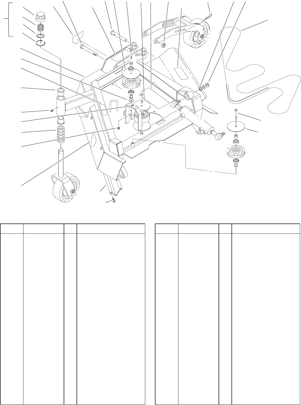
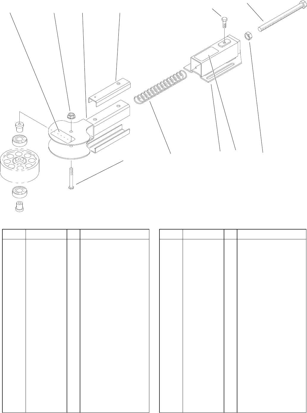
Right Hand Deck Assembly
DescriptionPart No. Qty.Ref. No. DescriptionPart No. Qty.Ref. No.
1 3216–6 1 Screw–HH
2 93–9413 1 Decal–HOC, Int’l
3 323–13 3 Screw–HH
4 86–2010 1 Pin–HOC
5 3290–256 1 Pin–Hair
6 3296–15 1 Nut–Lock NI
8 100–2588 1 V–Belt, B–Section
9 92–7758 1 RH Wing Deck ASM
9:1 32148–10 1 Insert–Threaded
9:2 43–8480 2 Decal–Danger
9:3 66–1340 1 Decal–Danger
9:4 69–6470 2 Bushing–Castor
9:5 85–6410 1 Decal–Danger
9:6 86–0700 1 Decal–HOC, RH Wing
9:7 86–0760 1 Decal–Belt, RH
10 92–9727 1 HOC Cap ASM
10:1 92–5581 1 Ring–Retaining
10:2 92–5583 1 Washer–Cap
10:3 92–9726 1 Spring–Compression
10:4 92–8861 1 Cap–HOC
11 86–2600–01 4 Washer–Guide, Belt
12 69–1510 5 Spacer–Castor
13 302–5 1 Fitting–Grease
15 32128–54 1 Nut–Flange
16 32128–29 1 Locknut–Flange
17 93–7814 1 Decal–Danger
18 93–7824 1 Decal–Danger, Int’l
19 93–7815 2 Decal–Danger, Int’l
21 86–1440 2 Washer–Flat
22 3256–35 1 Washer–Flat
23 93–7208–01 1 Shield–Deck, Wing
24 32144–11 10 Screw–TAP
3326–597
4
Sheet No.:3
1
21 3
4
5
6
8
15:7
15:414 1115
16 21
18 15:5
20
17
12
22:4
23:3
22:2
22:1
15:1
18
7
16
22
24 23
15:3
15:2 19
15:6
15:2
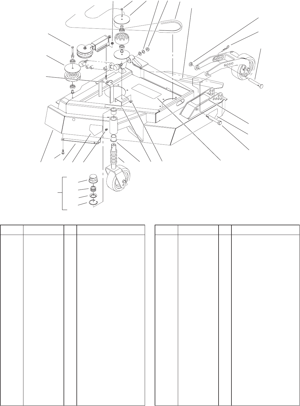
Left Hand Deck Assembly
DescriptionPart No. Qty.Ref. No. DescriptionPart No. Qty.Ref. No.
1 323–13 2 Screw–HH
2 32128–19 2 Nut–HF
3 100–2588 1 V–Belt, B–Section
4 3296–15 1 Nut–Lock NI
5 3290–256 1 Pin–Hair
6 86–2010 1 Pin–HOC
7 93–9412 1 Decal–HOC, Int’l
8 3216–6 1 Screw–HH
11 69–1510 5 Spacer–Castor
12 32128–54 1 Nut–Flange
14 302–5 1 Fitting–Grease
15 92–7756 1 LH Wing Deck ASM
15:1 32148–10 1 Insert–Threaded
15:2 43–8480 2 Decal–Danger
15:3 66–1340 1 Decal–Danger
15:4 69–6470 2 Bushing–Castor
15:5 85–6410 1 Decal–Danger
15:6 86–0710 1 Decal–HOC, LH Wing
15:7 86–0750 1 Decal–Belt, LH
16 86–2600–01 3 Washer–Guide, Belt
17 32128–29 1 Locknut–Flange
18 93–7815 2 Decal–Danger, Int’l
19 93–7814 1 Decal–Danger
20 93–7824 1 Decal–Danger, Int’l
21 86–1440 2 Washer–Flat
22 92–9727 1 HOC Cap ASM
22:1 92–5581 1 Ring–Retaining
22:2 92–5583 1 Washer–Cap
22:3 92–9726 1 Spring–Compression
22:4 92–8861 1 Cap–HOC
23 93–7208–01 1 Shield–Deck, Wing
24 32144–11 10 Screw–TAP
3326–597
5
Sheet No.:4
1 32 3 4, 5
6
14
15
17
18
19
20
21
22
23
24
252627
28
2
33
35
36
25:5
39 38 4020
44 42 2945
746
2
47
30:4
30:3
30:2
30:1
49
9
48
50 20 19
25:1
20
30
52
51
38
25:2 25:4 25:6
25:8
25:7
25:9
25:3
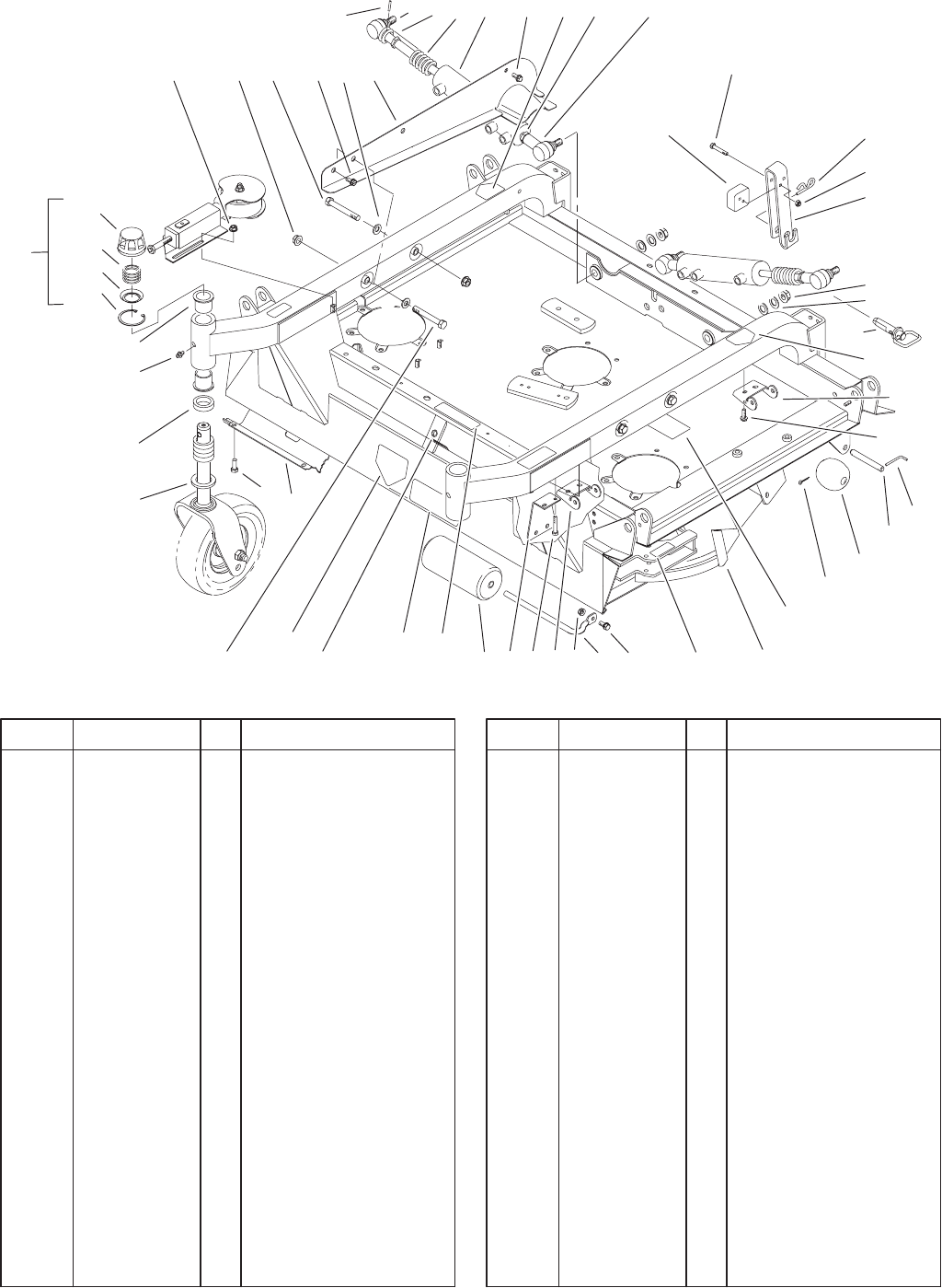
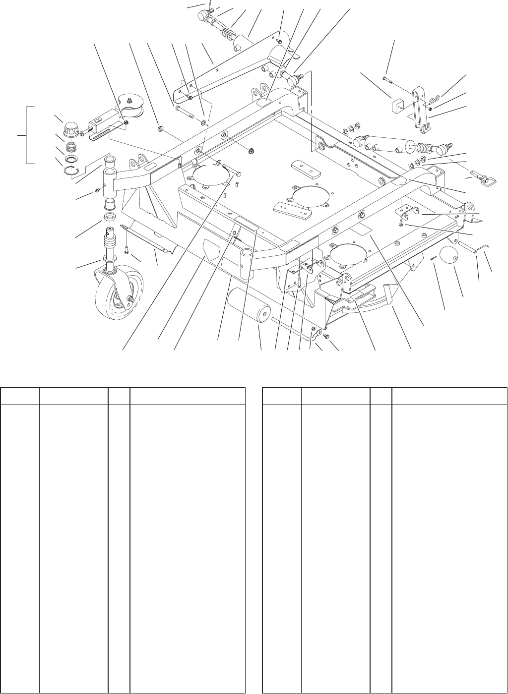
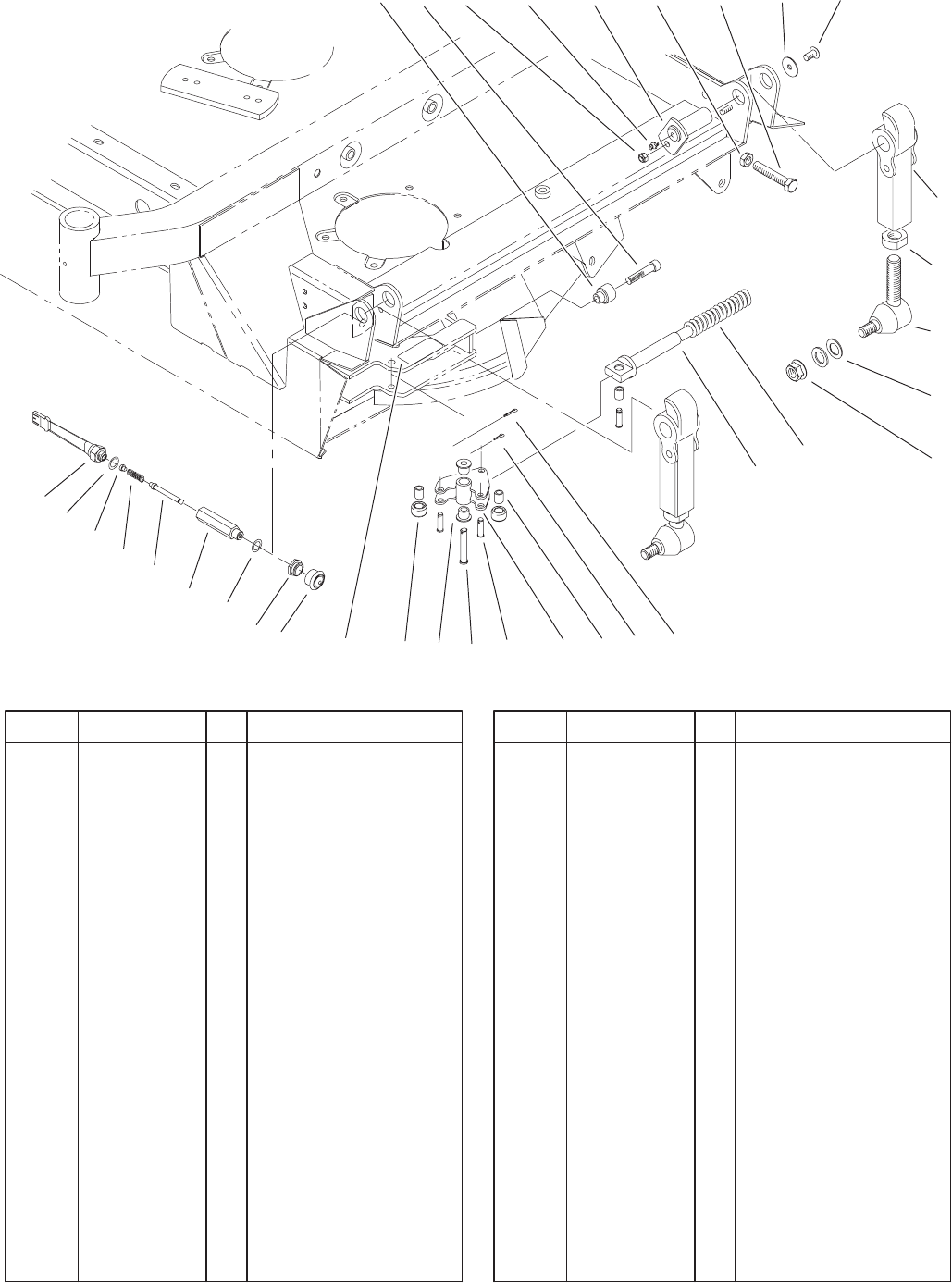
Center Deck Assembly
DescriptionPart No. Qty.Ref. No. DescriptionPart No. Qty.Ref. No.
1 32128–19 2 Nut–HF
2 325–35 4 Screw–HH
3 3256–26 4 Washer–Flat
4 86–2230–01 1 Guide–Cover, RH
5 86–2260–01 1 Guide–Cover, LH
6 86–2190 2 Cylinder–Lift, Wing
7 32121–51 2 Pin–Roll
9 94–8008 2 Plate–Wear
14 3290–256 2 Pin–Hair
15 94–8009–01 2 Strap–Deck, HOC
17 32128–54 2 Nut–Flange
18 86–2390 2 Pin
19 86–1890–03 4 Hinge
20 32144–26 12 Screw–Flow
21 57–0690 2 Pin–Special
22 57–0680 2 Shaft–Roller
23 29–4820 2 Roller
24 3272–11 2 Pin–Cotter
25 92–7757 1 Center Deck ASM
25:1 32148–10 1 Insert–Threaded
25:2 43–8480 1 Decal–Danger
25:3 55–4300 2 Decal–Warning
25:4 68–8340 1 Decal–Torque
25:5 69–6470 4 Bushing–Castor
25:6 85–6410 1 Decal–Danger
25:7 86–0720 1 Decal–HOC, LH
Center
25:8 86–0730 1 Decal–HOC, RH
Center
25:9 86–0740 1 Decal–Belt, Center
26 3234–1 1 Screw–HHF
27 68–6840 1 Shaft–Roller
28 32128–21 1 Nut–HF
29 68–6710 1 Roller
30 92–9727 2 HOC Cap ASM
30:1 92–5581 1 Ring–Retaining
30:2 92–5583 1 Washer–Cap
30:3 92–9726 1 Spring–Compression
30:4 92–8861 1 Cap–HOC
32 32128–23 4 Nut–HF
33 77–0950 2 Washer–Castor
35 69–1510 10 Spacer–Castor
36 302–5 2 Fitting–Grease
38 84–5300 4 Nut–Jam
39 92–5810–03 2 Female Rod End ASM
40 92–5811–03 2 Male Rod End ASM
42 93–7814 1 Decal–Danger
44 93–7818 1 Decal–Torque, Blade
Bolt
45 93–7815 1 Decal–Danger, Int’l
3326–597
6
Sheet No.:4
1 32 3 4, 5
6
14
15
17
18
19
20
21
22
23
24
252627
28
2
33
35
36
25:5
39 38 4020
44 42 2945
746
2
47
30:4
30:3
30:2
30:1
49
9
48
50 20 19
25:1
20
30
52
51
38
25:2 25:4 25:6
25:8
25:7
25:9
25:3
Center Deck Assembly (Continued)
DescriptionPart No. Qty.Ref. No. DescriptionPart No. Qty.Ref. No.
46 86–2510–01 2 Spring–Comp, Lift
47 86–1440 4 Washer–Flat
48 3296–29 4 Nut–Lock NI
49 322–21 4 Screw–HH
50 94–8020–03 2 Shield–Harness, Wire
51 32144–11 14 Screw–TAP
52 93–7207–01 1 Shield–Deck, Center
3326–597
7
Sheet No.:A1
4
1
2
3
T–1464
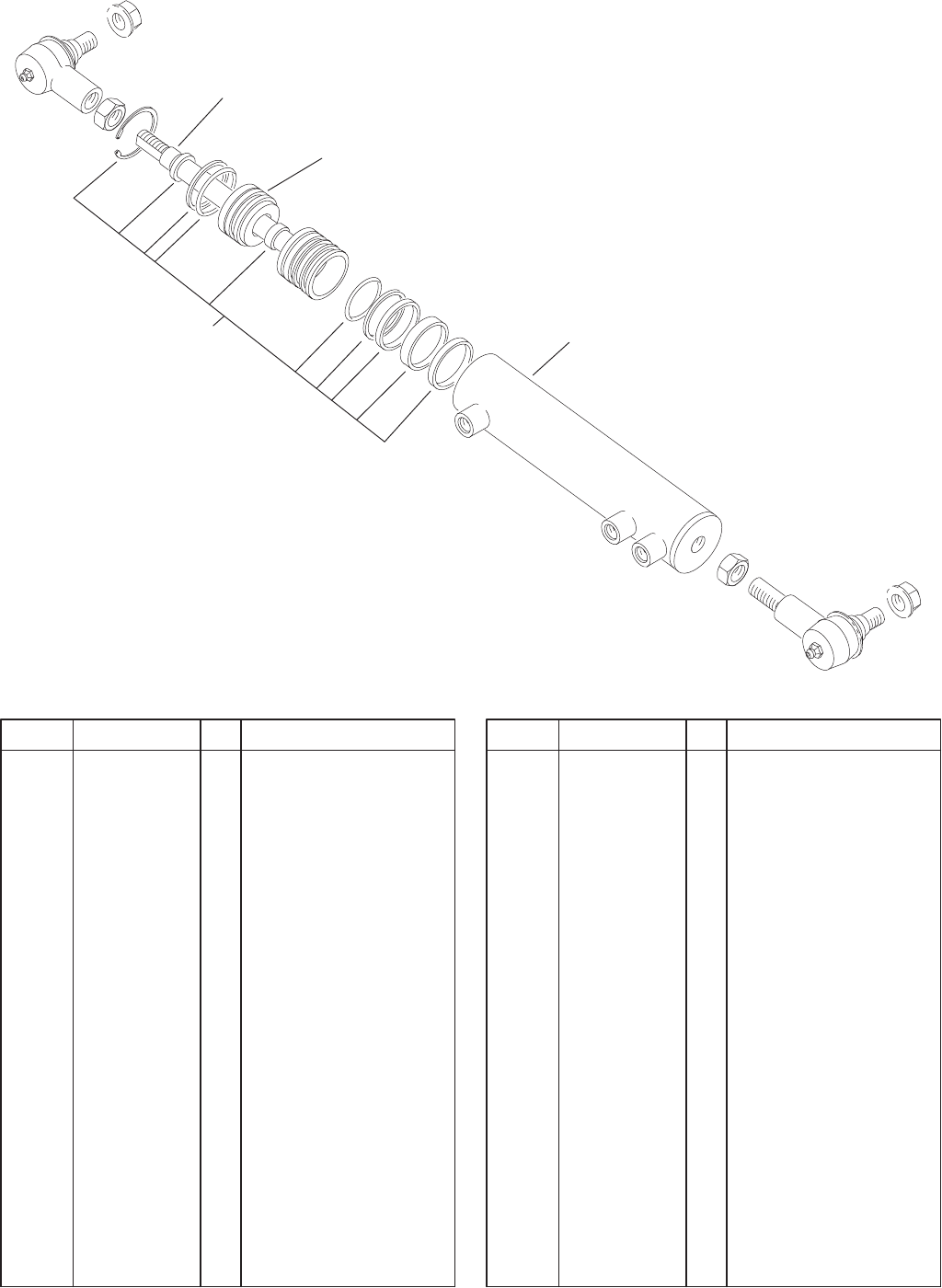
Hydraulic Cylinder Assembly No. 86–2190
DescriptionPart No. Qty.Ref. No. DescriptionPart No. Qty.Ref. No.
1 92–0603 1 Rod/Piston
2 92–0604 1 Head–Ring, Snap
3 92–0602 1 Barrel ASM
4 92–0600 1 Kit–Seal
3326–597
8
Sheet No.:5
1 23456
9
10
11
12
13
14
15
16
18192021
23
24
34
31
87
33
32
30
29
28
27
26 25 17 22
Deck Breakaway Assembly
DescriptionPart No. Qty.Ref. No. DescriptionPart No. Qty.Ref. No.
1 3296–29 4 Nut–Lock NI
2 84–1350 4 Pin–Pivot
3 3218–18 2 Nut–Jam
4 60–9870 2 Screw
5 53–6380 4 Washer
6 323–4 4 Screw–HH
7 92–4036 2 Cap–Rod
8 92–4037 2 Capscrew–HSH
9 84–0800–01 4 Arm–Pivot
10 302–5 4 Fitting–Grease
11 86–2070 4 Nut
12 86–2080–01 4 Joint–Ball
13 86–1440 8 Washer–Flat
14 32128–54 4 Nut–Flange
15 86–2560–01 2 Spring–Compression
16 86–2650 2 Spring–Support
17 3272–5 6 Pin–Cotter
18 86–2090 6 Bushing–Pm
19 86–2150 2 Lock
20 283–61 6 Pin–Yoke
21 86–2130 2 Pin–Clevis
22 3272–9 2 Pin–Cotter
23 86–2180 4 Bushing–Flange
24 86–2120 4 Roller–Lock
25 94–8031 2 Boot–Switch
26 94–8029 2 Nut–Special
27 237–7 2 O–Ring
28 94–8023 2 Guide–Pin, Switch
29 94–8024 2 Plunger–Switch
30 43–8600 2 Spring–Compression
31 93–6674 2 Decal–Warning
32 43–8610 2 Guide
33 237–42 2 O–Ring
34 72–4320 2 Switch
3326–597
9
Sheet No.:6
123
456
8
9
10
11
12
13
141618
16
23
2
2
7
26
2
29
25
24
28 15 20
27
27
17 27
19
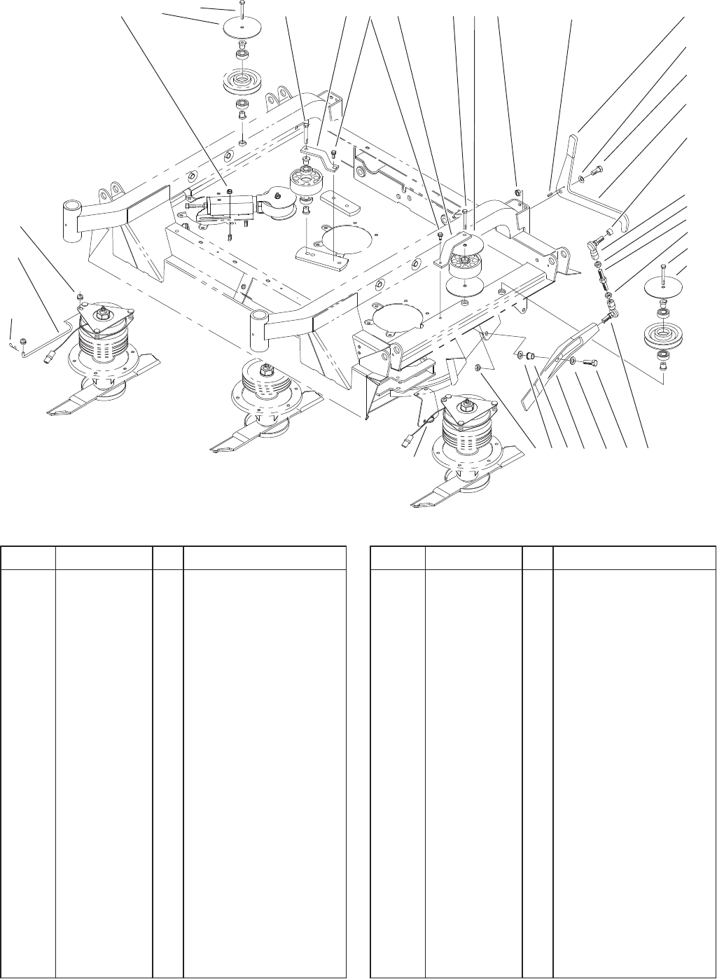
Trap Door Assembly
DescriptionPart No. Qty.Ref. No. DescriptionPart No. Qty.Ref. No.
1 32128–19 2 Nut–HF
2 323–13 4 Screw–HH
3 86–1820–01 1 Bracket–Pulley
4 32144–70 2 Screw–HH
5 3296–25 2 Nut–Lock NI
6 32121–11 2 Pin–Roll
7 86–2400–01 2 Latch–Arm
8 325–5 2 Screw–HH
9 86–1560 2 Spacer–Cylinder, Lift
10 86–1490 2 End–Rod, LH Thread
11 3220–12 2 Nut–HJ, LH Thread
12 86–1570 2 Rod–Threaded
13 3220–5–01 2 Nut–HJ
14 86–1550 2 End–Rod, RH Thread
15 3296–25 2 Nut–Lock NI
16 3256–26 4 Washer–Flat
17 92–7766–01 1 Bracket – Pulley
18 92–4033–01 2 Trap–Door
19 256–243 2 Bearing–Flange
20 325–7 2 Screw–HH
23 3290–467 2 Pin–Hair
24 86–2590 2 Rod–Clutch
25 237–141 4 Grommet–Rubber
26 48–7081 2 Grip–Plastic
27 86–2600–01 4 Washer–Guide, Belt
28 3290–378 2 Tie–Cable
29 3290–483 2 Washer
3326–597
10
Sheet No.:7
2
3
4
5
6
7
9
8
10
11
12
13
15
17
16
18
19
20
3
21
22
23
27
29
26
29:2
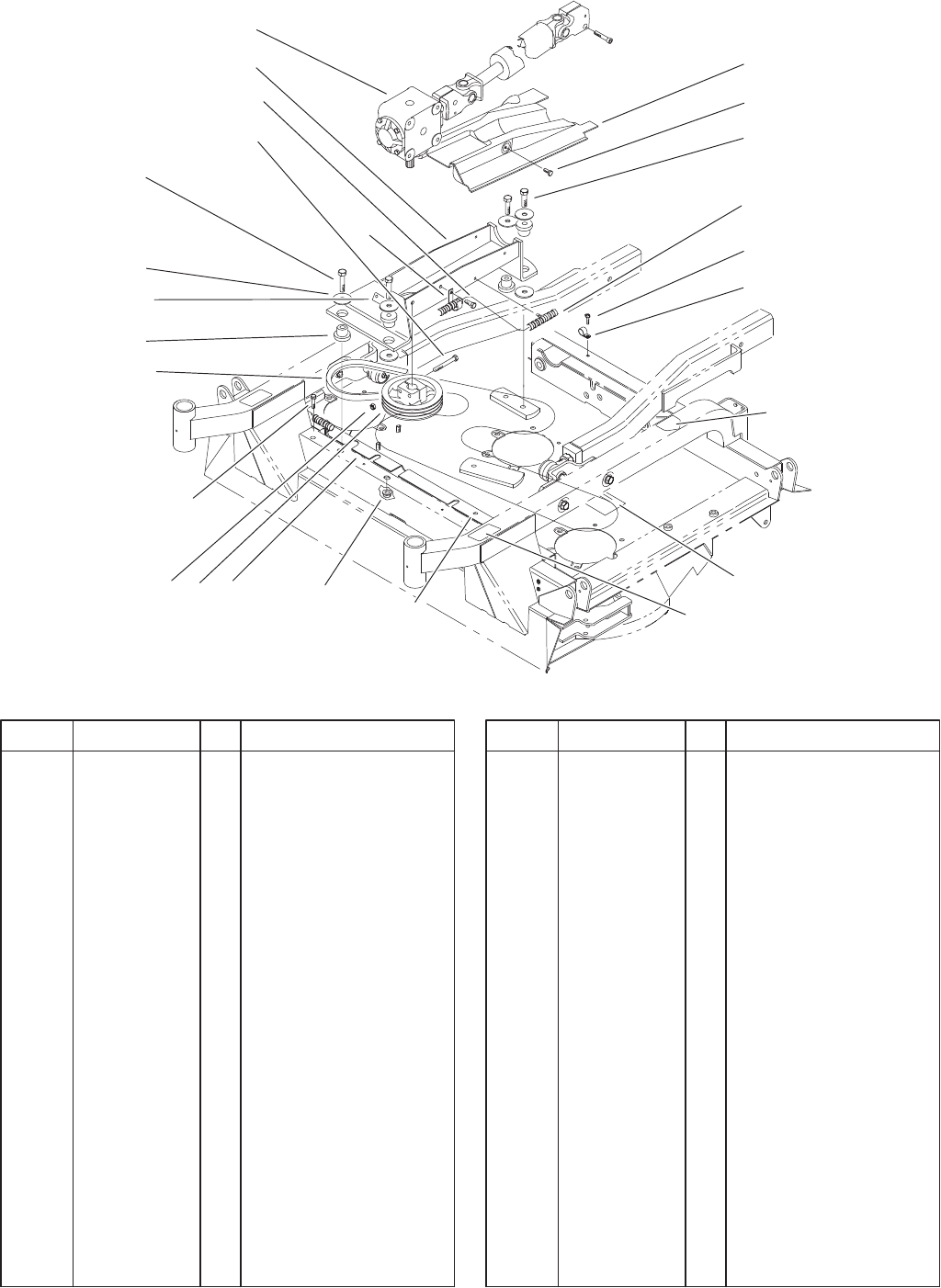
Drive Assembly
DescriptionPart No. Qty.Ref. No. DescriptionPart No. Qty.Ref. No.
2 86–1830 1 Cover–Driveshaft
3 32144–70 3 Screw–HH
4 325–7 2 Screw–HH
5 3234–1 4 Screw–HHF
6 95–4375 1 Harness–Wire, Deck
7 323–14 2 Screw–HH
8 93–9410 1 Decal–HOC, RH
Center
9 93–9411 1 Decal–HOC, LH
Center
10 86–0740 1 Decal–Belt, Center
11 32128–23 2 Nut–HF
12 86–1410–03 1 Pulley–Gearbox
*12 86–3100–03 1 Pulley–Gearbox, High
Speed
13 3296–39 2 Nut–Lock, NI
15 86–1970 1 V–Belt
16 86–1990 6 Washer
17 84–1550 4 Mount–Rubber
18 325–9 2 Screw–HH
19 86–2020–01 1 Support–Gearbox
20 100–2585 1 Gearbox
21 2412–138 1 R–Clamp
22 93–6697 1 Decal–Lube
23 86–0780 1 Decal–HOC
23 93–9421 1 Decal–HOC
26 2412–150 1 J–Clip
27 3234–1 2 Screw–HHF
29 100–2591 1 Shield ASM
29:2 32148–9 2 Nut–Insert
* Not illustrated
3326–597
11
Sheet No.:A2
T–3570
1,2
3,4
5,6
8
9
10
17
18
19
20
23
24
25
26,27,28,29
30
11
12
13 14
15
7
16
26,27,28,29
25
8
8
7
9
3,4
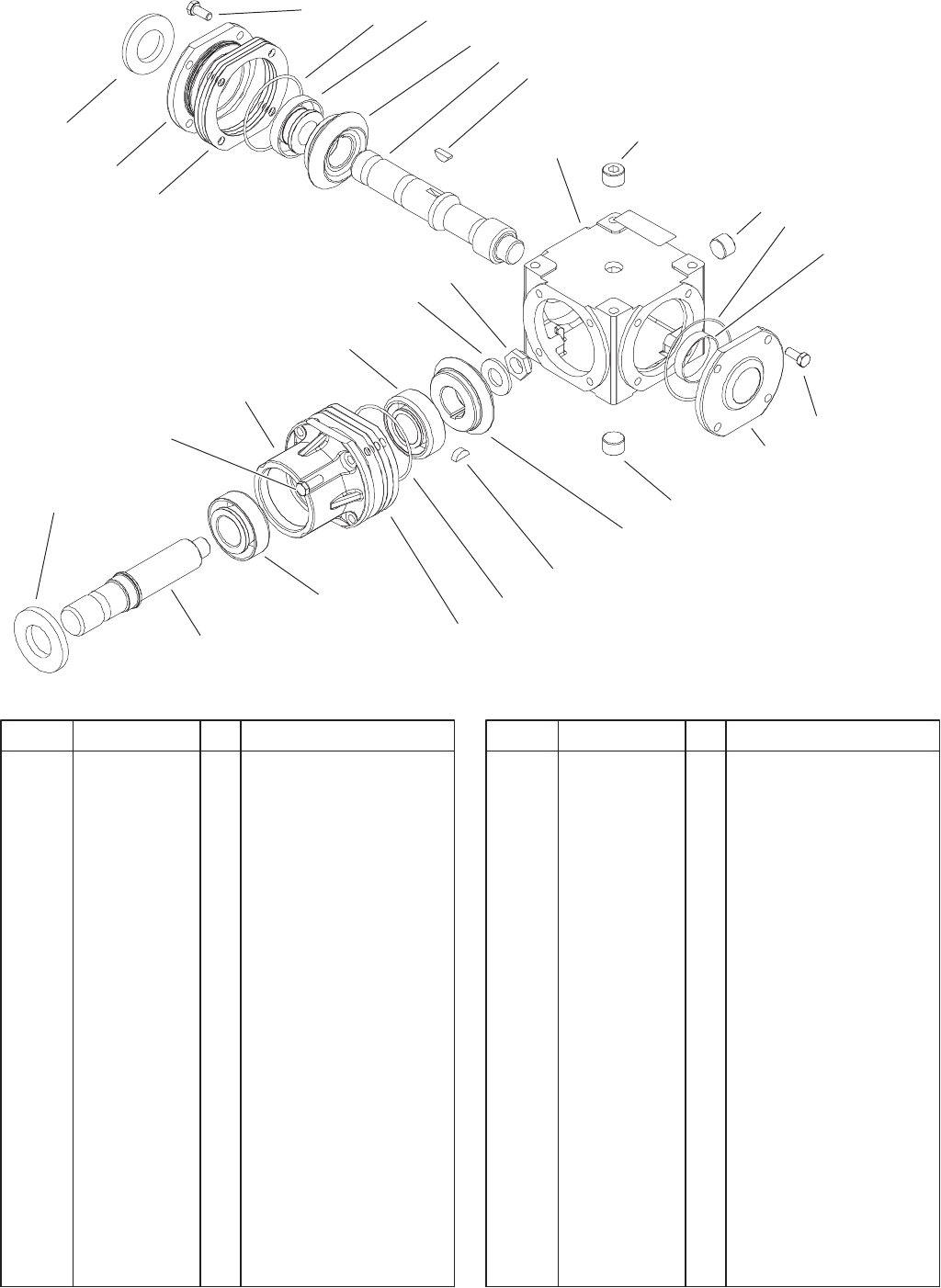
Gearbox Assembly No. 100–2585
DescriptionPart No. Qty.Ref. No. DescriptionPart No. Qty.Ref. No.
1 100–4571 1 Bearing–Cup
2 100–4572 1 Bearing–Cone
3 104–2359 2 Bearing–Cup
4 104–2360 2 Bearing–Cone
5 100–5817 1 Bearing–Cup
6 104–2358 1 Bearing–Cone
7 100–5818 8 Screw–HH
8 100–5812 3 Plug
9 100–4580 2 Key–Woodruff
10 100–1391 1 Nut–Lock
11 104–2361 1 Seal
12 104–2367 1 Gear–RH
13 104–2368 1 Gear–LH
14 104–2362 1 Shaft–Input
15 100–9984 1 Cap–End, Closed
16 104–2357 1 Cap–End, Open
17 100–5826 1 Case
18 104–2363 1 Shaft–Output
19 104–2364 1 Seal
20 100–5824 1 Washer
23 100–5847 1 O–Ring
24 104–2365 1 Housing–Pinion
25 100–5848 2 O–Ring
26 100–1394 3 Shim–Green (.003)
27 100–7758 3 Shim–Blue (.005)
28 100–1396 3 Shim–Brown (.010)
29 100–7760 3 Shim – Yellow (.020)
30 104–2366 4 Screw
3326–597
12
Sheet No.:8
1
3
4
2:1
2:8
2:9
2:3
2:4
2:2
2:7
2:6
2:4
2:10
2
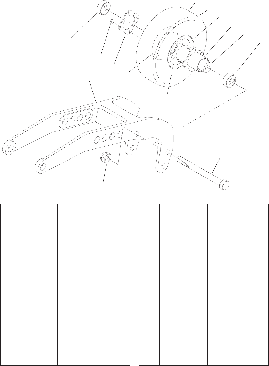
Rear Castor Assembly
DescriptionPart No. Qty.Ref. No. DescriptionPart No. Qty.Ref. No.
1 75–9790–01 2 Arm–Pivot
2 93–9938 2 8 Inch Wheel ASM
2 93–5974 2 Wheel–8 Inch, Foam
Filled
2:1 93–9939 2 Tire
2:2 68–8950 1 Tube–Inner (W/Valve)
2:3 93–4241 2 Spacer–Bearing, Inner
2:4 93–4237 4 Bearing
2:6 32128–16 8 Nut–HHF
2:7 93–4242 2 Plate
2:8 93–4239 3 Rim–Wheel, Half
2:9 93–5980 2 Hub
2:10 95–2741 1 Rim–Wheel, Half
3 327–24 2 Screw–HH
4 3296–53 2 Nut–Lock, NI
3326–597
13
Sheet No.:9
2:3
2:2
1:1
1:2
3:2
3:3
1
2
3
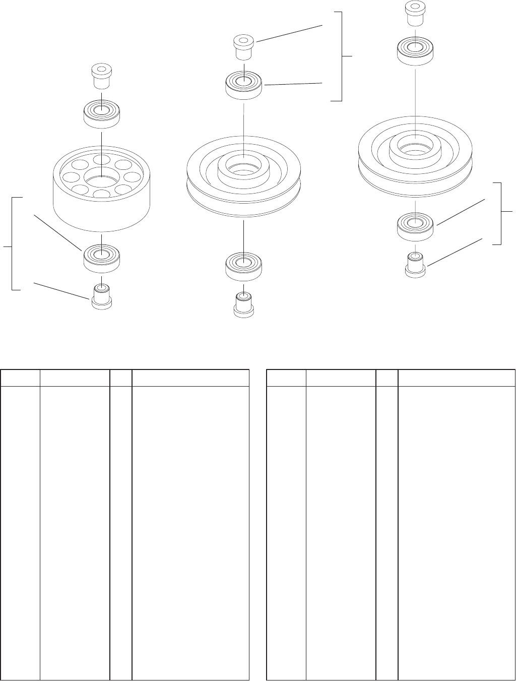
Pulley Assembly
DescriptionPart No. Qty.Ref. No. DescriptionPart No. Qty.Ref. No.
1 92–0625 6 Flat Pulley ASM
1:1 100–2587 2 Spacer–Bearing
1:2 38–7820 2 Bearing–Ball
2 92–9722 4 V–Pulley ASM
2:2 38–7820 2 Bearing–Ball
2:3 100–2587 2 Spacer–Bearing
3 104–2355 2 Idler Pulley ASM
3:2 38–7820 2 Bearing–Ball
3:3 100–2587 2 Spacer–Bearing
3326–597
14
Sheet No.:10
1
2
4
5
5:8
5:9
5:3
5:4
5:2
5:7
5:6
5:10
6
6:5
6:7
6:4
6:3
6:9
6:8
5:1
6:10
6:1
6:2
(WING)
(CENTER)
3
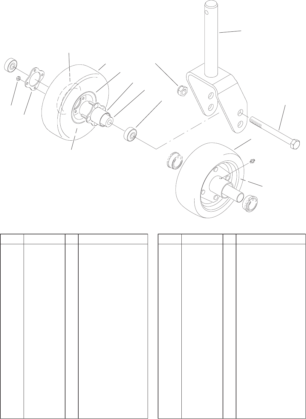
Front Castor Assembly
DescriptionPart No. Qty.Ref. No. DescriptionPart No. Qty.Ref. No.
1 3296–53 4 Nut–Lock, NI
2 92–7750–01 2 Fork–Castor
3 92–7752–01 2 Fork–Castor
4 327–24 4 Screw–HH
*5 93–5974 2 Wheel–8 Inch, Foam
Filled
5 93–9938 2 8 Inch Wheel ASM
5:1 93–9939 2 Tire
5:2 68–8950 1 Tube–Inner (W/Valve)
5:3 93–4241 2 Spacer–Bearing, Inner
5:4 93–4237 4 Bearing
5:6 32128–16 8 Nut–HHF
5:7 93–4242 2 Plate
5:8 93–4239 3 Rim–Wheel, Half
5:9 93–5980 2 Hub
5:10 95–2741 1 Rim–Wheel, Half
*6 93–5973 2 Wheel–10 Inch, Foam
Filled
*6 93–4240 2 Wheel ASM–10 Inch
6 76–1880 2 10 Inch Tire ASM
6:1 93–4243 2 Tire
6:2 93–4244 1 Tube–Inner (W/Valve)
6:3 93–4241 2 Spacer–Bearing, Inner
6:4 93–4237 4 Bearing
6:5 32128–16 4 Nut–HHF
6:7 93–4242 2 Plate
6:8 93–4239 3 Rim–Wheel, Half
6:9 93–5980 2 Hub
6:10 95–2741 1 Rim–Wheel, Half
* Not illustrated
3326–597
15
Sheet No.:11
2
4
5
7
8
9
31
(WING)
10
(CENTER)
2:1
6:1
6
11
Belt Tensioner Assembly
DescriptionPart No. Qty.Ref. No. DescriptionPart No. Qty.Ref. No.
1 32128–43 3 Nut–Flange
2 95–4383 3 Pulley Yoke ASM
2:1 55–4300 1 Decal–Warning
3 86–0060 6 Sleeve–Tube
4 86–0050 3 Screw
5 3217–9 3 Nut–HH
6 92–0626 3 Tube ASM
6:1 93–9418 1 Decal–Adjustment
7 92–7767 2 Spring–Compression
8 92–7768 1 Spring–Compression
9 86–2000 3 Screw
10 322–5 3 Screw–HH
11 93–6674 3 Decal–Warning
3326–597
16
Sheet No.:12
1234 67
89101112131210
14
15
16
17 519 18 18
15:215:1
16:1
16:2
15:1
13:1 11:1 11:2
6:2
6:1
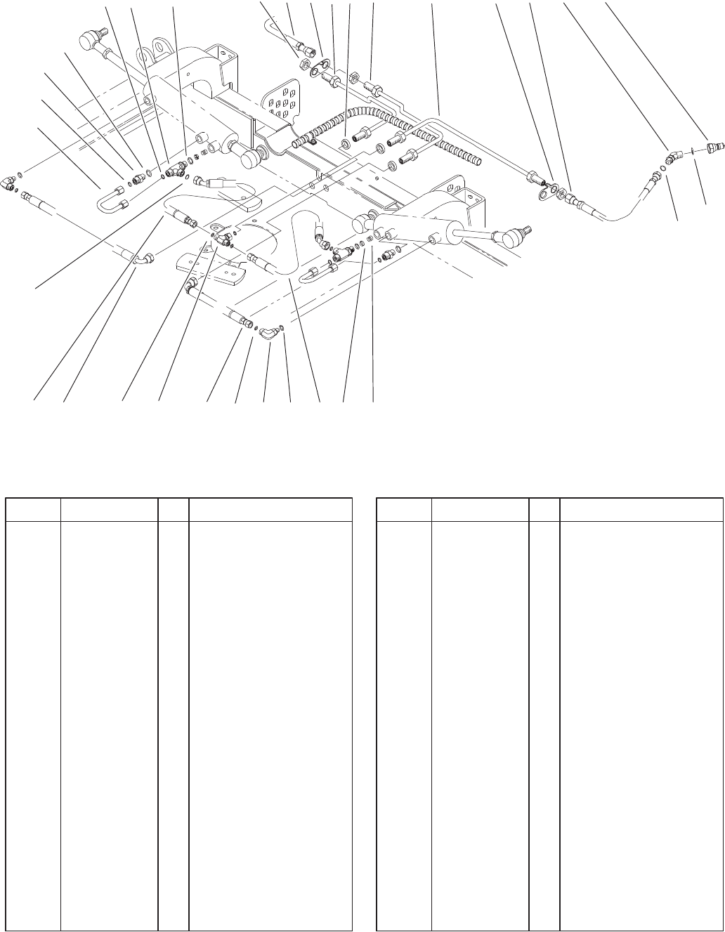
Hydraulics Assembly
DescriptionPart No. Qty.Ref. No. DescriptionPart No. Qty.Ref. No.
1 340–70 6 Locknut–Bulkhead
2 86–2480 1 RH Cylinder Tube ASM
3 86–2490 1 LH Cylinder Tube ASM
4 86–2470 1 Cylinder Drain Tube
ASM
5 86–2460 2 Hose ASM
6 340–87 3 Fitting–Adapter, 45
6:1 237–22 1 O–Ring
6:2 237–42 1 O–Ring
7 86–5460 3 Nipple–Coupler
8 86–2630 2 Spring–Compression
9 84–6403 2 Disc–Orifice
10 86–2450 2 Hose ASM
11 340–77 2 Fitting–HYD, 90
11:1 237–22 1 O–Ring
11:2 237–42 1 O–Ring
12 86–2440 2 Hose ASM
13 340–166 1 Fitting–Tee, HYD
13:1 237–22 1 O–Ring
14 86–2640 2 Deck Cylinder Tube
ASM
15 340–86 2 Fitting–Tee, HYD
15:1 237–22 2 O–Ring
15:2 237–42 1 O–Ring
16 340–2 2 Adapter–Straight, HYD
16:1 237–22 1 O–Ring
16:2 237–42 1 O–Ring
17 86–0690 3 Spacer
18 92–5807 2 Retainer–Hardlines
19 86–1420 1 LH Lift Hose ASM
3326–597
17
Sheet No.:13
1
2
34
5
68910 111213 1415
716
18
17
19
20 20
20
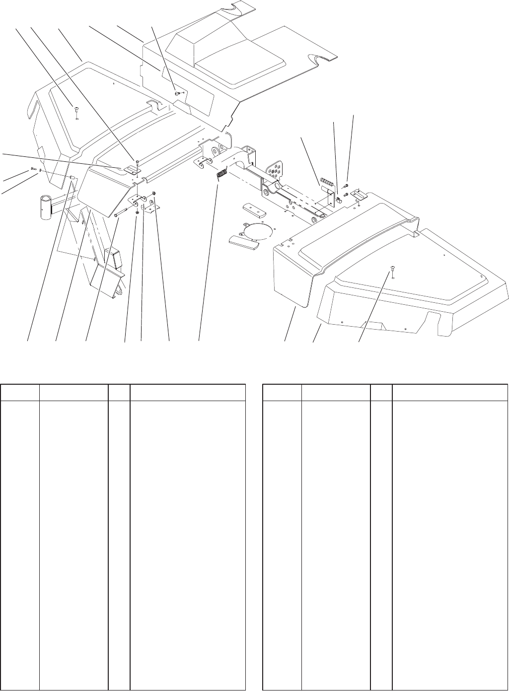
Covers Assembly
DescriptionPart No. Qty.Ref. No. DescriptionPart No. Qty.Ref. No.
1 3250–20 8 Screw–PPH
2 3256–67 8 Washer–Flat
3 86–1840 1 Cover–Deck, RH
4 3234–29 8 Screw–HHF
5 86–1900–03 4 Plate–Hinge
6 86–1870 1 Cover–Center, RH
7 86–1860 1 Cover–Center
8 86–1880 1 Cover–Center, LH
9 86–1850 1 Cover–Deck, LH
10 3296–59 4 Nut–Lock NI
11 86–1920 2 Spring–Torsion
12 32128–20 8 Nut–HF
13 323–15 4 Screw–HH
14 86–1890–03 4 Hinge
15 86–0790 8 Insert–Cover
16 86–0770 1 Decal–Quadfloat
17 32144–70 2 Screw–HH
18 86–2660–01 1 Stop–Cover
19 2412–138 1 R–Clamp
20 3250–36 3 Screw–PPH
3326–597
18
Sheet No.:14
1
2
3
4
5
6
7
8
9
10
11
12
13
14
16
17
15
19
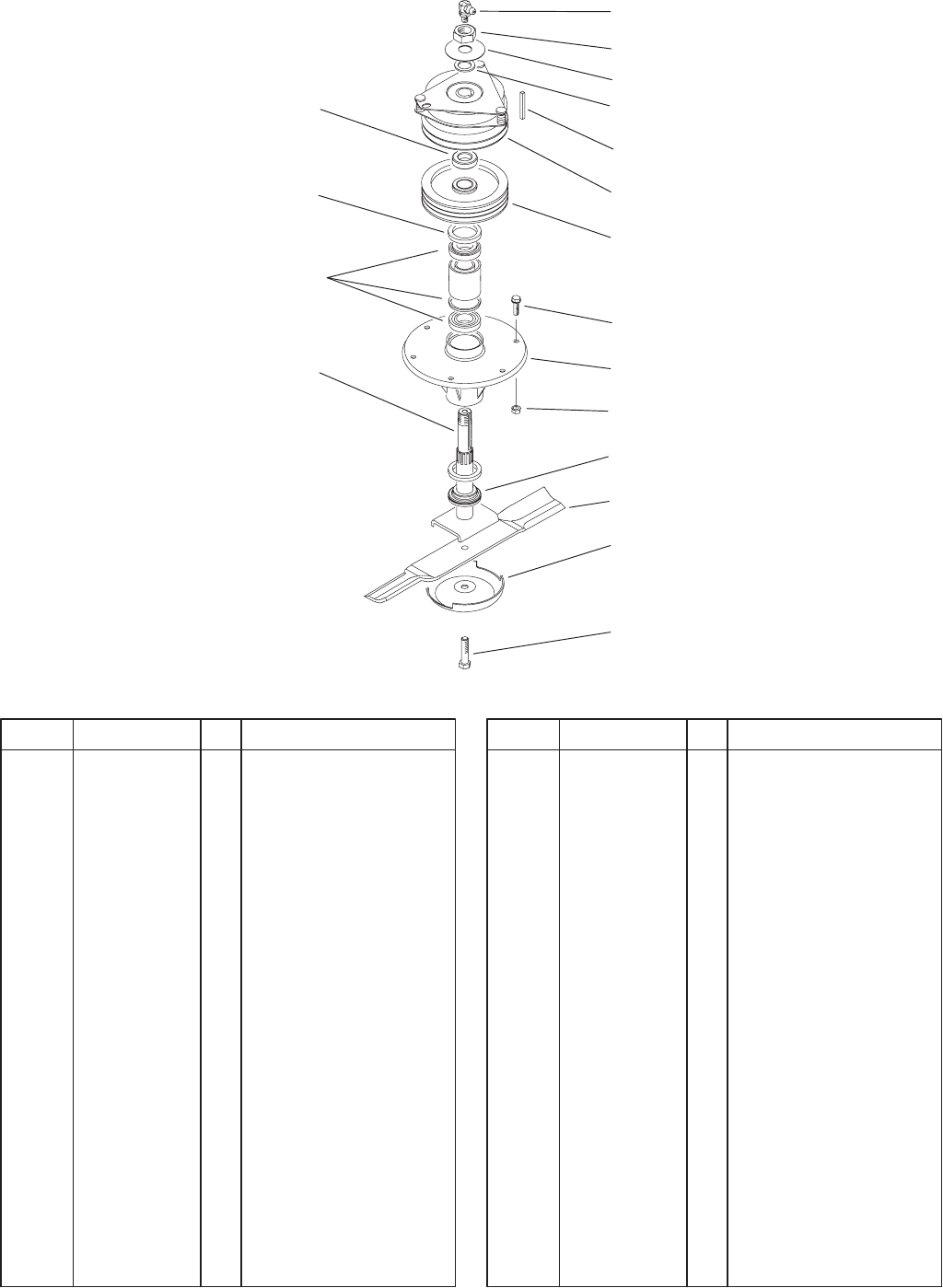
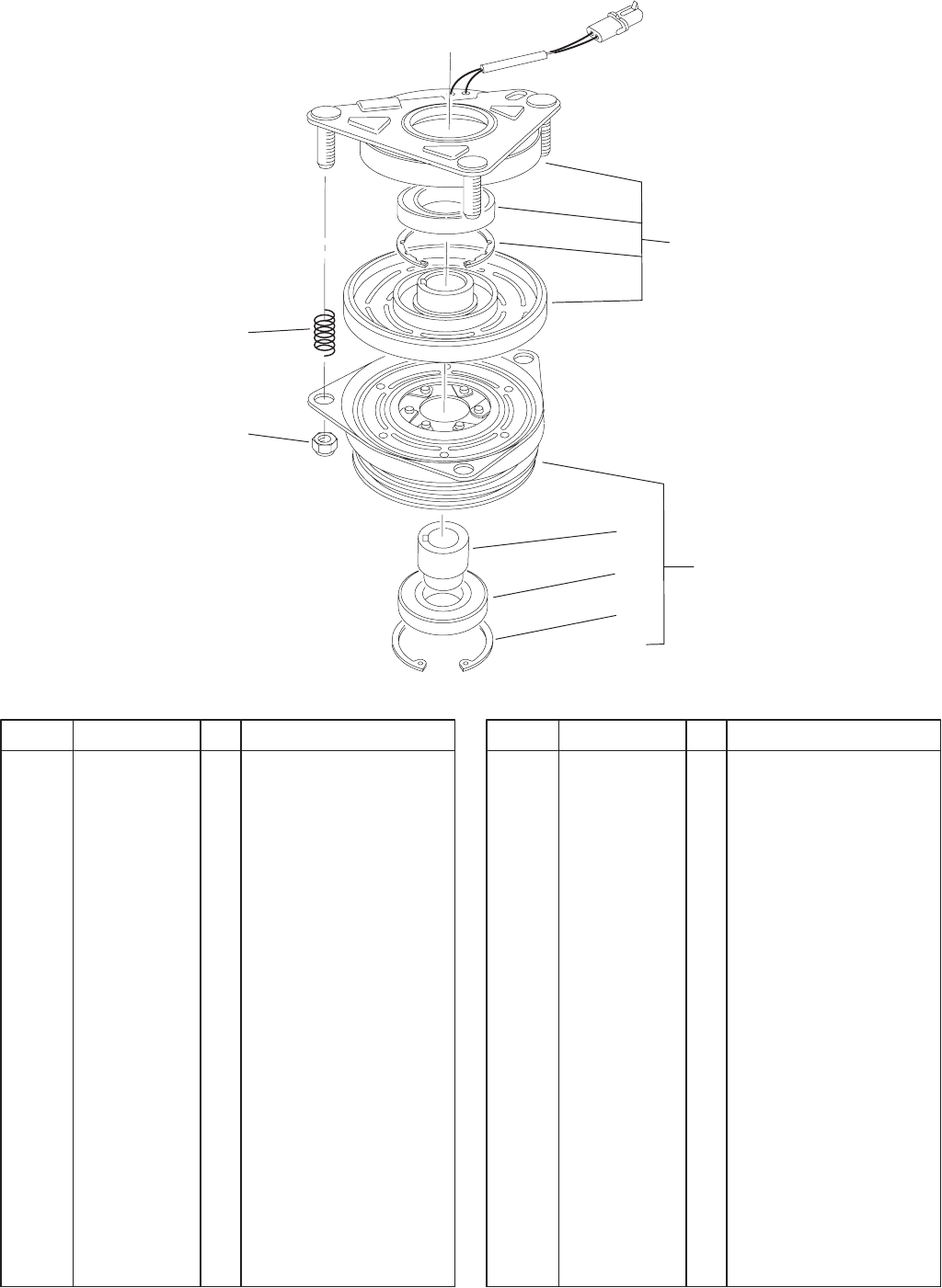
Clutch Spindle Assembly
DescriptionPart No. Qty.Ref. No. DescriptionPart No. Qty.Ref. No.
1 302–33 2 Fitting–Grease
2 3296–49 2 Nut–Lock NI
3 100–2559 2 Clutch–Brake, Electric
4 68–3220 2 Stock–Key
5 86–1740 2 Spacer
6 84–0780–01 2 Pulley–Spindle
7 253–154 4 Seal–Oil
8 3234–42 12 Screw–HHF
9 69–1530 2 Housing–Spindle
10 3290–357 12 Nut–Flange, Lock
11 86–2360 2 Shaft–Spindle, Clutch
12 69–6950 2 Spacer–Shaft, Spindle
13 86–0010–03 2 Blade–19”
14 72–9361 2 Cup–Scalp, Anti
15 94–8013 2 Washer–Thrust
16 92–5816 2 Bolt–Blade
17 86–1480 2 Washer
19 71–2530 2 Kit–Bearing/Spacer
3326–597
19
Sheet No.:A3
T–3581
1
5
5:1
5:2
5:3
9
10
Electric Clutch Brake No. 100–2559
DescriptionPart No. Qty.Ref. No. DescriptionPart No. Qty.Ref. No.
1 67–7050 1 Field & Rotor ASM
5 104–2370 1 Armature ASM
5:1 67–7080 1 Sleeve–Bearing,
Armature
5:2 67–7090 1 Bearing–Armature
5:3 67–7060 1 Ring–Retaining
9 3296–6 3 Nut–Lock, NI
10 44–8320 3 Spring
3326–597
20
Sheet No.:15
5
1
2
3
4
6
7
8
10
11
12
13
14
5
9
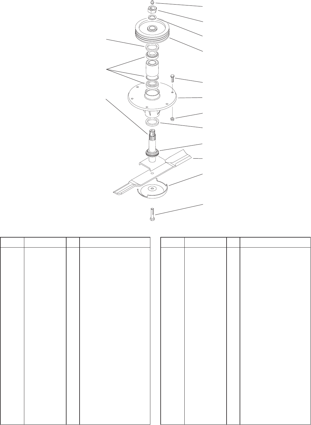
Center Spindle Assembly
DescriptionPart No. Qty.Ref. No. DescriptionPart No. Qty.Ref. No.
1 302–2 1 Fitting–Grease
2 3296–49 1 Nut–Lock NI
3 86–1480 1 Washer
4 84–0780–01 1 Pulley–Spindle
5 253–154 2 Seal–Oil
6 3234–42 6 Screw–HHF
7 69–1530 1 Housing–Spindle
8 3290–357 6 Nut–Flange, Lock
9 86–2340 1 Shaft–Spindle, Center
10 69–6950 1 Spacer–Shaft, Spindle
11 86–0010–03 1 Blade–19”
12 72–9361 1 Cup–Scalp, Anti
13 92–5816 1 Bolt–Blade
14 71–2530 1 Kit–Bearing/Spacer
3326–597
21
Sheet No.:16
1
2
3
4
5
6
7
8
9
10
11
12
13
5
14
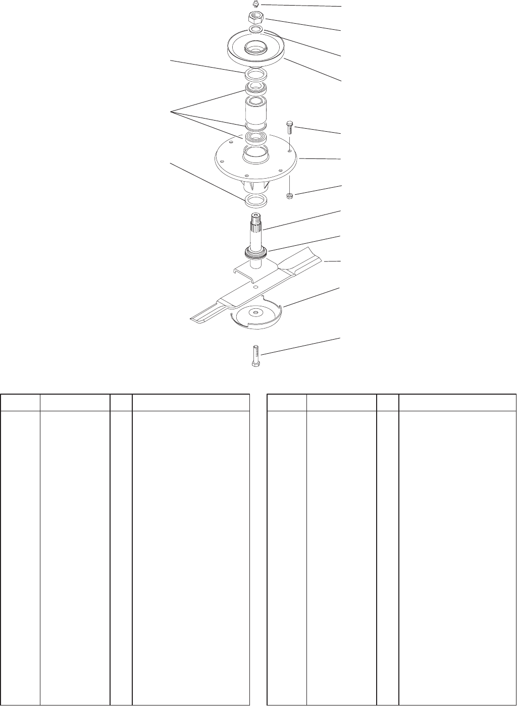
Wing Spindle Assembly
DescriptionPart No. Qty.Ref. No. DescriptionPart No. Qty.Ref. No.
1 302–2 4 Fitting–Grease
2 3296–49 4 Nut–Lock NI
3 86–1480 4 Washer
4 104–2354–03 4 Pulley–Spindle
5 253–154 8 Seal–Oil
6 3234–42 24 Screw–HHF
7 69–1530 4 Housing–Spindle
8 3290–357 24 Nut–Flange, Lock
9 86–2340 4 Shaft–Spindle, Center
10 69–6950 4 Spacer–Shaft, Spindle
11 86–0010–03 4 Blade–19”
12 72–9361 4 Cup–Scalp, Anti
13 92–5816 4 Bolt–Blade
14 71–2530 4 Kit–Bearing/Spacer

22
Maintenance Record
Date

23
Maintenance Record
Date