PDF Toshiba Perception E & EX Manual
Perception E & EX Manual Perception E & EX Manual
User Manual: PDF T E X T F I L E S
Open the PDF directly: View PDF ![]() .
.
Page Count: 368 [warning: Documents this large are best viewed by clicking the View PDF Link!]
- Installation Instructions
- Programming Procedures
- Table of Contents
- Chapter 1 Introduction
- Chapter 2 Set Up Keyboard/Remote Maintenance
- Chapter 3 Data Input/Output Procedures
- Chapter 4 Authorization Procedures/Utility Program Use
- Chapter 5 System Data
- Chapter 6 Feature Data
- Chapter 7 Attendant/Station/DSS Data
- Chapter 8 Message Center Data
- Chapter 9 Trunk Data
- Chapter 10 Toll Restriction Data
- Chapter 11 Data Switching Data
- Chapter 12 Least Cost Routing Data
- Chapter 13 Lodging/Health Care Data
- Chapter 14 Speed Dial List Data
- Chapter 15 Traffic Measurement Data
- Chapter 16 Alphanumeric Messaging Data
- Chapter 17 ACD Data
- Chapter 18 Verifiable Codes Data
- Chapter 19 Maintenance Prodecedures
- Appendix #1 System Record
- Appendix #2 Least Cost Routing and Toll Restriction Programming Guide
- Appendix #3 Prerequisites and Procedures for Installation

Perceptions
&
ex
DiGITAL
PBX
INSTALLATION AND MAINTENANCE MANUAL
TOSHIBA AMERICA INFORMATION SYSTEMS, INC.
Telecommunication Systems Division
TOSHIBA SYSTEM PRACTICES
DIGITAL PBX TOSHIBA PUBLICATIONS
SECTION 200-255-000
FEBRUARY 1992
Perception& a ex
DIGITAL PBX
INSTALLATION AND MAINTENANCE MANUAL
TABLE OF CONTENTS
GENERAL DESCRIPTION
INSTALLATION INSTRUCTIONS
PROGRAMMING PROCEDURES
FAULT FINDING PROCEDURES
TECHNICAL BULLETINS
SECTION 200-255-200
SECTION 200-255-300
SECTION 200-255-500
SECTION 200-255-600
TOSHIBASYSTEM PRACTICES
DIGITAL PBX INSTALLATION INSTRUCTIONS
SECTlON200-255-200
FEBRUARY1992
Perception& 65 ex
DIGITAL PBX
INSTALLATION INSTRUCTIONS
INSTALLATION INSTRUCTIONS
SECTION 200-255-200
FEBRUARY 1992
PERCEPTION,&,
INSTALLATION INSTRUCTIONS
TABLE OF CONTENTS
PARAGRAPH SUBJECT PAGE
CHAPTER1
1.
2.
3.
4.
5.
5.00
5.10
5.20
CHAPTER2
1.
1.00
1.10
1.20
2.
2.00
2.10
2.20
3.
4.
5.
6.
INTRODUCTION . . . . . . . . . . . . . . . . . . . . . . . . . . . . . . . . . . . . . . . . . . . . . . . . . . . . . . . . . . . . . . . . . . . . . . . . . . . . . . . . . . . . . . . . . ...*...
PURPOSE . . . . . . . . . . . . . . . . . . . . . . . . . . . . . . . . . . . . . . . . . . . . . . . . . . . . . . . . . . . . . . . . . . . . . . . . . . . . . . . . . . . . . . . . . . . . . . . . . . . . . . . . . . .
ORGANIZATION . . . . . . . . . . . . . . . . . . . . . . . . . . . . . . . . . . . . . . . . . . . . . . . . . . . . . . . . . . . . . . . . . . . . . . . . . . . . . . . . . . . . . . . . . . . . . . . . .
REFERENCE DOCUMENTATION . . . . . . . . . . . . . . . . . . . . . . . . . . . . . . . . . . . . . . . . . . . . . . . . . . . . . . . . . . . . . . . . . . . . . .
SYSTEM MNEMONICS . . . . . . . . . . . . . . . . . . . . . . . . . . . . . . . . . . . . . . . . . . . . . . . . . . . . . . . . . . . . . . . . . . . . . . . . . . . . . . . . . . . . . .
INSPECTION, PACKING AND STORAGE . . . . . . . . . . . . . . . . . . . . . . . . . . . . . . . . . . . . . . . . . . . . . . . . . . . . . . . . .
Inspection . . . . . . . . . . . . . . . . . . . . . . . . . . . . . . . . . . . . . . . . . . . . . . . . . . . . . . . . . . . . . . . . . . . . . . . . . . . . . . . . . . . . . . . . . . . . . . . . . . . . . . . .
Packing and Storage . . . . . . . . . . . . . . . . . . . . . . . . . . . . . . . . . . . . . . . . . . . . . . . . . . . . . . . . . . . . . . . . . . . . . . . . . . . . . . . . . . . . . . .
Required Tools . . . . . . . . . . . . . . . . . . . . . . . . . . . . . . . . . . . . . . . . . . . . . . . . . . . . . . . . . . . . . . . . . . . . . . . . . . . . . . . . . . . . . . . . . . . . . . . .
SYSTEM DESCRIPTION ...................................................................................
PERCEPTION
e ..................................................................................................
Basic Equipment
Cabinet ................................................................................
Expansion Cabinet ..........................................................................................
Power Supply ..................................................................................................
PERCEPTION
ex .................................................................................................
Basic Equipment Cabinet ................................................................................
Expansion Cabinet ..........................................................................................
Power Supply ..................................................................................................
PEAK LOAD BATTERY ......................................................................................
EXTENDED RESERVE POWER ........................................................................
POWER FAILURE/EMERGENCY TRANSFER ..................................................
PRINTED CIRCUIT BOARD DESCRIPTION.. ....................................................
NFDU (Floppy Disk Drive Unit).
.......................................................................
LCCU (Central Control Unit) ............................................................................
NTWU (Time Switch Unit) ...............................................................................
NPRU (Paging and Music-on-Hold Unit) .........................................................
NRCU (Receiver Unit) .....................................................................................
NEKU (Electronic Telephone Unit) ..................................................................
NDKU (Digital Telephone Unit). .......................................................................
NSTU (Standard
Telephone Unit) ...................................................................
NDSU (DSS Console Controller Unit) .............................................................
NDCU (Data Control Unit) ...............................................................................
NMDU (Modem Pooling Unit) ..........................................................................
NCOU (Central Office Trunk Unit) ...................................................................
NEMU (E & M TIE Trunk Unit). ........................................................................
NLSU (DID Trunk Interface Unit). ....................................................................
NDTU (Tl Interface) ........................................................................................
NOCU (Off-hook Call Announce Interface Unit) ..............................................
HVSUHVSI (Off-hook Call Announce PCBs) .................................................
DVSI (Digital Off-hook Call Announce PCB) ...................................................
1-l
1-l
1-l
1-l
1-l
l-2
1-2
l-2
l-2
2-l
2-l
2-1
2-l
2-l
2-l
2-l
2-l
2-2
2-2
2-3
2-3
2-4
2-4
2-4
2-4
2-5
2-5
2-5
2-5
2-6
2-6
2-6
2-6
2-6
2-6
2-6
2-6
2-6
2-6
2-6
INSTALLATION INSTRUCTIONS
SECTION 200-255-200
FEBRUARY 1992
PARAGRAPH SUBJECT PAGE
7.
a.
a.00
a.10
a.20
a.30
a.40
a.50
8.60
a.70
8.80
a.90
CHAPTER 3
1.
2.
3.
4.
5.
CHAPTER 4
1.
1 .oo
1.10
2.
2.00
2.10
2.20
3.
3.00
3.10
3.20
3.30
3.40
3.50
3.60
SYSTEM INDICATORS AND CONTROLS . . . . . . . . . . . . . . . . . . . . . . . . . . . . . . . . . . . . . . . . . . . . . . . . . . . . . . . . .
NFDU
. . . . . . . . . . . . . . . . . . . . . . . . . . . . . . . . . . . . . . . . . . . . . . . . . . . . . . . . . . . . . . . . . . . . . . . . . . . . . . . . . . . . . . . . . . . . . . . . . . . . . . . . . . . . . . .
LCCU . . . . . . . . . . . . . . . . . . . . . . . . . . . . . . . . . . . . . . . . . . . . . . . . . . . . . . . . . . . . . . . . . . . . . . . . . . . . . . . . . . . . . . . . . . . . . . . . . . . . . . . . . . . . . . .
NTWU . . . . . . . . . . . . . . . . . . . . . . . . . . . . . . . . . . . . . . . . . . . . . . . . . . . . . . . . . . . . . . . . . . . . . . . . . . . . . . . . . . . . . . . . . . . . . . . . . . . . . . . . . . . . . .
NPRU . . . . . . . . . . . . . . . . . . . . . . . . . . . . . . . . . . . . . . . . . . . . . . . . . . . . . . . . . . . . . . . . . . . . . . . . . . . . . . . . . . . . . . . . . . . . . . . . . . . . . . . . . . . . . .
NCOU/NEMU/NLSU . . . . . . . . . . . . . . . . . . . . . . . . . . . . . . . . . . . . . . . . . . . . . . . . . . . . . . . . . . . . . . . . . . . . . . . . . . . . . . . . . . . . . . . .
NDTU
. . . . . . . . . . . . . . . . . . . . . . . . . . . . . . . . . . . . . . . . . . . . . . . . . . . . . . . . . . . . . . . . . . . . . . . . . . . . . . . . . . . . . . . . . . . . . . . . . . . . . . . . . . . . . . .
NEKU/NSTU/NOCU/NDKU
. . . . . . . . . . . . . . . . . . . . . . . . . . . . . . . . . . . . . . . . . . . . . . . . . . . . . . . . . . . . . . . . . . . . . . . . . . . . .
NDSU . . . . . . . . . . . . . . . . . . . . . . . . . . . . . . . . . . . . . . . . . . . . . . . . . . . . . . . . . . . . . . . . . . . . . . . . . . . . . . . . . . . . . . . . . . . . . . . . . . . . . . . . . . . . . .
NDCU . . . . . . . . . . . . . . . . . . . . . . . . . . . . . . . . . . . . . . . . . . . . . . . . . . . . . . . . . . . . . . . . . . . . . . . . . . . . . . . . . . . . . . . . . . . . . . . . . . . . . . . . . . . . . .
NMDU ..............................................................................................................
NPSA-M/LPSA-M
............................................................................................
N PSA-S ...........................................................................................................
PERIPHERAL EQUIPMENT ...............................................................................
Electronic and Digital Telephone
.....................................................................
Headset Upgrade (HHEU)
...............................................................................
Attendant Console ...........................................................................................
DSS Console ...................................................................................................
Standard Telephone
........................................................................................
DDIU/PDIU
......................................................................................................
Paging Equipment
...........................................................................................
Music-on-Hold
.................................................................................................
Universal Night Answer
...................................................................................
Station Message Detail Recording ..................................................................
2-7
‘.
2-7
2-7
2-7
2-7
2-7
2-7
2-a
2-a
2-a
2-a
2-a
2-a
2-a
2-a
2-9
2-9
2-9
2-9
2-9
2-9
2-9
2-9
2-9
INSTALLATION SITE REQUIREMENTS . . . . . . . . . . . . . . . . . . . . . . . . . . . . . . . . . . . . . . . . . . . . . . . . . . . . . . . . . . . 3-1
COMMERCIAL POWER
. . . . . . . . . . . . . . . . . . . . . . . . . . . . . . . . . . . . . . . . . . . . . . . . . . . . . . . . . . . . . . . . . . . . . . . . . . . . . . . . . . . . . 3-1
ENVIRONMENTAL REQUIREMENTS . . . . . . . . . . . . . . . . . . . . . . . . . . . . . . . . . . . . . . . . . . . . . . . . . . . . . . . . . . . . . . . 3-1
EQUIPMENT ROOM RECOMMENDATIONS . . . . . . . . . . . . . . . . . . . . . . . . . . . . . . . . . . . . . . . . . . . . . . . . . . . . 3-1
CABLING CONSIDERATIONS . . . . . . . . . . . . . . . . . . . . . . . . . . . . . . . . . . . . . . . . . . . . . . . . . . . . . . . . . . . . . . . . . . . . . . . . . . . 3-1
GROUNDING
. . . . . . . . . . . . . . . . . . . . . . . . . . . . . . . . . . . . . . . . . . . . . . . . . . . . . . . . . . . . . . . . . . . . . . . . . . . . . . . . . . . . . . . . . . . . . . . . . . . . . .
3-2
SYSTEM INSTALLATION ..................................................................................
PERCEPTlONe
..................................................................................................
Power Supply Installation
................................................................................
Expansion Cabinet
Installation ........................................................................
PERCEPTIONex
.................................................................................................
Power Supply Installation
................................................................................
First Expansion Cabinet Installation ................................................................
Second
Expansion
Cabinet Installation
...........................................................
PRINTED CIRCUIT BOARD INSTALLATION..
...................................................
NFDU
...............................................................................................................
LCCU
...............................................................................................................
NTWU
..............................................................................................................
NPRU ..............................................................................................................
NEKU, NDKU, and NOCU
...............................................................................
NSTU
...............................................................................................................
NDSU ..............................................................................................................
4-1
4-1
4-1
4-3
4-4
4-4
4-6
4-a
4-9
4-9
4-10
4-10
4-10
4-10
4-12
4-12
INSTALLATION INSTRUCTIONS
SECTION 200-255-200
FEBRUARY 1992
PARAGRAPH SUBJECT PAGE
3.70
3.80
3.90
4.
5.
5.00
5.10
5.20
5.30
5.40
5.50
5.60
5.70
5.80
5.90
6.
6.00
6.10
6.20
6.30
6.40
6.50
6.60
6.70
6.80
6.90
6.100
6.110
6.120
6.130
6.140
6.150
6.160
6.170
6.180
7.
7.00
8.00
9.
9.00
9.10
9.20
9.30
9.40
9.50
9.60
9.80
NEMU, NCOU, and
NLSU
...............................................................................
NDTU
...............................................................................................................
NMDU and NDCU ...........................................................................................
CABLE
CONNECTIONS .....................................................................................
ELECTRONIC TELEPHONE STATION EQUIPMENT INSTALLATION.. ...........
Electronic Telephone Connections.. ................................................................
Electronic Telephone Wall Mounting
...............................................................
Off-hook
Call
Announce ..................................................................................
Carbon Handset Transmitter Installation
.........................................................
HHEU Installation
............................................................................................
Attendant Console Connection ........................................................................
DSS Console Connections ..............................................................................
Digital Data Interface
Unit Connections (DDIU) ..............................................
DDIU-MAT .......................................................................................................
DDIU-MA
.........................................................................................................
DIGITAL TELEPHONE STATION
EQUIPMENT INSTALLATION
......................
Digital Telephone Connections..
......................................................................
Digital Telephone Wall Mounting
.. .
..................................................................
Off-hook Call
Announce
..................................................................................
Carbon Handset Transmitter
Installation
.........................................................
Beep Strap Removal
.......................................................................................
Microphone/Speaker Threshold Adjustment (Speakerphone only) .................
HHEU Installation ............................................................................................
Attendant Console Connection ........................................................................
DSS Console Connections ..............................................................................
Digital Data
Inter-face
Unit Installation
(PDIU) .................................................
Common DIU Connections..
............................................................................
EIA Interface
Leads
(Signals) ..........................................................................
DIP Switch Options..
........................................................................................
PDIU-DI Installation .........................................................................................
PDIU-DI to Personal Computer (PC) Installation.. ...........................................
PDIU-DS to Printer
Installation ........................................................................
PDIU-DS to Modem
Installation.. .....................................................................
PDIU-DS Disassembly and Assembly..
...........................................................
PDIU-DVPDIU-DS Installation
Tests ...............................................................
STANDARD TELEPHONE EQUIPMENT INSTALLATION .................................
Standard Telephone Connections
...................................................................
TRUNK CONNECTIONS ....................................................................................
PERIPHERAL
EQUIPMENT
INSTALLATION.. ...................................................
Modem Pooling Connections
(DDIU-MA
only) ................................................
Power Failure/Emergency Transfer.. ...............................................................
Reserve Power
................................................................................................
Paging
Equipment
...........................................................................................
Music-on-Hold
.................................................................................................
Universal
Night Answer
...................................................................................
Station Message Detail Recording
..................................................................
Lodging/Health Care Data Audit.. ....................................................................
4-13
4-15
4-18
4-19
4-20
4-20
4-20
4-20
4-23
4-23
4-25
4-26
4-26
4-28
4-30
4-32
4-32
4-32
4-34
4-35
4-36
4-36
4-36
4-37
4-37
4-37
4-39
4-39
4-46
4-46
4-47
4-47
4-51
4-52
4-52
4-58
4-58
4-58
4-58
4-58
4-58
4-60
4-61
4-62
4-62
4-63
4-67
. . .
-Ill-
INSTALLATION INSTRUCTIONS
SECTION 200-255-200
FEBRUARY 1992
PARAGRAPH SUBJECT PAGE
IO.
SYSTEM POWER UP . . . . . . . . . . . . . . . . . . . . . . . . . . . . . . . . . . . . . . . . . . . . . . . . . . . . . . . . . . . . . . . . . . . . . . . . . . . . . . . . . . . . . . . . . 4-67
10.00 General
. . . . . . . . . . . . . . . . . . . . . . . . . . . . . . . . . . . . . . . . . . . . . . . . . . . . . . . . . . . . . . . . . . . . . . . . . . . . . . . . . . . . . . . . . . . . . . . . . . . . . . . . . . . . 4-67
CHAPTER 5 MDF ARRANGEMENT . . . . . . . . . . . . . . . . . . . . . . . . . . . . . . . . . . . . . . . . . . . . . . . . . . . . . . . . . . . . . . . . . . . . . . . . . . . . . . . . . . . . . . . 5-I
TABLE
5-I
5-2
5-3
5-4
5-5
5-6
5-7
5-8
5-9
5-10
5-1 I
5-12
5-13
S-14
s-15
FIGURE
2-I
2-2
2-3
2-4
2-5
2-6
2-7
2-8
3-I
3-2
3-3
4-I
4-2
4-3
4-4
4-5
TABLE LIST
SUBJECT PAGE
CARD SLOT/CABLE CONNECTOR MATRIX ........................................................ 5-4
LIST OF CONNECTOR CABLES ........................................................................... 5-5
ATTENDANT CONSOLE #0 & #1 ........................................................................... 5-6
PAGING, MUSIC & UNA RINGING ........................................................................ 5-7
NDSU/NDKU (DSS CONSOLE) “C” SLOT ............................................................. 5-8
NDSU/NEKU/NDKU/NSTU/NDCU/NMDU/NOCU (LOO - L03/L15 - L18).
............. 5-9
NDSU/NEKU/NDKU/NSTU/NDCU/NMDU/NOCU (LO4 - Ll l/L1 9 - L26) or
NCOU/NLSU/NEMU (TO7 - TOO/-T15
- T08) .......................................................... 5-10
CENTRAL OFFICE LINE CONNECTION & PFT CONTROL Jl ............................. 5-11
STATION LINE CONNECTION J2 .......................................................................... 5-12
ATTENDANT CONSOLE #O
& #l ........................................................................... 5-13
PAGING, MUSIC & UNA RINGING ........................................................................ 5-14
NCOU/NEMU/NLSU/NDTU (TOO
w 115) ................................................................. 5-15
NDSU/NEKU/NDKU/NSTU/NDCU/NMDU/NOCU (UOO - U31) or .
NCOU/NEMU/NLSU (T16 u T31) ............................................................................ 5-16
CENTRAL OFFICE LINE CONNECTION & PFT CONTROL Jl ............................. 5-17
STATION LINE CONNECTION J2.. ........................................................................ 5-18
FIGURE LIST
SUBJECT PAGE
PERCEPTION, BASIC CABINET ........................................................................... 2-l
PERCEPTION, EXPANSION CABINET ................................................................ 2-I
PERCEPTION,, BASIC CABINET ......................................................................... 2-2
PERCEPTION,, WITH EXPANSION CABINETS .................................................. 2-2
PERCEPTION,, MAIN POWER SUPPLY.. ............................................................ 2-2
DPFT FUNCTIONAL DIAGRAM ............................................................................. 2-3
PERCEPTlONe PCB INSTALLATION .................................................................... 2-4
PERCEPTION,, PCB INSTALLATION .................................................................. 2-5
PERCEPTION, MINIMUM FLOOR SPACE ........................................................... 3-I
PERCEPTION,, MINIMUM FLOOR SPACE.. ........................................................ 3-I
UL GROUNDING DIAGRAM ................................................................................... 3-2
PERCEPTION, BASIC CABINET REAR COVER .................................................. 4-I
PERCEPTION, CABLE CONNECTIONS.. ............................................................. 4-I
PERCEPTlONe VOLTAGE CHECKS ..................................................................... 4-2
PEAK LOAD BATTERY .......................................................................................... 4-3
PERCEPTION, POWER SUPPLY CONTROLS AND INDICATORS .................... 4-3
-iv-
INSTALLATION INSTRUCTIONS
SECTION 200-255-200
FEBRUARY 1992
FIGURE SUBJECT PAGE
4-6
4-7
4-8
4-9
4-10
4-l
1
4-12
4-13
4-14
4-15
4-16
4-17
4-18
4-19
4-20
4-21
4-22
4-23
4-24
4-25
4-26
4-27
4-28
4-29
4-30
4-31
4-32
4-33
4-34
4-35
4-36
4-37
4-38
4-39
4-40
4-41
4-42
4-43
4-44
4-45
4-46
4-47
4-48
4-49
4-50
PERCEPTION, EXPANSION
CABINET INSTALLATION
......................................
PERCEPTION,, BASIC CABINET REAR COVER ................................................
PERCEPTION,, CABLE CONNECTIONS .............................................................
PERCEPTION,, VOLTAGE CHECKS ...................................................................
PERCEPTION,, POWER SUPPLY CONTROLS AND INDICATORS..
.................
PERCEPTION,, EXPANSION CABINET INSTALLATION ....................................
NFDU STRAPPING.. ...............................................................................................
LCCU STRAPPING .................................................................................................
NTWU STRAPPING ................................................................................................
NPRU STRAPPING ................................................................................................
NRCU MOUNTING .................................................................................................
NDKU SWITCH OPTIONS.. ....................................................................................
NEMU STRAPPING ................................................................................................
NCOU STRAPPING ................................................................................................
NLSU STRAPPING .................................................................................................
NDTU STRAPPING.. ...............................................................................................
NMDU STRAPPING ................................................................................................
ELECTRONIC TELEPHONE CONNECTION .........................................................
REMOVAL OF ELECTRONIC TELEPHONE BASE ...............................................
REMOVAL OF HANDSET HANGER ......................................................................
INSTALLATION OF MOUNTING BASE FOR WALL-MOUNT INSTALLATION
.....
HVSI/HVSU INSTALLATION ..................................................................................
ELECTRONIC TELEPHONE PCB CONNECTIONS ..............................................
OFF-HOOK CALL ANNOUNCE CONNECTION
(NOCU)
.......................................
LOCATION OF CARBON STRAPS ........................................................................
REMOVAL OF HHEU MODULAR CONNECTOR ACCESS TAB.. .........................
INSTALLATION OF HHEU UPGRADE OPTION ....................................................
ATTENDANT CONSOLE #0 CONNECTION ..........................................................
ATTENDANT CONSOLE #I CONNECTION ..........................................................
DSS CONSOLE CONNECTION FOR PERCEPTION, “C” SLOT.. ........................
DSS CONSOLE CONNECTION FOR PERCEPTION,, “U” SLOTS AND
PERCEPTION, ‘I” SLOTS.. ...................................................................................
DIGITAL DATA INTERFACE UNIT CONNECTION (DDIU-MA and DDIU-MAT) ...
INSTALLING DDIU-MAT.. .......................................................................................
DDIU-MAT DIP SWITCHES.. ..................................................................................
DDIU-MA DIUA PCB ...............................................................................................
DIUB PCB ...............................................................................................................
DIGITAL TELEPHONE CONNECTION ..................................................................
REMOVAL OF DIGITAL TELEPHONE BASE ........................................................
REMOVAL OF HANDSET HANGER ......................................................................
INSTALLATION OF MOUNTING BASE FOR WALL-MOUNT INSTALLATION .....
DVSU INSTALLATION ............................................................................................
TELEPHONE PCB CONNECTIONS AND STRAPS.. .............................................
HHEU INSTALLATION FOR DIGITAL TELEPHONE .............................................
DIGITAL DSS CONSOLE CONNECTION FOR PERCEPTION, “C” SLOT ...........
DIGITAL DSS CONSOLE CONNECTION FOR PERCEPTION,, “U” SLOTS
AND PERCEPTION, “L” SLOTS ............................................................................
4-3
4-5
4-5
4-6
4-7
4-8
4-10
4-10
4-11
4-11
4-11
4-12
4-14
4-14
4-16
4-16
4-19
4-21
4-22
4-22
4-22
4-23
4-23
4-24
4-24
4-24
4-25
4-25
4-26
4-27
4-27
4-28
4-29
4-29
4-31
4-31
4-33
4-34
4-34
4-34
4-35
4-35
4-36
4-38
4-38
-V-
INSTALLATION INSTRUCTIONS
SECTION 200-255-200
FEBRUARY 1992
FIGURE
4-51
4-52
4-53
4-54
4-55
4-56
4-57
4-58
4-59
4-60
4-61
4-62
4-63
4-64
4-65
4-66
4-67
4-68
4-69
4-70
4-71
4-72
4-73
4-74
4-75
4-76
5-l
5-2
5-3
SUBJECT PAGE ”
PERCEPTION DATA INSTALLATION EXAMPLE BLOCK DIAGRAM..
................. 4-40
PDIU-DI/PDIU-DS MODULAR CABLURJ-45 ADAPTER CONNECTIONS ........... 4-41
PDIU-DI/PDIU-DS MODULAR CORDS AND RJ-45/RS-232 ADAPTER PIN
CONNECTIONS.. .................................................................................................... 4-42
PDIU-DS JUMPER PLUG OPTIONS/RS-232 CONNECTOR INFORMATION ...... 4-43
PDIU-DI/PDIU-DS SW1 DIP SWITCH INFORMATION .......................................... 4-44
PDIU-DI PCBIDIGITAL TELEPHONE INSTALLATION .......................................... 4-46
PDIU-DS TO TOSHIBA PRINTER, RS-232 CONNECTOR/CABLE
CONNECTIONS ...................................................................................................... 4-48
PDIU-DI TO IBM XT-TYPE COMPUTER, RS-232 CONNECTOR/CABLE
CONNECTIONS
...................................................................................................... 4-49
PDIU-DI TO IBM AT-TYPE COMPUTER, RS-232 CONNECTOR/CABLE
CONNECTIONS .................. . ................................................................................... 4-50
PDIU-DS TO HAYES-TYPE SMART MODEM, RS-232 CONNECTOR/CABLE
CONNECTIONS.. .................................................................................................... 4-53
PDIU-DS DISASSEMBLY/ASSEMBLY DIAGRAM ................................................. 4-54
PC TO PC TEST CALL USING AT COMMANDS.. ................................................. 4-55
PC TO PRINTER TEST CALL USING MANUAL DIALING..
................................... 4-55
INTERNAL PC TO EXTERNAL PC TEST CALL USING AT COMMANDS.. .......... 4-55
EXTERNAL PC TO INTERNAL PC TEST CALL USING AT COMMANDS.. .......... 4-56
STANDARD TELEPHONE CONNECTION..
........................................................... 4-59
MODEM POOLING CONNECTION (DDIU-MA ONLY) .......................................... 4-60
RESERVE POWER INSTALLATION ...................................................................... 4-61
PAGING WITH MUSIC OVER EXTERNAL SPEAKER FROM SAME AMPLIFIER 4-62
PAGING WITH ONE AMPLIFIER ........................................................................... 4-63
PAGING WITH MULTIPLE AMPLIFIERS ............................................................... 4-64
LCCU SWITCHES
................................................................................................... 4-65
EXAMPLE: SMDR CALL RECORD ........................................................................ 4-66
EXAMPLE: AUDIT PRINTOUT (LODGING/HEALTH CARE) ................................. 4-68
INSERTING DISK (PERCEPTION, ONLY) .......................................................... 4-69
INSERTING DISK (PERCEPTION, ONLY) ............................................................ 4-69
CONNECTOR LOCKING BAR.. .............................................................................. 5-I
MAIN DISTRIBUTION FRAME LAYOUT ................................................................ 5-2
SECONDARY PROTECTOR DIAGRAM ................................................................ 5-3
-vi-
CHAPTER 1
INTRODUCTION
1. PURPOSE
1 .OO This section describes the installation proce-
dures necessary to ensure proper operation of the
PERCEPTIONeLex system.
2. ORGANIZATION
2.00 The organization of this manual is as follows:
1. INTRODUCTION
2. SYSTEM DESCRIPTION
3. INSTALLATION SITE REQUIREMENTS
4. SYSTEM INSTALLATION
5. MDF ARRANGEMENTS
3. REFERENCE DOCUMENTATION
3.00 The PERCEPTION eslex
system is supported
by a complete set of documentation. A list of the
reference documentation associated with the
PERCEPTION e&ex system is provided below:
Document Section Number
Fault Finding 200-255-500
General Description
Operating Procedures 200-255-400
Programming 200-255-300
System Record
4. SYSTEM MNEMONICS
4.00 The system is provided with a complete set of
mnemonics that relate directly to its operation and
features. The following alphabetical list describes
the mnemonics used in this manual.
DATT-Attendant Console
DDIU-Digital Data Interface Unit PC6 (Electronic
Telephone)
INSTALLATION INSTRUCTIONS
SECTION 200-255-201
FEBRUARY 1992
DDIU-MA-Digital Data Interface Unit (Stand-alone)
DDIU-MAT-Digital Data Interface Unit (Electronic
Telephone)
DDSS-Digital Direct Station Selection Console
DKT-Digital Telephone
DPFT-Power Failure/Emergency Transfer Unit
DSS-Direct Station Selection Console (Electronic
Telephone)
DVSU-PCB for Off-hook Call Announce (installed
inside the digital telephone)
EKT-Electronic Telephone
FDDO-Floppy Disk Drive 0
FDDl-Floppy Disk Drive 1
GND-Ground
HHEU-Optional Headset Module
HVSI-PCB for Off-hook Call Announce (installed
inside the electronic telephone)
HVSU-PCB for Off-hook Call Announce (installed
inside the electronic telephone)
LCCU-Central Control Unit
LCD-Liquid Crystal Display
LCEC-M-PERCEPTIONex Basic Cabinet
LCEC-S-PERCEPTIONex Expansion Cabinet
LPSA-M-PERCEPTlONe, Main Power Supply
MDF-Main Distribution Frame
NCEC-M-PERCEPTlONe Basic Cabinet
NCEC-S-PERCEPTlONe Expansion Cabinet
NCOU-Central Office Trunk Unit
l-l
INSTALLATION INSTRUCTIONS
SECTION 200-255-201
FEBRUARY1992
NDCU-Data Control Unit
NDKU-Digital Telephone, Digital DSS, PDIU-DI,
PDIU-DS Unit
NDSU-DSS Console Controller Unit (Electronic
Telephone)
NDTU-Digital Trunk Unit
NEKU-Electronic Telephone Unit
NEMU-E & M TIE Trunk Unit
NFDU-Floppy Disk Drive Unit
NLSU-DID Trunk Interface Unit
NMDU-Modem Pooling Unit
NOCU-Off-hook Call Announce Interface Unit
NPRU-Paging and Music-on-Hold Unit
NPSA-M-PERCEPTlONe Main Power Supply
NPSA-S-PERCEPTIONehex Expansion Power
SUPPlY
NRCU--Receiver Unit
NSTU-Standard Telephone Unit
NTWU-Time Switch Unit
PCB-Printed Circuit Board
PDIU-DI-Integrated Data Interface Unit (Digital
Telephone)
PDIU-DB-Stand-alone Data Interface Unit (Key-
board Dial)
TTY-Teletypewriter
UNA-Universal Night Answer
5. INSPECTION,
PACKING and STORAGE
5.00 Inspection
5.01
When the system is received, examine all
packages and make careful note of any visible
damage. If any damage is found, bring it to the
attention of the delivery carrier and make the proper
claims.
5.02 Check the system against the purchase order
and packing slip. If it is determined that equipment
is missing, contact your supplier immediately.
5.03 After unpacking (and before installing), in-
spect all equipment for damage. If any is detected,
contact your supplier immediately.
CAUTION!
When handling (installing, removing, ex-
amining, etc.) prin ted circuit boards (PCBs),
do not touch the back (soldered) side or
edge connector. Always hold the PCB by
its edge whenever handling it.
5.10 Packing and Storage
5.11 When storing or shipping PCBs, be sure they
are packed in their original antistatic bags for pro-
tection against static discharge.
5.20 Required Tools
5.21 Installation of the PERCEPTIONeLe, systems
requires standard telephony tools. A 13mm socket
wrench and extension is recommended for ease of
expansion cabinet installation.
PFT-Power Fail Transfer
SMDR-Station Message Detail Recording
1-2
INSTALLATION INSTRUCTIONS
SECTION 200-255-202
FEBRUARY 1992
CHAPTER 2
SYSTEM DESCRIPTION
1. PERCEPTION,
1.00 Basic Equipment Cabinet
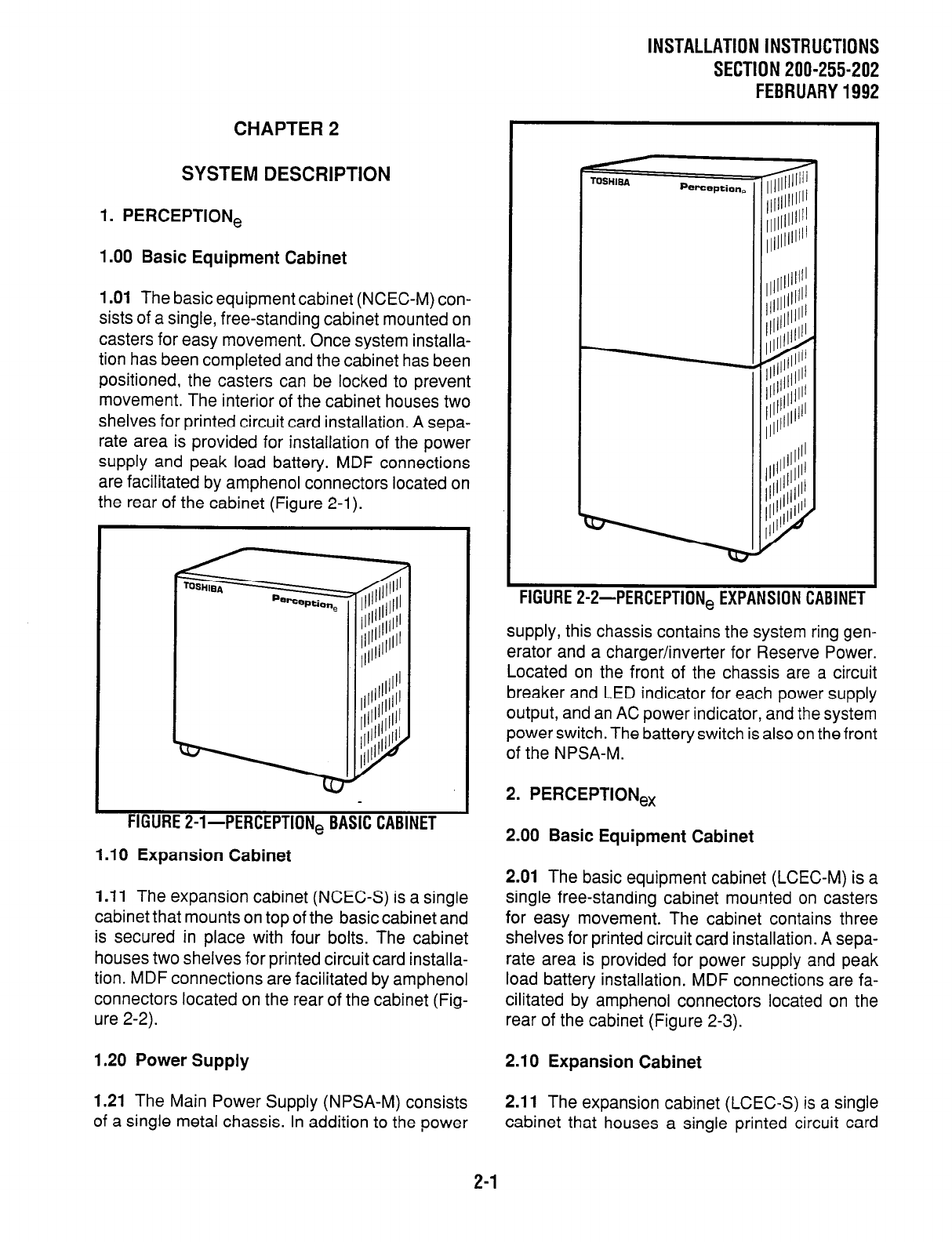
1 .Ol
The basic equipment cabinet (NCEC-M) con-
sists of a single, free-standing cabinet mounted on
casters for easy movement. Once system installa-
tion has been completed and the cabinet has been
positioned, the casters can be locked to prevent
movement. The interior of the cabinet houses two
shelves for printed circuit card installation. A sepa-
rate area is provided for installation of the power
supply and peak load battery. MDF connections
are facilitated by amphenol connectors located on
the rear of the cabinet (Figure 2-l).
FIGURE 2-I-PERCEPTION, BASIC CABINET
1 .I0 Expansion Cabinet
1 .I 1
The expansion cabinet (NCEC-S) is a single
cabinet that mounts on top of the basic cabinet and
is secured in place with four bolts. The cabinet
houses two shelves for printed circuit card installa-
tion. MDF connections are facilitated by amphenol
connectors located on the rear of the cabinet (Fig-
ure 2-2).
1.20 Power Supply
1.21
The Main Power Supply (NPSA-M) consists
2.11
The expansion cabinet (LCEC-S) is a single
of a single metal chassis. In addition to the power cabinet that houses a single printed circuit card
TOSHISA Perception,
FIGURE P-2-PERCEPTION, EXPAWIUN LABINt I
supply, this chassis contains the system ring gen-
erator and a charger/inverter for Reserve Power.
Located on the front of the chassis are a circuit
breaker and LED indicator for each power supply
output, and an AC power indicator, and the system
power switch. The battery switch is also on the front
of the NPSA-M.
2. PERCEPTIONex
2.00 Basic Equipment Cabinet
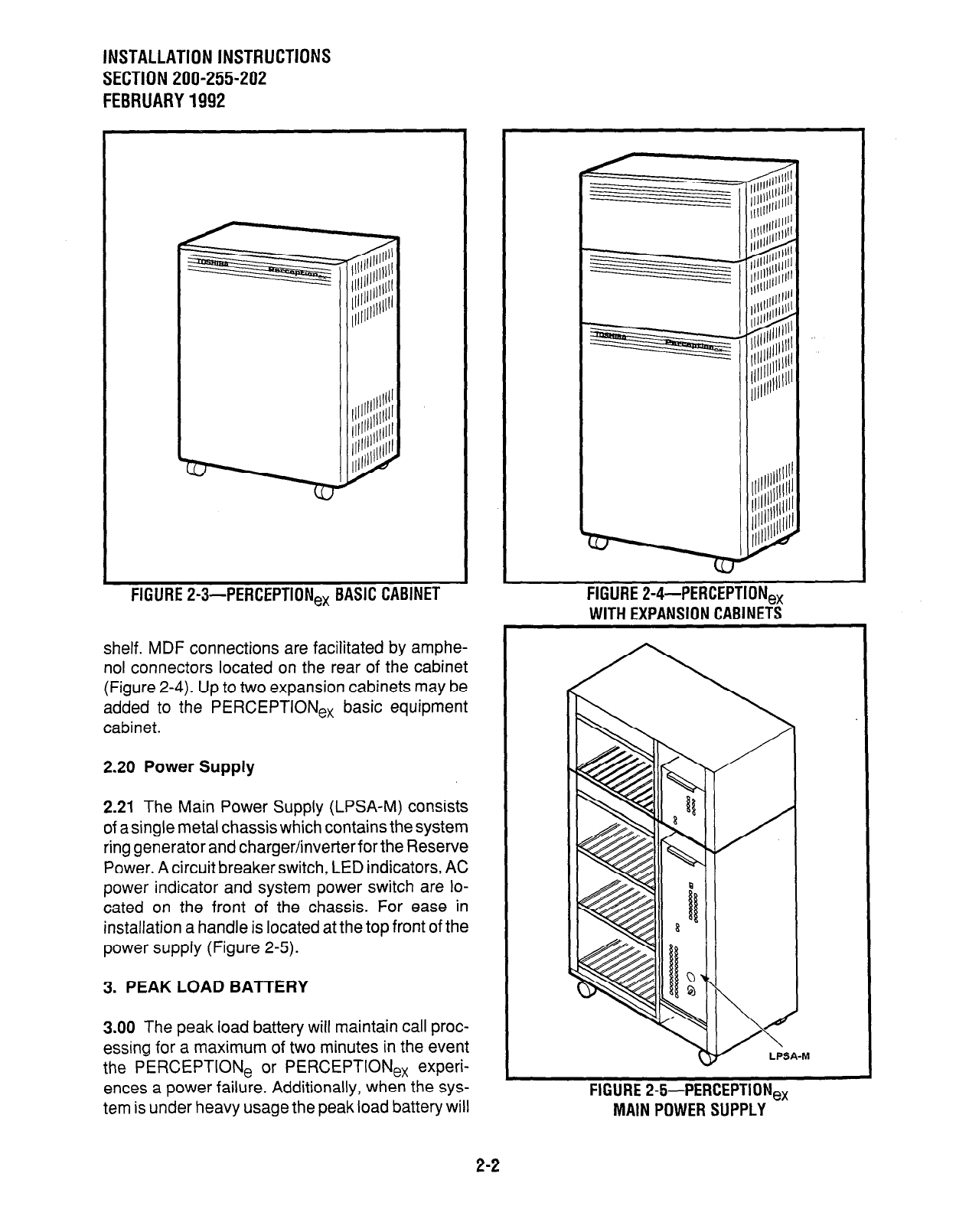
2.01 The basic equipment cabinet (LCEC-M) is a
single free-standing cabinet mounted on casters
for easy movement. The cabinet contains three
shelves for printed circuit card installation. A sepa-
rate area is provided for power supply and peak
load battery installation. MDF connections are fa-
cilitated by amphenol connectors located on the
rear of the cabinet (Figure 2-3).
2.10 Expansion Cabinet
2-1
INSTALLATION INSTRUCTIONS
SECTION 200-255-202
FEBRUARY1992
FIGURE
P-3-PERCEPTION, BASIC CABINET
shelf. MDF connections are facilitated by amphe-
nol connectors located on the rear of the cabinet
(Figure Z-4). Up to two expansion cabinets may be
added to the PERCEPTlONe, basic equipment
cabinet.
2.20 Power Supply
2.21
The Main Power Supply (LPSA-M) consists
of a single metal chassis which contains the system
ring generator and charger/inver&er for the Reserve
Power. A circuit breaker switch, LED indicators, AC
power indicator and system power switch are lo-
cated on the front of the chassis. For ease in
installation a handle is located at the top front of the
power supply (Figure 2-5).
3. PEAK LOAD BAl-rERY
3.00 The peak load battery will maintain call proc-
essing for a maximum of two minutes in the event
the PERCEPTlONe or PERCEPTlONe, experi-
ences a power failure. Additionally, when the sys-
tem is under heavy usage the peak load battery will
FIGURE P-4-PERCEP
-.-..-m - - -a-----.-..
HtiUHE 24+PtRCtP I IUNeX
MAIN POWER SUPPLY
2-2
avoid power degradation by supplementing the -24
volts, maintaining a constant power level.
4. EXTENDED RESERVE POWER
4.00 The power supply is equipped, as a standard
feature, with an internal battery chargemnverter.
Full reserve power can be provided for any system
by connecting an appropriate, customer-supplied
24-volt battery pack. During normal operation, the
power supply chargemnverter will maintain the
proper charge in the battery pack. In the event of an
AC power failure, switchover to battery power will
be automatic. There will be no loss of system
operation as a result of power switchover. When
AC power is restored, switchback to the power
supply will be automatic.
4.01 Battery selection and size will depend on
system size and desired reserve operating time.
The maximum power consumption of the basic
cabinet is 11.5 amps at -24 VDC. For both a basic
and expansion cabinet configuration, the maxi-
mum will be 19 amps at -24 VDC. The selected
batteries must be compatible with the system’s
charger float voltage of 27.3 VDC.
INSTALLATION INSTRUCTIONS
SECTION 200-255-202
FEBRUARY1992
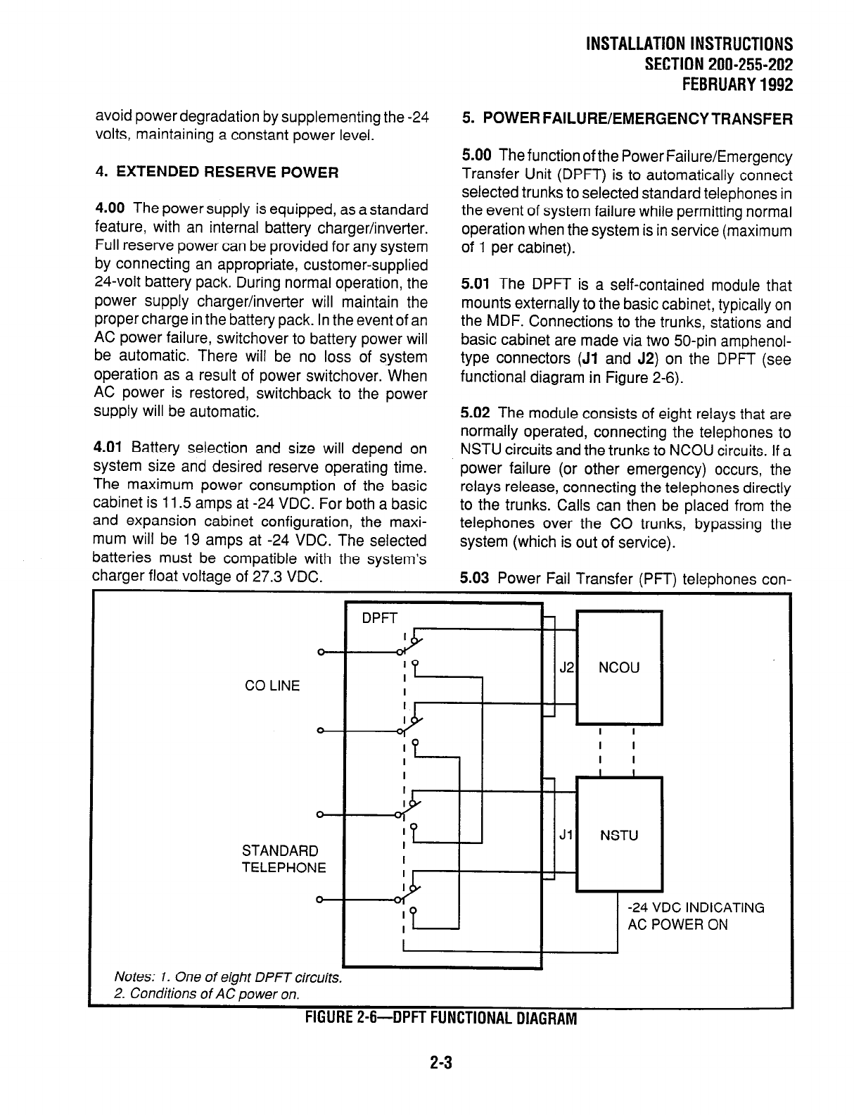
5. POWER FAILURE/EMERGENCY TRANSFER
5.00 The function of the Power Failure/Emergency
Transfer Unit (DPFT) is to automatically connect
selected trunks to selected standard telephones in
the event of system failure while permitting normal
operation when the system is in service (maximum
of 1 per cabinet).
5.01 The DPFT is a self-contained module that
mounts externally to the basic cabinet, typically on
the MDF. Connections to the trunks, stations and
basic cabinet are made via two 50-pin amphenol-
type connectors (Jl and J2) on the DPFT (see
functional diagram in Figure 2-6).
5.02 The module consists of eight relays that are
normally operated, connecting the telephones to
NSTU circuits and the trunks to NCOU circuits. If a
power failure (or other emergency) occurs, the
relays release, connecting the telephones directly
to the trunks. Calls can then be placed from the
telephones over the CO trunks, bypassing the
system (which is out of service).
5.03 Power Fail Transfer (PFT) telephones con-
I
J2 NCOU
CO LINE I
I
TELEPHONE TELEPHONE
Notes: 1. One of eight DPFT circuits.
Notes: 1. One of eight DPFT circuits.
2. Conditions of AC power on. 2. Conditions of AC power on.
FIGURE Z-6-DPFT FUNCTIONAL DIAGRAM
FIGURE Z-6-DPFT FUNCTIONAL DIAGRAM
2-3 2-3
C INDICATING C INDICATING
WER ON
WER ON
INSTALLATION INSTRUCTIONS
SECTION 200-255-202
FEBRUARY 1992
netted to ground-start trunks must have ground
taps (tap buttons) in order to make outgoing calls
during power fail transfer conditions.
5.04 A transfer can be caused by a loss of power
or triggered manually by either of two buttons, one
of which is located on the underside of the atten-
dant console and the other on the front of the NPRU
PCB. A transfer that is caused by a power failure
will be reset automatically when power is restored;
a manual transfer must be reset manually.
5.05 When the DPFT is reset after a transfer,
existing PFT conversations will be protected. Indi-
vidual circuits will be restored only when they
become idle.
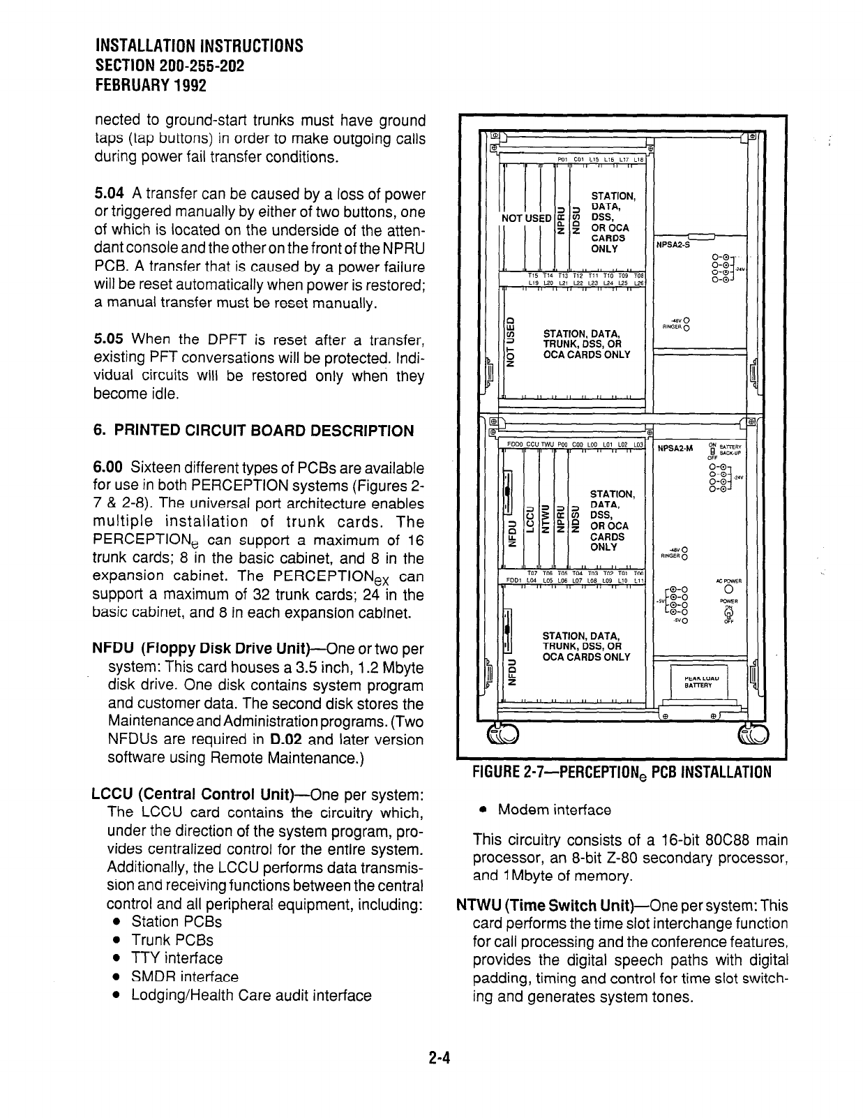
6. PRINTED CIRCUIT BOARD DESCRIPTION
6.00 Sixteen different types of PCBs are available
for use in both PERCEPTION systems (Figures 2-
7 & 2-8). The universal port architecture enables
multiple installation of trunk cards. The
PERCEPTlONe can support a maximum of 16
trunk cards; 8 in the basic cabinet, and 8 in the
expansion cabinet. The PERCEPTIONex can
support a maximum of 32 trunk cards; 24 in the
basic cabinet, and 8 in each expansion cabinet.
NFDU (Floppy Disk Drive Unit)-One
or two per
system: This card houses a 3.5 inch, 1.2 Mbyte
disk drive. One disk contains system program
and customer data. The second disk stores the
Maintenance and Administration programs. (Two
NFDUs are required in D.02 and later version
software using Remote Maintenance.)
LCCU (Central Control Unit)-One
per system:
The LCCU card contains the circuitry which,
under the direction of the system program, pro-
vides centralized control for the entire system.
Additionally, the LCCU performs data transmis-
sion and receiving functions between the central
control and all peripheral equipment, including:
l
Station PCBs
l
Trunk PCBs
0 TTY interface
l
SMDR interface
l
Lodging/Health Care audit interface
STATION, DATA,
TRUNK, DSS, OR
OCA CARDS ONLY
STATION, DATA,
TRUNK, DSS, OR
OCA CARDS ONLY
FIGURE P-7sPERCEPTION,
PC6 INSTALLATION
l
Modem interface
This circuitry consists of a 16-bit 8OC88 main
processor, an 8-bit Z-80 secondary processor,
and 1 Mbyte of memory.
NTWU (Time Switch Unit)-One
per system: This
card performs the time slot interchange function
for call processing and the conference features,
provides the digital speech paths with digital
padding, timing and control for time slot switch-
ing and generates system tones.
2-4
INSTALLATION INSTRUCTIONS
SECTION 200-255-202
JANUARY1993
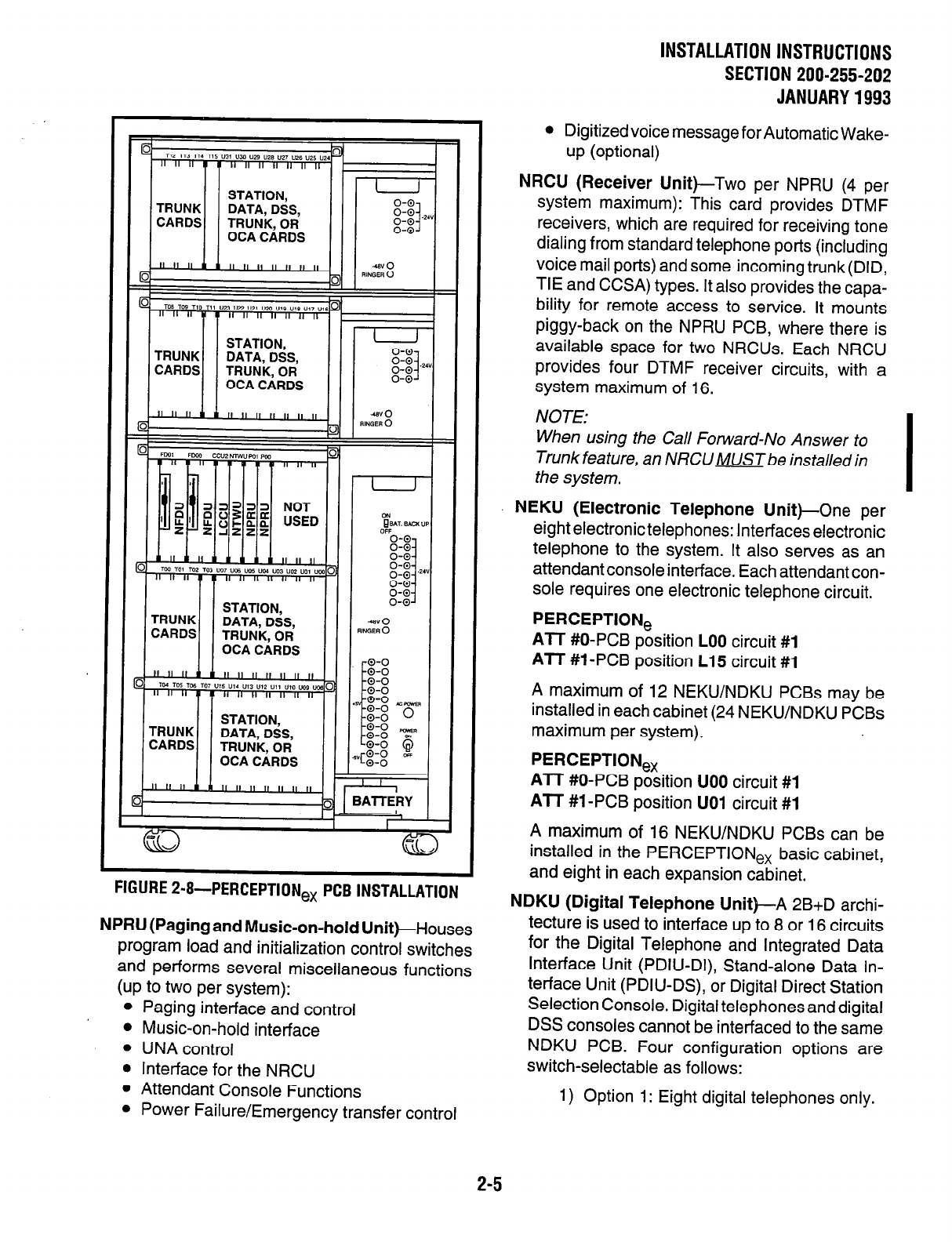
w.iu~t Z-I+PERCEPTION,
PCB INSTALLATION
NPRU (Paging and Music-on-hold Unit)-Houses
program load and initialization control switches
and performs several miscellaneous functions
(up to two per system):
l
Paging interface and control
l
Music-on-hold interface
l
UNA control
l
Interface for the NRCU
* Attendant Console Functions
l
Power Failure/Emergency transfer control
l
Digitized voice message for Automatic Wake-
up (optional)
NRCU (Receiver Unit)-Two per NPRU (4 per
system maximum): This card provides DTMF
receivers, which are required for receiving tone
dialing from standard telephone ports (including
voice mail ports) and some incoming trunk (DID,
TIE and CCSA) types. It also provides the capa-
bility for remote access to service. It mounts
piggy-back on the NPRU PCB, where there is
available space for two NRCUs. Each NRCU
provides four DTMF receiver circuits, with a
system maximum of 16.
NOTE:
When using the Call Forward-No Answer to
Trunk feature, an NRCU MUSTbe installed in
the system.
NEKU (Electronic Telephone Unit)-One per
eight electronic telephones: Interfaces electronic
telephone to the system. It also serves as an
attendant console interface. Each attendant con-
sole requires one electronic telephone circuit.
PERCEPTION,
ATT #O-PCB position LOO circuit #1
ATT #1 -PCB position L15 circuit #l
A maximum of 12 NEKU/NDKU PCBs may be
installed in each cabinet (24 NEKU/NDKU PCBs
maximum per system).
PERCEPTION,
ATT #O-PCB position UOO circuit #1
AIT #l -PCB position UOl circuit #l
A maximum of 16 NEKU/NDKU PCBs can be
installed in the PERCEPTIONex basic cabinet,
and eight in each expansion cabinet.
NDKU (Digital Telephone Unit)-A 2B+D archi-
tecture is used to interface up to 8 or 16 circuits
for the Digital Telephone and Integrated Data
Interface Unit (PDIU-DI), Stand-alone Data In-
terface Unit (PDIU-DS), or Digital Direct Station
Selection Console. Digital telephones and digital
DSS consoles cannot be interfaced to the same
NDKU PCB. Four configuration options are
switch-selectable as follows:
1) Option 1: Eight digital telephones only.
2-5
INSTALLATION INSTRUCTIONS
SECTION 200-255-202
JANUARY 1993
2)
3)
4)
Option 2: Eight digital telephones with
integrated Data Interface Unit (PDIU-DI)
or Off-hook Call Announce. This position
also supports Stand-alone Data Inter-
face Units (PDIU-DS).
Option 3: Four digital DSS consoles. In
PERCEPTION, COO and CO1 may be
used for this option only.
Option 4: Eight digital DSS consoles.
NOTE:
When using Option
2 or 4,
the next
highest
number adjacent card slot
cannot
be used.
For example: If an NDKU is installed in LO1 or
UO 7, the card slot LO2 or UOZ respective/y,
must be left vacant.
NSTU (Standard Telephone
Unit)-Interfaces
eight standard telephones (DTMF or rotary dial)
to the system.
NDSU (DSS Console Controller
Unit)-Interfaces
four DSS consoles to the system. The NDSU is
installed in the COO or COI, or any line slot for
PERCEPTION,; or in any universal slot for
PERCEPTIONex. A maximum of two NDSU
PCBs are allowed per system, and both can be
installed in the same cabinet.
NDCU (Data Control
Unit)-Interfaces eight Digi-
tal Data Interface Units (DDIUs) to the system.
The NDCU controls data transmission between
the DDIU and the cabinet. A maximum of four
NDCU PCBs may be installed in each
PERCEPTlONe cabinet. In the PERCEPTIONex,
four PCBs per shelf can be installed.
NMDU (Modem Pooling
Unit)-Interfaces up to
four modems and their associated DDIU-MAs.
Any of the four DDIU circuits not required by a
modem can be used with a standard DDIU (-MA
or -MAT). A maximum of four NMDU PCBs may
be installed in each PERCEPTlONe cabinet. In
the PERCEPTIONex, four PCBscan be installed
per shelf.
NOTE:
The system maximum of NDCU or NMDU
PCBs consists of any combination of the two
PCBs totaling four per cabinet for
PERCEPTlONe and four per she/f for
PERCEPTION,, .
NCOU (Central Office Trunk Unit)-One
per four
CO trunks: Provides the signaling supervisory
functions on loop- and ground-start trunks. Inter-
faces four CO trunks to the system. These trunks
can be incoming, outgoing, or both way CO
trunks; WATS trunks, or Foreign Exchange (FX)
trunks.
NEMU (E & M TIE Trunk Unit)-One
per four E &
M TIE trunks: Each TIE trunk can be individually
strapped for Type I or II operation with either 2-
wire or 4-wire connection.
NLSU (DID Trunk Interface
Unit)-One per four
DID trunks: Each NLSU connects four Direct
Inward Dialing (DID) trunks to the system.
NDTU (Tl
Interface)-Maximum of two per sys-
tem (one in the main cabinet, one in the expan-
sion cabinet): Each NDTU provides a’ maximum
of 24 trunk lines. The Digital Trunk printed circuit
card enables the PERCEPTIONehex systems
to use DSl signaling to connect directly to either
Tl span lines which connect to the telco (through
a Channel Service Unit), or to a private network.
NOCU (Off-hook Call Announce interface Unit)-
One per eight electronictelephones. Each NOCU
provides eight Off-hook Call Announce circuits
for up to eight electronic telephones. Each NOCU
takes a station PCB location in the cabinet.
HVSUP (Off-hookCall Announce
PCBs)--Install 1
inside the electronic telephone. One unit per
electronic telephone is required to receive off-
hook call announce.
DVSU (Digital Off-hook Call Announce
PCB)- 1
Installs inside the digital telephone. One unit per
digital telephone is required to receive off-hook
call announce.
2-6
7. SYSTEM INDICATORS AND CONTROLS
7.00 Several system indicators and controls are
located on the various PCBs and assemblies. The
locations and functions are:
NFDU
l
Disk Drive LED-Will light to indicate when
the disk is being accessed.
l
PUSH Button-Used to eject the diskette
from the drive.
LCCU
MAJ LED-Lights when a MAJOR alarm
exists in the system.
MDR LED-Lights when the DTRsignalfrom
the SMDR device is not present. An MDR
alarm on the attendant console lights simul-
taneously if enabled in programming.
AUX LED-Lights when the DTR signal from
the MIS system is not present.
TTY switch-Slide switch used to select 300
or 1,200 bps speed for TTY port. This port is
used for either programming and mainte-
nance and/or the Lodging/Health Care Audit.
MDR switch-Slide switch used to select 300
or 1,200 bps speed for the SMDR port. This
port is used for SMDR and/or the Lodging/
Health Care Audit.
AUX switch-This switch is used with MIS
system. Must be set at 1200 bps.
NTWU
l
CLOCK LED-Flashes contjnuously when
the system is functioning as usual.
NPRU
l
FALT LED-Indicates software-detected
faults concerning MOH or Paging circuits.
. BSYLED1&2
#l lights when any page is in progress.
#2 indicates when MOH is in use (a call is on
hold or camp-on).
l
MOH volume control-Adjust, Music-on-hold
volume level.
l
LOAD switch-A momentary switch used in
an emergency condition to reload system
program and data from disk. All existing calls
will be dropped when this switch is pushed.
l
INT switch-A momentary switch used in
2-7
lNSTALLATlONlNSTRUCTlONS
SECTION 200-255-202
FEBRUARY1992
emergency conditions to reset system logic.
All existing calls will be dropped when this
switch is pushed.
PFT switch-A locking switch used to manu-
ally activate a transfer with the DPFT unit. A
transfer activated by this switch can only be
reset by this switch.
MDM LED-Not currently used.
PFT LED-LED is ON whenever a power fail
transfer condition has been manually initi-
ated.
NRCU FALT LEDs 1, 2, 3 & 4-Used to
indicate software-detected faults or a dis-
abled state caused by an input command
from the maintenance terminal (TPER Pro-
gram). Each LED indicates two of the four
circuits on each of the two NRCUs that can
mount on the NPRU.
FALT #l = Circuits 1 & 2, NRCU2 1
FALT #2 = Circuits 3 & 4, NRCU2 1
FALT #3 = Circuits 1 & 2, NRCU2 2
FALT #4 = Circuits 3 & 4, NRCU2 2
NCOU/NEMU/NLSU
l
FALT LEDs 1 & 2-Indicate software-de-
tected faults or a disabled state caused by an
input command from the maintenance termi-
nal (TPER Program) or while ports are pro-
grammed. Each LED indicates two of the
four circuits on the NCOU, NEMU or NLSU:
FALT #l = Circuits 1 & 2
FALT #2 = Circuits 3 & 4
. BSY LEDs 1 w 4-Indicate the busy/idle
status of each of the four circuits on the
NCOU, NEMU or NLSU. LED is ON when
circuit is busy.
NDTU
l
FALT LED-Indicates software-detected
faults or a disabled state caused by an input
command from the maintenance terminal
(TPER Program) or while ports are pro-
grammed. LED indicates fault occuring in
more than one channel.
l
BSY LED-Indicates the busy/idle status of
the 24 channels on the NDTU. LED is ON
when more than one channel is busy.
l
FALM LED-Indicates NDTU has not
achieved Synchronization.
INSTALLATION INSTRUCTIONS
SECTlON200-255-202
FEBRUARY1992
l
MFALM LED-indicates NDTU has not
achieved Frame Synchronization.
l
YALM LED-Indicates a Yellow Alarm is
detected by the NDTU.
l
BALM LED-Indicates a Blue Alarm is de-
tected by the NDTU.
l
Signaling Type Selection Switches S4 w
Sl l-Six-element DIP switches used to se-
lect one of four available signaling modes, on
a per channel basis, for each of the 24 NDTU
channels. Available signaling modes are:
CO (Loop Start) mode
CO (Ground Start) mode
DID (2-wire signaling)
TIE Line mode (4-wire E&M)
NEKWNSTWNOCWNDKU
l
FALT LEDs 1 & 2-Indicate software-de-
tected faults or a disabled state caused by an
input command from the maintenance termi-
nal (TPER Program) or while ports are pro-
grammed. Each LED indicates four of the
eight circuits on the NEKU, NSTU, NOCU, or
NDKU:
FALT #l = Circuits 1 w 4
FALT #2 = Circuits 5 w 8
NDSU
l
FALT LEDs 1 & 2-Indicate software-de-
tected faults or a disabled state caused by an
input command from the maintenance termi-
nal (TPER Program) or while ports are pro-
grammed. Each LED represents two of the
four ports on the NDSU:
FALT #1 = Circuits 1 & 2
FALT #2 = Circuits 3 & 4
NDCU
l
FALT LEDs 1 & 2-Indicate software-de-
tected faults or a disabled state caused by an
input command from the maintenance termi-
nal (TPER Program) and while ports are
programmed. Each LED indicates four of the
eight circuits on the NDCU:
FALT #l = Circuits 1 w 4
FALT #2 = Circuits 5 m 8
l
NOT READY LEDs DIU l* 4and DIU 5 u 8-
Indicate the DDIU’s (-MA or -MAT) power
switch is not in the ON position or tip and ring
line polarity is reversed.
NMDU
l
FALT LEDs 1 & 2-Indicate software-de-
tected faults or a disabled state caused by an
input command from the maintenance termi-
nal (TPER Program) and while ports are
programmed:
FALT #l = DIU Circuits 1 w 4
FALT #2 = Modem Circuits 1 w 4
l
NOT READY LEDs DIU 1 w 4-Indicate the
DDIU’s (-MA or -MAT) power switch is not in
the ON position or tip and ring line polarity is
reversed.
l
BSY LEDs (Modem) 1 Y 4-Indicate the
busy/idle status of each of the four modem
circuits (the LED is ON when the circuit is
busy).
NPSA-M/LPSA-M
l
LEDs indicate the presence of: Ringer and
-48, -24, -12, +12, -5, +5 voltages.
l
AC Power LED-Indicates the presence of
AC power to the NPSA-M.
NPSA-S
l
LEDs indicate the presence of: -48 and -24
voltages.
8. PERIPHERAL EQUIPMENT
8.00 Electronic and Digital Telephone
8.01 Four different electronic telephones and two
different digital telephones may be used in the
system.
8.02 All electronic telephones share the same
dimensions:
Height: 3.7 in. (94mm)
Width: 7.1 in. (180mm)
Depth: 9.5 in. (241 mm)
8.03 All digital telephones share the same dimen-
sions:
Height: 3.6 in. (92mm)
Width: 7.3 in. (184mm)
Depth: 9.0 in. (229mm)
8.04 Both electronic and digital telephones feature
modular handset cords. Electronic telephones are
connected to the system via 4-conductor modular
2-8
line cords. Digital telephones are connected to the
system via 2-conductor modular line cords. In ad-
dition, all models may be used at any or all stations.
8.10 Headset Upgrade (HHEU)
8.11
Each electronic/digital telephone may also
be upgraded to provide a modular headset jack by
installing a headset upgrade assembly. The as-
sembly consists of a small PCB (HHEU) which
installs on the main PCB, inside the electronic or
digital telephone, with a plug-in connector. Most
standard headsets are compatible with the HHEU
jack.
8.20 Attendant Console
8.21
The Attendant Console is available with face-
plates for the Business and Lodging/Health Care
applications. The console consists of a plastic
housing with handset/headset modular jacks. Two
horizontal rows of non-locking buttons, LEDs and
a 12-button dialpad enable call processing.
8.30 DSS Console
8.31
As an option both electronic and digital Direct
Station Selection (DSS) consoles can be used with
systems that do not require attendant consoles, or
require distributed call-handling positions. Two DSS
consoles per electronic/digital telephone, up to a
system maximum of eight DSS consoles, can be
installed.
8.40 Standard Telephone
8.41
Standard telephones can be mixed with elec-
tronic telephones as required by the user’s applica-
tion, Standard telephones can access all telephone
features using dial code access.
8.50 DDIWPDIU
8.51
There are four types of Digital Data Interface
Units(DDIUs/PDIUs), DDIU-MAT, DDIU-MA, PDIU-
DI, and PDIU-DS. The DDIU-MAT is a built-in unit
that attaches directly to the bottom of a lo- or
20-button electronic telephone (replacing the base).
The PDIU-DI is a built-in unit that attaches directly
to the bottom of both digital telephones (replacing
the base). The DDIU-MA and PDIU-DS are stand-
alone units. Each unit is equipped with a female
INSTALLATlONlNSTRUCTlONS
SECTlON200-255-202
FEBRUARY1992
RS-232C connector and operation switches. Both
the DDIU-MAT and DDIU-MA are equipped with a
power supply that connects to the DDlUs via a 6’
cord, and plugs into astandard 117 VAC wall outlet.
8.60 Paging Equipment
8.61
A customer-supplied paging amplifier can
work in conjunction with the system’s paging inter-
face and speaker zone switching to provide a
system paging capability.
8.70 Music-on-Hold
8.71
A standard interface enables a customer-
provided music source to be connected to the
system. This music is connected to all calls placed
in the hold, camp-on or call waiting condition by a
station or the attendant. The same music source
can also be used by the Automatic Wake-up fea-
ture for wake-up calls.
8.80 Universal Night Answer
8.81
Incoming calls, when the system is in night
operation, can be programmed to go either to a
night answer station or to a Universal Night Answer
device such as a bell or loud ringer. Any station user
can pick up a UNA call by either pressing a m
button on the telephone or by dialing an access
code. Up to two UNA zones can be programmed
per system, when the system is in tenant service.
8.90 Station Message Detail Recording
8.91
PERCEPTIONeLex automatically record call
data (such as call duration, digits dialed, originating
station and account codes) of calls made to and
from the system. Lodging/Health Care feature ac-
tivation (Automatic Wake-up, Message Registra-
tion, etc.) is also recorded. This data can then
output to a printer, recording device or call account-
ing system. The Lodging/Health Care feature audit
can be combined with SMDR or can be output
separately. SMDR helps the user reduce tele-
phone costs and monitor employee telephone
usage.
2-9
INSTALLATION INSTRUCTIONS
SECTION 200-255-203
FEBRUARY 1992
CHAPTER 3
INSTALLATION SITE REQUIREMENTS
1. COMMERCIAL POWER
1 .OO The system requires a power source of 100 m
120 VAC, 50/60 Hz. The AC outlet must be dedi-
catedto system use, grounded and fused. To avoid
accidental power turn-off, it is recommended that
an ON/OFF wall switch not be used on this dedi-
cated AC circuit.
1 .Ol If reserve power is to be installed, the battery
pack requires a well-ventilated location adjacent to
the equipment cabinet.
2. ENVIRONMENTAL REQUIREMENTS
2.00 Humidity at the equipment cabinet should be
within 20 - 80% (non-condensing), and the tem-
perature should be relatively constant within 32 w
104°F (0 w 40°C). Exposure to dust and airborne
chemicals should be avoided.
3. EQUIPMENT ROOM RECOMMENDATIONS
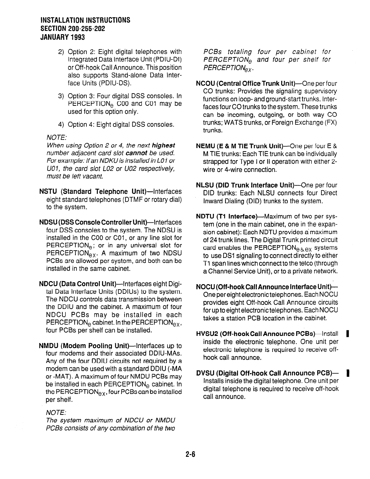
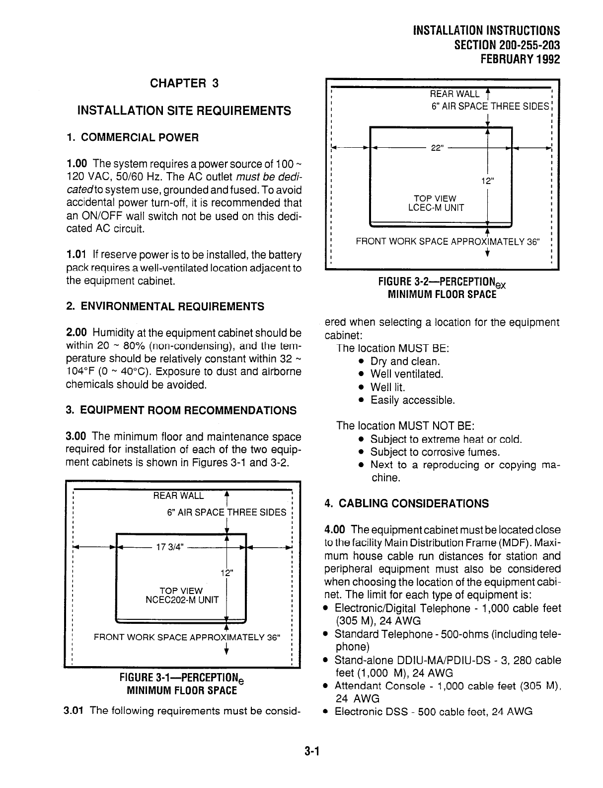
3.00 The minimum floor and maintenance space
required for installation of each of the two equip-
ment cabinets is shown in Figures 3-l and 3-2.
I I
I
REAR WALL t I
4 6” AIR SPACE’THREE SIDES i
I c I
I I
I 1
t 1
Y 17 314” I
I I
I
I
I lb I I
1 1 1 2” I I
I I
I I I I
I I TOP VIEW TOP VIEW I I
I I
I I I I
8 8 NCEC202-M UNIT NCEC202-M UNIT I I
I I I I
I I I I
I
I
I
I c w I
I
I
I I
I
I 4
I
I
I
I FRONT WORK SPACE APPROXIMATELY 36”
FRONT WORK SPACE APPROXIMATELY 36” ;
;
I I + + I I
I I
I I I I
I I I I
FIGURE 3-I-PERCEPTION,
MINIMUM FLOOR SPACE
l
Stand-alone DDIU-MA/PDIU-DS - 3, 280 cable
feet (1,000 M), 24 AWG
l
Attendant Console - 1,000 cable feet (305 M),
24 AWG
3.01 The following requirements must be consid-
l
Electronic DSS - 500 cable feet, 24 AWG
I
I
REAR WALL t
I
I 6” AIR SPACE THREE
f
A
22” I
1 2”
TOP VIEW
LCEC-M UNIT
I
I FRONT WORK SPACE APPROXIMATELY 36”
I
I f
FIGURE 3-P-PERCEPTION,
MINIMUM FLOOR SPACE
ered when selecting a location for the equipment
cabinet:
The location MUST BE:
l
Dry and clean.
l
Well ventilated.
l
Well lit.
l
Easily accessible.
The location MUST NOT BE:
l
Subject to extreme heat or cold.
l
Subject to corrosive fumes.
l
Next to a reproducing or copying ma-
chine.
4. CABLING CONSIDERATIONS
4.00 The equipment cabinet must be located close
to the facility Main Distribution Frame (MDF). Maxi-
mum house cable run distances for station and
peripheral equipment must also be considered
when choosing the location of the equipment cabi-
net. The limit for each type of equipment is:
l
Electronic/Digital Telephone - 1,000 cable feet
(305 M), 24 AWG
l
Standard Telephone - 500-ohms (including tele-
phone)
3-1
INSTALLATION INSTRUCTIONS
SECTION 200-255-203
FEBRUARY 1992
l
Digital DSS - 1,000 cable feet (305 M), 24 AWG
4.01 Acceptable cable for all telephones is 22 or 24
AWG twisted pair inside telephone station cable
(jacketed but not shielded). Two twisted pairs are
required for the electronic telephone, one pair for a
standard telephone, and one twisted pair for the
digital telephone, even if equipped with a PDIU-DI.
Three twisted pairs are required for an electronic
telephone equipped with a DDIU-MAT. The stand-
alone DDIU-MA/PDIU-DS requires one twisted
pair.
4.02 A 25-pair cable is required for the attendant
console. The console is equipped with a male 50-
pin amphenol-type connector.
WARNING!
1. Never install telephone wiring during a
lightning storm.
2.
Never
install telephone jacks in wet
locations, unless the jacks are specifi-
cally designed for wet locations.
3. Never touch uninsulated telephone
wires or terminals unless the telephone
line has been disconnected at the in-
terface.
4. Use caution when installing or modi-
fying telephone lines.
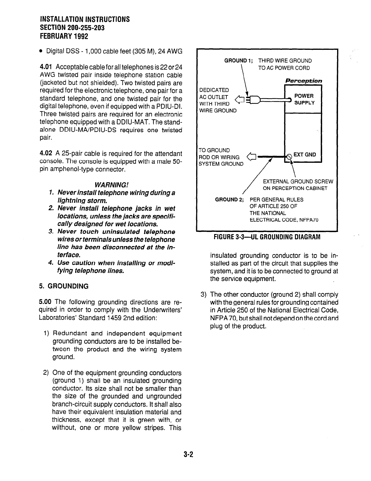
5. GROUNDING
5.00 The following grounding directions are re-
quired in order to comply with the Underwriters’
Laboratories’ Standard 1459 2nd edition:
1) Redundant and independent equipment
grounding conductors are to be installed be-
tween the product and the wiring system
ground.
2) One of the equipment grounding conductors
(ground 1) shall be an insulated grounding
conductor. Its size shall not be smaller than
the size of the grounded and ungrounded
branch-circuit supply conductors. It shall also
have their equivalent insulation material and
thickness, except that it is green with, or
wilthout, one or more yellow stripes. This
GROUND 1; THIRD WIRE GROUND
TO AC POWER CORD
Perception
3EDICATED
4C OUTLET
NITH THIRD
NIRE GROUND
-0 GROUND
;YSTEM GROUND
EXTERNAL GROUND SCREW
ON PERCEPTION CABINET
GROUND 2; PER GENERAL RULES
OF ARTICLE 250 OF
THE NATIONAL
ELECTRICAL CODE, NFPA70
FIGURE 3-3-UL GROUNDING DIAGRAM
insulated grounding conductor is to be in-
stalled as part of the circuit that supplies the
system, and it is to be connected to ground at
the service equipment.
3) The other conductor (ground 2) shall comply
with the general rules for grounding contained
in Article 250 of the National Electrical Code,
NFPA70, but shall not depend on the cord and
plug of the product.
3-2
CHAPTER 4
SYSTEM INSTALLATION
1. PERCEPTION,
1 .OO
Power Supply installation
1 .Ol Install the main power supply as follows:
-
INSTALLATION INSTRUCTIONS
SECTION 200-255-204
FEBRUARY 1992
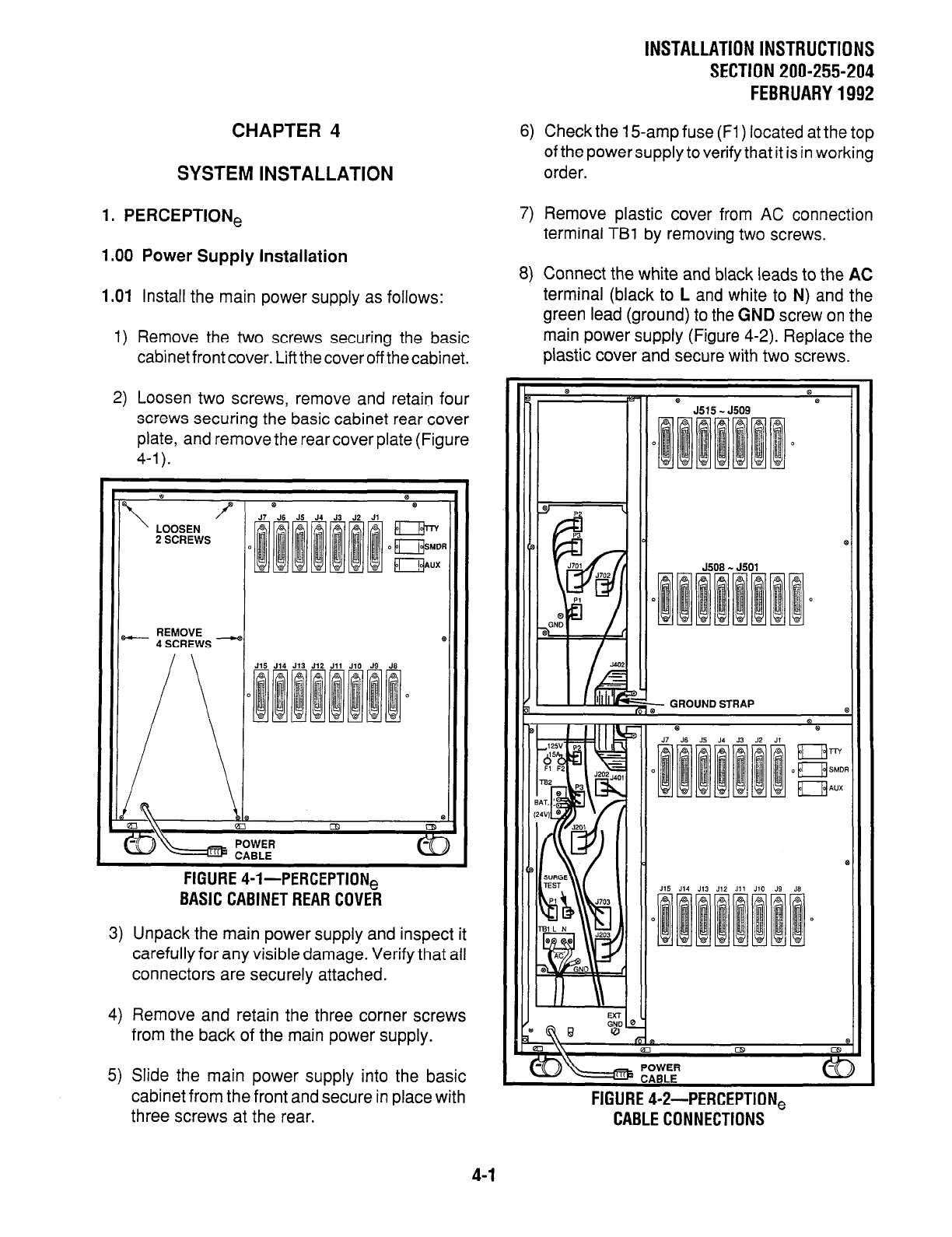
6) Check the 15amp fuse (Fl) located at the top
of the power supply to verify that it is in working
order.
7) Remove plastic cover from AC connection
terminal TBl by removing two screws.
8) Connect the white and black leads to the AC
terminal (black to L and white to N) and the
green lead (ground) to the GND screw on the
main power supply (Figure 4-2). Replace the
plastic cover and secure with two screws.
1) Remove the two screws securing the basic
cabinet front cover. Lift the cover off the cabinet.
2) Loosen two screws, remove and retain four
screws securing the basic cabinet rear cover
plate, and remove the rear cover plate (Figure
4-l).
Ir
0
\ /f
LOOSEN
2 SCREWS
- REMOVE
4 SCREWS -)(
FIGURE 4-l-PERCEPTION@
BASIC CABINET REAR COVER
3) Unpack the main power supply and inspect it
carefully for any visible damage. Verify that all
connectors are securely attached.
4) Remove and retain the three corner screws
from the back of the main power supply.
5) Slide the main power supply into the basic
cabinet from the front and secure in place with
three screws at the rear.
5515 - J509
i- GROUND STRAP
FIGURE 4sP-PERCEPTION,
CABLE CONNECTIONS
4-1
INSTALLATION INSTRUCTIONS
SECTION 200-255-204
FEBRUARY1992
9) With the main power supply turned OFF, plug
the AC power cord into the AC outlet.
10) Momentarily press each circuit breaker to
verify that it is not tripped.
11) Place the main power supply power switch in
the ON position.
WARNING!
Hazardous voltage that may cause death
or injury is exposed at the power supply
AC terminal.
12) Verify that all main power supply power indi-
cator LEDs are on (RINGER LED should be
pulsating rapidly). If any of the LEDs are
not
on, replace the main power supply.
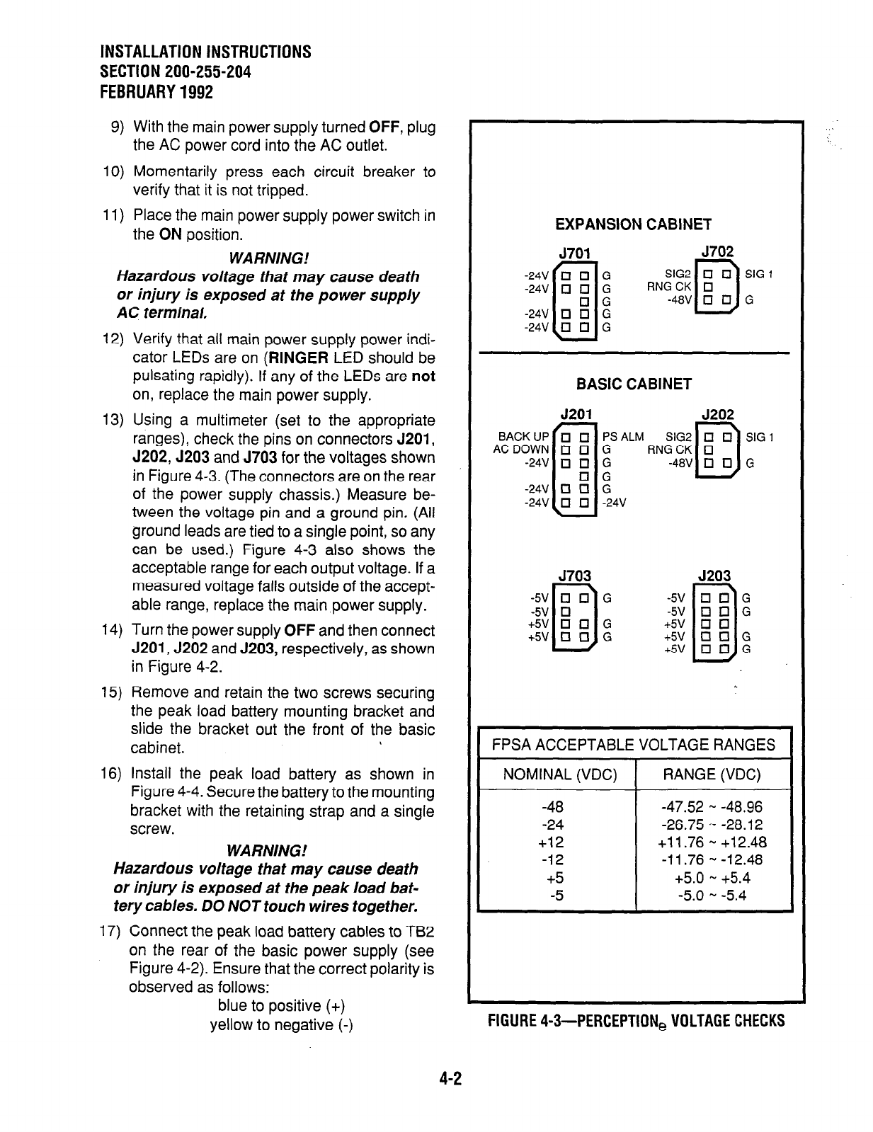
13) Using a multimeter (set to the appropriate
ranges), check the pins on connectors 5201,
J202,5203 and J703 for the voltages shown
in Figure 4-3. (The connectors are on the rear
of the power supply chassis.) Measure be-
tween the voltage pin and a ground pin, (Ail
ground leads are tied to a single point, so any
can be used.) Figure 4-3 also shows the
acceptable range for each output voltage. If a
measured voltage falls outside of the accept-
able range, replace the main power supply.
14) Turn the power supply OFF and then connect
J201, J202 and J203, respectively, as shown
in Figure 4-2.
15) Remove and retain the two screws securing
the peak load battery mounting bracket and
slide the bracket out the front of the basic
cabinet.
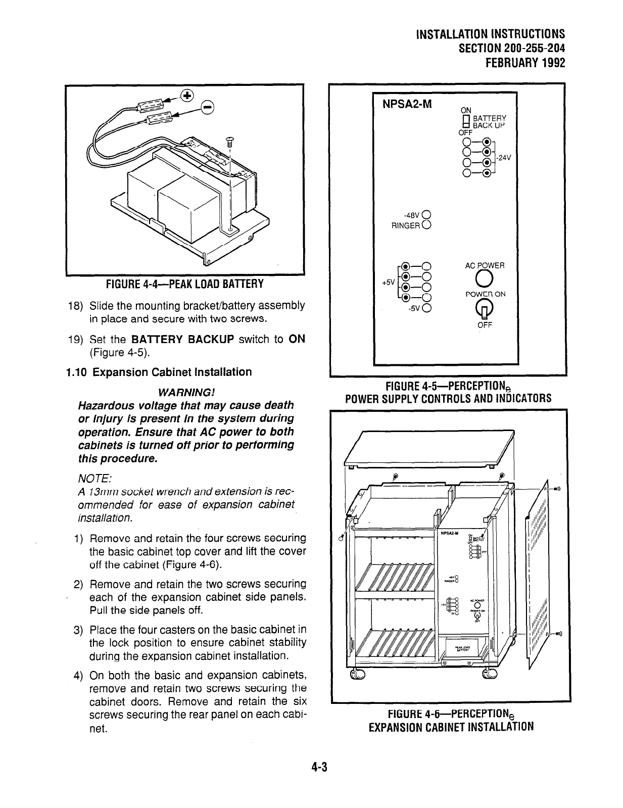
16) Install the peak load battery as shown in
Figure 4-4. Secure the battery to the mounting
bracket with the retaining strap and a single
screw.
WARNING!
Hazardous voltage that may cause death
or injury is exposed at the peak load bat-
tery cables. DO NOT touch wires together.
17) Connect the peak load battery cables to TB2
on the rear of the basic power supply (see
Figure 4-2). Ensure that the correct polarity is
observed as follows:
blue to positive (+)
yellow to negative (-)
EXPANSION CABINET
$fi; RN;lic] rG1
BASIC CABINET
J201 J202
SIG2
q q SIG 1
RNG CK 0
D
-48V
q
El G
J703 J203
FPSA ACCEPTABLE VOLTAGE RANGES
NOMINAL (VDC) RANGE (VDC)
-48 -47.52 ..a -48.96
-24 -26.75 - -28.12
+12 +11.76 - +12.48
-12 -11.76 - -12.48
+5 +5.0 - +5.4
-5 -5.0 - -5.4
FIGURE 4-3-PERCEPTlONe VOLTAGE CHECKS
4-2
INSTALLATION INSTRUCTIONS
SECTION 200-255-204
FEBRUARY1992
FIGURE 4-4-PEAK LOAD BATTERY
18) Slide the mounting bracket/battery assembly
in place and secure with two screws.
19)
Set the
BATTERY BACKUP
switch to ON
(Figure 4-5).
1.10 Expansion Cabinet Installation
WARNING!
Hazardous voltage that may cause death
or injury is present in the system during
operation. Ensure that AC power to both
cabinets is turned off prior to performing
this procedure.
NOTE:
A 13mm socket wrench and extension is rec-
ommended for ease of expansion cabinet
ins talla tion.
1) Remove and retain the four screws securing
the basic cabinet top cover and lift the cover
off the cabinet (Figure 4-6).
2) Remove and retain the two screws securing
each of the expansion cabinet side panels.
Pull the side panels off.
3) Place the four casters on the basic cabinet in
the lock position to ensure cabinet stability
during the expansion cabinet installation.
4) On both the basic and expansion cabinets,
remove and retain two screws securing the
cabinet doors. Remove and retain the six
screws securing the rear panel on each cabi-
net.
L
NPSA2-M ON
El
EiEF
OFF
-48” 0
RINGER 0
AC POWER
0
POWER ON
OFF
FIGURE 4-5-PERCEPTION,
POWER SUPPLY CONTROLS AND INDICATORS
d
FIGURE 4-6-PERCEPTION,
EXPANSION CABINET INSTALLATION
4-3
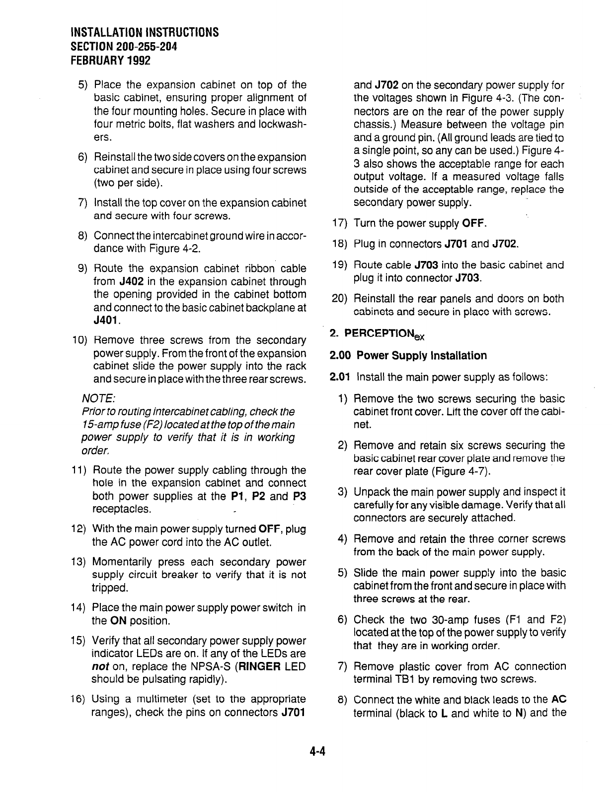
INSTALLATION INSTRUCTIONS
SECTION 200-255-204
FEBRUARY 1992
5)
6)
7)
8)
9)
10)
Place the expansion cabinet on top of the
basic cabinet, ensuring proper alignment of
the four mounting holes. Secure in place with
four metric bolts, flat washers and lockwash-
ers.
Reinstall the two side covers on the expansion
cabinet and secure in place using four screws
(two per side).
Install the top cover on the expansion cabinet
and secure with four screws.
Connect the intercabinet ground wire in accor-
dance with Figure 4-2.
Route the expansion cabinet ribbon cable
from J402 in the expansion cabinet through
the opening provided in the cabinet bottom
and connect to the basic cabinet backplane at
J401.
Remove three screws from the secondary
power supply. From the front of the expansion
cabinet slide the power supply into the rack
and secure in place with the three rear screws.
NOTE:
Prior to routing intercabinet cabling, check the
15-amp fuse (F2) located at the top of the main
power supply to verify that it is in working
order,
11)
12)
13)
14)
15)
16)
Route the power supply cabling through the
hole in the expansion cabinet and connect
both power supplies at the
Pl, P2
and P3
receptacles.
With the main power supply turned OFF, plug
the AC power cord into the AC outlet.
Momentarily press each secondary power
supply circuit breaker to verify that it is not
tripped.
Place the main power supply power switch in
the ON position.
Verify that all secondary power supply power
indicator LEDs are on. If any of the LEDs are
not on, replace the NPSA-S
(RINGER
LED
should be pulsating rapidly).
Using a multimeter (set to the appropriate
ranges), check the pins on connectors
J701
17)
‘8)
19)
20)
and J702 on the secondary power supply for
the voltages shown in Figure 4-3. (The con-
nectors are on the rear of the power supply
chassis.) Measure between the voltage pin
and a ground pin. (All ground leads are tied to
a single point, so any can be used.) Figure 4-
3 also shows the acceptable range for each
output voltage. If a measured voltage falls
outside of the acceptable range, replace the
secondary power supply.
Turn the power supply
OFF.
Plug in connectors
J701
and J702.
Route cable J703 into the basic cabinet and
plug it into connector J703.
Reinstall the rear panels and doors on both
cabinets and secure in place with screws.
2. PERCEPTION,
2.00 Power Supply Installation
2.01
1)
2)
3)
4)
5)
6)
7)
8)
Install the main power supply as follows:
Remove the two screws securing the basic
cabinet front cover. Lift the cover off the cabi-
net.
Remove and retain six screws securing the
basic cabinet rear cover plate and remove the
rear cover plate (Figure 4-7).
Unpack the main power supply and inspect it
carefully for any visible damage. Verify that all
connectors are securely attached.
Remove and retain the three corner screws
from the back of the main power supply.
Slide the main power supply into the basic
cabinet from the front and secure in place with
three screws at the rear.
Check the two 30-amp fuses (Fl and F2)
located at the top of the power supply to verify
that they are in working order.
Remove plastic cover from AC connection
terminal TBl by removing two screws.
Connect the white and black leads to the AC
terminal (black to
L
and white to N) and the
4-4
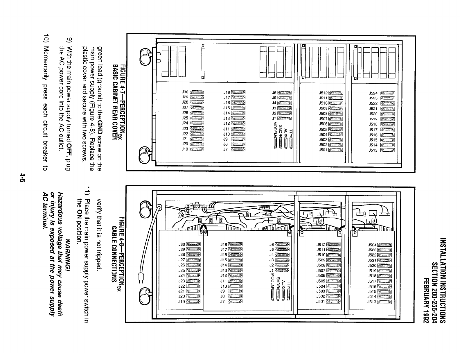
-
0
6
L
J30 B
J29 !Qi--
J28 !Ob
J27 -1
J26 M
J25 w
J24 -1
J23 -1
J22 m
J21 D
J20 -“;101
J,CJ w
Jf,,? w-;-
J511 I-
J510~
J509 !op_
J508 I-
J507 !Q,-
J506 !Q’;-
J505 R
J504 D
J503 [n
J502 FZZ%l
J501 EZSI
J524 ID
J523 m
J522 -1
~521 B
J520 -1
J519 -1
J516 loi--
J517 a
J516 !opI
J515 ETBl
J514 !Qb
J513 IZTZij
h
0
6
L
//
0
e
k.
J30 w
J29 [@ZZSl
J’&3 w
J27 -1
J26 -1
J25 -1
J24 W
J23 !81
J22 !()b
J21 n
J20 D
J19 k?iEZZd
J16 w J6l!jEsa
J17w
J5 1-1
Jl6IpEzzq J4 L-1
J15iGZZSj
J14lZSS%l
Jl3m
J17m1
Jil n
JlO 1-1
J9 !Orl
Jt3 m
J7 E===Zd
~520 M
J519m1
J516wI
J517D
J516k%zzm
J515w1
J514n,I
J513m1
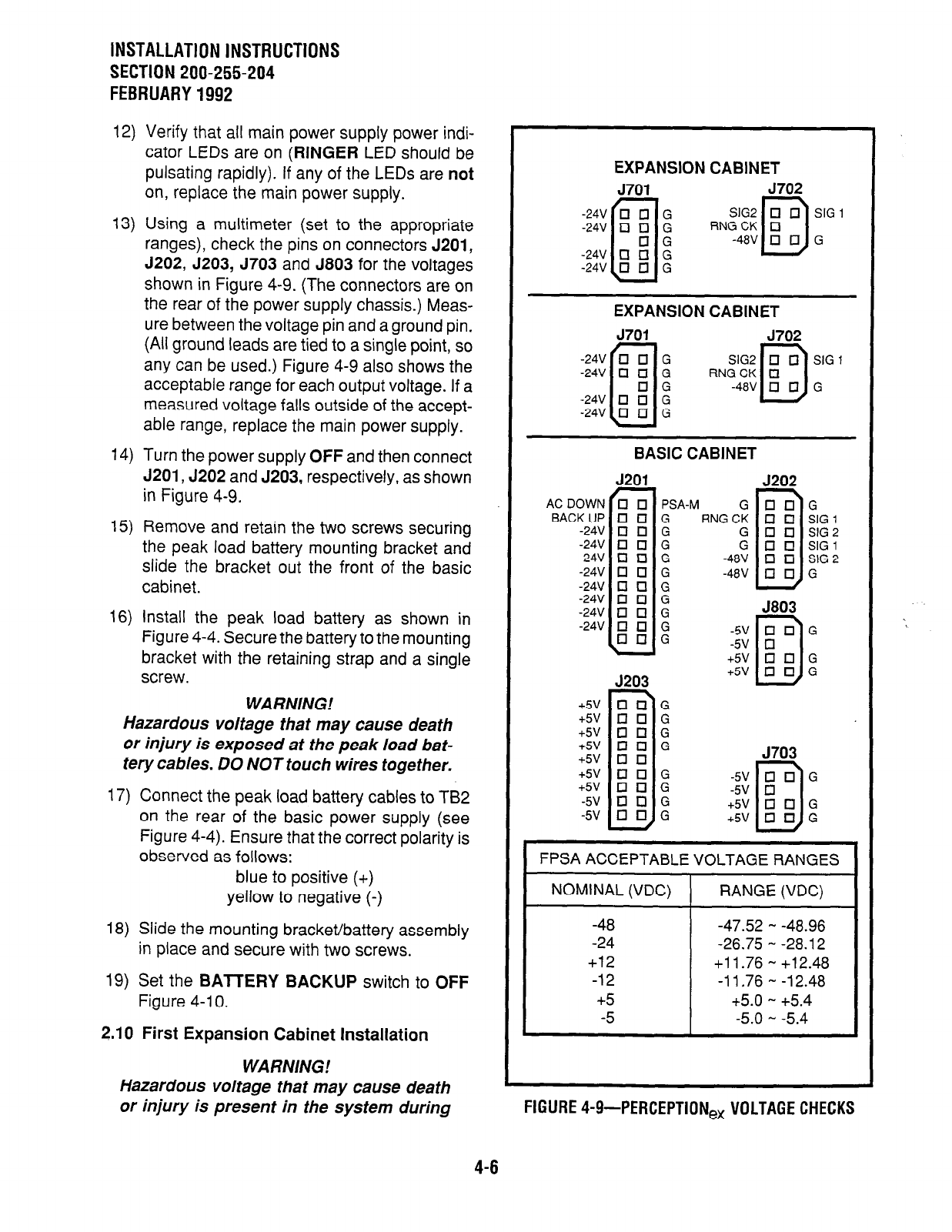
INSTALLATION INSTRUCTIONS
SECTION 200-255-204
FEBRUARY 1992
12) Verify that all main power supply power indi-
cator LEDs are on
(RINGER
LED should be
pulsating rapidly). If any of the LEDs are not
on, replace the main power supply.
13) Using a multimeter (set to the appropriate
ranges), check the pins on connectors J201,
J202, J203, J703 and J803 for the voltages
shown in Figure 4-9. (The connectors are on
the rear of the power supply chassis.) Meas-
ure between the voltage pin and a ground pin.
(All ground leads are tied to a single point, so
any can be used.) Figure 4-9 also shows the
acceptable range for each output voltage. If a
measured voltage falls outside of the accept-
able range, replace the main power supply.
14) Turn the power supply
OFF
and then connect
J201, J202 and J203, respectively, as shown
in Figure 4-9.
15) Remove and retain the two screws securing
the peak load battery mounting bracket and
slide the bracket out the front of the basic
cabinet.
16) Install the peak load battery as shown in
Figure 4-4. Secure the battery to the mounting
bracket with the retaining strap and a single
screw.
WARNING!
Hazardous voltage that may cause death
or injury is exposed at the peak load bat-
tery cables. DO NOT touch wires together.
17) Connect the peak load battery cables to TB2
on the rear of the basic power supply (see
Figure 4-4). Ensure that the correct polarity is
observed as follows:
blue to positive (+)
yellow to negative (-)
18) Slide the mounting bracket/battery assembly
in place and secure with two screws.
19) Set the BATTERY BACKUP switch to
OFF
Figure 4-l 0.
2.10 First Expansion Cabinet Installation
WA RNlNG!
Hazardous voltage that may cause death
or injury is present in the system during
EXPANSION CABINET
5701 5702
$i# RN;;i?$Gi
EXPANSION CABINET
J701 J702
$$ RNfj?$$ zG1
BASIC CABINET
J201 J202
G
q U G
RNGCK
q
El SIG1
G q q
SIG 2
D
G q q
SIG 1
-48V
q q
SIG 2
-48V
q q G
J803
-5V
q
0 G
-5v q
J203
D
+5V 0 17 G
+5V
q q G
2; : : 2
+5V
q q G
+5V
q q G
+5v q q
D
J703
+5V
q q G
+5V
q q G
-5V
q q G
-5V
q q G
FPSA ACCEPTABLE VOLTAGE RANGES
NOMINAL (VDC) RANGE (VDC)
-48 -47.52
- -48.96
-24 -26.75
-
-28.12
+12
+l 1.76 - +12.48
-12 -11.76 - -12.48
+5 +5.0
-
+5.4
-5
-5.0 -
-5.4
FIGURE 4-9-PERCEPTION, VOLTAGE CHECKS
4-6
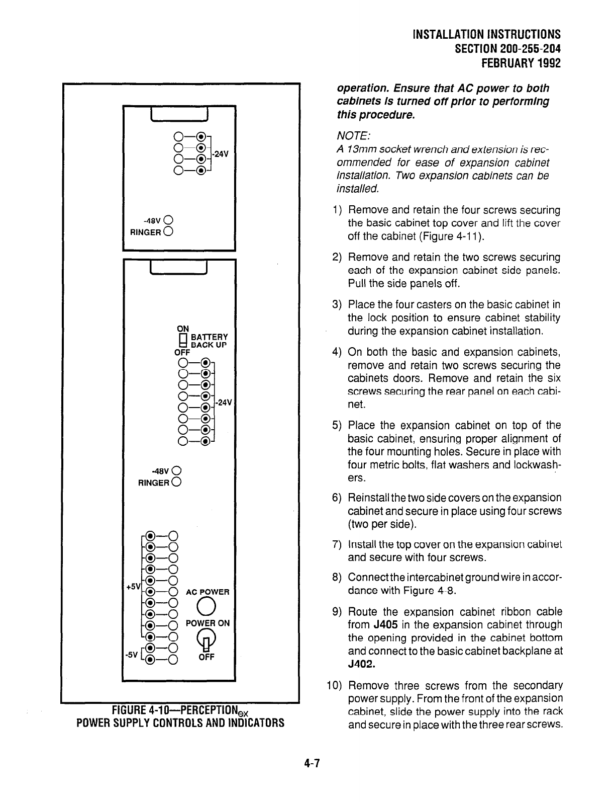
-48” 0
RINGER 0
I 1
ON
El BA-ITERY
BACK UP
OFF
-48” 0
RINGER 0
+5v-0-0
-0-o AC POWER
FIGURE4-lo-PERCEPTION,,
POWERSUPPLYCONTROLSANDINDICATORS
4-7
INSTALLATiONlNSTRUCTlONS
SECTION 200-255-204
FEBRUARY1992
operation. Ensure that AC power to both
cabinets is turned off prior to performing
this procedure.
NOTE:
A 13mm socket wrench and extension is rec-
ommended for ease of expansion cabinet
installation. Two expansion cabinets can be
installed.
1) Remove and retain the four screws securing
the basic cabinet top cover and lift the cover
off the cabinet (Figure 4-l 1).
2) Remove and retain the two screws securing
each of the expansion cabinet side panels.
Pull the side panels off.
3) Place the four casters on the basic cabinet in
the lock position to ensure cabinet stability
during the expansion cabinet installation.
4) On both the basic and expansion cabinets,
remove and retain two screws securing the
cabinets doors. Remove and retain the six
screws securing the rear panel on each cabi-
net.
5) Place the expansion cabinet on top of the
basic cabinet, ensuring proper alignment of
the four mounting holes. Secure in place with
four metric bolts, flat washers and lockwash-
ers.
6) Reinstall the two side covers on the expansion
cabinet and secure in place using four screws
(two per side).
7) Install the top cover on the expansion cabinet
and secure with four screws.
8) Connect the intercabinet ground wire in accor-
dance with Figure 4-8.
9) Route the expansion cabinet ribbon cable
from J405 in the expansion cabinet through
the opening provided in the cabinet bottom
and connect to the basic cabinet backplane at
5402.
IO) Remove three screws from the secondary
power supply. From the front of the expansion
cabinet, slide the power supply into the rack
and secure in place with the three rear screws.
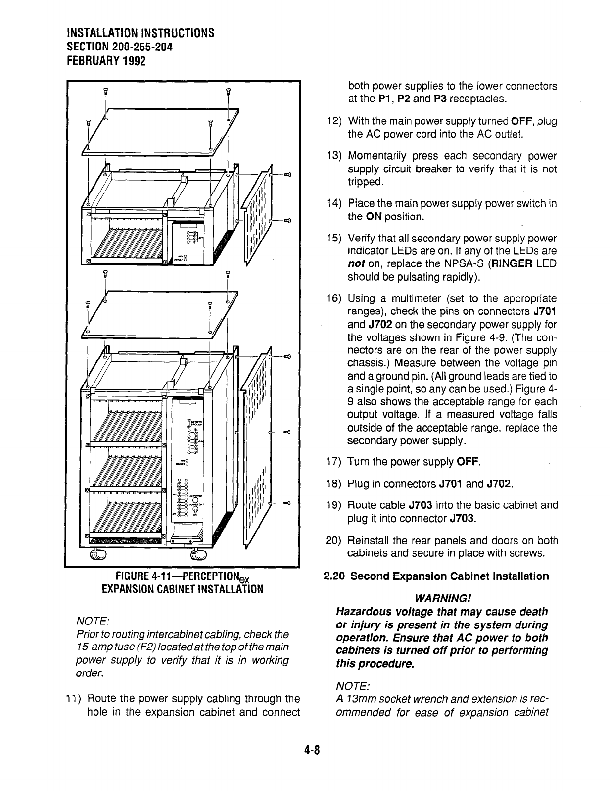
INSTALLATION INSTRUCTIONS
SECTION 200-255-204
FEBRUARY 1992
FIGURE 4-ll-PERCEPTION,
EXPANSION CABINET INSTALLATION
NOTE:
Prior to routing intercabinet cabling, check the
15amp fuse (F2) located at the top of the main
power supply to verify that it is in working
order.
11) Route the power supply cabling through the
hole in the expansion cabinet and connect
both power supplies to the lower connectors
at the Pl , P2 and P3 receptacles.
12) With the main power supply turned OFF, plug
the AC power cord into the AC outlet.
13) Momentarily press each secondary power
supply circuit breaker to verify that it is not
tripped.
14) Place the main power supply power switch in
the ON position.
15) Verify that all secondary power supply power
indicator LEDs are on. If any of the LEDs are
not on, replace the NPSA-S (RINGER LED
should be pulsating rapidly).
16) Using a multimeter (set to the appropriate
ranges), check the pins on connectors 5701
and 5702 on the secondary power supply for
the voltages shown in Figure 4-9. (The con-
nectors are on the rear of the power supply
chassis.) Measure between the voltage pin
and a ground pin. (All ground leads are tied to
a single point, so any can be used.) Figure 4-
9 also shows the acceptable range for each
output voltage. If a measured voltage falls
outside of the acceptable range, replace the
secondary power supply.
17) Turn the power supply OFF.
18) Plug in connectors J701 and J702.
19) Route cable J703 into the basic cabinet and
plug it into connector 5703.
20) Reinstall the rear panels and doors on both
cabinets and secure in place with screws.
2.20 Second Expansion Cabinet Installation
WARNING!
Hazardous voltage that may cause death
or injury is present in the system during
operation. Ensure that AC power to both
cabinets is turned off prior to performing
this procedure.
NOTE:
A 13mm socket wrench and extension is rec-
ommended for ease of expansion cabinet

1)
2)
3)
4)
5)
6)
7)
8)
9)
10)
installation. Two expansion cabinets can be
installed.
Remove and retain the four screws securing
the basic cabinet top cover and lift the cover
off the cabinet (Figure 4-l 1).
Remove and retain the two screws securing
each of the expansion cabinet side panels.
Pull the side panels off.
Place the four casters on the basic cabinet in
the lock position to ensure cabinet stability
during the expansion cabinet installation.
On both the basic and expansion cabinets,
remove and retain two screws securing the
cabinets’ doors. Remove and retain the six
screws securing the rear panel on each cabi-
net.
Place the expansion cabinet on top of the
basic cabinet, ensuring proper alignment of
the four mounting holes. Secure in place with
four metric bolts, flat washers and lockwash-
ers.
Reinstall the two side covers on the expansion
cabinet and secure in place using four screws
(two per side).
Install the top cover on the expansion cabinet
and secure with four screws.
Connect the intercabinet ground wire in accor-
dance with Figure 4-8.
Route the expansion cabinet ribbon cable
from J406 in the expansion cabinet through
the opening provided in the cabinet bottom
and connect to the basic cabinet backplane at
J403.
Remove three screws from the secondary
power supply. From the front of the expansion
cabinet, slide the power supply into the rack
and secure in place with the three rear screws.
NOTE:
Prior to routing intercabinet cabling, check the
15-amp fuse (F2) located at the top of the main
power supply to verify that it is in working
order.
11)
12)
13)
14)
15)
16)
17)
18)
19)
20)
INSTALLATION INSTRUCTIONS
SECTION 200-255-204
JUNE1992
Route the power supply cabling through the
hole in the expansion cabinet and connect
both power supplies to the upper connectors
at the Pl, P2 and P3 receptacles.
With the main power supply turned OFF, plug
the AC power cord into the AC outlet.
Momentarily press each secondary power
supply circuit breaker to verify that it is not
tripped.
Place the main power supply power switch in
the ON position.
Verify that all secondary power supply power
indicator LEDs are on. If any of the LEDs are
not on, replace the NPSA-S (RINGER LED
should be pulsating rapidly).
Using a multimeter (set to the appropriate
ranges), check the pins on connectors 5701
and J702 on the secondary power supply for
the voltages shown in Figure 4-9. (The con-
nectors are on the rear of the power supply
chassis.) Measure between the voltage pin
and a ground pin. (All ground leads are tied to
a single point, so any can be used.) Figure 4-
9 also shows the acceptable range for each
output voltage. If a measured voltage falls
outside of the acceptable range, replace the
secondary power supply.
Turn the power supply OFF.
Plug in connectors J701 and J702.
Route cable J703 into the basic cabinet and
plug it into connector J803.
Reinstall the rear panels and doors on both
cabinets and secure in place with screws.
3. PRINTED CIRCUIT BOARD INSTALLATION
3.00 NFDU
3.01 Install an NFDU in the FDDO slot in the basic
cabinet. If the system uses 0.02 or later version
softwareand Remote Maintenance, asecond NFDU
must be installed in the FDDI slot in the basic
cabinet. There are different strap selections on the
various NFDUs, depending on the slot in which the
4-9
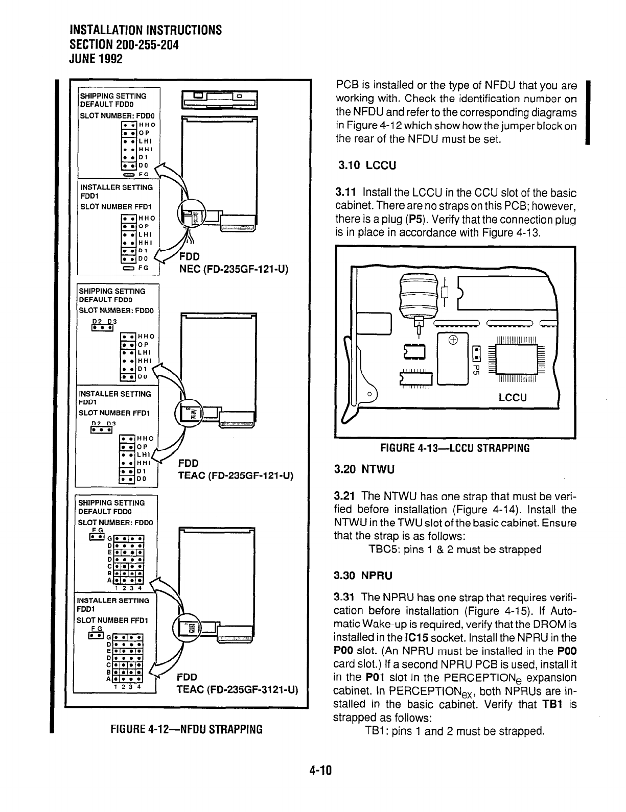
INSTALLATION INSTRUCTIONS
SECTION 200-255-204
JUNE1992
SHIPPING SETTING
DEFAULT FDDO
SLOT NUMBER: FDDO
o FG
INSTALLER SElTlNG
FDDl
SLOT NUMBER FFDI
NEC (FD-235GF-121-U)
SHIPPING SElTlNG
IEFAULT FDDO
SLOT NUMBER: FDDO
NSTALLER SETTING
=DDl
SLOT NUMBER FFDl
D2 D3
m
jHlPPlNG SETTING
IEFAULT FDDO
iLOT NUMBER: FDDC
FG
ISG D
E
D
C
B
A
1234 1
USTALLER SElTlNG
‘DDl
#LOT NUMBER FFDl
FG
EIG D
E
D
C
B
A
123 4
FDD
TEAC (FD-235GF-3121-U)
FIGURE 4-12-NFDU STRAPPING
PCB is installed or the type of NFDU that you are
working with. Check the identification number on
the NFDU and refer to the corresponding diagrams
in Figure 4-l 2 which show how the jumper block on
the rear of the NFDU must be set.
3.10
LCCU
3.11 Install the LCCU in the CCU slot of the basic
cabinet. There are no straps on this PCB; however,
there is a plug (P5). Verify that the connection plug
is in place in accordance with Figure 4-13.
FIGURE 4-13-LCCU STRAPPING
3.20 NTWU
3.21 The NTWU has one strap that must be veri-
fied before installation (Figure 4-14). Install the
NTWU in the TWU slot of the basic cabinet. Ensure
that the strap is as follows:
TBC5: pins 1 & 2 must be strapped
3.30 NPRU
3.31 The NPRU has one strap that requires verifi-
cation before installation (Figure 4-15). If Auto-
matic Wake-up is required, verify that the DROM is
installed in the IC15 socket. Install the NPRU in the
PO0 slot. (An NPRU must be installed in the PO0
card slot.) If a second NPRU PCB is used, install it
in the PO1 slot in the PERCEPTION, expansion
cabinet. In PERCEPTlONe,, both NPRUs are in-
stalled in the basic cabinet. Verify that TBl is
strapped as follows:
TBI : pins 1 and 2 must be strapped.
4-10
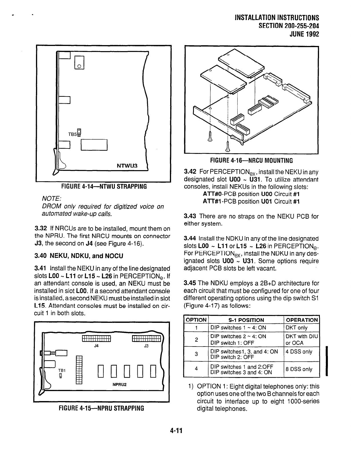
INSTALLATION INSTRUCTIONS
SECTION 200-255-204
JUNE1992
-Tl
0
NTWU3
FIGURE 4-14-NTWU STRAPPING
NOTE:
DROM on/y required for digitized voice on
automated wake-up calls.
3.32 If NRCUs are to be installed, mount them on
the NPRU. The first NRCU mounts on connector
J3, the second on J4 (see Figure 4-16).
3.40 NEKU, NDKU, and NOCU
3.41 Install the NEKU in any of the line designated
slots LOO N Lll or L15 m L26 in PERCEPTlONe. If
an attendant console is used, an NEKU must be
installed in slot LOO. If a second attendant console
is installed, a second NEKU must be installed in slot
L15. Attendant consoles must be installed on cir-
cuit 1 in both slots.
FIGURE 4-15-NPRU STRAPPING
FIGURE 4-16-NRCU MOUNTING
3.42 For PERCEPTlONe,, install the NEKU in any
designated slot UOO N U31. To utilize attendant
consoles, install NEKUs in the following slots:
AlT#O-PCB position UOO Circuit #l
ATT#l -PCB position UOl Circuit #l
3.43 There are no straps on the NEKU PCB for
either system.
3.44 Install the NDKU in any of the line designated
slots LOO
m Lll orL15 w L26 in PERCEPTlONe.
For PERCEPTlONe,, install the NDKU in any des-
ignated slots UOO W U31. Some options require
adjacent PCB slots be left vacant.
3.45 The NDKU employs a 2B+D architecture for
each circuit that must be configured for one of four
different operating options using the dip switch Sl
(Figure 4-l 7) as follows:
IPTION S-l POSITION OPERATION
1 DIP switches 1 - 4: ON DKT only
DIP switches 2 4: ON
-
2 DKT with DIL
DIP switch 1: OFF or OCA
3 DIP switchesl, 3, and 4: ON
DIP switch 2: OFF 4 DSS only
I
1
I
4 DIP switches 1 and 2:OFF
DIP switches 3 and 4: ON 8 DSS only
1) OPTION 1: Eight digital telephones only: this
option uses one of the two B channels for each
circuit to interface up to eight lOOO-series
digital telephones.
4-11
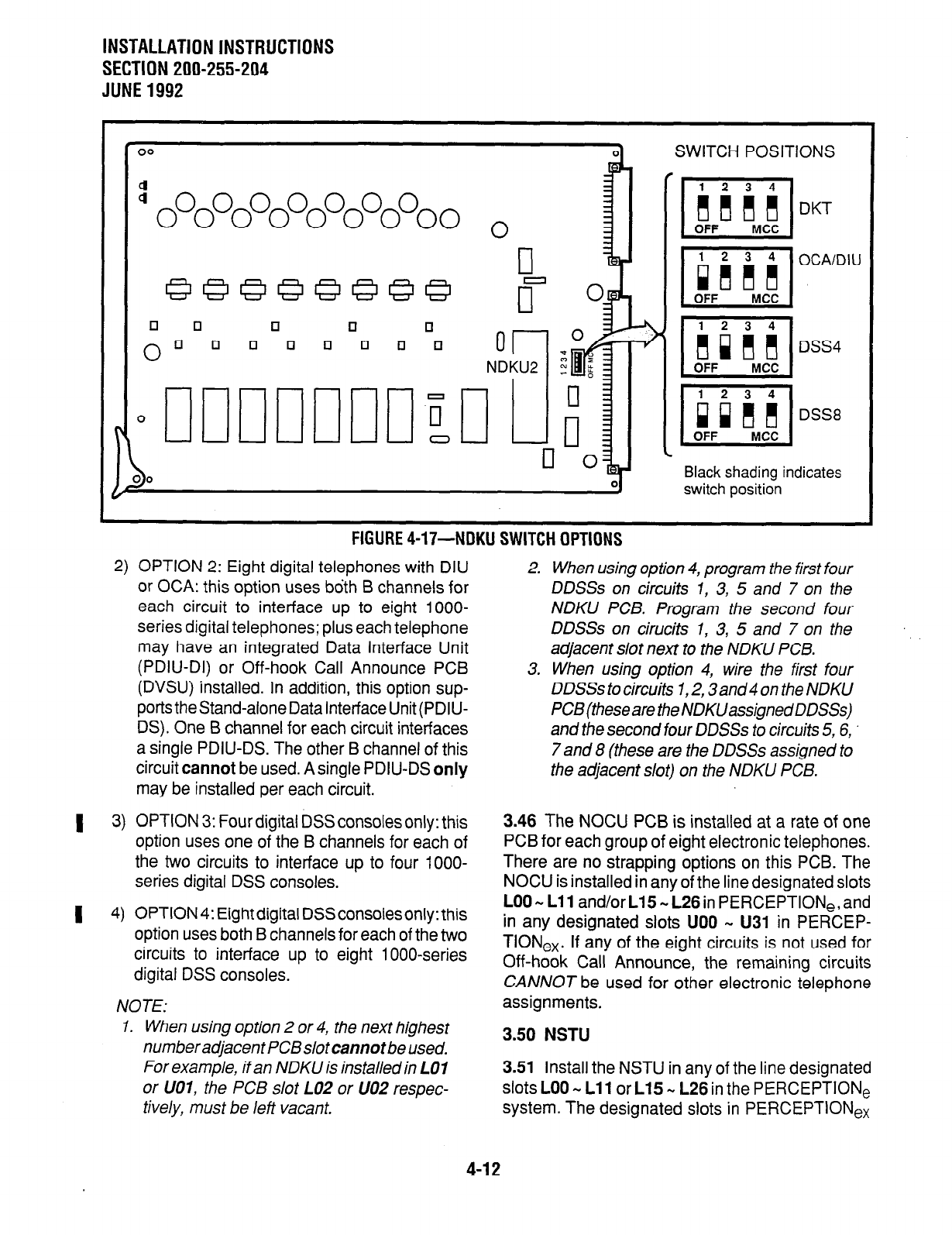
INSTALLATION INSTRUCTIONS
SECTION 200-255-204
JUNE 1992
n
NDKU2
SWITCH POSITIONS
Black shading indicates
switch position
FIGURE
4-Ii’-NDKU SWITCH OPTIONS
2) OPTION 2: Eight digital telephones with DIU
or OCA: this option uses bdth 6 channels for
each circuit to interface up to eight lOOO-
series digital telephones; plus each telephone
may have an integrated Data Interface Unit
(PDIU-DI) or Off-hook Call Announce PCB
(DVSU) installed. In addition, this option sup-
ports the stand-alone Data Interface Unit (PDIU-
DS). One B channel for each circuit interfaces
a single PDIU-DS. The other B channel of this
circuit cannot be used. A single PDIU-DS only
may be installed per each circuit.
1 3) OPTION 3: Four digital DSS consoles only: this
option uses one of the B channels for each of
the two circuits to interface up to four lOOO-
series digital DSS consoles.
1 4) OPTION 4: Eight digital DSS consoles only: this
option uses both B channels for each of the two
circuits to interface up to eight lOOO-series
digital DSS consoles.
NOTE:
1. When using option 2 or 4, the next highest
numberadjacentPCBs/otcannotbeused.
For example, if an NDKU is installed in LO1
or UOl, the PCB slot LO2 or UO2 respec-
tively, must be left vacant.
2. When using option 4, program the first four
DDSSs on circuits 7, 3, 5 and 7 on the
NDKU PCB. Program the second four
DDSSs on cirucits 1, 3, 5 and 7 on the
adjacent slot next to the NDKU PCB.
3. When using option 4, wire the first four
DDSSs to circuits 1,2,3 and 4 on the NDKU
PCB(thesearetheNDKUassignedDDSSs)
and the second four DDSSs to circuits 5, 6,
7 and 8 (these are the DDSSs assigned to
the adjacent slot) on the NDKU PCB.
3.46 The NOCU PCB is installed at a rate of one
PCB for each group of eight electronic telephones.
There are no strapping options on this PCB. The
NOCU is installed in any of the line designated slots
LOO m Lll and/or L15 m L26 in PERCEPTION,, and
in any designated slots UOO m U31 in PERCEP-
TION,,. If any of the eight circuits is not used for
Off-hook Call Announce, the remaining circuits
CANNOT be used for other electronic telephone
assignments.
3.50 NSTU
3.51 Install the NSTU in any of the line designated
slots LOO w Lll or L15 w L26 in the PERCEPTION,
system. The designated slots in PERCEPTION,,
4-12
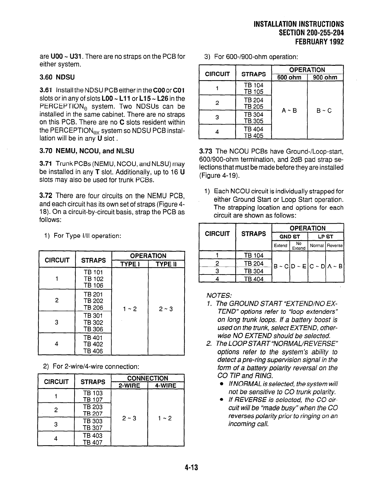
INSTALLATIONINSTRUCTIONS
SECTlON200-255-204
FEBRUARY1992
are UOO M U31. There are no straps on the PCB for
either system.
3.60 NDSU
3.61 Install the NDSU PCB either in the COO or CO1
slots or in any of slots LOO - Ll 1 or L15 - L26 in the
PERCEPTION, system. Two NDSUs can be
installed in the same cabinet. There are no straps
on this PCB. There are no C slots resident within
the PERCEPTION,, system so NDSU PCB instal-
lation will be in any U slot .
3.70 NEMU, NCOU, and NLSU
3.71 Trunk PCBs (NEMU, NCOU, and NLSU) may
be installed in any T slot. Additionally, up to 16 U
slots may also be
used
for trunk PCBs.
3.72 There are four circuits on the NEMU PCB,
and each circuit has its own set of straps (Figure 4-
18). On a circuit-by-circuit basis, strap the PCB as
follows:
1) For Type VII operation:
CIRCUIT
CIRCUIT STRAPS OPERATION
TYPEI 1 TYPEII
TB 101 I
1 TB 102
TB 106
TB 201
2 TB 202
TB 206
TB 301
3 TB 302
TB 306
TB 401
4 TB 402
TB 406
l-2
2) For 2-wire/4-wire connection:
2-3
CIRCUIT STRAPS CONNECTION
2-WIRE 1 4-WIRE
TB 103 I
3) For 600-/900-ohm operation:
CIRCUIT STRAPS OPERATION
6000hm 1 900 ohm
4 TB 104 I
I- I
1 TB105 1 I I
3.73 The NCOU PCBs have Ground-/Loop-start,
600/900-ohm termination, and 2dB pad strap se-
lections that must be made before they are installed
(Figure 4-19).
1) Each NCOU circuit is individually strapped for
either Ground Start or Loop Start operation.
The strapping location and options for each
circuit are shown as follows:
OPERATION
STRAPS GND ST LP ST
Extend $ind Normal Reverse
1 TB 104
2 TB 204 B-CD-E C-DA-B
3 TB 304
4 TB 404
NOTES:
1. The GROUND START “EXTEND/NO EX-
TEND” options refer to “loop extenders”
on long trunk loops. If a battery boost is
used on the trunk, select EXTEND, other-
wise NO EXTEND should be selected.
2. The LOOP START “NORMAL/REVERSE”
options refer to the system’s ability to
detect a pre-ring supervision signal in the
form of a battery polarity reversal on the
CO TIP and RING.
l
lf NORMAL is selected, the system will
not
be
sensitive to CO trunk polarity.
l
If REVERSE is selected, the CO cir-
cuit will be “made busy” when the CO
reverses polarity prior to ringing on an
incoming call.
4-13
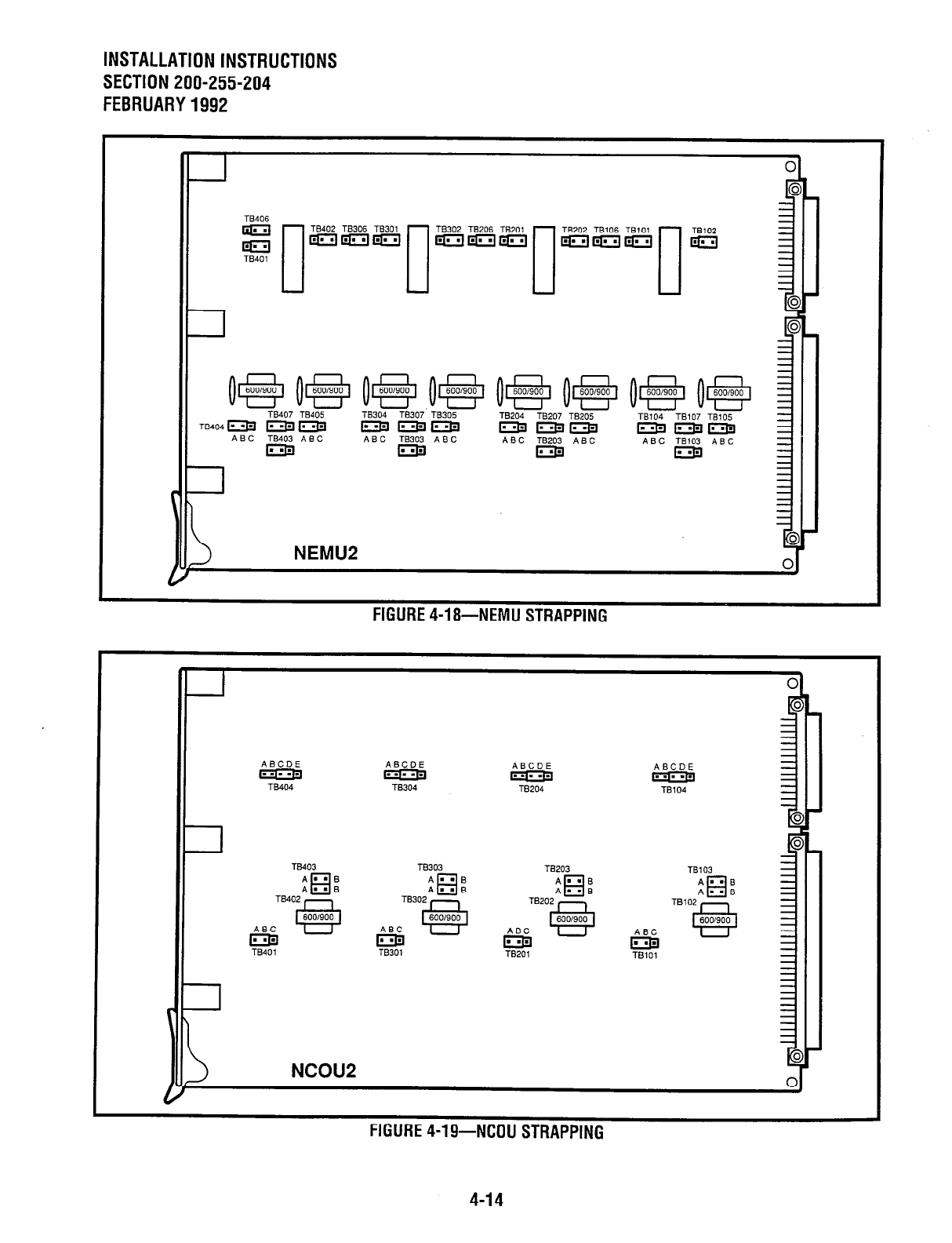
INSTALLATION INSTRUCTIONS
SECTION 200-255-204
FEBRUARY1992
0
o@l(@ o@ 0,s ojs, oej fpiii$-~ oe, ;
TB407 TB405 TB304 TE307 TB305
TB404m
TBZO4 TB207 TB205
mmm TB104 TB107 TB105
pJ?JpzlqzJ mmjzJtJ
ABC TM03 ABC ABC TB203 ABC
FIGURE
4-18-NEMU STRAPPING
ABCDE ABCDE
ygEl YE?
ABCDE
YEi?
ABCDE
rqqq
TB104
l-B403 TB303 TB203
El El
TB103
Am-B A
n - B
AmmB
R
A”B
Am=13 A . . B Al=B Am=8
TM02
I:
TB302
cl
TB202 E
6001900 600/900 600/900
ABC ABC
GE
ABC
EY
e
NCOU2
r,a,,w..- I -- ..-a.. --- -------
r~bunt 4-lY-NWU
Sl~RAPPlNG
4-14
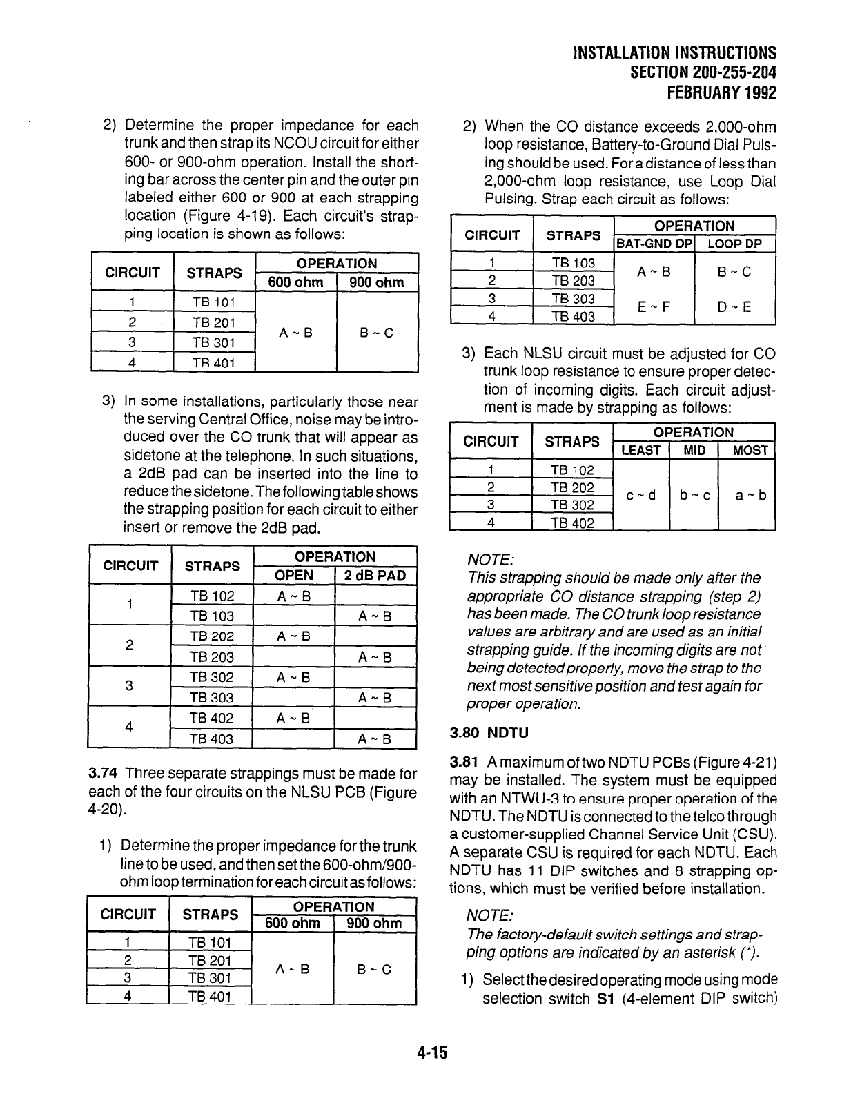
INSTALLATION INSTRUCTIONS
SECTlON200-255-204
FEBRUARY1992
2) Determine the proper impedance for each
trunk and then strap its NCOU circuit for either
600- or 900-ohm operation. Install the short-
ing bar across the center pin and the outer pin
labeled either 600 or 900 at each strapping
location (Figure 4-19). Each circuits strap-
ping location is shown as follows:
CIRCUIT STRAPS - OPERATION
600 ohm 900 ohm
1 TB101
2 TB201
3 TB301 A-B
B-C
4 TB401
3) In some installations, particularly those near
the serving Central Office, noise may be intro-
duced over the CO trunk that will appear as
sidetone at the telephone. In such situations,
a 2dB pad can be inserted into the line to
reduce thesidetone. The following table shows
the strapping position for each circuit to either
insert or remove the 2dB pad.
3.74 Three separate strappings must be made for
each of the four circuits on the NLSU PCB (Figure
4-20).
1) Determine the proper impedance for the trunk
line to be used, and then set the 600-ohm/900-
ohm loop termination for each circuit as follows:
CIRCUIT STRAPS OPERATION
6000hm 1 900ohm
1 1 TBlOl 1 I I
2 TB201
3 TB301 A-B
B-C
4 TB401
2) When the CO distance exceeds 2,000-ohm
loop resistance, Battery-to-Ground Dial Puls-
ing should be used. Foradistance of less than
2,000-ohm loop resistance, use Loop Dial
Pulsing. Strap each circuit as follows:
CIRCUIT STRAPS OPERATION
r BAT-GND DP( LOOP DP
3) Each NLSU circuit must be adjusted for CO
trunk loop resistance to ensure proper detec-
tion of incoming digits. Each circuit adjust-
ment is made by strapping as follows:
CIRCUIT STRAPS - OPERATION
LEAST MID MOST
1 TB102
2
3 TB202 c-d bwc awb
TB
302 _
4 TB402
NOTE:
This strapping should be made only after the
appropriate CO distance strapping (step 2)
has been made. The CO trunk loop resistance
values are arbitrary and are used as an initial
strapping guide. If the incoming digits are not
being detectedproperly, move the strap to the
next most sensitive position and test again for
proper operation.
3.80 NDTU
3.81
A maximum of two NDTU PCBs (Figure 4-21)
may be installed. The system must be equipped
with an NTWU-3 to ensure proper operation of the
NDTU. The NDTU is connected to the telco through
a customer-supplied Channel Service Unit (CSU).
A separate CSU is required for each NDTU. Each
NDTU has 11 DIP switches and 8 strapping op-
tions, which must be verified before installation.
NOTE:
The factory-default switch settings and strap-
ping options are indicated by an asterisk (*).
1) Select thedesired operating mode using mode
selection switch
Sl
(4-element DIP switch)
4-15
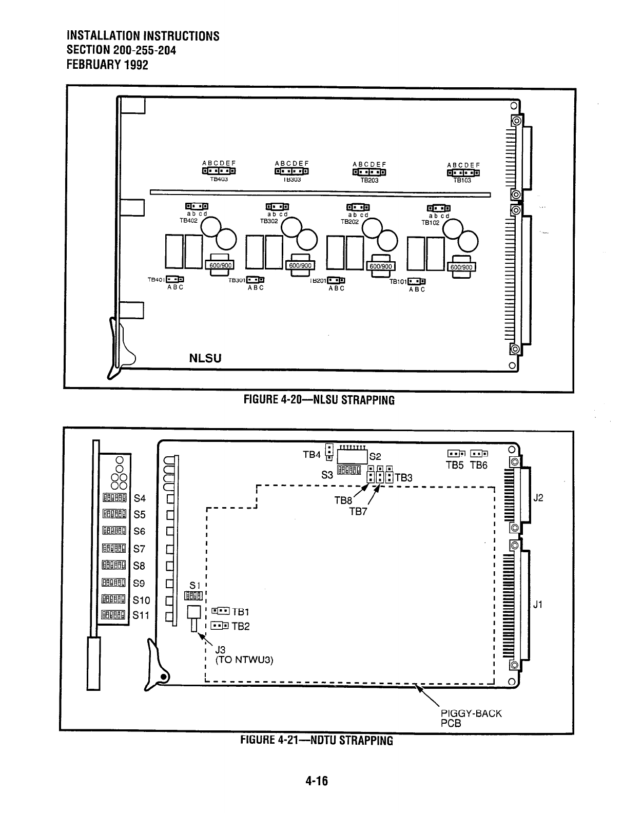
INSTALLATION INSTRUCTIONS
SECTION 200-255-204
FEBRUARY1992
ABCDEF ABCDEF
T
ABCDEF
yg3
ABCDEF
v T
ABC ABC ABC
FIGURE 4-ZO-NLSU STRAPPING
I J2
TB7
L,,,,---,,-,,,,,,,,- --------------
PIGGY-BACK
PCB
C,m,.mC - 1- ..--.. --- -----.-
miunt 4-Zl-NU I U
STRAPPING
4-16
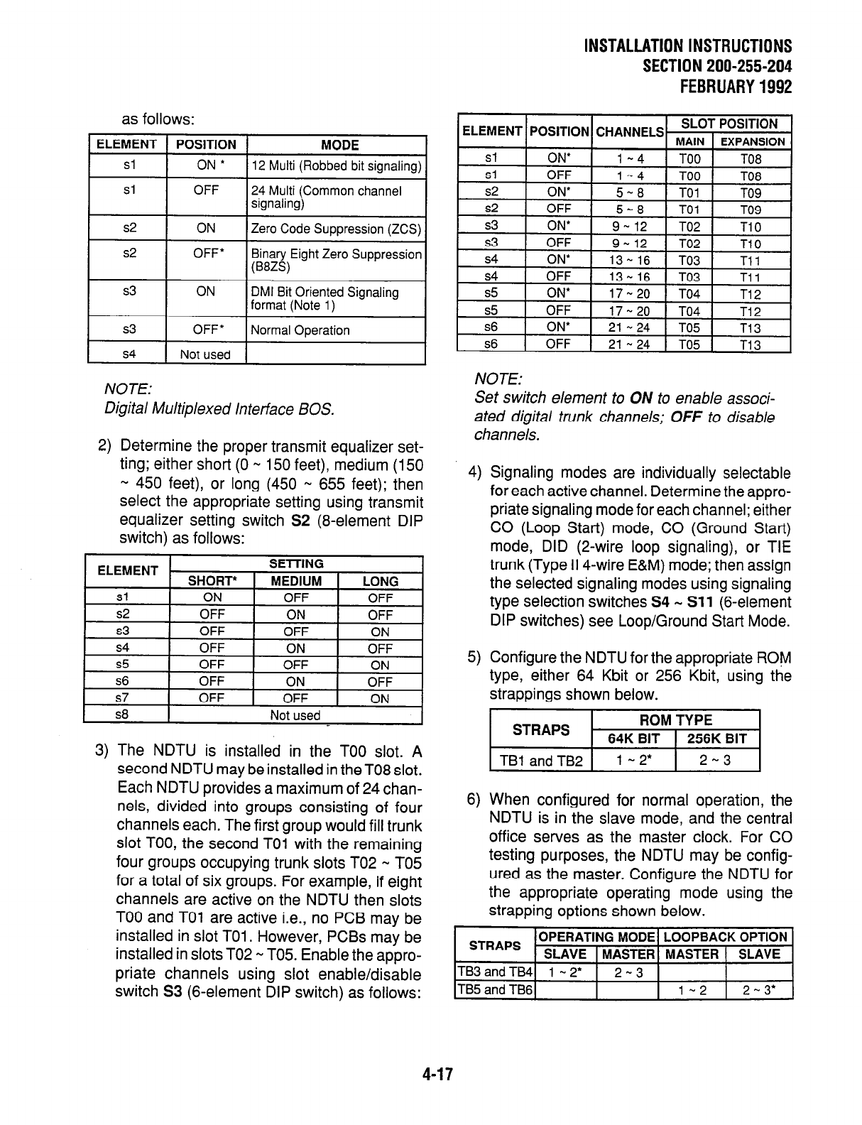
INSTALLATION INSTRUCTIONS
SECTION 200-255-204
FEBRUARY1992
as follows:
ELEMENT POSITION MORE
Sl
ON * 12 Multi (Robbed bit signaling)
Sl
OFF 24 Multi (Common channel
signaling)
s2 ON Zero Code Suppression (ZCS)
I
s2
I
OFF* Binary Eight Zero Suppression
(B8ZS)
s4 1 Not used 1
NOTE:
Digital Multiplexed Interface BOS.
2)
Determine the proper transmit equalizer set-
ting; either short (0 w 150 feet), medium (150
w 450 feet), or long (450 * 655 feet); then
select the appropriate setting using transmit
equalizer setting switch S2 (8-element DIP
switch) as follows:
I
s8 I Not used I
3) The NDTU is installed in the TOO slot. A
second NDTU may be installed in the TO8 slot.
Each NDTU provides a maximum of 24 chan-
nels, divided into groups consisting of four
channels each. The first group would fill trunk
slot TOO, the second TO1 with the remaining
four groups occupying trunk slots TO2 m TO5
for a total of six groups. For example, if eight
channels are active on the NDTU then slots
TOO and TO1 are active i.e., no PCB may be
installed in slot TO1 . However, PCBs may be
installed in slots TO2 w T05. Enable the appro-
priate channels using slot enable/disable
switch S3 (6-element DIP switch) as follows:
NOTE:
Set switch element to ON to enable associ-
ated digital trunk channels; OFF to disable
channels.
4)
Signaling modes are individually selectable
for each active channel. Determine the appro-
priate signaling mode for each channel; either
CO (Loop Start) mode, CO (Ground Start)
mode, DID (2-wire loop signaling), or TIE
trunk (Type II 4-wire E&M) mode; then assign
the selected signaling modes using signaling
type selection switches S4 w Sll (6-element
DIP switches) see Loop/Ground Start Mode.
5)
Configure the NDTU for the appropriate ROM
type, either 64 Kbit or 256 Kbit, using
strappings shown below. the
6)
When configured for normal operation, the
NDTU is in the slave mode, and the central
office serves as the master clock. For CO
testing purposes, the NDTU may be config-
ured as the master. Configure the NDTU for
the appropriate operating mode using the
strapping options shown below.
STRAPS OPERATING MODE LOOPBACK OPTION
SLAVE 1 MASTER MASTER ( SLAVE
TB3andTB4 l-2’
I
2-3
ITB~ and TB6l 1 1-2 1 2-3’ 1
4-17
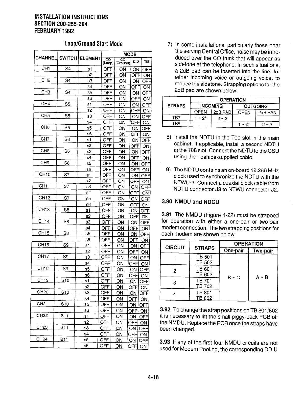
INSTALLATION INSTRUCTIONS
SECTION 200-255-204
FEBRUARY1992
Loop/Ground Start Mode
7) In some installations, particularly those near
the serving Central Office, noise may be intro-
duced over the CO trunk that will appear as
sidetone at the telephone. In such situations,
a 2dB pad can be inserted into the line, for
either incoming voice or outgoing voice, to
reduce the sidetone. Strapping options for the
2dB pad are shown below.
8) Install the NDTU in the TOO slot in the main
cabinet. If applicable, install a second NDTU
in the TO8 slot. Connect the NDTU to the CSU
using the Toshiba-supplied cable.
9) The NDTU contains an on-board 12.288 MHz
clock used to synchronize the NDTU with the
NTWU-3. Connect a coaxial clock cable from
NDTU connector 53 to NTWU connector J2.
3.90 NMDU and NDCU
3.91 The NMDU (Figure 4-22) must be strapped
for operation with either a one-pair or two-pair
modem connection. The two strapping positions for
each modem are shown below.
CIRCUIT OPEfi
STRAPS One-pair
4
TB
501
I I
1 TB 502 1
,TION
Two-pair
A-B
3.92 To change the strap positions on TB 8011802
it is necessary to lift the small piggy-back PCB off
the NMDU. Replace the PCB once the straps have
been changed.
3.93 If any of the first four NMDU circuits are not
used for Modem Pooling, the corresponding DDIU
4-18
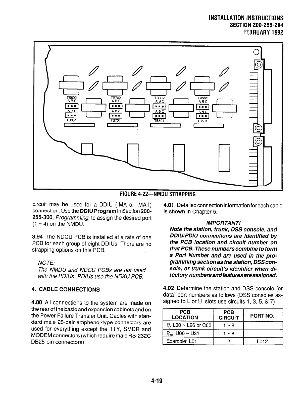
INSTALLATION INSTRUCTIONS
SECTION 200-255-204
FEBRUARY1992
\
TBBOI TB701 TB601 TB501
I I - II
\ n
n n
rluunc *xl-
IYIVIUU 3 I mrruw
circuit may be used for a DDIU (-MA or -MAT)
connection. Use the DDIU Program in Section 200-
255-300, Programming, to assign the desired port
(1 -, 4) on the NMDU.
3.94 The NDCU PCB is installed at a rate of one
PCB for each group of eight DDIUs. There are no
strapping options on this PCB.
NOTE:
The NMDU and NDCU PCBs are not used
with the PDIUs. PDlUs use the NDKU PCB.
4. CABLE CONNECTIONS
4.00 All connections to the system are made on
the rear of the basic and expansion cabinets and on
the Power Failure Transfer Unit. Cables with stan-
dard male 25pair amphenol-type connectors are
used for everything except the TTY, SMDR and
MODEM connectors (which require male RS-232C
DB25pin connectors).
4.01 Detailed connection information for each cable
is shown in Chapter 5.
IMPORTANT!
Note the station, trunk, DSS console, and
DDIWPDIU connections are identified by
the PCB location and circuit number on
that PCB. These numbers combine to form
a Port Number and are used in the pro-
gramming section as the station, DSS con-
sole, or trunk circuit’s identifier when di-
rectory numbers and features are assigned.
4.02 Determine the station and DSS console (or
data) port numbers as follows (DSS consoles as-
signed to L or U slots use circuits 1, 3, 5, & 7):
PCB PCB
LOCATION CIRCUIT PORT NO.
FL LOO - L26orCOO 1 - 8
I FL uoo- u31 t l-8 1 I
1 Example:
LO1 2 LO12
4-19
INSTALLATION INSTRUCTIONS
SECTION 200-255-204
FEBRUARY 1992
4.03 Determine trunk port numbers as follows:
I
PC6
LOCATION
I PCB
CIRCUIT I PORT NO. I
1 P,TOO-~15 I 1-4 I I
gx TOO-T15
uoo - u31
Example: TO2
1-4
3 TO23
5. ELECTRONIC TELEPHONE STATION
EQUIPMENT INSTALLATION
5.00 Electronic Telephone Connections
5.01 See the DEKT Program in Section 200-255-
300, Programming, for instructions on program-
ming electronic telephones. The system must be
told which type of electronic telephone (lo- or 20-
button, LCD) and what button assignment is re-
quired.
5.02 Electronic telephones are connected to the
MDF via standard twisted-pair jacketed telephone
cable. (Two-pair wiring is required; however, 3-pair
wiring is strongly recommended to permit future
upgrades, such as data, etc.) To accommodate the
electronic telephone line cord, terminate the cable
in a modular station connector block (RJ25) at the
station location. The standard modular electronic
telephone cord length is 7 feet (the maximum
allowed length is 25 feet).
5.03 The overall length of the electronic telephone
cable run from equipment cabinet to phone must
not exceed 1,000 feet (305 M), 24 AWG cable.
IMPORTANT!
When installing the electronic telephone
cable, do not run parallel to and within 3
feet of an AC power line. Such power lines
should be crossed at right angles (90”)
only.
5.04 Electronic telephone connection details are
shown in Figure 4-23.
5.10 Electronic Telephone Wall Mounting
5.11 All electronic telephones are wall-mounted in
the same manner, and they may be mounted on a
wall or any other flat, vertical surface to which the
base can be secured. When selecting the mounting
site, consider the electronic telephone’s weight and
the additional stresses to which the mounting will
be subjected.
5.12 Loosen the four captive screws securing the
electronic telephone’s base, and remove the base
(Figure 4-24).
5.13 Using a cutter, remove the handset hanger
from the base. Insert the handset hanger in the slot
provided on the front of the telephone (Figure 4-
25). The hanger fits in the notch on the handset.
5.14 Rotate the mounting base 180” and secure to
the telephone with the four captive screws (Figure
4-26).
5.15 Connect the electronic telephone to the wall
modular connector with a short cord (approximately
3 inch length). Route the cord into the hollow
portion of the base, then mount the electronic
telephone on the wail mounting connector. Test
each electronic telephone using the TTRM Pro-
gram, Section 200-255-300, Programming.
5.20 Off-hook Call Announce
5.21 The Off-hook Call Announce (OCA) feature
enables an electronic telephone to originate and
receive voice announcement when the station’s
handset is off-hook. Standard telephones can origi-
nate off-hook call announces, however, it cannot
receive them. A station user is allowed or denied
the ability to originate the Off-hook Call Announce
feature in the DCOS Program. In order to receive
the Off-hook Call Announce feature, PCBs are
required to be installed in each affected electronic
telephone and the cabinet.
5.22 A PCB called NOCU is required to be installed
in the cabinet. Each NOCU provides eight Off-hook
Call Announce circuits. This PCB takes up a station
slot. Therefore, for each NOCU installed, station
capacity is decreased by eight stations.
5.23 HVSU and HVSI PCBs inside a 6500-series
electronic telephone allow the electronic telephone
to receive the Off-hook Call Announce feature.
4-20
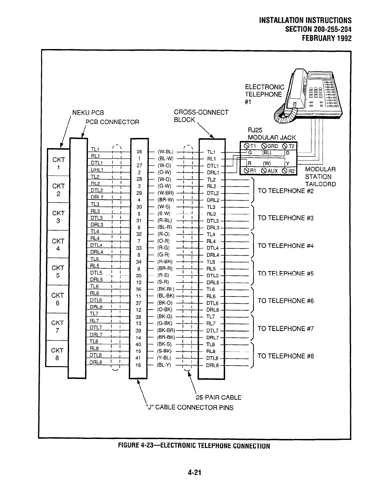
INSTALLATION INSTRUCTIONS
SECTION 200-255-204
FEBRUARY1992
NEKU PCB
PCB CONNECTOR
1
CKT
1
CKT
2
CKT
3
CKT
4
CKT
5
CKT
c
26 -
1 -
27 -
2 -
28 -
3 -
29 -
4 -
30 -
5 -
31 -
6 -
32 -
7 -
33 -
8 -
34 -
9 -
35 -
10 -
36 -
11 -
37 -
CKT
8
1 RL7 i ;
CROSS-CONNECT
BLOCK
(W-BL)
(BL-W)
W-0)
(0-W
W-G)
G-W
(W-BR)
VI,.I,V
TAILCO
TO TELEPWNF *p
TO TELEPHONE #3
TO TELEPHONE #4
TO TELEPHONE #5
TO TELEPHONE #6
(G-W 1 f
RL7
(BK-BR) i 1 DTL7
(BR-BK) ; ! DRL7
W-S) , I TL8
(S-BK) I ; RL8
(Y-W ; ; DTL8
(BL-Y) I I DRL8 1
.
\ 25-PAIR CABLE
“J” CABLE CONNECTOR PINS
TO
TO
TELEPHONE
TELEPHONE
#7
#8
FlGURE4-23-ELECTRONICTELEPHONECONNECTION
4-21
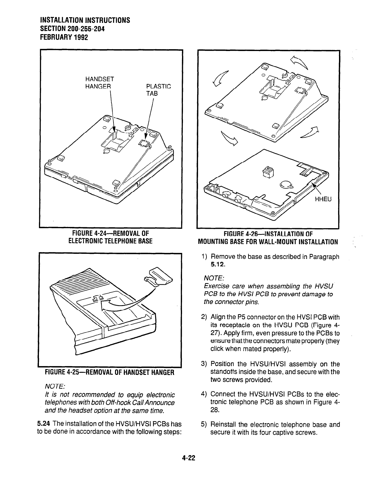
INSTALLATION INSTRUCTIONS
SECTION 200-255-204
FEBRUARY1992
HANDSET
HANGER PLASTIC
FIGURE 4-24--REMOVAL OF
ELECTRONIC TELEPHONE BASE
FIGURE 4-25-REMOVAL OF HANDSET HANGER
NOTE:
3) Position the HVSWHVSI assembly on the
standoffs inside the base, and secure with the
two screws provided.
It is not recommended to equip electronic 4) Connect the HVSWHVSI PCBs to the elec-
telephones with both Off-hook Cal/Announce tronic telephone PCB as shown in Figure 4-
and the headset option at the same time.
2a.
5.24 The installation of the HVSWHVSI PCBs has
to be done in accordance with the following steps:
FIGURE 4-26-INSTALLATION OF
MOUNTING BASE FOR WALL-MOUNT INSTALLATION
1) Remove the base as described in Paragraph
5.12.
:
NOTE:
Exercise care when assembling the HVSU
P CB to the HVSl PC5 to prevent damage to
the connector pins.
2) Align the P5 connector on the HVSI PCB with
its receptacle on the HVSU PCB (Figure 4-
27). Apply firm, even pressure to the PCBs to
ensure thatthe connectors mate properly (they
click when mated properly).
5) Reinstall the electronic telephone base and
secure it with its four captive screws.
4-22
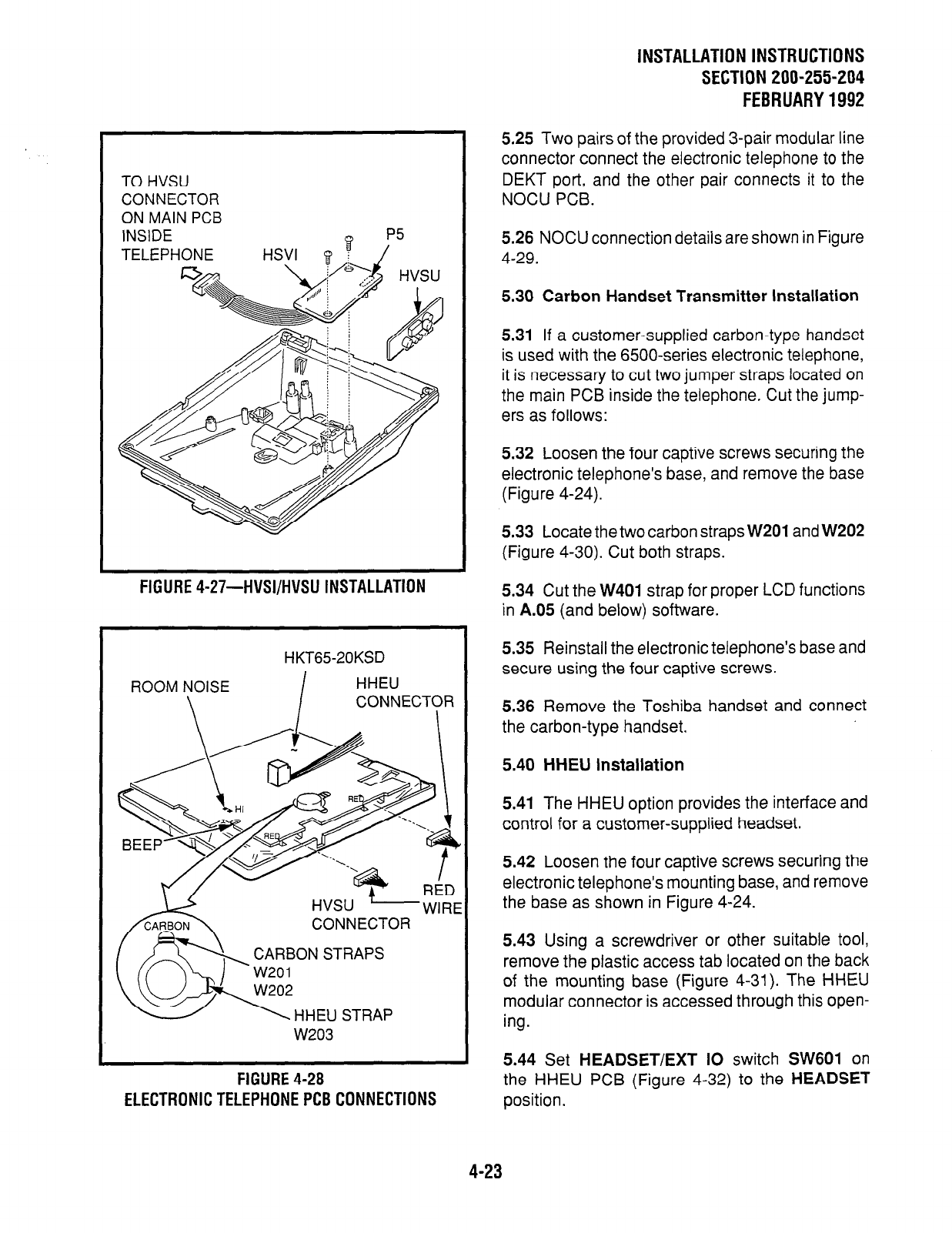
TO HVSU
CONNECTOR
ON MAIN PCB
INSIDE
TELEPHONE HSVI 8 /‘”
Q i
FIGURE 4-27-HVSI/HVSU INSTALLATION
HKT65-20KSD
ROOM NOISE
I
HHEU
\ CONNECTOR
I
HVSU -WIRE
CONNECTOR
W203
FIGURE 4-28
ELECTRONIC TELEPHONE PC8 CONNECTIONS
INSTALLATION INSTRUCTIONS
SECTION 200-255-204
FEBRUARY 1992
5.25 Two pairs of the provided 3-pair modular line
connector connect the electronic telephone to the
DEKT port, and the other pair connects it to the
NOCU PCB.
5.26 NOCU connection details are shown in Figure
4-29.
5.30 Carbon Handset Transmitter Installation
5.31
If a customer-supplied carbon-type handset
is used with the 6500-series electronic telephone,
it is necessary to cut two jumper straps located on
the main PCB inside the telephone. Cut the jump-
ers as follows:
5.32 Loosen the four captive screws securing the
electronic telephone’s base, and remove the base
(Figure 4-24).
5.33 Locate the two carbon straps
W201
and W202
(Figure 4-30). Cut both straps.
5.34 Cut the W401 strap for proper LCD functions
in A.05 (and below) software.
5.35 Reinstall the electronic telephone’s base and
secure using the four captive screws.
5.36 Remove the Toshiba handset and connect
the carbon-type handset.
5.40 HHEU Installation
5.41
The HHEU option provides the interface and
control for a customer-supplied headset.
5.42 Loosen the four captive screws securing the
electronic telephone’s mounting base, and remove
the base as shown in Figure 4-24.
5.43 Using a screwdriver or other suitable tool,
remove the plastic access tab located on the back
of the mounting base (Figure 4-31). The HHEU
modular connector is accessed through this open-
ing.
5.44
Set
HEADSET/EXT IO
switch SW601 on
the HHEU PCB (Figure 4-32) to the
HEADSET
position.
4-23
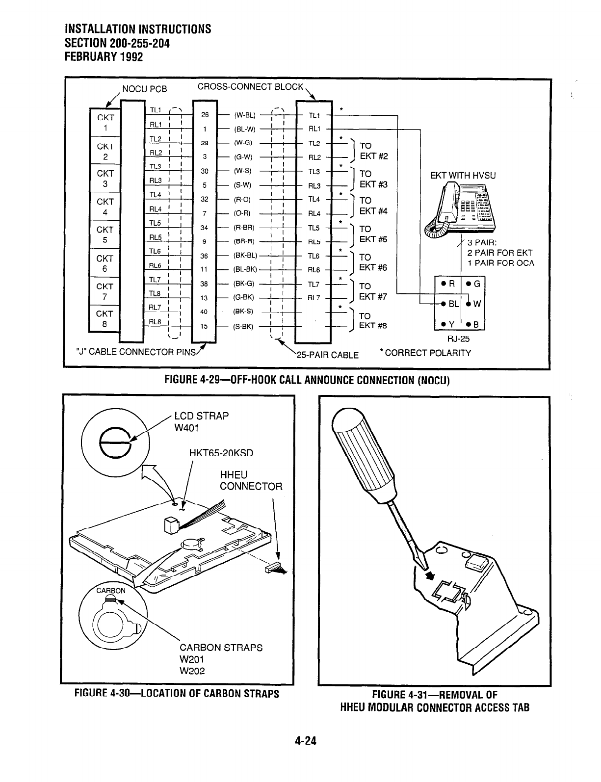
INSTALLATION INSTRUCTIONS
SECTION 200-255-204
FEBRUARY 1992
CKT
1
CKT
2
CKT
3
CKT
4
CKT
5
CKT
6
CKT
7
CKT
a
NOCU PCB CROSS-CONNECT BLOCK I
-
-
TLI (-1 26
I
RLI f ’
I l-
TL2 1 ! 28
RL2I !
I 0 3 -
TL3 I ]
I 30 -
RL3 ’ !
I 5 -
TL4 ! ;
I 32 -
RL4 ! ; 7 -
I
TL5 ! ,
RL5 f ;
34 -
I 9 -
TL6 1 I 36
I
RL6II ,,
I
TL7 1 I 38
I
TL8Il ,3
I
RL7 ; l 4.
I
RL8I !
I ’ 15 -
\,I
I
“J” CABLE CONNECTOR PINSr
(W-BL) I-:
I &
TLl
@L-W) ; I RLI
(W-G) 1 ; TL2
I
(G-W) ; /
RL2
(W-S) I ; TL3
(S-W I j RL3
(R-O) ! ’ TL4
RL4
TL5
RL.5
TL6
RL6
TL7
RL7
*
I=) To
EKT#7 -
TO
EKT #8
d RJ-25
-
f
EKT WITH HVSU
1 PAIR FOR OCA
‘25-PAIR CABLE *CORRECT POLARITY
FIGURE 4-29-OFF-HOOK CALL ANNOUNCE CONNECTION (NOCU)
LCD STRAP
w401
HKT6520KSD
CARBON STRAPS
w201
FIGURE 4-30-LOCATION OF CARBON STRAPS FIGURE 4-31-REMOVAL OF
HHEU MODULAR CONNECTOR ACCESS TAB
4-24
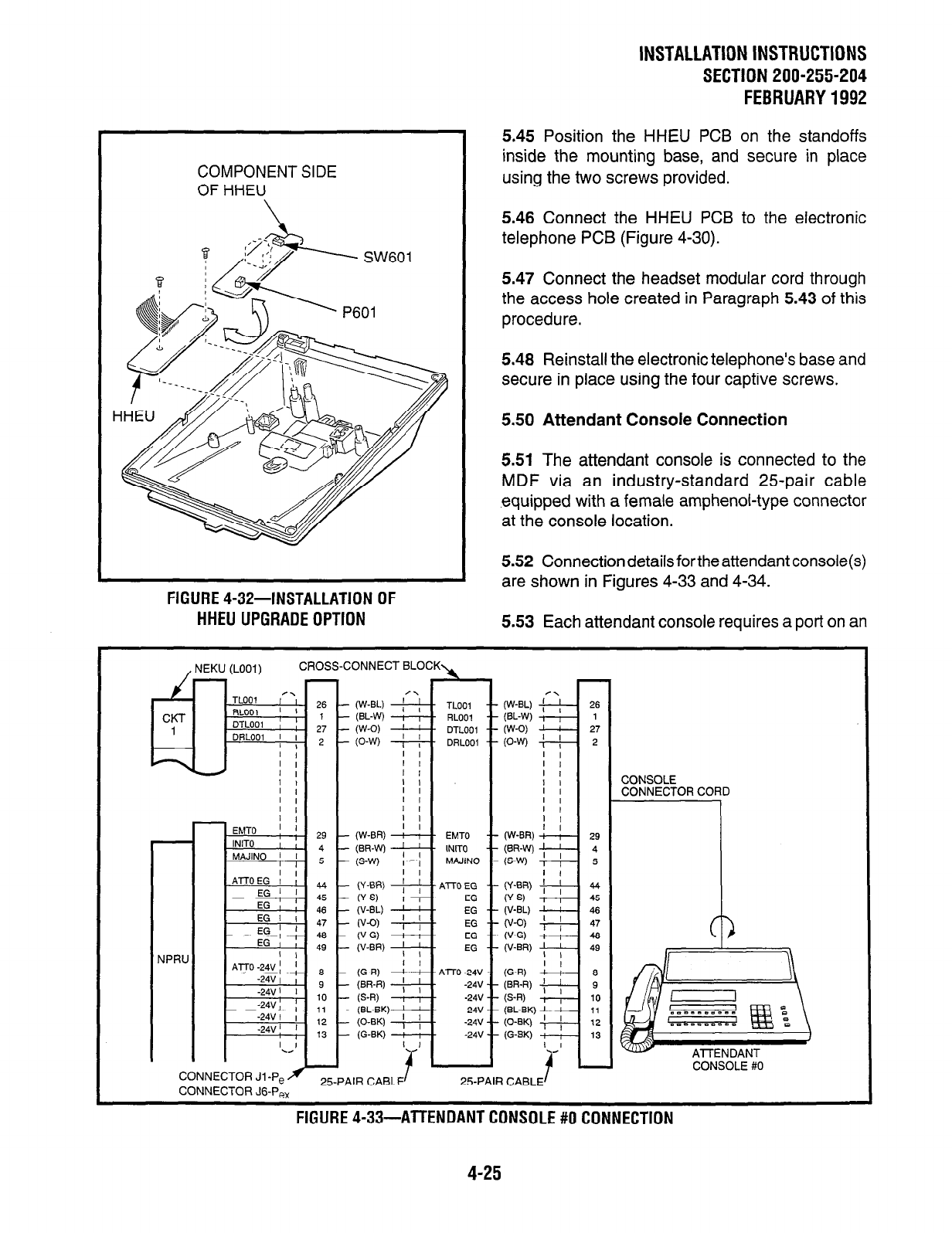
COMPONENT SIDE
OF HHEU
FIGURE 4-32-INSTALLATION OF
HHEU UPGRADE OPTION
INSTALLATlONlNSTRUCTlONS
SECTlON200-255-204
FEBRUARY1992
5.45 Position the HHEU PCB on the standoffs
inside the mounting base, and secure in place
using the two screws provided.
5.46 Connect the HHEU PCB to the electronic
telephone PCB (Figure 4-30).
5.47 Connect the headset modular cord through
the access hole created in Paragraph 5.43 of this
procedure.
5.48 Reinstall the electronic telephone’s base and
secure in place using the four captive screws.
5.50 Attendant Console Connection
5.51 The attendant console is connected to the
MDF via an industry-standard 25pair cable
equipped with a female amphenol-type connector
at the console location.
5.52 Connection details for the attendant console(s)
are shown in Figures 4-33 and 4-34.
5.53 Each attendant console requires a port on an
, NEKU (LOOI) CROSS-CONNECT BLOCK\
CONNECTOR Jl -P, fl
CONNECTOR JG-Pex
26
1
27
2
29
4
5
44
45
46
47
48
49
a
9
IO
11
12
13
/\ /\
- (W-BL) ; ; - TLOOl --
- (W-BL) ; ; TLOOl --
- @L-W) i , - RLOO~ --
- (BL-W) ; , - RLOOl --
- (W-D) ’ ’ - DTLOOl --
- (W-O) ’ ’
- (O-W) ; ( - DRLOOI --
. DTLOOl --
- (O-W) ; ( DRLOOI --
I I I I
I I I I
I I I I
I I I I
I I I I
I I I I
I I I I
I I I I
I I I I
- (W-BR) : I - EMT0 --
- (W-BR) : , - EMT0 --
- (BR-W) ; ; - INITO --
- (BR-WI ; ; INITO --
- (S-W) , , - (S-W) , , - MPJINO --
- MAJINO --
I I I I
- (Y-EM) ; ; -AlTOEG --
- (Y-BR) ; ; -AlTOEG --
-(Y-S) i I.- - (Y-S) i 1 EG -- EG --
- w-w ; ; - - W-W ; ; EG -- EG --
- (V-0) , , - - (V-0) , , EG -- EG --
- (V-G) : 8 - (V-G) : 8 - EG -- EG --
- (V-BR) ; ; - (V-BR) ; ; - EG -- EG --
I I I I
- (G-R) ! : - (G-R) ! : -AnO-24V -- - AnO -24V - -
- (BR-R) ; ; - (BR-R) ; ; - -24V - - -24V - -
- (S-R) , , - (S-R) , , - -24V - - -24V - -
I >_ I >__
- (BL-BK) I - (BL-BK) I I -24V - - -24V - -
I
- (O-BK) , , - (O-BK) , , - -24V - - -24V - -
- (G-BK) : , - (G-BK) : , - -24V - - -24V - -
(W-BL) +
(BL-W) 4
(W-0) -
(0-w) +
I I
I I
I I
I I
I I
I I
I
I I
(W-BR) d+
(BR-W) I
(S-W) g-
(Y-BR) =
(Y-S) I
(V-BL) I
(V-BR) I I 1
(G-R) d--i-
(BR-R) +/--
6-R) -
25PAIR CABLE’ 25PAIR CABLE/
26
1
27
2
29
4
5
44
45
46
47
48
49
a
9
10
11
12
13
CONSOLE
CONNECTOR CORD
CONSOLE #O
FIGURE 4-33-AlTENDANTCONSOLE#OCONNECTlON
4-25
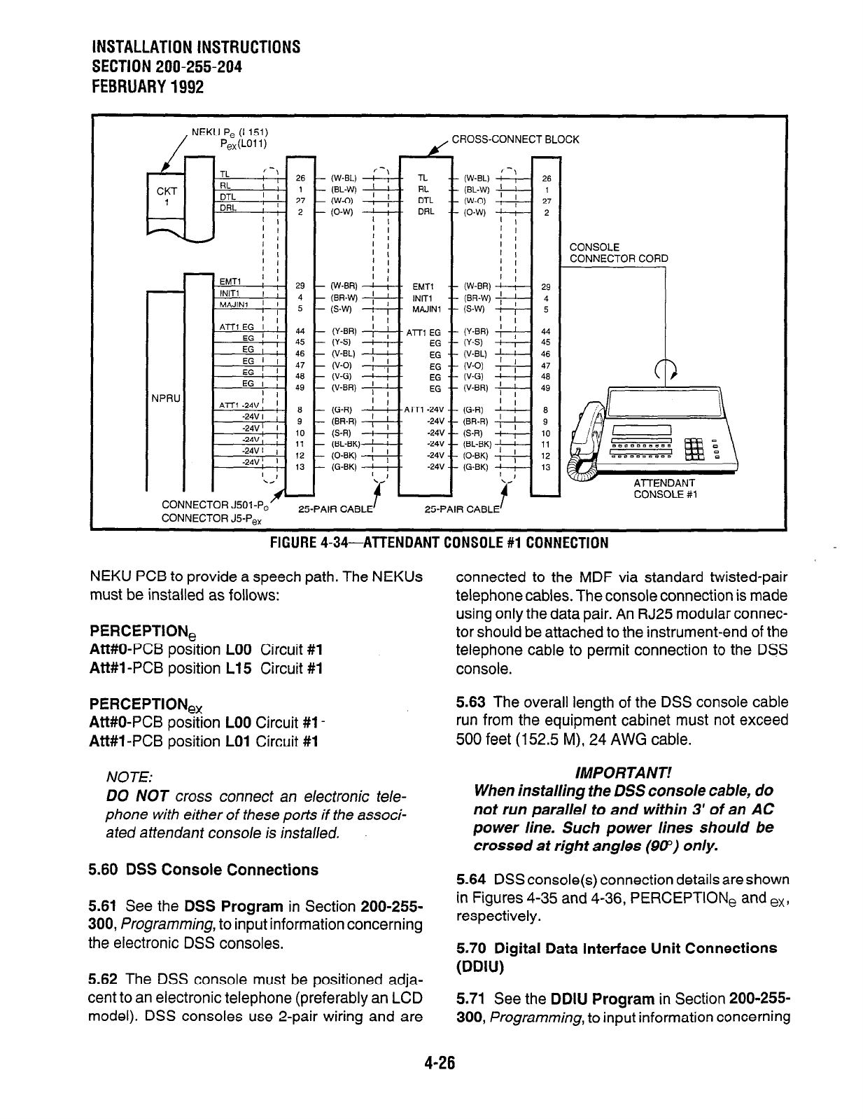
INSTALLATION INSTRUCTIONS
SECTION 200-255-204
FEBRUARY1992
NEKU P, (L151)
PexWll) CROSS-CONNECT BLOCK
CONNECTOR J501-P,
CONNECTOR J5-Pex
I-
\
(W-EL) ! r - TL -- (W-EL)
(BL-W) ; ; - RL -- (BL-W)
W-0) I - DTL -- (W-O)
(O-W) ; : - DAL -- (O-W)
I
’ I
’ I
’ I
’ I
’ I
1 I
I
(W-W --cy - EMT1 -- (w-BR)
(BR-W) ; ; iNIT -- (BR-W)
(S-W) -- MPlJlNl -- (S-W)
’ I
W-W ; ; -- Al71 EG -- (Y-BR)
(Y-S) -v- EG -- (Y-S)
W-B’-) ; ! .- EG -- W-W
W-0) --+- EG -- (V-0)
W-G) ! i .- EG -- (V-G)
(V-W ; ; .- EG -- (V-BR)
’ ,
(G-R) ’ : -ATT1 -24V -- (G-R)
(BR-R) ( ; .- -24V -- (BR-R)
(S-R) : , .- -24V -- (S-R)
(BL-BK) ; j - -24V -- (BL-BK)
(O-BK) , , -24V -- (O-BK)
(G-BK) ---cy - -24V - (G-BK)
‘\ ’
t*
l-l
w
ATTENDANT
CONSOLE
#l
25-PAIR CABLE
f
25-PAIR CABLE
f
-.-__-- _ -_ _--_.--_.---_.--.- . -- ____ ---_-_.
NEKU PCB to provide a speech path. The NEKUs
must be installed as follows:
PERCEPTlONe
Att#O-PCB position LOO Circuit #l
Att#l -PCB position L15 Circuit #l
connected to the MDF via standard twisted-pair
telephone cables. The console connection is made
using only the data pair. An RJ25 modular connec-
tor should be attached to the instrument-end of the
telephone cable to permit connection to the DSS
console.
PERCEPTlONe,
Att#O-PCB position LOO Circuit #1-
Att#l-PCB position LO1 Circuit #l
5.63 The overall length of the DSS console cable
run from the equipment cabinet must not exceed
500 feet (152.5 M), 24 AWG cable.
NOTE: IMPORTANT!
DO NOT cross connect an electronic tele-
phone with either of these ports if the associ-
ated aftendant console is installed.
5.60 DSS Console Connections
When installing the DSS console cable, do
not run parallel to and within 3’ of an AC
power line. Such power lines should be
crossed at right angles (90”) only.
5.61 See the DSS Program in Section 200-255-
300, Programming, to input information concerning
the electronic DSS consoles.
5.64 DSS console(s) connection details are shown
in Figures 4-35 and 4-36, PERCEPTION, and ex,
respectively.
5.62 The DSS console must be positioned adja-
cent to an electronic telephone (preferably an LCD
model). DSS consoles use 2-pair wiring and are
5.70 Digital Data Interface Unit Connections
(DDIU)
5.71 See the DDIU Program in Section 200-255-
300, Programming, to input information concerning
FIGURE 4-34-ATTENOANT CONSOLE #l CONNECTION
4-26
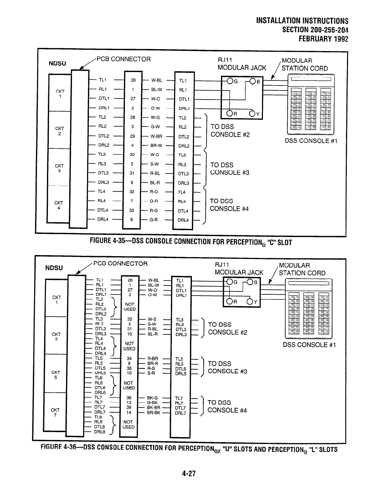
INSTALLATION INSTRUCTIONS
SECTION 200-255-204
FEBRUARY1992
NDSU PCB CONNECTOR
MODULAR JACK
- TLI - 26 - W-BL
CKT - RLl - 1 - BL-w
1 - DTLl - 27 - w-0
- DRLl - 2 - O-w
- TL2 - 28 - W-G
CKT - RI-2 - 3 - G-W
2 - DTL2 - 29 - W-BR
DSS CONSOLE #l
- DRL2 - 4 - BR-w
- TL3 - 30 - w-s
CKT - RL3 - 5 - S-w
3 - DTL3 - 31 - R-BL
CONSOLE #3
- DRL3 - 6 - BL-R
- TL4 - 32 - R-O
CKT - RL4 - 7 - O-R
4 - DTL4 - 33 - R-G
- DRL4 - 8 - G-R
NDSU
FIGURE 4-35-DSS CONSOLE CONNECTION FOR PERCEPTION, “c” SLOT
PCB CONNECTOR
- TLI - 26 - W-BL
- RLl - I - BL-w
- DTLl - 27 - W-O
CKT - DRLl - 2 - O-w
1 - TL2
I”” >
NOT
- DTL2 USED
DRL2
- TL3 - 30 - W-S
- RL3 - 5 - S-w
- DTL3 - 31 - R-BL
WI- - DRL3 - 10 - BL-R
3 NOT
USED
- TL.5 - 34 - R-BR
- RL5 - 9 - BR-R
- DTL5 - 35 - R-S
CKT -DRL5 - 10 -S-R
5
NOT
USED
- TL7 - 38 - BK-G
- RL7 - 13 - G-BK
CKl - DTL7 - 39 - BK-BR
7 - DRL7 - 14 - BR-BK
- TL8
-RL8 >
NOT
- DTL8 USED
- DRL8 I I
c,m,,nr 1 -c nnn #tm.,r,e, c #b- . . . . .-a-.-.. m-e ---------~~ ____ -_-.. ..-.. -- ---
rluunc
4-30-1~33
ldJNSULt WNNtl; I ION HJK
PERCEPTION,
“U” SLOTS AND PERCEPTION, ‘I” SLOTS
4-27
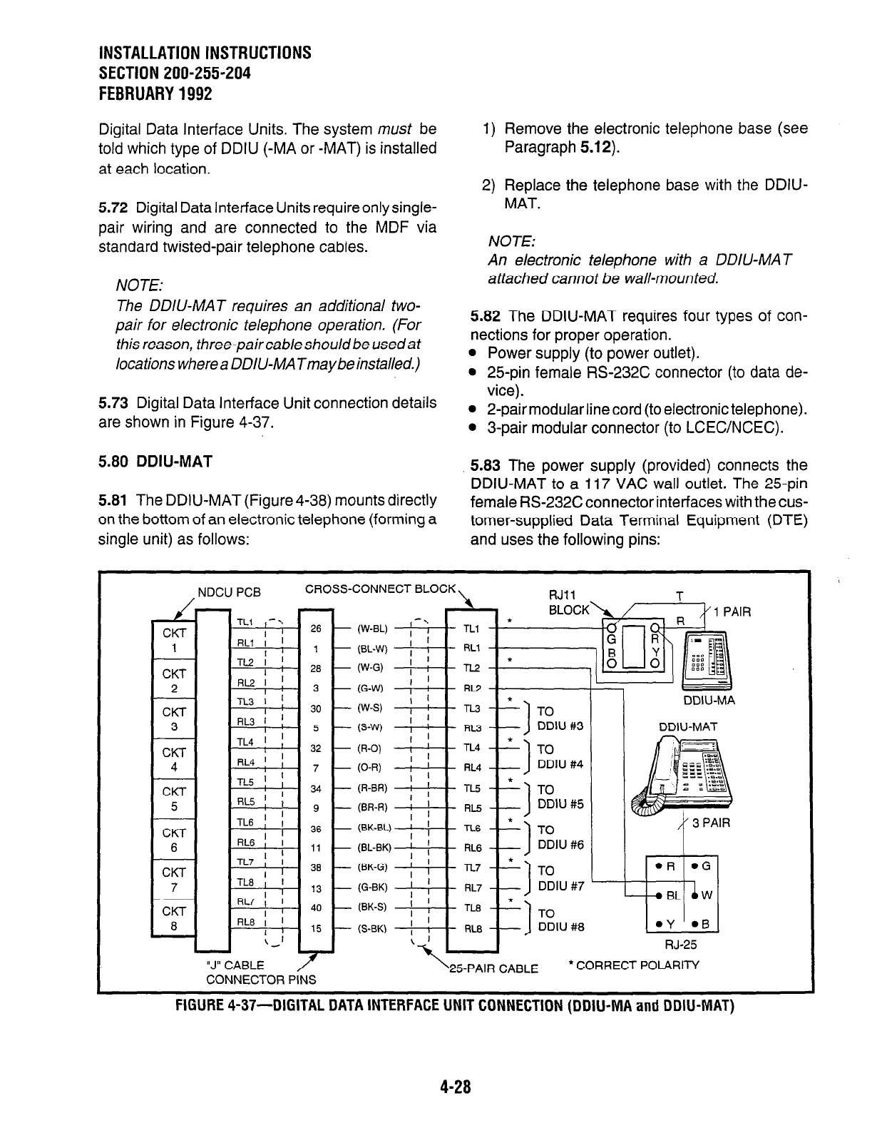
INSTALLATION INSTRUCTIONS
SECTION 200-255-204
FEBRUARY1992
Digital Data Interface Units. The system must be
told which type of DDIU (-MA or -MAT) is installed
at each location.
1) Remove the electronic telephone base (see
Paragraph 5.12).
5.72 Digital Data Interface Units requireonlysingle-
pair wiring and are connected to the MDF via
standard twisted-pair telephone cables.
NOTE:
2) Replace the telephone base with the DDIU-
MAT.
NOTE:
An electronic telephone with a DDIlJ-MAT
attached cannot be wall-mounted.
The DDIU-MAT requires an additional two-
pair for electronic telephone operation. (For
this reason, three-pair cab/e should be used at
locations where a DDIU-MATmaybe installed.)
5.82 The DDIU-MAT requires four types of con-
nections for proper operation.
l
Power supply (to power outlet).
l
25-pin female RS-232C connector (to data de-
5.73 Digital Data Interface Unit connection details
are shown in Figure 4-37.
vice).
l
2-pair modular line cord (to electronic telephone).
l
3-pair modular connector (to LCECYNCEC).
5.80 DDIU-MAT
5.83 The power supply (provided) connects the
DDIU-MAT to a 117 VAC wall outlet. The 25-pin
5.81 The DDIU-MAT (Figure4-38) mounts directly female RS-232C connector interfaces with the cus-
on the bottom of an electronic telephone (forming a tomer-supplied Data Terminal Equipment (DTE)
single unit) as follows: and uses the following pins:
, NDCU PCB CROSS-CONNECT BLOCK \. RJll T
CKT
TLI I-‘\ 26
I
1 RLl I ’
I 1
PI/-r TL2 f ! 26
I 1
Ur\l
2
CKT
3
CKT
4
CKT
5
CKT
6
CKT
7
CKT
8
- (W-BL)
- (EL-W)
- (W-G)
- (G-W)
AL2 i !
I r 3
TL3 I ;
I ’ 30
-
RL3 1 ;
I 5
TL4 ’ j
I 32
-
RL4 ! I 7
TL5 ! ; 34
I (R-BR) : ’
I ’ - TO
RL5 j , 9
-
(BR-R) I ’
DDIU #5
I
TL6 ] , 36 (BK-EL)
’ f
TL5 --I
lx5 -
I
RL6II ,,
/ , TL6 -* J-0
I
TL7 ; I 36
(BL-BK) ’ ;
,qL6 --] DDlU#6
I ’
-
(BK-G) ; ; TL7 -* l-0
TL8 I I ,3
-
I ’ (G-BK) / f RL7
--] DDIU #7
RL7 I ’ do
RL6h ,5
(BK-S) ; ]
I ’ (S-BK) ; :
TO
DDIU #8
L-1
RJ-25
“J” CABLE ‘25-PAIR CABLE *CORRECT POLARITY
CONNECTOR PINS
I I
DDIU-MA
DDIU-MAT
FIGURE 4-37-DIGITAL DATA INTERFACE UNIT CONNECTION (DDIU-MA and DDIU-MAT)
4-28
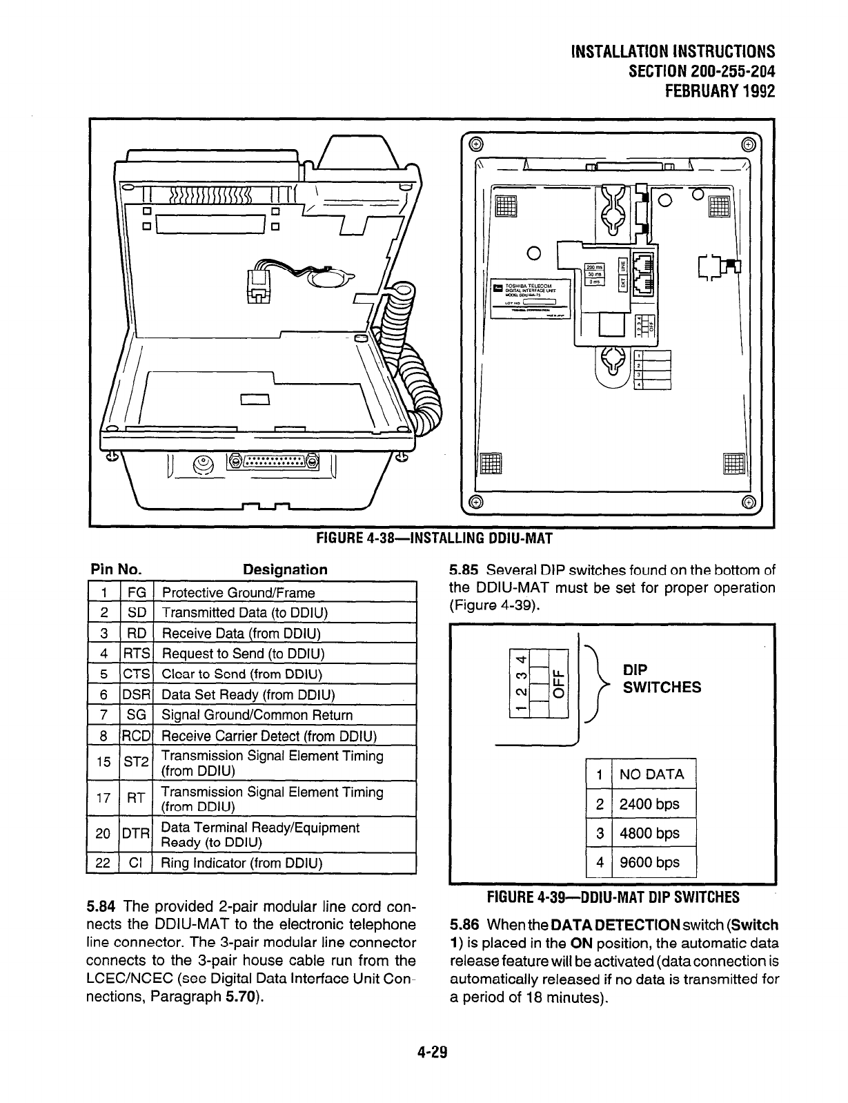
INSTALLATlONlNSTRUCTlONS
SECTION 200-255-204
FEBRUARY1992
FIGURE 4-38-INSTALLING DDIU-MAT
Pin No. Designation
1 FG Protective Ground/Frame
2 SD Transmitted Data (to DDIU)
3 RD Receive Data (from DDIU)
4 RTS Request to Send (to DDIU)
5 CTS Clear to Send (from DDIU)
6 DSR Data Set Readv (from DDIU)
1 7 1 SG 1 Sianal Ground/Common Return
1
1 8 (RCDI Receive Carrier Detect (from DDIU) 1
1 15 /ST21 Transmission Signal Element Timing
(from DDIU) I
, 7 RT Transmission Signal Element Timing
(from DDIU)
Data Terminal Ready/Equipment
2o DTR Readv (to DDIU)
I I < .
22 1 Cl ) Ring Indicator (from DDIU)
5.84 The provided 2-pair modular line cord con-
nects the DDIU-MAT to the electronic telephone
line connector. The 3-pair modular line connector
connects to the 3-pair house cable run from the
LCEC/NCEC (see Digital Data Interface Unit Con-
nections, Paragraph 5.70).
5.85 Several DIP switches found on the bottom of
the DDIU-MAT must be set for proper operation
(Figure 4-39).
DIP
SWITCHES
1 1 1 NO DATA 1
1 2 1 2400 bps 1
1 3 1 4800 bps 1
1 4 / 9600 bps )
FIGURE 4-39-DDIU-MAT DIP SWITCHES
5.86 When the DATA DETECTION switch (Switch
1) is placed in the ON position, the automatic data
release feature will be activated (data connection is
automatically released if no data is transmitted for
a period of 18 minutes).
4-29
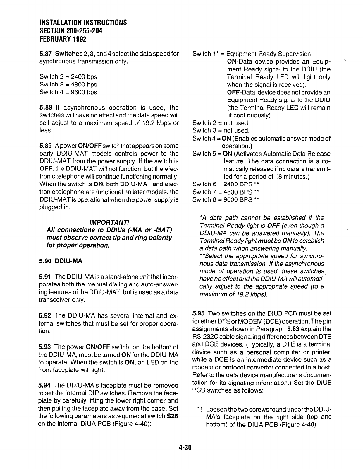
INSTALLATION INSTRUCTIONS
SECTION 200-255-204
FEBRUARY1992
5.87 Switches 2,3, and 4 select the data speed for
synchronous transmission only.
Switch 2 = 2400 bps
Switch 3 = 4800 bps
Switch 4 = 9600 bps
5.88 If asynchronous operation is used, the
switches will have no effect and the data speed will
self-adjust to a maximum speed of 19.2 kbps or
less.
5.89 A power ON/OFFswitch that appears on some
early DDIU-MAT models controls power to the
DDIU-MAT from the power supply. If the switch is
OFF, the DDIU-MAT will not function, but the elec-
tronic telephone will continue functioning normally.
When the switch is ON, both DDIU-MAT and elec-
tronic telephone are functional. In later models, the
DDIU-MAT is operational when the power supply is
plugged in.
/MPORTANT!
All connections to DDlUs (-MA or -MAT)
must observe correct tip and ring polarity
for proper operation.
5.90 DDIU-MA
5.91 The DDIU-MA is a stand-alone unit that incor-
porates both the manual dialing and auto-answer-
ing features of the DDIU-MAT, but is used as a data
transceiver only.
5.92 The DDIU-MA has several internal and ex-
ternal switches that must be set for proper opera-
tion.
5.93 The power ON/OFF switch, on the bottom of
the DDIU-MA, must be turned ON for the DDIU-MA
to operate. When the switch is ON, an LED on the
front faceplate will light.
5.94 The DDIU-MA’s faceplate must be removed
to set the internal DIP switches. Remove the face-
plate by carefully lifting the lower right corner and
then pulling the faceplate away from the base. Set
the following parameters as required at switch S26
on the internal DIUA PCB (Figure 4-40):
Switch 1* = Equipment Ready Supervision
ON-Data device provides an Equip-
ment Ready signal to the DDIU (the
Terminal Ready LED will light only
when the signal is received).
OFF-Data device does not provide an
Equipment Ready signal to the DDIU
(the Terminal Ready LED will remain
lit continuously).
Switch 2 = not used.
Switch 3 = not used.
Switch 4 = ON (Enables automatic answer mode of
operation.)
Switch 5 = ON (Activates Automatic Data Release
feature. The data connection is auto-
matically released if no data is transmit-
ted for a period of 18 minutes.)
Switch 6 = 2400 BPS **
Switch 7 = 4800 BPS **
Switch 8 = 9600 BPS **
*A data path cannot be established if the
Terminal Ready light is OFF (even though a
DDIU-MA can be answered manually). The
Terminal Ready light must be ON to establish
a data path when answering manually.
**Select the appropriate speed for synchro-
nous data transmission. If the asynchronous
mode of operation is used, these switches,
have no effectand the DDIU-MA willautomati-
tally adjust to the appropriate speed (to a
maximum of 19.2 kbps).
5.95 Two switches on the DIUB PCB must be set
for either DTE or MODEM (DCE) operation. The pin
assignments shown in Paragraph 5.83 explain the
RS-232C cable signaling differences between DTE
and DCE devices. (Typically, a DTE is a terminal
device such as a personal computer or printer,
while a DCE is an intermediate device such as a
modem or protocol converter connected to a host.
Refer to the data device manufacturer’s documen-
tation for its signaling information.) Set the DIUB
PCB switches as follows:
1) Loosen the two screws found under the DDIU-
MA’s faceplate on the right side (top and
bottom) of the DIUA PCB (Figure 4-40).
4-30
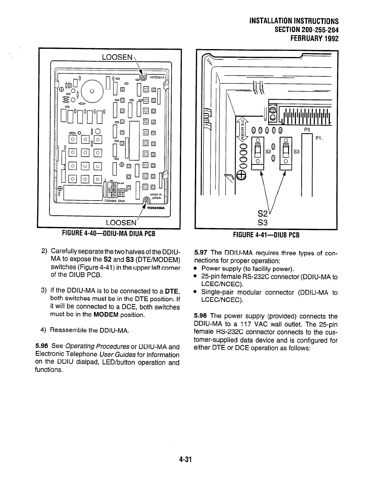
LOOSEN
I- \
LOOSEN’
FIGURE 4-40-DDIU-MA DNA PCB
2) Carefully separate the two halves of the DDIU-
MA to expose the S2 and S3 (DTE/MODEM)
switches (Figure 4-41) in the upper left corner
of the DIUB PCB.
3) If the DDIU-MA is to be connected to a DTE,
both switches must be in the DTE position. If
it will be connected to a DCE, both switches
must be in the MODEM position.
4) Reassemble the DDIU-MA.
5.96 See Operating Procedures or DDIU-MA and
Electronic Telephone User Guides for information
on the DDIU dialpad, LED/button operation and
functions.
INSTALLATION INSTRUCTIONS
SECTlON200-255-204
FEBRUARY1992
s3
--
FIGURE 4-41-DIUB
P[;B
5.97 The DDIU-MA requires three types of con-
nections for proper operation:
l
Power supply (to facility power).
l
25-pin female RS-232C connector (DDIU-MA to
LCEC/NCEC).
l
Single-pair modular connector (DDIU-MA to
LCEWNCEC).
5.98 The power supply (provided) connects the
DDIU-MA to a 117 VAC wail outlet. The 25pin
female RS-232C connector connects to the cus-
tomer-supplied data device and is configured for
either DTE or DCE operation as follows:
4-31
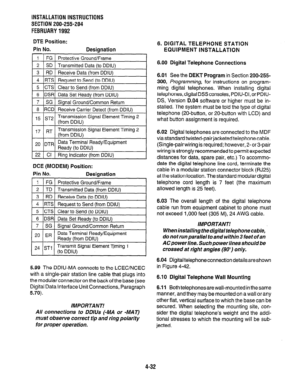
INSTALLATION INSTRUCTIONS
SECTION 200-255-204
FEBRUARY
1992
DTE Position:
Pin No. Desianation
6. DIGITAL TELEPHONE STATION
EQUIPMENT INSTALLATION
1 FG Protective Ground/Frame
2 SD Transmitted Data (to DDIU) 6.00 Digital Telephone Connections
1 8 ( RD ) Receive Data (from DDIU) I
4 RTS Request to Send (to DDIU)
5 CTS Clear to Send (from DDIU)
6 DSR Data Set Ready (from DDIU)
7 SG Signal Ground/Common Return
8 RCD Receive Carrier Detect (from DDIU)
,5 ST2 Transmission Signal Element Timing 2
(from DDIU)
1
17
j RT 1 ~ ~ ____ ~~~ ~
Transmission Signal Element Timing 2
(from DDIU)
1
1
20
/DTRI Data Terminal Ready/Equipment
Ready (to DDIU) I
1 22 ( Cl 1 Ring Indicator (from DDIU)
DCE (MODEM) Position:
Pin No. Designation
1 FG Protective Ground/Frame
2 TD Transmitted Data (from DDIU)
3 RD Receive Data (to DDIU)
I
4
I
RTS / Request to Send (from DDIU)
I
1 24 1 ST1 1 (to DDIU)
Transmit Signal
Element Xming 1
5.99 The DDIU-MA connects to the LCEC/NCEC
with a single-pair station line cable that plugs into
the modular connector on the back of the base (see
Digital Data interface Unit Connections, Paragraph
5.70).
IMPORTANT!
All connections to DDlUs (-MA or -MAT)
must observe correct tip and ring polarity
for proper operation.
6.01 See the DEKT Program in Section 200-255-
300, Programming, for instructions on program-
ming digital telephones. When installing digital
telephones, digital DSSconsoles, PDIU-DI, or PDIU-
DS, Version D.04 software or higher must be in-
stalled. The system must be told the type of digital
telephone (20-button, or 20-button with LCD) and
what button assignment is required.
6.02 Digital telephones are connected to the MDF
via standard twisted-pair jacketed telephone cable.
(Single-pair wiring is required; however, 2- or 3-pair
wiring is strongly recommended to permit expected
-distances for data, spare pair, etc.) To accommo-
date the digital telephone line cord, terminate the
cable in a modular station connector block (RJ25)
at the station location. The standard modular digital
telephone cord length is 7 feet (the maximum
allowed length is 25 feet).
6.03 The overall length of the digital telephone
cable run from equipment cabinet to phone must
not exceed 1,000 feet (305 M), 24 AWG cable.
IMPORTANT!
When installing the digital telephone cable,
do not run parallel to and within 3 feet of an
AC po wer line. Such power lines should be
crossed at right angles (90”) only.
6.04 Digital telephone connection details areshown
in Figure 4-42.
6.10 Digital Telephone Wall Mounting
6.11 Both telephones are wall-mounted in the same
manner, and they may be mounted on a wall or any
other flat, vertical surface to which the base can be
secured. When selecting the mounting site, con-
sider the digital telephone’s weight and the addi-
tional stresses to which the mounting will be sub-
jected.
4-32
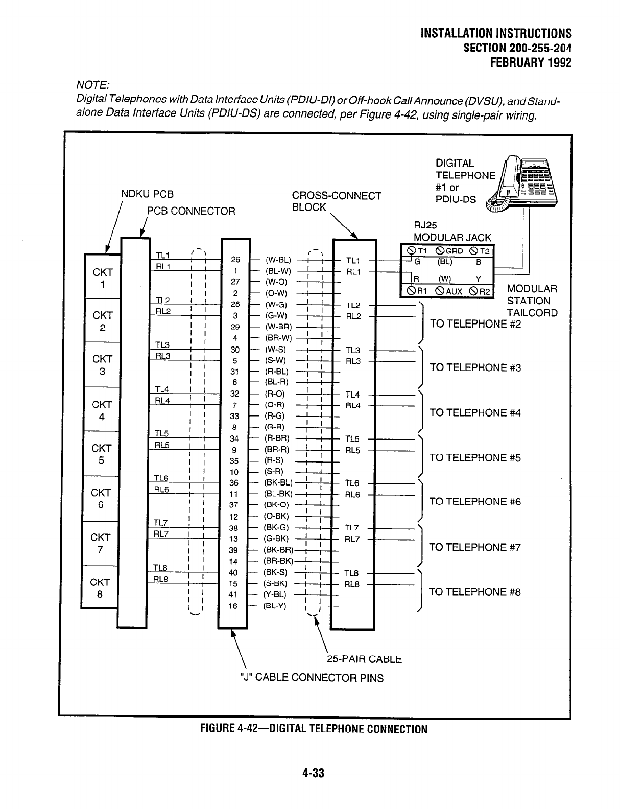
INSTALLATION INSTRUCTIONS
SECTIONZOO-255-204
FEBRUARY1992
NOTE:
Digital Telephones with Data Interface Units (PDIU-DI) or Off-hook Cal/Announce (DVSU), and Stand-
a/one Data Interface Units (PDIU-DS) are connected, per Figure 4-42, using single-pair wiring.
NDKU PCB
I PCB CONNECTOR
26
1
27
2
28
3
29
4
30
5
31
6
-I
TL4
I l
DI ” I I I 32 I-
I I La I
-. -
1 34 l-
I
I I
I I
37
l-I 7 I I
I k
12
I I I 15 l-
(W-BL)
(BL-W)
(W-0)
(0-W)
(W-G)
G-W)
(W-BR)
(BR-W)
W-S)
- TLl
- RLl
-
- TL2
- RL2
IR (W) Y
&Rl 8AUX 8R2
MODULAR
I
STATION
TAILCORD
I
1 TO TELEPHONE #2
ii;; 8’ f= j TOTELEPHONE#3
CROSS-CONNECT
BLOCK
MODULAR JACK
(R-O) --+- TL4
(0-R) I , RL4
(R-G) I !
(G-R) ; ; 1
(R-BR) ! ; TL5
P-R) 1 ; RL5
P-3 I ,
(S-W I I
(BK-BL) ; ; 1
TL6
(BL-BK) ; i RL6
(BK-0) I ’
(0-BK) [ ; I
(BK-G) ! I TL7
G-W 1 ; RL7
(BK-BR) ; ,
I I
(BR-BK) I ; 1
(BK-S) I I TL8
(S-BK) I ; RL8
U-W 1 ;
(BL-Y) I J
1
.
\ 25-PAIR CABLE
“J” CABLE CONNECTOR PINS
TO TELEPHONE #4
TO TELEPHONE #5
TO TELEPHONE #6
TO TELEPHONE #7
TO TELEPHONE #8
FIGURE 4-42-DIGITAL TELEPHONE CONNECTION
4-33
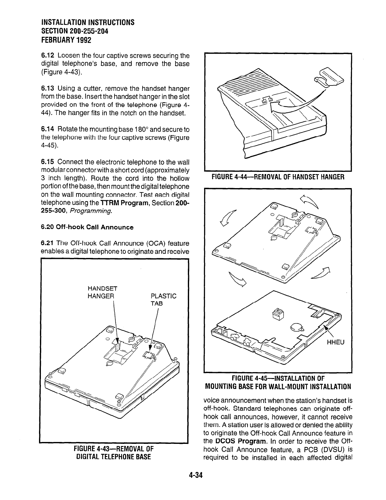
INSTALLATION INSTRUCTIONS
SECTION 200-255-204
FEBRUARY 1992
6.12 Loosen the four captive screws securing the
digital telephone’s base, and remove the base
(Figure 4-43).
6.13 Using a cutter, remove the handset hanger
from the base. Insert the handset hanger in the slot
provided on the front of the telephone (Figure 4-
44). The hanger fits in the notch on the handset.
6.14 Rotate the mounting base 180” and secure to
the telephone with the four captive screws (Figure
4-45).
6.15 Connect the electronic telephone to the wall
modular connector with a short cord (approximately
3 inch length). Route the cord into the hollow
portion of the base, then mount the digital telephone
on the wall mounting connector. Test each digital
telephone using the 7TRM Program, Section 200-
255-300, /=rogramming.
6.20 Off-hook Call Announce
6.21 The Off-hook Call Announce (OCA) feature
enables a digital telephone to originate and receive
HANDSET
HANGER
I
PLASTIC
TAB
I-IbUKt 4-4Y-HtMUVAL Ul-
DIGITAL TELEPHONE BASE
FIGURE 4-44-REMOVAL OF HANDSET HANGER
MOUNTING BASE FOR WALL-MOUNT INSTALLATION
voice announcement when the station’s handset is
off-hook. Standard telephones can originate off-
hook call announces, however, it cannot receive
them. A station user is allowed or denied the ability
to originate the Off-hook Call Announce feature in
the DCOS Program. In order to receive the Off-
hook Call Announce feature, a PCB (DVSU) is
required to be installed in each affected digital
FIGURE 4-45-INSTALLATION OF
4-34
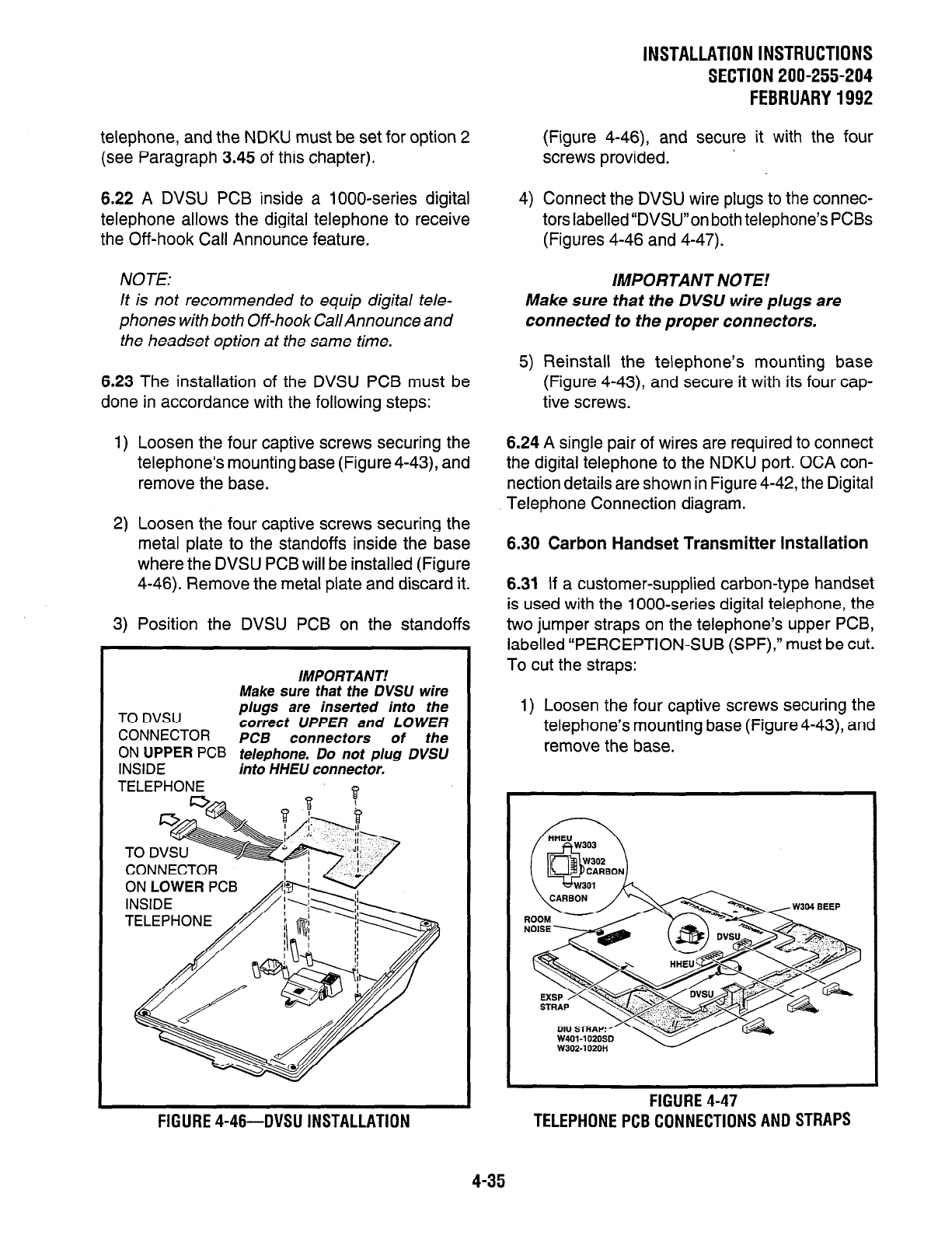
telephone, and the NDKU must be set for option 2
(see Paragraph 3.45 of this chapter).
6.22 A DVSU PCB inside a lOOO-series digital
telephone allows the digital telephone to receive
the Off-hook Call Announce feature.
NOTE:
It is not recommended to equip digital tele-
phones with both Off-hook Cal/Announce and
the headset option at the same time.
6.23 The installation of the DVSU PCB must be
done in accordance with the following steps:
1) Loosen the four captive screws securing the
telephone’s mounting base (Figure 4-43), and
remove the base.
2) Loosen the four captive screws securing the
metal plate to the standoffs inside the base
where the DVSU PCB will be installed (Figure
4-46). Remove the metal plate and discard it.
3) Position the DVSU PCB on the standoffs
Make sure that
the
DVSU wire
TO DVSU plugs are inserted into the
correct UPPER and LOWER
CONNECTOR PCB connectors of the
ON UPPER PCB
telephone. Do not plug DVSU
INSIDE into HHEU connector.
TELEPHONE
IMPORTANT! IMPORTANT!
.I-,--
-----? that
the
DVSU wire
! inserted into the
‘PPER and LOWER
nnectors of the
ON LOWER
PC
TELEPHONE
FIGURE 4-46-DVSU INSTALLATION
INSTALLATION INSTRUCTIONS
SECTlON200-255-204
FEBRUARY1992
(Figure 4-46), and secure it with the four
screws provided. ’
4) Connect the DVSU wire plugs to the connec-
tors labelled “DVSU”on both telephone’s PCBs
(Figures 4-46 and 4-47).
IMPORTANT NOTE.’
Make sure that the DVSU wire plugs are
connected to the proper connectors.
5) Reinstall the telephone’s mounting base
(Figure 4-43), and secure it with its four cap-
tive screws.
6.24 A single pair of wires are required to connect
the digital telephone to the NDKU port. OCA con-
nection details are shown in Figure 4-42, the Digital
Telephone Connection diagram.
6.30 Carbon Handset Transmitter Installation
6.31 If a customer-supplied carbon-type handset
is used with the 1 OOO-series digital telephone, the
two jumper straps on the telephone’s upper PCB,
labelled “PERCEPTION-SUB (SPF),” must be cut.
To cut the straps:
1) Loosen the four captive screws securing the
telephone’s mounting base (Figure4-43), and
remove the base.
FIGURE 4-47
TELEPHONEPCBCONNECTIONSANDSTRAPS
4-35
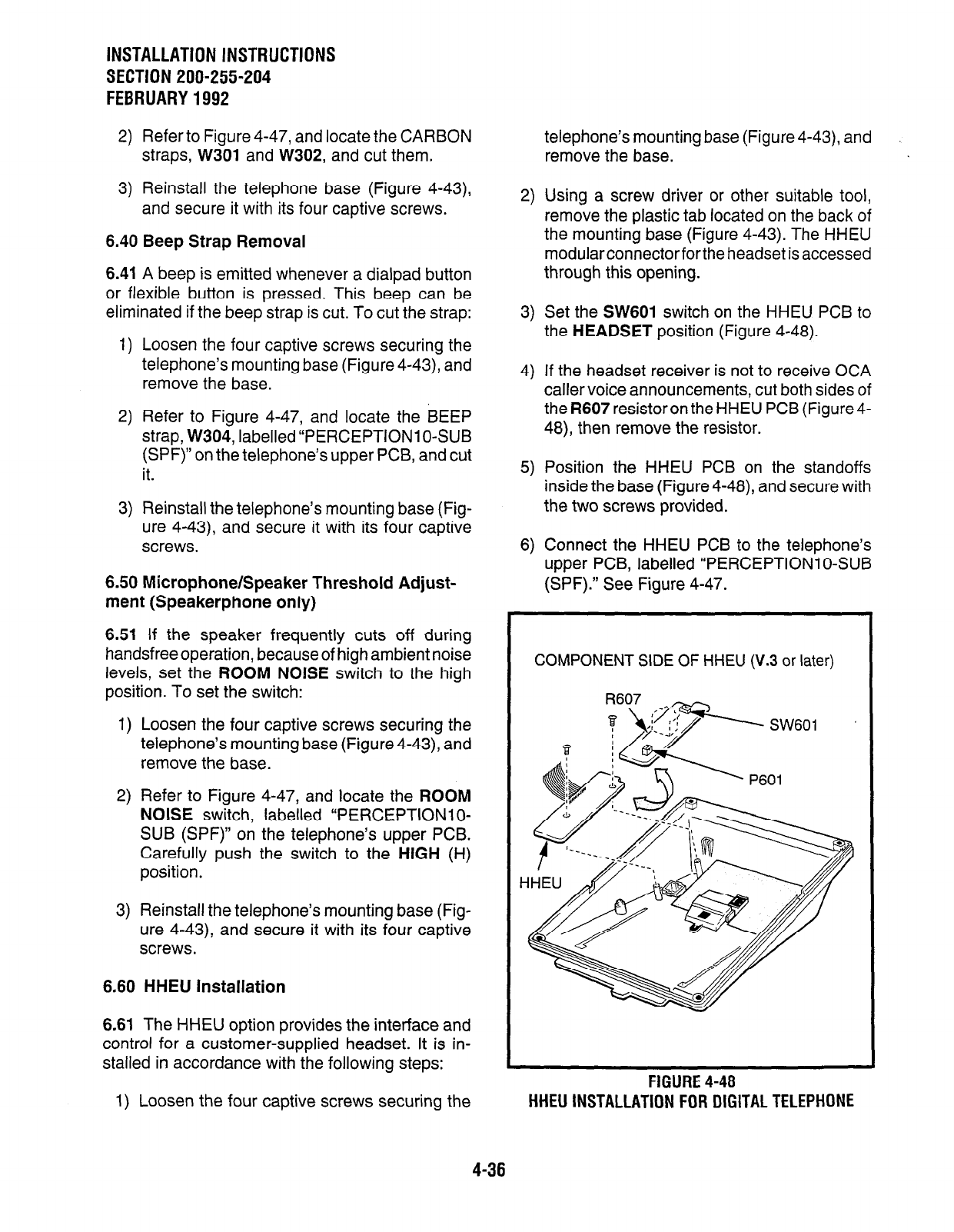
INSTALLATION INSTRUCTIONS
SECTION 200-255-204
FEBRUARY1992
2) Refer to Figure 4-47, and locate the CARBON
straps, W301 and W302, and cut them.
3) Reinstall the telephone base (Figure 4-43),
and secure it with its four captive screws.
6.40 Beep Strap Removal
6.41 A beep is emitted whenever a dialpad button
or flexible button is pressed. This beep can be
eliminated if the beep strap is cut. To cut the strap:
1) Loosen the four captive screws securing the
telephone’s mounting base (Figure 4-43), and
remove the base.
2) Refer to Figure 4-47, and locate the BEEP
strap, W304, labelled “PERCEPTION1 O-SUB
(SPF)” on the telephone’s upper PCB, and cut
it.
3) Reinstall the telephone’s mounting base (Fig-
ure 4-43), and secure it with its four captive
screws.
6.50 Microphone/Speaker Threshold Adjust-
ment (Speakerphone only)
6.51 If the speaker frequently cuts off during
handsfree operation, because of high ambient noise
levels, set the ROOM NOISE switch to the high
position. To set the switch:
1) Loosen the four captive screws securing the
telephone’s mounting base (Figure4-43), and
remove the base.
2) Refer to Figure 4-47, and locate the ROOM
NOISE switch, labelled “PERCEPTION1 O-
SUB (SPF)” on the telephone’s upper PCB.
Carefully push the switch to the HIGH (H)
position.
3) Reinstall the telephone’s mounting base (Fig-
ure 4-43), and secure it with its four captive
screws.
6.60 HHEU Installation
6.61 The HHEU option provides the interface and
control for a customer-supplied headset. It is in-
stalled in accordance with the following steps:
1) Loosen the four captive screws securing the
telephone’s mounting base (Figure 4-43) and
remove the base.
2) Using a screw driver or other suitable tool,
remove the plastic tab located on the back of
the mounting base (Figure 4-43). The HHEU
modularconnectorfor the headset is accessed
through this opening.
3) Set the SW601 switch on the HHEU PCB to
the HEADSET position (Figure 4-48).
4) If the headset receiver is not to receive OCA
caller voice announcements, cut both sides of
the R607 resistoron the HHEU PCB (Figure4-
48), then remove the resistor.
5) Position the HHEU PCB on the standoffs
inside the base (Figure 4-48), and secure with
the two screws provided.
6) Connect the HHEU PCB to the telephone’s
upper PCB, labelled “PERCEPTION1 O-SUB
(SPF).” See Figure 4-47.
COMPONENT SIDE OF HHEU (V.3 or later)
FIGURE 4-48
HHEU INSTALLATION FOR DIGITAL
TELEPHONE
4-36

7) Refer to Figure 4-47, and locate the HHEU
strap, W303, on the upper PCB. Cut the strap
if the HHEU PCB is to be connected to a
headset.
8) Reinstall the telephone’s mounting base and
secure it with its four captive screws.
6.70 Attendant Console Connection
6.71 See Paragraph 5.50 for the attendant console
connection.
6.80 DSS Console Connections
6.81 See the DSS Program in Section 200-255-
300, Programming, to input information concern-
ing the digital DSS consoles.
6.82 The DSS console must be positioned adja-
cent to a digital telephone (preferably an LCD
model). DSS consoles use 2-pair wiring and are
connected to the MDF via standard twisted-pair
telephone cables. An RJ25 modular connector
should be attached to the instrument-end of the
telephone cable to permit connection to the DSS
console.
6.83 The overall length of the DSS console cable
run from the equipment cabinet must not exceed
1000 feet (304 M), 24 AWG cable.
IMPORTANT!
When installing the DSS console cable, do
not run parallel to and within 3’ of an AC
power line. Such power lines should be
crossed at right angles (90”) only.
6.84 DSS console(s) connection details are shown
in Figures 4-49 and 4-50, for both PERCEPTION,
and ex.
6.90 DIGITAL DATA INTERFACE UNIT (PDIU)
6.91 The Perceptione8ie, with D.04 software pro-
vides two new style digital Data Interface Units
(DIUs) that enable digital telephone users to si-
multaneously transmit and receive data on the
same NDKU station port and wire pair while com-
INSTALLATION INSTRUCTIONS
SECTION 200-255-204
FEBRUARY1992
municating on a voice call. One unit, called the
integrated DIU (PDIU-DI) replaces the digital
telephone’s base; the other unit is a small self-
contained box called the stand-alone DIU (PDIU-
DS). Each DIU is powered by the NDKU PCB it is
connected to; therefore, no external power is re-
quired.
6.92 Both PDlUs can be connected to standard
Electronic Industries Association (EIA) RS-232
asynchronous serial data devices. EIA devices
are divided into two categories:
l
Data communication equipment (DCE). Com-
mon DCE devices are modems and some print-
ers.
l
Data terminal equipment (DTE). Common DTE
devices are personal computers, ASCII termi-
nals, and some printers.
.The PDIU-DI operates like a DCE, and it connects
directly to DTE devices using standard RS-232
cables. Depending on how its internal jumper
plugs are configured, the PDIU-DS can either
operate like a DTE and connect to DCE devices, or
operate like a DCE device and connect to a DTE
device. In most applications, DTE and DCE devices
exchange data between each other via the stan-
dard RS-232 cable connection.
6.93 PDlUs can function with DCE and DTE de-
vices at data speeds of up to 19.2kbps; however,
keyboard dialing using AT commands (from a PC
or a terminal connected to a PDIU) is limited up to
9.6kbps. PDIU data transmission speed is set by
the first AT command that the PDIU receives once
it is in the command mode. The transmission
speed is transparent to the PDIU if data is being
sent via manual dialing or if the PDIU is receiving
calls.
NOTES:
1. See the DDIU
Program
in Section 200-
255-300 for information on programming
the Digital Data interface Units. The sys-
tem must be told which type of PDIU
(-DI
or -DS) is installed at each location.
2. Digital Data interface Unit (PDIU-DI and
PDIU-DS) connection details are shown
in Figure 4-42, the Digital Telephone
Connection diagram.
4-37
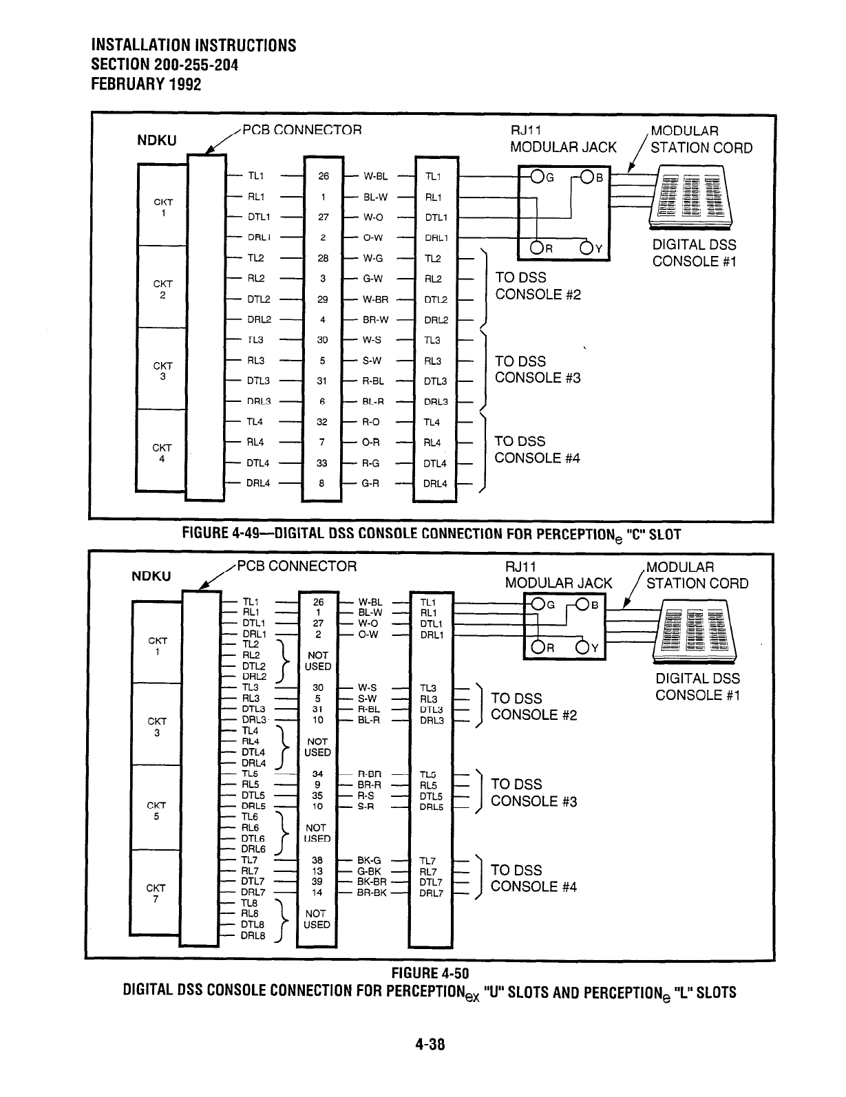
INSTALLATION INSTRUCTIONS
SECTlON200-255-204
FEBRUARY1992
NDKU PCB CONNECTOR
t MODULAR JACK STATION CORD
- TLl - 26 - W-EL
CKT - RLl - 1 - BL-W
1 - DTLl - 27 - W-O
- DRLl - 2 - O-W
- TL2 - 20 - W-G
CONSOLE #l
CKT - RLZ! - 3 - G-W
2 - DTL2 - 29 - W-BR
- DRL2 - 4 - BR-W
- TL3 - 30 - W-S
CKT - AL3 - 5 - s-w
3 - DTL3 - 31 - R-BL
CONSOLE #3
- DRL3 - 6 - BL-R
- TL4 - 32 - R-O
CKT - RL4 - 7 - O-R
4 - DTL4 - 33 - R-G
CONSOLE #4
- DRL4 - 0 - G-R
FIGURE 4-49-DIGITAL DSS CONSOLE CONNECTION FOR PERCEPTION, “c” SLOT
NDKU PCB CONNECTOR MODULAR JACK STATION CORD
- TLl - 26 - W-BL
- RLI - 1 - BL-W
- DTLl - 27 - W-O
CKl - DRLl - 2 - O-W
1 NOT
USED
- TL3 - 30 - W-S
- RL3 - 5 - S-W
- DTL3 - 31 - R-BL
CKT - DRLB - 10 --L-R
3 NOT
USED
- TL5 - 34 - R-BR
- RL5 - 9 - BR-R
- DTL.5 - 35 - R-S
CKT - DRL5 - 10 - S-R
5 NOT
USED
CKT
7
- n-7 - 38 - BK-G
- RL7 - 13 - G-BK
- DTL7 - 39 - BK-BR
- DRL7 - 14 - BR-BK
NOT
USED
CONSOLE #4
I-Ibunt
4-su
DIGITAL DSS CONSOLE CONNECTION FOR PERCEPTION, “U” SLOTS AND PERCEPTION, ‘I” SLOTS
4-38
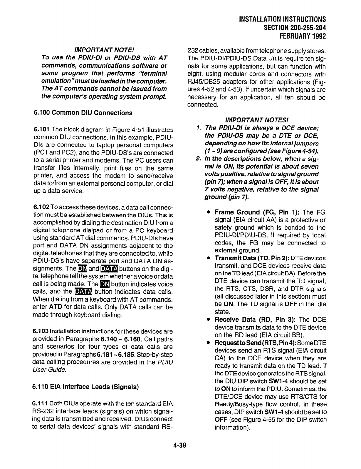
IMPORTANT NOTE!
To use the PDIU-DI or PDIU-DS with AT
commands, communications software or
some program that performs “terminal
emulation”must be loaded in the computer.
The AT commands cannot be issued from
the computer’s operating system prompt.
6.100 Common DIU Connections
6.101 The block diagram in Figure 4-51 illustrates
common DIU connections. In this example, PDIU-
Dls are connected to laptop personal computers
(PC1 and PC2), and the PDIU-DS’s are connected
to a serial printer and modems. The PC users can
transfer files internally, print files on the same
printer, and access the modem to send/receive
data to/from an external personal computer, or dial
up a data service.
6.102 To access these devices, a data call connec-
tion must be established between the DIUs. This is
accomplished by dialing the destination DIU from a
digital telephone dialpad or from a PC keyboard
using standard AT dial commands. PDIU-Dls have
port and DATA DN assignments adjacent to the
digital telephones that they are connected to, while
PDIU-DS’s have separate port and DATA DN as-
signments. The
q
and m buttons on the digi-
tal telephone tell the system whether a voice or data
call is being made: The
q
button indicates voice
calls, and the m button indicates data calls.
When dialing from a keyboard with AT commands,
enter
ATD
for data calls. Only DATA calls can be
made through keyboard dialing.
6.103 Installation instructions for these devices are
provided in Paragraphs 6.140 w 6.160. Call paths
and scenarios for four types of data calls are
provided in Paragraphs6.181 m 6.185. Step-by-step
data calling procedures are provided in the PDlU
User Guide.
6.110 EIA interface Leads (Signals)
6.111 Both DIUs operate with the ten standard EIA
M-232 interface leads (signals) on which signal-
ing data is transmitted and received. DlUs connect
to serial data devices’ signals with standard RS-
lNSTALLATlONlNSTRUCTlONS
SECTION 200-255-204
FEBRUARY1992
232 cables, available from telephone supply stores.
The PDIU-DVPDIU-DS Data Units require ten sig-
nals for some applications, but can function with
sight, using modular cords and connectors with
RJ45/DB25 adapters for other applications (Fig-
.rres 4-52 and 4-53). If uncertain which signals are
iecessary for an application, all ten should be
connected.
IMPORTANT NOTES.’
1. The PDIU-DI is always a DCE device;
the PDIU-DS may be a DTE or DCE,
depending on how its in ternal jumpers
(1 - 9) are configured (see Figure 4-54).
2. In the descriptions below, when a sig-
nal is ON, its potential is about seven
volts positive, relative to signal ground
(pin 7); when a signal is OFF, it is about
7 volts negative, relative to the signal
ground
(pin 7).
Frame Ground (FG, Pin 1):
The FG
signal (EIA circuit AA) is a protective or
safety ground which is bonded to the
PDIU-DVPDIU-DS. If required by local
codes, the FG may be connected to
external ground.
Transmit Data (TD, Pin
2): DTE devices
transmit, and DCE devices receive data
on theTD lead (EIA circuit BA). Before the
DTE device can transmit the TD signal,
the RTS, CTS, DSR, and DTR signals
(all discussed later in this section) must
be ON. The TD signal is
OFF
in the idle
state.
Receive Data (RD, Pin 3):
The DCE
device transmits data to the DTE device
on the RD lead (EIA circuit BB).
Request to Send (RTS, Pin
4): Some DTE
devices send an RTS signal (EIA circuit
CA) to the DCE device when they are
ready to transmit data on the TD lead. If
the DTE device generates the RTS signal,
the DIU DIP switch
SWI-4
should be set
to ON to inform the PDIU. Sometimes, the
DTUDCE device may use RTSKTS for
Ready/Busy-type flow control. In these
cases, DIP switch
SWl-4
should be set to
OFF
(see Figure 4-55 for the DIP switch
information).
4-39
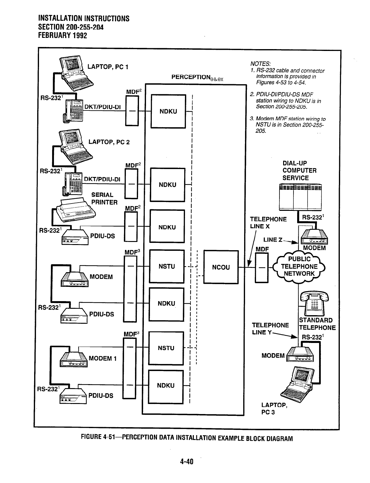
INSTALLATION INSTRUCTIONS
SECTION 200-255-204
FEBRUARY1992
1
LAPTOP, PC 1
PERCEI
PTiONeh.ex
NOTES:
1. W-232 cable and connector
information is provided in
Figures 4-53 to 4-54.
DIIJ-DI
I I r-l!
2. PDIU-DVPDIU-DS MDF
station wiring to NDKU is in
Section 200-255-205.
UlIl
3. Modem MDF station wiring to
NSTU is in Section 200-255-
DIAL-UP
COMPUTER
I fiff!E&MODEM I I I L
I aMoDEM I 111
- m-m
PDIU-DS u IL
TFI FDUANF 1
I
TELEPHONE
PC3 .
FIGURE 4-51-PERCEPTION DATA INSTALLATION EXAMPLE BLOCK DIAGRAM
4-40
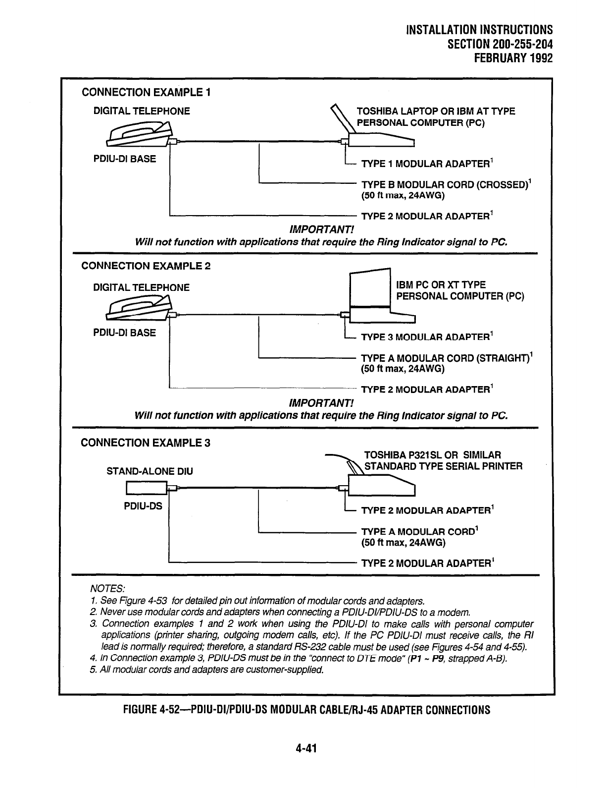
INSTALLATION INSTRUCTIONS
SECTION 200-255-204
FEBRUARY1992
CONNECTION EXAMPLE 1
DIGITAL
TELEPHONE TOSHIBA LAPTOP OR IBM AT TYPE
PERSONAL COMPUTER (PC)
PDIU-DI BASE
I
L
TYPE 1 MODULAR ADAPTER’
/ L EikfY;;;;;ssED)’
IMPORTANT!
Will not function with applications that require the Ring Indicator signal to PC.
CONNECTION EXAMPLE 2
DIGITAL TELEPHONE IBM PC OR Xl TYPE
PERSONAL COMPUTER (PC)
PDIU-DI BASE TYPE 3 MODULAR ADAPTER’
TYPE A MODULAR CORD (STRAIGHT)’
(50 ft max, 24AWG)
TYPE 2 MODULAR ADAPTER’
IMPORTANT!
Will not function with applications that require the Ring Indicator signal to PC.
CONNECTION EXAMPLE 3
NOTES:
1. See Figure 4-53 for detailed pin out information of modular cords and adaprers.
2. Never use modular cords and adapters when connecting a PDIU-Dl/PDIU-DS to a modem.
3. Connection examples 1 and 2 work when using the PDIU-DI to make calls with personal computer
applications (printer sharing, outgoing modem calls, erc). If the PC PDIU-DI must receive calls, rhe RI
lead is normally required; therefore, a srandard 1X-232 cable must be used (see Figures 4-54 and 4-55).
4. In Connection example 3, PDIU-DS must be in the “connect to DTE mode” (Pl - P9, strapped A-B).
5. All modular cords and adapters are customer-supplied.
FIGURE
4-5%PDIU-DI/PDIU-DS MODULAR CABLE/RJ-45 ADAPTER CONNECTIONS
4-41
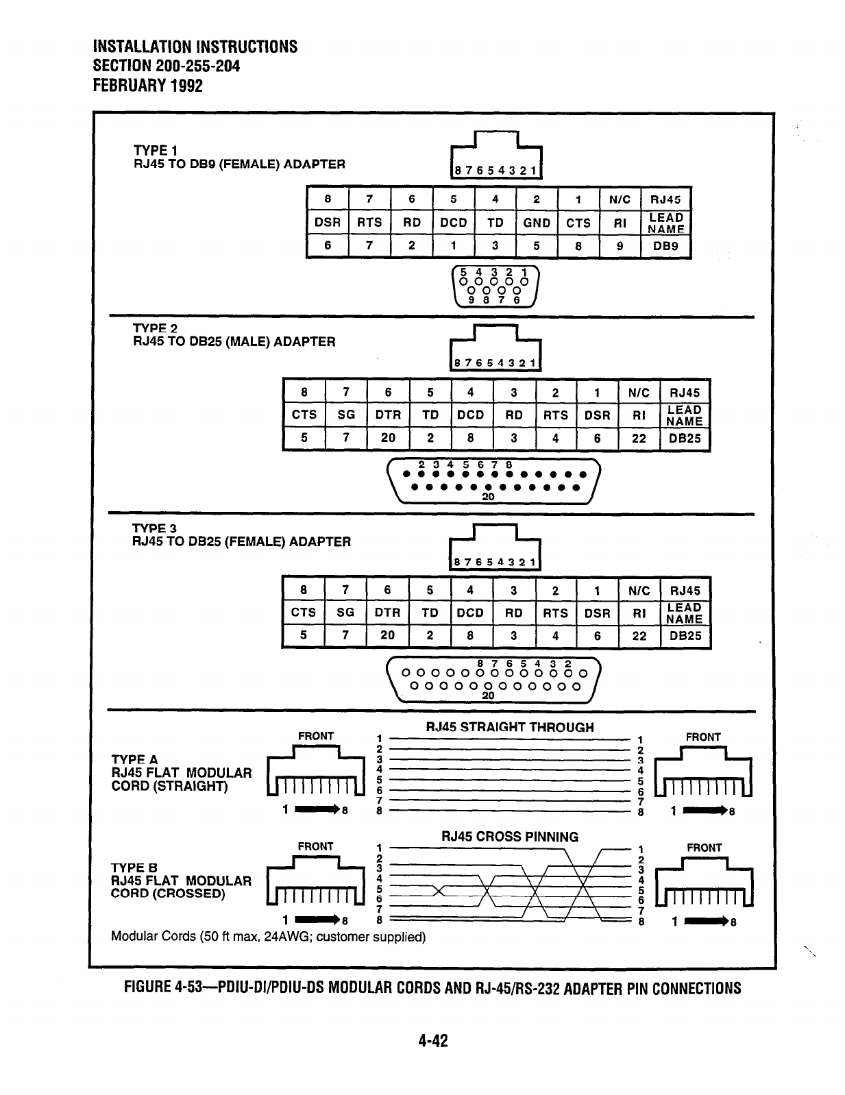
INSTALLATION INSTRUCTIONS
SECTION 200-255-204
FEBRUARY 1992
TYPE 1
RJ45 TO DB9 (FEMALE) ADAPTER
8 7 6 5 4 2 1 N/C RJ45
DSR RTS RD DCD TD GND CTS RI LEAD
NAME
6 7 2 1 3 5 8 9
DB9
TYPE 2
RJ45 TO
DB25 (MALE) ADAPTER
8 7 6 5 4 3 2 1 N/C RJ45
CTS SG
DTR TD DCD RD RTS DSR RI LEAD
NAME
5
7 20 2 8 3 4 6 22
DB25
2345678
l ooooeooooooo
l ooooooooooo
TYPE 3
RJ45 TO
DB25
(FEMA ,I
-E) ADAPTER
CTS SG DTR TD DCD RD RTS DSR RI LEAD
NAME 1
5 7 20 2 8 3 4 6 22 DB25
FRONT
RJ45 STRAIGHT THROUGH
1
1
FRONT
2
i
TYPE A
RJ45 FLAT MODULAR : :
CORD (STRAIGHT) x 5
1-8 3 f 8 1.8
TYPE B
RJ45 FLAT MODULAR
CORD (CROSSED)
Modular Cords (50 ft max, 24AWG; customer supplied)
FIGURE 4-53-PDIU-DI/PDIU-DS MODULAR CORDS AND RJ-45/W-232
ADAPTER
PIN CONNECTIONS
4-42
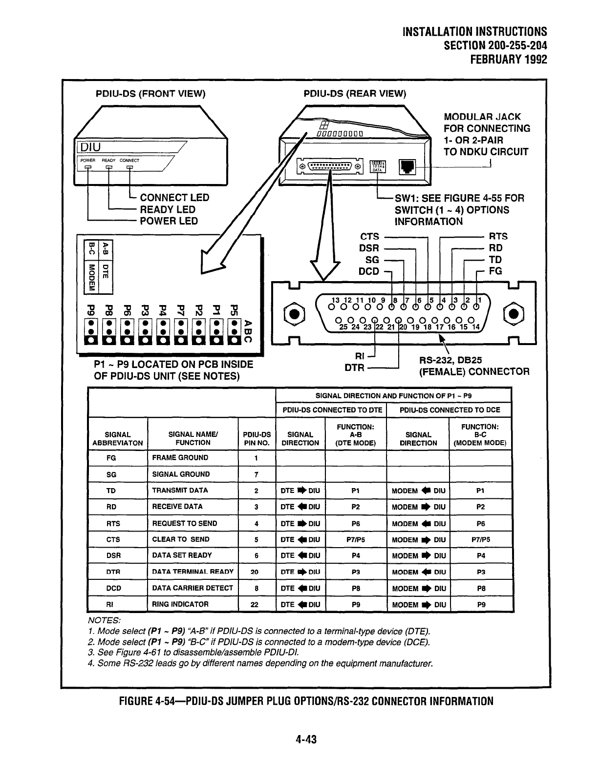
lNSTALLATlONlNSTRUCTlONS
SECTION 200-255-294
FEBRUARY1992
PDIU-DS (FRONT VIEW) PDIU-DS (REAR VIEW)
MODULAR JACK
FOR CONNECTING
E FIGURE 4-55 FOR
POWER LED SWITCH (1 - 4) OPTIONS
INFORMATION
Pl - P9 LOCATED ON PCB INSIDE
OF PDIU-DS UNIT (SEE NOTES)
RS-23i, DB25
(FEMALE) CONNECTOR
SIGNAL DIRECTION AND FUNCTION OF Pl - P9
POIU-DS CONNECTED TO CITE 1 PDIU-DS CONNECTED TO DCE
I
FG -1 FRAME GROUND I 1 I
I~- -I-- I I
SG SIGNAL GROUND
TD TRANSMIT DATA
7
2 DTE e DIU Pl MODEM c DIU Pl
I
RD I RECEIVE DATA I 3 ~2 1 kIDEM w DIU 1 P2 1
RTS
CTS
DSR
REQUEST TO SEND
CLEAR TO SEND
DATA SET READY
4 DTE
l
DIU P6 MODEM c DIU P6
5 DTE
l
DIU P7lP5 MODEM r) DIU P7iP5
6 DTE CDIIJ P4 MODEM I) DIU P4
DTR
DCD
DATA TERMINAL READY
DATA CARRIER DETECT
20 DTE e DIU P3 MODEM a DIU P3
6 DTE c DIU P6 MODEM I) DIU P6
I
RI
I
RING INDICATOR
I
22
I
DTECDIU
I p9 I- ~~
MODEM * DIU
I
P9 I
NOTES:
1. Mode select (Pl - P9) ‘A-B” if PDIU-DS is connected to a terminal-type device (DTE),
2. Mode select (PI - P9) “B-c” if PDIU-DS is connected to a modem-type device (DCE).
3. See Figure 4-61 to disassemble/assemble PDIU-DI.
4. Some US-232 leads go by different names depending on the equipment manufacturer.
FIGURE 4-54-PDIU-DS JUMPER PLUG OPTIONS/R%?32 CONNECTOR INFORMATION
4-43
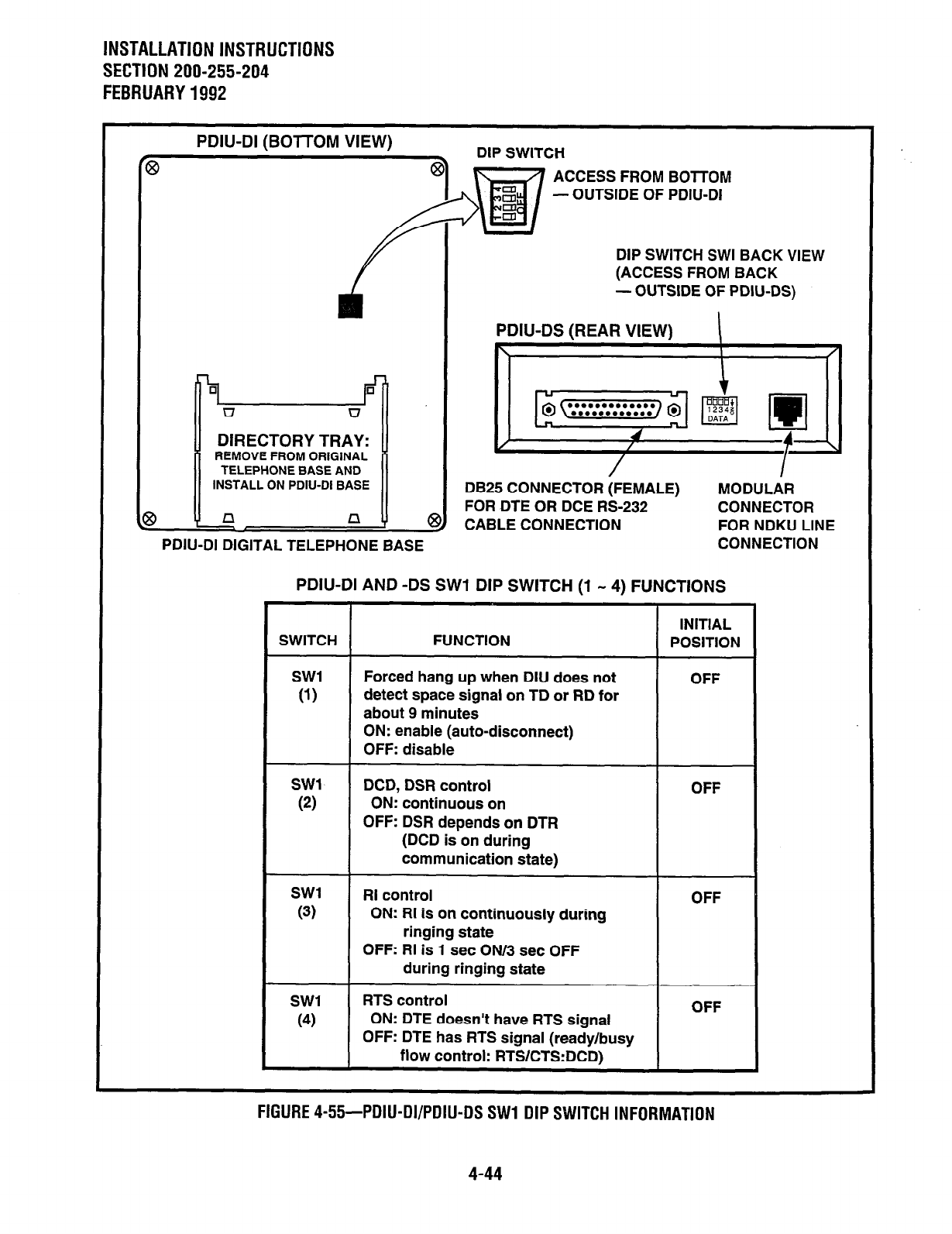
INSTALLATION INSTRUCTIONS
SECTION 200-255-204
FEBRUARY 1992
PDIU-DI (BOmOM VIEW)
DIP SWITCH
ACCESS FROM BOTTOM
- OUTSIDE OF PDIU-DI
DIP SWITCH SWI BACK VIEW
(ACCESS FROM BACK
PDIU-DI DIGITAL TELEPHONE BASE
1 OUTSIDE OF PDIU-DS)
PDIU-DS (REAR VIEW)
I
DB25 CONNECTOR (FEMALE) MODULAR
FOR DTE OR DCE RS-232 CONNECTOR
CABLE CONNECTION FOR NDKU LINE
CONNECTION
PDIU-DI AND -DS SW1 DIP SWITCH
(1 .. 4) FUNCTIONS
SWITCH
SW1
(1)
SW1
(2)
SW1
(3)
SW1
(4)
FUNCTION
Forced hang up when DIU does not
detect space signal on TD or RD for
about 9 minutes
INITIAL
POSITION
OFF
ON: enable (auto-disconnect)
OFF: disable
DCD, DSR control
ON: continuous on
OFF: DSR depends on DTR
(DCD is on during
communication state)
RI control OFF
ON: RI is on continuously during
ringing state
OFF: RI is 1 set ON/3 set OFF
during ringing state
RTS control
ON: DTE doesn’t have RTS signal
OFF: DTE has RTS signal (ready/busy
flow control: RTS/CTS:DCD1
OFF
FIGURE 4-55-PDIU-DI/PDIU-DS SW1 DIP SWITCH INFORMATION
4-44
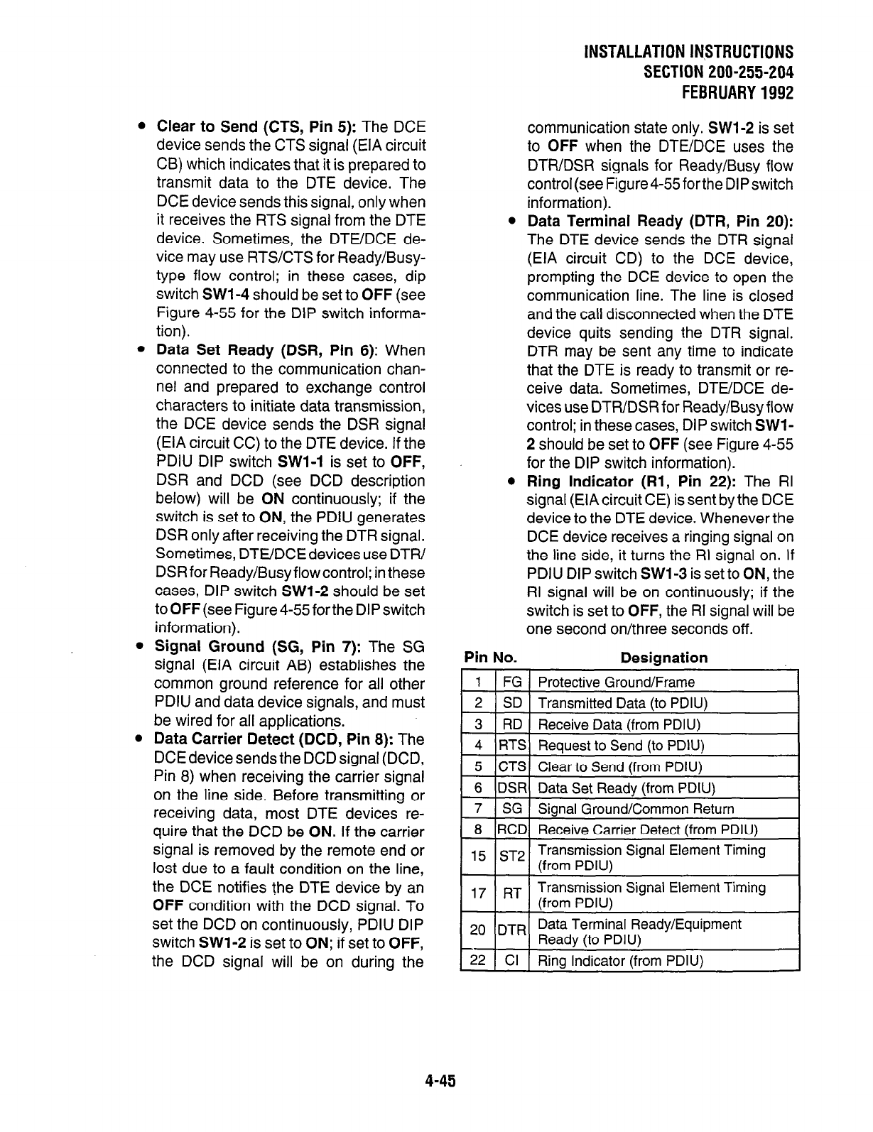
INSTALLATIONIN~TRUCTlONS
SECTION 200-255-204
FEBRUARY1992
l
Clear to Send (CTS, Pin 5): The DCE
device sends the CTS signal (EIA circuit
CB) which indicates that it is prepared to
transmit data to the DTE device. The
DCE device sends this signal, only when
it receives the RTS signal from the DTE
device. Sometimes, the DTE/DCE de-
vice may use RTS/CTS for Ready/Busy-
type flow control; in these cases, dip
switch SW1 -4 should be set to OFF (see
Figure 4-55 for the DIP switch informa-
tion).
l
Data Set Ready (DSF?, Pin 6): When
connected to the communication chan-
nel and prepared to exchange control
characters to initiate data transmission,
the DCE device sends the DSR signal
(EIA circuit CC) to the DTE device. If the
PDIU DIP switch SWl-1 is set to OFF,
DSR and DCD (see DCD description
below) will be ON continuously; if the
switch is set to ON, the PDIU generates
DSR only after receiving the DTR signal.
Sometimes, DTE/DCE devices use DTW
DSR for Ready/Busy flow control; in these
cases, DIP switch SWl-2 should be set
to OFF (see Figure 4-55for the DIP switch
information).
l
Signal Ground (SG, Pin 7): The SG
signal (EIA circuit AB) establishes the
common ground reference for all other
PDIU and data device signals, and must
be wired for all applications.
l
Data Carrier Detect (DCD, Pin 8): The
DCE
device sends the DCD signal (DCD,
Pin 8) when receiving the carrier signal
on the line side. Before transmitting or
receiving data, most DTE devices re-
quire that the DCD be ON. If the carrier
signal is removed by the remote end or
lost due to a fault condition on the line,
the DCE notifies the DTE device by an
OFF condition with the DCD signal. To
set the DCD on continuously, PDIU DIP
switch SW1 -2 is set to ON; if set to OFF,
the DCD signal will be on during the
communication state only. SWl-2 is set
to OFF when the DTE/DCE uses the
DTFUDSR signals for Ready/Busy flow
control(seeFigure4-55fortheDIPswitch
information).
l
Data Terminal Ready (DTR, Pin 20):
The DTE device sends the DTR signal
(EIA circuit CD) to the DCE device,
prompting the DCE device to open the
communication line. The line is closed
and the call disconnected when the DTE
device quits sending the DTR signal.
DTR may be sent any time to indicate
that the DTE is ready to transmit or re-
ceive data. Sometimes, DTE/DCE de-
vices use DTWDSR for Ready/Busy flow
control; in these cases, DIP switch SWI-
2 should be set to OFF (see Figure 4-55
for the DIP switch information).
l
Ring Indicator (Rl, Pin 22): The RI
signal (EIA circuit CE) is sent by the DCE
device to the DTE device. Whenever the
DCE device receives a ringing signal on
the line side, it turns the RI signal on. If
PDIU DIP switch SWI-3 is set to ON, the
RI signal will be on continuously; if the
switch is set to OFF, the RI signal will be
one second on/three seconds off.
Pin No. Designation
1 1 1 FG 1 Protective Ground/Frame
1 6 IDSRl Data Set Readv (from PDIU)
7 SG Signal Ground/Common
Return
8 RCD Receive Carrier Detect (from PDIU)
, 5 ST2 Transmission Signal Element Timing
(from PDIU)
I 171RTI
Transmission Signal Element Timing
(from PDIU) I
20 DTR Data Terminal Ready/Equipment
Ready (to PDIU)
22 Cl Ring Indicator (from PDIU)
4-45
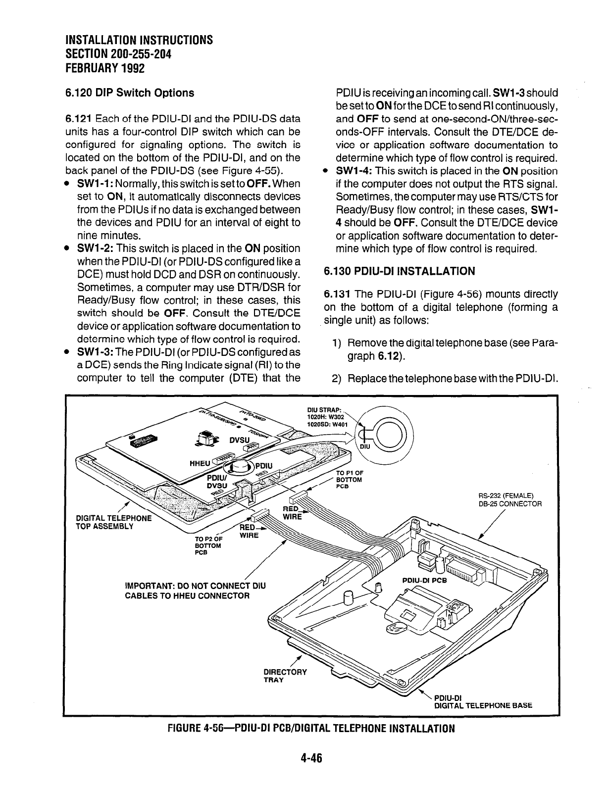
INSTALLATION INSTRUCTIONS
SECTION 200-255-204
FEBRUARY1992
6.120 DIP Switch Options
6.121 Each of the PDIU-DI and the PDIU-DS data
units has a four-control DIP switch which can be
configured for signaling options. The switch is
located on the bottom of the PDIU-DI, and on the
back panel of the PDIU-DS (see Figure 4-55).
l
SW1 -1: Normally, this switch is set to OFF. When
set to ON, it automatically disconnects devices
from the PDlUs if no data is exchanged between
the devices and PDIU for an interval of eight to
nine minutes.
l
SWl-2: This switch is placed in the ON position
when the PDIU-DI (or PDIU-DS configured like a
DCE) must hold DCD and DSR on continuously.
Sometimes, a computer may use DTR/DSR for
Ready/Busy flow control; in these cases, this
switch should be OFF. Consult the DTE/DCE
device or application software documentation to
determine which type of flow control is required.
l
SWl-3: The PDIU-DI (or PDIU-DS configured as
a DCE) sends the Ring Indicate signal (RI) to the
computer to tell the computer (DTE) that the
PD.lU is receiving an incoming call. SW1 -3should
be set to ON for the DCE to send RI continuously,
and OFF to send at one-second-ON/three-sec-
onds-OFF intervals. Consult the DTUDCE de-
vice or application software documentation to
determine which type of flow control is required.
l
SWl-4: This switch is placed in the ON position
if the computer does not output the RTS signal.
Sometimes, the computer may use RTS/CTS for
Ready/Busy flow control; in these cases, SW1 -
4 should be OFF. Consult the DTE/DCE device
or application software documentation to deter-
mine which type of flow control is required.
6.130 PDIU-DI INSTALLATION
6.131 The PDIU-DI (Figure 4-56) mounts directly
on the bottom of a digital telephone (forming a
single unit) as follows:
1) Remove the digital telephone base (see Para-
graph 6.12).
2) Replace the telephone base with the PDIU-DI.
RS-232 (FEMALE)
DB-25 CONNECTOR
- / ii;E-
TO P2 OF
BOITOM
IMPORTANT: DO NOT CONNECT DIU
CABLES TO HHEU CONNECTOR
DIRECTORY
-.- -.
DIGITAL TELEPHONE BASE
FIGURE 4-56-PDIU-DI PCB/DIGITAL TELEPHONE INSTALLATION
4-46
NOTE:
A digital telephone with a PDIU-DI attached
cannot be wall-mounted.
6.140 PDIU-DI to Personal Computer (PC)
Installation
6.141 The PDIU-DI always functions as a DCE
device; it transmits data on the Receive Data lead
(RD) and receives data on the Transmit Data lead
(TD). Most personal computers function as DTE
devices; PCs transmit data on the TD lead and
receive data on the RD lead. Follow the steps below
to install the PDIU-DI to a DTE or DCE PC:
NOTES:
1.
2.
1)
2)
Use the steps below when installing an
ASCII terminal, orany other DTE device to
a PDIU-DI.
The PDIU-DI can connect to a DCE com-
puter or any other DCE-type device using
a specially configured M-232 cable or
adapter; however, this applica tion is rarely
required.
lnstall the digital telephone that is to be
aquipped with PDIU-DI in accordance with the
i nstructions in Section 200-255-205, MDF
Jrrangement, Paragraph 1.01 and in Figure
5-2.
nstall the PDIU-DI in the digital telephone’s
)ase in accordance with the instructions in
‘aragraph 6.130.
NOTE:
The PDIU-DI operates only as a DCE device;
therefore, unlike the PDIU-DS, it has no inter-
nal jumpers.
3) Connect the appropriate RS-232 cable be-
tween the PDIU-DI DB-25 female connector
and the PC’s appropriate asynchronous serial
communications port connector.
IMPORTANT NOTE!
Check the PC manufacturer’s serial com-
munication port interface documentation
INSTALLATION INSTRUCTIONS
SECTION 200-255-204
FEBRUARY1992
for correct RS-232 pin requirements; re-
quirements vary with each manufacturer.
The number of EIA RS-232 signals re-
quired (8,9, or 10 wires) will depend on the
application. When EIA signal requirements
are not known, connect the 10 EIA signals
listed in Paragraph 6.110. Figures 4-57,4-
58, and 4-59 provide diagrams for con-
necting RS-232 cables between PDIU-Dls
and a Toshiba printer and laptop com-
puter, IBM XT-type and A T-type personal
computers.
4)
5)
Set the PDIU-DVPDIU-DS DIP switch (SWl-
1 - 4) for the desired application. Figure 4-55
shows the DIP switch locations and Para-
graph 6.120 describes the switch functions.
Access the DEKT and DDIU Programs for
PDIU port connection and data button assign-
ments.
l
The port number entered for the PDIU-DI
in the DDIU Program is the adjacent port
number of the digital telephone.
Example: DKTportnumber= L024, PDIU-
DI port number = LO34
IMPORTANT NOTE.’
The eighth port (circuit) of the NDKU can-
not be used for data switching connections
(PDIU-DI or PDIU-DS).
6.150 PDIU-DS To Printer Installation
6.151 PERCEPTIONeLex enables serial printers
(laser, dot matrix, or other types) to be connected
to stand-alone data interface units (PDIU-DS).
Digital telephones equipped with PDIU-DI and
Electronic Telephones equipped with DDIU-MAT
can share access to these printers. Serial printers
operate as DCE or DTE devices, depending on the
vendor. The PDIU-DS can be connected to either
type, since it can be configured as a DTE or DCE
device. (The PDIU-DS comes from the factory
configured as a DCE device.) Follow the steps
below to install the PDIU-DS to a serial printer.
4-47
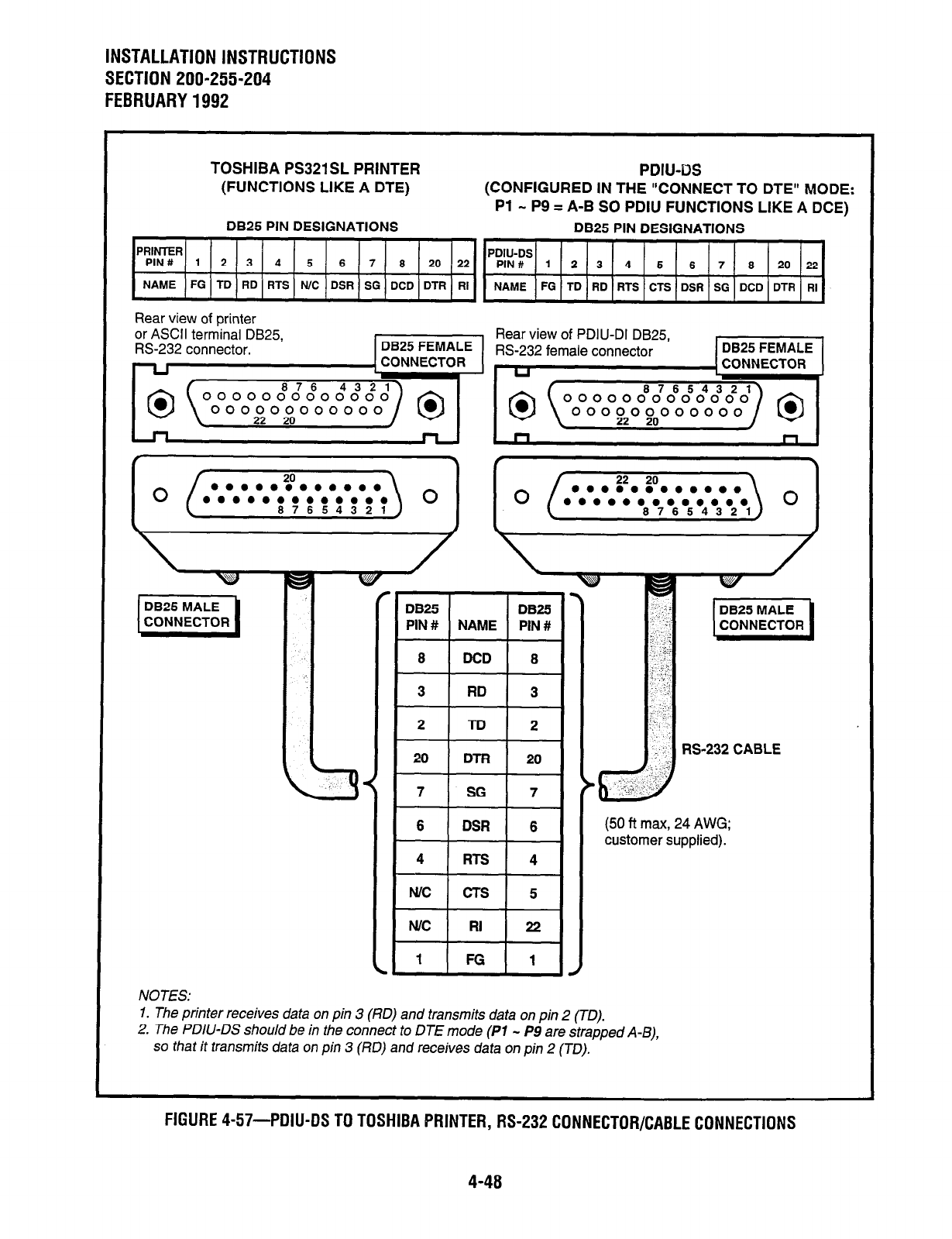
INSTALLATION INSTRUCTIONS
SECTION 200-255-204
FEBRUARY1992
TOSHIBA PS321SL PRINTER PDIU-US
(FUNCTIONS LIKE A DTE) (CONFIGURED IN THE “CONNECT TO DTE” MODE:
Pl - P9 = A-B SO PDIU FUNCTIONS LIKE A DCE)
DB25 PIN DESIGNATIONS DB25 PIN DESIGNATIONS
PRIMER
PIN# 1 2 3 4 5 6 7 8 20 22 piK#Ds 12345678 20 22
NAME FG TD RD FITS N/C DSR SG DCD DTR RI NAME FG TD RD RTS CTS DSR SG DCD DTR RI
Rear view of printer
(50 ft max, 24 AWG;
customer supplied).
NOTES:
1. The printer receives data on pin 3 (RD) and transmits data on pin 2 (TO).
2. The PDIU-DS should be in the connect to DTE mode (Pl - P9 are strapped A-B),
so that it transmits data on pin 3 (RD) and receives data on pin 2 (TO).
FIGURE 4-57-PDIU-DS TO TOSHIBA PRINTER, RS-232 CONNECTOR/CABLE CONNECTIONS
4-48
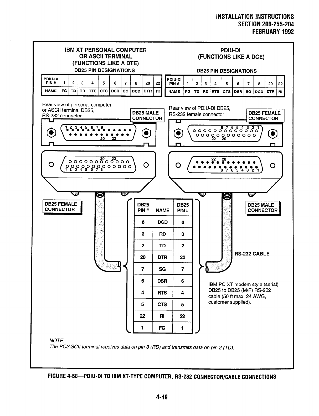
INSTALLATION INSTRUCTIONS
SECTlON200-255-204
FEBRUARY1992
IBM XT PERSONAL COMPUTER
OR ASCII TERMINAL
(FUNCTIONS LIKE A DTE)
DB25 PIN DESIGNATIONS
PDIU-DI
(FUNCTIONS LIKE A DCE)
DB25 PIN DESIGNATIONS
PDIU-DI PDIU-DI
PIN# 1 2 3 4 5 6 7 6 20 22 PIN# 1 2 3 4 5 6 7 6 20 22
NAME FG TD RD FITS CTS DSR SG DCD DTR RI NAME FG TD RD RTS CTS DSR SG DCD DTR RI
Rear view of personal computer
or ASCII te Rear view of PDIU-DI DB25. ,
1
CONNECTOR 1
RS-232 CABLE
IBM PC XT modem style (serial)
DB25 to DB25 (M/F) RS-232
cable (50 ft max, 24 AWG,
customer supplied).
NOTE:
The PC/ASCII terminal receives data on pin 3 (170) and transmits data on pin 2 (TO).
FIGURE 4-58-PDIU-DI TO IBM XT-TYPE COMPUTER,
RS-232 CONNECTOR/CABLE CONNECTIONS
4-49
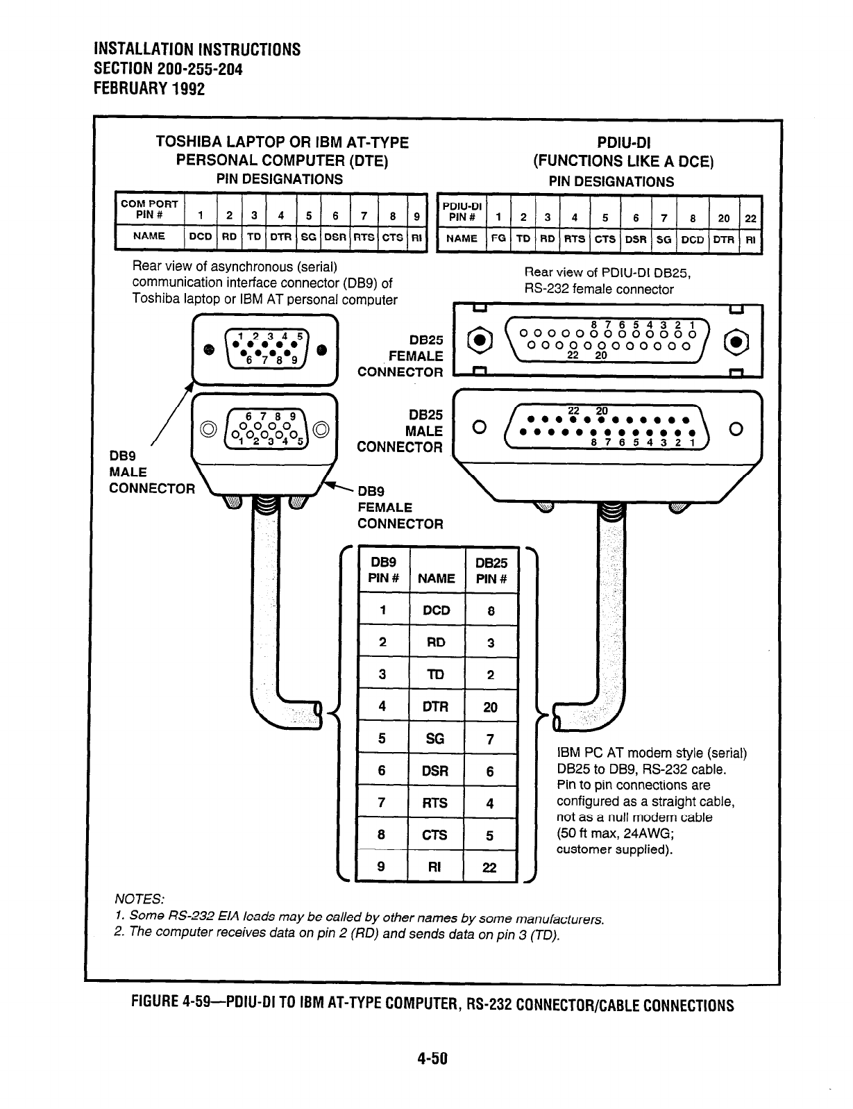
INSTALLATION INSTRUCTIONS
SECTION 200-255-204
FEBRUARY 1992
TOSHIBA LAPTOP OR IBM AT-TYPE PDIU-DI
PERSONAL COMPUTER (DTE) (FUNCTIONS LIKE A DCE)
PIN DESIGNATIONS PIN DESIGNATIONS
COM PORT
PIN # PDIU-DI
123456769 PIN# 1 2 3 4 5 6 7 8 20 22
NAME DCD RD TD DTR SG DSR RTS CTS RI NAME FG TD RD RTS CTS DSR SG DCD DTR RI
Rear view of asynchronous (serial)
communication interface connector (DB9) of Rear view of PIN-DI DB25,
Toshiba laptop or IBM AT personal computer FE-232 female connector
DE9
MALE
CONNECTOR
CONNECTOR
IBM PC AT modem style (serial)
DB25 to DB9, RS-232 cable.
Pin to pin connections are
configured as a straight cable,
not as a null modem cable
(50 ft max, 24AWG;
customer supplied).
NOTES:
1. Some RS-232 E/A leads may be called by other names by some manufacturers.
2. The computer receives data on pin 2 (RD) and sends data on pin 3 (TD).
FIGURE 4-59-PDIU-DI TO IBM AT-TYPE COMPUTER, RS-232 CONNECTOR/CABLE CONNECTIONS
4-50
INSTALLATION INSTRUCTIONS
SECTlON200-255-204
FEBRUARY1992
NOTES:
1. Only serial printers that conform to EIA
M-232 signaling requirements can be
connected to PDIU-DS units.
2. In rare applications, printers can be con-
nected to PDIU-Dls. Refer to the printer’s
installation instructions.
1) Consult the serial printer’s documentation,
and determine if the printer operates as a DCE
or DTE device:
l
As a DCE device:
a) Disassemble the PDIU-DS, and con-
figure it to operate like a DTE device
by placing the jumper plugs PI - P9
in the “B-C” (MODEM) position.
b) Reassemble the PDIU-DS, and mark
“B-C” on the bottom identification la-
bel for future reference. (Paragraph
6.170 provides PDIU-DS disassem-
bly/assembly instructions, and Fig-
ure 4-54 provides jumper plug infor-
mation).
l
As a DTE device:
It may not be necessary to disassemble
the PDIU-DS, since it comes direct from
the factory configured as a DCE device.
However, if uncertain,
a) Disassemble the PDIU-DS, and verify
that jumper plugs PI - P9 are in the
“A-B” (DTE) position for DTE opera-
tion.
b) Reassemble the PDIU-DS and mark
“A-B” on the bottom identification la-
bel for future reference. (Paragraph
6.170 provides PDIU-DS disassem-
bly/assembly instructions, and Fig-
ure 4-54 provides jumper plug infor-
mation).
2) Connect the PDIU-DS to the appropriate NDKU
circuit in accordance with the wiring diagrams
in Section 200-255-205.
3) Connect the appropriate RS-232 cable be-
tween the printer and the PDIU-DS.
4) If steps 2 and 3 are properly done, the POWER
and READY LEDs on the PDIU-DS should
light when the printer is turned on.
IMPORTANT NOTE!
Check the printer’s serial documentation
for correct RS-232 pin requirements. The
requirements vary with each manufacturer.
5) Refer to the DDIU Program for PDIU-DS data
assignments.
IMPORTANT NOTE!
The eighth port (circuit) of the NDKU can-
not be used for data switching connection
(PDIU-DI or PDIU-DS).
6.160 PDIU-DS To Modem Installation
6.161 With D.04 software, PERCEPTIONeLe,
enables asynchronous-type (not synchronous)
modems to be connected to PDIU-DS’s. This al-
lows PDIU-Dl-equipped digital telephones that are
connected to PCs, terminals, and other devices to
share access to a modem.
6.162 Modems can be accessed internally for out-
going data calls or externally for incoming data
calls. Modems operate as DCE devices, so the
PDIU-DS must be configured to operate like DTE
devices. The installation example in Figure 4-51
shows that two modems are connected to NSTU
ports; however, the line side of modems can be
directly connected to a dedicated CO line. The
modem connects to the PDIU-DS with a standard
RS-232 connector; the PDIU-DS line side (RJ-I 1
connector) always connects to its own individual
NDKU port. Use the following instructions to con-
nect modems to PDIU-DS’s.
1) Configure the PDIU-DS as a DTE device:
a) Disassemble the PDIU-DS, and place
jumper plugs PI - P9 in the “B-C” position
(MODEM).
b) Reassemble the PDIU-DS, and mark “B-C”
on the bottom identification label for future
reference (Paragraph 6.170 provides
4-51
INSTALLATION INSTRUCTIONS
SECTION 200-255-204
FEBRUARY 1992
2)
3)
PDIU-DS disassembly/assembly instruc-
tions, and Figure 4-54 provides jumper plug
information).
Connectthe PDIU-DS totheappropriate NDKU
circuit in accordance with the wiring diagrams
in Section 200-255-205.
Connect the appropriate RS-232 cable be-
tween the modem and the PDIU-DS. Figure
4-60 shows an example of PDIU-DS to a
Hayes modem RS-232 connection.
IMPORTANT NOTE!
All ten PDIU-DS EIA leads (signals) should
be connected to the modem. Consult the
modem’s documentation for correct RS-
232 pin requirements. The requirements
may vary with each manufacturer.
4) Connect the line side of the modem to a NSTU
standard telephone circuit, or a dedicated CO
line (Consult the modem’s documentation to
connect it to a CO line). Section 200-255-205
provides NSTU station portwiring information.
5) Refer to the DDIU Program for PDIU-DS
connection assignments.
IMPORTANT NOTE.’
The eighth port (circuit) of the NDKU can-
not be used for data switching connections
(PDIU-DI or PDIU-DS).
6.170 PDIU-DS Disassembly and Assembly
6.171 To set the jumper plugs PI - P9 on the sub-
assembly inside the PDIU-DS for DCE or DTE
operation, the PDIU-DS must be disassembled
(Figure 4-61). Disassemble the PDIU-DS in accor-
dance with the steps in Paragraph 6.172.
6.172 Disassembling the PDIU-DS
1) Remove the four screws securing the bottom
panel to the rest of the unit. These screws are
2)
3)
4)
not captive, so place them together where
they can be easily accessed.
Remove the bottom panel.
Remove the PCB by lifting the back panel from
its side grooves.
Turn the PCB over and set jumper plugs Pl -
P9 as follows:
l
If the PDIU-DS is connected to a DTE,
set the plugs to the “A-B” position.
l
If the PDIU-DS is connected to a DCE
device, set the plugs to the “B-C” position.
6.173 Assembling the PDIU-DS
1) Position the back panel to the PCB.
2) Slide the back panel down into its side grooves.
3) Attach the bottom panel, and secure it with the
four noncaptive screws.
6.180 PDIU-DVPDIU-DS Installation Tests
6.181 Figures 4-62 - 4-65 provide tests for four
PDIU call applications. The telephone and port
numbers used in these figures are provided for
explanation purposes only. When actually testing,
use port and telephone numbers appropriate for
the system. Each of these tests can be conducted
with either manual dialing from atelephone dialpad,
or AT dialing from a personal computer keyboard;
however, only the preferred method of dialing for
the application is presented, The PDIU User Guide
has additional information on the tests, which are
listed below:
l
Figure 4-62-PC to PC Test Call Using AT Com-
mands
l
Figure4-63-PCto PrinterTest Call Using Manual
Dialing
l
Figure 4-64-Internal PC to External PC Test Call
Using AT Commands
l
Figure 4-65-External PC to Internal PC Test Call
Using AT Commands
4-52
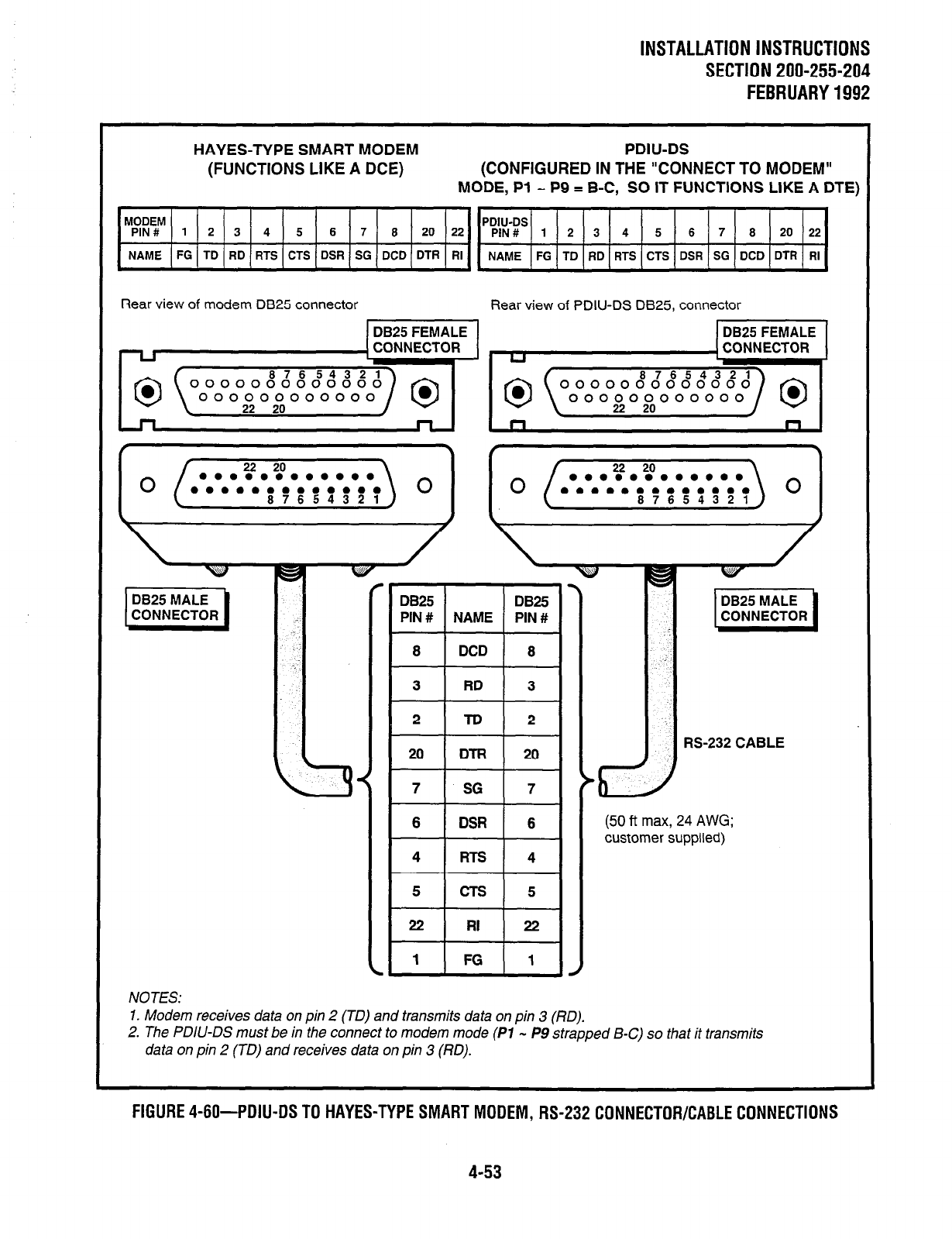
INSTALLATION INSTRUCTIONS
SECTION 200-255-204
FEBRUARY1992
HAYES-TYPE SMART MODEM
(FUNCTIONS LIKE A DCE)
PDIU-DS
(CONFIGURED IN THE “CONNECT TO MODEM”
MODE, Pl - P9 = B-C, SO IT FUNCTIONS LIKE A DTE)
MODEM PDIU-DS
PIN# 1 2 3 4 5 6 7 8 20 22 PIN# 1 2 3 4 5 6 7 8 20 22
NAME FG TD RD RTS CTS DSR SG DCD DTR RI NAME FG TD RD RTS CTS DSR SG DCD DTR RI
Rear view of modem DB25 connector Rear view of PDIU-DS DB25. connector
DB25 FEMALE DB25 FEMALE
CONNECTOR
I
DB25 n
CONNE
AALE
ECTOR I
,825
I I
DBW
I PIN# NAME PIN #
1
LCONNECTOR 1
MALE 1
a
DCD
t-l-
3 RD
L--k--
8
3
2
FG
6
4
5
22
1
(50 ft max, 24 AWG;
customer supplied)
NOTES:
1. Modem receives data on pin 2 (TO) and transmits data on pin 3 (170).
2. The PDIU-DS must be in the connect to modem mode
(PI
- P9 strapped B-C) so that it transmits
data on pin 2 (TO) and receives data on pin 3 (RD).
FIGURE 4-60-PDIU-DS TO HAYES-TYPE SMART MODEM, RS-232 CONNECTOR/CABLE CONNECTIONS
4-53
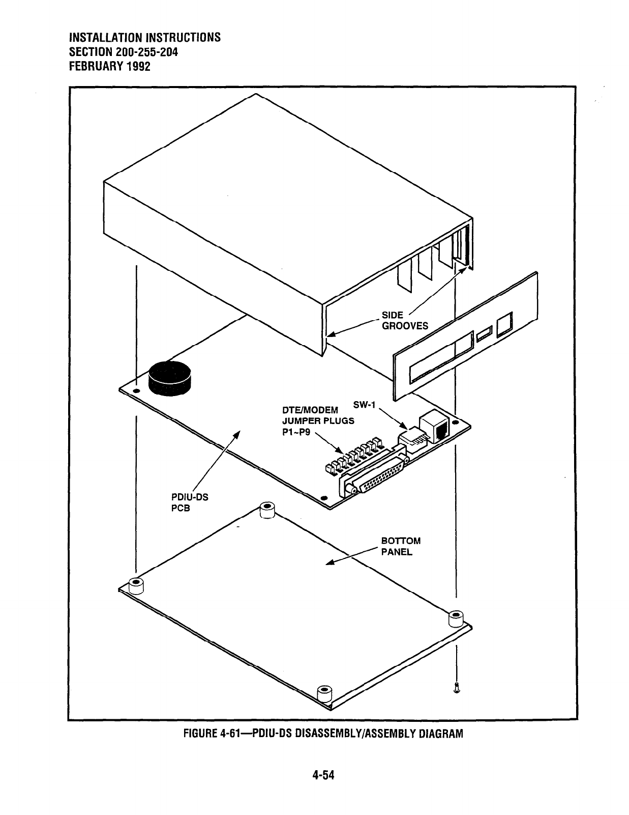
INSTALLATION INSTRUCTIONS
SECTION 200-255-204
FEBRUARY 1992
DTE/h!ODEM
JUMPER PLUGS
PDIU-DS
FIGURE 4-61-PDIU-DS DISASSEMBLY/ASSEMBLY DIAGRAM

INSTALLATION INSTRUCTIONS
SECTION 200-255-204
FEBRUARY 1992
3 DKT/PDIU-DI 1 w
LAPTOP PC 2
FIGURE 4-62 FIGURE 4-63
PC TO PC TEST CALL USING AT COMMANDS PC TO PRINTER TEST CALL USING MANUAL DIALING
PERCEPTION,,,,
TELEPHONE
TELEPHONE 1
LAPTOP PC 1
LAPTOP -
PC2
FIGURE 4-64-INTERNAL PC TO EXTERNAL PC TEST CALL USING AT COMMANDS
4-55
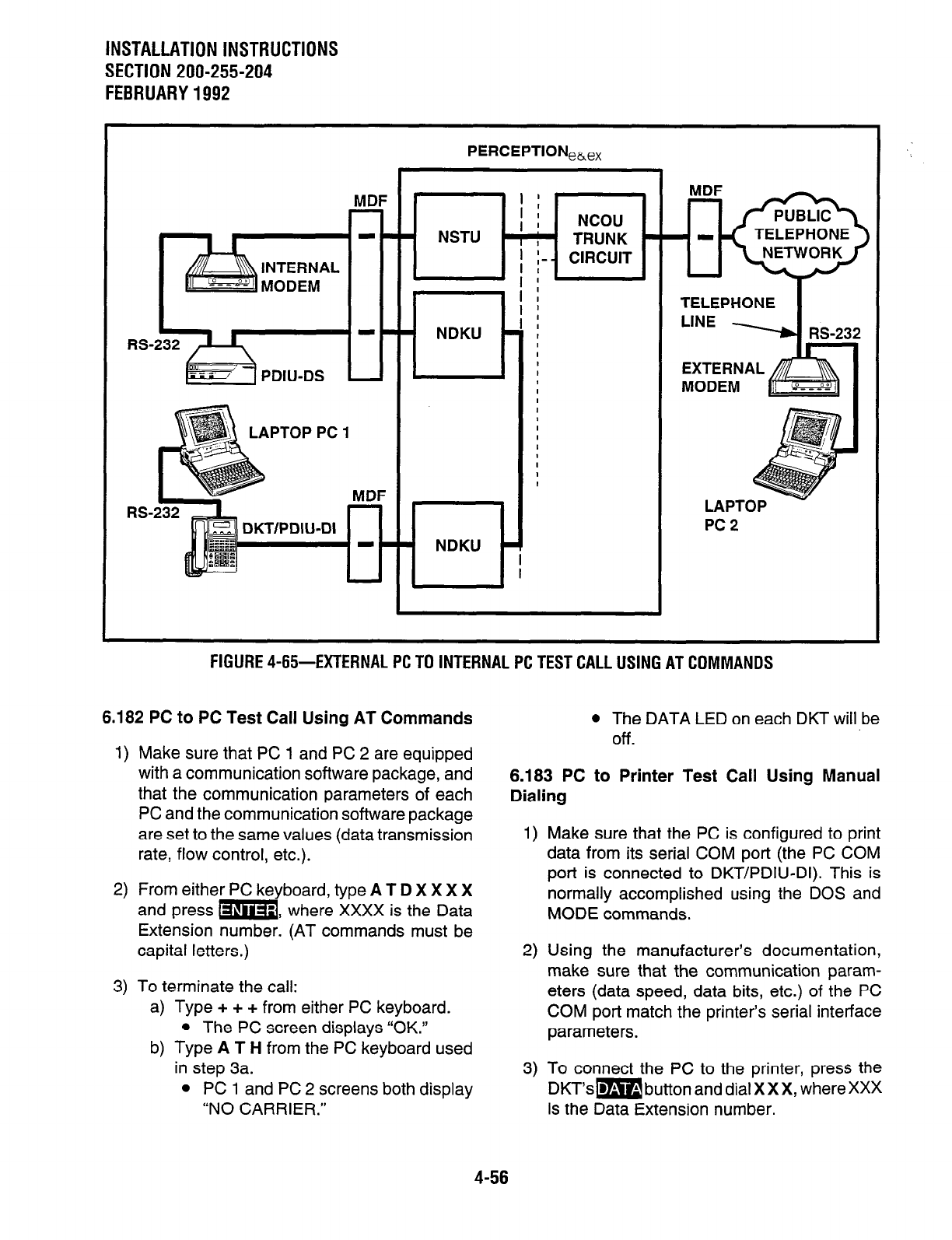
INSTALLATION INSTRUCTIONS
SECTION 200-255-204
FEBRUARY1992
MDF ’ :
I : NCOU
NSTU ’ , ; ’ TRUNK - TELEPHONE
I
I :- - CIRCUIT
! :
LAPTOP PC 1
TELEPHONE
PC2
FIGURE 4-65-EXTERNAL PC TO INTERNAL PC TEST CALL USING AT COMMANDS
6.182 PC to PC Test Call Using AT Commands
1) Make sure that PC 1 and PC 2 are equipped
with a communication software package, and
that the communication parameters of each
PC and the communication software package
are set to the same values (data transmission
rate, flow control, etc.).
2) From either PC keyboard, type A T D X X X X
and press m, where XXXX is the Data
Extension number. (AT commands must be
capital letters.)
3) To terminate the call:
a) Type + + + from either PC keyboard.
l
The PC screen displays “OK.”
b) Type A T H from the PC keyboard used
in step 3a.
l
PC 1 and PC 2 screens both display
“NO CARRIER.”
l
The DATA LED on each DKT will be
Off.
6.183 PC to Printer Test Call Using Manual
Dialing
1) Make sure that the PC is configured to print
data from its serial COM port (the PC COM
port is connected to DKT/PDIU-DI). This is
normally accomplished using the DOS and
MODE commands.
2) Using the manufacturer’s documentation,
make sure that the communication param-
eters (data speed, data bits, etc.) of the PC
COM port match the printer’s serial interface
parameters.
3) To connect the PC to the printer, press the
DKT’sm button and dial XXX, where XXX
is the Data Extension number.
4-56
INSTALLATION INSTRUCTIONS
SECTION 200-255-204
FEBRUARY1992
l
The CONNECT LED on the PDIU-DS will
light.
l
The connection between the PC and the
printer is complete.
l
If busy tone is sent to the DKT, the connec-
tion is not complete. Try step 3 again.
4) Operate the PC to print data as required.
5) To terminate the call, press the DKT’s m
button.
6.184 Internal PC to External PC Test Call Using
AT Commands
1) Make sure PC 1 and PC 2 are equipped with
a communication software package, and that
the communication parameters of each PC
and communication software package are set
to the same values (data transmission rate,
flow control, etc.).
2) From PC 1 ‘s keyboard, type A T D X X X X and
press m, where XXXX is Data Extension
number. (AT commands must be capital let-
ters.)
l
The DATA LED on the DKT will light.
l
The CONNECT LED on the PDIU-DS will
light.
l
The screen on PC 1 displays “CON-
NECT XXXX,” where XXXX is the data
transmission speed set by the communi-
cation software.
l
At this time, PC 1 and the PDIU-DS are
connected.
3) From PC l’s keyboard, type A T D T X X X X
X X X X X X and press m, where
XXXXXXXXXXX is the trunk access code and
modem telephone number.
l
The internal modem goes off-hook, dials
the access code to seize the trunk, and
then dials the external modem’s tele-
phone number.
l
The external modem rings and auto an-
swers, the modems handshake and es-
tablish communications.
l
If the external modem sends result codes,
the screen on PC 1 displays “CONNECT
XxXx,” where XXXX is the data trans-
mission speed set by the communication
software.
l
At this time PC 1 and PC 2 are con-
nected, and can exchange data (file
transfers, type messages, etc.).
4) To terminate the call:
a) Type + + + from either PC keyboard.
l
The PC screen displays “OK.”
b) Type A T H from the PC keyboard used
in step 5a.
l
PC 1 and PC 2 screens both display
“NO CARRIER.”
l
The DATA LEDs on each DKT will go
out.
6.185 External PC to Internal PC Test Call Using
AT Commands
1) Make sure PC 1 and PC 2 are equipped with
a communication software package, and that
the communication parameters of each PC
and communication software package are set
to the same values (data transmission rate,
flow control, etc.).
2) From PC 2’s ke board, type A T D X X X X,X
X X and press km3 -, where XXXXXXX is
telephone number.
l
The external modem originates the call.
l
Trunk rings incoming call to the internal
modem.
l
The internal modem rings and auto an-
swers, the modems handshake and es-
tablish communications.
l
If the internal modem sends result codes,
PC 2’s screen displays “CONNECT
XXXX,” where XXXX is the data trans-
mission speed set by the communication
software.
l
At this time, PC 2 is connected to the
PDIU-DS.
4-57
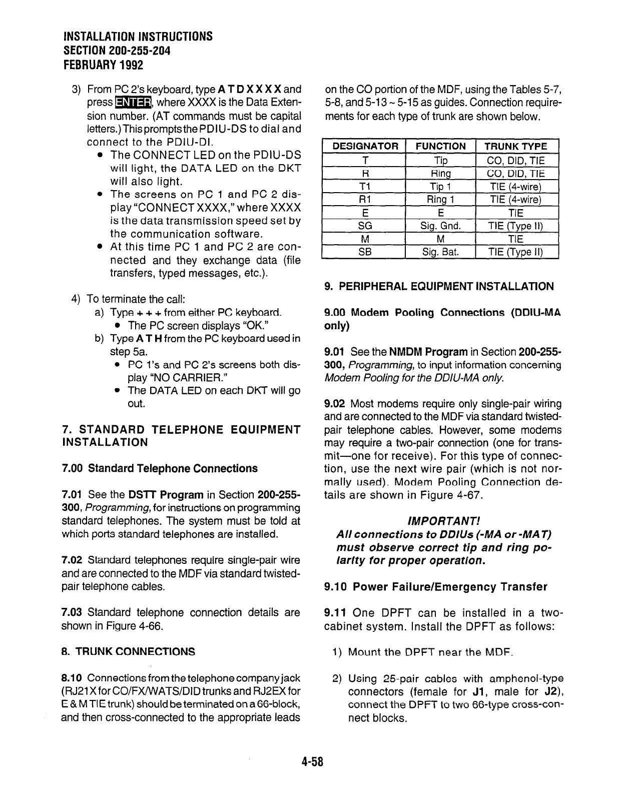
INSTALLATION INSTRUCTIONS
SECTION 200-255-204
FEBRUARY1992
3) From PC 2’s keyboard, type
A T D
X X X X and
press m, where XXXX is the Data Exten-
sion number. (AT commands must be capital
letters.)ThispromptsthePDIU-DS to dial and
connect to the PDIU-DI.
l
The CONNECT LED on the PDIU-DS
will light, the DATA LED on the DKT
will also light.
l
The screens on PC 1 and PC 2 dis-
play “CONNECT XXXX,” where XXXX
is the data transmission speed set by
the communication software.
l
At this time PC 1 and PC 2 are con-
nected and they exchange data (file
transfers, typed messages, etc.).
4) To terminate the call:
a) Type + + + from either PC keyboard.
l
The PC screen displays “OK.”
b) Type
AT H
from the PC keyboard used in
step 5a.
l
PC l’s and PC 2’s screens both dis-
play “NO CARRIER.”
l
The DATA LED on each DKT will go
out.
7. STANDARD TELEPHONE EQUIPMENT
INSTALLATION
7.00 Standard Telephone Connections
7.01 See
the
DSTT Program
in Section 200-255-
300, Programming, for instructions on programming
standard telephones. The system must be told at
which ports standard telephones are installed.
7.02 Standard telephones require single-pair wire
and are connected to the MDF via standard twisted-
pair telephone cables,
7.03 Standard telephone connection details are
shown in Figure 4-66.
8. TRUNK CONNECTIONS
8.10 Connections from the telephone company jack
(RJ21 X for CO/FX/VVATSIDID trunks and RJ2EXfor
E & M TIE trunk) should be terminated on a 66-block,
and then cross-connected to the appropriate leads
on the CO portion of the MDF, using the Tables 5-7,
5-8, and 5-13 - 5-l 5 as guides. Connection require-
ments for each type of trunk are shown below.
i DESIGNATOR 1 FUNCTION
t TRUNKTYPE 1
I
T I
Tb t CO. DID. TIE 1
R
Ti
Rl
E
Ring
CO, DID, TIE
Tip
1 TIE (Cwire)
Ring 1 TIE (4-wire)
E TIE
SG
M
SB
Sig. Gnd.
M
Sig. Bat.
TIE (Type II)
TIE
TIE (Type II)
9. PERIPHERAL EQUIPMENT INSTALLATlON
9.00 Modem Pooling Connections (DDIU-MA
only)
9.01 See
the
NMDM Program
in Section 200-255.
300, Programming, to input information concerning
Modem Pooling for the DDIU-MA only.
9.02 Most modems require only single-pair wiring
and are connected to the MDF via standard twisted-
pair telephone cables. However, some modems
may require a two-pair connection (one for trans-
mit-one for receive). For this type of connec-
tion, use the next wire pair (which is not nor-
mally used). Modem Pooling Connection de-
tails are shown in Figure 4-67.
IMPORTANT!
All connections to DDlUs (-MA or -MAT)
must observe correct tip and ring po-
larity for proper operation.
9.10 Power Failure/Emergency Transfer
9.11
One DPFT can be installed in a two-
cabinet system. Install the DPFT as follows:
1) Mount the DPFT near the MDF.
2) Using 25-pair cables with amphenol-type
connectors (female for
Jl,
male for J2),
connect the DPFT to two 66-type cross-con-
nect blocks.
4-58
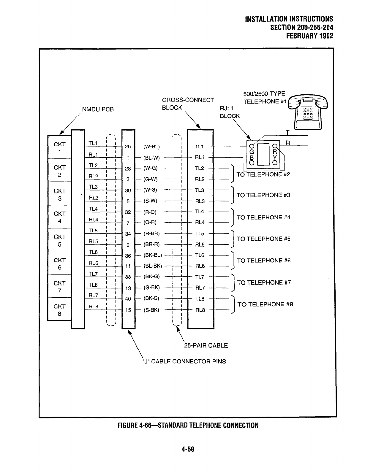
INSTALLATION INSTRUCTIONS
SECTION 200-255-204
FEBRUARY1992
NMDU PCB
30
5
32
7
34
9
36
CKT
TL8 ; j
7 I
,3
RL7 i ; 4.
I ’
CKT
RL8 ; !
8 ’ I
,5
’
.- :
- 1
500/2500-TYPE
CROSS-CONNECT
BLOCK FiJil
BLOCK
-.
( I
’ I
W-W ; I
TLl
(BL-W) ! ; RLI
W-G) ’ I
; i
TL2
(G-W) : 1
TO TELEPHONE #2
RL2
’ I
W-S) ; ;
TL3
I
TO TELEPHONE #3
RL3
TL4
TO TELEPHONE #4
RL4
TL5
RL5 1
TO TELEPHONE #5
TL6
I
TO TELEPHONE #6
RL6
TL7
TO TELEPHONE #7
RL7
TL8
TO TELEPHONE #8
RL8
\
‘25-PAIR CABLE
“J” CABLE CONNECTOR PINS
FIGURE 4-66-STANDARD TELEPHONE CONNECTION
4-59
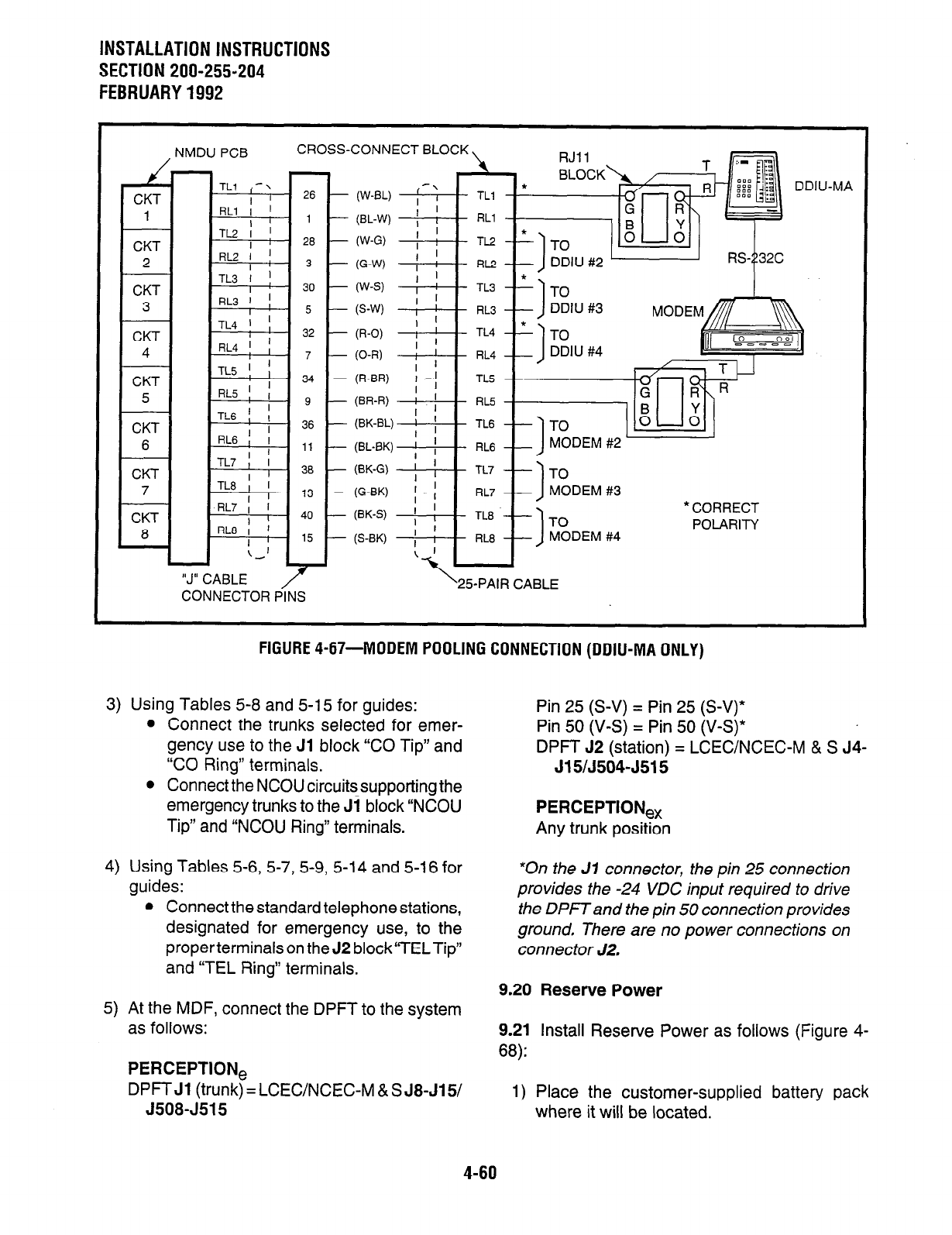
INSTALLATION INSTRUCTIONS
SECTION 200-255-204
FEBRUARY1992
, NMDU PCB CROSS~
CKT
1
CKT
2
CKT
3
CKT
5
CKT
6
CONNECTOR PINS
CONNECT BLOCK \ RJII
\
DDll
(W-BL) I-:
*
TLl
I
(BL-W) ; , RLl
(W-G)
i /
I TL2-L TO
6-W ; i I
RC~ -- DDIU #2
(W-S) ] !
TL3 2 ‘1 -rn
I
(S-W) ; ! FiL3
I ’
(R-0) I TL4
(O-R) ; ’ RL4
I ’
(R-BR) : ’
! I
TLS
(BR-R) .
’ I
RL5
W-B’-) f , TL6
J
MODEM #2 -
I
TO
MODEM #3
1
l
CORRECT
TO POLARITY
MODEM #4
25-PAIR CABLE
J-MA
FIGURE 4-67-MODEM POOLING CONNECTION (DDIU-MA ONLY)
3) Using Tables 5-8 and 5-15 for guides:
l
Connect the trunks selected for emer-
gency use to the Jl block “CO Tip” and
“CO Ring” terminals.
l
Connect the NCOU circuits supporting the
emergency trunks to the Ji block “NCOU
Tip” and “NCOU Ring” terminals.
4) Using Tables 5-6, 5-7, 5-9, 5-14 and 5-16 for
guides:
l
Connect the standard telephone stations,
designated for emergency use, to the
properterminals on the J2 block“TELTip”
and “TEL Ring” terminals.
5) At the MDF, connect the DPFT to the system
as follows:
PERCEPTION,
DPFT Jl (trunk) = LCEWNCEC-M & S J8-J15/
J508-J515
Pin 25 (S-V) = Pin 25 (S-V)*
Pin 50 (V-S) = Pin 50 (V-S)*
DPFT 52 (station) = LCEWNCEC-M & S J4-
J15/J504-J515
PERCEPTION,
Any trunk position
*On the J7 connector, the pin 25 connection
provides the -24 VDC input required to drive
the DPFTand the pin 50 connection provides
ground, There are no power connections on
connector J2.
9.20 Reserve Power
9.21 Install Reserve Power as follows (Figure 4-
68):
1) Place the customer-supplied battery pack
where it will be located.
4-60
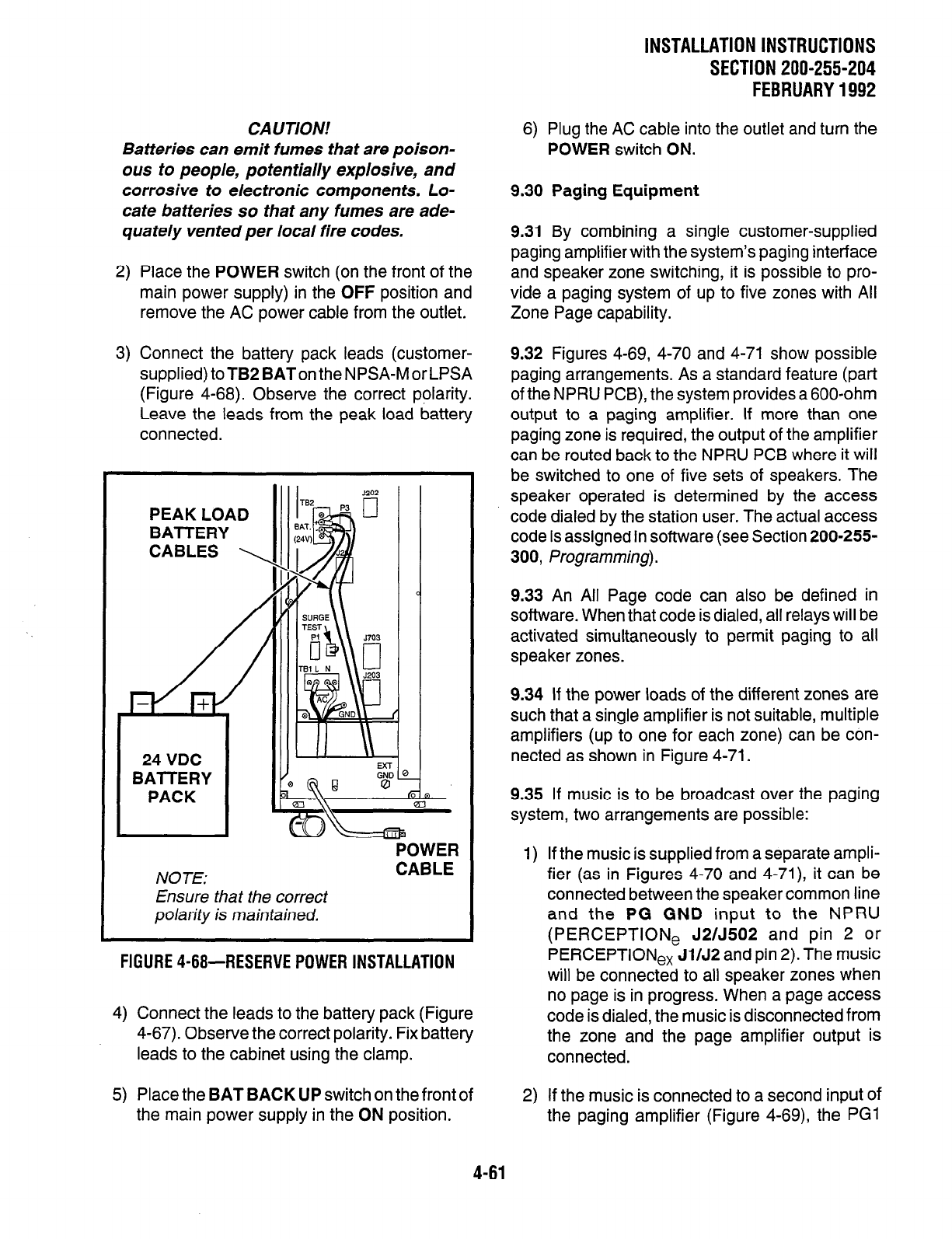
CA UT/ON!
Batteries can emit fumes that are poison-
ous to people, potentially explosive, and
corrosive to electronic components. Lo-
cate batteries so that any fumes are ade-
quately vented per local fire codes.
2) Place the POWER switch (on the front of the
main power supply) in the OFF position and
remove the AC power cable from the outlet.
3) Connect the battery pack leads (customer-
supplied) to TB2 BAT on the NPSA-M or LPSA
(Figure 4-68). Observe the correct polarity.
Leave the leads from the peak load battery
PEAK LOAD
I I IllIll \\I
POWER
NOTE: CABLE
Ensure that the correct
polarity is maintained.
FIGURE 4-68-RESERVE POWER INSTALLATION
4-61
4) Connect the leads to the battery pack (Figure
4-67). Observe the correct polarity. Fix battery
leads to the cabinet using the clamp.
5) Place the BAT BACK UP switch on the front of
the main power supply in the ON position.
INSTALLATION INSTRUCTIONS
SECTION 200-255-204
FEBRUARY1992
6) Plug the AC cable into the outlet and turn the
POWER switch ON.
9.30 Paging Equipment
9.31 By combining a single customer-supplied
paging amplifier with the system’s paging interface
and speaker zone switching, it is possible to pro-
vide a paging system of up to five zones with All
Zone Page capability.
9.32 Figures 4-69, 4-70 and 4-71 show possible
paging arrangements. As a standard feature (part
of the NPRU PCB), the system provides a 600-ohm
output to a paging amplifier. If more than one
paging zone is required, the output of the amplifier
can be routed back to the NPRU PCB where it will
be switched to one of five sets of speakers. The
speaker operated is determined by the access
code dialed by the station user. The actual access
code is assigned in software (see Section 200-255-
300, Programming).
9.33 An All Page code can also be defined in
software. When that code is dialed, all relays will be
activated simultaneously to permit paging to all
speaker zones.
9.34 If the power loads of the different zones are
such that a single amplifier is not suitable, multiple
amplifiers (up to one for each zone) can be con-
nected as shown in Figure 4-71.
9.35 If music is to be broadcast over the paging
system, two arrangements are possible:
1) If the music is supplied from a separate ampli-
fier (as in Figures 4-70 and 4-71), it can be
connected between the speaker common line
and the PG GND input to the NPRU
(PERCEPTlONe J2/J502 and pin 2 or
PERCEPTlONe, Jl/J2 and pin 2). The music
will be connected to all speaker zones when
no page is in progress. When a page access
code is dialed, the music is disconnected from
the zone and the page amplifier output is
connected.
2) If the music is connected to a second input Of
the paging amplifier (Figure 4-69), the PG1
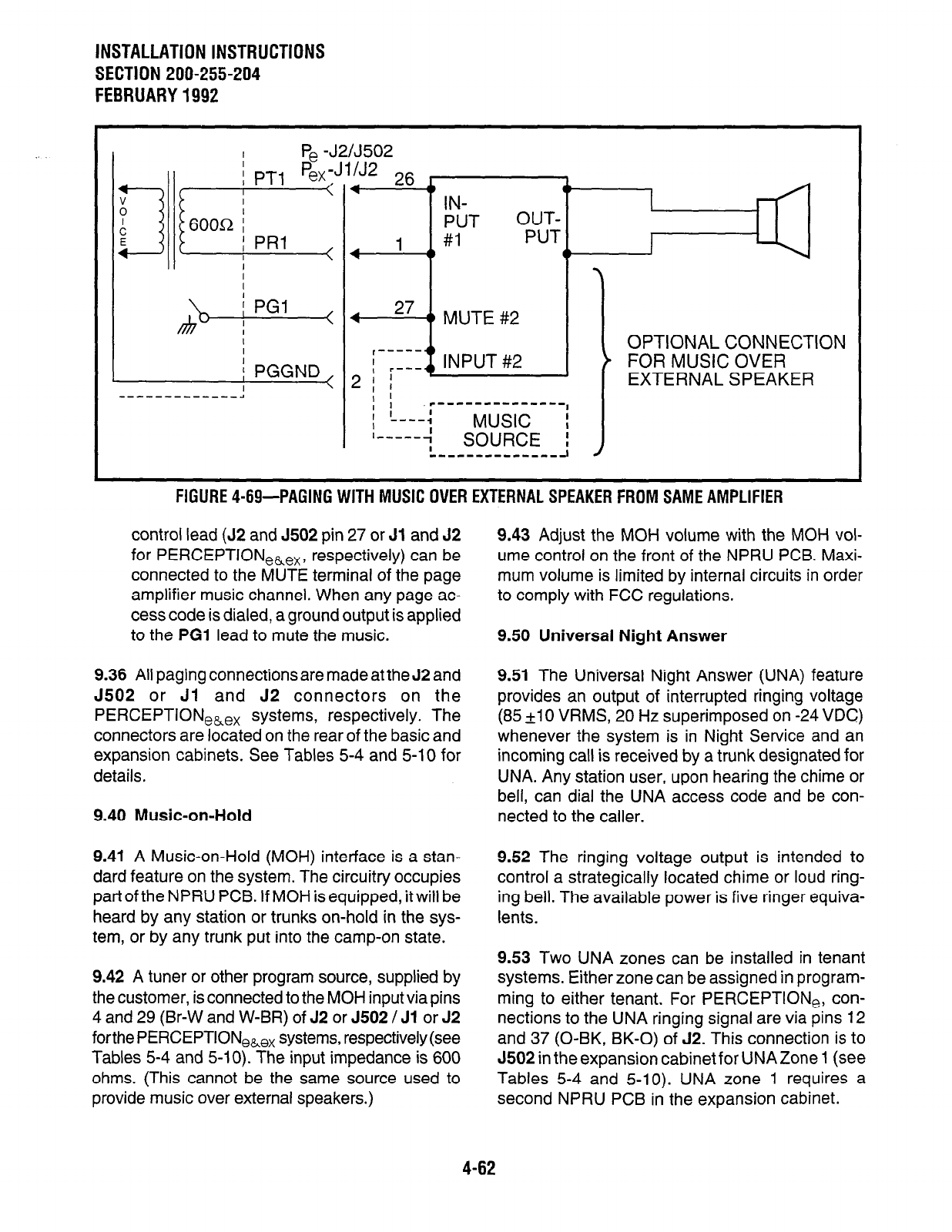
INSTALLATION INSTRUCTIONS
SECTION 200-255-204
FEBRUARY 1992
I
Pe -J2/J502
jl,, -..
x-1 %x-J1/J2 3c: L
I
<
I I-
IN-
; PRl
1 #I
I
I
I
I
I
\ I IThA ---t e-
I I
I -mm-,
I
MUSIC i
1-e-m-q
I SOURCE :
,,,,-,,-,,,,,,J I
FIGURE 4-69-PAGINGWlTHMUSlCOVEREXTERNALSPEAKERFROMSAMEAMPLlFlER
control lead (52 and J502 pin 27 or Jl and 52
for PERCEPTION,&,, , respectively) can be
connected to the MUTE terminal of the page
amplifier music channel. When any page ac-
cess code is dialed, a ground output is applied
to the PGl lead to mute the music.
9.36 All paging connections are made at the J2 and
J502 or Jl and 52 connectors on the
PERCEPTION,&,, systems, respectively. The
connectors are located on the rear of the basic and
expansion cabinets. See Tables 5-4 and 5-10 for
details,
9.40 Music-on-Hold
9.41 A Music-on-Hold (MOH) interface is a stan-
dard feature on the system. The circuitry occupies
part of the NPRU PCB. If MOH is equipped, it will be
heard by any station or trunks on-hold in the sys-
tem, or by any trunk put into the camp-on state.
9.42 A tuner or other program source, supplied by
the customer, is connected to the MOH input via pins
4 and 29 (Br-W and W-BR) of J2 or J502 / Jl or J2
forthe PERCEPTION
e&ex systems, respectively (see
Tables 5-4 and 5-10). The input impedance is 600
ohms. (This cannot be the same source used to
provide music over external speakers.)
9.43 Adjust the MOH volume with the MOH vol-
ume control on the front of the NPRU PCB. Maxi-
mum volume is limited by internal circuits in order
to comply with FCC regulations.
9.50 Universal Night Answer
9.51 The Universal Night Answer (UNA) feature
provides an output of interrupted ringing voltage
(85 +10 VRMS, 20 Hz superimposed on -24 VDC)
whenever the system is in Night Service and an
incoming call is received by a trunk designated for
UNA. Any station user, upon hearing the chime or
bell, can dial the UNA access code and be con-
nected to the caller.
9.52 The ringing voltage output is intended to
control a strategically located chime or loud ring-
ing bell. The available power is five ringer equiva-
lents.
9.53 Two UNA zones can be installed in tenant
systems. Either zone can be assigned in program-
ming to either tenant. For PERCEPTION,, con-
nections to the UNA ringing signal are via pins 12
and 37 (0-BK, BK-0) of J2. This connection is to
J502 in the expansion cabinet for UNAZone 1 (see
Tables 5-4 and 5-10). UNA zone 1 requires a
second NPRU PCB in the expansion cabinet.
4-62
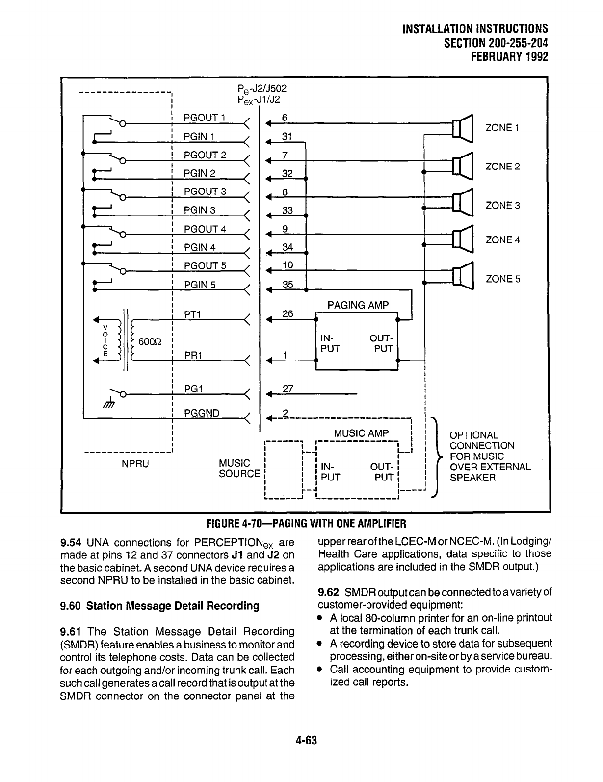
INSTALLATION INSTRUCTIONS
SECTION 200-255-204
FEBRUARY1992
P,-J2lJ502
P,, -J 1 lJ2
ZONE 1
ZONE 2
ZONE 3
ZONE 4
ZONE 5
I I
hi-
I PGl
I < 4 27 !
I i
, PGGND
I < +-z-- ‘-““--“-“--“-, i
I
I MUSIC AMP I 1 OPTIONAL
r-----1 I ,““““““”
r-4 I I
,,,-,,---,----,I I I
L-1
I I CONNECTION
NPRU MUSIC : FOR MUSIC
SOURCE ; I i IN-
; i PUT OUT- I i
PUT: ! OVER EXTERNAL
i
SPEAKER
1-j I----!
L------l ,,,,,,-,,,,,,,I
FlGURE4-70-PAGING WITH ONE AMPLIFIER
9.54 UNA connections for
PERCEPTION,,
are
made at pins 12 and 37 connectors Jl and 52 on
the basic cabinet. A second UNA device requires a
second NPRU to be installed in the basic cabinet.
9.60 Station Message Detail Recording
9.61 The Station Message Detail Recording
(SMDR) feature enables a business to monitor and
control its telephone costs. Data can be collected
for each outgoing and/or incoming trunk call. Each
such call generates a call record that is output at the
SMDR connector on the connector panel at the
upper rear of the LCEC-M or NCEC-M. (In Lodging/
Health Care applications, data specific to those
applications are included in the SMDR output.)
9.62 SMDR output can be connected to a variety of
customer-provided equipment:
l
A local 80-column printer for an on-line printout
at the termination of each trunk call.
l
A recording device to store data for subsequent
processing, either on-site or by a service bureau.
0 Call accounting equipment to provide custom-
ized call reports.
4-63
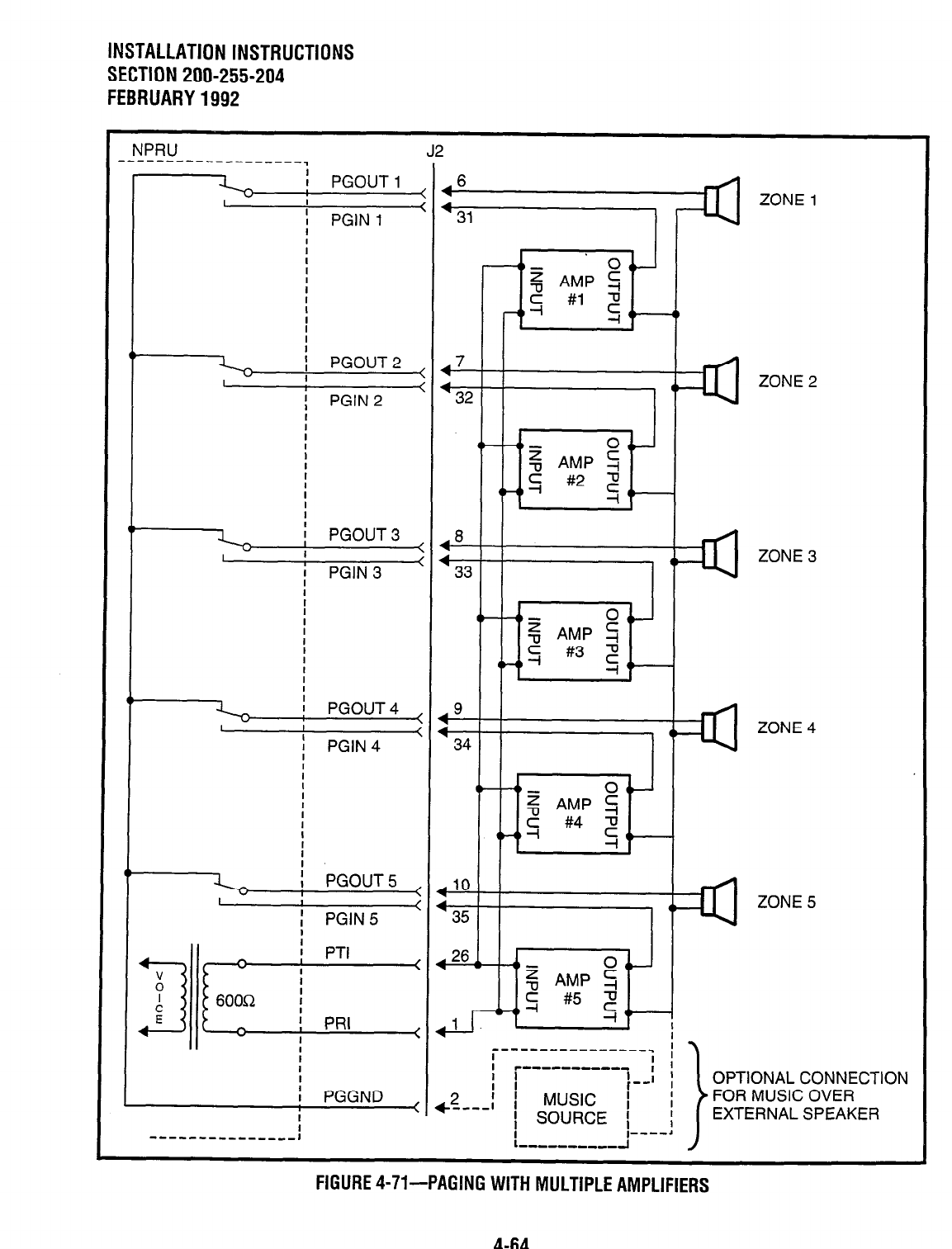
INSTALLATION INSTRUCTIONS
SECTION 200-255-204
FEBRUARY 1992
NPRU
-------------------. J2
I
I
i PGGND
i
-----------,-,-I
ZONE 2
ZONE 3
ZONE 4
OPTIONAL CONNECTION
FIGURE 4-71-PAGING WITH MULTIPLE AMPLIFIERS
4-64
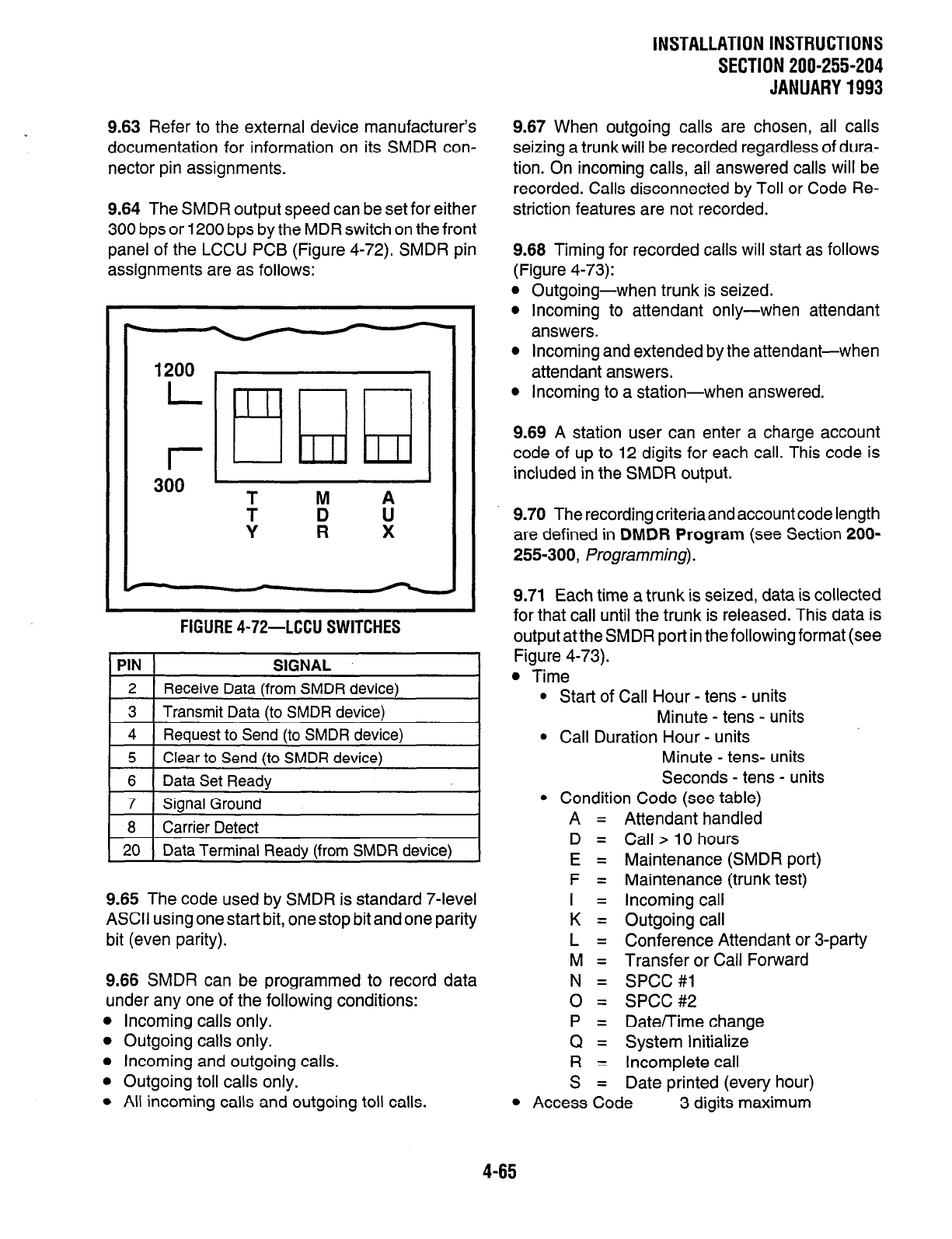
9.63 Refer to the external device manufacturer’s
documentation for information on its SMDR con-
nector pin assignments.
9.64 The SMDR output speed can be set for either
300 bps or 1200 bps by the MDR switch on the front
panel of the LCCU PCB (Figure 4-72). SMDR pin
assignments are as follows:
FIGURE
4-72-LCCU
SWITCHES
9.70 The recording criteriaand account code length
are defined in DMDR Program (see Section 200-
255-300, Programming).
1 5 1 Clear to Send (to SMDR device) I
6 Data Set Ready
7
Sianal Ground
1 8
I
Carrier Detect
I 20 I Data Terminal Readv (from SMDR device)
I
4-65
9.65 The code used by SMDR is standard 7-level
ASCII using one start bit, one stop bit and one parity
bit (even parity).
9.66 SMDR can be programmed to record data
under any one of the following conditions:
0 Incoming calls only.
l
Outgoing calls only.
l
Incoming and outgoing calls.
l
Outgoing toll calls only.
l
All incoming calls and outgoing toll calls.
9.71 Each time a trunk is seized, data is collected
for that call until the trunk is released. This data is
output at the SMDR port in thefollowingformat (see
Figure 4-73).
l
Time
l
Start of Call Hour - tens - units
Minute - tens - units
l
Call Duration Hour - units
Minute - tens- units
Seconds - tens - units
l
Condition Code (see table)
A = Attendant handled
D = Call > 10 hours
E = Maintenance (SMDR port)
F = Maintenance (trunk test)
I = Incoming call
K = Outgoing call
L = Conference Attendant or 3-party
M = Transfer or Call Forward
N = SPCC #l
0 = SPCC #2
P = Date/Time change
Q = System Initialize
R = Incomplete call
S = Date printed (every hour)
l
Access Code 3 digits maximum
INSTALLATION INSTRUCTIONS
SECTION 200-255-204
JANUARY 1993
9.67 When outgoing calls are chosen, all calls
seizing a trunk will be recorded regardless of dura-
tion. On incoming calls, all answered calls will be
recorded. Calls disconnected by Toll or Code Re-
striction features are not recorded.
9.68 Timing for recorded calls will start as follows
(Figure 4-73):
l
Outgoing-when trunk is seized.
l
Incoming to attendant only-when attendant
answers.
l
Incoming and extended by the attendant-when
attendant answers.
l
Incoming to a station-when answered.
9.69 A station user can enter a charge account
code of up to 12 digits for each call. This code is
included in the SMDR output.
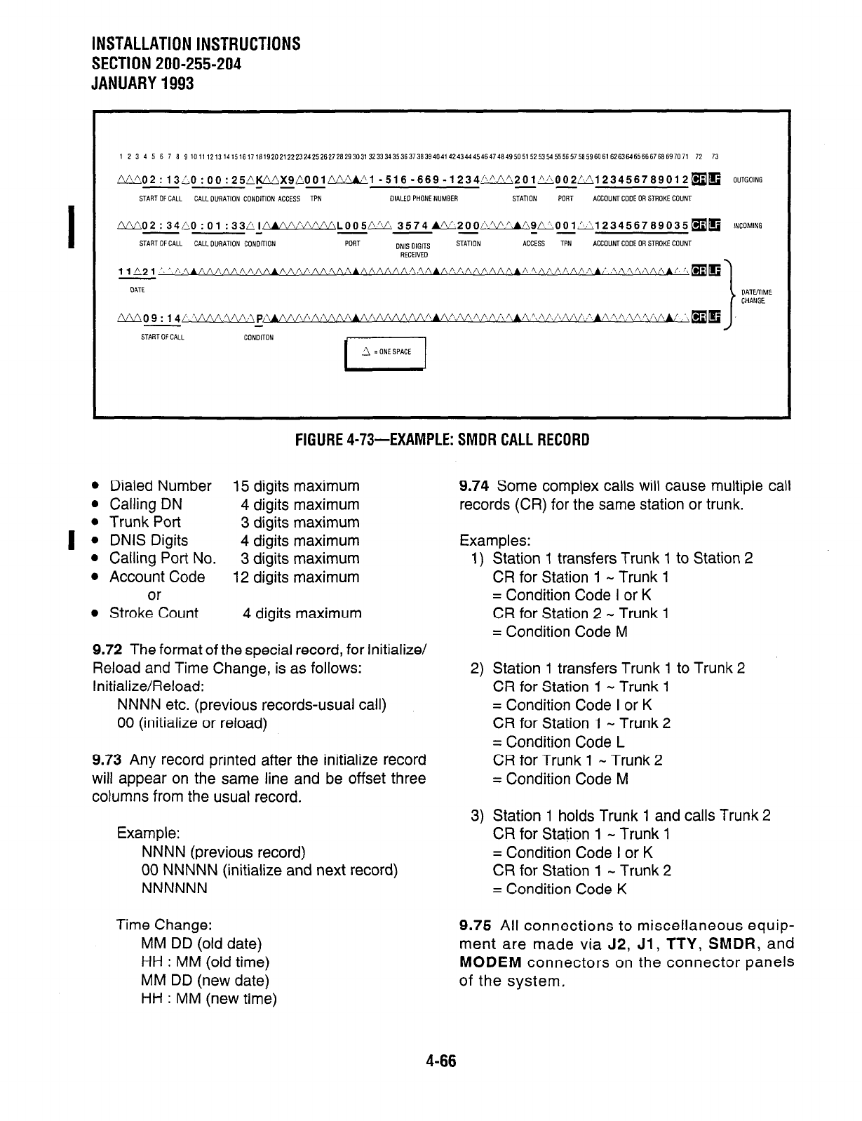
INSTALLATION INSTRUCTIONS
SECTION 200-255-204
JANUARY1993
I
1 2 3 4 5 6 7 6 9 101112131415161716192021222324252627282930313233343536373639404i424344454647484950515253545556575859606162636165666768697071 72 73
/?/202:13310:00:25A~X9C001~1-516-669-1234/:201I'ii002~123456789012~~
OUTGOING
- -- --
START
OF CALL
CALLWRATlON CONDlTlON ACCESS TPN DIALEDPHONENUMBER STATION PGRT ACCOUNTCODE OR STROKE COUNT
FIGURE 4-73-EXAMPLE: SMDR CALL RECORD
l
Dialed Number 15 digits maximum
l
Calling DN 4 digits maximum
l
Trunk Port 3 digits maximum
l
DNIS Digits 4 digits maximum
l
Calling Port No. 3 digits maximum
l
Account Code 12 digits maximum
or
l
Stroke Count 4 digits maximum
9.72 The format of the special record, for Initialize/
Reload and Time Change, is as follows:
Initialize/Reload:
NNNN etc. (previous records-usual call)
00 (initialize or reload)
9.73 Any record printed after the initialize record
will appear on the same line and be offset three
columns from the usual record.
Example:
NNNN (previous record)
00 NNNNN (initialize and next record)
NNNNNN
Time Change:
MM DD (old date)
HH : MM (old time)
MM DD (new date)
HH : MM (new time)
9.74 Some complex calls will cause multiple call
records (CR) for the same station or trunk.
Examples:
1) Station 1 transfers Trunk 1 to Station 2
CR for Station 1 - Trunk 1
= Condition Code I or K
CR for Station 2 - Trunk 1
= Condition Code M
2) Station 1 transfers Trunk 1 to Trunk 2
CR for Station 1 - Trunk 1
= Condition Code I or K
CR for Station 1 - Trunk 2
= Condition Code L
CR for Trunk 1 - Trunk 2
= Condition Code M
3) Station 1 holds Trunk 1 and calls Trunk 2
CR for Station 1 - Trunk 1
= Condition Code I or K
CR for Station 1 - Trunk 2
= Condition Code K
9.75 All connections to miscellaneous equip-
ment are made via J2,
Jl, TTY, SMDR,
and
MODEM
connectors on the connector panels
of the system.
4-66
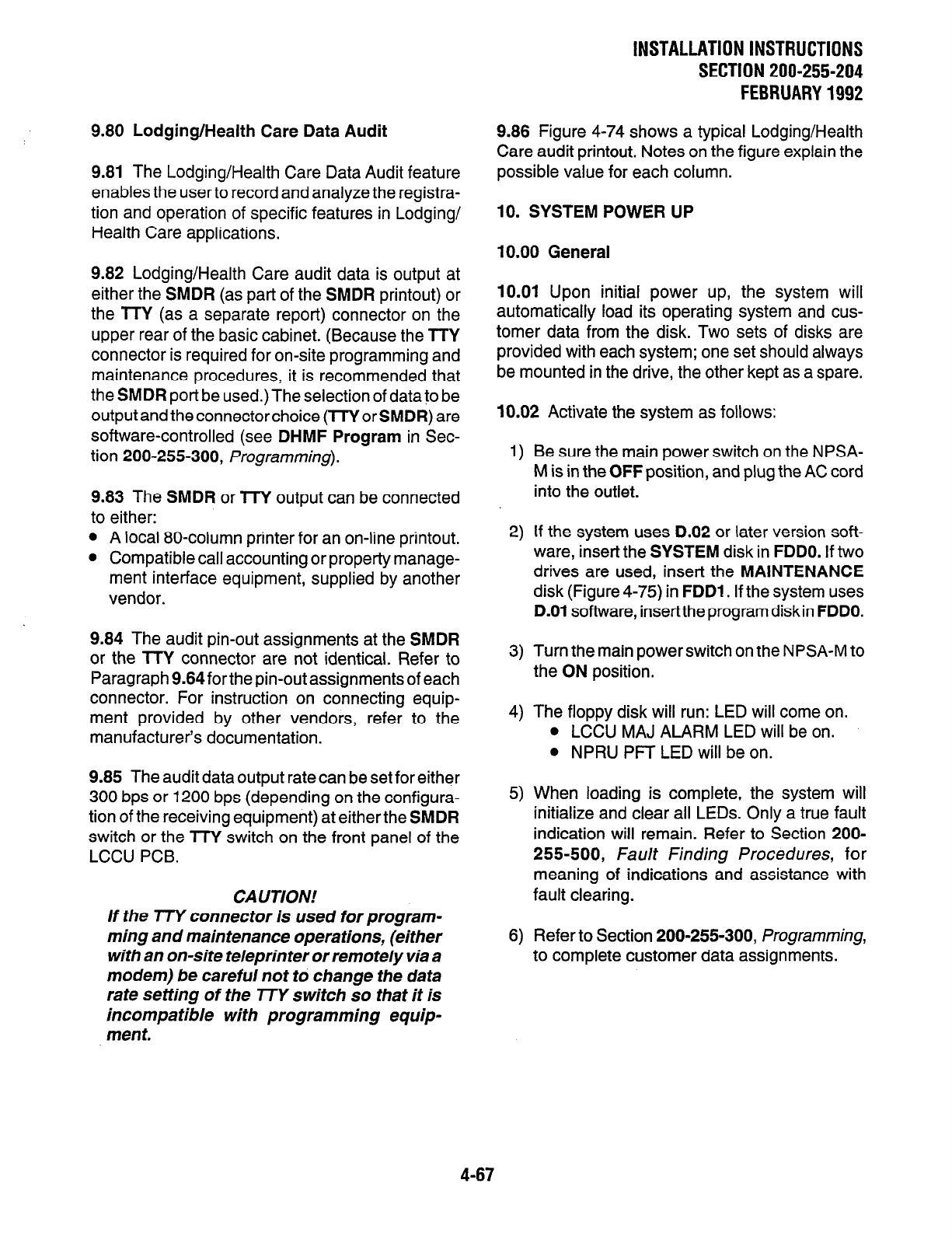
9.80 Lodging/Health Care Data Audit
9.81 The Lodging/Health Care Data Audit feature
enables the user to record and analyze the registra-
tion and operation of specific features in Lodging/
Health Care applications.
9.82 Lodging/Health Care audit data is output at
either the SMDR (as part of the SMDR printout) or
the TTY (as a separate report) connector on the
upper rear of the basic cabinet. (Because the TTY
connector is required for on-site programming and
maintenance procedures, it is recommended that
the SMDR port be used.) The selection of data to be
output and the connector choice (lTY or SMDR) are
software-controlled (see DHMF Program in Sec-
tion 200-255-300, Programming).
9.83 The SMDR or TTY output can be connected
to either:
l
A local 80-column printer for an on-line printout.
l
Compatible call accounting or property manage-
ment interface equipment, supplied by another
vendor.
9.84 The audit pin-out assignments at the SMDR
or the TTY connector are not identical. Refer to
Paragraph 9.64for the pin-out assignments of each
connector. For instruction on connecting equip-
ment provided by other vendors, refer to the
manufacturer’s documentation.
9.85 The audit data output rate can be set for either
300 bps or 1200 bps (depending on the configura-
tion of the receiving equipment) at either the SMDR
switch or the TTY switch on the front panel of the
LCCU PCB.
CAUTION!
If the TTY connector is used for program-
ming and maintenance operations, (either
with an on-site teleprinter or remotely via a
modem) be careful not to change
the data
rate setting of the 773’ switch so that it is
incompatible with programming equip-
men
t.
INSTALLATION INSTRUCTIONS
SECTIONZOO-255-204
FEBRUARY1992
9.86 Figure 4-74 shows a typical Lodging/Health
Care audit printout. Notes on the figure explain the
possible value for each column.
10. SYSTEM POWER UP
10.00 General
10.01 Upon initial power up, the system will
automatically load its operating system and cus-
tomer data from the disk. Two sets of disks are
provided with each system; one set should always
be mounted in the drive, the other kept as a spare.
10.02 Activate the system as follows:
1)
Be sure the main power switch on the NPSA-
M is in the OFF position, and plug the AC cord
into the outlet.
2)
If the system uses D.02 or later version soft-
ware, insert the SYSTEM disk in FDDO. If two
drives are used, insert the MAINTENANCE
disk (Figure 4-75) in FDDl . If the system uses
D.O1 software, insert the program disk in FDDO.
3) Turn the main power switch on the NPSA-M to
the ON position.
4) The floppy disk will run: LED will come on.
l
LCCU MAJ ALARM LED will be on.
l
NPRU PFT LED will be on.
5) When loading is complete, the system will
initialize and clear all LEDs. Only a true fault
indication will remain. Refer to Section 200-
255-500, Fault Finding Procedures, for
meaning of indications and assistance with
fault clearing.
6)
Refer to Section 200-255-300, Programming,
to complete customer data assignments.
4-67
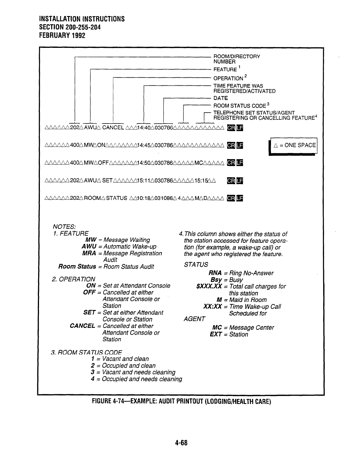
INSTALLATION INSTRUCTIONS
SECTION 200-255-204
FEBRUARY 1992
ROOM/DIRECTORY
NUMBER
FEATURE ’
OPERATION *
TIME FEATURE WAS
REGISTERED/ACTIVATED
ROOM STATUS CODE 3
TELEPHONE SET STATUS/AGENT
REGISTERING OR CANCELLING FEATURE4
NW AAzmma CANCEL
LYL!VVd202nAWU~SETAAAAAAl5:11~0307660~M~15:1~~
q
m
NOTES:
1. FEATURE MW = Message Waiting
A WU = Automatic Wake-up
MRA = Message Registration
Audit
Room Status = Room Status Audit
2. OPERATION
4. This column shows either the status of
the station accessed for feature opera-
tion (for example, a wake-up call) or
the agent who registered the feature.
STATUS
RNA = Ring No-Answer
ON = Set at Attendant Console
OFF = Cancelled at either
Bsy = Busy
$XxX.Xx = Total call charges for
this station
Attendant Console or
Station
SET = Set at either Attendant
Console or Station
CANCEL = Cancelled at either
Attendant Console or
Station
M = Maid in Room
XX:XX = Time Wake-up Call
Scheduled for
AGENT
MC = Message Center
EXT = Station
3. ROOM STATUS CODE
1 = Vacant and clean
2 = Occupied and clean
3 = Vacant and needs cleaning
4 = Occupied and needs cleaning
FIGURE 4-74-EXAMPLE: AUDIT PRINTOUT (LODGING/HEALTH CARE)
4-68
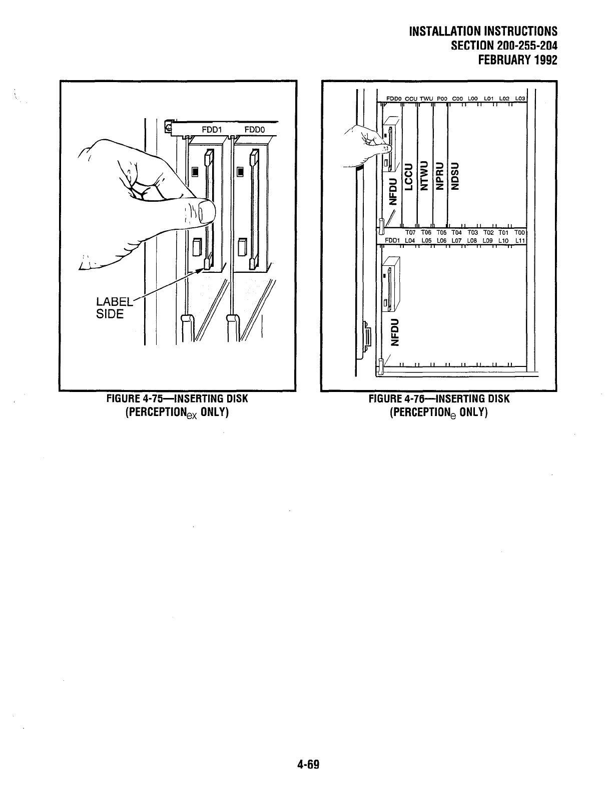
LABEL’
SIDE
FIGURE 4-75-INSERTING DISK FIGURE 4-76-INSERTING DISK
(PERCEPTION,, ONLY) (PERCEPTION, ONLY)
INSTALLATION INSTRUCTIONS
SECTION 200-255-204
FEBRUARY 1992
PO0 coo LOO LO1 LO2 LO:
l--
TO5 TO4 TO3 TO2 TO1 TOI
FDDl LO4 LO5 LO6 LO7 LOB LO9 LlO Ll
T ” ” ” ” ” ” ” ”
4-69
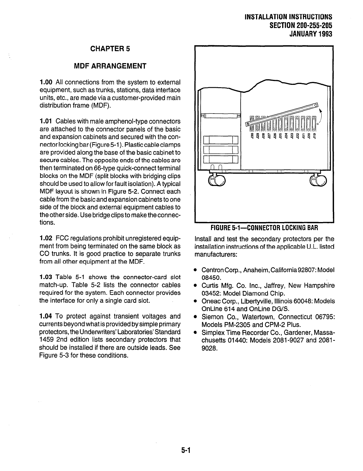
INSTALLATION INSTRUCTIONS
SECTION 200-255-205
JANUARY 1993
CHAPTER 5
MDF ARRANGEMENT
1.00 All connections from the system to external
equipment, such as trunks, stations, data interface
units, etc., are made via a customer-provided main
distribution frame (MDF).
1 .Ol Cables with male amphenol-type connectors
are attached to the connector panels of the basic
and expansion cabinets and secured with the con-
nectorlocking bar (Figure51). Plasticcableclamps
are provided along the base of the basic cabinet to
secure cables. The opposite ends of the cables are
then terminated on 66-type quick-connect terminal
blocks on the MDF (split blocks with bridging clips
should be used to allow for fault isolation). A typical
MDF layout is shown in Figure 5-2. Connect each
cable from the basic and expansion cabinets to one
side of the block and external equipment cables to
the other side. Use bridge clips to make the connec-
tions.
1.02 FCC regulations prohibit unregistered equip-
ment from being terminated on the same block as
CO trunks. It is good practice to separate trunks
from all other equipment at the MDF.
1.03 Table 5-I shows the connector-card slot
match-up. Table 5-2 lists the connector cables
required for the system. Each connector provides
the interface for only a single card slot.
1.04 To protect against transient voltages and
currents beyond what is provided by simple primary
protectors, the Underwriters’ Laboratories’ Standard
1459 2nd edition lists secondary protectors that
should be installed if there are outside leads. See
Figure 5-3 for these conditions.
FlGURE5-l-CONNECTORLOCKINGBAR
Install and test the secondary protectors per the
installation instructions of the applicable U.L. listed
manufacturers:
l
Centron Corp., Anaheim, California92807: Model
08450.
l
Curtis Mfg. Co. Inc., Jaffrey, New Hampshire
03452: Model Diamond Chip.
l
Oneac Corp., Libertyville, Illinois 60048: Models
OnLine 614 and OnLine DG/S.
l
Siemon Co., Watertown, Connecticut 06795:
Models PM-2305 and CPM-2 Plus.
l
Simplex Time Recorder Co., Gardener, Massa-
chusetts 01440: Models 2081-9027 and 2081-
9028.
5-1
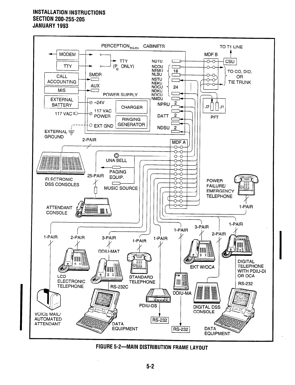
INSTALLATION INSTRUCTIONS
SECTION 200-255-205
JANUARY 1993
PERCEPTION,~,, CABINETS
- MODEM --
l-l-Y -- I-+ (P, ZLY)
NDTU
NCOU /-I
TO Tl LINE
MDF B t
CALL SMDR
ACCOUNTING -co
AUX
c TO CO, DID,
OR
TIE TRUNK
POWER SUPPLY
EXTERNAL ,NMDU ‘I
BATTERY -24V I. --
117VAC L_’
POWER r RINm
EXTERNAL+
,----j/o ExT GND 1 GENERATOR 1 1
GROUND e -AI-
NDSU 2
--4ll
0
03 J
“V
UNA BELL / T\n
V” ,
\
2dAIR
ELECTRONIC
DSS CONSOLES .- --. .--.
IUSIC; SOURCE
Al-rENDANT
CONSOLE II II
EMERGENCY
TELEPHONE
I-PAIR
l-PilR I
2-PAIR 3Pj9lR l-PAIR . . ,...,
II
JOICE MAIL/
4UTOMATED
4lTENDANT TA
UIPMENT
I’ --J
DDIU-MA
DIGITAL DSS
tUUIrMtl\ I J
FIGURE 5-2-MAIN DISTRIBUTION FRAME LAYOUT
5-2
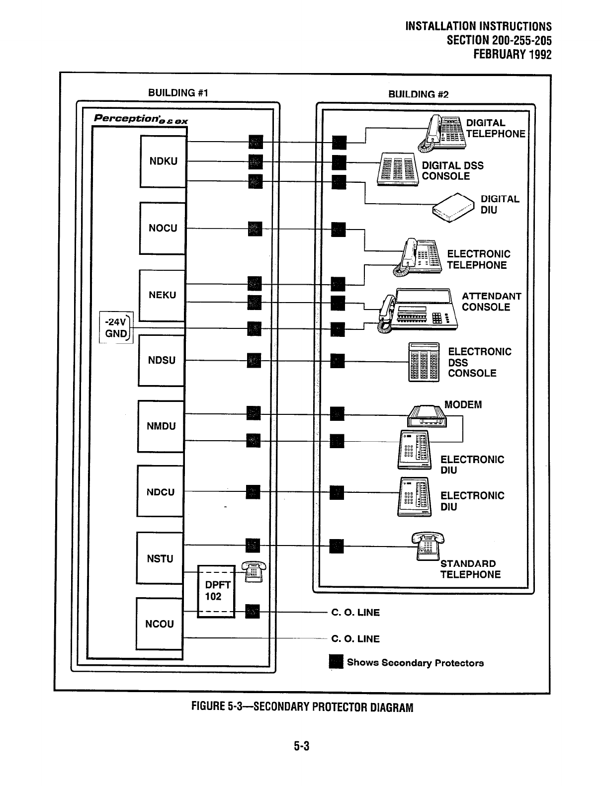
INSTALLATION INSTRUCTIONS
SECTION 200-255-205
FEBRUARY1992
BUILDING #l BUILDING #2
e \ /
Perception;, 6; ex
I I
I
DIGITAL DSS
NEKU
I
NDSU
I
NSTU
II II
n DIG11
DIU
curlTRONIC
Cl cm
DSS
CONSOLE
EM
ELECTRONIC
TAL
4NT
E
m 0. LINE
-0. LINE
1 Shows Secondary Protectors
FIGURE!+3-SECONDARYPROTECTORDIAGRAM
5-3
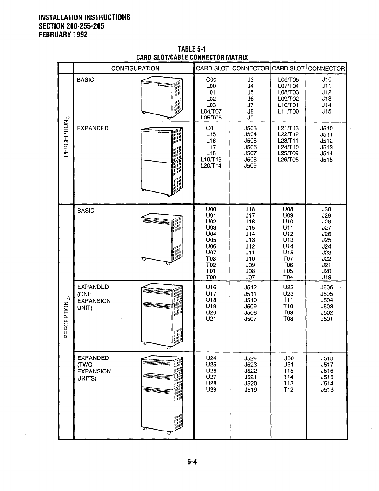
INSTALLATION INSTRUCTIONS
SECTION 200-255-205
FEBRUARY 1992
TABLE 5-1
PAQll
Cl
IlTIPAQl
E PflU)rlEPTflQ
MATQIY
CONFIGURATION CARD SLOT CONNECTOR CARD SLOT CONNECTOF
BASIC coo J3 LO6iTO5 JlO
LOO J4 LO7rrO4 Jll
LO1 J5 LO8iTO3 J12
LO2 J6 L09iT02 J13
LO3 Ll o/-r01 J1.4
LO4/TO7 Ll 1 /Too J15
L05/T06 J9
i= EXPANDED co1 J503 L21m3 J510
4 L15 J504 L22rr12 J511
E L16 J505 L23rrll J512
L17 J506 L24i-n 0 J513
nw L18 J507 L25rro9 J514
L19iT15 J508 L26rrO8 J515
L2orr14 J509
BASIC
EXPANDED
E WE
EXPANSION
$ UNIT)
h
2
if
uoo J18 U08 J30
UOl J17 uo9 J29
uo2 J16 UlO J28
uo3 J15 Ull J27
uo4 J14 u12 J26
uo5 J13 u13 J25
U06 J12 u14 J24
uo7 Jll u15 J23
TO3 JlO TO7 J22
TO2 JO9 TO6 J21
TO1 JO8 TO5 J20
TOO JO7 TO4 J19
J512 u22 J506
J511 U23 J505
J510 Tll J504
J509 TlO J503
J508 TO9 J502
J507 TO8 J501
EXPANDED
CrwO
EXPANSION
UNITS)
U24 J524 u30 J518
U25 J523 u31 J517
U26 J522 T15 J516
U27 J521 T14 J515
U28 J520 T13 J514
u29 J519 T12 J513
5-4
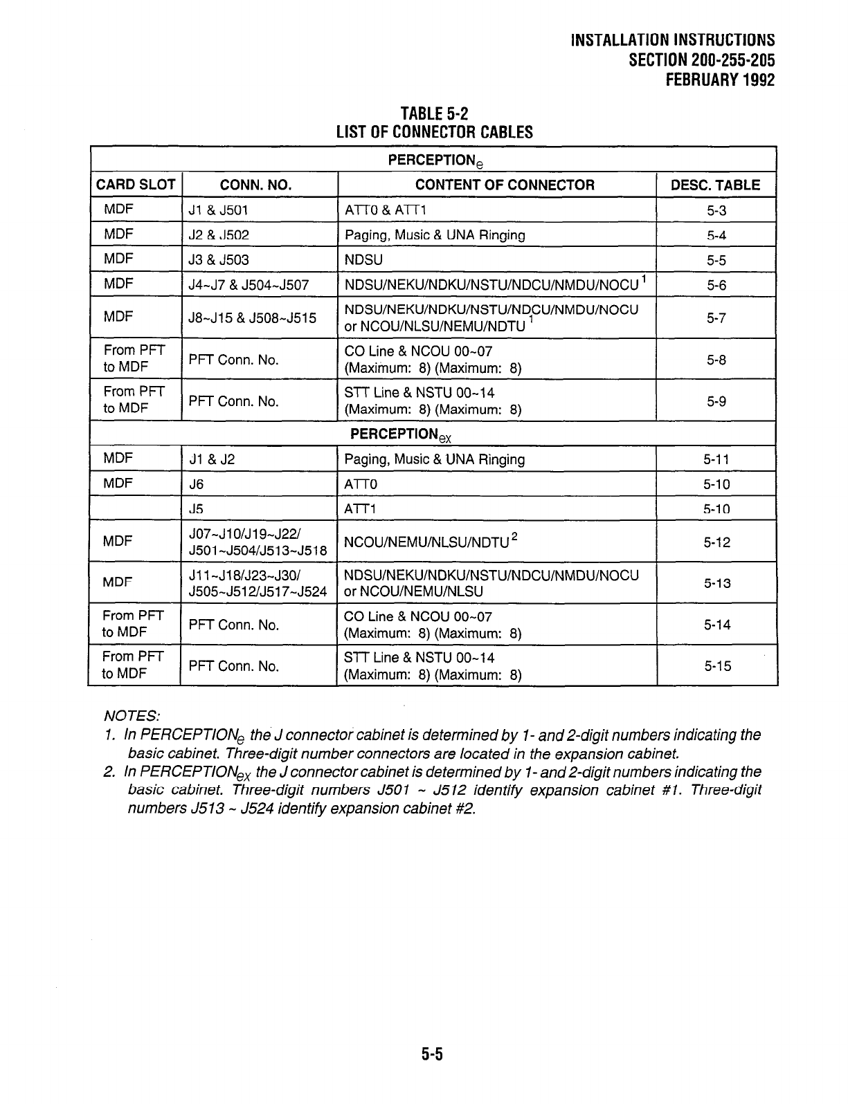
INSTALLATION INSTRUCTIONS
SECTION 200-255-205
FEBRUARY1992
TABLE5-2
LISTOFCONNECTORCABLES
CONN. NO.
Ji & J501
PERCEPTION,
CONTENT OF CONNECTOR
ATO & Al-r1
DESC. TABLE
5-3
CARD SLOT
MDF
MDF J2 & J502 Paging, Music & UNA Ringing 5-4
MDF J3 & J503 NDSU 5-5
J4-J7&J504-J507 NDSU/NEKU/NDKU/NSTU/NDCU/NMDU/NOCU ’ 5-6 MDF
MDF J8-J15 & J508-J515 NDSU/NEKU/NDKU/NSTU/NDCU/NMDU/NOCU
or NCOU/NLSU/NEMU/NDTU ’ 5-7
From PFT
to MDF PFT Conn. No. CO Line & NCOU 00-07
(Maximum: 8) (Maximum: 8)
I-
5-8
From PFT
to MDF PFT Conn. No. Sll Line & NSTU 00- 14
(Maximum: 8) (Maximum: 8) 5-9 I
PERCEPTION,,
/ Paging, Music & UNA Ringing 5-l 1 MDF 1 Jl & J2
MDF I J6 1 A-IT0 I 5-l 0 I
I
J5 AlTl
I
5-l 0
MDF JO7-JlO/J19-J22/
J501 -J504/J513-J518 NCOWNEMWNLSWNDTU *
NDSU/NEKU/NDKU/NSTU/NDCU/NMDU/NOCU
or NCOWNEMWNLSU
5-l 2
5-l 3
Jl 1 -J18/J23-J30/
J505-J512/J517-J524
From PFT
to MDF I PFT Conn. No. CO Line & NCOU 00-07
(Maximum: 8) (Maximum: 8) I 5-l 4 I
From PFT
to MDF PFT Conn. No. STT Line & NSTU 00-14
(Maximum: 81 (Maximum: 81 I 5-15 I
NOTES:
1. In PERCEPTION, the J connector cabinet is determined by I- and Z-digit numbers indicating the
basic cabinet. Three-digit number connectors are located in the expansion cabinet.
2. In PERCEPTION,, the J connector cabinet is determined by 1- and Z-digit numbers indicating the
basic cabinet. Three-digit numbers J50 1 - J512 identity expansion cabinet #l. Three-digit
numbers J513 - J524 identity expansion cabinet #2.
5-5
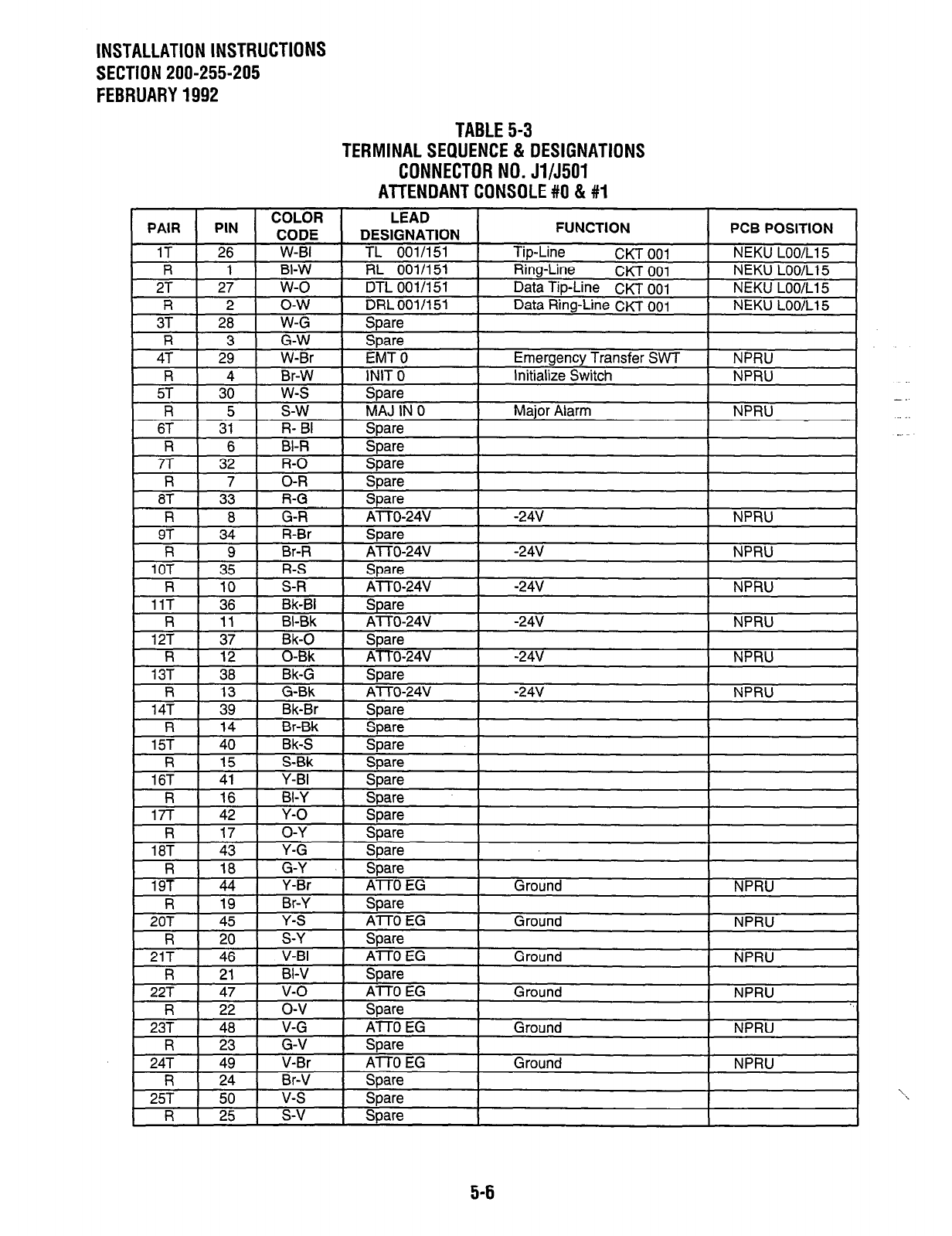
INSTALLATION INSTRUCTIONS
SECTION 200-255-205
FEBRUARY 1992
TABLE 5-3
TERMINAL SEQUENCE & DESIGNATIONS
CONNECTOR NO. Jl/J501
ATTENDANT CONSOLE #O & #I
OR
IE
LEAD
DESIGNATION
001/151
FUNCTION
Ticdine CKT on1
PCB POSITION
NEKU LOO/L1 5
PIN -coti
COL , -~-~
26 W-BI TL -... --.
1 BI-W RL 001/151 Ring-Line CKT 001 NEKU LOO/L1 5
27 w-o DTL 001/151 Data Tip-Line CKT 001 NEKU LOO/L1 5
2 o-w DRL 001/l 51 Data Ring-Line CKT 001 NEKU LOO/L1 5
28 W-G SDare
PAIR
1T
R
2T
R
3T
5-6
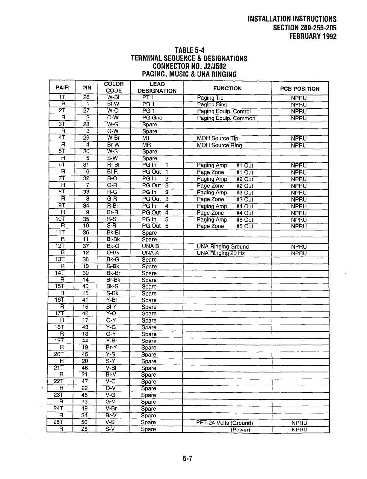
INSTALLATION INSTRUCTIONS
SECTION 200-255-205
FEBRUARY 1992
TABLE 5-4
TERMINAL SEQUENCE & DESIGNATIONS
CONNECTOR NO. J2/5502
PAGING, MUSIC & UNA RINGING
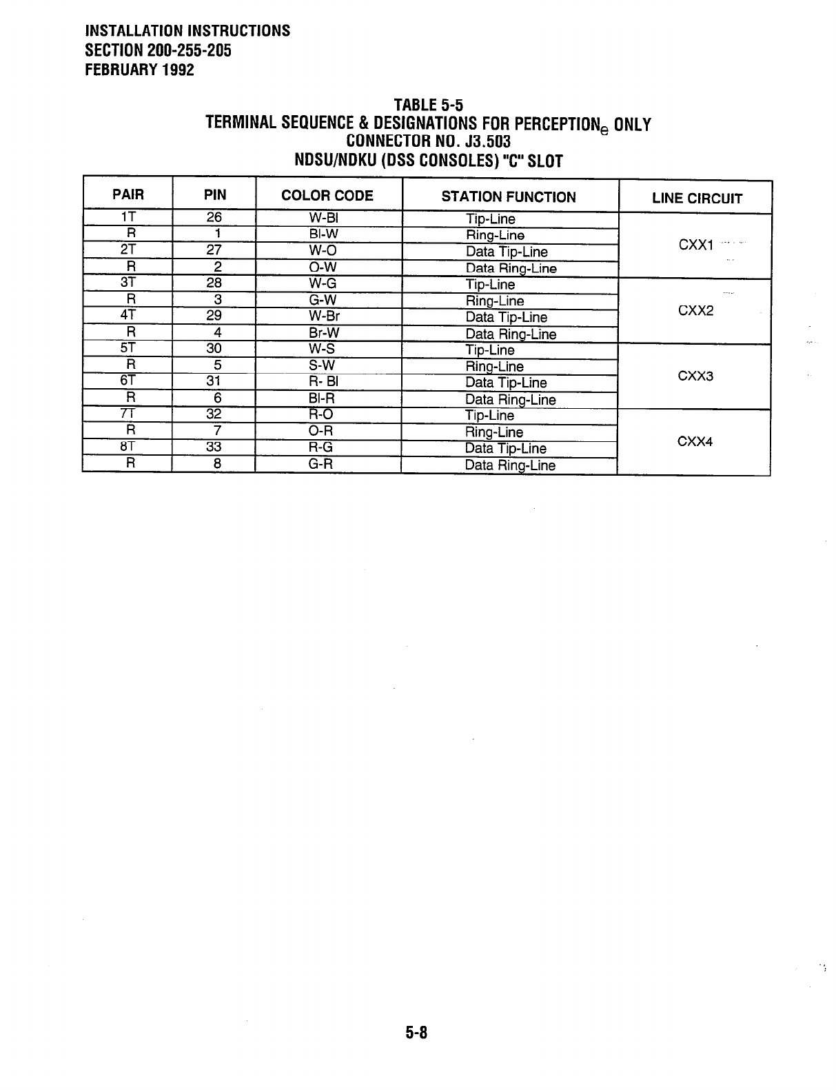
INSTALLATION INSTRUCTIONS
SECTION 200-255-205
FEBRUARY 1992
TABLE 5-5 TABLE 5-5
TERMINAL SEQUENCE & DESIGNATIONS FOR PERCEPTION, ONLY TERMINAL SEQUENCE & DESIGNATIONS FOR PERCEPTION, ONLY
CONNECTOR NO. 53.503 CONNECTOR NO. 53.503
“ne”“‘n”‘l (DSS CONSOLES) “c” SLOT NDSU/NDKU (DSS CONSOLES) “c” SLOT
5-B
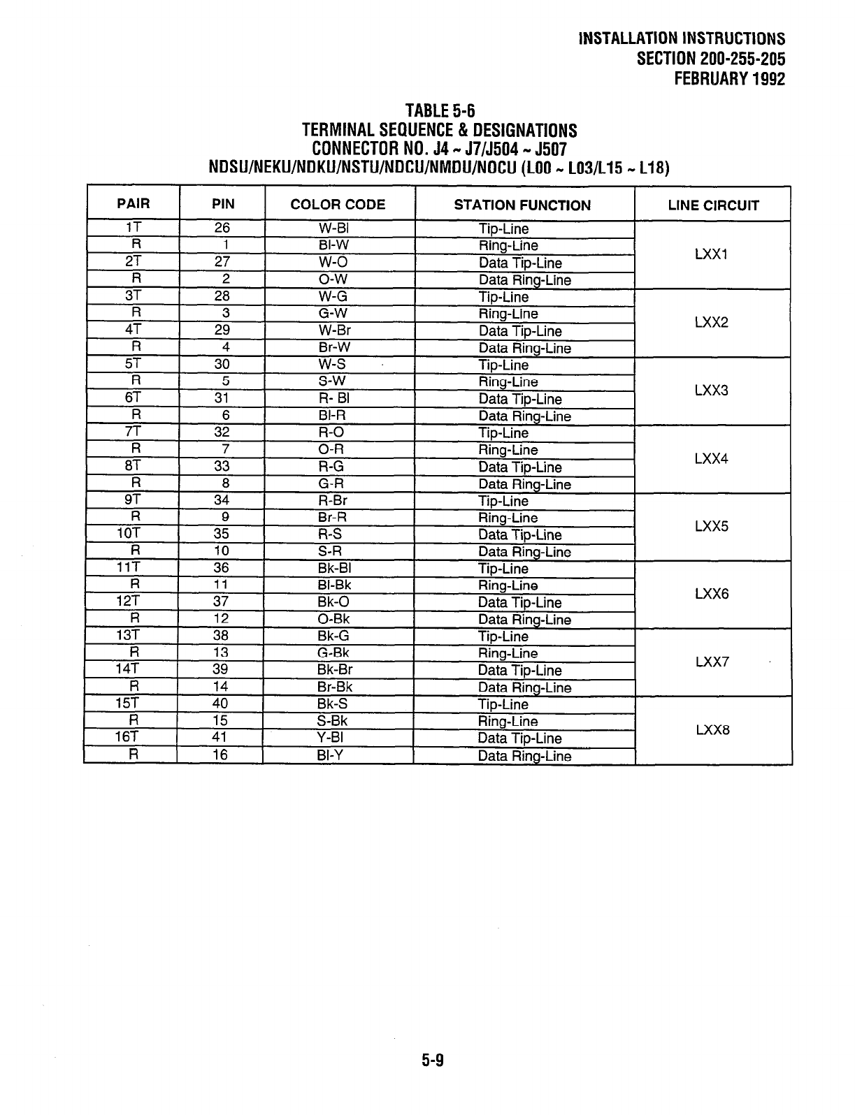
INSTALLATION INSTRUCTIONS
SECTION 200-255-205
FEBRUARY 1992
TABLE 5-6
TERMINAL SEQUENCE & DESIGNATIONS
CONNECTOR NO. 54 - J7/5504 - 5507
NDSU/NEKU/NDKU/NSTU/NDCU/NMDU/NOCU (LOO - LO3/L15 - L18)
PAIR
1T
R
2T
PIN
26
1
27
COLOR CODE
W-BI
BI-W
w-o
STATION FUNCTION I LINE CIRCUIT I
TiD-Line
Ring-Line
I I 1
g-w
Data Tip-Line LXX1
R I
2
Data Rinc
3T 28 - . . J-Line
W-G Tip-Line
R 3 G-W I Rim-Line
4T 29
W-Br
_. -.
fi
Data - rip-line
R
5T 3d -. . . I-Line
w-s
Data Ring
Tip-Line
R 5 s-w I Ring-Line
I 6T 31 -
-R I -. I FL RI . . -. I
I Da& rip-line
I fi I RI-R I Data Ring
LXX2
I
LXX3
rr
R
87
R
9T
R
10T
R
3;
7
33
8
34
G-0
O-R
R-G
G-R
R-Br
I-Line
Tip-Line
Rha-Line
TiD-Line LXX4
i&R
R-S
S-R
I
I Data J-Line Data Rinc_
Tip-Line
Ring-Line
Data Tip-Line
Data Ring-Line
Tip-Line
Ring-Line
Data Tip-Line
Data Riq J-Line
Tip-Line
LXX5
LXX6
I
Tip-Line
Data Ring-Line
Tip-Line
TiD-Line
5-9
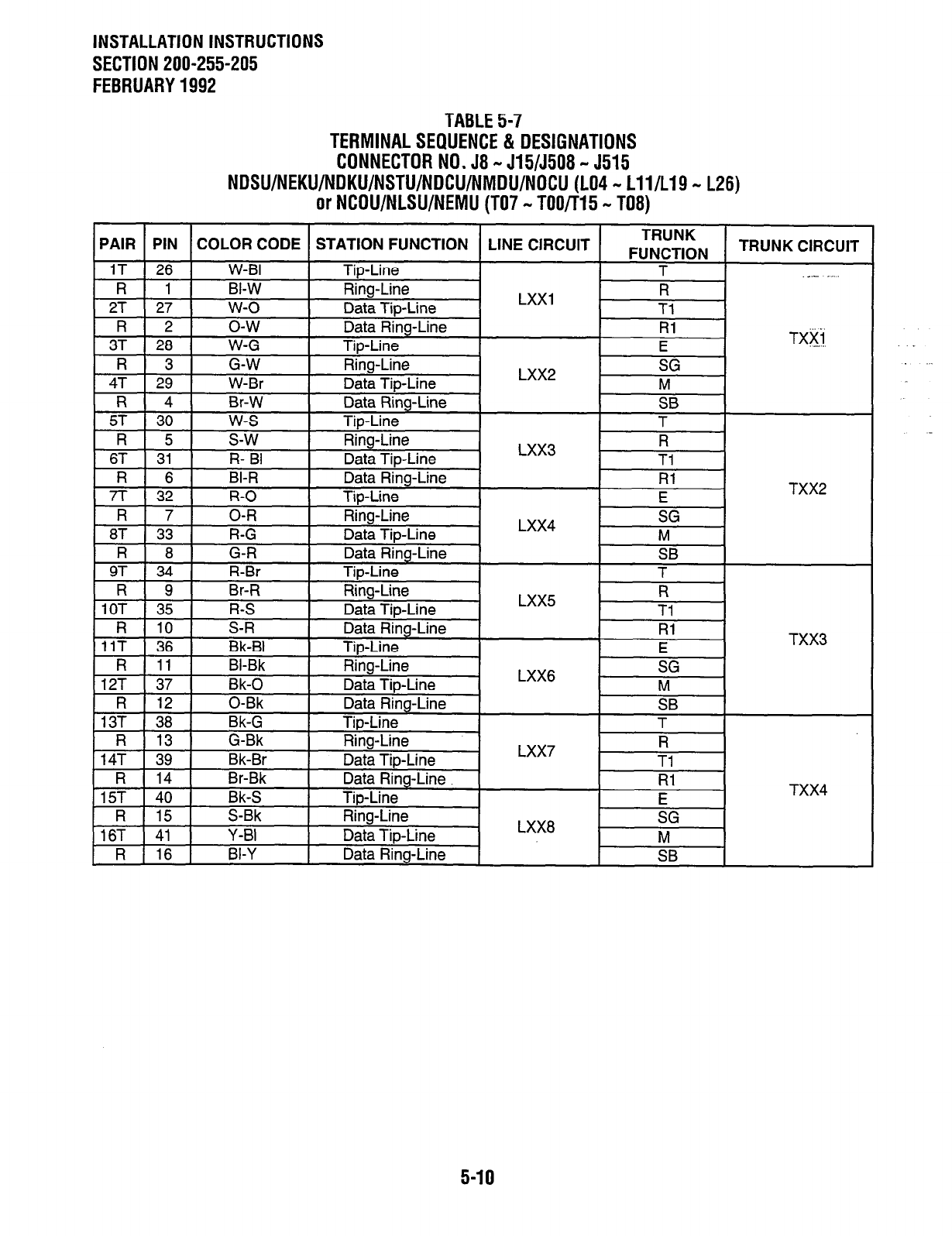
INSTALLATION INSTRUCTIONS
SECTION 200-255-205
FEBRUARY 1992
TABLE 5-7
TERMINAL SEQUENCE & DESIGNATIONS
CONNECTOR NO. 58 - J15/5508 - 5515
NDSU/NEKU/NDKU/NSTU/NDCU/NMDU/NOCU (LO4 - Lll/L19 - L26)
or NCOU/NLSU/NEMU (TO7 - TOO/T15 - T08)
5-10
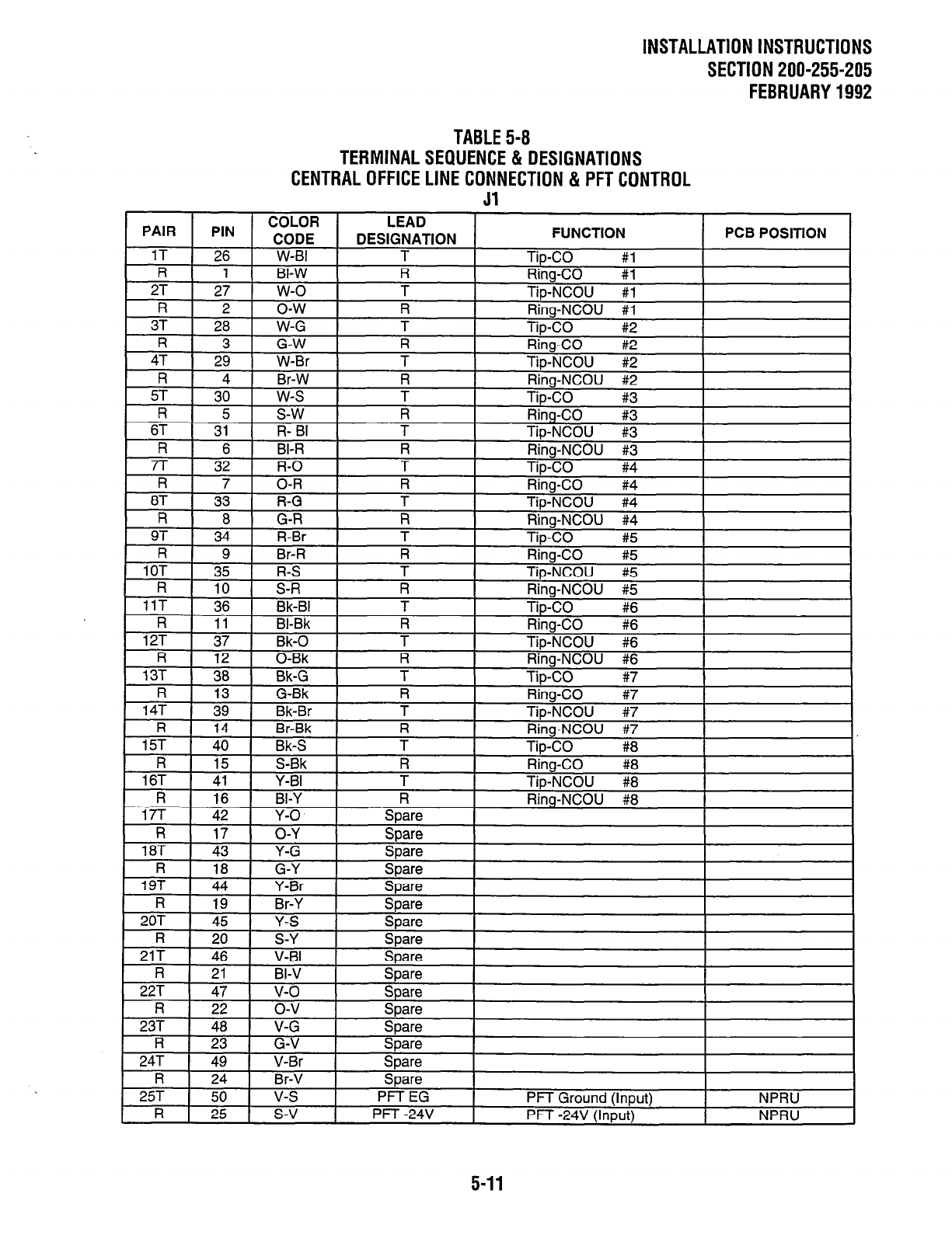
lNSTALLATlONlNSTRUCTlONS
SECTION 200-255-205
FEBRUARY1992
PAIR PIN COLOR LEAD
t 1 CnnF FUNCTION PCB POSITION
, w-w- , DESIGNATION
1T I 76 I W-RI I T Tip-CO #l
R Rinn-Cm #l
.‘r ._--- #l
R Ring-NCOU #l
T Tip-CO #2
R Ring-CO #2
T Tip-NCOU #2
R Rim-NCOI I #2
#3
R liikgzo #3
T Tip-NCOU #3
R Rinn-NC01 I #3
ft4
TABLE 5-B
TERMlNALSEQUENCE& DESIGNATIONS
CENTRALOFFlCELlNECONNECTlON&PFTCONTROL
Jl
I II I l/ I U-Y i mare I I I
18T 43 Y-G &are
R 18 G-Y Spare
19T 44 Y-Br Spare
R 19 Br-Y Spare
20T 45 Y-S Snare
I l-l
. .
I XI I
, b-
-S-Y spare
71T I 46 I v-
-. .- . BI Spare
R I 71 I RI-V Spare
StX3W
227
R
23T
47
22
48
r/L&
o-v
V-G
-I---- I
Spare I I
SDare I I
R 23 G-V
24T 49 V-Br
R 24 Br-V
25T 50 v-s
R 25 s-v
I
C..“Vr.
qJa1 e I
I I
I I
Spare I
Snare
-r-‘- I
PFT EG PFT Grm rnfi llnnl It\ NPRU
PFT -24V pFT -24v’iln;;;;j-., NPRl I
5-11
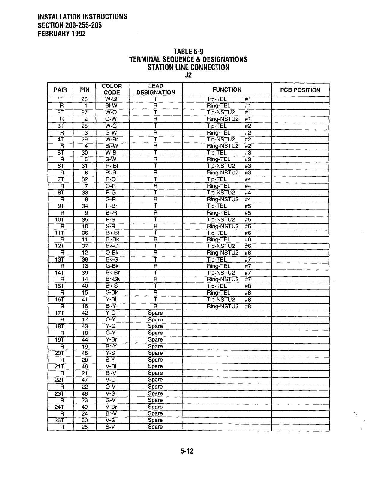
INSTALLATION INSTRUCTIONS
SECTION 200-255-205
FEBRUARY 1992
TABLE 5-9
TERMINAL SEQUENCE & DESIGNATIONS
STATION LINE CONNECTION
52
5-12
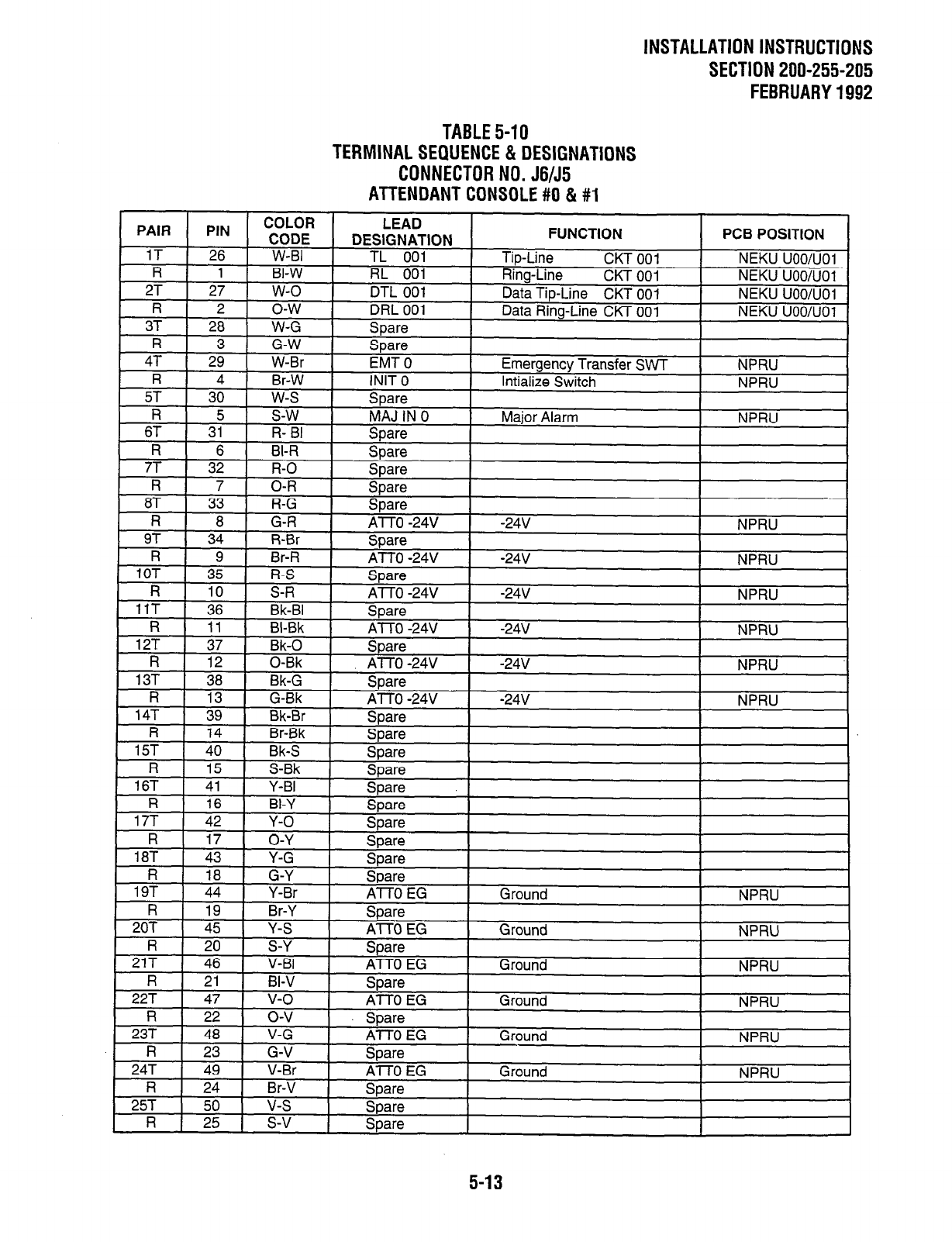
INSTALLATION INSTRUCTIONS
SECTlON200-255-205
FEBRUARY1992
TABLE5-10
TERMlNALSEQUENCE&DESlGNATlONS
CONNECTORNO.J6/J5
ATTENDANTCONSOLE#O&#l

INSTALLATION INSTRUCTIONS
SECTION 200-255-205
FEBRUARY 1992
TABLE 5-11
TERMINAL SEQUENCE & DESIGNATIONS
CONNECTOR NO. Jl 8152
PAGING, MUSIC & UNA RINGING
61 1 31 1 R- BI I PG In
1
I
I 1
Pnninn Amn it-i nllt
hlDDl I
R 6
7T 32
R 7
BI-R I PG Out i I Paging Zone
R-O PGIn 2
Paninn Amn
n-
8? I
1 33 I
1 i-G
I
PG In 3
R I 8 1 G-R
I
I 97 I I
34 I -..
I
R-Br
I
PG In 4
- -. - .
R 9 Br-R PG Out 4 Paging Zone
10T 35 R-S PG In 5 Paging Amp
R 10 S-R PG Out 5
Paninn 7nne
-BI 1 SDare
#4 out . .-
#5 out NPRU
- . . . --.,- #5 out NPRU
I
1 12T ,Bk 1 &are
t 37 I Bk-0 I UNA B UNA Ringing Ground NPRU
UNA Rinoino 20 Hz
NPRI I
V-V
R ;; o-v Spare
23T 48 V-G Spare
R 23 G-V
Spare
Snare
247
R
25T
R
49
24
50
25
V-l%
Br-V
v-s
s-v
-r-‘-
Spare
Spare
Share
I I
PFT-3d \/nltc ICjround)
I
NPRU
hlDDI I
5-14

INSTALLATION INSTRUCTIONS
SECTION 200-255-205
FEBRUARY1992
TABLE5-12
TERMlNALSEQUENCE&DESlGNATlONS
CONNECTOR NO.J07-JlO/J19-J22/5501 -5504/5513-5518
NCOU/NEMU/NLSU/NDTU (TOO-T15)
TXXl
TXX2
TXX4
NOTE:
The NDTU may be installed in TOO or TO8, connectors JO7 and J50 1 respectively. It may not be used
in universal slots.
5-15
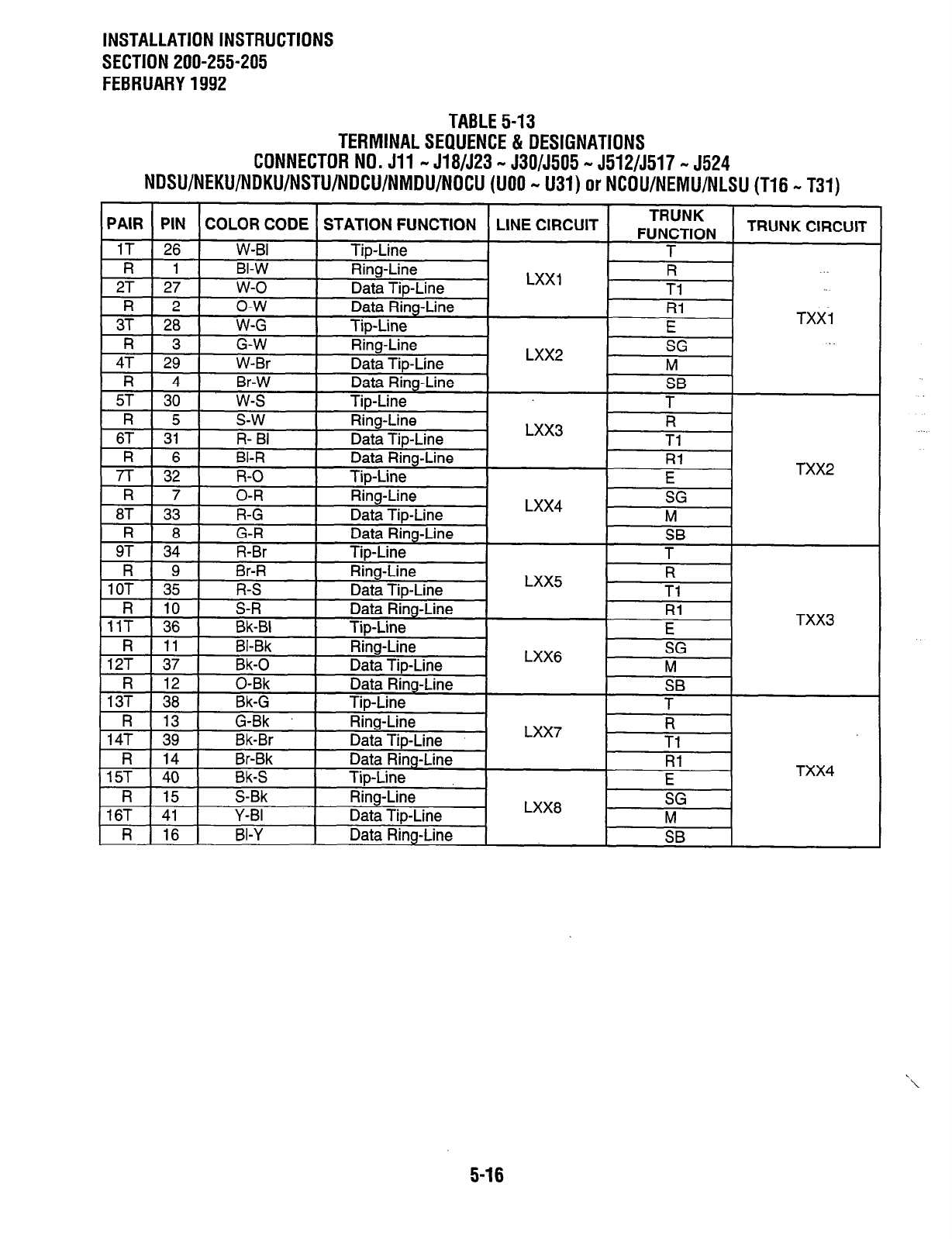
INSTALLATION INSTRUCTIONS
SECTION 200-255-205
FEBRUARY 1992
TABLE 5-13
TERMINAL SEQUENCE & DESIGNATIONS
CONNECTOR NO. Jll - J18/523 - J30/5505 - J512/5517 - 5524
NDSU/NEKU/NDKU/NSTU/DCU/NMDU/NOCU (UOO - U31) or NCOU/NEMU/NLSU (T16 - T31)
5-16
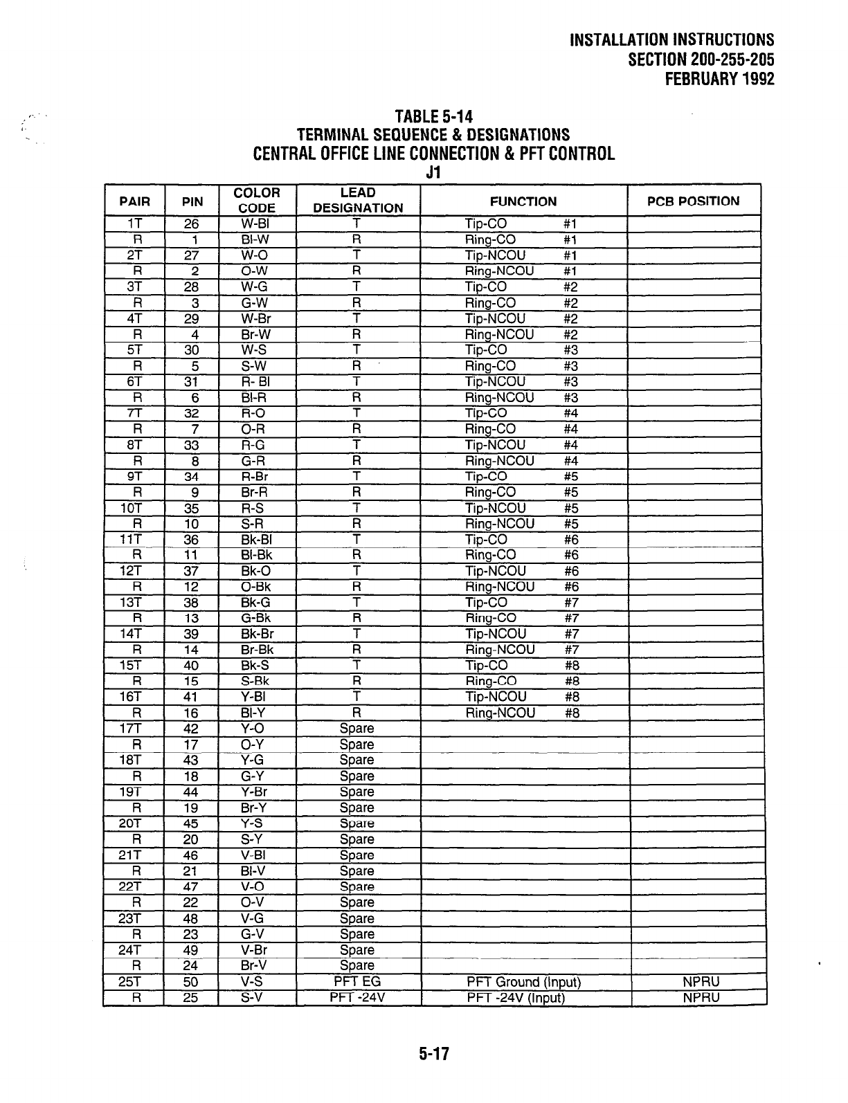
INSTALLATION INSTRUCTIONS
SECTlON200-255-205
FEBRUARY1992
TABLE5-14
TERMlNALSEQUENCE&DESlGNATlONS
CENTRALOFFlCELlNECONNECTlON&PFTCONTROL
Jl
1 PAIR 1 PIN LEAD
DESIGNATION FUNCTION PC6 POSITION
T TbCO #l

INSTALLATION
INSTRUCTIONS
SECTION 200-255-205
AUGUST 1991
TABLE 5-15
TERMINAL SEQUENCE & DESIGNATIONS
STATION LINE CONNECTION
52
5-18
PROGRAMMINGPROCEDURES
SECTlON200-255-300
FEBRUARY1992
Perceptionb 6$ ex
PROGRAMMING PROCEDURES
(D.05 SOFTWARE)
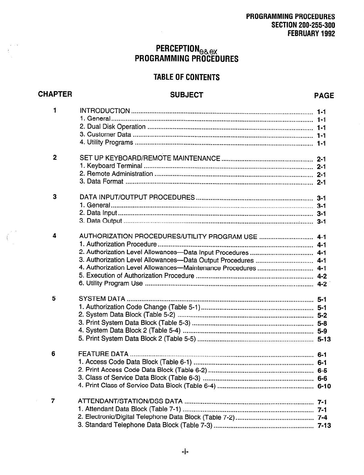
PROGRAMMINGPROCEDURES
SECTlON200-255-300
FEBRUARY1992
CHAPTER
I
2
3
4
5
6
7
PERCEPTIONeh,
PROGRAMMING PROCEDURES
TABLEOFCONTENTS
SUBJECT PAGE
INTRODUCTION ..................................................................................................... I-I
1. General ................................................................................................................ I-I
2. Dual Disk Operation ............................................................................................ I-I
3. Customer Data .................................................................................................... I-I
4. Utility Programs ................................................................................................... I-I
SET UP KEYBOARD/REMOTE MAINTENANCE ................................................... 2-I
1. Keyboard Terminal .............................................................................................. 2-I
2. Remote Administration ........................................................................................ 2-I
3. Data Format ........................................................................................................ 2-I
DATA INPUT/OUTPUT PROCEDURES.. ............................................................... 3-I
1. General.. .............................................................................................................. 3-I
2. Data Input.. .......................................................................................................... 3-I
3. Data Output ................................................................................................ .;. ...... 3-I
AUTHORIZATION PROCEDURES/UTILITY PROGRAM USE .............................. 4-I
I. Authorization Procedure.. .................................................................................... 4-I
2. Authorization Level Allowances-Data Input Procedures ................................... 4-I
3. Authorization Level Allowances-Data Output Procedures ................................ 4-I
4. Authorization Level Allowances-Maintenance Procedures ............................... 4-I
5. Execution of Authorization Procedure ................................................................. 4-2
6. Utility Program Use ............................................................................................. 4-2
SYSTEM DATA ........................................................................................................ 5-I
1. Authorization Code Change (Table 5-I). ............................................................. 5-I
2. System Data Block (Table 5-2) ........................................................................... 5-2
3. Print System Data Block (Table 5-3) ................................................................... 5-8
4. System Data Block 2 (Table 5-4) ........................................................................ 5-9
5. Print System Data Block 2 (Table 5-5) ................................................................ 5-13
FEATURE DATA ..................................................................................................... 6-I
1. Access Code Data Block (Table 6-l) .................................................................. 6-I
2. Print Access Code Data Block (Table 6-2) .......................................................... 6-5
3. Class of Service Data Block (Table 6-3) ............................................................. 6-6
4. Print Class of Service Data Block (Table 6-4) ..................................................... 6-10
Al-TENDANT/STATION/DSS DATA ....................................................................... 7-I
1. Attendant Data Block (Table 7-1) ........................................................................ 7-I
2. Electronic/Digital Telephone Data Block (Table 7-2). .......................................... 7-4
3. Standard Telephone Data Block (Table 7-3) ....................................................... 7-I 3
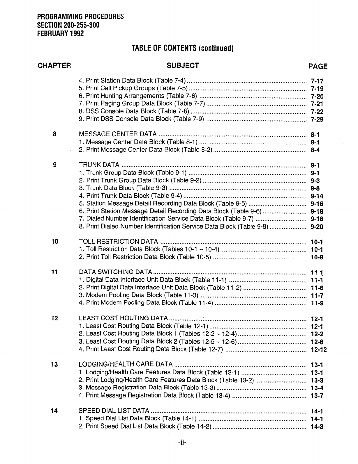
PROGRAMMING PROCEDURES
SECTION 200-255-300
FEBRUARY 1992
TABLE OF CONTENTS (continued)
CHAPTER SUBJECT PAGE
4. Print Station Data Block (Table 7-4) .................................................................... 7-17
5. Print Call Pickup Groups (Table 7-5) ................................................................... 7-19
6. Print Hunting Arrangements (Table 7-6) ............................................................. 7-20
7. Print Paging Group Data Block (Table 7-7) ......................................................... 7-21
8. DSS Console Data Block (Table 7-8) .................................................................. 7-22
9. Print DSS Console Data Block (Table 7-9) ........................................................ . 7-29
MESSAGE CENTER DATA .................................................................................... 8-1
1. Message Center Data Block (Table 8-l) ............................................................. 8-l
2. Print Message Center Data Block (Table 8-2). .................................................... 8-4
TRUNK DATA ......................................................................................................... 9-I
1. Trunk Group Data Block (Table 9-l) ................................................................... 9-1
2. Print Trunk Group Data Block (Table 9-2) ........................................................... 9-3
3. Trunk Data Block (Table 9-3) .............................................................................. 9-8
4. Print Trunk Data Block (Table 9-4) ...................................................................... 9-14
5. Station Message Detail Recording Data Block (Table 9-5) ................................. 9-16
6. Print Station Message Detail Recording Data Block (Table 9-6). ........................ 9-18
7. Dialed Number Identification Service Data Block (Table 9-7) ............................. 9-18
8. Print Dialed Number Identification Service Data Block (Table 9-8) ..................... 9-20
10
11
12
13
14
TOLL RESTRICTION DATA ................................................................................... 10-I
1. Toll Restriction Data Block (Tables IO-1 - 10-4). ................................................ IO-I
2. Print Toll Restriction Data Block (Table 1 O-5) ..................................................... 1 O-8
DATA SWITCHING DATA.. ..................................................................................... 11-I
1. Digital Data Interface Unit Data Block (Table 11-l) ............................................ 11-i
2. Print Digital Data Interface Unit Data Block (Table 1 l-2) .................................... 11-6
3. Modem Pooling Data Block (Table 1 l-3) ............................................................ 1 l-7
4. Print Modem Pooling Data Block (Table 1 l-4) .................................................... 11-9
LEAST COST ROUTING DATA .............................................................................. 12-I
1. Least Cost Routing Data Block (Table 12-1) ....................................................... 12-1
2. Least Cost Routing Data Block 1 (Tables 12-2 - 12-4) ....................................... 12-2
3. Least Cost Routing Data Block 2 (Tables 12-5 - 12-6) ....................................... 12-6
4. Print Least Cost Routing Data Block (Table 12-7) .............................................. 12-12
LODGING/HEALTH CARE DATA ........................................................................... 13-1
1. Lodging/Health Care Features Data Block (Table 13-I) ..................................... 13-I
2. Print Lodging/Health Care Features Data Block (Table 13-2) ............................. 13-3
3. Message Registration Data Block (Table 13-3) ................................................... 13-4
4. Print Message Registration Data Block (Table 13-4) .......................................... 13-7
SPEED DIAL LIST DATA ........................................................................................ 14-1
1. Speed Dial List Data Block (Table 14-I) ............................................................. 14-1
2. Print Speed Dial List Data Block (Table 14-2) ..................................................... 14-3
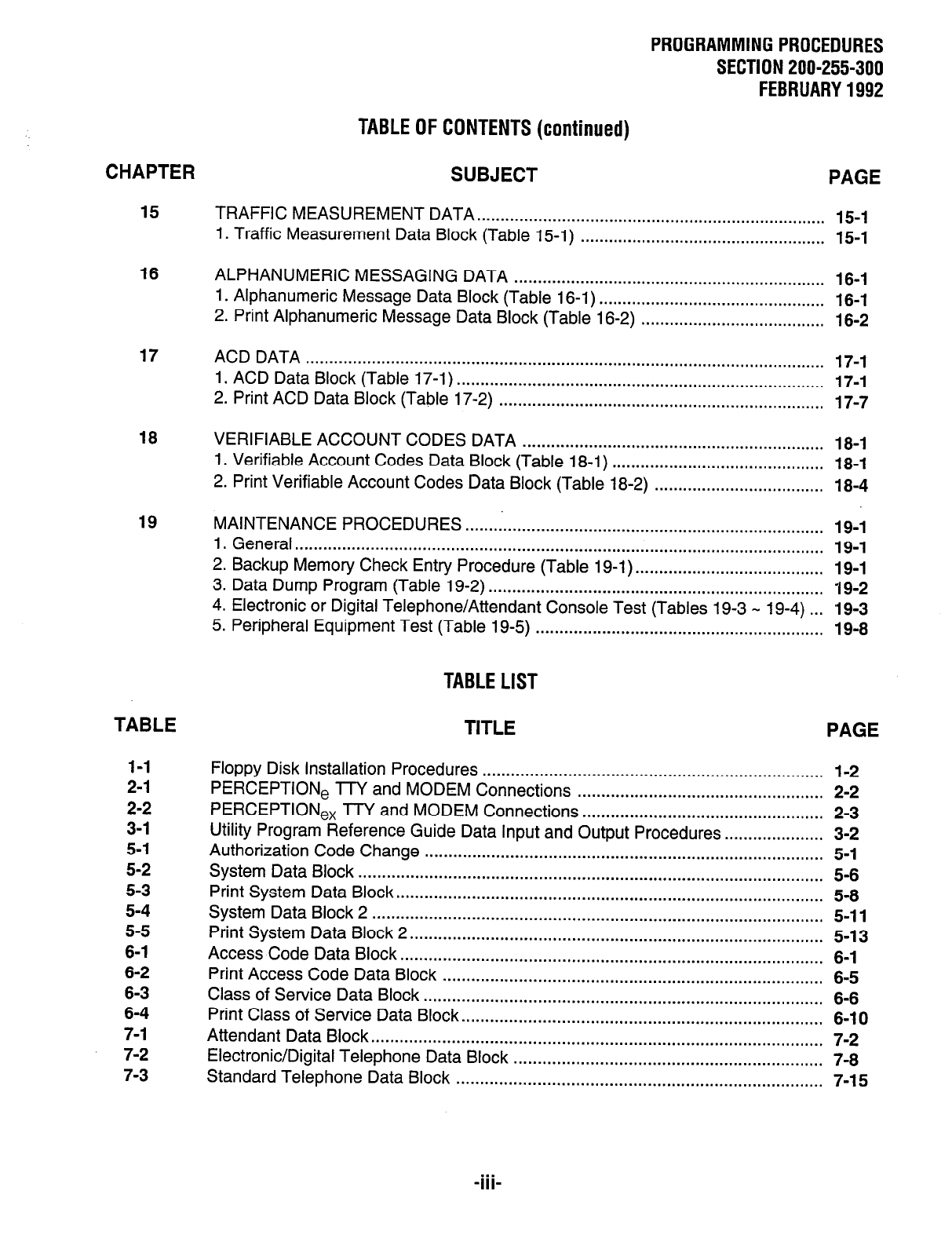
PROGRAMMING PROCEDURES
SECTION 200-255-300
FEBRUARY 1992
TABLE OF CONTENTS (continued)
CHAPTER SUBJECT PAGE
15 TRAFFIC MEASUREMENT DATA . . . . . . . . . . . . . . . . . . . . . . . . . . . . . . . . . . . . . . . . . . . . . . . . . . . . . . . . . . . . . . . . . . . . . . . . . . 15-1
1. Traffic Measurement Data Block (Table 15-1) . . . . . . . . . . . . . . . . . . . . . . . . . . . . . . . . . . . . . . . . . . . . . . . . . . . . 15-1
16 ALPHANUMERIC MESSAGING DATA .................................................................. 16-1
1. Alphanumeric Message Data Block (Table 16-l) ................................................ 16-1
2. Print Alphanumeric Message Data Block (Table 16-2) ....................................... 16-2
17 ACD DATA .............................................................................................................. 17-1
1. ACD Data Block (Table 17-l) .............................................................................. 17-I
2. Print ACD Data Block (Table 17-2) ..................................................................... 17-7
18 VERIFIABLE ACCOUNT CODES DATA ................................................................ 18-1
1. Verifiable Account Codes Data Block (Table 18-1) ............................................. 18-1
2. Print Verifiable Account Codes
Data
Block (Table 18-2) .................................... 18-4
19 MAINTENANCE PROCEDURES . . . . . . ..*..........................*........................................
1. General . . . . . . . . . . . . . . . . . . . . . . . . . . . . . . . . . . . . . . . . . . . . . . . . . . . . . . . . . . . . . . . . . . . . . . . . . . . . . . . . . . . . . . . . . . . . . . . . . . . . . . . . . . . . . . . .
2. Backup Memory Check Entry Procedure (Table 19-1) . . . . . . . . . . . . . . . . . . . . . . . . . . . . . . . . . . . . . . . .
3. Data Dump Program (Table 19-2) . . . . . . . . . . . . . . . . . . . . . . . . . . . . . . . . . . . . . . . . . . . . . . . . . . . . . . . . . . . . . . . . . . . . . . .
4. Electronic or Digital Telephone/Attendant Console Test (Tables 19-3 - 19-4) . . .
5. Peripheral Equipment Test (Table 19-S) . . . . . . . . . . . . . . . . . . . . . . . . . . . . . . . . . . . . . . . . . . . . . . . . . . . . . . . . . . . . .
9-1
9-1
9-1
9-2
9-3
9-8
TABLE LIST
TABLE TITLE PAGE
l-1
2-l
2-2
3-1
5-I
5-2
5-3
5-4
5-5
6-1
6-2
6-3
6-4
7-1
7-2
7-3
Floppy Disk installation Procedures ........................................................................ l-2
PERCEPTlONe TTY and MODEM Connections .................................................... 2-2
PERCEPTION,, TTY and MODEM Connections.. ................................................. 2-3
Utility Program Reference Guide Data Input and Output Procedures ..................... 3-2
Authorization Code Change .................................................................................... 5-1
System Data Block .................................................................................................. 5-6
Print System Data Block .......................................................................................... 5-8
System Data Block 2 ............................................................................................... 5-11
Print System Data Block 2 ....................................................................................... 5-13
Access Code Data Block ......................................................................................... 6-l
Print Access Code Data Block ................................................................................ 6-5
Class of Service Data Block .................................................................................... 6-6
Print Class of Service Data Block ............................................................................ 6-10
Attendant Data Block ............................................................................................... 7-2
Electronic/Digital Telephone Data Block ................................................................. 7-8
Standard Telephone Data Block ............................................................................. 7-15
. . .
-ill-
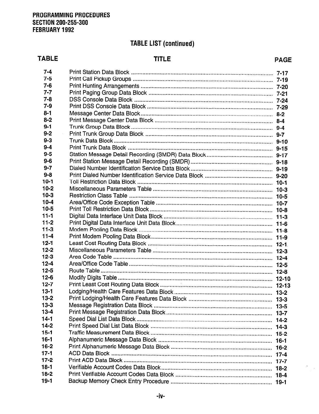
PROGRAMMING PROCEDURES
SECTION 200-255-300
FEBRUARY 1992
TABLE LIST (continued)
TABLE TITLE PAGE
7-4
7-5
7-6
7-7
7-8
7-9
8-I
8-2
9-1
9-2
9-3
9-4
9-5
9-6
9-7
9-8
10-l
IO-2
10-3
10-4
10-5
11-l
11-2
11-3
11-4
12-I
12-2
12-3
12-4
12-5
12-6
12-7
13-1
13-2
13-3
13-4
14-1
14-2
15-1
16-1
16-2
17-l
17-2
18-1
18-2
19-1
Print Station Data Block .......................................................................................... 7-17
Print Call Pickup Groups ......................................................................................... 7-19
Print Hunting Arrangements .................................................................................... 7-20
Print Paging Group Data Block ............................................................................... 7-21
DSS Console Data Block ........................................................................................ 7-24
Print DSS Console Data Block ................................................................................ 7-29
Message Center Data Block .................................................................................... 8-2
Print Message Center Data Block ........................................................................... 8-4
Trunk Group Data Block .......................................................................................... 9-4
Print Trunk Group Data Block ................................................................................. 9-7
Trunk Data Block ..................................................................................................... 9-l 0
Print Trunk Data Block ............................................................................................ 9-15
Station Message Detail Recording (SMDR) Data Block.. ........................................ 9-17
Print Station Message Detail Recording
(SMDR)
.................................................... 9-18
Dialed Number Identification Service Data Block.. .................................................. 9-19
Print Dialed Number Identification Service Data Block ........................................... 9-20
Toll Restriction Data Block ...................................................................................... 10-l
Miscellaneous Parameters Table ............................................................................ 1 O-3
Restriction Class Table ........................................................................................... IO-5
Area/Office Code Exception Table .......................................................................... 1 O-7
Print Toll Restriction Data Block .............................................................................. 10-8
Digital Data Interface Unit Data Block ..................................................................... 11-3
Print Digital Data Interface Unit Data Block.. ........................................................... 1 l-6
Modem Pooling Data Block ..................................................................................... 11-8
Print Modem Pooling Data Block ............................................................................. 11-9
Least Cost Routing Data Block ............................................................................... 12-1.
Miscellaneous Parameters Table ............................................................................ 12-3
Area Code Table ..................................................................................................... 12-4
Area/Off ice Code Table ........................................................................................... 12-5
Route Table ............................................................................................................. 12-8
Modify Digits Table .................................................................................................. 12-10
Print Least Cost Routing Data Block ....................................................................... 12-13
Lodging/Health Care Features Data Block.. ............................................................ 13-2
Print Lodging/Health Care Features Data Block ..................................................... 13-3
Message Registration Data Block ........................................................................... 13-5
Print Message Registration Data Block ................................................................... 13-7
Speed Dial List Data Block ...................................................................................... 14-2
Print Speed Dial List Data Block ............................................................................. 14-3
Traffic Measurement Data Block ............................................................................. 15-2
Alphanumeric Message Data Block ........................................................................ 16-1
Print Alphanumeric Message Data Block ................................................................ 16-2
ACD Data Block ...................................................................................................... 17-4
Print ACD Data Block .............................................................................................. 17-7
Verifiable Account Codes Data Block ...................................................................... 18-2
Print Verifiable Account Codes Data Block ............................................................. 18-4
Backup
Memory Check Entry
Procedure ................................................................ 19-I
-iv-
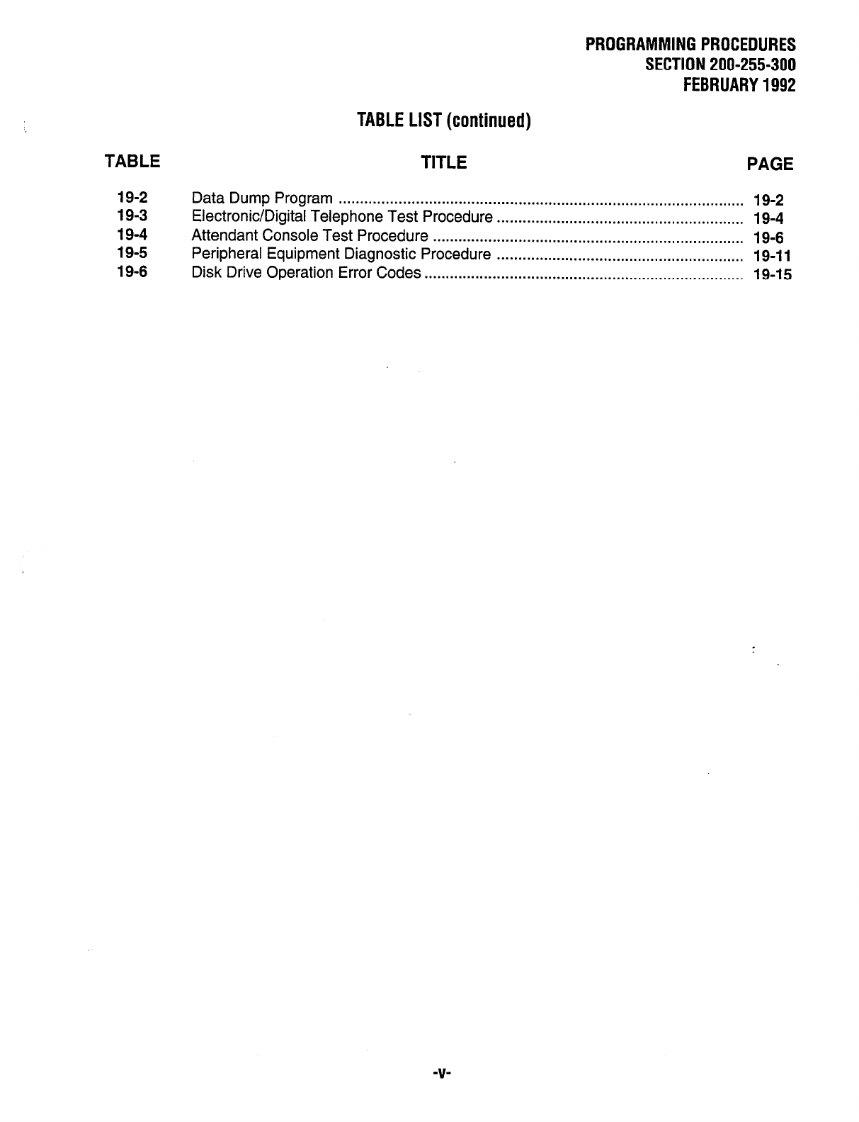
PROGRAMMING PROCEDURES
SECTION 200-255-300
FEBRUARY 1992
TABLE LIST (continued)
TABLE TITLE PAGE
19-2
19-3
19-4
19-5
19-6
Data Dump Program . . . . . . . . . . . . . . . . . . . . . . . . . . . . . . . . . . . . . . . . . . . . . . . . . . . . . . . . . . . . . . . . . . . . . . . . . . . . . . . . . . . . . . . . . . . . . . . 19-2
Electronic/Digital Telephone Test Procedure . . . . . . . . . . . . . . . . . . . . . . . . . . . . . . . . . . . . . . . . . . . . . . . . . . . . . . . . . . 19-4
Attendant Console Test Procedure . . . . . . . . . . . . . . . . . . . . . . . . . . . . . . . . . . . . . . . . . . . . . . . . . . . . . . . . . . . . . . . . . . . . . . . . . 19-6
Peripheral Equipment Diagnostic Procedure . . . . . . . . . . . . . . . . . . . . . . . . . . . . . . . . . . . . . . . . . . . . . . . . . . . . . . . . . . 19-l 1
Disk Drive Operation Error Codes . . . . . . . . . . . . . . . . . . . . . . . . . . . . . . . . . . . . . . . . . . . . . . . . . . . . . . . . . . . . . . . . . . . . . . . . . . . 19-15
-V-
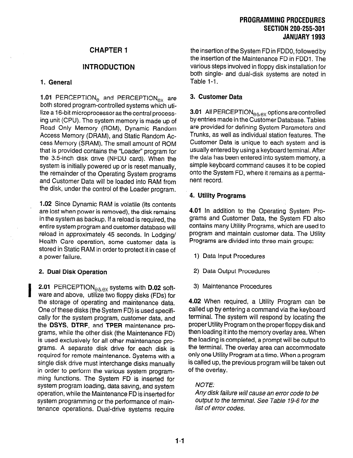
CHAPTER 1
INTRODUCTION
1. General
1.01 PERCEPTION, and PERCEPTION,, are
both stored program-controlled systems which uti-
lize a 16-bit microprocessor as the central process-
ing unit (CPU). The system memory is made up of
Read Only Memory (ROM), Dynamic Random
Access Memory (DRAM), and Static Random Ac-
cess Memory (SRAM). The small amount of ROM
that is provided contains the “Loader” program for
the 3.5inch disk drive (NFDU card). When the
system is initially powered up or is reset manually,
the remainder of the Operating System programs
and Customer Data will be loaded into RAM from
the disk, under the control of the Loader program.
1.02 Since Dynamic RAM is volatile (its contents
are lost when power is removed), the disk remains
in the system as backup. If a reload is required, the
entire system program and customer database will
reload in approximately 45 seconds. In Lodging/
Health Care operation, some customer data is
stored in Static RAM in order to protect it in case of
a power failure.
2. Dual Disk Operation
I
2.01 PERCEPTION e&ex systems with D.02 soft-
ware and above, utilize two floppy disks (FDs) for
the storage of operating and maintenance data.
One of these disks (the System
FD)
is used specifi-
cally for the system program, customer data, and
the DSYS, DTRF, and TPER maintenance pro-
grams, while the other disk (the Maintenance FD)
is used exclusively for all other maintenance pro-
grams. A separate disk drive for each disk is
required for remote maintenance. Systems with a
single disk drive must interchange disks manually
in order to perform the various system program-
ming functions. The System FD is inserted for
system program loading, data saving, and system
operation, while the Maintenance FD is inserted for
system programming or the performance of main-
tenance operations. Dual-drive systems require
PROGRAMMING PROCEDURES
SECTION 200-255-301
JANUARY 1993
the insertion of the System FD in FDDO, followed by
the insertion of the Maintenance FD in FDDl. The
various steps involved in floppy disk installation for
both single- and dual-disk systems are noted in
Table l-1.
3. Customer Data
3.01 All PERCEPTION,,,, options are controlled
by entries made in the Customer Database. Tables
are provided for defining System Parameters and
Trunks, as well as individual station features. The
Customer Data is unique to each system and is
usually entered by using a keyboard terminal. After
the data has been entered into system memory, a
simple keyboard command causes it to be copied
onto the System FD, where it remains as a perma-
nent record.
4. Utility Programs
4.01 In addition to the Operating System Pro-
grams and Customer Data, the System FD also
contains many Utility Programs, which are used to
program and maintain customer data. The Utility
Programs are divided into three main groups:
1) Data Input Procedures
2) Data Output Procedures
3) Maintenance Procedures
4.02 When required, a Utility Program can be
called up by entering a command via the keyboard
terminal. The system will respond by locating the
proper Utility Program on the proper floppy disk and
then loading it into the memory overlay area. When
the loading is completed, a prompt will be output to
the terminal. The overlay area can accommodate
only one Utility Program at a time. When a program
is called up, the previous program will be taken out
of the overlay.
NOTE:
Any disk failure will cause an error code to be
output to the terminal. See Table 19-6 for the
list of error codes.
l-1
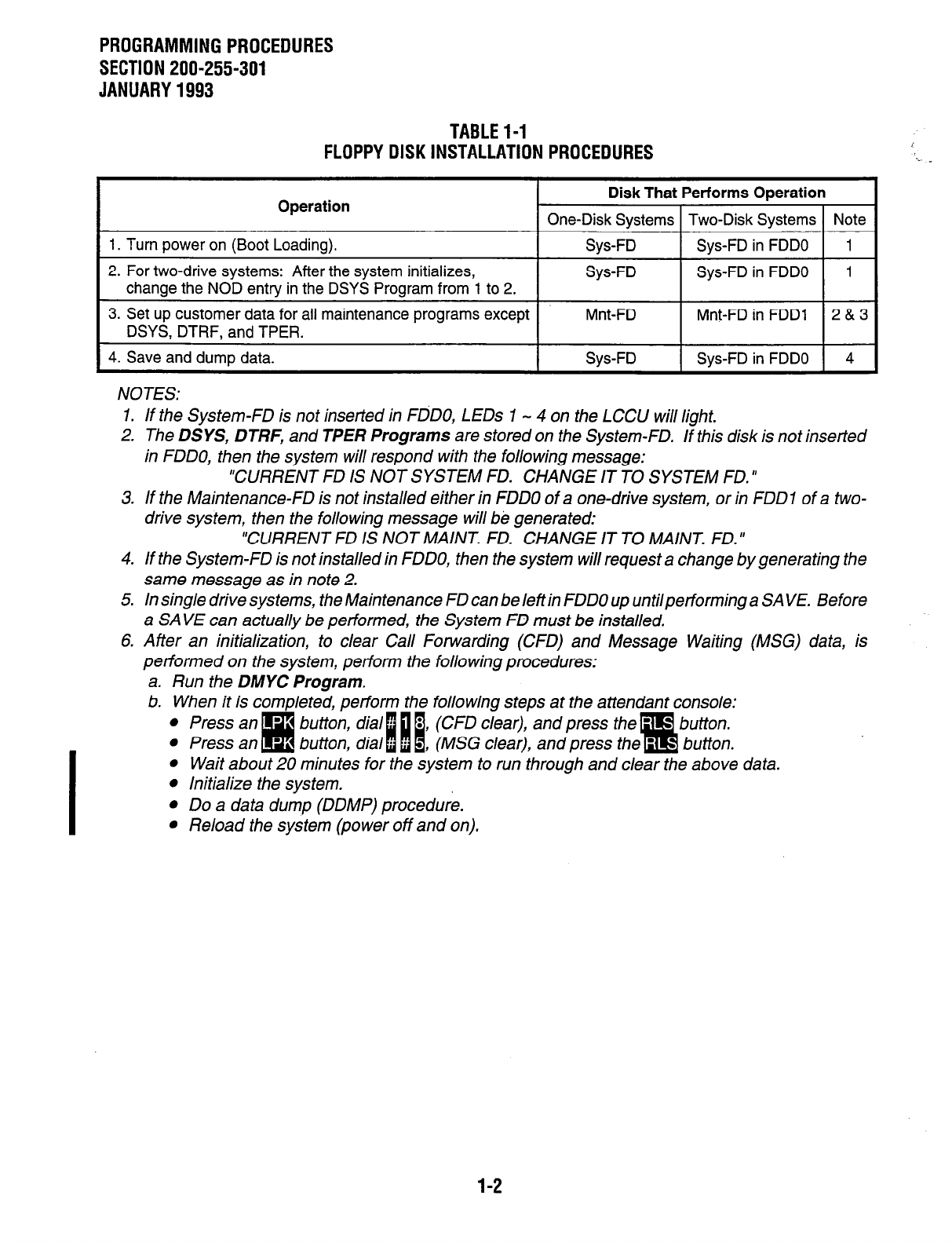
PROGRAMMINGPROCEDURES
SECTION 200-255-301
JANUARY1993
TABLEl-1
FLOPPYDISKINSTALLATION PROCEDURES
Operation
1. Turn power on (Boot Loading).
2. For two-drive systems: After the system initializes,
change the NOD entry in the DSYS Program from 1 to 2.
Disk That Performs Operation
One-Disk Systems Two-Disk Systems Note
Sys-FD Sys-FD in FDDO 1
Sys-FD Sys-FD in FDDO 1
3. Set up customer data for all maintenance programs except
DSYS, DTRF, and TPER. Mnt-FD Mnt-FD in FDDl
2&.3
4. Save and dump data. I Sys-FD Sys-FD in FDDO 4
NOTES:
1. If the System-FD is not inserted in FdDO, LEDs 1 - 4 on the LCCU will light.
2. The DSYS, DTRF, and TPER Programs are stored on the System-FD. If this disk is not inserted
in FDDO, then the system will respond with the following message:
“CURRENT FD IS NOT SYSTEM FD. CHANGE IT TO SYSTEM FD.”
3. If the Maintenance-FD is not installed either in FDDO of a one-drive system, or in FDDl of a two-
drive system, then the following message will be generated:
“CURRENT FD IS NOT MAINT. FD. CHANGE IT TO MAINT. FD. ”
4. If the System-FD is not installed in FDDO, then the system will request a change by generating the
same message as in note 2.
5. In single drive systems, the Maintenance FD can be left in FDDO up untilperforming a SAVE. Before
a SAVE can actually be performed, the System FD must be installed.
6. After an initialization, to clear Call Forwarding (CFD) and Message Waiting (MSG) data, is
performed on the system, perform the following procedures:
a. Run the DMYC Program.
b. When it is completed, perform the following steps at the attendant console:
: ~~~~~~~~~~~~~~~~~~~~~~~~~~~~
l
Wait about 20 min& for the system to run ihrough and clear the above data.
l
Initialize the system.
l
Do a data dump (DDMP) procedure.
l
Reload the system (power off and on).
1-2
CHAPTER 2
SET UP KEYBOARD/REMOTE
MAINTENANCE
1. Keyboard Terminal
1 .Ol
PERCEPTION, and PERCEPTION,,
systems are designed to interface with a standard
asynchronous keyboard/printer data terminal (a
Texas instruments Model 743or745, or equivalent)
or a personal computer configured as a dumb
terminal. The terminal is connected to the system
via a female-type RS-232C connector (labeled
TTY), which is located on the connector panel on
the lower rear of the basic cabinet. The TTY port
can operate at a speed of either 300 or 1200 bps,
which is designated by a switch on the front of the
LCCU PCB. The selected bps setting must match
the setting on the connected modem or TTY. TTY
and modem port pin assignments for
PERCEPTlONe systems are shown in Table 2-1,
while assignments for PERCEPTlONe, systems
are shown in Table 2-2.
2. Remote Administration
2.01 PERCEPTlONe and PERCEPTIONex
SYS-
terns can be programmed and tested from a re-
mote location via a locally-provided 300 or 1200
bps modem. Utility Programs can be called up via
a telephone line and then the desired data change
or test can be performed. On the PERCEPTION,,
the modem connects to the TTY RS-232C connec-
tor on the rear of the basic cabinet via a Null
Modem cable (see Table 2-1 for PERCEPTlONe
pin assignments). On the PERCEPTIONex, the
modem connects directly to the modem connector
on the rear of the basic cabinet (see Table 2-2 for
PERCEPTIONex pin assignments).
PROGRAMMINGPROCEDURES
SECTION 200-255-302
FEBRUARY1992
3. Data Format
3.01
The PERCEPTION, and PERCEPTION,,
systems communicate on the TTY and modem
ports via the standard 7-bit ASCII code, using one
start bit, one stop bit, and one parity bit. Both
systems transmit even parity and ignore parity on
the receive side.
3.02 Prior to switching on the PERCEPTfONe or
PERCEPTION,, system, data terminal, ormodem
power, all speed settings should be made and data
terminals and modems should be set for full duplex
operation.
2-1
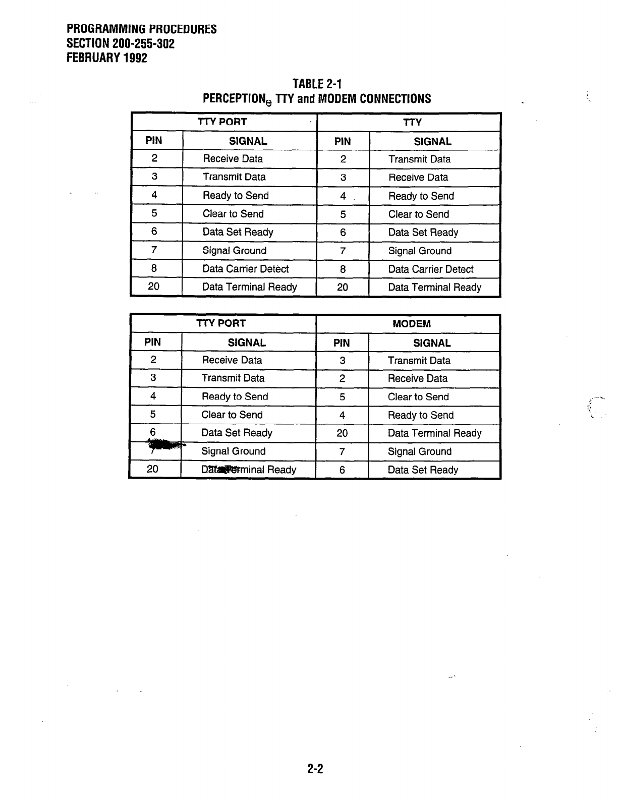
PROGRAMMING PROCEDURES
SECTION 200-255-302
FEBRUARY 1992
TABLE 2-1
PERCEPTION, TTY and MODEM CONNECTIONS
TTY PORT MODEM
PIN I SIGNAL PIN I SIGNAL
2 I
Receive Data I 3 I Transmit Data I
3 Transmit Data
4 Ready to Send
5 Clear to Send
2 Receive Data
5 Clear to Send
4 Readv to Send
6 Data Set Ready 20 Data Terminal Ready
m Signal Ground 7 Signal Ground
20 D8W#E3’Fminal Ready 6 Data Set Readv
2-2
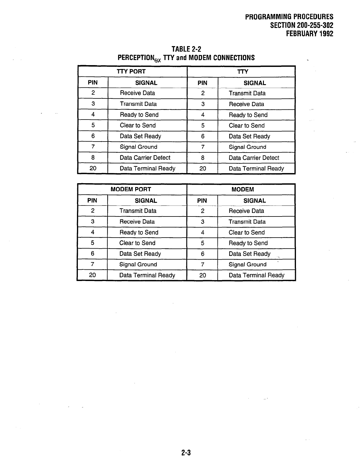
PROGRAMMING PROCEDURES
SECTION 200-255-302
FEBRUARY 1992
TABLE 2-2
PERCEPTION,, TTY and MODEM CONNECTIONS
MODEM PORT MODEM
PIN 1 SIGNAL PIN 1 SIGNAL
I
2 1 Transmit Data 1 2 1 Receive Data
I 3 I
Receive Data I 3 I Transmit Data I
4 Ready to Send
5 Clear to Send
4 Clear to Send
5 Ready to Send
I
6 I
Data Set Ready
I
6 I
Data Set Ready 1
7 Signal Ground
20 Data Terminal Ready
7 Signal Ground -
20 Data Terminal Ready
2-3
CHAPTER 3
DATA INPUT/OUTPUT PROCEDURES
1. General
1.01
Prior to actual system programming, cus-
tomer data is recorded on special System Record
Sheets which correspond with the prompts outlined
in the data block tables contained in this manual
(see Appendix 1). Afterthese sheets arecompleted
and after the PERCEPTION, or PERCEPTlONe,
system is connected to the data terminal (see
Chapter 2), data can be entered into the system via
the Data Input Utility Programs. Once the informa-
tion is input, it can be printed out via Data Output
Procedures and tested via special Maintenance
Procedures. The Utility Programs used to program
and maintain customer data are summarized as
follows:
1) Data Input Procedures-used when entering
or making changes to Customer Data.
2) Data Output Procedures-used for obtaining
printouts of the contents of the Customer Data
memory.
3) Maintenance Procedures-used when test-
ing the system. The System FD contains only
the
DSYS, DTRF,
and
TPER
maintenance
programs, while the maintenance FD con-
tains all other maintenance programs.
1.02 Within this manual, tables dealing with Data
input and Data Output Procedures are presented
collectively under each chapter category of data
(e.g., System Data, Station Data, etc.). This pro-
vides a convenient reference to all information that
deals with a specific type of data. Maintenance
Procedures, consisting of the Data Dump and
various test procedures, are grouped into their own
chapter at the end of this manual. For convenient
reference, each Utility Program’s location within
this manual is listed in Table 3-l.
1.03 Each Utility Program has a4-letter mnemonic
name that is used to identify it and to call it up from
the disk on which it is contained. Each program’s
PROGRAMMING PROCEDURES
SECTION 200-255-303
JANUARY 1993
mnemonic name is included in the listing in Table 3-
1. Before a Utility Program can be called up, an
Authorization Procedure must be performed.
2. Data Input
2.01
Before PERCEPTION,~,, system data can
be input, option selections must be made and then
listed on the System Record Sheets (see Appendix
1). The System Record will then serve as a pro-
gramming guide and installation record.
2.02 The System Record contains a form for each
Data Input Utility Program. Each form is identified
by the Utility Program name and by the program’s
corresponding mnemonic that is requested by the
system (for example: System Data Block =
DSYS
Program).
2.03 Data input via a Utility Program is accom-
plished by responding to the program’s prompts.
These prompts are listed in their proper order in the
System Record Sheets. Space is provided to rec-
ord a response to each prompt.
2.04 Refer to each Utility Program’s specific in-
structions for an explanation of the possible re-
sponses to each prompt. Record each selected
response on the program’s corresponding System
Record Sheet.
2.05 To input new customer data or to change an
established database, perform the Authorization
Procedure and then enter the mnemonic name of
the desired Data Input Utility Program (see Chapter
4). Refer to the completed System Record Sheets
and input the required information.
3. Data Output
3.01
To print. out data that is contained in the
various data blocks of the customer database,
perform the Authorization Procedure and then en-
ter the mnemonic name of the desired Data Output
Utility Program. Within this manual, Data Output
programs are grouped next to their related Data
Input Program. For detailed instructions on how to
print out data, refer to each specific program and
program table.
3-I
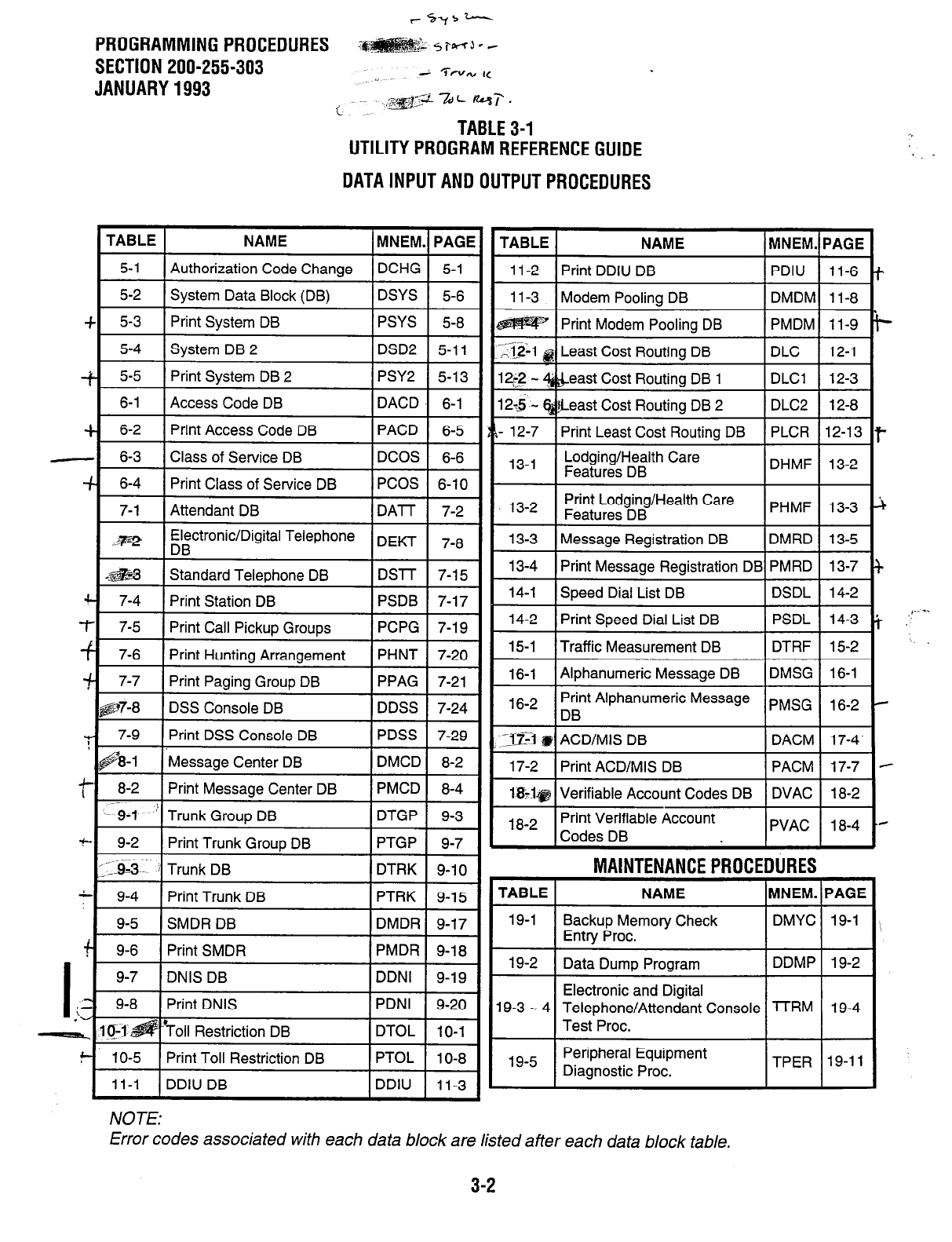
t-cays-
PROGRAMMINGPROCEDURES
SECTION 200-255-303 --: 7-w I(
JANUARY1993 .,
~~ .,@23 -I&L -7.
c. TABLE3-1
UTILITYPROGRAMREFERENCEGUIDE
DATAINPUTANDOUTPUTPROCEDURES
TABLE 1 NAME I MNEM.I PAGE
11-2 1 Print DDIU DB I PDIU 11-6
11-3
I
Modem Poolina DB I DMDMI 1 l-8
I Print Modem Poolina DB I PMDMI 11-9
.:.12-l p Least Cost Routing DB DLC 1 12-1
12i;2 - &east Cost Routine DB 1 IDLCl 1 12-3
I26 - &east Cost Routing DB 2 1 DLC2 12-8
- 12-7 1 Print Least Cost Routing DB 1 PLCR I 12-l 3
Lodging/Health Care
Features DB
I I
DHMF 13-2
13-2 Print Lodging/Health Care
Features DB PHMF 13-3
13-3 Message Registration DB DMRD 13-5
13-4 Print Message Registration DB PMRD 13-7
14-1 I Speed Dial List DB 1 DSDL 1 14-2
14-2 I Print Speed Dial List DB 1 PSDL 14-3
15-1 1 Traffic Measurement DB 1 DTRF 1 15-2
16-l I Alphanumeric Message DB IDMSG I 16-1
16-2 I rnt Alphanumeric Message PMSC 1 6-2
I I
I I I
3%1 @I ACD/MIS DB I DACM I 17-4.
17-2 I Print ACD/MIS DB 1 PACM 1 17-7
l&l@ 1 Verifiable Account Codes DB I DVAC I 18-2
18-2 I Print Verifiable Account
Codes DB I I
PVAC 18-4
IURES
HNEM.
MAINTENANCEPROCE
TABLE I NAME
19-l Backup Memory Check
Entry Proc.
19-2 I Data Dump Program
Ill
I
I
Electronic and Digital
19-3 - 4 Telephone/Attendant Console
Test Proc.
19-5 Peripheral Equipment
Diagnostic Proc.
PAGE
DMYC 19-1
DDMP 19-2
lTRM 19-4
TPER 19-11
NOTE:
Error codes associated with each data block are listed after each data block table.
3-2
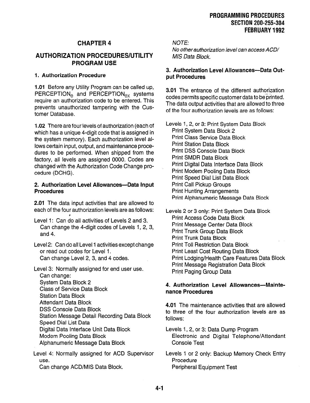
PRQGRAMMING PROCEDURES
SECTION 200-255-304
FEBRUARY 1992
CHAPTER 4
AUTHORIZATION PROCEDURES/UTILITY
PROGRAM USE
1. Authorization Procedure
1 .Ol Before any Utility Program can be called up,
PERCEPTlONe and PERCEPTlONe, systems
require an authorization code to be entered. This
prevents unauthorized tampering with the Cus-
tomer Database.
1.02 There are four levels of authorization (each of
which has a unique 4-digit code that is assigned in
the system memory). Each authorization level al-
lows certain input, output, and maintenance proce-
dures to be performed. When shipped from the
factory, all levels are assigned 0000. Codes are
changed with the Authorization Code Change pro-
cedure (DCHG).
2. Authorization Level Allowances-Data input
Procedures
2.01 The data input activities that are allowed to
each of the four authorization levels are as follows:
Level 1: Can do all activities of Levels 2 and 3.
Can change the 4-digit codes of Levels 1, 2, 3,
and 4.
Level 2: Can do all Level 1 activities except change
or read out codes for Level 1.
Can change Level 2,3, and 4 codes.
Level 3: Normally assigned for end user use.
Can change:
System Data Block 2
Class of Service Data Block
Station Data Block
Attendant Data Block
DSS Console Data Block
Station Message Detail Recording Data Block
Speed Dial List Data
Digital Data Interface Unit Data Block
Modem Pooling Data Block
Alphanumeric Message Data Block
Level 4: Normally assigned for ACD Supervisor
use.
Can change ACD/MIS Data Block.
NOTE:
No otherauthorization level can access ACD/
MIS Data Block.
3. Authorization Level Allowances-Data Out-
put Procedures
3.01 The entrance of the different authorization
codes permits specific customer data to be$nted.
The data output activities that are allowed to three
of the four authorization levels are as follows:
Levels 1, 2, or 3: Print System Data Block
Print System Data Block 2
Print Class Service Data Block
Print Station Data Block
Print DSS Console Data Block
Print SMDR Data Block
Print Digital Data Interface Data Block
Print Modem Pooling Data Block
Print Speed Dial List Data Block
Print Call Pickup Groups
Print Hunting Arrangements
Print Alphanumeric Message Data Block
Levels 2 or 3 only: Print System Data Block
Print Access Code Data Block
Print Message Center Data Block
Print Trunk Group Data Block
Print Trunk Data Block
Print Toll Restriction Data Block
Print Least Cost Routing Data Block
Print Lodging/Health Care Features Data Block
Print Message Registration Data Block
Pri?t Paging Group Data
4. Authorization Level Allowances-Mainte-
nance Procedures
4.01 The maintenance activities that are allowed
to three of the four authorization levels are as
follows:
Levels 1, 2, or 3: Data Dump Program
Electronic and Digital Telephone/Attendant
Console Test
Levels 1 or 2 only: Backup Memory Check Entry
Procedure
Peripheral Equipment Test
4-1
PROGRAMMINGPROCEDURES
SECTION 200-255-304
FEBRUARY1992
5. Execution of Authorization Procedure
5.01 To perform the Authorization Procedure:
1)
2)
3)
Plug in and power up the data terminal.
The system will respond with a copyright and
then greater than sign (>).
Press the carriage return [9 key.
l
The system will respond by printing COD
and will print several characters in the
spaces to be occupied by your next entry
(this is done to mask the authorization
code).
This masking measure is not effective when
IMPORTANT!
a CRT is used. Be careful not to leave the
authorization code displayed on the screen.
4) Enter the 4-digit authorization code (0000
default value), followed by a
q
.
l
The system will print:
ERROR if an invalid code is entered
(return to Step 2).
OK if a valid code is entered (proceed to
request Utility Program).
6. Utility Program Use
6.01 After performing the Authorization Procedure
and receiving an OK response, enter the mne-
monic of the required Utility Program.
6.02 After the Utility Program name is entered, the
program will be loaded from the disk. When the
loading is complete, the system will prompt REQ for
Request.
6.03 Entering data via a Utility Program is a matter
of responding to the prompts given by the system
via the data terminal. The prompts and the required
responses are mnemonics that are usually abbre-
viations of the actual English word required.
6.04 If an improper response is made to a prompt,
the system will respond with an error message. The
error message will be a “?,, when the error is
obvious, but in most cases it will be an alphanu- . .
mericcode. The alphanumeric code consists of five . . .
letters (identifying the program) and two numbers
(identifying the error). Error code lists are provided
in this manual to explain each error code.
6.05 Boxes are used to indicate keys on the pro-
gramming terminal. The m (control) key must
be held down while simultaneously pressing either
key. Press the carriage return key
appears. The following keys are
available when using Utility Programs (press the
5
- pycegr each.code):
I nore lrne entered-the same prompt
will be repeated.
mEBackspace will allow you to overwrite the
W-May be entered at anytime-the system will
previous character(s).
stoo execution and return to the REQ oromot.
F-Exits the program-ends the u.se of bne
utility. The system will respond with SAVE. A ‘Y”
entry will cause the system to copy all present
data onto the disk. If more changes are to be
made, enter “N.”
NOTE:
The above key indications are for Texas ln-
struments Silent 700 series terminals. Other
*.
6.06 When data already exists for a given prompt
and a change is not required, entering a
q
will
advance the system to the next prompt without
changing existing data.
6.07 Tables 5-1 through 19-5 show the format of
each Utility Program. Programs are grouped into
general categorical areas (e.g., System Data, Fea-
ture Data, etc.). Each Data Output program is
grouped with its related Data Input program(s). If
applicable, each data table is followed by a list
explaining the error codes which pertain to that
program. Using the appropriate tables as guides,
enter data that has been previously recorded in the
System Record Sheets.
4-2
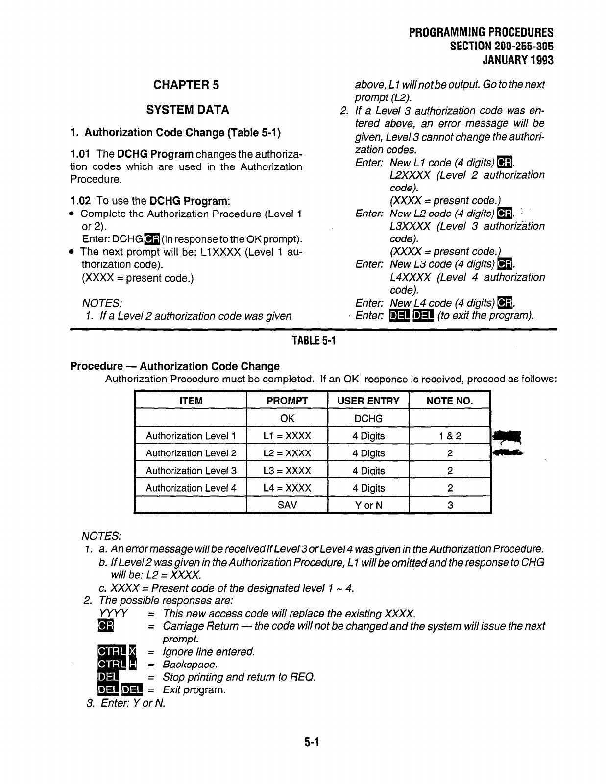
CHAPTER 5
SYSTEM DATA
1. Authorization Code Change (Table 5-1)
1 .Ol The DCHG Program changes the authoriza-
tion codes which are used in the Authorization
Procedure.
2.
1.02 To use the DCHG Program:
Complete the Authorization Procedure (Level 1
or 2).
Enter:
Enter: DCHGm (in response to the OK prompt).
The next prompt will be: LiXXXX (Level 1 au-
thorization code).
(XXXX = present code.)
New L2 code (4 digits)
q
. j
L3XXXX (Level 3 authorization
code).
Enter:
(XXXX = present code.)
(XXXX = present code.)
New L3 code (4 digits)
q
,
L4XXXX (Level 4 authorization
code).
NOTES: Enter: New L4 code (4 digits)
q
,
I. If a Level 2 authorization code was given En ten m m (to exit the program).
PROGRAMMING PROCEDURES
SECTION 200-255-305
JANUARY 1993
above, L 1 willnotbe output. Go to the next
prompt (L2).
If a Level 3 authorization code was en-
tered above, an error message will be
given, Level 3 cannot change the authori-
zation codes.
Enter: New L 1 code (4 digits) a.
L2XXXX (Level 2 authorization
code).
TABLE 5-l
Procedure - Authorization Code Change
Authorization Procedure must be completed. If an OK response is received, proceed as follows:
NOTES:
1.
2.
a. An error message will be received if Level3 or Level4 was given in the Authorization Procedure.
6. If Level2 was given in the Authorization Procedure, L 1 will be omitted and the response to CHG
will be: L2 = XXXX.
c. XXXX = Present code of the designated level 1 - 4.
The possible responses are:
YYYY =
(9
This new access code will replace the existing XXXX.
= Carriage Return - the code will not be changed and the system will issue the next
prompt.
= Ignore line entered.
= Backspace.
- Stop printing and return to REQ.
= Exit program.
3. Enter: Y or N.
5-I
PROGRAMMINGPROCEDURES
SECTION 200-255-305
JANUARY1993
2. System Data Block (Table 5-2)
2.01 The System Data Block (DSYS Program)
contains miscellaneous data entries that apply to
the system as a whole rather than to any individual
station or trunk. Data is entered as follows:
REQ (Request)-Indicates that the program has
loaded. Since data is always present, only the
CHG response is possible.
EXP (Expansion Cabinet)-Indicates whether or
not an expansion cabinet is installed.
Enter: Y: if an expansion cabinet is installed.
N: if only the basic cabinet is installed.
NOTES:
1. Y must be entered to enable the system to
provide up to 20 simultaneous confer-
ences in a cabinet using a second NPRU
PCB.
2. If N is entered, then only ten simultaneous
conferences will be supported.
NOD (Number of Drives)--Indicates whether one
or two disk drives are being used. (Two drives
are used only with D.02 or later software ver-
sions.)
Enter: 1:
;$s&
..q:
M%LwzG
if only a single drive (FDDO) is used.
if two drives (FDDO and FDDl) are
used. (The system will not access
maintenance programs in FDDl if 1 is
entered, unless the Maintenance FD
is used in place of the System FD.)
TOR (Time of Daily Routine)-Specifies the time
of day that the daily routine task (System Dump)
will run (listed after the next prompt).
Enter: 24-hour clock time.
(For example: 1315 = 1:15 pm.)
DRT (Daily Routine Task)-Specifies whether or
not a System Data Dump is to be performed at
the time specified in response to TOR.
Enter: DDMP (Data Dump) or NONE.
TEN (Tenant Service)-Specifies whether or not
tenant service is to be used. If “Y” is entered,
incoming trunk calls, dial calls, intercepts, etc.
will be routed to the proper attendant console
(Att. #O for Tenant #0, and Att. #l for Tenant #l).
Tenant designation for each telephone and trunk
is selected in response to the TEN prompt in the
5-2
following Data Blocks: Electronic/Digital Tele-
phone (DEKT Program), Standard Telephone
(DSTT Program), and Trunk Group (DTGP Pro-
gram). If “N” is entered, then the attendant
consoles will operate in the load sharing mode.
Enter: Y or N.
NOTE:
In tenant service, when the Attendant console
transfers a call to a station, if the call RNAs and
recalls back to the Attendant, it will recall to the
original Attendant that transferred the call. In
some cases this may mean the call will recall
to the Attendant that the station is not as-
signed to.
ICPl (Intercept #l)--If the attendant takes control
of a trunk group by using the trunk group access
control feature, then stations that place calls to
that trunk group will be routed to Intercept #Il.
This entry defines ICPl as being either overflow
tone (OFL) or the attendant (ATT).
Enter: ATT or OFL.
ICP2 (Intercept #2)-An incoming call from a DID,
TIE, or CCSA trunk to a non-existing DN will be
routed to Intercept #2 when the system is in day
service and to overflow tone when night service
is active. This entry defines ICP2 as being either
overflow tone (OFL), the attendant (An), a
standard station, or an answering device con-
nected to a trunk or a standard station pdrt
(TNNX, LNNX).
Enter: AlT, OFL, TNNX, or LNNX.
ICP3 (Intercept #3)-A call that is’violating trunk
access restrictions will be routed to Intercept #3
when the system is in day service and to overflow
tone when night service is active. This entry
defines ICP3 as being either ovetflow tone or the
attendant.
Enter: AIT or OFL.
LCR (Least Cost Routing)-A 7 response en-
ables Least Cost Routing in the system. Refer to
the Least Cost Routing Data Block DLCI and
DLC2 Programs.
Enter: Y or N.
APG (All Page Access Code)-Defines the All
Page access code. The use of this code will
simultaneously access Internal Group 0 Paging
PROGRAMMING PROCEDURES
SECTION 200-255-305
JANUARY 1993
AAT (Not Used):
Enter: m.
APX (Not Used):
Enter: (9.
LNl (Listed Directory Number
#l)-Defines the
LDN #l , which is used with the DID feature when
routing a call to the attendant console (maxi-
mum: 4 digits).
Enter: 1, 2, 3, or 4 digits or NONE.
LN2 (Listed Directory Number
#2-Defines the
LDN #2, which is used with the DID feature when
routing a call to the attendant console (maxi-
mum: 4 digits).
Enter: 1, 2, 3, or 4 digits or NONE.
NT1 (LDN #1 Night
Number)-Defines the desti-
nation to which LDN #l calls will be routed when
the system is in night service (DN or Universal
Night Answer).
Enter: 1,2, 3, or 4 digits or UNA.
NT2 (LDN #2 Night Number)-
The response to
this prompt defines the destination to which LDN
#2 calls will be routed when the system is in night
service (DN or UNA).
Enter: 1, 2, 3, or 4 digits or UNA.
BLFl (Busy Lamp Field
#l)-Defines one of the
hundreds groups that is to be displayed by the
console BLF.
Enter: 1 digit (1 - 9).
BLF2 (Busy Lamp Field
#P)-Defines one of the
hundreds groups that is to be displayed by the
console BLF.
Enter: 1 digit (1 - 9).
OFLl (Overflow DN-Attendant Console #IO)-
Defines the destination for calls that are rerouted
from attendant console #0 during an overflow
condition.
Enter: 1, 2, 3, or 4 digits or NONE (UNA).
NOTE:
This data may also be changed via the atten-
dant console.
OFL2 (Overflow DN-Attendant Console #l)-
Defines the destination for calls that are rerouted
from attendant console #l during an overflow
condition.
Enter: 1, 2, 3, or 4 digits, or NONE (UNA).
NOTES:
1. The overfiow destination can also be
changed at the attendant console.
2. OF1 2 applies to tenant 1 and wiiinotprint
out when the system is not in tenant ser-
vice. -.
MMP (Meet-me Page Access
Code)-Defines
the access code that is used by the attendant or
attendant-position electronic/digital telephone to
“park” a call for the Meet-me Page feature (maxi-
mum: 3 digits; the system default is 10).
Enter: 1,2, or 3 digits.
REM (Remote Access
DN)-Defines the DN that
is used to assign a trunk for “Remote Access to
Services” operation (maximum: 4 digits). The
DN must be the same as an assigned station DN.
Refer to the note at the NIT prompt in the DTRK
Program .
Enter: 1,2, 3, or 4 digits, or NONE.
RAC (Remote Access to Services Change
Code)-Defines the access code that must be
entered before the system’s remote access code
can be changed. The remote access code can
be changed from either an attendant console or
an attendant-position electronic telephone after
entering the change code. The remote access
code is used by outside callers who want to
access the system’s remote access feature.
Enter: 1, 2, or 3 digits.
ACC*
(*Access Code)-Defines the digit that is to
be used by a rotary dial telephone in place of the
a button.
Enter: 1 digit or NONE.
NOTE:
AAC * must not conflict with either the DN or
other access codes-it is not checked by
software.
5-3
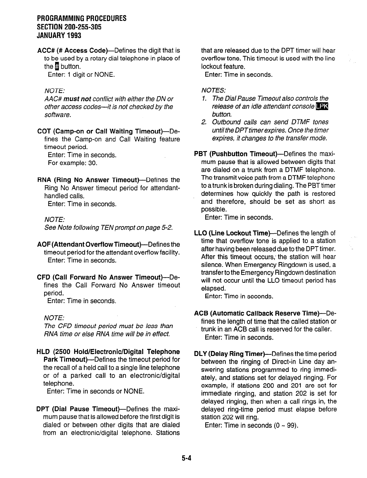
PROGRAMMING PROCEDURES
SECTION 200-255-305
JANUARY 1993
ACC# (# Access Code)-Defines the digit that is that are released due to the DPT timer will hear
to be used by a rotary dial telephone in place of overflow tone. This timeout is used with the line
the 1 button. lockout feature.
Enter: 1 digit or NONE. Enter: Time in seconds.
NOTE:
AAC# must not conflict with either the DN or
other access codes-it is not checked by the
software.
NOTES:
1. The Dial Pause Timeout also controls the
release of an idle attendant console m
button.
COT (Camp-on or Call Waiting Timeout)-De-
fines the Camp-on and Call Waiting feature
timeout period.
Enter: Time in seconds.
For example: 30.
2. Outbound calls can send DTMF tones
until the DPTtimerexpires. Once the timer
expires, it changes to the transfer mode.
RNA (Ring No Answer Timeout)-Defines the
Ring No Answer timeout period for attendant-
handled calls,
Enter: Time in seconds.
NOTE:
PBT (Pushbutton Timeout)-Defines the maxi-
mum pause that is allowed between digits that
are dialed on a trunk from a DTMF telephone.
The transmit voice path from a DTMF telephone
to a trunk is broken during dialing. The PBT timer
determines how quickly the path is restored
and therefore, should be set as short as
possible.
Enter: Time in seconds.
See Note following TEN prompt on page 5-2.
AOF (Attendant Overflow Timeout)-Defines the
timeout period for the attendant overflow facility.
Enter: Time in seconds,
CFD (Call Forward No Answer Timeout)-De-
fines the Call Forward No Answer timeout
period.
Enter: Time in seconds.
LLO (Line Lockout Time)-Defines the length of
time that overflow tone is applied to a station
after having been released due to the DPT timer.
After this timeout occurs,’ the station will hear
silence. When Emergency Ringdown is used, a
transfer to the Emergency Ringdown destination
will not occur until the LLO timeout period has
elapsed.
Enter: Time in seconds.
NOTE:
The CFD timeout period must be less than
RNA time or else RNA time will be in effect.
ACB (Automatic Callback Reserve Time)-De-
fines the length of time that the called station or
trunk in an AC6 call is reserved for the caller.
Enter: Time in seconds.
HLD (2500 Hold/Electronic/Digital Telephone
Park Timeout)-Defines the timeout period for
the recall of a held call to a single line telephone
or of a parked call to an electronic/digital
telephone.
Enter: Time in seconds or NONE.
DPT (Dial Pause Timeout)-Defines the maxi-
mum pause that is allowed before the first digit is
dialed or between other digits that are dialed
from an electronic/digital telephone. Stations
DLY (Delay Ring Timer)-Defines the time period
between the ringing of Direct-in Line day an-
swering stations programmed to ring immedi-
ately, and stations set for delayed ringing. For
example, if stations 200 and 201 are set for
immediate ringing, and station 202 is set for
delayed ringing, then when a call rings in, the
delayed ring-time period must elapse before
station 202 will ring.
Enter: Time in seconds (0 - 99).
5-4
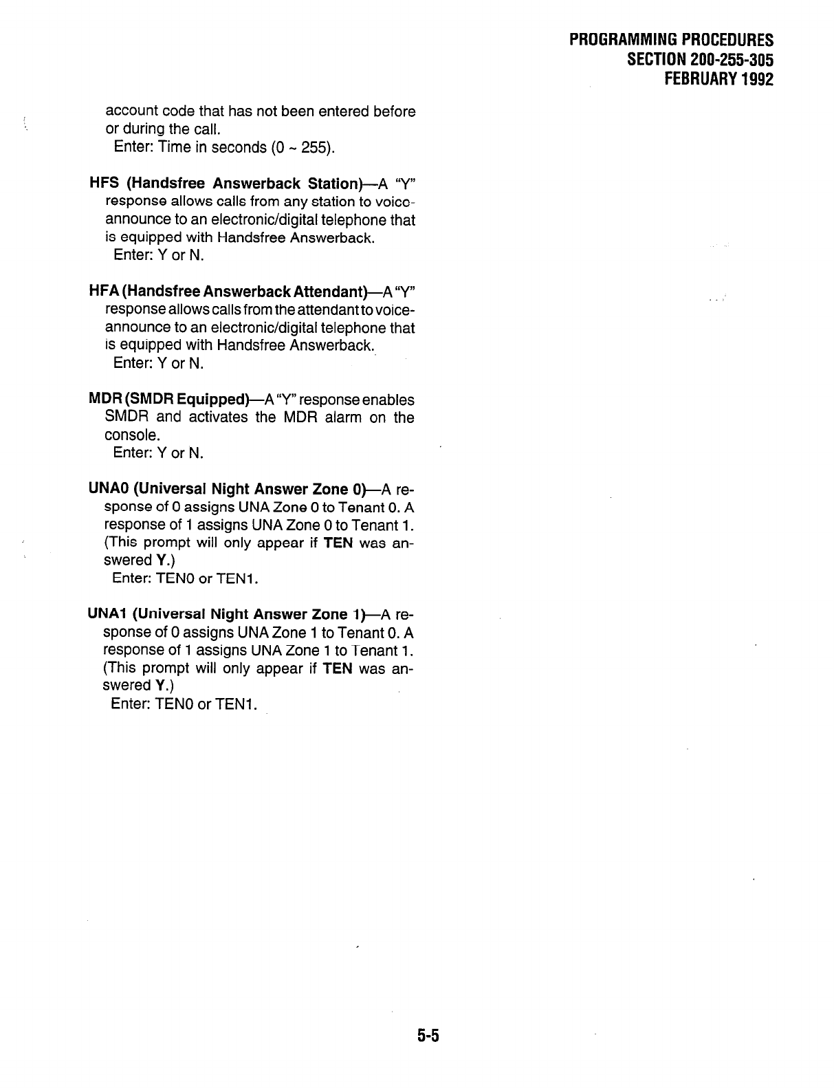
PROGRAMMINGPROCEDURES
SECTION 200-255-305
FEBRUARY1992
account code that has not been entered before
or during the call.
Enter: Time in seconds (0 M 255).
HFS (Handsfree Answerback Station)-A ‘Y”
response allows calls from any station to voice-
announce to an electronic/digital telephone that
is equipped with Handsfree Answerback.
Enter: Y or N.
HFA (Handsfree AnswerbackAttendant)-A Y”
response allows calls from the attendant to voice-
announce to an electronic/digital telephone that
is equipped with Handsfree Answerback.
Enter: Y or N.
MDR (SMDR Equipped)-A”Y” response enables
SMDR and activates the MDR alarm on the
console.
Enter: Y or N.
UNAO (Universal Night Answer Zone 0)-A re-
sponse of 0 assigns UNA Zone 0 to Tenant 0. A
response of 1 assigns UNA Zone 0 to Tenant 1.
(This prompt will only appear if TEN was an-
swered Y.)
Enter: TEN0 or TENl.
UNAI (Universal Night Answer Zone 1)-A re-
sponse of 0 assigns UNA Zone 1 to Tenant 0. A
response of 1 assigns UNA Zone 1 to Tenant 1.
(This prompt will only appear if TEN was an-
swered Y.)
Enter: TEN0 or TENl.
5-5
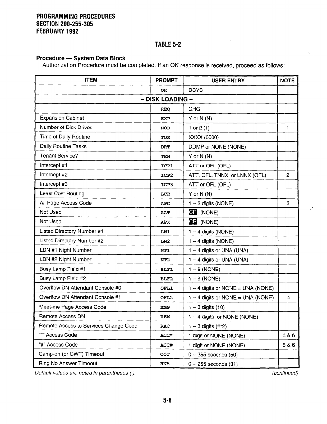
PROGRAMMING PROCEDURES
SECTION 200-255-305
FEBRUARY 1992
TABLE 5-2
Procedure - System Data Block
Authorization Procedure must be completed. If an OK response is received, proceed as follows:
Meet-me Page Access Code
Remote Access DN
Remote Access to Services Change Code
“*‘I Access Code
‘W Access Code
Camp-on (or CWT) Timeout
Ring No Answer Timeout
REM
RAC
ACC*
ACC#
COT
RNA
1 - 4 digits or NONE (NONE)
1 - 3 digits (#*2)
1 digit or NONE (NONE)
1 digit or NONE (NONE)
0 - 255 seconds (50)
0 - 255 seconds (31)
5&6
5&6
Default values are noted in parentheses (). (continued)
5-6
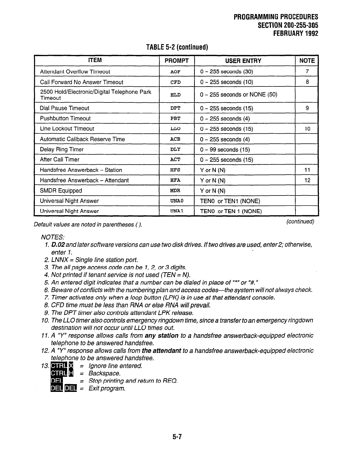
PROGRAMMINGPROCEDURES
SECTION 200-255-305
FEBRUARY1992
TABLE 5-2(continued)
ITEM PROMPT USER ENTRY NOTE
Attendant Overflow Timeout AOF 0 - 255 seconds (30) 7
Call Forward No Answer Timeout CFD 0 - 255 seconds (10) 8
2500 Hold/Electronic/Digital Telephone Park
Timeout I HLD I 0 - 255 seconds or NONE (50) I
Dial Pause Timeout I DPT 1 0 - 255 seconds (15) I 9
Pushbutton Timeout
Line Lockout Timeout
Automatic Callback Reserve Time
PBT
LLO
ACB
0 - 255 seconds (4)
0 - 255 seconds (15)
0 - 255 seconds (4)
10
Delay Ring Timer DLY 0 - 99 seconds (15)
After Call Timer
Handsfree Answerback - Station
ACT
HFS
0 - 255 seconds (15)
Y or N (Nl 11
Handsfree Answerback - Attendant HFA Y or N (N) 12
SMDR Equipped
Universal Night Answer
Universal Niaht Answer
MDR
UNAO
DNA1
Y or N (N)
TEN0 or TEN1 (NONE)
TEN0 or TEN 1 (NONE)
Default values are noted in parentheses (). (continued)
NOTES:
1. D.02and latersoftware versions can use two diskdrives. If two drives are used, enter2; otherwise,
enter 1.
2. LNNX = Single line station port.
3.
The all page access code can be 1,2, or 3 digits.
4. Not printed if tenant service is not used (TEN = N).
5. An entered digit indicates that a number can be dialed in place of ‘*‘I or “#. ’
6. Be ware of conflicts with the numbering plan and access codes-the system will not always check.
7. Timer activates only when a loop button (LPK) is in use at that attendant console.
8. CFD time must be less than RNA or else RNA will prevail.
9. The DPT timer also controls attendant LPK release.
10. The LLO timer also controls emergency ringdown time, since a transfer to an emergency ringdown
destination will not occur until LLO times out.
II. A “Y” response allows calls from any station to a handsfree answerback-equipped electronic
telephone to be answered handsfree.
12. A “Y” response allows calls from the attendant to a handsfree answerback-equipped electronic
telephone to be answered handsfree.
= Ignore line entered.
= Backspace.
= Stop printing and return to REQ.
= Exit program.
5-7
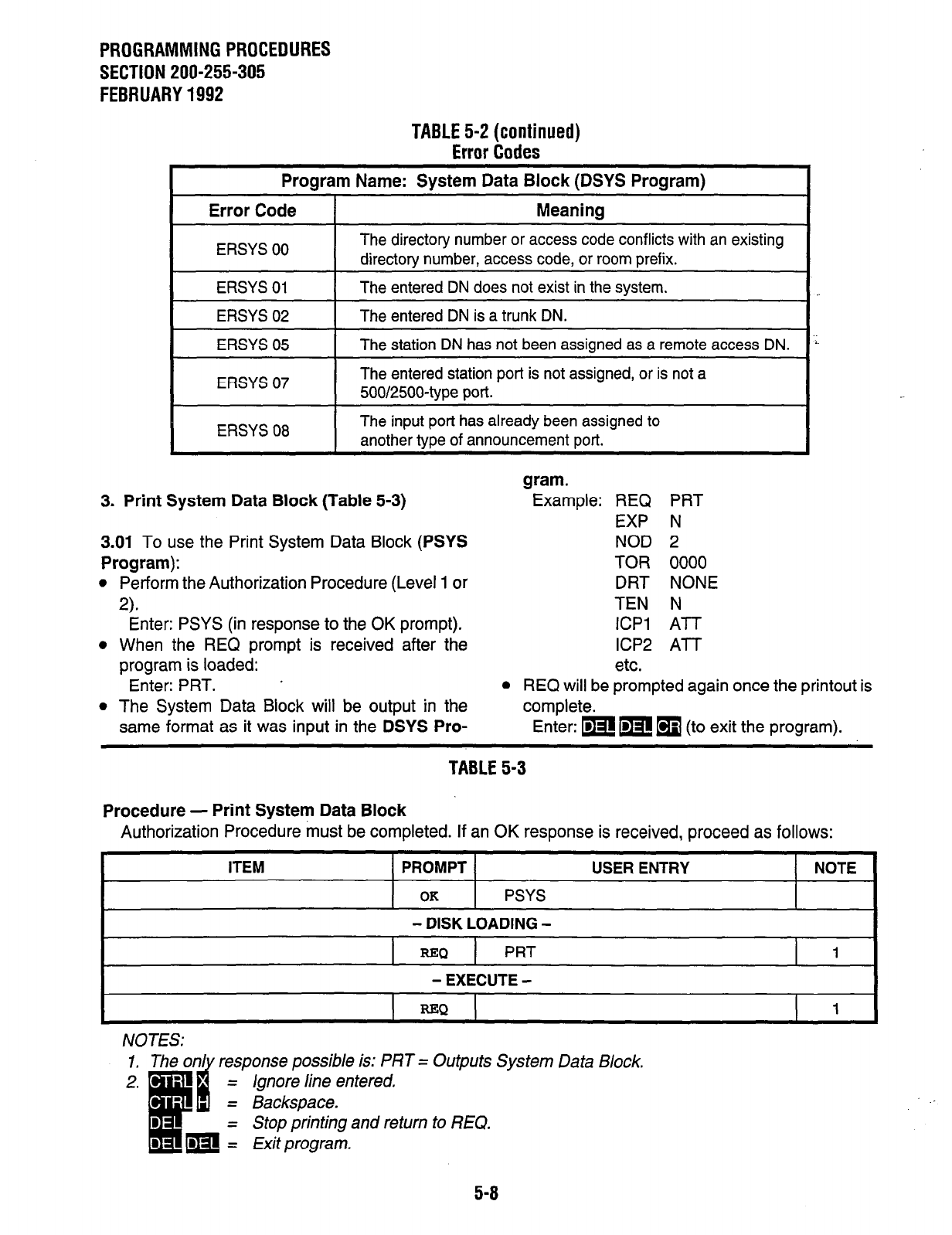
PROGRAMMING PROCEDURES
SECTION 200-255-305
FEBRUARY 1992
TABLE 5-2 (continued)
Error Codes
Program Name: System Data Block (DSYS Program)
Error Code I Meaning
ERSYS 00 The directory number or access code conflicts with an existing
directory number, access code, or room prefix.
ERSYS 01 I The entered DN does not exist in the system.
ERSYS 02 -entered DN is a trunk DN.
ERSYS 05 1 The station DN has not been assigned as a remote access DN.
The entered station port is not assigned, or is not a
500/25004ype port.
ERSYS 08 I The input port has already been assigned to
another tvoe of announcement bon.
1..
i
3. Print System Data Block (Table 5-3)
3.01 To use the Print System Data Block
(PSYS
Program):
l
Perform the Authorization Procedure (Level 1 or
2).
Enter: PSYS (in response to the OK prompt).
l
When the REQ prompt is received after the
program is loaded:
Enter: PRT. ’
l
The System Data Block will be output in the
same format as it was input in the
DSYS Pro-
gram.
Example: REQ PRT
EXP N
NOD 2
TOR 0000
DRT NONE
TEN N
ICPl Al-T
ICP2 Al-T
etc.
l
REQ will be prompted again once the printout is
complete.
Enter: mm
q
(to exit the program).
TABLE 5-3
Procedure - Print System Data Block
Authorization Procedure must be completed. If an OK response is received, proceed as follows:
I
ITEM 1 PROMPT 1 USER ENTRY t NOTE
I
I I PSYS
OK
- DISK LOADING -
REQ
PRT
- EXECUTE -
NOTES: response possible is: PRT = Outputs System Data Block.
Ignore line entered.
Stop printing and return to REQ.
5-8
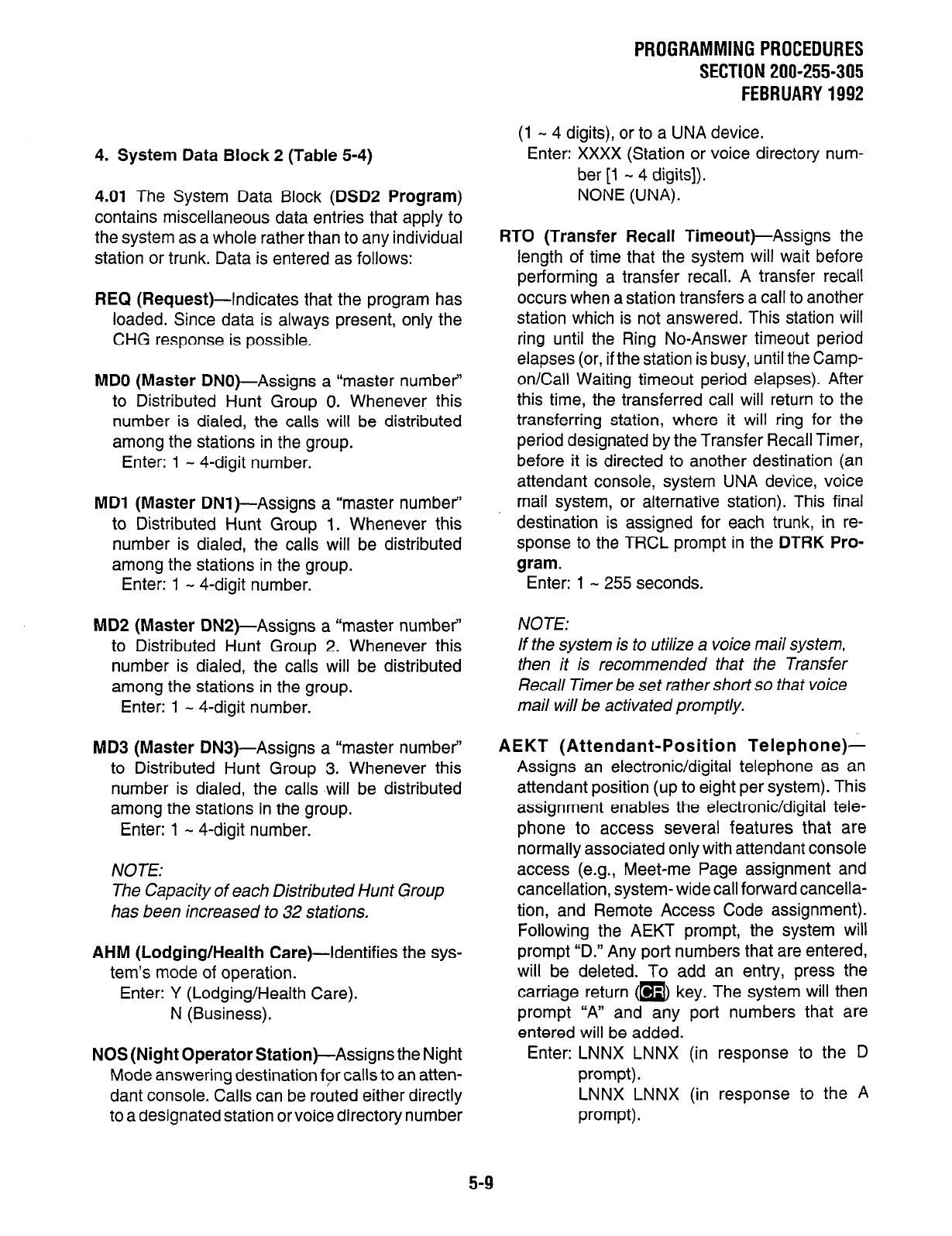
4. System Data Block 2 (Table 5-4)
4.01 The System Data Block (DSDZ Program)
contains miscellaneous data entries that apply to
the system as a whole rather than to any individual
station or trunk. Data is entered as follows:
REQ (Request)-Indicates that the program has
loaded. Since data is always present, only the
CHG response is possible.
MD0 (Master DNO)-Assigns a “master number’
to Distributed Hunt Group 0. Whenever this
number is dialed, the calls will be distributed
among the stations in the group.
Enter: 1 - 4-digit number.
MD1 (Master DNl)-Assigns a “master number’
to Distributed Hunt Group 1. Whenever this
number is dialed, the calls will be distributed
among the stations in the group.
Enter: 1 - 4-digit number.
MD2 (Master DNP)-Assigns a “master number’
to Distributed Hunt Group 2. Whenever this
number is dialed, the calls will be distributed
among the stations in the group.
Enter: 1 - 4-digit number.
MD3 (Master DN3)-Assigns a “master number’
to Distributed Hunt Group 3. Whenever this
number is dialed, the calls will be distributed
among the stations in the group.
Enter: 1 - 4-digit number.
NOTE:
The Capacity of each Distributed Hunt Group
has been increased to 32 stations.
AHM (Lodging/Health Care)-Identifies the sys-
tem’s mode of operation.
Enter: Y (Lodging/Health Care).
N (Business).
NOS (Night Operator Station)-Assigns the Night
Mode answering destination for calls to an atten-
dant console. Calls can be routed either directly
to a designated station or voice directory number
PROGRAMMINGPROCEDURES
SECTION 200-255-305
FEBRUARY1992
(1 - 4 digits), or to a UNA device.
Enter: XXXX (Station or voice directory num-
ber [l - 4 digits]).
NONE (UNA).
RTO (Transfer Recall Timeout)-Assigns the
length of time that the system will wait before
performing a transfer recall. A transfer recall
occurs when a station transfers a call to another
station which is not answered. This station will
ring until the Ring No-Answer timeout period
elapses (or, if the station is busy, until the Camp-
on/Call Waiting timeout period elapses). After
this time, the transferred call will return to the
transferring station, where it will ring for the
period designated by the Transfer Recall Timer,
before it is directed to another destination (an
attendant console, system UNA device, voice
mail system, or alternative station). This final
destination is assigned for each trunk, in re-
sponse to the TRCL prompt in the DTRK Pro-
gram.
Enter: 1 - 255 seconds.
NOTE:
If the system is to utilize a voice mail system,
then it is recommended that the Transfer
Recall Timer be set rather short so that voice
mail will be activated promptly.
AEKT (Attendant-Position Telephone)-
Assigns an electronic/digital telephone as an
attendant position (up to eight per system). This
assignment enables the electronic/digital tele-
phone to access several features that are
normally associated only with attendant console
access (e.g., Meet-me Page assignment and
cancellation, system- wide call forward cancella-
tion, and Remote Access Code assignment).
Following the AEKT prompt, the system will
prompt “D.” Any port numbers that are entered,
will be deleted. To add an entry, press the
carriage return ([9> key. The system will then
prompt “A” and any port numbers that are
entered will be added.
Enter: LNNX LNNX (in response to the D
prompt).
LNNX LNNX (in response to the A
prompt).
5-9
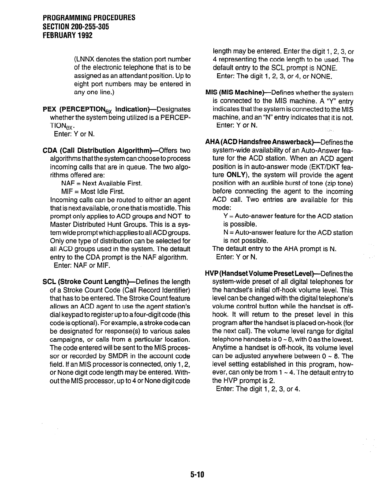
PROGRAMMINGPROCEDURES
SECTION 200-255-305
FEBRUARY1992
(LNNX denotes the station port number
of the electronic telephone that is to be
assigned as an attendant position. Up to
eight port numbers may be entered in
any one line.)
PEX (PERCEPTIONex Indication)-Designates
whether the system being utilized is a PERCEP-
TIONex.
Enter: Y or N.
CDA (Call Distribution Algorithm)-Offers two
algorithms that the system can choose to process
incoming calls that are in queue. The two algo-
rithms offered are:
NAF = Next Available First.
MIF = Most Idle First.
Incoming calls can be routed to either an agent
that is next available, or one that is most idle. This
prompt only applies to ACD groups and NOT to
Master Distributed Hunt Groups. This is a sys-
tem wide promptwhich applies to all ACD groups.
Only one type of distribution can be selected for
all ACD groups used in the system. The default
entry to the CDA prompt is the NAF algorithm.
Enter: NAF or MIF.
SCL (Stroke Count Length)-Defines the length
of a Stroke Count Code (Call Record Identifier)
that has to be entered. The Stroke Count feature
allows an ACD agent to use the agent station’s
dial keypad to register up to a four-digit code (this
code is optional). For example, a stroke code can
be designated for response(s) to various sales
campaigns, or calls from a particular location.
The code entered will be sent to the MIS proces-
sor or recorded by SMDR in the account code
field. If an MIS processor is connected, only 1,2,
or None digit code length may be entered. With-
out the MIS processor, up to 4 or None digit code
length may be entered. Enter the digit 1, 2, 3, or
4 representing the code length to be used. The
default entry to the SCL prompt is NONE.
Enter: The digit 1, 2, 3, or 4, or NONE.
MIS (MIS Machine)-Defines whether the system
is connected to the MIS machine. A “Y” entry
indicates that the system is connected to-the MIS
machine, and an “N” entry indicates that it is not.
Enter: Y or N.
AHA (ACD Handsfree Answerback)--Defines the
system-wide availability of an Auto-Answer fea-
ture for the ACD station. When an ACD agent
position is in auto-answer mode (EKT/DKT fea-
ture ONLY), the system will provide the agent
position with an audible burst of tone (zip tone)
before connecting the agent to the incoming
ACD call. Two entries are available for this
mode:
Y = Auto-answer feature for the ACD station
is possible.
N = Auto-answer feature for the ACD station
is not possible.
The default entry to the AHA prompt is N.
Enter: Y or N.
HVP (Handset Volume Preset Level )-Defines the
system-wide preset of all digital telephones for
the handset’s initial off-hook volume level. This
level can be changed with the digital telephone’s
volume control button while the handset is off-
hook. It will return to the preset level in this
program after the handset is placed on-hook (for
the next call). The volume level range for digital
telephone handsets is 0 - 8, with 0 as the lowest.
Anytime a handset is off-hook, its volume level
can be adjusted anywhere between 0 - 8. The
level setting established in this program, how-
ever, can only be from 1 - 4. The default entry to
the HVP prompt is 2.
Enter: The digit 1,2, 3, or 4.
5-10
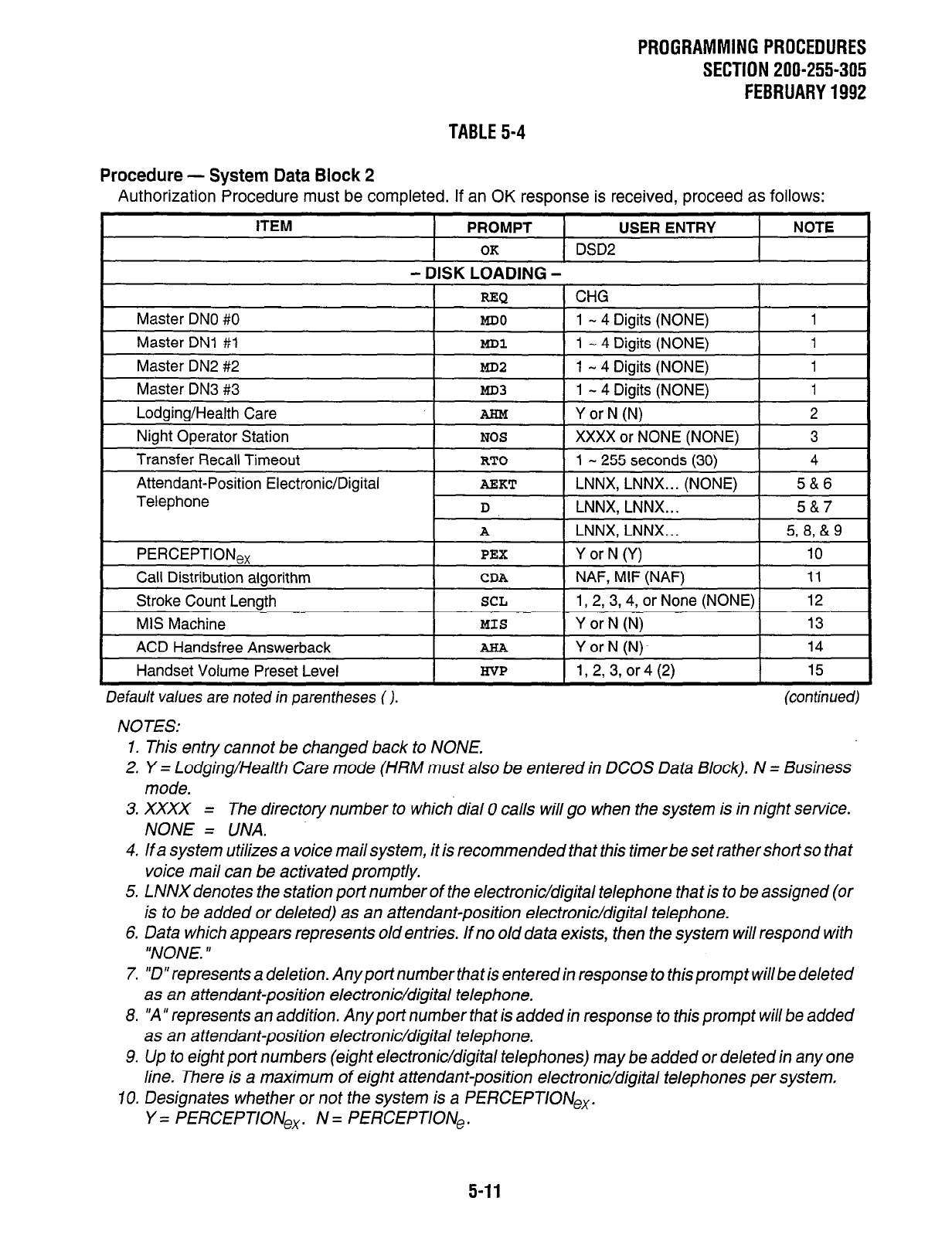
PROGRAMMINGPROCEDURES
SECTION 200-255-305
FEBRUARY1992
TABLE 5-4
Procedure - System Data Block 2
Authorization Procedure must be completed. If an OK response is received, proceed as follows:
ITEM PROMPT USER ENTRY NOTE
OK
DSD2
- DISK LOADING -
REQ
1 CH& I
Master DNO #0
MD0
1 - 4 Digits (NONE) 1
Master DNl #I MD1 1 - 4 Digits (NONE) 1
Master DN2 #2
MD2
1 - 4 Digits (NONE) 1
Master DN3 #3
MD3
1 - 4 Digits (NONE) 1
Lodging/Health Care AHM Y or N (N) 2
Night Operator Station
NOS
XXXX or NONE (NONE) 3
Transfer Recall Timeout
RTO
1 - 255 seconds (30) 4
Attendant-Position Electronic/Digital
Telephone
AEKT
LNNX, LNNX... (NONE) 5&6
D
LNNX, LNNX.. . 5&7
A
LNNX, LNNX. . . 5, 8, & 9
PERCEPTlONe,
PEX
Y or N (Y) 10
Call Distribution algorithm
CDA
NAF, MIF (NAF) 11
Stroke Count Length
SCL
1,2,3,4, or None (NONE) 12
MIS Machine
MIS
Y or N (N) 13
ACD Handsfree Answerback AHA Y orN (N)~ 14
Handset Volume Preset Level
H-VP
1,2,3, or4 (2) 15
Default values are noted in parentheses ( ).
NOTES:
(continued)
1. This entry cannot be changed back to NONE.
2. Y = Lodging/Health Care mode (HRM must also be entered in DCOS Data Block). N = Business
mode.
3. XXXX = The directory number to which dial 0 calls will go when the system is in night service.
NONE = UNA.
4. If a system utilizes a voice mail system, it is recommended that this timer be set rather short so that
voice mail can be activated promptly.
5. LNNX denotes the station port number of the electronic/digital telephone that is to be assigned (or
is to be added or deleted) as an attendant-position electronic/digital telephone.
6. Data which appears represents old entries. If no old data exists, then the system will respond with
“NONE. ’
7. “D” represents a deletion. Any port number that is entered in response to this prompt will be deleted
as an attendant-position electronic/digital telephone.
8. “A’ represents an addition. Any port number that is added in response to this prompt will be added
as an attendant-position electronic/digital telephone.
9. Up to eight port numbers (eight electronic/digital telephones) may be added or deleted in any one
line. There is a maximum of eight attendant-position electronic/digital telephones per system,
10. Designates whether or not the system is a PERCEPTIONex.
Y = PERCEPTIONex. N = PERCEPTlONe.
5-11
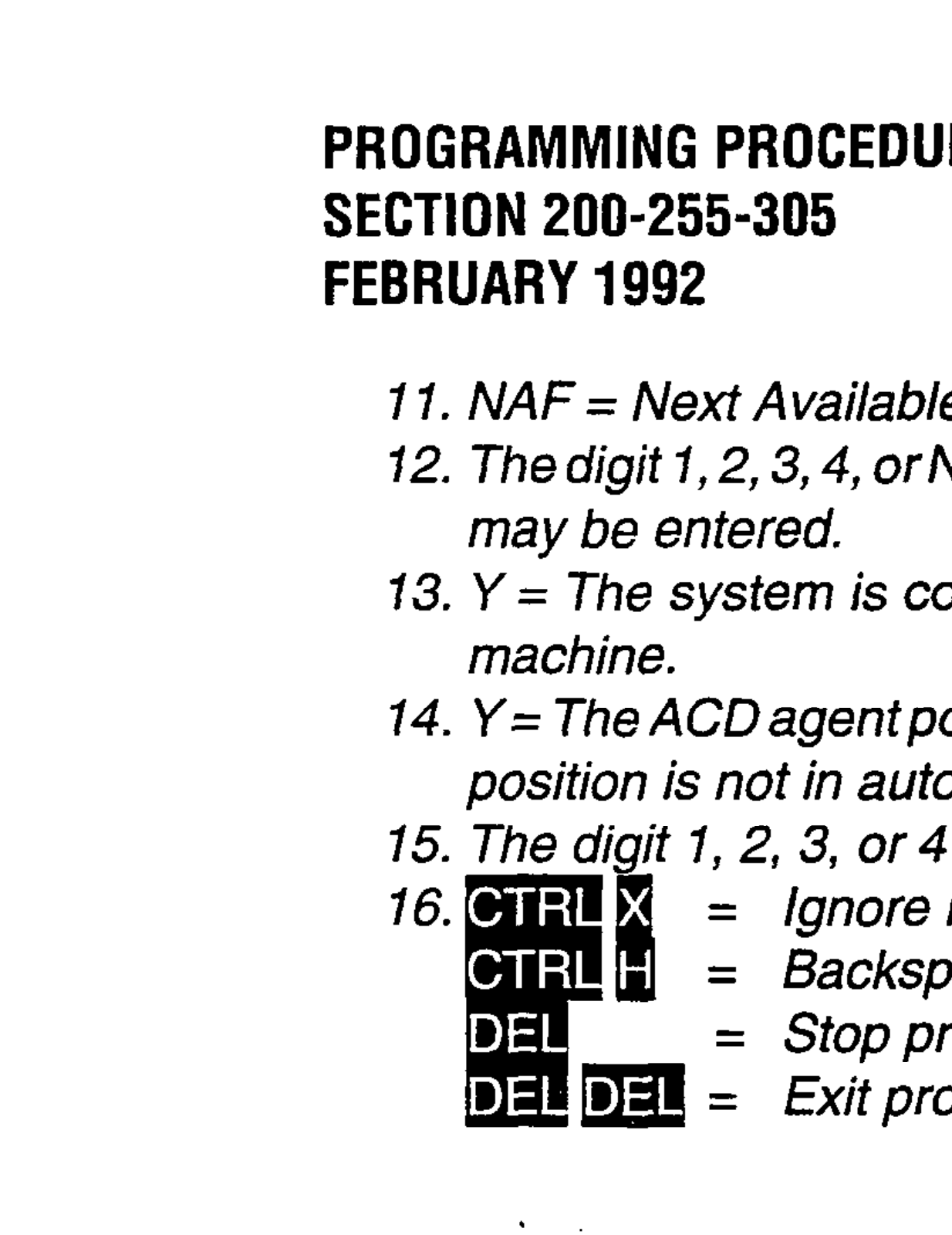
PROGRAMMING PROCEDURES
SECTION 200-255-305
FEBRUARY 1992
I 1. NAF = Next Available First. M/F = Most Idle First.
72. The digit 7, 2,3,4, or NONE. /fan M/S machine is connected, only I- or2-digit code length, or NONE
may be entered.
13. Y = The system is connected to the M/S machine. N = The system is not connected to the MIS
machine.
14. Y= The ACDagentpositionisinauto-answermode (EfWDKTfeature ONLY). N= The ACDagent
position is not in auto-answer mode.
15. The digit 1, 2, 3, or 4 representing the preset level for all digital telephones system wide.
= Ignore line entered.
= Backspace.
= Stop printing and return to REQ.
= Exit program.
TABLE 5-4 (continued)
Error Codes
Program Name: System Data Block 2 (DSD2)
Error Code I Meaning
ERSY2 00
ERSY2 03
ACD Master DN conflicts with existing ACD Master DN.
The port that you are trying to delete does not exist.
ERSY2 04
ERSY2 05
ERSY2 06
ERSY2 08 AlT#l is assigned.
ERSY2 09
The number of ports which has been entered exceeds the
maximum number of eiaht.
The entered port has already been assigned as an attendant-
position electronic/digital telephone port.
The entered port is not an assigned electronic/digital telephone port.
Business mode cannot be changed into Lodging/Health Care mode,
because the number of attendant loop buttons is six or eight.
5-12
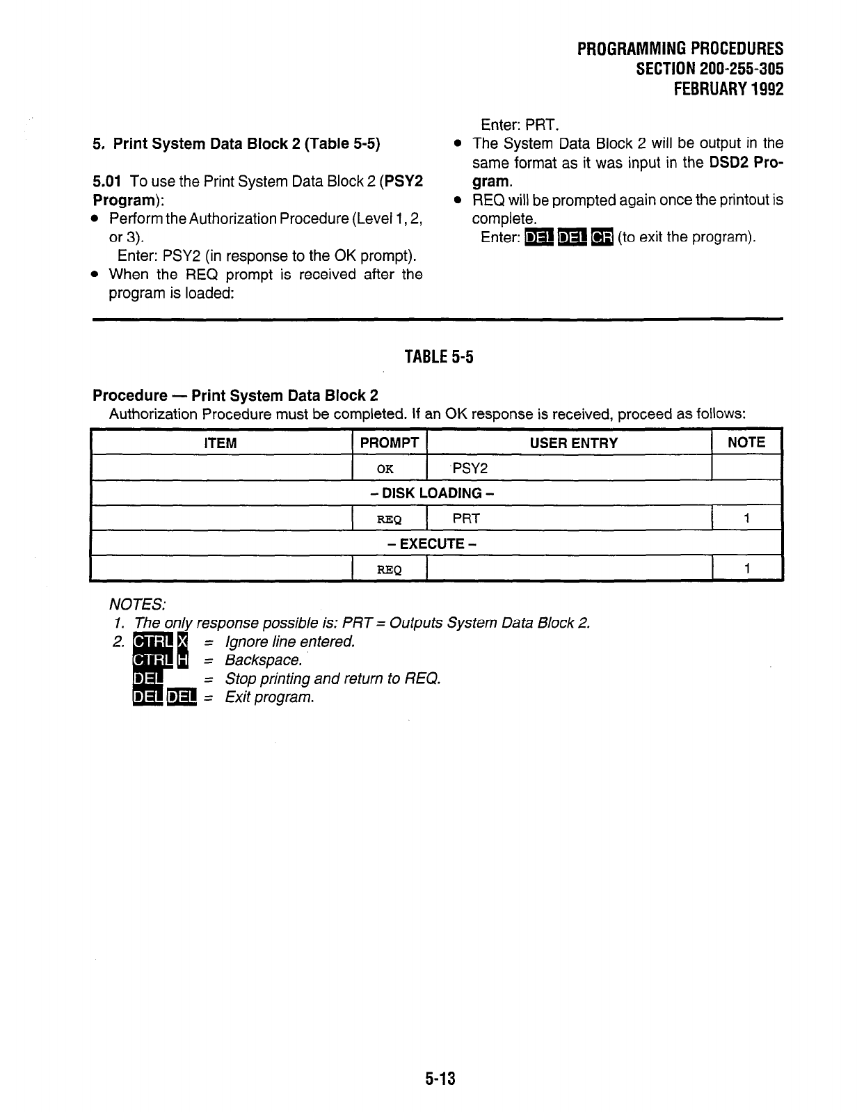
PROGRAMMING PROCEDURES
SECTION 200-255-305
FEBRUARY 1992
Enter: PRT.
5. Print System Data Block 2 (Table 5-5)
5.01 To use the Print System Data Block 2 (PSYS
Program):
l
Perform the Authorization Procedure (Level 1,2,
or 3).
Enter: PSY2 (in response to the OK prompt).
l
When the REQ prompt is received after the
program is loaded:
l
The System Data Block 2 will be output in the
same format as it was input in the DSDP Pro-
gram.
l
REQ will be prompted again once the printout is
complete.
Enter: p w
q
(to exit the program).
TABLE 5-5
Procedure - Print System Data Block 2
Authorization Procedure must be completed. If an OK response is received, proceed as follows:
ITEM PROMPT USER ENTRY NOTE
OK
.PSY2
- DISK LOADING -
=Q
PRT 1
- EXECUTE -
REQ 1
NOTES:
1.
2.
The on/y response possible is: PRT = Outputs System Data Block 2.
5-13
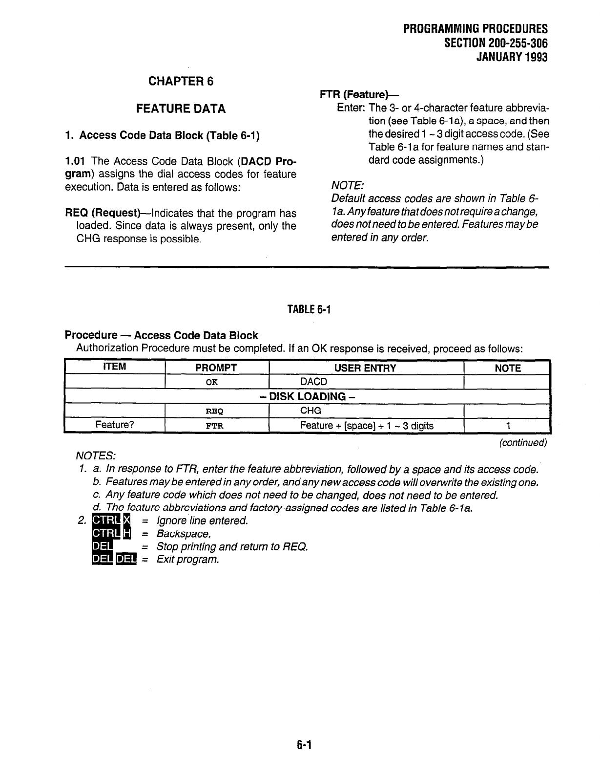
PROGRAMMINGPROCEDURES
SECTION 200-255-306
JANUARY1993
CHAPTER 6
FEATURE DATA
1. Access Code Data Block (Table 6-1)
1.01 The Access Code Data Block (DACD Pro-
gram) assigns the dial access codes for feature
execution. Data is entered as follows:
REQ (Request)--indicates that the program has
loaded. Since data is always present, only the
CHG response is possible.
FTR (Feature)-
Enter: The 3- or 4-character feature abbrevia-
tion (see Table 6-1 a), a space, and then
the desired 1 - 3 digit access code. (See
Table 6-1 a for feature names and stan-
dard code assignments.)
NOTE:
Default access codes are shown in Table 6-
1a. Any fea ture that does not require a change,
does notneed to be entered. Features maybe
entered in any order.
TABLE 6-1
Procedure - Access Code Data Block
Authorization Procedure must be completed. If an OK response is received, proceed as follows:
ITEM PROMPT USER ENTRY NOTE
OK
DACD
- DISK LOADING -
REQ
CHG
Feature?
FTR
Feature + [space] + 1 - 3 digits 1
(continued)
NOTES:
1. a. In response to FTR, enter the feature abbreviation, followed by a space and its access code.
b. Features may be entered in any order, and any new access code will overwrite the existing one.
c. Any feature code which does not need to be changed, does not need to be entered.
d. The feature abbreviations and factory-assigned codes are listed in Table 6-la.
Ignore line entered.
Stop printing and return to REQ.
6-1
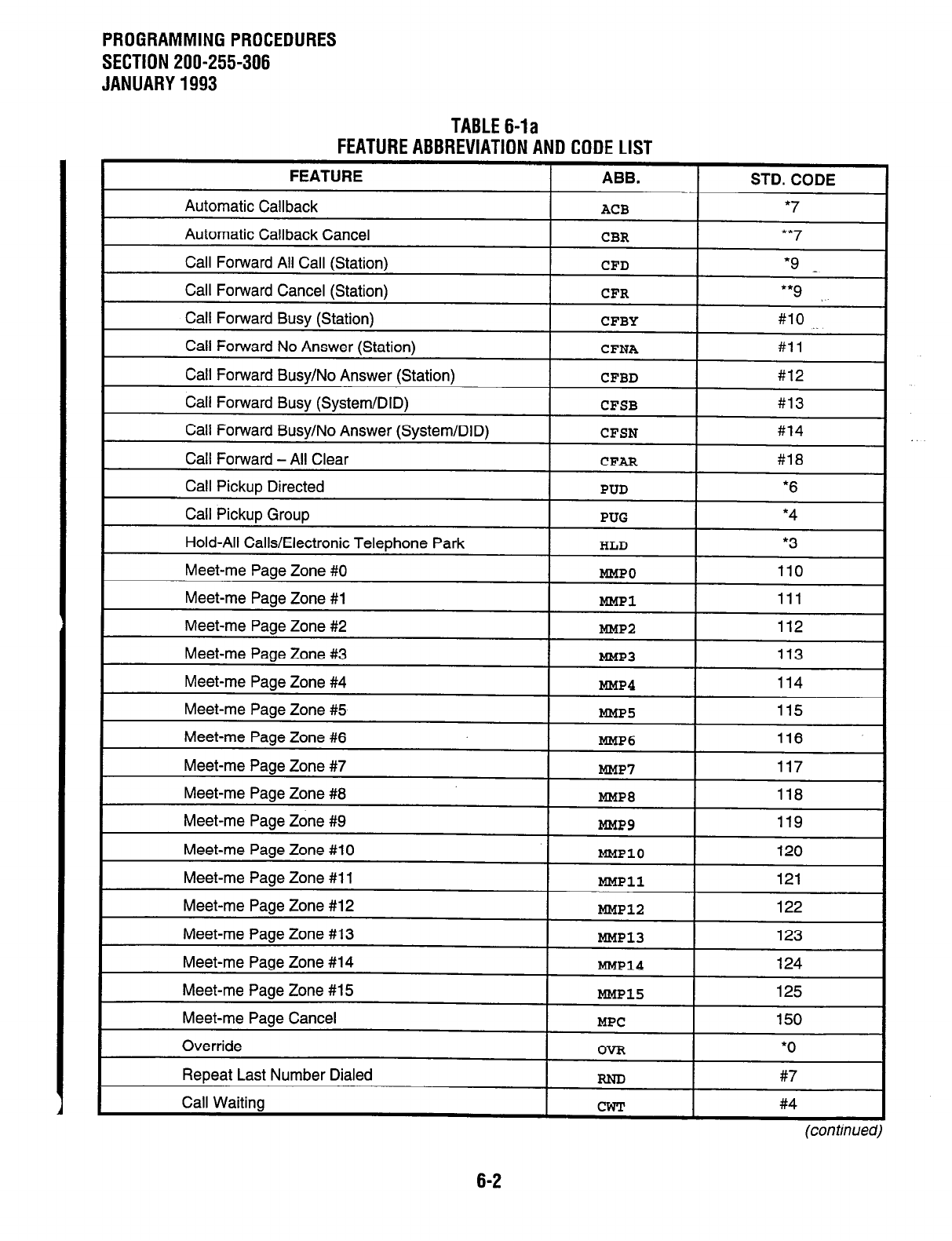
PROGRAMMINGPROCEDURES
SECTION 200-255-306
JANUARY1993
TABLE64a
FEATUREABBREVIATIONANDCODELIST
(con tirtued)
6-2
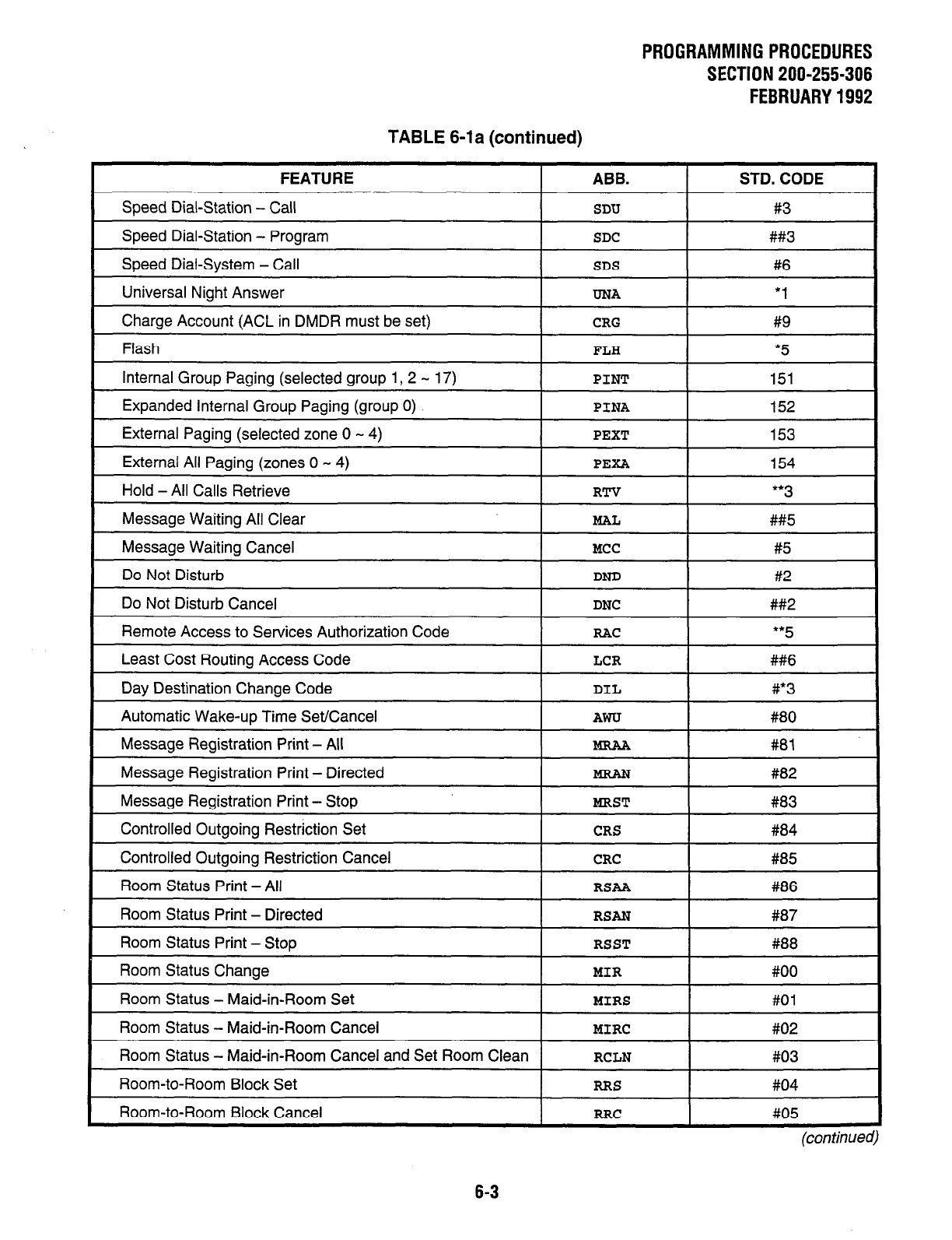
PROGRAMMINGPROCEDURES
SECTlON200-255-306
FEBRUARY1992
TABLE 6-la (continued)
FEATURE
Speed Dial-Station - Call
Speed Dial-Station - Program
Speed Dial-System - Call
Universal Night Answer
Charge Account (ACL in DMDR must be set)
Flash
Internal Group Paging (selected group 1, 2 - 17)
Expanded Internal Group Paging (group 0)
External Paging (selected zone 0 - 4)
External All Paging (zones 0 - 4)
Hold - All Calls Retrieve
Message Waiting All Clear
Message Waiting Cancel
Do Not Disturb
Do Not Disturb Cancel
Remote Access to Services Authorization Code
Least Cost Routing Access Code
Day Destination Change Code
Automatic Wake-up Time Set/Cancel
Message Registration Print - All
Message Registration Print - Directed
Message Registration Print - Stop
Controlled Outgoing Restriction Set
Controlled Outgoing Restriction Cancel
Room Status Print - All
Room Status Print - Directed
Room Status Print - Stop
Room Status Change
Room Status - Maid-in-Room Set
Room Status - Maid-in-Room Cancel
Room Status - Maid-in-Room Cancel and Set Room Clean
Room-to-Room Block Set
Room-to-Room Block Cancel
ABB.
SDU
SDC
SDS
UNA
CRG
FLH
PINT
PINA
PEXT
PEXA
RTV
MAL
MCC
DND
DNC
RAC
LCR
DIL
AWTJ
MRST
CRS
CRC
RSAA
RSAN
RSST
MIR
MIRS
MIRC
RCLN
RRS
RRC
STD. CODE
#3
##3
#6
‘1
#9
*5
151
152
153
154
t* 3
##5
#5
#2
##2
l *
5
##6
#*3
#80
#81
#a2
#83
#84
#85
#86
#87
#88
#OO
#Ol
#02
#03
#04
#05
(con timed)
6-3
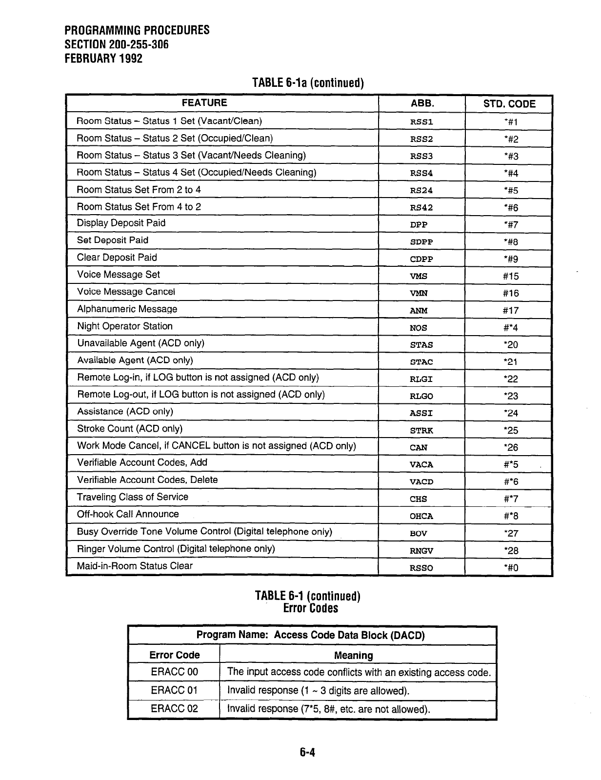
PROGRAMMING PROCEDURES
SECTION 200-255-306
FEBRUARY 1992
TABLE 6-la (continued)
FEATURE ABB. I STD. CODE
Room Status - Status 1 Set (Vacant/Clean) I
RSSl
I %l
Room Status - Status 2 Set (Occuoied/CleanI I
RSS2
I “#2
Room Status - Status 3 Set (Vacant/Needs Cleaning)
RSS3
*#3
Room Status - Status 4 Set (Occupied/Needs Cleaning)
Room Status Set From 2 to 4
RSS4
*#4
RS24 *#5
Room Status Set From 4 to 2 I
RS42 I
*#6
Display Deposit Paid
Set Deposit Paid
Clear Deposit Paid
Voice Message Set
Voice Message Cancel
Alphanumeric Message
Night Operator Station
Unavailable Agent (ACD only)
Available Agent (ACD only)
Remote Log-in, if LOG button is not assigned (ACD only)
Remote Log-out, if LOG button is not assigned (ACD only)
Assistance (ACD only)
Stroke Count (ACD only)
SDPP
*#8
CDPP *#9
VW3
#15
mm #16
AN-M #17
NOS
#*4
STAS
‘20
STAC
l 21
RLGI
*22
RLGO
l 23
ASS1
*24
STRK
l 25
Work Mode Cancel, if CANCEL button is not assigned (ACD only)
Verifiable Account Codes, Add
Verifiable Account Codes, Delete
Traveling Class of Service
Off-hook Call Announce
Busy Override Tone Volume
Control (Digital telephone only)
Ringer Volume Control (Digital telephone only)
Maid-in-Room Status Clear
CAN
‘26
VACA #*5
VACD
#*6
CHS #*7
OHCA
#*8
BOV
*27
RNGV l 28
RSSO
l #fl
TABLE 6-I (continued)
Error Codes
Program Name: Access Code Data Block (DACD)
Error Code Meaning
ERACC 00 The input access code conflicts with an existing access code.
ERACC 01 Invalid response (1 - 3 digits are allowed).
ERACC 02 Invalid response (7*5, 8#, etc. are not allowed).
6-4
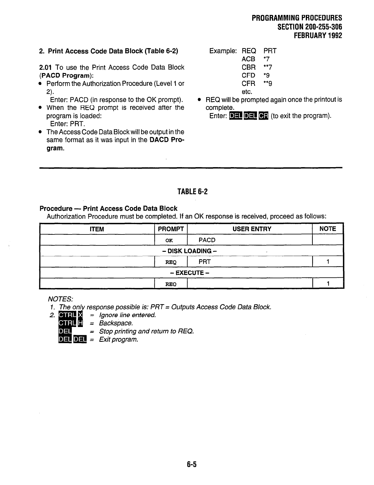
PROGRAMMINGPROCEDURES
SECTION 200-255-306
FEBRUARY1992
2. Print Access Code Data Block (Table 6-2)
2.01 To use the Print Access Code Data Block
(PACD Program):
l
Perform the Authorization Procedure (Level 1 or
a
Enter: PACD (in response to the OK prompt).
l
When the REQ prompt is received after the
program is loaded:
Enter: PRT.
l
The Access Code Data Block will be output in the
same format as it was input in the DACD Pro-
gram.
Example: REQ PRT
ACB *7
CBR **7
CFD *9
CFR **9
etc.
l
REQ will be prompted again once the printout is
complete.
Enter: pm
q
(to exit the program).
TABLE 6-2
Procedure - Print Access Code Data Block
Authorization Procedure must be completed. If an OK response is received, proceed as follows:
ITEM PROMPT
OK
PACD
- DISK LOADING -
USER ENTRY NOTE
I
=Q
PRT
1
- EXECUTE -
RElQ
1
NOTES: response possible is: PRT = Outputs Access Code Data Block.
= Ignore line entered.
Backspace.
Stop printing and return to REQ.
Exit program.
6-5
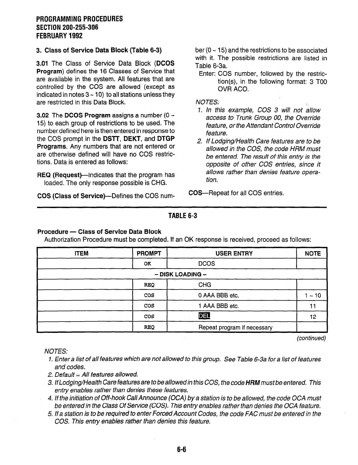
PROGRAMMINGPROCEDURES
SECTION 200-255-306
FEBRUARY1992
3. Class of Service Data Block (Table 6-3)
3.01
The Class of Service Data Block (DCOS
Program)
defines the 16 Classes of Service that
are available in the system. All features that are
controlled by the COS are allowed (except as
indicated in notes 3 - 10) to all stations unless they
are restricted in this Data Block.
3.02
The
DCOS Program
assigns a number (0 -
15) to each group of restrictions to be used. The
number defined here is then entered in response to
the COS prompt in the
DSlT, DEKT,
and
DTGP
Programs.
Any numbers that are not entered or
are otherwise defined will have no COS restric-
tions. Data is entered as follows:
REQ (Request)-Indicates that the program has
loaded. The only response possible is CHG.
COS (Class of Service)--Defines the COS num-
ber (0 - 15) and the restrictions to be associated
with it. The possible restrictions are listed in
Table 6-3a.
Enter: COS number, followed by the restric-
tion(s), in the following format: 3 TOO
OVR ACO.
NOTES:
1. In this example, COS 3 will not allow
access to Trunk Group 00, the Override
feature, or the Attendant Control Override
fea We.
2. If Lodging/Health Care features are to be
allowed in the COS, the code HRM must
be entered. The result of this entry is the
opposite of other COS entries, since it
allows rather than denies feature opera-
tion.
COS-Repeat for all COS entries.
TABLE 6-3
Procedure - Class of Service Data Block
Authorization Procedure must be completed. If an OK response is received, proceed as follows:
ITEM
PROMPT USER ENTRY
OK DCOS
- DISK LOADING -
NOTE
I I
REQ I CHG I
cos
0 AAA BBB etc. l-10
cos 1
AAA BBB
etc. 11
cos Ia! 12
r I REQ
I
Repeat prowam if necessary
I
(con timed)
NOTES:
1. Enter a list of all features which are not allowed fo this group. See Table 6-3a for a list of features
and codes.
2. Default = All features allowed.
3. lfLodging/Health Care features are to be allowed in this COS, the code HRM must be entered. This
entry enables rather than denies these features.
4. If the initiation of Off-hook Call Announce (OCA) by a station is to be allowed, the code OCA must
be entered in the Class Of Service (COS). This entry enables rather than denies the OCA feature.
5. If a station is to be required to enter Forced Account Codes, the code FAC must be entered in the
COS. This entry enables rather than denies this feature.
6-6
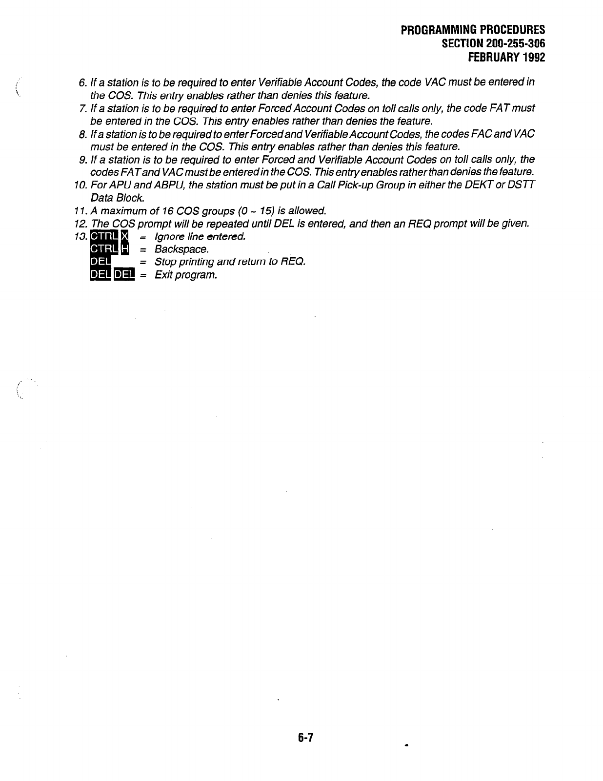
PROGRAMMING PROCEDURES
SECTION 200-255-306
FEBRUARY 1992
6. If a station is to
be
required to enter Verifiable Account Codes, the code VAC must be entered in
the COS. This entry enables rather than denies this feature.
7. If a station is to be required to enter Forced Account Codes on to// calls only, the code FATmust
be entered in the COS. This entry enables rather than denies the feature.
8. if a station is to be required to enter Forcedand Verifiable Account Codes, the codes FAC and VAC
must be entered in the COS. This entry enables rather than denies this feature.
9. If a station is to be required to enter Forced and Verifiable Account Codes on toll calls only, the
codes FATand VACmust be enteredin the COS. This entry enables rather than denies the feature.
IO. For APU and ABPU, the station must be put in a Call Pick-up Group in either the DEKTor DSTT
Data Block.
I 1. A maximum of 16 COS groups (0 - 15) is allowed,
12. The COS prompt will be repeated until DEL is entered, and then an REQ prompt will be given.
= ignore line entered.
= Backspace.
- Stop printing and return to REQ.
= Exit program.
/’
6-7
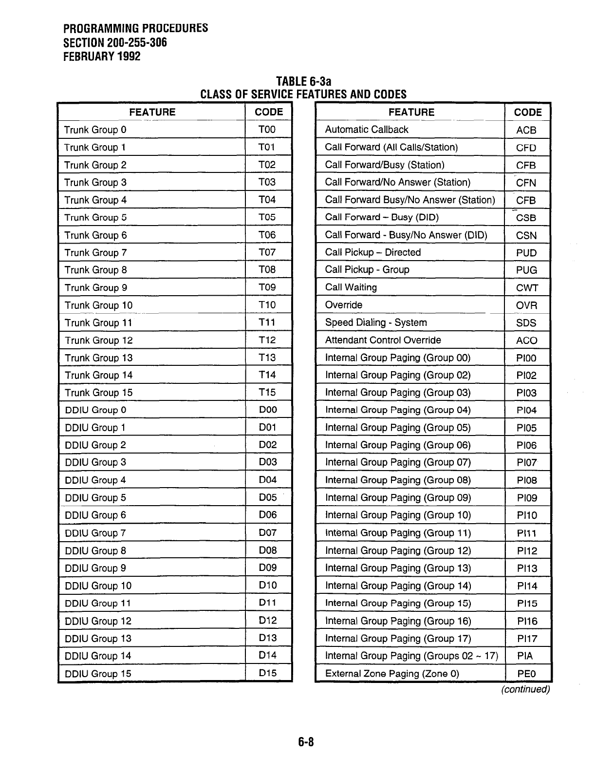
PROGRAMMING PROCEDURES
SECTION 200-255-306
FEBRUARY 1992
TABLE 6-3a
CLASS OF SERVICE FEATURES AND CODES
I
FEATURE 1 CODE
I
Trunk Group 0
Trunk Group 1 TO1
Trunk Grouo 2 TO2
1 Trunk Group 3
I
TO3
I
Trunk Group 7
1 Trunk Group 14 I T14
I
Trunk Group 15
I
DDIU Group 3
DDIU Group 10
DDIU Grouo 11
DlO
Dll
DDIU Group 12
DDIU Group 13
D12
D13
DDIU Group 14
DDIU GrouD 15
D14
D15
FEATURE CODE
Automatic Callback ACB
Call Forward (All Calls/Station) CFD
Call Forward/Busy (Station) CFB
Call Forward/No Answer (Station) ‘CFN
Call Forward Busy/No Answer (Station) -CFB
Call Forward - Busy (DID) CSB
Call Forward - Busy/No Answer (DID) CSN
Call Pickup - Directed PUD
Call Pickup - Group PUG
Call Waiting CW-I-
Override OVR
Speed Dialing - System SDS
Attendant Control Override AC0
Internal Group Paging (Group 00) PI00
Internal Group Paging (Group 02) PI02
Internal Group Paging (Group 03) PI03
Internal Group Paging (Group 04) PI04
Internal Group Paging (Group 05) PI05
Internal Group Paging (Group 06) PI06
Internal Group Paging (Group 07) PI07
Internal Group Paging (Group 08) PI08
Internal Group Paging (Group 09) PI09
Internal Group Paging (Group 10) PI10
Internal Group Paging (Group 11) PI11
Internal Group Paging (Group 12) PI12
Internal Group Paging (Group 13) PI13
Internal Group Paging (Group 14) PI14
Internal Group Paging (Group 15) PI15
Internal Group Paging (Group 16) PI16
Internal Group Paging (Group 17) PI17
Internal Group Paging (Groups 02 - 17) PIA
External Zone Paging (Zone 0) PEO
(con timed)
6-8
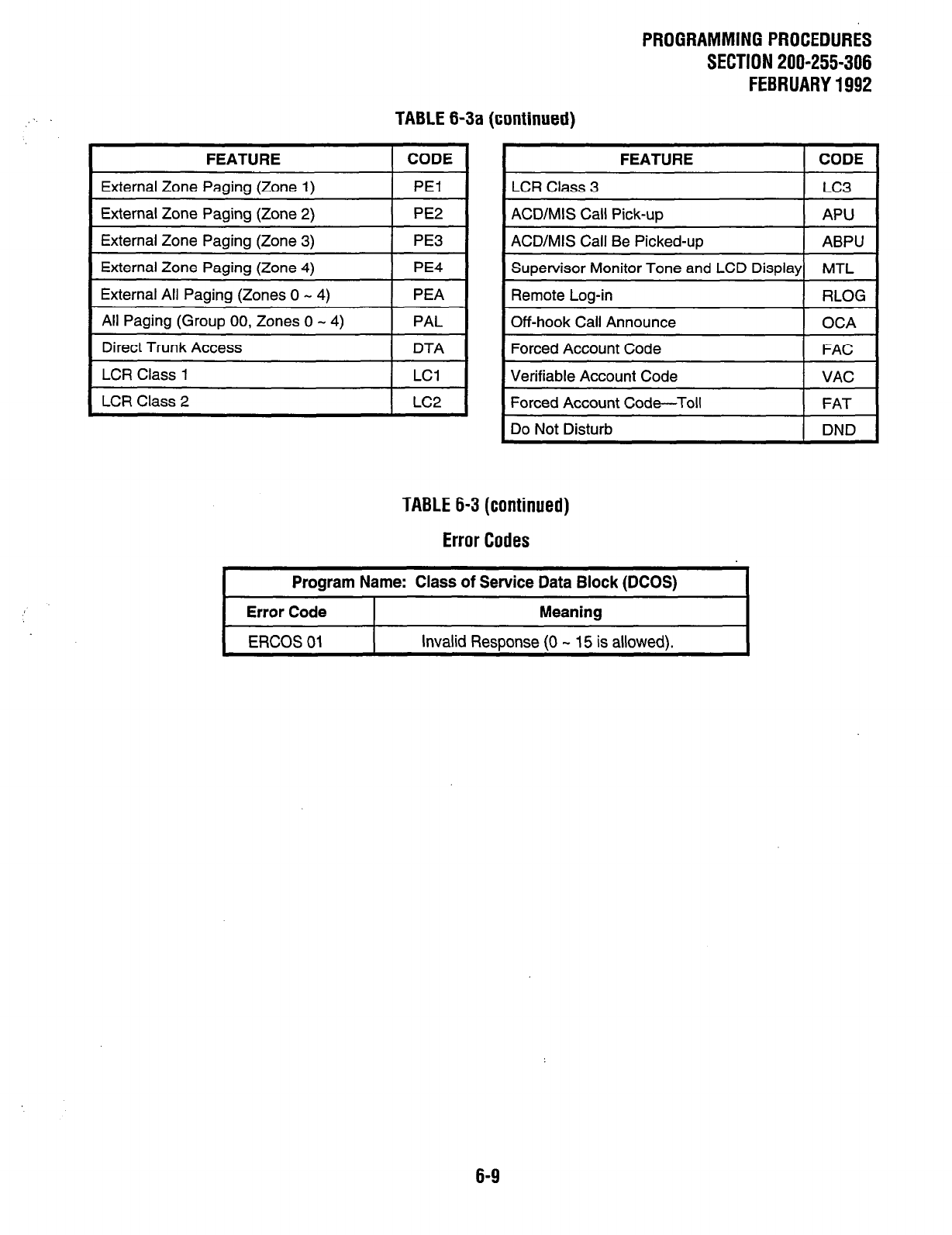
PROGRAMMING PROCEDURES
SECTION 200-255-306
FEBRUARY 1992
TABLE 6-3a (continued)
FEATURE CODE
External Zone Paging (Zone 1) PEI
External Zone Paging (Zone 2) PE2
External Zone Paging (Zone 3) PE3
External Zone Paging (Zone 4) PE4
External All Paging (Zones 0 - 4) PEA
All Paging (Group 00, Zones 0 - 4) PAL
Direct Trunk Access DTA
LCR Class 1 LCl
LCR Class 2 LC2
FEATURE CODE
LCR Class 3 LC3
ACD/MIS Call Pick-up APU
ACD/MIS Call Be Picked-up ABPU
Supervisor Monitor Tone and LCD Display MTL
Remote Log-in RLOG
Off-hook Call Announce OCA
Forced Account Code FAC
Verifiable Account Code VAC
Forced Account Code-Toll FAT
Do Not Disturb DND
TABLE 6-3 (continued)
Error Codes
Program Name: Class of Service Data Block (DCOS)
Error Code Meaning
ERCOS 01 Invalid Resoonse (0 - 15 is allowed).
6-9
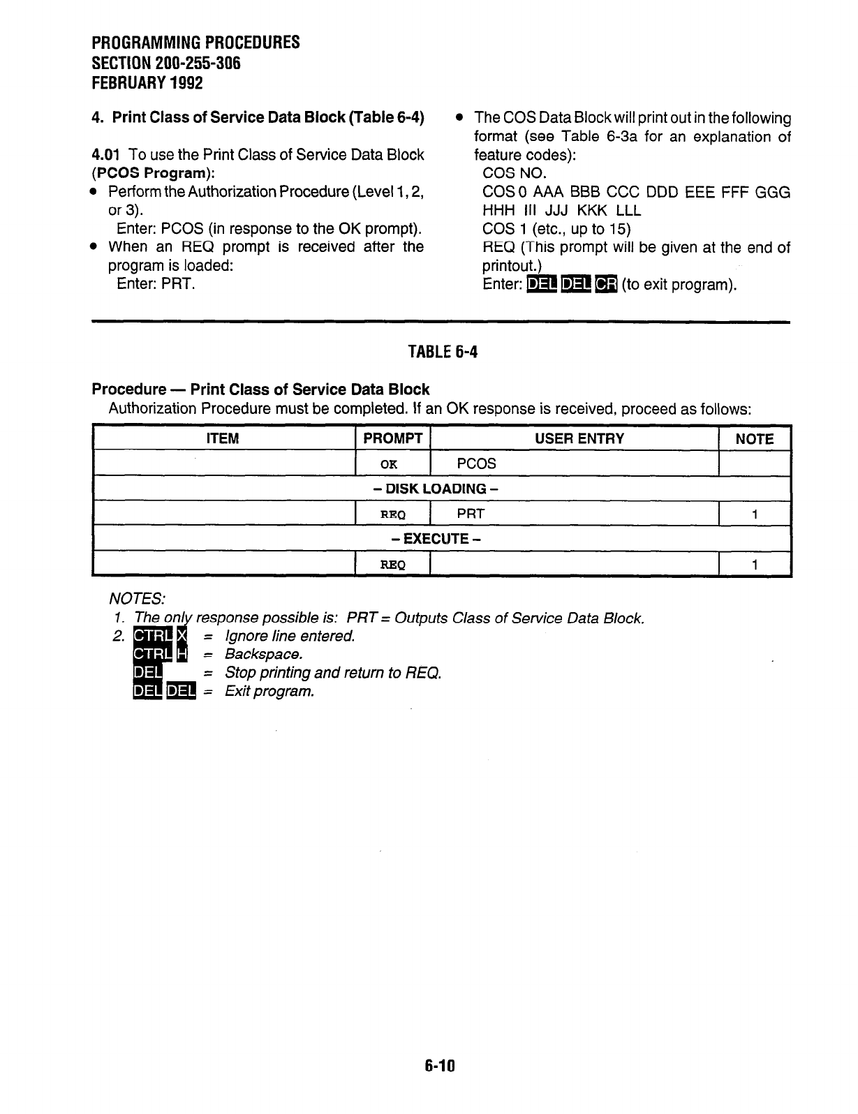
PROGRAMMINGPROCEDURES
SECTION 200-255-306
FEBRUARY1992
4. Print Class of Service Data Block (Table 6-4)
4.01 To use the Print Class of Service Data Block
(PCOS Program):
l
Perform the Authorization Procedure (Level 1,2,
or 3).
Enter: PCOS (in response to the OK prompt).
l
When an REQ prompt is received after the
program is loaded:
Enter: PRT.
l
The COS Data Block will print out in the following
format (see Table 6-3a for an explanation of
feature codes):
COS NO.
COSO AAA BBB CCC DDD EEE FFF GGG
HHH ill JJJ KKK LLL
COS 1 (etc., up to 15)
REQ (This prompt will be given at the end of
printout.)
Enter: w m 19 (to exit program).
TABLE 6-4
Procedure - Print Class of Service Data Block
Authorization Procedure must be completed. If an OK response is received, proceed as follows:
ITEM PROMPT
OK
PCOS
USER ENTRY NOTE
- DISK LOADING -
=Q PRT
- EXECUTE -
=Q
NOTES: is: PRT = Outputs Class of Service Data Block.
= Stop printing and return to REQ.
6-10
PROGRAMMING PROCEDURES
SECTION 200-255-307
FEBRUARY 1992
CHAPTER 7
Al-i-ENDANT/STATION/DSS DATA
1. Attendant Data Block (Table 7-I)
1.01 The Attendant Data Block (DAlT Program)
defines one or two attendant consoles in the sys-
tem and selects the attendant options. Data is
entered as follows:
REQ (Request)-Indicates that the program has
loaded. Three responses are possible:
NEW-To create a new Data Block.
CHG-To alter an existing Data Block.
OUT-To delete an existing Data Block.
AN0 (Attendant Number)---Selects the console
that is to be assigned.
Enter: 0 or 1.
POR (Port Number)-Selects the port that is to be
occupied by the console.
Enter: For PERCEPTlONe-LO01 for Atten-
dant Console #O.
L151 for Attendant Console #I.
For PERCEPTION,,-LO01 for Atten-
dant Console #O.
LO1 1 for Attendant Console #l.
NLPK (Number of Loop Keys)-Indicates the
quantity of buttons that can be designated as
Attendant Loop Buttons. _
Enter: 4, 6, or 8.
NOTE:
If the system is operating in the Lodging/
Health Care mode, only four loop buttons can
be assigned.
LKO (Lockout Allowed?)-A “Y” response will
enable the lockout feature, and will not allow the
attendant to re-enter a held m button confer-
ence.
Enter: Y or N.
paging zones, or the Expanded Internal Paging
Group and all external paging zones. Options
that are not assigned to the feature access
button may still be accessed by dialing a paging
access code.
Enter one of the following:
INT-Expanded Internal Group Paging
(Group 0).
EXT-External All Paging (Zones 0 - 4).
N-External Paging to Zone N (0 - 4).
ALL-Expanded Internal Group Paging and
External All Paging.
NONE-No Internal or External Paging
Access.
PRI (Incoming Call Priority )-A “Y” response will
direct all calls to the attendant console according
to the priority defined by the PRl - PR5 prompts.
An “N” response will direct all calls to the atten-
dant console on a first-in/first-out priority basis.
Enter: Y or N.
PRl - 5 (Priority 1 - 5, Current)--A “Y” response
to the PRI prompt will print the current priority
tables.
PRl - 5 (Priority 1 - 5, Set)--Defines the incoming
call priority. The possible types of calls are: CO,
FX, TIE, WAT, OPR, RCL, HLD, TIM, LNl, LN2,
INT, SER (Business mode only).
Enter: NN or NNN (type of call).
NOTE:
There is no program provided to print out the
Attendant Data Bock.
PAG (Page Button)-Assigns the console m
button to access either the Expanded Internal
Paging Group (Group 0), one or all external
7-1
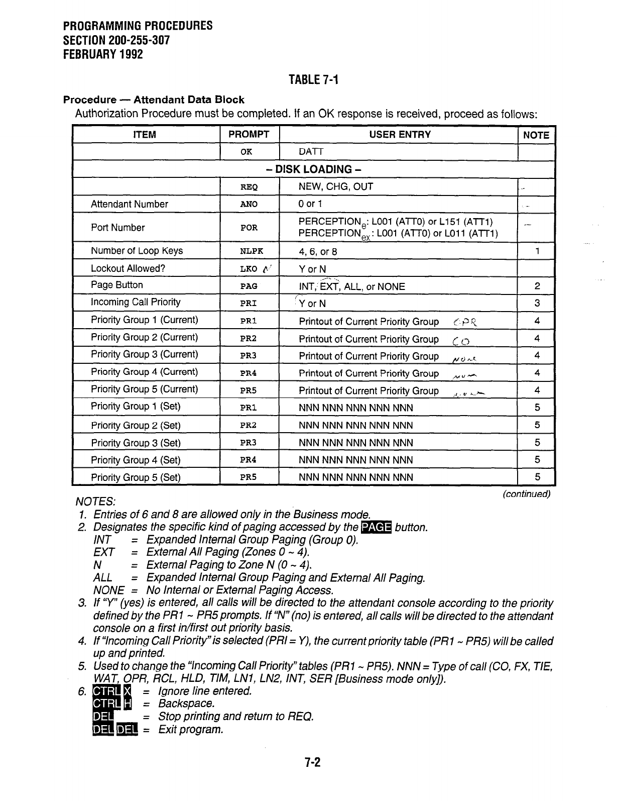
PROGRAMMINGPROCEDURES
SECTION 200-255-307
FEBRUARY1992
TABLE7-1
Procedure - Attendant Data Block
Authorization Procedure must be completed. If an OK response is received, proceed as follows:
NOTES: (continued)
1. Entries of 6 and 8 are allowed only in the Business mode.
2. Designates the specific kind of paging accessed by the m button.
/NT = Expanded Internal Group Paging (Group 0).
EXT = External All Paging (Zones 0 - 4).
N = External Paging to Zone N (0 - 4).
ALL = Expanded Internal Group Paging and External All Paging.
NONE = No Internal or External Paging Access.
3. If ‘7”’ (yes) is entered, all calls will be directed to the attendant console according to the priority
defined by the PR1 - PR5 prompts. If “N” (no) is entered, all calls will be directed to the attendant
console on a first in/first out priority basis.
4. If “Incoming Call Priority” is selected (PI?/ = Y), the current priority table (PR 1 - PR5) will be called
up and printed.
5. Used to change the “Incoming Call Priority” tab/es (PRl - PR5). NNN = Type of call (CO, FX, T/E,
WAT, OPR, RCL, HLD, TIM, LNl, LN2, INT, SER[Business mode only]).
7-2
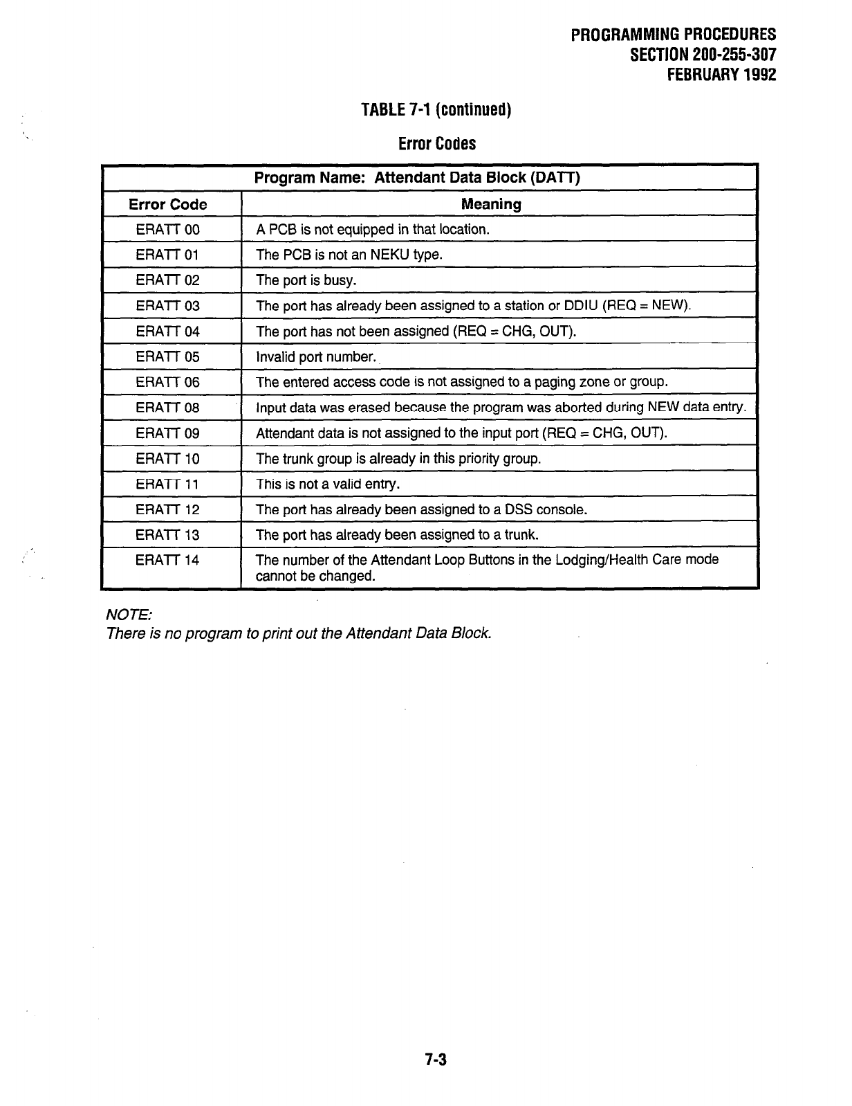
PROGRAMMING PROCEDURES
SECTION 200-255-307
FEBRUARY 1992
TABLE 7-1 (continued)
Error Codes
Program Name: Attendant Data Block (DAlT)
Error Code
ERAT-T 00
ERATT 01
ERA-I-T 02
ERAl-f 03
ERATI- 04
ERAl-F 05
ERA-I-T 06
ERA-I-I- 08
ERA-IT 09
ERA-I-T 10
ERAl-T 11
ERA-I-T 12
ERA-I-T 13
ERA-I-T 14
Meaning
A PCB is not equipped in that location.
The PCB is not an NEKU type.
The port is busy.
The port has already been assigned to a station or DDIU (REQ = NEW).
The port has not been assigned (REQ = CHG, OUT).
Invalid port number.
The entered access code is not assigned to a paging zone or group.
Input data was erased because the program was aborted during NEW data entry.
Attendant data is not assigned to the input port (REQ = CHG, OUT).
The trunk group is already in this priority group.
This is not a valid entry.
The port has already been assigned to a DSS console.
The port has already been assigned to a trunk.
The number of the Attendant Loop Buttons in the Lodging/Health Care mode
cannot be changed.
NOTE:
There is no program to print out the Attendant Data Block.
7-3
PROGRAMMING PROCEDURES
SECTION 200-255-307
FEBRUARY 1992
2. Electronic/Digital Telephone Data Block
(Table 7-2)
2.01 The Electronic/Digital Telephone Data Block
(DEKT Program) defines all parameters for each
electronic/digital telephone. A separate Electronic/
Digital Telephone Data Block must be completed
for each electronic/digital telephone in the system.
Data is entered as follows:
REQ (Request)-Indicates that the program has
loaded. Three responses are possible:
NEW-To create a new Data Block.
CHG-To alter an existing Data Block.
OUT-To delete an existing Data Block.
POR (Port Number)-Identifies the hardware lo-
cation of the electronic/digital telephone circuit
that is to be defined. The port number has two
parts:
1) NEKU/NDKU PCB location:
PERCEPTION, -LOO-Lll/Ll&L26(NN).
PERCEPTlONe, -LOO - L31 (NN).
2) Circuit number on that PCB: 1 - 8 (X).
Example: The port number of the 4th circuit
on the NEKU/NDKU in position
LO1 is L014.
Enter: Port number of the electronic/digital
telephone (LNNX).
NOTES:
1. If the OUT command was given above, the
port just defined will be deleted and the
next prompt will be REQ.
2. Port L378 cannot be assigned.
3. The NEKU will not support Digital Tele-
phones and the NDKU will not support
Electronic telephones.
DKT (Digital Key Telephone)-Defines the type
of telephone. A YES answer is to be entered with
digital telephones, and a NO answer with non-
digital electronic telephones.
Enter: Y or N.
KS (Number of Button Strips)-Informs the sys-
tem of the number of feature buttons (groups of
ten) that the electronic/digital telephone will have.
Enter: 1 (for 1 O-button) or 2 (for 20-button).
COS (Class of Service)-Assigns one of the 16
Classes of Service to the electronic/digital tele-
phone. (Classes of Service are defined in the
DCOS Program.)
Enter: COS Number (0 - 15).
TEN (Tenant Number)-Assigns the electronic/
digital telephone to one of two possible tenants
in the system.
Enter: 0 if tenant service is not selected in the
DSYS Program (TEN = N).
0 or 1 to indicate the specific tenant if
tenant service is selected in the DSYS
Program (TEN = Y).
PUG (Call Pickup Group)-Assigns the elec-
tronic/digital telephone to one of the 32 possible
Call Pickup groups.
Enter: Group number (0 - 31) or NONE.
WTA (Warning Tone Allowed? )-Defines an in-
terruption-protected station. An “N” response
will prevent warning tones from being applied to
the station. (CWT cannot be assigned if N is
entered.)
Enter: Y or N.
CFT(Call Forward toTrunk)-Permits calls tothis
station to be forwarded over a trunk to an outside
directory number (maximum: 16 digits).
Enter: Y or N.
TOL
(Toll Restricted Class)-Assigns one of the
ten classes of Toll Restriction to the electronic/
digital telephone. Classes 0 - 7 are defined in the
Toll Restriction Data Block (DTOL Program).
Class 8 is simple toll restriction, restricting when
0 or 1 is dialed as the first digit. NONE defines the
electronic/digital telephone as unrestricted.
Enter: 0 - 8 or NONE.
MTA (Not Used):
Enter: N.
HFA (Handsfree Answerback Equipped)-A ‘9”’
response activates the Handsfree Answerback
7-4
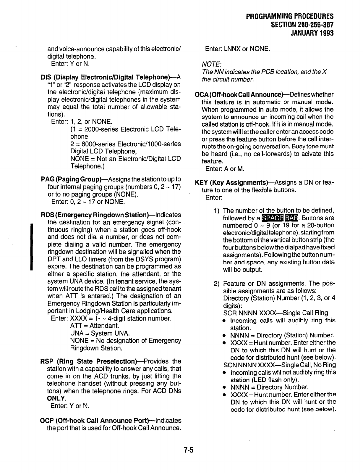
and voice-announce capability of this electronic/
digital telephone.
Enter: Y or N.
DIS (Display Electronic/Digital Telephone)-A
“1” or “2” response activates the LCD display on
the electronic/digital telephone (maximum dis-
play electronic/digital telephones in the system
may equal the total number of allowable sta-
tions).
Enter: 1, 2, or NONE.
(1 = 2000-series Electronic LCD Tele-
phone,
2 = 6000~series Electronic/l OOO-series
Digital LCD Telephone,
NONE = Not an Electronic/Digital LCD
Telephone.)
PAG (Paging Group)-Assigns
the station to up to
four internal paging groups (numbers 0, 2 - 17)
or to no paging groups (NONE).
Enter: 0, 2 - 17 or NONE.
RDS (Emergency Ringdown Station)-Indicates
the destination for an emergency signal (con-
tinuous ringing) when a station goes off-hook
and does not dial a number, or does not com-
plete dialing a valid number. The emergency
ringdown destination will be signalled when the
DPT
and LLO timers (from the DSYS program)
expire. The destination can be programmed as
either a specific station, the attendant, or the
system UNA device. (In tenant service, the sys-
tem will route the RDS call to the assigned tenant
when ATT is entered.) The designation of an
Emergency Ringdown Station is particularly im-
portant in Lodging/Health Care applications.
Enter: XXXX = l- - 4-digit station number.
AIT = Attendant.
UNA = System UNA.
NONE = No designation of Emergency
Ringdown Station.
RSP (Ring State Preselection)-Provides
the
station with a capability to answer any calls, that
come in on the ACD trunks, by just lifting the
telephone handset (without pressing any but-
tons) when the telephone rings. For ACD DNs
ONLY.
Enter: Y or N.
OCP (Off-hook Call Announce
Port)-Indicates
the port that is used for Off-hook Call Announce.
PROGRAMMINGPROCEDURES
SECTION 200-255-307
JANUARY1993
Enter: LNNX or NONE.
NOTE:
The NN indicates the PCB location, and the X
the circuit number.
OCA(Off-hookCallAnnounce)-Defineswhether
this feature is in automatic or manual mode.
When programmed in auto mode, it allows the
system to announce an incoming call when the
called station is off -hook. If it is in manual mode,
the system will let the caller enter an access code
or press the feature button before the call inter-
rupts the on-going conversation. Busy tone must
be heard (i.e., no call-forwards) to acivate this
feature.
Enter: A or M.
KEY (Key Assignments)-Assigns
a DN or fea-
ture
to one of the flexible buttons.
Enter:
1)
2)
The number of the button to be defined,
followed by a m m. Buttons are
numbered 0 - 9 (or 19 for a 20-button
electronic/digital telephone), startingfrom
the bottom of the vertical button strip (the
four buttons below the dialpad have fixed
assignments). Following the button num-
ber and space, any existing button data
will be output.
Feature or DN assignments. The pos-
sible assignments are as follows:
Directory (Station) Number (1, 2, 3, or 4
digits):
SCR NNNN XXXX-Single Call Ring
l
Incoming calls will audibly ring this
station.
l
NNNN = Directory (Station) Number.
l
XXXX = Hunt number. Enter either the
DN to which this DN will hunt or the
code for distributed hunt (see below).
SCN NNNN XXXX-Single Call, No Ring
l
Incoming calls will not audibly ring this
station (LED flash only).
l
NNNN = Directory Number.
0 XXXX = Hunt number. Enter either the
DN to which this DN will hunt or the
code for distributed hunt (see below).
7-5
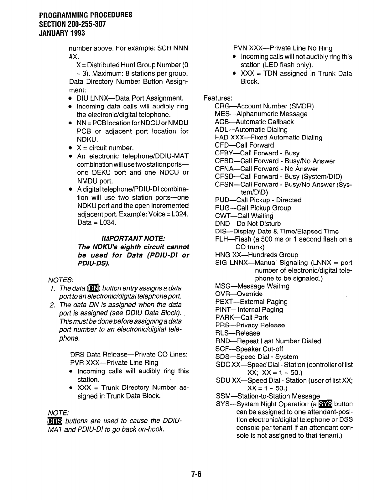
PROGRAMMING PROCEDURES
SECTION 200-255-307
JANUARY 1993
number above. For example: SCR NNN
#X.
X = Distributed Hunt Group Number (0
- 3). Maximum: 8 stations per group.
Data Directory Number Button Assign-
ment:
0
0
0
NOTES:
DIU LNNX-Data Port Assignment.
Incoming data calls will audibly ring
the electronic/digital telephone.
NN = PC9 location for NDCU or NMDU
PC9 or adjacent port location for
NDKU.
X = circuit number.
An electronic telephone/DDIU-MAT
combination will use two station ports-
one DEKU port and one NDCU or
NMDU port.
A digital telephone/PDIU-DI combina-
tion will use two station ports-one
NDKU port and the open incremented
adjacent port. Example: Voice = L024,
Data = L034.
IMPORTANT NOTE:
The NDKU’s eighth circuit cannot
be used for Data (PDIU-DI or
PDIU-DS).
7, The data a) button entry assigns a data
port to an electronic/digital telephone port.
2, The data DN is assigned when the data
port is assigned
(see
DDIU
Data Block).
This must be done before assigning a data
port number to an electronic/digital tele-
phone.
DRS Data Release-Private CO Lines:
PVR XXX-Private Line Ring
l
Incoming calls will audibly ring this
station.
l
XXX = Trunk Directory Number as-
signed in Trunk Data Block.
NOTE:
lm buttons are used to cause the DDIU-
MAT and PDIU-DI to go back on-hook.
PVN XXX-Private Line No Ring
l
Incoming calls will not audibly ring this
station (LED flash only).
l
XXX = TDN assigned in Trunk Data
Block.
Features:
CRG-Account Number (SMDR)
MES-Alphanumeric Message
ACB-Automatic Callback
ADL-Automatic Dialing
FAD XXX-Fixed Automatic Dialing
CFD-Call Forward
CFBY-Call Forward - Busy
CFBD-Call Forward - Busy/No Answer
CFNA-Call Forward - No Answer
CFSB-Call Forward - Busy (System/DID)
CFSN-Call Forward - Busy/No Answer (Sys-
tem/DID)
PUD-Call Pickup - Directed
PUG-Call Pickup Group
CWT-Call Waiting
DND-Do Not Disturb
DIS-Display Date & Time/Elapsed Time
FLH-Flash (a 500 ms or 1 second flash on a
CO trunk)
HNG XX-Hundreds Group
SIG LNNX-Manual Signaling (LNNX = port
number of electronic/digital tele-
phone to be signaled.)
MSG-Message Waiting
OVR-Override
PEXT-External Paging
PINT-Internal Paging
PARK-Call Park
PRS-Privacy Release
RLS-Release
RND-Repeat Last Number Dialed
SCF-Speaker Cut-off
SDS-Speed Dial - System
SDC XX-Speed Dial - Station (controller of list
xx; xx = 1 - 50.)
SDU XX-Speed Dial - Station (user of list XX;
xx = 1 - 50.)
SSM-Station-to-Station Message
SYS-System Night Operation (a m button
can be assigned to one attendant-posi-
tion electronic/digital telephone or DSS
console per tenant if an attendant con-
sole is not assigned to that tenant.)
7-6
PROGRAMMING PROCEDURES
SECTION 200-255-307
JANUARY 1993
UNA-Universal Night Answer
VCP XXXX-Voice Page (XXXX = DN to be
paged.)
ACDS XXXX-ACD Supervisor Line
ACDA XXX-ACD Agent Line
ASST-Assistance
LOG-Log-in/out
MONT-Monitor
OCA-Off-hook Call Announce
STAT-Status Available/Unavailable
STRK-Stroke Count
ATAP-Agent Monitor
CAN-Work Mode Cancel
NOTE:
The system does not check to verify if two
buttons are assigned the same feature. When
programming digital telephones (DKT= Y), do
NOTassign RND and MSG to feature buttons.
They are fixed buttons on the telephone set.
KEY-The prompt will be repeated until all entries
have been made and the m key is pressed.
7-7
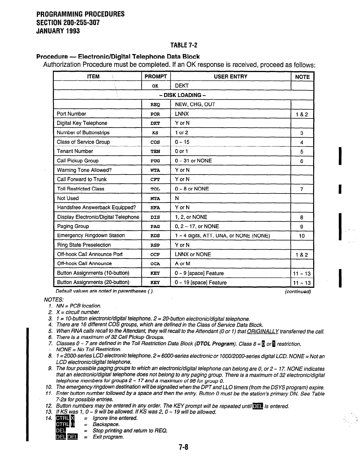
PROGRAMMING PROCEDURES
SECTION 200-255-307
JANUARY 1993
TABLE 7-2
Procedure - Electronic/Digital Telephone Data Block
Authorization Procedure must be completed. If an OK response is received, proceed as follows:
ITEM ‘: PROMPT USER ENTRY NOTE
OK DEKT
- DISK LOADING - I
I
REQ I NEW, CHG, OUT
I1
Port Number POR LNNX l&2
Digital Key Telephone DKT Y or N
Number of Buttonstrips KS 1 or2 3
Class of Service Group cos o-15 4
Tenant Number I TEN
I
0 or 1
I
5 I
Call Pickup Group
I
PUG
I
0 - 31 or NONE
1 -61
Warning Tone Allowed?
Call Forward to Trunk
Toll Restricted Class
WTA Y or N
CFT Y or N
TOL 0-8orNONE
7 I
Not Used
I
mA
1 N I
Handsfree Answerback Equipped? I HFA I Y or N
I
Display Electronic/Diqital Telephone I DIS 1 1,2, or NONE
1-s
Paging Group
Emergency Ringdown Station
Ring State Preselection
PA0
RDS
RSP
0,2-17,0rNONE
1 - 4 digits, ATT, UNA, or NONE (NONE)
Y or N
9
IO
Off-hook Call Announce Port
Off-hook Call Announce
OCP
OCA
LNNX or NONE
A or M
l&2
Button Assignments (lo-button) I KEY
I
o - 9 [space] Feature
l11-13
Button Assignments (20-button) I KEY
I
0 - 19 [space1 Feature Ill - 13
L
Default values are noted in parentheses (). (continued)
NOTES:
1. NN = PCB location.
2. X = circuit number.
3. 1 = 1 O-button electronic/dig~tal telephone. 2 = ZO-button electronic/digiital telephone.
4. There are 16 different COS groups, which are defined in the Class of Service Data Block.
5. When RNA calls recall to the Attendant, they will recall to the Attendant (0 or 1) that ORIGINALLY transferred the call.
6. There is a maximum of 32 Call Pickup Groups.
7. Classes 0 - 7 are defined in the Toll Restriction Data Block (DTOL Program). Class 8 = 1 ori restriction.
.~ NONE = No Toll Restriction.
8. I= ZOOO-series LCD electronic telephone. 2 = 6000-series electronic or 1 OOO/ZOOO-series digital LCD. NONE = Not an
LCD electronic/digiital telephone.
9. The four possible paging groups to which an electronic/dgiital telephone can belong are 0, or 2 - 17. NONE indicates
that an electronic/digital telephone does not belong to any paging group. There is a maximum of 32 electronic/digiial
telephone members for groups 2 - 17 and a maximum of 96 for group 0.
70. The emergency ringdown destination will be signalled when the DPTand LLO timers (from the DSYSprogram) expire.
11. Enter button number followed by a space and then the entry. Button 0 must be the station’s primary DN. See Table
7-2a for possible entries.
12. Button numbers may be entered in any order. The KEY prompt will be repeated untilm is entered.
13. If KS was 1, 0 - 9 will be allowed. If KS was 2, 0 - 19 will be allowed.
= Ignore line entered.
Stop printing and return to REQ.
7-8
.I
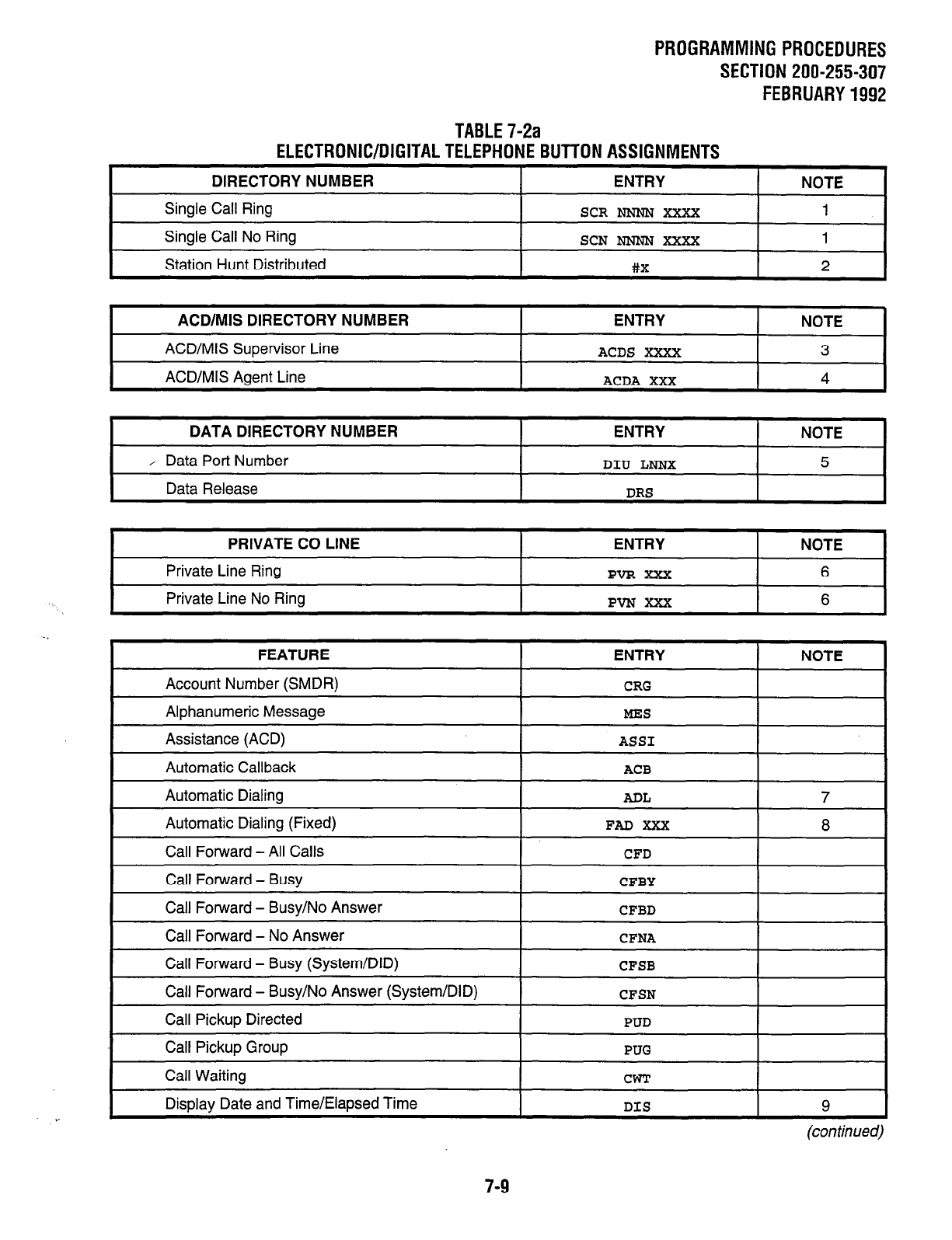
PROGRAMMINGPROCEDURES
SECTION 200-255-307
FEBRUARY1992
TABLE7-2a
ELECTRONIC/DIGITALTELEPHONEBUTTONASSlGNMENTS
DIRECTORY NUMBER ENTRY NOTE
Single Call Ring SCR Nmm XxXx 1
Single Call No Ring
Station Hunt Distributed
SCN N’NNN XXXX 1
+bx 2
I
ACD/MIS DIRECTORY NUMBER I ENTRY I NOTE 1
ACD/MIS Supervisor Line
ACD/MIS Agent Line
ACDS XXXX 3
ACDA XXX 4
I
DATA DIRECTORY NUMBER I ENTRY I NOTE I
/ Data Port Number
Data Release
DIU LNNX 5
DRS
PRIVATE CO LINE
Private Line Ring
Private Line No Ring
ENTRY NOTE
PVR XXX 6
PVNXXX 6
FEATURE
Account Number (SMDR)
Alphanumeric Message
Assistance (ACD)
Automatic Callback
Automatic Dialing
Automatic Dialing (Fixed)
Call Forward - All Calls
Call Forward - Busy
Call Forward - Busy/No Answer
Call Forward - No Answer
Call Forward - Busy (System/DID)
Call Forward - Busy/No Answer (System/DID)
Call Pickup Directed
Call Pickup Group
Call Waiting
Display Date and Time/Elapsed Time
ENTRY
CRG
MES
ASS1
ACB
ADL
FAD XXX
CFD
CFBY
CFBD
CFNA
CFSB
CFSN
PUD
PUG
CWT
DIS
NOTE
7
8
9
(continued)
7-9
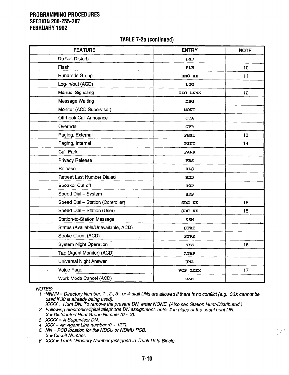
PROGRAMMING PROCEDURES
SECTION 200-255-307
FEBRUARY 1992
TABLE 7-2a (continued)
I
FEATURE ! ENTRY NOTE
I
Do Not Disturb I DND I
Flash FLH 10
Hundreds Group HNG XX 11
Log-in/out (ACD) LOG
I
Manual Signaling I SIG LNNX I 12
Message Waiting
Monitor (ACD Supervisor)
MSG
MONT
I
.Off-hook Call Announce I OCA I
Override
Paging, External
Paging, internal
OVR
PEXT
PINT
13
14
I
Call Park
Privacy Release PRS
Release RLS
Repeat Last Number Dialed RND
I
Speaker Cut-off
Speed Dial - System SDS
Speed Dial - Station (Controller) SDC XX 15
Speed Dial - Station (User) SDU XX 15
Station-to-Station Message SSM
Status (Available/Unavailable, ACD) STAT
Stroke Count (ACD) STRK
System Night Operation - SYS
Tap (Agent Monitor) (ACD) ATAP
Universal Night Answer UNA
Voice Page VCP XXXX
16
17
I
Work Mode Cancel (ACD)
NOTES:
7:WNNN = Directory Number: l-, 2-, 3-, of 4-digit DNs are
allowed if there is no conflict (e.g., 30X cannot be
used if 30 is already being used).
XXXX = Hunt DN. To remove the present DN, enter
NONE. (Also see Station Hunt-Distributed.)
2. Following electronic/digital telephone DN assignment, enter # in place of the usual hunt DN.
X = Distributed Hunt Group Number (0 - 3).
3. XXXX = A Supervisor DN.
4. XXX = An Agent Line number (0 - 127).
5. NN = PCB location for the NDClJ or NDMU PCB.
X = Circuit Number.
6. XXX = Trunk Directory Number (assigned in Trunk Data Block).
7-10
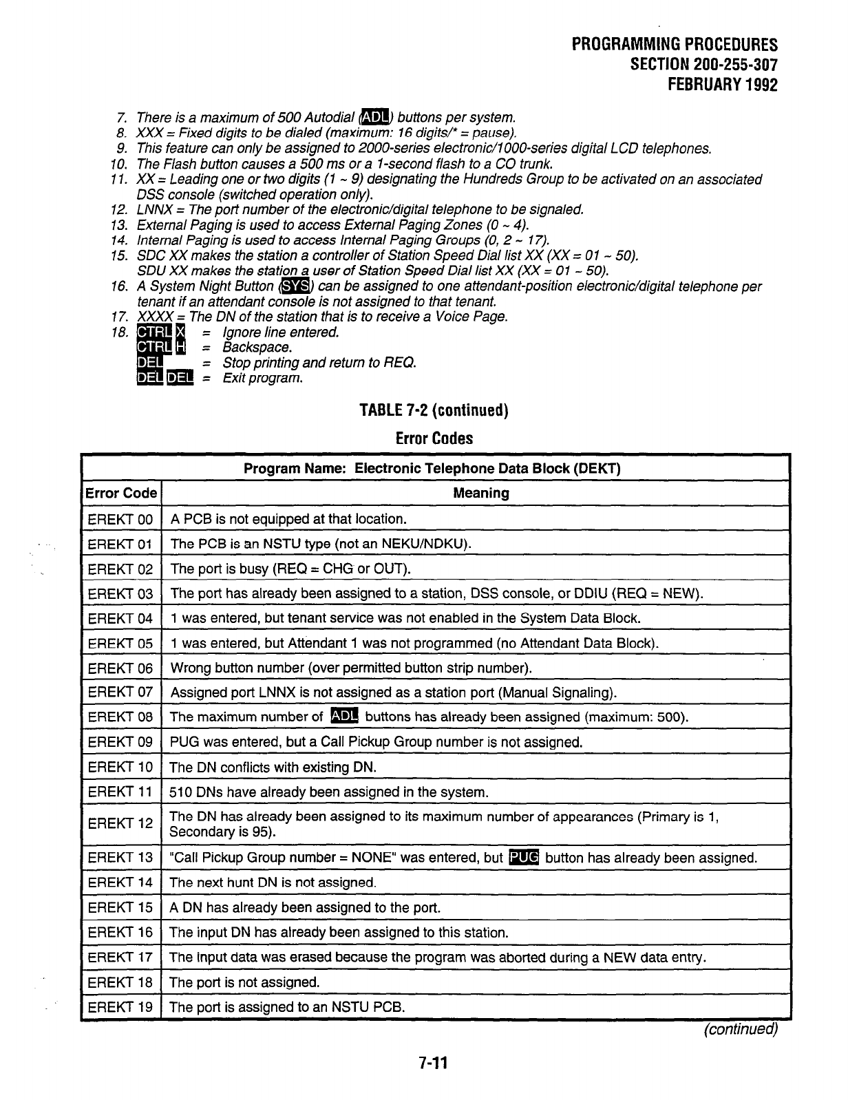
PROGRAMMING PROCEDURES
SECTION 200-255-307
FEBRUARY 1992
7. There is a maximum of 500 Autodial a buttons per system.
8. XXX = Fixed digits to be dialed (maximum: 16 digits/* = pause).
9. This feature can on/y be assigned to 2000~series electronic/l OOO-series digital LCD telephones.
IO. The Flash button causes a 500 ms or a 1 -second flash to a CO trunk.
11. XX = Leading one or two digits (1 - 9) designating the Hundreds Group to be activated on an associated
DSS console (switched operation only).
12. LNNX = The port number of the electronic/digital telephone to be signaled.
13. External Paging is used to access External Paging Zones (0 - 4).
14. Internal Paging is used to access Internal Paging Groups (0, 2 - 17).
15. SDC XX makes the station a controller of Station Speed Dial list XX (XX = 01 - 50).
SDU XX makes the station a user of Station Speed Dial list XX (XX = 01 - 50).
16. A System Night Button m can be assigned to one attendant-position electronic/digital telephone per
tenant if an attendant console is not assigned to that tenant.
17. XXXX = The DN of the station that is to receive a Voice Page.
= Ignore line entered.
= Backspace.
= Stop printing
and return to REQ.
= Exit program.
TABLE 7-2 (continued)
Error Codes
I
Program Name: Electronic Telephone Data Block (DEKT) I
Error Code Meaning
EREKT 00 A PCB is not equipped at that location.
~. EREKT 01 1 The PCB is an NSTU type (not an NEKU/NDKU).
I I
1 EREKT 02 1 The port is busy (REQ = CHG or OUT).
EREKT 03 The port has already been assigned to a station, DSS console, or DDIU (REQ = NEW). I
EREKT 04 1 1 was entered, but tenant service was not enabled in the Svstem Data Block.
EREKT 05 1 was entered, but Attendant 1 was not programmed (no Attendant Data Block).
EREKT 06 Wrong button number (over permitted button strip number).
EREKT 07 Assigned port LNNX is not assigned as a station port (Manual Signaling).
-.
EREKT 08 1 The maximum number of m buttons has already been assigned (maximum: 500).
EREKT 09 PUG was entered, but a Call Pickup Group number is not assigned.
EREKT 10 The DN conflicts with existing DN.
EREKT 11 510 DNs have already been assigned in the system.
IEREKT12 1 The DN has already been assigned to its maximum number of appearances (Primary is 1,
Secondary is 95).
EREKT 13 “Call Pickup Group number = NONE” was entered, but m button has already been assigned.
EREKT 14 The next hunt DN is not assigned.
EREKT 15 A DN has already been assigned to the port.
1 EREKT 16 1 The input DN has already been assigned to this station. I
EREKT 17 The input data was erased because the program was aborted during a NEW data entry.
EREKT 18 The port is not assigned.
EREKT 19 The port is assianed to an NSTU PCB.
7-11
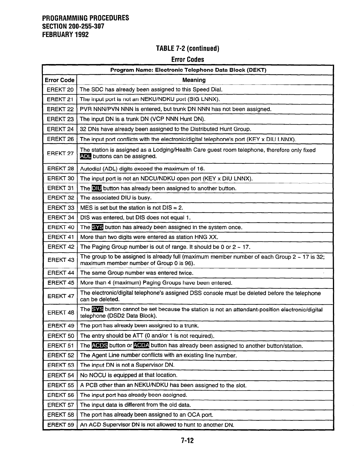
PROGRAMMING PROCEDURES
SECTION 200-255-307
FEBRUARY 1992
TABLE 7-2 (continued)
Error Codes
Error Code 1
Program Name: Electronic Telephone Data Block (DEKT)
Meaning
1 EREKT 20 1 The SDC has already been assigned to this Speed Dial.
-1
1 EREKT 21 1 The input port is not an NEKUINDKU port (SIG LNNX).
EREKT 22 PVR NNN/PVN NNN is entered, but trunk DN NNN has not been assigned.
EREKT 23 The input DN is a trunk DN (VCP NNN Hunt DN).
EREKT 24 32 DNs have already been assigned to the Distributed Hunt Group.
I-EREKT 26 TThe input port conflicts with the electronic/digital telephone’s port (KEY x DIU LNNX). I
1 EREKT27 1
The station is assigned as a Lodging/Health Care guest room telephone, therefore only fixed
m buttons can be assigned.
EREKT 28 Autodial (ADL) digits exceed the maximum of 16. I
1 EREKT 30 1 The input port is not an NDCU/NDKU open port (KEY x DIU LNNX).
1 EREKT 31 (The m button has already been assigned to another button.
I
I EREKT 32 1 The associated DIU is busy. -1
EREKT 33 MES is set but the station is not DIS = 2.
EREKT 34 DIS was entered, but DIS does not equal 1.
EREKT 40 The m button has already been assigned in the system once.
EREKT 41 More than two digits were entered as station HNG XX.
EREKT 42 The Paging Group number is out of range. It should be 0 or 2 - 17.
EREKT 43 The group to be assigned is already full (maximum member number of each Group 2 - 17 is 32;
I
maximum member number of Group 0 is 96).
EREKT 44 The same Group number was entered twice. I
I EREKT 45 1 More than 4 (maximum) Paging Groups have been entered.
---1
I
EREKT 47 The electronic/digital telephone’s assigned DSS console must be
can be deleted.
EREKT 48 The m button cannot be set because the station is not an attendant-position electronic/digital
telephone (DSD2 Data Block).
EREKT 49 The port has already been assigned to a trunk.
EREKT 50
I
The entry should be AIT (0 and/or 1 is not required).
EREKT 51 The m button or m button has already been assigned to another button/station. I
EREKT 52 1 The Agent Line number conflicts with an existino line-number.
I
EREKT 53 The input DN is not a Supervisor DN.
EREKT 54 No NOCU is equipped at that location.
EREKT 55 A PCB other than an NEKWNDKU has been assigned to the slot.
EREKT 56 The input port has already been assigned.
EREKT 57 The input data is different from the old data.
EREKT 58 The
port
has already been assigned to an OCA port.
I EREKT 59 1 An ACD Supervisor DN is not allowed to hunt to another DN.
7-12

3. Standard Telephone Data Block (Table 7-3)
3.01 The Standard Telephone Data Block
(DSTT
Program)
defines all parameters for a given stan-
dard telephone. One Data Block must be com-
pleted for each standard telephone in the system.
Data is entered as follows:
REQ
(Request)--indicates that the program has
loaded. Three responses are possible:
NEW-To create a new Data Block.
CHG-To alter an existing Data Block.
OUT-To delete an existing Data Block.
NOTE:
If OUT is entered, then only the port number
(PO/?) needs to be entered below. No other
entry is necessary.
POR (Port Number)-Identifies the hardware lo-
cation of the STT circuit that is to be defined. The
port number has two parts:
1) NSTU PCB location:
PERCEPTlONe -LOO-Lli/L15-L26(NN).
PERCEPTlONe, -LOO - L31 (NN).
2) Circuit number on that PCB: 1 - 8 (X).
For example: The port number of the fifth
circuit on the NSTU in position’L02 is L025.
Enter: Port Number of station (LNNX).
NOTES:
1. If the OUTcommand wasgivenabove, the
port just defined will be deleted and the
next prompt will be REQ.
2. Port L318 cannot be assigned.
DN (Directory Number)-Defines
the directory
number (station number) of the station.
Enter: DN (1, 2, 3, or 4 digits).
SMX (Station Set Mix)-When
the DN that was
entered after the DN prompt is also programmed
I
as a secondary DN(s) on an electronic/digital
telephone(s), bridging is possible between the
telephones.
Enter: Y (bridging is automatically established
without a warning tone-i.e., no privacy.)
or...
PROGRAMMINGPROCEDURES
SECTION 200-255-307
JANUARY1993
N (bridging is not allowed-privacy ex-
ists with an LED indication).
NOTE:
If Station Set Mix is not desired, enter “N. ”
COS (Class of Group
Services)--Assigns one of
the 16 available Classes of Service to the tele-
phone. (The Classes of Service are defined in
the
DCOS Program.)
Enter: COS Number 0 - 15).
TEN (Tenant Number)-Assigns
the station to
one of the two possible tenants in the system.
Enter: 0 if tenant service is not selected in the
System Data Block.
(TEN = N.)
0 or 1 to specify tenant, if tenant service
is selected in the System Data Block.
(TEN = Y.)
PUG (Call Pickup
Group)-Assigns the station to
one of the 32 possible pickup groups.
Enter: Group number (0 - 31) or NONE.
HNT (Hunt Number)-Defines
the station to which
this DN hunts.
Enter: Next DN in hunt group (1 - 4 digits).
For Station Hunt-Distributed: #X.
(X = Distributed hunt group number, [0 -
31; Maximum: 8 stations per group.)
NONE: No hunt group assignment.
DLG (Dialing
Type)-Defines the type of dialing, if
any, to be used by the station.
Enter: DIP for dial pulse.
TON
for
DTMF.
MNL
XXXX for Manual Line to
dant or a DN.
(XXXX = ATTO, ATTl, or DN
digits].)
atten-
[-I - 4
SDL (Speed Dial List)-Assigns
one of the 50,l O-
number speed dial lists for use at this station.
Enter: SDC XX-Makes the station a control-
ler of list number XX.
(XX = 1 - 50.)
SDU XX-Makes the station a user of
list number XX.
(XX = 1 - 50.)
NONE-No list assigned.
7-13
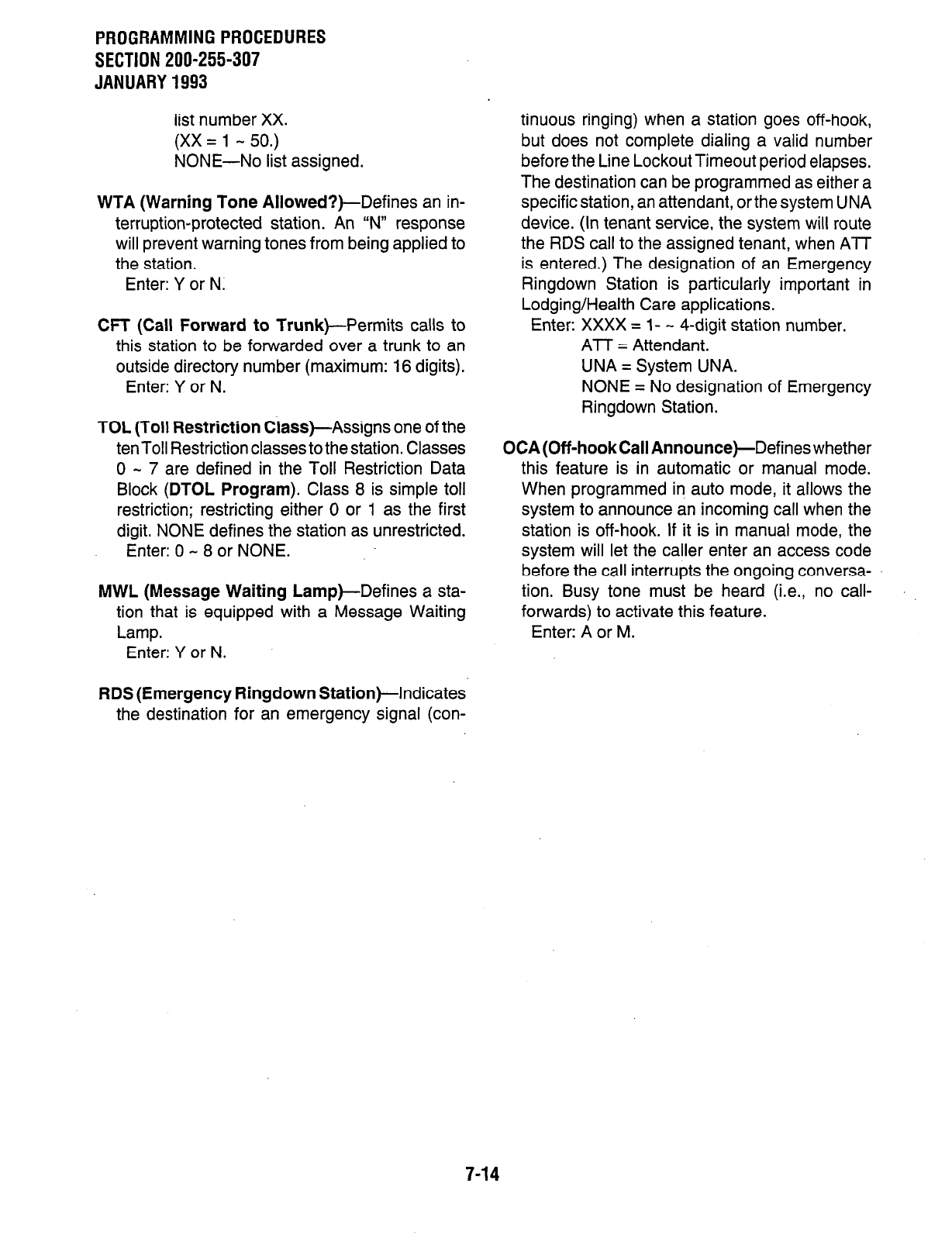
PROGRAMMINGPROCEDURES
SECTION 200-255-307
JANUARY1993
list number XX.
(XX = 1 - 50.)
NONE-No list assigned.
WTA (Warning Tone Allowed?)-Defines an in-
terruption-protected station. An “N” response
will prevent warning tones from being applied to
the station.
Enter: Y or N.
CFT (Call Forward to Trunk)-Permits calls to
this station to be forwarded over a trunk to an
outside directory number (maximum: 16 digits).
Enter: Y or N.
TOL (Toll Restriction Class)-Assigns one of the
ten Toll Restriction classes to the station. Classes
0 - 7 are defined in the Toll Restriction Data
Block (DTOL Program). Class 8 is simple toll
restriction; restricting either 0 or 1 as the first
digit. NONE defines the station as unrestricted.
Enter: 0 - 8 or NONE.
MWL (Message Waiting Lamp)-Defines a sta-
tion that is equipped with a Message Waiting
Lamp.
Enter: Y or N.
tinuous ringing) when a station goes off-hook,
but does not complete dialing a valid number
before the Line Lockout Timeout period elapses.
The destination can be programmed as either a
specific station, an attendant, orthe system UNA
device. (In tenant service, the system will route
the RDS call to the assigned tenant, when ATT
is entered.) The designation of an Emergency
Ringdown Station is particularly important in
Lodging/Health Care applications.
Enter: XXXX = l- - 4-digit station number.
ATT = Attendant.
UNA = System UNA.
NONE = No designation of Emergency
Ringdown Station.
OCA (Off-hook Call Announce)-Defines whether
this feature is in automatic or manual mode.
When programmed in auto mode, it allows the
system to announce an incoming call when the
station is off-hook. If it is in manual mode, the
system will let the caller enter an access code
before the call interrupts the ongoing conversa-
tion. Busy tone must be heard (i.e., no call-
forwards) to activate this feature.
Enter: A or M.
RDS (Emergency Ringdown Station)-Indicates
the destination for an emergency signal (con-
7-14
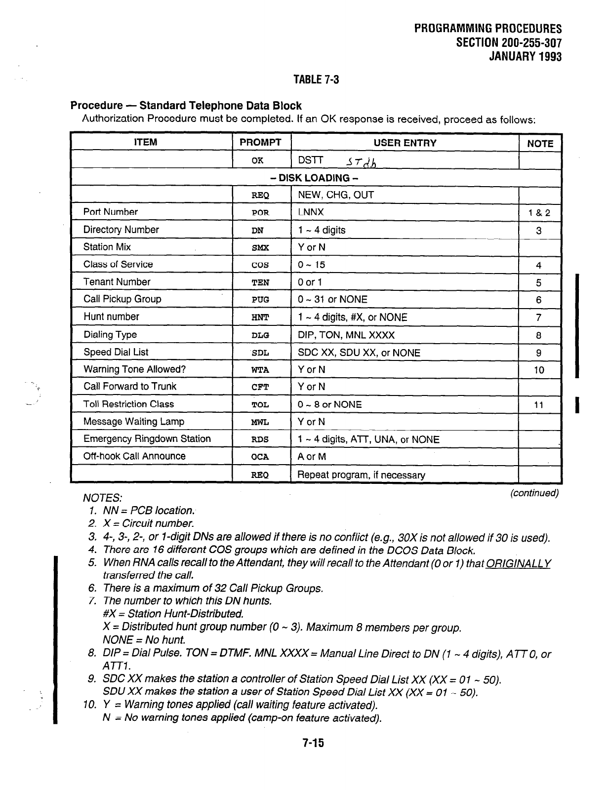
TABLE 7-3
Procedure - Standard Telephone Data Block
PROGRAMMINGPROCEDURES
SECTION 200-255-307
JANUARY1993
Authorization Procedure must be completed. If an
OK
response is received, proceed as follows:
ITEM PROMPT USER ENTRY NOTE
OK
DS-IT JY-IAl,
Port Number
- DISK LOADING -
-Q NEW, CHG, OUT
POR
LNNX l&2
Directory Number I
DN
1 - 4 digits I 3 I
Station Mix
SMX
Y or N
Class of Service cos o- 15 4
Tenant Number
TEN
0 or 1 5
Call Pickup Group
PUG
0 - 31 or NONE 6
Hunt number
Dialing Type
Speed Dial List
HNT 1 - 4 digits, #X, or NONE 7
DLG
DIP, TON, MNL XXXX 8
SDL
SDC XX, SDU XX, or NONE 9
Warning Tone Allowed?
Call Forward to Trunk
WTA
CFT
Y or N
Y or N
10
Toll Restriction Class
Message Waiting Lamp
Emergency Ringdown Station
Off-hook Call Announce
TOL
MWL
RDS
OCA
0-8orNONE
Y or N
1 - 4 digits, ATT, UNA, or NONE
AorM
11
I -JQ Repeat program, if necessary I I
NOTES:
(continued)
1. NN = PCB location.-
2. X = Circuit number.
3. 4-, 3-, 2-, or l-digit DNs are allowed if there is no conflict (e.g., 30X is not allowed if 30 is used).
4. There are 16 different COS groups which are defined in the DCOS Data Block.
5. When RNA calls recall to the Attendant, they will recall to the Attendant (0 or 1) that ORIGINALLY
transferred the call.
6. There
is a
maximum of 32 Call Pickup Groups.
7. The number to which this DN hunts.
#X = Station Hunt-Distributed,
X = Distributed hunt group number
(0 - 3), Maximum 8 members per group.
NONE = No hunt.
8. DIP = Dial Pulse. TON = DTMF. MNL XXXX = Manual Line Direct to DN (1 - 4 digits), ATT 0, or
A777.
9. SDC XX makes the station a controller of Station Speed Dial List XX (XX = 01 - 50).
SDU XX makes the station a user of Station Speed Dial List XX (XX = 01 - 50).
10. Y = Warning tones applied (call waiting feature activated).
N = No warning tones applied (camp-on feature activated).
7-15
.
I

PROGRAMMING PROCEDURES
SECTION 200-255-307
JANUARY 1993
Classes 0 - 7 are defined in the Toll Restriction Data Block
Class 8 = Dia/m or 0 restriction.
NONE = No Toll Restriction.
Ignore line entered.
Backspace.
Stop printing and return to REQ.
Exit program.
TABLE 7-3 (continued)
Error Codes
(DTOL Program).
Error Code 1
Program Name: Standard Telephone Data block (DSlT)
Meanina
ERSTA 00 No PCB is equipped at that location.
ERSTA 01 The PCB is an NEKU type (not an NSTU).
ERSTA 02 Port is busy (REQ = CHG, OUT).
ERSTA 03 Port has already been assigned to a station, DSS console, or DDIU.
ERSTA 05 1 was entered, but tenant service was not enabled in the System Data Block.
ERSTA 06 1 was entered, but ATT #l was not programmed (no Attendant Data Block).
ERSTA 09 1 Unknown input.
ERSTA 10
ERSTA 11
DN conflicts with existing DN.
510 DNs have already been assigned in the system.
ERSTA 12
ERSTA 13
DN has already been assigned to the maximum number of appearances (96).
Hot Line DN does not exist.
ERSTA 14 1 Next Hunt DN does not exist.
ERSTA 17
ERSTA 18
ERSTA 19
MNL 0 was entered, but ATO is not equipped.
MNL 1 was entered, but ATT1 is not equipped.
MNL 0 was entered, but this station is in tenant group #l.
ERSTA 20 1 MNL 0 was entered, but this station is in tenant group #2.
I
ERSTA 21
ERSTA 22
ERSTA 23
ERSTA 24
Input data was erased because the program was aborted during NEW data entry.
The port is not assigned.
Another type of data (electronic telephone, etc.) is assigned to the input port.
SDC has already been assigned to the input list.
ERSTA 25 I The next input hunt DN is a trunk DN.
ERSTA 26
ERSTA 27
ERSTA 28
ERSTA 29
ERSTA 30
ERSTA 31
The Distributed Hunt Group has already been assigned its maximum member number (8),
invalid Toll Class Number (0 - 8).
The first digit does not match with RM PFX, or the second digit conflicts with
another DN or access code.
The port has already been assigned to a trunk.
The entry should be ATT (0 and/or 1 not required).
Port has already been assigned as an announcement port.
7-16
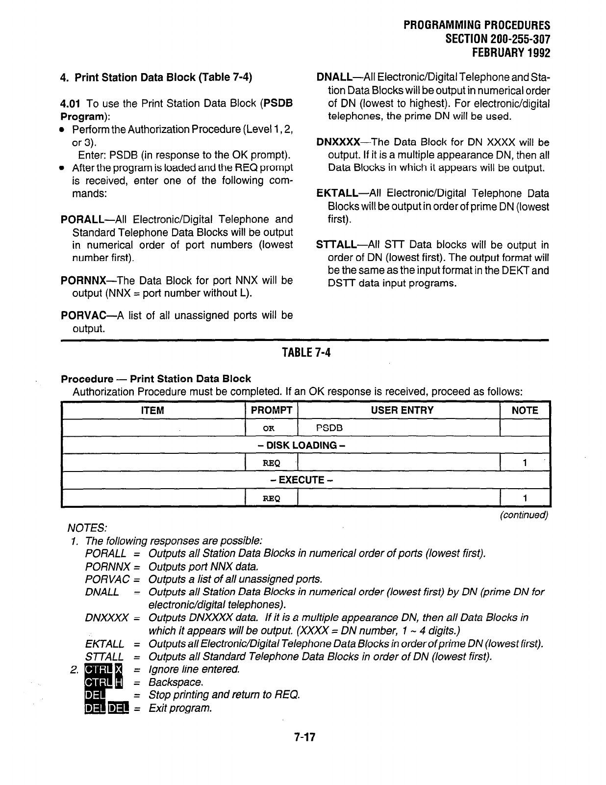
4. Print Station Data Block (Table 7-4)
4.01
To use the Print Station Data Block (PSDB
Program):
l
Perform the Authorization Procedure (Level 1,2,
or 3).
Enter: PSDB (in response to the OK prompt).
l
After the program is loaded and the REQ prompt
is received, enter one of the following com-
mands:
PORALL-All
Electronic/Digital Telephone and
Standard Telephone Data Blocks will be output
in numerical order of port numbers (lowest
number first).
PORNNX-The Data Block for port NNX will be
output (NNX = port number without L).
PORVAC-A list of all unassigned ports will be
output.
PROGRAMMING PROCEDURES
SECTION 200-255-307
FEBRUARY 1992
DNALL-All Electronic/Digital Telephone and Sta-
tion Data Blocks will be output in numerical order
of DN (lowest to highest). For electronic/digital
telephones, the prime DN will be used.
DNXXXX-The Data Block for DN XXXX will be
output. If it is a multiple appearance DN, then all
Data Blocks in which it appears will be output.
EKTALL-All
Electronic/Digital Telephone Data
Blocks will be output in order of prime DN (lowest
first).
ST-TALL-All SIT Data blocks will be output in
order of DN (lowest first). The output format will
be the same as the input format in the DEKT and
DSTT data input programs.
TABLE 7-4
Procedure - Print Station Data Block
Authorization Procedure must be completed. If an OK response is received, proceed as follows:
ITEM PROMPT USER ENTRY NOTE
OK
PSDB
- DISK LOADING -
REQ
1'
- EXECUTE -
t REQ I 1 I
NOTES:
(continued)
1. The following responses are possible:
PORALL =
PORNNX =
PORVAC =
DNALL =
Outputs all Station Data Blocks in numerical order of ports (lowest first).
Outputs port NNX data.
Outputs a list of all unassigned ports.
Outputs all Station Data Blocks in numerical order (lowest first) by DN (prime DN for
electronic/digital telephones).
Outputs DNXXXX data. If it is a multiple appearance DN, then all Data Blocks in
which it appears will be output. (XXXX = DN number, 1 - 4 digits.)
Outputs all Electronic/Digital Telephone Data Blocks in orderofprime DN (lowest first).
Outputs all Standard Telephone Data Blocks in order of DN (lowest first).
Ignore line entered.
Backspace.
DNXXXX =
EKTALL =
SmALL =
Stop printing and return to REQ.
Exit program.
7-17
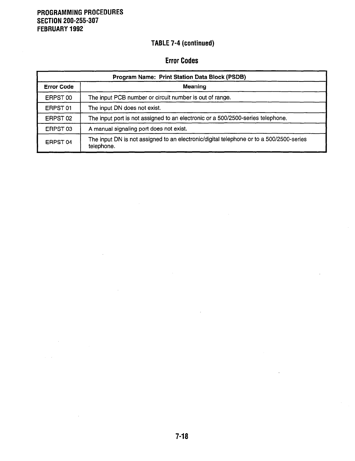
PROGRAMMING PROCEDURES
SECTION 200-255-307
FEBRUARY 1992
TABLE 7-4 (continued)
Error Codes
Program Name: Print Station Data Block (PSDB)
Error Code 1 Meaning
ERPST 00
ERPST 01
The input PCB number or circuit number is out of range.
The inout DN does not exist.
1 ERPST 02 1 The input port is not assigned to an electronic or a 500/2500-series telephone.
ERPST 03
ERPST 04
A manual signaling port does not exist.
The input DN is not assigned to an electronic/digital telephone or to a 500/2500-series
telephone.
7-18
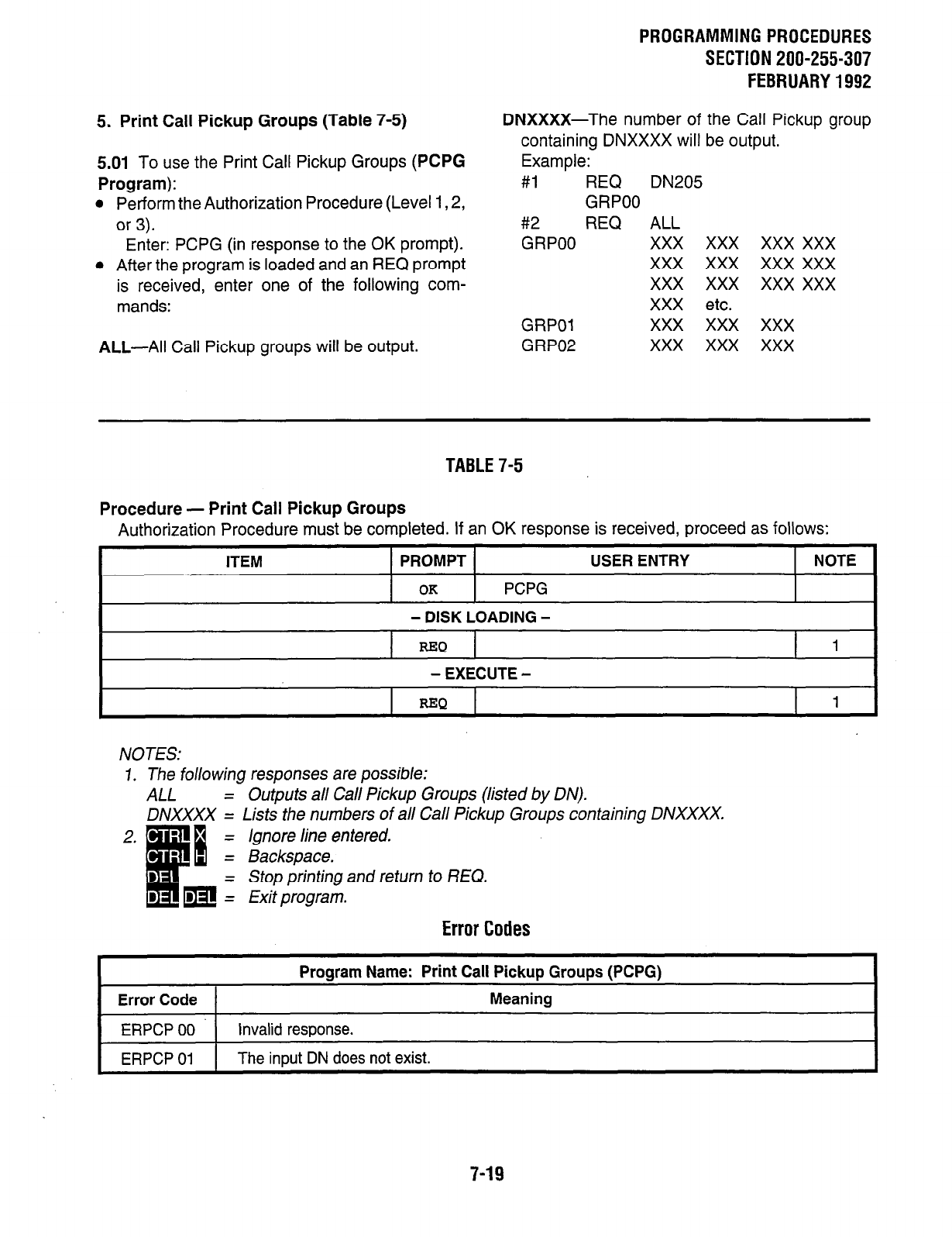
5. Print Call Pickup Groups (Table 7-5)
5.01 To use the Print Call Pickup Groups (PCPG
Program):
l
Perform the Authorization Procedure (Level 1,2,
or 3).
Enter: PCPG (in response to the OK prompt).
l
After the program is loaded and an REQ prompt
is received, enter one of the following com-
mands:
ALL-All Call Pickup groups will be output.
PROGRAMMINGPROCEDURES
SECTION 200-255-307
FEBRUARY1992
DNXXXX-The number of the Call Pickup group
containing DNXXXX will be output.
Example:
#l REQ DN205
GRPOO
#2 REQ ALL
GRPOO xxx xxx xxx xxx
xxx xxx xxx xxx
xxx xxx xxx xxx
XXX etc.
xxx xxx xxx
xxx xxx xxx
GRPOl
GRP02
TABLE7-5
Procedure - Print Call Pickup Groups
Authorization Procedure must be completed. If an OK response is received, proceed as follows:
ITEM PROMPT USER ENTRY NOTE
OK
PCPG
- DISK LOADING -
REQ 1
- EXECUTE -
NOTES:
I. The following responses are possible:
ALL = Outputs all Call Pickup Groups (listed by DN).
DNXXXX = Lists the numbers of all Call Pickup Groups containing DNXXXX.
Error Codes
Error Code 1
Program Name: Print Call Pickup Groups (PCPG)
Meaning
i 1 invalid rewonse. I
1 ERPCP 01 1 The input DN does not exist. I
7-19

PROGRAMMING PROCEDURES
SECTION 200-255-307
FEBRUARY 1992
6. Print Hunting Arrangements (Table 7-6)
6.01 To use the Print Hunting Arrangements (PHNT
Program):
l
Perform the Authorization Procedure (Level 1,2,
or 3).
Enter: PHNT (in response to the OK prompt).
l
When an REQ prompt is received after the
program is loaded, enter the following com-
mand:
ALL-All hunting sequences will be output.
l
The output format will be as in the following
examples:
REQ ALL
HNT 223-224-225
HNT 242-243
HNT 250-25 l-252
etc.
TABLE 7-6
Procedure - Print Hunting Arrangements
Authorization Procedure must be completed. If an OK response is received, proceed as follows:
I
ITEM TiiOiPT 1 USER ENTRY i ~~
NOTE
OK
PHNT
- DISK LOADING -
t =Q
ALL 1
- EXECUTE -
=Q 1
NOTES:
7. The following responses are possible:
ALL = Outputs a// hunting sequences (listed by DN).
Ignore line entered.
Backspace.
Stop printing and return to REQ.
Exit program. -
Error
Codes
Error Code 1
Program Name: Print Hunting List (PHNT)
Meaning
&PHT 00 The input DN does not exist. I
7-20
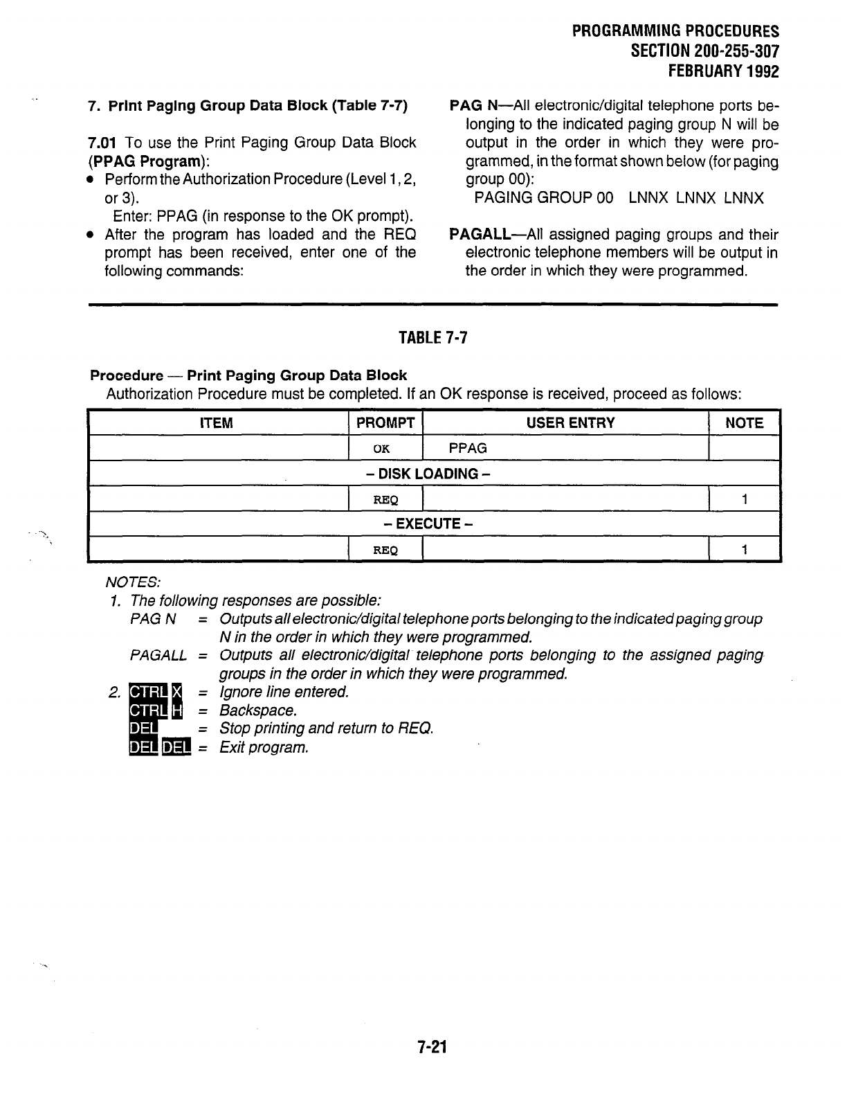
7. Print Paging Group Data Block (Table 7-7)
7.01
To use the Print Paging Group Data Block
(PPAG Program):
l
Perform the Authorization Procedure (Level 1,2,
or 3).
Enter: PPAG (in response to the OK prompt).
l
After the program has loaded and the REQ
prompt has been received, enter one of the
following commands:
PROGRAMMING PROCEDURES
SECTION 200-255-307
FEBRUARY 1992
PAG
N-All electronic/digital telephone ports be-
longing to the indicated paging group N will be
output in the order in which they were pro-
grammed, in the format shown below (for paging
group 00):
PAGING GROUP 00 LNNX LNNX LNNX
PAGALL-All
assigned paging groups and their
electronic telephone members will be output in
the order in which they were programmed.
TABLE 7-7
Procedure - Print Paging Group Data Block
Authorization Procedure must be completed. If an OK response is received, proceed as follows:
ITEM PROMPT USER ENTRY NOTE
OK PPAG
- DISK LOADING -
-Q 1
- EXECUTE -
REQ
1
NOTES:
1. The following responses are possible:
PAGN =
PAGALL =
Outputs all electronic/digital telephone ports belonging to the indicated paging group
N in the order in which they were programmed.
Outputs all electronic/digital. telephone ports belonging to the assigned paging
groups in the order in which they were programmed,
/snore line entered.
Backspace.
Stop printing and return to REQ.
Exit program.
. .
7-21
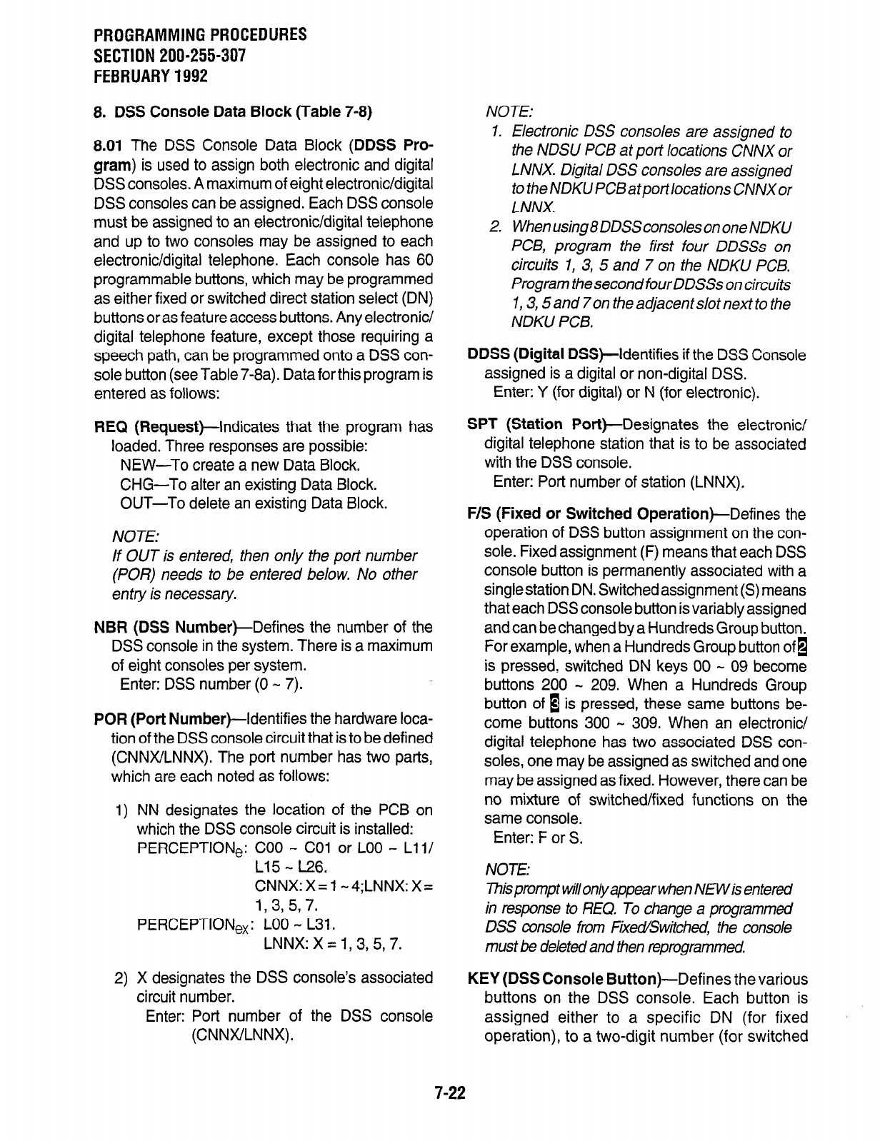
PROGRAMMING PROCEDURES
SECTION 200-255-307
FEBRUARY 1992
8. DSS Console Data Block (Table 7-8)
8.01
The DSS Console Data Block
(DDSS Pro-
gram)
is used to assign both electronic and digital
DSS consoles. A maximum of eight electronic/digital
DSS consoles can be assigned. Each DSS console
must be assigned to an electronic/digital telephone
and up to two consoles may be assigned to each
electronic/digital telephone. Each console has 60
programmable buttons, which may be programmed
as either fixed or switched direct station select (DN)
buttons or as feature access buttons. Any electronic/
digital telephone feature, except those requiring a
speech path, can be programmed onto a DSS con-
sole button (see Table 7-8a). Data for this program is
entered as follows:
REQ (Request)-Indicates that the program has
loaded. Three responses are possible:
NEW-To create a new Data Block.
CHG-To alter an existing Data Block.
OUT-To delete an existing Data Block.
NOTE:
If OUT is entered, then only the port number
(POR) needs to be entered below. No other
en try is necessary.
NBR
(DSS
NumberkDefines the number of the
DSS console in the system. There is a maximum
of eight consoles per system.
Enter: DSS number (0 - 7).
POR (Port
Number)-Identifies the hardware loca-
tion of the DSS console circuit that is to be defined
(CNNX/LNNX). The port number has two parts,
which are each noted as follows:
1) NN designates the location of the PCB on
which the DSS console circuit is installed:
PERCEPTION,: COO - CO1 or LOO - Lli/
L15 - L26.
CNNX:X=l-4;LNNX:Xz
1, 3, 5, 7.
PERCEPTION,: LOO - L31.
LNNX:X=1,3,5,7.
2) X designates the DSS console’s associated
circuit number.
Enter: Port number of the DSS console
(CNNWLNNX).
NOTE:
1.
2.
Electronic DSS consoles are assigned to
the NDSU PCB at port locations CNNX or
LNNX. Digital DSS consoles are assigned
to the NDKU PCBatportlocations CNNXor
LNNX.
When using8 DDSSconsoles on one NDKU
PCB, program the first four DDSSs on
circuits I, 3, 5 and 7 on fhe NDKU PCB.
Program the second four DDSSs on circuits
1,3,5and7on theadjacentslotnextto the
NDKU PCB.
DDSS (Digital
DSS)-Identifies if the DSS Console
assigned is a digital or non-digital DSS.
Enter: Y (for digital) or N (for electronic).
SPT (Station
Port)-Designates the electronic/
digital telephone station that is to be associated
with the DSS console.
Enter: Port number of station (LNNX).
F/S (Fixed or Switched
Operation)-Defines the
operation of DSS button assignment on the con-
sole. Fixed assignment (F) means that each DSS
console button is permanently associated with a
singlestation DN. Switchedassignment (S) means
that each DSS console button is variably assigned
and can be changed by a Hundreds Group button.
For example, when a Hundreds Group button ofi
is pressed, switched DN keys 00 - 09 become
buttons 200 - 209. When a Hundreds Group
button of B is pressed, these same buttons be-
come buttons 300 - 309. When an electronic/
digital telephone has two associated DSS con-
soles, one may be assigned as switched and one
may be assigned as fixed. However, there can be
no mixture of switched/fixed functions on the
same console.
Enter: F or S.
NOTE:
hisprompt wilonlyappearwhen NEWis entered
in response to REQ. To change a programmed
DSS console from Fixed/Switched, the console
must be deleted and then reprogrammed
KEY (DSS Console Button)-Defines the various
buttons on the DSS console. Each button is
assigned either to a specific DN (for fixed
operation), to a two-digit number (for switched
7-22
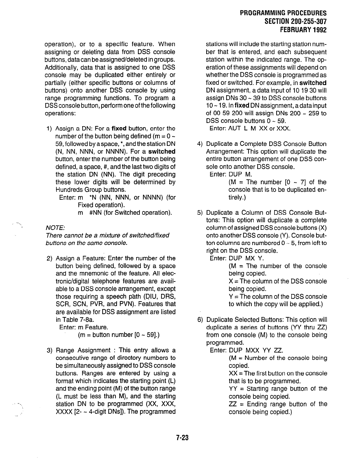
PROGRAMMING PROCEDURES
SECTION 200-255-307
FEBRUARY 1992
operation), or to a specific feature. When
assigning or deleting data from DSS console
buttons, data can be assigned/deleted in groups.
Additionally, data that is assigned to one DSS
console may be duplicated either entirely or
partially (either specific buttons or columns of
buttons) onto another DSS console by using
range programming functions. To program a
DSS console button, perform oneof the following
operations:
--.,
1) Assign a DN: For a
fixed
button, enter the
number of the button being defined (m = 0 -
59, followed by a space, *, and the station DN
(N, NN, NNN,
or
NNNN).
For a
switched
button, enter the number of the button being
defined, a space, #, and the last two digits of
the station DN (NN). The digit preceding
these lower digits will be determined by
Hundreds Group buttons.
Enter: m
l
N (NN, NNN, or NNNN) (for
Fixed operation).
m #NN (for Switched operation).
NOTE:
There cannot be a mixture of switched/fixed
buttons on the same console.
2) Assign a Feature: Enter the number of the
button being defined, followed by a space
and the mnemonic of the feature. All elec-
tronic/digital telephone features are avail-
able to a DSS console arrangement, except
those requiring a speech path (DIU, DRS,
SCR, SCN, PVR, and PVN). Features that
are available for DSS assignment are listed
in Table 7-8a.
Enter: m Feature.
(m = button number [0 - 591.)
3) Range Assignment : This entry allows a
consecutive range of directory numbers to
be simultaneously assigned to DSS console
buttons. Ranges are entered by using a
format which indicates the starting point (L)
and the ending point (M) of the button range
(L must be less than
M),
and the starting
station DN to be programmed (XX, XXX,
xxxx [2- - 4-digit DNs]). The programmed
stations will include the starting station num-
ber that is entered, and each subsequent
station within the indicated range. The op-
eration of these assignments will depend on
whether the DSS console is programmed as
fixed or switched. For example, in
switched
DN assignment, a data input of 10 19 30 will
assign DNs 30 - 39 to DSS console buttons
IO - 19.
In
fixed
DN assignment, a data input
of 00 59 200 will assign DNs 200 - 259 to
DSS console buttons 0 - 59.
Enter: AUT L M XX or XXX.
4) Duplicate a Complete DSS Console Button
Arrangement: This option will duplicate the
entire button arrangement of one DSS con-
sole onto another DSS console.
Enter: DUP M.
(M = The number [0 - 71 of the
console that is to be duplicated en-
tirely.)
5) Duplicate a Column of DSS Console But-
tons: This option will duplicate a complete
column of assigned DSS console buttons (X)
onto another DSS console (Y). Console but-
ton columns are numbered 0 - 5, from left to
right on the DSS console.
Enter: DUP MX Y.
(M = The number of the console
being copied.
X = The column of the DSS console
being copied.
Y = The column of the DSS console
to which the copy will be applied.)
6) Duplicate Selected Buttons: This option will
duplicate a series of buttons (YY thru ZZ)
from one console (M) to the console being
programmed.
Enter: DUP MXX YY ZZ.
(M = Number of the console being
copied.
XX = The first button on the console
that is to be programmed.
YY = Starting range button of the
console being copied.
zz = Ending range button of the
console being copied.)
7-23
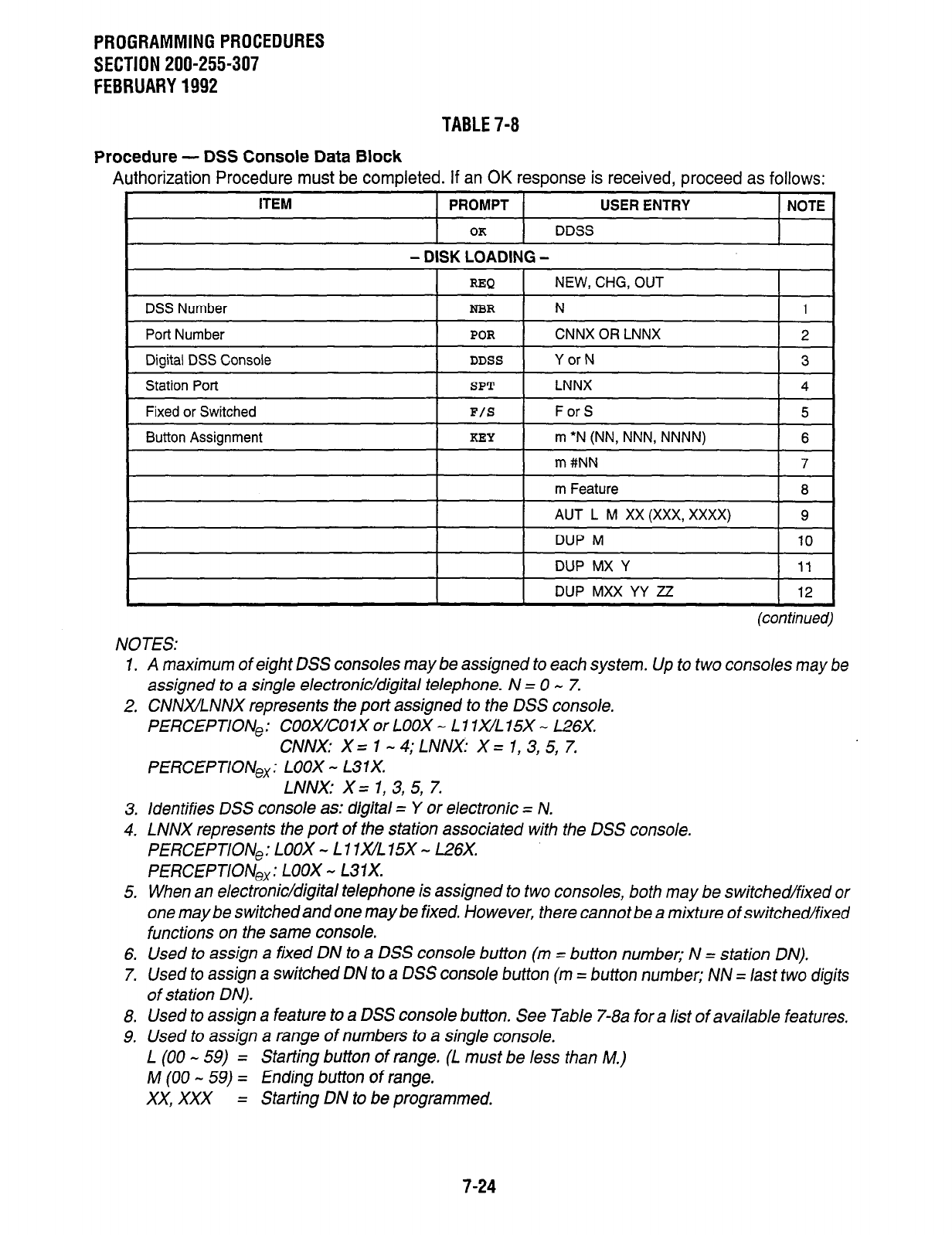
PROGRAMMINGPROCEDURES
SECTION 200-255-307
FEBRUARY1992
TABLE7-8
Procedure - DSS Console Data Block
Authorization Procedure must be completed. If an OK response is received, proceed as follows:
m #NN 7
m Feature 8
AUT L M XX (XXX, XXXX) 9
DUP M 10
DUP MX Y 11
DUP MXX YY ZZ 12
(continued)
NOTES:
1. A maximum of eight DSS consoles may be assigned to each system. Up to two consoles may be
assigned to a single electronic/digital telephone. N = 0 - 7.
2. CNNx/LNNX represents the port assigned to the DSS console.
PERCEPTlONe: COOXZOlX or LOOX - L 1 lx/L 15X - L26X.
CNNX: X = 1 - 4; LNNX: X = 1, 3, 5, 7.
PERCEPTIONex: LOOX - L31X.
LNNX: X= 1, 3, 5, 7.
3. Identifies DSS console as: digital = Y or electronic = N.
4. LNNX represents the port of the station associated with the DSS console.
PERCEPTION,: LOOX - L 1 lx/L 15X - L26X.
PERCEPTIONex: LOOX - L31X.
5. When an electronic/digital telephone is assigned to two consoles, both may be switched/fixed or
one maybe switched and one maybe fixed. However, there cannot be a mixture of switched/fixed
functions on the same console.
6. Used to assign a fixed DN to a DSS console button (m = button number; N = station DN).
7.
Used
to assign
a switched DN
to a DSS console button (m = button number;
NN
= last two digits
of station DN).
8. Used to assign a feature to a DSS console button. See Table 7-8a for a list of available features.
9. Used to assign a range of numbers to a single console.
L (00 - 59) = Starting button of range. (L must be less than M.)
M (00 - 59) = Ending button of range.
XX, XXX = Starting DN to be programmed.
7-24
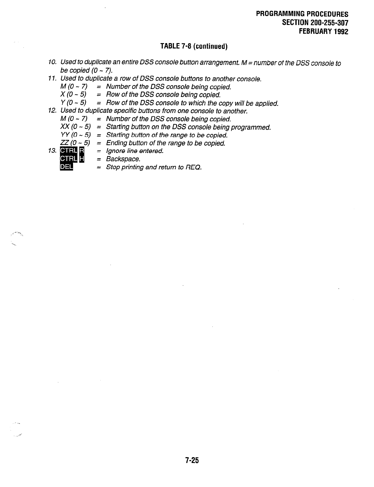
10.
11.
12.
13.
PROGRAMMING PROCEDURES
SECTION 200-255-307
FEBRUARY 1992
TABLE 7-8 (continued)
Used to duplicate an entire DSS console button arrangement, M = number of the DSS console to
be copied (0 - 7).
Used to duplicate a row of DSS console buttons to another console.
M (0 - 7) = Number of the DSS console being copied.
x (0 - 5) = Row of the DSS console being copied.
Y (0 - 5) = Row of the DSS console to which the copy will be applied.
Used to duplicate specific buttons from one console to another.
M (0 - 7) = Number of the DSS console being copied.
XX(0 - 5) = Starting button on the DSS console being programmed.
YY (0 - 5) = Starting button of the range to be copied.
ZZ (0 - 5) = Ending button of the range to be copied.
= /snore line entered.
= Backspace.
= Stop printing and return to REQ.
7-25
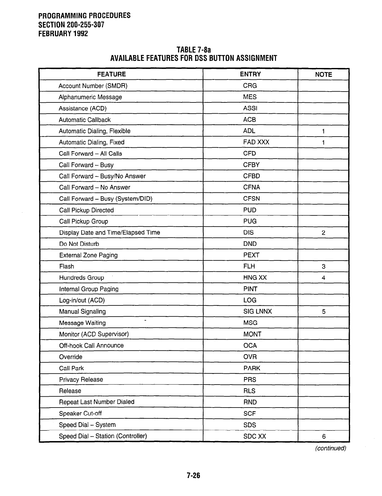
PROGRAMMING PROCEDURES
SECTION 200-255-307
FEBRUARY 1992
TABLE 7-8a
AVAILABLE FEATURES FOR DSS BUTTON ASSIGNMENT
FEATURE ENTRY
I
NOTE
Account Number (SMDR) I CRG I
Alphanumeric Message
Assistance (ACD)
Automatic Callback
MES
AS.9
AC6
Automatic Dialing, Flexible
I 1
Automatic Dialing, Fixed
Call Forward - All Calls
FAD XXX 1
CFD
Call Forward - Busy I CFBY
I
Call Forward - Busy/No Answer CFBD
Call Forward - No Answer
Call Forward - Busy (System/DID)
CFNA
CFSN
Call Pickup Directed
Call Pickup Group
Display Date and Time/Elapsed Time
Do Not Disturb
PUG
DIS
DND
2
External Zone Paging
Flash
Hundreds Group
Internal Group Paging
FLH
HNG XX
PINT
3
4
Log-in/out (ACD)
Manual Signaling SIG LNNX 5
Message Waiting MSG
Monitor (ACD Supervisor) MONT
Off-hook Call Announce OCA
Override OVR
Call Park PARK
Privacy Release PRS
Release RLS
Repeat Last Number Dialed RND
Speaker Cut-off SCF
Speed Dial - System SDS
Speed Dial - Station (Controller) SDC XX 6
(con timed)
7-26
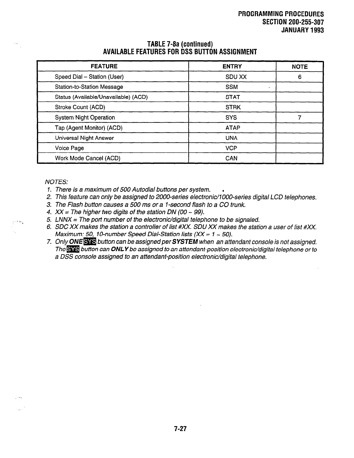
PROGRAMMING PROCEDURES
SECTION 200-255-307
JANUARY 1993
:--.+
TABLE 7-8a (continued)
AVAILABLE FEATURES FOR DSS BUTTON ASSIGNMENT
FEATURE ENTRY NOTE
Speed Dial - Station (User) SDU XX 6
Station-to-Station Message SSM
I
Status (Available/Unavailable) (ACD) I STAT I
Stroke Count (ACD)
System Night Operation
Tap (Agent Monitor) (ACD)
STRK
SYS
ATAP
7
Universal Night Answer
Voice Page
Work Mode Cancel (ACD)
UNA
VCP
CAN
NOTES:
1. There is a maximum of 500 Autodial buttons per system.
2. This feature can only be assigned to 2000series electronic/l boo-series digital LCD telephones.
3. The Flash button causes a 500 ms or a i-second flash to a CO trunk.
4. XX = The higher two digits of the station DN (00 - 99).
5. LNNX = The port number of the electronic/digital telephone to be signaled.
6, SDC XX makes the station a controller of list #XX. SDU XX makes the station a user of list #XX.
Maximum: 50, lo-number Speed Dial-Station lists (XX = 1 - 50).
7. Only ONE= button can be assignedper SYSTEM when an attendant console is not assigned.
Them button can ONLY be assigned to an attendant-position electronic/digital telephone or to
a DSS console assigned to an attendant-position electronic/digital telephone.
-.
7-27
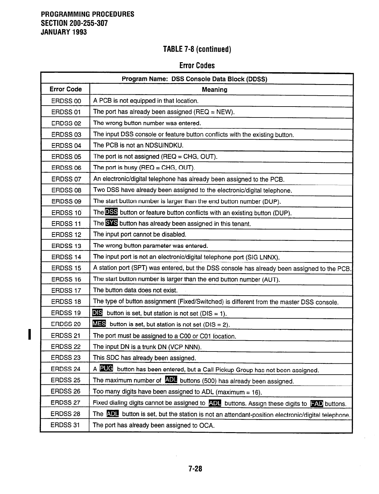
PROGRAMMING PROCEDURES
SECTION 200-255-307
JANUARY 1993
TABLE 7-8 (continued)
Error Codes
Program Name: DSS Console Data Block (DDSS)
Error Code Meaning
ERDSS 00 A PCB is not equipped in that location.
ERDSS 01 The port has already been assigned (REQ = NEW).
ERDSS 02 The wrong button number was entered.
ERDSS 03 The input DSS console or feature button conflicts with the existing button.
I I
ERDSS 04 The PCB is not an NDSU/NDKU.
ERDSS 05 The port is not assigned (REQ = CHG, OUT).
ERDSS 06 The port is busy (REQ = CHG, OUT).
1 ERDSS 07 1 An electronic/digital telephone has already been assigned to the PCB.
ERDSS08 1 Two DSS have already been assigned to the electronic/digital telephone. I
ERDSS 09 The start button number is larger than the end button number (DUP).
ERDSS 10’ Them button or feature button conflicts with an existing button (DUP).
ERDSS 11 The m button has already been assigned in this tenant.
ERDSS 12 The input port cannot be disabled.
ERDSS 13 The wrong button parameter was entered.
ERDSS 14 The input port is not an electronic/digital telephone port (SIG LNNX).
I I
ERDSS 15
ERDSS 16
ERDSS 17
A station port (SPT) was entered, but the DSS console has already been assigned to the PCB.
The start button number is larger than the end button number (AUT).
The button data does not exist.
I
ERDSS 18 1 The type of button assignment (Fixed/Switched) is different from the master DSS console. 1
ERDSS 19 m button is set, but station is not set (DIS = 1).
ERDSS 20 m button is set, but station is not set (DIS = 2).
ERDSS 21 The
port
must be assianed to a COO or CO1 location.
ERDSS 22
ERDSS 23
ERDSS 24
ERDSS 25
ERDSS 26
ERDSS 27
ERDSS 28
ERDSS 31
The input DN is a trunk DN (VCP NNN).
This SDC has already been assigned.
A m button has been entered, but a Call Pickup Group has not been assigned.
The maximum number of m buttons (500) has already been assigned.
Too many digits have been assigned to ADL (maximum = 16).
Fixed dialing digits cannot be assigned to m buttons. Assign these digits to m buttons.
The m button is set, but the station is not an attendant-position electronic/digital telephone.
The port has already been assigned to OCA.
7-28
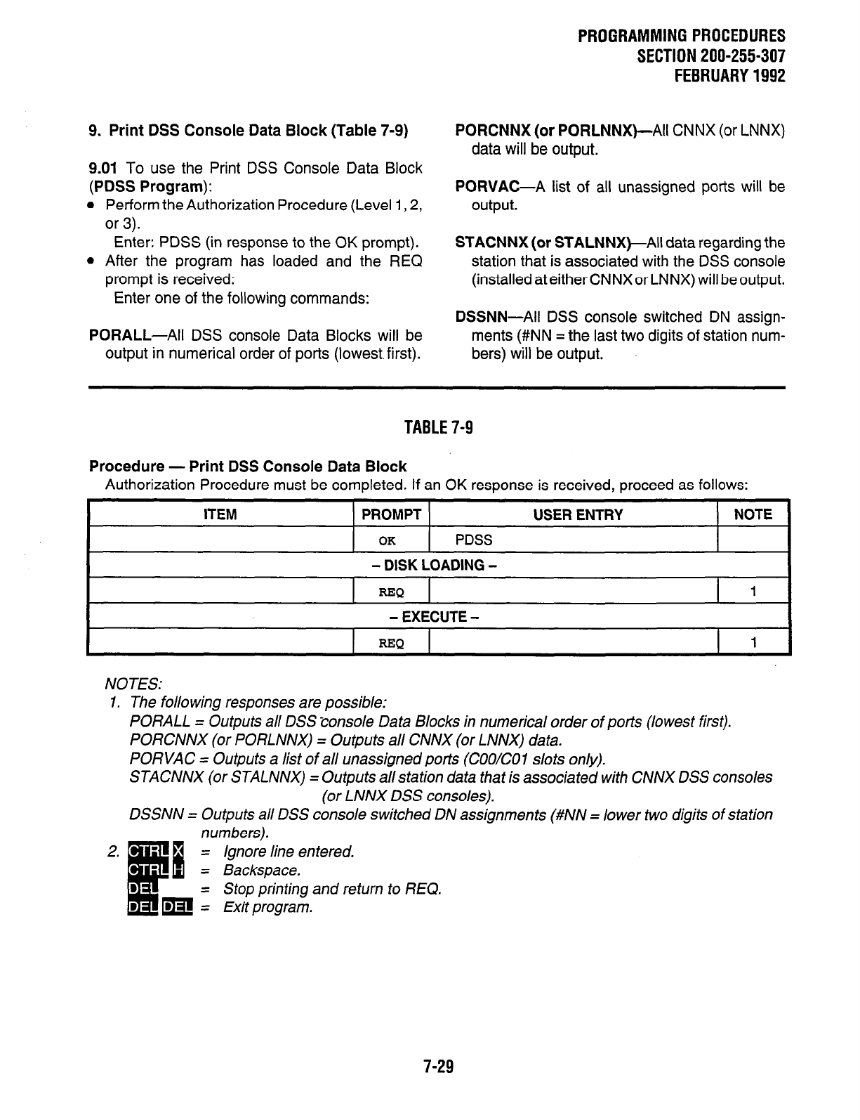
9. Print DSS Console Data Block (Table 7-9) PORCNNX (or PORLNNX)-All CNNX (or LNNX)
data will be output.
9.01 To use the Print DSS Console Data Block
(PDSS Program):
l
Perform the Authorization Procedure (Level 1,2,
or 3).
PORVAC-A list of all unassigned ports will be
output.
Enter: PDSS (in response to the OK prompt). STACNNX (or STALNNX)-All data regarding the
l
After the program has loaded and the REQ station that is associated with the DSS console
prompt is received: (installed at either CNNX or LNNX) will be output.
Enter one of the following commands:
PORALL-All DSS console Data Blocks will be
output in numerical order of ports (lowest.first).
DSSNN-All DSS console switched DN assign-
ments (#NN = the last two digits of station num-
bers) will be output.
PROGRAMMINGPROCEDURES
SECTION 200-255-307
FEBRUARY1992
TABLE7-9
Procedure - Print DSS Console Data Block
Authorization Procedure must be completed. If an OK response is received, proceed as follows:
ITEM PROMPT
OK
PDSS
- DISK LOADING -
=Q
- EXECUTE -
USER ENTRY NOTE
1
I
REP 1 I
NOTES:
1. The folio wing responses are possible:
PORALL = Outputs all DSS console Data Blocks in numerical order of ports (lowest first).
PORCNNX (or PORLNNX) = Outputs all CNNX (or LNNX) data.
PORVAC = Outputs a list of all unassigned ports (COO/CO1 slots only).
STACNNX (or STALNNX) = Outputs allstation data that is associated with CNNX DSS consoles
(or LNNX DSS consoles).
DSSNN = Outputs all DSS console switched DN assignments (#NN = lower two digits of station
numbers).
= Ignore line entered.
= Backspace.
= Stop printing and return to REQ.
= Exit program.
7-29
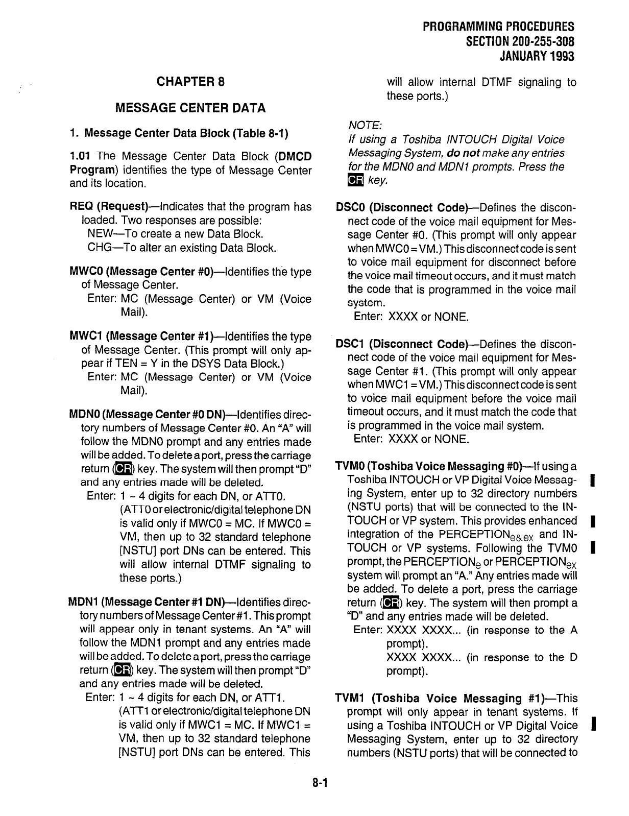
PROGRAMMING PROCEDURES
SECTION 200-255-308
JANUARY 1993
CHAPTER 8
MESSAGE CENTER DATA
will allow internal DTMF signaling to
these ports.)
1. Message Center Data Block (Table 8-1) NOTE:
If using a Toshiba INTOUCH Digital Voice
1.01 The Message Center Data Block (DMCD Messaging System, do not make any entries
Program) identifies the type of Message Center for the MDNO and MDNI prompts. Press the
and its location.
q
key,
REQ (Request)-Indicates that the program has
loaded. Two responses are possible:
NEW-To create a new Data Block.
CHG-To alter an existing Data Block.
MWCO (Message Center #0)-Identifies the type
of Message Center.
Enter: MC (Message Center) or VM (Voice
Mail).
DSCO (Disconnect Code)-Defines the discon-
nect code of the voice mail equipment for Mes-
Enter: XXXX or NONE.
sage Center #O. (This prompt will only appear
when MWCO =VM.) This disconnect code is sent
to voice mail equipment for disconnect before
the voice mail timeout occurs, and it must match
the code that is programmed in the voice mail
svstem.
MWCI (Message Center #I )-Identifies the type
of Message Center. (This prompt will only ap-
pear if TEN = Y in the DSYS Data Block.)
Enter: MC (Message Center) or VM (Voice
Mail).
MDNO (Message Center #0 DN)-Identifies direc-
tory numbers of Message Center #O. An “A” will
follow the MDNO prompt and any entries made
will be added. To delete a port, press the carriage
return (m key. The system will then prompt “D”
and any entries made will be deleted.
Enter: 1 - 4 digits for each DN, or ATTO.
(ATT0 or electronic/digital telephone DN
is valid only if MWCO = MC. If MWCO =
VM, then up to 32 standard telephone
[NSTUJ port DNs can be entered. This
will allow internal DTMF signaling to
these ports.)
MDNl (Message Center #l DN)-Identifies direc-
tory numbers of Message Center #l . This prompt
will appear only in tenant systems. An “A” will
follow the MDNl prompt and any entries made
will be added. To delete a port, press the carriage
return (m key. The system will then prompt “D”
and any entries made will be deleted.
Enter: 1 - 4 digits for each DN, or ATT1 .
(ATT1 or electronic/digital telephone DN
is valid only if MWCl = MC. If MWCI =
VM, then up to 32 standard telephone
[NSTU] port DNs can be entered. This
DSCI (Disconnect Code)--Defines the discon-
nect code of the voice mail equipment for Mes-
sage Center #1. (This prompt will only appear
when MWCl = VM.) This disconnect code is sent
to voice mail equipment before the voice mail
timeout occurs, and it must match the code that
is programmed in the voice mail system.
Enter: XXXX or NONE.
NM0 (Toshiba Voice Messaging #O)-If using a
Toshiba INTOUCH or VP Digital Voice Messag- 1
ing System, enter up to 32 directory numbers
(NSTU ports) that will be connected to the IN-
TOUCH or VP system. This provides enhanced 1
integration of the PERCEPTIONehex and IN-
TOUCH or VP systems. Following the NM0 1
prompt, the PERCEPTlONe or PERCEPTION,,
system will prompt an “A.” Any entries made will
be added. To delete a port, press the carriage
return m) key. The system will then prompt a
“D” and any entries made will be deleted.
Enter: XXXX XXXX... (in response to the A
prompt).
XXXX XXXX... (in response to the D
prompt).
TVMl
(Toshiba Voice Messaging #1)-This
prompt will only appear in tenant systems. If
using a Toshiba INTOUCH or VP Digital Voice 1
Messaging System, enter up to 32 directory
numbers (NSTU ports) that will be connected to
8-1
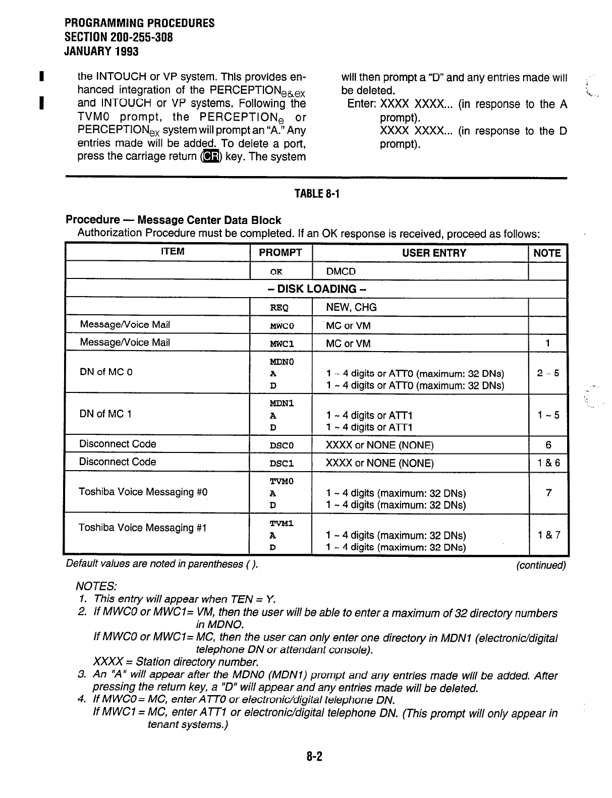
PROGRAMMINGPROCEDURES
SECTION 200-255-308
JANUARY1993
I
the INTOUCH or VP system. This provides en- will then prompt a 9” and any entries made will
hanced integration of the PERCEPTIONeke, be deleted.
I and INTOUCH or VP systems. Following the Enter: XXXX XXXX... (in response to the A
TVMO prompt, the PERCEPTlONe or prompt).
PERCEPTION,, system will prompt an “A.“Any XXXX XXXX... (in response to the D
entries made will be added. To delete a port,
press the carriage return m key. The system prompt).
TABLE 8-1
Procedure - Message Center Data Block
Authorization Procedure must be completed. If an OK response is received, proceed as follows:
Toshiba Voice Messaging #O
1 - 4 digits (maximum: 32 DNs)
Default values are noted in parentheses (). (con timed)
NOTES:
1. This entry will appear when TEN = Y.
2. If MWCO or M WC1 = VM, then the user will be able to enter a maximum of 32 directory numbers
in MDNO.
If MWCO or MWCl= MC, then the user can only enter one directory in MDNI (electronic/digital
telephone DN or attendant console).
XXXX = Station directory number.
3. An “A” will appear after the MDNO (MDNl) prompt and any entries made will be added. After
pressing the return key, a “D” will appear and any entries made will be deleted.
4. If MWCO= MC, enter Al70 or electronic/digital telephone DN.
If MWCI = MC, enter ATT1 or electronic/digital telephone DN. (This prompt will only appear in
tenant systems.)
8-2
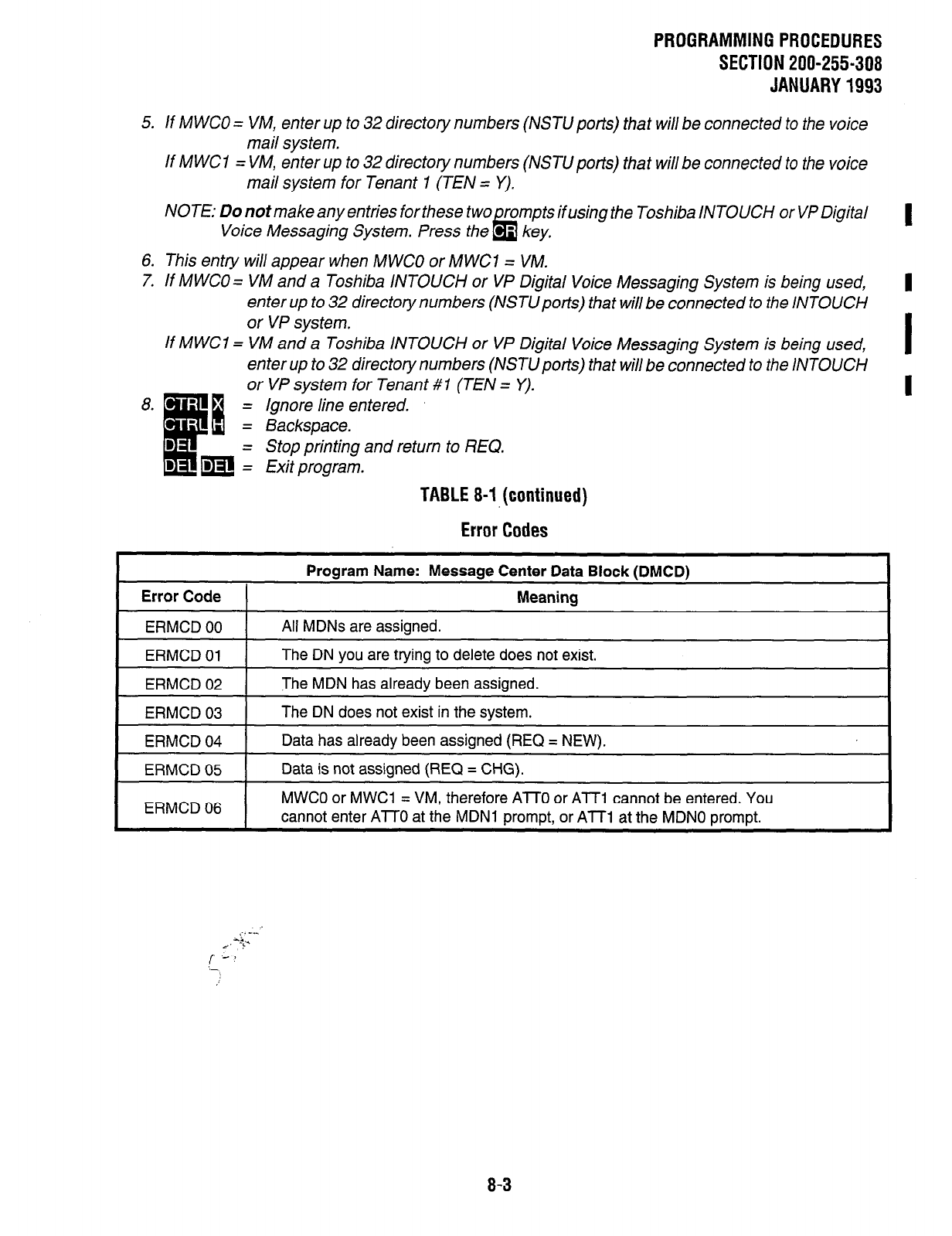
PROGRAMMING PROCEDURES
SECTION 200-255-308
JANUARY 1993
5. If M WC0 = VM, enter up to 32 directory numbers (NSTU ports) that will be connected to the voice
mail system.
If MWCI = VM, enter up to 32 directory numbers (NSTUporfs) that will be connected to the voice
mail system for Tenant 1 (TEN = Y).
NOTE: Do not make any entries for these two rompts if using the Toshiba INTOUCH or VP Digital
Voice Messaging System. Press the lb - key.
6. This entry will appear when MWCO or MWCl = VM.
7. If MWCO = VM and a Toshiba INTOUCH or VP Digital Voice Messaging System is being used,
enter up to 32 directory numbers (NSTlJpons) that will be connected to the iNTOUCH
or VP system.
If MWC1 = VM and a Toshiba INTOUCH or VP Digital Voice Messaging System is being used, I
enter up to 32 directory numbers (NSTU ports) that will be connected to the INTOUCH
or VP system for Tenant #1 (TEN = Y).
Ignore line entered.
Backspace.
Stop printing and return to REQ.
Exit program.
TABLE 8-1, (continued)
Error Codes
Program Name: Message Center Data Block (DMCD)
Error Code I Meaning
ERMCD 00 All MDNs are assigned.
ERMCD 01 The DN you are trying to delete does not exist.
ERMCD 02 The MDN has already been assigned.
ERMCD 03
ERMCD 04
The DN does not exist in the system.
Data has already been assigned (REQ = NEW).
ERMCD 05
ERMCD 06
Data is not assigned (REQ = CHG).
MWCO or MWCl = VM, therefore AlTO or ATT1 cannot be entered. You
cannot enter Al70 at the MDN1 prompt, or ATT1 at the MDNO prompt.
,.. -..
I. “‘Y
/-
:-
8-3
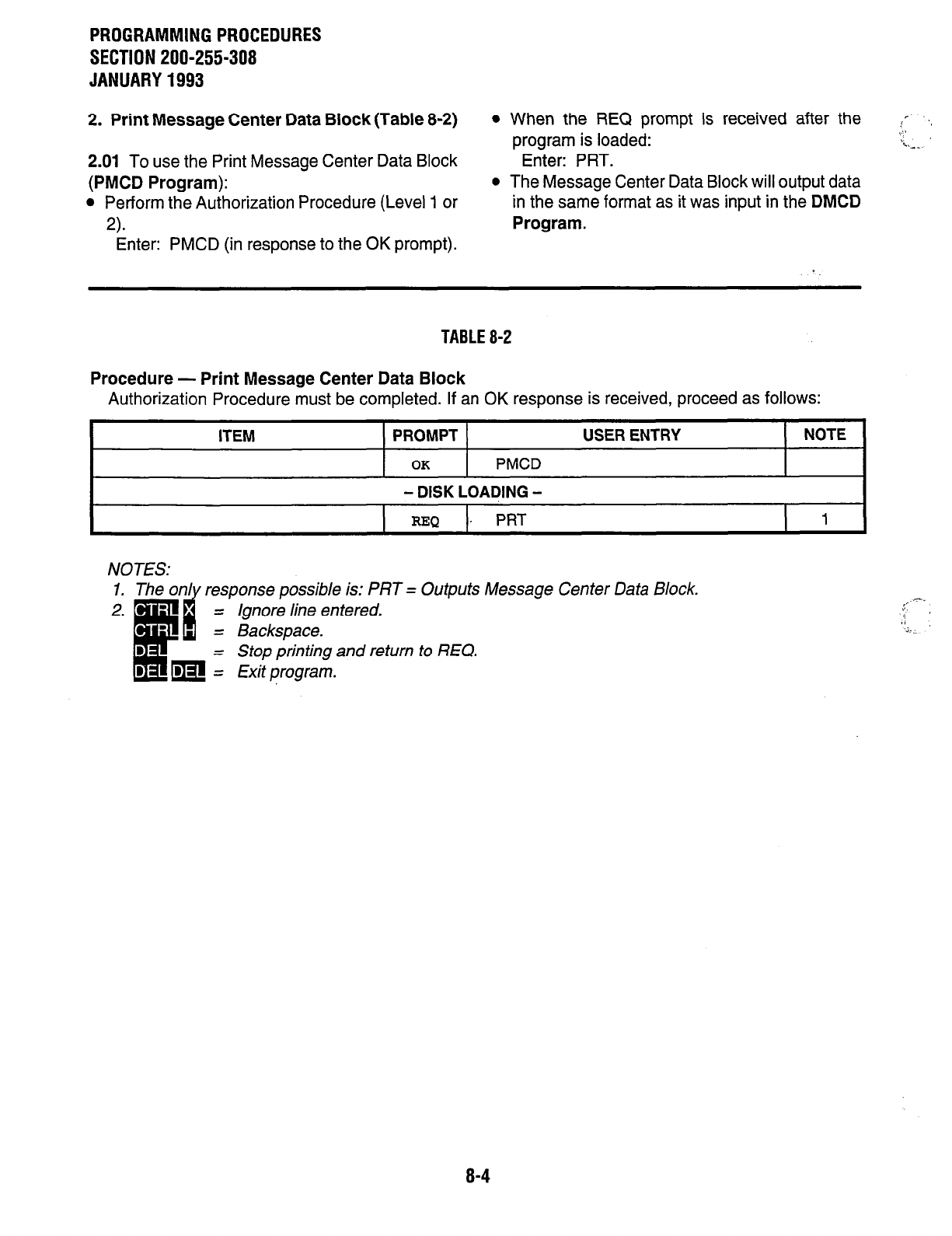
PROGRAMMING PROCEDURES
SECTION 200-255-308
JANUARY 1993
2. Print Message Center Data Block (Table 8-2)
2.01 To use the Print Message Center Data Block
(PMCD Program):
l
Perform the Authorization Procedure (Level 1 or
2).
Enter: PMCD (in response to the OK prompt).
l
When the REQ prompt is received after the
program is loaded:
Enter: PRT.
l
The Message Center Data Block will output data
in the same format as it was input in the
DMCD
Program.
!r-
.,: I
Le.
TABLE 8-2
Procedure - Print Message Center Data Block
Authorization Procedure must be completed. If an OK response is received, proceed as follows:
ITEM PROMPT
OK
PMCD
- DISK LOADING -
USER ENTRY NOTE
=x2
PRT
1 I
NOTES: response possible is: PRT = Outputs Message Center Data Block.
= Ignore line entered.
= Backspace.
= Stop printing and return to REQ.
= Exit program.
8-4
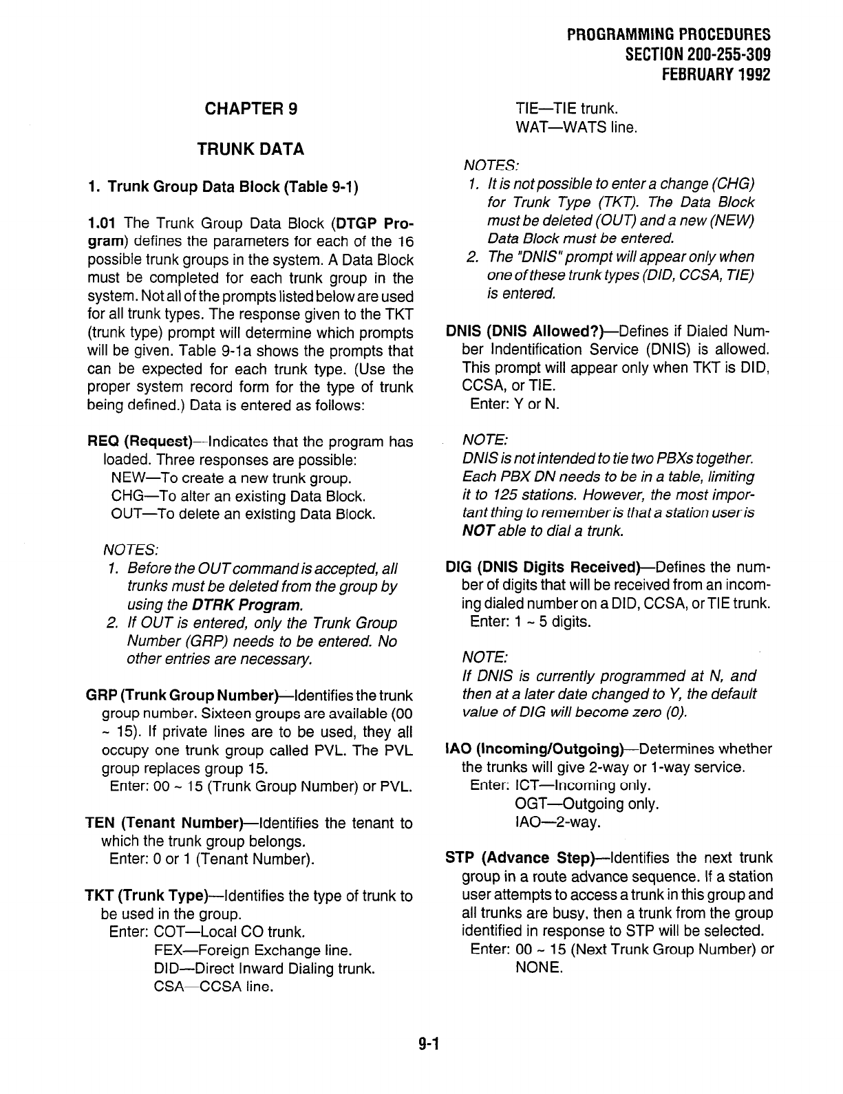
CHAPTER 9
TRUNK DATA
1. Trunk Group Data Block (Table 9-1)
1.01 The Trunk Group Data Block (DTGP Pro-
gram) defines the parameters for each of the 16
possible trunk groups in the system. A Data Block
must be completed for each trunk group in the
system. Not all of the prompts listed below are used
for all trunk types. The response given to the TKT
(trunk type) prompt will determine which prompts
will be given. Table g-la shows the prompts that
can be expected for each trunk type. (Use the
proper system record form for the type of trunk
being defined.) Data is entered as follows:
REQ (Request)--Indicates that the program has
loaded. Three responses are possible:
NEW-To create a new trunk group.
CHG-To alter an existing Data Block.
OUT-To delete an existing Data Block.
NOTES:
1. Before the OUT command is accepted, all
trunks must be deleted from the group by
using the DTRK Program.
2. If OUT is entered, only the Trunk Group
Number (GRP) needs to be entered. No
other entries are necessary.
GRP (Trunk Group Number)-Identifies the trunk
group number. Sixteen groups are available (00
- 15). If private lines are to be used, they all
occupy one trunk group called PVL. The PVL
group replaces group 15.
Enter: 00 - 15 (Trunk Group Number) or PVL.
TEN (Tenant Number)-Identifies the tenant to
which the trunk group belongs.
Enter: 0 or 1 (Tenant Number).
TKT (Trunk Type)-Identifies the type of trunk to
be used in the group.
Enter: COT-Local CO trunk.
FEX-Foreign Exchange line.
DID-Direct Inward Dialing trunk.
CSA-CCSA line.
PROGRAMMING PROCEDURES
SECTION 200-255-309
FEBRUARY 1992
TIE-TIE trunk.
WAT-WATS line.
NOTES:
1.
2.
It is not possible to enter a change (CHG)
for Trunk Type (TKT). The Data Block
must be deleted (OUT) and a new (NEW)
Data Block must be entered.
The ‘DNIS” prompt will appear only when
one of these trunk types (DID, CCSA, TIE)
is entered.
DNIS (DNIS Allowed?)-Defines if Dialed Num-
ber lndentification Service (DNIS) is allowed.
This prompt will appear only when TKT is DID,
CCSA, or TIE.
Enter: Y or N.
NOTE:
DNIS is not intended to tie two PBXs together.
Each PBX DN needs to be in a table, limiting
it to 125 stations. However, the most impor-
tant thing to remember is that a station user is
NOT able to dial a trunk.
DIG (DNIS Digits Received)-Defines the num-
ber of digits that will be received from an incom-
ing dialed number on a DID, CCSA, or TIE trunk.
Enter: 1 - 5 digits.
NOTE:
If DNIS is currently programmed at N, and
then at a later date changed to Y, the default
value of DIG will become zero (0).
IA0 (Incoming/Outgoing)-Determines whether
the trunks will give 2-way or 1 -way service.
Enter: ICT-Incoming only.
OGT-Outgoing only.
IAO-2-way.
STP (Advance Step)--Identifies the next trunk
group in a route advance sequence. If a station
user attempts to access a trunk in this group and
all trunks are busy, then a trunk from the group
identified in response to STP will be selected.
Enter: 00 - 15 (Next Trunk Group Number) or
NONE.
9-1
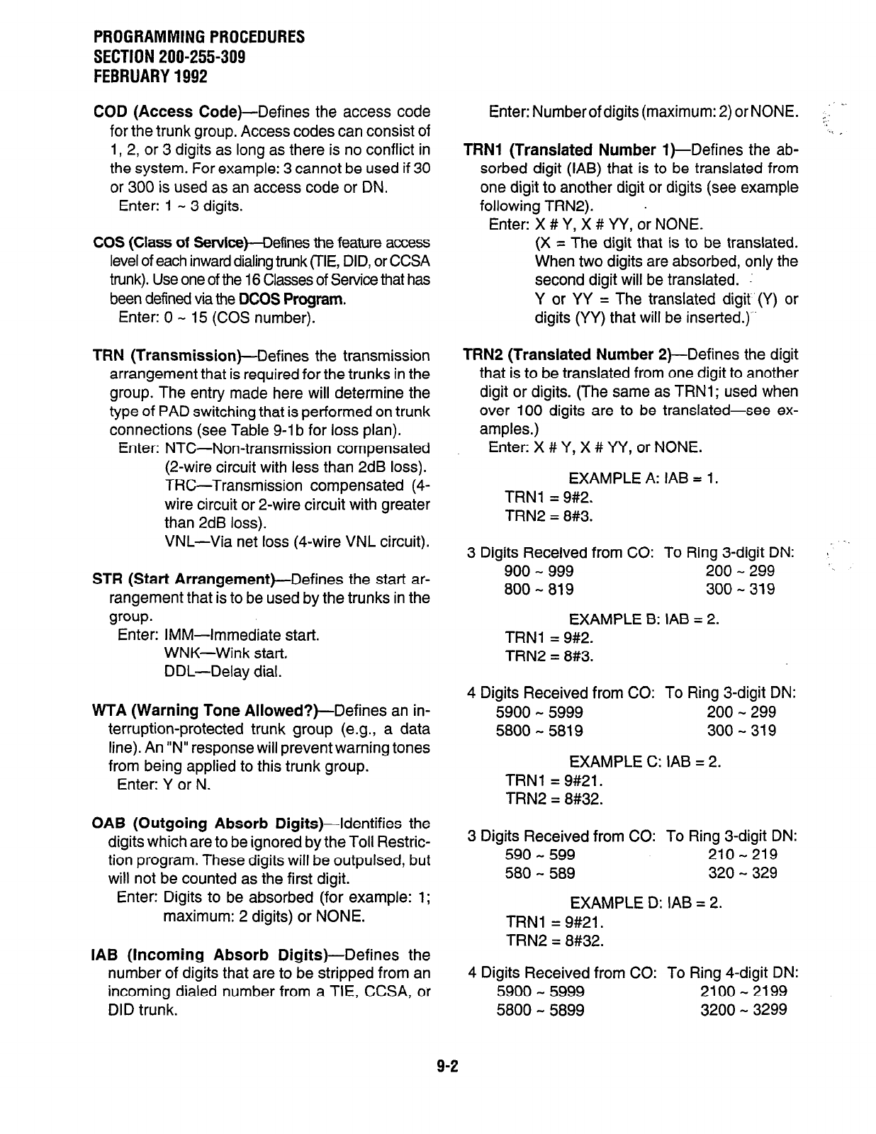
PROGRAMMINGPROCEDURES
SECTION 200-255-309
FEBRUARY1992
COD (Access
Code)-Defines the access code
for the trunk group. Access codes can consist of
1, 2, or 3 digits as long as there is no conflict in
the system. For example: 3 cannot be used if 30
or 300 is used as an access code or DN.
Enter: 1 - 3 digits.
COS
(Class of
Service)-Defines the feature access
level of each inward dialing trunk (TIE, DID, or CCSA
trunk). Use one of the 16 Classes of Service that has
been defined via the DCOS
Program.
Enter: 0 - 15 (COS number).
TRN (Transmission)-Defines
the transmission
arrangement that is required for the trunks in the
group. The entry made here will determine the
type of PAD switching that is performed on trunk
connections (see Table g-lb for loss plan).
Enter: NTC-Non-transmission compensated
(2-wire circuit with less than 2dB loss).
TRC-Transmission compensated (4-
wire circuit or 2-wire circuit with greater
than 2dB loss).
VNL-Via net loss (4-wire VNL circuit).
STR (Start Arrangement)--Defines
the start ar-
rangement that is to be used by the trunks in the
group.
Enter: IMM-Immediate start.
WNK-Wink start.
DDL-Delay dial.
WTA (Warning Tone Allowed?)-Defines
an in-
terruption-protected trunk group (e.g., a data
line). An “N” response will prevent warning tones
from being applied to this trunk group.
Enter: Y or N.
OAB (Outgoing Absorb
Digits)-Identifies the
digits which are to be ignored by the Toll Restric-
tion program. These digits will be outpulsed, but
will not be counted as the first digit.
Enter: Digits to be absorbed (for example: 1;
maximum: 2 digits) or NONE.
IAB (Incoming Absorb Digits)-Defines the
number of digits that are to be stripped from an
incoming dialed number from a TIE, CCSA, or
DID trunk.
Enter: Number of digits (maximum: 2) or NONE.
TRNl (Translated Number
l)-Defines the ab-
sorbed digit (IAB) that is to be translated from
one digit to another digit or digits (see example
following TRN2). .
Enter: X # Y, X # YY, or NONE.
(X = The digit that is to be translated.
When two digits are absorbed, only the
second digit will be translated.
Y or YY = The translated digit (Y) or
digits (YY) that will be inserted.)
TRNP (Translated Number
2)-Defines the digit
that is to be translated from one digit to another
digit or digits. (The same as TRNl; used when
over 100 digits are to be translated-see ex-
amples.)
Enter: X # Y, X # YY, or NONE.
EXAMPLE A: IAB =
TRNl = 9#2.
TRN2 = 8#3.
1.
3 Digits Received from CO: To Ring 3-digit DN:
900 - 999 200 - 299
800 - 819 300
- 319
EXAMPLE B: IAB = 2.
TRNl = 9#2.
TRN2 = 8#3.
4 Digits Received from CO: To Ring 3-digit DN:
5900 - 5999 200 - 299
5800 - 5819 300 - 319
EXAMPLE C: IAB = 2.
TRNl = 9#21.
TRN2 = 8#32.
3 Digits Received from CO: To Ring 3-digit DN:
590 - 599 210-219
580 - 589 320 - 329
EXAMPLE D: IAB = 2.
TRNl = 9#21.
TRN2 = 8#32.
4 Digits Received from CO: To Ring 4-digit DN:
5900 - 5999 2100 - 2199
5800 - 5899 3200 - 3299
9-2
PROGRAMMINGPROCEDURES
SECTION 200-255-309
FEBRUARY1992
TOL (Toll Restriction Class)-Assigns one of the
IO classes of Toil Restriction to each outgoing
TIE, CCSA, and DID trunk. Classes 0 - 7 are
defined in the Toll Restriction Data Block (DTOL
Program). Class 8 is simple Toll Restriction and
restricts when either 1 or n is dialed as the first
digit. NONE defines the trunk as unrestricted.
Enter: 0 - 8 or NONE.
FLT (Flash-hook Timing)-Defines the length of
time of a flash-hook (line open) while connected
to a CO trunk. On an electronic/digital telephone,
the flash-hook will occur whenever them key
is pressed.
Enter: 1 = 500 milliseconds.
2 = 1 second.
CTX (Centrex)-A “Y” response indicates that the
trunk group is operating on Centrex lines. An “N”
response indicates that the trunk group is not
operating on Centrex lines. The entry “Y” made
here defeats Toll Restriction.
Enter: Y or N.
NOTE:
When DNIS = Y, the following prompts do
NOT apply, eventhough they appear on the
screen: COS, IAB, TRNI, TRN2, and TOL.
2. Print Trunk Group Data Block (Table 9-2)
2.01 To use the Print Trunk Group Data Block
(PTGP Program):
l
Perform the Authorization Procedure (Level 1 or
Enter: PTGP (in response to the OK prompt).
l
When an REQ prompt is received after the
program is loaded:
Enter one of the following commands:
ALL-All Trunk Group Data Blocks will be output.
GRPXX-Trunk Group XX Data Block will be out-
put.
COT-All CO Trunk Group Data Blocks will be
output.
FEX-All FX Trunk Group Data Blocks will be
output.
WAT-All WATS Trunk Group Data Blocks will be
output.
TIE-All TIE Trunk Group Data Blocks will be
output.
DID-All DID Trunk Group Data Blocks will be
output.
CSA-All CCSA Trunk Group Data Blocks will be
output.
PVL-All Private Line Trunk Group Data Blocks will
be output.
NOTE:
The output format willbe the same as the input
format that is used in the DTGP Program.
l
REQ will be prompted when the printout is
complete.
Enter: m m
q
(to exit the program).
9-3

PROGRAMMING PROCEDURES
SECTION 200-255-309
FEBRUARY 1992 TABLE 9-l
Procedure - Trunk Group Data Block
Authorization Procedure must be completed. If an OK response is received, proceed as follows:
NOTES:
(continued)
I. A maximum of 7 6 Trunk’Groups (normally 00 - 75) is possible. If priva te lines are to be equipped, the code
PVL is used in place of 15.
2. TKT cannot be changed. The Data Block must be removed (OUT) and NEW data must be entered. The
“DNIS” prompt will appear only when one of these trunk types (DID, CCSA, TIE) is entered.
3. This prompt will appear only when TKT is DID, CCSA, or TIE.
4. This prompt will appear only when DNIS is allowed.
5. The Trunk Group that is to be stepped to if this group is busy (00 - 15).
6. COS is meaningful only for TiE/CCSA/DiD Trunks. Sixteen COS groups are provided and are defined in the
Class of Service Data Block.
7. List the digits which are to be ignored for the purpose of Toil Restriction, These,digits will be outpulsed, but
not counted as the first digit.
8. Enter the number of digits which are to be stripped from an incoming dialed DN (TIE, DID, or CCSA Trunk).
Example: IAB = 1. incoming DN = 8249. Recognized DN = 249.
9. Enter the absorbed digit (IAB) to be translated.
X = the absorbed digit (IAB) to be translated. Y or YY = the translated digits to be inserted.
Example: IAB = 1. TRNl = 9#2. incoming DN = 949. Recognized DN = 249.
TRN2 = 8#3. incoming DN = 849. Recognized DN = 349.
10. Classes 0 - 7are defined in the Toil Restriction Data Block
(DTOL
Program).
Class 8 = 0 and 1 restriction. NONE = no restriction.
11. 1 = 500 ms. 2 = 1 second.
12. Enter yes if the trunk group is
73. mm = ignore line entered.
=B = Backspace.
Stop printing and return to REQ.
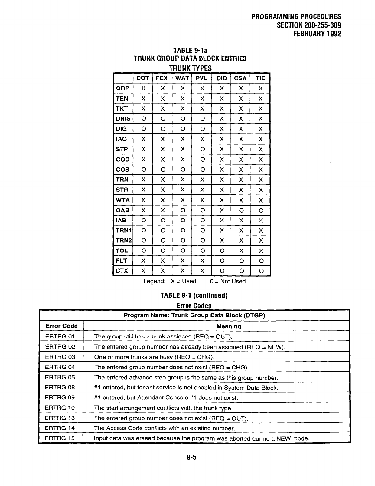
PROGRAMMING PROCEDURES
SECTION 200-255-309
FEBRUARY 1992
TABLE 9- -la
TRUNK GROUP DATA I
BLOCK ENTRIES
TRUNK TYPES
COT FEX WAT PVL DID CSA TIE
GRP X X X X X X X
TEN X X X X X X X
ITKT I x I x I x I x I x I x
I x I
DNIS 0 0 0 0 X X X
DIG 0 0 0 0 X X X
IA0 X X X X X X X
STP X X X 0 X X X
COD X X X 0 X X X
cos 0 0 0 0 x x x
TRN X X X X X X X
STR X X X X X X X
WTA X X X X X X X
IAB 0 0 0 0 X X X
TRNl 0 0 0 0 X X X
ITRNPI 0 I 0 1 0 1 0 1 X 1 X I X 1
TOL 0 0 0 0 0 X X
FLT X X X X 0 0 0
ICTX 1 X I X I X I X I 0 I 0 I 0 I
Legend: X = Used 0 = Not Used
TABLE 9-l (continued)
Error Codes
Error Code
ERTRG 01
ERTRG 02
ERTRG 03
ERTRG 04
ERTRG 05
ERTRG 08
ERTRG 09
ERTRG 10
ERTRG 13
ERTRG 14
ERTRG 15
Program Name: Trunk Group Data Block (DTGP)
Meaning
The group still has a trunk assigned (REQ = OUT).
The entered group number has already been assigned (REQ = NEW).
One or more trunks are busy (REQ = CHG).
The entered group number does not exist (REQ = CHG).
The entered advance step group is the same as this group number.
#1 entered, but tenant service is not enabled in System Data Block.
#l entered, but Attendant Console #1 does not exist.
The start arrangement conflicts with the trunk type.
The entered group number does not exist (REQ = OUT).
The Access Code conflicts with an existing number.
Input data was erased because the program was aborted during a NEW mode.
9-5
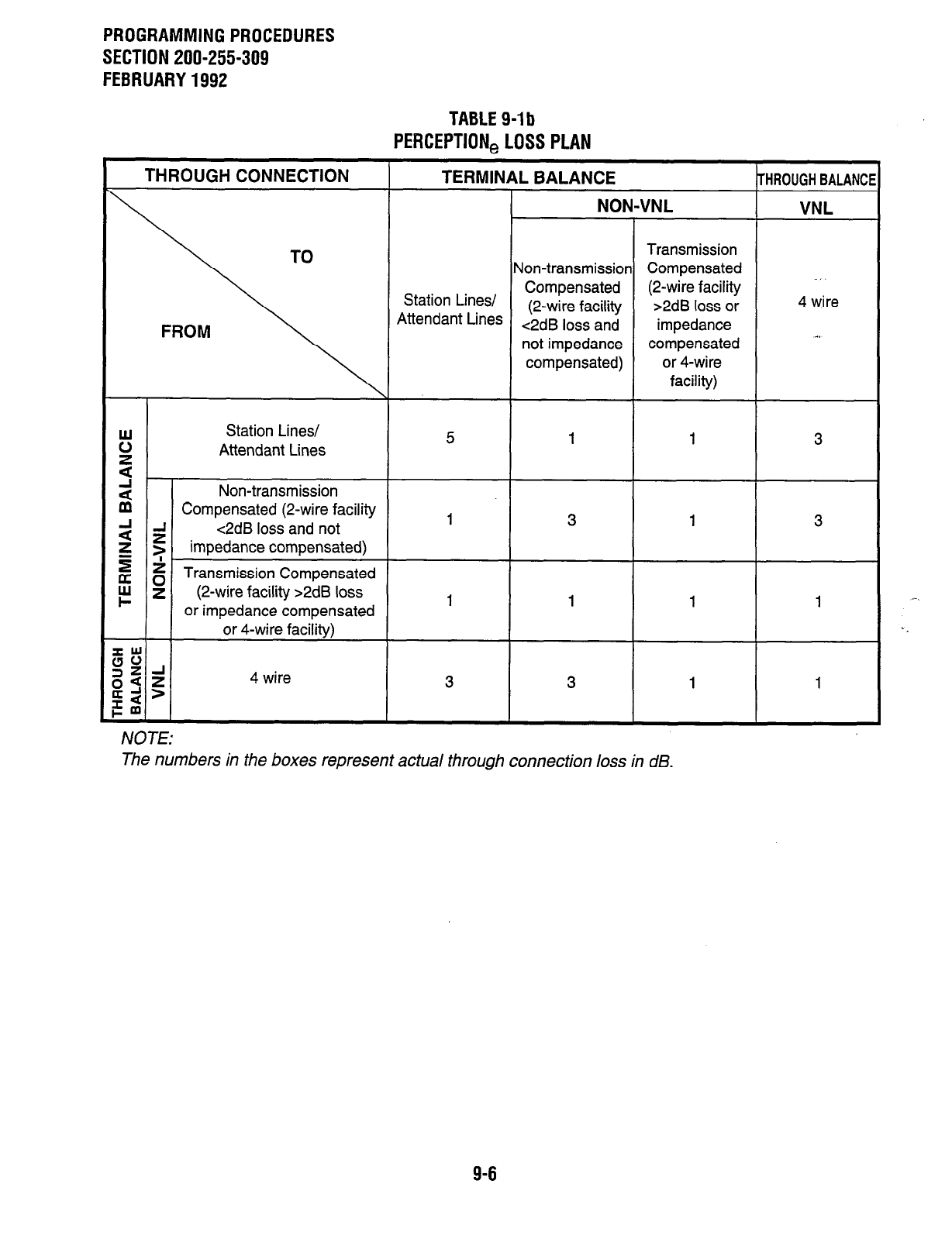
PROGRAMMINGPROCEDURES
SECTION ZOO-255309
FEBRUARY1992
TABLEg-lb
PERCEPTION,LOSSPLAN
THROUGH CONNECTION TERMINAL BALANCE
THROUGH BALANC
NON-VNL VNL
Transmission
Non-transmission Compensated .
Station Lines/ Compensated (2-wire facility
(2-wire facility >2dB loss or 4 wire
Attendant Lines <2dB loss and impedance
not impedance compensated . .
compensated) or 4-wire
facility)
ti Station Lines/
Attendant Lines
2
2 Non-transmission
Compensated (2-wire facility
i 1 c2dB loss and not
impedance compensated)
$ 2 Transmission Compensated
E = (2-wire facility >2dB loss
or impedance compensated
or 4-wire facility)
g$
gsg 4 wire
lx-‘>
Id
cm
5 1 1 3
1 3 1 3
1 1 1 1
3 3 1 1
/VOTE:
The numbers in the boxes represent actual through connection loss in dB.
9-6
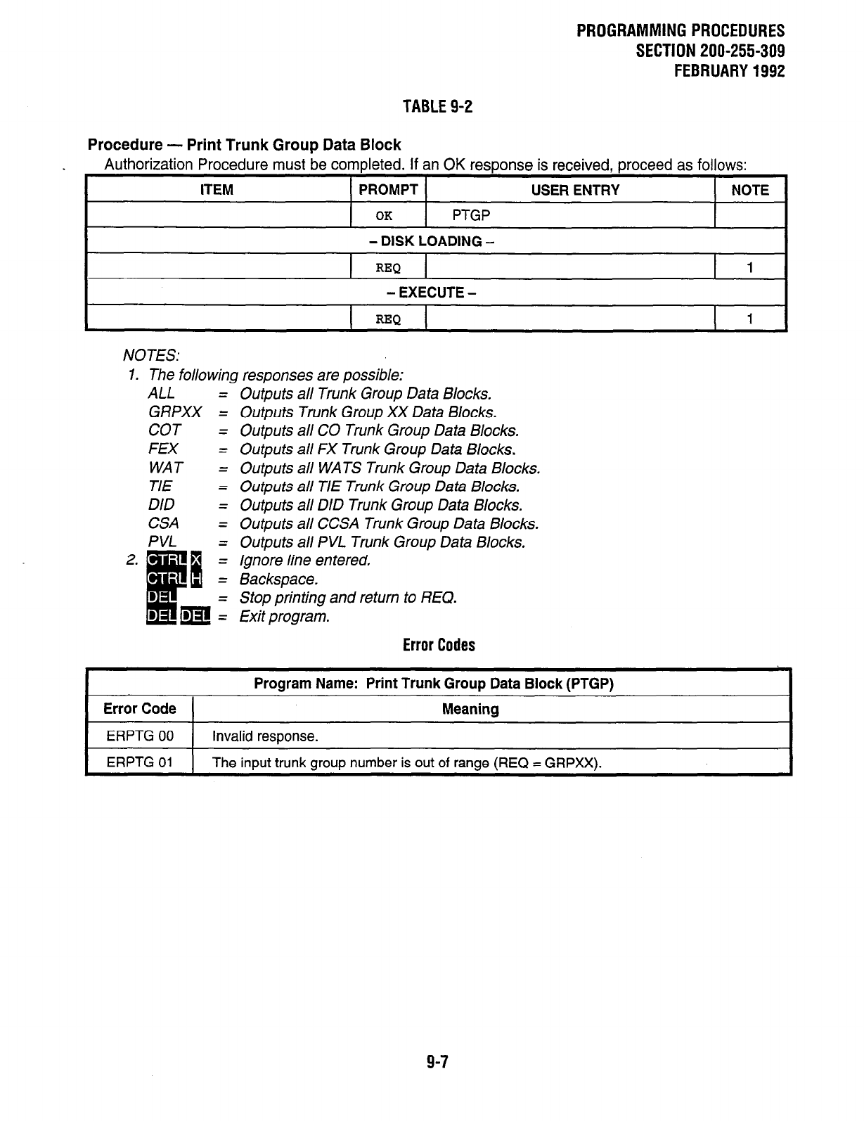
PROGRAMMINGPROCEDURES
SECTION 200-255-309
FEBRUARY1992
TABLE 9-2
Procedure - Print Trunk Group Data Block
Authorization Procedure must be completed. If an
OK
response is received, proceed as follows:
ITEM PROMPT USER ENTRY NOTE
OK
PTGP
- DISK LOADING -
REQ 1
- EXECUTE -
NOTES:
1. The following responses are possible:
ALL = Outputs all Trunk Group Data Blocks.
GRPXX = Outputs Trunk Group XX Data Blocks.
COT = Outputs all CO Trunk Group Data Blocks.
FEX = Outputs all FX Trunk Group Data Blocks.
WAT = Outputs all WATS Trunk Group Data Blocks.
TIE = Outputs all TIE Trunk Group Data Blocks.
DID = Outputs all DID Trunk Group Data Blocks.
CSA = Outputs all CCSA Trunk Group Data Blocks.
PVL = Outputs all PVL Trunk Group Data Blocks.
= Ignore line entered,
= Backspace.
- Stop printing and return to REQ.
= Exit program.
Error Codes
Error Code 1
Program Name: Print Trunk Group Data Block (PTGP)
Meaning
ERPTG 00 Invalid response.
ERPTG 01 The input trunk group number is out of range (REQ = GRPXX).
9-7
PROGRAMMINGPROCEDURES
SECTION 200-255-309
FEBRUARY1992
3. Trunk Data Block (Table 9-3)
3.01 The Trunk Data Block (DTRK Program) de-
fines the parameters for each of the trunk circuits in
the system. A separate Data Block must be com-
pleted for each trunk circuit in the system.
NOTE:
When using the NDTU PC6 (Digital T-l inter-
face) Trunk Data Block programming remains
the same. Each T-l channel (24 per each
NDTU PCB) equals a trunk circuit.
3.02 The trunk type (TKT) defined for the group (in
the DTPG Program) will determine which entries
must be made. Not all prompts are meaningful for
all trunk types. Table 9-3a shows the prompts to
which responses should be made. (Use the proper
system record form for the type of trunk being
defined.) Data is entered as follows:
REQ (Request)-Indicates that the program has
loaded. Three responses are possible:
NEW-To create a new Data Block.
CHG-To alter an existing Data Block.
OUT-To delete an existing Data Block.
NOTE:
If OUT is entered, then only the port (POR)
needs to be specified. No other dafa entries
are necessary.
POR (Port Number)--Identifies the hardware lo-
cation of the trunk circuit that is to be defined in
a PERCEPTION, or PERCEPTION,, system.
The port number has two parts:
1)
2)
PERCEPTlONe: TOO - T15 (trunk PCB loca-
tion).
PERCEPTIONex: TOO - T15; T16 - T31 for
the assignment of additional trunk ports,
exceeding T15. When Ti 6 - T31 are used,
an entry must also be made in response to
the UPN prompt. While TOO - T15 are fixed
trunk slots, T16 - T31 are flexible and may be
assigned to any universal port slot (00 - 31).
A maximum of 16 universal port slots can be
used for trunks.
1 - 4 (circuit number on the trunk PCB).
For example: The port number of the third
circuit on the PCB in position TO2 is T023.
Enter: PERCEPTlONe: TNNX (port num- ,.
ber of trunk). ‘i,(
PERCEPTION,,: See UPN prompt.
NOTE:
NN = Trunk PCB number; X= Circuit number.
UPN (Universal Port Number)-Identifies the
hardware location of the trunk circuit that is to be
defined in a PERCEPTlONe, system which has
trunks assigned above T15. The universal port
number’s trunk PCB location is TOO - T31.
Enter: NN (NN = 00 - 31).
NOTE:
When reprogramming universal port assign-
ments from trunk to station ports (and vice
versa), all ports on the existing PCB must be
deleted prior to entering the new port assign-
ment.
GMN (Group/Member Number)-The group/
member number identifies the trunk position in
the system. The GMN is composed of two parts:
1) Group (GG) Number (defined in the DTGP . ..-.
Program): Identifies the trunk as being a ‘.
member of that group (00 - 15).
2) Member (MM) Number: A unique number is
given to each trunk in a group. The numerical
order of the number will determine the order
in which the trunks will be selected upon dial
access. The highest member number will be
selected first. (PERCEPTlONe: 00 - 63;
PERCEPTlONe,: 00 - 63).
Enter: GGMM (Group and Member Num-
ber).
NOTES:
1. GMN cannot be altered by CHG proce-
dure. The GMN prompt will be followed by
the existing GMN.
2. To change the GMN, the Data Blockmust
be deleted (OUT) and a new Data Block
(NEW) must be entered.
TKID (Trunk Name)-Indicates the alphanumeric
name assigned to a particular trunk for CO, FX,
and WATS only. When a call is coming in via a
named trunk, the receiver can see in the LCD
display who the call is intended for. This feature
9-8
better enables the receiver to handle the call.
Trunk Name also appears on outgoing calls.
Enter: Trunk name (A - Z, 0 - 9, [space]),
NONE.
NOTE:
The maximum number of alphanumeric char-
acters a//owed for a trunk name is 16.
TDN (Trunk Directory Number)-For private lines
only (Trunk Group 15-PVL). TDN defines a
directory number that will be used to assign
private lines to a station.
Enter: 1 - - 3-digit directory number.
RAD (Remote Access Day)-A “Y” response en-
ables the Remote Access to Services trunk for
both day and night service. An “N” response
enables Remote Access only during night service.
Enter: Y or N.
NIT(Night Number)-Assigns the night station for
the trunk. Incoming calls on the trunk will ring the
night station whenever the system is in night
service. If NONE is entered, then the call will
activate the UNA signal. This parameter can also
be entered and changed by the attendant con-
sole.
Enter: Night station number (maximum: 4 dig-
its) or NONE (UNA).
NOTE:
To assign a ground-start trunk to Remote
Access to Services, enter the same DN that
was used for the REM entry in the System
Data Block (DSYS Program) for NIT (Night
Number).
DAY (Day Number)-Assigns the day station(s) for
the trunk. Incoming calls on the trunk will ring the
day station(s) when the system is not in night
service. Up to eight stations can be entered as day
stations, to have ,either immediate or delayed
ringing. Delayed ringing is achieved by entering a
9 immediately after each station number that is to
ring after the immediate-ring station(s). This will
delay the ringing of these stations for the period
set by the Delay Ring Timer in the DSYS Program
(0 - 99 seconds). After this time period elapses,
the delayed station(s) will ring. All day stations will
receive an immediate visual LED indication with
PROGRAMMINGPROCEDURES
SECTION 200-255-309
FEBRUARY1992
each incoming call. A Day Number can also be
assigned as the attendant console, but the At-
tendant Console cannot be included as part of
delayed ringing. ACD pilot numbers cannot be
used as part of delayed ringing either. If NONE is
entered, the following occurs: If TEN = N in DSYS,
calls will load share between the two consoles in
the DAY mode, and will activate the UNA device
in the NIGHT mode. If TEN = Y in DSYS, trunks
assigned to TEN 0 will ring AlTO in the DAY mode
and UNA 0 in the NIGHT mode; trunks assigned
to TEN1 will ring ATT1 in the DAY mode and
UNAI in the NIGHT mode. The DAY parameter
can also be entered and changed by the attendant
console.
Enter: Day station number (up to 8 numbers
maybeentered; maximum:4digitseach).
After each station number that is to have
delayed ringing, enter a i. Enter a space
after each DN and/or DN p assignment.
AlTO orATT1 (attendant console0 or l),
or NONE (UNA in NITE service-ATT in
Day Service).
TRCL (Destination for Transfer Recall Termina-
tion)--Assigns the destination to which a transfer
recall terminates. When a transfer recall is not
answered at the originally transferring station, the
call can be routed to either an attendant, the sys-
tem UNA device, or an alternative DN.
Enter: AlTO, Al71 -Attendant Console 0 or 1.
UNA-System UNA device.
DN-Alternative station (either a station
user DN or a master hunt DN).
NONE-No termination destination (the
call will continue to ring at the originally-
transferring station).
SIG (Signaling)-ldentiies the type of signaling to be
used on the trunk circuit:
Enter: GRD-Ground Start.
LOP--Loop start.
EAM-E&M.
LDR-LoopDialRepeating(forDIDtrunks).
DIS (Disconnect Supetvision~lnfotrns the system
whether or not supervision can be expected when the
distant end disconnects. Disconnect Supervision
controls trunk-to-trunk connections for ground start
trunks.
Enter: Y or N.
9-9
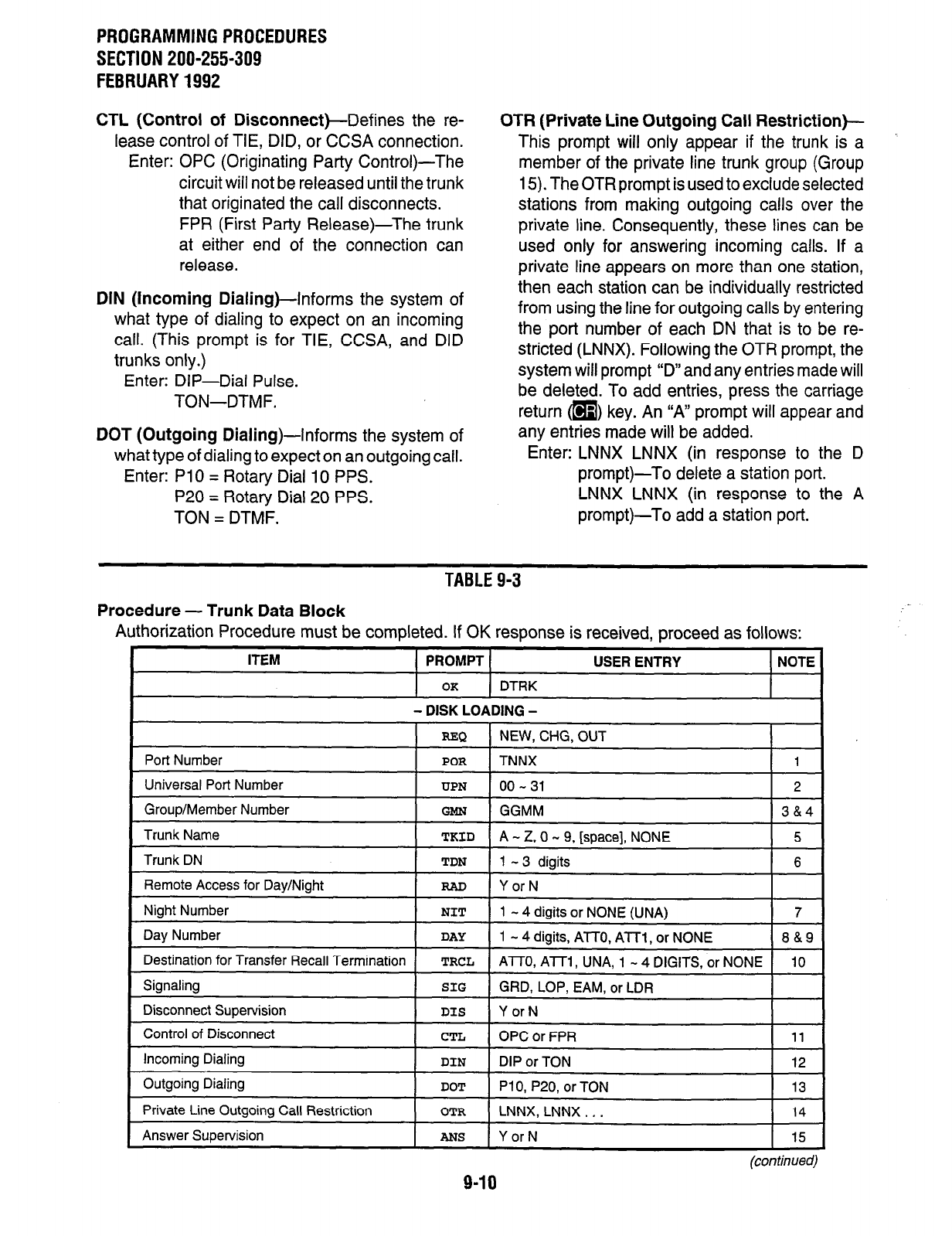
PROGRAMMING PROCEDURES
SECTION 200-255-309
FEBRUARY 1992
CTL (Control
of Disconnect)-Defines the re-
lease control of TIE, DID, or CCSA connection.
Enter: OPC (Originating Party Control)-The
circuit will not be released until the trunk
that originated the call disconnects.
FPR (First Party Release)-The trunk
at either end of the connection can
release.
DIN (incoming
Dialing)-Informs the system of
what type of dialing to expect on an incoming
call. (This prompt is for TIE, CCSA, and DID
trunks only.)
Enter: DIP-Dial Pulse.
TON-DTMF.
DOT (Outgoing
Dialing)-Informs the system of
what type of dialing to expect on an outgoing call.
Enter: PlO = Rotary Dial IO PPS.
P20 = Rotary Dial 20 PPS.
TON = DTMF.
OTR (Private Line Outgoing Call Restriction)--
This prompt will only appear if the trunk is a
member of the private line trunk group (Group
15). The OTR prompt is used to exclude selected
stations from making outgoing calls over the
private line. Consequently, these lines can be
used only for answering incoming calls. If a
private line appears on more than one station,
then each station can be individually restricted
from using the line for outgoing calls by entering
the port number of each DN that is to be re-
stricted (LNNX). Following the OTR prompt, the
system will prompt “D” and any entries made will
be deleted. To add entries, press the carriage
return m key. An “A” prompt will appear and
any entries made will be added.
Enter: LNNX LNNX (in response to the D
prompt)-To delete a station port.
LNNX LNNX (in response to the A
prompt)-To add a station port.
TABLE 9-3
Procedure - Trunk Data Block
Authorization Procedure must be completed. If OK response is received, proceed as follows:
(continued)
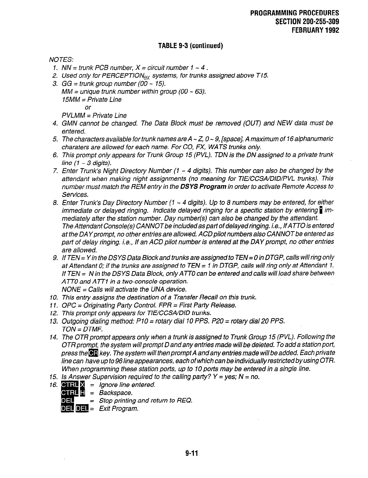
PROGRAMMINGPROCEDURES
SECTION 200-255-309
FEBRUARY1992
NOTES:
TABLE 9-3 (continued)
1. NN = trunk PCB number, X = circuit number 1 - 4 .
2. Used only for PERCEPTIONex systems, for trunks assigned above T15.
3. GG = trunk group number (00 - 15).
MM = unique trunk number within group (00 - 63).
15MM = Private Line
or
PVLMM = Private Line
4.
5.
6.
7.
GMN cannot be changed. The Data Block must be removed (OUT) and NEW data must be
entered.
8.
The characters available for trunk names are A - Z, 0 - 9, [space]. A maximum of 16 alphanumeric
charaters are allowed for each name. for CO, FX, WATS trunks only.
This prompt only appears for Trunk Group 15 (PVL). TDN is the DN assigned to a private trunk
line (1 - 3 digits).
Enter Trunk’s Night Directory Number (1 - 4 digits). This number can also be changed by the
attendant when making night assignments (no meaning for TIuCCSA/DID/PVL trunks). This
number must match the REM entry in the DSYS Program in order to activate Remote Access to
Services.
Enter Trunk’s Day Directory Number (1 - 4 digits). Up to 8 numbers may be entered, for either
immediate or delayed ringing. Indicate delayed ringing for a specific station by entering i im-
mediately after the station number. Day number(s) can also be changed by the attendant.
The Attendant Console(s) CANNOTbe included as part of delayed ringing. i.e., lfA770 is entered
at the DA Yprompt, no other entries are allowed. ACD pilot numbers also CANNOT be entered as
part of delay ringing. i.e., If an ACD pilot number is entered at the DAY prompt, no other entries
are allowed.
9. If TEN = Yin the DSYS Data Block and trunks are assigned to TEN = 0 in DTGP, calls will ring only
at Attendant 0; if the trunks are assigned to TEN = 1 in DTGP, calls will ring only at Attendant 1.
If TEN = N in the DSYS Data Block, only ATO can be entered and calls will load share between
ATT0 and ATT1 in a two-console operation.
NONE = Calls will activate the UNA device.
10.
11.
12.
13.
14.
This entry assigns the destination of a Transfer Recall on this trunk.
OPC = Originating Party Control. FPR = First Party Release.
This prompt only appears for TlffCCSA/DID trunks.
Outgoing dialing method: PlO = rotary dial 10 PPS. P20 = rotary dial 20 PPS.
TON = DTMF.
The OTR prompt appears only when a trunk is assigned to Trunk Group 15 (PVL). Following the
OTR prom t, the system will prompt D and any entries made will be deleted. To add a station port,
press the &I - key. The system will then prompt A and any entries made will be added. Each private
line can have up to 96 line appearances, each of which can be individually restricted by using OTR.
When programming these station ports, up to 10 ports may be entered in a single line.
15.
16.
Is Answer Supervision required to the calling party? Y = yes; N = no.
= Ignore line entered.
Backspace.
Stop printing and return to REQ.
Exit Program.
9-11
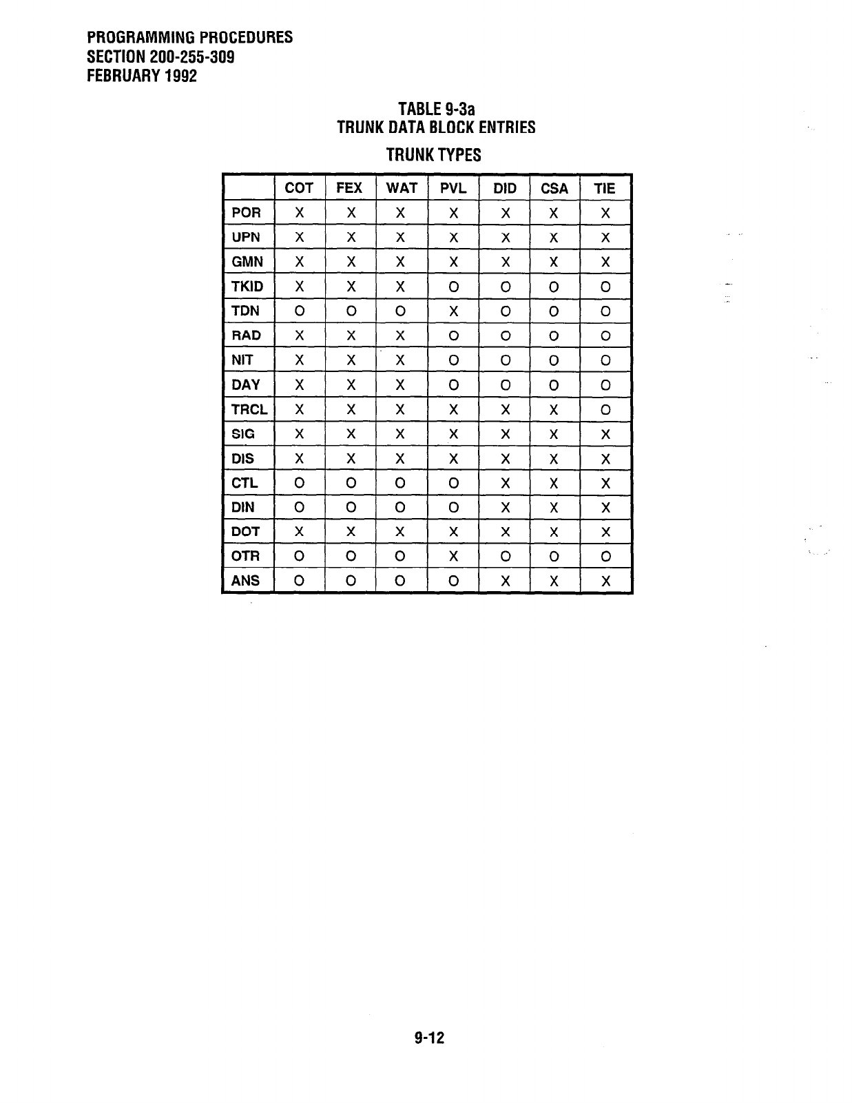
PROGRAMMINGPROCEDURES
SECTION 200-255-309
FEBRUARY1992
TABLEg-3a
TRUNKDATABLOCKENTRIES
TRUNKTYPES
COT 1 FEX 1 WAT PVL 1 DID ) CSA 1 TIE
POR
x I x I x xlxlxlx
+-l-+-k
UPN
GMN
TKID
TDN
RAD
NIT
DAY
TRCL
SIG
DIS
x I x I x
CTL
0 I 0 I 0
DIN 0 0 0 0 x x X
DOT X X X X X X X
OTR 0 0 0 X 0 0 0
ANS 0 0 0 0 x x X
9-12
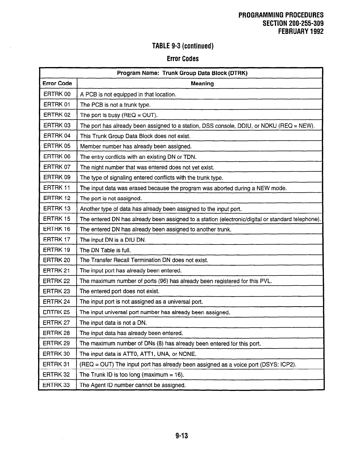
PROGRAMMINGPROCEDURES
SECTION 200-255-309
FEBRUARY1992
TABLE 9-3(continued)
Error Codes
Error Code 1
Program Name: Trunk Group Data Block (DTRK)
Meaning
ERTRK 00 1 A PCB is not equipped in that location.
ERTRK 01 The PCB is not a trunk type.
ERTRK 02 The port is busy (REQ = OUT).
ERTRK 03 1 The port has alreadv been assiqned to a station, DSS console, DDIU, or NDKU (REQ = NEW). 1
ERTRK 04 This Trunk Group Data Block does not exist.
ERTRK 05 Member number has already been assigned.
ERTRK 06 1 The entry conflicts with an existinq DN or TDN.
ERTRK 07 The night number that was entered does not yet exist.
ERTRK 09 The type of signaling entered conflicts with the trunk type.
ERTRK 11 The input data was erased because the program was aborted during a NEW mode.
ERTRK 12 The port is not assigned.
ERTRK 13 Another type of data has already been assigned to the input port.
ERTRK 15 The entered DN has already been assigned to a station (electronic/digital or standard telephone).
ERTRK 16 The entered DN has already been assigned to another trunk.
ERTRK 17 The input DN is a DIU DN.
ERTRK 19 I The DN Table is full.
ERTRK 20 The Transfer Recall Termination DN does not exist.
ERTRK 21 The input
port
has alreadv been entered.
ERTRK 22 I The maximum number of ports (96) has already been registered for this PVL. I
ERTRK 23 The entered port does not exist.
ERTRK 24 The input
port
is not assiqned as a universal
port.
ERTRK 25 I The input universal port number has already been assiqned.
ERTRK 27 The input data is not a DN.
ERTRK 28 The input data has already been entered.
ERTRK 29 The maximum number of DNs (8) has already been entered for this port.
ERTRK 30 The input data is AlTO, AlTl, UNA, or NONE.
ERTRK 31 (REQ = OUT) The input port has already been assigned as a voice port (DSYS: ICP2).
ERTRK 32 The Trunk ID is too long (maximum = 16).
ERTRK 33 The Aqent ID number cannot be assianed.
9-13
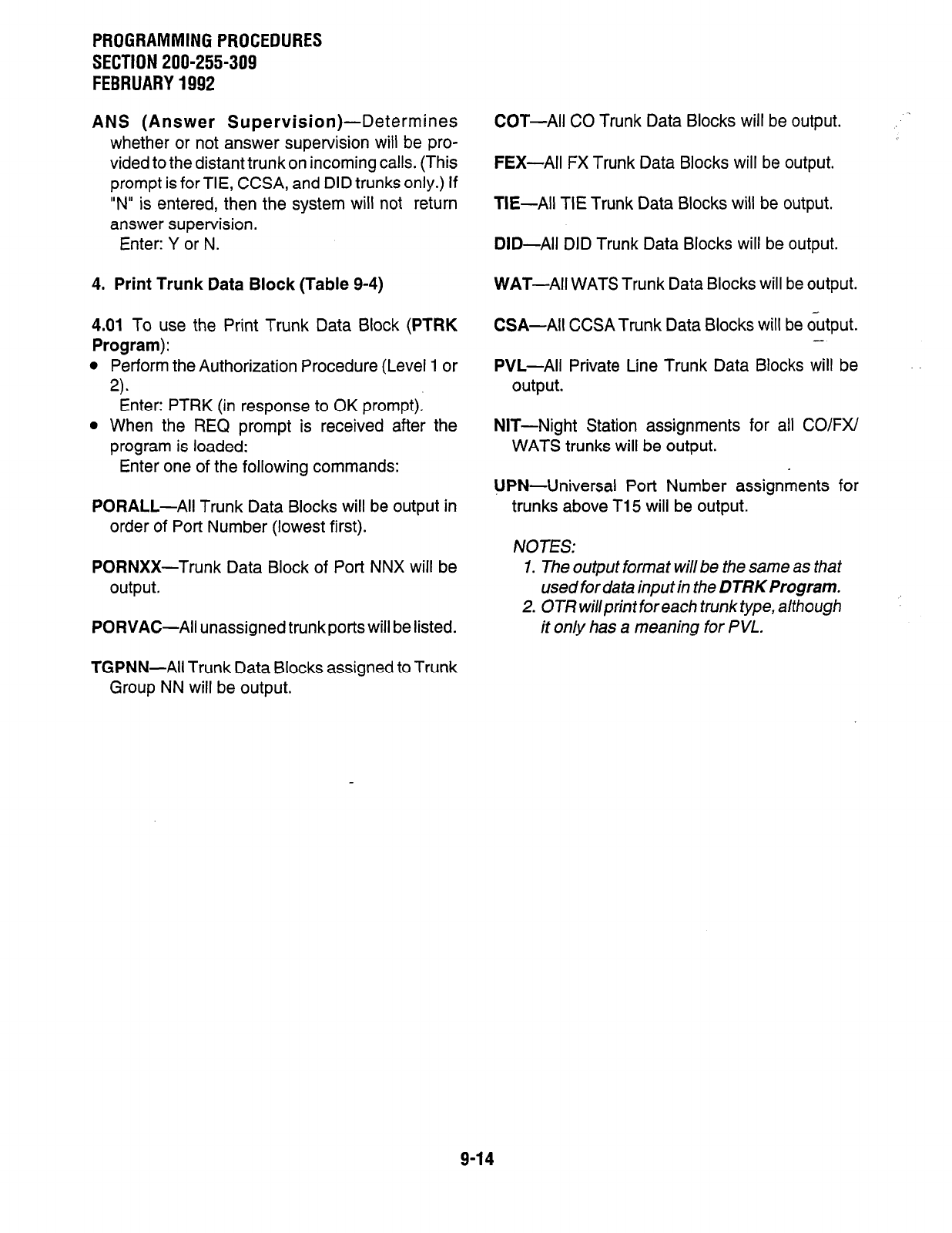
PROGRAMMING PROCEDURES
SECTION 200-255-309
FEBRUARY 1992
ANS (Answer
Supervision)-Determines
whether or not answer supervision will be pro-
vided to the distant trunk on incoming calls. (This
prompt is for TIE, CCSA, and DID trunks only.) If
“N” is entered, then the system will not return
answer supervision.
Enter: Y or N.
4. Print Trunk Data Block (Table 9-4)
WAT-All WATS Trunk Data Blocks will be output.
4.01 To use the Print Trunk Data Block
(PTRK
Program):
l
Perform the Authorization Procedure (Level 1 or
2).
Enter: PTRK (in response to OK prompt).
l
When the REQ prompt is received after the
program is loaded:
Enter one of the following commands:
PORALL-All Trunk Data Blocks will be output in
order of Port Number (lowest first).
PORNXX-Trunk Data Block of Port NNX will be
output.
PORVAC-All unassigned trunk ports will be listed.
COT-All CO Trunk Data Blocks will be output. -
FEX-All FX Trunk Data Blocks will be output.
TIE-All TIE Trunk Data Blocks will be output.
DID-All DID Trunk Data Blocks will be output.
CSA-All CCSA Trunk Data Blocks will be output.
--
PVL-All Private Line Trunk Data Blocks will be
output.
NIT-Night Station assignments for all CO/FX/
WATS trunks will be output.
UPN-Universal Port Number assignments for
trunks above T15 will be output.
NOTES:
1. The output format will be the same as that
used for data input in the DTRK Program.
2. OTR willprint for each trunk type, although
it only has a meaning for PVL.
TGPNN-All Trunk Data Blocks assigned to Trunk
Group NN will be output.
9-14
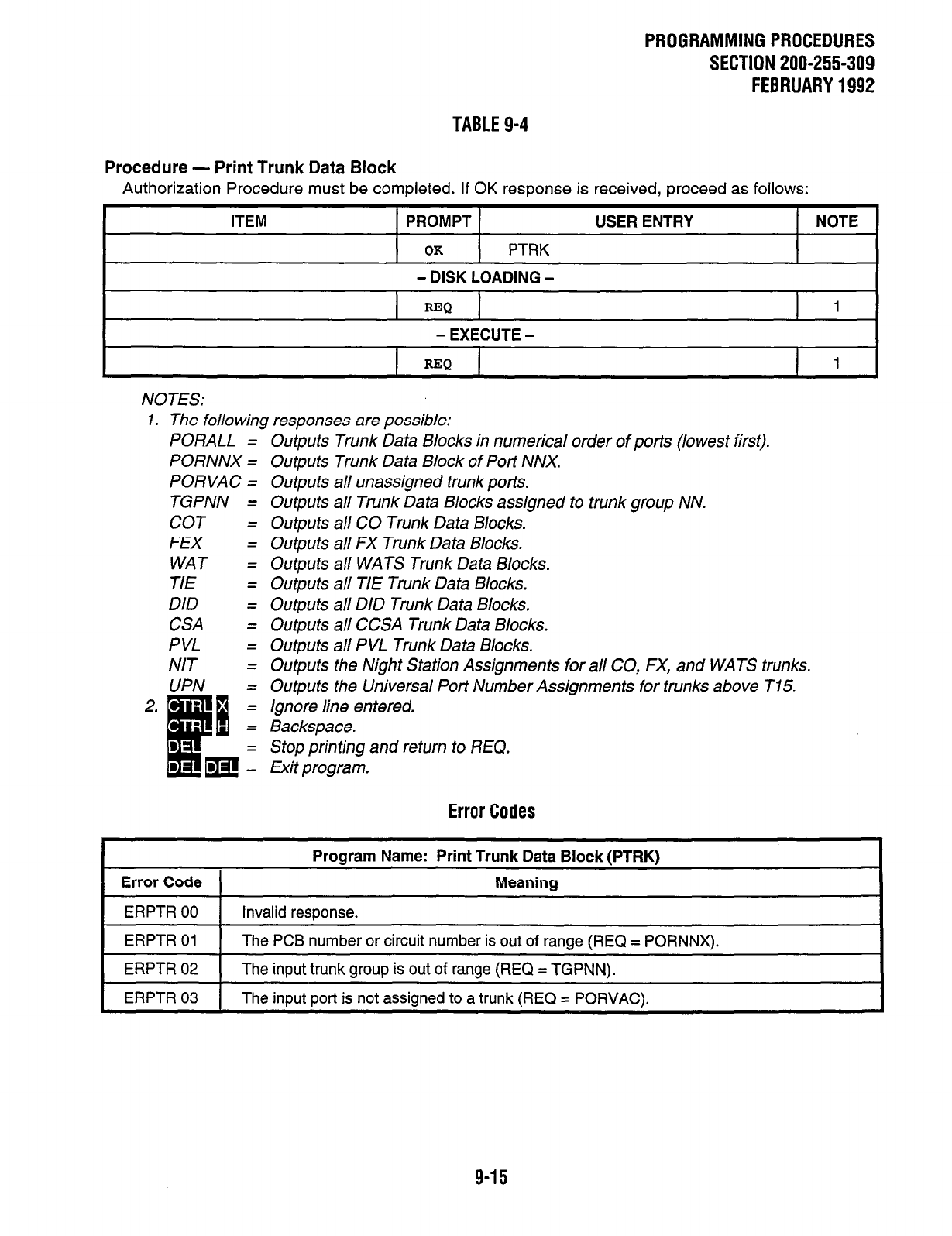
PROGRAMMINGPROCEDURES
SECTlON200-255-309
FEBRUARY1992
TABLE 9-4
Procedure - Print Trunk Data Block
Authorization Procedure must be completed. If OK response is received, proceed as follows:
ITEM PROMPT
OK
PTRK
- DISK LOADING -
USER ENTRY NOTE
REQ 1
- EXECUTE -
REQ 1
NOTES:
1. The following responses are possible:
PORALL = Outputs Trunk Data Blocks in numerical order of ports (lowest first).
PORNNX = Outputs Trunk Data Block of Port NNX.
PORVAC = Outputs all unassigned trunk pot-is.
TGPNN = Outputs all Trunk Data Blocks assigned to trunk group NN.
COT = Outputs all CO Trunk Data Blocks.
FEX = Outputs all FX Trunk Data Blocks.
WAT = Outputs all WATS Trunk Data Blocks.
TIE = Outputs all TIE Trunk Data Blocks.
DID = Outputs all DID Trunk Data Blocks.
CSA = Outputs all CCSA Trunk Data Blocks.
PVL = Outputs all PVL Trunk Data Blocks.
NIT = Outputs the Night Station Assignments for all CO, FX, and WATS trunks.
UPN = Outputs the Universal Port Number Assignments for trunks above T15.
Ignore line entered.
Backspace.
Stop printing and return to REQ.
Exit program.
Error Codes
Program Name: Print Trunk Data Block IPTRK)
Error Code
ERPTR 00 Invalid response.
Meaning
ERPTR 01 The PCB number or circuit number is out of range (REQ = PORNNX).
ERPTR 02 The input trunk group is out of range (REQ = TGPNN).
1 ERPTR 03 1 The inDut ~ort is not assianed to a trunk (REQ = PORVAC).
9-15
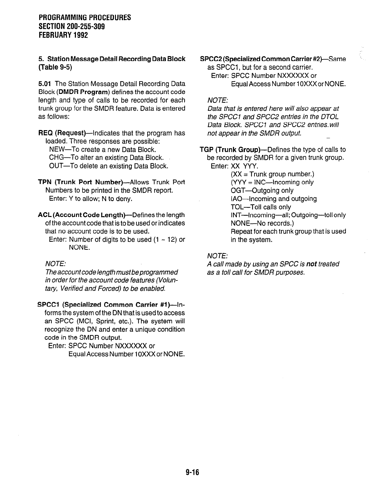
PROGRAMMINGPROCEDURES
SECTION 200-255-309
FEBRUARY1992
5. Station Message Detail Recording Data Block
(Table 9-5)
5.01 The Station Message Detail Recording Data
Block (DMDR Program) defines the account code
length and type of calls to be recorded for each
trunk group for the SMDR feature. Data is entered
as follows:
REQ (Request)-Indicates that the program has
loaded. Three responses are possible:
NEW-To create a new Data Block.
CHG-To alter an existing Data Block.
OUT-To delete an existing Data Block.
TPN (Trunk Port Number)-Allows Trunk Port
Numbers to be printed in the SMDR report.
Enter: Y to allow; N to deny.
ACL (Account Code Length)--Defines the length
of the account code that is to be used or indicates
that no account code is to be used.
Enter: Number of digits to be used (1 - 12) or
NONE.
NOTE:
The account code length must be programmed
in order for the account code features (Volun-
tary, Verified and Forced) to be enabled.
SPCCI (Specialized Common Carrier #l )-In-
forms the system of the DN that is used to access
an SPCC (MCI, Sprint, etc.). The system will
recognize the DN and enter a unique condition
code in the SMDR output.
Enter: SPCC Number NXXXXXX or
Equal Access Number 1 OXXX or NONE.
SPCC2 (Specialized Common Carrier &+-Same
as SPCCI , but for a second carrier.
Enter: SPCC Number NXXXXXX or
Equal Access Number 1 OXXXor NONE.
NOTE:
Data that is entered here will also appear at
the SPCCI and SPCC2 entries in the DTOL
Data Block. SPCCI and SPCC2 entries..will
not appear in the SMDR output.
TGP (Trunk Group)-Defines the type of calls to
be recorded by SMDR for a given trunk group.
Enter: XX YYY.
(XX = Trunk group number.)
(YYY = INC-Incoming only
OGT-Outgoing only
IAO-Incoming and outgoing
TOL-Toll calls only
INT-Incoming-all; Outgoing-toll only
NONE-No records.)
Repeat for each trunk group that is used
in the system.
NOTE:
A call made by using an SPCC is not treated
as a toll call for SMDR purposes.
9-16
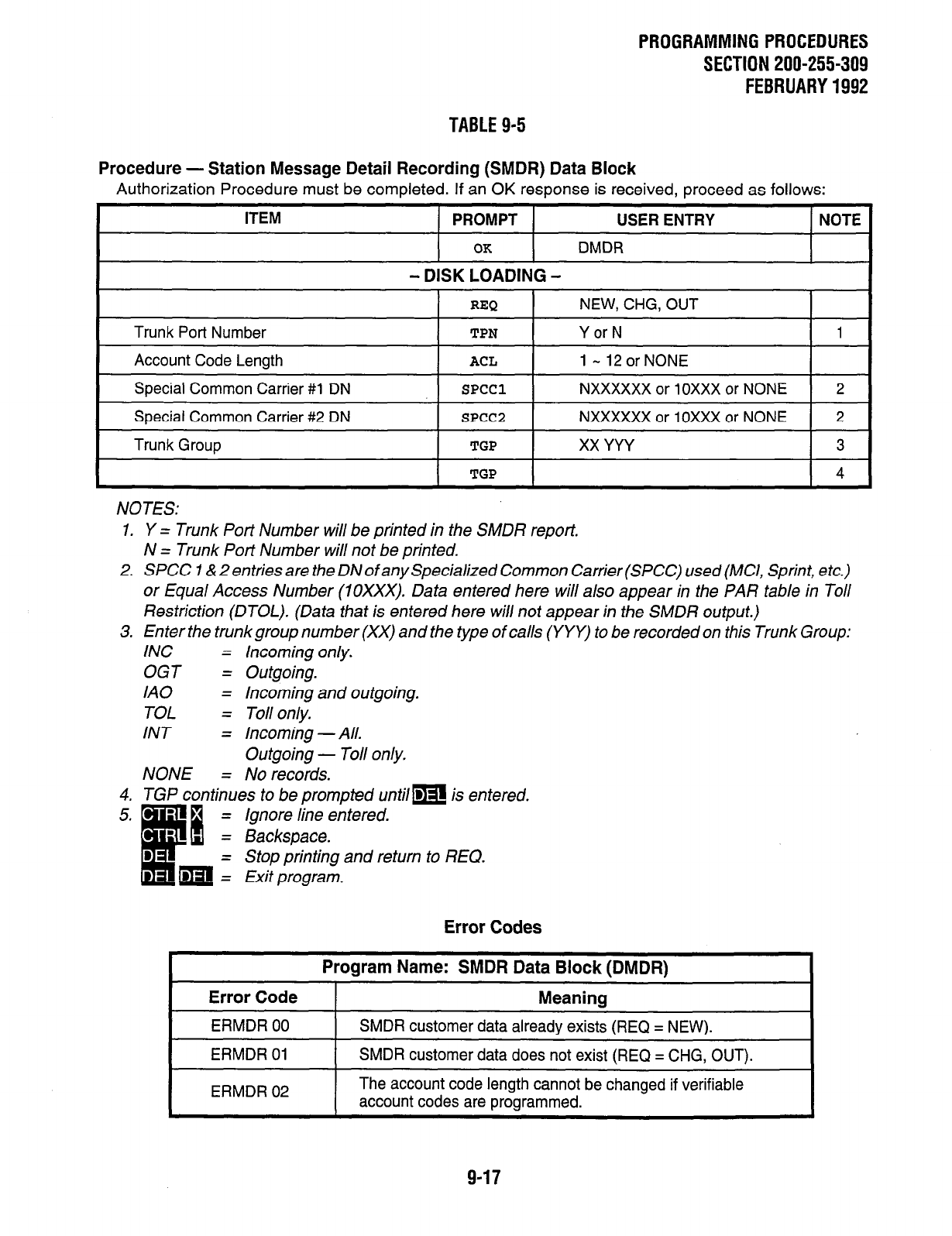
PROGRAMMINGPROCEDURES
SECTION 200-255-309
FEBRUARY1992
TABLE 9-5
Procedure - Station Message Detail Recording (SMDR) Data Block
Authorization Procedure must be completed. If an OK response is received, proceed as follows:
ITEM PROMPT USER ENTRY NOTE
OK
DMDR
- DISK LOADING -
I I
REQ 1
NEW, CHG, OUT I
Trunk Port Number
TPN
Account Code Length
ACL
Y or N
1 - 12 or NONE
1
I
Special Common Carrier #l DN I
SPCCl I
NXXXXXX or 10XxX or NONE 1 2
Special Common Carrier #2 DN
Trunk Group
SPCC2
TGP
NXXXXXX or 10XxX or NONE 2
xx YYY
3
I
TGP
I
NOTES:
1. Y = Trunk Port Number will be printed in the SMDR report.
N = Trunk Port Number will not be printed.
2. SPCC I & 2 entries are the DN of any Specialized Common Carrier (SPCC) used (MCI, Sprint, etc.)
or Equal Access Number (10XxX). Data entered here will also appear in the PAR table in Toll
Restriction (DTOL). (Data that is entered here will not appear in the SMDR output.)
3. Enter the trunkgroup number (XX) and the type of calls (YYY) to be recorded on this Trunk Group:
INC =
OGT =
IA0 =
TOL =
INT =
NONE =
Incoming only.
Outgoing.
Incoming and outgoing.
Toll only.
Incoming -All.
Outgoing - Toll only.
No records.
4. TGP continues to be prompted untilm is entered.
= Ignore line entered.
Backspace.
Stop printing and return to REQ.
Exit program.
Error Codes
Program Name: SMDR Data Block (DMDR)
Error Code
ERMDR 00
ERMDR 01
Meaning
SMDR customer data already exists (REQ = NEW).
SMDR customer data does not exist (REQ = CHG, OUT).
ERMDR 02 I The account code length cannot be changed if verifiable
account codes are programmed. I
9-17
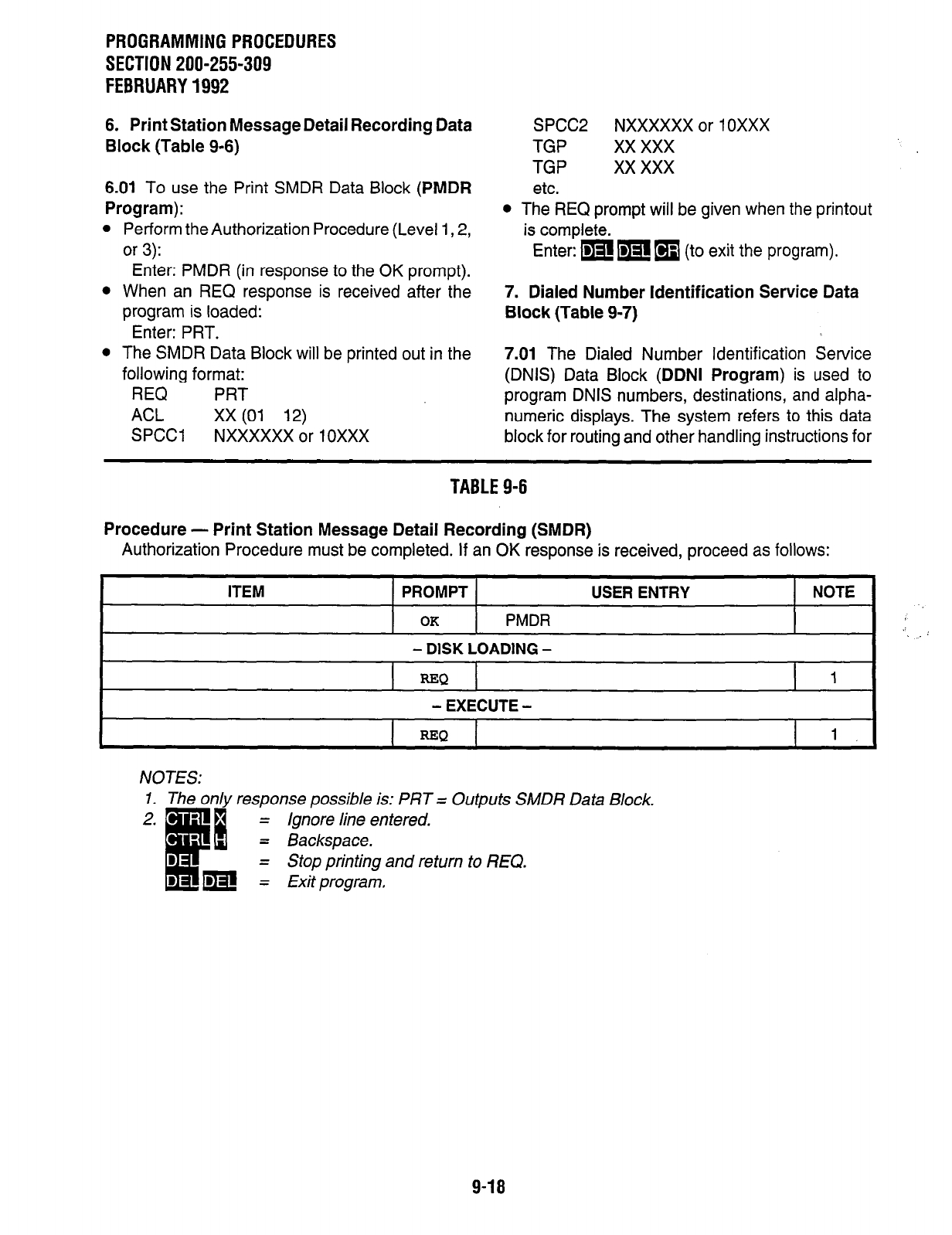
PROGRAMMING PROCEDURES
SECTION 200-255-309
FEBRUARY 1992
6. Print Station Message Detail Recording Data
Block (Table 9-6)
6.01 To use the Print SMDR Data Block (PMDR
Program):
l
Perform the Authorization Procedure (Level 1,2,
or 3):
Enter: PMDR (in response to the OK prompt).
l
When an REQ response is received after the
program is loaded:
Enter: PRT.
l
The SMDR Data Block will be printed out in the
following format:
REQ PRT
ACL xx (01 12)
SPCCl NXXXXXX or 1 OXXX
SPCC2 NXXXXXX or 1 OXXX
TGP xx xxx
TGP xx xxx
etc.
l
The REQ prompt will be given when the printout
is complete.
Enter: mm
q
(to exit the program).
7. Dialed Number Identification Service Data
Block (Table 9-7)
7.01 The Dialed Number Identification Service
(DNIS) Data Block (DDNI Program) is used to
program DNIS numbers, destinations, and alpha-
numeric displays. The system refers to this data
block for routing and other handling instructions for
TABLE 9-6
Procedure - Print Station Message Detail Recording (SMDR)
Authorization Procedure must be completed. If an OK response is received, proceed as follows:
I
ITEM PROMPT USER ENTRY NOTE
OK PMDR
- DISK LOADING -
I
=Q 1
I
- EXECUTE -
I
REQ
1
NOTES:
1. The only response possible is: PRT = Outputs SMDR Data Block.
Ignore line entered.
Backspace.
Stop printing and return to REQ.
Exit program.
9-18
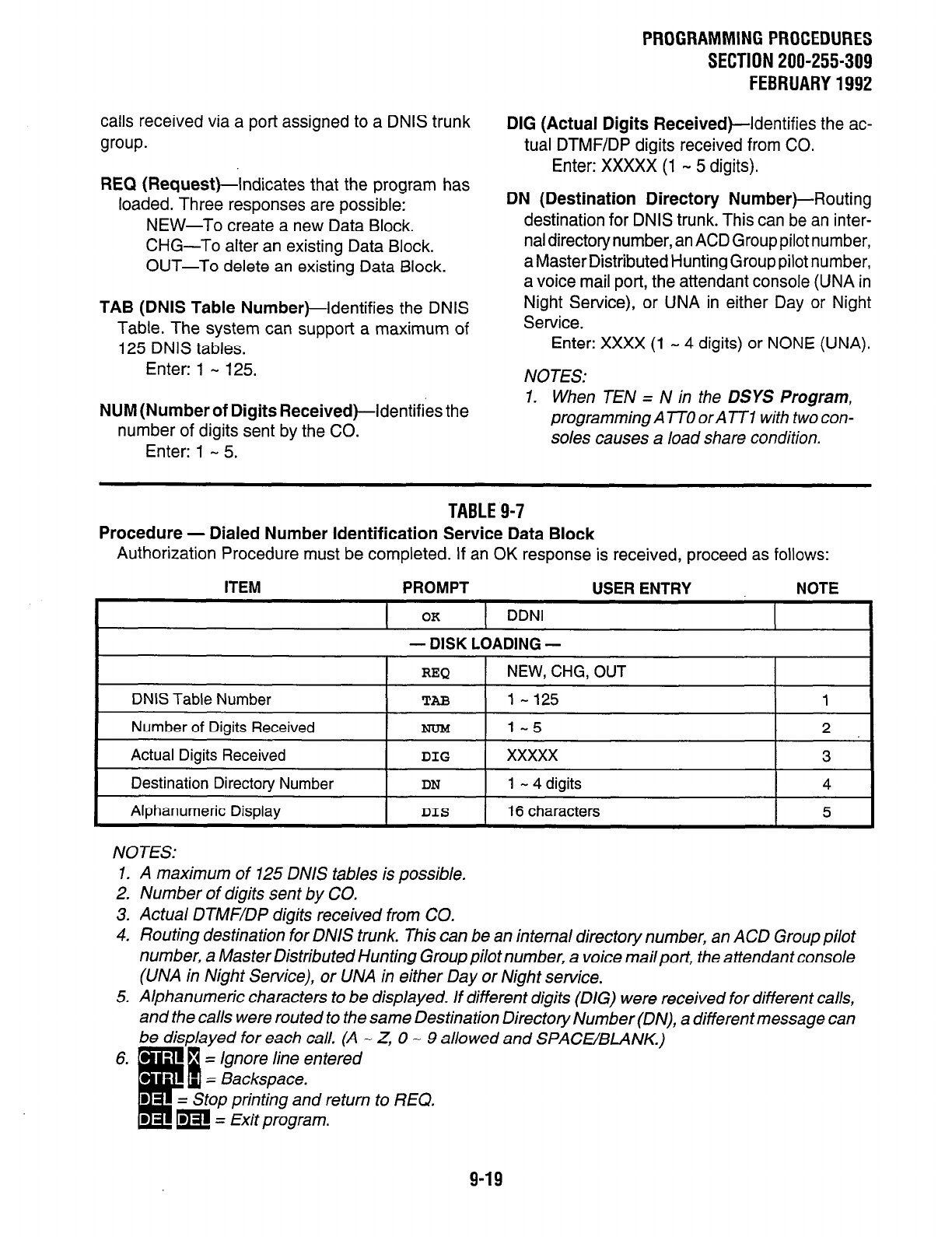
calls received via a port assigned to a DNIS trunk
group.
REQ (Request)-Indicates that the program has
loaded. Three responses are possible:
NEW-To create a new Data Block.
CHG-To alter an existing Data Block.
OUT-To delete an existing Data Block.
TAB (DNIS Table Number)-Identifies the DNIS
Table. The system can support a maximum of
125 DNIS tables.
Enter: 1 - 125.
NUM (Number of Digits Received)-identifies the
number of digits sent by the CO.
Enter: 1 - 5.
PROGRAMMING PROCEDURES
SECTION 200-255-309
FEBRUARY 1992
DIG (Actual Digits
Received)-Identifies the ac-
tual DTMF/DP digits received from CO.
Enter: XXXXX (1 - 5 digits).
DN (Destination Directory Number)-Routing
destination for DNIS trunk. This can be an inter-
nal directory number, an ACD Group pilot number,
a Master Distributed Hunting Group pilot number,
a voice mail port, the attendant console (UNA in
Night Service), or UNA in either Day or Night
Service.
Enter: XXXX (1 - 4 digits) or NONE (UNA).
NOTES:
1. When TEN = N in the DSYS Program,
programming A TTO or A TTI with two con-
soles causes a load share condition.
TABLE 9-7
Procedure - Dialed Number Identification Service Data Block
Authorization Procedure must be completed. If an OK response is received, proceed as follows:
ITEM PROMPT USER ENTRY NOTE
I
OK 1 DDNI
- DISK LOADING -
I
REQ I NEW, CHG, OUT I I
DNIS Table Number
Number of Digits Received
Actual Digits Received
Destination Directory Number
TAB
NOM
DIG
DN
l-125
1-5
xxxxx
1 - 4 digits
Alphanumeric Display I DIS
I ~
16 characters
--~l--il
NOTES:
1. A maximum of 125 DNIS tables is possible.
2. Number of digits sent by CO.
3. Actual DTMF/DP digits received from CO.
4. Routing destination for DNIS trunk. This can be an internal directory number, an ACD Group pilot
number, a Master Distributed Hunting Group pilot number, a voice mailport, the attendant console
(UNA in Night Service), or UNA in either Day or Night service.
5. Alphanumeric characters to be displayed. If different digits (DIG) were received for different calls,
and the calls were routed to the same Destination Directory Number (DN), a different message can
be displayed for each call. (A - Z, 0 - 9 allowed and SPACE/BLANK.).
-- = Ignore line entered
= Backspace.
= Stop printing and return to REQ.
= Exit program.
9-19
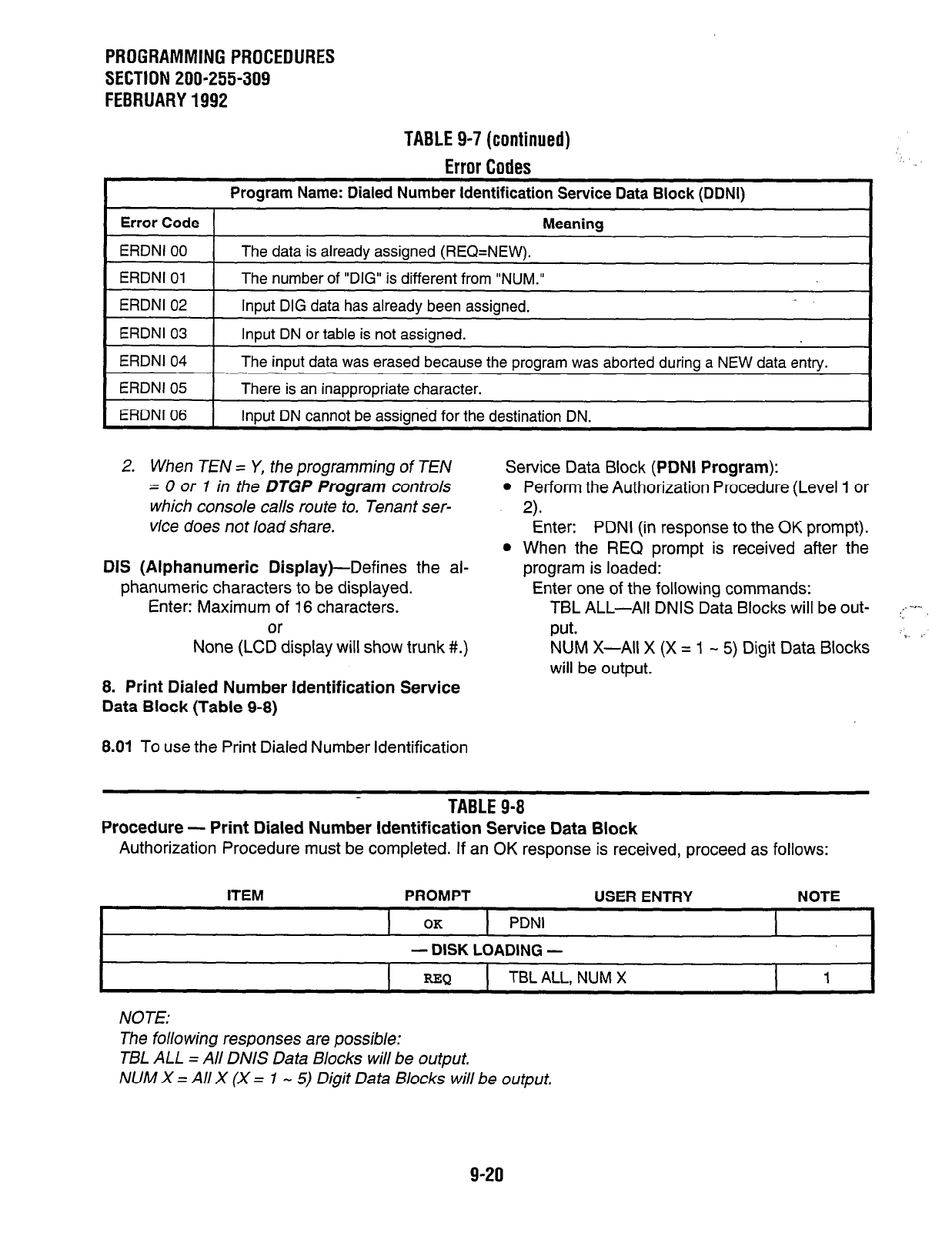
PROGRAMMING PROCEDURES
SECTION 200-255-309
FEBRUARY 1992
TABLE 9-7 (continued)
Error Codes
I
Program Name: Dialed Number Identification Service Data Block (DDNI) I
1 Error Code 1 Meaning I
ERDNI 00
ERDNI 01
The data is already assigned (REQ=NEW).
The number of “DIG” is different from “NUM.”
I
ERDNI 02 I Input DIG data has already been assigned. I
ERDNI 03
ERDNI 04
ERDNI 05
Input DN or table is not assigned.
The input data was erased because the program was aborted during a NEW data entry.
There is an inappropriate character.
ERDNI 06 Input DN cannot be assigned for the destination DN. I
2. When TEN = Y, the programming of TEN
= 0 or 1 in the DTGP Program controls
which console calls route to. Tenant ser-
vice does not load share.
DIS (Alphanumeric Display)--Defines the al-
phanumeric characters to be displayed.
Enter: Maximum of 16 characters.
or
None (LCD display will show trunk #I.)
8. Print Dialed Number Identification Service
Data Block (Table 9-8)
8.01 To use the Print Dialed Number Identification
Service Data Block (PDNI Program):
l
Perform the Authorization Procedure (Level 1 or
2).
Enter: PDNI (in response to the OK prompt).
l
When the REQ prompt is received after the
program is loaded:
Enter one of the following commands:
TBL ALL-All DNIS Data Blocks will be out- ::.-r-,
put. ‘. ”
NUM X-All X (X = 1 - 5) Digit Data Blocks
will be output.
TABLE 9-8
Procedure - Print Dialed Number Identification Service Data Block
Authorization Procedure must be completed. If an OK response is received, proceed as follows:
I
ITEM PROMPT USER ENTRY NOTE
I
OK
1 PDNI I I
- DISK LOADING -
=Q TBL ALL, NUM X 1
NOTE:
The following responses are possible:
Tl3L ALL = All DNIS Data Blocks will be output.
NUM X = All X (X = 1 - 5) Digit Data Blocks will be output.
9-20
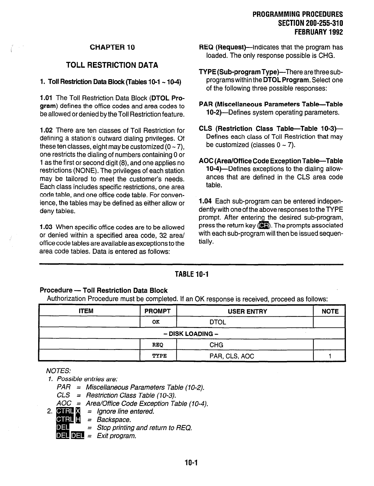
CHAPTER 10
TOLL RESTRICTION DATA
1. Toll Restriction Data Block (Tables 1 O-l - 1 O-4)
1.01 The Toll Restriction Data Block (DTOL Pro-
gram) defines the office codes and area codes to
be allowed or denied by the Toll Restriction feature.
1.02 There are ten classes of Toll Restriction for
defining a station’s outward dialing privileges. Of
these ten classes, eight may be customized (0 - 7),
one restricts the dialing of numbers containing 0 or
1 as the first or second digit (8), and one applies no
restrictions (NONE). The privileges of each station
may be tailored to meet the customer’s needs.
Each class includes specific restrictions, one area
code table, and one off ice code table. For conven-
ience, the tables may be defined as either allow or
deny tables.
1.03 When specific off ice codes are to be allowed
or denied within a specified area code, 32 area/
office code tables are available as exceptions to the
area code tables. Data is entered as follows:
PROGRAMMING PROCEDURES
SECTION 200-255-310
FEBRUARY 1992
REQ (Request)-Indicates that the program has
loaded. The only response possible is CHG.
TYPE (Sub-program Type)-There are three sub-
programs within the DTOL Program. Select one
of the following three possible responses:
PAR (Miscellaneous Parameters Table-Table
lo-2)-Defines system operating parameters.
CLS (Restriction Class Table-Table 1 O-3)-
Defines each class of Toll Restriction that may
be customized (classes 0 - 7).
AOC (Area/Off ice Code Exception TableTable
lo-4)-Defines exceptions to the dialing allow-
ances that are defined in the CLS area code
table.
1.04 Each sub-program can be entered indepen-
dently with one of the above responses to the TYPE
prompt. After enterin the desired sub-program,
press the return key &I ‘). The prompts associated
with each sub-program will then be issued sequen-
tially.
TABLE IO-1
Procedure - Toll Restriction Data Block
Authorization Procedure must be completed. If an OK resoonse is received, oroceed as follows:
ITEM PROMPT USER ENTRY NOTE
OK
DTOL
- DISK LOADING -
I I
REQ
CHG
TYPE PAR. CL8 AOC 1
NOTES:
1. Possible entries are:
PAR = Miscellaneous Parameters Table (1 O-2).
CLS = Restriction Class Table (10-3).
AOC = Area/Office Code Exception fable (10-4).
10-l
PROGRAMMINGPROCEDURES
SECTION 200-255-310
FEBRUARY1992
When entering PAR in response to TYPE (Table
10.2), the next prompt will be:
HAC (Home Area
Code)--Defines the area code
in which the system is operating. Home area
codes are also used to analyze a dialed number
that does not contain an area code, Data that is
entered here will appear in the Least Cost Rout-
ing Data Block
(DLCl Program,
PAR table, HAC
prompt).
Enter: Area Code NO/IX.
NOTE:
N=2 -9, O/l=OorI, X=0 -9.
ICC (Interchangeable Codes)-A
“Y” informs the
system that interchangeable codes are used.
Interchangeable codes are office codes that
have 0 or 1 as the second digit (NO/IX format).
Area codes will be identified as the three digits
following the DDD prefix. Office codes will be
identified as the first three digits when a DDD
prefix is not dialed (see DDP prompt).
Enter: Y or N.
SPCCl (Specialized Common Carrier #1)-h-t-
forms the system of the DN that is to be used to
access an SPCC (MCI, Sprint, etc.) or equal
access carrier (10XxX). The system will recog-
nize the DN and ignore it for Toll Restriction
purposes. Data that is entered here will also
appear in the
DMDR Program .
Enter: NXXXXXX (SPCC Number) or
10XxX (Equal Access Number) or
NONE.
SPCC2 (Specialized Common Carrier#2)-Same
as SPCCl, but for a second carrier.
Enter: NXXXXXX (SPCC Number) or
10XxX (Equal Access Number) or
NONE.
DDP (Direct Distance Dialing Prefix)--Defines
the
Direct Distance Dialing (DDD) prefix in the Num-
bering Plan Area (NPA). If ICC is “Y,” then NO/l X
and NXX become interchangeable, enabling area
codes and office codes to have 0 or 1 as their
second digit. In this case, the DDP is used to
differentiate between the two code types (see
example). If the ICC response is “N,” then calls
will be made using the normal NPA formula of
NO/lx and NNX.
Enter: 1,2, or 3 digits or NONE.
Example: If ICC is ‘Y” and the DDP is pro-
grammed as 1, then the dialed number 209-
1234 is recognized as a call within the home
area code, while the dialed number l-209-555
1234 is recognized as a call outside the home
area code. If ICC is ‘IN,” this dialing plan-js not
used.
NOTE:
If a DDD prefix is used in the NPA, it must be
entered here even if To//
Restriction is not
used.
&JTHl (Authorization Code
#l)-Indicates the
number of digits in the authorization code to be
used with SPCCl . These digits and the SPCCl
DN that is entered will be ignored forToll Restric-
tion purposes.
Enter: 1 - 12 or NONE.
NOTE:
When using equalaccess (10XxX) forSPCC1
orSPCC2, do not enteran authorization code.
AUTHP (Authorization Code
#2)-Same as
AUTHl, but for SPCC2.
Enter: 1 - 12 or NONE.
NOTE:
The SPCC and AUTH entries will not appear
in the SMDR output.
IO-2

PROGRAMMINGPROCEDURES
SECTlON200-255-310
FEBRUARY1992
TABLE10-2
Miscellaneous Parameters Table
Load the
DTOL Utility Program.
When the TYPE prompt is received, proceed as follows:
NOTES:
I.
2.
3.
4.
5.
This entry is coupled with the HAC entry in the PAR table in Least Cost Routing (DLCl). Data that
is entered here will also appear in that table.
Informs the system if interchangeable codes are used (office codes with NO/lx format).
SPCC 1 & 2 entries are the DN of any specialized common carrier (SPCC) used (MCI, Sprint, etc.)
or Equal Access Number (10XxX). Data that is entered here will also appear in the SMDR (DMDR
Program), but will not appear in the SMDR output.
This represents the number of d&its in the authorization codes that are used with SPCCl or
SPCC2. Data that is entered here will not appear in the SMDR output.
= ignore line entered.
= Backspace.
= Stop printing and return to REQ.
= Exit program.
10-3
PROGRAMMINGPROCEDURES
SECTION 200-255-310
FEBRUARY1992
When entering CLS in response to TYPE (Table
NO/i X NO/i X etc. (in response to the D
lo-3), the next prompt will be:
prompt) to delete area codes.
CNO
(Class
Number)---Indicates the number of
the Toll Restriction class that is being defined.
This number is used in response to the TOL
prompt in the
DEKT, DSIT,
and
DTGP Pro-
grams .
Enter: 0 - 7 (Class Number) or NOUT.
NOTE:
Enter OUT after the class number (N) in order
to remove that class from service.
OPR (Operator and Operator-Assisted Calls)-
A “Y” response allows a station in this toll restric-
tion class to make operator and operator-as-
sisted calls.
Enter: Y or N.
INT (International Calls)-A
‘Y” response allows
a station in this toll restriction class to make
international calls (011, 01).
Enter: Y or N.
LDA (Long Distance Directory Assistance)-A
‘Y” response allows a station in this toll restric-
tion class to call long distance directory assis-
tance. Any area code + 555 + XXXX will be
allowed.
Enter: Y or N.
ACT (Area Code Table
Type)-Defines the Area
Code Table of this toll restriction class as either
an Allow (A) or a Deny (D) type table.
l
An “A” entry will allow all area codes except
those deleted below, in response to the ACD
prompt.
l
A “D” entry will deny all area codes except
those added below, in response to the ACD
prompt.
Enter: A or D.
ACD (Area Code
Table)-Indicates the area codes
that are to be allowed or denied for this toll
restriction class. Area codes may be either added
or deleted, as described above.
Enter: NO/l X NO/i X etc. (in response to the A
prompt) to add area codes.
. . . or. . .
NOTES:
1. N=2 -9, O/l=Oorl, X=0 -9.
2. If “D” is entered in response to the ACT
prompt, then “D” must also be entered in
response to ACD (and vice versa). For no
entries, press the return key m.
3. Following the ACDprompt, an ‘A”prompt
will appear and any entered codes will be
added. To delete, press the return key
m. A “D” will appear and any entered
codes will be deleted.
OCT (Office Code Table
Type)--Defines the Of-
fice Code Table of this toll restriction class as
either an Allow (A) or a Deny (D) type table. An
“A” entry will allow all office codes within the
Home Area Code (HAC), except those deleted
in response to the OCD prompt. A “D” entry will
deny all off ice codes within the Home Area Code,
except those added in response to the OCD
prompt.
Enter: A or D. ,‘_
OCD
(Office Code
Table)-Indicates the office
codes to be allowed or denied for this toll restric-
tion class. Office codes may be added or deleted
either as single 3-digit codes, or as a “range”
covering up to ten sequential 3-digit office codes.
Ranges are entered by using a 4-digit format;
where the first two digits are common to all codes
in this range; the third digit represents the start-
ing point of the range (from) for the last digit of the
office code; and the fourth digit represents the
end point of the range (to) for the last digit of the
office code. See ranges example.
Enter: NXXX NXX NXXX etc. (in response to
the A prompt) to add office codes.
. . . or. . .
NXXX NXX NXXX etc. (in response to
the D prompt) to delete office codes.
NOTES:
1. N=2 -9, X=0 -9.
2. If “D” is entered in response to the OCT
prompt, then “D” must also be entered in
response to OCD (and vice versa). For no
entries, press the return key m.
10-4
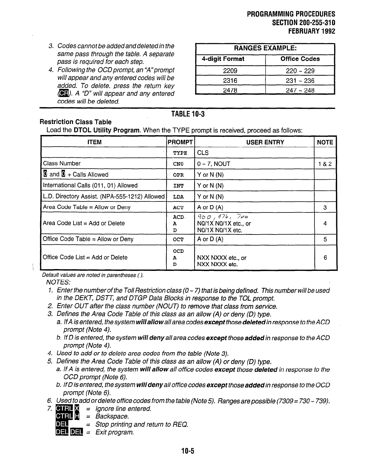
PROGRAMMINGPROCEDURES
SECTION 200-255-310
FEBRUARY1992
3. Codes cannot be added and deletedin the
same pass through the table. A separate
pass is required for each step.
4. Following the OCDprompt, an ‘A”prompt
will appear and any entered codes will be
added. To delete, press the return key
m. A ‘D” will appear and any entered
codes will be deleted.
RANGES EXAMPLE:
4-digit Format Off ice Codes
2209 220 - 229
2316 231 - 236
2478 247 - 248
Restriction Class Table
TABLE10-3
Load the DTOL Utility Program. When the TYPE prompt is received, proceed as follows:
Area Code List = Add or Delete
Office Code List = Add or Delete
Default values are noted in parentheses ( ).
NOTES:
1. Enter the number of the Toll Restriction class (0 - 7) that is being defined. This number will be used
in the DEKT, DSlT, and DTGP Data Blocks in response to the TOL prompt.
2. Enter OUT after the class number (NOUT) to remove that class from service.
3. Defines the Area Code Table of this class as an allow (A) or deny (0) type.
a. IfA is entered, thesystem willallowallarea codes except those deletedin response to the ACD
prompt (Note 4).
b. If D is entered, the system will deny all area codes except those added in response to the ACD
prompt (Note 4).
4. Used to add or to delete area codes from the table (Note 3).
5. Defines the Area Code Table of this class as an allow (A) or deny (0) type.
a. If A is entered, the system will allow all office codes except those deleted in response to the
OCD prompt (Note 6).
b. If D is entered, the system will deny all office codes except those added in response to the OCD
prompt (Note 6).
6. Used to add or delete office codes from the table (Note 5). Ranges are possible (7309 = 730 - 739).
= Ignore line entered.
= Backspace.
= Stop printing and return to REQ.
= Exit program.
10-5
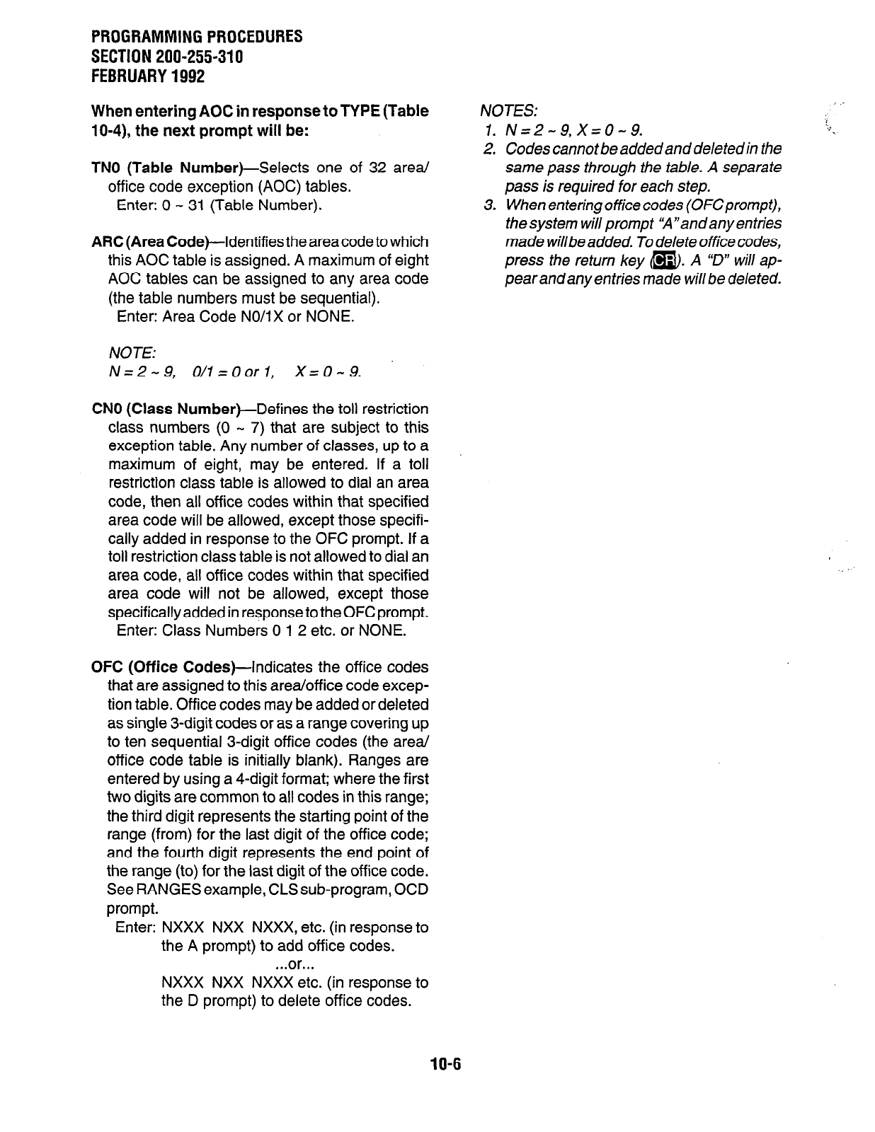
PROGRAMMINGPROCEDURES
SECTION 200-255-310
FEBRUARY1992
When entering AOC in response to TYPE (Table
lo-4), the next prompt will be:
TN0 (Table Number)-Selects
one of 32 area/
office code exception (AOC) tables.
Enter: 0 - 31 (Table Number).
ARC (Area
Code)--Identifies the area code to which
this AOC table is assigned. A maximum of eight
AOC tables can be assigned to any area code
(the table numbers must be sequential).
Enter: Area Code NO/IX or NONE.
NOTE:
N=2-9, O/l=OorI, X=0-9.
CNO (Class Number)-Defines
the toll restriction
class numbers (0 - 7) that are subject to this
exception table. Any number of classes, up to a
maximum of eight, may be entered. If a toll
restriction class table is allowed to dial an area
code, then all office codes within that specified
area code will be allowed, except those specifi-
cally added in response to the OFC prompt. If a
toll restriction class table is not allowed to dial an
area code, all office codes within that specified
area code will not be allowed, except those
specifically added in response to the OFC prompt.
Enter: Class Numbers 0 1 2 etc. or NONE.
OFC (Office
Codes)-Indicates the office codes
that are assigned to this area/office code excep-
tion table. Office codes may be added or deleted
as single 3-digit codes or as a range covering up
to ten sequential 3-digit office codes (the area/
office code table is initially blank). Ranges are
entered by using a 4-digit format; where the first
two digits are common to all codes in this range;
the third digit represents the starting point of the
range (from) for the last digit of the office code;
and the fourth digit represents the end point of
the range (to) for the last digit of the office code.
See RANGES example, CLS sub-program, OCD
prompt.
Enter: NXXX NXX NXXX, etc. (in response to
the A prompt) to add office codes.
. ..or...
NXXX NXX NXXX etc. (in response to
the D prompt) to delete office codes.
NOTES:
1. N=2-9,X=0-9.
2. Codes cannot be added and deleted in the
same pass through the table. A separate
pass is required for each step.
3. When entering office codes (OFCprompt),
thesystem willprompt %“andanyentries
made willbeadded. To delete office codes,
press the return key @). A “D” will ap-
pear and any entries made will be deleted.
10-6
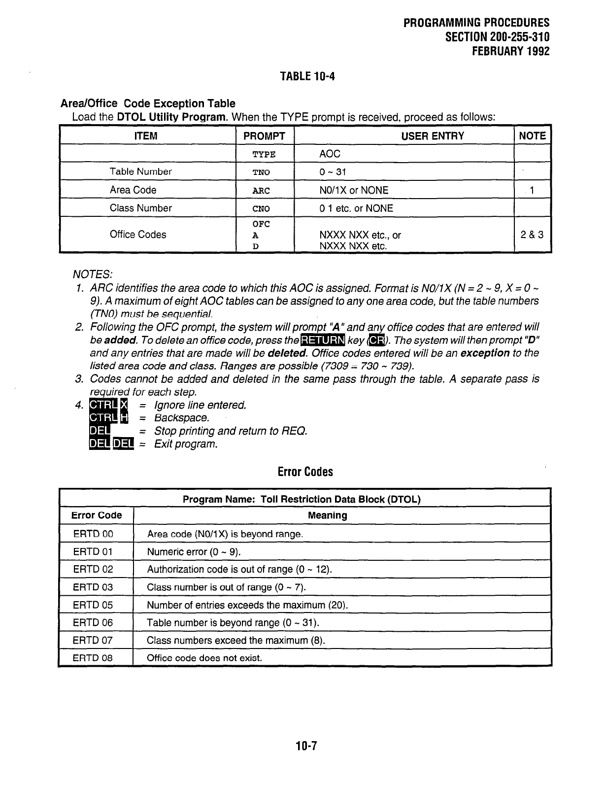
PROGRAMMINGPROCEDURES
SECTION 200-255-310
FEBRUARY1992
TABLE10-4
Area/Office Code Exception Table
Load the
DTOL Utility Program.
When the TYPE prompt is received, proceed as follows:
ITEM
PROMPT USER ENTRY NOTE
TYPE
AOC
Table Number
TN0
0 - 31
Area Code
ARC
NO/l X or NONE 1
Class Number
CNO
0 1 etc. or NONE
OFC
Off ice Codes
A
NXXX NXX etc., or 2&3
D NXXX NXX etc.
NOTES:
1. ARC identifies the area code to which this AOC is assigned. Format is NO/lx (N = 2 - 9, X = 0 -
9). A maximum of eight AOC tables can be assigned to any one area code, but the table numbers
(TNO) must be sequential.
2. Following the OFC prompt, the system will prompt “A” and any office codes that are entered will
be added. To delete an office code, press them key @. The system will then prompt “D”
and any entries that are made will be deleted. Office codes entered will be an exception to the
listed area code and class. Ranges are possible (7309 = 730 - 739).
3. Codes cannot be added and deleted in the same pass through the table. A separate pass is
required for each step.
4. Ignore line entered.
Backspace.
= Stop printing and return to REQ.
Exit program.
Error Codes
I
Program Name: Toll Restriction Data Block (DTOLI
Error Code
ERTD 00
Meaning
Area code (NO/lx) is bevond ranae.
I
ERTD 01 1 Numeric error (0 - 9).
ERTD 02
ERTD 03
ERTD 05
Authorization code is out of range (0 - 12).
Class number is out of range (0 - 7).
Number of entries exceeds the maximum (20).
I
ERTD 06 1 Table number is beyond range (0 - 31).
ERTD 07
ERTD 08
Class numbers exceed the maximum (8).
Office code does not exist.
10-7
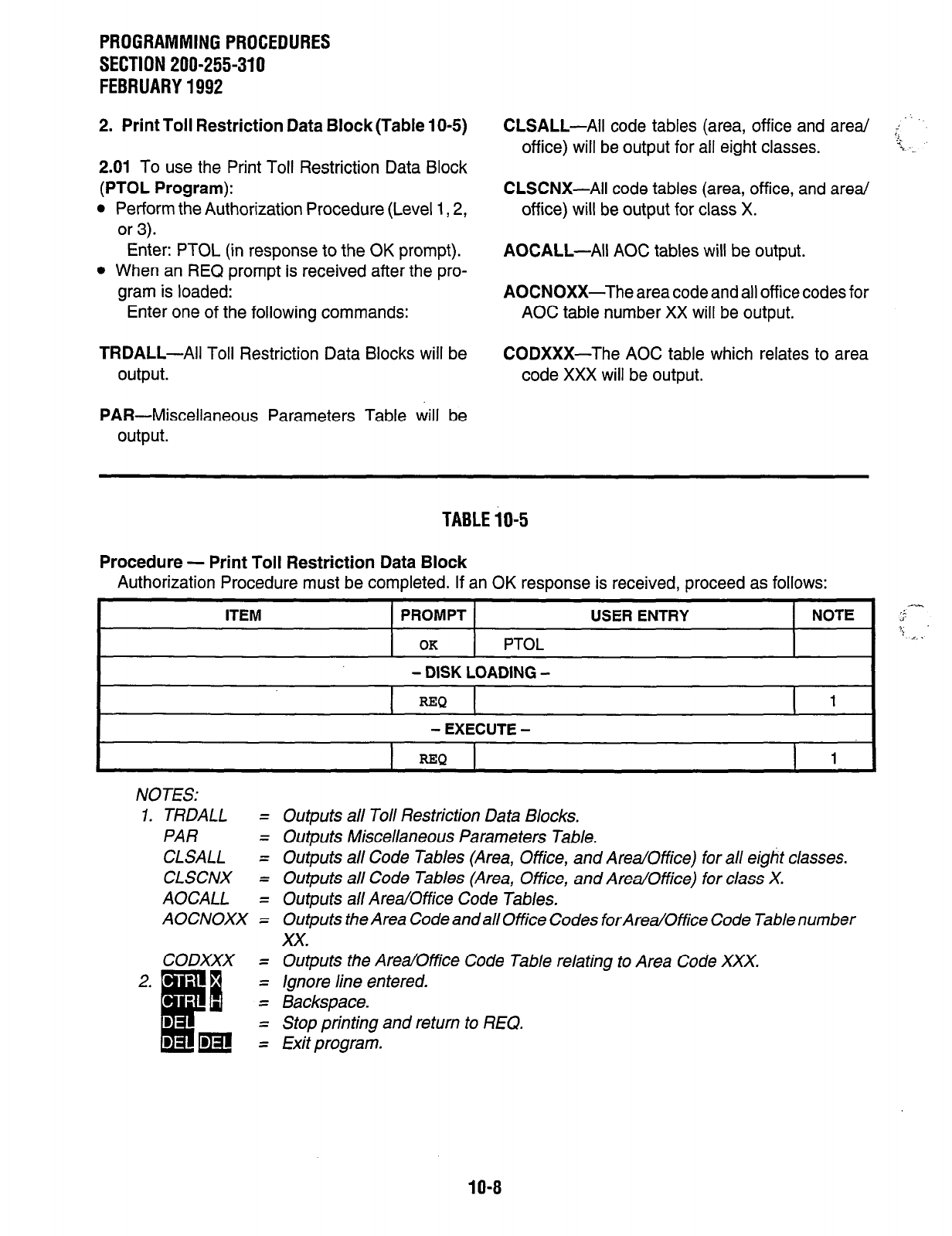
PROGRAMMINGPROCEDURES
SECTION 200-255-310
FEBRUARY1992
2. Print Toll Restriction Data Block (Table 1 O-5)
2.01
To use the Print Toll Restriction Data Block
(PTOL Program):
l
Perform the Authorization Procedure (Level 1,2,
or 3).
Enter: PTOL (in response to the OK prompt).
l
When an REQ prompt is received after the pro-
gram is loaded:
Enter one of the following commands:
CLSALL-All code tables (area, office and area/
office) will be output for all eight classes.
CLSCNX-All code tables (area, office, and area/
office) will be output for class X.
AOCALL-All AOC tables will be output.
AOCNOXX-The area code and all office codes for
AOC table number XX will be output.
TRDALL-All
Toll Restriction Data Blocks will be CODXXX-The AOC table which relates to area
output. code XXX will be output.
PAR-Miscellaneous Parameters Table will be
output.
TABLEiO-5
Procedure - Print Toll Restriction Data Block
Authorization Procedure must be completed. If an OK response is received, proceed as follows:
ITEM
PROMPT
OK PTOL
- DISK LOADING -
USER ENTRY NOTE $--
? =..
REQ 1
- EXECUTE -
REQ
1
NOTES:
1. TRDALL =
PAR =
CLSALL =
CLSCNX =
AOCALL =
AOCNOXX =
CODXXX =
2. *
c
ii
=
. =
:m:
Outputs all Toll Restriction Data Blocks.
Outputs Miscellaneous Parameters Table.
Outputs all Code Tables (Area, Office, and Area/Office) for all eight classes.
Outputs all Code Tables (Area, Office, and Area/Office) for class X.
Outputs all Area/Office Code Tables.
Outputs the Area Code and all Office Codes forArea/Office Code Table number
xx.
Outputs the Area/Office Code Table relating to Area Code XXX.
Ignore line entered.
Backspace.
Stop printing and return to REQ.
Exit program.
10-8
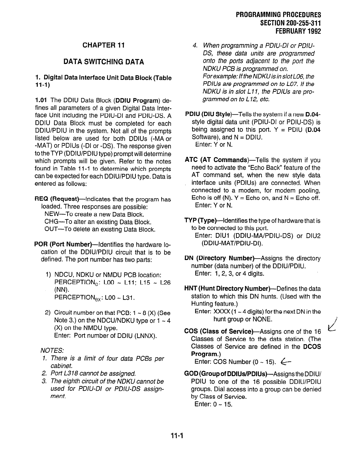
PROGRAMMING PROCEDURES
SECTION 200-255-311
FEBRUARY 1992
CHAPTER 11
DATA SWITCHING DATA
1. Digital Data Interface Unit Data Block (Table
11-I)
1.01 The DDIU Data Block (DDIU Program) de-
fines all parameters of a given Digital Data Inter-
face Unit including the PDIU-DI and PDIU-DS. A
DDIU Data Block must be completed for each
DDIU/PDIU in the system. Not all of the prompts
listed below are used for both DDlUs (-MA or
-MAT) or PDlUs (-DI or -DS). The response given
totheTYP (DDIU/PDIU type) promptwill determine
which prompts will be given. Refer to the notes
found in Table 11-l to determine which prompts
can be expected for each DDIU/PDIU type. Data is
entered as follows:
REQ (Request)-Indicates that the program has
loaded. Three responses are possible:
NEW-To create a new Data Block.
CHG-To alter an existing Data Block.
OUT-To delete an existing Data Block.
POR (Port Number)--Identifies the hardware lo-
cation of the DDIU/PDIU circuit that is to be
defined. The port number has two parts:
1)
2)
NDCU, NDKU or NMDU PCB location:
PERCEPTlONe: LOO - Li 1; L15 * L26
(NW
PERCEPTIONex: LOO - L31.
Circuit number on that PCB: 1 - 8 (X) (See
Note 3.) on the NDCU/NDKU type or 1 - 4
(X) on the NMDU type.
Enter: Port number of DDIU (LNNX).
NOTES:
1. There is a limit of four data PCBs per
cabinet.
2. Port L318 cannot be assigned.
3. The eighth circuit of the NDKU cannot be
used for PDIV-DI or PDIU-DS assign-
ment.
4. When programming a PDIU-DI or PDIU-
DS, these data units are programmed
onto the ports adjacent to the port the
NDKU PCB is programmed on.
For example: If the NDKU is in slot L06, the
PDlUs are programmed on to L07. If the
NDKU is in slot L 1 I, the PDllJs are pro-
grammed on to L 12, etc.
PDIU (DIU Style)-Tells the system if a new D.04-
style digital data unit (PDIU-DI or PDIU-DS) is
being assigned to this port. Y = PDIU (D.04
Software), and N = DDIU.
Enter: Y or N.
ATC (AT Commands)-Tells the system if you
need to activate the “Echo Back” feature of the
AT command set, when the new style data
interface units (PDIUs) are connected. When
connected to a modem, for modem pooling,
Echo is off (N). Y = Echo on, and N = Echo off.
Enter: Y or N.
TYP (Type)--Identifies the type of hardware that is
to be connected to this port.
Enter: DIUl (DDIU-MA/PDIU-DS) or DIU2
(DDIU-MAT/PDIU-DI).
DN (Directory Number)-Assigns the directory
number (data number) of the DDIU/PDIU.
Enter: 1, 2, 3, or 4 digits.
HNT(Hunt Directory Number)-Defines the data
station to which this DN hunts. (Used with the
Hunting feature.)
Enter: XXXX (1 - 4 digits) for the next DN in the
hunt group or NONE.
COS (Class of Service)-Assigns one of the 16
Classes of Service to the data station. (The
Classes of Service are defined in the DCOS
Program.)
Enter: COS Number (0 - 15). &
GOD(Groupof DDIUs/PDIUs)-Assigns the DDIU/
PDIU to one of the 16 possible DDIU/PDIU
groups. Dial access into a group can be denied
by Class of Service.
Enter: 0 - 15.
11-l
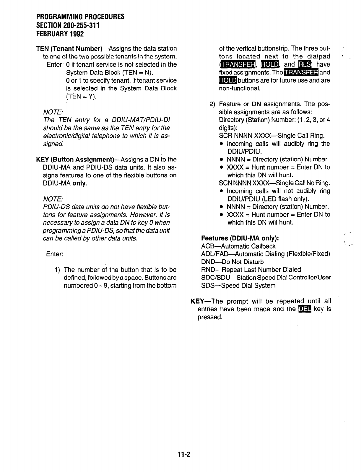
PROGRAMMINGPROCEDURES
SECTION 200-255-311
FEBRUARY1992
TEN (Tenant
Number)-Assigns the data station
to one of the two possible tenants in the system.
Enter: 0 if tenant service is not selected in the
System Data Block (TEN = N).
0 or 1 to specify tenant, if tenant service
is selected in the System Data Block
(TEN = Y).
NOTE:
The TEN entry for a DDIU-MAT/PDIU-DI
should be the same as the TEN entry for the
electronic/digital telephone to which it is as-
signed.
KEY (Button
Assignment)-Assigns a DN to the
DDIU-MA and PDIU-DS data units. It also as-
signs features to one of the flexible buttons on
DDIU-MA
only.
NOTE:
PDIU-DS data units do not have flexible but-
tons for feature assignments. However, it is
necessary to assign a data DN to key 0 when
programming a PDIU-DS, so that the data unit
can be called by other data units.
Enter:
1) The number of the button that is to be
defined, followed byaspace. Buttons are
numbered 0 - 9, starting from the bottom
of the vertical buttonstrip. The three but- ,
tons located next to the dialpad : .._
fixed assignments. The
ons are for future use and are
non-functional.
2) Feature or DN assignments. The pos-
sible assignments are as follows:
Directory (Station) Number: (1,2,3, or 4
digits):
SCR NNNN XXXX-Single Call Ring.
l
Incoming calls will audibly ring the
DDIWPDIU.
l
NNNN = Directory (station) Number.
l
XXXX = Hunt number = Enter DN to
which this DN will hunt.
SCN NNNN XXXX-Single Call No Ring.
l
Incoming calls will not audibly ring
DDIWPDIU (LED flash only).
l
NNNN = Directory (station) Number.
l
XXXX = Hunt number = Enter DN to
which this DN will hunt.
Features (DDIU-MA only):
ACB-Automatic Callback
ADUFAD-Automatic Dialing (Flexible/Fixed)
DND-Do Not Disturb
RND--Repeat Last Number Dialed
SDC/SDU-Station Speed Dial Controller/User
SDS-Speed Dial System
KEY-The prompt will be repeated until all
entries have been made and the m key is
pressed.
11-2
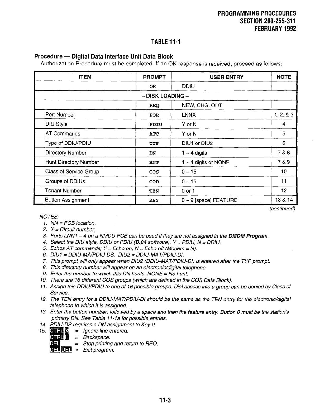
PROGRAMMINGPROCEDURES
SECTION 200-255-311
FEBRUARY1992
TABLEli-1
Procedure - Digital Data Interface Unit Data Block
Authorization Procedure must be completed. If an OK response is received, proceed as follows:
ITEM
PROMPT
OK DDIU
- DISK LOADING -
USER ENTRY NOTE
Port Number
REQ
NEW, CHG, OUT
POR LNNX
DIU Style I PDIU I Y or N
AT Commands ATC Y or N
Type of DDIU/PDIlJ TYP DIUl or DIU2
Directotv Number DN 1 - 4 diaits
Hunt Directory Number I HNT I 1 - 4 digits or NONE
Class of Service Group cos o- 15
Groups of DDlUs GOD o- 15
Tenant Nbmber TEN 0 or 1
Button Assignment KEY 0 - 9 [space] FEATURE
1,2,&3
4
5
6
7&8
78x9
10
11
12
13 & 14
NOTES:
(continued)
7.
2.
3.
4.
5.
6.
7.
8.
9.
10.
11.
12.
13.
14.
15.
NN = PC5 location.
X = Circuit number.
Ports LNNl - 4 on a NMDU PC5 can be used if they are not assigned in the DMDM Program.
Select the DIU style, DDIU or PDIU (0.04 software). Y = PDIU, N = DDIU.
Ethos AT commands; Y = Echo on, N = Echo off (Modem = N).
D/U7 = DDIU-MA/PD/U-DS. D/U2 = DDIU-MAT/PD/U-DI.
This prompt will only appear when DIU2 (DDIU-MAT/PDIU-DI) is entered after the TYP prompt.
This directory number will appear on an electronic/digital telephone.
Enter the number to which this DN hunts. NONE = No hunt.
There are 16 different COS groups (which are defined in the COS Data Block).
Assign this DDIWPDIU to one of 76 possible groups. Dial access into a group can be denied by Class of
Service.
The TEN entry for a DDIU-MAT/PDIU-DI should be the same as the TEN entry for the etectronic/digital
telephone to which it is assigned.
Enter the button number, followed by a space and then the feature entry. Button 0 must be the station’s
primary DN. See Table 1 I- la for possible entries.
PDIU-DS requires a DN assignment to Key 0.
= Ignore line entered.
= Backspace.
= Stop printing and return to REQ.
= Exit program.
11-3
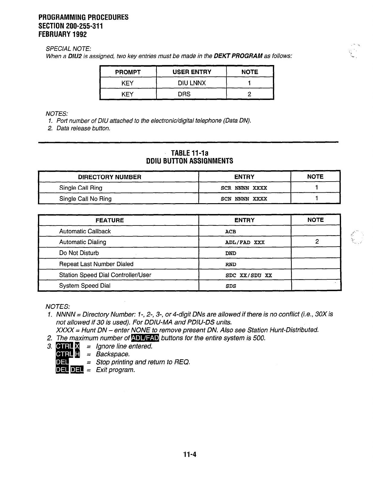
PROGRAMMING PROCEDURES
SECTION 200-255-311
FEBRUARY 1992
SPECIAL NOTE:
When a DlU2 is assigned, two key entries must be made in the DEKT PROGRAM as follows:
I
PROMPT I USER ENTRY I NOTE I
KEY DIU LNNX 1
KEY DRS 2
NOTES:
1. Port number of DIlJ attached to the electronic/digital telephone (Data ON).
2. Data release button.
TABLE V-la
DDIU BUTTON ASSIGNMENTS
DIRECTORY NUMBER ENTRY NOTE
Single Call Ring
SCR NNNN XXXX
1
I
Single Call No Ring
SCN
NN’NN XXXX 1 I
FEATURE
Automatic Callback
ENTRY NOTE
ACB
I
Automatic Dialing 1
zmL/FziD xxx I 2
Do Not Disturb
Repeat Last Number Dialed
DND
RND
Station Speed Dial Controller/User
Svstem Soeed Dial
SDC XX/SDTJ XX
SDS
NOTES:
1.
2.
3.
NNNN = Directory
Number: l-, 2-, 3-, or 4-digit DNs are allowed if there is no conflict (i.e., 30X is
not allowed if 30 is used). For DDIU-MA and PDIU-DS units.
XXXX = Hunt DN - enter NONE to remove present DN. Also see Station Hunt-Distributed.
The maximum number of m buttons for the entire system is 500.
.
I
c
6
= Ignore line entered.
= Backspace.
D - Stop printing and return to REQ.
D m i Exit program.
11-4
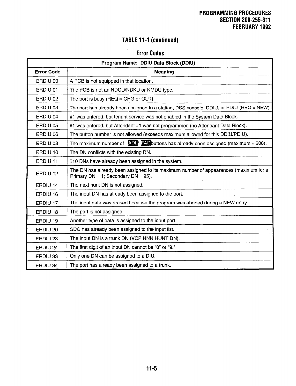
PROGRAMMINGPROCEDURES
SECTION 200-255-311
FEBRUARY1992
TABLE114 (continued)
Error Codes
Proaram Name: DDIU Data Block (DDIU)
Error Code I Meaning
ERDIU 00 1 A PCB is not eauiooed in that location.
ERDIU 01 The PCB is not an NDCU/NDKU or NMDU type.
ERDIU 02 The oort is busv (REQ = CHG or OUT).
ERDIU 03
ERDIU 04
The port has already been assigned to a station, DSS console, DDIU, or PDIU (REQ = NEW).
#1 was entered, but tenant service was not enabled in the Svstem Data Block.
ERDIU 05 1 #l was entered, but Attendant #I was not programmed (no Attendant Data Block).
ERDIU 06
ERDIU 08
The button number is not allowed (exceeds maximum allowed for this DDIU/PDIU).
The maximum number of m mbuttons has already been assigned (maximum = 500).
ERDIU 10
ERDIU 11
The DN conflicts with the existing DN.
510 DNs have already been assigned in the system.
ERDIU 12 The DN has already been assigned to its maximum number of appearances (maximum for a
Primary DN = 1; Secondary DN = 95).
ERDIU 14
ERDIU 16
ERDIU 17
The next hunt DN is not assigned.
The input DN has already been assigned to the port.
The input data was erased because the program was aborted during a NEW entry.
ERDIU 18
ERDIU 19
The port is not assigned.
Another type of data is assigned to the input port.
ERDIU 20
ERDIU 23
SDC has already been assigned to the input list.
The input DN is a trunk DN (VCP NNN HUNT DN).
ERDIU 24
ERDIU 33
The first digit of an input DN cannot be “0” or “9.”
Only one DN can be assigned to a DIU.
ERDIU 34 I The port has already been assioned to a trunk.
11-5
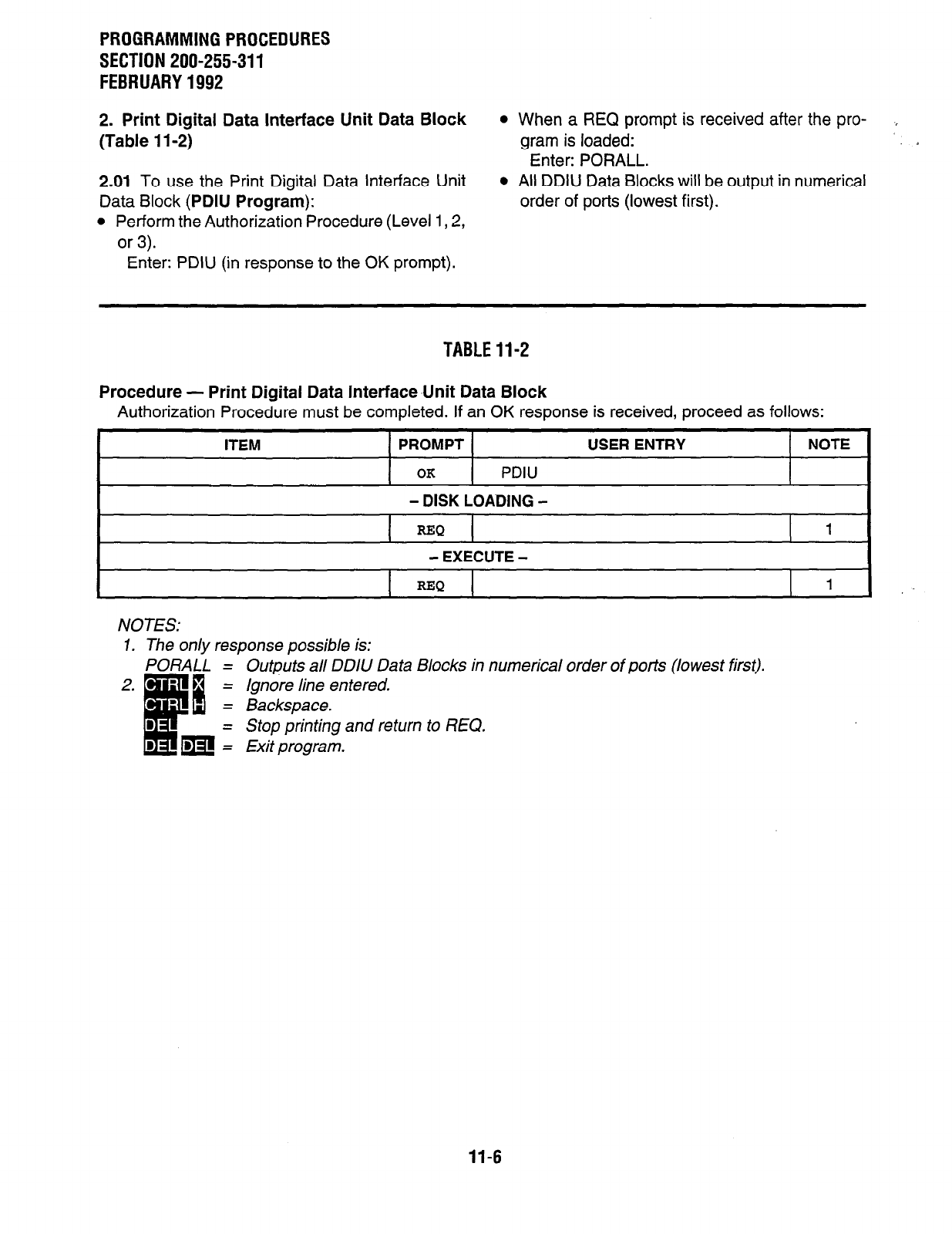
PROGRAMMING PROCEDURES
SECTION 200-255-311
FEBRUARY 1992
2. Print Digital Data Interface Unit Data Block
l
When a REQ prompt is received after the pro- I
(Table 1 l-2)
gram is loaded:
Enter: PORALL.
2.01 To use the Print Digital Data Interface Unit
Data Block
(PDIU Program):
l
Perform the Authorization Procedure (Level 1,2,
or 3).
l
All DDIU Data Blocks will be output in numerical
order of ports (lowest first).
Enter: PDIU (in response to the OK prompt).
TABLE 11-2
Procedure - Print Digital Data InterfaceUnit Data Block
Authorization Procedure must be completed. If an OK response is received, proceed as follows:
ITEM PROMPT USER ENTRY NOTE
OK
PDIU
- DISK LOADING -
I
REQ 1
- EXECUTE -
REQ 1
NOTES:
7. The only response possible is:
PORALL = Outputs all DDIU Data Blocks in numerical order of ports (lowest first).
2.
a
= Ignore line entered.
= Backspace.
= Stop printing and return to REQ.
m = Exit program.
11-6
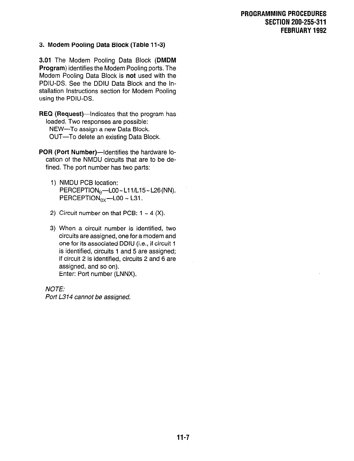
PROGRAMMINGPROCEDURES
SECTION 200-255-311
FEBRUARY1992
3. Modem Pooling Data Block (Table 11-3)
3.01 The Modem Pooling Data Block (DMDM
Program) identifies the Modem Pooling ports. The
Modem Pooling Data Block is not used with the
PDIU-DS. See the DDIU Data Block and the In-
stallation Instructions section for Modem Pooling
using the PDIU-DS.
REQ (Request)-Indicates that the program has
loaded. Two responses are possible:
NEW-To assign a new Data Block.
OUT-To delete an existing Data Block.
POR (Port Number)--Identifies the hardware lo-
cation of the NMDU circuits that are to be de-
fined. The port number has two parts:
1) NMDU PCB location:
PERCEPTION,-L00-L11/L15-L26(NN).
PERCEPTION,,-LOO - L31.
2) Circuit number on that PCB: 1 - 4 (X).
3) When a circuit number is identified, two
circuits are assigned, one for a modem and
one for its associated DDIU (i.e., if circuit 1
is identified, circuits 1 and 5 are assigned;
if circuit 2 is identified, circuits 2 and 6 are
assigned, and so on).
Enter: Port number (LNNX).
NOTE:
Port L314 cannot be assigned.
11-7
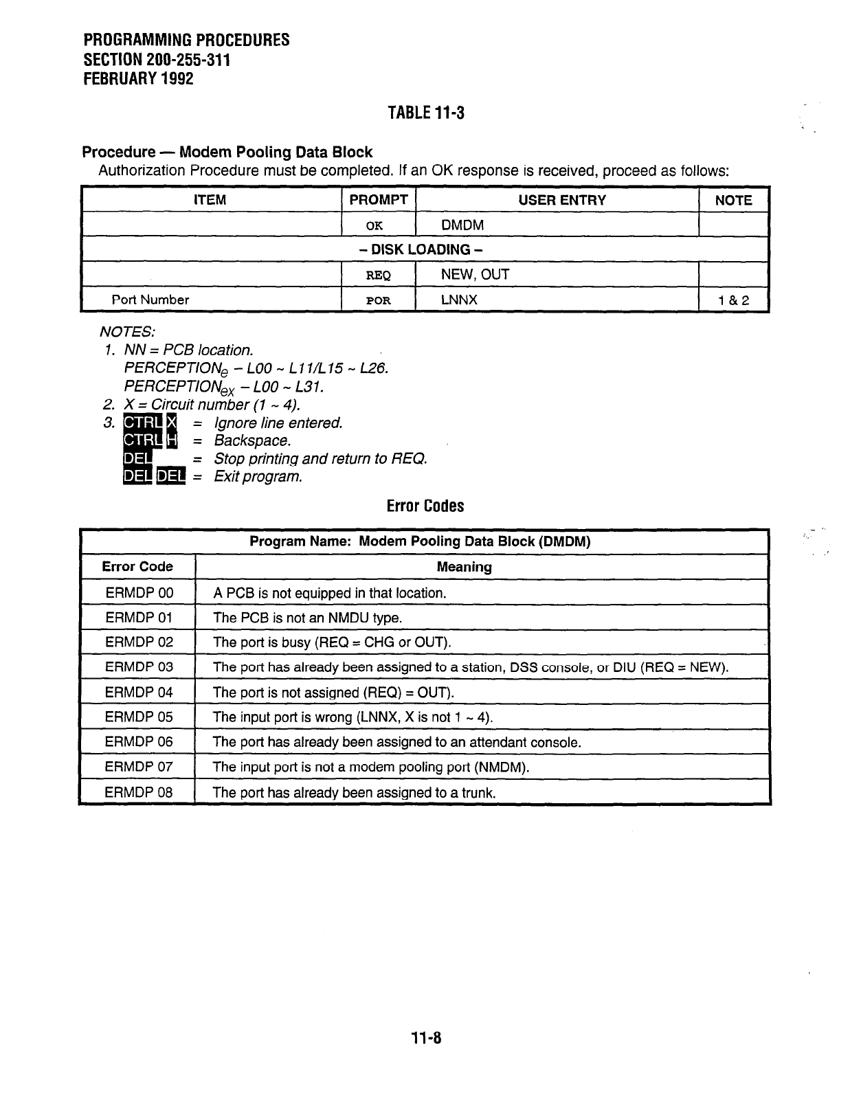
PROGRAMMING PROCEDURES
SECTION 200-255-311
FEBRUARY 1992
TABLE 11-3
Procedure - Modem Pooling Data Block
Authorization Procedure must be completed. If an
OK
response is received, proceed as follows:
ITEM PROMPT USER ENTRY NOTE
OK
DMDM
- DISK LOADING -
REQ
NEW, OUT
Port Number
POR
LNNX l&2
NOTES:
1. NN = PCB location.
PERCEPTION, - LOO - Ll7/L75 - L26.
PERCEPTION,, - LOO - L31.
2. X = Circuit number (1 - 4).
ignore line entered.
Backspace.
Stop printing and return to REQ.
Exit program.
Error Codes
Error Code
Program Name: Modem Pooling Data Block (DMDM)
Meaning
ERMDP 00 A PCB is not equipped in that location.
ERMDP 01 The PCB is not an NMDU tvoe.
ERMDP 02 1 The port is busy (REQ = CHG or OUT).
ERMDP 03
ERMDP 04
The port has already been assigned to a station, DSS console, or DIU (REQ = NEW).
The port is not assigned (REQ) = OUT).
ERMDP 05
ERMDP 06
The input port is wrong (LNNX, X is not 1 - 4).
The port has already been assigned to an attendant console.
ERMDP 07
ERMDP 08
The input port is not a modem pooling port (NMDM).
The port has already been assigned to a trunk.
11-8

PROGRAMMINGPROCEDURES
SECTION 200-255-311
FEBRUARY1992
4. Print Modem Pooling Data Block (Table 11-4) program is loaded:
Enter: PORALL.
4.01 To use the Print Modem Pooling Data Block
(PMDM Program):
l
Perform the Authorization Procedure (Level 1,2,
or 3).
l
All Modem Pooling Data Blocks will be output in
numerical order of ports (lowest first).
Enter: PMDM (in response to the OK prompt).
l
When the REQ prompt is received after the
TABLEll-4
Procedure - Print Modem Pooling Data Block
Authorization Procedure must be completed. If an OK response is received, proceed as follows:
I
1 PROMPT 1
I I
OK
PMDM
- DISK LOADING -
USER ENTRY
I
NOTE
REQ 1
- EXECUTE -
I I I
REQ
NOTES:
1. The only response possible is:
PORALL = Outputs all Modem Pooling Data Blocks in numerical order of ports (lowest first).
= Ignore line entered.
Backspace.
Stop printing and return to REQ.
Exit program.
11-9
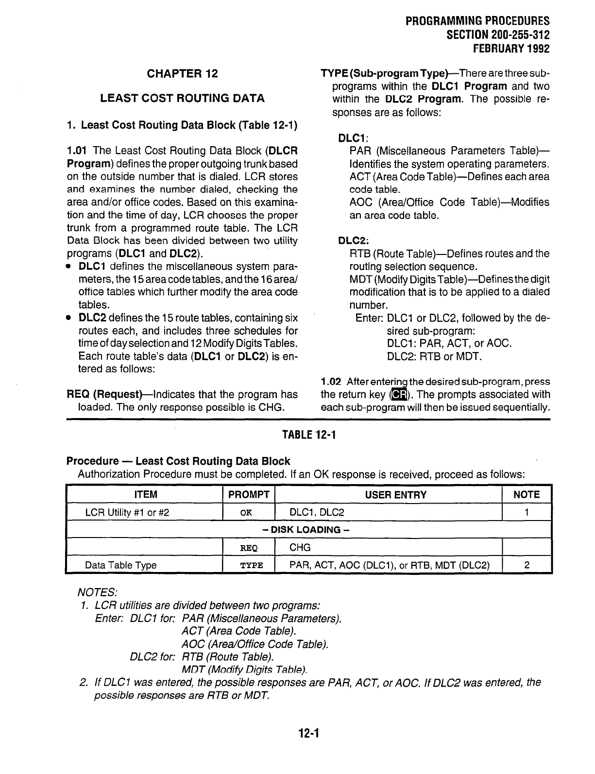
CHAPTER 12
LEAST COST ROUTING DATA
1. Least Cost Routing Data Block (Table 12-1)
1.01 The Least Cost Routing Data Block (DLCR
Program) defines the proper outgoing trunk based
on the outside number that is dialed. LCR stores
and examines the number dialed, checking the
area and/or office codes. Based on this examina-
tion and the time of day, LCR chooses the proper
trunk from a programmed route table. The LCR
Data Block has been divided between two utility
programs (DLCI and DLC2).
l
DLCl defines the miscellaneous system para-
meters, the 15 area code tables, and the 16 area/
office tables which further modify the area code
tables.
l
DLC2 defines the 15 route tables, containing six
routes each, and includes three schedules for
time of day selection and 12 Modify Digits Tables.
Each route table’s data (DLCl or DLCS) is en-
tered as follows:
REQ (Request)-indicates that the program has
loaded. The only response possible is CHG.
PROGRAMMING PROCEDURES
SECTION 200-255-312
FEBRUARY1992
TYPE (Sub-program Type)-There are three sub-
programs within the DLCl Program and two
within the DLC2 Program. The possible re-
sponses are as follows:
DLCI :
PAR (Miscellaneous Parameters
Table)-
Identifies the system operating parameters.
ACT (Area Code Table)-Defines each area
code table.
AOC (Area/Office Code Table)-Modifies
an area code table.
DLC2:
RTB (Route Table)-Defines routes and the
routing selection sequence.
MDT (Modify Digits Table)-Defines the digit
modification that is to be applied to a dialed
number.
Enter: DLCI or DLC2, followed by the de-
sired sub-program:
DLCl: PAR, ACT, or AOC.
DLC2: RTB or MDT.
1.02 After enterin the desired sub-program, press
the return key d ‘). The prompts associated with
each sub-program will then be issued sequentially.
TABLE12-1
Procedure - Least Cost Routing Data Block
Authorization Procedure must be completed. If an OK response is received, proceed as follows:
ITEM
LCR Utility #I or
#2
PROMPT USER ENTRY NOTE
OK
DLCl , DLC2 1
- DISK LOADING -
Data
Table Type
REQ
CHG
TYPE
PAR, ACT, AOC (DLCl),
or RTB,
MDT (DLC2)
2
NOTES:
1. LCR utilities are divided between two programs:
Enter: DLC 1 for: PAR (Miscellaneous Parameters).
ACT (Area Code Table).
AOC (Area/Office Code Table).
DLC2 for: RTB (Route Table).
MDT (Modify Digits Table).
2. If DLCl was entered, the possible responses are PAR, ACT, or AOC. If DLC2 was entered, the
possible responses are RTB or MDT.
12-1
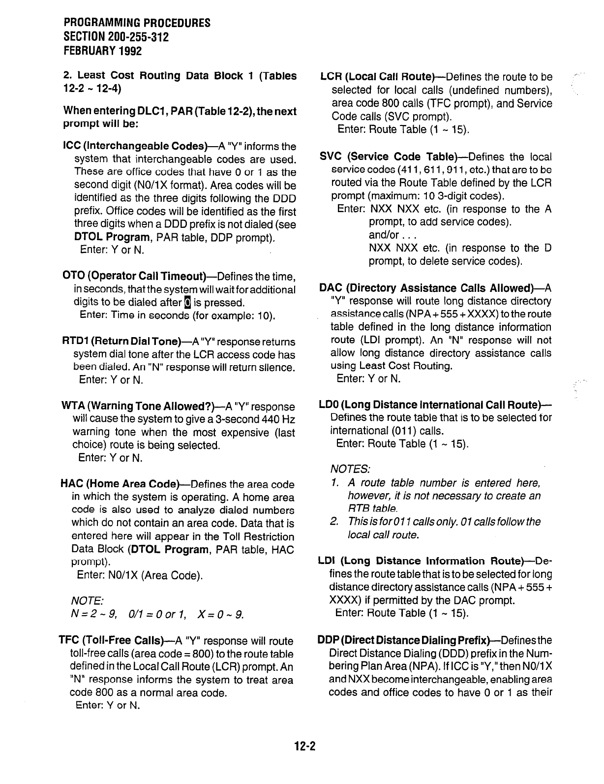
PROGRAMMINGPROCEDURES
SECTION 200-255-312
FEBRUARY1992
2. Least Cost Routing Data Block 1 (Tables
12-2 - 12-4)
When entering DLCI , PAR (Table 12-2), the next
prompt will be:
ICC (Interchangeable Codes)-A “Y” informs the
system that interchangeable codes are used.
These are office codes that have 0 or 1 as the
second digit (NO/i X format). Area codes will be
identified as the three digits following the DDD
prefix. Office codes will be identified as the first
three digits when a DDD prefix is not dialed (see
DTOL Program, PAR table, DDP prompt).
Enter: Y or N.
OTO (Operator Call Timeout)-Defines the time,
in seconds, that the system will wait for additional
digits to be dialed after 1 is pressed.
Enter: Time in seconds (for example: 10).
RTDl (Return Dial Tone)-A “Y” response returns
system dial tone after the LCR access code has
been dialed. An “N” response will return silence.
Enter: Y or N.
WTA (Warning Tone Allowed?)-A “Y” response
will cause the system to give a 3-second 440 Hz
warning tone when the most expensive (last
choice) route is being selected.
Enter: Y or N.
HAC (Home Area Code)-Defines the area code
in which the system is operating. A home area
code is also used to analyze dialed numbers
which do not contain an area code. Data that is
entered here will appear in the Toll Restriction
Data Block (DTOL Program, PAR table, HAC
prompt).
Enter: NO/IX (Area Code).
NOTE:
N=2-9, O/l=Oorl, X=0-9.
TFC (Toll-Free Calls)-A “Y” response will route
toll-free calls (area code = 800) to the route table
defined in the Local Call Route (LCR) prompt. An
“N” response informs the system to treat area
code 800 as a normal area code.
Enter: Y or N.
LCR (Local Call Route)--Defines the route to be
selected for local calls (undefined numbers),
area code 800 calls (TFC prompt), and Service
Code calls (SVC prompt).
Enter: Route Table (1 - 15).
SVC (Service Code Table)--Defines the local
service codes (411,611,911, etc.) that are to be
routed via the Route Table defined by the LCR
prompt (maximum: IO 3-digit codes).
Enter: NXX NXX etc. (in response to the A
prompt, to add service codes).
and/or . . .
NXX NXX etc. (in response to the D
prompt, to delete service codes).
DAC (Directory Assistance Calls Allowed)-A
“Y” response will route long distance directory
assistance calls (NPA + 555 + XXXX) to the route
table defined in the long distance information
route (LDI prompt). An “N” response will not
allow long distance directory assistance calls
using Least Cost Routing.
Enter: Y or N.
LDO (Long Distance International Call Route)-
Defines the route table that is to be selected for
international (011) calls.
Enter: Route Table (1 - 15).
NOTES:
7. A route table number is entered here,
however, it is not necessary to create an
RTB table.
2. This is for 0 11 calls only. 0 1 calls folio w the
local call route.
LDI (Long Distance Information Route)-De-
fines the route table that is to be selected for long
distance directory assistance calls (NPA + 555 +
XXXX) if permitted by the DAC prompt.
Enter: Route Table (1 - 15).
DDP (Direct Distance Dialing Prefix)-Defines the
Direct Distance Dialing (DDD) prefix in the Nurn-
bering Plan Area (NPA). If ICC is “Y,” then NO/l X
and NXX become interchangeable, enabling area
codes and office codes to have 0 or 1 as their
12-2
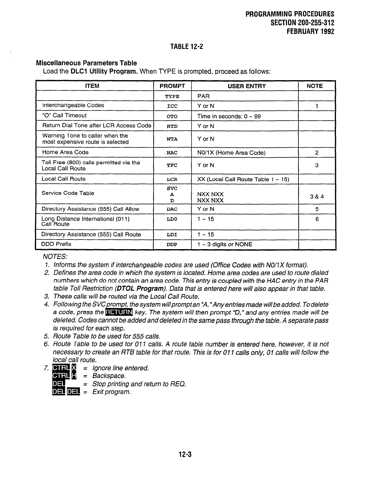
PROGRAMMINGPROCEDURES
SECTION 200-255-312
FEBRUARY1992
TABLE12-2
Miscellaneous Parameters Table
Load the DLCI Utility Program. When TYPE is prompted, proceed as follows:
ITEM 1 PROMPT 1 USER ENTRY I NOTE
I
TYPE 1
-PAR
I
Interchangeable Codes
“0” Call Timeout
ICC
OTO
Y or N
Time in seconds: 0 - 99
1
Return Dial Tone after LCR Access Code
Warning Tone to caller when the
most expensive route is selected
RTD
WTA
Y or N
Y or N
Home Area Code ! .lxAc NO/l X (Home Area Code) 2
Toll Free (800) calls permitted via the
Local Call Route I
TFC
I Y or N
Local Call Route
I I I
LCR
1 XX (Local Call Route Table 1 - 15) 1
Long Distance International (011)
Call Route
Directory Assistance (555) Call Route
DDD Prefix
LDO
LDI
DDP
1 - 15
l-15
1 - 3 digits or NONE
6
NOTES:
7. Informs the system if interchangeable codes are used (Office Codes with NO/IX format).
2, Defines the area code in which the system is located. Home area codes are used to route dialed
numbers which do not contain an area code. This entry is coupled with the HAC entry in the PAR
table Toll Restriction (DTOL Program). Data that is entered here will also appear in that table.
3. These calls will be routed via the Local Call Route.
4. Folio wing the S esystem willpromptan “A. “Anyentriesmade willbeadded. Todelete
a code, press key. The system will then prompt “D,” and any entries made will be
deleted. Codes cannot be added and deleted in the same pass through the table. A separate pass
is required for each step,
5. Route Table to be used for 555 calls.
6. Route Table to be used for 017 calls. A route tab/e number is entered here, however, it is not
necessary to create an RTB table for that route. This is for 011 calls only, 01 calls will follow the
local call route.
= Ignore line entered.
= Backspace.
- Stop printing and return to REQ.
1 Exit program.
12-3
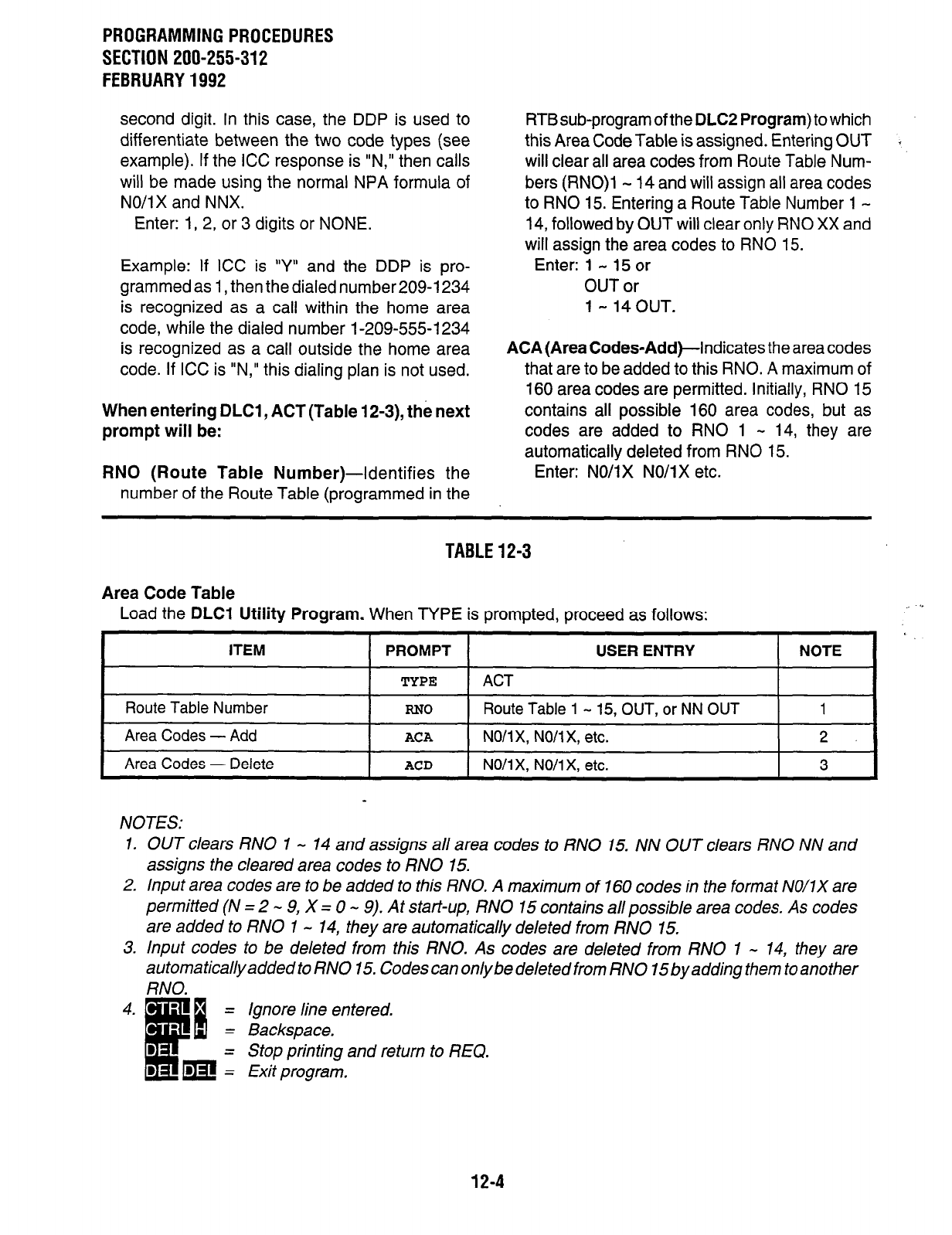
PROGRAMMING PROCEDURES
SECTION 200-255-312
FEBRUARY 1992
second digit. In this case, the DDP is used to
differentiate between the two code types (see
example). If the ICC response is “N,” then calls
will be made using the normal NPA formula of
NO/i X and NNX.
Enter: 1, 2, or 3 digits or NONE.
Example: If ICC is ‘Y” and the DDP is pro-
grammed as 1, then the dialed number209-1234
is recognized as a call within the home area
code, while the dialed number 1-209-555-l 234
is recognized as a call outside the home area
code. If ICC is “N,” this dialing plan is not used.
When entering DLCl , ACT (Table 12-3), the next
prompt will be:
RN0 (Route Table
Number)-Identifies the
number of the Route Table (programmed in the
RTB sub-program of the
DLC2 Program)
to which
this Area Code Table is assigned. Entering OUT
will clear all area codes from Route Table Num-
bers (RNO)l - 14 and will assign all area codes
to RN0 15. Entering a Route Table Number 1 -
14, followed by OUT will clear only RN0 XX and
will assign the area codes to RN0 15.
Enter: 1 - 15 or
OUT or
1 - 14 OUT.
ACA (Area
Codes-Add)-Indicates the area codes
that are to be added to this RNO. A maximum of
160 area codes are permitted. Initially, RN0 15
contains all possible 160 area codes, but as
codes are added to RN0 1 - 14, they are
automatically deleted from RN0 15.
Enter: NO/l X NO/l X etc.
TABLE 12-3
Area Code Table
Load the
DLCI Utility Program.
When TYPE is prompted, proceed as follows: . .
ITEM
Route Table Number
Area Codes - Add
Area Codes - Delete
PROMPT USER ENTRY NOTE
TYPE
ACT
RN0
Route Table
1 -
15, OUT, or NN OUT 1
ACA
NO/l X, NO/l X, etc.
2.
ACD
NO/lx, NO/lx, etc.
3
NOTES:
1. OUT clears
RN0
1 - 14 and assigns all area codes to RN0 15. NN OUT clears RN0 NN and
assigns the cleared area codes to RN0 15.
2. Input area codes are to be added to this RNO. A maximum of 160 codes in the format NO/IX are
permitted (N = 2 - 9, X = 0 - 9). At start-up, RN0 15 contains al/possible area codes. As codes
are added to RN0 1 - 14, they are automatically deleted from RN0 15.
3. Input codes to be deleted from this RNO. As codes are deleted from RN0 1 - 14, they are
automaticallyadded to RN0 15. Codes can onlybe deleted from RN0 15byadding them to another
RNO.
4. - =
.
B
6 =
: m:
Ignore line entered.
Backspace.
Stop printing and return to REQ.
Exit program,
12-4
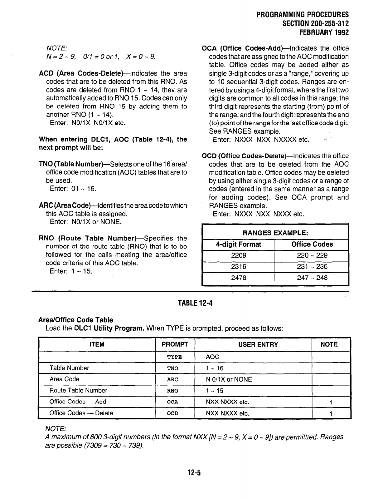
NOTE:
N=2-9, O/l=Oorl, X=0-9.
ACD (Area Codes-Delete)-indicates the area
codes that are to be deleted from this RNO. As
codes are deleted from RN0 1 - 14, they are
automatically added to RN0 15. Codes can only
be deleted from RN0 15 by adding them to
another RN0 (1 - 14).
Enter: NO/i X NO/i X etc.
When entering DLCl, AOC (Table 12-4), the
next prompt will be:
TN0 (Table Number)-Selects one of the 16 area/
office code modification (AOC) tables that are to
be used.
Enter: 01 - 16.
ARC
(Area Code)-Identifies the area code to which
this AOC table is assigned.
Enter: NO/IX or NONE.
RN0 (Route Table Number)-Specifies the
number of the route table (RNO) that is to be
followed for the calls meeting the area/office
code criteria of this AOC table.
Enter: 1 - 15.
PROGRAMMING PROCEDURES
SECTION 200-255-312
FEBRUARY 1992
OCA (Off ice Codes-Add)-Indicates the off ice
codes that are assigned to the AOC modification
table. Office codes may be added either as
single 3-digit codes or as a “range,” covering up
to 10 sequential 3-digit codes. Ranges are en-
tered by using a4-digit format, where the first two
digits are common to all codes in this range; the
third digit represents the starting (from) point of
the range; and the fourth digit represents the end
(to) point of the range for the last office code digit.
See RANGES example.
Enter: NXXX NXX NXXXX etc. I’-
OCD (Office Codes-Delete)-Indicates the office
codes that are to be deleted from the AOC
modification table. Office codes may be deleted
by using either single 3-digit codes or a range of
codes (entered in the same manner as a range
for adding codes). See OCA prompt and
RANGES example.
Enter: NXXX NXX NXXX etc.
I
RANGES EXAMPLE: I
I
4-digit Format 1 Off ice Codes I
2209 220 - 229
2316 231 - 236
I 2478 I 247 - 248 I
TABLE 12-4
Area/Off ice Code Table
Load the DLCl Utility Program. When TYPE is prompted, proceed as follows:
I
ITEM PROMPT 1 USER ENTRY I NOTE
Table Number
Area Code
I
Route Table Number
RN0 I
1-15 I
Off ice Codes - Add
OCA
NXX NXXX etc. 1
Off ice Codes - Delete
OCD
NXX NXXX etc. 1
TYPE
TN0
ARC
AOC
1-16
N 0/1X
or NONE
NOTE:
A maximum of 800 3-digit numbers (in the format NXX [N = 2 - 9, X = 0 - 91) are permittted. Ranges
are possible (7309 = 730 - 739).
12-5
PROGRAMMING PROCEDURES
SECTION 200-255-312
FEBRUARY 1992
NOTE:
Codes cannot be added and deleted in the
same pass through the table. A separate pass
is required for each step.
3. Least Cost Routing Data Block 2 (Tables
12-5 - 12-6)
When entering DLC2, RTB (Table 124, the next
prompt will be:
RN0 (Route Table
Number)-identifies the
number of the Route Table to which an Area
Code Table (ACT) and/or an AOC Table is
assigned. Entering OUT will clear all Route
Tables. Entering RN0 1 - 15, followed by OUT
will clear RN0 XX.
Enter: 1 - 15 or
1 - 150UT.
RTl - 6 (Route Definition)-Defines
the Trunk
Group for each route in this Route Table. If a
Trunk Group is entered at this time, then a Modify
Digits Table must also be entered. A particular
routing definition (RTl, RT2, etc.) may only be
used one time per routing schedule.
Enter: XX MM or NONE.
(XX = Trunk Group Number 0 - 15.)
(MM = Modify Digits Table Number 1 -
12.)
NOTE:
The existing Route Schedule data will be
automatically printed after the response to
RT6 prompt is entered.
12-6
SCHA (Route Schedule
A)-Defines the time-of-
day interval for the first of three possible routing
schedules. Start and end times are entered by
using a 24-hour-clock format.
Enter: Start Time End Time.
(for example: 0900 1700.)
LC3 (Class 3 Routing Priority)-Defines
the
routing choice sequence that is accessible to
station classes LC3, LC2, and LCl during
Schedule A time interval. Enter the routes (RTl
- 6) in the order of selection priority.
Enter: Routing Choice (for example: RT6 RTl
etc.).
. . .
or. . .
NONE (this entry for LC3 will also change r
LC2 & LCl to NONE for this schedule).
LC2 (Class 2 Routing Priority)-Defines
the
routing choice sequence that is accessible to
station classes LC2 and LCl during Schedule A
time interval. Enter the routes (RTl - 6) in the
order of selection priority.
Enter: Routing Choice (for example: RT5 RT2
etc.).
NONE. ’ ”
or. . .
LCl (Class 1 Routing Priority)-Defines
the
routing choice sequence that is accessible to
station class LCl during Schedule A time inter-
val. Enter the routes (RTl - 6) in the order of
selection priority.
Enter: Routing Choice (for example: RT4 RT3
etc.).
NONE. * ‘.
or. . .
. .
NOTE: .i
The DCOS Data Block is used to define sta-
tion class of service for Least Cost Routing
(LCR) by using three classes of service for
LCR. Theaccesspermitted to each LCR Class
of Service is as follows:
LCI-Allows routes defined for LC3, LC2;
and LCI.
‘.-
LCZ-Allows routes defined for LC2 and LC3.
LC3-Allows routes defined for LC3 only.
SCHB (Route Schedule
B)-Defines the time-of-
day interval for the second of three possible
routing schedules. The start time, which is the
end time of Schedule A, will be automatically
printed (24-hour-clock format).
Enter: End Time (for example: 2300).
LC3 (Class 3 Routing Priority)-Same as LC3
in
Schedule A, but for Schedule B time interval.
Enter: Routing Choice (for example: RT5 RT4
etc.). . ..or... ” NONE (this entry for LC3 will also cause
LC2 & LCl to be longer for this sched-
ule).
LC2 (Class 2 Routing Priority)-Same as LC2 in
Schedule A, but for Schedule B time interval.
Enter: Routing Choice (for example: RT3 RT2
etc.).
NONE.
, . . or.. .
LCl (Class 1 Routing Priority)-Same as LCl in
Schedule A, but for Schedule B time interval.
Enter: Routing Choice (for example: RTl RT6
etc.).
NONE. * * ’
or.. .
SCHC (Route Schedule Q-Defines the time-of-
day interval for the last of three possible routing
schedules. The start time, which is the end time
of Schedule B, and the end time, which is the
start time of Schedule A, will be automatically
printed (24-hour-clock format).
No entry is necessary.
LC3 (Class 3 Routing Priority)-Same as LC3 in
Schedules A and B, but for Schedule C time
interval.
Enter: Routing Choice (for example: RTl RT6
etc.).
. ..or...
NONE (this entry for LC3 will also cause
LC2 and LCl to be NONE for this
schedule).
PROGRAMMINGPROCEDURES
SECTION 200-255-312
FEBRUARY1992
LC2 (Class 2 Routing Priority)-Same as LC2 in
Schedules A and B, but for Schedule C time
interval.
Enter: Routing Choice (for example: RT2 RT3
etc.).
NONE. ” ’
or. . .
LCI (Class 1 Routing Priority)-Same as LCI in
Schedules A and B, but for Schedule C time
interval.
Enter: Routing Choice (for example: RT4 RT5
etc.).
NONE. ’ ” or.. .
12-7
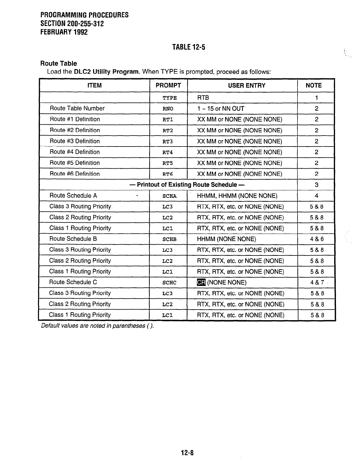
PROGRAMMINGPROCEDURES
SECTION 200-255-312
FEBRUARY1992
Route Table
TABLE12-5
Load the DLC2 Utility Program. When TYPE is prompted, proceed as follows:
Default values are noted in parentheses (),
12-8

PROGRAMMINGPROCEDURES
SECTlON200-255-312
FEBRUARY1992
NOTES:
TABLE12-5(continued)
1.
2.
3.
4.
5.
6.
7.
8.
9.
OUT = Will clear all Route Tables. NN OUT = Will clear Route Table NN.
Route definition - maximum is six routes,
Format is: XX = Trunk Group Number (0 - 15).
MM = Modify Digits Table to be applied (1 - 12). Modify Digits Table
must
be entered.
Existing Route Schedule data is printed automatically after the response to RT6prompt is entered.
Time-of-day interval for this routing schedule.
Maximum combinedentries for LC3, LC2, LCl are sixroutes. Do notassign the same route tomore
than one c/ass. .
Entry required for schedule B end time only. Schedule A end time has definedschedule B start time.
No entry required. Schedule A start time has defined the schedule C end time and schedule B end
time has defined the schedule C start time.
LC3, LC2, and LCI are used in DCOS Data Block to define Station Class of Service. The access
permitted to each class is as follows: LCl = All routes defined for LCl, LC2, LC3.
LC2 = Routes defined for LCZ, LC3.
LC3 = Routes defined for LC3 on/v.
Ignore line entered,
Backspace.
Stop printing and return to REC.
Exit program.
12-9
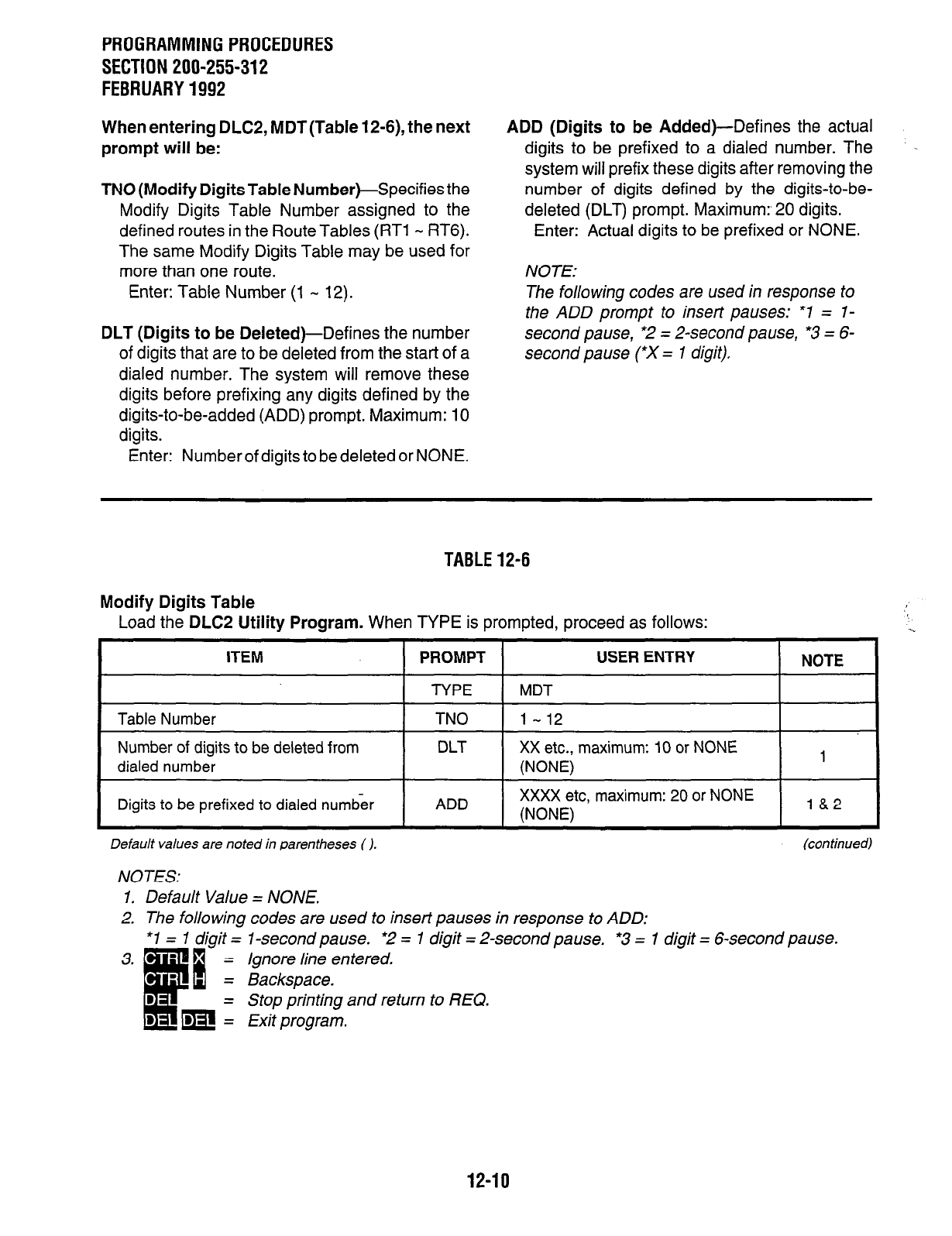
PROGRAMMINGPROCEDURES
SECTION 200-255-312
FEBRUARY1992
When entering DLCP, MDT(Table 12-6), the next
prompt will be:
TN0 (Modify Digits Table
Number)-Specifies the
Modify Digits Table Number assigned to the
defined routes in the Route Tables (RTl - RT6).
The same Modify Digits Table may be used for
more than one route.
Enter: Table Number (1 - 12).
DLT (Digits to be Deleted
)-Defines the number
of digits that are to be deleted from the start of a
dialed number. The system will remove these
digits before prefixing any digits defined by the
digits-to-be-added (ADD) prompt. Maximum: 10
digits.
Enter: Number of digits to be deleted or NONE.
ADD (Digits to be
Added)-Defines the actual
digits to be prefixed to a dialed number. The .
system will prefix these digits after removing the
number of digits defined by the digits-to-be-
deleted (DLT) prompt. Maximum:, 20 digits.
Enter: Actual digits to be prefixed or NONE.
NOTE:
The following codes are used in response to
the ADD prompt to insert pauses: *I = l-
second pause, *2 = 2-second pause, *3 = 6-
second pause (*X = 1 digit).
TABLE12-6
Modify Digits Table
Load the
DLC2 Utility Program.
When TYPE is prompted, proceed as follows: ‘:
ITEM
Table Number
Number of digits to be deleted from
dialed number
Digits to be prefixed to dialed numb&
PROMPT USER ENTRY NOTE
TYPE MDT
TN0 1 - 12
DLT XX etc., maximum: 10 or NONE
(NONE) 1
ADD XXXX etc, maximum: 20 or NONE
(NONE) 18.2
Default values are noted in parentheses ( j. (continued)
NOTES:
1. Default Value = NONE.
2. The following codes are used to insert pauses in response to ADD:
*I = 1 digit = 1 -second pause.
l
2 = I &git = 2-second pause. *3 = 1 digit = 6-second pause.
Ignore line entered.
Backspace.
Stop printing and return to REQ.
Exit program.
12-10
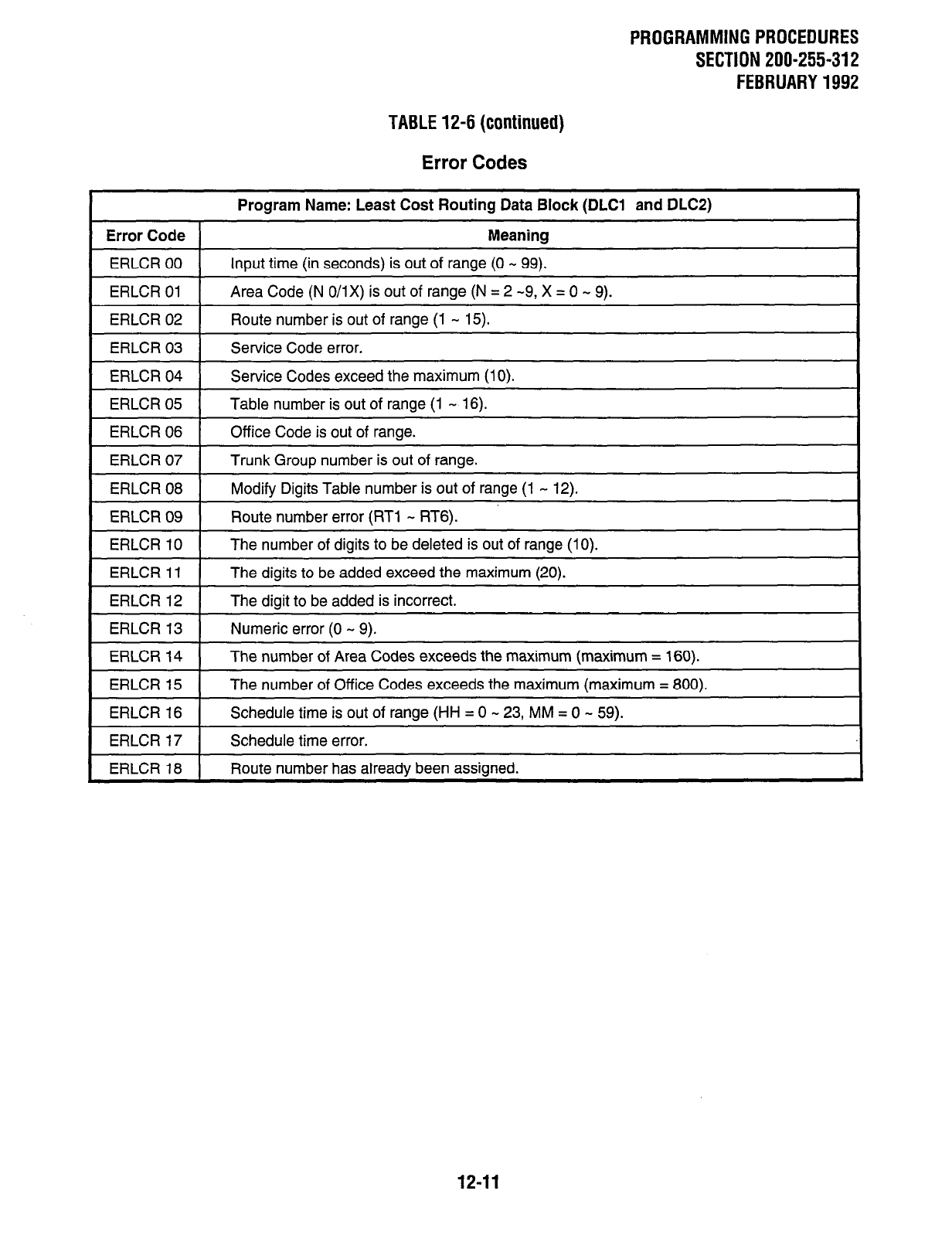
PROGRAMMING PROCEDURES
SECTION 200-255-312
FEBRUARY 1992
TABLE 12-6 (continued)
Error Codes
Program Name: Least Cost Routing Data Block (DLCl and DLCP)
Error Code Meaning
ERLCR 00 Input time (in seconds) is out of range (0 - 99).
ERLCR 01 Area Code (N 0/1X) is out of range (N = 2 -9, X = 0 - 9).
ERLCR 02 Route number is out of range (I - 15).
ERLCR 03
ERLCR 04
ERLCR 05
Service Code error.
Service Codes exceed the maximum (10).
Table number is out of range (1 - 16).
1 ERLCR 06 1 Office Code is out of range.
ERLCR 07
ERLCR 08
ERLCR 09
Trunk Group number is out of range.
Modify Digits Table number is out of range (1 - 12).
Route number error (RTl - RT6).
ERLCR 10
ERLCR 11
ERLCR 12
1 ERLCR 13 1 Numeric error (0 - 9).
The number of digits to be deleted is out of range (10).
The digits to be added exceed the maximum (20).
The diait to be added is incorrect.
ERLCR 14
ERLCR 15
ERLCR 16
The number of Area Codes exceeds the maximum (maximum = 160).
The number of Office Codes exceeds the maximum (maximum = 800).
Schedule time is out of ranoe (HH = 0 - 23, MM = 0 - 59).
1 ERLCR 17 1 Schedule time error.
ERLCR 18 Route number has alreadv been assianed.
12-11
PROGRAMMINGPROCEDURES
SECTION 200-255-312
FEBRUARY1992
4. Print Least Cost Routing Data Block (Table
12-7)
4.01 To use the Print Least Cost Routing Data
Block
(PLCR Program).
l
Perform Authorization Procedure (Level 1,2, or
3).
Enter: PLCR (in response to the OK prompt).
l
When the REQ prompt is received after the
program is loaded, enter one of the following
commands:
LCRALL-Ail Least Cost Routing Data Blocks will
be output.
PAR-Miscellaneous Parameters Table will be
output.
AOCNOXX-Area/Office Code Table XX will be .
output.
AOCRNXX-All Area/Office Code Tables that point
to Route Number (RN) XX will be output.
CODXXX-All Area/Office Code Tables relating to
Area Code XXX will be output.
RTALL-All
Route Tables will be output.
RTXX-Route Table XX will be output.
TGPXX-All Route Tables using Trunk Group XX
will be output.
RTMDXX-All Route Tables using Modify Digits
Table XX will be output.
ACTALL-All Area Code Tables will be output. MDTXX-Modify Digits Table XX will be output.
ACTRNXX-All Area Code Tables that point to
Route Number (RN) XX will be output.
AOCALL-All Area/Office Code Tables will be
output.
12-12

PROGRAMMINGPROCEDURES
SECTION 200-255-312
FEBRUARY1992
TABLE12-7
Procedure - Print Least Cost Routing Data Block
Authorization Procedure must be completed. If an OK response is received, proceed as follows:
ITEM PROMPT USER ENTRY NOTE
OK
PLCR
- DISK LOADING -
=JQ 1
- EXECUTE -
REQ 1
NOTES:
1. The following responses are possible:
LCRALL =
PAR =
ACTALL =
ACTRNXX =
AOCALL -
AOCNOXX =
AOCRNXX =
CODXXX =
RTALL =
RTXX =
TGPXX =
RTMDXX =
MDTXX =
2. - =
.
d
ii =
:m:
Outputs all Least Cost Routing Data Blocks,
Outputs Miscellaneous Parameters Table.
Outputs all Area Code Tables.
Outputs all Area Code Tables that point to Route Number (RNO) XX.
Outputs all Area/Office Code Tables.
Outputs Area/Office Code Table XX.
Outputs all Area/Office Code Tables that point to Route Number (RNO) XX.
Outputs all Area Code and Area/Office Code Tables relating to Area Code XXX.
Outputs all Route Tables.
Outputs Route Table XX.
Outputs all Route Tables using Trunk Group XX.
Outputs all Route Tables using Modify Digits Table XX.
Outputs Modify Digits Table XX.
Ignore line entered.
Backspace.
Stop printing and return to REQ.
Exit program.
12-13
CHAPTER 13
LODGING/HEALTH CARE DATA
1. Lodging/Health Care Features Data Block
(Table 13-l)
1 .Ol
The Lodging/Health Care Features Data Block
(DHMF Program)
defines the number of miscella-
neous parameters that pertain to the Lodging/
Health Care features. Data is entered as follows:
NOTE:
Be sure to run the DMYC program (Back-up
Memory Check Entry Procedure) when the
system is put into the Lodging/Health Care
mode of operation, and before this program is
entered,
REQ (Request)-Indicates that the program has
loaded. Three responses are possible:
NEW-To create a new Data Block.
CHGTo alter an existing Data Block.
OUT-To delete an existing Data Block.
NOTE:
If OUT is entered, all entries will be set to
“NONE. ”
PROGRAMMING PROCEDURES
SECTION 200-255-313
FEBRUARY 1992
AWU SRC (Automatic Wake-up Source)-
identifies the source that the called party will
hear after the wake-up call has been answered.
Enter: MOH-Music-on-Hold.
VCE-Preprogrammed digitized voice
announcement.
NONE-Silence.
AWU POR (Automatic
Wake-up)-Identifies the
output port that the system will use to send
automatic wake-up verification information.
Enter: SMDR, TTY, or NONE.
MW POR
(Message
Waiting)-Identifies the out-
put port that the system will use to send message
waiting verification information.
Enter: SMDR, TTY, or NONE.
MR POR
(Message
Registration)-Identifies the
output port that the system will use to send
message registration information.
Enter: SMDR, TTY, or NONE.
RMS
(Room Status
Audit)-Identifies the output
pot-tthat the system will use to send Room Status
Audit information.
Enter: SMDR, -TTY, or NONE.
13-1
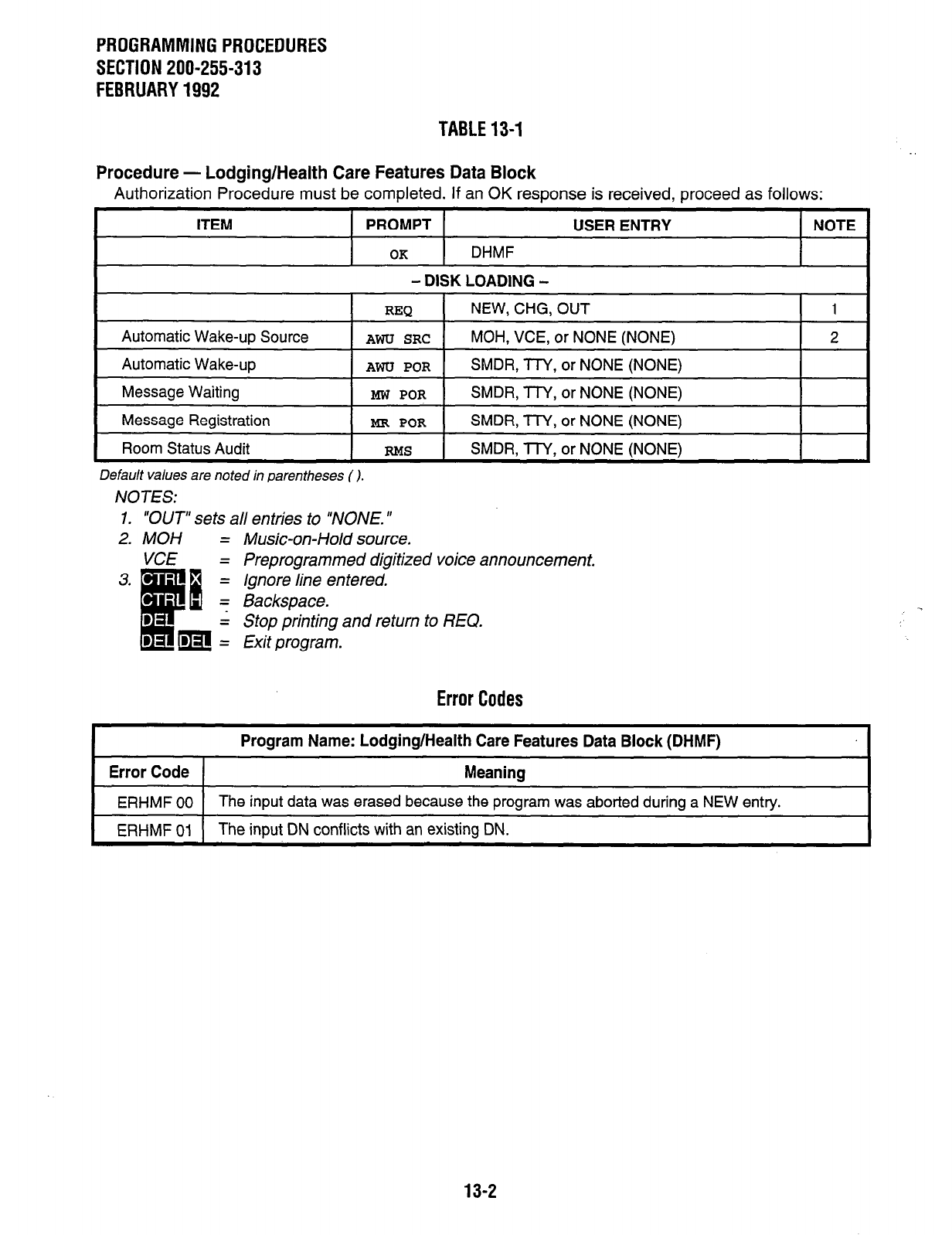
PROGRAMMING PROCEDURES
SECTION 200-255-313
FEBRUARY 1992
TABLE 13-I
Procedure - Lodging/Health Care Features Data Block
Authorization Procedure must be completed. If an OK response is received, proceed as follows:
ITEM PROMPT USER ENTRY NOTE
OK
DHMF
- DISK LOADING -
REQ NEW, CHG, OUT 1
Automatic Wake-up Source
AWU SRC
MOH, VCE, or NONE (NONE) 2
Automatic Wake-up
AWU POR
SMDR, TTY, or NONE (NONE)
Message Waiting
MW POR
SMDR, TTY, or NONE (NONE)
Message Registration
MR POR
SMDR, TTY, or NONE (NONE)
Room Status Audit
RMS
SMDR, lTY, or NONE (NONE)
Default values are noted in parentheses ( ).
NOTES:
1. “OUT” sets all entries to “NONE. ”
2. MOH = Music-on-Hold source.
Preprogrammed digitized voice announcement.
Ignore line entered.
Backspace.
Stop printing and return to REQ.
Exit program.
Error Codes
I Program Name: Lodging/Health Care Features Data Block (DHMF)
1 Error Code 1 Meanina
ERHMF 00 The input data was erased because the program was aborted during a NEW entry.
ERHMF 01 The input DN conflicts with an existing DN.
13-2
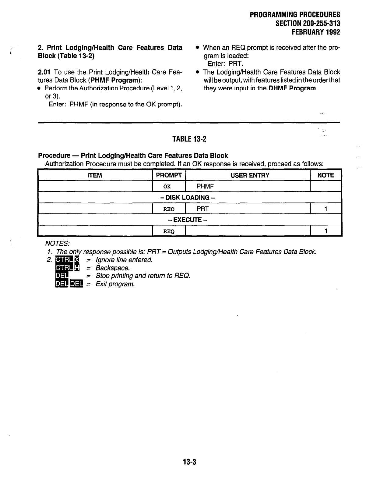
PROGRAMMINGPROCEDURES
SECTION 200-255-313
FEBRUARY1992
2. Print Lodging/Health Care Features Data
Block (Table 13-2)
l
When an REQ prompt is received after the pro-
gram is loaded:
Enter: PRT.
2.01 To use the Print Lodging/Health Care Fea-
tures Data Block
(PHMF Program):
l
Perform the Authorization Procedure (Level 1,2,
or 3).
l
The Lodging/Health Care Features Data Block
will be output, with features listed in the order that
they were input in the
DHMF Program.
Enter: PHMF (in response to the OK prompt).
TABLE13-2 .,.-
Procedure - Print Lodging/Health Care Features Data Block
Authorization Procedure must be completed. If an OK response is received, proceed as follows:
ITEM PROMPT USER ENTRY NOTE
OK PHMF
- DISK LOADING -
REQ PRT 1 I
- EXECUTE -
REO
I
1
NOTES: response possible is: PRT = Outputs Lodging/Health Care Features Data Block.
= Ignore line entered.
= Backspace.
= Stop printing and return to REQ.
= Exit program.
13-3
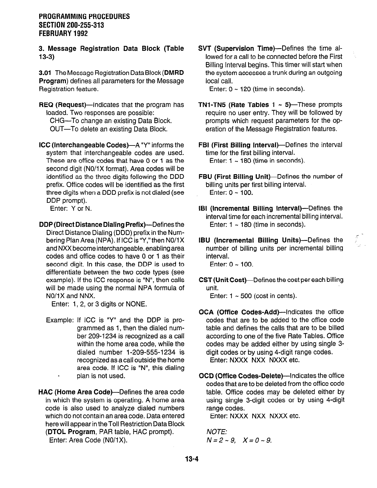
PROGRAMMING PROCEDURES
SECTION 200-255-313
FEBRUARY 1992
3. Message Registration Data Block (Table
13-3)
3.01 TheMessage Registration DataBlock(DMRD
Program) defines all parameters for the Message
Registration feature.
REQ (Request)-Indicates that the program has
loaded. Two responses are possible:
CHG-To change an existing Data Block.
OUT-To delete an existing Data Block.
ICC (Interchangeable Codes)-A “Y” informs the
system that interchangeable codes are ,used.
These are office codes that have 0 or 1 as the
second digit (NO/i X format). Area codes will be
identified as the three digits following the DDD
prefix. Office codes will be identified as the first
three digits when a DDD prefix is not dialed (see
DDP prompt).
Enter: Y or N.
DDP (Direct Distance Dialing Prefix)-Defines the
Direct Distance Dialing (DDD) prefix in the Num-
bering Plan Area (NPA). If ICC is “Y,” then NO/l X
and NXX become interchangeable, enabling area
codes and office codes to have 0 or 1 as their
second digit. In this case, the DDP is used to
differentiate between the two code types (see
example). If the ICC response is “N”, then calls
will be made using the normal NPA formula of
NO/lx and NNX.
Enter: 1, 2, or 3 digits or NONE.
Example: If ICC is “Y” and the DDP is pro-
grammed as 1, then the dialed num-
ber 209-1234 is recognized as a call
within the home area code, while the
dialed number 1-209-555-l 234 is
recognized as acall outside the home
area code. If ICC is “N”, this dialing
plan is not used.
HAC (Home Area Code)-Defines the area code
in which the system is operating. A home area
code is also used to analyze dialed numbers
which do not contain an area code. Data entered
here will appear in theToll Restriction Data Block
(DTOL Program, PAR table, HAC prompt).
Enter: Area Code (NO/l X).
SVT (Supervision Time)-Defines the time al-
lowed for a call to be connected before the First
Billing Interval begins. This timer will start when
the system accesses a trunk during an outgoing
local call.
Enter: 0 - 120 (time in seconds).
TNl-TN5 (Rate Tables 1 - 5)-These prompts
require no user entry. They wiil be followed by
prompts which request parameters for the op-
eration of the Message Registration features.
FBI (First Billing Interval)-Defines the interval
time for the first billing interval.
Enter: 1 - 180 (time in seconds).
FBU (First Billing Unit)-Defines the number of
billing units per first billing interval.
Enter: 0 - 100.
IBI (Incremental Billing Interval)-Defines the
interval time for each incremental billing interval.
Enter: 1 - 180 (time in seconds).
IBU (Incremental Billing Units)-Defines the
number of billing units per incremental billing
interval.
Enter: 0 - 100.
CST (Unit Cost)-Defines the cost per each billing
unit.
Enter: 1 - 500 (cost in cents).
OCA (Office Codes-Add)-Indicates the office
codes that are to be added to the office code
table and defines the calls that are to be billed
according to one of the five Rate Tables. Office
codes may be added either by using single 3-
digit codes or by using 4-digit range codes.
Enter: NXXX NXX NXXX etc.
OCD (Off ice Codes-Delete)-indicates the off ice
codes that are to be deleted from the office code
table. Office codes may be deleted either by
using single 3-digit codes or by using 4-digit
range codes.
Enter: NXXX NXX NXXX etc.
NOTE:
N=2-9, X=0-9.
13-4
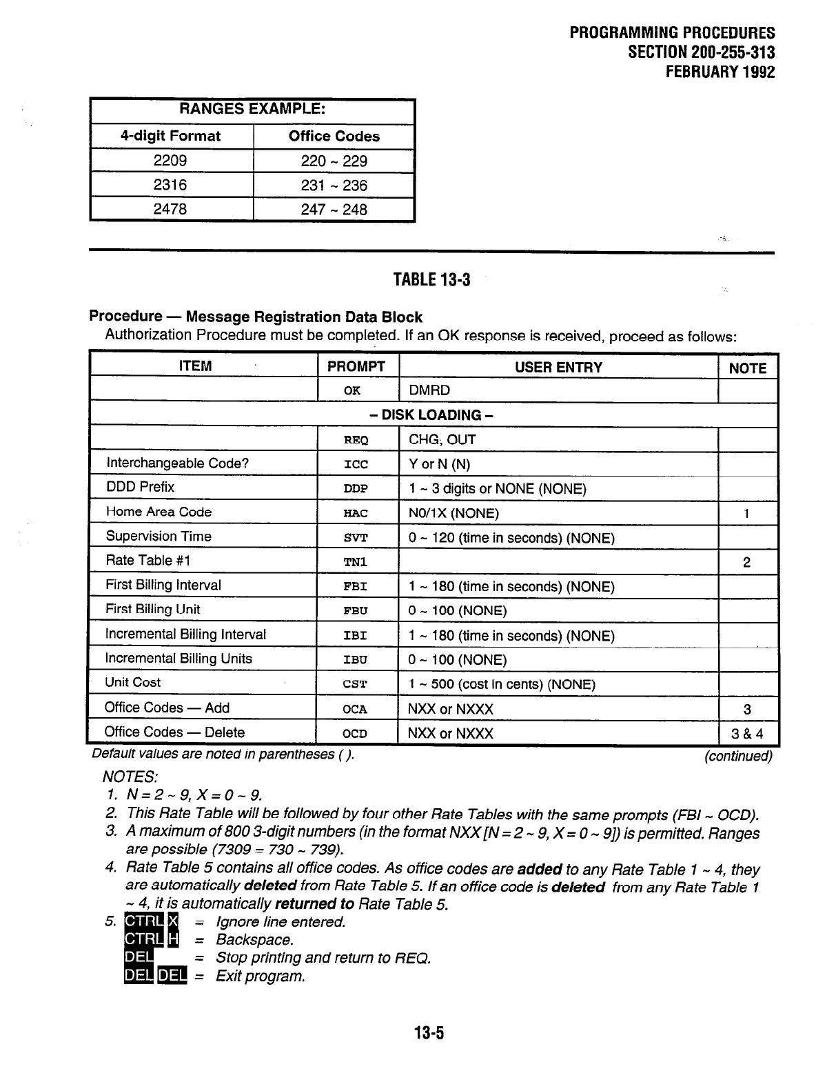
PROGRAMMINGPROCEDURES
SECTION 200-255-313
FEBRUARY1992
RANGES EXAMPLE:
4-digit Format Off ice Codes
2209 220-229
2316 231 -236
2478 247-248
TABLE13-3
Procedure - Message Registration Data Block
Authorization Procedure must be completed. If an OK response is received, proceed as follows:
ITEM PROMPT USER ENTRY NOTE
OK DMRD
- DISK LOADING -
=Q 1 CHG; OUT
I I
interchangeable
Code? ICC 1 Y or N (N)
I
1
1
-
3
digits or NONE (NONE)
!
DDD Prefix DDP
! 1 NO/lx (NONE)
!
Home Area Code HAC 1
Supervision
Time SVT
1 0 - 120 (time in seconds) (NONE)
Rate Table #l TN1 2
First Billing interval FBI 1 - 180 (time in seconds) (NONE)
First Billing Unit FBU 1 0 - 100 (NONE)
Incremental Billing Interval ! IBI 1 1 - 180 (time in seconds) (NONE)
Incremental Billing Units IBU 1 0 - 100 (NONE)
Unit Cost CST 1 - 500 (cost in cents) (NONE)
Off ice Codes - Add OCA NXX or NXXX 3
Off ice Codes - Delete
I
OCD I NXX or NXXX
I
3&4
Default values are noted in parentheses 0. (con timed,
NOTES:
1. N=2-9,X=0-9.
2. This Rate Table will be followed by four other Rate Tables with the same prompts (FBI - OCD).
3. A maximum of 800 3-digit numbers (in the format NXX[N = 2 - 9, X = 0 - 91) is permitted. Ranges
are possible (7309 = 730 - 739).
4. Rate Table 5 contains all office codes. As office codes are added to any Rate Table 1 - 4, they
are automatically deleted from Rate Table 5. If an office code is deleted from any Rate Table 1
- 4, it is automatically returned to Rate Table 5.
Ignore line entered.
Stop printing and return to REQ.
13-5
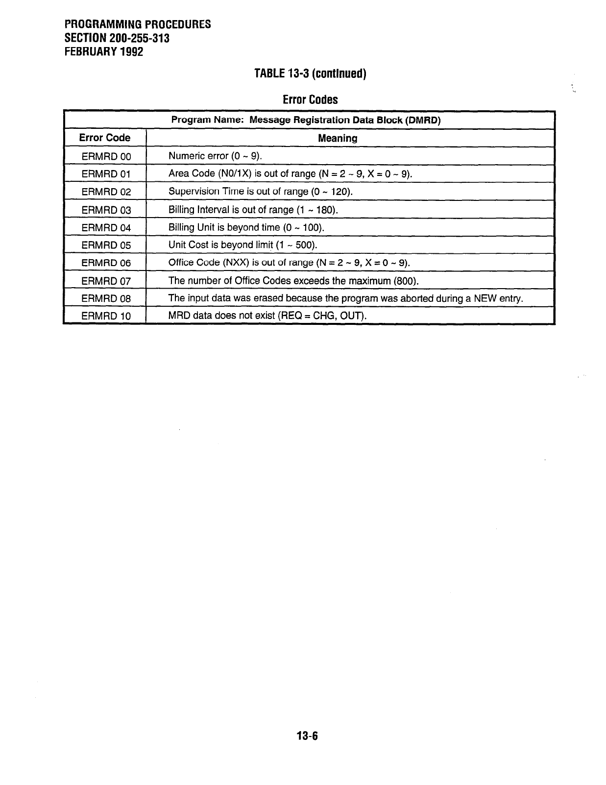
PROGRAMMING PROCEDURES
SECTION 200-255-313
FEBRUARY 1992
TABLE13-3(continued)
Error Codes
Error Code
ERMRD 00
ERMRD 01
Program Name: Message Registration Data Block (DMRD)
Meaning
Numeric error (0 - 9).
Area Code (NO/IX) is out of range (N = 2 - 9, X = 0 - 9).
ERMRD 02 Supervision Time is out of range (0 - 120).
ERMRD 03 Billing Interval is out of range (1 - 180).
ERMRD 04 Billing Unit is beyond time (0 - 100).
ERMRD 05 Unit Cost is bevond limit (1 - 500).
ERMRD 06
ERMRD 07
ERMRD 08
Office Code (NXX) is out of range (N = 2 - 9, X = 0 - 9).
The number of Office Codes exceeds the maximum (800).
The input data was erased because the program was aborted during a NEW entry.
ERMRD 10 1 MRD data does not exist (REQ = CHG, OUT).
13-6
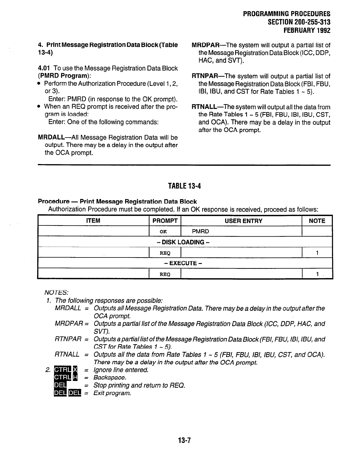
4. Print Message Registration Data Block(Table
13-4)
4.01 To use the Message Registration Data Block
(PMRD Program):
l
Perform the Authorization Procedure (Level 1,2,
or 3).
Enter: PMRD (in response to the OK prompt).
l
When an REQ prompt is received after the pro-
gram is loaded:
Enter: One of the following commands:
MRDALL-Ail Message Registration Data will be
output. There may be a delay in the output after
the OCA prompt.
PROGRAMMINGPROCEDURES
SECTION 200-255-313
FEBRUARY1992
MRDPAR-The system will output a partial list of
the Message Registration Data Block (ICC, DDP,
HAC, and S/T).
RTNPAR-The system will output a partial list of
the Message Registration Data Block (FBI, FBU,
IBI, IBU, and CST for Rate Tables 1 - 5).
RTNALL-The system will output all the data from
the Rate Tables 1 - 5 (FBI, FBU, IBI, IBU, CST,
and OCA). There may be a delay in the output
after the OCA prompt.
TABLE.13-4
Procedure - Print Message Registration Data Block
Authorization Procedure must be completed. If an OK response is received, proceed as follows:
ITEM PROMPT
OK
PMRD
USER ENTRY NOTE
- DISK LOADING -
REQ 1
- EXECUTE -
I I
=Q
I 1. I
NOTES:
1. The following responses are possible:
MRDALL =-
MRDPAR =
RTNPAR =
RTNALL =
Outputs all Message Registration Data. There may be a delay in the output after the
OCA prompt.
Outputs a partial list of the Message Registration Data Block (ICC, DDP, HAC, and
SW,).
Outputs a partiallist of the Message Registration Data Block(FBI, FBU, IBI, IBU, and
CST for Rate Tables 1 - 5).
Outputs all the data from Rate Tables 1 - 5 (FBI, FBLJ, IBI, IBU, CST, and OCA).
There may be a delay in the output after the OCA prompt.
Ignore line entered.
Backspace.
Stop printing and return to REQ.
Exit program.
13-7
PROGRAMMING PROCEDURES
SECTION 200-255-314
FEBRUARY 1992
CHAPTER 14
SPEED DIAL LIST DATA
1. Speed Dial List Data Block (Table 14-I)
1.01 The Speed Dial List Data Block (DSDL Pro-
gram) contains all numbers stored on the 90-
number Speed Dial - System list and the 50 lo-
number Speed Dial - Station lists.
1.02 The DSDL Program allows initial storage or
changes to any speed dial list from the mainte-
nance terminal. Data is entered as follows:
REQ (Request)--Indicates that the program has
loaded. Two responses are possible:
CHG-To alter an existing or to enter a new
Data Block.
OUT-To delete an existing Data Block.
LNO (List Number)-The number of the list to be
changed or deleted.
Enter: 00 (for System List) or
01 - 50 (for Station List).
STR
(Store
Number)-This prompt requests the
number to be stored.
Enter: Address code, space, and number in the
following format:
Example: 0 9*NPANNXXXXX
1 9*NPANNXXXXX
NOTE:
In these examples, 9 is a trunk access code.
Therefore, a “““is entered to cause a 3-second
pause for dial tone delay. The “*“is counted as
one of the 16 allowable digits.
NOTE:’
If the OUTcommand was entered in response
to REQ above, then no other data is required.
14-l
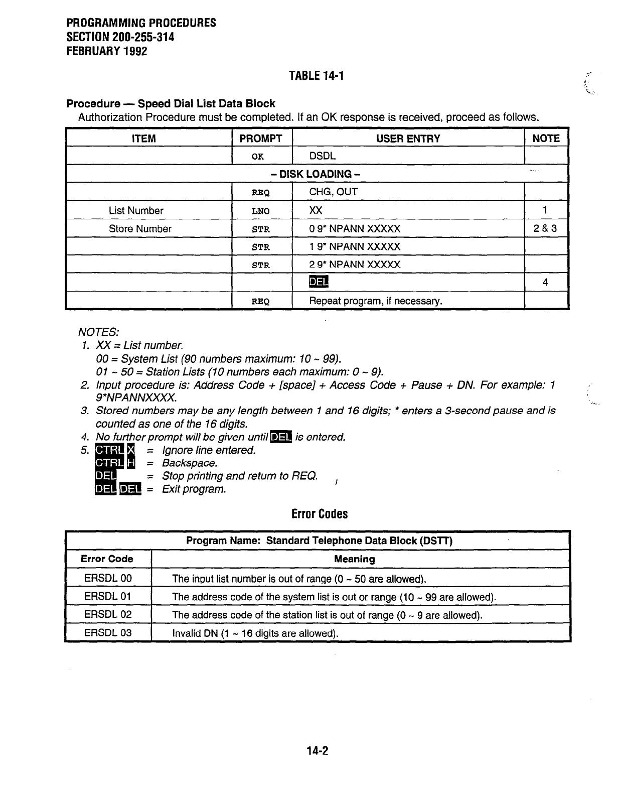
PROGRAMMING PROCEDURES
SECTION 200-255-314
FEBRUARY 1992
TABLE 14-l
Procedure - Speed Dial List Data Block
Authorization Procedure must be completed. If an OK response is received, proceed as follows.
ITEM PROMPT USER ENTRY NOTE
OK
DSDL
- DISK LOADING -
I RN
I
List Number I
LNO
I
Store Number I
STR
STR
I I
RR0
CHG, OUT
0 9’ NPANN XXXXX
I
2&3
19’ NPANN XXXXX I
2 9* NPANN XXXXX
ma!
Repeat program, if necessary.
4
NOTES:
1. XX = List number.
00 = System List (90 numbers maximum: 10 - 99).
01 - 50 = Station Lists (10 numbers each maximum: 0 - 9).
2. Input procedure is: Address Code + [space] + Access Code + Pause + DN. For example: 1
9*NPANNXXXX.
3. Stored numbers may be any length between 1 and 16 digits; * enters a 3second pause and is
counted as one of the 16 diaits.
4. No further prompt will be &en until= is entered.
ii
= Ignore line entered.
= Backspace.
= Stop printing and return to REQ.
m = Exit program. ,
Error Codes
Error Code
Program Name: Standard Telephone Data Block (DSTT)
Meaning
ERSDL 00 The input list number is out of range (0 - 50 are allowed). I
ERSDL 01
ERSDL 02
The address code of the system list is out or range (10 - 99 are allowed).
The address code of the station list is out of range (0 - 9 are allowed).
ERSDL 03 I Invalid DN (1 - 16 digits are allowed).
14-2
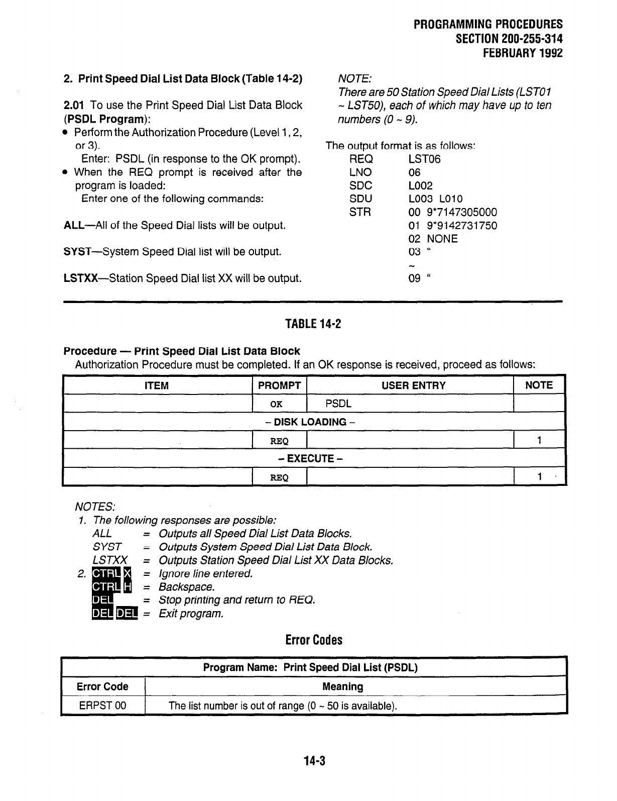
2. Print Speed Dial List Data Block (Table 14-2)
2.01 To use the Print Speed Dial List Data Block
(PSDL Program):
l
Perform the Authorization Procedure (Level 1,2,
or 3).
Enter: PSDL (in response to the OK prompt).
l
When the REQ prompt is received after the
program is loaded:
Enter one of the following commands:
ALL-All of the Speed Dial lists will be output.
SYST-System Speed Dial list will be output.
LSTXX-Station Speed Dial list XX will be output.
PROGRAMMINGPROCEDURES
SECTION 200-255-314
FEBRUARY1992
NOTE:
There are 50 Station Speed Dial Lists (LSTOI
- LST50), each of which may have up to ten
numbers (0 - 9).
The output format is as follows:
REQ LSTOG
LNO 06
SDC LOO2
SDU LO03 LO10
STR 00 9*7147305000
01 9*9142731750
02 NONE
03 ‘(
09 rr
TABLE14-2
Procedure - Print Speed Dial List Data Block
Authorization Procedure must be completed. If an OK response is received, proceed as follows:
ITEM PROMPT
OK
PSDL
USER ENTRY NOTE
- DISK LOADING -
REQ 1
- EXECUTE -
I I
REQ
I 1.
NOTES:
1. The following responses are possible:
ALL =
SYST =
LSTXX =
2. - =
.
c
a =
: m:
Outputs all Speed Dial List Data Blocks.
Outputs System Speed Dial List Data Block.
Outputs Station Speed Dial List XX Data Blocks.
Ignore line entered.
Backspace.
Stop printing
and
return to REQ.
Exit program.
Error Codes
Error Code
ERPST 00
Program Name: Print Speed Dial List (PSDL)
Meaning
The list number is out of ranae (0 - 50 is available).
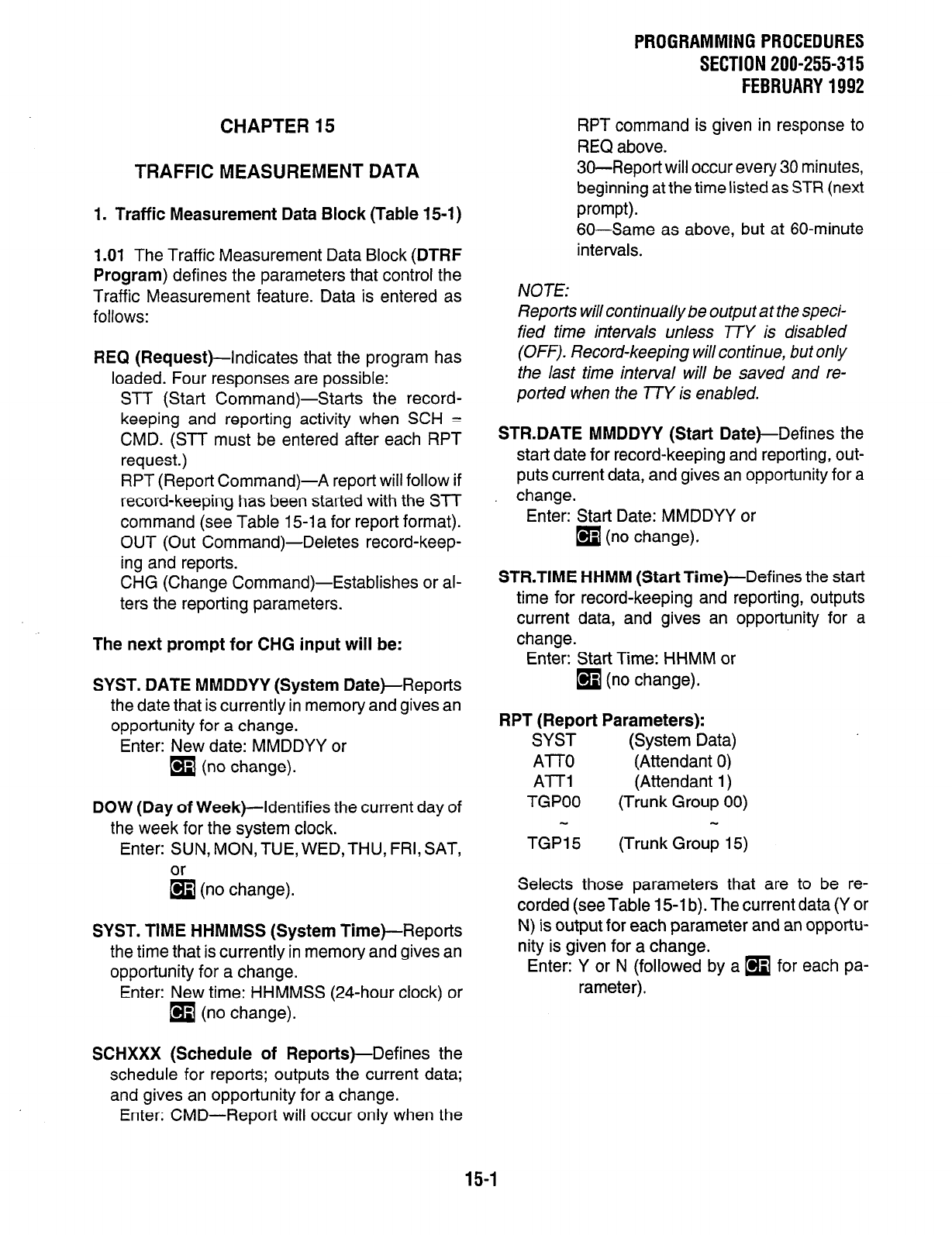
CHAPTER 15
TRAFFIC MEASUREMENT DATA
1. Traffic Measurement Data Block (Table 15-1)
1 .Ol The Traffic Measurement Data Block (DTRF
Program) defines the parameters that control the
Traffic Measurement feature. Data is entered as
follows:
REQ (Request)-Indicates that the program has
loaded. Four responses are possible:
STT (Start Command)-Starts the record-
keeping and reporting activity when SCH =
CMD. (STT must be entered after each RPT
request.)
RPT (Report Command)-A report will follow if
record-keeping has been started with the SIT
command (see Table 15-1 a for report format).
OUT (Out Command)-Deletes record-keep-
ing and reports.
CHG (Change Command)-Establishes or al-
ters the reporting parameters.
The next prompt for CHG input will be:
SYST. DATE MMDDYY (System Date)-Reports
the date that is currently in memory and gives an
opportunity for a change.
Enter: New date: MMDDYY or
q
(no change).
DOW (Day of Week)--Identifies the current day of
the week for the system clock.
Enter: SUN, MON, TUE, WED,THU, FRI, SAT,
or
q
(no change).
SYST. TIME HHMMSS (System Time)--Reports
the time that is currently in memory and gives an
opportunity for a change.
Enter: New time: HHMMSS (24-hour clock) or
q
(no change). ’ ’
PROGRAMMING PROCEDURES
SECTION 200-255-315
FEBRUARY 1992
RPT command is given in response to
REQ above.
30-Report will occur every 30 minutes,
beginning at the time listed as STR (next
prompt).
60-Same as above, but at 60-minute
intervals.
NOTE:
Reports will continually be output at the speci-
fied time intervals unless 77Y is disabled
(OFF). Record-keeping will continue, but only
the last time interval will be saved and re-
ported when the TTY is enabled.
STFLDATE MMDDYY (Start Date)-Defines the
start date for record-keeping and reporting, out-
puts current data, and gives an opportunity for a
change.
Enter: Start Date: MMDDYY or
q
(no change).
STR.TIME HHMM (Start Time)-Defines the start
time for record-keeping and reporting, outputs
current data, and gives an opportunity for a
change.
Enter: Start Time: HHMM or
q
(no change).
RPT (Report Parameters):
SYST (System Data)
ATT0 (Attendant 0)
A-l-T1 (Attendant 1)
TGPOO (Trunk Group 00)
TGPI 5 (Trunk Group 15)
Selects those parameters that are to be re-
corded (see Table 15lb). The current data (Y or
N) is output for each parameter and an opportu-
nity is given for a change.
Enter: Y or N (followed by a
q
for each pa-
rameter).
SCHXXX (Schedule of Reports)-Defines the
schedule for reports; outputs the current data;
and gives an opportunity for a change.
Enter: CMD-Report will occur only when the
15-1
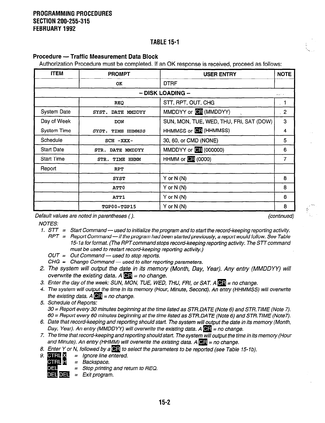
PROGRAMMINGPROCEDURES
SECTION 200-255-315
FEBRUARY1992
TABLE15-1
Procedure - Traffic Measurement Data Block
Authorization Procedure must be completed. If in OK response is received, proceed as follows:
ITEM I PROMPT
- DISK
Schedule
I
ATT0
ATT1
TGPOO-TGP15
USER ENTRY I NOTE
DTRF
I
,OADING - .+; s
SlT, RPT, OUT, CHG 1
MMDDYY or
q
(MMDDYY) . .2
SUN, MON, TUE, WED, THU, FRI, SAT (DOW) 3
HHMMSS or
q
(HHMMSS)
4
Y or N (N)
I 8
Y or N (N) 8
Y or N (N) 8
Y or N (N)
8
Default values are noted in parentheses 0. (continued)
NOTES:
1. SlT = Start Command- used to initialize the program and to start the record-keeping repotting activity.
RPT = Report Command- if the program had been startedpreviously, a repot? would follow. See Table
15 1 a for format. (The RPT command stops record-keeping reporting activity. The STT command
must be used to restart record-keeping reporting activity,)
OUT = Out Command - used to stop reports.
CHG = Change Command - used to alter reporting parameters.
2. The system will output the date in its memory (Month, Day, Year). Any entry (MMDDYY) will
overwrite the existing data. A
q
= no change.
3. Enter the day of the week: SUN, MON, TUE, WED, THU, FRI, or SAT. A
q
= no change.
4.
The
system will output the time in its memory (Hour, Minute, Second). An entry (HHMMSS) will overwrite
the existing data. A
q
= no change.
5. Schedule of Reports:
30 = Report every 30 minutes beginning at the time listed as STR. DATE (Note 6) and STR. TIME (Note 7).
60 = Repot? every 60 minutes beginning at the time listed as STR.DATE (Note 6) and STR. TIME (Note7).
6. Date that record-keeping and reporting should start. The system will output the date in its memory (Month,
Day, Year). An entry (MMDDYY) will overwrite the existing data. A
q
= no change.
7. The time that record-keeping and reporting should start. The system will output the time in its memory (Hour
and Minute). An entry (HHMM) will overwrite the existing data. A
q
= no change.
8. Enter Y or N, followed by a
q
to select the parameters to be reported (see Tab/e 15-lb).
= Ignore line entered.
= Backspace.
= Stop printing and return to REQ.
= Exit program.
15-2
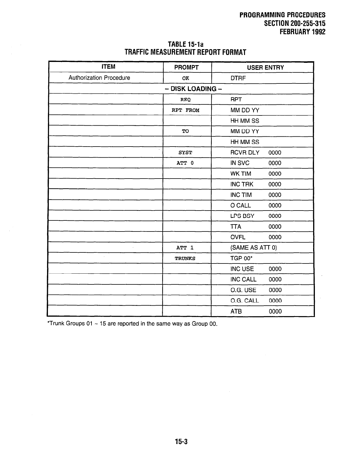
PROGRAMMINGPROCEDURES
SECTIONZOO-255-315
FEBRUARY1992
TABLE154a
TRAFFICMEASUREMENTREPORTFORMAT
ITEM PROMPT
Authorization Procedure OK
USER ENTRY
DTRF
- DISK LOADING -
REQ RPT
RPT FROM
TO
SYST
MM DD YY
HH MM SS
MM DD YY
HH MM SS
RCVR DLY 0000
I I
ATT 0
WK TIM 0000
INC TRK 0000
INC TIM 0000
0 CALL 0000
I I
LPS BSY 0000
l-l-A 0000
OVFL 0000
I I
ATT 1
I
(SAME AS Al7 0)
TRUNKS TGP 00*
INC USE 0000
INC CALL 0000
O.G. USE 0000
O.G. CALL 0000
I I I
ATB 0000
‘Trunk Groups 01 - 15 are reported in the same way as Group 00.
15-3
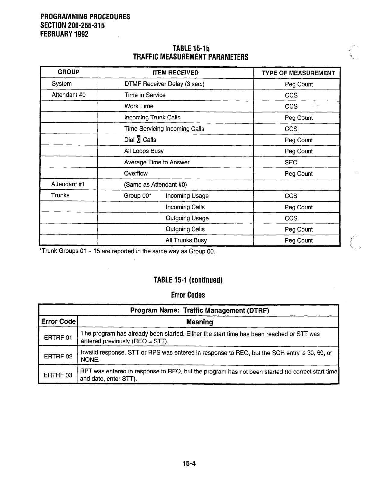
PROGRAMMING PROCEDURES
SECTION 200-255-315
FEBRUARY 1992
TABLE 15-1 b
TRAFFIC MEASUREMENT PARAMETERS
GROUP
System
Attendant #0
ITEM RECEIVED TYPE OF MEASUREMENT
DTMF Receiver Delay (3 sec.) Peg Count
Time in Service ccs
Work Time ccs . .--
Incoming Trunk Calls Peg Count.
Time Servicing Incoming Calls
Dial 1 Calls
All Loops Busy
ccs
Peg Count
Peg Count
Attendant #l
Trunks
Average Time to Answer
Overflow
(Same as Attendant #0)
Group 00’ Incoming Usage
Incoming Calls
SEC
Peg Count
ccs
Peg Count
Outgoing Usage
Outgoing Calls
All Trunks Busv
ccs
Peg Count
Pea Count
*Trunk Groups 01 - 15 are reported in the same way as Group 00.
TABLE 15-I (continued)
Error Codes
Program Name: Traffic Management (DTRF)
Error Code Meaning
I
I
ERTRF 01 I The program has already been started. Either the start time has been reached or STT was
entered oreviouslv fREQ = Sll7. I
I I
Invalid response. SIT or RPS was entered in response to REQ, but the SCH entry is 30, 60, or
ERTRF 02 NONE. I
I
ERTRF 03 I RPT was entered in response to REQ, but the program has not been started (to correct start time
and date. enter SllX I
15-4
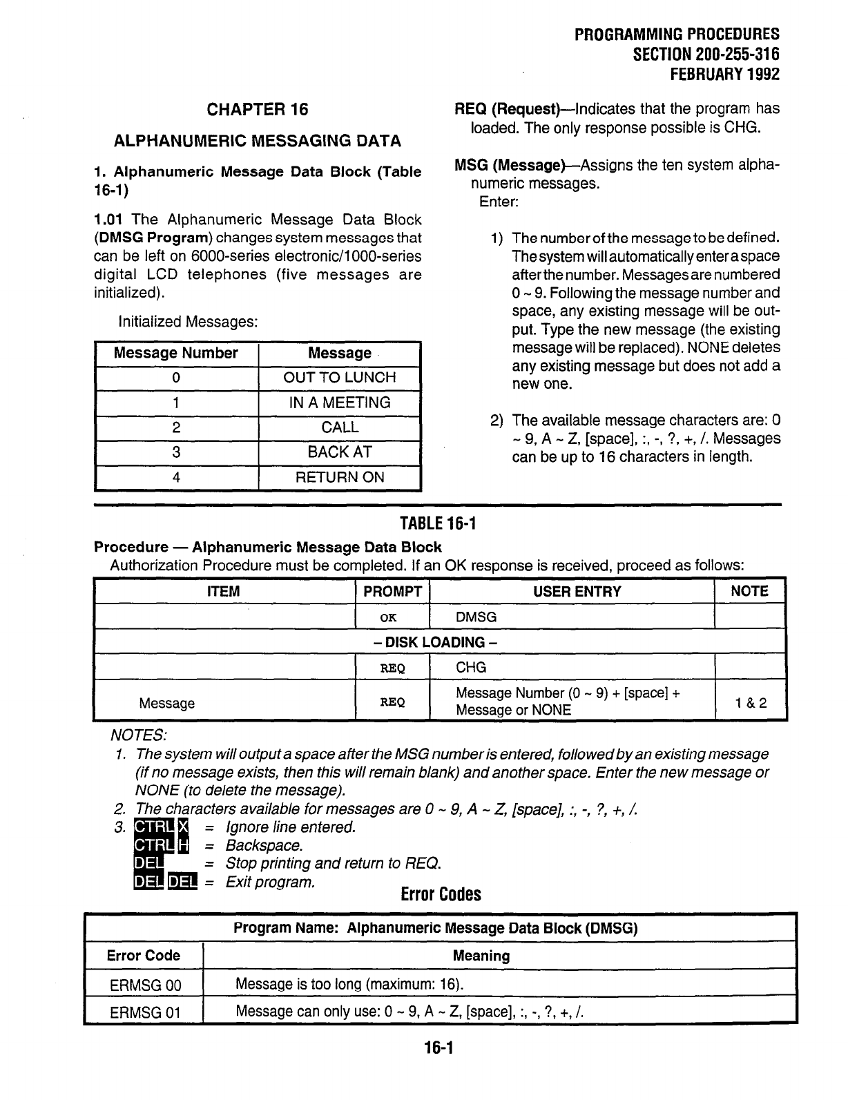
PROGRAMMING PROCEDURES
SECTION 200-255-316
FEBRUARY 1992
CHAPTER 16
ALPHANUMERIC MESSAGING DATA
1. Alphanumeric Message Data Block (Table
16-1)
1.01 The Alphanumeric Message Data Block
(DMSG Program) changes system messages that
can be left on 6000-series electronic/l OOO-series
digital LCD telephones (five messages are
initialized).
Initialized Messages:
I
2 I CALL I
I
3 I BACK AT I
I
4 I RETURN ON I
REQ (Request)-Indicates that the program has
loaded. The only response possible is CHG.
MSG
(Message)-Assigns
the ten system alpha-
numeric messages.
Enter:
1) The number of the message to be defined.
Thesystem willautomaticallyenteraspace
after the number. Messages are numbered
0 - 9. Following the message number and
space, any existing message will be out-
put. Type the new message (the existing
message will be replaced). NONE deletes
any existing message but does not add a
new one.
2) The available message characters are: 0
- 9, A - Z, [space], :, -, ?, +, /. Messages
can be up to 16 characters in length.
TABLE 16-I
Procedure - Alphanumeric Message Data Block
Authorization Procedure must be completed. If an OK response is received, proceed as follows:
ITEM PROMPT USER ENTRY NOTE
OK DMSG
- DISK LOADING -
REQ CHG I
I
Message
I *Q I
Message Number (0 - 9) + [space] +
Message or NONE I
l&2
NOTES:
1. The system will output a space after the MSG number is entered, followed by an existing message
(if no message exists, then this will remain blank) and another space. Enter the new message or
NONE (to delete the message).
2. The characters available for messages are 0 - 9, A - Z, [space], :, -, ?, +, /.
Stop printing and return to REQ.
Error Codes
Program Name: Alphanumeric Message Data Block (DMSG)
Error Code I
Meaning
1 ERMSGOO 1 Message is too long (maximum: 16). I
ERMSG 01 Message can only use: 0 - 9, A - Z, [space], :, -, ?, +, /. I
16-l
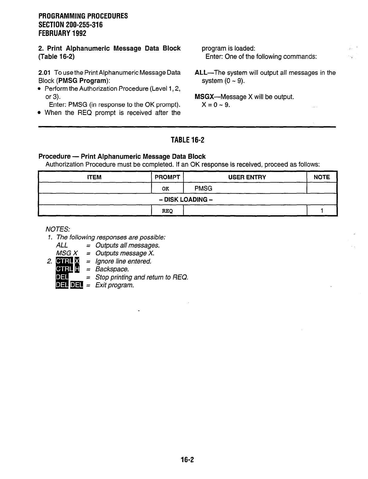
PROGRAMMINGPROCEDURES
SECTION 200-255-316
FEBRUARY1992
2. Print Alphanumeric Message Data Block program is loaded:
(Table 16-2) Enter: One of the following commands:
2.01 To use the Print Alphanumeric Message Data ALL-The system will output all messages in the
Block (PMSG Program): system (0 - 9).
l
Perform the Authorization Procedure (Level 1,2,
or 3). MSGX-Message X will be output.
Enter: PMSG (in response to the OK prompt). x=0-9.
l
When the REQ prompt is received after the
TABLE16-2
Procedure - Print Alphanumeric Message Data Block
Authorization Procedure must be completed. If an OK response is received, proceed as follows:
ITEM PROMPT
OK
PMSG
- DISK LOADING -
USER ENTRY NOTE
I I I
REQ
I 1 I
NOTES:
1. The following responses are possible:
ALL = Outputs all messages.
MSG X = Outputs message X.
Ignore line entered,
Backspace.
Stop printing and return to REQ.
Exit program.
16-2
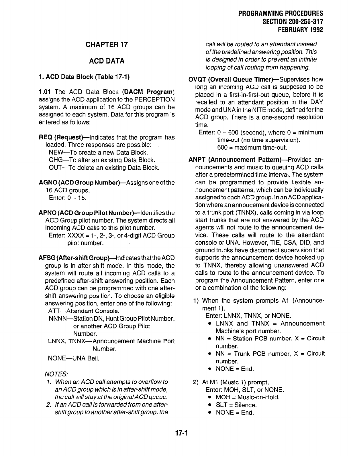
CHAPTER 17
ACD DATA
1. ACD Data Block (Table 17-1)
1.01 The ACD Data Block (DACM Program)
assigns the ACD application to the PERCEPTION
system. A maximum of 16 ACD groups can be
assigned to each system. Data for this program is
entered as follows:
REQ (Request)-Indicates that the program has
loaded. Three responses are possible:
NEW-To create a new Data Block.
CHG-To alter an existing Data Block.
OUT-To delete an existing Data Block.
AGNO (ACD Group Number)-Assigns one of the
16 ACD groups.
Enter: 0 - 15.
APNO (ACD Group Pilot Number)-Identifies the
ACD Group pilot number. The system directs all
incoming ACD calls to this pilot number.
Enter: XXXX = 1-, 2-, 3-, or 4-digit ACD Group
pilot number.
AFSG (After-shift Group)-Indicates that the ACD
group is in after-shift mode. In this mode, the
system will route all incoming ACD calls to a
predefined after-shift answering position. Each
ACD group can be programmed with one after-
shift answering position. To choose an eligible
answering position, enter one of the following:
ATT-Attendant Console.
NNNN-Station DN, HuntGroup Pilot Number,
or another ACD Group Pilot
Number.
LNNX, TNNX-Announcement Machine Port
Number.
NONE-UNA Bell.
NOTES:
7. When an ACD call attempts to overflow to
an ACD group which is in after-shift mode,
the call willstayat the originalACD queue.
2. /fan ACD call is forwarded from one after-
shiftgroup toanotherafter-shiftgroup, the
PROGRAMMING PROCEDURES
SECTION 200-255-317
FEBRUARY 1992
call will be routed to an attendant instead
of the predefined answering position. This
is designed in order to prevent an infinite
looping of call routing from happening.
OVQT (Overall Queue Timer)-Supervises how
long an incoming ACD call is supposed to be
placed in a first-in-first-out queue, before it is
recalled to an attendant position in the DAY
mode and UNA in the NITE mode, defined for the
ACD group. There is a one-second resolution
time.
Enter: 0 - 600 (second), where 0 = minimum
time-out (no time supervision).
600 = maximum time-out.
ANPT (Announcement Pattern)-Provides an-
nouncements and music to queuing ACD calls
after a predetermined time interval. The system
can be programmed to provide flexible an-
nouncement patterns, which can be individually
assigned to each ACD group. In an ACD applica-
tion where an annoucement device is connected
to a trunk port (TNNX), calls coming in via loop
start trunks that are not answered by the ACD
agents will not route to the announcement de-
vice. These calls will route to the attendant
console or UNA. However, TIE, CSA, DID, and
ground trunks have disconnect supervision that
supports the announcement device hooked up
to TNNX, thereby allowing unanswered ACD
calls to route to the announcement device. ‘To
program the Announcement Pattern, enter one
or a combination of the following:
1) When the system prompts Al (Announce-
ment l),
Enter: LNNX, TNNX, or NONE.
LNNX and TNNX = Announcement
Machine’s port number.
NN = Station PCB number, X = Circuit
number.
NN = Trunk PCB number, X = Circuit
number.
NONE = End.
2) At Ml (Music 1) prompt,
Enter: MOH, SLT, or NONE.
l
MOH = Music-on-Hold.
l
SLT = Silence.
l
NONE = End.
17-1
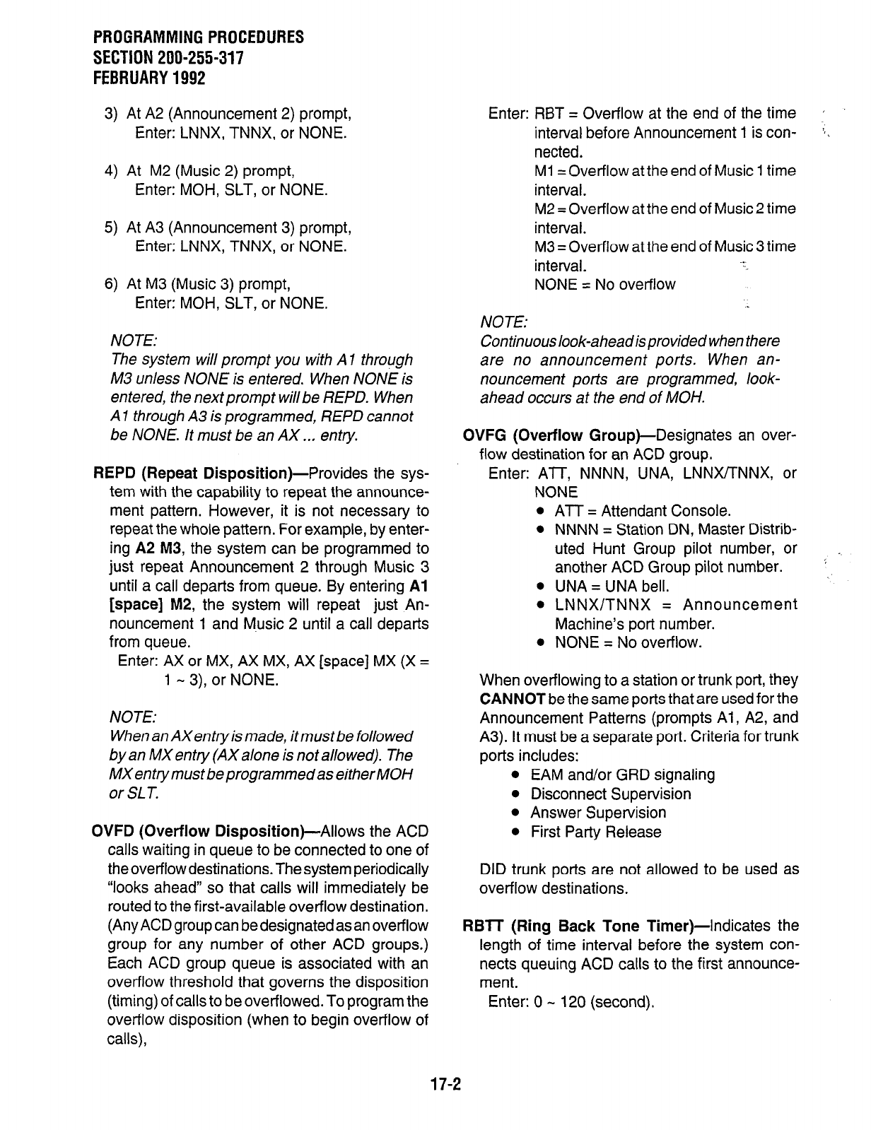
PROGRAMMINGPROCEDURES
SECTION 200-255-317
FEBRUARY1992
3) At A2 (Announcement 2) prompt,
Enter: LNNX, TNNX, or NONE.
4) At M2 (Music 2) prompt,
Enter: MOH, SLT, or NONE.
5) At A3 (Announcement 3) prompt,
Enter: LNNX, TNNX, or NONE.
6) At M3 (Music 3) prompt,
Enter: MOH, SLT, or NONE.
NOTE:
The system will prompt you with Al through
M3 unless NONE is entered. When NONE is
entered, the next prompt will be REPD. When
A 1 through A3 is programmed, REPD cannot
be NONE. It must be an AX .., entry.
REPD (Repeat Disposition)-Provides the sys-
tem with the capability to repeat the announce-
ment pattern. However, it is not necessary to
repeat the whole pattern. For example, by enter-
ing A2 M3, the system can be programmed to
just repeat Announcement 2 through Music 3
until a call departs from queue. By entering Al
[space] M2, the system will repeat just An-
nouncement 1 and M.usic 2 until a call departs
from queue.
Enter: AX or MX, AX MX, AX [space] MX (X =
1 - 3), or NONE.
NOTE:
When an AXentryis made, itmustbe followed
by an MX entry (AX alone is not allowed). The
MXentrymustbeprogrammedaseitherMOH
or SL T.
OVFD (Overflow Disposition)-Allows the ACD
calls waiting in queue to be connected to one of
the overflow destinations. The system periodically
“looks ahead” so that calls will immediately be
routed to the first-available overflow destination.
(Any ACD group can be designated as an overflow
group for any number of other ACD groups.)
Each ACD group queue is associated with an
overflow threshold that governs the disposition
(timing) of calls to be overflowed. To program the
overflow disposition (when to begin overflow of
calls),
Enter: RBT = Overflow at the end of the time ’
interval before Announcement 1 is con- :.
netted.
Ml = Overflow at the end of Music 1 time
interval.
M2 = Overflow at the end of Music 2 time
interval.
M3 = Overflow at the end of Music 3 time
interval. . .
NONE = No overflow .
NOTE:
Continuouslook-aheadisprovided when there
are no announcement ports. When an-
nouncement ports are programmed, look-
ahead occurs at the end of MOH.
OVFG (Overflow Group)-Designates an over-
flow destination for an ACD group.
Enter: ATT, NNNN, UNA, LNNX/TNNX, or
NONE
l
ATT = Attendant Console.
l
NNNN = Station DN, Master Distrib-
uted Hunt Group pilot number, or
another ACD Group pilot number. ’
l
UNA = UNA bell.
l
LNNX/TNNX = Announcement
Machine’s port number.
l
NONE = No overflow.
When overflowing to a station or trunk port, they
CANNOT be the same ports that are used for the
Announcement Patterns (prompts Al, A2, and
A3). It must be a separate port. Criteria for trunk
ports includes:
l
EAM and/or GRD signaling
l
Disconnect Supervision
l
Answer Supervision
l
First Party Release
DID trunk ports are not allowed to be used as
overflow destinations.
RBTT (Ring Back Tone Timer)-Indicates the
length of time interval before the system con-
nects queuing ACD calls to the first announce-
ment.
Enter: 0 - 120 (second).
17-2
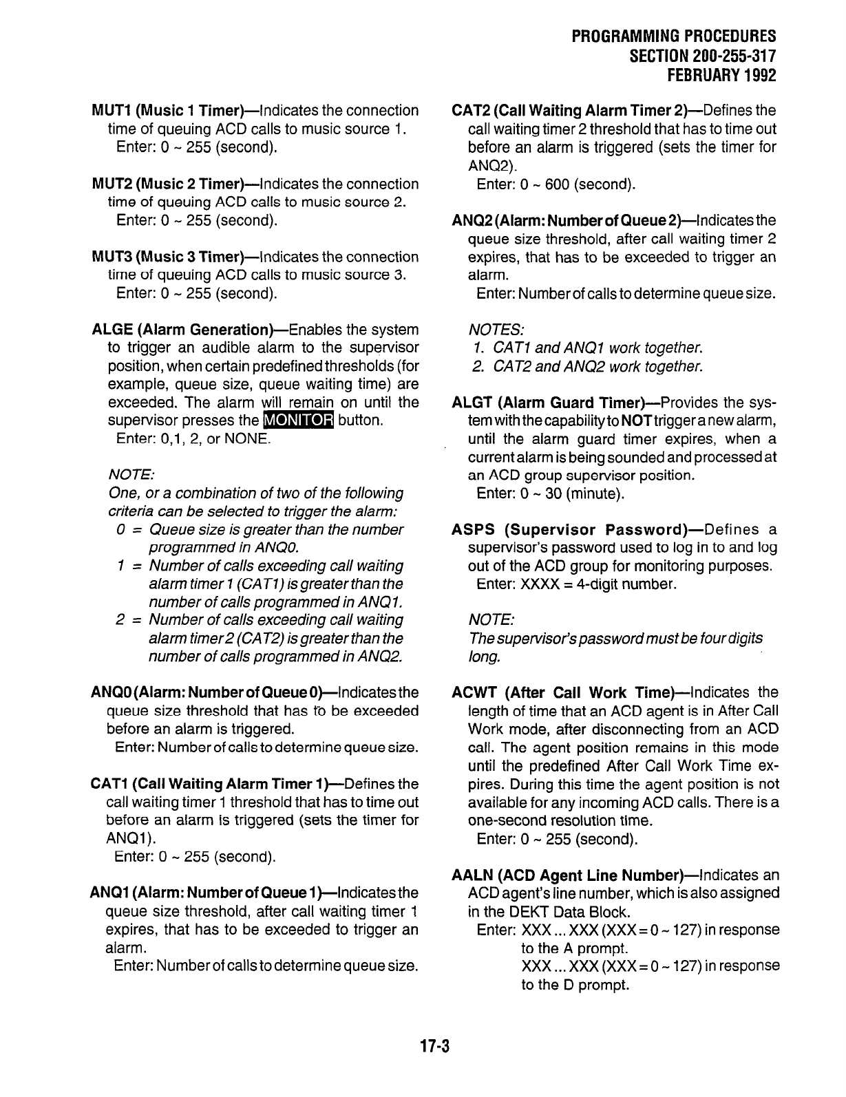
PROGRAMMING PROCEDURES
SECTION 200-255-317
FEBRUARY 1992
MUTl (Music 1 Timer)-Indicates the connection
time of queuing ACD calls to music source 1.
Enter: 0 - 255 (second).
MUT2 (Music 2 Timer)-indicates the connection
time of queuing ACD calls to music source 2.
Enter: 0 - 255 (second).
MUT3 (Music 3 Timer)-Indicates the connection
time of queuing ACD calls to music source 3.
Enter: 0 - 255 (second).
ALGE (Alarm Generation)-Enables the system
to trigger an audible alarm to the supervisor
position, when certain predefined thresholds (for
example, queue size, queue waiting time) are
exceeded. The alarm will remain on until the
supervisor presses the m button.
Enter: O,l, 2, or NONE.
NOTE:
One, or a combination of two of the following
criteria can be selected to trigger the alarm:
0 = Queue size is greater than the number
programmed in ANQO.
1 = Number of calls exceeding call waiting
alarm timer 7 (CAT7) is greater than the
number of calls programmed in ANQ 1,
2 = Number of calls exceeding call waiting
alarm timer2 (CATZ) is greater than the
number of calls programmed in ANQZ,
ANQO (Alarm: Number of Queue O)-Indicates the
queue size threshold that has to be exceeded
before an alarm is triggered.
Enter: Number of calls to determine queue size.
CAT1 (Call Waiting Alarm Timer 1 )-Defines the
call waiting timer 1 threshold that has to time out
before an alarm is triggered (sets the timer for
ANQl).
Enter: 0 - 255 (second).
ANQI (Alarm: Number of Queue I)-Indicates the
queue size threshold, after call waiting timer 1
expires, that has to be exceeded to trigger an
alarm.
Enter: Number of calls to determine queue size.
CAT2 (Call Waiting Alarm Timer 2)-Defines the
call waiting timer 2 threshold that has to time out
before an alarm is triggered (sets the timer for
ANQ2).
Enter: 0 - 600 (second).
ANQ2 (Alarm: Number of Queue2)-Indicates the
queue size threshold, after call waiting timer 2
expires, that has to be exceeded to trigger an
alarm.
Enter: Number of calls to determine queue size.
NOTES:
1. CAT1 and ANQI work together.
2. CAT2 and ANQ2 work together.
ALGT (Alarm Guard Timer)-Provides the sys-
tem with the capability to NOT trigger a new alarm,
until the alarm guard timer expires, when a
current alarm is being sounded and processed at
an ACD group supervisor position.
Enter: 0 - 30 (minute).
ASPS (Supervisor Password)-Defines a
supervisor’s password used to log in to and log
out of the ACD group for monitoring purposes.
Enter: XXXX = 4-digit number.
NOTE:
The supervisor’s password must be four digits
long.
ACWT (After Call Work Time)-Indicates the
length of time that an ACD agent is in After Call
Work mode, after disconnecting from an ACD
call. The agent position remains in this mode
until the predefined After Call Work Time ex-
pires. During this time the agent position is not
available for any incoming ACD calls. There is a
one-second resolution time.
Enter: 0 - 255 (second).
AALN (ACD Agent Line Number)-Indicates an
ACD agent’s line number, which is also assigned
in the DEKT Data Block.
Enter: XXX . . . XXX (XXX = 0 - 127) in response
to the A prompt.
XXX...XXX(XXX=O-127)inresponse
to the D prompt.
17-3
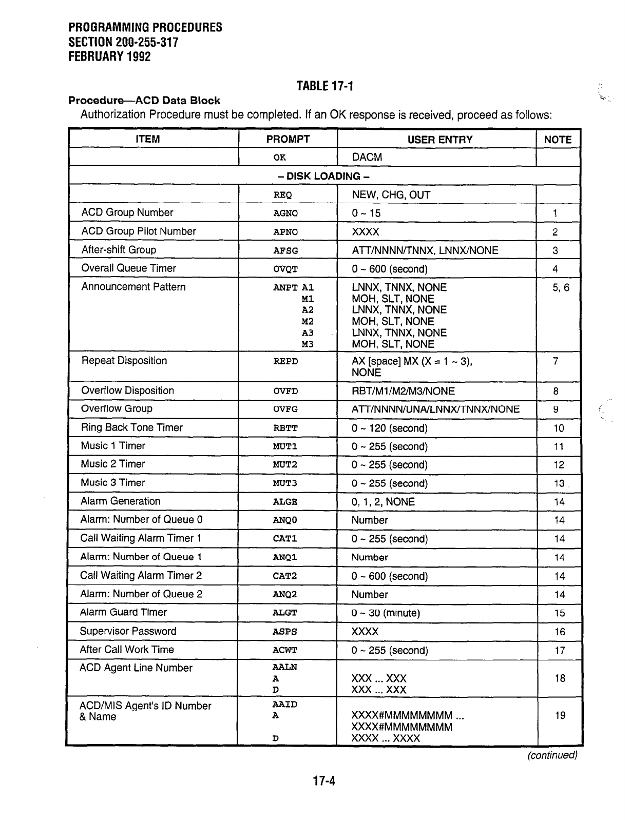
PROGRAMMING PROCEDURES
SECTION 200-255-317
FEBRUARY 1992
TABLE 17-1
Procedure-ACD Data Block
Authorization Procedure must be completed. If an
OK
response is received, proceed as follows:
ITEM PROMPT USER ENTRY NOTE
OK DACM
- DISK LOADING -
MOH SLT NONE
ACD
Agent Line Number
AALN
A xxx . . . xxx 18
D xxx . . . xxx
ACD/MIS Agent’s ID Number
AAID
& Name
A
XXXX#MMMMMMMM . . . 19
XXXX#MMMMMMMM
D xxxx . . . xxxx
(con tin uedl
17-4
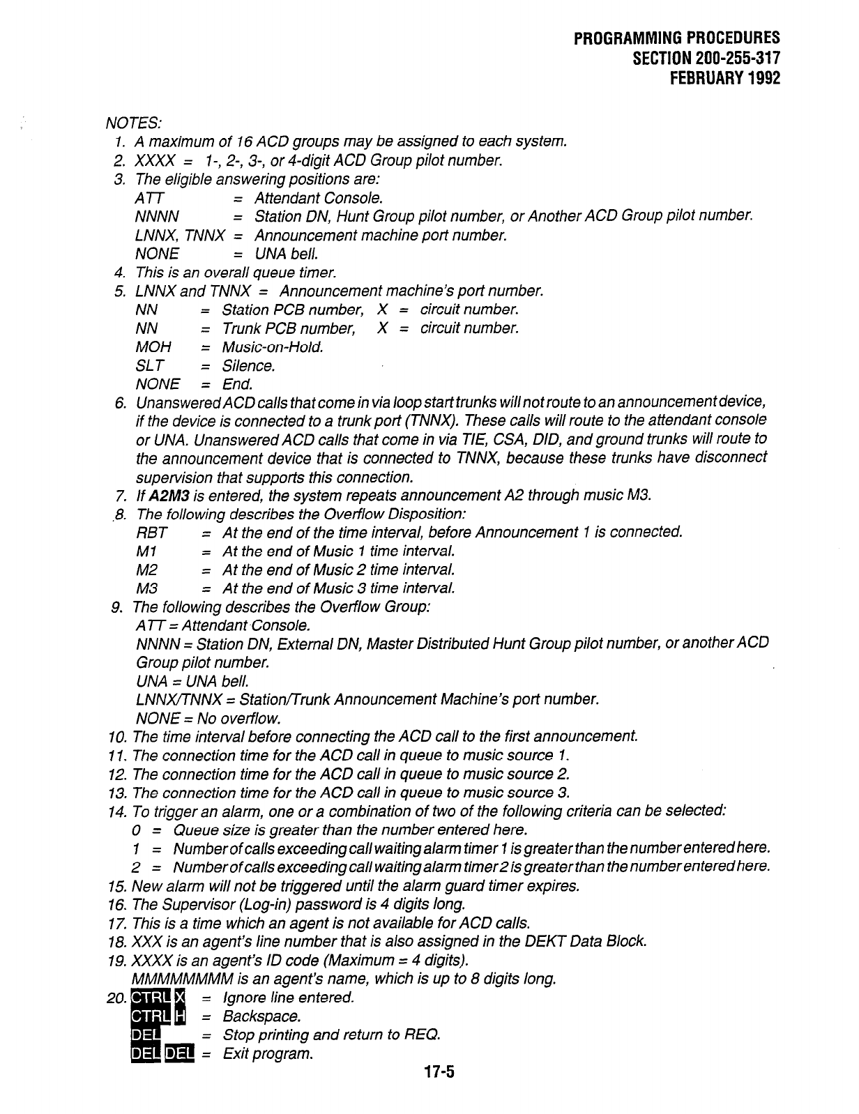
PROGRAMMINGPROCEDURES
SECTION 200-255-317
FEBRUARY1992
NOTES:
1. A maximum of 16 ACD groups may be assigned to each system.
2. XXXX = I-, 2-, 3-, or 4-digit ACD Group pilot number.
3. The eligible answering positions are:
ATT = Attendant Console.
NNNN = Station DN, Hunt Group pilot number, or Another ACD Group pilot number.
LNNX, TNNX = Announcement machine port number.
NONE = UNA bell.
4. This is an overall queue timer.
5. LNNX and TNNX = Announcement machine’s port number.
NN = Station PCB number, X = circuit number.
NN = Trunk PCB number, X = circuit number.
MOH = Music-on-Hold.
SLT = Silence.
NONE = End.
6. UnansweredACDcalls thatcomein via loopstarttrunks willnotroute toanannouncementdevice,
if the device is connected to a trunk port (TNNX). These calls will route to the attendant console
or UNA. Unanswered ACD calls that come in via TIE, CSA, DID, and ground trunks will route to
the announcement device that is connected to TNNX, because these trunks have disconnect
supervision that supports this connection.
7. If AZM3 is entered, the system repeats announcement A2 through music M3.
8. The following describes the Overflow Disposition:
RBT = At the end of the time interval, before Announcement I is connected.
MI = At the end of Music 1 time interval.
M2 = At the end of Music 2 time interval.
M3 = At the end of Music 3 time interval.
9. The following describes the Overflow Group:
A lT = Attendant Console.
NNNN = Station DN, External DN, Master Distributed Hunt Group pilot number, or another ACD
Group pilot number.
UNA = UNA bell.
LNNXITNNX = Station/Trunk Announcement Machine’s port number.
NONE = No overflow.
10. The time interval before connecting the ACD call to the first announcement.
11. The connection time for the ACD call in queue to music source 1.
12. The connection time for the ACD call in queue to music source 2.
13. The connection time for the ACD call in queue to music source 3.
14. To trigger an alarm, one or a combination of two of the following criteria can be selected:
0 = Queue size is greater than the number entered here.
7 = Number of calls exceeding call waiting alarm timer 7 is grea ter than the number entered here.
2 = Number of calls exceeding call waiting alarm timer2 is grea ter than the number entered here.
15. New alarm will not be triggered until the alarm guard timer expires.
16. The Supervisor (Log-in) password is 4 digits long.
17. This is a time which an agent is not available for ACD calls.
18. XXX is an agent’s line number that is also assigned in the DEKT Data Block.
19. XXXX is an agent’s ID code (Maximum = 4 digits).
MMMMMMMM is an agent’s name, which is up to 8 digits long.
Ignore line entered.
Stop printing and return to REQ.
17-5
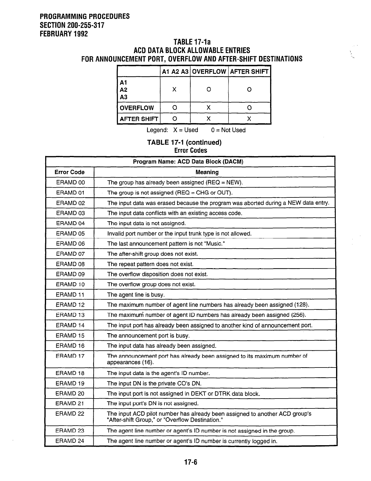
PROGRAMMING PROCEDURES
SECTION 200-255-317
FEBRUARY 1992 TABLE 17-la
ACD DATA BLOCK ALLOWABLE ENTRIES
FOR ANNOUNCEMENT PORT, OVERFLOW AND AFTER-SHIFT DESTINATIONS
1
Al
A2 A3 1 OVERFLOW 1 AFTER SHIFT
Al
A2 0 0
A3
OVERFLOW 1 0 1 X 1 0
AFTER SHIFT1 0 I X I
Legend: X = Used 0 = Not Used
TABLE 17-1 (continued)
Error Codes
Error Code
ERAMD 00
ERAMD 01
ERAMD 02
ERAMD 03
ERAMD 04
ERAMD 05
ERAMD 06
ERAMD 07
ERAMD 08
ERAMD 09
ERAMD 10
ERAMD 11
ERAMD 12
ERAMD 13
ERAMD 14
ERAMD 15
ERAMD 16
ERAMD 17
Program Name: ACD Data Block (DACM)
Meaning
The group has already been assigned (REQ = NEW).
The group is not assigned (REQ = CHG or OUT).
The input data was erased because the program was aborted during a NEW data entry.
The input data conflicts with an existing access code.
The input data is not assigned.
Invalid port number or the input trunk type is not allowed.
The last announcement pattern is not “Music.”
The after-shift group does not exist.
The repeat pattern does not exist.
The overflow disposition does not exist.
The overflow group does not exist.
The agent line is busy.
The maximum number of agent line numbers has already been assigned (128).
The maximum number of agent ID numbers has already been assigned (256).
The input port has already been assigned to another kind of announcement port.
The announcement port is busy.
The input data has already been assigned.
The announcement port has already been assigned to its maximum number of
appearances (16).
ERAMD 18
ERAMD 19
ERAMD 20
ERAMD 21
ERAMD 22
The input data is the agents ID number.
The input DN is the private CO’s DN.
The input port is not assigned in DEKT or DTRK data block.
The input port’s DN is not assigned.
The input ACD pilot number has already been assigned to another ACD group’s
“After-shift Group,” or “Overflow Destination.”
ERAMD 23 The agent line number or agent’s ID number is not assigned in the group.
ERAMD 24 The agent line number or agents ID number is currently logged in.
17-6
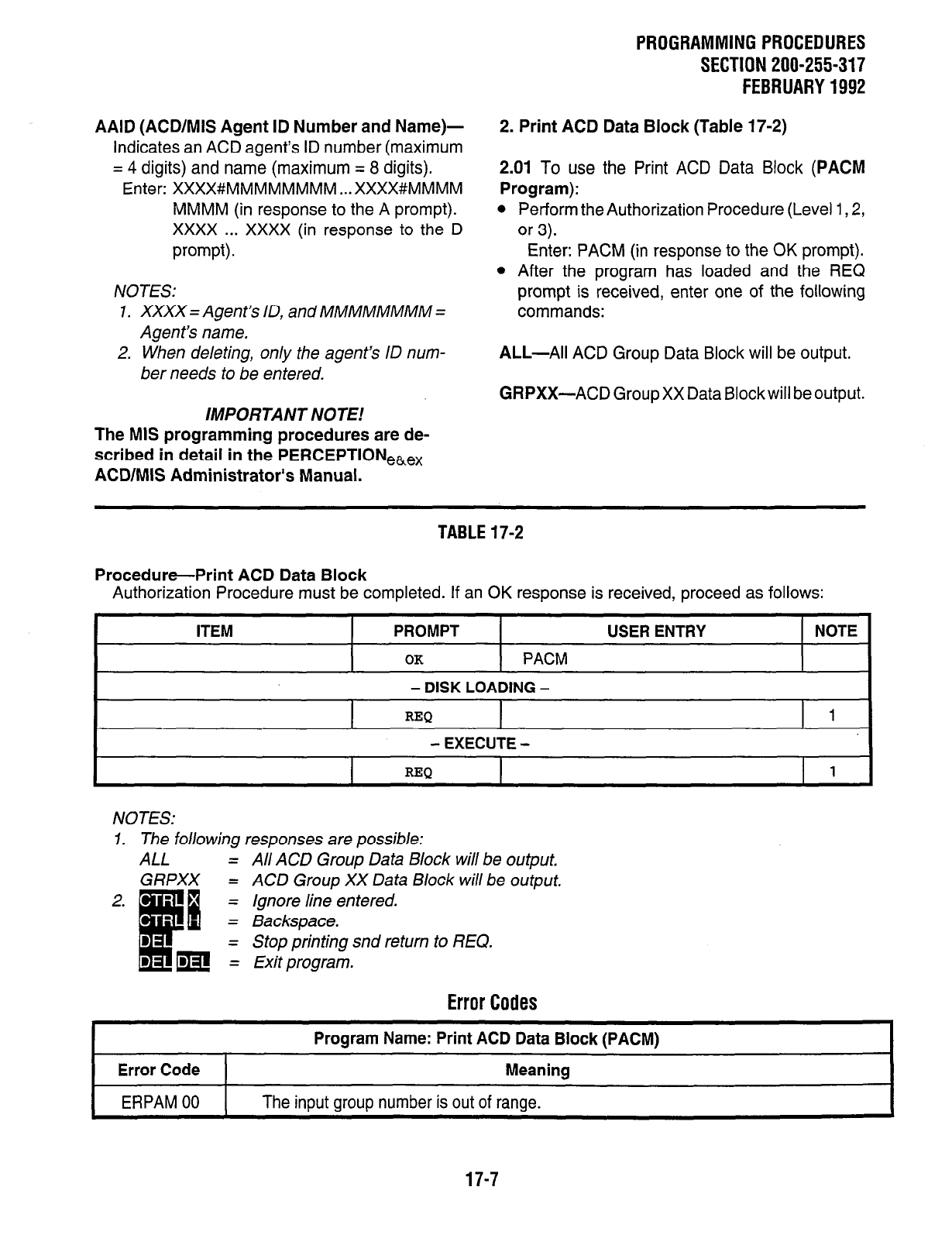
AAID (ACD/MlS Agent ID Number and Name)-
Indicates an ACD agent’s ID number (maximum
= 4 digits) and name (maximum = 8 digits).
Enter: XXXX#MMMMMMMM . . . XXXX#MMMM
MMMM (in response to the A prompt).
xxxx . . . XXXX (in response to the D
prompt).
NOTES:
1. XXXX = Agent’s ID, and MMMMMMMM =
Agent’s name.
2. When deleting, only the agent’s ID num-
ber needs to be entered.
IMPORTANT NOTE!
The MIS programming procedures are de-
scribed in detail in the PERCEPTlONe,,
ACD/MIS Administrator’s Manual.
PROGRAMMINGPROCEDURES
SECTION 200-255-317
FEBRUARY1992
2. Print ACD Data Block (Table 17-2)
2.01 To use the Print ACD Data Block
(PACM
Program):
l
Perform the Authorization Procedure (Level 1,2,
or 3).
Enter: PACM (in response to the OK prompt).
l
After the program has loaded and the REQ
prompt is received, enter one of the following
commands:
ALL-All ACD Group Data Block will be output.
GRPXX-ACD Group XX Data Blockwill be output.
TABLE17-2
Procedure-Print ACD Data Block
Authorization Procedure must be completed. If an OK response is received, proceed as follows:
ITEM PROMPT
OK
PACM
USER ENTRY NOTE
- DISK LOADING -
REQ 1
- EXECUTE -
I
REQ I 1 I
NOTES:
7. The following responses are possible:
ALL =
GRPXX =
All ACD Group Data Block will be output.
ACD Group XX Data Block will be output.
Ignore line entered.
Backspace.
Stop printing snd return to REQ.
Exit program.
Error Codes
Program Name: Print ACD Data Block (PACM) I
Error Code Meaning
ERPAM 00 The input group number is out of range.
17-7
PROGRAMMING PROCEDURES
SECTION 200-255-318
FEBRUARY 1992
CHAPTER 18
VERIFIABLE ACCOUNT CODES DATA
1. Verifiable Account Codes Data Block (Table
18-I)
1.01 If a station user is required (via the COS) to
enter verifiable account codes, the Verifiable Ac-
count Codes Data Block
(DVAC Program)
en-
ables the system to verify the account codes en-
tered. The account code can be a 1 - - 12-digit code,
and it is output via the SMDR port as part of the
SMDR data.
NOTE:
DMDR’s ACL MUST be programmed before
the Verifiable Account Codes in the DVAC
program will be operable.
Data for this program is entered as follows:
REQ (Request)-Indicates that the program has
loaded. CHG is the only possible response.
TYPE (Data
Type)-Indicates the addition or de-
letion of verified account codes.
Enter: ACTA (to add codes), or ACTD (to de-
lete codes).
ACL (Account Code
Length)-Defines the length
of the account code that is to be used, or indi-
cates that no account code is to-be used. (The
ACL prompt appears only if TYPE = ACTA.)
NOTES:
1. The Account Code Length (ACL) is de-
fined in the DMDR (Station Message De-
tail Recording) Program.
2. No entry to the ACL prompt is possible
here. The system will print out the infor-
mation from the ACL prompt in the DMDR
Program.
A (Account Codes to
Add)-Defines the account
codes. (The A prompt appears only if TYPE =
ACTA.)
Enter: I- - 12-digit Account Codes (spaces
between them) depending on digit length,
as defined in the ACL of DMDR.
NOTE:
For ease of entry, Account Codes will auto-
matically be distributed to the appropriate
tables.
TABLE NO.
(Table
Number)-Indicates the table
number that the account codes are to be deleted
from. (The TABLE NO. prompt appears only if
TYPE = ACTD.)
Enter: 0 - 14.
ACT-(TABLE
#) (Account
Number)-The
Table Number (from the Table Number indicated
in TABLE NO. entry) of the account code that is
to be deleted (see Table 18-la).
NOTE:
No entry to the ACTprompt is necessary. The
system will print out the account codes from
the entry at the TABLE NO. prompt.
D (Account Codes to
Delete)-Defines the ac-
count codes (the D prompt appears only if TYPE
= ACTD).
Enter: The number associated with each ac-
count code to be deleted.
18-1
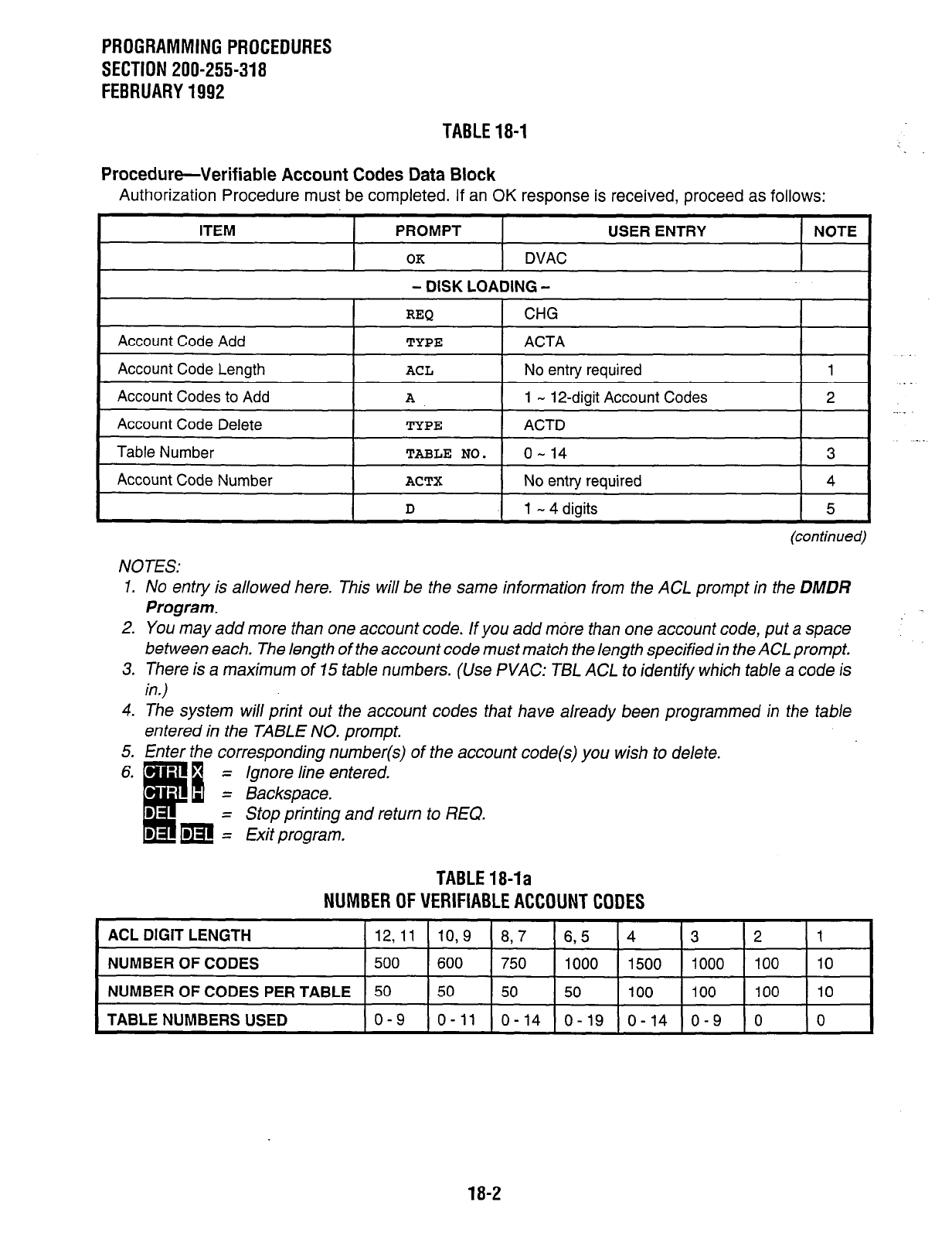
PROGRAMMINGPROCEDURES
SECTION 200-255-318
FEBRUARY1992
TABLE18-1
Procedure-Verifiable Account Codes Data Block
Authorization Procedure must be completed. If an OK response is received, proceed as follows:
ITEM PROMPT
OK
DVAC
- DISK LOADING -
USER ENTRY NOTE
REQ CHG
Account Code Add I
TYPE I
ACTA I
Account Code Length
ACL
No entry required 1
Account Codes to Add
A
1 - 12-digit Account Codes 2
Account Code Delete
TYPE
ACTD
Table Number
TABLE NO.
o- 14 3
Account Code Number
ACTX
No entry required
D
1 - 4 digits
4
5
(continued)
NOTES:
1. No entry is allowed here. This will be the same information from the ACL prompt in the DMDR
Program.
2. You may add more than one account code. If you add m&e than one account code, put a space
between each. The length of the account code must match the length specified in the ACL prompt.
3. There is a maximum of 75 tab/e numbers. (Use P VAC: T5L ACL to identify which table a code is
in.)
4. The system will print out the account codes that have a/ready been programmed in the fable
entered in the TABLE NO. prompt.
5. Enter the corresponding number(s) of the account code(s) you wish to delete.
= Ignore line entered.
= Backspace.
= Stop printing and return to REQ.
= Exit program.
TABLE18-la
NUMBER OF
VERIFIABLE ACCOUNT CODES
ACL DIGIT LENGTH 12,ll 10,9 8,7 6,5 4 3 2 1
NUMBER OF CODES 500 600 750 1000 1500 1000 100 10
NUMBER OF CODES PER TABLE 50 50 50 50 100 100 100 10
TABLE NUMBERS USED o-9 o-11 o-14 o-19 o-14 o-9 0 0
18-2
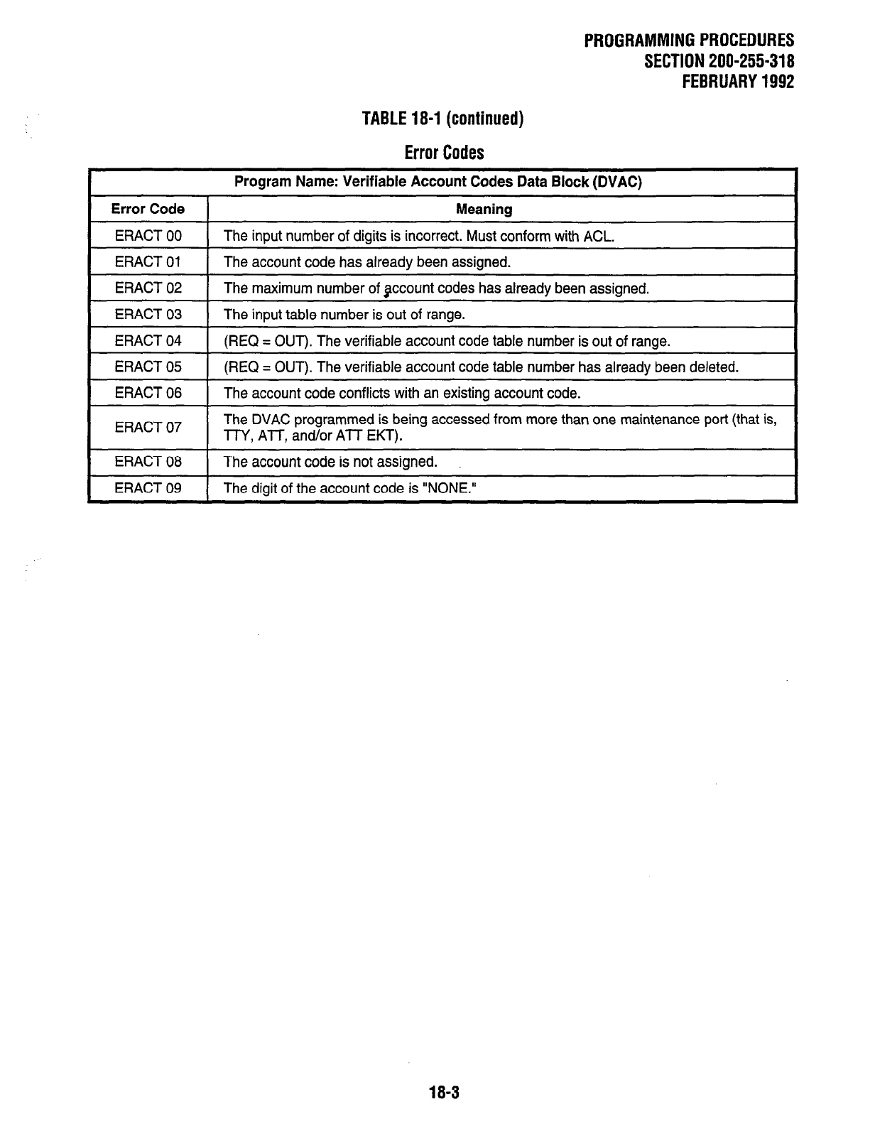
PROGRAMMING PROCEDURES
SECTION 200-255-318
FEBRUARY 1992
TABLE 18-l (continued)
Error Codes
Error Code
Program Name: Verifiable Account Codes Data Block (DVAC)
Meaning
ERACT 00
ERACT 01
The input number of digits is incorrect. Must conform with ACL.
The account code has already been assigned.
ERACT 02
ERACT 03
The maximum number of jlccount codes has already been assigned.
The inout table number is out of ranoe.
I
ERACT 04 1 (REQ = OUT). The verifiable account code table number is out of range.
ERACT 05
ERACT 06
(REQ = OUT). The verifiable account code table number has already been deleted.
The account code conflicts with an existing account code.
ERACT 07 The DVAC programmed is being accessed from more than one maintenance port (that is,
TTY, ATT, and/or ATT EKT).
ERACT 08 The account code is not assigned.
I
ERACT 09 1 The digit of the account code is “NONE.”
18-3
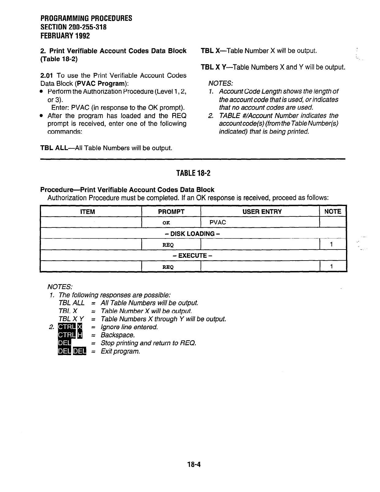
PROGRAMMING PROCEDURES
SECTION 200-255-318
FEBRUARY 1992
2. Print Verifiable Account Codes Data Block
(Table 18-2)
2.01
To use the Print Verifiable Account Codes
Data Block
(PVAC Program):
l
Perform the Authorization Procedure (Level 1,2,
or 3).
Enter: PVAC (in response to the OK prompt).
l
After the program has loaded and the REQ
prompt is received, enter one of the following
commands:
TBL ALL-All
Table Numbers will be output.
TBL
X-Table Number X will be output.
TBL
X Y-Table Numbers X and Y will be output,
NOTES:
1. Account Code Length shows the length of
the account code that is used, or indica tes
that no account codes are used.
2. TABLE #/Account Number indicates the
accountcode (from the Table Number(s)
indicated)
that
is
being printed.
TABLE 18-2
Procedure-Print Verifiable Account Codes Data Block
Authorization Procedure must be completed. If an OK response is received, proceed as follows:
.
ITEM
PROMPT USER ENTRY NOTE
OK
PVAC
- DISK LOADING - /’
REQ
1 .,
- EXECUTE -
REQ I 1
NOTES:
1. The folio wing responses are possible:
TBLALL =
TBLX =
TBLXY =
All Table Numbers will be output.
Table Number X will be output.
Table
Numbers X through Y
will
be output.
Ignore line entered.
Backspace.
Stop printing and return to REQ.
Exit program.
2. - =
.
c
8 =
: mz
18-4
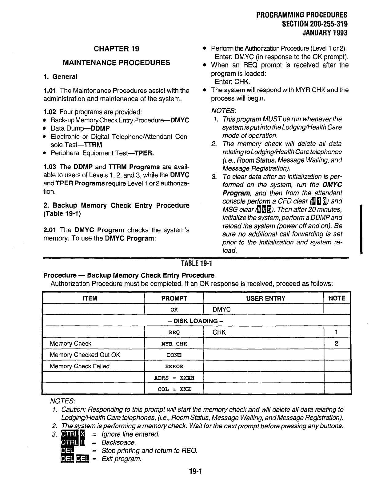
CHAPTER 19
MAINTENANCE PROCEDURES
1. General
1 .Ol The Maintenance Procedures assist with the
administration and maintenance of the system.
1.02 Four programs are provided:
l
Back-up Memory Check Entry Procedure-DMYC
0 Data Dump-DDMP
l
Electronic or Digital Telephone/Attendant Con-
sole Test-TTRM
l
Peripheral Equipment Test-TPER.
1.03 The DDMP and lTRM Programs are avail-
able to users of Levels 1,2, and 3, while the DMYC
and TPER Programs require Level 1 or 2 authoriza-
tion.
2. Backup Memory Check Entry Procedure
(Table 19-1)
2.01 The DMYC Program checks the system’s
memory. To use the DMYC Program:
PROGRAMMING PROCEDURES
SECTION 200-255-319
JANUARY 1993
l
Perform the Authorization Procedure (Level 1 or 2).
Enter: DMYC (in response to the OK prompt).
0 When an REQ prompt is received after the
program is loaded:
Enter: CHK.
l
The system will respond with MYR CHK and the
process will begin.
NOTES:
1.
2.
3.
This program MUST be run whenever the
system isputinto the Lodging/Health Care
mode of operation.
The memory check will delete all data
relating to Lodging/Health Care telephones
(i.e., Room Status, Message Waiting, and
Message Registration).
To clear data after an initialization is per-
formed on the system, run the
DMYC
Program,
and then from the attendant
console perform a CFD clear fi u m and
MSG clear a b m. Then after 20 minutes,
initialize the system, perform a DDMP and
reload the system (power off and on). Be
sure no additional call forwarding is set
prior to the initialization and system re-
load.
TABLE 19-1
Procedure - Backup Memory Check Entry Procedure
Authorization Procedure must be completed. If an OK response is received, proceed as follows:
ITEM PROMPT USER ENTRY NOTE
OK
DMYC
Memory Check
Memory Checked Out OK
Memory Check Failed
- DISK LOADING -
REQ CHK 1
mR CHK
2
DONE
ERROR
?iDRS = XXXH
COL = XXH
NOTES:
1. Caution: Responding to this prompt will start the memory check and will delete all data relating to
Lodging/Health Care telephones, (i.e., Room Status, Message Waiting, and Message Registration).
‘. The system is performing a memory check. Wait for the next prompt before pressing any buttons.
Ignore line entered.
Backspace.
Stop printing and return to REQ.
Exit program.
19-1
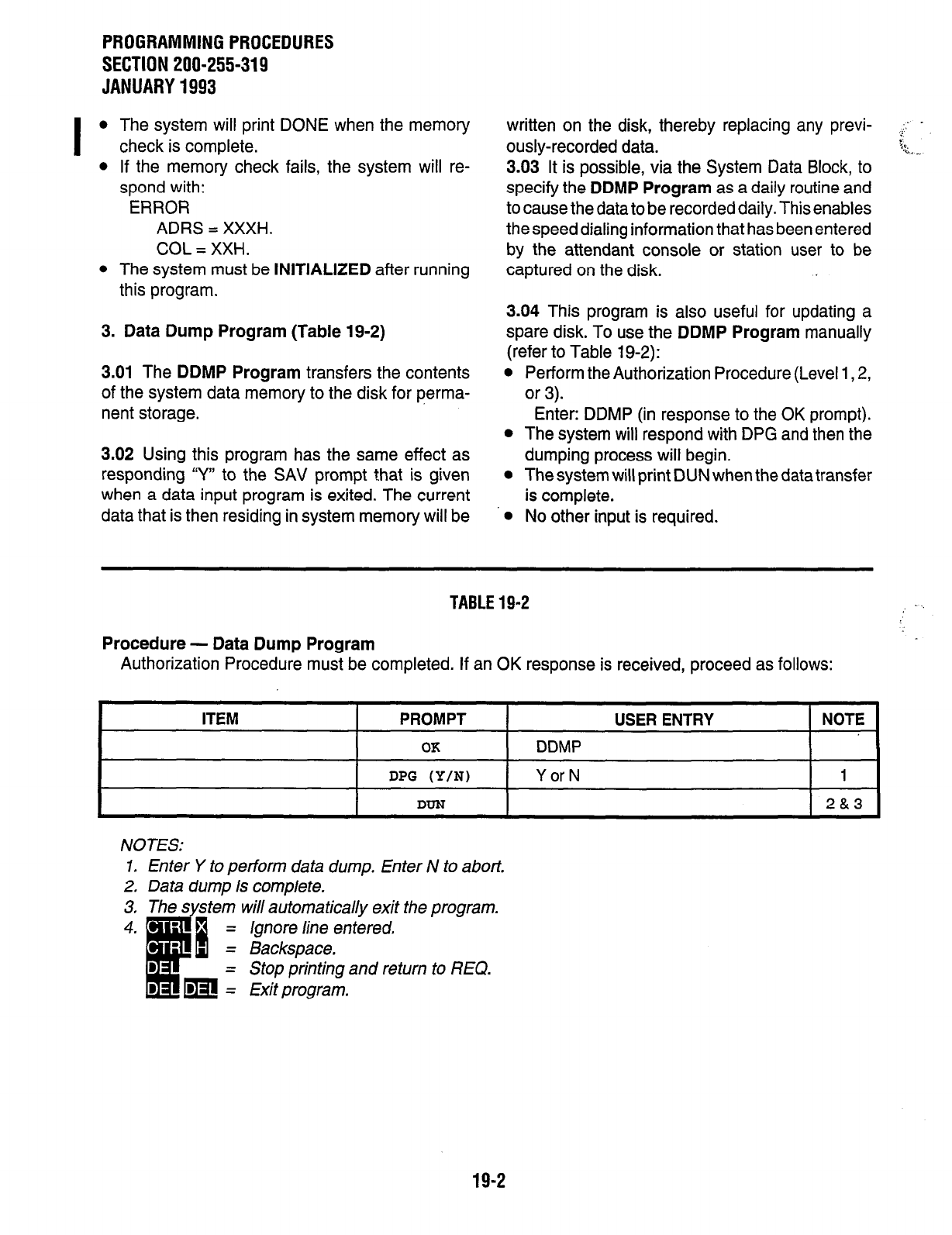
PROGRAMMING PROCEDURES
SECTION 200-255-319
JANUARY 1993
l
The system will print DONE when the memory
check is complete.
l
If the memory check fails, the system will re-
spond with:
ERROR
ADRS = XXXH.
COL = XXH.
l
The system must be INITIALIZED after running
this program.
3. Data Dump Program (Table 19-2)
3.01 The DDMP Program transfers the contents
of the system data memory to the disk for perma-
nent storage.
3.02 Using this program has the same effect as
responding Y” to the SAV prompt that is given
when a data input program is exited. The current
data that is then residing in system memory will be
written on the disk, thereby replacing any previ- i: .
ously-recorded data. c
5%.
-a*.-.
3.03 It is possible, via the System Data Block, to
specify the DDMP Program as a daily routine and
to cause the data to be recorded daily. This enables
the speed dialing information that has been entered
by the attendant console or station user to be
captured on the disk.
3.04 This program is also useful for updating a
spare disk. To use the DDMP Program manually
(refer to Table 19-2):
l
Perform the Authorization Procedure (Level 1,2,
or 3).
Enter: DDMP (in response to the OK prompt).
l
The system will respond with DPG and then the
dumping process will begin.
l
The system will print DUN when the data transfer
is complete.
l
No other input is required.
TABLE 19-2
Procedure - Data Dump Program
Authorization Procedure must be completed. If an OK response is received, proceed as follows:
ITEM PROMPT USER ENTRY NOTE
OK DDMP
DPG (Y/N)
DUN
Y or N
1
2&3
NOTES:
1. Enter Y to perform data dump. Enter N to abort.
2. Data dump is complete.
Stop printing and return to REQ.
19-2
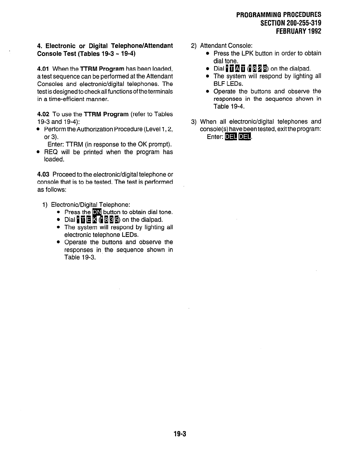
4. Electronic or Digital Telephone/Attendant
Console Test (Tables 19-3 - 19-4)
4.01 When the ?TRM Program has been loaded,
a test sequence can be performed at the Attendant
Consoles and electronic/digital telephones. The
test is designed to checkall functions of the terminals
in a time-efficient manner.
4.02 To use the TITIM Program (refer to Tables
19-3 and 19-4):
l
Perform the Authorization Procedure (Level 1,2,
or 3).
Enter: TTRM (in response to the OK prompt).
l
REQ will be printed when the program has
loaded.
4.03 Proceed to the electronic/digital telephone or
console that is to be tested. The test is performed
as follows:
1) Electronic/Digital Telephone:
l
Press the D
l
Dial p fii R
button to obtain dial tone.
( aI@ on the dialpad.
l
The system will respond by lighting all
electronic telephone LEDs.
l
Operate the buttons and observe the
responses in the sequence shown in
Table 19-3.
PROGRAMMINGPROCEDURES
SECTlON200-255-319
FEBRUARY1992
2) Attendant Console:
l
Press the LPK button in order to obtain
dial tone.
l
Dial iclfi (~~~~) on the dialpad.
l
The system will respond by lighting all
BLF LEDs.
l
Operate the buttons and observe the
responses in the sequence shown in
Table 19-4.
3) When all electronic/digital telephones and
console(s) have been tested, exit the program:
Enter: m m.
19-3
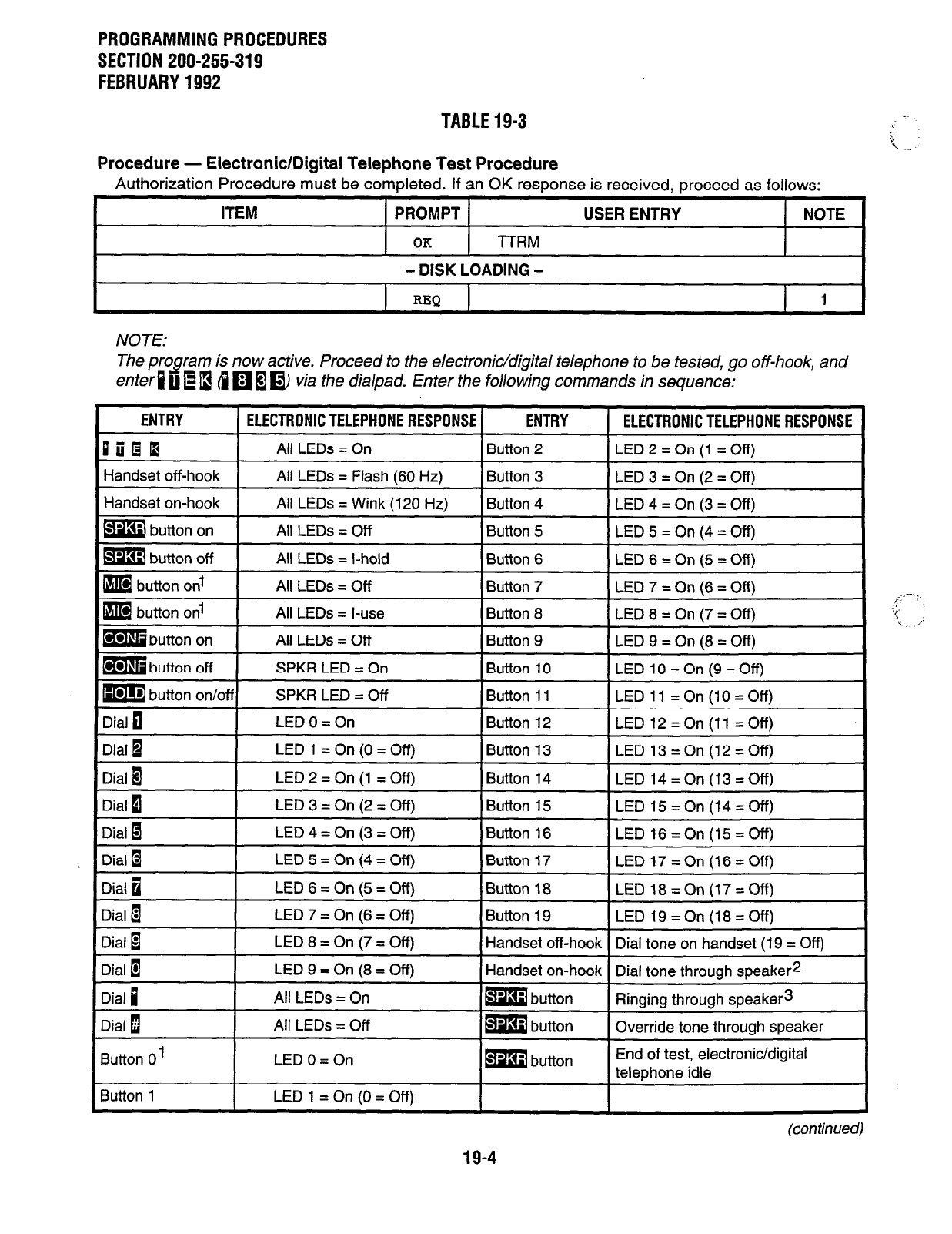
PROGRAMMING PROCEDURES
SECTION 200-255-319
FEBRUARY 1992
TABLE 19-3
Procedure - Electronic/Digital Telephone Test Procedure
Authorization Procedure must be completed. If an OK response is received, proceed as follows:
ITEM PROMPT USER ENTRY NOTE
OK lTRM
- DISK LOADING -
REO
I
1
NOTE:
The program
e~diuQI3
is now active. Proceed to the electronic/digital telephone to be tested, go off-hook, and
4
q
1 m via the dialpad. Enter the following commands in sequence:
ENTRY 1 ELECTRONIC TELEPHONE RESPONSE 1 ENTRY I ELECTRONIC TELEPHONE RESPONSE
DiiOQ
All LEDs = On Button 2 LED2=On(l =Off)
Handset off-hook All LEDs = Flash (60 Hz) Button 3 LED3=On(2=Off)
Handset on-hook All LEDs = Wink (120 Hz) Button 4 LED4=On(3=Off)
I
mbutton on 1 All LEDs = Off I Button 5 ILED5=On(4=Off)
ma
button off
BIB button on1
m button on1
All LEDs = l-hold
All LEDs = Off
All LEDs = l-use
Button 6 LED6=On(5=Off)
Button 7 LED7=On(6=Off)
Button 8 LED8=On(7=Off)
ml
button on
I
All LEDs = Off I Button 9 (LED9=On(8=Off)
m button off
Dial 0
SPKR LED = On
SPKR LED = Off
LEDO=On
Button 10 LEDlO=On(g=Off)
Button 11 LED 11 =On(lO=Off)
Button 12 LED 12 = On (11 = Off)
Dial 1
Dial 8
Dial 1
Dial 1
Dial 1
Dial 0
LED 1 =On(O=Off) Button 13 LED 13=On(12=Off)
LED2=On(l =Off) Button 14 LED 14 = On (13 = Off)
LED3=On(2=Off) Button 15 LED 15 = On (14 = Off)
LED4=On(3=Off) Button 16 LED 16=On(15=Off)
LED5=On(4=Off) Button 17 LED 17 = On (16 = Off)
LED6=On(5=Off) Button 18 LED 18=On(17=Off)
Dial m
I
LED7=On(6=Off)
I
Button 19
I
LED 19=On(18=Off)
Dial 1
Dial 1
Dial p
Dial 1
Button 0’
Button 1
I
LED8=On(7=Off)
I
Handset off-hook] Dial tone on handset (19 = Off)
LED9=On(8=Off)
All LEDs = On
All LEDs = Off
Handset on-hook Dial tone through speaker2
m button Ringing through speaker3
m button Override tone through speaker
LEDO=On
LED1 =On(O=Off)
m button End of test, electronic/digital
telephone idle
(continued)
i --. :
3;.
* i!
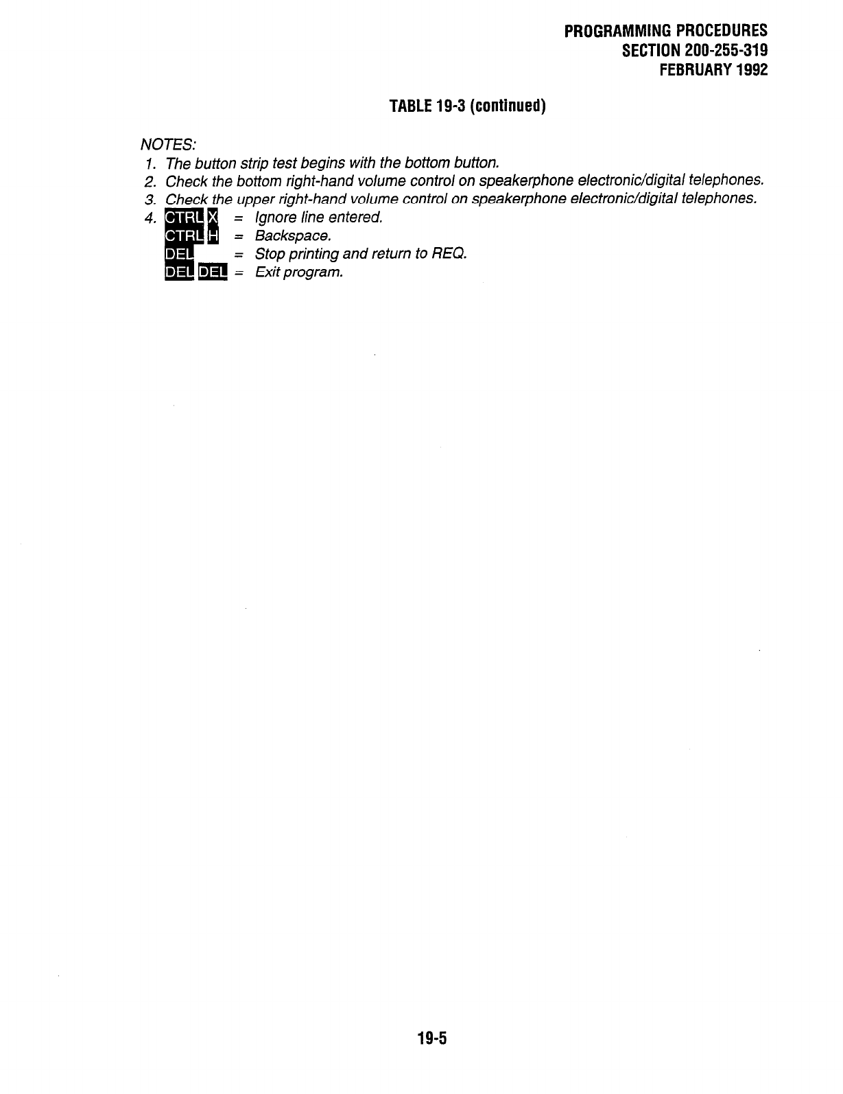
PROGRAMMINGPROCEDURES
SECTION 200-255-319
FEBRUARY1992
TABLE19-3 (continued)
NOTES:
1. The button strip test begins with the bottom button.
2. Check the
bottom
right-hand
volume
control on speakerphone electronic/digital telephones.
3. Check the upper right-hand volume control on speakerphone electronic/digital telephones.
ignore line entered.
Stop printing and return to REQ.
19-5
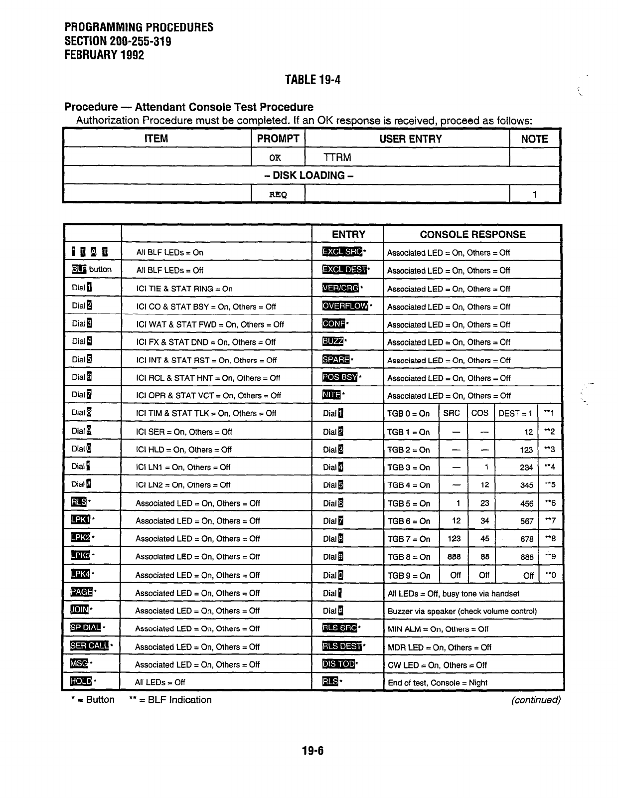
PROGRAMMING PROCEDURES
SECTION 200-255-319
FEBRUARY 1992
TABLE 19-4
Procedure - Attendant Console Test Procedure
Authorization Procedure must be completed. If an OK response is received, proceed as follows:
ITEM PROMPT USER ENTRY NOTE
OK
-lTRM
- DISK LOADING -
REQ
1
I I
ENTRY I ~~~~~
CONSOLE RESPONSE
Piilii
All BLF LEDs = On m: Associated LED = On, Others = Off
m button All BLF LEDs = Off mmsi* Associated LED = On, Others = Off
Dial n I ICI TIE & STAT RING = On
I@izma* I
Associated LED = On, Others = Off
Dial I
Dial 1
ICI CO & STAT BSY = On, Others = Off
ICI WAT & STAT FWD = On, Others = Off
-m* -~
Associated LED = On, Others = Off
m* Associated LED = On, Others = Off
Dial i
Dial 1
Dial 1
ICI FX & STAT DND = On, Others = Off
ICI INT & STAT RST = On, Others = Off
ICI RCL & STAT HNT = On, Others = Off
m* Associated LED = On, Others = Off
m* Associated LED = On, Others = Off
W’ Associated LED = On, Others = Off
Dial 0
I
ICI OPR & STAT VCT = On, Others = Off
Im* I
Associated LED = On, Others = Off
Dial 1
Dial 1
Dial B
ICI TIM & STAT TLK = On, Others = Off
ICI SER = On, Others = Off
ICI HLD = On, Others = Off
Dial a
Dial a
Dial a
TGBO=On SRC COS DEST= 1 ‘“1
TGBl=On - - 12 **2
TGB2=On - - 123 “3
Associated LED = On, Others = Off Dial 1 All LEDs = Off, busy tone via handset
Associated LED = On, Others = Off
Associated LED = On, Others = Off
Dial 1
m*
Buzzer via speaker (check volume control)
MIN ALM = On, Others = Off
m.
Associated LED = On, Others = Off BE** MDR LED = On, Others = Off
mEI* Associated LED = On, Others = Off w CW LED = On, Others = Off
All LEDs = Off End of test, Console = Night
* = Button
l
* = BLF Indication
19-6
(con timed)
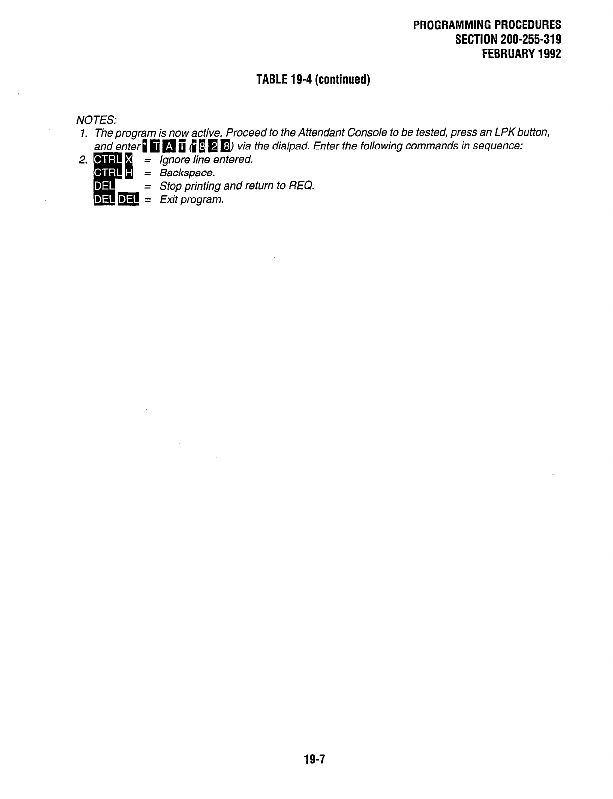
PROGRAMMINGPROCEDURES
SECTION 200-255-319
FEBRUARY1992
TABLE19-4(continued)
NOTES:
1. The program is now active. Proceed to the Attendant Console to be tested, press an LPK button,
and enter 1 fi
q
i 4 B @ n via the dialpad. Enter the following commands in sequence:
ignore line entered.
Stop printing and return to REQ.
19-7
PROGRAMMING PROCEDURES
SECTION 200-255-319
FEBRUARY 1992
5. Peripheral Equipment Test (Table 19-5)
5.01
The
TPER Program
is designed to aid in fault
location by disabling and enabling various PCE3s
and circuits. When a faulty circuit or PC6 has been
located, it is left disabled until it can be replaced in
order to prevent it from interfering with normal
system operation.
5.02 It is also possible, with the
TPER Program,
to
determine the busy/idle status of any station, trunk,
or DTMF receiver port. To use the
TPER Program
(refer to Table 19-5):
l
Perform the Authorization Procedure (Level 1 or
a
Enter: TPER (in response to the OK prompt).
l
REQ will be printed when the program has
loaded.
Enter: One of the following commands:
DSCDXXX-Disables PC6 XXX regardless of busy/
idle status (XXX = TXX, LXX, CXX, or RXX);
lights PCB FALT LEDs, and returns the REQ
prompt.
DSTKNNX-Disables trunk NNX if it is idle (NN =
trunk PCB number, i.e., TO1 = 01; X = circuit
number on that PCB, i.e.,1 - 4), lights the FALT
LED relating to that circuit (FALT #1 for circuits 1
& 2; FALT #2 for circuits 3 & 4), and returns the
REQ prompt.
DSLCNNX-Disables station circuit NNX if it is idle
(NN = station PCB number, i.e., LO4 = 04; X =
circuit number on that PCB, i.e., 1 - 8), lights the
FALT LED relating to that circuit (FALT #l for
circuits 1 - 4; FALT #2 for circuits 5 - 8), and
returns the REQ prompt.
ENCDXXX-Enables PCB XXX (XXX = TXX, LXX,
CXX, or RXX), turns FALT LEDs off, and returns
the REQ prompt.
ENTKNNX-Enables trunk NNX (NN = trunk PCB
number; X = circuit number on that PCB), turns
FALT LEDs off unless other circuit is still dis-
abled, and returns the REQ prompt.
ENLCNNX-Enables station line circuit NNX (NN
= station PCB number; X = circuit number on that
PCB), turns FALT LEDs off unless the other ...
circuits are still disabled, and returns the REQ GG ._-,
prompt.
DSDSNNX-Disables DSS console circuit NNX
(NN = PCB number; X = circuit number), lights
the FALT LED relating to that circuit, and returns
the REQ prompt.
ENDSNNX-Enables DSS console circuit NNX
(NN = PCB number; X = circuit number), turns
FALT LEDs off if all circuits are enabled, and
returns the REQ prompt.
DSRCNNX-Disables DTMF receiver circuit 00X/
01X if it is idle (ROO = basic cabinet /ROl =
expansion cabinet; X = DTMF receiver circuit in
that cabinet, 1 - 8), lights the FALT LED on the
NPRU PCB relating to that circuit (FALT #l for
circuits 1 & 2; FALT #2 for circuits 3 & 4; FALT #3
for circuits 5 & 6; and FALT #4 for circuits 7 & 8),
and returns the REQ prompt.
ENRCNNX-Enables DTMF receiverOOX/Ol X (OO/
01 = PCB number ROO; X = circuit number in that
cabinet, 1 -.8), turns the FALT LED off unless the
other circuit is still disabled, and returns the REQ
prompt.
DSCIXXX-Disables each circuit on the PCB as it
becomes idle, lights the appropriate FALT LED
as circuits are disabled, and returns the REQ
prompt.
LIPS-Prints out a list of all system ports (DTMF
receivers, DSS consoles, stations, and trunks)
that are idle at the time that the command is
entered, and returns the REQ prompt when the
printout is complete.
LBPS-Prints out a list of all system ports (DTMF
receivers, DSS consoles, stations, and trunks)
that are busy at the time that the command is
entered, and returns the REQ prompt when the
printout is complete.
LDPS-Prints out a list of all system ports (DTMF
receivers, DSS consoles, stations, and trunks)
that are in a disabled state at the time that the
command is entered, and returnsthe REQprompt
when the printout is complete.
19-8

STLCNNX-Gives the status of station line circuit
NNX (NN = station line PC6 number; X = circuit
number on that PCB). The output format will be
a combination of two items. (See Notes 1 and 2.)
Station Type’
EKT
ATT
UNEQ
UNAS
Example:
REQ
Status2
BSY
DIS TTY
DIS CBL
DIS TLD
STLC002
CKT 2 EKT IDL
l
Returns the REQ prompt when the printout is
complete.
SlTKNNX-Gives the status of trunk circuit NNX
(NN = trunk PCB number; X = circuit number on
that PCB). The output format will be a combina-
tion of two items. (See Notes 1 and 2.)
Trunk Type’
co
FX
WAT
TIE
CCSA
UNEQ
UNAS
Example:
REQ
Status*
IDL
BSY
DIS l-f-Y
DIS TLD
ST-i-K001
CKT 1 TIE IDL
l
Returns the REQ prompt when the printout is
complete.
STDSNNX-Gives the status of DSS circuit NNX
(NN = PCB number; X = circuit number). The
output format will be IDL, BSY, DIS TTY, DIS
CBL, DIS TLD. (See Notes 1 and 2.)
Example:
REQ STDSOOi
CKT 1 IDL
l
Returns the REQ prompt when the printout is
complete.
STRCNNX-Gives the status of DTMF receiver
00X/01X (OO/Ol = receiver PCB number ROO/
R01; X = circuit number in that cabinet). The
PROGRAMMINGPROCEDURES
SECTION 200-255-319
FEBRUARY1992
output format will be IDL, BSY, DIS TTY, DIS
TLD, UNEQ, UNAS. (See Notes 1 and 2.)
Example:
REQ STRCOOl
CKT 1 IDL
l
Returns the REQ prompt when the printout is
complete.
NOTES:
1. Type: UNEQ = No PCBin thatposition.
UNAS = PCB is equipped but no
data is assigned.
2. Status: IDL = Idle.
BSY = Busy.
D/S 77-Y = Manually disabled
via 77-Y.
DIS CBL = Electronic/digital
telephone, port dis-
abled by soft-ware,
due to open cable.
DIS TLD = Software disabled
due to trafficioad (in-
dicates faulty PCB).
STCDXXX-Gives the status of all circuits on PCB
XXX (XXX = PCB location LXX, CXX, TXX, or
ROO/Ol ). Printout formats will be the same as for
STLC, SlTK, and STRC commands, but will list
all circuits on that PCB in the order of the circuit
number.
l
Returns the REQ prompt when the printout is
complete.
CALL TNNX-Sets up a monitor link from Trunk
NNX to the remote test center:
l
This command is used at a remote test
center to establish an audio link between the
system and the test center. The objective is
to command the system to select a particular
trunk (A) and to dial the number of a tele-
phone at the test center. When the call is
answered, a 440 Hz tone will be heard.
l
Once a monitor link has been established,
other trunks can be tested. The trunk to be
tested (B) is seized by the keyboard terminal
command and then the test number (for
example: time, weather, tone, etc.) to be
dialed is entered via the terminal. The audio
responses are monitored at the test center.
19-9
PROGRAMMING PROCEDURES
SECTION 200-255-319
FEBRUARY 1992
l
The set-up sequence includes several steps
that are led by system prompts. Following
the entry CALL TNNX, the system prompts
will be as follows:
WAIT-Indicates that the first command was re-
ceived. A carriage return must be entered in
order to advance the program.
Enter: [9.
STS TLK, WAIT, or OVR (Status)-Gives the
status of the requested trunk.
l
STS TLK will be output if the trunk was idle
and has now been seized. The program will
automatically advance to the next prompt
W).
l
STS WAIT indicates that the requested trunk
is busy. The program will automatically re-
turn to the WAIT prompt.
Enter:
‘9m!
- to access the same trunk again
or m
q
to return to the REQ
prompt.
l
STS OVR indicates that the requested trunk
does not exist in the system.
Enter: mato return to the REQ prompt.
WAIT-Indicates that the command was received.
A carriage return must be entered to advance the
program.
Enter:
q
.
DN (Directory Number)-The system is request-
ing the number of the,telephone to be called at
the test center.
Enter: DN followed by a
q
.
STS TLK, DDL, or RLSA (Status)-Gives the
status of the connection.
l
STS TLK will be output if the dialing is com-
plete, and the program will automatically
advance to the next prompt (TRK).
l
STS DDL indicates that the trunk was still
STSTLK, BSY, OVR, or RLSA(Status)-Gives the
status of the connection.
l
STS TLK will be output if the requested trunk
was idle and has now been seized. The
program will automatically advance to the
next prompt (DN).
l
STS BSY indicates that the requested trunk
is busy. The program will automatically re-
turn to the TRK prompt above in order to
allow another trunk to be selected.
l
STS OVR indicates that the requested trunk
does not exist in the system. The program
will automatically return to the TRK prompt
above to allow another trunk to be selected.
l
STS RLSA is output if the monitor link trunk
(A) was disconnected due to a malfunction or
some outside influence, such as the distant
end going on-hook. After printing STS RLSA,
the program will automatically return to the
REQ prompt.
19-10
DN (Directory Number)-The trunk undertest (6)
has been seized and the system is requesting
the number to be dialed (time, weather, tone,
dialing when
q
was entered.
Enter:
q
to advance the program.
l
STS RLSA indicates that Trunk A was dis-
connected due to a malfunction or some
outside influence, such as the distant end
going on-hook on a ground start trunk. After
printing STS RLSA, the program will auto-
matically return to the REQ prompt.
TRK (Trunk)-At this point, the monitor link to the
test center (using Trunk A) has been established
(a 440 Hz tone is heard when Trunk A is an-
DDL (Dialing)-The system is dialing via Trunk 6.
When dialing is complete, progress tones (ring-
ing, etc.) will be heard over Trunk E3 via the
monitor link Trunk A). When the test is com-
plete, enter h - to release Trunk B and to return
to the TRK prompt.
Enter: [9.
STS TLK, DDL, RLSA, or RLSB (Status)-Gives
the status of the connection.
swered at the remote test center), and the sys-
tem is requesting the identity of a trunk to be
tested.
Enter: CALL TNNX (TNNX = port number of
the trunk to be tested; 440 Hz tone
removed).
etc.).
Enter: DN followed by a
q
.
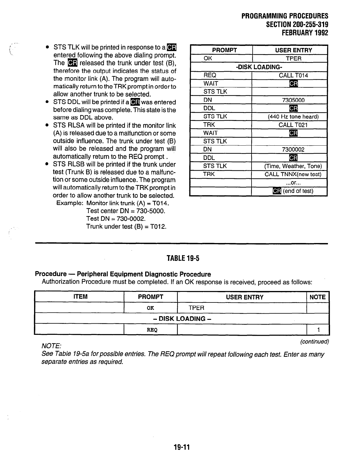
PROGRAMMINGPROCEDURES
SECTION 200-255-319
FEBRUARY1992
, 1,.
, 0
0
STS TLK will be printed in response to a
q
entered following the above dialing prompt.
The
q
released the trunk under test (B),
therefore the output indicates the status of
the monitor link (A). The program will auto-
matically return to the TRK prompt in order to
allow another trunk to be selected.
STS DDL will be printed if a
q
was entered
before dialing was complete. This state is the
same as DDL above,
STS RLSA will be printed if the monitor link
(A) is released due to a malfunction or some
outside influence. The trunk under test (B)
will also be released and the program will
automatically return to the REQ prompt .
STS RLSB will be printed if the trunk under
test (Trunk B) is released due to a malfunc-
tion or some outside influence. The program
will automatically return to the TRK prompt in
order to allow another trunk to be selected.
Example: Monitor link trunk (A) = T014.
Test center DN = 730-5000.
Test DN = 730-0002.
Trunk under test (B) = T012.
I
PROMPT 1 USER ENTRY 1
. ..or...
TABLE19-5
Procedure - Peripheral Equipment Diagnostic Procedure
Authorization Procedure must be completed. If an OK response is received, proceed as follows:
ITEM PROMPT USER ENTRY NOTE
OK
TPER
- DISK LOADING -
=Q
I 1
NOTE: (con timed)
See Table 19-5a forpossible entries. The REQ prompt will repeat following each test. Enter as many
separate entries as required.
19-11
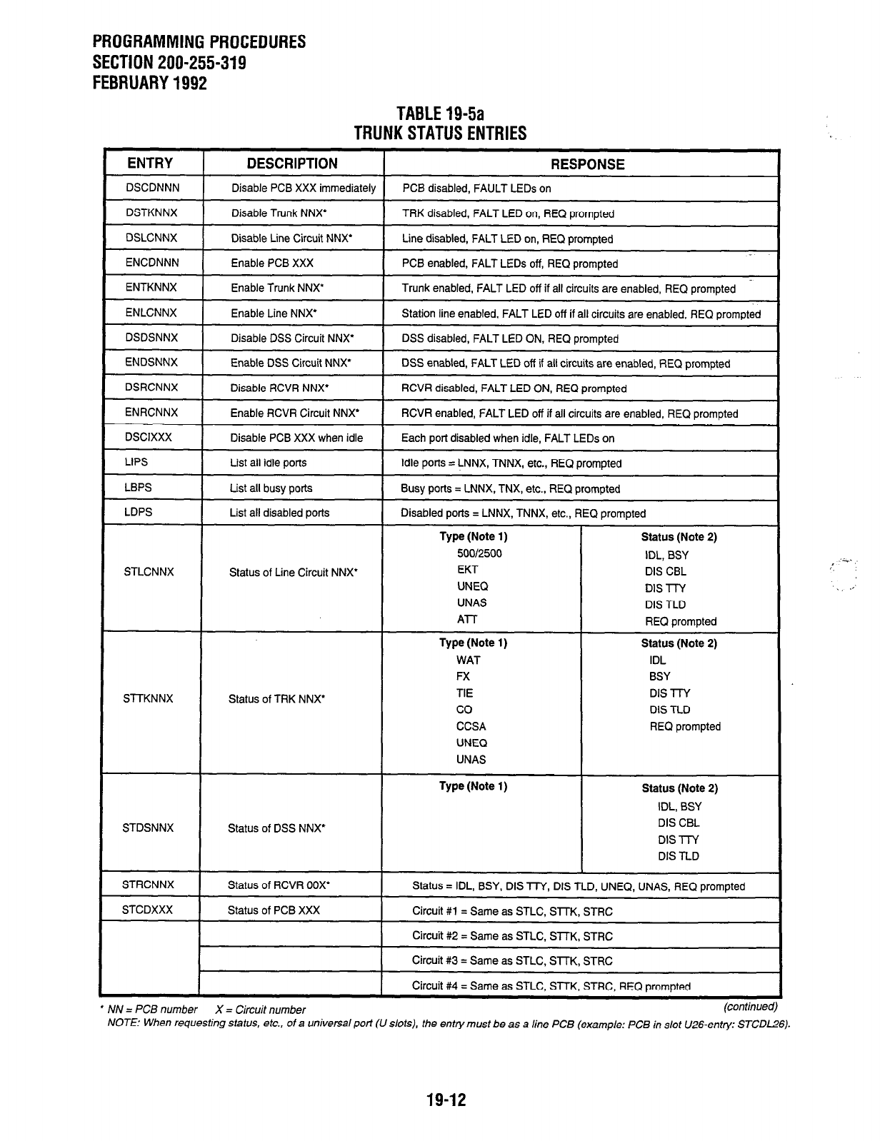
PROGRAMMING PROCEDURES
SECTION 200-255-319
FEBRUARY 1992
TABLE 19-5a
TRUNK STATUS ENTRIES
ENTRY DESCRIPTION RESPONSE
DSCDNNN
DSTKNNX
DSLCNNX
ENCDNNN
ENTKNNX
ENLCNNX
DSDSNNX
ENDSNNX
DSRCNNX
ENRCNNX
DSCIXXX
LIPS
LBPS
LDPS
STLCNNX
Sl-TKNNX
Disable PCB XXX immediately
Disable Trunk NNX’
Disable Line Circuit NNX’
Enable PCB XXX
Enable Trunk NNX’
Enable Line NNX’
Disable DSS Circuit NNX’
Enable DSS Circuit NNX”
Disable RCVR NNX’
Enable RCVR Circuit NNX’
Disable PCB XXX when idle
List all idle ports
List all busy ports
List all disabled ports
Status of Line Circuit NNX’
Status of TRK NNX’
PCB disabled, FAULT LEDs on
TRK disabled, FALT LED on, REQ prompted
Line disabled, FALT LED on, REQ prompted
PCB enabled, FALT LEDs off, REQ prompted
Trunk enabled, FALT LED off if all circuits are enabled, REQ prompted
Station line enabled, FALT LED off if all circuits are enabled, REQ prompted
DSS disabled, FALT LED ON, REQ prompted
DSS enabled, FALT LED off if all circuits are enabled, REQ prompted
RCVR disabled, FALT LED ON, REQ prompted
RCVR enabled, FALT LED off if all circuits are enabled, REQ prompted
Each port disabled when idle, FALT LEDs on
Idle ports = LNNX, TNNX, etc., REQ prompted
Busy ports = LNNX, TNX, etc., REQ prompted
Disabled ports = LNNX, TNNX, etc., REQ prompted
Type (Note 1) Status (Note 2)
5OQl2500 IDL, BSY
EKT DIS CBL
UNEQ DE -l-l-Y
UNAS DIS TLD
Al-l- REQ prompted
Type (Note 1) Status (Note 2)
WAT IDL
Fx BSY
TIE DIS l-l-Y
co DIS TLD
CCSA REQ prompted
UNEQ
UNAS
STDSNNX Status of DSS NNX’
Type (Note 1) Status (Note 2)
IDL, BSY
DIS CBL
DIS l-l-Y
DIS TLD
STRCNNX
STCDXXX
Status of RCVR 00X’
Status of PCB XXX
Status = IDL, BSY, DIS TTY, DIS TLD, UNEQ, UNAS, REQ prompted
Circuit #1 = Same as STLC, STTK, STRC
Circuit #2 = Same as STLC. SlTK, STRC
Circuit #3 = Same as STLC, SlTK, STRC
Circuit #4 = Same as STLC, STTK, STRC, REQ prompted
l
NN = PCB number X = Circuit number (confinuec
NOTE: When requesting status, etc., of a universal port (U slots), the entty must be as a line PCB (example: PCB in slot U26-entry: STCDLZG).
19-12
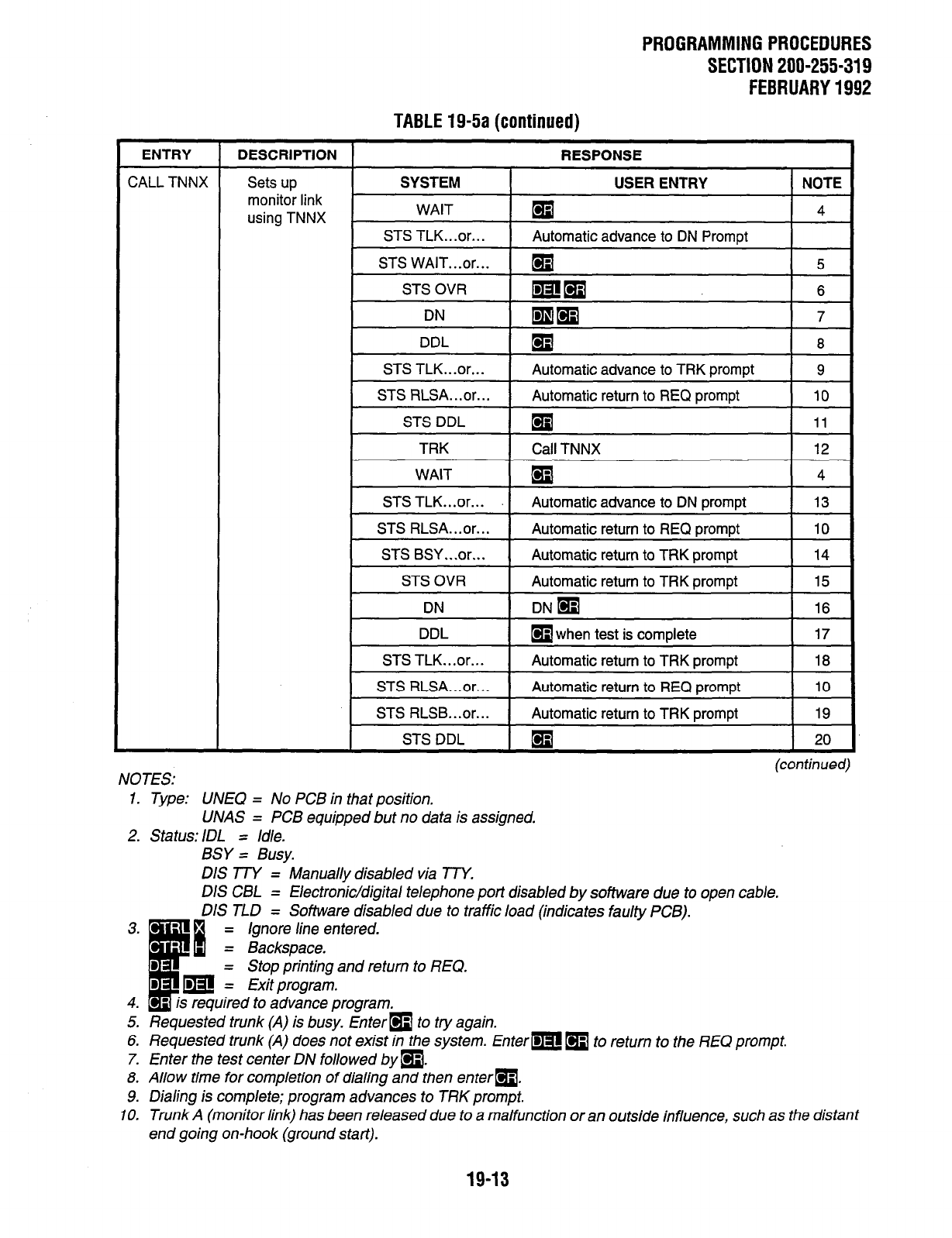
PROGRAMMING PROCEDURES
SECTION 200-255-319
FEBRUARY 1992
TABLE 19-5a (continued)
ENTRY DESCRIPTION RESPONSE
CALL TNNX Sets up SYSTEM USER ENTRY NOTE
monitor link
using TNNX WAIT
q
4
STS TLK.. .or.. . Automatic advance to DN Prompt
STS WAIT...or...
q 5
STS OVR mm 6
DN mm 7
DDL El 8
STS TLK...or... Automatic advance to TRK prompt 9
STS RLSA...or... Automatic return to REQ prompt 10
STS DDL
q
11
TRK Call TNNX 12
(contimed)
NOTES:
1. Type: UNEQ = No PCB in that position.
LJNAS = PCB equipped but no data is assigned.
2. Status: IDL = Idle.
BSY = Busy.
DIS TTY = Manually disabled via TTY.
DIS CBL = Electronic/digital telephone port disabled by software due to open cable.
3. -
I
B
DIS TLD = Software disabled due to traffic load (indicates faulty PCB).
B
= Ignore line entered.
= Backspace.
D = Stop printing and return to REQ.
B m = Exit program.
4. - is required to advance program.
5. Requested trunk (A) is busy. Enterm to try again.
6. Requested trunk (A) does not exist in the system. Enter-m m to return to the REQ prompt.
7. Enter the test center DN followed by a.
8. Allow time for completion of dialing and then enterm.
9. Dialing is complete; program advances to TRK prompt.
IO. Trunk A (monitor link) has been released due to a malfunction or an outside influence, such as the distant
end going on-hook (ground start).
19-13
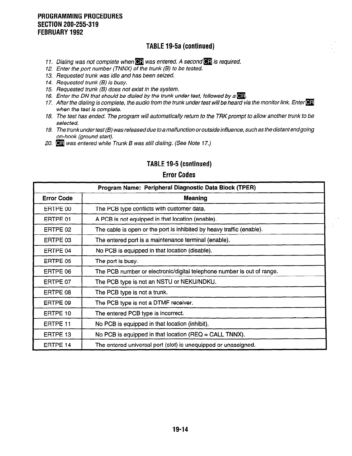
PROGRAMMING PROCEDURES
SECTION 200-255-319
FEBRUARY 1992
TABLE 19-5a (continued)
7 7. Dialing was not complete when
q
was entered. A second
q
is required.
12. Enter the port number (TNNX) of the trunk (B) to be tested.
73. Requested trunk was idle and has been
seized.
14. Requested trunk (B) is busy.
15. Requested trunk (B) does not exist in the system.
16. Enter the DN that should be dialed by the trunk under test, followed by a
q
,
17. After the dialing is complete, the audio from the trunk under test will be heard via the monitor link. Enterm
when the test
is complete.
18. The test has ended. The program will automatically return to the TRKprompt to allow another trunk to be
selected.
19. The trunk under test(B) was released due to a ma/function or outside influence, such as the distant endgoing
on-hook (ground start).
20. [9
was
entered
while
Trunk
B
was
still
dialing. (See
Note 17.)
TABLE 19-5 (continued)
Error Codes
Error Code
ERTPE 00
Program Name: Peripheral Diagnostic Data Block (TPER)
Meaning
The PCB tvoe conflicts with customer data.
ERTPE 01 A PCB is not equipped in that location (enable).
ERTPE 02 The cable is open or the port is inhibited by heavy traffic (enable).
ERTPE 03 The entered port is a maintenance terminal (enable).
ERTPE 04 No PCB is eauiooed in that location (disable).
ERTPE 05
ERTPE 06
The port is busy.
The PCB number or electronic/digital telephone number is out of range.
ERTPE 07
ERTPE 08
The PCB type is not an NSTU or NEKWNDKU.
The PCB type is not a trunk.
~~~ ~ -1 ~~ ~ -
ERTPE 09 The PCB tvoe is not a DTMF receiver. I
ERTPE 10
ERTPE 11
The entered PCB type is incorrect.
No PCB is eauiooed in that location (inhibit).
ERTPE 13 I No PCB is
eQIJiDPed
in that location (REQ = CALL TNNX).
ERTPE 14
1 ~ ~~ ~~~~
The entered universal
sort
(slot) is uneauiooed or unassianed. I
19-14

PROGRAMMINGPROCEDURES
SECTION 200-255-319
FEBRUARY1992
TABLE19-6
DISKDRIVEOPERATIONERRORCODES
Error Codes
Program Name: Floppy Disk Drive Error
Error Code Meaning
ERFD 01 File is closed.
ERFD 02 Read error.
ERFD 03
ERFD 04
ERFD 05
Write error.
Directory is full.
Disk is full.
I
ERFD 06 I End-of-file error.
1 ERFD 07 1 Disk drive is not readv.
I
ERFD 08 I Incorrect version number. I
ERFD 09
ERFD 10
File is write-protected.
File not found.
ERFD 11
ERFD 12
ERFD FF
Volume not initialized.
File already exists.
Other hardware is causina the error.
19-15
PERCEPTIONea,
LCFVTR PROGRAMMING GUIDE
MARCH 1991
Perception& 63 ex
DIGITAL HYBRID PBX
APPENDIX #2
LEAST COST ROUTING (LCR)
and
TOLL RESTRICTION (TR)
PROGRAMMING GUIDE
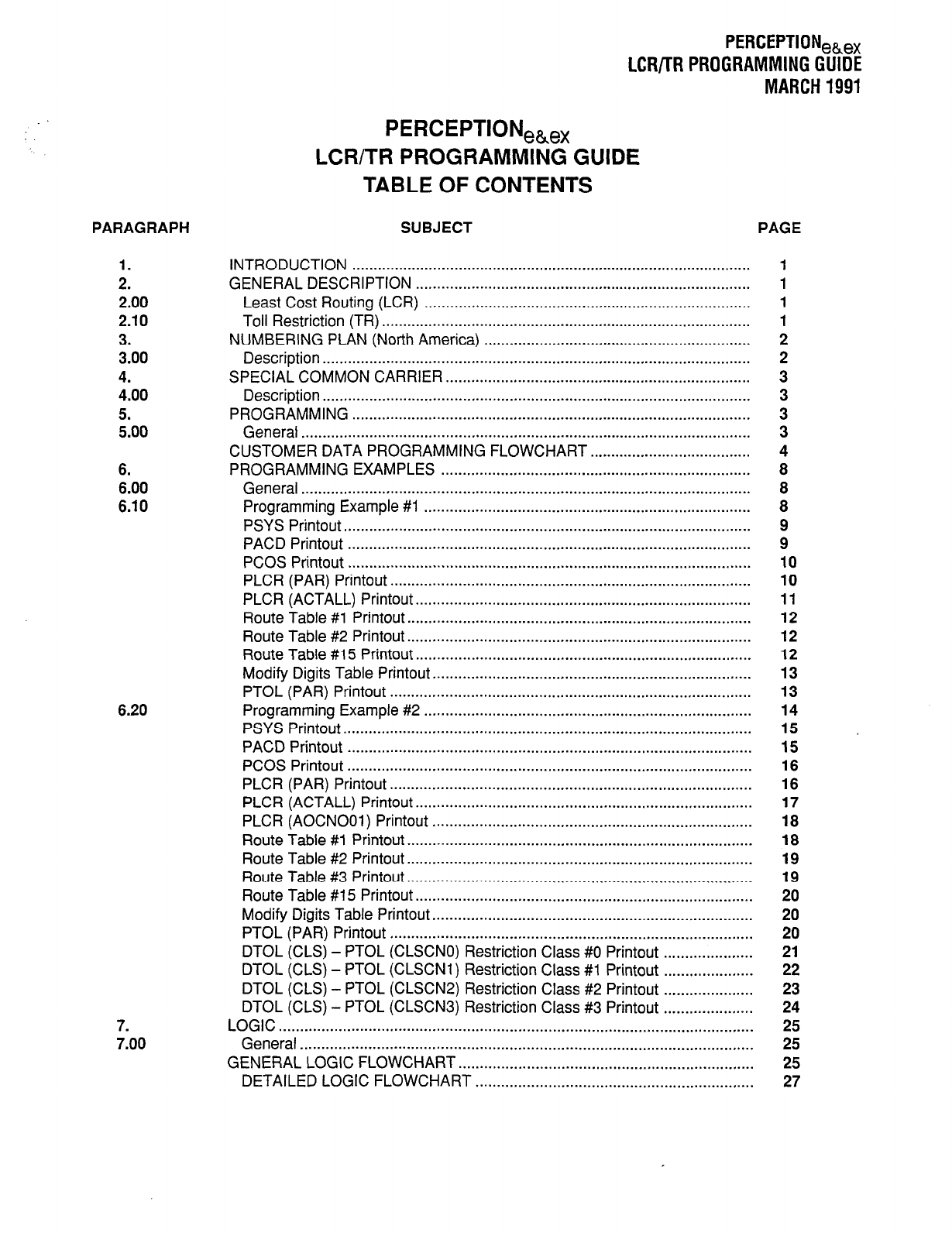
PERCEPTIONeh,
LCR/TR PROGRAMMING GUIDE
MARCH 1991
PARAGRAPH
1.
2.
2.00
2.10
3.
3.00
4.
4.00
5.
5.00
6.
6.00
6.10
6.20
7.
7.00
PERCEPTION,,,
LCR/TR PROGRAMMING GUIDE
TABLE OF CONTENTS
SUBJECT PAGE
INTRODUCTION ..............................................................................................
GENERAL DESCRIPTION ...............................................................................
Least Cost Routing (LCR) .............................................................................
Toll Restriction (TR) .......................................................................................
NUMBERING PLAN (North America) ...............................................................
Description .....................................................................................................
SPECIAL COMMON CARRIER.. ......................................................................
Description .....................................................................................................
PROGRAMMING ..............................................................................................
General ..........................................................................................................
CUSTOMER DATA PROGRAMMING FLOWCHART ......................................
PROGRAMMING EXAMPLES .........................................................................
General ..........................................................................................................
Programming Example #I .............................................................................
PSYS Printout.. ..............................................................................................
PACD Printout ...............................................................................................
PCOS Printout ...............................................................................................
PLCR (PAR) Printout.. ...................................................................................
PLCR (ACTALL) Printout.. .............................................................................
Route Table #l Printout.. ...............................................................................
Route Table #2 Printout.. ...............................................................................
Route Table #15 Printout.. .............................................................................
Modify Digits Table Printout.. .........................................................................
PTOL (PAR) Printout .....................................................................................
Programming Example #2 .............................................................................
PSYS Printout.. ..............................................................................................
PACD Printout ...............................................................................................
PCOS Printout ...............................................................................................
PLCR (PAR) Printout.. ...................................................................................
PLCR (ACTALL) Printout.. .............................................................................
PLCR (AOCNOOi) Printout ...........................................................................
Route Table #l Printout.. ...............................................................................
Route Table #2 Printout.. ...............................................................................
Route Table #3 Printout.. ...............................................................................
Route Table #15 Printout.. .............................................................................
Modify Digits Table Printout ...........................................................................
PTOL (PAR) Printout .....................................................................................
DTOL (CLS) - PTOL (CLSCNO) Restriction Class #0 Printout .....................
DTOL (CLS) - PTOL (CLSCNl) Restriction Class #1 Printout .....................
DTOL (CLS) - PTOL (CLSCN2) Restriction Class #2 Printout .....................
DTOL (CLS) - PTOL (CLSCN3) Restriction Class #3 Printout .....................
LOGIC ...............................................................................................................
General ..........................................................................................................
GENERAL LOGIC FLOWCHART .....................................................................
DETAILED LOGIC FLOWCHART .................................................................
1
1
1
1
2
2
3
3
3
3
4
8
8
8
9
9
10
10
11
12
12
12
13
13
14
15
15
16
16
17
18
18
19
19
20
20
20
21
22
23
24
25
25
25
27
1. INTRODUCTION
1
.Ol
This document has two main purposes: a) to
describe the Least Cost Routing (LCR) and Toll
Restriction (TR) features, and b) to serve as a
supplement to Section 200-255-300, System Pro-
gramming, in order to guide the service technician
in LCRflR programming. Various examples, tables,
and flowcharts are provided to clarify feature expla-
nations.
a .02 This document assumes that the reader is
familiar with PERCEPTIONekex programming
procedures and the mnemonics used with the LCR
and TR data entry utility programs.
2. GENERAL DESCRIPTION
2.00 Least Cost Routing (LCR)
2.01
Least Cost Routing causes the system to
select the least expensive trunk available for that
particular time of day. The station user simply dials
an LCR access code and the required telephone
number. LCR will then select the optimally-priced
route and automatically delete and/or insert any
necessary digits (for MCI, Sprint, etc.) by analyzing
the dialed telephone number (including area code
and, in some cases, office code).
2.02 The three variable time schedules per 24-
hour clock allow the end-user to take advantage of
rate variations during these hours. The various
routing combinations for the three time schedules
are contained in 15 Route Tables. Each table is
selected as a function of the dialed telephone
number.
2.03 The LCR feature is compatible with and
transparentto all other PERCEPTIONehex features.
It is designed so that it is completely disabled until
a simple parameter (LCR) is enabled in the System
Data Block
(DSYS Program).
2.04 If a Direct Trunk Access code (not the LCR
access code) is dialed, the outgoing call is handled
as a normal direct trunk access call without using
LCR.
PERCEPTIONeh,
LCR/TR PROGRAMMING GUIDE
MARCH 1991
2.05 LCR Data Blocks are separated from all other
Data Blocks. It is unnecessary to change a com-
pleted Data Block when adding the LCR feature to
a system already in use, except to assign the LCR
access code
(DACD Program)
or to enable LCR
(DSYS Program).
2.06 There are three LCR classes (LCI , LC2, and
LC3), which allow specific stations to be denied
access to the most expensive routes. LC3 is the
lowest class; LCl is the highest. LC3 routes are
always selected first, no matter what class the
station is allowed. If all LC3 routes are busy, and
the calling station is allowed LC2, the system will try
to select an LC2 route in the order programmed. If
LCl is allowed, and all LC2 routes are busy, the
system will try to select an LCI route.
l
The Class of Service Data Block indicates the
LCR class of that particular Class of Service.
l
A warning tone is received by the station user if
the last choice route is selected (if the WTA
prompt, PAR table,
DLCI Program,
is pro-
grammed to Y).
l
If all the routes are busy, busy tone is received
by the station user, who may then activate the
Automatic Callback feature. The station will
then be called when the first trunk in that sta-
tion’s LCR class is idle. When the station
answers the callback, the idle trunk will be
seized and the telephone number will be auto-
matically dialed out to the distant end.
2.07 All of the above logic and the remainder of the
Least Cost Routing and Toll Restriction features
are described, and can be followed step-by-step, in
the Detailed Logic Flowchart. Thisflowchartcan be
used as a fault finding procedure for customer data
programming, and to answer questions regarding
what will happen when certain parameters are
programmed in a certain way.
2.10 Toll Restriction (TR)
2.11 The Toll Restriction (TR) program causes the
system to restrict (or not restrict) specific stations
from calling certain area codes and/or office codes.
2.12 Toll Restriction can be used for long distance
toll restriction, for restriction in the local area (home
area), or both. The TR class also decides whether
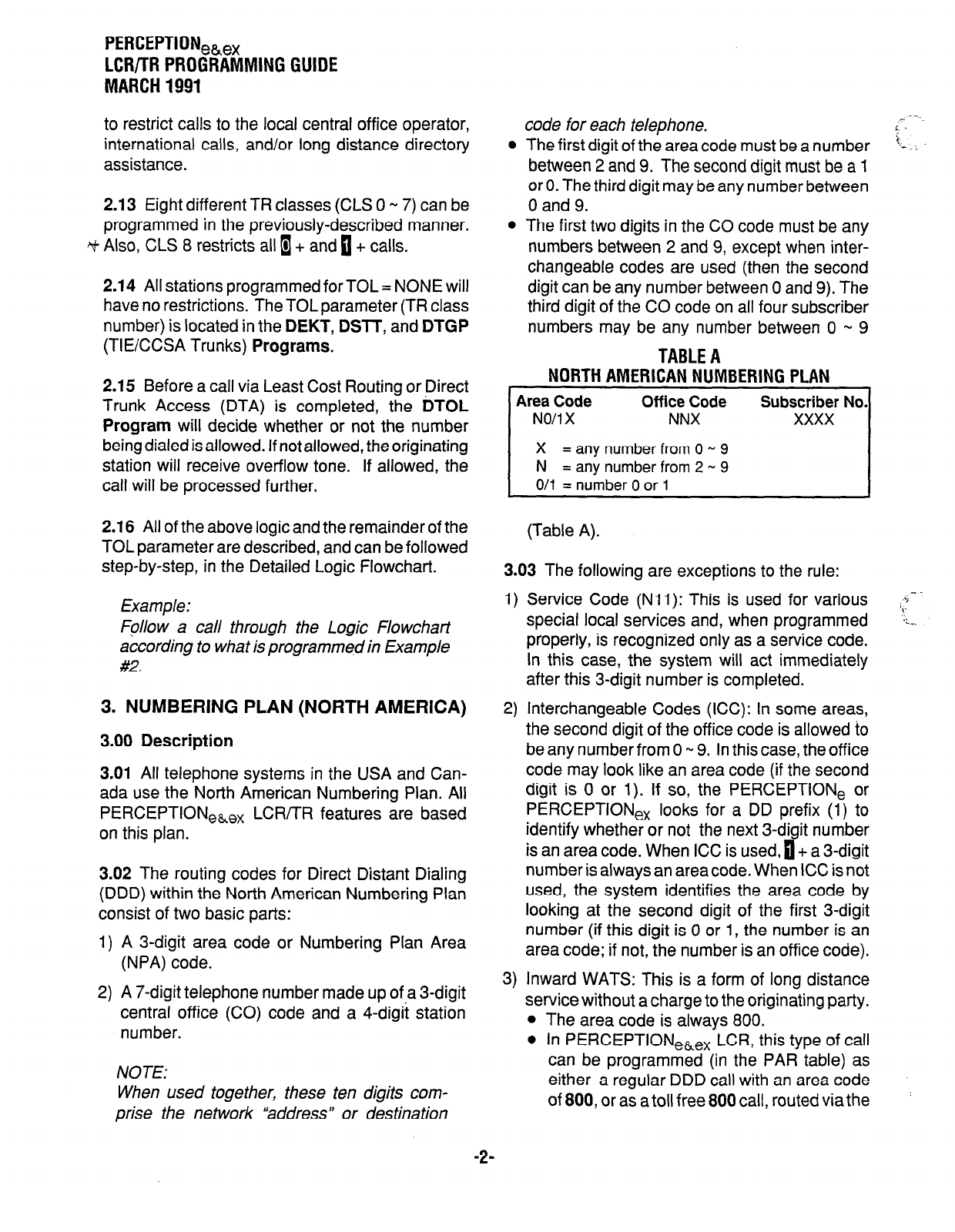
PERCEPTIONea,
LCWTR PROGRAMMING GUIDE
MARCH 1991
to restrict calls to the local central office operator,
international calls, and/or long distance directory
assistance.
2.13 Eight different TR classes (CLS 0 w 7) can be
programmed in the previously-described manner.
+I+ Also, CLS 8 restricts all I+ and a + calls.
2.14 All stations programmed for TOL = NONE will
have no restrictions. The TOL parameter (TR class
number) is located in the
DEKT, DSlT,
and
DTGP
(TIECCSA Trunks)
Programs.
2.15
Before a call via Least Cost Routing or Direct
Trunk Access (DTA) is completed, the
DTOL
Program
will decide whether or not the number
being dialed is allowed. If not allowed, the originating
station will receive overflow tone. If allowed, the
call will be processed further.
2.16 All of the above logic and the remainder of the
TOL parameter are described, and can be followed
step-by-step, in the Detailed Logic Flowchart.
Example:
Fpllow a call through the Logic Flowchati
according to what is programmed in Example
#2.
3. NUMBERING PLAN (NORTH AMERICA)
3.00 Description
3.01
All telephone systems in the USA and Can-
ada use the North American Numbering Plan. All
PERCEPTION,&,, LCR/TR features are based
on this plan.
3.02 The routing codes for Direct Distant Dialing
(DDD) within the North American Numbering Plan
consist of two basic parts:
1) A 3-digit area code or Numbering Plan Area
(NPA) code.
2) A 7-digit telephone number made up 0f.a 3-digit
central office (CO) code and a 4-digit station
number.
NOTE:
When used together, these ten digits com-
prise the network “‘address” or destination
code for each telephone.
l
The first digit of the area code must be a number
between 2 and 9. The second digit must be a 1
or 0. The third digit may be any number between
0 and 9.
l
The first two digits in the CO code must be any
numbers between 2 and 9, except when inter-
changeable codes are used (then the second
digit can be any number between 0 and 9). The
third digit of the CO code on all four subscriber
numbers may be any number between 0 w 9
TABLE A
NORTH AMERICAN NUMBERING PLAN
Area Code Off ice Code
NO/l X NNX
X = any number from 0 - 9
N = any number from 2 - 9
Subscriber No.
xxxx
O/l = number 0 or 1 I
(Table A).
3.03 The following are exceptions to the rule:
1)
2)
3)
Service Code (Nli): This is used for various
special local services and, when programmed
properly, is recognized only as a service code.
In this case, the system will act immediately
after this 3-digit number is completed.
Interchangeable Codes (ICC): In some areas,
the second digit of the office code is allowed to
be any number from 0 w 9. In this case, the office
code may look like an area code (if the second
digit is 0 or 1). If so, the PERCEPTlONe or
PERCEPTIONex looks for a DD prefix (1) to
identify whether or not the next 3-digit number
is an area code. When ICC is used, 0 + a 3-digit
number is always an areacode. When ICC is not
used, the system identifies the area code by
looking at the second digit of the first 3-digit
number (if this digit is 0 or 1, the number is an
area code; if not, the number is an office code).
Inward WATS: This is a form of long distance
service without a charge to the originating party.
,. - -..
t
i;- .-1
--
i ‘i
,‘
-_.
The area code is always 800.
In PERCEPTIONeLex LCR, this type of call
can be programmed (in the PAR table) as
either a regular DDD call with an area code
of 800, or as a toll free 800 call, routed via the
-2-

4)
local call route table (LCR).
Long distance directory assistance (555): This
is a call using any area code (or no area code)
plus 5551212. If allowed, this type of call is
routed via the LDI route table, as indicated in the
PAR table, or via the route table (DAC = N) to
which this area code is assigned.
NOTE:
When a DDD callis dialed,
needed before the area
cause the local operator to be connected.
4. SPECIAL COMMON CARRIER
4.00 Description
4.01 Dialing extra digits to access the Special
Common Carrier (SPCC) trunks is not necessary if
the LCR feature has been activated. The selection
of SPCC trunks (like all other trunks) and the
outpulsing of the extra digits (access code, authori-
zation code, etc.), is accomplished automatically
by the PERCEPTIONeLex LCR feature. This func-
PERCEPTION,&,
LCR/TR PROGRAMMING GUIDE
MARCH 1991
tion is completely transparent to the station user.
5. PROGRAMMING
5.00 General
5.01 Customer data programming can be done in
many different ways with the same results. The
starting point and the particular order may differ
according to personal preferences. As an example,
one logical sequence for programming customer
data is shown in the Customer Data Programming
Flowchart.
5.02 For detailed information,
see Programming
Procedures,
Section 200-255-300, in the
PERCEPTIONekex Insfaallation and Maintenance
manual, and the Logic paragraph in this LCR/TR
programming guide (Paragraph 7).
-3-
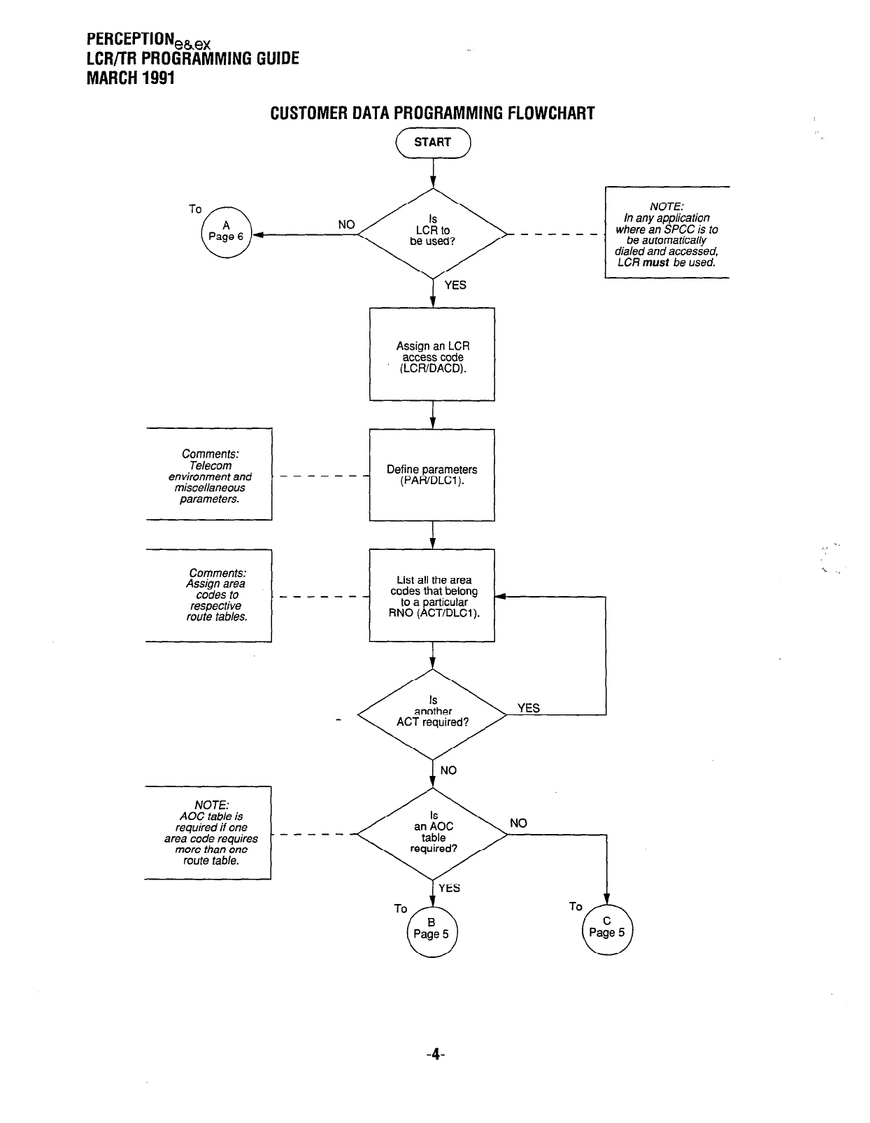
PERCEPTIONeh,
LCR/TR PROGRAMMING GUIDE
MARCH 1991
CUSTOMER DATA PROGRAMMING FLOWCHART
To
0
Pate 6 NO
4 ------
YES
;
Assign an LCR
accesscode
(LCWDACD).
Telecom
environment and - - - - - - Define parameters
miscellaneous (PAR/DLCl).
parameters.
Comments:
Assign area
codes to - - - -
respective
route tables.
YES
NOTE:
in any application
where an SPCC is to
be automatically
dialed and accessed,
LCR must be used.
i NO
AOC table is
area code requires
more than one
route table.
-4-
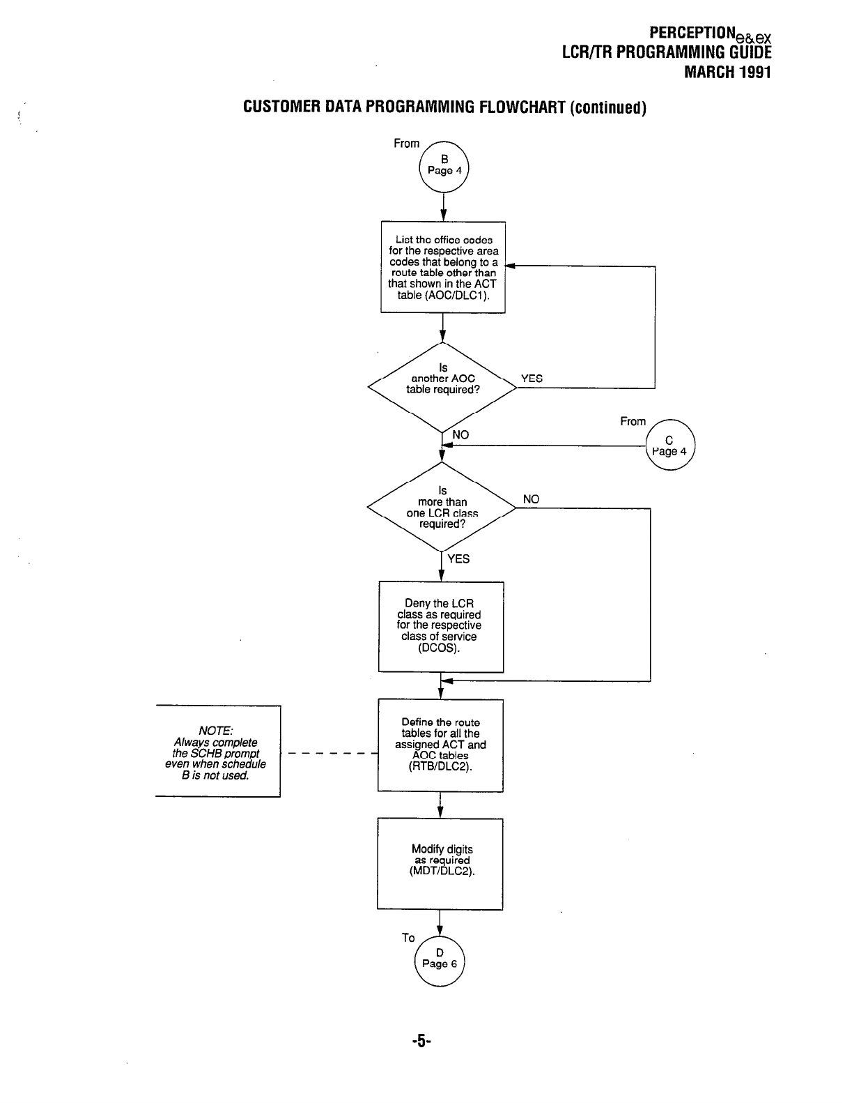
PERCEPTIONeb,
LCR/TR PROGRAMMING GUIDE
MARCH 1991
CUSTOMER DATA PROGRAMMING FLOWCHART (continued)
List the office codes
for the respective area
codes that belong to a
route table other than
that shown in the ACT
table (AOC/DLCl).
I-
Deny the LCR
class as required
for the respective
class of service
(DCOS).
one LCR class
NO
NOTE:
Always complete
the SCHB prompt
even when schedule
B is not used.
Define the route
tables for all the
assigned ACT and
AOC tables
(RTB/DLC2).
I
Modify digits
as required
(MDT/DLC2).
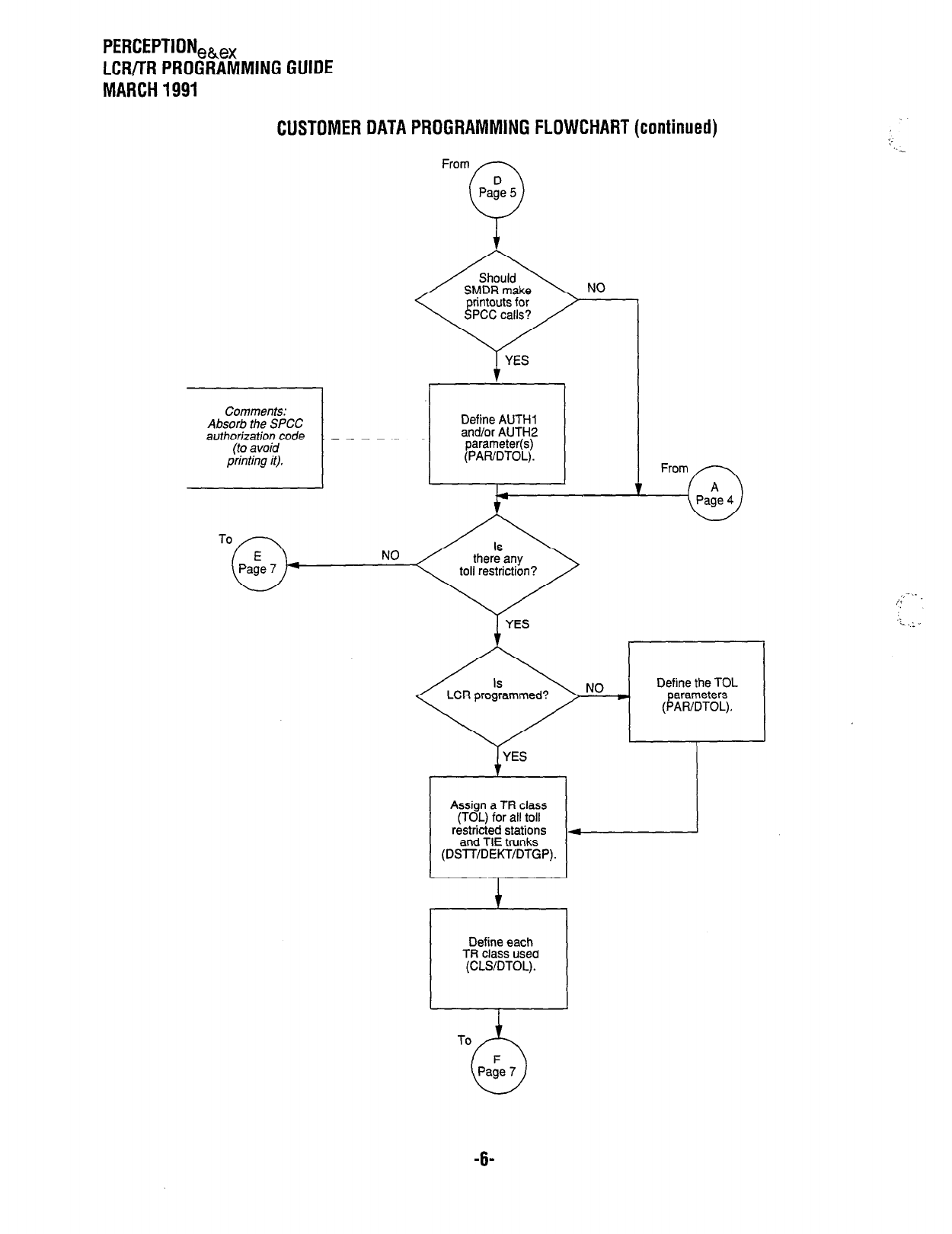
PERCEPTIONek,
LCR/TR PROGRAMMING GUIDE
MARCH 1991
CUSTOMER DATA PROGRAMMING FLOWCHART (continued)
From
NO
Comments:
Absorb the SPCC
authorization code _ _ _ - - -
1
anator AL I
‘^../
(l’AH/U I VI
I
Define AUTHl
*. - * IT,,2
paramebl (s)
-. - ‘--v.
NO toll restriction?
From
r A
-0
Page 4
LCR programmed? NO Define the TOL
arameters
(PAWDTOL).
Assign a TR class
restricted stations 4
and TIE trunks
(DSlT/DEKT/DTGP).
Define each
TR class used
(CLSDTOL).
-6-
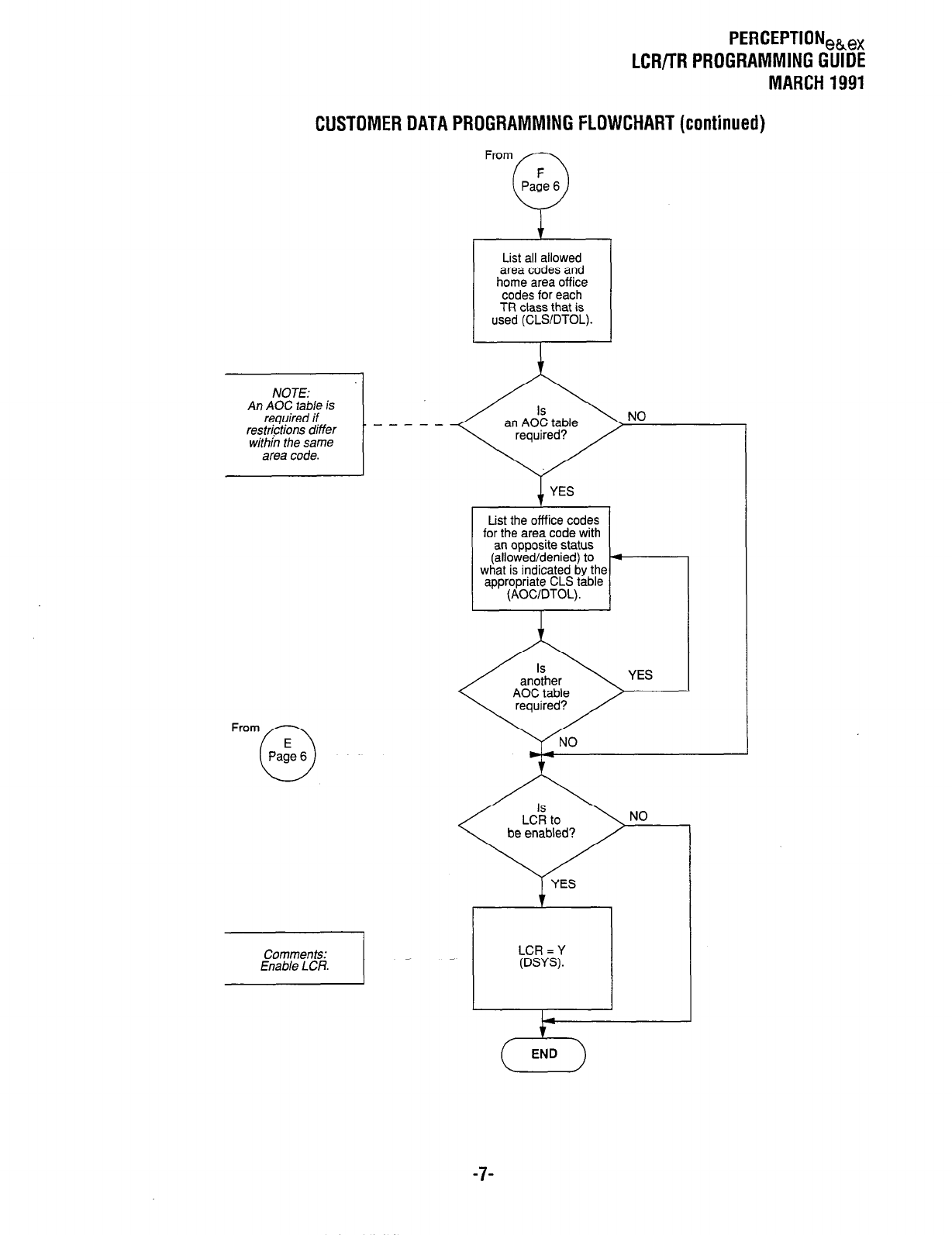
PERCEPTION,k,,
LCR/TR PROGRAMMING GUIDE
MARCH 1991
CUSTOMER DATA PROGRAMMING FLOWCHART (continued)
List all allowed
area codes and
home area off ice
codes for each
TR class that is
used (CLSIDTOL).
From
List the offfice codes
for the area code with
an opposite status
(allowed/denied) to
what is indicated by the
appropriate CLS table
(AOCIDTOL).
-7-
LCR/TR PROGRAMMING GUIDE
MARCH 1991
6. PROGRAMMING EXAMPLES
d)
6.00 General
6.01 Examples are given here to show how
PERCEPTIONehex systems can be programmed
for various system applications. It is assumed that
your system has been programmed in all areas,
except LCR and TR. Comments are shown on the
right side of the TTY printouts. These comments
are shown only once for the same prompt and are
not repeated for every Data Block in the same
programming example.
e)
f) The selection of the Route Table number is
accomplished in the Area Code Table. The
Modify Digits Table number is selected in the
Route Table.
6.02 The two examples show printouts using the
Data Output mode (see equivalent Data Blocks for
Data Input).
IMPORTANT!
These are examples only and may not be
realistic applications for the area under
discussion.
6.10 Programming Example #l
6.13 Toll Restriction: Toll restrictions or home area
restrictions are not programmed in the example
(TOL = NONE). However, theAUTH1 parameter is
programmed to “05” on the PAR table, DTOL
Program. This causes the 5-digit authorization
code to be absorbed (not printed) when the SMDR
prints the called number.
6.11 This is a very simple case, where only two
trunk groups are used. In this case, there is no
Least Cost Routing in the true sense, as this
application has only one routing choice for the
particular area code dialed. However, LCR recog-
nizes the area code, selects the correct trunk
group, and when required, automatically outpulses
the codes for SPCC access and authorization.
6.12 Least Cost Routing
a) In this case, the system is located in Orange
County, California (NPA=714).
b) For Least Cost Routing purposes, the outgoing
trunk calls are divided into three different areas.
1) Route Table #1 = Local area (NPA = 714).
2) Route Table #2 = Los Angeles area
(NPA = 213).
3) Route Table #I5 = Remainder of North
America.
c) One Special Common Carrier (SPCC) is used.
An access code (730 0000) and an authoriza-
tion code (87654) are used to access SPCC.
No routing priority is used (i.e., the only LCR
class is LCl). This is defined in the DCOS
Program, by not denying any LCR class. The
LCR access code is “9.”
The telecommunications environment is de-
fined in the DLCl Program (TYPE = PAR).
NOTE:
Even when only one time schedule is used
(ie., SCHA), Schedule 6 (SCHBprompt) must
also be completed in fhe DLCZ Program.
-a-
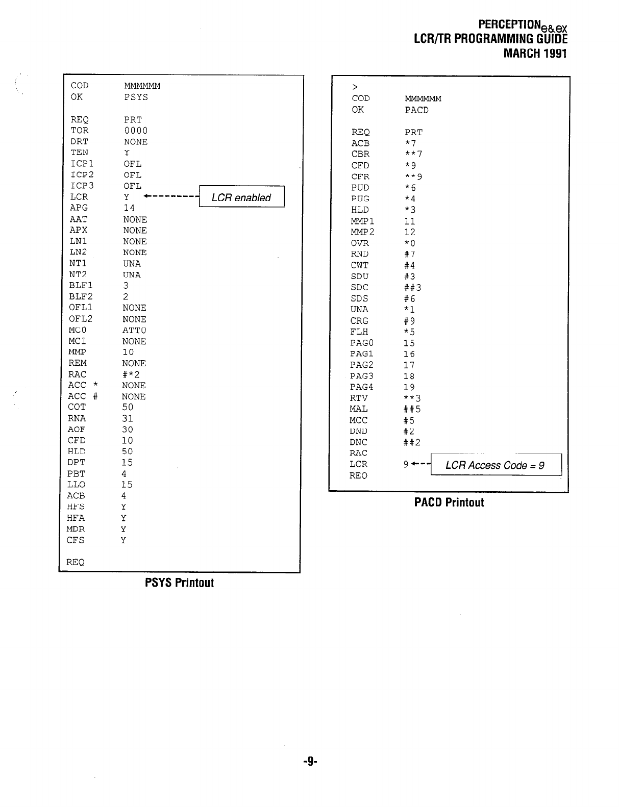
COD
OK PSYS
REQ PRT
TOR 0000
DRT NONE
TEN Y
ICPl OFL
ICP2 OFL
ICP3 OFL
LCR Y '-------
APG 14
AAT NONE
APX NONE
LNl NONE
LN2 NONE
NT1 UNA
NT2 UNA
BLFl 3
BLF2 2
OFLl NONE
OFL2 NONE
MC0 ATT0
MC1 NONE
MMP 10
REM NONE
RAC #*2
ACC * NONE
ACC # NONE
COT 50
RNA 31
AOF 30
CFD 10
HLD 50
DPT 15
PBT 4
LLO 15
4CB 4
SFS Y
3FA Y
ilDR Y
3FS Y
PSYS Printout
PERCEPTIONek,
LCR/TR PROGRAMMING GUIDE
MARCH 1991
>
COD
OK
REQ
ACB
CBR
CFD
CFR
PUD
PUG
HLD
MMPl
MMP2
OVR
RND
CWT
SDU
SDC
SDS
UNA
CRG
FLH
PAGO
PAGl
PAG2
PAG3
PAG4
RTV
MAL
MCC
DND
DNC
RAC
LCR
REQ
PACD
PRT
*7
**7
*9
**9
*6
*4
*3
11
12
*0
#7
#4
#3
##3
#6
*1
#9
*5
15
16
17
18
19
**3
##5
#5
#2
##2
9+- LCR Access Code = 9
-9-
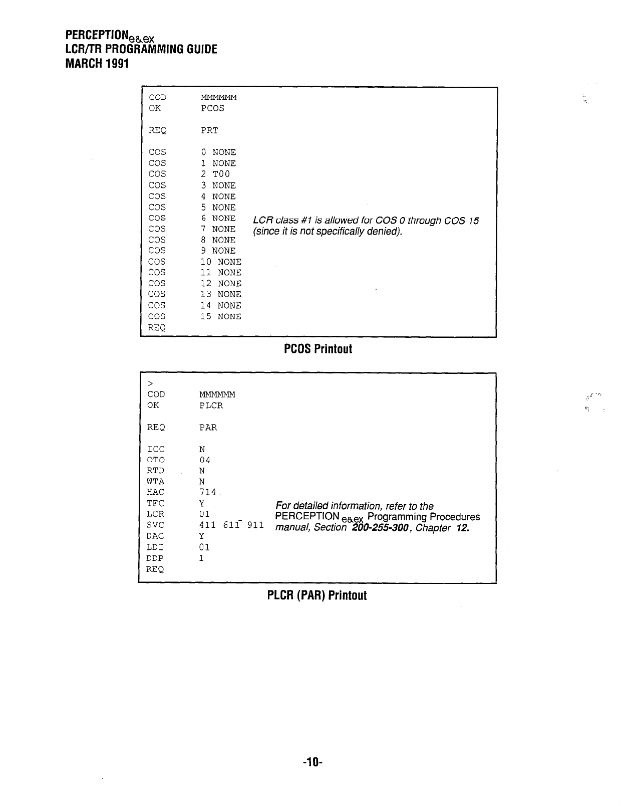
PERCEPTION,,,
LCR/l-R PROGRAMMING GUIDE
MARCH 1991
COD
OK
REQ
cos
cos
cos
cos
cos
cos
cos
cos
cos
cos
cos
cos
cos
cos
cos
cos
REQ
PCOS
PRT
0 NONE
1 NONE
2 TOO
3 NONE
4 NONE
5 NONE
6 NONE
7 NONE
LCR class #I is allowed for COS 0 through COS 15
8 NONE
(since it is not specifically denied).
9 NONE
10 NONE
11 NONE
12 NONE
13 NONE
14 NONE
15 NONE
PCOS Printout
COD
/ OK
1
REQ
PAR
ICC
OTO
RTD
WTA
HAC
TFC
LCR
svc
DAC
LDI
DDP
REQ
PLCR
N
04
N
N
714
Y
01
For detailed information, refer to the
61i-
PERCEPTION Procedures
411 911
manual, Section egeX Programming
Y 200-255-300, Chapter 12.
01
1
PLCR (PAR) Printout
-lO-
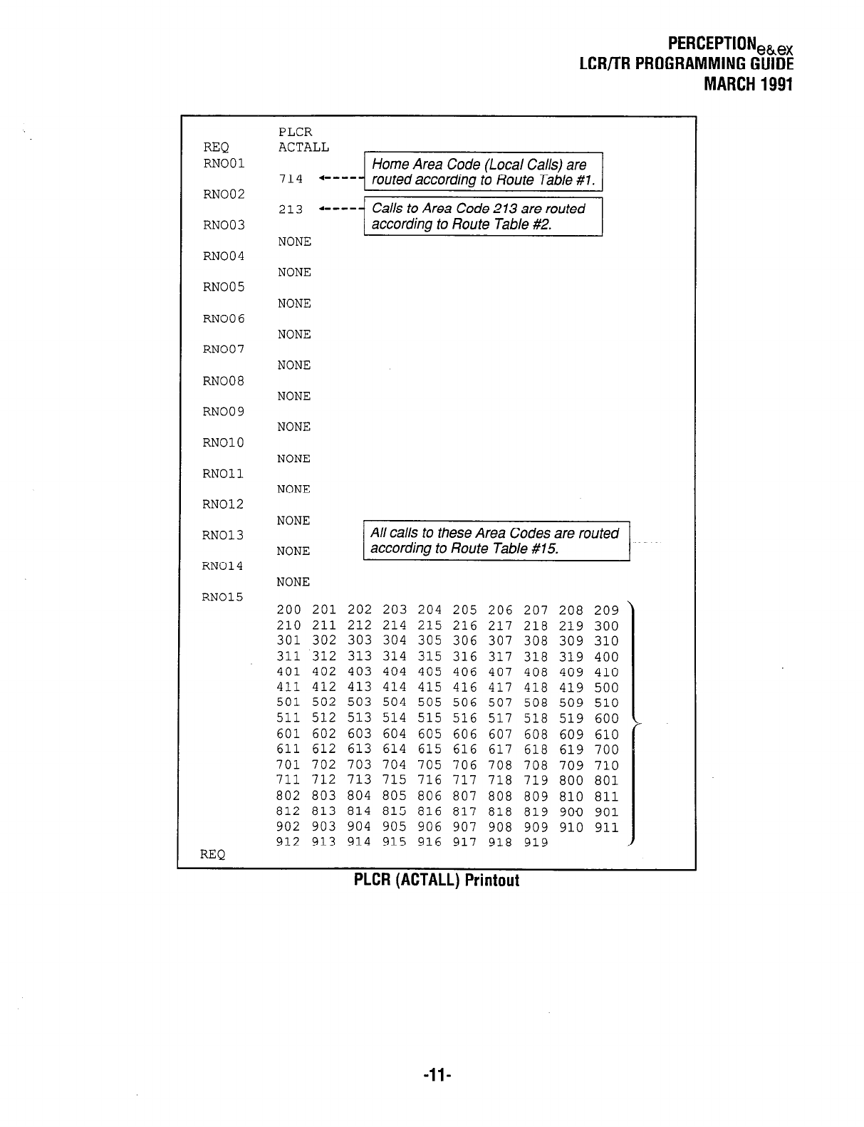
PERCEPTION,,,
LCWTR PROGRAMMING GUIDE
MARCH 1991
REQ
RN001
RN002
RN003
RN004
RN005
PLCR
ACTALL
Home Area Code (Local Calls) are
7 14
l
-- -- - routed according to Route Table #1.
213
a----- Calls to Area Code 213 are routed
according to Route Table #2.
NONE
NONE
NONE
RN006 NONE
RN007
RN008
RN009
RN010
RN011
RN012
NONE
NONE
NONE
NONE
NONE
NONE
RN013
All calls to these Area Codes are routed
NONE
according to Route Table #15.
RN014 NONE
RN015 200 201 202 203 204 205 206 207 208 209
210 211 212 214 215 216 217 218 219 300
301 302 303 304 305 306 307 308 309 310
311 312 313 314 315 316 317 318 319 400
401 402 403 404 405 406 407 408 409 410
411 412 413 414 415 416 417 418 419 500
501 502 503 504 505 506 507 508 509 510
511 512 513 514 515 516 517 518 519 600 I
601 602 603 604 605 606 607 608 609 610
611 612 613 614 615 616 617 618 619 700
701 702 703 704 705 706 708 708 709 710
711 712 713 715 716 717 718 719 800 801
802 803 804 805 806 807 808 809 810 811
812 813 814 815 816 817 818 819 900 901
902 903 904 905 906 907 908 909 910 911
912 913 914 915 916 917 918 919 I
REQ
PLCR (ACTALL) Printout
-ll-

PERCEPTION,&,
LCR/TR PROGRAMMING GUIDE
MARCH 1991
RTOl
RN001
RTl
RT2
RT3
RT4
RT5
RT6
SCHA
LC3
LC2
LCl
SCHB
LC3
LC2
LCl
SCHC
LC3
LC2
LCl
REQ
00 01
+ - - - Trunk Group 00, Modify Digits Table 0 1.
NONE NONE
NONE NONE
NONE NONE
NONE NONE
NONE NONE
0000 2400 a----
RTl
Schedule A used only in this application.
NONE
NONE
2400
0000 l ----
SCHB prompt must be completed.
NONE
NONE
NONE
0000 0000
NONE
NONE
NONE
RT02
RN002
RTl 01 01
RT2 NONE NONE
RT3 NONE NONE
RT4 NONE NONE
RT5 NONE NONE
RT6 NONE NONE
SCHA 0000 2400
LC3 RTl
LC.2 NONE
LCl NONE
SCHB 2400 0000
LC3 NONE
LC2 NONE
LCl NONE
SCHC 0000 0000
LC3 NONE
LC2 NONE
LCl NONE
REQ
Route Table #2 Printout
PLCR (RT02)
Route Table #l Printout
PLCR (RTOI )
RT15
RN015
RTl
RT2
RT3
RT4
RT5
RT6
SCHA
LC3
LC2
LCl
SCHB
LC3
LC2
LCl
SCHC
LC3
LC2
LCl
REQ
00
NONE
NONE
NONE
NONE
NONE
0000
RTl
NONE
NONE
2400
NONE
NONE
NONE
0000
NONE
NONE
NONE
03
NONE
NONE
NONE
NONE
NONE
2400
0000
0000
Route Table #15 Printout
PLCR (RT15)
-12-
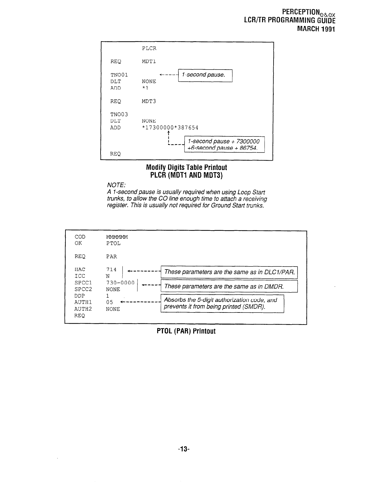
PERCEPTION,,,,
LCRflR PROGRAMMING GUIDE
MARCH 1991
PLCR
REQ MDT1
TN001
DLT NONE +---jI-secondpause.1
ADD *1
REQ MDT3
TN003
DLT NONE
ADD "17300000"387654
:
REQ
NOTE:
Modify Digits Table Printout
PLCR (MDT1 AND MDT3)
A 1 -second pause is usually required when using Loop Start
trunks, to allow the CO line enough time to attach a receiving
register. This is usually not required for Ground Start trunks.
COD
OK PTOL
REQ PAR
HAC 714 + - - - - - - - -
ICC 'N These parameters are the same as in DL C I/PA R.
SPCCl 730-0000
SPCC2 NONE 1 +---- These parameters are the same as in DMDR.
DDP 1
AUTHl o 5 .- _ _ _ _ _ _ _ _ _ _ Absorbs the S-digit authorization code, and
AUTH2 NONE prevents it from being printed (SMDR).
REQ
PTOL (PAR) Printout
-13-
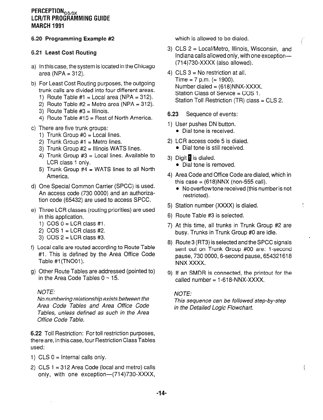
PERCEPTIONehex
LCR/TR PROGRAMMING GUIDE
MARCH 1991
6.20 Programming Example #2
6.21 Least Cost Routing
a)
b)
c)
d)
e)
f )
9)
In this case, the system is located in the Chicago
area (NPA = 312).
For Least Cost Routing purposes, the outgoing
trunk calls are divided into four different areas.
1) Route Table #I = Local area (NPA = 312).
2) Route Table #2 = Metro area (NPA = 312).
3) Route Table #3 = Illinois.
4) Route Table #15 = Rest of North America.
3) CLS 2 = Local/Metro, Illinois, Wisconsin, and
Indiana calls allowed only, with one exception-
(714)730-XxXx (also allowed).
4) CLS 3 = No restriction at all.
Time = 7 p.m. (= 1900).
Number dialed = (618)NNX-XXXX.
Station Class of Service = COS 1.
Station Toll Restriction (TR) class = CLS 2.
6.23 Sequence of events:
There are five trunk groups:
1) Trunk Group #0 = Local lines.
2) Trunk Group #l = Metro lines.
3) Trunk Group #2 = Illinois WATS lines.
4) Trunk Group #3 = Local lines. Available to
LCR class 1 only.
5) Trunk Group #4 = WATS lines to all North
America.
1)
2)
3)
4)
User pushes DN button.
l
Dial tone is received.
LCR access code 5 is dialed.
l
Dial tone is still received.
Digit 0 is dialed.
l
Dial tone is removed.
One Special Common Carrier (SPCC) is used.
An access code (730 0000) and an authoriza-
tion code (65432) are used to access SPCC.
Three LCR classes (routing priorities) are used
in this application.
1) COS 0 = LCR class #l .
2) COS 1 = LCR class #2.
3) COS 2 = LCR class #3.
Local calls are routed according to Route Table
#I. This is defined by the Area Office Code
Table #I (TNOOl).
Area Code and Office Code are dialed, which in
this case = (618)NNX (non-555 call).
l
No overflow tone received (this number is not
restricted).
5)
6)
7)
8)
Station number (XXXX) is dialed.
Route Table #3 is selected.
At this time, all trunks in Trunk Group #2 are
busy. Trunks in Trunk Group #0 are idle.
Route3 (RT3) is selected and the SPCC signals
sent out on Trunk Group #00 are: l-second
pause, 730 0000,6-second pause, 654321618
NNX XXXX.
Other Route Tables are addressed (pointed to)
in the Area Code Tables 0 w 15.
9)
If an SMDR is connected, the printout for the
called number = l-61 8-NNX-XXXX.
NOTE: NOTE:
No numbering relationship exists between the
Area Code Tables and Area Office Code
Tables, unless defined as such in the Area
Office Code Table.
This sequence can be followed step-by-step
in the Detailed Logic Flowchart.
6.22 Toll Restriction: For toll restriction purposes,
there are, in this case, four Restriction Class Tables
used:
1) CLS 0 = Internal calls only.
2) CLS 1 = 312 Area Code (local and metro) calls
only, with one exception-(71 4)730-XxXx,
which is allowed to be dialed.
-14-
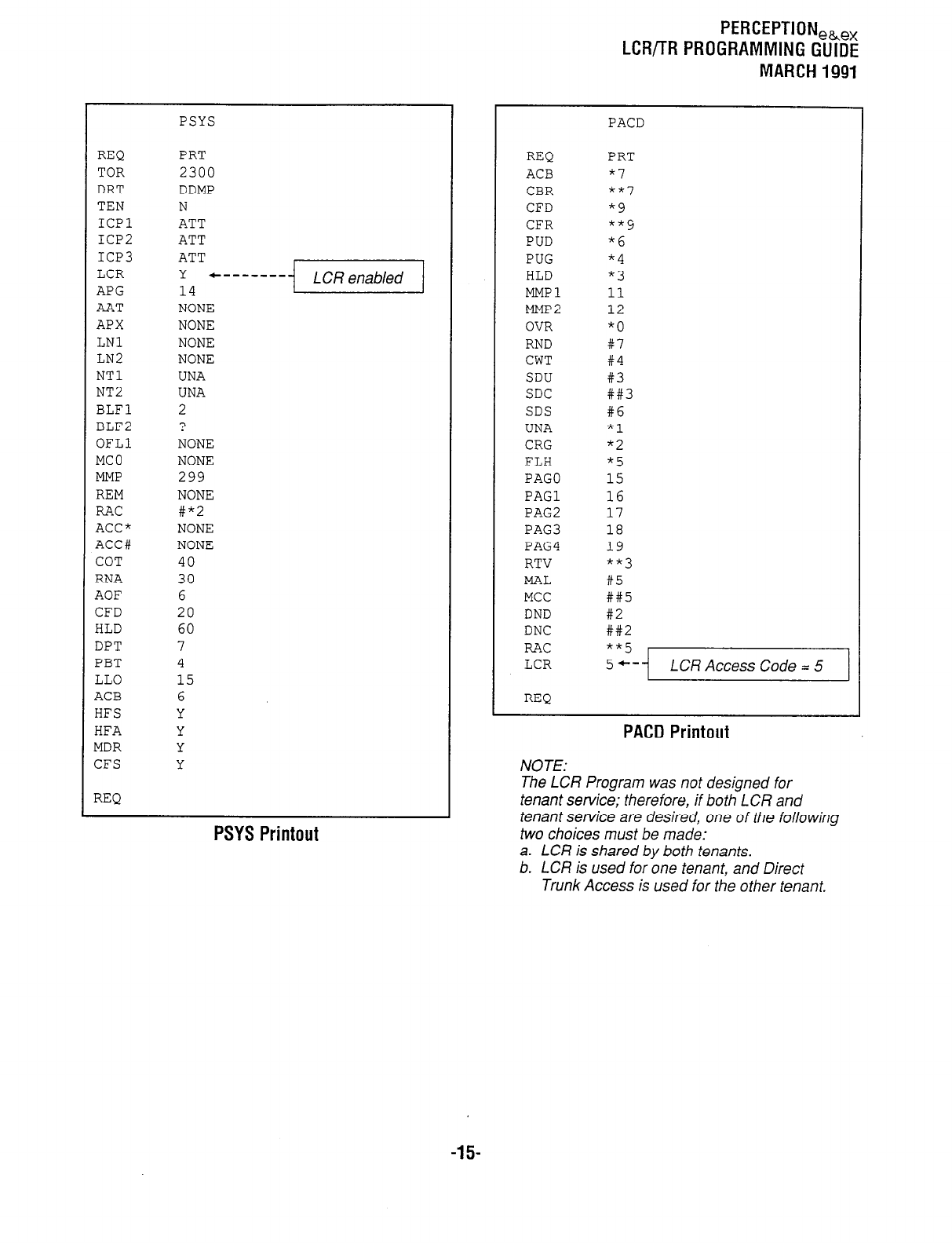
PERCEPTION,~,,
LCR/TR PROGRAMMING GUIDE
MARCH 1991
REQ
TOR
DRT
TEN
ICPl
ICP2
ICP3
LCR
APG
AAT
APX
LNl
LN2
NT1
NT2
BLFl
BLF2
OFLl
MC0
MMP
REM
RAC
ACC"
ACC#
COT
RNA
AOF
CFD
HLD
DPT
PBT
LLO
ACB
HFS
HFA
MDR
CFS
REQ
PSYS
PRT
2300
DDMP
N
ATT
ATT
ATT
Y
14 --------j-1
NONE
NONE
NONE
NONE
UNA
UNA
7
L
?
NONE
NONE
299
NONE
#"2
NONE
NONE
40
30
6
20
60
7
4
15
6
Y
Y
Y
Y
PSYS Printout
REQ
ACB
CBR
CFD
CFR
PUD
PUG
HLD
MMPl
MMP2
OVR
RND
CWT
SDU
SDC
SDS
UNA
CRG
FLH
PAGO
PAGl
PAG2
PAG3
PAG4
RTV
MAL
MCC
DND
DNC
RAC
LCR
REQ
PACD
PRT
*I
**7
"9
""9
"6
"4
*3
11
12
"0
#7
#4
#3
##3
#6
*1
"2
*5
15
16
17
18
19
**3
#5
##5
#2
##2
**5
5+- LCR Access Code = 5
PACD Printout
NOTE:
The LCR Program was not designed for
tenant service; therefore, if both LCR and
tenant service are desired, one of the following
two choices must be made:
a. LCR is shared by both tenants.
b. LCR is used for one tenant, and Direct
Trunk Access is used for the other tenant.
-15-
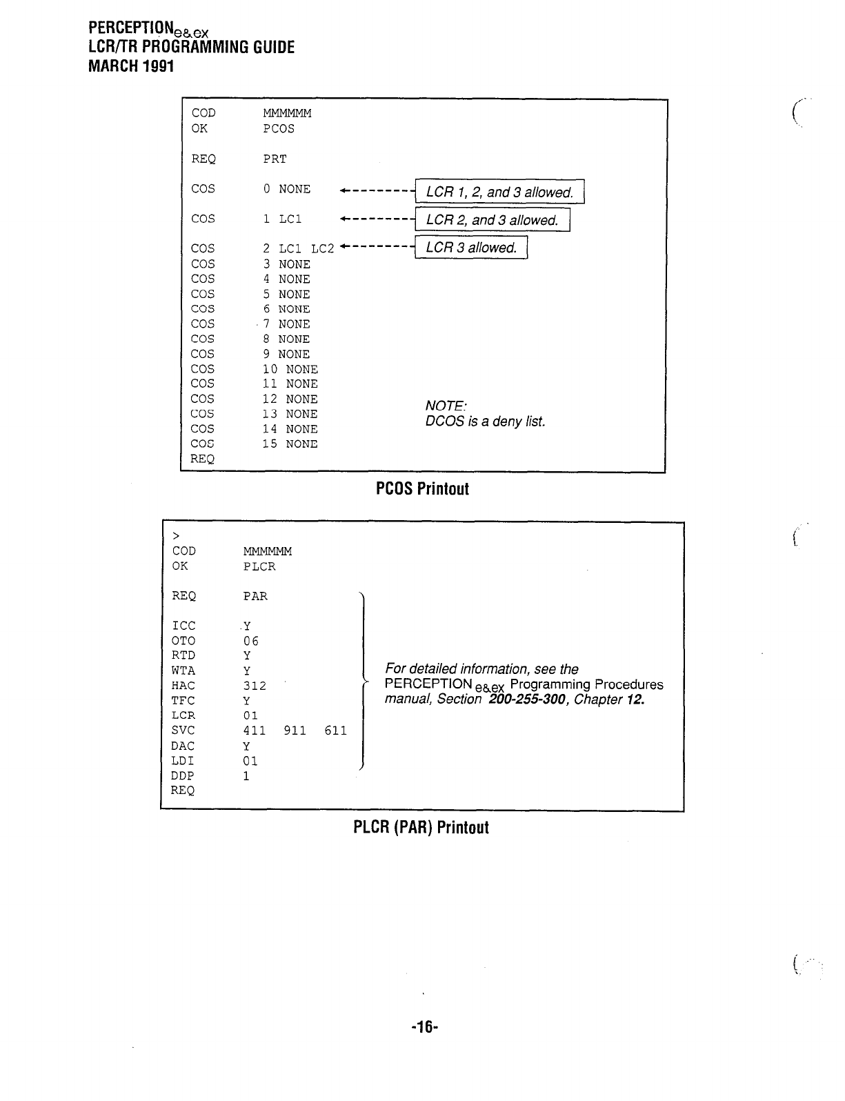
PERCEPTIeNeh,,
LCR/TR PROGRAMMING GUIDE
MARCH 1991
COD
OK PCOS
REQ PRT
cos 0 NONE +------- LCR 1,2, and 3 allowed.
cos
cos
cos
cos
cos
cos
cos
cos
cos
cos
cos
cos
cos
cos
cos
REQ
1 LCl +------- LCR 2, and 3 allowed.
2 LCl LC2
3 NONE +-------]&-zGq
4 NONE
5 NONE
6 NONE
7 NONE
8 NONE
9 NONE
10 NONE
11 NONE
12 NONE
13 NONE
14 NONE
15 NONE
NOTE:
DCOS is a deny list.
PCOS Printout
>
COD
OK PLCR
REQ
ICC
OTO
RTD
WTA
HAC
TFC
LCR
svc
DAC
LDI
DDP
REQ
PAR
.Y
06
Y
Y
312
Y
01
411 911 611
Y
01
1
For detailed information, see the
* PERCEPTION ebeX Programming Procedures
manual, Section 200-255-300, Chapter 12.
-16-
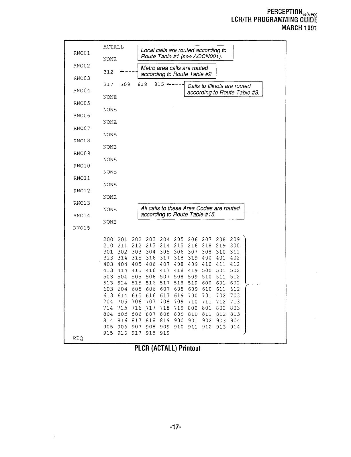
PERCEPTION,,,,
LCR/TR PROGRAMMING GUIDE
MARCH 1991
ACTALL
RN001 Local calls are routed according to
NONE Route Table #l (see AOCNOOl).
RN002 312 +---- Metro area calls are routed
RN003 according to Route Table #2.
217 309 618 815 ‘----- Calls to Illinois are routed
RN004 NONE according to Route Table #3.
RN005 NONE
RN006 NONE
RN007 NONE
RN008 NONE
RN009 NONE
RN010 NONE
RN011 NONE
RN012 NONE
RN013 NONE All calls to these Area Codes are routed
RN014 according to Route Table 815.
NONE
RN015
200 201 202 203 204 205 206 207 208 209
210 211 212 213 214 215 216 218 219 300
301 302 303 304 305 306 307 308 310 311
313 314 315 316 317 318 319 400 401 402
403 404 405 406 407 408 409 410 411 412
413 414 415 416 417 418 419 500 501 502
503 504 505 506 507 508 509 510 511 512
513 514 515 516 517 518 519 600 601 602
603 604 605 606 607 608 609 610 611 612
613 614 615 616 617 619 700 701 702 703
704 705 706 707 708 709 710 711 712 713
714 715 716 717 718 719 800 801 802 803
804 805 806 807 808 809 810 811 812 813
814 816 817 818 819 900 901 902 903 904
905 906 907 908 909 910 911 912 913 914
915 916 917 918 919
REQ
PLCR (ACTALL) Printout
-17-
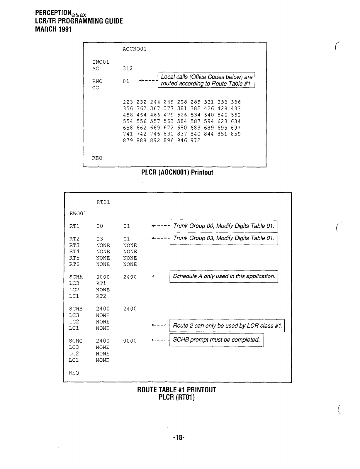
PERCEPTIONeh,
LCR/TR PROGRAMMING GUIDE
MARCH 1991
TN001
AC
RN0
oc
REQ
AOCNOOl
312
01 .---- Local calls (Office Codes below) are
routed according to Route Table 81
223 232 244 249 258 289 331 333 336
356 362 367 371 381 382 426 428 433
458 464 466 479 526 534 540 546 552
554 556 557 563 584 587 594 623 634
658 662 669 672 680 683 689 695 697
741 742 746 830 83-l 840 844 851 859
879 888 892 896 946 972
PLCR (AOCNOOl) Printout
RTOl
RN001
RTl 00 01
RT2 03 01
RT3 NONE NONE
RT4 NONE NONE
RT5 NONE NONE
RT6 NONE NONE
SCHA 0000 2400
LC3 RTl
LC2 NONE
LCl RT2
SCHB 2400 2400
LC3 NONE
LC2 NONE
LCl NONE
SCHC 2400 0000
LC3 NONE
LC2 NONE
LCl NONE
+ - - - - Trunk Group 00, Modify Digits Table 0 7.
+ - - - - Trunk Group 03, Modify Digits Table 0 1.
l
- - - - Schedule A only used in this application.
+ - - - - Route 2 can only be used by LCR class #l.
+ - - - - SCHB prompt must be completed.
REQ
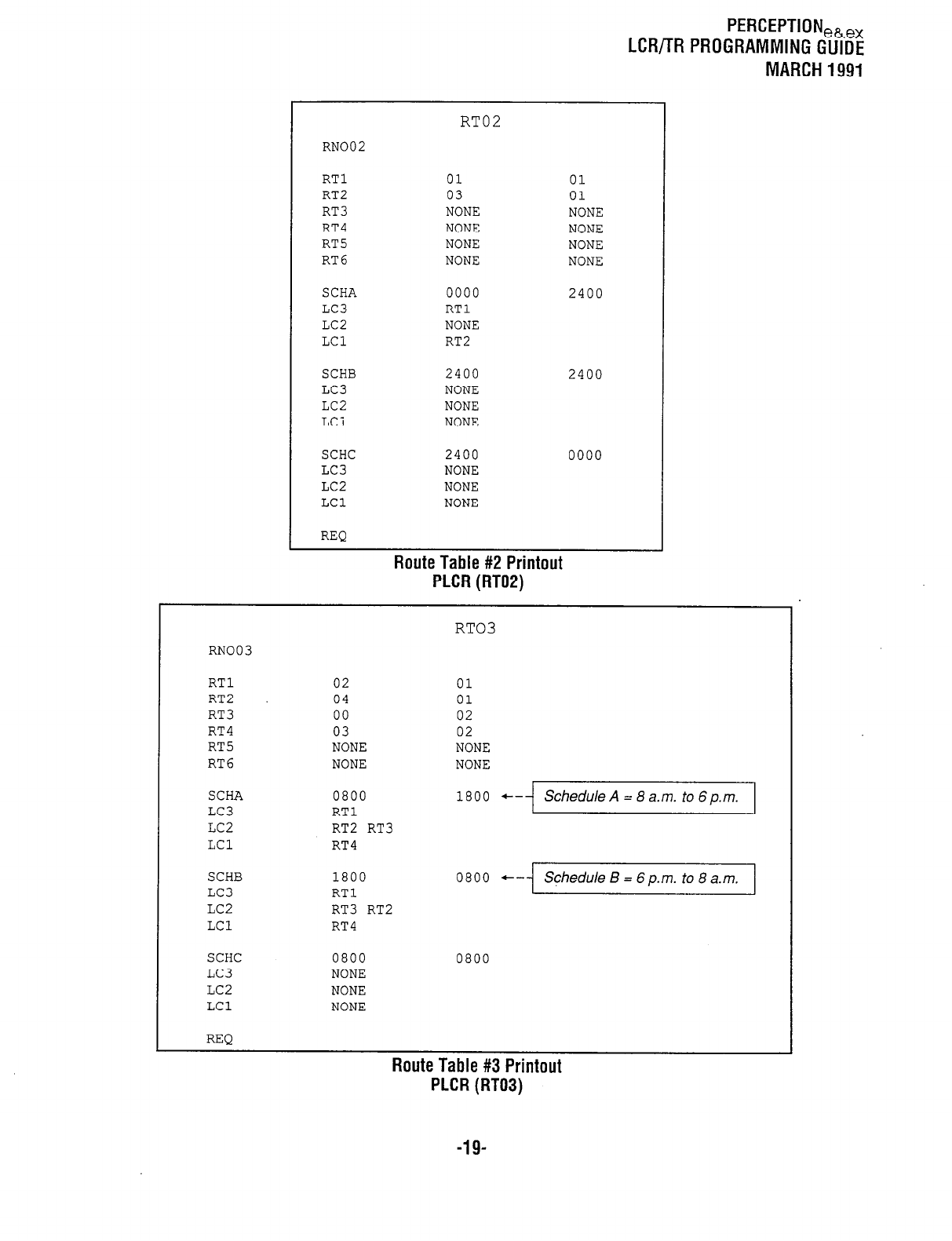
PEFiCEPTION,h,,
LCR/TR PROGRAMMING GUIDE
MARCH 1991
RT02
RN002
RTl 01 01
RT2 03 01
RT3 NONE NONE
RT4 NONE NONE
RT5 NONE NONE
RT6 NONE NONE
SCHA 0000 2400
LC3 RTl
LC2 NONE
LCl RT2
SCHB 2400 2400
LC3 NONE
LC2 NONE
LCi NONE
SCHC 2400 0000
LC3 NONE
LC2 NONE
LCl NONE
REQ
Route Table #2 Printout
PLCR (RT02)
RT03
RN003
RTl 02 01
RT2 04 01
RT3 00 02
RT4 03 02
RT5 NONE NONE
RT6 NONE NONE
SCHA
LC3
LC2
LCl
0800
RTl
RT2 RT3
RT4
1800 +-
Schedule A = 8 a.m. to 6 p.m.
SCHB
LC3
LC2
LCl
SCHC
LC3
LC2
LCl
REQ
1800 0800 +-
Schedule B = 6 p.m. to 8 a.m.
RTl
RT3 RT2
RT4
0800 0800
NONE
NONE
NONE
Route Table #3 Printout
PLCR (RT03)
-19-
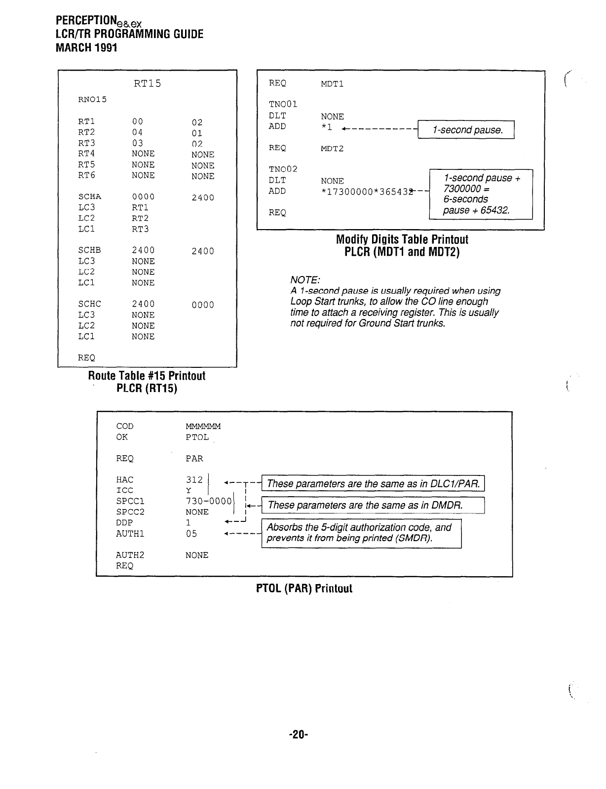
PERCEPTION,&,,
LCf?/TR PROGRAMMING GUIDE
MARCH 1991
RT15
RN015
RTl 00 02
RT2 04 01
RT3 03 02
RT4 NONE NONE
RT5 NONE NONE
RT6 NONE NONE
SCHA 0000 2400
LC3 RTl
LC2 RT2
LCl RT3
SCHB 2400 2400
LC3 NONE
LC2 NONE
LCl NONE
SCHC 2400 0000
LC3 NONE
LC2 NONE
LCl NONE
REQ
Route Table #I5 Printout
PLCR (RT15)
REQ MDT1
TN001
DLT NONE I
ADD *1 +--------- I -second pause.
REQ MDT2
TN002
DLT
ADD
REQ
~~~;00000*36543~-~~
Modify Digits Table Printout
PLCR (MDT1 and MDTP)
NOTE:
A 1 -second pause is usually required when using
Loop Start trunks, to allow the CO line enough
time to attach a receiving register. This is usually
not required for Ground Start trunks.
COD
OK
REQ PAR
HAC
ICC
SPCCl
SPCC2
DDP
AUTHl
AUTH2
REQ
PTOL
312
Y I .---r- These parameters are the same as in DLCl/PAR.
I
730~0000
NONE I c These parameters are the same as in DMDR.
1 c- J
05 4---- Absorbs the 5-digit authorization code, and
prevents it from being printed (SMDR).
t 1
NONE
PTOL (PAR) Printout
-2o-
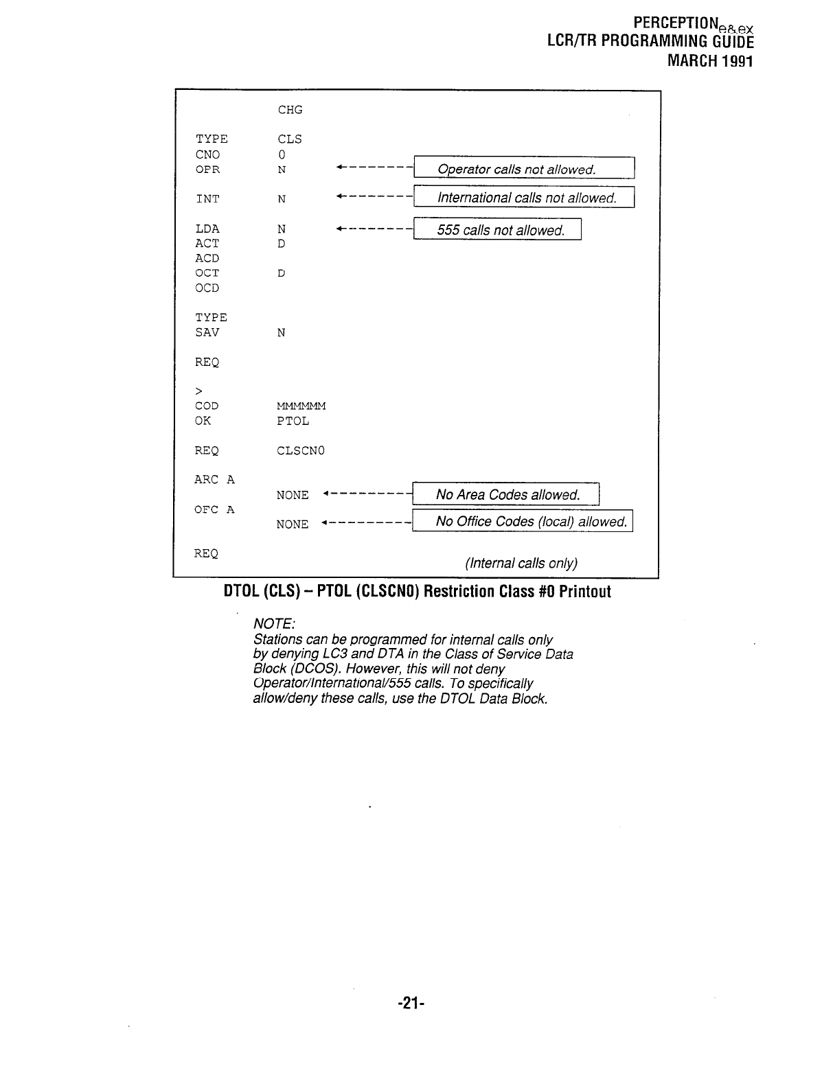
PERCEPTION,B,,
LCR/TR PROGRAMMING GUIDE
MARCH 1991
TYPE
CNO
OPR
INT
LDA
ACT
ACD
OCT
OCD
TYPE
SAV
REQ
>
COD
OK
REQ
ARC A
OFC A
REQ
CHG
CLS
0
N *------- Operator calls not allowed. 1
N *------- International calls not allowed.
r
N f------- 555 calls not allowed.
D
D
N
PTOL
CLSCNO
NONE +---------I No Area Codes allowed. 1
NONE 4---------
No Office Codes (local) allowed.
(Internal calls only)
DTDL (CLS) - PTDL (CLSCNO) Restriction Class #O Printout
NOTE:
Stations can be programmed for internal calls only
by denying LC3 and DTA in the Class of Service Data
Block (DCOS). However, this will not deny
Operator/International/555 calls. To specifically
allow/deny these calls, use the DTOL Data Block.
-21-
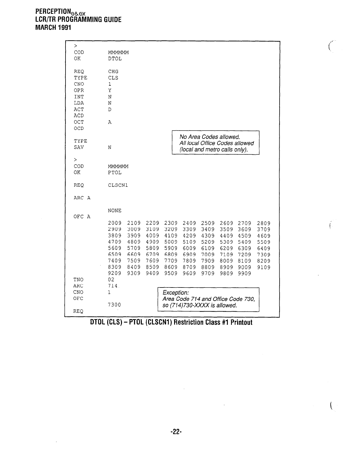
PERCEPTION,h,,
LCR/TR PROGRAMMING GUIDE
MARCH 1991
>
COD
OK
REQ
TYPE
CNO
OPR
INT
LDA
ACT
ACD
OCT
OCD
TYPE
SAV
>
COD
OK
REQ CLSCNl
DTOL
CHG
CLS
A
N Ji
PTOL
ARC A
NONE
OFC A
TN0
ARC
CNO
OFC
2009
2909
3809
4709
5609
6509
1409
8309
9209
02
714
1
7300
REQ
2109 2209
2309 2409 2509 2609
2709
3009
3109 3209 3309 3409 3509
3609
3909
4009 4109 4209 4309 4409
4509
4809 4909 5009 5109 5209 5309
5409
5709 5809 5909 6009 6109 6209
6309
6609 6709 6809 6909 7009 7109
7209
7509 7609 7709 7809 7909 8009 8109
8409 8509 8609 8709 8809 8909 9009
9309 9409 9509 9609 9709 9809 9909
2809
3709
4609
5509
6409
7309
8209
9109
DTDL (CLS) - PTOL (CLSCNl) Restriction Class #1 Printout
c
-22-
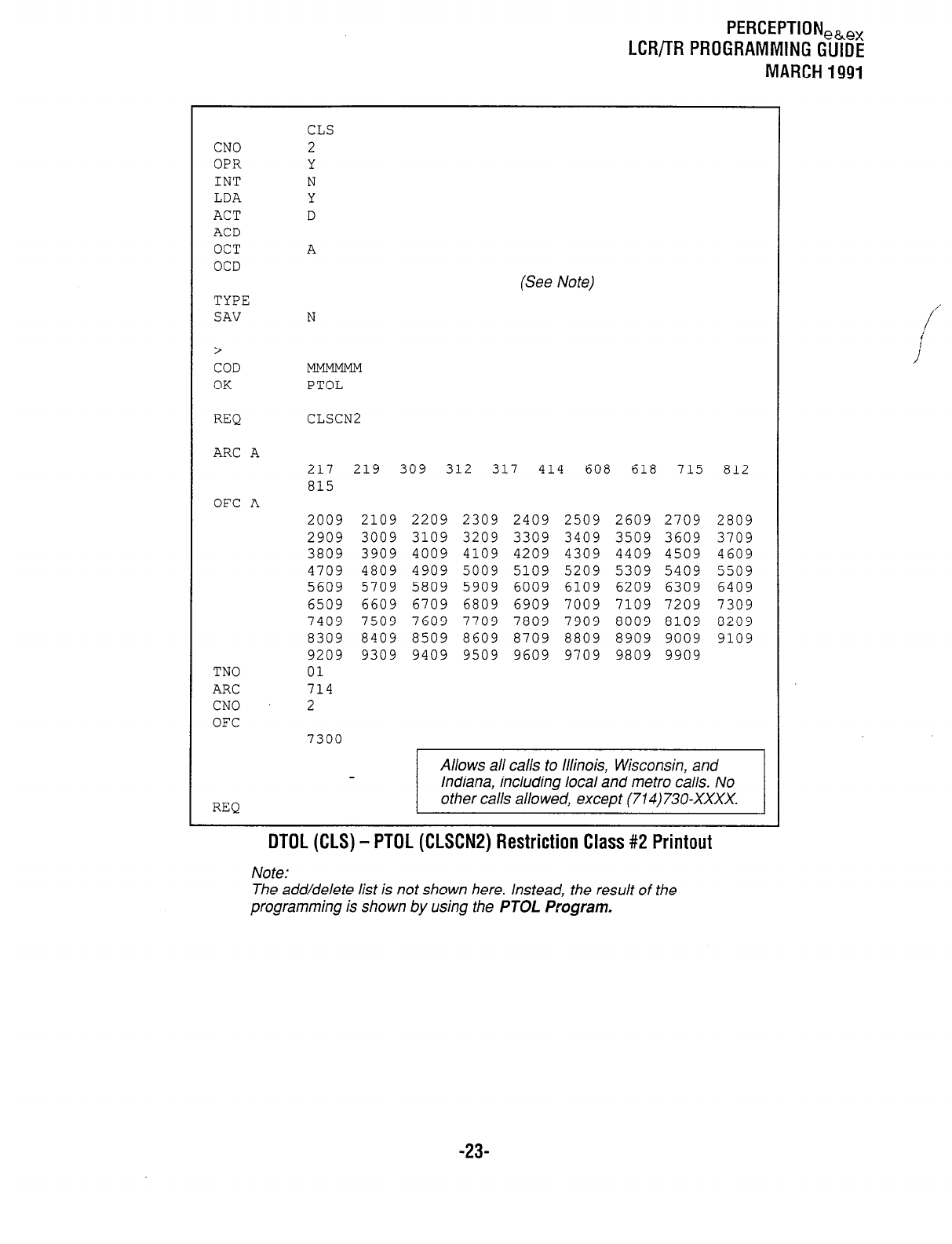
PERCEPTION,&,,
LCR/TR PROGRAMMING GUIDE
MARCH 1991
CNO
OPR
INT
LDA
ACT
ACD
OCT
OCD
TYPE
SAV
>
COD
OK
REQ CLSCN2
ARC A
OFC A
TN0
ARC
CNO
OFC
A
N
PTOL
217
815
2009
2909
3809
4709
5609
6509
7409
8309
9209
01
714
L
7300
(See Note)
219 309 312 317 414 608 618 715 812
2109 2209 2309 2409 2509 2609 2709
3009 3109 3209 3309 3409 3509 3609
3909 4009 4109 4209 4309 4409 4509
4809 4909 5009 5109 5209 5309 5409
5709 5809 5909 6009 6109 6209 6309
6609 6709 6809 6909 7009 7109 7209
7509 7609 7709 7809 7909 8009 8109
8409 8509 8609 8709 8809 8909 9009
9309 9409 9509 9609 9709 9809 9909
2809
3709
4609
5509
6409
7309
8209
9109
REQ
Allows all calls to Illinois, Wisconsin, and
Indiana, including local and metro calls. No
other calls allowed, except (714) 730-XxXx.
DTDL (CLS) - PTOL (CLSCN2) Restriction Class #2 Printout
Note:
The add/delete list is not shown here. Instead, the result of the
programming is shown by using the
PTOL Program.
-23-
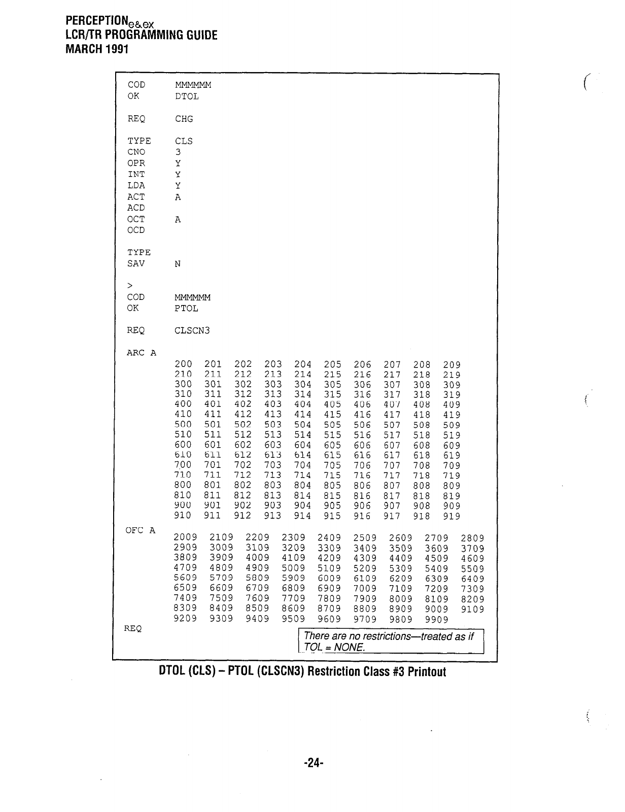
PERCEPTION,&,
LCR/lR PROGRAMMING GUIDE
MARCH 1991
COD
OK DTOL
REQ CHG
TYPE
CNO
OPR
INT
LDA
ACT
ACD
OCT
OCD
CLS
3
Y
Y
Y
A
A
TYPE
SAV N
>
COD
OK PTOL
REQ CLSCN3
ARC A
OFC A
REQ
200 201 202 203 204 205 206 207 208 209
210 211 212 213 214 215 216 217 218 219
300 301 302 303 304 305 306 307 308 309
310 311 312 313 314 315 316 317 318 319
400 401 402 403 404 405 406 407 408 409
410 411 412 413 414 415 416 417 418 419
500 501 502 503 504 505 506 507 508 509
510 511 512 513 514 515 516 517 518 519
600 601 602 603 604 605 606 607 608 609
610 611 612 613 614 615 616 617 618 619
7.0 0 701 702 703 704 705 706 707 708 709
710 711 712 713 714 715 716 717 718 719
800 801 802 803 804 805 806 807 808 809
810 811 812 813 814 815 816 817 818 819
900 901 902 903 904 905 906 907 908 909
910 911 912 913 914 915 916 917 918 919
2009
2909
3809
4709
5609
6509
7409
8309
9209
2109
3009
3909
4809
5709
6609
7509
8409
9309
2209
3109
4009
4909
5809
6709
7609
8509
9409
2309 2409 2509 2609 2709 2809
3209 3309 3409 3509 3609 3709
4109 4209 4309 4409 4509 4609
5009 5109 5209 5309 5409 5509
5909 6009 6109 6209 6309 6409
6809 6909 7009 7109 7209 7309
7709 7809 7909 8009 8109 8209
8609 8709 8809 8909 9009 9109
9509 9609 9709 9809 9909
There are no restrictions-treated as if
TOL = NONE.
c
OTOL (,CLS) - PTOL (CLSCNS) Restriction Class #3 Printout
-24-
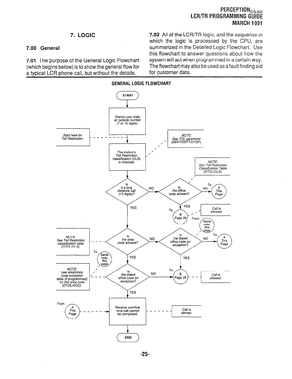
LCR/TR PROGRAMMING GUIDE
MARCH 1991
7.
LOGIC
7.02 All of the LCR/TR logic, and the sequence in
which the logic is processed by the CPU, are
7.00 General summarized in the Detailed Logic Flowchart. Use
this flowchart to answer questions about how the
7.01 The purpose of the General Logic Flowchart system will act when programmed in a certain way.
(which begins below) is to show the general flow for The flowchart may also be used as a fault finding aid
a typical LCR phone call, but without the details. for customer data.
GENERAL LOGIC FLOWCHART
Station user dials
Start here for
To// Restriction.
NOTE:
See To// Restriction
classificafion table
(DTOUCLS).
See area/office
code exception
table (if programmed)
for this area code
NO
office code an
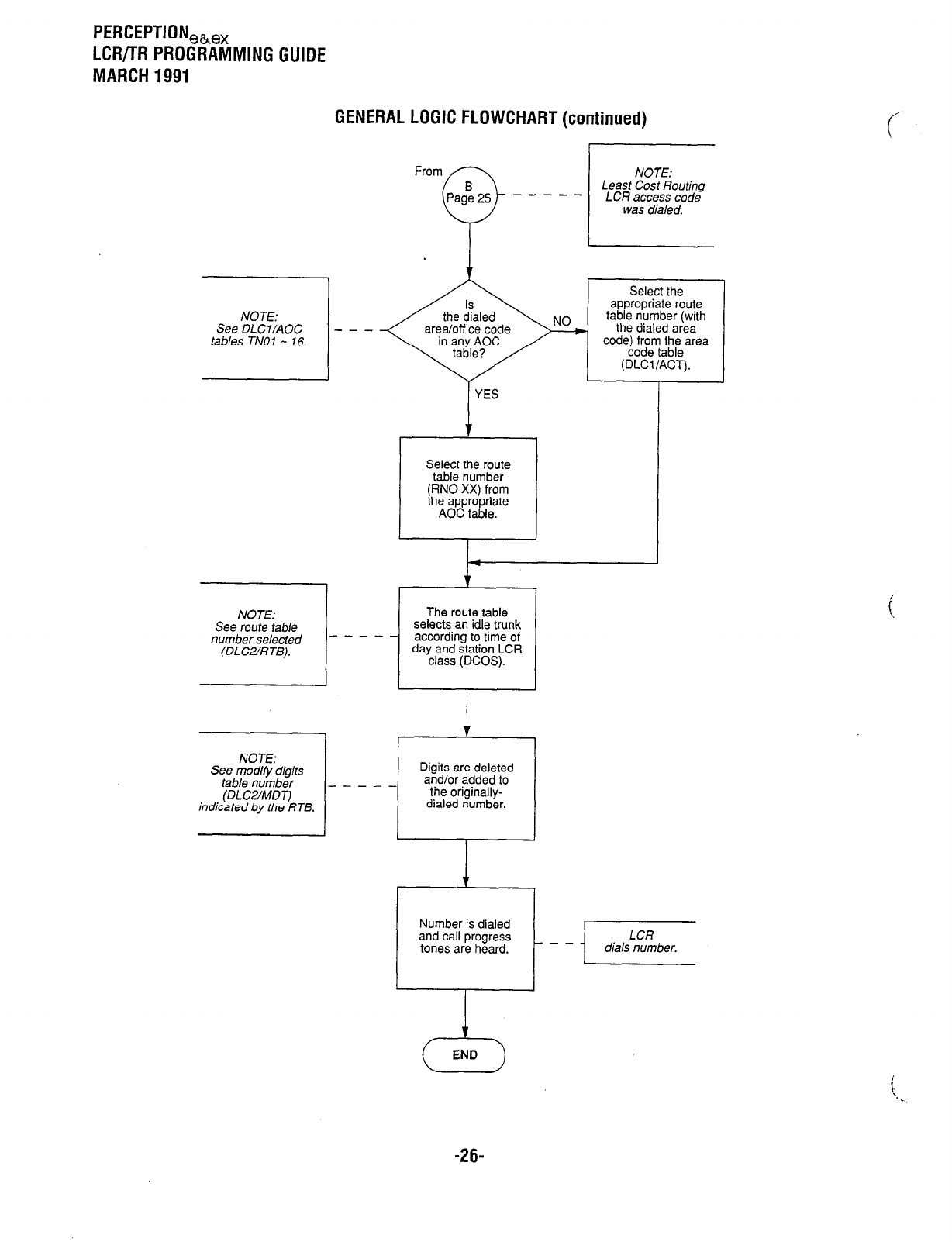
PERCEPTION,h,,
LCR/TR PROGRAMMING GUIDE
MARCH 1991
GENERAL LOGIC FLOWCHART (continued)
NOTE:
See DLCVAOC - - -
tables TN01 - 16.
See route table
number selected -
See modify digits
table number _
indicated by the RTB.
The route table
selects an idle trunk
--- according to time of
day and station LCR
Digits are deleted
and/or added to
---
dialed number.
From NOTE:
Least Cost Routing
- - - - - LCR access code
was dialed.
Y I I
YES
Select the route
table number
(RN0 XX) from
the appro riate
AOC ta I! le.
Number is dialed
and call progress
tones are heard.
i
A
END
1
\. . .
-26-
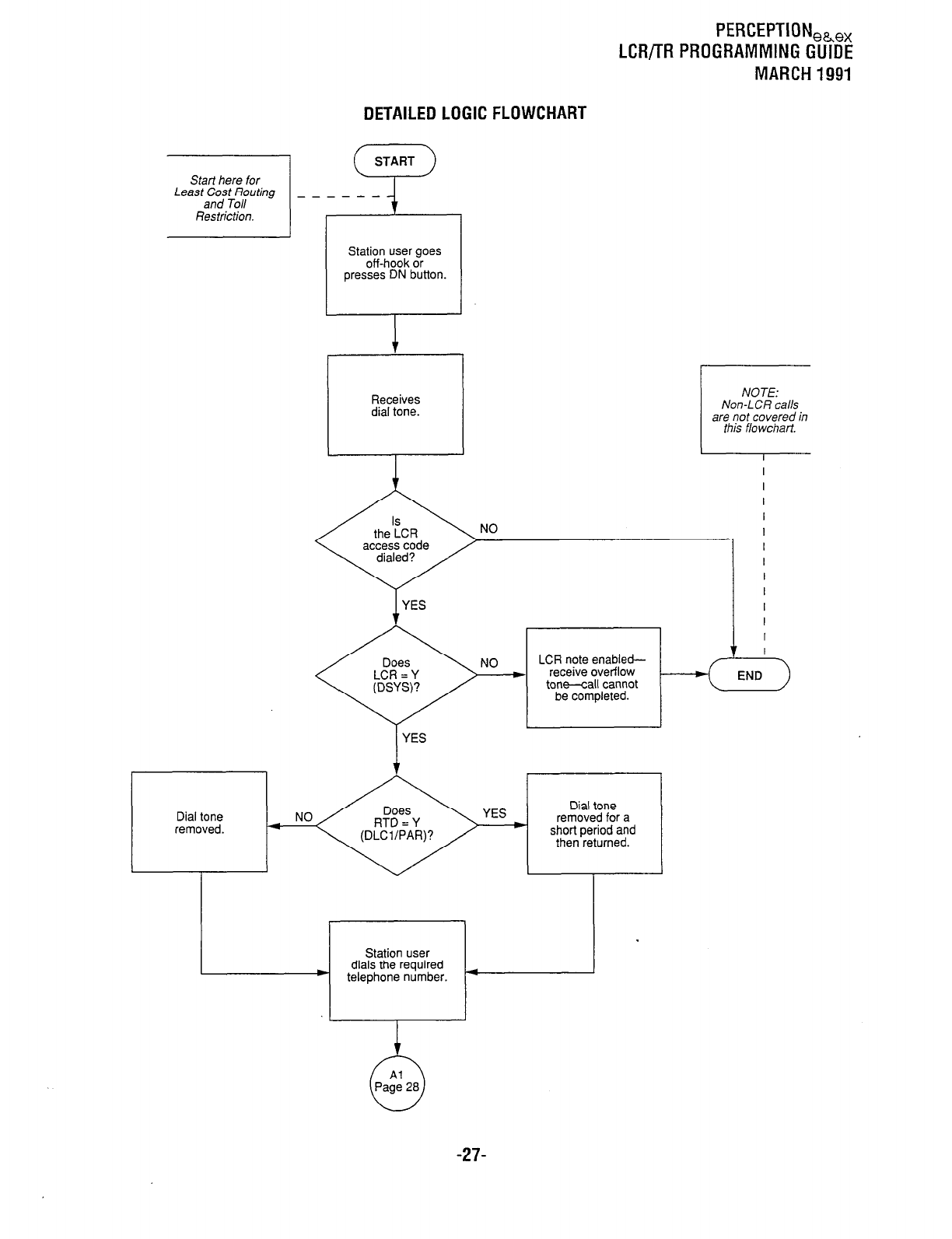
PERGEPTIONeh,,
LCR/TR PROGRAMMING GUIDE
MARCH 1991
DETAILED LOGIC FLOWCHART
Start here for
Station user goes
off-hook or
presses DN button.
NOTE:
Non-LCR calls
are not covered in
this flowchart.
I I
NO
1
YES
YES
LCR note enabled-
receive overflow
tone--call cannot
be completed.
I
I
I
I
I
I
I
I
I
I
I
I
7
Dial tone
removed.
Dial tone
removed for a
short period and
then returned.
Station user
dials the required
) telephone number. 4
-27-
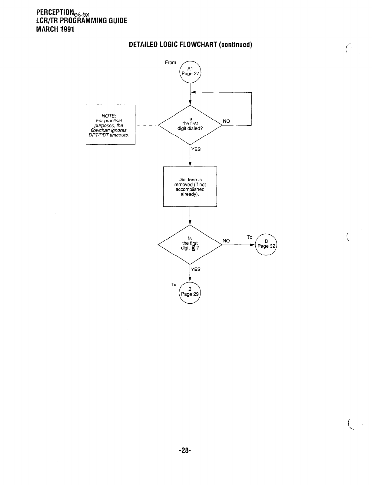
PERCEPTION,b,
LCR/TR PROGRAMMING GUIDE
MARCH 1991
DETAILED LOGIC FLOWCHART (continued)
From
Al
c
Page 27
- - -
flowchart ignores
DPT/PBJ
timeouts.
YES
I t
Dial tone is
removed (if not
accomplished
already).
NO
YES
1
To
3
Pagt 29
-28-
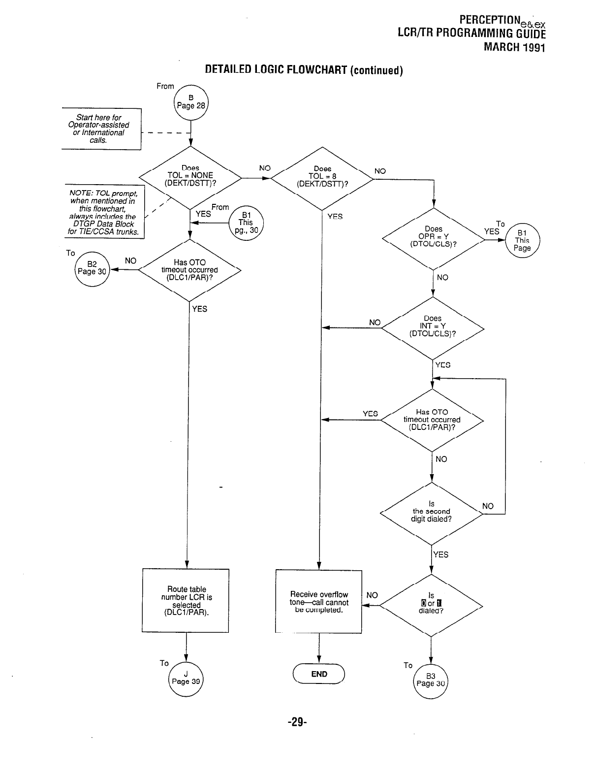
PERCEPTION,&,,
LCR/TR PROGRAMMING GUIDE
MARCH 1991
DETAILED LOGIC FLOWCHART (continued)
NO
I
timeout occurred NO
(ES
NO
I
YES
I timeout occurred
I
NO
Route table
number LCR is
selected
(DLCVPAR).
Receive overflow
tone-call cannot
be completed.
YES
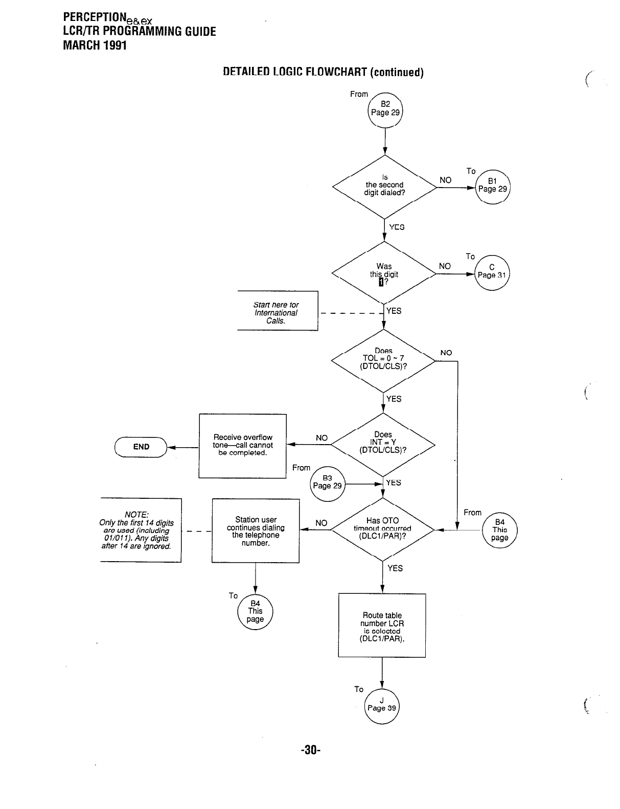
PERCEPTION,h,,
LCR/TR PROGRAMMING GUIDE
MARCH 1991
DETAILED LOGIC FLOWCHART (continued)
From
Start here for
International -
Calls.
NO
----_
YES
YES I
Route table
number LCR
is selected
(DLWPAR).
To
-3o-
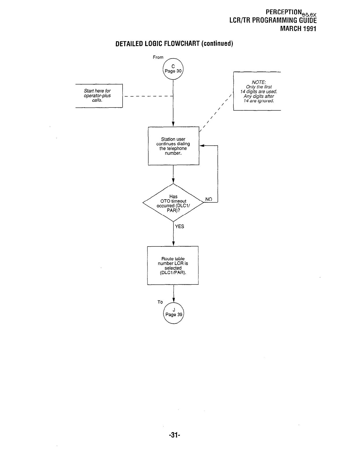
PERCEPTIONeb,,
LCR/TR PROGRAMMING GUIDE
MARCH 1991
DETAILED LOGIC FLOWCHART (continued)
Station user
continues dialing
NOTE:
Only the first
14 digits are used.
/ Any digits after
/
/ 14 are ignored.
/
/
/
/
/
-
YES
number LCR is
To
-31-
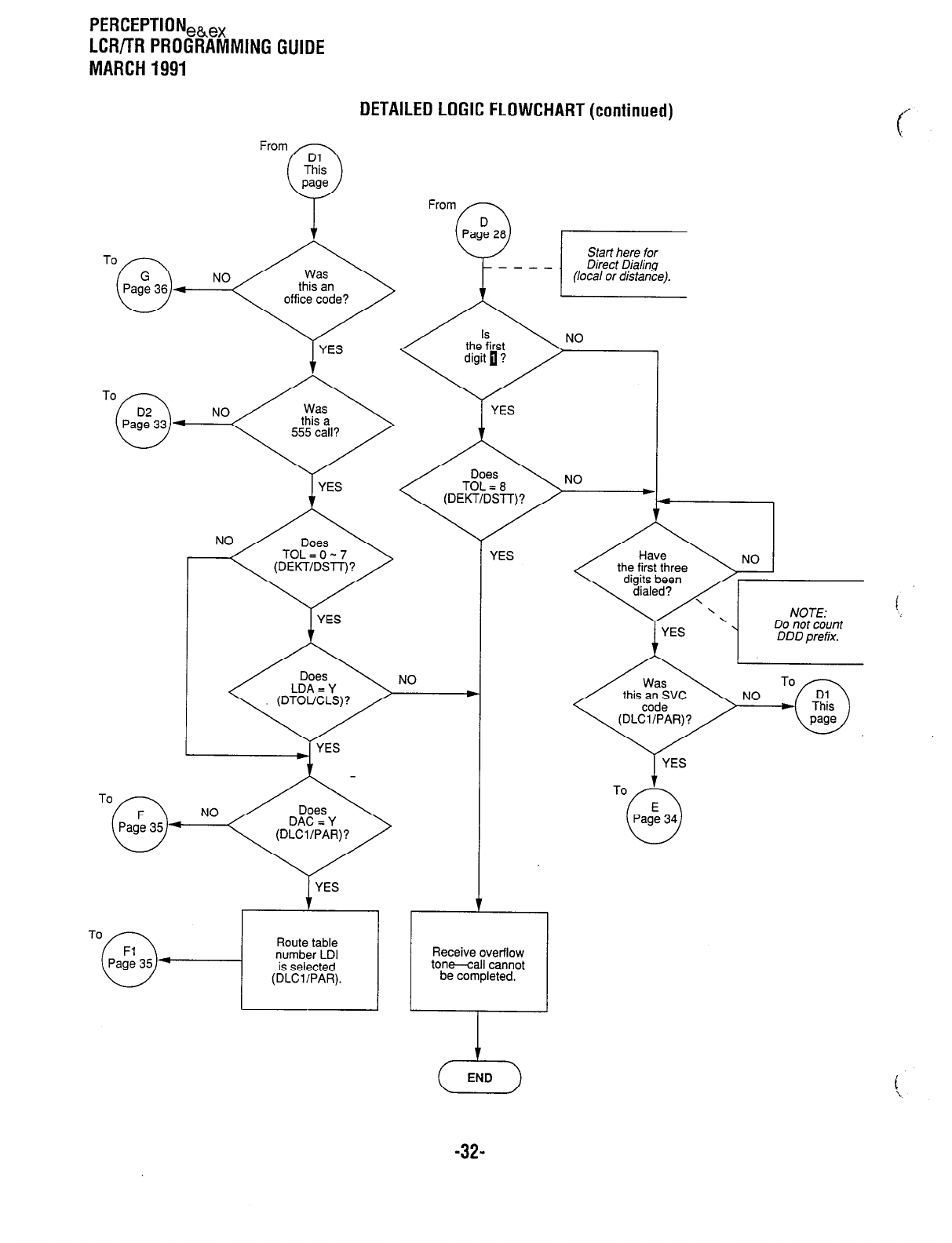
PERCEPTION,h,
LCR/TR PROGRAMMING GUIDE
MARCH 1991
From
To
G
0
NO
Page 36 4
DETAILED LOGIC FLOWCHART (continued)
I
YES
I
YES
NO
. .-
NW
(DEKT/DSTT)? /
w
I.
Y
YES
NO
l
To
0
PagF, 35 +
I
YES
I
/ the first three n
1
YES
To f
E
0
Page 34
Receive overflow
ton-all cannot
be completed.
Route table
number LDI
is selected
(DLWPAR).
c-4
END
-32-
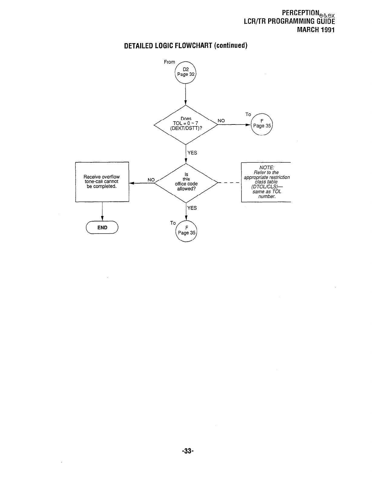
PERCEPTION,b,x
LCR/TR PROGRAMMING GUIDE
MARCH 1991
DETAILED LOGIC FLOWCHART (continued)
NO
(YES
Receive overflow
tone-call cannot 4
be completed.
23
END
YES
To
NOTE:
Refer to the
appropriate restriction
class table
(DTOUCLS)-
same as TOL
number.
-33-
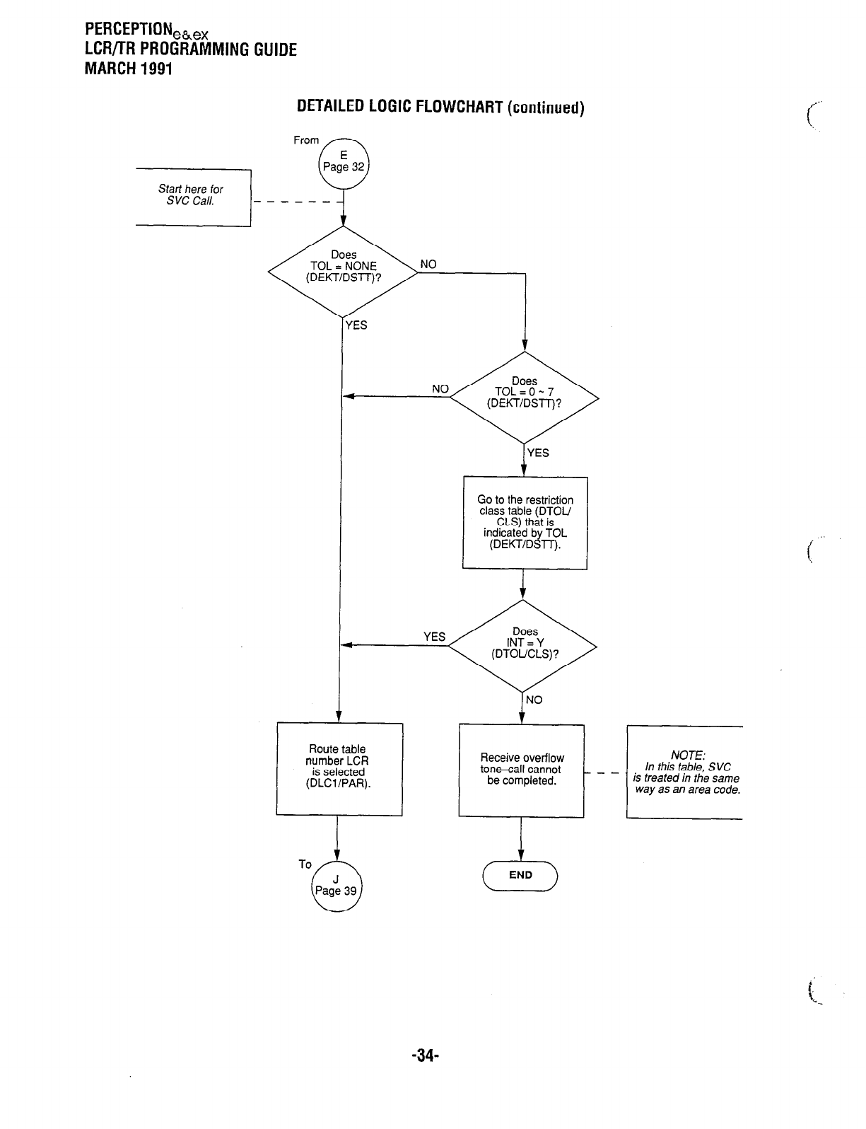
PERCEPTION,~,
LCR/TR PROGRAMMING GUIDE
MARCH 1991
DETAILED LOGIC FLOWCHART (continued)
Start here for - - - - - -
NO
i
YES
Go to the restriction
YES
I
Route table
number LCR
is selected
(DLCl/PAR).
Receive overflow
ton~all cannot
be completed. way as an area code.
END
-34-
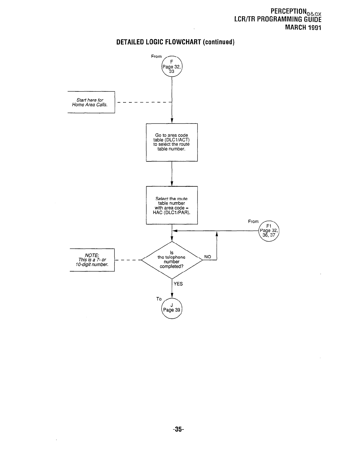
PERCEPTION,~,,
LCR/TR PROGRAMMING GUIDE
MARCH 1991
DETAILED LOGIC FLOWCHART (continued)
From
Go to area code
table (DLCl/ACT)
to select the route
table number.
Select the route
r-l
table number
with area code =
HAC (DLCVPAR).
NOTE:
This is a 7- or - - -
1 O-digit number.
-35-
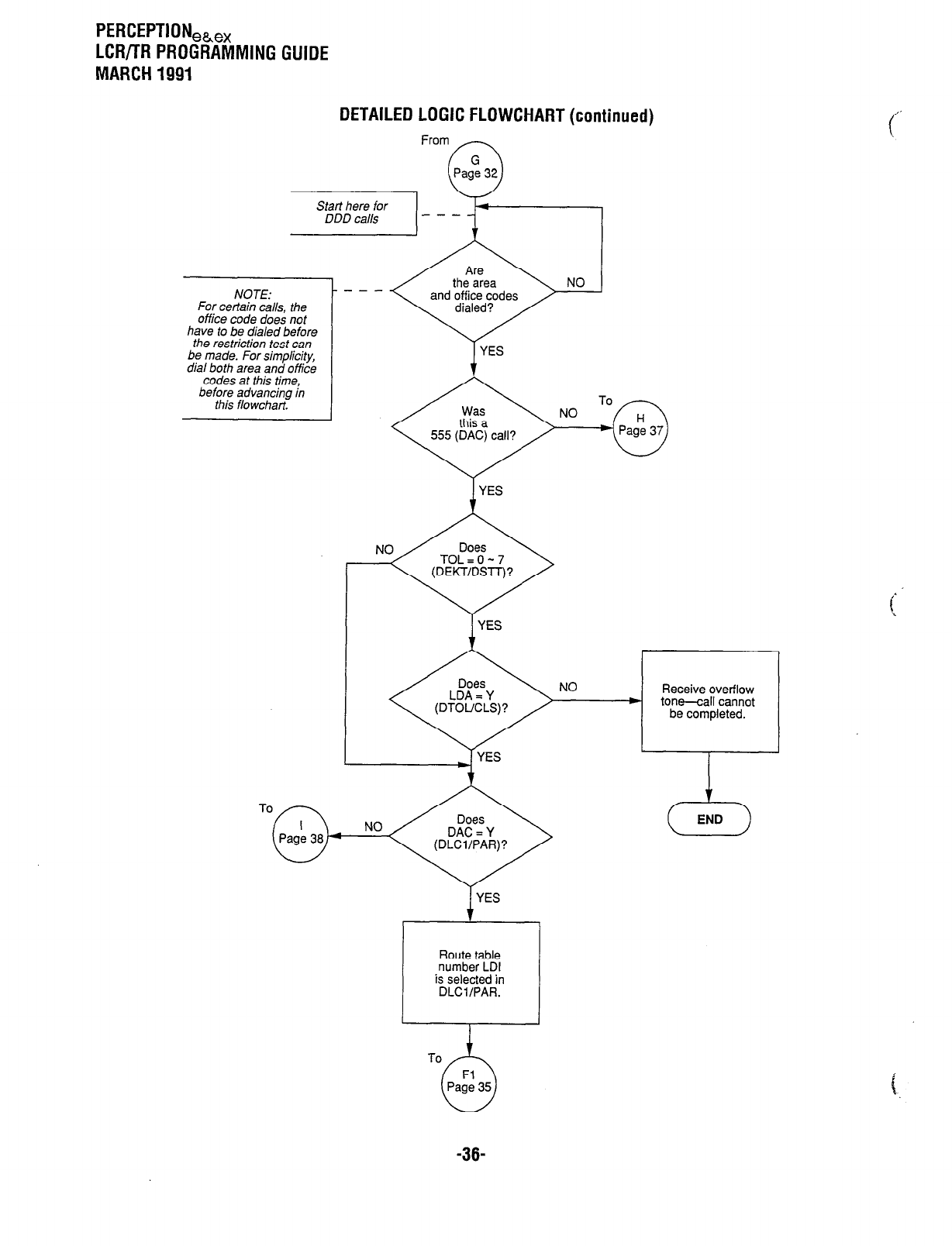
PERCEPTION,&,,
LCR/TR PROGRAMMING GUIDE
MARCH 1991
DETAILED LOGIC FLOWCHART (continued)
From
Pag: 32
w---
9-l
IICIYG LV “CT _,_.-_ ”
the restriction test
I.^ ---I- cnnr =jrnn
“ldl uu,, cur.. -,,-
codes at this tirr
before advancin& ,, ,
this flowchart.
e
I( in
!
I
YES
1 YES
NO Receive overflow
) tone-call cannot
be completed.
v
To END
Route table
number LDI
is selected in
DLClIPAR.
-36-
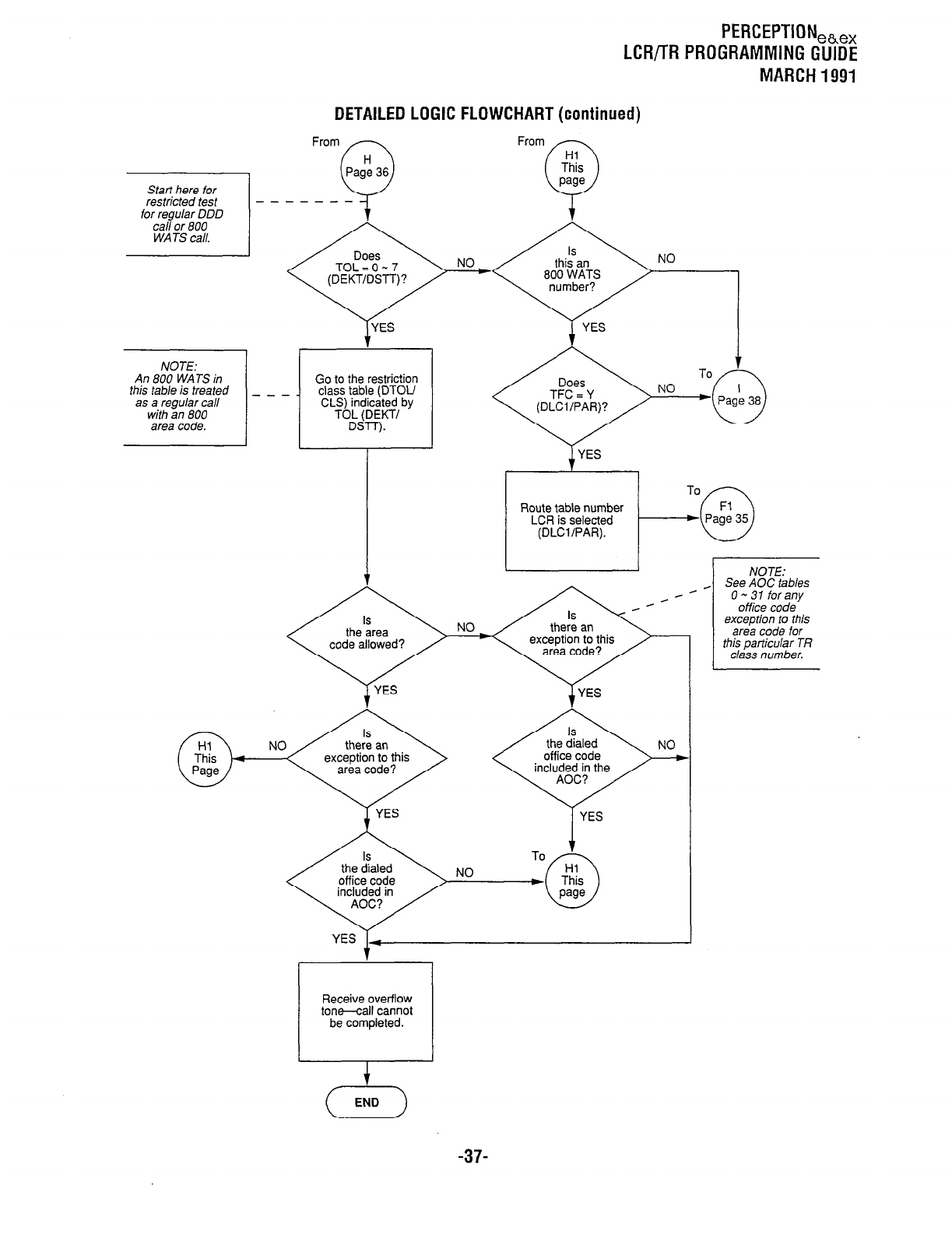
PERCEPTION,h,x
LCR/TR PROGRAMMING GUIDE
MARCH 1991
Start here for
restricted test
for regular DDD
call or 800
WATS call.
NOTE:
An 800 WATS in
this tab/e is treated
as a regular call
with an 800
area code.
-.
DETAILED LOGIC FLOWCHART (continued)
From
--
Go to the restriction
_- class table (DTOU
CLS) indicated by
From
NO
NO
code aliowea.!
NO
t
Route table number
LCR is selected
(DLCUPAR).
I t NOTE:
_ See AOC tab/es
O-31 forany
office code
exception to this
area code for
this particular TR
c/ass number.
included in the
1
Receive overflow
tone-call cannot
be completed.
,
-37-
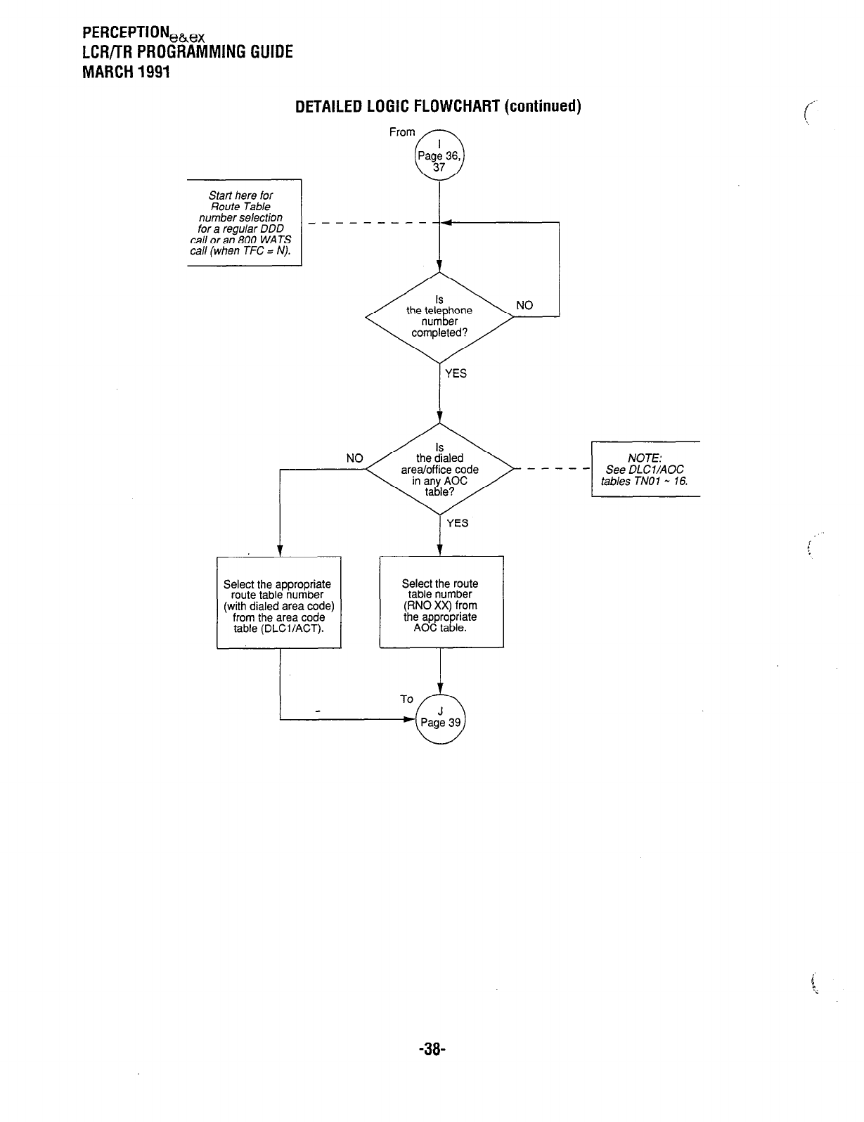
PERCEPTION,h,,
LCR/TR PROGRAMMING GUIDE
MARCH 1991
DETAILED LOGIC FLOWCHART (continued)
I
From
Start here for
Route Table I I
number selection - - -------
for a regular DDD
call or an 800 WATS
call (when TFC = N). i-
1 YES
Select the appropriate
route table number
(with dialed area code)
from the area code
table (DLCi/ACT).
I
YES
Select the route
table number
(RN0 XX) from
To 2-Y
-38-
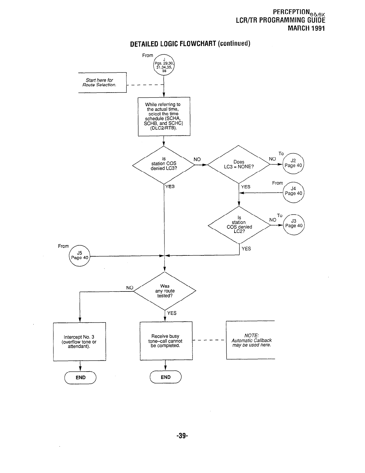
PERCEPTION,&,,
LCRil-R PROGRAMMING GUIDE
MARCH 1991
DETAILED LOGIC FLOWCHART (continued)
While referring to
the actual time,
select the time
schedule (SCHA,
SCHB, and SCHC)
(DLC2IRTB).
Y
YES
aLo.LI”I I
COS denied
- - NOTE:
Automatic Callback
may be used here.
-39-
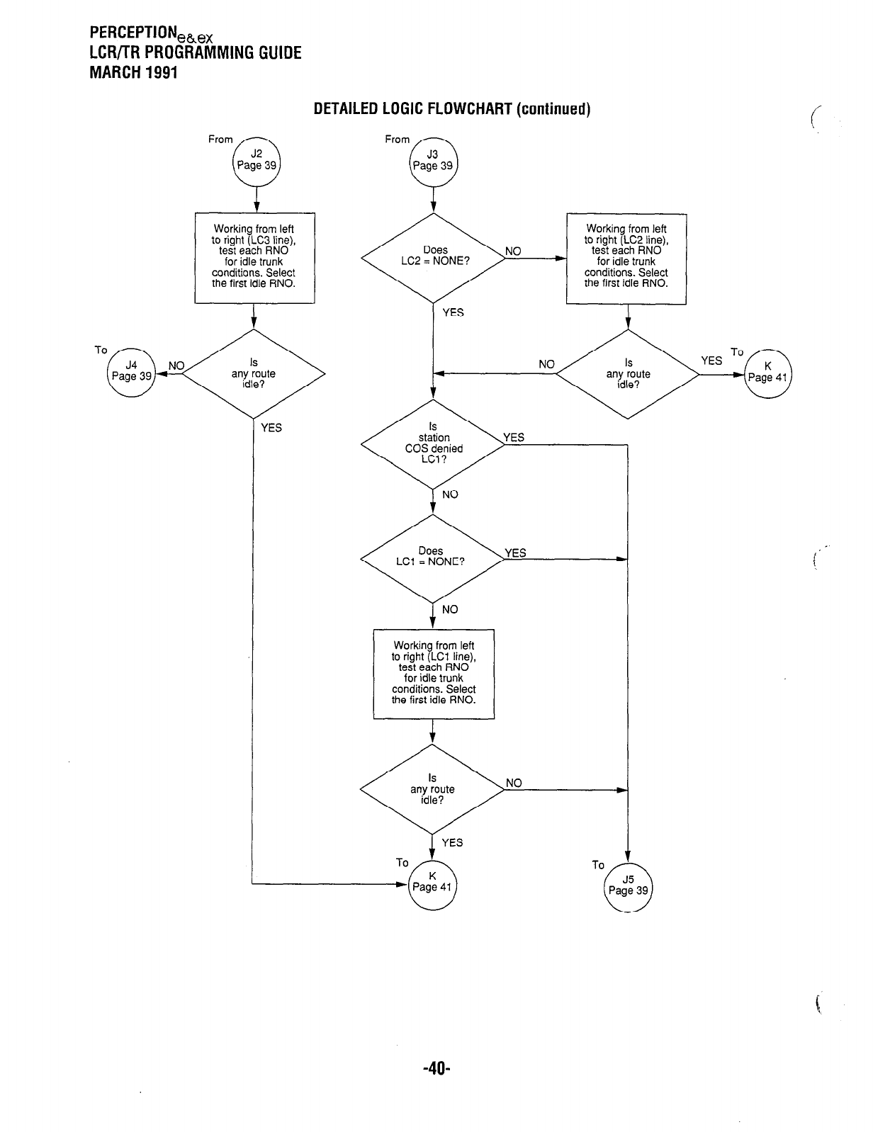
PERCEPTION,h,,
LCR/TR PROGRAMMING GUIDE
MARCH 1991
From
Working from left
to right (LC3 line),
test each RN0
for idle trunk
conditions. Select
the first idle RNO.
DETAILED LOGIC FLOWCHART (continued)
From n
i,
Pa:,3 39
To;
/
YES
Working from left
to right (LC2 line),
NO test each RN0
LC2 = NONE? for idle trunk
conditions. Select
the first idle RNO.
LCl = NONE? YES .
Working from left
to right (LCl line),
test each RN0
for idle trunk
conditions. Select
the first idle RNO.
-4o-
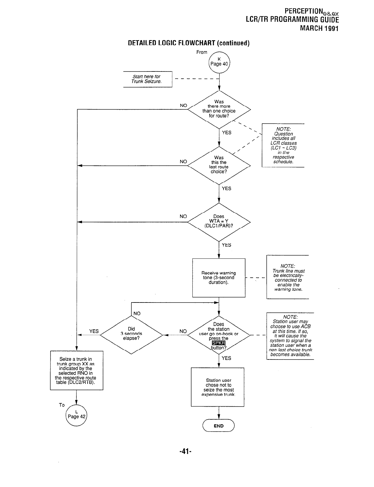
PERCEPTIONeb,,
LCR/TR PROGRAMMING GUIDE
MARCH 1991
DETAILED LOGIC FLOWCHART (continued)
YES
I
YES
Receive warning
Seize a trunk in
trunk group XX as
indicated by the
selected RN0 in
the respective route
table (DLC2MTB).
To
Station user
chose not to
seize the most
expensive trunk.
I I
NOTE:
Trunk line must
be electrically-
connected to
enable the
warning tone.
-41-
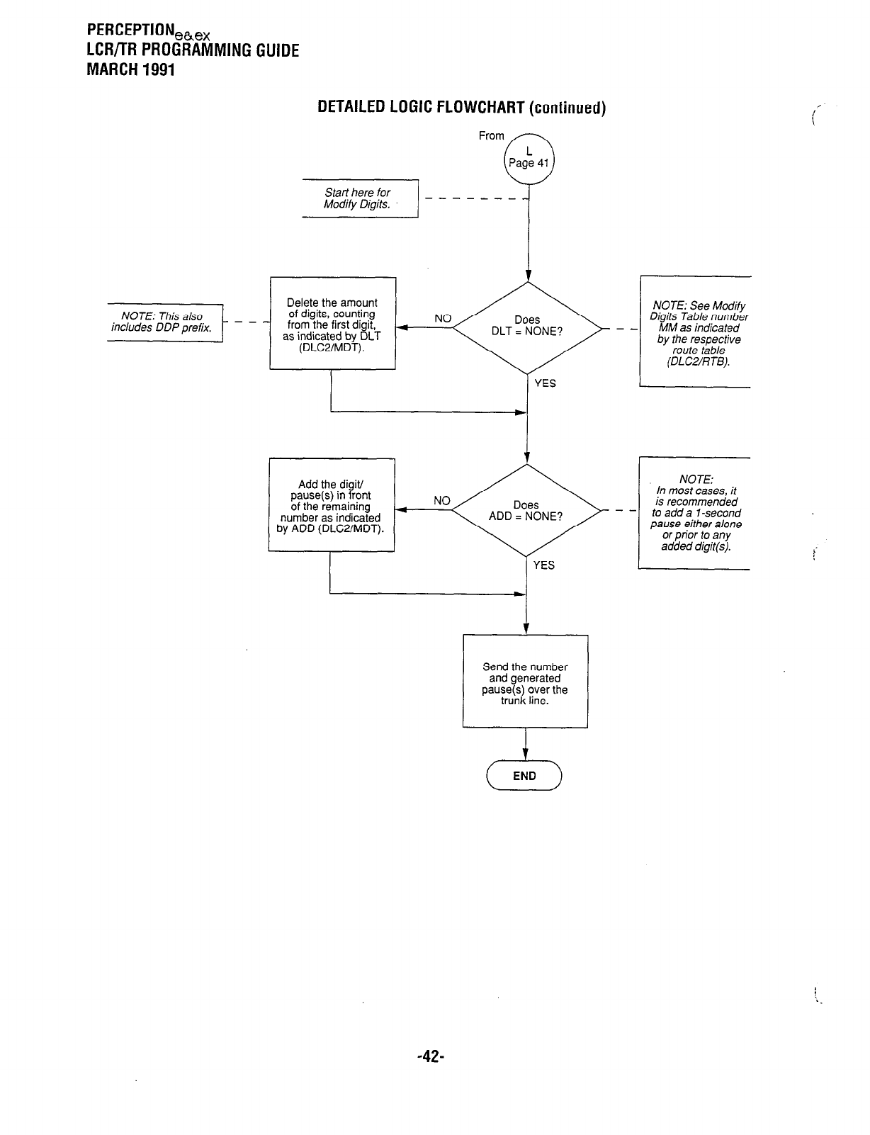
PERCEPTION,h,x
LCFVTR PROGRAMMING GUIDE
MARCH 1991
DETAILED LOGIC FLOWCHART (continued)
Add the digit/
pause(s) in front
of the remaining NO
+
number as indicated ADD = NONE?
by ADD (DLWMDT).
Send the number
and generated
pause(s) over the
trunk line.
NOTE:
In most cases, it
is recommended
to add a l-second
pause either alone
or prior to any
added digit(s).
,
23
END
-4%
PERCEPTION,,,,
Tl/DS-1 DIGITAL TRUNK INTERFACE
SEPTEMBER 1991
Perceptionl, & ex
Tl/DS-1 DIGITAL TRUNK INTERFACE
APPENDIX #3
PRODUCT FEATURES
PREREQUISITES and PROCEDURES
for INSTALLATION
and
TROUBLESHOOTING FLOWCHARTS

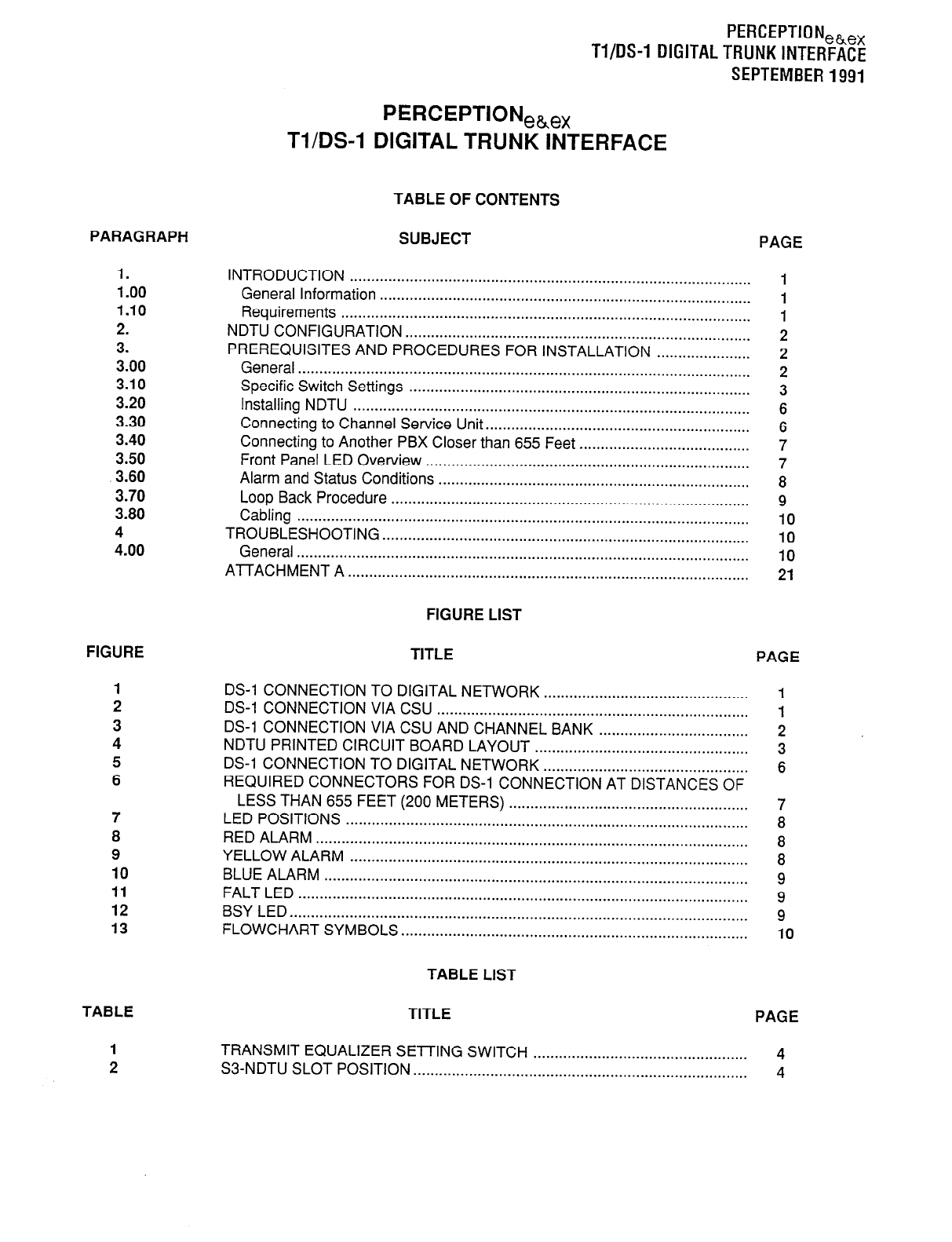
PARAGRAPH
1.
1 .oo
1.10
2.
3.
3.00
3.10
3.20
3.30
3.40
3.50
3.60
3.70
3.80
4
4.00
FIGURE
7
8
9
10
11
12
13
TABLE
1
2
PERCEPTIONeh,,
Tl/DS-1 DIGITAL TRUNK INTERFACE
SEPTEMBER 1991
PERCEPTIONeh,,
Tl/DS-1 DIGITAL TRUNK INTERFACE
TABLE OF CONTENTS
SUBJECT PAGE
INTRODUCTION .............................................................................................. 1
General Information ....................................................................................... 1
Requirements ................................................................................................ 1
NDTU CONFIGURATION ................................................................................. 2
PREREQUISITES AND PROCEDURES FOR INSTALLATION ...................... 2
General .......................................................................................................... 2
Specific Switch Settings ................................................................................ 3
Installing NDTU ............................................................................................. 6
Connecting to Channel Service Unit .............................................................. 6
Connecting to Another PBX Closer than 655 Feet ........................................ 7
Front Panel LED Overview ............................................................................ 7
Alarm and Status Conditions ......................................................................... 8
Loop Back Procedure .................................................................................... 9
Cabling .......................................................................................................... IO
TROUBLESHOOTING ...................................................................................... 10
General .......................................................................................................... 10
AlTACHMENT A .............................................................................................. 21
FIGURE LIST
TITLE PAGE
DS-1 CONNECTION TO DIGITAL NETWORK ................................................ 1
DS-1 CONNECTION VIA CSU ......................................................................... 1
DS-1 CONNECTION VIA CSU AND CHANNEL BANK ................................... 2
NDTU PRINTED CIRCUIT BOARD LAYOUT .................................................. 3
DS-1 CONNECTION TO DIGITAL NETWORK ................................................ 6
REQUIRED CONNECTORS FOR DS-1 CONNECTION AT DISTANCES OF
LESS THAN 655 FEET (200 METERS) ........................................................ 7
LED POSITIONS .............................................................................................. 8
RED ALARM ..................................................................................................... 8
YELLOW ALARM ............................................................................................. 8
BLUE ALARM ................................................................................................... 9
FALT LED ......................................................................................................... 9
BSY LED ........................................................................................................... 9
FLOWCHART SYMBOLS ................................................................................. 10
TABLE LIST
TITLE PAGE
TRANSMIT EQUALIZER SETTING SWITCH .................................................. 4
S3-NDTU SLOT POSITION .............................................................................. 4
PERCEPTIONeke,
Tl/DS-1 DIGITALTRUNKINTERFACE
SEPTEMBER1991
TABLE LIST (CONT)
TABLE
3
4
TITLE PAGE
SIGNALING TYPE SELECTION SWITCHES . . . . . . . . . . .
. . . . . . . . . . . . . . . . . . . . . . . . . . . . . . . . . . . . . . . 5
TERMINAL SEQUENCE & DESIGNATIONS CONNECTOR
NUMBERS J7/J501 (PERCEPTION,,),
J15/J515 (PERCEPTION,) NDTU TOO/T08 . . . . .
. . . . . . . . . . . . . . . . . . . . . . . . . . . . . . . . . . . . . . . . . . . . . 11
CHART LIST
CHART TITLE PAGE
1 HARDWARE VERIFICATION . . . . . . . . . . . . . . . . . . . . . . . . . . . . . . . . . . . . . . . . . . . . . . . . . . . . . . . . . . . . . . . . . . . . . . . . . . . 12
2 FAULT CLASSIFICATION .
. . . . . . . . . . . . . . . . . . . . . . . . . . . . . . . . . . . . . . . . . . . . . . . . . . . . . . . . . . . . . . . . . . . . . . . . . . . . . . . 13
3 ALARM FAULTS . . . . . . . . . . . . . . . . . . . . . . . . . . . . . . . . . . . . . . . . . . . . . . . . . . . . . . . . . . . . . . . . . . . . . . . . . . . . . . . . . . . . . . . . . . . . . . . 15
4 HARDWARE FAULTS . . . . . . . . . . . . . . . . . . . . . . . . . . . . . . . . . . . . . . . . . . . . . . . . . . . . . . . . . . . . . . . . . . . . . . . . . . . . . . . . . . . . . . 16
5 FALT LED . . . . . . . . . . . . . . . . . . . . . . . . . . . . . . . . . . . . . . . . . . . . . . . . . . . . . . . . . . . . . . . . . . . . . . . . . . . . . . . . . . . . . . . . . . . . . . . . . . . . . . . . . 17
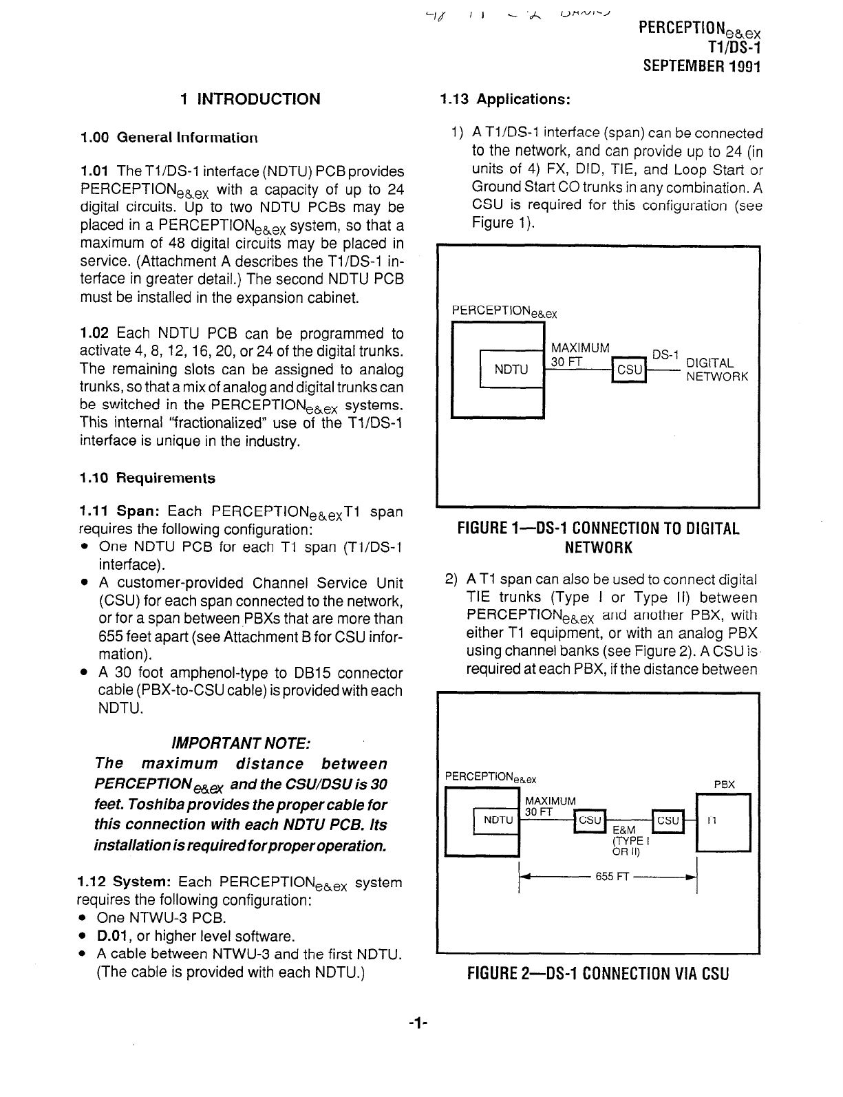
1 INTRODUCTION
I .OO General Information
1.01
TheTl/DS-1 interface (NDTU) PCBprovides
PERCEPTIONeLex with a capacity of up to 24
digital circuits. Up to two NDTU PCBs may be
placed in a PERCEPTIONeLex system, so that a
maximum of 48 digital circuits may be placed in
service. (Attachment A describes the Tl/DS-1 in-
terface in greater detail.) The second NDTU PCB
must be installed in the expansion cabinet.
1.02
Each NDTU PCB can be programmed to
activate 4, 8, 12, 16, 20, or 24 of the digital trunks.
The remaining slots can be assigned to analog
trunks, so that a mix of analog and digital trunks can
be switched in the PERCEPTIONekex systems.
This internal “fractionalized” use of the Tl/DS-1
interface is unique in the industry.
I .I 0 Requirements
1.11 Span:
Each PERCEPTIONe,exTl span
requires the following configuration:
l
One NDTU PCB for each Tl span (Tl/DS-1
interface).
l
A customer-provided Channel Service Unit
(CSU) for each span connected to the network,
or for a span between PBXs that are more than
655 feet apart (see Attachment B for CSU infor-
mation).
l
A 30 foot amphenol-type to DB15 connector
cable (PBX-to-CSU cable) is provided with each
NDTU.
IMPORTANT NOTE:
The maximum distance between
PERCEPTION,, and the CSWDSU is 30
feet. Toshiba provides the proper cable for
this connection with each NDTU PCB. Its
installation is required forproperoperation.
I .I2 System:
Each PERCEPTIONehex system
requires the following configuration:
l
One NTWU-3 PCB.
l
D.01,
or higher level software.
l
A cable between NTWU-3 and the first NDTU.
(The cable is provided with each NDTU.)
‘If ‘I - .A ,>H,vI-/
PERCEPTION,~,,
Tl/DS-1
SEPTEMBER 1991
I .I3 Applications:
1) A TI/DS-1 interface (span) can be connected
to the network, and can provide up to 24 (in
units of 4) FX, DID, TIE, and Loop Start or
Ground Start CO trunks in any combination. A
CSU is required for this configuration (see
Figure 1).
PERCEPTIONeaex
FIGURE I-DS-1 CONNECTION TO DIGITAL
NETWORK
2) A Tl span can also be used to connect digital
TIE trunks (Type I or Type II) between
PERCEPTIONeLex and another PBX, with
either Tl equipment, or with an analog PBX
using channel banks (see Figure 2). A CSU is.
required at each PBX, if the distance between
FIGURE 2-DS-1 CONNECTION VIA CSU
-l-
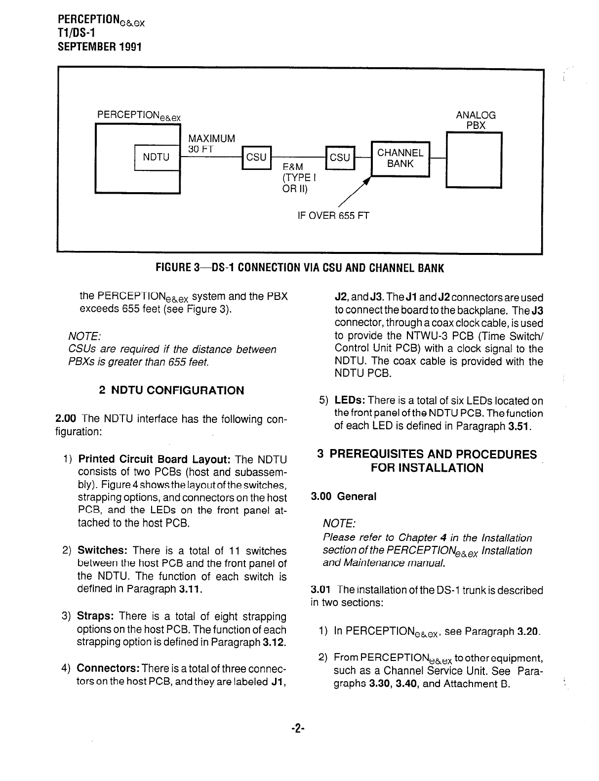
PERCEPTION,~,,
Tl/OS-1
SEPTEMBER 1991
PERCEPTION,,,, ANALOG
PBX
MAXIMUM
- 30FT
NDTU csu E&M
(TYPE I
OR II) I
IF OVER 655 FT
FIGURE 3-DS-1 CONNECTION VIA CSU AND CHANNEL BANK
the PERCEPTIONehex system and the PBX
exceeds 655 feet (see Figure 3).
NOTE:
CSUs are required if the distance between
PBXs is greater than 655 feet.
2 NDTU CONFIGURATION
2.00 The NDTU interface has the following con-
figuration:
1) Printed Circuit Board Layout: The NDTU
consists of two PCBs (host and subassem-
bly). Figure 4 shows the layout of the switches,
strapping options, and connectors on the host
PCB, and the LEDs on the front panel at-
tached to the host PCB.
2) Switches: There is a total of 11 switches
between the host PCB and the front panel of
the NDTU. The function of each switch is
defined in Paragraph 3.11.
3) Straps: There is a total of eight strapping
options on the host PCB. The function of each
strapping option is defined in Paragraph 3.12.
4) Connectors: There is a total of three connec-
tors on the host PCB, and they are labeled Jl,
J2, and J3. The Jl and J2 connectors are used
to connect the board to the backplane. The J3
connector, through a coax clock cable, is used
to provide the NTWU-3 PCB (Time Switch/
Control Unit PCB) with a clock signal to the
NDTU. The coax cable is provided with the
NDTU PCB.
5) LEDs: There is a total of six LEDs located on
the front panel of the NDTU PCB. The function
of each LED is defined in Paragraph 3.51.
3 PREREQUISITES AND PROCEDURES
FOR INSTALLATION
3.00 General
NOTE:
Please refer to Chapter 4 in the Installation
section of the PERCEPTIONe,ex Installation
and Maintenance manual.
3.01 The installation of the DS-1 trunk is described
in two sections:
1) In PERCEPTIONeLex, see Paragraph 3.20.
2) From PERCEPTIONe,ex tootherequipment,
such as a Channel Service Unit. See Para-
graphs 3.30, 3.40, and Attachment B.
-2-
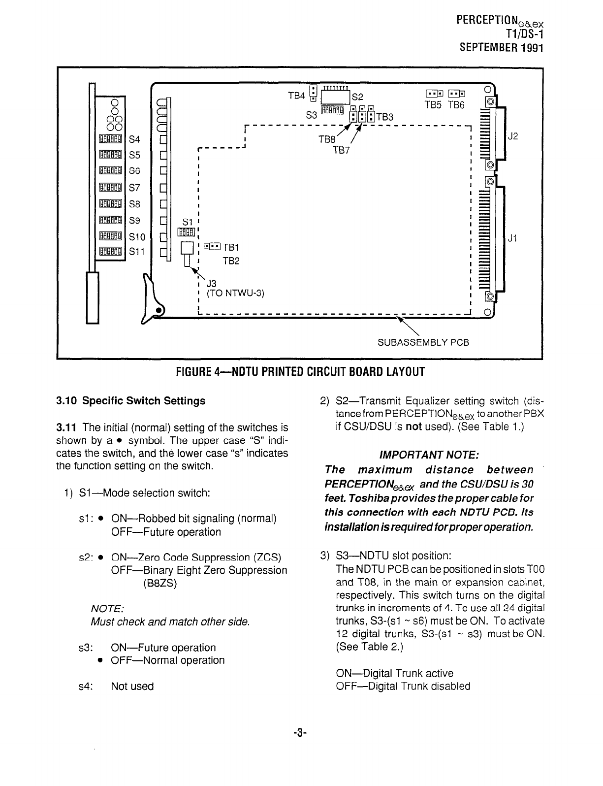
PERCEPTIONeb,,
T-l/IX-l
SEPTEMBER1991
--------- I^
SUBASSEMBLY PCB
FlGURE4-NDTU PRINTED CIRCUITBOARD LAYOUT
3.10 Specific Switch Settings
3.11 The initial (normal) setting of the switches is
shown by a
l
symbol. The upper case “S” indi-
cates the switch, and the lower case “s” indicates
the function setting on the switch.
1) Sl-Mode selection switch:
sl : l
ON-Robbed bit signaling (normal)
OFF-Future operation
s2:
l
ON-Zero Code Suppression (ZCS)
OFF-Binary Eight Zero Suppression
(B8ZS)
NOTE:
Must check and match other side.
s3: ON-Future operation
l
OFF-Normal operation
s4: Not used
2) S2-Transmit Equalizer setting switch (dis-
tancefrom PERCEPTIONe&ex to another PBX
if CSWDSU is not used). (See Table 1.)
IMPORTANT NOTE:
The maximum distance between
PERCEPTIONHex and the CSWDSU is 30
feet. Toshiba provides the proper cable for
this connection with each NDTU PCB. Its
installation is required forproper operation.
3) S3-NDTU slot position:
The NDTU PCB can be positioned in slots TOO
and
T08, in the main or expansion cabinet,
respectively. This switch turns on the digital
trunks in increments of 4. To use all 24 digital
trunks, S3-(sl w s6) must be ON. To activate
12 digital trunks, S3-(sl M s3) must be ON.
(See Table 2.)
ON-Digital Trunk active
OFF-Digital Trunk disabled
-3-
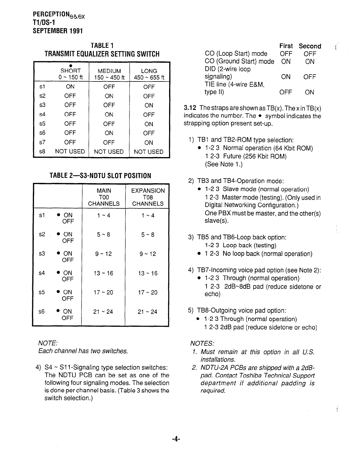
PERCEPTIONeh,,
Tl/DS-1
SEPTEMBER 1991
TABLE 1
TRANSMIT EQUALIZER SETTING SWITCH
SH&T MEDIUM LONG
o- 150ft 150s450ft 450 - 6.55 ft
sl ON OFF OFF
s2 OFF ON OFF
s3 OFF OFF ON
s4 OFF ON OFF
s5 OFF OFF ON
s6
OFF ON OFF
s7
OFF OFF ON
s8
NOT USED NOT USED NOT USED
TABLE 2-S3-NDTU SLOT POSITION
MAIN EXPANSION
TOO TO8
CHANNELS CHANNELS
Sl
l ON
l-4 1-4
OFF
s2
l ON
5-8 5-8
OFF
s3
l ON
9- 12 9 - 12
OFF
s4
l ON
13 ew 16 13 - 16
OFF
s5
l ON
17 - 20 17-20
OFF
s6
l ON
21 -24 21 -24
OFF
4
NOTE: NOTES:
First Second
CO (Loop Start) mode OFF OFF
CO (Ground Start) mode ON ON
DID (2-wire loop
signaling) ON OFF
TIE line (4-wire E&M,
type 11) OFF ON
3.12 The straps are shown as TB(x). The x in TB(x)
indicates the number. The
l
symbol indicates the
strapping option present set-up.
1) TB1 and TB2-ROM type selection:
l
l-2 3 Normal operation (64 Kbit ROM)
1 2-3 Future (256 Kbit ROM)
(See Note 1.)
2) TB3 and TB4-Operation mode:
l
l-2 3 Slave mode (normal operation)
1 2-3 Master mode (testing). (Only used in
Digital Networking Configuration.)
One PBX must be master, and the other(s)
slave(s).
3) TB5 and TBG-Loop back option:
1-2 3 Loop back (testing)
l
1 2-3 No loop back (normal operation)
4) TB7-Incoming voice pad option (see Note 2):
l
1-2 3 Through (normal operation)
1 2-3 2dB-8dB pad (reduce sidetone or
echo)
5) TB8-Outgoing voice pad option:
l
1-2 3 Through (normal operation)
1 2-3 2dB pad (reduce sidetone or echo)
E<
2
ach channel has two switches. 1. Must remain at this option in all U.S.
installations.
S4 - Sl 1 -Signaling type selection switches:
The NDTU PCB can be set as one of the
following four signaling modes. The selection
is done per channel basis. (Table 3 shows the
switch selection.)
2. NDTU-2A PCBs are shipped with a 2dB-
pad. Contact Toshiba Technical Support
department if additional padding is
required.
-4-
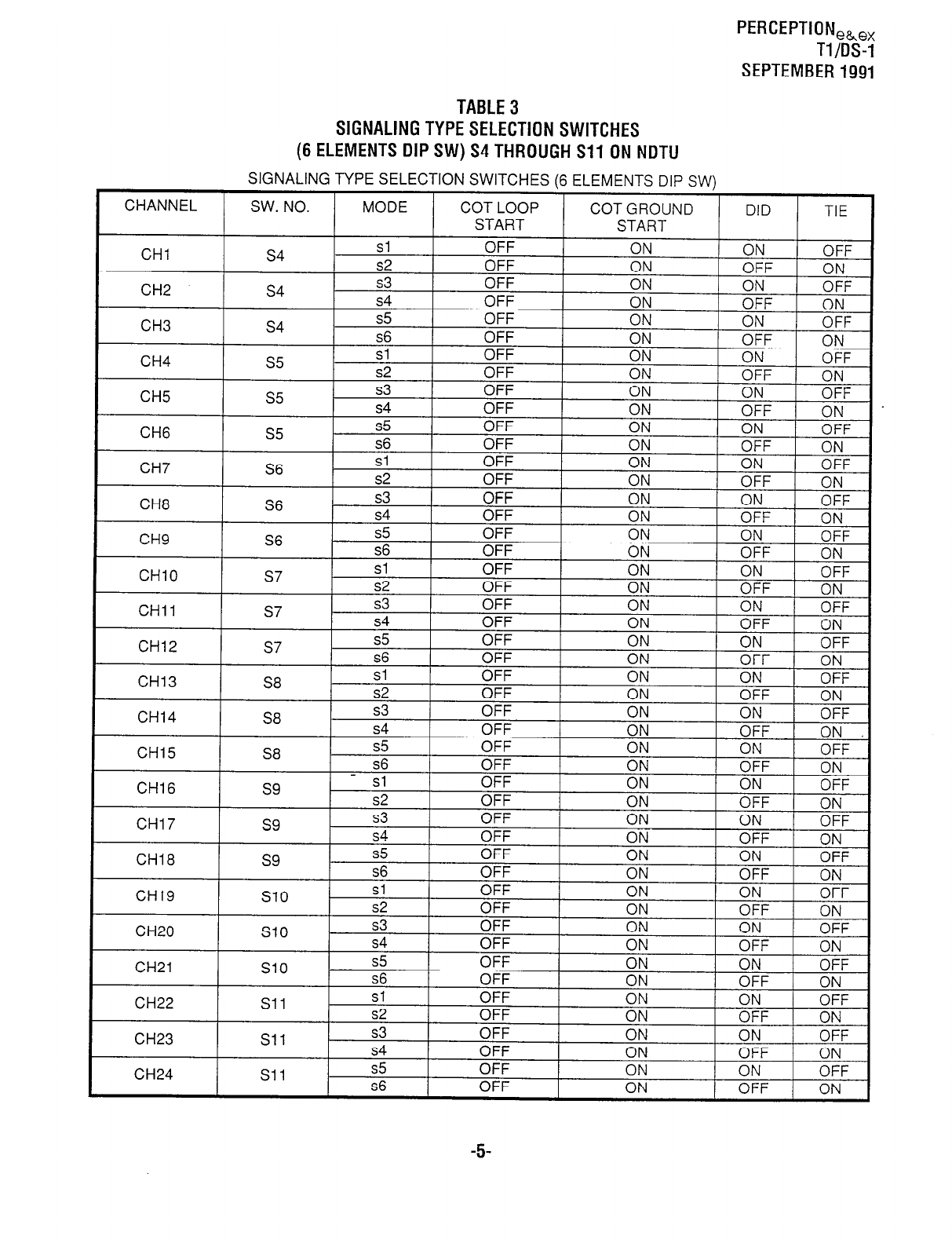
PERCEPTIONeh,,
Tl/DS-1
SEPTEMBER 1991
TABLE 3
SIGNALING TYPE SELECTION SWITCHES
(6 ELEMENTS DIP SW) S4 THROUGH Sll ON NOTU
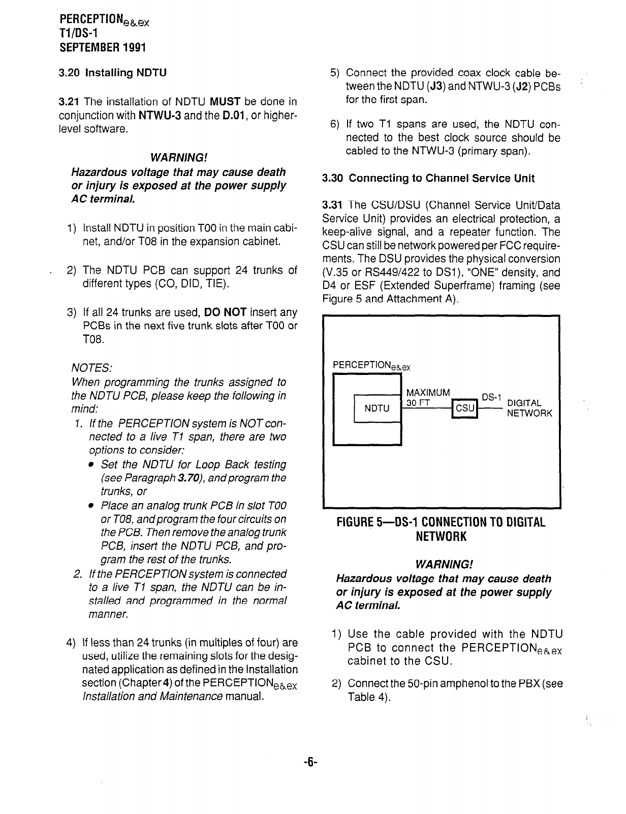
PERCEPTIONeb,,
Tl/OS-1
SEPTEMBER 1991
3.20 Installing NDTU
3.21 The installation of NDTU MUST be done in
conjunction with
NTWU-3
and the D.O1, or higher-
level software.
WARNING!
Hazardous voltage that may cause death
or injury is exposed at the power supply
AC terminal.
1) Install NDTU in position TOO in the main cabi-
net, and/or TO8 in the expansion cabinet.
2) The NDTU PCB can support 24 trunks of
different types (CO, DID, TIE).
3) If all 24 trunks are used, DO NOT insert any
PCBs in the next five trunk slots after TOO or
T08.
NOTES:
When programming the trunks assigned to
the NDTU PCB, please keep the following in
mind:
1. If the PERCEPT/ON system is NOT con-
nected to a live Tl span, there are two
options to consider:
l
Set the NDTU for Loop Back testing
(see Paragraph 3.70) and program the
trunks, or
l
Place an analog trunk PCB in slot TOO
or TO8, and program the four circuits on
the PCB. Then remove the analog trunk
PCB, insert the NDTU PCB, and pro-
gram the rest of the trunks.
2. If the PERCEPTION system is connected
to a live Tl span, the NDTU can be in-
stalled and programmed in the normal
manner,
4) If less than 24 trunks (in multiples of four) are
used, utilize the remaining slots for the desig-
nated application as defined in the Installation
section (Chapter4) of the PERCEPTIONe&ex
installation and Maintenance manual.
5) Connect the provided coax clock cable be-
tween the NDTU (J3) and NTWU-3 (J2) PCBs
for the first span.
6) If two Tl spans are used, the NDTU con-
nected to the best clock source should be
cabled to the NTWU-3 (primary span).
3.30 Connecting to Channel Service Unit
3.31 The CSU/DSU (Channel Service Unit/Data
Service Unit) provides an electrical protection, a
keep-alive signal, and a repeater function. The
CSU can still be network powered per FCC require-
ments. The DSU provides the physical conversion
(V.35 or RS449/422 to DSI), “ONE” density, and
D4 or ESF (Extended Super-frame) framing (see
Figure 5 and Attachment A).
PERCEPTIONeaex
FIGURE 5-DS-1 CONNECTION TO DIGITAL
NETWORK
WARNING!
Hazardous voltage that may cause death
or injury is exposed at the power supply
AC terminal.
1) Use the cable provided with the NDTU
PCB to connect the PERCEPTIONekex
cabinet to the CSU.
2) Connect the 50-pin amphenol to the PBX (see
Table 4).
-6-
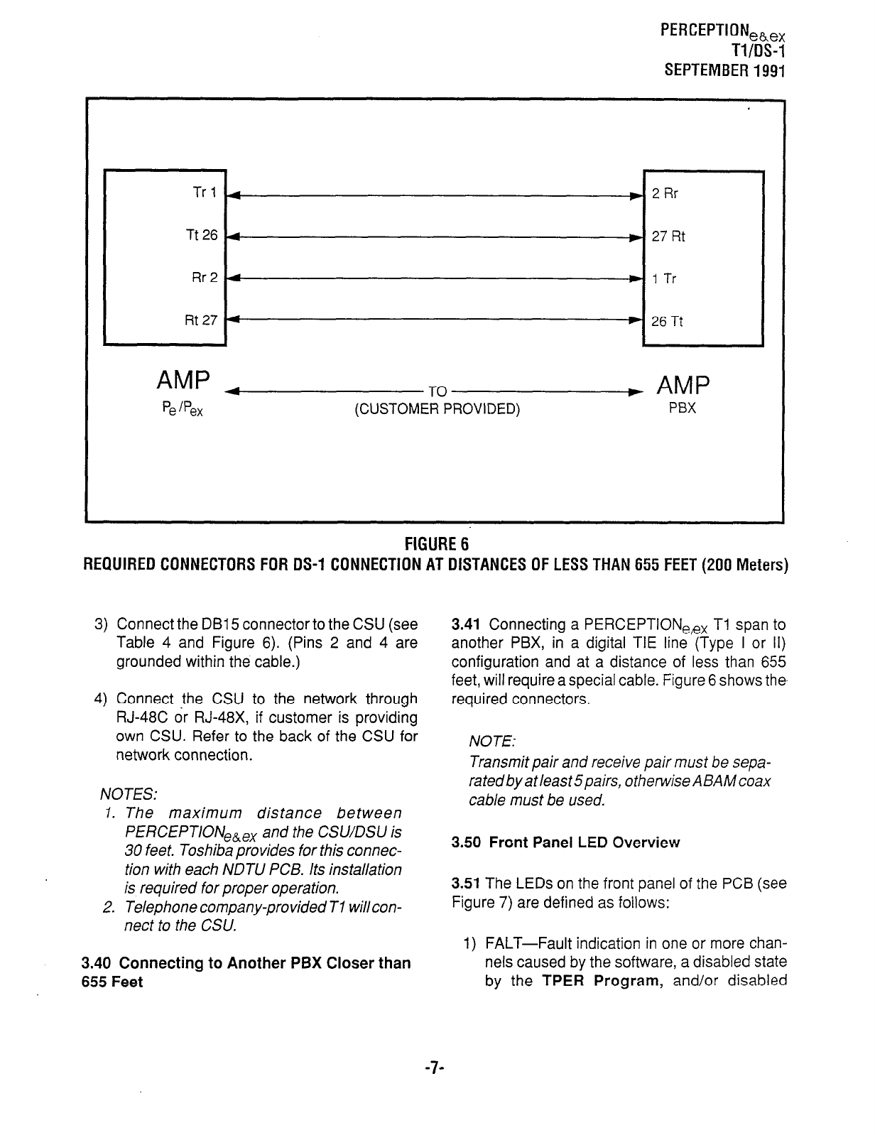
PERCEPTION,h,x
Tl/OS-1
SEPTEMBER 1991
Trl 4
) 2Rr
Tt26 4 w 27 Rt
Rr2 4 w 1 Tr
Rt 27 4 ) 26Tt
AMP 4
Pe jpex + AMP
P6X
FIGURE 6
REQUIRED CONNECTORS FOR DS-1 CONNECTION AT DISTANCES OF LESS THAN 655 FEET (200 Meters)
3) Connect the DB15 connector to the CSU (see
Table 4 and Figure 6). (Pins 2 and 4 are
grounded within the cable.)
4) Connect the CSU to the network through
RJ-48C or RJ-48X, if customer is providing
own CSU. Refer to the back of the CSU for
network connection.
NOTES:
1. The maximum distance between
PERCEPTION,,, and the CSV/DSU is
30 feet. Toshiba provides for this connec-
tion with each NDTU PCB. Its installation
is required for proper operation.
2. Telephone company-provided Tl willcon-
nect to the CSU.
3.40 Connecting to Another PBX Closer than
655 Feet
3.41 Connecting a PERCEPTIONee, TI span to
another PBX, in a digital TIE line (Type I or II)
configuration and at a distance of less than 655
feet, will require a special cable. Figure 6 shows the
required connectors.
NOTE:
Transmit pair and receive pair must be sepa-
ratedbyatleast5pairs, otherwiseABAMcoax
cable must be used.
3.50 Front Panel LED Overview
3.51 The LEDs on the front panel of the PCB (see
Figure 7) are defined as follows:
1) FALT-Fault indication in one or more chan-
nels caused by the software, a disabled state
by the TPER Program, and/or disabled
-7-
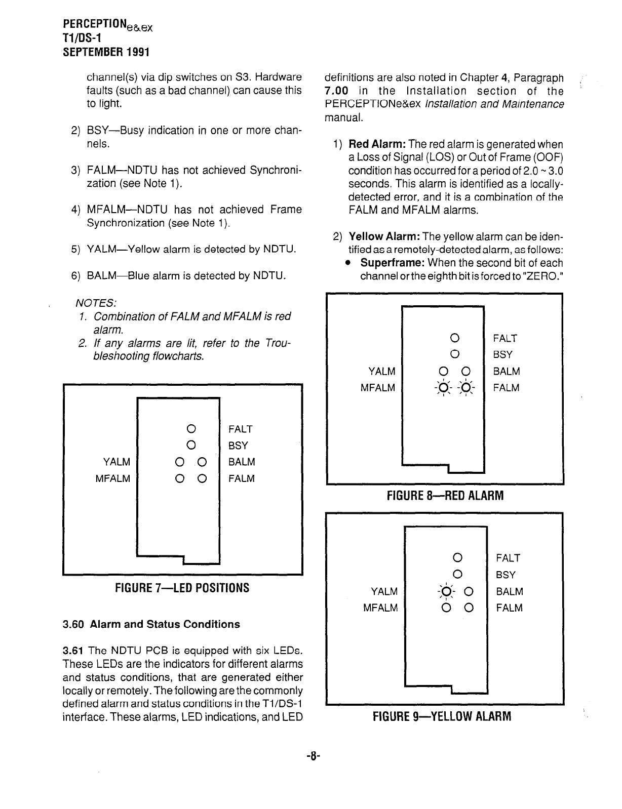
PERCEPTIONea,,
Tl/OS-1
SEPTEMBER 1991
channel(s) via dip switches on S3. Hardware
faults (such as a bad channel) can cause this
to light.
2) BSY-Busy indication in one or more chan-
nels.
3) FALM-NDTU has not achieved Synchroni-
zation (see Note 1).
4) MFALM-NDTU has not achieved Frame
Synchronization (see Note 1).
5) YALM-Yellow alarm is detected by NDTU.
6) BALM-Blue alarm is detected by NDTU.
NOTES:
1. Combination of FALM and MFALM is red
alarm.
2. If any alarms are /it, refer to the Trou-
bleshooting flowcharts.
YALM
MFALM
0
0
0 0
0 0
1
FALT
BSY
BALM
FALM
FIGURE II-LED POSITIONS
3.60 Alarm and Status Conditions
3.61 The NDTU PCB is equipped with six LEDs.
These LEDs are the indicators for different alarms
and status conditions, that are generated either
locally or remotely. The following are the commonly
defined alarm and status conditions in the Ti/DS-1
interface. These alarms, LED indications, and LED
definitions are also noted in Chapter 4, Paragraph
7.00 in the Installation section of the ’
PERCEPTlONe&ex installation and Maintenance
manual.
1) Red Alarm: The red alarm is generated when
a Loss of Signal (LOS) or Out of Frame (OOF)
condition has occurred for a period of 2.0 w 3.0
seconds. This alarm is identified as a locally-
detected error, and it is a combination of the
FALM and MFALM alarms.
2) Yellow Alarm: The yellow alarm can be iden-
tified as a remotely-detected alarm, as follows:
l
Superframe: When the second bit of each
channel orthe eighth bit is forced to”ZER0.”
YALM
MFALM
I
FALT
BSY
BALM
FALM
FIGURE g--RED ALARM
YALM
MFALM
0
FALT
0
BSY
-:@- 0
BALM
0 0
FALM
FIGURE g-YELLOW ALARM
-8-
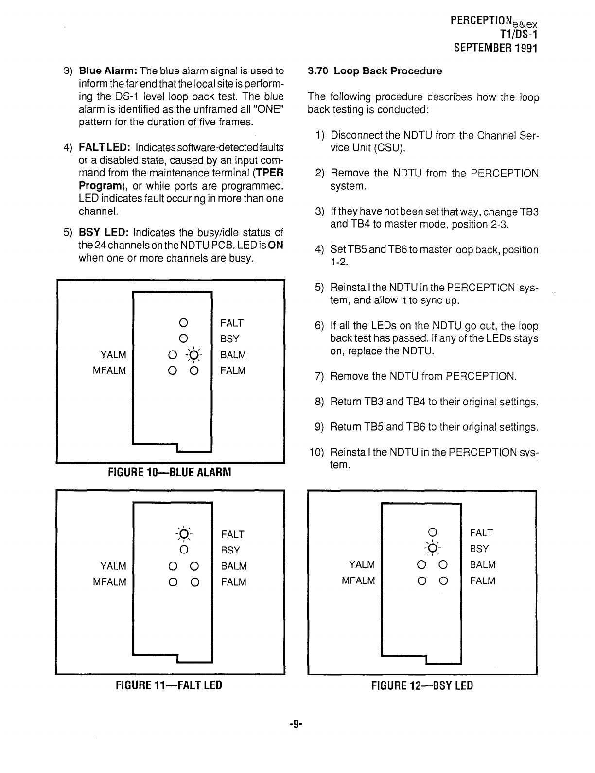
PERCEPTION,h,x
Tl/DS-1
SEPTEMBER 1991
3) Blue Alarm:
The blue alarm signal is used to
inform the far end that the local site is perform-
ing the DS-1 level loop back test. The blue
alarm is identified as the unframed all “ONE”
pattern for the duration of five frames.
4) FALT LED:
Indicates software-detected faults
or a disabled state, caused by an input com-
mand from the maintenance terminal
(TPER
Program),
or while ports are programmed.
LED indicates fault occuring in more than one
channel.
5) BSY LED:
Indicates the busy/idle status of
the 24 channels on the NDTU PCB. LED is ON
when one or more channels are busy.
0
FALT
0
BSY
YALM 0 -:q- BALM
MFALM 0 0 FALM
I
FIGURE lo-BLUE ALARM
-@-
FALT
0
BSY
YALM 0 0 BALM
MFALM 0 0 FALM
1
FIGURE ll-FALT LED
3.70 Loop Back Procedure
The following procedure describes how the loop
back testing is conducted:
1) Disconnect the NDTU from the Channel Ser-
vice Unit (CSU).
2) Remove the NDTU from the PERCEPTION
system.
3) If they have not been set that way, change TB3
and TB4 to master mode, position 2-3.
4) Set TB5 and TB6 to master loop back, position
l-2.
5) Reinstall the NDTU in the PERCEPTION sys-
tem, and allow it to sync up.
6) If all the LEDs on the NDTU go out, the loop
back test
has passed. If any of the LEDs stays
on, replace the NDTU.
7) Remove the NDTU from PERCEPTION.
8) Return TB3 and TB4 to their original settings.
9) Return TB5 and TB6 to their original settings.
10) Reinstall the NDTU in the PERCEPTION sys-
tern.
YALM
MFALM
FALT
BSY
BALM
FALM
FIGURE IP-BSY LED
-9-

PERCEPTIONeke,
Tl/OS-1
SEPTEMBER 1991
11) Reconnect the connection to the CSU.
3.80 Cabling
3.81 Table 4 is provided to give cabling pin bits off
the PERCEPTIONekex backplane.
4 TROUBLESHOOTING
4.00 General
The Troubleshooting section contains flowcharts
for diagnosing possible faults when installing aTl/
DS-1 interface, and performing maintenance tasks.
To eliminate system faults, they must first be clas-
sified, then cleared by replacing the defective ap-
paratus. Operational tests can then be performed
to verify correct apparatus operation. The flow-
charts must be followed in the sequence they are
arranged.
Start and end of flowchart
sequence.
Important notes affecting _____
the fault clearing
procedure.
Question to be answered
YES or NO.
Progression TO or FROM
another flowchart. Page
numbers indicate the
location of the flowchart
within this bulletin. Letters
and numbers denote the
exact entrance or exit point
in the flowchart.
0
Statement of a required
action.
FIGURE 13-FLOWCHART SYMBOLS
-lO-
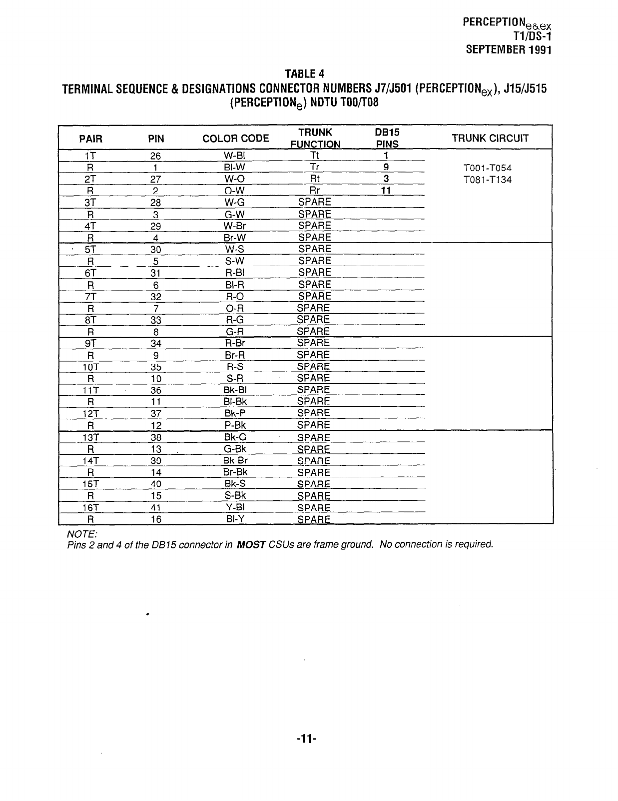
PERCEPTIONeh,,
Tl/DS-1
SEPTEMBER 1991
TABLE 4
TERMINAL SEQUENCE & DESIGNATIONS CONNECTOR NUMBERS J7/5501 (PERCEPTION,,), J15/5515
(PERCEPTION,) NDTU TOO/r08
1 CODE TRUNK DB15
Cm . ..A-wme.. P.s. mm TRUNK CIRCUIT PAIR PIN COLOf
I-UNL I IUN rlN5
1T 26 W-BI Tt 1
R 1 BI-W Tr 9 TOO 1
-TO54
2T 27 w-o Fit 3 TO81 -T134
R 2 o-w Rr 11
3T 28 W-G SPARE
R 3 G-W SPARE
4T 29 W-Br SPARE
I? 4 Br-W SPARE
. 5T 30 w-s SPARE
R 5 s-w SPARE
6T 31 R-BI SPARE
R 6 81-R SPARE
7T 32 R-O SPARE
R 7 O-R SPARE
8T 33 R-G SPARE
R 8 G-R SPARE
9T 34 R-Br SPARE
R 9 Br-R SPARE
10T 35 R-S SPARE
R 10 S-R SPARE
11T 36 Bk-BI SPARE
R 11 BI-Bk SPARE
12T 37 Bk-P SPARE
R 12 P-Bk SPARE
13T 38 Bk-G SPARE
R 13 G-Bk SPARE
14T 39 Bk-Br SPARE
R 14 Br-Bk SPARE
15T 40 Bk-S SPARE
R 15 S-Bk SPARE
16T 41 Y-BI SPARE
R 16 BI-Y SPARE
NOTE:
Pins 2 and 4 of the DB15 connector in MOST CSUs are frame ground. No connection is required.
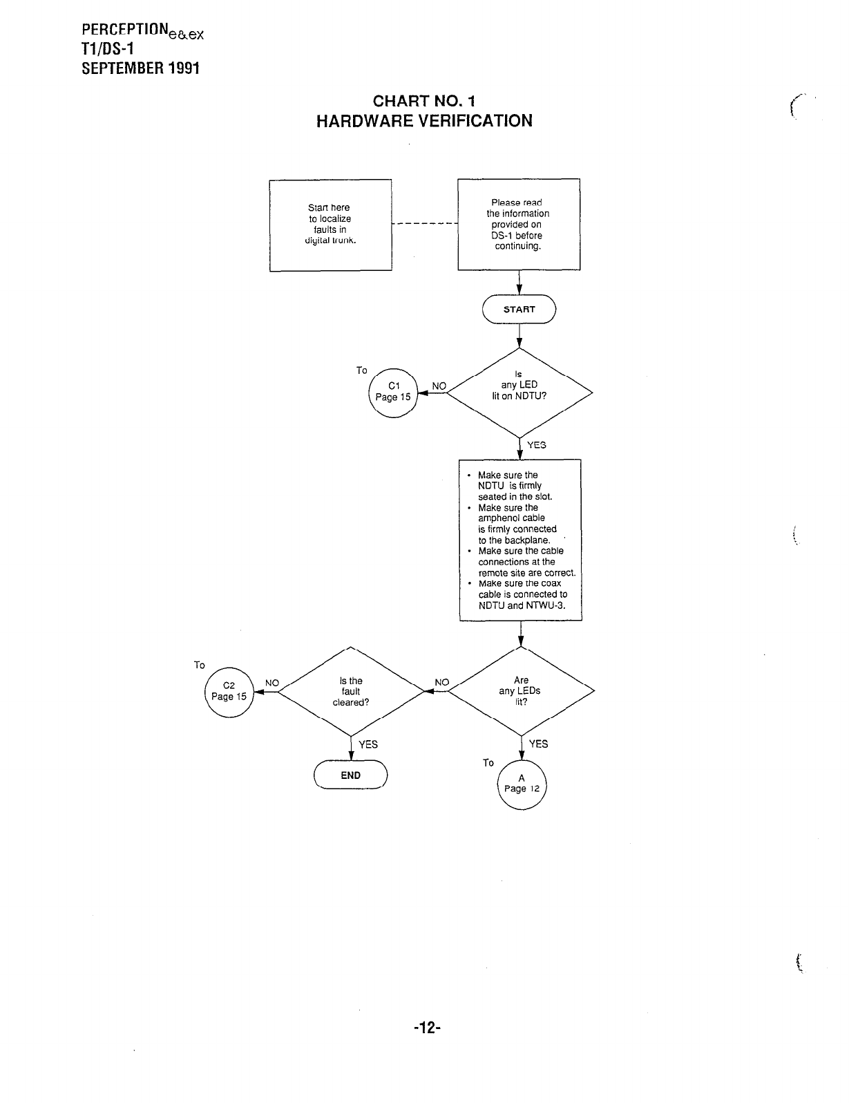
PERCEPTIONeb,,
Tl/DS-1
SEPTEMBER 1991
CHART NO. 1
HARDWARE VERIFICATION
- Make sure the
NDTU is firmly
seated in the slot.
- Make sure the
amphenol cable
is firmly connected
to the backplane.
* Make sure the cable
connections at the
remote site are correct
- Make sure the coax
cable is connected to
NDTU and NTWU-3.
To n /\
YES
c---f END
-12-
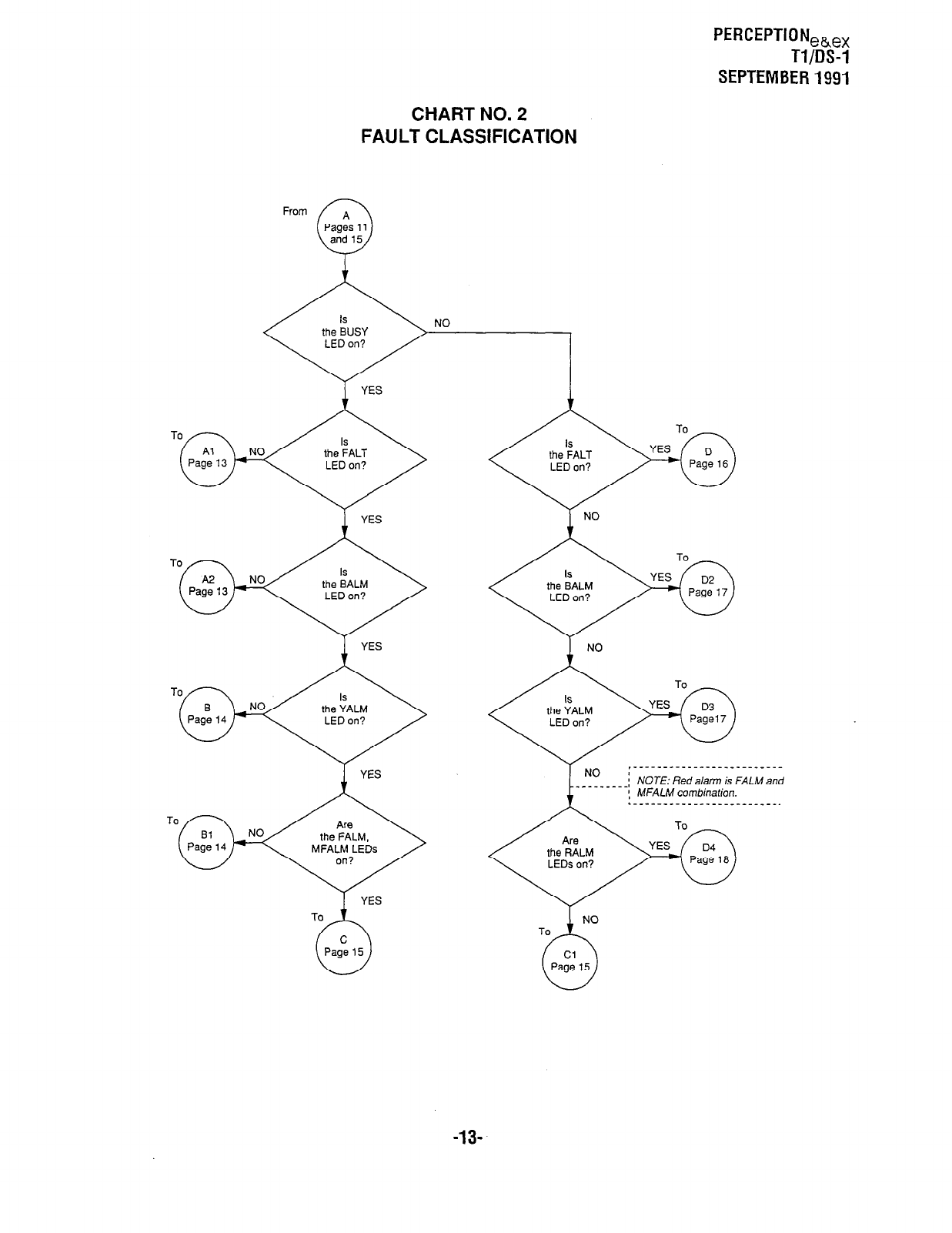
PERCEPTIONeh,,
Tl/DS-1
SEPTEMBER1991
CHART NO. 2
FAULT CLASSIFICATION
From
MFALM LEDs
,______-__________________
:
- - - - - _ - - -I NOTE: Red alarm is FALM and
; MFALM combination.
.__--__-__________________
-13-
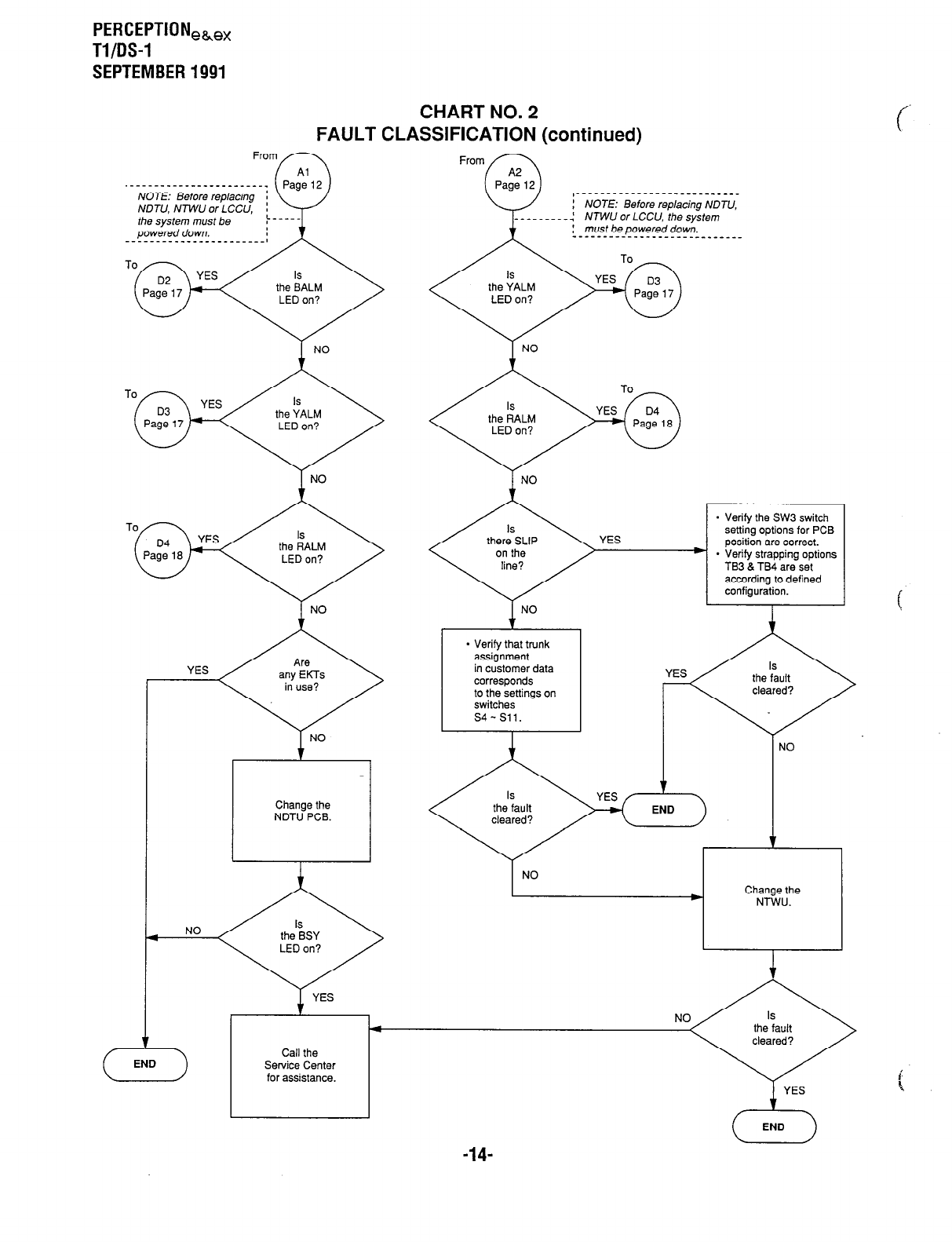
PERCEPTIONeke,
Tl/DS-1
SEPTEMBER 1991
CHART NO. 2
FAULT CLASSIFICATION (continued)
powered down.
T NO
YES
From
,_____________-_____________
: NOTE: Before replacing NDTU,
’
__________( NTWU or LCCU, the system
: must be powered down.
----------__________________
I
NO
. Verify the SW3 switch
setting options for PCB
position are correct.
+ * Verify strapping options
TB3 & TB4 are set
according to defined
configuration.
. Verify that trunk
assignment
in customer data
corresponds
to the settings on
switches
s4-Sll.
J I
NO
Call the
Service Center
for assistance.
1 YES
-14-

PERCEPTION,~,,
Tl/OS-1
SEPTEMBER1991
CHART NO. 3
ALARM FAULTS
From From
* Verify remote site
is in loop back.
If so, wait until
loop back test is
complete for the
BALM LED to go off.
* Verify the
customer data,
switches, and
straps for correct
configuration.
I-
* Verify the following
straps, switches,
and data are set
according to the
defined system
and network
configuration.
. TB3 and TB4
- s3-Sll
* Customer data
* Replace the NDTU
with the removed
PCB.
* Change the NTWU.
1
YES
I
* Verify the following
options and data
are according to
defined
configuration
for the system:
. TB5 and TB6
. Sl switch
. Customer data
- Network
connection
1 for trunk type
allocation
* Connections
L
- Replace the
NTWU with
the removed PCB.
* Change the
LCCU.
Change the
NDTU.
L
A
YES
IYES
customer data.
connections.
Alarm LEDs
Follow instructions
for each alarm in
Paragraph 3.61.
YES
To
t,
82
This
paw
YES
Call the
b Service Center 4
for assistance.
-15-
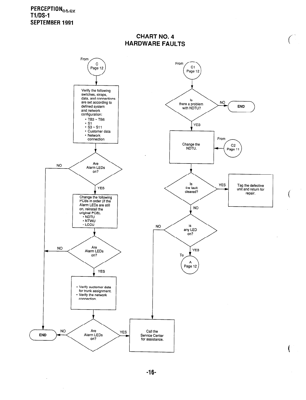
PERCEPTIONeb,,
Tl/OS-1
SEPTEMBER 1991
HAF
Verify the following
switches, straps,
data, and connections
are set according to
defined system
and network
configuration:
* TB3 - TB6
- Sl
.s3-Sll
* Customer data
* Network
connection
r
NO
on, reinstall the
NO
I
* Verify customer data
for trunk assignment.
* Verify the network
connection.
ZHART NO. 4
DWARE FAULTS
Change the
NDTU.
Tag the defective
unit and return for
repair.
NO
Service Center
for assistance.
c
,.
-16-
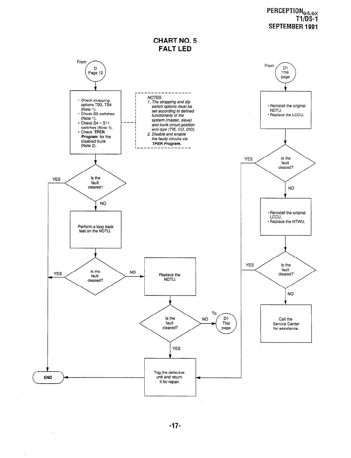
PERCEPTIONeb,,
Tl/DS-1
SEPTEMBER 1991
* Check strapping
options TB3. TB4
(Note 1).
- Check S3 switches
(Note 1).
* Check S4 - Sll
switches (Note 1).
* Check TPER
Program for the
disabled trunk
(Note 2).
YES
Perform a loop back
test on the NDTU.
CHART NO. 5
FALT LED
NOTES:
1. The strapping and dip
switch options must be
set according to defined
functionality of the
system (master, slave)
and trunk circuit position
and type (TIE, CO, DID).
2 Disable and enable
the fau/ty circuits via
TPER Program.
--
YES
+
- Reinstall the original
NDTU.
* Replace the LCCU.
i
NO
- Reinstall the original
- Replace the NTWU.
.
Call the
Service Center
for assistance.
-17-
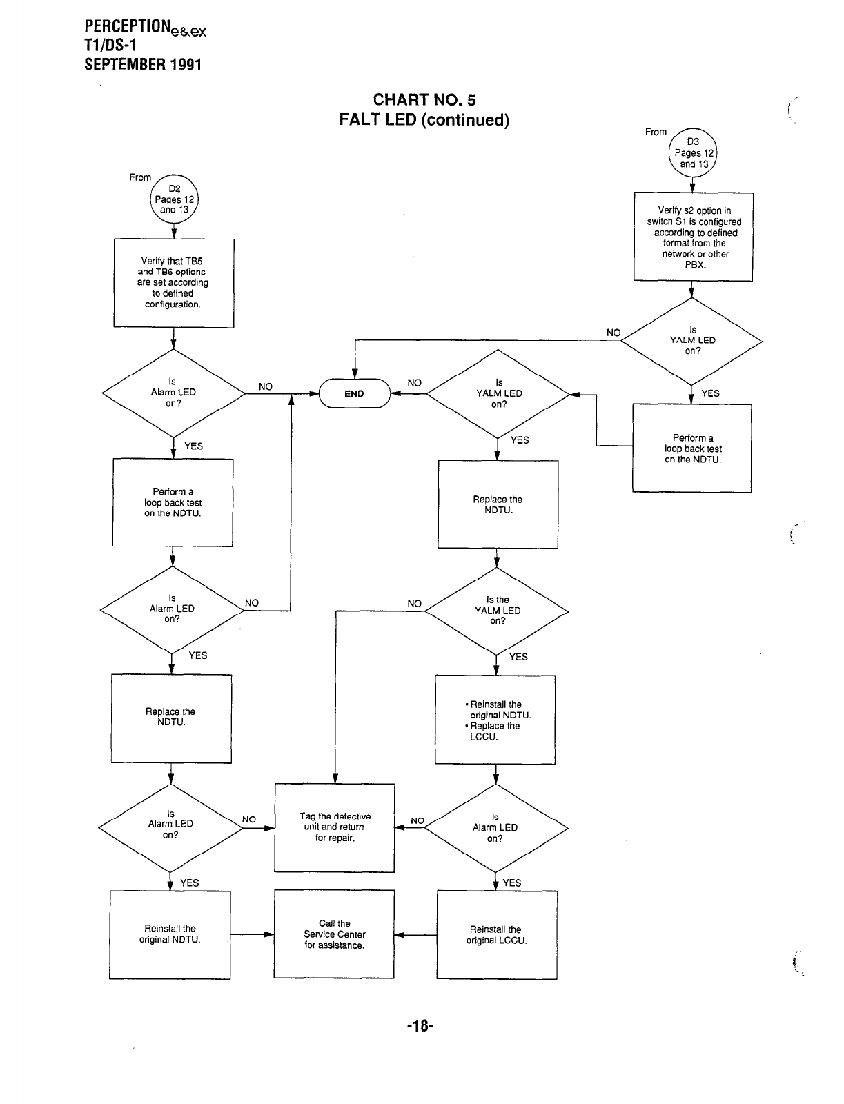
PERCEPTIONeGe,
Tl/DS-1
SEPTEMBER 1991
Verify that TB5
and TB6 options
are set according
to defined
configuration.
NO
CHART NO. 5
FALT LED (continued)
Replace the
NDTU.
* Reinstall the
original NDTU.
- Replace the
LCCU.
Tag the defective
unit and return
for repair.
YES YES
r
Reinstall the
original NDTU.
Call the Reinstall the
m Service Center
for assistance. original LCCU.
i’
From
Verify s2 option in
switch Sl is configured
according to defined
format from the
network or other
PBX.
-18-
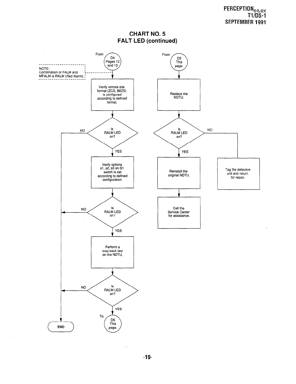
PERCEPTIONea,,
Tl/DS-1
SEPTEMBER 1991
CHART NO. 5
FALT LED (continued)
NOTE:
Combination of FALM and
MFALM is RALM (Red Alarm). :
__-_----_____--__________
Verify remote site
format (ZCS, SSZS)
according to defined
NO
Verify options
sl, s2, s3 on Si
switch is set
according to defined
on the NDTU.
NO
I
To
NO
Reinstall the
original NDTU.
Service Center
for assistance.
Tag the defective
unit and return
for repair.
-19-

This page intentionally left blank.
f .
t
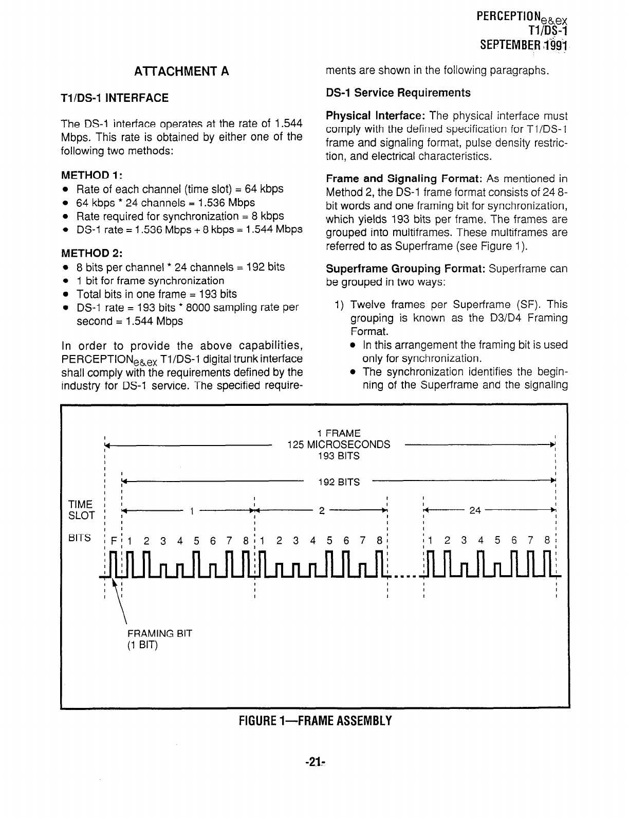
AlTACHMENT A
Tl/DS-1 INTERFACE
The DS-1 interface operates at the rate of 1.544
Mbps. This rate is obtained by either one of the
following two methods:
METHOD 1:
l
Rate of each channel (time slot) = 64 kbps
l
64 kbps * 24 channels = 1.536 Mbps
l
Rate required for synchronization = 8 kbps
l
DS-1 rate = 1.536 Mbps + 8 kbps = 1.544 Mbps
METHOD 2:
l
8 bits per channel * 24 channels = 192 bits
l
1 bit for frame synchronization
l
Total bits in one frame = 193 bits
l
DS-1 rate = 193 bits * 8000 sampling rate per
second = 1.544 Mbps
In order to provide the above capabilities,
PERCEPTIONe,e, Tl/DS-1 digital trunk interface
shall comply with the requirements defined by the
industry for DS-1 service. The specified require-
Tl/DS-1
SEPTEMBER i&j
ments are shown in the following paragraphs.
DS-1 Service Requirements
Physical Interface: The physical interface must
comply with the defined specification for Tl/DS-I
frame and signaling format, pulse density restric-
tion, and electrical characteristics.
Frame and Signaling Format: As mentioned in
Method 2, the DS-1 frame format consists of 24 8-
bit words and one framing bit for synchronization,
which yields 193 bits per frame. The frames are
grouped into multiframes. These multiframes are
referred to as Super-frame (see Figure 1).
Superframe Grouping Format: Super-frame can
be grouped in two ways:
1) Twelve frames per Super-frame (SF). This
grouping is known as the D3/D4 Framing
Format.
l
In this arrangement the framing bit is used
only for synchronization.
l
The synchronization identifies the begin-
ning of the Super-frame and the signaling
I
1
FRAME I
Y
125
MICROSECONDS w
I
193 BITS I
, I
FRAMING
BIT
(1 BIT)
FIGURE l-FRAME ASSEMBLY
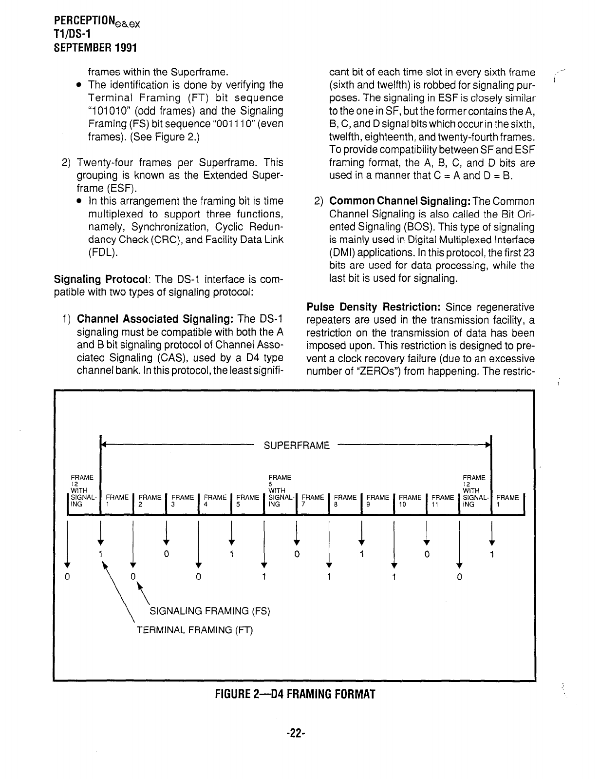
PERCEPTIONea,,
Tl/DS-1
SEPTEMBER 1991
frames within the Super-frame.
l
The identification is done by verifying the
Terminal Framing (FT) bit sequence
“101010” (odd frames) and the Signaling
Framing (FS) bit sequence “001110” (even
frames). (See Figure 2.)
2) Twenty-four frames per Super-frame. This
grouping is known as the Extended Super-
frame (ESF).
l
In this arrangement the framing bit is time
multiplexed to support three functions,
namely, Synchronization, Cyclic Redun-
dancy Check (CRC), and Facility Data Link
(FDL).
Signaling Protocol: The DS-1 interface is com-
patible with two types of signaling protocol:
cant bit of each time slot in every sixth frame
(sixth and twelfth) is robbed for signaling pur-
poses. The signaling in ESF is closely similar
to the one in SF, but the former contains the A,
B, C, and D signal bits which occur in the sixth,
twelfth, eighteenth, and twenty-fourth frames.
To provide compatibility between SF and ESF
framing format, the A, B, C, and D bits are
used in a manner that C = A and D = B.
2) Common Channel Signaling: The Common
Channel Signaling is also called the Bit Ori-
ented Signaling (BOS). This type of signaling
is mainly used in Digital Multiplexed Interface
(DMI) applications. In this protocol, the first 23
bits are used for data processing, while the
last bit is used for signaling.
1) Channel Associated Signaling: The DS-1
signaling must be compatible with both the A
and B bit signaling protocol of Channel Asso-
ciated Signaling (CAS), used by a D4 type
channel bank. In this protocol, the least signifi-
Pulse Density Restriction: Since regenerative
repeaters are used in the transmission facility, a
restriction on the transmission of data has been
imposed upon. This restriction is designed to pre-
vent a clock recovery failure (due to an excessive
number of “ZEROS”) from happening. The restric-
n
SUPERFRAME
_I
FRAME FRAME FRAME
SIGNALING FRAMING (FS)
TERMINAL FRAMING (FT)
FIGURE 2-D4 FRAMING FORMAT
-22-
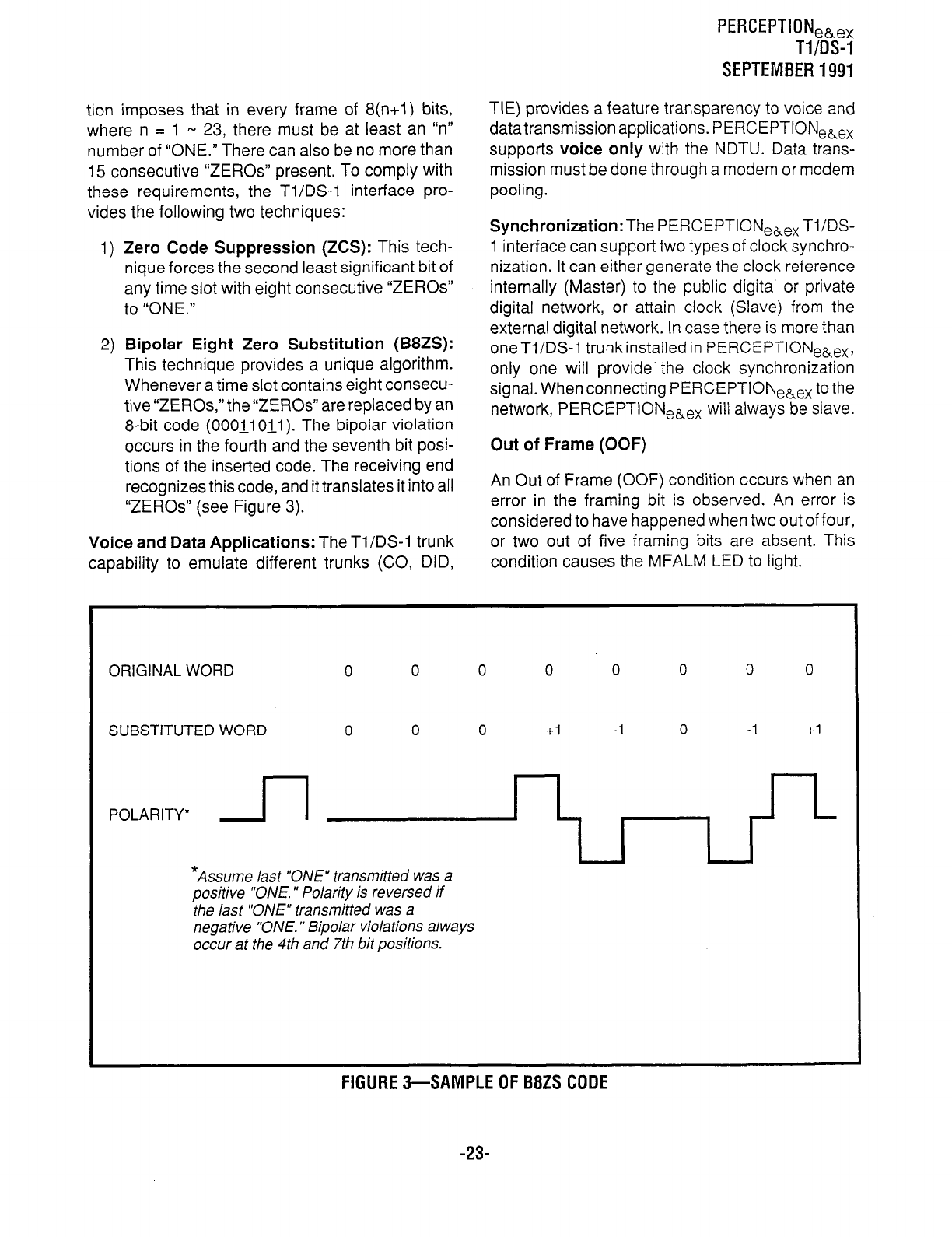
PERCEPTIONeb,,
Tl/DS-1
SEPTEMBER1991
tion imposes that in every frame of 8(n+l) bits,
where n = 1 - 23, there must be at least an “n”
number of “ONE.” There can also be no more than
15 consecutive “ZEROS” present. To comply with
these requirements, the Tl/DS-1 interface pro-
vides the following two techniques:
1) Zero Code Suppression (ZCS): This tech-
nique forces the second least significant bit of
any time slot with eight consecutive “ZEROS”
to “ONE.”
2)
Bipolar Eight Zero Substitution (B8ZS):
This technique provides a unique algorithm.
Whenever a time slot contains eight consecu-
tive “ZEROS,” the “ZEROS” are replaced by an
8-bit code (OOOll O-j.1). The bipolar violation
occurs in the fourth and the seventh bit posi-
tions of the inserted code. The receiving end
recognizes this code, and it translates it into all
“ZEROS” (see Figure 3).
Voice and Data Applications: The Tl/DS-1 trunk
TIE) provides a feature transparency to voice and
datatransmission applications. PERCEPTIONeLex
supports voice only with the NDTU. Data trans-
mission must be done through a modem or modem
pooling.
Synchronization: The PERCEPTIONeLex Tl/DS-
1 interface can support two types of clock synchro-
nization. It can either generate the clock reference
internally (Master) to the public digital or private
digital network, or attain clock (Slave) from the
external digital network. In case there is more than
oneTl/DS-1 trunkinstalledin PERCEPTIONehex,
only one will provide the clock synchronization
signal. When connecting PERCEPTIONehex to the
network, PERCEPTIONeLex will always be slave.
Out of Frame (OOF)
An Out of Frame (OOF) condition occurs when an
error in the framing bit is observed. An error is
considered to have happened when two out of four,
or two out of five framing bits are absent. This
capability to emulate different trunks (CO, DID, condition causes the MFALM LED to light.
ORIGINAL WORD 0 0 0 0 0 0 0 0
SUBSTITUTED WORD 0 0 0 +I -1 0 -1 +I
POLARITY*
JJ
*Assume last “ONE” transmitted was a
positive “ONE. ” Polarity is reversed if
the last “ONE” transmitted was a
negative “ONE. ‘I Bipolar violations always
occur at the 4th and 7th bit positions.
FIGURES-SAMPLEOFB8ZSCODE
-23-
PERCEPTIONeb,,
Tl/DS-1
SEPTEMBER 1991
Loss of Signal (LOS)
A Loss of Signal (LOS) condition is specified when
the DS-1 signal is absent for more than 150 milli-
seconds. Upon detection of LOS, the DS-1 inter-
face generates a consecutive sequence of unfra-
med all “ONE”signal, in orderto keep the regenera-
tive repeaters alive. This condition causes the
FALM LED to light.
Jitter
Jitters are short-term variations of significant in-
stants (of a digital signal) from their idle positions in
time. In the digital transmission, a jitter is generated
from two principal sources, digital regenerator and
multiplexers. A regenerator jitter is introduced by
the imperfections in the timing recovery process,
whereas a multiplexer jitter is mainly related to the
stuffing mechanism used to synchronize the low
speed incoming pulse stream.
Jitters may introduce a number of impairments
such as errors, slips, crosstalks, and distortions to
the original signal. The following data indicates the
maximum input jitter allowed in band 1 (10 Hz to 40
KHz) and band 2 (8 KHz to 40 KHz).
l
Band 1: 5.0 per 648 nsec. peak-to-peak (10 Hz
to 40 KHz)
l
Band 2: 0.1 per 648 nsec. peak-to-peak (8 KHz
to 40 KHz)
Slip
Slip occurrences are caused by two factors:
1) Lack of frequency synchronization between
the two ends of the DS-1 network.
2) Phase jitter.
An overflow or underflow of the receiver buffer is
indicative of a slip.
Bipolar Violation (BPV)
The Alternative Mark Inversion (AMI) coding is
used in the DS-l/DMI line transmission. Any vari-
ation to this rule is considered a violation. An
excessive bipolar violation is declared when a
number of BPV, which causes performance to r:-
degrade, goes below the threshold of 1455 BPVs in
1000 consecutive seconds. If a B8ZS coding is
used, a bipolar violation detected due to “ZERO”
substitution should not be considered an error.
Cyclic Redundancy Check (CRC)
The CRC is used with an Extended Super-frame
(ESF). The CRC code uses 2Kb/s of the 8Kb/s-
frame-bit pattern for an end-to-end error rate
checking.
AlTACHMENT B
CHANNEL SERVICE UNIT
1) A Channel Service Unit (CSU) provides the
following:
l
Electrical protection
l
Keep-alive signal
l
Repeater function
2) CSU requirements:
l
One CSU for each Tl/DS-1 interface con-
nected to the network.
l
One CSU for a Tl/DS-1 interface between
PBXs that are located more than 655 feet
apart.
3) Examples of approved CSUs:
l
Kentrox
l
Digital Link
-24-
PERCEPTIONeh,
SYSTEM RECORD
FEBRUARY 1992
Pdwceptionk 6; ex
APPENDIX #I
SYSTEM RECORD
Version D.05
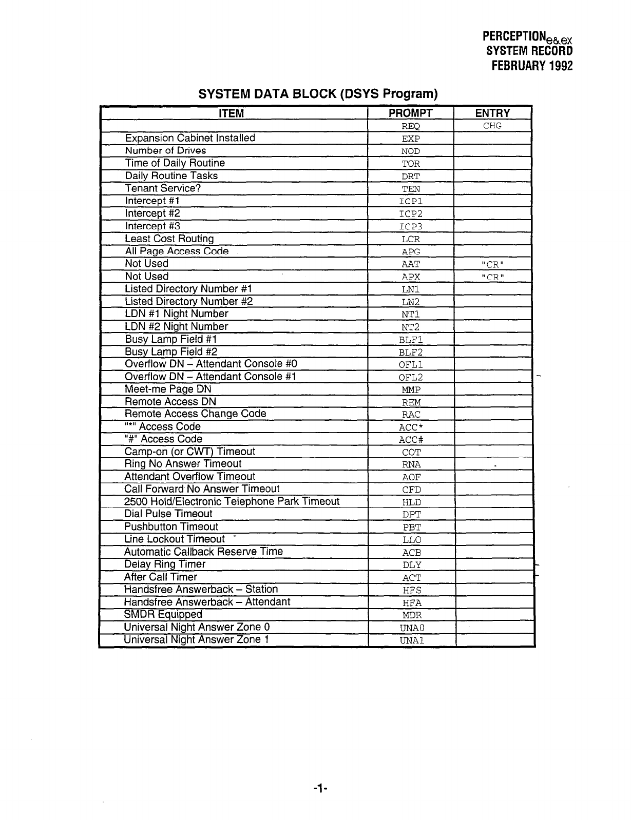
PERCEPTIONek,
SYSTEMRECORD
FEBRUARY 1992
SYSTEM DATA BLOCK (DSYS Program)
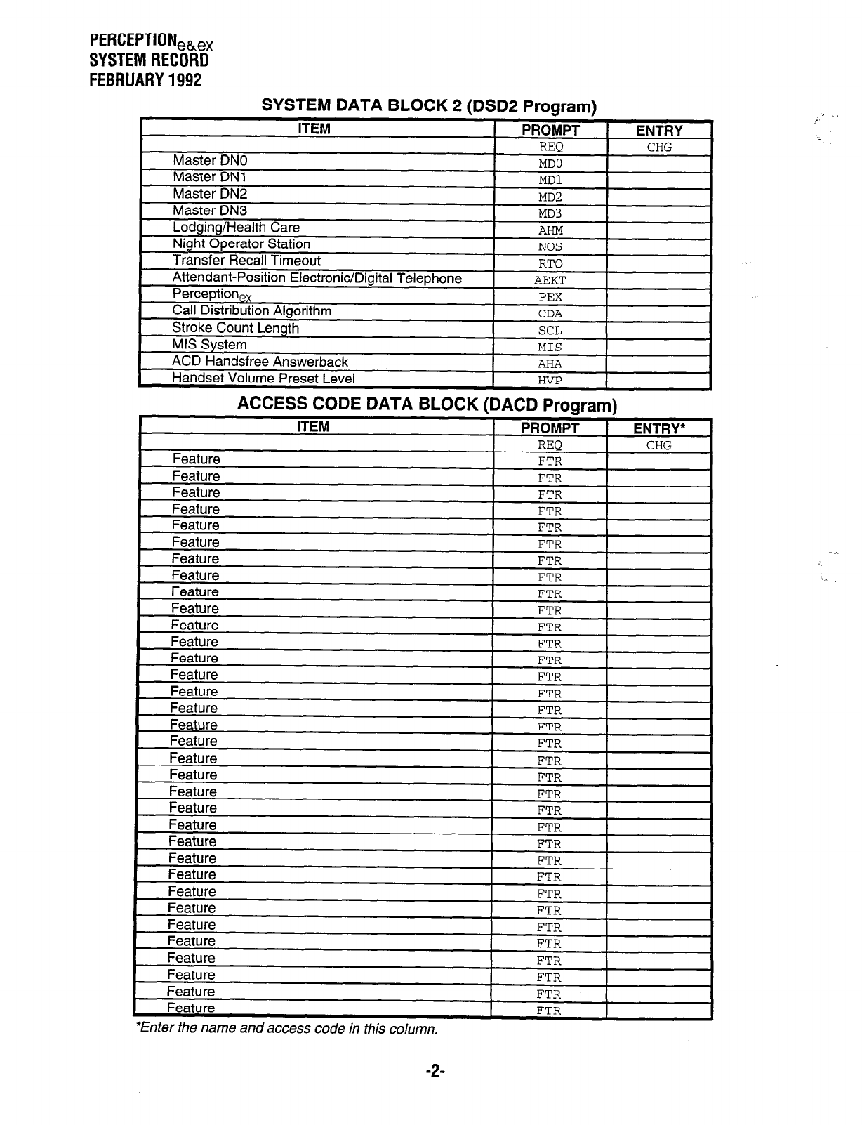
PERCEPTIONeh,
SYSTEM RECORD
FEBRUARY 1992
SYSTEM DATA BLOCK 2 (DSD2 Program)
*Enter the name and access code in this column.
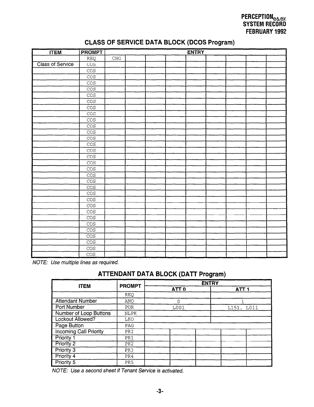
PERCEPTIONeh,,
SYSTEM RECORD
FEBRUARY 1992
CLASS OF SERVICE DATA BLOCK (DCOS Program)
NOTE: Use multiple lines as required.
AlTENDANT DATA BLOCK (DATT Program)
ITEM
Attendant Number
PROMPT
REQ
AN0
ENTRY
Al-l-0 ATT1
0 1
NOTE: Use a second sheet if Tenant Service is activated.
-3-
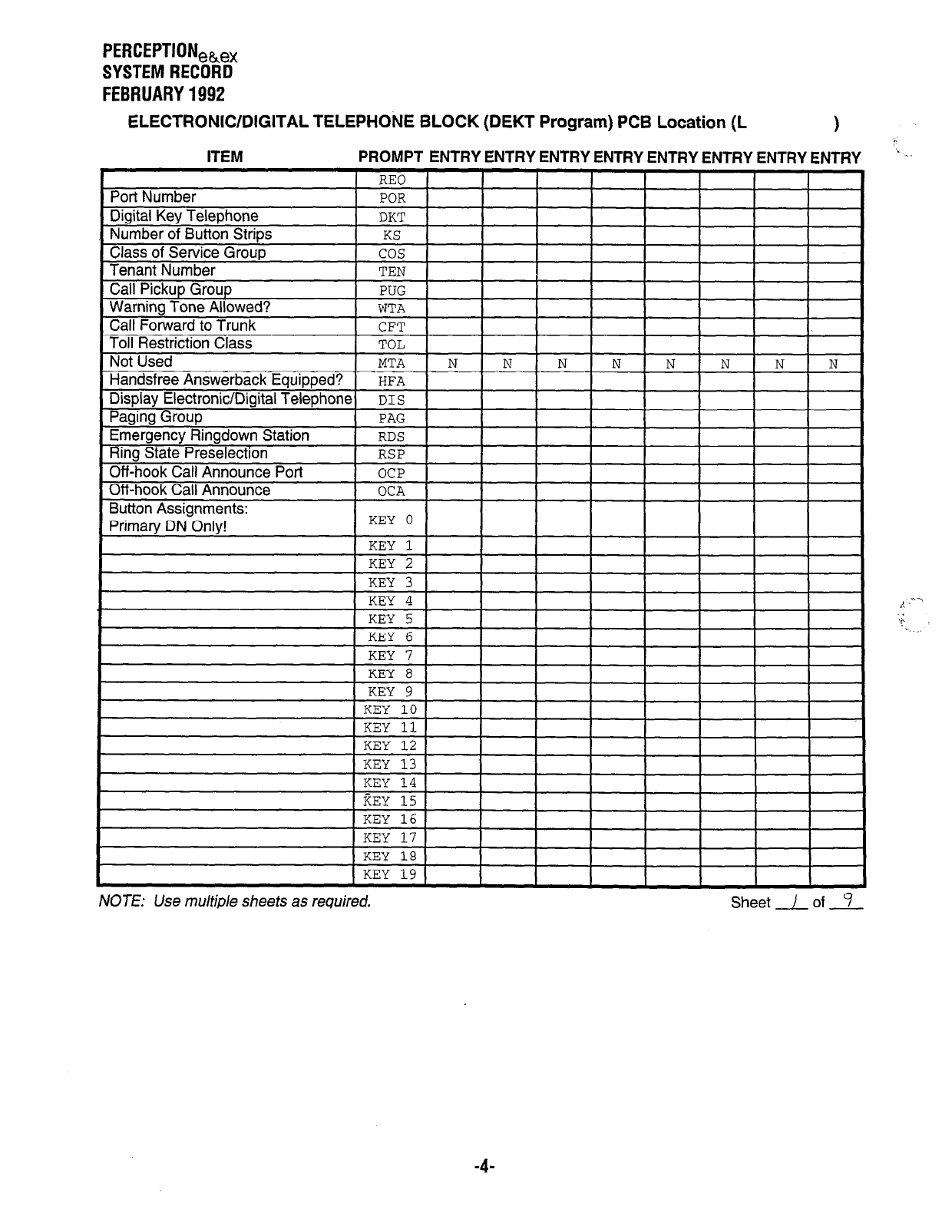
PERCEPTIONeh,
SYSTEM RECORD
FEBRUARY 1992
ELECTRONIC/DIGITAL TELEPHONE BLOCK (DEKT Program) PCB Location (L 1
PROMPT ENTRY ENTRY ENTRY ENTRY ENTRY ENTRY ENTRY ENTRY ’ _-
d
, I”U , I I I I I I I
MT A I\T t N
Button Acsinnmnnts-
““Syy . . I l”. ..“.
DN Onlv! KEY 0
1 I I I I I I I
Primary , t 1
KEY 1
KEY 2
_--__ ^
KEY 4
KEY 5
KEY 6
KEY 7
KRV 8
I -_-- -
1 KEY 9 1
KEY 10
KEY 11
KEY 12
NOTE: Use multiple sheets as required, Sheet / of 9
-4-
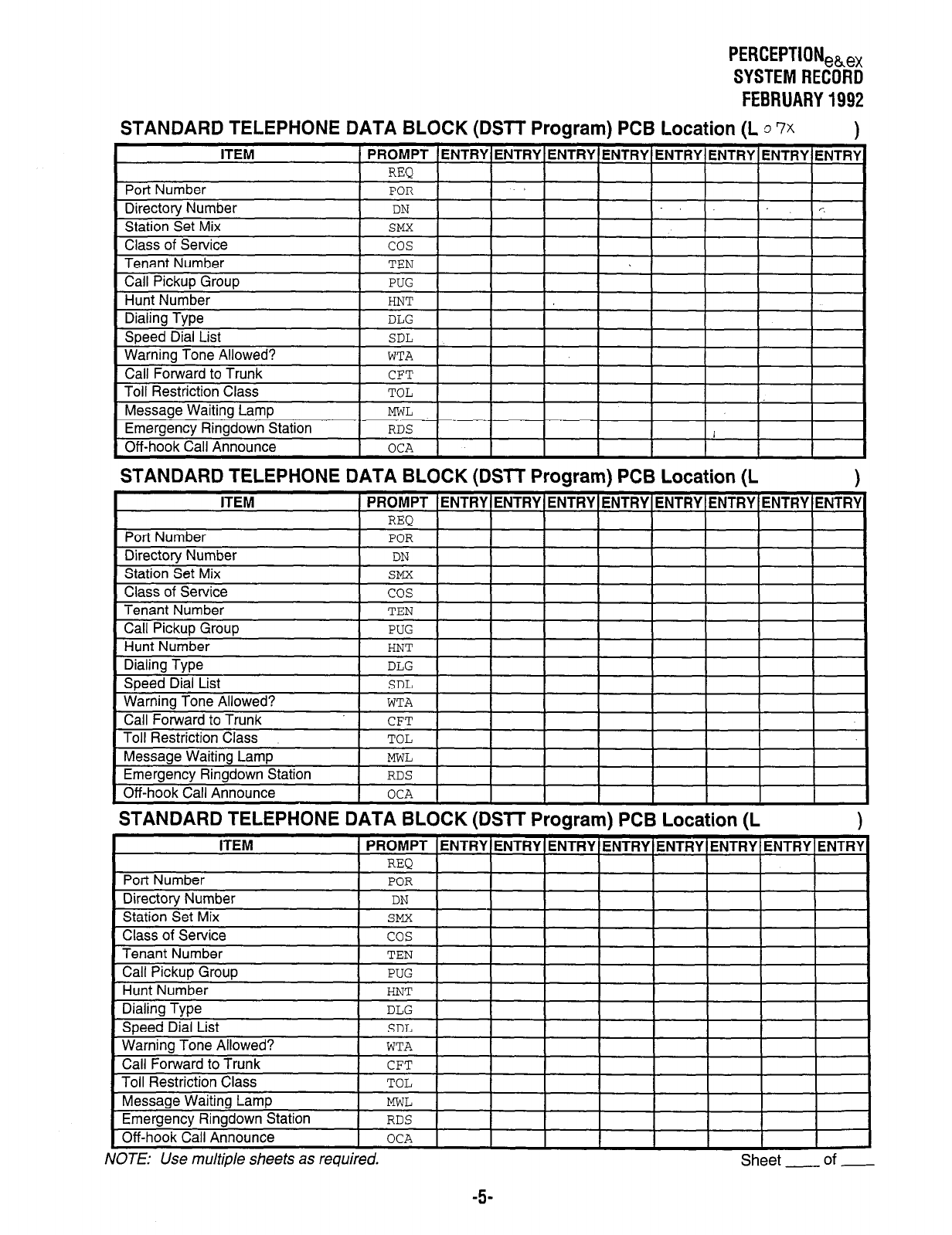
STANDARD TELEPHONE DATA BLC
ITEM 1 PROMPT
Port Number
Directory Number
Station Set Mix
Class of Service
Tenant Number
Call Pickup Group
Hunt Number
REQ
POR
DN
SMX
cos
TEN
PUG
HNT
Dialing Type
Speed Dial List
Warning Tone Allowed?
Call Forward to Trunk
Toll Restriction Class
DLG
SDL
WTA
CFT
TOL
Off-hook Call
Messaae Waitina Lamo
I I
Announce
Emeraencv Rinadown Station I
I
I
MWL
i RDS
OCA
PERCEPTION,~,
SYSTEM RECORD
FEBRUARY 1992
CK (DSlT Program) PCB Location (1
ENTRY 1 ENTRY 1 ENTRY 1 ENTRY 1 ENTRY 1 ENTRY
I I I I I
I I I I I
I I I
I
STANDARD TELEPHONE DATA BLOCK (DSIT Program) PCB Location (L
Message Waiting Lamp
MWL
Emergency Ringdown Station
RDS
Off-hook Call Announce
OCA
NOTE: Use multiple sheets as required. Sheet - of -
-5-
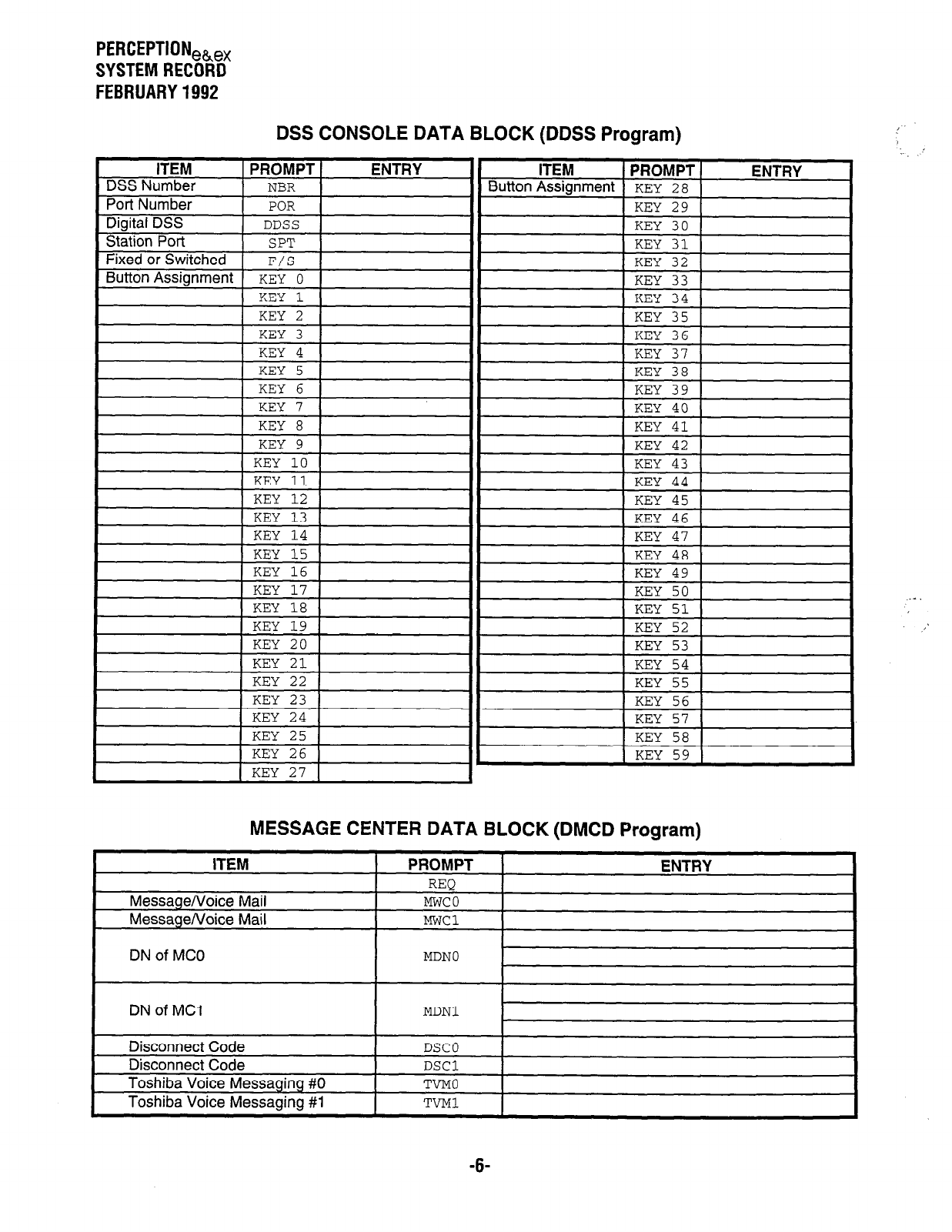
PERCEPTIONeh,
SYSTEM RECORD
FEBRUARY 1992
DSS CONSOLE DATA BLOCK (DDSS Program)
ITEM
DSS Number
Port Number
fX7ital
nss
PROMPT
NBR
POR
DDSS
ENTRY ITEM PROMPT ENTRY
Button Assignment KEY 2 8
KEY 29
KEY 30
Station Port SPT
Fixed or Switched F/S
Button Assianment KEY 0
KEY 3 KEY 36
KEY 4 KEY 37
KEY 5 KEY 38
G-IT-J K TI73V 10
, ILUJ. ” II , LlLI -17 ,
I
1 KEY 7 1 1 KEY 40 1
I
KEY 41
KEY 42
KEY 43
L-~V nn
II ,
II , I-Lfil -9 ,
1 KEY 12 1 II 1 KEY 45 1
r.LI -I”
KEY 18 KEY 51
KEY 19 KEY 52
KEY 53
KEY 54
vI7v cc:
1,LII 2-J
KEY 23 KEY 56 I
KEY 24 KEY 57
I:,',
KEY 58 1
IKEY 1
MESSAGE CENTER DATA BLOCK (DMCD Program)
ITEM
Message/Voice Mail
Message/Voice Mail
PROMPT
REQ
Mwco
MWCl
ENTRY
DN of MC0 MDNO
DN of MCI MDNl
Disconnect Code DSCO
Disconnect Code DSCl
Toshiba Voice Messaging #0 TVMO
Toshiba Voice Messaging #1 TVMl
:. ’
-6-
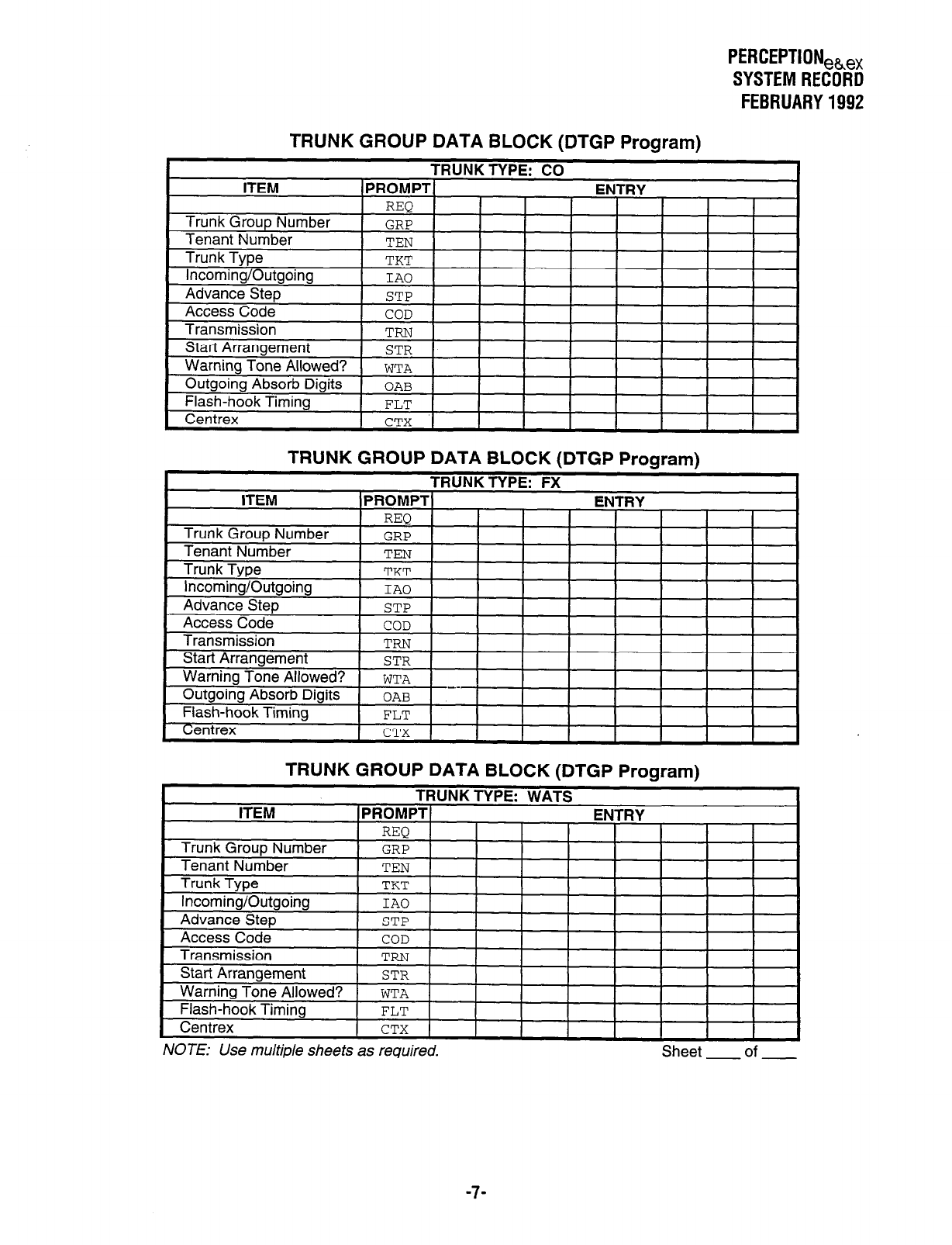
PERCEPTION,~,,
SYSTEM RECORD
FEBRUARY 1992
TRUNK GROUP DATA BLOCK (DTGP Program)
ITEM TRUNK TYPE: CO
1~~40~~1 ENTRY
I I I I I I
TRUNK GROUP DATA BLOCK (DTGP Program)
TRUNK GROUP DATA BLOCK (DTGP Program)
-
TRUNK TYPE: WATS
laanrrnsl
IZhll-PV
I
NOTE: Use multiple sheets as required. Sheet of
-7-
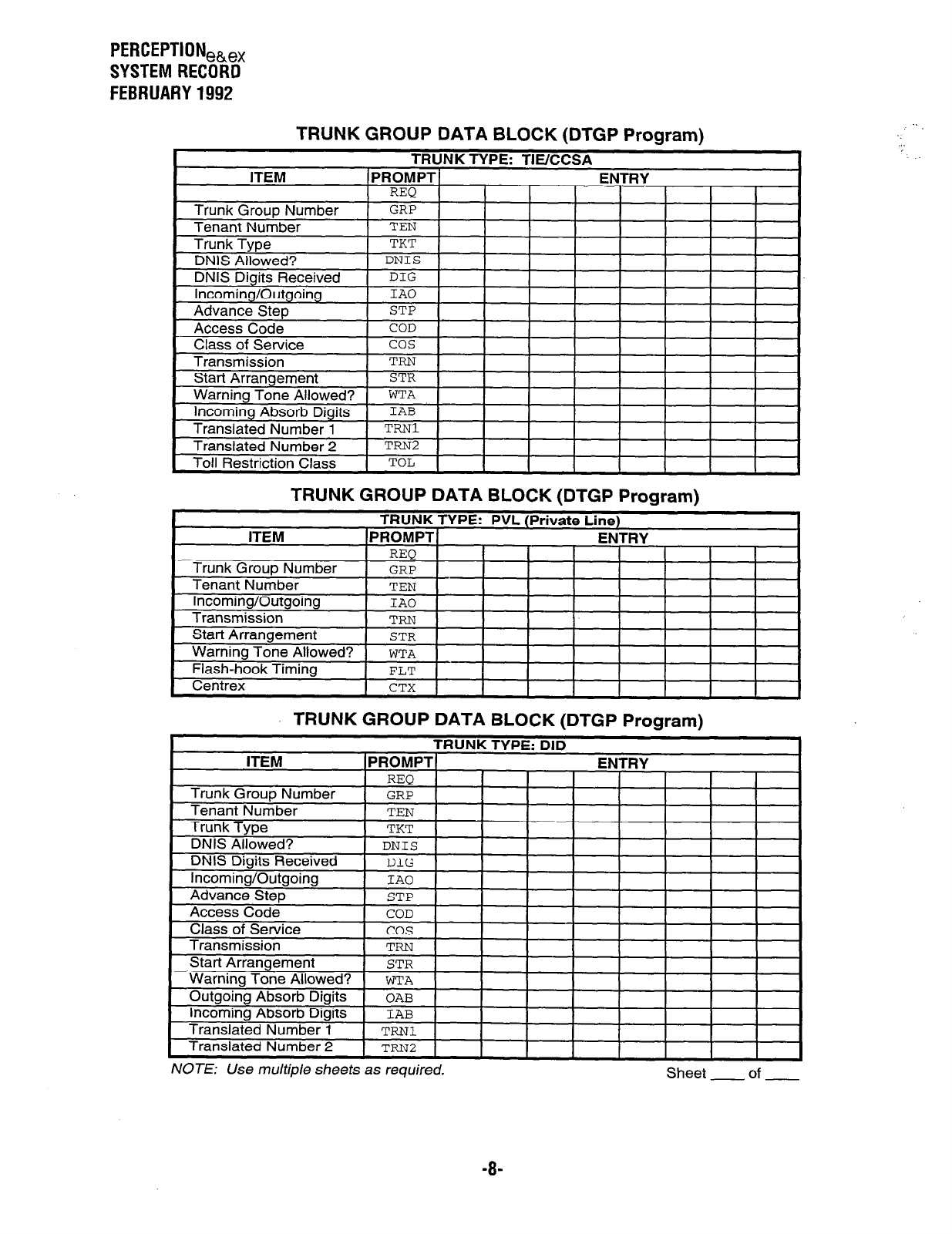
PERCEPTIONeb,,
SYSTEM RECORD
FEBRUARY 1992
TRUNK GROUP DATA BLOCK (DTGP Program)
TRUNK GROUP DATA BLOCK (DTGP Program)
Start Arrangement
Warning Tone Allowed?
Flash-hook Timing
STR
WTA
FLT
Centrex 1 CTX 1 I I 1
I
TRUNK GROUP DATA BLOCK (DTGP Program)
TRUNK TYPE:
\ DID
ITEM PROMPT ENTRY
REQ
Trunk Group Number GRP
Tenant Number TEN
Trunk Tvoe
TUT
ransmlsslon
NOTE: Use multiple sheets as required. Sheet of
-B-
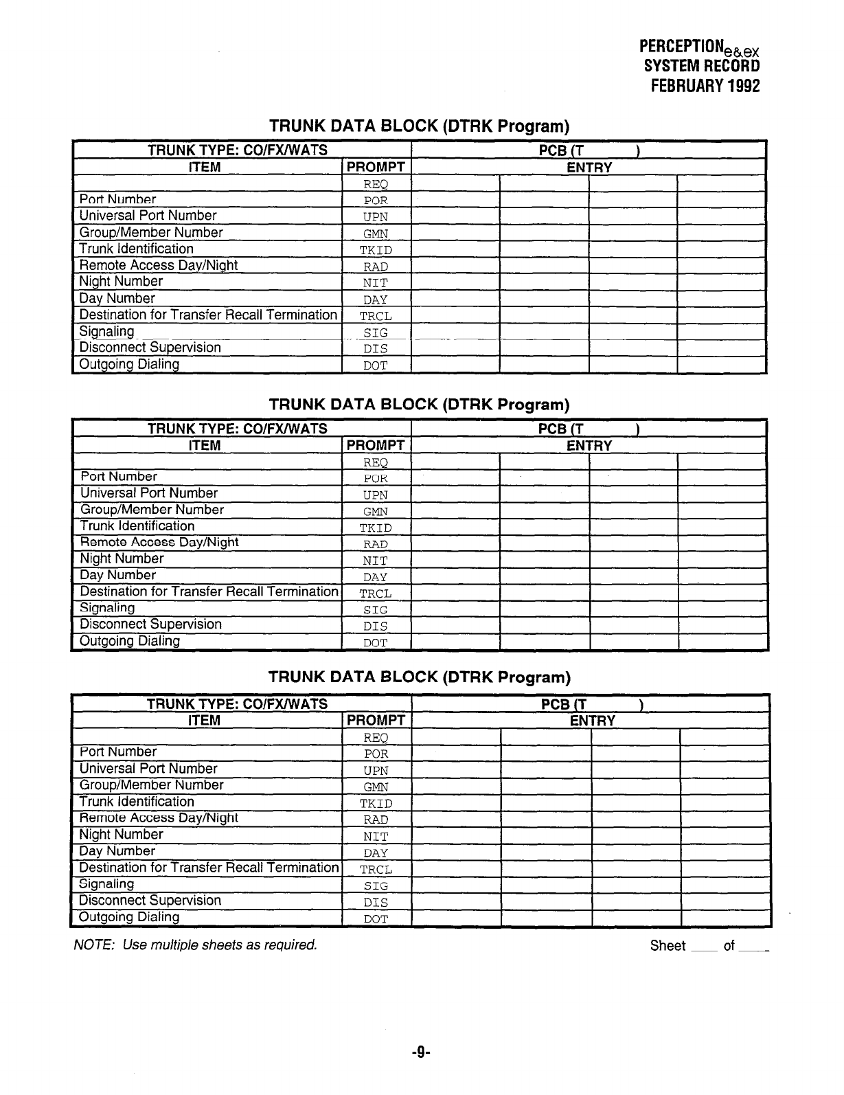
PERCEPTION,~,,
SYSTEM RECORD
FEBRUARY 1992
TRUNK DATA BLOCK (DTRK Program)
TRUNK DATA BLOCK (DTRK Program)
TRUNK DATA BLOCK (DTRK Program)
Destination for Transfer Recall Termination TRCL
Signaling SIG
Disconnect Supervision DIS
Outgoing Dialing DOT
NOTE: Use multiple sheets as required.
-9-
Sheet - of -
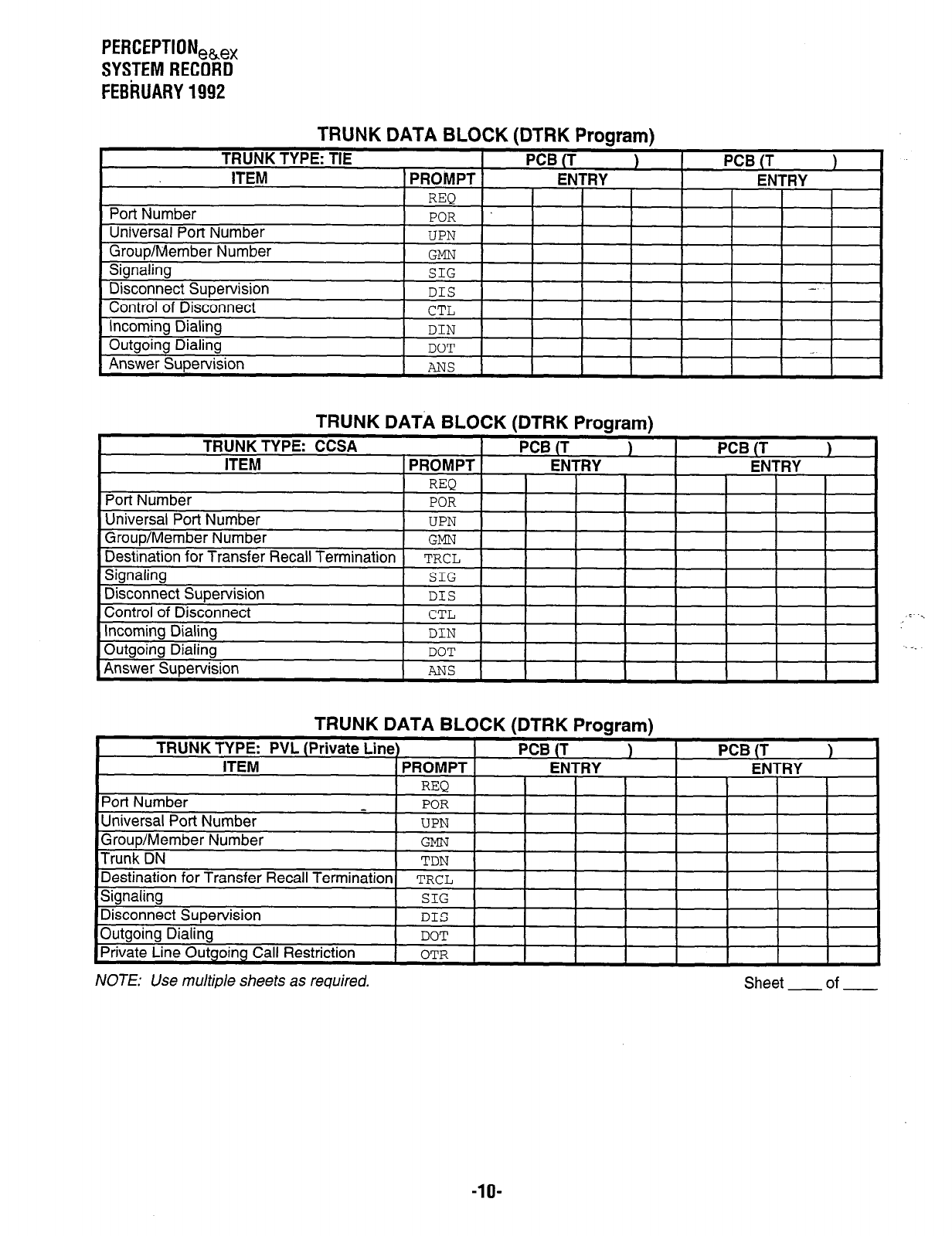
PERCEPTION,,,,
SYSTEM RECORD
FEBRUARY 1992
TRUNK DATA BLOCK (DTRK Program)
TRUNK TYPE: TIE PCB (T 1
ITEM PROMPT ENTRY
REQ I I I
Port Number POR
Universal Port Number
GrouDIIVI~,IIv~l lyulIIu~~
PCB IT \ 1
ENTRY
I I
I
Signaling
Disconnect Supervision
Control of Disconnect
Incoming Dialing
Outgoing Dialing
Answer Supervision
3L.u
DIS -.
CTL
DIN
DOT
ANS
Control of Disconnect CTL
Incoming Dialing DIN
Outgoing Dialing DOT
Answer Supervision
ANS
TRUNK DATA BLOCK (DTRK Program)
NOTE: Use multiple sheets as required.
-lO-
Sheet of
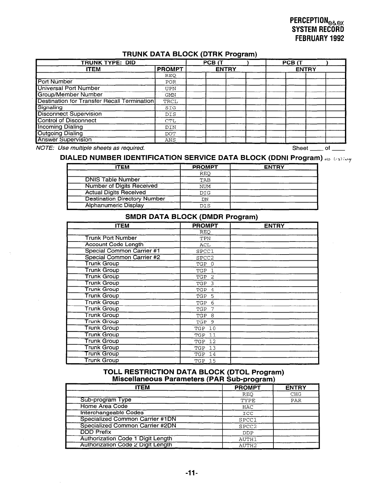
PERCEPTIONeh,,
SYSTEMRECORD
FEBRUARY1992
TRUNK DATA BLOCK fDTRK
TRUNK TYPE: DID
ITEM
. Program)
PCB (T ) PCB (T 1
1 PROMPT ENTRY ENTRY
1 REO I I I I I I
Port Number
Universal Port Number
I I
1 POR 1 I 1 I I
1 UPN I
I
I I I
NOTE: Use multiple sheets as required. Sheet - of -
DIALED NUMBER IDENTIFICATION SERVICE DATA BLOCK (DDNI Program) d0 L;~::~~
ITEM PROMPT ENTRY
REQ
DNIS Table Number TAB
Number of Digits Received NUM
Actual Digits Received DIG
Destination Directory Number DN
Alphanumeric Display DIS
SMDR DATA BLOCK (DMDR Program)
TOLL RESTRICTION DATA BLOCK (DTOL Program)
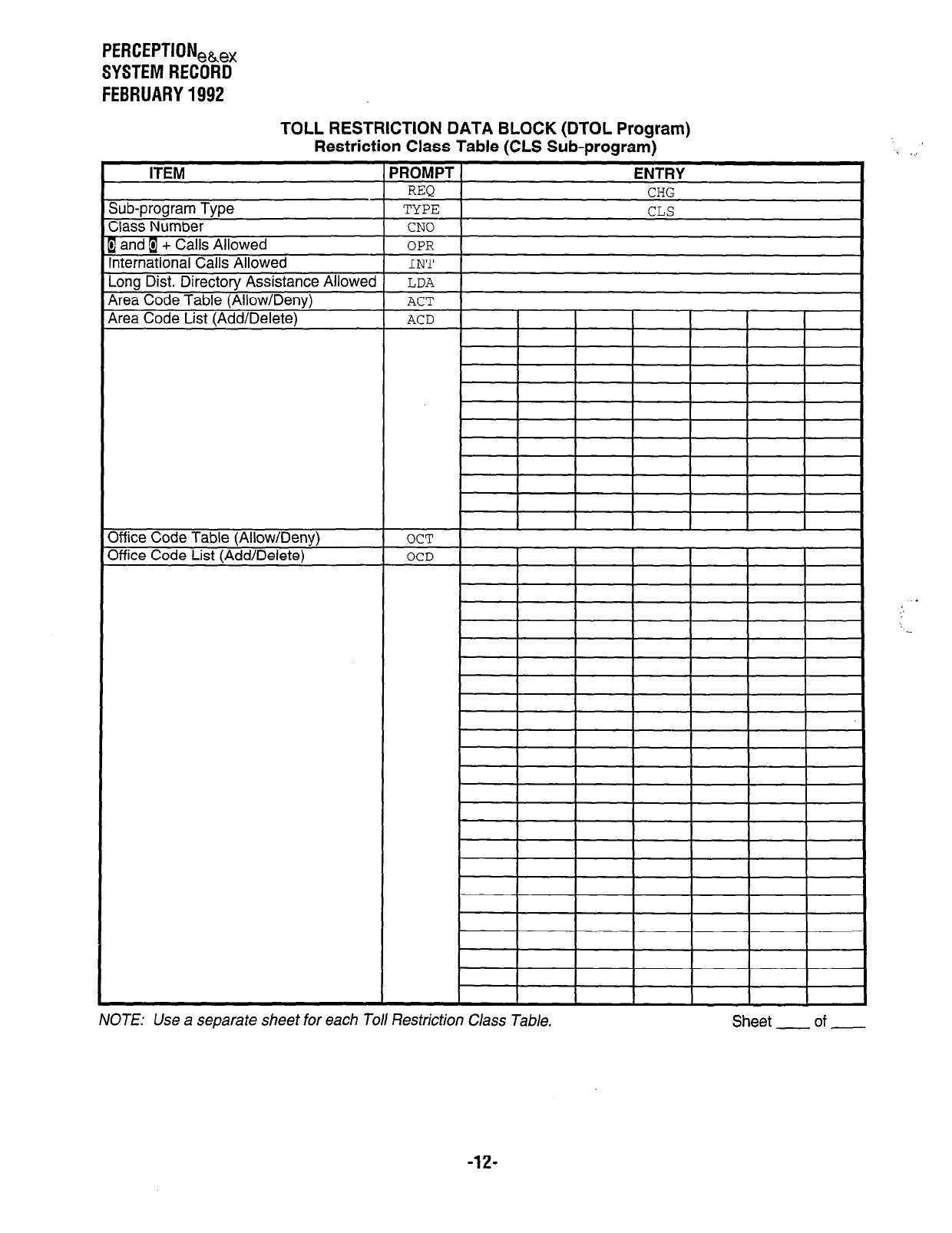
PERCEPTION,~,,
SYSTEM RECORD
FEBRUARY 1992
ITEM
sub-program Type
Iass Number
TOLL RESTRICTION DATA BLOCK (DTOL Program)
Restriction Class Table (CLS Sub-program)
‘ROMPT
ENTRY
REQ CHG
TYPE CLS
CNO
. _..
a and i + Calls Allowed
nternational Calls Allowed
-ong Dist. Directory Assistance Allowed
4rea Code Table (Allow/Deny)
Area Code List (Add/Delete)
34 ice Code Table (Allow/Deny)
Mice Code List (Add/Delete)
OPR 1 I
INT 1
1 I
I I I I I I
OCT
NOTE: Use a separate sheet for each Toll Restriction Class Table. Sheet - of -
-12-
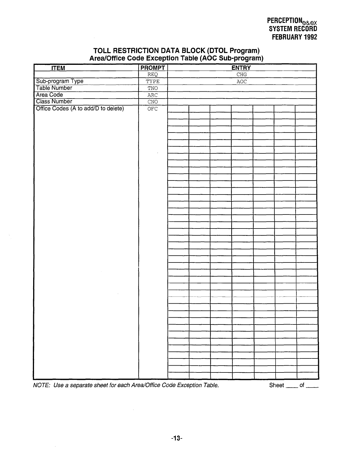
PERCEPTION,&,,
SYSTEM RECORD
FEBRUARY 1992
TOLL RESTRICTION DATA BLOCK (DTOL Program)
Area/Off ice Code Exception Table (AOC Sub-program)
ITEM
Sub-oroaram Tvoe
rable Number
4rea Code
Zlass Number
Mice Codes (A to add/D to delete)
‘ROMPT
REQ
TYPE
TN0
ARC
CNO
OFC
ENTRY
CHG
AOC
NOTE: Use a separate sheet for each Area/Office Code Exception Table, Sheet of
-13-
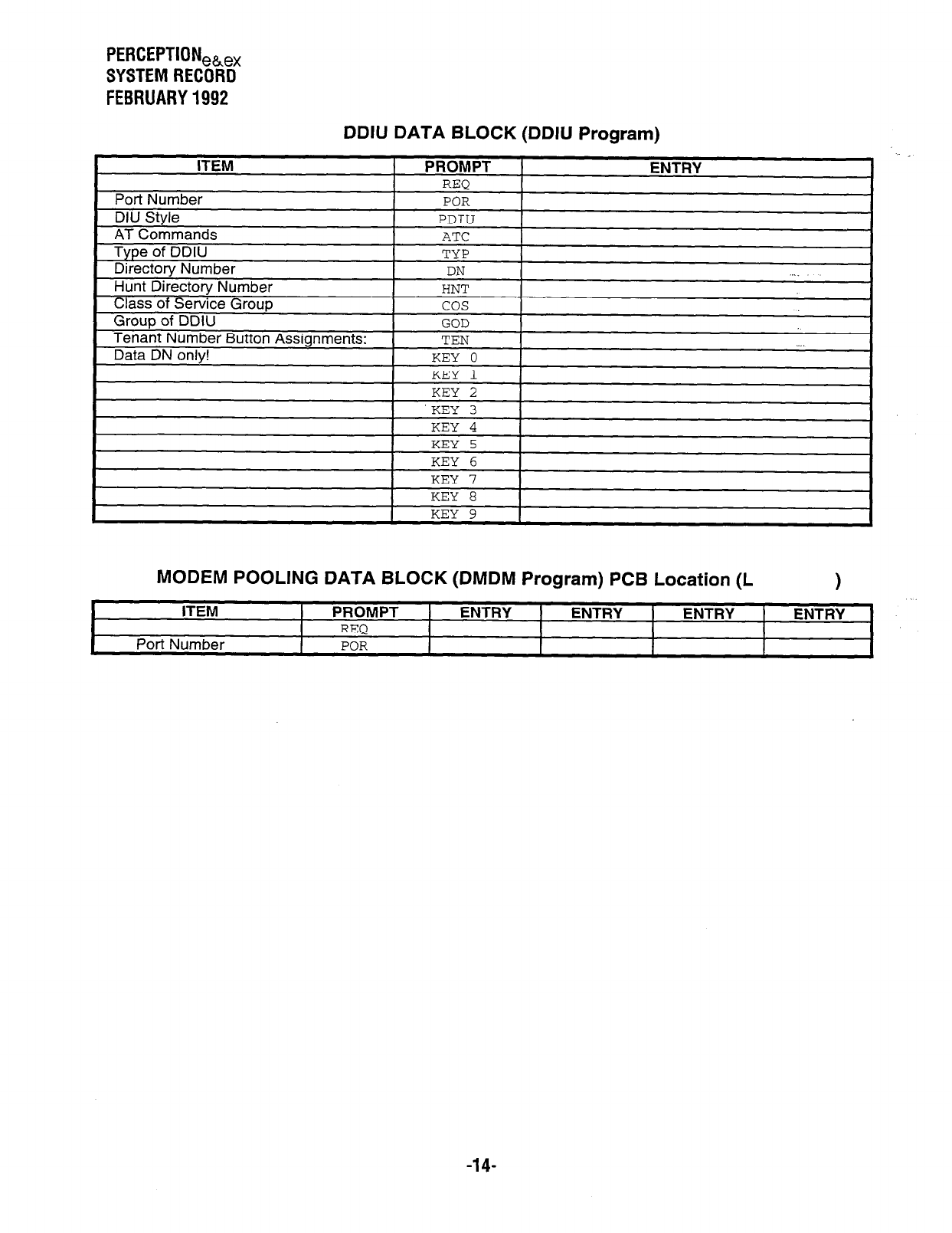
PERCEPTIONea,,
SYSTEM RECORD
FEBRUARY 1992
DDIU DATA BLOCK (DDIU Program)
KEY 4
KEY 5
KEY 6
KEY 7
KC-V 8
I I
KEY 9 I I
MODEM POOLING DATA BLOCK (DMDM Program) PCB Location (L 1
ITEM PROMPT ENTRY ENTRY ENTRY ENTRY
REQ
Port Number
POR
-14-
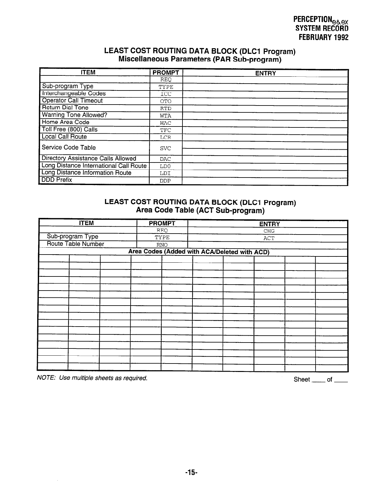
PERCEPTIONeh,
SYSTEMRECORD
FEBRUARY1992
LEAST COST ROUTING DATA BLOCK (DLCl Program)
Miscellaneous Parameters (PAR Sub-program)
LEAST COST ROUTING DATA BLOCK (DLCl Program)
Area Code Table (ACT Sub-program)
NOTE: Use multiple sheets as required. Sheet of
-15-
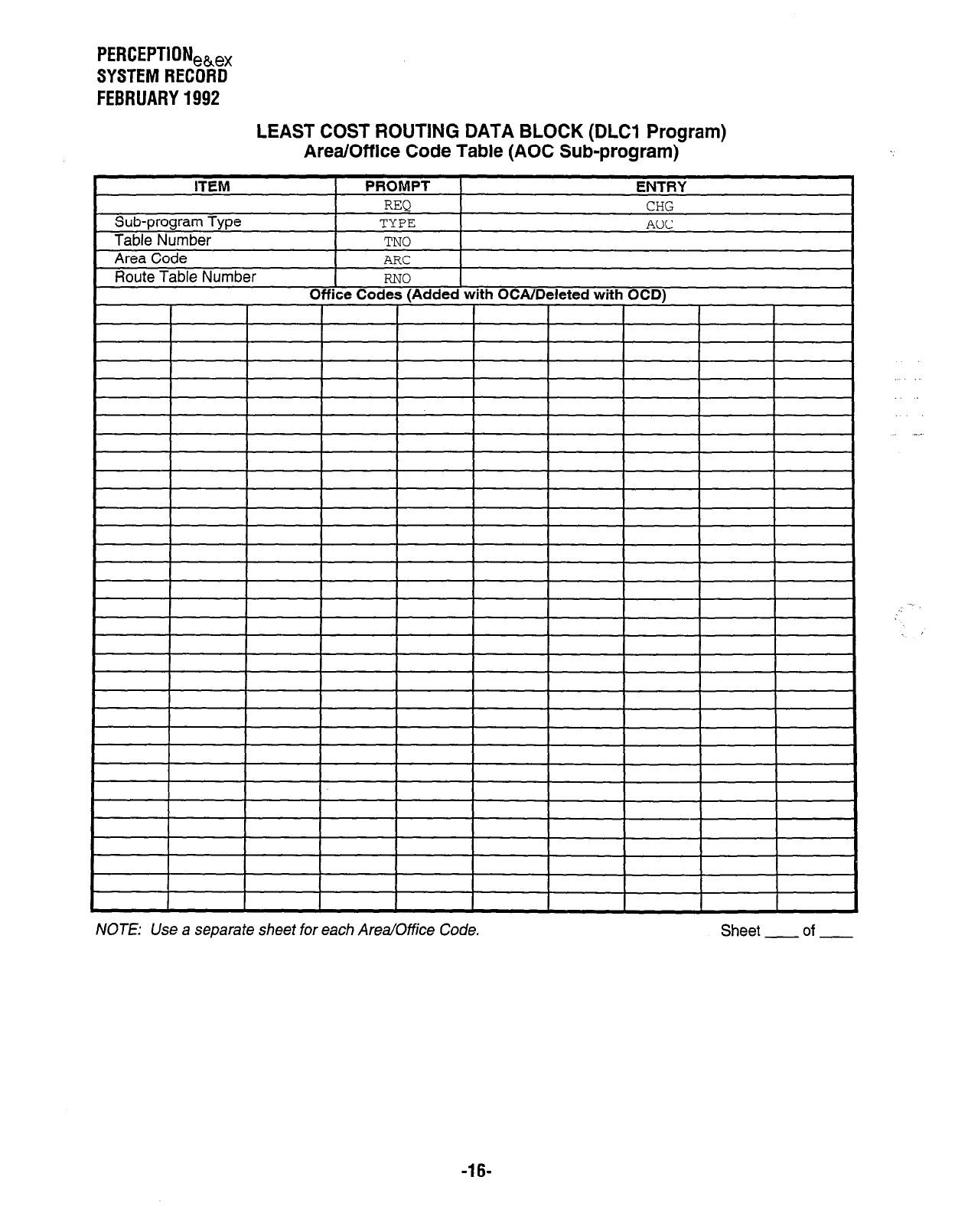
PERCEPTIONeb,,
SYSTEM RECORD
FEBRUARY 1992
LEAST COST ROUTING DATA BLOCK (DLCl Program)
Area/Off ice Code Table (AOC Sub-program)
NOTE: Use a seDarate sheet for each Area/Office Code. Sheet of
-16-
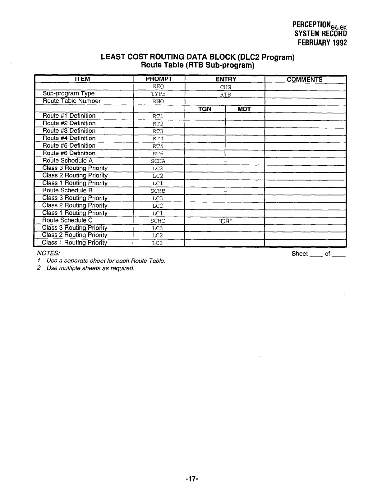
PERCEPTIONeh,
SYSTEM RECORD
FEBRUARY 1992
LEAST COST ROUTING DATA BLOCK (DLC2 Program)
Route Table (RTB Sub-program)
NOTES:
1. Use a separate sheet for each Route Table.
2. Use multiple sheets as required.
Sheet of
-17-
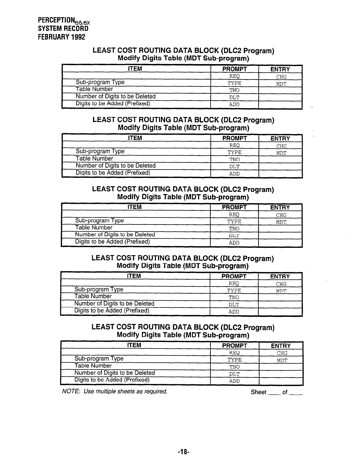
PERCEPTION,~,,
SYSTEM RECORD
FEBRUARY 1992
LEAST COST ROUTING DATA BLOCK (DLC2 Program)
Modify Digits Table (MDT Sub-program)
ITEM PROMPT ENTRY
REQ CHG
Sub-program Type TYPE MDT
Table Number TN0
Number of Digits to be Deleted DLT
Digits to be Added (Prefixed) ADD
LEAST COST ROUTING DATA BLOCK (DLC2 Program)
Modify Digits Table (MDT Sub-program)
ITEM PROMPT ENTRY
REQ CHG
Sub-program Type TYPE MDT
Table Number TN0
Number of Digits to be Deleted DLT
Digits to be Added (Prefixed) ADD
LEAST COST ROUTING DATA BLOCK (DLC2 Program)
Modify Digits Table (MDT Sub-program)
ITEM PROMPT ENTRY
REQ CHG
Sub-program Type TYPE MDT
Table Number TN0
Number of Digits to be Deleted DLT
Digits to be Added (Prefixed) ADD
LEAST COST ROUTING DATA BLOCK (DLC2 Program)
Modify Digits Table (MDT Sub-program)
ITEM PROMPT ENTRY
REQ CHG
Sub-program Type TYPE MDT
Table Number TN0
Number of Digits to be Deleted DLT
Digits to be Added (Prefixed) ADD
LEAST COST ROUTING DATA BLOCK (DLC2 Program)
Modify Digits Table (MDT
Sub-program)
ITEM
_ -
PROMPT ENTRY I
-18-
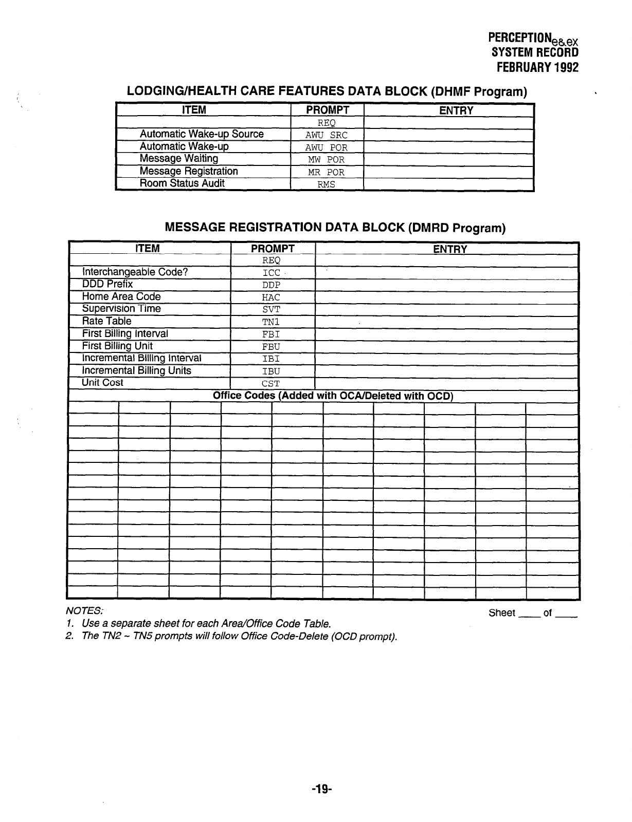
LODGING/HEALTH CARE
ITEM
Automatic Wake-up Source
Automatic Wake-up
Message Waiting
Message Registration
Room Status Audit
PERCEPTIONeke,
SYSTEM RECORD
FEBRUARY 1992
FEATURES DATA BLOCK (DHMF Program)
PROMPT
REQ
AWU SRC
AWU POR
MW POR
MR POR
RMS
ENTRY
MESSAGE REGISTRATION DATA BLOCK (DMRD Program)
I I I I I I I I I I I
NOTES:
Sheet of
1. Use a separate sheet for each Area/Office Code Table.
2. The TN2 - TN5 prompts will follow Office Code-Delete (OCD prompt).
-19-
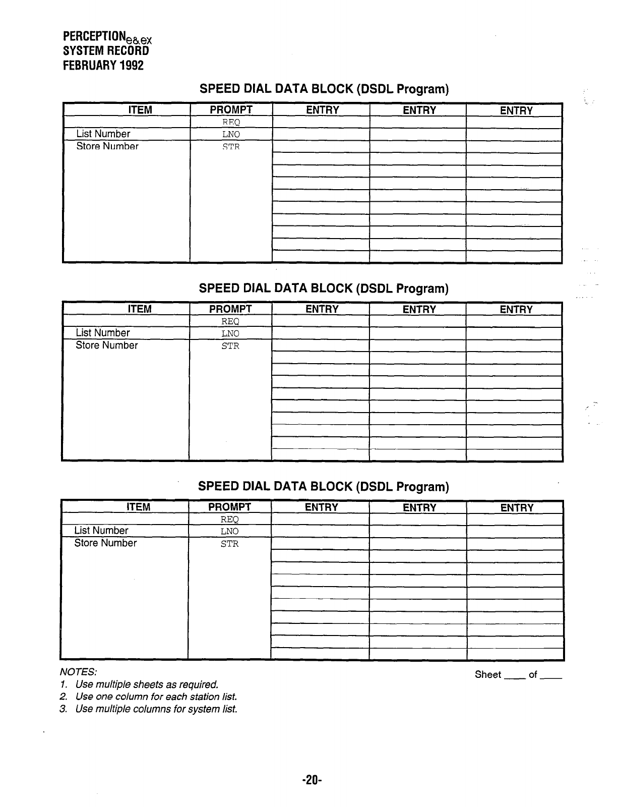
PERCEPTIONeb,
SYSTEM RECORD
FEBRUARY 1992
L
ITEM
List Number
Store Number
ITEM
List Number
Store Number
SPEED DIAL DATA BLOCK (DSDL Program)
PROMPT
REQ
LNO
STR
ENTRY ENTRY ENTRY
I I I
SPEED DIAL DATA BLOCK (DSDL Program)
PROMPT I ENTRY I ENTRY I ENTRY
nl-bn I
LNO I I I I
STR
SPEED DIAL DATA BLOCK (DSDL Program)
, -
NOTES:
1. Use multiple sheets as required.
2. Use one column for each station list.
3. Use multiple columns for system list.
Sheet - of -
-2o-
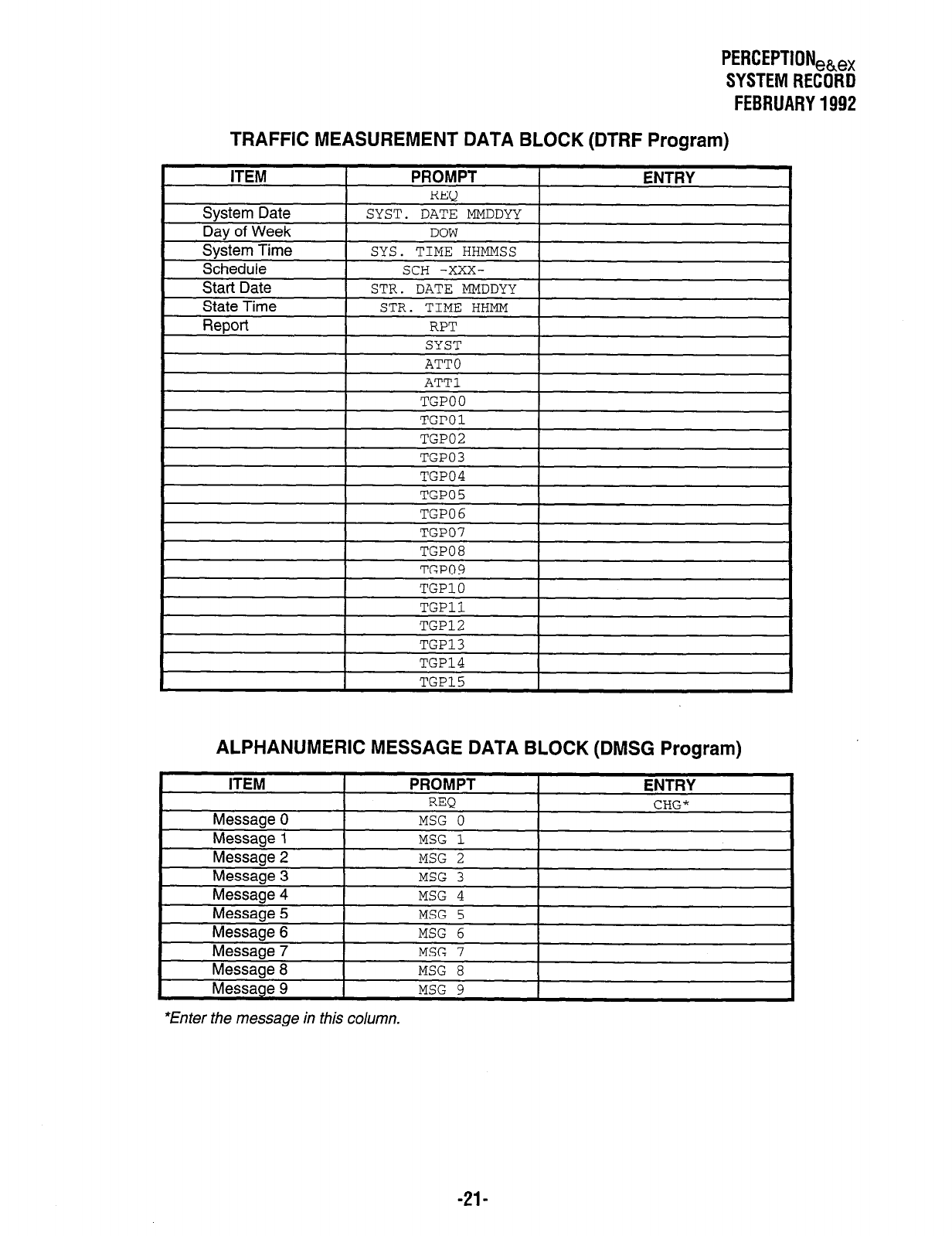
PERCEPTIONeh,,
SYSTEMRECORD
FEBRUARY1992
TRAFFIC MEASUREMENT DATA BLOCK (DTRF Program)
ALPHANUMERIC MESSAGE DATA BLOCK (DMSG Program)
*Enter the message in this column.
-21-
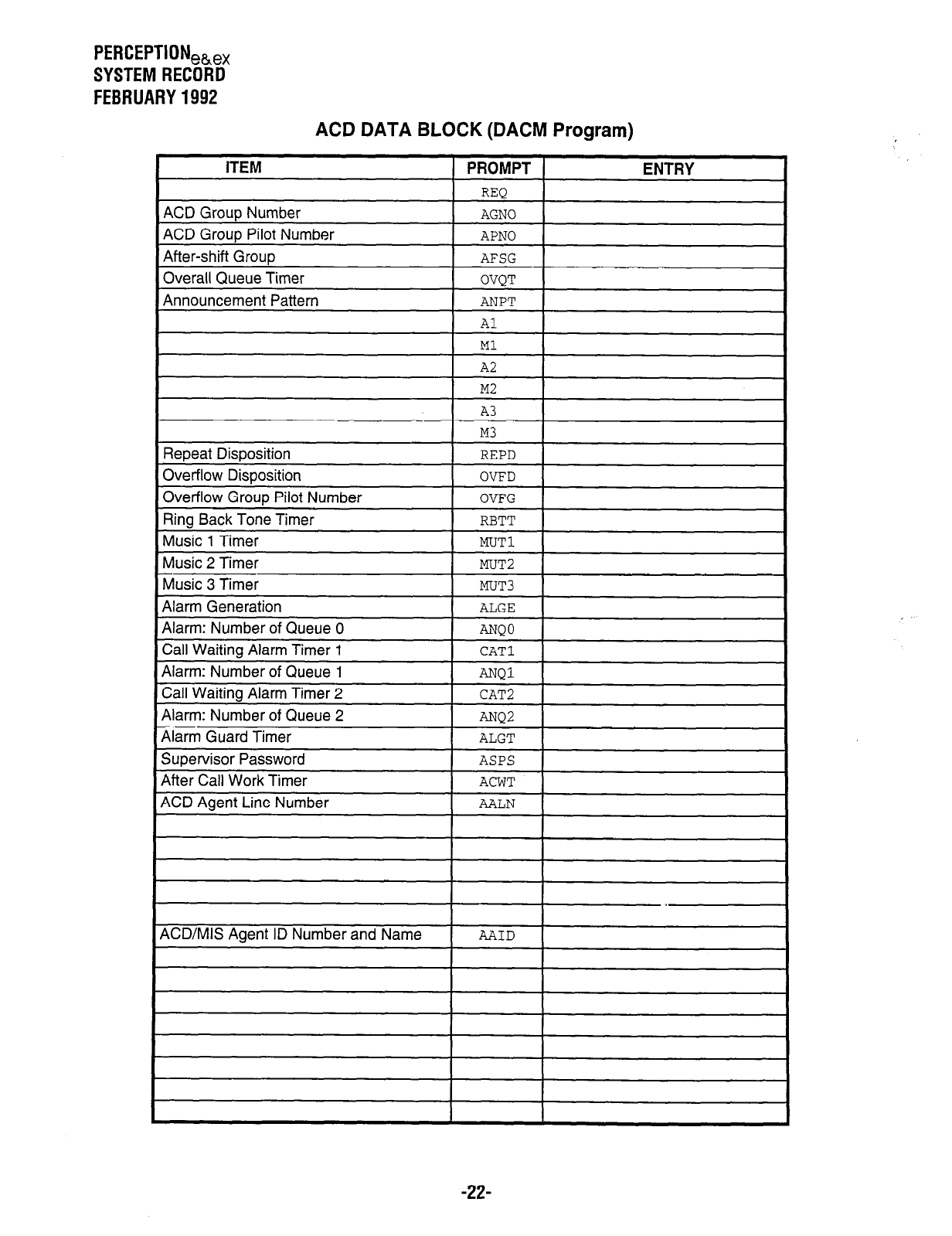
PERCEPTION,,,
SYSTEM RECORD
FEBRUARY 1992
ACD DATA BLOCK (DACM Program)
ITEM
ACD GrouD Number
PROMPT
REQ
AGNO
ENTRY
ACD Group Pilot Number APNO
After-shift Group AFSG
1 OVQT 1
1 ANPT 1
Overall Queue Timer
Announcement Pattern
Repeat Disposition
Overflow Disposition
Overflow Group Pilot Number
Ring Back Tone Timer
Music 1 Timer
Music 2 Timer
Music 3 Timer
Alarm Generation
Al
Ml
A2
M2
A3
M3
REPD
OVFD
OVFG
RBTT
MUTl
MUT2
MUT3 I I
ACD/MIS Agent ID Number and Name AAID
I I I I
-22-
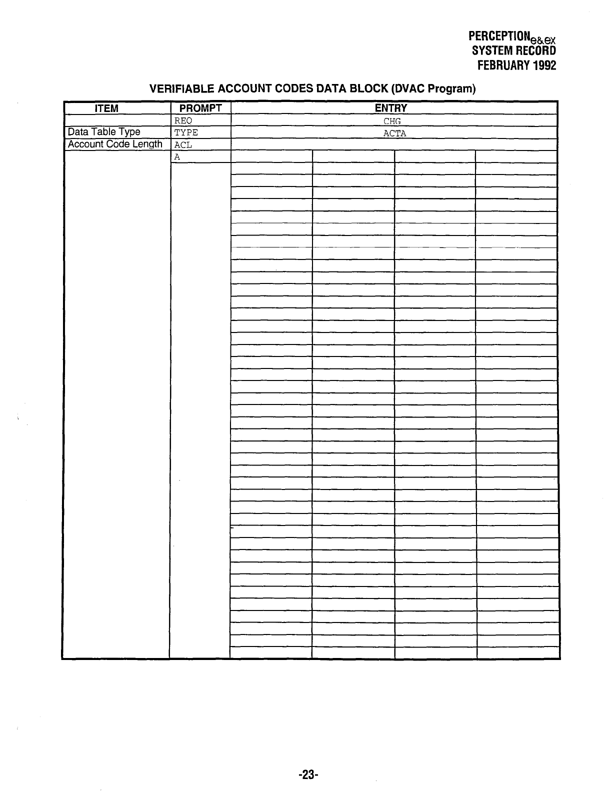
PERCEPTION,&,
SYSTEM RECORD
FEBRUARY 1992
VERIFIABLE ACCOUNT CODES DATA BLOCK (DVAC Program)
ITEM
Data Table Type
Account Code Lenath
-23-
