PDF Toshiba Strata DK 14,40,424 PC DATA INTERFACE USER GUIDE
User Manual: PDF T E X T F I L E S
Open the PDF directly: View PDF ![]() .
.
Page Count: 47


Telecommunication Systems Division
May 1999
Digital Business Telephone Systems
Personal Computer/Data Interface
User Guide

Publication Information
Toshiba America Information Systems, Inc., Telecommunication Systems
Division, reserves the right, without prior notice, to revise this information
publication for any reason, including, but not limited to, utilization of new
advances in the state of technical arts or to simply change the design of
this document.
Further, Toshiba America Information Systems, Inc., Telecommunication
Systems Division, also reserves the right, without prior notice, to make
such changes in equipment design or components as engineering or
manufacturing methods may warrant.
DKA-UG-PC/DIUVC
4016165
Version C, May 1999
Version B.1, November 1998
Version B, October 1997
Version A, September 1996
© Copyright 1999
Toshiba America Information Systems, Inc.
Telecommunication Systems Division
All rights reserved. No part of this manual, covered by the copyrights
hereon, may be reproduced in any form or by any means—graphic,
electronic, or mechanical, including recording, taping, photocopying, or
information retrieval systems—without express written permission of the
publisher of this material.
Strata is a registered trademark of Toshiba Corporation.
Trademarks, registered trademarks, and service marks are the property of
their respective owners.

Strata DK PC/Data Interface 5/99 i
Contents
Introduction
Organization ............................................................................................................... iv
Conventions ................................................................................................................. v
Mnemonics ................................................................................................................vii
Related Documents ....................................................................................................vii
Chapter 1 – The Grand Tour
Hardware Requirements .............................................................................................. 2
Integrated Data Interface Unit (RPCI-DI) ................................................................... 2
RPCI-DI Buttons and LEDs ..................................................................................... 3
Stand-alone Data Interface Unit (PDIU-DS) Connections .......................................... 5
Communication Parameters ......................................................................................... 7
Chapter 2 – Features
Data Call to Internal Printer or Other Data Device ..................................................... 9
Data Call to Another Internal Data Telephone’s PC or Terminal ............................. 10
Simultaneous Voice and Data Calls .......................................................................... 14
Voice Call While On Data Call .............................................................................. 14
Data Call While On a Voice Call ........................................................................... 14
Data Call to Data Telephone While on a Voice Call to Another Telephone ......... 15
Outgoing Data Call .................................................................................................... 16
Dialing Through the System Modem Pool ............................................................. 16

Contents
Chapter 3 - Mode Definitions
ii Strata DK PC/Data Interface 5/99
Incoming Data Call (External) ................................................................................... 20
Switch From Outside Voice Call to Data Call ........................................................... 23
Switch Back to the Voice Call Using Privacy Override ........................................ 25
Switch Back to the Voice Call Using Executive Override ..................................... 26
Personal Computer Dialing of Voice Calls ............................................................... 27
Chapter 3 – Mode Definitions
Data Communications Mode ..................................................................................... 29
Switching Between Data Communications and TAPI Modes ............................... 29
Data Communications Command Mode ................................................................ 30
Data Communications Mode (On-line state) .......................................................... 32
Switching Between Data Communication Modes .................................................. 32
RPCI/DIU Data Speed (Baud Rate) ....................................................................... 33
RPCI/DIU Default Communication Parameters .................................................... 33
Index .............................................................................................................................. 37

Strata DK PC/Data Interface 5/99 iii
Introduction
This guide provides instructions for the use of the Strata DK Personal Computer
(RCPI-DI) and Data Interface Unit (PDIU-DS) features for the Strata DK systems.
These systems include:
♦DK14
♦DK16e/16
♦DK40i/DK40
♦DK424/DK280 (Release 3.0 or higher)
All the features in this guide have practical applications for diverse office
environments. Instructions are provided on how to use the RCPIs and DIUs to connect
Personal Computers (PCs) together to exchange files, to share a printer or a modem, to
access a mainframe, and more.
This user guide is not needed to use a TAPI software application. See the user guide
for the software application program being used.

Introduction
Organization
iv Strata DK PC/Data Interface 5/99
Organization
This user guide is divided as follows:
♦Chapter 1 – The Grand Tour provides an overview of DIU hardware: their
function, controls, and applicable indicators.
♦Chapter 2 – User Instructions provides descriptions and instructions for each
type of voice and data transmission made from the DIUs.
♦Chapter 3 – Mode Definitions contains information on various advanced
communication modes.

Introduction
Conventions
Strata DK PC/Data Interface 5/99 v
Conventions
Note Elaborates specific items or references other information.
Important! Calls attention to important instructions or information.
Letters in [brackets] represent buttons which have Directory Numbers on them. For
example:
Note Throughout this guide, RPCI-DI-equipped digital telephones that are
connected to ASCII terminals or PCs are referred to as data telephones.
[PDN] represents a Primary Directory Number (also known
as an Extension Number for your telephone).
[SDN] represents a Secondary appearance of a [PDN]. A
[PDN] which appears on another telephone is
considered an [SDN].
[PhDN] represents a Phantom Directory Number button (an
additional Directory Number).
[DN] represents a Directory Number button (also known as
an Extension or Intercom Number). Whenever [DN] is
used in this guide, it means the user can use any
[PDN], [SDN], or [PhDN].
[DSS] represents the directory number of another station
which is accessed from a DADM or DSS Console
when this button is pressed.
([WUDEROG represents buttons on a telephone.
~ means “through”
+ is used for multiple key entries.
➤denotes the step in a one-step procedure.
represents text that appears on a PC or terminal
screen.
ATDDYYY
CONNECTXXXX

Introduction
Mnemonics
vi Strata DK PC/Data Interface 5/99
Mnemonics
Mnemonics appearing in this user guide are defined below:
BPS Bits Per Second
DIU Data Interface Unit
LCD Liquid Crystal Display
LED Light Emitting Diode
PC Personal Computer
DPIU-DS Stand-alone Data Interface Unit
RPCI-DI Personal Computer/Data Interface Unit
Related Documents
The following user guides are available for Strata DK telephones:
♦Strata DK Digital Telephone User Guide, which includes instructions for LCD
Telephones, Add-on Modules, and Digital Direct Station Selection (DDSS)
Consoles.
♦Strata DK Installation and Maintenance Manual provides installation instructions
and requirements for RPCI-DIs and Data Interface Units connecting to a Strata
DK system. See the chapter on Peripherals.
♦Strata DK Programming Manual provides programming instructions and record
sheets for RPCI-DIs and Data Interface Units.

Strata DK PC/Data Interface 5/99 1
The Grand Tour 1
Toshiba provides two interface units that integrate the Strata DK telephone system
with PCs, printers, and modems for a variety of applications.
The Stand-alone Data Interface Units (PDIU-DS) normally connects to printers and
modems so that they can be shared by all users via data calls through the DK
telephone system.
The telephone PC Interface Unit (RPCI-DI) is built into the base of the digital
telephone and connects to the COM port of a PC. There are two operating modes:
♦Telephone Application Program Interface (TAPI) mode
♦Data communication mode
The PC TAPI software program automatically controls the operation mode (TAPI or
Data Communications) of the RPCI.
A 2B+D ISDN-type digital link in conjunction with the RCPIs and DIUs enable
digital telephones to participate in simultaneous voice and data calls. Voice and data
calls are transmitted over the same digital telephone wire pair. This offers you several
calling options. For example, a digital telephone user can place a voice call while in
the middle of a data call to a printer or host computer, etc.
This chapter lists all the equipment required to originate or receive a data call. In
addition, it explains the function and configuration of the Data Interface Units (DIUs),
both the RPCI-DI and PDIU-DS types.

The Grand Tour
Hardware Requirements
2Strata DK PC/Data Interface 5/99
Hardware Requirements
The following hardware is required to originate a data call:
♦A RPCI-DI (replaces digital telephone base)
♦A PC or ASCII Terminal
♦One of the following Toshiba 2000- or 1000-Series Digital Telephones:
♦DKT2010-H (10-button model)
♦DKT2010-SD (10-button model with a LCD and speakerphone)
♦DKT2020-S (20-button model)
♦DKT2020-SD (10-button model equipped with LCD and speakerphone)
♦DKT1010-H (10-button model)
♦DKT1020-SD (10-button model equipped with LCD and speakerphone)
A data call can be made to a device connected to a DIU (RPCI-DI or PDIU-DS), such
as mainframe computers, printers, modems, PCs, and ASCII terminals.
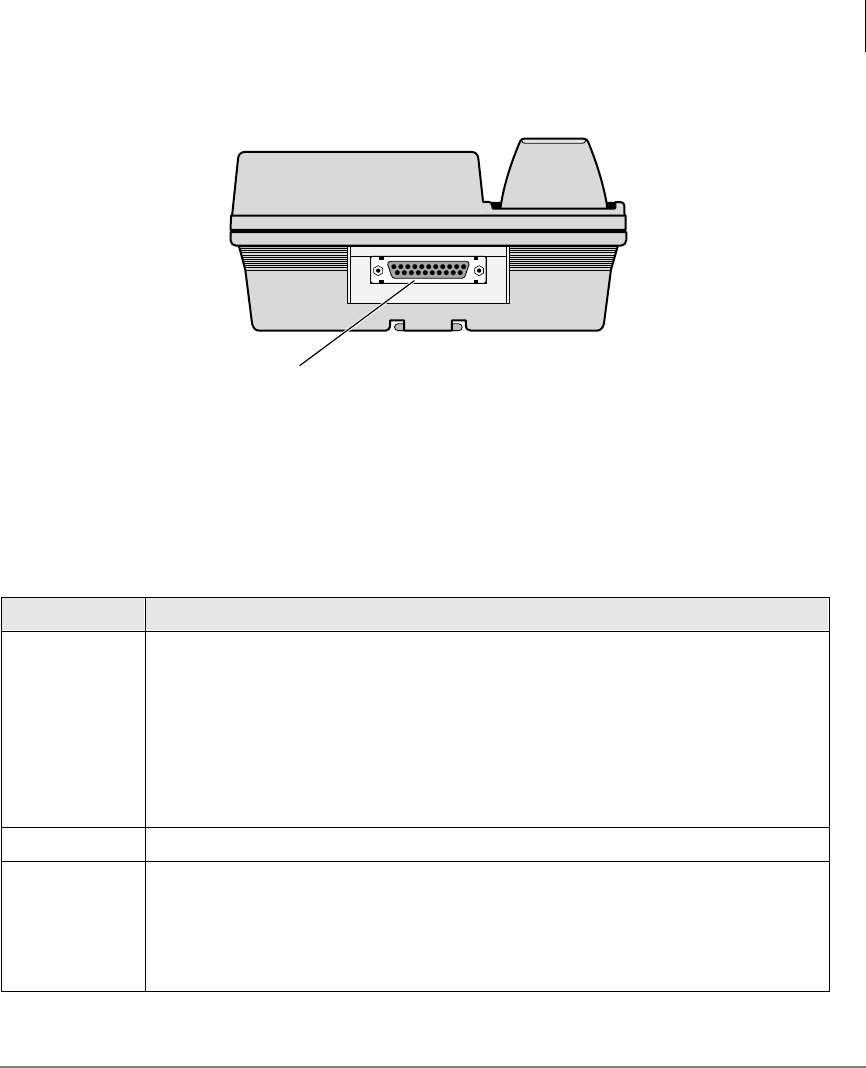
Integrated Data Interface Unit (RPCI-DI)
A telephone within the Strata DK system that participates in a data call must be a
Toshiba digital telephone equipped with an integrated DIU (RPCI-DI). A label
reading “MODEL RPCI-DI” on the bottom of the telephone and an RS-232 connector
on the back of the telephone both indicate that a telephone is equipped with a RPCI-
DI. See Figure 1.
Note Throughout this guide, RPCI-DI-equipped digital telephones that are
connected to ASCII terminals or PCs are referred to as data telephones.
The Grand Tour
Integrated Data Interface Unit (RPCI-DI)
Strata DK PC/Data Interface 5/99 3
RPCI-DI Buttons and LEDs
In system programming, the data telephone can be assigned data feature buttons
shown below.
Table 1 Data Feature Buttons
Button Description
DWDDOO
Enables a connection between the digital telephone’s RPCI-DI to another DIU in
the system when manually dialing from the telephone. When DWDDOOis pressed
on an idle data telephone, the system sends intercom dial tone to the telephone to
prompt dialing. DWDDOOalso can be used to switch data telephones and CO lines
from voice to data on external calls.
The Data Call LED lights when you receive a data call from another data telephone
or when you make a call from your data telephone, PC, or ASCII terminal. The Data
Call LED is always red when ON.
DWD 5 HOHDVH Terminates data calls. The Data Release LED never illuminates.
0RGHP
Reserves a system modem for 60 seconds. If a modem is not accessed within this
time limit, press this button again to reserve for another 60 seconds.
A flashing Modem LED indicates that a modem is currently reserved for your
telephone; a continuously lit LED indicates that you have accessed a modem or
that all modems are busy. The Modem LED is always red when ON or flashing.
RPCI-DI RS-232 Connector
0601
Figure 1 Data Telephone (Integrated DIU) Connector

The Grand Tour
Integrated Data Interface Unit (RPCI-DI)
4Strata DK PC/Data Interface 5/99
RPCI-DI Data Connections
See the Strata DK I&M Manual for detailed installation instructions.
If a data terminal is connected to a data telephone, the terminal must be an ASCII type
with a standard keyboard and a display screen or printer display.
If a PC is connected to a data telephone, the PC must be running at least one of the
following types of programs: word processor, desk organizer dialer, or
communications software. Also, the PC must be active (on-line) on its COM port
connected to the data telephone’s RPCI-DI.
Note It is not possible to establish data call connections from your PC DOS prompt.
The data telephone is connected to the PC serial communications port (COMX, where
X = 1, 2, 3, or 4) or terminal with an RS-232 cable and connector. It is connected to
the Strata DK system like any other digital telephone with a modular cord.
The Grand Tour
Stand-alone Data Interface Unit (PDIU-DS) Connections
Strata DK PC/Data Interface 5/99 5
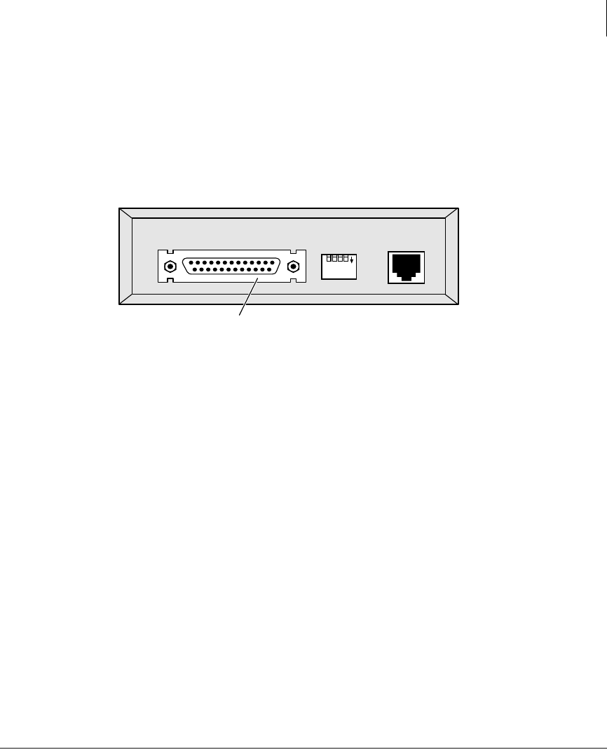
Stand-alone Data Interface Unit (PDIU-DS)
Connections
Data devices, such as printers, modems, mainframe computers, etc., must be
connected to a PDIU-DS with an RS-232 cable and connector. An RS-232 connector
is below (see Figure 2).
Figure 2 Stand-alone DIU Connector
See the Strata DK I&M Manual for detailed installation instructions.
Note
●The PDIU-DS must be connected to the Strata DK system with a modular cord.
Similar to a regular station, the PDIU-DS is assigned a station number.
●Toshiba recommends connecting the line sides of the modems to standard
telephone ports to ensure access to the complete set of modem pooling features.
Connecting the modems to a dedicated CO line may not allow access to the whole
set.
1234
DNT4
ON
RS-232 Connector
0603
The Grand Tour
Stand-alone Data Interface Unit (PDIU-DS) Connections
6Strata DK PC/Data Interface 5/99
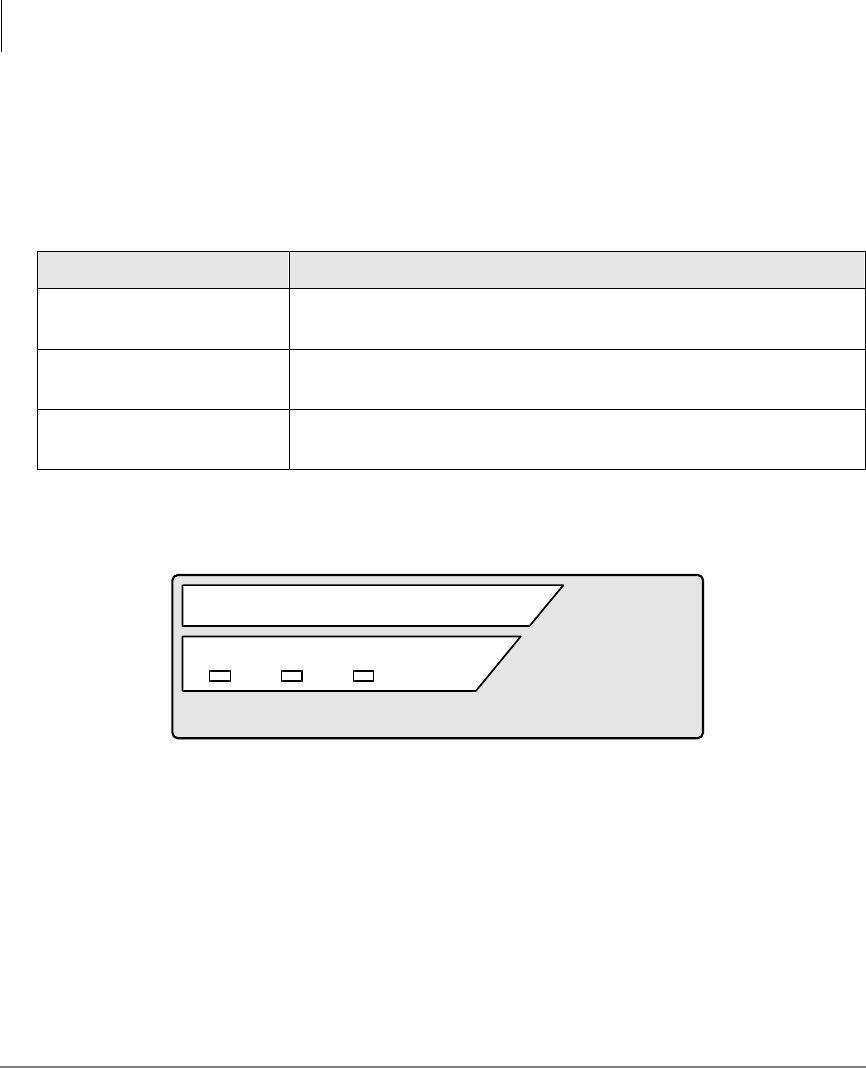
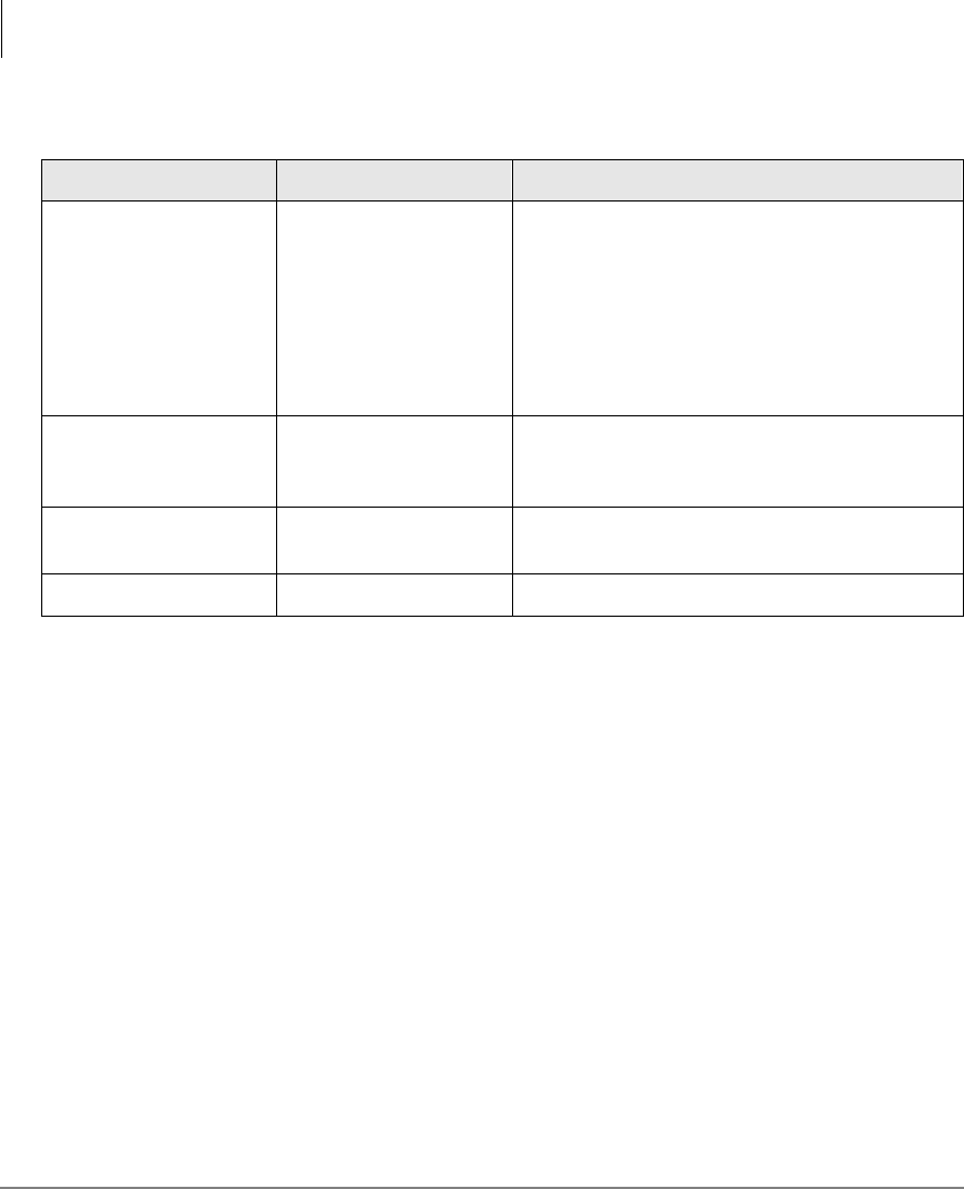
PDIU-DS LEDs
The PDIU-DS has three green LEDS on its front panel which indicate transmission
status (See below).
Figure 3 PDIU-DS LEDs
Table 2 PDIU-DS LED Status
LED Description
Power LED When the PDIU-DS is connected to the Strata DK system with a
modular cord, the Power LED is ON (lit).
Ready LED The Ready LED is ON (lit) when the PDIU-DS is connected to a device
that is turned ON and ready to exchange data.
Connect LED When a data call is established (ringing or answered), the Connect
LED is ON (lit).
DIU
POWER READY CONNECT
0604

The Grand Tour
Communication Parameters
Strata DK PC/Data Interface 5/99 7
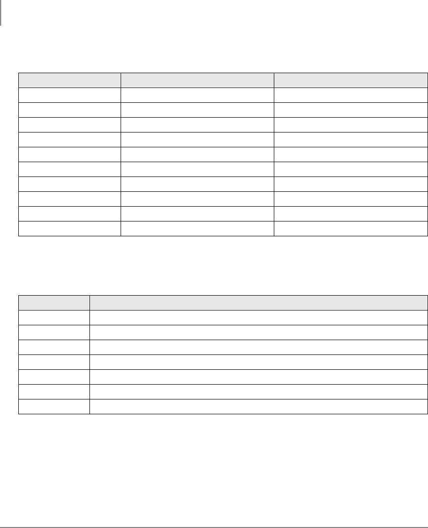
Communication Parameters
Before a data connection is established, the communication parameters—data speed
(baud rate or bps), parity, data bits, stop bits—of the terminal or PC must be the same
as the data device that is calling or being called. The PC communication parameters
are set with MS-DOS MODE commands.
➤To set the PC Communication parameters
Communication parameter options are shown in Table 3.
➤Enter MODE
LPTx:=COMx
(x = 1, 2, 3, or 4)
Use this parameter, if you connect to your printer via
an RPCI to DIU-DS data call connection.
...or MODE COMx:
baud rate, parity, data
bits, stop bits
Notes
●Toshiba recommends entering these MODE
command lines into the DOS AUTOEXEC.BAT
file, in most cases.
●The COM port number and communication
parameters must be set to allow proper operation
of data calls in most communications, desktop, and
word processor software.
The Grand Tour
Communication Parameters
8Strata DK PC/Data Interface 5/99
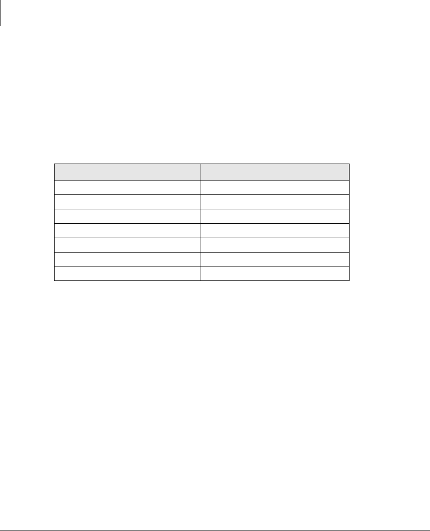
Table 3 Communication Parameter Options
Option Legal Values Meaning
Baud Rate
110
150
300
600
1200 (default)
2400
4800
9600
Transmission speed in bits per second
Parity N (default)
O
E
No parity
Odd parity
Even parity
Data Bits 7
8 (default)
Stop Bits 1 (default)

Strata DK PC/Data Interface 5/99 9
Features 2
This chapter explains how to use your data telephone to connect to other data devices,
such as an internal printer, modem pool, or mainframe computer. It also explains how
to originate and answer simultaneous voice and data transmissions from your
telephone or another telephone.
Data Call to Internal Printer or Other Data Device
If using a PC, data calls to printers can be connected anytime while running a word
processor, spread sheet, or database program. This procedure can also be used to make
data calls to other internal data devices, such as modems or mainframe computers, that
are connected to stand-alone DIUs. A communications software program is generally
required for these types of internal data calls.
Before making your call, verify that the communication parameters of your PC or
terminal match those of the printer or data device you are calling.

Features
Data Call to Another Internal Data Telephone’s PC or Terminal
10 Strata DK PC/Data Interface 5/99
➤To call a data device
➤To terminate the call
Data Call to Another Internal Data Telephone’s
PC or Terminal
PCs involved in this call must be running a communications software program.
Before making this call, verify that the communication parameters of your PC or
terminal match those of the PC or terminal that you are calling.
The following instructions work with typical communications software programs.
Higher-level software may integrate these low-level communications dialing
commands to provide more automated operation.
1. Press 'DWD&DOOon
your data telephone. The Data Call, Spkr, and Mic (see note) LEDs turn ON
(red); and the [DN] LED turns ON (green). The data
telephone receives internal dial tone.
Note Depending on system programming, the Mic
LED may or may not turn ON.
2. Enter the station
number of the DIU
connected to the
printer.
The Spkr, Mic, and [DN] LEDs turn OFF; the Data
Call LED remains ON (red).
If busy, press 'DWD5HOHDVHand try again; if busy
tone is not received, the call is connected.
3. Print the data. The data can be printed using your terminal or PC
software program.
➤Press 'DWD5HOHDVH
on your data
telephone.
The Data Call LED turns OFF and the call is
terminated.

Features
Data Call to Another Internal Data Telephone’s PC or Terminal
Strata DK PC/Data Interface 5/99 11
➤To verify communications from your PC or terminal
➤To call from your PC or terminal
➤Type AT and then
press Enter on your
PC or terminal.
Type AT commands
as capital letters (use
caps lock).
AT commands appear on your PC or terminal as you
type them.
Wait for this display:
The above display verifies that communications exist
between your PC or terminal and your data telephone.
The Data Call LED turns ON (red) after you press
Enter.
1. Type ATDD, the
[PDN] of the other
data telephone, and
then press Enter.
If “BUSY” displays
on your screen, the
call automatically
terminates. You can
then try again.
Wait for this display:
This display indicates that a connection has been
established between the called and calling terminals
and/or PCs.
XXXX = data transmission speed
YYY = called data telephone number
The [DN] of a data telephone’s RPCI-DI is the same as
its voice [PDN].
Example: If the other data telephone’s [PDN] is 209,
type ATDD209 and press Enter. (ATDD is the DIU
command for data call dialing, and 209 represents the
[PDN] of the other data telephone).
2. Exchange data. The data can be exchanged using your terminal or PC
software program as required.
AT
OK
ATDDYYY
CONNECTXXXX

Features
Data Call to Another Internal Data Telephone’s PC or Terminal
12 Strata DK PC/Data Interface 5/99
➤To call from your data telephone
1. Press 'DWD&DOO. The Data Call, Spkr, and Mic (see note) LEDs turn ON
(red); and the [PDN] LED turns ON (green). The data
telephone receives an internal dial tone.
Note Depending on system programming, the Mic
LED may or may not turn ON.
2. Dial the [PDN] of the
other data telephone. The Spkr, Mic, and [PDN] LEDs turn off. The Data
Call LED remains ON (red).
Wait for this display:
3. Press 'DWD5HOHDVH
again,if the called
number is busy.
The above message appears at both the sending and
destination locations, indicating that a connection has
been established.
XXXX = data transmission speed.
4. Exchange the data. The data can be exchanged using your terminal or PC
software program, as required. Either the calling or
called user can terminate the data call using the
following procedures.
CONNECTXXXX
Features
Data Call to Another Internal Data Telephone’s PC or Terminal
Strata DK PC/Data Interface 5/99 13
➤To terminate the call from your PC or terminal
➤To terminate the call from either data telephone
1. Hold the Shift key
down and type +++.Wait for this display:
The above display indicates that the RPCI-DI
connected to your terminal or PC is now in the
command mode and can accept AT commands.
The following screen displays on the other PC or
terminal screen.
The Data Call LED on both data telephones turns OFF.
2. Type ATH, and then
press Enter.Wait for this display:
This display indicates that the call is terminated.
➤Press 'DWD
5HOHDVH.The Data Call LED on both data telephones turns OFF.
Wait for the following screen to display on both PCs
and/or terminal screens.
This display indicates that the call is terminated.
+++
OK
+++
ATH
OK
NO CARRIER

Features
Simultaneous Voice and Data Calls
14 Strata DK PC/Data Interface 5/99
Simultaneous Voice and Data Calls
Voice Call While On Data Call
You can make a simultaneous voice and data call between the same or different
telephones.
While on a data call, a data telephone can originate, answer, and disconnect any type
of voice call without interrupting the data call. For example, Phone 1 can be on a voice
call with Phone 2, and during the call, Phone 1 can also send data to Phone 2.
➤To make a voice call while on a data call
➤Make a voice call in the normal manner, while on a data call.
See “Data Call to Internal Printer or Other Data Device” on Page 9 or “Data Call
to Another Internal Data Telephone’s PC or Terminal”on Page 10 for additional
information on making data calls.
Data Call While On a Voice Call
You can make a simultaneous voice and data transmission between the same data
telephones.
Without interrupting their voice conversation, two data telephones can establish a data
call between each other.
➤To make a data call while on a voice call
1. Press 'DWD&DOO
while on a voice call
with another data
telephone.
The Data Call LED turns ON (red).
A data path is automatically established between the
PCs
and/or terminals connected to the two data telephones.
The voice call continues uninterrupted.
2. Exchange the data. The data can be exchanges using your terminal or PC
software program as required. While data is being
exchanged, the voice call continues uninterrupted.

Features
Simultaneous Voice and Data Calls
Strata DK PC/Data Interface 5/99 15
Data Call to Data Telephone While on a Voice Call to Another
Telephone
You can make a simultaneous voice and data transmission to different data telephones.
While established on an internal or external voice call, a data telephone can make a
data call to another internal or external data telephone or data device. For example,
Phone 1 can be on a voice call to Phone 2. At the same time, Phone 1 can also be
transmitting data to Phone 3.
➤To make a data call while on a voice call
➤To return to the voice call
➤To terminate voice or data calls
1. Press +ROG on your
data telephone, while
on a voice call.
The voice call is placed on hold.
2. Make a data call to a
different data
telephone or data
device.
For more information, see “Data Call to Internal
Printer or Other Data Device”on Page 9 or “Data Call
to Another Internal Data Telephone’s PC or
Terminal”on Page 10.
3. Exchange the data. The data can be exchanged using your terminal or PC
software program as required.
➤Press the held CO
/LQH or [DN] button
on your data
telephone.
The voice call is re-established and the data call
continues uninterrupted.
➤Press 'DWD5HOHDVH
on your data
telephone
The data call terminates; the voice call, if not
terminated earlier, continues.
...or 6SNU on your
data telephone or
hang up.
The voice call terminates; the data call, if not
terminated earlier, continues.

Features
Outgoing Data Call
16 Strata DK PC/Data Interface 5/99
Outgoing Data Call
Dialing Through the System Modem Pool
A PC involved in this type of call must be running a communications software
program. Before making this call, verify that the communication parameters of your
PC or terminal match those of the device that your are calling.
To place the RPCI-DI into the command mode while keeping the modem in the
communications mode, Toshiba recommends that the RPCI-DI escape sequence be
changed from +++ to some other sequence before beginning. For example: Using the
ATS2 command, send ATS2=36 to the RPCI-DI to change its escape sequence to
$$$. Store these commands in the PC communication software modem initialization
sequence - this sets the RPCI-DI escape sequence each time the communication
software is run.
➤To verify communications from your PC or terminal
➤Type AT, and press
Enter on your PC or
terminal.
Wait for the following to display on your PC or
terminal screen.
This display verifies that communications exist
between your PC or terminal and your data telephone.
Note AT commands must be typed as capital letters
(use caps lock), and they appear on your PC or
terminal screen as you type them.
AT
OK

Features
Outgoing Data Call
Strata DK PC/Data Interface 5/99 17
➤To dial an internal modem from your PC or terminal
➤Type ATDD, the
[PDN] of the DIU
connected to the
system modem
(pool), and then press
Enter.
The Data Call and Modem LEDs turn ON (red) after
you press Enter.
Wait for this display:
The above display indicates that a connection has been
established between your PC or terminal and the
PDIU-DS connected to the system modem (pool).
XXXX = data transmission speed
YYY = [PDN] of the PDIU-DS connected to the
system modem (pool)
The system DIUs at this time are transparent and in the
communication mode, ready to pass data. The system
modem is in the command mode, ready to receive AT
dialing commands.
Entry Example: If the station number of the DIU
connected to the system modem is 208, type
ATDD208 and press Enter. (ATDD is the DIU
command for data call dialing, and 208 is the station
number of the DIU connected to the system modem).
ATDDYYY
CONNECTXXXX
Features
Outgoing Data Call
18 Strata DK PC/Data Interface 5/99
➤To issue commands to the modem
1. Type ATDT (a system
CO line access code,
the telephone number
of the external
modem, or data
service) from your PC
or terminal keyboard,
and then press
Enter.
Wait 5~30 seconds for the following screen to display
on your PC or terminal screen.
This display indicates that a connection has been
established between the Strata DK system modem and
the external modem.
XXXX = data transmission speed
YYYYYYYYYYYYYY = external telephone number
(CO line access code, see Table 4 on Page 28 CO line
access codes)
The commands issued and the telephone number
dialed in this step are sent to the system modem
transparently through the system DIUs.
Note If the modem seizes a CO line that appears on
your data telephone, the CO line LED turns ON
and is red.
Entry Example: If the telephone number is (714) 837-
4408 and the call is made on CO line 1, type
ATDT80117148374408 and press Enter. (ATDT
is the modem dial command; 801 is the access code for
system CO line Group 1; and 7148374408 is the
telephone number.)
2. Exchange the data. The data can be exchanges by using your terminal or
PC software program.
ATDTYYYYYYYYYYYYYY
CONNECTXXXX
Features
Outgoing Data Call
Strata DK PC/Data Interface 5/99 19
Terminating a Call to an Internal Modem from a Terminal or PC
This sequence should only be used if your modem is connected to a system station
port. This sequence should not be used if your modem is connected directly to a CO
line.
➤To terminate the call from your data telephone
1. Hold down the
Shift key and type
+++.
The following screen displays on your PC or terminal
screen.
The Data and Modem LEDs turn OFF.
2. Type ATH, and then
press Enter.The following screen displays on your PC or terminal
screen.
This display indicates that the call is terminated.
➤Press 'DWD
5HOHDVH.If your modem is connected to a system station port
directly to an outside line. The Data Call and Modem
LEDs turn OFF.
The following screen displays on your PC or terminal
screen.
This display indicates that the call is terminated.
+++
OK
ATH
OK
NO CARRIER

Features
Incoming Data Call (External)
20 Strata DK PC/Data Interface 5/99
Incoming Data Call (External)
An external data call (from the outside) can be made to the Strata DK system. Before
making the call, verify that the communication parameters of the external PC or
terminal and modem match those of the internal device (PC, terminal, or host
computer, and modem) that you are calling.
PCs involved in this call must be running a communications software program.
➤To verify communications from your external PC or terminal
➤Type AT from the
external PC or
terminal, and press
Enter.
The following screen displays on your (external) PC or
terminal screen.
This display verifies that communications exist
between your PC or terminal and your modem.
Note AT commands must be typed as capital letters
(use caps lock), and they appear on your PC or
terminal screen as you type them.
AT
OK

Features
Incoming Data Call (External)
Strata DK PC/Data Interface 5/99 21
➤To make the call from the external PC or terminal
1. Type ATDT, the
number of the CO line
that rings the DK
system internal
modem, and then
press Enter on the
external PC or
terminal.
The internal modem rings and auto answers.
Wait 5~30 seconds for the following screen to display
on your (external) PC or terminal screen.
This display indicates that the external and internal
modems are connected and in the communication
mode.
XXXX = data transmission speed
YYYYYYY = telephone number of the internal
modem
The PDIU-DS connected to the internal modem is in
the command mode, ready to accept AT commands
from the external PC or terminal. The internal and
external modems are in the communication mode,
ready to pass data.
Entry example: If the telephone number is 1213-4567,
type ATDT12134567 and press Enter. (ATDT is
the dial command, and 12134567 is the telephone
number.)
ATDTYYYYYYY
CONNECTXXXX
Features
Incoming Data Call (External)
22 Strata DK PC/Data Interface 5/99
➤To terminate the call from the external PC or terminal
2. Type ATDD, the
[PDN] of the
PDIU-DS or data
telephone connected
to the internal device
you wish to connect
to, and then press
Enter on the
external PC or
terminal.
Wait for the following screen to display on your
(external) PC or terminal screen.
This display indicates that the external PC or terminal
and the internal data device are connected.
XXXX = data transmission speed
YYY = station number of the DIU
If calling a device connected to a PDIU-DS, the
CONNECT LED turns ON; if calling a device
connected to a data telephone, the Data Call LED turns
ON (red).
Entry example: If the station number of the DIU is
210, type ATDD210 and press Enter. (ATDD is the
DIU command for data dialing, and 210 is the number
of the DIU.)
3. Exchange the data. The data can be exchanged by using your terminal or
PC software program.
1. Hold down the
Shift key and type
+++ on the external
PC or terminal.
The following screen displays on your (external) PC or
terminal screen.
ATDDYYY
CONNECTXXXX
+++
OK

Features
Switch From Outside Voice Call to Data Call
Strata DK PC/Data Interface 5/99 23
Switch From Outside Voice Call to Data Call
While on a CO line voice call, an internal (Strata DK system) data telephone can
switch to a data call on the same line.
Before making the call, verify that the communication parameters of your internal PC
or terminal match those of the external modem and PC or terminal. PCs involved in
this call must be running a communications software program.
The external telephone must share its CO line with a modem connected to a PC or
terminal. The external CO line must be plugged into the external modem jack labeled
“LINE”, and the external telephone must be plugged into the modem jack labeled
“PHONE”. The internal modem must be installed and programmed in the system
modem pool configuration (i.e., the modem is connected to a system standard
telephone port, not a CO line).
2. Type ATH and then
press Enter on the
external PC or
terminal.
The following screen displays on your (external) PC or
terminal screen.
This display indicates that the call is terminated.
Note Always terminate incoming data calls from the
external PC or terminal.
ATH
OK

Features
Switch From Outside Voice Call to Data Call
24 Strata DK PC/Data Interface 5/99
l
1. Verify
communications from
your PC or terminal
by typing AT and
pressing Enter on
your PC or terminal.
The following screen displays on your PC or terminal
screen.
This display verifies that communications exist
between your PC or terminal and your data telephone.
Note AT commands must be typed as capital letters
(use caps lock), and they appear on your PC or
terminal screen as you type them.
2. Establish an external
voice call. The normal method establishes your voice call. You
can do this before verifying communications.
3. Press 0RGHP on
your data telephone. The Modem LED flashes red.
This flash indicates that a system modem is reserved.
The modem is reserved for 60 seconds. The voice call
continues during this time.
4. Press the 0RGHP
button again. If the LED turns OFF before a modem is accessed, this
reserves another 60 seconds. The voice call continues
during this time.
5. Press'DWD&DOO on
your data telephone. The Data Call LED lights red. The Modem LED stops
flashing and stays red.
The CO line you were talking on is picked up by the
internal modem. The CO line LED blinks and changes
from green to red, or if the call was on [DN], the [DN]
LED turns OFF.
AT
OK
Features
Switch From Outside Voice Call to Data Call
Strata DK PC/Data Interface 5/99 25
Switch Back to the Voice Call Using Privacy Override
To perform this function, your data telephone must have Privacy Override assigned in
system programming.
6. Type ATD#42 from
your PC or terminal,
and then press
Enter.
The following screen displays on your PC or terminal
screen.
This display indicates that the internal modem has
gone off-key and originated. XXXX indicates the data
transmission speed.
7. Type ATA from the
external terminal or
PC, and then press
Enter (do not hang
up the external
telephone).
The external modem answers.
Wait 3~20 seconds the following screen to display on
the external PC or terminal screen.
8. Exchange the data. This display indicates that a data path has been
established. XXXX indicates the data transmission
speed.
Exchange data using your terminal or PC software
program. The voice call is on-hold during the data
exchange. The external telephone can be placed on-
hook or remain off-hook during data transmission.
1. Make sure that the
external telephone is
off-hook.
If the voice call is on a CO Line that appears on your
[DN] button, refer to the following procedure, “To
switch back to the voice call using Executive
Override.”
ATD42
CONNECTXXXX
ATA
CONNECTXXXX

Features
Switch From Outside Voice Call to Data Call
26 Strata DK PC/Data Interface 5/99
Switch Back to the Voice Call Using Executive Override
If you are on a data call, you can switch back to a voice call from a data call using
Privacy or Executive Override, but the data telephone must have Privacy or Executive
Override assigned in system programming.
2. Press the busy CO
/LQHbutton on the
data telephone.
The Data and Modem LEDs turn OFF, and the CO line
LED changes from red to green.
The following screen displays on both PC and/or
terminal screens.
The system modem is dropped, and the CO line is
transferred to the voice path. The external modem goes
on-hook, and the voice path connects to the external
telephone.
1. Make sure that the
external telephone is
off-hook.
If the voice call did
not appear on your
[DN] button, see the
previous section,
“Switch Back to the
Voice Call Using
Privacy Override”on
Page 25.
NO CARRIER

Features
Personal Computer Dialing of Voice Calls
Strata DK PC/Data Interface 5/99 27
➤To terminate the call when in the voice connection state
➤To terminate the call if in the data connection state
Personal Computer Dialing of Voice Calls
A PC which contains a software package and provides a dialing feature can be used to
place outgoing voice calls. Typically, Personal Information Management or
Appointment type software packages contain dialing programs. The dialing program
must be Hayes modem compatible; however, when using the Toshiba Data Telephone,
a modem or special line is not required.
2. Press a [DN] on the
data telephone, dial
the modem’s standard
telephone port
number.
3. Press 3when you
hear busy tone.
The Data and Modem LEDs turns OFF, and the CO
line LED changes from red to green.
The following screen displays on both PC and/or
terminal screens.
The system modem is dropped, and the CO line is
transferred to the voice path. The external modem goes
on-hook, and the voice path connects to the external
telephone.
➤Press 6SNU on your
data telephone or go
on-hook.
The CO line or [DN] LED turns OFF and the voice call
terminates.
➤Press 'DWD5HOHDVH
on your data
telephone.
The Data, Modem, and CO line LEDs turn off and the
data call terminates.
NO CARRIER
Features
Personal Computer Dialing of Voice Calls
28 Strata DK PC/Data Interface 5/99
Dialing programs vary, but most require that you enter the telephone number to be
called in a designated field or space. When using a Toshiba Data Telephone you must
also enter the outgoing call access code in front of the telephone number to be called.
Example: If the telephone number is 1-714-583-3700, the following sequence should
be entered in the telephone number field:
CO Line Access Code + 17145833700
When the CO line access code and telephone number is entered into the dialing field
properly and the computer software dialing is initiated, the PC automatically sends the
following sequence to the Data Telephone:
ATDT + CO Line Access Code + 17145833700
Note ATDT is the Hayes modem dialing command automatically inserted by the
computer dialing software.
When the Data Telephone receives the above dialing command, it automatically
accesses an outgoing CO line and dials 17145833700. The Data Telephone’s [DN]
or CO line button LED turns ON (green), and its LCD (if equipped) displays the
dialed digits.
Table 4 CO Line Access Codes
System CO Line Access
DK14 a or a
DK16e and DK16 a or a
DK40i and DK40 a or a
DK424 (RCTUA) a or a
DK424 (RCTUBA/BB) a or a
DK424 (RCTUC/D) a or a
DK424 (RCTUE/F) aor a

Strata DK PC/Data Interface 5/99 29
Mode Definitions 3
This chapter contains advanced information for the sophisticated data communication
user. The contents are not required for typical operation.
Data Communications Mode
When in the Data Communications mode, the RPCI and DIU can operate in either the
Command Mode or the Communication Mode. All the dialing, answering, and
disconnecting activities related to a data call take place during the command mode
using standard Hayes “AT” commands. The actual data operation—file transferring,
printing, etc.—takes place during the communication mode.
Switching Between Data Communications and TAPI Modes
The PC software normally controls the RPCI operating mode (TAPI or DATA). To
switch between modes, the PC software or manual keyboard must send the following
chapters to the RPCI:
♦When in the TAPI mode, send the HEX (FØ), decimal 240, or the ∫ (ASCII
character) to the RPCI to switch it to the Data Communications mode.
(Unplugging the telephone cord and then reconnecting it also resets the RPCI to
the Data Communications mode.)

Mode Definitions
Data Communications Mode
30 Strata DK PC/Data Interface 5/99
♦When in the Data Communications mode, send (ATCØ) to the RPCI to switch it
to the TAPI mode.
♦RPCI mode switching should be performed automatically by the application
programs running on the PC connected to the RPCI-DI.
Data Communications Command Mode
A RPCI or DIU must be told what number to dial, whether to answer, or whether to
disconnect. These instructions, when typed from the keyboard of a PC or terminal, are
called AT commands. A complete list of RPCI or DIU-supported AT commands is
provided in Table 4 on Page 28. RPCIs or DIUs remain in or enter into the Command
Mode when any of the following actions occur.
♦The RPCI and DIU are powered up by connecting it to the Strata DK system via
the modular jack/cord. The RPCI powers up in the Data Communications mode as
opposed to the TAPI mode.
♦The reset (Z) AT command is issued.
♦No carrier is detected while originating or answering a data call.
♦The carrier signal from a remote DIU or modem is lost.
♦A semicolon (;) is entered at the end of the dial (D) command.
♦The escape sequence (+++) is entered while the RPCI or DIU is in the
Communication Mode (on-line mode).
Note Always change the escape sequence of a RPCI-DI connected to your PC to
avoid operation conflicts. Consult the documentation provided by the modem
manufacturer for documentation on the ATS2 command.
Other Command Mode features—Result Codes, Dialing Modifiers, and S-Registers—
are explained below.
Result Codes: Displayed on the terminal or PC screen, Result Codes are RPCI and
DIU responses to AT commands and end-to-end connections and disconnections.
DIUs support the Result Codes in Table 6 on Page 35.
Dialing Modifiers: Dialing Modifiers do exactly what their name indicates. They can
be issued anywhere in the dialing string and provide additional dialing instructions.

Mode Definitions
Data Communications Mode
Strata DK PC/Data Interface 5/99 31
Dialing Modifiers can be used for a variety of applications, including tone dialing, dial
pulse dialing, and pause and flash inserting. DIUs support the Dialing Modifiers listed
in Table 9 on Page 36.
S-Registers: RPCIs and DIUs can be configured for specific applications with S-
Registers, which can only be changed or checked during the Command Mode. When
power is first applied to it and whenever its modular line cord is temporarily
disconnected and then reconnected, the RPCI and DIU initializes the S-Registers to
the default values and enters the Command Mode. DIUs support the S-Registers listed
in Table 7 on Page 35. To check or change an S-Register, refer to the following
procedure:
➤To check the value of an S-Register
➤To change the value of an S-Register
Notes
●A PC must be running communications software or a desk organizer dialing
program (be on-line) to issue AT commands. AT commands cannot be
inputted from a data telephone’s dial pad, a PC DOS prompt, word processor,
database, or spread sheet-type programs.
●AT commands are executed by the DIUs only after the carriage return key is
pressed. The carriage return is referred to as Enter in this guide. On some
keyboards, though, this key may have a different designation, such as
RETURN, <CR>, ENTER, etc.
●All AT commands must be typed as capital letters.
➤Type ATSX? and
press Enter (X is
the S-Register you
want to check).
The value along with the “OK” Result Code is
displayed.
➤Type ATSX=Y and
press Enter (X is
the S-Register you
want to change and Y
is its value).
The S-Register value is now changed, and the screen
displays “OK”. (If the entry is invalid, “ERROR” is
displayed in most cases.)

Mode Definitions
Data Communications Mode
32 Strata DK PC/Data Interface 5/99
●DIUs can operate at up to 19,200 bps with manual dialing from a data
telephone. If keyboard dialing with AT commands, the DIUs can operate at up
to 9600 bps.
Data Communications Mode (On-line state)
A PDIU-DI automatically enters the communication mode when its call to another
DIU is answered. At this point, the desired data operation—file transfer, printing, etc.,
can begin. DIUs remain in the Communications Mode until the data operation is
manually terminated or the escape sequence (see “Switching Between Data
Communication Modes”on Page 32) is issued. A calling PDIU-DI switches to the
Communication Mode from the Command Mode when the following sequences
occur:
♦When the ATD or ATDD command strings are typed and Enter is pressed, the
called DIU answers (manually or automatically).
♦When the ATO command string is typed and Enter is pressed, a DIU-to-DIU
data connection is established (see “Switching Between Data Communication
Modes”on Page 32).
♦When a remote modem issues the ATA command string after the calling DIU
issues the ATD42 command string, a CO line voice call is switched to a data call
using the system modem pool.
Note A called DIU switches to the Communication Mode when it answers,
automatically or manually.
Switching Between Data Communication Modes
Once a PRCI or DIU is connected to another RPCI or DIU and in the Communication
Mode, it can be switched back to the Command Mode with the escape sequence and
then back again to the Communication Mode with the re-enter command. This feature
is helpful when you change a parameter after establishing a data call. Parameters can
only be changed while in the Command Mode.
♦Escape Sequence: To escape from the Communication Mode, hold down the
Shift key and type +++ (it is not necessary to press Enter).
♦Re-enter Sequence: To re-enter the Communication Mode, type ATO and press
Enter.

Mode Definitions
Data Communications Mode
Strata DK PC/Data Interface 5/99 33
RPCI/DIU Data Speed (Baud Rate)
DIUs pass data at a baud rate of up to 19,200 bits per second (bps), if the call was
established by manually dialing from a data telephone. If the call was established with
AT commands from a PC or terminal, the DIU passes data at up to 9600 bps. The baud
rate of a DIU is transparent when originating calls with the data telephone or when
receiving data calls, manually and automatically. When originating data calls with AT
commands from a PC or terminal, the DIU speed is the same as the rate of the first AT
command. When answering data calls with the ATA command string, the DIU baud
rate is the same as the command string; the AT command baud rate is determined by
software running the terminal or PC.
RPCI/DIU Default Communication Parameters
Default parameters for the DIUs are shown below; however, they are transparent or
changed by the first AT commands issued, as described above. A DIU assumes these
default parameters when power is initially applied to it, or after the modular cord is
disconnected and then reconnected.
♦Baud rate: 1200 bps
♦Data bits: 8 bits
♦Parity: none
♦Stop bits: 1 stop bit
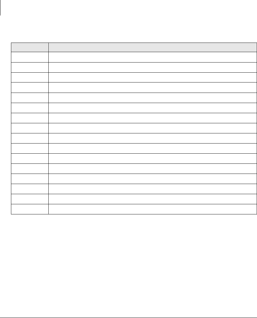
Table 5 DIU AT Command Set
Command Description
AT Command prefix
ATDY...Y Voice call to telephone number (Y…Y = any number of digits), internal or external
ATDDXXXX Data call to DIU station number XXXX (1~4 digits)
Enter Carriage return character
AGo into the answer mode; attempt to go to Communication Mode
A/ Re-execute previous command line; not preceded with AT nor followed by Enter
DGo into originate mode; dial number that follows; attempt to go to on-line state
Mode Definitions
Data Communications Mode
34 Strata DK PC/Data Interface 5/99
Note A DIU assumes the V1 default value when power is initially applied to it or
when the modular line cord is disconnected and then reconnected.
EO Disable character echo in Command Mode
E1 Enable character echo in Command Mode
H0 Go on-hook (hang up)
H1 Go off-hook
OGo to Communication Mode
Q0 DIU returns Result Codes
Q1 DIU does not return Result Codes
SR = n Set Register “R” to value “n” (R = 0~12)
SR? Display value stored in Register “R” (R = 0~12)
V0 Display Result Codes in numeric form
V1 Display Result Codes in words
X0 Enable features represented by Result Codes 0~4
X1 Enable features represented by Result Codes 0~7, 10~12
X2 Enable features represented by Result Codes 0 ~ 5, 10 ~ 12
X3 Enable features represented by Result Codes 0~7, 10~12
X4 Enable features represented by Result Codes 0~7, 10~12
Table 5 DIU AT Command Set
(continued)
Command Description
Mode Definitions
Data Communications Mode
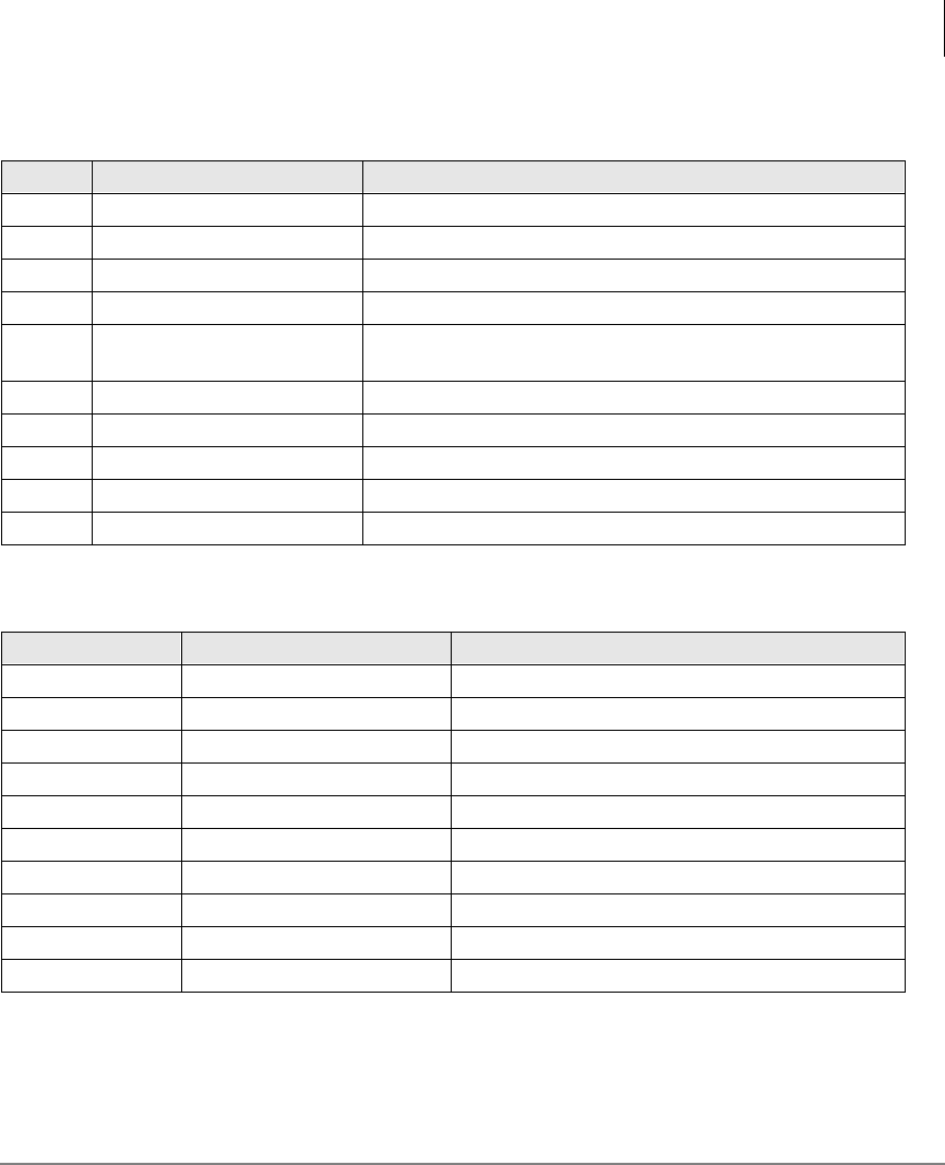
Strata DK PC/Data Interface 5/99 35
Table 6 DIU Result Code Set
No. Word Description
0OK Command executed
1Connect Connection at 0 to 300 bps
2Ring Ring Signal Detected
3No Carrier Carrier signal not detected, or lost
4Error Invalid command, checksum. Error in command line, or
command line exceeds 255 characters
5Connect 1200 Connection at 1200 bps
7Busy Busy signal detected
10 Connect 2400 Connection at 2400 bps
11 Connect 4800 Connection at 4800 bps
12 Connect 9600 Connection at 9600 bps
Table 7 DIU S-Register Set
Register Range Description
S0 0~255 rings Select ring to answer on specific number of rings
S1 0~255 rings Ring count (increment with each ring)
S2 0~127 ASCII Define escape sequence character
S3 0~127 ASCII Define carriage return character
S4 0~127 ASCII Define line feed character
S5 0~32, 0~127 ASCII Define back space character
S7 1~255 sec. Select wait time for carrier/dial tone
S9 1~255 sec. Select carrier detect response time
S10 1~255 sec. Select-delay between carrier loss/hang-up
S12 0~255 sec. Define escape sequence guard time
Mode Definitions
Data Communications Mode
36 Strata DK PC/Data Interface 5/99
Note A DIU assumes these default values when power is initially applied to it or
when the modular line cord is disconnected and then reconnected.
Table 8 Default Values
Register Value S-Register Control
S0 Auto ring enabled S0 = 1
S1 0 rings S1 = 0
S2 ASCII 43 S2 = 43
S3 ASCII 13 S3 = 13
S4 ASCII 10 S4 = 10
S5 ASCII 08 S5 = 8
S7 30 sec. S7 = 30
S9 0.6 sec. S9 = 6
S10 0.7 sec. S10 = 7
S12 1 sec. S12 = 50
Table 9 DIU Dialing Modifier Set
Modifier Description
0~9*# Digits/characters for dialing
ABCD Digits/characters for dialing
PPulse dial
TTone dial
,Delay processing of next character (1 second)
!Hookflash
;Return to Command Mode after dialing

Strata DK PC/Data Interface 5/99 37
Index
B
baud rate, 7
C
call data call while on a voice call, 14, 15
data device, 10
from data telephone, 12
from the externa PC or terminal, 21
from your PC or terminal, 11
terminate, 10
voice call while on a data call, 14
CO line, 15, 26
CO line access codes, 28
communication parameters, 7
options, 7
connect LED, 6
D
data bits, 8
data call, 3, 10, 12, 14, 24
data communications
command mode, 30
mode
(on-line state), 32
data communications mode, 29
data release, 3, 10, 12, 13, 15, 19, 27
default values, 36
dial internal modem from your PC or
terminal, 17
dialing modifiers, 30
DIU dialing modifier set, 36
DIU S-register set, 35
H
hardware requirements, 2
hold, 15
M
modem, 3, 18, 24
P
parity, 8
power LED, 6
R
ready LED, 6
result codes, 30
RPCI/DIU default communication
parameters, 33

Index
S ~ V
38 Strata DK PC/Data Interface 5/99
S
spkr, 16, 27
s-registers, 31
stop bits, 8
switch between data communications and
TAPI modes, 29
T
terminate a call
data connection state, 27
from data telephones, 13, 19
from external PC or terminal, 22
from PC or terminal, 13
voice connection state, 27
voice or data, 15
V
verify communications, 11
from your external PC or terminal, 20
from your PC or terminal, 16
