PDF Toshiba Strata DK14,40i, 424 PROGRAMMING MANUAL
User Manual: PDF T E X T F I L E S
Open the PDF directly: View PDF ![]() .
.
Page Count: 418 [warning: Documents this large are best viewed by clicking the View PDF Link!]

726+,%$ Telecommunication Systems Division
May 1999
Digital Business Telephone Solutions
Programming Manual
Software Release 4.1
and ACD
Software Release 3.1
Software Release 4.1

Publication Information
Toshiba America Information Systems, Inc., Telecommunication Systems Division,
reserves the right, without prior notice, to revise this information publication for any
reason, including, but not limited to, utilization of new advances in the state of
technical arts or to simply change the design of this document.
Further, Toshiba America Information Systems, Inc., Telecommunication Systems
Division, also reserves the right, without prior notice, to make such changes in
equipment design or components as engineering or manufacturing methods may
warrant.
DKA-MA-PRGRM-VE
4025060
Version E, May 1999
Version D.3, December 1998 (Format change)
Version D.2, October 1998 (Update TBDK-0021)
Version D.1, September 1998 (Update TBDK-0019)
Version D, June 1998 (Update TBDK-0009)
Version C, October 1997
Version B, April 1997
Version A.1, February 1997 (Update TB16-0003)
Version A, December 1996
© Copyright 1999
Toshiba America Information Systems, Inc.
Telecommunication Systems Division
All rights reserved. No part of this manual, covered by the copyrights hereon, may be
reproduced in any form or by any means—graphic, electronic, or mechanical,
including recording, taping, photocopying, or information retrieval systems—without
express written permission of the publisher of this material.
Strata is a registered trademark of Toshiba Corporation. Stratagy is a registered
trademark of Toshiba America Information Systems, Inc. Strata AirLink, Call Center
Viewer are trademarks of Toshiba America Information Systems, Inc.
Trademarks, registered trademarks, and service marks are the property of their
respective owners.
Strata DK
General End User Information
The Strata DK Digital Business Telephone System is registered in accordance with the
provisions of Part 68 of the Federal Communications Commission’s Rules and
Regulations.
FCC Requirements
Means of Connection: The Federal Communications Commission (FCC) has
established rules which permit the Strata DK system to be connected directly to the
telephone network. Connection points are provided by the telephone company—
connections for this type of customer-provided equipment will not be provided on coin
lines. Connections to party lines are subject to state tariffs.
Incidence of Harm: If the system is malfunctioning, it may also be disrupting the
telephone network. The system should be disconnected until the problem can be
determined and repaired. If this is not done, the telephone company may temporarily
disconnect service. If possible, they will notify you in advance, but, if advance notice is
not practical, you will be notified as soon as possible. You will be informed of your
right to file a complaint with the FCC.
Service or Repair: For service or repair, contact your local Toshiba telecommunications
distributor. To obtain the nearest Toshiba telecommunications distributor in your area,
call Toshiba America Information Systems, Inc., Telecommunication Systems Division
in Irvine, CA (949) 583-3700.
Telephone Network Compatibility: The telephone company may make changes in its
facilities, equipment, operations, and procedures. If such changes affect the
compatibility or use of the Strata DK system, the telephone company will notify you in
advance to give you an opportunity to maintain uninterrupted service.
Notification of Telephone Company: Before connecting a Strata DK system to the
telephone network, the telephone company may request the following:
1. Your telephone number.
2. FCC registration number:
♦Strata DK may be configured as a Key or Hybrid telephone system. The
appropriate configuration for your system is dependent upon your operation of
the system.
♦If the operation of your system is only manual selection of outgoing lines, it may
be registered as a Key telephone system.
♦If your operation requires automatic selection of outgoing lines, such as dial
access, Least Cost Routing, Pooled Line Buttons, etc., the system must be
registered as a Hybrid telephone system. In addition to the above, certain
features (tie Lines, Off-premises Stations, etc.) may also require Hybrid
telephone system registration in some areas.
♦If you are unsure of your type of operation and/or the appropriate FCC
registration number, contact your local Toshiba telecommunications distributor
for assistance.
DK14 and DK40i
Key system: CJ6MLA-74479-KF-E
Hybrid: CJ6MLA-74478-MF-E
DK424
Hybrid: CJ69XA-10243-MF-E
Key system: CJ69XA-10242-KF-E
PBX: CJCHN-22757-PF-E
3. Ringer equivalence number: 0.3B. The ringer equivalence number (REN) is useful
to determine the quantity of devices which you may connect to your telephone line
and still have all of those devices ring when your number is called. In most areas,
but not all, the sum of the RENs of all devices connected to one line should not
exceed five (5.0B). To be certain of the number of devices you may connect to your
line, as determined by the REN, you should contact your local telephone company
to ascertain the maximum REN for your calling area.
4. Network connection information USOC jack required: RJ1CX, RJ2EX, RJ2GX,
RJ48C, RJ48X, RJ11, RJ14C, RJ21X (see Network Requirements in this
document). Items 2, 3 and 4 are also indicated on the equipment label.
Radio Frequency Interference
Warning: This equipment generates, uses, and can radiate radio frequency energy and if
not installed and used in accordance with the manufacturer’s instruction manual, may
cause interference to radio communications. It has been tested and found to comply
with the limits for a Class A computing device pursuant to Subpart J of Part 15 of FCC
Rules, which are designed to provide reasonable protection against such interference
when operated in a commercial environment. Operation of this equipment in a
residential area is likely to cause interference, in which case, the user, at his/her own
expense, will be required to take whatever measures may be required to correct the
interference.
This system is listed with Underwriters Laboratory.
UL Requirement: If wiring from any telephone exits the building or is
subject to lightning or other electrical surges, then secondary protection
is required. Secondary protection is also required on DID, OPS, and tie
lines. (Additional information is provided in this manual.)
Important Notice — Music-On-Hold
In accordance with U.S. Copyright Law, a license may be required from
the American Society of Composers, Authors and Publishers, or other similar
organization, if radio or TV broadcasts are transmitted through the music-on-hold
feature of this telecommunication system. Toshiba America Information Systems, Inc.,
hereby disclaims any liability arising out of the failure to obtain such a license.
CP01, Issue 8, Part I Section 14.1
Notice: The Industry Canada label identifies certified equipment. This certification
means that the equipment meets certain telecommunications network protective,
operational and safety requirements as prescribed in the appropriate Terminal
Equipment Technical Requirements document(s). The Department does not guarantee
the Equipment will operate to the user’s satisfaction.
Before installing this equipment, users should ensure that it is permissible to be
connected to the facilities of the local telecommunications company. The equipment
must also be installed using an acceptable method of connection. The customer should
be aware that compliance with the above conditions may not prevent degradation of
service in some situations.
Repairs to certified equipment should be coordinated by a representative designated by
the supplier. Any repairs or alterations made by the user to this equipment, or
equipment malfunctions, may give the telecommunications company cause to request
the user to disconnect the equipment.
Users should ensure for their own protection that the electrical ground connections of
the power utility, telephone lines and internal metallic water pipe system, if present, are
connected together. This precaution may be particularly important in rural areas.
CAUTION! Users should not attempt to make such connections themselves, but
should contact the appropriate electric inspection authority, or
electrician, as appropriate.
CP01, Issue 8, Part I Section 14.2
Notice: The Ringer Equivalence Number (REN) assigned to each terminal device
provides an indication of the maximum number of terminals allowed to be connected to
a telephone interface. The terminal on an interface may consist of any combination of
devices subject only to the requirement that the sum of the Ringer Equivalence
Numbers of all the Devices does not exceed 5.
UL
®

Strata DK Programming 5/99 i
Contents
Introduction
Organization..........................................................................................................................................vii
Conventions..........................................................................................................................................viii
Related Documents/Media.....................................................................................................................ix
Chapter1–Overview
Numerical Program Listing..................................................................................................................1-1
Alphabetical Program Listing ..............................................................................................................1-7
How to Program a Strata DK System ................................................................................................1-10
First-time Programming.....................................................................................................................1-14
Programming Examples.....................................................................................................................1-16
Chapter 2 – Initialization & Test
Program 91-9 – System Initialization ..................................................................................................2-2
Program 90 – Initialize Programs 00~*99 ...........................................................................................2-4
Program 91-1 – Automatic PCB Recognition and Port Renumber......................................................2-6
Program 91-2 – Data Transfer from Temporary Memory to Working Memory.................................2-8
Program 92 – Initializing Misc. Backup RAM....................................................................................2-9
Program 00 – Part 1: Software Check................................................................................................2-12
Program 00 – Part 2: Processor RAM Test........................................................................................2-15
Chapter 3 – System & Station
Program 01 – Station Logical Port Display and/or Change.................................................................3-1
Program 02 – Station Physical Port Display and/or Change................................................................3-2
Program 03 for DK14 – Slot Assignments ..........................................................................................3-3
Program 03 for DK40i – Flexible PCB Slot Assignments...................................................................3-4
Program 03 for DK424 – Flexible PCB Cabinet Slot Assignments ....................................................3-6
Program *03 for DK424 – Cabinet Type Identification ....................................................................3-11
Program 04 – Station Logical Port [PDN] Assignment.....................................................................3-12
Program *04 – [PhDN] and Distributed Hunt [DN] Assignments For Internal and Tie Line Calls..3-17
Program 05 – Flexible Access Code Numbering...............................................................................3-19
Program *05 – Call Park Pickup Abbreviated Dialing......................................................................3-22
Program 09 – Built-in Auto Attendant Prompt / Station Assignments..............................................3-23
Program *09 – [PDN], [PhDN], DH, ACD or Modem DID Ext. Assignments ................................3-25
Program 10-1 – System Assignments, Part 1 of 3 .............................................................................3-27
Program 10-2 – System Assignments, Part 2 of 3 .............................................................................3-30
Program 10-3 – System Assignments, Part 3 of 3 .............................................................................3-35
Program *10 – Enhanced 911 Operation ...........................................................................................3-39
Program 12 – System Assignments, Basic Timing............................................................................3-41

Contents
Chapter 3 – System & Station
ii Strata DK Programming 5/99
Program 13 – Defining the Message Center ......................................................................................3-43
Program 15 – Ground/Loop/Tie/DID Line Options...........................................................................3-44
Program *15 – CO Line Tenant Assignments ...................................................................................3-47
Program 16 – Assign CO Line Groups (or Dial 9) ............................................................................3-48
Program 17 – DID/Tie Line Options .................................................................................................3-50
Program *17 – DID Intercept Port Number (Vacant or Wrong Number) .........................................3-53
Program 19 – Alternate Background Music Source Slot Assignment...............................................3-54
Program 20 – Computer and Data Interface Unit Configuration.......................................................3-55
Program 21 – Modem Pool Port Assignments...................................................................................3-58
Program 22 – RPCI and DIU Station Hunting for Data Calls ...........................................................3-60
Program 23 – Built-in Auto Attendant (AA) Primary Announcement Assignments ........................3-61
Program 24 – Built-in AA Secondary Announcement Assignments.................................................3-61
Program 25-1 – Built-in AA Incoming Call Overflow Time.............................................................3-62
Program 26 – Built-in AA Camp-on Busy Time ...............................................................................3-63
Program 27 – DKT Handset/Headset Receiver Volume Level .........................................................3-65
Program 28 – DSS Console/Attendant Telephone Assignments.......................................................3-66
Program 29-1~8 – DSS Console and Number Button Assignments..................................................3-68
Program *29 – Add-on Modules Button Assignments ......................................................................3-71
Program 30 – Station Class of Service...............................................................................................3-73
Program *30 – Telephone Group Page Assignments ........................................................................3-79
Program 31 – Station Class of Service...............................................................................................3-80
Program *31 – Group Pickup Assignments.......................................................................................3-86
Program 32 – Automatic Preference..................................................................................................3-87
Program *32 – RS-232 Voice Mail Message Center Port .................................................................3-89
Program 33 – [PDN]/ [PhDN] Station Hunting (Voice Calls Only)..................................................3-90
Program *33 – [PhDN] Owner Telephone Assignment ....................................................................3-92
Program 34 – Hold Recall Timing.....................................................................................................3-94
Program *34 – Station Class Of Service............................................................................................3-95
Program 35 – Station Class of Service...............................................................................................3-97
Program 36 – Fixed Call Forward....................................................................................................3-101
Program *36 – System NT Button Lock Password Changing Station Assignment ........................3-102
Program 37 – Ring Transfer (Camp-on) Recall Time .....................................................................3-103
Program *37 – Park Recall Timing..................................................................................................3-104
Program 38 – Digital and Electronic Telephone Keystrip Type......................................................3-105
Program *38 – Standard Telephone Ring-Down Destination..........................................................3-109
Program 39 – Flexible Button Assignments ....................................................................................3-111
Program *40 – Distributed Hunt Group Member Assignments.......................................................3-120
Program *41 for DK424 – T1 Assignment Series (Part 1)..............................................................3-122
Program *50 – Caller ID Circuit Assignments to CO Line PCBs...................................................3-126
Program *51 – Station Memory Allocation.....................................................................................3-128
Program *52 – Caller ID/ANI Abandoned Call Number Station Owner Assignments...................3-130
Program 58 – DK424 Attendant Console Series (Part 1) ................................................................3-132
Program 59 – Attendant Console Flexible Button Codes................................................................3-135
Program 60-1 – SMDR Data Output Options..................................................................................3-139
Program 60-2~7 – SMDR Output/Account Code Digit Length ......................................................3-140
Program 60-8 – Call Forward External (Remote Change, Security) ID Code.................................3-142
Program 69 – Verified Account Codes............................................................................................3-143
Program 70 – Verified Account Code Toll Restriction Assignments..............................................3-145
Program 71 – DNIS..........................................................................................................................3-147
Program *71~*73 – [DN] to [DN], Tie to [DN], and DID to [DN] Ringing Assignments.............3-152

Contents
Chapter 4 – Toll Restriction
Strata DK Programming 5/99 iii
Program 72 – DNIS Number Network Table Assignments.............................................................3-154
Program 74 – System NT Button Lock Password ...........................................................................3-156
Program 76-1(X-Y) – DK14, DK40i, All RCTUs...........................................................................3-157
Program 76-2 (X-Z) – WSIU, TSIU and RSIU / RSIS / RMDS Transmission Rates.....................3-158
Program 77-1 – Peripheral Options (Door Phones).........................................................................3-159
Program 77-2 – Door Phone Busy Signal/Door Lock Assignments................................................3-163
Program 77-3 – Night Ringing Over PIOU External Page Zones ...................................................3-165
Program 77-4 – RSIU Open Architecture Interface (OAI) Data Output Assignments....................3-166
Program 78 – CO Line Special Ringing Assignments.....................................................................3-168
Program 79 – Door Phone Ringing..................................................................................................3-170
Program *79 – Door Phone to [DN] Flashing Assignments............................................................3-172
Program 80 – EKT and DKT Ringing Tones (CO Line Calls)........................................................3-173
Program *80 – Call Forward Station Ring Assignment...................................................................3-174
Programs 81~89 – Ground/Loop Start/CO Line Station Ringing....................................................3-175
Programs *81, *84, and *87 – Ground/Loop Start/CO Line to [DN] LED Flash Assignments......3-179
Program 93 – CO Line Identification...............................................................................................3-183
Program 97 – Printing Program Data through SMDR.....................................................................3-185
Chapter 4 – Toll Restriction
Toll Restriction Methods......................................................................................................................4-1
Toll Restriction Features......................................................................................................................4-1
Completing the Toll Restriction System Record .................................................................................4-3
Program 40 – Station CO Line Access ................................................................................................4-4
Program 41 – Station Outgoing Call Restriction .................................................................................4-6
Program 42-0 – CO Line to PBX/Centrex Connection & Access Codes ............................................4-8
Program 42-1~8 – PBX/Centrex Access Codes.................................................................................4-10
Program 43 – 0 + Credit Card Dialing Option...................................................................................4-11
Program 44-1~8 – Toll Restriction/Traveling Class Override Codes................................................4-13
Program 44-91~93 – Emergency Bypass of Forced/Verified Account Codes ..................................4-14
Program 45-1 – LCR/Toll Restriction Dial Plan................................................................................4-15
Program 45-2 – Toll Restriction Disable ...........................................................................................4-19
Program 45-3~6 – Special Common Carrier Numbers and Authorization Code Digit Length.........4-20
Program 45-8~9 – Toll Restriction Override Code............................................................................4-22
Program *45-1 (1~4) – Toll Restriction for Office Codes.................................................................4-23
Program *45-2 (1~6) – LCR/Toll Restriction Bypass.......................................................................4-24
Program *45-3 (1~9) – LCR/Toll Restriction Bypass For Special Numbers that Begin with */# ....4-26
Program *45-4 – Special Code Dialing Sequence with LCR ............................................................4-28
Program 46-2~4 – Toll Restriction Allowed/Denied Area Codes by Class ......................................4-30
Program 46-6~8 – Toll Restriction Allowed/Denied Local Office Codes Assigned by Class..........4-31
Programs 46-10~80 – Toll Restriction Class Parameters ..................................................................4-33
Programs 46-11~46-81 – Toll Restriction Class (1~8) Parameters...................................................4-35
Program 47 – Toll Restriction Exception Office Codes Assigned by Area Codes (Tables 1~16) ....4-36
Program 48 – Station Toll Restriction Classification ........................................................................4-38
Chapter 5 – Least Cost Routing
LCR Features .......................................................................................................................................5-1
LCR Conditions ...................................................................................................................................5-2
LCR CO Line Programming Reference Table.....................................................................................5-3
Program 50-1 – LCR Parameters.........................................................................................................5-4

Contents
Chapter 6 – Automatic Call Distribution
iv Strata DK Programming 5/99
Program 50-2 – LCR Home Area Code...............................................................................................5-5
Programs 50-3 (1~5) – LCR Special Codes.........................................................................................5-6
Program 50-4 – LCR Long Distance Information (LDI) Plan Number...............................................5-7
Program 50-5 – LCR Local Call Plan Number....................................................................................5-8
Program 50-6 – LCR Dial 0 (Zero) Time-out......................................................................................5-9
Program 51 – LCR Area Codes .........................................................................................................5-10
Program 52 – LCR Office Code Exceptions for Specified Area Code..............................................5-12
Program 53 – LCR Schedule Assignments for LCR Plans................................................................5-14
Program 54 – LCR Route Definition Tables......................................................................................5-17
Program 55 – LCR Modified Digits Table ........................................................................................5-19
Program 55-0 – Delete Number of Digits From the Front of Dialed Number...................................5-20
Program 55-1 and 2 – Add Digits Before and/or After the Dialed Number......................................5-21
Program 56 – LCR Station Group Assignments................................................................................5-23
Chapter 6 – Automatic Call Distribution
Program 03 – RSIU, RSSU, PIOU, PIOUS ACD/MIS Slot Assignments ..........................................6-2
Program 09 – Auto Attendant Prompt/ACD Group Assignments.......................................................6-3
Program *09 – ACD Group DID Line Digit Assignments..................................................................6-5
Program 10-4 – ACD/ISDN Parameters..............................................................................................6-6
Program 11 – ACD Timing Assignments............................................................................................6-8
Program 14-0 – Loop/Ground Start Line Direct to ACD Group Assignments..................................6-12
Program 14-1 – ACD Agent Identification Code Assignments.........................................................6-13
Program *14-1 – Auto Answer with Zip Tone Assigned to Agent ID ..............................................6-14
Program 18 – Agent Names for SMIS/MIS Assignments .................................................................6-15
Program 14-2 – ACD Supervisor Passwords.....................................................................................6-17
Program *14-2 – DID, Tie, DNIS, ANI Line After Shift/Overflow Substitution Destinations ........6-18
Program 14-3 – Announcement/Music Port and Queue Pattern........................................................6-20
Program 14-4 – Queue Time Out Overflow Destination...................................................................6-23
Program 14-5 – Overflow Point and Ring No Answer Routing Destination.....................................6-25
Program 14-6 – After Shift Service Destination................................................................................6-29
Program 14-71 – Queue Size for Alarm, Immediate Assignments....................................................6-31
Program 14-72 – Queue Size for Alarm 1 .........................................................................................6-32
Program 14-73 – Queue Size for Alarm 2 .........................................................................................6-33
Program 14-8 – Alarm Pattern Assignments .....................................................................................6-34
Program 14-9 – Work Unit Assignments...........................................................................................6-35
Program 15 – Ground/Loop/Tie/DID Line Options...........................................................................6-36
Program 17 – DID/Tie Line Options .................................................................................................6-36
Program 35 – Station Class of Service...............................................................................................6-36
Program 71 – DID/Tie/DNIS/ANI Lines...........................................................................................6-36
Program 39 – Flexible Button Assignments for ACD Telephones....................................................6-37
Chapter7–ISDN
System Programs Overview.................................................................................................................7-1
ISDN Related Programs.......................................................................................................................7-3
Trunk Programs Overview...................................................................................................................7-5
Program 16 – Assign CO Line Groups ................................................................................................7-6
Program *16 – ISDN Trunk Group Type Assignment ........................................................................7-7
Program *42 – Clock Source ...............................................................................................................7-8
Program *42-1 – Primary Timing Reference Assignments (Release 3.1 and earlier).........................7-9

Contents
Chapter8–E911
Strata DK Programming 5/99 v
Program *43-1~3 – D-Channel Control and NFAS Assignments.....................................................7-10
Program *43-2 – Non-Facility Associated Signaling (NFAS) Assignment ......................................7-11
Program *43-3 – Network PRI Interface Assignment.......................................................................7-12
Program *44 – BRI Service Profile Identifier (SPID) Parameters ....................................................7-13
Program *60 – BRI Line/Station Operation Assignment ..................................................................7-14
Program *61 – Analog Trunk Services for ISDN..............................................................................7-15
Program *62 – Non-ISDN Station Bearer Service ............................................................................7-16
Program *63 – ISDN Dialing Parameters..........................................................................................7-17
Program *64-1 – Direct Inward Dialing Parameters..........................................................................7-18
Program *64-2 – Number of DID/DNIS Digits for Trunk Groups....................................................7-19
Program *65 – ISDN Channel Group Assignment............................................................................7-20
Program *66-1 – Channel Group Number Parameters ......................................................................7-21
Programs *66-2 and *66-4 – Call-by-Call Trunk Group Codes and Network ID.............................7-22
Program *66-3 – Channel Group/Trunk Parameters .........................................................................7-24
Program *66-5 – Line Directory Number (LDN) Registration .........................................................7-25
Program *66-6 – LDN/Trunk Group to Channel Group Assignments..............................................7-26
Program *66-7 – LDN/Trunk Group Assignments............................................................................7-27
Program *67-1 – Trunk Group Call Direction...................................................................................7-28
Program *67-2 – Call Types for ISDN Trunk Group Supported.......................................................7-29
Program *67-3 – ISDN Trunk Group Minimum Channel Reservation.............................................7-30
Program *67-4 – ISDN Trunk Groups Maximum Channel Reservation...........................................7-31
Program *67-5 – Multiple Time Zone Settings .................................................................................7-32
Program *68-1 – Calling Number ID Presentation Parameters.........................................................7-33
Program *68-2 – Outbound CNIS Parameters...................................................................................7-34
Program *69-1 – CNIS Presentation Parameters...............................................................................7-35
Program *69-2 – Special Number Assignment..................................................................................7-36
Chapter 8 – E911
Operation Overview.............................................................................................................................8-1
SMDR ..................................................................................................................................................8-2
Programming Overview.......................................................................................................................8-3
Program *11-0 – E911/CAMA Trunk Assignments............................................................................8-4
Program *11-1 – CAMA Trunk Group Line Assignments..................................................................8-6
Program *11-2 – CAMA Trunk Group Hunting Assignments............................................................8-7
Program *11-5 – CAMA Digits Sent on 911 Calls..............................................................................8-8
Program *11-6 – E911 Interdigital Timer............................................................................................8-9
Program *11-8 – 911 Special [DN] Notification Assignments .........................................................8-10
Program *12 – CESID Station Information.......................................................................................8-11
Program *13 – Station To CAMA Trunk Group Assignment...........................................................8-13
Glossary .......................................................................................................................................... GL-1
Index.....................................................................................................................................................IN-1

Contents
Chapter 8 – E911
vi Strata DK Programming 5/99

Strata DK Programming 5/99 vii
Introduction
This manual provides for programming the Strata DK14, DK40i, and DK424 digital business
telephone systems. It is intended for qualified service technicians and system programmers. At the
time of this printing, this book contains Release 4.1 information for the DK424. It also contains
some pre-release information for software beyond Release 4.1.
Important! Information beyond Release 4.1 is preliminary and given prior to product release.
Be careful when using this information as the software will change and updates/
additions will be required upon final release.
This manual uses simplified, generic system record sheets that have legends that show you specific
port configurations for Strata DK14, DK40i and DK424 systems.
After using the legends, copy the generic record sheets as required to accommodate your system
ports and settings.
The Installation and Maintenance (I&M) Manual, a companion book, covers the installation and
maintenance information and instructions for the Strata DK systems discussed in this book.
Organization
This manual is organized as follows for your convenience:
♦Chapter 1 – Overview includes general programming information and basic instructions on
how to program the system with a 20-button LCD digital or electronic telephone.
♦Chapter 2 – Initialization & Test includes information for initializing and test programs.
♦Chapter 3 – System & Station includes programming information for the entire system and
individual stations.
♦Chapter 4 – Toll Restriction includes programming information for Toll Restriction.
♦Chapter 5 – Least Cost Routing includes programming information for Least Cost Routing.
♦Chapter 6 – Automatic Call Distribution includes ACD programming for DK424 (ACD
does not apply to the RCTUA processor).
♦Chapter 7 – ISDN includes programming instructions and record sheets for Integrated
Systems Digital Networking features for the DK424 and DK40i.
♦Chapter 8 – E911 includes programming information for connecting the DK424 to Enhanced
911 CAMA trunks.
♦
♦♦
♦Glossary/Index

Introduction
Conventions
viii Strata DK Programming 5/99
The programs in each chapter are given in numerical order (except Initialization and Test which is
given in order of importance). The “*” programs are located behind the program of the same name
(e.g., Program *09 follows Program 09).
Conventions
Conventions Description
Note Elaborates specific items or references other information. Within some
tables, general notes apply to the entire table and numbered notes apply to
specific items.
Important! Calls attention to important instructions or information.
CAUTION! Advises you that hardware, software applications, or data could be
damaged if the instructions are not followed closely.
WARNING! Alerts you when the given task could cause personal injury or death.
[DN] Represents any Directory Number button, also known as an extension or
intercom number.
[PDN] Represents any Primary Directory Number button (the extension number
for the telephone).
[SDN] Represents any Secondary appearance of a PDN. A PDN which appears on
another telephone is considered an SDN.
[PhDN] Represents any Phantom Directory Number button (an additional DN).
$ULDO#%R OGRepresents telephone buttons.
Courier Shows a computer keyboard entry or screen display.
“Type” Indicates entry of a string of text.
“Press” Indicates entry of a single key. For example: Type prog then press
Enter.
Plus (+)
Shows a multiple PC keyboard or phone button entry. Entries without
spaces between them show a simultaneous entry. Example: Esc +
Enter. Entries with spaces between them show a sequential entry.
Example: # + 5.
Tilde (~) Means “through.” Example: 350 ~ 640 Hz frequency range.
➤Denotes the step in a one-step procedure.
➤Denotes a procedure.
Used in a programming sequence to denote a variable LED button. A
number on the black button represents a specific LED button.
Indicates continuation of a series of numbers entered.
See Figure 10 Grey words within the printed text denote cross-references. In the
electronic version of this document (Library CD-ROM or FYI Internet
download), cross-references appear in blue hypertext.
36

Introduction
Related Documents/Media
Strata DK Programming 5/99 ix
Related Documents/Media
Note Some documents listed here may appear in different versions on the CD-ROM, FYI or in
print. To find the most current version, check the version/date in the Publication
Information on the back of the document’s title page.
The following documents and CD-ROMS can be used to reference further information about the
Strata DK systems.
♦Digital Telephone User Guide provides all the procedures necessary to operate Toshiba-
proprietary digital telephones, including Liquid Crystal Display (LCD) features. It also
includes instructions for using the add-on module/DSS console.
♦Digital Telephone Quick Reference Guide provides a quick reference for frequently-used
digital telephone features.
♦Digital Single Line Telephone User Guide provides all the procedures necessary to operate
Toshiba-proprietary digital single line telephones.
♦Electronic Telephone User Guide explains all the procedures necessary to operate Toshiba-
proprietary electronic telephones, including all LCD features. Does not apply to the Strata
DK14 system. It also includes instructions for using the electronic DSS console.
♦Electronic Telephone Quick Reference Guide provides a quick reference for frequently-
used electronic telephone features. Does not apply to the Strata DK14 system.
♦Standard Telephone User Guide explains all the procedures necessary to operate rotary dial
and push-button standard telephones.
♦Strata AirLink External Wireless Handset User Guide shows how to use the wireless
handset configured to standard ports of the Strata DK telephone system and many non-Toshiba
systems.
♦
♦♦
♦Strata AirLink External Wireless Quick Reference Guide contains instructions for
operation of commonly used Strata AirLink External Wireless Handset features.
♦Strata AirLink Integrated Wireless Handset User Guide shows how to use the wireless
handset configured to digital ports of the Strata DK telephone system.
♦
♦♦
♦Strata AirLink Integrated Wireless Quick Reference Guide contains instructions for
operation of commonly used Strata AirLink Integrated Wireless Handset features.
♦System Administrator Guide gives instructions for the System Administrator to manage the
system. Contains instructions for Station Relocation, System Speed Dial, and other features
only activated by the System Administrator.
♦PC/Data Interface User Guide explains all the procedures necessary to operate stand-alone
data interface units while in the data mode for printer sharing and modem pooling. Also
provides instructions on connecting to a Personal Computer with Telephone Application
Programming Interface (TAPI).
♦Cordless Telephone User Guide provides instructions on using the DKT2004-CT cordless
digital telephone as a single unit or in conjunction with a digital telephone.
♦PC-DKT User Guide provides installation and operation information for the Personal
Computer Digital Key Telephone system.
♦Strata DK Feature Description Manual describes each feature associated with the Strata
DK424, DK40i and DK14. Also provides descriptions of compatible Toshiba-proprietary
telephones and peripherals.

Introduction
Related Documents/Media
xStrata DK Programming 5/99
♦Keyprint 2000 User Guide provides instructions for the Keyprint 2000 software printing
package which allows you to print and store custom button label keystrips for Strata DK 2000-
series 10-button or 20-button digital telephones, 20-button add-on modules, and 60-button
digital DSS consoles.
♦Strata DK Programming Manual provides all instructions necessary to program the system
and system record sheets, including ACD.
♦Strata DK Installation & Maintenance Manual provides installation instructions for
configuring and installing the Strata DK14, DK40i and DK424. It also includes T1/DS-1
interface installation and configuration instructions, as well as fault finding flowcharts to
troubleshoot the systems. An ACD Section provides instructions for installing ACD into the
Strata DK424.
♦Strata AirLink External Wireless System Installation Guide provides step-by-step
hardware and software installation instructions. It includes examples of system configurations,
information on performing a site survey, and troubleshooting techniques.
♦Hospitality Management Information System (HMIS) General Description provides an
overall view of the system’s hardware, software, applications and features. The HMIS is a PC-
based solution, designed to meet the specific operational needs of small- to medium-sized
hotel/motels and includes both the PC and software.
♦Hospitality Management Information System (HMIS) User Guide describes the product’s
many software features and gives step-by-step instructions for using them.
♦Strata DK Library CD-ROM enables you to view, print, navigate and search publications
for Strata DK14, DK40 and DK424 digital business telephone systems. It also includes Strata
DK424 ACD Documentation, including the Strata DK424 Call Center Solutions General
Description, ACD Agent Guide, ACD Supervisor’s Guide. ACD Installation and Programming
instructions are included in the Strata DK Installation and Maintenance Manual and
Programming Manual.
♦Strata DK HMIS CD-ROM contains a copy of all HMIS documentation/bulletins and
enables you to view, print, navigate and search publications.
♦StrataControl CD-ROM contains the StrataControl software, that enables viewing,
downloading, editing, and uploading Strata DK programmed data on a PC. This software also
provides a method of creating custom lists and user guides based on information from the
Strata DK system.The CD-ROM contains the StrataControl User Guide.
♦DKQuote CD-ROM contains the DKQuote application and the DKQuote User Guide, that
shows how to use this interactive software to assist you with Strata DK Systems configuration
and pricing worksheets.
♦DKAdmin/DKBackup CD-ROM includes the programs that let you easily and quickly
custom program and/or update the Strata DK14/DK40/DK424 with a user-friendly PC display.
The CD-ROM also contains the DKAdmin/DKBackup User Guide, that explains how to use
the DKAdmin/DKBackup interactive software applications. The current version does not
support DK40i.
The following documentation and media applies to the Strata DK424 system only.
♦Strata DK424 Call Center Solutions General Description provides a system overview,
including hardware and feature information. Highlights the technology employed in operating
the ACD Strata DK424 system.
♦ACD Agent Guide describes the ACD agent feature operation along with step-by-step
procedures for using features.
♦ACD Supervisor Guide provides instruction on how to use the ACD supervisor features.

Introduction
Related Documents/Media
Strata DK Programming 5/99 xi
♦Insight DK CD-ROM which includes Insight DK software, the upgrade to Insight DK Plus,
Demo software, Insight DK documentation and training modules.
♦
♦♦
♦Insight DK Installation Guide explains how to set up the network, install the server software,
install clients and explains how the data files are organized.
♦
♦♦
♦Insight DK Supervisor Guide provides instructions for using the Strata DK Insight and
Insight DK Plus MIS for the Supervisor of a call center. Instructions for creating and using
Real Time Displays, Reports, Alarms, and Wallboards are also included.
♦
♦♦
♦Insight DK inView Quick Reference Guide provides instructions for viewing and
customizing the on-screen wallboard and large character views of the real time call center
data.
♦PC Attendant Console User Guide explains the procedures necessary to operate the PC
Attendant Console.
♦PC Attendant Console Quick Reference Guide provides a quick reference for frequently-
used PC Attendant Console features.
♦Call Center Viewer User Guide describes how to install and operate the Call Center Viewer
application on a PC. It explains how to view and customize ACD group and agent status
information.
♦Software MIS (SMIS) Supervisor Manual provides descriptions, examples, and instructions
on using the Software MIS application.
For authorized users, Internet site FYI (http://fyi.tsd.toshiba.com) contains all current Strata DK
documentation and enables you to view, print, and download current publications.

Introduction
Related Documents/Media
xii Strata DK Programming 5/99
Strata DK Programming 5/99 1-1
Overview
Overview 1
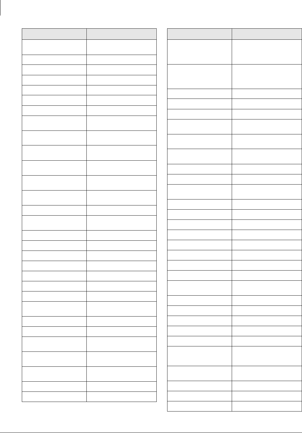
Numerical Program Listing
The following numerical listing gives you the Strata DK program numbers, titles and program
types.
Program Number
Program Title
Initialization & Test
System
Station
Toll Restriction
Least Cost Routing
ACD
ISDN
00 Part 1: Software Check/Remote Maintenance Security Code
Assignments X
00 Part 2: RCTU: Random Access Memory (RAM) Test X
01 Station Logical Port Display and/or Change X
02 Station Physical Port Display and/or Change X
03 Flexible PCB Cabinet and Slot Assignments X X
*03 Cabinet Type Identification X
04 Station Logical Port Primary Directory Number Assignment X
*04 [PhDN] and Distributed Hunt [DN] for Internal Tie Line Calls X
05 Flexible Access Code Numbering X
*05 Call Park Pickup Abbreviated Dialing X
09 Built-in Auto Attendant Prompt/Station Assignments X X
*09 [PDN], [PhDN], DH, ACD or Modem DID External Assignments X X
10-1~3 System Assignments, Basic Timing X X
10-4 ACD Parameters and ISDN PRI and BRI T-wait Timers X X
*10-11 E911 Standard Telephone Ports Assignment X
*10-12 E911 Standard Telephone Ports Assignment X
*10-91 E911 Interdigital TImer X
*10-92 E911 Pause Before Send TImer X
11 ACD Timing Assignments X
*11-1~9 CAMA Trunk Assignments X
12 System Assignments X
*12 ANI Station Information X
13 Defining the Message Center X
*13 Station Group Information X
14-0 Loop/Ground Start CO Line Direct Ring to ACD Group Assignments X
14-1 ACD Agent Identification Code Assignments X

Overview
Numerical Program Listing
1-2 Strata DK Programming 5/99
*14-1 Auto Answer with Zip Tone Assigned to Agent ID X
14-2 ACD Supervisor Passwords X
*14-2 DID/Tie/DNIS/ANI Line After Shift and Overflow Substitution Destination X
14-3 Announcement / Music Port Assignments and Queue Pattern X
14-4 Queue Time Out Overflow Destination X
14-5 Overflow Point and Ring No Answer Routing Destination Assignments X
14-6 After Shift Service Destination X
14-71 Queue Size for Alarm (Immediate Assignments) X
14-72 Queue Size for Alarm 1 X
14-73 Queue Size for Alarm 2 X
14-8 Alarm Pattern Assignments X
14-9 Work Unit Assignments / Stroke Digit Length X
15 Ground/Loop/Tie/DID Line Options X X
*15 CO Line Tenant Assignments X
16 Assign CO Line Groups (Dial 9, 81~84, 81~88 or 801~816) X X
*16 ISDN Trunk Group Type Assignment X
17 DID/Tie Line Options X X
*17 DID Intercept Port Number X
18 Agent ID Code Name for MIS Assignments X
19 Alternate Background Music (BGM) Source Slot Assignment X
20 Computer Interface Unit and Data Interface Unit Configuration X
21 Modem Pool Port Assignments X
22 Computer and Data Interface Units (DIU) Station Hunting (Data Calls) X
23 Built-in Primary Auto Attendant Announcement Device Assignments X
24 Built-in Secondary Auto Attendant Announcement Device Assignments X
25-1 Incoming Built-in Auto Attendant Call Overflow Time X
26 Built-in Auto Attendant Camp-on-Busy Time X
27 Digital Telephone Handset/Headset Receiver Volume Level X
28 DSS Console/Attendant Telephone Assignments X
29-1~8 DSS Console Button Assignments Console Number X
*29 Add-on Module Button Assignments X
30 Station Class of Service X
*30 Telephone Group Page Assignments X
31 Station Class of Service X
*31 Group Pickup Assignments X
32 Automatic Preference X
*32 RS-232 (SMDI or Toshiba Proprietary) Voice Mail Message Center Port X
33 Station Intercom and Directory Number Hunting (Voice Calls Only) X
*33 Phantom Directory Number [PhDN] Owner Telephone Assignments X
Program Number
Program Title
Initialization & Test
System
Station
Toll Restriction
Least Cost Routing
ACD
ISDN

Overview
Numerical Program Listing
Strata DK Programming 5/99 1-3
Overview
34 Hold Recall Timing X
*34 Station Class of Service (Standard Telephone Camp-on Busy and Busy
Override Tone Option) X
35 Station Class of Service X X
36 Fixed Call Forward (Voice Calls Only) X
*36 System NT Button Lock Password Changing Station Assignment X
37 CO and Tie Line Ring Transfer (Camp-on) Recall Time X
*37 Park Recall Timing X
38 Digital and Electronic Telephone Keystrip Type X
39 Flexible Button Assignment X X
40 Station CO Line Access X
*40 Distributed Hunt Group Member Assignments X
41 Station Outgoing Call Restriction X
*41-1 T1 Span Frame and Coding Assignments X X
*41-2 T1 Channel Assignments X X
*41-3 T1 Span Transmit (Send) Level Pad Assignments X
*41-4 T1 Span Receive Level Pad Assignments X
42-0 CO Line to PBX/Centrex Connection X
42-1~8 PBX/Centrex Access Code X
*42-1 T1 Span Primary Reference Assignments X
*42-2 T1 Span and Secondary Timing (Backup) Reference Assignments X
43 0 + Credit Card Dialing Option X
*43-1~3 D-Channel Control and NFAS Assignments X
44-1~8 Toll Restriction Class (1~8)/Traveling Class Override Codes X
44-91~93 Emergency Bypass of Forced/Verified Account Codes X
*44 BRI Service Profile Identifier (SPID) Parameters X
45-1 LCR/Toll Restriction Dial Plan X X
45-2 Toll Restriction Disable X
45-3~6 Special Common Carrier (SPCC) Numbers and Authorization Code Digit
Length X
45-8~9 Toll Restriction Override Code X
*45-1 Toll Restriction for Office Codes in Local and All Other Area Codes X
*45-2 LCR/Toll Restriction Bypass for Special Numbers That Do Not Being
with or # Digits X X
*45-3 LCR/Toll Restriction Bypass - Special Numbers Beginning with or # X X
*45-4 LCR/Toll Restriction Bypass X X
46-2~4 Toll Restriction Allowed/Denied Area Codes Assigned by Class X
46-6~8 Toll Restriction Allowed/Denied Office Codes Assigned by Class for
Local Calls X
46-10~80 Toll Restriction Class Parameters X
Program Number
Program Title
Initialization & Test
System
Station
Toll Restriction
Least Cost Routing
ACD
ISDN

Overview
Numerical Program Listing
1-4 Strata DK Programming 5/99
46-11~81 Toll Restriction Class Parameters X
46-21,46-31
46-41,
46-51,
46-61,
46-71,
46-81
Toll Restriction Classes 2~8 X
47 Toll Restriction Exception Office Codes Assigned by Area Codes X
48 Station Toll Restriction Classification X
50-1 Least Cost Routing Parameters X
50-2 Least Cost Routing Home Area Code X
50-31~35 Least Cost Routing Special Code X
50-4 Least Cost Routing Long Distance Information (LDI) Plan Number X
50-5 Least Cost Routing Local Call Plan Number X
50-6 Least Cost Routing Dial Zero Time-out X
*50 Caller ID (RCIU/RCIS) Circuit Assignments to CO Line (RCOU, RCOS,
RGLU, and PCOU) X
51 Least Cost Routing Area Codes X
*51 Station Memory Allocation to Store Caller ID and/or ANI Numbers on
Abandoned/ Unanswered Calls X
52 Least Cost Routing Code Exceptions for Specified Area Code X
*52 Caller ID or ANI Ground/Loop/Tie/DID Line Circuit Abandoned Call
Number Store Station Owner Assignments X
53 Least Cost Routing Schedule Assignments for LCR Plans X
54 Least Cost Routing Route Definition Tables X
55-0 Least Cost Routing Modified Digits Table (Delete) X
55-1~2 Least Cost Routing Modified Digits Table (Add) X
56 Least Cost Routing Station Group Assignments X
58-1 Attendant Console Overflow Timer X
58-2 Attendant Console Display Type, Answer Button Operation, and Call
Waiting Tone X
58-4 Attendant Console Answer Button Priority Assignments X
58-5 Attendant Console Overflow Destination Assignments X
59 Attendant Console Flexible Button Codes X
60-1 SMDR Data Output Options X
*60 BRI Assignment for Line/Station Operation X
60-2~7 SMDR Output/Account Code Digit Length X
60-8 Call Forward External (Remote Change, Security) ID Code X
*61 Analog Trunk Bearer Service X
*62 Non-ISDN Station Bearer Service X
*63 Timer for Sending Dialed Digits X
*64-1 Direct Inward Dialing Parameters X
Program Number
Program Title
Initialization & Test
System
Station
Toll Restriction
Least Cost Routing
ACD
ISDN

Overview
Numerical Program Listing
Strata DK Programming 5/99 1-5
Overview
*64-2 Number of DID/DNIS Digits for Trunk Groups X
*65 Call by Call Channel Group Assignment X
*66-1 Channel Group Number Parameters X
*66-2,
*66-4
Call-by-Call Trunk Group Codes and Network ID X
*66-3 Channel Group/Trunk Parameters X
*66-5 Line Directory Number (LDN) Registration X
*66-6 LDN/Trunk Group to Channel Group Assignments X
*66-7 LDN/Trunk Group Assignments X
*67-1 Trunk Group Call Direction X
*67 Call Types for ISDN Trunk Group Supported X
*67 Call Types for ISDN Trunk Groups X
*67 ISDN Trunk Group Maximum Channel Reservation X
*68-1 Calling Number ID Presentation Parameters X
*68-2 Outbound CNIS Parameters X
69 Verified Account Codes X
*69-1 CNIS Presentation Parameters X
*69-2 Special Number Assignment X
70 Verified Account Code Toll Restriction Class Assignments X
71-0 DID/Tie/DNIS/ANI Lines X
71-1~3 DNIS Number and ANI Line Routing Assignments X X
71-4 DNIS Number and ANI Only Lines Voice Mail (VM) ID Assignments X
71-5 DNIS Number Name Display X
*71~*73 [DN] to [DN], Tie to [DN], and DID to [DN] Ringing Assignments X
72 DNIS Network Table Assignments X
74 System NT Button Lock Password X
76-1 TSIU, WSIU, RSIU, RSIS, and RMDS Port Assignments X
76-2 TSIU, WSIU, RSIU, RSIS, and RMDS Port Assignments X
77-1 Peripheral Options RSIU, RSIS, RMDS, IMDU, PIOU, PIOUS, and
PEPU X
77-2 Door Phone Busy Signal/Door Lock Assignments X
77-3 Night Ringing Over PIOU External Page Zones X
77-4 RSIU Open Architecture Interface (OAI) Data Output Assignments
(Caller ID/DNIS/ANI Open Architecture Output Options) X
78 Ground and Loop Start CO Line Special Ringing Assignments, DISA,
IMDU, RMDS, and Night Ringing Over External Page X
79 Door Phone Ringing X
*79 Door Phone to [DN] Flashing Assignments X
80 Electronic and Digital Telephone Ringing Tones (CO Line Calls) X
*80 Call Forward Station Ring Assignment (Release 3.2) X
Program Number
Program Title
Initialization & Test
System
Station
Toll Restriction
Least Cost Routing
ACD
ISDN
Overview
Numerical Program Listing
1-6 Strata DK Programming 5/99
*81, *84, *87 Ground/Loop Start/ CO Line to Directory Number Button LED Flash
Assignments X
81~89 Ground/Loop Start/CO Line/Station Auto Attendant, Attendant Console,
and Distributed Hunt Group Ringing Assignments X
90 Initializing Program 00~*99 X
91-1 Automatic PCB Recognition/Port Renumber X
91-2 Data Transfer from Temporary Memory to Working Memory X
91-9 System Initialization X
92 Initializing Speed Dial Numbers, VM ID Codes, Character Message
Memory Timed Reminders, Digital Telephone Volume, Called ID, ANI,
and Call Forward Backup RAM
X
93 CO Line Identification X
97 Printing Program Data through SMDR X
Program Number
Program Title
Initialization & Test
System
Station
Toll Restriction
Least Cost Routing
ACD
ISDN
Overview
Alphabetical Program Listing
Strata DK Programming 5/99 1-7
Overview
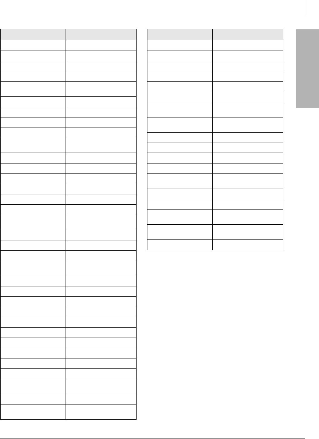
Feature or Topic Program Number
Account Codes 15, 70, 39, 69, 30, 60
ACD
03, 09, *09, 10-4, 11,
14-0, 14-1, *14-1, 14-2, *14-2,
14-3, 14-4, 14-5, 14-6, 14-8, 14-
9, 14-71, 14-72, 14-73, 15, 17,
18, 35, 39, 71-1~3
Add-on Module *29
Alarm Sensor 39
All Call Voice Page 05, 10-2, 31, 39
Alert Signal 39
Alternate Point Answer 10-1
Amplified Conference
(External) 10-2, 10-3
ANI 10-3, 20, 39, *51, *52, 59, 60-1,
71-0~5), 72, 77-4
Attendant Console 03, 58-1, 58-2, 58-4, 58-5, 59
Auto Attendant (Built-in) 09, 10-3, 23~26, 78, 81~89
Automatic Busy Redial (ABR) 10-1, 16, 30, 39
Automatic Callback 05, 39, 10-2
Automatic Hold 35
Automatic Hold Recall 34
Automatic PCB Recognition 91
Automatic Preference 32
Automatic Release Hold/VM
Port 15
Background Music 05, 10-2, 19, 39
Busy Override 05, 31
Busy Station Transfer/Ringing 35
Cabinet Type Identification *03
Call Blocking (VM Ports) 31
Call Forward Blocking with
Handsfree 35
Call Forward External 05, 12, 15, 41, 60-8
Call Forward Station Ring
(ground/loop start lines) *80
Call Forwarding (all types) 10-2, 36, 39, 40
Call Park Orbits *05, *37, 39, 58-4, 59
Call Pickup 10-1, *15, *31, 39
Call Transfer with Camp-on 10-1
Caller ID 03, 10-3, 20, 39, *50, *51, *52,
59, 60-1, 77-4, (DK 14 only: 76-1,
76-2)
Camp-on 10-2, 31, *34, 37
Centrex/PBX Compatible 42-0, 42-1~8, *45
Centrex Ringing Repeat 10-1
CO/Centrex/PBX Feature
Buttons 39, 42-0, 42-1~8
CO Line Access 39, 40, 41
CO Line Alpha Identification 93
CO Line Groups 16
CO Line Reseize Guard Time 10-1, 42-0
CO Line Queuing 05, 16
CO Line Ringing 78, *80, 81~89, *81, *84, *87
Conferencing 10-1, 10-2, 10-3,15
Credit Card Calls (0 + dialing) 43, 60-7
Data Port/DIU Configuration 20, 21, 22, 39
DAY/NIGHT Mode 10-2, 78, 81~89, *80, *81, *84,
*87
Delayed Ringing *80, 82, 83, 85, 86, 88, 89
Digital Telephone 03, 27, 30, 38, 39, 80, 92-5
Direct Inward Dialing (DID) *09, 15, 17, *17, 30, 71, 72
Direct Inward System Access
(DISA) 15, 10-1, 60, 78
Direct Station Selection
Buttons 29-1~29-8, 39
Directory Number 04, *04, *33, 39, 71-(0-3), *71,
*72, *73, 79, *79, 81-89, *81, *84,
*87
Directory Number Buttons 39
DISA Code Revision 04, 05, 30, 40, 41
Distinctive Station Ringing 10-2, 80
Distributed Hunt *04, 33, *40, 71-(0-3), 81-89, *81,
*84, *87
DKAdmin 77-1
Feature or Topic Program Number
Alphabetical Program Listing
This alphabetical program listing gives you features/topics and the corresponding Strata DK
program numbers that relate to the topic
Overview
Alphabetical Program Listing
1-8 Strata DK Programming 5/99
DNIS 12, 17, 20, 60-1, 71-(0-5), 72,
77-4
Do Not Disturb 39
Do Not Disturb Override 05, 30
Door Lock Control 39, 77-1, 77-2
Door Phones 05, 77-1, 77-2, 79, *79
DSS Console Features 03, 28, 29-1~29-8, 10-2
DSS DKT/EKT 28
DTMF and Dial Pulse
Assignments 10-1, 15, 30, 39
DTMF Receiver (QRCU3,
K5RCU, RRCS) Operation 03, 12, 15
DTMF Signal Time, CO lines
(80/160 ms) 10-1
DTMF Signal Time, VM Ports
(80/160 ms) 10-2
DTMF Tone/No Tone/Padded
Tone Return 10-2
DTMF Continuous Tone
(2000-series DKT) 35
Emergency Numbers 44-91~93
Enhanced 911 (E911) *11-0, *11-1, *11-2, *11-5, *11-6,
*11-8, *12, *13
Exclusive Hold 10-1
Executive Override 05, 10-2, 30
External Page Interface 10-2, 77-1, 77-3, 78
External Zone Paging 05, 77-1, 77-3
Fixed Call Forwarding 36, 39
Flash Key Assignment 39
Flash Timing 12
Flexible Access Code
Numbering 05, *05
Flexible Button Assignments 38, 39
Flexible Directory Numbering 04, *04, 05, 39
Flexible Line Ringing
Assignment 81~89
Flexible PCB Slot
Configuration 91-9, 91-1, 03
Forced and Voluntary Account
Codes 15, 30, 60, 39
Group Paging 05, *30
Group Pickup *31
Feature or Topic Program Number
HMIS
03, 50-1, 50-2, 50-3, 50-4, 50-5,
50-6, 51, 52, 53, 54, 55-0, 55-1/2,
56, 60-2,
60-3, 76-1
ISDN
10-1, 10-4, 16, *16, *42-1, *42-2,
*43-1~3, *44, *60, *61, *62, *63,
*64-1, *64-2, *65, *66-1~7, *67-
1~4, *68-1, *68-2, *69-1, *69-2
Handsfree Answerback 17, 31
Hold/Park Recall Timing 34
Hunting, Station 10-2, 22, 33
Immediate Transfer with Soft
Key 10-2
Initialization (system
programs) 91-9, 91-1, 90
Initialization (system/personal
memory) 91-9, 92
Keystrips 38
Least Cost Routing *45-2, *45-3, *45-4, 50~56
Liquid Crystal Display
Features 10-2, 35, 39
Logical Port Display/Change 01
RAM Memory Test 00 (Part 2)
Message Center 13, *32
Message Waiting/Flash 05, 10-2, 12, 35, 39
Microphone Control 30, 39
Modem Pool Port Assignment 20, 21
Music-on-Hold 77-1
Night Pickup Code 05
Night Ringing over External
Page 77-1, 77-3, 78
Night Transfer 29, 39, 59, 77-1, 78
Night Transfer Lock *36, 39, 59, 74
Off-hook Call Announce 03, 30, 31, 39
On-hook Dialing 32
Outgoing Call Restriction 41
Paging-DKT/EKT (Also see
Group Paging and External
Paging) 31, 39
Passwords-Remote
Programming 00
Pause Timing 12, 39
PBX Access Code 42-1~42-8
PBX Backup 42-0
Feature or Topic Program Number
Overview
Alphabetical Program Listing
Strata DK Programming 5/99 1-9
Overview
Physical Port Display/Change 02
Pooled CO Lines 16, 39
Pooled Line Buttons 16, 39
Pooled Line LED – No Flash 31
Port/Station Number
Assignment 04
Privacy/Non-Privacy 31, 30, 39
Privacy Override 10-2, 30, 31
RAM Test (see Memory Test) 00 (Part 2)
Redial Last Number 39
Remote Administration and
Maintenance 00, 03, *09, 77-1, 78
Repeat Last Number Dialed 39
Ring Transfer 10-1, 37
Ringing Repeat 10-1
Ring Tones 80
Ring Flash Assignments *71~*73, 81~89, *81, *84, *87
Ringing Line Preference 32, 81~89
RS-232 Interface 03, (41, 42, 43, 49), 20, 76, 77-1,
77-4
Saved Number Redial 39
Security Code (CF-EXT.) 60-8
Security Code (DISA) 05, 30, 60-6
Security Code (R.
Maintenance) 00
Slot Assignment 03
Software Version 00
Speakerphone Assignment 30
Speed Dial 10-1, 30, 39
Speed Dial Clear 92
Speed Dial Entry Timeout 10-3
Standard Telephone Options 10-2, 30, *34, 35
Station Class of Service 30, 31, *34, 35
Station Hunting (Data Calls) 22
Station Hunting (Voice Calls) 33
Station Message Detail
Recording (SMDR) 03, 60-1~60-7, 76, 97
Station-to-Station Volume 10-1
SMDI VM Interface 03, 10-2, 10-3, 13, 31, *32, *40,
76
Feature or Topic Program Number
T1 Assignments *41, *42
Tandem CO Line Connections 10-1, 15
Tenant Service *15, *36, 39, 77-3, 74
Tie Lines 03, 04, 15, 17, 30, 37, 71, 72
Toll Restriction 10-1, 30, 35, 41~48, *45-1~3
Toll Restriction Override 10-1
Toll Restriction Override Code
Revision 30
Toshiba Proprietary VM
Interface 03, 10-2, 13, *32
Transfer Privacy 10-1
Traveling Class 44-1~8
Traveling Class Code Revision 30
Verifiable Account Codes 15, 30, 39, 60, 69, 70
Verifiable Account Codes
Revision 30
Voice Mail Interface 10-2, 31, 33, 39
Voice or Tone Signaling 05, 10-1, 10-2
Volume Reset (Digital
Telephones) 92-5
Volume Set (Digital
Telephones) 27
Voluntary Account Codes 39
Feature or Topic Program Number
Overview
How to Program a Strata DK System
1-10 Strata DK Programming 5/99
How to Program a Strata DK System
Fill out the record sheets that are provided, then enter this data using a 20-button LCD digital
(DKT) or electronic (EKT) telephone. Strata DK enables you to enter data from an on-site or off-
site PC with Toshiba DKAdmin software. Toshiba highly recommends this easier method of
programming.
DK14/DK40i: the programming telephone must be any 20-button LCD DKT (or EKT, DK40i
only). The DKT must be connected to a Base KSU, PDKU, RDSU, QCDU, or KCDU digital port.
An EKT must be connected to a PEKU port.
DK424: the programming telephone must be a 20-button LCD DKT or EKT connected to circuit 6
of a PDKU or PEKU installed in cabinet slot 11 and/or slot 12.
Note Telephones connected to an RDSU or PESU cannot be used to program DK424.
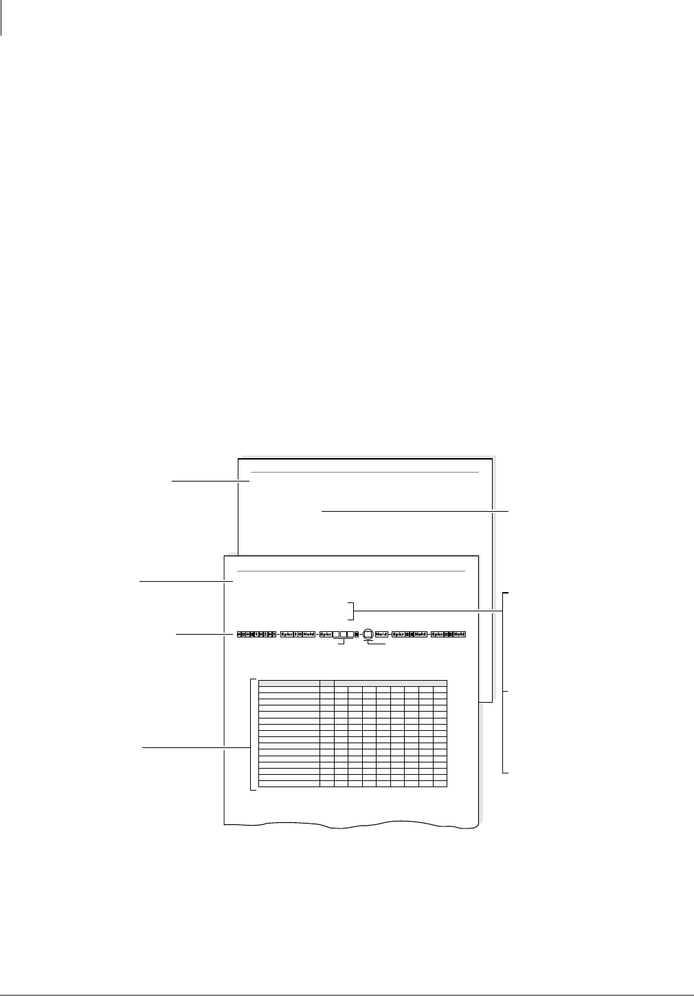
Programming Section Layout
Each programming section within a chapter begins with the program’s number and title, followed
by processor and program type, initialized default, program sequence, then record sheets. A
program overview and additional program information are given after the record sheets
(see Figure 1-1).
Note Some common program sections also include examples for your convenience.
Program 30 Overview
Program 30 Station Class of Service
System Programs
Program 30 enables or disables features for individual telephones at the station level. The following text
describes Program 30 LEDs.
Privacy Override, LED 19
With Privacy Override enabled (LED 19 ON), a station can override calls and listen to a CO line
conversation by pressing a common CO line button (not a [DN] button). You can set a warning tone for
Privacy Override (see Program 10-2).
SELECT = Station Logical Port Number(s) Buttons/LEDs
Light LEDs for the port specified in the
last step. All LEDs marked with an “X”
in the table below should be lit.
2174
Feature LED
20
19
18
17
16
15
14
13
12
11
10
09
08
07
06
05
Port
Processor Type: DK14/DK40/DK424
Program Type: System
Initialized Default: LEDs 01, 05 and 07 for all ports
Program 30
Station Class of Service
Program 30 Station Class of Service
System Programs
Number/Title
Program Sequence
Record Sheet
Program Overview
Additional Program
Information
Processor Type
Program Type
Gives the type of processor that is
compatible with the given program.
Be sure to read this information
before attempting to use a program
with your system application.
Type of function the program
performs. Can be: Initialization,
Test System, Station, Toll
Restriction or Least Cost Routing.
Default configuration set by
Program 91-9 “System
Initialization” when the system is
first installed or re-initialized.
Additional details on the program
features that were given on the
system record sheet.
Keystrokes for entering data
from system record sheets
follow a pattern, consisting of a
five-step process described and
illustrated in “Program
Sequence” on Page 1-13.
Provides a list of available
features. The sheet is used to
record the assignment of
features or the operation of each
program. Each sheet provides
space to record data. This data
will be referred to when
programming the system.
Brief description of program
function(s).
Initialized Default
Figure 1-1 System Record Sheet Sample
Overview
How to Program a Strata DK System
Strata DK Programming 5/99 1-11
Overview
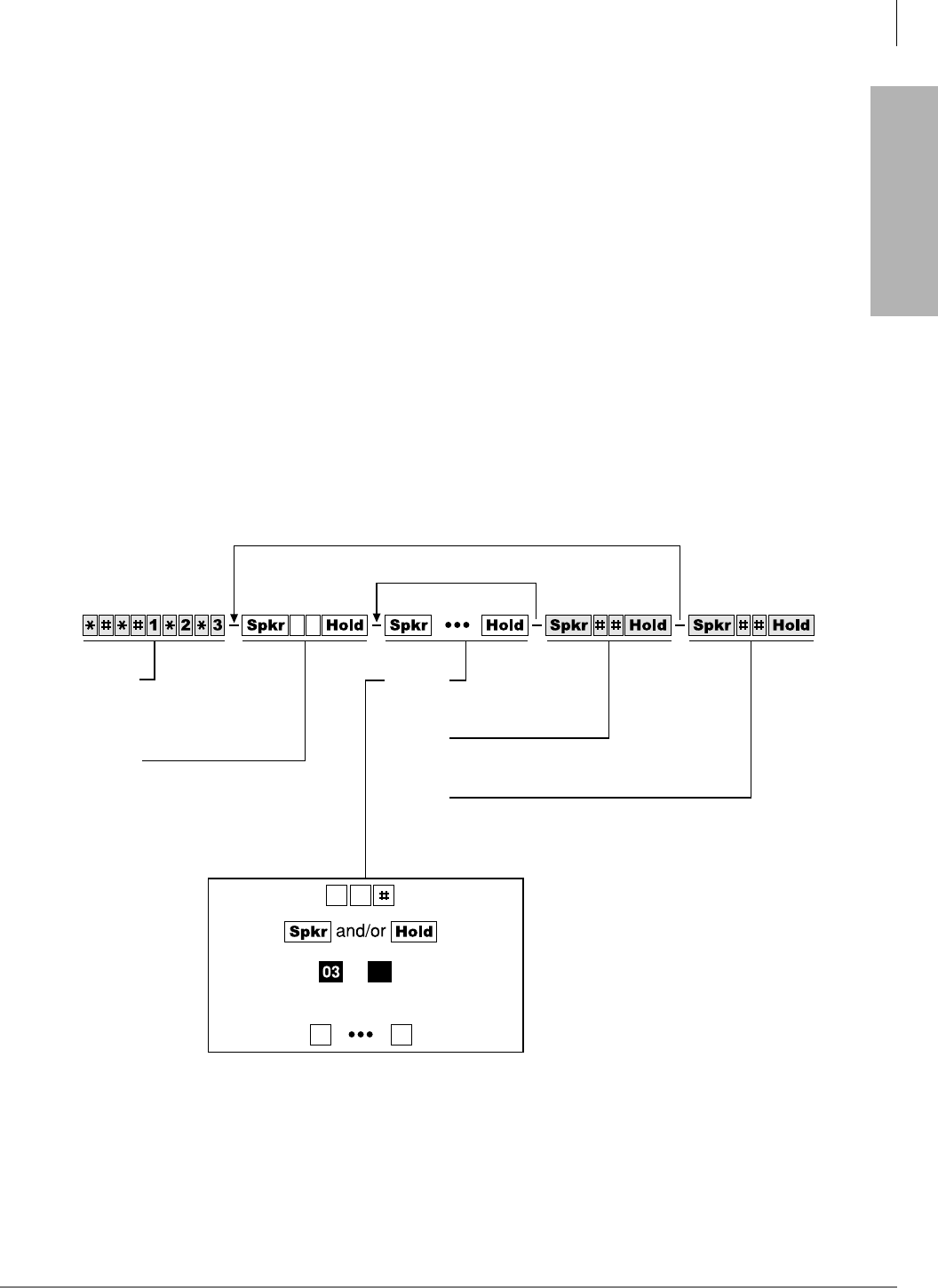
Program Sequence
Detailed data entry instructions are on the top of each record sheet (see Figure 1-2).
➤To use the program sequence on the record sheet
1. From the programming telephone, enter the programming mode by pressing a series of shaded
buttons. The shaded buttons represent the entry sequence for all programs.
2. Enter the program number. This sequence is unique for every program. The buttons are white
on every record sheet.
3. Enter the program data. Again, this sequence is unique for every program. The buttons are
white on every record sheet. To make another entry, repeat this step until ready to exit the
current program.
4. Exit the current program. This sequence never changes, and the buttons are always shaded.
Upon exiting the current program, repeat Step 2 to enter another program, or continue with
Step 5 to exit the programming mode entirely.
5. Exit the programming mode by pressing the same button sequence as in Step 4. This sequence
also never changes and is always shaded.
More Data
Another Program
Step 1
Enter Program Mode
(Do not press or [DN] button)
Step 2
Enter Program Number
Step 3
Enter Program Data
Step 4
Exit Current Program
Step 5
Exit Program Mode
and/or
(LED Buttons)or
1697
Figure 1-2 Programming Button Sequence Overview

Overview
How to Program a Strata DK System
1-12 Strata DK Programming 5/99
Programming Data Variations
There are two different ways to enter data in Step 3 (Figure 1-2) of a program: pressing the buttons
on the dial pad and pressing the LED buttons. Many programs are multidimensional and involve
both types of entry.
Simple Programs
Simple programs such as Program 00, only require data to be specified through the dial pad. Data
entered from the dial pad displays on the programming digital or electronic telephone’s LCD,
along with prompts and confirmations.
Multidimensional Programs
Once a program number is entered, the first dimension (usually a CO line number, a station port
number, or a range of ports) must be specified. Upon specifying this first dimension on the dial
pad, programming button LEDs 01~20 light in the default configuration.
The status of each LED can be changed by pressing its associated button. Pressing the button while
its LED is lit turns the LED OFF; pressing the button while its LED is OFF turns the LED ON. An
example of multidimensional programming is Program 30.
Range Programming
Data can be entered for a range of stations, [DN] reference ports and CO lines with some
programs.
➤To enter a range
➤Enter a “” between the starting point of a range and the ending point of a range.
For example, to program the station range of 001~010 for Program 35, press .
♦When programming a range of station ports, the station’s programming LEDs indicate
whether the data programmed matches for all items in the range:
♦LED ON: Indicates that all ports in the range are programmed with the data choice that
lights the particular LED.
♦LED OFF: Indicates that all ports in the range are programmed with the data choice that
does not light the particular LED.
♦LED Flashing: Indicates that data is currently inconsistent for all ports in the range. Some
may be programmed with the LED ON; some with the LED OFF.
CO Line Programming
Since the programming telephone only has 20 buttons, data can only be entered for 20 CO lines at
a time.
➤To program another range
➤Press the 3DJH or 6FUROO button below the LCD.
For example, to change from one range to another in Program 15, enter the program code, then
press 6FUROO to advance or 3DJH to go back to another range.
If the programming telephone is a digital telephone, all CO lines within a range can be
activated or deactivated for a feature by pressing the 9RO▲/9RO ▼ buttons.
➤Press 9RO▲ to turn all LEDs ON; press 9RO ▼ button to turn all LEDs OFF.
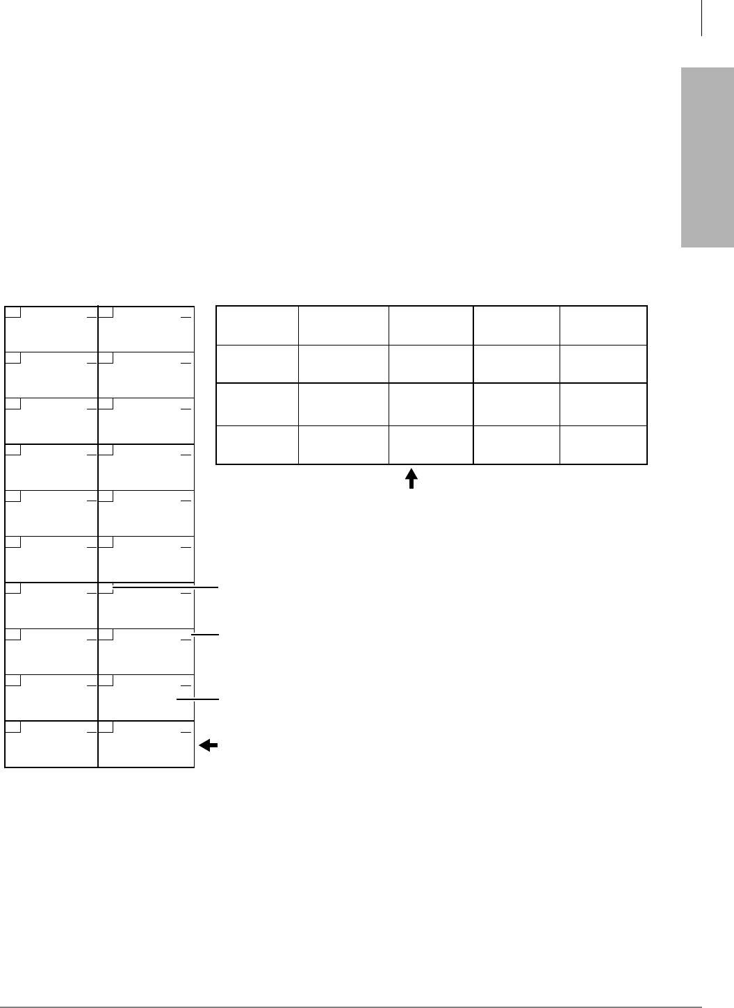
Overview
How to Program a Strata DK System
Strata DK Programming 5/99 1-13
Overview
➤To check the status of a CO line in Program 15
1. Press the 0RGH button (below the LCD) after entering the program code.
2. Then enter the CO line number to be verified.
3. Press to display the status of the CO line and to advance to the next CO line.
Programming LED Buttons Keystrip Template
You place a special buttonstrip template (see Figure 1-3) over the 20 flexible feature buttons of the
programming telephone. The template assigns a series of numbers to each of the 20 buttons that
correspond with tables found on the record sheets for programming purposes.
Since each button represents more than one CO line, depending on the CO line range selected, the
template assigns more than one number to each button.
10 20
09 19
08 18
07 17
06 16
05 15
04 14
03 13
02 12
01 11
9
8
7
6
5
4
3
2
1
0
9
8
7
6
5
4
3
2
1
0
1843
LED Buttons and CO line numbers (01~20)
CO line numbers (21~200)
Last digit of EK port number for
programs with a format like *71, *72, and *73
2000-series digital telephone strip - supplied with each
Strata DK
Programming Manual
and each Documentation Package that ships with the
system. Can also be used with 6000- and 6500-series electronic telephones.
1000-series digital telephone strip - shows programming button/LED
assignment locations. Shown as reference only - not available as an
individual strip.
29, 49, 69
89, 109, 129,
149, 169, 189
28, 48, 68
88, 108, 128,
148, 168, 188
27, 47, 67
87, 107, 127,
147, 167, 187
26, 46, 66
86, 106, 126,
146, 166, 186
25, 45, 65
85, 105, 125,
145, 165, 185
24, 44, 64
84, 104, 124,
144, 164, 184
23, 43, 63
83, 103, 123,
143, 163, 183
22, 42, 62
82, 102, 122,
142, 162, 182
21, 41, 61
81, 101, 121,
141, 161, 181
40, 60, 80
100, 120, 140,
160, 180, 200
39, 59, 79
99, 119, 139,
159, 179, 199
38, 58, 78
98, 118, 138,
158, 178, 198
37, 57, 77
97, 117, 137,
157, 177, 197
36, 56, 76
96, 116, 136,
156, 176, 196
35, 55, 75
95, 115, 135,
155, 175, 195
34, 54, 74
94, 114, 134,
154, 174, 194
33, 53, 73
93, 113, 133,
153, 173, 193
32, 52, 72
92, 112, 132,
152, 172, 192
31, 51, 71
91, 111, 131,
151, 171, 191
30, 50, 70
90, 110, 130,
150, 170, 190
01, 21, 41, 61
81, 101, 121,
141, 161, 181
02, 22, 42, 62
82, 102, 122,
142, 162, 182
06, 26, 46, 66
86, 106, 126,
146, 166, 186
07, 27, 47, 67
87, 107, 127,
147, 167, 187
11, 31, 51, 71
91, 111, 131,
151, 171, 191
12, 32, 52, 72
92 112, 132,
152, 172, 192
16, 36, 56, 76
96, 116, 136,
156, 176, 196
17, 37, 57, 77
97, 117, 137,
157, 177, 197
03, 23, 43, 63
83, 103, 123,
143, 163, 183
04, 24, 44, 64
84, 104, 124,
144, 164, 184
08, 28, 48, 68
88, 108, 128,
148, 168, 188
09, 29, 49, 69
89, 109, 129,
149, 169, 189
13, 33, 53, 73
93, 113, 133,
153, 173, 193
14, 34, 54, 74
94, 114, 134,
154, 174, 194
18, 38, 58, 78
98, 118, 138,
158, 178, 198
19, 39, 59, 79
99, 119, 139,
159, 179, 199
05, 25, 45, 65
85, 105, 125,
145, 165, 185
10, 30, 50, 70
90, 110, 130,
150, 170, 190
15, 35, 55, 75
95, 115, 135,
155, 175, 195
20, 40, 60, 80
100, 120, 140,
160, 180, 200
Figure 1-3 LED Buttons Programming Keystrips

Overview
First-time Programming
1-14 Strata DK Programming 5/99
First-time Programming
Follow these general procedures the first time you install a system or after major hardware changes
and/or you need to start from scratch.
Step 1: Check Minimum Hardware Requirements
A system must have the following minimum hardware installed for programming, as described in
the Installation chapters of the Strata DK Installation and Maintenance Manual.
➤To check hardware requirements on the DK14 and DK40i
1. Make sure the base cabinet power supply was tested and is functional.
2. Make sure a 20-button digital LCD DKT telephone (equipped with a programming template)
is connected to any digital telephone circuit (Base KSU, PDKU, QCDU, KCDU or RDSU
digital port); or make sure that a 20-button electronic LCD EKT telephone is connected to a
PEKU electronic port (not PESU).
♦DK14 and DK40i: make sure the Base KSU’s BATT jumper is in the ON position.
➤To check hardware requirements on the DK424
1. Make sure the base cabinet power supply was tested and is functional.
2. If using an RCTUE/F, remove the small jumper PCB (MBJU) from the front side of the
DK424 base unit backplane (between slot R11 and the RCTU slot. All other RCTUs require
the MBJU PCB.
3. Make sure an RCTUA, RCTUBA, RCTUC/D or RCTUF is installed and that its BATT jumper
is in the ON position.
4. Make sure a PDKU or PEKU, is installed in Slot S11 or S12 in the base cabinet (S11 if RSIU
is not installed, S12 if RSIU is installed in S11).
5. Make sure a 20-button LCD DKT or EKT telephone (equipped with programming template) is
connected to physical port 005 and/or port 013 (PDKU or PEKU - circuit 6/slot 11 and/or
circuit 6/slot 12). Do not use RDSU or PESU.
Step 2: Initialize the System
1. From a 20-button LCD programming telephone, or from DKAdmin on a PC, run Program 91–
9 twice in succession to initialize the system. At this point it is not necessary that all PCBs are
installed. However, if they are, Program 03 codes are automatically assigned to the appropriate
slots.
CAUTION! If you run Program 91-9 while the system is in service, all program data is
erased and all calls are dropped.
Program 91-9 sets the following elements to initial default status:
♦Data for Programs 00~*99
♦Speed Dial Memory
♦Logical/Physical Port Locations
♦Voice Mail Identification Codes
♦Character Message Memory

Overview
First-time Programming
Strata DK Programming 5/99 1-15
Overview
♦Timed Reminders
♦Digital Telephone Volume Levels
♦Call Forward Memory (Power OFF, then ON).
♦Station Message Waiting Status
♦Caller ID Lost Call Memory
2. Install all PCBs. Run Program 91-1 to inform the software of the system hardware
configuration.
Step 3: Run Programs 03 and 19-1
1. Run Program 03 for all PCBs that have options.
2. Run Program 19-1 to inform the software of the system option Alternate BGM slot.
Step 4: Run Program 00
➤Run Program 00 - Part 1 to assign remote maintenance security codes. Run Program 00 - Part
2 to test the processor and RAM.
Step 5: Set Date, Time and Day
You can set date, time and day anytime - individually or all.
1. Use DKT or EKT assigned to logical Port 000 or attendant console.
2. Make sure the handset is on-hook.
3. Set the date:
4. Set the time:
5. Set the day:
Step 6: Run Additional Programs as Required
[PDN] #651 5HGLDO
[PDN] #652 5HGLDO
[PDN] #653 5HGLDO
Date in year/month/day format
(YYMMDD). If month or day is
single digit, precede with a zero.
Time in hours/minutes/seconds format (HHMMSS
from 000000 to 235959). If any of these values is
single digit, precede with a zero.
Enter the digit for today’s day:
= Sunday
= Monday
= Tuesday
= Wednesday
= Thursday
= Friday
= Saturday
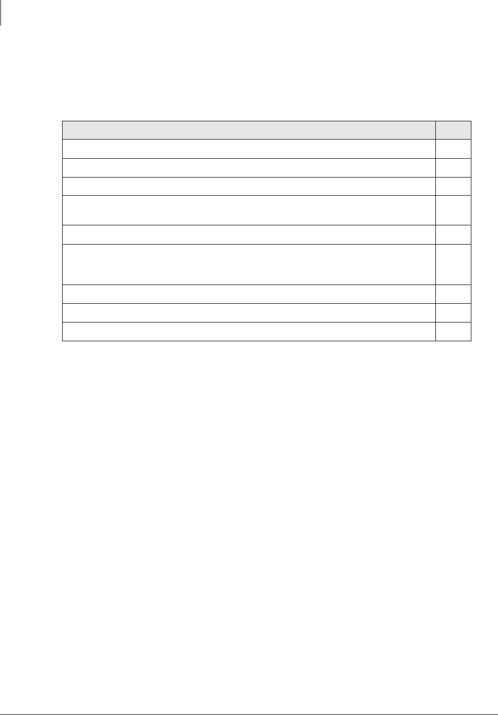
Overview
Programming Examples
1-16 Strata DK Programming 5/99
Programming Examples
Some commonly used programs have explicit examples (listed below). Refer to these pages to
help familiarize you with running these programs.
Program Page
Program 91-9—System Initialization 2-2
Program 90—Initializing Programs 00~*99 2-4
Program 91-1—Automatic PCB Recognition and Logical/Physical Port Initialization 2-6
Program 92—Initializing Speed Dial Numbers, VM ID Codes, Character Message Memory,
Timed Reminders, Digital Telephone Volume, and Call Forward Backup Memory 2-9
Program 00—Software Check 2-12
Program 03—DK14 Slot Assignments and DK14/DK424 Flexible PCB Slot Assignments 3-3,
3-4,
3-6
Program 04—Station Logical Port Primary Directory Intercom or Number Assignment 3-12
Program 30—Station Class of Service 3-73
Program 33—Station Hunting 3-90

Strata DK Programming 5/99 2-1
Initialization & Test
Initialization & Test 2
This chapter gives you information on the Strata DK’s Initialization and Test programs. The
programs in this chapter are not given in numerical order, rather in order of importance. These
programs include:
♦Program 91-9 – System Initialization
♦Program 90 – Initialize Programs 00~99
♦Program 91-1 – Automatic PCB Recognition and Port Renumber
♦Program 91-2 – Data Transfer from Temporary Memory to Working Memory
♦Program 92 – Initializing Misc. Backup RAM
♦Program 00 – Part 1: Software Check
♦Program 00 – Part 2: RCTU RAM Test
Examples are also given for these programs - except Programs 91-2 and Program 00 - Part 2.
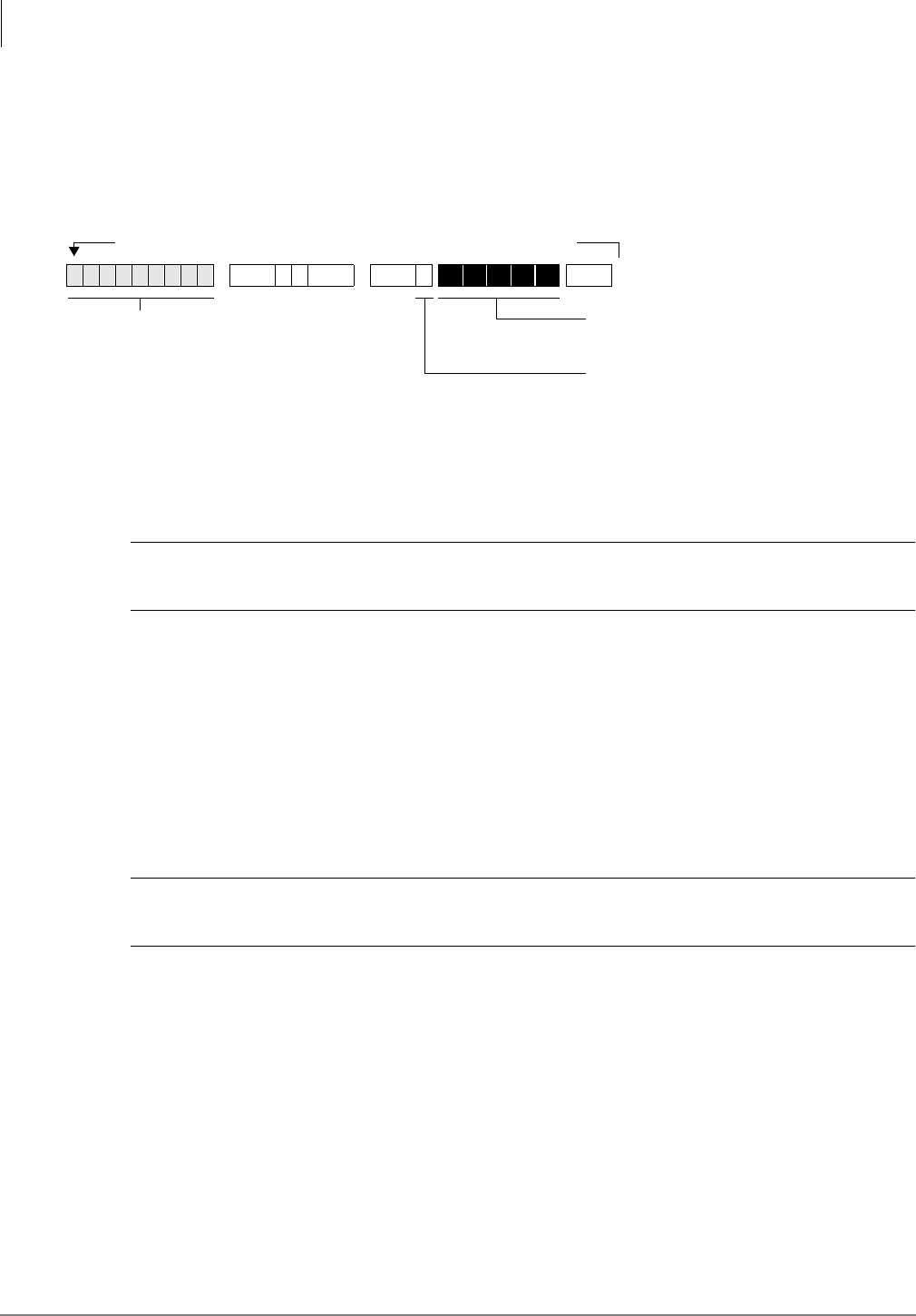
Initialization & Test
Program 91-9 – System Initialization
2-2 Strata DK Programming 5/99
Program 91-9 – System Initialization
Processor Type:
DK14, DK40i, All RCTUs
Program Type:
Initialization
Initialized Default:
See individual programs
Program 91-9 Overview
Note Always run Program 91-9 before entering the customer database when first installing a
system or when its software must be set to the default configuration, but not while system
is in service.
CAUTION! If you run Program 91-9 while the system is in service, it will erase all program
data and drop all calls.
Running Program 91-9 also runs Program 03 and assigns codes to all PCBs (except options)
installed. It also erases all Program 03 option codes for piggyback PCBs, DSS consoles, RRCS,
etc., except the RCOS PCB Code (17).
Program 91-9 erases all random or programmed data in all Strata DK software programs and sets
all program data to the default value. It automatically runs all other initialization Programs 90-
00~99, 91-1, and 92-1~9. It also brings back logical and physical ports to their initialized
settings.
If you are installing the system processor(s) for the first time, after initializing the system, test the
RAM: run Program 00 Part 2.
CAUTION! Running Program 00 Part 2 drops all calls in progress and interrupts telephone
service for 15 seconds. This test will not erase programmed customer data.
Important! Do not use Program 91-9 if you are only making minor programming changes and
system programming is basically correct.
Note Run Program 03 after Program 91-9 for: PCBs with options such as Dual-tone
Multi-frequency Receivers K5RCU, QRCU3, RRCS, and DSS consoles, etc.
...or if entering a customer database into system RAM memory before other system
PCBs (stations, lines, options) are installed. Program 03 identifies which universal and
option PCBs (e.g., RRCS, etc.) are to be installed in each cabinet slot.
6SNU +ROG 6SNU +ROG Program Telephone Exits Program Mode
Repeat a second time after LEDs 01, 03, 05, 07, and 09 extinguish.
Enter programming mode.
(Do not press [DN] button.)
Press Buttons 01, 03, 05, 07, and 09.
LEDs 01, 03, 05, 07, and 09 must be ON.
LCD Displays: SYSTEM INITIALIZATION
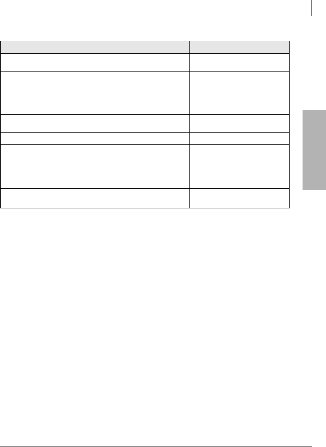
Initialization & Test
Program 91-9 – System Initialization
Strata DK Programming 5/99 2-3
Initialization & Test
Program 91-9 Example
Action (press buttons + LED Buttons) LCD Response
1. Use the programming LCD electronic or digital telephone. (See
“Programming Examples” on Page 1-16.) No. N-N1
Jan 20 Sun 06:43
1. N-N is the Program Telephone [DN].
2.
Enter programming mode. (Do not press [DN] button.) Program Mode
3. 6SNU6SHDNHU+ROG
Access Program 91. System beeps after 6SNU6SHDNHU is
pressed to indicate program number may be entered.
Program = 91
Data Store
4. 6SNU6SHDNHU
Prepare the system for a station port selection. 91 Select =
5. Press System Initialization
6. Press LED Buttons 01, 03, 05, 07, and 09 (LEDs turn ON) System Initialization
7. Press +ROG
The telephone will exit the programming mode and button LEDs 01,
03, 05, 07, and 09 will go out after a short delay. Make sure all LEDs
go out before proceeding to Step 8.
No. N-N
(Month Day Time)
8. Repeat Steps 1~7 a second time. No. N-N
(Month Day Time)

Initialization & Test
Program 90 – Initialize Programs 00~*99
2-4 Strata DK Programming 5/99
Program 90 – Initialize Programs 00~*99
Processor Type:
DK14, DK40i, All RCTUs
Program Type:
Initialization
Initialized Default:
See individual programs
Program 90 Overview
Program 90 enables you to clear all customer data and initialize individual programs or range of
programs.
Important! When installing the system, you must run Program 91-9 which runs Program 90
(before running any other program); if you do not, the system could begin to operate
erratically.
Notes
●Running Program 91-9, automatically runs Program 90.
●To initialize all programs without dropping calls or erasing user names, speed dial numbers,
voice mail ID codes, etc., enter as “Programs to be initialized.”
●Each “*” program record sheet immediately follows the program record sheet having the same
number (example: *31 follows 31 record sheet). However, in system memory all “*” programs
follow Program 99. Therefore, “” program ranges must be initialized separately from non-
star programs unless initializing all system Programs (00**99).
For example, to initialize Programs 30, *30, 31, *31, and 32: initialize the range (30*32), for
Programs 30, 31, 32; and the range (*30**31), for Programs *30 and *31.
●If you are installing the system for the first time, run Program 91-9 to erase random data from
RAM (caused by battery jumper movement to the internal battery). You can then skip Program
90, since Program 91-9 automatically runs Program 90.
6SNU +ROG 6SNU +ROG 6SNU +ROG 6SNU +ROG
Enter programming
mode
Press LED Buttons 01 and 02
LEDs 01 and 02 must be ON
Programs to be initialized. Add
a range of program numbers
by entering XX*XX or XX**XX.
Exit programming modeEnd Program 90
LEDs 01 and 02 must flash
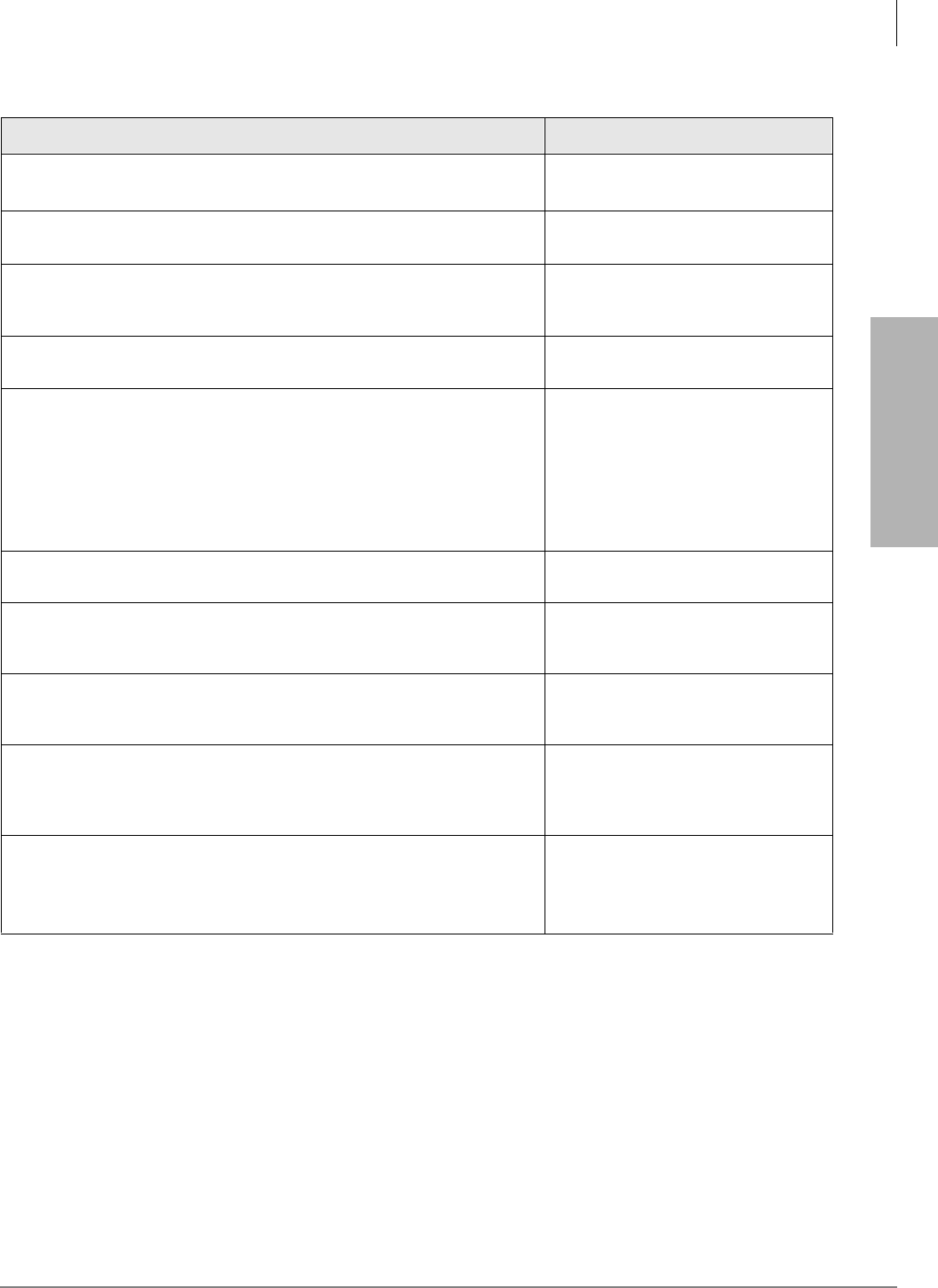
Initialization & Test
Program 90 – Initialize Programs 00~*99
Strata DK Programming 5/99 2-5
Initialization & Test
Program 90 Example
Action LCD Response
1. Use the LCD programming phone per Minimum Hardware
Requirements on -14.No. N-N1
Jan 20 Sun 06:43
1. N-N is the Program Telephone [DN].
2. Enter Program mode by pressing (Do not press
[DN] button.) Program Mode
3. 6SNU6SHDNHU+ROG
Access Program 90. System beeps after 6SNU6SHDNHU is
pressed to indicate program number may be entered.
Program = 90
Data Store
4. 6SNU6SHDNHU
Prepare the system for the programs to be initialized. 90 Select =
5. + LED buttons 01 & 02
Enter Program numbers individually, followed by #, or in a range. For a
range, separate the low program number and the high program
number with an asterisk.
initializes all Programs 00~99.
Star Program memory follows Program 97.
90 Select = 00**99
Data Clr
6. +ROG
Secure data in system programming. LEDs 01 and 02 flash. 90 Select = 00**99
Data Programmed
7. 6SNU6SHDNHU
Prepare system for another selection (go back to Step 5) or exit
Program 90 (continue with Step 8).
90 Select =
8. +ROG
Secure default data in system memory. LED 01 and 02 continue to
flash.
90 Select = ##
Data Programmed
9. 6SNU6SHDNHU
Exit Program 90. Enter another program number (see “Program 92
Example” on Page 2-10) or exit programming mode (go to Step 10).
System beeps to indicate it is exiting Program 90.
Program =
10. +ROG
Exit programming mode.
The system will not allow the 6SNU6SHDNHU LED to light to re-
enter the programming mode.
No. N-N
Jan 20 Sun 06:43

Initialization & Test
Program 91-1 – Automatic PCB Recognition and Port Renumber
2-6 Strata DK Programming 5/99
Program 91-1 – Automatic PCB Recognition and Port
Renumber
Processor Type:
DK14, DK40i, All RCTUs
Program Type:
Initialization
Initialized Default:
None
Program 91-1 Overview
Program 91-1 makes slot code assignments to installed PCBs that do not have options - such as a
PDKU without a Data Interface Unit or Off-hook Call Announce (OCA), the common control
without a Dual-tone Multi-frequency Receiver (RRCS), K5RCU, QRCU3, etc.
Program 91-1 also sets physical and logical ports to their initialized settings - even if you
previously relocated them. (See Program 01 and 02 for initialized settings.). Programs 04, 04, 05,
05, 09, or 71 are not affected.
CAUTION! Running Program 91-1 drops all calls.
Important! To identify Program 03 PCB slot codes, run Program 91-1 after you install all
PCBs.
Notes
●You can run Program 91-1 after setting PCB option codes with Program 03; this does not erase
option codes. For example, if Slot 00 is assigned code 92, Program 91-1 will not erase the
codes previously assigned with Program 03.
●If you install PCBs before initializing the system with Program 91-9, it is not necessary to run
Program 91-1 to assign the Program 03 PCB slot codes for the installed PCBs. You must
always run Program 03 to identify PCB options such as K5RCU, QRCU3, and RRCS codes
92, 93 and 94 and PDKU codes 61, 62, and 64, etc.
6SNU +ROG 6SNU +ROG Program Telephone Exits Program Mode
Enter programming mode.
(Do not press [DN] button.)
Press LED Buttons 01 and 02.
LEDs 01 and 02 must be ON.
LCD Displays:91 SELECT = 1
Renumber and Reset

Initialization & Test
Program 91-1 – Automatic PCB Recognition and Port Renumber
Strata DK Programming 5/99 2-7
Initialization & Test
Program 91-1 Example
Action (press buttons + LED Buttons) LCD Response
1. Use the LCD programming phone per Minimum Hardware
Requirements on -14.No. N-N1
Jan 20 Sun 06:43
1. N-N is the Program Telephone [DN].
2.
Enter programming mode. (Do not press [DN] button.) Program Mode
3. 6SNU6SHDNHU+ROG
Access Program 91. System beeps after 6SNU6SHDNHU is
pressed to indicate program number may be entered.
Program = 91
Data Store
4. 6SNU6SHDNHU
Prepare the system for a station port selection. 91 Select =
5. Press 91 Select = 1
Renumber and Reset
6. Press LED Buttons 01 and 02 (LEDs turn ON) 91 Select = 1
Renumber and Reset
7. Press +ROG
The telephone will exit the programming mode and button LEDs 01
and 02 will go out after a short delay.
No. N-N
(Month Day Time)
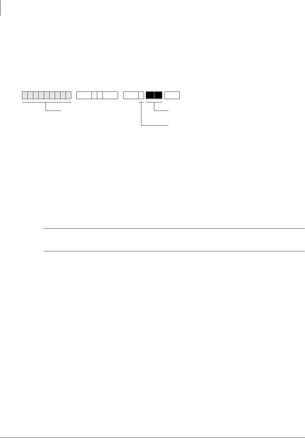
Initialization & Test
Program 91-2 – Data Transfer from Temporary Memory to Working Memory
2-8 Strata DK Programming 5/99
Program 91-2 – Data Transfer from Temporary Memory
to Working Memory
Processor Type:
DK14, DK40i, All RCTUs
Program Type:
Initialization
Initialized Default:
See individual programs
Program 91-2 Overview
Program 91-2 simulates turning system power OFF for five seconds then ON to transfer data from
temporary memory to working memory.
This power OFF / power ON sequence is required when programming with a telephone or when
using DK Admin/DK Backup. In these cases Program 03, 41-2, 50 and 76-1 data must be
transferred from temporary to working memory.
Program 91-2 does not change or erase any programmed data including directory numbers set in
Program 04 and *04 or logical/physical port assignments in Program 01 and 02.
CAUTION! Running Program 91-2 drops all calls and renders the system inoperative for
up to eight seconds.
6SNU +ROG 6SNU +ROG Program Telephone Exits Program Mode and Transfers Data
Enter programming mode.
(Do not press [DN] button.)
Press LED Buttons 03 and 04.
LEDs 03 and 04 must be ON.
LCD Displays:91 SELECT = 2
Programming
Taking Effect
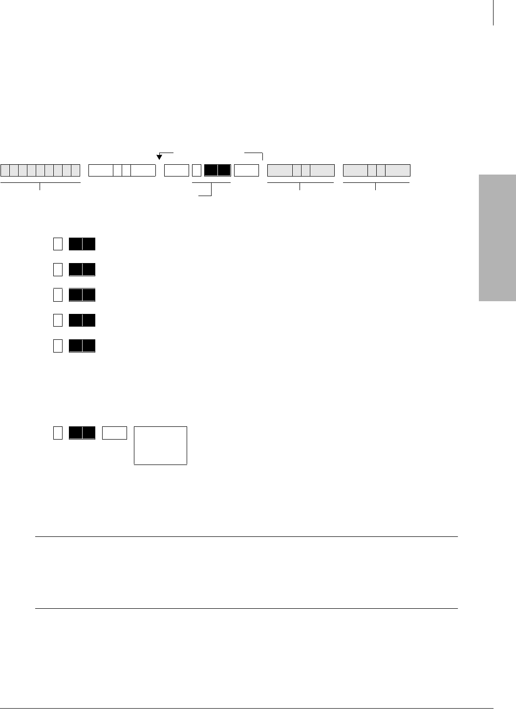
Initialization & Test
Program 92 – Initializing Misc. Backup RAM
Strata DK Programming 5/99 2-9
Initialization & Test
Program 92 – Initializing Misc. Backup RAM
Processor Type:
DK14, DK40i, All RCTUs
Program Type:
Initialization - Includes: Initializing Speed Dial Number, VM ID Codes, Character
Message Memory, Timed Reminders, Digital Telephone Volume, Called ID, ANI, and
Call Forward Backup RAM
Initialized Default:
See individual programs
Program 92 Overview
Program 92 clears all previously entered or random data (of the type listed) but does not clear data
in system Programs 00~99.
CAUTION! You must run Program 92 when first installing the system or an RCTU; if you
do not, the system could begin to operate erratically.
Running Program 91-9 automatically runs Program 92 (1~9) to erase customer
data.
Notes
●Running Program 92-5 does not affect digital telephone handset receiver volume levels. Use
Program 27 to set off-hook handset receiver volume levels for digital telephones.
6SNU +ROG 6SNU +ROG 6SNU +ROG 6SNU +ROG
Clears Station Speed Dial, Voice Mail ID Codes, and LCD memos
assigned to Station Speed Dial numbers.
Clears System Speed Dial and LCD memos assigned to System Speed
Dial numbers.
Clears Character Message Memory (Station and System) and User
Name/Number Display.
Clears Timed Reminders.
Resets digital telephone volume levels to initialized settings, specifically,
speaker volume levels for Internal Calls [DN], Tone/BGM, Busy Override
(muted ring), and Ring volume to approximately mid-range on all DKTs.
Program 92-5 does not affect digital telephone handset receiver volume
levels. Use Program 27 to set off-hook digital telephone handset
receiver volume levels.
+ROG Power OFF 5
seconds; then
Power ON
Clears Call Forward and Message Waiting Memory
(all stations). Program 92-9 does not affect Call
Forward External or Fixed Call Forward settings.
Clear more data
Enter programming
mode.
SELECT = Press appropriate
buttons as shown below.
Exit programming
mode.
End Program 92.

Initialization & Test
Program 92 – Initializing Misc. Backup RAM
2-10 Strata DK Programming 5/99
●Program 92-9 does not affect Call Forward External or Fixed Call Forward settings.
●You must power the system OFF then back ON to clear telephone LCD Call Forward Displays
and Call Forward button LEDs. Call Forward memory is cleared when you run Program 92-9,
even if system power is not cycled.
Program 92 Example
Action (press buttons + LED Buttons) LCD Response
1. Use the programming LCD electronic or digital telephone. (See “Step
1: Check Minimum Hardware Requirements” on Page 1-14.) No. N-N1
Jan 20 Sun 06:43
2.
Enter programming mode. (Do not press [DN] button.) System beeps
after 6SNU6SHDNHU is pressed to indicate program number may
be entered.
Program Mode
3. 6SNU6SHDNHU+ROG
Access Program 92. Program = 92
Data Store
4. 6SNU6SHDNHU
Prepare the system for selection of programs to initialize. For new
system installation perform all 1~4.
92 Select =
5. Select one of the following.
+ LED Buttons 01 & 03
Clears Station Speed Dial, Voice Mail ID codes, and LCD memos
assigned to station speed dial numbers.
92 Select = 1
Each Dial Clr
or...
+ LED Buttons 01 & 04
Clears System Speed Dial and LCD memos assigned to system
speed dial numbers.
92 Select = 2
Common Dial Clr
or...
+ LED Buttons 02 & 03
Clears Character Message Memory (station and system) and user
name display.
92 Select = 3
Msg Clr
or...
+ LED Buttons 02 & 04
Clears timed reminders.
92 Select = 4
Tmr Reminder Clr
or...
+ LED Buttons 01 & 05
Presets the Ring, Speaker, Mute Ring, and Intercom Tone, BGM,
volume levels of all digital telephones to approximately mid-range.
92 Select = 5
DKT VR Initial
or...
+ LED Buttons 03 & 04
Clears Call Forward and Message Waiting (R3) Memory except Fixed
Call Forward Memory.
92 Select = 9
Back Up RAM Clr
6. +ROG
LEDs lit in Step 5 turn off to secure data in system programming.
Repeat Steps 4~6 until Step is completed.
92 Select = (1~0)
Data Programmed
1. N-N is the Program Telephone [DN].
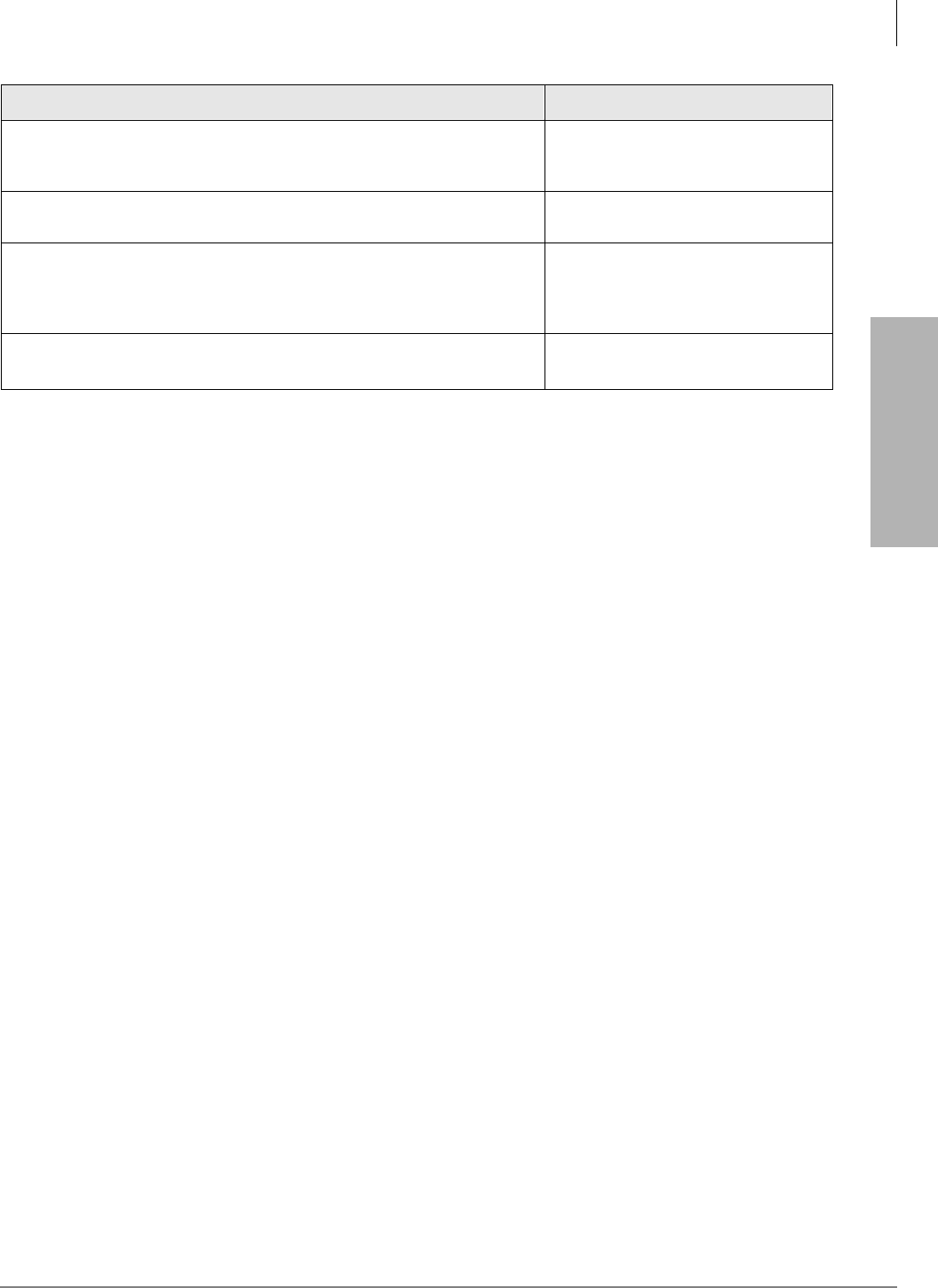
Initialization & Test
Program 92 – Initializing Misc. Backup RAM
Strata DK Programming 5/99 2-11
Initialization & Test
7. 6SNU6SHDNHU
Prepare system for another selection (go back to Step 5) or exit
Program 92 (continue with Step 8).
92 Select =
8. +ROG
Initialized data in system memory (LEDs got out). 92 Select = ##
Data Programmed
9. 6SNU6SHDNHU
Exit Program 92. Enter another program number (see “Program 30 –
Station Class of Service” on Page 3-73) or exit programming mode (go
to Step 10). System beeps to indicate it is exiting Program 92.
Program =
10. +ROG
Exit programming mode. No. N-N
Jan 20 Sun 06:43
Action (press buttons + LED Buttons) LCD Response
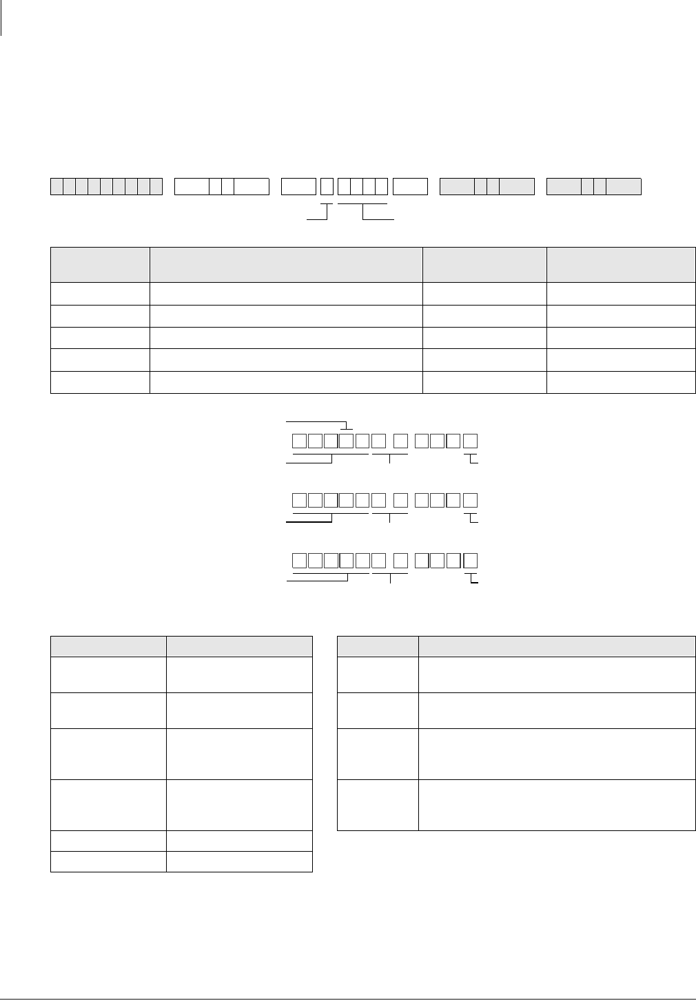
Initialization & Test
Program 00 – Part 1: Software Check
2-12 Strata DK Programming 5/99
Program 00 – Part 1: Software Check
Processor Type:
DK14, DK40i, All RCTUs
Program Type:
Test - Includes: Remote Maintenance Security Code Assignments
Initialized Default:
None
6SNU +ROG 6SNU +ROG6SNU +ROG 6SNU +ROG
Select = Code Item Password or S/W
Check Codes LCD Display
0ROM Version (not programmable) Version =
11st Level Password Password =
22nd Level Password Password =
8Software RAM Checksum (not programmable) Sum =
9Power Cycle Counter (not programmable) Counter =
DKT LCD Display RCTU Type Key Type Description
WMA4 DK14 KEY 1 AA: Indicates built-in Auto Attendant software
(RKYS1, KKYS, or QKYS installed).
TMA4 DK40i KEY 2 ACD: Indicates Automatic Call Distribution
software and AA (RKYS2 installed).
RAA3X RCTUA3 KEY 3 ACD/MIS: Indicates Automatic Call Distribution,
Management Information System Software, plus
AA and ACD (RKYS3 installed).
RBA3X RCTUBA3/RCTUBB3 KEY 4 Open Architecture Interface (OAI) and AA, plus
AA, ACD, and ACD/MIS (RKYS4 R3.2
installed).
RCA3X RCTUC3/D3
REA3X RCTU E3/F3
Select = Code Password Codes (4 digits)
VER=
Indicates RCTU Type
DK424 software
ROM Version X = 1, 2, or 3
1830
RA3X--KEY X
VER=
Indicates DK40i ROM Version Indicates KKYS
installed
TAM4X--KEY 1
VER=
Indicates DK14 ROM Version Indicates QKYS
installed
WAM4X--KEY 1
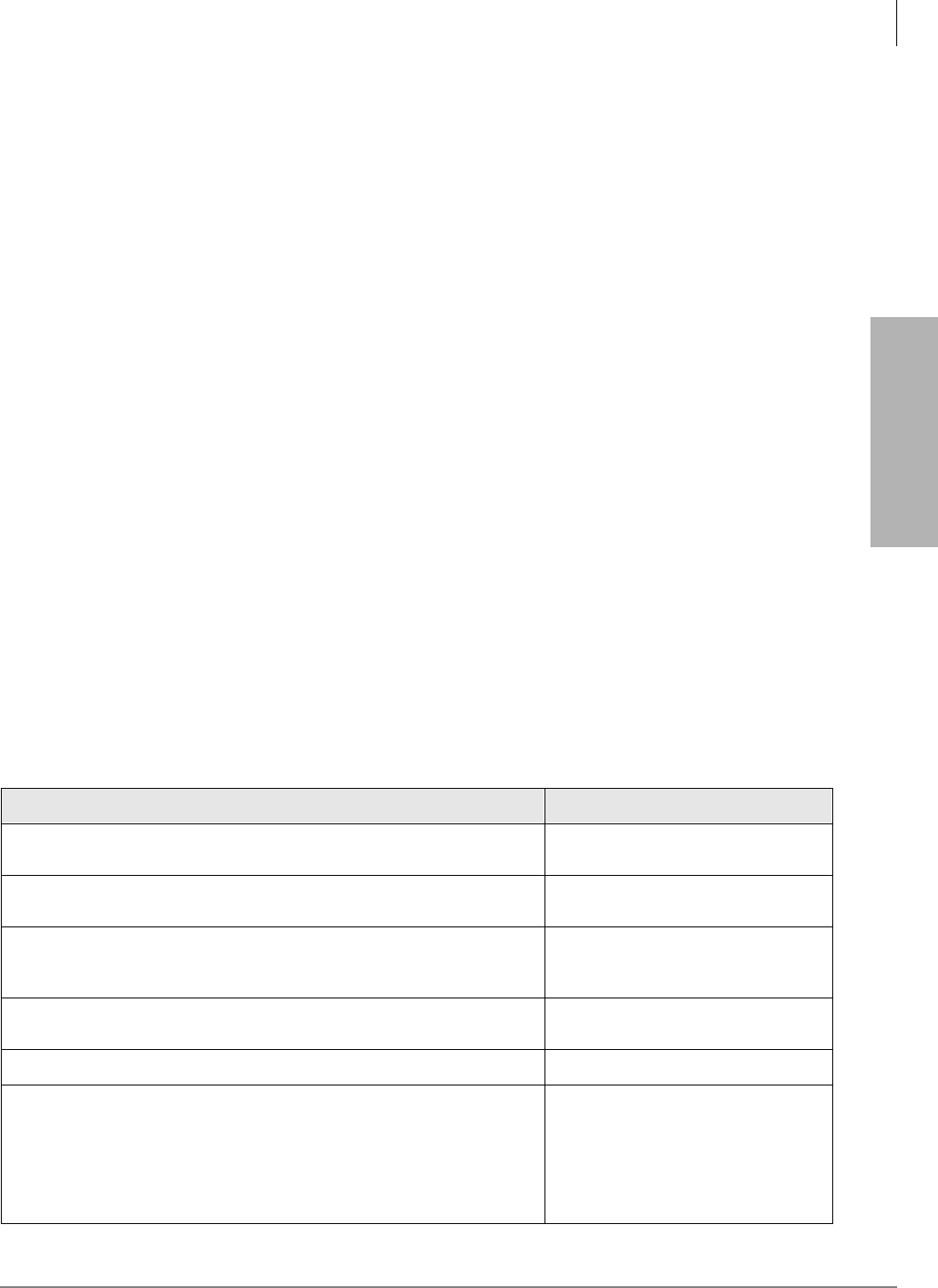
Initialization & Test
Program 00 – Part 1: Software Check
Strata DK Programming 5/99 2-13
Initialization & Test
Program 00 Part 1 - Overview
This program enables you to run various checks on the Strata DK System.
DK14: the QKYS feature key must be installed on the QRCU3 PCB to allow AA.
DK40i: the KKYS feature key must be installed on the K5RCU PCB to allow AA.
DK424: the RKYS feature key must be installed on the RCTU to allow AA, ACD, and ACD/MIS.
Code 0, ROM Version
Code 0 displays the software version of the system common control unit (RCTUA, RCTUB,
RCTUBA/RCTUBB and RCTUC/RCTUD, RCTUE/F, DK40i Base KSU, or DK14KSU) and if
installed on the RCTU, the RKYS, KKYS, or QKYS key type. See the Program 00 Record Sheet
for an illustration of software displays. This information cannot be altered with this program.
Code 1, Level 1 Security Code
Use to assign a Remote Maintenance security code that allows entry to all programs and data.
Code 2, Level 2 Security Code
Use this program to assign a Remote Maintenance security code that allows entry to Programs
30~39, 77~89, and 30~31.
Important! When using a DK Admin PC, either Security Code (1 or 2) enables the DK Admin
user full access to all Strata DK programs. Always change Security Code 1 and
Code 2 to prevent unauthorized programming changes by DK Admin users that may
try to log-in remotely with the default security code: 0000.
Code 8, Software RAM Checksum and Code 9, Power OFF Counter
For factory purposes only.
Program 00 Part 1 - Example
Action (press buttons + LED Buttons) LCD Response
1. Use the programming LCD electronic or digital telephone. (See “First-
time Programming” on Page 1-14.) No. N-N1
Jan 20 Sun 06:43
2.
Enter programming mode. (Do not press [DN] button.) Program Mode
3. 6SNU6SHDNHU+ROG
Speaker beeps to indicate when to enter program number. Access
Program 00.
Program = 00
Data Store
4. 6SNU6SHDNHU
Prepare system for a selection. 00 Select =
5. Select one of the following attributes:
View the software version. This attribute can not be edited.
or...
00 Select = 0
RNAXNN-Key X
Note NN = The actual version
number and letter. See Program
00 record sheet for details).
X = 1, 2, or 3.

Initialization & Test
Program 00 – Part 1: Software Check
2-14 Strata DK Programming 5/99
1111
Define the Level 1 remote maintenance security code from the System
Record Sheet (four digits maximum). Level 1 allows remote access to
all programs and data. Default Level 1 security code is “0000.”
or...
00 Select = 1
Password = 0000
1111
Define the Level 2 remote maintenance security code from the System
Record Sheet (four digits maximum). Level 2 allows remote access to
programs 30~39 and 77~89 only. Default Level 2 security code is
“0000.”
or...
00 Select = 2
Password = 0000
View the software RAM Checksum. This attribute can not be edited.
The default checksum may change.
or...
00 Select = 8
Sum = XXXXXXXXX
View the RPSU Power Cycle Counter. This attribute can not be edited.
The counter indicates the number of times power is removed from the
system after Program 00 was initialized via Program 90 or 91-9.
00 Select = 9
Counter = XXXX
6. +ROG
Secure data in system programming. (Only works for “1” and “2”) 00 Select = (0,1,2,8, or 9)
Data Programmed
7. 6SNU6SHDNHU
Prepare system for another selection (go back to Step 5) or exit
Program 00 (continue with Step 8).
00 Select =
8. +ROG
Secure Program 00 data in system memory. 00 Select = ##
Data Programmed
9. 6SNU6SHDNHU
Exit Program 00. Enter another program number (see “Program 91-1
Example” on Page 2-7) or exit programming mode (go to Step 10).
System beeps to indicate it is exiting Program 00.
Program =
10. +ROG
Exit programming mode. No. N-N
Jan 20 Sun 06:58
1. N-N is the Program Telephone [DN].
Action (press buttons + LED Buttons) LCD Response
Initialization & Test
Program 00 – Part 2: Processor RAM Test
Strata DK Programming 5/99 2-15
Initialization & Test
Program 00 – Part 2: Processor RAM Test
Processor Type:
DK14, DK40i, All RCTUs
Program Type:
Test - Includes: Remote Maintenance Security Code Assignments
Initialized Default:
None
General RAM Test
Note See “Program 00 Part 2 - Overview” on Page 2-16
Display General RAM Test Results
Backup RAM Test
6SNU +ROG 6SNU +ROG Tests RAM (15 seconds downtime)
6SNU +ROG 6SNU Programming Telephone LCD Displays:
DK424 DK14/DK40i
TEST 1 X=OK Y=OK TEST 1 =OK
or... or...
TEST 1 X=NG Y=NG
X=00000 X=00000
TEST 1 =NG
Where:
X = RCTUA, RCTUBA, RCTUC
Y = RCTUD3, RCTUF
OK = RAM is good
NG = RAM is defective
An X=NG or Y=NG RAM test result indicates a defective RCTU PCB; change
the appropriate (X or Y) RCTU PCB and retest RAM on the newly installed
RCTU.
Replace the DK14 KSU or DK40i Base KSU if Test 1=NG.
6SNU +ROG 6SNU +ROGRCTU Tests RAM (15 seconds downtime)
Programming Telephone LCD Displays:
GENERAL RAM TEST
Programming Telephone LCD Displays:
BACKUP RAM TEST
Initialization & Test
Program 00 – Part 2: Processor RAM Test
2-16 Strata DK Programming 5/99
Display Backup RAM Test Results
Program 00 Part 2 - Overview
Use this program to test the RAM on system processor. If a RAM test error occurs during this test,
the processor causing the error should be replaced. In the case of two-PCB processors, isolation of
a RAM failure is indicated on the programming telephone X or Y (see above).
If the DK14 or DK40i processor fails the RAM test, the Base KSU must be replaced.
CAUTION! Running each RAM test drops all calls and interrupts telephone service for 15
seconds.
Note Running Program 00 RAM tests do not change or erase any customer data.
6SNU +ROG 6SNU Programming Telephone LCD Displays:
DK424 DK14/DK40i
TEST 2 X=OK Y=OK TEST 1 =OK
or... or...
TEST 2 X=NG Y=NG
X=00000 X=00000
TEST 2 =NG
Where:
X = RCTUA, RCTUBA, RCTUC
Y = RCTUD3, RCTUF
OK = RAM is good
NG = RAM is defective
An X=NG or Y=NG RAM test result indicates a defective RCTU PCB; change
the appropriate (X or Y) RCTU PCB and retest RAM on the newly installed
RCTU.
Replace the DK14 or DK40i Base KSU if Test 1=NG.
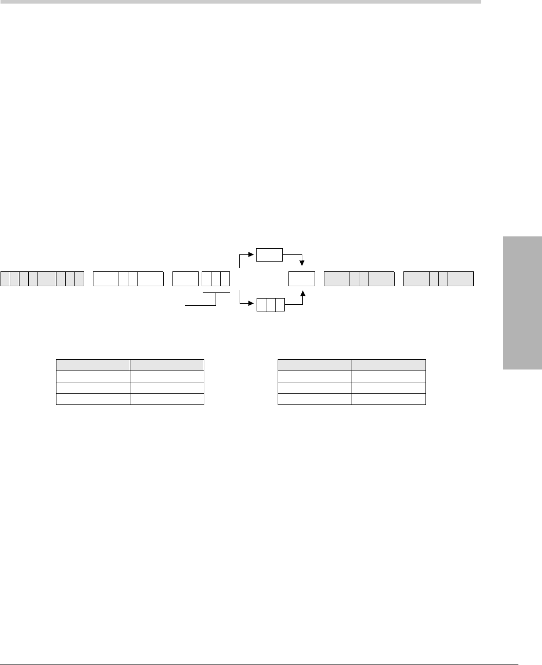
Strata DK Programming 5/99 3-1
System & Station
System & Station 3
This chapter gives you programming information for the Strata DK system and its stations.
Program 01 – Station Logical Port Display and/or
Change
Processor Type:
DK14, DK40i, All RCTUs
Program Type:
Station
Initialized Default:
Logical port number = physical port number
Program 90, 91-1, or 91-9 initializes Program 01
Program 01 Overview
Program 01 enables you to enter a physical port to display the associated logical port. You then
have the option to assign a new logical port to the physical port. (To return ports to their initialized
settings, see Programs 90 and 91.)
Note Record port locations on Program 04 record sheet.
6SNU +ROG 6SNU +ROG6SNU +ROG 6SNU +ROG
Processor [PDN] Port Range Processor [PDN] Port Range
DK14 000~009 RCTUBA/BB 000~079
DK40i 000~027 RCTUC/D 000~239
RCTUA 000~031 RCTUE/F 000~335
To Save existing Logical Port 6SNU
SELECT = Physical Port Number
The logical port number associated with
the physical port displays after the
physical port number is entered.
Enter new Logical Port
to change existing Logical Port
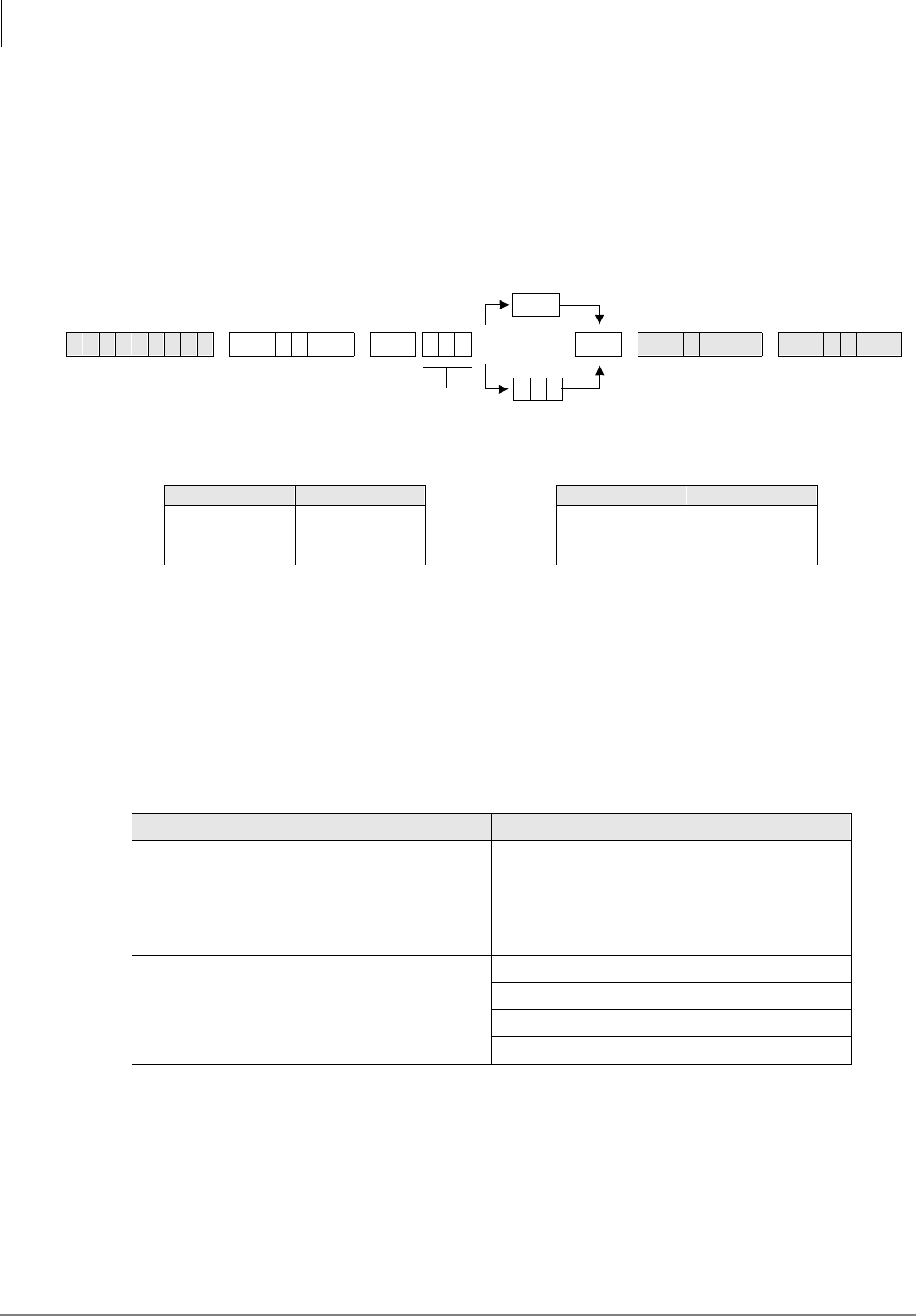
System & Station
Program 02 – Station Physical Port Display and/or Change
3-2 Strata DK Programming 5/99
Program 02 – Station Physical Port Display and/or
Change
Processor Type:
DK14, DK40i, All RCTUs
Program Type:
Station
Initialized Default:
Logical port number = physical port number
Program 90, 91-1, or 91-9 initializes Program 02
Program 02 Overview
Program 02 enables you to enter a logical port to display the associated physical port. You then
have the option to assign a new physical port to the logical port. (To return ports to their initialized
settings, see Programs 90 and 91.)
Notes
●Record port locations on Program 04 record sheet.
●The system allows only like ports to be reassigned (see below).
●RCIU/RCIS circuit assignments to CO lines are not affected by Program 01 and 02.
6SNU +ROG 6SNU +ROG6SNU +ROG 6SNU +ROG
Processor [PDN] Port Range Processor [PDN] Port Range
DK14 000~009 RCTUBA/BB 000~079
DK40i 000~027 RCTUC/D 000~239
RCTUA 000~031 RCTUE/F 000~335
Allowed Not Allowed
Digital-to-Digital Ports (KCDU-QCDU-PDKU-
PDKU-RDSU Ports) Attendant Console (DK424 only), DSS, BGM
or Amplified Conference Ports should not be
reassigned
Electronic-to-Electronic Ports (PEKU-PEKU-
PESU Ports) Door Phone Ports (004, 012, 020, 028) should
not be reassigned
Standard Tel to Standard Tel Ports (QSTU-
KSTU-PSTU-RSTU-PESU-RDSU/RSTS) Tie/DID Line Ports – should not be reassigned
PDKU to PEKU – cannot be exchanged
PSTU to PDKU – cannot be exchanged
PEKU to PSTU – cannot be exchanged
To Save existing Physical Port 6SNU
SELECT = Logical Port Number
The physical port number associated
with the logical telephone port displays
after the logical port number is entered.
Enter new Physical Port
to change existing Physical Port
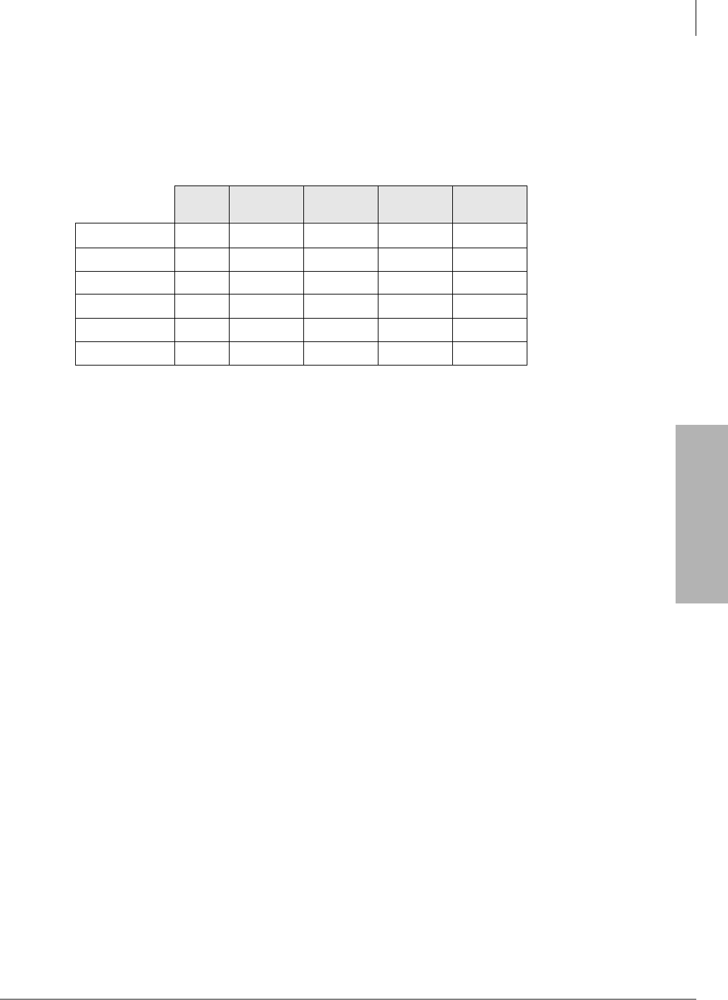
System & Station
Program 03 for DK14 – Slot Assignments
Strata DK Programming 5/99 3-3
System & Station
Program 03 for DK14 – Slot Assignments
When DK14 is powered ON, Program 03 automatically assigns the correct codes for installed
PCBs. No record sheet is needed. Refer to the following table for PCB slot and slot code
information:
DK14 Base KSU
Notes
●In the DK14 software: QCDU2 digital ports are considered to be installed in slot 11. QCDU2
CO lines are considered to be installed in slot 12.
●opt=QRCU3
●opt=Always assigns 8 ports (000~007), digital ports (OCA/DIU). No DSS allowed.
●Always assigns 4 CO lines
●Always assigns 2 ports (008, 009) standard telephone ports
WMAU DKU COU
and QCDU2 QSTU2 None
Slot Number 00 11 12 13 14
PCB Code 91 or 92 62 11 00 or 31 00
PCB Type QRCU3
Options OCA/DIU
Station Numbers 000~007 008~009
CO Line Numbers 001~004
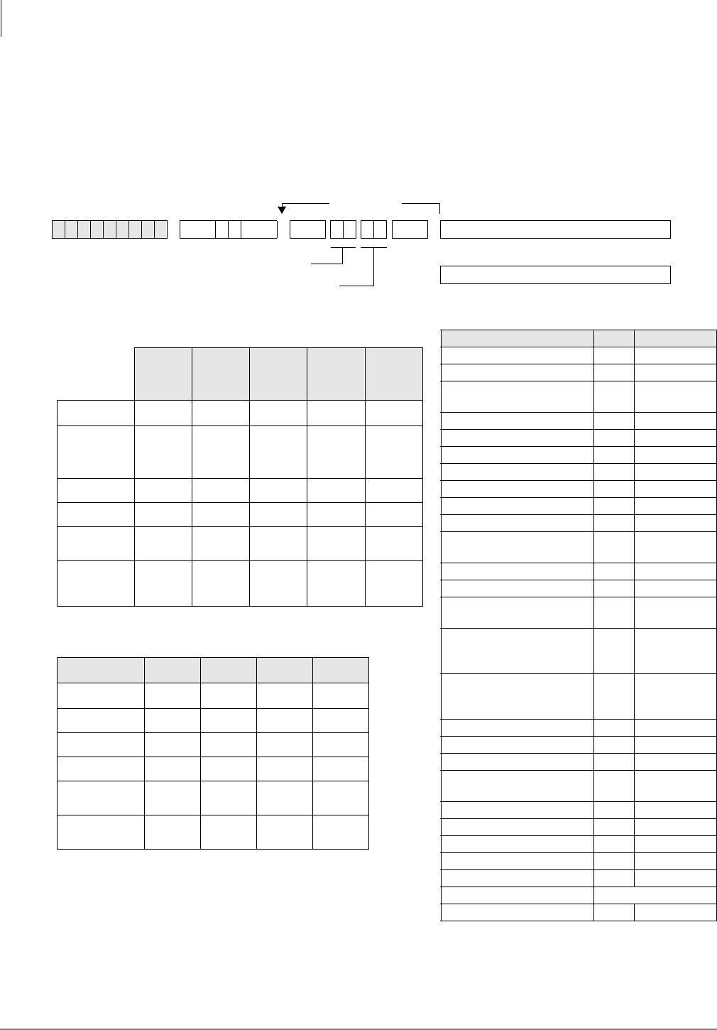
System & Station
Program 03 for DK40i – Flexible PCB Slot Assignments
3-4 Strata DK Programming 5/99
Program 03 for DK40i – Flexible PCB Slot Assignments
Processor Type:
DK40i
Program Type:
System
Initialized Default:
PCB codes of PCBs installed prior to running Program 91-1 or Program 91-9
Code 00 for empty slots (15~18), Base KSU has codes for PCBs
6SNU +ROG 6SNU +ROGTurn System Power OFF (5 sec) then ON
PCB Code Reference Table
PCB Fixed Slot Code Ports/Type
Common Control 91 None
Common Control w/K4RCU3 92 4 DTMF/ABR
Common Control w/K5RCU
or K5RCU2
98 5 DTMF/ABR
PIOU/PIOUS/RSSU/PEPU 41 None
PEKU 21 8 EKT
PEKU with EOCU 22 8 EKT
PEKU with DSS 23 8 EKT
PEKU with EOCU, DSS 24 8 EKT
PESU 25 2 SLT/4 EKT
PESU with EOCU 26
KSTU2/RSTU2/Stratagy DK 31 4 SLT/8 SLT/
8VM
TCOU/PCOU/RCOU/RGLU2 11 4/CO
RCOU + RCOS 17 8 Loop CO
Base Unit DKT CKTs, PDKU,
and RWIU
61 8 DKT
Base Unit DKT CKTs
& PDKU w/ DIU
or SP-OCA
62 8 DKT
Base Unit DKT CKTs and
PDKU with DSS (w/ or w/o
DIU or SP-OCA)
64 8 DKT
KCDU 65 2/CO, 4 DKT
KCDU SP-OCA or DIU 66 2/CO, 4 DKT
RDSU (RSTS) 27 4 DKT/4 SLT
RDSU (RSTS) with DIU or
SP-OCA
28 4 DKT/4 SLT
RDDU/TDDU 16 4 DID Lines
REMU 13 4-Tie Lines
RCIU2/RCIS/TCIU2 81 4 or 8 Caller ID
TBSU or RBSU 77 2 BRI S/T
RBSU/RBSS 78 4 BRI S/T
TSIU No Code Required
None 00 None
more codes
...or
Run Program 91-2
SELECT = Slot Number (00, 11~18)
CARD = PCB Code (See Reference Table)
DK40i Base KSU
DK40i Expansion KSU
TMAU2 DKU TBSU,
TCOU
or TDDU KSTU2 TCIU2
Slot Number 00 11 12 13 14
PCB Code
91, 92 or
98
62
or
64
00, 11,
16, or 77
00
or
31
00
or
81
PCB Type
Options
Station/BRI
Port Numbers
CO/DID/BRI
Line
Numbers
Cabinet Label 04 05 06 07
Slot Number 15 16 17 18
PCB Code
PCB Type
Options
Station/BRI
Port Numbers
CO/Tie/DID/BRI
Line Numbers
Notes
●For systems containing ISDN PCBs, immediately after running
Program 03, make sure to run Program *60 to identify all station
(NT) and CO (TE) BRI circuits for each RBSU/RBSS and TBSU
installed. Program *60 causes station port and CO line shifting on
PCBs installed in higher slots that follow the BRI PCBs.
●Consult DK40i configuration section to check that the DK40i is
configured properly.

System & Station
Program 03 for DK40i – Flexible PCB Slot Assignments
Strata DK Programming 5/99 3-5
System & Station
Program 03 for DK40i - Overview
Program 03 tells the system what type of optional PCBs are installed in the Expansion KSU. You
must run Program 03 after installing PCBs with options such as OCA, DIU, etc. Also, run Program
03 for each PCB slot when installing a PCB in that location.
It is not necessary to run Program 03 for slots 00~14. The DK40i automatically assigns the Base
KSU PCBs if they are installed when system power is turned ON. However, if DSS is required on
the Base KSU’s DKT circuit 8, you must run Program 03 to assign code 64 to slot 11. If universal
PCBs are installed, Program 91-1 and 91-9 automatically assign the appropriate PCB codes to the
installed slots. But, Programs 91-1 or 91-9 do not assign option codes (such as OCA, DIU, etc.).
Codes allowed in DK40i Expansion KSU: 11, 13, 16, 21~28, 31, 41, 61~62, 64~66, 77, 78, 91, 92,
and 81.
CAUTION! Running Program 91-9 erases Program 03 option codes; Program 91-1 does
not.
Important! After completing Program 03 set the configuration in memory by running OFF and
wait five seconds before turning it back ON.
The Program 03 record sheet is the main record for the hardware configuration of the entire
system. It provides space to record station ports assigned to the station, Tie, and DID line PCBs
and line numbers assigned to the ground loop start, CO, Tie, and DID line PCBs. Use the PCB
Code Reference Table on the Program 03 record sheet to determine the proper option code for each
PCB with an option.
The DK40i Base KSU is divided into four fixed slots, even through the unit has no slots per se.
♦Slot 00 represents the system’s common control (TMAU2) and optional K4RCU3, K5RCU, or
K5RCU2
♦Slot 11 contains the KSU’s eight digital circuits/ports (DKU)
♦Slot 12 contains the KSU’s four optional CO or DID line circuits (TCOU or TDDU) or two
BRI (TBSU) circuits
♦Slot 13 contains the four optional standard telephone circuits KSTU2
♦Slot 14 contains four optional Caller ID circuits for TCOU (TCIU2)
DK40i Slots 15~18 (Expansion KSU Assignment Criteria)
♦Allowed PCBs: PDKU, RDSU/RSTS, RSTU, RSTU2, PSTU, PEKU, PESU, KCDU, RCOU/
RCOS, RGLU2, RCIU2/RCIS, RWIU, PCOU, RDDU, REMU, PEMU, PIOU, PIOUS,
RSSU, PEPU, Stratagy DK.
Note Some PCBs cannot be installed in slot 18 (see Chapter 2 – DK40i Configuration).
♦Expansion KSU PCBs must be installed in the slots specified in Tables 2-9~2-15 or the system
may not operate properly. (See tables in Chapter 2 – DK40i Configuration of the Strata DK
Installation and Maintenance Manual.)
♦Slots 15 and 16 support Speaker OCA and RPCI/DIU Data Switching; slots 17 and 18 do not.
All slots support Handset OCA and RPCI-DI TAPI operation.
♦On DK40i, RCIU2 must be installed in slot 17; RCIU1 cannot be used.
♦The RWIU must be installed in slot 15 and slot 16 must be vacant to support 9 to 16 wireless
handsets. It can be installed in any expansion slot to support 1~8 wireless handsets.
♦If the RWIU supports 9 to 16 handsets, program code 61 in slot 15 and 16.
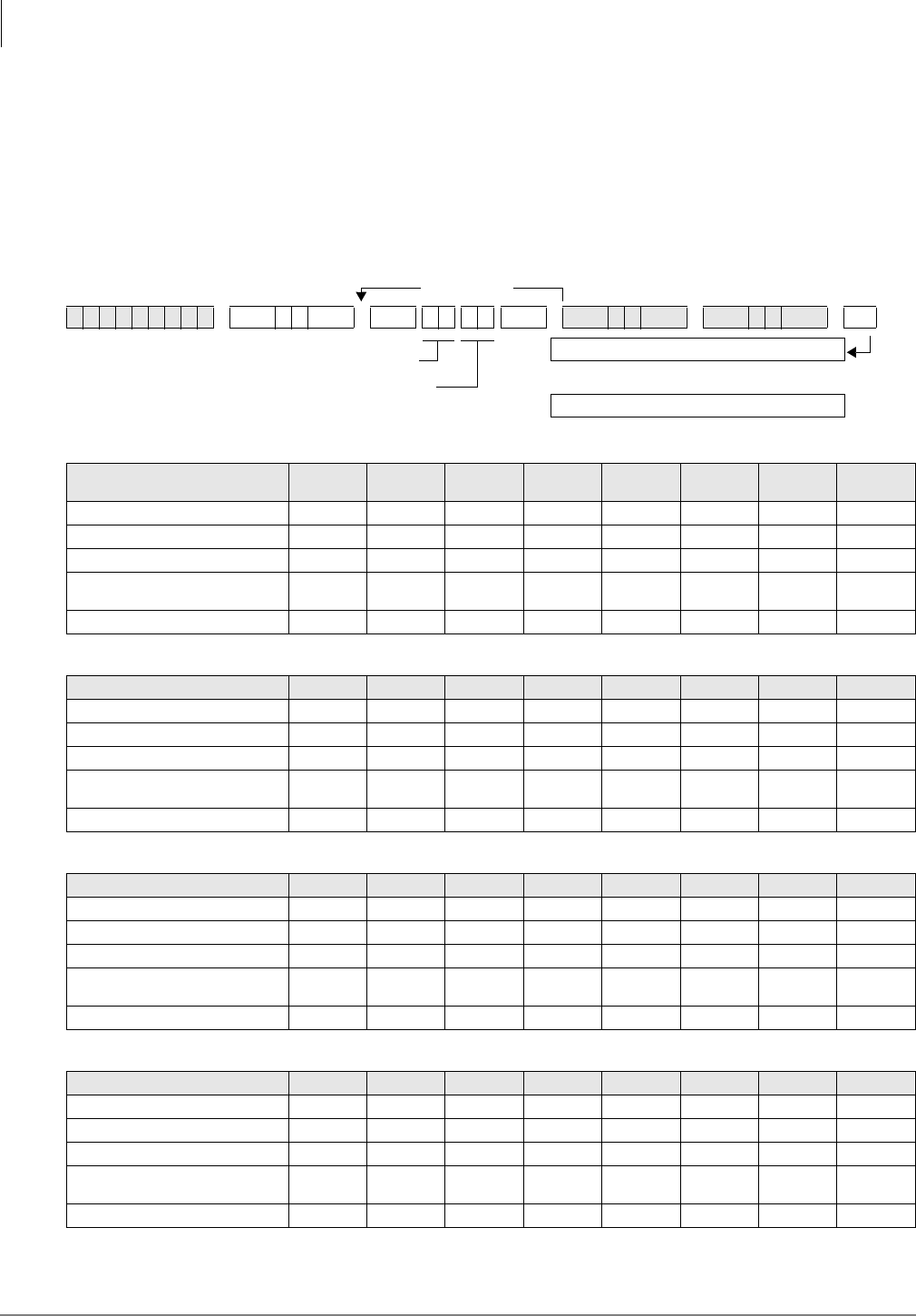
System & Station
Program 03 for DK424 – Flexible PCB Cabinet Slot Assignments
3-6 Strata DK Programming 5/99
Program 03 for DK424 – Flexible PCB Cabinet Slot
Assignments
Processor Type:
All RCTUs
Program Type:
System
Initialized Default:
PCB codes of PCBs installed prior to running Programs 91-1 or 91-9;
Code 00 for empty slots
6SNU +ROG 6SNU +ROG6SNU +ROG 6SNU +ROG
DK424 Base Cabinet 1
Slot Number 00
(R11) 01
(RCTU) S11 S12 S13 S14 S15 S16
PCB Code
PCB Type
Options
Station/Tie/DID/ISDN
Port Numbers
CO/Tie/DID/ISDN Line Numbers
DK424 Expansion Cabinet 2
Slot Number S21 S22 S23 S24 S25 S26 S27 S28
PCB Code
PCB Type
Options
Station/Tie/DID/ISDN
Port Numbers
CO/Tie/DID/ISDN Line Numbers
DK424 Expansion Cabinet 3
Slot Number S31 S32 S33 S34 S35 S36 S37 S38
PCB Code
PCB Type
Options
Station/Tie/DID/ISDN
Port Numbers
CO/Tie/DID/ISDN Line Numbers
DK424 Expansion Cabinet 4
Slot Number S41 S42 S43 S44 S45 S46 S47 S48
PCB Code
PCB Type
Options
Station/Tie/DID/ISDN
Port Numbers
CO/Tie/DID/ISDN Line Numbers
more codes
SELECT = Slot Number (00, 01, 11~78)
CARD = PCB Code (See Reference Table)
Turn System Power OFF (5 sec) then ON.
or...
Run Program 91-2
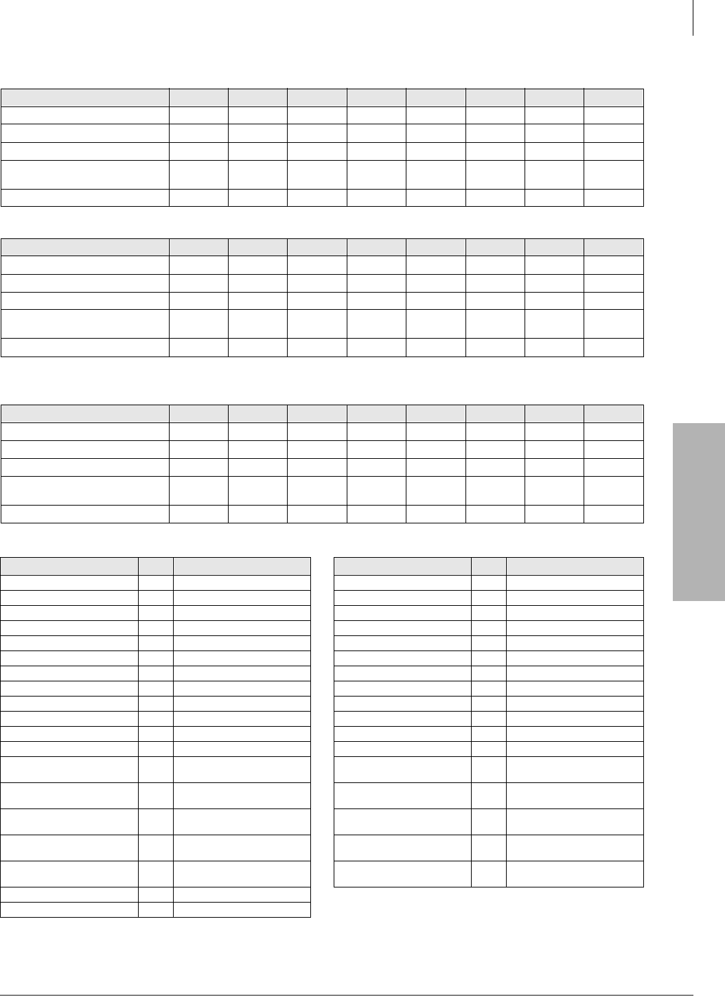
System & Station
Program 03 for DK424 – Flexible PCB Cabinet Slot Assignments
Strata DK Programming 5/99 3-7
System & Station
DK424 PCB Codes
See the following text for specific installation rules on the above PCBs.
DK424 Expansion Cabinet 5
Slot Number S51 S52 S53 S54 S55 S56 S57 S58
PCB Code
PCB Type
Options
Station/Tie/DID/ISDN
Port Numbers
CO/Tie/DID/ISDN Line Numbers
DK424 Expansion Cabinet 6
Slot Number S61 S62 S63 S64 S65 S66 S67 S68
PCB Code
PCB Type
Options
Station/Tie/DID/ISDN
Port Numbers
CO/Tie/DID/ISDN Line Numbers
DK424 Expansion Cabinet 7
Slot Number S71 S72 S73 S74 S75 S76 S77 S78
PCB Code
PCB Type
Options
Station/Tie/DID/ISDN
Port Numbers
CO/Tie/DID/ISDN Line Numbers
PCB Code Ports/Type PCB Code Ports/Type
RCOU, RGLU2 11 4 Gnd./Loop Lines RDTU 71 8 T1 Channels
RCOU/RCOS 17 8 Loop CO Lines RDTU 72 16 T1 Channels
RDDU 16 4 DID Lines/4 Stations RDTU 73 24 T1-channels
REMU 13 4 Tie Lines/4 Stations RCTU 91 None
PEKU 21 8 Stations RCTU (with 4-CKT RRCS) 92 None
PEKU (EOCU) 22 8 Stations RCTU (with 8-CKT RRCS) 93 None
PEKU w/DSS 23 8 Stations RCTU (with 12-CKT RRCS) 94 None
PEKU (DSS, EOCU) 24 8 Stations NONE 00 00
PESU 25 6 Stations RATU 51 4 Stations
PESU (OCA) 26 6 Stations RSIU 49 I/O Interface
RDSU/RSTS 27 8 Stations RCIU2/RCIS 81 8 CKT, Caller ID
RDSU/RSTS (OCA, DIU) 28 8 Stations Stratagy DK 31 8 VM Ports
RSTU2 31 8 Stations RBUU without RBUS 75 2 U Interfaces
(4 stations/4 CO lines)
PIOU, PIOUS/ RSSU, PEPU 41 Remote Maintenance (TTY) RBUU with RBUS 76 4 U Interfaces
(8 stations/8 CO lines)
PIOU/PIOUS/RSSU 42 MIS for ACD (TTY) RBSU without RBSS 77 2 S/T Interfaces
(4 stations/4 CO lines)
PIOU/PIOUS/RSSU 43 SMDI VM Interface (TTY) RBSU with RBSS 78 4 S/T Interfaces
(8 stations/4 CO lines)
PDKU2, RWIU 61 8 Stations RPTU Interface Card 79 PRI Interface
(24 CO lines)
PDKU2 (OCA, DIU) 62 8 Stations
PDKU2 (DSS, OCA, DIU) 64 8 Stations

System & Station
Program 03 for DK424 – Flexible PCB Cabinet Slot Assignments
3-8 Strata DK Programming 5/99
Program 03 for DK424 - Overview
Program 03 tells the system what type of optional PCBs are installed.
The Program 03 record sheet is the main record for the hardware configuration of the entire
system. It provides space to record station ports assigned to the station, Tie, and DID line PCBs
and line numbers assigned to the ground loop start, CO, Tie, and DID line PCBs.
Use the DK424 PCB Code table on Page 3-7 to determine the proper option code for PCBs with
options. You must run Program 03 after installing PCBs with options such as OCA, RRCS, DIU,
etc. Also, run Program 03 for the slot of each new PCB when installing a new PCB in an existing
installation.
If universal PCBs are installed, Program 91-1 and 91-9 automatically assigns the appropriate PCB
codes to the installed slots. But, they do not assign option codes (such as OCA, PDIU, RRCS,
etc.).
CAUTION! Running Program 91-9 erases Program 03 option codes; Program 91-1 does
not.
Important! After completing Program 03 set the configuration in memory by running Program
91-2 or turn the base cabinet power supply switch off and wait five seconds before
turning it back on.
Expansion slots 7 and 8 can only be used if the following equipment is installed:
DK424 Base (with RCTUE/F and MBJU removed) and the DK424 Expansion.
See Chapter 4 – DK424 Configuration (Strata DK Installation and Maintenance
Manual) to determine PCB slot placement.
PIOU/PIOUS/RSSU
Codes 41, 42, and 43 assigns PIOU/PIOUS RSSU TTY port as Remote Maintenance, MIS for
ACD, and SMDI respectively; SMDR, Paging, Relay Control, and other miscellaneous options are
active on the PIOU/PIOUS that has the lowest number code (41, 42 or 43) in the system. Codes set
for RSIU/RSIS/RMDS in Program 76 have priority over codes 41, 42, and 43.
Piggyback PCB / Speaker OCA / Data Interface Unit Options
Run Program 03 to assign codes for all options except RCOS. Program 91-9 erases option codes
assigned with Program 03; Program 91-1 does not erase option codes already programmed. After
completing all Program 03 data entry, run Program 91-2 or cycle system power to transfer
Program 03 data into working memory.
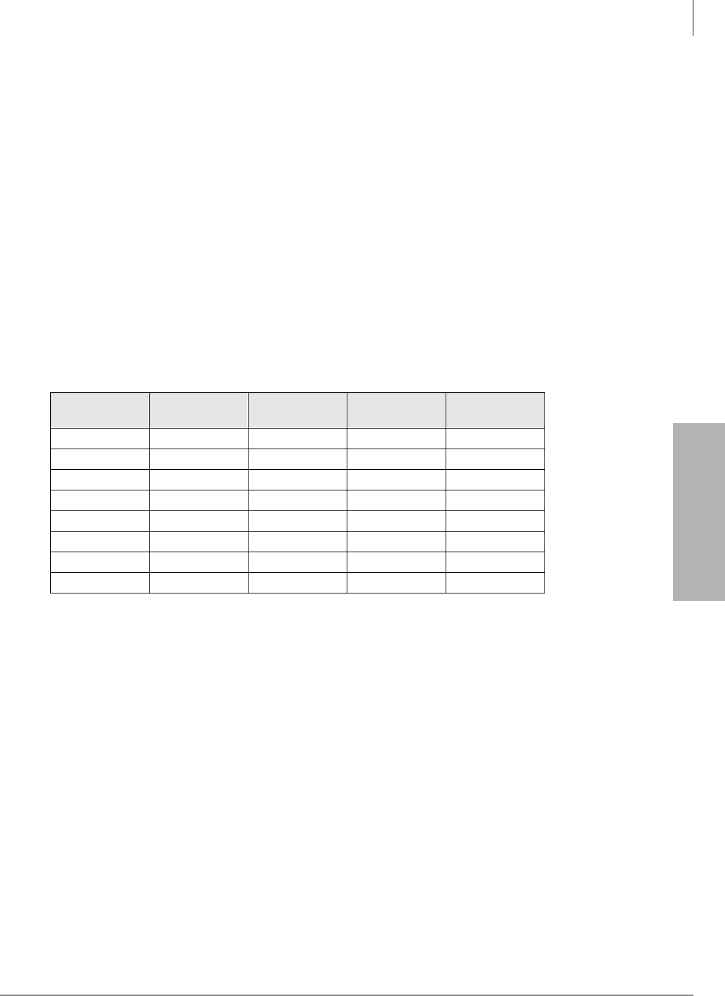
System & Station
Program 03 for DK424 – Flexible PCB Cabinet Slot Assignments
Strata DK Programming 5/99 3-9
System & Station
RCIU/RCIS or RCIU2/RCIS
When installing RCIU2/RCIS, enter the Caller ID circuit numbers on the record sheet in place of
the CO line number. Each RCIU2/RCIS slot uses eight Caller ID circuits. RCIU2/RCIS circuit
numbers are assigned automatically in numerical order (001~200) starting with the lowest slot
number, to the highest RCIU2/RCIS slot number in 8-circuit increments.
Important! If more than four circuits are needed, never install an RCIU without an RCIS.
On DK424, RCIU2/RCIS can be installed in any universal slot except slot 11 or if RSIU is
installed, slot 12; they do not have to be installed adjacent to corresponding CO lines. Refer to
Program *50 to manually assign RCIU2/RCIS circuits to CO line circuits.
RWIU
Code 61 must be set for all RWIU slots including slots that are vacant because they support RWIU
channels 09~32.
RCTU
The table below gives you slot locations and PCB Code Assignments for all RCTUs.
PCB Codes:
91=No RRCS
92=4 -circuit RRCS
93=8 -circuit RRCS
94=12 -circuit RRCS
Note When using RCTUA, Slot 15 and 16 does not support Speaker OCA or DIU Data
Switching. RCTUA does not support ACD, ACD/MIS, RS-232 Voice Mail Integration
(SMDI), and attendant console features.
RSIU
If an RSIU is installed in base cabinet slot 11, you must connect the programming station to circuit
6 in slot 12. In this case, a PDKU or PEKU should be installed in slot 12 and Station Port Number
000~007 will be in slot 12.
If an RSIU is not installed, you must connect the programming station to circuit 6 in slot 11 (Port
005) and/or circuit 6 in slot 12 (port 013). The station must be a 20-button digital LCD or
electronic LCD telephone. Also, if an RSIU is not installed, install a PDKU or PEKU in slot 11.
Processor R11 Slot RCTU Slot
Cabinet 1 Slot Code PCB Code
Assignment
RCTUA No Yes 00 91~94
RCTUB No Yes 00 91~94
RCTUBA Yes No 00 91~94
RCTUBB No Yes 01 91
RCTUC Yes No 00 91~94
RCTUD No Yes 01 91~94
RCTUE Yes No 00 91~94
RCTUF No Yes 01 91~94

System & Station
Program 03 for DK424 – Flexible PCB Cabinet Slot Assignments
3-10 Strata DK Programming 5/99
Program 03 Example
Action (press buttons + LED buttons) LCD Response
1. Use an LCD programming phone per Minimum Hardware
Requirements on Page 1-14. No. 205
Jan 20 Sun 06:43
2.
Enter programming mode. (Do not press [DN] button.) Program Mode
3. 6SNU6SHDNHU+ROG
Access Program 03. System beeps after 6SNU6SHDNHU is
pressed to indicate program number may be entered.
Program = 03
Data Store
4. 6SNU6SHDNHU
Prepare the system for a selection. 03 Select =
5. Dial a PCB slot number (00~78 for DK424 or 00-18 for DK40i) using
the dial pad. 03 Select = (00~78)
Card = (91, 62 or 00)
The system defaults as follows:
Initialized default assigns slot 00 and 01 to be a non-optioned RCTU
without RRCS DTMF receivers, or DK40i Base without K4RCU3,
K5RCU, and K5RCU2.
03 Select = 00 (Slot Number)
Card = 91
Initialized default assigns slot 11 to be a non-optioned PDKU without
DSS console or OCA (Code 61).
03 Select = 11 (Slot Number)
Card = 61
a (DK424), a (DK40i)
Initialized default assigns slot 12~78 to be empty (Code 00).
03 Select = 12~78 (Slot
Number)
Card = 00
6. a
Dial the PCB code recorded on the record sheet. Refer to the PCB
code reference table on Program 03 record sheet for a definition of the
codes.
03 Select = (00~78)
Card = (00~97)
7. +ROG
Secure data in system programming. 03 Select = (00~78)
Data Programmed
8. 6SNU6SHDNHU
Prepare system for another selection (go back to Step 5) or continue
with Step 9.
03 Select =
9. +ROG
Secure Program 92 data in system memory. 92 Select = ##
Data Programmed
10. 6SNU6SHDNHU
Exit Program 92 (system beeps). Enter another program number or
exit programming mode (go to Step 11).
Program =
11. +ROG
Exit programming mode. No. 205
Jan 20 Sun 06:58
12. To secure Program 03 entries, Power off for five seconds, then power
on, or run Program 91-2.
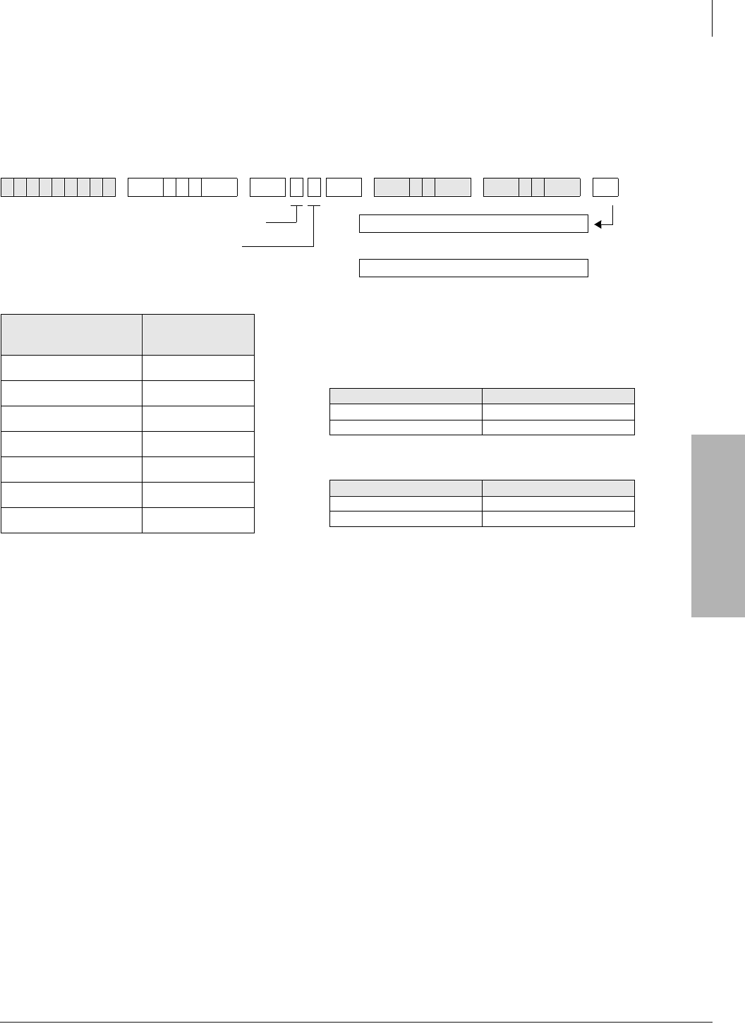
System & Station
Program *03 for DK424 – Cabinet Type Identification
Strata DK Programming 5/99 3-11
System & Station
Program *03 for DK424 – Cabinet Type Identification
Processor Type:
RCTUE/F only
Program Type:
System
Initialized Default:
All cabinets = 1
Program *03 - Overview
You must run this program when using the RCTUE/F processor. It identifies which type of
cabinets are installed (DK424 or DK280). The RCTUE/F processor can be installed in a DK424 or
DK280 base cabinet. The expansion cabinets can be any combination of DK424 and DK280 -
except the seventh expansion cabinet must be a DK424.
The DK280 expansion cabinet can only support six universal PCB slots in any possible
configuration.
The DK424 expansion cabinet supports eight universal PCB slots only if the RCTUE/F is installed
in a DK424 base cabinet and the MBJU jumper is removed from the DK424 base cabinet
backplane.
6SNU+ROG 6SNU + ROG6SNU +ROG 6SNU +ROG
SELECT =
(Cabinet No. 1~7) Cabinet Type
(1 or 2)
1 (Base)
2 (1st Expansion)
3 (2nd Expansion)
4 (3rd Expansion)
5 (4th Expansion)
6 (5th Expansion)
7 (6th Expansion) 1 only
SELECT = Cabinet No. (1~7)
CABINET = 1 or 2 (type)
Type 1 (DK424)
Type 2 (DK280)
Turn System Power OFF (5 sec) then ON.
or...
Run Program 91-2
Expansion Cabinet Universal PCB Slot Availability
Case 1
RCTUE/F in DK424 Base Cabinet with MBJU removed
Case 2
RCTUE/F in DK280 Base Cabinet
Expansion Cabinet (max 6) Universal PCB Slots
DK424 1~8 available
DK280 1~6 available
Expansion Cabinet (max 5) Universal PCB Slots
DK424 1~6 available
DK280 1~6 available
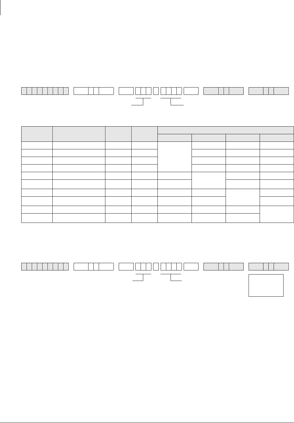
System & Station
Program 04 – Station Logical Port [PDN] Assignment
3-12 Strata DK Programming 5/99
Program 04 – Station Logical Port [PDN] Assignment
Processor Type:
DK14, DK40i, All RCTUs
Program Type:
Station
Initialized Default:
See [PDNs] in the record sheets
DK14 Record Sheet
1. Supports a Digital Telephone or a DDCB Door Phone Control Box.
2. Supports Alternate Background Music (BGM).
DK40i Record Sheet
Important! Refer to Chapter 2 – DK40i Configuration before installing PCBs in slots 15~18.
6SNU +ROG 6SNU +ROG 6SNU +ROG 6SNU +ROG
Physical
Ports Modular Jack
Location Record Logical
Ports [PDNs]
(Initialized)
Port Type for Different Base Configurations
KSU 1st QCDU2 2nd QCDU2 QSTU2
000 000 (10)
4 - Digital
Telephone
Ports
001 001 (11)
00210021(12)
00310031(13)
004 004 (14) 2 -Digital
Telephone
Ports
005 005 (15)
006 006 (16) 2 - Digital
Telephone
Ports
007 007 (17)
008 008 (18) 2 - Standard
Telephone
Ports
00920092(19)
6SNU +ROG 6SNU +ROG 6SNU +ROG 6SNU +ROG
SELECT = Station Logical Port Number(s)
(see table below)
[PDN] (1~4 digits)
SELECT = Station Logical Port Number(s)
(see table below)
[PDN] (1~4 digits) Logical
Ports
(Initialized)
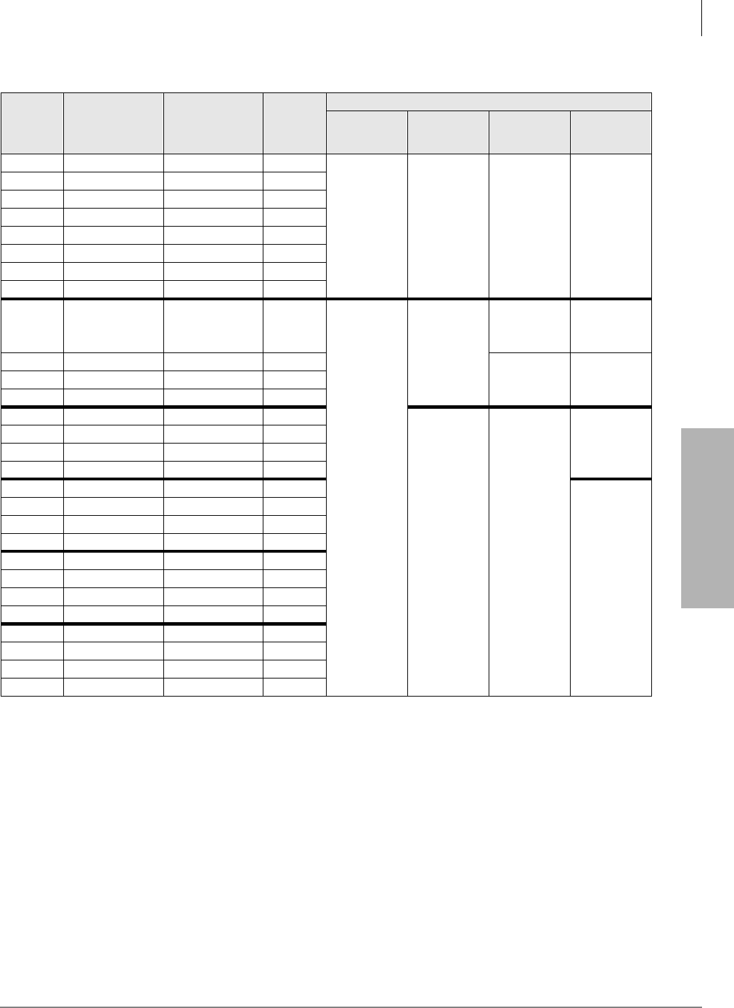
System & Station
Program 04 – Station Logical Port [PDN] Assignment
Strata DK Programming 5/99 3-13
System & Station
Expansion Slot Configuration Record1: Slot 15 ______ Slot 16 ______ Slot 17 ______ Slot 18 ______
1. Expansion slots 15~18: See DK40i Configuration tables in Chapter 2 of the Strata DK Installation and Maintenance Manual.
Physical
Ports Modular Jack
Location Record Logical Ports [PDNs]
(Initialized)
Port Type for Different Base Configurations
TCOU or TDDU TCOU, TBSU2
or
TDDU+KSTU2
2. TBSU circuits configured for line-side BRI.
TBSU TBSU+KSTU2
000 000 (10)
Base Slot 11
8 - Digital
Telephone
Ports
Base Slot 11
8 - Digital
Telephone
Ports
Base Slot 11
8 - Digital
Telephone
Ports
Base Slot 11
8 - Digital
Telephone
Ports
001 001 (11)
002 002 (12)
003 003 (13)
004 004 (14)
005 005 (15)
006 006 (16)
007 007 (17)
008 008 (18)
Expansion
Slots 15~18
Base Slot 13
Base Slot 123
TBSU CKT 1
2 Ports
3. If TBSU circuits that are set as station-side in Program *60, use two station ports per circuit. TBSU circuits that are set to line-side do not use
station ports.
Base Slot 123
TBSU CKT 1
2 Ports
009 009 (19) 4 KSTU2 Ports Base Slot 123
TBSU CKT 2
2 Ports
Base Slot 123
TBSU CKT 2
2 Ports
010 010 (20)
011 011 (21)
012 012 (22)
Expansion
Slots 15~18 Expansion
Slots 15~18
Base Slot 13
4 KSTU2 Ports
013 013 (23)
014 014 (24)
015 015 (25)
016 016 (26)
Expansion
Slots 15~18
017 017 (27)
018 018 (28)
019 019 (29)
020 020 (30)
021 021 (31)
022 022 (32)
023 023 (33)
024 024 (34)
025 025 (35)
026 026 (36)
027 027 (37)
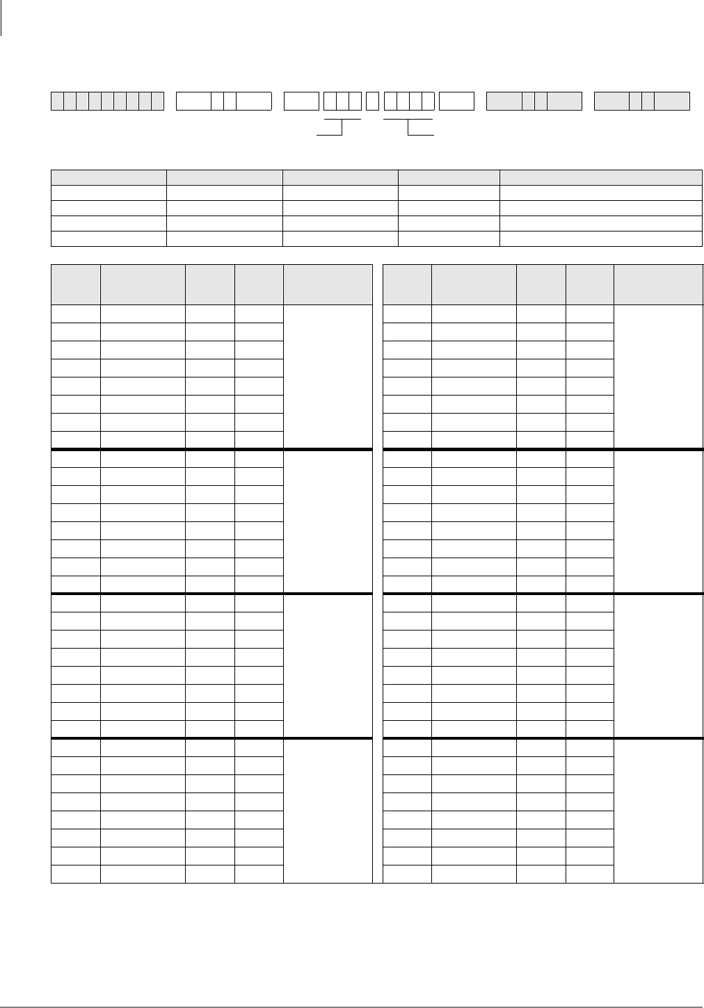
System & Station
Program 04 – Station Logical Port [PDN] Assignment
3-14 Strata DK Programming 5/99
DK424 Record Sheet
6SNU +ROG 6SNU +ROG 6SNU +ROG 6SNU +ROG
Processor [PDN] Port Range Initialized [PDNs] DISA Port Reserved for Special Functions
RCTUA 000~031 200~231 039 032~039
RCTUBA/BB 000~079 200~279 089 080~089
RCTUC/D 000~239 200~239 249 240~249
RCTUE/F 000~335 100~435 344 336~349
Physica
l Ports
Modular Jack
Location
Record
Logical
Ports [PDN] Cabinet and Slot
Number Physica
l Ports
Modular Jack
Location
Record
Logical
Ports [PDN] Cabinet and Slot
Number
Cabinet: ______
Slot: ______
Cabinet: ______
Slot: ______
Cabinet: ______
Slot: ______
Cabinet: ______
Slot: ______
Cabinet: ______
Slot: ______
Cabinet: ______
Slot: ______
Cabinet: ______
Slot: ______
Cabinet: ______
Slot: ______
SELECT = Station Logical Port Number(s) Press [PDN] or Button LED 01 to erase (1~4 digits)
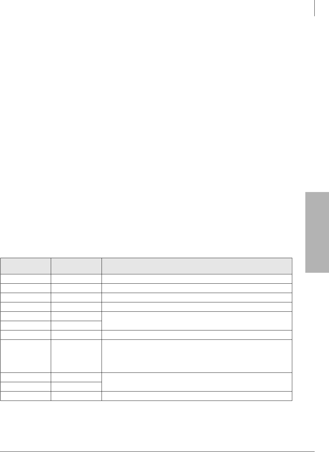
System & Station
Program 04 – Station Logical Port [PDN] Assignment
Strata DK Programming 5/99 3-15
System & Station
Program 04 Overview
Program 04 assigns the Primary Directory Number [PDN] to each telephone (logical port). [PDNs]
can be one to four digits. [PDNs] must not conflict with Phantom Directory Numbers [PhDNs] or,
DK424 Distributed Hunt Directory Numbers set in Program 04.
[PDNs] can be changed using Program 04, but door phone and modem numbering cannot.
●Door phone standard numbering is #151~#159 and #161~#163; the internal modem (IMDU or
RMDS) is #19 (DK40i and DK424).
●[PDNs] cannot begin with the digits 41~49 because 44 is the substitute code to rotary dial the
“#” in feature access codes.
Only the first digit of a feature code can be changed with Program 05. The system automatically
assigns door phone station numbers if a door phone is specified in Program
77-1. [PDN] assignments are flexible so that each station can have up to four assigned digits.
All Strata DK telephone user guides are written using the standard default access codes and
[PDNs]. If desired, a telephone accompanying a DSS console can have an [PDN] of 0 or 01, etc.,
without conflict.
If you make no assignment in Program 04, the system, upon powering up automatically assigns
eight [PDNs] for each station PCB installed and four logical station ports for each PEMU, REMU,
RDDU, and RATU PCB.
Each DK424 RDTU, Tie, and DID channel is also assigned a station port. This is done in sequence
of ascending slot numbers for station port numbers 008 and up.
DK424 Attendant consoles rings on the ICI “” button for Dial “0” calls, and on the [PDN] when
the [PDN] assigned to the console (station) port in this program is dialed.
Peripheral Devices other than telephones or DIUs can be connected to the ports listed below. If a
peripheral device is connected to a Physical Port, the Logical Port must have the same port number
as the Physical Port. See the following table.
Logical &
Physical Ports System Peripheral Device
00 DK40i Digital telephone associated with DSS console.
02, 03 DK14 Digital Door phone/lock control unit (DDCB).
04, 12, 20 DK40i Digital Door phone/lock control unit (DDCB).
07, 015, 027 DK40i Digital Direct Station Selection Console (DDSS).
10 DK14 DISA port number used for Toll Restriction Class and Verified/Forced
Account Code assignment.
35 DK40i
09 DK40i Separate background Music Source (KSTU2 required in Base KSU).
00, 08, 020 DK40i
Digital telephone associated with DSS console (PDKU/Expansion Unit
required).
Electronic telephone associated with DSS console (PEKU/Expansion Unit
required).
00, 13, 17 DK40i DK40i: Separate Background Music Source (PEKU, PESU, or PSTU/
Expansion Unit required). DK14: QSTU2 required.
09 DK14
31 DK40i IMDU modem.

System & Station
Program 04 – Station Logical Port [PDN] Assignment
3-16 Strata DK Programming 5/99
Program 04 Example
Action (press buttons+LED buttons) LCD Response
1. Use an LCD programming phone per Minimum Hardware
Requirements in Chapter 1 - Overview. No. N-N1
Jan 20 Sun 06:43
1. N-N = program telephone [PDN]
2. ****
Enter programming mode. (Do not press the [DN] button.) Program Mode
3. 6SNU6SHDNHU+ROG
Access Program 04. The speaker beeps to indicate when to enter a
program number.
Program = 04
Data Store
4. 6SNU6SHDNHU
Prepare the system for a selection. 04 Select =
5. a
Select a port number (use three digits plus #). 04 Select = 000
INT = N-N
6. ;;;;
Enter the port’s station number (up to four digits) from the record
sheet.
Note
Station numbers must not exceed four digits, or conflict with
feature access codes listed in Program 05 record sheet.
04 Select = 000 ~239
INT = XXXX
7. +ROG
Secure data in system programming. 04 Select = (000~335)
Data Programmed
8. 6SNU6SHDNHU
Prepare the system for another selection (go back to Step 5) or
continue with Step 9.
04 Select =
9. +ROG
Secure Program 04 data in system memory. 00 Select = ##
Data Programmed
10. 6SNU6SHDNHU
Exit Program 04 (system beeps). Enter another program number or
continue with Step 11.
Program =
11. +ROG
Exit programming mode. No. N-N
Jan 20 Sun 06:58
System & Station
Program *04 – [PhDN] and Distributed Hunt [DN] Assignments For Internal and Tie Line Calls
Strata DK Programming 5/99 3-17
System & Station
Program *04 – [PhDN] and Distributed Hunt [DN]
Assignments For Internal and Tie Line Calls
Processor Type:
DK14, DK40i, all RCTUs
Program Type:
Station
Initialized Default:
See the legend below
6SNU+ROG 6SNU +ROG 6SNU +ROG 6SNU +ROG
Processor [PhDN] Port Range Initialized [PhDN] DH [DN] Port Range Initialized DH [DN]
DK14 500~509 50~59 900~915 850~865
DK40i 500~527 50~77 900~915 850~865
RCTUA 500~531 500~531 900~915 850~865
RCTUBA/BB 500~579 500~579 900~915 850~865
RCTUC/D 500~739 500~739 900~915 850~865
RCTUE/F 500~835 450~785 900~915 850~865
[PhDN] or DH [DN]
Port XXX
Initialized
[PhDN] or DH
[DN] (YYYY)
[PhDN] or DH [DN]
Port XXX
Initialized
[PhDN] or DH
[DN] (YYYY)
[PhDN] or DH [DN]
Port XXX
Initialized
[PhDN] or DH
[DN] (YYYY)
SELECT = [PhDN] or DH [DN] Port Number
(see table below)
To erase existing [PDNs], enter XXXXXX
(low port high port). Adding a new range of
[PDNs] cannot be done in this manner.
[PhDN] or DH [DN] assigned to port number
(1~4 digits, see table below)
Press LED Button 01 to erase [PhDNs] and
DH[DNs].

System & Station
Program *04 – [PhDN] and Distributed Hunt [DN] Assignments For Internal and Tie Line Calls
3-18 Strata DK Programming 5/99
Program *04 Overview
Program *04 assigns the system Phantom Directory Numbers [PhDNs] and Distributed Hunt (DH)
Group [DNs].
All DK systems provide 16 DH groups. [PhDNs] and DH [DNs] can be one to four digits.
[PhDNs] and DH [DNs] cannot conflict with each other, or be the same as Primary Directory
Numbers assigned in Program 04. [PhDNs] can not conflict with, or be the same as Distributed
Hunt Directory Numbers assigned in this program. Default [PhDNs] and DH [DNs] are shown in
the legend above the record sheet.
Note
●[PhDNs] and DH [DNs] cannot have 41~49 as the first two digits because 44 is the substitute
code to rotary dial the “” in feature access codes.
●See Program 09 or 71 for DID line call routing to DH Groups; see Programs 81~89 or
Ground/Loop start CO line call routing to DH Groups.
System & Station
Program 05 – Flexible Access Code Numbering
Strata DK Programming 5/99 3-19
System & Station
Program 05 – Flexible Access Code Numbering
Processor Type:
DK14, DK40i, All RCTUs
Program Type:
System
Initialized Default:
See record sheet
6SNU +ROG 6SNU +ROG6SNU +ROG 6SNU +ROG
Default
Access
Code
Features Affected
(N/A = Not Affected/ Cannot Change)
New
Access
Codes
0Unused
1
Voice First/Tone First (Dial 1-N/A)
Door Phones: (#151~#159; #161~#163)
IMDU or RMDS Access: DK424 and DK40i (#19)
Default [PDNs] and Park Orbits (see Program 04)
Station LCD Messages (10~19-N/A)
Station Speed Dial (100~139-N/A) RCTUE/F
Station Speed Dial Set (10~49-N/A) RCTUA, BA/BB,
C/D
2
Default [PDNs] and Park Orbits (see Program 04)
Busy Override (Dial 2-N/A)
Do Not Disturb Override (Dial 2-N/A)
ACD Ports (*04, *09, 71)
Off-hook Call Announce (2-N/A)
RCTUE/F System Speed Dial (200~999)
3
Default [PDNs] and Park Orbits (see Program 04)
Executive Override (Dial 3-N/A)
All Call Voice Page (#30)
All Call Voice Page with External Spkrs (#39)
RCTUE/F Ext Page Zones #351~#358
RCTUA~C/D External Page Zones 1~4 (#35~#38)
Group Page (Internal) (#311~#318)
Park + Page (Cnf+#331)
Park Pick Up [DN]+#331 (see Program *05)
Park + Hold (Cnf+#332)
SELECT = Access Code (1~9)
See the table below for standard
access codes.
SPECIAL DIAL = New Access Codes
The first digit of access codes can be replaced by 2 digits.
Press LED Button 01 to enter blanks.

System & Station
Program 05 – Flexible Access Code Numbering
3-20 Strata DK Programming 5/99
4
Default [PDNs] and Park Orbits (see Program 04)
Default [PhDNs] (see Program *04)
Automatic Callback (Dial 4-N/A)
CO Line Queuing (Dial 4-N/A)
Station Number Display (#401)
Port Number Display (#402)
Hold (#41)
Hold Pickup (#42)
Automatic Busy Redial (Conf + #44)
Automatic Busy Redial Cancel (Int + #44)
Message Waiting Answer (#408) from INT, [PDN], or
[PhDN]
Display [PDN], [SDN], or [PhDN] on LCD (#407)
Emergency Call to Attendant Console (#400)
Standard telephone Redial (44) or dial # for feature
access code
Flash (Cnf + #45)
Account Code Input (Cnf + #46)
T.R. Override/T. Class Code Input (Cnf + #47)
BGM Over Stations ON (#481)
BGM Over Stations OFF (#480)
BGM Over External Speakers ON (#491)(Station Port
000 only)
BGM Over External Speakers OFF (#490)(Station
Port 000 only)
Cancel Message Waiting at Station (#409) from [PDN]
or [PhDN]
Retrieve Message Waiting (#408)
Access Code/Speed Dial Prefix (44 or #)
To store a CO line or feature access code in Speed
Dial memory from rotary phones or phones without
the Speed Dial and Redial buttons, enter 44 + 7XXX
instead of # + 7XXX.
Start Trace #489 (Station Port 000 only)
Stop Trace #488 (Station Port 000 only)
Cancel Auto Call Back (#43)
5
Call Pickup Station (#5+Station No.), Ringing CO or
DID line (#59)
Directed Pickup of CO Line on Hold (#5+#7 XXX,
XXX = 001~200),
Pick-up External Page (#5 +#30 or for Zone Page
#5+#35~#38)
#5#79 Pick up Tandem Connection (Release 3.2 and
above)
Selected Group Pickup (#5+#320~#339)
Own Group(s) Pickup (#5+#34)
Pickup Ringing Line (#59)
[DN] Pickup #5#2+XXX (XXX=[PDN] or [PhDN], DK
Release 3.1 and above)
Verified Account Codes (DK14, DK40i, RCTUA~C/D:
Speed Dial + 50; RCTUE/F Speed Dial + 050)
Default
Access
Code
Features Affected
(N/A = Not Affected/ Cannot Change)
New
Access
Codes
System & Station
Program 05 – Flexible Access Code Numbering
Strata DK Programming 5/99 3-21
System & Station
Program 05 Overview
Program 05 enables you to change feature access codes. The first digit of a feature access code can
be changed to a different digit or to two digits. Digits after this prefix cannot be changed. Some
access codes cannot be changed (such as the code for Automatic Callback) and are shown with N/
A on the record sheet.
Notes
●Access code conflicts may exist if new access codes are assigned, and a new system
numbering plan will have to be implemented.
●Be sure access code changes do not conflict with existing access code or station numbering
schemes. Refer to Program 04 – Port/Station Number Assignment.
●If access codes are being changed to a number that is currently assigned, change the currently
assigned code to an unused code first. In the initialized state, the only unused code is zero (0).
6
Call Forward (#601, #602, #603, #604)
Timed Reminder (#605~#609)
M/W for Voice Mail ON (#63+Station No.)
M/W for Voice Mail OFF (#64+Station No.)
Voice Mail ID Code Set (Call Fwd, #656)
Voice Mail ID Code Set (Ans. MW, #657)
LCD Message Set (#68)
DKT Mute Ring Adjust (#6101)
DKT Ring Level Adjust (#6102)
Port Swap/Station Relocation OFF (#6281)
Station Relocation ON (#6282)
Logical Port Swap ON (#6283)
Call Forward Ext Set or Remote Change Code (#670)
Date Set (#651)
Time Set (#652)
Weekday Set (#653)
T.R. Override Code Change (#654, #655)
System Speed Dial
(N/A 600~699 RCTUB, RCTUBA/BB, &
RCTUC/D)
System Speed Dial Set (N/A 60~99 - DK14, DK40i
and RCTUA)
LCD User Name (#621-Set, #620-Reset, TR dial plan
Set #650 +6267 +7/8/9 Change
DISA Security Code Change (#658)
Verified Account Code Change (#659)
Set LCD Messages (#68)
System LCD Messages (N/A 60-99)
Traveling Class Code 1~8 Change (#691~#698)
Logical Port Swap (#627 + Destination Intercom No.)
Physical Port Calling (#629 + Physical Port No.)
Message Waiting Set/Cancel (N/A) (7) (77)
Night Lock Password Change (#622)
7
CO Line Outgoing Calls (#7001~#7200)
To store a CO line or feature access code in Speed Dial memory from rotary telephones or telephones without
the Speed Dial and Redial buttons, enter 44 + 7XXX instead of # + 7XXX.
8CO Group Outgoing Calls (801~816) Default Distributed Hunt [DNs] (850~ 865)
See Program *04
9Least Cost Routing or CO Group (9), Distributed Hunt Group Prog *04 Port Ref. (900~915)
Default
Access
Code
Features Affected
(N/A = Not Affected/ Cannot Change)
New
Access
Codes

System & Station
Program *05 – Call Park Pickup Abbreviated Dialing
3-22 Strata DK Programming 5/99
Program *05 – Call Park Pickup Abbreviated Dialing
Processor Type:
DK14, DK40i, All RCTUs
Program Type:
System
Initialized Default:
Blank
Program 05 Overview
This program assigns two Call Park Pickup abbreviated dialing codes to pick up parked calls. For
dialing convenience, the 1- (or 2-) digit abbreviation for Call Park Pickup replaces the Call Park
access codes #331 and #332. To park calls, Code #331 and #332 must still be used if the Program
393DUNLQ2UELW buttons are not available on a telephone. Changing the #331 and #332 codes
only applies to Call Park Pickup.
♦LED 01 blanks out the Call Park abbreviated dialing data.
Example:
If Park Pickup code #331 is changed to the digit “1”, Park Pickup functions by dialing 1XXX,
where XXX is the orbit number in which the call is parked.
6SNU+ROG 6SNU +ROG 6SNU +ROG 6SNU +ROG
DATA = 1 or 2 digit abbreviated
dialing for Call Park Pickup.
SELECT = 1
SELECT = Call Park type:
1 = Change #331 Call Park Pickup Code
2 = Change #332 Call Park Pickup Code
It is only necessary to change one code, but
each code can be changed to the same or

System & Station
Program 09 – Built-in Auto Attendant Prompt / Station Assignments
Strata DK Programming 5/99 3-23
System & Station
Program 09 – Built-in Auto Attendant Prompt / Station
Assignments
Processor Type:
DK14, DK40i, All RCTUs
Program Type:
System and ACD
Initialized Default:
Blank
Program 09 Overview
Program 09 tells the system where to direct calls after incoming Auto Attendant callers dial a
digit(s) in response to the menu of dialing prompts offered by one of the Auto Attendant’s digital
announcers.
The exact dialing prompts along with their associated station numbers, [PDNs], [PhDNs],
Distributed Hunt [DN] and ACD group numbers are assigned with this program. The actual
announcements that are delivered to callers are recorded on customer-supplied digital announcers.
The dialing prompts can either be all one-digit or all two-digits (or numbers of 1~4 digits).
One digit dialing prompts can be used, but they cannot conflict with the first digit of the [PDN] in
Program 04 or the [PhDN] and DH [DN] in Program *04.
Two-digit dialing prompts are only used when it is necessary to stop the announcement to prevent
errors in digit translation or when single-digit prompts conflict with [PDN], [PhDN], and DH [DN]
numbering plans. Digit Translation errors occur sometimes when line transmission is low or the
announcement voice frequencies are the same as a DTMF digit and the system RRCS, K4RCU3,
K5RCU, K5RCU2, or QSTU3 circuit will not dial or misdials.
The first digit of the two-digit prompts cannot conflict with [PDNs] in Program 04 or [PhDNs] and
DH [DNs] in Program *04.
6SNU +ROG 6SNU +ROG6SNU +ROG 6SNU +ROG
Dialed Digit (Menu Prompts) Station Number [PDN] Department, Division, Etc.
0
1
2
3
4
5
6
7
8
9
SELECT = Prompt
Press prompt number offered
to caller. First or second digit.
AUTO ATT DIAL = (1~4 digits)
Enter the station numbers, [PDNs], [PhDNs], DH
[DNs], or #4 plus the ACD Group No. which will
receive Auto Attendant calls. Could be if
establishing the first digit.
Press LED Button 01 to delete data.

System & Station
Program 09 – Built-in Auto Attendant Prompt / Station Assignments
3-24 Strata DK Programming 5/99
➤To create one-digit dialing prompts and to assign the associated destination station numbers
1. Enter Program 09.
2. When “SELECT” appears on the LCD, press the desired digit (prompt). Then “AUTO ATT
DIAL” appears on the LCD.
3. Enter the destination DH or station [PDN] (not Port number) number or plus the ACD
group (per Note) associated with the prompts and then the +ROG button.
4. Press 6SNU and repeat Steps 2 and 3 for more prompt-station entries.
➤To enter two-digit dialing prompts along with their destination station numbers
1. Enter Program 09 and then see “SELECT” on the LCD.
2. Press the desired leading digit then see “AUTO ATT DIAL” on the LCD.
3. Press and then the +ROG button. The first digit will now be set, and “DATA PROGRAMED”
will again appear on the LCD.
4. Press 6SNU and press a second digit, and then see “AUTO ATT DIAL” on the LCD.
5. Enter the destination station [DN] assigned to the two-digit prompt and then the +ROG button.
6. To complete more prompt-station entries, repeat Steps 4 and 6.
➤To assign a digit (menu prompt) to an ACD Group
➤Enter ;; in place of the [DN]) at the “AUTO ATT DIAL” LCD programming prompt,
where XX is the ACD Group number 01~16.
Note When transmission and DTMF levels are lower than normal or when the digital
announcement voice frequencies match DTMF digital frequencies (talk-off), Auto
Attendant efficiency may be improved with two-digit dialing options, instead of one-digit
dialing options.
System & Station
Program *09 – [PDN], [PhDN], DH, ACD or Modem DID Ext. Assignments
Strata DK Programming 5/99 3-25
System & Station
Program *09 – [PDN], [PhDN], DH, ACD or Modem DID
Ext. Assignments
Processor Type:
See legend below
Program Type:
Station
Initialized Default:
See legend below
6SNU+ROG 6SNU +ROG 6SNU +ROG 6SNU +ROG
Processor [PDN]
Port
Range
[PDN] Ext.
#
[PhDN]
Port
Range
[PhDN]
Ext. # DH Group
Ports DH Ext. #
Default ACD
Port # ACD Ext. # RMDS/IMDU
Modem Port Modem
[PhDN] Ext. #
DK14 000~009 10~19 500~509 50~59 900~915 Blank N/A N/A N/A N/A
DK40i 000~027 10~37 500~527 50~77 900~915 Blank N/A N/A 031 41
RCTUA 000~031 200~231 500~531 500~531 900~915 Blank N/A N/A 035 235
RCTUBA/BB 000~079 200~279 500~579 500~579 900~915 Blank 090~097 290~297 085 285
RCTUC/D 000~239 200~439 500~739 500~739 900~915 Blank 250~265 450~465 245 445
RCTUE/F 000~335 100~435 500~835 450~785 900~915 Blank 345~360 850~865 340 840
[PDN],
[PhDN], DH,
ACD or
Modem Port
[PDN], [PhDN], DH, ACD
or Modem Port
DID Ext. # (1~4 Digits)
[PDN],
[PhDN], DH,
ACD or
Modem Port
[PDN], [PhDN], DH, ACD
or Modem Port
DID Ext. # (1~4 Digits)
[PDN],
[PhDN], DH,
ACD or
Modem Port
[PDN], [PhDN], DH, ACD
or Modem Port
DID Ext. # (1~4 Digits)
SELECT = Port No. (see legend)
To add a port range, enter XXXXXX
(low port high port). (Do not press #
after entering a port range.) Then enter
the lowest DID Ext. number as the first
Ext. number in the range.
DIAL = DID Extension Number (1~4 digits)
Press LED Button 01 to erase extension
numbers.

System & Station
Program *09 – [PDN], [PhDN], DH, ACD or Modem DID Ext. Assignments
3-26 Strata DK Programming 5/99
Program *09 Overview
This program assigns the routing destinations for incoming DID line calls.
Program 09 DID extension numbers can be routed to [PDNs], [SDNs], or [PhDNs], ACD
Groups, or Distributed Hunt groups. Each [PDN]/[SDN] and/or [PhDN] can appear and ring
(immediate, 12 sec. delay or 24 sec. delay with Program 71, 72 and 73) on up to 120
telephones. A DID extension number can ring up to 120 telephones maximum.
Any DID line can be assigned to route with Program 71 and 72 DNIS routing assignments, instead
of Program 09 assignments, to provide all the DNIS call routing features to normal DID lines.
Which program options (Program 09 or Program 71 and 72) DID line call routing will follow is
determined for each DID line in Program 17, LED 05 and/or 07 (see Program 17 for more details).
On DK424, DID calls will alternately ring all or selected Attendant Consoles (in the load share
group, assigned in Program 81-89) when a DID Attendant Console extension number is assigned
to ring any one of the Attendant Console ports in the load share group.
System & Station
Program 10-1 – System Assignments, Part 1 of 3
Strata DK Programming 5/99 3-27
System & Station
Program 10-1 – System Assignments, Part 1 of 3
Processor Type:
DK14, DK40i, All RCTUs
Program Type:
System
Initialized Default:
LEDs 07, 08, 09, 16, 18, 19 and 20 are ON
6SNU +ROG 6SNU +ROG 6SNU +ROG 6SNU +ROG
Button/
LED XLED ON LED OFF
20 Two-CO Line Conference/Allowed Not Allowed
Two-CO line Conference must be allowed for Tandem Line, DISA,
CF-EXT, and DNIS external routing operation. Also See Program
15, Code 5.
19 Conference/Allowed Not Allowed
18 Ring Detect Time-Normal Ring Detect Time-Short Rings
17 Station to Station Call Volume PAD (-
8db)
No Station to Station Call PAD
16 BRI Standard Initialization (2 TEIs) None (TEI = 0)
15~13 Not Used Not Used
12 ABR Cycles/10 times 15 times
11 ABR Redial time/30 sec. 1 min.
10 System Speed Dial Override, Toll
Restriction
Restricted
09 Exclusive Hold/Allowed Not Allowed
08 Alternate Point Answer Transfer Privacy
07 Ring Transfer of CO Line Allowed Not Allowed
If Ring Transfer is allowed, set Ring Transfer Recall time in Program
37; if ring transfer is not allowed (LED 07 OFF), the station recalls
immediately if transfer is attempted.
06 CO Line Repeat Ringing Standard Ring
Standard ring pattern is 1 sec. on, 3 sec. off.
05 Incoming Call Abandon 8 sec. 6 sec.
04 CO Line DTMF Signal Time 160 msec. 80 msec.
LED 04 DTMF Signal Time applies to manual and speed dial tones
sent out of the system via CO lines. This applies when dialing from
any Toshiba telephone, including the 2000-series Digital Telephone.
LED 04 does not apply to Call Forward or Voice Mail ID DTMF tones
sent to voice mail ports. (See Program 10-2, LED 06, for tones sent
to Voice Mail ports.)
03 Dial Pulse Make Ratio 33% 40%
02 0.45 or 1.5 sec. per Program 42-0 CO Line Re-seize guard time 0.45
CO line guard time is the time interval the system requires to release
a CO line and reseize it. If LED 02 is off, all lines are set with 0.45
second guard time; if LED is on, guard time is 0.45 or 1.5 seconds
per Program 42-0.
01 Tone First (from SLTs, DKTs and EKTs) Voice First (from SLTs, DKTs and EKTs)
This applies to [PDNs] not [PhDNs]; [PhDNs] are always tone first.
SELECT = 1 Light the LED Buttons that are marked with an X in
the table below.

System & Station
Program 10-1 – System Assignments, Part 1 of 3
3-28 Strata DK Programming 5/99
Program 10-1 Overview
You can make the following system assignments with Program 10-1:
LED 20: Two-CO Line Conference
Two lines can be conferenced with one or two telephones (digital, electronic, or standard).
Conference (see LED 19) in this program to enable this feature. Also, Two-line Conference must
be allowed for DISA, CF-EXT, and DNIS external routing use of outgoing lines. CO lines must be
enabled for tandem connection with Program 15, Code 5.
LED 19: Conference
Gives stations the ability to enable (LED 19 ON) or disable (LED 19 OFF) any Conference.
LED 18: Ring Detect Time
Sets normal ring detect time (LED 18 ON). Only use the normal setting, except unless connected
to CO/Centrex lines that send ring signals less than 120 milliseconds.
LED 17: Station-to-Station Call Volume PAD
ON reduces station-to-station talk path volume (-8 dB). LED 17 should be OFF in all cases except
where extreme quiet room noise is expected.
LED 16: BRI Standard or Non-initializing Terminal
Determines the initialization process for BRI lines connected to the ISDN network. A normal
sequence is followed if this is turned ON. If it is OFF, no initialization sequence is needed.
LED 12: Automatic Busy Redial (ABR) Cycles
If activated from an electronic or digital telephone, ABR retries dialing a telephone number on a
line if a far end busy signal is detected. Turn LED 12 ON to have the system try up to 10 times;
turn OFF for up to 15 attempts. This feature is not available with standard telephones and/or Tie or
DID lines.
LED 11: ABR Redial Time
Upon detecting a far end busy signal on a line, ABR will retry either once every 30 seconds or
once every minute. Turn LED 11 ON for 30 seconds; turn OFF for one minute.
LED 10: System Speed Dial Override, Toll Restriction
System Speed Dial can be chosen to override Toll Restriction if LED 10 is turned ON.
LED 09: Exclusive Hold
Exclusive Hold allows electronic and digital telephones to place calls on hold (by pressing the
+ROG button twice) so that other stations cannot pick up the held call with a CO /LQH button. This
feature can be disabled on a system-wide basis. Any station can pick up an Exclusive Hold call by
using the call pickup code.
LED 08: Alternate Point Answer/Transfer Privacy
If Transfer Privacy is selected, a ring/blind transferred call can only be answered at the called
station upon transfer of that call (after the transferring party releases the call). With Alternate Point
Answer, any electronic or digital telephone with the appropriate CO line or [DN] button can pick
up a call transferred to another telephone. In either case, Call Pickup will function from any
station. Station [DN] and CO line transferred calls that occur on [DN] buttons are always Private.

System & Station
Program 10-1 – System Assignments, Part 1 of 3
Strata DK Programming 5/99 3-29
System & Station
LED 07: Ring Transfer of CO Line Allowed
This option defines station operation for transferring [DN] and CO line calls. If Ring Transfer is
allowed, the system will allow “blind” transfers to busy or idle stations. The transferring station
may release a transferred call before the called party answers. If not allowed, the system will allow
supervised transfers only—the called station must answer before the transferring station releases.
If Ring Transfer is not allowed, immediate recall occurs if “blind” transfer is attempted. The
system denies Ring Transfer to stations in the Do Not Disturb (DND) mode, and immediate recall
will occur if attempted.
LED 06: CO Line Repeat Ringing
If selected, the incoming ringing timing pattern at a station will be the same as the CO line ringing
pattern. This is used mainly with Centrex or PBX systems which may vary the ring pattern to
distinguish between internal and external incoming calls, etc. If Standard Ringing is chosen, CO
line station ringing will cycle one second on, three seconds off regardless of the incoming ring
pattern. This ringing option may be undesirable for some COs.
LED 05: Incoming Call Abandon Timing
The amount of time between incoming CO line ring signals determines when the system will
discontinue (abandon) sending ringing tones to stations. The choice of six or eight seconds
depends on the line ring pattern. This assignment has no effect if the Line Repeat Ringing (LED
06) option is used.
LED 04: Dual-tone Multi-frequency (DTMF) Signal Time
DTMF signals sent out to CO lines can be either 80 or 160 msecs. in length. DTMF to QSTU2,
KSTU2, RSTU, RSTU2, RDSU/RSTS, PSTU, PESU ports (including voice mail ports) are not
affected by this assignment. See Program 10-2 for standard telephone port DTMF timing. This
program pertains to manual dialing or speed dialing from all Toshiba telephones, with the
following exception. When dialing manually from 2000-series telephones, signals last as long as
the buttons are pressed (minimum 80 msec.).
LED 03: Dial Pulse (DP) Make Ratio
Dial Pulse timing sent out to CO lines can be changed from the normal 40% make ratio to 33%.
This selection only applies to those CO lines assigned in Program 15 to signal dialing with dial
pulse instead of Dual-tone Multi-frequency (DTMF).
LED 02: Line Reseize Guard Time
Should be set for 0.45 seconds for most installations. Set guard time for 1.5 seconds (using
Program 10-1, LED 02 ON, and Program 42-0), if CO lines experience the following situations: no
dial tone when a line is released and reseized immediately; or, when operating behind Centrex or
PBX, false hookflash signals are sent to the CO when stations release and reseize the same line
immediately.
LED 01: Tone First/Voice First Signaling-Electronic and Digital Telephone
With Voice First, a Directory Number call to an electronic or digital telephone will be preceded by
a one-second burst of tone, followed by voice communication via the Handsfree Answerback
function. For Tone First, repetitive Directory Number ring tone is sent in a one-second on, three-
seconds off pattern. Conversion from one signaling mode to the other can be made by dialing an
additional digit of 1 from the calling station. Voice First applies to called [PDNs] only; [PhDNs]
are always tone first regardless of LED 01 setting.
System & Station
Program 10-2 – System Assignments, Part 2 of 3
3-30 Strata DK Programming 5/99
Program 10-2 – System Assignments, Part 2 of 3
Processor Type:
DK14, DK40i, All RCTUs
Program Type:
System
Initialized Default:
LEDs 02, 14, 15, and 16 are ON
6SNU +ROG 6SNU +ROG 6SNU +ROG 6SNU +ROG
Button/
LED XLED ON LED OFF
20 Padded DTMF Tone Return
When Dialing DTMF/No DTMF Per Prog 10-2, LED 11
19 External Conference Amp
Connected to PEKU No External Amplifier Connected
18 External Conference Amp
Connected to PEKU No External Amplifier Connected
17 “TRNS” Soft Key—
Immediate “TRNS” Soft Key—Normal
16 Executive Override Warning
Tone/O N Executive Override Warning Tone/OFF
15 External Page included with
All Call Page Not Included - see Button/LED 20 note.
14 Privacy Override/Attendant/
Supervised Loop Warning
Tone/O N Privacy/Attendant Supervised Loop Override Warning Tone/OFF
13 Send Auto Callback Camp-
on Tone No Callback Tone. Called party receives notification tone when calling party activates Auto Call
Back.
12 CO Line 3 min Beep Tone No Beep Tone
11 No DTMF Tone Return When
Dialing DTMF tone return when dialing
10 BGM connected to PESU,
Circuit 8 EKT connected to PESU, CKT 8
09 BGM connected to PEKU,
Circuit 3 EKT connected to PEKU, CKT 3
08 Elapsed Time Display 1 min.
After Access or Answer a CO
line Elapsed Time Display 15 sec. After Access or Answer a CO Line
07 Standard Tel. CO Ring per
Prog. 10-1, LED 06 Standard Tel. CO Ring Distinctive
06 VM ID Code DTMF Signal
Time 80 ms 160 ms
05 Send Music-on-hold. Send Ringback Tone to the transferred party.
04 MW cancel from VM: RS-232
or dial #64 + [DN] MW cancel from VM: Automatic When Answer
03 3 Ringing Modes 2 Ringing Modes
02 Hunt/C.F. override from DSS
console's phone Hunt/C.F. override from DSS console
01 Tone First (from DSS
Console) Voice First (from DSS Console)
This applies to [PDNs] not [PhDNs]; [PhDNs] are always tone first.
SELECT = 2 Light the LED Buttons that are marked with an X in
the table below.

System & Station
Program 10-2 – System Assignments, Part 2 of 3
Strata DK Programming 5/99 3-31
System & Station
Program 10-2 Overview
You can make the following system assignments with Program 10-2:
LED 20: Padded Tone Return
With some Central Offices, callers may experience clicking or squealing sounds or a loud DTMF
tone return during or after dialing. To counteract this, it is recommended that padded tone return or
no tone return be enabled (LED 20 ON) or No DTMF tone return (LED 20 OFF and LED 11 ON).
If this option is not selected (LED 20 OFF), Program 10-2, LED 11 selects normal level DTMF
Return or No DTMF Return.
The optional padded DTMF frequency system tone is returned to callers at a lower-than-normal
volume level with each digit dialed from the telephone dial pad or when speed dialing is used.
The tones are also heard by callers routed to voice mail when DK sends VM ID codes.
LED 19: Stations Use External Amplified Conference
Enable this feature (LED 19 ON) only if an external amplifier (Program 10-3) is used for Two-line
conference calls. This provides additional amplification to the station during a Two-line
conference call. If Two-CO line conference/tandem call volume is low due to CO line loss,
Toshiba recommends testing two-line Conference with LED 19 ON; if it improves the volume
level and there is no hum noise, keep LED 19 ON.
Disable this feature (LED 19 OFF) if an external amplifier is not switched into two-line conference
calls in all cases. Do this because line unbalance may cause hum noise on the station talk path
during Two-CO line conference calls.
LED 18: Two-CO Line Conference
LED 18 should be OFF whenever Two-line (Tandem, DNIS Network, External Call Forward,
DISA) connection is allowed (in Program 15-5 and Program 10-1, LEDs 19 and 20) unless Two-
CO line conference amplifiers are connected (Program 10-3, LED 01~04).
This increases the volume level between the two outside parties on a tandem (two-line)
connection, but it will not affect station volume if conferenced into the tandem connection. If Two-
CO line volume is low due to CO line loss, test the volume level with LED 18 ON. If it improves
without adding hum noise, keep LED 18 ON.
LED 17: “TRNS” Soft Key Immediate Transfer
If this feature is activated and a transfer is initiated with the “TRNS” Soft Key, the call will ring
transfer (Camp-on Busy) immediately after the last digit of the called station (busy or idle) number
is dialed. This feature does not apply to transfers initiated with the fixed &QI7UQ button or
“CONF” Soft Key.
LED 16: Executive Override Warning Tone
Executive Override allows a station user (if assigned in ) to break into and listen to an existing
station conversation. A warning tone can be set optionally to be heard by the conversing parties.

System & Station
Program 10-2 – System Assignments, Part 2 of 3
3-32 Strata DK Programming 5/99
LED 15: External Page Included with All Call Page
External speakers and all electronic and digital telephones are paged by dialing: Directory Number
[DN] + . The$OO&DOO3DJHbutton is used to page all digital and electronic telephones only;
external speakers are not included when using the button.
If the All Call voice page access code () is entered, or if the paging number is dialed on
incoming Tie, DID or DNIS lines, external page (all zones) may be included with All Call
telephone speaker paging. This option does not affect the $OO&DOO3DJH button function, which
activates electronic and digital telephone speakers only, never external page (See Program 17,
LED 01 and Program 71).
LED 14: Privacy Override Warning Tone
Privacy Override allows a station user to enter an existing CO line conversation by pressing a CO
/LQH button (if the called station is assigned in Program 30). A warning tone can be set optionally
to be heard by the conversing parties.
LED 13: Auto Callback Camp-on Tone
A busy called digital or electronic telephone user may optionally hear a one-time beep tone (from
the speaker) signifying that another station has tried to call and has activated the Automatic
Callback feature.
LED 12: CO Line Beep Tone
If this LED is lit, a beep tone will be sent every three minutes to stations on outgoing line calls.
LED 11: Dual-tone Multi-frequency (DTMF) Tone Return
This option deletes DTMF tones that are returned to digital or electronic telephones when
manually dialing or speed dialing. It also eliminates auto dial digits returned to callers when digits
are automatically sent to voice mail ports on forwarded calls.
LEDs 10 and 09: Background Music/Music-on-Hold Separation
An alternate Background Music (BGM) source can be sent to digital telephone speakers,
electronic telephone speakers, and external page speakers, while another Music-on-hold (MOH)
source can be sent to lines or internal stations on hold.
The alternate BGM source can be connected to either circuit 3 on a PEKU PCB, circuit 8 on a
PESU PCB, or circuit 2 on a PSTU, KSTU2, RDSU, RSTU2, RSTU, or QSTU2. LEDs 09 and 10
should be OFF for RSTU2, RSTU, RDSU, KSTU2, QSTU2, and PSTU alternate BGM. Also run
Program 19 to assign BGM to a PCB slot number.
♦DK14, DK40i: The normal MOH source can be connected to the MOH RCA jack on the
DK14 KSU or on the DK40i KSU.
♦DK424: The normal MOH source always connects to an RCTU. Also run Program 19 to
assign BGM to a PCB slot number.
When disabled (LED 10 OFF), deletes DTMF tones returned to digital and electronic telephones
when dialing from dial pad or speed dialing; also deletes auto dial digits from callers that are call
forwarded to voice mail. This does not affect the actual DTMF tones sent out to trunks or voice
mail devices.
When disabled (LED 09 OFF) BGM connected to the PEKU or PESU is sent to electronic and
digital telephone speakers and external page (optional). To assign the BGM PCB slot number, see
Program 19-1.
PESU/PEKU can be in any universal slot assigned in Program 19-1.

System & Station
Program 10-2 – System Assignments, Part 2 of 3
Strata DK Programming 5/99 3-33
System & Station
LED 08: Display Dialed Number Timing
An LCD telephone will display a dialed number on outgoing calls and the CO line (Program 93)
ID name, DNIS, ANI, or Caller ID information on incoming calls for either 15 or 60 seconds
before the display changes to the elapsed time of the call.
LED 07: Standard Telephone Distinctive Ring
If Distinctive Ring is enabled (LED 07 ON) the CO line call ring pattern is standard: 0.2 seconds
on, 0.4 seconds off, 0.2 seconds on, 3.4 seconds off; intercom ring is always 1 second on, 3
seconds off. This does not apply to VM Ports (Program 31, LED 17 ON) which are always
standard ring. The line call ring pattern to standard telephones can be made distinct from the
intercom ring pattern.
If Distinctive Ring is not enabled (LED 07 OFF), the pattern is per Program 10-1, LED 06.
Intercom, Transferred, Tie, and DID calls, with or without Distinctive Ring enabled, ring with a 1-
second on and 3-seconds off pattern.
LED 06: Voice Mail Identification Code, Dual-tone Multi-frequency (DTMF) Signal Time
DTMF digits automatically sent to RSTU/RDSU/RSTU2/RSTS/PSTU/PESU/KSTU2/QSTU2
voice mail ports can be sent in either 80- or 160-millisecond bursts. This applies to digits sent via
the voice mail identification code (/) set at each station. This also applies to manually
dialed digits sent to voice mail ports from Toshiba telephones, including 2000-series digital
telephones.
LED 05: Music-on-hold or Ring Back Tone
Prior to Release 3.2, transferred parties would either hear Music-on-hold (MOH) or silence. With
Release 3.2 and higher, transferred parties can hear MOH or Ring Back Tone (RBT). Turn LED 05
ON to play MOH for transferred parties; turn LED 05 OFF to send RBT. If MOH is not installed,
and LED 05 has been turned on, the transferred party will hear nothing.
LED 04: Voice Mail Message Waiting Cancel Via Dial #64/Automatic
Set Voice Mail Message Waiting Cancel Via Dial (LED 04 ON) if the Strata DK system is
connected to a voice mail (VM) system that sets station Message Waiting (MW) LEDs by RS-232
or by dialing + Station number, [PDN] or [PhDN] or RS-232 signal. This ensures the message
LED remains flashing and are not cancelled by the DK system until the VM machine cancels the
Message LED by sending an RS-232 signal or pressing + Station Intercom number, [PDN] or
[PhDN].
Also, when using RS-232 Voice Mail Integration (SMDI) LED 16 must be set to ON in Program
31, for PGM 10-2 to function.
Set to Automatic (LED 04 OFF) to cancel the flashing message waiting LED any time a station
calls the VM machine and the VM machine answers.
LED 03: Ringing Modes
The Strata DK system can be set for either two-ringing mode or three-ringing mode operation. The
Day and Night modes are available with the two-mode operation, and the Day, Day2, and Nights
modes are available with the three-mode operation. Each ringing mode has distinct CO line ring
assignments (Programs 71 (1~3), 78; 81~89 and 81, 84, 87).
The three-mode selection is useful for alternate answering positions. Station users can change
modes with the 1LJKW7UDQVIHU button on either a DSS console (Program 29), a telephone
(Program 39) and/or Attendant Consoles (Program 59).

System & Station
Program 10-2 – System Assignments, Part 2 of 3
3-34 Strata DK Programming 5/99
This feature applies to loop and ground start lines, and also Tie, DID, and DNIS lines assigned
with Program 17, LED 05 ON; these lines will use Program 71 (1~3) assignments. Tie and DID
lines assigned with Program 17, LED 05 OFF cannot be routed to different destinations in the Day/
Day 2/Night modes.
LED 02: Call Forward/Station Hunt Override From DSS Console (DK424 and DK40i only)
If a station has activated Call Forwarding or Station Hunting, all calls to that station—except for
calls from the DSS console position—will forward or hunt to another number. You can Call
Forward from the console itself or from the digital or electronic telephone assigned to it. You
cannot Call Forward from both; it is an either/or choice. If the console calls (using the DSS
console station buttons) are forwarded, the telephone attached to the console will not be
forwarded, and vice versa. This allows the console operator flexibility in reaching a station user
that has Call Forward or Station Hunt telephone options activated.
Note This feature applies to both types of DSS consoles, the DDSS and the HDSS.
LED 01: Tone First/Voice First-DSS Console
The intercom call signal from a DSS console can be set for Tone First Signaling or Voice First
Signaling. This setting is independent of the system-wide signal option in Program 10-1. Thus,
DSS consoles and their attendant stations can ring with different signaling modes. Voice First
applies to called [PDNs] only; [PhDNs] are always tone first.
System & Station
Program 10-3 – System Assignments, Part 3 of 3
Strata DK Programming 5/99 3-35
System & Station
Program 10-3 – System Assignments, Part 3 of 3
Processor Type:
DK14, DK40i, All RCTUs
Program Type:
System
Initialized Default:
LEDs 11, 13 and 20 ON, all other LEDs OFF
Program 10-3 Overview
You can make the following system assignments with Program 10-3:
LED 20: SMDI Message Desk Number
For CO line calls answered by Voice Mail/Auto Attendant devices, either the three-digit CO line
number (001~200) or the Message Desk number (001) can be sent in the Message Desk fields of
the SMDI packet. The system distinguishes CO line number 001 from Message Desk number 001.
6SNU +ROG 6SNU +ROG 6SNU +ROG 6SNU +ROG
Button/
LED XLED ON LED OFF
20 SMDI Message Desk Number (001) is sent in SMDI
packet. CO line number is sent in SMDI packet.
19 Speed Dial Entry Timeout- 3 minutes Speed Dial Entry Timeout - 1 minute
18 Auto Attendant: Normal Ringing Pattern After Camp-
on Auto Attendant: Back to Announcement After Camp-on
17 Auto Attendant: Ring Before Disconnect time Auto Attendant: Ring Before Disconnect time
16 Auto Attendant: Ring Before Disconnect time Auto Attendant: Ring Before Disconnect time
15 Auto Attendant: Sends MOH to Caller Auto Attendant: Sends RBT to Caller
14 SMDI-Bellcore Standard VM Interface, per LED 09
Below Not used
13 SMDI-Station Number Digit Length (HEX-8) SMDI-Station Number Digit Length (HEX-0)
12 SMDI-Station Number Digit Length (HEX-4) SMDI-Station Number Digit Length (HEX-0)
11 SMDI-Station Number Digit Length (HEX-2) SMDI-Station Number Digit Length (HEX-0)
10 SMDI-Station Number Digit Length (HEX-1) SMDI-Station Number Digit Length (HEX-0)
09 Bellcore Standard 1985 Version (1-space) Bellcore Standard 1985 Version (2-space)
08 Caller ID/ANI numbers are sent out the SMDI port Caller ID/ANI numbers are not sent out the SMDI port.
07
06
05
04 PEKU Ports 33, 34-Amp, connected (RCTUBA/BB
or higher) PEKU Ports 33, 34-stations connected
03 PEKU Ports 25, 26-Amp, connected PEKU Ports 25, 26-stations connected
02 PEKU Ports 17, 18-Amp, connected PEKU Ports 17, 18-stations connected
01 PEKU Ports 09, 10-Amp, connected PEKU Ports 09, 10-stations connected
SELECT = 3 Light the LED Buttons that are marked with an X in
the table below.

System & Station
Program 10-3 – System Assignments, Part 3 of 3
3-36 Strata DK Programming 5/99
LED 19: Speed Dial Entry Timeout
Station users can either have up to one minute or up to three minutes to store a Speed Dial number
or memo. If they do not store the number or memo within the set time, their station exits the Speed
Dial-storage mode and returns to the normal idle state. The timer is required because of the User
Programmable Feature Buttons feature, which allows the [PDN], +ROG, and &QI7UQV buttons to
be programmed in Speed Dial Memory. The three-minute setting is recommended if station users
frequently store memos with Speed Dial numbers using the 0RGH button below the LCD.
LED 18: Built-in Auto Attendant Camp-on Busy/Ring No Answer Routing
This option is designed for Auto Attendant configurations that have primary announcement
devices, but no secondary ones tells the system where to route Auto Attendant calls that ring and
are not answered or have been camped-on for a designated time (see Program 26). The calls can be
sent back to the primary announcement device or to the station or stations assigned to the CO lines’
normal ringing pattern (see Programs 81, 84, and 87).
LEDs 16 and 17: Built-in Auto Attendant Disconnect Time
If LED 18 is assigned for normal ringing, set LEDs 16 and 17 to tell the system when to disconnect
Built-in Auto Attendant calls that have not been answered by the alternative stations.
The time the Auto Attendant rings stations (per Program 81, 84, 87) after a loop start line caller
does not dial and/or a ringing station does not answer. If a call is not answered before ring
disconnect time period time-out, the call will disconnect. This prevents loop start lines from being
locked-up when there is no CPC supervision from the central office after the outside caller hangs
up.
Set LEDs 16 and 17 for the desired time as follows:
♦40 seconds: LED 16 OFF, LED 17 OFF (Initialized default)
♦120 seconds: LED 16 OFF, LED 17 ON
♦240 seconds: LED 16 ON, LED 17 OFF
LED 15: Built-in Auto Attendant MOH/RBT for Transfer
Callers can hear ring back tone (RBT) or Music-on-hold (MOH) after being transferred from the
Built-in Auto Attendant to a station, depending on the selection made with LED 15.
LED 14: RS-232 Voice Mail Signaling Method
The DK provides two types of RS-232 signaling: Bellcore Standard type (TR-TSY-000283, TR-
NWT-000283) or Toshiba Proprietary. Refer to the VM machine installation documentation and
contact the Toshiba and/or VM machine manufacturer for VM machine SMDI configuration.
Notes
●Toshiba VP products require Release 7 software or above for Toshiba proprietary integration.
●Toshiba VP products require the SW-X0042 feature package (CO Centrex) for SMDI, but not
for Toshiba Proprietary RS-232 Interface.
●Toshiba Stratagy products support SMDI only in the standard configuration, not Toshiba
proprietary RS-232 interface.

System & Station
Program 10-3 – System Assignments, Part 3 of 3
Strata DK Programming 5/99 3-37
System & Station
LEDs 13-10: SMDI Station Number Digit Length
Set LED 10-13 ON so that the hex values add up to the Voice Mail station digit length for SMDI
VM interface. (Example: For VP100 or Stratagy/Stratagy DK SMDI interface, set LEDs 10, 11,
and 12 on for 7 digits (1+2+4=7).
Do not set LED 10-13 OFF for Toshiba proprietary interface; it is no longer supported by DK
systems.
This refers to the station digit length that the SMDI voice mail system design requires. This
parameter is set for the Voice Mail system digit length; not the DK station digit length. If the voice
mail system SMDI is designed per the Bellcore Standard TR-TSY-000283, 1985 version, set this
parameter to seven-digits (LEDs 10, 11, and 12 ON which is equal to Hex 7). Current VP and
Stratagy voice mail SMDI systems are designed for this seven-digit operation.
If the voice mail system SMDI is designed per the Bellcore Standard TR-NWT-000283, 1991
version, set this parameter between 1-10 digits with LEDs 10, 11, 12, and 13. (See Program 10-3
record sheet for LED-HEX values.) Digit length setting is not necessary with Toshiba Proprietary
Interface (LED 10-13 OFF).
LED 08: Caller ID / Automatic Number ID
This option determines if Caller ID (CLID) and/or Automatic Number Identification (ANI)
telephone numbers will be sent out the system SMDI port (SMDI only not Toshiba proprietary):
♦Turn LED 08, 10, 11, 12, and 13 ON if received Caller ID and/or ANI numbers should be sent
out the system SMDI port.
♦Turn LED 08 OFF (initialized default) if received Caller ID and/or ANI numbers should not be
sent out the system SMDI port.
LED 09: SMDI Bellcore Standard Version
Toshiba Proprietary and SMDI is available with RCTUB2 or RCTUC/RCTUD2 Release 2 and
above only and is only for use with Toshiba VP systems, not with Toshiba Stratagy systems.
Bellcore released two versions of the SMDI specification. Contact your voice mail machine
vendor to determine which specification to enable with this program – TR-TSY-000283, Issue 1,
July 1985 version, or the TR-NWT-000283, Issue 2, May 1991 version. Toshiba VP and Stratagy
SMDI products currently use the 1985 version. In either case, the VM station digit length must be
set with LED 10~13 as shown above.
Also note that the 1985 and 1991 version Bellcore specifications use different space/character
parameters for some call types which means the DK will not operate properly if the correct version
is not selected. Select the 1985 version (LED 09 OFF) for Toshiba VP and Stratagy products. This
selection is not needed with Toshiba Proprietary Interface.

System & Station
Program 10-3 – System Assignments, Part 3 of 3
3-38 Strata DK Programming 5/99
LEDs 01~04: Amplified Conference Assignments
Light LEDs 01~04 to identify which PEKU ports should be connected to external amplifiers.
External Amplified Conference is provided by customer-supplied two-way amplifiers connected
to system PEKU ports to amplify “two-line” calls.
♦DK424 and DK40i: Up to four amplifiers can be connected, depending on the DK system
type (two PEKU ports per amplifier). The number of simultaneous Two-CO line conferencing
(three-party) calls varies according to the processor:
DK40i: 4 calls (2 amplified)
RCTUA: 4 calls (3 amplified)
RCTUB, RCTUBA/BB and RCTUC/D: 10 calls (4 amplified)
RCTUE: 20 calls (4 amplified)
For DK424 and DK 40, amplifiers are switched into Two-CO line calls automatically, one
amplifier for each call, starting from the lowest PEKU ports enabled to the highest (see
Program 10-3 record sheet). Skipping ports is allowed. Two-CO line calls established after all
amplifiers are in use will not be amplified.
Example
The first amplifier can be connected to PEKU ports 017 and 018, skipping ports 009 and 010. In
this case, LED 02 should be ON and LED 01 should be OFF. (See Program 10-1, LEDs 19 and 20;
Program 10-2, LEDs 18 and 19; and Program 15-5 for more information on Two-line Conference.)
Important! The amplifiers used for supervised, Two-line Conference connections are switched
in automatically starting with the first connection. Calls made when there are no
amplifiers available will not be amplified. Unsupervised Two-line tandem
connections are not limited to the numbers listed above (by processor), but are
limited by the number of lines equipped in the system.
Note External amplifiers also amplify two-line DISA, Call Forward External, DNIS externally
routed calls, DID, and Tie line trunk to trunk calls.
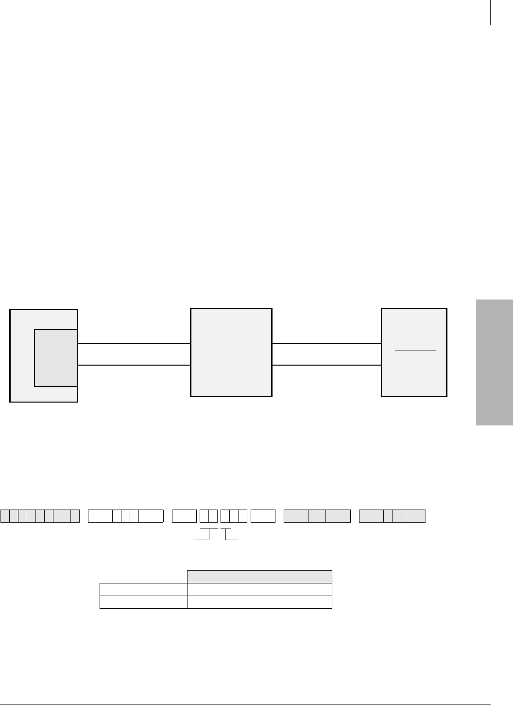
System & Station
Program *10 – Enhanced 911 Operation
Strata DK Programming 5/99 3-39
System & Station
Program *10 – Enhanced 911 Operation
Processor Type:
DK14, DK40i, all RCTUs
Program Type:
System
Initialized Default:
See each program
Program *10 provides two QSTU2, RSTU, KSTU2, RDSU, PSTU, or PESU ports to be assigned
to interface with central office E911 trunks.
E911 enhanced operation provides locator information to the responding agency to provide more
complete name and address information, including building, floor, etc. This is done by sending the
station number of the 911 caller to the E911 emergency center. This locator information is then
cross referenced with name/number/address data in the E911 central database, and the E911
operator receives the precise location along with the basic information.
The Strata DK14, DK40i and DK424 accomplishes this through a special interface between the
KSU and the CO. This special interface takes the station number information and sends it through
the public network in a format compatible with the central E911 database. This special interface is
required in addition to sending software within the Strata DK.
The required interface is an external device (Telident or Proctor) that interfaces to up to two
standard analog station ports.
Figure 3-1 Physical Connection of E911 Interface
Programs *10-11 and *10-12 – E911 Standard Telephone Ports Assignment
Initialized Default:
Blank
6SNU+ROG 6SNU + ROG6SNU +ROG 6SNU +ROG
Tip/Ring E911 CKT #1 CAMA Trunk #1
Strata DK
Proctor or
Telident
E911 Interface
Central
Office
E911
Center
KSTU2
QSTU2
RSTU
RDSU
PESU
CAMA Trunk #2Tip/Ring E911 CKT #2
1687
E911 CKT 1 and 2 assigned in Program *10
First E911 Port = 11
Second E911 Port = 12
E911 RSTU/KSTU2 Port Number
E911 RSTU/KSTU2/QSTU2 Port Number
First Standard Port
Second Standard Port
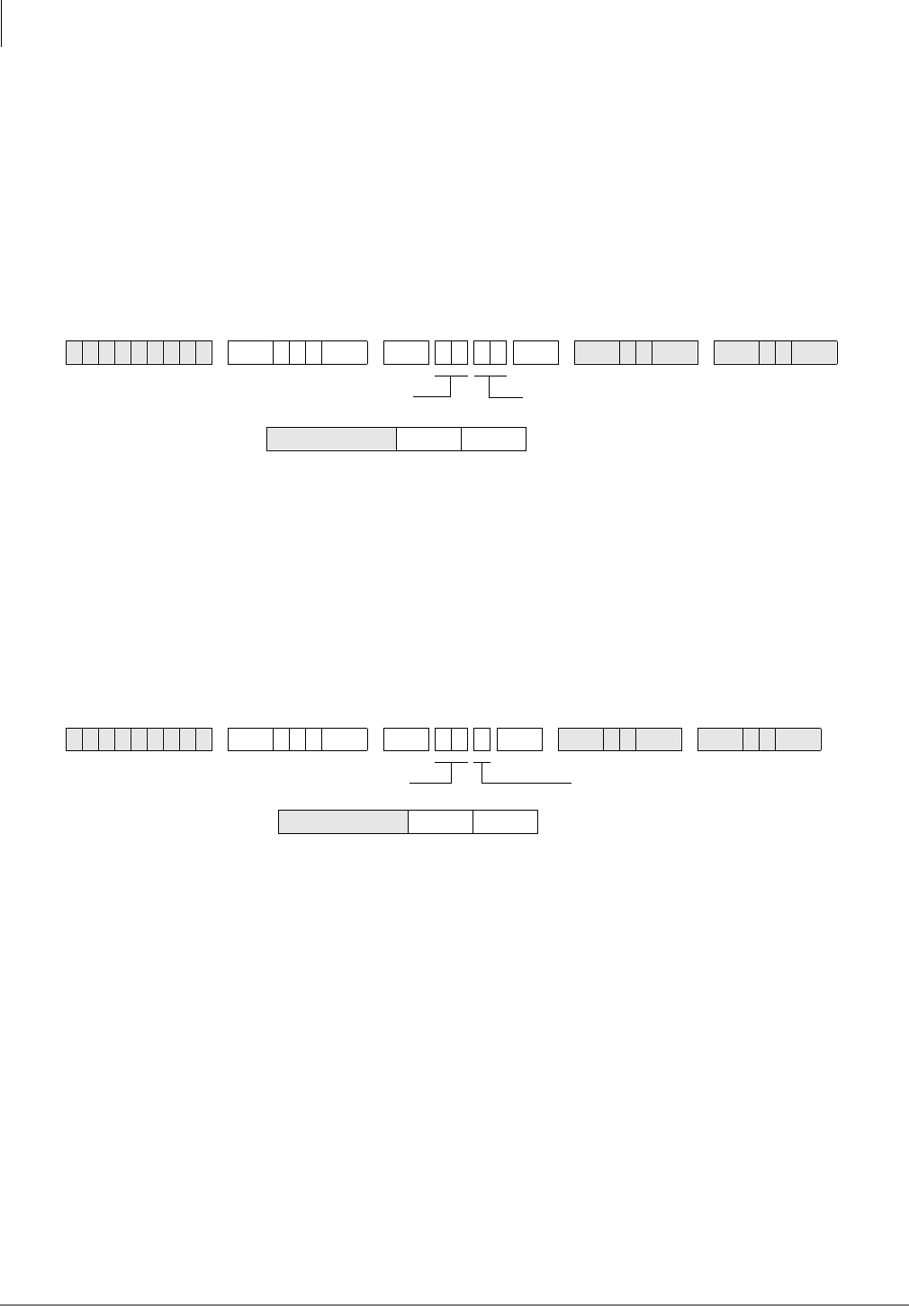
System & Station
Program *10 – Enhanced 911 Operation
3-40 Strata DK Programming 5/99
Programs *10-11 and *10-12 Overview
Programs 10-11 and 10-12 assign which QSTU2, KSTU2, RSTU2, RSTU, RDSU, PSTU, or
PESU standard telephone ports are connected to the E911 interface unit.
Important! Program 04 Directory Number data must be blank for E911 QSTU2, KSTU2,
RSTU2, or RSTU ports.
Program *10-91 – E911 Interdigital Time
Initialized Default:
15 seconds
Program *10-91 Overview
10-91 assigns the time allowed to dial each digit after dialing 9 when using the E911 feature.
This time will affect the time that LCR or CO Line dial tone is returned when dialing 9. However,
a user can dial a 9+ (non-911) calls normally before receiving LCR or CO line dial tone and the
DK will route the call appropriately.
Program *10-92 – E911 Pause Before Send Timer
Initialized Default:
0 - No pause
Program *10-92 Overview
10-92 assigns the time the DK will wait before sending the Station Primary Directory Number to
the E911 SLT port after the E911 SLT port answers.
6SNU+ROG 6SNU + ROG6SNU +ROG 6SNU +ROG
6SNU+ROG 6SNU + ROG6SNU +ROG 6SNU +ROG
Interdigit Timer = 91 01~15 seconds
Interdigit Timer seconds
Pause Timer = 92 0 = No pause
1 = 1.5 second pause
2 = 3 second pause
Pause Timer seconds
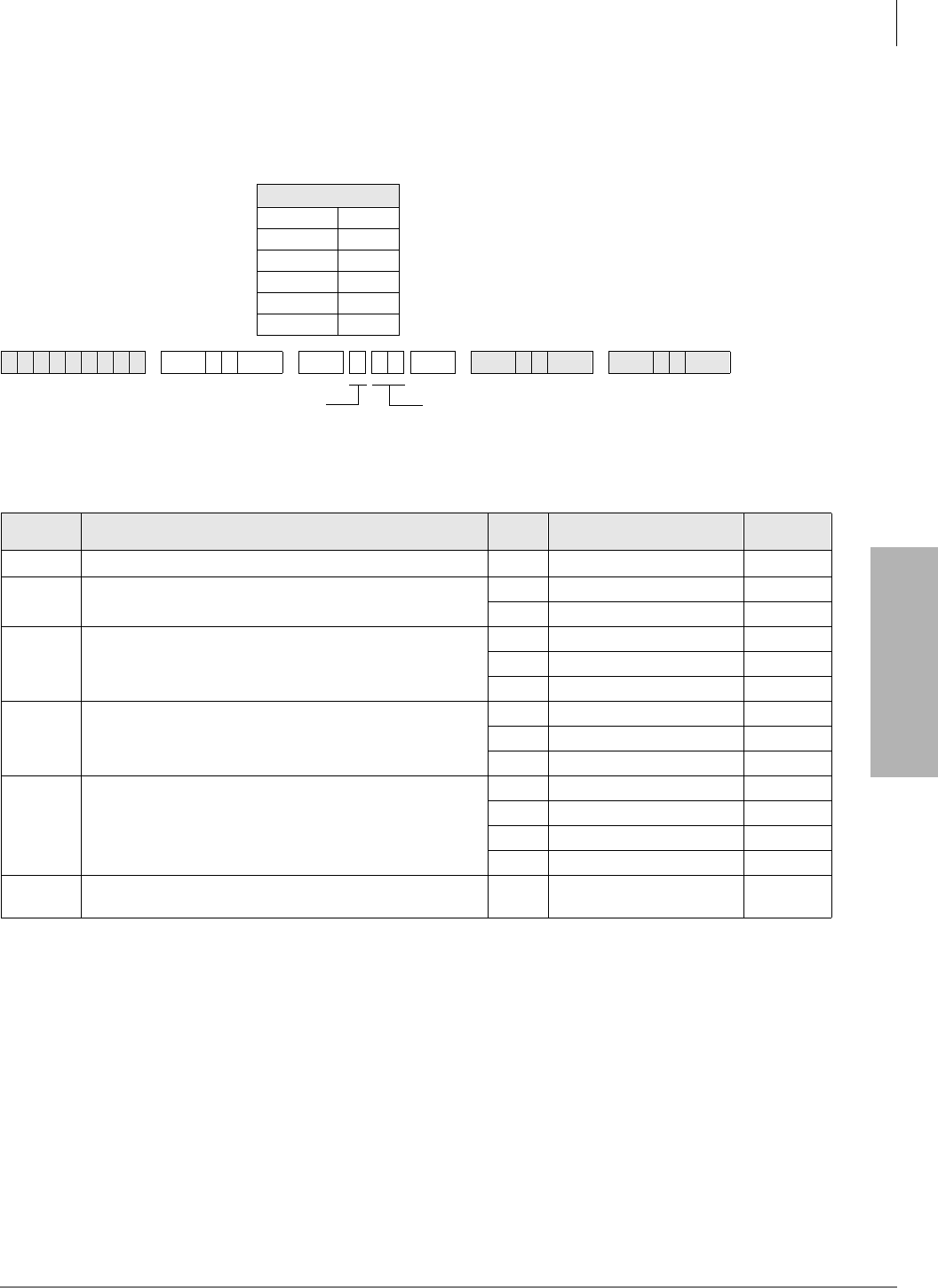
System & Station
Program 12 – System Assignments, Basic Timing
Strata DK Programming 5/99 3-41
System & Station
Program 12 – System Assignments, Basic Timing
Processor Type:
DK14, DK40i, All RCTUs
Program Type:
Station
Program 12 Overview
This program assigns system times for ring down, disconnecting calls, pause times, flash times,
auto attendant, DISA, Call Forward External, and DNIS and DTMF receiving decoding.
Code 1: Standard Telephone Ring Down Timer
This feature is available for Release 4.0 and higher. Code 1 assigns the number of seconds that a
Hotline or Emergency standard telephone waits after going off-hook before automatically ringing
a preassigned directory number. If a valid feature access code or [DN] is dialed prior to the ring
down timer expiration, then ring down does not occur. Ring down applies only to standard
telephone ports, not electronic or digital telephone ports. Ring down destination numbers are
assigned in Program *38.
Initialized Default: Program Timing
Code 1 15 secs.
Code 3 1
Code 4 2
Code 5 0
Code 8 1
Code 9 4
6SNU +ROG 6SNU +ROG6SNU +ROG 6SNU +ROG
Program
Code Function Code Time Required
Code
1Standard Telephone Ring Down Timer (Release 4.0) XX XX = 2 digits. 00~60 secs.
3Pause Timing
(Speed Dial)
1 1.5 sec
23.0 sec.
4
Flash Timing 1 0.5 sec.
2 2.0 sec. (Not used in U.S.)
40.2 sec.
5
Pause After Flash
(Voice Path Delay)
0 no pause
11.5 sec.
23.0 sec.
8
DNIS Ext. Network, External Call Forward, and DISA
Disconnect Timer for Loop Start Lines
0 no disconnect timer
1 4 min. disconnect
2 10 min. disconnect
3 20 min. disconnect
9QRCU3/K4RCU3/RRCS DTMF Inter-digital Release Time
(Standard Phone)
1~9 1~9 secs.
SELECT = 1, 3~5, 8, 9
Enter program code from
the table below.
DATA = Enter ring down time (00~60)
SELECT CODE = Enter the 1 digit code which
corresponds to the time listed in the table below.
For Program Codes 8 and 9, the LCD responds with

System & Station
Program 12 – System Assignments, Basic Timing
3-42 Strata DK Programming 5/99
Code 3: Pause Timing
Code 3 enables station users to program short and long pauses in Speed Dial numbers. Applies to
pauses inserted in Speed Dial numbers used for both telephone voice calls and data calls from data
interface units. The short pause length can be set system wide for either 1.5 or 3 seconds with this
program. The long pause is always 10 seconds.
Code 4: Flashing Timing
When on a CO line, a station user can press the )ODVK button (or enter access code &QI7UQ)
and the line opens (flash) for 2 seconds, 0.2 seconds (not used in the USA), or 0.5 seconds
depending on this assignment. This choice reflects whether to disconnect and regain dial tone (2
seconds), or to use PBX or Centrex features which require a flash signal (0.5 seconds). It also
applies to flashes inserted when dialing via Data Interface Units (DIUs).
Code 5: Pause After Flash
Some COs or Centrex facilities require a period of time after a flash signal before they can accept
dialing signals. A selection of pause timing is available to automatically delay any dialing signals
after flash. This timing applies to Speed Dial calls (with flash signals between the telephone
number digits) as well as to manual dialing.
Code 8: DNIS Ext. Network External, Call Forward, and DISA Disconnect Timer for Loop
Start LInes
Disconnects DISA, Call Forward External and/or DNIS Telephone Network routed calls when
made on loop start lines. Calls can lock-up (keep busy indefinitely) if the CO does not send a
disconnect signal (CPC or AR) when the caller hangs up. This timer prevents loop start lines from
locking up by disconnecting the call automatically when the timer expires, 4, 10, or 20 minutes
from the start of the call. Callers will hear a warning tone and can reset the timer repeatedly by
dialing “0”. This disconnect feature is only needed for loop start lines.
Code 9: QRCU3/K4RCU3/K5RCU/K5RCU2/RRCS DTMF Receiver Inter-digital Release Time
With Code 9, one channel of the QRCU3, K4RCU, K5RCU, and K5RCU2 or RRCS Dual-tone
Multi-frequency (DTMF) receiver is seized when it is needed for the decoding process, such as for
a standard telephone with a DTMF dial pad. When placing outgoing calls with DTMF standard
telephones, the talk path to the outside party is not “cut-through” until the DTMF receiver circuit is
released. The DTMF receiver channel’s release time can be programmed for between one and nine
seconds (initialized timing is four seconds)—this is the time it takes to release the DTMF receiver
circuit after the last digit is dialed.
The choice of timing is a trade-off between CO line time to connect and user speed. If the time is
too long, the outside called party may answer before the voice path is “cut-through,” and the caller
is not heard. If the time is too short, a standard telephone user inputting DTMF tones could be cut
off prematurely from using other features, such as Speed Dial or Toll Restriction.
Standard telephones can also defeat Toll Restriction if the seize time is too short and they are not
required to dial outgoing calls via Least Cost Routing (LCR). Toshiba recommends that standard
telephones should always be required to dial outgoing calls via LCR to prevent them from
defeating Toll Restriction.
Note If no digits are dialed after accessing an outgoing CO line, the DTMF receiver remains
seized for 15 seconds and then drops; however, the line remains connected.
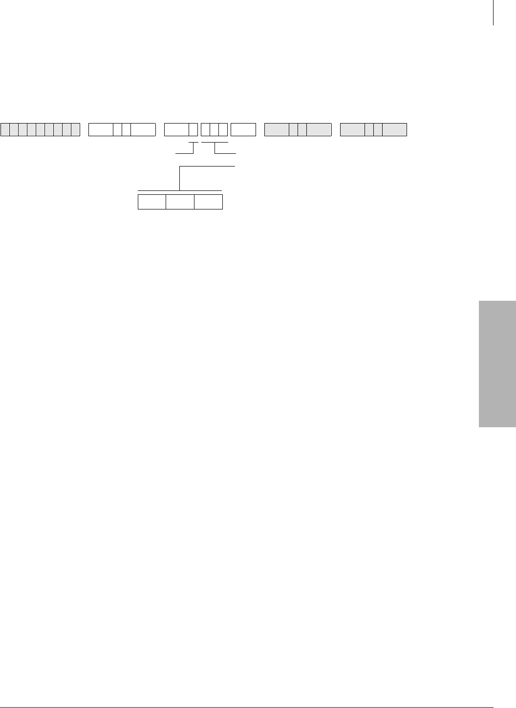
System & Station
Program 13 – Defining the Message Center
Strata DK Programming 5/99 3-43
System & Station
Program 13 – Defining the Message Center
Processor Type:
DK14, DK40i, All RCTUs
Program Type:
Station
Initialized Default:
No port assigned
Program 13 Overview
This program assigns a station as the Message Center.
Each digital, electronic and standard telephone can receive a maximum of four message waiting
indications per [PDN] and each [PhDN] owned by the station. One of these four is reserved for the
designated Message Center. The Message Center should be the customer’s main answering
position.
Typically, the Message Center is a voice mail device, attendant console, a digital or electronic
telephone with a DSS console (DDSS or HDSS), or an add-on module. If incoming traffic to a
DDSS or HDSS console attendant is heavy, another station can be assigned as the Message Center.
Notes
●The Message Center is allowed to perform “Message Waiting,” even if disallowed on all other
stations.
●Assign the Message Center to the customer’s main answering position: a station or the lowest
port (in VM group) of the customer’s voice mail device (see Program 31 for voice mail group
port assignments), whichever the customer specifies.
●When using RS-232 SMDI or DTMF voice mail interface, all stations must also be assigned to
the message center port in Program 32 and Program 13. This should be the lowest standard
telephone port (QSTU2/KSTU2/RSTU2) connected to the VM device. This is also the same
(lowest) port assigned in the Program 31 VM group and the lowest standard telephone port
assigned in the Program 40 VM Distributed Hunt Group. Do not assign the VM DH Group
port number (900~915) as the message center port.
6SNU +ROG 6SNU +ROG 6SNU +ROG 6SNU +ROG
SELECT = 1 PORT = Station Logical Port Number
Enter the station logical port number of the station
to be defined as the Message Center.
For RS-232 SMDI and In Band (DTMF) voice mail
integration, enter the lowest QSTU2/KSTU2/
RSTU2 standard telephone port connected to the
VM device (see notes below.)
Port Number
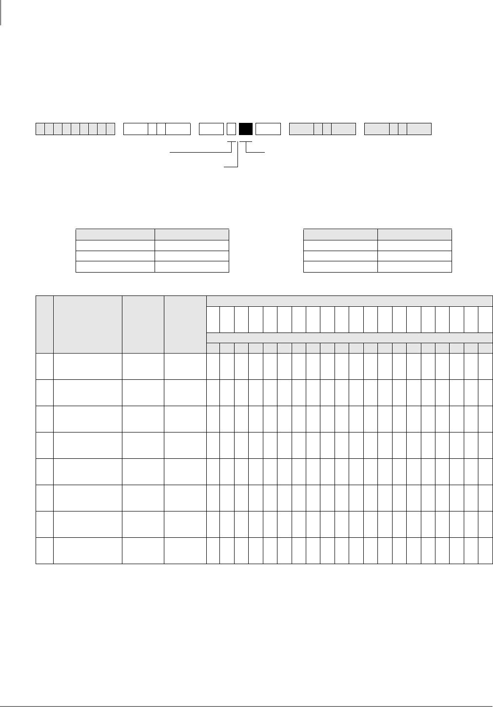
System & Station
Program 15 – Ground/Loop/Tie/DID Line Options
3-44 Strata DK Programming 5/99
Program 15 – Ground/Loop/Tie/DID Line Options
Processor Type:
DK14, DK40i, All RCTUs
Program Type:
System
Initialized Default:
All LEDs are OFF
6SNU +ROG 6SNU +ROG 6SNU +ROG 6SNU +ROG
Processor Type CO Line Range Processor Type CO Line Range
DK14 001~004 RCTUBA/BB 001~048
DK40i 001~012 RCTUC/D 001~144
RCTUA 001~016 RCTUE/F 001~200
Program Code
Program LED ON LED OFF
Line
LED
01 02 03 04 05 06 07 08 09 10 11 12 13 14 15 16 17 18 19 20
0CPC on AR VM
Calls and Voice
Calls
Detect Ignore
1CO/DID/Tie Line
Signal DP DTMF
2CO/DID/Tie Dial
Pulse Rate
(Pulse per sec.)
20 PPS 10 PPS
3AR Hold Detect Ignore
4AR Timing Crossbar
95 msec. ESS
(electronic)
450 msec.
5Tandem CO Line
Connection with
Station Dropout
Enabled Not
Enabled
7Forced Account
Code Enabled Not
Enabled
8Operation After CO
Line Flash No DTMF
receiver
After Flash
DTMF
receiver
After Flash
SELECT = Program Code
Press Scroll to advance or 3DJH to go back.
To advance the CO line range, press 6FUROO
located beneath the LCD. Press 3DJH for a
lower range.
LED Buttons = CO line
Specify CO line by setting LEDs as defined by the
table below. When you are finished, all LEDs with
an “X” should be lit.

System & Station
Program 15 – Ground/Loop/Tie/DID Line Options
Strata DK Programming 5/99 3-45
System & Station
Program 15 Overview
This program specifies operational options on a line by line basis.
Code 0: Automatic Release (AR) on Voice Mail or Voice Calls
On loop start CO lines, some COs send the AR (Automatic Release) or CPC (Calling party
Control) signal after an external party hangs up (typically 1~15 seconds) to disconnect a loop start
line. An AR/CPC signal is a 95 or 450-millisecond open of the CO line loop. If the CO sends this
signal after an external party hangs up and before the VM/auto attendant transfers a call, D tone
will be sent to the voice mail port (Program 30, LED 15), releasing and clearing that port for
another call. This feature is active on all voice calls.
When a station is disconnected from a CO line call by the AR/CPC signal, its LCD will display
“CO LINE HANG UP”. The line can be disconnected anytime by the AR/CPC signal during the
“talk state” of a call. CO line calls disconnected by the AR/CPC signal will be represented on the
SMDR report by a “*” next to the CO line number. Code 0 does not apply to ground start lines,
which automatically disconnect when the external party hangs up. The Voice Mail device must
recognize the “D” tone as a disconnect signal.
Important! This option cannot always be used because some COs may send unreliable AR/CPC
signaling or no AR/CPC signaling for loop start lines.
Enable AR/CPC-Hold detect on loop start lines only after testing that the CO sends
the AR/CPC-Hold signal.
Code 1: CO Outgoing Signal
Each line can be independently assigned to have either Dial Pulse (DP) or Dual-tone Multi-
frequency (DTMF) signaling on outgoing calls toward the Central Office.
♦If a line is set for DP operation, the 7RQH'LDO6HOHFWbutton must be programmed on
stations that must send DTMF tones over the lines.
♦If Tie or DID lines are programmed for dial pulse, turn LED 11 ON in Program 30 for each
station port assigned to the DID or Tie line.
Code 2: Line Pulse (DP) Rate
If a line is assigned DP signaling, the rate can be either 20 or 10 pulses per second (PPS). Some
Central Offices do not reliably accept 20 PPS.
Code 3: Automatic Release (AR) From Hold/Transfer
The Automatic Release (AR) signal sometimes called Calling Party Control (CPC) or Supervised
Loop Control. This signal consists of a momentary open of the loop start CO line provided by
some COs—the duration of the open depends on the CO. If a CO line is programmed (Programs
15-0 and 15-3) to detect the AR/CPC signal, the DK system drops the line when the CO sends the
signal (typically 1~15 seconds after the outside party hangs up). The system sends D Tone to voice
mail ports to drop the ports when AR/CPC is detected.
The Strata DK system disconnects a loop start CO line voice call and displays “CO LINE HANG
UP” on the station’s LCD anytime the AR/CPC signal is detected and the CO line has Programs
15-0 and 15-3 enabled.
On loop start CO lines, some Central Offices send an AR/CPC signal. If the system CO line is on
hold (or being transferred to another station or Auto Attendant port) when the AR/CPC signal is
sent, it is automatically disconnected if this option is activated.

System & Station
Program 15 – Ground/Loop/Tie/DID Line Options
3-46 Strata DK Programming 5/99
Two-CO line DISA calls always release when AR/CPC is sent. DISA release via AR/CPC is not
related to this program. CO line calls disconnected by the AR/CPC signal will be represented on
the Station Message Detail Recording (SMDR) report by a “*” next to the CO line number. Code 3
does not apply to ground start lines, which automatically disconnect when the external party hangs
up. See Important! note in earlier paragraph on Code 0.
DK424 only: If loop start lines are programmed to detect the AR/CPC-Hold signal, they do not
remain on the attendant console loop keys when the attendant console sets up trunk-to-trunk
connection. If programmed to ignore AR/CPC-Hold, they remain on the attendant console Hold
loop keys.
Important! Enable AR/CPC-Hold detect on loop start lines only after testing that the CO sends
the AR/CPC-Hold signal.
Code 4: Automatic Release (AR) Time
AR/CPC signaling timing is different depending on the Central Office equipment. An assignment
choice exists between Crossbar or ESS Central Offices.
For more information on AR/CPC, see the preceding Code 0 and Code 3 sections.
Code 5: Tandem Line Connection
Once a Two-line Conference call is made by an electronic, digital or (in R3.2) standard telephone
users or voice mail ports, the user or voice mail device may drop out of the conference and leave
the two lines connected. The choice exists for each line that may have this capability. This option
must be enabled to allow CO lines (ground/loop/Tie/DID) to be used for outgoing DISA, Call
Forward External, and Tie/DID/DNIS External Network routing calls.
With Release 3.2, a station which set up a tandem call and then dropped out can dial the pickup
code () to retrieve the tandem call. If more than one tandem connection is set up by a
station, picks up the call with the lowest CO line as a priority.
Prior to Release 3.2, standard telephones could set up tandem calls, but they could not drop out. If
they tried to drop out, the call would ring back to the standard phone.
Code 7: Forced Account Code (Verified or Non-verified)
If the Forced Account Code feature is used, (see Program 30) a station user is required to enter an
Account Code before a CO line call can be completed. A choice exists for each line.
Code 8: Operation After CO Line Flash
If a standard telephone user is on an existing CO line call and flashes the hookswitch on their
telephone, a Dual-tone Multi-frequency (DTMF) receiver channel may or may not be connected,
depending on this assignment. If the CO line is a rotary dial only type, the QRCU2, K4RCU3,
K5RCU, K5RCU2, or RRCS must be seized after flash when dialing from DTMF standard
telephones. The QRCU2, K5RCU, K5RCU2, K4RCU3 or RRCS will decode the dialed tones and
send dial pulses to the line.
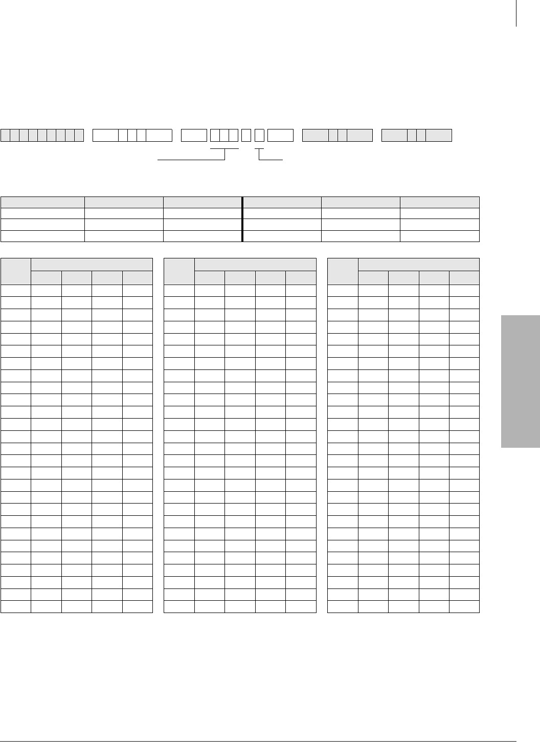
System & Station
Program *15 – CO Line Tenant Assignments
Strata DK Programming 5/99 3-47
System & Station
Program *15 – CO Line Tenant Assignments
Processor Type:
DK14, DK40i, All RCTUs
Program Type:
System
Initialized Default:
All CO lines assigned to Tenant 1
Program 15 Overview
A system CO line can be shared by more than one business tenant for the purpose of separating CO
line ringing pickup and Night Transfer. Program 15 assigns CO line business tenants.
6SNU+ROG 6SNU +ROG 6SNU +ROG 6SNU +ROG
Processor Type CO Line Range Tenants Supported Processor Type CO Line Range Tenants Supported
DK14 001~004 2 RCTUBA/BB 001~048 4
DK40i 001~012 2 RCTUC/D 001~144 4
RCTUA 001~016 2 RCTUE/F 001~200 4
CO
Line
Tenant Group CO
Line
Tenant Group CO
Line
Tenant Group
1234 1234 1234
SELECT = CO Line Number
To add a line range, enter XXXXXX (low port high port).
TENANT = Assign the CO line to a tenant
(see legend below)
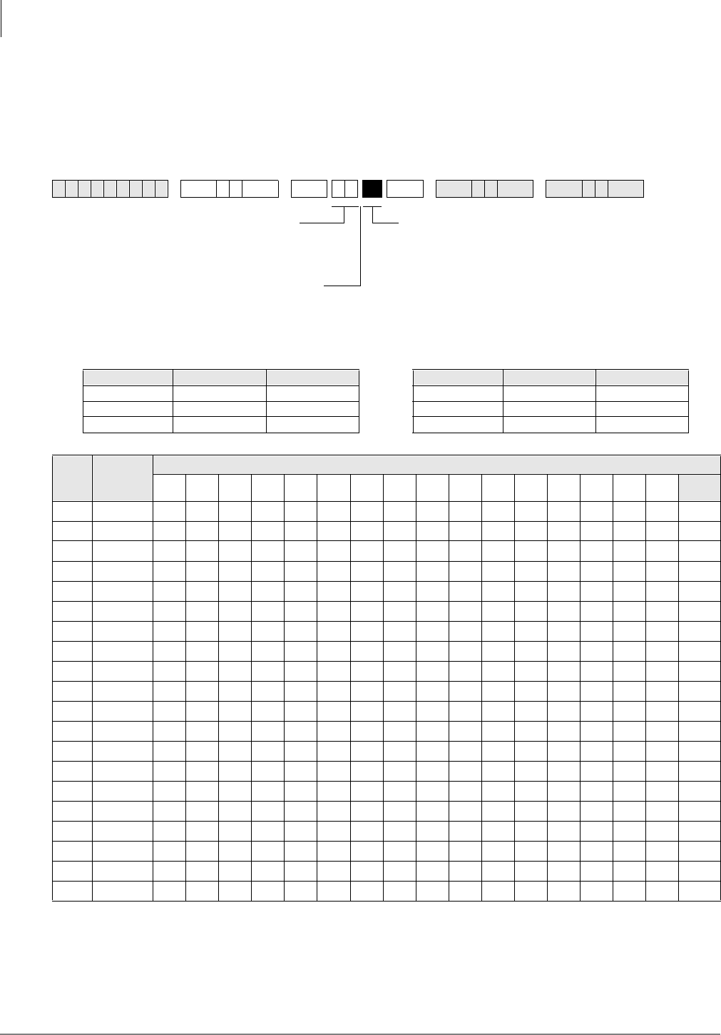
System & Station
Program 16 – Assign CO Line Groups (or Dial 9)
3-48 Strata DK Programming 5/99
Program 16 – Assign CO Line Groups (or Dial 9)
Processor Type:
DK14, DK40i, All RCTUs
Program Type:
System
Initialized Default:
All CO lines assigned to the Dial 9 group
6SNU +ROG 6SNU +ROG 6SNU +ROG 6SNU +ROG
Processor Type CO Line Range CO Line Groups Processor Type CO Line Range CO Line Groups
DK14 001~004 01~04 RCTUBA/BB 001~048 01~08
DK40i 001~012 01~08 RCTUC/D 001~144 01~16
RCTUA 001~016 01~08 RCTUE/F 001~200 01~16
LED Line
Number
CO Line Groups
Dial
9(00)
20
19
18
17
16
15
14
13
12
11
10
09
08
07
06
05
04
03
02
01
SELECT = CO Line Group (see legend)
Only enter the last two digits of the CO line
Group, or enter for Dial 9 group.
Press 6FUROO to advance or 3DJH to go back.
To advance the CO line range, press 6FUROO
located beneath the LCD. Press 3DJH for a
LED Buttons = CO line
Specify CO line by setting LEDs as defined by the
table below. When you are finished, all LEDs with
an “X” should be lit.

System & Station
Program 16 – Assign CO Line Groups (or Dial 9)
Strata DK Programming 5/99 3-49
System & Station
Program 16 Overview
Use Program 16 to assign each CO line to a CO line group or a general “dial 9” group. A general
group for outside calling is available with a “dial 9” access code as the initialized state for all lines.
Lines can be accessed with a dialing code instead of with a CO /LQH button. This is useful for
WATS lines or other facilities, and is heavily used in Least Cost Routing and Pooled Line Button
assignments.
Do not attempt to assign a line to more than one group. A line need not be assigned to a group. If
lines are not used, they should be taken out of all groups, including the “dial 9” group. Automatic
Busy Redial (ABR) will not function if unconnected (unused) lines are assigned to a line group.
After programming, press:
♦9RO▲ to turn all LEDs ON
♦9RO▼ to turn all LEDs OFF
♦0RGH and CO line number, then to display and advance
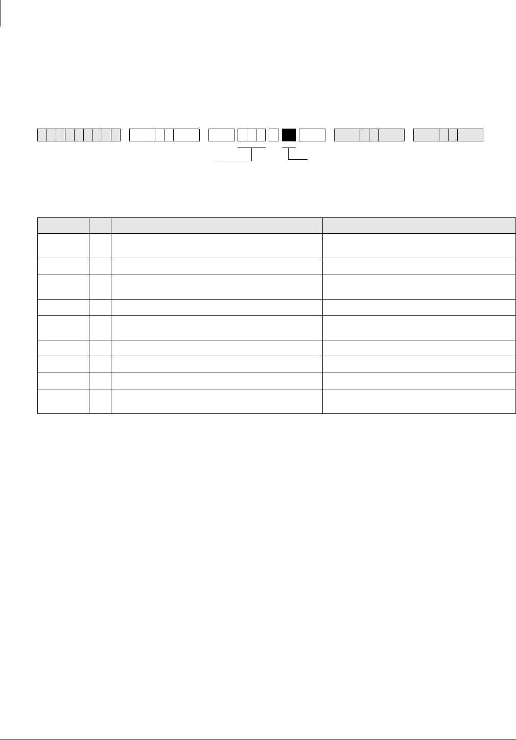
System & Station
Program 17 – DID/Tie Line Options
3-50 Strata DK Programming 5/99
Program 17 – DID/Tie Line Options
Processor Type:
DK40i, All RCTUs
Program Type:
System
Initialized Default:
LED 01/02 OFF, LED 03/04 ON
Program 17 Overview
Program 17 assigns lines for Tie and DID operation.
Important! When normal Tie/DID lines are configured with Program 71 and 72 DNIS
assignments, turn LED 05 ON and LED 06, 07 and 08 OFF for those lines - then
program the lines as required in Programs 71 and 72.
Notes
●Each REMU, PEMU, RDDU or TDDU PCB reduces the station port capacity by four station
ports, each RDTU Tie/DID line channel reduces the system’s station port capacity by one port.
●Always install Tie or DID line PCBs in slot numbers that are higher than station PCB slot
numbers (see Chapter 2 – DK40i Configuration in the Strata DK Installation and Maintenance
Manual).
●Incoming Tie line calls camp-on only if Program 71 assignments are used.
●Copy one record sheet for each group of Tie/DID lines that have different Program 17
parameters.
LEDs 09, 10 and 14~20
Not used at this time.
6SNU +ROG 6SNU +ROG 6SNU +ROG 6SNU +ROG
Line Numbers:
LED/Button XLED ON LED OFF
09, 10, and
14~20 Not used at this time.
08 DID/Tie line DTMF digits with tones DID/Tie line DTMF digits without tones
07 DID/Tie line receives ANI and routes per Programs 71 and 72 DID/Tie line does not receives ANI (DID Program *09 and
Tie Program 04)
06 Telephone LCD priority is ANI Telephone LCD priority is DNIS
05 DID/Tie line routes per DNIS assignments:
(Programs 71 and 72) DID/Tie line routes per Non-DNIS assignments:
(DID Program *09 and Tie Program 04)
04 DID/Tie no second dial tone DID/Tie second dial tone
03 DID line Auto Camp-on busy DID line no Camp-on busy
02 Wink Start for Tie or DID Immediate Start for Tie or DID
01 Page and Voice Announce on incoming Tie line Page access for
Tie/DID DNIS lines No Page and Voice Announce on incoming Tie line No
Page access for Tie/DID DNIS lines
Enter Line No. that will be DID or Tie line.
To add a port range, enter XXXXXX (low port high
Light LED Buttons 01~08 as noted in table below

System & Station
Program 17 – DID/Tie Line Options
Strata DK Programming 5/99 3-51
System & Station
LED 08: ANI/DNIS Digit Format
Most DID/Tie lines with ANI/DNIS digit format include tone with digits (LED 08 ON). One
exception, as of this writing, Sprint provides DNIS without ANI and does not include tone with
digits - in this case LED 08 should be turned OFF.
Examples of this signal format are: ANI digitsDNIS digits and DNIS digits.
DID/Tie lines with normal digit format does not include tone with digits (LED 08 OFF).
LED 07: ANI Receive Line Option
If a Tie or DID line should receive ANI information, LED 07 should be turned ON for that line. If
the Tie/DID line receives ANI digits only (no DNIS digits) LED 06, 07, and 08 should be ON and
LED 05 should be OFF. See Program 71-1, address 199, 299, and 499 for Tie/DID ANI only call
routing assignments. If a line receives ANI and DNIS, LEDs 05, 07 and 08 must be ON; LED 06
can be ON or OFF.
LED 06: Telephone LCD Display Option ANI or DNIS
Telephone LCDs can display ANI or DNIS information as a priority when Tie/DID lines or ISDN
channels receive both ANI and DNIS digits. This system-wide option determines if ANI or DNIS
information should display on telephone LCDs when Tie/DID lines provide both ANI and DNIS
information together on incoming calls.
It is not possible to display both ANI and DNIS information simultaneously on the same call but
the 3DJH button on the LCD telephone can be used to toggle between the ANI and DNIS
information when an ANI/DNIS line is ringing the telephone. After answering the call, it is not
possible to toggle the LCD display between ANI and DNIS
LED 05: DNIS Line/Non-DNIS Line
This option assigns Tie and/or DID lines to follow Dialed Number Identification Service (DNIS)
Program assignments.
Turn LED 05 ON for DNIS only or ANI with DNIS lines.
Turn LED 05 OFF and LED 07 and 08 ON for ANI only lines which should route per the last
address assignment in Program 71.
Important! Any Tie or DID line can be assigned to use the features of Program 71 and 72. If
normal Tie/DID lines are assigned Name Tags, External Routing, selective Day/
Day2/Night Routing: In Program 17, Turn LED 05 ON and turn LED 06, 07 and 08
OFF for those lines - then program the lines as required in Program 71 and 72. In
this case, Program *09 (DID) and Program 04 (Tie) do not apply to these lines.
LED 04: DID/Tie Second Dial Tone Option
If the second dial tone option is selected (LED 04 OFF), callers calling in on the DK DID or Tie
lines will hear dial tone after accessing the DK Tie/DID lines. Second Dial tone will not be sent to
callers if this option is not selected (LED 04 ON).
Important! Normally, Tie lines require a second dial tone (LED 04 OFF) and DID lines should
not return a second dial tone (LED 04 ON). The initialized data is set for DID lines
so this data must be changed when installing Tie lines if second dial tone is
required.
LED 03/04 applies to REMU, PEMU, TDDU, RDDU and RDTU DIDs and Tie lines.

System & Station
Program 17 – DID/Tie Line Options
3-52 Strata DK Programming 5/99
LED 03: DID Camp-on/Busy
Turn LED 03 ON if DID line callers should hear ringback tone and camp on to busy stations when
calling busy stations. Turn LED 03 OFF if the DID callers should hear busy tone when calling
busy stations. Analog Tie lines will not camp-on to busy stations.
It is recommended to turn LED 03 ON for all DID lines. To provide Camp-on-busy over RDTU
Tie line calls, configure Tie lines as DID lines in Program 41-2; LED 03 must be on for the lines
in Program 17. This is allowed because Tie and DID signalling is the same for Tie and DID T1
lines.
Also, both Tie and DID lines that route per Program 71 DNIS assignments will camp on busy if
LED 03 is turned ON. Tie lines that route per Program 04 will not camp on busy.
LED 03/04 applies to REMU, PEMU, TDDU, RDDU and RDTU DIDs and Tie lines.
LED 02: Wink/Immediate
Applies to REMU, TDDU, PEMU, and RDDU Tie/DID lines only. Select Wink Start or
Immediate Start for the entered Tie or DID line. See Program 41-2 for RDTU Tie/DID Wink/
Immediate Start assignments or RDTU T1 Tie lines configured as DID lines in Program 42-1.
LED 01: Page/Handsfree Answerback
Allows (LED 01 ON) or denies (LED 01 OFF) the following features when connecting the Strata
DK to another Key/PBX. LED 01 applies to both Tie and DID lines when programmed with
Program 71 assignments.
If using a private network, then turn LED 01 ON to allow Page access on Tie and DID lines
programmed with DNIS assignments in Program 71 (Code #039).
Per FCC regulations, public telephone network, Tie, DID, or DNIS lines must always be restricted
(LED 01 OFF) from Page and Handsfree Answerback.
♦Callers on the far-end Key/PBX system can access the Strata DK system external and/or
Station All Call Page over DID and/or Tie lines programmed with DNIS assignment (Program
10-2, LED 15 and Program 71-1, Code #039) for DID/Tie DNIS assignments. Tie lines only
that route per Program 04 can dial any Page Zone or Page Group access code.
♦Callers on the far-end Key/PBX system can make voice announce calls to stations on the near-
end Strata DK. This option applies only Tie lines (not DID lines) that route per Program 04 or
Program 71. You must program the Strata DK as “Voice First” in Program 10-1, LED 01; or,
the far end can dial “1” after dialing the [DN] on tone first systems.
♦Callers on the far-end Strata DK can answer Tie lines calls (not DID lines) from the Far End
Key/PBX in the hands free mode. You must program the near-end Strata DK as “Voice First”
in Program 10-1, LED 01, or the far-end caller must dial “1” to switch from ring to voice
signaling.
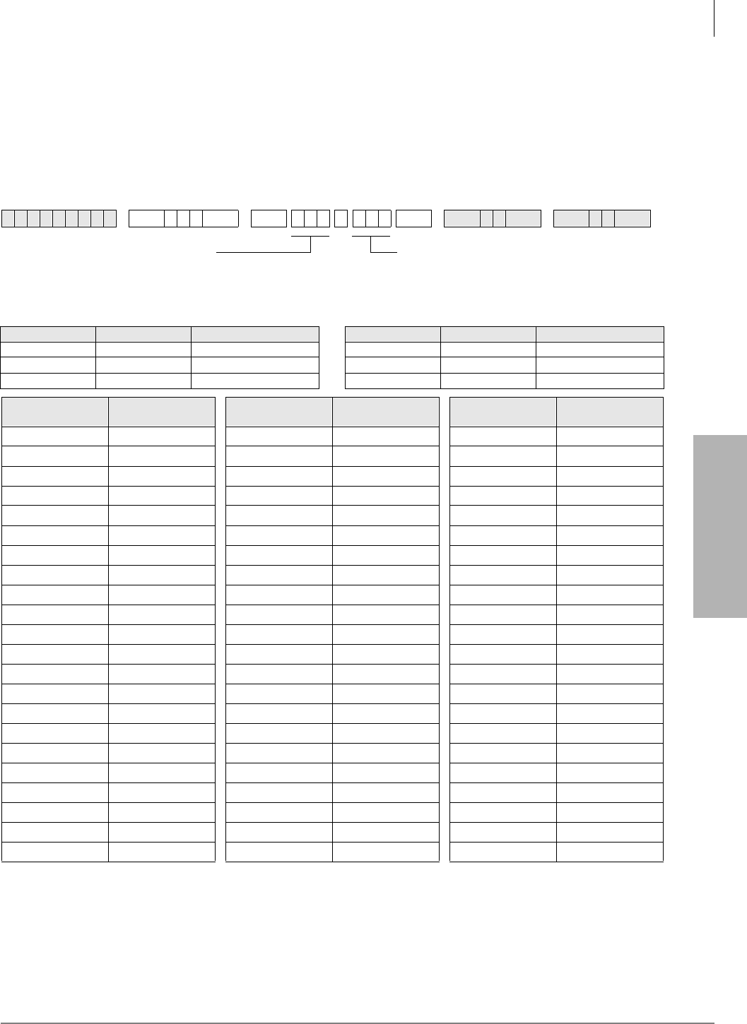
System & Station
Program *17 – DID Intercept Port Number (Vacant or Wrong Number)
Strata DK Programming 5/99 3-53
System & Station
Program *17 – DID Intercept Port Number (Vacant or
Wrong Number)
Processor Type:
DK40i, All RCTUs
Program Type:
System
Initialized Default:
No data
Program *17 Overview
DID and/or DNIS calls in which callers have dialed a vacant or invalid port can be routed to
intercept ports assigned with this program. Each DID and/or DNIS line can have its own intercept
port. In all cases, Intercept does not apply to Tie lines.
6SNU+ROG 6SNU + ROG 6SNU +ROG 6SNU +ROG
Processor Type DID Line Range Intercept Port Range Processor Type DID Line Range Intercept Port Range
DK14 N/A N/A RCTUBA/BB 001~048 000~079
DK40i 001~012 000~027 RCTUC/D 001~144 000~239
RCTUA, RCTUB 001~016 000~031 RCTUE/F 001~200 000~335
DID LIne Number Intercept Port
Number DID LIne Number Intercept Port
Number DID LIne Number Intercept Port
Number
SELECT = DID Line Number
Intercept does not apply to Tie line calls.
To add a port range, enter XXXXXX (low port high port).
HUNT TO = Enter Intercept Station
Logical Port No.
LED Button 01 enters blanks.

System & Station
Program 19 – Alternate Background Music Source Slot Assignment
3-54 Strata DK Programming 5/99
Program 19 – Alternate Background Music Source Slot
Assignment
Processor Type:
DK40i, All RCTUs (not used for DK14. See Program 10-2, LED 10)
Program Type:
System
Initialized Default:
Slot 11
Program 19 Overview
The PCB connected to the alternate BGM source can be in any slot. Use this program to designate
that slot. LEDs 09 and 10 in Program 10-2 should be OFF if the source is connected to a QSTU2,
KSTU2, PSTU, RSTU, RSTU2, or RDSU. (Only circuit 2 of these PCBs can support the BGM
source.)
The alternate BGM source sends BGM to the external speakers and telephone (digital and
electronic) speakers. If an alternate BGM source is used, the Music-on-Hold (MOH) source
connected to an RCTU will continue to play for lines and stations that are on hold.
Important! If the alternate BGM source is not connected to a PEKU, PESU or PSTU, RSTU,
RSTU2, or RDSU, assign Slot 11 as data in Program 19. If BGM is connected to
circuit 2 of QSTU2 or KSTU2, assign slot 13 as data in Program 19. This ensures
that all PSTU or RSTU ports function normally. Digital / electronic telephones or
RSIU PCBs installed in Slot 11 are not affected by this assignment.
PEKU/PESU
If using a PEKU, wire the BGM source to circuit 3 and turn LED 09 ON (Program 10-2) to enable
the BGM connection.
If using a PESU, wire the BGM source to circuit 8 and turn LED 10 ON (Program 10-2) to enable
the BGM connection.
QSTU2, KSTU2, RSTU, RSTU2, RDSU, or PSTU
If using a QSTU2, KSTU2, RSTU, RSTU2, RDSU, or PSTU, wire the BGM source to circuit 2
and turn LED 09 and 10 OFF (Program 10-2). Also, an isolation transformer may be required if
connecting the source these PCBs. See Chapter 10 – Peripheral Installation in the Installation and
Maintenance Manual for isolation transformer installation instructions.
PDKU
BGM cannot be connected to the PDKU.
6SNU +ROG 6SNU +ROG Turn System Power OFF (5 sec) then ON
more codes
...or
Run Program 91-2
Enter the Slot Number (11~78)
SELECT = 1
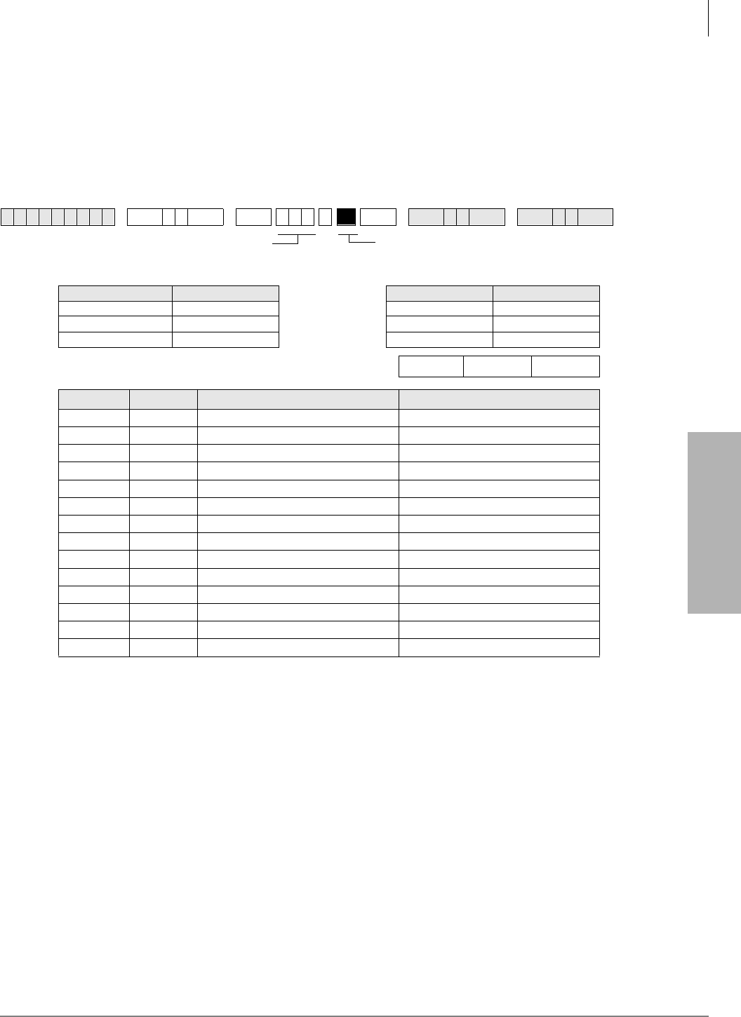
System & Station
Program 20 – Computer and Data Interface Unit Configuration
Strata DK Programming 5/99 3-55
System & Station
Program 20 – Computer and Data Interface Unit
Configuration
Processor Type:
DK14, DK40i, All RCTUs
Program Type:
Station
Initialized Default:
LED 17 ON, all others OFF
Program 20 Overview
Program 20 identifies the digital station ports connected to RPCI/PDIU and the type of PDIU
connected.
RPCIs have two modes: the Data Switching (DIU mode) and the Application Program Interface
(or TAPI) mode. In the DIU mode, the RPCI operates as a PDIU-DI (Integrated Data Interface
Unit); all Program 20 options apply except LED 10 and LED 11 - which only apply to the RPCI in
TAPI mode. In TAPI mode the RPCI does not require Program 20 assignments, except for LED 10
and/or LED 11 if ANI, DNIS, and/or Caller ID must be sent from the RPCI-DI to the PC to which
it is connected.
Notes
●RPCIs and PDIUs cannot be connected to PDKU1 circuit 8, but can be connected to all eight
PDKU2 circuits. RPCIs and PDIUs that support data switching cannot be connected to PDKU
in all slots. See DK424 Chapter 4 – DK424 Configuration, Tables 4-4 and 4-5. DK40i slots 17
and 18 do not support data switching.
6SNU +ROG 6SNU +ROG 6SNU +ROG 6SNU +ROG
Processor Type Port Range Processor Type Port Range
DK14 000~009 RCTUBA/BB 000~079
DK40i 000~027 RCTUC/D 000~239
RCTUA 000~031 RCTUE/F 000~335
DK40i Base, PDKU, RDSU, KCDU Digital Port Number
LED XLED ON LED OFF
20 Data Security Group 4 Not Included
19 Data Security Group 2 Not Included
18 Data Security Group 3 Not Included
17 Data Security Group 1 Not Included
12~16 Not Used
11 RPCI-DI DNIS Sent RPCI-DI DNIS Not Sent
10 RPCI-DI Caller ID/ANI Sent RPCI-DI Caller ID/ANI Not Sent
07~09 Not Used
06 DTR Pulse with Data Release No DTR Pulse
05 Auto Pause Behind PBX No Auto Pause
04 PDIU-DS Connected PDIU-DI/RPCI-DI Connected
03 PDIU-DS to Modem Connection PDIU-DS to other type DCE or DTE
02 AT Commands and Result Codes AT Commands Only
01 PDIU-DS or RPCI Connected No PDIU-DS or RPCI Connected
SELECT = PDKU/PDSU Station Logical Port
Number that is connected to PDIIU-DS or to
DKT with PDIU-DI or RPCI-DI
LED Buttons 01~06 define data port type;
LED Buttons 17~20 assign data port to
security group.

System & Station
Program 20 – Computer and Data Interface Unit Configuration
3-56 Strata DK Programming 5/99
●If a PC is connected to the RPCI or PDIU, set the communication mode escape sequences in
the PC communication software “Modem Initialization” character sequence. This ensures the
escape sequence is restored in case the RPCI Telephone or PDIU is unplugged temporarily.
●RPCI and PDIU-DS units that mostly do data switching, can be connected to ports associated
with PDKU1 circuits 1~7 only. All PDKU2 circuits, 1~8, support RPCIs and PDIUs. RDSU
digital circuits 5~8 support RPCI and PDIUs.
●Each PDIU-DS requires a separate digital port.
●If a PDIU-DS (Stand-alone Data Interface Unit) is connected to a modem, refer to Modem
Setup Recommendations in the PC/Data Communication section of Chapter 10 – Peripheral
Installation of the Installation and Maintenance Manual.
●See Chapter 10 – Peripheral Installation for additional hardware information and Chapter 2 –
DK40i Configuration and Chapter 4 – DK424 Configuration to identify which slots can
support RPCIs and DIUs.
Typical LED Settings for Program 20
RCPI-DI/PDIU-DI Connected to a terminal or personal computer—LEDs 01, 02, 05, and 17 ON;
all other LEDs OFF.
PDIU-DS Connected to a Printer: LEDs 01, 04, and 17 ON; all other LEDs OFF.
PDIU-DS Connected to a Modem: LEDs 01, 02, 03, 04, and 17 ON; all other LEDs OFF.
LEDs 17~20: Data Security Groups
Data security groups can be set to block data calls between RPCI/DIUs. RPCI/DIUs can only
make data calls to RPCI/DIUs in the same security group. LEDs 17~20 assign the RPCI/DIU to
the appropriate security group: light LED 17 for Group 1; LED 18, for Group 3; LED 19, for
Group 2; and LED 20, for Group 4. If an RPCI-DI is used in the Application Program Interface
(TAPI) mode only, and not the Data Switching mode, this option is not applicable.
LEDs 12~16
Not used at this time.
LED 11: RPCI-DI DNIS to PC Option
DNIS Number or NAME tag information that is sent to a telephone can be sent, or blocked, from
the telephone’s RPCI-DI, RS-232 output. If DNIS information should be sent from the
Telephone’s RPCI-DI to the Personal Computer to which it is connected, turn LED 11 ON; if this
information should not be sent to the PC, turn LED 11 OFF.
LED 10: RPCI-DI Caller ID and ANI to PC Option
Caller ID and ANI information that is sent to a telephone can be sent, or blocked, from the
telephone’s RPCI-DI, RS-232 output. If Caller ID and ANI information should be sent from the
RPCI-DI to the Personal Computer to which it is connected, turn LED 10 ON; if this information
should not be sent to the PC, turn LED 10 OFF. This option does not apply to PDIUs because they
can not send ANI, Caller ID, or DNIS numbers.
LEDs 07~09
Not used at this time.

System & Station
Program 20 – Computer and Data Interface Unit Configuration
Strata DK Programming 5/99 3-57
System & Station
LED 06: DTR Pulse
LED 06 should always be OFF.
LED 06 should be off for all PDIU-DS, RPCI-DIs, or PDIU-DIs.
(Refer to Chapter 10 – Peripheral
Installation for more PDIU-DS/modem pool information).
LED 05: Auto Pause Behind PBX
Turn LED 05 ON to enable Auto Pause Behind PBX. This inserts the Auto Pause after a Centrex
or PBX access code is dialed by a DIU or RPCI. A CO line must be assigned in Program 42-0, and
must have an access code assigned in Program 42 (1~8). Pause time is determined by Program 12-
3. Also, when Auto Pause Behind PBX is enabled, the Auto Pause is inserted after the CO line
access code is dialed (by the DIU).
If the system CO lines are connected to a PBX, Centrex, or a Central Office that is slow to return
dial tone after seizure, enable Auto Pause Behind PBX to insert a pause before and after the PBX
or Centrex access code is dialed by the DIU or RPCI. Also, light LED 05 to automatically insert a
pause before network telephone numbers are autodialed by DIUs or RPCIs.
LED 04: PDIU-DS or PDIU-DI/RPCI-DI Connection
Set LED 04 ON if a PDIU-DS is connected to the digital port.
Important! If LED 04 is turned on for a telephone port, that telephone cannot be called.
Set LED 04 OFF if a PDIU-DI or RPCI-DI or any type of telephone is connected. In this case, the
digital telephone supporting this PCB may require the Data Call (DATA), Data Release (DRLS),
and/or Modem buttons assigned in Program 39. Also, if an RPCI-DI is used in the Application
Program Interface (TAPI) mode only, and not the Data Switching mode, set LED 04 OFF.
Note The pause length is set in Program 12-3, and lines behind PBX/Centrex are assigned in
Programs 42-0 and 42-1~8.
LED 03: RPCI/PDIU-DS to Modem Connection
If a PDIU-DS is connected to the digital port, identify whether the RPCI/PDIU-DS is connected to
a modem (LED 03 ON) or not connected to a modem (LED 03 OFF). If not connected to a
modem, the connected device can be a DCE or DTE. This feature is not necessary for RPCI/PDIU-
DIs, because they are not normally connected to modems.
LED 02: AT Commands and Result Codes
Enable this feature (LED 02 ON) if the RPCI or DIU must respond to AT commands and return
result codes in the Data Switching command mode. RPCI/DIU “AT” dialing commands and
“result” codes are listed in the RPCI-DI and the Data Interface User Guide.
If the DIU is connected to a modem, LED 02 should be ON. If the RPCI/DIU is connected to a
printer, LED 02 should be OFF. If an RPCI-DI is used in the Application Program Interface (TAPI)
mode only, and not the Data Switching mode, this option is not applicable.
If the feature is not enabled (LED 02 OFF), the RPCI/DIU only responds to AT dialing commands
(ATDT, ATD, and ATDD) and does not return result codes. If the DIU is connected to a terminal or
a personal computer with communication software, LED 02 should be ON
LED 01: RPCI and PDIU Connection
Enable this feature (LED 01 ON) if there is a PDIU-DI, RPCI-DI or PDIU-DS connected to the
digital port. Each RPCI-DI or PDIU-DI uses the same digital port as the telephone it is attached to.
This feature is not applicable if an RPCI-DI is used only in TAPI, and not DIU mode.
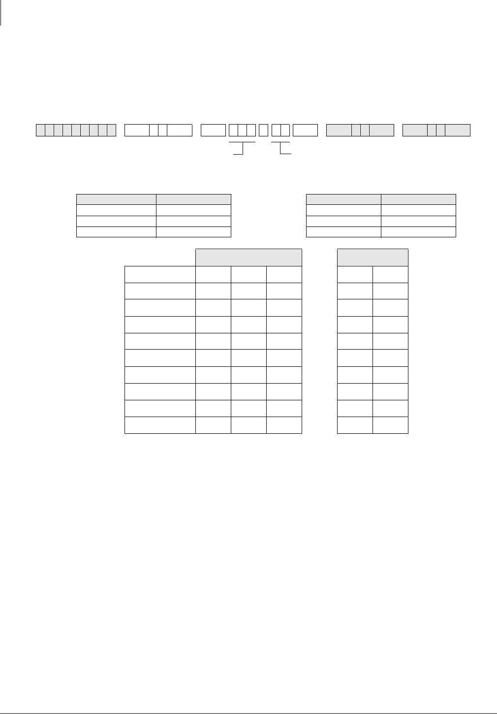
System & Station
Program 21 – Modem Pool Port Assignments
3-58 Strata DK Programming 5/99
Program 21 – Modem Pool Port Assignments
Processor Type:
DK14, DK40i, All RCTUs
Program Type:
Station
Initialized Default:
Blank
Notes
●Digital Ports include: DK14 KSU, DK40i Base KSU, QCDU2, KCDU, PDKU2, and RDSU
digital ports.
●Standard telephone ports include: QSTU2, KSTU2, RSTU2, RDSU, PSTU, and PESU
standard telephone ports.
6SNU +ROG 6SNU +ROG 6SNU +ROG 6SNU +ROG
Processor Type Port Range Processor Type Port Range
DK14 008~009 RCTUBA/BB 008~079
DK40i 008~027 RCTUC/D 008~239
RCTUA 008~031 RCTUE/F 008~335
Logical Port No. Modem Port No.
Assignment 1
Assignment 2
Assignment 3
Assignment 4
Assignment 5
Assignment 6
Assignment 7
Assignment 8
Assignment 9
Assignment 10
Digital Station Logical Port
Number (see notes below)
Standard Telephone Modem Port
Number (see notes below)

System & Station
Program 21 – Modem Pool Port Assignments
Strata DK Programming 5/99 3-59
System & Station
Program 21 Overview
This program assigns modems to the system modem pool. Program 21 identifies modems
connected to standard telephone ports (line side of modem) and digital/PDIU-DS ports
(RS-232 side of modem). With data security groups (Program 20, LEDs 17~20) and the call the
blocking feature (Program 31, LED 04), modem access can be denied or allowed to data users.
Notes
●PDIU-DS must be installed on PDKUs in slots designated for DIU operation. (See Chapter 2 –
DK40i Configuration and Chapter 4 – DK424 Configuration.)
●When modems are connected to standard telephone ports (PSTU, RSTU, RSTU2, PESU,
RDSU/RSTS, KSTU2, QSTU2) the Executive/ Privacy Override blocking feature (Program
31, LED 18) should be enabled for the modem RSTU, RSTU2, PSTU, PESU, RDSU, KSTU2
and QSTU2 ports for data security. The LED 18 feature should be disabled to enable callers to
switch from voice to data, or vice versa.
●Digital telephones with RCPI-DIs or PDIU-DIs that must access modems from a pool require
a 0RGHP button assigned in Program 39.
●PDIU-DS ports that are connected to modems in the modem pool should be set with LEDs 01,
02, 03, and 04 in Program 20.
●If a modem connected to PDIU-DS is connected to a telephone network line instead of a
standard telephone station port, Program 21 should not be used.
●Use Program 22 to assign modem/PDIU-DS stations to hunt sequences.
●DIUs can be connected to any ports associated with PDKU circuits, except for ports associated
with circuit 8 on a PDKU1. All PDKU2, KCDU, and QCDU circuits can support DIUs. DIUs
can also be connected to any digital circuit in the DK14 or DK40i KSU.
●DIUs can be connected to ports associated with PDKU1 circuits 1~7 only. All PDKU2
circuits, 1~8, can support RPCI/DIUs. RDSU circuits 5~8 can support RPCI/DIUs.
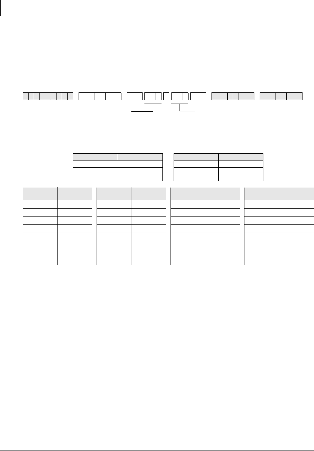
System & Station
Program 22 – RPCI and DIU Station Hunting for Data Calls
3-60 Strata DK Programming 5/99
Program 22 – RPCI and DIU Station Hunting for Data
Calls
Processor Type:
DK14, DK40i, All RCTU’s
Program Type:
Station
Initialized Default:
Does not assign “hunt-to” ports to any port
Program 22 Overview
This program assigns computer and Data Interface Unit (DIU) station hunt ports for data calls. If a
RPCI/PDIU station (printer, modem, etc.) is busy, data station hunting allows the data call to hunt
to an alternate RPCI/PDIU station assigned in this program. If the hunted RPCI/PDIU station is
busy, the system will ring the next “hunt-to” station, and so on. If all RPCI/PDIU stations in the
“hunt-to” sequence are busy, then the data caller will receive a busy tone. Toshiba recommends
that all PDIU-DS station ports grouped in a modem pooling or printer pooling/server configuration
be placed into a hunt-sequence arrangement with Program 22.
Notes
●Program 22 applies to RCPI-DI, PDIU-DI and PDIU-DS data calls, not telephone station
voice calls. If programming an RCPI-DI or PDIU-DI station, use the associated DKT logical
port number; the PDIU-DS is programmed using its own unique port number.
●When a PDIU-DS is connected to a modem(s) assigned to the system modem pool in Program
21, modem hunting is automatic when the user presses the 'DWD&DOO button to transfer a line
call to a modem. However, if the user dials the modem's PDIU-DS's station number, modem
hunting follows the hunt sequence specified in Program 22.
6SNU +ROG 6SNU +ROG 6SNU +ROG 6SNU +ROG
Processor Type Port Range Processor Type Port Range
DK14 000~007 RCTUBA/BB 000~079
DK40i 000~027 RCTUC/D 000~239
RCTUA 000~031 RCTUE/F 000~335
Hunt From
Port Hunt To
Port Hunt From
Port Hunt To
Port Hunt From
Port Hunt To
Port Hunt From
Port Hunt To
Port
SELECT = Port Number (see legend below)
Enter the RPCI/DIU digital port number of the “hunt-from” station.
Enter the port number(s) to which class of service must be assigned.
To add a port range, enter XXXXXX (low port high port).
HUNT TO = (see legend below)
Enter the “hunt-to” RPCI/DIU digital port number.
LED Button 01 deletes a digit from the “hunt-to”
port.
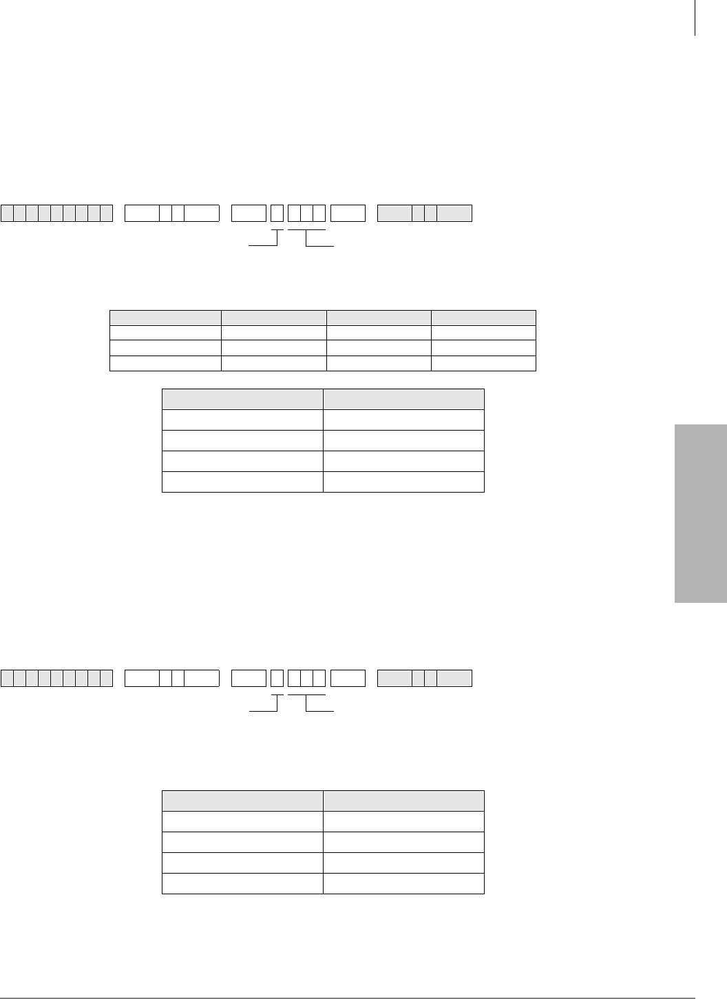
System & Station
Program 23 – Built-in Auto Attendant (AA) Primary Announcement Assignments
Strata DK Programming 5/99 3-61
System & Station
Program 23 – Built-in Auto Attendant (AA) Primary
Announcement Assignments
Processor Type:
DK14, DK40i, All RCTUs
Program Type:
System
Initialized Default:
No ports assigned
Program 24 – Built-in AA Secondary Announcement
Assignments
Processor Type:
DK14, DK40i, All RCTUs
Program Type:
System
Initialized Default:
No ports assigned
Note See Program 23 legend for port ranges.
6SNU +ROG 6SNU +ROG6SNU +ROG
Processor Type Port Range Processor Type Port Range
DK14 008~009 RCTUBA/BB 008~079
DK40i 008~027 RCTUC/D 008~239
RCTUA 008~031 RCTUE/F 008~335
Announcement Device Port Number
1
2
3
4
6SNU +ROG 6SNU +ROG6SNU +ROG
Announcement Device Port Number
1
2
3
4
SELECT = 1~4
Select the Auto Attendant
device (digital announcer).
AUTO ATT 1 NO. = Port
Enter the standard station logical port
number to which the device will be assigned.
SELECT = 1~4
Select the Auto Attendant
device (digital announcer).
AUTO ATT 2 NO. = Port
Enter the standard station logical port
number to which the device will be assigned.
System & Station
Program 25-1 – Built-in AA Incoming Call Overflow Time
3-62 Strata DK Programming 5/99
Programs 23 and 24 Overview
Programs 23 and 24 assign customer-supplied Auto Attendant announcement devices (digital
announcers) to standard telephone ports (QSTU2, KSTU2, RSTU, RSTU2, PSTU, PESU, RDSU/
RSTS). Use Program 23 to assign devices that deliver primary announcements, dialing options and
greetings heard when callers first call in; also, devices that deliver secondary announcements.
Use Program 24 to offer options to unanswered calls routed back to the Auto Attendant. Up to
eight devices can be connected to a system. See Primary and secondary announcements below:
Any combination is allowed within the maximum limitations. For example, three primary
announcements and one secondary announcement are allowed.
Ports assigned in Programs 23 and 24 should never be assigned with External Auto Attendant
voice mail options in other programs (30, 31, 81~89, etc.)
To allow the built-in Auto Attendant programs to function:
DK424: the RKYS (1, 2, 3, or 4) and RRCS must be installed on the RCTU PCB;
DK40i: the KKYS must be installed on the K5RCU;
DK14: the QKYS, and QRCU3 must be installed in the DK14 KSU.
Overflow stations and delay ring operation is assigned in Programs 81~89.
Program 25-1 – Built-in AA Incoming Call Overflow
Time
Processor Type:
DK14, DK40i, All RCTUs
Program Type:
System
Initialized Default:
20 seconds before overflow
Program 25-1 Overview
This program sets the time it takes an unanswered incoming Auto Attendant call to overflow to a
preassigned station(s). The time can be anywhere from 12 to 24 seconds—the default is 20
seconds. The overflow station or group of stations is assigned in Programs 81~89.
This overflow time applies to the overflow of incoming Auto Attendant calls to normal CO line
ringing if either a primary announcement device or K5RCU, K5RCU2, K4RCU3/RRCS (DTMF)
circuit is not available.
Note Auto Attendant will not answer when all of the RRCS, K5RCU, K5RCU2, K4RCU3 or
QRCU2 circuits or primary announcements are busy.
Processor Type Primary
Announcements Secondary
Announcements Processor Type Primary
Announcements Secondary
Announcements
DK14 1 1 RCTUBA/BB 4 4
DK40i 4 4 RCTUC/D 4 4
RCTUA, RCTUB 4 4 RCTUE/F 4 4
6SNU +ROG 6SNU +ROG 6SNU +ROG 6SNU +ROG
SELECT = 1 AATT TIME = Seconds before overflowing
Enter the number of seconds, 12~24.
System & Station
Program 26 – Built-in AA Camp-on Busy Time
Strata DK Programming 5/99 3-63
System & Station
Program 26 – Built-in AA Camp-on Busy Time
Processor Type:
DK14, DK40i, All RCTUs
Program Type:
Station
Initialized Default:
Assigns an AA Camp-on-Busy Time of 016 seconds to all ports
6SNU +ROG 6SNU +ROG 6SNU +ROG 6SNU +ROG
Processor Type [PDN] Port Range Processor Type [PDN] Port Range
DK14 000~009 RCTUBA/BB 000~079
DK40i 000~027 RCTUC/D 000~239
RCTUA 000~031 RCTUE/F 000~335
Port Camp-on
Time Port Camp-on
Time Port Camp-on
Time Port Camp-on
Time
SELECT = Port Number
Enter the number of the called Station
Logical port that needs a Camp-on
Busy time assigned.
To add a port range, enter XXXXXX
(low port high port).
CAMP-ON TIME = AA Camp-on-Busy Time
Enter the time in seconds (1~3 digits). The range is
011~999 seconds (16.65 minutes).

System & Station
Program 26 – Built-in AA Camp-on Busy Time
3-64 Strata DK Programming 5/99
Program 26 Overview
Note This program only applies to Auto Attendant (built-in) calls to busy or ringing stations; it
does not apply to ring transfer camp-on time from stations or customer-supplied Auto
Attendant devices; see Program 37 Ring Transfer (Camp-on) recall time.
This program establishes the time it takes for unanswered Auto Attendant calls camped-on to busy
or ringing [DNs] to be routed to other destinations. The time, which is set for the “camped-on to
station”, can be set from 011 seconds to 999 seconds. Ring/No Answer call time to idle stations is
fixed at 16 seconds unless Call Forward/No Answer is set at the called station.
The destination that the call can be rerouted to depends on the Auto Attendant application. In Auto
Attendant applications that use just primary announcement devices, the destination is set in
Program 10-3, and can be either back to the primary announcement or the normal ringing pattern
of the line that the call came in on (Programs 81, 84, or 87 for telephone ringing and 81, 82, 83
for [DN] flash. Also see Program 10-3, LEDs 15 and 16 for disconnect time options. In
applications that use secondary announcement devices in addition to primary ones, the rerouted
calls are automatically sent to secondary announcement devices.
This program timer sets the time that Auto Attendant calls to a busy or ringing station will camp-
on before routing back to a primary announcement or to the calling CO line’s normal ring pattern.
(See Program 10-3, LED 3 for routing option after Camp-on-Busy). The time set in this program
applies to the called station.
If CF-NA or CF-B/NA is set on a Telephone, the CF-N/A ring timer will have priority over this
16-sec. camp-on-busy timer so the telephone will ring for the duration of the CF-NA timer. Auto
Attendant calls to a ring-no-answer or busy station will only forward to one destination, if the CF
destination station has call forward set, the call will camp-on for 16-seconds and then route per the
Auto Attendant flow diagram—the call will not forward a second time to another destination.
System & Station
Program 27 – DKT Handset/Headset Receiver Volume Level
Strata DK Programming 5/99 3-65
System & Station
Program 27 – DKT Handset/Headset Receiver Volume
Level
Processor Type:
DK14, DK40i, All RCTUs
Program Type:
Station
Initialized Default:
VR=2
Program 27 Overview
This program sets the initial off-hook volume level for each digital telephone handset and/or
headset. This level can be changed with the digital telephone’s volume control button while the
handset or headset is off-hook, but it will return to the default level set in this program after the
handset is placed on-hook. The volume level range for digital telephone handsets is 0~8, with 0 as
the lowest volume. Anytime a handset is off-hook, the station user can adjust the volume level
anywhere between 0~8. The level setting established in this program, however, can only be from
1~4.
6SNU +ROG 6SNU +ROG 6SNU +ROG 6SNU +ROG
Processor Type Port Range Processor Type Port Range
DK14 000~007 RCTUBA/BB 000~079
DK40i 000~027 RCTUC/D 000~239
RCTUA 000~031 RCTUE/F 000~335
Port VR Level Port VR Level Port VR Level Port VR Level
Digital Telephone Logical Port Number VR = Enter volume level 1~4
Default volume level is 2.
012345678
Total DKT Volume Range (VR)
Highest
VolumeVolume
Lowest
Set VR 1~4 for initial off-hook handset receiver volume level;
VR resets to programmed level (1~4) after each call (on-
hook/off-hook). Each level is equivalent to a 2dB change.
System & Station
Program 28 – DSS Console/Attendant Telephone Assignments
3-66 Strata DK Programming 5/99
Program 28 – DSS Console/Attendant Telephone
Assignments
Processor Type:
DK40i, All RCTUs
Program Type:
Station
Initialized Default:
Assigns Console #1 to Attendant Telephone #1;
Console #2 to Attendant Telephone #2; etc.
6SNU +ROG 6SNU +ROG6SNU +ROG 6SNU +ROG
Processor DSS Consoles HDSS Consoles
DK14 0 0
DK40i 1~3 1~3
RCTUA 1~3 1~3
RCTUBA/BB 1~4 1~4
RCTUC/D 1~8 1~8
RCTUE/F 1~8 1~8
DDSS PDKU/HDSS PEKU PCBs
(Lowest to Highest) DDSS/HDSS
Console Number Attendant DKT/EKT Number (1~8)
Low Slot Number: 1
Slot Number: 2
Slot Number: 3
Slot Number: 4
Slot Number: 5
Slot Number: 6
Slot Number: 7
High Slot Number: 8
SELECT = 1~8
Enter the DSS console number.
Digital DSS consoles (DDSS) should
be assigned to digital telephones, and
electronic consoles (HDSS) should be
assigned to electronic telephones.
DSS ATT = 1~8
Enter the attendant digital or electronic telephone
number.

System & Station
Program 28 – DSS Console/Attendant Telephone Assignments
Strata DK Programming 5/99 3-67
System & Station
Program 28 Overview
DK40i: allows up to three DSS consoles (DK40i KSU supports one DSS, Expansion Unit
supports two more). A DDSS console can only be connected to circuit 8 of the DK40i base
digital ports or a PDKU, and an HDSS console can only be connected to circuits 7 and 8 of a
PEKU.
♦DK424: supports up to eight DDSS consoles, or eight HDSS consoles, or any combination of
the two types of consoles up to eight may be installed with an RCTUC/D or RCTUE/F
common control unit. The RCTUA and DK40i can support three DSS consoles, the RCTUB,
RCTUBA/BB can support four, and the RCTUC/D and RCTUE/F support eight.
The telephone connected to circuit 1 of the PCB or the DK40i Base KSU supporting a console
is designated as an attendant telephone. Consoles and telephones are numbered 1~8 as they are
installed from the lowest to highest slot number. For example, in DK424, if a PDKU in Slot 11
had a DDSS console connected to it, the DDSS console would be Console #1 and the digital
telephone connected to circuit 1 would be Attendant Telephone #1.
As many as four DSS consoles can be assigned to one attendant telephone. Because more than
one DSS console can be assigned to an attendant telephone, the detailed arrangement must be
programmed. Initialized data assigns one DSS console to one attendant telephone, both
connected to the same PDKU or PEKU PCB.
Notes
●Refer to Program 03—Flexible PCB Slot Assignments, for the PCB slots of PEKUs and
PDKUs configured to support consoles.
●The system automatically assigns the console supported by the PEKU or PDKU in the lowest-
number PCB slot to be console number 1.
●The system automatically assigns the telephone connected to the first station port on a console
PDKU or PEKU to be attendant number 1.
●If more than one console is associated with one attendant telephone, then specify the same
number attendant telephone for all consoles associated with it.
System & Station
Program 29-1~8 – DSS Console and Number Button Assignments
3-68 Strata DK Programming 5/99
Program 29-1~8 – DSS Console and Number Button
Assignments
Processor Type:
DK40i, All RCTUs
Program Type:
Station
Initialized Default:
See “Program 29 - Initialized Default DSS Console Button Assignments” on Page 3-72
Code Table and Legend
6SNU +ROG 6SNU +ROG 6SNU +ROG 6SNU +ROG
Button Type Code Processor Personal
Speed Dial Bin
Numbers
System Speed
Dial Bin
Numbers CO Line Range DSS Button
Range
All Call 489 DK40i 10~49 60~99 001~012 #000~#027
Night Transfer 1 439 RCTUA 10~49 60~99 001~016 #000~#031
Night Transfer 2 440 RCTUBA/BB 10~49 600~699 001~048 #000~#079
Night Transfer 3 441 RCTUC/D 10~49 600~699 001~144 #000~#239
Night Transfer 4 442 RCTUE/F 100~139 200~999 001~200 #000~#335
Console Number _______
Group Number 1 Group Number 2 Group Number 3
Button/Code Button/Code Button/Code Button/Code Button/Code Button/Code
10 20 10 20 10 20
09 19 09 19 09 19
08 18 08 18 08 18
07 17 07 17 07 17
06 16 06 16 06 16
05 15 05 15 05 15
04 14 04 14 04 14
03 13 03 13 03 13
02 12 02 12 02 12
01 11 01 11 01 11
SELECT = DDSS/HDSS console number 1~8
DDSS/HDSS LED Button Group 1~3
Each console has three groups of 20 LED
buttons.
DKT LEDs 01~20
Press the DKT LED that is in the same position
as the console button being assigned. The LED
lights and the LCD displays the console button’s
number.
CODE =
Assign Speed Dial, trunk access, or DSS access to
this button chosen. See code table below.
The 1LJKW7UDQVIHU and OO& DOO3 DJ H buttons may
be changed to '66, /LQH (CO) or 6' buttons, but
they may not be reassigned to other button
locations.
Initialized key assignments are shown following the
Program 29 System Record Sheets.

System & Station
Program 29-1~8 – DSS Console and Number Button Assignments
Strata DK Programming 5/99 3-69
System & Station
Program 29-1~8 Overview
Each button on the DSS consoles can be flexibly assigned as either a Direct Station Selection
('66), Line (&2), or 6' button. The standard equipped 1LJKW7UDQVIHU (17), and $OO&DOO
3DJH ($&) buttons may be changed to one of these three types, but not vice versa.
Station Speed Dial buttons assigned to a DSS console share the associated attendant digital or
electronic telephone’s Speed Dial memory. The personal Speed Dial numbers of the DSS console
circuit port(s) are not available. Initialized data assigns the 60 buttons to be Direct Station
Selection ('66), $OO&DOO3DJH ($&), and 1LJKW7UDQVIHU (17). Each of the consoles can be
independently programmed.
Important! Only program the following buttons: 6', /LQH (&2), '66, $OO&DOO3DJH ($&),
and 1LJKW7UDQVIHU(17); programming other feature buttons on a console may
cause system operation problems.
It is not possible to assign [PDNs]/[SDNs]/[PhDNs] to DSS consoles or ADMs
Note When assigning CO line access buttons (001~200), the associated telephone must be
assigned access to the CO line also. See Program 40.
System & Station
Program 29-1~8 – DSS Console and Number Button Assignments
3-70 Strata DK Programming 5/99
Program 29 - Initialized Default DSS Console Button Assignments
Group 1 Group 2
DSS
Button No. DK40i RCTUA RCTUB
RCTUC/D
RCTUE/F
DSS
Button No DK40i RCTUA RCTUB
RCTUC/D
RCTUE/F
01 #000 #000 #000 01 #020 #020 #020
02 #001 #001 #001 02 #021 #021 #021
03 #002 #002 #002 03 #022 #022 #022
04 #003 #003 #003 04 #023 #023 #023
05 #004 #004 #004 05 #024 #024 #024
06 #005 #005 #005 06 #025 #025 #025
07 #006 #006 #006 07 #026 #026 #026
08 #007 #007 #007 08 #027 #027 #027
09 #008 #008 #008 09 10 #028 #028
10 #009 #009 #009 10 11 #029 #029
11 #010 #010 #010 11 12 #030 #030
12 #011 #011 #011 12 13 #031 #031
13 #012 #012 #012 13 14 10 #032
14 #013 #013 #013 14 15 11 #033
15 #014 #014 #014 15 16 12 #034
16 #015 #015 #015 16 17 13 #035
17 #016 #016 #016 17 18 14 #036
18 #017 #017 #017 18 19 15 #037
19 #018 #018 #018 19 20 16 #038
20 #019 #019 #019 20 21 17 #039
Group 3
DSS
Button No DK40i RCTUA RCTUB
RCTUC/D
RCTUE/F
01 22 18 #040
02 23 19 #041
03 24 20 #042
04 25 21 #043
05 26 22 #044
06 27 23 #045
07 28 24 #046
08 29 25 #047
09 30 26 #048
10 31 27 #049
11 32 28 #050
12 33 29 #051
13 34 30 #052
14 35 31 #053
15 36 32 #054
16 37 33 #055
17 38 34 #056
18 39 35 #057
19 AC (489) AC (489) AC (489)
20 NT 1 (439) NT 1 (439) NT 1 (439)
System & Station
Program *29 – Add-on Modules Button Assignments
Strata DK Programming 5/99 3-71
System & Station
Program *29 – Add-on Modules Button Assignments
Processor Type:
DK14, DK40i, All RCTUs
Program Type:
Station
Initialized Default:
See “Program 29 - Add-on Modules Button Assignments” on Page 3-74
Program *29 Overview
This program allows ADM buttons to be customized. Each ADM button can be programmed as
either a Direct Station Selection, CO line, System Speed Dial or Personal Speed Dial buttons. Only
2000-series Digital Telephones can connect with ADMs, and up to two ADMs can be connected to
a telephone.
6SNU+ROG 6 SNU +ROG 6SNU +ROG 6SNU +ROG
Processor Personal Speed Dial Bin
Numbers System Speed Dial
Bin Numbers CO Line Range DSS Button Range
DK14 10~49 60~99 001~004 #000~#009
DK40i 10~49 60~99 001~008 #000~#027
RCTUA 10~49 60~99 001~016 #000~#031
RCTUBA/BB 10~49 600~699 001~048 #000~#079
RCTUC/D 10~49 600~699 001~144 #000~#239
RCTUE/F 100~139 200~999 001~200 #000~#335
Port _____ Port _____
Add-on Module 1 Add-on Module 2 Add-on Module 1 Add-on Module 2
Button Code Button Code Button Code Button Code Button Code Button Code Button Code Button Code
10 20 10 20 10 20 10 20
09 19 09 19 09 19 09 19
08 18 08 18 08 18 08 18
07 17 07 17 07 17 07 17
06 16 06 16 06 16 06 16
05 15 05 15 05 15 05 15
04 14 04 14 04 14 04 14
03 13 03 13 03 13 03 13
02 12 02 12 02 12 02 12
01 11 01 11 01 11 01 11
Processor ADMs Number of
System Speed
Dial Numbers
Number of
Personal Speed
Dial Numbers
DK14 8 40 40
DK40i 12 40 40
RCTUA 12 40 40
RCTUBA/BB 40 100 40
RCTUC/D 120 100 40
RCTUE/F 200 800 40
Enter the station logical port of the telephone which
will have buttons assigned to its attached Add-on.
Enter the Add-on Module which will have buttons
assigned to it (0, 1, or 2). Enter 0 when removing
ADMs.
CODE=
See the Code Table below.
LED 01~20
Press the LED that is in the same position as
the Add-on Module button being assigned.
System & Station
Program *29 – Add-on Modules Button Assignments
3-72 Strata DK Programming 5/99
Important! Run this program for each station that has an ADM or the ADM will not function.
Program at least one ADM key for each ADM.
It is impossible to assign [PDNs], [SDNs] or [PhDNs] to DSS consoles or ADMs.
Button Assignments
Add-on
Module 1
Button
No.
DK14 DK40i RCTUA RCTUB
RCTUC/D
RCTUE/F
Add-on
Module 2
Button No. DK14 DK40i RCTUA RCTUB
RCTUC/D
RCTUE/F
01 #000 #000 #000 #000 01 20 #020 #020 #020
02 #001 #001 #001 #001 02 21 #021 #021 #021
03 #002 #002 #002 #002 03 22 #022 #022 #022
04 #003 #003 #003 #003 04 23 #023 #023 #023
05 #004 #004 #004 #004 05 24 #024 #024 #024
06 #005 #005 #005 #005 06 25 #025 #025 #025
07 #006 #006 #006 #006 07 26 #026 #026 #026
08 #007 #007 #007 #007 08 27 #027 #027 #027
09 #008 #008 #008 #008 09 28 10 #028 #028
10 #009 #009 #009 #009 10 29 11 #029 #029
11 10 #010 #010 #010 11 30 12 #030 #030
12 11 #011 #011 #011 12 31 13 #031 #031
13 12 #012 #012 #012 13 32 14 10 #032
14 13 #013 #013 #013 14 33 15 11 #033
15 14 #014 #014 #014 15 34 16 12 #034
16 15 #015 #015 #015 16 35 17 13 #035
17 16 #016 #016 #016 17 36 18 14 #036
18 17 #017 #017 #017 18 38 19 15 #037
19 18 #018 #018 #018 19 39 20 16 #038
20 19 #019 #019 #019 20 40 21 17 #039
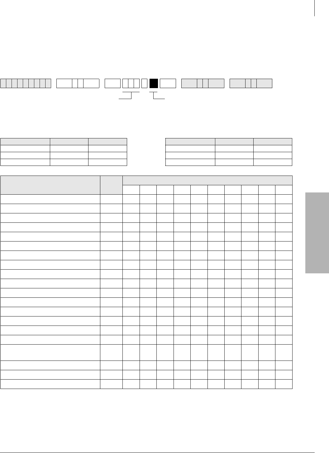
System & Station
Program 30 – Station Class of Service
Strata DK Programming 5/99 3-73
System & Station
Program 30 – Station Class of Service
Processor Type:
DK14, DK40i, All RCTUs
Program Type:
Station
Initialized Default:
LEDs 01, 05 and 07 for all ports
6SNU +ROG 6SNU +ROG 6SNU +ROG 6SNU +ROG
Processor Type Port Range DISA Port Processor Type Port Range DISA Port
DK14 000~009 010 RCTUBA/BB 000~079 089
DK40i 000~027 035 RCTUC/D 000~239 249
RCTUA 000~031 039 RCTUE/F 000~335 344
Feature LED Port
SLT/ISDN Terminal “#” Dial 20
Privacy Override 19
Executive Override 18
DND Override 17
Change TR Traveling Class Code 16
Change Verified Account Code 15
Verified Account Codes 14
13
SLT-Hook Flash Anti-Bounce Guard 12
Dial Pulse - DTMF OFF 11
Change DISA Security Code 10
Change TR Override Code 09
Forced Account Code 08
OCA Automatic (originating OCA) 07
ABR Access 06
Speed Dial Allowed 05
#5#30 Pickup AC Page Only
(Release 3.2 and higher) 04
Microphone Button on at Start of Call 03
MIC Button Locked 02
Speakerphone 01
SELECT = Station Logical Port Number(s)
Enter the port numbers to which class of service
must be assigned. To add a port range, enter
XXXXXX (low port high port).
Light LEDs for the port specified in the last step. All
LEDs marked with an “X” in the table below should
be lit.

System & Station
Program 30 – Station Class of Service
3-74 Strata DK Programming 5/99
Program 30 Overview
Program 30 enables or disables features for individual telephones at the station level. The
following text describes Program 30 LEDs.
LED 20: SLT/ISDN Terminal “#” Dial
This feature applies to single-line telephones and ISDN station terminals to indicate when a
number has been dialed and to begin dialing a sub-address. If a is dialed as the first digit, it
indicates that a feature access code is being entered.
For ISDN, if separate dialing and sub-address digits will be used, turn LED 20 ON. If it is OFF,
can be used as a dialing separator.
LED 19: Privacy Override
With Privacy Override enabled (LED 19 ON), a station can override calls and listen to a CO line
conversation by pressing a common CO /LQH button (not a [DN] button). [DN] buttons are always
private. A maximum of two stations can override an existing “station-line” conversation. You can
set a warning tone for Privacy Override (see Program 10-2).
Privacy Override of Direct Inward System Access (DISA) Two-CO line calls is not allowed.
Privacy Override is not available on any call (CO line or internal) that appears on a [PDN], [SDN],
or [PhDN] button.
Block Privacy Override by a station via a 3ULYDF\ button (Program 39) or with the Executive/
Privacy Override blocking option (Program 31, LED 18). To configure the Strata DK system to
operate as nonprivate, allow Privacy Override from all stations.
Disabling Privacy Override for attendant console ports does not deny Attendant Supervised Loop
Monitoring.
LED 18: Executive Override
With Executive Override enabled (LED 18 ON) a station can break into and overhear an existing
station conversation by pressing after the busy station number or by pressing the “EXEOVR”
LCD soft key. You can set a warning tone for this feature (see Program 10-2).
Privacy Override can be perform from stations with Executive/Privacy Override blocking enabled
in Program 31, LED 18. The 3ULYDF\ button does not block Executive Override. Disabling
Executive Override for attendant console ports does not deny Attendant Supervised Loop
Monitoring.
LED 17: Do Not Disturb (DND) Override
With DND Override enabled, (LED 17 ON), you can override a station that has DND ON. A called
station with DND activated will return very fast busy tone (four tones per second). If the caller
presses after dialing the DND station directory number, a DND Override tone is heard on the
called station’s speaker.
If a DND station has more than one [PDN] and it appears on other telephones, when called, the
[PDN] rings at the other telephones and flashes on the DND station. In this case, DND override is
not available unless all [PDNs] of the DND station are busy.
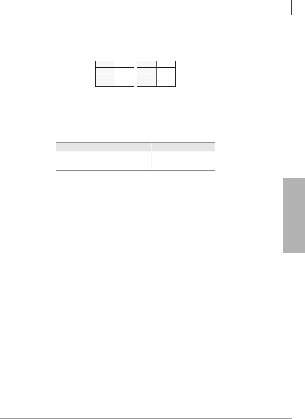
System & Station
Program 30 – Station Class of Service
Strata DK Programming 5/99 3-75
System & Station
LED 16: Change Toll Restriction Traveling Class Code
When LED 16 is ON for a port, the station occupying it can change the four-digit Toll Restriction
Traveling Class of Service Codes established in Program 44-1~8. Stations selected for this feature
must follow the dialing sequences below to change the codes:
LED 15: Change Verified Account Code
With LED 15 ON, a station can change the Verified Account Codes established in Program 69.
Selected stations must dial the following sequence to change the codes:
[PDN] + + Verified Account Code + Redial:
Press button if your electronic telephone does not have a 5HGLDO button.
Total Account Code digit length is set in Program 10-4 (up to 15 digits). All digits do not have to
be verified.
LED 14: Verified Account Code
With LED 14 ON, the system verifies all Forced or Voluntary Account Codes (set in Program 69)
dialed by the station user. If the station user does not dial a specific Verified Account Codes, the
call does not execute (Forced), or the Account Code is not validated for the SMDR call report
(Voluntary).
To force a verified account code entry on Two-CO line DISA calls through the system, turn LED
08 and 14 ON for Port 10-DK14, Port 035-DK40i, Port 039-RCTUA, Port 089-RCTUB,
RCTUBA/BB or Port 249-RCTUC/D or Port 344-RCTUE/F. Also, you must enable Forced
Account Code for outgoing CO line in Program 15-7.
LED 12: Single Line Telephone (SLT) Hookflash Anti-bounce Guard
SLT Hookflash Anti-Bounce Guard (LED 12 ON) prevents false recalls due to hook flash bounce
during SLT hang-up on outside calls. The system automatically disconnects the CO line if the SLT
hangs-up after a Hook Flash.
Use for QSTU2, PSTU, RSTU, RSTU2, RDSU, PESU, and KSTU2 standard telephone ports that
have standard telephones (with/without message lamps) connected to them to prevent false ring
signals. With this option ON, a CO line connected to a standard telephone is disconnected if the
standard telephone user hookflashes and then hangs up. If this option is OFF, the CO line recalls
the standard telephone.
LED 11: Dial Pulse - Dual-tone Multi-frequency (DTMF) OFF
Use Dial Pulse - DTMF OFF (LED 11 ON) if any device, DID or Tie line station port does not
require the RRCS, K5RCU, K5RCU2, or K4RCU for DTMF decoding. When the device goes off-
hook or the DID or Tie line is seized for an incoming call, the DTMF receiver is not accessed -
reducing unnecessary traffic to it.
Class 1 #691 Class 5 #695
Class 2 #692 Class 6 #696
Class 3 #693 Class 7 #697
Class 4 #694 Class 8 #698
[PDN] + class code ( ~ ) +four-digit code + 5 HGLDO
System Verified Account Code
RCTUE/F 000~499
RCTUA, BA/BB, C/D, DK40i, DK14 000~299

System & Station
Program 30 – Station Class of Service
3-76 Strata DK Programming 5/99
If a Tie or DID line is Dial Pulse (Program 15-1, LED ON), enable Dial Pulse - DTMF OFF (LED
11 ON) for that Tie or DID station port number. If the DID or Tie line is DTMF tone dial (Program
15-1, LED OFF) disable Dial Pulse - DTMF OFF (LED 11 OFF) and install an RRCS on the
RCTU, K5RCU, K5RCU2, or K4RCU3 in the DK40i.
LED 10: Change DISA Security Code
When enabled (LED 10 ON), allows a selected station to change the DISA security code by
dialing [PDN] + , + Security Code + 5HGLDO.
LED 09: Change Toll Restriction (TR) Override Code
When enabled (LED 09 ON), two TR Override codes are available. When one of these codes is
dialed from any station, all Toll Restriction is bypassed. Change TR Override codes by pressing
[PDN] + for Code 1, or [PDN] + for Code 2. Press 5HGLDO to store.
LED 08: Forced Account Code
When enabled, (LED 08 ON), a station or DISA CO line user using a line with a Forced Account
requirement (Program 15-7) must enter an Account Code before the outgoing CO/Tie/DID line
call can be completed. If Forced Account Codes should be verified, enable Verified Account Code
(LED 14 ON). Program 60-4 defines the Forced Account Code digit length.
To force a verified account code entry on Two-CO line DISA calls through the system, (LED 08
and 14 ON: Port 10-DK14, Port 035-DK40i, Port 039-RCTUA, Port 089-RCTUB, RCTUBA/BB,
249-RCTU C/D, and Port 344 for RCTU E/F). Also, enable Forced Account Code for outgoing
CO line in Program 15-7.
LED 07: Off-hook Call Announce (OCA) Automatic
When LED 07 is ON, a calling station has this feature enabled. If the system is set for Ring First
Signaling (Program 10-1, LED 10 ON), the user must dial after hearing busy tone or after
hearing ringback tone in order to OCA the called station. OCA Automatic only works on systems
with Voice First Signaling (Program 10-1 or 10-2, LED 01, OFF) in which case the user does not
have to dial or . Initialized default: ON - all ports. The called station must also be enabled to
receive OCA (see Program 31, LED 03).
LED 06: Automatic Busy Redial (ABR) Access
ABR can be enabled (LED 06 ON) or disabled (LED 06 OFF) for each station. The system selects
the last line in the originating line group each time ABR is initiated (see also Program 10-1). If you
do not enable ABR access here, the ABR soft key does not appear on LCD telephones. ABR
operates when calling on ground and loop start lines, but is not functional for DID or Tie line calls.
ABR overrides Program 41. Program 41 is normally used with LCR.
For the DK40i, K5RCU, K5RCU2, or K4RCU must be installed; for the DK14, QRCU must be
installed to detect busy tone so that ABR will function.
LED 05: Speed Dial
LED 04 enables (ON) or disables (OFF) Station and System Speed Dial. Initialized default: ON -
all ports.
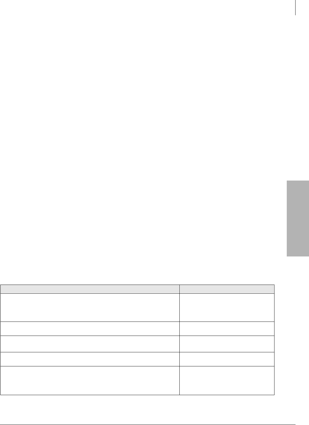
System & Station
Program 30 – Station Class of Service
Strata DK Programming 5/99 3-77
System & Station
LED 04: Call Pickup Code Option
Determines the operation of pickup code in Release 3.2 (and above) software. If LED 04 is
ON, only picks up All Call Page and External Page (per Program 10-2, LED 15). If LED
04 is OFF, picks up an internal call ringing on a telephone as a priority or it picks up All
Call Page or External Page if no internal calls are ringing. Prior to Release 3.2, picked up
ringing calls as priority over All Call Page pickup calls.
LED 03: Microphone Button On at Start of Call
When enabled (LED 03 ON), the microphone and Mic button LED is turned ON at the start of an
on-hook speakerphone call. For this feature to work, you must enable the MIC button lock
operation (LED 02 ON).
When receiving internal DN calls, the flexible Microphone Cutoff (0LFURSKQ&XWRII) button
(Program 39) can be used to prevent room monitoring and Handsfree Answerback.
LED 02: Mic Button - Locked/Momentary
The 0LF button turns electronic or digital telephone microphones ON/OFF:
With “Locked” (LED 02 ON), the 0LF button will be ON or OFF (depending on LED 03) when
you begin the call and you can alternately push it ON or OFF. This does not apply to Handset OCA
- which is 0LF push-to-talk only.
With “Momentary” (LED 02 OFF), the 0LF is always ON at the start of a speakerphone call/ You
must continuously press 0LF to disable the microphone when during a speakerphone call.
LED 01: Speakerphone
Enables (LED 01 ON) or disables (LED 01 OFF) speakerphone operation on any electronic or
digital telephone. If disabled, a speakerphone:
♦Can be used as a handsfree electronic or digital telephone.
♦Enables talk back with the receiver on-hook when receiving an internal call.
♦Will not allow you to talk on a call that you place or a call that you answer by pressing a
ringing button with the handset on-hook.
Program 30 - Example
Action (press buttons + LED buttons) LCD Response
1. Use an LCD programming phone per Minimum Hardware
Requirements on Page 1-14.
Make sure the programming button strip template is installed on the
programming telephone.
No. N-N1
Jan 20 Sun 06:43
2.
Enter programming mode. (Do not press [DN] button.) Program Mode
3. 6SNU6SHDNHU+ROG
Access Program 30. Program = 30
Data Store
4. 6SNU6SHDNHU
Prepare the system for a station port selection. 30 Select =
5. Enter the port number where the station being defined is
connected. Use three digits, followed by a button. A range of
ports may be entered at once by using the button. (See Note
on system record sheet for port numbers.)
30 Select =

System & Station
Program 30 – Station Class of Service
3-78 Strata DK Programming 5/99
6. LED buttons 01~20
LED buttons 01~20 activate features for each station port or port
range. Make the following selections by turning the appropriate button
LED ON or OFF for each item (01~20) for each port, as marked on the
system record sheet:
LED 01: Speakerphone Enabled
LED 02: Microphone Key Lock Enabled
LED 03: Microphone ON at Start of Call
LED 04: Not Used
LED 05: Speed Dial Allowed
LED 06: Automatic Busy Redial Access Enabled
LED 07: Automatic Off-hook Call Announce
LED 08: Forced Account Code Enabled
LED 09: Toll Restriction Override Code Revision Authority
LED 10: DISA Security Code Change Allowed
LED 11: Dial Pulse (DTMF Off) for Standard Telephone
LED 14: Account Codes Verified
LED 15: Verified Account Code Revision Authority
LED 16: Traveling Class of Service Code Revision Authority
LED 17: Do Not Disturb Override Allowed
LED 18: Executive Override Allowed
LED 19: Privacy Override Allowed
LED 20: Not Used
If programming a port range, the LED indications are as follows:
♦LED-ON, all ports in range are enabled for that item.
♦LED-OFF, all ports in range are disabled for that item.
♦LED-FLASHING, some ports in range are enabled and some
ports are disabled.
7. +ROG
Secure data in system programming. 30 Select
Data Programmed
8. 6SNU6SHDNHU
Prepare system for another selection (go back to Step 5), or exit
Program 30 (continue with Step 9).
30 Select =
9. +ROG
Secure Program 30 data in system memory. 30 Select = ##
Data Programmed
10. 6SNU6SHDNHU
Exit Program 30. Enter another program number or exit programming
mode (go to Step 11). Speaker beeps to indicate it is exiting Program
33.
Program =
11. ## Hold
Exit programming mode. No. N-N
Jan 20 Sun 06:58
1. N-N = Programming telephone [PDN]
Action (press buttons + LED buttons) LCD Response
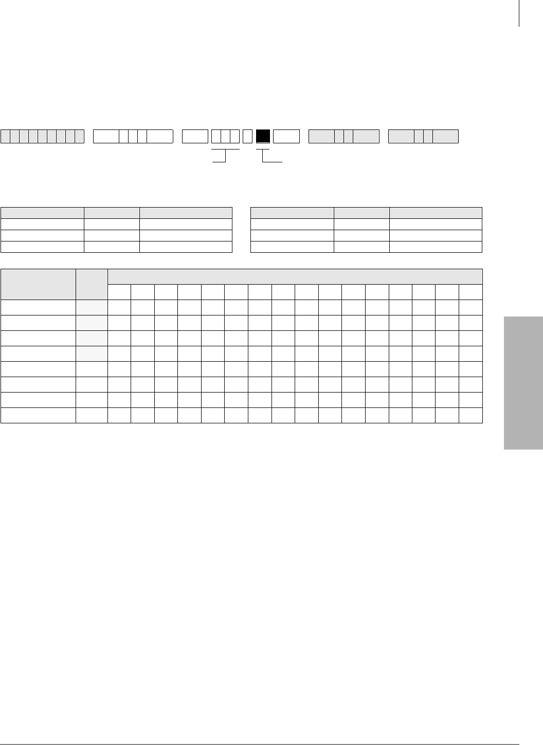
System & Station
Program *30 – Telephone Group Page Assignments
Strata DK Programming 5/99 3-79
System & Station
Program *30 – Telephone Group Page Assignments
Processor Type:
DK14, DK40i, All RCTUs
Program Type:
Station
Initialized Default:
All LEDs OFF
Shaded groups apply to RCTUC/D and RCTUE/F only.
Program *30 Overview
Digital and electronic telephones can be assigned to “internal telephone speaker” page groups with
this program. Each group can have as many as 120 stations. Telephones can be a member of more
than one group. Station users can access each group separately by dialing access codes. (See
Program 05 for access codes.) The above table shows four or eight page groups. An additional
group is the All Call Page Group set in Program 31, LED 10.
Notes
●A maximum of 120 telephones can be assigned to a particular page group.
●Only 120 telephones can be paged simultaneously. Example: If Page Group “A” has 60
telephones, Page Group “B” has 50 telephones, and Page Group “C” has 70 telephones, then
Group A + B (60 + 50 = 110) can be paged simultaneously, but Group A + C (60 + 70 = 130)
cannot be paged simultaneously.
6SNU+ROG 6 SNU +ROG 6SNU +ROG 6SNU +ROG
Processor Type Port Range Number of Page Groups Processor Type Port Range Number of Page Groups
DK14 000~007 4 RCTUBA/BB 000~079 4
DK40i 000~027 4 RCTUC/D 000~239 8
RCTUA 000~031 4 RCTUE/F 000~335 8
Feature LED Port
Page Group H 08
Page Group G 07
Page Group F 06
Page Group E 05
Page Group D 04
Page Group C 03
Page Group B 02
Page Group A 01
Enter the station logical port which will be assigned
to page a group or groups. To add a port range,
enter XXXXXX (low port high port).
Press LED Buttons 01~08 to light LEDs for the port
specified in the last step. In the table below, “X” all
LED Buttons which should be lit.
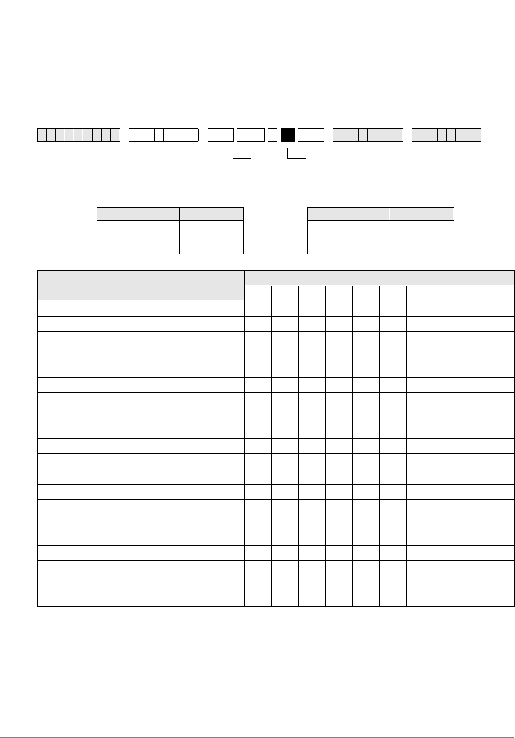
System & Station
Program 31 – Station Class of Service
3-80 Strata DK Programming 5/99
Program 31 – Station Class of Service
Processor Type:
DK14, DK40i, All RCTUs
Program Type:
Station
Initialized Default:
LED 10 ON for Ports 000~119
;
LED 11~13 ON for all ports.
Program 31 Overview
Program 31 sets most voice mail or External Auto Attendant port assignments. Each standard
telephone port (QSTU2, RSTU2, RSTU, PSTU, PESU, RDSU, KSTU2, QSTU2) connected to a
Toshiba Stratagy, Stratagy DK or VP voice mail system should have LEDs 04, 15, 16, 17, 18, 19,
and 20, and one of the following: 05, 06, 07, or 08 turned ON. These LED’s should be ON for VM
ports only, not for telephone ports.
6SNU +ROG 6SNU +ROG 6SNU +ROG 6SNU +ROG
Processor Type Port Range Processor Type Port Range
DK14 000~009 RCTUBA/BB 000~079
DK40i 000~027 RCTUC/D 000~239
RCTUA 000~031 RCTUE/F 000~335
Feature LED Port
Toshiba Stratagy/VP (B + Station No.) 20
Toshiba Stratagy/VP (B No Station) 19
Executive & Privacy Override Blocking 18
End/End Signal Rcv (VM) 17
Receive VM ID Code 16
Toshiba Stratagy/VP Integration (A/D) 15
Handset OCA 14
Handset OCA Warning Tone 13
Pooled Line Key - No Flash if No Ring 12
Busy Override Tone - Continuous 11
All Call Page Allowed - EKTs/DKTs 10
VM (No Conference) 09
VM Group 4 (does not apply to DK14) 08
VM Group 3 (does not apply to DK14) 07
VM Group 2 06
VM Group 1 05
VM to VM Call Blocking Called/Calling 04
OCA Enabled (To Receive) 03
Handsfree No Warning Tone 02
Handsfree Disabled 01
SELECT = Station Logical Port Number(s)
Enter the port numbers to which class of service
must be assigned.
Light LED Buttons for the port specified in the last
step. All LED Buttons marked with an “X” in the
table below should be lit.
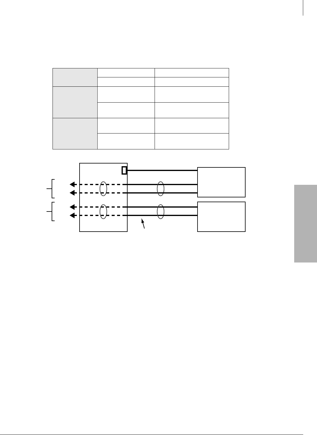
System & Station
Program 31 – Station Class of Service
Strata DK Programming 5/99 3-81
System & Station
LED 09 should be OFF for VM Auto Attendant “blind” transfer and VM tandem CO line
connection with automatic release. LED 09 should be ON for VM Auto Attendant supervised
transfer operation.
Example Programming Assignment to Set Up Voice Mail in a Distributed Hunt Group
All ports assigned to a Voice Mail Group should also be assigned to a unique Distributed Hunt
Group using Program 40. Each Program 31 Voice Mail Group must be associated with a unique
Program 40 Distributed Hunt Group that hunts only to its own Voice Mail Group ports. (See
above example of how to connect/program two voice mail/auto attendant machines and associate
them with two different DH groups.)
♦If LED 15 or 19 is ON, turn LED 17 ON. If LED 20 is ON, turn LEDs 17 and 19 ON.
♦For SMDI or DTMF integration, turn ON LEDs 04, 16, 17 and 18, and one of the following:
05, 06, 07, or 08 for all standard telephone ports connected to a VM unit.
♦Turn LED 19 and 20 OFF if the VM unit does not respond properly to transfer recall (B-Tone)
signals when using any type of Voice Mail Interface.
♦LED 09 – see above comments in Program Overview.
♦If CO lines direct ring VM ports via Program 81~89, the data in Programs 81, 84, and 87
must be blank.
Important! Do not assign Program 31 VM/AA options to built-in Auto Attendant digital
announcer ports.
Program*32
Program 13
008 VMG1 Message Center
010 VMG2 Message Center
Program 31
008 – Button 5 ON
009 – Button 5 ON VMG1 RSTU VM Ports
010 – Button 6 ON
011 – Button 6 ON VMG2 RSTU VM Ports
Program *40
850 – 01 008
850 – 02 009 VMG1 DH Group Members
851 – 01 010
851 – 02 011 VMG1 DH Group Members
#200
#201
#202
#203
Telephones
using voice mail
machine #1
Telephones
using voice mail
machine #2
008
RS232C (SMDI)
N/A on DK14
Standard Telephone
Voice Mail Ports
#008
#009
DHG1/VMG1
DHG2/VMG2
#010
#011
010
Voice Mail
Machine #1
Voice Mail
Machine #2
1565

System & Station
Program 31 – Station Class of Service
3-82 Strata DK Programming 5/99
LED 20: Toshiba Stratagy/VP (B + Station Number)
Use with Toshiba Stratagy/Stratagy DK/VP systems connected to a standard telephone port
(PSTU, RSTU, RSTU2, PESU, RDSU, KSTU2 and QSTU2). Toshiba voice mail systems
receiving DTMF B tone followed by the station number may not know where the call is coming
from - such as hold recall or “blind” ring transfer recall.
When enabled (LED 20 ON), allows Toshiba voice mail systems to respond more intelligently
with appropriate voice prompts. Use this feature for standard telephone ports connected to voice
mail devices only, not for station ports connected to telephones. The station number is not
returned, it blind transfers to a DND station.
Note You must enable Toshiba Stratagy/Stratagy DK/VP (B No Station) with LED 19 to allow
this function.
LED 19: Toshiba Stratagy/Stratagy DK/VP (B No Station)
DTMF “B” tone is sent to Toshiba voice mail systems to signify a recall where Toshiba voice mail
systems already knows the recalling station number. Again, this allows Toshiba voice mail systems
to respond more intelligently with appropriate voice prompts. Use this feature for standard
telephone ports (PSTU, RSTU, RSTU2, PESU, RDSU, KSTU2 and QSTU2) connected to voice
mail devices only, not for station ports connected to telephones.
LED 18: Executive and Privacy Override Blocking (Modem)
When enabled (LED 18 ON), denies a station user the capability to break into a station connection
with Executive or Privacy Override. Use this feature for standard telephone ports (PSTU, RSTU,
RSTU2, PESU, RDSU, KSTU2 and QSTU2) connected to a modem, voice mail/auto attendant or
ACD digital announcement device in order to ensure data and voice security. Also, use this feature
to deny override of any station. This feature does not block Attendant Supervised Loop
Monitoring.
You can use the Privacy Release 3ULYDF\5HOHDVH button to disable Privacy on a call-by-call
basis; this button does not disable Executive Override Blocking.
Enable this feature if a modem is assigned to the system modem pool in Program 21 to provide
data security for modem standard telephone ports.
Disable this feature (LED 18 OFF) for the modem standard telephone ports assigned in Program
21 if using the system modem pool for data calls that must be switched between voice and data.
LED 17: End-to-end Signal RCV (VM)
When enabled (LED 17 ON), provides End-to-end Signaling of Dual-tone Multi-frequency
(DTMF) tones through the system. Required on all voice mail ports (RSTU, RSTU2, RDSU/
RSTS, PSTU, PESU, RDSU, QSTU2 and KSTU2) for proper signaling communication.
LED 16: Receive Voice Mail (VM) ID Code
When a station is call-forwarded to a VM system, certain identification (ID) DTMF tones are
automatically sent to direct the call to a specific mailbox (VM ID Code #656 or DNIS VM ID
Code). The automatic ID is also sent to the VM device when electronic, digital, or standard
telephone users retrieve messages via the Message Waiting buttons (VM ID Code #657). The VM
port must be programmed for this feature to allow the reception of VM ID DTMF digits.

System & Station
Program 31 – Station Class of Service
Strata DK Programming 5/99 3-83
System & Station
LED 15: Toshiba Stratagy, Stratagy DK and/or VP Integration (A Tone/D Tone)
When enabled (LED 15 ON), sends an answer tone (DTMF A tone) to the Toshiba voice mail
system when a station answers, and a disconnect tone (DTMF D tone) when a station disconnects.
This allows Toshiba voice mail systems to respond quickly rather than waiting during long time-
outs. If the Central Office (CO) provides an Automatic Release (AR) signal (sometimes referred to
as Calling Party Control or Loop Supervision), D tone is also sent to disconnect VM ports when
outside callers hang up (see Program 15-0 and 15-3).
LED 14: Off-hook Call Announce (OCA) Handset or Speaker
If a station is enabled to receive OCA (Program 31, LED 03 ON), LED 14 defines which type of
OCA the telephone should receive: Headset/Handset (LED 14 ON) or Speaker (LED 14 OFF).
Digital Telephones: Speaker OCA requires a DVSU and a special Program 03 code. Only digital
telephones can receive Handset OCA. Handset OCA does not require DVSU or any other special
hardware.
Electronic Telephones: Speaker OCA requires a HVSU and three-pair wiring. Headset OCA does
not require these items; Electronic or standard telephones cannot receive Handset OCA.
LED 13: OCA Handset Warning Tone
This option enables (LED 13 ON) or disables (LED 14 OFF) a warning-tone (one-second tone
burst) for digital telephones that receive Headset OCA. Does not apply to Speaker OCA.
LED 12: Pooled Line Button Operation, No Flash if No Ring
When enabled (LED 12 ON) on telephones assigned to ring in Programs 81~89, incoming line
calls in pooled line groups only flash on 3RROHG/LQH buttons. When disabled (LED 12 OFF), the
Pooled Line LED flashes when an incoming line call is received – even if the telephone does not
ring.
LED 11: Busy Override (BOV) Tone
Digital or Electronic Telephones: If a [DN] is busy and receives a call on an idle [DN] or CO
button from another station or an outside line then BOV tone is sent. BOV tone can be continuous
muted one-second rings (LED 11 ON) or two muted one-second rings three seconds apart (LED 11
OFF).
If all the [DN] button appearances of the called [DNs] are busy, the call will camp-on and the
telephone receives two muted rings (camp-on tone) three seconds apart (only if LED 01 is ON for
the telephone in Program 34).
This BOV feature does not apply to CO lines that are ring transferred to a busy telephone - with or
without an idle [DN] or CO /LQH button. In this case, the call is a camped-on call to the busy
telephone.
BOV and Camp-on muted ring tone frequency for digital and electronic telephones:
1209Hz/modulated by 10Hz on CO line calls; 1209Hz/unmodulated on station-to-station calls.
Standard Telephones: This feature does not apply to Camp-on tone sent to standard telephones.
Standard telephones only receive two Camp-on tone bursts - three seconds apart, regardless of this
BOV Tone feature’s setting. Also, you must run Program 34 to enable a standard telephone to
receive Camp-on tone. Camp-on tone is sent when the busy standard telephone receives a
transferred CO line call and when the busy standard telephone receives a direct call from a station
or CO line.
System & Station
Program 31 – Station Class of Service
3-84 Strata DK Programming 5/99
BOV and Camp-on muted ring tone frequency for standard telephone:
BOV tone is a 160ms burst of 1209Hz/ unmodulated, twice - three seconds apart.
Camp-on tone is two one-second bursts of 1209Hz/interrupted by 160ms bursts, three seconds
apart.
LED 10: All Call Page Allowed-Digital and Electronic Telephones
When enabled, (LED 10 ON) any station can be allowed to receive an All Call Page and still have
the ability to initiate an All Call Page. Up to 120 stations can be can be assigned and paged at one
time. All Call Page is treated as any other page group. See Program 30 for telephone page group
assignments and Program 10-2, LED 15 for External Page with All Call Page option (see Program
34).
LED 09: No Station plus CO Line Conference Origination by VM
When enabled (LED 09 ON), prohibits VM ports from setting up conference calls with a station
and the outside line party and tandem calls with two outside lines. Use this feature for VM (RSTU,
RSTU2, PSTU, PESU, RDSU/RSTS, KSTU2, QSTU2) ports. This LED should be ON when VM/
Auto Attendant does screened or supervised transfers and OFF if only doing blind transfers.
If LED 09 is OFF or ON, station can still set up a conference call with an outside line and a VM
port so the station user and outside party can listen to a message together (R3.2 and above).
In DK release 3.2 software, VM ports are allowed to set up tandem calls with two CO lines and
then hook-flash and hang-up to exit the call, allowing the two CO lines to remain connected. For
this feature, LED 09 must be OFF for VM ports.
LED 05~08: Voice Mail (VM) Groups 1~4
The system allows the following VM station port groups to be configured for support of VM/auto
attendant devices:
One group is intended for each different device.
All standard telephone ports (RSTU, RSTU2, PSTU, PESU, RDSU/RSTS, KSTU2 and QSTU2)
connected to a particular VM machine should be assigned to the same VM group (SMDI or DTMF
Integration). The purpose of VM grouping is to allow efficient use of the message waiting (MW)
set and cancel operations from the VM machine. Since each digital, electronic, and standard
telephone can only have a maximum of four messages waiting, the VM device should set MW
only once, regardless of how many messages there are.
Assign all ports of each Program 31 VM Group to a unique Program 40 Distributed Hunt (DH)
Group. Telephones should Call and/or Call Forward to the DH Group [DN] to connect to VM. In
Programs 13 and 32, assign the lowest port in the Program 31 VM group as the message center.
Do not assign the VM DH Group port as the message center.
LED 04: Voice Mail (VM) to VM Call Blocking
When enabled (LED 04 ON), prevents VM/auto attendant ports from call forwarding to other VM
ports during screened or supervised voice mail transfers. Use this feature for all VM/auto attendant
ports if their transferred calls are screened or supervised. Disable this feature (LED 04 OFF) for all
VM/auto attendant ports if their calls are ring (blind) transferred.
System Number of VM Groups LEDs
DK14 1~2 05~06
DK424 and DK40i 1~4 05~08

System & Station
Program 31 – Station Class of Service
Strata DK Programming 5/99 3-85
System & Station
LED 03: Off-hook Call Announce (OCA) Enabled (Receive)
Enable this option (LED 03 ON) for any digital or electronic telephone requiring OCA.
Telephones must be equipped for OCA. OCA is not available on standard telephones.
This feature does not affect the station’s ability to originate OCA.
Digital telephones: Speaker OCA requires a DVSU in the telephone. Also, the PDKU supporting
OCA must have code 62 or 64 set in Program 03. Handset/headset OCA does not require extra
hardware - only that Program 31 LED 03, and 14 be ON.
Electronic telephones: Speaker OCA requires a HVSU/HVSI in the telephone and a third pair of
wires from the PEKU. Electronic telephones cannot receive Handset OCA.
LED 02: Handsfree No Warning
As a default, on Voice First systems (Program 10-1, LED 1) a one-second warning tone is sent to a
handsfree digital or electronic telephone to inform its user that someone is calling and that they can
be heard. If the warning tone is not desired at the called digital or electronic telephone, this
assignment can disable it, allowing silent room monitoring of the area surrounding the telephone.
This will also prevent ringing the digital or electronic telephone as a ring-first situation. Initialized
data activates the warning tone for all ports.
LED 01: Handsfree Disabled
It is possible to disable the internal call Handsfree Answerback function on any digital or
electronic telephone. This option ensures privacy (no room monitoring) when enabled on the
called station but it prevents the called station from answering an internal call hands free. The
0LFURSKQ&XWRII button (Program 39) can be used instead of this feature to allow the user to
enable/disable Handsfree Answerback, as desired.
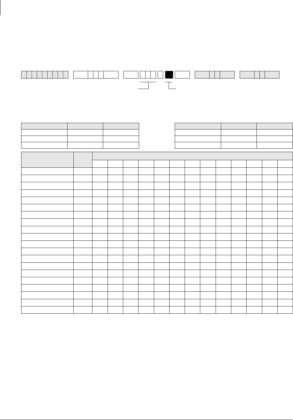
System & Station
Program *31 – Group Pickup Assignments
3-86 Strata DK Programming 5/99
Program *31 – Group Pickup Assignments
Processor Type:
DK14, DK40i, All RCTUs
Program Type:
Station
Initialized Default:
All LEDs OFF
Program *31 Overview
Stations can be divided into as many as 20 pickup groups (see the legend above the record sheet).
Station users can pick up calls (internal or line) that are ringing any station within their group by
dialing a single access code (or with a &DOO3LFNXS button assigned with Code 480 in Program
39), and pick up calls that are ringing stations in other groups by dialing selected access codes.
Stations can belong to more than one group. (See Program 05 for access codes.) This feature also
picks up ringing transfer and hold recall calls, but does not pick up held calls or selectively by
directory number.
To pickup held or ringing [PDN] and/or [PhDN] calls selectively, use the + XXX pickup
access code (where XXX is the [PDN] or [PhDN]).
6SNU+ROG 6SNU +ROG 6SNU +ROG 6SNU +ROG
Processor Type Port Range Pickup Groups Processor Type Port Range Pickup Groups
DK14 000~009 8 RCTUBA/BB 000~079 20
DK40i 000~027 16 RCTUC/D 000~239 20
RCTUA 000~031 20 RCTUE/F 000~335 20
Pickup Group LED Port
Pickup Group 20 20
Pickup Group 19 19
Pickup Group 18 18
Pickup Group 17 17
Pickup Group 16 16
Pickup Group 15 15
Pickup Group 14 14
Pickup Group 13 13
Pickup Group 12 12
Pickup Group 11 11
Pickup Group 10 10
Pickup Group 9 09
Pickup Group 8 08
Pickup Group 7 07
Pickup Group 6 06
Pickup Group 5 05
Pickup Group 4 04
Pickup Group 6 03
Pickup Group 2 02
Pickup Group 1 01
Station Logical Port Number
Enter the station logical port which will
be assigned to a pickup group or groups.
To add a port range, enter XXXXXX
(low port high port).
Light LED Buttons for the port specified in the last
step. In the table below, mark an “X” for all LED
Buttons which should be lit.
System & Station
Program 32 – Automatic Preference
Strata DK Programming 5/99 3-87
System & Station
Program 32 – Automatic Preference
Processor Type:
DK14, DK40i, All RCTUs
Program Type:
Station
Initialized Default:
Assigns Ringing Code 1 and Automatic Off-hook (Preference) Code 00 for all ports
6SNU +ROG 6SNU +ROG 6SNU +ROG 6SNU +ROG
Processor
Type Port Range
Port Reference Number Number of CO Line
Groups Processor
Type Port Range
Port Reference Number Number of CO Line
Groups
DK14 000~007 01~04 RCTUBA/BB 000~079 01~08
DK40i 000~027 01~08 RCTUC/D 000~239 01~16
RCTUA 000~031 01~08 RCTUE/F 000~335 01~16
Port Number Ringing Code Automatic
Preference Code Port Number Ringing Code Automatic
Preference Code
SELECT = Station Logical Port Number
Enter the port number of the station having
preference defined. To add a port range,
enter XXXXXX (low port high port).
DATA = Ringing Code
0 = Disable Ringing Line Preference
1 = Enable Ringing Line Preference
Automatic Preference Code:
00 = No selection
01 = [PDN]
02 = Lowest CO, Tie, or DID line
11~26 = 01~16 Line groups
(See legend below for maximum line groups.)

System & Station
Program 32 – Automatic Preference
3-88 Strata DK Programming 5/99
Program 32 Overview
This program defines which [PDN] or CO line a digital (cordless, corded, or Strata AirLink
wireless) and electronic telephone will be automatically connected to when the telephone handset
is taken off-hook or the 6SNU button is used.
Note Strata AirLink wireless handsets do not have a 6SNU button.
The lowest [PDN], lowest CO line, or Line Group is selected only if the telephone is not ringing
when it is taken off-hook (no 6SNU pressed). If a telephone is ringing, the [PDN] Auto Preference,
or outgoing CO line is canceled. In this case, no selection is made if Ring Line Preference is
disabled; the ring line is selected if Ringing Line Preference is enabled.
Automatic Preference for digital, electronic, or Strata AirLink wireless telephones via handset off-
hook or the 6SNU button is the automatic connection to lines, or the [PDN] of a telephone under
various conditions.
With Ringing Line Preference, a digital, electronic, or Strata AirLink wireless telephone user by
going off-hook (or by pressing the 6SNU button) may be automatically connected to the lowest line
ringing in without having to press a CO /LQH button or dial an access code.
If no lines are ringing and an electronic or digital telephone goes off-hook, the station can be
automatically connected to the [PDN] or to a line. The line connected can be the lowest numbered
line available on the telephone or the highest idle line from a selected group.
Notes
●Program 32 does not apply to standard telephones. To allow system features to be accessed,
standard telephones always receive system internal dial tone when originating calls.
●If ringing line preference is not selected, no auto preference selection will occur when a station
goes off hook during an incoming ring condition.
●Toshiba cordless telephones can have [PDN] (Code 01) selected for Auto Preference so the
user will get system dial tone when pressing the 7$/. button from the idle state, or a line or
line group can be selected for Auto Preference if CO dial tone should be accessed when the
7$/. button is pressed.
●Strata AirLink wireless handsets must have Code 01 assigned to receive system dial tone after
pressing &$//in the idle mode. A line or line group can be selected instead, if CO dial tone
should be accessed when &$// is pressed.
System & Station
Program *32 – RS-232 Voice Mail Message Center Port
Strata DK Programming 5/99 3-89
System & Station
Program *32 – RS-232 Voice Mail Message Center Port
Processor Type:
DK14, DK40i, All RCTUs
Program Type:
Station
Initialized Default:
Blank
Program *32 Overview
This program assigns which Voice Mail Message Center port number will be called when a station
user presses the flashing 0VJ button. When using SMDI or DTMF voice mail integration, the
Voice Mail Port Message Center must be assigned for each station. The Message Center port must
be the lowest voice mail standard telephone port in the Program 31 Voice Mail Group. It is
normally the same port for all stations.
6SNU+ROG 6SNU + ROG 6SNU +ROG 6SNU +ROG
Processor Type Port Range Processor Type Port Range
DK14 008~009 RCTUBA/BB 000~079
DK40i 008~027 RCTUC/D 000~239
RCTUA 000~031 RCTUE/F 000~335
Port MW Center Port Port MW Center Port Port MW Center Port Port MW Center Port
SELECT = Station Logical Port Number
(see ranges below)
Enter the port number having a Message
Center assigned. Enter all station ports
using the same Voice Mail machine.
To add a port range, enter XXXXXX
(low port high port).
VM PORT = Voice Mail Message Port
Enter the Voice Mail Message Center Port
number (see ranges below) that should be
assigned to each station.
Enter the lowest KSTU2, QSTU2 or RSTU2 port
number that is connected to the VM machine.
If VM ports are assigned to a Distributed Hunt
(DH) Group in Program *40, enter the port
number of the first DH Group member, not the
DH Group port (900~915). See example following
System & Station
Program 33 – [PDN]/ [PhDN] Station Hunting (Voice Calls Only)
3-90 Strata DK Programming 5/99
Program 33 – [PDN]/ [PhDN] Station Hunting (Voice
Calls Only)
Processor Type:
DK14, DK40i, All RCTUs
Program Type:
Station
Initialized Default:
Blank
Program 33 Overview
Program 33 assigns Station Hunting to [PDNs] or [PhDNs]. When a called station is busy, the
Station Hunting feature will ring the alternate “hunt to” [PDNs] or [PhDNs] defined in this
program. If the “hunt-to” [DN] is busy, the system will try to ring the next “hunt-to” [DN], and so
on.
If a “hunt-to” [DN] is in the Call Forward mode, the call forward will have priority over the hunt.
A ground/loop start CO line will hunt from a [PDN] or [PhDN] only if it has been assigned to
immediate ring at the owner station of the [PDN] or [PhDN] exclusively (in Programs 81, 84, or 87
and 81, 84, or 87).
6SNU +ROG 6SNU +ROG 6SNU +ROG 6SNU +ROG
Processor [PDN] Port Range [PhDN] Port Range Processor [PDN] Port Range [PhDN] Port Range
DK14 000~009 500~509 RCTUBA/BB 000~079 500~579
DK40i 000~027 500~527 RCTUC/D 000~239 500~739
RCTUA 000~031 500~531 RCTUE/F 000~335 500~835
Hunt From Hunt To Hunt From Hunt To Hunt From Hunt To Hunt From Hunt To
SELECT = [PDN] or [PhDN] Port
Reference Number of the “hunt-from”
station.
To add a port range, enter XXXXXX
(low port high port).
HUNT TO = [PDN] or [PhDN] Port Reference
Number of the “hunt-to” station.
Press LED Button 01 to delete digit from the
“hunt-to” port.
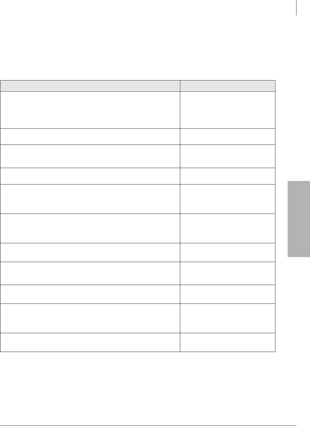
System & Station
Program 33 – [PDN]/ [PhDN] Station Hunting (Voice Calls Only)
Strata DK Programming 5/99 3-91
System & Station
On Ring-first systems, if a [PDN] appears on more than one button (on owner’s telephone), the
DK will not hunt until all appearances of the [PDN] are in use.
On Voice-first systems, the system will hunt for an available station if any one of the [PDN]
appearances is busy.
Program 33 - Example
Action (press buttons+LED buttons) LCD Response
1. Use the programming LCD electronic or digital telephone connected to
physical port 005 - circuit 6.
Make sure the programming button strip template is installed on the
programming telephone. (See “Program 38 Digital and Electronic
Telephone Keystrip Type” on Page 3-109.)
No. N-N1
Jan 20 Sun 06:43
1. N-N = Program telephone [PDN]
2.
Enter programming mode. (Do not press [DN] button.) Program Mode
3. 6SNU6SHDNHU+ROG
Access Program 33. System beeps after 6SNU6SHDNHU is pressed
to indicate program number may be entered.
Program = 33
Data Store
4. 6SNU6SHDNHU
Prepare the system for a station port selection. 33 Select =
5. ~ or ~
Select the port number of the Hunt From station. A range of ports can
be entered as specified on the record sheet. After the Hunt From port
is entered, press the button. Do not press when entering a range.
33 Select = (000~335)
Hunt To =
6. ~ or ~
Enter the port number of the Hunt To point, as recorded on the system
record sheet. Press LED button 01 to delete a digit from Hunt To point
ports.
33 Select = (000~335)
Hunt To = (000~335)
7. +ROG
Secure data in system programming. 33 Select = (000~335)
Data Programmed
8. 6SNU6SHDNHU
Prepare system for another selection (go back to Step 5), or exit
Program 33 (continue with Step 9).
33 Select = ##
9. +ROG
Secure Program 33 data in system memory. 33 Select =
Data Programmed
10. 6SNU6SHDNHU
Exit Program 33. Enter another program number or exit programming
mode (go to Step 11). Speaker beeps to indicate it is exiting
Program 33.
Program =
11. +ROG
Exit programming mode. No. N-N
Jan 20 Sun 06:58
System & Station
Program *33 – [PhDN] Owner Telephone Assignment
3-92 Strata DK Programming 5/99
Program *33 – [PhDN] Owner Telephone Assignment
Processor Type:
DK14, DK40i, All RCTUs
Program Type:
Station
Initialized Default:
Blanks (no data)
6SNU+ROG 6SNU + ROG 6SNU +ROG 6SNU +ROG
Processor [PhDN] Port
Reference Number [PDN] Port Range Processor [PhDN] Port
Reference Number [PDN] Port Range
DK14 500~509 000~009 RCTUBA/BB 500~579 000~079
DK40i 500~527 000~027 RCTUC/D 500~739 000~239
RCTUA 500~531 000~031 RCTUE/F 500~835 000~335
[PhDN] Port
Reference
Number
Owner Telephone
(Program 04)
Port Number
[PhDN] Port
Reference
Number
Owner Telephone
(Program 04)
Port Number
[PhDN] Port
Reference
Number
Owner Telephone
(Program 04)
Port Number
SELECT = [PhDN] Port Reference Number Enter the [PDN] Owner Station Logical Port
Number.

System & Station
Program *33 – [PhDN] Owner Telephone Assignment
Strata DK Programming 5/99 3-93
System & Station
Program *33 Overview
This program assigns each [PhDN] to a designated “Owner” telephone. Each [PhDN] must be
assigned to a designated “Owner” telephone and that [PhDN] must be assigned (using Program 39)
to appear on the owner telephone. If a [PhDN] is not assigned to an “Owner” telephone, it cannot
receive calls (caller will receive reorder tone) but it can be used to originate calls.
If the [PhDN] owner telephone is unplugged, the [PhDN] is busy (vacant) when called, unless CF-
All Call is set, in which case, it will forward. A telephone can be assigned as “Owner” of up to
eight [PhDNs].
[PhDN] “Owner” telephones have the following attributes for the [PhDNs] that it is assigned to
own:
♦Set Call Forward for all [PhDNs] that the telephone owns.
♦Set Call Forward to a VM Mail Box and Message Retrieve ID codes (#656/#657), independent
of the telephone’s Voice Mail assignments. This “CF to” VM Box can be the same as the
Owner telephone’s VM Box or any other VM Box, including a dedicated VM Box for the
[PhDN].
♦Have up to four [PhDN] Message Waiting (MW) LEDs (Program 39, flexible button). This
[PhDN] MW button indicates that the [PhDN] has a message waiting from voice mail or
another [DN] - again independent of the telephone’s fixed Msg LED.
♦Store ANI and/or Caller ID information for abandon calls directed to the [PhDN]. The [PhDN]
Owner telephone must be assigned “Abandon Call Memory” in Program 51 if the [PhDN]
rings on more than one telephone.
♦Can receive OCA calls to the [PhDN].
System & Station
Program 34 – Hold Recall Timing
3-94 Strata DK Programming 5/99
Program 34 – Hold Recall Timing
Processor Type:
DK14, DK40i, All RCTUs
Program Type:
Station
Initialized Default:
Assigns a Hold Recall Time of 032 seconds to all ports
Program 34 Overview
Each station can have a different time (from 011 to 160 seconds) from the point of placing a call on
hold to the point of recall. Initialized data assigns a recall time of 032 seconds to all ports.
6SNU +ROG 6SNU +ROG 6SNU +ROG 6SNU +ROG
Processor Port Range Processor Port Range
DK14 000~009 RCTUBA/BB 000~079
DK40i 000~027 RCTUC/D 000~239
RCTUA 000~031 RCTUE/F 000~335
Port Seconds Port Seconds Port Seconds Port Seconds
SELECT = Station Logical Port Number
Enter the port number having its Hold
Recall Time defined.
To add a port range, enter XXXXXX
(low port high port).
HUNT TIME = Seconds
Enter the number of seconds the system will
wait (three digits).
Enter 000 for no Hold Recall. Enter 011~160 for
11 to 160 seconds.
System & Station
Program *34 – Station Class Of Service
Strata DK Programming 5/99 3-95
System & Station
Program *34 – Station Class Of Service
Processor Type:
DK14, DK40i, All RCTUs
Program Type:
Station
Initialized Default:
LED 01 ON for all ports
6SNU+ROG 6 SNU +ROG 6SNU +ROG 6SNU +ROG
Processor Port Range Processor Port Range
DK14 000~009 RCTUBA/BB 000~079
DK40i 000~027 RCTUC/D 000~239
RCTUA 000~031 RCTUE/F 000~335
Feature LED Port
20
19
18
17
16
15
14
13
12
11
10
09
08
07
06
05
04
03
02
Camp-on Tone to standard telephone,
DKT, or EKT handset/Spkr 01
SELECT = Station Logical Port Number
Enter the port number(s) being defined.
To add a port range, enter XXXXXX
(low port high port).
LED = Select LEDs to light for the port
specified in the last step. Mark an “X” in the
table below for all LEDs which should be lit.

System & Station
Program *34 – Station Class Of Service
3-96 Strata DK Programming 5/99
Program *34 Overview
Program *34 assigns Camp-on tone to standard telephones.
A standard telephone can receive (LED 01 ON), or be blocked (LED 01 OFF) from receiving
Camp-on tone depending on how LED 01 is programmed for its standard station port.
When LED 01 is ON for a standard telephone: Camp-on tone is sent when the busy standard
telephone receives a transferred CO line call and when the busy standard receives a direct call
from a station or CO line.
An optional Camp-on busy tone burst can be sent to standard telephone handsets/headsets (LED
01 ON). Turn LED 01 OFF for all standard telephone ports connected to voice mail and/or auto
attendant devices.
Camp on tone to a standard telephone handset is:
♦Two 160 ms bursts of 1209 Hz, 3-seconds apart (internal, transferred, or Tie line calls)
♦Two 1-second bursts of 1209 Hz, (interrupted by 160 ms), 3-seconds apart (external CO or
DID line call)
If this option is disabled on Toshiba digital or electronic telephones (LED 01 OFF), the telephone
will not receive camp-on tone on direct DID calls or transferred CO line calls if there is not an idle
[DN] or /LQH button to receive the call, but the telephone will continue to receive BOV tone on
direct internal or CO line calls, providing there is a [DN] or /LQH button available for the call to
ring.
Also, if a busy DKT or EKT receives any type of call and there is not an idle [DN] or /LQH button
available for the call to ring, the DKT or EKT will receive camp-on tone (if LED 01 is ON) or will
not receive camp-on or BOV tone (LED 01 OFF).
System & Station
Program 35 – Station Class of Service
Strata DK Programming 5/99 3-97
System & Station
Program 35 – Station Class of Service
Processor Type:
DK14, DK40i, All RCTUs
Program Type:
Station
Initialized Default:
LED 01, 02, 04, 05, 16 are ON, all other LEDs OFF.
6SNU +ROG 6SNU +ROG 6SNU +ROG 6SNU +ROG
Processor Port Range Maximum LCD Phones With
Personal Messages Processor Port Range Maximum LCD Phones With
Personal Messages
DK14 000~009 8 RCTUBA/BB 000~079 32
DK40i 000~027 16 RCTUC/D 000~239 96
RCTUA 000~031 16 RCTUE/F 000~335 96
Feature LED Port
Busy Station Transfer 20
Busy Station Ringing 19
Automatic Hold 18
DKT 2000 Telephone
Continuous DTMF Tones
OFF 17
No CF/NA Handsfree or OCA 16
Not used 15
Toll Restriction After Answer 14
Toll Restriction After Answer 13
Not used 12~07
Disable Hold Display
Scrolling (Release 3.2 and
higher) 06
LCD Personal Message
(10~19) Allowed 05
Message Waiting (RCV) 04
Message Waiting Lamp
Standard. Telephones 03
LCD Type/32-ON/12-OFF 02
LCD Display 01
SELECT = Station Logical Port Number
Enter the port number(s) being defined.
To add a port range, enter XXXXXX
(low port high port).
LED = Select LEDs to light for the port
specified in the last step. Mark an “X” in the
table below for all LEDs which should be ON.

System & Station
Program 35 – Station Class of Service
3-98 Strata DK Programming 5/99
Program 35 Overview
LED 19: Busy Station Transfer (BST), LED 20 / Busy Station Ringing (BSR)
BST and BSR operate together to ensure that a busy digital or electronic telephone station always
receives transferred line calls along with LED and tone indications. The station or Voice Mail
(VM)/auto attendant device that transfers the call must be programmed with BST (LED 20 ON)
and the station port that receives it must have BSR (LED 19 ON).
When a busy station with BSR receives a transfer from a station or VM/auto attendant with BST,
there is a muted repetitive BOV tone (see Program 31, LED 11) at the busy station; if there is an
idle [DN], its LED will flash at the ringing rate until the station transferring the call hangs up.
When it does hang up, or if there is not an idle [DN], the line call then camps-on to the busy
station. The busy station is alerted of the camp-on by a camp-on tone (see Program *34), the CO
line LED flashes at the exclusive hold rate, and a message (“CAMP-ON X”, X = the line number)
appears on the LCD (if equipped).
Among other applications, a VM/auto attendant device that transfers calls to a typically busy
answering position station benefits from this program. Some auto attendant devices cannot transfer
a call to a busy station if BST and BSR are not activated.
Notes
●A BST station receives ringback tone, instead of busy tone, when transferring a call to a busy
BSR station.
●Do not assign BST/BSR to built-in Auto Attendant announcement ports.
●BST (LED 20 ON) should be assigned to all ACD agent telephones and BSR (LED 19 ON)
should be assigned to all ACD supervisor telephones to allow agent assistance calls to
supervisor telephones that are busy.
●LEDs 01, 02, and 04 must be ON to allow the Telephone’s Message Waiting LED to function
with voice mail—even if the Telephone is not an LCD type.
●Dial out (with or without Toll Restriction) must be allowed to use Speed Dial Buttons after
answering incoming calls. If a CO line is put on hold, Toll Restriction is applied to stations
that are restricted when the held line is picked up by a toll restricted station. If “Dial out with
T.R.” is enabled, the CO line will drop if a station dials a restricted number after answering an
incoming call, or if any digit is dialed with “dial out not allowed.”
LED 18: Automatic Hold
When enabled, (LED 18 ON), station users with CO /LQH buttons can place a CO line or [DN] call
on hold, then call another line or station just by pressing another CO /LQH or [DN] button and
dialing the number. If Automatic Hold is not allowed (LED 18 OFF), users can put calls on hold
and place calls, but they must press the +ROG button before accessing another line or [DN].
Notes
●CO line or internal calls that appear on the [DN] buttons will automatically hold when
accessing another line.
●Toshiba recommends that the 5HOHDVHDQG$QV button be provided via Program 39 to
telephones programmed for Auto Hold.
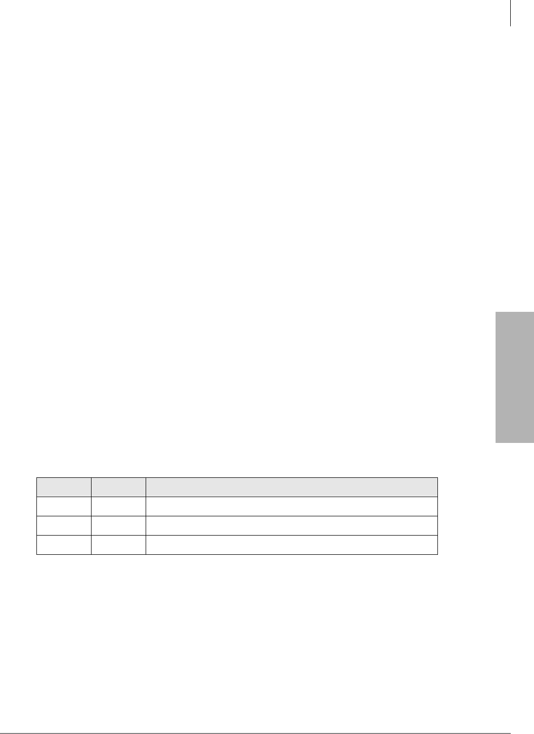
System & Station
Program 35 – Station Class of Service
Strata DK Programming 5/99 3-99
System & Station
LED 17: Continuous DTMF Tones Off
2000-series digital telephones can send DTMF tones for as long as station users press their buttons
(80 msec. minimum). This feature can be disabled (LED 17 ON). If it is disabled, DTMF tones
sent by these telephones will be either 80 or 160 milliseconds depending on the selection made
with Program 10-1, LED 04 and Program 10-2, LED 06.
Note PDKU1 does not support continuous DTMF tones on 2000-series digital telephones.
LED 16: No Call Forward/No Answer on Handsfree Answerback
When enabled (LED 16 ON), a Handsfree Answerback call to an idle station in the Call Forward
No-Answer or Call Forward-Busy/No Answer mode is not forwarded. If the system is
Programmed for Voice first (Program 10-1 and 10-2, LED 01 OFF), Voice Announce calls do not
Call Forward No-Answer; however, calls will call forward busy. This prevents the call from being
forwarded 8-60 seconds after the called party has been talking in the Handsfree Answerback
mode.
Outside calls and busy internal calls to the station continue to forward with this feature set. If the
system is set for Tone First, calls will call forward on Busy and No Answer.
Notes
●The caller can press the RING Soft Key on digital LCD telephones or press on digital or
electronic telephones to activate Call Forward on Voice Announce calls.
●OCA calls do not Call Forward No Answer in any case.
LED 15
Not used at this time.
LEDs 13 and 14: Toll Restriction After Answer
These two LEDs determine whether or not a toll restricted telephone user is allowed to use one
touch speed dial buttons after answering an incoming CO line call. LED 13 and 14 should be
turned ON for Toll Restricted Telephones that must answer incoming CO line calls and use 6'
(speed dial) buttons programmed to perform functions that Hold or Park calls and access the page
system automatically.
Initialized data sets both LEDs 13 and 14 off for all telephone users (not allowed to use Speed Dial
buttons after answering incoming CO line calls).
LED 07~12
Not used at this time.
LED 13 LED 14 Description
OFF OFF Not allowed to use Speed Dial after answering a line call.
ON OFF Allowed to use Speed Dial buttons but subject to toll restriction tables.
OFF ON Allowed to use Speed Dial buttons and not subject to toll restriction.

System & Station
Program 35 – Station Class of Service
3-100 Strata DK Programming 5/99
LED 06: Disable Hold Display Scrolling (Release 3.2)
If LED 06 is ON, Hold Display scrolling is disabled. Also, a telephone LCD cannot display which
CO lines are on hold on a [PDN] if the 6FUROO button is pressed. Hold Display causes the [DN]
button LED, of the line displayed on the LCD, to flash at a fast rate. If LED 06 is OFF, Hold
Display Scrolling is enabled. Prior to Release 3.2, Hold Display Scrolling was always enabled.
Hold Display Scrolling requires an LCD telephone.
LED 05: LCD Individual Message
This option defines which ports can allows LCD digital and electronic telephones to store up to 10
personal messages. It offers the option of entering alphanumeric memos for each of the LCD’s
station speed dial numbers. See the record sheet legend for the maximum stations that can have
this option:
A low port must be disabled (LED 05 OFF) before adding a port above the initialized ports.
LED 04: Message Waiting (RCV)
If the message waiting indication is not desired on an electronic, digital or standard telephone, this
program can be used to deny it. This does not affect that station’s ability to send a message waiting
indication to another station ([PDN] or [PhDN]). Do not use this option to enable/disable MW
lamps on standard telephones; use LED 03 below for standard telephones.
LED 03: Standard Telephone Message Waiting Lamp Enable
This option is used to identify which station ports are connected to Standard Telephones (2500 or
500 type telephones) that have Message Waiting Lamps. LED 03 should be turned ON for all
Standard Telephones ports that should support Standard Telephone Message Waiting lamps; LED
03 must be turned OFF for all other station ports including digital and electronic telephone ports
that support Message Waiting LEDs. This also applies to Voice Mail ports.
Important! Standard telephones that require the Message Waiting Lamp functions must be
connected to an RSTU2 PCB. Only one standard telephone with Message Waiting
Lamp is allowed to be connected to each RSTU2 port.
LED 02: LCD Type 32/12
Digital and 6000/6500-series LCD electronic telephones have 32-character displays. Therefore,
assignments should be left in the initialized state of 32 characters. LED 02 must be ON to receive
the voice mail message waiting indication.
LED 01: LCD Display
This option should be used (LED 01 ON) for all stations (even non-LCD), unless it is desired to
disable the station's LCD and message waiting functions.
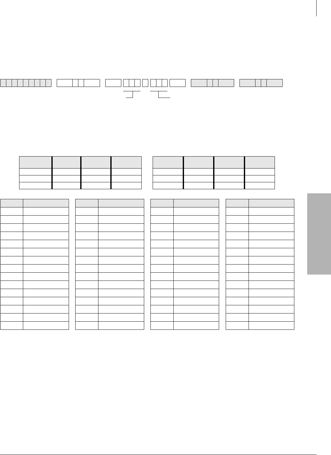
System & Station
Program 36 – Fixed Call Forward
Strata DK Programming 5/99 3-101
System & Station
Program 36 – Fixed Call Forward
Processor Type:
DK14, DK40i, All RCTUs
Program Type:
Station
Initialized Default:
Does not assign a Fixed Call Forward location to any port
Program 36 Overview
Fixed Call Forwarding is different from other station Call Forwarding options. It is fixed in terms
of the destination [PDN] which is assigned in this program. The station user cannot change the
Fixed Call Forward destination, unlike the other station Call Forwarding options. If Fixed Call
Forwarding is set on a station, the station does not ring and all calls forward immediately.
Note Telephones and attendant consoles must have a )L[HG&DOO)RUZDUG button to activate
this feature (See Programs 39 and 59).
6SNU +ROG 6SNU +ROG 6SNU +ROG 6SNU +ROG
Processor [PDN] Port
Range [PhDN] Port
Range DH Group
Ports Processor [PDN] Port
Range [PhDN] Port
Range DH Group
Ports
DK14 000~009 500~509 900~915 RCTUBA/BB 000~079 500~579 900~915
DK40i 000~027 500~527 900~915 RCTUC/D 000~239 500~739 900~915
RCTUA 000~031 500~531 900~915 RCTUE/F 000~335 500~835 900~915
Port Forward to Tel Port Port Forward to Tel Port Port Forward to Tel Port Port Forward to Tel Port
SELECT = Station Logical Port Number
Enter the port number of the station that
needs a Fixed Call Forward location
assigned.
To add a port range, enter XXXXXX
(low port high port).
FORWARD TO TEL = Port Number
Enter the port number of the [PDN], [PhDN] or
DH [DN] that will be call forwarded to when the
)L[HG&DOO ) R U Z DUG button is pressed.
[PhDNs] or DH [DNs] can be entered with DK
Release 3.2 and above software only.
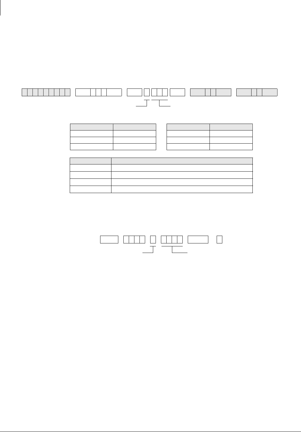
System & Station
Program *36 – System NT Button Lock Password Changing Station Assignment
3-102 Strata DK Programming 5/99
Program *36 – System NT Button Lock Password
Changing Station Assignment
Processor Type:
DK14, DK40i, All RCTUs
Program Type:
Station
Initialized Default:
000
Program *36 Overview
Attendant Consoles and stations assigned in this program can change the System Night Transfer
(NT) Lock password by dialing the sequence below:
Only one station or console can change the code. System/Tenant CO lines can be locked into the
Day, Day2, or Night ringing mode only after the NT Lock password is entered. Locking the system
into a particular ringing mode adds security to line call routing which prevents accidental or
mischievous changing of the system ringing mode.
Any telephone or an attendant console can lock the system into a ringing mode. The telephone or
console must have both a 1LJKW7UDQVIHUand an 1LJKW7UDQVIHU/RFN button and the person
locking the system must enter the password.
NT lock related programs include:
6SNU+ROG 6SNU + ROG6SNU +ROG 6SNU +ROG
Processor Port Range Processor Port Range
DK14 000~009 RCTUBA/BB 000~079
DK40i 000~027 RCTUC/D 000~239
RCTUA 000~031 RCTUE/F 000~335
Tenant Number NT Lock Station or Console Port
1
2
3
4
3 ' 1 5 HGLDO RU
Program 39 Station Flexible Button Assignments – 1LJKW7UDQVIHUand
1LJKW7UDQVIHU/RFN buttons
Program 59 Attendant Console Flexible Button Codes – 1LJKW7UDQVIHUand
1LJKW7UDQVIHU/RFN buttons
Program *36 NT Lock Station Assignment. Program *36 is not required to assign
attendant consoles to NT Lock functions
Program *15 CO Line Tenant Assignments
Program 74 System NT Lock Password Assignment
Program 77-3 Tenant Night Ring Over External Page Assignments
Tenant Number 1~4 DATA = Station port designated as Night Transfer Lock
Password Change Station for selected tenant.
Tenant Number 1~4 Night Transfer Lock Password
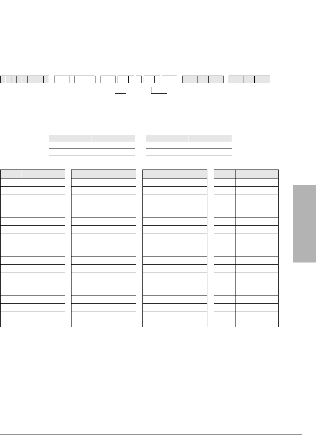
System & Station
Program 37 – Ring Transfer (Camp-on) Recall Time
Strata DK Programming 5/99 3-103
System & Station
Program 37 – Ring Transfer (Camp-on) Recall Time
Processor Type:
DK14, DK40i, All RCTUs
Program Type:
Station
Initialized Default:
Assigns Ring Transfer Recall Time of 32 seconds to all ports
Program 37 Overview
If a busy or ringing station does not answer a call sent to it via ring (blind) call transfer (lines or
[DNs]), the station originating the ring (blind) transfer is recalled after an amount of time
determined with this program. This time (011~999 seconds) is set independently for each
originating station port. Initialized data sets all stations for a 032-second recall time. Ring Transfer
must first be enabled for the system with Program 10-1, LED 07 ON.
6SNU +ROG 6SNU +ROG 6SNU +ROG 6SNU +ROG
Processor Port Range Processor Port Range
DK14 000~009 RCTUBA/BB 000~079
DK40i 000~027 RCTUC/D 000~239
RCTUA 000~031 RCTUE/F 000~335
Port Hold Time Port Hold Time Port Hold Time Port Hold Time
SELECT = Station Logical Port Number
Enter the port number that needs a Ring Transfer Recall
Time assigned.
To add a port range, enter XXXXXX (low port high port).
HOLD TIME = Port Number
Enter the Ring Transfer Recall Time (three
digits, in seconds)
Enter 011~999 for 11 to 999 seconds.
System & Station
Program *37 – Park Recall Timing
3-104 Strata DK Programming 5/99
Program *37 – Park Recall Timing
Processor Type:
DK14, DK40i, All RCTUs
Program Type:
Station
Initialized Default:
Assigns Ring Transfer Recall Time of 32 seconds to all ports
Program *37 Overview
Each station can have a different duration (from 011 to 999 seconds) from the time of parking a
call to the time the parked party recalls the station. Initialized data assigns a park recall time of 032
seconds to all ports.
6SNU+ROG 6SNU + ROG 6SNU +ROG 6SNU +ROG
Processor Port Range Processor Port Range
DK14 000~009 RCTUBA/BB 000~079
DK40i 000~027 RCTUC/D 000~239
RCTUA 000~031 RCTUE/F 000~335
Port Seconds Port Seconds Port Seconds Port Seconds
SELECT = Station Logical Port Number
Enter the port number having its Park Recall
Time assigned.
To add a port range, enter XXXXXX
(low port high port).
PARK TIME = Seconds
Enter the number of seconds the system will
wait (three digits). Enter 011~999 for 11 to 999
seconds.
System & Station
Program 38 – Digital and Electronic Telephone Keystrip Type
Strata DK Programming 5/99 3-105
System & Station
Program 38 – Digital and Electronic Telephone
Keystrip Type
Processor Type:
DK14, DK40i, All RCTUs
Program Type:
Station
Initialized Default:
Assigns Code 31 to all ports
6SNU +ROG 6SNU +ROG 6SNU +ROG 6SNU +ROG
Processor Port Range Processor Port Range
DK14 000~009 RCTUBA/BB 000~079
DK40i 000~027 RCTUC/D 000~239
RCTUA 000~031 RCTUE/F 000~335
Port Button Menu Port Button Menu Port Button Menu Port Button Menu
Important! If you only want to view Program 38
data, do not press +ROG, press 6SNU.
Pressing +ROG will change Program 39
assignments.
6SNU
...or
SELECT = Port Number
Enter the port number of the station
that needs a keystrip defined.
To add a port range, enter XXXXXX
(low port high port).
BUTTON MENU = Code
Enter the appropriate code:
Code 21 = 10-button telephone
Code 31 = 20-button (A) telephone
Code 32 = 20-button (B) telephone
Code 33 = 20-button (C) telephone

System & Station
Program 38 – Digital and Electronic Telephone Keystrip Type
3-106 Strata DK Programming 5/99
Program 38 Overview
Four telephone button arrangements are provided (see the Program 38 System Record Sheet). It is
best to start with one of these four, and then move on to Program 39, where individual buttons may
be programmed. Initialized data treats all digital telephone ports as 20-button types with 17 CO
/LQH buttons, one [PDN] button, one 'R1RW'LVWXUE button, and the 6SHHG'LDO button. See
the System Record Sheet for electronic telephone arrangements.
Important!
●Always complete Program 38 before proceeding to Program 39.
●DKAdmin will program a Pause on buttons 11~20 on 10-key telephones.
Assignments for 2000-Series Digital Telephone Keystrips
All Call
Voice Page
(for DK40i only) ...or
Speed Dial 1
Speed Dial 1Line 9
Do Not Disturb Line 8 Do Not Disturb
Line 7 Line 7 Line 172
Line 6 Line 6 Line 16
Line 5 Line 5 Line 15
Line 4 Line 4 Line 14
Line 3 Line 3 Line 13
Line 2 Line 2 Line 12
Line 1 Line 1 Line 11
[PDN] [PDN] Line 10
Code 21 – 10-Button Code 31 (Default) – 20-Button (A)
Line 9 Speed Dial1SD14 Speed Dial1
Line 8 Do Not Disturb SD13 Do Not Disturb
Line 7 SD 14 SD12 SD 22
Line 6 SD 13 SD11 SD 21
Line 5 SD 12 SD10 SD 20
Line 4 SD 11 Line 4 SD 19
Line 3 SD 10 Line 3 SD 18
Line 2 Line 12 Line 2 SD 17
Line 1 Line 11 Line 1 SD 16
[PDN] Line 10 [PDN] SD 15
DK424 and DK40i
Code 32 – 20-Button (B) DK14
Code 32 – 20-Button (B)
SD10 Flash Line 9 Flash
Line 8 Do Not Disturb Line 8 Do Not Disturb
Line 7 Speed Dial Line 7 Speed Dial
Line 6 Redial Line 6 Redial
Line 5 Speed Dial Pause Line 5 Speed Dial Pause
Line 4 SD 15 Line 4 Line 12
Line 3 SD 14 Line 3 Line 11
Line 2 SD 13 Line 2 Line 10
Line 1 SD 12 Line 1
[PDN] SD 11 [PDN]
DK424
Code 33 – 20-Button (C)
(Keystrip not provided, but can be assigned)
DK40i
Code 33 – 20-Button (C)
System & Station
Program 38 – Digital and Electronic Telephone Keystrip Type
Strata DK Programming 5/99 3-107
System & Station
Assignments for 1000-Series Digital Telephone Keystrips
Assignments for Electronic Telephone Keystrips
1. The 6 S HHG ' LDO button is the same as the 6' 6 or 5( 3 buttons in previous Strata systems (Program 39, Code 97). Also, if
changing PEKU PCBs (electronic telephone) to PDKU PCBs (digital telephone), or vice versa, always check that the 6SHHG
'LDO
or 0: )/ button is set appropriately in Program 39.
2. This button is initialized as 6' with RCTUA since there are only 16 CO lines.
CO15 CO16 CO17 DND SDS SD12 SD13 SD14 DND SDS PAU RDL SDS DND FLASH
CO10 CO11 CO12 CO13 CO14 CO10 CO11 CO12 SD10 SD11 SD11 SD12 SD13 SD14 SD15
CO5 CO6 CO7 CO8 CO9 CO5 CO6 CO7 CO8 CO9 CO5 CO6 CO7 CO8 CO9
[PDN] CO1 CO2 CO3 CO4 [PDN] CO1 CO2 CO3 CO4 [PDN] CO1 CO2 CO3 CO4
Code 31 (Default) – 20-Button (A) Code 32 – 20-Button (B) Code 33 – 20-Button (C)
MW/FL1CO9 MW/FL1
Do Not Disturb CO8 Do Not Disturb
CO7 CO7 CO172
CO6 CO6 CO16
CO5 CO5 CO15
CO4 CO4 CO14
CO3 CO3 CO13
CO2 CO2 CO12
CO1 CO1 CO11
[PDN] [PDN] CO10
Code 21 – 10-Button Code 31 (Default) – 20-Button (A)
CO9 MW/FL1SD10 MW/FL1
CO8 Do Not Disturb CO8 Do Not Disturb
CO7 SD14 CO7 SDS
CO6 SD13 CO6 RDL
CO5 SD12 CO5 PAU
CO4 SD11 CO4 SD15
CO3 SD10 CO3 SD14
CO2 CO12 CO2 SD13
CO1 CO11 CO1 SD12
[PDN] CO10 [PDN] SD11
Code 32 – 20-Button (B) Code 33 – 20-Button (C)
System & Station
Program 38 – Digital and Electronic Telephone Keystrip Type
3-108 Strata DK Programming 5/99
Note Button numbers 01~200 on electronic telephones (6000, 6500 series, etc.) are in the same
position as shown on the 2000-series digital telephone programming keystrip.
10 20
09 19
08 18
07 17
06 16
05 15
04 14
03 13
02 12
01 11
9
8
7
6
5
4
3
2
1
0
9
8
7
6
5
4
3
2
1
0
1843
LED Buttons and CO line numbers (01~20)
CO line numbers (21~200)
Last digit of EK port number for
programs with a format like
*
71,
*
72, and
*
73
2000-series digital telephone strip - supplied with each
Strata DK
Programming Manual
and each Documentation Package that ships with the
system. Can also be used with 6000- and 6500-series electronic telephones.
1000-series digital telephone strip - shows programming button/LED
assignment locations. Shown as reference only - not available as an
individual strip.
29, 49, 69
89, 109, 129,
149, 169, 189
28, 48, 68
88, 108, 128,
148, 168, 188
27, 47, 67
87, 107, 127,
147, 167, 187
26, 46, 66
86, 106, 126,
146, 166, 186
25, 45, 65
85, 105, 125,
145, 165, 185
24, 44, 64
84, 104, 124,
144, 164, 184
23, 43, 63
83, 103, 123,
143, 163, 183
22, 42, 62
82, 102, 122,
142, 162, 182
21, 41, 61
81, 101, 121,
141, 161, 181
40, 60, 80
100, 120, 140,
160, 180, 200
39, 59, 79
99, 119, 139,
159, 179, 199
38, 58, 78
98, 118, 138,
158, 178, 198
37, 57, 77
97, 117, 137,
157, 177, 197
36, 56, 76
96, 116, 136,
156, 176, 196
35, 55, 75
95, 115, 135,
155, 175, 195
34, 54, 74
94, 114, 134,
154, 174, 194
33, 53, 73
93, 113, 133,
153, 173, 193
32, 52, 72
92, 112, 132,
152, 172, 192
31, 51, 71
91, 111, 131,
151, 171, 191
30, 50, 70
90, 110, 130,
150, 170, 190
01, 21, 41, 61
81, 101, 121,
141, 161, 181
02, 22, 42, 62
82, 102, 122,
142, 162, 182
06, 26, 46, 66
86, 106, 126,
146, 166, 186
07, 27, 47, 67
87, 107, 127,
147, 167, 187
11, 31, 51, 71
91, 111, 131,
151, 171, 191
12, 32, 52, 72
92 112, 132,
152, 172, 192
16, 36, 56, 76
96, 116, 136,
156, 176, 196
17, 37, 57, 77
97, 117, 137,
157, 177, 197
03, 23, 43, 63
83, 103, 123,
143, 163, 183
04, 24, 44, 64
84, 104, 124,
144, 164, 184
08, 28, 48, 68
88, 108, 128,
148, 168, 188
09, 29, 49, 69
89, 109, 129,
149, 169, 189
13, 33, 53, 73
93, 113, 133,
153, 173, 193
14, 34, 54, 74
94, 114, 134,
154, 174, 194
18, 38, 58, 78
98, 118, 138,
158, 178, 198
19, 39, 59, 79
99, 119, 139,
159, 179, 199
05, 25, 45, 65
85, 105, 125,
145, 165, 185
10, 30, 50, 70
90, 110, 130,
150, 170, 190
15, 35, 55, 75
95, 115, 135,
155, 175, 195
20, 40, 60, 80
100, 120, 140,
160, 180, 200
System & Station
Program *38 – Standard Telephone Ring-Down Destination
Strata DK Programming 5/99 3-109
System & Station
Program *38 – Standard Telephone Ring-Down
Destination
Processor Type:
Release 4.0 and higher RCTUs
Program Type:
Station
Initialized Default:
Does not assign Ring Down Destination to any port
6SNU+ROG 6SNU + ROG 6SNU +ROG 6SNU +ROG
Processor [PDN] Port
Range [PhDN] Port
Range DH Group
Ports Processor [PDN] Port
Range [PhDN] Port
Range DH Group
Ports
DK14 N/A N/A 900~915 RCTUBA/BB 000~079 500~579 900~915
DK40i N/A N/A 900~915 RCTUC/D 000~239 500~739 900~915
RCTUA 000~031 500~531 900~915 RCTUE/F 000~335 500~835 900~915
Port Forward to Tel Port Port Forward to Tel Port Port Forward to Tel Port Port Forward to Tel Port
SELECT = Standard Telephone Logical Port Number
Enter the port number of the station that needs a Ring Down
Destination assigned.
To add a port range, enter XXXXXX (low port high port).
FORWARD TO TEL = Port Number
Enter the port number of the [PDN], [PhDN] or
DH [DN] that should ring when the Ring-Down
Timer (Program 12-1) expires.

System & Station
Program *38 – Standard Telephone Ring-Down Destination
3-110 Strata DK Programming 5/99
Program *38 Overview
Standard telephones can be assigned to ring a destination automatically by going off-hook (ring
down). They can also be programmed to ring a destination if an incomplete valid number is dialed.
This program assigns the ring down destination. The timer in Program 12-1 determines when the
destination should ring after the standard telephone goes off hook or if an incomplete valid number
is dialed.
If a standard telephone is assigned a ring down destination, ring down will always occur after the
ring down timer expires unless a valid feature access code or [DN] is dialed prior to the ring down
timer expiration (Program 12-1). Ring down applies only to standard telephone ports, not
electronic or digital telephone ports.
System & Station
Program 39 – Flexible Button Assignments
Strata DK Programming 5/99 3-111
System & Station
Program 39 – Flexible Button Assignments
Processor Type:
DK14, DK40i, All RCTUs
Program Type:
Station
Initialized Default:
See Program 38
6SNU +ROG 6SNU +ROG 6SNU +ROG 6SNU +ROG
Port No. _______ 10 ❏
20 ❏
LCD ❏
DIU ❏Port No. _______ 10 ❏
20 ❏
LCD ❏
DIU ❏Port No. _______ 10 ❏
20 ❏
LCD ❏
DIU ❏Port No. _______ 10 ❏
20 ❏
LCD ❏
DIU ❏
Location: Location: Location: Location:
Button Code Button Code Button Code Button Code Button Code Button Code Button Code Button Code
10 20 10 20 10 20 10 20
09 19 09 19 09 19 09 19
08 18 08 18 08 18 08 18
07 17 07 17 07 17 07 17
06 16 06 16 06 16 06 16
05 15 05 15 05 15 05 15
04 14 04 14 04 14 04 14
03 13 03 13 03 13 03 13
02 12 02 12 02 12 02 12
01 11 01 11 01 11 01 11
Enter the port number(s) to which
class of service must be assigned.
To add a port range, enter
XXXXXX (low port high port).
Code
Press LED Button to be defined.
SELECT = Port Number

System & Station
Program 39 – Flexible Button Assignments
3-112 Strata DK Programming 5/99
Program 39 Overview
Program 39 assigns features to the flexible buttons for individual telephones in the system. Several
types of buttons can be assigned with this program, including:
♦Feature
♦[PDNs], [SDNs] and [PhDNs] – Message Waiting buttons can be assigned to [PhDNs]
♦Alert Signal (Buzz key)
Feature Buttons Assignments
You can assign commonly used telephone features to any flexible button (see Table 3-1). Button
assignments can be different for individual telephones. Telephone users can also assign flexible
buttons if their COS and/or if programming permits the feature on their telephone.
Strata AirLink handsets interfaced to the Strata DK using the RWIU/WWIS PCB have only six
flexible buttons (4~9) available for programming.
Important!
●DKAdmin programs a Pause on buttons 11~20 on 10-key telephones.
●The /LQH button on the DKT2001 is flexible button 01. Only program a [PDN] onto this
button. Do not program CO lines or secondary line appearances onto button 01 or in any
other position. Since the system assigns CO lines 01~17 by default, be sure to remove any CO
line appearances by programming them as Station Speed Dial buttons (code ).
Note If the 6SHHG'LDO6HOHFW button is removed, the key becomes the 6SHHG'LDO
6HOHFW button. While on an outside call, the user must press then to activate the
and DTMF tones for the duration of the call.
➤To assign features to flexible buttons
1. Complete Program 38 before Program 39. Initialized data assigns the keystrip pattern
associated with Code 31 from Program 38.
2. Use “Program 39 – Flexible Button Assignments”on Page 3-111 to indicate feature buttons.
Use the programming sequence after this table to perform the following steps.
3. Program the port number or enter a range of port numbers.
4. Press the button that will be associated with the feature.
5. Enter the feature code.
6. Repeat this procedure until all feature buttons have been assigned.
Table 3-1 Feature Button Codes for Digital, Electronic, and Strata AirLink Wireless Telephones
Button Function Button Labels Code Notes
Account Code Account Code or ACCNT 450 Allows a Voluntary Account Code entry.
Alarm1Alarm Reset or ALRM 477 Resets alarm condition system-wide.
Alert Signaling (see following pages)1
All Call Voice Page All Call Page or AC 489 Pages up to 120 idle electronic or digital telephones over speaker.
Automatic Busy Redial Auto Busy Redial or ABR 470 Sets ABR of busy outgoing number.
Automatic Callback Busy Auto Callback or ACB 494 Sets ACB for station recalled by busy line.
Background Music1Tel Set Music or BGM 478 Turns BGM ON or OFF through station speaker.
Call Forward All Calls Call Frwd All Calls or CFAC 487 All calls forward to selected station.
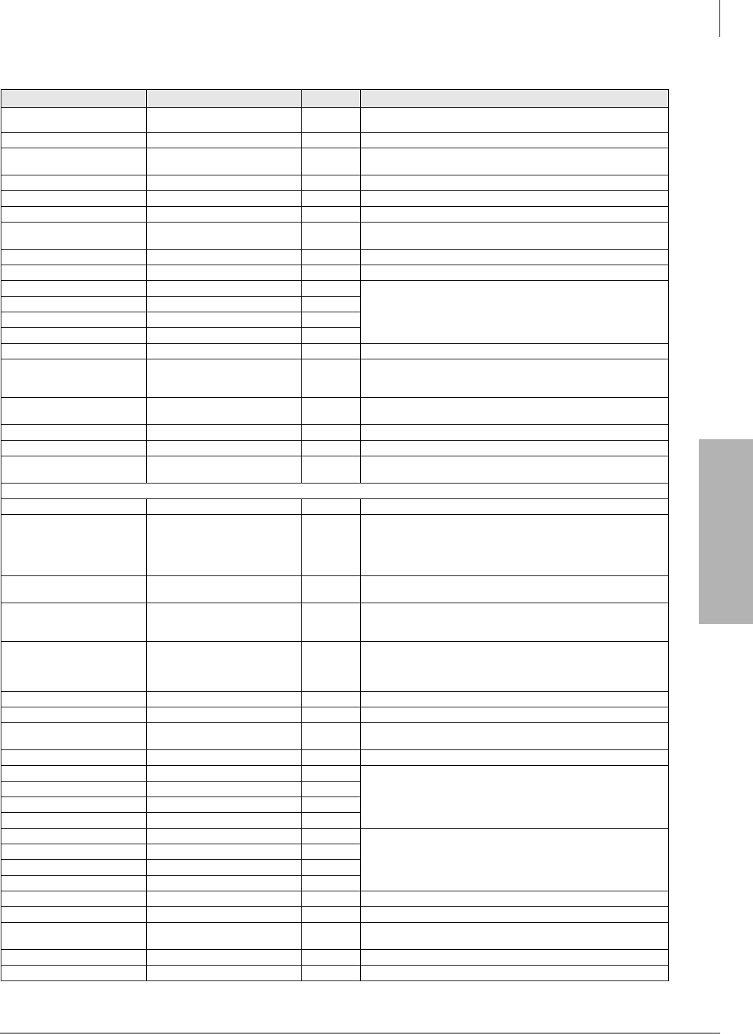
System & Station
Program 39 – Flexible Button Assignments
Strata DK Programming 5/99 3-113
System & Station
Call Forward A.C. Fixed Call Frwd to: or CFF 486 Forwards all calls to pre-defined destination. See Program 36.
Call Forward Busy Call Frwd Busy or CFB 459 Forwards calls to selected station if station is busy.
Call Forward Busy/No
Answer Call Frwd Busy/NAns or CFB/
NA 457 Forwards calls to selected station if station is busy or does not
answer.
Call Forward External Call Frwd External or CF-EXT 460 Forward calls externally.
Call Forward No Answer Call Frwd No Answer or CFNA 458 Forwards calls to selected station if station does not answer.
Call Park2Park in Orbit or PARK (R3) 464 Call Park Only.
Call Park LCD Display1Park Orbit DIsplay or CPD
(R3) 465 CP Display Button and Mode 64 can be used interchangeably.
Displays call parked via telephone LCD.
Call Park and Page Call Park/Page or CP/PG (R3) 463 Parking and Paging Park Pickup.
Call Pickup (Directed) Directed Pickup or PKUP 484 Picks up ringing or held intercom, trunk calls, and page.
Call Pickup Tenant 43PKUP 4 435
Picks up tenant’s ringing CO calls.
See Program *15 for Tenant Group assignments.
Call Pickup Tenant 33PKUP 3 436
Call Pickup Tenant 23PKUP 2 437
Call Pickup Tenant 13PKUP 1 438
Call Pickup (Group)2Group Pickup 480 Picks up a call to any group to which station is assigned in *31.
Unanswered Caller ID and/
or ANI Stored Number Auto
Dial1
Lost Call Auto Dial (R3) or
LCAD 462 Will Auto Dial a Caller ID and/or Automatic Number Identification
(ANI) telephone number that was stored in station Caller ID/ANI
memory.
CO Line Appearance Line 1~200 or CO 001~CO
200 001~
200 CO line access of appearing calls.
Data1Data Call or DATA 456 Used to place data call.
Data Release1Data Release or DRLS 454 Releases data call.
Direct Station Selection DSS #000~
#239 Assigns DSS hotline keys to port number.
Directory Numbers (see following pages)
Do Not Disturb4Do Not Disturb or DND 498 Prevents calls to station.
Door Lock 0 ~4 (DDCB/
HDCB)1
Unlock Door 0 or DRLK 0
Unlock Door 1 or DRLK 1
Unlock Door 2 or DRLK 2
Unlock Door 3 or DRLK 3
Unlock Door 4 or DRLK 4
471
472
473
474
475
Momentarily unlocks door (3 or 6 seconds).
See Program 77-1 and 77-2.
Handset Off-Hook Call
Announce1HS-OCA 468 Activates 2-way voice path to Off-Hook Call Announce caller. (R3)
ISDN Sub-address Sub-address 467 Separates the called party’s ISDN sub-address from the called
party number. The digit performs this function on standard
telephones.
ISDN Start Start 469
Initiates DK to send dialed digits to the ISDN network when this
button is pressed from a digital or electronic telephone. Program
*63-2 invokes the same function when the Dial Timer expires. Also
see Tone Button in this table.
LCD Message Select LCD Msg Select or LCD M 481 Begins LCD message selection.
Message Waiting and Flash Msg Wait, Flash or MW/FL 499 Provides message waiting LED for EKT and Flash Button.
Microphone Cutoff5Microphn Cut-off or MCO 488 Sets microphone ON/OFF for incoming handsfree Directory
Number [DN] calls.
Modem1Modem or MODEM 455 Used to reserve modem in modem pool.
Night Transfer Tenant 13Night Transfer1 or NT1 439
Sets Tenant CO line DAY/NIGHT ring mode.
Night Transfer Tenant 23Night Transfer2 or NT2 440
Night Transfer Tenant 33Night Transfer3 or NT3 441
Night Transfer Tenant 43Night Transfer4 or NT4 442
Night Transfer Lock Tenant 1 Night Lock1 or NT1 L1 431 Available with RCTUA3, RCTUBA3/RCTUBB3 or RCTUC/D3
Release 3 or above only.
Used to lock system ringing mode: DAY, DAY2, NIGHT See
Programs 74 and *36 for NT Lock Password assignments.
Night Transfer Lock Tenant 2 Night Lock2 or NT2 L2 432
Night Transfer Lock Tenant 3 Night Lock3 or NT3 L3 433
Night Transfer Lock Tenant 4 Night Lock4 or NT4 L4 434
Pause1Spd Dial Pause or PAU 495 Sets pause in Speed dial See Program 12-3.
Pause (Long)1Spd Dial Lng Pause or PAU/L 493 Sets a 10-second pause in Speed Dial.
Pooled Line Pooled Line Grp or PL 301~
316 Multiple CO line may appear under one button.
Privacy Privacy On Line or PRIV 453 Prevents Privacy Override (not Executive Override).
Privacy Release Privacy Release or PRV RLS 479 Changes station Privacy mode to Non-private for CO lines.
Table 3-1 Feature Button Codes for Digital, Electronic, and Strata AirLink Wireless Telephones
(continued)
Button Function Button Labels Code Notes
System & Station
Program 39 – Flexible Button Assignments
3-114 Strata DK Programming 5/99
Redial Last Number
(Button) Redial or RDL 496 Redials the last number.
Release to Idle Release Call or RLS 476 Releases current call and makes station idle.
Release and Answer Release and Ans or RLS/ANS 466 Simulates On-hook/Off-hook operation to release an existing call
and answer new incoming/ringing call.
Save Last Dialed Number Save Last Number on SAVE 485 Saves last number dialed for future speed dial.
Speed Dial Select
(Button)6Speed Dial or SDS 497 Begins speed dial selection.
Station Speed Dial Codes6SD (All DK systems)
Reserves button for station speed dial. Station Speed Dial code
ranges vary per processor:
10~
49 DK14, DK40i, RCTUA
10~
49 RCTUBA/BB, RCTUC/D
100~
139 RCTUE/F
System Speed Dial Codes6SD
Speed dial number set by station port 000. System Speed Dial
code ranges vary per processor:
60~
99 DK14, DK40i, RCTUA
600~
699 RCTUBA/BB, RCTUC/D
200~
999 RCTUE/F
Tone1Tone Dial Select or TONE 490 CO dial signals set to tone or pulse.
1. Unavailable to Strata AirLink handsets (RWIU/WWIS interface).
2. Picks up calls to telephones in any call pickup group to which the telephone is assigned in Program *31.
3. See Program *15 for Tenant Group assignments.
4. The Strata AirLink handset (RWIU/WWIS interface) displays DND, but no warning tone is enabled for Executive or Busy Override.
5. The Strata AirLink handset (RWIU/WWIS interface) has mute only.
6. Both wireless system handsets (RWIU and Base Station Interface Adapter) only have an internal memory Speed Dial capability.
Notes
●The Strata AirLink “call” button is set using Program 39, key 01. It must be set as the PDN of
the handset.
●Strata AirLink handset buttons 1~6 when used with the FCN button are set using Program 39,
keys 02~07 respectively.
Table 3-1 Feature Button Codes for Digital, Electronic, and Strata AirLink Wireless Telephones
(continued)
Button Function Button Labels Code Notes
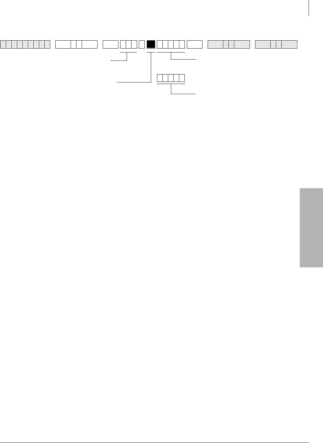
System & Station
Program 39 – Flexible Button Assignments
Strata DK Programming 5/99 3-115
System & Station
Directory Number Button Assignments
Directory Numbers are assigned to the flexible button positions on telephones.
♦Primary Directory Number Buttons [PDNs] are similar to Intercom numbers.
♦Secondary Directory Numbers [SDNs] are [PDNs] which appear on another telephone.
♦Phantom Directory Numbers [PhDNs] are generally used as numbers that may appear on a
group of telephones, such as an extension number which rings all phones in a department.
♦There are a number of considerations for assigning Directory Numbers. Toshiba suggests
reading the following steps and Directory Number Considerations before assigning [DNs].
➤To assign directory numbers to flexible buttons
1. Refer to the next page to determine how many and what type of Directory Numbers to assign
per telephone. You can use the Flexible Button Assignments forms to indicate where [DNs]
will be placed (see “Program 39 Flexible Button Assignments” on Page 3-113).
2. Assign [PDNs] and [SDNs] by entering the Program 04 port number assignment sequence
shown below. Refer to Program 04 for Station Logical Port Numbers.
##YYY, where YYY is the port number of the DN.
If a telephone has multiple [PDN] buttons, put the lowest number [NNNN-1] on the top, the
next lowest number [NNNN-2] below that, etc. This is the order in which they will ring (from
the top down). See the Directory Number Programming Example.
3. Assign [PhDNs] by entering the Program 04 port number assignment sequence shown below.
Refer to Program 04 for Station Logical Port Numbers. Also refer to Program 33 to
determine which Station Logical Port Number is the owner of the [PhDN].
##ZZZ, where ZZZ is the Program 04 port number of the [PhDN].
6SNU +ROG 6SNU ; ; ; +ROG 6SNU +ROG 6SNU +ROG
Enter the logical port number of the
telephone that will be assigned a [DN]
button.
Press the telephone button to which the
[DN] button should be assigned.
YYY = the Program 04 Port Number
(000~336) of the [DN] that should be
assigned. If YYY=XXX, then the [DN]
is the [PDN]; if YYY does not = XXX,
then the [DN] is an [SDN].
ZZZ = the Program *04 Port Number
(500~835) of the [PhDN] that should
be assigned.
...or
===
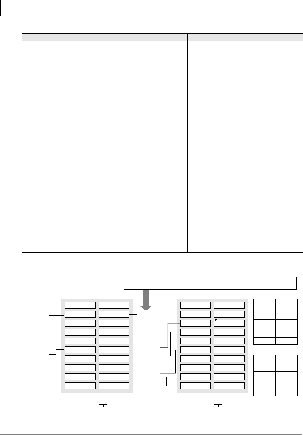
System & Station
Program 39 – Flexible Button Assignments
3-116 Strata DK Programming 5/99
Button Type Button Labels Code Notes
Primary Directory
Numbers [PDNs]
4-Maximum of
same [PDN] per
telephone
[PDN] NNNN - 1, Highest button
[PDN] NNNN - 2, next highest
[PDN] NNNN - 3, next highest
[PDN] NNNN - 4, Lowest button
##YYY
##YYY
##YYY
##YYY
YYY = the Program 04 station logical port
number of the [DN] that should appear as a
[PDN]. YYY should be the same port number
as the port number (XXX) of the telephone to
which the [PDN] is assigned. NNNN is the
actual [DN] assignment for Port YYY in
Program 04.
Secondary
Directory Numbers
[SDNs]
16 total [PDNs] +
[SDNs];
4-Maximum of
same [SDN] per
telephone
[SDN] NNNN - 1, Highest button
[SDN] NNNN - 2, next highest
[SDN] NNNN - 3, next highest
[SDN] NNNN - 4, Lowest button
##YYY
##YYY
##YYY
##YYY
YYY = the Program 04 station logical port
number of the [DN] that should appear as a
[SDN]. YYY should not be the same port
number as the port number (XXX) of the
telephone on which the [SDN] is assigned.
NNNN is the actual DN assignment for Port
YYY in Program 04.
Phantom Directory
Numbers [PhDNs]
8-Maximum unique
[PhDNs]
1-Maximum of
same [PhDN] per
telephone
[PhDN] NNNN ##ZZZ ZZZ = the Program *04 Port ref. number of
the [PhDN]. NNNN is the actual [DN]
assignment for Port ZZZ in Program *04.
Each [PhDN] must have an owner telephone
assigned in Program *33. If an owner is not
assigned, the [PhDN] can originate but
cannot receive calls.
Phantom Directory
Number Message
Waiting button
[PhDN]
4- maximum
[PhDN/MW] per
telephone
[PhDN/MW] - 1 Lowest [PhDN]
[PhDN/MW] - 2 Next Highest
[PhDN/MW] - 3 Next Highest
[PhDN/MW] - 4 Highest [PhDN]
423
424
425
426
Message Waiting Key for [PhDNs] assigned
to telephone. Telephone must be assigned as
[PhDN] owner in Program *33 to allow it to be
equipped with a [PhDN/MW] button.
Directory Number Programming Example
Program 04
Station 3200
Port 000
PhDN 4502
PhDN 4501
PhDN 4500
SDN 3202
SDN 3201-1
SDN 3201-2
PDN 3200-1
PDN 3200-2
PDN 3200-3
MW 4502
MW 4500
CO 10
CO 9
CO 3
CO 2
CO 1
ZZZ
ZZZ
ZZZ
YYY
=
=
=
=
502
501
500
002
Code
Code
=
=
424
423
Station 3201
Port 001
PhDN 4501
PhDN 4500
SDN 3203
SDN 3200-1
SDN 3200-2
PDN 3200-3
PDN 3201-1
PDN 3201-2
MW4501
CO 11
CO 10
CO 9
CO 3
CO 2
CO 1
ZZZ
ZZZ
YYY
YYY
YYY
=
=
=
=
=
501
500
003
000
001
XXX= 001
Port No.
XXX
and
YYY
000
001
002
003
Directory
No.
[PDN/SDN]
NNNN
3200
3201
3202
3203
Program *04
Port No.
ZZZ
500
501
502
503
Directory
No. [PhDN]
NNNN
4500
4501
4502
4503
Program *33: Assign Station Logical Port 000 as owner of [PhDN] 500 and 502.
Assign Station Logical Port 001 as owner of [PhDN] 501.
XXX= 000
1569
YYY = 000
YYY = 001
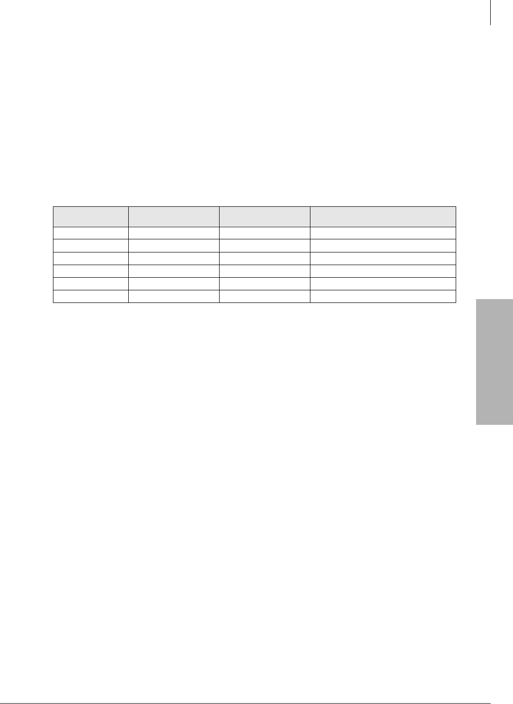
System & Station
Program 39 – Flexible Button Assignments
Strata DK Programming 5/99 3-117
System & Station
♦The total number of [DNs] allowed on a telephone ([PDN], [SDNs], and [PhDNs]) is limited
to the number of buttons on the telephone (i.e., a 20-button telephone can have 20 [DN]
buttons).
♦The number of [SDN] buttons programmed on a telephone for a given Primary Directory
Number must always be the same as the number of [PDN] buttons that exist on the [PDN]
owner telephone.
Example: If [PDN] 200 appears on 3 buttons on station 200, and [SDN] 200 should appear on
station 201, then [SDN] 200 must appear on 3-buttons on station 201. Never put more (or less)
[SDN] buttons of the same Directory Number on a telephone than [PDN] buttons that appear
on the [PDN] owner telephone. If this guideline is not followed, calls to the [PDN] telephone
will be missed on the [SDN] telephone.
♦The maximum number of [DNs] per system is listed below:
♦[PhDN] can appear on all Toshiba telephones in the system, but a [PhDN] is limited to ring on
120 telephones maximum.
♦Phantom [DN] owner telephones have the following attributes:
♦Set Call Forward for [PhDNs]
♦Set Call Forward Mail Box destinations (VM ID codes) for [PhDNs]
♦Receive Message Waiting indication for up to four Phantom Directory Numbers on
individual [PhDN/MW] button LEDs
♦When off-hook, the [PhDN] telephone owner will receive OCA calls directed to a busy the
[PhDN].
♦[PDN] and/or [PhDN] Call Forward/Message retrieval can only be set/received from the
[PDN] and/or [PhDN] owner telephone.
Processor Maximum [PDNs] per
System Maximum [PhDNs] per
System Total Number of Unique [DNs]
per system [PDNs] + [PhDNs]
DK14 10 10 20
DK40i 27 27 54
RCTUA 32 32 64
RCTUBA/BB 80 80 160
RCTUC/D 240 240 480
RCTUE/F 336 336 672
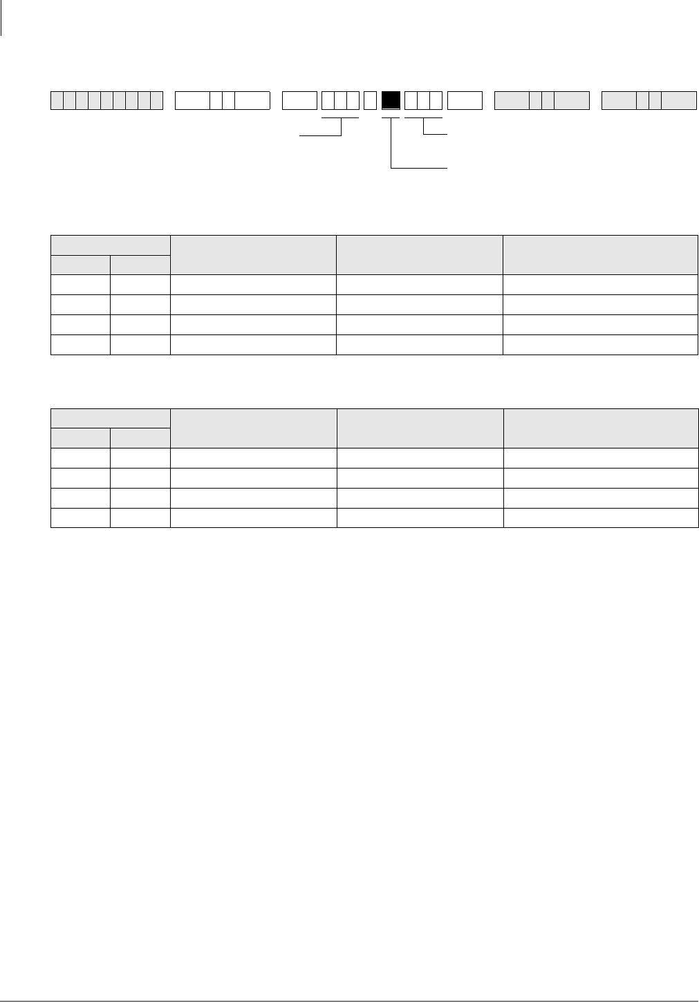
System & Station
Program 39 – Flexible Button Assignments
3-118 Strata DK Programming 5/99
Alert Signal Button Assignments
Station Number: _______
Station Number: _______
The Alert Signal is four short bursts of tone, sent two times/three seconds apart from one partner
station when the other partner station when one of the partners presses the $OHUW6LJQDObutton
on their telephone. An Alert Signal can be sent to stations that are idle or busy, or in Call Forward
or Do Not Disturb mode. No talk path will exist before or after the Alert Signal is activated.
Important!
●Both partner stations must have the same Alert Signal button number programmed in Program
39 and the appropriate Speed Dial Number programmed to allow the Alert Signal buttons to
operate.
●Strata AirLink does not support this feature.
6SNU +ROG 6SNU +ROG 6SNU +ROG 6SNU +ROG
Alert Signal Button Button Number (01~20) Speed Dial Number Alert Signal Button Partner
Station Number
No. Code
1 427
2 428
3 429
4 430
Alert Signal Button Button Number (01~20) Speed Dial Number Alert Signal Button Partner
Station Number
No. Code
1 427
2 428
3 429
4 430
Enter the logical port number of the
telephone that will be assigned an
OHUW6LJ QDO button.
YYY = the Program 39 code for the OHUW
6LJQDO
button that should be installed.
Press the telephone button to which OHUW
6LJQDO
should be assigned.
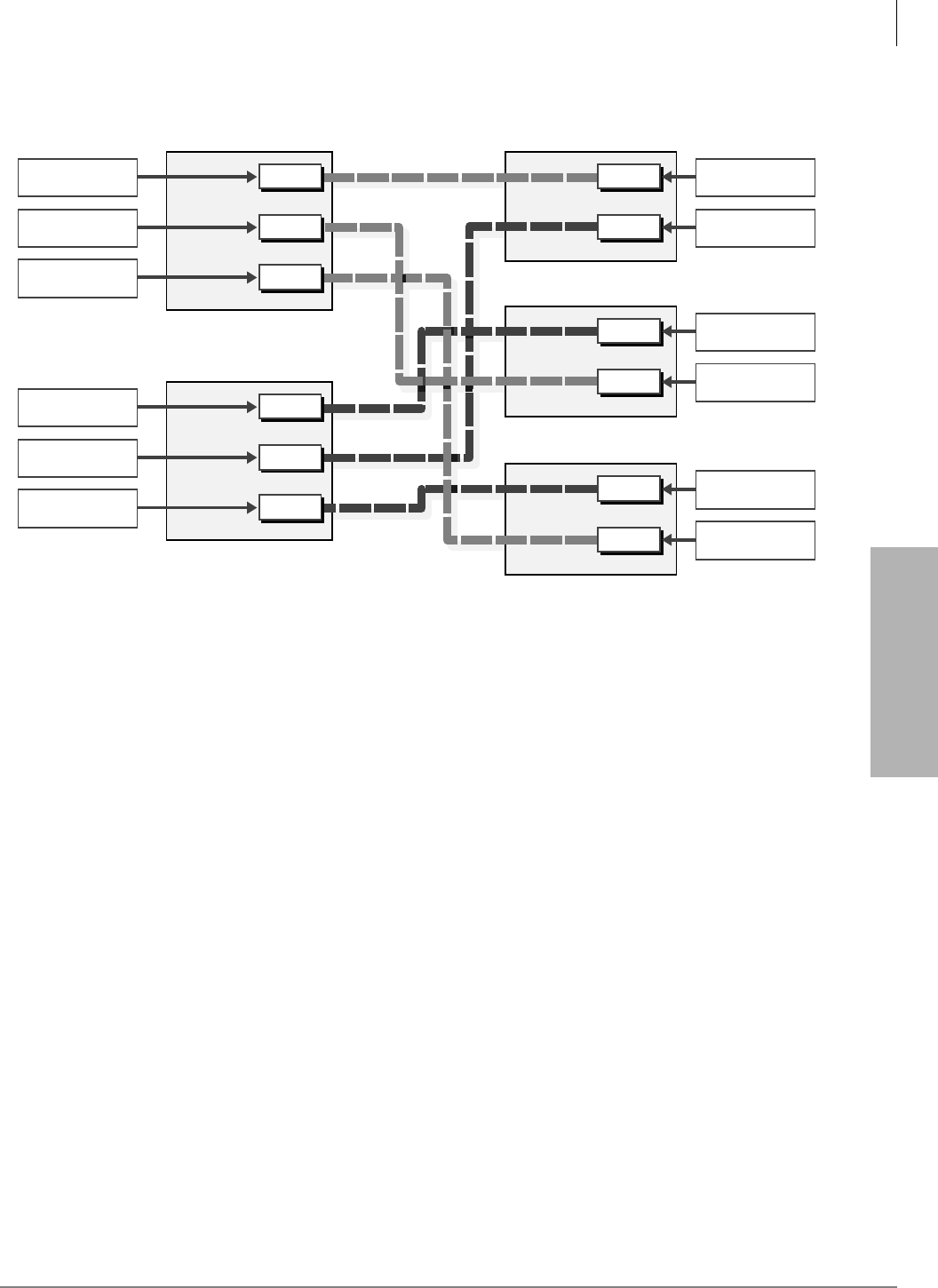
System & Station
Program 39 – Flexible Button Assignments
Strata DK Programming 5/99 3-119
System & Station
Alert Signal Button Programming Example
Station 200
Code
SD *48
Code
SD *47
Code
SD *45
=
=
=
=
=
=
427
202
428
203
430
204
Signal
1
Signal
2
Signal
4
Station 201
Code
SD *48
Code
SD *47
Code
SD *46
=
=
=
=
=
=
427
203
428
202
429
204
Signal
1
Signal
2
Signal
3
Station 202
Code
SD *48
Code
SD *47
=
=
=
=
427
200
428
201
Signal
1
Signal
2
Station 203
Code
SD *48
Code
SD *47
=
=
=
=
427
201
428
200
Signal
1
Signal
2
Station 204
Code
SD *46
Code
SD *45
=
=
=
=
429
201
430
200
Signal
3
Signal
4
1571
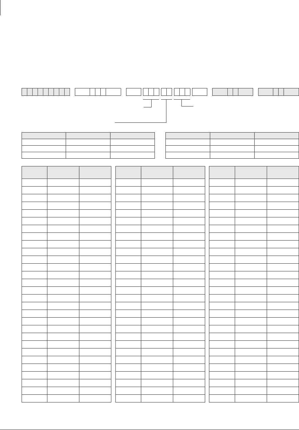
System & Station
Program *40 – Distributed Hunt Group Member Assignments
3-120 Strata DK Programming 5/99
Program *40 – Distributed Hunt Group Member
Assignments
Processor Type:
DK14, DK40i, all RCTUs
Program Type:
Station
Initialized Default:
No member (station port) assigned to any DH Group
6SNU+ROG 6SNU + ROG6SNU +ROG 6SNU +ROG
Processor DH Port Range Hunt Port Range Processor DH Port Range Hunt Port Range
DK14 900~915 000~009 RCTUBA/BB 900~915 000~079
DK40i 900~915 000~027 RCTUC/D 900~915 000~239
RCTUA 900~915 000~031 RCTUE/F 900~915 000~335
DH Port
(900~915) Hunt Order
(01-32) Hunt Port
Number DH Port
(900~915) Hunt Order
(01-32) Hunt Port
Number DH Port
(900~915) Hunt Order
(01-32) Hunt Port
Number
SELECT = Distributed Hunt (DH)
Group Number (see legend)
Hunt order (01~32)
DATA = Hunt Port Number
When editing the data field, use LED
Button 01 to delete a number.

System & Station
Program *40 – Distributed Hunt Group Member Assignments
Strata DK Programming 5/99 3-121
System & Station
Program *40 Overview
This program assigns the members (station primary [DN] port numbers and hunting orders
[01~32] of Distributed Hunt (DH) groups [900~915]). When a member of a DH group is added or
deleted, all the other members’ hunting orders are automatically shifted to a new sequential order.
If Ground/Loop start CO lines ring DH Group member telephones, use Program 81~89 to assign
the selected CO lines to ring the DH group (900~915); do not use 81, 84, and 87 to assign
[PDNs] or [PhDNs] to flash and ring on the DH Group member telephones. Instead, put the CO
lines in a pooled line group and put the appropriate 3RROHG/LQH*US buttons on the DH member
telephones. Do not assign DH Group member telephones to ring in Program 81~89.
To assign ANI/DNIS/DID/Tie and Internal calls to ring DH groups, use Program 04, 09,
71~*73, or 71 (1~3) as required and do not put DID or Tie line pooled or direct line buttons on
DH member telephones. These calls ring the DH member telephone [PDN].
Each port assigned to a Program 31 Voice Mail Group should also be assigned to a dedicated
Distributed Hunt Group. (See Program 31 record sheet overview for Voice Mail/Distributed Hunt
program example.)
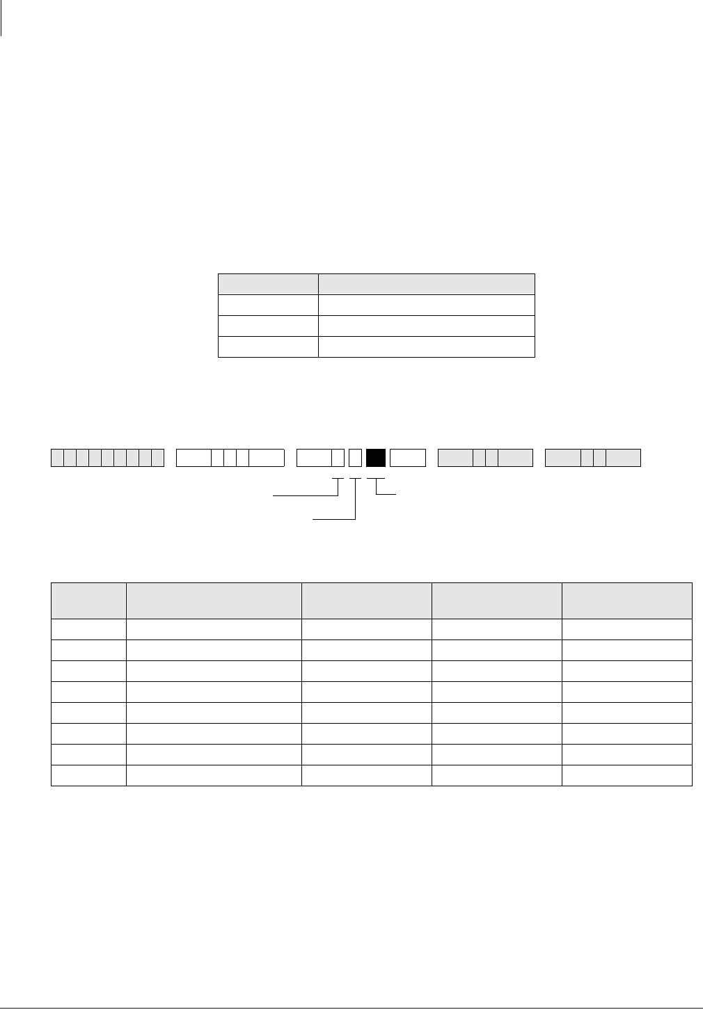
System & Station
Program *41 for DK424 – T1 Assignment Series (Part 1)
3-122 Strata DK Programming 5/99
Program *41 for DK424 – T1 Assignment Series (Part 1)
Processor Type:
RCTUBA/BB, RCTUC/D and RCTUE/F
Program Type:
System
Initialized Default:
See each program
Series Overview
Use Program 41 (Part 1) and 42 (Part 2) series to set T1 parameters and assignments on the
DK424. See the Strata DK Configuration and T1 sections for additional T1 information. RCTU
support is as follows:
Program *41-1 – T1 Span (RDTU) Frame and Line Code Assignments
Initialized Default:
LED 01 and LED 02 OFF for all T1 span lines
Program *41-1 Overview
T1 Span Framing Assignments: Each RDTU PCB can be individually assigned for Superframe
(LED 01 OFF) or Extended Superframe (LED 01 ON).
T1 Span Line Code Assignments: Each RDTU PCB can be individually assigned for B8ZS
(LED 02 ON) or AMI coding (LED 02 OFF).
Processor Number of RDTU’s Supported
RCTUBA/BB 2
RCTUC/D 6
RCTUE/F 8
6SNU+ROG 6 SNU +ROG 6SNU +ROG 6SNU +ROG
T1 Span Extended Superframe
LED 01 ON Superframe
LED 01 OFF B8ZS
LED 02 ON AMI Code
LED 02 OFF
1 RDTU
2 RDTU
3 RDTU
4 RDTU
5 RDTU
6 RDTU
7 RDTU
8 RDTU
SELECT = 1
Select the RDTU being
programmed (1~8)
LEDs 01 and 02
Set as described below.
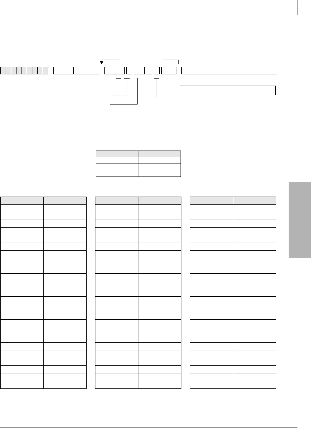
System & Station
Program *41 for DK424 – T1 Assignment Series (Part 1)
Strata DK Programming 5/99 3-123
System & Station
Program *41-2 – T1 Channel Assignments
Initialized Default:
1 = Loop Start
Important! See Program 17 for other Tie/DID assignments; see Program *17 and Program *09
for other DID assignments.
6SNU+ROG 6SNU + ROG7XUQ6 VWHP 3 RZ HU2 ) ) VHF WKHQ
Processor Line Range
RCTUBA/BB 001~048
RCTUC/D 001~144
RCTUE/F 001~200
RDTU:___________ Slot:___________ RDTU:___________ Slot:___________ RDTU:___________ Slot:___________
RDTU Channel No. Line Type RDTU Channel No. Line Type RDTU Channel No. Line Type
111
222
333
444
555
666
777
888
999
10 10 10
11 11 11
12 12 12
13 13 13
14 14 14
15 15 15
16 16 16
17 17 17
18 18 18
19 19 19
20 20 20
21 21 21
22 22 22
23 23 23
24 24 24
More channels
or...
Run Program 91-2
SELECT = 2
Enter the RDTU being programmed (1~8).
Enter the RDTU channel number (01~24)
to be assigned a line type.
To add a port range, enter XXXXXX
(low port high port).
Enter the line type to be assigned to the RDTU channel:
See Programs 17 and 71 for other Tie/DID assignments;.
See Program *17 and Program *09 for other DID assignments.
1 = Loop Start (initialized) 4 = Tie (Wink)
2 = Ground Start 5 = DID (immediate)
3 = Tie (immediate) 6 = DID (Wink)
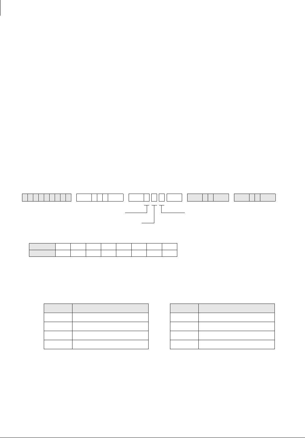
System & Station
Program *41 for DK424 – T1 Assignment Series (Part 1)
3-124 Strata DK Programming 5/99
Notes
●You must cycle system power or run Program 91-2 to transfer Program 41-2 data from
temporary memory to working memory. Turn system power OFF (five seconds) and ON after
running Program 41-2.
●Always install RDTU PCBs that have Tie or DID channels in slot numbers that are higher than
station and Attendant Console PCB slot numbers whenever possible. Each Tie or DID line
installed uses a station port in software (see the Configuration worksheets for Tie/DID
configuration in the Strata DK Installation and Maintenance Manual).
Program *41-2 Overview
RDTUs provide 8, 16, or 24 channels as set in Program 03. Each channel can operate
independently as CO lines (ground start or loop start), Tie lines (Wink or Immediate Start), or DID
lines (Wink or Immediate Start). Assign the number of channels for each RDTU with Program 03.
Important! Program 91-2 must be run or System Power must be momentarily turned OFF (five
seconds) then ON for Program *41-2 to take effect.
Program *41-3 – T1 Span Transmit Level Pad Assignments
Initialized Default:
5 (-6dB)
Program *41-3 Overview
The transmission path of each RDTU can be set for one of several pad settings:
6SNU+ROG 6SNU +ROG 6SNU +ROG 6SNU +ROG
Code Decibel Level Code Decibel Level
Enter 1 +6 decibel (dB) padding Enter 5 -6 dB (initialized setting)
Enter 2 +3 dB Enter 6 -9 dB
Enter 3 0 dB Enter 7 -12 dB
Enter 4 -3 dB Enter 8 -15 dB
SELECT = 3
Enter the RDTU being
programmed (1~8).
Enter one of the following pad codes for the
transmission of path:
1 = +6 dB pad
2 = +3 dB pad
3 = 0 dB pad
4 = -3 dB pad
5 = -6 dB pad (Initialized: PAD_S = 5)
6 = -9 dB pad
7 = -12 dB pad
8 = -15 dB pad
RDTU No.12345678
PAD Code
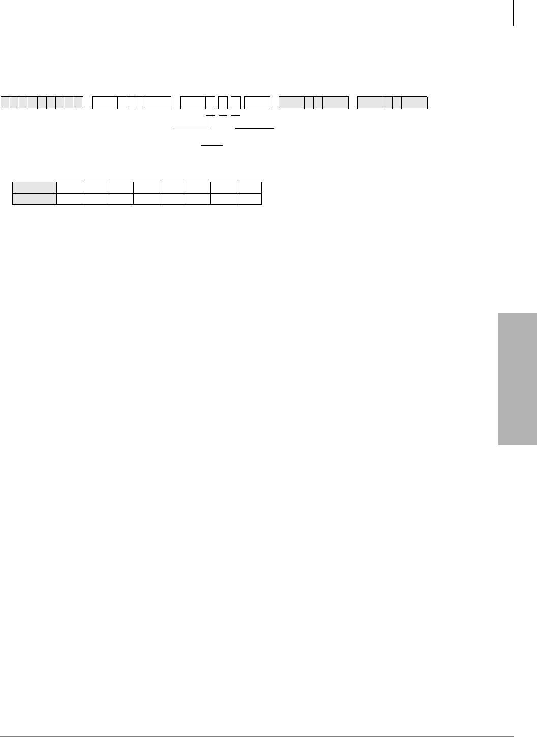
System & Station
Program *41 for DK424 – T1 Assignment Series (Part 1)
Strata DK Programming 5/99 3-125
System & Station
Program *41-4 – T1 Span Receive Level Pad Assignments
Initialized Default:
4 (-3dB)
Note See “Program *41-3 Overview”on Page 3-124 above for decibel levels.
Program *42 for DK424 – T1 Assignment Series (Part 2)
See “Program *42 – Clock Source”on Page 7-8.
6SNU+ROG 6SNU +ROG 6SNU +ROG 6SNU +ROG
SELECT = 4
Enter the RDTU being
programmed (1~8).
Enter one of the following pad codes for the
transmission of path:
1 = +6 dB pad
2 = +3 dB pad
3 = 0 dB pad
4 = -3 dB pad
5 = -6 dB pad (Initialized: PAD_R = 4)
6 = -9 dB pad
7 = -12 dB pad
8 = -15 dB pad
RDTU No.12345678
PAD Code
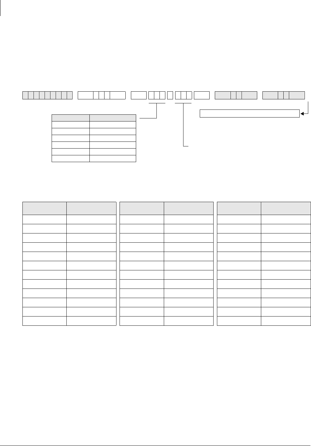
System & Station
Program *50 – Caller ID Circuit Assignments to CO Line PCBs
3-126 Strata DK Programming 5/99
Program *50 – Caller ID Circuit Assignments to CO
Line PCBs
Processor Type:
DK14, DK40i, All RCTUs
Program Type:
System
Initialized Default:
No RCIU/RCIS circuits assigned
Note The Tip/Ring leads of RGLU, RCOU, RCOS, and PCOU Caller ID CO lines assigned to
RCIU2/RCIS circuits must be bridged at the MDF. The Tip/Ring leads of TCOU and
TCIU2 are bridged by the PCB connectors in the DK40i Base KSU.
For more information on RCIU/RCIS assignments and installation, refer to Chapter 7 –
Universal Slot PCB Installation and Chapter 8 – Universal Slot PCB Wiring Diagrams in
the Strata DK Installation and Maintenance Manual.
On DK14, the Tip/Ring leads of the CO line circuit must be connected to the line Tip/Ring
leads of the Caller ID interface box. (See Chapter 1 - DK14 Installation, Figure 1-18 and
the Caller ID text under “WSIU1 Serial Interface Board” in the Strata DK Installation
and Maintenance Manual.)
6SNU+ROG 6SNU + ROG 6SNU +ROG 6SNU +ROG
CO Line Number RCIU/RCIS Circuit
Number Assigned CO Line Number RCIU/RCIS Circuit
Number Assigned CO Line Number RCIU/RCIS Circuit
Number Assigned
System power must be cycled or Program 91-2 must
be run after completing *50 data entry to transfer
data from temporary memory to working memory.
CIUNO = RCIU/RCISU Caller ID circuit number
(001~200) or use LED Button 01 to erase data. For
DK14, enter the Caller ID interface box line number
(001~004).
Any Caller ID circuit can be assigned to any analog
ground or loop start CO line circuit. Circuit numbers
do not have to match.
Processor CO Line Range
DK14 001~004
DK40i 001~012
RCTUA 001~016
RCTUBA/BB 001~048
RCTUC/D 001~144
RCTUE/F 001~200
Run Program 91-2

System & Station
Program *50 – Caller ID Circuit Assignments to CO Line PCBs
Strata DK Programming 5/99 3-127
System & Station
Program *50 Overview
In DK40i and DK424, each analog ground/loop start CO line that receives Caller ID information
from the local Central Office must be assigned to an RCIU or RCIS circuit using this program.
In DK14, each CO line that receives Caller ID must be assigned an MLX-41 interface box circuit
number. For information regarding the MLX-41, see Chapter 1 - DK14 Installation in the Strata
DK Installation and Maintenance Manual. This is necessary to allow Caller ID information to be
recognized by the DK system processor. Any RCIU, RCIS or MLX-41 circuit can be assigned to
any analog ground/loop start CO line circuit.
Each RCIU slot will be allocated eight Caller ID circuits when assigned with Code 81 in Program
03; because of this, you should always install RCIS on RCIU when more than four circuits are
required. TCIU2 allocates four Caller ID circuits to TCOU.
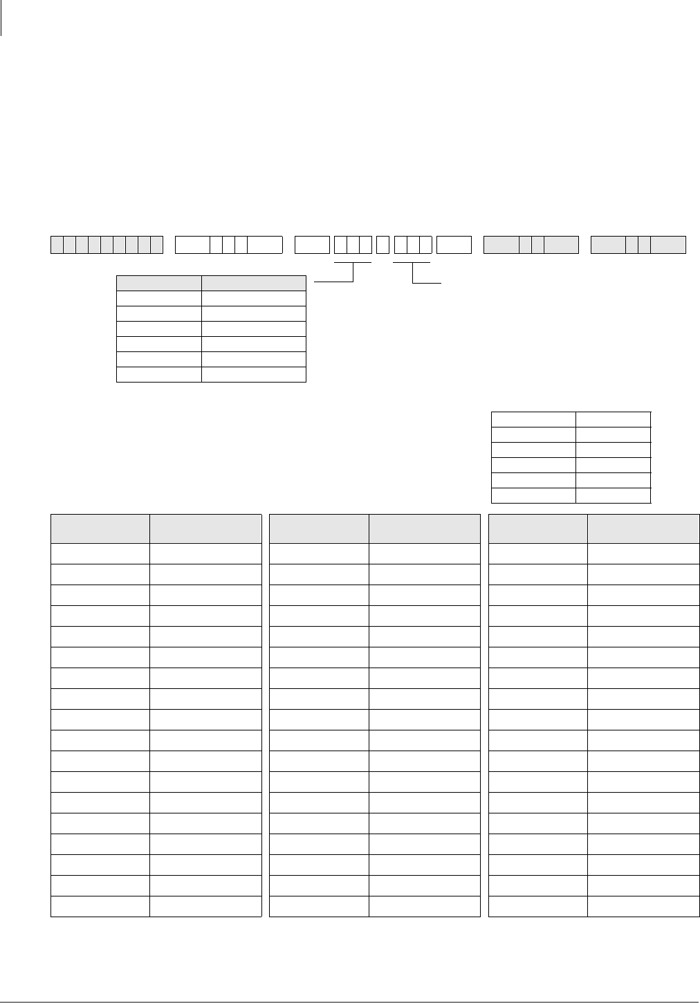
System & Station
Program *51 – Station Memory Allocation
3-128 Strata DK Programming 5/99
Program *51 – Station Memory Allocation
for Storing Caller ID/ANI Numbers on Abandoned/
Unanswered Calls
Processor Type:
DK14, DK40i, All RCTUs
Program Type:
Station
Initialized Default:
No memory for all ports
6SNU+ROG 6SNU + ROG 6SNU +ROG 6SNU +ROG
Station Logical
Port Number Memory Allocation
(100 max each) Station Logical
Port Number Memory Allocation
(100 max each) Station Logical
Port Number Memory Allocation
(100 max each)
BUF = 000, 010, 020, 030, 040, 060, 070, 080,
090 or 100.
This is the number of telephone numbers that can
be stored at the designated port(s). The
maximum Caller ID/ANI numbers that can be
stored per telephone is 100.
IDL = Total number of Caller ID/ANI Telephone
Numbers Available in each system
DK14 200
DK40i 200
RCTUA 200
RCTUBA/BB 400
RCTUC/D 1000
RCTUE/F 2000
Processor Station Ports
DK14 000~007
DK40i 000~027
RCTUA 000~031
RCTUBA/BB 000~079
RCTUC/D 000~239
RCTUE/F 000~335
To add a port range, enter
XXXXXX (low port high port).

System & Station
Program *51 – Station Memory Allocation
Strata DK Programming 5/99 3-129
System & Station
Program *51 Overview
Use this program to allocate “Abandon-Call-Memory” when any LCD telephone must store
abandon call information for Caller ID, Ground/Loop start line and/or ANI, DID/Tie lines.
On direct incoming calls that ring on more than one telephone, the Caller ID, Ground/Loop start,
line must also be assigned to the designated abandon call storage LCD telephone in Program 52.
If a CO line only direct-rings one telephone, that telephone will store the abandoned call
information automatically without being assigned in Program 52; however, Program 51 is still
required.
The IDL memory allocation displays on the program telephone’s LCD, indicating the total number
of telephone numbers that can be stored at the designated port(s). These numbers are reduced
accordingly each time memory is allocated to a station.
On direct incoming calls, the ANI abandon call information is stored in the “Abandon-Call-
Memory” of the [PDN] owner or [PhDN] owner LCD telephone - depending on which [DN] rings
when the call is received. Do not assign ANI/DNIS lines in Program 52.
Abandoned “Call-forwarded” calls will store Caller ID and/or ANI information in the “Abandon-
Call-Memory” of the “first-call-forwarded-from-station”. The “first-call-forwarded-from-station”
does not have to be assigned as the owner of the CO line in program 52 or as the owner of the
[PhDN] in Program 33, but it must be assigned memory in this program.
Distributed Hunt Queue or DISA line, Abandoned Calls store ANI/Caller ID data in the Program
52 CO line owner station.
If a Caller ID CO line is programmed to direct ring more than one station (81~89) a station logical
port must be assigned as owner of the ground and/or loop start Caller ID line (in Program 52) to
be able to store Caller ID numbers on abandoned or unanswered calls on Direct Incoming calls.
If a Caller ID CO line is programmed (81~89) to ring only one station, that station will store Caller
ID abandoned call information regardless of Program 52 data - the station must have storing
memory assigned in Program 51. ANI abandoned call numbers will be stored in the telephone
memory of the called Primary Directory Number [PDN] owner telephone or the called Phantom
Directory Number [PhDN] owner telephone.
Transferred Caller ID and/or ANI line abandoned call numbers will be stored in the “transferred-
to” telephone memory if that telephone is assigned memory in this program. (see Program 52).
Call forwarded Caller ID and/or ANI line abandoned call numbers will be stored in the [PDN] or
[PhDN] owner telephone memory if that telephone is assigned memory in this program.
ACD calls that are abandoned while the call is in queue or calls abandoned while connected to an
Auto Attendant or VM device will register on the SMDR report as a call answered by the ACD
announcement [DN], Auto Attendant [DN], or Voice Mail [DN].
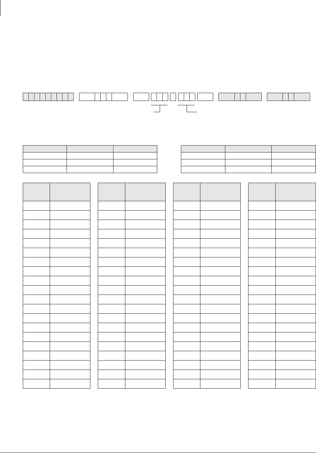
System & Station
Program *52 – Caller ID/ANI Abandoned Call Number Station Owner Assignments
3-130 Strata DK Programming 5/99
Program *52 – Caller ID/ANI Abandoned Call Number
Station Owner Assignments
Processor Type:
DK14, DK40i, All RCTUs
Program Type:
Station
Initialized Default:
No station owners assigned
6SNU+ROG 6SNU + ROG 6SNU +ROG 6SNU +ROG
Processor CO Line Range [PDN] Port Range Processor CO Line Range [PDN] Port Range
DK14 001~004 000~009 RCTUBA/BB 001~048 000~079
DK40i 001~012 000~027 RCTUC/D 001~144 000~239
RCTUA 001~016 000~031 RCTUE/F 001~200 000~335
CLID/ANI
CO Line
Number
Station Owner
Port Number
Assigned
CLID/ANI
CO Line
Number
Station Owner
Port Number
Assigned
CLID/ANI
CO Line
Number
Station Owner
Port Number
Assigned
CLID/ANI
CO Line
Number
Station Owner
Port Number
Assigned
CLASS OWNER = the station port number that
should store Abandon Call Numbers for the Caller
ID or ANI CO Line(s) entered.
Press LED Button 01 to erase data.
SELECT = Caller ID or ANI CO Line Number
To add a range of line numbers, enter
XXXXXX (low port high port).

System & Station
Program *52 – Caller ID/ANI Abandoned Call Number Station Owner Assignments
Strata DK Programming 5/99 3-131
System & Station
Program *52 Overview
Use this program for any LCD telephone that must store abandon call information for Caller ID,
Ground/Loop start lines and/or ANI, DID/Tie lines must be allocated “Abandon-Call-Memory”
LCD telephones can be allocated memory to save up to 100 numbers in 10 number increments (see
IDL totals).
When Caller ID and ANI lines ring into the Strata DK system and the caller hangs-up before the
call is answered, the call is considered abandoned. In this case, the Caller ID and ANI information
received can be stored at a designated LCD telephone. When a Caller ID line rings at more than
one telephone (Program 81-89), the LCD telephone that should store the Caller ID information for
that line must be programmed as the owner of that Caller ID line using this program.
When a Caller ID line rings only one LCD telephone (Program 81-89), the abandoned call Caller
ID information will be stored at that LCD telephone regardless of the Program *52 assignment.
The number of abandoned calls the station can store is set in Program *51.
An LCD telephone can be assigned as owner of any number of Caller ID lines. A Caller ID line
can only be assigned to one owner LCD telephone.
If a Caller ID CO line or ANI Tie/DID line is answered by the, Distributed Hunt group queue, or
DISA line, and if this call is abandoned before it is routed to and rings a station, the Caller ID or
ANI data will be stored in the abandoned call memory of the station owner assigned to the Caller
ID or ANI line assigned in this program.
Notes
●Abandoned “call-forwarded” calls will store Caller ID information in the “Abandon-Call-
Memory” of the “first-call-forwarded-from-station”. The “first-call-forwarded-from-station”
does not have to be assigned to the CO line in this program. To store abandon call information
for CO lines, the station must also be allocated “Abandon Call Memory” in Program *51.
●If a Caller ID CO line is answered by the Strata DK Distributed Hunt Group Queue or DISA
line, and if this call is abandoned before it is routed to and rings a station, the Caller ID data is
stored in the abandon call memory of the station owner assigned to the Caller ID line assigned
in this program.
●Tie/DID ANI lines store abandoned call ANI numbers on the Primary and/or Phantom
Directory Number owner telephones if they are allocated memory in Program *51. Tie/DID
ANI line calls that are abandoned while Distributed Hunt Group queue will store ANI
information on the station owner assigned in this program.
●ACD or Auto Attendant calls that are abandoned while the call is in queue or calls abandoned
while connected to an Auto Attendant or VM device will register on the SMDR report as a call
answered by the ACD announcement [DN], Auto Attendant [DN], or Voice Mail [DN].
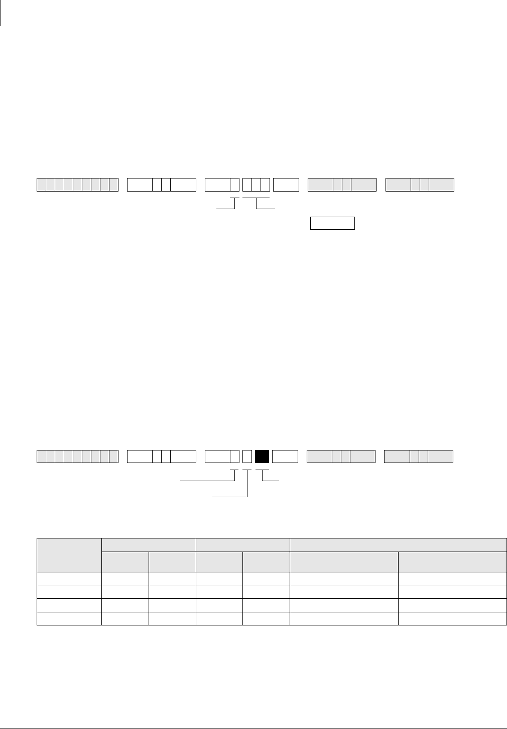
System & Station
Program 58 – DK424 Attendant Console Series (Part 1)
3-132 Strata DK Programming 5/99
Program 58 – DK424 Attendant Console Series (Part 1)
Processor Type:
RCTUBA/BB, RCTUC/D and RCTUE/F
Program Type:
Station
Initialized Default:
see each program
Program 58-1 – Attendant Console Overflow Timer
Initialized Default:
32 seconds
Program 58-1 Overview
Incoming Line Calls (not recalls) to attendant consoles will overflow to a designated attendant
console or station port (Program 58-5) if the call is not answered within the time (011~999
seconds) specified by this program. The overflow call will ring on either the ,Q7UDQV button
(assigned in Program 59) of the console that receives the overflow call, or the [DN] or CO /LQH
button of a station.
Notes
●This program sets overflow timer for all attendant consoles (1~4)
●The overflow destination is assigned in Program 58-5.
Program 58-2 – Attendant Console Display Type
Initialized Default:
All LEDs OFF
6SNU +ROG 6SNU +ROG 6SNU +ROG 6SNU +ROG
6SNU +ROG 6SNU +ROG 6SNU +ROG 6SNU +ROG
Attendant
Console
Button 01 LED Button 02 LED Button 03 LED
ON
(EL) OFF
(EGA) ON (FIFO) OFF (58-4) ON
(Call Waiting Tone) OFF
(No Call Waiting Tone)
1
2
3
4
DATA = 011~999 seconds
DATA =
SELECT = 1
LED Button 01 ON for EL or OFF for EGA display
LED Button 02 ON sets Answer Button operation for First In/
First Out (FIFO) or priority per Program 58-4
LED Button 03 ON sets Attendant Console Call Waiting Tone
SELECT = 2
Console Number (1~4)
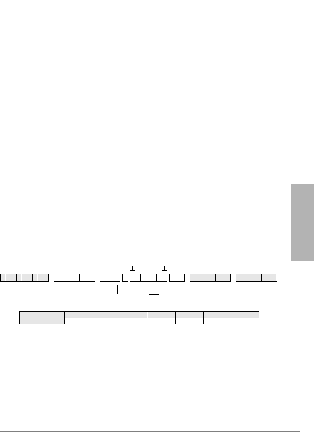
System & Station
Program 58 – DK424 Attendant Console Series (Part 1)
Strata DK Programming 5/99 3-133
System & Station
Program 58-2 Overview
This program identifies in software the type of display connected to each console. It also enables
you to set priorities for types of incoming calls. You can also enable Call Waiting tones.
LED 01: Attendant Console Display Type
Base units can connect to an Electroluminescent (EL) display (LED 01 ON) or Extended Graphics
Adapter (EGA) Display (LED 01 OFF).
LED 02: Answer Button Operation
The attendant console $QVZHU button can be programmed to answer calls on either a First-in,
First-out (FIFO) or a Priority basis. With FIFO, new calls or recalls are stacked in queue in the
order in which they are received. This is true regardless of the type of call/recall (CO line,
Intercom, [DN] call or Hold Recall, etc.). The queued calls ring to the $QVZHU button in the order
in which they are received.
With Priority operation, each type of incoming call or recall (CO line call, [DN] call, Hold Recall
or Park Recall, etc.) is assigned a specific answering priority ranging from 1~6. (Call Priority is
flexible and is assigned in Program 58-4.) Calls will queue to the attendant in order of their
predetermined priority levels. For example, Priority Level 1 calls ring to the attendant before
Priority 2 calls; Priority 2 calls ring before Priority 3 calls, and so forth.
LED 03: Attendant Console Call Waiting Tone
Each attendant console can be programmed individually to receive a muted ring signal that will
alert the console that a new call is waiting while the console is busy on another call. If call waiting
tone is not enabled, new calls do not present an audible indication. The call waiting display always
displays the number of calls waiting to be answered.
Program 58-4 – Attendant Console Answer Button Priority Assignments
Initialized Default:
0, 1, 2, 3, 4, 5, 6
Program 58-4 Overview
Each incoming call or recall type can be assigned a specific $QVZHU button priority level, ranging
from 0~6. If the $QVZHU button is assigned Priority answer operation in Program 58-2, then
incoming calls/recalls will ring to the $QVZHU button based on their assigned priority levels.
Priority 1 calls have the highest priority while Priority 6 calls have the lowest.
Notes
●EMRG has first priority over the above key assignments.
●See Program 59 for the function of each button.
6SNU +ROG 6SNU +ROG 6SNU +ROG 6SNU +ROG
Lowest Priority
Highest Priority
Enter button numbers in priority order.SELECT = 4
Console Number (1~4)
Button Name Park-RC Trans RC Hold-RC In-Trans LINE In Dial “O” [PDN]
Button Number 0123456

System & Station
Program 58 – DK424 Attendant Console Series (Part 1)
3-134 Strata DK Programming 5/99
Program 58-5 – Attendant Console Overflow Destination Assignments
Initialized Default:
Blank
Program 58-5 Overview
When the attendant console has been placed in the Overflow mode (via the 2YHUIORZ button),
calls queue to be answered based on the predetermined FIFO or priority basis. If a call remains in
queue for a period longer than the time period set for the Overflow Timer (set in Program 58-1),
then the call will overflow to the destination assigned in this program.
The assigned destination can be either a station, voice mail, auto attendant, or another attendant
console.
●Calls that will overflow include ring transfer, incoming CO /LQH, GLDO“”, and $WWG&DOO
button calls; Transfer Recall (,Q7UDQV) and +ROG recall will not overflow.
●Overflow recall time is set in Program 58-1.
6SNU +ROG 6SNU +ROG 6SNU +ROG 6SNU +ROG
Processor [PDN] Port Range Max. Consoles
RCTUBA/BB 000~079 2
RCTUC/D 000~239 4
RCTUE/F 000~335 4
Enter the overflow destination port number.
SELECT = 5
Console Number (1~4) Console overflow destination =
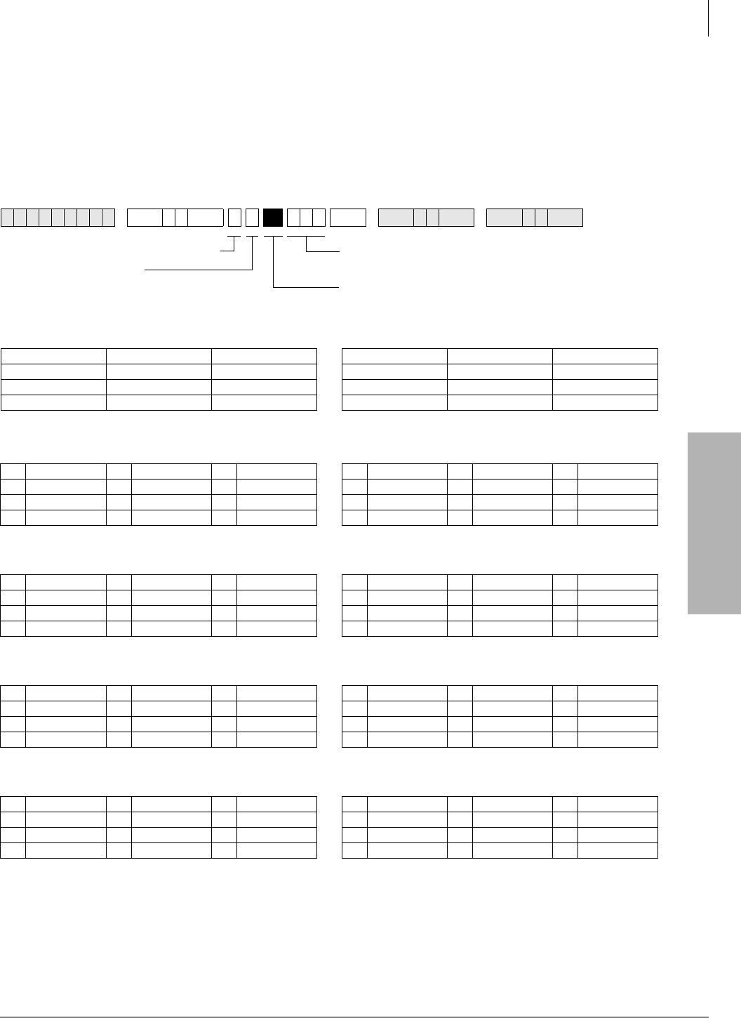
System & Station
Program 59 – Attendant Console Flexible Button Codes
Strata DK Programming 5/99 3-135
System & Station
Program 59 – Attendant Console Flexible Button
Codes
Processor Type:
RCTUBA/BB, RCTUC/D, RCTUE/F
Program Type:
Station
Initialized Default:
Given throughout this section
6SNU +ROG +ROG 6SNU +ROG 6SNU +ROG
Codes (Left Buttons 1~12) Codes (Right Buttons 1~12)
Split (295) Join Loop (239) Sup. Loop (296) Conf (297) Overflow (299) Night (439)
In-Emrg (261) In-DN (257) In-Dial “0” (262) Redial (496) Spdial (497) SD13 (*13)
In-Trans (258) Trans-RC (260) Hold-RC (259) BLF (298) Out Dial (294) SD12 (*12)
In-LG3 (243) In-LG2 (242) In-LG1 (241) Attd Call (000) SD10 (*10) SD11 (*11)
Console 1
Left Right
10 11 12 10 11 12
07 08 09 07 08 09
04 05 06 04 05 06
01 02 03 01 02 03
Console 2
Left Right
10 11 12 10 11 12
07 08 09 07 08 09
04 05 06 04 05 06
01 02 03 01 02 03
Console 3
Left Right
10 11 12 10 11 12
07 08 09 07 08 09
04 05 06 04 05 06
01 02 03 01 02 03
Console 4
Left Right
10 11 12 10 11 12
07 08 09 07 08 09
04 05 06 04 05 06
01 02 03 01 02 03
DATA = Button Code
See legend.
Press LED Buttons 01~12 on Programming Telephone to
enter data for corresponding console button.
Attendant Console (1~4)
1 = Left
2 = Right
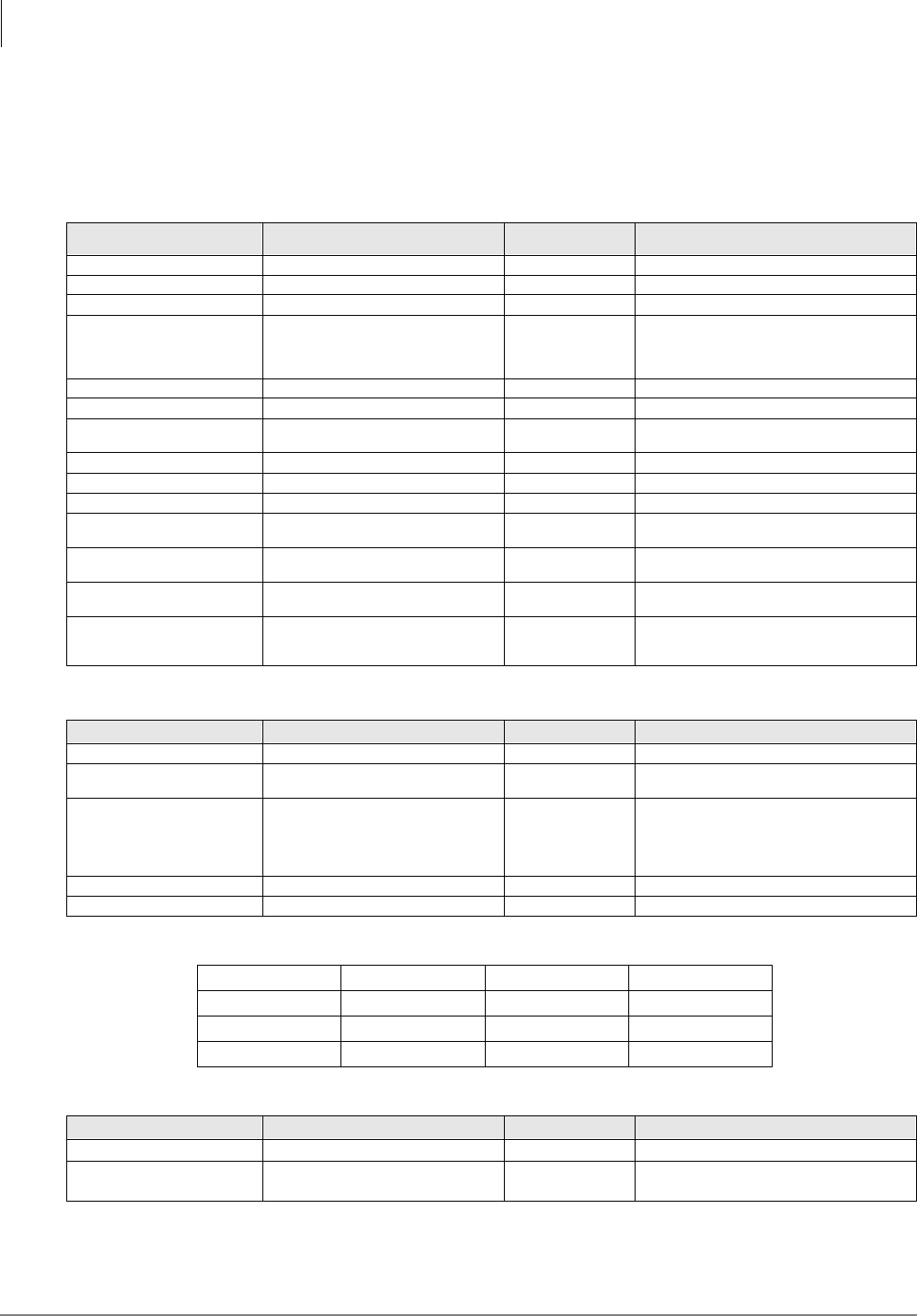
System & Station
Program 59 – Attendant Console Flexible Button Codes
3-136 Strata DK Programming 5/99
Program 59 Overview
Attendant Consoles have 24 flexible buttons (12 on left and 12 on the right side of the dial pad).
This program is used to assign each button to an available function or options. Program 59 record
sheets define the button options (and codes) available.
Table 3-2 Required PC Attendant Console Button Codes
Button Function Button Labels Code Notes
Conference Conf 297 Starts conference calls.
Hold Recall Hold-RC 259 Held calls recall on this button.
Incoming Dial “0” In-Dial “0” 262 Dial “0” calls ring in on this button.
Incoming Directory Number In-DN 257
Incoming calls to the console DN ring on this
button. The console [DN] is the Prog 04
assignment of the Prog 04 console port
number.
Incoming Ring Transfer In-Trans 258 Receive call transfer.
Join-Loop Join-Loop 293 Connects any held call to an existing call.
Out Dial Out Dial 294 Switches ATTD consoles dial pad from digital
to tone mode.
Redial Last Number ( ) Redial or RDL 496 Redials the last number.
Release to Idle Release Call or RLS 476 Releases current call and makes station idle.
Speed Dial Select () Speed Dial or SDS 497 Begins speed dial selection.
Split Call Split 295 Allows attendant to talk to either party
separately on a conference call.
Supervised Loop Sup Loop 296 Places call on attendant hold loop key so
attendant can supervise call.
Transfer Recall Trans-RC 260 No answer transferred calls, recall on this
button.
Attendant Call Attd Call 000 Can originate calls on this button. The
Attendant Call LED is lit red any time the
attendant talk path is connected.
Table 3-3 Recommended PC Attendant Console Button Codes
Button Function Button Labels Code Notes
Display BLF BLF 298 Displays BLF on CRT or EL display.
Incoming Emergency In-Emrg 261 Indicates to all consoles an incoming
emergency call.
Message Waiting/Flash Msg Wait, Flash or MW/FL 499
Indicates a message from station or VM
device to Attendant. Disconnects and recalls
dial tone on CO line; accesses Centrex or
PBX features; enters pause or flash during
speed dial programming.
Overflow Overflow 299 Places console in the call overflow mode.
Park Recall Park-RC 263 Parked calls recall on this button.
Table 3-4 Incoming Line Group Button Assignments
In-LG1~241 In-LG5~245 In-LG9~249 In-LG13~253
In-LG2~242 In-LG6~246 In-LG10~250 In-LG14~254
In-LG3~243 In-LG7~247 In-LG11~251 In-LG15~255
In-LG4~244 In-LG8~248 In-LG12~252 In-LG16~256
Table 3-5 Optional Attendant Console Button Codes
Button Function Button Labels Code Notes
Alarm Alarm Reset or ALRM 477 Resets alarm condition system-wide.
Call Pickup Tenant 1~Call
Pickup Tenant 4 PKUP 1~PKUP 4 435~438 Picks up tenant 3’s ringing CO calls.
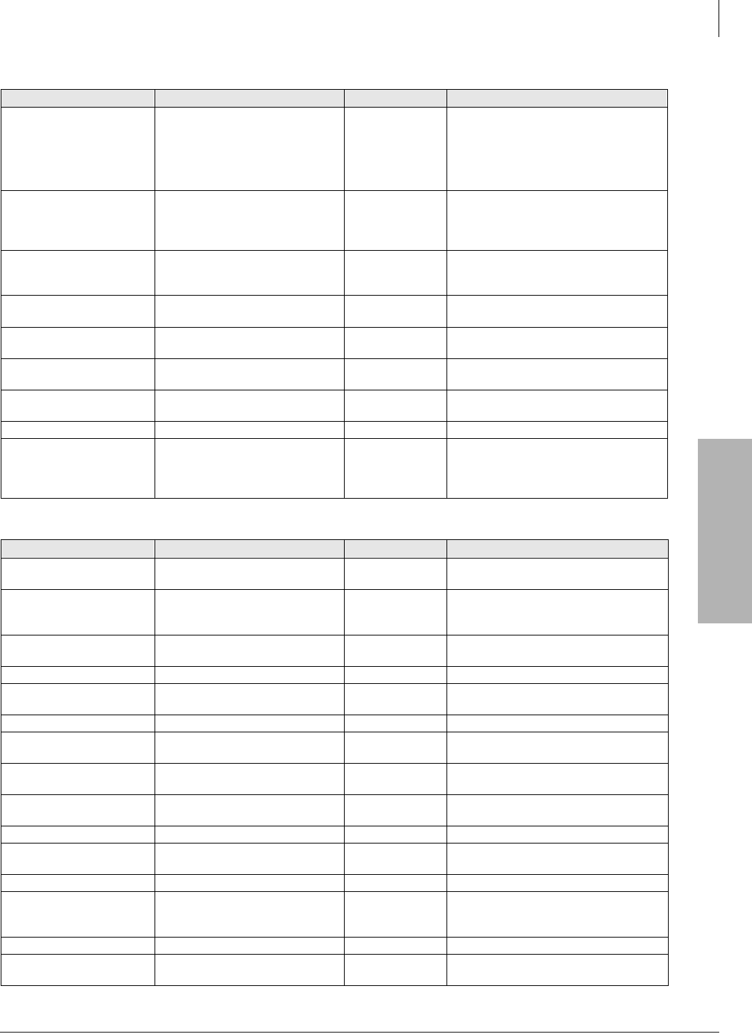
System & Station
Program 59 – Attendant Console Flexible Button Codes
Strata DK Programming 5/99 3-137
System & Station
CO Line Appearance
CO line access of appearing calls. CO
line ranges vary according to processor:
Line 1~48 001~048 RCTUBA/BB
Line 1~144 001~144 RCTUC/D
Line 1~200 001~200 RCTUE/F
Door Lock 0~Door Lock 4
(DDCB/HDCB) DRLK 0~4 471~475
Momentarily unlocks door (3 or 6
seconds). The PC attendant activates
these options when these buttons are
assigned.
Emergency Page Access Emrg Page 292
Activates ALL CALL Paging to
telephone speakers (not EXTR Page).
Overrides any existing ALL CALL page.
Night Transfer
Tenant 1~Tenant 4
Night Transfer1 or NT1~Night
Transfer4 or NT4 439~442 Sets Tenant 1 CO line DAY/NIGHT ring
mode.
Privacy Privacy On Line or PRIV 453 Prevents Privacy Override (not
Executive Override).
Privacy Release Privacy Release or PRV RLS 479 Changes station Privacy mode to Non-
private for CO lines.
Pause Spd Dial Pause or PAU 495 Sets pause in Speed dial (see Program
12-3.)
Pause (Long) Spd Dial Lng Pause or PAU/L 493 Sets a 10-second pause in Speed Dial.
Unanswered Caller ID and/
or ANI Stored Number
Auto Dial
Lost Call Auto Dial or LCAD 462
Will Auto Dial a Caller ID and/or
Automatic Number Identification (ANI)
telephone number that was stored in
station Caller ID/ANI memory.
Table 3-6 Additional Feature Button Codes
Button Function Button Labels Code Notes
Account Code Account Code or ACCNT 450 Allows a Voluntary Account Code to be
entered.
Alert Signaling Alert 1~4 427~430
Console can alert another station but
another station cannot alert the console.
See Program 39 for more information.
All Call Voice Page All Call Page or AC 489 Pages up to 120 idle electronic or digital
telephones over speaker.
Automatic Busy Redial Auto Busy Redial or ABR 470 Sets ABR of busy outgoing number.
Automatic Callback Busy Auto Callback or ACB 494 Sets ACB for station recalled by busy
line.
Call Forward All Calls Call Frwd All Calls or CFAC 487 All calls forward to selected station.
Call Forward A.C. Fixed Call Frwd to: or CFF 486 Forwards all calls to pre-defined
destination. See Program 36.
Call Forward Busy Call Frwd Busy or CFB 459 Forwards calls to selected station if
station is busy.
Call Forward Busy/
No Answer Call Frwd Busy/NAns or CFB/NA 457 Forwards calls to selected station if
station is busy or does not answer.
Call Forward External Call Frwd External or CF-EXT 460 Forward calls externally.
Call Forward No Answer Call Frwd No Answer or CFNA 458 Forwards calls to selected station if
station does not answer.
Call Park Park in Orbit or PARK 464 Call Park Only.
Call Park LCD Display Park Orbit DIsplay or CPD 465
CP Display Button and Mode 64 can be
used interchangeably. Displays call
parked via telephone LCD.
Call Park and Page Call Park/Page or CP/PG 463 Parking and Paging Park Pickup.
Call Pickup (Directed) Directed Pickup or PKUP 484 Picks up ringing or held intercom, trunk
calls, and page.
Table 3-5 Optional Attendant Console Button Codes
(continued)
Button Function Button Labels Code Notes

System & Station
Program 59 – Attendant Console Flexible Button Codes
3-138 Strata DK Programming 5/99
Notes
●See Program *15 for Tenant Group assignments.
●Picks up calls to telephones in any call pickup group to which the telephone is assigned in
Program *31.
●Attendant consoles cannot be equipped with [SDNs] or [PhDNs]. The console [DN] is
assigned to the console port number in Program 04. The console’s [DN] can have only one
appearance.
●Attendant consoles cannot be equipped with [PDNs], [SDNs], or [PhDNs]. The [In-DN]
button is the console’s [DN], assigned in Program 04; it supports incoming calls only and can
only appear once on a console.
Call Pickup (Group)4 Group Pickup 480 Picks up a call to any group to which
station is assigned in *31.
Do Not Disturb Do Not Disturb or DND 498 Prevents calls to station.
ISDN Sub-address Sub-address 467
Separates the called party’s ISDN sub-
address from the called party number.
The digit performs this function on
standard telephones.
ISDN Start Start 469
Initiates DK to send dialed digits to the
ISDN network when this button is
pressed from a digital or electronic
telephone. Program *63-2 invokes the
same function when the Dial Timer
expires. Also see Tone Button in this
table.
LCD Message Select LCD Msg Select or LCD M 481 Begins LCD message selection.
Night Transfer Lock
Tenant 1~Night Transfer
Lock Tenant 4
Night Lock1 or NT1 L1~Night
Lock4 or NT4 L4 431~434
Used to lock system ringing mode: DAY,
DAY2, NIGHT See Programs 74 and *36
for NT Lock Password assignments.
Release and Answer Release and Ans and RLS/ANS 466
Simulates On-hook/Off-hook operation
to release an existing call and answer
new incoming/ringing call.
Save Last Dialed Number Save Last Number or SAVE 485 Saves last number dialed for future
speed dial.
Station Speed Dial Codes SD
Reserves button for station speed dial
for the following processors:
*10~*49 RCTUBA/BB
*10~*49 RCTUC/D
*100~*139 RCTUE/F
System Speed Dial Codes SD
Speed dial number is set by station port
000.
*600~*699 RCTUBA/BB
*600~*699 RCTUC/D
*200~*999 RCTUE/F
Tone Tone Dial Select or TONE 490
CO dial signals set to tone or pulse.
For ISDN applications, after the user
presses the Tone Dial Select button, any
digits dialed after it is will be sent using
DTMF tones.
Table 3-6 Additional Feature Button Codes
(continued)
Button Function Button Labels Code Notes
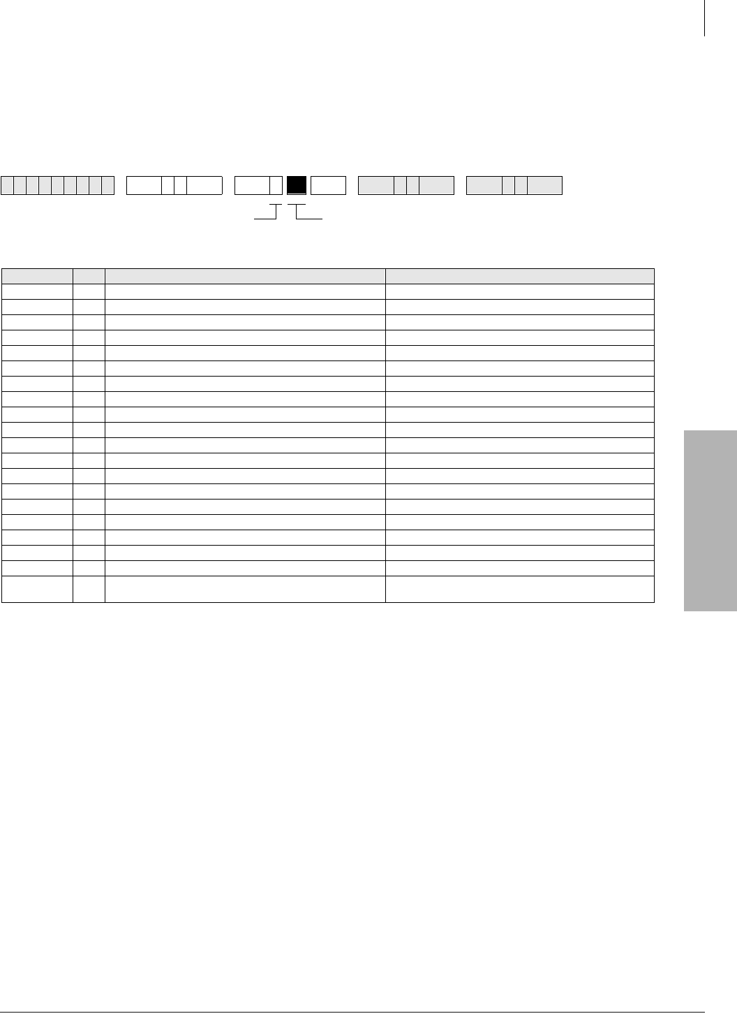
System & Station
Program 60-1 – SMDR Data Output Options
Strata DK Programming 5/99 3-139
System & Station
Program 60-1 – SMDR Data Output Options
Processor Type:
DK14, DK40i, All RCTUs
Program Type:
System
Initialized Default:
LED 01 OFF
Program 60-1 Overview
Program 60-1 determines which information will be sent out the system SMDR port: System
Account codes or Caller ID and/or ANI telephone numbers.
Turn LED 01 ON if received Caller ID and/or ANI information should be sent out the system
SMDR port.
Turn LED 01 OFF if Account Code information should be sent out the system SMDR port.
Note LED 01 determines if received Caller ID and/or ANI information (LED 01 ON) or data is
sent out the SMDR port. This data is output on the last 15-digit (right hand) field columns
of the SMDR print out.
6SNU +ROG 6SNU +ROG 6SNU +ROG 6SNU +ROG
LED/Button XLED ON LED OFF
20
19
18
17
16
15
14
13
12
11
10
09
08
07
06
05
04
03
02
01 Caller ID, ANI and DNIS data will be sent from the system
SMDR port Account code data will be sent from the system SMDR
port
Light the LED Buttons that are marked
with an X in the table below.
SELECT = 1
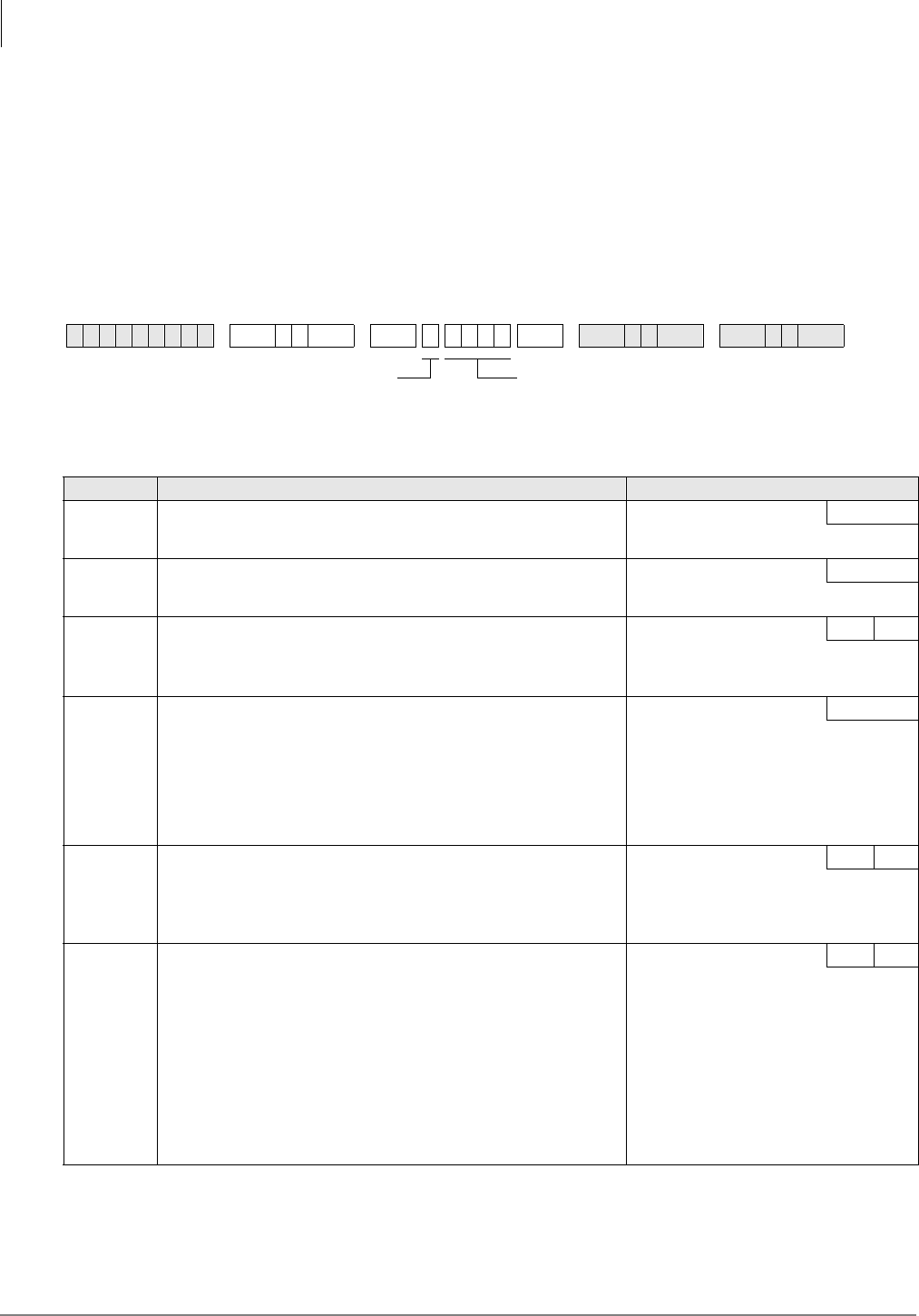
System & Station
Program 60-2~7 – SMDR Output/Account Code Digit Length
3-140 Strata DK Programming 5/99
Program 60-2~7 – SMDR Output/Account Code Digit
Length
Processor Type:
DK14, DK40i, All RCTUs
Program Type:
System
Initialized Default:
Item 2: 10 seconds
Item 3: SMDR output is enabled for answered incoming/outgoing calls
Item 4: a 6-digit length is assigned to all Forced/Voluntary Account Codes
Item 7: 21 digits
6SNU +ROG 6SNU +ROG6SNU +ROG 6SNU +ROG
Item Description Data
2SMDR Threshold Time
0 =1 second
1 = 10 seconds Time
3SMDR Output when a call is completed
0 = Outgoing Only
1 = Incoming and Outgoing SMDR COR
4
Forced/Voluntary Account Code Digit Length 04~15
(See Program 69 for Verified Account Codes)
Digits are verified per Program 30, Button/LED 14 and Program 69 Account
5
SMDR Printout Options
Toll Dial:
0 = All Calls (item 3, printout outgoing call only is still available)
1 = Dial “0” calls only
2 = Dial “1” calls only
3 = Dial “00” calls only
4 = Dial “1”, “0” calls only
5 = Dial “1”, “00” calls only Toll Dial Data
6
DISA Security Code
01~15 digits, may be changed from station, per Program 30
If a security code is not programmed, outgoing trunk access via DISA
will not require a security code when dialing.
Data
Button 01 = blank
Button 02 is wild card
(any digit from 1~9)
7
Credit Card Call Digit Length, 01~30 digits
(see Program 43)
Credit
Number of digits required
when “0” is the first digit
dialed; if this number of
digits is not dialed, the
system will disconnect the
call after 20 seconds. “0” is
counted as a digit.
Example: 0 + 714 + 583 -
3700 = 11 digits; 11 should
be programmed as a
minimum in this case.
See table below.SELECT = 2~7 (Item)
Make a selection from
the table below.

System & Station
Program 60-2~7 – SMDR Output/Account Code Digit Length
Strata DK Programming 5/99 3-141
System & Station
Program 60-2-7 Overview
This program assigns the type of data to send to the Station Message Detail Report (SMDR).
Item 2: SMDR Threshold Time
The time that a call must be in progress before it will register with SMDR can be set to 1 or 10
seconds.
Item 3: SMDR Output
System output to a Station Message Detail Recording (SMDR) device can include information for
both incoming and outgoing calls, or only for outgoing calls. Local and long distance call data will
be sent out.
Item 4: Forced/Voluntary Account Code Digit Length
The Account Code entered at a station can vary in length from 4~15 digits. For Forced Account
Code use, a call will not be completed unless the specified number of digits is entered by a station
user. In the case of Voluntary Account Codes, the Account Code will not be sent to the SMDR call
record unless the specified number of digits is dialed. Initialized data assigns a six-digit length for
all Account Codes. See Program 60-1 and Program 69 for Verified Account Codes.
Item 5: Station Message Detail Recording (SMDR) Printout Options
This option selectively deletes local call data and allows long distance/toll call data only to be sent
out the SMDR port. The type of long distance/toll call data that prints out is selected by long
distance prefix codes 0, 1, 00, or 1 or 0.
Item 6: Direct Inward System Access (DISA) Security Code
The optional security code (1~15 digits) is required for incoming DISA calls to access outgoing
CO lines. If the DISA security code is not set in programming, DISA users can access outgoing
lines without dialing a security code. This code is not required for DISA internal calls to stations.
The DISA security code can also be changed from stations enabled in Program 30. If the DK280
built-in Auto Attendant is installed, make sure to program a DISA security code to prevent Auto
Attendant callers from making unauthorized external DISA calls by using the DISA access feature
(Dial ).
Item 7: Credit Card Call Digit Length
Station users bypassing Toll Restriction with the “0 +” Credit Card Calling feature (Program 43)
must dial a predetermined number of digits including the “0.” This predetermined number is
established with Item 7, and can be 1~30 digits. Set 11 digits in this program when using LCR.
Notes
●If PBX code is dialed, numbers dialed after the code will be checked.
●If A/C, O/C or SPCC code begins with “0”, “1”, or “00”, that call will print out.
●When accessing LCR feature, all digits sent to CO will be output.
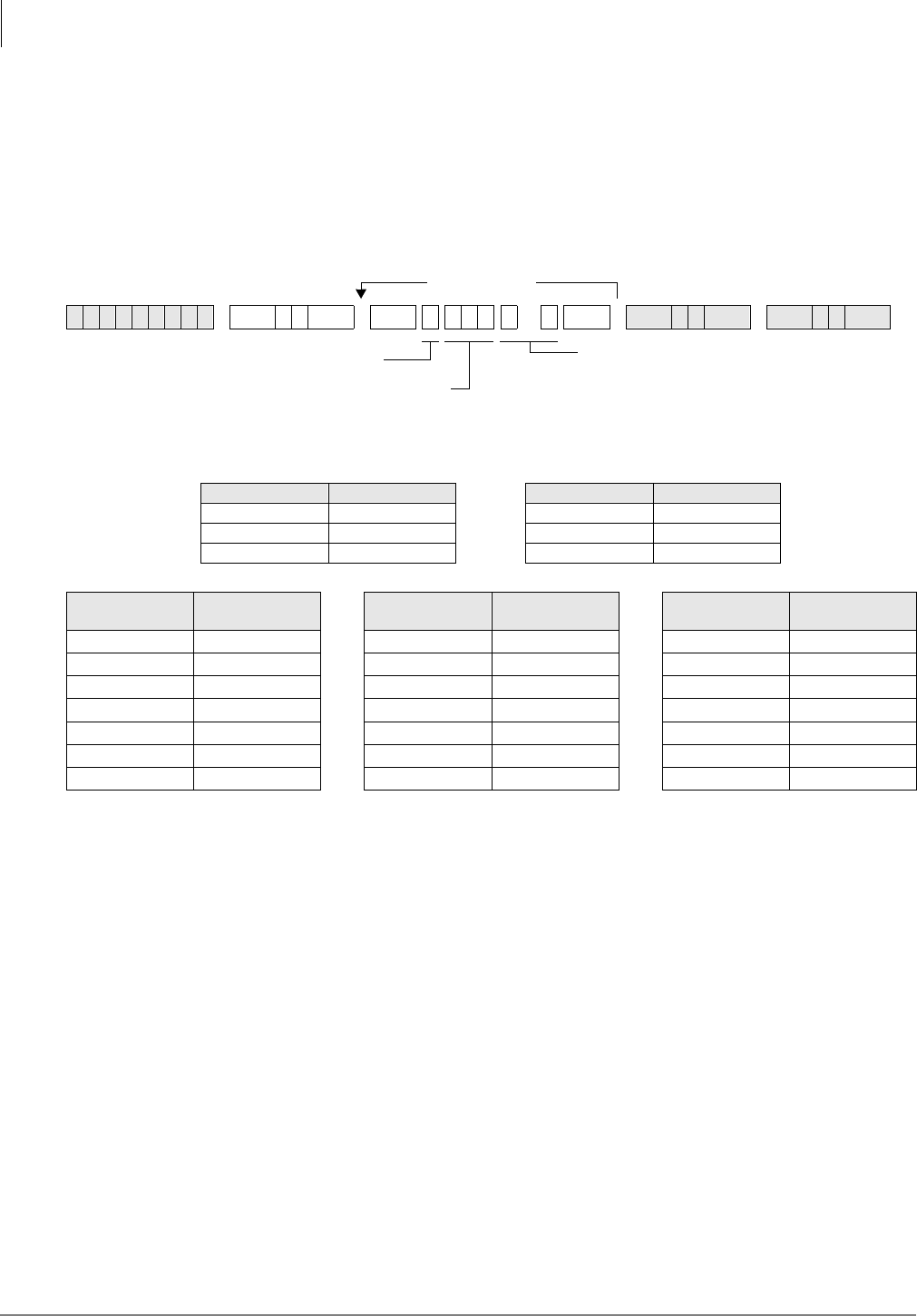
System & Station
Program 60-8 – Call Forward External (Remote Change, Security) ID Code
3-142 Strata DK Programming 5/99
Program 60-8 – Call Forward External (Remote
Change, Security) ID Code
Processor Type:
DK14, DK40i, All RCTUs
Program Type:
System
Initialized Default:
No digits
Program 60-8 Overview
Changes a telephone’s External Call Forward destination to [PDNs] but not [PhDNs] from outside
the system. The person that wishes to change the destination must call into a DISA CO line, enter
the telephone’s [PDN] + and then enter a security code plus the destination telephone
number. CF/EXT ID code must be assigned to a telephone to allow callers to change the Call
Forward-External destination of that telephone from a remote location by calling in on a DISA CO
line.
The security code (1~15 digits) for each telephone is set with this program.
Important!
To allow Call Forward External, CO lines must be enabled for the following:
●Two CO line connection in Program 10-1 and Program 15-5.
●Outgoing Access in Program 41 including DISA port numbers.
6SNU +ROG 6SNU +ROG6SNU +ROG 6SNU +ROG
Processor [PDN] Port Range Processor [PDN] Port Range
DK14 000~009 RCTUBA/BB 000~079
DK40i 000~027 RCTUC/D 000~239
RCTUA 000~031 RCTUE/F 000~335
Telephone Port
Number CF/EKT ID Code
(1~15 digits) Telephone Port
Number CF/EKT ID Code
(1~15 digits) Telephone Port
Number CF/EKT ID Code
(1~15 digits)
More Codes
DATA = ID code (1~15 digits)
When entering less than 15 digits, enter digits,
then press Hold.
LED Button 01 = blanks, erases data
LED Button 02 = a wild card (can be any digit
from 1~9)
SELECT = 8
Telephone port number to
which the CF Ext ID (security)
code will be assigned.
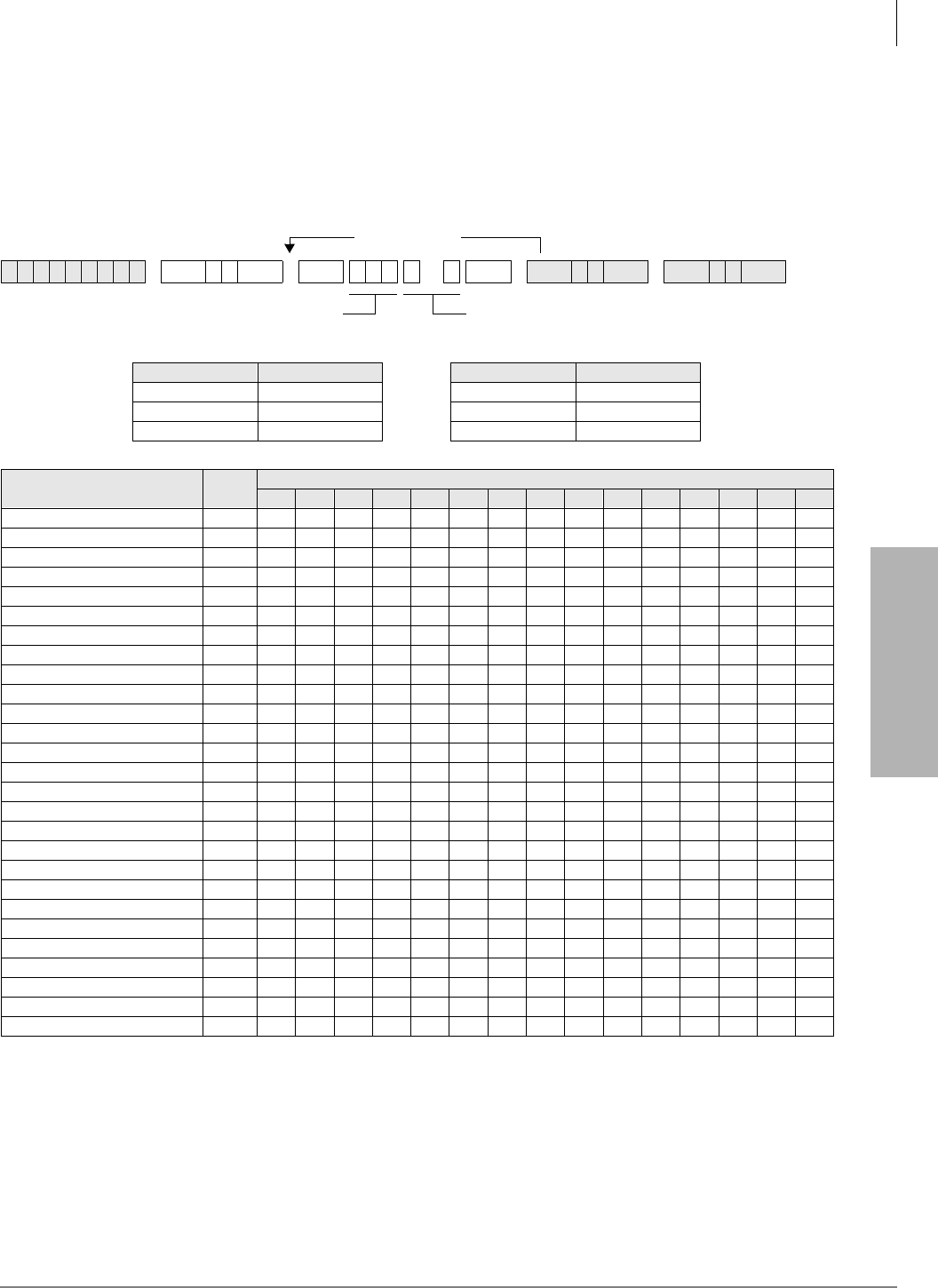
System & Station
Program 69 – Verified Account Codes
Strata DK Programming 5/99 3-143
System & Station
Program 69 – Verified Account Codes
Processor Type:
DK14, DK40i, All RCTUs
Program Type:
System
Initialized Default:
Blank
6SNU +ROG 6SNU +ROG 6SNU +ROG 6SNU +ROG
Processor VACN Processor VACN
DK14 000~299 RCTUBA/BB 000~299
DK40i 000~299 RCTUC/D 000~299
RCTUA 000~299 RCTUE/F 000~499
Name VACN
(3-digit)
Verified Account Code (1~15 digits)
12345678910 11 12 13 14 15
More Codes
Verified Account Code (1~15 digits)
SELECT = Verified Account Code
Number (VACN)

System & Station
Program 69 – Verified Account Codes
3-144 Strata DK Programming 5/99
Program 69 Overview
Verified Account Codes (VACs) may be added, deleted, or changed with Program 69. Each
Verified Account Code can be 1~15 digits long, but cannot exceed the Account Code length
requirement set in Program 60-4.
Account Codes may not conflict with (be the same as) emergency numbers in Program 44-91~93.
The following programs and options should be considered when establishing Verified Account
Codes.
Account Code Digit Length
Program 60-4 sets the digit length that must be dialed for all Account Codes: Forced (Verified/
Nonverified) and Voluntary (Verified/Nonverified).
Full and Partially Verified Account Codes
Verified Account Codes can contain the same number of digits (full Verified Account Code) or less
(partially Verified Account Code) than the length set in Program 60-4.
If the quantity of digits in a VAC is the same as the Account Code digit length in Program 60-4,
then all digits will be Verified; if the quantity of digits is less, then only those digits will be
verified. Stations must have LED 14 ON in Program 30 to use Verified Account Codes.
If partially verified, the first part of the Account Code is verified and the remainder is not. For
example, if VAC 2734 is set in Program 69, but the digit length is set to eight in Program 60-4,
then the user must dial 2734 plus any other four digits to enter a partially Verified Account Code.
There are many applications for partially VACs. For instance, using the code in the example
above, the numbers 2734 could be the user’s dial restriction code and the remaining four digits
could be a customer-client code, a sales order, etc.
Verified Account Code Toll Restriction Assignments
A Toll Restriction Class can be assigned with Program 70 to each of the 300 VACs. This feature
can be used to change a telephone’s Class of Service to allow long distance calls from restricted
telephones only when a verified account code is entered before dialing the long distance number.
These calls will be recorded with the account code on the system SMDR output.
Verified Account Code Dial Requirement
Assigned on a station-by-station basis in Program 30, LED 14 ON. All Account Codes dialed
(Forced or Voluntary) from stations assigned in this program will be verified.
Code Change
Stations selected in Program 30, LED 15 ON, can change VACs by dialing the following:
[PDN] + &98< + 333~7<< + VAC + 5HGLDO
Verified Account Codes: Forced/Voluntary Program Options
Any station can dial a VAC after accessing a CO line—by pressing the 6 SHHG#' L DO + 83 (DK14,
DK40, RCTUA~C/D), 6SHHG#'LDO + 383 (RCTUE/F),#or by pressing the $FFRXQW#& R GH
button. Forced Account Code requirements are assigned via station and line program options:
stations are assigned in Program 30, LED 08 ON; and lines are assigned in Program 15-7. Stations
must dial VACs when assigned in Program 30, LED 14 ON. Direct Inward System Access (DISA)
callers that access outgoing lines can be required to enter Verified Account Codes with Program 30
(LED 08 ON for Port 99).
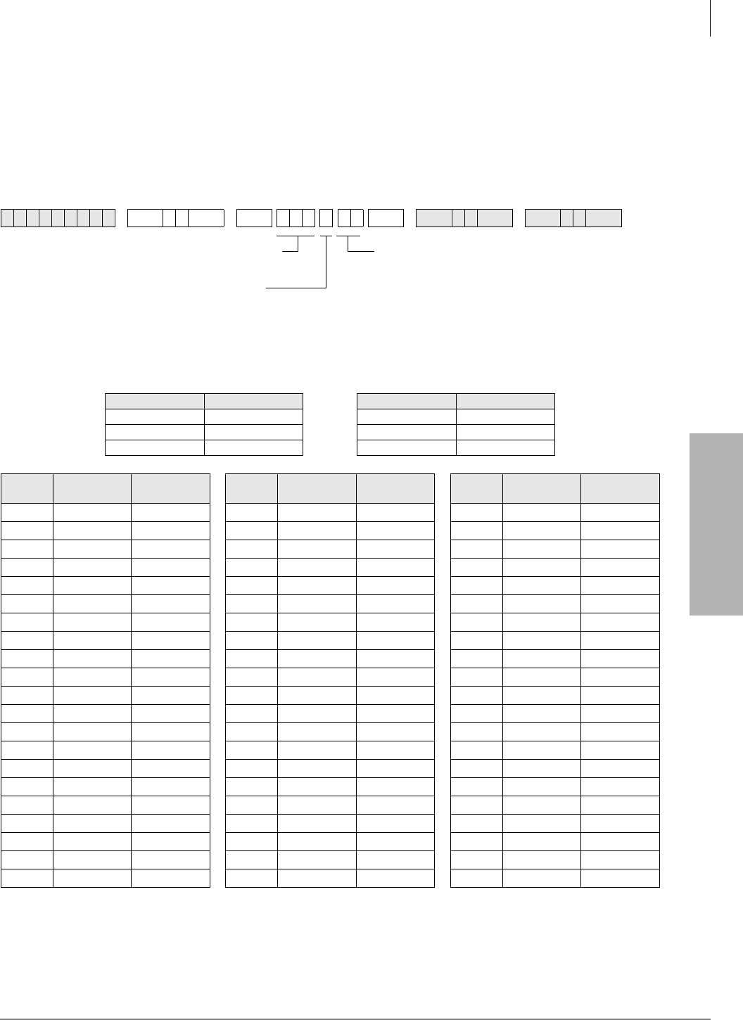
System & Station
Program 70 – Verified Account Code Toll Restriction Assignments
Strata DK Programming 5/99 3-145
System & Station
Program 70 – Verified Account Code Toll Restriction
Assignments
Processor Type:
DK14, DK40i, All RCTUs
Program Type:
System
Initialized Default:
000 for all VACNs
6SNU +ROG 6SNU +ROG6SNU +ROG 6SNU +ROG
Processor VACN Processor VACN
DK14 000~299 RCTUBA/BB 000~299
DK40i 000~299 RCTUC/D 000~299
RCTUA 000~299 RCTUE/F 000~499
VACN VAC Digit
Restrict Code VAC Restrict
Code VACN VAC Digit
Restrict Code VAC Restrict
Code VACN VAC Digit
Restrict Code VAC Restrict
Code
VAC Restrict Code (00~10)
00 =No Station Toll Restriction
01 =Area Code Toll Restriction
02 =Area Code Toll Restriction and 0 or 1 as 1st (or
2nd digit)
03 =Class 1 T.R.07 = Class 5 T.R.
SELECT = Verified Account Code
Number (VACN)
DATA = VAC Digit Restriction
0 = No Digit Restriction
1 = Digit Restriction

System & Station
Program 70 – Verified Account Code Toll Restriction Assignments
3-146 Strata DK Programming 5/99
Program 70 Overview
A Toll Restriction Class can be assigned with this program to each of the 300 Verified Account
Codes assigned in Program 69. This class of restriction overrides the normal station class of
restriction assigned in Program 48 when a VAC is entered at the station. The station resumes its
Program 48 restriction after the call is disconnected.
When a Forced or Voluntary Verified Account Code is dialed at a station after accessing a CO line
and before dialing a telephone number, the station temporarily assumes the Toll Restriction Class
assigned to the Verified Account Code. When Program 70 is initialized, all Verified Account
Codes are assigned as not Toll Restricted (data = 00). Verified Account Code Toll Restriction class
assignments are not user programmable; so if the assignments are not known, it is recommended to
assign a number (block) of Verified Account Codes to each type of Toll Restriction class. For
example:
VACs 000~050 = no restriction
VACs 051~100 = total restriction
VACs 101~150 = Class 1, etc.
♦When stations enter VACs they will be unrestricted.
♦Range programming is not available.
♦If dial “0” credit card dialing is allowed, use Program 43 to allow designated stations/CO lines
credit card calling.
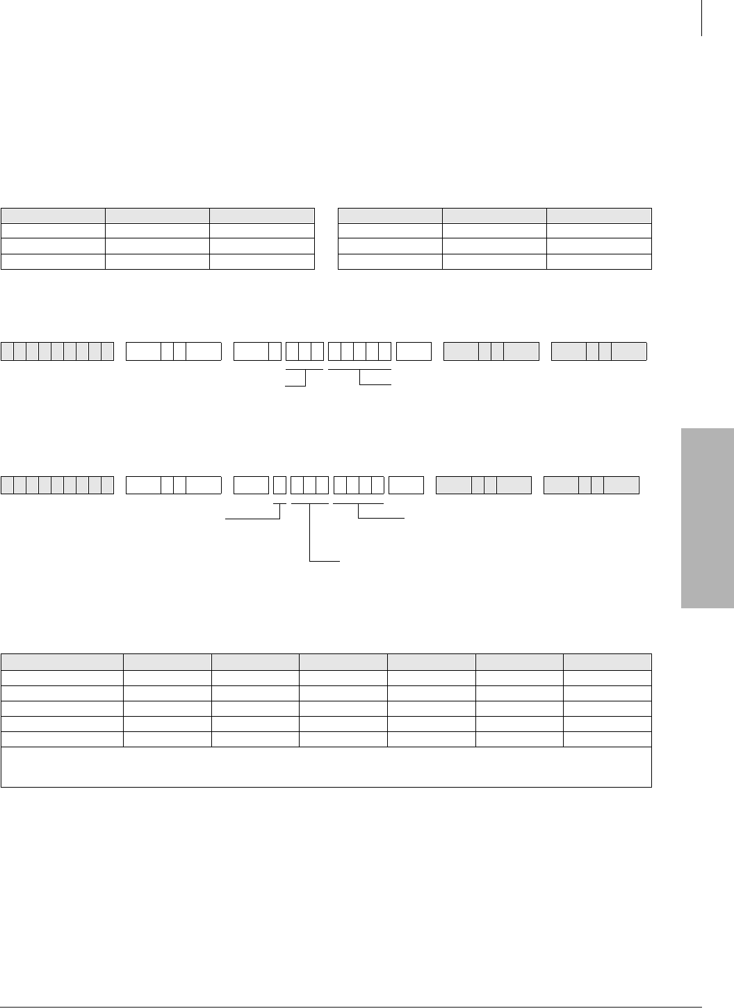
System & Station
Program 71 – DNIS
Strata DK Programming 5/99 3-147
System & Station
Program 71 – DNIS
Processor Type:
DK40i, all RCTUs
Program Type:
System
Initialized Default:
All Programs blank
DNIS Addresses
Program 71-0: DID / Tie / DNIS / ANI Lines
Program 71-1~3: DNIS Number and ANI Line Routing Assignments
DNIS/ANI Routing Destinations
Processor DNIS Address ANI Address Processor DNIS Address ANI Address
DK14 NA NA RCTUBA/BB 000~349 349
DK40i 000~199 199 RCTUC/D 000~499 499
RCTUA 000~199 199 RCTUE/F 000~499 499
6SNU +ROG 6SNU +ROG 6SNU +ROG 6SNU +ROG
6SNU +ROG 6SNU +ROG6SNU +ROG 6SNU +ROG
Route to Ports [PDN] [PhDN] DH [DN] ACD IMDU/RMDS Network Table
DK40i 0000~0027 0500~0527 0900~0915 NA #031 #300~#399
RCTUA 0000~0031 0500~0531 0900~0915 NA #035 #300~#399
RCTUBA/BB 0000~0079 0500~0589 0900~0915 #090~#097 #085 #300~#499
RCTUC/D 0000~0239 0500~0739 0900~0915 #250~#265 #245 #300~#599
RCTUE/F 0000~0335 0500~0835 0900~0915 #345~#360 #340 #400~#699
All Processors: External Page = #039
All processors except RCTUE/F: Night Ring Over External Page = #271
Night Ring Over External Page for RCTUE/F = #366
DNIS Number (2~5 digits)
Press LED Button 01 to blank out data.
DNIS Address (see legend above)
Ringing Destination (see legend below)
Use LED Button 01 to blank out data.
Enter 1, 2, or 3
1 = Day Ring Assignment
2 = Day2 Ring Assignment
3 = Night Ring Assignment DNIS Address (see legend above)
For ANI-only lines, enter address (only one assignment is
provided for ANI lines without DNIS, see legend above).
System & Station
Program 71 – DNIS
3-148 Strata DK Programming 5/99
Program 71-4: DNIS and ANI Only Lines Voice Mail ID Assignments
Program 71-5: DNIS Number Name Display
DNIS Record Sheet
6SNU +ROG 6SNU +ROG6SNU +ROG 6SNU +ROG
6SNU +ROG 6SNU +ROG6SNU +ROG 6SNU +ROG
DNIS
Address
DNIS Number
(1~5 digits)
71-0
DNIS Number
Routing Points (71-
1, 71-2, 71-3)
DNIS Number
VM ID Code (1~16 digits)
71-4
DNIS Number Name
(1~16 characters)
71-5
123
VM ID Code
Enter VM ID code that should be sent to Voice Mail
when the selected DNIS number Call-Forwards or
rings directly to Voice Mail (1~16 digits).
Press LED Button 02 to enter
Press LED Button 03 to enter #
Press LED Button 04 to enter Pause
DNIS Address
(see legend above)
Important! DNIS VM ID codes operate with in-
band DTMF tone VM integration only;
not with SMDI VM integration.
DNIS NAME TAG (up to 16 characters)
Use the character entry procedures that follow
Program 93 record sheets. NAME TAG displays on
LCD telephones when a DNIS Call rings in.
DNIS Address
(see previous legend)
System & Station
Program 71 – DNIS
Strata DK Programming 5/99 3-149
System & Station
Program 71-0 Overview
Defines the DID / Tie / DNIS / ANI line extension numbers that the system should be able to
receive. Each extension number can be from two to five digits; normally the local telephone
company and/or the DNIS long distance carrier company will provide a list of these numbers.
Each RCTU supports a different quantity of DNIS or DID/Tie line extension numbers (shown
above in the Program Sequence).
To assign a DNIS and/or normal Tie/DID line to Program 70-0 assignments: Program 17, LED 05
must be turned ON for the line. In this case, Tie lines do not follow Program 04 assignments and
DID lines do not follow Program 09 assignments. When this program is used with normal (non-
DNIS or non-ANI) Tie and/or DID Lines -Program 17, LEDs 06, 07, and 08 must be OFF.
Program 71-1~71-3 Overview
Assigns the routing destination of each DNIS and/or normal Tie/DID line extension number and/or
the routing destination of Automatic Number Identification (ANI) only lines.
Important! Program 71-1 assigns DNIS numbers to route to selected [DN] buttons and makes
them flash when the DNIS number is called. When assigning DNIS numbers to route
to Directory Numbers ([PDNs], [SDNs], [PhDNs]) using program 71-1, Program
*71, *72, and *73 must also be used to assign the telephones, on which the [DNs]
appear, to ring. When assigning DNIS numbers to route to ACD and DH groups
using Program 71, the telephones (and appropriate [PDN], [SDN], or [PhDN]) in
these groups must also be assigned to ring in Program *71, *72, and *73.
DNIS
Address
DNIS Number
(1~5 digits)
71-0
DNIS Number
Routing Points (71-
1, 71-2, 71-3)
DNIS Number
VM ID Code (1~16 digits)
71-4
DNIS Number Name
(1~16 characters)
71-5
123

System & Station
Program 71 – DNIS
3-150 Strata DK Programming 5/99
A DNIS and/or Tie/DID extension number and/or ANI only line can be assigned to route one of
the following destinations:
♦Primary Directory Number [PDN] - secondary appearances of this [PDN] will also ring if
Programmed to ring in Program *71, *72, and/or *73
♦Phantom Directory Number
♦Distributed Hunt Group
♦ACD Group
♦Outside telephone number routed externally over the Public Telephone Network
♦The system remote maintenance modem
♦Night ringing over the external page
♦The external voice paging system (Private Network Tie lines only)
A DNIS number or ANI only line can be assigned to route to one destination only in each of the
three system ringing modes (Day, Day2 and Night); the destination can be unique or different in
each ringing mode. For each DNIS Tie/DID extension number, the routing destination can be a
unique destination or it can be the same destination as that assigned to other DNIS numbers. To
assign lines that receive both ANI and DNIS with each call to Program 71-1 assignments: Program
17, LED 05, 07 and 08 must be turned ON; for lines that receive DNIS digits only, LED 05 and 08
must be ON.
This program can also be used with non-DNIS or non-ANI Tie and/or DID lines to route calls. In
this case, the normal Tie digit assignments in Program 04 and DID digit assignments in Program
09 will not be active - Program 17, LED 06, 07, 08 must be OFF and LED 05 must be ON for
normal Tie/DID lines.
The last address (499 for RCTUC3/D3, RCTUE3/F3; 349 for RCTUBA3/B3; and 199 for
RCTUA3 or DK40i) in Program 71-0 is used to assign ANI only lines to a routing destination. All
ANI only lines must be assigned to the same routing destination; this destination can be unique in
each of the ringing modes (Day/Day2/Night).
To assign an ANI only Tie/DID line to Program 71-1 assignments: Program 17, LED 05 must be
turned OFF and LED 07 and 08 must be ON for lines that receive ANI digits only.
Program 71-4 Overview
This feature is available when using DTMF In-band VM integration only; it is not provided with
SMDI VM integration.
This Program assigns a Voice Mailbox ID (VMID) number to each DNIS/Tie/DID extension
number and/or ANI only lines. This allows each DNIS/Tie/DID extension number and/or ANI
only lines to be routed to a unique Voice Mail box when the number directly rings or is Call
Forwarded to the Voice Mail system. When a DNIS/Tie/DID extension number or ANI line rings a
station that has call forwarding set to Voice Mail, the DNIS/Tie/DID extension or ANI VMID is
sent to the VM machine (if programmed in Program 71-4). If a DNIS/Tie/DID extension or ANI
VMID is not programmed, the Call Forwarding station’s VMID is sent to the voice mail machine
when the DNIS/Tie/ DNIS extension or ANI call forwards to VM. This program can also be used
with non-DNIS Tie and/or DID lines to assign VMID digits to normal Tie or DID numbers.
The last address (499 for RCTUC3/D3, RCTUE3/F3; 349 for RCTUBA3/B3, and 199 for
RCTUA3 or DK40i) in Program 71-4 can be used to assign a VMID code to ANI only lines. All
ANI only lines will be directed to the same Voice Mailbox.
To assign an ANI only Tie/DID line to Program 71-4 assignments: Program 17, LED 05 must be
turned OFF and LED 07 and 08 must be ON for lines that receive ANI digits only.

System & Station
Program 71 – DNIS
Strata DK Programming 5/99 3-151
System & Station
Program 71-5 Overview
This program is used to assign names to each DNIS number. The names for each DNIS/Tie/DID
extension number is normally supplied by the customer. Each DNIS name can be up to 16
alphanumeric characters. The DNIS/Tie/DID extension name will display on a telephone’s LCD
when the DNIS/Tie/DID extension number rings the telephone directly or is transferred, Call
Forwarded, or Hunted to the telephone.
To assign a Tie/DID line to Program 71-5 assignments: Program 17, LED 05 must be turned ON
for lines that should display DNIS/Tie/DID extension name tags. When a Tie/DID line receives
both DNIS and ANI digits on the same call, Program 17, LED 06 determines what information,
DNIS extension name or ANI number, will display as a priority when the line rings incoming to
the system.
This program can also be used with non-DNIS or ANI Tie and/or DID lines to display names,
associated with the Tie or DID numbers, on telephone LCDs. In this case, the normal Tie digit
assignments in Program 04 and/or DID digit assignments in Program 09 will not be active.
Important!
●An individual telephone user can disable/enable the DNIS name display by using the Mode 60/
61 function on his/her LCD telephone.
●The DNIS extension name can be assigned or not assigned to display as a priority over the
ANI display (in Program 17, LED06) when both ANI and DNIS digits are received on the same
call.
●If a name is not assigned to a DNIS number, DN:XXXX will display on telephone LCDs when
the DNIS/Tie/DID line rings into the DK system (where XXXX = actual DNIS/Tie/DID digits
received).
System & Station
Program *71~*73 – [DN] to [DN], Tie to [DN], and DID to [DN] Ringing Assignments
3-152 Strata DK Programming 5/99
Program *71~*73 – [DN] to [DN], Tie to [DN], and DID to
[DN] Ringing Assignments
Processor Type:
DK14, DK40i, All RCTUs
Program Type:
System
Initialized Default:
[PDNs] are programmed to immediately ring their
respective telephones in Program *71; no other default ringing assignments are made.
Important! In the EK Telephone Ports column, enter the Program 04 telephone ports of the
telephones that should ring when the [DN] is called from another [DN] or a Tie or
DID line (maximum of 120 telephones can be assigned to ring). The [DN] button
must be assigned (Program 39) to the telephone that should ring.
6SNU +ROG 6SNU ( . %XWWRQ + ROG 6SNU +ROG
Processor [PDN] Port [PhDN] Port Processor [PDN] Port [PhDN] Port
DK14 000~009 500~509 RCTUBA/BB 000~079 500~589
DK40i 000~027 500~527 RCTUC/D 000~239 500~739
RCTUA 000~031 500~531 RCTUE/F 000~335 500~835
[DN] Port Reference
Number EK Telephone Ports (The Program 04 [PDN] port number of the telephones that should ring.)
Press the button associated with the
telephones (EKs) that should ring
when the selected [DN] is called.
Port Reference Number of that should ring [PDN] or [PhDN]
Press 6FUROO to advance or 3DJH to go back.
Press Vol▲ to turn all LEDs ON.
Press Vol▼ to turn all LEDs OFF.
Enter:
1 = Immediate Ring
2 = Delay 1 Ring (12 sec. delay)
3 = Delay 2 Ring (24 sec. delay)
To add a port range, enter
XXXXXX (low port high port).

System & Station
Program *71~*73 – [DN] to [DN], Tie to [DN], and DID to [DN] Ringing Assignments
Strata DK Programming 5/99 3-153
System & Station
First Telephone Group
Buttons 01~20 on the programming telephone are associated with the telephone groups displayed
on the telephone LCD.
GRP EK000 = Telephone Port 000 is represented by programming button 01...
GRP EK001 = Telephone Port 001 is represented by programming button 02...
GRP EK019 = Telephone Port 019 is represented by programming button 20.
Second Telephone Group
In telephone group “GRP 020~039”, the relationship is as shown below:
GRP EK020 = Telephone Port 020 is represented by programming button 01...
GRP EK021 = Telephone Port 021 is represented by programming button 02...
GRP EK039 = Telephone Port 039 is represented by programming button 20.
Program *71, *72, *73 Overview
Primary/Phantom Directory Number and Telephone Ringing assignments:
♦This program assigns telephones to ring when a [PDN] or [PhDN] that appears on the
telephone is dialed from another telephone (direct or transferred call). The [PDN] may appear
as an [SDN] on other telephones that should ring.
♦This program assigns telephones to ring when a call is routed from a Tie, DID, DNIS, DNIS/
ANI or ANI only line to a [PDN] or [PhDN] that appears on the telephone. The [PDN] may
appear as an [SDN] on other telephones that should ring.
♦Calls that Call Fwd, Hunt, or are transferred to a [PDN] or [PhDN] will ring on telephones per
Program *71, *72, and *73 ringing assignments. The [PDN] or [PhDN] must appear on a
flexible button (as a [PDN], [SDN], or [PhDN]) of telephones that should ring.
Important! 120 Telephones (maximum) can be programmed to ring for any given [PDN],
[SDN] or [PhDN] in Program *71, *72, and *73 combined.
For the above case:
♦Telephones can be programmed to immediately Ring (*71 assignments), delay ring after 12
seconds (*72 assignments), or delay ring after 24 seconds (*73 assignments) for each [PDN]
or [PhDN] button that appears on the telephone.
♦The called [PDN], [SDN], or [PhDN] button must be programmed to appear (Program 39) on
all Telephones that should ring.
System & Station
Program 72 – DNIS Number Network Table Assignments
3-154 Strata DK Programming 5/99
Program 72 – DNIS Number Network Table
Assignments
Processor Type:
DK40i, All RCTUs
Program Type:
System
Initialized Default:
Blank
6SNU +ROG 6SNU +ROG 6SNU +ROG 6SNU +ROG
Route to Ports Network Table
Number Total DNIS Network
Number Route to Ports Network Table
Number Total DNIS Network
Number
DK14 NA NA RCTUBA/BB 300~499 200
DK40i 300~399 100 RCTUC/D 300~599 300
RCTUA 300~399 100 RCTUE/F 400~699 300
Network
Table
Number
Ground / Loop / Tie / DID Line Access Code and
Network Telephone Number
Network
Table
Number
Ground / Loop / Tie / DID Line Access Code and
Network Telephone Number
Line Access Code and Network Telephone
Number (1~27 digits)
Any type line can be accessed (ground, loop,
Tie, and/or DID) to send a DNIS call back out
over the telephone network.
Press LED Button 02 to enter .
Press LED Button 03 to enter #.
Network Table Number

System & Station
Program 72 – DNIS Number Network Table Assignments
Strata DK Programming 5/99 3-155
System & Station
Program 72 Overview
This program defines the external Network routing numbers that can be assigned DNIS/Tie/DID
extension numbers in the Day, Day2, or Night ringing mode. This assignment will cause incoming
DNIS/Tie/DID calls to route (forward) back out over a public, or private, telephone network to a
pre-assigned telephone number.
To assign a Tie/DID line to Program 72 assignments: The DNIS/Tie/DID extension number must
be assigned to route to the appropriate Network routing number in Program 71-1.
This program can also be used with non-DNIS or ANI (only), Tie and/or DID Lines to assign
normal incoming Tie/DID calls to route back out over the public, or private telephone network to
an external telephone number.
Important!
●Tie/DID lines used for DNIS network routing must be enabled with tandem (Two-CO line)
connection with Program 15, Code 5 and Program 10-1, LED 20.
●DNIS Network routing numbers will not be restricted by DK424 Toll Restriction assignments.
●Tie/DID lines must have LED05 ON in Program 17 to use the (DID, Tie) DNIS routing
assignments in Program 71 and 72.
●DNIS network calls are timed by the Program 12 disconnect timer which, if set to default, will
disconnect the call after four minutes. The disconnect timer may be disabled
(see “Program 12 – System Assignments, Basic Timing”on Page 3-41).
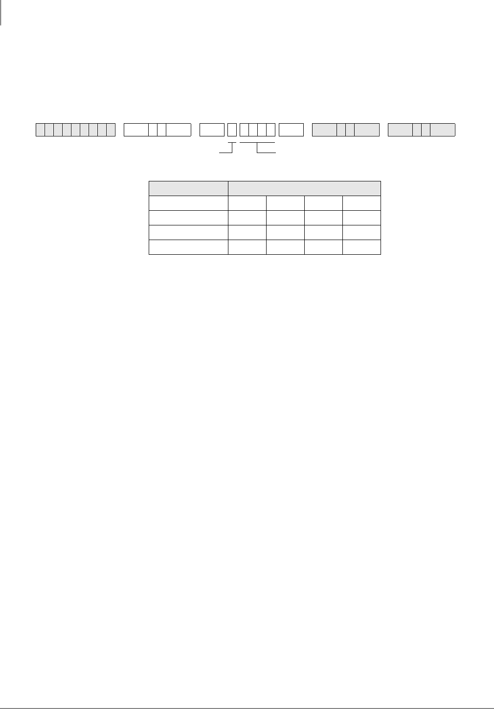
System & Station
Program 74 – System NT Button Lock Password
3-156 Strata DK Programming 5/99
Program 74 – System NT Button Lock Password
Processor Type:
DK14, DK40i, All RCTUs
Program Type:
System
Initialized Default:
Port 000 for all tenants
Program 74 Overview
This program assigns the password for each 1LJKW7UDQVIHU or 1LJKW7UDQVIHUa button. To
lock the system ringing mode requires a password and two buttons: 1LJKW7UDQVIHU and 1LJKW
7UDQVIHU/RFN.
♦1LJKW7UDQVIHU switches the station to Night Transfer mode.
♦1LJKW7UDQVIHU /RFN + the Night Lock password, locks the 1LJKW7UDQVIHU button into
that ringing mode.
The Strata DK system provides three system ringing modes (Day/Day2/Night). The system ringing
modes are controlled by the 1LJKW7UDQVIHU button which is programmed on a flexible button of
a telephone or attendant console. Each ringing mode allows incoming calls to be routed to
different destinations.
Programs related to Program 74 are:
Program 39, which assigns the 1LJKW7UDQVIHU and 1LJKW7UDQVIHU/RFN buttons to stations.
Also, these station(s) must be assigned as the designated Night Transfer Lock station in Program
36.
Program 59, which assigns 1LJKW7UDQVIHU/1LJKW7UDQVIHU/RFN buttons to attendant
consoles. Attendant consoles and stations (assigned in Program 36) can also change the 1LJKW
7UDQVIHU/RFN button password using a special access code. Program 36 is not required to
assign attendant consoles to Night Transfer Lock functions.
Also see Programs 39, 36, 15 and 77-3.
6SNU +ROG 6SNU +ROG6SNU +ROG 6SNU +ROG
Tenant Number NT Lock Password (4 Digits)
1
2
3
4
DATA = Night Lock Password for selected
Tenant (4-digits)
Tenant Number (1~4)
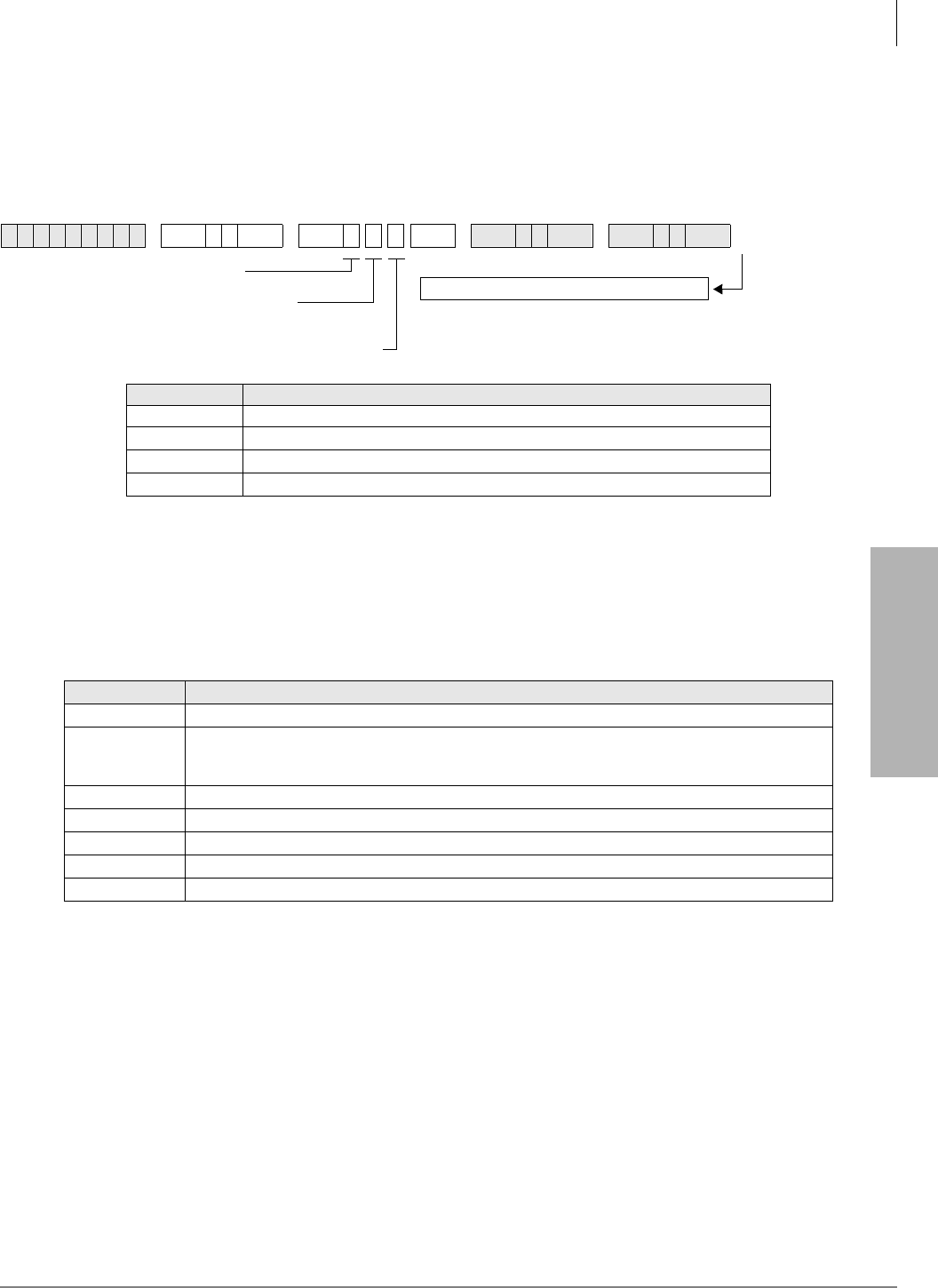
System & Station
Program 76-1(X-Y) – DK14, DK40i, All RCTUs
Strata DK Programming 5/99 3-157
System & Station
Program 76-1(X-Y) – DK14, DK40i, All RCTUs
Processor Type:
DK14, DK40i, All RCTUs
Program Type:
System
Initialized Default:
Port 1 (Type 1), Ports 2~4 (Type 0)
Program 76-1 Overview
This program assigns each installed WSIU (DK14 only), TSIU (DK40i only) or RSIU/RSIS
(DK424 only) port to a function.
For Program 76-1(X-Y):
X identifies the WSIU, TSIU port number 1~2 or RSIU/RSIS/RMDS port number 1~4.
Y identifies the WSIU, TSIU or RSIU/RSIS/RMDS port function as shown below:
♦Port types set in this program override RSSU, PIOU, and/or PIOUS function codes (41, 42,
43) set in Program 03. To activate changes made to this program, system power must be turned
off/on or Program 91-2 must be run.
♦Communication Parameters: SMDI, MIS or SMIS, TTY, IMDU/RMDS, Caller ID, OAI: 7
bits, even parity, 1 stop bit. SMDR: 8 bits, no parity, 1 stop bit.
6SNU +ROG 6SNU +ROG 6SNU +ROG 6SNU +ROG
Port Number Port Type (0~6)
1
2
3
4
Port Type (Y) Function
0No port equipped. This should be used for any of the four RSIU/RSIS/RMDS ports that are not used.
1TTY or modem1.
TTY RS-232 port (set Program 77-1, LED 14 OFF; DK14, DK40i or DK424).
RMDS modem port (set Program 77-1, LED 14 ON; DK424).
1. If port type code 1 is set, then Program 77-1, LED 14 status determines if the port operates as a system administration/maintenance
modem (LED 14 ON) or an RS-232 administration/maintenance TTY port (LED 14 OFF). For modem operation, an RMDS piggy-
back PCB is required, for RS-232 TTY port, a TSIU, WSIU, RSIU/RSIS/RMDS PCB may be used.
2SMDR
3MIS or SMIS (DK424)
4SMDI
5Open Architecture Interface (see Program 77-4) (DK424 R3.2)
6Caller ID output to Caller ID interface box (DK14 only)2
2. If the DK14 CO lines must pass Caller ID information to the Toshiba telephones, LCD/RPCI-DI, an interface box, TC1041 (MLX-
41), must be connected to one of the WSIU outputs. For more information, see the Caller ID instructions in Chapter 1 – DK14
Installation of the Strata DK Installation and Maintenance Manual.
System power must be cycled or Program 91-2
must be run to transfer Program 76-1 data entries
from temporary memory to working memory.
Y=Port Type (0~6), see table below.
Run Program 91-2
SELECT = 1
X = Port Number (1~4)
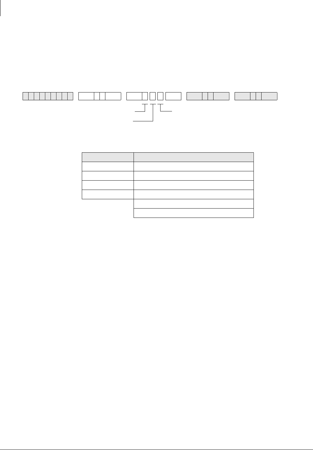
System & Station
Program 76-2 (X-Z) – WSIU, TSIU and RSIU / RSIS / RMDS Transmission Rates
3-158 Strata DK Programming 5/99
Program 76-2 (X-Z) – WSIU, TSIU and RSIU / RSIS /
RMDS Transmission Rates
Processor Type:
DK14, DK40i, All RCTUs
Program Type:
System
Initialized Default:
All ports 2400 bps
Program 76-2 Overview
Assigns each installed WSIU (DK14 only), TSIU (DK40i only) or RSIU port to operate at a
specified transmission rate. Where X identifies the WSIU, TSIU port number 1~2 or RSIU/RSIS/
RMDS port number 1~4 and Z identifies the WSIU, TSIU or RSIU/RSIS/RMDS port data
transmission rate in bits-per-second (bps).
Whenever uploading Program 76 with DKAdmin/DKBackup, the bps rate of the DKBackup/
DKAdmin customer database (on the PC) and the WSIU, TSIU or RSIU/RSIS/RMDS TTY/
RMDS port must all be set the same. If the bps rate of these items are not the same, uploading
Program 76 will fail.
The sum of the transmission rates of equipped WSIU, TSIU or RSIU/RSIS/RMDS ports cannot
exceed 9600 bps. Ports assigned “no-function” (code 0) in Program 76-2X-Y will not be included
in the transmission rate sum. The RMDS will only function at 1200 or 2400 bps on the DK424 (see
Program 77-1 LED 15).
Program 76-2 does not require system power OFF/ON to change the bps rate.
6SNU +ROG 6SNU +ROG 6SNU +ROG 6SNU +ROG
Port Number (x) Data Transmission Rate (z)
1
2
3
4
Total
Note
Total must be
≤ 9600 bps
.
Z=Transmission Rate (1~4):
1 = 9600 bps
2 = 4800 bps
3 = 2400 bps
4 = 1200 bps
SELECT = 2
X=Port (1~4)
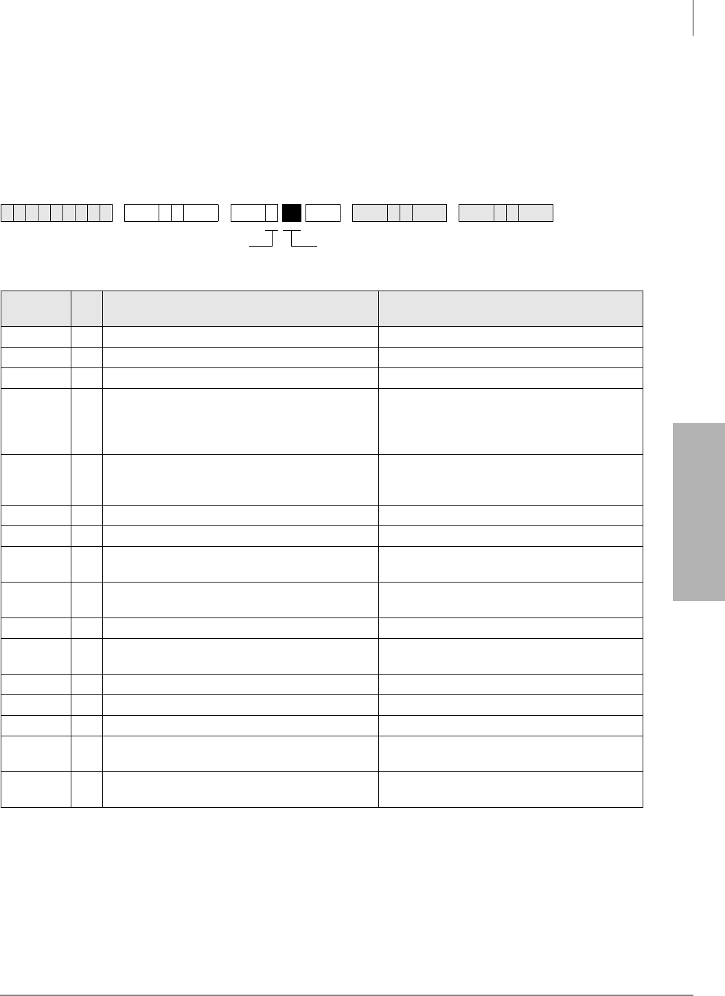
System & Station
Program 77-1 – Peripheral Options (Door Phones)
Strata DK Programming 5/99 3-159
System & Station
Program 77-1 – Peripheral Options (Door Phones)
RSIU / RSIS / RMDS, PIOU/PIOUS / IMDU, PEPU
Processor Type:
DK14, DK40i, All RCTUs
Program Type:
System
Initialized Default:
All LEDs are OFF
6SNU +ROG 6SNU +ROG 6SNU +ROG 6SNU +ROG
LED/
Button XLED ON LED OFF
20 Door Lock Time/6 seconds Door Lock Time/3 seconds
19 Port 028/DDCB 4 or HDCB 4 (DK424) Port 028/Telephone (DK424)
18 Port 020/DDCB 3 or HDCB 3 (DK40i/DK424) Port 020/Telephone (DK40i/DK424)
17
Port 012/DDCB 2 or HDCB 2 (DK424)
Port 012/DDCB 2 or HDCB 2 (DK40i
Expansion Unit)
Port 003/DDCB 2 (DK14)
Port 012/Telephone (DK40i Expansion Unit,
DK424).
Port 003/Telephone (DK14).
16 Port 004/DDCB 1 or HDCB 1 (DK424)
Port 004/DDCB 1 (DK40i)
Port 002/DDCB 1 (DK14)
Port 004/Telephone (DK40i, DK424).
Port 002/Telephone (DK14).
15 RMDS Modem Protocol CCIT (2400 bps) RMDS Modem Protocol Bell212A (1200 bps)
14 RMDS/IMDU Modem (DN #19)/Enabled RMDS/IMDU Modem (DN #19)/Disabled
10 Enable DKAdmin/Backup ACK/NAC Protocol Disable DKAdmin/Backup ACK/NAC
Protocol
08 Door Phone Ring on External Page in Night
Mode No Ring on External Page in Night Mode
07 Door Lock Relay Enabled External Page Relay Enabled
06 NT Relay with NT1 and NT2 Button and
Ringing CO Line NT Relay Steady with NT1 Button (DK424
only)
05 MOH Relay Enabled NT Relay Enabled
04 ——
03 ——
02 LED 02 applies to DK14/DK40i only.
LED 01 has priority. External Page on Base Unit Relay Enabled
01 LED 01 applies to DK14/DK40i only.
MOH on Base Unit Relay Enabled NT on Base Unit Relay Enabled
Light the LED Buttons that are
marked with an X in the table below.
SELECT = 1

System & Station
Program 77-1 – Peripheral Options (Door Phones)
3-160 Strata DK Programming 5/99
Program 77-1 Overview
This program performs the following functions:
♦Programs door lock relays
♦Assigns door phones/lock control units
♦Enables RMDS/IMDU built-in maintenance modems
♦Sets RMDS communications standard type
♦Enables DKAdmin Communications Protocol
♦Enables/disables door phone ring tone to external paging when system is in Night mode
♦Assigns a relay to operate with door lock function or external page for mute control
♦Assigns a relay to operate in one of two Night Transfer modes
♦Assigns a relay to operate in one of two applications
LED 20: Door Lock Time
The Door Lock Relay contact may be programmed to operate for either three or six seconds
(applies to PIOU, PIOUS, PEPU, DDCB, and HDCB door lock controls).
LEDs 16~19: Port Number/Door Phone/Lock Control Units
Door phone/lock existence is defined by this program. The door lock option is set via Program
77-2.
♦DK424: Door phone/lock controllers (DDCBs and/or HDCBs) can only exist at Ports 004,
012, 020 and 028, and can only be installed on Circuit 5 of a PDKU, RDSU, PEKU and/or
PESU. PDKUs and RDSUs support DDCBs, but not HDCBs. PEKUs and PESUs can support
HDCBs, but not DDCBs. After assignment of a DDCB or HDCB, door phone numbers
(#151~#159, #161~#163) effectively replace the station number assignment in Program 04.
Up to four DDCBs/HDCBs can be installed in a system with RCTUB, RCTUBA/BB and C/D,
only 3 are allowed with RCTUA. They must be assigned a PDKU, RDSU, PEKU or PESU
port number to operate (DDCB to PDKU or RDSU, and HDCB to PEKU or PESU). (See
Program 79 and 79 for door phone ringing assignments)
Station PCBs that are connected to HDCB/DDCB door phones control boxes must be installed
in lower slot numbers than Tie, DID, or Attendant Console PCBs.
♦DK40i and DK14: See port information on record sheet.
LED 15: RMDS Protocol
This program sets the RMDS communications standard type to CCITT/V.22bis (2400bps) or Bell
212A (1200bps). The standard set in this program must match the standard of the modem that will
be used to communicate with the Strata DK RMDS.
♦If the RMDS modem standard should be 2400bps/CCITT/ V.22bis, turn LED 15 on; if the
RMDS standard is a 1200 bps/Bell 212A, turn LED 15 off. Most Hayes compatible modems
will function with either standard; check with the modem manufacturer’s documentation to
verify which protocol should be used. When the system is initialized the Bell 212A (1200 bps)
standard is set (LED 15 off).
♦IMDU can be 1200 bps or 300 bps as set by SW2 on the PIOU or PIOUS PCB; RMDS can be
1200 bps or 2400 bps as set in Program 76-2 and Program 77-1 LED 15.

System & Station
Program 77-1 – Peripheral Options (Door Phones)
Strata DK Programming 5/99 3-161
System & Station
LED 14: RMDS or IMDU Modem
DK424: This program enables the DK424 built-in maintenance modem function: RMDS or
IMDU. If LED 14 is off, the RSIU Port (1~4) which is set for TTY operation (Code 1 in
Program 76-1) will operate as a local RS-232 maintenance port. If RSIU is not configured as
TTY, then the PIOU/PIOUS/RSSU that has code 41 set in Program 03, will operate as a local
TTY maintenance port.
Only one DK424 built-in modem RMDS or IMDU can be used in the DK424; if both are
installed, RMDS will be accessed when a CO line direct rings the modem or is transferred to
the modem by dialing &QI7UQ+.
♦DK40i: Turn LED 14 ON if the optional PIOU or PIOUS has Remote Maintenance from the
IMDU modem subassembly. If an IMDU is installed on a DK40i PIOU or PIOUS, it can be
accessed by dialing station #19 (unless the access code prefix has been changed with Program
05).
Other system Programs that are related to the system modem are: Program 76, RMDS/TTY
assignments on RSIU PCB; *-51~53, system CO line to modem ringing assignments; Program 71-
1, DNIS line to modem ringing assignments; Program *09, DID line to modem ringing
assignments; Program 77-1, LED 15, RMDS modem Protocol/speed assignments.
If a modem unit (RMDS/IMDU) is installed, it can be accessed by dialing Station #19 and can be
assigned a DID extension number in Program 09 or in Program 71 (1~3). See Program 79 and
Program 79 for door phone ringing assignments.
LED 10: DKAdmin/Backup
Enables the system to Upload/Download the RCTU RAM data base using Toshiba DKAdmin and/
or DKBackup software program. DKAdmin/Backup will automatically turn LED 10 ON when the
DKAdmin/Backup PC communicates with the DK424. LED 10 should be OFF if the maintenance
PC is using standard communication software (such as Procomm™) to program the DK424.
LED 08: Door Phone Ring On External Page
If a door phone button is pressed, a ring tone can be enabled or disabled to external paging when
the system is in the Night mode. Activation of a Tenant 1 1LJKW7UDQVIHU button is required to
activate this feature. The Tenant 2~4 1LJKW7UDQVIHUa buttons do not apply to door phones.
CO lines must be assigned to night ring over External Page (Program 78-1) to allow the NT relay
to operate when incoming CO lines ring. See Programs 79 and *79 for door phone ringing
assignments.
LED 07: Door Lock Relay/External Page Relay
A relay on the PIOU, PIOUS, or PEPU can be assigned to operate with the Door Lock function or
with External Page for mute control. The door lock button (8QORFN'RRUa) is assigned in
Program 39; the door lock activation time is assigned in Program 77-1. This door lock function is
not associated with the DDCB or HDCB door lock, but is an addition to them.
This option applies to the PIOU/PIOUS/PEPU Door Lock Control 0 assigned to electronic or
digital telephone buttons using Code 471 in Program 39; it does not apply to DDCB or HDCB
Door Lock Control.

System & Station
Program 77-1 – Peripheral Options (Door Phones)
3-162 Strata DK Programming 5/99
LED 06: NT Relay
A relay located on the PIOU, PIOUS, PEPU, DK14 KSU or DK40i KSU can be assigned to
operate in one of two Night Transfer modes (see next item, MOH/NT Relay).
♦DK14: Activate the NT Relay in the DK14 KSU before setting the specific Night Transfer
mode with LED 06.
♦DK40i: Activate the NT Relay on the PIOU or PIOUS with LED05, or activate the NT Relay
on the DK40i KSU with LED 01 before setting Night Transfer mode with LED 06.
In one mode, the relay will activate for one second, then be idle for three seconds when a line rings
(incoming) while the system is in the Night mode. The intended application is to control an
external ringing device at night.
Program 78 or Program 71 (1~3, Code #271) must have Ring Over External Page activated for this
feature. In the second mode, the relay will operate continuously while the NIGHT mode is
activated. One application for this mode is to control an external answering machine.
CO lines must be assigned to night ring over External Page (Program 78-1) to allow the NT relay
to operate when incoming CO lines ring.
LED 05: MOH/NT Relay (DK40i, DK424)
A relay on the PIOU, PIOUS, or PEPU can be assigned to operate in one of two applications. A
choice must be made between use for Night Transfer application (see NT Relay, LED 06) or
Music-on-Hold (MOH). If used for MOH, the relay will activate when any trunk or station is
placed on hold. The intended application is to control a tape player which can be used as a Music-
on-Hold source.
LEDs 02 and 01: MOH/NT/External Page Relay (DK14 and DK40i)
For KSU relay to MOH, LEDs 01 and 02 must be ON.
For NT function, LED 02 must be ON, LED 01 OFF.
For External Page function, LED02 must be OFF, LED 01 can be ON or OFF.
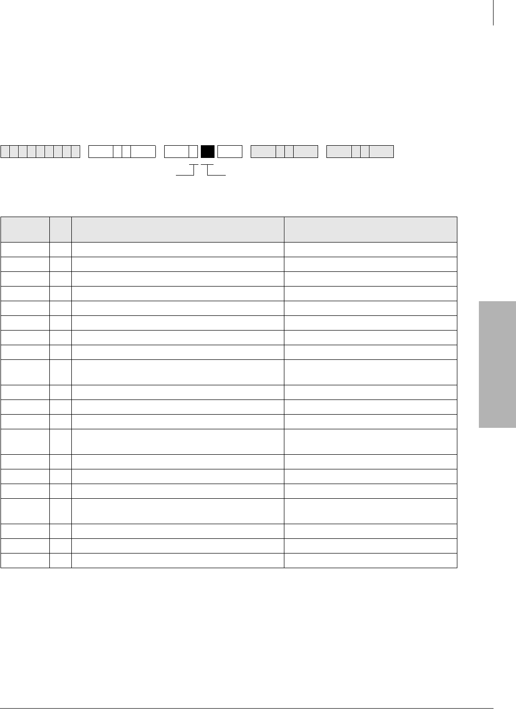
System & Station
Program 77-2 – Door Phone Busy Signal/Door Lock Assignments
Strata DK Programming 5/99 3-163
System & Station
Program 77-2 – Door Phone Busy Signal/Door Lock
Assignments
Processor Type:
DK14, DK40i, All RCTUs
Program Type:
Station
Initialized Default:
All LEDs are OFF
6SNU +ROG 6SNU +ROG 6SNU +ROG 6SNU +ROG
LED/
Button XLED ON LED OFF
20 One Door Phone Ring Five Door Phone Rings
19 ——
18 ——
17 ——
16 DDCB4/HDCB4 B-jack is Lock Control #4 (DK424) B is connected to Door Phone 4B
15 Door phone 4C Busy Out No Busy Signal
14 Door phone 4B Busy Out No Busy Signal
13 Door phone 4A Busy Out No Busy Signal
12 DDCB4/HDCB3 B-jack is Lock Control #3 (DK40i/
DK424) B is connected to Door Phone 3B
11 Door phone 3C Busy Out No Busy Signal
10 Door phone 3B Busy Out No Busy Signal
09 Door phone 3A Busy Out No Busy Signal
08 DDCB4/HDCB2 B-jack is Lock Control #2 (DK424)
DDCB2 B-jack is Lock Control #2 (DK40i, DK14) B is connected to Door Phone 2B
07 Door phone 2C Busy Out No Busy Signal
06 Door phone 2B Busy Out No Busy Signal
05 Door phone 2A Busy Out No Busy Signal
04 DDCB4/HDCB1 B-jack is Lock Control #1 (DK424)
DDCB1 B-jack is Lock Control #2 (DK40i, DK14) B is connected to Door Phone 1B
03 Door phone 1C Busy Out No Busy Signal
02 Door phone 1B Busy Out No Busy Signal
01 Door phone 1A Busy Out No Busy Signal
Light the LED Buttons that are
marked with an X in the table below.
SELECT = 2

System & Station
Program 77-2 – Door Phone Busy Signal/Door Lock Assignments
3-164 Strata DK Programming 5/99
Program 77-2 Overview
This program performs three functions:
♦Sets number of times door phone rings
♦Sets fast busy tone if the called door phone does not exist
♦Configures B-pack on DDCB/HDCB output for door lock control
LED 20: Door Phone Ring Count
The number of times that a door phone will ring digital and electronic telephones is set with this
LED. Light the LED for one ring; turn it OFF for five rings. The default is five rings. See Program
79 to assign which telephones will be rung by door phones.
LEDs 01, 02, 03, 05, 06, 07, 09, 10, 11, 13, 14, and 15: Door Phone Busy Out
Each door phone controller (DDCB or HDCB) can interface with up to three door phones. The
system treats each controller as a station. Therefore, this is quite different from all other station
arrangements using telephones. Only one door phone can be in used at one time. The system does
not automatically know how many door phones are connected to each DDCB or HDCB, so it must
be told.
This program is used to enter that information so that a caller will receive fast busy tone if the
called door phone does not exist. Door phones 1A, 1B, 1C are numbered #151, #152, #153,
respectively, and are connected to the DDCB or HDCB at Port 004. Door phones 2A, 2B, 2C are
numbered #154, #155, #156, respectively, and are connected to the DDCB or HDCB at port 012,
etc.
LEDs 04, 08, 12, and 16: Door Lock Assignments
Each B-jack on the DDCB and HDCB output can be configured for door lock control. Door lock
control buttons (8QORFN'RRUa) for door locks are assigned to electronic or digital telephones
in Program 39. Door lock activation time is set in Program 77-1. Each DDCB requires one PDKU
or RDSU circuit, and each HDCB requires one PEKU or PESU electronic telephone circuit. These
door locks are not associated with, but are in addition to the door lock control provided by the
PIOU, PIOUS, or PEPU PCB.
CAUTION! To prevent system malfunction, DO NOT install the RDSU or PESU in slot 18
of the DK40i system.
DK424 DK40i, DK14
DDCB/HDCB Slot Number Port Number DDCB Type DK40i Port Number DK14 Port Number
11 004 DDCB1 004 002
12 012 DDCB2 012 003
13 020 DDCB3 020 NA
14 028
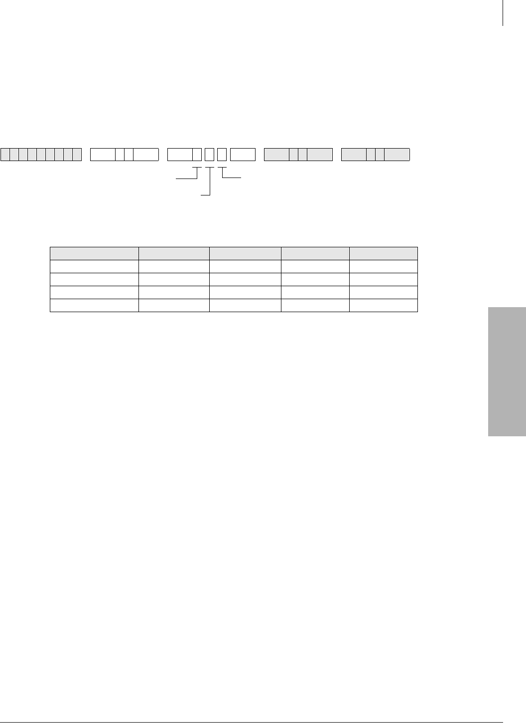
System & Station
Program 77-3 – Night Ringing Over PIOU External Page Zones
Strata DK Programming 5/99 3-165
System & Station
Program 77-3 – Night Ringing Over PIOU External Page
Zones
Processor Type:
DK40i, All RCTUs
Program Type:
System
Initialized Default:
Zones 1~4 assigned to tenant 1
Program 77-3 Overview
Each tenant’s CO lines can be assigned to ring over selected PIOU external page zones during the
NIGHT mode. Lines must be allowed to Night Ring over External Page in Program 78 or Program
71 (1~3, Code #271) for this feature to work. Tenant assignments are made in Program 15.
6SNU +ROG 6SNU +ROG 6SNU +ROG 6SNU +ROG
Tenant Zone 1 Zone 2 Zone 3 Zone 4
Tenant 1 CO Lines
Tenant 2 CO Lines
Tenant 3 CO Lines
Tenant 4 CO Lines
Enter the tenant (1~4) to be assigned with
the zone entered in the preceding step.
These assignments apply to ground and
loop start lines only; they do not apply to DID
and Tie lines.
SELECT = 3
Enter a PIOU external
page zone relay (1~4).
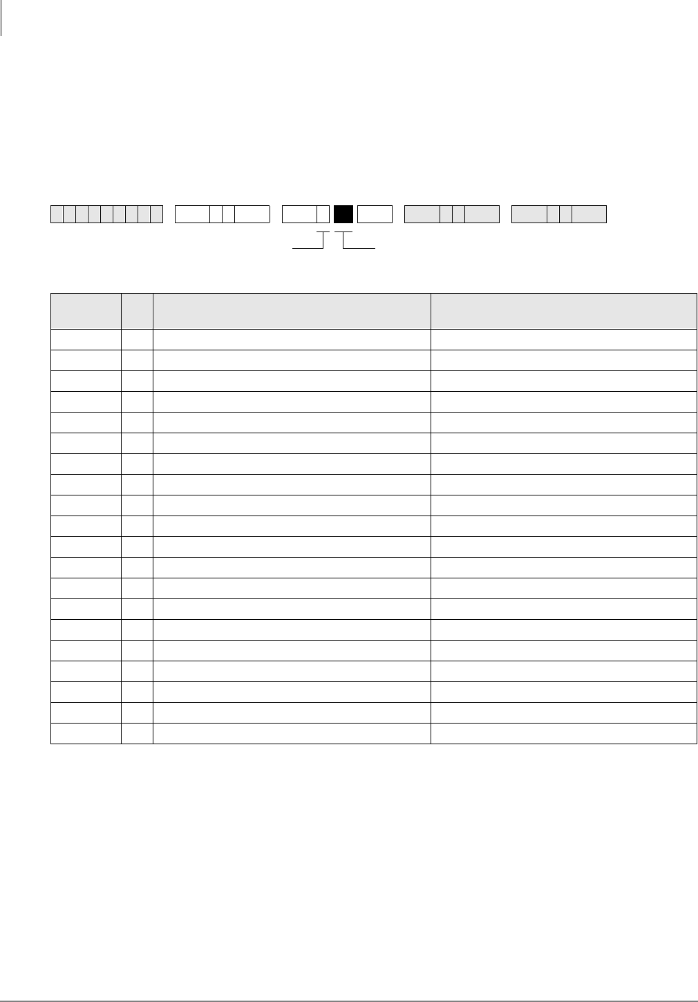
System & Station
Program 77-4 – RSIU Open Architecture Interface (OAI) Data Output Assignments
3-166 Strata DK Programming 5/99
Program 77-4 – RSIU Open Architecture Interface (OAI)
Data Output Assignments
Processor Type:
All RCTUs (Release 3.2 and above)
Program Type:
System
Initialized Default:
All LEDs are OFF
Program 77-4 Overview
This program is used to enable Caller ID, Automatic Number Identification (ANI), and/or Dialed
Number Identification Service (DNIS) Numbers (received) to be sent from the RSIU Open
Architecture Interface (OAI) port. The OAI port sends MIS data for ACD calls (only) along with
ANI, Caller ID and/or DNIS Numbers received on ACD calls depending on LED 01 and LED 02
option settings. ANI, Caller ID and/or DNIS numbers on non-ACD calls will not be sent out the
OAI port for non-ACD calls.
6SNU +ROG 6SNU +ROG 6SNU +ROG 6SNU +ROG
LED/
Button XLED ON LED OFF
20
19
18
17
16
15
14
13
12
11
10
09
08
07
06
05
04
03
02 DNIS Number will be sent from OAI port DNIS Number will not be sent from OAI port
01 Caller ID/ANI will be sent from OAI port Caller ID/ANI will not be sent from OAI port
Light the LED Buttons that are
marked with an X in the table below.
SELECT = 4

System & Station
Program 77-4 – RSIU Open Architecture Interface (OAI) Data Output Assignments
Strata DK Programming 5/99 3-167
System & Station
LED 01/LED 02: RSIU Open Architecture Interface (OAI) Data Output Assignments (Caller
ID/DNIS/ANI/OAI Output Options)
Turn LED 01 ON if the OAI port should send Caller ID and/or ANI information for ACD calls and
LED 02 ON if the OAI port should send DNIS Number (not DNIS NAME) for ACD calls. LED 01
and 02 may be ON or OFF in any combination.
RCTU PCB requires RKYS4 and RSIU to provide MIS, Caller ID, ANI, and DN information via
the system OAI port.
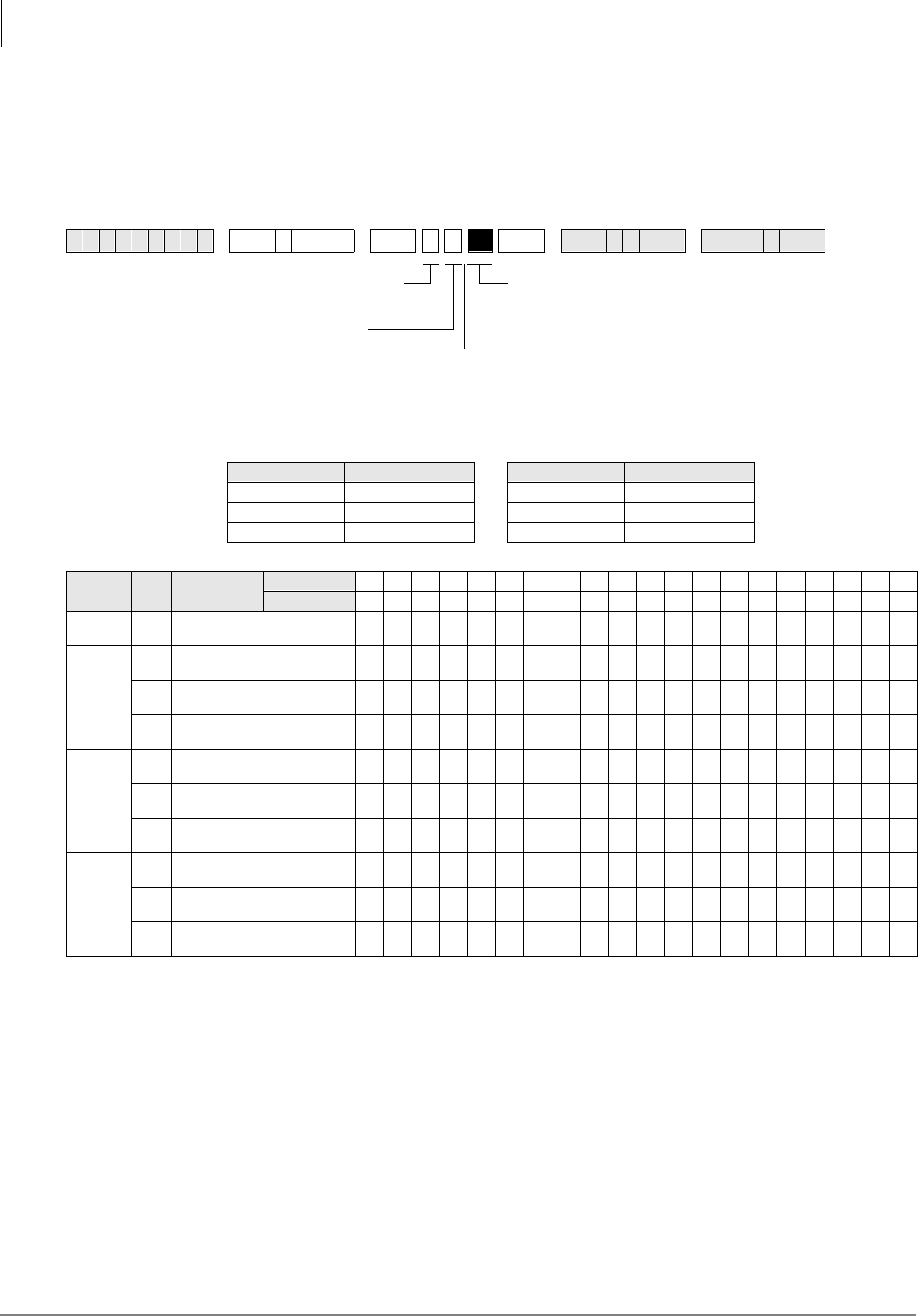
System & Station
Program 78 – CO Line Special Ringing Assignments
3-168 Strata DK Programming 5/99
Program 78 – CO Line Special Ringing Assignments
Processor Type:
DK14, DK40i
Program Type:
Station
Initialized Default:
All LEDs are OFF
6SNU +ROG 6SNU +ROG 6SNU +ROG 6SNU +ROG
Processor CO Line Range Processor CO Line Range
DK14 001~004 RCTUBA/BB 001~048
DK40i 001~012 RCTUC/D 001~144
RCTUA 001~016 RCTUE/F 001~200
Feature
Number Code Feature
Description
Line
LED 0102030405060708091011121314151617181920
13Ring Over External Page
during NIGHT mode
2
1DISA CO Line during DAY
Mode
2DISA CO Line during DAY2
Mode
3DISA CO Line during NIGHT
Mode
5
1Ring IMDU or RMDS1 Modem
during DAY Mode
1. RMDS requires RSIU and is available with DK424 only, IMDU requires PIOU or PIOUS. See Programs 77-1 LED 14, and Program 76 for
RMDS. Only one built-in maintenance modem, IMDU or RMDS, will function at a time in DK424.
2Ring IMDU or RMDS1 Modem
during DAY2 Mode
3Ring IMDU or RMDS1 Modem
during Night Mode
6
1Auto Attendant during DAY
Mode2
2. If CO lines should ring telephones before the Auto Attendant answers, use Program 81~89 to assign telephones to ring. Do not assign telephones
in Program 81~89, if the Auto Attendant should answer on the first ring.
2Auto Attendant during DAY2
Mode2
3Auto Attendant during Night
Mode2
CO Line
Specify CO lines with LED Buttons as defined by the table
below. All LEDs with an X should be lit when finished.
Press 6FUROO to advance or 3DJH to go back.
After programming, press:
Press 9RO▲ to turn all LEDs ON
Press 9RO▼ to turn all LEDs OFF
0RGH + CO line number + to display and advance
Feature Number
1, 2, 5, or 6
Code 1~3

System & Station
Program 78 – CO Line Special Ringing Assignments
Strata DK Programming 5/99 3-169
System & Station
Program 78 Overview
This program assigns ground/loop start CO lines:
♦to ring over external page during night mode
♦to be used with DISA features
♦for direct access to IMDU/RMDS modem
♦for Auto Attendant operation
Feature 1: Ring Over External Page During Night Mode
This program selects which ground/loop start CO lines will activate ringing over external paging
facilities during the NIGHT mode (for Tenants 1~4). The NT Relay on the PIOU, PIOUS, or
PEPU will also be activated if it is in the 1-second ON/3-seconds OFF mode.
Feature 2: DISA CO Line Assignment
This program assigns ground/loop start CO lines to be used with the Direct Inward System Access
(DISA) features. These lines may be set for DISA operation during the different system modes of
DAY, DAY2, and NIGHT. A line will switch to normal ringing after ten seconds if the outside
caller does not use the DISA feature. Normal function of these lines occurs for outgoing calls.
Note An optional security code for DISA outgoing lines calls is available via Program 60-6.
This code should always be programmed when using DISA and built-in Auto Attendant to
prevent unauthorized calls through the DK system.
Feature 5: Ring IMDU or RMDS Maintenance Modem
The IMDU (DK40i and DK424 only) or RMDS (DK424 only) Remote Maintenance modem can
be directly accessed by incoming ground/loop start CO lines assigned in this Program. Different
alternatives are available for the system modes of DAY, DAY2, and NIGHT. If none of these are
selected, the IMDU or RMDS can still be reached by dialing a modem [DN] with the DISA feature
or by a Ring Transfer from the DSS console attendant or any other station. The IMDU or RMDS
modem must be enabled with Program 77-1, LED 14-ON.
Feature 6: Built-in Auto Attendant CO Line Assignment
This feature selects ground/loop start CO lines for Auto Attendant operation. There is no limit to
the number of lines which can be assigned with Auto Attendant. Different alternatives are
available for system modes DAY, DAY2, and NIGHT.
Built-in Auto Attendant is not available for Tie, DID, ANI or DNIS lines on DK40i or DK424 and
is not available on any line of DK14.
Note Auto Attendant assignments 61~63 have priority over ACD assignments in Program 14-0.
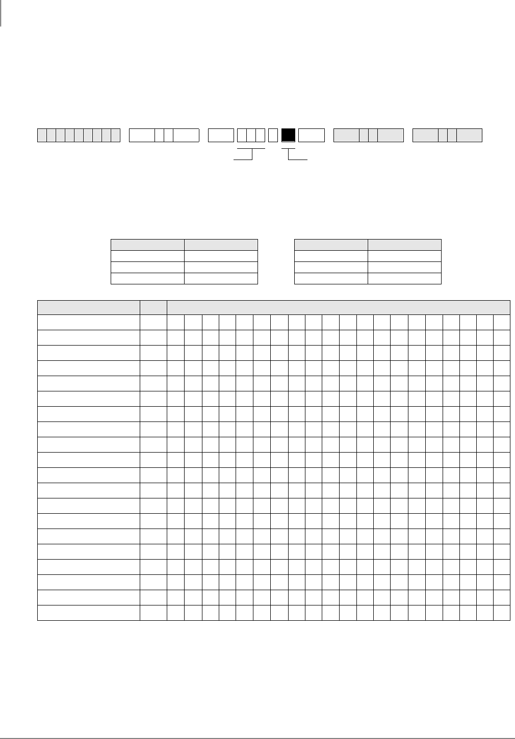
System & Station
Program 79 – Door Phone Ringing
3-170 Strata DK Programming 5/99
Program 79 – Door Phone Ringing
Processor Type:
DK14, DK40i, All RCTUs
Program Type:
Station
Initialized Default:
All LEDs are OFF
DP = Door Phone Program
6SNU +ROG 6SNU +ROG 6SNU +ROG 6SNU +ROG
Processor Port Range Processor Port Range
DK14 000~009 RCTUBA/BB 000~079
DK40i 000~027 RCTUC/D 000~239
RCTUA 000~031 RCTUE/F 000~335
Feature LED Ports
Muted ring to busy DKT/EKT 20
19
18
17
16
15
14
13
Door phone 4C Ring DP12 12
Door phone 4B Ring DP11 11
Door phone 4A Ring DP10 10
Door phone 3C Ring DP9 9
Door phone 3B Ring DP8 8
Door phone 3A Ring DP7 7
Door phone 2C Ring DP6 6
Door phone 2B Ring DP5 5
Door phone 2A Ring DP4 4
Door phone 1C Ring DP3 3
Door phone 1B Ring DP2 2
Door phone 1A Ring DP1 1
Light the LED Buttons that are marked with an X in
the table below.
SELECT = Port Number
Enter the port number having
Door Phone Ringing assigned.
To specify a port range, enter
XXXXXX (low port high port).

System & Station
Program 79 – Door Phone Ringing
Strata DK Programming 5/99 3-171
System & Station
Program 79 Overview
This program assigns the door phone ringing feature to ports.
LED 20: Muted Ring to Busy Electronic and Digital Telephone
If all electronic and digital telephones are busy and a door phone button is pressed, a muted ring
tone can be sent to selected digital and electronic telephones, as defined with this program. (Only
the lowest port in the appropriate ringing group will mute ring.)
LEDs 01~12: Door Phone Ring
When a door phone button is pressed, selected digital and/or electronic telephones will ring as
assigned with this program. See Program 77-2 for an explanation of the door phone A, B, and C
numbering scheme. (Use Program 79 to assign [DN] button LEDs to flash on telephones that are
assigned to ring.)
Door phones will not ring attendant consoles or standard telephones. Ringing door phones will
flash on idle console’s $QVZHU buttons, but will not alert a console that is in the busy mode. See
Program 77-1 for door phone box port assignments.
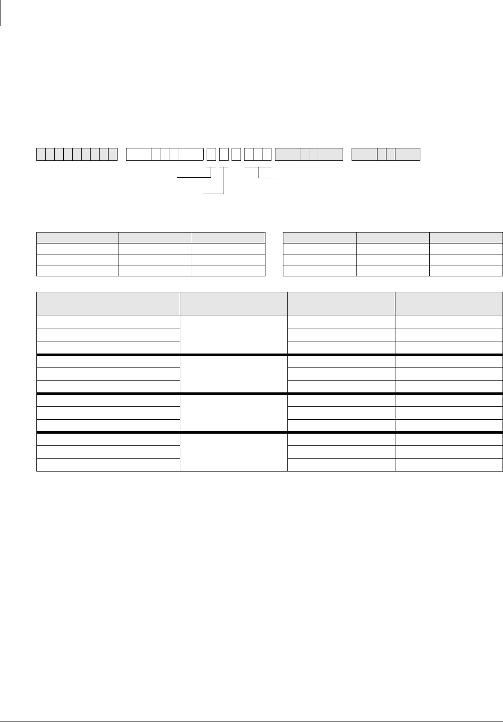
System & Station
Program *79 – Door Phone to [DN] Flashing Assignments
3-172 Strata DK Programming 5/99
Program *79 – Door Phone to [DN] Flashing
Assignments
Processor Type:
DK14, DK40i, All RCTUs
Program Type:
Station
Initialized Default:
No [DNs] assigned to ring for any door phone
Program *79 Overview
This program assigns door phones to ring Directory Number buttons ([PDNs]/[SDNs] [PhDNs])
when pressed and flash the [DN]’s LED. Each door phone can be assigned to flash one [DN]’s
LED and the [DN] can be assigned to appear and ring on up to 120 telephones.
Program 79 must be used in conjunction with Program 79 to ring a telephone with a flashing
[DN], when the door phone button is pressed. See Program 77-1 for door phone control box port
assignments.
Important! To allow a door phone to flash and ring, you must assign the [DN] to flash in
Program *79 and the telephone on which it appears must be assigned to ring in
Program 79.
6SNU+ROG 6SNU +ROG 6SNU +ROG
Processor [PDN] Port Range [PhDN] Port Range Processor [PDN] Port Range [PhDN] Port Range
DK14 000~009 500~509 RCTUBA/BB 000~079 500~579
DK40i 000~027 500~527 RCTUC/D 000~239 500~739
RCTUA 000~031 500~531 RCTUE/F 000~335 500~835
Door Phone Number/Location Door Phone Box
Number Door Box Circuit
Number [DN] Port Reference
Number
1
1
1
22
33
4
2
1
52
63
7
3
1
82
93
10
4
1
11 2
12 3
Enter a [DN] Port Reference
(Port Number of the [DN] that should flash when the
door phone button is pressed.)
[DN] = [PDN] or [PhDN] port (see Legend below)
Door Box Number (1~4)
Door Box Circuit Number (1~3)
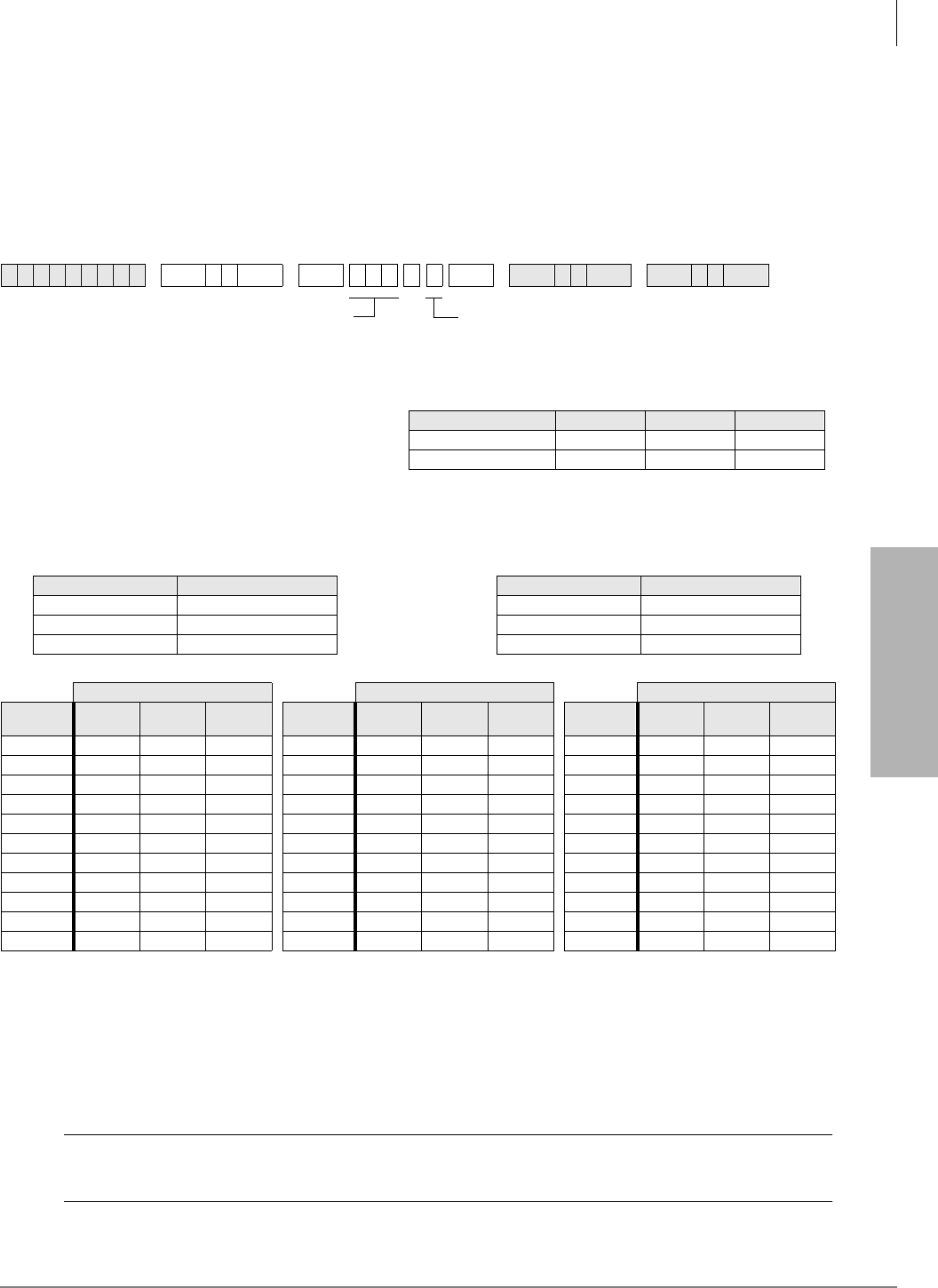
System & Station
Program 80 – EKT and DKT Ringing Tones (CO Line Calls)
Strata DK Programming 5/99 3-173
System & Station
Program 80 – EKT and DKT Ringing Tones (CO Line
Calls)
Processor Type:
DK14, DK40i, All RCTUs
Program Type:
Station
Initialized Default:
Tone 1 is assigned to all ports
Program 80 Overview
External speakers and all electronic and digital telephones are paged by dialing: [DN] + . The
$OO&DOO3DJH$& button is used to page all digital and electronic telephones only; external
speakers are not included when using the button.
PESU/PEKU can be in any universal slot assigned in Program 19-1.
CAUTION! To prevent system malfunction, DO NOT install the PESU in slot 18 of the
DK40i system.
6SNU +ROG 6SNU +ROG 6SNU +ROG 6SNU +ROG
Processor Port Range Processor Port Range
DK14 000~009 RCTUBA/BB 000~079
DK40i 000~027 RCTUC/D 000~239
RCTUA 000~031 RCTUE/F 000~335
Ringing Tone (Code) Ringing Tone (Code) Ringing Tone (Code)
Port
Number Tone 1
(1) Tone 2
(2) Tone 3
(3) Port
Number Tone 1
(1) Tone 2
(2) Tone 3
(3) Port
Number Tone 1
(1) Tone 2
(2) Tone 3
(3)
Ringing Tone Code
1 = Tone Option 1
2 = Tone Option 2
3 = Tone Option 3
SELECT = Station Logical Port Number
Enter the telephone port number for which
the ringing tone is being defined.
To specify a port range, enter XXXXXX
(low port high port).
*Incoming Line Call distinctive ring tones apply to DID, ground, and
loop start CO lines.
Ring tone for internal or [DN] calls, and Tie line incoming calls is
Ring Tone Option 123
Incoming Line Call* 500/640 Hz 1200/1500 Hz 800/1000 Hz
Transferred Line Call 540/760 Hz 1300/1780 Hz 880/1180 Hz
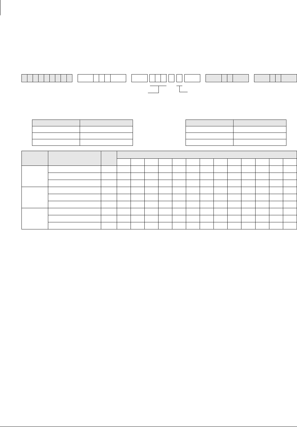
System & Station
Program *80 – Call Forward Station Ring Assignment
3-174 Strata DK Programming 5/99
Program *80 – Call Forward Station Ring Assignment
Processor Type:
All RCTUs with Release 3.2 and above
Program Type:
Station
Initialized Default:
LED 01, 04, and 07 ON for all lines
Program *80 Overview
Sets the Call Forward (CF) ringing assignment for ground/loop CO line calls. The station that
controls CF should be the only station programmed to ring in the appropriate Ringing Assignment
Programs (81~89). This program does not apply to Tie, DID, DNIS, or ANI lines.
Example application: A CO line call rings a CO line button on multiple stations, then Call
Forwards. CO line 001 is programmed to ring station 200, then after 12 secs., it delay rings
stations 201 and 202 (12 secs.). Then, CO line 001 will CF per station 203’s CF setting. If station
203 has CF-No Answer, CO line 001 will ring station 203, and then CF. If station 203 has CF-All
Calls, CO line 001 will not ring station 203, but will forward immediately.
Programming for the above example:
Program 39 - Put CO line 001 button on stations 200~203.
Program 81 - Set CO line 001 to ring station 200 immediately.
Program 82 - Set CO line 001 to Delay Ring station 201 and 202
Program 83 - Set CO line 001 to Delay 2 Ring station 203.
Program *80 - Set CO line 001 to CF during Delay 2 Ring assignment (LED 03 ON).
Set station 203 to CF to Voice Mail. When CO line 001 rings, the call will forward per station
203’s CF (All Calls, No Answer, etc.) setting during the Delay 2 ring period. Note that only station
203 can be set to ring in the Delay 2 (Program 83) ring assignment to allow CF to operate. VM will
receive station 203’s VMID (set via code #656).
6SNU+ROG 6 SNU + ROG 6SNU +ROG 6SNU +ROG
Processor CO Line Range Processor CO Line Range
DK14 NA RCTUBA/BB 001~048
DK40i NA RCTUC/D 001~144
RCTUA 001~016 RCTUE/F 001~200
System
Ring Mode Call Forward Station
Ring Assignment LED CO Lines
Night
Delay 2 (89) 09
Delay 1 (88) 08
Immediate (87) 07
Day 2
Delay 2 (86) 06
Delay 1 (85) 05
Immediate (84) 04
Day
Delay 2 (83) 03
Delay 1 (82) 02
Immediate (81) 01
LED buttons = ringing assignment in
which calls should Call Forward
SELECT = CO Line Number
To specify a CO line range, enter
XXXXXX (low line high line).
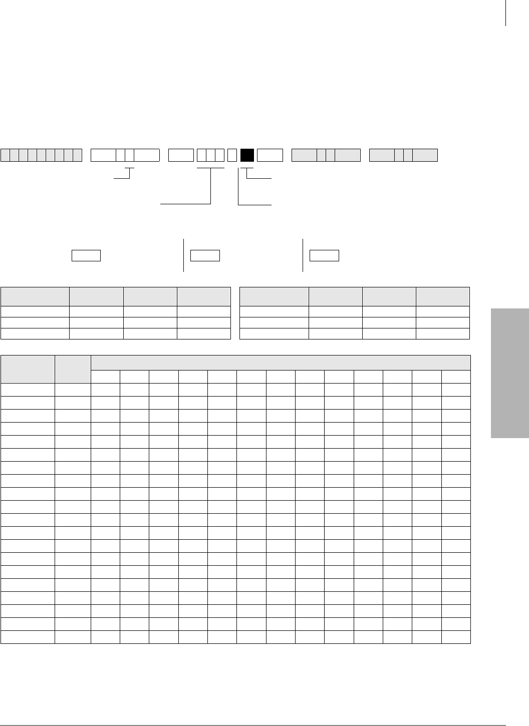
System & Station
Programs 81~89 – Ground/Loop Start/CO Line Station Ringing
Strata DK Programming 5/99 3-175
System & Station
Programs 81~89 – Ground/Loop Start/CO Line Station
Ringing
Processor Type:
DK14, DK40i, All RCTUs
Program Type:
System
Initialized Default:
All LEDs ON for Port 000 (81), Port 001 (87), all other LEDs OFF
6SNU +ROG 6SNU +ROG 6SNU +ROG 6SNU +ROG
Processor Station Port
Range DH Port CO Line Processor Station Port
Range DH Port CO Line
DK14 000~009 900~909 001~004 RCTUBA/BB 000~079 900~915 001~048
DK40i 000~027 900~915 001~012 RCTUC/D 000~239 900~915 001~144
RCTUA 000~031 900~915 001~016 RCTUE/F 000~335 900~915 001~200
CO Line LED Station or DH Port
20
19
18
17
16
15
14
13
12
11
10
09
08
07
06
05
04
03
02
01
LED Buttons = CO line assigned to ring selected
station port or DH Group number(s).
Press 6FUROO to advance or 3DJH to go back.
SELECT = 1~9
(for type of ringing)
Selected trunks ring selected station ports as follows:
81 = Immediate 84 = Immediate 87 = Immediate
DAY 82 = 12-second delay DAY 2 85 = 12-second delay NIGHT 88 = 12-second delay
83 = 24-second delay 86 = 24-second delay 89 = 24-second delay
SELECT = Station or DH port
(see legend below)

System & Station
Programs 81~89 – Ground/Loop Start/CO Line Station Ringing
3-176 Strata DK Programming 5/99
Program 81~89 Overview
Programs 81~89 assign telephones or a Distributed Hunt group to each CO line that will ring.
Use Programs *81, *84 and *87 to assign which [PDN] and/or [PhDN] buttons flash when a call
comes in on various CO lines.
♦If the telephone has a specific CO /LQH button or 3RROHG/LQH*US button, do not use
Programs *81, *84 or *87 to assign [DN] LEDs to flash. This will cause both the CO line and
[DN] button to flash on the telephone when the CO line rings on an incoming call.
♦Programs *81, *84, and *87 data should be blank for CO lines that ring Voice Mail (VM)
ports. Always check these programs because *81 and *87 default to port 000 and 001 and CO
lines 18~200.
➤To assign CO line ringing ports to station LEDs
1. On the record sheet on the previous page, enter the port numbers in the grey boxes in the top
row.
2. Enter the CO Line numbers in the left column.
3. Mark “X’s” in the boxes indicating which LED should be lit when a CO Line call comes in on
a particular port.
Auto Attendant
Use Programs 81~89 to set-up DK424 built-in Auto Attendant delay ring feature per the guide on
the next page.
CO lines to Ring Station [PDN] Ports and/or Distributed Hunt (DH) Group
Ports
CO lines that must ring DH groups must be assigned to ring the specific DH group number
(900~915). If the CO /LQH button or 3RROHG/LQH*US buttons must appear on the DH group
member telephones, Program *81, *84 and *87 assignments are not necessary. Do not assign DH
group member station ports in Program 81~89.
Station Ringing Modes
Important! 120 telephones maximum can be programmed to ring in any one mode (Day/Day2/
Night) per CO line.
The delay functions are mainly used in Centrex application, but can be used for other situations. If
delayed ringing occurs, the station that initially rings will continue to ring with subsequent delayed
ring stations. A wide variety of line ringing to stations can be programmed into the system.
There are nine categories:
Ringing Mode Comments
Day Immediate Ring assigned telephones on first ring from CO line (second ring to Caller ID lines).
Day Delay1 Delay1 is a 12-second delay of ringing signal to a standard, electronic, or digital
Day Delay2 Delay2 is a 24-second ring delay.
Day2 Immediate Same as Day Immediate except during Day2 NT mode.
Day2 Delay1 Same as Day Delay 1 except during Day 2.
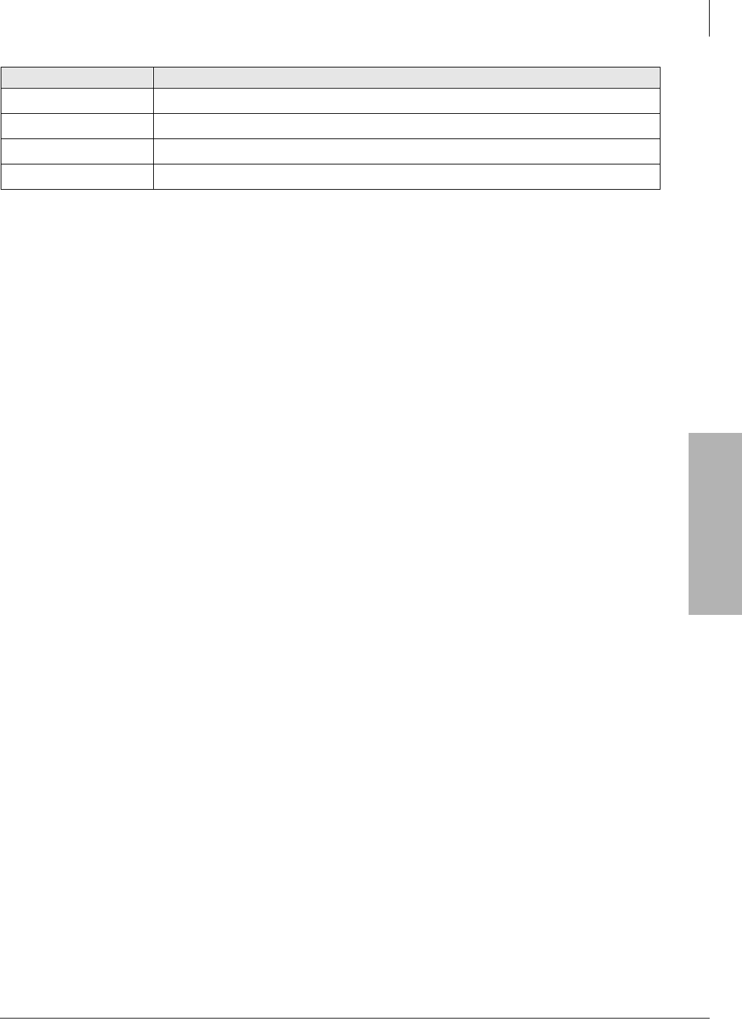
System & Station
Programs 81~89 – Ground/Loop Start/CO Line Station Ringing
Strata DK Programming 5/99 3-177
System & Station
Day, Day2, Night refer to the 1LJ KW7UDQVIHU button’s three modes.
Attendant Console (DK424 only)
Programs 81~89 are used to ring individual attendant consoles and/or to enable attendant console
incoming CO line call load sharing. (See “Auto Attendant Delay Ring” and “PC and Conventional
Attendant Console Programming Overview” in Chapter 5 – Station Apparatus of the Strata DK
Installation and Maintenance Manual.)
Attendant Console Load Sharing
In Programs 81, 84, and 87, assign all CO lines (ground, loop, and DID) that should alternately
ring multiple attendant consoles to the respective Load Share console ports (see “Attendant
Console Load Share Programming Example” on page 5-21 of the Strata DK Installation and
Maintenance Manual.
On DID lines, when the digits assigned to console ports in Program *09 are dialed on incoming
calls, the calls will alternately ring the Load Share consoles.
Auto Attendant Delay Ring
➤To set Auto Attendant Delay Ring operation
Note If the Auto Attendant must answer calls on the first ring, do not assign CO lines to ring
telephones in Programs 81~89.
1. Assign CO lines to ring the Auto Attendant (AA) in Program 78.
Program 78-61: AA DAY
Program 78-62: AA DAY 2
Program 78-63: AA NIGHT
2. Assign stations that should ring (immediately for 12 seconds) before the AA answers to the
AA CO lines in Program 81 (84 – Day 2, 87 – Night). Also assign the [DN] that should flash
when the CO lines ring with Program *81 (*84 – Day 2, *87 – Night). As an option, the station
can be equipped with the appropriate CO /LQH or 3RROHG/LQH*US buttons in which case
you should not program a [DN] to flash with Program *81.
♦Stations assigned in Program 81 and the [DN] assigned in Program *81 – ring immediate
for 12 seconds and then stop ringing unless they are also assigned to ring in Program 82.
Assign [DN] for the appropriate CO /LQH or 3RROHG/LQH*US buttons to these ports
using Program 39.
3. Assign stations that should ring (after a 12-second delay – for 12 seconds) before the AA
answers to the AA CO lines in Program 82 (85 – Day 2, 88 – Night). Also assign the [DN] that
should flash when the CO lines ring with Program *81 (*84 – Day 2, *87 – Night). As an
option, the station can be equipped with the appropriate &2/LQH or 3RROHG/LQH*US
buttons in which case you should not program a [DN] to flash with Program *81.
Day2 Delay2 Same as Day Delay 2 except during Day 2.
Night Immediate Same as Day Immediate except during Day2 NT mode.
Night Delay1 Same as Day Delay 1 except during Day 2 NT mode.
Night Delay2 Same as Day Delay 1 except during Day 2 NT mode.
Ringing Mode Comments

System & Station
Programs 81~89 – Ground/Loop Start/CO Line Station Ringing
3-178 Strata DK Programming 5/99
♦Station assigned in Program 82 and the [DN] assigned in Program *81 – ring after a 12-
second delay for 12 seconds and then stop ringing. Assign the appropriate [DN] or /LQH
or 3RROHG/LQH*US buttons to these ports using Program 39.
4. Assign any station to ring the AA CO lines in Program 83 (86 – Day 2, 89 – Night). This
assignment is only a flag that notifies the software to delay ring stations assigned in Program
82. Program 83 station assignments do not ring.
♦The station assigned in Program 83 will not ring because AA will answer the call after 24
seconds. Assign [DN] buttons that flash/ring on this station port using Program 39.
♦No Delay: If AA line(s) are assigned to ring stations in Program 81, but no stations are
assigned in Programs 82 or 83, AA will answer the call immediately (no delay ring).
♦12 Second Delay: If AA line(s) are assigned to ring stations in Programs 81 and 82 but no
stations are assigned in Program 83, stations assigned in Program 81 will ring immediately
for 12 seconds and then the AA will answer (stations assigned in Program 82 will not
ring).
♦24 Second Delay: If AA CO line(s) are assigned to ring stations in Programs 81, 82, and
83, then the following ringing occurs:
Note The Auto Attendant Answers after stations assigned in Program 81 and 82 stop ringing (24
seconds from start of call).
5. Use Program 39 to assign the [DN] button that should flash and ring before the AA answers.
The [DN] button, or buttons for multiple [PDNs], must be assigned on all station ports
assigned to ring in Programs 81-89 only if the stations that must ring before AA answers do
not have the appropriate CO /LQH or 3RROHG/LQH*US buttons.
Auto Attendant Program Example
♦CO lines 1~5 should ring [PhDN] 500 on station 200 immediately for 24 seconds (6 rings).
♦CO lines 1~5 should delay ring [PhDN] 500 on station 208 after ringing [PhDN] on station
200 for 12 seconds.
♦The Auto Attendant should answer CO 1~5, 24 seconds after station 200 started ringing and
12 seconds after station 208 started ringing. Stations 200 and 208 stop ringing when auto
attendant answers.
➤To program the example
1. Assign lines 001~005 to AA in Program 78-61.
2. Assign lines 001~005 to ring station 200 in Program 81.
3. Assign lines 001~005 to ring station 208 in Program 82.
4. Assign lines 001~005 to ring any installed RSTU, PDKU, or PEKU port that has a telephone
or does not have a telephone connected in Program 83 (Program 83 assignment is used only to
enable Program 82 delay ring stations to ring. Assign [PhDN] 500 button on this port using
Program 39).
5. Assign lines 001~005 to flash [PhDN] 500 in Program 81.
6. Assign the [PhDN] 500 button to station 200 and 208 using Program 39.
7. Make sure [PhDN] is assigned to an owner telephone (200 or 208) in Program 33.
8. Using Program 39, assign [PhDN] button 500 on stations 200 and 208.
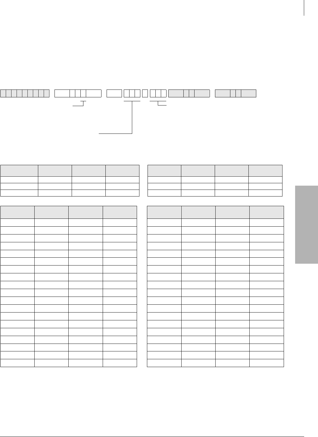
System & Station
Programs *81, *84, and *87 – Ground/Loop Start/CO Line to [DN] LED Flash Assignments
Strata DK Programming 5/99 3-179
System & Station
Programs *81, *84, and *87 – Ground/Loop Start/CO
Line to [DN] LED Flash Assignments
Processor Type:
DK14, DK40i, All RCTUs
Program Type:
System
Initialized Default:
CO 018~200 flashes Port 000 (
*
81) and Port 001 (
*
87)
Important! Blank out initialized default data if CO line should not ring and flash [PDN]
assigned to port 000 and port 001. If this initialized data is programmed when other
[DNs] or telephones should flash and ring, Call Forward and Station Hunt may not
operate properly.
6SNU+ROG 6 SNU 6SNU +ROG 6SNU +ROG
Processor CO Line [PDN] Port
Range [PhDN] Port
Range Processor CO Line [PDN] Port
Range [PhDN] Port
Range
DK14 001~004 000~009 500~509 RCTUBA/BB 001~048 000~079 500~579
DK40i 001~012 000~027 500~527 RCTUC/D 001~144 000~239 500~739
RCTUA 001~016 000~031 500~531 RCTUE/F 001~200 000~335 500~835
CO Line
Number Day Ring
[DN] (*81) Day 2 Ring
[DN] (*84) Night Ring
[DN] (*87) CO Line
Number Day Ring
[DN] (*81) Day 2 Ring
[DN] (*84) Night Ring
[DN] (*87)
.
Ringing Assignments
1 = Day Ring
4 = Day 2 Ring
7 = Night Ring
CO line number (see table below)
To add a CO line range, enter XXXXXX
(low CO line high CO line).
Station Logical Port Number
Enter the [PDN] or [PhDN] that should flash
LED Button 01 enters blank data.

System & Station
Programs *81, *84, and *87 – Ground/Loop Start/CO Line to [DN] LED Flash Assignments
3-180 Strata DK Programming 5/99
Programs *81, *84 and *87 Overview
Ground/loop start CO lines can be assigned to ring and flash specific Directory Number buttons,
including [PDNs], [SDNs] or [PhDNs]. These programs assign which [DN] will flash when a
ground/loop start CO line rings a direct incoming call to the DK system.
Programs 81~89 must be used in conjunction with Programs *81, *84, and *87 to ring the
telephone on which the flashing [DN] appears. Refer to the CO /LQH/[DN] button LED control
logic diagrams that follow these record sheets for more information.
Each ground/loop start CO line can be assigned to flash one [DN], but that [DN] button can be
assigned to up to 120 telephones. The assigned [DN] LED will flash as 1 Hz rate when CO line
call rings into the DK424.
If a specific CO /LQH or 3RROHG/LQH *US button is programmed to appear on a telephone (in
Program 39), do not assign a [DN] to flash on that telephone with Programs *81, *84, and *87.
Important! If CO lines direct ring voice mail (VM) ports in Programs 81~89, the data for those
CO lines in Programs *81, *84, and *87 must be blank.
Program *81
Assigns which [DN] flashes when the CO line rings during the system Day mode.
Program *84
Assigns which [DN] flashes when the CO line rings during the system Day2 mode.
Program *87
Assigns which [DN] flashes when the CO line rings during the system Night mode.
Programs 81, 82, 83
Assign Immediate Ring, 12-second delay Ring, 24-second delay Ring in the Day mode,
respectively, to telephones with [DNs] assigned to flash in Program *81
Programs 84, 85, 86
Assign Immediate Ring, 12-second delay Ring, 24-second delay Ring in the Day2 mode,
respectively, to telephones with [DNs] assigned to flash in Program *84
Programs 87, 88, 89
Assign Immediate Ring in the Night mode, 12-second delay Ring, 24-second delay Ring,
respectively, to telephones with [DNs] assigned to flash in Program *87.
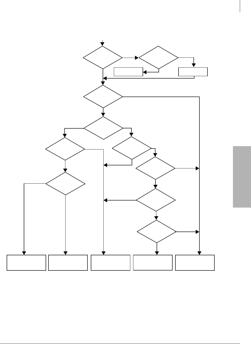
System & Station
Programs *81, *84, and *87 – Ground/Loop Start/CO Line to [DN] LED Flash Assignments
Strata DK Programming 5/99 3-181
System & Station
Figure 3-2 Strata DK CO Line Button/Directory Number [DN] Button Ringing Control Logic Diagram
Telephone
Receives Beep
and Camp-On Tone
Telephone Receives
Ring Tone Telephone Does Not
Ring
Telephone May
Receive Camp-On
Tone
3
Telephone Receives
No Ring
2
Program 39
CO Line
Button
I-Use or Red
Program *81
[DN] 1 HZ
Program 81
Program
*81
EKT/DKT
[DN]
Idle
EKT/DKT
or
SLT
SLT
[PDN]
1
Idle
SLT is
talking on
[PDN]
[DN] Idle
[DN]
I-Use
Y
Y
Y
Y
Y
Y
N
N
N
N
N
N
N
N
N
YY
Y
EKT/DKT
SLT
Ground/Loop Start
CO Incoming Call Ringing Control
1575
1. [PDN] belongs to Standard Telephone.
2. If a digital/electronic telephone has an SLT [PDN] on their telephone and if that telephone is currently using the SLT [PDN], the SLT
will not receive camp-on tone.
3. See Program *34.
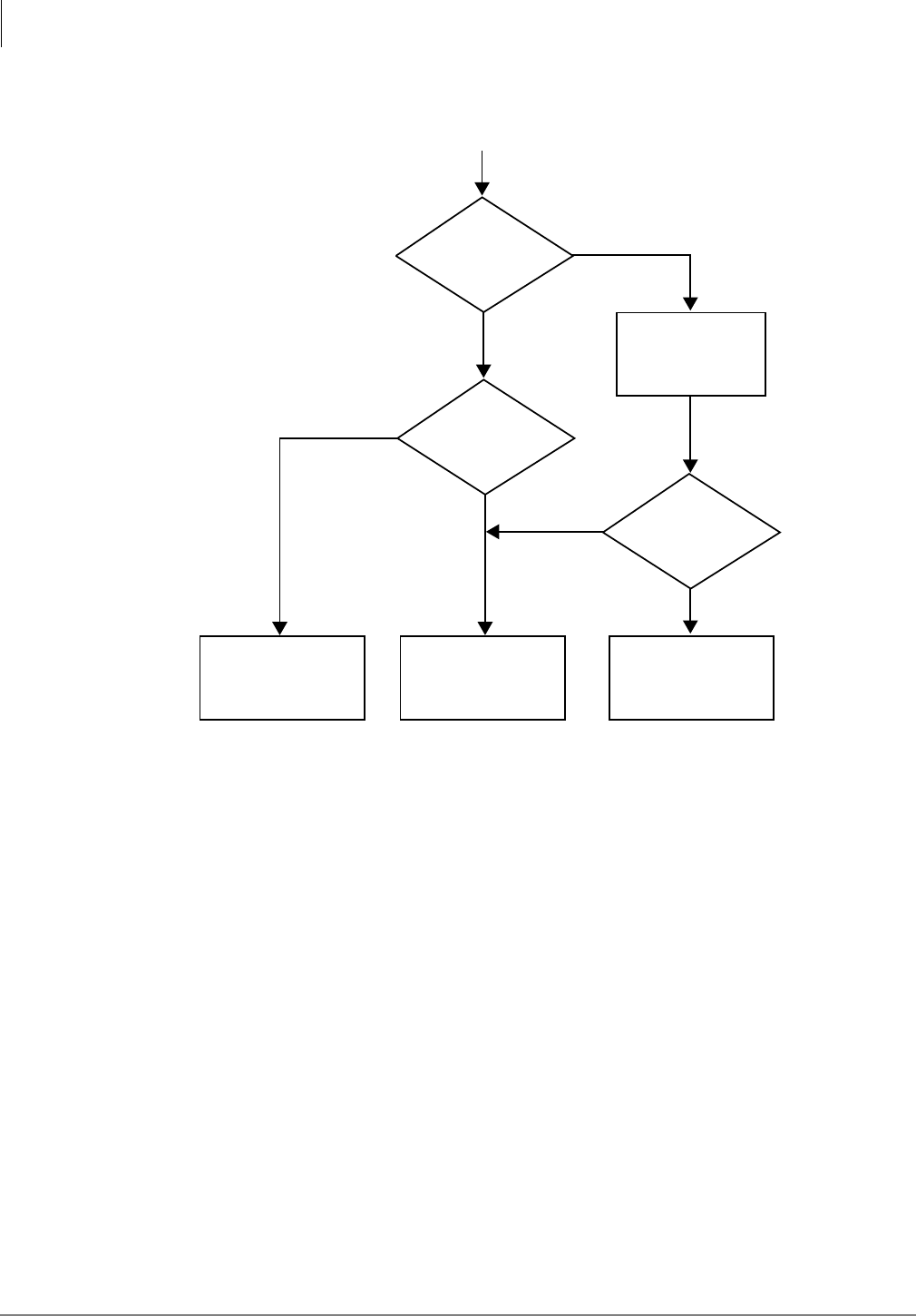
System & Station
Programs *81, *84, and *87 – Ground/Loop Start/CO Line to [DN] LED Flash Assignments
3-182 Strata DK Programming 5/99
Program *81 CO Line to Station [DN] LED flashing Control Logic also applies to Programs *84
and *87.
Program 81 CO Line to Station Ringing Control Logic also applies to Programs 82~89.
Important! System Record Sheets for Programs 90, 91, and 92 appear in the beginning of this
section because they must be executed prior to running any other programs.
Telephone CO Line
Button LED:
I-Called (Green)
Telephone [DN]
Button LED:
I-Called (Green)
Program 39
CO Line Button
on Telephone
?
Program 39
CO Line Button
on Telephone
?
YY
N
N
N
Y
No LED
Telephone
[DN] LED
1 HZ-Red
Program
*
81
and [PDN] or [PhDN]
button [DN]
on telephone
Ground/Loop Start CO Line
Incoming Call LED Control
1576
Figure 3-3 Strata DK CO Line Button/Directory Number LED Flash Control Logic Diagram
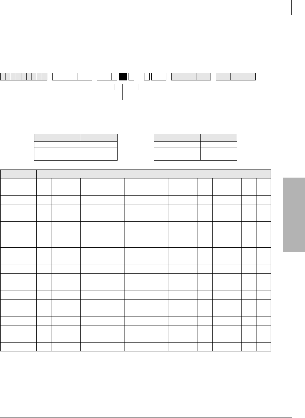
System & Station
Program 93 – CO Line Identification
Strata DK Programming 5/99 3-183
System & Station
Program 93 – CO Line Identification
Processor Type:
DK14, DK40i, All RCTUs
Program Type:
System
Initialized Default:
Blank
Program 93 Overview
Assigns alphanumeric names (such as “WATS BAND 5”, “FX TO NY,” “MR JONES,” etc.) to
lines. The names can be up to 16 characters each, and display when the line is being used by an
LCD station. When programmed to display, Caller ID, DNIS, ANI, and ACD call information will
display in place of CO line Alpha identification data.
6SNU +ROG 6SNU +ROG6SNU +ROG 6SNU +ROG
Processor CO Line Range Processor CO Line Range
DK14 001~004 RCTUBA/BB 001~048
DK40i 001~012 RCTUC/D 001~144
RCTUA 001~016 RCTUE/F 001~200
LED Line CO Line Identification (16 Characters Max. Enter One per Rectangle)
20
19
18
17
16
15
14
13
12
11
10
09
08
07
06
05
04
03
02
01
CO Line Identification
Enter the CO line identification. (See next page
for data entry procedures.)
SELECT = 1
LED Button for CO
line being named.
To advance the line
range, press Scroll.
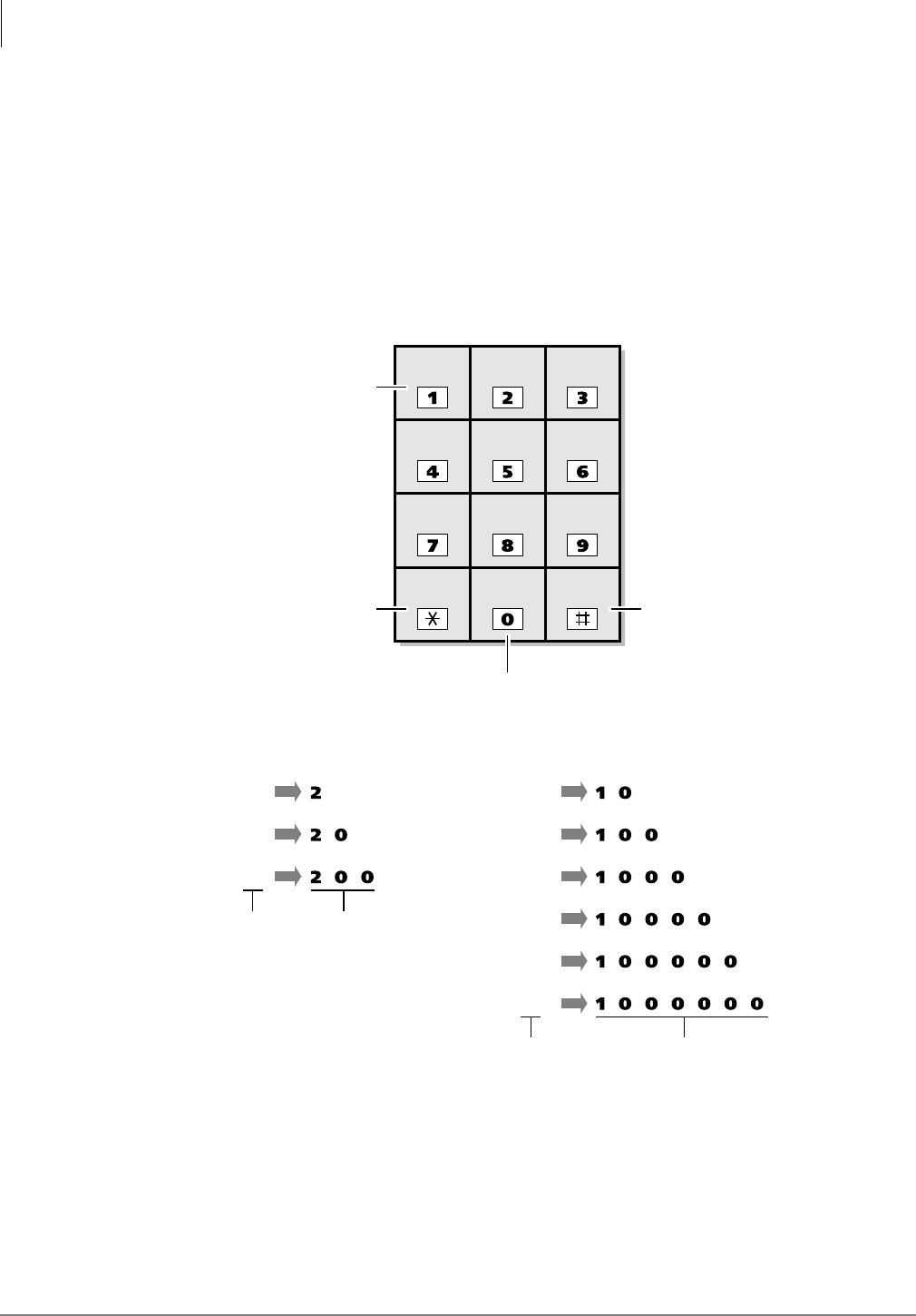
System & Station
Program 93 – CO Line Identification
3-184 Strata DK Programming 5/99
➤To enter CO line identification
1. Enter Program 93 and select the desired CO line.
2. Using the guide below enter the CO line identification information.
Numeric Mode
~ are treated as numerals.
Dial pad starts in numeric mode. Press to switch to alpha mode.
Alpha Mode
Moves cursor to left
Scrolls alpha and
special characters
Alpha Entry (Example): Special Character Entry:
Alpha
Character Entry
Sequence
Special
Character Entry
Sequence
QZ ABC DEF
GHI JKL MNO
PRS TUV WXY
Cursor
Left Scroll
Key Mode
Key
A
B
C
Q
Z
:
–
+
/
Moves cursor to
right, and starts
special character
entry when in the
Alpha Mode
Changes from
Numeric to
Alpha Mode
and vice versa
1700
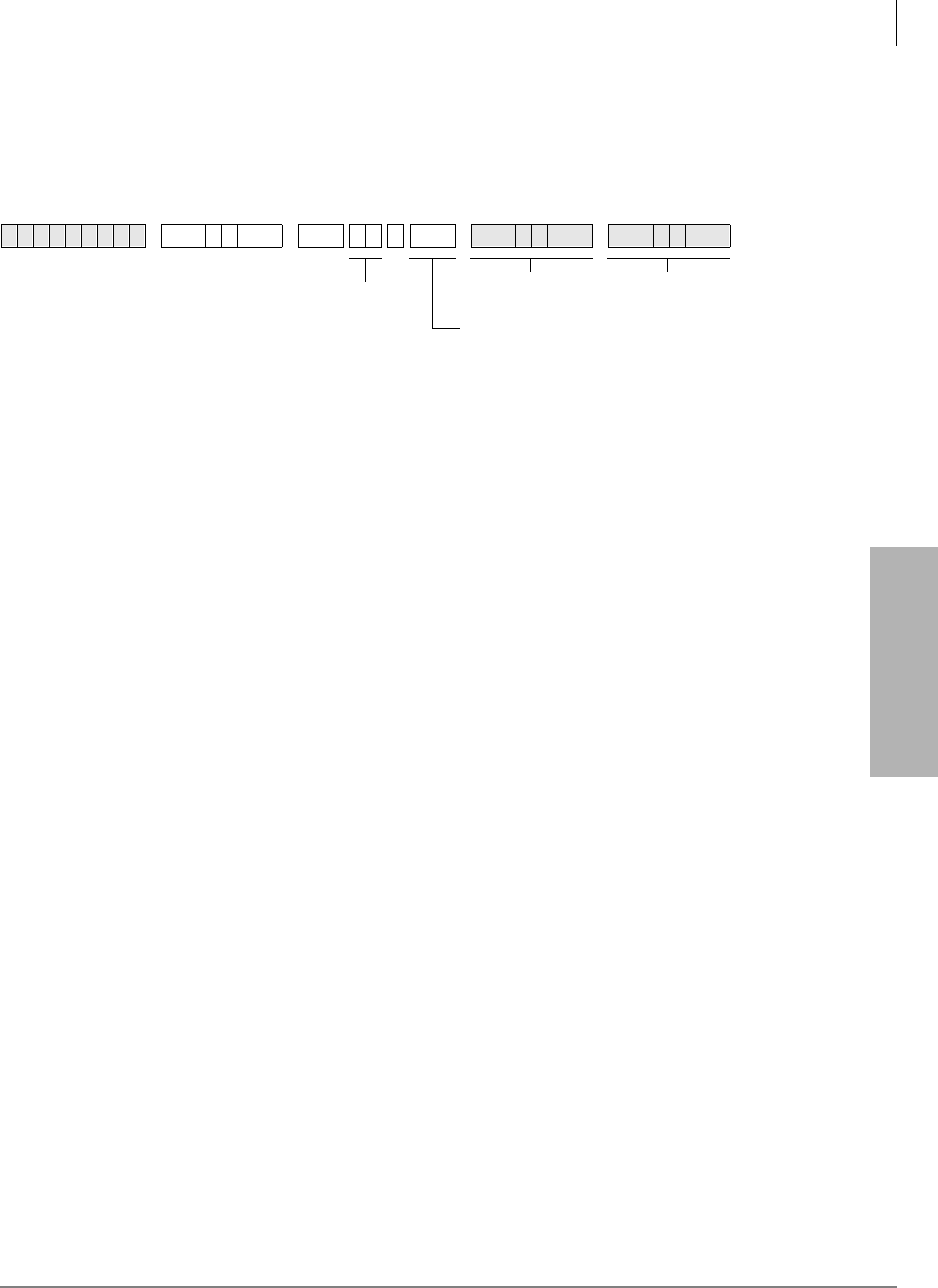
System & Station
Program 97 – Printing Program Data through SMDR
Strata DK Programming 5/99 3-185
System & Station
Program 97 – Printing Program Data through SMDR
Processor Type:
DK14, DK40i, All RCTUs
Program Type:
System
Initialized Default:
Prints out customer database
Program 97 Overview
Contents of each program can be sent to the SMDR port for a hard copy printout.
6SNU +ROG 6SNU +ROG 6SNU +ROG 6SNU +ROG
SELECT = Program Number
to be printed on SMDR.
To specify a range of programs, enter XXXX
(low program in range high program in range).
Exit Program
Mode.
Cancels printout at
any time.
Data Print
Printout begins.

System & Station
Program 97 – Printing Program Data through SMDR
3-186 Strata DK Programming 5/99

Strata DK Programming 5/99 4-1
Toll Restriction
Toll Restriction 4
This chapter gives you an overview of the Toll Restriction feature and step-by-step instructions to
fill in the Toll Restriction System Record Sheets for DK14, DK40i, and all RCTUs.
Toll Restriction Methods
Toll Restriction screens and selectively restricts outgoing calls using three different methods. Each
type of restriction can be programmed for individual stations. Toll Restriction can also be enabled/
disabled for each outgoing line in the system.
Important! Strata DK requires that a “1” be dialed before an area code to provide simple,
three, or six-digit toll restriction.
Simple Toll Restriction
Only involves the first digit dialed. The system can be programmed to reject outgoing calls
beginning with 0 or 1 (see Program 48).
Three-digit Toll Restriction
Involves the system analyzing the area code dialed, and selectively allowing/disallowing outgoing
calls following the criteria defined in Area Code Tables (see Program 46, Codes 2~4).
Six-digit Toll Restriction
Involves the system analyzing the area code and the office code, and selectively allowing/
disallowing outgoing calls following the criteria defined in Area Code Tables and Office Code
Tables (see Program 46, codes 2~4 and 6~8).
Note Standard telephones that are Toll Restricted should always be forced to use Least Cost
Routing (LCR) to place outside calls. This prevents Toll Restriction defeat when the
RRCS, K4RCU3, K5RCU or QRCU3 circuit times out.
Toll Restriction Features
For description purposes, Toll Restriction is divided into several components, or subfeatures. The
subfeatures operate independently of the restriction methods just described, although they may
employ these methods.

Toll Restriction
Toll Restriction Features
4-2 Strata DK Programming 5/99
Station Priority Classes 1~8
Eight classes of Toll Restriction can be defined to assign different levels of priority to individual
stations with RCTUC/D and RCTUE/F.
Four classes are supported with DK14, DK40i, RCTUA, and RCTUBA/BB.
Classes can be defined so each is progressively more restrictive by allowing or denying specific
area or office codes, calls to long distance information, international calls, and operator assisted
calls (Programs 46-10~80).
Office Code Exception Tables
Class 1~8 restrictions can be further modified by defining as many as eight exception tables to
allow or deny access to specific office codes that fall within previously restricted area codes
(Program 47). Exception office code access is accomplished with the Six-digit Toll Restriction
method described earlier.
Emergency, Information, and Toll-free Long Distance Toll Restriction
Override
Toll Restricted stations may be allowed to dial special codes such as 911 or Enhanced 911 (E911)
for emergency response, 1-411 or 411 for information, or 800 prefix toll-free calls (see Program 46
for normal 911 and 10 for E911).
Important! Always be sure to provide access to emergency numbers such as 911.
Toll Restriction Override by System Speed Dial
System Speed Dial numbers can be programmed to override Toll Restriction (see Basic System
Features, Program 10-1).
Toll Restriction/Traveling Class Override Codes
Up to two Toll Restriction Override Codes can be defined. When dialed at a toll restricted station,
these codes enable the station user to override toll restrictions defined at the station (Program 44-
1~8 or 45-8~9). Codes may be changed by stations chosen in programming (see Basic System
Features, Program 30). Also, Verified Account Codes (Forced or Voluntary) can be used to
override or change a telephone’s toll restriction class on a call by call basis (see Programs 69 and
70).
Special Common Carrier Authorization
Toll Restriction can be programmed to recognize Other Common Carrier (OCC) telephone
numbers, directory numbers, authorization codes, and Centrex/PBX access codes. The system
starts inspecting numbers for Toll Restriction purposes after the recognizable code is dialed
(Program 45-3~6). This does not apply to 10XXX or 101XXX carrier access codes which are
always restricted to stations that are toll restricted in any class in Program 48.

Toll Restriction
Completing the Toll Restriction System Record
Strata DK Programming 5/99 4-3
Toll Restriction
Completing the Toll Restriction System Record
The following instructions explain how to complete System Record Sheets used to program the
Toll Restriction feature. They are arranged in the same order in which the tables appear in the Toll
Restriction System Record Sheets. The following instructions are intended to give a concise
general definition of the programming characteristics defined by each record sheet.
Note On each record sheet, mark an X in the space provided to indicate that a choice is selected.
Unless otherwise specified, this indicates the LED is lit. When appropriate, indicate digits
to be entered using the station dialpad.
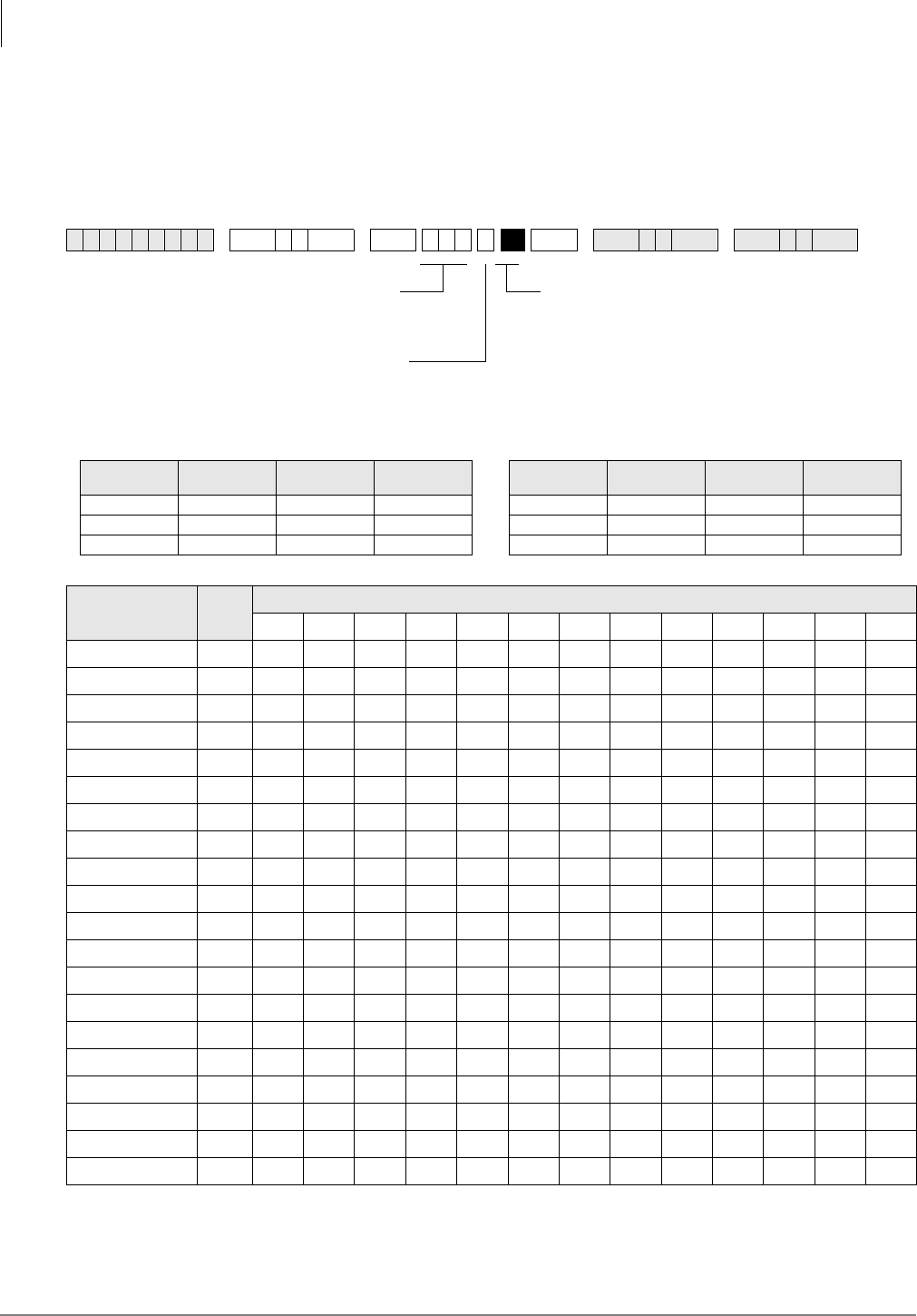
Toll Restriction
Program 40 – Station CO Line Access
4-4 Strata DK Programming 5/99
Program 40 – Station CO Line Access
Processor Type:
DK14, DK40i, All RCTUs
Program Type:
Toll Restriction
Initialized Default:
All LEDs ON for all CO lines (all stations can access all lines)
6SNU +ROG 6SNU +ROG 6SNU +ROG 6SNU +ROG
Processor CO Line
Range [PDN] Port
Range DISA Port Processor CO Line
Range [PDN] Port
Range DISA Port
DK14 001~004 000~009 10 RCTUBA/BB 001~048 000~079 089
DK40i 001~012 000~027 035 RCTUC/D 001~144 000~239 249
RCTUA 001~016 000~031 039 RCTUE/F 001~200 000~335 344
CO Line LED Port
20
19
18
17
16
15
14
13
12
11
10
09
08
07
06
05
04
03
02
01
LED Buttons = CO Lines
Light LEDs for the port(s) that are
allowed access.
SELECT = Station Logical Port Numbers
To add a port range, enter XXXXXX (low
port high port).
Press 6FUROO to advance or 3DJH to go back.
To turn all CO LEDs ON or OFF, after the port number and is entered, press 9RO▲ (all LEDs ON) or 9RO▼ (all LEDs OFF).
To check a particular CO line, after the port number is entered, press 0RGH and enter the CO line number, then use the
button to display and advance.

Toll Restriction
Program 40 – Station CO Line Access
Strata DK Programming 5/99 4-5
Toll Restriction
Program 40 Overview
This program is used to allow or deny each station and/or DISA to use CO lines on a line by line
basis. This applies to all analog and digital line types.
Any station can have access to as many lines as desired. Any station denied access (either to make
a call or to answer a call) to a line cannot seize it by dialing either an access or pickup code or by
using a CO line button. This also denies access via Least Cost Routing. Also, use this program to
divide lines for Tenant Service. Use Program 40 to deny CO line call pickup. If only outgoing
access is to be prevented but answering incoming calls should be allowed, use Program 41, not
Program 40 to deny CO line access.
Program 40 does not deny access to answer transferred calls. If the LED for a CO line is OFF in
this program, access to the line on direct incoming or outgoing calls is denied.
Important! If the DISA port is denied, CO line access in Program 40, DISA callers cannot
access outgoing CO lines when calling in on DISA lines. Also, External Call
Forward will be blocked on the denied lines. (See DISA port legend.)
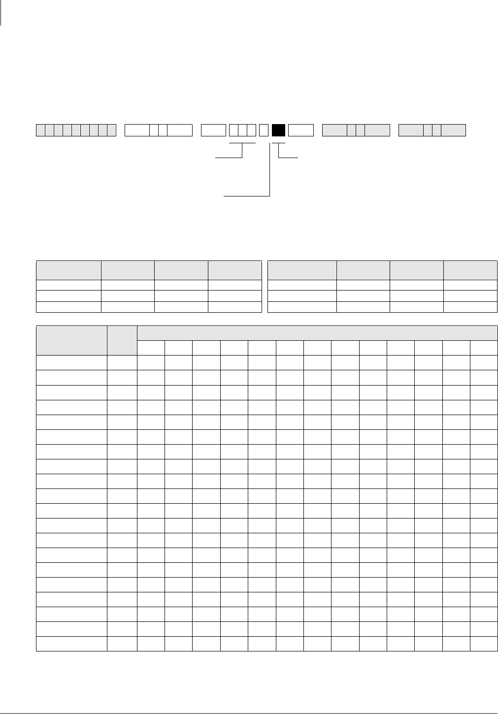
Toll Restriction
Program 41 – Station Outgoing Call Restriction
4-6 Strata DK Programming 5/99
Program 41 – Station Outgoing Call Restriction
Processor Type:
DK14, DK40i, All RCTUs
Program Type:
Toll Restriction
Initialized Default:
All LEDs OFF for all CO lines (all stations can access all lines)
6SNU +ROG 6SNU +ROG 6SNU +ROG 6SNU +ROG
Processor CO Line
Range [PDN] Port
Range DISA Port Processor CO Line
Range [PDN] Port
Range DISA Port
DK14 001~004 000~009 010 RCTUBA/BB 001~048 000~079 089
DK40i 001~012 000~027 035 RCTUC/D 001~144 000~239 249
RCTUA 001~016 000~031 039 RCTUE/F 001~200 000~335 344
CO Line LED Port
20
19
18
17
16
15
14
13
12
11
10
09
08
07
06
05
04
03
02
01
LED Buttons = CO Lines
Light LEDs for the port(s) that are
allowed access.
SELECT = Station Logical Port Numbers
To add a port range, enter XXXXXX (low
port high port).
Press 6FUROO to advance or 3DJH to go back.
After programming, press:
•9RO▲ to turn all LEDs ON
•9RO▼ to turn all LEDs OFF
•0RGH + CO line number, then to display and advance

Toll Restriction
Program 41 – Station Outgoing Call Restriction
Strata DK Programming 5/99 4-7
Toll Restriction
Program 41 Overview
Program 41 restricts each station (or Direct Inward System Access (DISA) CO line) from outgoing
access to each line. If restricted, that station can still answer a ringing line or pick up a call on hold
but cannot directly access a line for an outgoing call by pressing the line button or dialing the line
access code. All Call Pickup functions operate normally. This does not deny access via LCR.
Notes
●Automatic Busy Redial (ABR) overrides Program 41.
●To deny a CO line to be accessed for DISA tandem connection or external call forward, turn its
LED ON (see DISA ports legend).
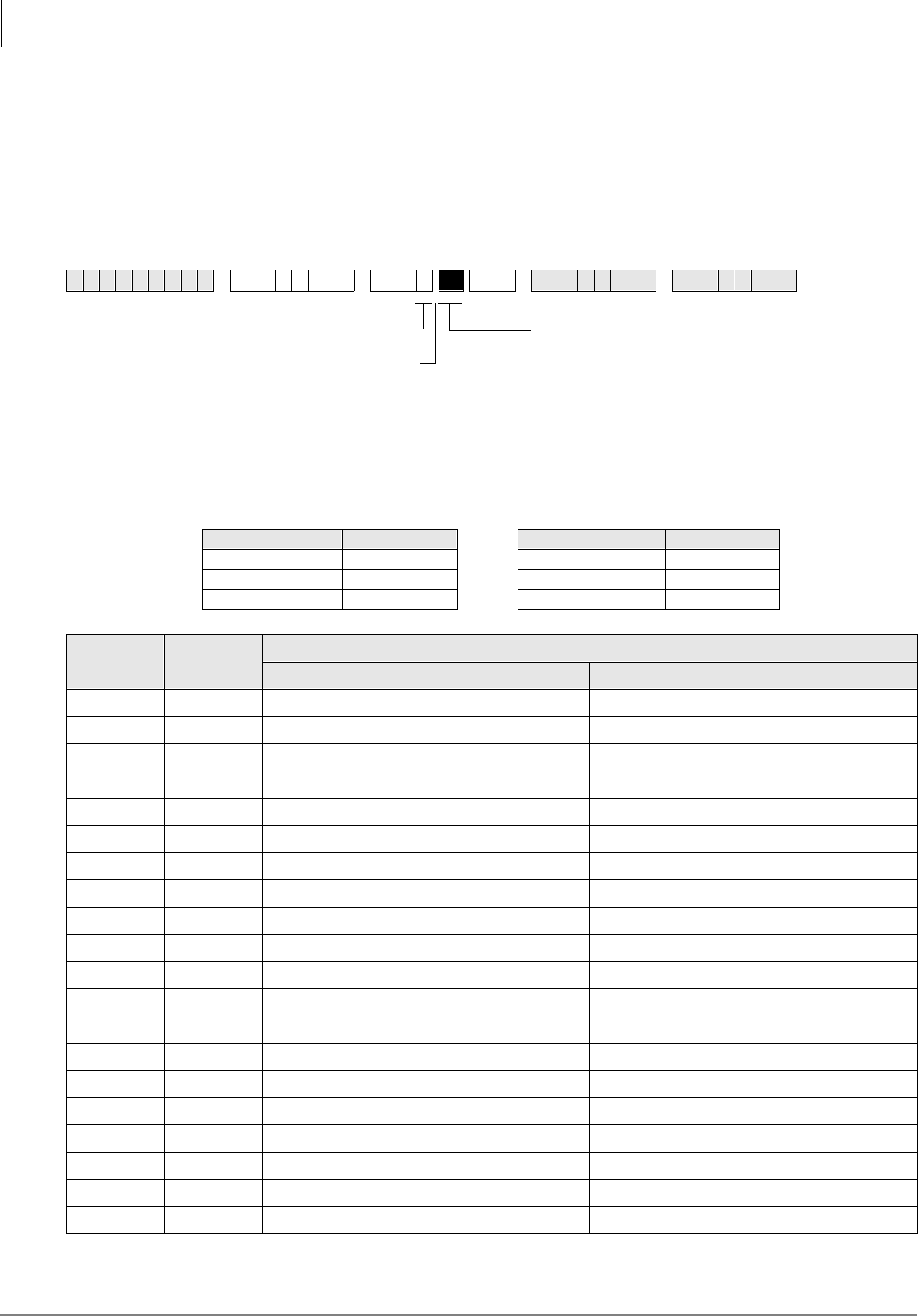
Toll Restriction
Program 42-0 – CO Line to PBX/Centrex Connection & Access Codes
4-8 Strata DK Programming 5/99
Program 42-0 – CO Line to PBX/Centrex Connection &
Access Codes
Processor Type:
DK14, DK40i, All RCTUs
Program Type:
Toll Restriction
Initialized Default:
All LEDs OFF for all CO lines. Assigns no access codes to PBX groups.
6SNU +ROG 6SNU +ROG 6SNU +ROG 6SNU +ROG
Processor CO Line Range Processor CO Line Range
DK14 001~004 RCTUBA/BB 001~048
DK40i 001~012 RCTUC/D 001~144
RCTUA 001~016 RCTUE/F 001~200
Button
LED Line
(Trunk)
Set Button LEDs
Centrex/PBX Connection (LED ON) Normal (LED OFF)
20
19
18
17
16
15
14
13
12
11
10
09
08
07
06
05
04
03
02
01
Specify CO Lines by setting LED Buttons as
defined by the table below.
SELECT = 0
Press 6FUROO to advance
or 3DJH to go back.
After programming, press:
•9RO▲ to turn all LEDs ON
•9RO▼ to turn all LEDs OFF
•Mode and CO line number, then to
display and advance

Toll Restriction
Program 42-0 – CO Line to PBX/Centrex Connection & Access Codes
Strata DK Programming 5/99 4-9
Toll Restriction
Program 42-0 Overview
Use this program to allow Centrex/PBX (after flash) features to operate. Do not use this program
when the Centrex feature (assume 9) is used and the DK LCR is activated (see notes below).
The Strata DK System recognizes PBX/Centrex access codes via Programs 42-1~8. Program 42-0
informs the software which lines are connected to a PBX or to Centrex. This combination allows
Toll Restriction and Speed Dialing to function properly.
Notes
●If the CO line is programmed for behind Centrex/PBX (LED ON), reseize guard time is 1.5
seconds. If CO line is programmed for normal operation guard time is 0.45 seconds. See
Program 10-1, Button/LED 02.
●Do not use this program when using LCR behind Centrex/PBX; use Program 45-2 instead.
Also, do not use this program if installing CO lines behind “assume-9” Centrex.
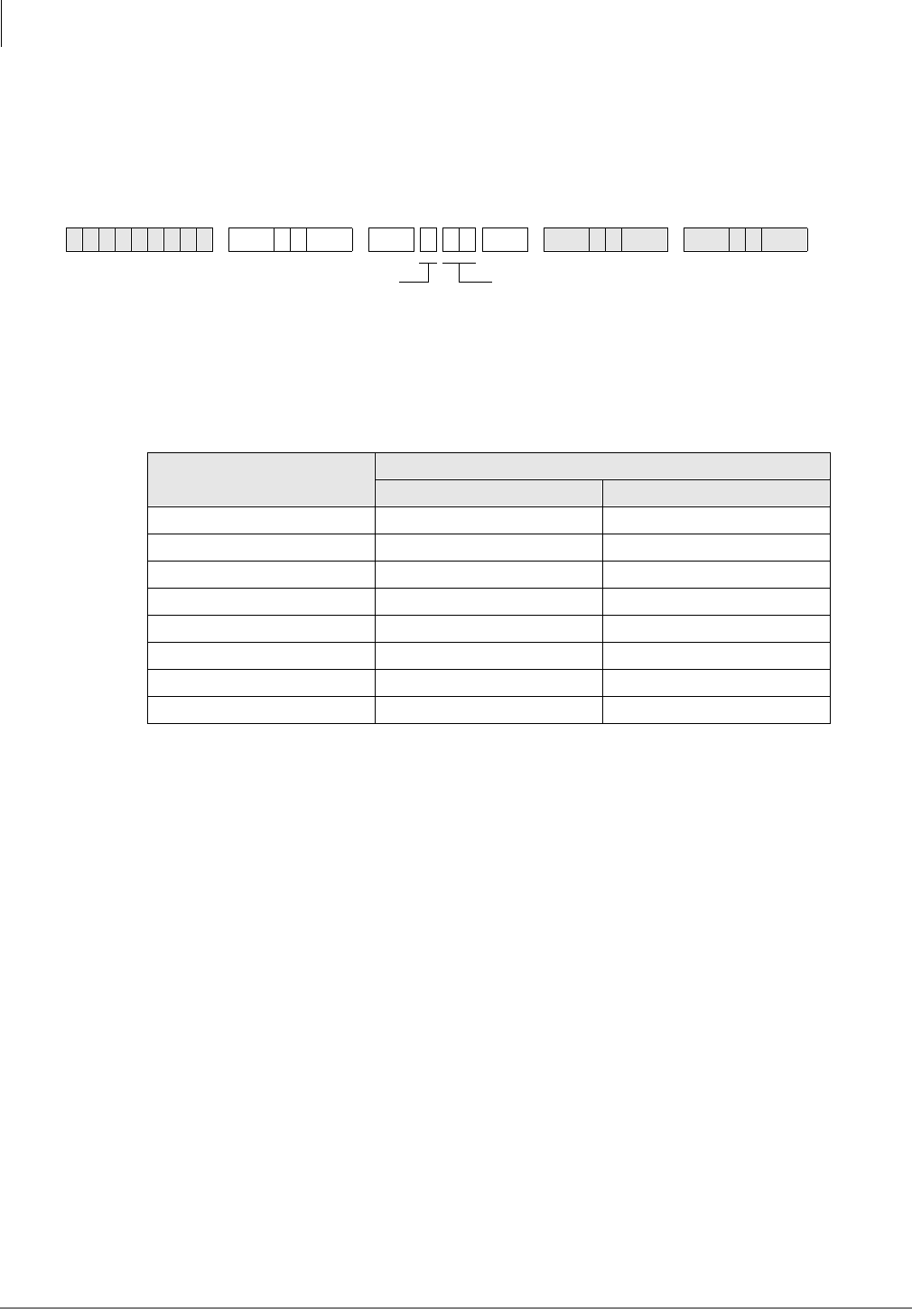
Toll Restriction
Program 42-1~8 – PBX/Centrex Access Codes
4-10 Strata DK Programming 5/99
Program 42-1~8 – PBX/Centrex Access Codes
Processor Type:
DK14, DK40i, All RCTUs
Program Type:
Toll Restriction
Initialized Default:
Assigns no access codes to PBX groups
Program 42-1~8 Overview
The Centrex access code(s) used to make out-of-centrex calls (usually 9) is entered in this table.
Use this program to allow correct Toll Restriction and Centrex/PBX transfer operation.
Do not use this program when using LCR behind Centrex/PBX; use Program 45-2 instead. Also,
do not use this program if installing CO lines behind “assume-9” Centrex.
6SNU +ROG 6SNU +ROG6SNU +ROG 6SNU +ROG
PBX/Centrex Access Code
Number
PBX/Centrex Outgoing CO Line Access Code(s)
1st Digit 2nd Digit
1
2
3
4
5
6
7
8
ACCESS CODE = Enter a 2-digit access code for the group,
as defined by the table below.
• If access code is single digit, enter the first digit and press
LED Button 01 as second digit.
• Press LED Button 01 to delete digit.
• Press LED Button 02 for Wild Card digit (any digit, 0~9). For
example, pressing + LED Button 02 allows 80~89.
SELECT = 1~8 PBX Access Code Group
Enter the PBX Group Number 1~8 that needs
an access code assigned.
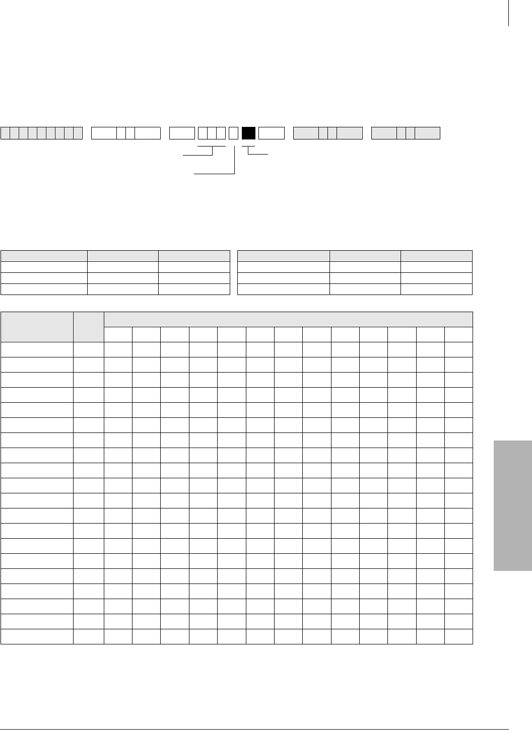
Toll Restriction
Program 43 – 0 + Credit Card Dialing Option
Strata DK Programming 5/99 4-11
Toll Restriction
Program 43 – 0 + Credit Card Dialing Option
Processor Type:
DK14, DK40i, All RCTUs
Processor Type:
Toll Restriction
Initialized Default:
All LEDS OFF
6SNU +ROG 6SNU +ROG 6SNU +ROG 6SNU +ROG
Processor CO Line Range [PDN] Port Range Processor CO Line Range [PDN] Port Range
DK14 001~004 000~009 RCTUBA/BB 001~048 000~079
DK40i 001~012 000~027 RCTUC/D 001~144 000~239
RCTUA 001~016 000~031 RCTUE/F 001~200 000~335
CO Line LED Port
20
19
18
17
16
15
14
13
12
11
10
09
08
07
06
05
04
03
02
01
LED Buttons = CO lines
Assigned to allow dial 0+ calls with
selected stations.
SELECT = Station Logical Port Numbers
Press 6FUROO to advance or 3DJH to go back.
After programming, press:
•9RO▲ to turn all LEDs ON
•9RO▼ to turn all LEDs OFF
•0RGH + CO line number, then to display and advance

Toll Restriction
Program 43 – 0 + Credit Card Dialing Option
4-12 Strata DK Programming 5/99
Program 43 Overview
This program enables selected station users to bypass their normal Toll Restriction assignments by
dialing “0” immediately after seizing a CO line. Both the station and the line must be enabled for
this feature with this program.
After seizing the line, the station user is required to dial a specific number of digits, which includes
the leading 0. This digit-length requirement forces the user to dial a telephone number or a
telephone number plus a credit card number. As a result, these calls are billed to the credit card,
and operator-placed calls are not billed to the line. The digit length, 1~30 numbers, is set in
Program 60-7. This length is determined by the system’s call routing method.
If the number of digits set in Program 60-7 are not dialed, the call will be cut off 20 seconds after
the last digit is dialed.
When not dialing via LCR, the digit length should usually be 25 which is the sum of the digits in
the telephone (11) and credit card (14) numbers. When using LCR, a digit length of 11 is
recommended.
Stations that are enabled with 0 + credit card calling should not be restricted for dialing 0 or 01 in
Programs 46 (10~80) and 48.
Important! More digits than the length set in Program 60-7 are allowed to be dialed; there is no
limit to the amount of digits that can be dialed.
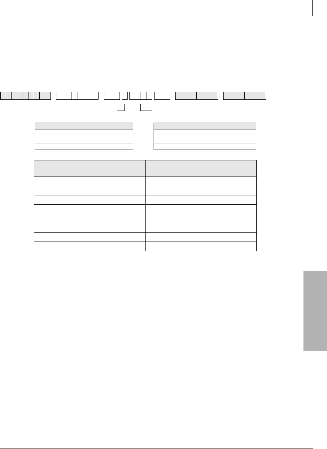
Toll Restriction
Program 44-1~8 – Toll Restriction/Traveling Class Override Codes
Strata DK Programming 5/99 4-13
Toll Restriction
Program 44-1~8 – Toll Restriction/Traveling Class
Override Codes
Processor Type:
DK14, DK40i, All RCTUs
Program Type:
Toll Restriction
Initialized Default:
All Classes Blank (no code)
Program 44-1~8 Overview
This program enables you to assign a code for each of the Toll Restriction classes established in
Program 46. If one of these codes is entered at a station, the station assumes the code’s class for
that call. When the call is complete, the station returns to its regular class assigned in Program 48.
The Traveling Class code data is not sent out the SMDR port and does not print out on station call
records. Account Codes (Forced or Voluntary) can also be used for this function, in which case the
Account Code will print out on SMDR (see Programs 69 and 70).
Notes
●Stations selected in Program 30, LED 16 ON, can add, change, or delete the codes set in
Program 44-1~8.
●When the Toll Restriction Override code is dialed, the station's class (defined in Program 48)
changes to the class assigned to the code in Program 44-1~8.
●Do not use the same codes set in Program 45 (8 and 9).
●Stations enabled in Program 30, Button/LED 16 ON, are allowed to enter and change Toll
Restriction Class (1~8) override codes.
6SNU +ROG 6SNU +ROG6SNU +ROG 6SNU +ROG
Processor Toll Restriction Class Processor Toll Restriction Class
DK14 1~4 RCTUBA/BB 1~4
DK40i 1~4 RCTUC/D 1~8
RCTUA 1~4 RCTUE/F 1~8
Toll Restriction Class
SELECT = DATA = (1~4 Digit Code)
1
2
3
4
5
6
7
8
DATA = Toll Restriction Code for Selected Class (1~4 digits)SELECT = Toll Restriction Class 1~8
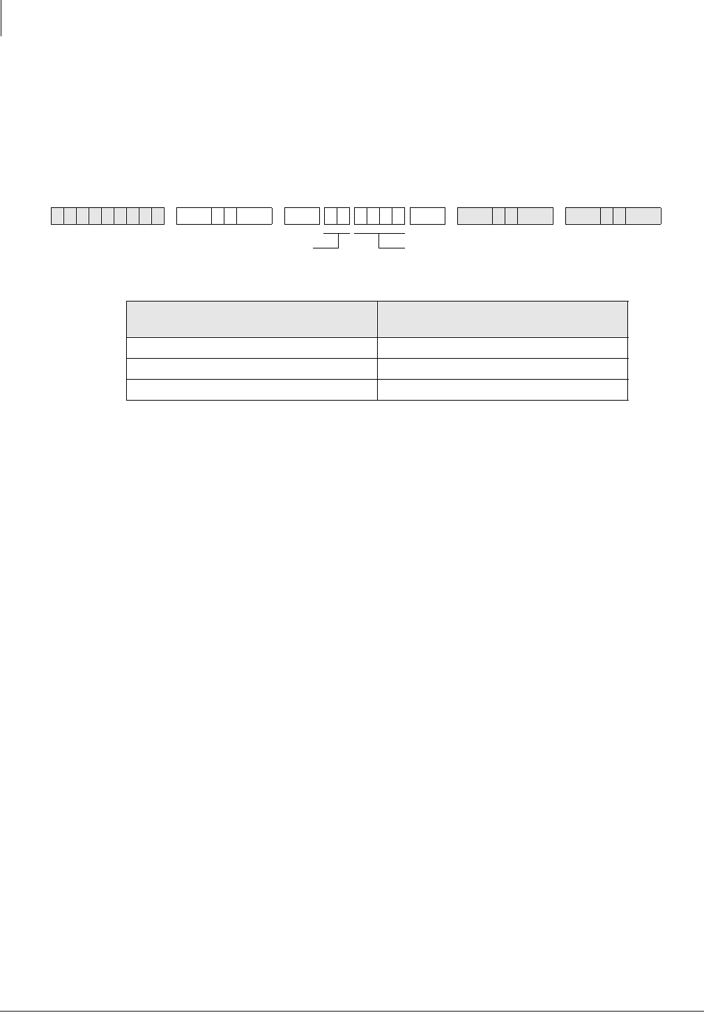
Toll Restriction
Program 44-91~93 – Emergency Bypass of Forced/Verified Account Codes
4-14 Strata DK Programming 5/99
Program 44-91~93 – Emergency Bypass of Forced/
Verified Account Codes
Processor Type:
DK14, DK40i, All RCTUs
Program Type:
Toll Restriction
Initialized Default:
Code 91 = 911, Codes 92 and 93 are blank
Program 44-91~93 Overview
This program exempts as many as three special numbers, each up to four digits (such as the
emergency 911 number), from Verified Account Code dialing restrictions. When dialed, these
numbers are sent out immediately, bypassing any Verified Account Code dialing restrictions set in
Programs 69 and 30, button/LEDs 8 and 14, respectively. If Verified Account Codes assigned in
Program 69 conflict (duplicate) with emergency or other type telephone numbers set in Program
44-91~93, Program 44-91~93 has priority.
If lines are behind Centrex or PBX, program the appropriate one- or two-digit Centrex/PBX line
access code in front of the emergency number.
Notes
●Do not use this program with ABR and DISA.
●This program does not override Toll Restriction. Emergency numbers must be put in
“allowed” tables in the normal Toll Restriction programming procedures.
●If Enhanced 911 (E911) is required, use E911 Programs in place of 44-91~93.
6SNU +ROG 6SNU +ROG6SNU +ROG 6SNU +ROG
Emergency Number (1~3)
SELECT = DATA = (1~4 Digit Telephone Number)
91 911 (default)
92
93
If CO lines are behind PBX or Centrex, program the PBX/Centrex outside CO line access code.
Example: “9”. A pause is automatically inserted following the first 9.
See Programs *45-2 to assign the CO line and access code for behind PBX/Centrex operation.
Also, if the system CO lines are behind Centrex/PBX, the Centrex/PBX CO line access codes
must be programmed in front of the emergency telephone number. Example: If the Centrex/PBX
access code is “9”, then enter 9911 in Program 44-91.
DATA = Emergency Telephone Number (1~4 digits)
To enter blanks, press LED Button 01.
SELECT = 91~93
to set Emergency Number 1~3
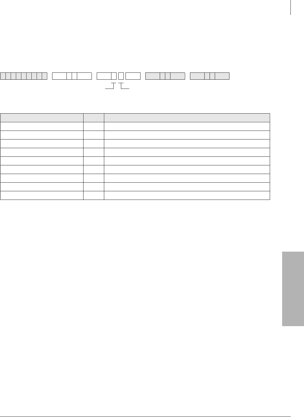
Toll Restriction
Program 45-1 – LCR/Toll Restriction Dial Plan
Strata DK Programming 5/99 4-15
Toll Restriction
Program 45-1 – LCR/Toll Restriction Dial Plan
Processor Type:
DK14, DK40i, All RCTUs
Program Type:
Toll Restriction
Initialized Default:
Assigns Dial Plan 7 to the system (current North American Numbering Plan)
Where:
Program 45-1 Overview
This program enables you to define a dial plan for the Toll Restriction software to recognize the
typical dialing sequence of long distance/local calls made from the system’s home area code, and
to identify area and office codes. The dialing plan defines several components of a telephone
number for long distance calling
Notes
●Setting the proper dialing plan in this program is also required for the Least Cost Routing
feature to function properly.
6SNU +ROG 6SNU +ROG 6SNU +ROG 6SNU +ROG
XPlan Toll Restriction/LCR Dial Plans
9(101XXXX)+1+NXX+NXX/NXX
8(101YXXX)+1+NXX+NXX/NXX
7(10XXX)+1+NXX+NXX/NXX
6For UK only.
50+ (0+ and universal (Codes 5 and 4) are not used in USA.)
4Universal (0+ and universal (Codes 5 and 4) are not used in USA.)
3(10XXX)+1+AC+NXX/NXX
2(10XXX)+1+AC+NXX/1+NNX
1(10XXX)+AC+NXX/1+NNX
In NXX and NNX,
X =
N = 0~9
2~9
NXX = Office code (interchangeable with area and office codes; second digit can be
0~9)
NNX = Office code (not interchangeable; second digit cannot be 1 or 0)
AC = Area Code
1+ NNX = 1 may be dialed before office codes
10XXX = old 5-digit Carrier Access Codes
101YXXX/101XXXX = new 7-digit Carrier Access Codes
Y = 0, 5 or 6
DATA = Plan 1~9
Enter Codes 1~9 to indicate the
dial plan for the system.
SELECT = 1

Toll Restriction
Program 45-1 – LCR/Toll Restriction Dial Plan
4-16 Strata DK Programming 5/99
●The Strata DK System automatically restricts direct dialing of 10XXX+1 and 10XXXXX+1
access codes to any station that is toll restricted. These codes are allowed in system speed dial
and LCR modified digit tables. This is necessary to control Long-Distance-Carrier access.
10XXX+0 and 10XXXXX+0 are allowed/denied depending on the station’s class and Program
46 (10~80) button/LED 01 assignment.
Pre-January 1995 North American Numbering Plan (NANP)
Plans 1~6 use numbering plans for systems that do not use the NANP established January, 1995.
DK14, DK40i, and all DK424 RCTUs provide plans 1~9.
Long Distance Prefix 1 in most areas must be the first digit dialed for long distance calling. In
such areas, the area code is dialed right away. The dial plan defines whether the prefix 1 is required
for a particular installation’s long distance calling.
Area/Office Code Numbering Schemes—In most places, the middle digit of an area code is 0 or
1, and the middle digit of an office code is 2~9. Toll Restriction examines the first three-digit
sequence dialed and determines whether it is an area code or an office code.
♦If the middle digit is 0 or 1, then the sequence is an area code.
♦If the middle digit does not equal 0 or 1, then the sequence is an office code, and the office
code parameters of the selected dialing plan apply.
An exception to this rule exists. In some places, area and office codes are interchangeable. The
middle digit is always 0 or 1 (see Code 3 selection). In such a case, the system only knows that
three digits dialed are an area code if 1 is dialed before them. If 1 is not dialed first, the system
knows the three digits are an office code. The dial plan defines the numbering scheme applicable
to the installation site.
Special Common Carrier Number and Digit Length - for SPCC numbers of the form 950-
XXXX, this program can allow credit card calling but will restrict the maximum number of digits
dialed to prevent defeat of Toll Restriction.
Plan 1
Older Strata DK Systems use Plan 1 for dialing plan AC+NXX/1+NNX if the installation is in a
location where a user places a long distance call to a destination outside the area code without
dialing 1 before dialing the area code. The user places a long distance call to a destination in the
same area code by dialing 1 directly before the office code.
♦The first three digits of a ten-digit number is an area code if the middle digit is 0 or 1.
♦Pressing the first three digits immediately after a 1 in an eight-digit string is an office code
♦A seven-digit string starting with an office code is a local call.
Plan 2
♦Plan 2 is 1+AC+NXX/1+NNX. Use this plan where a user places a long distance call to a
destination outside the area code by dialing a 1 before dialing the area code. The user places a
long distance call to a destination in the same area code by dialing a 1 directly before the office
code
♦When using this plan, the system recognizes the following:
♦The first three digits following a 1 in an 11-digit number are an area code, if the middle
digit is 0 or 1.
♦The first three digits dialed immediately after a 1 in an eight-digit string is an office code.

Toll Restriction
Program 45-1 – LCR/Toll Restriction Dial Plan
Strata DK Programming 5/99 4-17
Toll Restriction
Plan 3
♦Plan 3 is 1+AC+NXX/NXX. Use this plan where a user places a long distance call to a
destination outside the area code by dialing a 1 before dialing the area code. The user places a
long distance call to a destination in the same area code by simply dialing the number, without
a 1 in front. The office codes are interchangeable. The system differentiates between them
whenever it sees the digit 1 dialed.
When using this plan, the system recognizes the following:
♦If 1 is the first number entered in an 11-digit string, the next three digits are an area code.
♦A 10-digit string is not recognized.
♦The first three digits in a seven-digit string are an office code. (There is no distinction
between local call dialing and long distance dialing within the area code.)
♦Digits 5~7 in an 11-digit string may be an interchangeable office code as well.
Plans 4~6
Not used in the United States.
Post 1995 North American Numbering Plan (NANP)
Plans 7~9 use the NANP established January 1995. DK14, DK40i, and all DK424 RCTUs provide
plans 7~9.
♦Prefix 1 is used only when followed by an area code. The area code can be the home area code,
depending on the telephone company’s plan in that state.
♦Area/Office code numbering schemes – All area codes and office codes will have the format
NXX, making the new plan have both interchangeable area codes as well as interchangeable
office codes.
♦Intra-area code toll calls can be according to a seven-digit only plan in some states. In this
case, a seven-digit call may be a local call or a toll call. Therefore, only particular office codes
can determine a toll call for a seven-digit call, not the dial plan in 45-1.
Changing System Dialing Plan for NANP from a Station
For NANP upgraded SW version, the dial plan can also be changed from the station port 000
(default station 10, 100, or 200).
➤To change the System Dialing Plan for the North American Dialing Plan
1. With the handset on-hook,
press a [DN] + .You hear a confirmation tone. X is
the current system dialing plan 1, 2,
3, 7, 8, or 9.
2. Enter . You hear a confirmation tone.
3. Enter the one-digit (X) for
the system dialing plan (X
= 1, 2, 3, 7, 8, or 9).
You hear a confirmation tone.
NANP=X KEY CODE=
CODE=6267 NANP=
CODE=6267 NANP=X

Toll Restriction
Program 45-1 – LCR/Toll Restriction Dial Plan
4-18 Strata DK Programming 5/99
Plan 7 - (10XXX)+1+NXX+NXX/NXX
The Strata DK systems in this Programming Manual default to this plan. Used when dialing 1
before the long distance number. Call is placed to a destination outside the area code by dialing a 1
before dialing the area code.
The user places a local code plus distance call to a destination in the same area code by simply
dialing the number, without a 1 in front. The area and office codes may be interchangeable. The
system differentiates between them whenever it sees the digit 1 dialed. This plan supports five-
digit Carrier Access (CA) codes (10XXX) compared to seven-digit CA codes.
When using this plan, the system recognizes the following:
♦If 1 is the first number dialed in an 11-digit string, the next three digits are an area code
(+$&+ 7 digit number). A ten-digit string is not recognized ($&+ 7 digit number).
♦Digits 2~4 and 5~7 in an 11-digit string are NXX format and are interchangeable.
♦The first three digits in a seven-digit string are an office code. (There is no distinction between
local call dialing and long distance dialing within the area code.)
♦If 16-digit dialing (Area Code + 7 digits) is required to be unrestricted and routed over the
local LCR route, program the Area Code in Program 46-2~4 and Program 45-2.
Plan 8
Same as Plan 7 except a new 7-digit carrier access code must be 101YXXX format (where Y is 0,
5 or 6; X is 0 to 9).
Plan 9
Same as Plan 7 except a new 7-digit carrier access code must be 101XXXX format (where X is 0
to 9).
Area codes and office codes in XXX format (where X is 0 to 9) are allowed to be programmed in
the area code and office code tables for Toll Restriction and Least Cost Routing purposes.
Only area codes formatted N(0/1)X and office codes formatted NNX are valid on call processing
for the old dial plans 1, 2, 3.
New area codes NXX are valid only in NANP dialing plans 7, 8, 9.
Office codes of the form NNX and NXX are valid on call processing for the old dialing plans 1, 2,
3, and new dialing plans 7, 8, 9, respectively. For international calls, area code 011 and office
codes XXX (as country codes) are valid on the call processing for all dialing plans.
4. Press 5HGLDOor 5'/. The telephone returns to the idle
mode.
5. Press 6SNU.
DATA PROGRAMMED
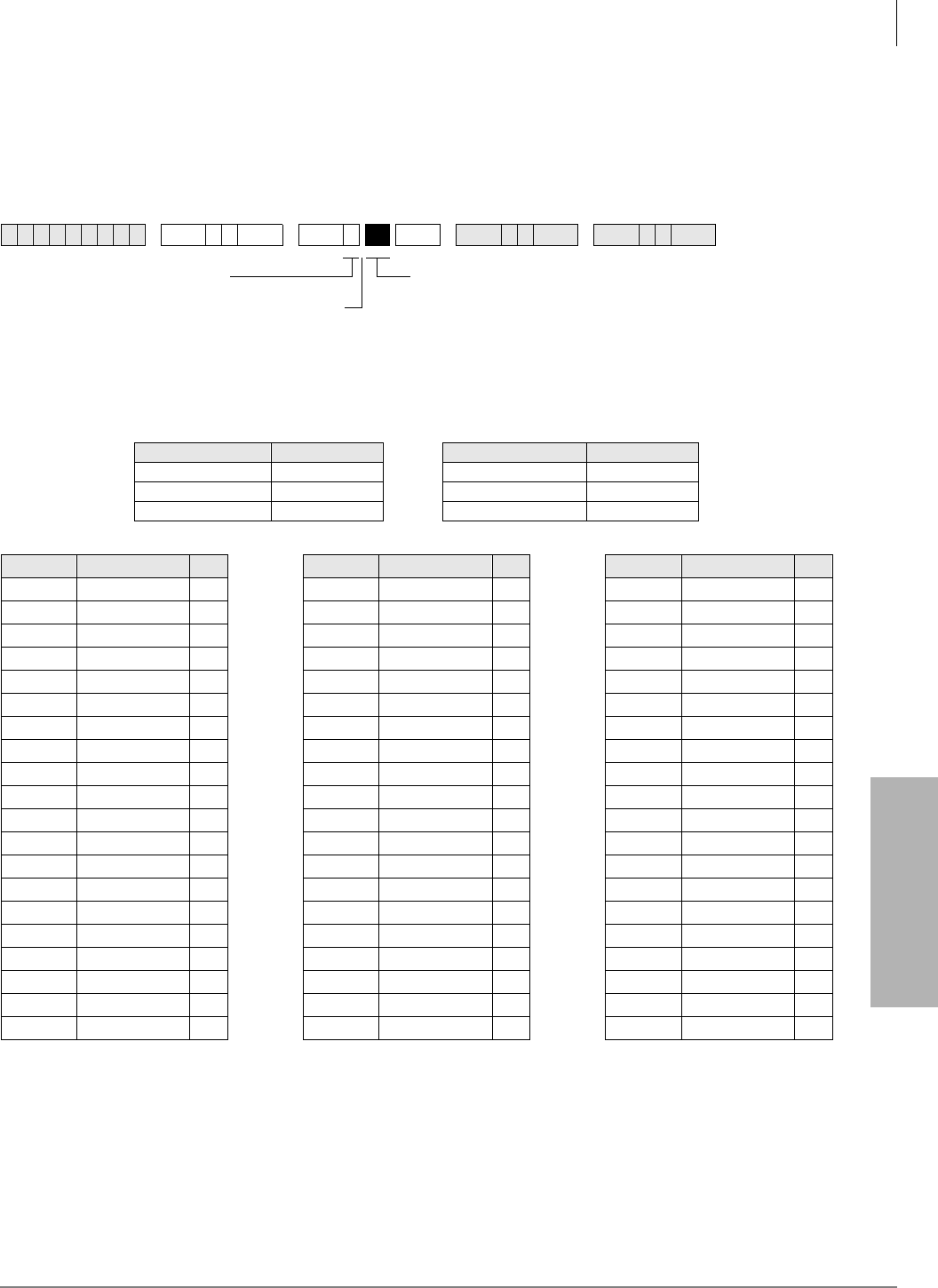
Toll Restriction
Program 45-2 – Toll Restriction Disable
Strata DK Programming 5/99 4-19
Toll Restriction
Program 45-2 – Toll Restriction Disable
Processor Type:
DK14, DK40i, All RCTUs
Program Type:
Toll Restriction
Initialized Default:
All LEDs OFF for all CO lines (all lines apply Toll Restriction)
Program 45-2 Overview
This program enables you to program lines be exempt from any Toll Restrictions defined in this
section. Mark the exempt lines with an X on the record sheet. Toll Restrictions disabled in this
program override Station Toll Restrictions defined in Program 48.
6SNU +ROG 6SNU +ROG 6SNU +ROG 6SNU +ROG
Processor CO Line Range Processor CO Line Range
DK14 001~004 RCTUBA/BB 001~048
DK40i 001~012 RCTUC/D 001~144
RCTUA 001~016 RCTUE/F 001~200
LED CO Line XLED CO Line XLED CO Line X
20 20 20
19 19 19
18 18 18
17 17 17
16 16 16
15 15 15
14 14 14
13 13 13
12 12 12
11 11 11
10 10 10
09 09 09
08 08 08
07 07 07
06 06 06
05 05 05
04 04 04
03 03 03
02 02 02
01 01 01
LEDs/Buttons
Specify CO lines by setting LED Buttons as defined by
the table below. All LEDs with an X should be lit when
finished.
ON = Disable Toll Restriction
SELECT = 2
Press 6FUROO to advance or 3DJH
to go back.
After programming, press:
•9RO▲ to turn all LEDs ON
•9RO▼ to turn all LEDs OFF
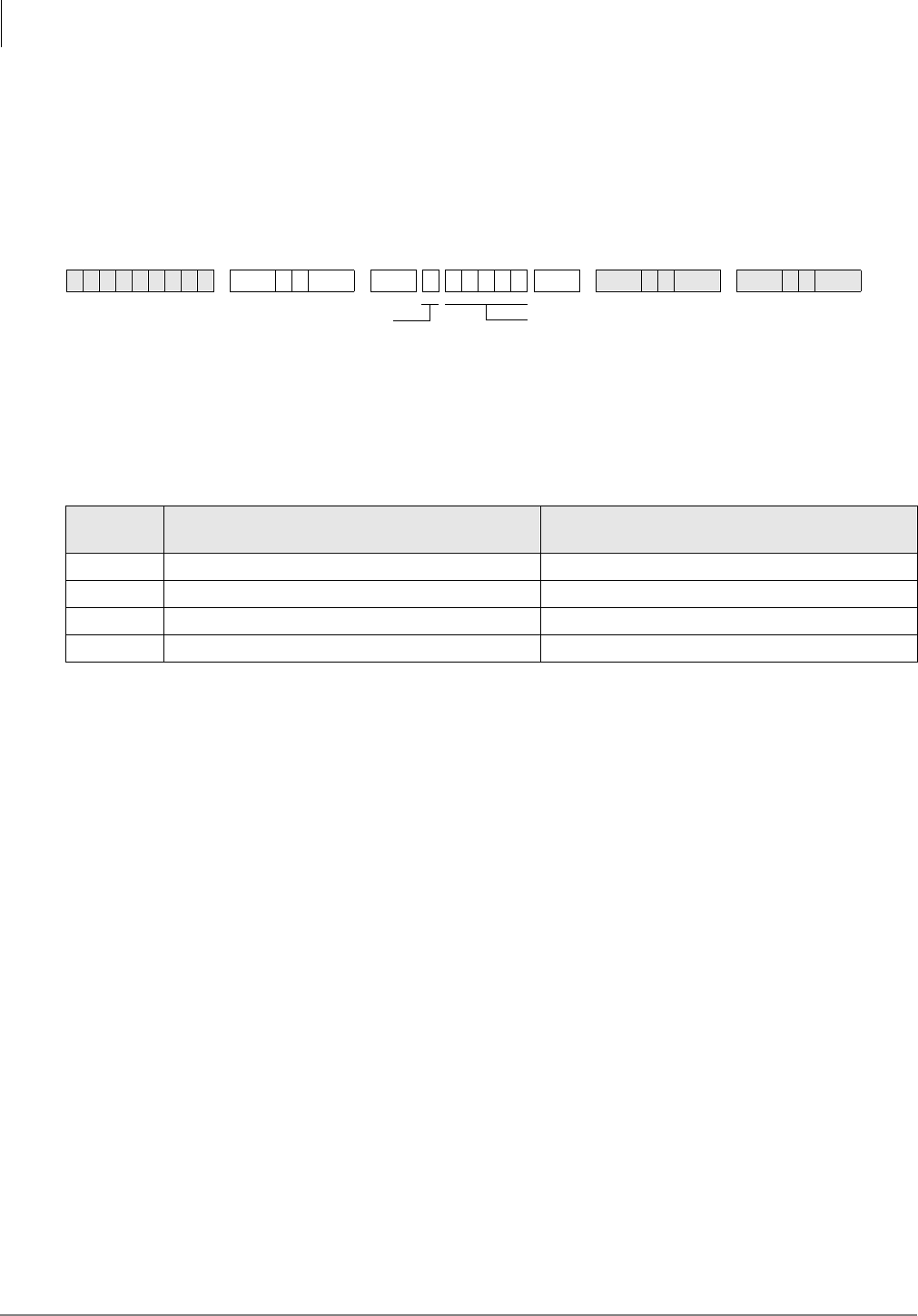
Toll Restriction
Program 45-3~6 – Special Common Carrier Numbers and Authorization Code Digit Length
4-20 Strata DK Programming 5/99
Program 45-3~6 – Special Common Carrier Numbers
and Authorization Code Digit Length
Processor Type:
DK14, DK40i, All RCTUs
Program Type:
Toll Restriction
Initialized Default:
Assigns blank data to Items 3 and 5 and “00” data to Items 4 and 6.
Program 45-3~6 Overview
This program notifies the system of how many digits to ignore before it applies Toll Restriction. It
allows the system to use Special Common Carrier (SPCC) authorization codes to modify
restrictions when the station user is dialing a long distance carrier. The user enters a telephone
number to access the carriers. Original restrictions re-activate after the carrier number is dialed.
The sequence is: the first five digits of the SPCC Number (950XXXX) + Telephone Number +
Credit Card Authorization Code.
SMDR prints out the following: SPCC Number + ---- + Telephone Number (the Authorization
Code does not print out. If the SPCC access code is a 1+800 number, the dialed SPCC code will
overwrite the actual telephone number dialed on the SMDR report.
Do not set 10XXX or 101XXXX Carrier Access Codes (CACs) in this program. The DK Strata
system automatically treats CACs as special codes and applies Toll Restriction and LCR as
follows:
♦For stations that are Toll Restricted, 10XXX+1/101XXXX+1 are restricted for manual dialing
but are allowed in system speed dial and LCR modified digit tables.
♦10XXX+0/101XXXX+0 are allowed or denied depending on the station’s class and 46 (10-80)
Key 01 assignment.
♦LCR always routes 10XXX and 101XXXX via the local route plan, if not restricted.
6SNU +ROG 6SNU +ROG6SNU +ROG 6SNU +ROG
Item Description DATA = 1st five digits
(SPCC Number or Digit Length)
3SPCC1 Telephone Number
4Allowed Digit Length (00~99)
5SPCC2 Telephone Number
6Allowed Digit Length (00~99)
DATA =
First five digits of the SPCC number, or digit length
specified in the table below.
When editing:
• Press to move cursor.
• Press LED Button 01 to delete or leave a blank.
• Press LED Button 02 to allow all digits to work.
SELECT = Item 3~6
Enter the Item number
3~6 from the table below.

Toll Restriction
Program 45-3~6 – Special Common Carrier Numbers and Authorization Code Digit Length
Strata DK Programming 5/99 4-21
Toll Restriction
There are two elements Toll Restriction software must verify for a user to successfully complete
long distance calling:
♦The first five digits of the number dialed to access the long distance special common carrier
(SPCC).
♦The total number of digits allowed following the SPCC number.
Items 3 and 5
Enter the first five digits of the SPCC telephone number in the spaces labeled SPCC1 Telephone
Number (Item 3) or SPCC2 Telephone Number (Item 5) on the record sheet. The initialized state
assigns “00000” to Items 3 and 5.
Items 4 and 6
The allowed digit length is the total number of digits allowed to be dialed after the SPCC Number
and before Toll Restriction Digit Restriction activates. This can be 00~99 digits. In most cases, 99
digits should be allowed for voice mail applications. Do not enter a digit length greater than
necessary or users may be able to override Toll Restriction.
Initialized data assigns “00” to items 4 and 6. Enter two digits on the record sheet.
A restricted station is not able to place a toll call through a long distance carrier by dialing the
SPCC1 or SPCC2 telephone number if the station is denied from that number in other toll
restriction programs. Upon recognizing the first five digits dialed, Toll Restriction software is
notified to allow the number of digits programmed in items 4 or 6 (00~99, following the including
the dialed SPCC1 or 2 number).
The system interprets data to be a seven-digit local call or 1-800 number to an SPCC. Only five
digits are entered; therefore, the last digits are “wild card” digits; any number dialed that has the
same first five digits as the carrier’s SPCC number, the system will assume the SPCC is being
called.
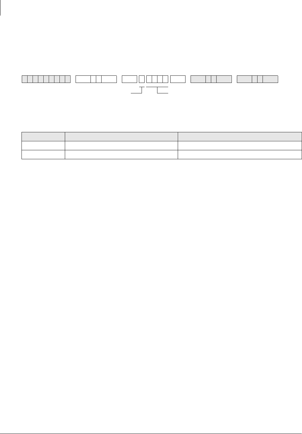
Toll Restriction
Program 45-8~9 – Toll Restriction Override Code
4-22 Strata DK Programming 5/99
Program 45-8~9 – Toll Restriction Override Code
Processor Type:
DK14, DK40i, All RCTUs
Program Type:
Toll Restriction
Initialized Default:
Leaves code assignments blank
Program 45-8~9 Overview
This program enables selected stations in the system to alter the override code. These stations are
defined by their users - specified in Program 30, Button/LED 09.
Two different codes can be dialed by any station user to override station-specific restrictions.
These codes will not register on SMDR.
To change the codes from selected stations:
Code 1: [PDN] + + code + 5HGLDO
Code 2: [PDN] + + code + 5HGLDO
Notes
●Do not use the same four-digit codes set in Program 44-1~8, Toll Restriction/Traveling Class
Override codes.
●Program 45 (8~9) overrides Program 44-1~8 if the same codes are used.
●Electronic telephone users can use the button instead of the 5HGLDO button.
●Verified Account Codes (Forced or Voluntary) can also be used to override Toll Restriction on
a call by call basis. When used for this function, the account code will register on the SMDR
report (see Programs 69 and 70).
6SNU +ROG 6SNU +ROG6SNU +ROG 6SNU +ROG
SELECT = Description DATA = (1 to 4 Digits)
8 (Code 1)
9 (Code 2)
DATA = Code
Enter 1 to 4-digit code from the table below.
Press LED Button 01 to delete or leave a blank.
Press LED Button 02 to allow all digits to work.
SELECT = Item 8 or 9
Enter 8 to select Code 1.
Enter 9 to select Code 2.
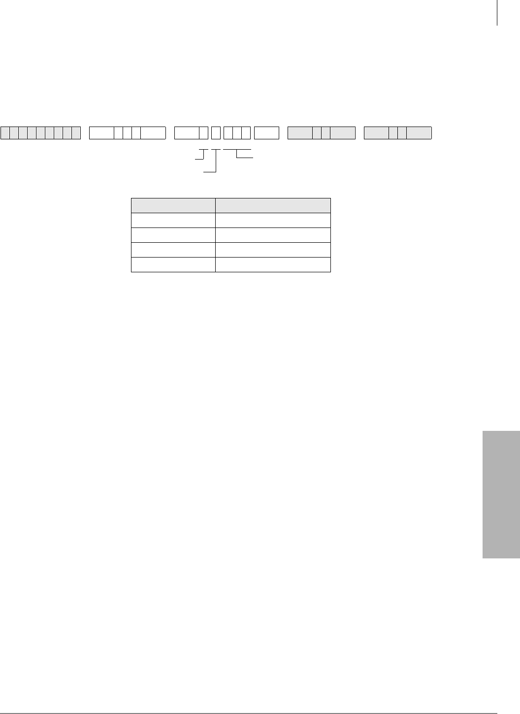
Toll Restriction
Program *45-1 (1~4) – Toll Restriction for Office Codes
Strata DK Programming 5/99 4-23
Toll Restriction
Program *45-1 (1~4) – Toll Restriction for Office Codes
Processor Type:
DK14, DK40i, All RCTUs
Program Type:
Toll Restriction
Initialized Default:
Assigns 976 to first office code - blank for other three office codes
Program *45-1 Overview
This program enables you assign up to four office codes to be restricted within all area codes. This
program only applies to telephone users which belong to toll restriction classes (assigned via
Program 48). If a telephone user does not belong to any class, he/she is not subject to any of the
restricted office codes assigned in this program.
The restricted office codes are verified when a user dials a seven-digit local call (in home area
code) or a “1” plus ten-digit long distance call (in any area code).
Notes
●Use this program with Program 45 Dial Plan 7, 8, or 9 only.
●This table applies to all stations with Program 48 TR Codes 03~10 only (TR classes 1~8); not
to stations with Program 48 TR Codes 00, 01, or 02.
6SNU+ROG 6SNU +ROG 6SNU +ROG 6SNU +ROG
SELECT = DATA = Office Code
1976
2
3
4
DATA = Office Code (3 digits)
Press LED Button 01 to delete a digit.
SELECT = 1
SELECT = 1~4
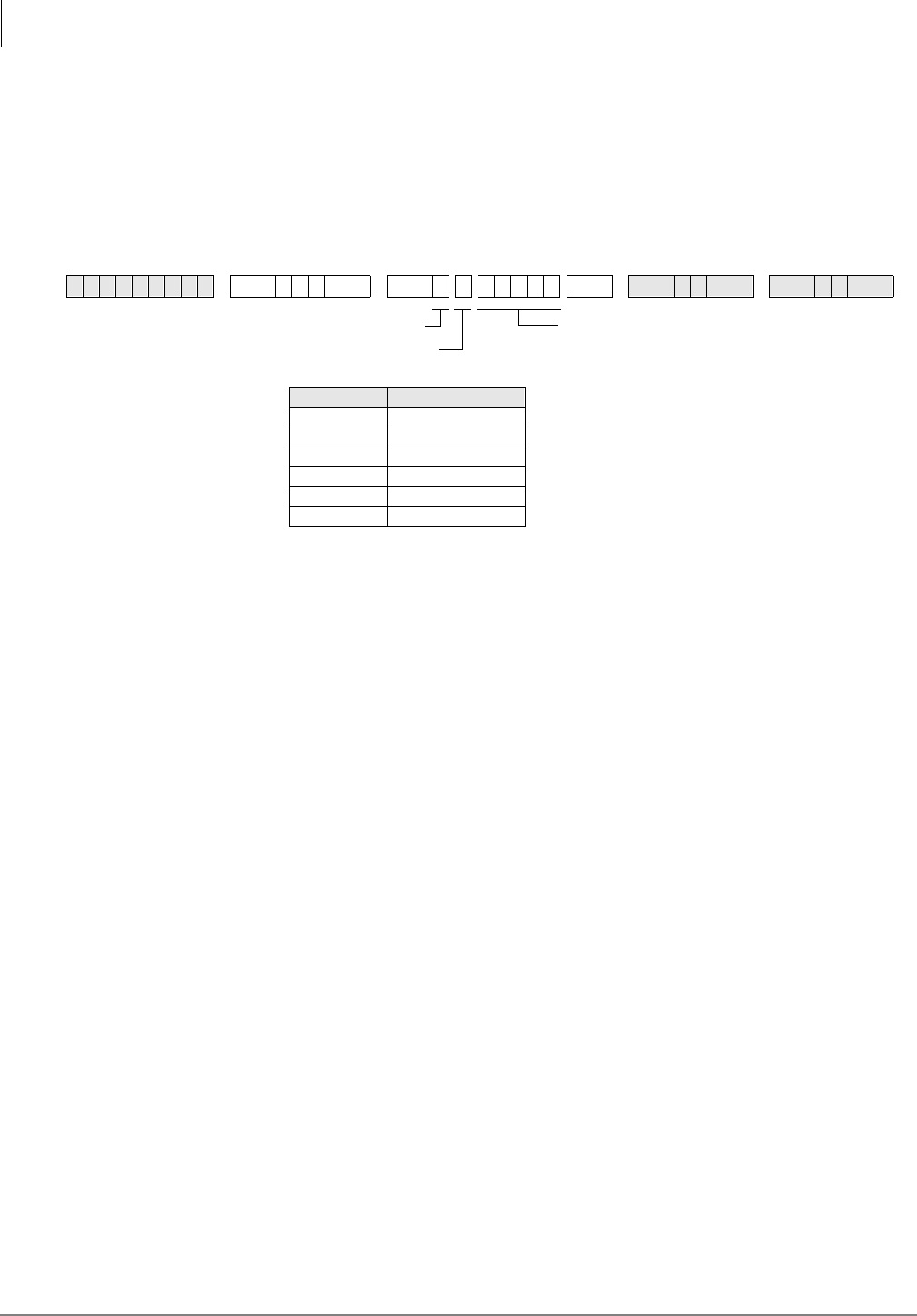
Toll Restriction
Program *45-2 (1~6) – LCR/Toll Restriction Bypass
4-24 Strata DK Programming 5/99
Program *45-2 (1~6) – LCR/Toll Restriction Bypass
for Special Numbers that Do Not Begin with */#
Processor Type:
DK14, DK40i, All RCTUs
Program Type:
Toll Restriction
Initialized Default:
All data blank
Program *45-2 Overview
Use this program to allow special CO Area Codes and Centrex feature access codes or extension
numbers to bypass toll restriction and route over the local LCR route - if using LCR. (Toll
Restriction is always applied after dialing the special numbers assigned to this table.
Codes programmed in this table will bypass Toll Restriction, and will be sent to the CO local route
if using LCR. Calls subject to toll restriction are normally restricted if “*” or “#” is pressed during
toll restriction digit analysis. However, in some special applications (e.g., the Strata DK System is
connected behind a PBX/Centrex, or assume_9 Centrex dialing), “*” and/or “#” may be required
within the first four digits or the last digit.
If the digit string containing */# matches with any of the six programmed digit strings of this
program, toll restriction is applied after the matched digit string. This program can also be used for
special area code dialing plans where the digit “1” is not dialed before the area code. See example
on the Program *45-2 Examples.
Notes
●If using LCR behind Centrex, enter the Centrex trunk access code (such as “9” entered in the
example below). If “9” is entered in this table, the user must dial 9 + 9 + 911 for an emergency
call when using LCR.
●The record sheet above allows up to 5-digit numbers. If the number to be entered is less than 5
digits, enter Blanks (Button 01) for all digits less than 5 digits.
Example (Centrex assume 9)
If using LCR behind “assume 9” Centrex, and restricted stations (1+AC not allowed) must dial
12XX# and 13XX# as Centrex station numbers (# is the Centrex end-of-dialing code for extension
numbers) enter + + %XWWRQ+ %XWWRQ+ and
+ + %XWWRQ + %XWWRQ+ as data in Programs *45-21 and *45-22, respectively.
6SNU+ROG 6SNU +ROG 6SNU +ROG 6SNU +ROG
SELECT = 2
SELECT = 1~6
DATA = 1~5 Digit Code
(that are not subject to toll restriction)
First Digit: 0~9 only
Non-first Digits: 0~9, ,
When editing:
• Press LED Button 01 to delete or leave a blank.
• Press LED Button 02 to allow all digits to work.
SELECT = DATA = 1~5 Digits
1
2
3
4
5
6

Toll Restriction
Program *45-2 (1~6) – LCR/Toll Restriction Bypass
Strata DK Programming 5/99 4-25
Toll Restriction
This will allow Centrex station numbers (1200#~1299# and 1300#~1399#) to de dialed -
overriding Toll Restriction. The call will route out the local LCR route immediately after the # is
dialed.
Use this record sheet to assign area codes in 10-digit dialing areas. If some non-toll numbers
require 10-digit dialing: Area Code (AC) + Office Code (OC) + YYYY dialing (no digit “1”
before the area code) enter the area code in this table if dialing through LCR. Area codes entered in
this table (without the long distance “1” prefix) will be routed over the LCR local call route when
dialed with the AC + OC + YYYY format (YYYY = 4-digit CO extension number).
Example (10-digit Dialing)
If area code 817 is a local area code that must be dialed without the prefix digit “1”, enter:
+ + + %XWWRQ+ %XWWRQ in Program *45-2X. With this entry, LCR will route 817
calls over the local route immediately after dialing: ;;;;;;; (10 digits).
This table applies to all stations with Program 48 TR Codes 03~10 only (TR classes 1~8); not to
stations with Program 48 TR Codes 00, 01, or 02.
Notes
●When editing the data field, use Button/LED 01 to end the digit string, Button/LED 02 to
assign a wild card value (0~9, *, #).
●See Program 46 (10~80) Button/LED 04 should be OFF when dialing codes containing * and/
or #.
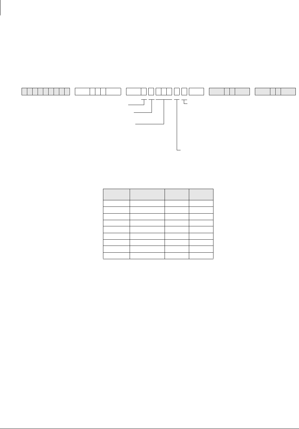
Toll Restriction
Program *45-3 (1~9) – LCR/Toll Restriction Bypass For Special Numbers that Begin with */#
4-26 Strata DK Programming 5/99
Program *45-3 (1~9) – LCR/Toll Restriction Bypass For
Special Numbers that Begin with */#
Processor Type:
DK14, DK40i, All RCTUs
Program Type:
Toll Restriction
Initialized Default:
All data blank
Program *45-3 Overview
Codes programmed in this record sheet are ignored by Toll Restriction and sent to the appropriate
route if using LCR. Calls started with “*” or “#” are normally not allowed. However, in some
special applications (e.g., Caller ID blocking), “*” or “#” might be the first digit before dialing the
actual destination’s telephone number. This program assigns up to nine such codes for toll
restriction bypass.
Digits dialed after the code starting with “*” or “#” are analyzed for toll restriction depending on
the option (0~3) assigned following the digit code. The option value 0 indicates that no Toll
Restriction applies to the telephone number dialed after the code is entered. The option value 1
indicates that Toll Restriction is applied as normal after the code entry. The option value 2
indicates that the call is restricted when the code is entered. The option value 3 applies LCR and
TR after the code entry.
Use this program to allow special CO or Centrex access codes that begin with the * or # prefix.
Assign them in this table if it is required to bypass Toll Restriction and/or route over the local LCR
route, if using LCR. (T.R. options 0~3 will be applied after dialing the special numbers assigned in
this table).
6SNU+ROG 6SNU +ROG 6SNU +ROG 6SNU +ROG
OPTION = 0~3
0 = No Toll Restriction after Special Code
1 = Toll Restriction after Special Code
2 = Special Code Restricted
3 = LCR + Toll Restriction after Special Code (R3.2)
SELECT = 3
SELECT = 1~9
SELECT =
(1~9) DATA = OPTION = OPTION =
1
2
3
4
5
6
7
8
9
OPTION = 0~4 (R4.15)
0 = Code is not valid in ISDN; is valid in analog line
1 = Privacy Change for ISDN; valid analog line
2 = Privacy Change for ISDN; not valid analog line
3 = No Privacy Change for ISDN; valid analog line
4 = No Privacy Change for ISDN; analog line not
valid
DATA = Digit String (1~3 digits)
When editing:
• Press LED Button 01 to end the digit string.
• Press LED Button 02 to allow all digits to work.
Do not enter or .

Toll Restriction
Program *45-3 (1~9) – LCR/Toll Restriction Bypass For Special Numbers that Begin with */#
Strata DK Programming 5/99 4-27
Toll Restriction
In the “Data = Digit String” part of the programming sequence, note that for two digit codes, such
as 87, 82, 67, Key (LED Button 01) must be pressed to get to the following “Option=” section. For
example, enter +ROG6SNUB ( _ = Press LED Button 01) + .
The Privacy Change option (0~4) enables the telephone user to override the setting for their own
telephone. For instance, if Privacy Change is enabled, then a user can press to allow their
Caller ID to be shown on the caller’s LCD.
Example 1
If using LCR behind Centrex and you must dial Centrex speed dial numbers~, enter
+ %XWWRQ+ %XWWRQ+ in Program *45-31. In this case, Toll Restriction will not be
applied after the Centrex speed dial number (;;) is sent to the Centrex because Option “0” is
set.
Example 2
If you are dialing out and you wish to block the Caller ID feature, you must dial or the
appropriate provider's code (e.g., , ). In this case, enter + + %XWWRQ+ in Table
*45-31. In this case, if the user dials + telephone number, then Toll Restriction and LCR is
applied to the telephone number after is dialed because Option “3” is set. Also, if you want to
override Privacy Change, for the fourth entry, Option “4”, enter a .
In this case, enter + + %XWWRQ+ in Table *45-31. In this case, if the user dials +
telephone number, then Toll Restriction and LCR is applied to the telephone number after is
dialed because Option “4” is set.
To allow or to be entered as a first digit, a number must be entered in at least one table of
Program 45-3X; do not enter and as the first digit of any number in Program *45-3X; Toll
Restriction assumes the number entered in this table begins with a or .
Important! To allow / to be dialed as a first digit, at least one number must be entered in
Program 45-3X.
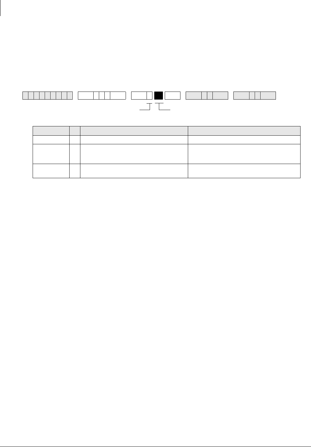
Toll Restriction
Program *45-4 – Special Code Dialing Sequence with LCR
4-28 Strata DK Programming 5/99
Program *45-4 – Special Code Dialing Sequence with
LCR
Processor Type:
DK424, all RCTUs (Release 4.1 and higher)
Program Type:
Toll Restriction and LCR
Initialized Default:
All LEDs OFF
Program *45-4 Overview
When LCR is used to make calls, this program determines if the codes set in Program *45-3 are
sent before or after the digits that are set in the modified digits table (MDT). See Programs 55-1
and 55-0.
Program *45-4 only works when the code of Program *45-3x is dialed. The length of the pause
inserted is determined by the timer setup in Program 12-3 (unit pause length of 1.5 or 3 seconds).
This program has no effect on outgoing calls without Program *45-3 codes.
The digit deletion function of the modified digits table (Program 55-0) applies to the digits that
immediately follow the Front Modified Digits Table (F-MDT).
LED 01: Pause following Program *45-3 code
If LED 01 is ON, a pause is inserted after the digits from Program *45-3 are sent; if LED 01 is
OFF, a pause is not inserted.
LED 02: Order of LCR bypass code and MDT
If LED 02 is ON, the code from Program *45-3 is inserted before the Front Modified Digits Table
(F-MDT) digits; if LED 02 is OFF, code from Program *45-3 is inserted after the
F-MDT digits. (See example on Page -28.)
If LED 02 is ON, digits are not deleted from the Program *45-3 code per Program 55-0; if LED 02
is OFF, digits are deleted from the Program *45-3 code per Program 55-0.
LCR Example
The table below shows the actual dial output digits at the time that LCR sends them. These output
digits are determined by the settings for LEDs 01 and 02. In this example, the user dials + code
+ telephone number.
6SNU+ROG 6 SNU +ROG 6SNU +ROG 6SNU +ROG
Button/LED XLED ON LED OFF
20~3 Not used. Not used.
02 Sends the digits from Program *45-3 before
the Programs 55-1 Modified Digits Table
(MDT) digits.
Sends the Programs 55-1 Modified Digits Table
(MDT) digits before the digits from Program *45-
3.
01 Inserts a pause into the dialing sequence. Does not insert a pause into the dialing
sequence.
SELECT = 4 Light the LED Buttons that are
marked with an X in the table below.

Toll Restriction
Program *45-4 – Special Code Dialing Sequence with LCR
Strata DK Programming 5/99 4-29
Toll Restriction
Program *45-4 LED 02 ON LED 02 OFF
LED 01 ON Code + Pause + F-MDT + number + E-MDT F-MDT + Code + Pause + number + E-MDT
LED 01 OFF Code + F-MDT + number + E-MDT F-MDT + Code + number + E-MDT
F-MDT = Added digits in Front of number dialed (Program 55-1)
E-MDT = Added digits at the End of number dialed (Program 55-2)
Code = Digits programmed in Program *45-3
Number = Dialed telephone number
9 = LCR access code
Pause = Pause time determined in Program 12-3
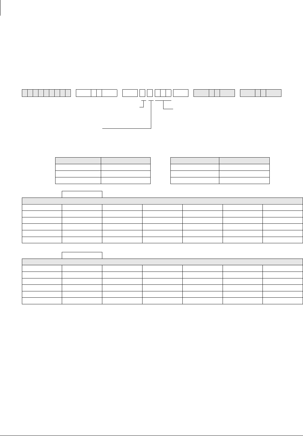
Toll Restriction
Program 46-2~4 – Toll Restriction Allowed/Denied Area Codes by Class
4-30 Strata DK Programming 5/99
Program 46-2~4 – Toll Restriction Allowed/Denied Area
Codes by Class
Processor Type:
DK14, DK40i, All RCTUs
Program Type:
Toll Restriction
Initialized Default:
Includes all area codes in all classes
♦Tables with deny box checked do not represent memory. All area codes in memory are allowed.
♦International calls may be allowed/denied by entering 011 as the area code. See Program 47 for International Call Restriction by
Country Codes.
Program 46-2~4 Overview
Each class area code provides for a different combination of restrictions.
The tables in this program define the area codes allowed or denied for each Toll Restriction class.
The tables (in memory) operate as allow tables. If an area code exists in a table (displays with 4#),
then it is allowed. Anything not displaying is not allowed. Initialized data allows all area codes for
each class (all codes are in all tables). All allowed area codes can be displayed (4#) for each class.
For each class, choose whether the record table is used to record allowed area codes in memory
(allowed) or denied area codes not in memory (denied). Enter the area codes that define the set.
6SNU +ROG 6SNU +ROG6SNU +ROG 6SNU +ROG
Processor Toll Restriction Class Processor Toll Restriction Class
DK14 1~4 RCTUBA/BB 1~4
DK40i 1~4 RCTUC/D 1~8
RCTUA 1~4 RCTUE/F 1~8
Class: (Check one) Allowed ❐Denied ❐
DATA = Area Codes
Class: (Check one) Allowed ❐Denied ❐
DATA = Area Codes
DATA = Area Codes
Enter or display area codes.
To add a range, enter XXXXXX (low area code
high area code).
Several ranges or individual area codes may be
entered by separating them with the # button.
SELECT = Toll Restriction Class
(see Legend below)
Enter: 2, 3, 4#
2 = add to memory
3 = Delete from memory
4# = Display allowed codes in
memory (press to scroll)
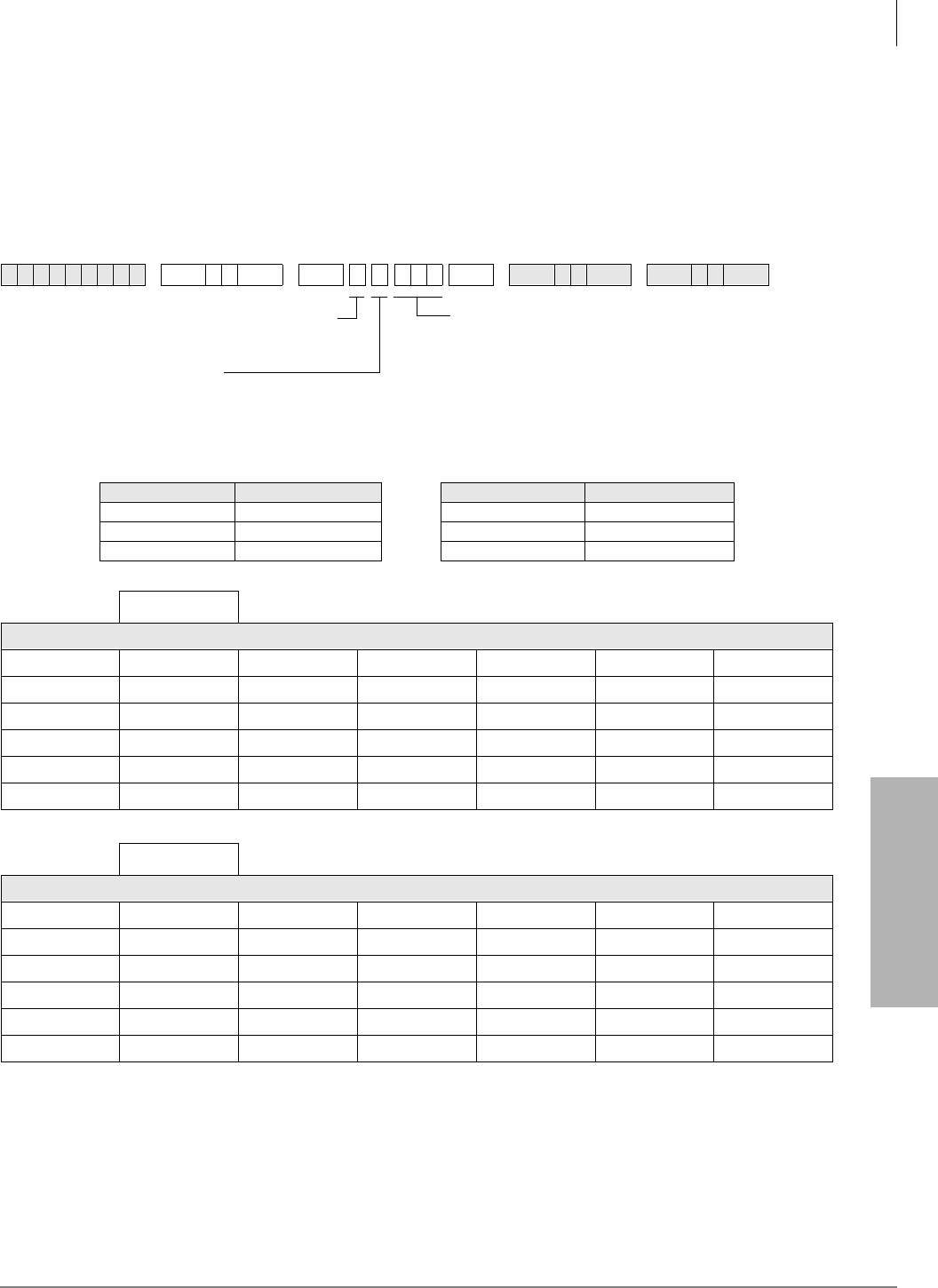
Toll Restriction
Program 46-6~8 – Toll Restriction Allowed/Denied Local Office Codes Assigned by Class
Strata DK Programming 5/99 4-31
Toll Restriction
Program 46-6~8 – Toll Restriction Allowed/Denied
Local Office Codes Assigned by Class
Processor Type:
DK14, DK40i, All RCTUs
Program Type:
Toll Restriction
Initialized Default:
Includes all office codes in all classes
♦Tables with deny box checked do not represent memory. All office codes in memory are allowed.
♦International calls may be allowed/denied by entering 011 as the area code. See Program 47 for International Call Restriction by
Country Codes.
6SNU +ROG 6SNU +ROG6SNU +ROG 6SNU +ROG
Processor Toll Restriction Class Processor Toll Restriction Class
DK14 1~4 RCTUBA/BB 1~4
DK40i 1~4 RCTUC/D 1~8
RCTUA 1~4 RCTUE/F 1~8
Class: (Check one) Allowed ❐Denied ❐
DATA = Office Codes
Class: (Check one) Allowed ❐Denied ❐
DATA = Office Codes
DATA = Office Codes
Enter or display office codes.
To add a range, enter XXXXXX (low office code
high office code).
Several ranges or individual office codes may be
entered by separating them with the # button.
SELECT = Toll Restriction Class
(see Legend below)
Enter: 6, 7, 8#
6 = add to memory
7 = Delete from memory
8# = Display allowed codes in
memory (press # to scroll)

Toll Restriction
Program 46-6~8 – Toll Restriction Allowed/Denied Local Office Codes Assigned by Class
4-32 Strata DK Programming 5/99
Program 46-6~8 Overview
This program defines the office codes allowed or denied for each Toll Restriction Class within the
home area code. Office code tables for each class can each describe office codes allowed or denied
for the class. The tables (in memory) operate as allow tables. If an office code exists in a table
(displays with 8#), then it is allowed. Anything not displaying is not allowed. Initialized data
allows all office codes in the home area code for each class.
For each class, choose whether the record table is used to record allowed office codes in memory
(allowed) or denied office codes not in memory (denied). Enter the office codes that define the set.
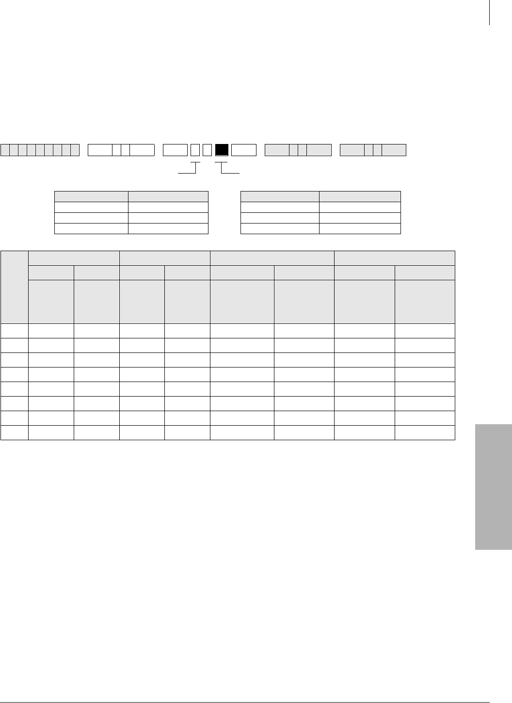
Toll Restriction
Programs 46-10~80 – Toll Restriction Class Parameters
Strata DK Programming 5/99 4-33
Toll Restriction
Programs 46-10~80 – Toll Restriction Class
Parameters
Processor Type:
DK14, DK40i, All RCTUs
Program Type:
Toll Restriction
Initialized Default:
All LEDs OFF
Programs 46-10~80 Overview
This program defines parameters of each Toll Restriction class, including dialing plan restrictions
and exceptions to previous restrictions. This program also relates to Program 47. See Program 47
for more explanation.
Run these programs for dial 0, 01, */# restriction and long distance information (555) assignments.
Toll Restriction exceptions and dialing plan restrictions may be defined for each class.
♦Programs 46-10 and 46-11 assign Class 1 restriction exceptions and parameters
♦Programs 46-20 and 46-21 assign Class 2
♦Programs 46-30 and 46-31 assign Class 3; etc.
LED 01: 0 Restricted
Mark an X next to LED 01 if operator or operator-assisted calls are restricted for the class being
defined. To allow 0 + dialing LED 01 must be OFF. Allowing 0 + dialing allows operator-assisted
toll calls. If a station is allowed 0 + Credit Card calling in Program 43, LED 01 must be OFF.
Program 43 will restrict operator assisted calls.
6SNU +ROG 6SNU +ROG 6SNU +ROG 6SNU +ROG
Processor Toll Restriction Class Processor Toll Restriction Class
DK14 1~4 RCTUBA/BB 1~4
DK40i 1~4 RCTUC/D 1~8
RCTUA 1~4 RCTUE/F 1~8
Class Number
Button 01 LED Button 02 LED Button 03 LED Button 04 LED
ON OFF ON OFF ON OFF ON OFF
Dial 0
Restricted Dial 0
Allowed Dial 01
Restricted Dial 01
Allowed
A/C+555 or 1+A/
C+555 Allowed
for all A/Cs
555 Allowed or
Denied per A/C
Restriction
TAble
Restrict
Numbers that
contain * or #
within the first
4 digits
Allow
Numbers that
contain * or #
within the first
4 digits
1
2
3
4
5
6
7
8
Turn LEDs 01, 02, 03, or 04 ON to select restriction option.Select Class from Legend below.

Toll Restriction
Programs 46-10~80 – Toll Restriction Class Parameters
4-34 Strata DK Programming 5/99
LED 02: 01 Restricted
Mark an X next to LED 02 if overseas operator or unassisted overseas operator calls are restricted
for the class being defined. If a station is allowed 0 + Credit Card calling in Program 43, LED 02
must be OFF. Program 43 will restrict 01 operator assisted calls.
LED 03: 1+AC+555 and AC+555 Allowed
Mark an X next to LED 03 to allow the particular class to call all restricted area codes plus the
office code of 555, including out-of-area directory assistance calls. Turning the LED off does not
necessarily deny information calls. This may also be accomplished in the office code table and/or
the area/office code exception tables.
LED 04: Restrict Numbers Containing * or # Within the First Four Digits
Numbers set in Program *45-2X override the #/* restriction function of Program 46 (10~80)
Button LED 04. LED 04 applies only to the first four digits of a dialed number when no digit
restriction (Code 0) is set for the station Toll Restriction class in Program 48.
Turn LED 04 ON only if Strata DK CO lines are connected to a Central Office that absorbs * and
# digits. The first four digits that contain # and * digits can be restricted (LED 04 ON). For
example: if LED 04 is ON, 17# is restricted when the # is dialed but 1751# is allowed because “#”
comes after the fourth digit dialed.
Turn LED 04 OFF if the telephone numbers that contain * and # after the first digit should be
allowed (see Programs *45-2 and *45-3).
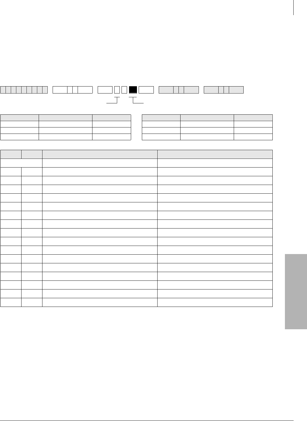
Toll Restriction
Programs 46-11~46-81 – Toll Restriction Class (1~8) Parameters
Strata DK Programming 5/99 4-35
Toll Restriction
Programs 46-11~46-81 – Toll Restriction Class (1~8)
Parameters
Processor Type:
DK14, DK40i, All RCTUs
Program Type:
Toll Restriction
Initialized Default:
Leaves all LEDs OFF
Programs 46-11~46-81 Overview
Run these programs for area/office code exception table assignments.
Refer to the legend above the record sheet for exception tables and classes. Exception tables for
both area and office codes will be defined in Program 47. Each class can be assigned any or all of
the available office code exception tables.
6SNU +ROG 6SNU +ROG 6SNU +ROG 6SNU +ROG
Processor Toll Restriction Class Exception Table Processor Toll Restriction Class Exception Table
DK14 1~4 8 RCTUBA/BB 1~4 8
DK40i 1~4 8 RCTUC/D 1~8 16
RCTUA 1~4 8 RCTUE/F 1~8 16
LED XLED ON LED OFF
20~17 Not Used
16 Table 16 Area/Office Exception Not Selected
15 Table 15 Area/Office Exception Not Selected
14 Table 14 Area/Office Exception Not Selected
13 Table 13 Area/Office Exception Not Selected
12 Table 12 Area/Office Exception Not Selected
11 Table 11 Area/Office Exception Not Selected
10 Table 10 Area/Office Exception Not Selected
9Table 09 Area/Office Exception Not Selected
8Table 08 Area/Office Exception Not Selected
7Table 07 Area/Office Exception Not Selected
6Table 06 Area/Office Exception Not Selected
5Table 05 Area/Office Exception Not Selected
4Table 04 Area/Office Exception Not Selected
3Table 03 Area/Office Exception Not Selected
2Table 02 Area/Office Exception Not Selected
1Table 01 Area/Office Exception Not Selected
Light LED Buttons as required to assign Table to Class.Select Class from Legend below.
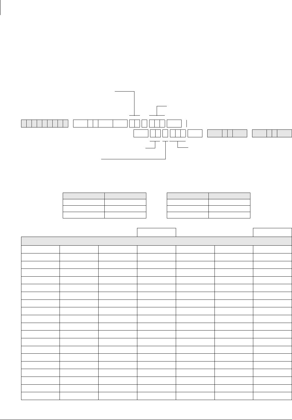
Toll Restriction
Program 47 – Toll Restriction Exception Office Codes Assigned by Area Codes (Tables 1~16)
4-36 Strata DK Programming 5/99
Program 47 – Toll Restriction Exception Office Codes
Assigned by Area Codes (Tables 1~16)
Processor Type:
DK14, DK40i, All RCTUs
Program Type:
Toll Restriction
Initialized Default:
Assigns no office codes to tables
6SNU +ROG 6SNU +ROG
6SNU +ROG6SNU +ROG 6SNU +ROG
Processor Exception Table Processor Exception Table
DK14 01~08 RCTUBA/BB 01~08
DK40i 01~08 RCTUC/D 01~16
RCTUA 01~08 RCTUE/F 01~16
Exception Table: Area Code:
DATA = Record of Exception Office Codes
SELECT = Exception Table from Legend
below.
A new exception table is needed for each
area code with office codes that are
exceptions to restriction.
AREA CODE =
Enter only one area code per exception table.
DATA =
Enter or display office code(s).
To add a range, enter XXXXXX (low office
code high office code).
Several ranges or individual office codes may be
entered by separating them with the # button.
SELECT = Exception Table (01~16)
Enter: 2, 3, 4#
2 = add to the exception table
3 = Delete from the exception table
4# = Display the exception table’s office codes.

Toll Restriction
Program 47 – Toll Restriction Exception Office Codes Assigned by Area Codes (Tables 1~16)
Strata DK Programming 5/99 4-37
Toll Restriction
Program 47 Overview
This program defines exceptions to previously defined office code restrictions for up to 16 area
codes, allowing six-digit Toll Restriction. Office codes entered in Tables 01~16 are opposite of
what is defined for the area code by Program 46-2~4. For instance, if Program 46 denies area code
714, entering office codes 530 and 555 into an exception table for area code 714 will allow 714 to
be dialed only with office codes 530 and 555. Conversely, if 714 is allowed in Program 46, then
714 + 530 or 714 + 555 will be restricted.
Each area code with exception office codes requires a table. Each table may hold up to 800
exception office codes.
Enter the area code and required office codes on the record sheet.
For International Call Restriction by country codes, enter 011 for the area code, and Restricted
country code(s) in the office table(s). To fully restrict a 2-digit country code, also Restrict the
imaginary third digit of that country code.
For example, to Restrict country code 81, you must Restrict 10 country codes 810 to 819.
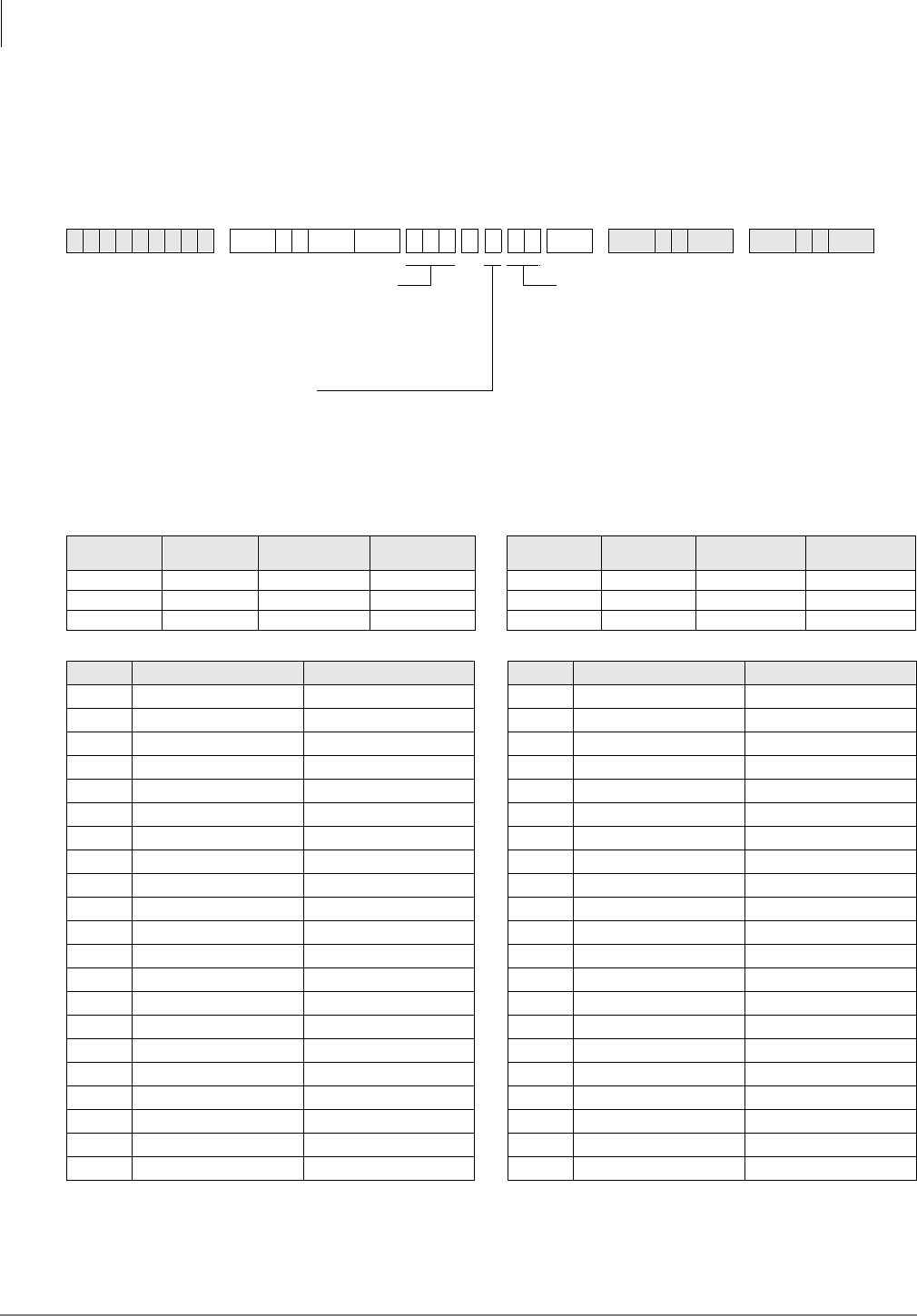
Toll Restriction
Program 48 – Station Toll Restriction Classification
4-38 Strata DK Programming 5/99
Program 48 – Station Toll Restriction Classification
Processor Type:
DK14, DK40i, All RCTUs
Program Type:
Toll Restriction
Initialized Default:
100 for all ports
6SNU +ROG 6SNU +ROG 6SNU +ROG 6SNU +ROG
Processor Port Range Toll Restriction
Ports for DISA Toll Restriction
Class Processor Port Range Toll Restriction
Ports for DISA Toll Restriction
Class
DK14 000~009 010 1~4 RCTUBA/BB 000~079 089 1~4
DK40i 000~027 035 1~4 RCTUC/D 000~239 249 1~8
RCTUA 000~031 039 1~4 RCTUE/F 000~335 344 1~8
Port No. Digit Restriction Code Station Restriction Code Port No. Digit Restriction Code Station Restriction Code
Station Restriction Code (00~10)
00 = No Station Toll Restriction
01 = Area Code toll Restriction and 0 or 1 as 1st digit
02 = Area Code Toll Restriction and 0 or 1 as 1st digit
03 = Class 1 07 = Class 5
04 = Class 2 08 = Class 6
05 = Class 3 09 = Class 7
06 = Class 4 10 = Class 8
If dial “0” credit card calling must be allowed, use
Program 43 to assign designated stations/CO lines to
allow credit card calling.
SELECT = Port Number(s)
Enter the port number(s) of the
station(s) being defined.
To add a port range, enter
XXXXXX (low port high port).
DATA ( 0 or 1)
0 = No digit restriction
1 = Digit restriction
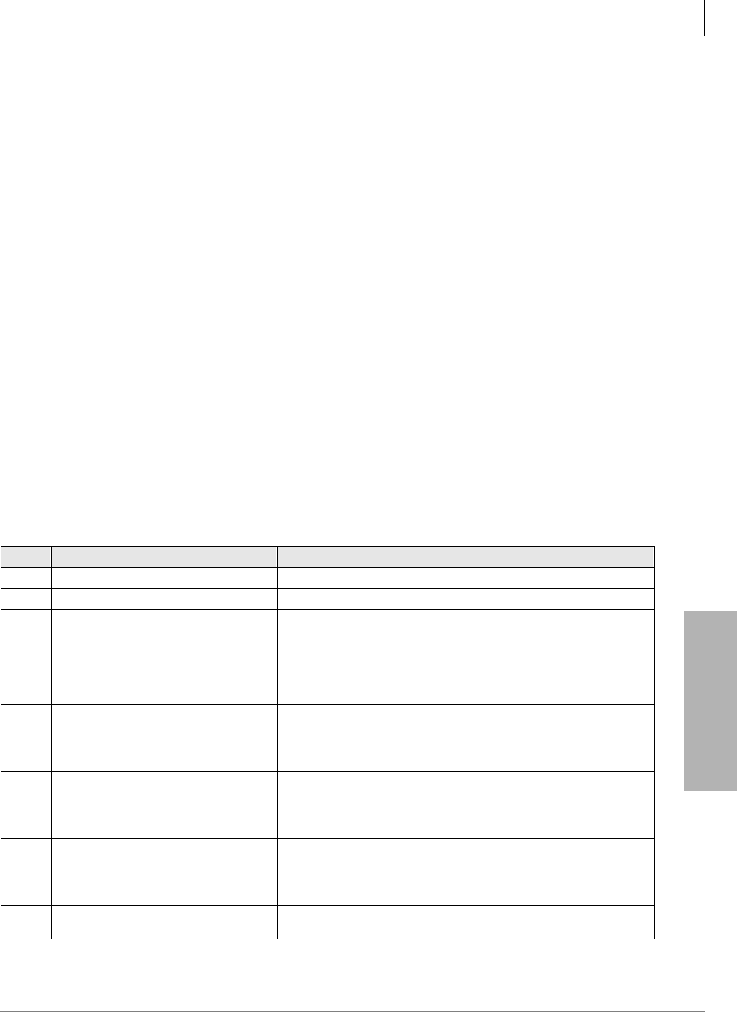
Toll Restriction
Program 48 – Station Toll Restriction Classification
Strata DK Programming 5/99 4-39
Toll Restriction
Program 48 Overview
This program assigns a combination of Digit Restriction and Station Restriction to each station
port defined in the system.
Digit Restriction
If Digit Restriction is enabled for a particular station, the station is able to dial the number of digits
defined in the Program 45-1 Toll Restriction dialing plan.
♦Enter 1 in the Digit Restriction column to enable Digit Restriction for the selected station. This
prevents a user from dialing a second call when dial tone is returned from a CO after the
outside party disconnects.
♦Enter 0 in the Digit Restriction column to disable Digit Restriction for the selected station.
This allows toll restricted users to dial any number of digits (e.g., to an external voice mail
device, computer, etc.).
♦In systems prior to the DK280 Release 3.1 and in DK40i, digit restriction is always applied to
restricted stations after dialing a number using system speed dial. With DK424 RCTU PCBs,
digit restriction after dialing a number using system speed dial will only be applied to stations
with digit restriction (Code 1) in this program.
Station Restriction
Station Restriction assigns Toll Restriction to individual station ports, in addition to previous
restrictions. It includes eleven different choices (described below). One of the choices must be
entered for each port. Station restrictions are overridden by lines disabled as defined in Program
45-2. If a station port has appearance of a line with restrictions disabled, the restrictions will be
removed from the station on an individual line basis through Program 45-2.
Enter one of the following codes in the Station Restriction column:
Enter Function Description
00 No Station Toll Restriction (default)
01 Area Code Toll Restriction This restricts a station from dialing all area codes.
02
Area Code Toll Restriction and “0” or “1”
as a first or second digit (for old plan 1, 2
or 3 or new plan 7, 8 or 9 - as defined in
Program 45-1).
This prevents the station from making any long distance calls or operator-
assisted calls, in addition to outgoing calls outside the home area code.
In applicable areas, this prevents long distance office codes from being
dialed (if 1+NNX).
03 Class 1 Toll Restriction Class 1 area and office code restrictions are defined in Program 46, and
exception office code tables in 46-10.
04 Class 2 Toll Restriction Class 2 area and office code restrictions are defined in Program 46, and
exception office code tables in 46-20.
05 Class 3 Toll Restriction Class 3 area and office code restrictions are defined in Program 46, and
exception office code tables in 46-30.
06 Class 4 Toll Restriction Class 4 area and office code restrictions are defined in Program 46, and
exception office code tables in 46-40.
07 Class 5 Toll Restriction Class 5 area and office code restrictions are defined in Program 46, and
exception office code tables in 46-50.
08 Class 6 Toll Restriction Class 6 area and office code restrictions are defined in Program 46, and
exception office code tables in 46-60.
09 Class 7 Toll Restriction Class 7 area and office code restrictions are defined in Program 46, and
exception office code tables in 46-70.
10 Class 8 Toll Restriction Class 8 area and office code restrictions are defined in Program 46, and
exception office code tables in 46-80.

Toll Restriction
Program 48 – Station Toll Restriction Classification
4-40 Strata DK Programming 5/99

Strata DK Programming 5/99 5-1
Least Cost Routing
Least Cost Routing 5
The following provides you an overview of the Least Cost Routing (LCR) feature and step-by-step
instructions to fill in the Least Cost Routing System record sheets. The quantities of LCR plans,
CO line groups, etc. vary between processors. This chapter and the LCR record sheets note these
differences when they exist.
LCR enables the system to automatically route each outgoing voice call over common carriers and
selected lines. The customer chooses these lines for the specific time of day, and for system users
with varying priorities. If the system is programmed properly, LCR can select the most economical
route. If the best routes are unavailable, users with priority can access more expensive outgoing
routes. Several elements of LCR must be defined in programming.
For LCR to function properly:
♦line groups must be created in Program 16;
♦line restrictions must be set in Programs 40 and 41; and
♦the area dialing plan must be assigned in Program 45-1.
LCR Features
Parameters
Enables LCR features, including a warning tone for last choice route number, a comfort dial tone
during LCR processing, and the Long Distance Information dialing plan.
Home Area Code
Notifies LCR software of the area code of the installation site.
Special Codes
Notifies LCR of special emergency and operator codes that will be automatically routed as a local
call, without unnecessary delay.
Long Distance Information Plan Number
Notifies LCR software how to route a long distance information call.
Local Call Plan Number
Notifies LCR software which call routing plan is designed to handle local and special calls.
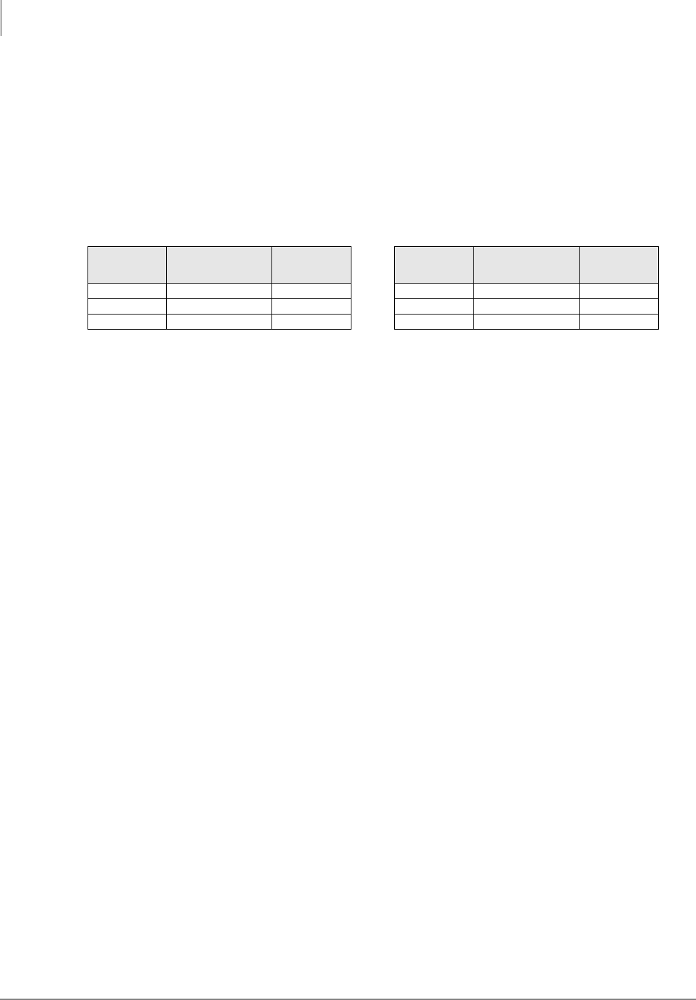
Least Cost Routing
LCR Conditions
5-2 Strata DK Programming 5/99
Timeout after 0 (Zero)
Notifies the system of the time delay to the user after dialing a 0, before a regular operator is
accessed.
Area Code and Office Code Exceptions
Separate area code tables and office code exception tables (quantity listed below) can be defined -
one for each available call routing plan. Each table defines the area codes that are handled by the
particular routing plan. According to the tables defined, specific exception office codes can be
routed through a different call plan than the overall area code plan.
Schedule Assignments Call Routing Plans
These plans (quantity listed above) can send the outgoing calls of different groups of stations
according to a time schedule, and call route definitions.
Route Definitions
Groups of CO lines assigned to special common carriers, foreign exchange lines, or other special
services can be specified as call routes.
LCR Modified Digit Assignments
Carrier codes can be programmed to dial automatically when a call is placed over the appropriate
route. Digits can be added to the front or back of special common carrier codes or other access
numbers to make placing calls an invisible process for the user. Digits may also be deleted from
the front of the dialed number.
LCR Station Access Priority Assignments
Each station port defined in the system may be assigned to one of four station priority groups. The
groups can have varying access to the defined call routes at different times of day. Each group is
partitioned from the other groups.
LCR Conditions
If a station has direct line appearances, or Pooled CO Line buttons programmed to allow direct
outgoing line access, LCR is bypassed using the 3RROHG/LQH or a CO /LQH button. LCR
accommodates special code dialing, such as 911 for emergency response, 1-411 or 411 for
information, or 800 area code toll-free numbers. These calls can be directed to the local call route
(see Program 50-31~35).
Important! Always provide emergency service access for numbers such as 911.
Standard telephones that are Toll Restricted should be required to use LCR to place outgoing calls.
This prevents Toll Restriction defeat when the K4RCU or RRCS times out.
Processor Area Code and
Office Code
Exception Tables
Call Routing
Plans Processor Area Code and
Office Code
Exception Tables
Call Routing
Plans
DK14 8 8 RCTUBA/BB 8 8
DK40i 8 8 RCTUC/D 16 16
RCTUA 8 8 RCTUE/F 16 16
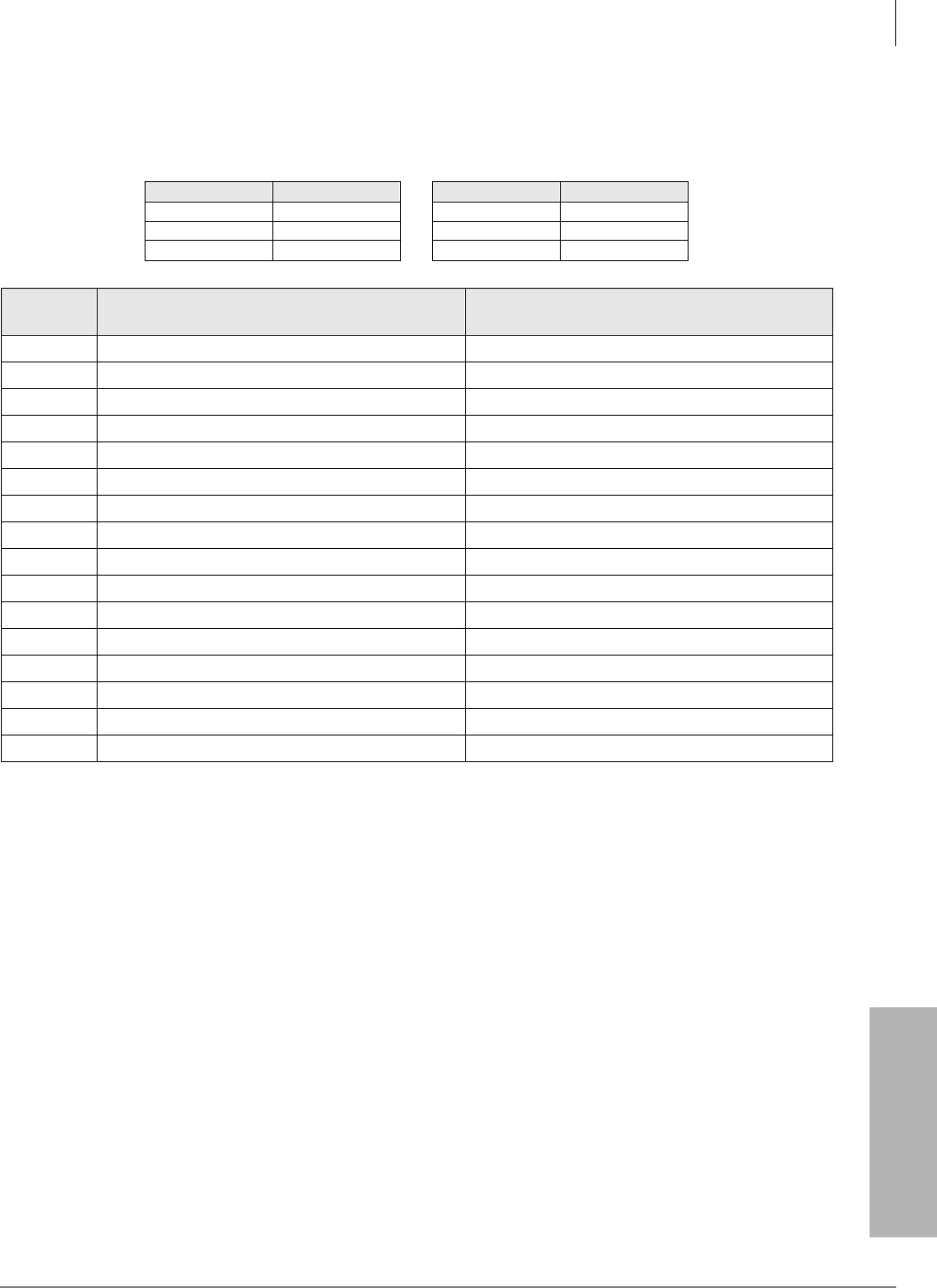
Least Cost Routing
LCR CO Line Programming Reference Table
Strata DK Programming 5/99 5-3
Least Cost Routing
LCR CO Line Programming Reference Table
1. Use Program 16 to assign CO lines in groups per the reference table below.
2. Use Program 40 to allow CO line access to stations using LCR for outgoing calls.
3. Use Program 41 to deny outgoing CO line access, except for LCR access.
Important! Area code and office code structure must be defined by Toll Restriction Dial Plan
for LCR to work properly.
4. Use Program 45-1 to enable the dial plan that is appropriate for the area where the LCR calls
will originate.
5. Under the column labeled “CO Line Type/ Comments,” enter the service type, the common
carrier name, or the line type for each line group, e.g., local line, Foreign Exchange (FX) to
818 (LA), WATS (out of state), etc.
6. Refer to the Program 40 to restrict stations from incoming and outgoing access of lines,
including using LCR. All stations that must use LCR to make outgoing calls must not be
restricted in this program. These restrictions do apply to LCR.
7. Refer to Program 41, to restrict stations from accessing outgoing lines, except through LCR.
All stations that must use LCR for outgoing calls must be restricted from line access in this
program.
Processor CO Line Group Processor CO Line Group
DK14 1~4 RCTUBA/BB 1~8
DK40i 1~8 RCTUC/D 1~16
RCTUA 1~8 RCTUE/F 1~16
Line
Group CO Line in Group CO Line Type/Comments
01
02
03
04
05
06
07
08
09
10
11
12
13
14
15
16
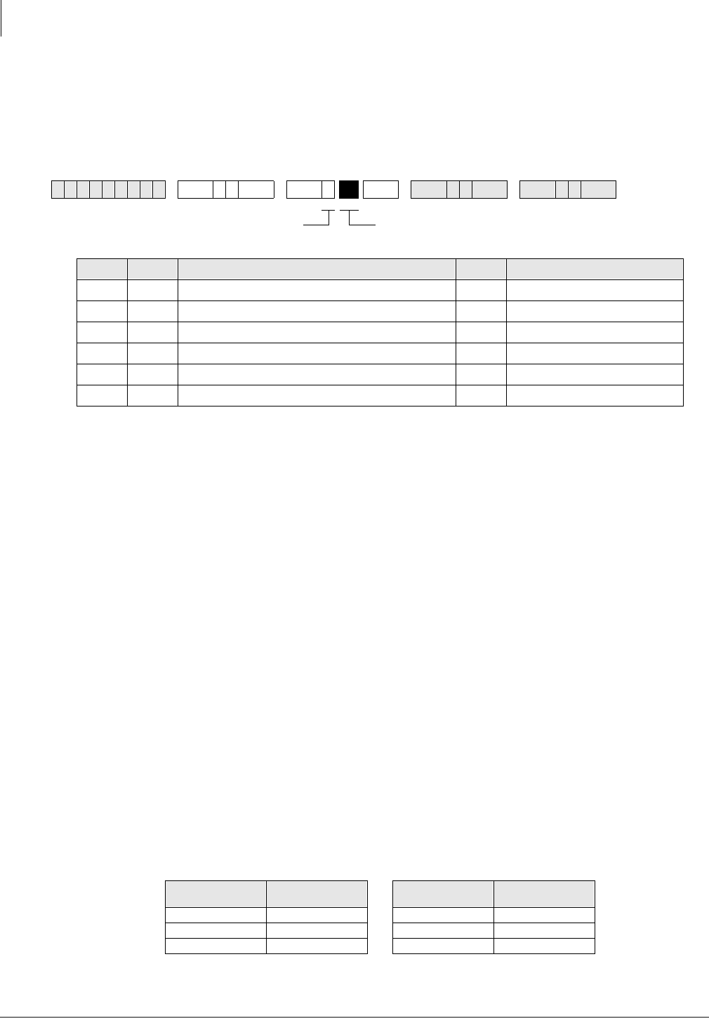
Least Cost Routing
Program 50-1 – LCR Parameters
5-4 Strata DK Programming 5/99
Program 50-1 – LCR Parameters
Processor Type:
DK14, DK40i, All RCTUs
Program Type:
Least Cost Routing
Initialized Default:
All LEDs OFF
Program 50-1 Overview
This program defines general operating parameters for LCR software.
●Program 40 denies CO line access via LCR, but denies all other access methods.
●Program 41 allows CO line access via LCR, but denies all other outgoing access methods:
(#7001~#7200, 801~816, Line button).
●Toll Restricted standard telephones should be forced to dial outgoing calls via LCR. This is to
prevent Toll Restriction defeat when the QRCU3, K4RCU3, K5RCU or RRCS times out.
LED 01: Enable System LCR
LED 01 ON: LCR software is enabled system-wide. For the Hospitality Management Information
System (HMIS), this LED must always be set to ON.
LED 01 OFF: LCR software is disabled. None of the LCR programming referred to by this section
is recognized. Dial 9 access assigned in Program 16 is enabled.
LED 02: Not used
LED 03: 555 LDI Route Per Program 50-4
LED 03 ON: LCR routes long distance information (LDI) calls over the plan number specified in
Program 50-4.
LED 03 OFF: LCR routes LDI calls using area codes specified in route plans in the following
table, as it would for any other call.
6SNU +ROG 6SNU +ROG 6SNU +ROG 6SNU +ROG
LED ON OFF
01 Enable System LCR No LCR
02 Not Used Not Used
03 555 LDI Route per Program 50-4 Per Area Code Table
04 Dial Tone After LCR Access Silent
05 Warning Tone Last Choice Route Number No Warning Tone
10 No CO Dial Tone After Line Access CO Dial Tone (R4.15)
Processor Route Plans
Supported Processor Route Plans
Supported
DK14 8 RCTUBA/BB 8
DK40i 8 RCTUC/D 16
RCTUA 8 RCTUE/F 16
Press LED Buttons for each LCR parameterSELECT = 1
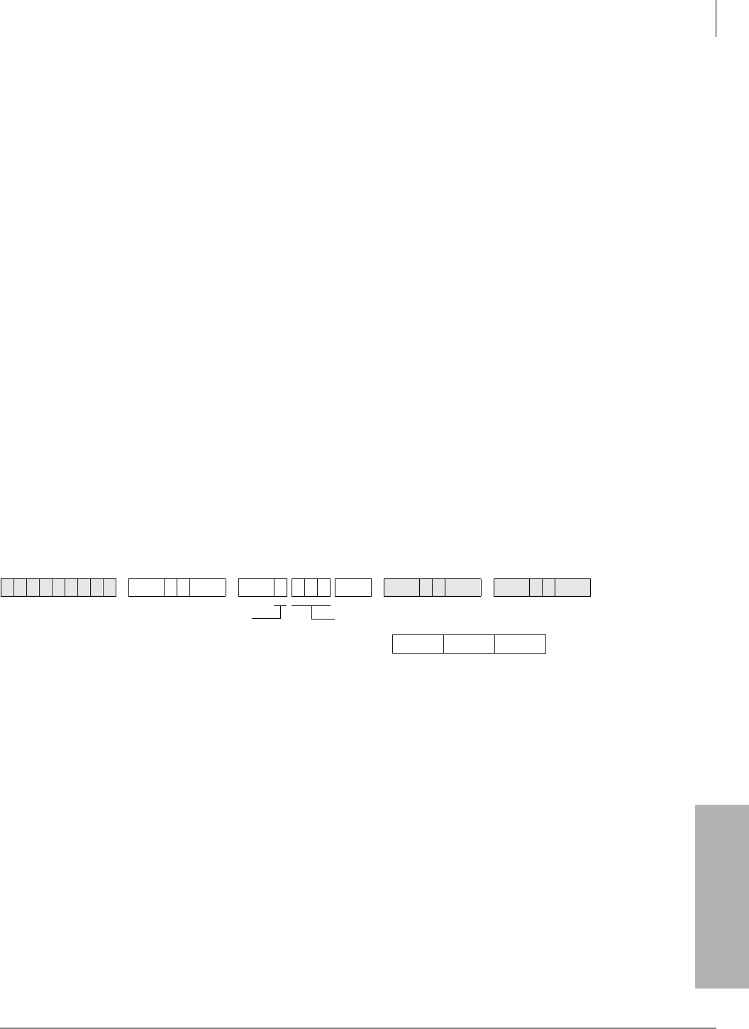
Least Cost Routing
Program 50-2 – LCR Home Area Code
Strata DK Programming 5/99 5-5
Least Cost Routing
LED Button 04: Dial Tone After LCR Access
LED 04 ON: Station users hear a simulated dial tone immediately after dialing the access LCR
code (typically 9), until the first digit of the phone number is dialed. The dial tone is simulated to
assure the user of the system’s proper operation, but it is not a functional dial tone.
For HMIS, set LED 04 ON.
If LED 04 is OFF, station users hear nothing after dialing the LCR access code until the destination
rings or issues a busy signal.
LED Button 05: Warning Tone Last Choice Route Number
LED 05 ON: The user is notified with a warning tone to indicate that LCR has routed the call over
the least desirable route number. The most expensive route is typically programmed to be the least
desirable. A user has three choices upon hearing the warning tone:
♦Ignore the tone, LCR places the call using the least desirable route.
♦Hang up and try later to save money.
♦Activate the Automatic Call Back feature. The appropriate line group calls the user back when
a more desirable route number becomes available.
LED 05 OFF: No warning tone sounds.
Program 50-2 – LCR Home Area Code
Processor Type:
DK14, DK40i, All RCTUs
Program Type:
Least Cost Routing
Initialized Default:
Leaves the home area code blank
Program 50-2 Overview
LCR matches the area code entered here with the LCR route plan containing the home area code in
its Area Code Table. (The home area code is later entered into one of the available LCR route
plans through Program 51). Thus, LCR is informed of how to handle local calls.
Typically, systems are configured to have the LCR route plan containing the home area code as the
same as the local route plan defined in Program 50-5. Typically you would program it to be Route
Plan Number 1, rather than the default Plan 16.
6SNU +ROG 6SNU +ROG 6SNU +ROG 6SNU +ROG
DATA = Home (local) area CodeSELECT = 2
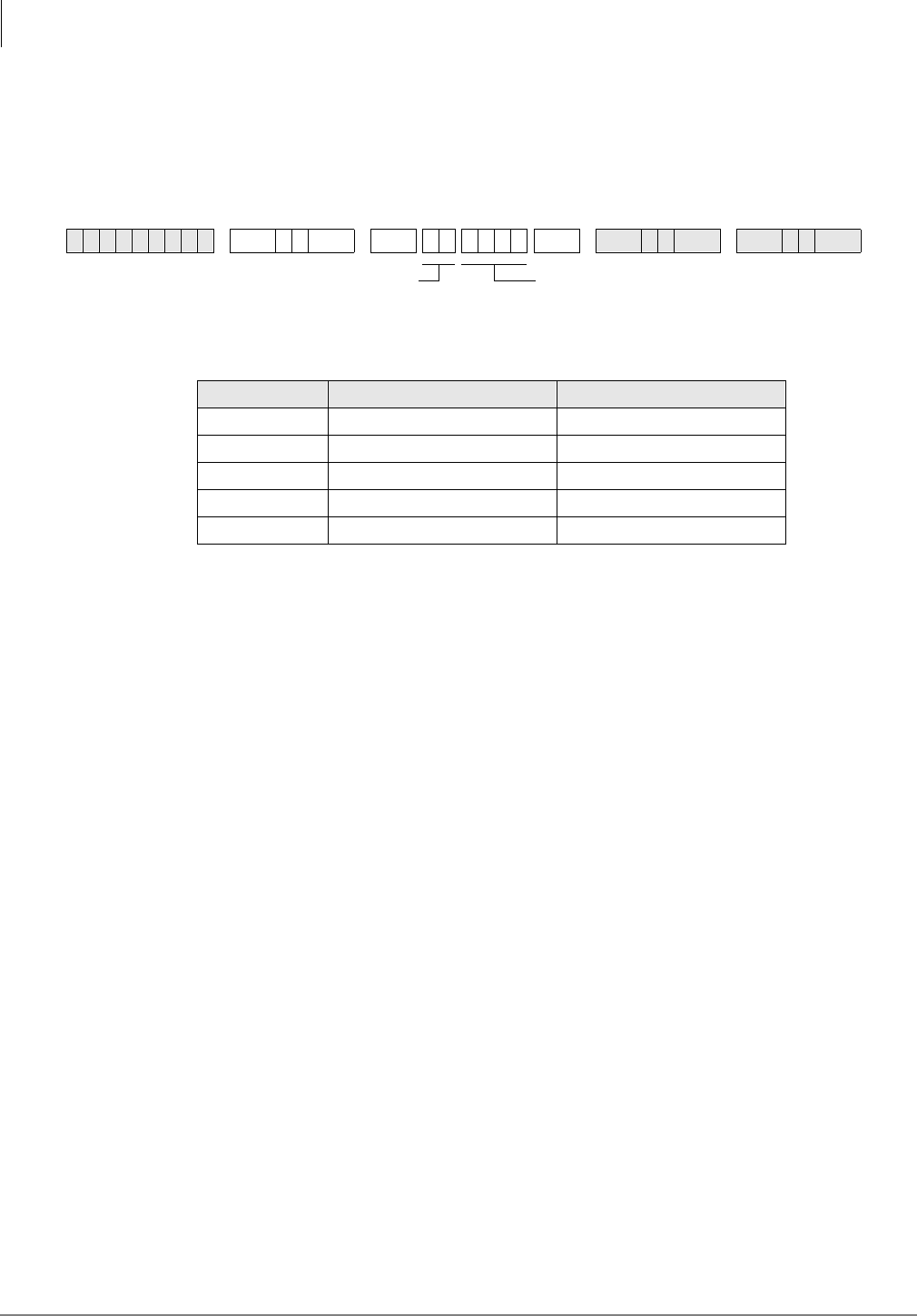
Least Cost Routing
Programs 50-3 (1~5) – LCR Special Codes
5-6 Strata DK Programming 5/99
Programs 50-3 (1~5) – LCR Special Codes
Processor Type:
DK14, DK40i, All RCTUs
Program Type:
Least Cost Routing
Initialized Default:
911 in 31, all other codes blank
Programs 50-3 (1~5) Overview
This program allows special 1~4 digit codes such as 911 to be routed over the local call route
immediately when dialed. If Enhanced 911 (E911) is required, E911 programs should be used
instead of this program.
You can enter five special codes in the spaces provided next to 31~35. The codes can be a
maximum of four digits, and should include items such as 911 for emergency calls, and 411 or
1+411 for local information, etc.
When any of these codes are dialed, LCR is flagged to treat the call as follows:
♦The call is sent over the local call route plan specified in Program 50-5.
♦No additional digits need to be dialed. They are not necessary. Therefore, the call is put
through immediately.
6SNU +ROG 6SNU +ROG6SNU +ROG 6SNU +ROG
SELECT = Special Code (4 Digits) Examples
31 911
32 411
33
34
35
DATA = Special Code
Enter the code from the table below.
Key 01 = blank
SELECT = 31~35
Enter 31~35 to indicate
the special code.
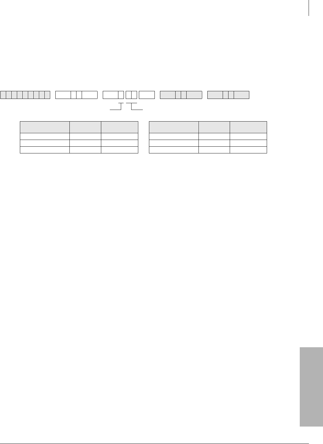
Least Cost Routing
Program 50-4 – LCR Long Distance Information (LDI) Plan Number
Strata DK Programming 5/99 5-7
Least Cost Routing
Program 50-4 – LCR Long Distance Information (LDI)
Plan Number
Processor Type:
DK14, DK40i, All RCTUs
Program Type:
Least Cost Routing
Initialized Default:
See the legend below
Program 50-4 Overview
Enter the number of the LCR route plan over which long distance information calls will be routed.
Typically, long distance information calls are routed over the local call route defined in Program
50-5.
♦If you choose the long distance information plan in Program 50-1, the call is routed as defined
by this table.
♦Typically, LDI Plan Number = Local Call Plan Number.
6SNU +ROG 6SNU +ROG 6SNU +ROG 6SNU +ROG
Processor LDI Route
Plans LDI Route Plans
Default Processor LDI Route
Plans LDI Route Plans
Default
DK14 01~08 08 RCTUBA/BB 01~08 08
DK40i 01~08 08 RCTUC/D 01~16 16
RCTUA 01~08 08 RCTUE/F 01~16 16
DATA = LDI Route Plan (see Legend below)SELECT = 4

Least Cost Routing
Program 50-5 – LCR Local Call Plan Number
5-8 Strata DK Programming 5/99
Program 50-5 – LCR Local Call Plan Number
Processor Type:
DK14, DK40i, All RCTUs
Program Type:
Least Cost Routing
Initialized Default:
See the legend below
Program 50-5 Overview
The Local Call Plan handles special codes and operator calls. Of the 16 Route Plans available for
LCR call processing, define one as the Local Call Plan, typically Route Plan 1. Enter the number
of the plan over which local calls, operator-assisted/0+ calls, and special code calls will be routed.
6SNU +ROG 6SNU +ROG 6SNU +ROG 6SNU +ROG
Processor Local Call Plan
Number Local Call Plan
Default Processor Local Call Plan
Number Local Call Plan
Default
DK14 01~08 08 RCTUBA/BB 01~08 08
DK40i 01~08 08 RCTUC/D 01~16 16
RCTUA 01~08 08 RCTUE/F 01~16 16
DATA = Local Call Plan (see Legend below)SELECT = 5
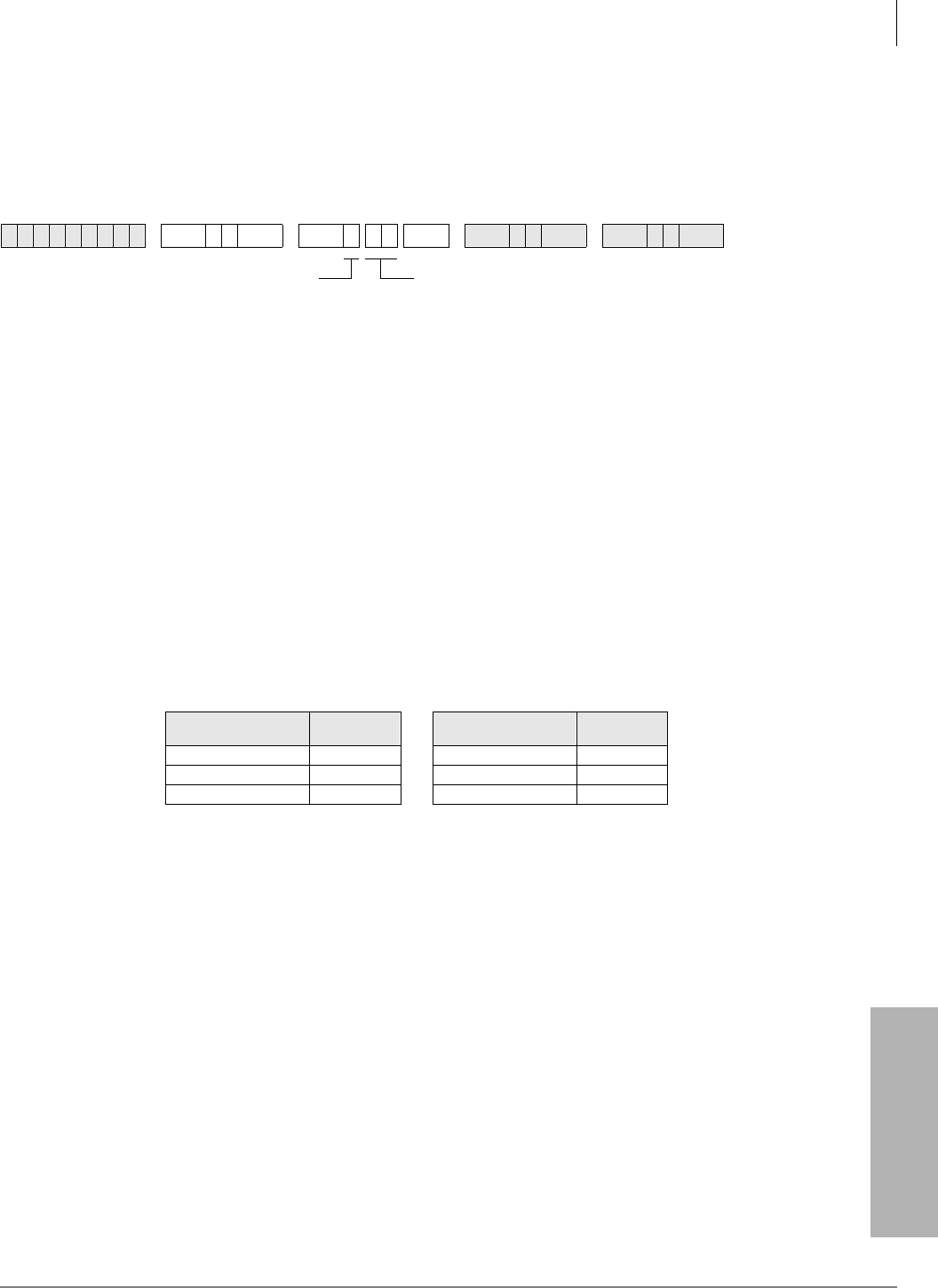
Least Cost Routing
Program 50-6 – LCR Dial 0 (Zero) Time-out
Strata DK Programming 5/99 5-9
Least Cost Routing
Program 50-6 – LCR Dial 0 (Zero) Time-out
Processor Type:
DK14, DK40i, All RCTUs
Program Type:
Least Cost Routing
Initialized Default:
Assigns an LCR Dial Zero Time-out value of 06
Program 50-6 Overview
Enter the maximum number of seconds LCR waits for a user to dial additional digits after a 0,
before it routes the call to an operator for assistance. LCR waits this number of seconds to receive
additional digits that indicate charge calls, collect calls or other 0+ calls.
♦The allowed range is 04~10 seconds. Always enter two digits.
♦Dial 0 calls will be restricted when using 0 + Credit Card calling (Program 43) if a telephone
number is not dialed after dialing 0 or if Dial 0 is restricted in Program 46 (10~80).
Overview for Programs 51~54
These programs provide the system with directions for routing all possible calls, made by all
possible users at all possible times of day. Tables for Programs 51~54 appear on LCR Route Plan
Numbers 1~16. The following instructions show how to fill in individual tables within the plans.
Each of the following program tables must be completed for all plans.
Programs 51~54 defines LCR route plans (quantities given below):
These separate plans provide the customer flexibility enough to route different area codes and
exception office codes over different line groups.
6SNU +ROG 6SNU +ROG 6SNU +ROG 6SNU +ROG
Processor LCR Route
Plans Processor LCR Route
Plans
DK14 8 RCTUBA/BB 8
DK40i 8 RCTUC/D 16
RCTUA 8 RCTUE/F 16
DATA = Time-out Value
Enter a time-out value from 04~10 seconds long.
SELECT = 6
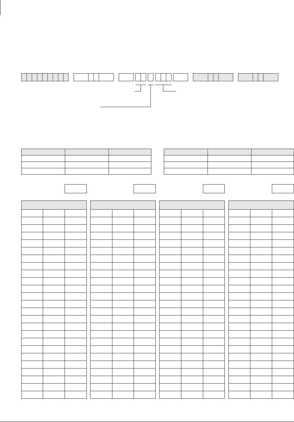
Least Cost Routing
Program 51 – LCR Area Codes
5-10 Strata DK Programming 5/99
Program 51 – LCR Area Codes
Processor Type:
DK14, DK40i, All RCTUs
Program Type:
Least Cost Routing
Initialized Default:
Leaves Tables 01~15 blank; all codes (000~999) initialized to the plan - legend below
6SNU +ROG 6SNU +ROG6SNU +ROG 6SNU +ROG
Processor LCR Plan Number LCR Plan Default Processor LCR Plan Number LCR Plan Default
DK14 01~08 08 RCTUBA/BB 01~08 08
DK40i 01~08 08 RCTUC/D 01~16 16
RCTUA 01~08 08 RCTUE/F 01~16 16
LCR Plan: LCR Plan: LCR Plan: LCR Plan:
Data = Area Code(s) Data = Area Code(s) Data = Area Code(s) Data = Area Code(s)
SELECT = LCR Plan Number
(see Legend below)
Action Code:
2 = To add code to table
3 = To delete code from table
4# =To display codes from table
DATA = Area Code(s) (3 digits)
To add a range of area codes, enter XXX
XXX (low office code high office code).
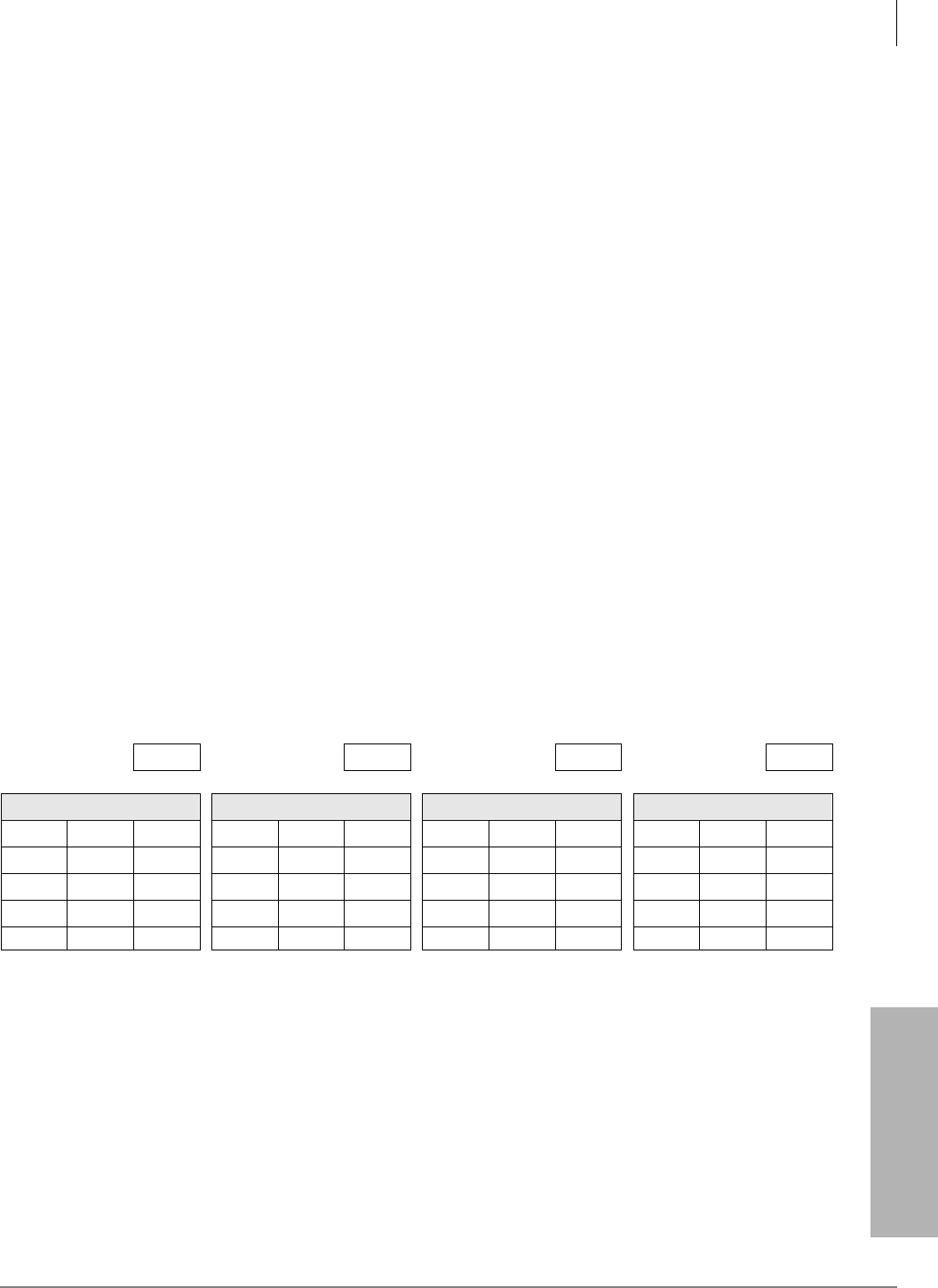
Least Cost Routing
Program 51 – LCR Area Codes
Strata DK Programming 5/99 5-11
Least Cost Routing
Program 51 Overview
Use Program 51 to define which area code calls are placed over which LCR Plan Number (01~08
or 01~16). Therefore, calls made to all area codes are routed over route definitions defined in
Program 54 for Plan 08 or 16, following the time schedule specified by Program 53 for Plan 08 or
16 (unless other assignments are made in plans 1~15).
Every route plan can be assigned to define a set of area codes and/or office codes.
011 can be entered as an Area Code into any LCR plan to route direct dial international calls via
LCR.
Example
Any area code entered in a Program 51 LCR area code table for plans 1~15 is subtracted from Plan
16. An area code cannot be lost. If it is subsequently deleted from Plans 01~07 or Plans 01~15,
LCR software automatically adds it to Plan 08 or 16.
Remember that LCR matches the home area code entered in Program 50-2 with the LCR route
plan containing the home area code in its Area Code Table. The home area code must be entered
into one of the 16 available LCR route plans through Program 51. Thus, LCR is informed of how
to handle local calls.
Typically, systems are configured to have the LCR route plan containing the home area code as the
same as the local route plan defined in Program 50-5. This usually is programmed by the installer
to be Route Plan Number 1, rather than the default Plan 08 or 16.
HMIS Example
Plan 01 includes home area code, 800, 888. Plan 08 includes long distance area codes. Plan 16 is
used for RCTUC/D and RCTUE/F processors. The following table gives you an example of how
you might set up Program 51 for the HMIS:
LCR Plan: 01 LCR Plan: 02 LCR Plan: 08 LCR Plan:
Data = Area Code(s) Data = Area Code(s) Data = Area Code(s) Data = Area Code(s)
714 000 713
800 715 799
888 801 887
889 999
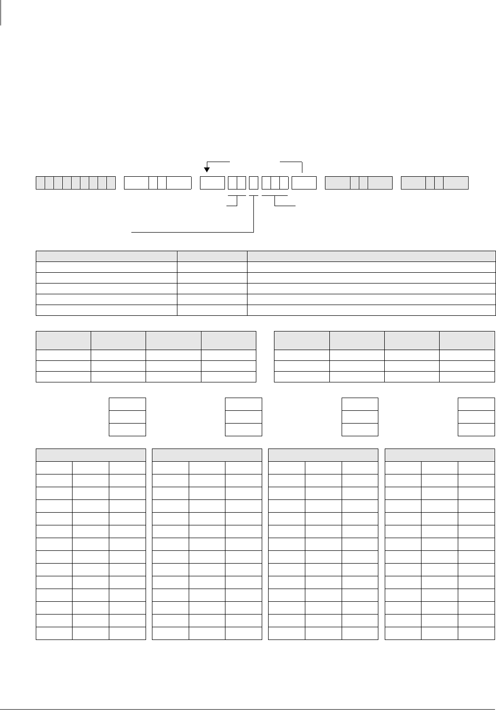
Least Cost Routing
Program 52 – LCR Office Code Exceptions for Specified Area Code
5-12 Strata DK Programming 5/99
Program 52 – LCR Office Code Exceptions for
Specified Area Code
Processor Type:
DK14, DK40i, All RCTUs
Program Type:
Least Cost Routing
Initialized Default:
Leaves all office code tables blank and all tables assigned to LCR Plan (see legend
below)
6SNU +ROG 6SNU +ROG6SNU +ROG 6SNU +ROG
Action Code Function Action Codes DATA =
Assign Exception Table to LCR Plan 0 (LCR Plan 01~16):
Assign Area Code to LCR Plan 1 (3-digit Area Code):
Add Office Code to Exception Table 2 (3-digit Office Code):
Delete Office Codes from Exception Table 3 (3-digit Office Code):
Display Office Codes in Exception Table 4# more # (3-digit Office Code):
Processor Table Number LCR Plan LCR Exception
Codes Processor Table Number LCR Plan LCR Exception
Codes
DK14 01~08 01~08 8 RCTUBA/BB 01~08 01~08 8
DK40ii 01~08 01~08 8 RCTUC/D 01~16 01~16 16
RCTUA 01~08 01~08 8 RCTUE/F 01~16 01~16 16
Table Number: Table Number: Table Number: Table Number:
Area Code: Area Code: Area Code: Area Code:
LCR Plan: LCR Plan: LCR Plan: LCR Plan:
Data = Office Code(s) Data = Office Code(s) Data = Office Code(s) Data = Office Code(s)
More Data
DATA = LCR Plan, Area Code, or Office Code
To add a range of office codes, enter XXX XXX (low
office code high office code).
SELECT = Office Code Exception Table
(see Legend below)
Action Code

Least Cost Routing
Program 52 – LCR Office Code Exceptions for Specified Area Code
Strata DK Programming 5/99 5-13
Least Cost Routing
Program 52 Overview
This Office Code exception table enables the user the flexibility of routing specific office codes
through a different call plan than other office codes used with that area code.
♦Any number of exception code tables can be assigned to each route plan, although each
exception table can only be used once system-wide.
♦Every route plan can be assigned to define a set of area codes and office code exceptions or a
set of office code exceptions.
♦This program applies to both examples listed below. In the first case, an office code exception
table does not need to be defined in addition to the area codes in Program 51, but it may. In the
second case, the plan only pertains to exception office codes for certain area codes.
♦To route International (011) calls over any selected plan by Country Code, program 011 as the
Area Code and the Country Code as the Office Code in Program 52 in any Exception Code
Table. If the Country Code is two digits, add 10, 3-digit Office Codes as follows: XX0 through
XX9, where XX is the Country Code.
Example 1
In the first example, office code exception tables are defined to the area code table. Use the
continuation sheet to define the exception office codes. As many as 16 office code exception tables
can be linked to a plan, but each exception table can only be used once. When using the
continuation sheet, be sure that the same exception table is not assigned to more than one plan.
1. Turn to the continuation sheet (that follows Plan 16 record sheet).
2. Determine the plan number where the exception office codes will be routed.
3. Fill in the area code of the exception office codes in the spaces provided by the correct plan
number. These office codes will be routed differently than the overall area code.
4. Enter the specific office codes that are to be routed differently.
Example 2
In the second example, the route plan only applies to office code exceptions. The first office code
exception table may be documented on the LCR Plan record sheet:
1. Check the box on the record sheet next to Office Code Exception Table number.
2. Enter the number of the exception table (01~16). Make sure this table number is not entered on
any other plan, or on the continuation sheet.
3. Enter the applicable area code.
4. Enter the specific office codes that are to be routed differently than the area code.
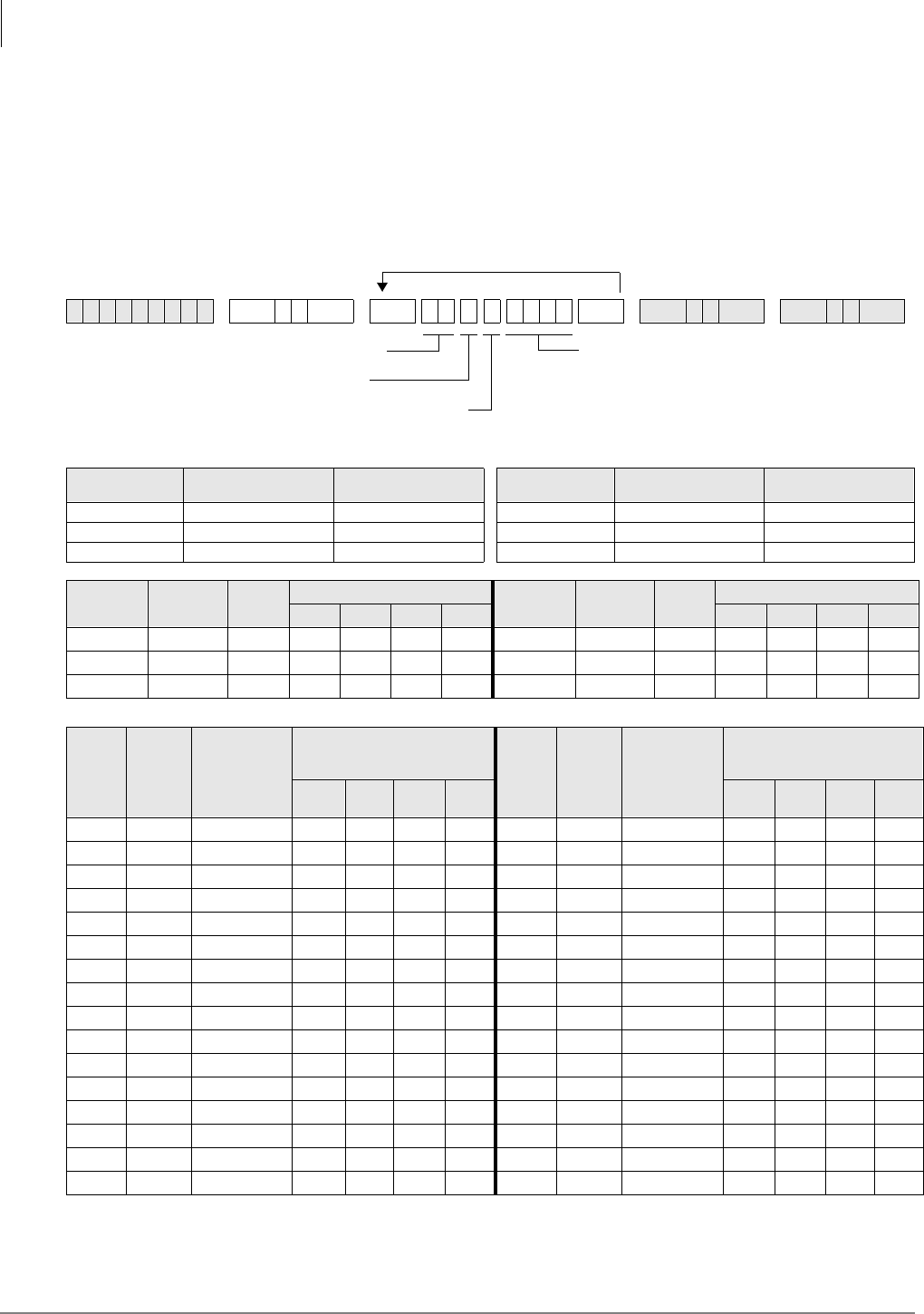
Least Cost Routing
Program 53 – LCR Schedule Assignments for LCR Plans
5-14 Strata DK Programming 5/99
Program 53 – LCR Schedule Assignments for LCR
Plans
Processor Type:
DK14, DK40i, All RCTUs
Program Type:
Least Cost Routing
Initialized Default:
Assigns starting time as 0000 and Route Definitions as blank for all schedules
6SNU +ROG 6SNU +ROG6SNU +ROG 6SNU +ROG
Processor Program 56
LCR Station Groups Program 54 Route
Definition # Processor Program 56
LCR Station Groups Program 54 Route
Definition #
DK14 1~4 1~4 RCTUBA/BB 1~4 1~4
DK40i 1~4 1~4 RCTUC/D 1~8 1~6
RCTUA 1~4 1~4 RCTUE/F 1~8 1~6
LCR Plan
01~16 Schedule
1~3 Action
Code
Start Time LCR Plan
01~16 Schedule
1~3 Action
Code
Start Time
H H M M H H M M
0 0
0 0
0 0
LCR
Plan
01~16
Sched.
1~3
Program 56
LCR Station
Group
(see legend
above)
Program 54
Route Definition #
(see legend above) LCR
Plan
01~16
Sched.
1~3
Program 56
LCR Station
Group
(see legend
above)
Program 54
Route Definition #
(see legend above)
1st
Pick 2nd
Pick 3rd
Pick 4th
Pick 1st
Pick 2nd
Pick 3rd
Pick 4th
Pick
Start Time (HHMM) (HH: 00~23; MM: 00~59)
or...
Route Definition Numbers (see Legend below)
Press LED Button 01 to erase data (LED does
not light).
LCR Plan (1~16)
Schedule 1~3
Action Code (0) or LCR Station
Group Number
(see Legend below)

Least Cost Routing
Program 53 – LCR Schedule Assignments for LCR Plans
Strata DK Programming 5/99 5-15
Least Cost Routing
Program 53 Overview
This program assigns up to three time schedules to each plan. Each time schedule consists of four
or six different route definition choices (defined in Program 54) available to the eight station
groups (defined in Program 56). It may be helpful to complete Program 54 portions of the plans
and Program 56 before proceeding.
If Schedules 1 & 2 start at the same time, then Time of Day schedule change does not occur, and
data only needs to be entered for Schedule 1.
Typical Installation Without Time Schedule Feature
In most cases, an installation does require use of the time schedule feature. To reflect this on the
record sheets for Plans 01~16:
1. Enter the same Schedule Start Times for Schedules 1 and 2. Use the military format - HH:MM
(Hours:Minutes). Fill in all four digits.
Note If LCR software sees Schedules 1 and 2 have the same start times, then it only looks at
Schedule 1 for route definitions.
2. Enter Route Definition numbers for Schedules 1 and 2. Four definitions (route pick or choices)
can be entered for each group.
♦LCR Station (Class) Groups 1~8 are assigned in Program 56.
♦LCR Route Definition numbers 1~4 or 1~6 are defined in Program 54.
3. The order in which the route definitions are entered defines the order of LCR line selection.
The most desirable route should be entered in the left-most position, and the least desirable
route in the right-most position.
4. If “1” is assigned to Station Group 1, and 1 for route definition only, then those assigned will
only be able to use Route Definition 1, thereby restricting them during times that route
definition 1 is not allowed.
5. Keep in mind that the route definition number is being entered, not the CO line group number.
The definitions are assigned in Program 54.
Installation Requiring Time Scheduling Feature
When an installation requires the time scheduling feature to be programmed, three “shifts” of route
definitions can be assigned per station group. To reflect this on the record sheet, substitute Step 1
of the procedure described for the typical customer with the following:
➤Enter the Schedule Start Times for Schedules 1, 2 and 3. Use military time, in the format
HH:MM (Hours:Minutes). Fill in all four digits. Initialized data assigns “0000” to all times.
♦Start time for schedule 2 is the stop time for schedule 1.
♦Start time for schedule 3 is the stop time for schedule 2.
♦Start time for schedule 1 is the stop time for schedule 3.
HMIS Example
Enter LCR schedule assignments for LCR plan 01, 02 and 08/16. Stations in groups 1, 2, and 3 are
controlled by HMIS. The following table gives you an example of how you might set up Program
53 for the HMIS:
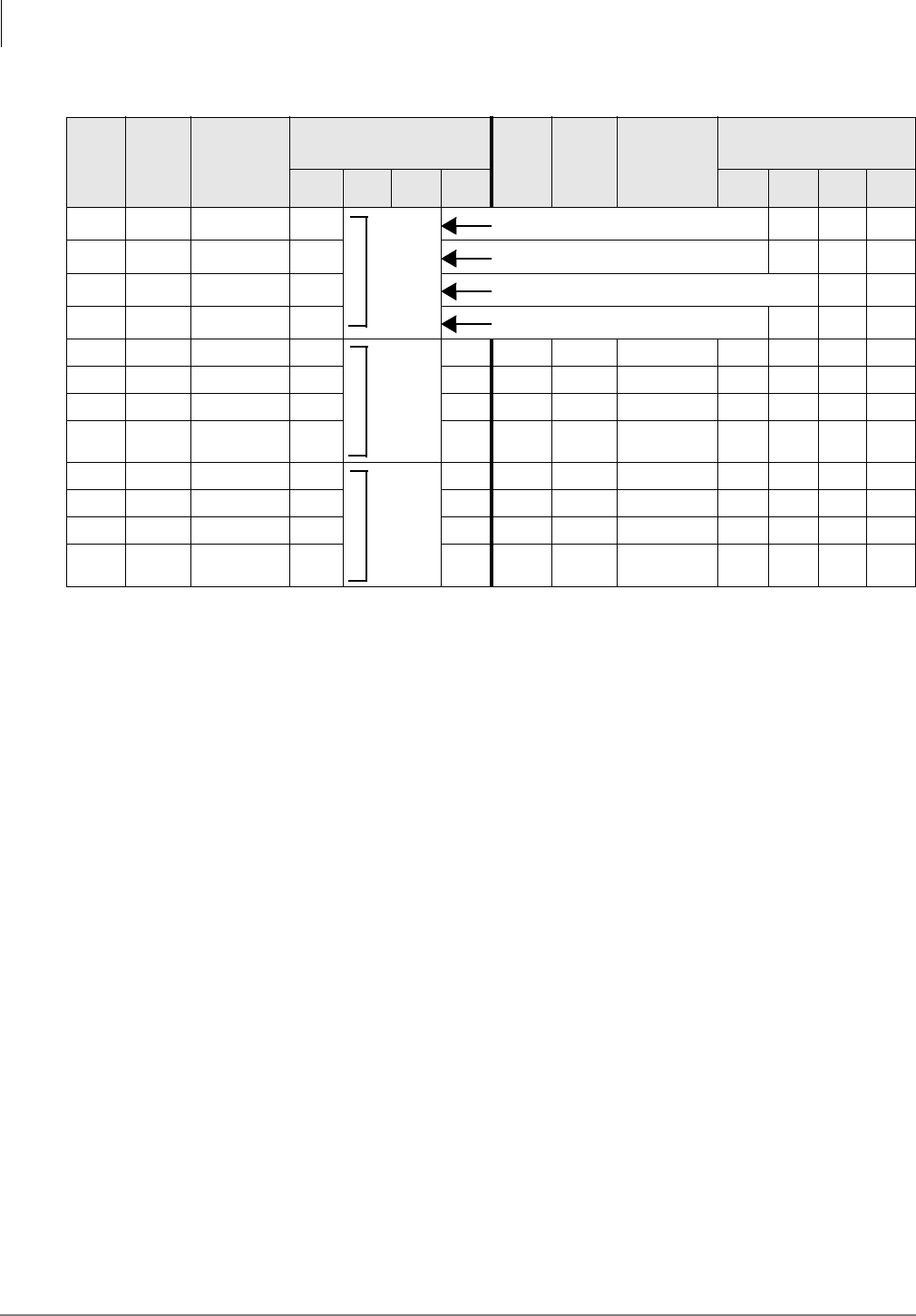
Least Cost Routing
Program 53 – LCR Schedule Assignments for LCR Plans
5-16 Strata DK Programming 5/99
LCR
Plan
01~16
Sched.
1~3
Program 56
LCR Station
Group
(see legend
above)
Program 54
Route Definition #
(see legend above) LCR
Plan
01~16
Sched.
1~3
Program 56
LCR Station
Group
(see legend
above)
Program 54
Route Definition #
(see legend above)
1st
Pick 2nd
Pick 3rd
Pick 4th
Pick 1st
Pick 2nd
Pick 3rd
Pick 4th
Pick
01 1 1 1 Guest Room with restricted calling
21 Guest Room local/800/888/911
3 Guest Room complete restriction/911 only
41 Hotel Administration (unrestricted)
02 1 1 1
21
31
41
08 1 1 1
2
3
41
Home
Area
Code
Local
Call
Route/
911
Long
Distance
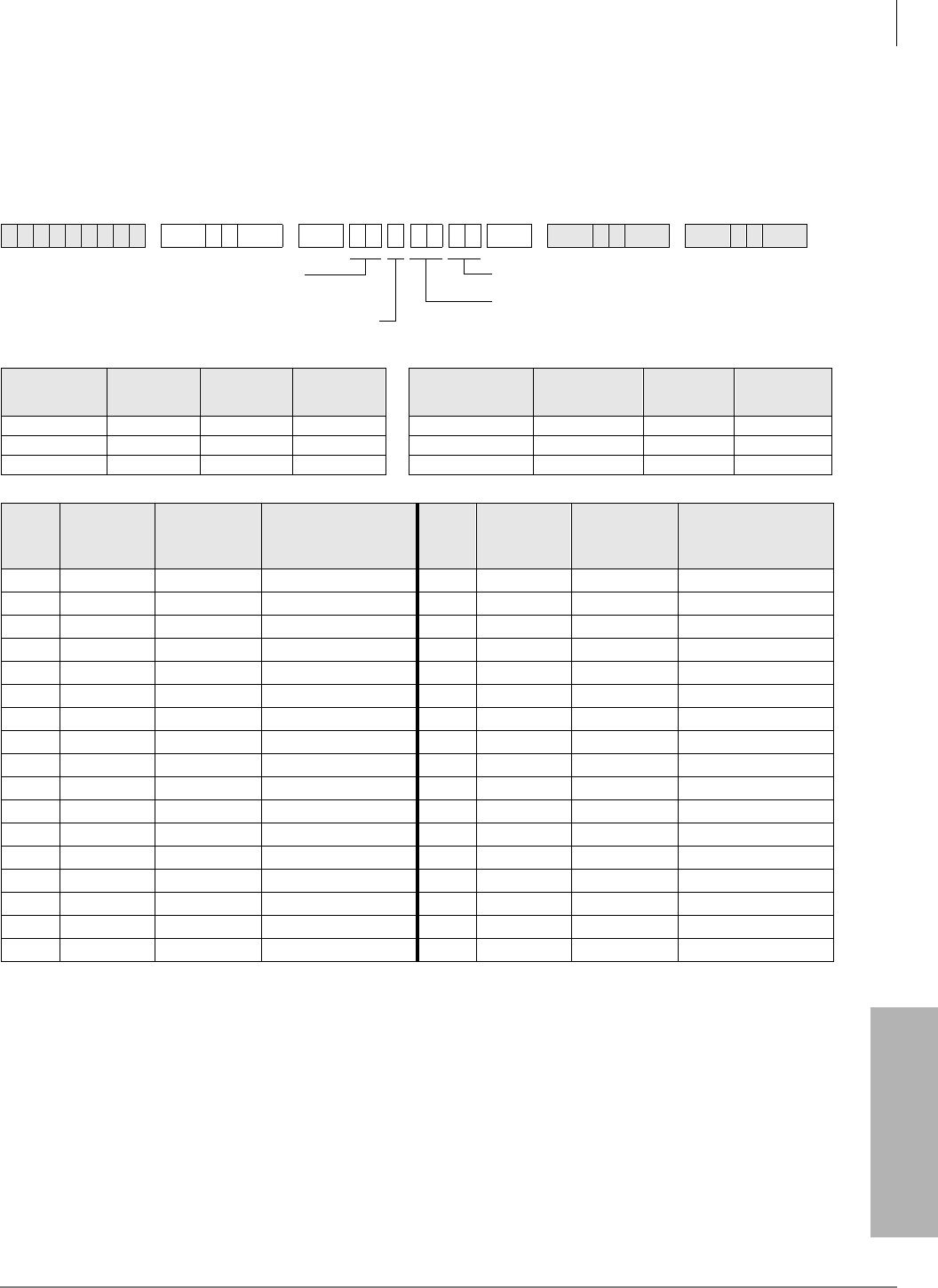
Least Cost Routing
Program 54 – LCR Route Definition Tables
Strata DK Programming 5/99 5-17
Least Cost Routing
Program 54 – LCR Route Definition Tables
Processor Type:
DK14, DK40i, All RCTUs
Program Type:
Least Cost Routing
Initialized Default:
0101
Program 54 Overview
Program 54 defines different ways of routing calls for each of the LCR plans. Define each route by
selecting and entering:
6SNU +ROG 6SNU +ROG6SNU +ROG 6SNU +ROG
Processor Route
Definition #
Program 16
CO Line
Group
Program 55
Modified
Digits Processor Route Definition
#
Program 16
CO Line
Group
Program 55
Modified
Digits
DK14 1~4 01~08 01~06 RCTUBA/BB 1~4 01~08 01~06
DK40i 1~4 01~08 01~06 RCTUC/D 1~6 01~16 01~12
RCTUA 1~4 01~08 01~06 RCTUE/F 1~6 01~16 01~12
LCR
Plan
01~16
Route
Definition #
(see legend
above)
Program 16
CO Line
Group (see
legend above)
Program 55
Modified Digits
(see legend above)
LCR
Plan
01~16
Route
Definition #
(see legend
above)
Program 16
CO Line
Group (see
legend above)
Program 55
Modified Digits
(see legend above)
Modified Digits Table (see Legend in Program 55)
CO Line Group (01~16, see Program 16)
LCR Plan No.
(see Legend below)
Route Definition Numbers
(see Legend below)
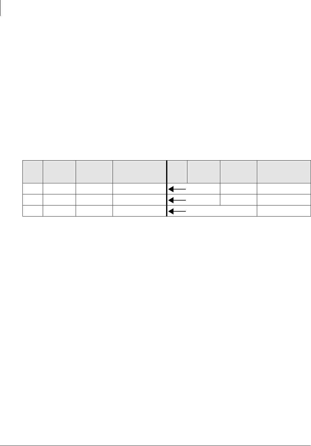
Least Cost Routing
Program 54 – LCR Route Definition Tables
5-18 Strata DK Programming 5/99
Route Definition Number
Route definitions define the CO line group and modified digit tables used for each LCR Plan. See
the legend for the number of route definition numbers for your processor.
CO Line Group (assigned in Program 16)
Each line group represents a type of service, e.g., special common carrier, foreign exchange, local
line group, etc. Program 40 denies incoming and outgoing line access to stations, including LCR
access. Program 41 allows line access to stations using LCR only for outgoing calls when enabled.
Modified Digits Table
Refer to Programs 55-0, 55-1 and 55-2. The system handles line groups differently, according to
which modified digits table was assigned in Program 54.
HMIS Example
The following table gives you an example of how you might set up Program 54 for the HMIS:
LCR
Plan
01~16
Route
Definition #
(see legend
above)
Program 16
CO Line
Group (see
legend above)
Program 55
Modified Digits
(see legend above)
LCR
Plan
01~16
Route
Definition #
(see legend
above)
Program 16
CO Line
Group (see
legend above)
Program 55
Modified Digits
(see legend above)
01 1 01 01 Local
02 1 01 01 911
08 1 01 01 Long Distance
Least Cost Routing
Program 55 – LCR Modified Digits Table
Strata DK Programming 5/99 5-19
Least Cost Routing
Program 55 – LCR Modified Digits Table
Processor Type:
DK14, DK40i, All RCTUs
Program Type:
Least Cost Routing
Initialized Default:
See each program in the Program 55-X series
Program 55 Series Overview
This program defines call handling so the route definition used by LCR is invisible to the station
user. The station user handles all calls the same way. The goal is for LCR to remember the dialing
peculiarities of each call route, so the user does not need to know.
Each modified digits table assigns editing steps that include:
♦Deleting a pre-defined quantity of digits from the front of the number dialed
(Program 55-0).
♦Adding a pre-defined number to the front of the number dialed (Program 55-1).
♦Adding a pre-defined number to the end of the number dialed (Program 55-2).
Processor Modified/Add/Delete
Digit Tables Processor Modified/Add/Delete
Digit Tables
DK14 6 RCTUBA/BB 6
DK40i 6 RCTUC/D 12
RCTUA 6 RCTUE/F 12
Least Cost Routing
Program 55-0 – Delete Number of Digits From the Front of Dialed Number
5-20 Strata DK Programming 5/99
Program 55-0 – Delete Number of Digits From the Front
of Dialed Number
Initialized Default:
All tables blank
Program 55-0 Overview
Enter the quantity of digits that should be deleted from the front of the number dialed for each of
the Table Numbers in the Delete Digits Table. The maximum number is 10. Always make the entry
two digits.
If the Delete Digits Table is activated, refer to Programs *45-3 and *45-4 if special dialing codes,
such as Caller ID blocking, etc., will be used.
6SNU +ROG 6SNU +ROG 6SNU +ROG 6SNU +ROG
Program 55-0
Delete Digits Table
Table Number Quantity of Digits (01~10 max)
01
02
03
04
05
06
07
08
09
10
11
12
FIGURE = Quantity of Digits (00~10) to be deleted.SELECT = Modified Digits Table
(see Program 55 Legend)
Least Cost Routing
Program 55-1 and 2 – Add Digits Before and/or After the Dialed Number
Strata DK Programming 5/99 5-21
Least Cost Routing
Program 55-1 and 2 – Add Digits Before and/or After
the Dialed Number
Initialized Default:
Leaves all tables blank except Delete Digits, which are all 00
6SNU +ROG 6SNU +ROG 6SNU +ROG 6SNU +ROG
Pause Entry Reference (Programs 55-1, 55-2)
Key/LED Pause (Seconds) Record Entry Special Functions
08 16 P8 Key/LED 09 (R4.15)
ISDN Start Key, LCD = G
07 14 P7 Key/LED 11:
Clear All
06 12 P6 Key/LED 10:
Convert DP to DTMF,
LCD = T
05 10 P5
04 8 P4
03 6 P3 Key/LED 12:
Code for ISDN Sub-address Separator
LCD = S
02 4 P2
01 2 P1
Modified Digits Table (MDT)
Add to FRONT of Dialed Number (Program 55-1)
Table No. 1 2 3 4 5 6 7 8 9 10 11 12 13 14 15 16 17 18 19 20 21 22
01
02
03
04
05
06
07
08
09
10
11
12
Modified Digits Table (MDT)
Add to END of Dialed Number (Program 55-2)
Table No. 1 2 3 4 5 6 7 8 9 10 11 12 13 14 15 16 17 18 19 20 21 22
01
02
03
04
05
06
07
08
09
10
11
12
SELECT = Modified Digits Table
1 = Add digits in front of number dialed (F-MDT)
2 = Add digits at the end of number dialed (E-MDT)
(see Program 55 and *45-4 Legend)
CODE = Digits added (up to 22)
Enter the digits to be added. Pauses may be coded
as described in the pause entry reference table
below.

Least Cost Routing
Program 55-1 and 2 – Add Digits Before and/or After the Dialed Number
5-22 Strata DK Programming 5/99
Program 55-1 and 2 Overview
Enter the digits that must be added to the front of the number dialed in the Add Digits Table. The
maximum digits is 22, including pauses.
♦Length of pause can be indicated by using codes (P1~P8) specified in the Pause Entry
Reference Table. Each pause takes two digits of memory space.
♦Try to allow for the longest wait, e.g., make the pause longer, rather than shorter, to
accommodate the length of time a carrier may need to access the service tones, etc.
♦If using special codes in Program *45-3, use Program *45-4 to indicate if the Program *45-3
codes should be sent before or after the Program 55-1 and 55-0 Modified Digits Table (MDT)
digits. Program *45-4 also allows a pause to be inserted into the dialing sequence.
Least Cost Routing
Program 56 – LCR Station Group Assignments
Strata DK Programming 5/99 5-23
Least Cost Routing
Program 56 – LCR Station Group Assignments
Processor Type:
DK14, DK40i, All RCTUs
Program Type:
Least Cost Routing
Initialized Default:
Assigns all stations to Group 1
6SNU +ROG 6SNU +ROG 6SNU +ROG 6SNU +ROG
Processor Port Range LCR Station Groups Processor Port Range LCR Station Groups
DK14 000~009 1~4 RCTUBA/BB 000~079 1~4
DK40i 000~027 1~4 RCTUC/D 000~239 1~8
RCTUA 000~031 1~4 RCTUE/F 000~335 1~8
Port
Number LCR Station Group
No. (1~8) Port
Number LCR Station Group
No. (1~8) Port
Number LCR Station Group
No. (1~8) Port
Number LCR Station Group
No. (1~8)
Enter LCR Station Group (1~8)SELECT = Station Logical Port Number(s)
Enter port numbers of stations being assigned.
To add a port range, enter XXX XXX (low port high port).
Least Cost Routing
Program 56 – LCR Station Group Assignments
5-24 Strata DK Programming 5/99
Program 56 Overview
The purpose of this program is to assign all defined station ports to one of four or eight LCR
Station Groups (see Program 56, record sheet notes).
♦Station groups are completely independent of one another. Therefore, each station group must
be defined separately.
♦Software does not automatically assign the highest, all-inclusive routing priority to Class 1
stations, making all routes available to Class 2~8 stations available to Class 1 as well.
♦Instead, stations are assigned (partitioned) to independent groups. Flexible assignment of
routing definitions to groups is allowed, with no one group’s definition affecting another’s.
Each group’s route definitions are specified to activate separately according to the time
schedules set by Program 53. Enter the station group number next to the port number.
HMIS Example
LCR Station Group Assignments for LCR Plans 01, 02, and 08/16:
LCR Group Allows
Guest Rooms
01 All calls to be dialed by rooms.
02 Local Calls, 800/888, 911 only.
03 911 only.
Administration 04 As needed (most likely will be the same as Group 01).

Strata DK Programming 5/99 6-1
Automatic Call Distribution
Automatic Call Distribution 6
This chapter provides ACD programming information for the Strata DK424 system and its
stations. ACD is not available for the DK14 or DK40i.
The programs specific to ACD are listed below.
♦Program 03 – RSIU, RSSU, PIOU, or PIOUS ACD/MIS Slot Assignments
♦Program 09 – Auto Attendant Prompt/ACD Group Assignments
♦Program *09 – ACD Group DID/Tie Line Digit Assignments (use if Program 71 is not used)
♦Program 10-4 – ACD Parameters
♦Program 11 – ACD Timing Assignments
♦Program 14-0 – Loop/Ground Start CO Line Direct Ring to ACD Group Assignments
♦Program 14-1 – ACD Agent Identification Code Assignments
♦Program *14-1 – Auto Answer with Zip Tone Assigned to Agent ID
♦Program 14-2 – ACD Supervisor Passwords
♦Program *14-2 – DID/Tie/DNIS/ANI Line After Shift and Overflow Substitution Destination
♦Program 14-3 – Announcement/Music Port Assignments and Queue Pattern
♦Program 14-4 – Queue Time Out Overflow Destination
♦Program 14-5 – Overflow Point and Ring No Answer Routing Destination Assignments
♦Program 14-6 – After Shift Service Destination
♦Program 14-71 – Queue Size for Alarm (Immediate Assignments)
♦Program 14-72 – Queue Size for Alarm 1 (See also Timer Program 11-6 in Strata DK
Programming Manual)
♦Program 14-73 – Queue Size for Alarm 2 (See also Timer Program 11-7 in Strata DK
Programming Manual)
♦Program 14-8 – Alarm Pattern Assignments
♦Program 14-9 – Work Unit Assignments (Work Unit/Stroke Digit Length)
♦Program 15 – Ground/Loop/Tie/DID Line Options
♦Program 17 – DID/Tie Line Options
♦Program 18 – Agent ID Code Name for MIS Assignments
♦Program 35 – Station Class of Service
♦Program 39 – Flexible Button Assignments for ACD Telephones (in System and Station
Chapter)
♦Program 71 – DID/Tie/DNIS/ANI Lines (use if Program *09 is not used)
Star (*) programs are the newer programs, and they are located behind the program of the same
name (e.g., Program *14-2 follows Program 14-2).

Automatic Call Distribution
Program 03 – RSIU, RSSU, PIOU, PIOUS ACD/MIS Slot Assignments
6-2 Strata DK Programming 5/99
Program 03 – RSIU, RSSU, PIOU, PIOUS ACD/MIS Slot
Assignments
Initialized Default:
n/a
Program 03 Overview
This program is for specifying RSIU, RSSU, PIOU, or PIOUS ACD/MIS Slot Assignments.
If MIS output is required for ACD, set Code 42 for the slot in which the RSSU, PIOU or PIOUS is
installed, or Code 49 if RSIU is installed in slot 11 (that connects to the SMIS personal computer).
If you use RSIU/RSIS for MIS output, you must set the appropriate port for MIS operation/speed
using Program 76.
6SNU +ROG 6SNU +ROG6SNU +ROG Power OFF (5 sec.) then ON
Enter 42 to assign the PIOU, PIOUS, or RSSU
TTY Port as MIS port, or enter 49 to assign RSIU
to slot 11 (see Program 76 if installing RSIU).
PIOU, PIOUS, or RSSU Slot Number (12~78)
...or RSIU Slot Number 11
Automatic Call Distribution
Program 09 – Auto Attendant Prompt/ACD Group Assignments
Strata DK Programming 5/99 6-3
Automatic Call Distribution
Program 09 – Auto Attendant Prompt/ACD Group
Assignments
Initialized Default:
n/a
1. Do not use digits 2, 3, and 4, unless the station numbering plan is changed. These numbers conflict with the default station
[PDNs] of the system.
Program 09 Overview
Program 09 enables you to assign Auto-Attendant (AA) prompt numbers that will route calls to
specific ACD Groups.
Important! If using DK Built-in AA, program call flow assignment of DK AA per Chapter 10 –
Peripheral Installation of the DK Installation and Maintenance Manual.
➤To enter one-digit dialing prompts along with their destination station numbers
1. Enter Program 09.“SELECT” appears on the LCD.
2. Press the desired prompt digit. “AUTO ATT DIAL” displays on the LCD.
3. Enter ;; (;; = the destination ACD Group number associated with the prompts) and
press the +ROG button.
4. Repeat Steps 2 and 3 for more prompt-station entries.
6SNU +ROG 6SNU +ROG6SNU +ROG 6SNU +ROG
Processor ACD Group Numbers
RCTUBA/BB 01~08
RCTUC/D 01~16
RCTUE/F 01~16
Dialed Digit
(Menu Prompts) ACD Group Number Department, Division, Etc.
0
1
21
31
41
5
6
7
8
9
AUTO ATT DIAL = ACD Group Number
Enter the ACD Group numbers which will receive
Auto Attendant calls. Press if establishing the
first digit of a two digit dialing format.
SELECT = Dialed Digit(s)
Menu prompts offered to
caller (1 or 2 digits)

Automatic Call Distribution
Program 09 – Auto Attendant Prompt/ACD Group Assignments
6-4 Strata DK Programming 5/99
➤To enter two-digit dialing prompts along with their destination group numbers
1. Enter Program 09. “SELECT” appears on the LCD.
2. Press the desired leading digit. “AUTO ATT DIAL” displays on the LCD.
3. Press then the +ROG button. The first digit will now be set.
4. Press 6SNU, then press a second digit. “AUTO ATT DIAL” displays on the LCD. Enter .
5. Enter the destination ACD Group number assigned to the two-digit prompt, then press the
+ROG button.
6. To complete more second digit prompt-station entries, repeat Steps 4 and 5.
Notes
●When transmission and DTMF levels are lower than normal or when the digital announcement
voice frequencies match DTMF digital frequencies (talk-off), AA efficiency may be improved
with two-digit dialing options, instead of one-digit dialing options.
●Press button LED 01 to delete data.
●Program 78-61~63 overrides CO line assignments in Program 14-0, which means CO lines
that are assigned to AA and ACD Groups will be routed to the AA.
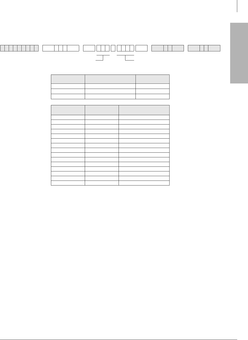
Automatic Call Distribution
Program *09 – ACD Group DID Line Digit Assignments
Strata DK Programming 5/99 6-5
Automatic Call Distribution
Program *09 – ACD Group DID Line Digit Assignments
Initialized Default:
See table below
Program *09 Overview
Program *09 assigns DID/Tie line incoming digits to a particular ACD Group and assigns DID
digits to station ports (only if Program 71 is not used).
Related Programs
Program 04 assigns Tie line digits to station ports. (See Programs *09 and 04 in the Strata DK
Programming Manual.)
Refer to Program 17, LED 05-for DID and Tie line options. Use Program *09 if Program 71 DID/
Tie/DNIS/ANI line call routing is not being used.
If the digits assigned to the group are sent to the Strata DK System on any incoming DID or Tie
line call, the call is directed to the assigned ACD Group (see Program 14-0 to assign ground and
loop start lines to an ACD Group).
Note If DID/Tie/DNIS/ANI lines use Program 71 (DNIS assignments) instead of Program *09
to route callers to ACD Groups, turn on LED 05 in Program 17 for each of the appropriate
DID/Tie/DNIS/ANI lines. If the line receives ANI but not DNIS, turn LED 05 OFF and 07
and 08 ON in Program 17. Use Program 71 (0~3) to make the appropriate digit and
routing assignments. Refer to Programs 17 and 71.
6SNU+ROG 6SNU +ROG 6SNU +ROG 6SNU +ROG
Processor ACD Group
Port Numbers Default DID/Tie
Line Digits
RCTUBA/BB 090~097 290~297
RCTUC/D 250~265 450~465
RCTUE/F 345~360 870~885
ACD Group
Number ACD Group Port
Number DID/Tie Line Digits
Assigned (1~4 Digits)
DID/Tie line digits assigned to ACD Group Port
Number (1~4 digits)
ACD Group Port Number (3 digits)
Automatic Call Distribution
Program 10-4 – ACD/ISDN Parameters
6-6 Strata DK Programming 5/99
Program 10-4 – ACD/ISDN Parameters
Initialized Default:
LEDs 12 and 14 are ON
Program 10-4 Overview
This program provides three system options. When enabled/disabled these options apply to all
ACD Groups and Agents. ACD system options are set as follows:
LED 01: Set Next-Available-First or Most-Idle-First Routing
Sets which algorithm the system follows to route ACD calls.
Next-Available-First, Turn LED 01 OFF—The Agent list is searched sequentially, starting from
(not including) the last found Agent, and ending with the first found available Agent. This method
of searching is similar to the circular-distributed hunt method.
Most-Idle-First, Turn LED 01 ON—The Agent with the most idle time, since the last ACD call,
receives the next call. If all Agents are busy and an Agent becomes available, that Agent
automatically receives the next call, regardless of idle time. If that should happen, the Agent with
the longest idle time may have to wait to receive a call. As Agents go idle, they are added to the
end of the ACD Agent routing list.
6SNU +ROG 6SNU +ROG 6SNU +ROG 6SNU +ROG
Button/
LED XLED ON LED OFF
20
19
18
17
16
15
14 ISDN “Start” access code is sent when the Speed Dial
(SDS) button is pressed (initialized). ISDN Start access code is not sent.
13 Receive 3.1kHz audio calls as speech calls only if a
progress indicator is sent. Always receives 3.1kHz calls.
12 BRI T-Wait ON (initialized) BRI T-Wait OFF
11 PRI T-Wait ON PRI T-Wait OFF (initialized)
10
09
08
07
06
05
04 All Agents Unavailable Route: Per Prog. 14-5 (Overflow
Point Destination) All Agents Unavailable Route: Per Prog. 14-6 (After Shift
Destination)
03 Agent receives Supervisor Monitor Tone/LCD display
when being monitored Agent does not receive Supervisor Monitor Tone/LCD
display when being monitored
02
01 ACD Mode: Most idle Agent receives next call ACD Mode: Next Available Agent receives next call
Light Button/LEDs as defined by the table below. If
the X column is checked, the LED should be ON.
SELECT = 4

Automatic Call Distribution
Program 10-4 – ACD/ISDN Parameters
Strata DK Programming 5/99 6-7
Automatic Call Distribution
Note During busy ACD call traffic conditions, the algorithm routes calls that have been waiting
in the ACD Group queue directly to the first Agent telephone that becomes available.
LED 03: Supervisor Monitor Tone and Display
If Tone/LCD is enabled when a Supervisor monitors an Agent telephone, the Agent receives a
short dial tone burst (every 15 seconds) and a steady LCD display: MONITOR BY SUPRV. The
system also sends the monitor tone to the outside caller connected to the Agent. If Tone/LCD is not
enabled, the Agent and outside caller has no indication that their call is being monitored by the
Supervisor.
LED 04: ACD Group Unavailable Destination
When all Agents in a Group are in the Unavailable mode simultaneously, new incoming ACD calls
that are normally routed to the ACD Group’s call waiting queue is immediately diverted to either
the Overflow-Queue-Point destination (set in Program 14-5) or to the End-of-Shift destination (set
in Program 14-6), depending on the status of Program 10-4 LED 04 (see Flowchart 6-6 on Page
6-46).
LED 11: PRI ISDN Timer
The T-Wait timer is an ISDN timer that is required to reduce the potential for a network overload
condition due to a large number of ISDN terminals requesting initialization at the same time (e.g.,
due to an area-wide power failure). This timer creates a random time interval and is called upon
power up to set a value to delay the initialization process until the timer has expired. This timer is
seldom used for PRI interfaces.
LED 12: BRI ISDN Timer
The T-Wait timer for BRI and PRI terminals works the same way. See LED 11 for a description.
This timer should be used for BRI terminals and only disabled if the local provider instructs
disabling this timer.
LED 13: 3.1kHz Audio
Calls received from the non-ISDN portion of the public network come in 3.1 kHz audio. A
progress indicator is not always provided for these types of calls. Turning LED 13 OFF allows all
calls to be received. Toshiba recommends keeping LED 13 OFF until some time in the future when
the public network is updated to send a progress indicator with all calls.
LED 14: ISDN Start Button Access Code
When LED 14 is ON, the ISDN 6WDUW button access code is automatically sent when the 6SHHG
'LDO (or 6'6) button is pressed. The default is ON. If LED 14 is OFF, the number entry timer
expires.
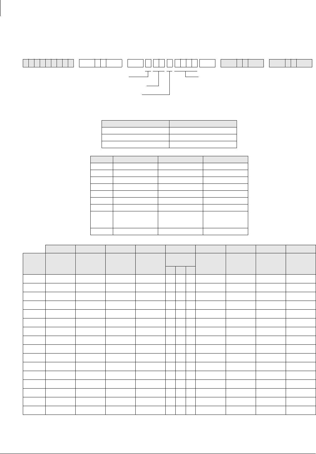
Automatic Call Distribution
Program 11 – ACD Timing Assignments
6-8 Strata DK Programming 5/99
Program 11 – ACD Timing Assignments
Initialized Default:
See table below
6SNU +ROG 6SNU +ROG6SNU +ROG 6SNU +ROG
Processor ACD Group Numbers
RCTUBA/BB 01~08
RCTUC/D 01~16
RCTUE/F 01~16
Code Time Initialized Data Notes
1 0000~3600 sec. 0030 sec. 0000 = No Overflow
2 000~255 sec. 030 sec.
3 000~255 sec. 060 sec.
4 000~120 sec. 001 sec.
5 000~999 sec. 030 sec.
6 000~255 sec. 120 sec.
7 000~600 sec. 240 sec.
8 00~30 min. 01 min. 00 Disables Alarm
Guard Timer; blocks
Alarm Reset
9 00~60 min. 00 min. 00 Disables Timer
Code 1 Code 2 Code 3 Code 4 Code 5 Code 6 Code 7 Code 8 Code 9
ACD
Group
Number
Queue
Overflow
Timer
Ring Agent
Timer Wrap-up
Timer
RBT before
Announce
Timer
Connect to
Music Timer Call Waiting
Alarm
Timer 1
Call Waiting
Alarm
Timer 2
Alarm
Guard Timer
Disconnect
of ACD Call
Timer
1 2 3
1
2
3
4
5
6
7
8
9
10
11
12
13
14
15
16
DATA = Time (min. or sec.)Code (1~9)
ACD Group Number
Music Timer (1~3)
(used only with Code 5, skip this
entry for all other codes)

Automatic Call Distribution
Program 11 – ACD Timing Assignments
Strata DK Programming 5/99 6-9
Automatic Call Distribution
Program 11 Overview
The ACD timers listed below can be set individually for each ACD Group. ACD timers apply to
loop, Tie, DID, DNIS, and ANI lines, not ground start lines.
Code 1: Time in ACD Queue Before Overflow
The time period (ranges from 0000~3600 seconds) a call(s) remains in an ACD queue pattern
before it attempts to overflow to the destination set in Program 14-4. The queue timer can be set
from 1 second to 3600 seconds (60 minutes) or to no overflow time out. If no overflow time out is
set (Data = “0000”), then the call remains in queue or overflows per Program 14-5 operation
settings (see Flowcharts 6-3 and 6-4 on Pages 6-43 and 6-44).
Code 2: Ring Agent Timer
The time period (ranges from 000 seconds to 4 minutes and 15 seconds) an ACD call will ring an
idle Agent telephone. When the time expires and the call is unanswered, the system hunts and
rings another idle Agent telephone from the same ACD Group for the same duration of time.
This process continues until all idle Agent telephones have been rung or the call is answered. If the
call remains unanswered after ringing the last idle Agent, it is routed to the destination set in
Program 14-5.
If the destination set in Program 14-5 is a [DN], the ACD line if idle rings the [DN]. If the [DN] is
busy, the ACD line rings the idle or busy [DN] or CO /LQH3RROHG/LQH*US button assigned to
ring in Programs 81, 84, and 87 and flash in *81, *84, and *87. If a DID/Tie/DNIS/ANI line is
used, the call camps on to the busy station set in Program *14-2 (see Flowchart 6-7 on Page 6-47).
Code 3: After Call Work Timer
Immediately after an Agent disconnects from an ACD call, the After Call Work Timer begins to
count down (ranges from 000 seconds to 4 minutes, 15 seconds). The wrap-up count is updated to
display the active condition on the Agent telephone LCD (the wrap-up time remaining counts
down each second).
When an Agent telephone is in the After Call Work Time mode (wrap-up timer count down), the
telephone does not receive ACD calls, but it can receive non-ACD or PBX calls. An Agent can
cancel the wrap-up mode anytime by pressing the (QG$IWHU&DOO:RUN7LPH button, by
making another call, or by going off and on-hook. After Call Work Time is not activated after the
completion of PBX calls made from, or received on, the Agent telephone’s $&'&DOO button or
[PhDN].
Code 4: Ring-Back-Tone (RBT) Timer
Defines the time that a new incoming ACD call receives ring back tone, if no Agents are idle and
the caller must wait for the ACD queue announcement (ranges from 000~120 seconds) (Flowchart
6-1 on Page 6-41). This timer only applies to CO lines that are routed directly to the ACD Group
(all types of CO lines).
If a CO line is transferred to an ACD Group by a station or DK AA and no Agents are idle, this
timer does not apply. Calls immediately enter the ACD Group’s queue. If a caller hangs up while
connected to the RBT timer, the call is considered unanswered and the Strata DK system does not
send answer supervision (800-type calls are not billed in this case).
If the outside caller hangs up while the incoming call is connected to the RBT timer, the call is
abandoned and is not considered as an answered call. No answer supervision is sent from the
Strata DK System and “800” type calls will not be billed. Calls abandoned after the call is sent to
the first announcement will be considered as answered and billed.

Automatic Call Distribution
Program 11 – ACD Timing Assignments
6-10 Strata DK Programming 5/99
Code 5: Music Timers 1, 2, and 3
Defines the time interval that ACD callers in queue are sent music following the first, second, or
third announcement. Range of each music timer is 000~999 seconds (about 5 seconds to 16 1⁄2
minutes).
The connection time tolerance when switching between music and announcements is 5 seconds;
example, if a music timer is set for 00 seconds, the caller may still hear up to 5 seconds of music if
a music source is installed.
♦Timer 11-51 defines the music interval following the first announcement.
♦Timer 11-52 defines the music interval between the second and third announcement on three-
announcement queue patterns. Timer 11-52 is not used on one or two announcement queue
patterns.
♦Timer 11-53 defines the music interval following the second announcement on two-
announcement queue patterns; or, the music interval following the third announcement on
three-announcement queue patterns. Each music timer can be individually set from 000
seconds to 16 minutes, 39 seconds (see Flowcharts 6-8~6-10 on Pages 6-48~6-51).
Code 6: Call Waiting Alarm Timer 1
Defines the first alarm threshold time for the ACD calls waiting in queue (ranges from 000~255
seconds). If a defined number of ACD calls (per Program 14-72) are in queue longer than the time
defined in Program 11-6, the ACD Supervisor telephone is sent a beeping alarm indication (2400
Hz/10 Hz, 0.75 second OFF, 0.75 second ON). Program 14-8 DATA must be set to “2” for the Call
Waiting Alarm Timer 1 to operate.
Code 7: Call Waiting Alarm Timer 2
Defines the second alarm threshold time for ACD calls waiting in queue (ranges from 000~600
seconds). If a defined number of ACD calls (per Program 14-73) are in queue longer than the time
defined in Program 11-7, the ACD Supervisor telephone is sent a beeping alarm indication (2400
Hz/10 Hz, one continuous sound). Program 14-8 DATA must be set to “2” for the Call Waiting
Alarm Timer 2 to operate.
Code 8: Alarm Guard Timer
Defines the minimum time interval between queue alarm signals sent to the Supervisor telephone.
The timer can be set from 01~30 minutes. If the timer is set to 00, the 5HVHW4XHXH$ODUP
button does not function to end a queue alarm indication on the Supervisor telephone.
Example: If the queue alarm sounds at the Supervisor telephone and the Supervisor resets the
alarm by pressing the flashing 5HVHW4XHXH$ODUP button, the Alarm Guard Timer begins to
count down from the time set in this program. If the number of calls in the ACD queue still
exceeds the queue size (set in Program 14-71, 72, or 73) after the Alarm Guard Timer expires, the
alarm sounds again on the Supervisor telephone.

Automatic Call Distribution
Program 11 – ACD Timing Assignments
Strata DK Programming 5/99 6-11
Automatic Call Distribution
Code 9: Call Disconnect Timer
Defines the maximum time an ACD call can remain in queue (ranges from 01~60 minutes). This
timer should be used when using loop start, Tie, or DID, DNIS, ANI on ACD lines. This prevents
CO lines from being connected to an ACD queue for an indefinite period of time after the outside
caller hangs up and the CO line does not provide the Calling Party Control (CPC or AR)
disconnect signal. This timer only disconnects calls in queue; it does not disconnect calls that are
answered by Agent telephones or other telephones/devices. If 00 data is entered, the disconnect
feature is disabled.
The disconnect feature is always disabled for ground start CO lines (see Flowchart 6-2 on Page
6-42, later in this chapter).
Note 255 sec. is 4 minutes and 15 seconds.
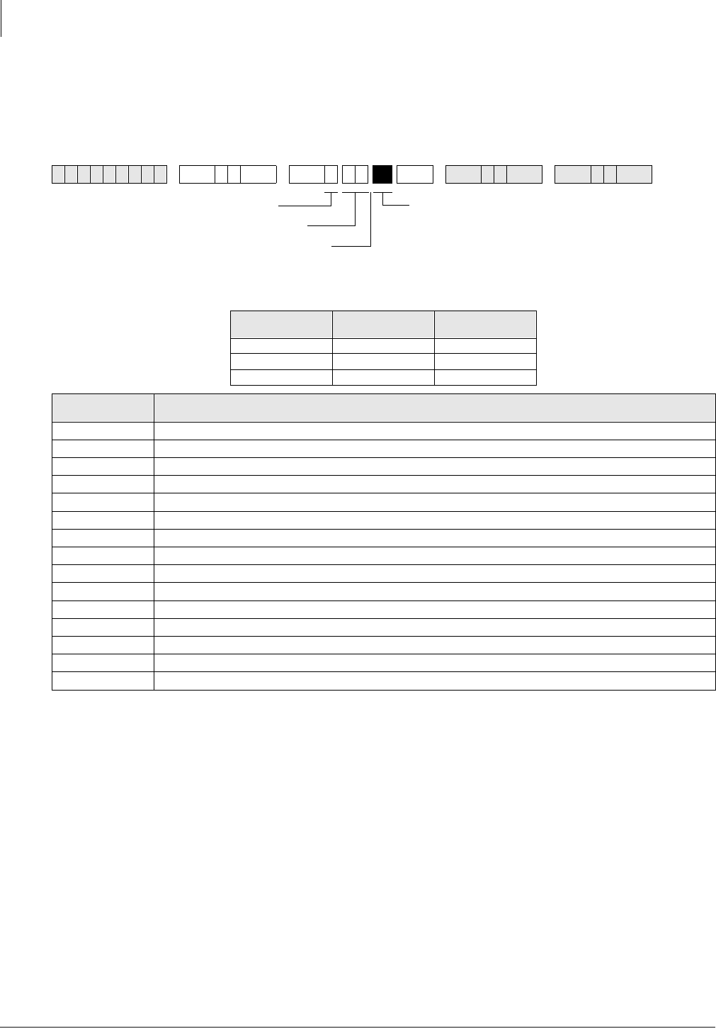
Automatic Call Distribution
Program 14-0 – Loop/Ground Start Line Direct to ACD Group Assignments
6-12 Strata DK Programming 5/99
Program 14-0 – Loop/Ground Start Line Direct to ACD
Group Assignments
Initialized Default:
No CO lines assigned to direct ring to ACD Groups (all LEDS OFF)
Program 14-0 Overview
Assigns ground and loop start CO lines to directly ring a designated ACD Group. CO lines that are
assigned to an ACD Group should also be assigned as a line group in Program 16. A CO line can
only be assigned to one ACD Group.
Important! Agent telephones that should receive calls from lines assigned to an ACD Group,
should not be assigned a 3RROHG/LQH*US button or individual CO /LQH buttons
(Program 39) for lines that are in the ACD Group.
ACD line calls ring Agent $&'&DOO buttons [PhDNs] and ACD calls that overflow ring the
overflow destination telephone [DN] buttons or CO /LQH/3RROHG/LQH*US button.
See Programs *09, 17 (LED 05) and 71-1 for DID/Tie/DNIS/ANI line digit to ACD Group
assignments. Also see Program 11 (Code 1~9)—ACD Timing Assignments.)
Note Program assignment 78-61~63 overrides Program 14-0 CO line assignments.
6SNU +ROG 6SNU +ROG 6SNU +ROG 6SNU +ROG
Processor ACD Group
Number CO Line Range
RCTUBA/BB 01~08 001~048
RCTUC/D 01~16 001~144
RCTUE/F 01~16 001~200
ACD Group
Number ACD CO Line Assignments
(Write in CO lines assigned to direct ring each ACD Group on incoming calls.)
Light Button/LEDs of CO lines that should be
assigned to the ACD Group.
SELECT = 0
ACD Group Number
Press Scroll to advance or
Page to go back.

Automatic Call Distribution
Program 14-1 – ACD Agent Identification Code Assignments
Strata DK Programming 5/99 6-13
Automatic Call Distribution
Program 14-1 – ACD Agent Identification Code
Assignments
Initialized Default:
blank
Use the Record Sheet that follows Program 18.
Program 14-1 Overview
This program assigns Agent Identification (ID) codes to each ACD Group. To receive an ACD call
from a specific ACD line group, the Agent must log in to the ACD Group by dialing the ID code
(four digits) assigned in this program.
Note A telephone can be logged in as either an Agent or Supervisor telephone in any ACD
Group, but it cannot be logged in as an Agent and a Supervisor simultaneously. Agents can
only log in to one ACD Group at a time. See Program 14-2 for more information.
6SNU +ROG 6SNU +ROG 6SNU +ROG 6SNU +ROG
DATA = Agent ID Log in Code (0000~9999)
DATA = ACD Group Number
SELECT = 1
SELECT = Agent ID Number (000~255)

Automatic Call Distribution
Program *14-1 – Auto Answer with Zip Tone Assigned to Agent ID
6-14 Strata DK Programming 5/99
Program *14-1 – Auto Answer with Zip Tone Assigned
to Agent ID
Initialized Default:
Group Number = 01. Agent ID Code = blank. DATA 0 = No Auto Answer.
Use the Record Sheet that follows Program 18.
Program *14-1 Overview
This program assigns Auto Answer to Agent telephones. When Auto Answer is enabled, the
telephone generates a zip tone (one-half second burst of dial tone) into the handset and the Agent
can automatically answer ACD calls.
If the Agent telephone is off-hook, the headset receiver or if on-hook, the telephone speaker
receives zip tone when an ACD call is sent to the Agent. Auto Answer applies to direct and
transferred ACD calls, but not to incoming PBX calls to the Agent $&'&DOO [PhDN] button.
6SNU+ROG 6SNU +ROG 6SNU +ROG 6SNU +ROG
DATA =
0 = No Auto Answer
1 = Auto Answer
SELECT = 1
SELECT = Agent ID Number
(000~255)
Press # for single port entry.
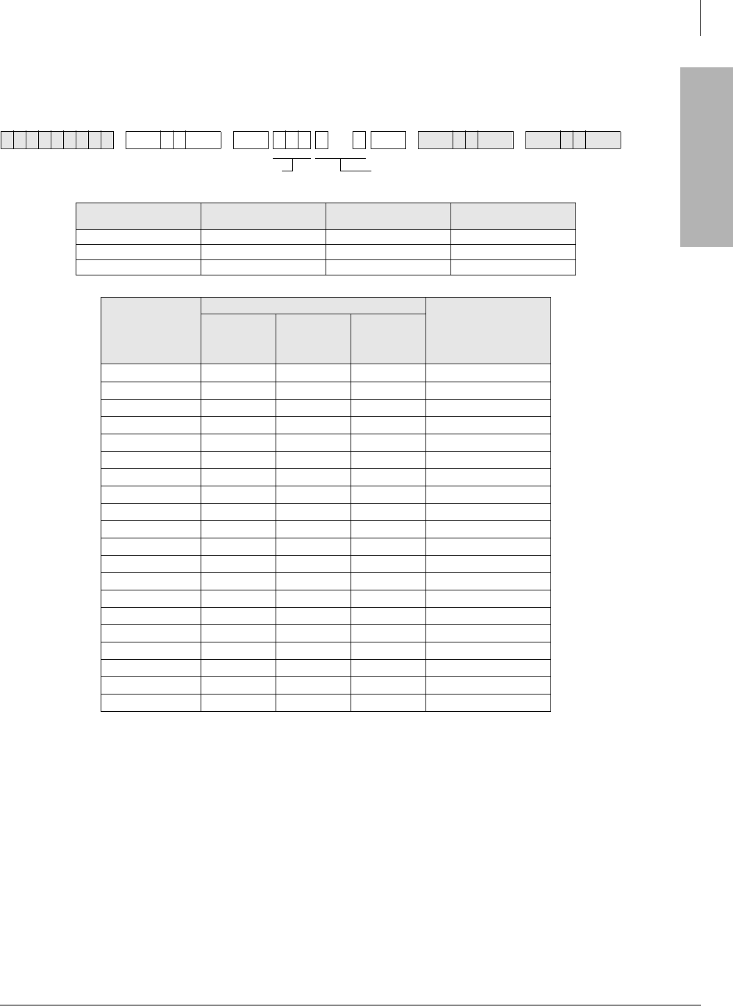
Automatic Call Distribution
Program 18 – Agent Names for SMIS/MIS Assignments
Strata DK Programming 5/99 6-15
Automatic Call Distribution
Program 18 – Agent Names for SMIS/MIS Assignments
Initialized Default:
blank
Program 18 Overview
Each Agent ID number (set in Program 14-1) can be assigned an alphanumeric name (8 characters
maximum) that displays on the ACD SMIS displays and reports.
The name for each Agent is entered in this program from a terminal or the programming telephone
(use the Program Record Sheet following Program *14-1).
➤To enter an Agent ID name or number
1. Enter Program 18, then select the desired Agent ID Number.
2. Enter the Agent name (eight characters maximum, see dial pad callouts below).
6SNU +ROG 6SNU +ROG 6SNU +ROG 6SNU +ROG
Processor Agent ID
Numbers ACD Group
Numbers Maximum Number of
Agent ID Codes
RCTUBA/BB 000~199 01~08 200
RCTUC/D 000~255 01~16 256
RCTUE/F 000~255 01~16 256
Program *14-1
Auto Answer with
Zip Tone
Program 14-1
Program 18
Agent Name
(8 characters max.)
Agent ID
Number ACD Group
Number
Agent ID
Code
(4 digits
max.)
DATA = Agent Name (8 characters maximum)SELECT = Agent ID Number (000~255)
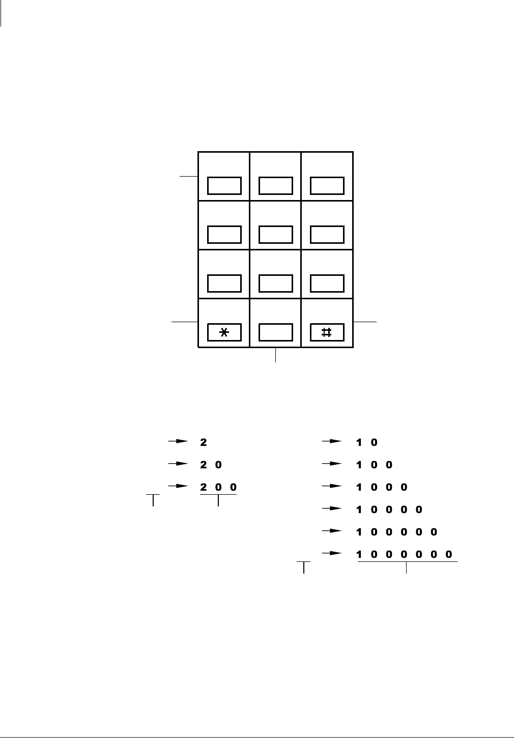
Automatic Call Distribution
Program 18 – Agent Names for SMIS/MIS Assignments
6-16 Strata DK Programming 5/99
➤To erase data
➤Press LED button 01.
Numeric Mode
0 to 9 are treated as numerals.
Note Dial pad starts out in Numeric Mode. Press button to switch to Alpha Mode.
Figure 6-1 Alpha Mode
0
123
456
789
Moves cursor to
right, and starts
special character
entry when in
the Alpha Mode.
Moves cursor
to left. Changes from
Numeric to
Alpha Mode
and vice versa.
Scrolls alpha and
special characters.
Alpha Entry (Example): Special Character Entry:
A
B
C
“Q”
“Z”
“:”
“–”
“+”
“/”
Alpha
Character Entry
Sequence
Special
Character Entry
Sequence
QZ ABC DEF
GHI JKL MNO
PRS TUV WXY
Cursor
Left Scroll Mode
1936

Automatic Call Distribution
Program 14-2 – ACD Supervisor Passwords
Strata DK Programming 5/99 6-17
Automatic Call Distribution
Program 14-2 – ACD Supervisor Passwords
Initialized Default:
All blanks
Program 14-2 Overview
Assigns a Supervisor ID code to each ACD Group. Only one code is allowed per Group. When a
Supervisor ID code is logged into the system, the telephone is assigned (with all Supervisor
features) to the ACD Group with that Supervisor ID code.
If the telephone has an LCD, it can be used to monitor Agent and Queue Status for all ACD
Groups by using special access codes ;; and ;; (where XX = ACD Group number).
If a code is assigned to a non-existing ACD Group, the code can be used by a Manager (for
example) to check the Agent and/or Queue Status of any ACD Group.
6SNU +ROG 6SNU +ROG 6SNU +ROG 6SNU +ROG
Processor ACD Group Numbers
RCTUBA/BB 01~08
RCTUC/D 01~16
RCTUE/F 01~16
ACD Group Number Supervisor ID Code Name
DATA = Supervisor ID Code (0000~9999)
GROUP = ACD Group Number
SELECT = 2
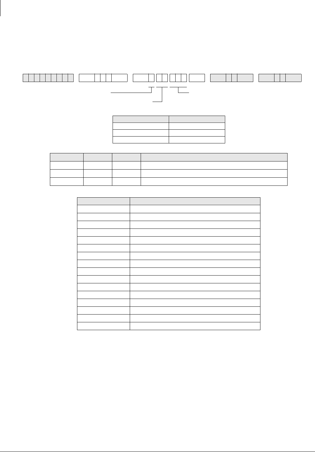
Automatic Call Distribution
Program *14-2 – DID, Tie, DNIS, ANI Line After Shift/Overflow Substitution Destinations
6-18 Strata DK Programming 5/99
Program *14-2 – DID, Tie, DNIS, ANI Line After Shift/
Overflow Substitution Destinations
Initialized Default:
Port 000
Program *14-2 Overview
Assigns a Normal Ringing or AA substitute destination for DID and/or Tie lines.
If an ACD Group is assigned to overflow (in Program 14-4 or 14-5) or route after shift service
(Program 14-6) to the DK built-in AA or to Normal Ringing assignments (code 320 or 321), these
assignments only apply to loop/ground start CO line calls. DID/Tie/DNIS/ANI line calls are
directed to the port assigned in this Program (*14-2).
This is because only loop and ground start CO lines (not Tie or DID lines) can be routed to DK AA
and/or Normal Ringing assignments.
6SNU+ROG 6SNU + ROG 6SNU +ROG 6SNU +ROG
Processor ACD Group Numbers
RCTUBA/BB 01~08
RCTUC/D 01~16
RCTUE/F 01~16
RCTUBA/BB RCTUC/D RCTUE/F DID/Tie/DNIS/ANI Overflow Substitution Destination
000~079 000~239 000~335 Station or Attendant Console [PDN] Program 04 Port Number
500~579 500~739 500~835 [PhDN] Program *04 Port Number
900~915 900~915 900~915 Distributed Hunt Group Program *04 Port Number
ACD Group Number Destination
DATA =
DID/Tie/DNIS/ANI Overflow Substitution
SELECT = 2
SELECT = ACD Group Number

Automatic Call Distribution
Program *14-2 – DID, Tie, DNIS, ANI Line After Shift/Overflow Substitution Destinations
Strata DK Programming 5/99 6-19
Automatic Call Distribution
Notes
●If the assignments for an ACD Group: Overflow Queue Timer (Program 14-4), Overflow
Queue Point (Program 14-5), and/or After Shift (Program 14-6) destinations are programmed
as Normal Ringing or AA, DID/Tie/DNIS/ANI lines will be routed to the destination [DN]
assigned in this program. This is because DID/Tie/DNIS/ANI lines cannot be assigned to AA
or Normal CO line ringing.
●If the destination [DN] assigned in this program is busy when one of the following occurs
(Ring No Answer, All Agents Unavailable, End of ACD Shift), the overflowing DID/Tie/
DNIS/ANI line will camp on to the [DN]. Call Forward and/or Hunt from the destination
assigned will occur if set on the destination station.
●DID, DNIS, ANI, and Tie line calls in queue do not overflow to busy ACD Groups, Intercom
numbers, [PDNs], [PhDNs], or Distributed Hunt Groups; they remain in queue until the
destination becomes idle.
●Call Forward No Answer will occur if set on the destination assignment. If the overflow
destination is a Strata DK Attendant Console, calls will exit queue and overflow to the
Attendant Console when the console is idle or busy.

Automatic Call Distribution
Program 14-3 – Announcement/Music Port and Queue Pattern
6-20 Strata DK Programming 5/99
Program 14-3 – Announcement/Music Port and Queue
Pattern
Initialized Default:
all blanks
Program 14-3 Overview
This program is used to make announcement/music port and queue pattern assignments. All
announcement devices (digital announcers) must connect to standard telephone ports (RSTU,
RSTU2, RDSU/RSTS, PSTU, PESU).
The music source can be the MOH source connected to the RCTU RCA jack, another source
connected to a standard telephone port or an electronic telephone port (voice pair).
6SNU +ROG 6SNU +ROG 6SNU +ROG 6SNU +ROG
Processor ACD Group Numbers Port Numbers
RCTUBA/BB 01~08 000~079
RCTUC/D 01~16 000~239
RCTUE/F 01~16 000~335
Code 1 Enter the RSTU or RSTU2 (or equivalent) port number of the first announcement.
Code 2 Enter the RSTU or RSTU2 (or equivalent) port number of the second announcement if queue pattern has three announcements.
(Enter Code 2 assignment only if there are three announcements. Skip to Code 3 if only two announcements are used for the ACD
Group queue.
Code 3 Enter the second announcement port for two-announcement queue patterns or enter the third announcement port for three-
announcement queue patterns.
Code 4 Enter the RSTU, RSTU2 or PEKU Music Source port number or enter 999 if the music source is a Music-on-Hold (MOH) source.
Code 5 Enter the announcement number (1~3) of the first announcement that should repeat to calls in queue.
ACD Group
Number
Code 1
Announcement
1 Port
Code 2
Announcement
2 Port
Code 3
Announcement
2 or 3 Port
Code 4
Music Source Port
Code 5
Repeat
Announcement
Number
DATA = Port number of Music or Announcement
Source
Enter blanks with Button/LED 01.
SELECT = 3
Code (1~5)
ACD Group Number

Automatic Call Distribution
Program 14-3 – Announcement/Music Port and Queue Pattern
Strata DK Programming 5/99 6-21
Automatic Call Distribution
Each ACD Group can have from one to three announcements and a separate music source.
Announcements and/or music sources can also be shared in any combination between ACD
Groups (see Flowcharts 6-8~6-10 on Pages 6-48~6-51).
Code 1: Announcement Port One
Assigns the port that will be connected to the digital announcer that should be activated first when
a CO line call enters the ACD Group queue. Code 1 always assigns the first announcements in a
queue pattern. Skip Code 2 and Code 3 programming if only one announcement is used for the
ACD Group queue.
Code 2: Announcement Port Two
Assigns the port to which the second announcement device connects in a three-announcement
queue pattern. If only two announcements are used for the ACD Group queue, skip to Code 3.
Code 3: Assigns Port for Second or Third Announcement Device
Assigns the port to which the second announcement device connects in a two-announcement
queue pattern. Or, it is the port connected to the third announcement device in a three-
announcement queue pattern.
Code4: ACD Queue Music Source Port
Assigns the station port or RCTU MOH jack to which the ACD queue music source is connected.
The music is sent to callers in the ACD Group queue during the time intervals set in Programs 11-
51, -52, and -53, or continuously until an Agent answers or the call overflows (see Non-repeating
Queue Announcement following Program 14-5).
Code 5: Select Repeat Enactment for Queue Pattern
After the last music timer (11-51, -52, or -53) in the queue pattern expires, the queue pattern
announcements and music can be repeated to callers starting with announcement 1, 2, or 3. Use
Code 5 to select which announcement to start the repeat queue pattern process. The queue pattern
is repeated until an Agent answers, the call overflows per Program 14-4, the caller hangs up, or the
disconnect timer expires (Program 11-9). The queue pattern can be set to repeat or not repeat
announcements, depending on the options set in Program 14-5 (see Flowcharts 6-8~6-10 on Pages
6-48~6-51).
Queue Pattern Options 1, 2, and 3 are shown in the following diagram. For more details, ee
Flowcharts 6-8~6-10 on Pages 6-48~6-51.
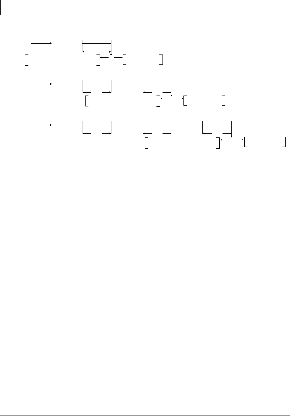
Automatic Call Distribution
Program 14-3 – Announcement/Music Port and Queue Pattern
6-22 Strata DK Programming 5/99
Figure 6-2 ACD Queue Announcement and Music Patterns
Or
Or
QUEUE
PATTERN 1
Go back to repeat announcement 1
assigned in Code 5 above, no
overflow point OP0 in Program 14-5XX0.
Announcement 1
Code 1
Code 4
Music Source
Program 11-51
Timer
QUEUE
PATTERN 2 Announcement 1
Code 1 Announcement 2
Code 3
Program 11-51
Timer Program 11-53
Timer
QUEUE
PATTERN 3 Announcement 1
Code 1 Announcement 2
Code 2
Program 11-51
Timer Program 11-52
Timer Program 11-53
Timer
Overflow point OP1
in (Program 14-5XX1).
Go back to repeat announcement 1 or 2
assigned in Code 5 above, no
overflow point OP0 in Program 14-5XX0.
Overflow point OP2
in (Program 14-5XX2).
Announcement 3
Code 3
Go back to repeat announcement 1, 2 or 3
assigned in Code 5 above, no
overflow point OP0 in Program 14-5XX0.
Overflow point OP3
in (Program 14-5XX3).
Code 4
Music Source Code 4
Music Source
Code 4
Music Source Code 4
Music Source Code 4
Music Source
Or
1940
XX=ACD Group Number
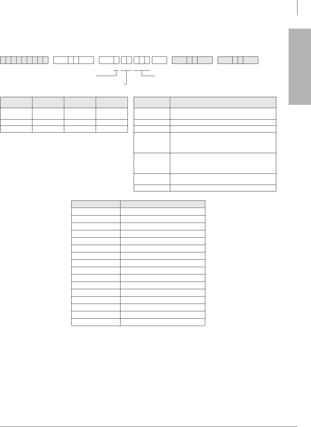
Automatic Call Distribution
Program 14-4 – Queue Time Out Overflow Destination
Strata DK Programming 5/99 6-23
Automatic Call Distribution
Program 14-4 – Queue Time Out Overflow Destination
Initialized Default:
Port 000
Program 14-4 Overview
This program sets the overflow point destination for CO line calls that are in an ACD queue for
longer than the queue time set in Program 11-1. Calls only overflow when the overflow destination
is idle or when it becomes idle if the overflow destination is a [PDN], [PhDN], Distributed Hunt
[DH] Group, port or another ACD Group (see Flowchart 6-3 on Page 6-43).
If the overflow destination is an ACD Group or a station port [DN] and it is busy, the call remains
in queue.
6SNU +ROG 6SNU +ROG 6SNU +ROG 6SNU +ROG
Processor ACD Group
Numbers [PDN] Port
Range [PhDN] Port
Range DATA Queue Timeout Overflow Destination
RCTUBA/BB 01~08 000~079 500~079 See [PDN] Port
Range Station or Attendant Console (See [PDN] Port Range)
RCTUC/D 01~16 000~239 500~739 301~316 ACD Group (RCTUBA/BB, RCTUC/D)
RCTUE/F 01~16 000~335 500~835 401~416 ACD Group (RCTUE/F)
320 (RCTUBA/
RCTUBB,
RCTUC/D)
420 (RCTUE/F)
Auto Attendant (DK Built-in)
321 (RCTUBA/
RCTUBB,
RCTUC/D)
421 (RCTUE/F)
Normal CO line; Ring assignments not including delayed
ringing assignments
See [PhDN] Port
Range [PhDN] Program *04 Port Number
900~915 Distributed Hunt Group Program *04 Port Number
ACD Group Number Overall Queue Time Out Destination
SELECT = 4
SELECT = ACD Group Number
DATA = Queue Timeout Overflow Destination

Automatic Call Distribution
Program 14-4 – Queue Time Out Overflow Destination
6-24 Strata DK Programming 5/99
If the overflow destination is to a Normal Ring assignment (Programs 81~89 and *81, *84, and
*87), Attendant Console or the built-in AA, calls will exit queue and overflow if the destination is
idle or busy. This assignment is not necessary if the overflow queue timer is set to infinity (infinity
= 0000 in Program 11-1).
Only ground and loop start ACD calls will overflow to the Strata DK AA or Normal Ringing. DID,
DNIS, and Tie lines will overflow to the assignment set in Program *14-2 if codes 320, 321, 440 or
441 is set in this program.
If the overflow destination is busy when overflow time occurs, the following options are available:
♦If the call(s) should exit the ACD queue and mute ring the busy overflow station, assign Code
321 (normal ringing) in Program 14-4 and assign the ACD lines to ring the overflow station
[DN] in Programs 81, 84, 87, *81, *84, and *87.
Note Delay ring assignments do not apply to Program 14-4 for delay ring.
♦If the overflow destination is the DK Built-in AA or an Attendant Console, calls will always
exit queue when the overflow timer expires (Program 11-1) – even if the AA or Attendant
Console is busy.
♦If the call(s) should remain in queue until the busy overflow station or [DN] becomes idle,
assign the overflow destination [DN] or another ACD Group in Program 14-4 as the overflow
point.
♦If the overflow destination is a busy Distributed Hunt Group, the ACD call will not exit the
ACD queue and enter the Distributed Hunt Group queue.
♦If it is required to route “Queue Time Out” overflow calls to a Voice Mail box (see the
Program 14-6 record sheet).
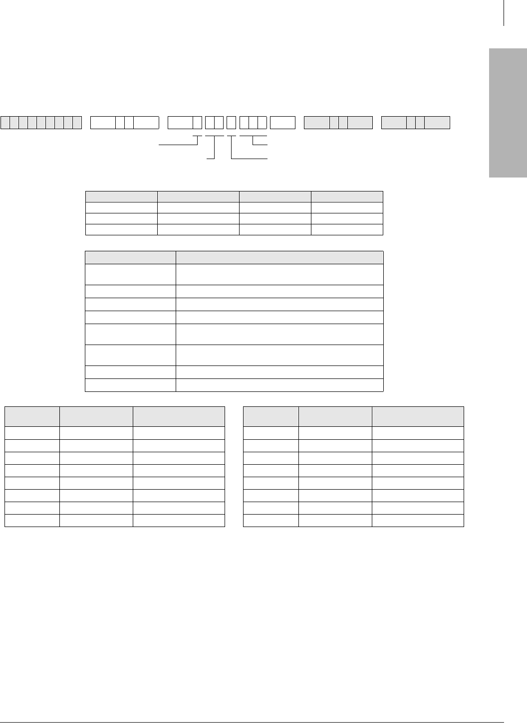
Automatic Call Distribution
Program 14-5 – Overflow Point and Ring No Answer Routing Destination
Strata DK Programming 5/99 6-25
Automatic Call Distribution
Program 14-5 – Overflow Point and Ring No Answer
Routing Destination
Initialized Default:
Overflow point=0, no overflow point
Program 14-5 Overview
There are two basic options for call overflow:
Overflow Point: Calls in queue can overflow when they reach a particular point in the queue
pattern (after the first, second, or third music timer expires). DATA = 1, 2, or 3 sets the music timer
overflow point.
Queue Timer Expiration: Calls can cycle in the queue pattern and the same announcement(s) and
music repeats until the overall queue timer expires (no overflow point). DATA = 0 selects the
queue timer expiration. (See Program 14-3, Code 5, also see Flowcharts 6-2 and 6-8 on Pages 6-42
and 6-48).
6SNU +ROG 6SNU +ROG 6SNU +ROG 6SNU +ROG
Processor ACD Group Numbers [PDN] Port Range [PhDN] Port Range
RCTUBA/BB 01~08 000~079 500~079
RCTUC/D 01~16 000~239 500~739
RCTUE/F 01~16 000~335 500~835
DATA Destination
OP0, OP1, OP2, OP3 Overflow Point (OP) Destination (Incoming Port 000). Only one
OP can be programmed. For No Overflow, select DATA=0.
See [PDN] Port Range Station or Attendant Console [PDN] Program 04 Port Number
301~316 ACD Group (RCTUBA/BB, RCTUC/D)
401~416 ACD Group (RCTUE/F)
320 (RCTUBA/BB, C/D)
420 (RCTUE/F) Auto Attendant (DK Built-in)
321 (RCTUBA/BB, C/D)
421 (RCTUE/F) Normal CO line; Ring assignments not including delayed
ringing assignments
See [PhDN] Port Range [PhDN] Program *04 Port Number
900~915 Distributed Hunt Group Program *04 Port Number
ACD Group
Number Overflow Point RNA and Overflow
Point Destination ACD Group
Number Overflow Point RNA and Overflow
Point Destination
DATA = Destination
SELECT = Overflow Point (1~3)
= Queue Timer (0)
SELECT = 5
SELECT = ACD Group Number
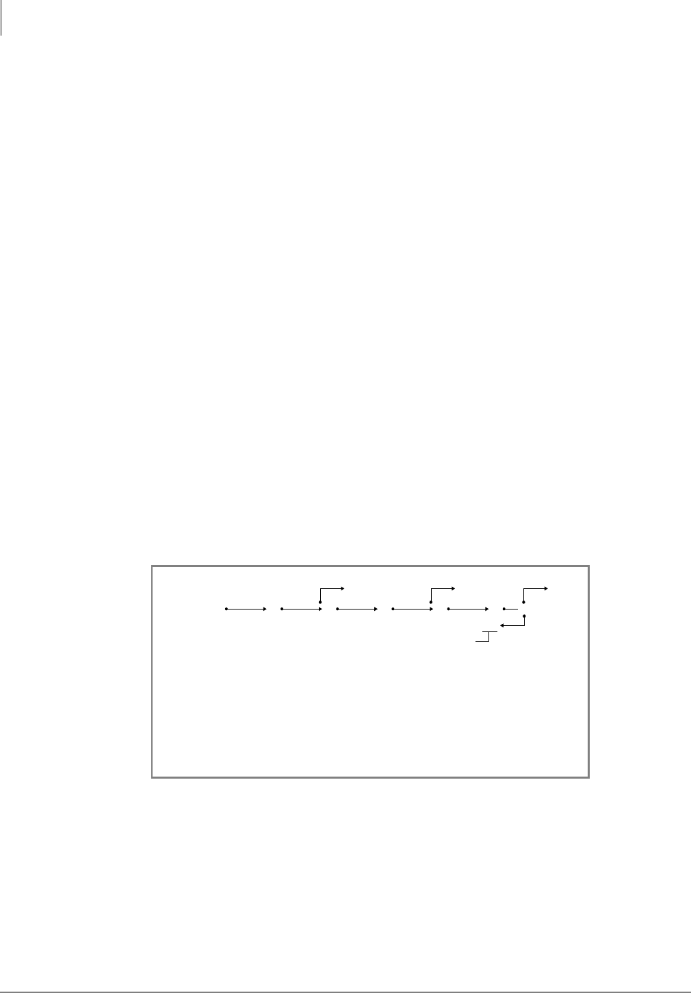
Automatic Call Distribution
Program 14-5 – Overflow Point and Ring No Answer Routing Destination
6-26 Strata DK Programming 5/99
Calls in queue can overflow when they reach a particular point in the queue pattern (after the first,
second, or third music timer expires) or calls can cycle in the queue pattern and the same
announcement(s) and music are repeatedly sent to the destination set in Program 14-4 until the
overall queue timer expires (see diagram later in this section). For further details, see Program 14-
3, Code 5 or Flowcharts 6-4 and 6-8 on Pages 6-44 and 6-48.
♦If all Agents are Unavailable and the LED 04 is turned ON in Program 10-4, calls route to the
destination set in Program 14-5.
♦If the overflow station(s) or [DNs] are busy when overflow time occurs, the following options
are available:
♦If the call(s) should exit the ACD queue and mute ring the busy overflow station, assign
Code 321 (normal ringing) in Program 14-5 and assign the ACD lines to ring the overflow
station [DN] in Programs 81, 84, 87, *81,*84, and *87. Delay Ring assignments do not
apply to Program 14-5 for delay ring.
♦If the overflow destination is the Strata DK System built-in AA or Attendant Console,
calls will always exit queue when the overflow point is reached – even if the AA or
Attendant Console is busy.
♦If the call(s) should remain in queue until the busy overflow destination becomes idle
assign the overflow destination as a [DN] (000~239 or 500~739, except Attendant
Console ports) or ACD Group (01~16) in Program 14-5.
If the Program 14-5 overflow destination is a DH Group, calls will not exit the ACD queue and
enter the busy DH Group queue.
Only ground and loop start ACD calls overflow to the DK AA or normal ringing. DID, DNIS, ANI
and Tie lines will overflow to the assignment set in Program *14-2 if code 320 or 321 is set in this
program.
If announcements should not be repeated, see Flowcharts 6-8~6-10 on Pages 6-48~6-51 and “Non-
Repeating Queue Announcement” explanation under Program 14-5.
Notes
♦Unanswered ACD calls to Agent telephones will be routed to the destination assigned in
Program 14-5.
♦If it is desired to route Overflow Point/RNA calls to a Voice Mail box, see Program 14-6
record sheet for instructions.
A1 M1 A2 M2 A3 M3
OP1 OP2 OP3
OP0
Call Queue Overflow Point (OP) Guide
or
Calls in Queue go back to the announcement (1~3) selected in Program 14-3, Code 5
and continue to repeat until overall overflow Queue Time (Program 11-1). When the
Overflow Queue Timer expires, the call attempts to overflow to the destinations set in
Program 14-4.
1943
A1~A3 = Announcement Device 1~3.
OP1~OP3 can be a station or Attendant Console port (including an additional
announcement device, but not A1~A3), ACD Group, built-in AA, or ring telephone [DNs]
per the normal ringing assignment (Programs 81, 84, 87, *81, *84, and *87).
M = Music Source
M1 Time = Program 11-51
M2 Time = Program 11-52
M3 Time = Program 11-53

Automatic Call Distribution
Program 14-5 – Overflow Point and Ring No Answer Routing Destination
Strata DK Programming 5/99 6-27
Automatic Call Distribution
♦If no overflow point is selected (DATA = 0) and the queue overflow time is set to infinity
(Program 11-1), calls do not overflow.
♦If the overflow operation is at overflow points 1, 2, or 3, assign the overflow destination in this
program.
♦If the overflow occurs after the queue timer expires, assign the overflow destination in
Program 14-4.
♦If all Agents are in the Unavailable mode, CO calls to the ACD Group can be routed to the
assigned overflow destination in this program as an option (see Program 10-4 LED 04).
ACD calls that ring Agent telephones and are not answered route to the destination set in Program
14-5 (see Flowchart 6-7).
Overflow Operation
If the Program 14-5 overflow destination is a station [PDN], [PhDN], another ACD Group, or, a
Distributed Hunt Group and it is busy when a call overflow point is reached, the call remains in
queue until the overflow point destination becomes idle. (See Flowcharts 6-2, 6-3 and 6-4.)
When the overall queue timer expires, the call also attempts to overflow to the destination set in
Program 14-4. The call is sent to an idle Agent or to the overflow point set in Programs 14-4 or 14-
5, whichever becomes idle first.
If the overflow destination is the Normal Ring assignment (Programs 81, 84, and 89), the DK
Attendant Console, or AA, overflow occurs even if the destination is busy. See Flowchart 6-4 on
Page 6-44.)
If the overflow destination is the DK AA or Normal Ringing assignments, DID/Tie/DNIS/ANI
line calls overflow to Program *14-2 assignment only when the destination is idle.)
Non-Repeating Queue Announcement
Case 1—Provide callers with one announcement, followed by music until the call is answered by
an Agent or until the call overflows — refer to Flowchart 6-8 on Page 6-48. (Overflow time is
determined by the overall queue timer; Program 11-1, one second to one hour or no overflow.)
♦Assign Announcement 1 to the appropriate digital announcer standard telephone port
(Program 14-31).
♦Assign Announcements 2 and 3 to any vacant PDKU or PEKU port. (Program 14-32 and 14-
33 , DATA = XXX vacant port. See Notes.)
♦Assign music in Program 14-34.
♦See Notes, following Case 2.
Case 2—Provide the following sequence to callers: Announcement 1, followed by Music 1,
Announcement 2, and then continuous music until the call is answered by an Agent or until the call
overflows — refer to Flowchart 6-10 on Page 6-51. (Overflow time is determined by the overall
queue timer; Program 11-1, one second to one hour or no overflow.)
♦Assigns Announcements 1 and 2 to the appropriate digital announcer, standard telephone port
(Programs 14-31 and 14-32).

Automatic Call Distribution
Program 14-5 – Overflow Point and Ring No Answer Routing Destination
6-28 Strata DK Programming 5/99
♦Assign Announcement 3 to any vacant PDKU or PEKU port (Program 14-33). XX = ACD
Group number, DATA = Vacant Port Number ZZZ.
♦Assign music in Program 14-34.
Notes
In both Cases 1 and 2 above:
♦The vacant port is a digital or electronic telephone port. It must not be connected to a
telephone when assigned as an announcement port in Program 14-3. A station PCB does not
have to be installed for the vacant announcement port.
♦Set overflow point to “0” and the destination to the desired Ring No Answer port XXX
(Program 14-5XX-0-XXX).
♦Set overall queue overflow time (Program 11-1) and the overall queue overflow destination
(Program 14-4XX-YYY) as appropriate for overflow or no-overflow.
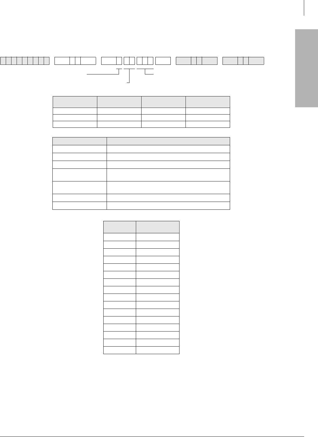
Automatic Call Distribution
Program 14-6 – After Shift Service Destination
Strata DK Programming 5/99 6-29
Automatic Call Distribution
Program 14-6 – After Shift Service Destination
Initialized Default:
Destination = Incoming port 000
6SNU +ROG 6SNU +ROG 6SNU +ROG 6SNU +ROG
Processor ACD Group
Numbers [PDN] Port Range [PhDN] Port Range
RCTUBA/BB 01~08 000~079 500~079
RCTUC/D 01~16 000~239 500~739
RCTUE/F 01~16 000~335 500~835
DATA Destination
See [PDN] Port Range Station or Attendant Console [PDN] Program 04 Port Number
301~316 ACD Group (RCTUBA/BB, RCTUC/D)
401~416 ACD Group (RCTUE/F)
320 (RCTUBA/BB, C/D)
420 (RCTUE/F) Auto Attendant (DK Built-in)
321 (RCTUBA/BB, C/D)
421 (RCTUE/F) Normal CO line; Ring assignments not including delayed
ringing assignments
See [PhDN] Port Range [PhDN] Program *04 Port Number
900~915 Distributed Hunt Group Program *04 Port Number
ACD Group
Numbers After Shift
Destination
DATA = DestinationSELECT = 6
SELECT = ACD Group Number

Automatic Call Distribution
Program 14-6 – After Shift Service Destination
6-30 Strata DK Programming 5/99
Program 14-6 Overview
This program assigns the destination for ACD calls, or calls transferred to an ACD group, that
come in after the ACD shift has ended.
After Shift begins when the Supervisor presses the (QGRI$&'6KLIW button or when the last
Agent logs off (see Flowchart 6-5 on Page 6-45).
If a station port is assigned, only one call at a time is serviced by the End of ACD Shift telephone
or answering device (lowest CO line first if calls are waiting). Waiting calls camp on and receive
ring-back tone.
If all Agents are in the Unavailable mode, calls to the ACD Group can be routed to the After Shift
destination, set in Program 14-6, or to the queue overflow point destination set in Program 14-5
(see Program 10-4, LED 04).
If the End of ACD Shift destination is the Normal Ring assignment (Program 81~89), loop and
ground start lines mute ring busy stations and DID/Tie/DNIS/ANI lines camp on to busy End of
ACD Shift stations assigned in Program *14-2.
If the End of ACD Shift destination is another ACD Group, calls are directed to the Group as if
they were new ACD calls to the Group.
➤To Program ACD loop and/or ground start CO lines to night ring over external page
A PIOU, PEPU, or PIOUS is required.
1. Assign normal ringing (321 or 441) in Program 14-6.
2. Assign ACD lines to night ring over external page in Program 78-13.
3. Assign 1LJKW7UDQVIHU button to appropriate telephone(s) in Program 39.
4. Assign Night Relay operation in Program 77-1, LED 06.
If the destination port assigned in this program is busy when After Shift (or all Agents log out) is
set, DID and Tie lines will camp on to the port while ground and loop start lines will busy override
(mute) ring the port. If the destination station has Call Forward or Hunt set, these features will
operate.
Notes
●DID, DNIS, ANI, and Tie lines cannot be directed to the Strata DK System AA or Normal ring
assignments (321) if code 320, 321, 440, or 441 is assigned in Program 14-6. DID, DNIS, ANI
and Tie line calls will be routed to the destination assigned in Program 14-2.
●Assign all Groups (even if not used) to a destination. This is in case a transferred call is sent to
an unused ACD Group, the call will be sent to the destination assigned in Program 14-6.
●If it is required to route calls to a Voice Mail box during the After Shift mode, you may
designate a Group announcement (A1~A3) port as the After Shift destination – temporarily
use a standard telephone to Call Forward All Calls from the announcement port to the Voice
Mail device and set the VMID code of the announcement port (#656 digits) to the desired After
Shift Mailbox.
●During normal operation, the announcement port will play messages to callers in queue;
during the After Shift mode, calls will forward from the announcement port to the After Shift
Voice Mail box. This operation is also allowed for Programs 14-4 and 14-5 assignments.
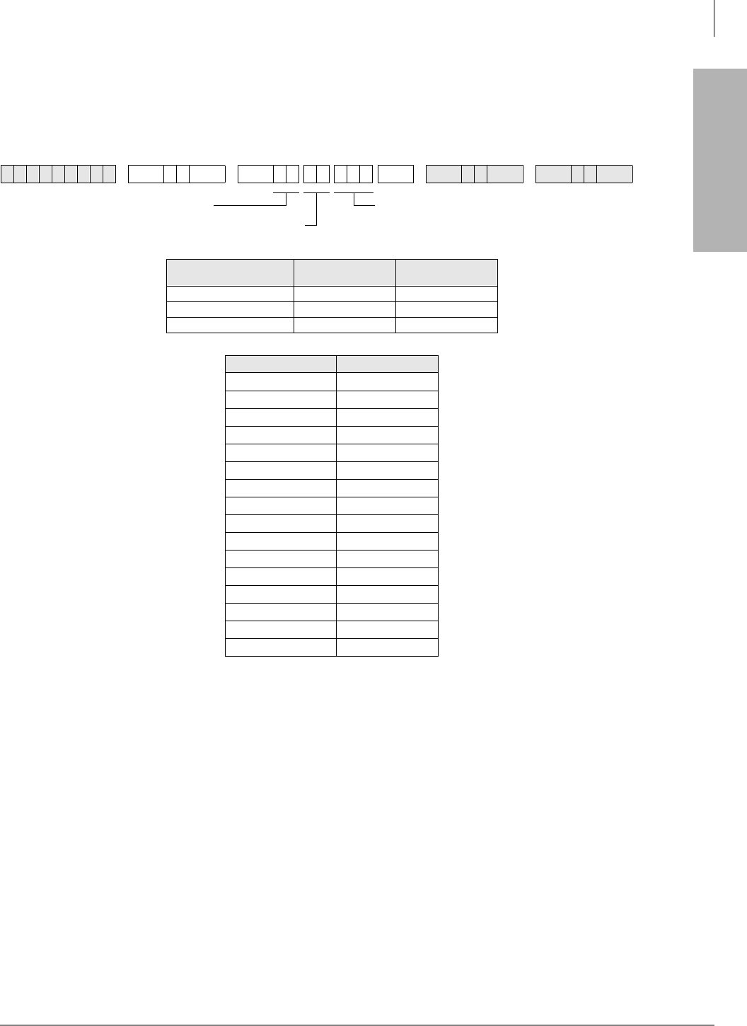
Automatic Call Distribution
Program 14-71 – Queue Size for Alarm, Immediate Assignments
Strata DK Programming 5/99 6-31
Automatic Call Distribution
Program 14-71 – Queue Size for Alarm, Immediate
Assignments
Initialized Default:
Queue Size = 010
Program 14-71 Overview
The system causes the Supervisor 5HVHW4XHXH$ODUP button to flash and the Supervisor
telephone sounds immediately a one second ON, one-half OFF beeping alarm when the number of
calls in the ACD queue exceeds the number set in this program. Program 14-8 DATA must be set
to “1” if using this option (see Program 14-8 for more information).
6SNU +ROG 6SNU +ROG6SNU +ROG 6SNU +ROG
Processor ACD Group
Numbers Queue Size
RCTUBA/BB 01~08 001~048
RCTUC/D 01~16 001~144
RCTUE/F 01~16 001~200
ACD Group Number Queue Size
DATA = Queue SizeSELECT = 71
SELECT = ACD Group Number
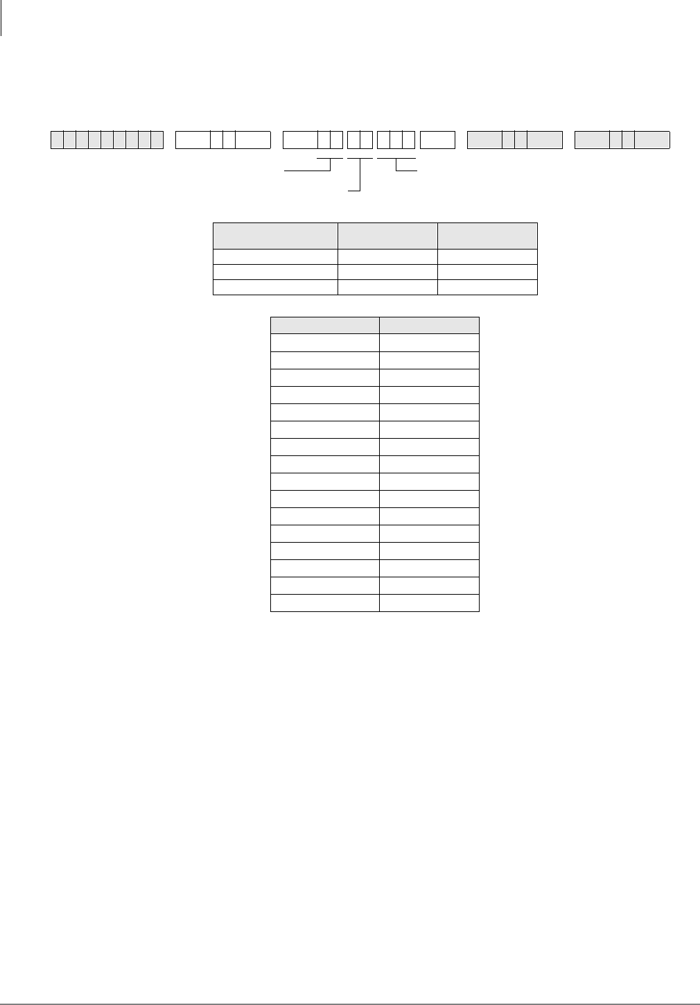
Automatic Call Distribution
Program 14-72 – Queue Size for Alarm 1
6-32 Strata DK Programming 5/99
Program 14-72 – Queue Size for Alarm 1
Initialized Default:
Queue Size = 010
Program 14-72 Overview
The system causes the Supervisor 5HVHW4XHXH$ODUP button to flash and the Supervisor
telephone to sound a one second ON, one second OFF beeping alarm when the number of calls in
the ACD queue exceeds the number of calls set in this program for a time duration set in Program
11-6.
Program 14-8 DATA must be set to “2” if using this option (see Program 11-6 and Program 14-8
for more information).
6SNU +ROG 6SNU +ROG6SNU +ROG 6SNU +ROG
Processor ACD Group
Numbers Queue Size
RCTUBA/BB 01~08 001~048
RCTUC/D 01~16 001~144
RCTUE/F 01~16 001~200
ACD Group Number Queue Size
DATA = Queue SizeSELECT = 72
SELECT = ACD Group No.
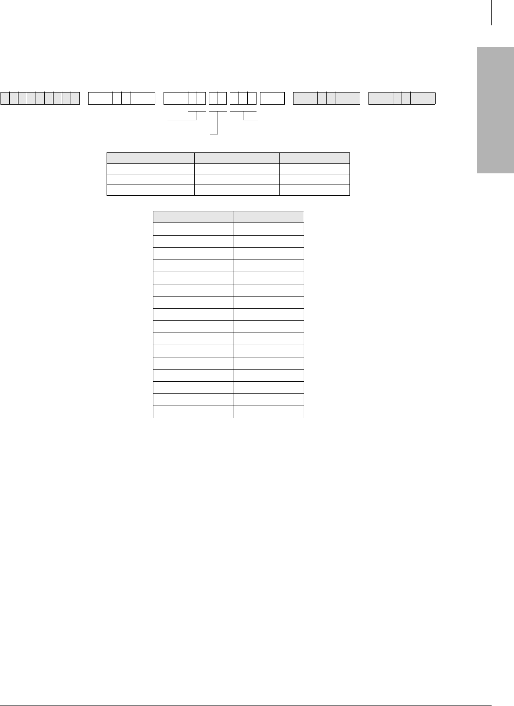
Automatic Call Distribution
Program 14-73 – Queue Size for Alarm 2
Strata DK Programming 5/99 6-33
Automatic Call Distribution
Program 14-73 – Queue Size for Alarm 2
Initialized Default:
Queue Size = 010
Program 14-73 Overview
The system causes the Supervisor 5HVHW4XHXH$ODUP button to flash and the Supervisor
telephone to sound a continuous beeping alarm when the number of calls in the ACD queue
exceeds the number of calls set in this program for a time duration set in Program 11-7.
Program 14-8 DATA must be set to “2” if using this option (see Program 11-7 and Program 14-8
for more information).
6SNU +ROG 6SNU +ROG6SNU +ROG 6SNU +ROG
Processor ACD Group Numbers Queue Size
RCTUBA/BB 01~08 001~048
RCTUC/D 01~16 001~144
RCTUE/F 01~16 001~200
ACD Group Number Queue Size
DATA = Queue SizeSELECT = 73
SELECT = ACD Group No.
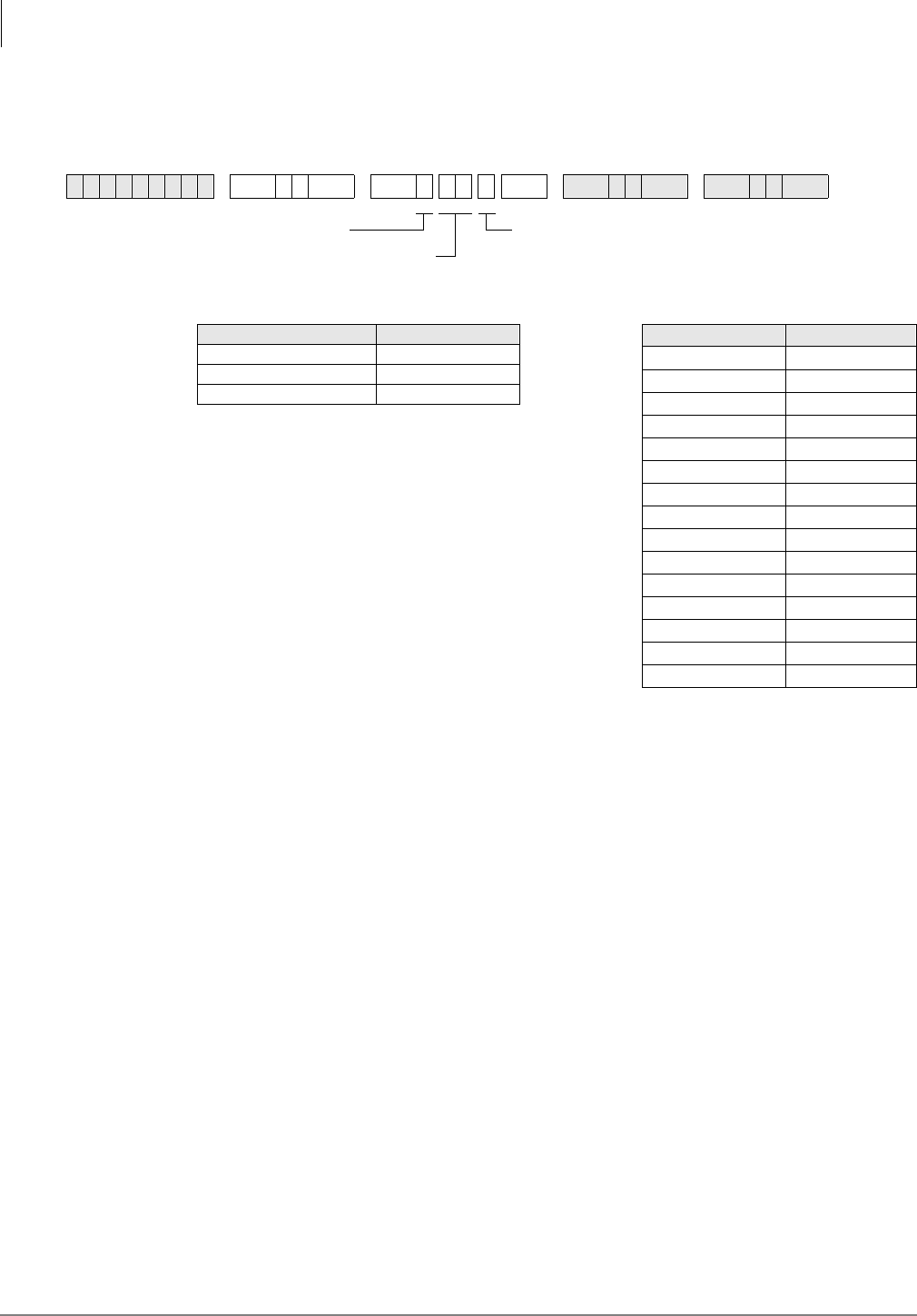
Automatic Call Distribution
Program 14-8 – Alarm Pattern Assignments
6-34 Strata DK Programming 5/99
Program 14-8 – Alarm Pattern Assignments
Initialized Default:
0 for each group
Program 14-8 Overview
This program selects the type of queue alarm that is sent to the Supervisor telephone for each ACD
Group. Only one alarm type is allowed for a given ACD Group. The Supervisor can reset the alarm
by pressing the flashing 5HVHW4XHXH$ODUP button.
DATA = 0: No Alarm
This selection disables the queue alarm.
DATA = 1: Immediate Alarm
This selection causes the system to send immediately a queue alarm to the Supervisor telephone
when the number of calls in the ACD queue exceeds the number set in Program 14-71.
DATA = 2: Call Waiting Alarm 1 and 2
This selection allows two timed alarms to be set. Alarm 1 sounds when (X + 1) number of calls are
in the ACD queue longer than the time period set in Program 11-6 (X is set in Program 14-72).
Alarm 2 sounds when (Y + 1) number of calls are in the ACD queue longer the time period set in
Program 11-7 (Y is set in Program 14-73). Normally, Alarm 1 is used as a caution alarm to indicate
a less critical alarm than Alarm 2.
Example:
Alarm 1 may be set to alert the Supervisor when five calls are in queue for longer than three
minutes; and Alarm 2 may be set to alert the Supervisor when ten calls are in queue for five
minutes. Once alarm 2 is activated, Alarm 1 is inactive until Alarm 2 thresholds are no longer
exceeded. Alarm 1 is an interrupted beeping tone; Alarm 2 is a continuous beeping tone.
6SNU +ROG 6SNU +ROG 6SNU +ROG 6SNU +ROG
Processor ACD Group Numbers
RCTUBA/BB 01~08
RCTUC/D 01~16
RCTUE/F 01~16
ACD Group Number Alarm Pattern
DATA = Pattern (0, 1, or 2)
0 = None
1 = Immediate Alarm (Program 14-71)
2 = Alarm Timer 1 and 2 (Program 14-72, 11-6
and Program 14-73, 11-7)
SELECT = 8
SELECT = ACD Group No.
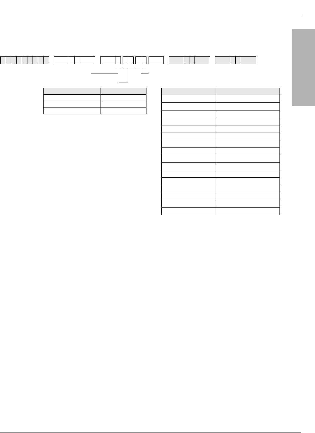
Automatic Call Distribution
Program 14-9 – Work Unit Assignments
Strata DK Programming 5/99 6-35
Automatic Call Distribution
Program 14-9 – Work Unit Assignments
Initialized Default:
account digits for each Group = 02
Program 14-9 Overview
This program selects the length of the Work Unit code for each ACD Group.
Agents talking on an ACD call can press the :RUN8QLW button and enter a Work Unit code (1~15
digits) for each call. The outside caller cannot hear the code, so conversation is not interrupted.
SMIS only records (Peg) one or two digit Work Unit codes. SMDR can record 1~15 digit Work
Unit codes. If multiple work unit codes are entered on the same ACD call, only the last code
entered will be sent to SMDR; however, SMIS will register all Work Unit codes entered.
The Strata DK SMDR data will send up to 15 Work Unit digits in the Account Code data field of
the standard DK SMDR output. MIS (TTY) data will send only 1- or 2-digit Work Unit codes.
When the :RUN8QLW button is pressed on the Agent telephone, the LCD shows “ENTER STRK
DIAL”. The Agent must enter the number of digits assigned in this program to allow a work unit
peg to be sent to SMIS. Any number of digits entered (even if less than assigned in this program)
will be sent to SMDR when the ACD call is ended.
6SNU +ROG 6SNU +ROG 6SNU +ROG 6SNU +ROG
Processor ACD Group Numbers
RCTUBA/BB 01~08
RCTUC/D 01~16
RCTUE/F 01~16
ACD Group Number Number of Work Unit Digits
DATA = Account Digits (01~15)SELECT = 9
SELECT = ACD Group No.

Automatic Call Distribution
Program 15 – Ground/Loop/Tie/DID Line Options
6-36 Strata DK Programming 5/99
Program 15 – Ground/Loop/Tie/DID Line Options
If loop start lines are routed to ACD Groups, set each line to automatically release when the CO
sends the AR signal after the outside party hangs up. Use Program 15 Code 1 and Code 3 to set
auto release detection for each CO line.
See 3-44 for the programming record sheet.
Program 17 – DID/Tie Line Options
If DID/Tie lines must be routed to ACD Groups, use Program 17 to set the appropriate options for
each DID/Tie line.
See 3-50 for the programming record sheet.
Program 35 – Station Class of Service
To allow Agent Help (assistance) calls to busy Supervisor telephones, enable Busy-Station-
Transfer (LED 20-ON) on Agent telephones and Busy-Station-Ring (LED 19-ON) on Supervisor
telephones. Supervisor telephones should have more than one [PDN] (Program 39) to receive
Agent Help calls when the Supervisor telephone is busy.
See 3-97 for the programming record sheets.
Program 71 – DID/Tie/DNIS/ANI Lines
If DID/Tie/DNIS/ANI lines route to ACD Groups and provide DNIS line features (such as the
DNIS name, night/day routing, etc.), use Program 71 to assign the DID/Tie/DNIS digits or ANI
lines to route the appropriate ACD Group (see Program 17, LED 05).
Also see “Program 17 – DID/Tie Line Options” on Page 3-50.
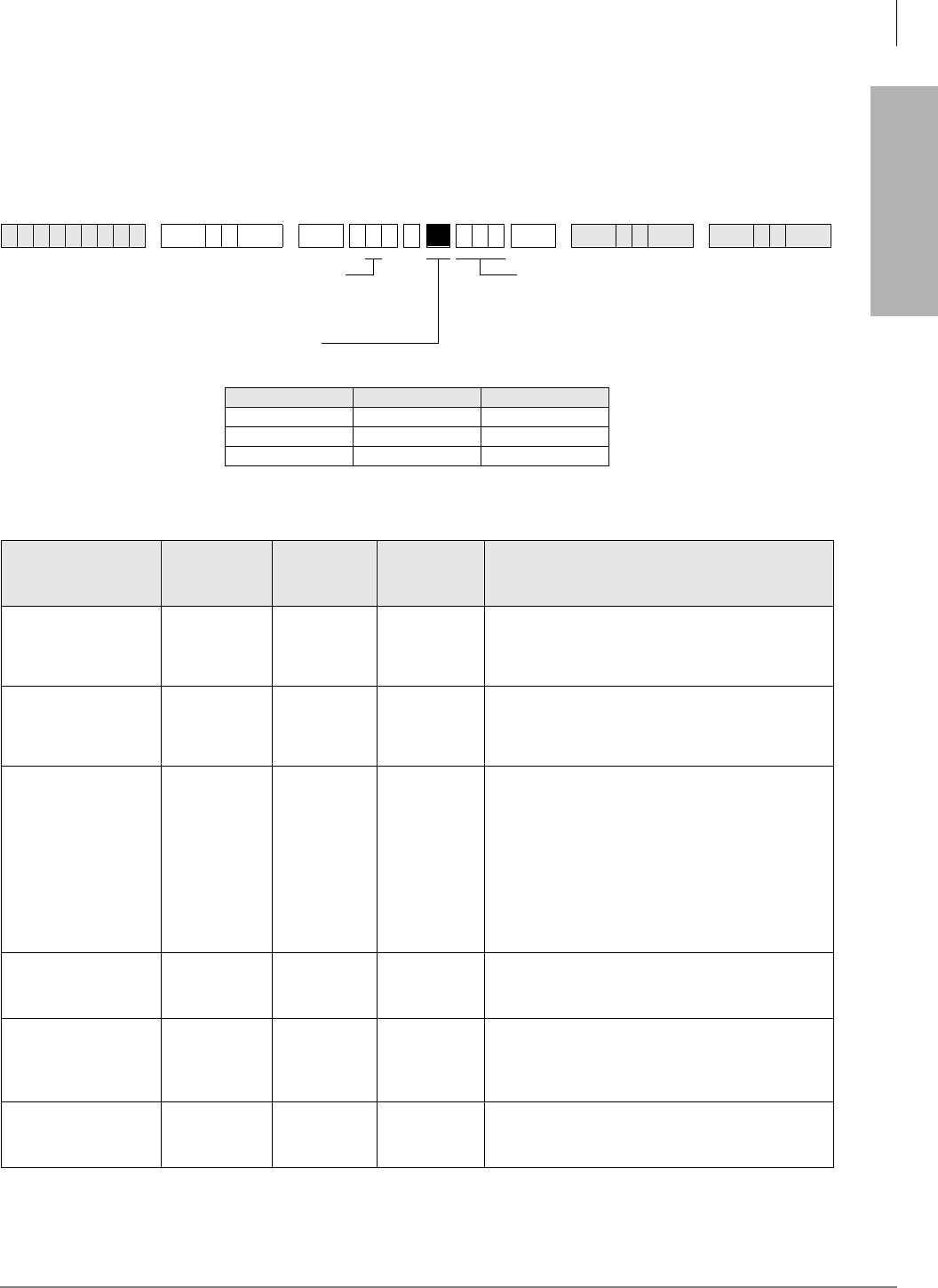
Automatic Call Distribution
Program 39 – Flexible Button Assignments for ACD Telephones
Strata DK Programming 5/99 6-37
Automatic Call Distribution
Program 39 – Flexible Button Assignments for ACD
Telephones
Initialized Default:
Logical port number = physical port number
Program 90, 91-1, or 91-9 initializes Program 02
Toshiba highly recommends that you enter the button keystrip names exactly as shown in the left
column, since these button names are used in the ACD Agent and Supervisor Guides.
6SNU +ROG 6SNU +ROG 6SNU +ROG 6SNU +ROG
Processor [PDN] Port Range [PhDN] Port Range
RCTUBA/BB 000~079 500~079
RCTUC/D 000~239 500~739
RCTUE/F 000~255 500~835
ACD Feature Button
Designation Feature Code Program
on Agent
Telephone
Program on
Supervisor
Telephone Notes
/RJ ,Q
/RJ 2XW
(Agent)
X
Used by Agents to Log In/Out.
[PhDN] + Log In/Out + ZZZZ
(ZZZZ = Agent ID code)
/RJ LQ
/RJ 2XW
(Supervisor)
X
Used by Supervisor to Log In/Out
Log In/Out + YYYY
(YYYY = Agent ID code)
&' &DOO
Program
[PhDN] in
Program 39
X
Each Agent telephone must have a unique, single-
appearing [PhDN] button to receive and originate
ACD calls.
When the Agent logs into an ACD Group from any
single-appearing [PhDN], that [PhDN] is the active
&' %XWWRQ on the Agent telephone.
(Supervisor telephones do not require a unique
[PhDN] button unless the Supervisor telephone will
be used as an Agent telephone periodically.)
:RUN8QLW
X
Enables the Agent to peg an ACD call with an
account number that will be sent to a SMIS personal
computer and/or SMDR device.
&' 3LFNXS
XX
Provides ACD call pickup within the Group. The
Agent must be logged into the same Group in order
to pick up the ACD call. The Pickup call is considered
an ACD call on the MIS status report.
8 QDYDLODEOH
X
Turns the Agent’s availability off and on. While in this
mode, the Agent does not receive any new incoming
ACD calls.
CODE =
Enter the appropriate feature code. See the
Feature Code Table below.
SELECT = Port Number or Range.
To add a port range, enter
XXXXXX (low port high port)
Press Button/LED to be defined.

Automatic Call Distribution
Program 39 – Flexible Button Assignments for ACD Telephones
6-38 Strata DK Programming 5/99
&' +HOS X
Rings a Supervisor [DN] button, enabling an Agent to
request assistance while talking on an ACD call.
Calls the highest numbered Supervisor telephone or
[PDN]
(QG IWHU &DOO
:RUN7LPH XManually cancels unused wrap-up time. This enables
an Agent to receive another ACD call.
(QG2I
&' 6KLIW X
Enables the Supervisor to stop new calls from
entering the ACD Group queue or from ringing
Agents. The End of ACD Shift mode routes new calls
to the After Shift destination set in Program 14-6. A
Supervisor must be logged in to use this button.
7 UDQVI HU WR&'
*URXS
&RQI 7 UQ
;; XX
Program this Speed Dial sequence on telephones
that must transfer calls to ACD Groups. This enables
one-touch transfer of CO lines (ground/loop start or
DID/Tie) to ACD Group ;; . ;; = ACD Group
01~16.
Transfer to an ACD Group is always blind and
immediate and does not recall the transferring
station.
If the ACD Group shift is ended or all Agents are
unavailable, the transferred call is routed per the
called Group’s After Shift or All Agents Unavailable
destination.
0RQLWRU
&' &DOOX
Used by Supervisor to monitor Agent calls
(Supervisor telephone only). Enables the Supervisor
to listen to any Agent’s ACD calls (not non-ACD or
PBX calls) by pressing the Monitor ACD Call button and
then entering the Agent’s ID code.
During Agent monitoring, a one-way talk path
enables the Supervisor to listen to the Agent/outside
party conversation without the Agent/caller hearing
the Supervisor.
An optional “Call Monitor” tone (dial tone burst) can
be sent to the Agent/caller every 15 seconds (see
Program 10-4, LED 03) while the Supervisor is
monitoring the ACD call. The Agent LCD displays
MONITOR BY SUPRV when this option is enabled.
4XHXH6WDWXV [PDN] +
;; XProgram these speed dial buttons on the
Supervisor’s telephone to enable quick access to
Queue Status, Agent Status, and one-touch
Supervisor log in.
(XX = ACD Group 01~16)
JHQW
6WDWXV
[PDN] +
;; X
5HVHW4XHXH
ODUP 448 X
Used to reset a queue alarm that is sent to the
Supervisor telephone when the number of calls in
queue exceeds the limits of queue alarm parameters
(see Programs 14-71~73, 14-8, 11-6, and 11-7 for
queue alarm parameters).
ACD Feature Button
Designation Feature Code Program
on Agent
Telephone
Program on
Supervisor
Telephone Notes
Automatic Call Distribution
Program 39 – Flexible Button Assignments for ACD Telephones
Strata DK Programming 5/99 6-39
Automatic Call Distribution
6XSHUYLVRU &DOO
Program
[PDN] in
Program 39
X
This is the [PDN] of the Supervisor telephone.
Supervisor telephones do not require a unique
[PhDN] like Agent telephones.
Toshiba recommends programming more than one
[PDN] onto Supervisor telephones to enable Agent
Help (assistance) calls to ring busy Supervisor
telephones.
Also program Agents with Busy Station Transfer and
Supervisors with Busy Station Ring (see Program 35
BST and BSR).
Speed Dial Codes Speed Dial
Code
Program on
Agent
Telephone
Program on
Supervisor
Telephone Notes
RCTUBA/BB, C/D
(station) ~XX
All of the above ACD Features can be programmed
onto SD buttons or onto speed dial codes. This table
shows the range of Station and System Speed Dial
Codes by processor.
RCTUBA/BB, C/D
(system) ~XX
RCTUE/F (station) ~XX
RCTUE/F (system) ~XX
ACD Feature Button
Designation Feature Code Program
on Agent
Telephone
Program on
Supervisor
Telephone Notes

Automatic Call Distribution
Program 39 – Flexible Button Assignments for ACD Telephones
6-40 Strata DK Programming 5/99
Program 39 Overview
This program assigns ACD Agent and Supervisor buttons for Toshiba digital and/or electronic
telephones. All other button codes (see Program 39 Record Sheet in Chapter 10—Record Sheets in
this manual) are allowed on Agent and Supervisor telephones. Telephones can be programmed
with both Agent and Supervisor buttons to enable dual functions, however, a telephone cannot
function as a Supervisor and Agent station simultaneously.
If both Agent and Supervisor buttons are assigned to a telephone, the type of log in code (Agent or
Supervisor) determines how the telephone will function (see Program 14-1 and 14-2).
Agent and Supervisor Telephone Programming Considerations
ACD Agent telephones must be programmed with a [PhDN] button (called the $&'&DOO button)
to receive ACD calls. This button must be a unique [PhDN] that appears only on that Agent
telephone.
The $&'&DOO button is used to originate and receive PBX calls that register on SMIS when the
Agent is logged into an ACD Group with the $&'&DOO button. PBX calls are calls that originate
from or ring the Agent $&'&DOO button when the $&'&DOO button [PhDN] is dialed or when a
CO line is programmed to ring the $&'&DOO button [PhDN].
If the Agent’s telephone is not logged into an ACD Group, calls originated or received by the $&'
&DOO button are considered non-ACD calls.
Do not program ACD CO /LQH or 3RROHG/LQH*US buttons on Agent telephones. Supervisor
telephones do not require an ACD [PhDN].
If the ACD call is placed on hold while the Supervisor is monitoring it, there is only silence until
the Agent takes the call off-hold and monitoring resumes. The Supervisor telephone is busy to new
calls when in the Monitor mode. (Busy Override, Off-hook Call Announce, and Camp-on are
available to callers that call a Supervisor in the Monitor or Verify Status mode.)
Important! The Monitor mode is automatically cancelled if an Agent transfers an ACD call.
Related Programs
♦Programs ground/loop start CO line ringing assignments (Programs 81~89) for use with
Overflow/After Shift destinations in Programs 14-4, 14-5, and 14-6.
♦Programs CO line Group assignments (Program 16) for lines that are assigned to an ACD
Group in Program 14-0.
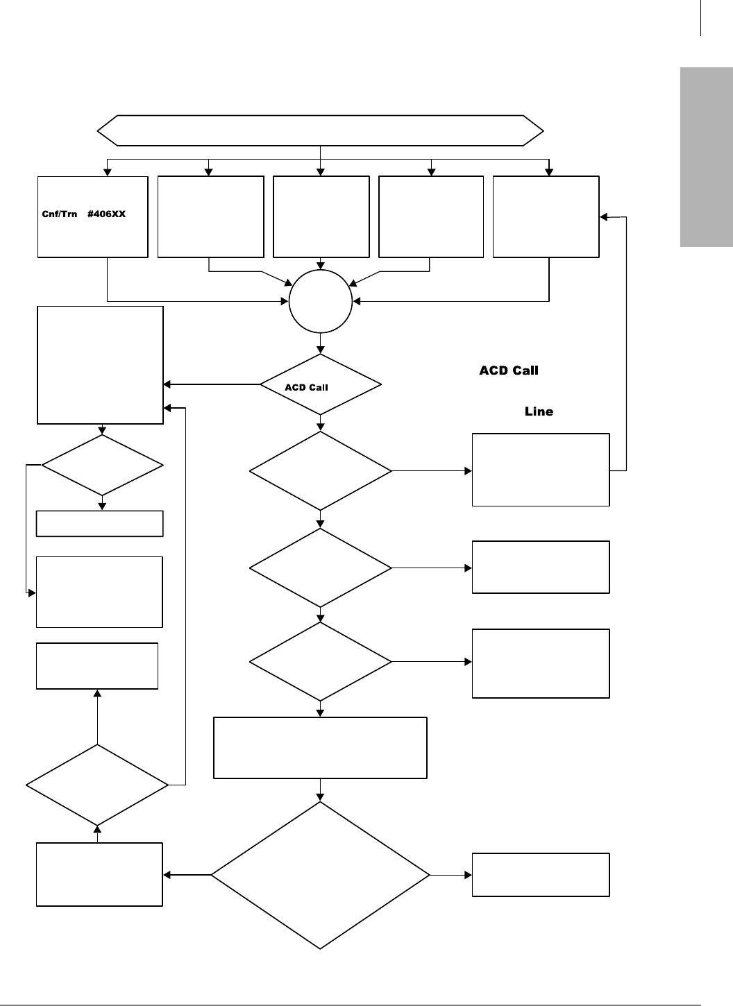
Automatic Call Distribution
Program 39 – Flexible Button Assignments for ACD Telephones
Strata DK Programming 5/99 6-41
Automatic Call Distribution
Yes
Yes
Yes
Yes
Yes
No
Direct
Yes
No
No
No
No
No
Continue
Continue
Other Send call to ACD Group queue:
go to ACD Flowchart 6-2.
Possible ways to route CO line calls to ACD group.
CO line transferred to
ACD Group
(XX = 01~16). Internal
[DN] calls cannot be
transferred to ACD groups.
Ring idle agent telephone
per ring agent timer in
Program 11-2; if agent
does not answer, ring next
idle agent per timer and
continue until all idle agent
telephones are rung or an
agent answers the call.
Loop and ground start
CO lines are assigned
to ACD groups in
Program 14-0.
DID/tie/DNIS/ANI
line incoming digits
are assigned to
ACD Groups in
Program *09 or
Program 71.
DK built-in Auto
Attendant “one digit
prompts” are
assigned to ACD
groups in Program
09.
From another ACD
group: call overflow
attempt, or all agents
unavailable, or in
After Shift mode.
Call is
routed to
ACD
Group.
Is
an Agent
button
idle?
Does an Agent
answer?
Ring No Answer (RNA)
overflow to destination set
in Program 14-5. See
ACD Flowchart 6-7.
Talk on ACD call.
Send call to ACD Group
queue: go to ACD
Flowchart 6-2.
Does an
agent become idle
before Program 11-4 timer
expires?
Are all
Agents logged
out or has the supervisor
ended the shift?
Is the
call attempting to
overflow from another
ACD Group
queue?
Send ring back tone to the
caller for the time duration
set in Program 11-4 or until
an agent becomes idle.
Is the call a direct CO line
call, or other type: transferred from a
station or Auto Attendant, routed from
another ACD group because all agents
are unavailable or in After Shift
Mode?
If the answer to all the above questions is no,
then one or more agents are in the available
mode but are talking on other calls or in After
Call Work mode.
Are all Agents
unavailable?
Do not overflow. Remain in
original queue and continue
to look for an idle Agent in the
overflow group and in the
original group.
Call routes to ACD Group's
After Shift destination. See
ACD Flowchart 6-5.
Notes
♦Internal [DN] and external DISA
callers cannot direct dial into ACD
Groups.
♦If an Agent ACD Call button is idle,
ACD calls will busy override and ring
the button even if an Agent is busy on
another [DN] or CO button.
Call routes to ACD Group's
After Shift destination or
Overflow Point destination.
See ACD Flowchart 6-6.
0875
Flowchart 6-1 ACD Group Call Routing
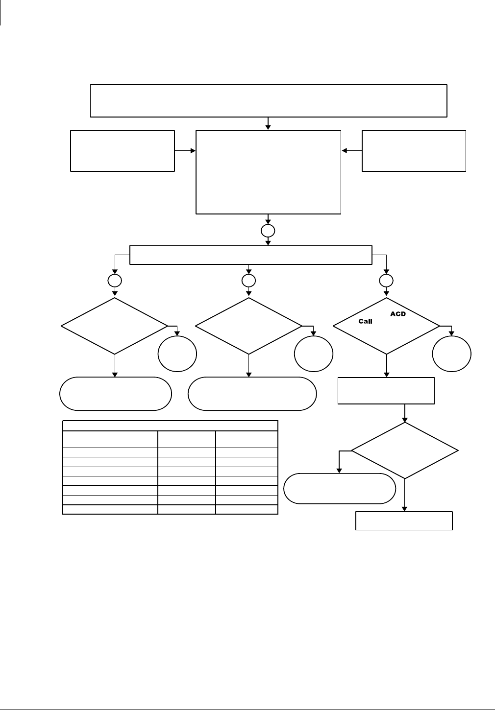
Automatic Call Distribution
Program 39 – Flexible Button Assignments for ACD Telephones
6-42 Strata DK Programming 5/99
No No No
Go
back to
1 above.
Go
back to
1 above.
Go
back to
1 above.
Yes
Continue
GO to ACD Flowchart 6-7
"Ring No Answer."
BA C
Yes
Yes Yes Yes
No
Yes
Yes
1
Has
agent ACD
Call button in ACD
group become idle before
overflow occurs?
Talk on ACD call.
Does
the agent answer
before the Ring No Answer
timer in Program 11-3
expires?
Call enters ACD group queue because: agents are logged in, but are busy on other calls; or are in “After Call
Work” mode when the call is directed to the ACD group. Call is sent to ACD group directly by Program 14-0, *09,
or 71; or, the call is transferred to the group from a station or Auto Attendant (see ACD Flowchart 6-1).
Strata DK Continuously monitors points A, B, and C below.
Call enters ACD group queue because all
agents are busy on calls or in the After Call
Work mode. While a call is in queue, the
Strata DK continuously monitors points A, B,
and C below simultaneously.
If the queue disconnect timer set in Program
11-9 expires before the call is answered by
an Agent that goes idle, or the call
overflows, the Strata DK will disconnects the
call.
Call routed from another ACD
group because all agents in
that group are not available
(see ACD Flowchart 6-6).
Call routed from another ACD
group because the group is in
the after shift mode,
(see ACD Flowchart 6-5).
Ring agent
ACD call button.
Has the
overall queue
timer in Program 11-1
expired?
Has
the call
reached the overflow
point in Program
14-5?
Notes
1. “No overflow” means the call will not exit queue to ring the busy overflow
destination. The call exits queue and rings the busy overflow destination as
soon as the destination goes idle.
2. “Overflow” means the call will exit an ACD queue and busy override or mute
ring the busy destination.
3. System [DNs] include: Program 04 [PDNs]/[SDNs], and Program *04
[PhDNs].
4. The call will not overflow into a DH queue when all DH Group members are
busy or in DND.
0846
Go to ACD Flowchart 6-4
“Queue Point” and
Flowcharts 6-8 ~ 6-11
“Queue Pattern Configurations.”
Go to ACD Flowchart 6-3
“Queue Overflow Time Out.”
Overflow To Busy Destination Operation:
Tie/DID/DNIS/ANI
Lines
Ground/loop
Start Line
Overflow
Destination (Busy)
System [DN]
3
Distributed Hunt Group
Normal Ring Stations
Auto Attendant
Attendant Console
Another ACD Group
*
14-2 [DN]
No Overflow
No Overflow
4
See
*
14-2 Port
See
*
14-2 Port
Overflow
No Overflow
No Overflow
No Overflow
1
No Overflow
4
Overflow
2
Overflow
Overflow
No Overflow
N/A
Flowchart 6-2 ACD Group Queue/Overflow Operation
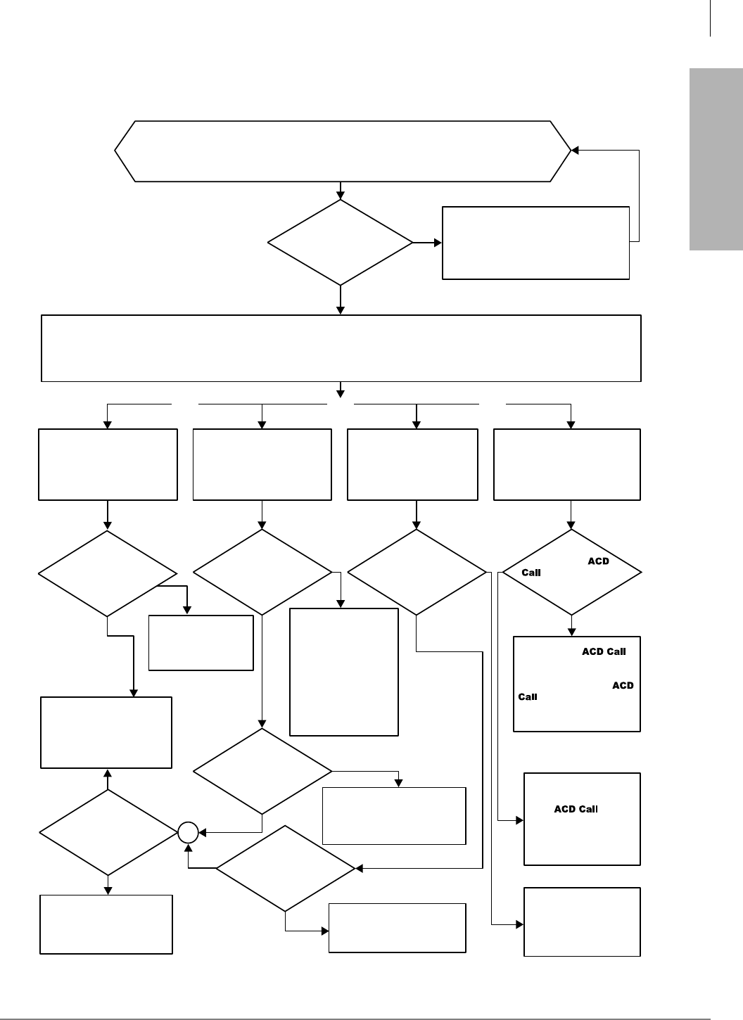
Automatic Call Distribution
Program 39 – Flexible Button Assignments for ACD Telephones
Strata DK Programming 5/99 6-43
Automatic Call Distribution
No
Yes
Yes
No
Yes Yes Yes
Yes Yes
Yes
Tie/DID/
DNIS/ANI
Tie/DID/DNIS/ANI
Ground/Loop
Busy
Idle
No
No
No
Yes
OrOr Or
Ground/
Loop
Has the queue
overflow timer in Program
11-1 expired?
Is destination
busy?
Is destination
busy? (See Note.)
Is the line
ground/loop or
Tie/DID/DNIS/ANI?
Is
the
system [DN] port
assigned in
Program
*
14-2
idle?
Is
the line
ground/loop start
or Tie/DID/
DNIS/ANI?
Is an agent ACD
Call button idle in the
overflow group?
Call remains in queue: the Strata DK
continuously monitors for an idle agent,
queue overflow timer – time out, or
overflow point per Program 14-5 (See
ACD Flowchart 6-2).
CO lines will atttempt to exit the ACD group’s queue and will route to the group’s “Queue Time-out Overflow Destination”
set in Program 14-4.
In some cases, if that destination is busy, the call remains in queue as shown below:
Only one destnation can be assigned in Program 14-4 per ACD group.
Queue Timeout Overflow
Destination is a system
[DN], DH, or attendant port
number. Program 14-4 (see
record sheet )
Ring system, DH, [DN],
or console port
assigned in Program
14-4.
Ring an idle agent in the
overflow group or idle system
[DN] or DH assigned in
Program 14-5.
Ring the idle system [DN]
assigned in Program
*
14-2.
Ground/loop start: busy
override ring system [DNs] per
Programs 81, 84, 87 and
*
81,
*
84,
*
87 (no delayed ring).
Call connects to the DK
Auto Attendant calls
routed per AA assignment
programs.
The call remains in
original queue until an
agent ACD C all
button or an overflow
destination assigned in
Programs 14-4 or 14-5
becomes idle.
Ring idle agent ACD Call
button: if agent answers, talk
on ACD call. if no answer,
ring another idle agent ACD
Call button or go to RNA
destination (ACD Flowcharts
6-8~6-11).
The call will remain in queue
until an agent or an overflow
destination assigned in
Program 14-4 or 14-5
becomes idle.
Ground/loop start:
ring system [DN] Per
Programs 81, 84, 87
and
*
81,
*
84,
*
87
(no delayed ring).
Tie/DID/DNIS/ANI
RING system [DN]
per Program
*
14-2.
Queue Timeout Overflow
Destination is normal CO line
ringing assignment. Program
14-4 (321, 441)
Queue Timeout Overflow
Destination is Strata DK
built-in Auto Attendant.
Program 14-4 (320, 440)
Queue Timeout Overflow
Destination is another ACD
group. Program 14-4:
RCTUBA/BB, RCTUC/D
(301~316), RCTUE/F (401~416)
Call enters ACD queue: calls waiting in an ACD group’s queue can be sent to
an overflow destination if they have been in queue longer than the time
duration set in Program 11-1 (Queue Over ow Timer).
Is the
destination in
Program 14-5 an idle
DH, ACD group, or
system [DN]
port?
0876
Notes
System [DNs] include:
Program 04 [PDNs]/[SDNs]
Program
*
04 [PhDNs]
DH = Distributed Hunt Group
Note If the
station port is
an RATU
Attendant Console
port, the call overflows
to the console: idle or
busy.
Flowchart 6-3 ACD Time Out Overflow
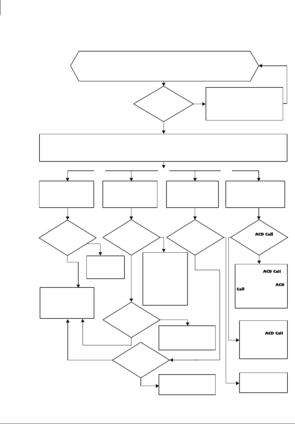
Automatic Call Distribution
Program 39 – Flexible Button Assignments for ACD Telephones
6-44 Strata DK Programming 5/99
No
Yes
Yes Yes Yes Yes
Yes
Tie/DID/DNIS/ANI
Tie/DID/DNIS/ANI
Busy
Idle
NO
NO
Yes
OrOr Or
Ground/
Loop
Ground/loop
No
Yes
Has the call
received the number of
announcements and
music
Is
destination
busy?
Is
the line
ground/loop or
tie/DID/DNIS/ANI?
Is the
system [DN], DH
assigned in
Program
*
14-2
busy or idle?
Is
the line
ground/loop start or
tie/DID/
DNIS/ANI?
Is an
agent ACD Call
button idle in the
group?
Call remains in queue. The Strata DK
continuously monitors for an idle agent,
queue overflow timer – timeout per
Programs 11-1, and 14-4, or overflow
point Per program 14-5 (see ACD
Flowchart 6-2).
CO lines will attempt to exit the ACD group’s queue and route to the group’s “Overflow Point Destination” set in Program 14-5 (see ACD
Flowchart 6-8~6-11). If that destination is busy, the call remains in queue as shown below.
Only one destination can be assigned in Program 14-5 per ACD group.
Note
The destination assigned in Program 14-5 will also be the RNA destination of the ACD group (see ACD Flowchart 6-7).
OP Destination is a system
[DN], DH or attendant
console port number.
Program 14-5 (see record
sheet)
Ring system DH,
[DN], or console
port assigned in
Program 14-5.
Ring the idle system [DN], DH
or assigned in Program
*
14-2.
Ground/loop start: busy
override ring system [DN]*
per Programs 81, 84, 87, and
*
81,
*
84,
*
87 (no delayed
ring).
Call connects to the DK
AA, call routed per AA
assignment programs.
The call remains in queue
until an agent ACD Call
button or an overflow
destination assigned in
Program 14-4 or 14-5
becomes idle.
Ring idle agent ACD Call
button: if agent answers, talk
on ACD call. If no answer,
ring another idle agent ACD
Call button or go to RNA
destination
(ACD Flowchart 6-3).
The call will remain in
queue until an agent or an
overflow destination
assigned in Program 14-4
or 14-5 becomes idle.
Ground/loop start: ring
system [DN] per
programs 81, 84, 87,
and
*
81,
*
84,
*
87 (no
delayed ring).
Tie/DID/DNIS/ANI
RING System [DN]
per Program
*
14-2.
OP Destination is normal
CO line ringing
assignments.
Program 14-5 (321, 441)
Queue Timeout Overflow
Destination is DK
built-in AA.
Program 14-5 (320, 440)
Queue Timeout Overflow
Destination is another ACD
group. Program 14-5:
RCTUBA/BB, RCTUC/D
(301~316), RCTUE/F (401~416)
Call enters ACD queue: calls waiting in an ACD group’s queue can
be sent to an overflow destination if they have received a specified
number of announcement messages and music sequences (overflow
point) determined by Program 14-5 (see ACD Flowchart 6-8~6-11).
0877
Notes
System [DNs] include:
Program 04 [PDNs]/[SDNs]
Program
*
04 [PhDNs]
DH = Distributed Hunt Group
Is destination
busy? (See Note.)
Note If the
station port is
an RATU
Attendant Console
port, the call overflows
to the console: idle or
busy.
Flowchart 6-4 ACD Overflow Point
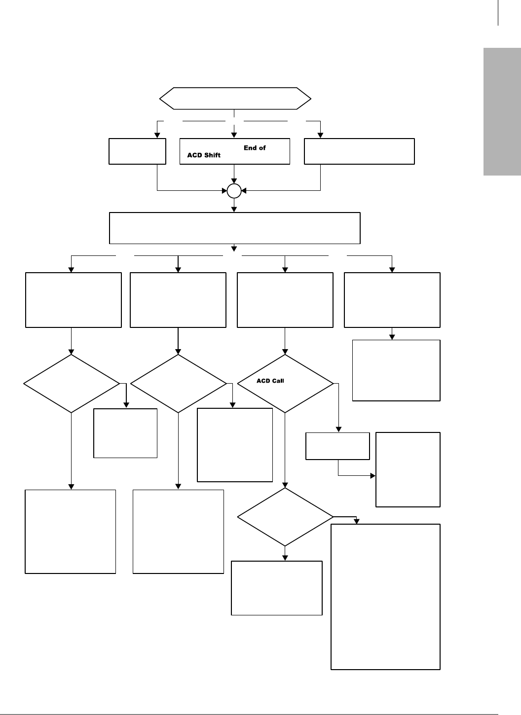
Automatic Call Distribution
Program 39 – Flexible Button Assignments for ACD Telephones
Strata DK Programming 5/99 6-45
Automatic Call Distribution
No
Yes
Yes
No
Yes Yes Yes
Yes
No
Yes No
Yes
Or
Or OrOr
Or Or
End of ACD Shift Conditions
Ring idle agent
Is
destination busy? Is
destination busy? Is an agent
ACD Call button idle
in the group?
Are all
agents Busy or in the
After Call Work
Mode?
Supervisor presses End of ACD
Shift button.
CO lines that normally route to the ACD group will only route to the group's After
Shift Destination set in Program 14-6.
Only one destination per ACD group can be assigned in Program 14-6.
All agents Unavailable and
Program 10-4 LED 4 OFF.
All agents
logged out.
Ring system [DN],
DH, or console port
assigned in
Program 14-5. If agent answers,
talk on ACD call if
no answer, ring
another idle agent
ACD Call button or
go to RNA
destination (see
ACD Flowchart 6-7)
The group’s shift is ended or all
agents are not available:
Route call to the group's “EOS” or
“All agents unavailable”
destination.
Important! If this destination is the
same ACD Group from
which the call originated
(including back to
itself), the call will be
routed as follows:
ground/loop lines to
Programs 81~89 and
*81, *84, *87 [DNs] and
DID/tie/DNIS/ ANI
lines to Program *14-2
System [DNs]* assigned
to this Group.
Ground/loop start: connect to
DK built-in Auto Attendant and
route call per AA programming
DID/tie/DNIS/ANI line:
Ring or Camp-on to station as
programmed in Program
*
14-2.
Ground/loop start: Busy
Override ring the system
[DN] or attendant console
port assigned.
DID/tie/DNIS/ANI line:
Camp-on Busy to the
system [DN], DH, or
console port assigned.
Call enters the back of the
group's queue and follows
the queue pattern and
overflow assignments for
the group.
Ground/loop start: Busy
Override ringing all busy
system [DN] assigned in
Programs 81~89 and
*
81,
*
84,
*
87
DID/tie/DNIS/ANI line:
Camp-on Busy to system
[DN]* assigned in
Program
*
14-2 or console
port assigned.
Ground/loop start:
ring system [DN] per
Programs 81~89 and
*
81,
*
84,
*
87.
TIE/DID ring system
[DN] per
Program
*
14-2.
After Shift Destination is
Normal CO line ringing
assignments.
Program 14-6 (321, 441)
After Shift Destination is a
system [DN] or DH or
attendant console port
number.
Program 14-6 (see record
sheet)
After Shift Destination is
another ACD group.
Program 14-6: RCTUBA/BB,
RCTUC/D (301~316),
RCTUE/F (401~416)
After Shift Destination is
DK built-in Auto Attendant.
Program 14-6 (320, 440)
Note Calls that are already in queue when the shift is
ended remain in queue until answered by an idle
agent, they overflow, the caller hangs up, or the
disconnect timer (Program 11-9) expires. 0878
Notes
System [DNs] include:
Program 04 [PDNs]/[SDNs]
Program
*
04 [PhDNs]
DH = Distributed Hunt Group
Flowchart 6-5 After Shift Operation
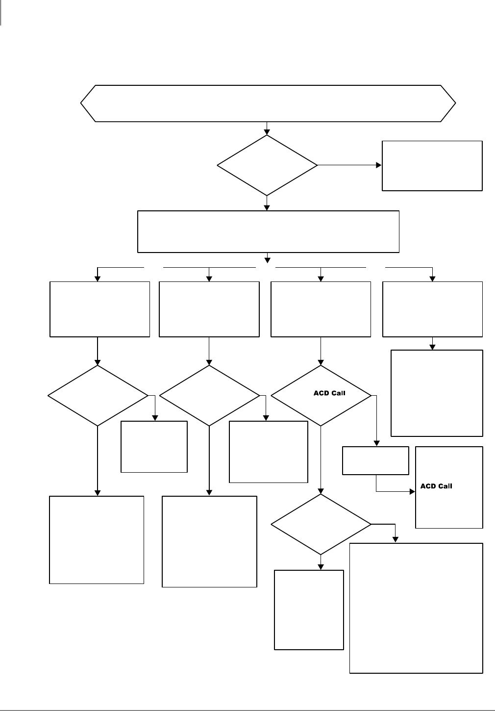
Automatic Call Distribution
Program 39 – Flexible Button Assignments for ACD Telephones
6-46 Strata DK Programming 5/99
No
Yes
Yes
No
Yes Yes
LED 04 OFF
LED 04 ON
Yes
Yes
No
Yes No
Yes
OrOr Or
All agents in ACD group are unavailable when a call is transferred to the group from a station or Auto Attendant, or
routed to the group directly by Programs 14-0 or *09.
Ring idle agent.
Is
destination
busy?
Is
destination
busy?
Is an
agent ACD Call
button idle in the
group?
Is LED 04
in Program 10-4
turned off or on?
Are
all agents
busy or in after call work
mode?
CO lines that normally route to the ACD group will route to the overflow point
destination set in Program 14-5 (see ACD Flowchart 6-4).
Only one destination per ACD group can be assigned in Program 14-5.
Ring system
[DN], DH or
console port
assigned in
Program 14-5. If agent answers,
talk on ACD call. If
No Answer, ring
another idle agent
ACD Ca ll button
or go to RNA
destination (see
ACD Flowchart
6-3).
The group’s shift is ended or all agents
are not available:
Route call to group’s “EOS” or “All Agents
Unavailable” destination.
Important! If this destination is the same
ACD Group from which the
call originated from (including
back to itself), the call will be
routed as follows: ground/loop
lines to Program 81 ~ 89 and
*81, *84, *87 [DNs] and
DID/tie/DNIS/ANI lines to
Program *14-2 system [DN]*
assigned to this group.
Ground/loop start:
connect to Strata DK AA
and route call per AA
programming.
DID/tie/DNIS/ANI line:
ring or camp-on to station
programmed in Program
*14-2.
Loop/ground start: busy
override ring system [DN]*
per programs 81, 84, 87,
and *81, *84, *87.
DID/tie/DNIS/ANI line:
camp-on busy to system
[DN]*, DH, or attendant
console port assigned.
Call will enter the
back of the
group’s queue
and follow the
queue pattern and
overflow
assignments for
the group.
Loop/ground start: busy
override ringing the busy
system [DN] assigned in
programs 81 ~ 89, and
*81, *84, *87.
DID/tie/DNIS/ANI line:
camp-on busy to system
[DN] assigned in Program
*14-2.
Ground/loop start:
ring system [DN] per
Programs 81~89, and
*81, *84, *87
tie/DID/DNIS/ANI ring
station port per
Program
*
14-2.
All Agents Unavailable:
Destination is normal CO
line ringing assignments.
Program 14-5 (321, 441)
All Agents Unavailable:
Destination is a system
[DN], DH, or attendant
console port number.
Program 14-5 (000~255)
All Agents Unavailable:
Destination is another ACD
group.
Program 14-5: RCTUBA/BB,
RCTUC/D (301~316),
RCTUE/F (401~416).
All Agents Unavailable:
Destination is Strata DK
built-in AA.
Program 14-5 (320, 440)
Call routes to the ACD
group’s After Shift
Destination set in Program
14-6 (see ACD Flowchart
6-5).
Note Calls that are already in queue when all agents go Unavailable are
treated as any other call in queue. A call remains in queue until it
is answered by an idle agent, it overflows, the caller hangs-up, or
the Strata DK disconnect timer set in Program 11-9 expires and
releases the call.
0879
Notes
System [DNs] include:
Program 04 [PDNs]/[SDNs]
Program *04 [PhDNs]
DH = Distributed Hunt Group
Flowchart 6-6 All Agents Unavailable Operation
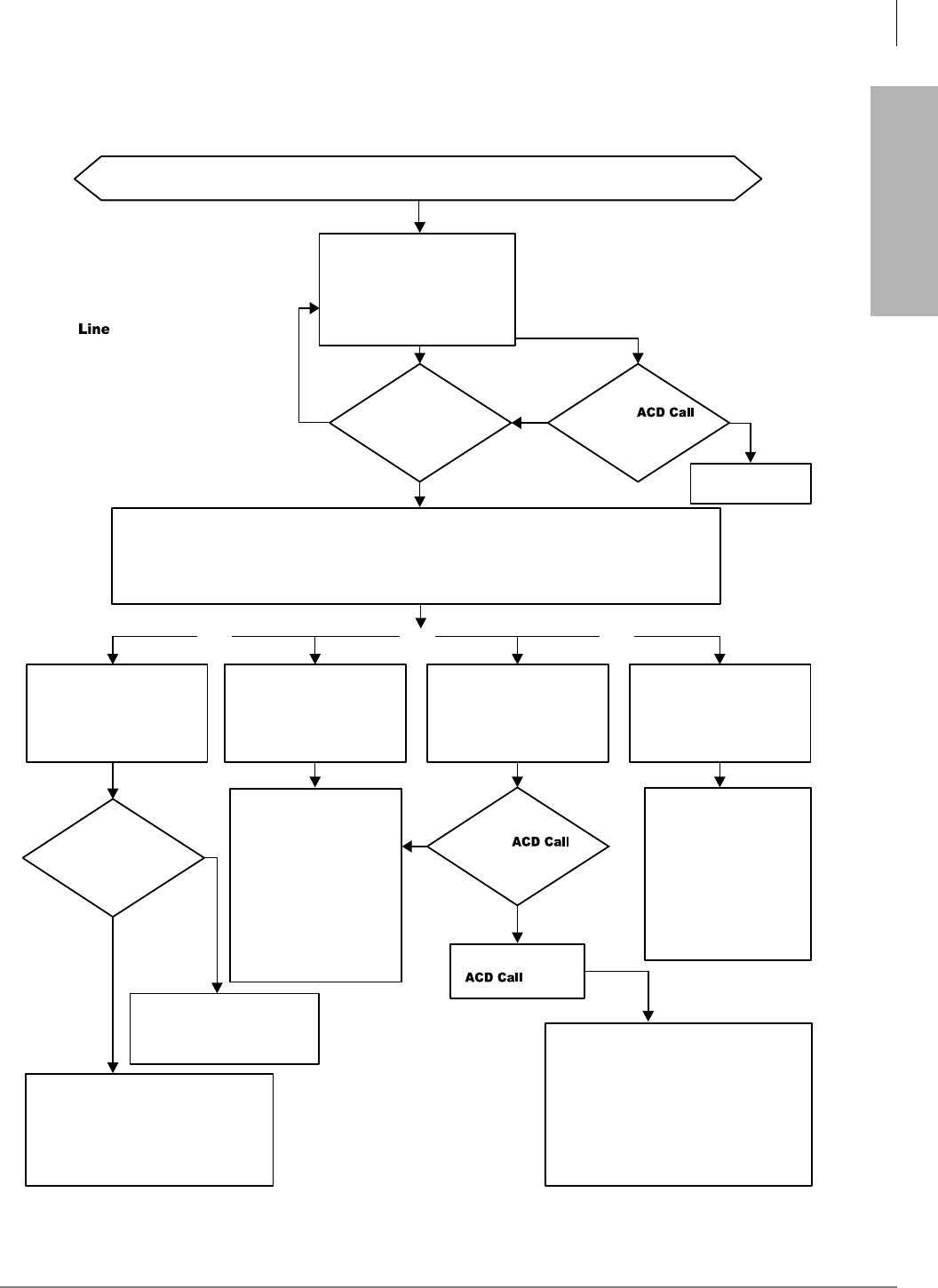
Automatic Call Distribution
Program 39 – Flexible Button Assignments for ACD Telephones
Strata DK Programming 5/99 6-47
Automatic Call Distribution
Yes
No
Yes Yes
Yes
Yes
Yes
No
OrOr Or
An ACD call routes to an idle agent telephone, but it is not answered when it rings.
0880
Talk on ACD call.
Ring idle agent
ACD Call button.
Is
destination
busy?
Is
another agent
idle?
Does agent
answer ACD Call
button before ring agent
timer expires?
Is an
agent ACD Call
button idle in the
group?
CO lines that normally route to the ACD group will route to the group’s overflow point destination set in
Program 14-5 (see ACD Flowchart 6-8~6-11). Only one destination per ACD group can be assigned in
Program 14-5.
The destination assigned in Program 14-5 will also be the overflow point destination.
Ground/loop start:
connect to Strata DK AA
and route call per AA
programming.
DID/tie/DNIS/ANI line:
ring or camp-on to station
programmed in
Program
*
14-2.
Loop/ground start: busy override ring
system [DN] per Programs 81, 84, 87,
and
*
81,
*
84,
*
87 (see Notes).
DID/tie/DNIS/ANI line: camp-on busy to
system [DN], DH, or console port
assigned.
If an agent answers, talk on ACD call. If no
answer, ring another idle agent or go to RNA
destination of this group.
If the RNA destination of this group is the
ACD group from which the call originated, the
call will be sent to the line's normal ring
pattern in Programs 81~89, and
*
81,
*
84,
*
87
[DN]; or, if tie/DID/DNIS/ANI line, to the
system [DN] assigned in Program
*
14-2.
Loop/ground start: ring or
busy override ring the
system [DN] in normal
ringing assignments per
Programs 81~89, and
*
81,
*
84,
*
87 (see Notes).
DID/tie/DNIS/ANI LINE:
ring or camp-on to system
[DN] assigned in Program
*
14-2 of original ACD
group.
Ring No Answer
destination is normal CO
line ringing assignments.
Program 14-5 (321, 441)
Ring no answer destination
is a system [DN] or DH
attendant console or DH port
number. Program 14-5
Ring No Answer destination
is another ACD group.
Program 14-5: RCTUBA/BB,
RCTUC/D (301~316),
RCTUE/F (401~416)
Ring No Answer
destination is Strata DK
built-in AA.
Program 14-5 (320, 440)
Ring agent telephone for the
time duration of the “Ring
Agent Timer” Set in Program
11-2 (see Notes).
Yes YesNo
No
Ring system [DN], DH, or
console port assigned in
Program 14-5.
Notes
●
If two consecutive ACD calls sent to
an idle agent telephone are not
answered, the telephone will be placed
in the Unavailable mode automatically.
●
If the agent presses a [DN] or another
CO Line button, while the ACD line
is ringing, the ACD call will mute ring
the Agent telephone.
●
If the call entered the ACD queue prior
to Ring No Answer operation, delay
ringing assignments will not ring; only
immediate ring assignments (Programs
81, 84, 87 and *81, *84, *87) will ring.
Notes
System [DNs] include:
Program 04 [PDNs]/[SDNs]
Program
*
04 [PhDNs]
DH = Distributed Hunt Group
Flowchart 6-7 Agent Telephone Ring No Answer Operation
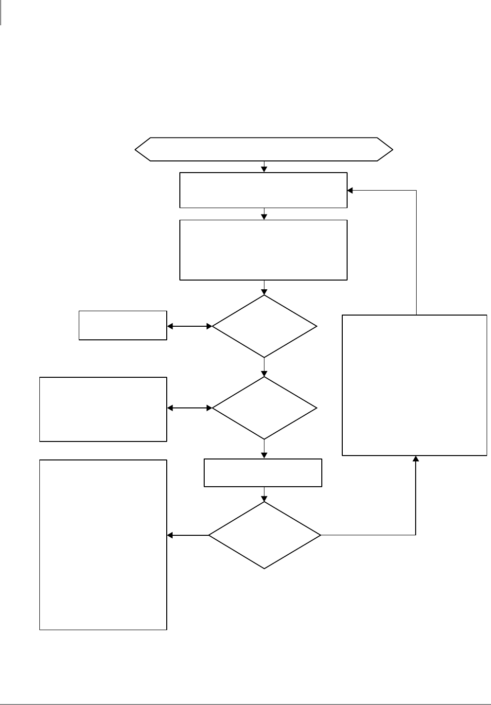
Automatic Call Distribution
Program 39 – Flexible Button Assignments for ACD Telephones
6-48 Strata DK Programming 5/99
Yes
Start: call enters queue from ACD Flowchart 6-1.
No
No
Continue
Yes, overflow
point 1.
No, send
continuous
music.
Yes, continue to repeat
announcement/music.
Caller continues to hear
music source.
Has the
Program 11-51 music timer
expired?
In Program 14-5, set the overflow
point data to “1” and set the desired
overflow destination.
The call will attempt to overflow per
ACD Flowchart 6-4 at this point.
Should the call
overflow after the Program
11-51 music timer
Should the
caller receive the 1st
announcement again when
the music time in
Program 11-51
expires?
Caller is connected to 1st announcement port.
this port is assigned in Program 14-3.
After the 1st announcement ends and hangs
up, the caller is connected to the music
source assigned in Program 14-34; the caller
will hear music from this source for the time
duration set in Program 11-51.
In Program 14-5, set overflow
point data to “0”.
Note The call will attempt to exit queue
when:
♦an Agent telephone goes idle.
♦the queue timer in Program
11-1 expires.
♦the call reaches the overflow
point.
♦the disconnect timer in
Program 11-9 expires.
♦the caller hangs up.
To continue to send music to the
caller until the call exits queue: in
Program 14-32, program a vacant
station port as Announcement 2. A
circuit card does not have to be
installed for the vacant port.
The caller will continue to hear
uninterrupted music until the call
exits queue. The call will exit queue
when:
♦an agent goes idle.
♦the call overflows when the
overflow timer in Program 11-1
expires.
♦the caller hangs up.
♦the disconnect timer in Program
11-9 expires.
In Program 14-35, set the repeat
announcement data to “1”.
The caller will be reconnected to the 1st
announcement. When the announcement
ends, the caller will be reconnected to the
music source for the time duration set in
Program 11-51. This sequence will
continue to repeat until the call exits
queue. the call will exit queue when:
♦an agent goes idle.
♦the call overflows when the overflow
timer in Program 11-1 expires.
♦the caller hangs up.
♦the disconnect timer in Program 11-9
expires.
0881
♦Overflow after announcement/music
...or
♦Repeat announcement/music
...or
♦One announcement then continous music
Flowchart 6-8 ACD Queue Pattern Configuration – One Announcement Only
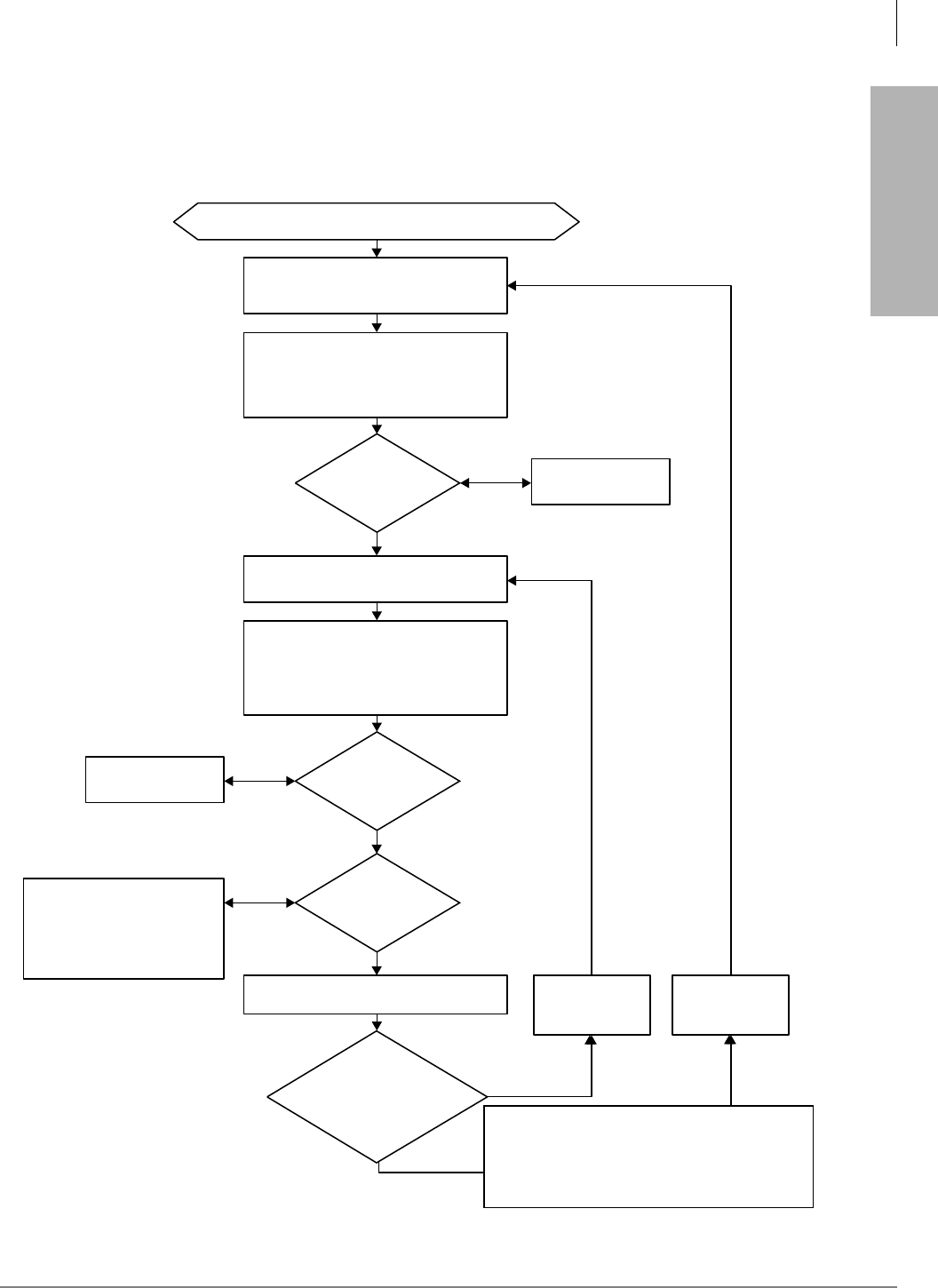
Automatic Call Distribution
Program 39 – Flexible Button Assignments for ACD Telephones
Strata DK Programming 5/99 6-49
Automatic Call Distribution
Yes
Start: call enters queue from ACD Flowchart 6-1.
No
Yes
No
No
Continue
Yes,
Overflow
Point 2
Repeat second
announcement
and music only.
Caller is connected to second announcement port.
This port is assigned in program 14-33 (not
Program 14-32).
Has the Program
11-51 music timer expired?
Caller continues to hear
music source.
Caller continues to hear
music source.
Has the
Program 11-53
music timer expired?
In Program 14-5, set the overflow
point data to “3” and set the desired
overflow destination.
The call will attempt to overflow per
ACD Flowchart 6-4 at this point.
Should
the call
overflow after the
Program 11-53 music
timer expires?
Caller is connected to first announcement port.
This port is assigned in Program 14-3.
After the first announcement ends and hangs up,
the caller is connected to the music source
assigned in Program 14-34; the caller will hear
music from this source for the time duration set in
Program 11-51.
After the second announcement ends and hangs
up, the caller is connected to the music source
assigned in Program 14-34; the caller will hear
music from this source for the time duration set in
Program 11-53 (not Program 11-52).
Should the call
continue to receive the
first and second announcement
or only the second when the music
timer in Program 11-53
expires?
In Program 14-5, set overflow point data to “0”. In Program 14-35,
set the repeat
announcement data
to “1”.
In Program 14-35,
set the repeat
announcement data
to “3”.
Notes The call will attempt to exit
queue when:
♦an Agent telephone goes
idle.
♦the queue timer in Program
11-1 expires.
♦the call reaches the overflow
point.
♦the caller hangs up.
♦the disconnect timer in
Program 11-9 expires.
In Program 14-32, set the
announcement port data to
blanks using K01 on the
programming telephone.
0847
Repeat first and second announcment and music until:
♦an agent goes idle.
♦the call overflows when the overflow timer in Program
11-1 expires.
♦the caller hangs up.
♦the disconnect timer in program 11-9 expires.
♦Overflow after second announcement/music
...or
♦Repeat announcement/music
Flowchart 6-9 ACD Queue Pattern Configuration – Two Announcements
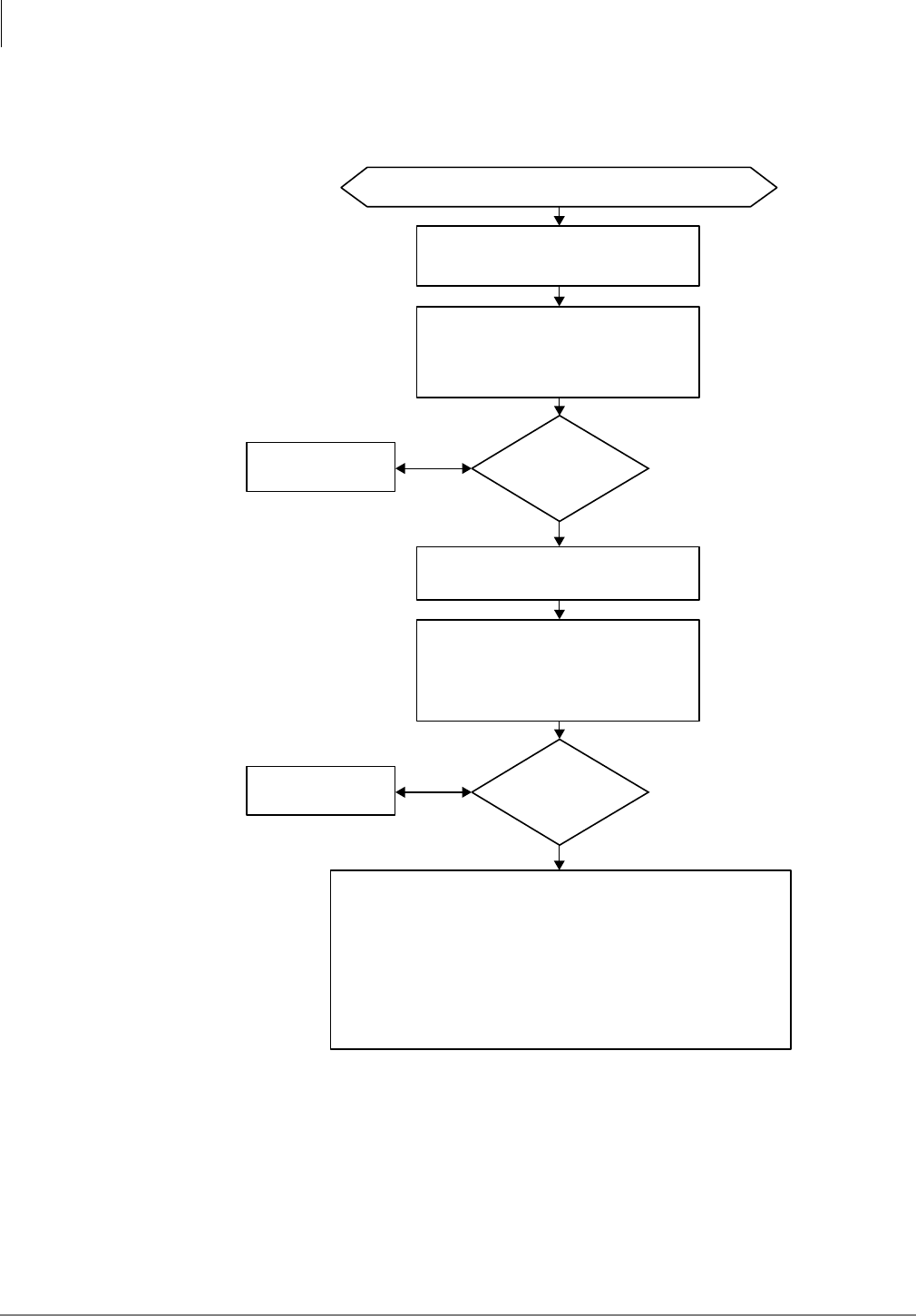
Automatic Call Distribution
Program 39 – Flexible Button Assignments for ACD Telephones
6-50 Strata DK Programming 5/99
Yes
Start: call enters queue from ACD Flowchart 6-1.
No
Yes
No
Caller is connected to second announcement port.
this port is assigned in Program 14-32 (not
Program 14-33).
Caller continues to hear
music source.
Has the
Program 11-51
music timer expired?
Caller continues to hear
music source.
Has the
Program 11-52
music timer
expired?
Caller is connected to first announcement port.
This Port Is Assigned In Program 14-3.
After the first announcement ends and hangs up,
the caller is connected to the music source
assigned in Program 14-34; the caller will hear
music from this source for the time duration set in
Program 11-51.
After the second announcement ends and hangs
up, the caller is connected to the music source
assigned in Program 14-34; the caller will hear
music from this source for the time duration set in
Program 11-52 (not Program 11-53).
To continue to send music to the caller until the call exits queue:
1. In Program 14-33, program a vacant station port as Announcement 3. A circuit
card does not have to be installed for vacant port.
2. In Program 14-5, set overflow point data to “0”.
The caller will continue to hear uninterrupted music until the call exits queue. The
call will exit queue when:
♦an agent goes idle.
♦the call overflows when the overflow timer in Program 11-1 expires.
♦the caller hangs up.
♦the disconnect timer in Program 11-9 expires.
Continue
Notes The call will attempt to exit queue
when:
♦an agent telephone goes idle.
♦the queue timer in Program 11-1
expires.
♦the call reaches the overflow
point.
♦the caller hangs up.
♦the disconnect timer in Program
11-9 expires.
0848
♦Two announcements, then continued music
ACD Queue Pattern Configuration – Two Announcements
(continued)
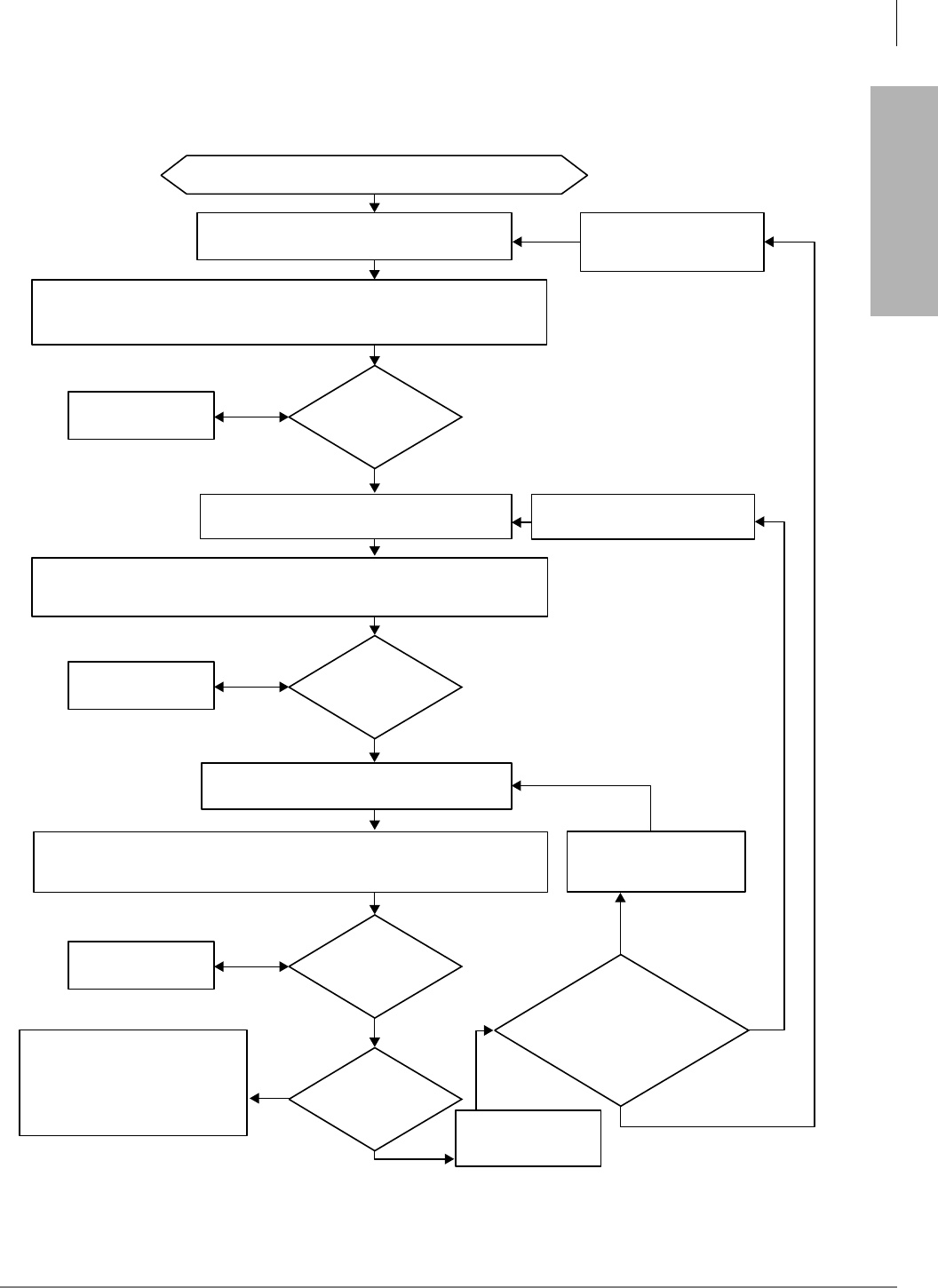
Automatic Call Distribution
Program 39 – Flexible Button Assignments for ACD Telephones
Strata DK Programming 5/99 6-51
Automatic Call Distribution
Start: call enters queue from ACD Flowchart 6-1.
Yes
No
No
No
Yes
Overflow
point 3
Yes
Yes
No
3rd only
1st, 2nd, and 3rd
2nd and 3rd
Caller is connected to 2nd announcement port.
This port is assigned in Program 14-32.
In Program 14-35, set the
repeat announcement data to
“2”.
In Program 14-35, set the
repeat announcement
data to “3”.
In Program 14-5, set the overflow point
data to “3” and set the desired overflow
destination.
The call will attempt to overflow per ACD
Flowchart 6-4 at this point in queue.
Caller continues to hear
music source.
Caller continues to
hear music source.
In Program 14-5, set
overflow point data to “0”.
Caller continues to hear
music source.
Has the
Program 11-51 music timer
expired?
Has the
Program 11-52 music timer
expired?
Has the
Program 11-53 music timer
expired?
Should
the call
overflow after the
Program 11-53 music
timer expires?
Should the
caller continue to
receive the 1st, 2nd and 3rd
announcements, or 2nd and 3rd
announcements, or only the 3rd
announcement when the music
timer in Program 11-53
expires?
Caller is connected to 1st announcement port. This
port is assigned in Program 14-31.
After the 1st announcement ends and hangs up, the caller is connected to the music
source assigned in Program 14-34; the caller will hear music from this source for the time
duration set in Program 11-51.
After the 2nd announcement ends and hangs up the caller is connected to the music source
assigned in Program 14-34; the caller will hear music from this source for the time duration set
in Program 11-52.
After the 3rd announcement ends and hangs up the caller is connected to the music source
assigned in Program 14-34; the caller will hear music from this source for the duration set in
Program 11-53.
In Program 14-35, set the repeat
announcement data to “1”.
Notes The call will attempt to exit queue
when:
• an agent telephone goes idle.
• the queue timer in Program 11-1
expires.
• the call reaches the overflow
point.
• the disconnect timer in Program
11-9 expires.
• the caller hangs up.
0882
Caller is connected to 3rd announcement port. This port
is assigned in Program 14-33.
Flowchart 6-10 ACD Queue Pattern Configuration – Three Announcements

Automatic Call Distribution
Program 39 – Flexible Button Assignments for ACD Telephones
6-52 Strata DK Programming 5/99

Strata DK Programming 5/99 7-1
ISDN
ISDN 7
This chapter provides you with an overview of Integrated Systems Digital Networking (ISDN) and
provides step-by-step instructions to fill in the ISDN record sheets. Included is an overview of
system and trunk programming for ISDN.
System Programs Overview
System programming for ISDN has some commonalities with T1 programming. ISDN
programming follows two different paths, depending on whether Basic Rate Interface (BRI) or
Primary Rate Interface (PRI) is being installed. Refer to Flowchart 7-1 and the following steps for
an overview of each program’s purpose.
ISDN features can be programmed onto the following systems as described:
♦DK40i and DK424 – support BRI S/T
♦DK40i and DK424 – will support BRI U basic features in Release 4.2
♦DK424 supports PRI
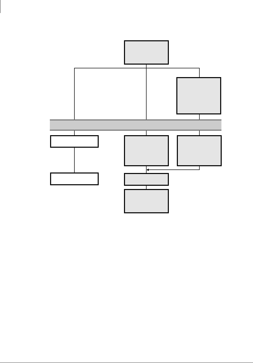
ISDN
System Programs Overview
7-2 Strata DK Programming 5/99
Flowchart 7-1 ISDN System Programs
➤To record and enter the data for ISDN system programs
1. Run Program 03-Assign the RPTU (PRI) PCB slot position as type 79. (See “Program 03 for
DK424 – Flexible PCB Cabinet Slot Assignments” on Page 3-6.) Assign the RBSU without
the RBSS piggy-back board as type 77 and the RBSU with the RBSS piggy-back as type 78.
2. For BRI, run Program *60 to assign each circuit for CO line (TE) or Station (NT) operation.
3. Turn system power supply OFF (five seconds) and ON to activate Program 03 and *60
program data.
Note These are the only programs relating to RPTU operation that require system power to be
cycled OFF and ON.
4. For PRI, run Program *43 to assign which channel on the PRI link is used for the
D-channel. The second assignment specifies the card slot of additional PRI links that are
dependent on the master D-channel PRI. The third assignment sets the ID code for the PRI
link. For BRI, skip to Step 5.
*41 T1 Assignments
*42 Clock Source
Program *60
Assign BRI circuits
for CO line (TE)
or Station (NT)
operation.
System power must cycle OFF and ON to effect changes.
T1 BRIPRI
Program 03
Assign BRI or
PRI card slots.
Program *43
Assign the PRI
D-channel and
network interface.
Program *44
Initialize BRI
Service Profile ID
(SPID) number.
*42 Clock Source
Program *63
Set ISDN dialing
timers.
2934

ISDN
ISDN Related Programs
Strata DK Programming 5/99 7-3
ISDN
5. For BRI, run Program *44 to initialize the Service Profile Identifier (SPID) interface. The TE
initializes the SPID and sends it to the network. Once the SPID is confirmed from the CO, it
does not have to be sent to the switch again.
6. For BRI and PRI, run Program *42 to assign the PRI or BRI, or T1, circuits to be used for
Primary and Secondary Clock Source. To enter the program, enter the card slot number
followed by the circuit number. When using the RPTU PRI or RDTU T1 interface then the
circuit number is always 1.
7. For BRI and PRI, run Program *63 to assign the timer for sending dialed digits. Also use this
program to enable sub-address dialing. (*63-1 is not zero).
8. See the following section, “ISDN Related Programs”, and make the appropriate programming
assignments.
ISDN Related Programs
♦Program 10-1–System Assignments: LED 16 determines the initialization process for BRI
lines connected to the ISDN network (see 3-27).
♦Program 10-4–ACD/ISDN Parameters: LEDs 11 and 12 set the T-Wait ISDN PRI and BRI
timers, respectively. T-wait timers are used for reducting overloading ISDN terminals during
concurrent initialization, such as following a wide-area power failure. LED 13 specifies
whether or not 3.1 kHz audio calls can be received as speech calls. LED 14 enables the ISDN
“Start” code to be sent when the Speed Dial button is pressed (see 6-6).
♦Program 39–Telephone Feature Buttons and Program 59–Attendant Console Feature
Buttons: A new button is provided called the 6WDUW button in both Program 39 (see 3-135)
and 59 (see 3-111) to defeat the timeout when dialing is complete. Also a 6XE button is
provided for entering sub-address information.
♦Programs 55-1 and 55-2–Least Cost Routing Modified Digits: Enables a sub-address
separator (see 5-21).
♦Program 30 – Station Class of Service: LED 12 defines whether the button is used for
dialing a sub-address or as a dialing separator. When LED 12 is ON, only the standard stations
are affected. The DKT and EKT ports are ignored (see 3-73).
If the first dialed digit is , the will be treated as a feature access code. If is entered at any
point after that (in other words, as long as it is not the first digit dialed), then the system will
treat the following numbers as a subaddress. A second should then be entered to indicate the
end of the subaddress.
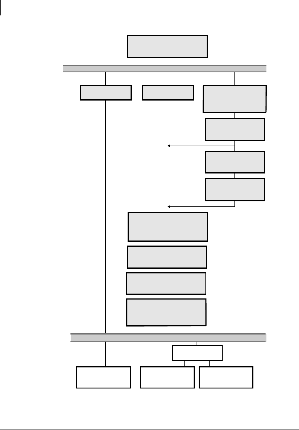
ISDN
ISDN Related Programs
7-4 Strata DK Programming 5/99
Flowchart 7-2 ISDN Trunk Programs
Programs 81~89,
*81~*87 Direct
Ringing Lines
Programs*09, *17,
*71~*73
DID Ringing
Programs 71 and 72
DNIS Ringing
Standard Trunks BRI PRI
Program *16
Define ISDN Trunk Group
Type (non-ISDN,PRI, BRI).
Program 16
Assign Trunk Groups.
Program 16
Assign Trunk Groups.
Programs *66-1~3
Assign channel and
trunk group parameters.
Programs *66-2, -4
Assign call-by-call
service parameters
Program *67
Assign call direction for
each ISDN trunk group.
Programs *68-1~2
Define and enable Called
Number ID Service (CNIS)
Program *69
Assign CNIS indexes and
DID or LDN.
Program *64
Assign ISDN trunk groups
to use DID, DNIS or DIL for
incoming calls.
Program 17
LEDs DID/DNIS
Programs *66-5~7
Assign LDNs to channel groups
and indexes. Assign LDN channel
groups to ISDN trunk ports.
Program *65
Define the number
of B-channels per
channel group.
2933

ISDN
Trunk Programs Overview
Strata DK Programming 5/99 7-5
ISDN
Trunk Programs Overview
See Flowchart 7-2 for an overview of the ISDN trunk programming procedure.
♦If you are installing all standard trunk groups, skip Program *16 (the default is for all standard
TGs).
♦If you are installing BRI ISDN, use Program *16 to assign BRI type and Program 16 to assign
BRI CO lines into trunk groups.
♦If you are installing PRI, use Program *16 to assign PRI types. Do not use Program 16. Do not
change settings in Program 16 for trunk groups marked for PRI.
Primary Rate Interface (PRI) Programming
1. Run Program *16 to define the ISDN trunk group type as: non-ISDN, Primary Rate Interface
(PRI), or Basic Rate Interface (BRI).
2. For BRI trunk groups, run Program 16 to assign the trunk groups. Then, skip to Step 7.
3. For PRI, run Program *65 to assign B-channels.
4. For PRI, run Programs *66-1, *66-3 to define trunk groups parameters and channels. (Program
16 will be assigned automatically.)
5. To assign Call-by-call features (PRI only), run Programs *66-2, *66-4 to assign Call-by- call
trunk groups codes and network ID.
6. For PRI, run Program *67 to assign call direction for ISDN trunk groups and call type
capabilities allowed for each trunk group.
7. For BRI and PRI, run Program *68 to define the parameters for Calling Number to be
presented for a call depending upon whether the ISDN trunk group uses DID, private numbers
or use default number programmed in *68-2.
8. For BRI and PRI, run Program *66-5 to assign Listed Directory Numbers (LDNs) to channel
groups and index numbers. Then run Program *66-6 to assign LDN channel groups to ISDN
trunk ports. Then run Program *66-7 to assign trunk groups to each LDN.
9. Run Program *68-2 to define whether or not the system presents a “user” Caller ID when calls
are made using ISDN services. This program also enables users to dial a code to send Caller
ID or to block it.
10. For BRI and PRI, run Program *69 to define the parameters for Calling Number to be
presented. Each phone can present a unique Caller ID number, such as DID or a private
number. If neither is chosen, the default is the Directory Number entered in Program *68-2 for
outgoing calls.
11. Run Program *64 to assign each ISDN trunk group to use DID/DNIS programming, or to
provide Direct in Line (DIL) ringing for incoming calls.
12. See “ISDN Related Programs” on Page 7-3, and make the appropriate programming
assignments.

ISDN
Program 16 – Assign CO Line Groups
7-6 Strata DK Programming 5/99
Program 16 – Assign CO Line Groups
This program assigns CO line groups (or Dial 9 groups). Refer to this program only for BRI lines.
Do not make changes to trunk groups assigned in Program *16 as PRI type. These will be assigned
automatically when PRI programming is entered. The system record sheet is on Page 3-48 of this
manual.

ISDN
Program *16 – ISDN Trunk Group Type Assignment
Strata DK Programming 5/99 7-7
ISDN
Program *16 – ISDN Trunk Group Type Assignment
Processor Type:
DK40i, All RCTUs (Release 4.0 or higher)
Program Type:
Trunk, PRI, BRI
Initialized Default:
Type 1 (non-ISDN)
Program *16 Overview
This program must be entered prior to Program 16. Each trunk group in the system must be
defined whether it is used for non-ISDN trunks, PRI trunks, or BRI trunks. Do not make changes
in Program 16 for PRI trunk groups. This may cause unexpected operations.
6SNU+ROG 6SNU +ROG 6SNU +ROG 6SNU +ROG
Trunk Groups Value Trunk Group Type
12345678910 11 12 13 14 15 16
1 Non-ISDN
2 Primary Rate Interface (PRI)
3 Basic Rate Interface (BRI)
TYPE = 1~3 (see below)
1 - non-ISDN Trunk Group (default)
2 - PRI Trunk Group
3 - BRI Trunk Group
SEL = Trunk Group Number
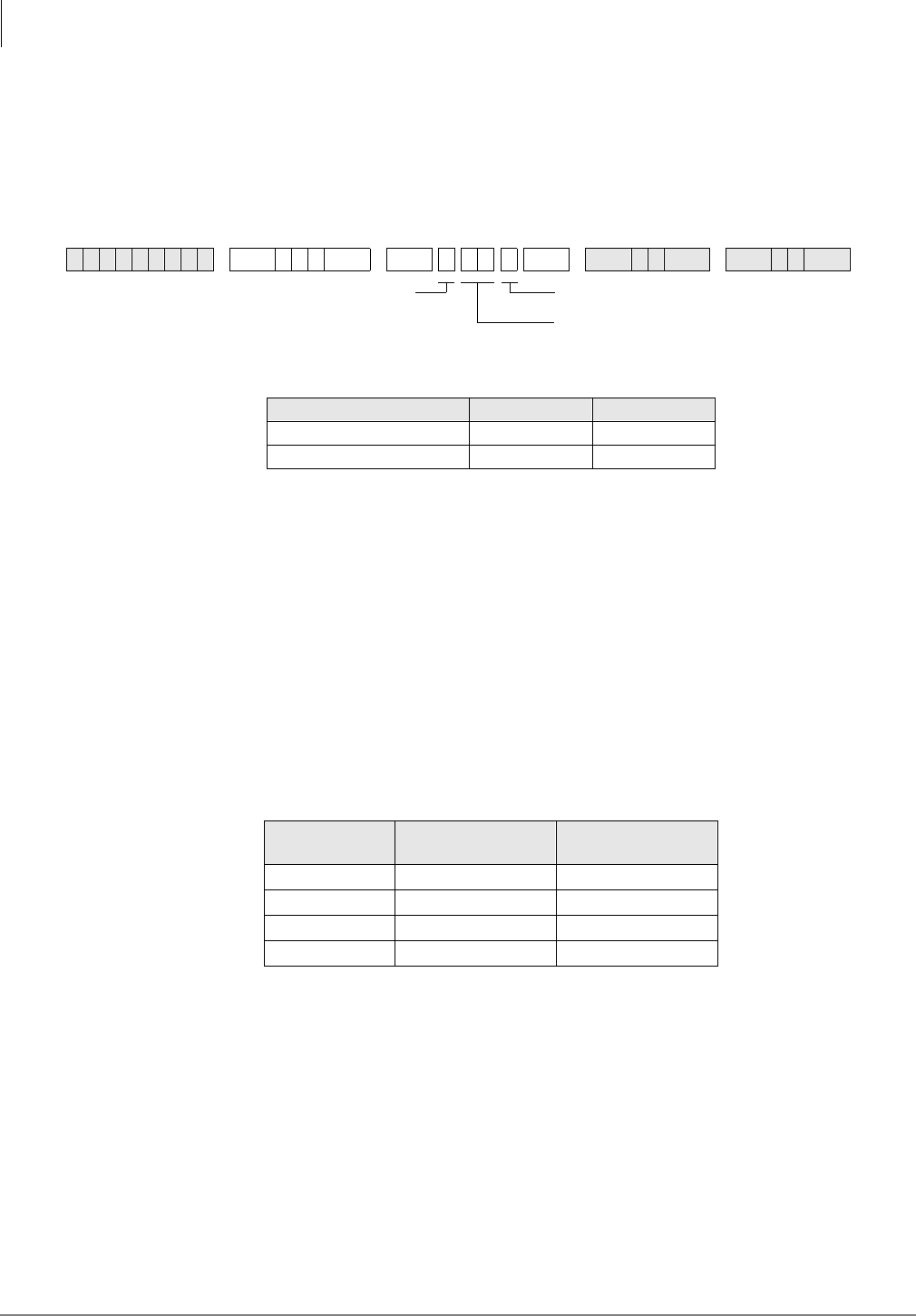
ISDN
Program *42 – Clock Source
7-8 Strata DK Programming 5/99
Program *42 – Clock Source
Processor Type:
DK40i, All RCTUs (Release 4.0 or higher). For Release 3.1 and earlier programming,
see below.
Program Type:
System, T1, PRI, BRI
Initialized Default:
Blank
Program *42 Series Overview
This program assigns the T1, PRI or BRI interface RPTU PCB as a Primary or Secondary timing
source. The DK424 is synchronized to the Public Network. If the Primary synchronization is lost,
it switches to the secondary timing source.
When a T1 or PRI slot number is assigned, the DK424 only accepts a “1” for the circuit number.
The circuit number is only used for BRI interfaces to specify which circuit is to be used for the
Clock Source. If the PCB in this slot is not a T1 or ISDN PCB, the system will not accept data and
any entries will be cleared.
BRI interfaces should be used as a clock source only when a T1 or PRI interface is not equipped
Set T1 parameters and assignments with the Program 41 (Part 1) and 42 (Part 2) series. See the
Strata DK Installation and Maintenance Manual for additional T1 information. RDTU/RPTU
support is as follows:
For proper T1 or ISDN operation, the equipment at each end of a digital T1 span line must be
synchronized. The DK424 is synchronized (as slave) to the equipment on the other end of the
digital line by the RDTU/RPTU, RBUU/RBUS PCB designated as the Primary Reference in
Program 42-1.
If a malfunction occurs and Primary Synchronization is lost, the DK424 automatically switches
modes and synchronizes to the equipment connected to the secondary PCB designated as the
Secondary Reference. If the equipment on the other end of the DK424 digital lines should
synchronize to the DK424 clock source, then enter blanks in Program 42-1 and 2. In this case, the
DK424 clock runs free and is considered the Master Synchronization source.
6SNU+ROG 6SNU + ROG6SNU +ROG 6SNU +ROG
Clock Source Slot Number Circuit No.
Primary
Secondary
Processor Number of RDTU/
RPTU’s Supported Number of RBUU/
RBUS’s Supported
RCTUA 0 4
RCTUBA/BB 2 8
RCTUC/D 6 14
RCTUE/F 8 20
Circuit NumberSEL = 1 or 2
1 - Primary Source
2 - Secondary Source PRIMARY = or SECONDARY =
Slot Number (Release 4.0 entry. Not used
for release 3.1 or earlier versions.)
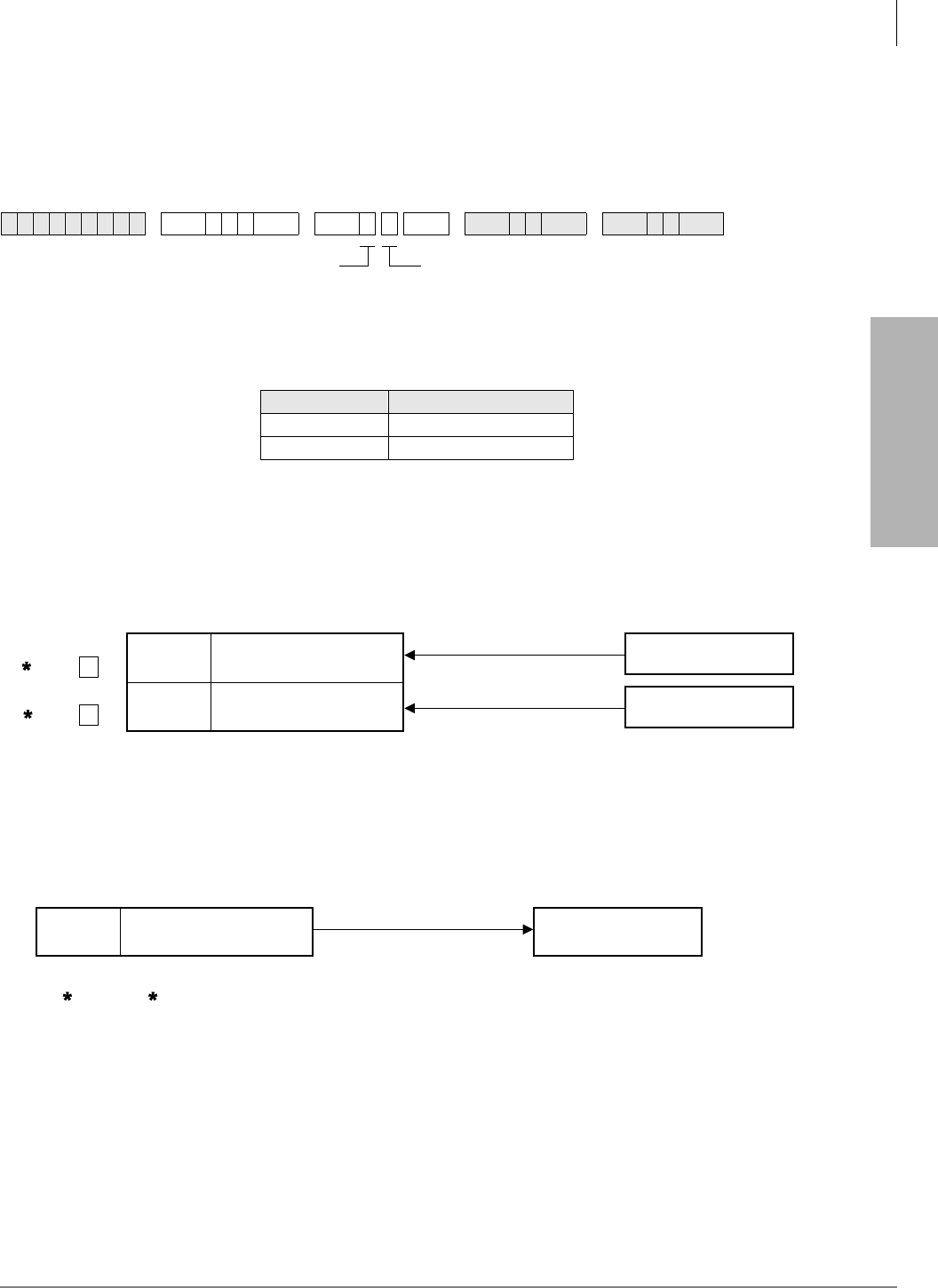
ISDN
Program *42-1 – Primary Timing Reference Assignments (Release 3.1 and earlier)
Strata DK Programming 5/99 7-9
ISDN
Program *42-1 – Primary Timing Reference
Assignments (Release 3.1 and earlier)
Initialized Default:
Primary = 1, Secondary = 2
Program *42-1 Overview (Release 3.1 and earlier)
Assign the Primary Timing Reference with this program.
Note RDTU No.1 is the RDTU PCB installed in the lowest slot number of all RDTU PCBs,
RDTU No. 2 is the RDTU PCB installed in the next highest slot number of all RDTUs and
so on.
Primary/Back-Up Assignments Example
Note A second RBOC T1 span line can also be used as the secondary clock source.
DK424 Master (free run) Assignment Example
Program *42-2 Overview (Release 3.1 and earlier)
Assign the Secondary (Backup) Timing Reference with this program.
Note To assign RDTUs as the Master Clock Reference (free run), leave Programs 42-1 and
42-2 blank. Press button/LED 01 to enter blanks.
6SNU+ROG 6SNU + ROG6SNU +ROG 6SNU +ROG
Select RDTU PCB Number
Primary
Secondary
SEL = 1 or 2
1 - Primary Source
2 - Secondary Source
RDTU PCB Number (1~8)
Enter the RDTU PCB number that is connected to the
primary reference T1 (span line) clock source.
Press LED Button 01 (blank) if the DK424 T1 is the
master (free run) clock source.
1863
RDTU in
Slot 13
RDTU in
Slot 25
T1 – Primary PCB
T1 – Secondary PCB
Central Office
RBOC CO lines
AT&T or MCI
Long Distance Lines
Span Line
(Primary clock source)
Span Line
(Secondary clock source)
DK424
Program Data
4 2 - 1 1 >
Program Data
4 2 - 2 2 >
Slot 13 T1 – PCB Other DK424
or PBX, etc
Span Line
(DK424 clock source)
DK424
Program Data = blank button (Button 01)
for 4 2 - 1 and 4 2 - 2 1864
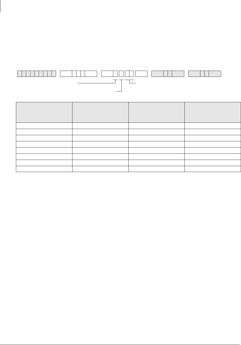
ISDN
Program *43-1~3 – D-Channel Control and NFAS Assignments
7-10 Strata DK Programming 5/99
Program *43-1~3 – D-Channel Control and NFAS
Assignments
Processor Type:
All RCTUs (Release 4.0 or higher)
Program Type:
System, PRI
Initialized Default:
Blank (see Important! below)
Program *43-1~3 Overview
Programs *43-1~3 are related in that there is a correspondence between Program *43-1 and *43-2.
Program *43-1 determines which channel acts as the master. Program *43-2 points back to the
master channel by using the corresponding index number.
Program *43-1 Overview
This program (*43-1) assigns which channel on the PRI link is used for D-channel (the data master
control channel). The default setting is none.
Important! For most carriers, channel 24 is assigned to the D-channel (default). NFAS
D-channel assignments are negotiated with the carrier.
6SNU+ROG 6SNU +ROG 6SNU +ROG 6SNU +ROG
PRI Index *43-1
D-Channel
Circuit Number
*43-2
Master
PRI Index
*43-3
Network PRI
Interface ID Code
Enter PRI Index Number (1~8)
DCH = D-channel circuit number (01~24)
LED Button 01 deletes a digit
SEL = 1

ISDN
Program *43-2 – Non-Facility Associated Signaling (NFAS) Assignment
Strata DK Programming 5/99 7-11
ISDN
Program *43-2 – Non-Facility Associated Signaling
(NFAS) Assignment
Processor Type:
All RCTUs (Release 4.0 or higher)
Program Type:
System, PRI
Initialized Default:
Blank (see Important! below)
Program *43-2 Overview
This program specifies the card slot of additional PRI links that are dependent upon the D-channel
of the master D-channel PRI. This setting is for Non-Facility Associated Signaling (NFAS).
Use the Record Sheet for *43-1.
6SNU+ROG 6SNU +ROG 6SNU +ROG 6SNU +ROG
Enter the dependent PRI Index
Number without D-channel (1~8)
PRI = Master PRI Index
Number with D-channel (1~8)
SEL = 2

ISDN
Program *43-3 – Network PRI Interface Assignment
7-12 Strata DK Programming 5/99
Program *43-3 – Network PRI Interface Assignment
Processor Type:
All RCTUs (Release 4.0 or higher)
Program Type:
System, PRI
Initialized Default:
Blank (see Important! below)
Program *43-3 Overview
Program *43-3 assigns each PRI interface and ID code for communicating with the ISDN provider
to identify the B-channels to be used with NFAS.
Use the Record Sheet for *43-1.
6SNU+ROG 6SNU +ROG 6SNU +ROG 6SNU +ROG
SEL = 3
Enter the PRI Index Number (1~8)
ID = Network PRI Interface Code,
supplied by public provider (0~19)
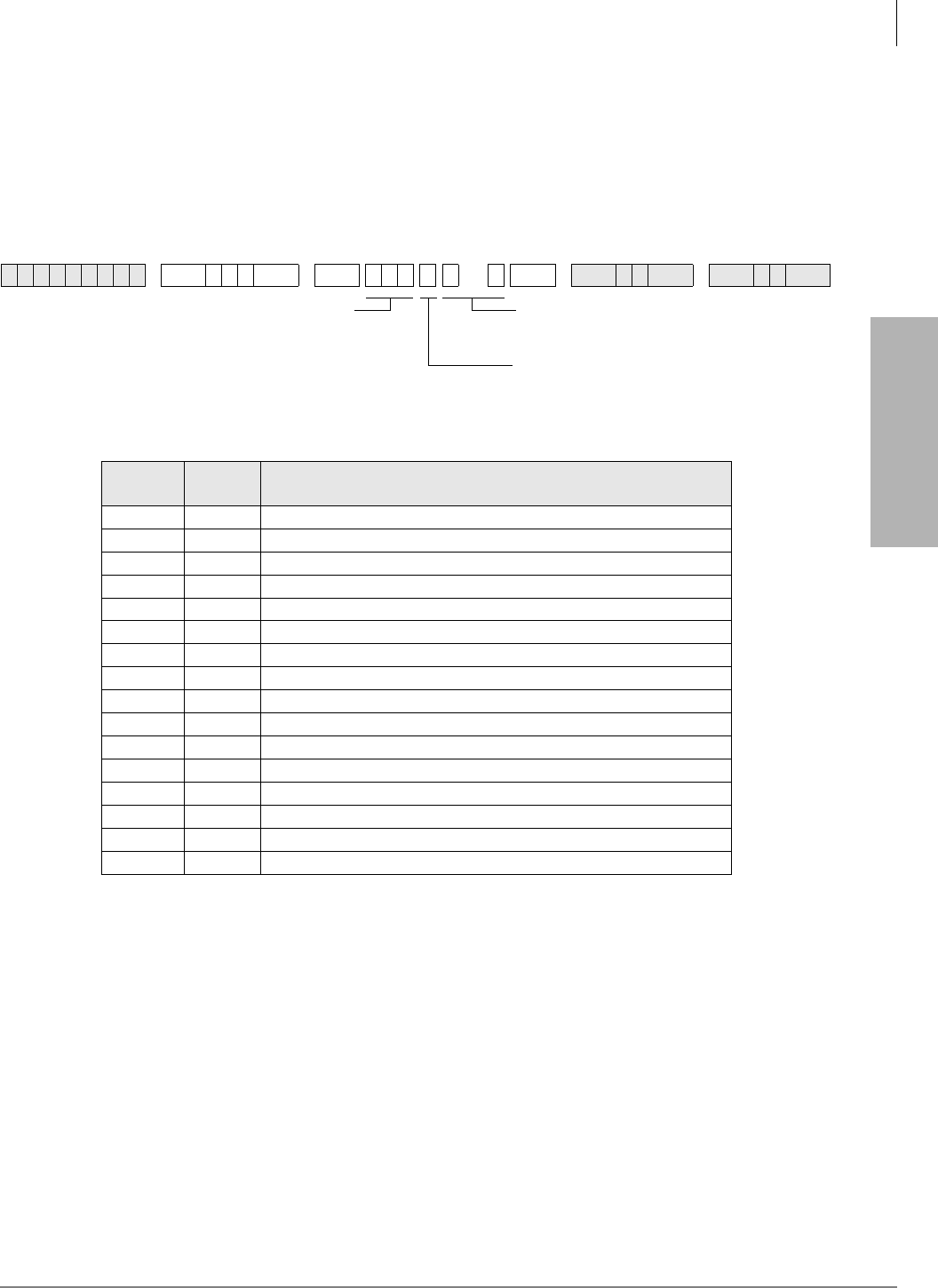
ISDN
Program *44 – BRI Service Profile Identifier (SPID) Parameters
Strata DK Programming 5/99 7-13
ISDN
Program *44 – BRI Service Profile Identifier (SPID)
Parameters
Processor Type:
DK40i, All RCTUs (Release 4.0 or higher)
Program Type:
Trunk, BRI
Initialized Default:
Blank
Program *44 Overview
BRI interfaces generally require entering an Service Profile Identifier (SPID) intialization value to
activate the interface. This program assigns the initialization interface.
When ISDN service is ordered, a SPID is issued from the carrier. A SPID usually includes a 10-
digit directory number along with additional digits, which notify the switch as to the type of
devices connected to the line and what services/features the switch is to provide.
There are three possible initialization processes, including a non-initializing terminal, one SPID,
or two SPID interfaces. These numbers are entered into the system to allow the interface to
automatically initialize the link. The type of initialization needed depends on the type of PSTN
equipment.
The basic procedure includes configuring a SPID, then the TE performs the initialization /
identification process and sends the SPID to the network. Once the SPID is confirmed from the
CO, the SPID does not have to be sent to the switch again.
6SNU+ROG 6SNU + ROG 6SNU +ROG 6SNU +ROG
BRI Trunk
Number SPID
Type SPID Value
DATA = SPID Type (0~2)
0 - Non-initializing trunk (NIT)
1 - one SPID for the interface
2 - one SPID for each B-channel
SEL = BRI Trunk Number Enter SPID Value (20 digits max.).
Use Button LED 01 to enter a blank.
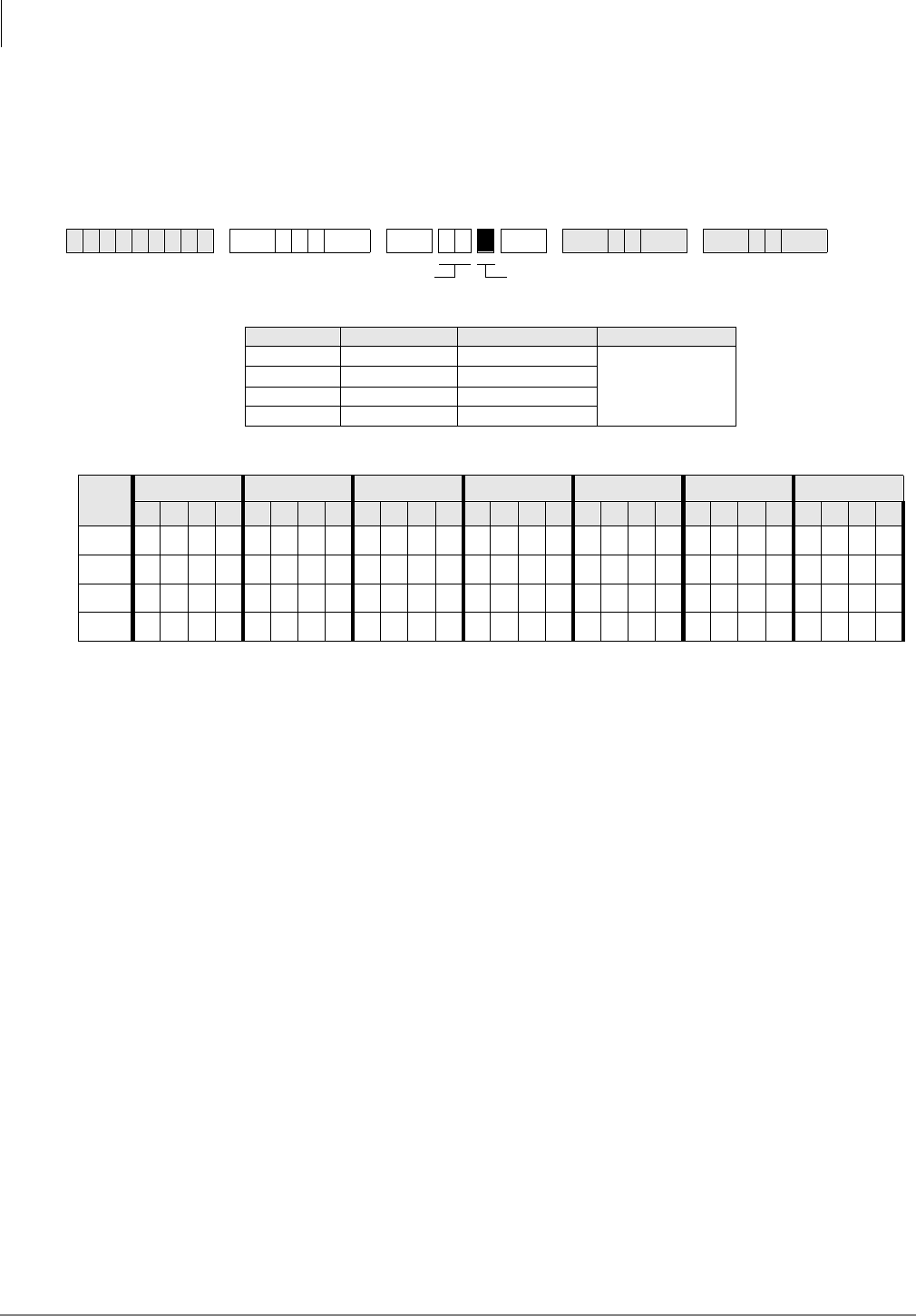
ISDN
Program *60 – BRI Line/Station Operation Assignment
7-14 Strata DK Programming 5/99
Program *60 – BRI Line/Station Operation Assignment
Processor Type:
DK40i, All RCTUs (Release 4.0 or higher)
Program Type:
System, BRI
Initialized Default:
All LEDs OFF
Note Power must be cycled OFF, then ON before changes take effect.
Program *60 Overview
This program assigns each circuit for CO Line (TE) or ISDN Station (NT) operation. Circuits 1 or
2 can be used for either CO line or ISDN station operation, while circuits 3 and 4 can only be used
for ISDN station operation.
6SNU+ROG 6 SNU +ROG 6SNU +ROG 6SNU +ROG
LED RBSU Circuit LED ON LED OFF
1 1 CO Line (TE)
Station Operation
(NT) (default)
2 2 CO Line (TE)
33 —
44 —
LEDs Slot 1 Slot 2 Slot 3 Slot 4 Slot 5 Slot 6 Slot 7
1 2 3 4 1 2 3 4 1 2 3 4 1 2 3 4 1 2 3 4 1 2 3 4 1 2 3 4
1
2
3
4
LEDs 1~4 = Circuits 1~4 (see legend below)SEL = Slot No.
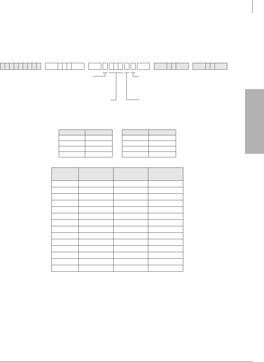
ISDN
Program *61 – Analog Trunk Services for ISDN
Strata DK Programming 5/99 7-15
ISDN
Program *61 – Analog Trunk Services for ISDN
Processor Type:
DK40i, All RCTUs (Release 4.0 or higher)
Program Type:
Trunk, PRI and BRI
Initialized Default:
see below
Program *61 Overview
When analog CO lines use ISDN facilities, each analog CO Line needs to be assigned the type of
service expected to be used when originating calls. The choices are Speech or 3.1 kHz (used for
modem and fax connections). Set the transmission level for outgoing and incoming paths for calls.
The default is set for -6 dB.
6SNU+ROG 6SNU + ROG 6SNU +ROG 6SNU +ROG
Data Pad Level (db) Data Pad Level (db)
00 4-12
1-3 5-15
2-6 6-18
3-9 7+3
Trunk
Number Bearer Service
*61-1 Outgoing Pad
Level *61-2 Incoming Pad
Level *61-3
Enter the trunk number(s) being defined.
To add a range, enter XXXXXX (low
trunk number high trunk number).
DATA = For *61-2 and *61-3, enter Pad
Level (default is 2). See legend below.
SEL = Type of Service (1~3)
1 - Bearer Service
2 - Outgoing Call Pad Level
3 - Incoming Call Pad Level
Enter the Bearer Service:
0 = 3.1 kHz Audio
1 = Speech (default)
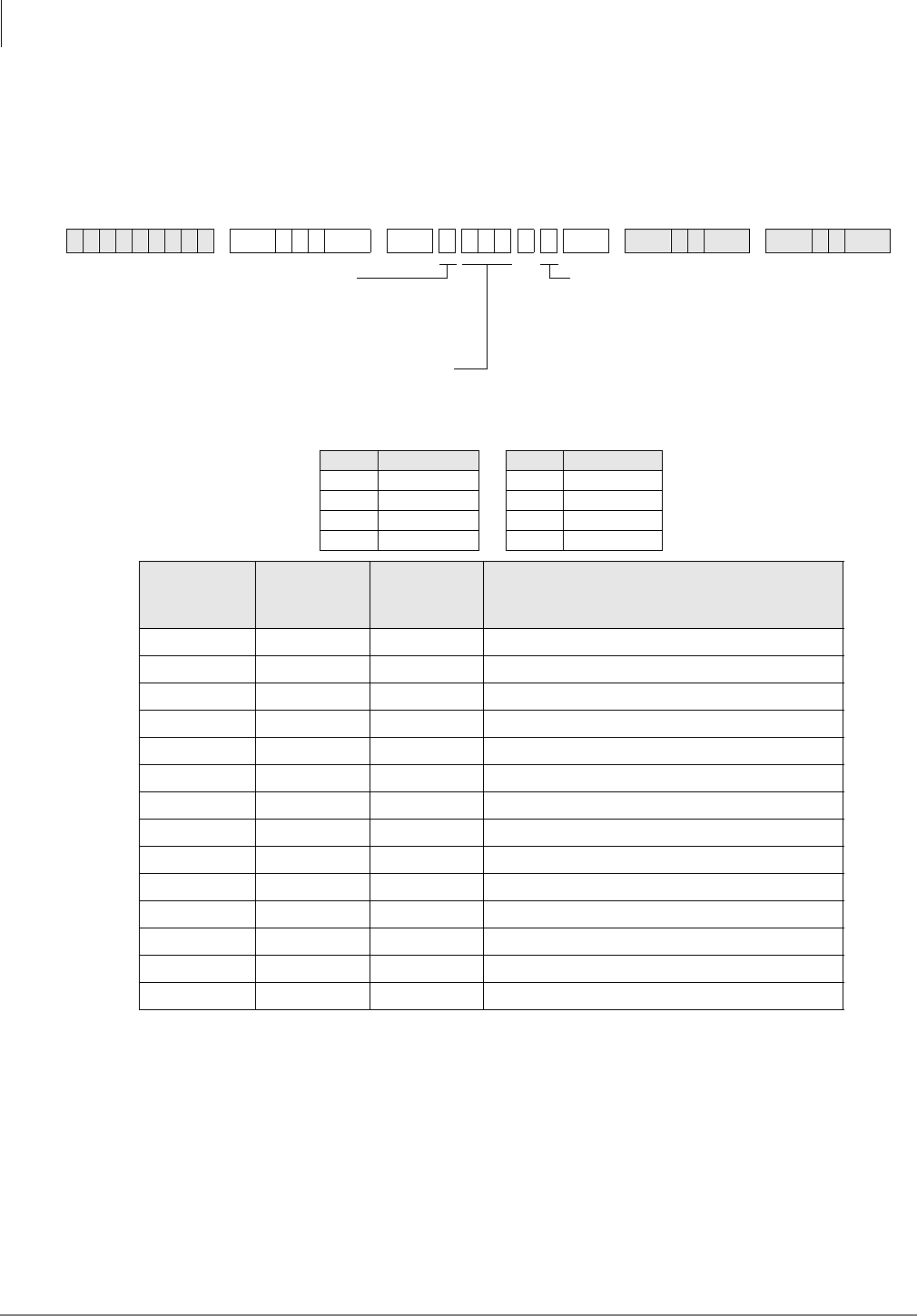
ISDN
Program *62 – Non-ISDN Station Bearer Service
7-16 Strata DK Programming 5/99
Program *62 – Non-ISDN Station Bearer Service
Processor Type:
DK40i, All RCTUs (Release 4.0 or higher)
Program Type:
System, PRI and BRI
Initialized Default:
see below
Program *62 Overview
When Strata DK stations, except ISDN stations, use ISDN facilities, each station needs to be
assigned the type of service expected to be used. The choices are Speech or 3.1 kHz (used for
modem and fax connections). Set the transmission level for outgoing paths for calls. Default value
is -6 db.
Phones marked as “Speech” bearer service can receive calls marked “Speech” or “3.1 KHz audio.”
Phones marked as “3.1 KHz Audio” can only receive calls marked with same bearer service.
6SNU+ROG 6SNU + ROG 6SNU +ROG 6SNU +ROG
Data Pad Level (db) Data Pad Level (db)
00 4-12
1-3 5-15
2-6 6-18
3-9 7+3
*62-1
Bearer
Service
*62-2
Outgoing
Pad Level
*62-3
Incoming
Pad Level Station Ports
Station Logical Port Number
Enter the port number(s) being defined.
To add a port range, enter XXXXXX
(low port high port).
SEL = 1~3
1 - Bearer Service
2 - Outgoing Call
3 - Incoming Call
DATA = Bearer Service (0 or 1)
0 - 3.1 kHz Audio (faxes)
1 - Speech
For options 2 and 3, enter the
Pad Level. See legend below.

ISDN
Program *63 – ISDN Dialing Parameters
Strata DK Programming 5/99 7-17
ISDN
Program *63 – ISDN Dialing Parameters
Processor Type:
DK40i, All RCTUs (Release 4.0 or higher)
Program Type:
System, PRI and BRI
Initialized Default:
4 seconds
Program *63 Overview
This program sets the timer for sending dialed digits if the user does not press the 6WDUW button or
if the dialed number does not meet the established dialing plan number of digits.
When the sub-address dialing timer is set to 00, subaddress dialing is not supported.
6SNU+ROG 6SNU + ROG6SNU +ROG 6SNU +ROG
Select Timeout Parameter Value Comments
1Sub-address dialing Value 00 to 10 seconds (default 04)
2Outdialing Value 02 to 10 second (default 04)
DATA = Seconds
(see table below)
SEL = 1 or 2
(see table below)
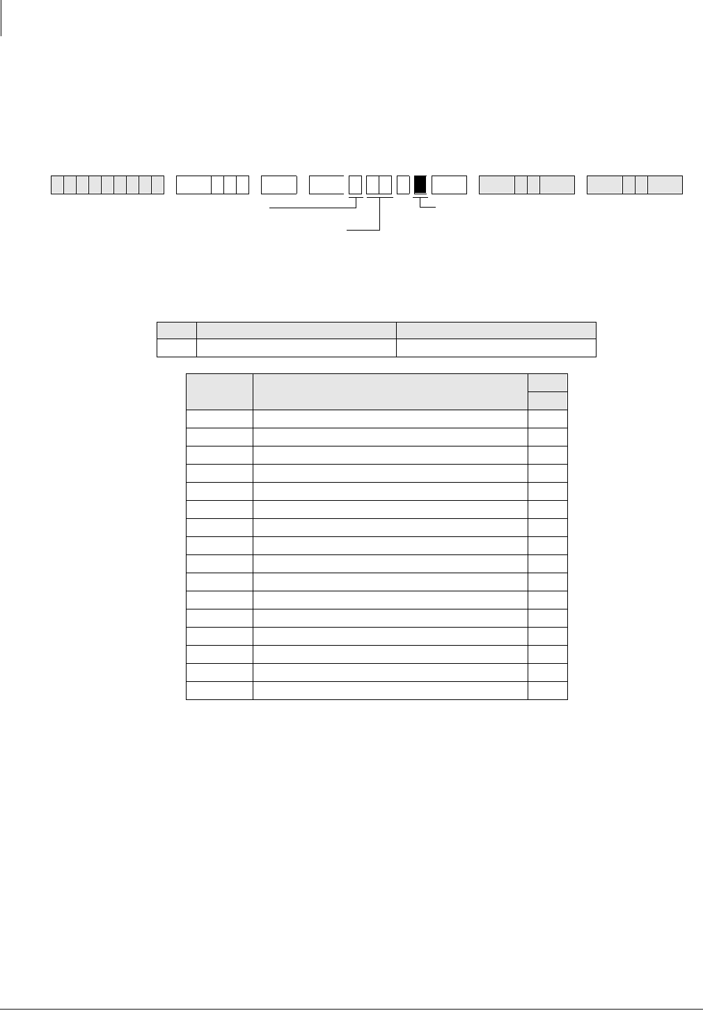
ISDN
Program *64-1 – Direct Inward Dialing Parameters
7-18 Strata DK Programming 5/99
Program *64-1 – Direct Inward Dialing Parameters
Processor Type:
DK40i, All RCTUs (Release 4.0 or higher)
Program Type:
Trunk, PRI and BRI
Initialized Default:
LED 01 ON for DID or DNIS programming
Program *64-1 Overview
Program *64-1 assigns each ISDN trunk group to use DID/DNIS programming or provide Direct
in Line (DIL) ringing for incoming calls.
6SNU+ROG 6 SNU +ROG 6SNU +ROG 6SNU +ROG
LED LED ON LED OFF
01 Use DID/DNIS for incoming calls. Direct ring the called station.
Trunk
Groups Ports LEDs
01
1
2
3
4
5
6
7
8
9
10
11
12
13
14
15
16
LED 01: ON = Use DID/DNIS tables in
Programs *09 or 71
OFF = Use direct ringing tables in
Programs 81~89, *81, *84, *87
Enter the trunk group(s)
To add a range of trunk
groups, enter XX*XX (low
trunk group * high trunk group)
SEL = 1
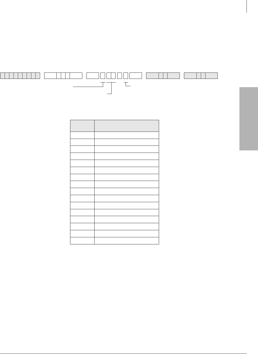
ISDN
Program *64-2 – Number of DID/DNIS Digits for Trunk Groups
Strata DK Programming 5/99 7-19
ISDN
Program *64-2 – Number of DID/DNIS Digits for Trunk
Groups
Processor Type:
DK40i, All RCTUs (Release 4.0 or higher)
Program Type:
System, PRI and BRI
Initialized Default:
Blank
Program *64-2 Overview
This program establishes the number of digits to be used for DID or DNIS table interpretation for
each ISDN trunk group.
The DK424 uses the last two to four digits of the incoming listed directory number (LDN) to
determine the DID call destination. If Program 17 was assigned for DNIS, the DK424 uses the last
two to five digits of an incoming LDN to determine the DNIS call destination.
6SNU+ROG 6SNU + ROG6SNU +ROG 6SNU +ROG
Trunk
Groups Number of DID Incoming Call
Digits per Trunk Group
1
2
3
4
5
6
7
8
9
10
11
12
13
14
15
16
DATA = Enter the number of digits to
use for incoming call DID digits (2~5)
SEL = 2
Enter Trunk Group Number
To add a range of trunk groups,
enter XX*XX (low trunk group *
high trunk group)
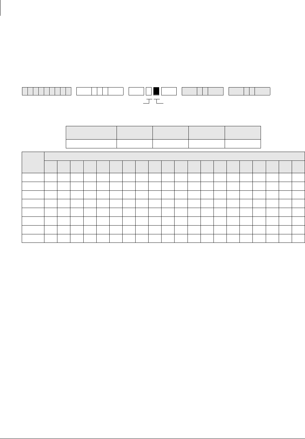
ISDN
Program *65 – ISDN Channel Group Assignment
7-20 Strata DK Programming 5/99
Program *65 – ISDN Channel Group Assignment
Processor Type:
All RCTUs (Release 4.0 or higher)
Program Type:
System, PRI
Initialized Default:
All LEDS OFF (see Important! below)
Note Program *65 must be assigned before entering Program*66.
Program *65 Overview
This program assigns an ISDN group number and its PRI B-channel members. All B-channels
assigned to an ISDN channel group must use the same D-channel. The B-channels on the same
DS-1 interface can belong to different channel groups.
All ISDN connections require the active B-channels to be assigned to a channel group. The B-
channels appear as CO ports assigned in sequence when the PRI card type is entered.
Note Do not include the channels used as D-channels.
Important! B-channels 1~23 are active (by default from the public carrier) in a standard PRI
interface.
6SNU+ROG 6 SNU +ROG 6SNU +ROG 6SNU +ROG
ISDN
B-channel Lines RCTUA RCTUBA/BB RCTUC/D RCTUE/F
PRI (T) 23 47 141 188
Chann
el
Group
CO Line Ports (B-Channels)
12345678910 11 12 13 14 15 16 17 18 19 20
1
2
3
4
5
6
7
8
GRP = Light LEDs to select PRI
B-channels for the channel group.
Press 6FUROO to advance or 3DJH to go back.
SEL = Channel Group (1~8)
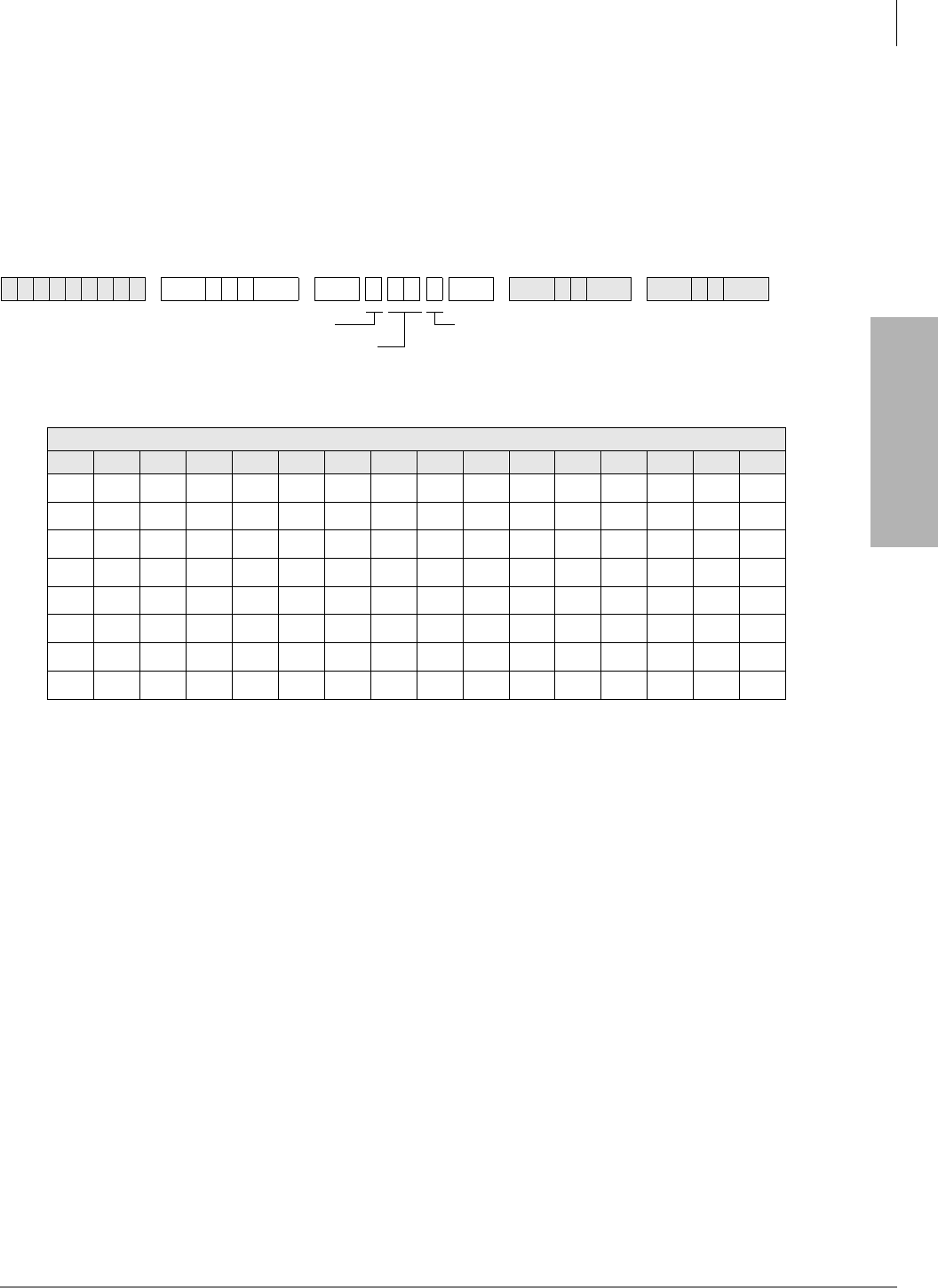
ISDN
Program *66-1 – Channel Group Number Parameters
Strata DK Programming 5/99 7-21
ISDN
Program *66-1 – Channel Group Number Parameters
Processor Type:
All RCTUs (Release 4.0 or higher)
Program Type:
Trunk, PRI
Initialized Default:
Blank
Note Program *65 must be assigned before entering Program *66. If Program *65 changes, then
this program will be affected. Program *66 defaults back to the settings in Program *65.
Program *66-1 Overview
This program assigns PRI ISDN trunk groups to a channel group.
ISDN Trunk Groups are assigned based upon all available trunk groups in Program *16, identified
as PRI trunk groups.
This program must be entered after Program *65 or anytime a change is made to *65.
The channels assigned in *65 will be transferred into the last trunk group entered in *66-1 for that
channel group.
6SNU+ROG 6SNU +ROG 6SNU +ROG 6SNU +ROG
Trunk Groups
12345678910 11 12 13 14 15 16
CHGP = Channel Group Number (1~8)SEL = 1
Enter the ISDN
Trunk Group Number
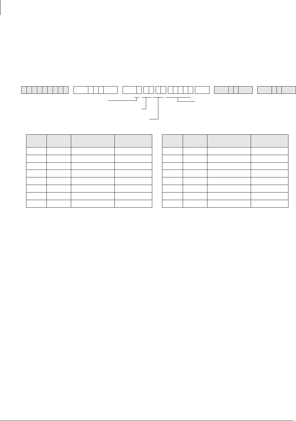
ISDN
Programs *66-2 and *66-4 – Call-by-Call Trunk Group Codes and Network ID
7-22 Strata DK Programming 5/99
Programs *66-2 and *66-4 – Call-by-Call Trunk Group
Codes and Network ID
Processor Type:
All RCTUs (Release 4.0 or higher)
Program Type:
Trunk, PRI
Initialized Default:
Blank
Program *66-2 Overview
The facility code and service parameters will be supplied by the ISDN carrier at the time the ISDN
lines are ordered. Standard telephone services (POTS) will not have a Facility Code, nor a Service
Parameter.
The Call-by-call feature enables individual PRI B-channels to be shared among various types of
services specified by the customer, rather than having to dedicate each channel to a particular type
of service. The Call-by-Call feature can reduce the number of circuits required to access various
services, especially if various services have different peak busy periods.
In a future release, the minimum and maximum number of B-channels allocatable to any type of
service can be assigned. Each of these values can be set for three time periods during the day. With
these values, calls can be rejected if they exceed the maximum number subscribed for that service
or they can ensure that a minimum number of channels remain available for incoming calls. Thus,
the system can be used to provide an optimum service to meet the objectives of the business.
Call-by-Call services can be specified to map Strata DK capabilities to network services such as
DID, Tie, FX, WATS, 800, etc. These services could be provided via the local telephone carrier or
be connected to any ISDN inter-exchange carrier.
A table listing all valid DNs is provided for identifying the outgoing calls or alternatively a
specific number or DID number. These may be used for identifying the call on a per station basis
to allow calls to be billed to a selected service or station. All numbers used for identifying the call
must be subscribed from the providing service or the call will be rejected by the provider.
6SNU+ROG 6SNU +ROG 6SNU +ROG 6SNU +ROG
Trunk
Group Facility
Code Service
Parameters Carrier Code
(Prog. *66-4) Trunk
Group Facility
Code Service
Parameters Carrier Code
(Prog. *66-4)
19
210
311
412
513
614
715
816
SV = Service Parameters
Enter ISDN Trunk Group
FA = Enter the Facility Code
SEL = 2

ISDN
Programs *66-2 and *66-4 – Call-by-Call Trunk Group Codes and Network ID
Strata DK Programming 5/99 7-23
ISDN
Program *66-4 Call-by-Call Network ID
Processor Type:
All RCTUs (Release 4.0 or higher)
Program Type:
Trunk, PRI
Initialized Default:
Blank
Program *66-4 Overview
Some Call-by-Call services are provided by inter-exchange carriers. These services need a
network ID code for call setup. When a Network ID Code is entered, the service parameters in
*66-2 must be blank.
If both the Service Parameter and the Network ID are programmed, Service Parameter has priority
and Network ID will be ignored.
Record Sheet
Use the record sheet for Program *66-2.
6SNU+ROG 6SNU +ROG 6SNU +ROG 6SNU +ROG
SEL = 4 ID = Network ID Code
(3 or 4 digits)
Enter ISDN Trunk
Group Number
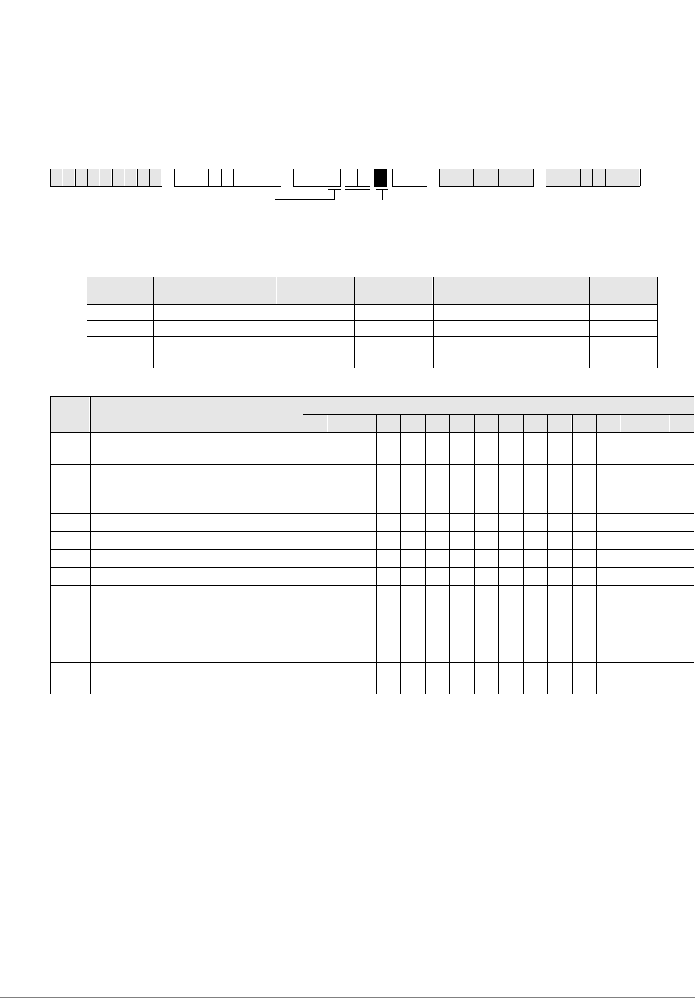
ISDN
Program *66-3 – Channel Group/Trunk Parameters
7-24 Strata DK Programming 5/99
Program *66-3 – Channel Group/Trunk Parameters
Processor Type:
All RCTUs (Release 4.0 or higher)
Program Type:
Trunk, PRI
Initialized Default:
Blank
LEDs 03~06 specify the trunk types shown in the following table.
Program *66-3 Overview
This program assigns special call treatment and defines the ISDN service. Call treatment includes
whether or not operator calls are allowed, if carrier access is allowed, etc. The ISDN service is
similar to trunk type, such as POTS, FX, Tie, outWATS and inWATS.
Program *66-4 Call-by-Call Network ID
See “Programs *66-2 and *66-4 – Call-by-Call Trunk Group Codes and Network ID” on Page
7-22. Use the record sheet for Program *66-2.
6SNU+ROG 6 SNU +ROG 6SNU +ROG 6SNU +ROG
LEDs POTS FX Tie
(senderized) Tie
(cutthrough) OutWATS
(IntraLATA) OutWATS
(InterLATA) InWATS
03 ON ON ON
04 ON ON ON ON
05 ON
06 ON ON
LEDs Setting Trunk Groups
12345678910 11 12 13 14 15 16
01 ON: Operator Calls Allowed/
OFF: Not allowed
02 ON: Carrier Access allowed
OFF: Not allowed
03 Trunk Group Type (see above table).
04 Trunk Group Type (see above table).
05 Trunk Group Type (see above table).
06 Trunk Group Type (see above table).
07~10 Not Used
11 ON: Called Party Number Type Unknown
OFF: Standard Called Party Number Type
12 ON: DK sends Ringback Tone to Network
OFF: No RBT to Network.
(Default is ON.)
13 ON: DMS CO switches only
OFF: Belcore (Default is OFF.)
DATA = Light LEDS to assign
features. See tables below.
SEL = 3
Enter the ISDN Trunk
Group Number (01~16)

ISDN
Program *66-5 – Line Directory Number (LDN) Registration
Strata DK Programming 5/99 7-25
ISDN
Program *66-5 – Line Directory Number (LDN)
Registration
Processor Type:
DK40i, All RCTUs (Release 4.0 or higher)
Program Type:
Trunk, PRI and BRI
Initialized Default:
Blank
Program *66-5 Overview
This program is used to assign seven-digit listed directory numbers per channel group. The index
number assigned is correlated to a CO line port number in Program *66-6 for direct inward ringing
assignments and to trunk groups in Program *66-7.
ISDN calls are originated and terminated using a listed directory number and call type (bearer
service). The Strata DK must know the listed directory numbers subscribed from the PSTN to
determine how to handle the call.
Wild card entries (*) are allowed for handling a larger number of LDNs. For example, a DID group
using 583-3700 through 583-3799 can be entered as a single LDN entry: 583-37**. To handle a
single number differently that falls within this range, enter that number in a lower number index.
e.g., Index 01 = 5833769 and Index 02 = 58337**. If a match occurs on Index 01, the call will be
handled based upon Index 01.
6SNU+ROG 6SNU + ROG 6SNU +ROG 6SNU +ROG
Ch.
Group LDN
Index LDN Ch.
Group LDN
Index LDN Ch.
Group LDN
Index LDN
LDN = Listed Directory Number
Use LED Button 01 to enter a blank.
Wild card (*) entries are valid.
Enter the Channel Group
0 = BRI
1~8 = PRI
Enter LDN Index (01~48)
SEL = 5
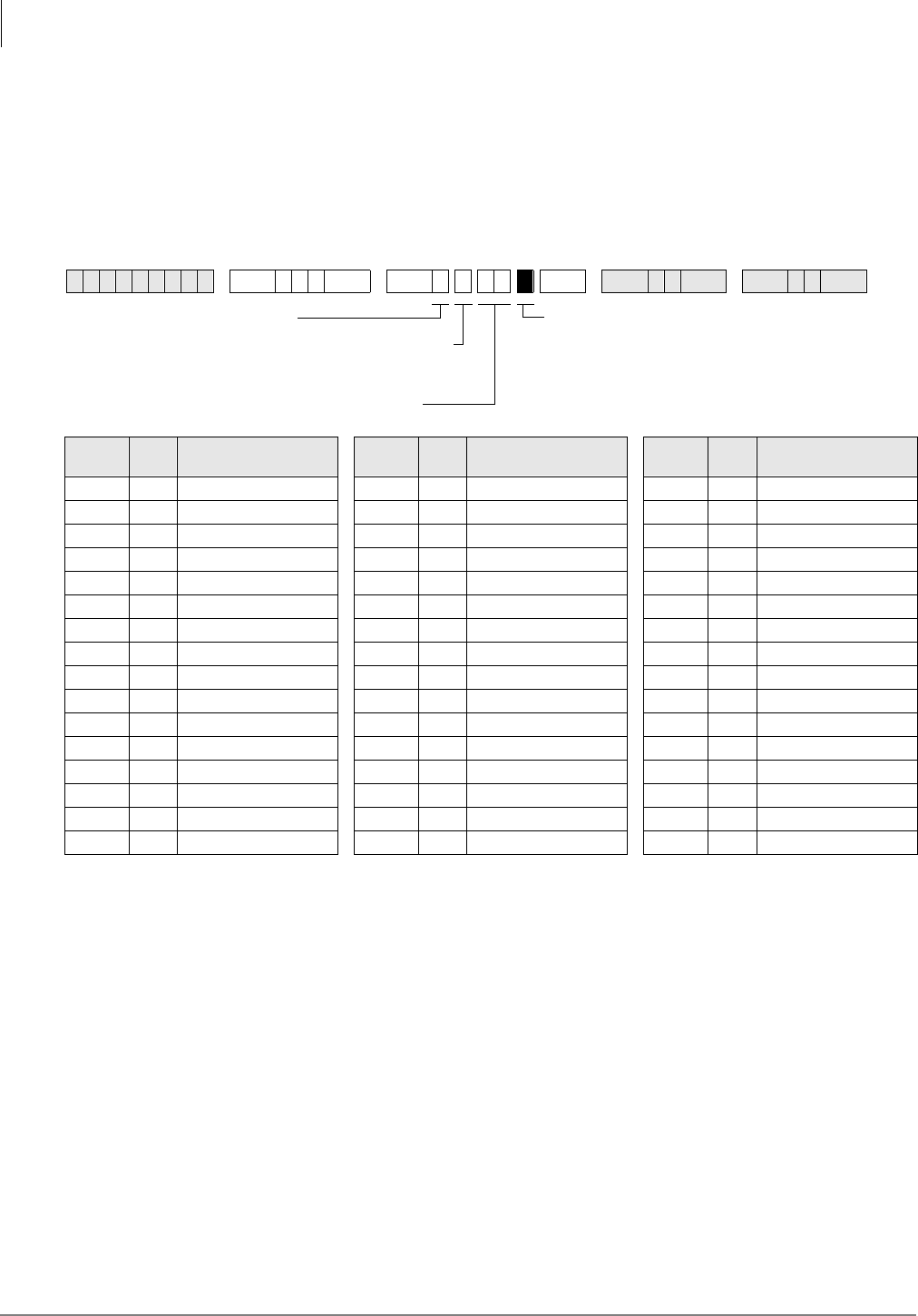
ISDN
Program *66-6 – LDN/Trunk Group to Channel Group Assignments
7-26 Strata DK Programming 5/99
Program *66-6 – LDN/Trunk Group to Channel Group
Assignments
Processor Type:
DK40i, All RCTUs (Release 4.0 or higher)
Program Type:
Trunk, PRI and BRI
Initialized Default:
Blank
Program *66-6 Overview
This program assigns Listed Directory Numbers (LDNs) trunk groups to the member’s channel
group.
Note The number of direct appearing CO lines cannot exceed the number of CO ports allocated
in Program 03. One PRI card, Type 79, assigns 24 B-channels; thus allowing 24 direct
appearances.
For Programs *66-5 and *66-6:
Multiple calls can be received with the same LDN. The LDN and Channel Group information in
*66-5 and *66-6 must match. Calls are assigned the next available non-busy port as follows:
♦For PRI: Choose the highest available port to the lowest.
♦For BRI: Choose the lowest available the highest.
♦Multiple LDNs can be assigned to the same CO appearances.
6SNU+ROG 6 SNU +ROG 6SNU +ROG 6SNU +ROG
Channe
l Group Index CO Line Ports Channe
l Group Index CO Line Ports Channe
l Group Index CO Line Ports
GRP = Select ISDN trunk ports for each LDN index.
Press 3DJH or 6FUROO for the next CO line ports.
Enter the LDN Index (1~48)
SEL = 6
Enter the Channel Group Number:
0 = BRI; 1~8 = PRI
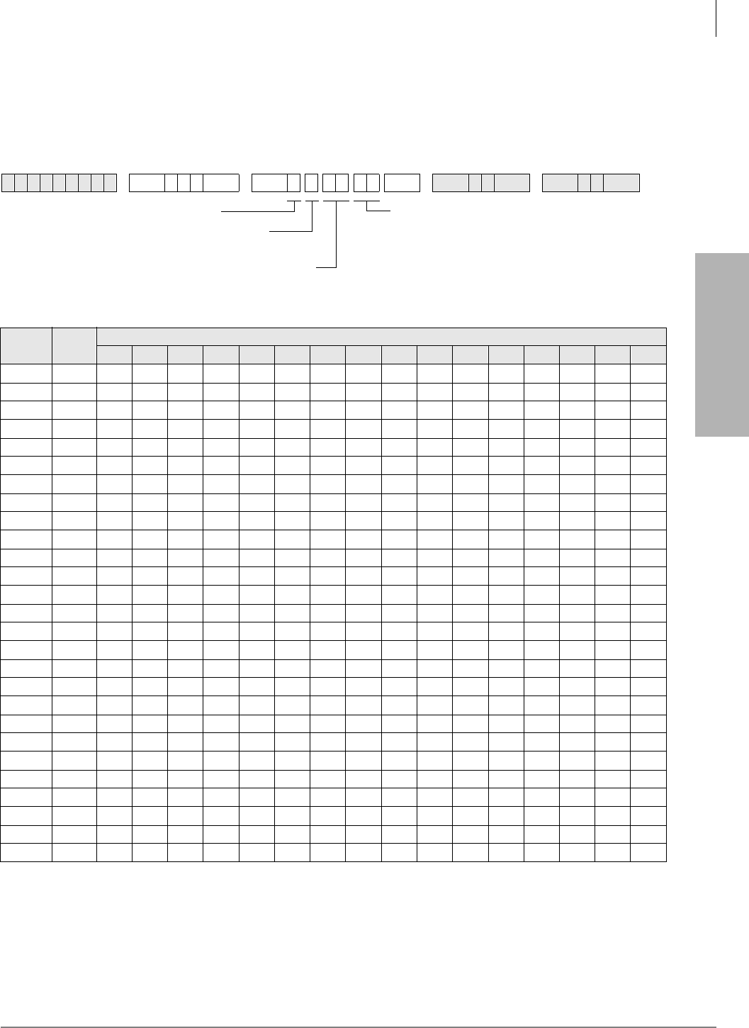
ISDN
Program *66-7 – LDN/Trunk Group Assignments
Strata DK Programming 5/99 7-27
ISDN
Program *66-7 – LDN/Trunk Group Assignments
Processor Type:
All RCTUs (Release 4.0 or higher)
Program Type:
Trunk, PRI
Initialized Default:
Blank
Program *66-7 Overview
This program assigns Listed Directory Numbers (LDNs) to each ISDN trunk group.
6SNU+ROG 6SNU +ROG 6SNU +ROG 6SNU +ROG
Channel
Group LDN
Index
Trunk Groups
12345678910 11 12 13 14 15 16
DIR = Trunk Group (1~16).
0 = blank. The lowest POTS trunk
group is used.
Enter the Channel
Group Number (1~8)
Enter the LDN Index (1~48).
See Program *66-5
SEL = 7
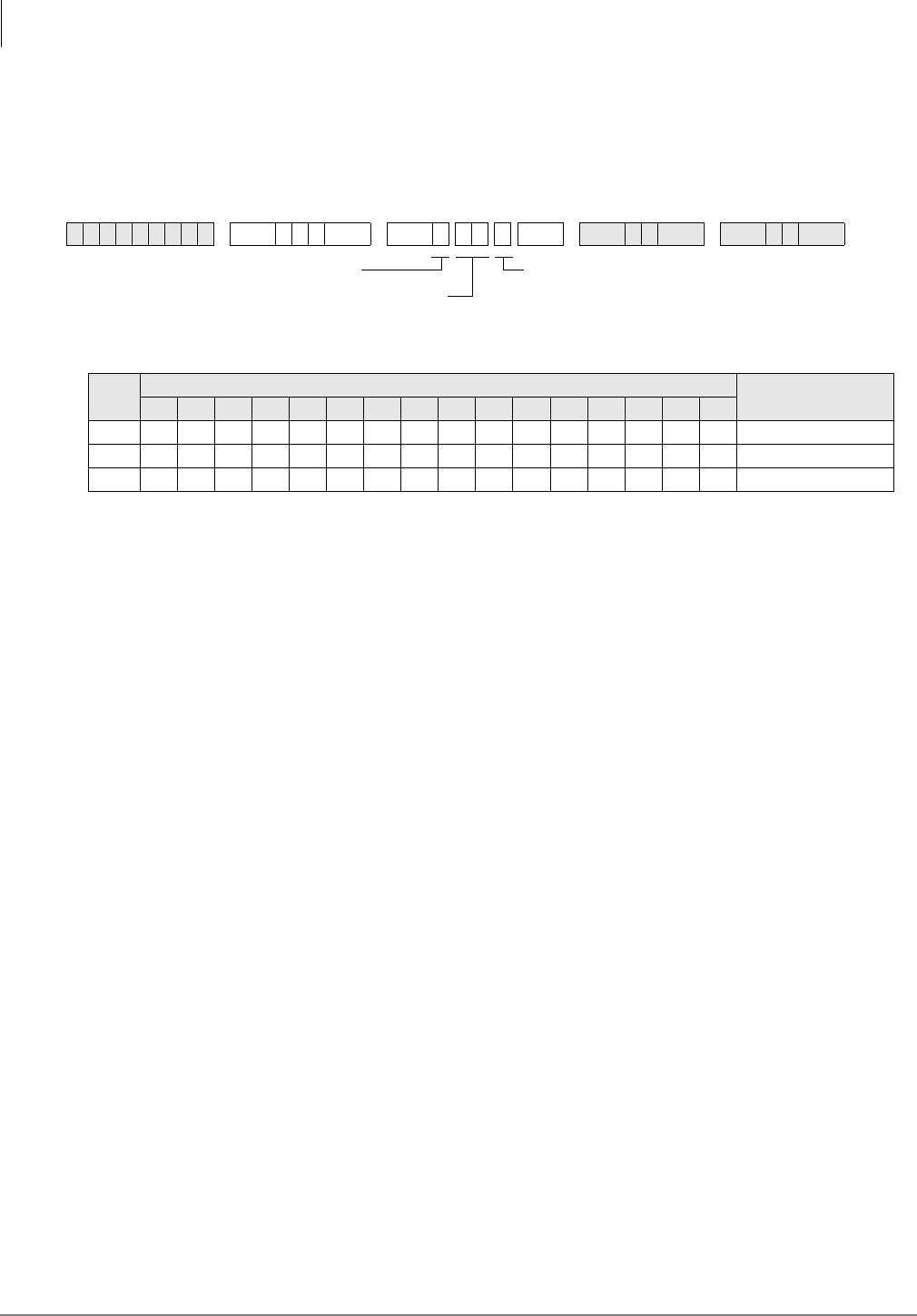
ISDN
Program *67-1 – Trunk Group Call Direction
7-28 Strata DK Programming 5/99
Program *67-1 – Trunk Group Call Direction
Processor Type:
All RCTUs (Release 4.0 or higher)
Program Type:
Trunk, PRI
Initialized Default:
Both Way
Program *67-1 Overview
This program assigns the call direction for each ISDN trunk group.
6SNU+ROG 6SNU +ROG 6SNU +ROG 6SNU +ROG
Value Trunk Groups Call Direction
12345678910 11 12 13 14 15 16
1Incoming
2Outgoing
3Both Way
DIR = Call Direction
1 = Incoming
2 = Outgoing
3 = Both Way
Enter the Trunk Group
(01~16)
SEL = 1
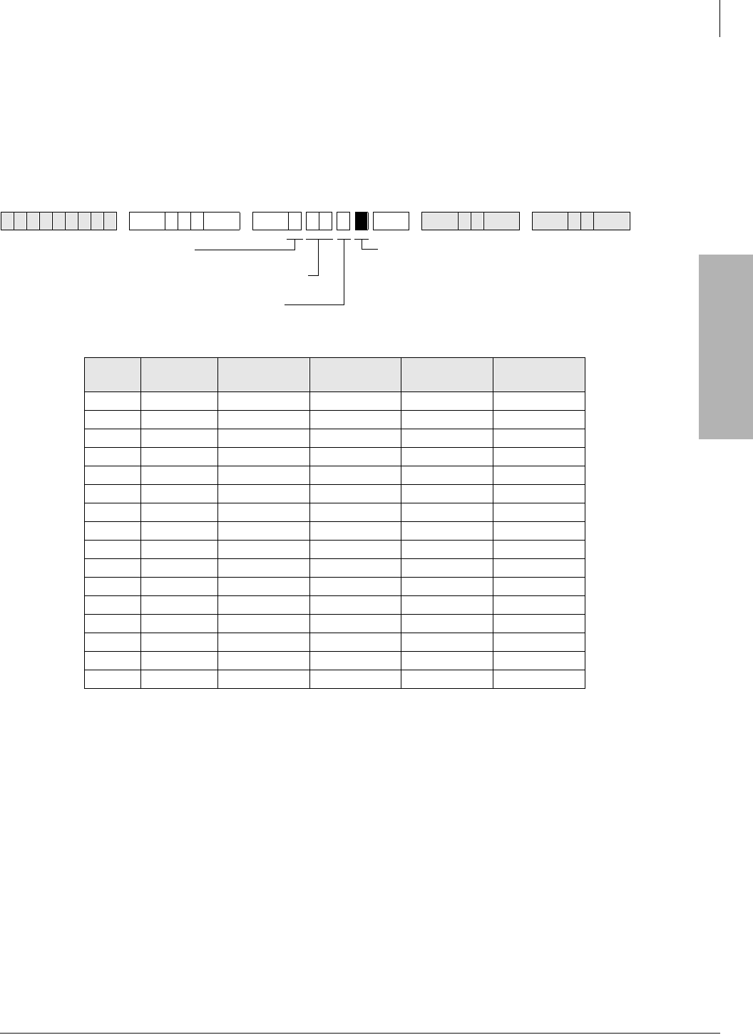
ISDN
Program *67-2 – Call Types for ISDN Trunk Group Supported
Strata DK Programming 5/99 7-29
ISDN
Program *67-2 – Call Types for ISDN Trunk Group
Supported
Processor Type:
All RCTUs (Release 4.0 or higher)
Program Type:
Trunk, PRI
Initialized Default:
Blank
Program *67-2 Overview
This program defines the call type or “Bearer Services” allowed for each ISDN trunk group. These
settings will be set for three different time zones in an upcoming release. All of the call types that
will be used should be turned on. Normally, Speech and 3.1 kHz Audio (non-ISDN voice calls and
fax calls), should be turned on.
6SNU+ROG 6 SNU +ROG 6SNU +ROG 6SNU +ROG
Trunk
Groups Time Zone Speech
LED 01
3.1 kHz Audio
LED 02 64 kbps. Data
LED 03
56 kbps. Data
LED 04
1
2
3
4
5
6
7
8
9
10
11
12
13
14
15
16
Turn on LEDs 01~04 to select the
call type. See table below.
Enter the Trunk Group (01~16)
Enter the Time Zone (1~3)
For Rel. 4.0, enter 1
SEL = 2
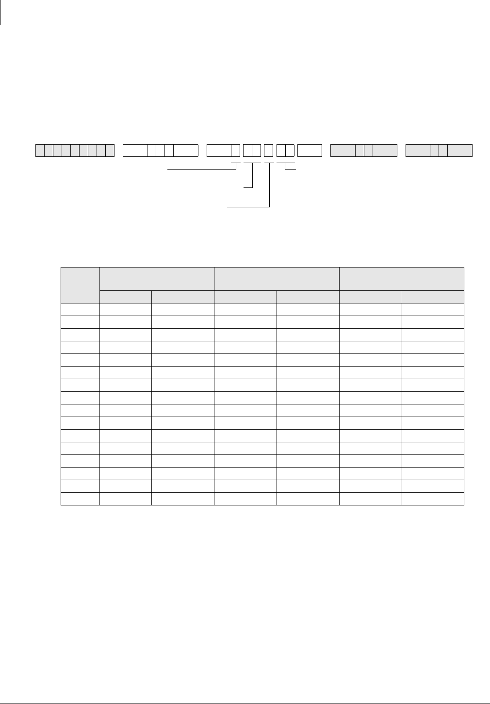
ISDN
Program *67-3 – ISDN Trunk Group Minimum Channel Reservation
7-30 Strata DK Programming 5/99
Program *67-3 – ISDN Trunk Group Minimum Channel
Reservation
Processor Type:
All RCTUs (Release 4.1)
Program Type:
Trunk, PRI
Initialized Default:
Default = 00
Program *67-3 Overview
This program defines the minimum number of B-channels reserved for this service. Each of the
three time zones may have a different value.
➤Enter the minimum and maximum number of B-channels reserved for each Time Zone.
6SNU+ROG 6SNU +ROG 6SNU +ROG 6SNU +ROG
Trunk
Groups
Time Zone 1
B-channels reserved Time Zone 2
B-channels reserved Time Zone 3
B-channels reserved
Min. Max. Min. Max. Min. Max.
1
2
3
4
5
6
7
8
9
10
11
12
13
14
15
16
MIN = Minimum number of
B-channels reserved.
Max. 47 when sharing D-channels.
SEL = 3
Enter the Trunk Group (01~16)
Enter the Time Zone (1~3)
For Rel. 4.0, enter 1

ISDN
Program *67-4 – ISDN Trunk Groups Maximum Channel Reservation
Strata DK Programming 5/99 7-31
ISDN
Program *67-4 – ISDN Trunk Groups Maximum Channel
Reservation
Processor Type:
All RCTUs (Release 4.1 or higher)
Program Type:
Trunk, PRI
Initialized Default:
23 maximum default channels
Program *67-4 Overview
This program specifies the maximum number of B-channels that can be used to carry calls with
this service. Each of the three time zones may have a different value.
Use the record sheet with Program *67-3.
6SNU+ROG 6SNU +ROG 6SNU +ROG 6SNU +ROG
MAX = Maximum number of
B-channels reserved.
(0047) when sharing D-channels,
Max. = 47.
Enter the Trunk Group (01~16)
Enter the Time Zone (1~3)
SEL = 4

ISDN
Program *67-5 – Multiple Time Zone Settings
7-32 Strata DK Programming 5/99
Program *67-5 – Multiple Time Zone Settings
Processor Type:
All RCTUs (Release 4.1 or higher)
Program Type:
Trunk, PRI
Initialized Default:
Default = 0000
Program *67-5 Overview
This program enables setting three different time zones. In Release 4.1, the maximum number of
lines that can be obtained by each trunk group and the minimum number of lines that can be
sequred is programmable. By programming the max. and min. number of lines that can be used by
a trunk group, this prevents a trunk group from monopolizing all the lines.
6SNU+ROG 6SNU + ROG 6SNU +ROG 6SNU +ROG
Enter the Time Zone Starting.
Time (0000~2359)
Enter the Channel Group (1~8)
Enter the Time Zone (1~3)
SEL = 5
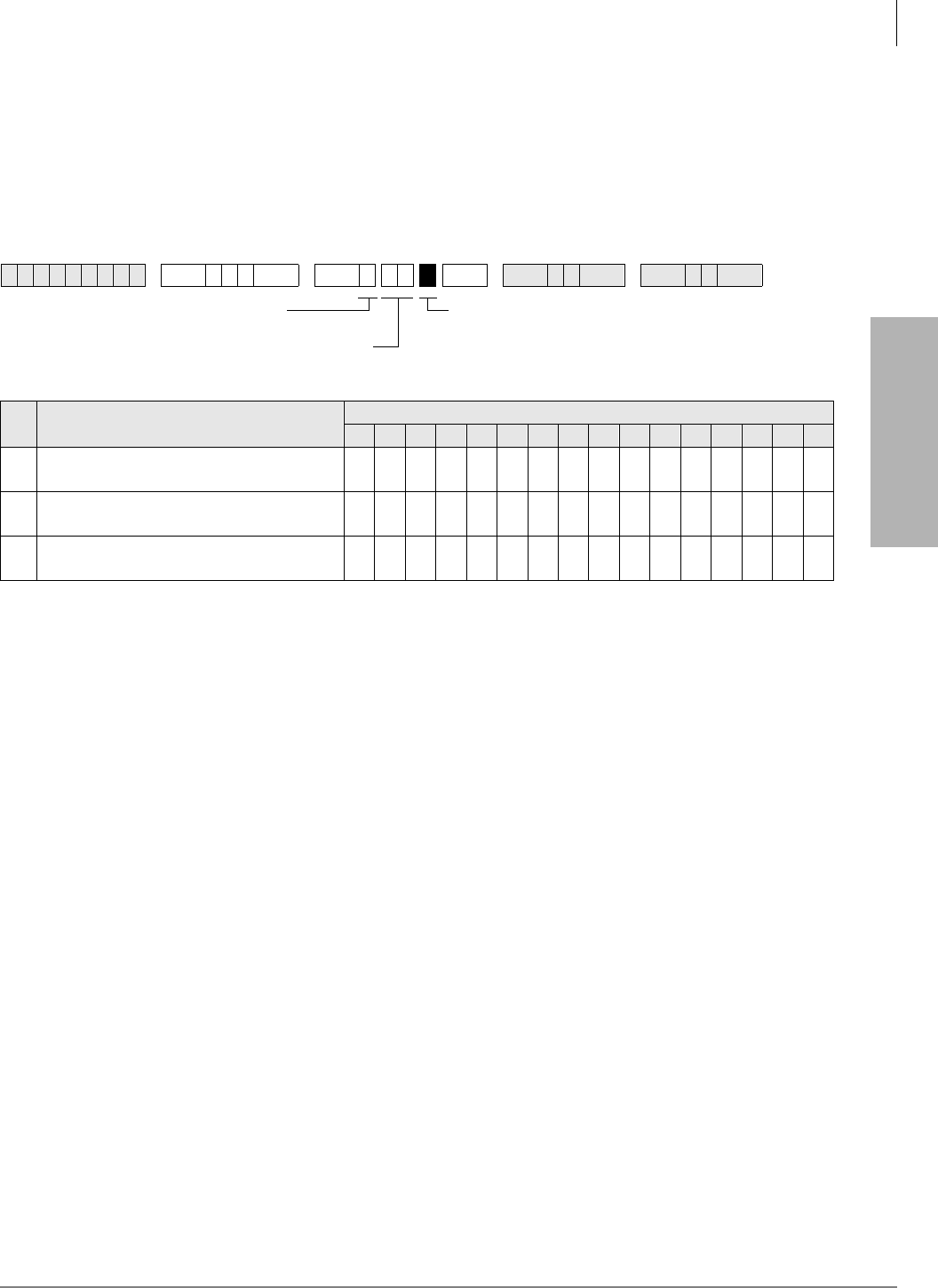
ISDN
Program *68-1 – Calling Number ID Presentation Parameters
Strata DK Programming 5/99 7-33
ISDN
Program *68-1 – Calling Number ID Presentation
Parameters
Processor Type:
DK40i, All RCTUs (Release 4.0 or higher)
Program Type:
Trunk, PRI and BRI
Initialized Default:
all LEDs OFF
Program *68-1 Overview
This program assigns the Number Privacy feature, which allows the caller to prevent the public
network from delivering the Calling Number to the called party on a per-call basis. The Public
Switched Telephone Network (PSTN) may still provide a network-based Caller ID, even when the
outgoing Caller ID is OFF Only a subscription parameter can change that.
LED 01: Outgoing Caller ID
Service subscribers can request from the public network that the number be presented or not as a
default.
LED 02: Outgoing Caller ID Status Change
If a public telco service allows changes to be made, then a user can enter change a code to the
setting for that call after selecting a trunk group.
LED 03: Incoming Caller ID Source
When LED 03 is ON, the calling number with the call setup message is provided by the network;
OFF indicates that this information is sent from the caller. The Strata DK handles the number the
same way that ANI information from T1 trunks is handled. For instance, the number can display
on the called telephone’s LCD, or it can be used by TAPI interfaces, or it can be recorded in
SMDR data records.
The PSTN may send one or two Caller ID messages for incoming calls. One message is the Caller
ID supplied by the network, which is generally the billing number, while the second is the user
generated number. The Strata DK will use the user-supplied number, if required.
Note Individual callers can choose to block this information, regardless of this setting.
6SNU+ROG 6 SNU +ROG 6SNU +ROG 6SNU +ROG
LED Caller ID Setting Trunk Groups
12345678910 11 12 13 14 15 16
1Outgoing Caller ID
(ON = Allowed / OFF = Not Allowed)
2Outgoing Caller ID Status Change:
ON = Allowed / OFF = Not Allowed
3Incoming Caller ID Source:
ON = Network Provided OFF = Caller Provided
DATA = Press LED Buttons 01~03 for the
desired Calling Number ID parameters.
See table below.
Enter the Trunk Group
(01~16)
SEL = 1
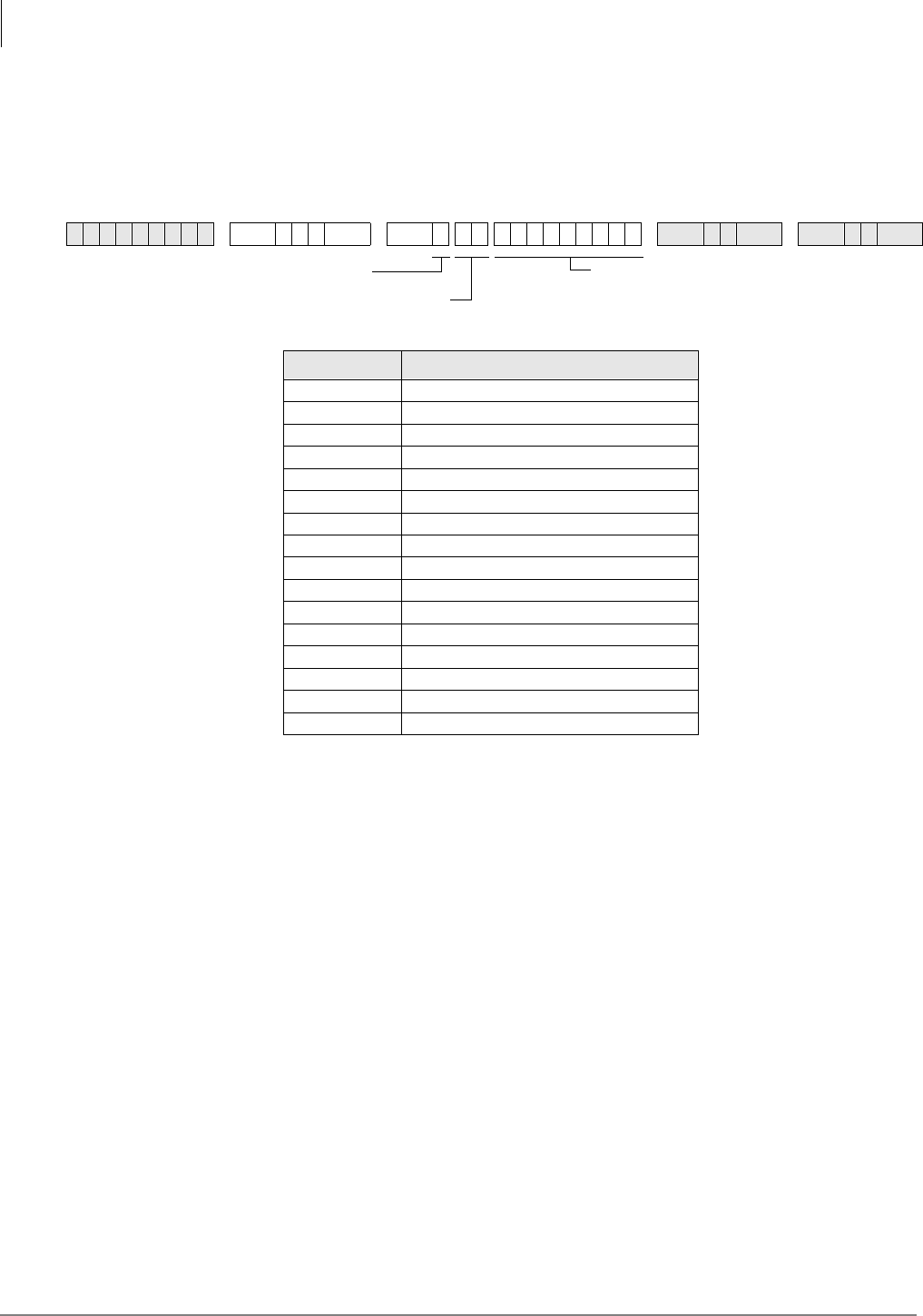
ISDN
Program *68-2 – Outbound CNIS Parameters
7-34 Strata DK Programming 5/99
Program *68-2 – Outbound CNIS Parameters
Processor Type:
DK40i, All RCTUs (Release 4.0 or higher)
Program Type:
Trunk, PRI and BRI
Initialized Default:
Blank
Program *68-2 Overview
This program defines the default Calling Party Number (CPN) for the ISDN trunk group used for
placing a call. The PSTN uses this Calling Party Number for the user provider Caller ID and
optionally may use it for billing the call.
The number sent is based on the call originator. The originator can be a tandem call, a station (with
or without DID), or a station with a designated number:
♦For a tandem call, the CPN digits received are the digits that will be sent.
♦For a direct station call, the default number assigned to the selected service and which is
programmed into the Strata DK as the CPN will be the number sent.
♦For a fixed number, the system sends the number assigned in the system (in this program) or it
can use the DID programming to determine the number to be sent. Program *69 (DATA=Type
1 or 2) defines whether fixed numbers from this program are sent or if DID digits from
Program *09 are sent.
6SNU+ROG 6 SNU 6SNU +ROG 6SNU +ROG
Trunk Groups Calling Party Number
1
2
3
4
5
6
7
8
9
10
11
12
13
14
15
16
CPN = Enter the Calling Party
Number (CPN) 10 or 11 digits.
Enter the Trunk Group
(01~16)
SEL = 2
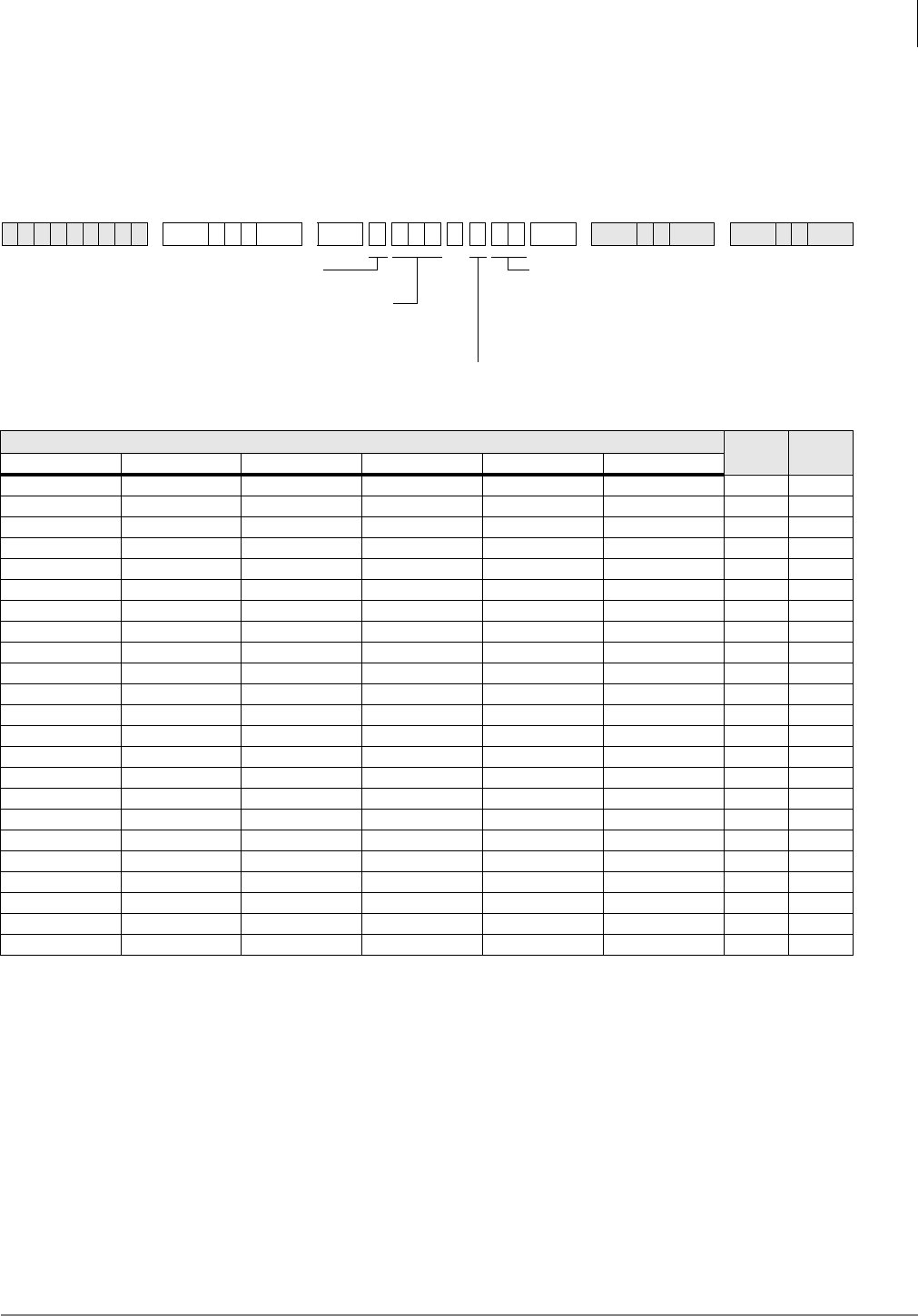
ISDN
Program *69-1 – CNIS Presentation Parameters
Strata DK Programming 5/99 7-35
Program *69-1 – CNIS Presentation Parameters
Processor Type:
DK40i, All RCTUs (Release 4.0 or higher)
Program Type:
Trunk, PRI and BRI
Initialized Default:
none
Program *69-1 Overview
This program defaults all ports to the 00 index, which means that outgoing calls will present the
Directory Number entered in Program *68-2 as the Calling Number for outbound calls. Each
station on the Strata DK can send a unique number based on the station making the call assigning
an index other than 00, and entering the number as Type 2 to be used in Program *69-2 or send a
Type 1 DID number by entering a prefix code to create a complete number.
Note If the PSTN is to use this number for billing the call, the number sent must match those
provided by the PSTN.
6SNU+ROG 6SNU +ROG6SNU +ROG 6SNU +ROG
Station Ports Channel
Group Index
Enter Station Port(s)
To add a range, enter
XXX*XXX (low port * high port)
SEL = 1
CG = Channel Group (1~8)
INDX = Index Number (00~32)
Index 00 uses default value assigned in*68-2.
All others use values assigned in *69-2
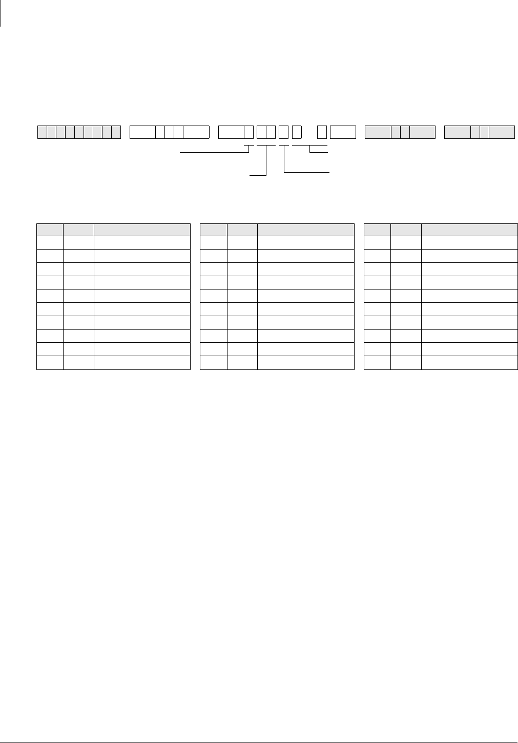
ISDN
Program *69-2 – Special Number Assignment
7-36 Strata DK Programming 5/99
Program *69-2 – Special Number Assignment
Processor Type:
DK40i, All RCTUs (Release 4.0 or higher)
Program Type:
Trunk, PRI and BRI
Initialized Default:
none
Program *69-2 Overview
This program defines the parameters for the Calling Party Number (CPN) to be presented for a call
depending upon whether the ISDN trunk group uses DID, private numbers or a default number
from Program *68-2. Calling Number Presentation for outbound calls is used by the public
network to send the telephone number to the called location.
For each phone in the system, assign an index value to define the Calling Number to be sent to the
public network. Each index value can be defined to provide a specific 10 digit telephone number
(DATA=Type 2) or a DID prefix value with the final digits to be programmed in *09 (DATA=Type
1) to complete the 10 digit telephone number.
The number of indexes is 32 maximum and an index value of zero (0) will cause the ISDN systems
to send the default number.
Program *69 provides a method to present the call back number that can be used to reach that
station. This number can either be a DID number or a designated number that is programmed to
ring that particular station. Through subscription options from the public service provider, this
Calling Party Number can be used for billing calls.
This capability may be required for office suites and certain contracted obligations needing
independent accounting for the telephone service. This subscription can require number screening.
When screened, calls not presenting a valid billing number will be rejected by the service local
provider. If optional, calls will always be placed and a number sent that does not match will be
billed to the main number for that site.
6SNU+ROG 6SNU + ROG 6SNU +ROG 6SNU +ROG
Index Type Calling Party Number Index Type Calling Party Number Index Type Calling Party Number
SEL = 2
DATA = Type (1, 2)
1 = Prefix plus *09 DID digits
2 = Fixed Number
Enter Calling Party Numbers (11 digits)
Enter Index Number (1~32)
or enter 00 for the ISDN
service default number

Strata DK Programming 5/99 8-1
E911
E911 8
This chapter contains programming record sheets, along with specific instructions for
programming E911 CAMA trunks.
Enhanced 911 CAMA trunks apply only to the DK424, Release 4.0. The RMCU/RCMS PCBs
provide up to four CAMA trunk circuits. The RMCU/RCMS eliminates the need for adjunct
terminal adapter equipment for connecting to E911 CAMA trunks. For more information on
hardware, refer to the Strata DK Installation and Maintenance Manual.
Operation Overview
The DK424 E911 feature provides flexible dialing of 911 emergency calls. This allows users who
are not familiar with DK424 dialing sequences to make an emergency call regardless of how they
dial 911 from Toshiba telephones. In all of the sequences below, the DK will seize an idle CAMA
trunk and send 911 plus the dialing station’s Caller Emergency Service Identification (CESID)
over the CAMA trunk via MF tones.
Note Once a 911 call is started, most other buttons/keys on a telephone are disabled to prevent
accidentally dropping the 911 call attempt. This includes the +ROG button, so that the 911
call cannot be put on hold.
♦Press DN button and dial 911. When the user dials 911, the PDN releases from the internal
connection and seizes the CAMA trunk.
♦Off Hook and dial 911 (station has off hook selection of PDN in Program 32). When the user
dials 911, the PDN releases from the internal connection and seizes the CAMA trunk.
♦Off Hook and dial 911 (station has off hook selection of a CO line or line group in Program 32
and has a CO /LQH or 3RROHG/LQH buttons). When the user goes off-hook, the station will
seize the normal CO line on the appropriate CO /LQH/3RROHG/LQH button. When the user
dials 911, the normal CO line is dropped and an idle PDN or CAMA CO button connects to
the CAMA trunk. If an idle PDN or CAMA CO button is not available, the 911 call will be
sent out the originally selected line without the station’s CESID information.
♦Press DN button and dial 9+911 (no LCR, 9 is line group access code, station does not have
CO /LQH, 3RROHG/LQH or &$0$ CO buttons). When the user dials 9, the station will seize
a “dial 9” CO line on its PDN button. When the user dials 911, the 911 call will be sent one of
two ways:
♦If the station does not have another idle PDN or &$0$ CO button, the 911 call will be
sent out the normal CO line in the dial 9 line group without the station’s CESID.
♦If the telephone has another PDN or &$0$ CO button, and it is idle, the first PDN will
drop and the second PDN or CAMA CO button will be connected to the CAMA trunk.
911 plus the station’s CESID will be sent out the CAMA trunk.

E911
SMDR
8-2 Strata DK Programming 5/99
♦Press DN button and dial 9+911 (with LCR). When the user dials 9, the station will seize LCR
on its PDN, when the user dials 911, the PDN will drop LCR and the same PDN will connect
to the CAMA trunk. 911 plus the station’s CESID will be sent out the CAMA trunk.
♦Press INT button and dial 911 (attendant console). When the user dials 911, the INT button
releases from the internal connection and seizes the CAMA trunk. 911 plus the Attendant
Console CESID is sent out the CAMA trunk.
♦Press CO /LQH, 3RROHG/LQH or &$0$ CO button and dial 911 (attendant console). When
the user dials 911 from an outgoing line button, the outgoing line button drops and the CAMA
trunk is seized on the INT button. 911 plus the Attendant Console CESID is sent out the
CAMA trunk.
SMDR
Two packets are sent out the SMDR port on each E911 call. The first packet will be sent
immediately at the start of the call and the second will be sent at the end of the call when the
CAMA trunk releases. See Figures 8-1 and 8-2 for E911 SMDR packet samples.
Notes
●This record is similar to a normal OG record except that:
●The first character “S” indicates “Start of Call.”
●Time of Day shows start time.
●There is no call duration.
●Station ID is substituted for the first ten characters of the outgoing dialed number field.
●The account code field is used for Name/Location data from the Table XXX.
Figure 8-1 SMDR Start of Call
11111111112222222222333333333344444444445555555555666666666677777777778
12345678901234567890123456789012345678901234567890123456789012345678901234567890
S004 3710 3710 08:14 5833710 911 MARY M NO.200
2997
LCD User Name
(65~80)
Originating number -
always 911 (61~63)
Station ID
(10D maximum characters 43~52)
Time of Day at start of call (19~21)
Originating DN (12~15)
PDN of originating station (7~10)
Originating trunk number (2~4)
“S” for start of call
“E” for end of call (1)

E911
Programming Overview
Strata DK Programming 5/99 8-3
E911
Notes
●This record is similar to a Start record except that:
●The first character “E” indicates “End of Call.”
●Call duration is provided.
●Time of day shows disconnect time.
Figure 8-2 SMDR End of Call
Programming Overview
The basic programming for the E911 CAMA trunks feature is accomplished using Programs *11,
*12, and *13. Program *10 is not used for RMCU/RCMS CAMA trunks, it is only used when
E911 is provided using an adjunct E911 device.
Program 39 tips:
♦When a user presses a normal CO line button and dials 911, the telephone drops the normal
line button and connects a CAMA trunk to an idle [PDN[ or &$0$ CO button on the
telephone. Then, the DK sends 911 + plus the telephone’s CESID on the CAMA trunk. If there
is no idle [PDN[, 911 is sent on the originally selected CO line without CESID.
♦To ensure that here is an idle PDN when a telephone is assigned to auto-off-hook, select a CO
line or CO line group in Program 32. The telephone should have a button appearance of this
CO (or pooled) line. Or, if the telephone does not have these line buttons it should have
another [PDN] button appearance to connect to the CAMA trunk in case 911 is dialed.
11111111112222222222333333333344444444445555555555666666666677777777778
12345678901234567890123456789012345678901234567890123456789012345678901234567890
E004 3710 3710 08:14 00:05;32 5833710 911 MARY M NO.200
2998
LCD User Name
(65~80)
Originating number -
always 911 (61~63)
Station ID
(10D maximum characters 43~52)
Time of day at end of call (19~21)
Call duration (23~30)
Originating DN (12~15)
PDN of originating station (7~10)
Originating trunk number (2~4)
“S” for start of call
“E” for end of call (1)
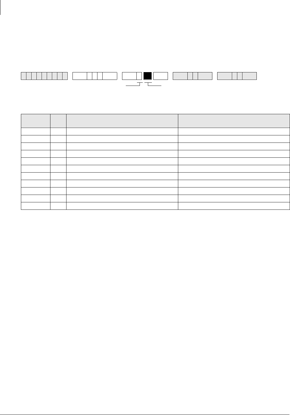
E911
Program *11-0 – E911/CAMA Trunk Assignments
8-4 Strata DK Programming 5/99
Program *11-0 – E911/CAMA Trunk Assignments
Processor Type:
All RCTUs (Release 4.0)
Program Type:
System
Initialized Default:
all LEDs OFF
Program *11-0 Overview
This program enables E911 calls to be analyzed by the system for appropriate handling. The
following assignments in Program *11-0 must be enabled to allow Enhanced 911 (E911) CAMA
trunks to operate:
LED 11: CAMA Operation Enabled/Disabled
Led 11 must be turned ON to enable the E911 feature to operate.
LED 10~07: CAMA Trunk Circuits Enabled/Disabled
Up to four CAMA (RMCU/RCMS) trunks can be installed on Release 4.0 DK424 systems. Turn
LEDs 07-10 ON to enable the appropriate CAMA trunks (1-4). RMCU/RCMS CAMA trunk
circuit are numbered 1~4 from the bottom-up (see the front of the installed RMCU/RCMS). If only
one RCMS is to be installed, place it on the bottom position of the RCMU. The Universal Slot
PCB and Universal PCB Wiring chapters of the DK14/40/424 Installation and Maintenance
Manual provides details regarding RMCU/RCMS PCB installation and circuit numbering.
LED 03: Internal Notification of E911 Calls Enabled/Disabled
To allow Attendant consoles and station DNs to be called along with the E911 CAMA trunk when
a 911 call is made, LED 03 must be turned OFF. With this feature enabled, E911 calls will ring the
CAMA trunk plus the Incoming Emergency (,1(UPJ) button on all Attendant consoles and the
[DN] button ([PDN] or [PhDN]) designated in Program *11-8. The designated DN must be
programmed to ring telephones in *71, *72, and *73, as required for each telephone on which the
designated [DN]appears.
6SNU+ROG 6 SNU +ROG 6SNU +ROG 6SNU +ROG
LED/
Button XLED ON LED OFF
11 E911 enabled E911 disabled
10 CAMA trunk 4 not used CAMA trunk 4 used
09 CAMA trunk 3 not used CAMA trunk 3 used
08 CAMA trunk 2 not used CAMA trunk 2 used
07 CAMA trunk 1 not used CAMA trunk 1 used
06
05
04
03 No internal notification Internal notification provided
02 CAMA trunk Control Disconnect Normal disconnect
01 Seven CESID Digits Ten CESID Digits
Light the LED Buttons that are
marked with an X in the table below.
ON=Enabled. OFF=Disabled.
SELECT = 0

E911
Program *11-0 – E911/CAMA Trunk Assignments
Strata DK Programming 5/99 8-5
E911
When this feature is used, the station or Attendant console that answers the E911 notification call
will be connected in a three party conference with the E911 calling telephone and the E911 CAMA
trunk (E911 dispatch person who answers the 911 call). The CESID information and user name of
the 911 calling station displays on all Attendant Console monitors and E911 notification telephone
LCDs when the E911 notification call rings.
LED 02: CAMA Trunk Disconnect Operation Options
After an E911 call is established, disconnecting the calling or notified telephone (or notified
telephone/console) from the CAMA trunk can be controlled exclusively by the E911 trunk
(dispatch person receiving the 911 call).
The disconnect operation for each option is:
♦LED 02 OFF: Allows either the E911 call originating telephone or 911 dispatcher to
disconnect the CAMA trunk. In the following example, conversation exists between
originating telephone, notified telephone/console and the E911 CAMA trunk dispatch person.
♦LED 02 ON: Enables E911 call disconnect to be exclusively controlled by the dispatch person
receiving the call on the E911 CAMA trunk. In the following table, conversation exists
between originating telephone, notified telephone/console and the E911 CAMA trunk dispatch
person.
LED 01: Number of CESID location digits sent with E911 Calls
After 911 is sent out the CAMA trunk, Automatic Number Identification (CESID) location digits
are sent out the CAMA trunk to identify the location of the station. The maximum number of
CESID digits sent with each E911 call can be either 7-digits (LED 01 ON) or 10-digits LED 01
OFF). CESID location digits are individually set in Program *12 for each station. Contact your
local E911 CAMA trunk provider to determine the number of CESID digits required.
E911 originator hangs up
and disconnects. The E911 notified station and the E911 CAMA trunk remain
connected. The notified station can disconnect from the CAMA trunk.
E911 notified station hangs
up and disconnects. The E911 originating station and the E911 CAMA trunk remain
connected. Originating station can disconnect from the CAMA trunk.
E911 dispatcher hangs up
and disconnects. All parties are disconnected, CAMA trunk goes idle.
E911 originator hangs up
and disconnects. The E911 notified station cannot disconnect from the E911 CAMA
trunk.
E911 notified station hangs
up and disconnects. The E911 originating station cannot disconnect from the E911 CAMA
trunk.
E911 dispatcher hangs up
and disconnects. All parties are disconnected, CAM trunk goes idle.
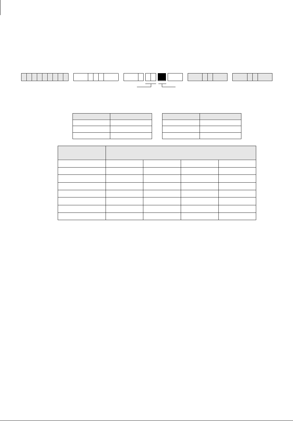
E911
Program *11-1 – CAMA Trunk Group Line Assignments
8-6 Strata DK Programming 5/99
Program *11-1 – CAMA Trunk Group Line Assignments
Processor Type:
All RCTUs (Release 4.0)
Program Type:
System
Initialized Default:
all LEDs OFF
Program *11-1 Overview
This program assigns lines to CAMA trunk groups. Each RCMU/RMCS line used must be
assigned to one of the eight CAMA trunk groups using Program *11-1. The RCMU/RMCS system
line number (not the CAMA trunk number, 1~4) is entered into the appropriate CAMA trunk
group in this program. If CAMA trunks are not assigned in this program, the E911 CAMA feature
will not operate.
When the RCMU/RMCS PCBs are installed, they assume the next four consecutive system CO
line numbers. For example if a normal ground start line PCB, RGLU, is installed in slot 12, its
system line numbers are 01~04. And, if the RCMU/RMCS is installed in slot 13, its line numbers
are 05~08.
This program also allows any type (ground, loop, Tie, DID) line to be assigned in CAMA Trunk
Groups. This is to allow 911 calls to be routed out normal CO lines in case the CAMA trunk(s) can
not be accessed (busy or out of service). If the 911 call hunts from the CAMA trunk(s) in a CAMA
Trunk Group to a normal CO line in a CAMA Trunk Group, the 911digits (dial pulses or DTMF
tones) will be sent out the normal line without the station CESID information digits. The normal
lines assigned in CAMA trunk groups can be assigned in Program 16 line groups as well.
It is recommended to always assign normal lines in CAMA Trunk groups to back CAMA trunks.
6SNU+ROG 6 SNU +ROG 6SNU +ROG 6SNU +ROG
Processor CO Line Range Processor CO Line Range
DK14 001~004 RCTUBA/BB 001~048
DK40i 001~012 RCTUC/D 001~144
RCTUA 001~016 RCTUE/F 001~200
CAMA Trunk
Group CO Line Numbers of CAMA Trunks
01
02
03
04
05
06
07
08
Line circuit number of CAMA trunk: Turn ON
LED of line that corresponds to the CAMA trunk
position in the system.
CAMA Trunk Group (01~08)
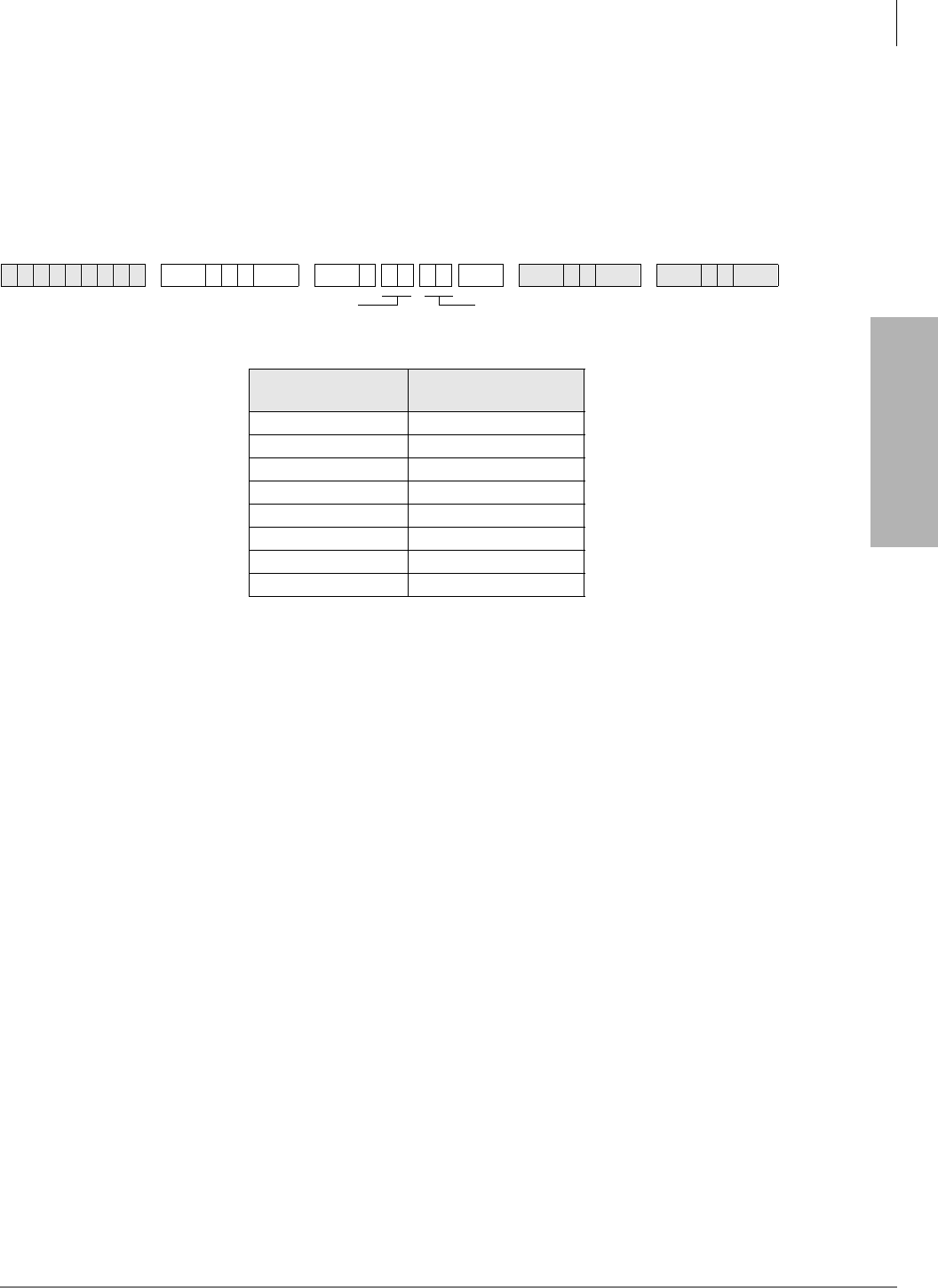
E911
Program *11-2 – CAMA Trunk Group Hunting Assignments
Strata DK Programming 5/99 8-7
E911
Program *11-2 – CAMA Trunk Group Hunting
Assignments
Processor Type:
All RCTUs (Release 4.0)
Program Type:
System
Initialized Default:
Blank
Program *11-2 Overview
This program enables E911 calls to hunt for an idle line in a CAMA trunk group in the order
assigned in this program.
If all lines in a CAMA trunk group are in use, a new 911 call that attempts to connect to a busy
trunk group can hunt to another trunk group. If that group is busy, the call will hunt to another
CAMA trunk group until an idle group is found. E911 calls will hunt for an idle line in a CAMA
trunk group in the order assigned in this program. Within each CAMA trunk group, E911 calls will
hunt the lines in that group from the lowest numbered line to the highest numbered line. This
hunting operation is true if the lines in a CAMA trunk Group are CAMA trunks or normal CO
lines.
6SNU+ROG 6SNU +ROG 6SNU +ROG 6SNU +ROG
Hunt from CAMA
Trunk Group Hunt to CAMA Trunk
Group
01
02
03
04
05
06
07
08
DATA = Hunt to CAMA Trunk Group (01~08)Hunt from CAMA Trunk Group (01~08)
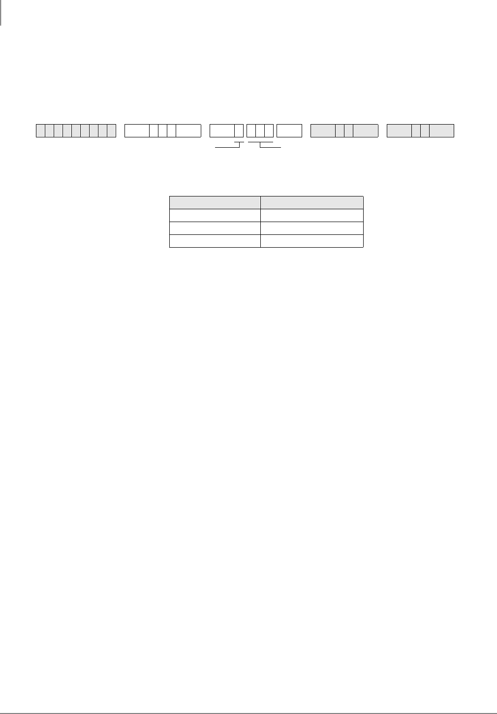
E911
Program *11-5 – CAMA Digits Sent on 911 Calls
8-8 Strata DK Programming 5/99
Program *11-5 – CAMA Digits Sent on 911 Calls
Processor Type:
All RCTUs (Release 4.0)
Program Type:
System
Initialized Default:
911
Program *11-5 Overview
This program specifies which digits (“911” or “11” or “1”) will be sent to the to CAMA trunk,
when a user dials 911 or 9+911.
When a caller dials 911, the DK can send 911, 11, or 1 out the CAMA trunk before sending the
CESID location digits set in Program *12. Normally it is required to send 911, but this will vary so
you must check with the CAMA trunk provider to identify what to enter into this program. Digits
sent on the CAMA trunk are multi-frequency (MF) tones, so they cannot be checked with a DTMF
test set.
6SNU+ROG 6SNU + ROG 6SNU +ROG 6SNU +ROG
X (choose 1) CAMA Digits Sent
911
11
1
CAMA digits sent if user dials 911 (911, 11, 1)
Use LED button 01 to blank out 9 or 91
SELECT = 5
E911
Program *11-6 – E911 Interdigital Timer
Strata DK Programming 5/99 8-9
E911
Program *11-6 – E911 Interdigital Timer
Processor Type:
All RCTUs (Release 4.0)
Program Type:
System
Initialized Default:
Data, 2 seconds
Program *11-6 Overview
This program assigns the amount of time allotted for the E911 interdigital timer. When the E911
feature is enabled, the DK applies the E911 interdigital timer any time a user dials “9” as the first
digit. This applies to any type of call originated from a [DN] when you dial 9XX or 9 + 9XX. After
9 is dialed as the first digit, the DK will wait the number of seconds set in this program before
processing the dialed digit.
If “91” or “99” is dialed as the first and second digit, the system will wait the number of seconds
set in this program before processing the dialed digits. If 91X is dialed, the system will route the
call out the CAMA trunk if X=1 or it will process the call as a normal call if X=0 or 2-9.
6SNU+ROG 6SNU + ROG 6SNU +ROG 6SNU +ROG
DATA (01~15 secs.)
DATA = interdigital time delay before routing calls after
9XX (01~15 seconds).
If X=1, timer resets
If X=0, 2~9, digits are routed/sent normally
SELECT = 6
E911
Program *11-8 – 911 Special [DN] Notification Assignments
8-10 Strata DK Programming 5/99
Program *11-8 – 911 Special [DN] Notification
Assignments
Processor Type:
All RCTUs (Release 4.0)
Program Type:
System
Initialized Default:
Data, Blank
Program *11-8 Overview
This program designates which [PDN] or PhDN] should have ringing notification on 911 calls (all
installed consoles are always notified). A unique (or the same) [DN] can be designated as the E911
notification DN in each system ring mode: Day, Day2, and Night.
The E911 Internal Notification option is enabled/disabled in Program *11-0, LED 03. When this
option is enabled, 911 calls will be sent on the CAMA trunk normally and will also ring on
attendant consoles’ Emergency ICI buttons and a designated telephone’s [DN] ([PDN] or
[PhDN]), if assigned in this program. Special CESID information regarding the E911 caller will
display on attendant consoles monitors and/or on notification telephone LCDs to help identify the
location of the telephone that dialed 911.
All telephones that must be notified when a 911 call is made must have an appearance of the
notification [DN] button (Program 39) and the Notification DN must be programmed to ring
(immediate or delayed) the notification telephones (Programs *71, *72 and/or *73).
If the notification [DN] has Call Forward set, the call will follow the call forward process as a
normal internal call.
When the notification [DN] is answered, a three-party conference is established between the E911
originating station, the E911 dispatcher (on CAMA trunk), and the E911notification station/
console answering party. After the E911 notification call is answered, it stops ringing on all
stations/consoles where it was presented.
6SNU+ROG 6SNU +ROG 6SNU +ROG 6SNU +ROG
Processor [PDN] Port Range [PhDN] Port Range Processor [PDN] Port Range [PhDN] Port Range
DK14 000~009 500~509 RCTUBA/BB 000~079 500~579
DK40i 000~027 500~527 RCTUC/D 000~239 500~739
RCTUA 000~031 500~531 RCTUE/F 000~335 500~835
Mode [DN] Port Number
Day
Day2
Night
[PDN] or [PhDN] port number that should ring to be
notified when 911 is dialed by a station (*71, *72 or
*73 required for ringing)
SELECT = 8
1 = Day Mode
4 = Day2 Mode
7 = Night Mode
E911
Program *12 – CESID Station Information
Strata DK Programming 5/99 8-11
E911
Program *12 – CESID Station Information
Processor Type:
All RCTUs (Release 4.0)
Program Type:
System
Initialized Default:
Data Blank
Program *12 Overview
This program assigns the Caller Emergency Service Identification (CESID) information that will
be sent to the CAMA trunk using Multi-Frequency (MF) signals.
When a station dials 911, the E911 feature causes the DK to seize the CAMA trunk and send 911,
11 or 1 (per Program *11-5) plus the station’s unique CESID information entered in this program.
This CESID information is also sent to the displays of internal notification consoles and stations.
The CESID information can be 7 or 10-digits maximum (per Program *11-0, LED 01). Note that
the digits sent on the CAMA trunk are MF tones, so they cannot be checked with a DTMF test set.
The digits entered in this program for each station is normally a unique telephone number for each
station or station location (i.e., office, room, building, etc.). The exact CESID digit format required
will vary, so you must get the format from the CAMA trunk provider in order to set the CESID
information in this program.
Example formats in which the DK is expected to send digits out the CAMA trunk on E911 calls
are as follows:
6SNU+ROG 6SNU ; ; +ROG 6SNU +ROG 6SNU +ROG
Processor Type Port Range Processor Type Port Range
DK14 008~009 RCTUBA/BB 000~079
DK40i 008~027 RCTUC/D 000~239
RCTUA 000~031 RCTUE/F 000~335
Port Location CESID
Digits Port Location CESID
Digits Port Location CESID
Digits Port Location CESID
Digits
X = Location CESID digits to send on
CAMA trunk when station dials 911
(0~10 digits max.) See Program *11,
LED 01 for 7 or 10 digits.
Station Port Number (see legend)

E911
Program *12 – CESID Station Information
8-12 Strata DK Programming 5/99
1. When the CAMA trunk is connected to the Public Switched Telephone Network:
CESID digits may be: 0-NYY-XXXX
Note The hyphens are for clarity - do not try to program them in *12
0 = Information code expected from a PBX on E911 calls. This multi-frequency (MF) “0”
digit is sent automatically by the DK digits are entered for the calling port in Program *12.
NYY = Office Code
XXXX = Station Directory Number
2. When the CAMA trunk is connected directly to the Public Safety Answering Point (PSAP) the
CESID digits may be: NXX-NYY-XXXX
NXX = Area Code
...or the PSAP serving multiple area codes will substitute a single digit representing an area
code.
NYY = Office Code
XXXX = Station Directory Number
3. If no digits are entered for a port in Program *12, the DK sends an MF digit of “2.”
E911
Program *13 – Station To CAMA Trunk Group Assignment
Strata DK Programming 5/99 8-13
E911
Program *13 – Station To CAMA Trunk Group
Assignment
Processor Type:
All RCTUs (Release 4.0)
Program Type:
System
Initialized Default:
Data Blank
Program *13 Overview
This program assign stations to different CAMA trunks groups (if more than one CAMA trunk is
installed). This can be used to divide services for multi-users (Tenants) or distribute traffic during
an emergency.
If only one CAMA trunk is installed all stations must be assigned to the CAMA trunk group in
which the CAMA trunk is assigned (in Program *11-1). If a station dials 911 and the trunk group
to which it is assigned is busy, the call will hunt to the next trunk group(s) per Program *11-2.
6SNU+ROG 6SNU +ROG 6SNU +ROG 6SNU +ROG
Port
Number Station Group Port
Group Number
Location
Information Digits Port
Group Number
Location
Information Digits Port
Group Number
Location
Information Digits
E911 Station CAMA Trunk Group Number
(01~08)
Station Port Number
(see legend)

E911
Program *13 – Station To CAMA Trunk Group Assignment
8-14 Strata DK Programming 5/99

Strata DK Programming 5/99 GL-1
Glossary
Glossary
Term Definition
AA Auto Attendant (built-in or external). This feature acts as an automatic operator that
directs incoming callers to stations by offering a menu of dialing prompts.
ACD Automatic Call Distribution. Allows incoming calls to be distributed to a group of
ACD agents. The ACD supervisor’s LCD telephone displays ACD Agent and
Group information which allows the supervisor to monitor calls and assist agents.
ACD/MIS Automatic Call Distribution (ACD) with Management Information System (MIS).
ADM Add-on Module—See DADM.
Amphenol
Connector A 25-pair connector typically used on a multi-button telephone set for interfacing
cables to many electronic key and PBX systems.
ANI Automatic Number Identification—Telephone number of the calling party is sent to
the Strata DK system over incoming DID or tie lines. This feature is provided by
some long distance telephone service companies.
B-channel Used in ISDN. Data or voice information is transmitted on the B-channels of an
ISDN line at 64kpbs. The B-channel refers to the frequency range of transmissions
on a copper pair; it is a logical, rather than a physical channel. Also see BRI and
PRI.
B8ZS Bipolar 8 Zero Substitution.
BGM Background Music—Allows customer-supplied music to be sent to telephone
speakers and external speakers.
bps Bits Per Second—Unit of measure that refers to the transmission speed (baud rate)
of electronic signals. It is used when describing data interface unit and modem
operation.
BRI Basic Rate Interface—ISDN line with 2B + 1D channel. BRI lines can have a
U-interface with RJ-11 jacks and single twisted pair wiring, or RJ-45 four pair S/T
interface wiring.
CAMA Centralized Automatic Message Accounting. A special trunk provided by the phone
company or the E911 Public Safety Answering Point Agency.
CESID Caller’s Emergency Service Identification—Telephone number for specific station
or station location which is sent to the CAMA trunk.

Glossary
CCVY ~ DK
GL-2 Strata DK Programming 5/99
CCVY Call Center Viewer “Y” Connector—Enables two-way transmissions between the
Strata DK and a host PC, or SMIS equipment, and one-way transmissions to other
PCs. There are four ports on the Call Center Viewer Connector for one Strata DK,
another master port, and two additional ports.
CLASS Custom Local Area Signaling Services—Defines a number of features offered by
local telephone companies.
CLID or CND Calling Line Identification or Calling Number Delivery—Telephone number or
name of the calling party sent to the Strata DK system over incoming ground or
loop start CO lines. This feature is one of the “CLASS” features offered by some
local telephone companies.
CO Central Office—The facility which houses switching equipment that provides
telephone service (CO lines, E & M tie lines, DID lines, Centrex lines, etc.) for the
immediate geographical area.
CO Line A term used to define the Strata DK system hardware circuits that connect to the
Central Office network line pair. Each CO line, DID and tie line circuit is assigned a
CO line number in system software.
CODECs Coder/Decoder—Semiconductors that allow the system to process analog-to-digital
and digital-to-analog conversions.
DADM Digital Add-on-Module—Optional device that connects to 2000-series digital
telephones to provide the telephones with 20 flexible feature buttons that can be
assigned individually for Direct Station Selection, System and Personal Speed Dial,
and CO line access.
D-channel Used in ISDN. This channel transmits call control information (out-of-band
signaling) for B-channels. The D-channel is a logical, not a physical channel.
DDCB Digital Door Phone/Lock Control Unit—A peripheral hardware unit compatible
with designated digital telephone circuits that supports optional door phones
(MDFBs) and provides door lock control.
DDSS Digital Direct Station Selection Console—A device that helps facilitate the
processing of a heavy load of incoming calls. The DDSS connects only to
designated digital telephone circuits, and is associated with a digital telephone.
DIL Direct In Line—Refers to two-way, standard CO trunk lines that are assigned to a
particular extension or hunt group.
DID Line Direct Inward Dialing line.
DISA Direct Inward System Access—A feature that allows an outside party to access the
Strata DK system internal stations or outgoing CO lines without having to go
through an operator or automated attendant. An optional security code may be set to
prevent unauthorized access to outgoing CO lines for through system calling.
DK Digital Key.
Term Definition

Glossary
DKAdmin ~ DVSU
Strata DK Programming 5/99 GL-3
Glossary
DKAdmin Toshiba's customer database programming and upload/download software package
for Strata DK systems.
DKBackup Toshiba’s customer database upload/download software package for Strata DK
systems.
DKT Digital Telephone.
DKT2000 series Toshiba proprietary digital telephones consisting of four models: two 10-button
models with handsfree answerback and/or LCD display and two 20 button
telephones with speakerphone or a speakerphone with LCD display.
DKSU14A Strata DK14 Key Service Unit (KSU) with power supply. Equipped with two loop
start CO line circuits and four digital telephone circuits built-in. Includes external
page interface, MOH/BGM interface, power failure transfer and miscellaneous
relay control.
DKSUB280 or
DKSUB424 Base Cabinet—Unit that houses the Common Control Unit (RCTU), as well as six
universal slots for station, line, and option PCBs. The Base Cabinet also contains a
power supply that provides power for all of the stations and peripherals connected
to the base cabinet PCBs.
DKSUE280 or
DKSUE424 Expansion Cabinet—Optional unit that has six universal slots for station, line, and
option PCBs. The expansion cabinet has a power supply that furnishes power for all
of the stations and peripherals connected to the expansion cabinet PCBs. As many
as five expansion cabinets can be added to the system.
DKSUBI40 Strata DK40i Base Key Service Unit (KSU) with power supply and battery charger.
Equipped with eight digital telephone circuits built-in, and no CO line circuits.
Includes external page interface, MOH/BGM interface, power failure transfer and
miscellaneous relay control.
[DN] Directory Number.
DNIS Dialed Number Identification Service—Telephone number of called party is sent to
the Strata DK over incoming DID or tie lines. This feature is provided by some long
distance telephone companies.
DPFT Power Failure/Emergency Transfer Unit—An optional backup unit that provides
emergency service during power failures by automatically connecting up to eight
standard telephones to designated CO lines.
DSS Direct Station Selection—Feature which allows a telephone user (as well as a DSS
console and ADM user) to call another station with the touch of a flexible feature
button.
DTMF Dual-tone Multi-frequency—Push-button tone dialing.
DVSU A subassembly that equips a digital telephone with the capability to receive Speaker
Off-hook Call Announce (OCA) calls. DVSU is not required to receive Handset
OCA (HS-OCA).
Term Definition

Glossary
E911 ~ ISDN
GL-4 Strata DK Programming 5/99
E911 Enhanced 911 operation that provides more complete locator information to the
responding agency.
EKT Electronic Telephone.
ESF Extended Super Frame.
EOCU Off-hook Call Announce Subassembly—An optional upgrade to the Electronic
Telephone Interface Unit (PEKU) or Electronic Telephone/Standard Telephone
Interface Unit (PESU) that enables properly configured telephones (see HVSU2) to
receive Off-hook Call Announce (OCA) calls.
FCC Federal Communications Commission—The federal agency which regulates the
telecommunication industry. All Toshiba hardware is FCC listed or approved.
HDCB Electronic Door Phone/Lock Control Unit—A peripheral hardware unit compatible
with designated electronic telephone circuits that supports optional door phones
(MDFBs) and provides door lock control.
HDSS Electronic Direct Station Selection Console—A device that helps facilitate the
processing of a heavy load of incoming calls. The HDSS console connects only to
designated electronic telephone circuits, and is associated with electronic
telephones.
HESB External Speaker Box—A speaker/amplifier that can be configured with the system
to provide a variety of functions, such as a paging speaker and/or Background
Music (BGM) speaker.
HESC-65A A cable used to connect an HHEU-equipped digital telephone or an HHEU-
equipped electronic telephone to the external speaker box (HESB) for the Loud
Ringing Bell feature.
HHEU Headset/Loud Ringing Bell Interface—Subassembly that fits inside a digital
telephone or a 6500-series electronic telephone to allow a headset or an external
speaker box (HESB) to be connected to the telephone.
HPFB Optional Reserve Power Battery Charger (DK14)—One or two can be connected to
the power supply to maintain normal operation during a power failure.
HVSU2 Subassembly that fits into a 6500-series electronic telephone enabling it to receive
Off-hook Call Announce (OCA) calls. The telephone must be connected to an
Electronic Telephone Interface Unit (PEKU) or a Standard Telephone/Electronic
Telephone Interface Unit (PESU) equipped with an Off-hook Call Announce
Subassembly (EOCU) to receive OCA, and must have three-pair wiring.
IMDU Remote Maintenance Modem Subassembly—A subassembly installed on an Option
Interface Unit (PIOU or PIOUS) that allows the system to be connected with a
remote administration/maintenance terminal or DK Admin/DK Backup personal
computer.
ISDN Integrated Services Digital Network.
Term Definition

Glossary
K4RCU3 ~ OCA
Strata DK Programming 5/99 GL-5
Glossary
K4RCU3 Dual-Tone Multi-Frequency (DTMF) Receiver/ABR Tone Detector Unit—An
optional PCB installed on the TMAU motherboard. The K4RCU3A must be
installed to recognize Dual-Tone Multi-Frequency (DTMF) tones generated by a
standard telephone (or any other device connected to a standard telephone circuit)
and it is required for Direct Inward System Access (DISA) and DID. The
K4RCU3A circuits are also used to detect busy tone for the Automatic Busy Redial
(ABR) feature and must be installed to allow ABR to operate.
KCDU CO Line/Digital Telephone Interface Unit (DK40i)—The KCDU has two loop start
CO line circuits and four digital telephone circuits. The KCDU digital telephone
circuits can support all but one of the devices supported by either the PDKU or
Base Unit integrated digital telephone circuits: digital telephones, PDIU-DIs/PDIU-
D12s, PDIU-DSs, ADMs, DDCBs and RPCIs.
KKYS Modular add-on key or integrated circuit that installs onto the K4RCU3 to add the
auto attendant feature to the DK40i.
KSTU2 The optional PCB provides four standard telephone circuits and it can only be
installed in the base unit. The KSTU2 supports the two-wire devices such as
standard telephones, Auto Attendant devices, voice mail machines, and facsimile
machines. The KSTU2 can also support an alternate Background Music (BGM)
source on circuit four.
LATA Local Access and Transport Area.
LCD Liquid Crystal Display—The optional display on digital and electronic telephones
that displays calling information.
LCR Least Cost Routing.
LDI Long Distance Information.
LED Light Emitting Diode—Status indicators located on printed circuit boards (PCBs),
digital telephones, and electronic telephones.
LSI Large Scale Integration—Related to circuit design technology. Strata DK system
printed circuit boards (PCBs) use LSI circuit design.
MDF Main Distribution Frame—The wiring frame usually located in a phone closet.
MDFB Door Phone Box—A peripheral two-way speaker box option.
MOH Music-on-Hold—Customer-supplied music or announcements can be sent to parties
on-hold on CO lines or the intercom.
NDTU Toshiba 30-foot cable that connects the RDTU to the KSU.
NT-1 Used in ISDN. Network Termination device that powers a U-interface ISDN line
and enables multiple S/T ISDN devices to connect to it. The NT-1 must be
UL-listed (U.S.) or CSA-certified (Canada).
OCA Off-hook Call Announce. There are two types: Handset OCA and Speaker OCA.
Term Definition

Glossary
OPS ~ PEPU
GL-6 Strata DK Programming 5/99
OPS Off-premises Station.
PBTC A Toshiba-supplied cable used to connect customer-supplied batteries to a cabinet
power supply in a one- or two-cabinet system for emergency reserve power for the
entire system.
PBX Private Branch Exchange—Industry-standard term which refers to a telephone
switch, usually on-premises, which serves an individual company, and is connected
to a public telephone exchange through the Central Office (CO).
PCB Printed Circuit Board.
PCM Pulse Code Modulation—A widely-used form of digital telephone switching.
PCOU CO Line Interface Unit—An optional PCB (an older version of RCOU) that
provides the system with four loop start CO lines. Supports Caller ID when used
with RCIU/RCIS circuits.
PDIU-DI2 Integrated Data Interface Unit—Replaces the normal digital telephone base so that
the telephone can be used for the transmission and reception of data between a
terminal/personal computer connected to the telephone and devices connected to
other PDIU-DIs or to modems, printers, and computers which are in turn connected
to PDIU-DSs. The PDIU-DI is also used to provide personal computer auto dialing
of voice calls without a modem; and, access to outside dial-up data services and/or
bulletin boards via modem pooling.
Note
Replaced by RPCI-DI.
PDIU-DS Stand-alone Data Interface Unit—Used for modem pooling, printer sharing, and
accessing host/mainframe computer.
PDKU2 Digital Telephone Interface Unit—An optional PCB that provides the system with
eight digital telephone circuits. In addition to digital telephones, the PDKU can
support data interface units (stand-alone and integrated), a digital DSS console
(DDSS), RPCI, ADM, and a digital door phone/lock control unit (DDCB).
[PDN] Primary Directory Number.
PEKU Electronic Telephone Interface Unit—An optional PCB that provides the system
with eight electronic telephone circuits, which can support electronic telephones, a
Background Music source, a door phone/lock control unit (HDCB), an electronic
DSS console (HDSS), and amplifiers for two CO-line conference calls. The PEKU
is also used with older Strata systems.
PEMU E & M Tie Line Unit—An optional PCB (an older version of REMU) that provides
the system with support for four E & M Type I tie lines. The PEMU is also used
with older Strata systems.
PEPU External Page Interface Unit—An optional PCB that provides support and/or circuit
interface mainly for optional hardware peripherals and upgrades associated with
external paging functions.
Term Definition

Glossary
PESU ~ QCDU2
Strata DK Programming 5/99 GL-7
Glossary
PESU Standard/Electronic Telephone Interface Unit—An optional PCB that provides the
system with a combination of two standard and four electronic telephone circuits.
The standard telephone circuits can support standard telephones and optional
hardware peripherals, such as voice mail devices and fax machines. Except for the
electronic DSS console, the PESU electronic telephone circuits can support the
same stations and peripherals that the PEKU does. The PESU is also used with
older Strata systems.
[PhDN] Phantom Directory Number.
PIOU Option Interface Unit—An optional PCB that provides support and/or circuit
interface for optional hardware peripherals and upgrades.
PIOUS The same as the PIOU, with some exceptions; most notably, the PIOUS has one
external paging interface zone, while the PIOU has four.
PORT A term used to identify a station circuit or CO line circuit location.
PBTC1A-3M Battery cable that connects reserve power batteries to cabinet RPSU280 power
supplies (102 cabinet installations).
PPTC A Toshiba-supplied adapter—An adapter that is used to connect: an SMDR device,
ASCII maintenance terminal, or remote maintenance external modem.
PPTC A Toshiba-supplied adapter—An adapter that is used to connect: the modular
SMDR, SMDI, MIS for ACD, Open Architecture (OA), maintenance ports of the
PIOU, PIOUS, RSSU, RSIU, or RSIS to the DB-9 (PPTC-9) connector of a call
accounting machine, DK Admin, DK Backup personal computer (PC), SMIS
personal computer or Open Architecture personal computer.
PPTC-9 Designed to connect directly to the DB9 connector of PC COM ports, while PPTC
connects directly to an ASCII terminal female DB25, not a PC COM port male
DB25.
PPTC-25F Used to connect a Call Center Viewer PC or SMIS PC to the RS-232 Strata DK424
MIS port on the PIOU, PIOUS, RSIU, or RSSU.
PRI Primary Rate Interface.
PSTU2 Standard Telephone Interface Unit—An optional PCB (an older version of RSTU2)
with a built-in ring generator that provides interface for eight standard telephones or
optional hardware peripherals (voice mail devices, Background Music source, fax
machines, etc.). The PSTU2 has a square wave ring generator that can be set for
190V peak-to-peak or 130V peak-to-peak. The PSTU2 is also used with older
Strata systems.
PSTN Public Switched Telephone Network.
QCDU2 CO Line Digital Telephone Interface Unit (DK14)—Provides one CO line (loop
start) circuit and two digital telephone circuits on each PCB. The QCDU2 interfaces
with digital telephones, PDIU-DIs/PDIU-DI2s/RPCI-DI, ADMs connected to the
telephones and PDIU-DSs, but does not support a DDSS or DDCB console.
Term Definition

Glossary
QKYS ~ RCMS
GL-8 Strata DK Programming 5/99
QKYS Auto Attendant Feature Key (DK14)—Provides built-in Auto Attendant software
without Program 03 assignments and installs directly onto the QRCU3 PCB.
QSTU2 Standard Telephone Interface Unit (DK14)—Provides two standard telephone
circuits (ports) and interfaces with standard telephones, Auto Attendant devices,
separate BGM source connections, voice mail machines, and facsimile machines.
QRCU2 DTMF Receiver/ABR Tone Detector Unit (DK14)—Provides three circuits to
receive DTMF tones (required for DISA and devices connected to QSTU2s), and
three circuits to detect busy tone (required for the ABR feature).
RAM Random Access Memory—Refers to the type of system memory that holds
individual system configuration and feature programming. RAM is read/write
memory, and can be easily revised in programming.
RATU Attendant Console Interface Unit—Optional PCB that can support up to four
attendant consoles and/or PC attendant consoles.
RBDB Battery Distribution Box—Interface used to connect reserve power batteries to
systems with three or more cabinets (also provides six RBTC1A-1.5M cables to
connect RBDB to cabinet RPSU280 power supplies).
RBSU ISDN Basic Rate Interface (BRI) Unit—Provides two circuits, each of which
provide two simultaneous voice and/or data connections with a single interface.
BRI uses the 2B+D transmission format which is defined as two 64-kbps bearer
channels and one 16-kbps data (control channel). Available for DK424 with
Release 4.1.
RBSS ISDN Basic Rate Interface (BRI) Subassembly—Attaches to the RBSU to provide
two additional BRI “U” circuits that can be used to connect to Network BRI lines
and/or station-side connections only. Available for DK424 with Release 4.1.
RBTC1A-2M Battery cable that connects reserve power batteries to RBDB battery distribution
box (3 or more cabinet installations).
RBUU ISDN Basic Rate Interface (BRI) Unit—Provides two BRI “U” circuits. Each
circuit provides two simultaneous voice and/or data connections with a single
interface. BRI uses the 2B+D transmission format which is defined as two 64-kbps
bearer channels and one 16-kbps data (control) channel. Available for DK424 with
Release 4.2.
RBUS ISDN Basic Rate Interface (BRI) Subassembly—Attaches to the RBUU to provide
two additional BRI “U” circuits that can be used to connect to Network BRI lines
and/or station-side connections only. An RBUU with the RBUS subassembly
provides four BRI “U” circuits in one card slot. Available for DK424 with Release
4.2.
RCMS Enhanced 911 (E911) CAMA Trunk Direct Subassembly—Enables the DK424
(Release 4.0 and above) to connect to one or two CAMA trunks. Two RCMS PCBs
enable connection to four CAMA trunks.
Term Definition

Glossary
RMCU ~ RGLU
Strata DK Programming 5/99 GL-9
Glossary
RMCU Enhanced 911 (E911) CAMA Trunk Direct Interface—Enables connection from the
DK424 (Release 4.0 and above) to E911 locator services without third-party
equipment. The RMCU supports two subassemblies (RCMS) that provide a total of
up to four ports.
RCCB Conduit Connection Box—Device required for floor-mounted systems with three or
more cabinets to connect AC power and reserve power battery cabling to the
system. Cabling from the AC power source and from the reserve power battery
source can only be installed by a licensed electrician.
RCIU2/RCIS Four-circuit plug-in PCB/four-circuit piggy-back PCB, each of which receives and
decodes FSK Caller ID (CLID or CND) information from the Central Office ground
or loops Caller ID lines. Each RCIU/RCIS circuit works in conjunction with a
DK424 RGLU/RCOU/RCOS line PCB circuit.
RCOS Loop Start CO Line Interface Subassembly—Optional subassembly that attaches to
the RCOU PCB to provide four additional CO analog line circuits to the PCB.
Supports Caller ID when used with RCIU/RCIS circuits.
RCOU CO Line Interface Unit—An optional PCB that provides the system with four loop
start CO lines. An optional RCOS subassembly can be attached to the RCOU for
four more loop start analog CO lines. Supports Caller ID when used with RCIU/
RCIS circuits.
RCTU Common Control Unit—The system’s controller PCB that contains the system's
main microprocessor and microprocessor bus, ROM, RAM, time switch logic, busy
tone detectors, system tones and MOH/BGM Interface. RCTUs include: RCTUA,
RCTUB, RCTUBA/BB, RCTUC/D, and RCTUE/F. Each RCTU supports different
station and line capacities. The RCTU PCBs also provide interface for the optional
RRCS PCB and RKYS key.
RDDU Direct Inward Dialing Interface Unit—Optional PCB that provides four analog
Direct Inward Dialing line circuits. Supports ANI and DNIS.
RDSU Digital/Standard Telephone Interface Unit—Optional PCB that provides two
standard telephone and four digital telephone circuits in its basic configuration. An
RSTS can be attached to the RDSU for two additional standard telephone circuits.
RDTU T1/DS-1 Interface Unit—Optional PCB that provides up to 24-digital channels that
can individually be assigned for loop start CO line, ground start CO line, E & M tie
line, or DID line operation. Supports ANI and DNIS.
REMU E & M Tie Line Unit—An optional PCB that provides the system with support for
four E & M Type I or Type II, Immediate or Wink Start tie lines. Supports ANI and
DNIS.
RFIF Floor Mount Installation Kit—Kit that is used to floor mount systems.
RGLU Analog Ground/Loop Start CO Line Interface Unit—Provides four CO line circuits
that can be individually configured for loop start or ground start CO line operation.
Supports Caller ID when used with RCIU/RCIS circuits.
Term Definition

Glossary
RKYS ~ RSIS
GL-10 Strata DK Programming 5/99
RKYS Feature Key Upgrade—Subassembly that attaches to the common control unit to
provide the system with optional features. There are four versions of the RKYS: the
RKYS1, the RKYS2, the RKYS3 and the RKYS4, each of which provides a distinct
set of features.
RMDS Remote Maintenance Modem Subassembly—A subassembly installed on the RSIU
Optional Interface Unit that allows the system to be connected with a remote
administration/maintenance terminal or DK Admin/DK Backup personal computer.
RPCI-DI Computer Data Interface Unit—Replaces the normal telephone base and provides
all the functions of PDIU-D12. In addition, it can be switched to a second mode
automatically and used with a Telephone Application Program Interface (TAPI)
software application.
RPTU ISDN Primary Rate Interface (PRI) Unit—Provides 1 data (control) channel and 23
bearer channels.All B-channels appear and program as CO lines in the DK424
system and can be individually configured for local service, FX, WATS, DID, tie,
etc., service operation. Supported by the RCTUBA3/BB4, RCTUC3/D4 and
RCTUE3/F4.
ROM Read Only Memory—Refers to the type of system memory that holds static
software that comprises the mechanics of the features’ functions. ROM is only
revised by Toshiba software engineers.
RPSB (1 and 2) Power Strip—Interface between cabinet power supplies and the commercial AC
power source. The RPSB provides outlets for three power supplies. One RSPS is
required for systems with three or four cabinets, two or three RSPSs for five- or six-
cabinet systems.
RPSU280 Cabinet Power Supply—Furnishes power to all of the stations and peripherals
connected to the cabinet PCBs. Each Base and optional expansion cabinet has a
separate power supply.
RRCS Dual-tone Multi-frequency Receiver—An optional upgrade to the system common
control unit (RCTU) that provides Dual-tone Multi-Frequency (DTMF) receivers
for system Direct Inward System Access (DISA) CO lines, E&M tie lines, DID,
DNIS and ANI lines, Auto attendant announcement devices, remote change of call
forward-external destination, DNIS external call routing, and stations and other
peripherals that connect to standard telephone circuits. The RRCS comes in three
models: the RRCS-4 (provides four DTMF receivers), the RRCS-8 (eight DTMF
receivers), and the RRCS-12 (12 DTMF receivers).
RSIS Optional RS-232 Serial Interface Unit—A subassembly installed on the RSIU
optional interface unit that allows the system to be connected to any of the
following features: voice mail SMDI, MIS for ACD, SMDR, local DK Admin/DK
Backup personal computer, external maintenance modem, Open Architecture
personal computer.
Term Definition

Glossary
RSIU ~
TAPI
Strata DK Programming 5/99 GL-11
Glossary
RSIU Optional RS-232 Serial Interface Unit—An optional PCB that provides interface to
any of the following features: voice mail SMDI, MIS for ACD, SMDR, local or
remote DK Admin/DK Backup Personal computer, built-in (RMDS) or external
system maintenance modem, Open Architecture personal computer. By itself, the
RSIU PCB provides one interface port. With up to three RSIU/RMDS
subassemblies, it can provide up to four interface ports.
RSTU Standard Telephone Interface Unit—An optional PCB (an older version of RSTU2)
with a built-in ring generator that provides interface for eight-standard telephones
or optional hardware peripherals (voice mail devices, Background music source,
fax machines, etc.). The RSTU has a built-in 80V RMS sine wave ring generator.
The RSTU also has connectors for the R48S, which extends station loop length and
is described in this section.
RSTU2 Standard Telephone Interface Unit—An optional PCB functionally identical to the
RSTU. RSTU2 also contains a 90-volt DC message waiting/generator/switching
circuit to operate standard telephone message waiting lamps.
RWBF1 Wall bracket Fixture—Bracket that is part of an installation kit (RFIF) that is used
to floor mount systems.
RWIU/WWIS Strata AirLink Wireless System Interface Unit—A proprietary PCB that enables
wireless telephone functionality to Strata DK systems.
RFMF Floor Mount Fixture—Fixture that is part of an installation kit (RFIF) that is used to
floor mount systems.
R48S Optional 48V Power Supply—Subassembly that can be connected to the RSTU or
RDSU to extend the loop length of standard telephone circuits (including the
resistance of the phone) from 600 ohms to 1200 ohms.
[SDN] Secondary Directory Number.
SF Super Frame.
SLT Single-line Telephone.
SMDI Simplified Message Desk Interface: RS-232 link from PIOU, PIOUS, RSSU, RSIS,
or RSIU modular jack connected to a voice mail machine to provide Strata DK
voice mail integration.
SMIS Software MIS for ACD.
SSTU Factory-installed sub-unit board that is “piggy-backed” onto the PSTU or PSTU2.
S/T Interface Reference interface points (“S” or “T”) of an ISDN network. S/T interfaces are
RJ-45, 8-wire connection interfaces for ISDN equipment. An NT-1 is needed to
network U-type BRI lines to S/T type interfaces.
TAPI Telephone Application Programming Interface.
Term Definition

Glossary
TA
~ WSIU
GL-12 Strata DK Programming 5/99
TA Terminal Adapter or ISDN modem that converts PC and other types of protocol into
a signal that works with ISDN. Generally, TAs support RJ-11 voice ports and RS-
232C or V.35 or V.449 data interfaces.
T1/DS-1 See RDTU.
TCIU1 Caller ID—An optional PCB that provides the Caller ID option in the Strata
DK424.
TCIU2 Caller ID—An optional PCB that provides the Caller ID option in the Strata DK40i.
TCOU Four-Circuit Loop Start CO Line Board— An optional PCB providing four loop
start CO line circuits in the Strata DK40i.
TDDU Four-Circuit DID Line Digital Telephone Interface Unit— An optional PCB
providing four DID line circuits in the Strata DK40i.
TE Terminal Equipment. This refers to devices using ISDN service (telephones, faxes,
computers, etc.). TE1 supports ISDN formats with S/T or U-type intefaces.
TSPI Telephony Service Provider Interface.
TSIU RS-232 Ports—An optional PCB that provides up to two RS-232 interface ports
(modular jacks) enabling the DK40i to connect to various hardware devices.
TTY Flexible RS-232 port which can be used for maintenance SMDI and MIS (ACD).
U Interface A single twisted pair of copper wire on an RJ-11 jack. The wiring is identical to
POTS, with different signaling. Only one U-interface device can be attached per
line.
Universal slot Slots in a telephone KSU/cabinet that are used for a variety of optional PCBs.
WSIU Serial Interface Board (DK14)—Provides two serial ports for either a Station
Message Detail Recording (SMDR) device or a maintenance terminal or modem, or
Caller ID interface.
Term Definition

Strata DK Programming 5/99 IN-1
Index
Index
A
alert signal
button assignments, 3-118
button programming example, 3-119
alternate background music source
slot assignment (see Program 19)
attendant console
answer button priority assignments, 3-133
display type, 3-132
flexible button codes (see Program 59)
overflow destination assignments, 3-134
overflow timer, 3-132
series (DK424, see Program 58)
auto attendant
built-in prompt/station assignments (see
Program 09)
automatic PCB recognition and port renumber (see
Program 91-1)
automatic preference (see Program 32)
B
backup RAM initialization (see Program 92)
C
cabinet type identification (DK424, see Program
*03)
call forward external (remote change, security) ID
code (see Program 60-8)
call forward station ring assignment (see Program
*80), 3-174
call park pickup abbreviated dialing (see Program
*05)
caller emergency service identification
(CESID), 8-1
caller ID / ANI
abandoned call number station owner
assignments (see Program *52)
caller ID circuit assignments to CO line PCBs
(see Program *50)
CAMA trunks
911 (enhanced) trunks, 8-1
CO line
assign groups (see Program 16)
special ringing assignments (see Program 78)
tenant assignments (see Program *15)
CO, DID, and tie line ring transfer (see Program 37)
computer and data interface unit configuration (see
Program 20)
computer and DIU station hunting for data calls
(see Program 22)
credit card dialing (0+) (see Program 43)
D
data transfer
from temporary memory to working memory
(see Program 91-2)
date, 1-15
day, 1-15
DID intercept port number (see Program *17)
DID/tie line options (see Program 17)
direct inward dialing parameters (see Program
*64-1)
directory number button assignments, 3-115
distributed hunt group member assignments
(DK424, see Program *40)
[DN] to [DN], tie to [DN], and DID to [DN] ringing
assignments (see Program *71~*73)
DNIS (see Program 71)
DNIS number network table assignments (see
Program 72)

Index
E ~ I
IN-2 Strata DK Programming 5/99
door phone
busy signal/door lock assignments (see
Program 77-2)
to [DN] flashing assignments (see Program
*79)
door phone ringing (see Program 79)
E
E911, 8-1
CAMA
digits sent on 911 calls (see Program *11-5)
DK424 operation overview, 8-1
trunk group
line assignments (see Program *11-1)
trunk group hunting (see Program *11-2)
CESID station information (see Program
*12), 8-11
E911/CAMA trunks (see Program *11-0)
interdigital timer (see Program *10-91)
interdigital timer (see Program *11-6)
pause before send timer (see Program *10-92)
programming overview, 8-3
SMDR, 8-2
special [DN] notification (see Program *11-8)
standard telephone ports assignment (see
Programs *10-11 and *10-12)
station to CAMA trunk group (see Program
*13)
EKT and DKT ringing tones (CO line calls) (see
Program 80)
emergency bypass of forced/verified account codes
(see Program 44-91~93)
enhanced 911 (see Program *10)
extension assignments (see Program *09)
F
first-time programming, 1-14
fixed call forward (see Program 36)
flexible access code numbering (see Program 05)
flexible button assignments (see Program 39)
flexible PCB cabinet slot assignments
DK424 (see Program 03)
G
ground/loop/tie/DID line options (see Program 15)
group pickup assignments (see Program *31)
H
hardware requirements (minimum), 1-14
hold recall timing (see Program 34)
I
initialization (system), 1-14
initialize Programs 00~*99 (see Program 90)
Integrated Systems Digital Networking (ISDN),
7-1
internal and tie line call assignments, 3-17
ISDN
ACD and ISDN parameters, including BRI,
PRI T-Wait and 3.1k audio (see Program
10-4)
analog trunk services (see Program *61)
assign CO line groups (see Program 16)
BRI line/station operation (see Program *60)
BRI SPID parameters (see Program *44)
call types for ISDN trunk group
(see Programs *67-2 and *67-3)
call types for ISDN trunk groups (see Program
*67-3)
call-by-call trunk group codes and network ID
(see Programs *66-2, *66-4)
calling number ID presentation parameters (see
Program *68-1)
channel group number parameters (see
Program *66-1)
channel group/trunk parameters (see Program
*66-3)
channel groups (see Program *65)
clock source (see Program *42)
CNIS presentation parameters (see Program
*69-1)
D-channel control and NFAS (see Program
*43-1~3)
dialing parameters (see Program *63)
DID/DNIS digits for trunk groups (see Program
*64-2)
LDN
registrations (see Program *66-5)
trunk group (see Program *66-7)
trunk group to channel group (see Program
*66-6)
line directory number (see LDN)
network PRI interface (see Program *43-3)

Index
K ~ P
Strata DK Programming 5/99 IN-3
Index
non-facility associated signaling (see Program
*43-2)
non-ISDN station bearer service (see Program
*62)
outbound CNIS parameters (see Program
*68-2)
related programs
ACD/ISDN parameters (see Program 10-4)
attendant console feature buttons (see
Program 59)
least cost routing modified digits (see
Programs 55-1 and 55-2)
station class of service (see Program 30)
system assignments, BRI lines (see
Program 10-1)
telephone feature buttons (see Program 39)
special number assignment (see Program *69-
2)
trunk groups
call direction (see Program *67-1)
maximum channel reservation (see
Program *67-4)
trunk groups (see Program *16)
K
keystrip
assignments
2000-series digital telephone, 3-106
template, 1-13
types (see Program 38)
L
LCR, 4-28
area codes (see Program 51)
CO line programming reference table, 5-3
conditions, 5-2
dial 0 (zero) time-out (see Program 50-6)
features, 5-1
home area code (see Program 50-2)
local call plan number (see Program 50-5)
long distance information (LDI) plan number
(see Program 50-4)
modified digits table (see Program 55-0)
modified digits table (see Program 55-1)
office code exceptions for specified area code
(see Program 52)
parameters (see Program 50-1)
route definition tables (see Program 54)
schedule assignments for LCR plans (see
Program 53)
special codes (see Program 50-3)
station group assignments (see Program 56)
LCR/toll restriction
bypass for special numbers
(see Program *45-2 (1~6))
(see Program *45-3 (1~9))
dial plan (see Program 45-1)
special code dialing sequence with LCR (see
Program *45-4)
least cost routing (see LCR)
M
message center
defining (see Program 13)
minimum hardware requirements, 1-14
modem pool port assignments (see Program 21)
N
night ringing over PIOU external page zones (see
Program 77-3)
numerical program listing, 1-1
P
park recall training (see Program *37)
PBX centrex access codes (see Program 42-1~8)
peripheral options (door phones), RSIU / RSIS /
RMDS, PIOU/PIOUS / IMDU, PEPU (see
Program 77-1)
[PhDN] owner telephone assignment (see Program
*33)
Program *03 – DK424 cabinet type
identification, 3-11
Program *04 – [PhDN] assignments for internal and
tie line calls, 3-17
Program *05 – call park pickup abbreviated
dialing, 3-22
Program *09 – [PDN], [PhDN], DH, ACD or
modem DID extension assignments, 3-25
Program *09 – ACD group DID/tie line digit
assignments, 6-5
Program *10-11 – E911 standard telephone ports
assignment, 3-39
Program *10-12
E911 standard telephone ports assignment,
3-39
Program *10-91 – E911 interdigital timer, 3-40

Index
P ~ P
IN-4 Strata DK Programming 5/99
Program *10-92 – E911 pause before send timer,
3-40
Program *10 – enhanced 911 operation, 3-39
Program *11-0 – E911/CAMA trunks, 8-4
Program *11-1 – CAMA trunk group line
assignments, 8-6
Program *11-2 – CAMA trunk group hunting
assignments, 8-7
Program *11-5 – CAMA digits sent on 911
calls, 8-8
Program *11-6 – E911 interdigital timer, 8-9
Program *11-8 – 911 special [DN] notification
assignments, 8-10
Program *12 – CESID station information, 8-11
Program *13 – station to CAMA trunk group, 8-13
Program *14-1 – auto answer with zip tone, 6-14
Program *14-2 – DID, tie, DNIS, ANI line after
shift/overflow substitution destinations, 6-18
Program *15 – CO line tenant assignments, 3-47
Program *16 – ISDN trunk group type
assignment, 7-7
Program *17 – DID intercept port number (vacant
or wrong number), 3-53
Program *31 – group pickup assignments, 3-86
Program *32 – RS-232 voice mail message center
port, 3-89
Program *33 – [PhDN] owner telephone
assignment, 3-92
Program *34 – station class of service, 3-95
Program *36 – system NT button lock password
changing station assignment, 3-102
Program *37 – park recall timing, 3-104
Program *40 for DK424 – distributed hunt group
member assignments, 3-120
Program *41 for DK424 – T1 assignment series
(part 1), 3-122
Program *42 – clock source for T1, ISDN –
Program *43-1~3 – D-channel control and
NFAS assignments, 7-10
Program *43-2 – non-facility associated signaling
(NFAS) assignment, 7-11
Program *43-3 – network PRI interface
assignment, 7-12
Program *44 – BRI service profile iIdentifier
(SPID) parameters, 7-13
Program *45-1 – toll restriction for office codes,
4-23
Program *45-2 (1~6) – LCR/toll restriction bypass
for special numbers, 4-24
Program *45-3 (1~9) – LCR/toll restriction bypass
for special numbers, 4-26
Program *45-4 – special code dialing sequence with
LCR, 4-28
Program *50 – caller ID circuit assignments to CO
line PCBs, 3-126
Program *51 – station memory allocation for store
caller ID / ANI, 3-128
Program *52 – caller ID / ANI abandoned call
number station owner assignments, 3-130
Program *60 – BRI Line/station operation
assignment, 7-14
Program *61 – analog trunk services for ISDN,
7-15
Program *62 – non-ISDN station bearer service,
7-16
Program *63 – ISDN dialing parameters, 7-17
Program *64-1 – direct inward dialing
parameters, 7-18
Program *64-2 – number of DID/DNIS Digits for
trunk groups, 7-19
Program *65 – ISDN channel group assignment,
7-20
Program *66-1 – channel group number
parameters, 7-21
Program *66-3 – channel group/trunk
parameters, 7-24
Program *66-5 – line directory number (LDN)
registrations, 7-25
Program *66-6 – LDN/trunk group to channel
group assignments, 7-26
Program *66-7 – LDN/trunk group assignment,
7-27
Program *67-1 – trunk group call direction, 7-28
Program *67-2 – call types for ISDN trunk group
supported, 7-29
Program *67-3 – call types for ISDN trunk
groups, 7-30
Program *67-4 – ISDN trunk groups maximum
channel reservation, 7-31
Program *68-1 – calling number ID presentation
parameters, 7-33
Program *68-2 – outbound CNIS parameters, 7-34
Program *69-1 – CNIS presentation parameters,
7-35
Program *69-2 – special number assignment, 7-36
Program *71~*73 – [DN] to [DN], tie to [DN], and
DID to [DN] ringing assignments, 3-152
Program *79 – door phone to [DN] flashing
assignments, 3-172

Index
P ~ P
Strata DK Programming 5/99 IN-5
Index
Program *80 – call forward station ring
assignment, 3-174
Program 00-part 1 – software check, 2-12
Program 00-part 2 – RCTU RAM test, 2-15
Program 01-station logical port display and/or
change, 3-1
Program 02 – station physical port display and/or
change, 3-2, 6-3, 6-5
Program 03 – DK424 flexible PCB cabinet slot
assignments, 3-6
RSIU, RSSU, PIOU, PIOUS ACD/MIS slot
assignments, 6-2
Program 04 – station logical port [PDN]
assignment, 3-12
Program 05 – flexible access code numbering,
3-19
Program 09 – auto attendant prompt/ACD
group, 6-3
built-in auto attendant prompt/station
assignments, 3-23
Program 10-1 – system assignments – part 1 of
3, 3-27
Program 10-2 – system assignments – part 2 of
3, 3-30
Program 10-3 – system assignments – part 3 of
3, 3-35
Program 10-4 – ACD/ISDN parameters, 6-6
Program 11 – ACD timing assignments, 6-8
Program 12 – system assignments, basic timing,
3-41
Program 13 – defining the message center, 3-43
Program 14-0 – loop/ground start line direct to
ACD group assignments, 6-12
Program 14-1 – ACD agent ID code
assignments, 6-13
Program 14-2 – ACD supervisor passwords, 6-17
Program 14-3 – announcement/music port and
queue pattern, 6-20
Program 14-4 – queue time out overflow
destination, 6-23
Program 14-5 – overflow point and ring no answer
routing destination, 6-25
Program 14-6 – after shift service destination, 6-29
Program 14-71 – queue size for alarm, immediate
assignments, 6-31
Program 14-72 – queue size for alarm 1, 6-32
Program 14-73 – queue size for alarm 2, 6-33
Program 14-8 – alarm pattern assignments, 6-34
Program 14-9 – work unit assignments, 6-35
Program 15 – ground/loop/tie/DID line options,
3-44, 6-36
Program 16 – assign CO line groups (dial 9 or
801~816), 3-48
Program 17 – DID/tie line options, 3-50, 6-36
Program 18 – agent names for SMIS/MIS
assignments, 6-15
Program 19 – alternate background music source
slot assignment, 3-54
Program 20 – computer and data interface unit
configuration, 3-55
Program 21 – modem pool port assignments, 3-58
Program 22 – computer and DIU station hunting for
data calls, 3-60
Program 32 – automatic preference, 3-87
Program 33 – [PDN]/ [PhDN] station hunting
(voice calls only), 3-90
Program 34 – hold recall timing, 3-94
Program 35 – station class of service, 3-97, 6-36
Program 36 – fixed call forward, 3-101, 3-109
Program 37 – CO, DID, and tie line ring transfer
(camp-on) recall time, 3-103
Program 38 – digital and electronic telephone
keystrip type, 3-105
Program 39 – flexible button assignments, 3-111
Program 40 – station CO line access, 4-4
Program 41 – station outgoing call restriction, 4-6
Program 42-0 – CO line to PBX/centrex connection
& access codes, 4-8
Program 42-1~8 – PBX/centrex access codes, 4-10
Program 43 – 0 + credit card dialing, 4-11
Program 44-1~8 – toll restriction/traveling class
override codes, 4-13
Program 44-91~93 – emergency bypass of forced/
verified account codes, 4-14
Program 45-1 – LCR/toll restriction dial plan,
4-14, 4-15
Program 45-2 – toll restriction disable, 4-19
Program 45-3~6 – special common carrier numbers
& authorization code digit length, 4-20
Program 45-8~9 – toll restriction override code,
4-22
Program 46-10~80 – toll restriction class
parameters, 4-33
Program 46-11~46-81 – toll restriction class (1~8)
parameters, 4-35
Program 46-2~4 – toll restriction allowed/denied
area codes assigned by class, 4-30
Program 47 – toll restriction exception office codes
assigned by area codes (tables 1~16), 4-36

Index
R ~ S
IN-6 Strata DK Programming 5/99
Program 48 – station toll restriction
classification, 4-38
Program 50-1 – LCR parameters, 5-4
Program 50-2 – LCR home area code, 5-5
Program 50-3 (1~5) – LCR special codes, 5-6
Program 50-4 – LCR long distance information
(LDI) plan number, 5-7
Program 50-5 – LCR local call plan number, 5-8
Program 50-6 – LCR dial 0 (zero) time-out, 5-9
Program 51 – LCR area codes, 5-10
Program 52 – LCR office code exceptions for
specified area code, 5-12
Program 53 – LCR schedule assignments for LCR
plans, 5-14
Program 54 – LCR route definition tables, 5-17
Program 55-0 – LCR modified digits table, 5-19
Program 55-1 – LCR modified digits table –
add, 5-21
Program 56 – LCR station group assignments,
5-23
Program 58 – DK424 attendant console series (part
1), 3-132
Program 59 – attendant console flexible button
codes, 3-135
Program 60 – SMDR data output options, 3-139
Program 60-2~7 – SMDR output/account code digit
length, 3-140
Program 60-8 – call forward external (remote
change, security) ID code, 3-142
Program 69 – verified account codes, 3-143
Program 70 – verified account code toll restriction
assignments, 3-145
Program 71 – DID/tie/DNIS/ANI lines, 6-36
DNIS, 3-147
Program 72 – DNIS number network table
assignments, 3-154
Program 74 – system NT button lock password,
3-156
Program 76-1(X-Y) – TSIU and RSIU / RSIS /
RMDS port assignments, 3-157
Program 76-2 (X-Z) – TSIU and RSIU / RSIS /
RMDS port assignments, 3-158
Program 77-1 – peripheral options (door phones) –
RSIU / RSIS / RMDS, PIOU/PIOUS / IMDU,
PEPU, 3-159
Program 77-2 – door phone busy signal/door lock
assignments, 3-163
Program 77-3 – night ringing over PIOU external
page zones, 3-165
Program 77-4 – RSIU open architecture (OA) data
output assignments, 3-166
Program 78 – CO line special ringing
assignments, 3-168
Program 79 – door phone ringing, 3-170
Program 80 – EKT and DKT ringing tones (CO line
calls), 3-173
Program 90-initialize programs 00~*99, 2-4
Program 91-1-automatic PCB recognition and port
renumber, 2-6
Program 91-2 – data transfer from temporary
memory to working memory, 2-8
Program 91-9-system initialization, 2-2
Program 92-initializing misc. backup RAM, 2-9
program listing
numerical, 1-1
program sequence, 1-11
programming
data variations, 1-12
first-time, 1-14
keystrip template, 1-13
overview, 1-1
section layout, 1-10
programs
system and station, 3-1
Programs *66-2 and *66-4-call-by-call trunk group
codes and network ID, 7-22
R
RAM test
RCTU (see Program 00)
RDDU, 6-1
RSIU open architecture (OA) data output
assignments (see Program 77-4)
RSIU, RSSU, PIOU, PIOUS ACD/MIS slot
assignments (see Program 03)
S
set date, time and day, 1-15
SMDR
data output options (see Program 60)
output/account code digit length (see Program
60-2~7)
software check (see Program 00)
special common carrier numbers and authorization
code digit length (see Program 45-3~6)

Index
T ~ V
Strata DK Programming 5/99 IN-7
Index
station
class of service
(see Program *34)
(see Program 35)
CO line access (see Program 40)
hunting (voice calls only, see Program 33)
logical port
[PDN] assignment (see Program 04)
display and/or change (see Program 01)
memory allocation for store caller ID/ANI (see
Program *51)
outgoing call restriction (see Program 41)
physical port display and or change (see
Program 02)
toll restriction classification (see Program 48)
Strata AirLink
Alert Signal, 3-118
DK424 PCB Codes, 3-7
Program 32, 3-88
Program 39, 3-112
Strata DK
how to program, 1-10
system
and station programs, 3-1
assignments
basic timing (see Program 12)
part 1 of 3 (see Program 10-1)
part 2 of 3 (see Program 10-2)
part 3 of 3 (see Program 10-3)
initialization, 1-14
(see Program 91-9)
NT button lock
(see Program *36)
password (see Program 74)
T
T1 assignment series
(DK424, see Program *41)
channel assignments, 3-123
clock source (see Program *42)
span (RDTU) frame and line code
assignments, 3-122
span primary timing reference assignments,
7-9
span receive level pad assignments, 3-125
span transmit level pad assignments, 3-124
time, 1-15
toll restriction
allowed/denied area codes assigned by class
(see Program 46-2~4)
allowed/denied local office codes assigned by
class (see Program 46-6~8)
class (1~8, see Program 46-11~46-81)
class parameters (see Program 46-10~80)
disable (see Program 45-2)
exception office codes assigned by area codes
(tables 1~16) (see Program 47)
for office codes (see Program *45-1)
override code (see Program 45-8~9)
toll restriction/traveling class override codes (see
Program 44-1~8)
TSIU and RSIU / RSIS / RMDS port assignments
(see Program 76-1)
(see Program 76-2 X-Y)
V
verified account code (see Program 69)
verified account code toll restriction assignments
(see Program 70)
voice mail message center port (see Program *32)
