Trans Tel SK 408 Installation And Programming
User Manual: TransTel SK 408 Installation And Programming
Open the PDF directly: View PDF ![]() .
.
Page Count: 99

i
SK-408
Hybrid Telephone System
General Description • Installation & Maintenance
Programming Forms Manual
Key Telephone Master User’s Guide

ii
Notification
Notification is hereby given that TransTel Communications Inc. reserves the right to modify, change, update or
revise this document from time to time as required without the prior obligation to notify any person, company or
organization. Further, TransTel makes no warranty or representation, either express or implied, with respect to
merchantability, or fitness of its products for a particular purpose.
© 2002 TransTel Communications Incorporated
This document or any parts thereof are not to be reproduced or transmitted in any form or by any means, electronic
or mechanical, including photocopying, recording, or information storage and retrieval systems for any purpose
whatsoever without the express written permission of TransTel Communications Inc.

iii
IMPORTANT SAFETY INSTRUCTIONS
Installation Safety Precautions:
1. Never install telephone wiring during a lightning storm.
2. Never install telephone jacks in wet locations unless the jack is specifically designed for wet locations.
3. Never touch un-insulated telephone wires or terminals unless the telephone line has been disconnected at
the network interface.
4. Use caution when installing or modifying telephone lines.
The TransTel SK-408 utilizes a 3 prong grounding power supply cord. This cord is not to be attached to any
building surfaces. When using your telephone equipment, basic safety precautions should always be followed
to reduce the risk of fire, electric shock and injury to persons, including the following:
1. Read and understand all instructions.
2. Follow all warnings and instruction marked on the
product.
3. Unplug this product from the wall outlet before
cleaning. Do not use liquid cleaners or aerosol
cleaners. Use a damp cloth for cleaning.
4. Do not use this product near water, for example, near
a bath tub, wash bowl, kitchen sink, or laundry tub,
in a wet basement, or near a swimming pool.
5. Do not place this product on an unstable cart, stand,
or table. The product may fall, causing serious
damage to the product.
6. Slots and openings in the cabinet and the back or
bottom are provided for ventilation, to protect it
from overheating, these openings must not be
blocked or covered. The openings should never
be blocked by placing the product on the bed,
sofa, rug, or other similar surface. This product
should never be placed near or over a radiator or
heat register. This product should not be placed in
a built-in installation unless proper ventilation is
provided.
7. This product should be operated only from the type
of power source indicated on the marking label. If
you are not sure of the type of power supply to
your home or office, consult your dealer or local
power company.
8. This product is equipped with a three wire grounding
type plug, a plug will only fit into a grounding type
power outlet. This is a safety feature. If you are
unable to insert the plug into the outlet, contact
your electrician to replace your obsolete outlet. Do
not defeat the safety purpose of the grounding type
plug.
9. Do not allow anything to rest on the power cord. Do
not locate this product where the cord will be
abused by persons walking on it.
10. Do not overload wall outlets and extension cords as this can
result in the risk of fire or electric shock.
11. Never push objects of any kind into this product through
cabinet slots as they may touch dangerous voltage points or
short out parts that could result in a risk of fire or electric
shock. Never spill liquid of any kind on the product.
12. To reduce the risk of electric shock, do not disassemble this
product, but take it to a qualified service man when some
service or repair work is required. Opening or removing
covers may expose you to dangerous voltages or other
risks. Incorrect reassembly can cause electric shock when
the appliance is subsequently used.
13. Unplug this product from the wall outlet and refer servicing to
qualified service personnel under the following conditions:
A. When the power supply cord or plug is damaged or frayed.
B. If liquid has been spilled into the product.
C. If the product has been exposed to rain or water.
D. If the product does not operate normally by following the
operating instructions. Adjust only those control, that are
covered by the operating instructions because improper
adjustment of other controls may result in damage and will
often require extensive work by a qualified technician to
restore the product to normal operation.
E. If the product has been dropped or the cabinet has been
damaged.
F. If the product exhibits a distinct change in performance.
14. Avoid using a telephone (other than a cordless type) during
an electrical storm. There may be a remote risk of electric
shock from lightning.,
15. Do not use the telephone to report a gas leak in the vicinity of
the leak.
SAVE THESE INSTRUCTIONS

TransTel Model SK-408
Hybrid Telephone System
General Description - Installation - Programming Forms Manual
Table of Contents
General Description - Introduction ....................................................................................................................................6
FCC Rules and Regulation................................................................................................................................................6
FCC Registration Number .............................................................................................................................................6
Ringer Equivalence Number .........................................................................................................................................6
Notification of the Telephone Company........................................................................................................................6
Incidence of Harm to the Telephone Lines...................................................................................................................6
Compatibility of the Telephone Network and Terminal Equipment.............................................................................7
Radio Frequency Interference.......................................................................................................................................7
DescriptionDescription.......................................................................................................................................................8
Economy and Efficiency.................................................................................................................................................8
Easy Installation .............................................................................................................................................................9
Easy Maintenance..........................................................................................................................................................9
Flexibility of System Applications...................................................................................................................................9
Keyset/Single Line Flexibility..........................................................................................................................................9
Dual Port Capability .......................................................................................................................................................9
Liquid Crystal Display...................................................................................................................................................10
System Specifications..................................................................................................................................................11
System Capacities / Maximum.................................................................................................................................11
Electrical Specifications ...............................................................................................................................................11
Mechanical Specifications (Key Service Unit).............................................................................................................12
Mechanical Specifications (Battery Back Up Housing)...............................................................................................12
Environmental Specifications.......................................................................................................................................12
Features ...........................................................................................................................................................................13
System Features ..........................................................................................................................................................13
Station Features ...........................................................................................................................................................14
Parts & Peripherals..........................................................................................................................................................15
System Modules...........................................................................................................................................................15
Type of Phones ............................................................................................................................................................15
Peripheral Devices.......................................................................................................................................................15
Optional Interface Cards..............................................................................................................................................15
System Installation - Introduction ....................................................................................................................................16
Site Requirements ...........................................................................................................................................................17
Location ........................................................................................................................................................................17
Choosing The Right Environment............................................................................................................................17
Installation Checklist ....................................................................................................................................................17
Equipment Requirements................................................................................................................................................17
Installation ........................................................................................................................................................................18
Installing expansion and optional cards ......................................................................................................................18

SK-408 - General Description
Page iii
B1-CKC- Real Time Clock Card............................................................................................................................. 19
B1-MSC- Multi Service Card ................................................................................................................................... 19
B1-VSC- Voice Service Card .................................................................................................................................. 19
B1-SLC- 2 or SLC-8 Hybrid Adapter Card.............................................................................................................. 19
B1-TKC- 2 Port CO Line Card................................................................................................................................. 19
B1-RGU - Ring Generator Unit ............................................................................................................................... 19
Voltage Selection Check ......................................................................................................................................... 19
Installing the Equipment.............................................................................................................................................. 20
Backboard................................................................................................................................................................ 20
Key Service Unit....................................................................................................................................................... 20
Power Supply............................................................................................................................................................... 20
Preparing The External Battery Backup ..................................................................................................................... 21
Charging the Battery.................................................................................................................................................... 21
Installing or Replacing Batteries ................................................................................................................................. 21
Caution..................................................................................................................................................................... 21
System Ground............................................................................................................................................................ 22
KSU Connecting (Main) Panel Layout........................................................................................................................ 22
Connecting Stations .................................................................................................................................................... 22
CO/PABX and PFT(Power Failure Transfer) Connections ....................................................................................... 24
Optional Cabling.............................................................................................................................................................. 25
Doorphone Connection............................................................................................................................................... 25
Door Switch Connection.............................................................................................................................................. 25
Sensor Connection...................................................................................................................................................... 25
RS232 Port Connection .............................................................................................................................................. 26
Music on Hold Connection .......................................................................................................................................... 26
Music Source Selection............................................................................................................................................... 26
Power On and Operational Test..................................................................................................................................... 27
Operational Tests........................................................................................................................................................ 27
Series Model SK-408 - Programming Forms Manual ................................................................................................... 28
Programming Information ........................................................................................................................................... 28
New Systems ........................................................................................................................................................... 28
Basic Programming Commands:............................................................................................................................ 29
Alphanumeric Entry: ................................................................................................................................................ 30
Form 01 - Day Ringing And Ringing Line Preference Assignment........................................................................... 31
Form 02 - Night Ringing And Ringing Line Preference Assignment......................................................................... 32
Form 03 - Door Phone Ringing Assignment Form .................................................................................................... 33
Form 04 - Console Assignment Form ........................................................................................................................ 33
Form 05-01 System Parameters Form - Timers-1 .................................................................................................. 34
Form 05-02 System Parameters Form - Timers-2 .................................................................................................. 35
Form 05-03 System Parameters Form - Codes-1................................................................................................... 36
Form 05-04 System Parameters Form - Codes-2................................................................................................... 37
Form 05-05 System Parameters Form - Codes-3................................................................................................... 38
Form 05-06 System Parameters Form - Timer/Codes............................................................................................ 39
Form 05-07 System Parameters Form - Timer/Codes............................................................................................ 40
Form 05-08 System Parameters Form - Timer/Codes............................................................................................ 41
Form 05-09 System Parameters Form - Misc.......................................................................................................... 42
Form 05-10 Voice Mail Leading Digits...................................................................................................................... 43
Form 05-11 System Parameters Form - Supplemental.......................................................................................... 44
Form 05-12 System Parameters Form - Miscellaneous ......................................................................................... 45
Form 06-01 Relay Assignment Form ......................................................................................................................... 46
Form 07 - Flexible Key Group Assignment ................................................................................................................ 47
Form 07 Key Assignment Parameters ....................................................................................................................... 47
Form 09 - System Speed Dial Assignment ................................................................................................................ 49
Form 10 - Single Digit Dialing Assignment................................................................................................................. 50
Form 11 Date and Time Settings................................................................................................................................ 50

Page iv Issue 1.1 December, 2003
Form 12 - System Alarm Schedule............................................................................................................................51
Form 13 - System Passwords .....................................................................................................................................51
Form 14 - Station Message Detail Recording.............................................................................................................52
Form 17 - Forced Account Code Assignment ............................................................................................................53
Form 18 - Toll Plan Assignment..................................................................................................................................54
Form 19 - Voice Service Unit Channel Assignment ...................................................................................................56
Form 20 - Day/Night Service Schedule.......................................................................................................................57
Form 29 - Line Specifications #1................................................................................................................................58
Form 35 - CO Line Specifications ...............................................................................................................................59
Form 39 - Sensor Assignment Form...........................................................................................................................61
Form 40 - Station Class of Service (Part 1) ...............................................................................................................62
Form 41 - Station Specifications..................................................................................................................................63
Form 42 - Personal Speed Dial Table Assignment....................................................................................................64
Form 43 - Port Assignments........................................................................................................................................65
Form 44 - Station Class of Service (Part 2) ...............................................................................................................66
Form 45 - Station Class of Service (Part 3) ...............................................................................................................67
Form 46 - Station Class of Service (Part 4) ...............................................................................................................68
Form 47 - Hot Line Table.............................................................................................................................................69
Form 51 - Exception (Allow) Tables............................................................................................................................70
Form 52 - Exception (Allow) Tables............................................................................................................................71
Form 5_ - Exception (Allow) Tables............................................................................................................................72
Form 61 - Restriction (Deny) Tables...........................................................................................................................73
Form 62 - Restriction (Deny) Tables...........................................................................................................................74
Form 6_ - Restriction (Deny) Tables...........................................................................................................................75
Form 67 - Hunt Group Pilot Assignment.....................................................................................................................76
Form 68 - Hunt Group Assignment .............................................................................................................................76
Programming Cross Reference ......................................................................................................................................77
Programming Number.................................................................................................................................................77
Incoming Calls..........................................................................................................................................................77
Outgoing Calls..........................................................................................................................................................77
Intercom Calls ..........................................................................................................................................................78
Busy/During Conversation........................................................................................................................................78
DISA..........................................................................................................................................................................79
Night Service.............................................................................................................................................................79
Group Assignments..................................................................................................................................................79
Call Control...............................................................................................................................................................80
System Clock............................................................................................................................................................80
Station Numbering....................................................................................................................................................81
Single Line Telephone .............................................................................................................................................81
Miscellaneous...........................................................................................................................................................81
Optional Services......................................................................................................................................................81
Voice Mail Integration ...............................................................................................................................................82
TransTel Key Telephone Operation Manual. .................................................................................................................83
Introduction...................................................................................................................................................................83
LED indicators ..........................................................................................................................................................83
Advisory Messages...................................................................................................................................................83
Alternate Trunk Group Access (Dial 87) .................................................................................................................85
Answering a call. ......................................................................................................................................................85
Answering a Doorphone...........................................................................................................................................85
Answer Paging (Meet Me Page) ..............................................................................................................................85
Automatic Last Number Redial................................................................................................................................86
Automatic Saved Number Redial ............................................................................................................................86
Barge-In (Override)...................................................................................................................................................86
Call Forwarding ........................................................................................................................................................86
Call Hold ...................................................................................................................................................................87

SK-408 - General Description
Page v
Calling the Doorphone............................................................................................................................................. 87
Call Pickup ............................................................................................................................................................... 87
Call Swap................................................................................................................................................................. 88
Call Transfer ............................................................................................................................................................ 88
Call Waiting.............................................................................................................................................................. 89
Conference .............................................................................................................................................................. 89
Conversation monitor............................................................................................................................................... 89
Date and Time Setting (Operator Function) ........................................................................................................... 89
Day / Night Service Switching Setup (Operator function)....................................................................................... 90
Dialing Operator....................................................................................................................................................... 90
Direct Trunk Access ................................................................................................................................................ 90
Do Not Disturb.......................................................................................................................................................... 90
Environment Monitor................................................................................................................................................ 90
Exclusive Hold.......................................................................................................................................................... 91
Flash (To an outside telephone line) ...................................................................................................................... 91
Forced Account Codes............................................................................................................................................ 91
Intercom call ............................................................................................................................................................ 91
Last Number Redial................................................................................................................................................. 92
Lock / Unlock SMDR from Console........................................................................................................................ 92
Macro Keys .............................................................................................................................................................. 92
Mute.......................................................................................................................................................................... 92
Operator Set Timed Reminder or Wakeup (Remote Setup)................................................................................. 92
Operator Timed Reminder or Wake Up ................................................................................................................. 93
Paging ...................................................................................................................................................................... 93
Pulse To Tone Conversion...................................................................................................................................... 93
Room Monitor .......................................................................................................................................................... 93
Speed Dialing........................................................................................................................................................... 94
Speed Dial Programming........................................................................................................................................ 94
Speed Dial Programming (Operator)...................................................................................................................... 95
Station Lock / Unlock............................................................................................................................................... 95
Super Save Redial................................................................................................................................................... 96
Switching between Handsfree and Handset mode................................................................................................ 96
Timed Reminder or Wake Up ................................................................................................................................. 96
Trunk Queuing ......................................................................................................................................................... 96
Trunk Group Access (Dial 9)................................................................................................................................... 97
Voice Service Unit (Operator Function) .................................................................................................................. 98
Volume Control........................................................................................................................................................ 98
Volume Levels Programming (Permanent)............................................................................................................ 98
Page 6 Issue 1.1 December, 2003
General Description - Introduction
The General Description section contains an easy to understand overview of the TransTel® SK-408 Hybrid
Telephone System. It is the intent of this document to provide both technical and non technical readers with
information pertaining to the system building blocks, capabilities, key highlights, electrical, physical and
environmental characteristics of the TransTel SK-408 Hybrid Telephone System.
FCC Rules and Regulation
In compliance with the requirements of Part 68 of the Federal Communications Commission Rules and Regulations
for connection of terminal system equipment to the telephone network and for your convenience, the following
information is presented.
FCC Registration Number
The TransTel SK-408 is registered with the FCC in a dual registration capacity enabling the system to operate as a
key system only or as a hybrid system. The FCC Registration Numbers are 3A7TAI-24615-KF-E for key systems
registration and 3A7TAI-24616-MF-E for hybrid operation.
Ringer Equivalence Number
Ringer Equivalence 0.38B.
Notification of the Telephone Company
Customers connecting terminal equipment to the telephone network shall, upon request of the
Telephone Company, inform the Telephone Company of the particular line(s) to which such
connection is made, the FCC registration number and ringer equivalence number (REN) of the
registered terminal equipment.
The REN is useful to determine the quantity of devices you may connect to your telephone line
and still have all of those devices ring when your telephone number is called. In most, but not all
areas, the sum of the REN's of all devices connected to one line should not exceed five (5.0). To
be certain of the number of devices you may connect to your line, as determined by the REN,
you should contact your local telephone company to determine the maximum REN for your
calling area.
Direct Connection to a Party-Line or Coin Operated Telephone Line is Prohibited.
Incidence of Harm to the Telephone Lines
Should terminal equipment cause harm to the Telephone Network, the Telephone Company shall, where practical,
notify the customer that service may be temporarily discontinued. However, where prior notice is not practical, the
Telephone Company may temporarily discontinue service, if such action is reasonable in the circumstances. In
case of such un-notified temporary discontinuance of service, the Telephone Company shall:
(a) Promptly notify the customer of such temporary discontinuance of service.
(b) Afford the customer the opportunity to correct the situation which gave rise to the temporary
discontinuance.
(c) Inform the customer of the right to bring a complaint to the FCC pursuant to the procedures set
out in Subpart E of Part 68 of FCC Telephone Equipment Rules.

SK-408 - General Description
Page 7
Compatibility of the Telephone Network and Terminal Equipment.
(a) Availability of telephone interface information.
Technical information concerning interface parameters and specifications not specified in FCC
Rules, including the number of Ringers which may be connected to a particular line, which is
needed to permit Terminal Equipment to operate in a manner compatible with Telephone
Company communications facilities, shall be provided by the Telephone Company upon
customer's request.
(b) Changes in Telephone Company Communications Facilities, Equipment, Operations and
Procedures.
The Telephone Company may make changes in its communications facilities, equipment, operations or procedures
where such action is reasonably required in the operation of its business and is not inconsistent with the rules and
regulations in FCC Part 68 of the FCC Rules and Regulations. If such changes can be reasonably expected to
render any customer Terminal Equipment incompatible with Telephone Company Communications Facilities, or
require modification or alteration of such Terminal Equipment, or otherwise materially affect its use or performance,
the customer shall be given adequate notice in writing to allow the customer an opportunity to maintain
uninterrupted service.
Radio Frequency Interference
This equipment generates and uses radio frequency energy and if not installed and used properly and in strict
accordance with the manufacturer's instructions, may cause interference to radio and television reception. It has
been type-tested and found to comply with the limits for a Class A computing device in accordance with the
specification in Subpart J of Part 15 of FCC Rules, which are designed to provide reasonable protection against
such interference in a residential installation. However, this is no guarantee that interference will not occur in a
particular installation. If this equipment does cause interference to radio or television reception, which can be
determined by turning the equipment off and on, the user is encouraged to try to correct the interference by one or
more of the following measures:
Re-orient the receiving antenna.
Relocate the equipment with respect to the receiver.
Move the equipment away from the receiver.
Plug the equipment into a different outlet so that equipment and receiver are on different branch
circuits.
Page 8 Issue 1.1 December, 2003
DescriptionDescription
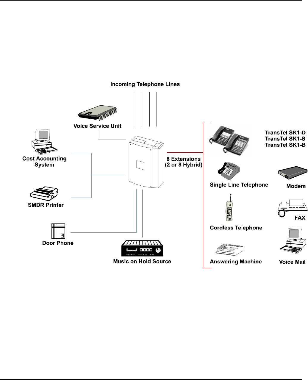
The SK-408 is an advanced hybrid telephone system employing a microprocessor stored program and digitally
controlled solid state space-division switching. The SK-408 system is specifically designed for small business as
well as residential applications. At the forefront of the system’s design is a universal concept to adapting and
connecting with a variety of communications devices. Productive TransTel Key Telephones offer thoughtfully
designed productive feature access to keep you connected with one another and customers. TransTel technology
leads the industry in providing for compatibility with devices such as fax machines, answering machines, cordless
phones, computer modems and other office/home equipment.
Key highlights of the SK-408 series include:
Economy and Efficiency
The base system is equipped to support two (2) CO lines and eight (8) stations. The system may be expanded to a
maximum of four (4) CO lines. Station cards may be selected to allow practically any combination ranging from all
TransTel Electronic Sets to all industry standard Single Line Telephone sets, with any combination of the two types.
Two of the 8 station ports may be converted to full hybrid operation or all 8 station ports as desired. In addition to
being cost effective at the initial phase and for expanding to it's maximum capacity, the SK-408 system also is
economical to operate as it consumes about the same amount of electricity as a 60 watt light bulb at full
configuration. A maximum of 4 CO lines and 8 Extensions can be accommodated. This allows a wide variety of
applications for the system to work effectively.

SK-408 - General Description
Page 9
Easy Installation
• “Factory Ready” - All SK-408 Telephone systems are "ready to go" right out of the box. A well thought out
default database is factory installed on each system which meets the needs for most installations. This
alleviates hours of on site time, minimizing installation costs for both dealer and customer.
• “Small & Compact” - The Key Service Unit's small size takes little space for installation and is about the size of
a legal piece of paper.
Easy Maintenance
• Solid-state design minimizes trouble and eliminates periodic maintenance.
• Easy Expansion. Various Interface Cards for simple, modular expansion.
• Versatile programming and options for ease of selection.
• Database Battery Back Up - Customer data is backed up when the power is turned off and back on. Batteries
can periodically be replaced with power on using commercially available replacements.
• Battery Back Up (System Operation) - SK-408 systems can be equipped with an optional battery back up which
keeps the system operational for up to 4 hours in the case of a commercial power failure.
• Customer Care Programming - Customers and service personnel can easily communicate and perform
programming right over the telephone. TransTel telephone systems allow programming and voice
conversations to co-exist at the same time.
Flexibility of System Applications
Unlike other conventional systems in the SK-408 size range, the installer will find an unprecedented range of
customer database programmability. In "system parameters" there are extensive options for various timing settings
related to features. An array of parameters are programmable for signaling options on outside lines and internal
single line telephone sets. The installer may Enable/Disable many system wide features. And in class of service,
there are over 20 options for each station providing maximum flexibility for nearly any application.
Keyset/Single Line Flexibility
The SK-408 has the ability to support proprietary Superkey® Electronic Telephones and/or conventional industry
standard single line sets. Single Line interfaces support both DTMF and rotary dial phones.
Dual Port Capability
When the hybrid station card (B1-SLC-2 or B1-SLC-8) is installed on the system, customers have the option of
connecting either an Electronic Key Telephone or a Single Line Set or both. This is particularly useful in offices
equipped with computers that have modems, fax machines, personal answering machines or simply an executive
office that would like to have two phones with the same extension number.
Page 10 Issue 1.1 December, 2003
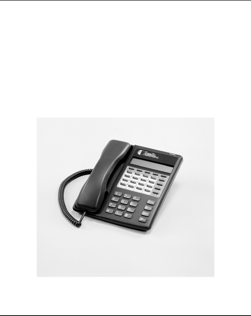
Liquid Crystal Display
The SK-408 Series Telephone Model SK1-D is equipped with a large, easy to read LCD display. The LCD is 32
characters total, comprised of 2 rows by 16 characters each. This LCD provides an invaluable tool for simplifying
the use of the telephone by identifying the calling extension by name, outside lines by name and self prompting
displays for feature access. Station feature usage is made simple with the help of the LCD display. Continuous
prompting information is displayed during calls so that users know what to do and when to do it.
32-character LCD Display shows:
• Time • Last number dialed
• Dialed telephone number • The status of operation/function
• Voice Mail Messages • Absent messages
• CO Line Names • Speed Dial Directory
• Last Number Redial • Calling Party Name
• Speed dial number • Input data during system data entry
TransTel Telephone Model SK1-D
SK-408 - General Description
Page 11
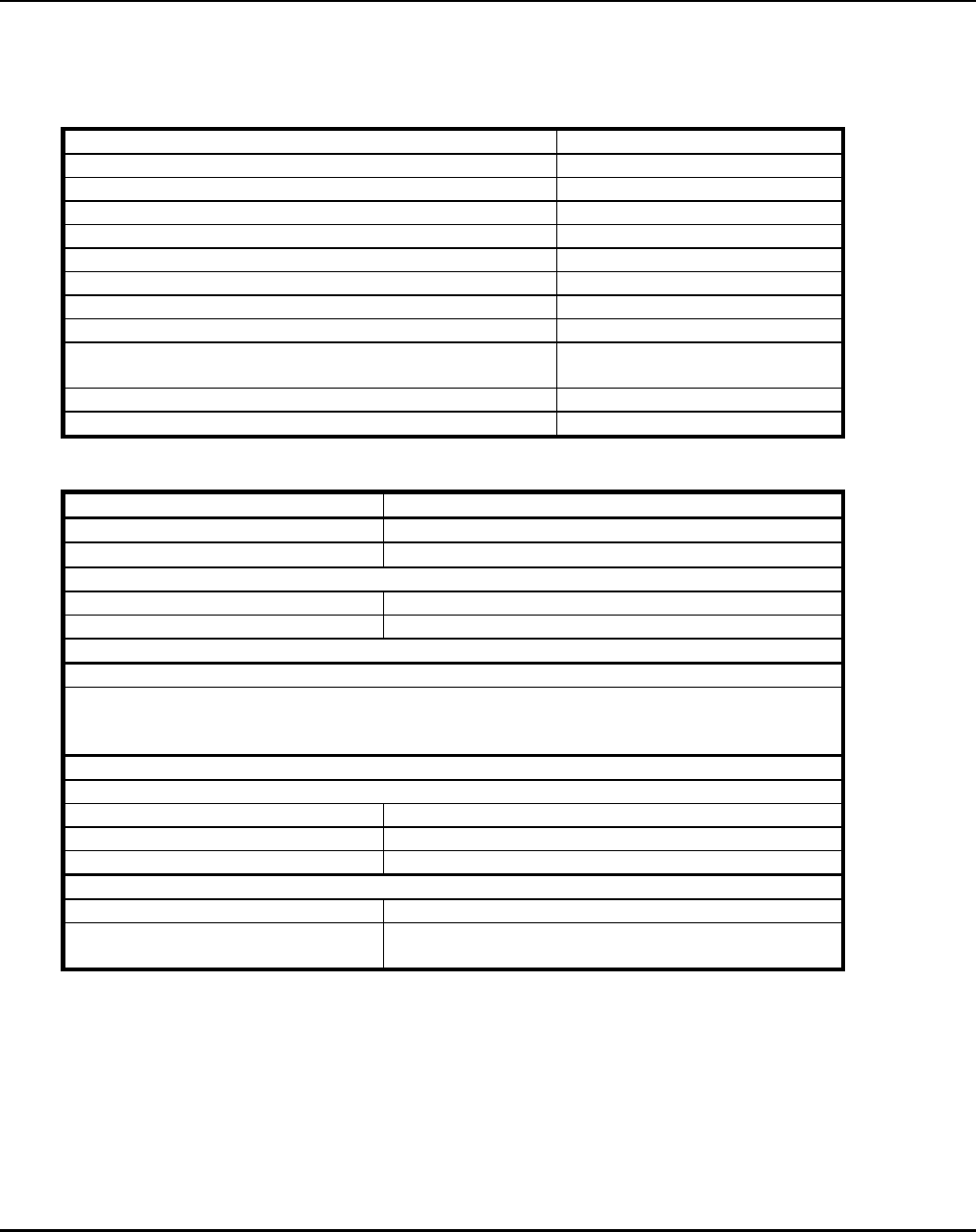
System Specifications
System Capacities / Maximum
CO/PABX Lines4
Key Telephones (Maximum)8
Single Line Phones(Maximum)8
Power Failure Transfer Phone4
Control Relay1
External Input Sensor1
Intercom Paths (Local)3
Doorphone1
External Music1
Speed dialTotal 600 sets for
Private/System Speed Dial.
Private Speed Dial20 sets per station(Max.)
System Speed Dial600 sets (Max.)
Electrical Specifications
CONTROL SYSTEM Stored Program
CPU 8 /16 bit CPU
SWITCHING METHOD SDM (Space Division Matrix)
POWER REQUIREMENTS
100 - 120 V AC, (50/60Hz) 0.9 AMPS
210 - 230 V AC, (50/60Hz) 0.45 AMPS
Dedicated AC line and a good earth ground for power supply
POWER FAILURE
System operation for 180 minutes (full load) or for 4 hours (normal load) by installing
batteries (with two 12 V DC batteries 6.5 AH for each)
POWER DISSIPATION
Common Equipment Unit (idle) 21 W (full) 56 Watts
Each Telephone
Electronic Sets 2.8 Watts, maximum
Single Line Telephone 1.25 Watts
DIALING
Outward Dial Pulse - 10 pps (Pulses Per Second), DTMF
Internal Dial Pulse - 10 pps (Pulses Per Second) / DTMF /
Digital

Page 12 Issue 1.1 December, 2003
MAXIMUM LOOP RESISTANCE/IMPEDANCE
Key Telephone Less than 40 ohms 22 AWG / 1,240 feet
Single Line telephone Less than 800 ohms 22 AWG / 24,780 feet
Doorphone Less than 40 ohms
Music Source Input Impedance 600 ohms
Maximum Input 0.775 VRMS
INTERNAL RELAY CONTACTS
Type SPST
Rating 3 AMP, 110VAC/220VAC
Function Door Switch, Music on Hold, etc
CABLE REQUIREMENTS
CO/PABX Line Twisted 1 Pair (2 wires)
Key Telephone Twisted 2 Pair (4 wires)
Doorphone Twisted 1 Pair (2 wires)
Door Switch Twisted 1 Pair (2 wires)
External Music Source Twisted 1 Pair (2 wires)
Single Line Telephone Twisted 1 Pair (2 wires)
Mechanical Specifications (Key Service Unit)
CABINET DIMENSIONS
233mm W 76mm D 290mm H
9.17” 2.99" 11.4"
WEIGHT 2.3 Kg (Configuration: 2 x 8)
5.0 lbs
Mechanical Specifications (Battery Back Up Housing)
CABINET DIMENSIONS
15.5” W 3.0” D 5.75” H
WEIGHT With Batteries -16 lbs Without Batteries- 4 lbs.
Mounting Screws 12.25” center to center
Environmental Specifications
OPERATING CONDITIONS STORAGE
CONDITIONS
Temperature 0º to 45º C -40º to 66º C
(32º to 113º F) (-40º to 150º F)
Humidity 10 to 95% relative 10 to 95% relative
non-condensing non-condensing

SK-408 - General Description
Page 13
Features
System Features
Account Code Capability
Attendant Console Assignment
Attendant Overflow
Automatic Line Access
Automatic Line Search
Automatic Ringdown
Automatic Wake-up
Battery Backup Memory
Battery Charger
Behind PABX Operation
Centrex Operation
Class Of Service
CO Line Groups
CO Line Hunting
CO Line Name Programming
CO Line Ring Types
Linear
Common Audible
Circular
Hunt
Console Assignment
Day/Night Service
Manual/Automatic Switch
Dial 9 Group
Direct In Line
Dial By Name
Dial Mode Selection(DP/DTMF)
Dial Pulse to DTMF Conversion
Distinctive Ringing
DTMF Signaling
Dual Port Capability
End to End Signaling
Easy Installation and Operation
Flash (Programmable)
Flexible Expansion
Flexible Ringing Assignment
Flexible Key Group Assignment
Flexible Number Plan 2,3 or 4 Digit
Flexible Time Format 12/24 Hour
Forced Account Code Assignment
Intercom
Intercom Single Digit Assignment
Intercom Ring / Voice Select
Host PABX Access
Hot line
Intercom Dialing Restriction
Line Group Assignment
Loud Bell Assignment
Multiple Attendant Consoles
Multiple Trunk Groups
Night Transfer
On Call Programming
Paging Internal
Zone
Meet Me
Password Assignment
DISA
System programming
Toll Override
Pause
Pick Up Groups
Power Fail Transfer
Security Code
Single Digit Dialing
Station Group Assignment
Station Hunting
Station Lock
System Speed Dial and Personal Speed Dial
System Date & Time Setting
System Time-Reminder Service
Telephone Directory
Toll Control
Day / Night
Tone to pulse dialing
Trunk Queuing
Trunk to trunk connections
Uniform Call Distribution
Voice Mail Compatibility

Page 14 Issue 1.0 December, 2003
Station Features
Advisory Messages
System
Personal
Access to System Programming
Account Code Capability
Auto Hold
Auto Hold Recall
Automatic Call Back
Automatic Answer-Intercom
Automatic Line Access
Automatic Redial
Automatic Volume Increase
Brokers Call
Call Duration Timer (LCD Phones)
Call Waiting
Call Forwarding
All Calls
Busy
No Answer
Busy / No Answer
External
Call Pickup
Call Split
Call Transfer
Calling Name Display (LCD Phones)
Calling Number Display (LCD Phones)
Camp On
Chain Dialing
Conference
Dial By Name (LCD Phones)
Dial Access to Attendant
Direct Station Selection
Doorphone Access
Do Not Disturb (DND)
Dual Color LED’s
Duration Time Display (LCD Phones)
Executive Override (Barge-In)
External Call Forwarding
Flash (Open Loop Timed Flash)
Hands-free Answer Back
Hearing Aid Compatibility
Headset Compatibility
Hold (Exclusive / System)
Hold Recall
I Hold Indication
I Use Indication
Intercom
Intercom ring / voice interchange
Intercom Step Call
Intercom Voice Announce
Last Number Redial
Message Waiting
On Hook Dialing
Prime Line Select
Privacy
Privacy Release
Private Line
Pulse/Tone Conversion
Ring Frequency Selection
Ringing Line Preference
Saved Number Redial
Speed Dialing
Station Lock / Unlock
Station Monitor
Store Speed Dial/DSS Number
Timed Reminder Service
System
Station
Toll Restriction Override
Trunk Queuing
Volume Control
Handset
Speaker
Ringer
Optional Features
Automated Attendant
Battery Backup (System)
Direct Inward System Access (DISA)
Doorphone / Door Latch
Dual Port Operation
External Music Source
Music On Hold
Relay Control
RS232
Security Sensor/Door Open Indication
Station Message Detail Record (SMDR)
Voice Mail
SK-408 System Installation
Page 15
Parts & Peripherals
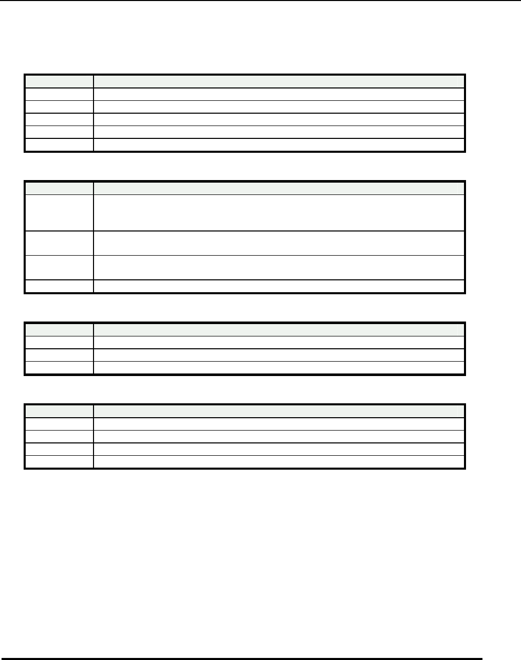
System Modules
Model Description
SK-408 Key Service Unit, Power Supply (2 Trunks and 8 Key Telephone Ports)
B1-TKC Expanded Trunk Card (2 Trunks)
B1-SLC/2 Hybrid Station Interface Card (2 Hybrid Ports)
B1-SLC/8 Hybrid Station Interface Card (8 Hybrid Ports)
B1-RGU Ring Generator Unit
Type of Phones
Model Description
SK1-D Multifunction Key Telephone. Includes 32 character LCD display,
speakerphone, headset jack, 29 keys for feature access, DSS, CO Lines and
speed dial.
SK1-S Multifunction Key Telephone. Includes speakerphone, headset jack, 29 keys for
feature access, DSS, CO Lines and speed dial.
SK1-B Multifunction Key Telephone. Basic telephone with monitor function for
handsfree dialing. 12 keys for feature access DSS, CO Lines or speed dial.
SK1-WMK Wall Mount Kit for SK1 Series Telephones
Peripheral Devices
Model Description
B1-DPU Door Phone - 2 Wires
BCAB/A Battery Box without Batteries
BCAB/B Battery Box with Batteries
Optional Interface Cards
Model Description
B1-VSC Voice Service Card - Auto Attendant, Wake-up, Message Waiting
B1-MSC Relay/Sensor/External Music Interface/Door Phone Interface
B1-MSC/R RS232/Relay/Sensor/Door Phone Interface/External Music Interface
B1-CKC Calendar/Clock Card
Page 16 Issue 1.0 December, 2003
System Installation - Introduction
This section provides directions for installing the system and optional equipment.
The installation must be performed by qualified service personnel.
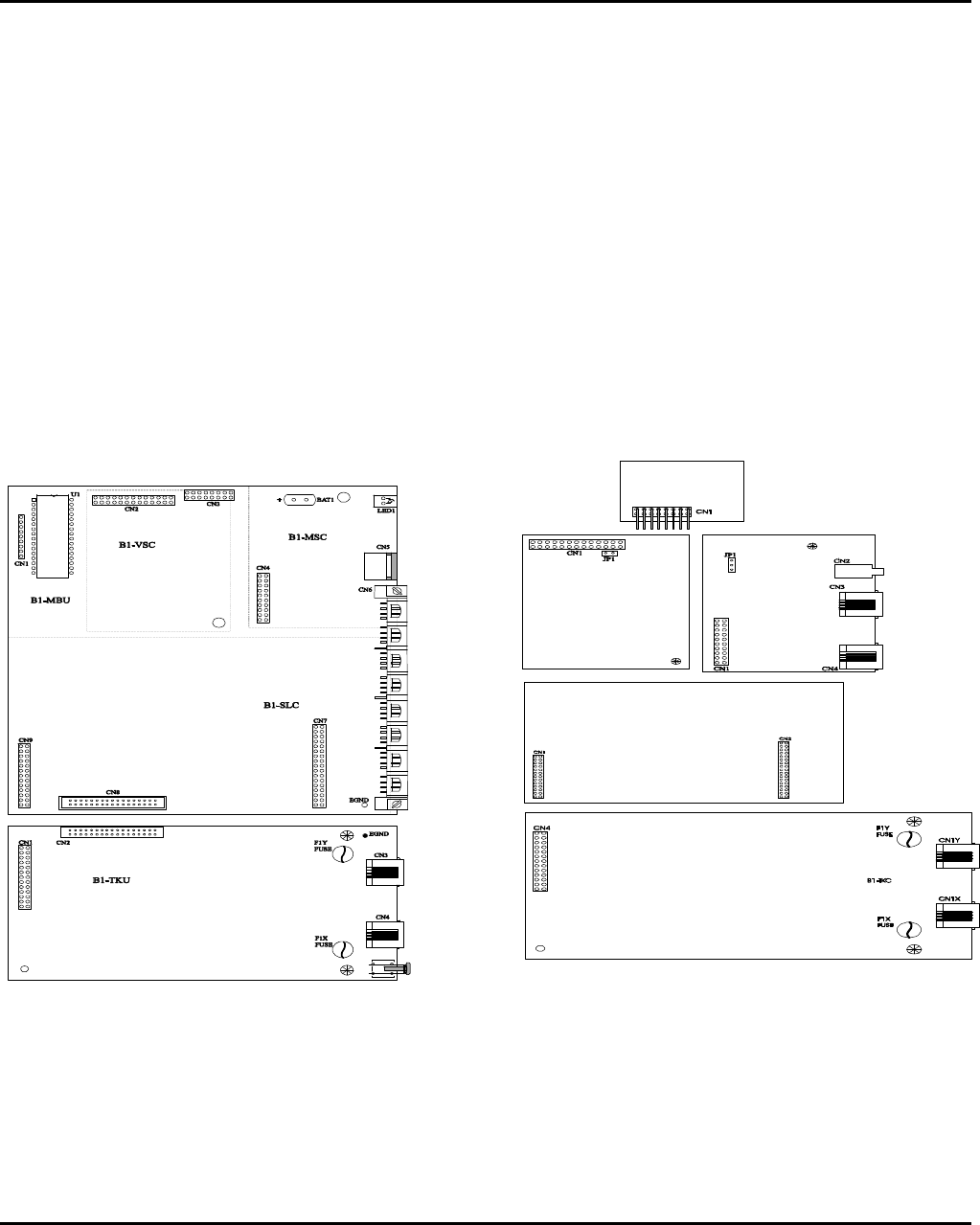
Main components of the system are:
Key Service Unit, which includes:
• Power Supply Unit (B1-PWU)
• Main Board Unit (B1-MBU / Common Control and
eight key telephone circuits))
• Trunk Unit (B1-TKU / Two CO Lines)
Optional Expansion Cards:
• Trunk Card (B1-TKC / Two CO Lines)
• Hybrid Station Card (B1-SLC/2 or B1-SLC/8 /
Converts Key telephone ports into universal
ports)
• Calendar and Clock Card (B1-CKC)
• Multi-Service Card (B1-MSC or B1-MSC/R)
• Voice Service Card (B1-VSC)
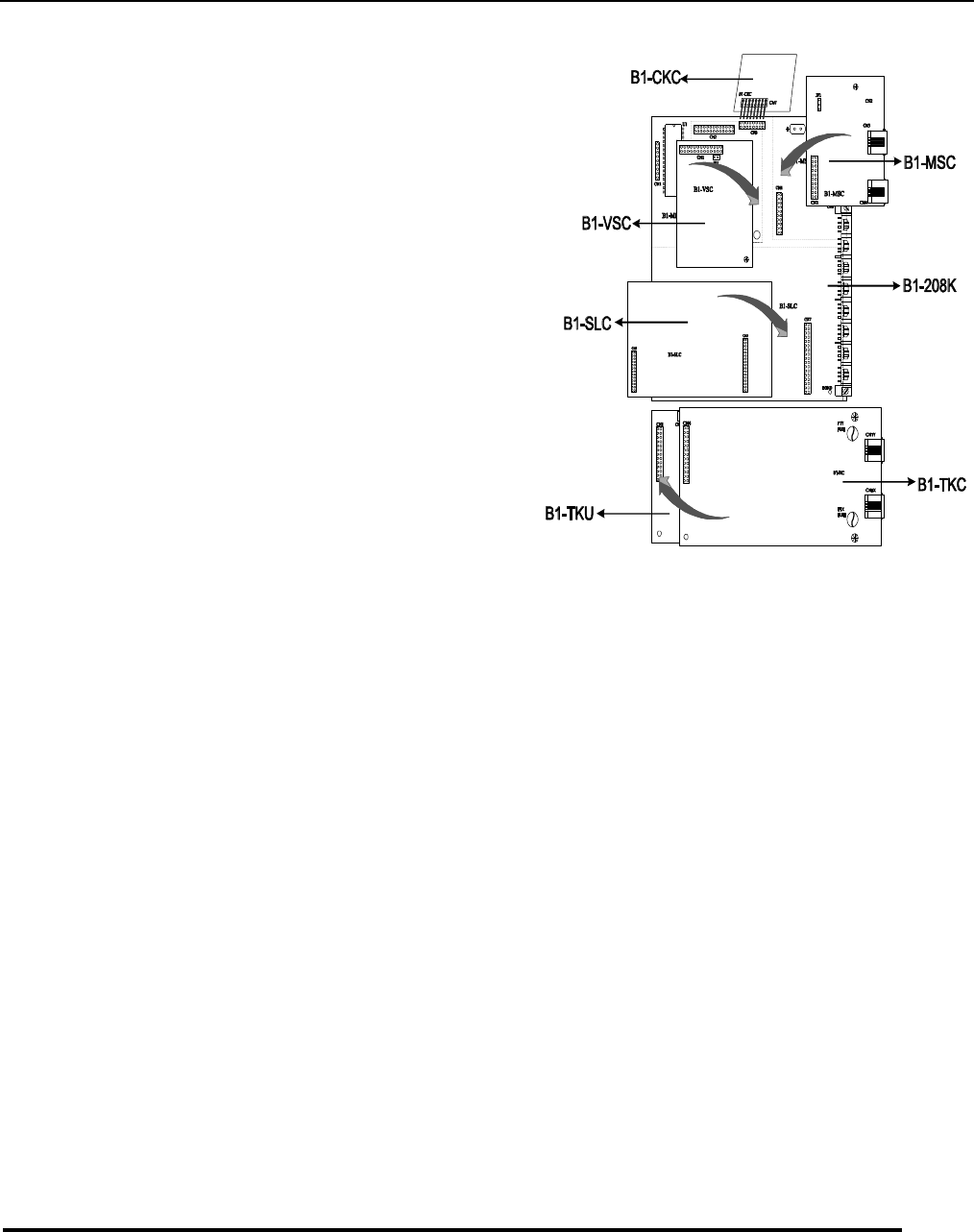
B1-CKC
B1-VSC B1-MSC
B1-SLC
B1-TKU
Optional Expansion Boards
NOTE: Please follow the directions step by step. The SK-408 system should be installed in strict accordance with
this manual.
Mounting Location Mounting Location
Mounting Location
Mounting Location
Key Service Unit Main Cabinet
SK-408 System Installation
Page 17
Site Requirements
Location
Choosing The Right Environment
• System should be installed in a clean, dry, secure location. This location must have adequate ventilation, and a
temperature from 0ºC to 45ºC (32ºF to 113ºF), with 10% to 95% non-condensing relative humidity. DO NOT
install the equipment near sources of static electricity, excessive vibration, or water. Avoid direct sunlight.
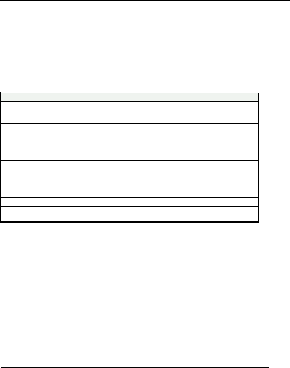
Installation Checklist
INSTALLATION REQUIREMENTS VERIFICATION
MOUNTING SURFACE Flat surface with adequate space for main cabinet,
power supply, wiring and optional Battery Backup
cabinet.
AC LINE AC line should be dedicated exclusively to the system.
POWER OUTLET Power Outlet must be a
3-wire grounded outlet plug, having parallel blades
and ground pin.
Input power Line capacity requirements - 10 amperes.
SURGE PROTECTION A Surge Protector is recommended on the dedicated AC
line.
VENTILATION AND TEMPERATURE Humidity: 10% to 95% relative non-condensing
Temperature:32ºF to 113ºF
(0ºC to 45ºC).
EARTH GROUND A proper ground connection. (14 AWG)
SERVICEABILITY Lighting conditions and working space adequate for
future service.
Equipment Requirements
• Unpack, Check and Verify Equipment - Unpack the telephone equipment boxes and verify the contents in
accordance with the packing list provided. If any discrepancies are noticed, please contact TransTel
Communications.
• Damaged Boxes - If you notice any damage to the packages, please notify both the shipper and TransTel at
once.
• List of parts included in basic KSU box:
• KSU Main Cabinet
• Power Supply
• Mounting Template
• Mounting Screws
• Station Connectors
• Spare Fuses
• Cable Cover
Page 18 Issue 1.0 December, 2003
Installation
Caution 1. This system should be installed by qualified service personnel.
2. Do not install the Power Supply unless you have read the following instructions and
completed all the installation and wiring.
3. STATIC SENSITIVE DEVICES! Please handle with care.
Installing expansion and optional cards
In this step you will be installing printed circuit cards on to header pins of the main board in the basic cabinet. Take
your time and extra care to assure the printed circuit cards are properly aligned. After installing each option and
expansion card, perform a visual inspection to assure the printed circuit card is installed properly.
1. Position the cabinet on a flat surface like a table or countertop. Avoid doing this on carpet.
2. Remove the 4 screws located at the corners of the cabinet and lift the front cover off.
3. Locate the expansion and option cards and unpack them at this time.
SK-408 System Installation
Page 19
Installing expansion and option cards (continued)
B1-CKC- Real Time Clock Card
Install this card on CN3 of the B1-MBU. CN3 is located just
beside the small back up battery. Be sure that the component
side of the B1-CKC is facing in towards the other components.
B1-MSC- Multi Service Card
Align the MSC card with CN4 of the B1-MBU. Align the hole
on the right side of the MSC with the standoff. Once aligned
push the MSC on the connector. Place the screw into the
standoff securing the MSC card. When installed correctly the
connectors should be easily accessible through the main
panel.
B1-VSC- Voice Service Card
Align the B1-VSC card with CN2 of the B1-MBU and the white
plastic snap on guide. Once aligned, press on the VSC until it
snaps onto the guide and is firmly seated on to CN2.
B1-SLC- 2 or SLC-8 Hybrid Adapter Card
Align the B1-SLC card with CN7 and CN9 of the B1-MBU as
well as the associated plastic snap on guide. Once aligned, press on the SLC until it snaps onto the guide and is
firmly seated on to the connectors.
B1-TKC- 2 Port CO Line Card
The B1-TKC card installs directly on top of the existing B1-TKC card provided for in the basic key service unit. Align
the B1-TKC card up with CN1 and the 2 metal standoffs. When aligned, press the B1-TKC until it is firmly seated
on CN1. Insert the 2 screws into the standoffs which will secure the B1-TKC in place.
B1-RGU - Ring Generator Unit
The ring generator installs inside the power supply unit. Remove the cover of the power supply by taking out the 4
screws located on each corner. Inside the B1-RGU are 4 screws and a connecting cable. Align the B1-RGU with
the 4 holes and secure by installing the screws provided. Install the cable from the B1-RGU to the 4 pin header
connector located on the B1-PWU board.
Voltage Selection Check
Make a check to assure the power supply jumper setting is for the proper voltage. (See the power supply section
for details). When complete, place the power supply cover back on the power supply.
Page 20 Issue 1.0 December, 2003
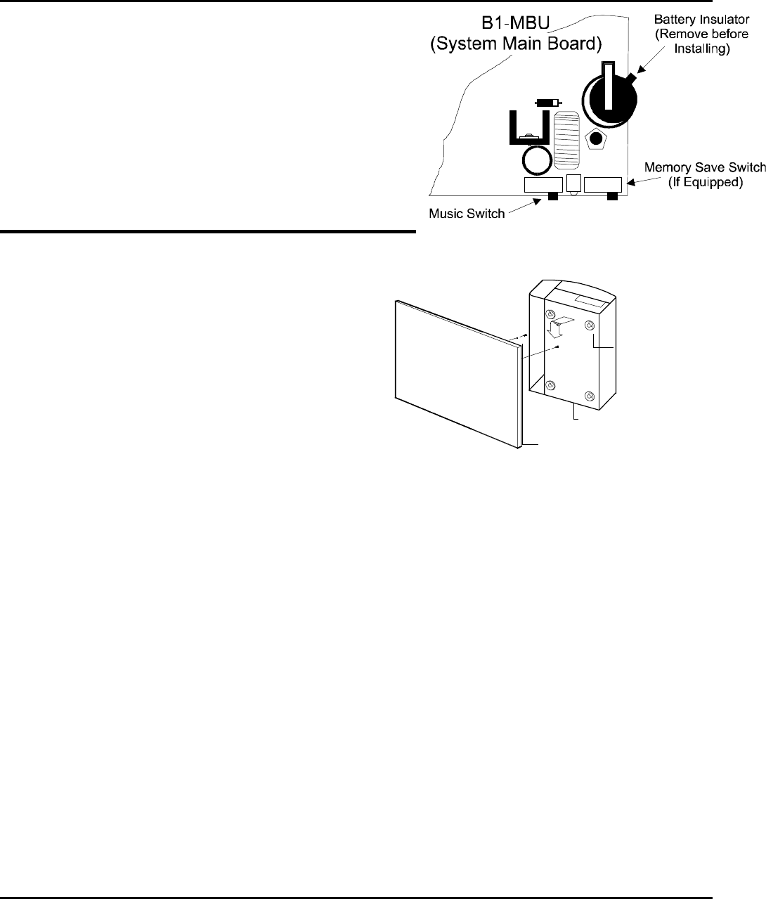
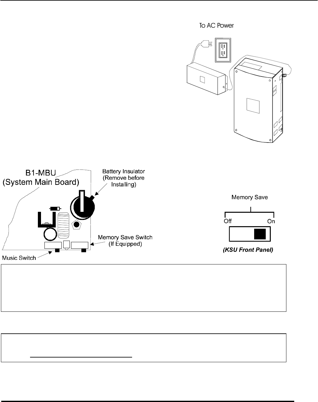
IMPORTANT STEP- Enable the Battery Back Up.
Remove the black insulator from the battery. The insulator needs
to be removed now in order to retain programming information
when the system is turned off.
Replace Cover
With the expansion and option cards installed and the battery
insulator removed, replace the cover and install the 4 screws you
removed earlier.
This concludes the installation of expansion and option cards!
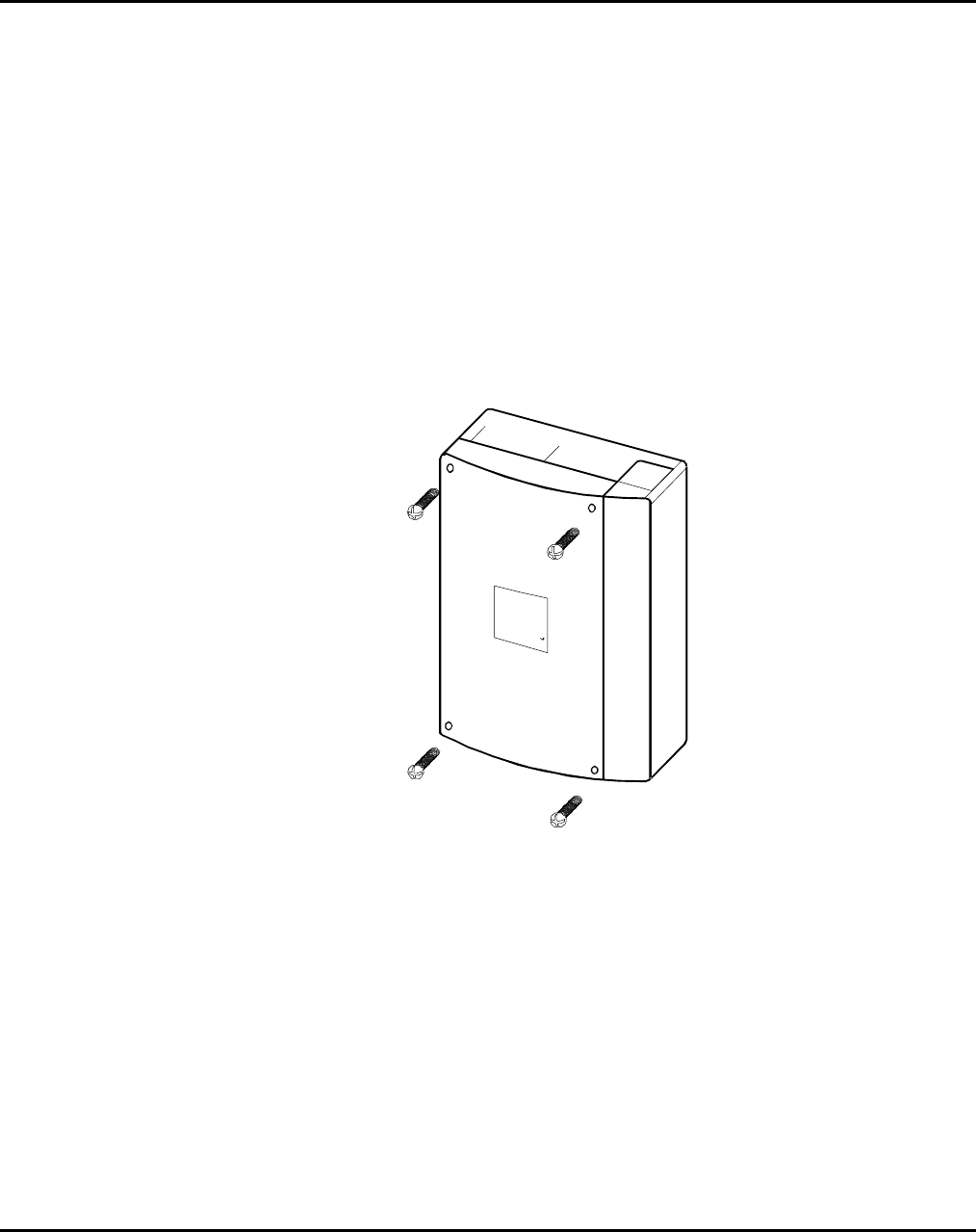
Installing the Equipment
Backboard
Be sure to plan and allow enough space to mount and
connect the key service unit, power supply and system
battery back up if applicable.
Key Service Unit
Use the enclosed paper template to locate the mounting
position for the Key Service Unit. Drill appropriately spaced
holes and mount the KSU on the wall. When mounting the
KSU, make certain that there is adequate room for the
system power supply and that the connecting cable between the Power Supply and the KSU will reach the KSU.
The same applies for the battery back up unit.
Power Supply
Dedicate The Power Source - The power supply must be connected to a dedicated AC outlet.
Be sure that the third wire earth ground of the AC circuit is connected to a good electrical ground. If a music source
is installed, it must be connected to a separate AC circuit rather than the system's dedicated AC line cord.
Check Your Voltage Selection Jumper
Verify that the input voltage and input voltage jumper are correct before you power on the system. The input
voltage is set according to the Customer's requirement before shipping. However it is important to verify that the
setting is correct prior to initial system power up.
Power Supply voltage options for the unit:
100-VAC: 100 to 120 V AC (50/60Hz) or 220-VAC: 210 to 230 V AC (50/60Hz).
Mount Power Supply
Using screws provided with the system, mount the power supply close to the KSU so that the connector reaches
from the Power Supply to the KSU.
Wall or backboard
Key Service Unit
Mounting Tabs
SK-408 System Installation
Page 21
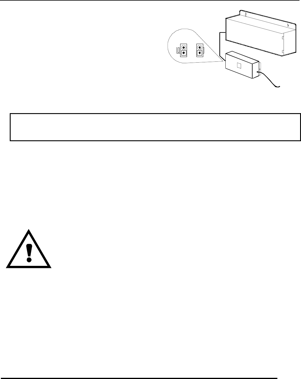
Preparing The External Battery Backup
The Key Service Unit can have two external backup
batteries in series (12 volts each) for emergency power
and when a power failure takes place.
If you are installing an optional Battery Backup (SK-
BCAB/B), make certain that there is adequate room for its
installation. Make certain that the Battery Backup is
mounted close enough to the Power Supply that the
interconnecting cable between the Battery Backup and
the Power Supply can connect.
Do Not Connect the Battery Backup at this time!
Do Not Connect the Battery Backup at this time! Battery Backup should not be
connected to the System power supply until all power up testing has been
completed!
Charging the Battery
The rechargeable batteries are automatically charged when the KSU is plugged in.
When System is in a full-load condition (four CO Trunks and eight Extensions all in use), the batteries provide a
minimum of 3 hour's consecutive use. Change the batteries every two years.
Installing or Replacing Batteries
Caution
To Reduce the Risk of Fire or Injury to persons, Read and Follow these Instructions.
1. Use only the following type and size batteries:
12 Volt 6.5 Amp/Hour "Gel-Cell" sealed batteries (2).
Dimensions, approximately 3 1/4" (H), 5 15/16" (W), 2 1/2" (D).
PowerSonic model PS660 or equivalent.
2. Do not dispose of the batteries in a fire. The cell may explode. Check with local codes
for possible special disposal instructions.
3. Do not open or mutilate the batteries. Released electrolyte is corrosive and may cause
damage to the eyes or skin. It may be toxic if swallowed.
4. Exercise care in handling batteries in order not to short the battery with conducting
materials such as rings, bracelets, and keys. The battery or conductor may overheat and cause burns.
This product is defined as a secondary battery operated device. As such, the following instructions should
also be read and followed:
1. Charge the batteries provided with or identified for use with this product only in accordance with the instructions
and limitations specified in this manual.
2. Observe proper polarity orientation between the batteries and battery charger.
3. Do not mix old and new batteries in this product.
4. Do not mix batteries of different sizes or from different manufacturers in this product.
Page 22 Issue 1.0 December, 2003
Before installing or replacing batteries, disconnect the battery supply unit to the KSU by removing the polarized
battery connector at the KSU. Due to the weight of the batteries, it is advised that the battery cabinet be removed
from the wall before working on it.
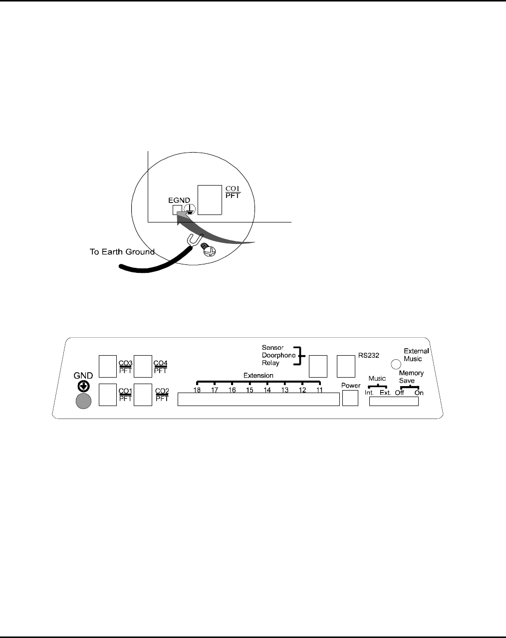
System Ground
It is strongly recommended that the system be grounded by connecting a heavy, insulated copper wire (e.g.,
14AWG or larger) between the grounding bolt on the right-lower side of the cabinet and an earth ground.
Do not connect the grounding wire of the KSU to a computer, telex, or any other external device.
KSU Connecting (Main) Panel Layout
The following illustration should be used as a reference when connecting equipment to the SK-408 KSU.
Refer to the wiring diagram located on the inside of the cable cover for all connections
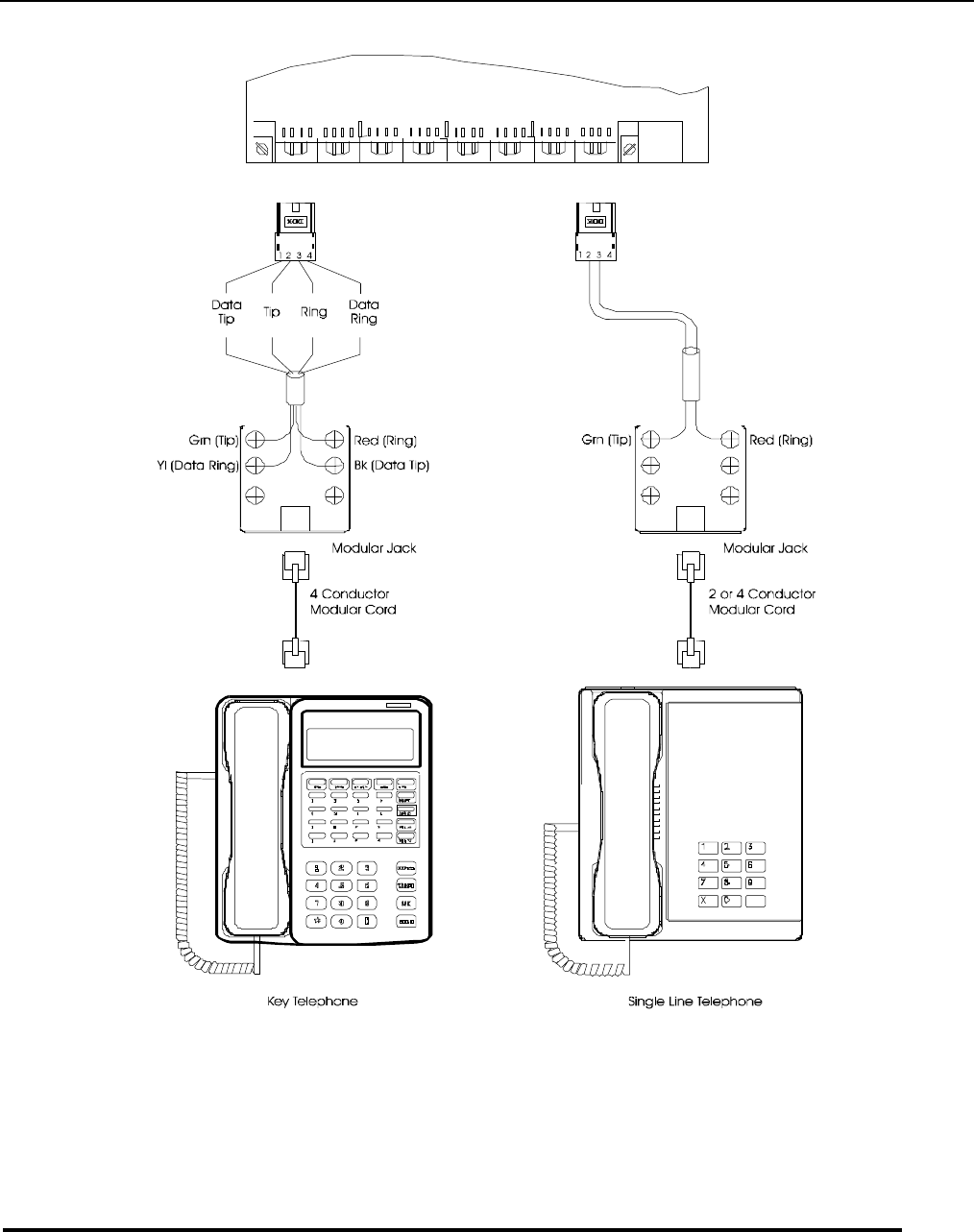
Connecting Stations
The station cabling for the SK-408 should be a home run from the jack to the telephone room. The termination
should be at conventional 66 type connecting blocks or directly to the provided station connectors. Two pair twisted
wiring is required for each station location. Attention to proper cabling will go a long way in a successful installation
and minimizing service calls after installation. Some guidelines for running station cable are as follows:
• Avoid running cable parallel to fluorescent light fixtures or electrical lines not in conduit. If these obstacles are
unavoidable, run the cable at right angles across them.
• Do Not run station cable inside conduit already occupied by electrical wiring.
• Do Not run station cable near equipment with electric motors or strong magnetic fields.
• Do not place station cable on the ground where it can be stepped on or rolled over by office furniture or office
equipment.
SK-408 KSU Main Panel
SK-408 System Installation
Page 23
• A cable cover is provided with the KSU. Station cables can enter from either the top or bottom as desired.
Remove one or both ends of the cover as required and route the station cable through the hole. Terminate the
station wires with the connectors that are provided. The stations will connect to the KSU as shown on the main
panel (above) on connector locations 11 - 18.
• Connect Tip terminal with GRN terminal(screws) of the modular jack, Ring with RED, Data Tip with BK, and
Data Ring with YL.
Station Connection
Page 24 Issue 1.0 December, 2003
• Attention must be given to the polarities of terminals: Data Tip ( - ),
Data Ring ( + ).
• 4-conductor wiring is required for Key Telephones.
• 2-conductor wiring is required for Single Line Telephones.
• Incorrect connections may cause a system malfunction or
equipment failure.
CAUTION!: Avoid using a 4-conductor wiring cord when connecting a
single line telephone. It may damage the B1-MBU or B1-SLC
board if the single line telephone uses the second pair for control
closure (A Lead control).
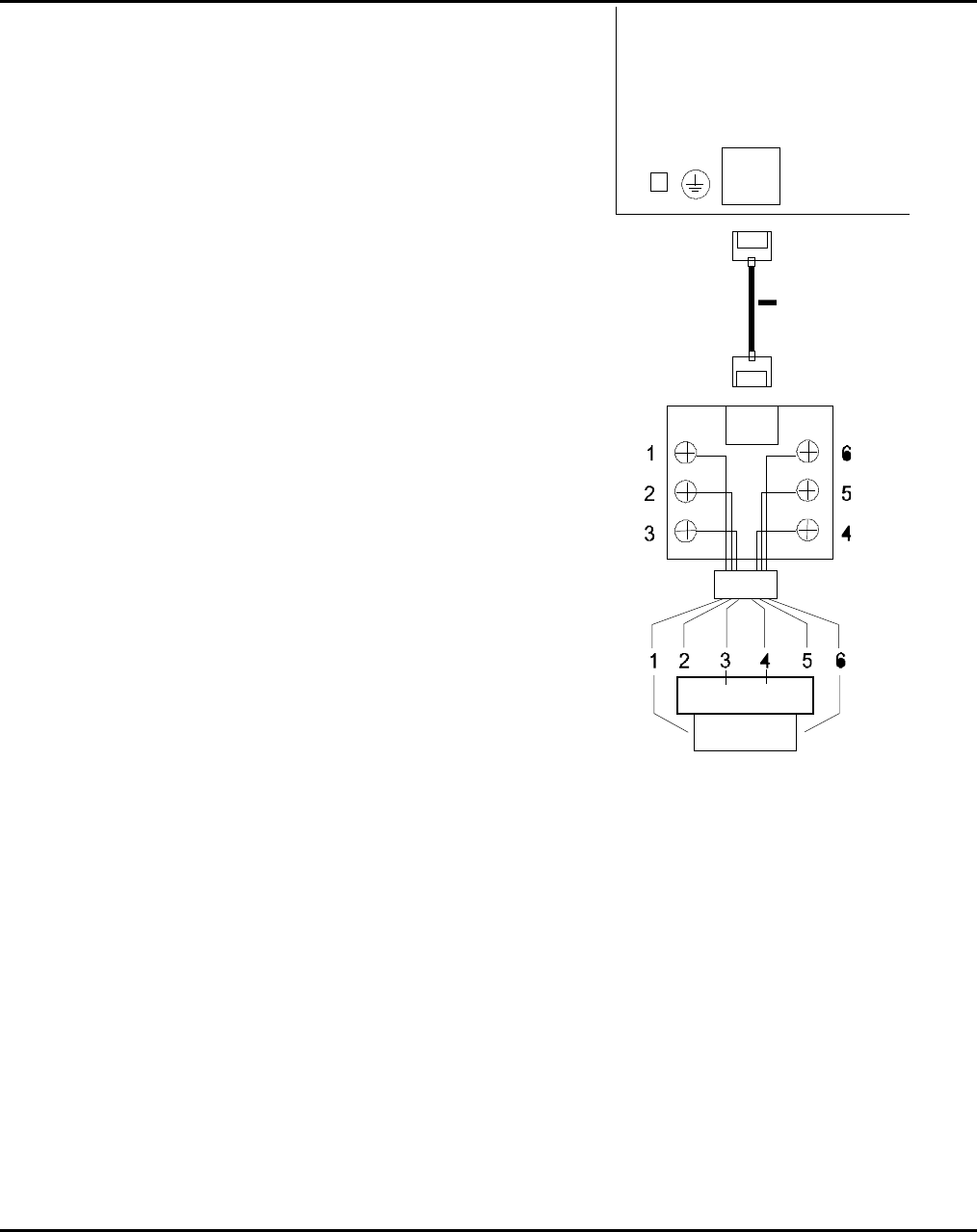
CO/PABX and PFT(Power Failure Transfer) Connections
Make your CO line connection to the telephone company on this
connector. Pins 3 and 4 of the connector are for the CO line. Pins 1
and 6 provide output for connection to power fail transfer circuits or
telephones.
• RJ-25 (6 wire) modular connector is required.
• 6-conductor wiring is required.
• Refer to the accompanying illustration CO/PABX and
Power Failure Transfer Connections:
EGND CO1
PFT
6 Conductor
Wiring Cord
CO Line (3,4)
PFT (1,6)
CO/PABX and Power Fail
Transfer Connections
SK-408 System Installation
Page 25
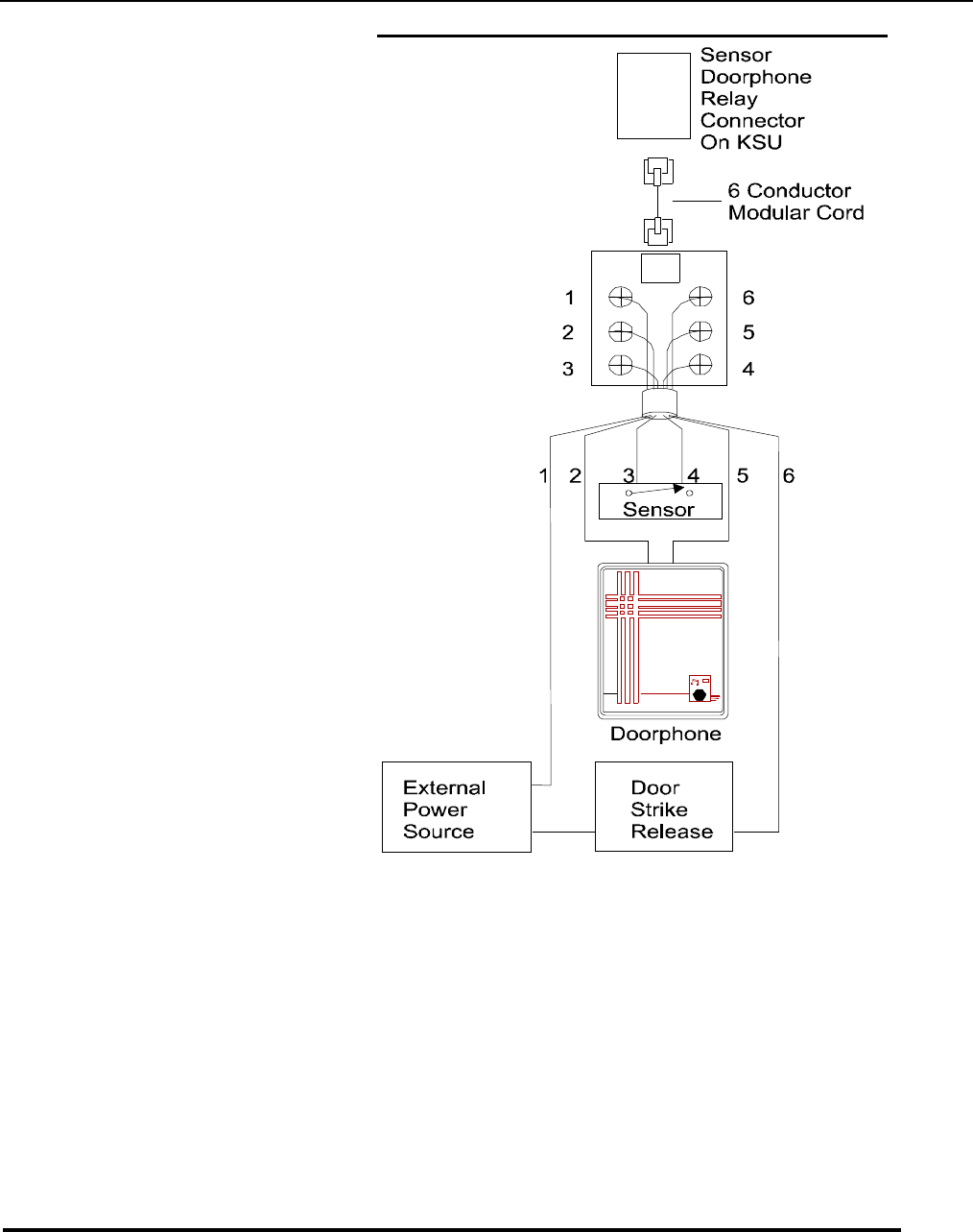
Optional Cabling
Connect a 6 conductor mounting cord
from the KSU to a RJ-25 modular block.
Doorphone Connection
• One Doorphone may be connected to
the SK-408 system.
• 2-conductor wiring is required.
• Connect the Doorphone to pins 2 and
5 of the RJ-25 connector.
Door Switch Connection
• One Door Switch may be used on the
SK-408 system.
• 2-conductor wiring is required.
• Connect the door switch to pins 1 and
6 of the RJ-26 connector.
Sensor Connection
• The Sensor connector on SK-408
may be used for the External Sensor
input.
• The sensor may be configured for
normally open or normally closed
operation.
• 2-conductor wiring is required.
• Connect the sensor to pins 3 and 4 of
the RJ-25 connector.
• Refer to System Programming Form
39 -- Sensor Assignment.
Refer to Illustration Doorphone/door
switch/Sensor cabling:
Doorphone/door switch/Sensor cabling
Page 26 Issue 1.0 December, 2003
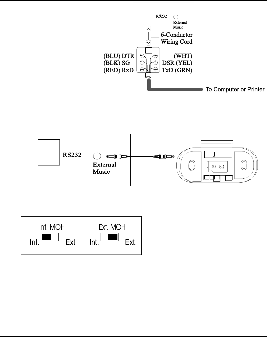
RS232 Port Connection
Use the RJ-25 connector to terminate the
RS232 cable. Then connect the RJ-25 to
the KSU with a 6 conductor mounting
cord. Insert the mounting cord into the
connector labeled RS-232.
Music on Hold Connection
• Connect the (optional) external music source to the “External Music" input labeled on the KSU.
• Use a 1/8” mini plug to connect the music source to the KSU.
Music Source Selection
You can select the external music source or internal music by adjusting the switch on the Main panel.
SK-408 System Installation
Page 27
Power On and Operational Test
Before connecting the B1-PWU to AC power:
• Verify that input voltage and input voltage selection jumper on
B1-PWU are correct before you power up the system.
• Recheck the cabling for incorrect connections, loose wires
and wiring fragments that may cause short-circuits.
• (If equipped) Place Memory Save Switch in the ON
position. If your KSU is not equipped with a Memory Save
Switch, it will be necessary to remove the battery insulator
from the lithium cell inside the KSU.
• Plug the power cord into a power outlet.
• Verify the system boots properly by checking the display of a
telephone set.
• You may now connect the battery back up unit if applicable.
Operational Tests
Check each telephone and CO line to verify that outgoing lines are connected properly.
Check that intercom calls can be made from extension to extension.
WARNING:
DISCONNECT THE POWER SUPPLY FROM THE AC POWER SOURCE BEFORE WIRING OR
CHANGING ANY WIRING.
Connect the Battery Backup AFTER AC power has been connected to the Power Supply.
Disconnect Battery Backup BEFORE disconnecting AC power from the Power Supply.
NOTICE:
ONCE THE SYSTEM OPERATES PROPERLY, PROCEED TO SYSTEM PROGRAMMING. (REFER
TO THE SYSTEM PROGRAMMING MANUAL.)

Page 28 Issue 1.0 December, 2003
Series Model SK-408 - Programming Forms Manual
Programming Information
This document contains the system forms required to program the SK-408 and an explanation of the parameters.
New Systems
We recommend that all new systems have the system memory reset before system programming takes place.
This ensures that any extraneous information that may be present in system memory is erased and that the system
database will not be corrupt.
To Reset System Memory.
Enter System Programming :
From an LCD equipped Superkey Electronic Telephone Set:
1. Press [PROG]. Press [7].
2. Enter Password if programmed. (New systems will not have a system password).
3. Press [SAVE].
4. LCD display will show:
PROGRAM MODE: __
(01 - 69)
5. Enter [2][5]. Press [SAVE]. Display will show:
25- Reset Data
0-9 Default
6. Enter [2].
7. System Database is now reset. LCD will display:
PROGRAM MODE: __
(01 - 69)
8. You may commence database entry at this point, or exit system programming by pressing SPK key
or by lifting and replacing the handset.
To Enter System Programming:
1. Press [PROG]. Press [7].
2. Enter Password if programmed. (New systems will not have a system password).
3. Press [SAVE].
4. LCD display will show:
PROGRAM MODE: __
(01 - 69)
5. You may begin system programming at this point.

SK-408 Programming Forms Manual
Page 29
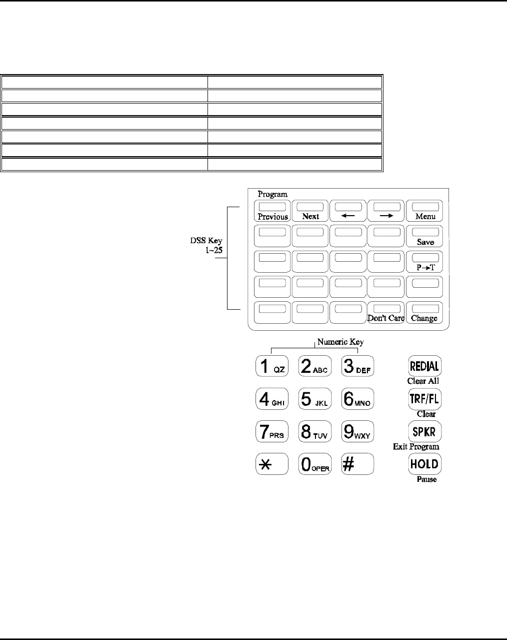
Basic Programming Commands:
For the first time or infrequent installer, a programming overlay is provided with each Key Service Unit. This overlay,
when placed on a TransTel LCD telephone set indicates keys used during programming for easy reference.
Experienced installers may program without the overlay. Both key designations are listed below.
Note: Keys listed between [ ] indicate the default keys shown on a telephone set. Keys listed between
{ } indicate keys displayed by the programming overlay. See illustration Programming Overlay on
the next page.
These commands are active while in the system programming mode
[MSG]{SAVE} Commits the data that is showing on the LCD display into the system database.
[DND/CN]{LEFT} Moves the programming cursor to the left.
[SPD]{RIGHT} Moves the programming cursor to the right.
[SAVE]{NEXT} Moves to the next section in any multiple part form.
[PGM]{PREV} Moves to the previous section of any multiple part form.
[FWD]{PGM} Moves to the Top Level Programming Mode Display (does not save information
entered into any field unless [SAVE] is pressed first).
[DSS Key 4]{Don’t care} Enters a Wild Card (don't care) into Account Codes or Toll control entries.
LCD will display d (lower case letter "d") to indicate don't care entry.
[HOLD]{PAUSE} Inserts a Pause when programming a Speed Dial Entry. LCD will display p
(lower case "p") to indicate a Pause entry.
[TRF/FL]{FLASH} Enters a FLASH command as part of a Speed Dial Entry. LCD will display F
(upper case "F") to indicate a Flash command. Clears a digit during other entries (Passwords, etc).
Same operation as [DSS Key 4] below.
[MIC]{P/T} Enters a command to convert from pulse dialing to DTMF dialing into a Speed Dial
Entry. LCD will display T (upper case "T") to indicate a tone conversion command.
[VOL ]{CHANGE} CHANGE key. Depending on form, it will cycle through available
Programming parameters.
[TRF/FL]{CLR DIGIT} Enters a FLASH command as part of a speed dial number. Clears a digit
during other entries (Passwords, etc). (Same as pressing [SPK] key as listed above).
[SPKR]{EXIT} Exits Programming. Returns telephone to normal idle mode.
[REDIAL]{CLR ALL} Clears all digits on an entry such as speed dial or account codes.
Page 30 Issue 1.0 December, 2003
Alphanumeric Entry:
The following table indicates the capabilities of the name programming functions if they are selected on the system.
System Speed Dial, Personal Speed Dial, Stations, CO Lines and Sensors may be programmed with names.
Key 1 = Q - Z - (Blank Space) - 1 Key 2 = A - B - C - 2
Key 3 = D - E - F - 3 Key 4 = G - H - I - 4
Key 5 = J - K - L - 5 Key 6 = M - N - O - 6
Key 7 = P - R - S - 7 Key 8 = T - U - V - 8
Key 9 = W - X - Y - 9 Key 0 = (Period). : & 0
Key # = ( ) $ # Key * = (Dash) / ! *
DSS Key 23 = Backspace Cursor (Left) DSS Key 24 = Cursor Forward
If an entry is made that is not within valid
system parameters, the Superkey
system will not accept the entry when
[SAVE] is pressed. The Speaker on the
programming set will return a busy tone
and the LCD Display will place the
programming cursor under the offending
entry. You may make corrections and
press [SAVE] again. If multiple errors
are made, the system will continue to
return you to the illegal entries as others
are corrected.
It is not necessary to re-enter existing
information on a multi-item form. You
need enter only the information that is to
be changed. You may move the cursor
to the left or right in order to access only
the specific entry that you want to
change. You may press {SAVE} without
regard for the placement of the cursor
on the LCD display.
Programming Overlay
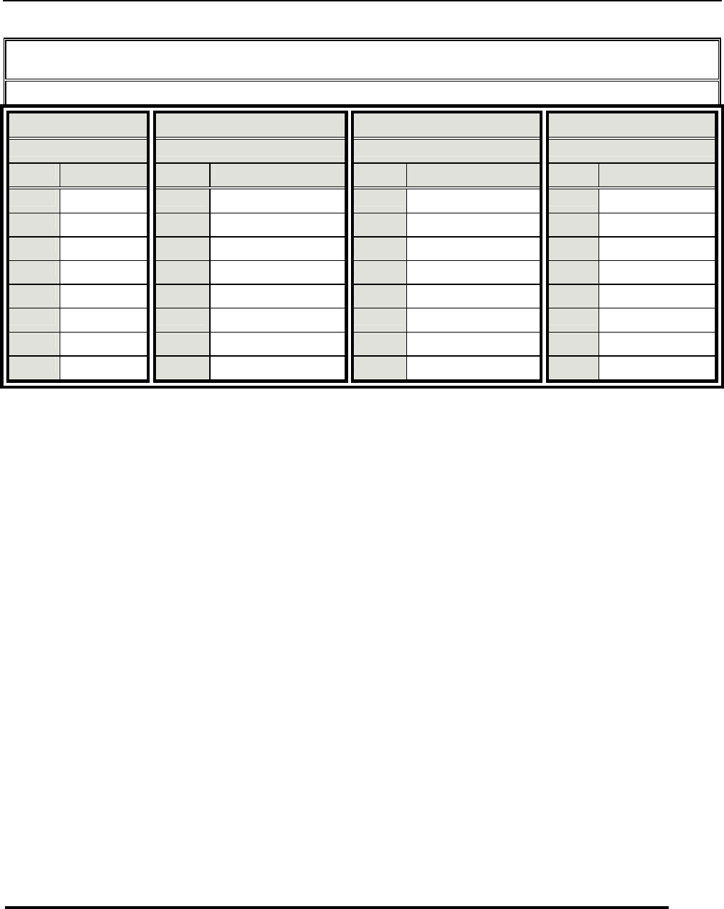
SK-408 Programming Forms Manual
Page 31
Form 01 - Day Ringing And Ringing Line Preference Assignment
Ring Type : Linear / Circular / Hunt / Private / Common See Form 35-CO-07
Line 1 Line 2 Line 3 Line 4
Form 01- 01- Form 01- 02 Form 01- 03 Form 01- 04
ITem Extension ITem Extension ITem Extension Item Extension
01 01 01 01
02 02 02 02
03 03 03 03
04 04 04 04
05 05 05 05
06 06 06 06
07 07 07 07
08 08 08 08
Any station programmed on a line will immediately be connected to it when the handset is lifted or the speaker
button is pressed. It also controls ringing assignments as per form 35-CO-07 (Linear, Circular, Private, Common).
The total number of stations that will ring is determined by Form 29-CO-05.
Some examples:
IF stations 11 through 18 are programmed on Form 01-01,
AND Form 35-CO-07 is programmed as 0,
AND Form 29-CO-05 is programmed as 2,
THEN Incoming calls on line 1 will ring ON Extensions 11 and 12 only, but any station
will be directly connected to an incoming call if they lift the handset or press the speaker button.
IF stations 11 through 14 are programmed on Form 01-01,
AND Form 35-CO-07 is programmed as 0,
AND Form 29-CO-05 is programmed as 4,
THEN Incoming calls on line 1 will ring ON Extensions 11 through 14 AND only extensions 11
through 14 will be directly connected to an incoming call when they lift the handset or press
the speaker button.
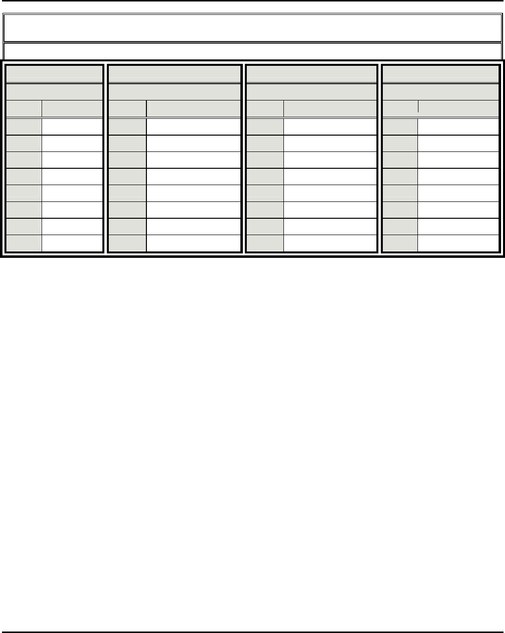
Page 32 Issue 1.0 December, 2003
Form 02 - Night Ringing And Ringing Line Preference Assignment
Ring Type : Linear / Circular / Hunt / Private / Common See Form 35-CO-08
Line 1 Line 2 Line 3 Line 4
Form 02- 01- Form 02- 02 Form 02- 03 Form 02- 04
Item Extension ITem Extension ITem Extension Item Extension
01 01 01 01
02 02 02 02
03 03 03 03
04 04 04 04
05 05 05 05
06 06 06 06
07 07 07 07
08 08 08 08
Any station programmed on a line will immediately be connected to it when the handset is lifted or the speaker
button is pressed. It also controls ringing assignments as per form 35-CO-08 (Linear, Circular, Private, Common).
The total number of stations that will ring is determined by Form 29-CO-05.
Some examples:
IF stations 11 through 18 are programmed on Form 02-01,
AND Form 35-CO-08 is programmed as 0,
AND Form 29-CO-05 is programmed as 8,
THEN Incoming calls on line 1 will ring ON Extensions 11 through 18 and any station
will be directly connected to an incoming call if they lift the handset or press the speaker button.
IF station 11 is the only station programmed on Form 02-01,
AND Form 35-CO-08 is programmed as 0,
AND Form 29-CO-05 is programmed as 1,
THEN Incoming calls on line 1 will ring ON Extensions 11 only AND only extension 11 will be directly
connected to an incoming call when he lifts the handset or presses the speaker button.
SK-408 Programming Forms Manual
Page 33
Form 03 - Door Phone Ringing Assignment Form
Form 03- Door Phone 01
Item 01 02 03 04 05 06 07 08
Station
A Door phone can be programmed to ring up to eight telephone sets. The first station to answer a call from a Door
phone is automatically connected to the Door phone and all other stations are excluded from the conversation.
Note: Door phones may not be connected to outside telephone lines. They may not be involved in any station
conference. They may not be transferred.
Any station can contact the Door phone by dialing 88 for Door phone
Form 04 - Console Assignment Form
Form 04- Console Group 01 Form 04- Console Group 05
Item 01 02 03 04 Item 01 02 03 04
STation STation
Form 04- Console Group 02 Form 04- Console Group 06
Item 01 02 03 04 Item 01 02 03 04
STation STation
Form 04- Console Group 03 Form 04- Console Group 07
Item 01 02 03 04 Item 01 02 03 04
STation STation
Form 04- Console Group 04 Form 04- Console Group 08
Item 01 02 03 04 Item 01 02 03 04
STation STation
Extension numbers can be put in to determine what stations will be considered system Operators. Extension
numbers that appear in a group will ring when another station in the same group Dials 0. When a station dials 0,
the routing is controlled by the setting of Form 41-Station-01. Please see Form 41 for more information.
System Default has Group 01 programmed with Extensions 11, 12, 13, and 14 as system consoles.
Page 34 Issue 1.0 December, 2003
Form 05-01 System Parameters Form - Timers-1
Form 05-01- 01 02 03 04 05 06 07 08
Item
Options 0-9 0-9 0-9 0-9 0-9 0-9 0-9 0-9
Default 1 1 1 1 5 2 2 1
ITem 01 - Hold Recall Timer When a call on hold is not retrieved prior to this setting, the station that
held the call will start ringing.
ITem 02 - Exclusive Hold Recall Timer Same as Item 01 but applies to calls held on Exclusive
Hold
ITem 03 - Hold Recall Timeout If Item 01 or 02 above expire, the system waits this amount of time
and then rings the Attendant Console.
0=30 seconds 1=60 seconds 2=90 seconds 3=120 seconds 4=150 seconds
5=180 seconds 6=210 seconds 7=240 seconds 8=253seconds 9=NONE
Item 04 - Delayed DISA Access Time Determines how long the system will wait before answering a
CO line that is marked as a DISA line
0=1 second 1=3 seconds 2=5 seconds 3=7 seconds 4=9 seconds
5=16 seconds 6=31 seconds 7=61 seconds 8=121 seconds 9=255 seconds
Item 05 - Busy Reminder Tone Interval Determines the length of time between muted ring signals
for an electronic set when an outside call is ringing or when a call has been transferred to the
set.
0=0 seconds 1=2 seconds 2=4 seconds 3=6 seconds 4=8 seconds
5=15 seconds 6=30 seconds 7=60 seconds 8=120 seconds 9=254 seconds
ITem 06 - (Dialing) Pause Time Duration (ms. = milliseconds) Time that elapses before speed
dial begins dialing on an outside line. The length of time represented by a P in speed dial
entries.
0=400 ms. 1=600 ms. 2=800 ms. 3=1000 ms. 4=1200 ms.
5=1400 ms. 6=1600 ms. 7=1800 ms. 8=2000 ms. 9=2200 ms.
Item 07 - DTMF Generation Time (ms. = milliseconds) Length of DTMF signals generated by
speed dial or by Electronic sets when dialing.
0=50 ms. 1=66 ms. 2=84 ms. 3=100 ms. 4=115 ms.
5=132 ms. 6=150 ms. 7=165 ms. 8=180 ms. 9=195 ms.
Item 08 - (No Answer) Call Forward Transfer Time Time that will elapse before a call is
forwarded when Call Forwarding-No Answer is active on a station.
0=10 seconds 1=20 seconds 2=30 seconds 3=40 seconds 4=50 seconds
5=60 seconds 6=70 seconds 7=80 seconds 8=90 seconds 9=100 seconds
SK-408 Programming Forms Manual
Page 35
Form 05-02 System Parameters Form - Timers-2
Form 05-02-T 01 02 03 04 05 06 07 08
Item
Options 0-9 0-9 0-9 0-9 0-9 0-9 0-9 0-9
Default 3 6 1 8 4 3 2 6
Item 01 - Single Line Telephone - Dial Tone Timeout Length of time that the system will wait for
the first digit to be dialed by a single line telephone.
Item 02 - Single Line Telephone - Inter-Digit Timeout Length of time that the system waits for
additional digits. Systems resources will be released after this timer.
0=1 second 1=3 seconds 2=5 seconds 3=7 seconds 4=9 seconds
5=16 seconds 6=31 seconds 7=61 seconds 8=121 seconds 9=255 seconds
ITem 03 - Auto Redial Off Hook Duration (Wait) Timer How long a station will stay off hook during
the Auto Redial function.
0=1 second 1=10 seconds 2=20 seconds 3=30 seconds 4=40 seconds
5=50 seconds 6=60 seconds 7=70 seconds 8=80 seconds 9=90 seconds
Item 04 - Single Line Telephone Release (Disconnect) Time An open loop condition longer than
this parameter is considered a hang-up (disconnect).
0=40 ms. 1=80 ms. 2=120 ms. 3=400 ms. 4=600 ms.
5=800 ms. 6=1000 ms. 7=1200 ms. 8=1400 ms. 9=1600 ms.
Item 05 - Key Telephone Flash Timer (ms. = milliseconds) This parameter determines the length
of an open loop (flash) condition that will occur on a CO line when an outside flash command is
given to the KSU.
0=80 ms. 1=120 ms. 2=160 ms. 3=440 ms. 4=640 ms.
5=840 ms. 6=1040 ms. 7=1240 ms. 8=1440 ms. 9=1640 ms.
Item 06 - Single Line Telephone (Hold) Minimum Flash Timer Sets the minimum time that will be
recognized as a flash by a single line telephone. Shorter interruptions will be ignored.
0=80 ms. 1=100 ms. 2=200 ms. 3=300 ms. 4=400 ms.
5=500 ms. 6=600 ms. 7=700 ms. 8=800 ms. 9=900 ms.
Item 07 - Minimum Ring Detection (Ring On) Timer (ms. = milliseconds) Minimum ring burst that
must be present for the system to detect an incoming call.
0=120 ms. 1=160 ms. 2=240 ms. 3=360 ms. 4=440 ms.
5=560 ms. 6=640 ms. 7=760 ms. 8=840 ms. 9=960 ms.
ITem 08 - Ring Cycle (Ring Off) Timer Length of time that the system must have without a ring
signal for the system to stop internal ringing (abandoned calls).
0=2 seconds 1=2 seconds 2=2 seconds 3=3 seconds 4=4 seconds
5=5 seconds 6=6 seconds 7=7 seconds 8=8 seconds 9=9 seconds
Page 36 Issue 1.0 December, 2003
Form 05-03 System Parameters Form - Codes-1
Form 05-03-C 01 02 03 04 05 06 07 08
Code
Options 0 - 1 0 - 1 0 - 1 0 - 9 0 - 9 2 - 4 0 - 1 1
Default 0 0 0 9 0 2 0 1
Code 01 - Pulse Dial - Make / Break Ratio Dial Pulse
Ratio. 0=33/67 1=40/60
Code 02 - Automatic CO Line Search During Speed
Dial, Auto Redial, Saved Redial, etc. 0=Enabled 1=Disabled
Code 03 -Intercom Call Signaling to Electronic
Telephone Set) 0=Voice Signaling 1=Tone
Signaling
Code 04 - PABX (Centrex) Outgoing Code (Reference
Form 35-CO-01) Actual Digit Programmed 0=0, 1=1,
2=2, 3=3, 4=4, 5=5, etc.
Code 05 - Toll Access Code Actual Digit Entered 0=0, 1=1, 2=2, 3=3, etc.
Code 06 - Station Number Digit
Length 2=2 digit length 3=3 digit length 4=4 digit length
Code 07 - SLT Dial Tone Options 0= Normal Dial Tone (When Idle).
Interrupted Dial tone on DND, Transfer Dial Tone or
Call Forward All Calls Active
Special Dial Tone presented if Message Waiting
active.
1= Interrupted Dial Tone (Idle)
Normal dial tone (DND, Transfer,
Call Forwarding All Calls
Special Dial tone (MW Active)
2=Same as 0 except no special dial tone on MW.
3= Same as 1 except no special dial
tone on MW.
Code 08 -Doorphone Ringing Frequency. Selections from 0 through 9 are valid.
05-03-04 PABX ([Centrex]) Outgoing Code) determines the code that is dialed to obtain “beyond Centrex” dial
tone. This is used to determine if a call is a “behind Centrex” call or a “beyond Centrex” call. It is only applicable if
Form 35-CO-01 is programmed as a 1, indicating that the CO trunk is connected behind a Centrex system. In such
conditions, “behind Centrex” calls will not be monitored for toll violations and SMDR purposes.
05-03-05 (Toll Access Code) determines the first digit that is checked for verification of a toll call. This has no
effect on toll restriction within the system. It is only used to notify SMDR that a particular call is a toll call.
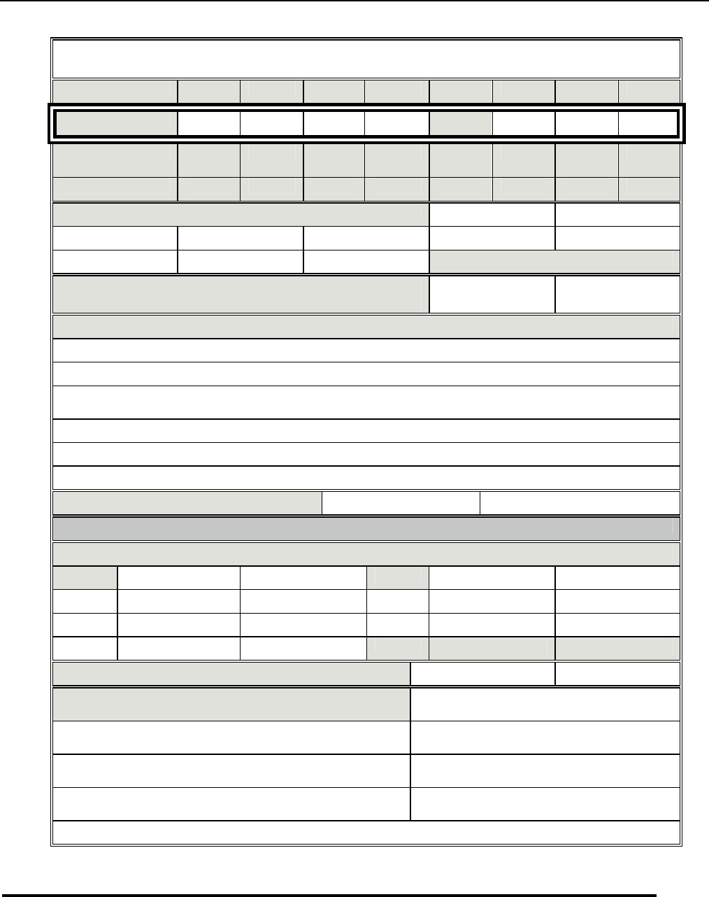
SK-408 Programming Forms Manual
Page 37
Form 05-04 System Parameters Form - Codes-2
Form 05-04-T 01 02 03 04 05 06 07 08
Item
Options 0 - 9 0 - 1 0 - 2
5 - 7 0 - 1 0 0 - 4 0 - 1 1 - 2
Default 0 1 0 0 0 1 0 1
ITem 01 - Callback Message Cancel Timer 0=Non Canceling 1=1 Hour
2=3 Hours 3=6 Hours 4=9 Hours 5=12 Hours 6=15 Hours
7=18 Hours 8=21 Hours 9=24 Hours
ITem 02 - Dial 9 (Hybrid) Activation Turns on Dial 9
(pooled CO lines). 0=Disable 1=Enable
Item 03 - Call Limit Type
0=Continuous Warning After Timeout (Outgoing).
1=1 Second Warning at Duration Limit (Outgoing).
2=1 Second Tone 10 seconds Prior to Timeout. Continuous Tone 5 seconds prior.
Line is released at Timeout (Outgoing).
5=Same as 1 above, except affects both Incoming and Outgoing.
6=Same as 2 above, except affects both Incoming and Outgoing.
7=Same as 3 above, except affects both Incoming and Outgoing.
Item 04 - Time Format Display 0=12 Hour AM/PM 1=24 Hour 00:00-23:59
Item 05 - Reserved
Item 06 - Speed Dial Distribution
System Personal System Personal
0 100 Sets 500 Sets 3 400 Sets 200 Sets
1 200 Sets 400 Sets 4 500 Sets 100 Sets
2 300 Sets 300 Sets
ITem 07 - Intercom Single Digit Dialing 0=Disabled 1=Enabled
ITem 08 - Message Waiting (MW) Status 0= Disable All Message Waiting
indications.
1=MW Ring - Route recipient to message originator.
(Day and Night) 2=MW - Route to VSU. (Day and Night)
3=250 millisecond ring every 5 minutes. (Day and
Night) 4=No MW during Night Service
5=No MW Ringing During Night Service Route To
originator during Day Service. 6=No MW During Night Service. Route
to VSU during day Service.
7=Disable 250 millisecond ring burst during night service (not currently used).
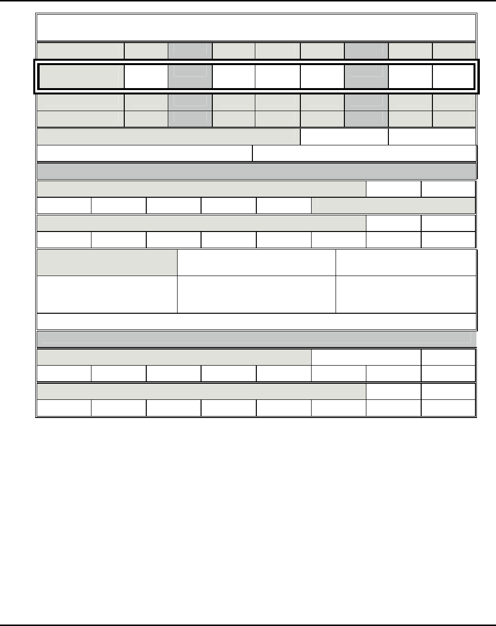
Page 38 Issue 1.0 December, 2003
Form 05-05 System Parameters Form - Codes-3
Form 05-05-T 01 02 03 04 05 06 07 08
Item
Options 0 - 1 0 0 - 6 0 - 9 0 1 0 - 9 0 - 9
Default 1 0 0 0 0 1 1 0
ITem 01 - Wake Up Call Signaling 0=VSU 1=DND Tone
2=Use VSU and use SMDR to print status 3=DND Tone and SMDR to print status
ITem 02 - Reserved
ITem 03 - Speed Dial Unrestricted (Hundreds Group) 0=000 1=100
2=200 3=300 4=400 5=500 6=600
ITem 04 - Speed Dial Unrestricted (Tens Group) 0=00 1=10
2=20 3=30 4-=40 5=50 6=60 7=70 8=80 9=90
Item 05 - Name Function 0=No Names Used 1=Display Names for
Extensions
2=Name Speed Dial. (Allow
Dial by Name Speed Dial
only)
3=Name Extensions & Speed Dial
(Dial by Name) 5=Name Display and Dial by
name for Extensions only
7=Enable Name display and speed Dial. Enabled Dial by name for Extensions and Speed Dial
Item 06 - Reserved
Item 07 - Auto Redial Attempts 0=Disabled 1=10
2=20 3=30 4=40 5=50 6=60 7=70 8=80 9=90
Item 08 - Auto Redial Inter-Call Timer (seconds) 0=10 1=20
2=30 3=40 4=50 5=60 6=70 7=80 8=90 9=100
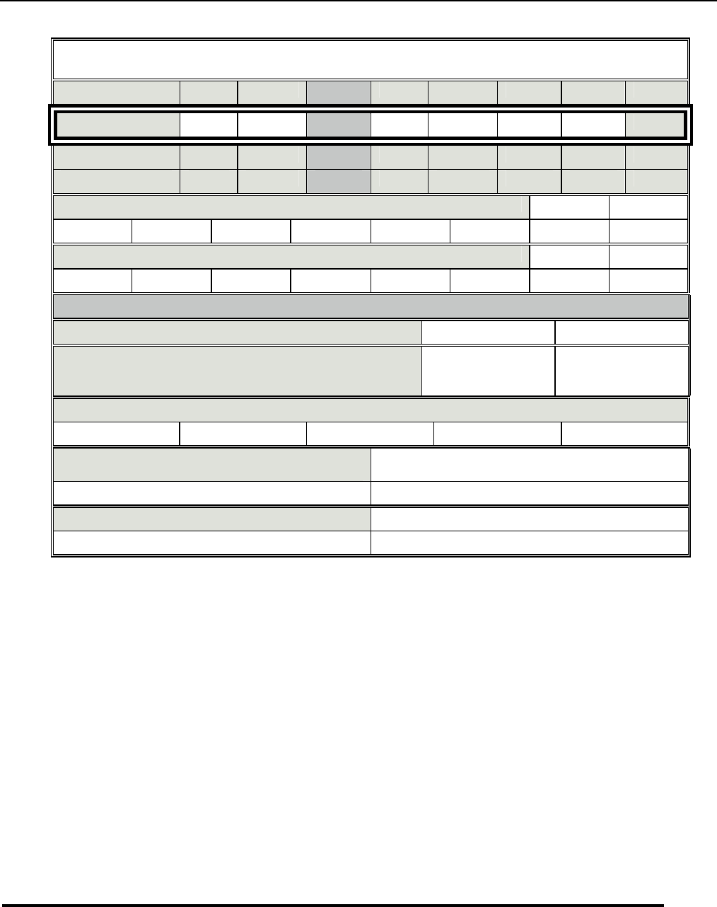
SK-408 Programming Forms Manual
Page 39
Form 05-06 System Parameters Form - Timer/Codes
Form 05-06-T 01 02 03 04 05 06 07 08
Item
Options 0 - 9 0 - 9 0 0 - 1 0 - 1 0-9 0, 1, 3 0
Default 4 4 0 1 0 3 0 0
ITem 01 - Transfer Recall Timeout-Busy (seconds) 0=5 1=10
2=15 3=20 4=30 5=40 6=50 7=60 8=70 9=None
ITem 02 - Transfer Recall Timeout-No Answer (seconds) 0=5 1=10
2=15 3=20 4=30 5=40 6=50 7=60 8=70 9=None
ITem 03 - Reserved
ITem 04 - Polarity Reverse Detection 0=Enable 1=Disable
ITem 05 - Operator Access Code 0
0 Operator
9 Outside Line
1
9 Operator
0 Outside Line
ITem 06 -CO Disconnect Timer for ECF, Unsupervised Conference, and DISA
0=Disable 1=1 minute 2=2 minutes 3=3 minutes 4-9=4 minutes
ITem 07 - Single Line Telephone Hold
Procedure 0=Flash only
1=Flash +[7] 3=Flash +[7] (System returns tone after Flash)
ITem 08 - Station Hunting Type 0=Disabled
1=Linear Hunting 2=Circular Ring
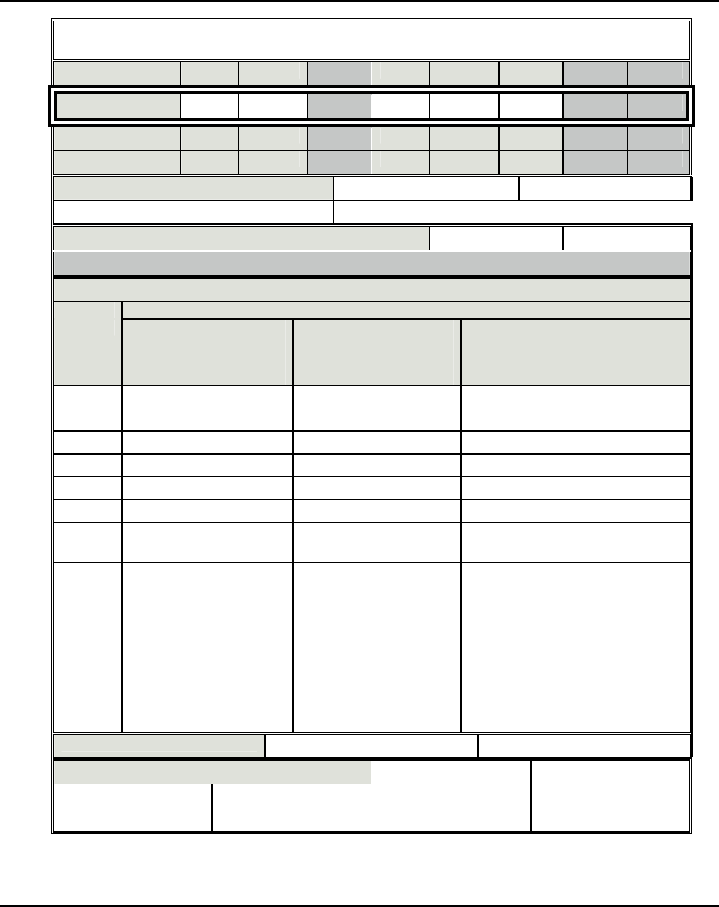
Page 40 Issue 1.0 December, 2003
Form 05-07 System Parameters Form - Timer/Codes
Form 05-07-T 01 02 03 04 05 06 07 08
Item
Options 0 - 1 0 - 1 0 0 - 1 0 - 7 0 - 9 0 0
Default 0 0 0 0 0 0 0 0
ITem 01 - Intercom Step Call 0=Disable 1=Enable on Busy
2=Enable on No Answer 3=Enable on Busy and No Answer
ITem 02 - SLT Calling Proof 0=Disable 1=Enable
ITem 03 - Reserved
ITem 04 - DISA Operator Recall Capability (No Digits Dialed)
Setting Situation
No dialing after the
first voice
announcement from
the VSU.
The VSU has
announced that the
called station is busy
or no answer
The VSU has already
announced the invalid number
or a dialed number that has not
been received completely.
0=
1= T
2= T
3= T T
4= T
5= T T
6= T T
7= T T T
Note “
” = Transfer the
incoming call to console
“T”=System will
announce VSU function
06 (if programmed) to
the incoming call if no
digits dialed timer has
expired. System
releases call (hangs up).
“
”=See Form 46-ST-
04
“T”=See Form 46-ST-
04. If 46-ST-04 is no
recall to operator, VSU
function 06 will be
played to the caller (if
programmed). System
will release call (hang
up).
“
”= System will transfer
incoming caller to system operator
if 05-08-07 has expired.
“T”=System will play VSU
function 06 (if programmed) to the
caller if 05-08-07 has expired.
System will release the call (hang
up).
ITem 05 - EKT Calling Proof 0=Disable 1=Enable
ITem 06 - SMDR Dialed Number Print 0=Print All Digits 1=Print 1st digit
2=Print First 2 digits. 3=Print First 3 digits 4=Print First 4 digits 5=Print First 5 digits
6=Print First 6 digits 7=Print First 7 digits 8=Print First 8 digits 9=Print First 9 digits
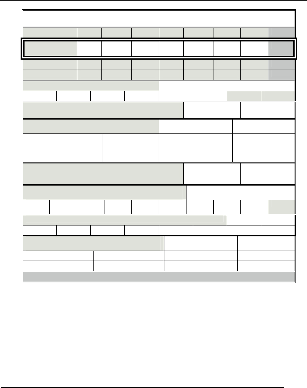
SK-408 Programming Forms Manual
Page 41
Form 05-08 System Parameters Form - Timer/Codes
Form 05-08-T 01 02 03 04 05 06 07 08
Item
Options 0 - 9 0 - 1 0 - 8 0 - 1 0 - 9 0 - 9 0-9 0
Default 5 0 0 0 7 1 7 0
ITem 01 - CO HUNT Interval (seconds) 0=0 1=2 2=4 3=6
4=8 5=15 6=30 7=60 8=120 9=250
Item 02 - Direct CO Access Access CO lines outside of a
station’s Dial 9 group 0=Disable 1=Enable
ITem 03 - SLT Busy Remind Tone Timer 0=Disable 1=1 X Value of
Form 05-01-05
2=2 X Value of
Form 05-01-05 3=3 X Value of
Form 05-01-05 4=4 X Value of
Form 05-01-05 5=5 X Value of
Form 05-01-05
6=6 X Value of
Form 05-01-05 7=7 X Value of
Form 05-01-05 7=7 X Value of
Form 05-01-05 8=8 X Value of
Form 05-01-05
ITem 04 - DISA Operator Recall Location
(No Answer) 0=Recall to
Console Group of
Dialed Station
1=Recall to CO
line Console
Group.
ITem 05 - SLT Feature Programming Access Code First
Digit (See Note Below) 0=Feature Programming of Single
Line Telephones Disabled
1=1 2=2 3=3 4=4 5=5 6=6 7=7 8=[*][#]
[7} 9=[*][#]
[8]
ITem 06 - DISA No Answer Recall Timer (seconds) 0=8 1=16
2=24 3=32 4=40 5=48 6=56 7=64 8=72 9=80
ITem 07 -DISA Transfer Time (No Digits Dialed)
Transfer to Console 0=No Expiration Timer
Invoked 1 = 1 second
2 = 2 seconds 3 = 3 seconds 4 = 4 seconds 5 = 5 seconds
6 = 6 seconds 7 = 7 seconds 8 = 8 seconds 9 = 9 seconds
Item 08 - Reserved
Note: For example If the setting of 05-08-05 is 1, DND is 1051.
If the setting is 2, DND 2051
If the setting is 0, Single Line Telephones cannot do programming.
If the setting is 8, DND is *#7051
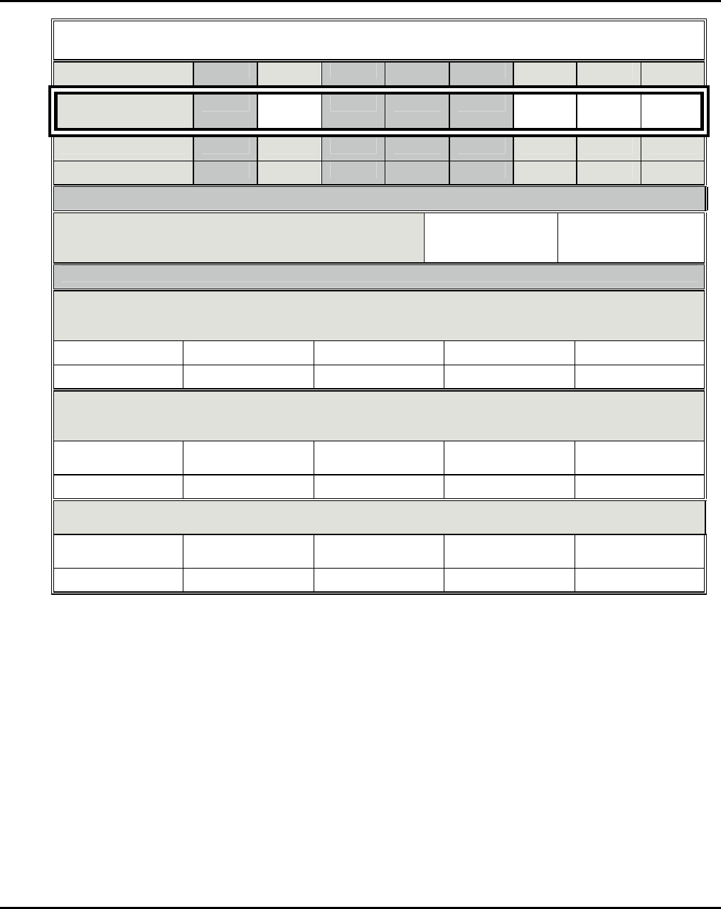
Page 42 Issue 1.0 December, 2003
Form 05-09 System Parameters Form - Misc.
Form 05-09-T 01 02 03 04 05 06 07 08
ITem
Options 0 0 - 1 0-9 0 0 0 0 0
Default 0 1 0 0 0 0 0 0
ITem 01 Reserved
ITem 02 - Console Automatic Queuing If enabled, Dial
0 calls will queue to busy consoles. If disabled, station
users dialing 0 to a busy console will hear busy tone.
0=Disable 1=Enable
ITem 03-05 Reserved
ITem 06 - UCD Enable Time When the Console operator or assigned ringing stations are busy, the
incoming call will be answered by the VSU after the assigned time. The UCD message will be played
and the caller queued to the assigned stations or Operator and placed on hold.
0=5 seconds 1=10 seconds 2=15 seconds 3=20 seconds 4=25 seconds
5=30 seconds 6=35 seconds 7=40 seconds 8=45 seconds 9=50 seconds
Item 07 - UCD Hold Recall Time After the assigned time duration, if a station in the hunt group or the
system operator has not become free, the caller will recall the VSU and VSU 2nd UCD recording will
be played. This time sets the hold value.
0=disabled (Does
not recall) 1=30 seconds 2=45 seconds 3=60 seconds 4=75 seconds
5=90 seconds 6=105 seconds 7=120 seconds 8=135 seconds 9-150 seconds
ITem 08 - UCD Duration Time If a call has not been answered by a live person by the time this timer
expires, the system will disconnect the outside caller.
0=No Disconnect
Timer 1=5 minutes 2=10 minutes 3=15 minutes 4=20 minutes
5=25 minutes 6=30 minutes 7=35 minutes 8=40 minutes 9=45 minutes

SK-408 Programming Forms Manual
Page 43
Form 05-10 Voice Mail Leading Digits
Form 05-10-T 01 02 03 04 05 06 07 08
Item
Default d d d d d d d d
Form 05-10-01 through 05-10-08 allows programming of treatment digits that are outpulsed over a Voice Mail port
(as defined on Form 43-Port-02) when a call is routed to the Voice Mail port due to call forwarding. The information
on this form is outpulsed in DTMF format, followed by the extension number of the station from where the call is
forwarded. Valid entries on this form include 0-9, *, #, p(ause), and d(on't care). All trailing entries should be filled
with don't care entries. Don't care entries are programmed by pressing the TSF (transfer) key. Pause entries are
entered by pressing HOLD.
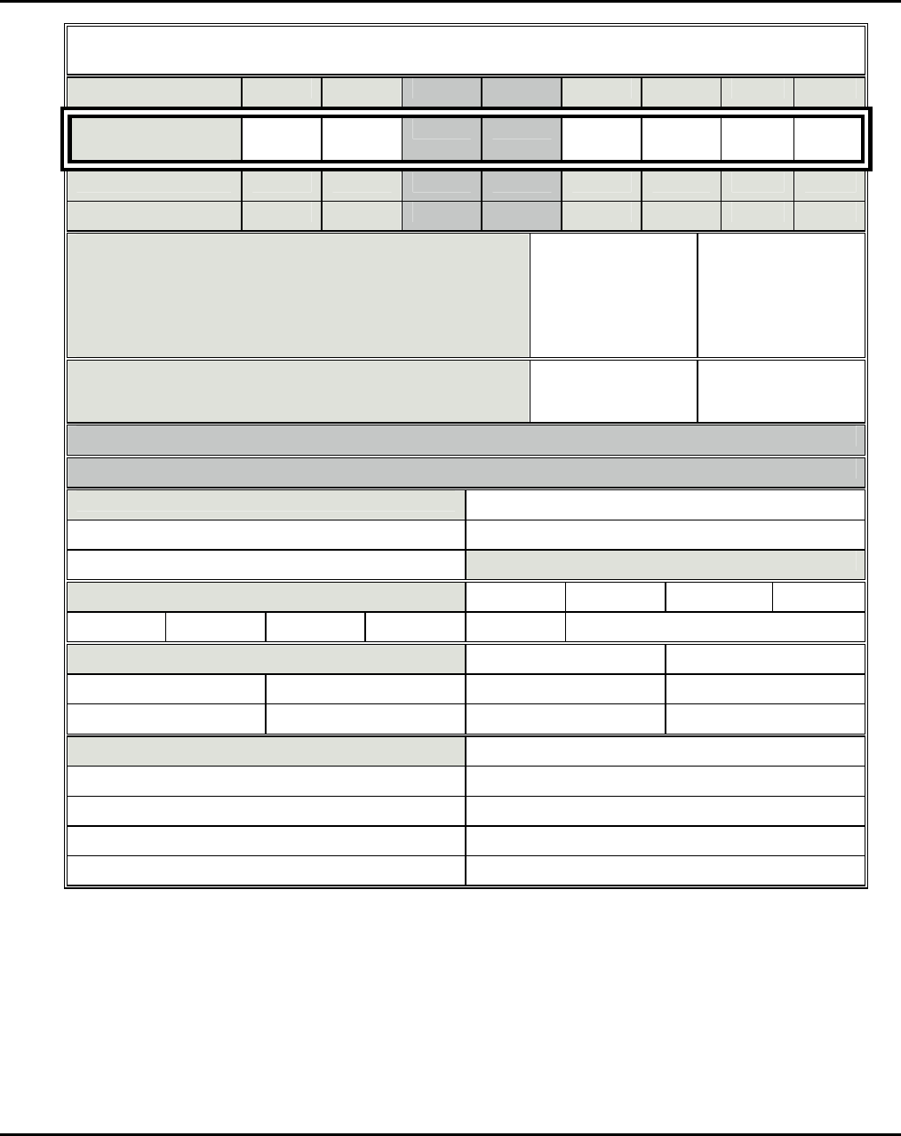
Page 44 Issue 1.0 December, 2003
Form 05-11 System Parameters Form - Supplemental.
Form 05-11-T 01 02 03 04 05 06 07 08
Item
Options 0 - 1 0 0 0 0-3 0-9 0-9 0-8
Default 1 0 0 0 0 0 1 0
ITem 01 - Power Up Volume Adjust When enabled, the
volume level settings of electronic sets are stored in the
KSU. When the power is interrupted, the system will
restore the programmed settings. If disabled, electronic
sets will return to their default factory set levels after a
power failure.
0=Disabled 1=Enabled
ITem 02 - DISA Password 24 sets When enabled,
forced Account Codes 17-25 through 17-48 are used as
additional DISA passwords
0=Disable 1=Enable
Item 03 Reserved
Item 04 Reserved
ITem 05 - DISA Digit Acceptance 0=All special digits valid
1=[*],[#] Special - [8],[9] Digits only 2=[8],[9] Special - [*],[#] Digits Only
3=No Special Digits
ITem 06 - DISA Transfer Count 0=2 1=3 2=4 3=5
4=6 5=7 6=8 7=9 8=10 9=Infinite
ITem 07 - Door Phone Ring Timer 0=5 seconds 1=10 seconds
2=15 seconds 3=20 seconds 4=25 seconds 5=30 seconds
6=35 seconds 7=40 seconds 8=45 seconds 9=50 seconds
ITem 08 - DISA Single Digit Dialing 0=No Single Digit Dialing
1=Single Digit Group 1 2=Single Digit Group 2
3=Single Digit Group 3 4=Single Digit Group 4
5=Single Digit Group 5 6=Single Digit Group 6
7=Single Digit Group 7 8=Single Digit Group 8
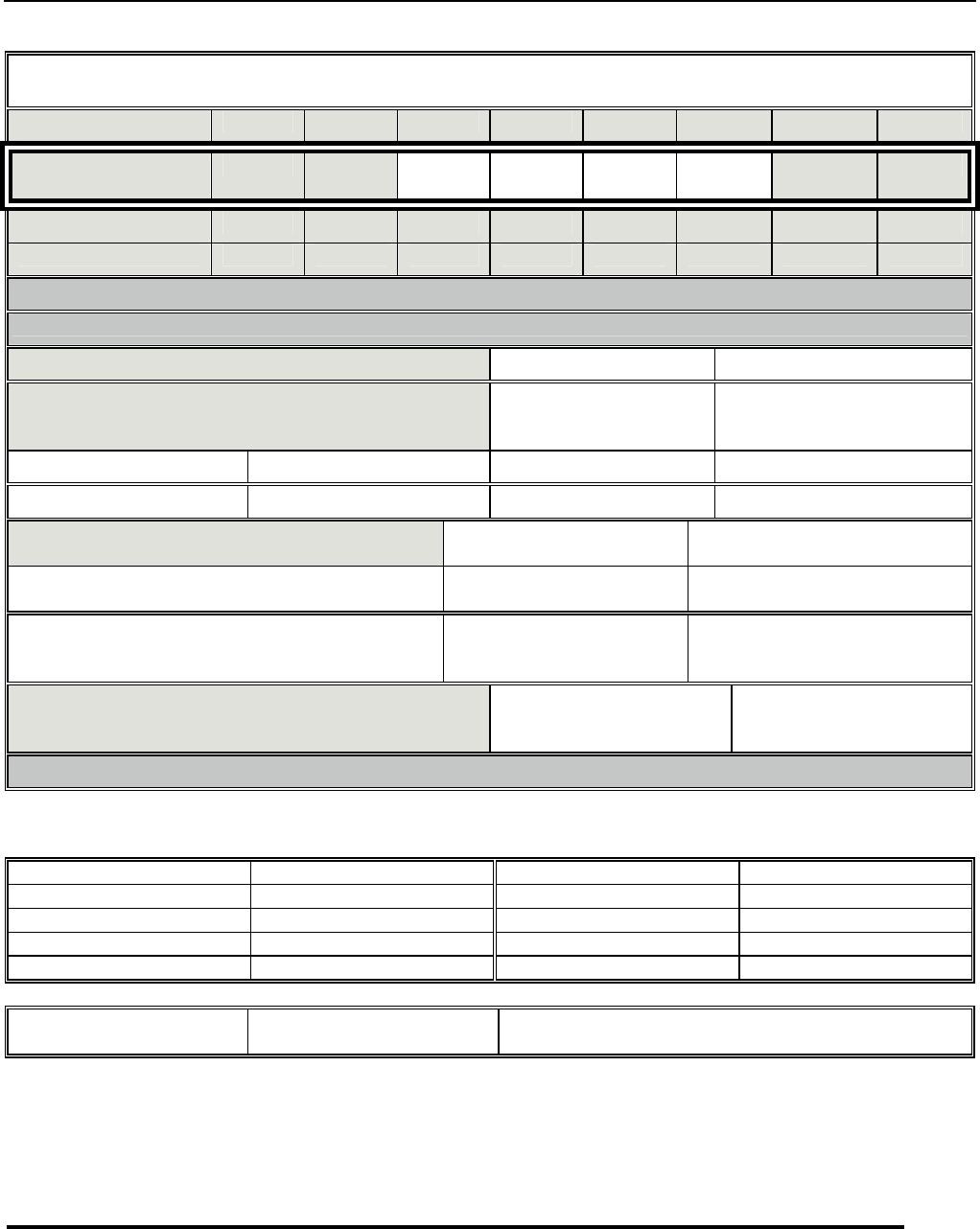
SK-408 Programming Forms Manual
Page 45
Form 05-12 System Parameters Form - Miscellaneous
Form 05-12-T 01 02 03 04 05 06 07 08
Item
Options 0 0 0-1 0 - 4 0-1 0 0 0
Default 0 0 0 4 0 0 0 0
ITem 01 - Reserved
ITem 02 - Reserved
ITem 03 - Exclusive Hold 0=Enable 1=Disable
ITem 04 - Door Relay Activation Timer Determines
the length of time that the door strike relay will be kept
on when the door strike release is activated.
0=1 second 1=2 seconds
2=3 seconds 3=4 seconds 4=5 seconds 5=6 seconds
6=7 seconds 7=8 seconds 8=9 seconds 9=10 seconds
ITem 05 - Voice Mail Integration Type 0=Use Form 05-10 DTMF
Not Muted 1=Use 10 Digit Spec.
DTMF Not Muted
2=Use Form 05-10
DTMF Muted 3=Use 10 Digit Spec.
DTMF Muted 4=Same as 0.
5=Use 10 Digit Spec. DTMF Not Muted. Does Not
send Direct CO Call Code. 6=Same As 2 7=Use 10 Digit Spec. DTMF
Muted. Does Not send Direct
CO Call Code.
ITems 06 Trunk Group Access Type Determines the
type of outbound hunt used to access CO lines on dial 9
access.
0=Linear Hunt 1=Circular Hunt
Items 07-08 Reserved
Note: 10 Digit Voice Mail integration is controlled by Form 05-12-05 provides the following information:
Internal Calls Digit String DISA And CO Calls Digit String
CFWD All Calls 11-STB-STA CFWD All Calls 21-STB-TRK
CFWD Busy 12-STB-STA CFWD Busy 22-STB-TRK
CFWD No Answer 13-STB-STA CFWD No Answer 23-STB-TRK
Direct Call to V-Mail Port 14-STA-STA Recall to Voice Mail 25-STB-TRK
Direct Call From Trunk 24-TRK-TRK This digit sequence is played only on incoming calls
when 05-12-05 is set at a value of 1 or 3.
STA=The originating station presented as 4 digits.
STB=The forwarding station presented as 4 digits.
TRK=The CO trunk presented as 4 digits.
In systems using 2 digit numbering plans, the STA and STB fields use leading digits. For example, extension 11
Page 46 Issue 1.0 December, 2003
is presented as 0011, extension 12 is presented as 0012, etc.
In systems using 3 digit numbering plans, the STA and STB fields use leading digits. For example, extension
121 is presented as 0121, extension 122 is presented as 0122, etc.
Systems using 4 digit extension numbering will present all four digits for STA and STB.
TRK is provided as the two digit trunk number (01-04 on SK-408). The field is also filled with leading zeros, so
trunk 01 is presented as 0001, trunk 04 is presented as 0004, etc.
Form 06-01 Relay
Assignment Form
00-10
Valid Settings:
00=Non-Operational (Default) 05=Station Loud Bell
01=Music On Hold 06=System Alarm
02=Door 1 Latch Release 10=All Zone Page
04=CO Line Loud Bell
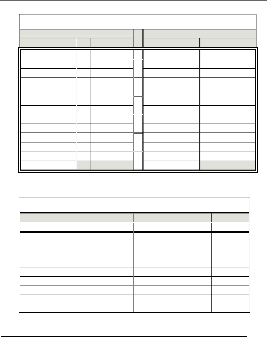
SK-408 Programming Forms Manual
Page 47
Form 07 - Flexible Key Group Assignment
07 - Group (01-08) 07 - Group (01-08)
Key
Function Key
Function Key
Function Key
Function
01 14 01 14
02 15 02 15
03 16 03 16
04 17 04 17
05 18 05 18
06 19 06 19
07 20 07 20
08 21 08 21
09 22 09 22
10 23 10 23
11 24 11 24
12 25 12 25
13 13
Note: Press Volume Down (CHANGE) to switch between DSS (Intercom), CO line, and FN (function key
assignment) capability during system programming.
Form 07 Key Assignment Parameters
Description Entry Description Entry
CO Lines 01-08 CO:XX Any valid Station Number XXXX
Account Code FN:09 Doorphone FN:60
Call Forward FN:53 Do Not Disturb/Conference FN:02
Charge Inquiry FN:19 Help List FN:15
Check In FN:17 Lock/Unlock FN:14
Check Out FN:18 Meet Me Page FN:56
Console Set System Time FN:50 Message Select FN:51
Day / Night Service FN:52 Microphone / Auto Answer FN:04
Department Pickup FN:35 MSG/Pulse To Tone FN:03
Directory Dial Key FN:62 Non-Operational FN:00
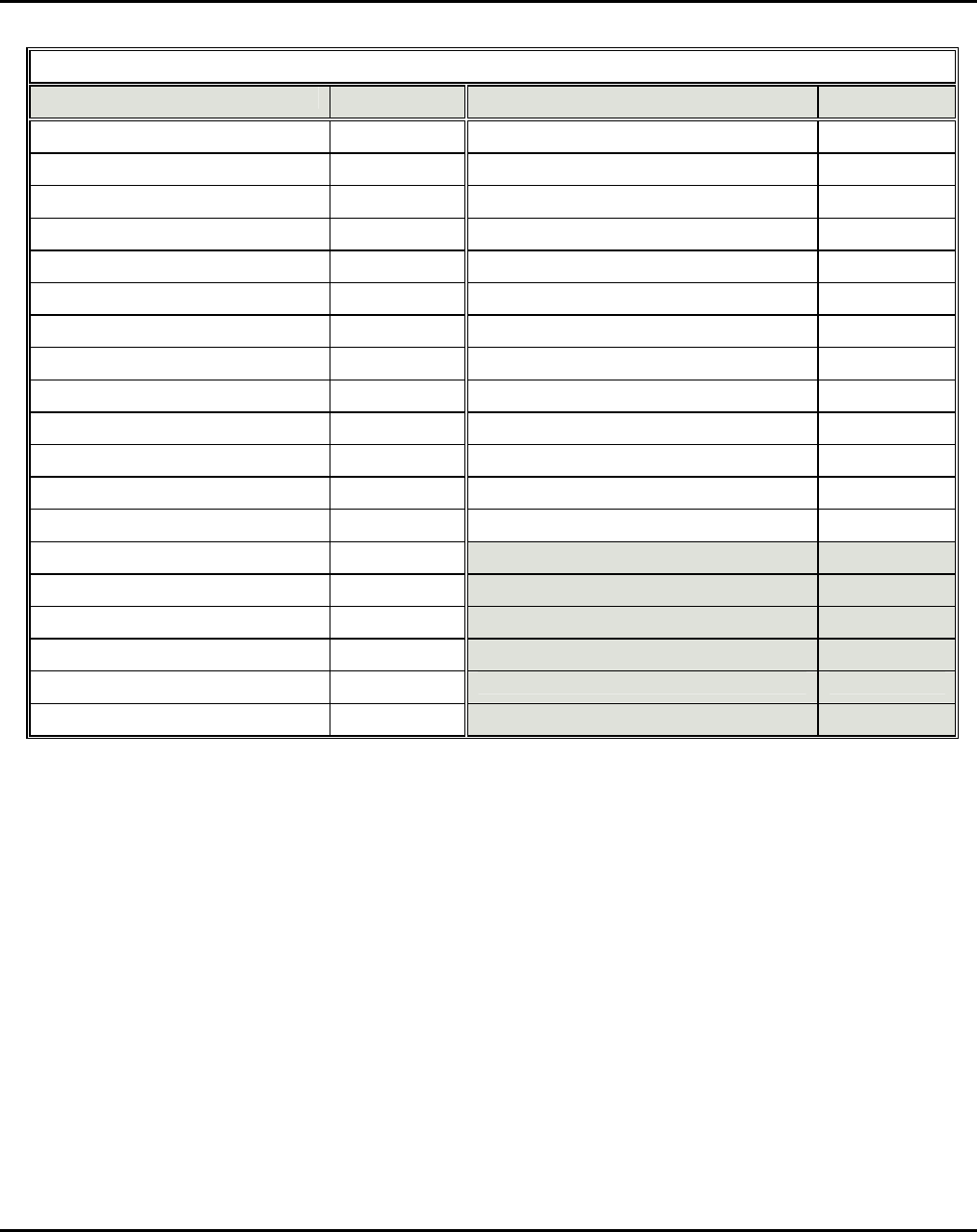
Page 48 Issue 1.0 December, 2003
Form 07 Key Assignment Parameters (continued)
Description Entry Description Entry
Page All (Internal) FN:20 Program FN:01
Paging Zone 1 FN:24 Save FN:06
Paging Zone 2 FN:25 Shift Key FN:57
Paging Zone 3 FN:26 Speed Dial Programming FN:11
Paging Zone 4 FN:27 Speed Dial FN:05
Paging Zone 5 FN:28 Temporary Unlock FN:16
Paging Zone 6 FN:29 Toll Override FN:46
Paging Zone 7 FN:30 Volume Down FN:08
Paging Zone 8 FN:31 Volume Up FN:07
Pickup (All Groups) FN:36 Volume Setup FN:10
Pickup Group FN:37 Wake Up/Reminder Setup (Console) FN:47
Pickup Group 1 FN:38 Wake Up/Reminder Setup (Station) FN:48
Pickup Group 2 FN:39 Zone Paging FN:23
Pickup Group 3 FN:40
Pickup Group 4 FN:41
Pickup Group 5 FN:42
Pickup Group 6 FN:43
Pickup Group 7 FN:44
Pickup Group 8 FN:45
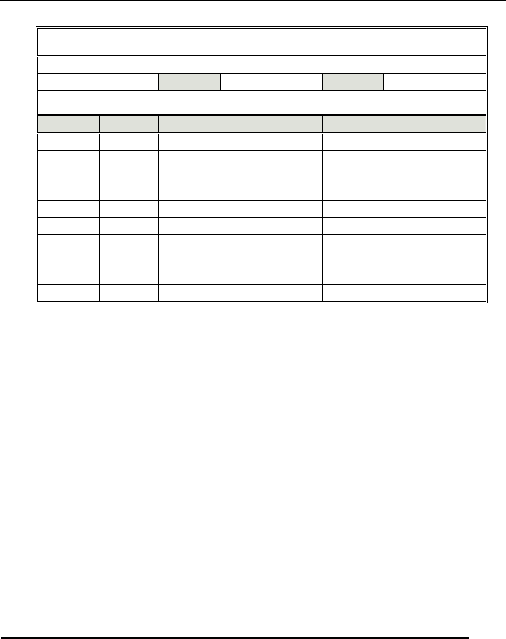
SK-408 Programming Forms Manual
Page 49
Form 09 - System Speed Dial Assignment
Special Characters
HOLD=Pause (p) MIC=Tone (T) TRF/FL=Flash(F)
CHG Key=DSS Key #5
Toggles between Line entry, telephone number entry and name entry.
Bin # 09- TK: ## Number Name
____0
____1
____2
____3
____4
____5
____6
____7
____8
____9
Note: An indication of TK:00 will cause the system to utilize the first free line in a station's dial 9 group.
An indication of 01-08 will cause the system to always select the same CO Line.
Note: To enter a name, press the CHG (Volume Down) key until the letter "N" appears in the upper right
corner of the LCD display. Letters and numbers may be entered through the keypad. For Dial by
name to operate, 05-05-05 must be enabled.
Phone numbers may not exceed 30 digits in length (including special characters). Names may be entered up to 30
characters, but will only be displayed to 16 characters.
Page 50 Issue 1.0 December, 2003
Form 10 - Single Digit Dialing Assignment
Form 10 - Single Digit Group 01 Form 10 - Single Digit Group 02
Item 01 02 03 04 05 Item 01 02 03 04 05
Station
Station
Form 10- Single Digit Group 03 Form 10- Single Digit Group 04
Item 01 02 03 04 05 Item 01 02 03 04 05
Station
Station
Form 10- Single Digit Group 05 Form 10- Single Digit Group 06
Item 01 02 03 04 05 Item 01 02 03 04 05
Station
Station
Form 10- Single Digit Group 07 Form 10- Single Digit Group 08
Item 01 02 03 04 05 Item 01 02 03 04 05
Station
Station
A station with single digit dialing enabled will ring the station number programmed in Item 01 whenever that station
dials 1. It will ring the station number programmed in Item 02 whenever the station dials 2, etc.
Single Digit Dialing is enabled on the system by programming Form 05-04-07 as 1 (Enable).
Any station that is to utilize Single Digit Dialing must be assigned to a Single Digit Dialing Group
on Form 41-STN-01.
DISA Single Digit Dialing is enabled on Form 05-11-08. The group selected will correspond to the table entry on
this form. A setting on 05-11-08 of 0 disables DISA Single Digit Dialing.
Form 11 Date and Time Settings
Form 11 - Date and Time
Item 01 02 03 04 05 06
Station
01= Month 02=Date 03=Year 04=Hour 05=Minute 06=Day of Week
All entries are two digit, except 06 which begins with Sunday as 0, Monday as 1, Tuesday as 2, etc.
SK-408 Programming Forms Manual
Page 51
Form 12 - System Alarm Schedule
Schedule: Alarm Time
(24 Hour Format 00:00-23:59) Duration
(01-98 minutes)
01
02
03
04
05
06
07
08
09
10
Note: A duration of 00 will deactivate a system alarm
Time entry format: 12 midnight until 11:59 AM = 00:00 to 11:59.
12 Noon until 11:59 PM = 12:00 to 23:59.
Form 13 - System Passwords
d(on't care) = DSS Key 4. All other digits are entered from the station keypad.
13-01 System Programming Password
Password
Default d d d d d d d d
13-02 DISA Password
Password
Default 3 4 7 2 d d d` d
13-03 Toll Override Password
Password
Default 8 6 5 5 d d d d
13-04 Monitor Password
Password
Default d d d d d d d d
Page 52 Issue 1.0 December, 2003
Form 14 - Station Message Detail Recording
Form 14 -01- 01 02 03 04 05 06 07 08
Item
Options 0-9 0-1 0-1 0-1 0-1 00-99 0 0-1
Default 0 0 0 0 0 21 0 0
01 - Recording Start Time 0=immediate start 1=5 seconds
2=10 seconds 3=15 Seconds 4=20 Seconds 5=25 Seconds
6=30 Seconds 7=35 Seconds 8=40 Seconds 9=45 Seconds
02 - Record Incoming Calls 0=Enable 1=Disable
03 - Record Local Calls (No Toll Access Code) 0=Enable 1=Disable
04 - Record Unanswered Incoming Calls 0=Enable 1=Disable
05 -Print Page Header 0=Enable 1=Disable
06 - Number of Call Records To be Printed
Between Headers 00 & 01=1 Call Record
02-99=Actual Number Of Call Records Between Headers
ITem 07 - RESERVED
ITem 08 - Detect Polarity Reversal 0=Enable 1=Disable
SK-408 Programming Forms Manual
Page 53
Form 17 - Forced Account Code Assignment
Special Character (DSS Key 4)=d (don't care. Any entry is satisfactory)
Entries less than eight digits should have "d" in all trailing locations, (e.g., 123245ddd).
Code# Actual Code Code# Actual Code
01 25
02 26
03 27
04 28
05 29
06 30
07 31
08 32
09 33
10 34
11 35
12 36
13 37
14 38
15 39
16 40
17 41
18 42
19 43
20 44
21 45
22 46
23 47
24 48
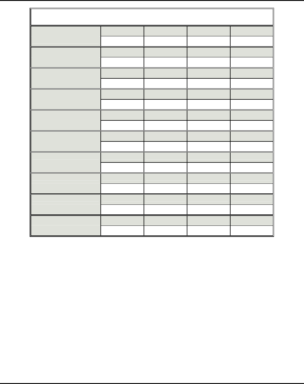
Page 54 Issue 1.0 December, 2003
Form 18 - Toll Plan Assignment
Plan 00 - ITem 01 02 03 04
Plan 01 - ITem 01 02 03 04
Plan 02 - ITem 01 02 03 04
Plan 03 - ITem 01 02 03 04
Plan 04 - ITem 01 02 03 04
Plan 05 - ITem 01 02 03 04
Plan 06 - ITem 01 02 03 04
Plan 07 - ITem 01 02 03 04
Plan 08 - ITem 01 02 03 04
Plan 09 - ITem 01 02 03 04
If this form is used for Form 57, 58, or 59 there are no corresponding Restriction tables (i.e., Form 67, 68, or 69. If
not otherwise specified on Forms 57, 58 or 59, telephones that are subject to toll plans 7,8, and 9 are unable to
place any calls on CO lines.
Note: Each Toll Plan defines the dialing characteristics of a telephone that is assigned the corresponding
Toll Plan number, (e.g., a Station that is programmed as Toll Plan 01 will be subject to the dialing
patterns defined for each of the CO lines in Plan 01. Toll Plan is assigned to a station on Form 41-
STN-05 for definition of Day Service Toll Plan and Form 41-STN-06 for definition of Night Service
Toll Plan.
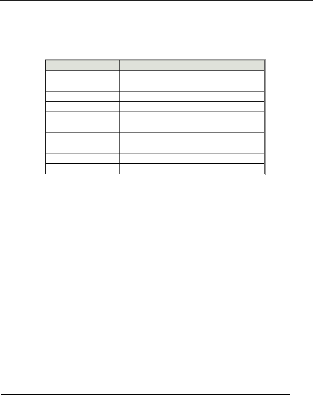
SK-408 Programming Forms Manual
Page 55
Each Toll Plan carries a default value that is equal to the plan number. For example Toll Plan 00 carries all 4 CO
lines with a default value of 0. Toll Plan 01 is set by default with all values at 1, through Toll Plan 09, which carries
a default value of 9.
A Toll Class must be assigned for each line within a Toll Plan.
Toll Class # Characteristics of Toll Class
0 Unrestricted
1 Subject to Form 51 & 61
2 Subject to Form 52 & 62
3 Subject to Form 53 & 63
4 Subject to Form 54 & 64
5 Subject to Form 55 & 65
6 Subject to Form 56 & 66
7 Restricted except for entries made on Form 57
8 Restricted except for entries made on Form 58
9 Restricted except for entries made on Form 59
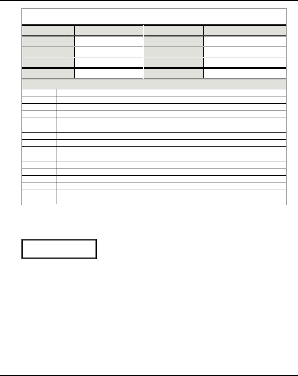
Page 56 Issue 1.0 December, 2003
Form 19 - Voice Service Unit Channel Assignment
Channel/Item Function Number Channel/Item Function Number
19-01 19-05
19-02 19-06
19-03 19-07
19-04 19-08
19-01 - 19-08=Channel Assignments
00 Non-functional (Not Programmed)
01 DISA: Day Main Answer Greeting
02 DISA: Dialed Extension is Busy Message
03 DISA: Dialed Extension does Not Answer
04 DISA: Dialed number is invalid (doesn’t exist)
05 DISA: Console (Operator) is Busy, Please Hold
06 DISA: Timer has Expired
07 DISA: Insufficient Digits Dialed
08 DISA: Night Answer Main Greeting
09 External Call Forward Reroute - Tells callers that call is being routed outside.
10 UCD: Answer Greeting and all stations are busy.
11 UCD: second announcement all stations are busy.
12 UCD: All stations busy. Call timer has expired. Call will be dropped
13 Reserved
14 Wake Up Message
15 SLT Message Waiting Advisory
To record and play voice promptsTo record and play voice prompts:
1. From the operators station, dial 86.
2. LCD display shows:
VOICE PORT (1)
*:REC #:PLAY
3. The number in parenthesis indicates the voice channel number that is presently being programmed.
4. You must record your entire set of messages, one at a time. Press [*] to record. Press 1 to stop recording and
step to the next message section.
5. Repeat step 4 until you have completed all messages you wish to record.
6. To listen to your recording(s), press [#]. The selected message will play. You may step from message to
message by pressing [1].
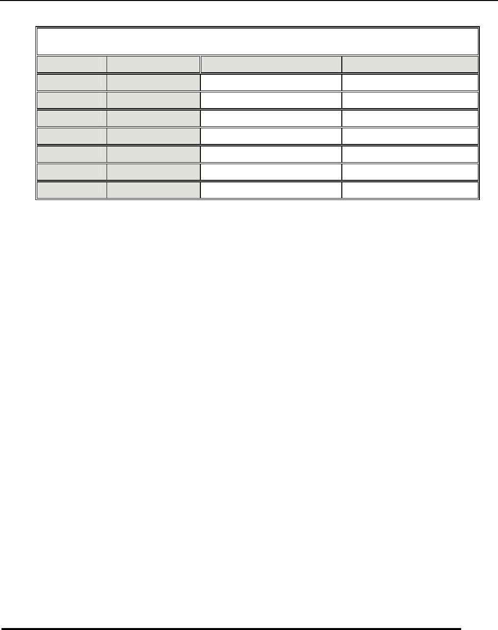
SK-408 Programming Forms Manual
Page 57
Form 20 - Day/Night Service Schedule
Schedule Day Day Service Begin Day Service End
20-00 Sunday
20-01 Monday
20-02 Tuesday
20-03 Wednesday
20-04 Thursday
20-05 Friday
20-06 Saturday
Entries into both Day Service Begin and Day service End must be in 24 hour format:
12:00 Midnight through 11:59 AM = 00:00 through 11:59
12:00 Noon through 11:59 PM = 12:00 through 23:59.
Any interval not covered by Day Service is automatically Night Service:
If Day Service Begin Time is programmed as 08 00
and the Day Service End Time is programmed as 17 00,
Day service will be from 8:00 AM until 5:00 PM.
The system will be in Night Service from 12:00 Midnight until 8:00 AM and again from 5:00 until 12:00
Midnight.
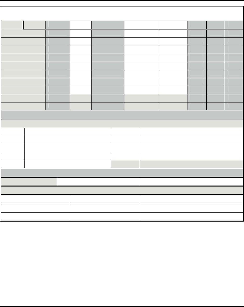
Page 58 Issue 1.0 December, 2003
Form 29 - Line Specifications #1
Line Data 01 02 03 04 05 06 07 08
Line 01
Line 02
Line 03
Line 04
Line 05
Line 06
Line 07
Line 08
Range 0-1 0-1 0-8 0-8
Default 0 1 0 6
01 - Reserved
02 - UCD Function Selection
0 Day Disable - Night Disable 1 Day Disable - Night Enable 1
2 Day Disable - Night Enable 2 3 Day Disable 1 - Night Disable
4 Day Enable 1 - Night Enable 1 5 Day Enable 1 - Night Enable 2
6 Day Enable 2 - Night Disable 7 Day Enable 2 - Night Enable 1
8 Day Enable 2 - Night Enable 2
03 - Reserved
04 - Set Ringing Tone 0=Use station’s default ring 1-8=Use assigned ring cadence
05 - Incoming Call Connect - Rings the number of stations listed in this parameter as per Form 01 or Form 02
0=Ring None 1=Ring first station 2=Ring first two stations
3=Ring first three stations 4=Ring first four stations 5=Ring first 5 stations
6=Ring first 6 stations 7=Ring first 7 stations 8=Ring all stations
Item 04 - Controls the incoming ring cadence. If set to 0, the incoming ring cadence will be the one selected by the
telephone set user. If set to any value from 1 to 8, the cadence will follow the individual cadence and frequency
combinations.
Item 05 - For examples of the operation of Item 05, please see Form 01 and 02.
1: Enable UCD when all stations on Form 01 (Day Service) or Form 02 (Night Service) are busy.
2. Enable UCD and activate UCD message after UCD-01 timer has expired, even if available stations are ringing.
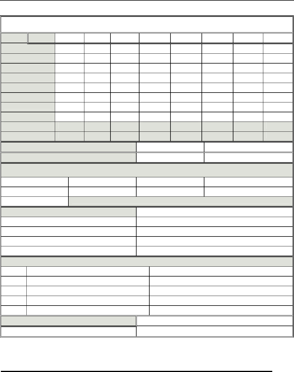
SK-408 Programming Forms Manual
Page 59
Form 35 - CO Line Specifications
Line Data 01 02 03 04 05 06 07 08
Line 01
Line 02
Line 03
Line 04
Line 05
Line 06
Line 07
Line 08
Range 0-1 0-1 0-8 0-8 0-3 0-2 0-3 0-3
Default 0 1 0 0 3 0 0 0
01 - Line Type 0=CO Line 1=Behind PABX
02 - Dial Signaling Type 0=Pulse 1=DTMF
03 - External Call Forwarding Location
(Only applicable if 35-CO-04 is programmed for External Call Forwarding)
0=Not Active 1=Speed Dial 101 2=Speed Dial 102 3=Speed Dial 103
4=Speed Dial 104 5=Speed Dial 105 6=Speed Dial 106 7=Speed Dial 107
8=Speed Dial 108
04 - DISA External Call Forward Status 0=Day Disable/Night Disable
1=Day Disable/Night DISA 2=Day DISA/Night Disable
3=Day DISA/Night DISA 4=Day Disable/Night ECF
5=Day ECF/Night Disable 6=Day ECF/Night ECF
7=Day DISA/Night ECF 8=Day ECF/Night DISA
05 - Line Pick Up Enable (Allows a non-ringing station to answer an incoming call)
Value Day Operation Night Operation
0 Disable Disable
1 Disable Enable
2 Enable Disable
3 Enable Enable
06 - Loud Bell Operation 0=Inoperative
1=Relay #1 2=Relay #2
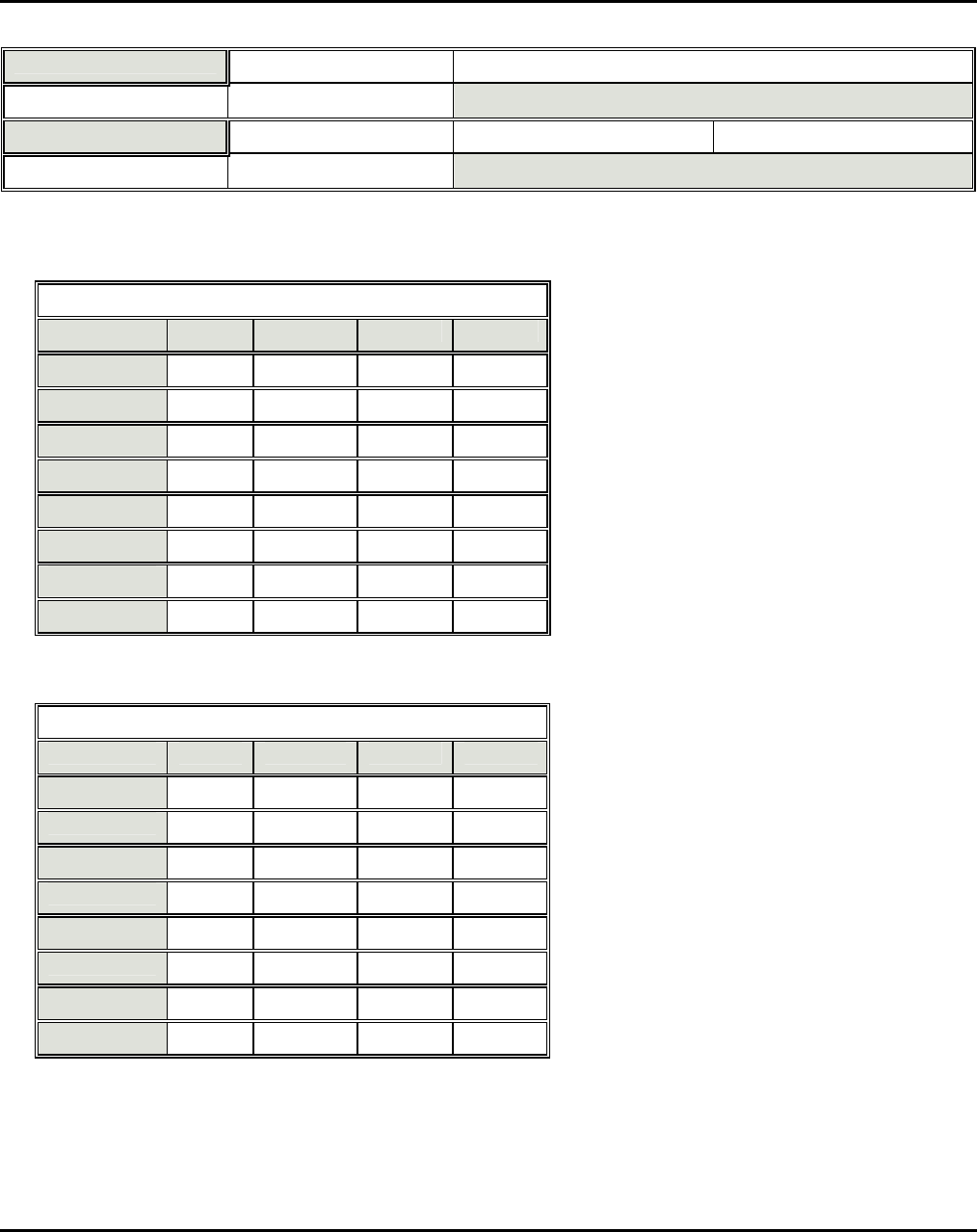
Page 60 Issue 1.0 December, 2003
Form 35 (continued)
07 - Day Ring Type 0=Common Audible 1=Linear 2=Circular
3=Hunt 4=Private Line
08 - Night Ring Type 0=Common Audible 1=Linear 2=Circular
3=Hunt 4=Private Line
Note: Private Line (35-CO-07/08) can be used when only one station is programmed as the ringing
station on Form 01 or 02. When Private Line is enabled, any call forwarding programmed on the
station will be honored by the incoming CO line.
Form 36 - CO Line (Trunk) Groups (Dial 9)
Line Group 01 02 03 04
Group 01
Group 02
Group 03
Group 04
Group 05
Group 06
Group 07
Group 08
Note: Each line group may contain up to four CO lines.
A line may be programmed in any number of Groups.
Form 38 - Alternate CO Line (Trunk) Groups (Dial 87)
Line Group 01 02 03 04
Group 01
Group 02
Group 03
Group 04
Group 05
Group 06
Group 07
Group 08
Note: Each line group may contain up to eight CO lines.
A line may be programmed in any number of Groups.
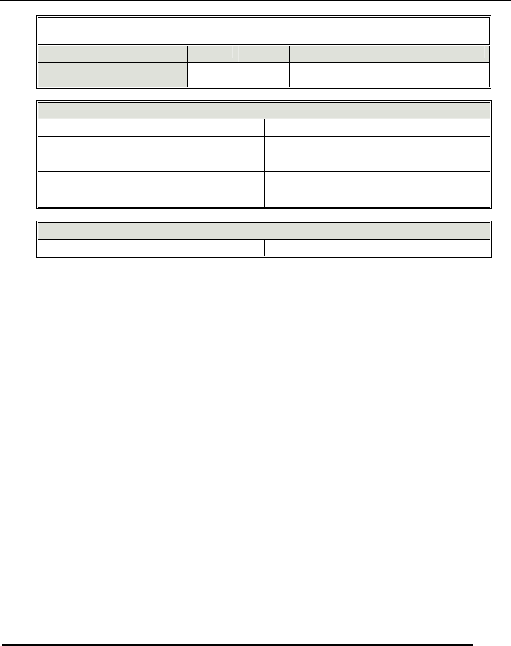
SK-408 Programming Forms Manual
Page 61
Form 39 - Sensor Assignment Form
Form 39-Item- 01 02 Name
Form 39-
Valid Options for Sensor Item Settings 39-01
00=Disabled
01=Latch operation
Requires either an access code to disable or will
reset automatically after 10 minutes if no access
code is dialed.
02=Non-Latching Operation.
Will cause alarm when activated.
Will cease alarm when condition returns to
normal.
Valid Idle Options for Sensor Item Settings 39-02
00= Normally Open 01=Normally Closed
Names or labels may be programmed for each of the system sensors. This name will appear on all LCD displays
whenever the respective alarm is activated. To access the name programming function, press DSS key 3 (CO Line
3) while in Form 39-Sensor. Information on how to enter alphanumeric characters is on page CROSS
REFERENCE of this document.
All stations to be alerted by sensor activation are programmed on Form 17.
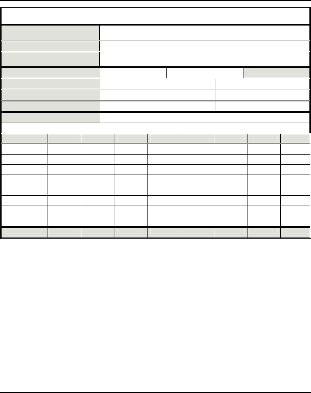
Page 62 Issue 1.0 December, 2003
Form 40 - Station Class of Service (Part 1)
01 - Override/Barge-In Level 0=Unable to Override 1-9= Can Override equal and lower
numbered levels
02 - Monitor Level 0=Unable to Monitor 1-9=Can Monitor lower numbered levels
03 - Call Limit Duration
(See 05-04-03 for limit type) 0=No Duration Limit 1-9=Actual Duration Limit Time (Minutes)
04 - Associated Loud Bell 0=Disabled 1=Relay
05 - Paging Access 0=Enable 1=Disable
06 - Paging Over Speaker 0=Enable 1=Disable
07- Station Lock/Unlock Status 0=Unlocked 1=Locked
08 - Forced Account Code 00=Any Valid Account Code
01-48=Only the corresponding Account Code (01-48) is Valid on this Set
Form 40-STN-
01 02 03 04 05 06 07 08
40-_____
40-_____
40-_____
40-_____
40-_____
40-_____
40-_____
40-_____
Default 1 1 0 0 0 0 0 00
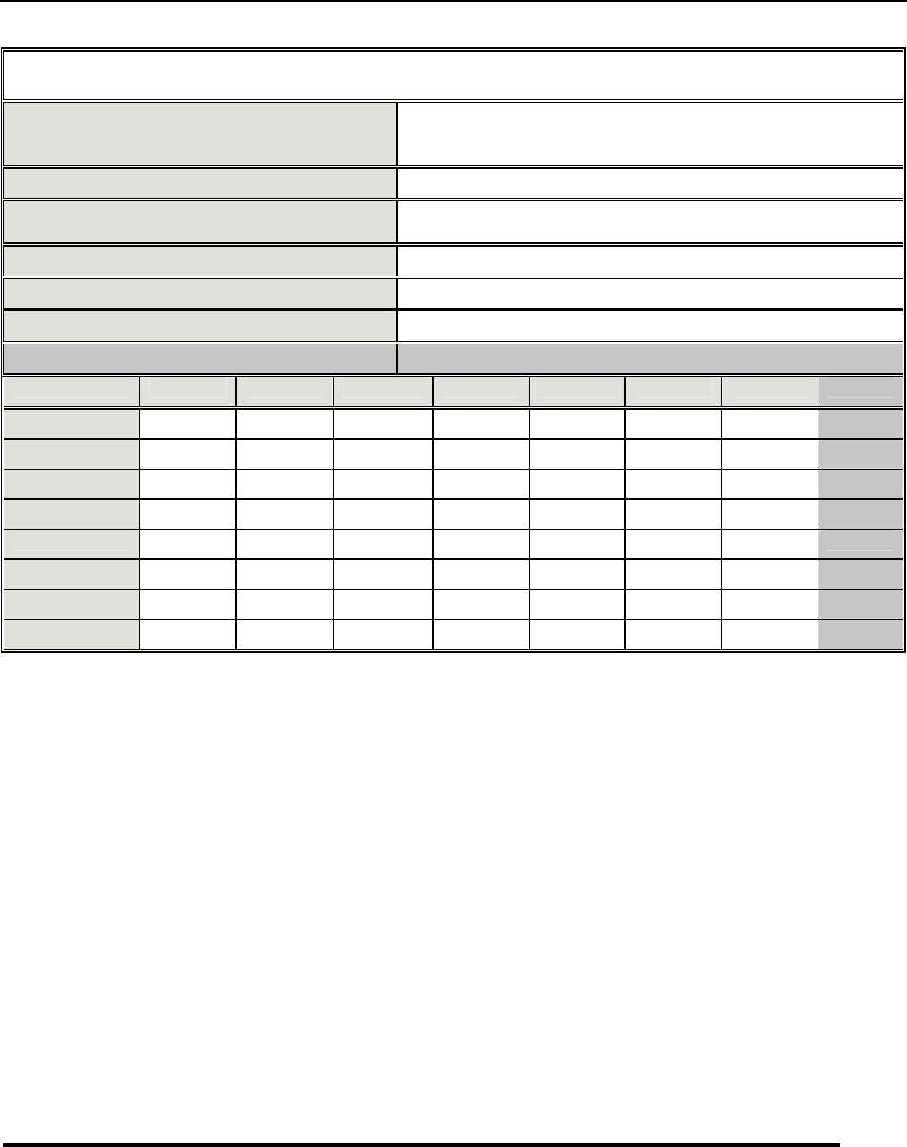
SK-408 Programming Forms Manual
Page 63
Form 41 - Station Specifications
01 - Group Assignment Zone Paging -
Pick Up Group Station Group
Single Digit Dialing Group
1-8 = Valid Group Entries
02 - Flexible Key Group (EKT) 1-8 = Applicable Key Group From Form 07
03 - SHIFT Key Group (EKT) 0 = Disabled
1-8 = Applicable Key Group From Form 07.
04 - Dial 9 Group 1-8 = Applicable Dial 9 Group From Form 36
05 - Toll Plan (Day Service) 0-9 = Applicable Toll Plan
06 - Toll Plan (Night Service) 0-9 = Applicable Toll Plan
07 - Port Number This parameter is not user programmable
41-STN-- 01 02 03 04 05 06 07
41-_____ 11
41-_____ 12
41-_____ 13
41-_____ 14
41-_____ 15
41-_____ 16
41-_____ 17
41-_____ 18
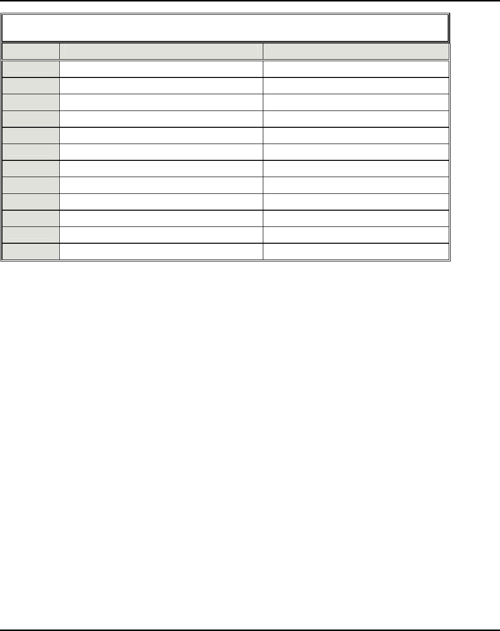
Page 64 Issue 1.0 December, 2003
Form 42 - Personal Speed Dial Table Assignment
Default Numerical -01 DSS -02
42-11-
42-12-
42-13-
42-14-
42-15-
42-16-
42-17-
42-18-
42-19-
42-20-
42-21-
42-22-
Default Information provides the basic two digit default numbering plan for the system.
Numeric allows you to enter the storage Bin Group that you wish to assign for a station to have numeric keypad
speed dialing capability.
DSS permits you to enter a storage Bin Group that you wish to assign for a station to have DSS speed dialing
capability on DSS keys 1 through 10.
Note: Entry of 00 at any location (numeric or DSS) disables speed dialing for that station of the selected
type.
It is possible to assign the same storage Bin Group to more than one station. If more than one station is assigned
the same Bin Group, the stations that share the Bin Group will be able to program the numbers and share the ability
to use them
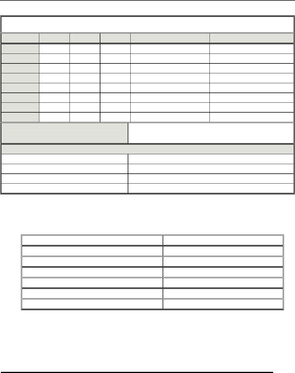
SK-408 Programming Forms Manual
Page 65
Form 43 - Port Assignments
01 02 03 User Name Comments (Optional)
43-01-
43-02-
43-03-
43-04-
43-05-
43-06-
43-07-
43-08-
01 - Station Extension Number Any valid entry: 10-69 (2 digit)
100-699 (3 digit)
1000-6999 (4 digit)
02 - Equipment Type (Recognized by the system Automatically)
0=No Equipment Connected 1=Key Telephone without LCD
2=Key Telephone with LCD 3=Parallel Key Telephone and Single Line Set
4=Single Line Telephone 5=DSS Console Set
7=Key Telephone With OHVA 8=Voice Mail Port
Programming Station Name. Entries may be programmed on this form. Select the STN number that you
wish to program, press [CHANGE] DSS Key 5. During name entry, the numeric keypad keys will
operate as alphabetical character keys. Each key will enter the letters that appear on the keycaps.
The following table illustrates the entries that each key can make.
Key 1 = Q - Z - (Blank Space) - 1 Key 2 = A - B - C - 2
Key 3 = D - E - F - 3 Key 4 = G - H - I - 4
Key 5 = J - K - L - 5 Key 6 = M - N - O - 6
Key 7 = P - R - S - 7 Key 8 = T - U - V - 8
Key 9 = W - X - Y - 9 Key 0 = (Period). - : - & - 0
Key # = ( - ) - $ - # Key * = (Dash) - / - ! - *
DSS Key 23 = Backspace DSS Key 24 = Forward
Each character is indicated in order. For instance, pressing 2 will display A. Pressing it again will display B.
Pressing it a third time will display C. Pressing it for the fourth time will display 2. The character that is being
programmed will be underscored. Movement from character to character (left to right) is through the use of the
Redial (left) and MSG (right) keys.
When the name is acceptable, press [SAVE] to store the name in system memory.
The Comments field is a forms only field and is for use by installation personnel.
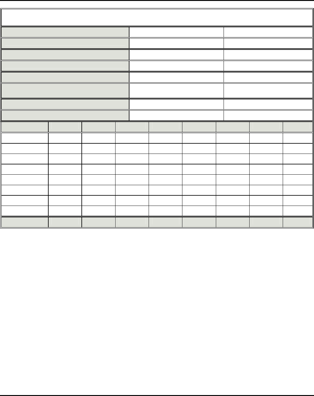
Page 66 Issue 1.0 December, 2003
Form 44 - Station Class of Service (Part 2)
01 - System Alarm Station 0=Enable 1=Disable
02 - Call Hold 0=Enable 1=Disable
03 - Call Split 0=Enable 1=Disable
04 - Manual Line 0=Disable 1=Enable
05 - Headset Operation 0=Disable 1=Enable
06 - Default Password (System
Programming Access) 0=Enable 1=Disable
07 - Display Meter Pulses 0=Enable 1=Disable
08 - Alarm Signaling Type 0=Reserved 1=DND Tone
44-STN-- 01 02 03 04 05 06 07 08
44-_____
44-_____
44-_____
44-_____
44-_____
44-_____
44-_____
44-_____
Default 0 0 0 0 0 0 0 0
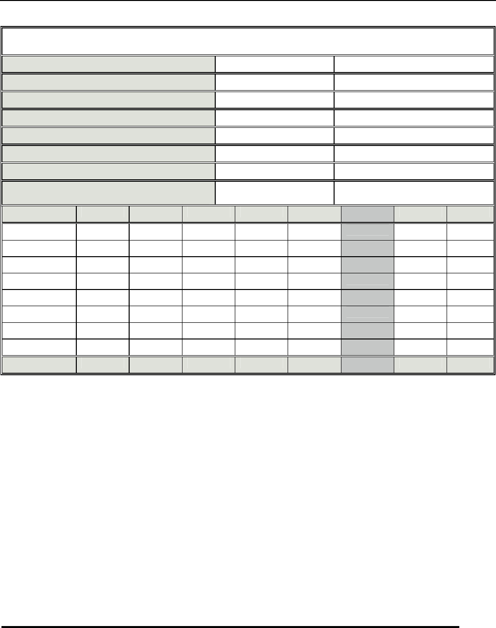
SK-408 Programming Forms Manual
Page 67
Form 45 - Station Class of Service (Part 3)
01-Intercom Dialing Restriction 0=Disable 1=Enable
02-Dual Port Operation 0=Disable 1=Enable
03 Ringing Volume Increase Gradually 0=Disable 1=Enable
04-Trunk Access 0=Trunk Access Allowed 1=Trunk Access Disallowed
05-Inter-Station Group Calling 0=Enable 1=Disable
06-Accept DTMF/Dial Pulse 0=DTMF or pulse 1=Dial pulse only
07-System Speed Dial Access 0=All System Access 1=Only Unrestricted
08-Direct CO Access
(Trunks other than Dial 9 Group) 0=Disable 1=Enable
45-STN-- 01 02 03 04 05 06 07 08
45-_____
45-_____
45-_____
45-_____
45-_____
45-_____
45-_____
45-_____
Default 0 0 0 0 0 0 0 0
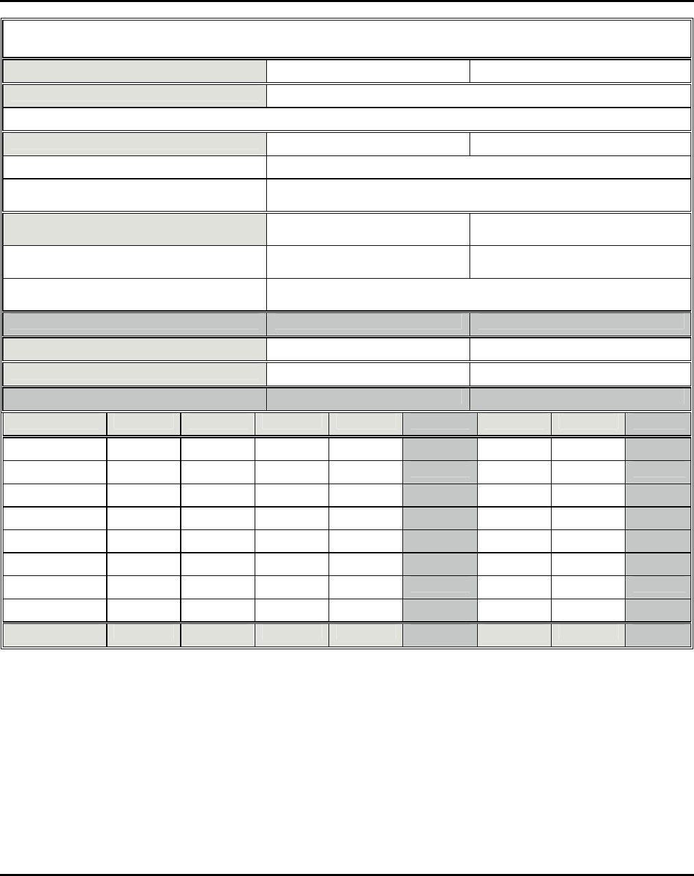
Page 68 Issue 1.0 December, 2003
Form 46 - Station Class of Service (Part 4)
01 - Dial 87 Line Group 0=Disabled 1-8=Group Number
02 - Message Waiting Level 0=Cannot Leave Callback Messages
1-9 -Able To leave messages for stations of equal or lesser Message Waiting Level
03 - Auto Answer Flag 0= Auto Answer Manual 1=Auto Answer On/MIC Light Lit
2=Auto Answer On/MIC Light Off 4= Auto Answer Manual/Speakerphone MIC On
5=Auto Answer On/MIC Light Lit
Speakerphone MIC On 6=Auto Answer On/MIC Light Off Speakerphone MIC On
04 - DISA Recall Capability To
Operator (No Answer/Busy) 0=No Recall to Operator 1=Recall on No Answer
2=Recall on Busy 3= Recall on Busy and No
Answer 5=Recall on No Answer
(Forwarding station stops ringing)
6=Recall on Busy and Stop Busy Remind
Tone at Forwarding Station 7= Recall to Operator on No Answer/Busy (Stop Notification at
Forwarding Station)
05 - RESERVED
06 - Doorphone Strike Control 0=Disable 1=Enable
07 - Telephone Type 0=SK1 1=Reserved
08 - RESERVED
46-STN-- 01 02 03 04 05 06 07 08
46-_____
46-_____
46-_____
46-_____
46-_____
46-_____
46-_____
46-_____
Default 0 1 0 0 0 1 2 0
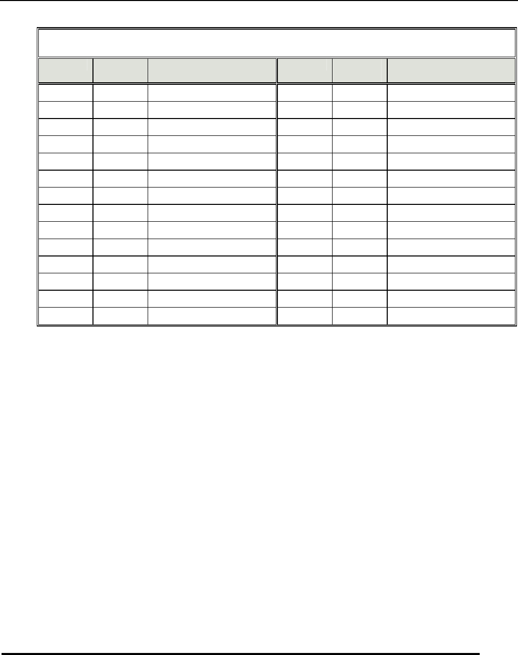
SK-408 Programming Forms Manual
Page 69
Form 47 - Hot Line Table
STN SPD?
(Y/N) Location STN SPD?
(Y/N) Location
STN = Station Number that is being programmed as a Hot Line.
SPD? (Y/N)= Enter a Y if the Station is to be routed to an external Speed Dial Number
Enter a N if the Station is to be routed to another station within the Superkey system.
If Y is entered, when programming the system press the CHanGe key (Volume Down).
LCD will display SPD: 000. Enter system speed Dial number to be accessed.
Location = The station number or Speed Dial Bin number to be accessed.
Page 70 Issue 1.0 December, 2003
Form 51 - Exception (Allow) Tables
Entry Number Actual Entry (Up to 12 digits in Length)
01
02
03
04
05
06
07
08
09
10
11
12
13
14
15
16
Entries on this form provide exception (allowances) to a condition that is restricted on Form 61.
Entries should have trailing digits set to “d”=Don’t Care Digits if additional digits are to be allowed after the target
digits have been entered.

SK-408 Programming Forms Manual
Page 71
Form 52 - Exception (Allow) Tables
Entry Number Actual Entry (Up to 12 digits in Length)
01
02
03
04
05
06
07
08
09
10
11
12
13
14
15
16
Entries on this form provide exception (allowances) to a condition that is restricted on Form 62.
Entries should have trailing digits set to “d”=Don’t Care Digits if additional digits are to be allowed after the target
digits have been entered.

Page 72 Issue 1.0 December, 2003
Form 5_ - Exception (Allow) Tables
Entry Number Actual Entry (Up to 12 digits in Length)
5___-01
5___-02
5___-03
5___-04
5___-05
5___-06
5___-07
5___-08
5___-09
5___-10
5___-11
5___-12
5___-13
5___-14
5___-15
5___-16
Note: Please copy and use this form as required for your system.
Entries on this form provide exception (allowances) to a condition that is restricted on Form 6___.
Entries should have trailing digits set to “d”=Don’t Care Digits if additional digits are to be allowed after the target
digits have been allowed.

SK-408 Programming Forms Manual
Page 73
Form 61 - Restriction (Deny) Tables
Entry Number Actual Entry (Up to 12 digits in Length)
61-01
6102
61-03
61-04
61-05
61-06
61-07
61-08
61-09
61-10
61-11
61-12
61-13
61-14
61-15
61-16
Entries on this form provide dialing restrictions to a telephone subject to this toll plan. If an entry is not followed by
a “d”=don’t care digit. The system will not consult the corresponding exception (allow) table, Form 51. The call will
be restricted. An entry of “624" will cause a call beginning with the digits 624 to be disconnected.
If an entry is followed by a “d” digit, the system will check the exception (allow) table, Form 51 to see if a valid
exception exists. An entry of “624d” will cause the system to check Form 51 for an exception of 624+additional
digits. If an exception is found on Form 51, the call will be allowed. If an exception is not found, the call will be
restricted.
Page 74 Issue 1.0 December, 2003
Form 62 - Restriction (Deny) Tables
Entry Number Actual Entry (Up to 12 digits in Length)
62-01
62-02
62-03
62-04
62-05
62-06
62-07
62-08
62-09
62-10
62-11
62-12
62-13
62-14
62-15
62-16
Entries on this form provide dialing restrictions to a telephone subject to this toll plan. If an entry is not followed by
a “d”=don’t care digit. The system will not consult the corresponding exception (allow) table, Form 52. The call will
be restricted. An entry of “624" will cause a call beginning with the digits 624 to be disconnected.
If an entry is followed by a “d” digit, the system will check the exception (allow) table, Form 52 to see if a valid
exception exists. An entry of “624d” will cause the system to check Form 52 for an exception of 624+additional
digits. If an exception is found on Form 52, the call will be allowed. If an exception is not found, the call will be
restricted.
SK-408 Programming Forms Manual
Page 75
Form 6_ - Restriction (Deny) Tables
Entry Number Actual Entry (Up to 12 digits in Length)
6___-01
6___-02
6___-03
6___-04
6___-05
6___-06
6___-07
6___-08
6___-09
6___-10
6___-11
6___-12
6___-13
6___-14
6___-15
6___-16
Entries on this form provide dialing restrictions to a telephone subject to this toll plan. If an entry is not followed by
a “d”=don’t care digit. The system will not consult the corresponding exception (allow) table, Form 5_. The call will
be restricted. An entry of “624" will cause a call beginning with the digits 624 to be disconnected.
If an entry is followed by a “d” digit, the system will check the exception (allow) table, Form 5_ to see if a valid
exception exists. An entry of “624d” will cause the system to check Form 5_ for an exception of 624+additional
digits. If an exception is found on Form 5_, the call will be allowed. If an exception is not found, the call will be
restricted.
Page 76 Issue 1.0 December, 2003
Form 67 - Hunt Group Pilot Assignment
Group
Num. Pilot
Number Group
Num. Pilot
Number
01
02
System Hunt Type is determined by Form 05-06-08. Please see that section of system programming.
Pilot Number Indicates the Access Code that must be dialed to reach the Hunt Group. It must be a unique number
(it cannot be the same as an extension). It must be within the range of valid numbers for extensions (2 digit
numbering plan 10-69, 3 digit numbering plan 100-699, 4 digit numbering plan 1000-6999).
Form 68 - Hunt Group Assignment
68-01-IT
Hunt Group 1 01 02 03 04
68-02-IT
Hunt Group 2 01 02 03 04
Entries on Form 68 must be valid extension numbers. Extensions can be entered in any order.

SK-408 Programming Cross Reference
Page 77
Programming Cross Reference
Programming Number
Incoming Calls
RINGING ASSIGNMENT
01-tk-stn Day Ringing And Ringing Line Preference Assignment
02-tk-stn Night Ringing And Ringing Line Preference Assignment
05-01-05 Busy Reminder Tone Interval (Off-Hook Ringing / Busy - Camp-On)
05-02-07 Ring On Timer (Minimum ring to be detected)
05-02-08 Ring Off Timer (Time to hold signal during silent period)
05-08-01 CO Hunt Interval
20-nn Day/Night Service Schedule
35-tk-07 Day Ring Type
35-tk-08 Night Ring Type
Outgoing Calls
DIAL
9'
05-04-02 Dial 9' Enable/Disable
36-grp-tk Dial 9' Group Assignment
41-stn-04 Stations Dial 9' Group Assignment
PABX OUTGOING CODE
05-03-04 Code for outside line in PABX (If trunk/trunks are served by PABX)
TRUNK SPECIFICATIONS
05-01-06 Pause Time Duration (For Speed Dial Pauses)
05-01-07 DTMF Generation Time
05-02-05 Flash Time to CO (For Special CO Features or Centrex)
05-02-07 Ring On Time (Minimum ring signal detected)
05-02-08 Ring Off Time (Time to hold signal during silent period)
05-03-01 Make/Break Ratio
35-trk-01 Trunk Type (PABX/CO)
35-trk-02 Trunk Signaling Type (dial pulse/DTMF)
SPEED DIAL
05-01-06 Pause Duration for Speed Dial pauses
05-03-02 Automatic Trunk Search During Speed Dial, Auto Redial, Saved
Redial, etc.
05-04-06 Speed Dial Distribution
05-05-03/04 Speed Dial Unrestricted
09-spd-xx System Speed Dial Locations
42-stn-01/02 Register Memory Block for Personal Speed Dial

Page 78 Issue 1.0 December, 2003
AUTO-REDIAL
05-02-03 Auto-Redial Off Hook (wait for answer) Timer
05-03-02 Automatic Trunk Search
05-05-07 Auto-Redial Attempts (Quantity)
05-05-08 Auto-Redial Time (Inter-Call) between attempts
Intercom Calls
INTERCOM CALL SIGNALING
05-03-03 Intercom call signaling to electronic telephone sets
STEP CALL
05-07-01 Intercom Step Call Type
41-stn-01 Station Group Assignment
DIAL TONE PATTERN
05-03-07 SLT Dial Tone Pattern Options
05-04-07 Intercom Single Digit Dialing
10-grp-xx Single Digit Dialing Assignment
41-stn-01 Station Group Assignment
DIRECT STATION SELECT
07-grp-key Flexible Key Group Assignment
41-stn-02 Keyphone Flexible Key Group Assignment
DIAL 0 (CALL OPERATOR)
05-06-05 Operator/CO access codes
44-stn-04 Manual Line
INTERCOM DIALING RESTRICTION
45-stn-01 Intercom Dialing Restriction
Busy/During Conversation
HOLD AND HOLD RECALL
05-01-01 Hold Recall Timer (Time until station is warned of held call)
05-01-02 Exclusive Hold Recall Timer (Same operation as hold recall)
05-01-03 Hold Recall Time out (Time before call is rerouted to Operator - After Hold
Recall Timer has expired.)
05-07-04 DISA Recall Capability
05-12-03 Station ability to place call on Exclusive Hold
44-stn-02 Station ability to hold a call
BUSY REMIND / CAMP-ON
05-01-05 Busy Reminder Interval (Time between notifications)
CALL SPLIT
44-stn-03 Call Split

SK-408 Programming Cross Reference
Page 79
TRANSFER
05-06-01 Transfer Recall Timer Blind transfer (Camp-On / Busy)
05-06-02 Transfer Recall Timer blind transfer (No Answer)
05-08-06 DISA No Answer Recall (To Message) Timer
05-08-07 DISA Transfer Time (No Digits Dialed)
MESSAGE WAITING LEVEL
46-stn-02 Message Waiting Level
OVERRIDE
40-stn-01 Override Level
DISA
05-01-04 Delayed DISA Access Time
05-07-04 DISA Recall Capability
05-08-04 DISA Operator Recall Location ( No Answer)
05-08-06 DISA No Answer Recall Timer
05-08-07 DISA Transfer Timer - No digits dialed
05-11-06 DISA Transfer Count - Console busy
05-11-02 DISA Password - Optional extra passwords
05-11-05 DISA Special Digit Acceptance
35-tk-04 DISA / External Call Forward Status
DISA SINGLE DIGIT DIALING
05-04-07 Intercom Single Digit Dialing Enable
05-11-08 DISA Single Digit Dialing
10-grp-stn Single Digit Dialing Assignment
20-nn Day/Night Service Schedule
AUTOMATED ATTENDANT - VOICE SERVICE UNIT
19-ch-fn Voice Service Unit Channel Assignments
46-stn-04 DISA Recall Capability (No Answer/Busy)
Night Service
02 Night Ringing And Ringing Line Preference Assignment
09-spd-nn System Speed Dial 101~109 for ECF
20-nn Day/Night Service Schedule
35-tk-03 External Call Forward Location (Speed Dial Assignment)
35-tk-04 DISA/ECF, Day/Night Status
Group Assignments
CONSOLE ASSIGNMENT
04-grp-stn Assign Stations to be consoles by group
FLEXIBLE KEY GROUP ASSIGNMENTS
07-grp-key Key Group Layout Assignment
41-stn-02 Assign stations to Key Groups

Page 80 Issue 1.0 December, 2003
DIAL
9' TRUNK GROUPS
36-grp-trk Assign trunks to groups for Dial 9'
41-stn-04 Assign stations a Dial 9' group
DIAL
87' TRUNK GROUPS
38-grp-trk Assign trunks to groups for Dial 87'
46-stn-01 Assign stations a Dial 87' group
GROUP ASSIGNMENT FOR STATIONS (PAGE ZONE, PICK UP, SINGLE DIGIT)
41-stn-01 Assign stations to station groups
Call Control
TOLL RESTRICTION
05-05-03 Set a portion of system speed dial for no restriction (Hundreds)
05-05-04 Set a portion of system speed dial for no restriction (Tens)
05-03-05 Toll Access Code (Usually a 1') for SMDR only
18-pln-trk Assigning Toll Class by Toll Plan/Trunk used
41-stn-05 Station Day Toll Plan Assingment
41-stn-06 Station Night Toll Plan Assignment
51~59 Allowed (Exception) Tables for Toll classes 1~9
61~66 Restrict (Deny) Tables for Toll classes 1~6
FORCED ACCOUNT CODES
17-nn Creating Account Codes
40-stn-08 Assigning Account Codes to Stations
CALL LIMIT
05-04-03 Call Limit Type
40-stn-03 Call Limit Duration (Class of Service - per station)
PASSWORDS
13-01 System Programming Password (default=none)
13-02 DISA Password (for using a trunk on DISA call)
13-03 Toll Override Password
13-04 Password for Monitoring over DISA (defaulr=none)
STATION LOCK/UNLOCK
40-stn-07 Station Lock/Unlock Status
BUSY OUT A TRUNK
37-tk-x Taking a trunk out of service
INTERCOM DIALING RESTRICTIONS
45-stn-01 Restrict station to station intercom dialing
System Clock
DATE AND TIME SETUP
05-04-04 12/24 hour time format

SK-408 Programming Cross Reference
Page 81
11- Set the system time
20-nn Day/Night schedule Definition
SYSTEM ALARM
12-nn System Alarm Clock
44-stn-01 Stations to include (notify) in system alarms
WAKE UP CALLS
05-05-01 Wake up signaling type
19-ch-fn VSU channel Assignment
Station Numbering
05-03-06 Digit length selection(2, 3, or 4 digits)
43-port-01 Station number (extension) Assignment
Single Line Telephone
05-02-01 Dial Tone Timeout
05-02-02 Interdigit Timeout
05-02-04 Hookswitch Disconnect Timer
05-02-06 Minimum Flash Timer (used to recognize a hook switch flash for hold)
05-04-08 Message Waiting Status Setup
05-06-07 Single Line Telephone Hold Procedure
05-07-02 Toll fraud Protection (Calling Proof)
05-08-03 SLT Busy Remind Tone Timer
05-08-05 SLT Feature Programming Access Code
45-stn-02 Setting Single line type (VM port, Dual Port)
Miscellaneous
MONITOR
40-stn-02 Station Monitor Level
PAGING
40-stn-05 Station Paging Access
40-stn-06 Receive Page Over Speaker
41-stn-01 Station Page Group
CALL FORWARD NO ANSWER TRANSFER TIME
05-01-08 Call Forward-No Answer Timer
HOT LINE
09-spd-nn System Speed dial number for Hot Line use
47-stn-xx Hot Line destination for a station
Optional Services
DOOR PHONE & DOOR SWITCH
03-01-ext Stations to ring upon Door Phone Activation
05-12-04 Door Relay Activation Timer

Page 82 Issue 1.0 December, 2003
06-01-fn Relay Assignment (for doorphone latch release)
Voice Mail Integration
01 Day Ringing Assignment
02 Night Ringing Assignment
05-02-04 Single Line Telephone Release (Disconnect) Timer
05-02-06 Single Line Telephone Minimum Flash Timer
05-06-07 Single Line Telephone Hold Procedure
05-10 Voice Mail Leading Digits
05-12-05 Voice Mail Integration Type
43-PO-02 Equipment Type
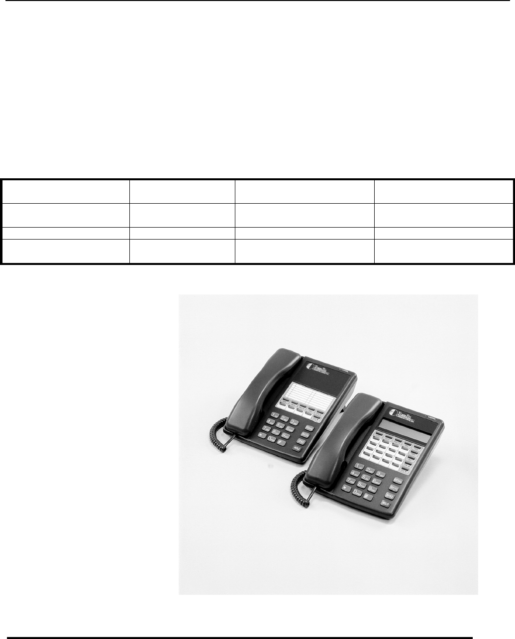
SK-408 Key Telephone Operation Manual
Page 83
TransTel Key Telephone Operation Manual.
Introduction
This section is devoted to an explanation of the implementation and operation of TransTel electronic telephones
(keysets). Included are normal functions that are available to most station users and functions that are available
only to console operators.
LED indicators
The upper right hand corner of all SK1 telephones is equipped with a multi-color LED bezel, which provides key
information pertaining to the operation of the SK1 series of telephones. The following table lists the visual
indications and their meanings:
Red - Continuous Speaker is On Red Flash - Two winks in 2
seconds Programming or Call
Forwarding
Red - Fast Flash Ringing Red Flash - Three winks in 2
seconds Auto Redial in Operation
Red - Slow Flash Message Waiting Green - Continuous Auto Answer Mode
Red Flash Once -
Periodically Do Not Disturb
Advisory Messages
If your telephone is equipped with an
LCD, you can put a message on your
telephone when you are unavailable.
Any other station that is equipped
with an LCD will see this message on
their LCD when they call your station.
Press PGM.
Press MSG.
Enter the message number you wish
to display.
You may enter information into the
messages by using the numeric
keypad and the forward and back
keys as defined in system
programming. They are listed below:
Press SAVE.
Press SPKR.
The following table indicates the
capabilities of the name
programming functions if they are
selected on the system. System
Speed Dial, Personal Speed Dial,
Stations, CO Lines and Sensors may
be programmed with names.

Page 84 Issue 1.0 December, 2003
Key 1 = Q - Z - (Blank Space) - 1 Key 2 = A - B - C - 2
Key 3 = D - E - F - 3 Key 4 = G - H - I - 4
Key 5 = J - K - L - 5 Key 6 = M - N - O - 6
Key 7 = P - R - S - 7 Key 8 = T - U - V - 8
Key 9 = W - X - Y - 9 Key 0 = (Period). : & 0
Key # = ( ) $ # Key * = (Dash) / ! *
DSS Key 23 = Backspace Cursor (Left) DSS Key 24 = Cursor Forward
To cancel an advisory message:
Press PGM.
Press MSG.
Press SPKR.
Alternate Trunk Group Access (Dial 87)
In some applications, you may have more than one type of outside line. If you do, you will probably use this method
to access your secondary lines.
Lift the handset or Press SPKR.
Dial 87.
You will be connected to an available line in your alternate trunk group.
Answering a call.
Why would we put an explanation of how to answer a call in this manual? Because there is more than one type of
call and more than one way to answer a call, depending on system programming.
Intercom Calls. Lift the handset or press SPKR.
Incoming Calls. Your phone is ringing. Lift the handset or press SPKR.
Incoming Calls. Your phone is not ringing.
This depends on system programming. In some instances, you may need to only lift the handset or press SPKR.
in other cases, you may also need to press the line number of the incoming line.
Answering a Doorphone
You can only answer a doorphone if your station is programmed to ring when the doorphone button is pressed.
When your telephone rings, lift the handset or press SPKR.
You will be connected to the doorphone.
If your system is equipped with a door strike relay:
Press 0 while talking to the doorphone. The strike release will activate, allowing security door (or other controlled
area) to be accessed.
Answer Paging (Meet Me Page)
Use this when you want to talk to the person who is making the page.
Lift the handset or press SPKR.
Dial # and *.
You will be connected to the person who is making the page.
If the person who made the page has hung up, you will hear busy tone.

SK-408 Key Telephone Operation Manual
Page 85
Automatic Last Number Redial
Rather than pressing REDIAL over and over again, you can let the telephone system do it for you. This feature will
repeatedly re-dial a telephone number for you. But you must be near your telephone, because this feature doesn’t
listen to see if the other end answers. It only stays off hook for a certain period of time (determined by system
programming) and then it hangs up…..unless you lift your handset or turn on your microphone.
After you have dialed an outside call,
Hang up.
Press SPD.
Press REDIAL. Your telephone will redial the last number called and remain off hook for at least 10 seconds
(depending on system programming). And will continue to redial the number periodically for a number of times (the
number of times also depends on system programming).
When the number you dialed answers, lift the handset or press your MIC key to carry on a conversation and keep
the system from hanging up.
Automatic Saved Number Redial
This feature is similar to Automatic Last Number Redial, but it adds the ability for you to save a number, dial some
other calls and then come back to it later.
After you have dialed an outside call,
Press SAVE. Your Display (if you have one) will show “Auto Save.”
Hang up.
You may make 1 or a hundred calls (or more if you need to…) in between.
Press SAVE. Your telephone will redial the number you previously saved and remain off hook for at least 10
seconds (depending on system programming). And will continue to redial the number periodically for a number of
times (the number of times also depends on system programming).
When the number you dialed answers, lift the handset or press your MIC key to carry on a conversation and keep
the system from hanging up.
Barge-In (Override)
If you need to join a conversation for any reason, this feature will let you drop in on an existing conversation.
Please be aware that this option is a level controlled option (from system programming), so you may be able to
override no phones, a few phones or all phones, depending on your telephone’s access level. Some stations may
not have access to this feature.
Dial a station. It is busy (or in Do Not Disturb)
Press 0. If you have access, you will hear a warning tone (so will everyone else in the call) and you will be allowed
into the conversation.
You may also use this feature on a CO line if you do not have an appearance of the station you want to override.
Lift the handset or press SPKR.
Press the busy CO line.
Press 0. If you have access, you will hear a warning tone (so will everyone else in the call) and you will be allowed
into the conversation.
Call Forwarding
To forward All calls:
Press PGM.
Enter 1 for All Calls.
Dial the extension number where you want to forward your calls.
Your telephone will return to idle. Your telephone is now forwarded. All calls to your station number will now ring at
the forwarding location.

Page 86 Issue 1.0 December, 2003
To forward busy calls:
Press PGM
Enter 2 for Busy Conditions.
Dial the extension number where you want to forward your calls.
Your telephone will return to idle. Your telephone is now forwarded. All calls to your station number will now ring at
the forwarding location, when your telephone is busy.
To forward calls when you don’t answer or are busy:
Press PGM
Enter 3 for No Answer / Busy Conditions.
Dial the extension number where you want to forward your calls.
Your telephone will return to idle. Your telephone is now forwarded. All calls to your station number will now ring at
the forwarding location, if you do not answer your telephone or your telephone is busy.
Call Hold
You can place outside callers and internal (intercom) calls on hold.
Press HOLD.
The caller is on hold.
To pick up an outside line call on Hold.
Lift the handset or press SPKR.
Press the Flashing CO line key
OR
Dial 80 plus the line number (1-4).
Calling the Doorphone
If your system is equipped with a doorphone, this is how you will call it.
Lift the handset or press SPKR.
Dial 88 to speak to the Doorphone.
(If the doorphone is programmed with a Relay, you may activate it
by dialing 0 while connected to the doorphone).
Call Pickup
You can use call pickup to answer calls that are ringing at other telephones. There are a variety of types that you
may choose.
DIRECT (EXTENSION) CALL PICKUP
This allows you to answer a specific station that is ringing.
Lift the handset or press SPKR.
Press the * key on the dial pad.
Dial the extension number of the station that is ringing.
You will be connected to the caller.
ALL GROUP PICKUP
You can pick up any ringing call in the system using this method. You will pick up the oldest ringing call.
Lift the handset or press SPKR.
Press the * key on the dial pad.
Press 9 on the dial pad.

SK-408 Key Telephone Operation Manual
Page 87
You will be connected to the caller.
PICKUP WITHIN YOUR GROUP
This allows you to pick up telephones that are in your own station group.
Lift the handset or press SPKR.
Press the * key on the dial pad.
Press 0 on the dial pad.
You will be connected to the caller.
PICKUP A CALLER IN ANOTHER GROUP
This allows you to pick up telephones in another station group. You must know the group number that you want to
answer to use this. In the SK-408, it is unlikely that you will use it, but it is available.
Lift the handset or press SPKR.
Press the * key on the dial pad.
Press 8 on the dial pad.
Press 1 - 8 for the group that you want to pick up.
You will be connected to the caller.
Call Swap
If you want to alternate between two callers, this feature allows you to do so quite easily.
You are speaking with the first caller.
Press HOLD.
The caller is on hold.
Make a second call.
Press SPD and then #. You will be connected to the first party. The second party will be on hold.
Press SPD and then #. You will be connected to the second party. The first party will be on hold.
Call Transfer
Call transfer allows you to send a call to a specific station. Most of the time when you are using TransTel Electronic
sets, placing a station on hold and announcing the call to the station is all that is necessary, but instances where
you need to transfer a call to a FAX machine or a computer modem, you need to use the capability.
Unscreened Transfer:
Place the caller on hold by pressing the HOLD button.
Dial the station number where the call needs to go.
Press TRF/FL.
The call has been successfully transferred.
Screened Transfer:
Place the caller on hold by pressing the HOLD button.
Dial the station number where the call needs to go.
Wait for the station to answer.
Press TRF/FL.
The call has been successfully transferred.
If you have a DSS button for the station where you transfer the call, you do not need to press the HOLD button first.
Just press the DSS button for the station where you want to transfer the call. Then you use either the Unscreened
or Screened method of transfer.

Page 88 Issue 1.0 December, 2003
Call Waiting
If the station you call is busy, you can “mark” the station so that when the station becomes free, the called station
will ring back to your telephone.
When you hear busy tone, Press MSG key.
Hang up.
When the other station is free, your station will ring with a special ringing tone. When you answer, the other station
will begin ringing.
Conference
You can conference any two parties, internal or outside CO lines.
Establish your conversation with the first party.
Press HOLD to hold the first party.
Get the second party on the line.
Press DND/CN when you have the second party on the line.
You know have a three way conference.
You can leave the conference and allow the other two parties to continue the conversation. Just press the
DND/CN key before you hang up. If you don’t press the key and just hang up, the other parties will be
disconnected, if they are both outside lines.
To rejoin the conference, press either CO line button and then the DND/CN key.
If you cannot rejoin an unsupervised conference, you may not have the capability in your class of service. Check
with your system administrator or check system programming to see if your override capability is enabled.
Conversation monitor
If you need to monitor a conversation for any reason, this feature will let you observe an existing conversation.
Please be aware that this option is a level controlled option (from system programming), so you may be able to
override no phones, a few phones or all phones, depending on your telephone’s access level. Some stations may
not have access to this feature.
Dial a station. It is busy.
Press #. If you have access, you will be connected to the station.
Date and Time Setting (Operator Function)
You must be a system operator to set the date and time.
Press PGM.
Press HOLD
Press 7
Press MSG.
Enter the two digit month (01 - 12)
Enter the two digit date (01 - 31)
Enter the two digit year (97 - 99 or even further)
Enter the hour (00 - 24).
Enter the minute (00-59)
Enter the day of the week (0=Sunday - 7=Saturday)
Press MSG.
Day / Night Service Switching Setup (Operator function)
With this feature, you can make incoming calls ring in different places based on day time or night time. You should
have a LCD equipped telephone to use this feature. It also controls the dialing (toll restriction) capabilities of

SK-408 Key Telephone Operation Manual
Page 89
telephones if your installer programmed it that way). Yes, you must be an operator to do this. The change from day
to night service may be either automatic, or it may be under manual control of the operator.
Selecting Manual or Automatic Switching:
Press PGM.
Press TRF/FL.
Your telephone will display the current mode (day or night) and status (automatic or manual).
By pressing the * key you will “toggle” between automatic and manual switching.
When you are finished, press SPKR.
Selecting Day or Night Mode When in Manual Switching Mode:
Press PGM.
Press TRF/FL.
You can alternate between Day Service and Night Service by pressing the TRF/FL key.
When finished, press SPKR.
OR
If you have a Day/Night button, you can achieve the same results simply by pressing the DAY/NIGHT key.
Note: Programming of Automatic schedules is done as a function of system programming. For more information
on Automatic scheduling, see Form 20 in the Programming Forms section of this manual.
Dialing Operator
Lift the handset or press SPKR. (Optional when dialing the operator).
Press 0.
Your telephone will ring the operator’s station.
Direct Trunk Access
Using this method, you can “punch in” to an outside line.
Lift the Handset or Press SPKR (Optional).
Press CO trunk button.
You will be connected to the CO line you pressed (if you have access to it).
Do Not Disturb
You can block incoming ringing from individual extensions, including paging announcements to them. If your
telephone is in Do Not Disturb, you can still place calls and use features of the telephone. Any station that calls you
and is equipped with an LCD will see “Do Not Disturb” on the LCD.
Press DND/CN key.
The Message Light will flash. Your telephone is in Do Not disturb.
To cancel Do Not Disturb:
Press DND/CN key.
Environment Monitor
This feature is similar to the Room Monitor, except that this can be done to a telephone without a prior setup. You
can be “sneaky” about listening with this option.
Lift handset or press SPKR.
Dial 7, 7, 4.

Page 90 Issue 1.0 December, 2003
Dial the extension number of the station you want to monitor.
You will be connected to the station you want to monitor.
Note: You can only use this feature to monitor either an SK-1D or SK-1S Electronic Set.
Exclusive Hold
Exclusive Hold allows you to place a call on hold without the worry of someone else picking it up from hold by
accident. Exclusive Hold only applies to outside calls. When a call is on exclusive hold at your station, the line
appears to be in use (not on hold) at all other stations.
While you are on a call.
Press HOLD HOLD (that’s pressing HOLD twice).
The call is placed on Exclusive Hold for your extension.
To retrieve a caller from Exclusive Hold at your station.
Lift Handset or press SPKR.
Press the line button that you placed on Exclusive Hold
OR
Dial 80 plus the line number that you placed on hold
You will be connected to the caller.
To retrieve a caller from Exclusive Hold at another station. (Yes, you can get a call from another extension…but
you have to make an effort to pick it up. It’s difficult to pick this call up by accident).
Press CO line button. Press HOLD.
You will be connected to that caller.
Flash (To an outside telephone line)
Use this feature to make use of telephone company services such as Call Waiting and Three way calling.
Or to access Centrex features like call transfer and call conferencing.
Press the TRF/FL key.
The outside line will receive a flash.
Forced Account Codes
If telephones are restricted within the system, this feature can allow people to enter a code and place calls on a
telephone that otherwise would be restricted.
Press PGM.
Dial 4
Enter the forced account code.
If the forced account code you dialed is recognized by the system, you will be connected to a CO line. You can then
place an outgoing call.
If the system does not authorize your account code, you will hear busy tone.
Intercom call
An intercom call allows you to talk to another station within your telephone system.
Lift Handset or press SPKR.
Dial the extension number of the station you wish to reach.
You can reach another station by using a DSS button if you are equipped with one.
Lift Handset or press SPKR. (Optional)

SK-408 Key Telephone Operation Manual
Page 91
Press the DSS button of the station you want to call.
Last Number Redial
This feature lets you redial the last number you just called. It’s great when you want to catch that busy number as
soon as it’s free!
Lift the handset or press SPKR. (Optional)
Press REDIAL.
The last (outside) number you called will be dialed again.
Lock / Unlock SMDR from Console
If your system is equipped with an RS-232 port and is using a printer to keep a telephone log, you can temporarily
suspend the output of the RS-232 port so you can change the paper on the printer or for any other reason where
the printer needs to go off line. If you lock the SMDR port, calls will be stored in the SK-408 until you re-enable the
port.
Press SPKR.
Dial 7, 7, 2.
This will toggle the RS-232 port on or off.
If you have an LCD equipped telephone, the display will show the current status of the SMDR port. If it is on, the
display will show “SMDR IS UNLOCK.” If it is off, the display will show “SMDR IS LOCK.”
Macro Keys
This feature will let you program your own “custom” function onto up to 4 keys on your telephone.
Press PGM.
Press one of the assigned Macro Keys (16-19).
Dial the exact keystrokes that you want to save. (Up to 5 keystrokes)
Press the assigned Macro Key again.
Mute
Use the mute function any time you don’t want the outside party to hear what you are saying.
While you are on the handset:
Press MIC key.
The microphone on the handset will be muted. The LED on the upper right hand corner of the telephone will glow
red.
Press MIC key.
The microphone on the handset will be enabled.
While you are on the speakerphone:
Press MIC key.
The microphone on the Speakerphone will be muted. The LED on the upper right hand corner of the telephone will
glow green.
Press MIC key.
The microphone on the Speakerphone will be enabled.
Operator Set Timed Reminder or Wakeup (Remote Setup)
This allows the system operator to set a Timed Reminder or Wake Up call for another station within the system.
Press PGM
Press REDIAL
Enter the extension number of the station you where you want to set up a reminder or wake up call.

Page 92 Issue 1.0 December, 2003
Enter the time for the reminder (24 hour clock, please).
Enter the type of call (01-98 for a reminder, 99 for a wakeup call).
Press SAVE.
Press SPKR
Operator Timed Reminder or Wake Up
Press PGM.
Press HOLD.
Press 8.
Enter the time you want the reminder to occur (must be in 24 hour format).
Enter the duration (01 through 98). That is how long you want the reminder period to be. This type of reminder will
occur every day at the same time.
OR
Enter 99 for a Wake Up call. This call will occur only once, then never again.
Press SAVE.
Press SPKR to exit.
To cancel:
Press PGM.
Press HOLD
Press 8
Press HOLD.
Paging
Internal Zone
Lift the handset or press SPKR.
Press # and 2.
Then press the one digit Paging Zone Code. (1-8)
You will be connected to the telephones in that zone.
All Paging
Lift the handset or press SPKR.
Press # and 1.
Pulse To Tone Conversion
This feature is of use to you if you are located in an area where your telephone company does not accept DTMF
(Touch Tone),This feature lets you dial DTMF (Touch-Tone) for services such as remote voice mail, bank by
phone, etc.
Press MSG key.
Your telephone set will now dial DTMF digits instead of pulse dialing on a CO line.
Room Monitor
If you need to listen in on another room, such as a baby’s room or a secured room, you can set this function up so
that any telephone in the system can monitor the room by dialing the extension number.
At the telephone that you are going to monitor:
Press the SPKR key or take the handset off hook.
Dial 770.

SK-408 Key Telephone Operation Manual
Page 93
The telephone is now in the room monitor mode. Any station can now dial the extension number of the station and
be placed in the Room Monitor mode. The calling station will hear room activitiy. This connection will stay in place
until the calling station hangs up or until the Monitored station is placed on Hook or the SPKR is turned off.
Only one station at a time can monitor a room, but the monitored station will stay in the room monitor mode until it is
reset. So you can set up a monitor from one telephone and if your activities take you to another room, when you
leave the first room, hang up. When you get to the next room, you can re-enter the monitor mode at the new
extension, so you can go all over a building and still be able to monitor an individual room.
Speed Dialing
You can use this feature to access frequently dialed telephone numbers.
Lift the handset or press SPKR.
Press SPD key.
Dial 100 through xxx (for system speed dial).
OR Dial 00 through 09 (for personal speed dial).
OR press a DSS button (for personal speed dial).
Speed Dial Programming
There are three types of speed dial in the system, numeric personal speed dial, DSS personal speed dial and
system speed dial. This section shows you how to program and personal speed dial if you are a regular station. If
you are the system attendant (operator), your methods will be different - Please See Programming Speed Dial
(Operator).
Note: There are three special keys that you may need to use when programming speed dial numbers. They are:
HOLD - When entering a speed dial number, if you press this key, the speed dial will pause for approximately 2
seconds (this time is programmable, but 2 seconds is the standard length). You may press HOLD multiple times for
a longer pause.
TRF/FL - Pressing this button while you are entering a speed dial number will cause the system to perform a
hookswitch “flash” to the outside telephone line. This may be of use if your telephone system has Centrex or
special telephone company provided features.
MW/PT - This key will cause the telephone to stop using pulse (rotary) dialing and begin using DTMF (Touch tone).
This may be useful if your telephone company doesn’t recognize Touch Tone, but you need to access remote
banking, paging, or voice mail services that require Touch Tone digits.
Programming Personal Numeric Speed Dial
Press PGM
Press 8 (or SPD if your telephone has a SPD button).
Press the number that you want to program (0-9).
(If you want the speed dial number to access a specific telephone line every time it places the call, Press the MIC
button and dial 0 plus the line number. Otherwise skip this step.)
Enter the telephone number you want to dial.
Press SAVE.
Press SPKR.
Programming Personal DSS Speed Dial
Press PGM
Press 8 (or SPD if your telephone has a SPD button).
Press the DSS button that you want to enter (DSS button 1 through 10).
(If you want the speed dial number to access a specific telephone line every time it places the call, Press the MIC
button and dial 0 plus the line number. Otherwise skip this step.)
Enter the telephone number you want to dial.

Page 94 Issue 1.0 December, 2003
Press SAVE.
Press SPKR.
Speed Dial Programming (Operator).
Programming (Operator) Personal Numeric Speed Dial
Press PGM
Press 8 8.
Press the number that you want to program (0-9).
(If you want the speed dial number to access a specific telephone line every time it places the call, Press the MIC
button and dial 0 plus the line number. Otherwise skip this step.)
Enter the telephone number you want to dial.
Press SAVE.
Press SPKR.
Programming (Operator) Personal DSS Speed Dial
Press PGM
Press 8 8.
Press the DSS button that you want to enter (DSS button 1 through 10).
(If you want the speed dial number to access a specific telephone line every time it places the call, Press the MIC
button and dial 0 plus the line number. Otherwise skip this step.)
Enter the telephone number you want to dial.
Press SAVE.
Press SPKR.
Programming System Speed Dial Numbers
Press PGM
Press 8 7.
Press the number that you want to program (100-xxx).
Press MSG.
(If you want the speed dial number to access a specific telephone line every time it places the call, Press the
VOLume Down button and dial 0 plus the line number. Otherwise skip this step.)
Enter the telephone number you want to dial.
Press MSG.
Press SPKR.
Station Lock / Unlock
This feature lets you lock your telephone so that no one can make unauthorized telephone calls on it. In order to
unlock your telephone, you must remember the 3 digit long “password” that you enter when you lock it. You will
need this to unlock your telephone. You can create any 3 digit code to lock your station, but the code to unlock it
MUST be the one that you used to lock it!
To lock or unlock your station:
Press PGM.
Dial 9.
Enter your 3 digit “password.”
Press SAVE.
Press SPKR.
Your telephone is now locked.
To temporarily unlock your station (This will allow you to make one telephone call. Then it reverts back to a locked
state):
Press PGM.
Dial #.

SK-408 Key Telephone Operation Manual
Page 95
Enter your 3 digit “password.”
You will be connected to the outside world. You may dial your call.
Your telephone will revert to the locked state when you hang up.
Super Save Redial
This feature comes in handy when you call directory assistance and can’t find a pencil (or paper) to write down the
telephone number that you are looking for.
You are on an outside call.
Press SAVE. Your LCD (if you have one) will show “Auto Save”
Enter the new telephone number (maybe the one that directory assistance gave you).
Hang Up.
Press SAVE. The number you stored will be dialed, and your telephone will remain off hook for at least 10 seconds
(depending on system programming). And will continue to redial the number periodically for a number of times (the
number of times also depends on system programming).
When the number you dialed answers, lift the handset or press your MIC key to carry on a conversation and keep
the system from hanging up.
Switching between Handsfree and Handset mode
If you want to switch from the handset to speakerphone….or vice versa.
While on the handset:
Press SPKR.
Place the handset back in the cradle.
You are now in Speakerphone mode.
While on the Speakerphone:
Lift the handset.
You are now in the handset mode.
Timed Reminder or Wake Up
With this feature, you can set an appointment reminder, that will alert you only once, or you can set a daily reminder
that will happen every day at the same time (like when it’s time to stop working and go home). Note: If you are a
system operator, the procedure you follow will be different. Please see Operator Timed Reminder or Wake
Up.
Press PGM.
Press HOLD.
Enter the time you want the reminder to occur (must be in 24 hour format).
Enter the duration (01 through 98). That is how long you want the reminder period to be. This type of reminder will
occur every day at the same time.
OR
Enter 99 for a Wake Up call. This call will occur only once, then never again.
Press SAVE.
Press SPKR to exit.
To cancel:
Press PGM.
Press HOLD HOLD (that’s Hold….two times).

Page 96 Issue 1.0 December, 2003
Trunk Queuing
If you need an outside line and none are available, this feature will make sure you get one when it becomes
available.
Lift the handset or press SPKR. (Optional)
Select a CO line (either by dialing 9 or by pressing a CO line button)
Press MSG key.
Hang up.
When the CO line (or one of the lines in your Dial 9 group) is free, your telephone will ring. When you answer it,
you will be connected to the outside line.
Trunk Group Access (Dial 9)
This is one method of getting an outside line.
Lift the handset or press SPKR. (Optional for Dial 9)
Dial 9.
You will be connected to an available line in your dial 9 group

SK-408 Key Telephone Operation Manual
Page 97
Voice Service Unit (Operator Function)
The Voice Service Unit has up to 8 channels on which you can record up to 8 different messages. The actual
number of messages that you record will be determined by how your system is programmed. This section explains
how to record and playback the messages so that the system can use them. Remember, the Voice Service Unit
allows a maximum of 60 seconds total recording time.
To Record (Operator only):
Lift handset (we don’t recommend that you make the recordings using the Speakerphone).
Dial 86.
Dial 0
Record your message after the tone.
To stop the recording and select the next voice channel, press 1.
To record the next segment, dial 0 . Repeat as necessary.
Your LCD display will always show you which channel you are currently recording.
Please note that you cannot record one message and then record another message at another time. When you
record a message, you must record all messages, one after another. In the future, if you need to update a
message, it will be necessary that you re-record all messages.
To Playback (Operator only):
Lift handset or press SPKR.
Dial 86
Dial 7 to play the first message.
Press 1 to advance to the next message.
Continue the Dial 7 and Dial 1 sequence to hear all messages.
When you are finished, either put the handset back in it’s cradle or Press the SPKR button (which ever is
appropriate).
Volume Control
If the person on the other end isn’t quite loud enough….or is too loud!
Press Vol UP to increase the volume level.
Press VOL DOWN to decrease the volume level.
Volume Levels Programming (Permanent)
You can permanently set the volume levels on your telephone.
Press PGM.
Press 6.
Dial 1 to set Ringing Volume.
OR
Dial 2 to set Speaker Volume.
OR
Dial 3 to set Handset volume
Press the Volume UP or Volume DOWN to reach the desired volume level.
Press PGM when finished.
