Report Trans XChange Schema Guide 2.1 V 45
User Manual:
Open the PDF directly: View PDF ![]() .
.
Page Count: 220 [warning: Documents this large are best viewed by clicking the View PDF Link!]

Department for Transport
TransXChange – An XML Standard for the Data
Exchange of Bus Schedules and Related
Information.
TransXChange Schema Guide
2.1 & 2.2a (v4.45)
Department for Transport
TransXChange Schema User Guide
Preamble
Contents
TransXChangeSchemaGuide-2.1-v-45.pdf.doc
Page 2
24 September 2013
Version History
Schema
Version
Date
Review
2.0a
0.1 Preliminary Consultation Draft
03 04 2004
NJSK
Review
2.0b
0.4 Consultation Draft
10 03 2004
RM /NJSK
Review
2.0c
0.9 Consultation Draft
11 05 2004
NJSK
Review
2.0c
0.10 Consultation Draft Corrections
12 05 2004
/NJSK
Review
2.0c
0.15 Corrections, added dead run, track & revised operation date
sections.
14 05 2004
NJSK
Internal
2.0d
0.16 Corrections.
09 06 2004
TW
Internal
2.0d
0.19 Internal Draft. NaPTAN 2a & Publisher updates
23 06 2004
NJSK
Review
2.0e
0.20 Further NaPTAN 2b changes. Rework FlexibleService.
Revise Frequent Service and Operational dates.
01 07 2004
NJSK
Internal
2.0e
0.23 Corrections. Registration change, Move Examples to web
16 07 2004
NJSK
Internal
2.0e
0.25 Clarifications & Corrections
15 08 2004
NJSK
Internal
2.0e
0.26 Minor formatting corrections
18 08 2004
NJSK
Review
2.0f
0.27 Add Public Use,
26 08 2004
NJSK
Review
2.0f
0.31 Corrections, renumber figures and tables, Add Booking
Arrangements, Legislative references, Block, Refine integrity
rules. Drop PPT
07 10 2004
NJSK
Internal
2.0g
0.32 Corrections. Revise Transmodel comparison, Refine integrity
rules.
16 12 2004
NJSK
Review
2.0g
0.33 Corrections. From RS
23 01 2005
NJSK
Review
2.0g
0.34 Clarify MDV points
30 02 2005
NJSK
Review
2.0
0.35 Release 2.0 Clarify versioning points
10 03 2005
NJSK
Final
2.1
0.36 Release 2.1 Minor fixes and corrections
27 09 2005
NJSK
Issued
2.1
0.37 Minor fixes and corrections
06 01 2006
NJSK
Issued
2.1
0.38 Clarify use of duration
15 11 2006
NJSK
Review
2.1
0.39 Update with Publisher enhancements in route merge
16 03 2007
NJSK
Issued
2.1
0.40 Clarify route map, correct times, improve diagrams
14 07 2007
NJSK
Issued
2.2a
0.41 Clarify rounding ,
24 07 2007
NJSK
Review
2.2a
0.41 correct subsidy classification
24 09 2007
NJSK
Review
2.2a
0.42 correct clarify use of journey times classification
12 03 2008
NJSK
Issued
2.2a
0.43 clarify stop request
03 09 2008
NJSK
Issued
2.2a
0.44 Revise all diagrams
02 03 2009
NJSK
Issued
2.2a
0.45 Remove wrong reference to change classification
10 06 2009
NJSK
Issued
2.2a
0.46 Update validation table
10 09 2009
Prepared By:
Prepared For:
Kizoom Ltd
schemer@kizoom.com
109-123 Clifton Street London, EC2A 4LD
Tel: +44 (0)20 7566 1400
Fax: +44 (0)20 7566 0033
Email: nick_knowles z @rkizoom.com
Department for Transport,
Great Minster House,
76 Marsham Street,
London,
SW1P 4DR
© Crown Copyright 2000-2009
The content in this document may be reproduced free of charge in any format or media without requiring specific
permission, subject to the TransXChange Terms & Conditions of use, viewable at
http://www.transxchange.org.uk. This is subject to the material not being used in a derogatory manner or in a
misleading context. The source of the material must be acknowledged as Crown copyright and the title of the
content must be included when being reproduced as part of another publication or service.

Department for Transport
TransXChange Schema User Guide
Preamble
Contents
TransXChangeSchemaGuide-2.1-v-45.pdf.doc
Page 3
24 September 2013
CONTENTS
Section Page
VERSION HISTORY ___________________________________________ 2
CONTENTS _________________________________________________ 3
LIST OF FIGURES ____________________________________________ 9
LIST OF TABLES _____________________________________________12
1 INTRODUCTION _________________________________________15
1.1 Antecedents 15
1.2 Document Structure 16
1.3 Intellectual Property Rights 17
1.3.1 TransXChange Schema 17
1.3.1.1 TransXChange Schedules 17
1.3.1.2 TransXChange Document Publisher 17
1.4 Versioning 18
1.5 Naming Conventions 18
1.6 Presentation Conventions Used in the Schema Guide 18
1.6.1 XML Elements in Text 18
1.6.1.1 UML Diagrams 18
1.6.1.2 XML Structure Diagrams 19
1.6.1.3 Element Structure – Sequence 19
1.6.1.4 Element Structure – Choice 19
1.6.1.5 Multiplicity and Optionality 19
1.7 Major Changes in Release 2.0 of TransXChange 20
1.8 Evolving TransXChange 21
1.9 Acknowledgments 21
1.10 Related Transport Information Standards 22
1.11 Legislation 22
1.12 Related Documents 23
2 OVERVIEW OF TRANSXCHANGE ___________________________24
2.1 The Purpose of TransXChange 24
2.2 TransXChange Elements 24
2.3 Document Validation 24
2.4 How is TransXChange Used? 26
2.4.1 Registration of a Route with VOSA 26
2.4.2 Update of a Registration with VOSA 26
2.4.3 General Purpose Exchange of Data 27
2.5 Differences between the Schemas 28
3 SHORT TOUR OF THE TRANSXCHANGE ESSENTIAL MODEL ___29
3.1 Representing a Bus Service in TransXChange 29
3.2 The NaPTAN Stop Model 31
3.2.1 Resolving NaPTAN Stop References 34
3.2.2 Variable Stop Allocations 34
3.2.3 Stop Types 34
3.3 The Route and Service Supply Model 36
3.3.1 Model Layer Concerns 38
3.3.2 Summary of Route & Supply Model Elements 39

Department for Transport
TransXChange Schema User Guide
Preamble
Contents
TransXChangeSchemaGuide-2.1-v-45.pdf.doc
Page 4
24 September 2013
3.3.3 Projection between Levels of Discourse 39
3.3.4 The Use of Links in TransXChange 40
3.3.5 Structure Example of a Schedule with one Pattern and Two Journeys, 41
3.3.6 Structure Example of a Schedule with an Express Journey 42
3.3.7 An Instance Example 43
3.3.8 Plotting a route on a Map 43
3.4 Inheriting Timing Link Values 45
3.4.1 Inheritable attributes 46
3.4.2 Schedule and Journey Terms and Definitions 48
3.4.2.1 Time Related Terms 48
3.4.2.2 Routing Related Terms 48
3.4.3 Computation of Passing Times 50
3.4.3.1 Example of Inheritance of Passing Times 51
3.5 Rounding of Passing Times 53
3.6 Standard Service Overview 54
3.6.1 Standard Service properties 55
3.7 Flexibly Routed Services 57
3.8 Interchanges 60
3.8.1 Inheriting Interchange Values 61
3.8.2 Interchange Schematic 62
3.8.3 Interchange Instance Example 62
3.9 Fare Stages 65
3.10 Dead Runs 66
3.10.1 Use of Dead Runs for Short Working 67
3.11 Tracks 68
3.11.1 Track Model 70
3.12 The Registration Model 71
3.12.1 Populating a Registration 73
3.13 Operators 73
3.14 Further Modelling Topics 73
3.14.1 Direction: Handling Inbound and Outbound Schedules. 73
3.14.2 Modelling Complex Routes 76
3.14.2.1 Services with Topologically Complex Routes 76
3.14.2.2 Services with Complex Temporal Operational Patterns 78
3.14.3 Modelling Services Efficiently 79
3.14.3.1 Overall Reuse of Elements 80
3.14.3.2 Inefficiencies in TransXChange 80
3.14.3.3 Use of Sections 81
3.14.4 Presenting Schedules in Timetables 82
3.14.4.1 Using a Sequence Number 83
3.14.4.2 Example of a Timetable using StopSequence 84
3.14.5 Associating operational data with a timetable 85
3.15 Modelling Operational Days 87
3.15.1 Specifying When the Service Operates – Summary 87
3.15.2 Regular Operation – OperatingProfile 89
3.15.3 Exceptional Operation – OperatingProfile 89
3.15.4 Services that Run for Specific ServicedOrganisation Working Days91
3.15.5 OperatingProfile Elements 92
3.15.6 General Principles for Using Operational Days 94
3.15.7 Frequent Services 95
3.15.8 Frequency Based Services 95
3.15.8.1 Frequency Described by Interval 95
3.15.8.2 Departure Described by Minutes Past Hour 96
3.15.8.3 Frequency Described on Multiple Individual Journeys 96
3.15.8.4 Multi-journey to single group, Multiple frequencies 97
3.15.8.5 Text Descriptions for Frequency service 97
3.15.9 Service Operational Days 98
3.15.10 Structure Example of Schedule with Operational Day Exceptions 99

Department for Transport
TransXChange Schema User Guide
Preamble
Contents
TransXChangeSchemaGuide-2.1-v-45.pdf.doc
Page 5
24 September 2013
3.16 Summary of TransXChange Entities and Identifiers 100
3.16.1 Private codes 101
3.16.2 Referencing Elements 101
3.17 Data types 102
4 WORKED EXAMPLE OF A TRANSXCHANGE SCHEDULE ______105
4.1 Worked Example: Bus Timetable 105
4.2 Worked Example: Service Components 105
4.3 Worked Example: Operator 105
4.4 Worked Example: Registration 106
4.5 Worked Example: StopPoints 106
4.6 Worked Example: Route and Tracks 106
4.7 Worked Example: JourneyPattern 108
4.8 Worked Example: Line 109
4.9 Worked Example: VehicleJourney 109
4.10 Worked Example: Operational Times 109
5 EXAMPLES ____________________________________________111
6 TRANSXCHANGE SCHEMA _______________________________113
6.1 TransXChange Schema Overview 113
6.2 TransXChange Root Element 113
6.2.1 TransXChange Element Attributes 113
6.2.2 TransXChange Child Elements 114
6.3 Topographical Elements – StopPoints and Zones 116
6.3.1 NptgLocalities Element 116
6.3.2 AnnotatedNptgLocalityRef Element 116
6.3.3 StopPoints Element 117
6.3.4 AnnotatedStopPointRef Element 117
6.3.5 StopPoint Element (Stop) 118
6.3.6 StopArea Element (StopGroup / StopCluster) 118
6.4 Network Topology Elements – Routes and Tracks 120
6.4.1 Route Element 120
6.4.2 RouteSection Element 120
6.4.3 RouteLink Element 121
6.4.4 Track Element 122
6.4.5 Track Subelements 122
6.4.5.1 Track / Mapping Element 122
6.4.5.2 Track / Instructions Element 122
6.4.5.3 Track / Instructions / Feature Element 123
6.5 Registration Elements: Operator, Registration, ShortNoticeRegistration125
6.5.1 Operators Element 125
6.5.2 Operator Element 125
6.5.3 LicensedOperator Element 126
6.5.4 Operator & LicensedOperator: Subelements 127
6.5.4.1 OperatorContactGroup 127
6.5.4.2 Operator / Garages Element 128
6.5.5 Registration Element 128
6.5.6 RegistrationSubmissionGroup 129
6.5.7 RegistrationInfoGroup 130
6.5.8 Registration Subelements 131
6.5.8.1 Registration / VosaRegistrationNumber Element 131
6.5.8.2 Registration / SubmissionAuthor Element 132
6.5.8.3 Registration / TrafficArea Element 132
6.5.8.4 Registration / CirculatedAuthorities Element 133
6.5.8.5 Registration / SubsidyDetails Element 137

Department for Transport
TransXChange Schema User Guide
Preamble
Contents
TransXChangeSchemaGuide-2.1-v-45.pdf.doc
Page 6
24 September 2013
6.5.8.6 Registration / ContractedService Element 137
6.5.8.7 Registration / SupportingDocument Element 137
6.5.9 ShortNoticeRegistration Element 138
6.5.10 ShortNoticeRegistration / ChangeImpactGroup 138
6.5.11 ShortNoticeRegistration / ChangeJustificationGroup 138
6.5.12 ShortNoticeRegistration Subelements 139
6.5.12.1 ShortNoticeRegistration / Public Availability Element 139
6.5.12.2 ShortNoticeRegistration / ChangeImpact Element 140
6.5.12.3 ShortNoticeRegistration / ChangeToConnectAlteredService Element 140
6.5.12.4 ShortNoticeRegistration / ReplaceDiscontinuedService Element140
6.5.12.5 ShortNoticeRegistration / LocalHolidayChange Element 141
6.5.12.6 ShortNoticeRegistration / SpecialOccasion Element 141
6.5.12.7 ShortNoticeRegistration / RegulationOrderCompliance Element141
6.5.12.8 ShortNoticeRegistration / ChangeRequestedByExternalAuthority
Element 142
6.5.12.9 ShortNoticeRegistration / ExceptionalRequirement Element 142
6.6 Service Description Elements 143
6.6.1 Services Element 143
6.6.2 Service Element 143
6.6.3 Service / ServiceInfoGroup 144
6.6.4 Service / ServiceDescriptionGroup 145
6.6.5 Service / ServiceComponentGroup 146
6.6.6 Service / Subelements 147
6.6.6.1 Service / Line Element 147
6.6.6.2 Service / OperatingPeriod Element 147
6.6.6.3 Service / ServiceClassification Element 147
6.6.6.4 Service / AssociatedOperators Element 148
6.6.6.5 Service / StopRequirements Element 149
6.6.6.6 Service / ServiceAvailability Element 149
6.6.6.7 Service / ToBeMarketedWith Element 149
6.7 StandardService, JourneyPattern, VehicleJourney 151
6.7.1 StandardService Element 151
6.7.2 JourneyPatterns 152
6.7.3 JourneyPattern Element 152
6.7.3.1 JourneyPattern / CommonJourneyGroup 153
6.7.3.2 JourneyPattern / JourneyPatternGroup 154
6.7.4 JourneyPattern Subelements 155
6.7.4.1 CommonJourneyGroup JourneyPattern / Operational Element 155
6.7.4.2 CommonJourneyGroup JourneyPattern / Operational / TicketMachine
Element 155
6.7.4.3 CommonJourneyGroup JourneyPattern / Block Element 156
6.7.4.4 CommonJourneyGroup / VehicleType Element 156
6.7.4.5 CommonJourneyGroup / LayoverPoint Element 156
6.7.5 JourneyPatternSection Element 157
6.7.6 JourneyPatternTimingLink Element 157
6.7.6.1 JourneyPatternTimingLink / CommonTimingLinkGroup 158
6.7.6.2 JourneyPatternTimingLink / JourneyPatternTimingLinkGroup 158
6.7.7 JourneyPatternStopUsageStructure 159
6.7.7.1 JourneyPatternStopUsage / JourneyStopUsageGroup 160
6.7.7.2 JourneyPatternStopUsage / JourneyPatternStopUsageGroup 161
6.7.7.3 VariableStopAllocations Element 162
6.7.8 JourneyPatternInterchange Element 163
6.7.8.1 JourneyPatternInterchange / CommonInterchangeGroup 163
6.7.8.2 JourneyPatternInterchange / InterchangeInfoGroup 164
6.7.8.3 JourneyPatternInterchange / JourneyPatternInterchangeGroup 165
6.7.9 VehicleJourney Element 166
6.7.9.1 VehicleJourney / VehicleJourneyGroup 166
6.7.9.2 VehicleJourney / StandardVehicleJourneyGroup 167

Department for Transport
TransXChange Schema User Guide
Preamble
Contents
TransXChangeSchemaGuide-2.1-v-45.pdf.doc
Page 7
24 September 2013
6.7.10 Common VehicleJourney Subelements 168
6.7.10.1 VehicleJourney / DeadRun Element 168
6.7.10.2 VehicleJourney / PositioningLink Element 168
6.7.10.3 VehicleJourney / PositioningLink / PositioningStopUsageStructure 169
6.7.10.4 VehicleJourney / Frequency Element 169
6.7.11 VehicleJourneyTimingLink Element 170
6.7.11.1 VehicleJourneyTimingLink / VehicleJourneyTimingLinkGroup 170
6.7.12 VehicleJourneyTimingLink / VehicleJourneyStopUsage Element171
6.7.13 VehicleJourneyTimingLink / VehicleJourneyInterchange Element171
6.7.13.1 VehicleJourneyTimingLink / VehicleJourneyInterchangeGroup172
6.8 FlexibleService, FlexibleJourneyPattern, FlexibleVehicleJourney 173
6.8.1 FlexibleService Element 173
6.8.1.1 FlexibleJourneyPattern Element 173
6.8.1.2 FlexibleJourneyPattern / FlexibleJourneyPatternGroup 173
6.8.2 FlexibleService Subelements 174
6.8.2.1 FlexibleService / StopUsage Element 174
6.8.2.2 FlexibleService / FlexibleStopUsage Element 174
6.8.2.3 FlexibleVehicleJourneyGroup / BookingArrangements Element 175
6.8.3 FlexibleVehicleJourney Element 175
6.8.3.1 FlexibleVehicleJourneyGroup / FlexibleServiceTimes Element 176
6.9 Operational Days & Times 177
6.9.1 OperatingProfile Element 177
6.9.1.1 Normal OperatingProfileGroup 177
6.9.1.2 Special OperatingProfileGroup 177
6.9.2 OperatingProfile Subelements 178
6.9.2.1 OperatingProfile / RegularDayType Element 178
6.9.2.2 OperatingProfile / RegularDayType / DaysOfWeek Element 178
6.9.2.3 OperatingProfile / PeriodicDayType / WeekOfMonth Element 179
6.9.2.4 SpecialDaysOperation Element: DaysOfOperation, DaysOfNonOperation
179
6.9.2.5 DateRange 180
6.9.2.6 OperatingProfile / BankHolidayOperation 180
6.9.2.7 OperatingProfile / BankHoliday Elements 181
6.9.3 ServicedOrganisation Element 183
6.9.4 ServicedOrganisation Subelements 183
6.9.4.1 ServicedOrganisation / DatePattern Element 183
6.10 Miscellaneous Elements 184
6.10.1 SupportingDocument Element 184
7 COMMON SCHEMA ELEMENTS ___________________________185
7.1 LocationStructure 185
7.2 Duration Simple Type 186
7.3 TelephoneContactStructure Element 186
7.4 PostalAddressStructure Element 186
7.5 Note Element 186
8 ELECTRONIC BUS SERVICE REGISTRATION PROCESS _______188
8.1 Step 1: Preparation 188
8.2 Step 2: Encoding 188
8.3 Step 3: Transmission 188
8.4 Step 4: Validation 188
8.5 Step 5: TAN Review 189
8.6 Step 6: Acceptance and Distribution 189
9 THE TRANSXCHANGE PUBLISHER ________________________190
9.1 Required Environment 191

Department for Transport
TransXChange Schema User Guide
Preamble
Contents
TransXChangeSchemaGuide-2.1-v-45.pdf.doc
Page 8
24 September 2013
9.2 Installation Process 191
9.3 Run Time Options 191
9.4 Generalised list of Publisher parameters 191
9.5 Publishing Actions 192
10 NAMING & CODING CONVENTIONS ________________________194
10.1 Naming of Elements 194
10.1.1 Use of Camel Case 194
10.1.2 Use of Standard Name Suffixes 194
10.1.3 Meaningful Names 194
10.1.4 Semantically Significant Order 195
10.1.5 Standardised Terminology 195
10.2 Typing of Elements 195
10.3 Element Constraints 195
10.4 Use of Attributes 196
10.5 Implementation of Model Relationships 196
11 NATIONAL LANGUAGE SUPPORT _________________________197
11.1 Text Content Types 197
11.1.1 Use of Fixed Text 197
11.1.2 Use of Free Text 197
11.1.3 External Data 198
11.2 Publishing or Exchanging Documents 198
12 VERSIONING ___________________________________________199
12.1 Version Numbering Convention 199
12.2 Resource Versions 199
12.2.1 Schema URI Version 199
12.2.2 Namespace URI Version 199
12.2.3 Package Versions 199
12.3 Packages 200
12.4 Version Identifiers & Change Tracking 202
12.4.1 Schema Version Identifier 202
12.4.2 Indicating Versions on Data 202
12.4.3 Data Element Version 202
12.4.4 Change Trackable Entities 203
12.5 Names of TransXChange Files 203
13 TRANSMODEL & TRANSXCHANGE COMPARISON ___________205
13.1 Transmodel Principles 205
13.2 Transmodel Terminology 206
13.3 Divergences from Transmodel 207
13.3.1 TransXChange Representation of Journey Patterns 207
13.3.2 Abbreviated Journey Patterns 207
13.3.3 Groups of Links 208
14 INTEGRITY RULES ______________________________________209
14.1 Syntactic Integrity Rules 209
14.2 Semantic Integrity Rules 210
14.3 Ordered Relationships 214
14.4 Precedence Rules for Combining General Date Elements 214
15 APPENDIX A – REFERENCES TO OTHER STANDARDS ________217
15.1 Transport Domain 217

Department for Transport
TransXChange Schema User Guide
Preamble
Contents
TransXChangeSchemaGuide-2.1-v-45.pdf.doc
Page 9
24 September 2013
15.1.1 NaPTAN & NPTG 217
15.1.2 JourneyWeb 217
15.1.3 Transmodel CEN TC 278 217
15.2 Software & General 217
15.2.1 XML Schema 217
15.2.2 ISO Time Formats 217
15.2.3 WGS 1984 Location Referencing 218
15.2.4 ISO 639-1 Names of Languages 218
15.2.5 Rfc 1766 Tags for the Identification of Languages 218
15.2.6 GovTalk XML Coding Standards 218
15.2.7 UML Unified Modelling Language 218
16 APPENDIX B - NEW FUNCTIONS IN TRANSXCHANGE 2.0 & 2.1 _219
16.1 Changes in 2.1 220
17 APPENDIX C – COMPARISON OF TERMINOLOGY TRANSXCHANGE 2.0
220
List of Figures
Figure 1-1 – XML Spy Diagram: Sequence ........................................................................ 19
Figure 1-2 – XML Spy Diagram: Choice ............................................................................. 19
Figure 1-3 – XML Spy Diagram: Multiplicity ........................................................................ 20
Figure 2-1 – Overview of TransXChange Use .................................................................... 26
Figure 2-2 – Common Set of Types in TransXChange Schemas ........................................ 28
Figure 3-1 – UML Overview of TransXChange Model for a StandardService ..................... 30
Figure 3-2 – UML Diagram of Elaboration of TransXChange model ................................... 31
Figure 3-3 – UML Diagram of Summary of Stop Model ...................................................... 32
Figure 3-4 – UML Diagram of NaPTAN Stop elements ....................................................... 33
Figure 3-5 – UML Diagram of Stop Classification Model .................................................... 35
Figure 3-6 – UML Diagram of Route, JourneyPattern and VehicleJourney Models ............ 37
Figure 3-7 – Service Model Layer Concerns....................................................................... 38
Figure 3-8 – Correspondence between Links at Different Levels ........................................ 39
Figure 3-9 – Simple Route Map .......................................................................................... 41
Figure 3-10 – UML Instance Diagram of Example of Link Model ........................................ 44
Figure 3-11 UML Diagram of Service Pattern elements ...................................................... 46
Figure 3-12 – UML Diagram of VehicleJourney & JourneyPattern Inheritable Properties ... 47
Figure 3-13 – Computation of Passing Times ..................................................................... 51
Figure 3-14 – UML Diagram of Standard Service ............................................................... 55
Figure 3-15 – UML Diagram of Standard Service Details ................................................... 56
Figure 3-16 – Flexible Network ........................................................................................... 57
Figure 3-17 – UML Diagram for Flexibly Routed Service .................................................... 59
Figure 3-18 – UML Diagram of Interchanges ...................................................................... 61
Figure 3-19 – Interchange Links ......................................................................................... 62
Figure 3-20 – UML Instance Diagram of Example Interchange .......................................... 64
Figure 3-21 – Fare Stages & Links ..................................................................................... 65
Figure 3-22 – UML Diagram of Dead Run Model ................................................................ 66
Figure 3-23 – UML Diagram of Track Model ....................................................................... 69
Figure 3-24 – UML Diagram of Basic Registration Model ................................................... 71
Figure 3-25 – UML Diagram of TransXChange Registration ............................................... 72
Figure 3-26 – UML Diagram of TransXChange Operator Model ......................................... 73
Figure 3-27 – Journey Directions ........................................................................................ 75
Figure 3-28 – Topology: Circular Route .............................................................................. 77
Figure 3-29 – Topology: Lollipop Route .............................................................................. 77

Department for Transport
TransXChange Schema User Guide
Preamble
Contents
TransXChangeSchemaGuide-2.1-v-45.pdf.doc
Page 10
24 September 2013
Figure 3-30 – Topology: Cloverleaf Route .......................................................................... 77
Figure 3-31 – Reuse of Elements ....................................................................................... 80
Figure 3-32 – Example of Sections ..................................................................................... 81
Figure 3-33 – Example: Use of Stop Sequencing ............................................................... 84
Figure 3-34 – UML Diagram of Operational data elements ................................................. 86
Figure 3-35 – UML Diagram Overview of Operational Times .............................................. 88
Figure 3-36 – UML Diagram of Normal Operation Profile ................................................... 89
Figure 3-37 – UML Diagram of Special Operation Profile ................................................... 90
Figure 3-38 – UML Diagram of Serviced Organisation Days .............................................. 91
Figure 3-39 – UML Diagram of Operational Time Elements ............................................... 93
Figure 3-40 UML Diagram of XML base Data types ......................................................... 102
Figure 3-41 – UML Diagram of Additional base types use dby NaPTAN .......................... 102
Figure 3-42 – UML Diagram of NaPTAN Location Types ................................................. 102
Figure 3-43 – UML Diagram of NPTG base types ............................................................ 103
Figure 3-44 – UML Diagram of NaPTAn base types ......................................................... 103
Figure 3-45 – UML Diagram of TransXChange simple identifier types.............................. 104
Figure 3-46 – UML Diagram of TransXChange other base types ..................................... 104
Figure 4-1 – Worked Example: Map of the Route ............................................................. 107
Figure 4-2 – Worked Example: Journey Pattern ............................................................... 108
Figure 6-1 – Top Level Elements of TransXChange ......................................................... 115
Figure 6-2 – NptgLocalities Element ................................................................................. 116
Figure 6-3 – AnnotatedNptgLocalityRef Element .............................................................. 117
Figure 6-4 – StopPoints Element ...................................................................................... 117
Figure 6-5 – Annotated StopPointRef Element ................................................................. 118
Figure 6-6 – Route Element ............................................................................................. 120
Figure 6-7 – RouteSection Element .................................................................................. 120
Figure 6-8 – RouteLink Element ....................................................................................... 121
Figure 6-9 – Track Element .............................................................................................. 122
Figure 6-10 – Mapping Element ....................................................................................... 122
Figure 6-11 – Instructions Element ................................................................................... 123
Figure 6-12 – Operators Element ..................................................................................... 125
Figure 6-13 – Operator Element ....................................................................................... 126
Figure 6-14 – LicensedOperator Element ......................................................................... 127
Figure 6-15 – Operator / OperatorContactGroup .............................................................. 128
Figure 6-16 – Operator / Garages / Garage Element ........................................................ 128
Figure 6-17 – Registration Element .................................................................................. 129
Figure 6-18 – RegistrationSubmissionGroup .................................................................... 130
Figure 6-19 – RegistrationInfoGroup ................................................................................ 131
Figure 6-20 – Registration / VosaRegistrationNumber Element ........................................ 132
Figure 6-21 – Registration / SubmissionAuthor Element .................................................. 132
Figure 6-22 – Registration / TrafficArea Element .............................................................. 133
Figure 6-23 – Registration / CirculatedAuthorities Element ............................................... 136
Figure 6-24 – Registration / SubsidyDetails Element ........................................................ 137
Figure 6-25 – Registration / ContractedService Element .................................................. 137
Figure 6-26 – Registration / SupportingDocument Element .............................................. 137
Figure 6-27 – ShortNoticeRegistration Element ................................................................ 138
Figure 6-28 – ShortNoticeRegistration / ChangeImpactGroup .......................................... 138
Figure 6-29 – ShortNoticeRegistration / ChangeJustificationGroup .................................. 139
Figure 6-30 – ShortNoticeRegistration / PublicAvailability Element .................................. 140
Figure 6-31 – ShortNoticeRegistration / ChangeImpact Element ...................................... 140
Figure 6-32 – ShortNoticeRegistration / ChangeToConnectAlteredService Element ........ 140
Figure 6-33 – ShortNoticeRegistration / ReplaceDiscontinuedService Element ................ 141
Figure 6-34 – ShortNoticeRegistration / LocalHolidayChange Element ............................ 141

Department for Transport
TransXChange Schema User Guide
Preamble
Contents
TransXChangeSchemaGuide-2.1-v-45.pdf.doc
Page 11
24 September 2013
Figure 6-35 – ShortNoticeRegistration / SpecialOccasion Element .................................. 141
Figure 6-36 – ShortNoticeRegistration / RegulationOrderCompliance Element ................ 142
Figure 6-37 – ShortNoticeRegistration / ChangeRequestedByExternalAuthority Element 142
Figure 6-38 – ShortNoticeRegistration / ExceptionalRequirement Element ...................... 142
Figure 6-39 – Service Element ......................................................................................... 144
Figure 6-40 – Service / ServiceInfoGroup ......................................................................... 145
Figure 6-41 – Service / ServiceDescriptionGroup ............................................................. 146
Figure 6-42 – Service / ServiceComponentGroup ............................................................ 146
Figure 6-43 – Service / Line Element ............................................................................... 147
Figure 6-44 – Service / OperatingPeriod Element ............................................................ 147
Figure 6-45 – Service / ServiceClassification Element ...................................................... 148
Figure 6-46 – Service / AssociatedOperators Element ..................................................... 149
Figure 6-47 – Service / StopRequirements Element ......................................................... 149
Figure 6-48 – Service / ServiceAvailability Element .......................................................... 149
Figure 6-49 – Service / ToBeMarketedWith Element ........................................................ 150
Figure 6-50 – StandardService Element ........................................................................... 151
Figure 6-51 – JourneyPattern Element ............................................................................. 153
Figure 6-52 – JourneyPattern / CommonJourneyGroup ................................................... 154
Figure 6-53 – JourneyPattern / JourneyPatternGroup ...................................................... 155
Figure 6-54 – JourneyPattern / Operational Element ........................................................ 155
Figure 6-55 – JourneyPattern / TicketMachine Element ................................................... 156
Figure 6-56 – JourneyPattern / Block Element ................................................................. 156
Figure 6-57 – JourneyPattern / VehicleType Element ....................................................... 156
Figure 6-58 – JourneyPattern / LayoverPoint Element ..................................................... 157
Figure 6-59 – JourneyPatternSection Element ................................................................. 157
Figure 6-60 – JourneyPatternTimingLink Element ............................................................ 157
Figure 6-61 – JourneyPatternTimingLink / CommonTimingLinkGroup .............................. 158
Figure 6-62 – JourneyPatternTimingLink / JourneyPatternTimingLinkGroup .................... 159
Figure 6-63 – JourneyPattern / JourneyPatternStopUsageStructure ................................ 160
Figure 6-64 – JourneyPattern / JourneyStopUsageGroup ................................................ 161
Figure 6-65 – JourneyPattern / JourneyPatternStopUsageGroup ..................................... 162
Figure 6-66 – JourneyPattern / VariableStopAllocation Element....................................... 163
Figure 6-67 – JourneyPatternInterchange Element .......................................................... 163
Figure 6-68 – CommonInterchangeGroup ........................................................................ 164
Figure 6-69 – JourneyPatternInterchange / InterchangeInfoGroup ................................... 165
Figure 6-70 – JourneyPatternInterchange / JourneyPatternInterchangeGroup ................. 165
Figure 6-71 – VehicleJourney Element ............................................................................. 166
Figure 6-72 – VehicleJourney / VehicleJourneyGroup ...................................................... 167
Figure 6-73 – VehicleJourney / StandardVehicleJourneyGroup........................................ 167
Figure 6-74 – VehicleJourney / DeadRun Element ........................................................... 168
Figure 6-75 – DeadRun / PositioningLink Element ........................................................... 168
Figure 6-76 – DeadRun / PositioningLinkUsageStructure ................................................. 169
Figure 6-77 – VehicleJourney / Frequency Element ......................................................... 170
Figure 6-78 – VehicleJourneyTimingLink Element ............................................................ 170
Figure 6-79 – VehicleJourneyTimingLinkGroup ................................................................ 171
Figure 6-80 – VehicleJourneyStopUsage Element ........................................................... 171
Figure 6-81 – VehicleJourneyInterchange Element .......................................................... 172
Figure 6-82 – VehicleJourneyInterchangeGroup .............................................................. 172
Figure 6-83 – FlexibleService Element ............................................................................. 173
Figure 6-84 – FlexibleJourneyPattern Element ................................................................. 173
Figure 6-85 – FlexibleJourneyPattern Element ................................................................. 174
Figure 6-86 – FlexibleServicePointsStructure Element ..................................................... 174
Figure 6-87 – FlexibleService / FlexibleStopUsage Element ............................................ 175

Department for Transport
TransXChange Schema User Guide
Preamble
Contents
TransXChangeSchemaGuide-2.1-v-45.pdf.doc
Page 12
24 September 2013
Figure 6-88 – FlexibleVehicleJourney / BookingArrangements Element ........................... 175
Figure 6-89 – FlexibleVehicleJourney .............................................................................. 176
Figure 6-90 – FlexibleVehicleJourney / FlexibleServiceTimes Element ............................ 176
Figure 6-91 – OperatingProfile Element ........................................................................... 178
Figure 6-92 – OperatingProfile / RegularDayType Element .............................................. 178
Figure 6-93 – OperatingProfile / DaysOfWeek Element .................................................... 179
Figure 6-94 – OperatingProfile / WeekOfMonth Element .................................................. 179
Figure 6-95 – OperatingProfile / SpecialDaysOfOperation Element .................................. 180
Figure 6-96 – DateRange Element ................................................................................... 180
Figure 6-97 – OperatingProfile / BankHolidayOperation Element ..................................... 180
Figure 6-98 – OperatingProfile / Bank Holidays Element .................................................. 182
Figure 6-99 – ServicedOrganisation Element ................................................................... 183
Figure 6-100 – ServicedOrganisation / Date Pattern ........................................................ 184
Figure 6-101 – SupportingDocument Element .................................................................. 184
Figure 7-1 – LocationStructure ......................................................................................... 185
Figure 7-2 – TelephoneContactStructure .......................................................................... 186
Figure 7-3 – PostalAddressStructure Element .................................................................. 186
Figure 7-4 – Note Element ............................................................................................... 187
Figure 9-1 – Publisher ...................................................................................................... 190
Figure 12-1 – TransXChange Packages ........................................................................... 200
Figure 12-2 – UML Diagram of Versioning Attributes ........................................................ 203
List of Tables
Table 1-1 – Forms for Registering Bus Services in England and Scotland ......................... 23
Table 2-1 – Differences between Schemas ........................................................................ 28
Table 3-1 – Resolving Stop References ............................................................................. 34
Table 3-2 – Correspondence between Links and Nodes .................................................... 39
Table 3-3 – Structure Example of a Schedule .................................................................... 41
Table 3-4 – Structure Example of Schedule: Shared Journey Pattern ................................ 42
Table 3-5 – Structure Example of Schedule: Express VehicleJourney ............................... 42
Table 3-6 – Journey Properties and Defaults ...................................................................... 45
Table 3-7 – Example of Computation of Inherited Passing Times ....................................... 52
Table 3-8 – Example of Rounding of Passing Times .......................................................... 53
Table 3-9 – Interchange Properties and Defaults ............................................................... 62
Table 3-10 – Example Track Instructions ........................................................................... 70
Table 3-11 – Example: Eye Timetable with Explicit Stop Sequencing ................................ 85
Table 3-12 – Example: Eye Timetable with Implicit Stop Sequencing ................................. 85
Table 3-13 – Precedence of Entity Levels .......................................................................... 94
Table 3-14 – Precedence of Normal Operation Day Types ................................................. 94
Table 3-15 Frequency Service Timetable: Representation ................................................. 95
Table 3-16 – Example Frequent Service Timetable: Minutes .............................................. 96
Table 3-17 – Example Frequent Service Timetable: Interval .............................................. 96
Table 3-18 – Multi-journey Representation of Frequency Based journeys .......................... 97
Table 3-19 – Merged presentation of separate Frequency journeys with identical
frequencies ................................................................................................................. 97
Table 3-20 – Multi-journey Representation of Two Frequencies ......................................... 97
Table 3-21 – Merged presentation of separate Journeys with different frequencies ........... 97
Table 3-22 – Frequency service Text Descriptions ............................................................. 98
Table 3-23 – Main Entities of the TransXChange Model ................................................... 101
Table 3-24 – References to Entities in the TransXChange Model ..................................... 101
Table 4-1 – Worked Example: Bus Timetable ................................................................... 105
Table 4-2 – Worked Example: StopPoint Instances .......................................................... 106
Table 4-3 – Worked Example: RouteLink Instances ......................................................... 107

Department for Transport
TransXChange Schema User Guide
Preamble
Contents
TransXChangeSchemaGuide-2.1-v-45.pdf.doc
Page 13
24 September 2013
Table 4-4 – Worked Example: Timing Links for Journey Pattern ...................................... 109
Table 4-5 – Worked Example: Timing Links for VehicleJourney 1A .................................. 109
Table 5-1 – TransXChange Examples .............................................................................. 112
Table 6-1 – Allowed Values for Link / Direction ................................................................ 121
Table 6-2 – Allowed Values for FeatureType .................................................................... 123
Table 6-3 – Allowed Values for RelativeBearing ............................................................... 124
Table 6-4 – Allowed Values for LicenceClassification ....................................................... 125
Table 6-5 – Allowed Values for Registration / ApplicationClassification ............................ 129
Table 6-6 – Allowed Values for TanCode ......................................................................... 131
Table 6-7 – Allowed Values for TrafficArea / Names ........................................................ 133
Table 6-8 – Allowed Values for CirculatedAuthority Names .............................................. 136
Table 6-9 – Allowed Values for SubsidyType ................................................................... 137
Table 6-10 – Allowed Values for Service / Mode .............................................................. 145
Table 6-11 – Allowed Values for Service / Direction ......................................................... 146
Table 6-12 – Allowed ServiceClassification Combinations................................................ 148
Table 6-13 – Allowed Values for JourneyPattern / Direction ............................................. 153
Table 6-14 – Allowed Values for TimeDemand ................................................................. 154
Table 6-15 – Allowed Values for VehicleJourney / Direction ............................................. 158
Table 6-16 – Allowed Values for Activity ........................................................................... 160
Table 6-17 – Allowed Values for TimingStatus ................................................................. 161
Table 6-18 – Allowed Values for TransferMode ................................................................ 164
Table 6-19 – Allowed Values for InterchangeActivity ........................................................ 165
Table 6-20 – AllBankHolidays by Country ........................................................................ 181
Table 10-1 – TransXChange Attributes ............................................................................ 196
Table 11-1 – Elements That May Contain Natural Language Text .................................... 198
Table 12-1 – TransXChange 2.0 Module Names .............................................................. 201
Table 12-2 – TransXChange Document Version Attributes .............................................. 202
Table 12-3 – Entity Change Tracking Attributes ............................................................... 202
Table 12-4 – TransXChange Tracked Data Elements ...................................................... 203
Table 13-1 – Comparison of Key Transmodel Terms ....................................................... 206
Table 14-1 – Syntactic Integrity Rules .............................................................................. 210
Table 14-2 – Severity Codes for Semantic Integrity Rules ................................................ 210
Table 14-3 – Intrinsic & Extrinsic Semantic Integrity Rules ............................................... 213
Table 14-4 – Ordered Relationships ................................................................................. 214
Table 14-5 – Date Elements in Order of Precedence ....................................................... 216
Table 16-1 – Main Changes in TransXChange 2.0 from TransXChange 1.2 .................... 219
Table 17-1 – Terminology Cross-Reference ..................................................................... 220

Department for Transport
TransXChange Schema Guide
Part I
Introduction & Overview
TransXChangeSchemaGuide-2.1-v-45.pdf.doc
Page 15
24 September 2013
1 INTRODUCTION
TransXChange is a UK national data standard for the exchange of bus route and timetable
information. The standard is sponsored by the UK Department for Transport and is
mandated by the Vehicle Operating Services Agency (VOSA) for the electronic registration
of UK bus services with Traffic Area Offices (TAO) and Local Authorities.
TransXChange allows the exchange of route and timetable information between, amongst
others:
Bus Service Operators
Traffic Area Offices
Local Authorities
Passenger Transport Executives
Traveline – the National Passenger Transport Information System
Suppliers of AVL (Automatic Vehicle Location) and delivery systems
TransXChange comprises a W3C XML schema with related documentation and other tools.
This Schema Guide is intended to provide a technical overview and reference manual to
TransXChange for system developers, data providers and other users of TransXChange.
The Guide is accompanied by a set of worked examples, available at the
www.transxchange.org.uk web site. These provide explanations, diagrams and XML for
using every feature of TransXChange. A summary table of the examples is given in Section
5.
Note that detailed documentation of individual schema elements is provided as annotations
within the schema itself. Software Tools such as XML SPY can be used to explore the
structure and details of the schema.
1.1 Antecedents
Version 1.0 of TransXChange was originally developed by Cap Gemini for the Traffic Area
Network (TAN) under contract to the UK Department for Transport. The TransXChange
model for public transport schedules was based on Transmodel, the European standard
reference Data Model for Public Transport. Transmodel is intended:
To promote a common integrated approach in the design of public transport
information systems.
To provide an open architecture for such systems.
To provide a general model that can easily be adapted to create specific
implementations.
To support the reliable exchange of information between different software products.
An early version of Transmodel provided a starting point for the TransXChange Logical
Reference Model that underpins the TransXChange XML schema. As a comprehensive,
supplier-neutral, general purpose information model for transport information, Transmodel
provides a valuable overall context of concepts and terminology extending over most
aspects of public transport information (see Section 13). However, it should be noted that
Transmodel is an abstract model, and it covers a wider scope of function than that required
for TransXChange. Furthermore, Transmodel was expressed primarily in terms of an Entity-
Relationship model, without the benefits of the encapsulation and richer constraints

Department for Transport
TransXChange Schema Guide
Part I
Introduction & Overview
TransXChangeSchemaGuide-2.1-v-45.pdf.doc
Page 16
24 September 2013
available in an Object-based language such as XML. A concrete XML implementation such
as TransXChange must make a specific interpretation of the subset of Transmodel that is
salient for its objectives, and must use the data types and other capabilities of its
technology. The main divergences from Transmodel terminology are listed in section 13.2.
Subsequent updates, also managed by Cap Gemini, developed revised releases 1.1, 1.2, &
1.2.1
TransXChange version 2.0, is a major revision of the standard, managed by Carl Bro and
Kizoom, which includes harmonisation with government standards for XML schemas, and
addresses a number of issues exposed through early-adopters’ experience of the initial
earlier versions.
2.1 is a very minor update to 2.0 to harmonise with other changes to NaPTAN. All
documents should be fully compatible with 2.1 tools for import.
Versions of the TransXChange Publisher, a tool used to produce human readable
timetables from TransXChange documents was provided with release 2.0 and 2.1. A new
enhanced version of the publisher was produced in 2007 including a desktop interface. This
includes support for a preliminary draft 2.2a version of the 2.2 schema.
1.2 Document Structure
The TransXChange Concept Guide is organised as follows:
Part I – Introduction & Overview.
The chapters in Part I are intended to give a summary of the basic concepts and purpose of
TransXChange:
Information about the TransXChange Concept Guide.
The Purpose of TransXChange.
TransXChange Basic Concepts.
TransXChange Logical Model.
Part II – Worked Examples.
Part II provides an example of the components of a TransXChange document.
Simple Worked Example.
It also provides an index to the systematic set of examples demonstrating the use of
all TransXChange features that may be found at the web site.
Part III – Schema Structure.
The chapters in Part III provide a detailed account of the TransXChange Schema elements:
Topographical Elements: Stops & Localities.
Network Topographical Elements: Routes & Tracks.
Service Description Elements.
Operational Date & Time Elements.
Part IV – Technical Reference.
The chapters in Part IV provide technical details on various aspects of TransXChange
documents and technology:
Technical Annexes.
Registration Process

Department for Transport
TransXChange Schema Guide
Part I
Introduction & Overview
TransXChangeSchemaGuide-2.1-v-45.pdf.doc
Page 17
24 September 2013
TransXChange Publisher.
Naming and Coding Conventions.
Transmodel comparison.
Versioning.
Integrity Rules.
Reference Appendixes.
1.3 Intellectual Property Rights
1.3.1 TransXChange Schema
TransXChange is Crown Copyright, managed by the UK Department for Transport. The
schema may be used without charge.
The TransXChange Schema may reference other Schemas that are also Crown Copyright,
or that are owned by Associate Members of the UK Government GovTalk initiative.
Anyone who wishes to reproduce the Schema in any format must acknowledge the source
and state that the Schema are the copyright of the named Associate Member or Crown
Copyright, as appropriate. The permission to reproduce does not extend to any Schema or
parts of Schema which are specifically identified as being the copyright of anyone who is not
a Member or Associate Member. Permission to reproduce these Schema or parts of these
Schemas must be obtained from the identified copyright holders.
TransXChange is based on open source software standards, notably XML.
The designated owner of the TransXChange schema for GovTalk is:
TransXChange, Transport Direct Project
Department for Transport,
Great Minster House,
76 Marsham Street,
London
SW1P 4DR
1.3.1.1 TransXChange Schedules
Rights in the contents of bus schedules encoded as TransXChange conformant XML
documents are separate from rights in the TransXChange Schema itself. Document content
is the property of the publisher of each document.
1.3.1.2 TransXChange Document Publisher
TransXChange includes a software tool, the TransXChange Publisher, which may be used
to transform XML schedules into pdf output. TransXChange Publisher, is supplied on a free-
to-use licence on an unwarranted, ‘as-is’ basis. The publisher runs under a Java
environment (JRE 1.4.2 or higher).
The Publisher may use on-line web services to fetch stop and map data that are
incorporated into the published output. The use of stop data and map data in published
output is governed by the terms of use of the publisher. In particular the map data may only
be used for validating TransXChange documents submitted to the EBSR process, and not
for other commercial uses such as publicity material, planning, etc.

Department for Transport
TransXChange Schema Guide
Part I
Introduction & Overview
TransXChangeSchemaGuide-2.1-v-45.pdf.doc
Page 18
24 September 2013
1.4 Versioning
A strict versioning system is used for TransXChange, following e-Gif principles. This is
made explicit in Version 2.0 and is explained in Section 12.1.
1.5 Naming Conventions
Systematic Naming conventions are used for schema elements following the e-Gif
guidelines. The conventions are described in Section 8.
1.6 Presentation Conventions Used in the Schema Guide
1.6.1 XML Elements in Text
TransXChange uses the XML Schema Language (See http://www.w3.org/TR/xmlschema-0/,
http://www.w3.org/TR/xmlschema-1/ and http://www.w3.org/TR/xmlschema-2/) and its
terminology, such as “sequence” and “choice” to formally describe its data structures.
Throughout this TransXChange Schema Guide:
XML elements are shown in bold italic type, for example the JourneyPattern
element.
XML attributes are shown in bold, for example MappingSystem.
Containment of a subelement by another element is shown by a forward slash, for
example StopPoint / AtcoCode.
1.6.1.1 UML Diagrams
Unified Modelling Language (UML) notation is used for class and instance diagrams to
show the formal structure of the TransXChange Logical Reference model; the diagrams
express structure in terms of classes, connected by association, aggregation and
inheritance relationships, corresponding to the semantics available in XML’s built-in
reference and extension mechanisms. Note that the UML diagrams are provided for
explanatory purposes only, and omit an amount of detail (in particular, only a few element
properties are typically shown as class attributes, and intermediary elements of a
relationship are sometimes omitted.). UML notation uses well known conventions for
showing the navigability, multiplicity, etc, of model elements, which we do not repeat here.
Note that in UML structure diagrams we label relationships in the direction of the
navigability. Most relationships are navigable in only one direction, indicated by the arrow
that points in the direction of navigability, i.e. coming from the entity that holds reference, to
the referenced entity.
For TransXChange, we refine the standard UML conventions by the systematic use of
colour: in particular:
Network topology elements are shown in diagrams in green (for example, Route,
StopPoint).
Service level and service pattern related elements are shown in yellow (for example,
FlexibleService, JourneyPattern, JourneyPatternTimingLink).
Vehicle journey related elements are shown in orange (for example,
VehicleJourney, VehicleJourneyTimingLink).
Elements concerned with operational days, dates and times are shown in blue, (for
example, OperatingProfile, BankHolidays, Frequency).
Department for Transport
TransXChange Schema Guide
Part I
Introduction & Overview
TransXChangeSchemaGuide-2.1-v-45.pdf.doc
Page 19
24 September 2013
1.6.1.2 XML Structure Diagrams
XML Spy (from Altova GmbH) structure diagrams are used extensively in the detailed
schema description to illustrate the containment structure of XML schema fragments. Each
XML element is shown as a solid box. Use of a complex data type is shown by a dashed
box.
Attributes are not shown in the diagrams, but are explained in the accompanying
documentation. To indicate the presence of an attribute we use a convention of including
the attribute name in the element comment prefixed by an 'at' sign (‘@’), for example
‘@lang’. Note that XML Spy diagrams use a slightly different notation from regular UML for
multiplicity and optionality.
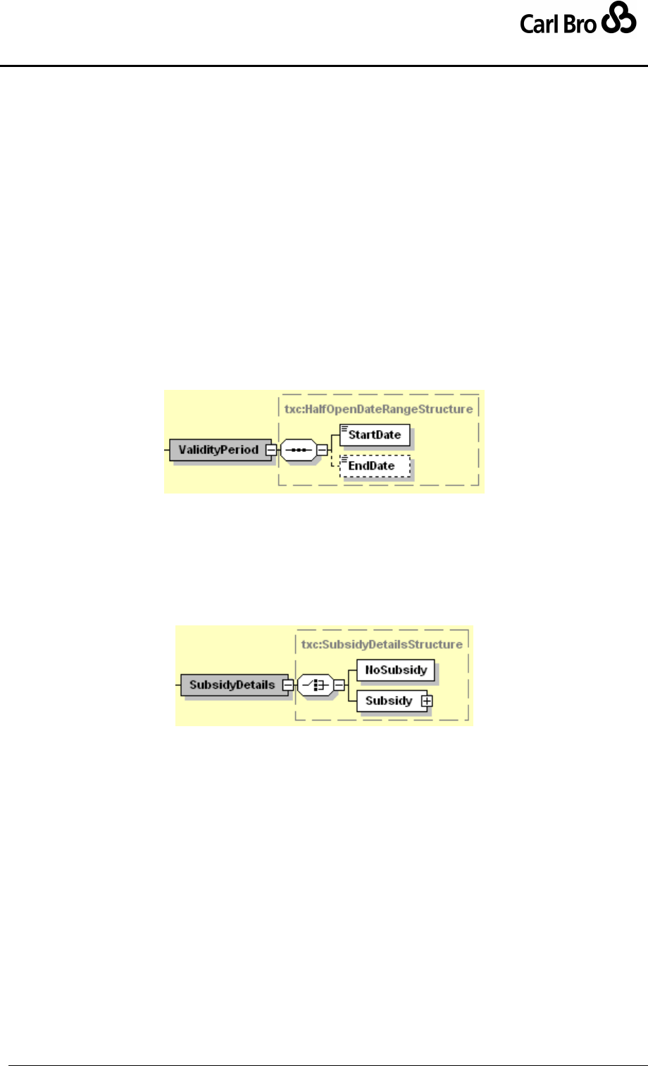
1.6.1.3 Element Structure – Sequence
The hexagonal symbol with the horizontal line of three dots indicates “sequence of.” For
example, Figure 1-1 says the element ValidityPeriod consists of the sequence of
StartDate followed by EndDate. Both elements are defined in the namespace whose prefix
is “txc”. The adornment of a small series of horizontal lines in their upper left box corners
indicates that StartDate and EndDate are non-empty elements.
Figure 1-1 – XML Spy Diagram: Sequence
1.6.1.4 Element Structure – Choice
The hexagonal symbol with the switch-like icon indicates a choice. For example in Figure
1-2 there is a choice between the elements NoSubsidy, and Subsidy. Subsidy has a
further substructure, indicated by a “+” in at the right-hand end. NoSubsidy is an empty
element.
Figure 1-2 – XML Spy Diagram: Choice
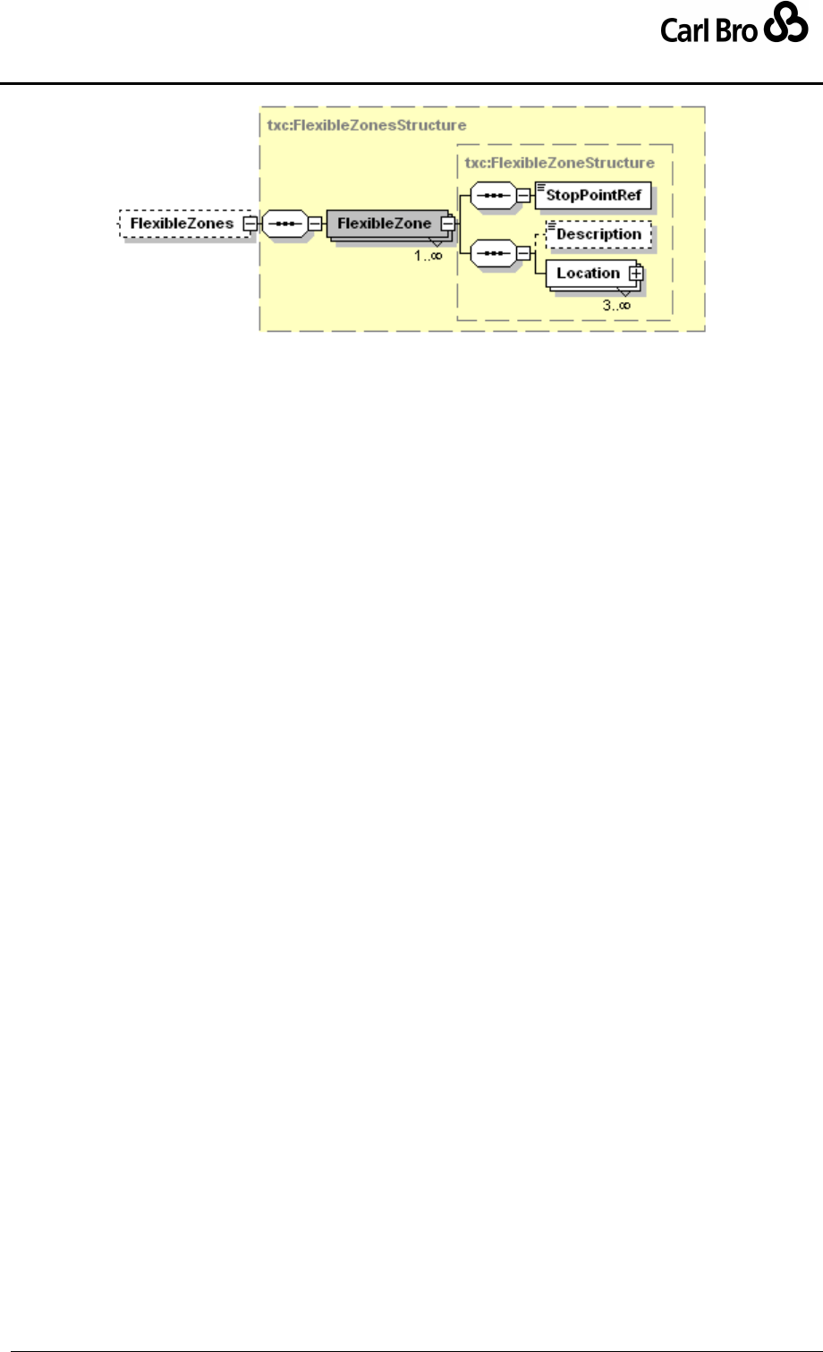
1.6.1.5 Multiplicity and Optionality
Whether elements are required or optional, and the multiplicity (cardinality) of elements is
indicated by adornments as follows:
A fine dashed line on the connecting line and surrounding box indicates an element
is optional. For example, in Figure 1-3; FlexibleZones and Description.
A solid line indicates a mandatory element. For example, in Figure 1-3; StopRef.
A number adornment indicates a multiplicity other than one. ‘Many’ is indicated by an
infinity sign ∞. Thus, for example in Figure 1-3, there may be one Description, but
there can be between one and many FlexibleZone, and must be three or more
Location Instances.
Department for Transport
TransXChange Schema Guide
Part I
Introduction & Overview
TransXChangeSchemaGuide-2.1-v-45.pdf.doc
Page 20
24 September 2013
Figure 1-3 – XML Spy Diagram: Multiplicity
1.7 Major Changes in Release 2.0 of TransXChange
TransXChange include major syntactic and semantic revisions to bring it closer to NaPTAN
and other standards. The following is a summary of major changes in release 2.0. See
Section 16 for a full list of changes.
Modularisation.
eGif GovTalk compliance.
Data Integrity improved.
Welsh Language support added.
Route Links remodelled.
VehicleJourney & JourneyPattern model revised for efficiency and integrity.
Days of Operation standardised and extended.
Registration Number supported.
Provision of a full TransXChange Schema Guide with examples.
New TransXChange Publisher to transform XML documents to Acrobat pdf format.
Use of revised NaPTAN & NPTG models.
Revision of Registration / Service relationship to enable connecting services to be
specified in registrations.
New function for:
New National Operator code, when available.
Flexibly Routed Services.
Vehicle Operations.
School Dates.
Fare Stages (but not fares).
Dead Run support.
Dynamic Bay Allocation.
Add further descriptive elements to Service.
For changes in 2.1 see Appendix B.
Note that an extension of TransXChange to handle fares information, currently referred as
FareXChange, is being considered for future development.

Department for Transport
TransXChange Schema Guide
Part I
Introduction & Overview
TransXChangeSchemaGuide-2.1-v-45.pdf.doc
Page 21
24 September 2013
1.8 Evolving TransXChange
The extensive changes mandated for TransXChange 2.0 inevitably mean that strict XML
compatibility between documents and tools running at TransXChange 1.2 is not possible.
The intention in TransXChange 2.0 was to undertake a comprehensive update that aligns it
closely to NaPTAN, and that will help to minimise changes needed in future. The objective
however was to achieve a full upwards compatibility of data – the existing content used to
create TransXChange 1.2 documents should be exactly mappable to the revised schema.
Since existing TransXChange documents are generated automatically by various suppliers’
tools, the enhancement of the tools to generate the new format should provide a
straightforward upward migration path.
At the same time, 2.0 put into place a formal versioning method that should aid with the
concurrent operation of schemas at different levels in future.
In order to achieve upwards compatibility of data, care has been taken to preserve the
existing semantics of TransXChange.
Work areas identified for future TransXChange work include:
Fine grained exchange of deltas.
Further support for multimodal Interchanges (Journey connections between different
modes of transport).
1.9 Acknowledgments
This document has been prepared by the Carlbro (Richard Mejia, Paul Robinson) and
Kizoom teams (Nick Knowles, Tom White) under direction of Roger Slevin of the
Department for Transport, and Tim Hughes (VOSA). Introduction, modelling, structure
example, schema and technical sections have been provided by Kizoom, worked examples
by Carlbro. We thank Matt Francis of Action Information Management Ltd for his examples,
comments and suggestions including the table of comparative terminology. Thanks also to
Andrew Cudbertson (Arriva), Ross Dixon (CGEY), Michael Forbes (Opcom), Kieran Holmes
(Cap Gemini), Paul Houghton (Trandata), Peter Miller (ACIS), Peter Neil (Trapeze), Mike
Ness (WSAtkins), Pete Ridley (Thales), John Prince (SYPTE), John Gallagher (Thales),
Stephen Corlett (Thales), Richard Shaw (WSAtkins), Alex Worrel (AtkinsGlobal), Adrian
Walters (Infocell), Mary Doonan (Journey Plan), Dave Walter (Anite), Dr Martin Siczkowski
(WYPTE), Mike James (Tandata), John Pryer (Omnibus), Wilfred Düx (MDV), Graham
Browne (WYPTE), Peter Stoner, and other ATCO,RTIG and PTIC members for their
comments, examples and other feedback.

Department for Transport
TransXChange Schema Guide
Part I
Introduction & Overview
TransXChangeSchemaGuide-2.1-v-45.pdf.doc
Page 22
24 September 2013
1.10 Related Transport Information Standards
TransXChange is an XML based standard and is compatible with the following standards for
public transport information:
ATCO-CIF: ATCO-CIF is a general purpose exchange format for common elements
of timetable information. TransXChange is intended to be a successor to ATCO-CIF.
NaPTAN: The National Public Transport Access Nodes database is a UK
nationwide system for uniquely identifying all the points of access to public transport
in the UK. The NaPTAN database is maintained centrally under contract to the
Department for Transport. The NaPTAN standard is described in a separate
document (see bibliography at end). NaPTAN is intended to assign every UK train
station, coach terminus, airport, ferry terminal, bus stop, etc, a unique NaPTAN
identifier. For large interchanges & termini, NaPTAN points identify the entrances
from the public thoroughfare – one identifier is distinguished as the main entrance.
NPTG: The National Public Transport Gazetteer is an auxiliary database to
NaPTAN that provides a means of relating NaPTAN stops to UK towns and villages,
as well as to the regional groupings used to manage Public Transport data.
TransXChange assumes knowledge of the current NPTG database by all parties.
Transmodel: Transmodel is an abstract Reference Data model of the data of
interest to organisations designing transport related information systems. It has been
developed through several European Commission sponsored projects. A pre-
standard version 4.0 is expected to be replaced soon by a full CEN standard as v5.1
JourneyWeb: JourneyWeb is an XML protocol allowing distributed journey planning.
The protocol is a UK national de facto standard sponsored by the UK Department for
Transport, and is being used in the Transport Direct Portal project to provide
contiguous distributed journey planning across the whole of the UK.
SIRI: Service Interface for Real-time Information is a standard for the exchange of
real time bus information between systems developed by CEN members of the UK
Real Time Interest Group. It is also based on NaPTAN and Transmodel, and will be
evolved so as to harmonise with other related standards including TransXChange.
UK Geocoding References: For geospatial location references TransXChange
supports both Grid references – using Eastings and Northings, with support for both
UK Mainland and Irish grids – and WGS 84 Latitude and Longitude. However Grid
location references must be used for registrations.
1.11 Legislation
Bus registration is covered by several sets of bus registration regulations under the
Transport Act 1985. These regulations are: The Public Service Vehicles (Registration of
Local Services) Regulations 1986, amended by SI1988 1697, SI1989 1064, SI1993 2752,
SI1994 3271 and SI2004 10.

Department for Transport
TransXChange Schema Guide
Part I
Introduction & Overview
TransXChangeSchemaGuide-2.1-v-45.pdf.doc
Page 23
24 September 2013
1.12 Related Documents
A TransXChange Registration provides an electronic representation of the following forms
issued by the Vehicle and Operating Services Agency (VOSA). The forms may be
downloaded in pdf format from http://www.vosa.gov.uk/.
Description
England and Wales
Scotland
Date
Application to Register a Bus Service
PSV350
PSV350 (Scotland)
June 2003
Short Notice Registration Supplementary Form
PSV350A
PSV350A (Scotland)
Sept 2001
Local Bus Service Registration. Guide for Operators
PSV353A
June 2004
Application to Change or Cancel details of a Local Service
Registration
PSV355
PSV355A (Scotland)
Table 1-1 – Forms for Registering Bus Services in England and Scotland

Department for Transport
TransXChange Schema Guide
Part I
Introduction & Overview
TransXChangeSchemaGuide-2.1-v-45.pdf.doc
Page 24
24 September 2013
2 OVERVIEW OF TRANSXCHANGE
2.1 The Purpose of TransXChange
TransXChange is a standard format for describing bus routes and schedules as XML
documents that can be automatically exported and imported between different computer
systems. The documents themselves can be exchanged by different transport mechanisms,
for example, FTP, email or http, and can be zipped (compressed) significantly to speed
transfer.
There are two main variants of TransXChange:
Registration schema: Defines XML documents specifically for the purpose of
registering bus services with VOSA. Each document contains a single registered
"service".
General schema: Defines XML documents for exchanging bus timetables and
related information for many different purposes. Many bus services can be specified
in a single document. Partial schedules may be exchanged.
2.2 TransXChange Elements
TransXChange comprises the following main elements:
TransXChange Schema: A model and formal schema for describing and encoding
bus schedules as XML documents. The schema can be used with software tools to
check that documents are correctly formatted and contain the required content.
TransXChange Documents and Process: A description and explanation of the
standard, including rules for creating, managing and using TransXChange
documents with software tools.
TransXChange Publisher. The publisher is a free tool issued along with
TransXChange, which allows users to render TransXChange XML documents into a
readable timetable-like layout, using Acrobat pdf file format. The free Acrobat reader
from Adobe can be used to read and print .pdf files. TransXChange Publisher
requires the installation of a standard open source environment for running Java and
XSLT – this can also be downloaded free. Use of these tools is described in Chapter
9. The TransXChange Publisher can be run in two modes: for Registration, in which
case a specific subset of content is published for the registered particulars of a
service, and for General use, which includes some additional content.
It should be emphasised that TransXChange is a data definition standard, and not a
software program or a dynamic protocol in itself. It is intended to enable different suppliers
and user communities to build systems that can share information correctly, cheaply and
efficiently, but does not prescribe detailed error handling or other implementation details that
will vary according to the requirements of individual applications.
2.3 Document Validation
To be valid TransXChange data, documents must satisfy two levels of validity criteria:
1. Well-formedness and validity: Documents must parse and validate against the
TransXChange schema at the specified level – Registration or General – including

Department for Transport
TransXChange Schema Guide
Part I
Introduction & Overview
TransXChangeSchemaGuide-2.1-v-45.pdf.doc
Page 25
24 September 2013
all the integrity constraints coded within the schema, such as for key uniqueness
and reference. Any document that does not satisfy the syntactic rules will be
rejected for Registration and may not be accepted or understood correctly in uses
on the General Schema.
2. Correctness: Documents must satisfy additional processing rules and constraints
that are not enforceable in the XML of the schema, but which are specified in this
document, or as annotations in the schema (In case of any inconsistency, the
schema should be regarded as definitive). Typically these rules cover additional
complex processing or uniqueness constraints that cannot readily be expressed
using XML’s built-in mechanisms. Any document that is not correct may be rejected
for Registration and may not be accepted or understood correctly in uses on the
General Schema. A number of semantic rules are listed later, and a severity
assigned to them. The publisher provides a diagnostic function to checks for a
number of these errors.
Department for Transport
TransXChange Schema Guide
Part I
Introduction & Overview
TransXChangeSchemaGuide-2.1-v-45.pdf.doc
Page 26
24 September 2013
2.4 How is TransXChange Used?
The following three scenarios give the most common uses for TransXChange:
(i) To register a complete service.
(ii) To update a registration.
(iii) To exchange service related data for a wide variety of other purposes.
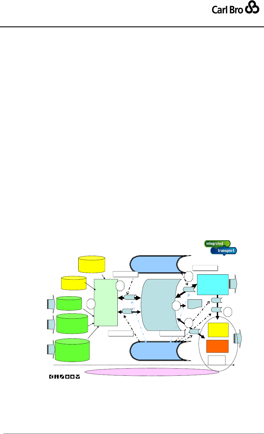
2.4.1 Registration of a Route with VOSA
The most common scenario for use of TransXChange is to make a registration (Figure 2-1),
and runs as follows:
1. Bus schedule data is prepared using scheduling software, including route and stop
data.
2. The schedule is exported as a TransXChange XML document to VOSA for
registration. On export, the document is validated against a specified version of the
schema. Note that TransXChange documents can also in principle be created by
hand, though this would be both tedious and error prone.
3. The schedule is then imported by VOSA and Local Transport Authorities. On
import, the document is validated against the version of the schema indicated by
the document.
4. Following validation, the registered particulars alone are rendered as a readable
pdf document using the Registration option of the TransXChange publisher.
5. The schedule is then imported by information system builders such as journey
planners and AVL system implementers.
6. All or part of routes and schedules may be exchanged by system providers,
annotated with additional operational data, over and above the registered
particulars.
© 2004Kizoom
Registration
Data
Build
Stops
NaPTAN
Places, Areas
Nat Gazetteer
Mapping
OS MasterMap
+ ITN Layer
RealTime
Servers
TransXChange
REGISTRATION
XML Schema Vn
Common Abstract model
Route
planning
&
Sched-
uling
Tools
Journey
Planners
TransXChange
GENERAL
XML Schema Vn
TXC
XML Doc
•Stops
•Routes
•Operators
•Services
•Vehicle
Journeys
R Vn
G Vn
ETC
R Vn
G Vn
G Vn
G Vn
Operators,
Services
Timetables
XML Validation
XML Validation
XML Validation
XML Validation
XML Validation
XML Validation
XML Validation
XML Validation
1
2
3
5
6
pdf
4
Figure 2-1 – Overview of TransXChange Use
2.4.2 Update of a Registration with VOSA
TransXChange will also be commonly used to update an existing registration.

Department for Transport
TransXChange Schema Guide
Part I
Introduction & Overview
TransXChangeSchemaGuide-2.1-v-45.pdf.doc
Page 27
24 September 2013
1. The schedule is updated by the owner using the schedule preparation system.
2. The schedule is reported as an XML registration document with updated data and
modified change dates. Note that the whole schedule must be recreated;
TransXChange does not currently formally support the exchange of ‘deltas’, that is,
changes to just part of a route or timetable (though this is likely to be added in
future).
3. The schedule is revalidated and imported by VOSA, and the changed parts are
updated in the VOSA database. The validation and propagation process thereafter
is as for registration.
2.4.3 General Purpose Exchange of Data
TransXChange can also be used for the general purpose exchange of structured bus
schedule data between any two information systems. Normally the TransXChange General
schema will be used for this purpose, as it allows consistent subsets of data to be
exchanged. Example uses might include:
Exchanging schedule information with journey planning systems that wish to use the
service.
Exchanging route information with mapping systems that wish to draw the route.
Exchanging schedule and operational data with AVL systems that wish to provide
real-time bus predictions.
Exchanging school term dates with Educational Authorities.
Exchanging Operator details.
The precise scenario of use will depend on each specific purpose, but may be described
generally (Figure 2-1), as follows:
The exporting system will output the desired selection of data into an XML
document. The resulting document must validate against the TransXChange schema
version referenced in the document header.
The document is transferred from the source to the target system by any appropriate
transport method (e.g. email, ftp, and http).
The importing system validates and imports the document, using the appropriate
version of the TransXChange schema indicated by the document to interpret the
document's contents. It will reject the document if it is not well-formed (including the
rules for internal integrity). It may decide its own actions to handling errors in the
conforming to application level integrity constraints.
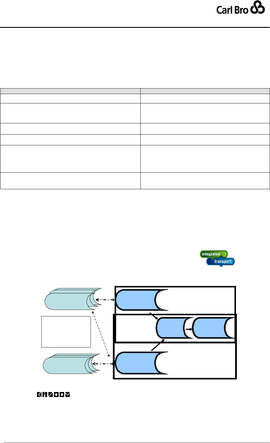
Department for Transport
TransXChange Schema Guide
Part I
Introduction & Overview
TransXChangeSchemaGuide-2.1-v-45.pdf.doc
Page 28
24 September 2013
2.5 Differences between the Schemas
The TransXChange Registration and General schema are essentially the same, but differ
in a few constraints as to cardinality and the required use of certain elements.
Table 2-1 summarises the differences between the two schema variations:
TransXChange Registration Document
TransXChange General Document
Must have a single Registration.
Can have zero or multiple Registration instances.
The Registration. Must reference a primary Service which
describes the service being registered. Other connecting
services to which the primary service connects can be included.
May have zero, one or many services.
The Service for the Registration must have a fully completed
Registered Operator, i.e. of type LicensedOperator.
Registered operator details need not all be completed, i.e.
can be of type Operator, rather than LicensedOperator.
Sufficient information about each stop must be provided to
constitute a stand alone definition for statutory purposes.
Simple Stop references may be used.
The Route information for the registered Service should include
additional mapping point information where appropriate (using
the RouteLink / Track / Mapping elements) to make the route
unambiguous when the stop and mapping points are followed in
sequence over a map containing a road network description.
Mapping information is optional.
Primary LocationSystem used in a Registration document
must be Grid.
Either WGS84 or Grid can be used for LocationSystem.
The same system should be used for all references in a
given document.
Table 2-1 – Differences between Schemas
The schemas share a common set of element types (Figure 2-2). As a general principle, the
Registration schema is strictly substitutable with the General schema, that is, a valid
Registration document will always validate against both schemas and can be used
wherever a General document is used.
Figure 2-2 – Common Set of Types in TransXChange Schemas
©
2004Kizoom
Schema structure
TransXChange
REGISTRATION
XML Schema
Vn
TransXChange
REGISTRATION
XML Doc
TransXChange
GENERAL
XML Schema
Vn
TransXChange
GENERAL
XML Doc
TXC
Common
Subschema
TXC
Data
Subschemas
A document that
validates for
registration
will validate against
general schema too

Department for Transport
TransXChange Schema Guide
Part I
Introduction & Overview
TransXChangeSchemaGuide-2.1-v-45.pdf.doc
Page 29
24 September 2013
3 SHORT TOUR OF THE TRANSXCHANGE ESSENTIAL MODEL
In this chapter, we provide an overview of the logical model underlying the TransXChange
schemas. Unified Modelling Language (UML) diagrams are used to show the relationships
between the most significant elements.
3.1 Representing a Bus Service in TransXChange
The TransXChange model) has seven basic concepts: Service, Registration, Operator,
Route, StopPoint, JourneyPattern, and VehicleJourney.
A Service brings together the information about a registered bus service, and may contain
two types of component service: Standard or Flexible; a mix of both types is allowed within
a single Service.
A normal bus schedule is described by a StandardService and a Route. A Route
describes the physical path taken by buses on the service as a set of route links.
A FlexibleService describes a bus service that does not have a fixed route, but only
a catchment area or a few variable stops with no prescribed pattern of use.
A StandardService has one or more JourneyPattern elements to describe the
common logical path of traversal of the stops of the Route as a sequence of timing
links (see later), and one or more VehicleJourney elements, which describe
individual scheduled journeys by buses over the Route and JourneyPattern at a
specific time.
Route, JourneyPattern and VehicleJoumey follow a sequence of NaPTAN
StopPoints. A Route specifies in effect an ordered list of StopPoints. A
JourneyPattern specifies an ordered list of links between these points, giving
relative times between each stop; a VehicleJourney follows the same list of stops at
specific absolute passing times. (The detailed timing Link and elements that connect
VehicleJourneys, JourneyPatterns etc to StopPoints are not shown in Figure
3-1).
Both types of service have a registered Operator, who runs the service. Other
associated operator roles can also be specified.
A Registration specifies the registration details for a service. It is mandatory in the
registration schema.
Figure 3-1 shows, in UML class diagram notation, the basic elements of the TransXChange
schema. Reusable elements with a global scope are organized beneath the root
TransXChange element of the schema by container elements; that is, Routes, StopPoints,
Services, Operators and VehicleJourneys. (Note that this picture is a simplification: for
example, there are some other global containers, such as ServicedOrganisations and
RouteSections, which are not shown.)
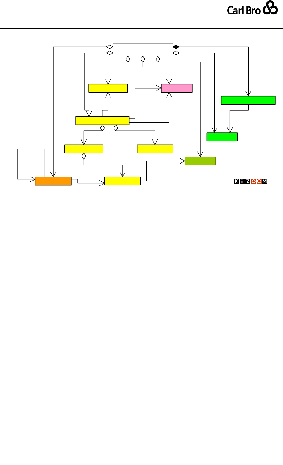
Department for Transport
TransXChange Schema Guide
Part I
Introduction & Overview
TransXChangeSchemaGuide-2.1-v-45.pdf.doc
Page 30
24 September 2013
«Schema root»
TransXChange
1
0..*
services
Service
1
0..*
routes
Route
0..*
1
has route
VehicleJourney
1..1 0..*
use links from
1
0..1
journeys
Operator
1
0..*
associated
StandardService FlexibleService
JourneyPattern
10..*
patterns
0..* 1
pattern
TransXChange
Overview
0..*
1
registered
1
0..*
operators
1
0..* registrations
Registration
1..1
0..1
service AnnotatedStopPointRef
1
0..*
stop references
© Crown Copyright 2003-2009
StopPoint
1
0..*
local
0..*
1
stop
10..1
flexible
1
1
standard
1
0..1
standard
Figure 3-1 – UML Overview of TransXChange Model for a
StandardService
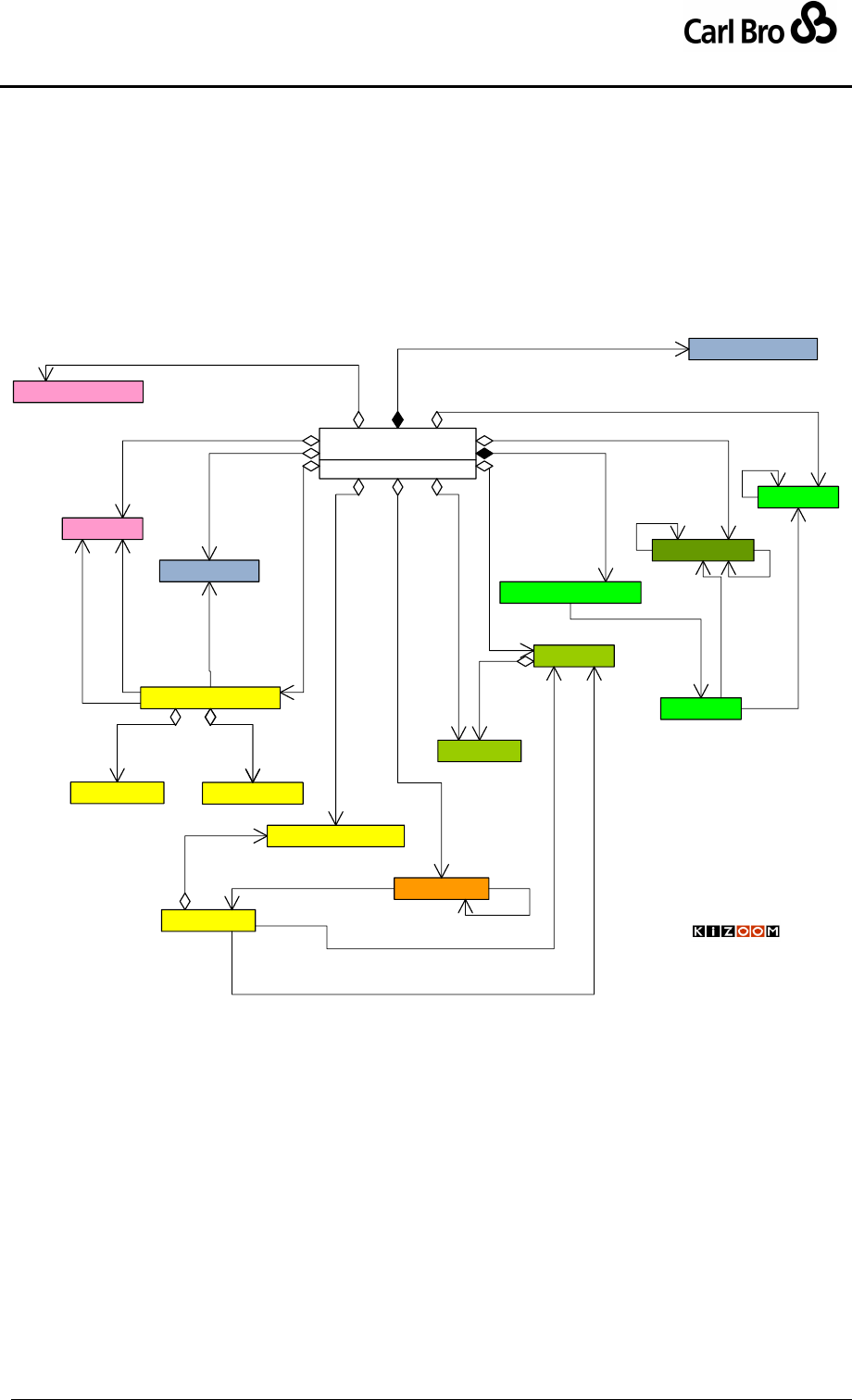
Department for Transport
TransXChange Schema Guide
Part I
Introduction & Overview
TransXChangeSchemaGuide-2.1-v-45.pdf.doc
Page 31
24 September 2013
Figure 3-2 shows further elements of the TransXChange model.
A ServicedOrganisation can be used to specify a school, works or other
organisation served by a service.
A Stop may be part of a group of stops making up a StopArea, and may reside in a
topographic region specified by an NptgLocality.
A Route may be made up of reusable JourneyPatternSection.
A JourneyPattern may be made up of reusable JourneyPatternSections.
A registration may be accompanied by SupportingDocuments.
«Schema root»
TransXChange
Service
Route
VehicleJourney
Operator
StandardService
FlexibleService
JourneyPattern
TransXChange
Overview
Registration
AnnotatedStopPointRef
ServicedOrganisation
StopPoint
NptgLocality
StopArea
0..*
0..*
areas
1..1
0..*
part of
1
0..*
local stop areas
1
0..*
stop references
0..*
1
stop
0..1
0..*
is adjacent to
1
0..*
is in
1..1
0..*
is part of
1
0..*
localities
0..*
1
registered
1
0..*
associated
1
0..*
operators
1
0..* organisations
JourneyPatternSection
0..1
1..*
sections
1
0..*
sections
RouteSection
1
1..*
sections
1
0..*
sections
1..1
0..1
service
1
0..*
registrations
1
1
standard
1
0..*
services
1
0..1
flexible
1
0..1
standard
1
0..1
journeys
1..1
0..*
use links from
0..*
1pattern
1
0..*
routes
0..*
1
has route
0..*
1
has route
SupportingDocument
1
0..*
supporting document
© Crown Copyright 2003-2009
Figure 3-2 – UML Diagram of Elaboration of TransXChange model
3.2 The NaPTAN Stop Model
TransXChange uses the NaPTAN stop model to define the stops and timing points of
routes, and to associate stops with topographical locations in the National Public Transport
Gazetteer (NPTG). For further details refer to the ‘NPTG and NaPTAN Schema Guide’.
Normally in TransXChange, stops comprise just a reference to an existing NaPTAN
definition using a stop code; all such references are declared as AnnotatedStopPointRef
instances. However, full StopPoint definitions for new bus stops may also be provided
locally in a TransXChange document, using the NaPTAN StopPoint elements within the
document. Each new locally defined stop definition must be allocated a NaPTAN identifier
(that is an AtcoCode) that can be used to reconcile them with the NaPTAN database later.
Stops are described using three main elements:
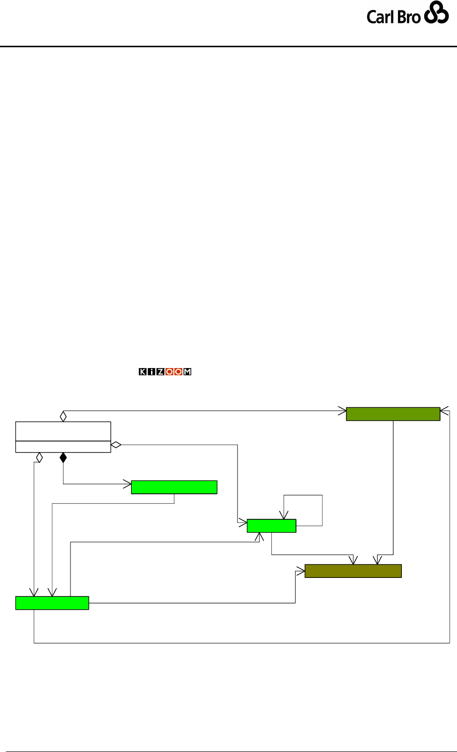
Department for Transport
TransXChange Schema Guide
Part I
Introduction & Overview
TransXChangeSchemaGuide-2.1-v-45.pdf.doc
Page 32
24 September 2013
Figure 3-3 summarises, in UML class diagram notation, the main stop elements of the
TransXChange schema.
StopPoint: Describes a stop, it contains a place, which is used to associate the
stop with an NptgLocality: localities are defined in the NPTG database and are
open to the Local Transport Authority to edit. Stops may be of a number of
different types and subtypes, each with different properties.
o OnStreet / Bus:
MarkedStop. UnmarkedStop, HailAndRideSection,
FlexibleZone.
o OffStreet / BusAndCoach
Bay, VariableBay.
StopArea: Used to group stops together.
NptgLocality: Representing a topographical locality in the country, such as a
city, town or village. Localities must exist in the NPTG database. Used to specify
where a StopPoint or StopArea is relative to towns and cities.
AdministrativeArea. All NaPTAN and NPTG elements are assigned to an
administrative areas – this represents the organisation responsible fro
maintaining the stop data. See NaPTAN schema guide for further details.
StopPoints may be declared as either a StopPoint, or AnnotatedStopPointRef, indicating
that further details may be found in the NaPTAN database. The latter is the normal
mechanism.
«Schema root»
TransXChange
AnnotatedStopPointRef
StopPoint
NptgLocality
StopArea
TransXChange
Stop Model
Overview
AdministrativeArea
© Crown Copyright 2003-2009
1
0..*
stop references
0..*
1
stop
1
0..*
local
1
0..*
local stop areas
1
0..*
localities
1
0..*
is in
1..1
0..* administered by
0..*
0..*
areas
1..1
0..*
administered by
1..1
0..*
admnistered by
1..1
0..*
part of
Figure 3-3 – UML Diagram of Summary of Stop Model
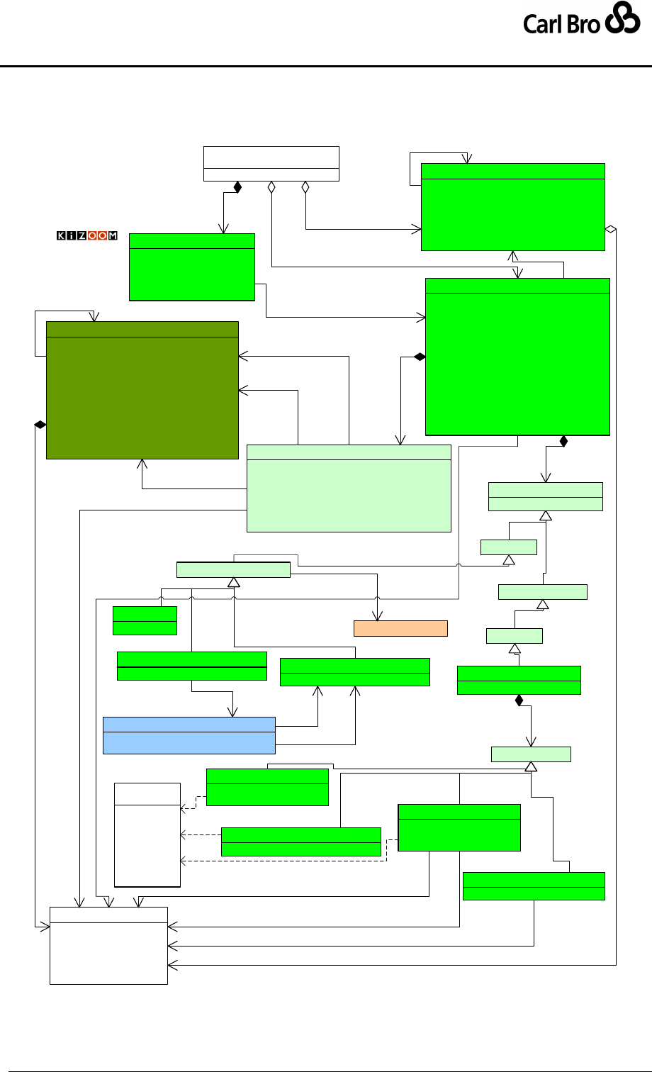
Department for Transport
TransXChange Schema Guide
Part I
Introduction & Overview
TransXChangeSchemaGuide-2.1-v-45.pdf.doc
Page 33
24 September 2013
Figure 3-4 shows further details of the NaPTAN stop elements. A StopPoint definition
includes a Place & Descriptor groups. A StopAvailability may specify when a stop is
available.
«Schema root»
TransXChange
1
0..*
local
TransXChange
Topography:
Stops, Stop Areas,
Localities 1
0..*
local stop areas
VariableStopAllocations
VariableStopPointAcllocation : StopAllocation
DefaultStopPointRef : StopPointCodeType 0..1
0..1
default
0..1
0..*
variable allocation
1..1 0..1
allocation
AnnotatedStopPointRef
StopPointRef[1] : AtcoCodeType
CommonName[1] : nlString
Indicator[0..1] : nlString
LocalityName[0..1] : nlString
LocalityQualifier[0..1] : nlString
1
0..*
stop references
0..*
1
stop
StopArea
<PK>StopAreaCode[1] : StopAreaCodeType
PrivateCode[0..1] : string
ParentAreaRef[0..1] : StopAreaCodeType
Name[1] : nlString
AdministrativeAreaRef[1] : AdminAreaCodeType
StopAreaClassification[1] : StopAreaTypeEnum
Location[1] : Location
1..1
0..*
part of
StopPoint
<PK>AtcoCode[1] : AtcoCodeType
NaptanCode[1] : NaptanCodeType
PlateCode[0..1] : string
CleardownCode[0..1] : string
PrivateCode[0..1] : string
Descriptor[1] : Descriptor
AlternativeDescriptor[0..*] : Descriptor
Place[1] : Place
StopClassification[1] : StopClassification
StopAreas[0..*] : StopArea
AdministrativeAreaRef[1] : AdminAreaCodeType
PlusbusZones[0..*] : PlusbusZone
Notes[0..1] : nlString
StopAvailability[0..*] : StopAvailability
0..* 0..*
areas
«group»Place
NptgLocalityRef[1] : NptgLocalityCodeType
AlternativeNptgLocalities[0..*] : NptgLocalityCodeType
MainNptgLocalities[0..*] : NptgLocalityCodeType
Suburb[0..1] : nlString
Town[0..1] : nlString
LocalityCentre[0..1] : boolean
Location[1] : Location
0..*
0..*
alternate localities
1..1
1
place
1..1
0..*
locality
1..1
0..*
main access points
1..1
1..1
at
BusCoachTramPublic[BCT]
BustStopType[1] : BusStopType
Bay[BCS]
TimingStatus[0..1] : TimingStatusEnum
Entrance[BCE]
VariableBay[BCQ]
TimingStatus[0..1] : TimingStatusEnum
BusAndCoach
AnnotatedCoachRef
1..1
0..*
translate
BusStopType
1
1..1
type
MarkedPoint[MKD]
DefaultWaitTime[0..1] : duration
Bearing[0..1] : CompassEnum
UnmarkedPoint[CUS]
Bearing[0..1] : CompassEnum
HailAndRideSection[HAR]
StartLocation[1] : Location
EndLocation[1] : Location
Bearing[0..1] : CompassEnum
FlexibleZone[FLX]
BoundingPolygon[0..*] : Location
1..1
{ordered}
3..* polygon
StopClassification
StopType[1] : StopTypeEnum
1
1
classification
OnStreet
Bus
OffStreet
Location
Id[1] : nmtoken
Longitude[0..1] : Latitude
Latitude[0..1] : Longtitude
Gridtype[0..1] : GridTypeEnum
Easting[0..1] : Easting
Northing[0..1] : Northing
1..1
1..1 end
1..1
1..1
at
1..1
1..1 start
0..*
1..1
is at
NptgLocality
<PK>NptgLocalityCode[1] : NptgLocalityCodeType
Descriptor[1] : LocalityDescriptor
AlternativeDescriptors[0..*] : LocalityDescriptor
ParentNptgLocalityRef[1] : NptgLocalityCodeType
ShortName[0..1] : nlString
QualifierName[0..1] : nlString
AdministrativeAreaRef[1] : AdminAreaCodeType
NptgDistrictRef[0..1] : DistrictCode
AdjacentLocalities[0..*] : NptgLocalityCodeType
SourceLocalityType[1] : LocalitySourceEnum
LocalityClassification[0..1] : LocalityTypeEnum
Location[1] : Location
1..1
0..*
is part of
1
1..1
is at
© Crown Copyright 2003-2009
N
S
E
W
NE
NW
SE
SW
«enumeration»
CompassEnum
Figure 3-4 – UML Diagram of NaPTAN Stop elements for buses

Department for Transport
TransXChange Schema Guide
Part I
Introduction & Overview
TransXChangeSchemaGuide-2.1-v-45.pdf.doc
Page 34
24 September 2013
3.2.1 Resolving NaPTAN Stop References
When importing TransXChange schedules, an importing application will normally attempt to
find the StopPoint details in the NaPTAN database using the NaPTAN identifier, i.e. the
AtcoCode, and if found may - depending on the application’s purpose - use the database’s
definition of the stop details in preference to any local definitions. Only if no existing
StopPoint definition is found, will the locally declared definition be used. See Table 3-1.
TransXChange
Document use of stop
NaPTAN database
Exists
Does not exist
NaPTAN StopPointRef
Resolve to NaPTAN
Error
Local NaPTAN declaration
Resolve to NaPTAN
Use Local definition
Table 3-1 – Resolving Stop References
3.2.2 Variable Stop Allocations
For bus stations where the allocation of stops may vary over time, TransXChange supports
variable stop allocation. In such cases the journey pattern should reference a NaPTAN stop
of type BCQ, representing an unspecified stop or bay within the bus station, and then also
specify a schedule of allocations to individual bays (i.e. NaPTAN stops of type BCT) for a
given date, using the VariableStopAllocations element.
3.2.3 Stop Types
Every NaPTAN StopPoint has a stop type that indicates its mode and nature, for example,
“on street, bus stop, marked “. Figure 3-5 shows, in UML class diagram notation, the stop
classification elements of the NaPTAN schema. The main items of interest for
TransXChange are:
OffStreet/BusAndCoach, for stops in coach stations
OnStreet/Bus for stops on the street
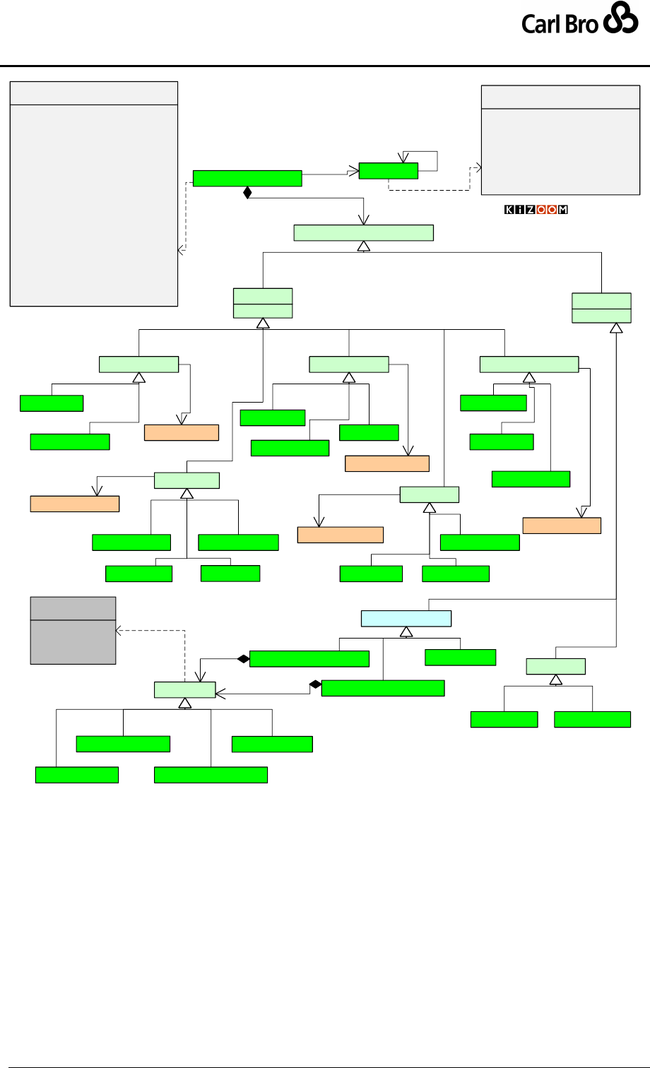
Department for Transport
TransXChange Schema Guide
Part I
Introduction & Overview
TransXChangeSchemaGuide-2.1-v-45.pdf.doc
Page 35
24 September 2013
BusCoachTramPublic[BCT]
NaPTAN
Stop Classification
HailAndRideSection[HAR]
FlexibleZone[FLX]
MarkedPoint[MKD]
OffStreet
UnmarkedPoint[CUS]
OnStreet
TaxiRank[TXR] SharedTaxi[SHR]
Air RailFerry
Metro
Taxi
AnnotatedAirRef
AnnotatedRailRef
AnnotatedCoachRef
BusAndCoach
1..1
0..*
translate
1..1
0..*
translate
1..1
0..1
translate
Entrance[AIR]
Entrance[FTD]
AccessArea[FER]
Entrance[RSE]
AccessArea[GAT]
AccessArea[RLY]
Entrance[TMU]
AccessArea[MET]AccessArea[BST]
Entrance[BCE]
BusStopType
1
1..1
type
Bay[BCS]
VariableBay[BCQ] AnnotatedMetroRef
1..1
0..*
translate
AnnotatedFerryRef
1..1
0..*
translate
Platform[RPL]
Platform[PLT]
Berth[FBT]
© Crown Copyright 2001-2008
HailAndRide = HAR
Flexible = FLX
Marked = MKD
Custom = CUS
«enumeration»
BusStopTypeEnum
WayPoint[WAY]
Bus
BusCoachTramPrivate(BCP)
1
1type
airportBuilding = GAIR
ferryOrPort = GFTD
railStation = GRLS
tramMetroUndergorundStation = GTMU
busOrCoachStation = GBCS
coachServiceCoverage = GCCH
onstreetBusCoachStopCluster = GCLS
onstreetBusCoachStopPair = GPBS
«enumeration»
StopAreaTypeEnum
busCoachTramStopOnStreet = BCT
busCoachTramStationBay = BCS
busCoachTramStationVariableBay = BCQ
busCoachAccess = BCT
busCoachStationEntrance = BCE
busCoachPrivate = BCP
wayPoint = WAY
railPlatform = RPL
railAccess = RLY
railStationEntrance = RSE
trainMetroUndergroundPlatform = PLT
trainMetroUndergroundAccess = MET
trainMetroUndergroundEntrance = TMU
ferryOrPortAccess = FER
ferryTerminalDockEntrance = FTD
taxiRank = TXR
sharedTaxiRank = STR
airAccessArea = GAT
airportEntrance = AIR
«enumeration»
StopTypeEnum
StopPoint StopArea
0..*
0..*
areas
1..1 0..*
part of
StopClassification
11
classification
Figure 3-5 – UML Diagram of Stop Classification Model

Department for Transport
TransXChange Schema Guide
Part I
Introduction & Overview
TransXChangeSchemaGuide-2.1-v-45.pdf.doc
Page 36
24 September 2013
3.3 The Route and Service Supply Model
TransXChange describes a bus service using a model made up of three distinct layers or
'levels of discourse' (see Figure 3-6 for an UML diagram):
1. A Route; described as a sequence of route links connecting individual stops. For
TransXChange, all stops are defined as being NaPTAN points, so a route describes
a path in ‘NaPTAN space’; a distinct frame of reference made up of Public Transport
Access Nodes (PTANs), which is semantically distinct from any given coordinate
system, but which can be projected onto geospatial coordinate systems and
mapping layers using Track elements.
o Track elements record both the plot of the route at non-NaPTAN points, and
associations with mapping layer identifiers, such as OS TOIDS.
o The RouteLink instances are grouped using a RouteSection, allowing the
reuse of whole sequences of links in different routes.
2. A JourneyPattern: a path over the route made up of a number of journey pattern
timing links, each with timing information (and other optional operational data)
ascribed to them. All timing information is relative (for example, ‘+5 minutes’).
o Each end of a JourneyPatternTimingLink can have stop usage information
associated with it on a JourneyPatternStopUsage element, specifying the
activity at stop, and other service information.
o The timing links are grouped using a JourneyPatternSection, allowing the
reuse of whole sequences of links in different patterns.
o The links of a JourneyPattern must traverse the same stops in the same
sequence as the links of any Route associated with the JourneyPattern.
However a JourneyPattern need not cover the whole Route; it may project
onto just a contiguous subset of the links of the route, omitting route links at
either or both ends.
3. A VehicleJourney: a traversal of a specific journey pattern at a specific time: again
modelled as a sequence of timing links connecting NaPTAN stops, using
VehicleJourneyTimingLink and VehicleJourneyStopUsage elements.
o Each vehicle journey has an absolute start time (e.g. '13:02') specified: this
can be combined with the timing information from each timing link to derive
the actual passing times of departure and arrival at each timing point.
o The public identifier of a VehicleJourney is given by a Line. One or more
Line instances may be associated with a service, and a VehicleJourney
must reference one of its service's lines.
o The link sequence of a VehicleJourney must exactly correspond to the link
sequence of the underlying JourneyPattern; that is, each
VehicleJourneyTimingLink must project onto a corresponding
JourneyPatternTimingLink.
The Transmodel principles underlying the TransXChange Route and Service Supply
model are summarised in Section 13.1, and divergences from Transmodel usage are
listed.
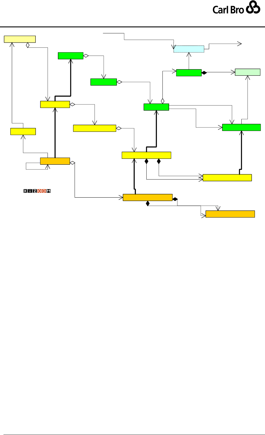
Department for Transport
TransXChange Schema Guide
Part I
Introduction & Overview
TransXChangeSchemaGuide-2.1-v-45.pdf.doc
Page 37
24 September 2013
JourneyPattern
Route
0..*
1
has route
StandardService
1
0..*
patterns
VehicleJourney
1..1
0..*
use links from
0..*
1
pattern
VehicleJourneyTimingLink
1..1
{ordered}
0..*
links
JourneyPatternTimingLink
0..*
1
journey link
RouteSection
1
{ordered}
1..*
sections
VehicleJourneyStopUsage
11..1
from
1
1..1
to
JourneyPatternStopUsage
1
1..1
to
1
1..1
from
RouteLink
1
{ordered} 1..*
links
0..*
1..1
to
0..*
1
uses
0..* 1..1
from
Track
1
{ordered}
0..*
projects
Line
0..*
1
line
MapSystemLink
0..*
1
projects onto
LINK
STOP
LINK STOP USAGELINK COLLECTION
0..*
0..1
follows
0..*
1
lines
JourneyPatternSection
1
{ordered}
0..*
links
0..1
{ordered}
1..*
sections
© Crown Copyright 2003-2008
StopPoint
Location
0..*
1..1
is at
11..*
path
© Crown Copyright 2003-2009
Figure 3-6 – UML Diagram of Route, JourneyPattern and VehicleJourney
Models
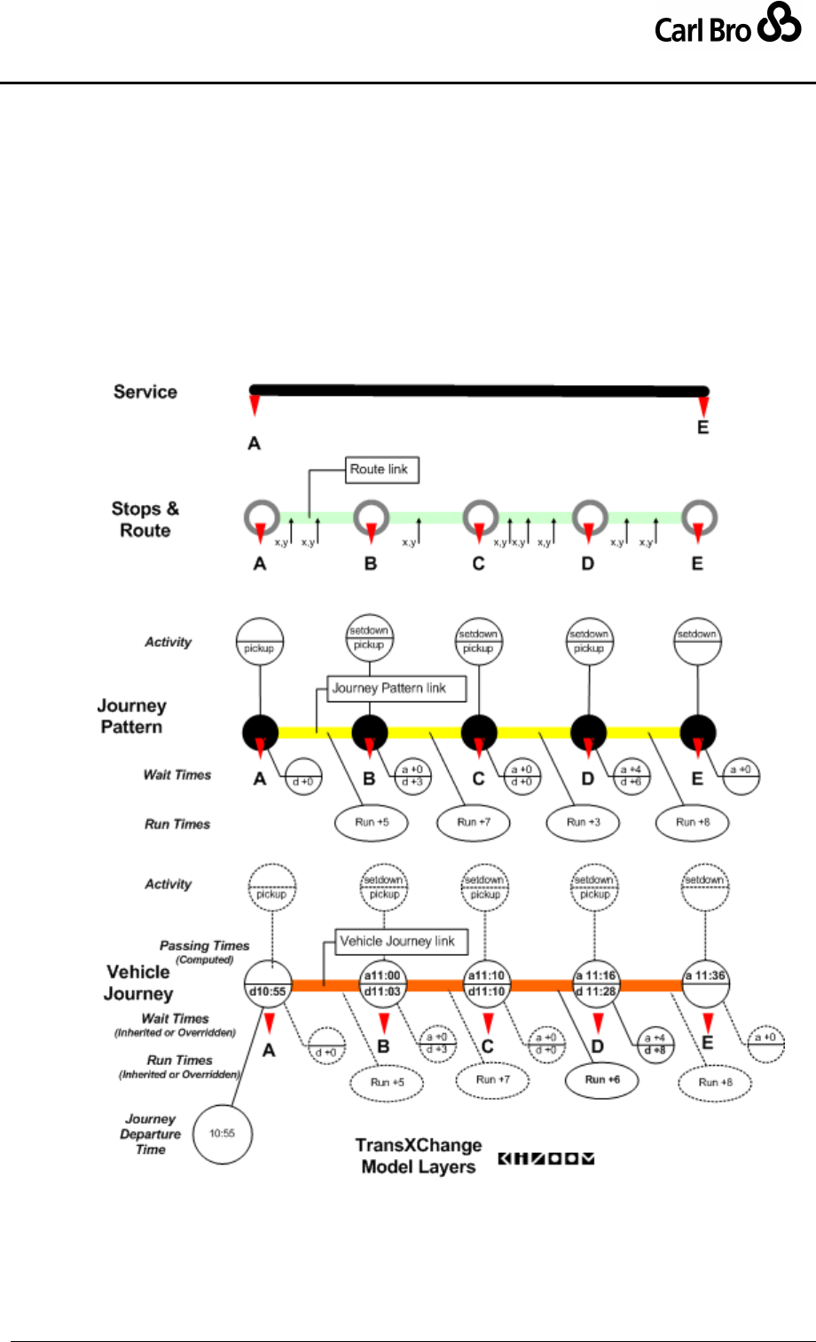
Department for Transport
TransXChange Schema Guide
Part I
Introduction & Overview
TransXChangeSchemaGuide-2.1-v-45.pdf.doc
Page 38
24 September 2013
3.3.1 Model Layer Concerns
Figure 3-7 illustrates how the each layer has a separate concern of the model:
1. The Route describes the stops, stop sequence, and the physical track between
them.
2. The JourneyPattern adds in timing information; how long each link takes to run,
how long to wait at each stop, and the allowed activities at each stop.
3. A VehicleJourney specifies a start time: this is used to compute actual passing
times for each stop in the journey pattern, taking into account the run and waiting
times. The vehicle journey can override the run time, wait time and activity from the
journey pattern values for its own journey, but not change the stop sequence.
4.
Figure 3-7 – Service Model Layer Concerns
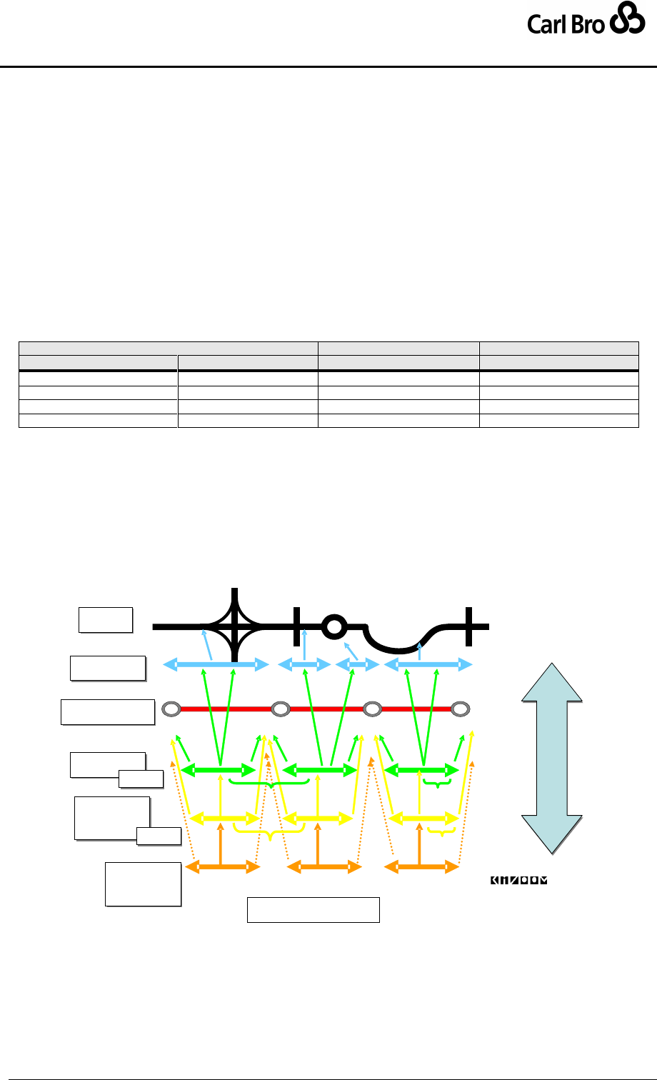
Department for Transport
TransXChange Schema Guide
Part I
Introduction & Overview
TransXChangeSchemaGuide-2.1-v-45.pdf.doc
Page 39
24 September 2013
3.3.2 Summary of Route & Supply Model Elements
Each of the three layers is made up of three sets of broadly equivalent elements:
(i) Ordered collections, i.e. sequences, of links (Patterns and Sections).
(ii) Links (Route Links and Timing Links).
(iii) Link ends (Stop Usages).
Table 3-2 summarises the route and supply model elements, showing the simple one-to-one
correspondences between equivalent elements in the different layers. The simple
correspondence makes it straightforward to project between the route, journey pattern and
vehicle journey layers. There are explicit references between elements in the pattern and
link columns, which can be used to derive an implicit projection of the section and stop
usage.
Ordered Link Sequence
Link
Link end
Pattern
(Section)
Link
Stop Usage
Route
RouteSection
RouteLink
StopReference
(AbstractJourneyPattern)
-
AbstractTimingLink
AbstractStopUsage
JourneyPattern
JourneyPatternSection
JourneyPatternTimingLink
JourneyPatternStopUsage
VehicleJourney
-
VehicleJourneyTimingLink
VehicleJourneyStopUsage
Table 3-2 – Correspondence between Links and Nodes
3.3.3 Projection between Levels of Discourse
Figure 3-8 shows a schematic example of links at different levels of discourse and the
correspondences between them.
Figure 3-8 – Correspondence between Links at Different Levels
B256
B214
High Street
Levels Of Discourse (2.0)
Route
Route
Journey
Pattern
Journey
Pattern
Vehicle
Journey
Vehicle
Journey
Links & Nodes
Track
Track
Projection
(Map)
(Map)
Stop Points
Stop Points
Section
Section
Section
Section

Department for Transport
TransXChange Schema Guide
Part I
Introduction & Overview
TransXChangeSchemaGuide-2.1-v-45.pdf.doc
Page 40
24 September 2013
3.3.4 The Use of Links in TransXChange
In Transmodel, a journey can be regarded either as an ordered list of stops, or as an
ordered list of links between the stops: both views can be derived from the underlying
TransXChange representation of a journey pattern and vehicle journey as a list of timed
links. In TransXChange, a ‘timing link in link sequence’ representation is used (see
discussion of Transmodel terminology and concepts in section 13.2), as this holds more
information than a simple stop list, and can be projected exactly onto a spatial route; it can
readily be transformed by applications into a list of stops and passing times if needed.
The following Transmodel principles apply to the use of journey patterns in TransXChange:
1. There should be a separate journey pattern for each physical route followed, i.e. a
sequence of timing links between stops defining a unique sequence of stops.
2. A vehicle journey must always follow a journey pattern.
3. A vehicle journey must visit all the stops of a journey pattern, with two qualifications
(which are not strictly Transmodel - see 13.2):
a. Short working of the underlying journey pattern is allowed, i.e. truncation of
one or more stops at either or both ends.
b. Express journeys over a service pattern are allowed – i.e. provided a
journey traverses a link and goes past a stop, it may specify an activity of
‘pass’ to omit a particular stop.
The following further principles apply to the use of links to represent journey patterns in
TransXChange:
4. A vehicle journey need specify explicitly only those timing links that are different from
the underlying journey pattern. Other vehicle journey links may be implicit, that is
derived automatically from the underlying journey pattern. In many cases, no explicit
concrete links need be specified in a vehicle journey.
5. A vehicle journey may reference all the links of another vehicle journey. In this case
all the link usage must be implicit, that is, all of the links of the referenced journey
are used with the same values as in the referenced journey. If the vehicle journey
needs to make modifications to links or link properties, it should be based directly on
an underlying journey pattern, and not reference another vehicle journey for some
links and make further changes.
6. Timing links may have a number of different ‘successive’ properties that change over
successive steps of the journey pattern, for example, destination headings, duty
crews, and fare stages. The properties may be set on individual links at both the
journey pattern and vehicle journey level. Once a successive property (such as a
dynamic destination heading) is set on a specific link (or individual link end), it is
considered to be in effect on successor links in the journey until any different value is
encountered on a subsequent link. Link values on successor vehicle journey links
may either be set explicitly, or be inherited from a parent journey pattern link.
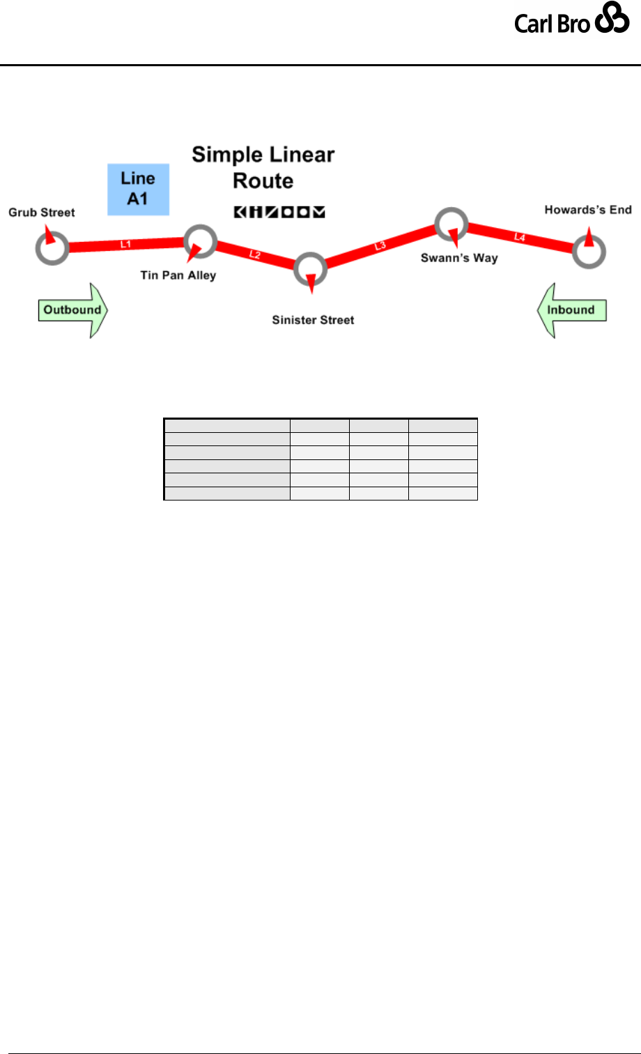
Department for Transport
TransXChange Schema Guide
Part I
Introduction & Overview
TransXChangeSchemaGuide-2.1-v-45.pdf.doc
Page 41
24 September 2013
3.3.5 Structure Example of a Schedule with one Pattern and Two Journeys,
Figure 3-9 shows a simple route, with five stops connected by four links.
Figure 3-9 – Simple Route Map
Table 3-3 shows an example timetable of a service running over the route, with two vehicle
journeys running between each of the five stops.
Name\Line
A1
A1
Grub Street
d
8:02
10:02
Tin Pan Alley
d
8:12
10:12
Sinister Street
d
8:37
10:37
Swans Way
d
8:45
10:45
Howard’s End
a
8:55
10:55
Table 3-3 – Structure Example of a Schedule
Table 3-4 shows this same timetable annotated with the XML element instances needed to
represent it in a TransXChange XML document.
The service has a single Line Ln_1 with a Line Name of 'A1'.
The service is presented in a matrix of five rows of stops (S_1 – S_5), and two
columns of journeys (#1 – #2), each column showing a vehicle journey stopping at
each row.
There is one route (R_1), with a single route section (RS_1) of four route links
(RL_1, RL_2, RL_3, and RL_4). Each route link has two stop references (RL_1a,
RL1b, etc).
The service is made up of a single journey pattern (JP_1). The journey pattern,
section and timing links correspond to those of the route; there is a single journey
pattern section (JS_1), and four timing links (JL_1, JL_2, JL_3, JL_4), with
individual run times of 10, 20, 8, and 10 minutes respectively. \There is also a 5
minute wait at sinister street.
o Each journey pattern timing link has two stop usages (JL_1a, JL_1b, etc),
one for each end of the link, i.e. on for departure, one for arrival. These can
hold information about the use of the stop
There are two vehicle journeys (VJ_1, VJ_2), that both use the same journey
pattern, and that are for the same line, ’A1’ (Ln_1).
o For VJ_1, each of the four vehicle journey timing links (VL_1, VL_2, VL_3,
VL_4) corresponds to a link of the journey pattern, and has its own pair of
stop usages (VL_1a, VL_1b, etc).
o Times at each stop are computed from the vehicle journey start time (e.g.
‘8.02’) and the individual link run times (e.g. +10mn), plus any wait time on
the stop usage. (For S_1 – S_4, only departure times are actually shown in
Table 3-4; for S_5 it is the arrival time).
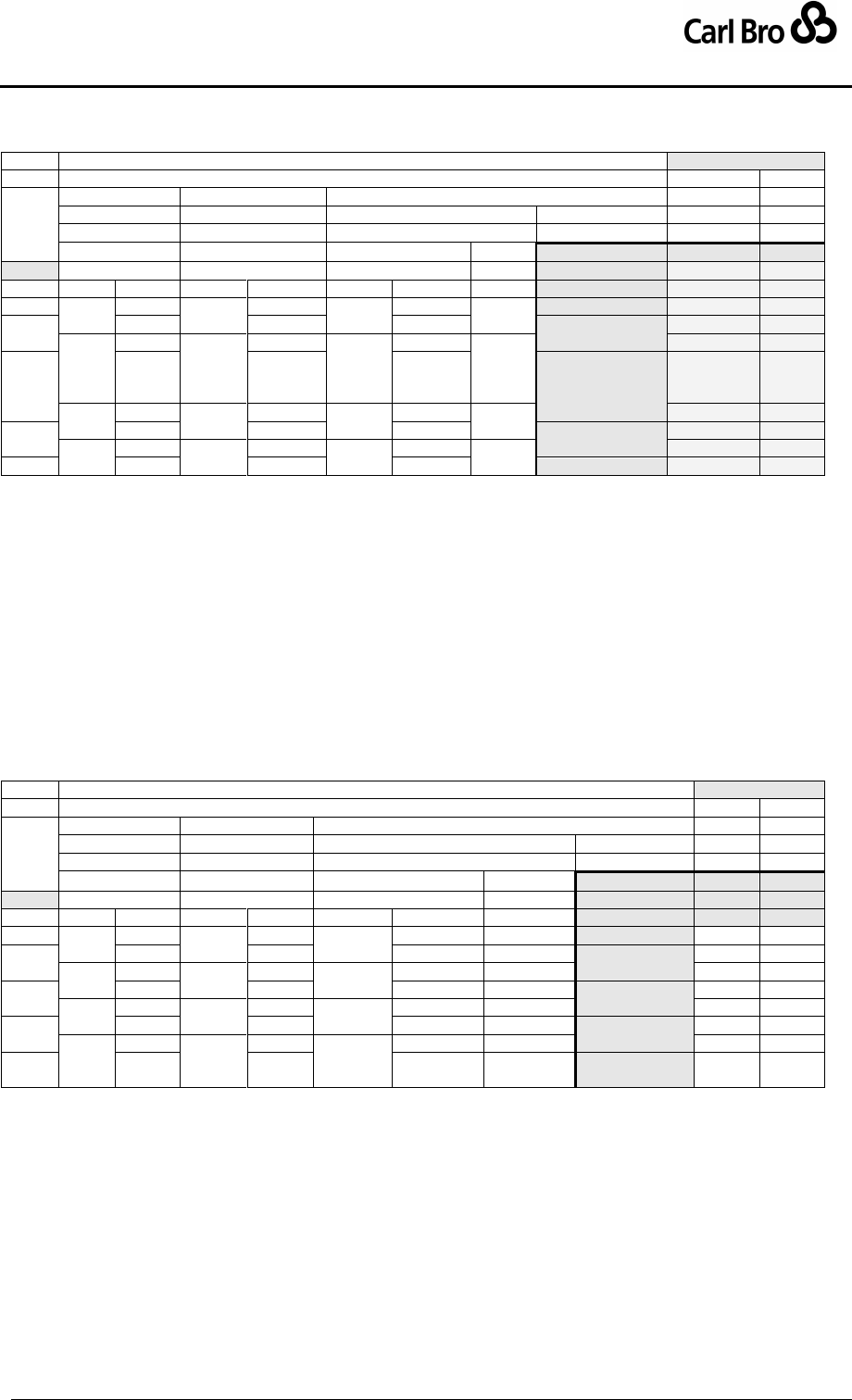
Department for Transport
TransXChange Schema Guide
Part I
Introduction & Overview
TransXChangeSchemaGuide-2.1-v-45.pdf.doc
Page 42
24 September 2013
o The second vehicle journey VJ_2 reuses the links of the first journey pattern
VJ_, with a different start time (‘10:02’).
Journeys
SV_1
Service
#1
#2
Line
Ln_1
Ln_1
Route
Journey Pattern
JP_1
JP_1
R_1
JP_1
Vehicle Journey
VJ_1
VJ_2
Route Section
Section
VJ_1
VJ_2
Name\Line
A1
A1
Stop
RS_1
JPS_1
8:02
10:02
Link
Ref
Link
Usage
Link
Usage
Link
S_1
RL_1
RL_1a
JL_1
+10mn
JL_1a
VL_1.
VL_1a
Grub Street
8:02
10:02
S_2
RL_1b
JL_1b
VL_1b
Tin Pan Alley
RL_2
RL_2a
JL_2
+20mn
JL_2a
VL_2
VL_2a
8:12
10:12
S_3
RL_2b
JL_2b
Wait
+5mn
VL_2b
Sinister Street
RL_3
RL_3a
JL_3
+08mn
JL_3a
VL_3
VL_3a
8:37
10:37
S_4
RL_3b
JL_3b
VL_3b
Swans Way
RL_4
RL_4a
JL_4
+10mn
JL_4a
VL_4
VL_4a
8:45
10:45
S_5
RL_4b
JL_4b
VL_4b
Howard’s End
8:55
10:55
Table 3-4 – Structure Example of Schedule: Shared Journey Pattern
3.3.6 Structure Example of a Schedule with an Express Journey
As a slight variation on the structure example given above, we consider a second example
(Table 3-5), in which the second vehicle journey (VJ_3) omits a particular stop (S_2) in the
same journey pattern (JP_1).
The second journey declares its own distinct set of vehicle journey timing links
(VL_3_1, VL_3_2, VL_3_3, and VL_3_4) for the journey, so that it can modify the
activity. These are based on the same journey pattern.
For the stop that is omitted (S_2), an override value of ‘pass’ is specified for the
activity on the vehicle journey stop usage of the link ends which connect to the stop
(VL_3_1b, VL_3_2a).
Journeys
SV_1
Service
#1
#2
Line
Ln_1
Ln_1
Route
Journey Pattern
JP_1
JP_1
R_1
JP_1
Vehicle Journey
VJ_1
VJ_3
Route Section
Section
VJ_1
VJ_3
Name\Line
A1
A1
Stop
RS_1
JPS_1
8:02
10:02
Link
Ref
Link
Usage
Link
Usage
Usage
S_1
RL_1
RL_1a
JL_1
+10mn
JL_1a
VL_1_1
VL_1_1a
VL_3_1a
Grub Street
8:02
10:02
S_2
RL_1b
JL_1b
VL_1_1b
VL_3_1b
Tin Pan Alley
pass
RL_2
RL_2a
JL_2
+20mn
JL_2a
VL_1_2
VL_1_2a
VL_3_2a
8:12
pass
S_3
RL_2b
JL_2b
VL_1_2b
VL_3_2b
Sinister
Street
RL_3
RL_3a
JL_3
+08mn
JL_3a
VL_1_3
VL_1_3a
VL_3_3a
8:32
10:32
S_4
RL_3b
JL_3b
VL_1_3b
VL_3_3b
Swans Way
RL_4
RL_4a
JL_4
+10mn
JL_4a
VL_1_4
VL_1_4a
VL_3_4a
8:40
10:40
S_5
RL_4b
JL_4b
VL_1_4b
VL_3_4’b
Howard’s
End
8:50
10:50
Table 3-5 – Structure Example of Schedule: Express VehicleJourney

Department for Transport
TransXChange Schema Guide
Part I
Introduction & Overview
TransXChangeSchemaGuide-2.1-v-45.pdf.doc
Page 43
24 September 2013
3.3.7 An Instance Example
As a pictorial example, Figure 3-10 shows a UML instance diagram of the element
instances for a simple journey with four stops, organized according to their different levels of
discourse.
At the bottom, in green, can be seen a RouteSection with three RouteLink
instances between the stops, one of which has two Track instances. The other two
have a single Track Instance. Each Track instance has a Mapping, a sequence of
points plotting the line of the route.
Above this, in yellow, can be seen the JourneyPatternSection, with three
JourneyPatternTimingLink instances which individually project onto the
appropriate route links by virtue of pairs of JourneyPatternStopUsage elements
that reference the same stops in the same order as the route links. (Note that an
explicit route link-to-timing link reference can also be included in order to avoid
ambiguity in circular and other routes with complex topologies – this is not shown).
At the top, in orange, can be seen the VehicleJourney, also made up of three links.
Each VehicleJourneyTimingLink individually projects onto the appropriate
JourneyPatternTimingLink links by an explicit link reference. Each end of each
VehicleJourneyTimingLink has a VehicleJourneyStopUsage with which to
specify any usage values that are different from that of the journey pattern. The
stops of a vehicle journey timing link may not be different from those of the
corresponding journey pattern timing link, so are inherited from the journey pattern
link, rather than being explicitly referenced.
3.3.8 Plotting a route on a Map
If Track data is present it can be used to plot an exact route track on a map. In this case the
Mapping data should be regarded as independent of the stop locations. That is to plot a
route the last point of each mapping is connected to the first point of the succeeding
Mapping. for example, in Figure 3-10 the route plot is given by
(t1_g1 — t1_g2 — t1_g3) — ( t2_1_g1 — t2_1_g2) — (t2_2_g1 — t2_2_g2) — (t3_g1 — t3_g2)
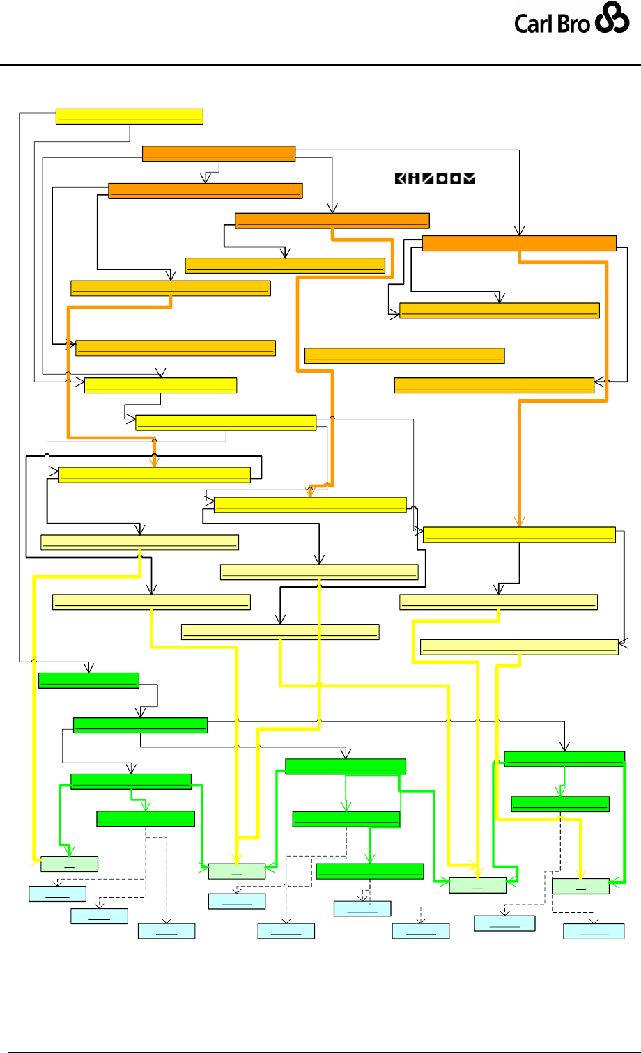
Department for Transport
TransXChange Schema Guide
Part I
Introduction & Overview
TransXChangeSchemaGuide-2.1-v-45.pdf.doc
Page 44
24 September 2013
VL_1 : Txc-SvcPtn-Mdl::VehicleJourneyTimingLink
R_1 : Txc-Rte-Mdl::Route
RL_1 : Txc-Rte-Mdl::RouteLink
S1 S2
RL_3 : Txc-Rte-Mdl::RouteLink
RL_2 : Txc-Rte-Mdl::RouteLink
S5
S4
from from
from
to
track(2) to
to
section (1)
link (2)
link (3)
VL_1a : Txc-SvcPtn-Mdl::VehicleJourneyStopUsage
VL_1b : Txc-SvcPtn-Mdl::VehicleJourneyStopUsage
from
to
stop
VL_2 : Txc-SvcPtn-Mdl::VehicleJourneyTimingLink
VL_2a : Txc-SvcPtn-Mdl::VehicleJourneyStopUsage
VL_2b : Txc-SvcPtn-Mdl::VehicleJourneyStopUsage
from
to
project
VL_3 : Txc-SvcPtn-Mdl::VehicleJourneyTimingLink
VL_3a : Txc-SvcPtn-Mdl::VehicleJourneyStopUsage
VL_3b : Txc-SvcPtn-Mdl::VehicleJourneyStopUsage
from
to
project
T1_g1 t2_1_g1 t2_2_g1
t3_1_g1
JP_1 : Txc-SvcPtn-Mdl::JourneyPattern
JL_1 : Txc-SvcPtn-Mdl::JourneyPatternTimingLink
JL_1a : Txc-SvcPtn-Mdl::JourneyPatternStopUsage
JL_1b : Txc-SvcPtn-Mdl::JourneyPatternStopUsage
from
to
stop
stop
JL_2 : Txc-SvcPtn-Mdl::JourneyPatternTimingLink
JL_2a : Txc-SvcPtn-Mdl::JourneyPatternStopUsage
JL_2b : Txc-SvcPtn-Mdl::JourneyPatternStopUsage
from
to
stop
stop
JL_3 : Txc-SvcPtn-Mdl::JourneyPatternTimingLink
JL_3a : Txc-SvcPtn-Mdl::JourneyPatternStopUsage
JL_3b : Txc-SvcPtn-Mdl::JourneyPatternStopUsage
from to
stop
stop
SV_1 : Txc-Rgs-Mdl::StandardService
link (2)
link (2)
link (3)
pattern
VJ_1 : Txc-SvcPtn-Mdl::VehicleJourney link (2)
link (3)
link (1)
route
pattern
T_1 : Txc-Rte-Mdl::Track
track (1)
T_2_1 : Txc-Rte-Mdl::Track
T_2_2 : Txc-Rte-Mdl::Track
T_3 : Txc-Rte-Mdl::Track
track (1) track (1)
RS_1 : Txc-Rte-Mdl::RouteSection
link (1)
JS_1 : Txc-SvcPtn-Mdl::JourneyPatternSection
link (1)
Route, JourneyPattern, VehicleJourney
Instance Example
t2_1_g2
t1_g2
t2_2_g2 t3_1_g2
t1_g3
Figure 3-10 – UML Instance Diagram of Example of Link Model
Department for Transport
TransXChange Schema Guide
Part I
Introduction & Overview
TransXChangeSchemaGuide-2.1-v-45.pdf.doc
Page 45
24 September 2013
3.4 Inheriting Timing Link Values
Table 3-6 shows the various values that may be specified for the VehicleJourney and
VehicleJourneyTimingLink elements, and whether they are:
(i) Required [‘R’].
(ii) Optional but otherwise inherited from the previous level of discourse [‘O’].
(iii) Always inherited [‘I’’].
The most significant properties are the actual run and wait times of each timing link, but
several other operational values, such as fare stages, may also be specified.
For elements that are optional at all levels, a default value is identified to use if no explicit
value is provided. For some ‘successive’ properties, such as fare stage number, the value in
effect from any previous link is assumed unless specified otherwise. This is indicated by a
[‘S’].
Level of Discourse
→
→
→
Level
Property
Serv
ice
Route
Journey
Pattern
Vehicle
Journey
Default Value
Pattern
ServiceRef
--
(R)
I
Direction
O
--
O
O
Outbound
OperatorRef
R
--
O
O
Service /
RegisteredOperator)
DestinationDisplay
(R)
--
O
O
Service /Destination
TicketMachineServiceCode
O
--
O
O
none
TicketMachine / JourneyCode
--
O
O
none
TicketMachine / Direction
--
O
O
Direction
Block / Board
--
O
O
none
Block / BoardNumber
--
O
O
none
Block / Note
--
O
O
none
GarageRef
--
O
O
none
VehicleType
--
O
O
none
LayoverPoint
--
O
O
none
TimeDemand
--
O
O
none
Frequency
--
O
O
false
OperatingProfile
O
--
O
O
Monday to Friday, Every
Day of Year
LineRef
O
--
--
R
--
DepartureTime
--
--
R
--
Section
order
--
O
I
None
↓
TimingLink
LinkRef
--
O
R
--
Direction
O
R
O
I
JourneyPattern / Direction
RunTime
--
R
O
--
Distance
O
O
I
zero
DestinationDisplay
--
O
O
none (same as Pattern /
DestinationDisplay)
HailAndRide
O
O
O
false
DutyCrewCode
--
O (S)
O (S)
none
StoppingArrangements
--
O
O
none
↓
TimingLink
StopUsage
From & To
StopPointRef
(R)
R
I
--
TimingStatus
--
O
I
TIP
Activity
--
O
O
PickUpAndSetDown
WaitTime
(++)
O
O
zero
VariableStopAllocation
O
O
none
FareStageNumber
--
O (S)
I
none
FareStage
--
O
I
false
Table 3-6 – Journey Properties and Defaults
++ A default wait time may be specified on stops. This merely sets a default that may be
used to set the initial value used by services. Each journey pattern sets the wait value on
each timing link.
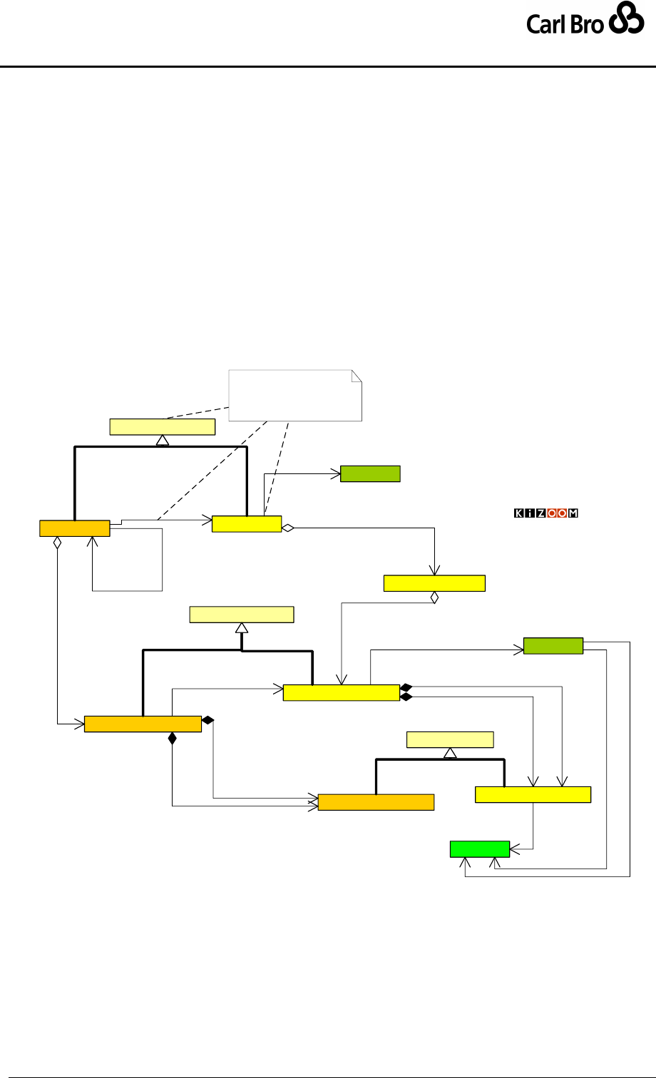
Department for Transport
TransXChange Schema Guide
Part I
Introduction & Overview
TransXChangeSchemaGuide-2.1-v-45.pdf.doc
Page 46
24 September 2013
Figure 3-12shows how inheritance relationships are used in the TransXChange supply
model so as to express the shared attributes and common data structure of equivalent
elements, that is, the elements and subelements of JourneyPattern and VehicleJourney.
For each element type, an abstract class is used to represent the common properties, and
distinct subtypes describe any specific differences. For example, AbstractTimingLink has
subtypes JourneyPatternTimingLink and VehicleJourneyTimingLink.
A VehicleJourney may override any common property it shares with a
JourneyPattern.
A VehicleJourneyTimingLink may override any common property it shares with
a JourneyPatternTimingLink.
A VehicleJourneyStopUsage may override any common property it shares with
a JourneyPatternStopUsage.
AbstractJourneyPattern
JourneyPatternSection
VehicleJourneyStopUsage
VehicleJourney
1..1
0..*
use links from
JourneyPattern
0..* 1
pattern
0..1
{ordered} 1..*
sections
VehicleJourneyTimingLink
1..1
{ordered}
0..*
links
1
1..1
from
1
1..1
to JourneyPatternStopUsage
AbstractStopUsage
JourneyPatternTimingLink
1
{ordered}
0..*
links
AbstractTimingLink
TXC Service Patterns & Links
Inheriting Properties (Bridge
Software Pattern)
1
1..1
to
1
1..1
from
0..* 1
journey link
© Crown Copyright 2003-2009
StopPoint
0..*
1
uses
Route
0..* 1
has route
Vehicle Journey
inherits common attrinutes
from journey pattern
RouteLink
0..* 0..1
follows
0..*
1..1
from
0..*
1..1
to
Figure 3-11 – UML Diagram of Service Pattern elements
3.4.1 Inheritable attributes
Figure 3-12 shows the attributes of JourneyPattern and VehicleJourney.
JourneyPatternTimingLink, and VehicleJourneyTimingLink, etc.
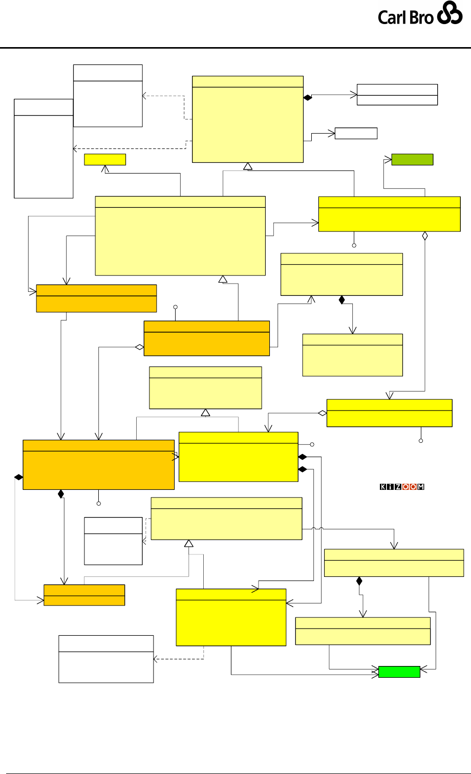
Department for Transport
TransXChange Schema Guide
Part I
Introduction & Overview
TransXChangeSchemaGuide-2.1-v-45.pdf.doc
Page 47
24 September 2013
PrivateCode[0..1] : string
DestinationDisplay[0..1] : nlString
OperatorRef[0..1] : OperatorCodeType
Direction[1] : ServiceDirectionEnum
Operational[0..1] : Operational
OperatingProfile[0..1] : OperatingProfile
TimeDemand[0..1] : OperatingProfile
LayoverPoint[0..*] : LayoverPoint
GarageRef[0..*] : Garage
Description[0..1] : nlString
AbstractJourneyPattern
Id[1] : JpSectionIdType
TimingLinks[1..*] : JourneyPatternTimingLink
JourneyPatternSection
Id[1] : idType
VehicleJourneyStopUsage
DepartureTime[1] : time
Frequency[0..1] : Frequency
TimingLinks[0..*] : VehicleJourneyTimingLink
VehicleJourney
Id[1] : JourneyPatternIdType
RouteRef[0..1] : RouteCodeType
JourneyPatternSectionRefs[0..*] : JpSectionIdType
JourneyPattern
Id[0..1] : VjTimingLinkIdType
JourneyPatternTimingLinkRef[1] : JpTimingLinkIdType
RunTime[0..1] : duration
From[1] : VehicleJourneyStopUsage
To[1] : VehicleJourneyStopUsage
VehicleJourneyTimingLink
Id[1] : idType
Sequence[0..1] : integer
StopPointRef[1] : StopPointCodeType
TimingStatus[0..1] : TimingStatusEnum
FareStageNumber[0..1] : string
FareStage[0..1] : boolean
JourneyPatternStopUsage
WaitTime[0..1] : duration
Activity[0..1] : ActivityEnum
DynamicDestinationDisplay[0..1] : nlString
VariableStopAllocations[0..*] : VariableStopAllocations
AbstractStopUsage
Id[0..1] : JpTimingLinkIdType
HailAndRide[0..1] : boolean
Express[0..1] : boolean
StoppingArrangements[0..1] : nlString
DutyCrewCode[0..1] : DutyCrewCodeType
JourneyPatternTimingLink
HailAndRide[0..1] : boolean
Express[0..1] : boolean
StoppingArrangements[0..1] : nlString
DutyCrewCode[1] : DutyCrewCodeType
AbstractTimingLink
Txc Service Pattern Elements
© Crown Copyright 2003-2009
outbound
inbound
inboundAndOutbound
circular
clockwise
anticlockwise
«enumeration»
ServiceDirectionEnum
Route
0..*
1
has route
0..*
1
pattern
0..1
1..*
sections
1..1
0..*
links
0..*
1
journey link
1
1..1
from
1
1..1
to
1
1..1
to
1
1..1
from
1
0..*
links
EndTime[1] : time
Interval[0..*] : Interval
MinutesPastHour[0..*] : nonNegativeInteger
FrequentService[0..1] : boolean
Frequency
1
0..1
operates at
pickUp
setDown
pickUpAndSetDown
pass
«enumeration»
ActivityEnum
ScheduledFrequency[1] : duration
MinimumFrequency[0..1] : duration
MaximumFrequency[0..1] : duration
Description[0..1] : nlString
Interval
-End461
0..1
interval
PositiingLink : PositioningLink
ShortWorkinkLinkRef : VjTimingLinkIdType
DeadRun
1..1
0..1
start
0..1
0..1
short working
1..1
0..1
end
StopPoint
0..*
1
uses
VariableStopPointAcllocation[0..*] : StopAllocation
DefaultStopPointRef[0..1] : StopPointCodeType
VariableStopAllocations
0..1
0..1
default
0..1 1..1
default
0..1
0..*
allocation
DateRange[1] : HalfOpenDateRage
VariableStopPointRef[0..*] : StopPointCodeType
StopAllocation
1
1..*
allocations
Txc-Time::OperatingProfile
10..1
operates on
earlyMorning
peakMorning
offPeak
peakAfternoon
evening
lateEvening
saturdayMorning
saturdayDaytime
saturdayEvening
sunday
bankHoliday
«enumeration»
TimeDemandEnum
LayoverPoint
VehicleJourneyCode[1] : VehicleJourneyCodeType
ServiceRef[1] : ServiceCodeType
LineRef[1] : LineCodeType
JourneyPatternRef[0..1] : JpCodeType
FollowVehicleJourneyRef[0..1] : VehicleJourneyCodeType
StartDeadRun[0..1] : DeadRun
EndDeadRun[0..1] : DeadRun
Note[0..1] : Note
VehicleJourneyInterchange[0..*] : VehicleJourneyInterchange
AbstractVehicleJourney
Service
10..*
service
0..*
0..1
layover
Versionable
Versionable
Versionable
Versionable
Versionable
PrinciplePoint = PPT
PrincipleAndTimeInfoPoint = PTP
TimeInformationPoint = TIP
Other = OTH
«enumeration»
TimingStatusEnum
Figure 3-12 – UML Diagram of VehicleJourney &
JourneyPattern Inheritable Properties

Department for Transport
TransXChange Schema Guide
Part I
Introduction & Overview
TransXChangeSchemaGuide-2.1-v-45.pdf.doc
Page 48
24 September 2013
3.4.2 Schedule and Journey Terms and Definitions
The TransXChange uses the following definitions of common scheduling terms. See also
the definitions of individual schema elements. Some of the terms are used in actually
element names; others merely define concepts.
3.4.2.1 Time Related Terms
Relative time: Time as a duration, usually in minutes, for example, ‘5 minutes’.
Absolute time: Time as a specific clock hour, for example, ‘10:00’, ’18:30’.
Overall Wait time: Relative time to wait at a specific stop, assuming bus arrives on
time. Used to compute passing times. In real-time operations, if bus is late at a stop,
wait time may be reduced to the minimum time need to disembark and board
passengers, i.e. wait is a buffer time used to adhere to schedule. The actual time
waited is the Dwell time - which is an operational time and not relevant to
TransXChange. Note that wait time is a property of a journey pattern or vehicle
journey, not of the stop itself, since it may be different on different journeys using the
same stop. In TransXChange, the overall wait time is computed from two separate
component timing link wait times that are stated on each end of the incoming and
outgoing JourneyPatternTimingLink or VehicleJourneyTimingLink instances :
o See JourneyPatternStopUsage / WaitTime
o See VehicleJourneyStopUsage / WaitTime.
Run time. Relative time taken to traverse a timing link.
o See JourneyPatternTimingLink / RunTime
o See VehicleJourneyTimingLink / RunTime.
Departure Time: The absolute time at which a vehicle journey leaves from its first
stop.
o See VehicleJourney / DepartureTime.
Passing time: Absolute time that a bus reaches a stop. Comprises the departure
time from the previous stop, plus the run time for the timing link connecting the
previous stop and the next stop. Derived.
Frequency Based Service: A service that runs to a regular frequency, for example
‘every 5 minutes’, rather than to a specific timetable. May or may not be a strict
Frequent Service.
o See VehicleJourney / Frequency.
Frequent Service, a service that runs to a frequency of every 10 minutes or less in
accordance with the Statutory Requirement, and that has been formally registered
as constituting a Frequent Service. Normally, but not necessarily, a Frequency
Based Service.
o See VehicleJourney / Frequency/FrequentService.
Day Type: A type of day or day such as Monday, Weekday, or Weekend as opposed
to a calendar date.
3.4.2.2 Routing Related Terms
Block: A description of a group of journeys to be operated by a particular vehicle, in
a specific working period, normally covering a full working day. Also called in English
a Running Board. May be identified by a block number.
o See JourneyPattern / Block / Description.
o See JourneyPattern / Block / BlockNumber.
Origin: The place that the service goes from. Does not vary; note however that some
journeys of the service may have a ‘short working’.
o See Service / Origin.
Destination: The place to which the service goes. Does not vary; Note however that
some journeys of the service may have a ‘short working’.

Department for Transport
TransXChange Schema Guide
Part I
Introduction & Overview
TransXChangeSchemaGuide-2.1-v-45.pdf.doc
Page 49
24 September 2013
o See Service / Destination.
Destination Display: Name of a destination to which the bus ultimately goes. Fixed
for whole journey.
o See JourneyPattern / DestinationDisplay.
o See VehicleJourney / DestinationDisplay.
Dynamic Destination Display: Name of a destination where the bus is currently
considered to be heading, shown on the front of the bus. Also known as the
Heading. On a circular or other route with a complex topology, the destination
display may change from stop to stop. On a linear route, normally the same as the
destination display, but on a short working may be an earlier point in the pattern.
o See JourneyPatternTimingLink / DestinationDisplay.
o See VehicleJourneyTimingLink / DestinationDisplay.
Stop List. The actual list of stops at which the bus will stop, in order of visiting.
Sometimes also termed the ‘calling pattern’.
Direction: relative course of a bus following a vehicle journey – may be outbound,
inbound, clockwise or anti-clockwise.
o JourneyPattern / Direction, JourneyPatternTimingLink / Direction.
o See VehicleJourneyTimingLink / Direction.
Bearing, Absolute, i.e. compass direction of a bus along a street, e.g. ‘North’.
o See StopPoint / Bearing.
Layover Point: Point at which a bus may stop and wait until it is time to start the next
service stage.
o See JourneyPattern / LayoverPoint.
Short Working: A vehicle journey that follows a journey pattern but omits one or
more stops at one or other end of the journey.
o See VehicleJourney / DeadRun / EndStopUsage.
Express Journey: A vehicle journey that follows a journey pattern but passes certain
stops without stopping (also referred to as a Limited Stop Journey).
o See JourneyPatternTimingLink / Activity.
Stop Footprint: The geometry of the stop coverage. Most stops are points. Some
stop types however have a footprint that covers more than a single point, for
example hail and ride sections, or flexible zones.

Department for Transport
TransXChange Schema Guide
Part I
Introduction & Overview
TransXChangeSchemaGuide-2.1-v-45.pdf.doc
Page 50
24 September 2013
3.4.3 Computation of Passing Times
The passing time at each stop (see Figure 3-13) is calculated from the cumulative sum of
the individual timing link values for all preceding stops in the journey link sequence as
follows:
[1] Arrival time at stopn = Departure time from previous stop n-1 + (Run time for inbound link
from stop n-1)
[2]. Departure time at stopn = Arrival time at stopn + Wait time for destination end of
inbound link from stopn-1). + Wait time for origin of outbound link to stop n+1
Where:
1. Default vehicle journey wait times for each link are derived from the journey pattern
timing link onto which the vehicle journey timing link projects (i.e. through the
VehicleJourneyTimingLink / JourneyPatternTimingLinkRef), as follows:
If no value for wait time is specified on the departure end of the timing link, i.e. for
the VehicleJourneyTimingLink / From / VehicleJourneyStopUsage, the
default WaitTime from the corresponding JourneyPatternTimingLink / From /
JourneyPatternStopUsage is used.
If no value for wait time is specified on the arrival end of the timing link, i.e. the
VehicleJourneyTimingLink / To / VehicleJourneyStopUsage, the default
WaitTime from the corresponding JourneyPatternTimingLink / To /
JourneyPatternStopUsage is used.
2. If unspecified, journey pattern wait times are defaulted as follows:
If no value for wait time is specified on the departure end of the timing link, i.e. the
JourneyPatternTimingLink / From / JourneyPatternStopUsage, a value of
zero is used.
If no value for wait time is specified on the arrival end of the timing link, i.e. the
JourneyPatternTimingLink / To / JourneyPatternStopUsage, a value of zero
is assumed.
3. Default vehicle journey run times for each link are derived from the journey pattern
timing link onto which the vehicle journey timing link projects. A run time is mandatory
on each JourneyPatternTimingLink.
The structured example shown earlier gives a simple example of how passing times are
derived from run times and wait times.
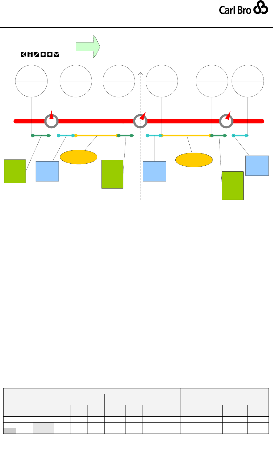
Department for Transport
TransXChange Schema Guide
Part I
Introduction & Overview
TransXChangeSchemaGuide-2.1-v-45.pdf.doc
Page 51
24 September 2013
B
AC
Timings Outbound
Arrival
Wait time
N-1
E.g. 0
mins
Departure
Wait time
N
E.g. 3 mins
Departure
Wait time
N-1
E.g. 2 Arrival
Wait time
N
E.g. 3
mins
Run Time N
E.g. 6 mins
Run Time N-1
E.g. 5 mins
Arrival time
11:02
Depart time
10:57
Depart time
11:05
Arrival time
10:54
Arrival
Wait time
N-1
E.g. 1
Arrival time
11:11
Depart time
11:16
Departure
Wait time
N+1
E.g. 2
Figure 3-13 – Computation of Passing Times
3.4.3.1 Example of Inheritance of Passing Times
Table 3-7 shows a more complex example, where wait and run times are specified at
different levels of discourse, that is, default values from the journey pattern are used except
where overridden by the vehicle journey. For each step, the wait and run times are added to
values from the previous step to arrive at an overall passing time. There are three stops S1,
S2, S3 and two links (L1. L2) between them.
An initial time of ‘10:00’ is specified.
Run time R1 (5 minutes) on the vehicle journey pattern timing link (L1) is defaulted
from the journey pattern timing link.
Run time R2 (10 minutes) on the vehicle journey pattern timing link (L2) overrides
the default (14 minutes) on the journey pattern.
Departure wait time W1b at S1 (2 minutes) on the vehicle journey timing link end L1a
overrides the default (0 minutes) on the journey pattern.
Arrival Wait time W2a (5 minutes) at S2 on the vehicle journey timing link end L1b is
defaulted from the journey pattern.
Departure wait time W2b at S2 (7 minutes) on the vehicle journey timing link end L2a
overrides the default (6 minutes) on the journey pattern.
Arrival Wait time W3a (10 minutes) at S3 on the vehicle journey timing link end L2b
overrides the default (5 minutes) on the journey pattern.
Departure wait time W3b at S3 (5 minutes) - which would come from a successor
link L3) can be used to compute the departure time from S3 i
Stop
Link
Usage
Wait Time
Run Time
Computation
Passing
Time
T
JP
VJ
Act-
ual
id
JP
mns
VJ
mns
Actual
mns
T
Actual
t1
10:00
s1
-
-
--
--
0
-
a

Department for Transport
TransXChange Schema Guide
Part I
Introduction & Overview
TransXChangeSchemaGuide-2.1-v-45.pdf.doc
Page 52
24 September 2013
w1b
From
(+0)
--
+2
L1a
t1 + w1b
t2
d
10:02
r1
L1
+5
--
+5
-
s2
w2a
To
+5
--
+5
L1b
t2 + r1
t3
a
10:07
w2b
From
(+6)
+7
+7
L2a
t3 + w2a + w2b
t4
d
10:19
r2
L2
(+14
)
+10
+10
s3
w3a
To
(+5)
+10
+10
L2b
t4 + r2
t5
a
10:29
w3b
From
--
+5
+5
L3a
t5 + w3a + w3b
t6
d
10:34
L3
..
..
..
To.
L3b
Table 3-7 – Example of Computation of Inherited Passing Times

Department for Transport
TransXChange Schema Guide
Part I
Introduction & Overview
TransXChangeSchemaGuide-2.1-v-45.pdf.doc
Page 53
24 September 2013
3.5 Rounding of Passing Times
Run and wait times are specified as values of type Duration, which may include seconds,
for example PT10M55S. The TransXChange publisher computes departure times using the
full value including seconds, but in the matrix timetable rounds down the total cumulative
time to the nearest whole minute, i.e. the rounded value is not used to reset the cumulative
time. Table 3-8 gives an example.
Stop
Run Time
Cumulative Time
Show As
A
7:00:00
7:00
B
PT20M50S
7:20:50
7:20
C
PT20M50S
7:41:40
7:41
D
PT10M55S
7:52:35
7:52
Table 3-8 – Example of Rounding of Passing Times

Department for Transport
TransXChange Schema Guide
Part I
Introduction & Overview
TransXChangeSchemaGuide-2.1-v-45.pdf.doc
Page 54
24 September 2013
3.6 Standard Service Overview
Figure 3-14 gives a slightly more detailed view of the central TransXChange model
introduced earlier, summarising the overall structure of a StandardService, and showing
again that JourneyPattern, and VehicleJourney are made up of collections of timing links
(JourneyPatternTimingLink, and VehicleJourneyTimingLink respectively), which hold
the details about each individual step between stops of the journey.
Each timing link has information about the arrival and departure of the vehicle at a
stop, specified with a stop usage element (JourneyPatternStopUsage, and
VehicleJourneyStopUsage respectively).
For Bus Stations, stop i.e. bay allocation may be variable, specified by a
VariableStopAllocation.
A StandardService describes the fixed route component of a Service.
Each Service can have one or more Line instances associated with it, this specifes
a label to be associated with journeys., fro example, “N93”.
Each StandardService must have one or more JourneyPattern instances.
o A JourneyPattern instance may reference a Route and a Track.
The StandardService must have one or more VehicleJourney instances. Each
VehicleJourney instances must reference a JourneyPattern of the same
StandardService, and a Line .instance of the Service to which it belongs.
Each VehicleJourney must specify a DepartureTime: Frequency based services
may also describe a Frequency. See 3.15.7 below.
Connections with other services are described by interchanges. These are described in
Section 3.8.
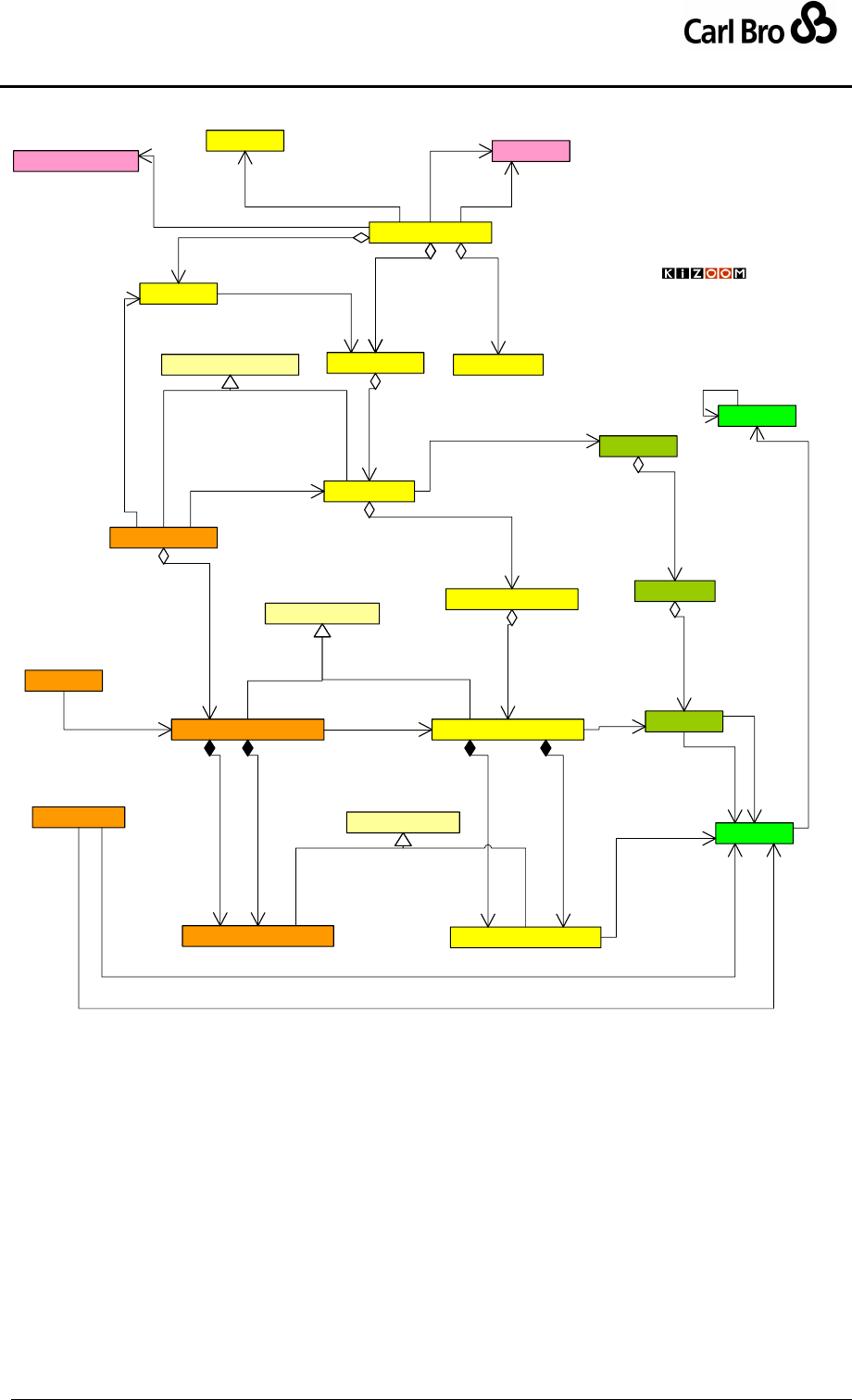
Department for Transport
TransXChange Schema Guide
Part I
Introduction & Overview
TransXChangeSchemaGuide-2.1-v-45.pdf.doc
Page 55
24 September 2013
Service
Route
JourneyPattern
VehicleJourney
StandardService FlexibleService
AbstractStopUsage
Standard Service
Overview
Operator
VehicleJourneyTimingLink JourneyPatternTimingLink
AbstractTimingLink
VehicleJourneyStopUsage JourneyPatternStopUsage
Registration
RouteSection
JourneyPatternSection
AbstractJourneyPattern
RouteLink
Line
PositioningLink
DeadRun
ServicedOrganisation
StopPoint
StopArea
1..1 0..*
part of
0..*
0..*
areas
0..*
1
registered
10..*
associated
1..1
0..1
service
1
1
standard
1
0..*
patterns
0..* 1
lines 1
0..1
standard 1
0..1
flexible
0..*
1
has route
0..* 1
pattern
0..1
1..*
sections
1
1..*
sections
1
0..*
links
1
1..*
links
1
1..1
to
0..*
1
uses
1
1..1
from
1
1..1
from
1
1..1
to
0..*
0..1
follows
0..*
1..1
from
0..*
1..1
to
0..*
1..1
from
0..*
1..1
to
0..1
0..1
short working
0..*
1
line
1..* 1..1
lines
0..* 1
journey link
1..1
0..*
links
© Crown Copyright 2003-2009
0..*
0..*
serves
Figure 3-14 – UML Diagram of Standard Service
3.6.1 Standard Service properties
Figure 3-15 shows further details of a StandardService including a ServiceClassification
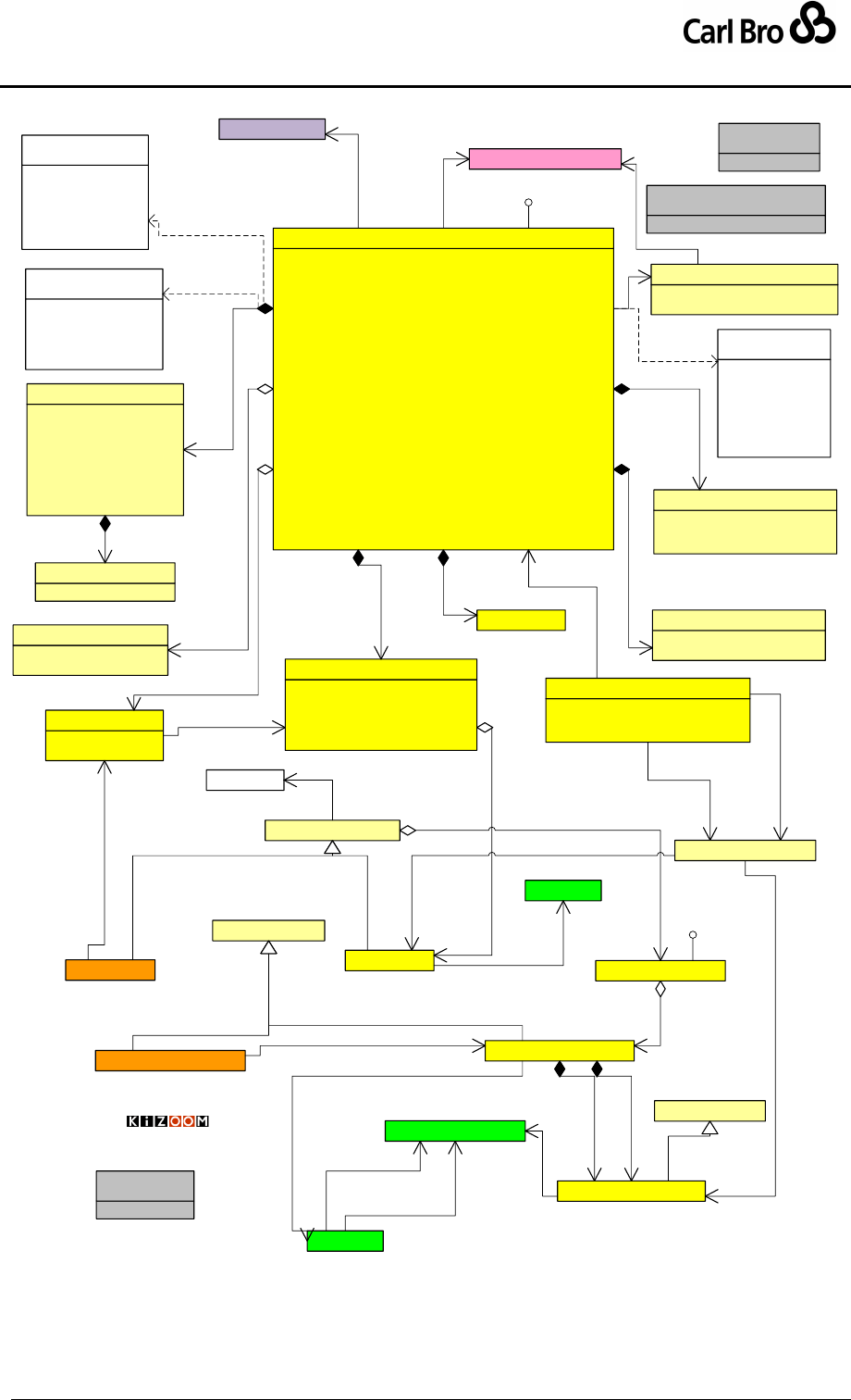
Department for Transport
TransXChange Schema Guide
Part I
Introduction & Overview
TransXChangeSchemaGuide-2.1-v-45.pdf.doc
Page 56
24 September 2013
ServiceCode[1] : ServiceCodeType
PrivateCode[1] : string
Lines[0..*] : Line
OperatingPeriod[1] : HalfOpenDateRage
ServiceClassification[0..1] : ServiceClassification
TicketMachineServiceCode[0..1] : TicketMachineServiceCodeType
RegisteredOperatorRef[1] : OperatorCodeType
AssociatedOperators[0..*] : OperatorRole
ServiceHasMirror[0..1] : boolean
StopRequirements[0..*] : JourneyPatternInterchange
Mode[0..1] : VehicleModesEnum
PublicUse[0..1] : boolean
ServiceAvailability[0..1] : ServiceAvailabilityEnum
Express[0..1] : boolean
Description[0..1] : nlString
Note[0..*] : Note
SchematicMap[0..1] : string
ToBeMarketedWith[0..*] : RelatedService
StandardService[0..1] : StandardService
FlexibleService[0..1] : FlexibleService
Direction[0..1] : ServiceDirectionEnum
JourneyPatternInterchange[0..*] : JourneyPatternInterchange
Service
Route
JourneyPattern
VehicleJourney
Origin[1] : nlString
Destination[1] : nlString
Vias[0..*] : nlString
UseAllStopPoints[0..1] : boolean
JourneyPattern[1..*] : JourneyPattern
StandardService
FlexibleService
AbstractStopUsage
Standard Service
Overview
Operator
VehicleJourneyTimingLink JourneyPatternTimingLink
AbstractTimingLink
JourneyPatternStopUsage
Registration
JourneyPatternSection
AbstractJourneyPattern
Id[1] : idType
LineName[1] : nlString
Line
StopPoint
0..*
1
registered
1
0..*
associated
1..1
0..1
service
1..*
1..1
lines
1
0..1
flexible
0..*
1
line
0..* 1
lines
1
0..1
standard
1
0..*
patterns
0..1
1..*
sections
0..*
1
has route
1
1..1
to
0..* 1
journey link
1
0..*
links
1
1..1
from
Versionable
«UniqueIdentifier»
ServiceCodeType
NormalStopping[0..1] : empty
LimitedStops[0..1] : empty
HailAndRide[0..1] : empty
Flexible[0..1] : empty
ExcursionOrTour[0..1] : empty
SchoolOrWorks[0..1] : empty
RuralService[0..1] : empty
OtherService[0..*] : nlString
ServiceClassification
«UniqueIdentifier»
TicketMachineServiceCodeType
OperatorRef[1] : OperatorCodeType
Role[0..1] : nlString
OperatorRole
0..*
1
does
Id[1] : JpInterchangeIdType
Inbound[1] : JourneyPatternUsageRef
Outbound[1] : JourneyPatternUsageRef
JourneyPatternInterchange
1..1
0..*
interchanges
NoNewStopsRequired[0..1] : empty
StopPointRef[0..*] : AtcoCodeType
Note[0..*] : nlString
StopRequirements
Daytime
Peak
OffPeak
Night
TwentyFourHour
«enumeration»
ServiceAvailabilityEnum
air
bus
coach
ferry
metro
rail
underground
«enumeration»
VehicleModesEnum
1
0..1
requirements
ServiceRef[1] : ServiceCodeType
Description[0..1] : nlString
RelatedService
1
0..1
classification
NoteCode[1] : NoteCodeType
NoteText[1] : nlString
Note
«UniqueIdentifier»
NoteCodeType
1
0..*
notes
MaxDepartures[1] : integer
ExcursionService
1
0..1
excursion
1
0..*
marketed with
outbound
inbound
inboundAndOutbound
circular
clockwise
anticlockwise
«enumeration»
ServiceDirectionEnum
LayoverPoint
1
0..*
layover
Versionable
0..*
1
uses
© Crown Copyright 2003-2009
JourneyPatternUsageRef
1..1
1..1
inbound
1
0..*
connects at
1..1
1..1
outbound
0..*
1
onwards
RouteLink
0..*
0..1
follows
0..*
1..1
from
0..*
1..1
to
Figure 3-15 – UML Diagram of Standard Service Details
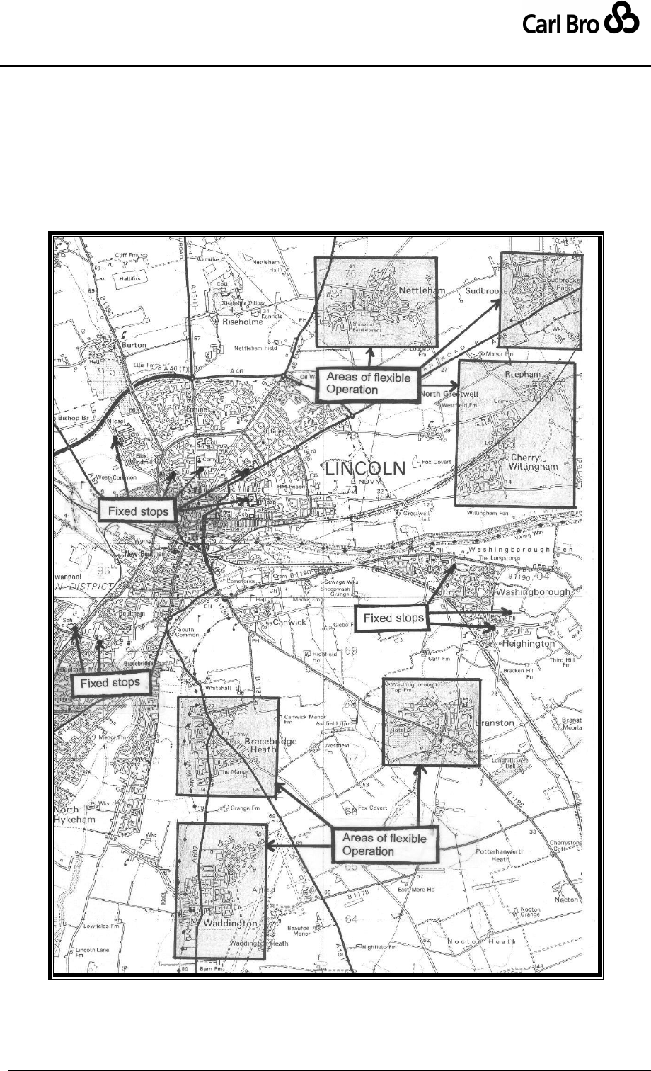
Department for Transport
TransXChange Schema Guide
Part I
Introduction & Overview
TransXChangeSchemaGuide-2.1-v-45.pdf.doc
Page 57
24 September 2013
3.7 Flexibly Routed Services
The TransXChange model can also support flexibly routed services (Figure 3-16).
A flexible service operates between catchment areas that can be made up of both spatial
zones, and lists of fixed stops, allowing combinations of (i) area-to-fixed stop, (ii) area-to-
area, (iii) fixed stop-to-fixed stop.Within a zone there is no fixed or marked stop, but the
service will call on demand.
Figure 3-16 – Flexible Network

Department for Transport
TransXChange Schema Guide
Part I
Introduction & Overview
TransXChangeSchemaGuide-2.1-v-45.pdf.doc
Page 58
24 September 2013
Representing a flexible service in TransXChange requires the additional concept of a
FlexibleService (see Figure 3-17, in UML notation), with which to specify the stops visited.
A FlexibleService has a FlexibleJourneyPattern, which must include some
NaPTAN stops of type FlexibleZone (FLX) to define areas within which passengers
may be picked up or set down.
o A FlexibleZone must be a contiguous area. Like other NaPTAN stop types, a
FlexibleZone stop can be associated with one or more NPTG Localities: the
locality with the greatest correspondence to the area of the zone should be
used as the primary NPTG Locality; other localities that the zone falls within
should be specified as alternative NPTG localities on the NaPTAN stop
definition. Where a flexible zone substantially covers two or more NPTG
Localities, it is preferable to define two separate zones, one for each locality.
o A FlexibleJourneyPattern may also have one or more FixedStopPoint
instances that can be visited in any order by the flexible service. Fixed stops
should be NaPTAN stops of a type other than FlexibleZone (FLX).
o The allowed activity (pick up, set down etc) and other behaviour of the
service at each stop, fixed or flexible, is defined by a stop usage instance for
each stop used.
A FlexibleVehicleJourney describes the actual operation of the flexible service,
using a FlexibleServiceTimes element to specify the time bands during which the
service operates.
A Service may contain both FlexibleService and StandardService components.
Interchange elements can be used to define the transition between flexible and fixed
stages.
Other properties of the service, such as Registration, Operator, Line and
OperatingProfile, are specified with the same elements as for a StandardService.
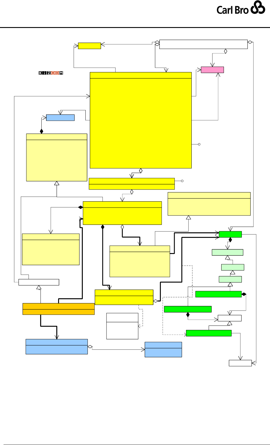
Department for Transport
TransXChange Schema Guide
Part I
Introduction & Overview
TransXChangeSchemaGuide-2.1-v-45.pdf.doc
Page 59
24 September 2013
«Schema root»
TransXChange
Registration
ServiceCode[1] : ServiceCodeType
PrivateCode[1] : string
Lines[0..*] : Line
OperatingPeriod[1] : HalfOpenDateRage
ServiceClassification[0..1] : ServiceClassification
TicketMachineServiceCode[0..1] : TicketMachineServiceCodeType
RegisteredOperatorRef[1] : OperatorCodeType
AssociatedOperators[0..*] : OperatorRole
ServiceHasMirror[0..1] : boolean
StopRequirements[0..*] : JourneyPatternInterchange
Mode[0..1] : VehicleModesEnum
PublicUse[0..1] : boolean
ServiceAvailability[0..1] : ServiceAvailabilityEnum
Express[0..1] : boolean
Description[0..1] : nlString
Note[0..*] : Note
SchematicMap[0..1] : string
ToBeMarketedWith[0..*] : RelatedService
StandardService[0..1] : StandardService
FlexibleService[0..1] : FlexibleService
Direction[0..1] : ServiceDirectionEnum
JourneyPatternInterchange[0..*] : JourneyPatternInterchange
Service
1..1
0..1
service
id[1]
FlexibleStopUsage[0..*] : FlexibleStopUsage
FixedStopPoints[0..*] : JourneyPatternStopUsage
BookingArrangements[0..1] : BookingArrangements
FlexibleJourneyPattern
1
0..*
zones
OperatingProfile
AllDayService[0..1] : boolean
ServicePeriod[0..*] : HalfOpenDateRage
FlexibleServiceTimes
1
1
available
Operator
1
0..*
associated
Flexibly
Routed
Service
StartTime[1] : dateTime
EndTime[1] : dateTime
PeriodsOfOperation
10..*
times
0..*
1..1
is at
1
1operates on 0..*
1
registered
1..1
{ordered}
3..*
polygon
VehicleServiceTimes[1] : FlexibleServiceTimes
FlexibleVehicleJourney
Activity[0..1] : ActivityEnum
StopPointRef[1] : StopPointCodeType
FlexibleStopUsage
1
0..*
zones
1
*
stops
0..*
1
pattern
1
0..*
services 1
0..*
operators
1
0..* registrations
StopPoint
1
0..*
local
OnStreet
StopClassification
1
1
classification
BusCoachTramPublic[BCT]
FlexibleZone[FLX]
Location
Bus
BusStopType
1
1..1 type
BusCoachTramPrivate(BCP)
1
1
type
FlexibleJourneyPattern[0..*] : FlexibleJourneyPattern
FlexibleService
1
0..1 flexible
1
1..*
patterns
1
0..1 flexible
© Crown Copyright 2003-2009
PrivateCode[0..1] : string
DestinationDisplay[0..1] : nlString
OperatorRef[0..1] : OperatorCodeType
Direction[1] : ServiceDirectionEnum
Operational[0..1] : Operational
OperatingProfile[0..1] : OperatingProfile
TimeDemand[0..1] : OperatingProfile
LayoverPoint[0..*] : LayoverPoint
GarageRef[0..*] : Garage
Description[0..1] : nlString
AbstractJourneyPattern
1
0..1
operates on
Versionable
Versionable
pickUp
setDown
pickUpAndSetDown
pass
«enumeration»
ActivityEnum
Id[1] : id
Sequence[0..1] : integer
StopPointRef[1] : StopPointCodeType
TimingStatus[0..1] : TimingStatusEnum
FareStageNumber[0..1] : string
FareStage[0..1] : boolean
JourneyPatternStopUsage
0..*
1
uses
WaitTime[0..1] : duration
Activity[0..1] : ActivityEnum
DynamicDestinationDisplay[0..1] : nlString
VariableStopAllocations[0..*] : VariableStopAllocations
AbstractStopUsage
Description[1] : nlString
Phone[0..1] : TelephoneNumberType
Email[0..1] : email
Address[0..1] : UkPostalAddress
WebAddress[0..1] : anyURI
AllBookingsTaken[0..1] : boolean
BookingArrangements
1
0..1
booking
AbstractVehicleJourney
1
0..*
service
Figure 3-17 – UML Diagram for Flexibly Routed Service

Department for Transport
TransXChange Schema Guide
Part I
Introduction & Overview
TransXChangeSchemaGuide-2.1-v-45.pdf.doc
Page 60
24 September 2013
3.8 Interchanges
To specify the connection between vehicle journeys, an Interchange model is used, as
shown in the UML structure diagram in Figure 3-18. The Interchange model operates on two
levels of discourse:
A JourneyPatternInterchange specifies a possible connection between any two
JourneyPattern instances, at a particular stop or pair of stops, with default values
for the connection activity.
o A service may hold multiple connections.
o The arrival stop of the inbound ‘feeder to’ journey, and the departure stop of
the outbound ‘distributor from’ journey may be different NaPTAN stop points,
i.e. require a transfer.
o The mode of transfer (e.g. walk or otherwise) is indicated by a TransferMode
property.
A VehicleJourneyInterchange specifies the connection between two specific
VehicleJourney instances, at a VehicleJourneyInterchange. A vehicle journey
connection projects onto an equivalent JourneyPatternInterchange, which
constrains it to use the corresponding inbound feeder and outbound distributor
journey, and the same stops specified by the JourneyPatternInterchange.
o A vehicle journey may have connections with more than one other vehicle
journey.
Note that inbound ‘feeder to’ and outbound ‘distributor from’ are relative roles; and a given
service may serve as both feeder and distributor (i.e. passengers may exchange both ways
between vehicles); in which case separate interchange instances can be declared for each
direction.
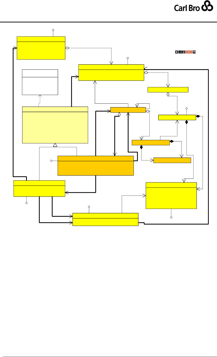
Department for Transport
TransXChange Schema Guide
Part I
Introduction & Overview
TransXChangeSchemaGuide-2.1-v-45.pdf.doc
Page 61
24 September 2013
Origin[1] : nlString
Destination[1] : nlString
Vias[0..*] : nlString
UseAllStopPoints[0..1] : boolean
JourneyPattern[1..*] : JourneyPattern
StandardService
Id[1] : JourneyPatternIdType
RouteRef[0..1] : RouteCodeType
JourneyPatternSectionRefs[0..*] : JpSectionIdType
JourneyPattern
1
0..*
patterns
JourneyPatternSection
0..1
{ordered}1..*
sections
JourneyPatternTimingLink
1
{ordered} 0..*
links
Id[1] : id
Sequence[0..1] : integer
StopPointRef[1] : StopPointCodeType
TimingStatus[0..1] : TimingStatusEnum
FareStageNumber[0..1] : string
FareStage[0..1] : boolean
JourneyPatternStopUsage
1
1..1
to
1
1..1
from
VehicleJourney
1..1 0..*
use links from
0..*
1
VehicleJourneyTimingLink
0..*
1
journey link
1..1
{ordered}
0..*
links
VehicleJourneyStopUsage
1
1..1
from
1
1..1
to
MinInterchangeTime[0..1] : duration
MaxInterchangeTime[0..1] : duration
TransferMode[0..1] : VehicleModesEnum
ValidityPeriod[0..1] : HalfOpenDateRage
StoppingArrangements[0..1] : nlString
InterchangeActivity[0..1] : InterchangeActivityEnum
CrossBorder[0..1] : boolean
GuaranteedConnection[0..1] : boolean
ChangeLineNumber[0..1] : boolean
AbstractInterchange
0..*
1
0..*
1
onwards
Id[1] : JpInterchangeIdType
Inbound[1] : JourneyPatternUsageRef
Outbound[1] : JourneyPatternUsageRef
JourneyPatternInterchange
1..1
0..*
interchanges
Id[0..1] : InterchangeCodeType
JourneyPatternInterchangeRef[1] : InterchangeCodeType
InboundVehicleJourneyRef[1] : VehicleJourneyCodeType
OutboundVehicleJourneyRef[1] : VehicleJourneyCodeType
VehicleJourneyInterchange
0..*
1
inbound 1
{ordered}
0..*
interchanges
0..*
1
onwards
0..*
1pattern
1..1
1..1
outbound
1..1
1..1
inbound
Interchanges
© Crown Copyright 2003-2008
© Crown Copyright 2003-2009
transferOnly
change
through
split
join
«enumeration»
InterchangeActivityEnum
Versionable
Versionable
Versionable
Versionable
Versionable
JournetPatternRef[1] : JpStopUsageIdType
JourneyPatternUsageRef[1] : JpInterchangeIdType
JourneyPatternUsageRef
1
0..*
connects at
Versionable Versionable
Figure 3-18 – UML Diagram of Interchanges
3.8.1 Inheriting Interchange Values
Table 3-6 shows the various values that may be specified for the
JourneyPatternInterchange and VehicleJourneyInterchange elements, and whether
they are:
(i) Required (‘R’).
(ii) Optional but otherwise inherited from the previous level of discourse (‘O’).
(iii) Always Inherited. (‘I’).
For elements that are optional at all levels, a default value is identified to use if no explicit
value is provided.
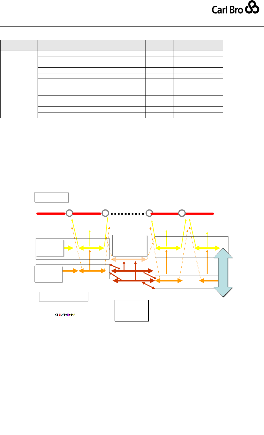
Department for Transport
TransXChange Schema Guide
Part I
Introduction & Overview
TransXChangeSchemaGuide-2.1-v-45.pdf.doc
Page 62
24 September 2013
Level
Property
Journey
Pattern
Vehicle
Journey
Default Value
Interchange
InboundJourneyPatternRef
R
I
--
OutboundJourneyPatternRef
R
I
--
InboundStopUsageRef
R
I
--
OutboundStopUsageRef
R
I
--
InterchangeActivity
O
O
change
MinInterchangeTime
R
O
--
MaxInterchangeTime
O
O
Zero
InterchangeMode
O
I
walk
ValidityPeriod
O
O
service end date
StoppingArrangements
O
O
none
InboundVehicleJourneyRef
-
R
--
OutboundVehicleJourneyRef
-
R
--
Table 3-9 – Interchange Properties and Defaults
3.8.2 Interchange Schematic
Figure 17 shows a schematic diagram of an interchange between two journeys. The
inbound feeder journey arriving at stop ‘A’ from stop ‘X’ connects to a second distributor
journey from stop ‘A’ onto stop ‘B’. The journey pattern interchange links the stop usages of
the two journey patterns. The vehicle journey interchange links the two vehicle journeys.
Interchanges
Links & Nodes
Stop Points
Stop Points
Journey
Pattern
Journey
Pattern
Journey
Pattern
Interchange
Journey
Pattern
Interchange
Vehicle
Journey
Vehicle
Journey
Projection
Projection
Vehicle
Journey
Interchange
Vehicle
Journey
Interchange
•Interchange : joins
two journeys with an
interchange activity
inbound
outbound
X AA B
Figure 3-19 – Interchange Links
3.8.3 Interchange Instance Example
As a pictorial example of a connection, Figure 3-20 shows a UML instance diagram of the
element instances for a connection between two vehicle journeys:
At the top, in yellow, can be seen a Service with two journey patterns, one inbound
feeder to a JourneyPatternInterchange, and one outbound distributor from it. Each
JourneyPattern has a single JourneyPatternSection containing a sequence of
timing links; only the last JourneyPatternTimingLink of the inbound feeder journey
pattern, and the first JourneyPatternTimingLink of the outbound distributor journey

Department for Transport
TransXChange Schema Guide
Part I
Introduction & Overview
TransXChangeSchemaGuide-2.1-v-45.pdf.doc
Page 63
24 September 2013
pattern are shown, along with the VehicleJourneyStopUsage instance for each end
of the link.
The JourneyPatternInterchange instance references both inbound feeder and
outbound distributor journey patterns. It also references the destination
VehicleJourneyStopUsage instance of the last timing link of the inbound feeder
pattern, and the origin VehicleJourneyStopUsage of the last timing link of the
outbound distributor pattern.
Below this, in orange, can be seen two corresponding inbound feeder and outbound
distributor VehicleJourney instances. Again, only the last
VehicleJourneyTimingLink of the inbound feeder vehicle journey, and the first
VehicleJourneyTimingLink of the outbound distributor vehicle journey are shown.
.Each VehicleJourneyTimingLink individually projects onto the appropriate
JourneyPatternTimingLink instance by an explicit reference.
Each vehicle journey has its own instance of a VehicleJourneyInterchange, which
references both the inbound feeder and outbound distributor vehicle journey
instances. It also references the JourneyPatternInterchange that connects the
journey patterns upon which the vehicle journeys are based.
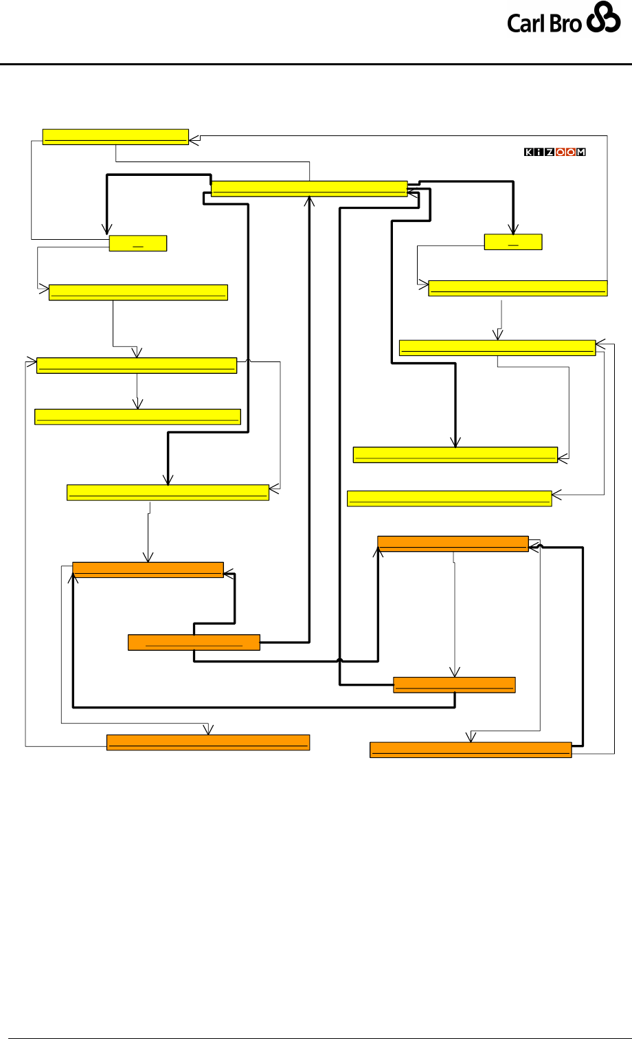
Department for Transport
TransXChange Schema Guide
Part I
Introduction & Overview
TransXChangeSchemaGuide-2.1-v-45.pdf.doc
Page 64
24 September 2013
VL_1 : Txc-SvcPtn-Mdl::VehicleJourneyTimingLink
R_1 : Txc-Rte-Mdl::Route
RL_1 : Txc-Rte-Mdl::RouteLink
S1 S2
outbound
inbound
sv_1 : Txc-Rgs-Mdl::StandardService
interchange
patterns (1)
patterns (2)
vj_1 : Txc-SvcPtn-Mdl::VehicleJourney
vj_2 : Txc-SvcPtn-Mdl::VehicleJourney
based on
based on
interchange (1)
interchange (1)
inbound outbound
outbound
inbound
js_1 : Txc-SvcPtn-Mdl::JourneyPatternSection js_2 : Txc-SvcPtn-Mdl::JourneyPatternSection
jl_1_N : Txc-SvcPtn-Mdl::JourneyPatternTimingLink
VL_2 : Txc-SvcPtn-Mdl::VehicleJourneyTimingLink
VL_2a : Txc-SvcPtn-Mdl::VehicleJourneyStopUsage
jl_1_Na : Txc-SvcPtn-Mdl::JourneyPatternStopUsage
jl_2_1a : Txc-SvcPtn-Mdl::JourneyPatternStopUsage
from
jl_2_1b : Txc-SvcPtn-Mdl::JourneyPatternStopUsage
vl_1_N : Txc-SvcPtn-Mdl::VehicleJourneyTimingLink vl_2_1 : Txc-SvcPtn-Mdl::VehicleJourneyTimingLink
inbound
outbound
sections (1) sections (1)
links (Nth)
links (1)
usage
to
from
to
links (Nth)
from
to
stop
Interchange
Instance Example
© Crown Copyright 2003-2009
Figure 3-20 – UML Instance Diagram of Example Interchange
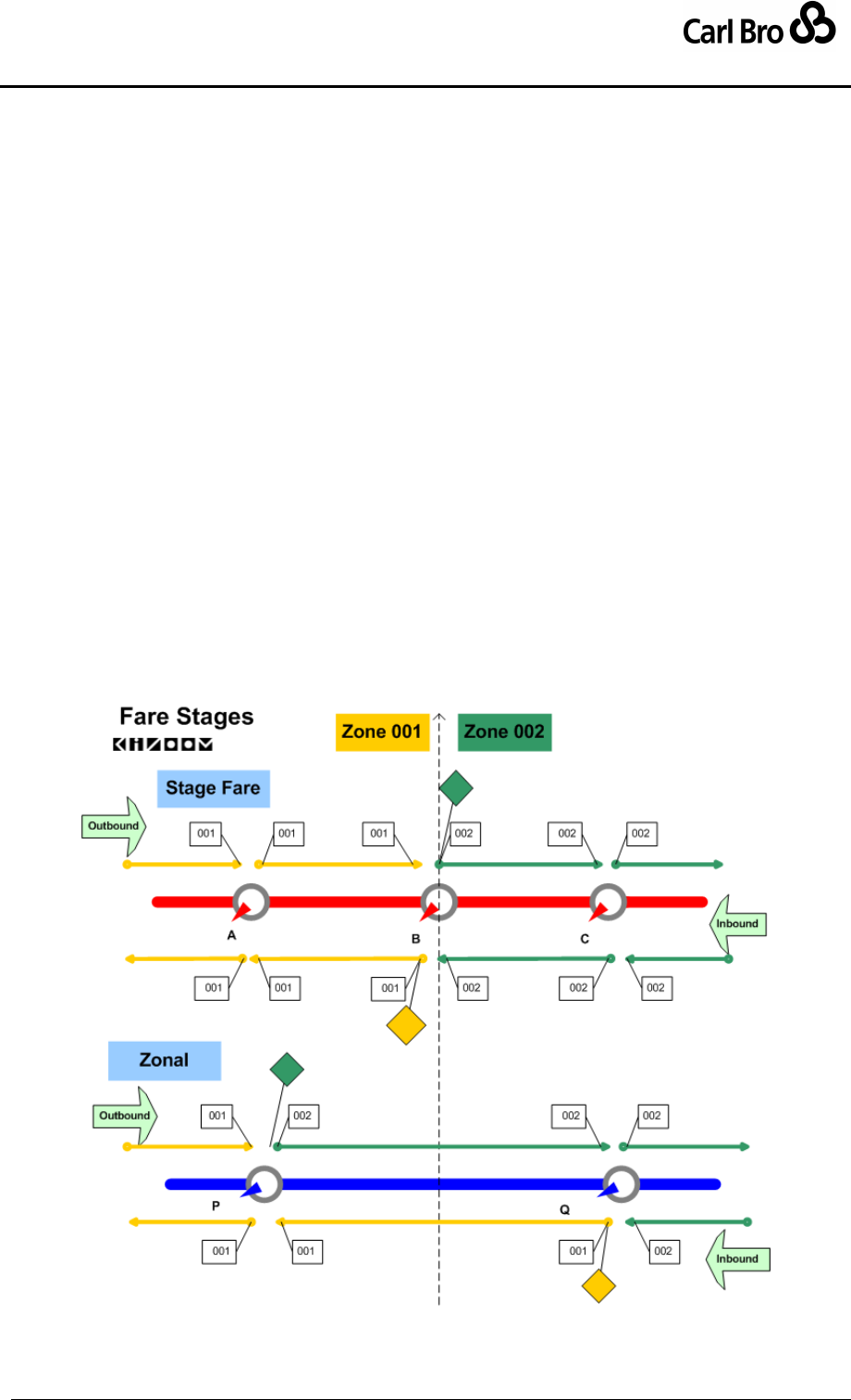
Department for Transport
TransXChange Schema Guide
Part I
Introduction & Overview
TransXChangeSchemaGuide-2.1-v-45.pdf.doc
Page 65
24 September 2013
3.9 Fare Stages
TransXChange supports the annotation of links with basic fare stage data for operational
purposes. There are two different models commonly used for fare stages:
1. A Stage Fare model, where the fare stage is located on a boundary between two
zones and is considered to be in both zones. In effect the fare stage is on the stop
point, but only applies to journeys (i.e. sequences of links) where the other end of
two subsequent links is in different zones.
2. A Zonal model, where the fare stage boundary lies between two stops, each within a
distinct fare zone. The fare stage is in effect on the link between the stops. Only
journeys going in the direction of the other zone and that cross the boundary will
encounter the fare stage.
In the TransXChange model, fare stages are a property of timing link stop usage, so that
both Stage Fare and Zonal models can be supported. Fare stage values can be specified at
both the journey pattern and vehicle journey level of discourse as a successive property,
that is one that carries onto succeeding links in the series until reset.
The fare stage change occurs at the point of pick up, that is, at the originating end of the
link, as shown in Figure 3-21, which shows examples of link sequences over a zone
boundary for both fare models, with fare stage numbers and fare stage points marked.
Whether a stop usage for a given link is a fare stage is properly determined by whether the
FareStageNumber changes when traversing a sequence of timing links: the FareStage
indicator can be used to store a statically computed determination of this property for
convenience of implementation.
Figure 3-21 – Fare Stages & Links
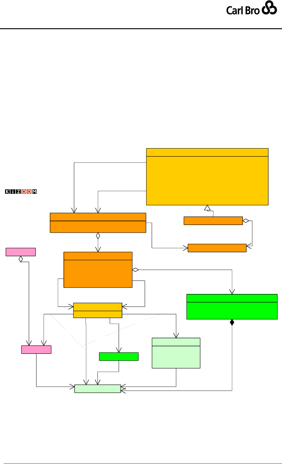
Department for Transport
TransXChange Schema Guide
Part I
Introduction & Overview
TransXChangeSchemaGuide-2.1-v-45.pdf.doc
Page 66
24 September 2013
3.10 Dead Runs
‘Dead run’ or positioning runs may be specified on vehicle journeys to describe how
vehicles are placed in position to deliver a service, and also how they are retrieved after
completing the service. Dead run positioning links are primarily of use for exchanging
information for AVL systems, and are not needed for registration or publishing schedules.
Dead runs can also be used to indicate short working. Figure 3-22 shows a UML structure
diagram of the elements used to describe dead runs.
A VehicleJourney may have an initial StartDeadRun and a final EndDeadRun.
Each DeadRun consists of one or more PositioningLink instances.
o Each PositioningLink runs between two position points, which may be
specified as either a Location, a StopPoint, a LayoverPoint or a Garage.
o A DeadRun may reference a VehicleJourneyTimingLink to indicate the
point at which short working starts or stops.
VehicleJourney
PositiingLink[1] : PositioningLink
ShortWorkinkLinkRef[0..1] : VjTimingLinkIdType
DeadRun
Id[1] : idType
RunTime[1] : duration
From[0..1] : PositioningLinkUsage
To[0..1] : PositioningLinkUsage
Track[0..1] : Track
PositioningLink
1
1..*
links
1..1
1..1
from 1..1
1..1
to
PositioningLinkUsage
VehicleJourneyTimingLink
1..1
0..*
links
1..1
0..1
is at
1..1
0..1
is at
Dead Runs
Garage
Operator
1..1
0..*
garages
1..1
0..1
is at
0..*
1..1
is at
0..1
0..1
short working
1..1 0..1
is at
id[1] : idType
Duration[1] : duration
Name[1] : nlString
Location[0..1] : Latitude
LayoverPoint
*
1point
Mapping[1..*] : Location
MapSystemReference[0..1] : MapSystemLink
Instructions[0..*] : Instructions
Track
1
1..* path
1..1 0..*
tracks
© Crown Copyright 2003-2008
StopPoint
Location
0..*
1..1
is at
© Crown Copyright 2003-2009
{OR}
{OR}
{OR}
VehicleJourneyCode[1] : VehicleJourneyCodeType
ServiceRef[1] : ServiceCodeType
LineRef[1] : LineCodeType
JourneyPatternRef[0..1] : JpCodeType
FollowVehicleJourneyRef[0..1] : VehicleJourneyCodeType
StartDeadRun[0..1] : DeadRun
EndDeadRun[0..1] : DeadRun
Note[0..1] : Note
VehicleJourneyInterchange[0..*] : VehicleJourneyInterchange
AbstractVehicleJourney
1..1
0..1
start
1..1
0..1
end
Figure 3-22 – UML Diagram of Dead Run Model

Department for Transport
TransXChange Schema Guide
Part I
Introduction & Overview
TransXChangeSchemaGuide-2.1-v-45.pdf.doc
Page 67
24 September 2013
3.10.1 Use of Dead Runs for Short Working
Dead runs may be used to indicate that a Vehicle Journey starts or ends at a particular point
in a journey pattern, omitting all links & stops before or after the intercept point. See the
Circular Route example for an illustration of both short and full workings of the same route.

Department for Transport
TransXChange Schema Guide
Part I
Introduction & Overview
TransXChangeSchemaGuide-2.1-v-45.pdf.doc
Page 68
24 September 2013
3.11 Tracks
The TransXChange Track model describes details about the physical course of a
RouteLink, in particular the collection of spatial points needed to plot the route
unambiguously in sequence on a map of the road network, for example using a 'snap to
track' algorithm. As well as such a Mapping, a Track can also be associated with a
reference to an external mapping system using a MapSystemReference element, allowing
the projection of links onto mapping layers. Track features can also be used to describe any
manoeuvre involved in navigating a route link, such as a U-turn.
The Track model allows a rich description of a route to be provided; it is intended for general
purpose data exchange. For a Registration a level of Track detail should be given sufficient
to unambiguously plot the route on a map using OSGR data – using both points and/or
TOIDS.
It is a requirement of registration that adequate spatial data is provided as to plot routes on
an OS map in a useful way: there should be intermediate coordinates for a reasonably high
level of resolution.
Figure 3-23 shows a UML structure diagram of the elements used to describe tracks. Tracks
can contain two different types of description:
A Mapping describes the geospatial plot of the route link as two or more Location
elements that provide point coordinates for the track between NaPTAN stop points.
An Instructions instance provides an optional additional structured description of
the steps involved in traversing the track as a sequence of Feature instances. For
example ‘Turn left at roundabout into Mary Street’.
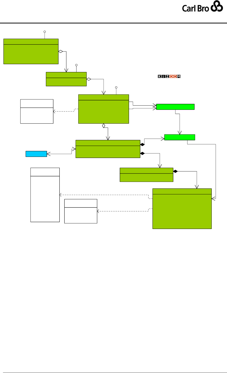
Department for Transport
TransXChange Schema Guide
Part I
Introduction & Overview
TransXChangeSchemaGuide-2.1-v-45.pdf.doc
Page 69
24 September 2013
Id[1] : RouteSectionIdType
PrivateCode[0..1] : string
Description[0..1] : nlString
RouteSectionRefs[1..*] : RouteSection
ReversingManoeuvres[0..1] : nlString
Route
Id[1] : RouteSectionIdType
RouteLinks[0..*] : RouteLink
RouteSection
Id[1] : RouteLinkIdType
From[1] : StopPointCodeType
To[1] : StopPointCodeType
Distance[0..1] : distanceType
Direction[0..1] : DirectionCodeType
Tracks[0..*] : Track
RouteLink
NaPTAN-Stop::StopPoint
© Crown Copyright 2003-2009
TransXChange
RouteModel
0..* 1..1
from
0..* 1..1
to
1
1..*
sections
11..*
links
Mapping[1..*] : Location
MapSystemReference[0..1] : MapSystemLink
Instructions[0..*] : Instructions
Track
1
0..*
projects
Id[1] : nmtoken
LocationRef[1] : Location
FeatureType[0..1] : FeatureTypeEnum
RelativeBearing[1] : RelativeBearingType
AbsoluteBearing[0..1] : compassBearing
OnwardName[0..1] : nlString
RoadNumber[0..1] : string
Distance[0..1] : distanceType
Description[0..1] : nlString
Feature
outbound
inbound
clockwise
anticlockwise
«enumeration»
RouteDirectionEnum
Summary[1] : nlString
Feature[0..*] : Feature
Instructions
10..1
Instructions
NaPT-Loc::Location
0..*
1..1
is at
1
1..*
path
left
right
straightAhead
uTurn
«enumeration»
RelativeBearingType 0..1
0..*
location
1
0..*
instructions
MappingLink
0..1
*feature
Versionable
Versionable
Versionable
legOrigin
legDestination
bend
crossing
bridge
junction
miniroundabout
roadChange
roundabout
subway
trafficLights
roundabout
«enumeration»
FeatureTypeEnum
Figure 3-23 – UML Diagram of Track Model

Department for Transport
TransXChange Schema Guide
Part I
Introduction & Overview
TransXChangeSchemaGuide-2.1-v-45.pdf.doc
Page 70
24 September 2013
3.11.1 Track Model
As a simple example, consider a RouteLink that runs along the B205 and B257,
represented by a two Track instances.
Each Track instance has a Mapping instance that describes the course of the track.
tr1 has two points (g_1, g_2)) and tr2 has seven points (g_3 to g_7) respectively;
each point is a Location instance that describes a point of the track.
Each Track has an Instructions instance containing an ordered collection of
Feature instances.
Each Feature instance describes a step needed to traverse the track, and
references a Location instance from the Mapping. Table 3-10 shows a sample of
the Feature instances.
Track
Location
Ref
Feature Type
Relative
Bearing
Absolute
Bearing
Onward
Name
Road
Number
Dist-
ance
Description
Tr1
G_1
legOrigin
straightAhead
N
Victoria
Road
B205
300m
Proceed 300m
North down
Victoria road
(B205.)
G_2
junction
left
W
Albert
Road
B205
500m
Turn left into
Albert road
(B257) and head
west 500m.
Tr2
G_3
landmark
straightAhead
--
--
--
Hospital on left
G_4
bend
right
NW
Albert
Road
B257
--
Follow bend to
right in Albert
Road
G_5
roadChange
straightAhead
NW
George
Road
B257
400m
Continue 400m
down George
Road (B257)
G_6
roundabout
left
SW
Mary
Street
B257
--
Turn left at
roundabout into
Mary Street
G_7
crossing
straightAhead
--
Bill Alley
B257
--
Cross over Bill
Alley
G_8
bridge
straightAhead
--
Mary
Street
B257
--
Pass under
bridge
G_9
legDestination
straightAhead
S
Mary
Street
B257
600m
Continue straight
ahead 600m
South down Mary
Street
Table 3-10 – Example Track Instructions
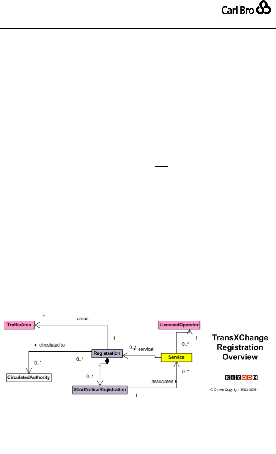
Department for Transport
TransXChange Schema Guide
Part I
Introduction & Overview
TransXChangeSchemaGuide-2.1-v-45.pdf.doc
Page 71
24 September 2013
3.12 The Registration Model
The statutory requirements of a bus registration are captured in TransXChange Registration
by a small submodel of descriptive elements associated with a service, as outline in the
UML structure diagram in Figure 3-24 and elaborated in Figure 3-25
A TransXChange document can contain Registration elements:
o A TransXChange Registration document must contain one Registration
instance.
o A TransXChange General document may contain one or more Registration
instances.
A single Service can be associated with each Registration.
o A TransXChange Registration document Registration must contain a
Service instance that references the Registration. It may have other
Service definitions for connecting services.
o A TransXChange General document may contain a Service instance.
A Service has a RegisteredOperator, and may have additional
AssociatedOperator instances. Operators may be instances of either
LicensedOperator or Operator.
o In a TransXChange Registration, the RegisteredOperator must be a
LicensedOperator instance, with all details completed. (Note this constraint
is enforced by an XML keyref).
o In a TransXChange General document the RegisteredOperator may be an
instance of either LicensedOperator or Operator.
A Registration records the TrafficAreaNetwork and CirculatedAuthority
instances.
o Additional special details can be recorded for a ShortNoticeRegistration,
including references to other services that the service replaces, or to which it
connects. A short notice registration is an application to register, cancel or
change a service made with less than the normally required 56 days' period
of notice.
o The Registration can be annotated with SupportingDocument instances
that identify related documents.
Figure 3-24 – UML Diagram of Basic Registration Model
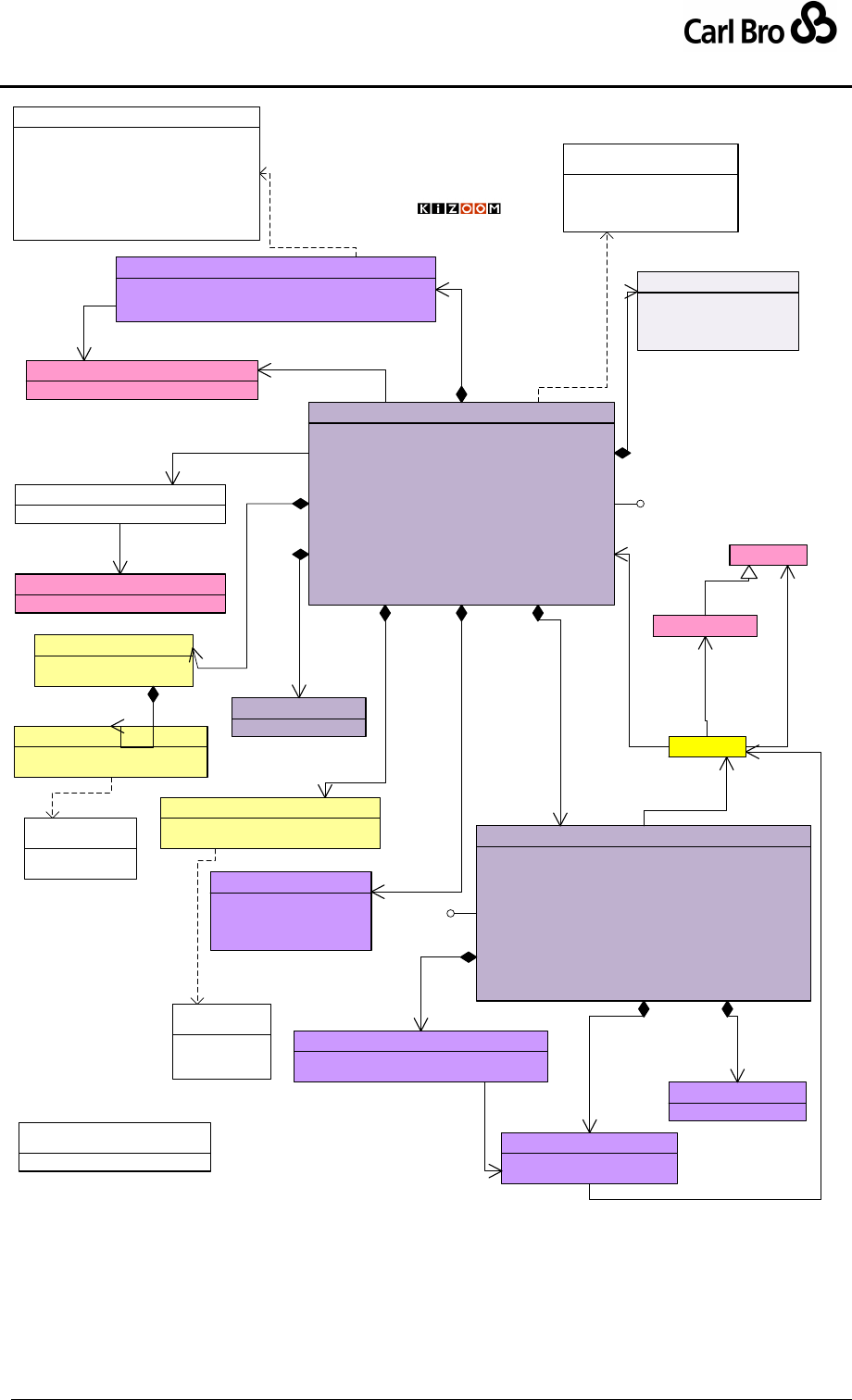
Department for Transport
TransXChange Schema Guide
Part I
Introduction & Overview
TransXChangeSchemaGuide-2.1-v-45.pdf.doc
Page 72
24 September 2013
ServiceRef[1] : ServiceCodeType
SubmissionDate[1] : date
VosaRegistrationNumber[1] : VosaRegistrationNumber
VariationNumber[1] : RegistrationVariationNumberType
ApplicationClassification[1] : ApplicationClassificationEnum
VariationNumber[1] : VariationNumberType
SubmissionAuthor[1] : FullPersonName
TrafficAreas[1..*] : TrafficArea
CirculatedAuthorities[1..*] : CirculatedAuthority
SubsidyDetails[1] : SubsidyDetails
QualityPartnership[0..1] : nlString
SupportingDocuments[0..*] : SupportingDocument
ContractedService[0..1] : ContractedService
Registration
Service
1..1
0..1
service
Operator
1
1
registered
PublicAvailability[1] : Subsidy
ChangeImpact[1] : Subsidy
BankHolidayChange[0..1] : boolean
ChangeToConnectAlteredService[0..1] : AnnotatedServiceRef
ReplaceDiscontinuedService[0..1] : ReplaceDiscontinuedService
LocalHolidayChange[0..1] : ChangeNote
SpecialOccasion[0..1] : ChangeNote
RegulationOrderCompliance[0..1] : ChangeNote
ChangeRequestByExternalAuthority[0..1] : ChangeNote
ExceptionalRequirement[0..1] : ChangeNote
MiscellaneousJustifcation[1] : nlString
ShortNoticeRegistration
TrafficAreaName[1] : TrafficAreaNameEnum
TrafficArea
AuthorityName[1] : AuthorityNameEnum
AuthorityName
TransXChange
Registration
0..*
1..1
registered with
0..* 0..*
ciirculated to
0..*
0..1
replaces
DocumentUri[1] : anyURI
SupportingDocument
1
0..*
documents
LicensedOperator
1
0..*
associated
TanCode[1] : TanCodeType
LicenceNumber[1] : OperatorPartialLicenceCodeNumberType
RegistrartionNumber[1] : string
VosaRegistrationNumber
AuthorityName[1] : AuthorityNameEnum
CirculatedAuthority
Position[1] : nlString
Title[1] : populatedString
Forename[1] : populatedString
Surname[1] : populatedString
FullPersonName
1
0..1
short notice
1
1
submitter
«datatype»
RegistrationVariationNumberType
1
1
number
North Eastern Traffic Area = PB
North Western Traffic Area = PC
West Midlands Traffic Area = PD
Eastern Traffic Area = PF
Welsh Traffic Area = PG
Western Traffic Area = PH
South Eastern & Metropolitan Traffic Area = PK
Scottish Traffic Area = PM
«enumeration»TanCodeType
NoSubsidy[0..1] : empty
Subsidy[0..1] : SubsidyDetails
SubsidyDetails
SubsidyType[1] : SubsidyLevelEnum
SubsidisingAuthority[1..*] : nlString
Subsidy
partial
full
«enumeration»
SubsidyLevelEnum ContractingType[1] : ContractedEnum
ContractingAuthority[0..*] : AuthorityName
ContractedService
1
1
subsidy
0..1
1
subsidy
1
0..1
contracted
new
chargeableChange
nonChargeableChange
cancel
«enumeration»
ApplicationClassificationEnum
Position[1] : nlString
Title[1] : populatedString
Forename[1] : populatedString
Surname[1] : populatedString
FullPersonName
1
1
submitter
1
*areas
notContracted
whollyContracted
partContracted
«enumeration»
ContractedEnum
0..*
0..1
authority
ServiceRef[1] : ServiceCodeType
Description[0..1] : nlString
AnnotatedServiceRef
Description[0..1] : nlString
ChangeNote
DiscontinuedOperator[0..1] : nlString
DiscontinuedService[0..1] : AnnotatedServiceRef
ReplaceDiscontinuedService
1
0..*
connections 1
0..*
justifcation
1
0..1
affected service
*
0..1
service
© Crown Copyright 2003-2009
0..*
0..1
service
Versionable
Versionable
Figure 3-25 – UML Diagram of TransXChange Registration
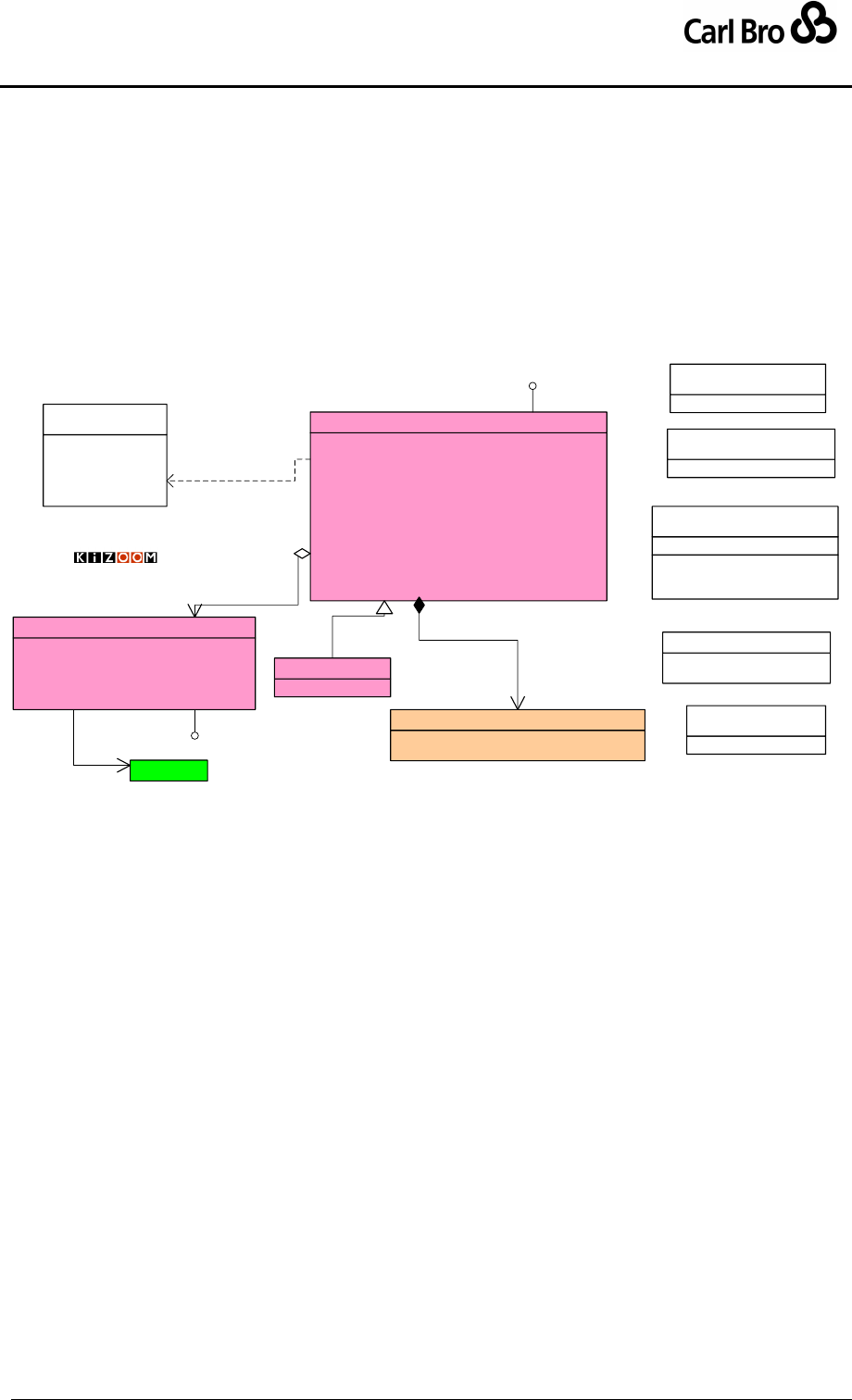
Department for Transport
TransXChange Schema Guide
Part I
Introduction & Overview
TransXChangeSchemaGuide-2.1-v-45.pdf.doc
Page 73
24 September 2013
3.12.1 Populating a Registration
Although it is legitimate for a Single Registered Service to have a number of journey pattern
variants, the variation should be less than 50% of the primary journey pattern; i.e. more than
50% of the mileage of the journeys should be in common, i.e. consist of vehicle journeys
with timing links that visit or pass the same stops in the same order.
3.13 Operators
TransXChange includes a basic representation of an Operator for use in Registrations see
Figure 3-26. An operator may have Garages associated with them.
NationalOperatorCode[0..1] : NationalOperatorCodeType
OperatorCode[0..1] : OperatorCodeType
OperatorShortName[1] : nlString
OperatorNameOnLicence[0..1] : nlString
TradingName[0..1] : nlString
LicenceNumber[0..1] : OperatorLicenceNumberType
LicenceClassification[1] : OperatorCodeType
EnquiryTelephoneNumber[0..1] : TelephoneNumberType
ContactTelephoneNumber[0..1] : TelephoneNumberType
EmailAddress[0..1] : emailType
OperatorAddresses[0..1] : OperatorAddresses
Garages[0..*] : Garage
Operator
GarageCode[1] : GarageCodeType
GarageName[0..1] : nlString
ContactNumber[0..1] : TelephoneNumberType
Address[1] : UkPostalAddress
Location[1] : Location
Garage
TelNationalNumber() : string
TelExtensionNumber() : string
TelCountryCode() : string
«datatype»
APD-mdl::TelephoneNumberType
«UniqueIdentifier»
OperatorLicenceNumberType
«UniqueIdentifier»
NationalOperatorCodeType
CorrespondanceAddress[1] : UkPostalAddress
MiscellaneousAddresses[0..*] : UkPostalAddress
OperatorAddresses
Line[0..*] : string
PostCode[0..1] : PostCodeType
APD-mdl::UkPostalAddress
«datatype»
APD-mdl::PostCodeType
1
0..1
addresses
standardNational
standardInternational
restricted
specialRestricted
communityBusPermit
«enumeration»
LicenceClassification
Versionable
LicensedOperator
Location
0..*
1..1
is at Versionable
1..1
0..* garages
TransXChange
Operator
© Crown Copyright 2003-2009
Figure 3-26 – UML Diagram of TransXChange Operator Model
3.14 Further Modelling Topics
3.14.1 Direction: Handling Inbound and Outbound Schedules.
A Service may contain both inbound and outbound journeys, comprising in effect two
distinct timetables for the two directions. Normally completely separate routes will be
specified for each direction, because there are typically separate NaPTAN points for bus
stop pairs each side of the road; routes will therefore be following a different sequence of
stops along slightly different road sections. However, there are scenarios where the route
(and associated sequence of stops) in one direction is an exact reversal of the route (and
associated sequence of stops) in the opposite direction. In this case it is possible to share
the route definitions for both directions of a service, as follows (Figure 3-27).
1. Each Route contains one or more route sections, each containing a sequence of
route links. Each route link is flagged as Outbound, Inbound, Clockwise or
Anticlockwise. All the links within a route section must be in the same direction.
2. At least one journey pattern is specified for each direction of the Route. The journey
pattern sections contain journey pattern timing links in the order of traversal, each of
which can specify a direction (if a direction is not specified the direction will be
assumed to be the same as that of any route link which the timing link references ).

Department for Transport
TransXChange Schema Guide
Part I
Introduction & Overview
TransXChangeSchemaGuide-2.1-v-45.pdf.doc
Page 74
24 September 2013
If the direction of a journey pattern timing link is the same as that of the route link
which it references, then the stops referenced in the from and to stop usages of
the timing link will be the same as for the route link, and the timing links will
appear in the same order as the route links.
o For example, if (a) Route Link ‘RL_1’ goes from ‘A’ to ‘B’ with a direction
of ‘outbound’, and (b) Route Link ‘RL_2’ goes from ‘B’ to ‘C’, also with a
direction of ‘outbound’, then the outbound journey pattern would have two
outbound journey pattern timing links: (i) ‘JTL_1’ which references ‘RL_1’
with a direction of ‘outbound’, and also runs from ‘A’ to ‘B’, followed by (ii)
journey pattern timing link ‘JTL_2’, which references ‘RL_2, and goes
from ‘B’ to ‘C’.’ Note that in this discussion; ‘A’, ‘B’, etc refer to stop pairs:
in actuality, the inbound and outbound stops are likely to be distinct stops
of a pair either side of the road. So actually the NaPTAN stops of inbound
and outbound routes and journey pattern will be quite distinct.
If the direction of the of a journey pattern timing link is the opposite to that of the
route link which it references, then both the link order, and the stops referenced
in the from and to stop usages will be reversed.
o For example, if (a) Route Link ‘RL_1’ goes from ‘A’ to ‘B’ with a direction
of ‘outbound’, and (b) Route Link ‘RL_2’ goes from ‘B’ to ‘C’, also with a
direction of ‘outbound’, then the inbound journey pattern would have two
inbound journey pattern timing links: (i) journey pattern timing link
‘JTL_X1,’ which references ‘RL_2’ but which runs from ‘C’ to ‘B’, and (ii)
journey pattern timing link ‘JTL_X2,’ which references ‘RL_1’ but which
runs from ‘B’ to ‘A’.
3. Each vehicle journey follows the same direction as the journey pattern that it
references.
4. The Service may be given an overall Direction: this may be one of Inbound,
Outbound, InboundAndOutbound, Clockwise, Anticlockwise, or Circular.
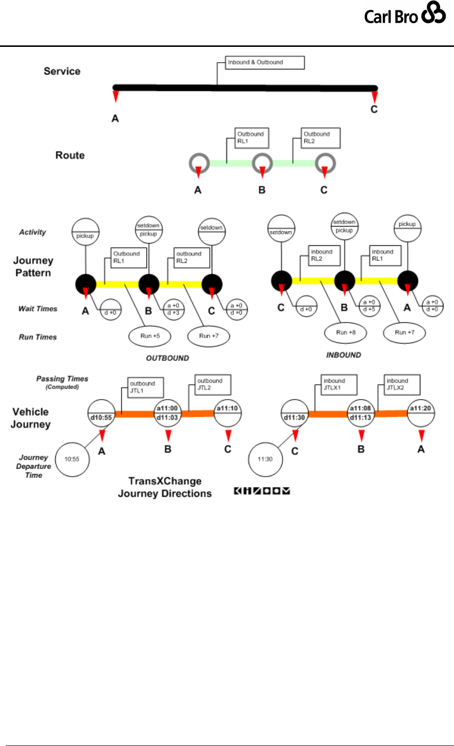
Department for Transport
TransXChange Schema Guide
Part I
Introduction & Overview
TransXChangeSchemaGuide-2.1-v-45.pdf.doc
Page 75
24 September 2013
Figure 3-27 – Journey Directions
The TransXChange Publisher will sort the vehicle journeys of a service into distinct
outbound and inbound groups, and create a separate matrix for each direction.

Department for Transport
TransXChange Schema Guide
Part I
Introduction & Overview
TransXChangeSchemaGuide-2.1-v-45.pdf.doc
Page 76
24 September 2013
3.14.2 Modelling Complex Routes
The TransXChange model can be used to represent complex services, for example:
Services with topologically complex routes.
Services with complex temporal operational patterns.
3.14.2.1 Services with Topologically Complex Routes
The TransXChange model can be used to represent complex patterns of service:
1. Repeated stop routes. Circular (Figure 3-28), Lollipop (Figure 3-29) and Cloverleaf
(Figure 3-30) routes involve visiting the same stop more than once within a single
vehicle journey. In the TransXChange model, each link has a separate identity in
both the route, journey pattern and vehicle journey link sequences, so it is possible
to distinguish the separate link traversals and occurrences of a stop in a journey, and
so to compose complex routes, and also to project unambiguously the links of such
routes between the route, journey pattern and vehicle journey level of discourse. (In
TransXChange 1.2 this was not always possible). Other features helpful in
representing complex routes are:
o Dynamic destination displays, so that bus headings can change over the
course of the route.
o Reusable route and journey pattern sections, so that definitions of sections
of the route and/or journey pattern may be shared between different
journeys. See ‘Modelling Services Efficiently’ below.
o Stop Sequence numbers – so that the presentation of a route in a matrix
can be exactly controlled. See ‘Presenting Schedules in Timetables’ below.
2. Multiple route variants. Complex services may be composed of multiple route and
journey pattern variations, involving either covering different branches of the physical
network, or traversing subsets of the full stop sequence, or both.
o Line elements can be used to separate the modelling of the network topology
as routes and journey patterns, from the labelling of the network services with
public identifiers on vehicle journeys – which is done using the Line /
LineName element. Thus several different route variants may all be grouped
under the same line name.
o RouteSection elements can be used to model reusable subsections and
branches of the route network, and JourneyPatternSection elements can
be used to annotate this substructure with timing values, allowing for the
representation and reuse of the route substructure.
3. Connecting routes. The connections between routes services may be described
using JourneyPatternInterchange and VehicleJourneyInterchange elements.
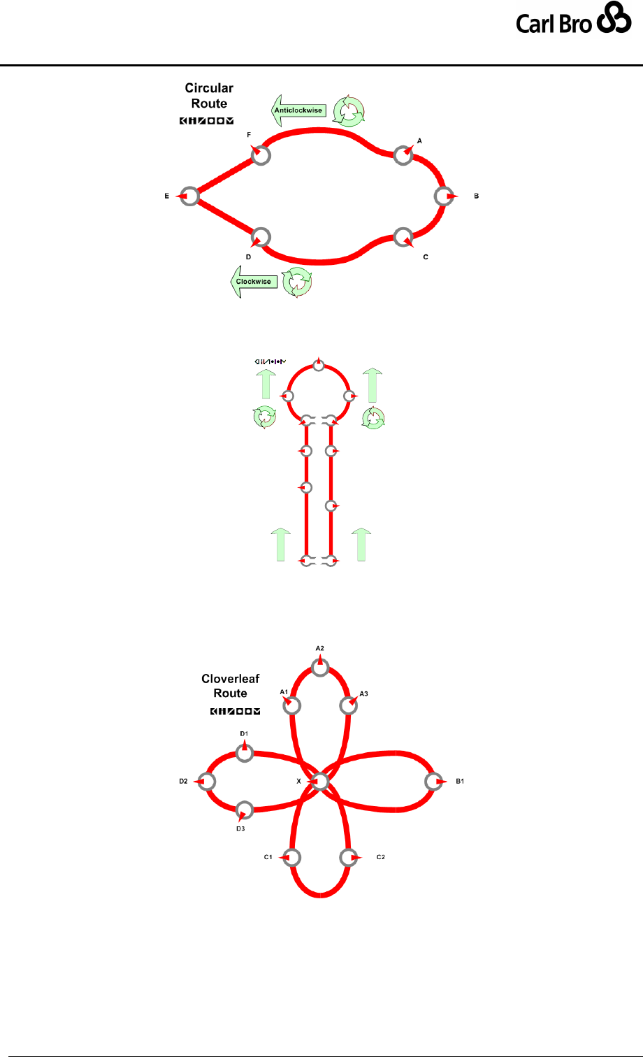
Department for Transport
TransXChange Schema Guide
Part I
Introduction & Overview
TransXChangeSchemaGuide-2.1-v-45.pdf.doc
Page 77
24 September 2013
Figure 3-28 – Topology: Circular Route
Lollipop
B
C
E
F
G
I
J
Lollipop
Route
DH
Outbound
Inbound
AAAAAAAAAA
Anticlockwise
Clockwise
KA
Figure 3-29 – Topology: Lollipop Route
Figure 3-30 – Topology: Cloverleaf Route

Department for Transport
TransXChange Schema Guide
Part I
Introduction & Overview
TransXChangeSchemaGuide-2.1-v-45.pdf.doc
Page 78
24 September 2013
3.14.2.2 Services with Complex Temporal Operational Patterns
The TransXChange model can be used to represent complex operational times. This is
discussed in detail under ‘Modelling Operational Days’ below. All of the following
mechanisms are available:
Regular day types: Days of week, Day Combinations, Weeks of month.
Special day types: Bank holidays.
Date ranges: OperatingPeriod, Validity Periods, and Exceptions.
Time bands: Time bands of operation of flexible services.
Frequency based: Interval or minute patterns of operation of frequency based
services.
Serviced Organisations: Term-times, holidays or other events of specified
organisations.

Department for Transport
TransXChange Schema Guide
Part I
Introduction & Overview
TransXChangeSchemaGuide-2.1-v-45.pdf.doc
Page 79
24 September 2013
3.14.3 Modelling Services Efficiently
TransXChange supports an extensive reuse of service and journey description elements so
that an efficient encoding of journeys can be achieved. In particular:
Existing data reference systems can be used; NaPTAN stop and stop area
definitions, NPTG localities.
Elements describing the network topology and other shared infrastructure entities
can be declared once, and then be reused by a simple reference. Notably:
Topographical elements: StopPoint, StopArea.
Organisational elements: ServicedOrganisation, Operator.
Network layer elements: Route, RouteSection.
Supply elements: JourneyPatternSection, and JourneyPattern.
Link Sequences – the timing link sequences of journey patterns and vehicle journeys
– may be reused in several different ways:
a. A JourneyPatternSection may be used in many different JourneyPattern
instances.
b. A given JourneyPattern may be referenced in many different
VehicleJourney instances, and its values inherited. Only those individual
vehicle journey timing links whose properties are different from the
corresponding timing links of the underlying journey pattern need be
specified.
c. A VehicleJourney may specify that particular stops of a referenced
JourneyPattern are omitted, allowing for “express” journeys constrained to a
basic journey, and for short working.
d. A VehicleJourney may reference another VehicleJourney to share the
timing links of that specific journey.
e. The Frequency element of VehicleJourney may be used to indicate that the
same vehicle journey is repeated to the same pattern many times at regular
intervals.
Operational day types and dates may be reused.
The OperatingProfile specified for a Service can be shared by all the
service’s vehicle journeys. Individual JourneyPattern and VehicleJourney
instances need only state their specific differences from the base values.
Properties of successive links need only be specified when they change:
The successive properties of links, such as fare stages and dynamic
headings, do not have to be repeated on every link, but only need to be
specified when they change from the preceding link.
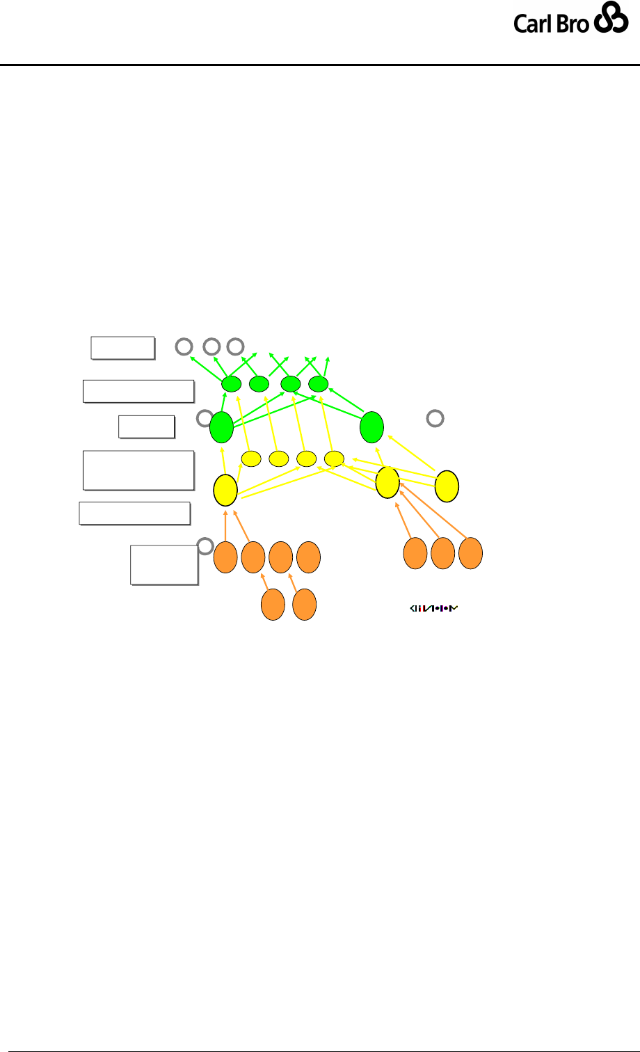
Department for Transport
TransXChange Schema Guide
Part I
Introduction & Overview
TransXChangeSchemaGuide-2.1-v-45.pdf.doc
Page 80
24 September 2013
It remains up to the implementer to decide the degree of reuse that she wishes to achieve.
A verbose implementation may, if it wishes, re-declare stops and create separate route,
route section, route links, journey pattern, journey pattern section, journey pattern links,
operation profile, and special operation profile instances for every single vehicle journey.
However it should be note that a verbose implementation (a) wastes space (b) may fail to
exchange structural information about the underlying schedule.
3.14.3.1 Overall Reuse of Elements
Figure 3-31 shows some of the ways that elements may be reused at different levels of
discourse.
Reuse in TXC 2.0
Routes
Routes
Journey Pattern
Journey Pattern
Vehicle
Journey
Vehicle
Journey
RouteSections
RouteSections
Stops
Stops
Journey
PatternSections
Journey
PatternSections
Figure 3-31 – Reuse of Elements
3.14.3.2 Inefficiencies in TransXChange
Although inheritance, default values and reuse can be used to optimise document content,
TransXChange is not a fully optimised representation, and has a number of data
redundancies in its representation. In particular:
Start and end stop usages are repeated on every successive link in a journey pattern
and vehicle journey, including the stop point reference on the journey pattern usage.
Start and end stop points are repeated on both route links and journey pattern links.
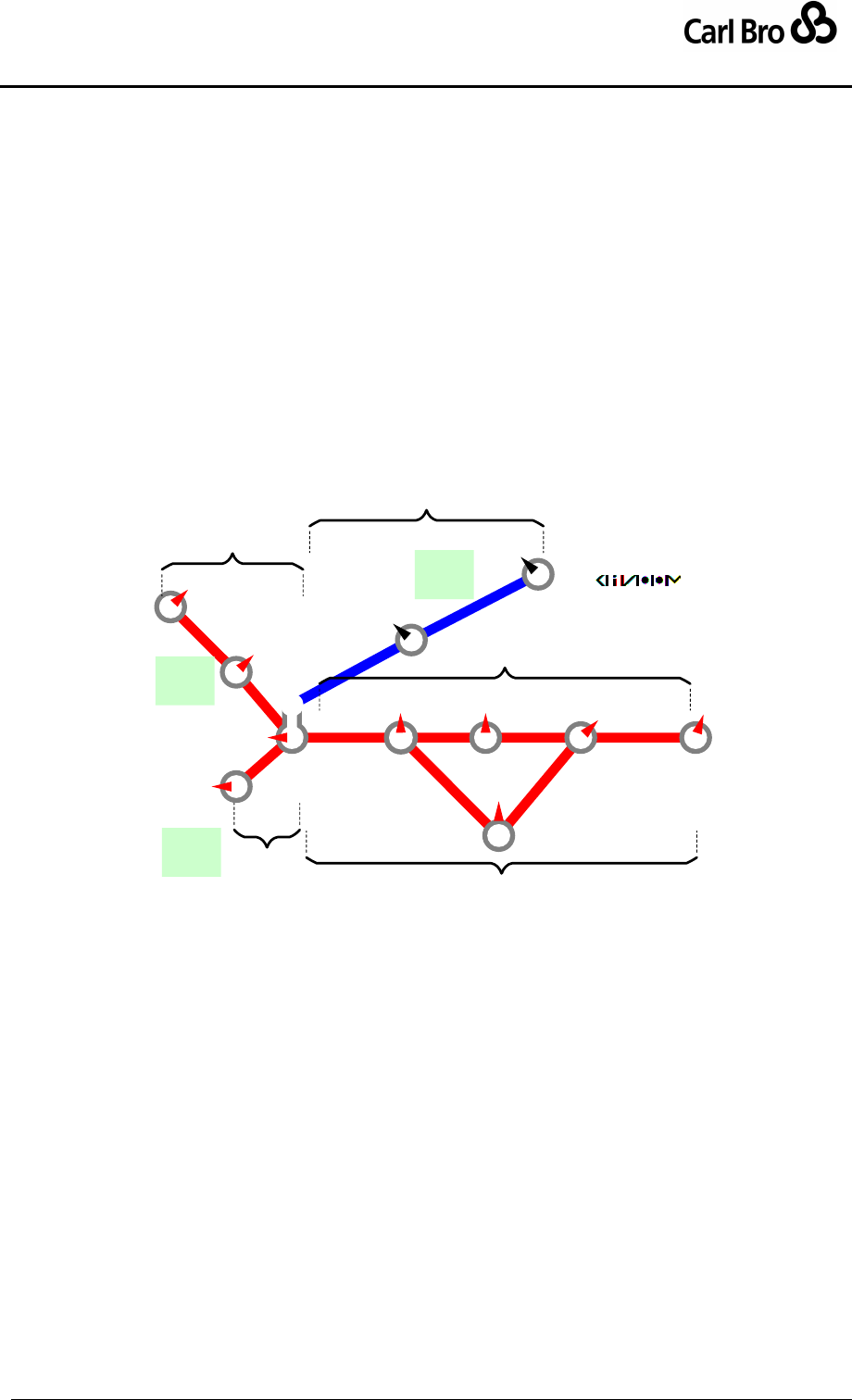
Department for Transport
TransXChange Schema Guide
Part I
Introduction & Overview
TransXChangeSchemaGuide-2.1-v-45.pdf.doc
Page 81
24 September 2013
3.14.3.3 Use of Sections
Route sections allow implementers to reuse a sequence of stops and links in more than one
route. Journey pattern sections allow the corresponding sequence of timing links to be
reused. Figure 3-32 shows an example of a service comprising three named lines (Line 54
Line 54A and Line 12). The lines are made up of four routes, containing five sections that
group the eleven different links of the network. Two of the sections (S1 & S2) are reused in
two different routes.
Line 54
R1 = S1(L1, L2) + S2(L3 + L4 + L5 + L6)
R2 = S1(L1, L2) + S4(L3 + N1 + N2 + L6)
Line 54A
R3 = S3(M1) + S2(L3+L4+L5+L6)
Line12
R4 = S3(M1) + S5(R1, R2)
L6
L1
M1
b
r1
L3 L4 L5
N2
N1
L2
D F
P
A
B
D
C
F
EG
Q
X
YUse of
Sections
S2
S4
S3
S5
S1
Line
54
Line
54A
Line
12
Figure 3-32 – Example of Sections

Department for Transport
TransXChange Schema Guide
Part I
Introduction & Overview
TransXChangeSchemaGuide-2.1-v-45.pdf.doc
Page 82
24 September 2013
3.14.4 Presenting Schedules in Timetables
TransXChange is primarily concerned with the representation of schedule data for
exchange between different computer systems, and is not intended to address all the
additional requirements for presenting schedules as published representations for the
public. However it is possible to transform a TransXChange schedule into a matrix timetable
format automatically, adopting a specific order for showing the stops. Rendering the
journeys in a tabular format is valuable because it allows a TransXChange document to be
validated by human inspection against the originating and published formats.
The TransXChange Publisher provides an example of a matrix rendering, which follows a
conventional mapping:
VehicleJourney instances generally correspond to columns.
1. Each VehicleJourney instance can have a VehicleJourney / Note
associated with it.
2. Each VehicleJourney can have an OperatingProfile to specify operational
time information specific to it in a quantitative structure.
3. If a Frequency is specified, one or more additional columns may be
interpolated to indicate the repeating journeys.
4. If a Frequency and the same EndTime is specified for more than one
journey, one or more journey columns may be merged to create a single
frequency group. See 3.15.8.3.
5. VehicleJourney are ordered as columns across the matrix in the same order
as they are declared in the document. Normally they should be sorted into
time time order.
JourneyPatternTimingLink / VehicleJourneyStopUsage instances generally
correspond to each individual row.
VehicleJourneyTimingLink / VehicleJourneyStopUsage instances generally
correspond to cells for each individual row.
1. Each From / VehicleJourneyStopUsage corresponds to a departure.
Normally the departure is shown for all stops of the route except the last.
2. Each To / VehicleJourneyStopUsage corresponds to an arrival. Normally
arrivals are only shown for the last stop.
3. If the arrival and departure time is different at a stop, two separate rows for
arrival and departure will be shown.
4. The stop rows will be ordered down the page in the same order that
VehicleJourneyStopUsage instances appear in the Journey pattern of the
Vehicle Journey (unless overridden by a SequenceNumber).
To collate different journeys that follow different journey patterns into a
single matrix, the publisher compiles a list of all the stops of all the
journey patterns, in order of use. The stops of each vehicle journey are
aligned against this list, leaving an empty cell for any stop that is not
visited by a particular journey. Thus for example, if two journey patterns
A-B-F and A-C-D-F are combined as list, these will be collated as A-B-C-
D-F, resulting in column entries A-B-()-()-F for the first and A-()-C-D-F for
the second.
Within this overall ordering, where there are stops that are specific to
particular journey patterns these will be ordered according to the passing
time. Thus for example, consider two vehicle journeys using separate
patterns A-B-D and A-C-D, which have passing times at stop A(t1)-B(t4)-
D(t6) and A(t2)-C(t3)-D(t5) where tn indicates the relative time. If these are
combined as list, these will be ordered A-C-B-D, rather than say A-B-C-D
because stop C is visited earlier (t3) than stop B (t4).

Department for Transport
TransXChange Schema Guide
Part I
Introduction & Overview
TransXChangeSchemaGuide-2.1-v-45.pdf.doc
Page 83
24 September 2013
As a further refinement to the overall ordering, the publisher uses the
grouping of stops given by the JourneyPatternSection to sequentially
order a series of stops in succession that are a route variants used only
by certain journeys, rather than the strict relative time. Thus for example,
if two journey patterns A-[B-C-D]-F and A-[P-Q-R]-F are combined as list
these will be ordered as A-B-C-D-P-Q-R-F, rather than say as A-B-P-C-
Q-D-R-F, regardless of the relative passing times at BCD and PQR. This
results in more readable columns entries of A-B-C-D-()-()-()-F and A-()-
()-()-P-Q-R-F, rather than say A-B-()-C-()-D-()-F and A-()-P-()-Q-()-R-F.
A SequenceNumber attribute can be specified on individual
JourneyPatternStopUsage instances to suggest a preferred sort order of stops for
presentation. When listing the stops as rows in a matrix, the explicit number
overrides the default traversal sequence that will be otherwise assumed for
publication. Note that each vehicle journey is still traversed by a bus in the actual
order of its links regardless of any SequenceNumber instances.
3.14.4.1 Using a Sequence Number
The SequenceNumber attribute on individual JourneyPatternStopUsage instances allows
you to control the ordering of stops in tabular presentations.
1. Every stop usage of a journey pattern timing link can be allocated a sequence
number (i.e. both the departure-from-stop end, and arrival-at-stop end).
2. Either all of the stop usages ('explicit numbering'), or none of the stop usages
('implicit numbering') of a complete journey pattern should be numbered. (N.B. If
some are numbered and some are not, indeterminate effects may occur in
applications that make use of the SequenceNumber.)
For implicit stop numbering, each stop usage is consequentially numbered in
order of traversal of the timing links of the route and journey pattern. (Note that
journey pattern timing links must in any case visit the same stops in the same
order as the route links of any route that the journey pattern references).
For explicit stop numbering, each stop usage is consequentially numbered in the
implementor’s preferred presentation order. The actual traversal of the journey
timing links for the computation of passing times still follows the sequence of the
links of the journey pattern, even if the stops are sequenced in a different order
by means of a SequenceNumber.
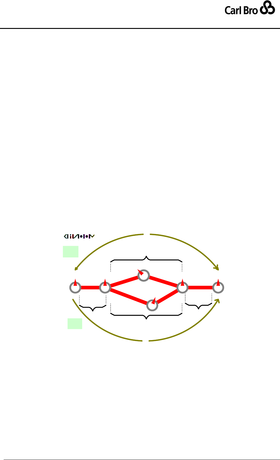
Department for Transport
TransXChange Schema Guide
Part I
Introduction & Overview
TransXChangeSchemaGuide-2.1-v-45.pdf.doc
Page 84
24 September 2013
For example, the TransXChange Publisher uses the SequenceNumber as follows:
1. The publisher builds a matrix by creating a line for each vehicle journey stop usage
(i.e. arrival and departure, of each vehicle journey in the service), and sorting them
all into stop sequence order.
If there are several different underlying journey patterns (i.e. routes) making up
the overall service, giving rise to overlapping (or even completely disjoint) sets of
stops, the publisher takes the combined set of all stop usages; if the same stop
usage appears with the same sequence number in multiple journey patterns,
then it is shown as the same stop row.
2. For each column, i.e. vehicle journey, the stop passing times for each stop are
computed in the order of traversal of the timing links; times are only shown in cells
for the stops that are visited.
3. If the arrival and departure usages for the same stop appear on consecutively lines
on the matrix, they can be shown as a single line, showing just the departure time.
3.14.4.2 Example of a Timetable using StopSequence
Figure 3-33 shows a service with two alternate routes (R1 & R2) over six stops (labelled
alphabetically ‘A’ to ‘F’) and which are labelled; line ‘1C’, which runs ‘A-B-C-E-F’, and line
‘1D’, which runs ‘A-B-D-E-F’.
L1
L2
L3
L4
L6
L5
A B
C
D
FE
R1
R2
1C
1D
Sequenced
Timetable
(“Matt’s Eye”)
S2
S3
S4
S1
Figure 3-33 – Example: Use of Stop Sequencing

Department for Transport
TransXChange Schema Guide
Part I
Introduction & Overview
TransXChangeSchemaGuide-2.1-v-45.pdf.doc
Page 85
24 September 2013
In the published timetable for the service, the preferred presentation might be to show the
two journeys aligned on all similar stops – see Table 3-11.
Journey
SequenceNumber
1C
1D
#
A
10:00
11:00
1
B
10:05
11:05
2
C
10:10
-------
3
D
-------
11:12
4
E
10:15
11:17
5
F
10:20
11:22
6
Table 3-11 – Example: Eye Timetable with Explicit Stop Sequencing
To specify the above presentation we might do the following:
Break the two routes down into four sections containing route links as follows:
• R1 = RS1(RL1) + RS2(RL2, RL3) + RS4(RL4)
• R2 = RS1(RL1) + RS3(RL5, RL6) + RS4(RL4)
Define a journey pattern, JP1, over route R1, specifying a preferred stop sequence n
for each end of each timing link:
• JP1 = R1
[ JS1(RL1: JPTL1[5mn, from:1, to: 2])
+ JS2(RL2: JPTL2[5mn, from:2, to: 3]. RL3: JPTL3[5mn, from:3, to: 5])
+ JS4(RL5: JPTL4[5mn, from:5, to: 6]) ]
Define a journey pattern, JP2, over route R2: also specifying a preferred stop
sequence:
JP2 = R2
[ JS1(RL1: JPTL1[5mn, from:1, to: 2])
+ JS3(RL5: JPTL5[7mn, from:2, to: 4], RL6: JPTL6[5mn, from:4, to: 5])
+ JS4(RL4: JPTL4[5mn, from:5, to: 6]) ]
As a comparison, Figure 3-34 shows the default ordering that would be used by the
TransXChange Publisher if no sequence guidance was given. Note this is a difference of
presentation, not representation – in the underlying TransXChange document, each
individual vehicle journey is still correctly ordered as to its sequence of visiting the stops by
virtue of its journey pattern. If wait times had been specified, then arrival and departure
would be distinct.
Stop
1C
1D
A
Dep 10:00
Dep 11:00
B
Dep 10:05
Dep 11:05
C
Dep 10:10
-
E
Arr 10:15
-
B
-
Dep 11:05
D
-
Dep 11:12
E
-
Arr 11:17
E
Dep 10:15
Dep 11:17
F
Arr 10:20
Arr 11:20
Table 3-12 – Example: Eye Timetable with Implicit Stop Sequencing
3.14.5 Associating operational data with a timetable
TransXChange provides several means of associating different types of operational data
with the elements of a timetable (See Figure 3-34). For example,
JourneyPatterns & VehicleJourneys may be associated with a Operational
element that specifies a Block, VehicleType or TicketMachine for a journey.
A TimingLink may specify a DutyCrew for a link.
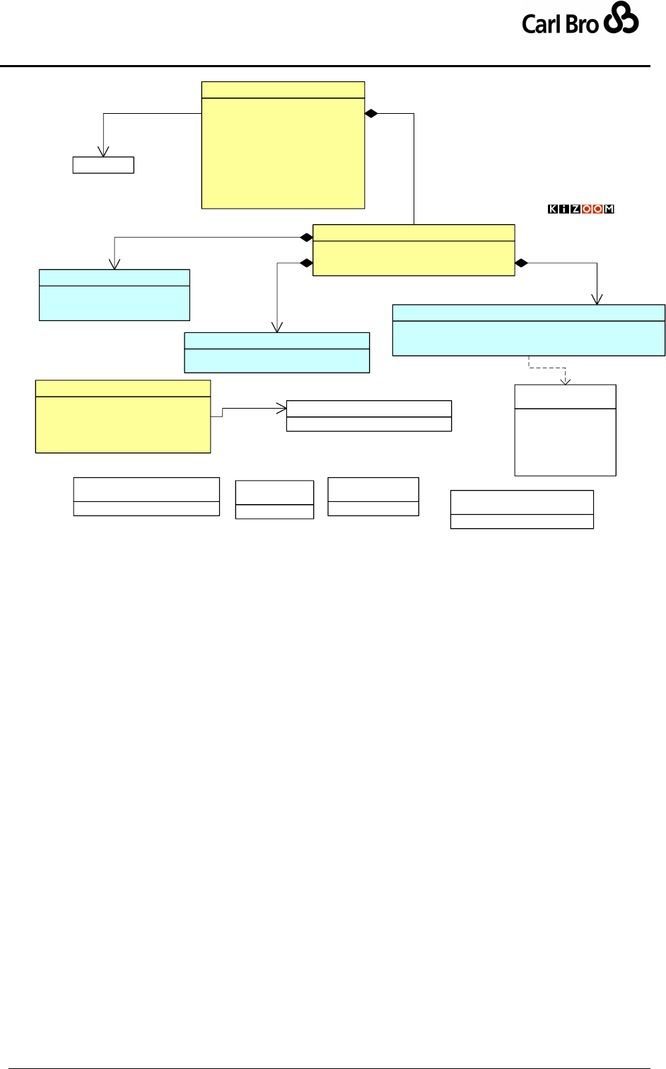
Department for Transport
TransXChange Schema Guide
Part I
Introduction & Overview
TransXChangeSchemaGuide-2.1-v-45.pdf.doc
Page 86
24 September 2013
Block[0..1] : Block
VehicleType[0..1] : VehicleType
TicketMachine[0..1] : TicketMachine
Operational
Description[1] : nlString
BlockNumber[0..1] : BlockCodeType
Note[0..1] : nlString
Block
© Crown Copyright 2003-2009
1
0..1
blocks
VehicleTypeCode[1] : VehicleTypeCodeType
Description[1] : nlString
VehicleType
TicketMachineServiceCode[0..1] : TicketMachineServiceCodeType
JourneyCode[0..1] : TicketMachineJourneyCodeType
Direction[0..1] : ServiceDirectionEnum
TicketMachine
«UniqueIdentifier»
TicketMachineJourneyCodeType
outbound
inbound
inboundAndOutbound
circular
clockwise
anticlockwise
«enumeration»
ServiceDirectionEnum
1
0..1
vehicle type 10..1
ticket machine
PrivateCode[0..1] : string
DestinationDisplay[0..1] : nlString
OperatorRef[0..1] : OperatorCodeType
Direction[1] : ServiceDirectionEnum
Operational[0..1] : Operational
OperatingProfile[0..1] : OperatingProfile
TimeDemand[0..1] : OperatingProfile
LayoverPoint[0..*] : LayoverPoint
GarageRef[0..*] : Garage
Description[0..1] : nlString
AbstractJourneyPattern
1
*
Association3
Operational Views
that can be
associated with a
VehicleJourney or
JourneyPattern
«UniqueIdentifier»
BlockCodeType «UniqueIdentifier»
TicketMachineServiceCodeType
Garage
0..1 0..*
garage
«datatype»
DutyCrewCodeType
Id[0..1] : JpTimingLinkIdType
HailAndRide[0..1] : boolean
Express[0..1] : boolean
StoppingArrangements[0..1] : nlString
DutyCrewCode[0..1] : DutyCrewCodeType
JourneyPatternTimingLink
0..* 0..1
duty crew
DutyCrewCode[1] : DutyCrewCodeType
DutyCrew
Figure 3-34 – UML Diagram of Operational data elements
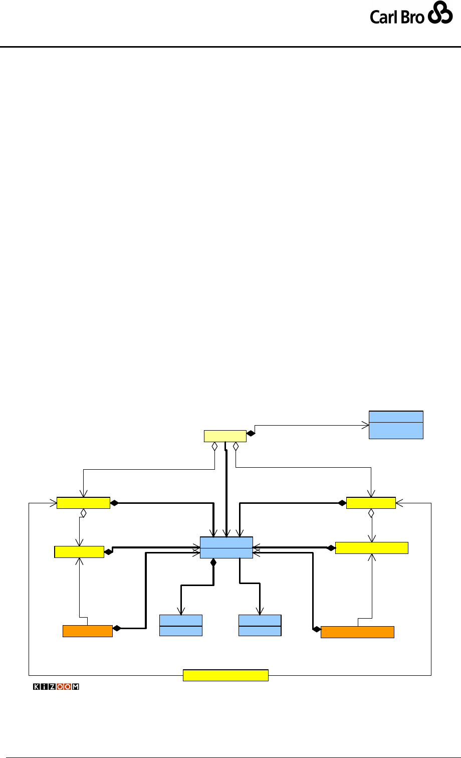
Department for Transport
TransXChange Schema Guide
Part I
Introduction & Overview
TransXChangeSchemaGuide-2.1-v-45.pdf.doc
Page 87
24 September 2013
3.15 Modelling Operational Days
TransXChange has rich (and complex!) capabilities for specifying the operational days and
times of a bus service for both regular running, and for exceptional days. We introduce
these capabilities here. For further details, see the descriptions of individual schema
elements. For an overall summary of how to combine date conditions, see also Section 13
‘Integrity Rules’.
3.15.1 Specifying When the Service Operates – Summary
The OperatingProfile specifies when a bus service runs, including both the types of days
(e.g. Monday to Friday) on which the service normally runs; and what happens on special
days such as Bank Holidays, and can also describe any exceptional periods of operation.
An overall OperatingPeriod can also be specified at the service level. This can be
open ended.
Default OperatingProfile values can be specified at the Service level, and be
overridden at both the JourneyPattern level and on individual VehicleJourney
instances.
Validity periods can also be specified for the operation of
JourneyPatternInterchange instances, constraining the availability of interchanges
between specified VehicleJourney instances.
Figure 3-35, in
UML
StandardService FlexibleService
Operational
Days and Dates
Overview Service
Special
VehicleJourney
10..1
operates on OperatingProfile
1
1
operates on
1
0..1
operates on
JourneyPattern
1
0..*
patterns
0..*
1
pattern
StartDate[1] : date
EndDate[1] : date
OperatingPeriod
1
1
1
0..1
flexible
1
0..1
standard
Normal
1
1..1
operates on 1
0..1
operates on
11..1
operates on
FlexibleJourneyPattern
1
1..*
patterns
FlexibleVehicleJourney
0..*
1
pattern
1
1..1
operates on
1
0..1 operates on
1
0..1
operates on
JourneyPatternInterchange
1..1
0..*
interchanges
0..1
0..*
interchanges
© Crown Copyright 2003-2008
class diagram notation, gives a high-level view of the main elements and relationships
concerned with operational days.
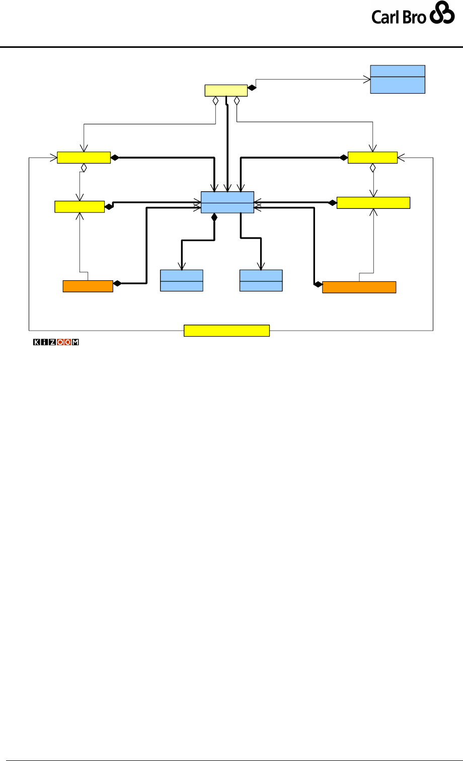
Department for Transport
TransXChange Schema Guide
Part I
Introduction & Overview
TransXChangeSchemaGuide-2.1-v-45.pdf.doc
Page 88
24 September 2013
StandardService FlexibleService
Operational
Days and Dates
Overview Service
Special
VehicleJourney
10..1
operates on OperatingProfile
1
1
operates on
1
0..1
operates on
JourneyPattern
1
0..*
patterns
0..*
1
pattern
StartDate[1] : date
EndDate[1] : date
OperatingPeriod
1
1
1
0..1
flexible
1
0..1
standard
Normal
1
1..1
operates on 1
0..1
operates on
11..1
operates on
FlexibleJourneyPattern
1
1..*
patterns
FlexibleVehicleJourney
0..*
1
pattern
1
1..1
operates on
1
0..1 operates on
1
0..1
operates on
JourneyPatternInterchange
1..1
0..*
interchanges
0..1
0..*
interchanges
© Crown Copyright 2003-2008
Figure 3-35 – UML Diagram Overview of Operational Times
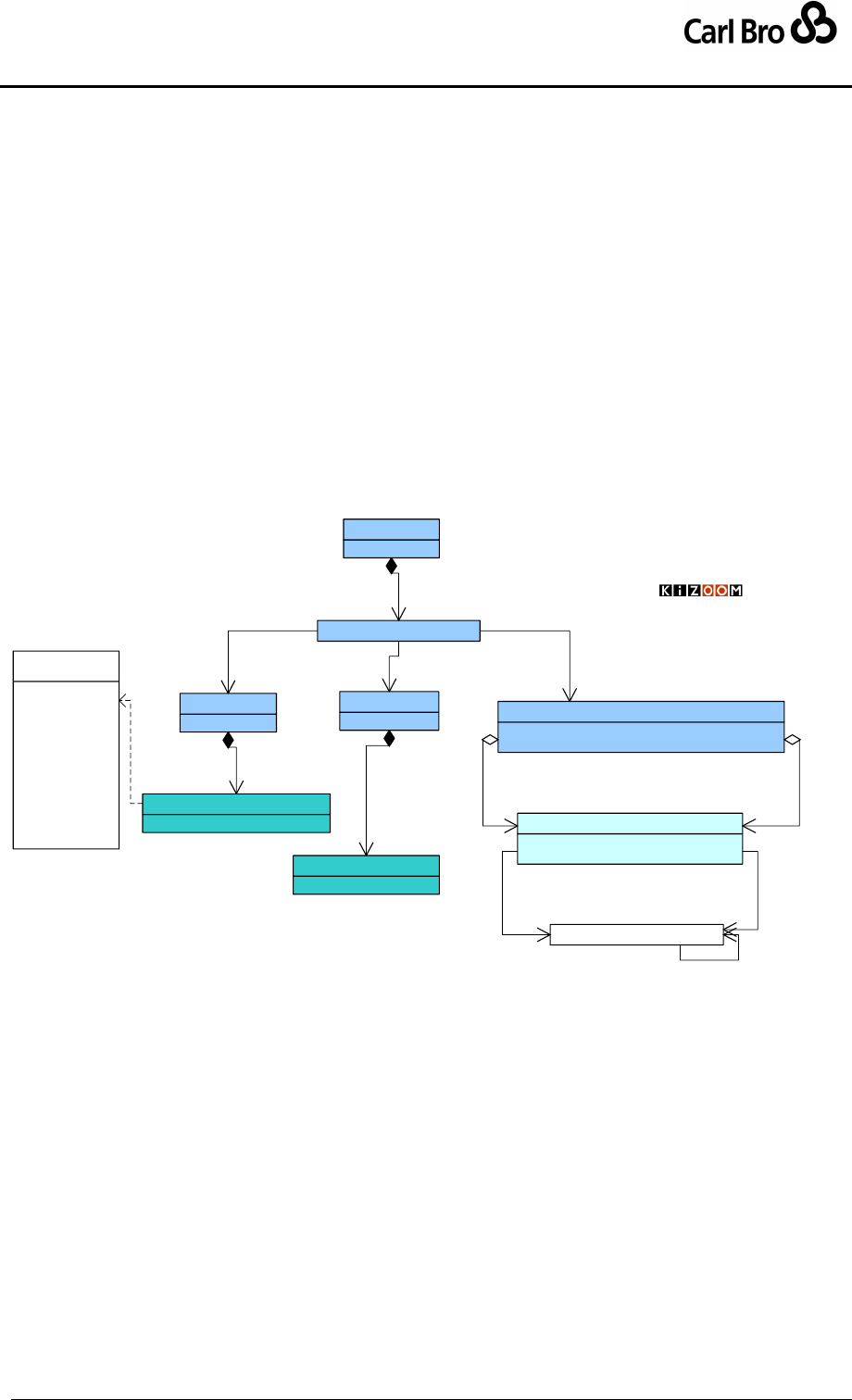
Department for Transport
TransXChange Schema Guide
Part I
Introduction & Overview
TransXChangeSchemaGuide-2.1-v-45.pdf.doc
Page 89
24 September 2013
3.15.2 Regular Operation – OperatingProfile
The OperatingProfile / Normal group specifies the normal operating day types of a service.
It can be made up of three elements, as shown in the UML structure diagram in Figure 3-36:
The types of day (RegularDayType) on which the service runs; for example,
‘Monday to Friday’, ‘Sunday’, or ‘Wednesday and Saturday.’
The weeks of the month on which the service is operated for the given day types;
for example, ‘first and third weeks of the month’. The PeriodicDayType further
qualifies the RegularDayType, (for example, a market service that might run
‘Wednesdays and Saturdays, first and third weeks of the month’).
The holiday or working day types of the serviced organisation for which the
service runs (for example, ‘term times for City of London School for Girls’) – see
ServicedOrganisation in Section 3.15.4 below. The
ServicedOrganisationDayType further qualifies the periodic and regular day
type. For example, ‘Wednesdays, during term times for City of London School for
Girls’’.
OperatingProfile
WorkingDays[0..*] : OrganisationCodeType
Holidays[0..*] : OrganisationCodeType
ServicedOrganisationDays
DaysOfOperation[0..1] : ServicedOrganisationDays
DaysOfNonOperation[0..1] : ServicedOrganisationDays
ServicedOrganisationDayType
1
0..*
runs on
Weeks[1] : Week
PeriodicDayType
Days[0..*] : Days
RegularDayType
1
0..1
days of week
1
0..1
weeks in month 1
0..1
serves
WeekNumber[0..5] : integer
Week
DaysOfWeek[1] : DayOfWeekEnum
Days
Normal
Operating
Profile
Normal
1
0..4
weeks
1
1..*
days
1
1..1
operates on
1
0..*
does not run on
© Crown Copyright 2003-2009
Monday
Tuesday
Wednesday
Thursday
Friday
Saturday
Sunday
MondayToFriday
MondayToSaturday
Weekend
Everyday
HolidaysOnly
«enumeration»
DayOfWeekEnum
ServicedOrganisation
0..*
0..1
working days of
0..*
0..1
holidays of
0..*
0..1
parent
Figure 3-36 – UML Diagram of Normal Operation Profile
3.15.3 Exceptional Operation – OperatingProfile
The OperatingProfile / Special group specifies the exceptional operating days of a service.
It can be made up of two distinct elements, as shown in the UML structure diagram in
Figure 3-37:
How the service operates on a bank holiday (BankHolidaysOperation). A
number of different bank holiday day types are supported for both individual days
and groups of days. For example ‘Does not run Christmas, New Year’s Day,
Good Friday’, ‘Runs Bank Holiday Mondays’. Day types include moveable feasts,
such as Easter Day, whose day may vary from year to year. The holidays on
which the service does (inclusion) or does not (exclusion) run are specified
separately.
Any special operating dates on which the service does (inclusion) or does not
(exclusion) run (SpecialDaysOperation). Special days are always absolute
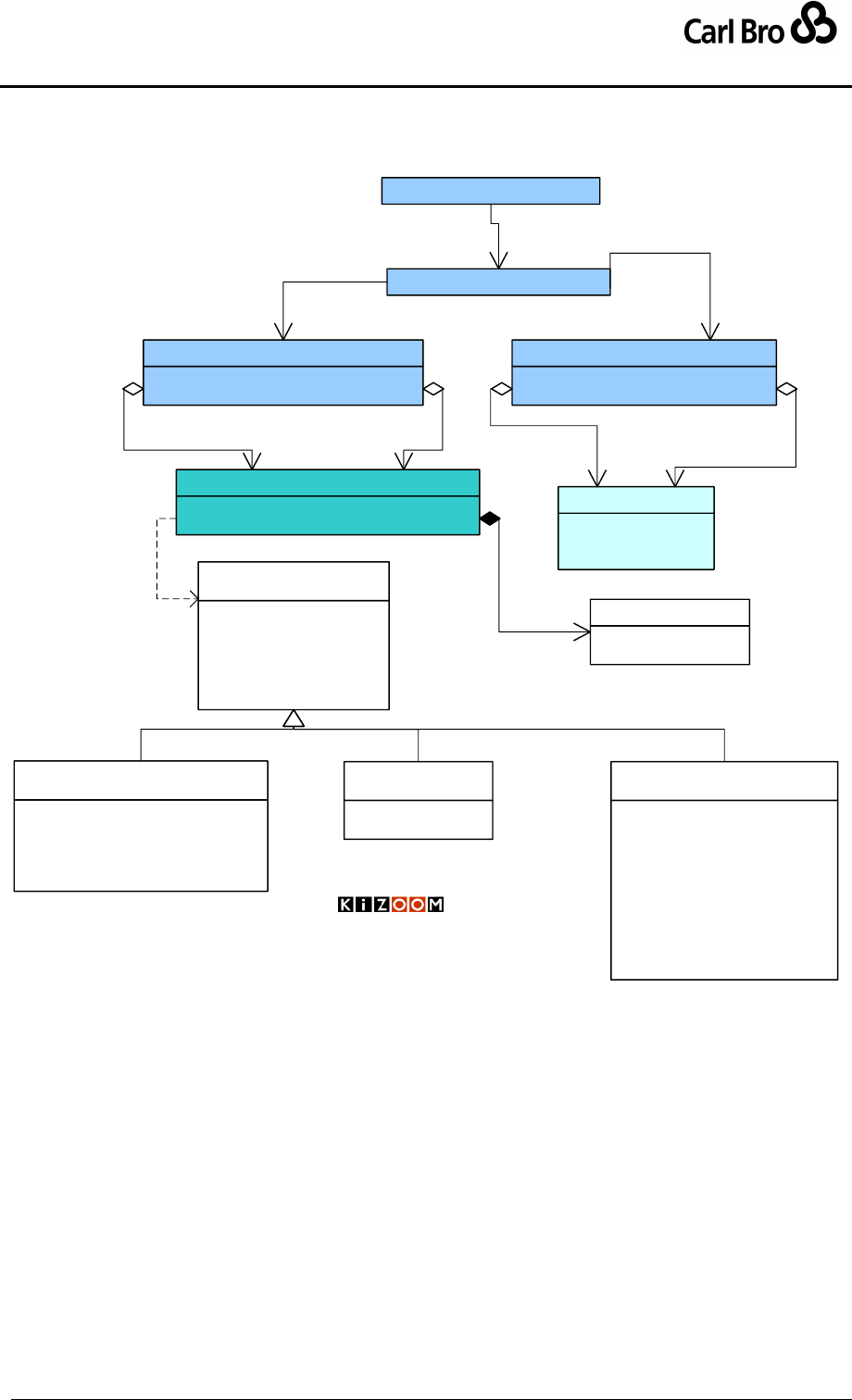
Department for Transport
TransXChange Schema Guide
Part I
Introduction & Overview
TransXChangeSchemaGuide-2.1-v-45.pdf.doc
Page 90
24 September 2013
calendar dates or calendar date ranges. For example ‘does not run 11/11/2005’.
Special days override any Bank Holiday day types.
Special
DaysOfOperation[0..*] : DateRange
DaysOfNonOperation[0..*] : DateRange
SpecialDaysOperation
1
0..1
special days
DaysOfOperation[0..*] : BankHolidays
DaysOfNonOperation[0..*] : BankHolidays
BankHolidayOperation
1
0..1
holidays
StartDate[1] : date
EndDate[1] : date
Note[0..1] : nlString
DateRange
BankHolidays[0..1] : BankHolidays
OtherPublicHoliday[0..1] : OtherPublicHoliday
BankHolidays
1
0..*
on 1
0..*
not on
1
0..*
on 1
0..* not on
Special
Operating
Profile
OperatingProfile
1
0..1
operates on
© Crown Copyright 2003-2009
LateSummerBankHolidayNotScotland
MayDay
EasterMonday
SpringBank
AugustBankHolidayScotland
«enumeration»
BankHolidayMondays
AllBankHolidays
AllHolidaysExceptChristmas
Christmas
EarlyRunOffDays
DisplacementHolidays
HolidayMondays
«enumeration»
BankHolidaysEnum
ChristmasEve
ChristmasDay
BoxingDay
NewYearsEve
NewYearsDay
Jan2ndScotland
ChristmasDayHoliday
BoxingDayHoliday
NewYearsDayHoliday
Jan2ndHoliday
«enumeration»
ChristmasPeriodHolidaysEnum
GoodFriday
EasterMonday
«enumeration»
OtherHolidaysEnum
Description[1] : nlString
Date[0..1] : date
OtherPublicHoliday
1
0..1
other
Figure 3-37 – UML Diagram of Special Operation Profile
A statement that a service does not operate on specific days should not be interpreted as
implying that it operates on all other days. Similarly a statement that a service runs on a
particular day does not necessarily imply that it does not run on all other days.
Note that the exclusion and inclusion of special days of operation have different meanings
(see also ‘General Principles for Using Operational Days’ below):
The Special Operation profile days of non-operation i.e. exclusion should be
interpreted as further constraining the days of week and month of the Normal
Operating Profile. For example, if the Normal Profile specifies that a service runs
‘Monday to Friday’, and the Special Operation Profile specifies that the Service does not
run on New Year’s Day, it will not run on New Year’s Day, whatever day of the week
New Year’s Day occurs.
The Special Operation profile days of explicit operation (i.e. inclusion) should be
interpreted as being additive to the days of week and month of the Normal Operating
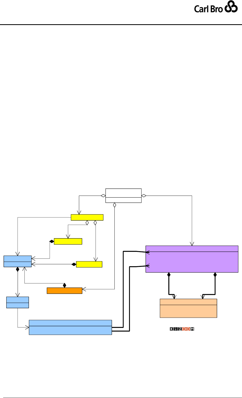
Department for Transport
TransXChange Schema Guide
Part I
Introduction & Overview
TransXChangeSchemaGuide-2.1-v-45.pdf.doc
Page 91
24 September 2013
Profile. For example, if the Normal Operation Profile specifies that a service runs
‘Sunday’, and the Special Operation Profile specifies that the Service does run on New
Year’s Day, then the service also runs to that timetable on New Year’s Day, regardless
of the day of week New Year’s Day falls.
Thus a typical usage is to have a lower frequency Service timetable that is used for
Sundays and Bank Holidays, and a regular timetable that is used for weekdays, except
when the weekday is a Bank holiday.
3.15.4 Services that Run for Specific ServicedOrganisation Working Days
Operational day types can be specified in terms of the working days or holidays of specified
organisations, for example schools. See Figure 3-38 in UML notation. A hierarchical parent
relationship can be used to specify that working days are derived from those of another
organisation, for example a Local Education Authority (LEAs), with specific variations.
LEAs and their Schools are modelled in the schema by a ServicedOrganisation
element. Each ServicedOrganisation may have a parent relationship (which should
be acyclic) to another ServicedOrganisation.
Patterns of WorkingDays and Holidays may be specified for service organisations.
Working days and holidays may be inherited from a parent organisation.
Services and vehicle journeys may be associated with one or more organisations on
the ServicedOrganisationDayType as part of the normal OperatingProfile.
ServicedOrganisationCode[1] : OrganisationCodeType
Name[0..1] : nlString
WorkingDays[0..1] : DatePattern
Holidays[0..1] : DatePattern
ParentServicedOrganisationRef[0..1] : OrganisationCodeType
ServicedOrganisation
0..1
1
holidays
0..*
0..*
operates on days
Serviced
Organisations -
Holidays and
Working Days
«Schema root»
TransXChange
Service
0..1
1
working days
FlexibleService
StandardService
0..*
0..*
does not operate on
1
0..1
flexible
1
0..1
standard
Normal
OperatingProfile 1
1..1operates on
1
1
operates on
1
1..1
operates on
1
1..1
operates on
DaysOfOperation[0..1] : ServicedOrganisationDays
DaysOfNonOperation[0..1] : ServicedOrganisationDays
ServicedOrganisationDayType
1
0..1
serves
VehicleJourney
1
0..1
operates on
1
0..1
journeys
1
0..*
organisations
1
0..*
services
© Crown Copyright 2003-2009
DateRange[1..*] : HalfOpenDateRage
Description[0..*] : nlString
DateExclusion[0..*] : date
DatePattern
Figure 3-38 – UML Diagram of Serviced Organisation Days
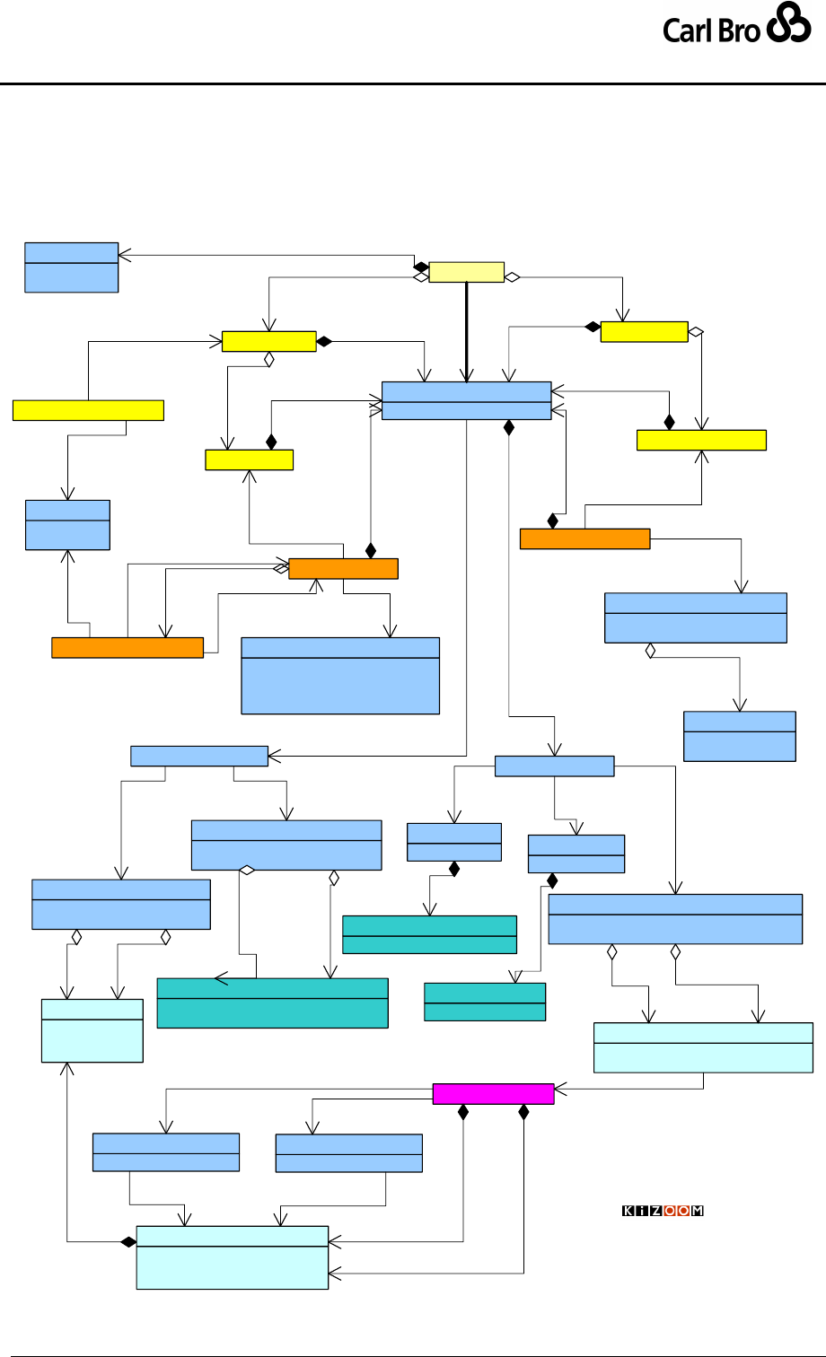
Department for Transport
TransXChange Schema Guide
Part I
Introduction & Overview
TransXChangeSchemaGuide-2.1-v-45.pdf.doc
Page 92
24 September 2013
3.15.5 OperatingProfile Elements
Figure 3-39 summarises, as a UML diagram, the elements that make up the
OperatingProfile, as well as other significant elements governing operational times such as
OperatingPeriod.
Service
StandardService
VehicleJourney
FlexibleService
StartDate : date
EndDate : date
OperatingPeriod 1
1operates within
AllDayService : boolean
ServicePeriod : HalfOpenDateRage
FlexibleServiceTimes
VehicleJourneyInterchange
0..*
1
inbound
1
{ordered}
0..*
interchanges
0..*
1
onwards
StartDate : date
EndDate : date
ValidityPeriod
1
1
valid within
StartTime : dateTime
EndTime : dateTime
PeriodsOfOperation
1
0..*
times
Special
OperatingProfile
JourneyPatternInterchange
1
1
valid within
1..1
0..*
interchanges
EndTime : time
Interval : Interval
MinutesPastHour : nonNegativeInteger
FrequentService : boolean
Frequency
10..1
operates at
DaysOfOperation : DateRange
DaysOfNonOperation : DateRange
SpecialDaysOperation
1
0..1
special days
DaysOfOperation : BankHolidays
DaysOfNonOperation : BankHolidays
BankHolidayOperation
10..1
StartDate[1] : date
EndDate[1] : date
Note[0..1] : nlString
DateRange BankHolidays[0..1] : BankHolidays
OtherPublicHoliday[0..1] : OtherPublicHoliday
BankHolidays
1
0..*
on
1
0..*
not on
Days : Days
RegularDayType
Weeks : Week
PeriodicDayType
DaysOfOperation : ServicedOrganisationDays
DaysOfNonOperation : ServicedOrganisationDays
ServicedOrganisationDayType
-DaysOfWeek : DayOfWeekEnum
Days
1
1..*
days
-WeekNumber : integer
Week
1
0..4
weeks
WorkingDays[0..*] : OrganisationCodeType
Holidays[0..*] : OrganisationCodeType
ServicedOrganisationDays
1
0..*
runs on 1
0..*
does not run on
0..*
0..1
DatePattern[1] : DatePattern
WorkingDays
DatePattern[1] : DatePattern
Holidays
11
pattern 1
1pattern
1
1..*
days
JourneyPattern
1
0..*
patterns
+journey 0..*
+pattern 1
ServicedOrganisation
0..1 1..*
working days
0..1 1..*
holidays
1
1
operates on
1
0..1
standard
10..1
flexible
Normal
1
0..1
serves
1
1..1
operates on
1
0..1
days of week
1
0..1
weeks in month
1
1..1
operates on
1
0..1
operates on
10..1
operates on
1
0..1
operates on
11..1
operates on
1
0..*
on 1
0..*
not on
FlexibleVehicleJourney
1
0..1
operates on
11
available
FlexibleJourneyPattern
0..*
1
pattern
1
0..1 operates on
1
1..*
patterns
Operating
Days &
Times
© Crown Copyright 2003-2009
DateRange[1..*] : HalfOpenDateRage
Description[0..*] : nlString
DateExclusion[0..*] : date
DatePattern
0..1
1
holidays
0..1
1
working days

Department for Transport
TransXChange Schema Guide
Part I
Introduction & Overview
TransXChangeSchemaGuide-2.1-v-45.pdf.doc
Page 93
24 September 2013
Figure 3-39 – UML Diagram of Operational Time Elements
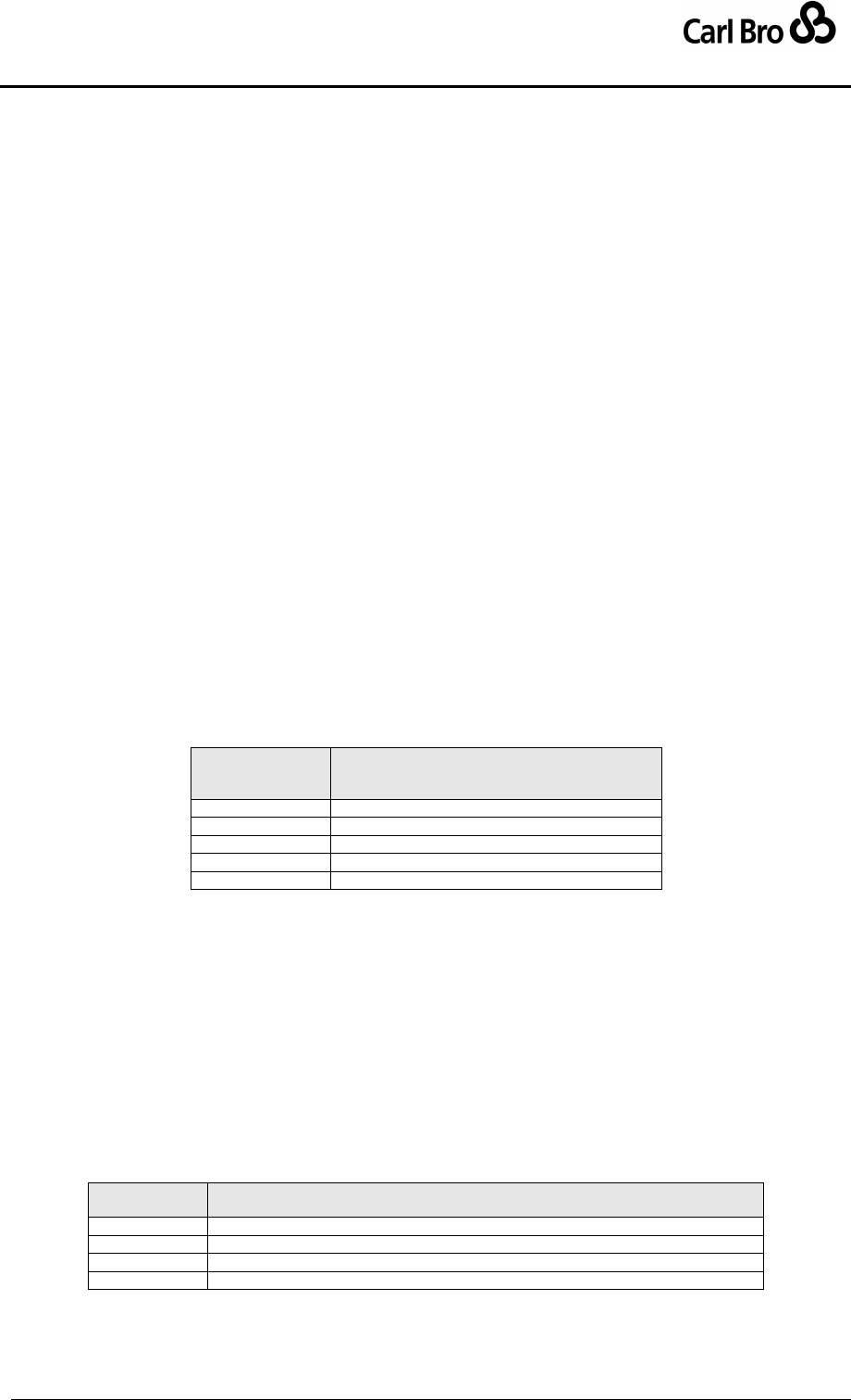
Department for Transport
TransXChange Schema Guide
Part I
Introduction & Overview
TransXChangeSchemaGuide-2.1-v-45.pdf.doc
Page 94
24 September 2013
3.15.6 General Principles for Using Operational Days
The TransXChange model has capabilities to specify operational days at a number of
different levels of discourse (Service, Journey Pattern, Vehicle Journey, Journey
Interchange); and to state operational days in both relative and absolute terms; that is,
(i) As general day types, such as ‘Monday to Friday’, or ‘Christmas Day’
(using the OperatingProfile / Normal elements).
(ii) As absolute calendar dates, such as ‘5th - 7th August 2005’ (using the
OperatingProfile / Special elements).
The different mechanisms can be combined to provide an overall set of operational
conditions for a given vehicle journey that is to run on a given day of operation.
When interpreting a schedule, a number of simplifying rules are followed for combining the
various element types to avoid ambiguity. The following general principles are followed for
the use of operational days:
1. Elements specified for a given profile property at a lower level of discourse
completely replace the equivalent element at a higher level. For example, if a
Journey level operating profile specifies days of operation as ‘Monday to Friday’ and
a vehicle journey specifies ‘Saturday’, then the vehicle journey runs only on
‘Saturday’, not ‘Monday to Saturday’. Similar considerations apply to Serviced
Organisation operating days for parent and child Service Organisation levels.
2. Lower level of discourse overrides higher level for operational days. In
particular, any operational days specified for a specific vehicle journey take
precedence over those specified over the journey pattern; and any for the journey
pattern over those specified for the whole service. For example, a vehicle journey
may state more restricted or more extensive operation days than the overall service.
Table 3-13 shows the relative precedence of levels of discourse. Similarly Serviced
Organisation properties override those of any parent organisation.
Operational days
Precedence
(1 high)
Level
1
VehicleJourneyInterchange.
2
VehicleJourney.
3
JourneyPatternInterchange.
4
JourneyPattern.
5
Service.
Table 3-13 – Precedence of Entity Levels
3. Exceptional operation overrides regular operation. Thus OperatingProfile
Special dates override any dates indicated by OperatingProfile Normal day types.
4. Exclusion constrains, inclusion adds. Special days of non-operating further
restrict the normal profile; special days of operation are additional to the profile.
5. Non-operation overrides operation. If conflicting overlapping dates for operation
and non-operation days are specified, the non-operation is assumed to be correct at
any given level of discourse. This applies only within each level of discourse –
operational days at a lower level override non-operational days at a higher level.
6. More specific day type overrides less specific day type. At any given level of
discourse, more specific normal OperatingProfile day type values qualify the less
specific values – as shown in Table 3-14.
Precedence
(1 high)
Days
1
ServicedOrganisationDayType days of non-operation.
2
ServicedOrganisationDayType days of operation.
3
PeriodicDayType qualifier.
4
RegularDayType days.
Table 3-14 – Precedence of Normal Operation Day Types

Department for Transport
TransXChange Schema Guide
Part I
Introduction & Overview
TransXChangeSchemaGuide-2.1-v-45.pdf.doc
Page 95
24 September 2013
3.15.7 Frequent Services
A Frequent service is a service that meets the regulatory requirements for being classified
as a frequent service, i.e. that runs to a frequency of every ten minutes or less in
accordance with the Statutory Requirement, and that is to be formally registered as
constituting a Frequent Service, as indicated by a FrequentService flag. Note that in
addition, a minimum and maximum time gap between services operating as a frequency
service can also be specified using the MinimumFrequency and MaximumFrequency
elements.
Journeys which comprise a frequent service do not have to run at an absolutely regular
frequency interval - they could be quite variable, such as every 2 - 7 minutes, as long as no
service interval exceeds 10 minutes between consecutive journeys. The service should be
describe as running to its lowest available frequency e.g. ‘Frequent service at least every 7
mins.’).
3.15.8 Frequency Based Services
Independently of whether the service is legally a Frequent Service, the TXC schema
supports a Frequency Based Service definition: that is, a service that runs to a regular
frequency, for example ‘every 5 minutes’ or ‘every 15 minutes’, rather than to a specific
timetable (and which may or may not be a statutory Frequent Service – in which case it
would be phrased ‘Frequent service at least every 5 mins..’).
The frequency pattern of a VehicleJourney is described by a Frequency element which
holds elements giving the frequency of the service, and an end time. Frequencies may be
specified either as an Interval of minutes (see Table 3-16), or as a collection of
MinutesPastTheHour instances (see Table 3-17).
The TransXChange schema allows the departure times for vehicle journeys occurring at
regular intervals to be coded efficiently as a single vehicle journey, with a frequency to be
repeated and an end-time (i.e. the last departure time that follows the standard pattern).
Such journeys may or may not be part of a Frequent Service. Using the mechanism, just
one vehicle journey is needed in the document rather than, say, many journeys that are
identical but for the departure time. The interval is arbitrary – i.e. may be longer than that
required to be a Frequent Service in the regulatory sense. The TransXChange Publisher will
then generate the necessary
3.15.8.1 Frequency Described by Interval
Table 3-15 shows a frequency based timetable described using a single journey and
Frequency interval. Only the initial journey of a period of frequency based service need be
explicitly given, so the entire timetable can be described by a single vehicle journey, as per
column #1, together with a ScheduledFrequency (15 minutes) and an EndTime (12:04).
DepartureTime
9:02
ScheduledFrequency
15
EndTime
12:02
#J1
Grub Street
9:02
Tin Pan Alley
9:12
Sinister Street
9:32
Table 3-15 – Frequency Service Timetable: Representation
Table 3-16 shows this as published - the Publisher generates the additional columns.
J1
J1
Department for Transport
TransXChange Schema Guide
Part I
Introduction & Overview
TransXChangeSchemaGuide-2.1-v-45.pdf.doc
Page 96
24 September 2013
#1
#2
Grub Street
9:02
Then every
15 minutes
until 12:02
Tin Pan Alley
9:12
Sinister Street
9:32
Table 3-16 – Example Frequent Service Timetable: Minutes
3.15.8.2 Departure Described by Minutes Past Hour
Table 3-17 shows an example of a service described using minutes past the hour. This can
be used to describe services that don’t run at regular intervals columns #1, #2 and #3 are all
described by a single vehicle journey with a start and end time, and a frequency stated as
two different minutes past the hour. Column #4 is a new journey.
Start time
9:02
Minutes {Past Hour
--
12
30
--
EndTime
12:02
#1
#2
#3
#4
Then at the
following minutes
past the hour
until
Grub Street
9:02
12
30
12:02
Tin Pan Alley
9:12
22
40
12:12
Sinister Street
9:32
42
00
12:32
Table 3-17 – Example Frequent Service Timetable: Interval
Frequency Described on Multiple Individual Journeys
For some purposes it is useful to supply information about every single journey making up a
Frequent service, for example so as to be able to specify operational Block and Run
information on journeys for AVL systems. Within the period of frequent operation these
multiple, individually timed journeys can still be published as a single Frequency Group, that
is a column of start times and a column giving the frequency, rather than separate columns
fro each journey. The enhanced TransXChange publisher will perform this merging of
separate journeys as follows:
If successive vehicle journeys are (a) flagged as Frequency Based (b) have the
same EndTime as the previous journey, then they will be collapsed into a single
Frequency column.
The indicated frequency values should normally also be the same for all journeys
(ScheduledFrequency, MinimumFrequency, MaximumFrequency,). If they differ
the values from the first journey will be used and a diagnostic will beaded to the
validation report.
If any frequent services are provided as individual journeys for a frequent service in
a document then all the individual journeys should be provided.
Note that the individual vehicle journeys themselves do not have to be at exactly
regular intervals.
The merging of journeys by the publisher can be suppressed using the
mergeFrequencyJourneys option. (this is useful for those that wish to see the
underlying data).
Thus one might have many journeys, , the journey intervals are all slightly different as
indicated by different start times, but less than the 10 minutes but rather than construing
them as separate journeys in Table 3-18 below.
Departure time
9:02
9:10
9:16
9:21
12:02
ScheduledFrequency
7
7
7
7
7
MinimumFrequency
6
6
6
6
6
Department for Transport
TransXChange Schema Guide
Part I
Introduction & Overview
TransXChangeSchemaGuide-2.1-v-45.pdf.doc
Page 97
24 September 2013
MaximumFrequency
8
8
8
8
8
EndTime
12:02
12:02
12:02
12:02
12:02
J1
J2
J3
J4
J(n)
Grub Street
9:02
9:10
9:16
9:21
Etc
12:02
Tin Pan Alley
9:12
9:20
9:26
9:31
12:12
Sinister Street
9:32
9:40
9:36
9:51
12:32
Table 3-18 – Multi-journey Representation of Frequency Based
journeys
The Publisher would present the journeys more concisely as in Table 3-19. (The actual text
in column #2 will vary as per Table 3-22.
j1
j2 to j(n-1)
j(n)
#1
#2
#3
Grub Street
9:02
Frequent service at
an interval of no
more than 7 mins
12:02
Tin Pan Alley
9:12
12:12
Sinister Street
9:32
12:32
Table 3-19 – Merged presentation of separate Frequency
journeys with identical frequencies
3.15.8.3 Multi-journey to single group, Multiple frequencies
If the frequency changes between journeys, as in Table 3-20
Departure time
9:02
9:17
9:32
9:47
11:02
11:20
16:00
ScheduledFrequency
15
15
15
15
15
15
20
20
20
EndTime
1102
1102
1102
1102
11:02
1600
16:00
J1
J2
J3
J4
J(n)
J(m)
J(p)
Grub Street
9:02
9:17
9:32
9:47
Etc
11:02
11:20
Etc
16:00
Tin Pan Alley
9:12
9:27
9:42
9:57
11:12
11:30
16:10
Sinister Street
9:32
9:47
10:02
10:17
11:32
11:50
16:30
Table 3-20 – Multi-journey Representation of Two Frequencies
The Publisher can add additional columns to describe the change in frequency as in Table
3-21. The additional column would be triggered by separate EndTime values (11:02, then
16:00), not by the separate ScheduledFrequency value, If the end time is the same, only a
single column will be shown with the first scheduled frequency.
j1
j2 to j(n-1)
j(n)
j(m)
j(m+1) to j(p-1)
j(p)
#1
#2
#3
#4
#5
#6
Grub Street
9:02
Then every 15
minutes
11:02
11:20
Then every 20
minutes
16:00
Tin Pan Alley
9:12
11:12
12:32
16:10
Sinister Street
9:32
11:32
13:42
16:40
Table 3-21 – Merged presentation of separate Journeys with
different frequencies
3.15.8.4 Text Descriptions for Frequency service
The text caption used in a column o describe the frequency is generated from the values of
the ScheduledFrequency MinimumFrequency, MaximumFrequency associated with the
journey, as per Table 3-22. For registrations the less informative Statutory definition is used
For non registration publication
Case
Frequent
Service
Scheduled-
Frequency
Interval
(mins)
Minimum-
Frequency
Interval
(mins)
Maximum
Frequency
Interval
(mins)
Result Phrase to show in matrix
column for NON-
REGISTRATION details
Result Phrase to show in matrix
column for REGISTRATIONS

Department for Transport
TransXChange Schema Guide
Part I
Introduction & Overview
TransXChangeSchemaGuide-2.1-v-45.pdf.doc
Page 98
24 September 2013
1
true
x
-
-
then about every [x] minutes until
Frequent service at least every10 mins
until
2
true
x
m
-
then at [m-x] minutes intervals until
Frequent service at least every10 mins
until
3
true
x
-
n
then at intervals of no more than [n]
mins until
Frequent service at least every 10
mins until
4
true
x
m
n
then at[ m-n] minutes intervals until
Frequent service at least every 10
mins until
5
false
x
-
-
then about every [x] minutes until
Then About every[x] mins until
(6)
false
x
m
-
then about every [m-x] minutes until
(Then About every[x] mins until)
(7)
false
x
-
n
then at intervals of no more than [n]
mins until
(Then About every[x] mins until)
(8)
false
x
m
n
then at[ m-n] minutes intervals until
(Then About every[x] mins until)
Table 3-22 – Frequency service Text Descriptions
3.15.9 Service Operational Days
Using the principles given above, we can summarise the use of the operational day
elements shown in Figure 3-39 to specify the operational days of a Service as follows:
1. Each Service has an OperatingPeriod defining its overall start and end dates. All
operational dates must fall within this period. The end date may be open.
2. Each Service can have a default OperatingProfile describing its operation: the
Service / OperatingProfile normal elements are used to provide default values for
all vehicle journeys of the service. Regular days can be specified in any or all of
three ways (which can be combined together):
a. RegularDayType: Any combination of days of the week on which the service
runs. Defaults to MondayToSunday if not specified.
b. PeriodicDayType: Additional qualifier of specific weeks of month on which
the regular service runs.
c. ServicedOrganisationDayType: Dates defined by the working days or
holidays of a named organisation, such as a school or Local Education
Authority. ServicedOrganisations can also be used to represent other types
of organisation such as Works, Football Stadia.
Special days can be specified in two ways (which can be combined together):
d. BankHolidayOperation: Specific named BankHoliday day types (for
example, ChristmasDay; see BankHoliday element Figure 6-98), or
instances of one-off holidays (such as, say, a Silver Jubilee) described by an
OtherPublicHoliday instance, are assigned to one of two categories:
i. Days of operation. Bank holiday days for which the service operates.
If the specified days of operation overlap with days of non-operation,
the days of non-operation take precedence.
ii. Days of non-operation. Bank holiday days for which the service does
not operate. If the specified days of non-operation overlap with days
of operation, the days of non-operation take precedence over days of
operation.
e. SpecialDaysOfOperation: Specific DateRange elements, assigned to one
of two categories:
i. Days of operation. If the specified days of operation overlap with days
of non-operation, the days of non-operation take precedence.
ii. Days of non-operation. If the specified days of non-operation overlap
with days of operation, the days of non-operation take precedence
over days of operation.

Department for Transport
TransXChange Schema Guide
Part I
Introduction & Overview
TransXChangeSchemaGuide-2.1-v-45.pdf.doc
Page 99
24 September 2013
3. Each JourneyPattern can also have a specific OperatingProfile, describing its
individual operational days. The profile is made up of the same elements as the
Service profile. Any values override the service level values.
4. Each VehicleJourney can have a specific OperatingProfile, describing its
individual operational days. The profile is made up of the same elements as the
Service profile. Any values override any service and journey pattern level values.
5. Interchange ValidityPeriod: As a further complication, a ValidityPeriod may be
specified for individual interchanges at both the JourneyPatternInterchange and
the VehicleJourneyInterchange level.
a. Use of the Interchange is only valid during the specified validity period. The
connection will not be available to the inbound vehicle journey except during
the validity period.
b. Any ValidityPeriod specified at the VehicleJourneyInterchange level
overrides any ValidityPeriod specified at the JourneyPatternInterchange
level.
Table 14-5 in Section 14.3; ‘Precedence Rules for Dates’, summarises the conditions for
specifying dates.
3.15.10 Structure Example of Schedule with Operational Day Exceptions
For an Example of a service using complex dates and times see the Interchange Example.
Department for Transport
TransXChange Schema Guide
Part I
Introduction & Overview
TransXChangeSchemaGuide-2.1-v-45.pdf.doc
Page 100
24 September 2013
3.16 Summary of TransXChange Entities and Identifiers
Table 3-23 summarises the significant entities of the TransXChange model. It also shows
the identifiers used for each element and their scope (which in all cases must be unique
within a document). The element identifiers fall into three scope groups:
External Codes forming part of well defined national data systems (‘A’). For example
the AtcoCode, as defined in the NaPTAN data set. External codes are modelled as
elements. These identifiers will always remain the same on repeated reissues of a
given schedule as a TransXChange document.
External Codes forming part of arbitrary data systems. (‘B’). External codes are
modelled as XML elements, and their names generally end in either ‘Code’ or
‘Number’. These identifiers will normally remain the same on repeated reissues of a
given schedule as a TransXChange document.
Internal Identifiers used to identify objects locally within a document (‘C’). Internal
identifiers are modelled as an id attribute on the entity element. All id attributes are if
type IdType. It is up to the application to decide whether internal identifiers should
persist between different versions of a document. Typically there is no guarantee
that these will remain the same on repeated reissues of a given schedule as a
TransXChange document, though implementors are free to make them so if they
wish.
Entity
Identifier
Type
Req-
uired
Name
Has
Private
Code
Scope
StopPoint
Element
R
AtcoCode,
Yes
A-National
Element
O
NaptanCode
Yes
A-National
StopArea (Cluster)r
Element
R
StopAreaCode
Yes
A-National
AdministrativeArea
Element
R
AdminAreaCode
No
A-National
NptgLocality
Element
R
NptgLocalityCode
Yes
A-National
ServicedOrganisation
Element
R
OrganisationCode
No
B-Various
Garage
Element
R
GarageCode
No
B-Operator
Service
Element
R
ServiceCode,
Yes
B-Operator
Element
P
TicketMachineServiceCode
B-Operator
Operator
Element
O
id
No
C-Document
Element
O
NationalOperatorCode
A-National
Element
O
OperatorCode
B-Regional
Element
O
LicenceNumber
A-National
Registration
Element
R
VosaRegistrationNumber
No
A-National
Element
R
/ TanCode
No
A-National
Element
R
/ LicenceNumber
No
A-National
Element
R
/ RegistrationNumber
No
A-National
Element
R
VariationNumber
No
B-Registration
Line
Element
R
LineName
No
B-Service
Attribute
O
id
C-Document
Route
Attribute
O
id
Yes
C-Document
RouteSection
Attribute
O
id
No
C-Document
RouteLink
Attribute
O
id
No
C-Document
JourneyPattern
Attribute
O
id
Yes
C-Document
JourneyPatternSection
Attribute
O
id
No
C-Document
JourneyPatternTimingLink
Attribute
O
id
No
C-Document
JourneyPatternStopUsage
Attribute
O
id
No
C-Document
JourneyPatternInterchange
Attribute
O
id
No
C-Document
VehicleJourney
Element
R
VehicleJourneyCode
Yes
B-Service
Element
O
TicketMachineJourneyCode
B-Service
VehicleJourneyTimingLink
Attribute
O
id
No
C-Document
VehicleJourneyStopUsage
Attribute
O
id
No
C-Document
VehicleJourneyInterchange
Attribute
O
id
No
C-Document
DeadRun
Attribute
O
id
No
C-Document
PositioningLink
Attribute
O
id
No
C-Document
LayoverPoint
Attribute
O
id
No
C-Document
Location
Attribute
O
id
No
C-Document
SupportingDocument
Element
R
DocumentUri
No
C-Document

Department for Transport
TransXChange Schema Guide
Part I
Introduction & Overview
TransXChangeSchemaGuide-2.1-v-45.pdf.doc
Page 101
24 September 2013
Note
Element
R
NoteCode
No
B-Service
Table 3-23 – Main Entities of the TransXChange Model
The uniqueness scope of many identifiers is formally defined in the TransXChange schema
by XML keyref constraints. See ‘Integrity Rules’ in Section 14.
3.16.1 Private codes
For a number of semantically significant elements, an additional PrivateCode element is
supported. The PrivateCode facilitates the general purpose exchange of data in
TransXChange format, as it allows instances to be annotated with the alternative identifier,
so as to allow the unambiguous reconciliation of element identity between different
computer systems on round trip exchanges. Table 3-23 also indicates the elements that can
have a PrivateCode.
Note: Private codes are used in preference to XML ANY element types, as the latter cause
a reduction in the efficacy of some commonly used validators.
3.16.2 Referencing Elements
A systematic convention is used to show the implementation of relationships (other than
inline containment) between elements. For each entity that is referenced, a RefStructure is
defined (based on the same type as the identifier of the referenced element), and this
structure is used to type all references. This helps when reading the schema – if you see an
element with REF on it, you know it implements a relationship with another entity. Table
3-24 lists the elements that are referenced in various relationships.
Entity
Reference
Type
Scope
StopPoint
StopPointRef
AtcoCodeType
NaPTAN
StopArea
StopAreaRef
StopAreaCodeType
NaPTAN
AdministrativeArea
AdministrativeAreaRef
AdminAreaCodeType
NPTG
NptgLocality
NptgLocalityRef
NptgLocalityCodeType
NPTG
ServicedOrganisation
ServicedOrganisationRef
OrganisationCodeType
TransXChange
Garage
GarageRef
GarageCodeType
TransXChange
Service
ServiceRef
ServiceCodeType
TransXChange
Operator
OperatorRef
idType
TransXChange
Registration
RegistrationRef
VosaRegistrationNumbe
r
Structure
TransXChange
Line
LineRef
idType
TransXChange
Route
RouteRef
idType
TransXChange
RouteSection
RouteSectionRef
idType
TransXChange
RouteLink
RouteLinkRef
idType
TransXChange
JourneyPattern
JourneyPatternRef
idType
TransXChange
JourneyPatternSection
JourneyPatternSectionRef
idType
TransXChange
JourneyPatternTimingLink
JourneyPatternTimingLinkRef
idType
TransXChange
JourneyPatternStopUsage
JourneyPatternStopUsageRef
idType
TransXChange
JourneyPatternInterchange
JourneyPatternInterchangeRef
idType
TransXChange
VehicleJourney
VehicleJourneyRef
VehicleJourneyCode
TransXChange
VehicleJourneyTimingLink
VehicleJourneyTimingLinkRef
idType
TransXChange
VehicleJourneyStopUsage
VehicleJourneyStopUsageRef
idType
TransXChange
VehicleJourneyInterchange
VehicleJourneyInterchangeRef
idType
TransXChange
DeadRun
DeadRunRef
idType
TransXChange
PositioningLink
PositioningLinkRef
idType
TransXChange
LayoverPoint
LayoverPointRef
idType
TransXChange
Location
LocationRef
idType
TransXChange
SupportingDocument
--
DocumentUri
TransXChange
Note
--
NoteCode
TransXChange
Table 3-24 – References to Entities in the TransXChange Model
Department for Transport
TransXChange Schema Guide
Part II
Examples
TransXChangeSchemaGuide-2.1-v-45.pdf.doc
Page 102
24 September 2013
3.17 Data types
The following diagrams Figure 3-40, Figure 3-41, Figure 3-42, Figure 3-43, Figure 3-44,
Figure 3-45, and Figure 3-46 summarise the base data types and enumerations used
TransXChange.
«datatype»
boolean
«datatype»
dateTime «datatype»
date «datatype»
time
«datatype»
nmtoken
«datatype»
string
«datatype»
any
«datatype»
anyURI
«datatype»
lang
«datatype»
duration
XML Data Types
© Crown Copyright 2008
«datatype»
decimal «datatype»
integer «datatype»
nonNegativeInteger
«datatype»
empty
Figure 3-40 – UML Diagram of XML base Data types
«datatype»
populatedString
«datatype»
distanceType
«datatype»
Longtitude «datatype»
Latitude
«datatype»
coordinatesType
lang()
«datatype»
nlString
«datatype»
compassBearing
«datatype»
emailType «datatype»
phoneNumberType
N
S
E
W
NE
NW
SE
SW
«enumeration»
CompassOctantEnum
Monday
Tuesday
Wednesday
Thursday
Friday
Saturday
Sunday
«enumeration»
DayTypeEnum
«datatype»
metres
«datatype»
kilos
Additional Generic
Data Types and
Enumerations
«datatype»
amount
«datatype»
Altitude
everyday
publicHoliday
regionalHoliday
nationalHoliday
schooldays
«enumeration»
HolidayTypeEnum
«datatype»
idType
«datatype»
CompassOctant
© Crown Copyright 2008
Figure 3-41 – UML Diagram of Additional base types use dby
NaPTAN
Id[1] : nmtoken
Longitude[0..1] : Latitude
Latitude[0..1] : Longtitude
Gridtype[0..1] : GridTypeEnum
Easting[0..1] : Easting
Northing[0..1] : Northing
Location «datatype»
Latitude «datatype»
Longtitude
UkOS
IrishOS
«enumeration»
GridTypeEnum
«datatype»
Easting «datatype»
Northing NaPTAN
Location DataTypes
© Crown Copyright 2002-2009
Figure 3-42 – UML Diagram of NaPTAN Location Types
Department for Transport
TransXChange Schema Guide
Part II
Examples
TransXChangeSchemaGuide-2.1-v-45.pdf.doc
Page 103
24 September 2013
«enumeration»
LangEnum
England
NorthernIreland
Scotland
Wales
UK
«enumeration»
CountryEnum
UkOS
IrishOS
«enumeration»
GridTypeEnum
«UniqueIdentifier»
NptgLocalityCodeType
Additional = Add
Community = Co
Lo
Loc
«enumeration»
LocalitySourceEnum
NPTG Data Types
© Crown Copyright 2001-2008
WS84
Grid
«enumeration»
LocationSystemErum
«UniqueIdentifier»
RegionCodeType «UniqueIdentifier»
PlusbusZoneCodeType
«UniqueIdentifier»
AtcoAreaCodeType «UniqueIdentifier»
AdminAreaCodeType
monday
tuesday
wednesday
thursday
friday
saturday
sunday
«enumeration»
DayTypesEnum
new
revise
delete
archive
«enumeration»
ModificationEnum
active
pending
inactive
«enumeration»
StatusEnum
city
town
suburb
urbanCentre
village
hamlet
placeOfInterest
other
unrecorded
«enumeration»
LocalityTypeEnum
Figure 3-43 – UML Diagram of NPTG base types
PrinciplePoint = PPT
PrincipleAndTimeInfoPoint = PTP
TimeInformationPoint = TIP
Other = OTH
«enumeration»
TimingStatusEnum
busCoachTramStopOnStreet = BCT
busCoachTramStationBay = BCS
busCoachTramStationVariableBay = BCQ
busCoachAccess = BCT
busCoachStationEntrance = BCE
busCoachPrivate = BCP
wayPoint = WAY
railPlatform = RPL
railAccess = RLY
railStationEntrance = RSE
trainMetroUndergroundPlatform = PLT
trainMetroUndergroundAccess = MET
trainMetroUndergroundEntrance = TMU
ferryOrPortAccess = FER
ferryTerminalDockEntrance = FTD
taxiRank = TXR
sharedTaxiRank = STR
airAccessArea = GAT
airportEntrance = AIR
«enumeration»
StopTypeEnum
HailAndRide = HAR
Flexible = FLX
Marked = MKD
Custom = CUS
«enumeration»
BusStopTypeEnum airportBuilding = GAIR
ferryOrPort = GFTD
railStation = GRLS
tramMetroUndergorundStation = GTMU
busOrCoachStation = GBCS
coachServiceCoverage = GCCH
onstreetBusCoachStopCluster = GCLS
onstreetBusCoachStopPair = GPBS
«enumeration»StopAreaTypeEnum
NaPTAN Data Types
«UniqueIdentifier»
AtcoCodeType «UniqueIdentifier»
NaptanCodeType «UniqueIdentifier»
StopAreaCodeType
«UniqueIdentifier»
TiplocType «UniqueIdentifier»
IataCodeType «UniqueIdentifier»
CrsCodeType
Active
Suspended
Deleted
«enumeration»
StopAvailabilityEnum
Figure 3-44 – UML Diagram of NaPTAn base types
Department for Transport
TransXChange Schema Guide
Part II
Examples
TransXChangeSchemaGuide-2.1-v-45.pdf.doc
Page 104
24 September 2013
«datatype»
DataFrameCodeType
«UniqueIdentifier»
OperationalUnitCode «UniqueIdentifier»
OperatorCodeType
«datatype»
DirectionCodeType
«datatype»
ConnectionLinkCodeType
«datatype»
JpCodeType
«UniqueIdentifier»
NetworkCodeType
«UniqueIdentifier»
StopPointCodeType
«UniqueIdentifier»
CourseOfJourneyCodeType
«UniqueIdentifier»
BlockCodeType
«datatype»
DatedVehicleJourneyCodeType «datatype»
VehicleJourneyCodeType
«UniqueIdentifier»
InterchangeCodeType
«UniqueIdentifier»
VehicleCodeType
«UniqueIdentifier»
RouteCodeType «UniqueIdentifier»
LineCodeType
«UniqueIdentifier»
PlaceIdType
«UniqueIdentifier»
TrainPartCodeType
Transmodel
Simple DataTypes
© Crown Copyright 2002-2009
«UniqueIdentifier»
TimetableVersionCodeType
«UniqueIdentifier»
ZoneCodeType
«datatype»
DestinationCodeType
«datatype»
DayTypeIdType
«UniqueIdentifier»
StopAreaCodeType
«UniqueIdentifier»
VehicleTypeCodeType
«UniqueIdentifier»
BlockPartIdType
«datatype»
InfraElementIdType
«UniqueIdentifier»
TrainElementIdType
«UniqueIdentifier»
StopPointCodeType «UniqueIdentifier»
StopAreaCodeType
«UniqueIdentifier»
EquipmentIdType
«UniqueIdentifier»
ModeCodeType
«datatype»
RouteLinkIdType
«UniqueIdentifier»
JpTimingLinkIdType «UniqueIdentifier»
VjTimingLinkIdType
«UniqueIdentifier»
JpInterchangeIdType
«UniqueIdentifier»
VjInterchangeIdType
Figure 3-45 – UML Diagram of TransXChange simple identifier
types
«UniqueIdentifier»
ServiceCodeType TransXChange
Simple DataTypes
© Crown Copyright 2009
«UniqueIdentifier»
OrganisationCodeType
North Eastern Traffic Area = PB
North Western Traffic Area = PC
West Midlands Traffic Area = PD
Eastern Traffic Area = PF
Welsh Traffic Area = PG
Western Traffic Area = PH
South Eastern & Metropolitan Traffic Area = PK
Scottish Traffic Area = PM
«enumeration»
TanCodeType
«UniqueIdentifier»
OperatorPartialLicenceCodeNumberType
«datatype»
RegistrationNumberType «datatype»
VariationNumberType
new
chargeableChange
nonChargeableChange
cancel
«enumeration»
ApplicationClassificationEnum
North Eastern
North Western
West Midlands
Eastern
Welsh
Western
SouthEasternMetropolitan
Scottish
«enumeration»
TrafficAreaNameEnum
Aberdeen
etc
«enumeration»
AuthorityNameEnum
partial
full
«enumeration»
SubsidyLevelEnum
«UniqueIdentifier»
NoteCodeType
Daytime
Peak
OffPeak
Night
TwentyFourHour
«enumeration»
ServiceAvailabilityEnum
outbound
inbound
inboundAndOutbound
circular
clockwise
anticlockwise
«enumeration»
ServiceDirectionEnum
«UniqueIdentifier»
TicketMachineServiceCodeType
«UniqueIdentifier»
JpSectionIdType «datatype»
RouteSectionIdType
«UniqueIdentifier»
JourneyPatternIdType
«datatype»
DutyCrewCodeType
air
bus
coach
ferry
metro
rail
underground
«enumeration»
VehicleModesEnum
air
bus
coach
ferry
metro
rail
underground
walk
car
taxi
cycle
drt
movingWalkway
through
«enumeration»
AllModesEnum
transferOnly
change
through
split
join
«enumeration»
InterchangeActivityEnum
«UniqueIdentifier»
JpStopUsageIdType
Figure 3-46 – UML Diagram of TransXChange other base types

Department for Transport
TransXChange Schema Guide
Part II
Examples
TransXChangeSchemaGuide-2.1-v-45.pdf.doc
Page 105
24 September 2013
4 WORKED EXAMPLE OF A TRANSXCHANGE SCHEDULE
This section provides a basic introductory example of using the main TransXChange
elements. For more complex examples, refer to Section 5.
4.1 Worked Example: Bus Timetable
The elements of a TransXChange StandardService are illustrated using the fictional
timetable shown in Table 4-1:
Table 4-1 – Worked Example: Bus Timetable
4.2 Worked Example: Service Components
To encode the example, we use a StandardService comprising:
A LicensedOperator, who registers the service.
A Registration, recording the statutory registration of the service with a TAN.
A StandardService, recording the schedule of a fixed route service.
A Route, over which the service runs from StopPoint to StopPoint.
A JourneyPattern, describing a general journey as a sequence of timing links.
A collection of VehicleJourney instances, describing individual journeys as timing
link sequences, and the departure times at which they run. Each VehicleJourney is
based on a JourneyPattern.
4.3 Worked Example: Operator
Two types of operator can be defined for a service: the RegisteredOperator who registers
the service, and one or more AssociatedOperator instances, who may perform subsidiary
roles.
In the example case the registering LicensedOperator is ‘ACO’, and the single associated
Operator is ‘RED’, who runs one particular journey on behalf of ‘ACO’.
Service:
1, Suborn - Beall
Line:
1A
1B
1A
1C
1A
1B
1A
Origin:
Suborn, Bus Station
Destination:
Beall, Bus Exchange
Notes: Valid from 5 February until further notice
Mondays to Fridays / Service on Mayday
Operator:
ACO
ACO
ACO
RED
ACO
ACO
ACO
Journey:
37
38
39
40
41
42
43
Suborn, Bus Station
Depart:
15:55
16:15
16:35
16:40
16:55
17:15
17:35
Garden Village, Shop
16:46
Robridge, Plough
16:26
Barford, Red Lion
Arrive:
16:08
16:28
16:48
16:53
17:08
17:28
17:48
Barford, Red Lion
Depart:
16:09
16:29
16:49
16:54
17:09
17:29
17:49
Egham, Golden Lion
16:12
16:52
16:57
17:12
17:52
Godhill Church
16:15
16:55
17:00
17:15
17:55
Beall, Exchange
16:32
16:52
17:12
17:32
17:52
18:12
Beall Business Park, Shell
16:53
17:16
17:53
Beall, Bus Station
Arrive:
17:17
Department for Transport
TransXChange Schema Guide
Part II
Examples
TransXChangeSchemaGuide-2.1-v-45.pdf.doc
Page 106
24 September 2013
4.4 Worked Example: Registration
The Registration holds administrative details of the service registration, such as
SubmissionDate, SubmissionAuthor, and the TrafficAreas with full or partial
responsibility for the registration of the submission.
4.5 Worked Example: StopPoints
A NaPTAN AnnotatedStopPoint instance is used to reference each of the vehicle stops
where passengers may embark or disembark. Each of these identifies a NaPTAN point.
In the example there are nine stops, each with a specified type and sub type. See Table
4-2.
Stop Point
Sequence
StopPoint / Name
StopPoint /
Name
AtcoCode
NaPTAN
Code (SMS
number)
Stop
Type
Sub Type
#1
Bus Station
Suborn
0600000001
chsadad
BCS
MKD
#2
Shops
Garden Village
0600000002
chsadag
BCT
MKD
#3
Plough
Robridge
0600000003
chsadaj
BCT
MKD
#4
Red Lion
Barford
0600000004
chsadam
BCT
MKD
#5
Golden Lion
Egham
0600000005
chsadap
BCT
MKD
#6
Church
Godhill
0600000006
chsadat
BCT
CUS
#7
Exchange
Beall
0600000007
chsadaw
BCT
MKD
#8
Shell
Beall
0600000008
chsadga
BCT
MKD
#9
Bus Station
Beall
0600000009
chsadgd
BCS
MKD
Table 4-2 – Worked Example: StopPoint Instances
4.6 Worked Example: Route and Tracks
A Route describes the sequence of stop points of the route, and contains an ordered
collection of references to RouteSection elements. Each RouteSection comprises an
ordered collection of RouteLink elements, making up the detailed stop sequence of the
route. Links always run from NaPTAN StopPoint to NaPTAN StopPoint. The spatial path
of each RouteLink is described by one or more Track elements, each having a Mapping; a
collection of points (Location elements) giving the physical path of the route between stops.
Figure 4-1 shows an example route: The route links all have tracks comprising several
location points.
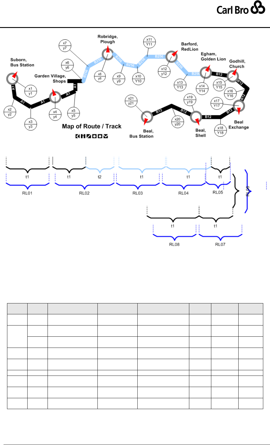
Department for Transport
TransXChange Schema Guide
Part II
Examples
TransXChangeSchemaGuide-2.1-v-45.pdf.doc
Page 107
24 September 2013
Figure 4-1 – Worked Example: Map of the Route
A single RouteSection, with a link sequence of eight RouteLink instances (RL_01 –
RL_08) suffices to connect the nine stops of the example, see Table 4-3. Each of the eight
route links has a single Track, except for the link between ‘Garden Village’ and ‘Robridge,
Plough’, which runs on two different roads (A1, B256), and so requires two track instance .(
T_2_1, T_2_2). The tracks have a varying number of intermediate points, depending on
their spatial depiction.
Link
Track
Origin
Destination
Mapping
Map
Ref
Distance
Bearing
RL_01
T_1_1
Suborn, Bus Station
Garden Village,
Shops
(x1,y1) (x2,y2) (x3,y3)
(x4,y4)
A1
5573
E
RL_02
T_2_1
Garden Village,
Shops
(junction)
(x4,y4) (x5,y5) (x6,y6)
A1
4512
NE
T_2_2
(junction)
Robridge,
Plough
x6,y6) (x7,y7) (x8,y8)
B256
RL_03
T_3_1
Robridge, Plough
Barford, Red
Lion
(x8,y8) (x9,y9) (x10,y10)
(x11,y11) (x12,y12)
B256
6046
E
RL_04
T_4_1
Barford, Red Lion
Egham, Golden
Lion
(x12,y12) (x13,y13)
(x14,y14)
B256
2520
NE
RL_05
T_5_1
Egham, Golden Lion
Godhill, Church
(x14,y14) (x15,y15)
B12
1955
SE
RL_06
T_6_1
Godhill, Church
Beall,
Exchange
(x15,y15) (x16,y16)
(x17,y17)
B12
2963
SW
RL_07
T_7_1
Beall, Exchange
Beall, Shell
(x17,y17) (x18,y18)
(x19,y19)
B12
3560
SW
RL_08
T_8_1
Beall, Shell
Beall, Bus
Station
(x19,y19) (x20,y20)
(x21,y21)
B12
2005
SW
Table 4-3 – Worked Example: RouteLink Instances
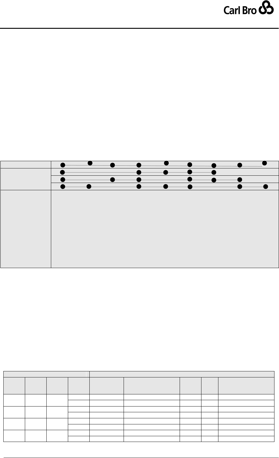
Department for Transport
TransXChange Schema Guide
Part II
Examples
TransXChangeSchemaGuide-2.1-v-45.pdf.doc
Page 108
24 September 2013
4.7 Worked Example: JourneyPattern
A JourneyPattern represents the pattern of working for vehicles of the service, and is
composed of an ordered collection of JourneyPatternSection instances, each containing
an ordered collection of JourneyPatternTimingLink instances, together defining a specific
sequence of timing links.
To model the bus service in the worked example, one JourneyPattern instance is used that
defines an overall sequence of stops.
Three main vehicle journey instances (37, 38 and 40) are defined that reference the
journey pattern; each vehicle journey omits particular stops (see Figure 4-2).
Four other vehicle journey instances (39, 41, 42 and 43) are exact replicas of the
first three vehicle journeys, apart from a different departure time, and so can be
defined simply by referencing the links of the appropriate journey.
Journey Pattern
Vehicle Journeys
Bus Stop
#1. Suborn, Bus Station
#2. Garden Village, Shops
#3. Robridge, Plough
#4. Barford, Red Lion
#5. Egham, Golden Lion
#6. Godhill, Church
#7. Beall, Exchange
#8. Beall, Shell
#9. Beall, Bus Station
Figure 4-2 – Worked Example: Journey Pattern
The exact sequence of stops is given by a JourneyPattern. The journey pattern will also
specify information about the use of the stop (which may vary according to service), in
particular: The JourneyPatternTimingLink instances for the example journey pattern are
shown in Table 4-4.
(i) The TimingStatus of each stop used in the route. Stops may be deemed
principal points or time information points, or both. The principal points must
appear in a timetable, and so are mandatory for TransXChange, while other stop
points are non-enforceable stops of the journey:
(ii) The Activity that takes place at each stop. For example, picking up or setting
down passengers. This may need to be overridden on individual vehicle
journeys.
TimingLink Properties
JourneyPatternStopUsage
Link
id
Run
Time
[sec]
Dist-
ance
[m]
id
StopPoint
Ref
Stop Name
Tim-
ing
Status
Wait
Tim
e
Activity
JL_1
#1-#2
360
5.573
JL_1a
0600000001
Suborn, Bus Station
PTP
0
PickUp
JL_1b
0600000002
Garden Village, Shops
PTP
0
PickUpAndSetDown
JL_2
#2-#3
300
4.512
JL_2a
0600000002
Garden Village, Shops
PTP
0
PickUpAndSetDown
JL_2b
0600000003
Robridge, Plough
PTP
0
PickUpAndSetDown
JL_3
#3-#4
120
6.046
JL_3a
0600000003
Robridge, Plough
PTP
0
PickUpAndSetDown
JL_3b
0600000004
Barford, Red Lion
PTP
60
PickUpAndSetDown
JL_4
#4-#5
180
2.520
JL_4a
0600000004
Barford, Red Lion
PTP
60
PickUpAndSetDown
JL_4b
0600000005
Egham, Golden Lion
TIP
0
PickUpAndSetDown
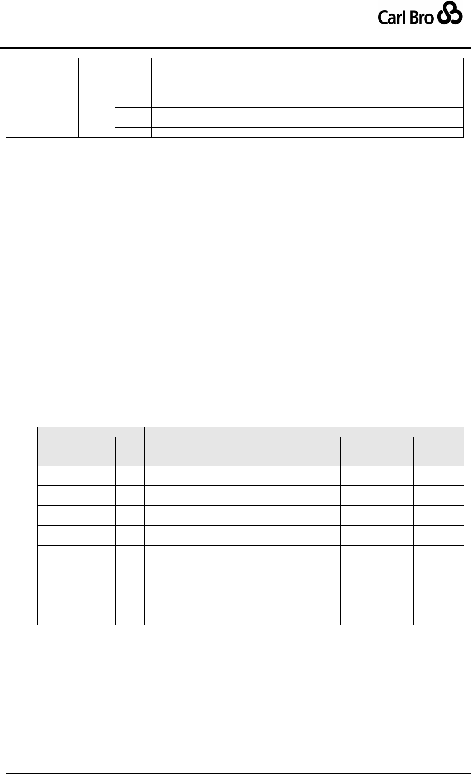
Department for Transport
TransXChange Schema Guide
Part II
Examples
TransXChangeSchemaGuide-2.1-v-45.pdf.doc
Page 109
24 September 2013
JL_5
#5-#6
180
1.955
JL_5a
0600000005
Egham, Golden Lion
TIP
0
PickUpAndSetDown
JL_5b
0600000006
Godhill, Church
TIP
0
PickUpAndSetDown
JL_6
#6-#7
420
2.963
JL_6a
0600000006
Godhill, Church
TIP
0
PickUpAndSetDown
JL_6b
0600000007
Beall, Exchange
PTP
0
PickUpAndSetDown
JL_7
#7-#8
60
3.560
JL_7a
0600000007
Beall, Exchange
PTP
0
PickUpAndSetDown
JL_7b
0600000008
Beall, Shell
TIP
0
PickUpAndSetDown
JL_7
#8-#9
60
2.005
JL_8a
0600000008
Beall, Shell
TIP
0
PickUpAndSetDown
JL_8b
0600000009
Beall, Bus Station
PTP
0
SetDown
Table 4-4 – Worked Example: Timing Links for Journey Pattern
4.8 Worked Example: Line
Line elements are used to model the labelling of lines for the public. A service may have a
number of lines, each with a LineName, and each vehicle journey can be assigned to a line.
Normally, the same line is used to label vehicle journeys following the same pattern, but
sometimes different journey variants with distinct patterns and link sequences may all be
labelled under the same line name (though usually they will always have at least a few
stops in common). Note that each VehicleJourney has a VehicleJourneyCode that is
quite independent of the Line and LineName with which it may be associated.
In our example, there are three line names ‘1A’, ‘1B’, and ‘1C’, used to distinguish the
different journeys that follow the three different journey patterns
4.9 Worked Example: VehicleJourney
A VehicleJourney represents the traversal of a journey pattern at a particular time, and is
composed of an ordered collection of VehicleJourneyTimingLink instances.
The timing links for VehicleJourney ‘40’ of the worked example are shown in Table 4-5.
Two stops are skipped: ‘Robridge, Plough’ and ‘Beall Bus Exchange’.
TimingLink Properties
VehicleJourneyStopUsage
id
Run
Time
[sec]
JL
Ref
id
StopPoint
Usage
Stop Name
Stop
Class
Wait
Time
Activity
VL_1
#1-#2
360
JL_1
VL_1a
0600000001
Suborn, Bus Station
BCT
0
pickUp
VL_1b
0600000002
Garden Village, Shops
BCT
0
setDown
VL_2#
2-#3
300
JL_2
VL_2a
0600000002
Garden Village, Shops
BCT
0
pickUp
VL_2b
0600000003
Robridge, Plough
BCT
0
pass
VL_3#
3-#4
120
JL_3
VL_3a
0600000003
Robridge, Plough
BCT
0
pass
VL_3b
0600000004
Barford, Red Lion
BCT
60
setDown
VL_4#
4-#5
180
JL_4
VL_4a
0600000004
Barford, Red Lion
BCT
60
pickUp
VL_4b
0600000005
Egham, Golden Lion
BCT
0
setDown
VL_5
#5-#6
180
JL_5
VL_5a
0600000005
Egham, Golden Lion
BCT
0
pickUp
VL_5b
0600000006
Godhill, Church
BCT
0
setDown
VL_6
#6-#7
420
JL_6
VL_6a
0600000006
Godhill, Church
BCT
0
pickUp
VL_6b
0600000007
Beall, Bus Exchange
BCT
0
pass
VL_7
#7-#8
60
JL_7
VL_7a
0600000007
Beall, Bus Exchange
BCT
0
pass
VL_7b
0600000008
Beall, Shell
BCT
0
setDown
VL_7
#8-#9
60
JL_7
VL_8a
0600000008
Beall, Shell
BCT
0
pickUp
VL_8b
0600000009
Beall, Bus Station
BCT
0
setDown
Table 4-5 – Worked Example: Timing Links for VehicleJourney 1A
4.10 Worked Example: Operational Times
The operational times of the example are modelled as follows:
There is a Service / ValidityPeriod from ‘5th February 2001’ until further notice.
The OperatingProfile / RegularDayType / will show MondayToFriday operation.
The OperatingProfile / BankHolidayOperation / DaysOfOperation / has a Value
of MayDay to show that it runs on Mayday.

Department for Transport
TransXChange Schema Guide
Part II
Examples
TransXChangeSchemaGuide-2.1-v-45.pdf.doc
Page 110
24 September 2013
The OperatingProfile / BankHolidayOperation / DaysOfNonOperation / has a
Value of Christmas to show that it does not run on Christmas or Boxing Day.

Department for Transport
TransXChange Schema Guide
Part II
Examples
TransXChangeSchemaGuide-2.1-v-45.pdf.doc
Page 111
24 September 2013
5 EXAMPLES
TransXChange is accompanied by a set of examples designed to illustrate the use of each
of its features. For each example, a web page with links to the following is provided:
Summary of features demonstrated by example.
A route map.
A matrix timetable representation.
The XML encoding of the example.
The TransXChange Publisher output of the encoded XML document.
Explanatory notes describing the representation and implementation of specific
features.
The examples can be found at http://www.transxchange.org.uk/examples.htm.
Table 5-1 lists the TransXChange examples, with the features covered by each case.
Group
Topology
Features covered
Basic
Linear
A single straight
route. All vehicle
journeys have the
same timings
Linear route.
Registration details.
RouteTrack maps
Tracks, including instructions and Mapping System References.
Frequency based journey times, specified as an interval.
Registration Schema.
Express
A linear route with
express journey
patterns
Express service.
Reuse of vehicle journey timing links in multiple journeys.
Holiday day type exclusions.
Local stop point definitions for an off-street bus station: BCQ and BCS stop
types.
Local stop area definitions.
Variable bay allocation.
Supporting document.
General Schema.
Complex
Interchange
Two patterns run
by two different
operators
presented as the
same Service. All
vehicle journeys
have the same
timings.
An Interchange.
Linear route, with different stop visiting pattern at one end.
Express stops.
Frequency based journey times, specified as an interval.
Combining operating days from service, journey pattern and vehicle journey
level.
Serviced organisation & school dates.
More than one operator.
Timetable notes.
Inward and outward timetables for the same service, using a single route.
Registration Schema.
Circular
A circular route.
Circular route.
Reuse of route sections.
Dead runs (positioning links).
Partial traversal of a journey pattern.
Operator Garage.
AVL data - Vehicle type ticket machine, duty crew.
WGS84.
Block (Running Board).
General Schema.

Department for Transport
TransXChange Schema Guide
Part II
Examples
TransXChangeSchemaGuide-2.1-v-45.pdf.doc
Page 112
24 September 2013
Cloverleaf
A cloverleaf route
shape with three
petals
Multiple routes composed of common route sections.
Multiple journey patterns composed of common. Journey pattern sections.
Dynamic destination display.
General Schema.
Lollipop
A lollipop” shaped
route, with two
parallel branches.
Circular and parallel sections.
Reuse of journey pattern sections.
Stop Sequence Numbers.
Layover Point.
Connecting services.
General Schema.
Eye
An ‘eye’ shaped
route, with two
alternative
branches.
Multiple routes composed of common route sections.
Multiple journey patterns composed of common. Journey pattern sections.
Stop Sequence Numbers.
Local stop point definitions.
Bilingual stop names & schedule (Cymraeg).
Block (Running Board).
Registration Schema.
Flexible
Use of flexible
zones
Flexible zones.
Flexible time bands.
Registration Schema.
Hail & Ride
Use of hail and
ride stops
Hail and ride sections.
Local stop point definitions.
Full lollipop topology.
Frequent service journey times, specified as minutes past the hour.
Short notice registration details.
Registration Schema
Large Route
Very large
timetable
More stops than fit on a page.
More journeys than fit on a page.
Table 5-1 – TransXChange Examples

Department for Transport
TransXChange Schema Guide
Part III
Schema Description
TransXChangeSchemaGuide-2.1-v-45.pdf.doc
Page 113
24 September 2013
6 TRANSXCHANGE SCHEMA
TransXChange describes bus schedules as a model of XML elements, contained within a
TransXChange root element. In this section we describe the different types of schema
elements in detail.
6.1 TransXChange Schema Overview
In a TransXChange document, data is organised around two main element types; Service
(which may contain either or both StandardService or FlexibleService elements) and
VehicleJourney, which together combine the instances of other elements into descriptions
of bus schedules. Service instances are grouped under the TransXChange root element
within a Services container, and VehicleJourney instances in a VehicleJourneys
container. Other high-level elements such as Operator, Registration, RouteSection and
JourneyPatternSection are also declared globally within containers under the
TransXChange root element so that they may be reused in many different services (or
even outside the context of a service, for general exchange).
The TransXChange element thus contains a number of different child and descendant
elements (Figure 6-1) which can be characterised as falling into four groups:
Topographical elements: StopPoint, StopArea, NptgLocality,
ServicedOrganisation.
Route and Network topology elements: Route, RouteSection, RouteLink.
Service Supply elements: Service, (StandardService, FlexibleService, Line,
JourneyPattern), JourneyPatternSection, VehicleJourney.
Registration Elements: Operator, Registration, (ShortNoticeRegistration).
Ancillary elements: SupportingDocument.
6.2 TransXChange Root Element
Every TransXChange document has a single instance of the TransXChange root element,
which contains all the other elements.
6.2.1 TransXChange Element Attributes
The TransXChange element has the following attributes:
xml:lang: Default language of document. ISO language identifier. Default is English.
Change Management attributes:
o CreationDateTime: Timestamp of document creation date and time.
o ModificationDateTime: Timestamp of document last modification date and
time.
o Modification: Nature of update ‘New’, ‘Revise’, ‘Delete’.
o RevisionNumber: Monotonically increasing version number.
o FileName: Name of file containing the document.
SchemaVersion: TransXChange schema version identifier used for the document
content model. Fixed: must be the schema version, e.g. ’2.0’.
MappingSystem: Data system to use for mapping references (’OS’, ’Navtech’, etc)
within the document.
LocationSystem: Data system to use for location coordinate references within the
document: ’WGS84’ or ’Grid’. Must be ’Grid’ for registration documents.
RegistrationDocument: Whether the document should be published as a
registration, i.e. satisfy the additional semantic integrity constraints. Boolean.

Department for Transport
TransXChange Schema Guide
Part III
Schema Description
TransXChangeSchemaGuide-2.1-v-45.pdf.doc
Page 114
24 September 2013
6.2.2 TransXChange Child Elements
The TransXChange element comprises the following child elements:
ServicedOrganisations: A collection of ServicedOrganisation elements. See later.
NptgLocalities: A collection of references to NPTG localities used in local stop
definitions in the schedule. See later.
StopPoints: A collection of the NaPTAN stop points used in the schedule. See later.
StopAreas: A collection of reusable StopArea instances declared locally to group
any stop points declared locally. See later.
RouteSections: A collection of reusable RouteSection elements for defining routes.
See later.
Routes: A collection of reusable Route elements for use in journey patterns. See
later.
JourneyPatternSections: A collection of reusable JourneyPatternSection
elements for defining journey patterns. See later.
Operators: A collection of Operator elements. See later.
Services: A collection of Service elements. See later.
VehicleJourneys: A collection of VehicleJourney elements. See later.
Registrations: A collection of Registration elements, each referencing a Service
element. See later.
o In the TransXChange Registration Schema, there must be one Registration.
o In the TransXChange General Schema documents, there may be zero, one
or many Registration instances.
SupportingDocuments: A collection of reusable SupportingDocument elements.
See later.
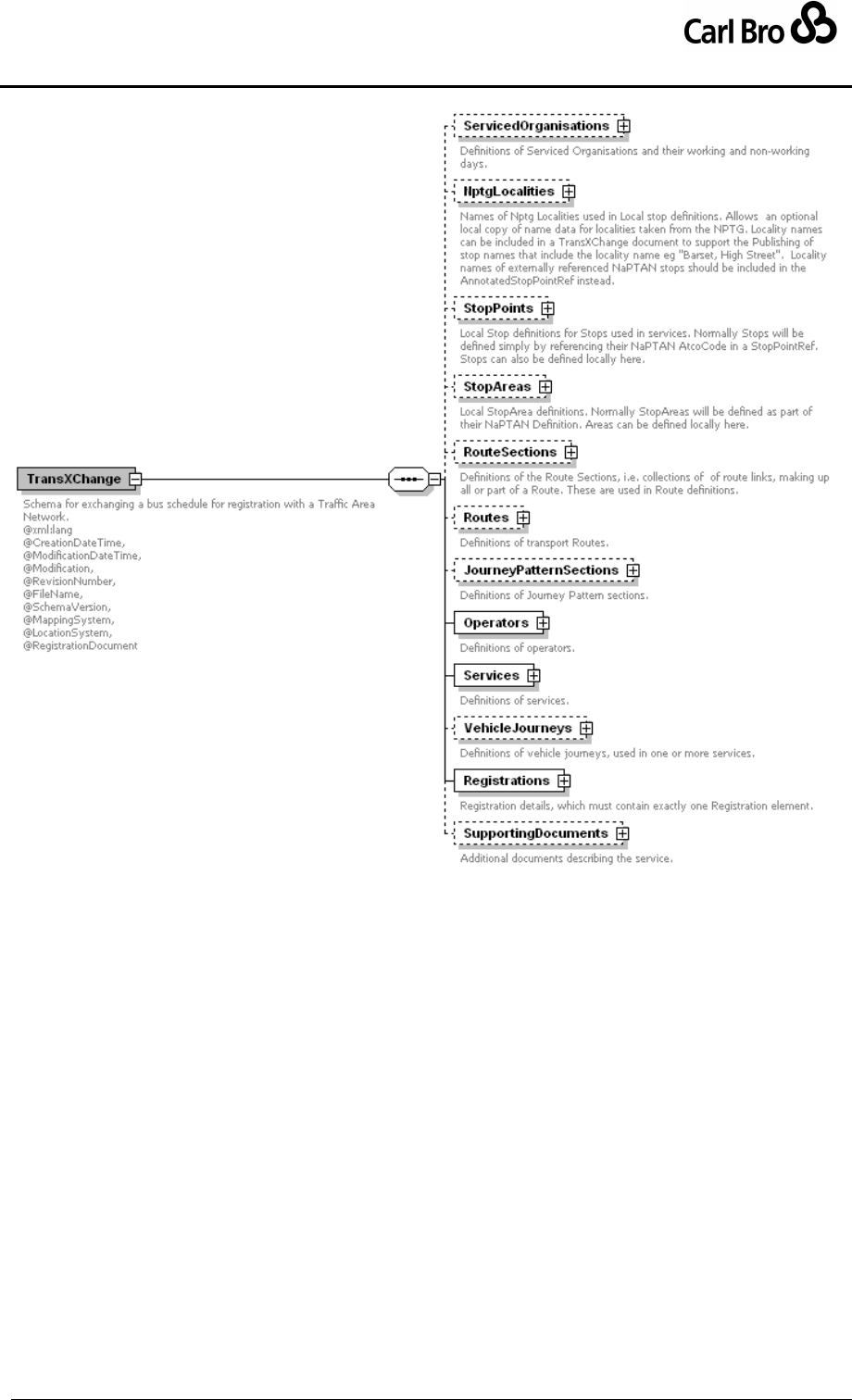
Department for Transport
TransXChange Schema Guide
Part III
Schema Description
TransXChangeSchemaGuide-2.1-v-45.pdf.doc
Page 115
24 September 2013
Figure 6-1 – Top Level Elements of TransXChange
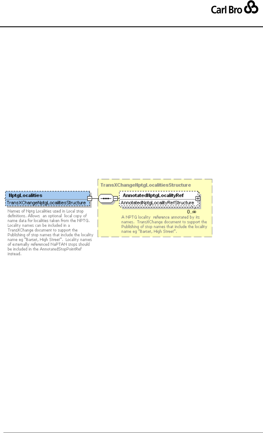
Department for Transport
TransXChange Schema Guide
Part III
Schema Description
TransXChangeSchemaGuide-2.1-v-45.pdf.doc
Page 116
24 September 2013
6.3 Topographical Elements – StopPoints and Zones
6.3.1 NptgLocalities Element
The use of stops in TransXChange is based on NaPTAN. See the StopPoints element
which allows stop usages to be declared. All stops are assigned to an NPTG Locality by
means of a reference to a NPTG Locality identifier. When publishing the stop with a tool
such as the TransXChange Publisher, the bus stop common names may be qualified with a
locality name, for example “Barset, High Street”, rather than just “High Street”. It is therefore
desirable that a TransXChange document contain the NPTG locality names so that a
document can be published without recourse to the NPTG database. For stops that are
externally referenced (using an AnnotatedStopPointRef instance), the NptgLocality
LocalityName can be included as an annotation on the stop point reference. However for
new stops that are defined locally using a StopPoint element, the locality names need to be
supplied with a separate AnnotatedNptgLocalityRef, as they are not part of a new
StopPoint declaration.
NptgLocalities: A collection of AnnotatedNptgLocalityRef instances to . See
below.
Figure 6-2 – NptgLocalities Element
6.3.2 AnnotatedNptgLocalityRef Element
Each AnnotatedNptgLocalityRef instance provides a local copy of NPTG Locality name
information that can be used without recourse to the full NPTG database.
NptgLocalityRef: Unique NPTG Locality identifier, i.e. NptgLocalityCode of
NptgLocality
LocalityName: Text name of NptgLocality; this name can be repeated locally so
that the schedule may be annotated by tools such as the TransXChange Publisher
without necessarily accessing the full NPTG database.
LocalityQualifier: Any Qualifier of text name of locality, for example “Kent” to
distinguish ‘Ashford (Kent)’ from ‘Ashford (Middlesex).
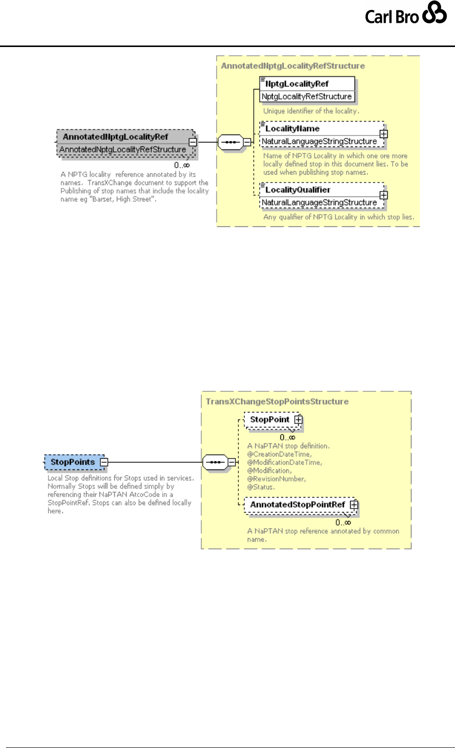
Department for Transport
TransXChange Schema Guide
Part III
Schema Description
TransXChangeSchemaGuide-2.1-v-45.pdf.doc
Page 117
24 September 2013
Figure 6-3 – AnnotatedNptgLocalityRef Element
6.3.3 StopPoints Element
The use of stops in TransXChange is based on NaPTAN. The StopPoints element (Figure
6-4) contains reusable declarations of the stops used by the routes and journey patterns of
the schedule. All StopPointRef instances elsewhere in a document are resolved against
the contents of the StopPoints element.
Existing NaPTAN StopPoint instances can be referred to simply by using an
AnnotatedStopPointRef to reference a NaPTAN system stop identifier – the
AtcoCode of the stop. For further details refer to the NaPTAN Schema Guide.
New stops may also be declared within a TransXChange XML document, by means
of a local StopPoint declaration within the StopPoints container element.
Figure 6-4 – StopPoints Element
6.3.4 AnnotatedStopPointRef Element
The AnnotatedStopPoint element (Figure 6-5) references an existing NaPTAN stop and
comprises the following elements:
StopPointRef: Unique NaPTAN identifier, i.e. AtcoCode of StopPoint.
CommonName: Common text name of StopPoint; this name is repeated locally so
that the schedule may be interpreted by tools such as the TransXChange Publisher
without necessarily accessing the full NaPTAN database.
Indicator: Further structured text descriptor element of StopPoint; that is used to
distinguish similar stops, for example bus station bays.
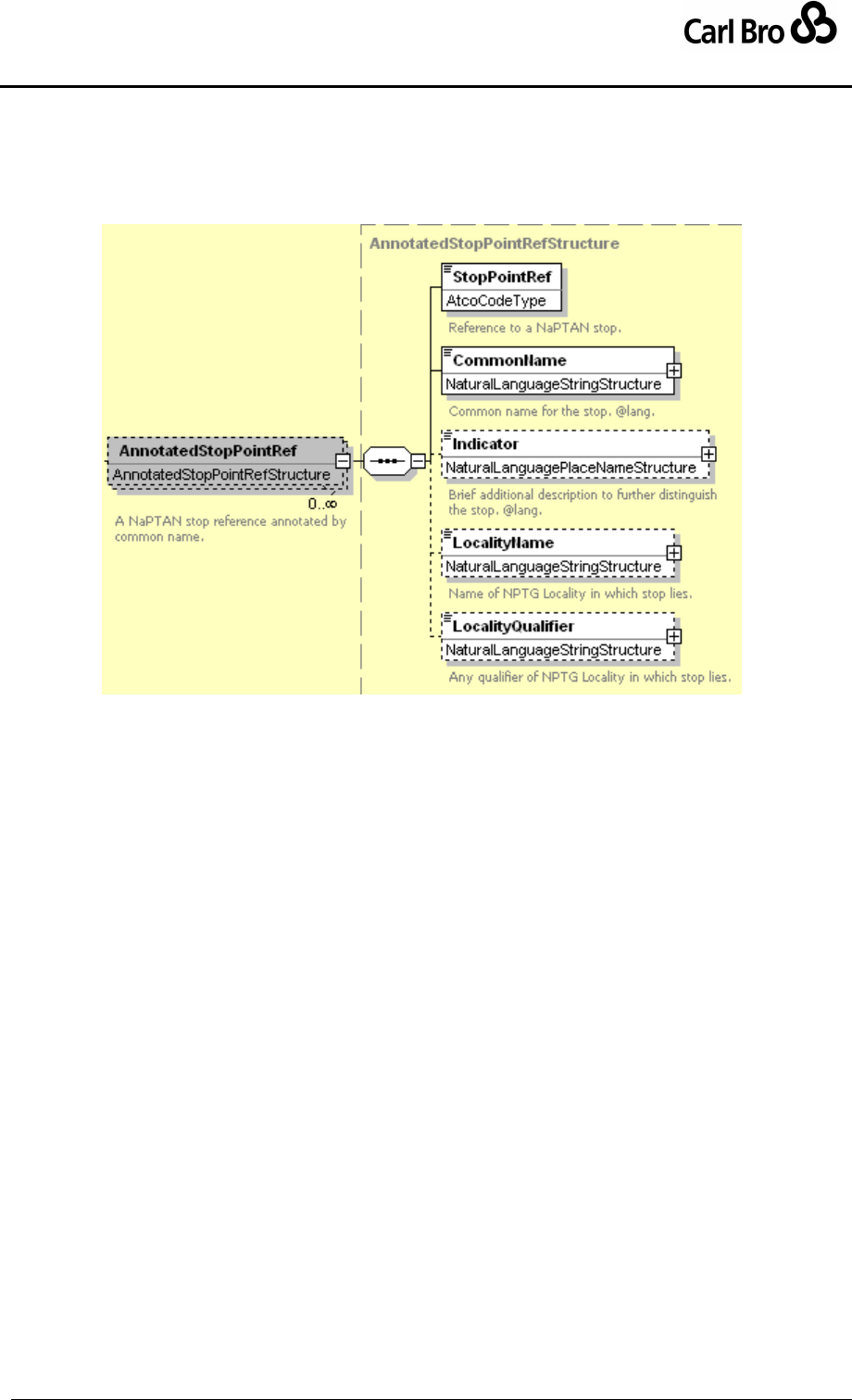
Department for Transport
TransXChange Schema Guide
Part III
Schema Description
TransXChangeSchemaGuide-2.1-v-45.pdf.doc
Page 118
24 September 2013
LocalityName: Text name of NptgLocality; this name can be repeated locally so
that the schedule may be annotated by tools such as the TransXChange Publisher
without necessarily accessing the full NPTG database.
LocalityQualifier: Any Qualifier of text name of locality, for example “Kent” to
distinguish ‘Ashford (Kent)’ from ‘Ashford (Middlesex).
Figure 6-5 – Annotated StopPointRef Element
6.3.5 StopPoint Element (Stop)
The StopPoint element declares locally defined stops. A local StopPoint declaration uses
NaPTAN elements, and must include a NaPTAN identifier for the stop. Local declarations
are for expediency in cases when the NaPTAN definition for a new stop has not yet been
promulgated to the NaPTAN database. Even then, the NaPTAN identifier for such stops
must be allocated by the relevant local transport authority. The other details of the stop may
change subsequently in the course of registering it with the Authority.
Refer to the NaPTAN 2.0 Schema Guide for a definition of the StopPoint Element and its
subelements.
6.3.6 StopArea Element (StopGroup / StopCluster)
A StopArea is used to group stops: locally declared StopPoint instances can be assigned
to one or more stop areas.
NaPTAN stops that exist in the NaPTAN database may already have a StopArea
element (previously called a StopGroup) associated with them.
Local definitions of individual StopArea elements may also be declared within the
StopAreas element of the TransXChange root element. Each StopArea must have
a StopAreaCode. Local stop area declarations are for expediency in cases when
the NaPTAN definition for a new stop area has not yet been promulgated to the
NaPTAN database.
Locally declared StopPoint elements may reference one or more StopArea
instances.

Department for Transport
TransXChange Schema Guide
Part III
Schema Description
TransXChangeSchemaGuide-2.1-v-45.pdf.doc
Page 119
24 September 2013
When importing schedules, an application will attempt to find the StopArea details in
the NaPTAN database using the StopAreaCode. Only if no StopArea is found for
the code will the locally supplied definition be used.
A NaPTAN StopArea is identified by an AreaCode, a unique NaPTAN identifier of the stop
area.
Refer to the NaPTAN 2.0 Schema guide for a definition of the StopArea Element and its
subelements.
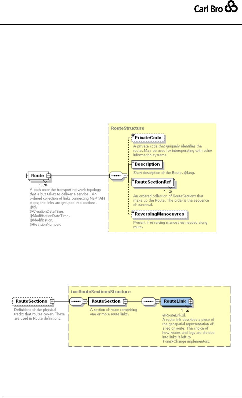
Department for Transport
TransXChange Schema Guide
Part III
Schema Description
TransXChangeSchemaGuide-2.1-v-45.pdf.doc
Page 120
24 September 2013
6.4 Network Topology Elements – Routes and Tracks
6.4.1 Route Element
A Route (Figure 6-6) describes the physical traversal of a bus along a route, described as
an ordered collection of RouteLink elements, grouped into RouteSection elements. It is
identified by a unique id attribute, and has the following properties:
PrivateCode: an optional cross reference to an external system identifier for the
route.
Description: A textual description of the route.
RouteSectionRef: An ordered collection of one or more references to
RouteSection elements that contain the route links making up the route.
ReversingManouevre: Used to describe any reversing manoeuvres needed.
Figure 6-6 – Route Element
6.4.2 RouteSection Element
A RouteSection (Figure 6-7) describes the course of a section of a route between several
NaPTAN stops, and comprises an ordered collection of RouteLink elements, each
describing a stop-to-stop path. A RouteSection can be used in multiple routes. It is
identified by a unique id attribute.
Figure 6-7 – RouteSection Element
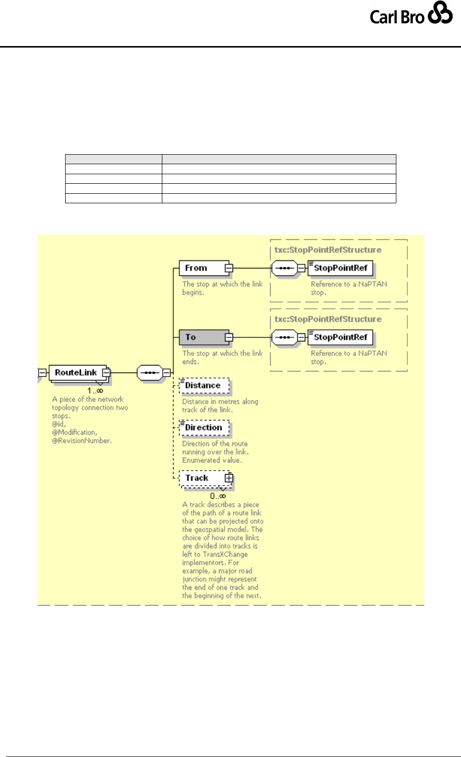
Department for Transport
TransXChange Schema Guide
Part III
Schema Description
TransXChangeSchemaGuide-2.1-v-45.pdf.doc
Page 121
24 September 2013
6.4.3 RouteLink Element
A RouteLink (Figure 6-8) describes the course of a route between two NaPTAN stops. It is
identified by a unique id attribute, and comprises:
From: The StopPointRef to the stop at which the link starts.
To: The StopPointRef to the stop at which the link ends.
Distance: The length of the path along the route in meters.
Direction: Direction of the Route running over the RouteLink. See Table 6-1.
Value
Description
inbound
Inbound Direction.
outbound
Outbound Direction.
clockwise
Clockwise Direction.
antiClockwise
Anti-Clockwise Direction.
Table 6-1 – Allowed Values for Link / Direction
Track: A description of the path of the link as one or more Track elements.
Figure 6-8 – RouteLink Element
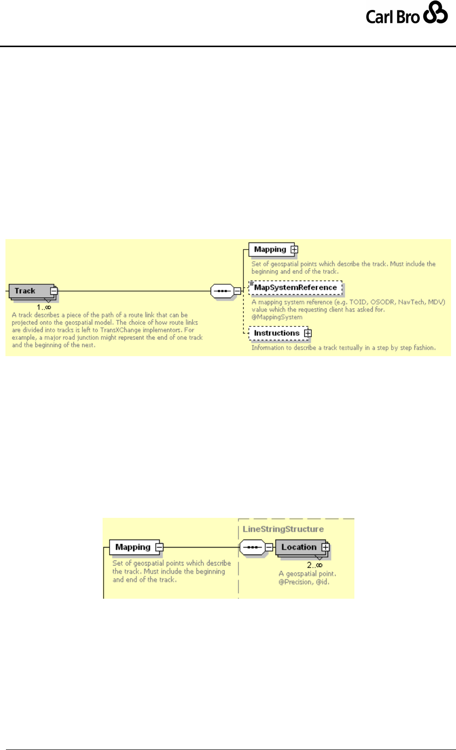
Department for Transport
TransXChange Schema Guide
Part III
Schema Description
TransXChangeSchemaGuide-2.1-v-45.pdf.doc
Page 122
24 September 2013
6.4.4 Track Element
A Track element (Figure 6-9) describes the path of a route link between NaPTAN stops,
and optionally, intermediate junction points. It comprises:
Mapping: A description of the path of the route as a series of geospatial points.
MapSystemReference: An optional reference to an Ordnance Service TOID or
other map feature identifier, using the mapping data system specified by the
MappingSystem attribute.
Instructions: Optional detailed step-by-step text instructions for navigating the track.
It is up to the implementor to choose the granularity of tracks – a give route might be
represented by none, one, several or many tracks. Typically a track will be used for each
distinct road or mapping layer feature that the implementor wishes to associate with part of
the route.
Figure 6-9 – Track Element
6.4.5 Track Subelements
6.4.5.1 Track / Mapping Element
A Mapping element (Figure 6-10) describes the spatial path of a route link between
NaPTAN stops that can be plotted on a map, as a series of at least two geospatial points:
These points are independent of the stop point coordinates (though end points may
reference the same coordinate) I.e. to plot a route the last and first point of each successive
mapping will be connected.
Location: A point in either WGS84 or grid coordinates. See Common Schema
Elements later.
Figure 6-10 – Mapping Element
6.4.5.2 Track / Instructions Element
The Instructions element (Figure 6-11) provides an additional description of the path of a
step of a route between NaPTAN stops as text instructions, and an ordered collection of
structured elements:
Summary: A free text description of the path of the route.
Feature: A structured description of one or more steps of the journey.
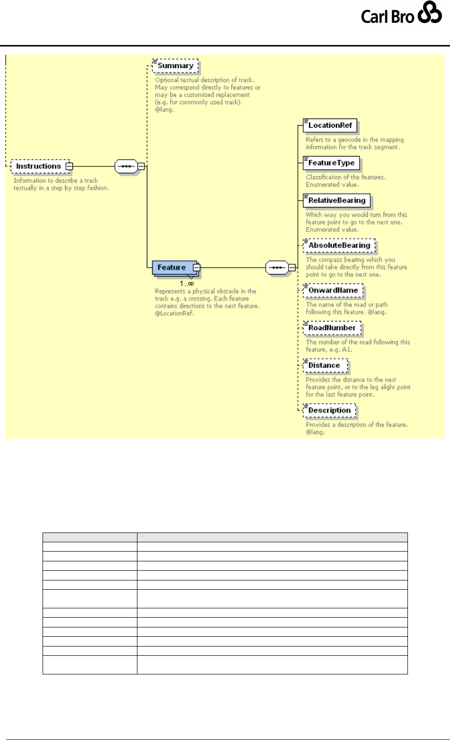
Department for Transport
TransXChange Schema Guide
Part III
Schema Description
TransXChangeSchemaGuide-2.1-v-45.pdf.doc
Page 123
24 September 2013
Figure 6-11 – Instructions Element
6.4.5.3 Track / Instructions / Feature Element
The Feature element (Figure 6-11) describes a step of a route between NaPTAN stops:
LocationRef: Reference to a Location in the Track’s Mapping instance that
locates the feature on a map.
FeatureType: Describes the type of feature encountered see Table 6-2.
Value
Description
legOrigin
The start point of the leg.
legDestination
The end point of the leg.
bend
A bend in the track that merits attention (without a junction).
crossing
Cross over the road.
bridge
Traversing over a bridge.
junction
Either a point at which another road is taken, or a side road that is passed
along the way.
miniRoundabout
Going round a small roundabout.
roadChange
Denotes a change of road name when there is no junction.
roundabout
Going round a small roundabout.
subway
Going through a subway.
trafficLights
Going through traffic lights.
landmark
A named landmark that can be seen from the track. The name should be
provided in the Feature Description.
Table 6-2 – Allowed Values for FeatureType

Department for Transport
TransXChange Schema Guide
Part III
Schema Description
TransXChangeSchemaGuide-2.1-v-45.pdf.doc
Page 124
24 September 2013
RelativeBearing: Which way you would turn from this feature to go to the next one.
See Table 6-3.
Value
Description
left
Left
right
Right
straightAhead
Straight ahead
uTurn
U-turn
Table 6-3 – Allowed Values for RelativeBearing
AbsoluteBearing: The compass bearing which you should take directly from this
feature point to go to the next one.
OnwardName: The name of the road or path following this feature
RoadNumber: The number of the road following this feature, e.g. ‘A1’.
Distance: The distance to the next feature point, or to the leg alight point for the last
feature point.
Description: A text description of the individual feature.
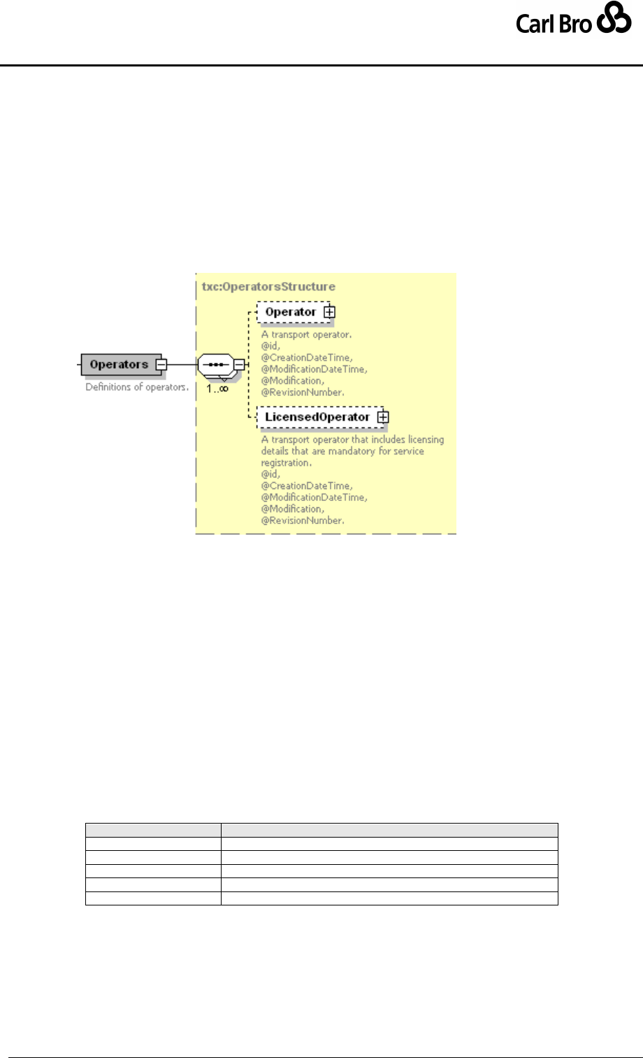
Department for Transport
TransXChange Schema Guide
Part III
Schema Description
TransXChangeSchemaGuide-2.1-v-45.pdf.doc
Page 125
24 September 2013
6.5 Registration Elements: Operator, Registration, ShortNoticeRegistration
6.5.1 Operators Element
The Operators element (Figure 6-12) contains instances of the two different kinds of
operator element that may be referenced by a Service:
Operator: An operator definition allowing partial definition of an operator.
LicensedOperator: A full definition of an operator as is required for a registration.
The Operator and LicensedOperator elements differ only as which of their child elements
are required or optional.
Figure 6-12 – Operators Element
6.5.2 Operator Element
The Operator element (Figure 6-13) describes the Operator of a service. Every operator
has an id attribute. References to operators within the document are made through the id
(rather than the OperatorCode or the NationalOperatorCode), in order to guarantee a
unique reference. Operator comprises:
NationalOperatorCode: Unique national identifier of operator. This element is to
support a future planned national operator code.
OperatorCode: Unique Identifier of operator within document.
OperatorShortName: Short text name for operator.
OperatorNameOnLicence: Full name of the operator, as it appears on licence.
TradingName: The name under which operator trades.
LicenceNumber: Operator's licence number.
LicenceClassification: Type of licence that the operator has. See Table 6-4.
Value
Description
standardNational
Standard National Licence type.
standardInternational
Standard International Licence type.
restricted
Restricted Licence type.
specialRestricted
Special Restricted Licence type.
communityBusPermit
Community Bus Permit Licence type.
Table 6-4 – Allowed Values for LicenceClassification
OperatorContactGroup: Information about how to contact the operator. See
OperatorContactGroup below.
Garages: The garages which the operator runs. See below.
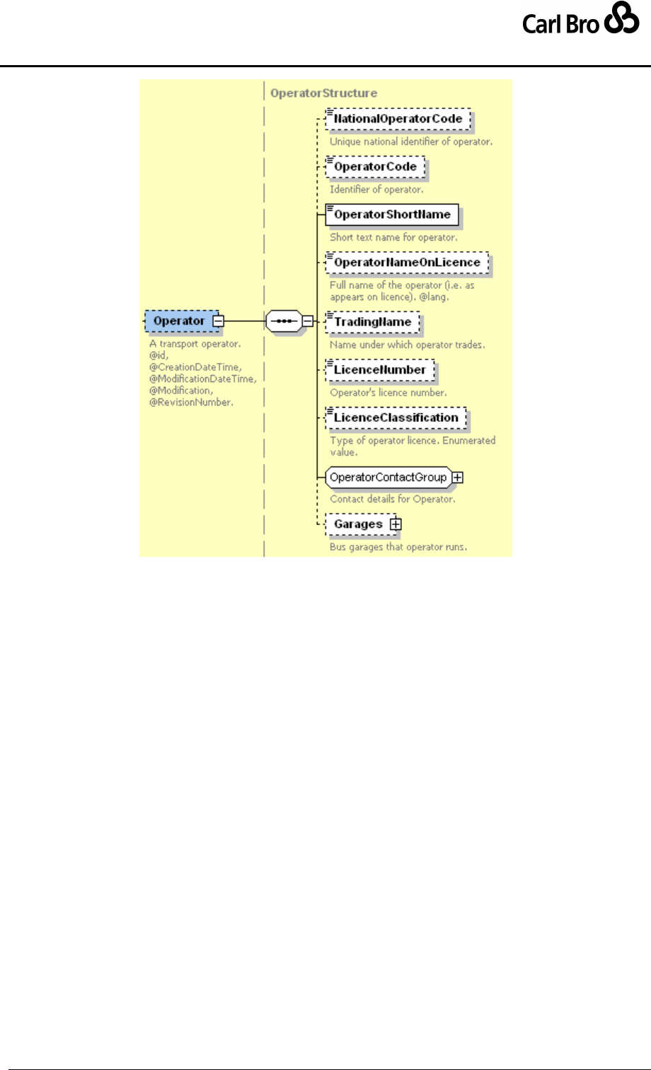
Department for Transport
TransXChange Schema Guide
Part III
Schema Description
TransXChangeSchemaGuide-2.1-v-45.pdf.doc
Page 126
24 September 2013
Figure 6-13 – Operator Element
6.5.3 LicensedOperator Element
The LicensedOperator element (Figure 6-13) is identical to the Operator element except
that certain fields are mandatory.
OperatorNameOnLicence, LicenceNumber, LicenceClassification.
LicensedOperatorContactGroup: ContactTelephoneNumber,
EnquiryTelephoneNumber, OperatorAddresses.
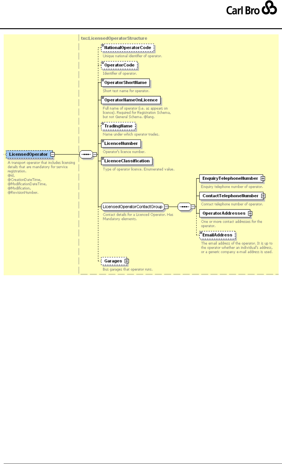
Department for Transport
TransXChange Schema Guide
Part III
Schema Description
TransXChangeSchemaGuide-2.1-v-45.pdf.doc
Page 127
24 September 2013
Figure 6-14 – LicensedOperator Element
6.5.4 Operator & LicensedOperator: Subelements
6.5.4.1 OperatorContactGroup
The OperatorContactGroup (Figure 6-15) describes the contact details for an Operator of
a service and comprises:
EnquiryTelephoneNumber: Telephone Number for public enquiries to the operator
concerning the service. See TelephoneContactStructure in common schema
elements in Section 7.
ContactTelephoneNumber: Telephone Number to contact operator concerning the
service. See TelephoneContactStructure below.
OperatorAddresses: Operator's addresses. A separate OperatorAddress and
CorrespondanceAddress can be specified. See PostalAddressStructure in
Common Schema Elements in Section 7.
EmailAddress: The email address of the operator. It is up to the operator whether
an individual's address or a generic company e-mail address is used.
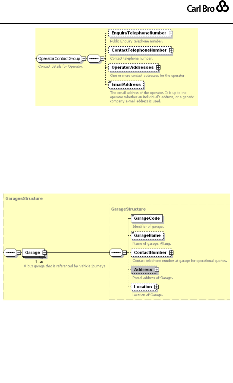
Department for Transport
TransXChange Schema Guide
Part III
Schema Description
TransXChangeSchemaGuide-2.1-v-45.pdf.doc
Page 128
24 September 2013
Figure 6-15 – Operator / OperatorContactGroup
6.5.4.2 Operator / Garages Element
The Operator / Garages element records details about the garages or depots which the
operator uses. It contains a collection of Garage (Figure 6-16) elements.
Each Garage is composed of:
GarageCode: Identifier of garage. This will be referenced by other elements.
GarageName: Name of garage.
ContactNumber: Telephone Number to contact for queries about operational data.
See TelephoneContactStructure in Common Schema Elements in Section 7.
Address: Postal Address of garage. See PostalAddressStructure in Common
Schema Elements in Section 7.
Location: Spatial coordinates of garage.
Figure 6-16 – Operator / Garages / Garage Element
6.5.5 Registration Element
The Registration element (Figure 6-17) records statutory administrative details about the
registration of the service. In the TransXChange Registration Schema the element is
mandatory; in the TransXChange General Schema it is not. A Registration comprises:
ServiceRef: The Service that the registration covers.
RegistrationSubmissionGroup: Describes basic properties of registration.
RegistrationInfoGroup: Describes further properties of the registration.
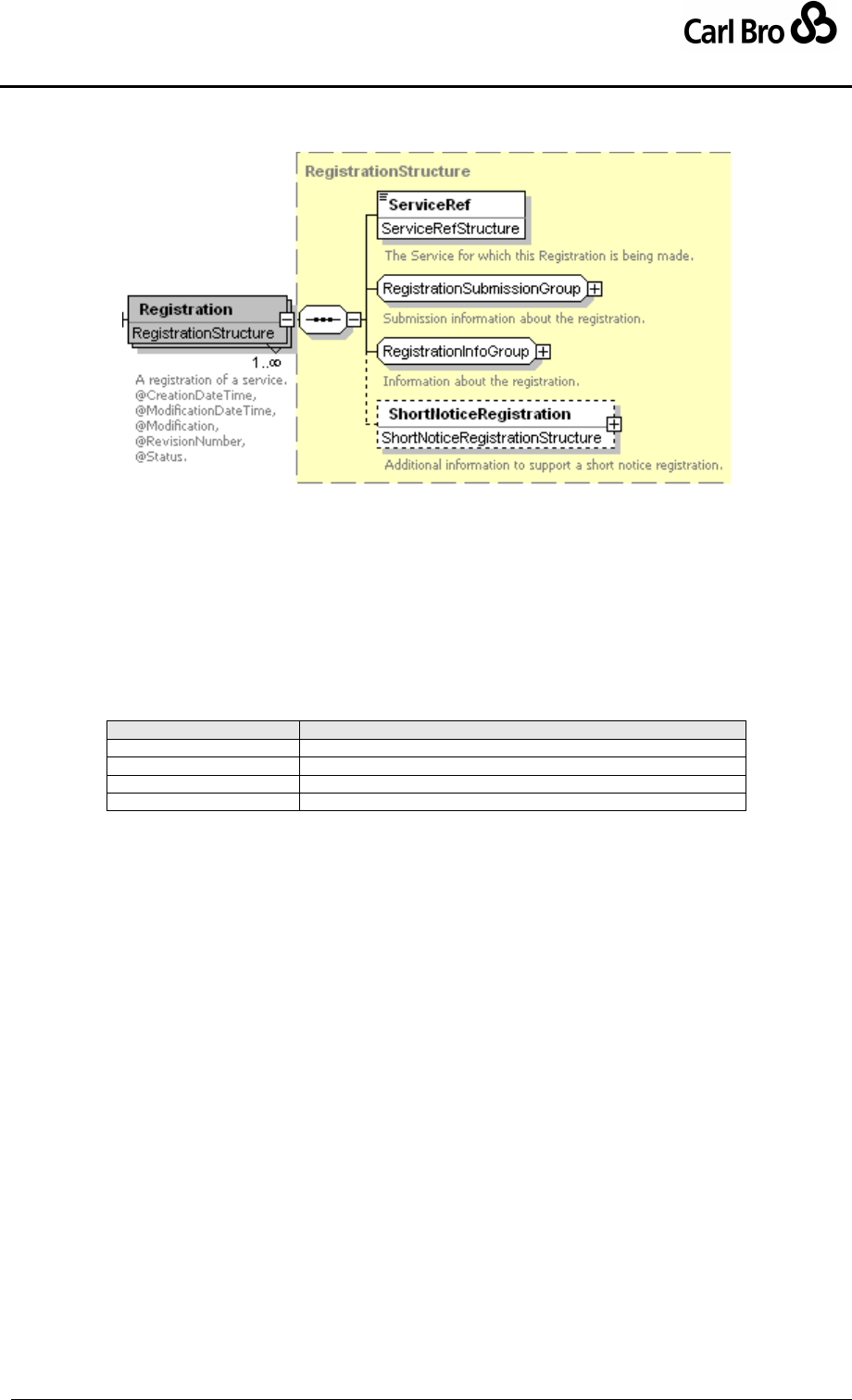
Department for Transport
TransXChange Schema Guide
Part III
Schema Description
TransXChangeSchemaGuide-2.1-v-45.pdf.doc
Page 129
24 September 2013
ShortNoticeRegistration: Additional information to support a registration made with
less than the statutory period of notice. See later below.
Figure 6-17 – Registration Element
6.5.6 RegistrationSubmissionGroup
The RegistrationSubmissionGroup (Figure 6-18) holds elements describing the basic
submission of registration.
SubmissionDate: Intended date of Registration submission by submitter (officially
received date may be different).
VosaRegistrationNumber: The identifiers for the Registration. See below.
ApplicationClassification: Type of the registration application. See Table 6-5.
Value
Description
new
New registration.
chargeableChange
Chargeable modification of an existing registration.
nonChargeableChange
Non-chargeable modification of an existing registration.
cancel
Cancellation of a registration.
Table 6-5 – Allowed Values for Registration / ApplicationClassification
VariationNumber: Variation number of the registration.
SubmissionAuthor: Contact details of person submitting registration. See below.
TrafficAreas: A collection of TrafficArea instances with full or partial responsibility
for the registration of the submission. See below.
CirculatedAuthorities: Collection of CirculatedAuthority instances to whom the
registration is to be circulated. See below.
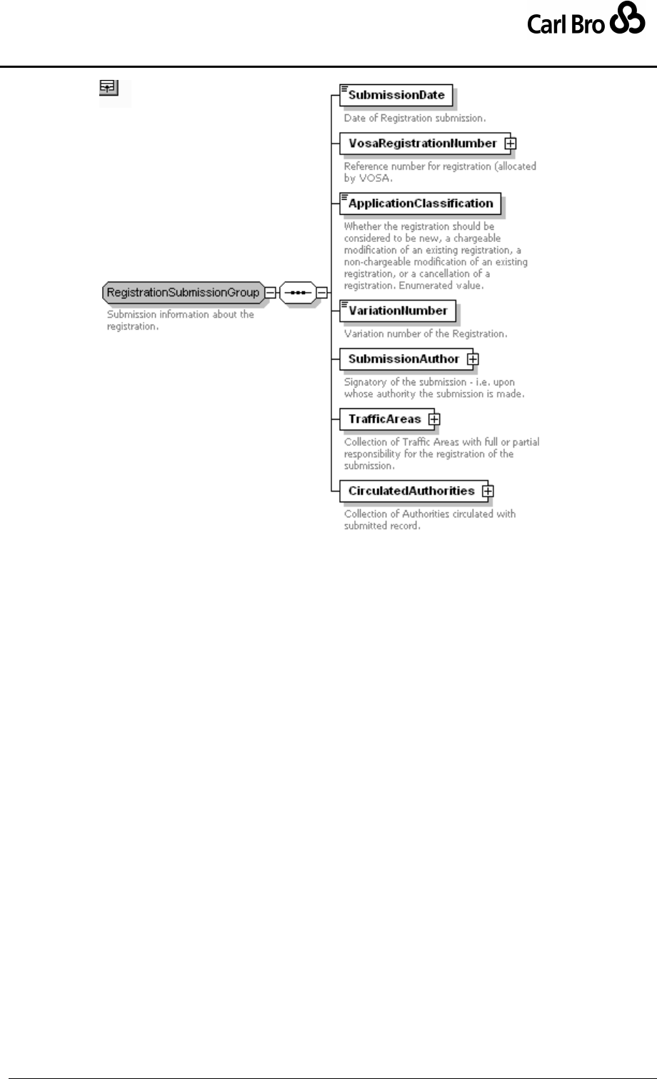
Department for Transport
TransXChange Schema Guide
Part III
Schema Description
TransXChangeSchemaGuide-2.1-v-45.pdf.doc
Page 130
24 September 2013
Figure 6-18 – RegistrationSubmissionGroup
6.5.7 RegistrationInfoGroup
The RegistrationInfoGroup (Figure 6-19) holds elements describing additional properties
of a registration.
SubsidyDetails: Information about any subsidy of the Service. See below.
ContractedService: Information about any contract under which the Service is run
for an authority. See below.
QualityPartnership: Information about any Statutory Quality partnership under
which the Service is run.
SupportingDocuments: Names of additional documents that accompany the
registration. Note that references to any schematic maps that are in image format
should be placed with the Service / SchematicMap element, and not here.
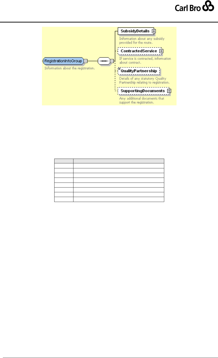
Department for Transport
TransXChange Schema Guide
Part III
Schema Description
TransXChangeSchemaGuide-2.1-v-45.pdf.doc
Page 131
24 September 2013
Figure 6-19 – RegistrationInfoGroup
6.5.8 Registration Subelements
6.5.8.1 Registration / VosaRegistrationNumber Element
The VosaRegistrationNumber element (Figure 6-20) specifies the unique identifiers of the
Registration. It is made up of three components:
TanCode: Two character Traffic Area prefix. See Table 6-6.
Value
Description
PB
North Eastern Traffic Area
PC
North Western Traffic Area
PD
West Midlands Traffic Area
PF
Eastern Traffic Area
PG
Welsh Traffic Area
PH
Western Traffic Area
PK
South Eastern and Metropolitan Traffic Area
PM
Scottish Traffic Area
Table 6-6 – Allowed Values for TanCode
LicenceNumber: The Registered operator’s seven character licence number. This
should be the same as the Operator / LicenceNumber value.
RegistrationNumber: Unique identifier of registration for licence holder. 1-4 numeric
only characters.
When displayed, numbers include a separator slash between the licence number and the
suffix, for example ‘PB1235601/456’.
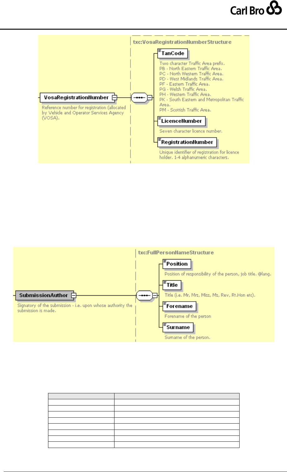
Department for Transport
TransXChange Schema Guide
Part III
Schema Description
TransXChangeSchemaGuide-2.1-v-45.pdf.doc
Page 132
24 September 2013
Figure 6-20 – Registration / VosaRegistrationNumber Element
6.5.8.2 Registration / SubmissionAuthor Element
The SubmissionAuthor (Figure 6-21) describes the signatory of the submission – that is,
upon whose authority the submission is made. It comprises:
Position: Position of the signatory of the Registration.
Title: Title of the signatory of the Registration.
Forename: Forename of the signatory of the Registration.
Surname: Surname of the signatory of the Registration.
Figure 6-21 – Registration / SubmissionAuthor Element
6.5.8.3 Registration / TrafficArea Element
The TrafficAreas element (Figure 6-22) lists the individual TrafficArea elements for the
registration.
TrafficAreaName: Specifies a TrafficArea – see Table 6-7.
Value
Description
Eastern
Eastern.
NorthEastern
North Eastern.
NorthWestern
North Western.
SouthEastMetropolitan
South East Metropolitan.
Scottish
Scottish.
Welsh
Welsh.
WestMidlands
West Midlands.
Western
Western.
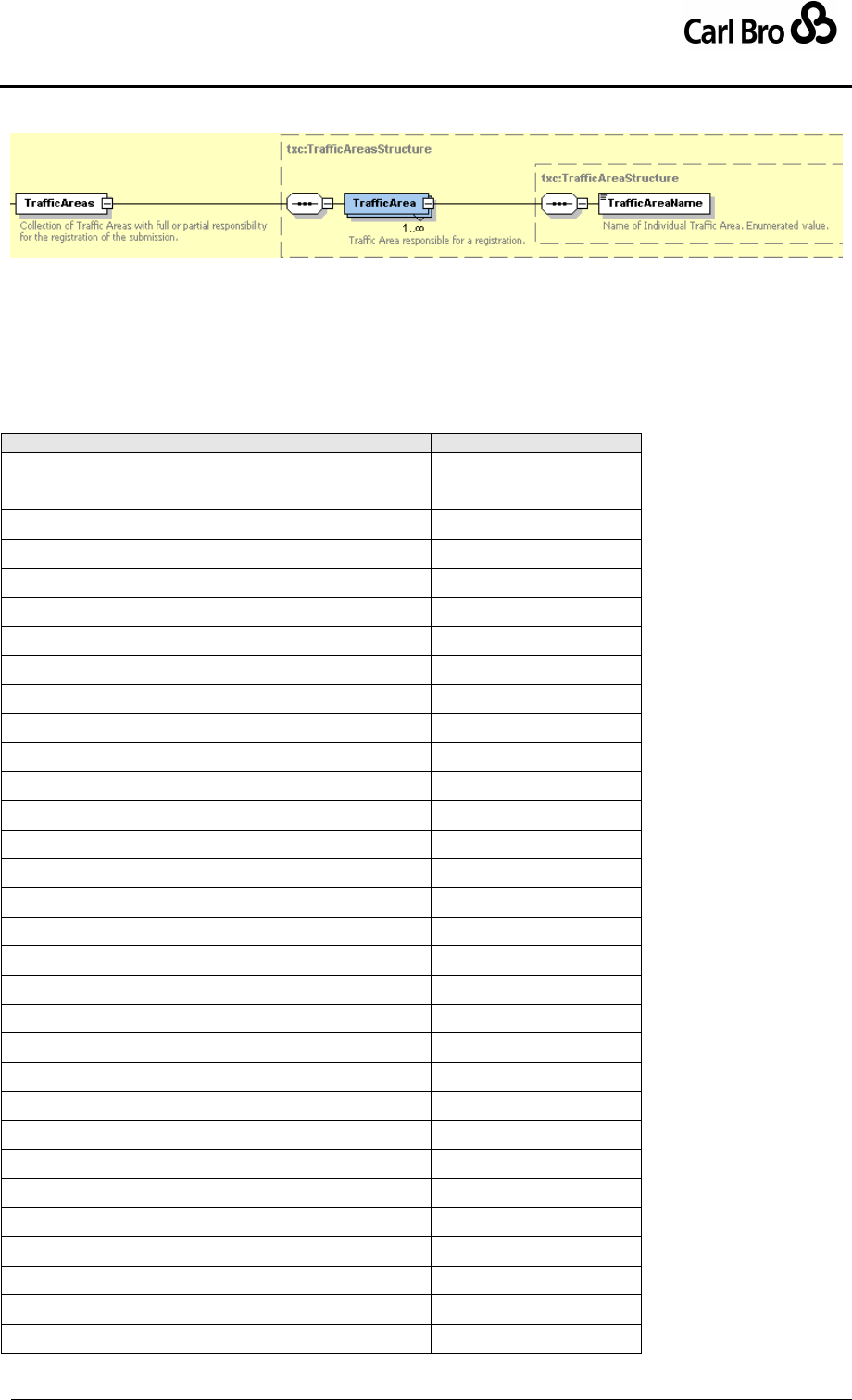
Department for Transport
TransXChange Schema Guide
Part III
Schema Description
TransXChangeSchemaGuide-2.1-v-45.pdf.doc
Page 133
24 September 2013
Table 6-7 – Allowed Values for TrafficArea / Names
Figure 6-22 – Registration / TrafficArea Element
6.5.8.4 Registration / CirculatedAuthorities Element
The CirculatedAuthorities element (Figure 6-23) lists the individual CirculatedAuthority
elements for the registration.
CirculatedAuthority: Names identifying circulated authority. See Table 6-8.
Value
English
Welsh
Aberdeen
Aberdeen
Aberdeenshire
Aberdeenshire
Angus
Angus
ArgyllAndBute
Argyll and Bute
BathAndNorthEastSomerset
Bath and North East Somerset
Bedfordshire
Bedfordshire
Berkshire
Berkshire
BlackburnWithDarwen
Blackburn with Darwen
Blackpool
Blackpool
BlaenauGwent
Blaenau Gwent
Bournemouth
Bournemouth
BracknellForest
Bracknell Forest
Bridgend
Bridgend
BrightonAndHove
Brighton and Hove
Bristol
Bristol
Buckinghamshire
Buckinghamshire
Caerphilly
Caerphilly
Cambridgeshire
Cambridgeshire
Cardiff
Cardiff
Carmarthenshire
Carmarthenshire
CentroWestMidlands
Centro (West Midlands)
Ceredigion
Ceredigion
ChannelIslands
Channel Islands
Cheshire
Cheshire
Clackmannanshire
Clackmannanshire
ComhairleNanEileanSiar
Comhairle Nan Eilean Siar
Conwy
Conwy
CornwallAndSclillies
Cornwall and Scillies
Cumbria
Cumbria
Darlington
Darlington
Denbighshire
Denbighshire

Department for Transport
TransXChange Schema Guide
Part III
Schema Description
TransXChangeSchemaGuide-2.1-v-45.pdf.doc
Page 134
24 September 2013
Derby
Derby
Derbyshire
Derbyshire
Devon
Devon
Dorset
Dorset
DumfriesAndGalloway
Dumfries and Galloway
Dundee
Dundee
Durham
Durham
EastAyrshire
East Ayrshire
EastDunbartonshire
East Dunbartonshire
EastLothian
East Lothian
EastRenfrewshire
East Renfrewshire
EastRidingOfYorkshire
East Riding of Yorkshire
EastSussex
East Sussex
Edinburgh
Edinburgh
Essex
Essex
Falkirk
Falkirk
Fife
Fife
Flintshire
Flintshire
Glasgow
Glasgow
Gloucestershire
Gloucestershire
GMPTE
GMPTE (Manchester)
Gwynedd
Gwynedd
Halton
Halton
Hampshire
Hampshire
Hartlepool
Hartlepool
Havering
Havering
Herefordshire
Herefordshire
Hertfordshire
Hertfordshire
Highland
Highland
Inverclyde
Inverclyde
IsleOfAnglesey
Isle of Anglesey
IsleOfMan
Isle of Man
IsleOfWight
Isle of Wight
Kent
Kent
KingstonUponHull
Kingston Upon Hull
Lancashire
Lancashire
Leicester
Leicester
Leicestershire
Leicestershire
Lincolnshire
Lincolnshire
London
London
Luton
Luton
Medway
Medway
Department for Transport
TransXChange Schema Guide
Part III
Schema Description
TransXChangeSchemaGuide-2.1-v-45.pdf.doc
Page 135
24 September 2013
Merseytravel
Merseytravel
MerthyrTydfil
Merthyr Tydfil
MetroWestYorks
Metro (West Yorks)
Middlesbrough
Middlesbrough
Midlothian
Midlothian
MiltonKeynes
Milton Keynes
Monmouthshire
Monmouthshire
Moray
Moray
NeathPortTalbot
Neath Port Talbot
WestBerkshire
West Berkshire
Newport
Newport
NexusTyneside
Nexus (Tyneside)
Norfolk
Norfolk
NorthAyrshire
North Ayrshire
NorthEastLincolnshire
North East Lincolnshire
NorthernIreland
Northern Ireland
NorthLanarkshire
North Lanarkshire
NorthLincolnshire
North Lincolnshire
NorthSomerset
North Somerset
NorthYorkshire
North Yorkshire
Northamptonshire
Northamptonshire
Northumberland
Northumberland
Nottingham
Nottingham
Nottinghamshire
Nottinghamshire
OrkneyIslands
Orkney Islands
Oxfordshire
Oxfordshire
Pembrokeshire
Pembrokeshire
PerthAndKinross
Perth and Kinross
Peterborough
Peterborough
Plymouth
Plymouth
Poole
Poole
Portsmouth
Portsmouth
Powys
Powys
Reading
Reading
RedcarAndCleveland
Redcar and Cleveland
Renfrewshire
Renfrewshire
RhonddaCynonTaff
Rhondda Cynon Taff
Rutland
Rutland
ScottishBorders
Scottish Borders
ShetlandIslands
Shetland Islands
Shropshire
Shropshire
Slough
Slough
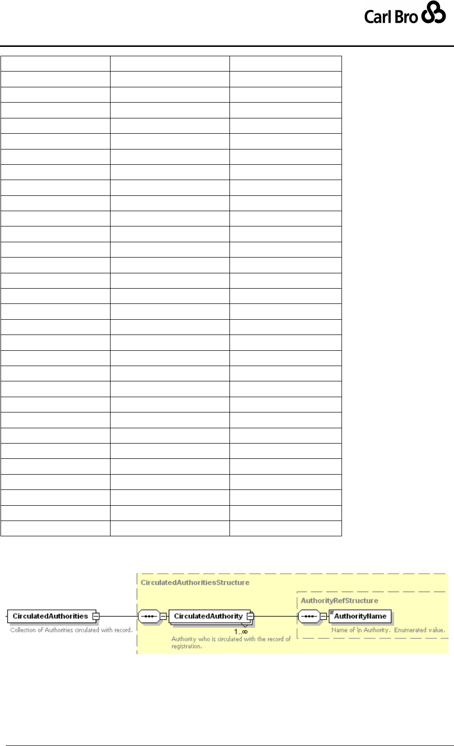
Department for Transport
TransXChange Schema Guide
Part III
Schema Description
TransXChangeSchemaGuide-2.1-v-45.pdf.doc
Page 136
24 September 2013
Somerset
Somerset
SouthAyrshire
South Ayrshire
SouthGloucestershire
South Gloucestershire
SouthLanarkshire
South Lanarkshire
SouthYorkshirePTE
South Yorkshire PTE
Southampton
Southampton
SouthendOnSea
Southend On Sea
Staffordshire
Staffordshire
Stirling
Stirling
StocktonOnTees
Stockton On Tees
StokeOnTrent
Stoke On Trent
StrathclydePTE
Strathclyde PTE
Suffolk
Suffolk
Surrey
Surrey
Swansea
Swansea
Swindon
Swindon
TelfordAndWrekin
Telford and Wrekin
Thurrock
Thurrock
Torbay
Torbay
Torfaen
Torfaen
ValeOfGlamorgan
Vale of Glamorgan
Warrington
Warrington
Warwickshire
Warwickshire
WestDunbartonshire
West Dunbartonshire
WestLothian
West Lothian
WestSussex
West Sussex
Wiltshire
Wiltshire
WindsorAndMaidenhead
Windsor and Maidenhead
Wokingham
Wokingham
Worcestershire
Worcestershire
York
York
Table 6-8 – Allowed Values for CirculatedAuthority Names
Figure 6-23 – Registration / CirculatedAuthorities Element
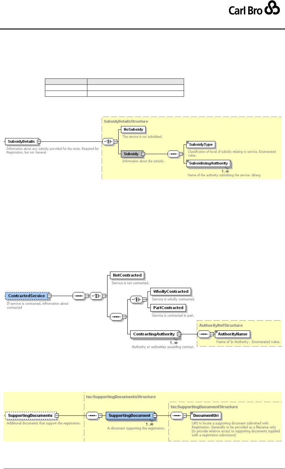
Department for Transport
TransXChange Schema Guide
Part III
Schema Description
TransXChangeSchemaGuide-2.1-v-45.pdf.doc
Page 137
24 September 2013
6.5.8.5 Registration / SubsidyDetails Element
The SubsidyDetails element (Figure 6-24) gives information about any subsidy that applies
to the Registration.
Either there are none – NoSubsidy, or there is a Subsidy, made up of two elements:
SubsidyType: Whether subsidy is full or partial. Table 6-9.
Value
Description
partial
Partial subsidy applies.
full
Full subsidy applies.
Table 6-9 – Allowed Values for SubsidyType
SubsidisingAuthority: Name of subsidising authority.
Figure 6-24 – Registration / SubsidyDetails Element
6.5.8.6 Registration / ContractedService Element
The ContractedService element (Figure 6-25) specifies if the service is run under contract
to a Local Authority or SPT. This item is specific to Scottish registration.
Nature of Contract:
NotContracted: Service is not run under contract.
WhollyContracted: Service is run wholly under contract.
PartContracted: Service is run in part under contract.
ContractingAuthority: Names of one or more authorities awarding contract. See
CirculatedAuthority / AuthorityName.
Figure 6-25 – Registration / ContractedService Element
6.5.8.7 Registration / SupportingDocument Element
The SupportingDocument element (Figure 6-26) Associates any supporting documents
associated with the service. Documents are identified by a DocumentUri.
Figure 6-26 – Registration / SupportingDocument Element
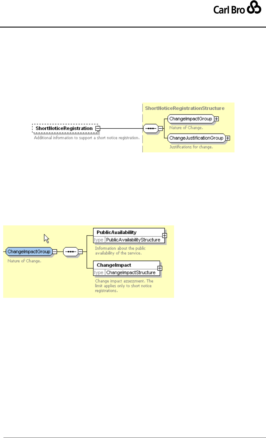
Department for Transport
TransXChange Schema Guide
Part III
Schema Description
TransXChangeSchemaGuide-2.1-v-45.pdf.doc
Page 138
24 September 2013
6.5.9 ShortNoticeRegistration Element
A short notice registration is an application to register, cancel or change a service made
with less than the normally 56 days' period of notice. Only certain determined cases can be
submitted within the reduced period. A ShortNoticeRegistration requires additional details
as specified by one or more elements in the ChangeImpactGroup & ChangeJustification-
Group.
ChangeImpactGroup: Elements describing the impact of the change.
ChangeJustificationGroup: Elements describing the justification(s) for the change.
Figure 6-27 – ShortNoticeRegistration Element
6.5.10 ShortNoticeRegistration / ChangeImpactGroup
The ChangeImpactGroup (Figure 6-28) holds elements describing the impact of the
change. These include:
PublicAvailability: Whether the service is to be available to the general public. See
below.
ChangeImpact: Whether the change to the service time is in excess of the normal
allowed limits and so requires additional justification. See below.
Figure 6-28 – ShortNoticeRegistration / ChangeImpactGroup
6.5.11 ShortNoticeRegistration / ChangeJustificationGroup
The ChangeJustificationGroup (Figure 6-29) holds elements describing the justification(s)
for the change. These include:
BankHolidayChange: Whether the ShortNoticeRegistration is needed to address
a bank holiday requirement. See below.
ChangeToConnectAlteredService: Whether the short notice registration is needed
to handle a modification to another service. See below.
ReplaceDiscontinuedService: Whether the service is to replace a discontinued
service, whose discontinuation justifies the short notice registration? See below.
LocalHolidayChange: Whether the short notice registration is to accommodate a
local holiday. See below.
SpecialOccasion: Whether the short notice registration is to accommodate a
special occasion. See below.
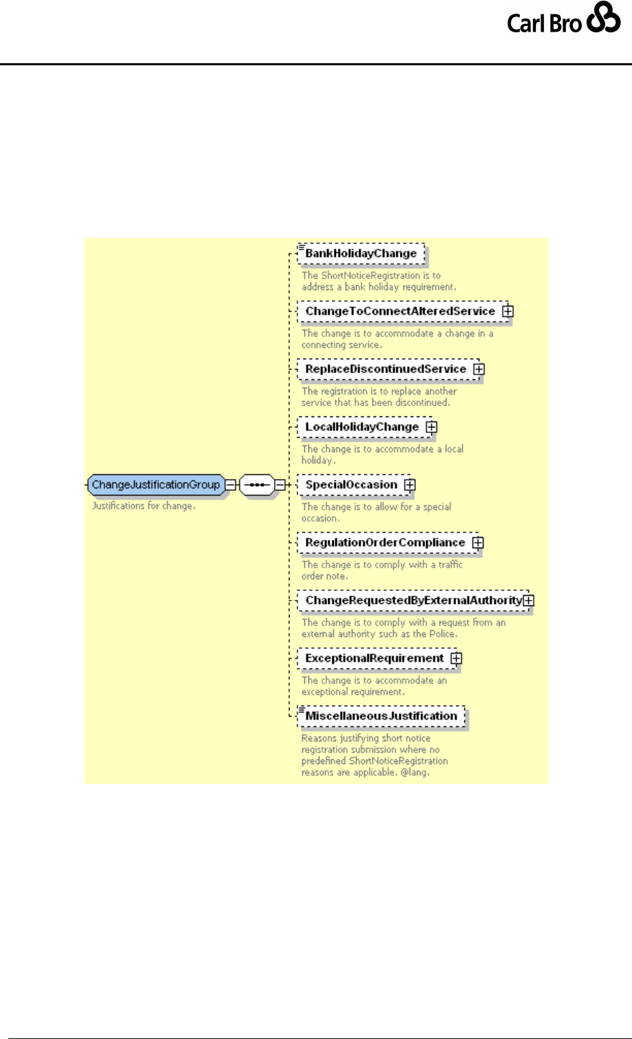
Department for Transport
TransXChange Schema Guide
Part III
Schema Description
TransXChangeSchemaGuide-2.1-v-45.pdf.doc
Page 139
24 September 2013
RegulationOrderCompliance: Whether the short notice registration is needed to
meet a road traffic order. See below.
ChangeRequestedByExternalAuthority: Whether the short notice registration is
needed to meet a request by an external authority such as the Police. See below.
ExceptionalRequirement: Whether the short notice registration is needed to meet
an allowed exceptional requirement. See below.
MiscellaneousJustification: The reasons justifying the short notice registration
submission where none of the above considerations are applicable. More than one
reason may be included.
Figure 6-29 – ShortNoticeRegistration /
ChangeJustificationGroup
6.5.12 ShortNoticeRegistration Subelements
6.5.12.1 ShortNoticeRegistration / Public Availability Element
The PublicAvailability element (Figure 6-30) specifies whether the service is to be
available to the general public.
AvailableToPublic: Specifies service is available.
NotAvailableToPublic. Specifies service is not available, accompanied by a
NonAvailabilityDescription.
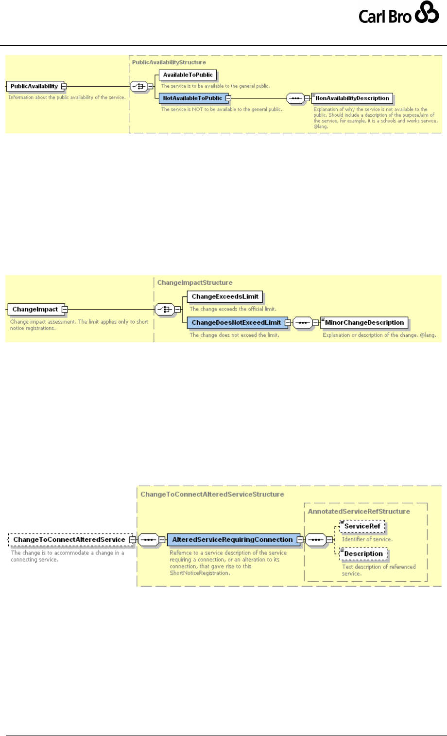
Department for Transport
TransXChange Schema Guide
Part III
Schema Description
TransXChangeSchemaGuide-2.1-v-45.pdf.doc
Page 140
24 September 2013
Figure 6-30 – ShortNoticeRegistration / PublicAvailability
Element
6.5.12.2 ShortNoticeRegistration / ChangeImpact Element
The ChangeImpact element (Figure 6-31) specifies whether the change to the service time
is in excess of the normal allowed limit (i.e. more than ten minutes from the current time): if
the change is more than the allowed amount, then a justification must be given, otherwise a
Minor Change Description can be used.
ChangeExceedsLimit: Change exceeds the allowed limit. Only possible if change
to existing application, i.e. if ChangeClassification is Change or Cancel.
ChangeDoesNotExceedLimit: The change does not exceed the limit.
Figure 6-31 – ShortNoticeRegistration / ChangeImpact Element
6.5.12.3 ShortNoticeRegistration / ChangeToConnectAlteredService Element
The ChangeToConnectAlteredService (Figure 6-32) specifies whether the short notice
registration is needed to handle a modification to another service, and if so, which one:
It contains an AlteredServiceRequiringConnection instance, which is an
AnnotatedServiceRefStructure.
ServiceRef: Reference to another Service definition provided elsewhere in the
document.
Description: Text description of the service &/or its identifier if not defined by a
service reference.
Figure 6-32 – ShortNoticeRegistration / ChangeToConnectAlteredService Element
6.5.12.4 ShortNoticeRegistration / ReplaceDiscontinuedService Element
The ReplaceDiscontinuedService (Figure 6-33) identifies the discontinued service which
the service of the short notice registration replaces.
DiscontinuedServiceOperator: Operator of the discontinued service.
DiscontinuedService: Description of the discontinued service, an
AnnotatedServiceRefStructure.
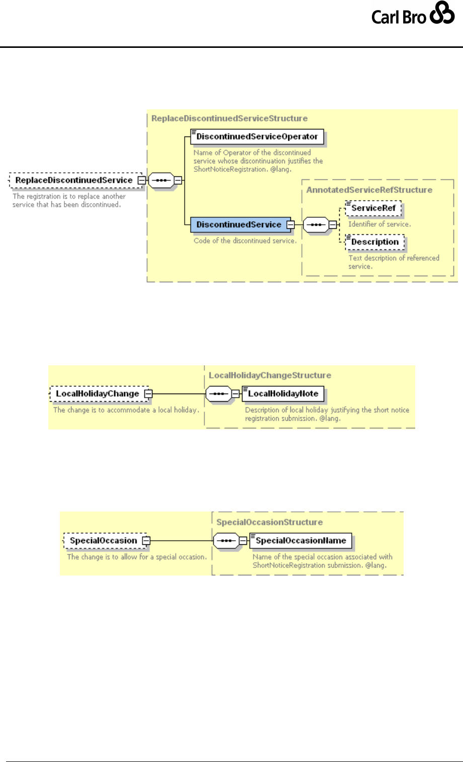
Department for Transport
TransXChange Schema Guide
Part III
Schema Description
TransXChangeSchemaGuide-2.1-v-45.pdf.doc
Page 141
24 September 2013
ServiceRef: Reference to another Service definition provided elsewhere in the
document.
Description: Text description of the service &/or its identifier if not defined by a
service reference.
Figure 6-33 – ShortNoticeRegistration / ReplaceDiscontinuedService Element
6.5.12.5 ShortNoticeRegistration / LocalHolidayChange Element
The LocalHolidayChange element (Figure 6-34) identifies the local holiday which justifies
the short notice registration.
LocalHolidayNote: Description of local holiday.
Figure 6-34 – ShortNoticeRegistration / LocalHolidayChange Element
6.5.12.6 ShortNoticeRegistration / SpecialOccasion Element
The SpecialOccasion element (Figure 6-35) identifies the special occasion which justifies
the short notice registration.
SpecialOccasionName: Name of special occasion.
Figure 6-35 – ShortNoticeRegistration / SpecialOccasion
Element
6.5.12.7 ShortNoticeRegistration / RegulationOrderCompliance Element
The RegulationOrderCompliance element (Figure 6-36) identifies whether the short notice
registration is to comply with a regulation order.
TrafficOrderNote: Identifies the order.
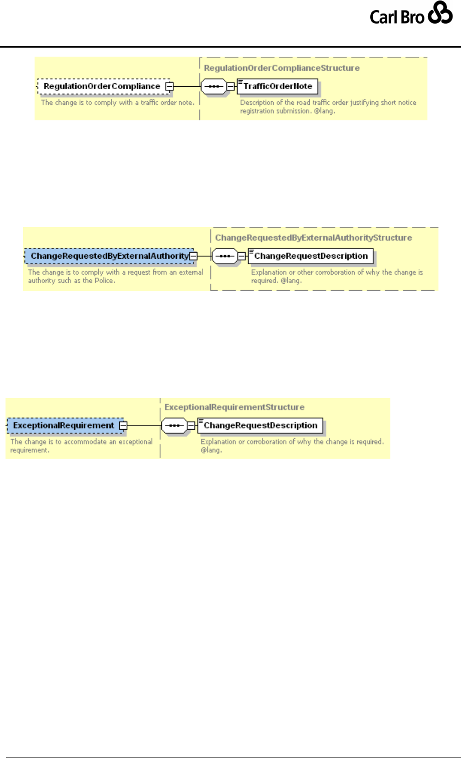
Department for Transport
TransXChange Schema Guide
Part III
Schema Description
TransXChangeSchemaGuide-2.1-v-45.pdf.doc
Page 142
24 September 2013
Figure 6-36 – ShortNoticeRegistration / RegulationOrderCompliance Element
6.5.12.8 ShortNoticeRegistration / ChangeRequestedByExternalAuthority Element
The ChangeRequestedByExternalAuthority (Figure 6-37) specifies whether the short
notice registration is needed to meet a request by an external authority such as the Police,
and any explanation or corroboration of the change.
ChangeRequestDescription: Explanation or corroboration of why the change is
required.
Figure 6-37 – ShortNoticeRegistration / ChangeRequestedByExternalAuthority
Element
6.5.12.9 ShortNoticeRegistration / ExceptionalRequirement Element
The ExceptionalRequirement element (Figure 6-38) specified whether the registration is
needed to meet an allowed exceptional requirement.
ChangeRequestDescription: Explanation or corroboration of why the change is
required.
Figure 6-38 – ShortNoticeRegistration / ExceptionalRequirement
Element

Department for Transport
TransXChange Schema Guide
Part III
Schema Description
TransXChangeSchemaGuide-2.1-v-45.pdf.doc
Page 143
24 September 2013
6.6 Service Description Elements
6.6.1 Services Element
Definitions of each Service describing a bus schedule are contained within the Services
container element:
In a TransXChange Registration schema document, only one registered service may
be described at a time. The registered Service must reference a Registration, and
the referenced Registration must describe the operator in full with a
LicensedOperator. Instance. Relevant details of other connecting services may be
included in the document as separate service declarations.
In a TransXChange General Schema document, many services can be described.
6.6.2 Service Element
The Service element (Figure 6-39) describes a service. The elements include:
ServiceCode: The unique identifier for the service.
PrivateCode: An identifier for the service that can be used to associate it with other
systems.
Lines: The public identifiers for the service. See later.
OperatingPeriod: Period within which service operates. See below.
OperatingProfile: Default operational days for journeys running the service. See
Operational Days elements later.
ServiceClassification: Type of the service. See below.
TicketMachineServiceCode: Unique Identifier associated with service for use in
ticketing machine systems. May be overridden on Individual Journey Patterns &
Vehicle Journey instances.
RegisteredOperatorRef: Registered operator of the service. See
LicensedOperator and Operator. On a Registration Service this must reference a
LicensedOperator instance.
AssociatedOperatorRef: Another operator associated with the service in a
secondary capacity. See Operator and LicensedOperator.
ServiceInfoGroup: Further informational elements about the service. See below.
ServiceDescriptionGroup: Further descriptive elements about the service. See
below.
ServiceComponentGroup: Information about the routes and journeys patterns
comprising the service. See below.
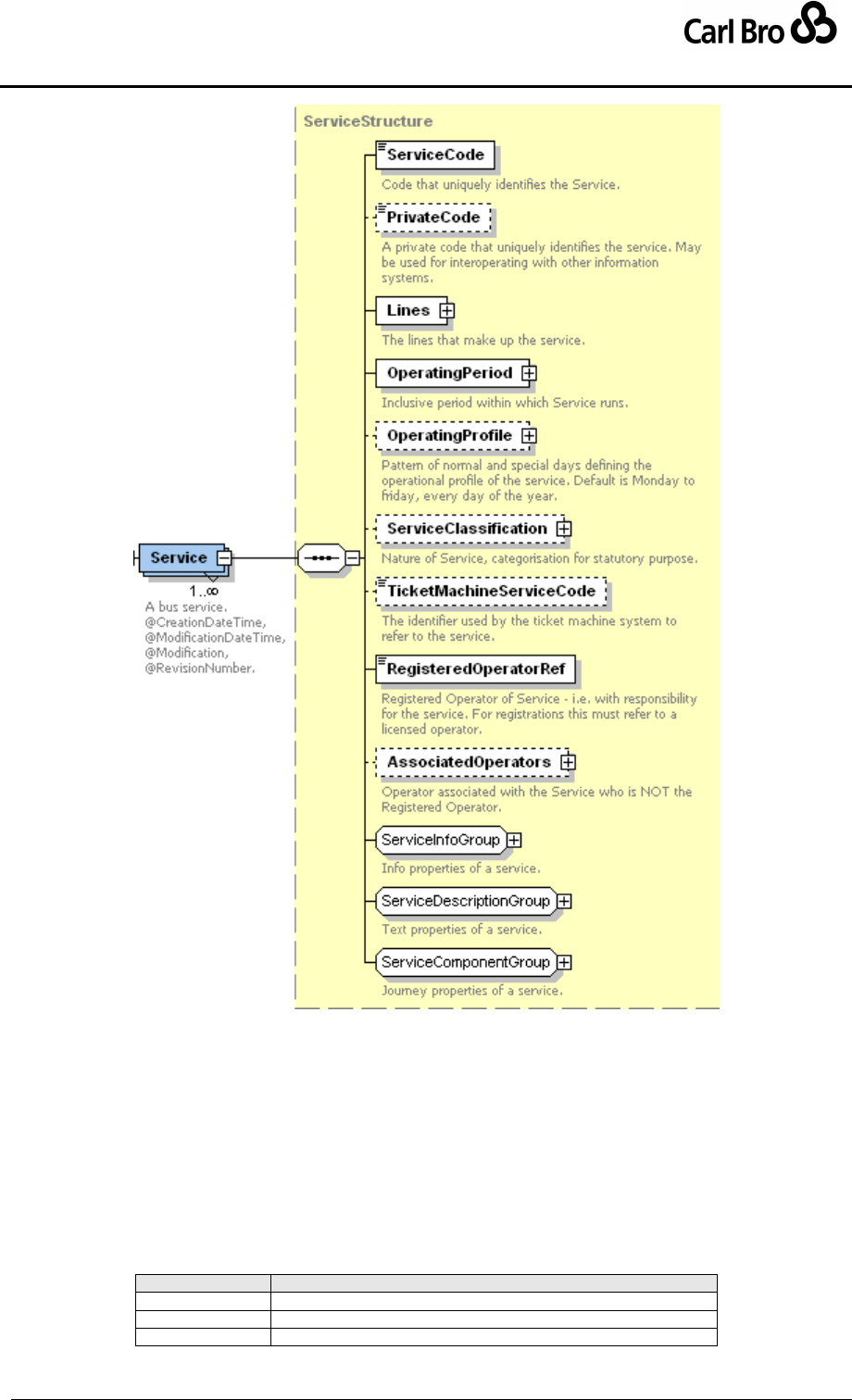
Department for Transport
TransXChange Schema Guide
Part III
Schema Description
TransXChangeSchemaGuide-2.1-v-45.pdf.doc
Page 144
24 September 2013
Figure 6-39 – Service Element
6.6.3 Service / ServiceInfoGroup
The ServiceInfoGroup (Figure 6-40) group holds informational elements describing the
Service.
ServiceHasMirror: Whether service has a corresponding service in the return
direction.
StopRequirements: Whether the service requires new stop declarations. See
below.
Mode: Transport mode of service. See Table 6-10. Default is bus.
Value
Description
air
Air service.
bus
Bus service.
coach
Coach service.
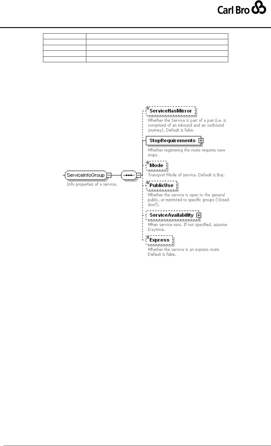
Department for Transport
TransXChange Schema Guide
Part III
Schema Description
TransXChangeSchemaGuide-2.1-v-45.pdf.doc
Page 145
24 September 2013
underground
Metro service.
ferry
Ferry service.
train
Train service.
tram
Tram service.
underground
Underground service.
Table 6-10 – Allowed Values for Service / Mode
PublicUse: Whether service allows public use, i.e. is not ‘Closed Door’.
ServiceAvailability: Whether service has a corresponding service in the return
direction. See below.
Express: Whether service is flagged as an express (i.e. limited stop) service.
Figure 6-40 – Service / ServiceInfoGroup
6.6.4 Service / ServiceDescriptionGroup
The ServiceDescriptionGroup (Figure 6-41) group holds ancillary descriptive elements
describing the Service.
Description: Text description of the services. On registrations should include “A
description of the service or change for Notices & Proceedings”. For example, “a
regular service at half-hourly intervals daytime on Mondays to Saturdays, and hourly
in the evenings and on Sundays".
Note: Structured notes associated with service. See common schema elements
later.
SchematicMap: Name of any schematic map associated with services. File name.
Must be an image file (.png, .gif, .jpeg). Schematic maps must be provided for
Registrations.
ToBeMarketedWith: Information on marketing of the services. See below.
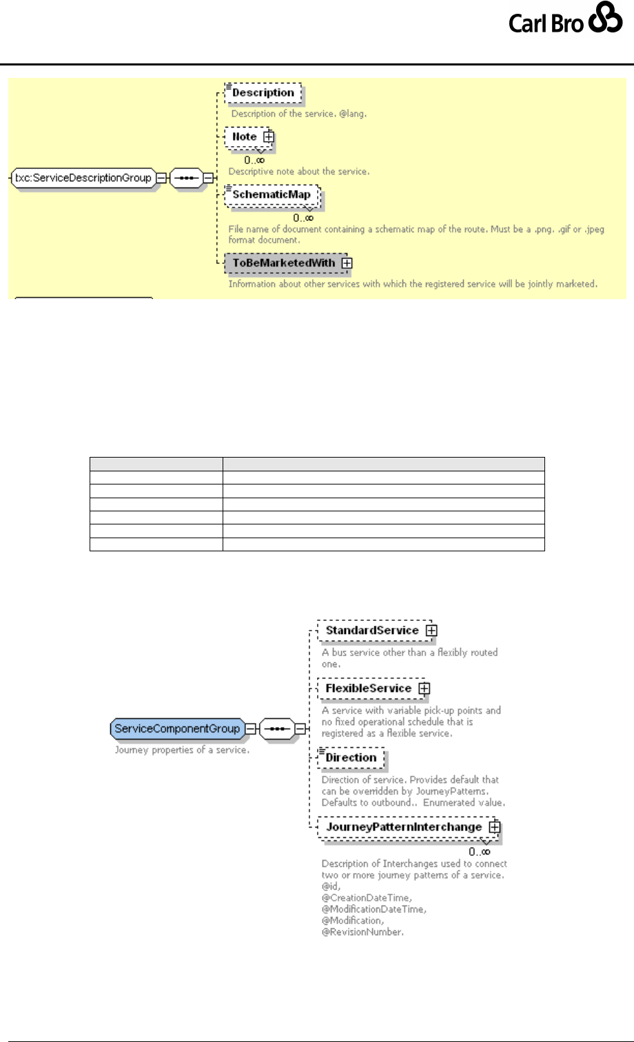
Department for Transport
TransXChange Schema Guide
Part III
Schema Description
TransXChangeSchemaGuide-2.1-v-45.pdf.doc
Page 146
24 September 2013
Figure 6-41 – Service / ServiceDescriptionGroup
6.6.5 Service / ServiceComponentGroup
The ServiceComponentGroup (Figure 6-42) holds the fundamental timetable components
of the Service.
StandardService: Any standard service component.
FlexibleService: Any flexible service component.
Direction: The direction of the Service. See Table 6-1
Value
Description
inbound
Inbound Direction.
outbound
Outbound Direction.
inboundAndOutbound
Inbound and Outbound Direction.
circular
Circular Direction.
clockwise
Clockwise Direction.
antiClockwise
Anti-Clockwise Direction.
Table 6-11 – Allowed Values for Service / Direction
JourneyPatternInterchange: Zero or more interchanges at which the journey
patterns of the service connect.
Figure 6-42 – Service / ServiceComponentGroup
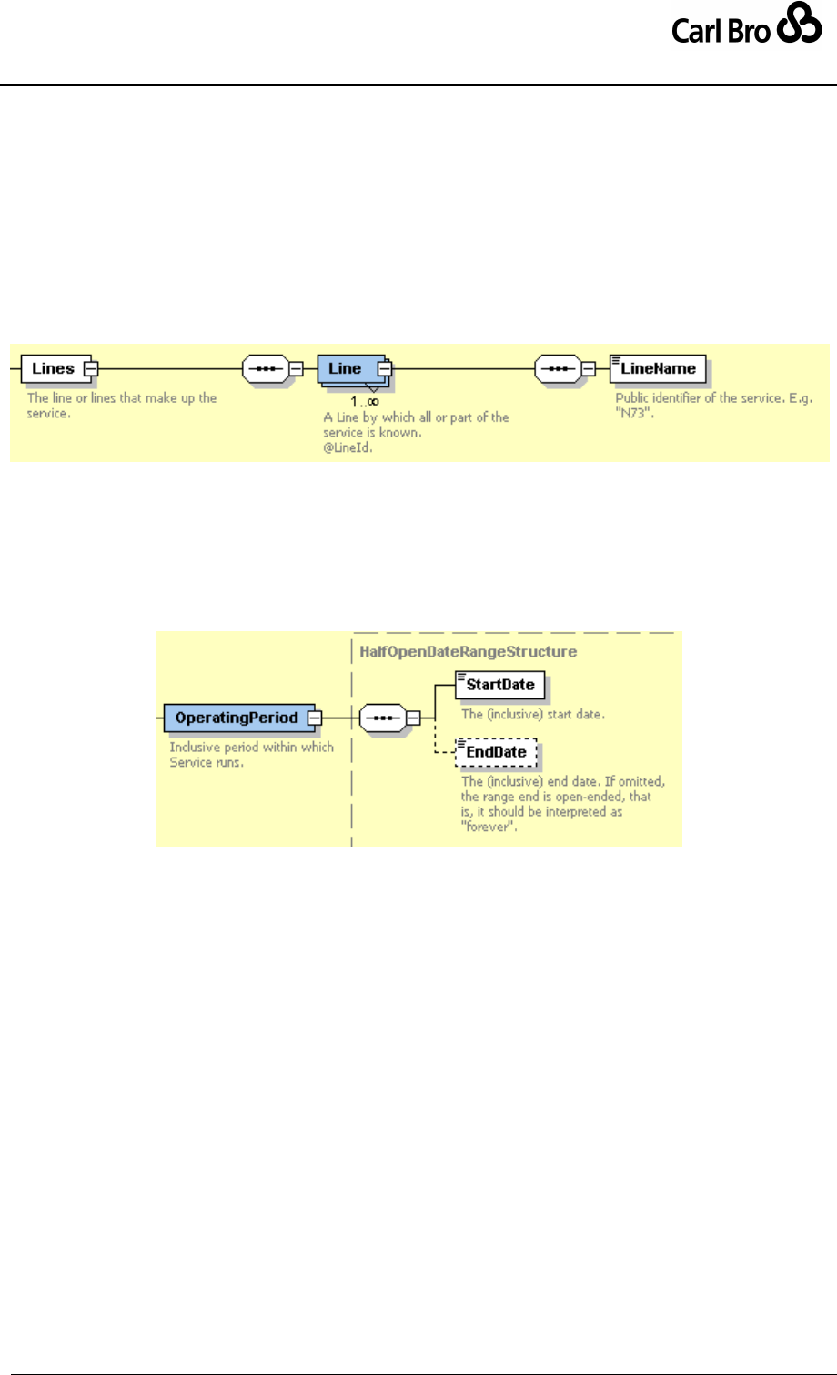
Department for Transport
TransXChange Schema Guide
Part III
Schema Description
TransXChangeSchemaGuide-2.1-v-45.pdf.doc
Page 147
24 September 2013
6.6.6 Service / Subelements
6.6.6.1 Service / Line Element
The Line element (Figure 6-43) allows one or more public identifiers of the service to be
associated with the vehicle journeys of the service. For example, lines ‘1’, ‘1a’, ‘1b’. Each
individual VehicleJourney element specifies the line or line variant that the journey runs. A
Line provides an arbitrary label for presentational and marketing purposes and does not
necessarily correspond to the strict route variants: the same line name may be used on
services with different stopping patterns. A Line is identified by a unique id attribute.
Each Line has a LineName.
Figure 6-43 – Service / Line Element
6.6.6.2 Service / OperatingPeriod Element
The OperatingPeriod element (Figure 6-44) states the period over which the Service
operates. It includes a StartDate and an option EndDate. See also OperationProfile
element for further elements relating to the operating days of a service.
Figure 6-44 – Service / OperatingPeriod Element
6.6.6.3 Service / ServiceClassification Element
The ServiceClassification element (Figure 6-45) classifies the service as being one or
more of a number of categories of service. The classifications are as follows:
NormalStopping: A service where all stops on a route are used.
LimitedStops: A service where only certain pre-defined stops on a route are used.
HailAndRide: A service that stops anywhere on designated parts of the route, if
flagged down by passengers where it is safe to do so.
Flexible: A service running in accordance with the rules for a flexible service, with
designated pickup and set down zones or points. Must be specified if service is a
FlexibleService.
ExcursionOrTour: A service where all passengers go to the same destination and
return to their departure point. Further qualified by:
o MaxDepartures: Maximum number of vehicle departures within one day
associated with an excursion type service.
RuralService: A service primarily aimed at serving rural communities (i.e. at
locations with populations less than 25,000 people).
SchoolOrWorks: A service dedicated to a school or works that is not available to
the public.
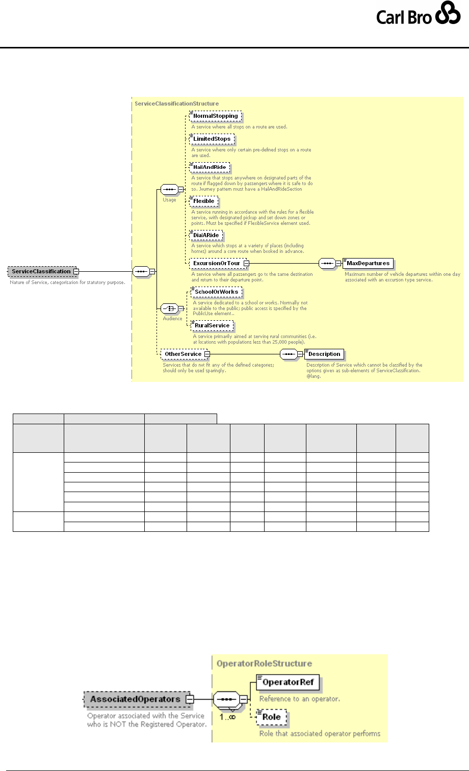
Department for Transport
TransXChange Schema Guide
Part III
Schema Description
TransXChangeSchemaGuide-2.1-v-45.pdf.doc
Page 148
24 September 2013
OtherService: Services that do not fit any of the defined categories. Should only be
used sparingly:
o Further explained by a Description.
Figure 6-45 – Service / ServiceClassification Element
Normal combinations of service are shown in Table 6-12:
Audience
Group
ServiceClassifica
tion
Normal
Stop-
ping
Limited
Stops
Hail
And
Ride
Flexible
Service
Excursion
Or
Tour
School
Or
Works
Rural
Serv-
ice
Operation
NormalStopping
-
N
N
N
N
Y
Y
LimitedStops
N
-
N
N
N
Y
Y
HailAndRide
N
N
-
N
N
Y
Y
FlexibleService
N
N
N
-
N
Y
Y
ExcursionOrTour
N
N
N
N
-
Y
Y
OtherService
N
N
N
N
N
Y
Y
Purpose
SchoolOrWorks
Y
Y
Y
Y
Y
-
N
RuralService
Y
Y
Y
Y
Y
N
-
Table 6-12 – Allowed ServiceClassification Combinations
6.6.6.4 Service / AssociatedOperators Element
The AssociatedOperators (Figure 6-46) element records details about any operators
associated with the service other than the registered operator. The AssociatedOperator
comprises:
OperatorRef: Reference to an Operator or LicensedOperator definition. See
above.
Role: Description of the role of the associated operator.
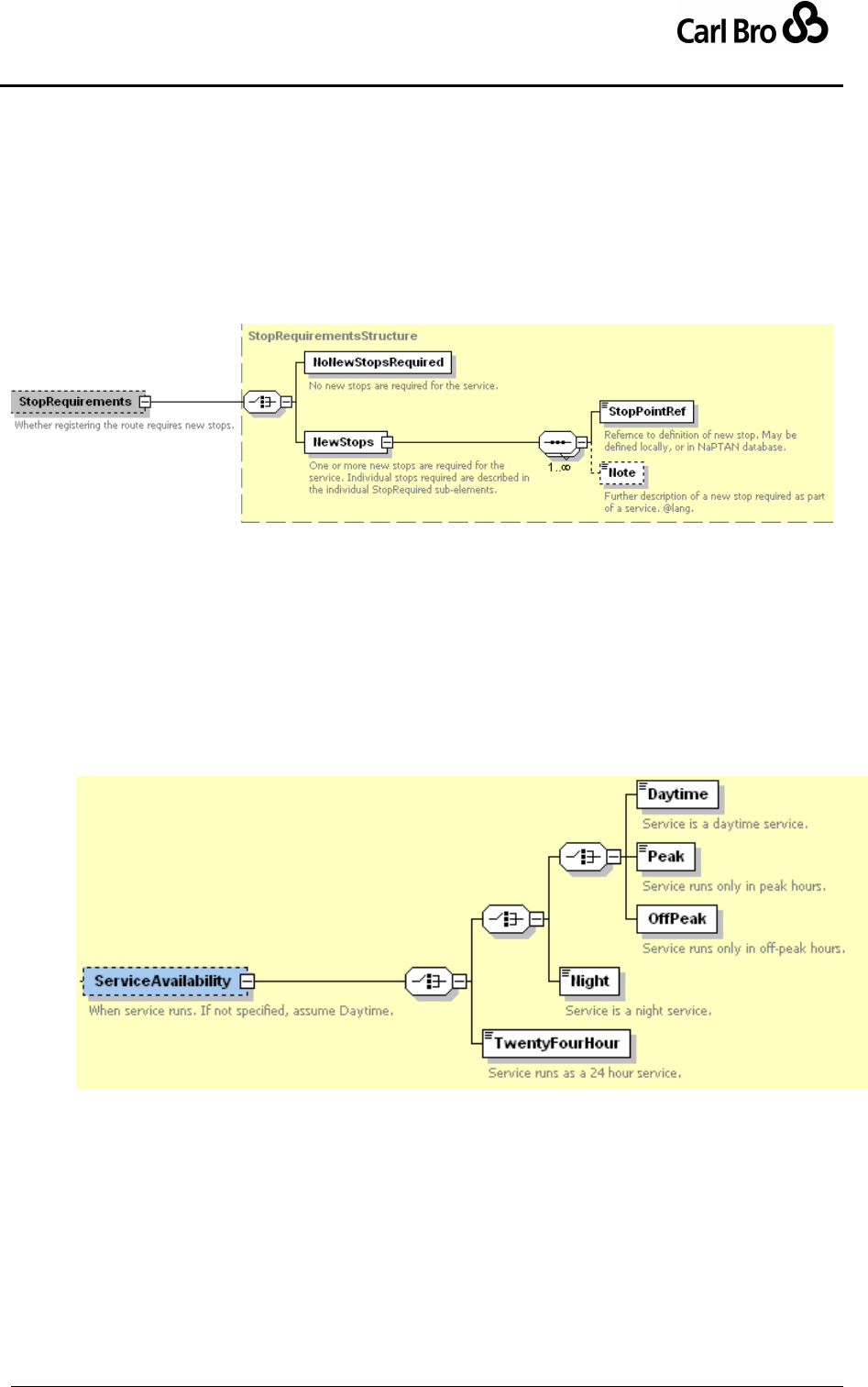
Department for Transport
TransXChange Schema Guide
Part III
Schema Description
TransXChangeSchemaGuide-2.1-v-45.pdf.doc
Page 149
24 September 2013
Figure 6-46 – Service / AssociatedOperators Element
6.6.6.5 Service / StopRequirements Element
The StopRequirements element (Figure 6-47) specifies whether a service does or does not
require any new stops.
NoNewStopsRequired: No new stops are needed.
NewStops: New stops are needed.
o StopPointRef: Reference to the new stop – may be declared locally.
o Note: Optional explanatory note accompanying definition.
Figure 6-47 – Service / StopRequirements Element
6.6.6.6 Service / ServiceAvailability Element
The ServiceAvailability element (Figure 6-48) specifies the time of day a service runs as a
broad classification. One of the following:
TwentyFourHours: Service runs all day and all night continuously.
Daytime: Service runs in daytime.
Peak: Service runs in peak hours only.
OffPeak: Service runs in off-peak hours only.
Night: Service is a night service.
Figure 6-48 – Service / ServiceAvailability Element
6.6.6.7 Service / ToBeMarketedWith Element
The ToBeMarketedWith element (Figure 6-49) records the Services that are normally
marketed with the bus service. It contains one or more RelatedService instances, each of
which is an AnnotatedServiceRefStructure.
ServiceRef: Reference to another Service definition provided elsewhere in the
document.
Description: Text description of the service &/or its identifier if not defined by a
service reference.
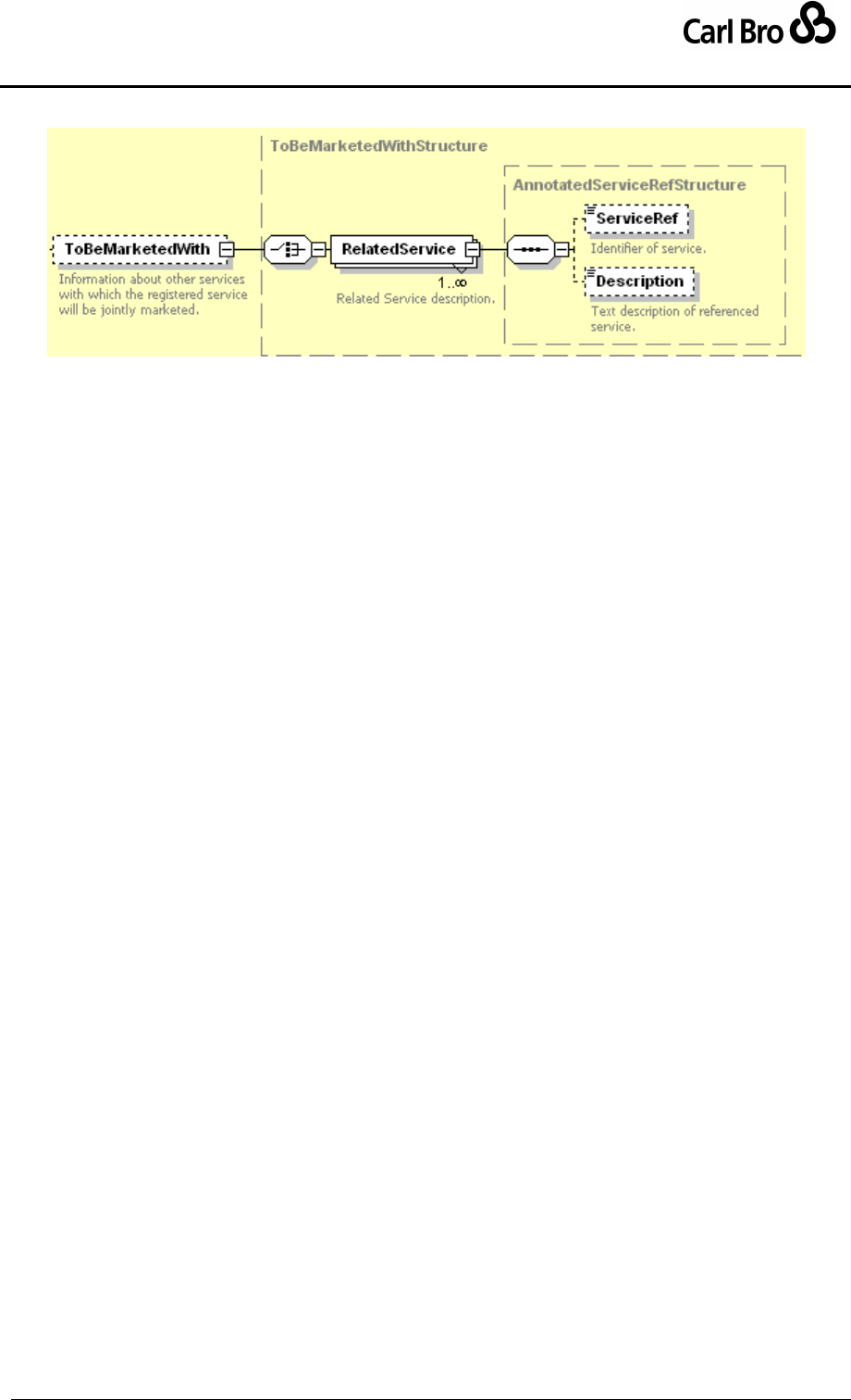
Department for Transport
TransXChange Schema Guide
Part III
Schema Description
TransXChangeSchemaGuide-2.1-v-45.pdf.doc
Page 150
24 September 2013
Figure 6-49 – Service / ToBeMarketedWith Element
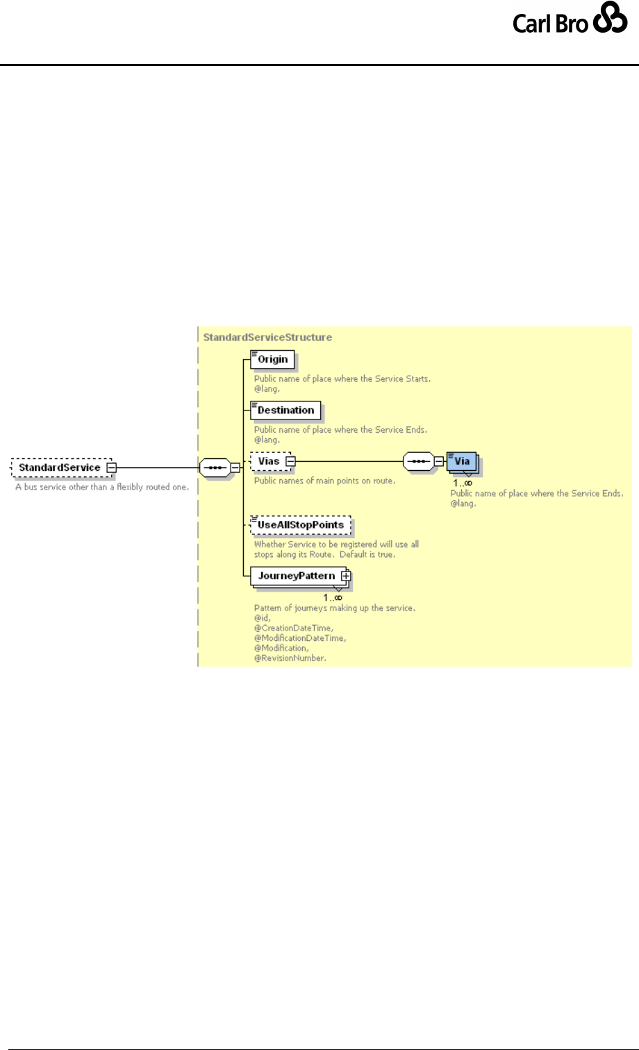
Department for Transport
TransXChange Schema Guide
Part III
Schema Description
TransXChangeSchemaGuide-2.1-v-45.pdf.doc
Page 151
24 September 2013
6.7 StandardService, JourneyPattern, VehicleJourney
6.7.1 StandardService Element
The StandardService element (Figure 6-50) describes the fixed-route component of a
Service. It comprises.
Origin: Public name of the place where the service starts.
Destination: Public name of the place where the service ends.
Vias: Public name(s) of the places that the service route goes past: One or more Via
elements.
UseAllStopPoints: Whether the service uses all the stops along its Route.
JourneyPattern: One or more JourneyPattern elements representing the working
of the service. See below.
Figure 6-50 – StandardService Element

Department for Transport
TransXChange Schema Guide
Part III
Schema Description
TransXChangeSchemaGuide-2.1-v-45.pdf.doc
Page 152
24 September 2013
6.7.2 JourneyPatterns
A JourneyPattern describes a possible bus route of a StandardService as a sequence of
timing links between stops that a vehicle will traverse in a particular order, representing the
pattern of working for vehicles of the service.
Each JourneyPattern belongs to a StandardService.
The individual steps of the journey are modelled as JourneyPatternTimingLink
elements; each link has information about the distance to travel, between two stops,
and the run time needed. Activity at stop and other information about stop usage is
described for each end of the link using JourneyPatternStopUsage elements.
The links are grouped into JourneyPatternSection elements, representing reusable
link sequences. Sections are declared within a TransXChange top-level container
element, JourneyPatternSections, and so may be reused in different
JourneyPattern instances.
The order of JourneyPatternTimingLinks in each JourneyPatternSection, and
the overall order of the JourneyPatternSection instances must both follow the order
in which they are traversed.
The timing links of a JourneyPattern should correspond to the RouteLink instances
of any associated Route, that is be an exact projection on a link-by-link basis of
either all the links of route in sequence, or a contiguous subset of the route links in
sequence
In a given JourneyPattern, the route links of an individual RouteSection should all
be referenced by timing links in a single JourneyPatternSection, i.e. not be divided
between different JourneyPatternSection instances. A JourneyPatternSection
may however project onto multiple RouteSection instances.
A JourneyPattern may be used in more than one VehicleJourney on a route. It
should be noted that a VehicleJourney following a JourneyPattern may not
necessarily stop at all stops identified within the JourneyPattern, thus the
JourneyPattern provides the ‘super set’ of stops of a route, of which all or some
may be served by the dependent VehicleJourney instances. Individual
VehicleJourney instances may subset the full JourneyPattern stop list either by
passing an individual stop, or by short working at either end. They must still follow
the route and stop sequence for the part of the journey pattern that they work.
6.7.3 JourneyPattern Element
A JourneyPattern (Figure 6-51) describes the stopping pattern of a standard i.e. fixed route
service. A JourneyPattern, is identified by a unique id attribute, and comprises a number of
elements falling into two groups:
1. CommonJourneyGroup: Shared elements common to journey patterns and vehicle
journeys.
2. JourneyPatternGroup: Elements specific to journey patterns.
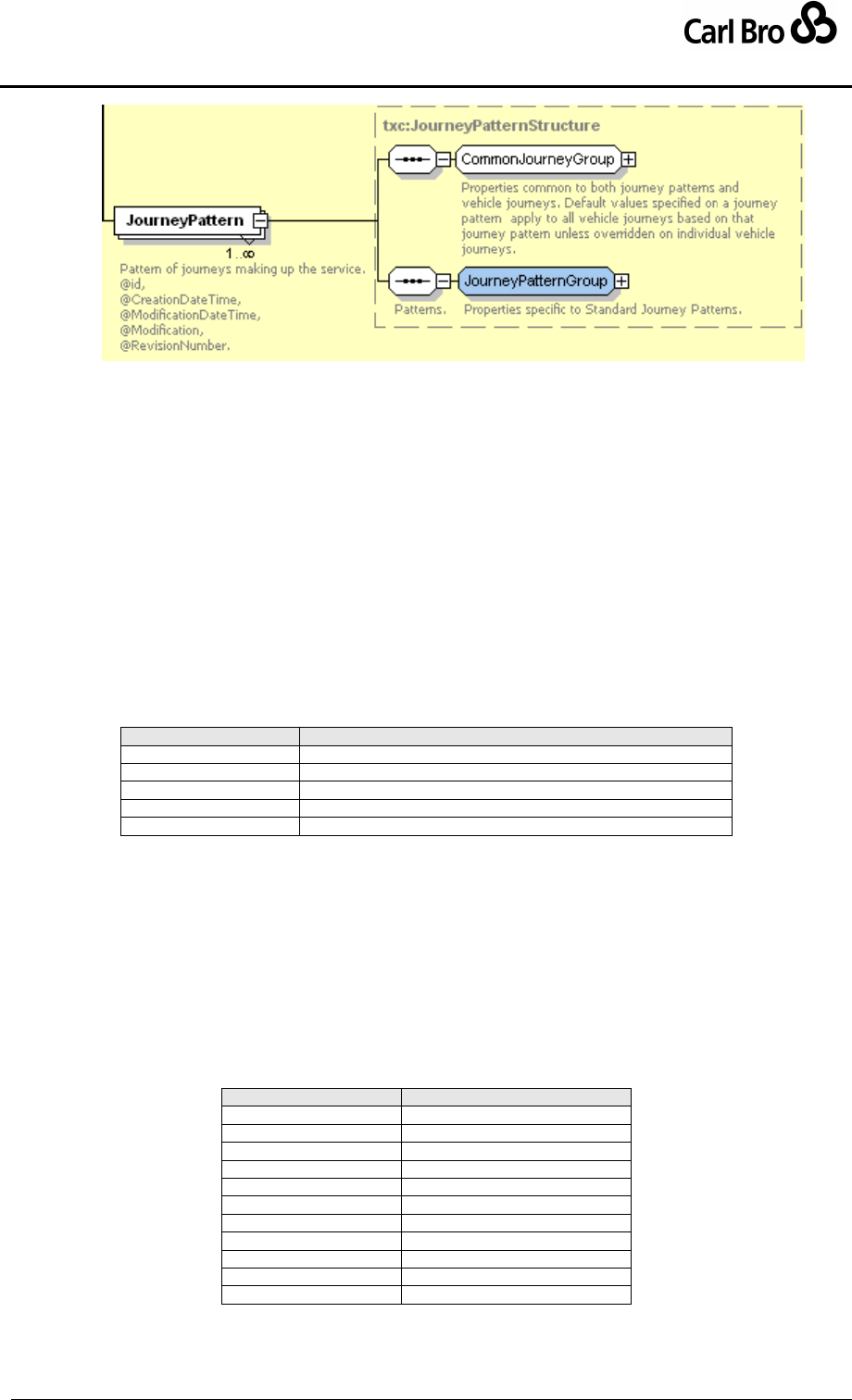
Department for Transport
TransXChange Schema Guide
Part III
Schema Description
TransXChangeSchemaGuide-2.1-v-45.pdf.doc
Page 153
24 September 2013
Figure 6-51 – JourneyPattern Element
6.7.3.1 JourneyPattern / CommonJourneyGroup
The CommonJourneyGroup (Figure 6-52) holds identity and operational information that is
common to both a JourneyPattern and a VehicleJourney: the JourneyPattern instances
provide default values to use on dependent VehicleJourney instances if no specific
override is provided on the VehicleJourney.
PrivateCode: A unique private code that can be used to identify the
JourneyPattern.
DestinationDisplay: Journey destination, as displayed on vehicle. If omitted, the
Destination of the Service is used.
OperatorRef: The operator for the journey. Normally this is not required since it is
the same as for the service.
Direction: The default Direction of the JourneyPattern. Default is ‘inherit’. See
Table 6-13.
Value
Description
inherit
Use value from Service.
inbound
Inbound Direction.
outbound
Outbound Direction.
clockwise
Clockwise Direction.
antiClockwise
Anti-Clockwise Direction.
Table 6-13 – Allowed Values for JourneyPattern / Direction
OperatingProfile: Specifies operational days and times associated with the
JourneyPattern. If not specified inherited from Service.
Operational: Specifies additional operational information associated with the
journey. See below. Normally this is not required since it is the same as for the
service. Includes TicketMachine and Block elements. See below.
LayoverPoint: Points at which the service lays over. See below.
GarageRef: A garage from which the Service operates.
TimeDemand: Classification of the route as to when peak demand occurs. See
Table 6-14.
Value
Description
earlyMorning
Early Morning.
offPeak
Off Peak.
peakMorning
Peak Morning.
peakAfternoon
Peak Afternoon.
evening
Evening.
lateEvening
Late Evening.
saturdayMorning
Saturday Morning.
saturdayDaytime
Saturday Daytime.
saturdayEvening
Saturday Evening.
sunday
Sunday.
bankHoliday
Bank Holiday.
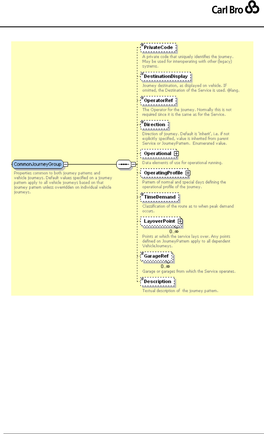
Department for Transport
TransXChange Schema Guide
Part III
Schema Description
TransXChangeSchemaGuide-2.1-v-45.pdf.doc
Page 154
24 September 2013
Table 6-14 – Allowed Values for TimeDemand
Figure 6-52 – JourneyPattern / CommonJourneyGroup
6.7.3.2 JourneyPattern / JourneyPatternGroup
The JourneyPatternGroup holds information specific to a JourneyPattern:
RouteRef: The Route which the JourneyPattern follows. See Route above.
JourneyPatternSectionRefs: An ordered collection of references to
JourneyPatternSections (as JourneyPatternSectionRef instances), that contain
the journey pattern timing links making up the JourneyPattern. See
JourneyPatternSection later.
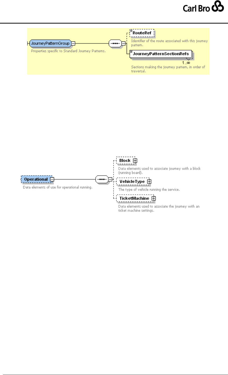
Department for Transport
TransXChange Schema Guide
Part III
Schema Description
TransXChangeSchemaGuide-2.1-v-45.pdf.doc
Page 155
24 September 2013
Figure 6-53 – JourneyPattern / JourneyPatternGroup
6.7.4 JourneyPattern Subelements
6.7.4.1 CommonJourneyGroup JourneyPattern / Operational Element
The Operational element (Figure 6-54) specifies operational information associated with
the JourneyPattern:
Block: Specifies information about the operational block within which the journey is
grouped.
VehicleType: Describes the type of vehicle running a service. See below.
TicketMachine: Information associated with service for use in ticketing machine
systems. See below.
Figure 6-54 – JourneyPattern / Operational Element
6.7.4.2 CommonJourneyGroup JourneyPattern / Operational / TicketMachine Element
The TicketMachine element (Figure 6-55) specifies information for associating a journey
with the settings of a ticket machine.
TicketMachineServiceCode: Unique Identifier associated with service for use in
ticketing machine systems. If not specified, defaults to any value specified at the
Service Level.
JourneyCode: The identifier used by the ticket machine system to refer to the
journey.
Direction: The direction used by the ticket machine system to refer to the journey.
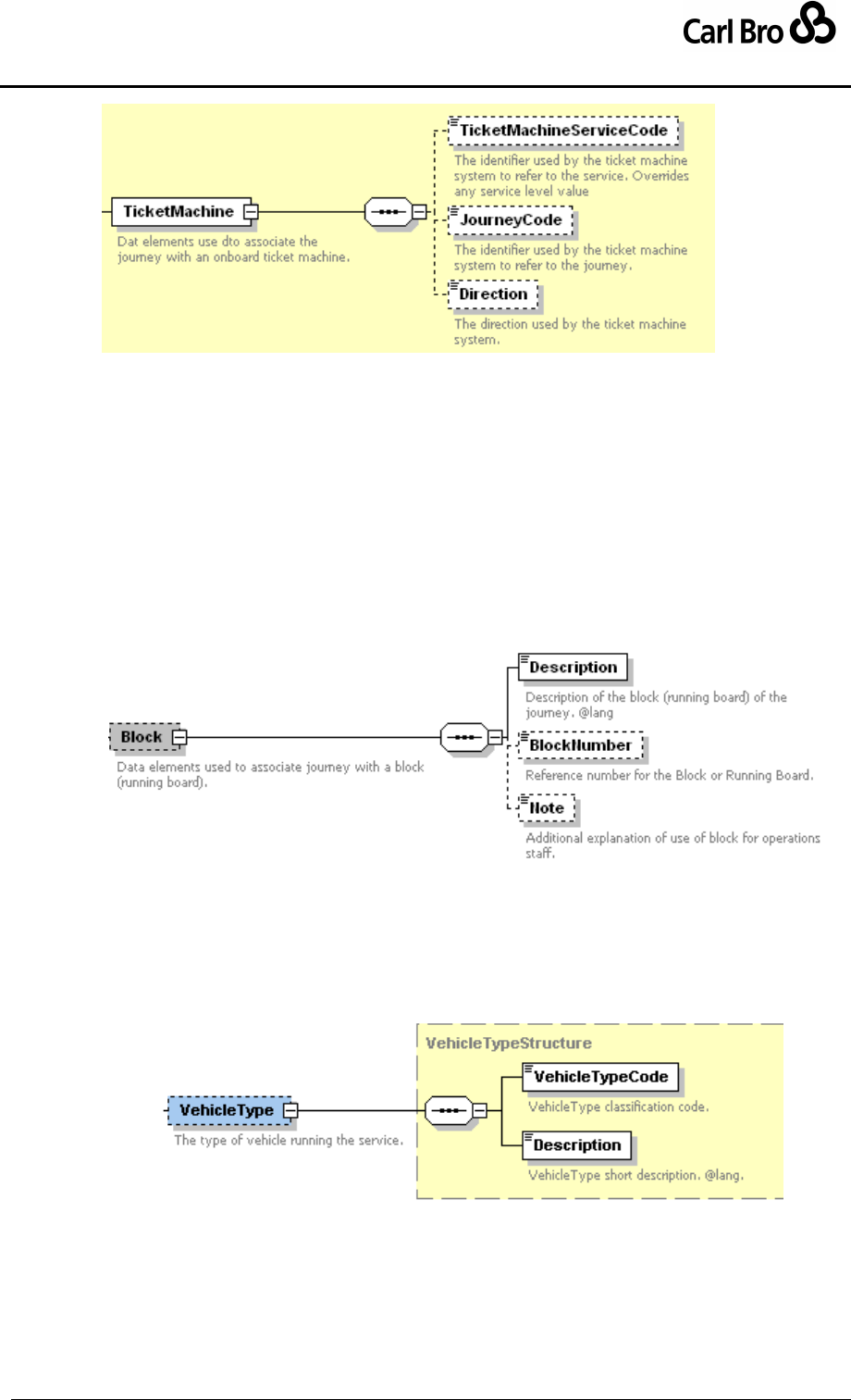
Department for Transport
TransXChange Schema Guide
Part III
Schema Description
TransXChangeSchemaGuide-2.1-v-45.pdf.doc
Page 156
24 September 2013
Figure 6-55 – JourneyPattern / TicketMachine Element
6.7.4.3 CommonJourneyGroup JourneyPattern / Block Element
The Block element (Figure 6-56) specifies information about the block (running board) of a
journey. A block enables VehicleJourney instances to be assigned to a logical group of
journeys that will be carried out by the same vehicle.
Description: Text describing the block.
BlockNumber: The number of the block associated with the journey.
VehicleJourney instances with the same BlockNumber will be carried out by the
same vehicle
Note: Explanatory text to explaining any further operational particulars about the
block.
Figure 6-56 – JourneyPattern / Block Element
6.7.4.4 CommonJourneyGroup / VehicleType Element
The VehicleType element (Figure 6-57) describes a type of vehicle running a service.
VehicleTypeCode: Arbitrary code that classifies the vehicle.
Description: Free text description of vehicle type.
Figure 6-57 – JourneyPattern / VehicleType Element
6.7.4.5 CommonJourneyGroup / LayoverPoint Element
The LayoverPoint element (Figure 6-58) describes a layover point used in a journey
pattern. It is identified by an id attribute, and comprises:
Duration: Time of wait at layover point. Uses standard duration type.
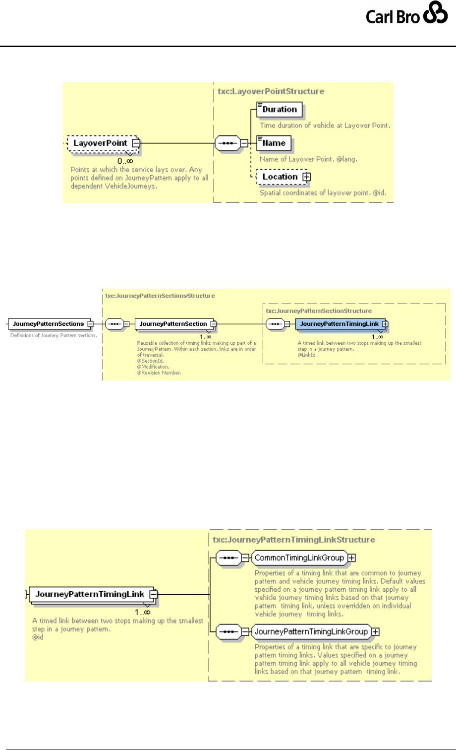
Department for Transport
TransXChange Schema Guide
Part III
Schema Description
TransXChangeSchemaGuide-2.1-v-45.pdf.doc
Page 157
24 September 2013
Name: Free text description of layover point.
Location: Location of layover point.
Figure 6-58 – JourneyPattern / LayoverPoint Element
6.7.5 JourneyPatternSection Element
A JourneyPatternSection (Figure 6-59) declares and groups an ordered collection of
JourneyPatternTimingLink elements. Each JourneyPatternSection can be identified by a
unique id attribute.
Figure 6-59 – JourneyPatternSection Element
6.7.6 JourneyPatternTimingLink Element
A JourneyPatternTimingLink (Figure 6-60) describes a timed link connecting two stops of
a JourneyPattern of a StandardService. Each JourneyPatternTimingLink can be
identified by a unique id attribute, and comprises a number of elements falling into two
groups:
1. CommonTimingLinkGroup: Shared elements common to journey pattern timing
links and to vehicle journey timing links.
2. JourneyPatternTimingLinkGroup: Elements specific to journey pattern timing
links.
Figure 6-60 – JourneyPatternTimingLink Element
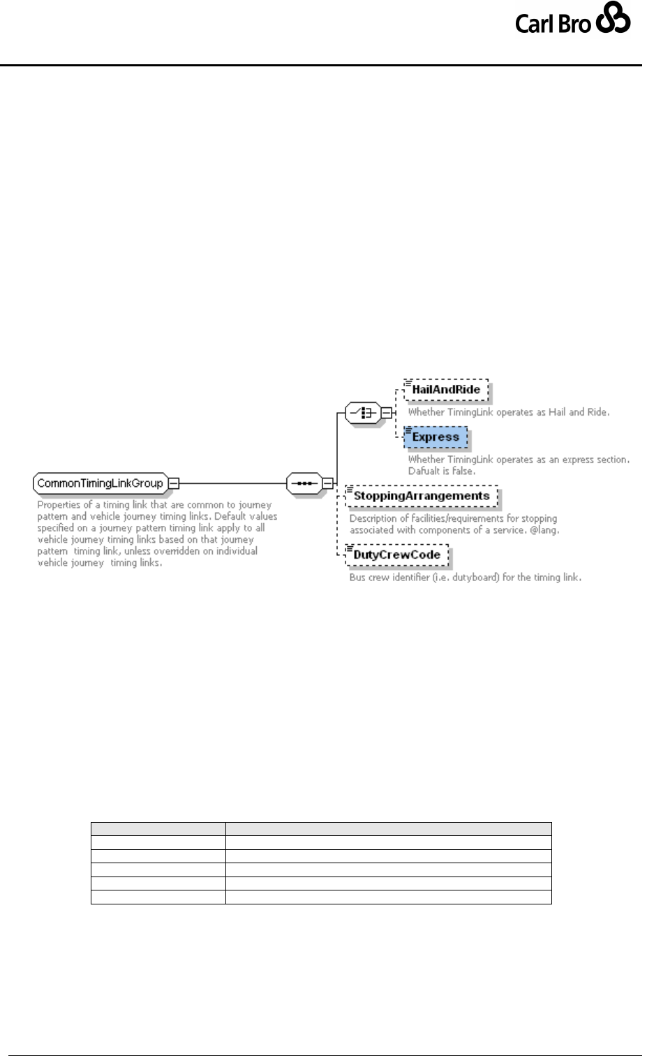
Department for Transport
TransXChange Schema Guide
Part III
Schema Description
TransXChangeSchemaGuide-2.1-v-45.pdf.doc
Page 158
24 September 2013
6.7.6.1 JourneyPatternTimingLink / CommonTimingLinkGroup
The CommonTimingLinkGroup (Figure 6-62) holds elements that are common to both a
JourneyPatternTimingLink and a VehicleJourneyTimingLink; the
JourneyPatternTimingLink instances provide default values to use on dependent
VehicleJourneyTimingLink instances if no specific override is provided on a particular
VehicleJourneyTimingLink.
HailAndRide: Whether link operates as a Hail and Ride service. Normally stops at
both ends of a link flagged as HailAndRide will be HailAndRide stops.
Express: Whether link operates as an express section (that is, typically going past a
stop without stopping at one or both ends of the link).
StoppingArrangements Text description of facilities/requirements for stopping
associated with link.
DutyCrewCode: Code identifying duty crew operating bus over link. Note that if
used, a value need not be specified on every link of a journey pattern: any value
specified is assumed to run for all intervening links until the next link with a value is
encountered.
Figure 6-61 – JourneyPatternTimingLink / CommonTimingLinkGroup
6.7.6.2 JourneyPatternTimingLink / JourneyPatternTimingLinkGroup
The JourneyPatternTimingLinkGroup (Figure 6-62) holds elements that are specific to a
JourneyPatternTimingLink:
From: Default usage details of from stop, specified by a
JourneyPatternStopUsageStructure. See later.
To: Default usage details of from stop, specified by a
JourneyPatternStopUsageStructure element. See later.
RouteLinkRef: Optional reference to a RouteLink onto which timing link projects.
Direction: Direction of link. Default is ‘inherit’. See Table 6-15.
RunTime: Time taken to traverse link. Normally this will be greater than zero.
Value
Description
inherit
Use value from Journey Pattern.
inbound
Inbound Direction.
outbound
Outbound Direction.
clockwise
Clockwise Direction.
antiClockwise
Anti-Clockwise Direction.
Table 6-15 – Allowed Values for VehicleJourney / Direction
Distance: Distance along link path in metres.
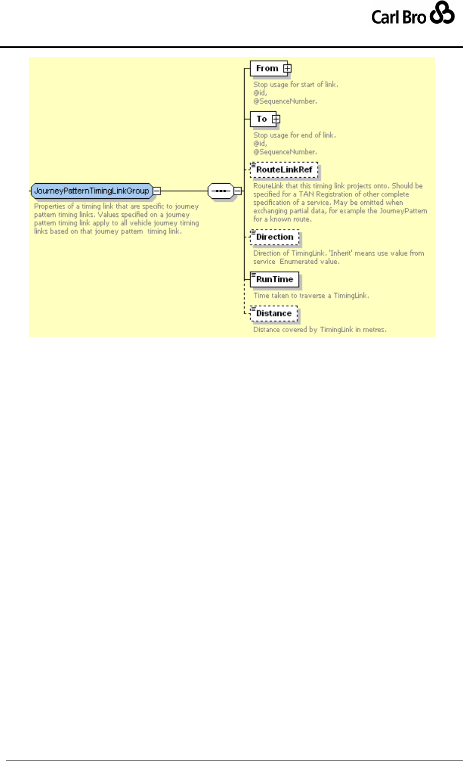
Department for Transport
TransXChange Schema Guide
Part III
Schema Description
TransXChangeSchemaGuide-2.1-v-45.pdf.doc
Page 159
24 September 2013
Figure 6-62 – JourneyPatternTimingLink / JourneyPatternTimingLinkGroup
6.7.7 JourneyPatternStopUsageStructure
The JourneyPatternStopUsageStructure (Figure 6-63) describes the use of a stop by the
start or end of a JourneyPatternTimingLink, or unordered stop reference in a
FlexibleJourneyPattern. It provides default values that will be inherited by the corresponding
VehicleJourneyStopUsage elements of dependent vehicle journeys.
Both JourneyPatternStopUsage and VehicleJourneyStopUsage instances can be
identified by a unique id attribute, and may also have a SequenceNumber attribute to
indicate the preferred ordering of stops when presenting schedules in matrix timetable
formats.
JourneyPatternStopUsage comprises a number of elements falling into two groups:
1. JourneyStopUsageGroup: Shared elements common to journey pattern stop
usage elements, and to vehicle journey stop usage elements.
2. JourneyPatternStopUsageGroup: Elements specific to journey pattern stop usage
elements.
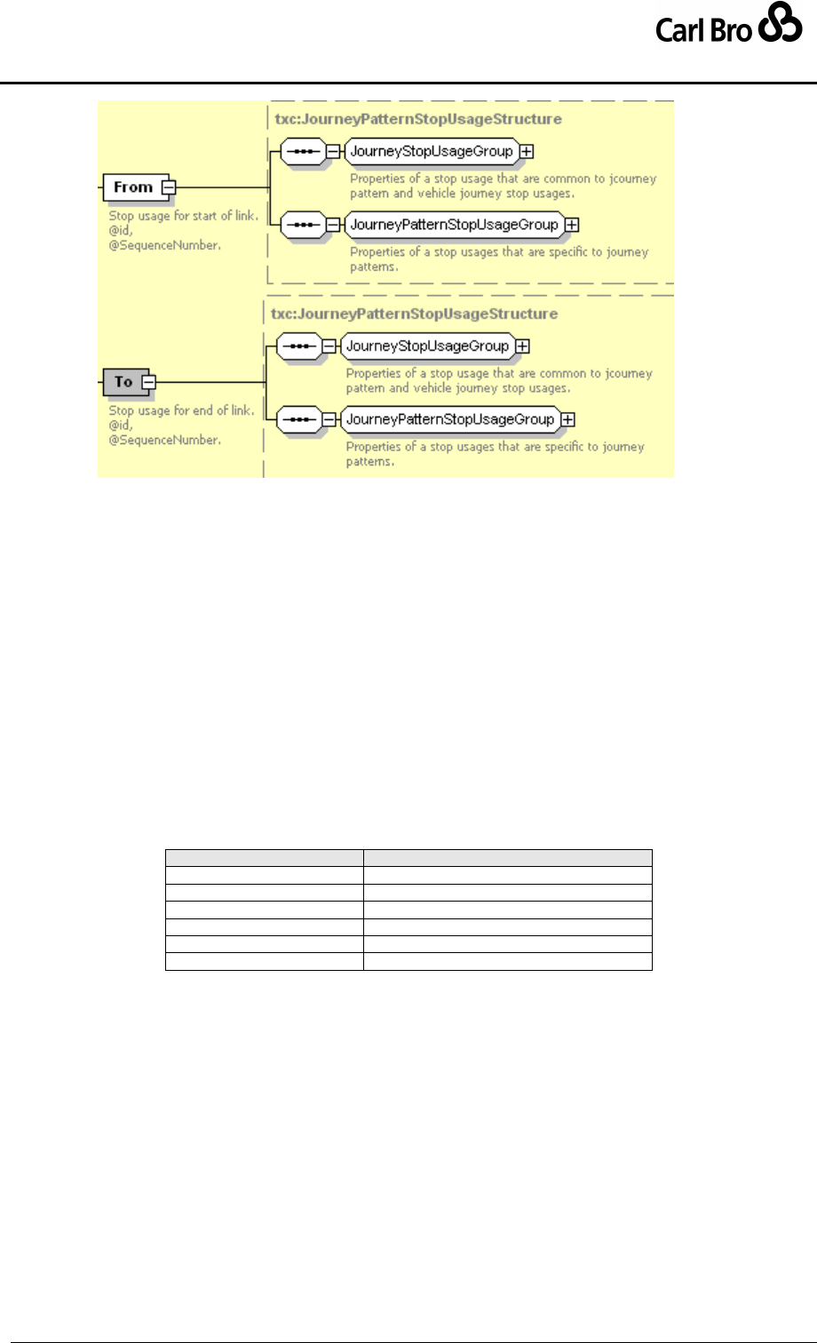
Department for Transport
TransXChange Schema Guide
Part III
Schema Description
TransXChangeSchemaGuide-2.1-v-45.pdf.doc
Page 160
24 September 2013
Figure 6-63 – JourneyPattern /
JourneyPatternStopUsageStructure
6.7.7.1 JourneyPatternStopUsage / JourneyStopUsageGroup
The JourneyStopUsageGroup (Figure 6-64) holds elements that are common to both a
JourneyPatternStopUsage and a VehicleJourneyStopUsage. Default values specified on
a journey pattern stop usage apply to all vehicle journey stop usages based on that journey
pattern stop usage, unless overridden on individual vehicle journey stop usages.
WaitTime: Time to wait at the referenced stop; thee wait time is the part of the
Overall Wait Time at the stop that has been ascribed to end of the link represented
by the stop usage. When calculating departure times for a specific vehicle journey,
the timing link WaitTime values from the respective stop usage ends of the
incoming and outgoing links are added together to create the total wait time at the
stop. See section 3.4.3. . If not specified, assume zero.
Activity: Activity undertaken by vehicle at stop. See Table 6-16. Defaults to pick up
and set down.
Value
Description
pickUp
Pick up passengers.
setDown
Set down passengers.
pickUpAndSetDown
Pick up and set down passengers.
hailAndRideStart
Start a Hail and ride section.
hailAndRideEnd
End a Hail and ride section.
pass
Do not stop at stop.
Table 6-16 – Allowed Values for Activity
DynamicDestinationDisplay: Journey destination applicable to vehicle at
referenced stop.
VariableStopAllocation: In bus stations, bays may be allocated to a service
variously on different days. This can be specified using the VariableStopAllocation
element. See below.
StopOnlyOnRequest: Whether stop is only a request stop on this journey. Default
false.
Note: Descriptive text note associated with stop.
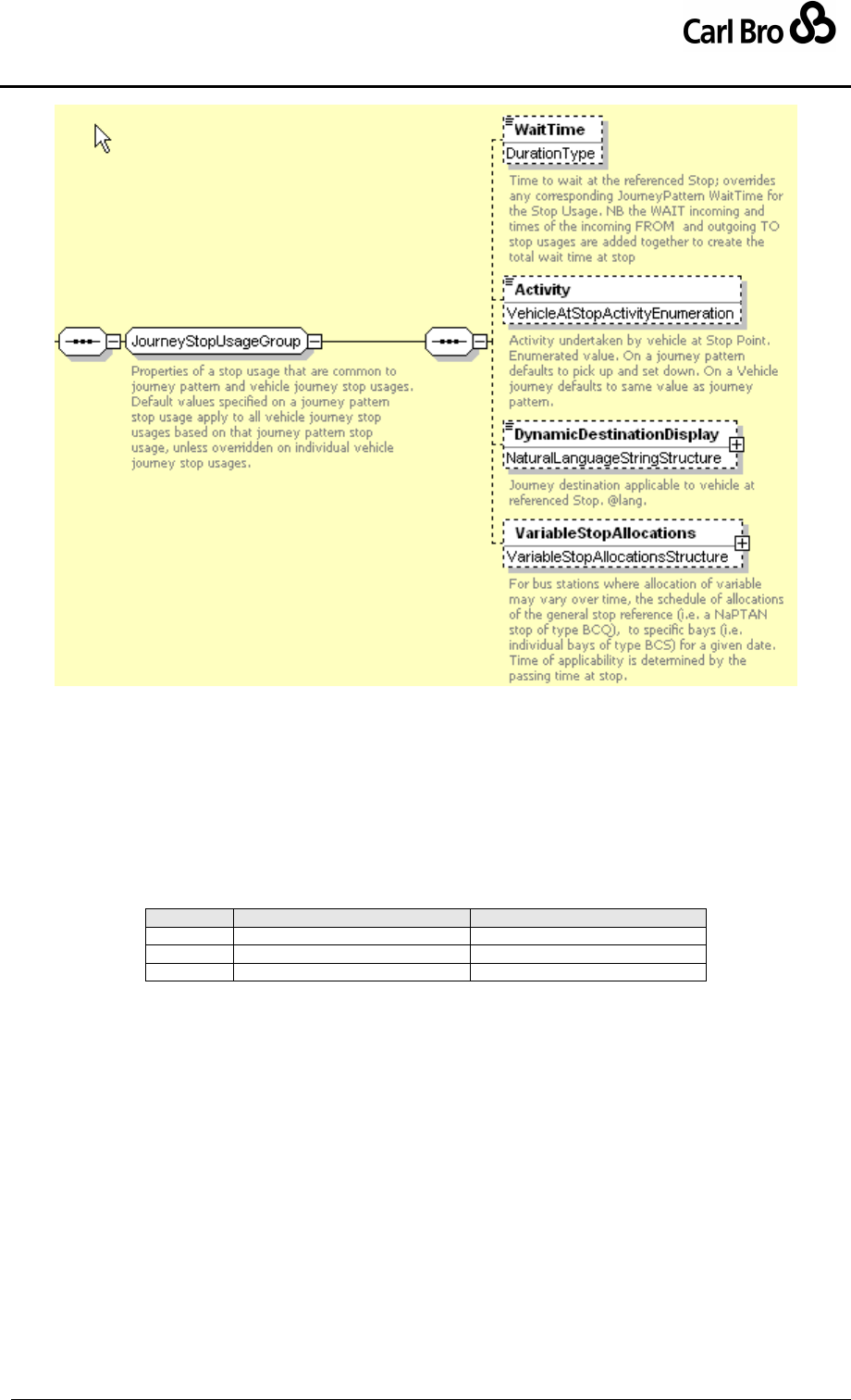
Department for Transport
TransXChange Schema Guide
Part III
Schema Description
TransXChangeSchemaGuide-2.1-v-45.pdf.doc
Page 161
24 September 2013
Figure 6-64 – JourneyPattern / JourneyStopUsageGroup
6.7.7.2 JourneyPatternStopUsage / JourneyPatternStopUsageGroup
The JourneyPatternStopUsageGroup (Figure 6-65) holds information specific to a
JourneyPatternStopUsage:
StopPointRef: NaPTAN Stop at which timing link starts or ends.
TimingStatus: Classification of the role of the stop as a timing point used by the
journey pattern. See Table 6-17. Overrides the classification defined by the stop in
NaPTAN.
Value
Long Value
Description
PTP
principalTimingPoint
Principal and time info point.
TIP
timeInfoPoint
Time Info Point.
OTH
otherPoint
Other Bus Stop.
Table 6-17 – Allowed Values for TimingStatus
FareStageNumber: The fare stage number for the referenced stop. A fare stage
number should be specified if the fare stage is different from that on the previous
link.
FareStage: Whether a fare stage is encountered while traversing the end of the
timing link. This should correspond to the value implied by the FareStageNumber. If
the two are in conflict, then the FareStageNumber will be assumed to be correct.
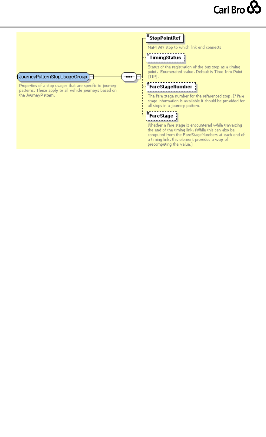
Department for Transport
TransXChange Schema Guide
Part III
Schema Description
TransXChangeSchemaGuide-2.1-v-45.pdf.doc
Page 162
24 September 2013
Figure 6-65 – JourneyPattern / JourneyPatternStopUsageGroup
6.7.7.3 VariableStopAllocations Element
The VariableStopAllocations element (Figure 6-66) describes the variable allocation of
bays in a bus station. It can be used to assign to assign specific bays for a service on
specific dates. It comprises zero or more VariableStopAllocation elements, each
specifying an individual allocation on a given date. The time of allocation is the passing time
of the service at the stop. Normally the assigning stop will be of stop type ‘BCQ’ (Bus /
Coach Station Variable Bay), the assigned stops of type ‘BCT’ (Bus / Coach Station Bay).
DateRange: A collection of one or more open-ended date ranges, and any number
of date exceptions.
o StartDate: The (inclusive) start date. If omitted, the range start is open-
ended, that is, it should be interpreted as "since the beginning of the service
validity period".
o EndDate: The (inclusive) end date. If omitted, the range end is open-ended,
that is, it should be interpreted as "until end of the service validity period"
(which may be indefinite).
VariableStopPoint: Bay or bays to which service is allocated for the specified date
(and time of the service). Normally will be a NaPTAN stop of type ‘BCT (Bus / Coach
Station Bay)’. If more than one stop is specified, then bays are considered to be a
pool that can be used on a first come first serve basis.
o StopPointRef: NaPTAN Identifier of a StopPoint.
DefaultStopAllocation: Bay or pool of bays to use if no date-specific
VariableStopAllocation is applicable for a given date.
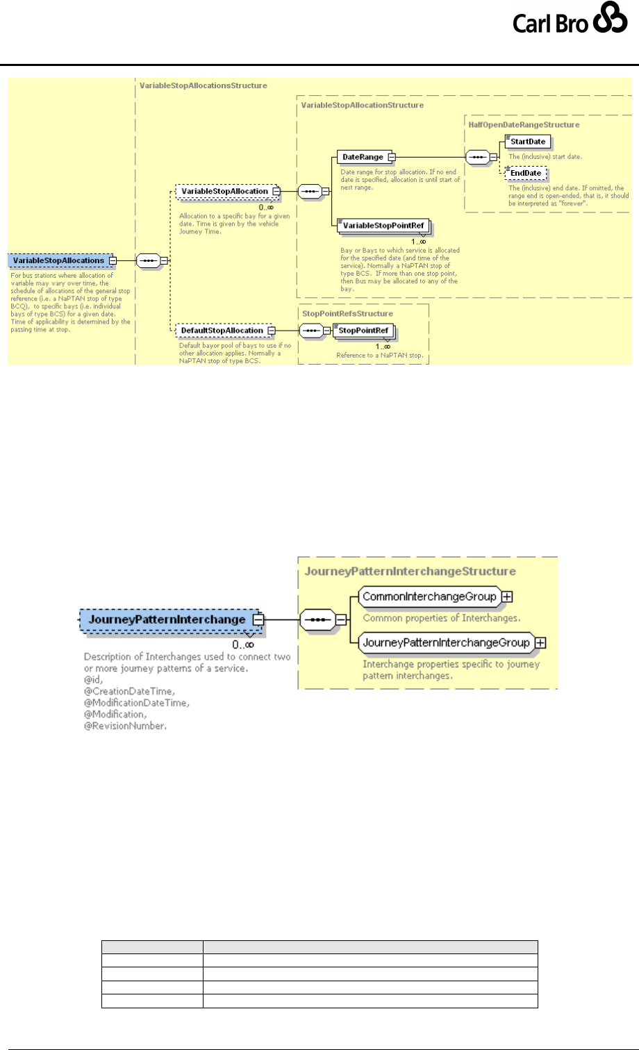
Department for Transport
TransXChange Schema Guide
Part III
Schema Description
TransXChangeSchemaGuide-2.1-v-45.pdf.doc
Page 163
24 September 2013
Figure 6-66 – JourneyPattern / VariableStopAllocation Element
6.7.8 JourneyPatternInterchange Element
The JourneyPatternInterchange element (Figure 6-67) describes an interchange
connecting two JourneyPatterns. Each interchange can be identified by a unique id
attribute, and comprises a number of elements, falling into two groups:
1. CommonInterchangeGroup: Shared elements common to journey pattern
interchanges and vehicle journey interchanges. See below.
2. JourneyPatternInterchangeGroup: Elements specific to vehicle journey
interchanges. See below.
Figure 6-67 – JourneyPatternInterchange Element
6.7.8.1 JourneyPatternInterchange / CommonInterchangeGroup
The CommonInterchangeGroup (Figure 6-68) holds information that is common to both a
JourneyPatternInterchange and a VehicleJourneyInterchange.
MinInterchangeTime: Minimum time to allow for changing services at the
interchange.
MaxInterchangeTime: Maximum time that connecting service will wait at the
interchange.
TransferMode: Method of transport used to make transfer between inbound and
outbound journeys at the interchange. See Table 6-18.
Value
Description
walk
Walk transfer.
bus
Bus transfer.
train
Train transfer.
tram
Tram transfer.
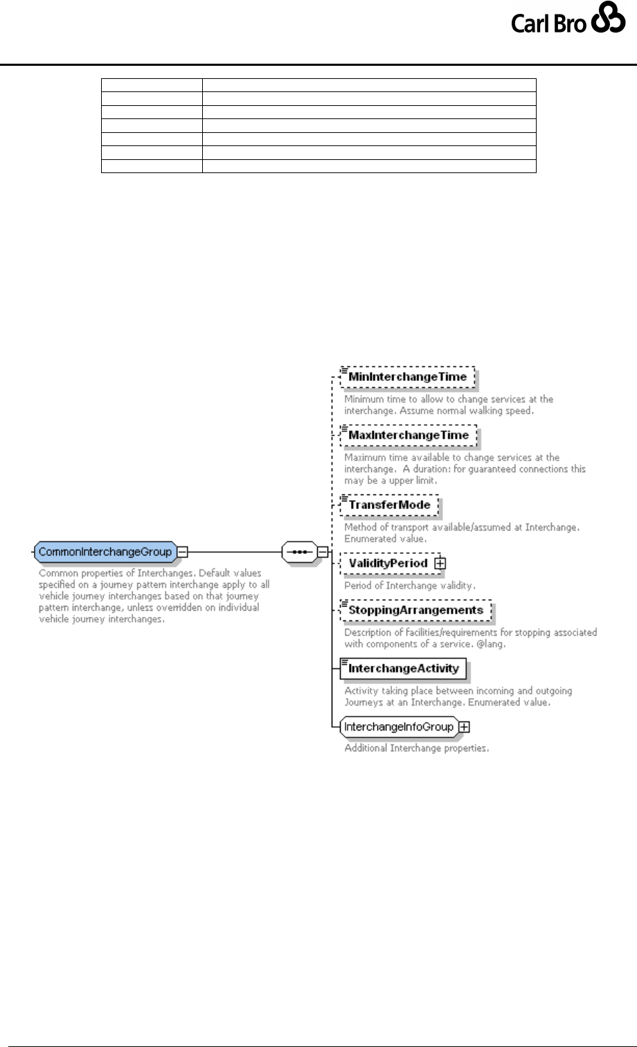
Department for Transport
TransXChange Schema Guide
Part III
Schema Description
TransXChangeSchemaGuide-2.1-v-45.pdf.doc
Page 164
24 September 2013
metro
Metro transfer.
coach
Coach transfer.
ferry
Ferry transfer.
air
Air transfer.
taxi
Taxi transfer.
cycle
Cycle transfer.
movingWalkway
Moving Walkway transfer.
Table 6-18 – Allowed Values for TransferMode
ValidityPeriod: Period when the interchange is valid.
o StartDate: Inclusive date of start of validity period.
o EndDate: Inclusive date of end of validity period.
StoppingArrangements: Text description of stopping arrangements for the
interchange.
InterchangeActivity: Activity taking place between incoming and outgoing
VehicleJourney instances at an interchange. See Table 6-19.
InterchangeInfoGroup: Additional information about the nature of the interchange.
See below.
Figure 6-68 – CommonInterchangeGroup
6.7.8.2 JourneyPatternInterchange / InterchangeInfoGroup
The InterchangeInfoGroup (Figure 6-69) holds additional information about the nature of
the interchange.
CrossBorder: Whether the connection crosses a border.
GuaranteedConnection: Whether the connection is guaranteed.
ChangeLineNumber: Whether the service changes number at the connection.
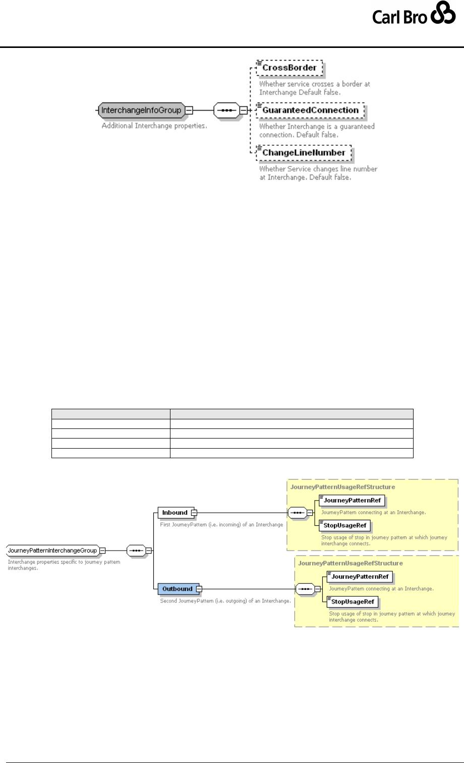
Department for Transport
TransXChange Schema Guide
Part III
Schema Description
TransXChangeSchemaGuide-2.1-v-45.pdf.doc
Page 165
24 September 2013
Figure 6-69 – JourneyPatternInterchange / InterchangeInfoGroup
6.7.8.3 JourneyPatternInterchange / JourneyPatternInterchangeGroup
The JourneyPatternInterchangeGroup holds elements that are specific to a
JourneyPatternInterchange, and describe the connection between two journeys.
Inbound
o JourneyPatternRef: Incoming JourneyPattern that connects to the
interchange.
o StopUsageRef: Reference to the JourneyPatternStopUsage of the
JourneyPatternTimingLink that connects inbound JourneyPattern to the
interchange.
Outbound
o JourneyPatternRef: Ongoing JourneyPattern that connects from the
interchange.
o StopUsageRef: Reference to the JourneyPatternStopUsage of the
JourneyPatternTimingLink that connects the outbound JourneyPattern to
the interchange.
Value
Description
change
Service changes at interchange
join
Service joins at interchange.
split
Service splits at interchange.
through
Through journey.
Table 6-19 – Allowed Values for InterchangeActivity
Figure 6-70 – JourneyPatternInterchange / JourneyPatternInterchangeGroup
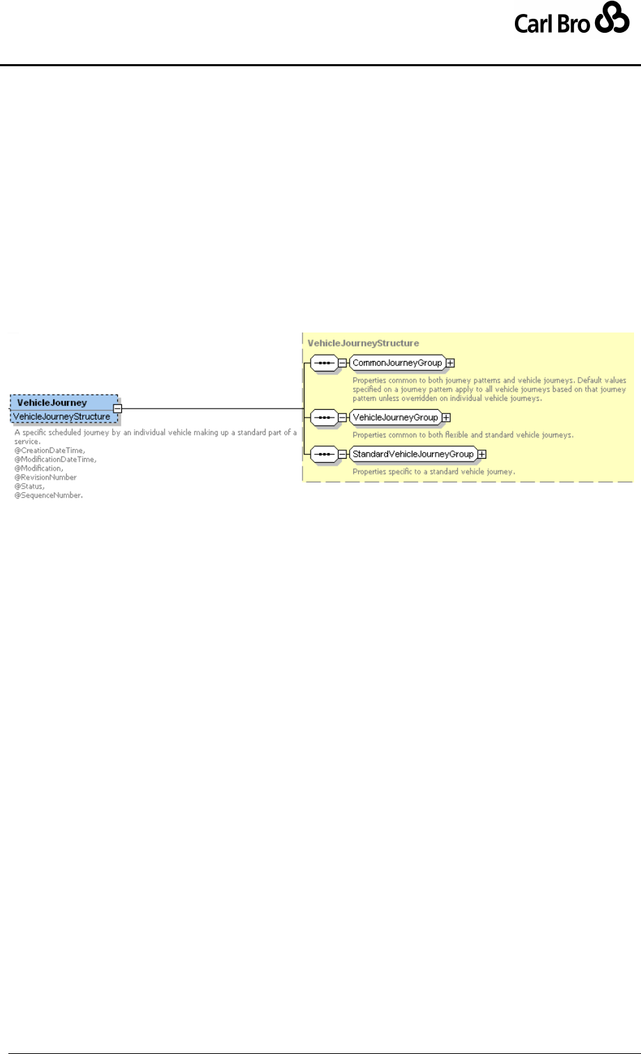
Department for Transport
TransXChange Schema Guide
Part III
Schema Description
TransXChangeSchemaGuide-2.1-v-45.pdf.doc
Page 166
24 September 2013
6.7.9 VehicleJourney Element
A VehicleJourney (Figure 6-71) describes a specific journey of a vehicle following a fixed
JourneyPattern of a StandardService. The JourneyPattern comprises one or more
VehicleJourneyTimingLink elements: the order of links represents the order in which they
are traversed. A VehicleJourney comprises a number of elements; the elements fall into
three groups:
1. CommonJourneyGroup: Shared elements common to journey patterns and vehicle
journeys. See JourneyPattern / CommonJourneyGroup earlier. Allows individual
properties to be overridden on a vehicle journey: if not specified the property from
the journey pattern will be used.
2. VehicleJourneyGroup: Elements specific to vehicle journeys, both fixed and
flexible.
3. StandardVehicleJourneyGroup: Elements specific to fixed route vehicle journeys.
Figure 6-71 – VehicleJourney Element
6.7.9.1 VehicleJourney / VehicleJourneyGroup
The VehicleJourneyGroup (Figure 6-72): holds elements that are common to both fixed
and flexible types of VehicleJourney.
VehicleJourneyCode: A unique code that can be used to identify the
VehicleJourney.
ServiceRef: The Service to which the VehicleJourney belongs.
LineRef: The Service / Line that the VehicleJourney serves.
Referenced Journey pattern. One of the following:
o JourneyPatternRef: The JourneyPattern over which the VehicleJourney
runs. Route, timing links and other properties will be derived from the
specified journey pattern.
o VehicleJourneyRef: Reuse the VehicleJourneyTimingLink elements of the
referenced VehicleJourney, and follow its JourneyPattern. If a
VehicleJourneyRef is specified, then any VehicleJourneyTimingLink
instances of the dependent VehicleJourney will be ignored.
StartDeadRun: Initial "dead run" for positioning the vehicle before it traverses its
timing links. See below.
EndDeadRun: Final "dead run" link for positioning the vehicle after it traverses its
timing links. See below.
VehicleJourneyInterchange: Interchanges where the vehicle journey connects with
another vehicle journey. See later.
Note: Any additional notes on the VehicleJourney. See below.
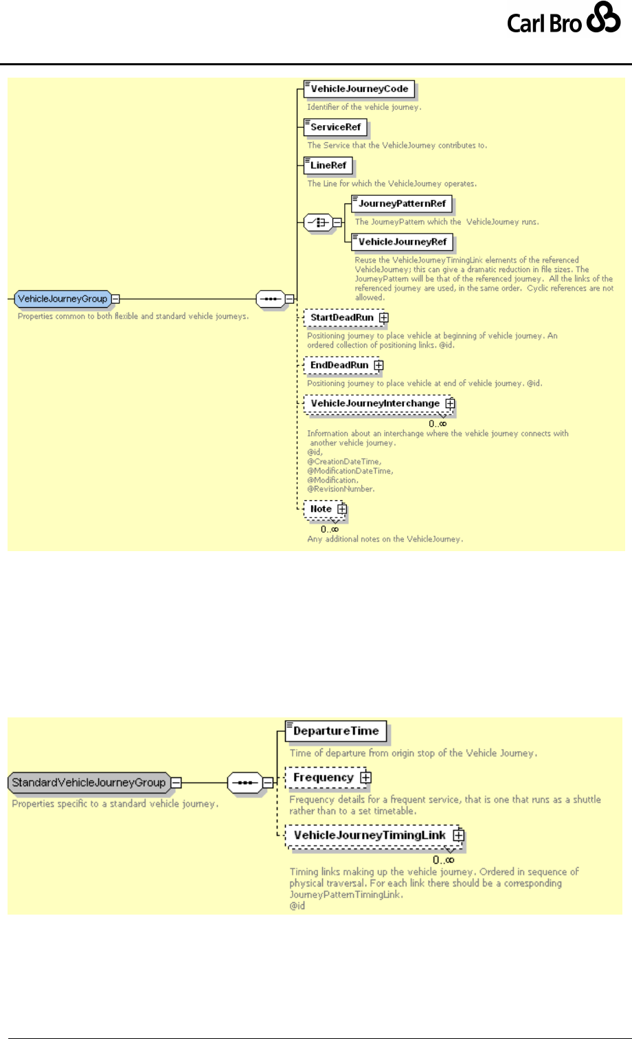
Department for Transport
TransXChange Schema Guide
Part III
Schema Description
TransXChangeSchemaGuide-2.1-v-45.pdf.doc
Page 167
24 September 2013
Figure 6-72 – VehicleJourney / VehicleJourneyGroup
6.7.9.2 VehicleJourney / StandardVehicleJourneyGroup
The StandardVehicleJourneyGroup (Figure 6-73) holds elements that are specific to fixed
VehicleJourney instances:
DepartureTime: Time of departure from origin stop of the VehicleJourney.
Frequency: Describes service frequency for frequency based services. See below.
VehicleJourneyTimingLink: An ordered collection of timing links making up the
VehicleJourney. See VehicleJourneyTimingLink later.
Figure 6-73 – VehicleJourney / StandardVehicleJourneyGroup
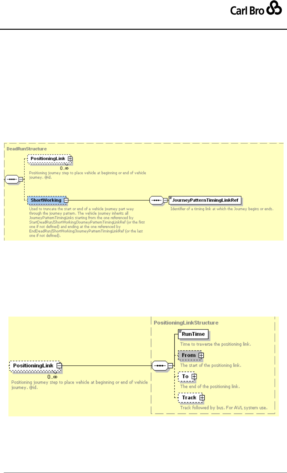
Department for Transport
TransXChange Schema Guide
Part III
Schema Description
TransXChangeSchemaGuide-2.1-v-45.pdf.doc
Page 168
24 September 2013
6.7.10 Common VehicleJourney Subelements
6.7.10.1 VehicleJourney / DeadRun Element
A DeadRun (Figure 6-74) models a StartDeadRun or EndDeadRun, that is, a positioning
run at the start or end of a journey; it is used to place a vehicle in position to start the
service, or to retrieve it at the end of the journey.
It comprises:
PositioningLink: One or more links describing how the vehicle travels to or from the
route. See below.
ShortWorking: If the dead run intercepts the journey pattern at a point, identifies the
start or end point on the journey pattern at which the interception happens. May be
used even if no positioning link is specified.
o JourneyPatternTimingLinkRef: Link at which journey starts or finishes.
Figure 6-74 – VehicleJourney / DeadRun Element
6.7.10.2 VehicleJourney / PositioningLink Element
A PositioningLink (Figure 6-75) models a step of a DeadRun. It comprises:
RunTime: Time taken to traverse link.
From: From point, a stop, garage, or location. See PositioningLinkUsage below.
To: To point; also a stop, garage, or location. See PositioningLinkUsage below.
Track: Path taken by vehicle when traversing the positioning link. See RouteLink /
Track element earlier.
Figure 6-75 – DeadRun / PositioningLink Element
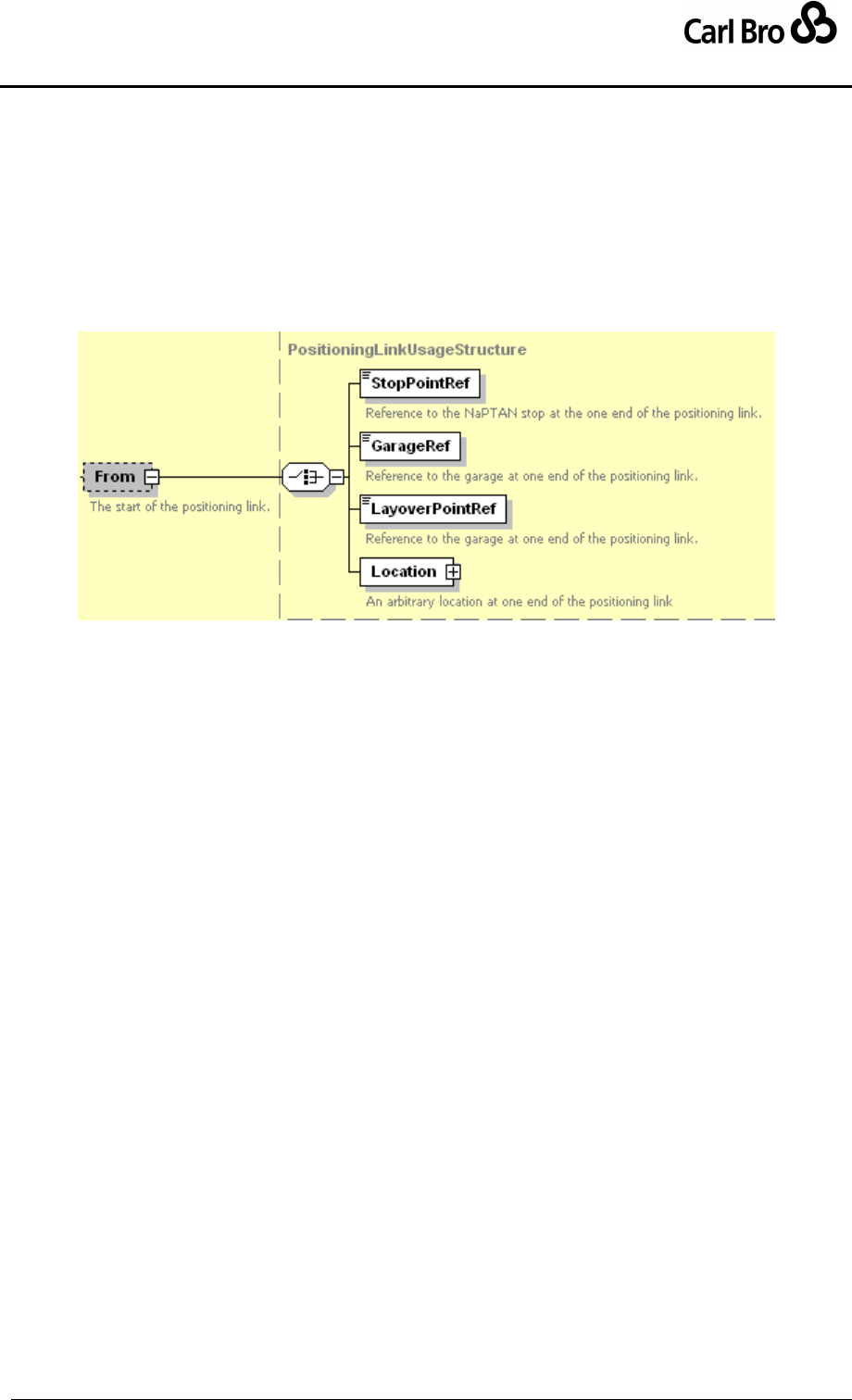
Department for Transport
TransXChange Schema Guide
Part III
Schema Description
TransXChangeSchemaGuide-2.1-v-45.pdf.doc
Page 169
24 September 2013
6.7.10.3 VehicleJourney / PositioningLink / PositioningStopUsageStructure
A PositioningLinkUsage (Figure 6-76) models one end of a PositioningLink. It comprises
one of the following:
StopPointRef: A NaPTAN stop point. Usually on the journey pattern, but can be
completely arbitrary – e.g. a stop on another route from which the bus is coming.
GarageRef: A Garage defined for the operator of the Service. to which vehicle
journey belongs
LayoverPointRef: A LayoverPoint defined for the JourneyPattern.
Location: An arbitrary location specified by spatial coordinates.
Figure 6-76 – DeadRun / PositioningLinkUsageStructure
6.7.10.4 VehicleJourney / Frequency Element
Frequency (Figure 6-77) gives details about a frequency based service, that is, one that
runs as a shuttle rather than to a set timetable.
EndTime: Describes when the frequency based period ends.
The frequency can be specified in one of two ways:
Interval: Describes the expected frequency of a service in quantitative terms as an
interval. Comprises:
o ScheduledFrequency: The scheduled time gap between departures.
o MinimumFrequency: The minimum time gap between departures.
o MaximumFrequency: The maximum time gap between.
Minutes past the hour: Describes the expected frequency of a service in
quantitative terms. Comprises:
o Minutes: One or more times past the hour.
FrequentService: Formally declares the journey to be a frequent service, with an
interval of at least once every 10 minutes. A minimum frequency should be specified.
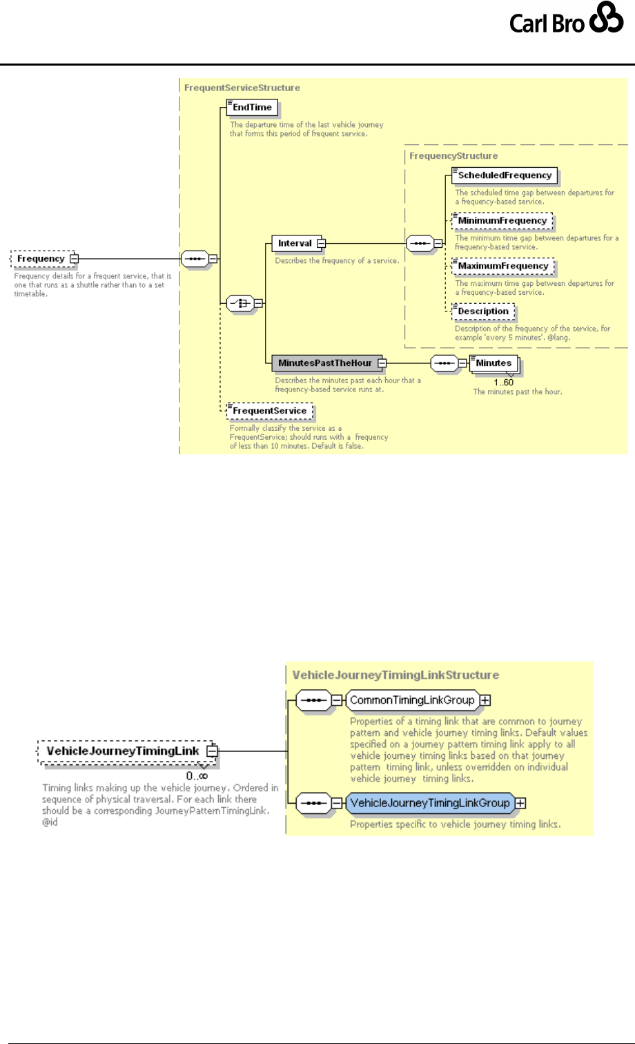
Department for Transport
TransXChange Schema Guide
Part III
Schema Description
TransXChangeSchemaGuide-2.1-v-45.pdf.doc
Page 170
24 September 2013
Figure 6-77 – VehicleJourney / Frequency Element
6.7.11 VehicleJourneyTimingLink Element
A VehicleJourneyTimingLink (Figure 6-78) models the link between two stops of a vehicle
journey. Each VehicleJourneyTimingLink can be identified by a unique id attribute, and
comprises a number of elements. The elements fall into two groups:
1. CommonTimingLinkGroup: Shared elements common to journey pattern timing
links and vehicle journey timing links. See JourneyPatternTimingLink /
CommonTimingLinkGroup earlier.
2. VehicleJourneyTimingLinkGroup: Elements specific to vehicle journey timing
links.
Figure 6-78 – VehicleJourneyTimingLink Element
6.7.11.1 VehicleJourneyTimingLink / VehicleJourneyTimingLinkGroup
The VehicleJourneyTimingLinkGroup (Figure 6-79) holds information is specific to a
VehicleJourneyTimingLink:
JourneyPatternTimingLinkRef: Reference to a JourneyPatternTimingLink onto
which timing link projects, and which defines the origin and destination points of the
link. See JourneyPatternTimingLink earlier.
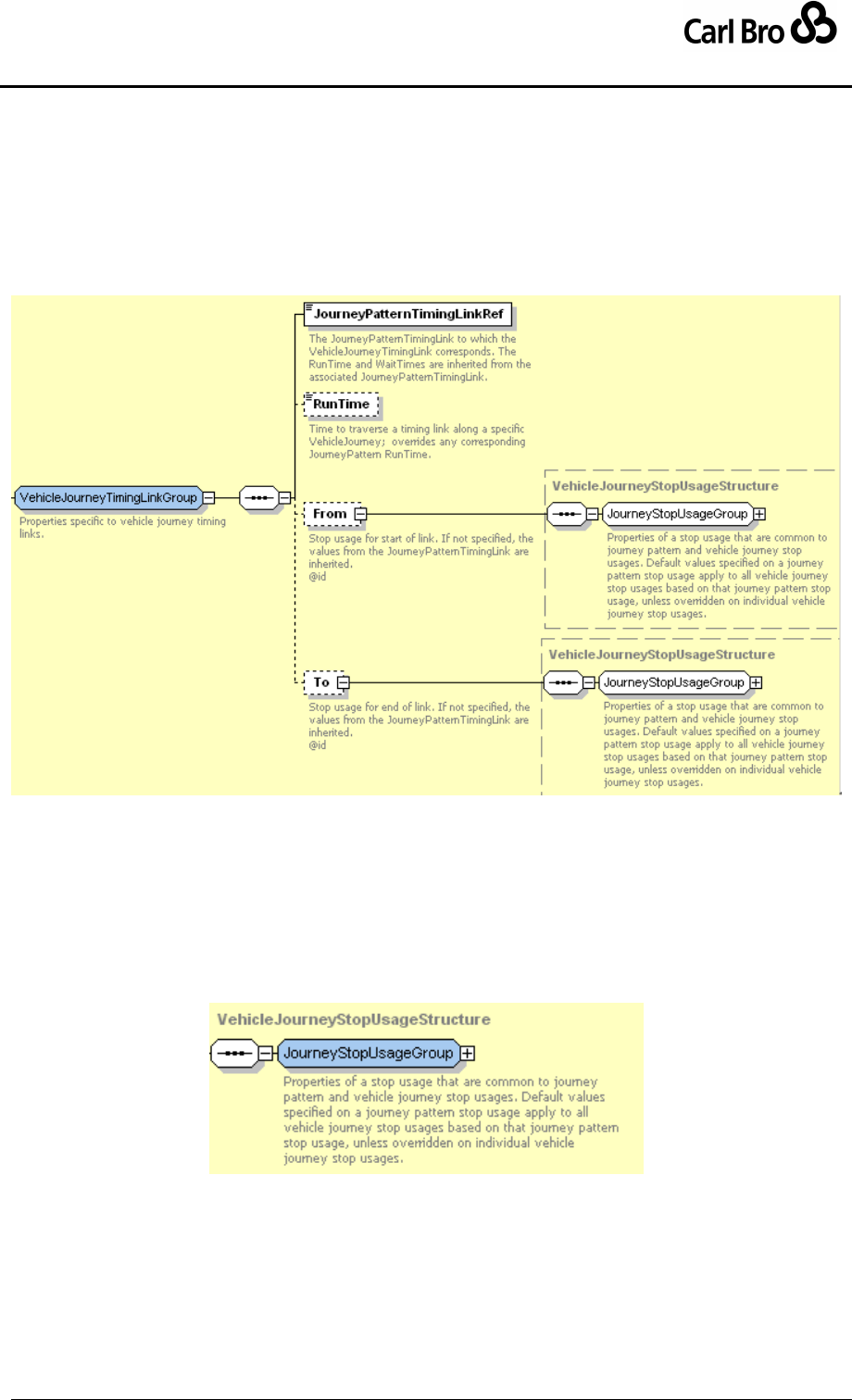
Department for Transport
TransXChange Schema Guide
Part III
Schema Description
TransXChangeSchemaGuide-2.1-v-45.pdf.doc
Page 171
24 September 2013
RunTime: Time taken to traverse link. Defaults to value specified for
JourneyPatternTimingLink.
From: Usage details of from stop, specified by a VehicleJourneyStopUsage
element. This projects onto the From / JourneyPatternStopUsage of the
corresponding JourneyPatternTimingLink.
To: Usage details of from stop, specified by a VehicleJourneyStopUsage element.
This projects onto the To / JourneyPatternStopUsage of the corresponding
JourneyPatternTimingLink.
Figure 6-79 – VehicleJourneyTimingLinkGroup
6.7.12 VehicleJourneyTimingLink / VehicleJourneyStopUsage Element
The VehicleJourneyStopUsageStructure (Figure 6-65) describes the use of a stop by the
start or end of a VehicleJourneyTimingLink. The VehicleJourneyStopUsage can be
identified by a unique id attribute, and comprises a JourneyStopUsageGroup: see
JourneyPatternStopUsage earlier. Any values specified override the values specified for
the underlying journey pattern.
Figure 6-80 – VehicleJourneyStopUsage Element
6.7.13 VehicleJourneyTimingLink / VehicleJourneyInterchange Element
The VehicleJourneyInterchange element (Figure 6-81) records information about an
interchange at which the vehicle journey connects with another vehicle journey. Each
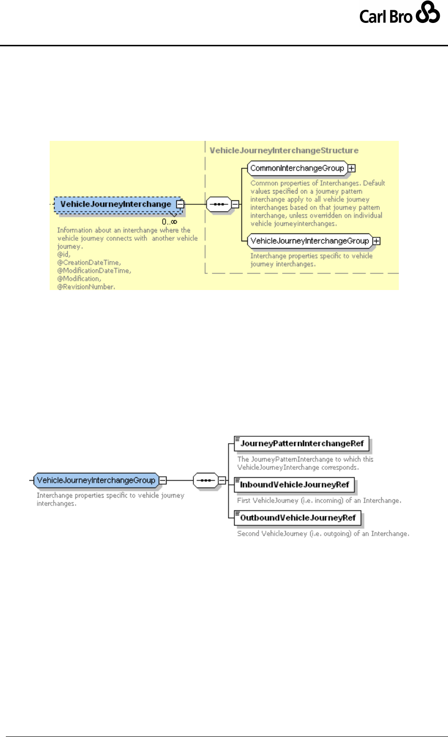
Department for Transport
TransXChange Schema Guide
Part III
Schema Description
TransXChangeSchemaGuide-2.1-v-45.pdf.doc
Page 172
24 September 2013
interchange can be identified by a unique id attribute, and comprises a number of elements,
falling into two groups:
1. CommonInterchangeGroup: Shared elements common to journey pattern
interchange and vehicle journey interchange elements. See
JourneyPatternInterchange / CommonInterchangeGroup element earlier.
2. VehicleJourneyInterchangeGroup: Elements specific to vehicle journey
interchange elements. See below.
Figure 6-81 – VehicleJourneyInterchange Element
6.7.13.1 VehicleJourneyTimingLink / VehicleJourneyInterchangeGroup
The VehicleJourneyInterchangeGroup (Figure 6-82) holds elements that are specific to a
VehicleJourneyInterchange:
JourneyPatternInterchangeRef: The JourneyPatternInterchange to which this
VehicleJourneyInterchange corresponds.
InboundVehicleJourneyPatternRef: The VehicleJourney of the incoming journey
that connects at the interchange.
OutboundVehicleJourneyPatternRef: The VehicleJourney of the ongoing journey
that connects at the interchange.
Figure 6-82 – VehicleJourneyInterchangeGroup
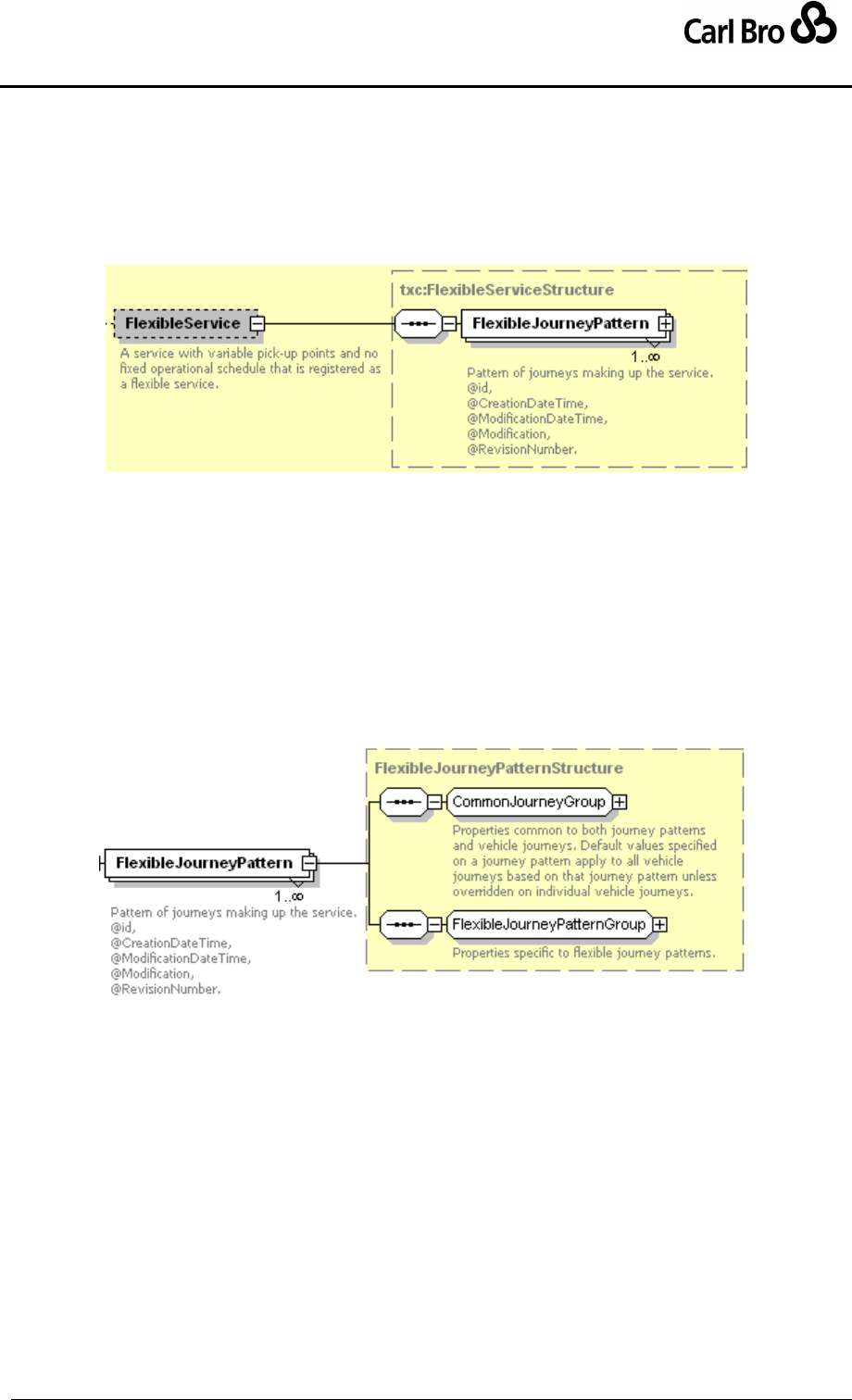
Department for Transport
TransXChange Schema Guide
Part III
Schema Description
TransXChangeSchemaGuide-2.1-v-45.pdf.doc
Page 173
24 September 2013
6.8 FlexibleService, FlexibleJourneyPattern, FlexibleVehicleJourney
6.8.1 FlexibleService Element
The FlexibleService element (Figure 6-83) describes the flexibly routed component of a
Service, using one or more FlexibleJourneyPattern instances.
Figure 6-83 – FlexibleService Element
6.8.1.1 FlexibleJourneyPattern Element
The FlexibleJourneyPattern element (Figure 6-85) describes the availability of a flexibly
routed journey of a Service. It is made up of two parts:
1. CommonJourneyGroup: Shared elements common to journey patterns and fixed
and flexible vehicle journeys. See JourneyPattern / CommonJourneyGroup
earlier. The JourneyPattern instances provide default values to use on dependent
FlexibleVehicleJourney instances if no specific override is provided on an
individual FlexibleVehicleJourney.
2. FlexibleJourneyPatternGroup: Elements specific to flexible journey patterns.
Figure 6-84 – FlexibleJourneyPattern Element
6.8.1.2 FlexibleJourneyPattern / FlexibleJourneyPatternGroup
The FlexibleJourneyPatternGroup (Figure 6-85) holds elements specific to a flexible
journey pattern that describes the area of flexible operation and comprises as follows:
FlexibleZones: Describes the zones that the service covers. See
FlexibleStopUsage below.
FixedStopPoints: Describes any fixed stops that can be visited by the service.
See FixedStopUsage below.
BookingArangements: Arrangements for booking the service. See below.
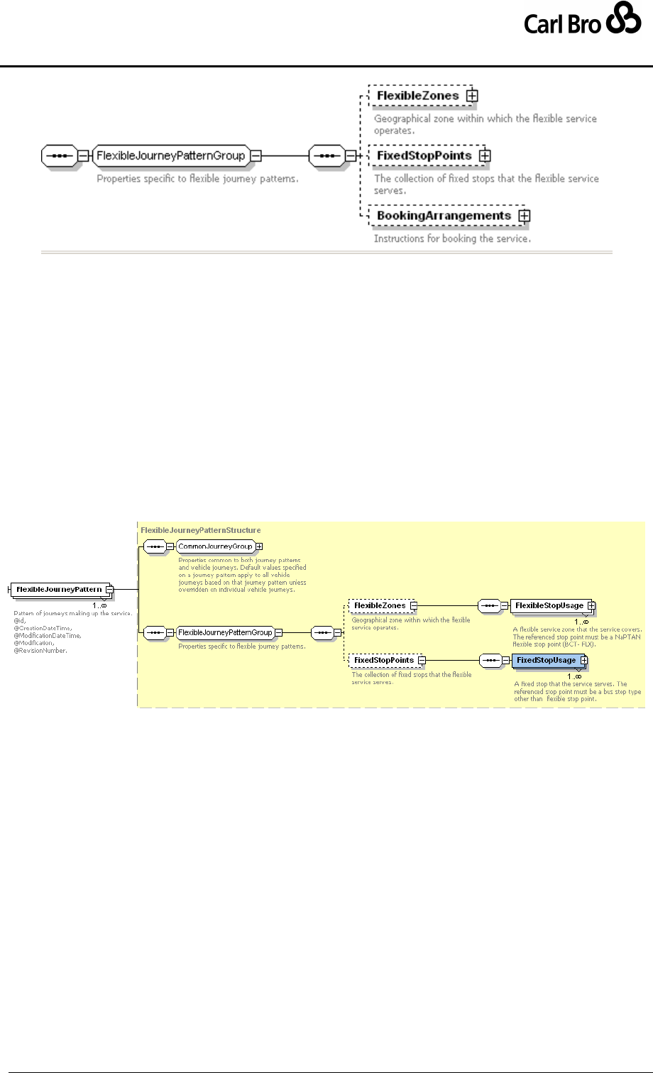
Department for Transport
TransXChange Schema Guide
Part III
Schema Description
TransXChangeSchemaGuide-2.1-v-45.pdf.doc
Page 174
24 September 2013
Figure 6-85 – FlexibleJourneyPattern Element
6.8.2 FlexibleService Subelements
6.8.2.1 FlexibleService / StopUsage Element
A flexible journey pattern describes the areas and stops covered by a flexible service as two
lists: one of flexible zones, and one of fixed stops (Figure 6-86).
FlexibleZones, Comprises a collection of FlexibleStopUsage instances: each is a
FlexibleStopUsageStructure (see below) instance with an activity (e.g. pick up, set
down), and a reference to a NaPTAN stop of type FlexibleZone.
FixedStopPoints: An ordered collection of FixedStopUsage instances: each is a
JourneyPatternStopUsageStructure (see earlier) instance with an activity (e.g.
pick up, set down), and a reference to a NaPTAN fixed stop, i.e. of any type such as
MarkedPoint, other than FlexibleZone.
Figure 6-86 – FlexibleServicePointsStructure Element
6.8.2.2 FlexibleService / FlexibleStopUsage Element
The FlexibleStopUsage element (Figure 6-87) describes a flexible journey stop.
Activity: Activity undertaken by vehicle at stop. See Table 6-16. Defaults to pick up
and set down.
StopPointRef: NaPTAN Stop at which timing link starts or ends.
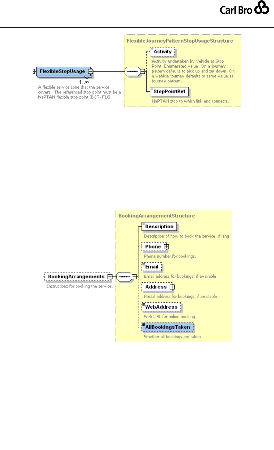
Department for Transport
TransXChange Schema Guide
Part III
Schema Description
TransXChangeSchemaGuide-2.1-v-45.pdf.doc
Page 175
24 September 2013
Figure 6-87 – FlexibleService / FlexibleStopUsage Element
6.8.2.3 FlexibleVehicleJourneyGroup / BookingArrangements Element
The BookingArrangements element (Figure 6-88) describes the booking arrangements
for the flexible service:
Description: Text description of booking process.
Phone: Phone number by which to make bookings. See
TelephoneContactStructure.
Email: Email address to which to make bookings.
Address: Postal address by which to make bookings. See
PostalAddressStructure.
WebAddress: URL of online web site by which make bookings.
AllBookingsTaken: Whether all bookings are taken. Default is true.
Figure 6-88 – FlexibleVehicleJourney / BookingArrangements Element
6.8.3 FlexibleVehicleJourney Element
The FlexibleVehicleJourney element (Figure 6-89) describes the availability of a flexible
journey. It adds time information to a FlexibleJourneyPattern instance. A
FlexibleVehicleJourney comprises a number of elements; the elements fall into three
groups:
1. CommonJourneyGroup: Shared elements common to journey patterns and vehicle
journeys (See JourneyPattern / CommonJourneyGroup earlier).
2. VehicleJourneyGroup: Elements specific to both fixed and flexible vehicle journeys
(See VehicleJourney / VehicleJourneyGroup earlier).
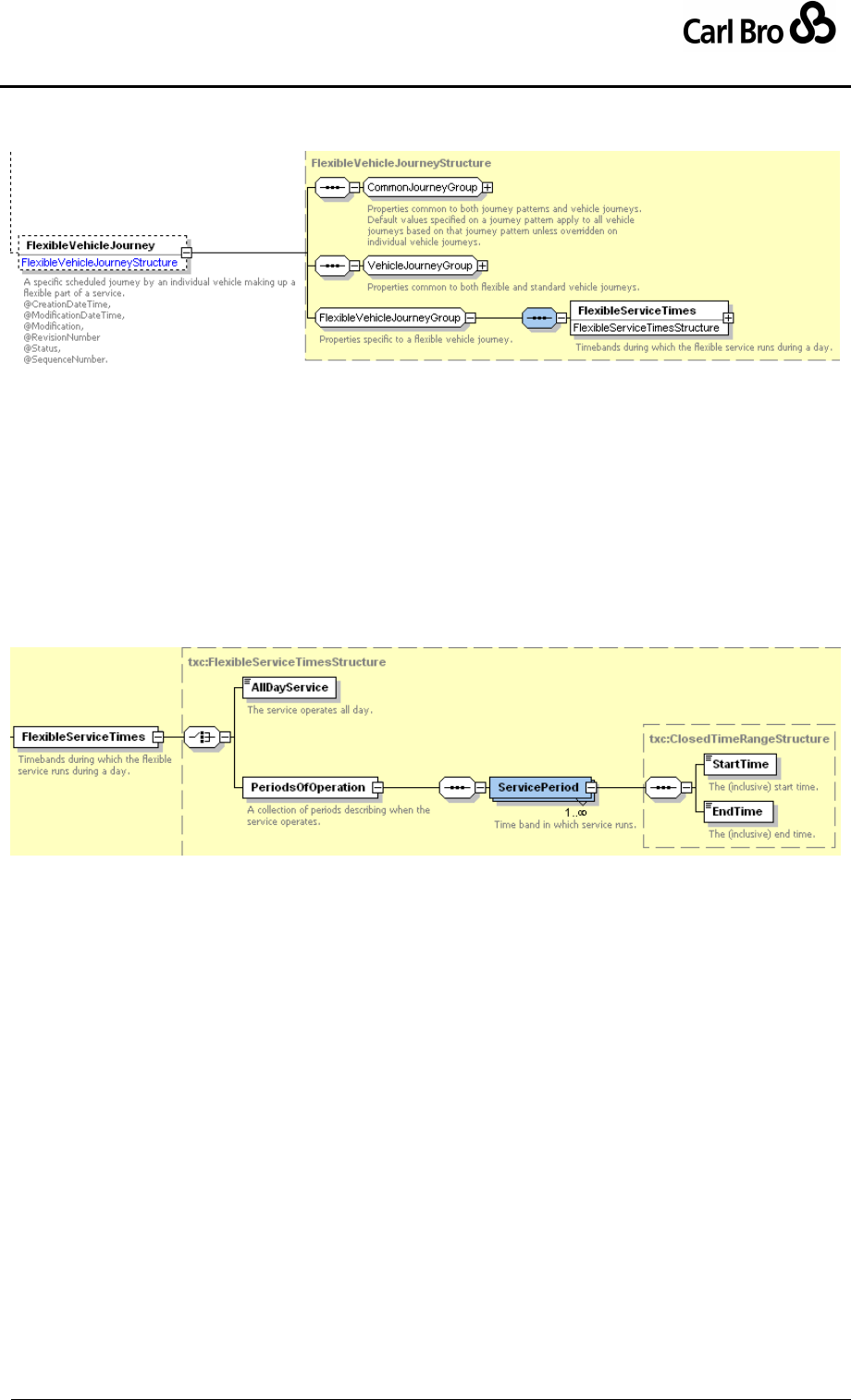
Department for Transport
TransXChange Schema Guide
Part III
Schema Description
TransXChangeSchemaGuide-2.1-v-45.pdf.doc
Page 176
24 September 2013
3. FlexibleVehicleJourneyGroup: Elements specific to flexible route vehicle journeys:
See FlexibleVehicleJourneyGroup / FlexibleServiceTimes below.
Figure 6-89 – FlexibleVehicleJourney
6.8.3.1 FlexibleVehicleJourneyGroup / FlexibleServiceTimes Element
The FlexibleServiceTimes element (Figure 6-90) describes the operational days of the
service.
FlexibleServiceTimes may either be:
AllDayService: Indicating the service runs all day, or
PeriodsOfOperation: A collection of at least one ServicePeriod element, made up
of:
o StartTime: Time at which time band starts.
o EndTime: Time at which time band ends.
Figure 6-90 – FlexibleVehicleJourney / FlexibleServiceTimes Element

Department for Transport
TransXChange Schema Guide
Part III
Schema Description
TransXChangeSchemaGuide-2.1-v-45.pdf.doc
Page 177
24 September 2013
6.9 Operational Days & Times
In this section we describe the schema elements used to specify operational dates and
times in TransXChange. These are common to both Flexible and Standard services. See
also the earlier section 3.15 on Modelling Operational days, which sets out the rules used
for combining the various day type and date elements.
6.9.1 OperatingProfile Element
The OperatingProfile element (Figure 6-91) specifies on which days a service operates. An
OperatingProfile can be specified on both a VehicleJourney, a JourneyPattern and on a
Service; the VehicleJourney values override those of the JourneyPattern or Service. It is
made up of two groups:
1. Normal operating profile group: describes normal regular behaviour.
2. Special operating profile group: describes behaviour on bank holidays and other
exceptional days.
6.9.1.1 Normal OperatingProfileGroup
The OperatingProfile normal elements describe the regular operation of the service and
comprise the following elements:
RegularDayType: specifies the days on which the service normally runs. See
below. Defaults to MondayToSunday.
PeriodicDayType: qualifies the RegularDayType days with any specific weeks of
the month that the service runs. It is ‘anded’ with RegularDayType, so that you may
specify for example ‘Wednesdays, first and third weeks of the month’.
ServicedOrganisationDayType: Specifies that the service runs or does not run on
the working days or holidays of a nominated organisation such as a school or Local
Education Authority. See ServicedOrganisation days below.
ServicedOrganisationDayType is ‘anded’ with RegularDayType and any
PeriodicDayType values.
6.9.1.2 Special OperatingProfileGroup
The OperatingProfile special elements describe exceptions to the normal days of operation
and comprise the following elements:
SpecialDaysOperation: Describes the specific dates (other than standard bank
holiday types) when the service will operate differently from its normal service.
DaysOfOperation and DaysOfNonOperation can be specified separately. See
below.
BankHolidayOperation: Describes how the service will operate on bank holidays.
DaysOfOperation and DaysOfNonOperation can be specified separately. See
below.
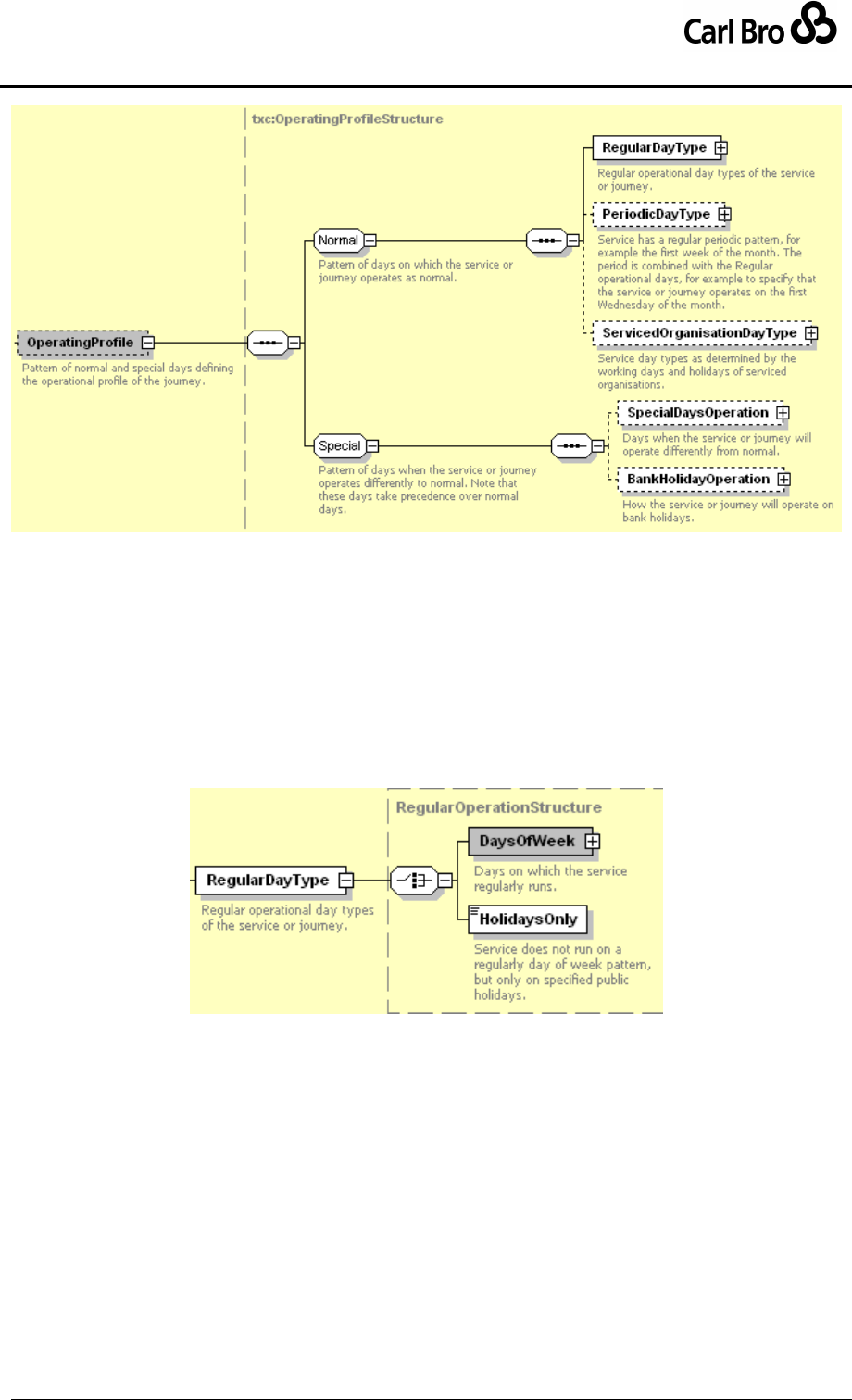
Department for Transport
TransXChange Schema Guide
Part III
Schema Description
TransXChangeSchemaGuide-2.1-v-45.pdf.doc
Page 178
24 September 2013
Figure 6-91 – OperatingProfile Element
6.9.2 OperatingProfile Subelements
6.9.2.1 OperatingProfile / RegularDayType Element
The RegularDayType element (Figure 6-92) specifies the normal days of operation of the
associated service, journey pattern or vehicle journey. It comprises either:
DaysOfWeek: Week days on which service operates. See below.
HolidaysOnly: Service only runs on holidays specified by OperatingProfile special
elements.
Figure 6-92 – OperatingProfile / RegularDayType Element
6.9.2.2 OperatingProfile / RegularDayType / DaysOfWeek Element
The DaysOfWeek element specifies any combination of day types using a DayGroup
structure (Figure 6-93). It allows any meaningful combination of:
Week days:
o Monday, Tuesday, Wednesday, Thursday, Friday, Saturday, Sunday
Groups of days:
o MondayToFriday, MondayToSaturday, MondayToSunday, NotSaturday
o Weekend: Saturday and Sunday.
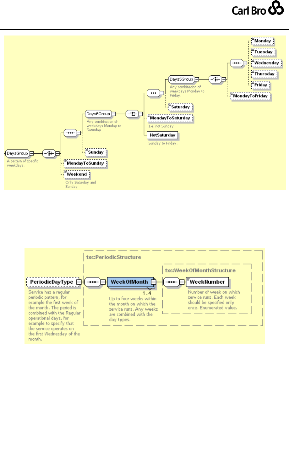
Department for Transport
TransXChange Schema Guide
Part III
Schema Description
TransXChangeSchemaGuide-2.1-v-45.pdf.doc
Page 179
24 September 2013
Figure 6-93 – OperatingProfile / DaysOfWeek Element
6.9.2.3 OperatingProfile / PeriodicDayType / WeekOfMonth Element
The PeriodicDayType / WeekOfMonth element (Figure 6-94) specifies any combination of
week types within a month, using up to four WeekNumber elements, i.e. any subset of four
elements out of the set of numbers 1, 2,3,4,5. The week numbers are combined with the
day type, for example: 'First Wednesday in the month'.
Figure 6-94 – OperatingProfile / WeekOfMonth Element
6.9.2.4 SpecialDaysOperation Element: DaysOfOperation, DaysOfNonOperation
The SpecialDaysOperation element (Figure 6-95) describes specific dates when a service
does or does not operate (other than Bank Holiday day types), and comprises two
collections of DateRange elements, wrapped in DaysOfOperation and
DaysOfNonOperation elements respectively. If conflicting dates are specified, days of non-
operation are given precedence.
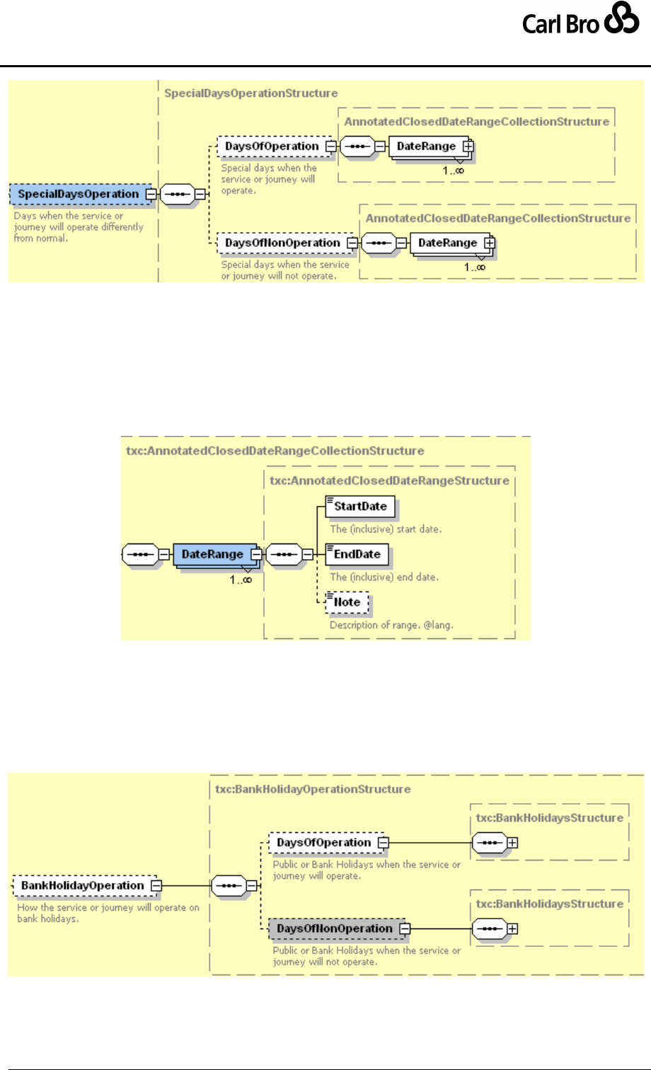
Department for Transport
TransXChange Schema Guide
Part III
Schema Description
TransXChangeSchemaGuide-2.1-v-45.pdf.doc
Page 180
24 September 2013
Figure 6-95 – OperatingProfile / SpecialDaysOfOperation
Element
6.9.2.5 DateRange
The DateRange element (Figure 6-96) describes a period. Each range is specified with:
StartDate: Inclusive date on which period starts.
EndDate: Inclusive date on which period ends.
Note: Annotation about period.
Figure 6-96 – DateRange Element
6.9.2.6 OperatingProfile / BankHolidayOperation
The BankHolidayOperation element (Figure 6-97) describes how the service does or does
not operate on bank holidays, and comprises two collections of BankHolidayStructure
elements, wrapped in DaysOfOperation and DaysOfNonOperation elements respectively.
If conflicting dates are specified, days of non-operation are given precedence.
Figure 6-97 – OperatingProfile / BankHolidayOperation Element
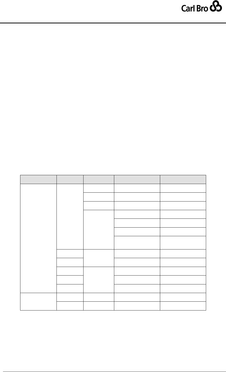
Department for Transport
TransXChange Schema Guide
Part III
Schema Description
TransXChangeSchemaGuide-2.1-v-45.pdf.doc
Page 181
24 September 2013
6.9.2.7 OperatingProfile / BankHoliday Elements
Holiday day types are explicitly enumerated using the BankHolidayOperationStructure
(see Figure 6-98), which allows individual holidays or combinations of holidays to be
enumerated.
Additional special holidays may be defined using OtherBankHoliday.
A special element AllBankHolidays is used to denote all Bank Holidays in the
country in which the service runs. See Table 6-20.
o The HolidayMondays element can be used to denote all the summer Bank
holiday Mondays.
o Christmas can be used to indicate special services for actual ChristmasDay
(strictly the 25th December) and BoxingDay (strictly the 26th December).
o The HolidayMondays element can be used to denote all the summer Bank
holiday Mondays.
o The AllHolidaysExceptChristmas element can be used to denote all the
Bank holidays in the year except for ChristmasDay and BoxingDay.
o DisplacementHolidays can be used to indicate special services for Public
holidays that are awarded when calendar based holidays such as Christmas
Day, Boxing Day or New Year’s Eve fall at a weekend so a compensating
weekday, usually a Monday or Friday, is also made a public holiday.
Sometimes different timetables are used for the Displacement Holiday from
those that would be used for the actual day itself.
EarlyRunOff can be used to indicate special services for Christmas and New Year’s
Eve.
Group
Subgroup
England & Wales
Scotland
AllBankHolidays
AllHolidays
Except
Christmas
NewYearsDay
NewYearsDay
Jan2ndScotland
GoodFriday
GoodFriday
Holiday
Mondays
EasterMonday
EasterMonday
MayDay
MayDay
SpringBank
SpringBank
LateSummerHoliday
NotScotland
AugustBankHoliday
Scotland
Christmas
ChristmasDay
ChristmasDay
BoxingDay
BoxingDay
Displacement
Holidays
ChristmasDayHoliday
ChristmasDayHoliday
BoxingDayHoliday
BoxingDayHoliday
NewYearsDayHoliday
NewYearsDayHoliday
EarlyRunOff
-
ChristmasEve
ChristmasEve
-
NewYearsEve
NewYearsEve
Table 6-20 – AllBankHolidays by Country
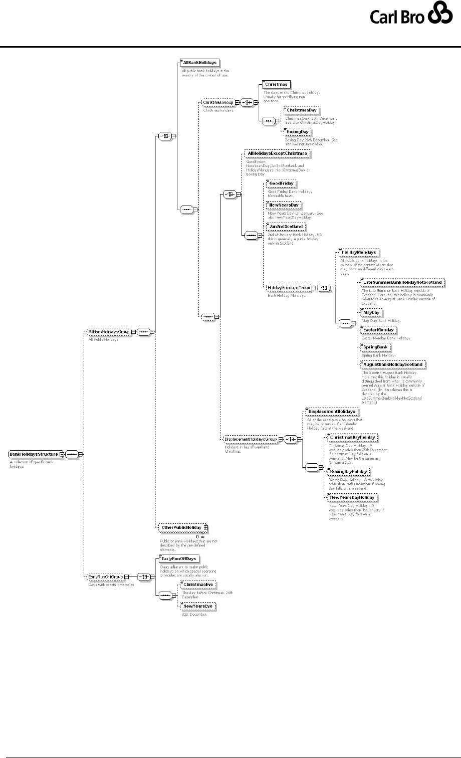
Department for Transport
TransXChange Schema Guide
Part III
Schema Description
TransXChangeSchemaGuide-2.1-v-45.pdf.doc
Page 182
24 September 2013
Figure 6-98 – OperatingProfile / Bank Holidays Element
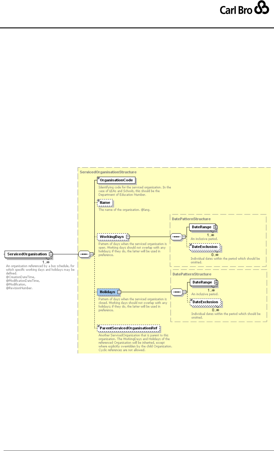
Department for Transport
TransXChange Schema Guide
Part III
Schema Description
TransXChangeSchemaGuide-2.1-v-45.pdf.doc
Page 183
24 September 2013
6.9.3 ServicedOrganisation Element
Operational days can also be specified in terms of the working days or holidays of specified
organisations, for example schools. The ServicedOrganisation element is used to define
the organisations covered, and to specify their working and non-working days.
A TransXChange document may contain a collection of ServicedOrganisation definitions.
Each ServicedOrganisation definition (Figure 6-99) comprises:
OrganisationCode: Identifier of the ServicedOrganisation.
Name: Name of the ServicedOrganisation.
WorkingDays: The working days of the ServicedOrganisation, for example a
LEA’s terms.
Holidays: The non-working days of the ServicedOrganisation, for example a LEA’s
holidays.
ParentRef: Identifier of another ServicedOrganisation that is the element’s parent.
References should be acyclic. Working days and holidays specified for a parent are
used as defaults for all child organisations, unless specifically overridden on the child
instance.
Figure 6-99 – ServicedOrganisation Element
6.9.4 ServicedOrganisation Subelements
6.9.4.1 ServicedOrganisation / DatePattern Element
The DatePattern element (Figure 6-100) specifies a group of one or more non-contiguous
periods as a collection of date ranges. See Modelling operation days for precedence of
overlapping dates.
DateRange: A collection of one or more open-ended date ranges, and any number
of date exceptions.
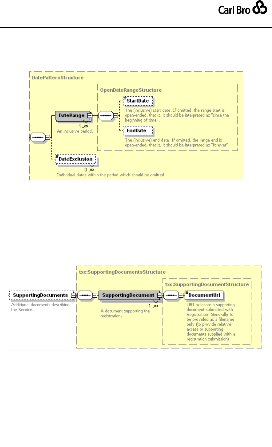
Department for Transport
TransXChange Schema Guide
Part III
Schema Description
TransXChangeSchemaGuide-2.1-v-45.pdf.doc
Page 184
24 September 2013
o StartDate: The (inclusive) start date. If omitted, the range start is open-
ended, that is, it should be interpreted as "since the beginning of time".
o EndDate: The (inclusive) end date. If omitted, the range end is open-ended,
that is, it should be interpreted as "forever"
DateExclusion: Individual dates within the period which should be omitted.
Figure 6-100 – ServicedOrganisation / Date Pattern
6.10 Miscellaneous Elements
6.10.1 SupportingDocument Element
The SupportingDocument element (Figure 6-26) Associates any supporting documents
associated with the whole TransXChange schedule document – other documents, for
example a schematic map, may be associated with individual elements using specific tags.
Documents may be in any file format and are identified by a DocumentUri. Note that
documents can also be associated more specifically with an individual registration.
Figure 6-101 – SupportingDocument Element
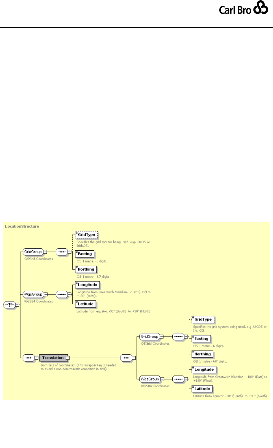
Department for Transport
TransXChange Schema Guide
Part III
Schema Description
TransXChangeSchemaGuide-2.1-v-45.pdf.doc
Page 185
24 September 2013
7 COMMON SCHEMA ELEMENTS
Some elements and types are common to a number of different elements in the
TransXChange & NaPTAN schemas. These are described here.
7.1 LocationStructure
The LocationStructure type (Figure 7-1) is used to describe the spatial position of a stop or
other point, for example on a Location element. Coordinates may be specified in Grid or
WGS84 formats, or both. The primary coordinates used can be indicated by the
LocationSystem value (Grid or WGS84) specified on TransXChange document root
elements. Coordinates must be supplied for all elements in the specified primary
coordinates, and may optionally be provided in the other system as well. NaPTAN data
should be submitted in Grid format. NaPTAN data will normally be distributed in both
formats.
If Grid coordinates are provided:
GridType: Nominated grid system e.g. UKOS or IrishOS; UKOS is assumed by
default.
Easting: Easting grid coordinates of stop.
Northing: Northing grid coordinates of stop.
If WGS84 coordinates are provided:
Longitude: Longitude of stop in WGS84 coordinates.
Latitude: Latitude of stop in WGS84 coordinates.
If Both Grid & WGS84 coordinates are provided:
Translation, containing both of the above coordinate groups.
Figure 7-1 – LocationStructure
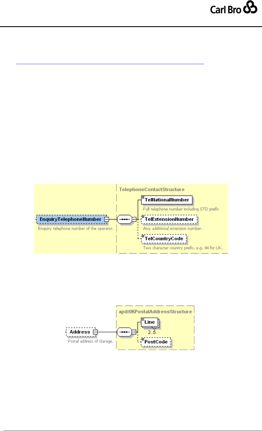
Department for Transport
TransXChange Schema Guide
Part III
Schema Description
TransXChangeSchemaGuide-2.1-v-45.pdf.doc
Page 186
24 September 2013
7.2 Duration Simple Type
The Duration simple type is used by a number of elements to specify a relative time in
minutes and seconds. It uses a standard W3C duration type.
See http://www.w3.org/TR/2001/REC-xmlschema-2-20010502/#duration.
Durations are encoded in the format PT99M88S, where 99 is the minutes and 88 is the
seconds. For example, ‘PT12M22S’ denotes twelve minutes and twenty-two seconds. The
seconds may be omitted for whole minutes, for example, PT5M. Note that the W3C format
also allows years, month, week and day intervals as well but these are not needed for
timing intervals. The W3C definition allows arbitrary integer values for the minutes and
arbitrary decimal values for the number of seconds can include decimal digits to arbitrary
precision. thus PT1201M, PT360.25S or PT1000S are valid (i.e. seconds do not have to be
modulo sixty). Either seconds or minutes or both may be coded. Units may be combined in
an arbitrary manner for example, P5M, PT300S and PT3M120S are all valid equivalent
encodings of 5 minutes.
7.3 TelephoneContactStructure Element
The TelephoneContactStructure (Figure 7-2) element specifies a phone number:
TelNationalNumber: Full telephone number including STD prefix
TelExtensionNumber: Any extension number.
TelCountryCode: International country code for telephone. E.g. +44.
Figure 7-2 – TelephoneContactStructure
7.4 PostalAddressStructure Element
The PostalAddressStructure (Figure 7-3) element specifies a postal address.
Line: Between two and five lines of address.
PostCode: Post code of address.
Figure 7-3 – PostalAddressStructure Element
7.5 Note Element
A Note (Figure 7-4) models a set of notes attached to an element:
NoteCode: Note identifier.
NoteText: Text of note.
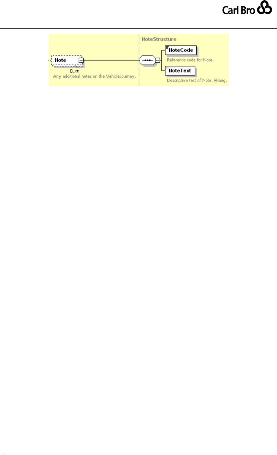
Department for Transport
TransXChange Schema Guide
Part III
Schema Description
TransXChangeSchemaGuide-2.1-v-45.pdf.doc
Page 187
24 September 2013
Figure 7-4 – Note Element

Department for Transport
TransXChange Schema Guide
Part IV
Technical Reference
TransXChangeSchemaGuide-2.1-v-45.pdf.doc
Page 188
24 September 2013
8 ELECTRONIC BUS SERVICE REGISTRATION PROCESS
This section summarises the anticipated process for registering a Bus Service using
TransXChange. The proposed process is subject to confirmation by VOSA following formal
testing in a demonstration. Registration includes the following steps:
8.1 Step 1: Preparation
The Transport Operator creates a proposal for a bus service and follows his normal
arrangements for consulting local authorities and others as appropriate before registering
the proposal.
8.2 Step 2: Encoding
The Transport Operator or its agent transfers the proposal onto a computer system. This
could be either a system that handles the scheduling of operations (and which includes the
capability to output the registration as TransXChange registration compliant XML
document), or a simpler system that only creates TransXChange registration files. Some
operators may use an agency to do this work for them – and in some areas the local
authority might offer to act as an agent, particularly in respect of contract services. Each
service Registration will create a separate TransXChange file – and these will be referenced
using the operator’s next available registration number. Each change to a Registration
likewise will carry a new sequential “version number”.
8.3 Step 3: Transmission
The Operator or the Operator’s agent logs onto the internet and connects to the VOSA
Server with a normal web browser (MS Internet Explorer, Netscape, etc) using a previously-
allocated username and password. The VOSA system provides a secure web connection
over which the electronic registration details can be sent to the relevant Traffic Area Office.
The VOSA service will offer a web page through which TransXChange files can be
submitted, individually or in bulk. Files can be zipped (compressed) to reduce connection
times – and multiple files can be submitted in a single zipped file. Files will be stored in a
secure area of the VOSA web site and will be accessible only to the relevant Traffic Area
staff, the operator making the submission and to the local authorities in whose area the
service is to operate.
8.4 Step 4: Validation
The VOSA system will check that each file (unzipped, if necessary) meets the technical
requirements of TransXChange – and will send a message back to the operator
immediately if the file(s) fail this test. If each file passes the test, then the VOSA system will
send an e-mail the relevant local authority (or authorities) and to the operator to advise them
that a registration(s) has been submitted and they can collect the submitted file(s) through
their own internet connection to a secure area of the VOSA web site

Department for Transport
TransXChange Schema Guide
Part IV
Technical Reference
TransXChangeSchemaGuide-2.1-v-45.pdf.doc
Page 189
24 September 2013
8.5 Step 5: TAN Review
Copies of the submitted file(s) are now passed into the Traffic Area Office’s business
system for review in the appropriate Traffic Area Office. Some automatic checks are made
on the content of the file – and the report of these checks is then passed to a case worker
who will review the proposal and, once any problems are resolved, issue the acceptance for
each Registration. The acceptance creates a new file – in PDF format – which provides an
unchangeable record of the “registered particulars” contained in the TransXChange file.
This file will be put into the secure area of the VOSA web site. Both the operator of the
service, and the local authorities in whose area the service is to operate, will be advised by
e-mail that the Registration has been accepted and that the PDF file of its registered
particulars is available for downloading securely from the web site. If problems are found
with the registration proposals during this process, the operator may be invited to make
changes to their proposals and to resubmit them, starting again at Step 2 of this process.
8.6 Step 6: Acceptance and Distribution
The operator who submitted the registration (and the relevant local authorities) can then
download a copy of the PDF file and can view the content of this file using freely available
software (such as Adobe Acrobat Reader). This provides confirmation of the acceptance of
the Registration – and sets out the only information (particularly the timetable shown only at
principal “timing” points) to which the Traffic Commissioner can make reference in any
enforcement proceedings.
The files submitted or created during this process will remain accessible through the VOSA
web site for up to 90 days using the secure access codes provided in the e-mails sent to the
operator and to the relevant local authorities. After that period, the files can still be obtained
on request from the relevant Traffic Area Office.
The electronic Registration process will be the same, whether the proposal is to register a
new service, to change an existing registered service, or to cancel an existing service.
Changes to an existing Registration require the re-submission of the complete registration
details using TransXChange (but most of these details will have been stored in the
operator’s systems for re-use in such circumstances). Cancellations require the submission
of a very small TransXChange file that identifies the Registration concerned and the last
date of operation.
TransXChange files can include timetables for use not only on normal operating days, but
also those which will be used on Bank Holidays and on other special days (such as those
around Christmas and the New Year). Operators will be encouraged to make full use of
these facilities so that special timetables are available for public information systems well in
advance of each special day of operation, and to avoid the need to submit special
registrations (or notifications) for such services.
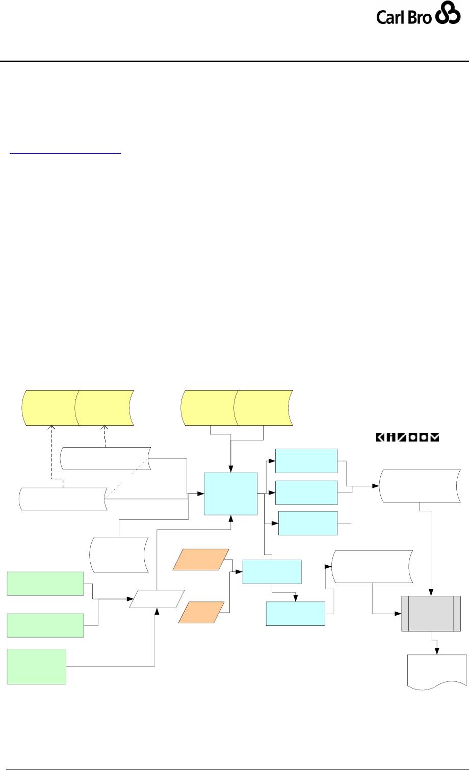
Department for Transport
TransXChange Schema Guide
Part IV
Technical Reference
TransXChangeSchemaGuide-2.1-v-45.pdf.doc
Page 190
24 September 2013
9 THE TRANSXCHANGE PUBLISHER
The TransXChange Publisher is a free tool issued along with TransXChange, which allows
users to render TransXChange XML documents into a readable timetable-like layout, that
uses the Acrobat pdf file format. See Figure 9-1. The free Acrobat reader from Adobe Inc
(http://www.adobe.com) can be used to read and print .pdf files.
The Publisher can be invoked from a Desktop GUI, or a command line. It has options to
produce
Particulars. The particulars section includes a summary of the contents of the
TransXChange document, (for example how many stops and journeys) followed by a
textual listing of the entities described in the file (such as operators, services, routes,
and stops).
Timetable. The timetable section contains matrix timetables for the services in the
TransXChange document. Separate timetables are generated for different services,
directions (e.g. outbound and inbound), and day types (e.g. a Monday to Friday
timetable, and a Saturday timetable).
Diagnostic Report. The diagnostics section contains a report detailing violations of
consistency checks for the TransXChange document (over and above those
expressed in the TransXChange XML Schemas alone).
Route Track. The route track section is a separate pdf document. It consists of route
plots for the services in the TransXChange on a map background along with an
accompanying table of stops. It requires an on-lien connection to use.
TransXChange
Publisher with
Track Router (Future)
TXC Publisher
Command Line
TXC Schedule as PDF
Printed Output
TXC Publisher
Acrobat
TXC
Registration
Schema
TXC
General
Schema
TXC
Registration
Schema
TXC
General
Schema
© Copyright Kizoom 2004- 2006
Options
Referenced
Images & Maps
TXC Publisher
Particulars
TXC Publisher
Matrix
TXC Publisher
Diagnostic Report
TXC Publisher
Track Router
Map
Data
NaPTAN
Data
TXC Schedule Document
TXC Registration XML
TXC Schedule Document
TXC General XML
TXC Publisher
GUI
TXC Publisher
Track Output
{OR}
TXC Publisher Web
Service (ESBR only)
TXC Route Track Map
as PDF
Figure 9-1 – Publisher
Department for Transport
TransXChange Schema Guide
Part IV
Technical Reference
TransXChangeSchemaGuide-2.1-v-45.pdf.doc
Page 191
24 September 2013
9.1 Required Environment
The TransXChange Publisher requires the installation of a standard open source
environment for running Java (Java Runtime Environment 1.4.2 or higher). See Installation
instructions for platform requirements.
The Route Track option requires a broadband internet connection to access the web
services that provide stop and map data.
9.2 Installation Process
The Publisher is available as a downloadable zip at http://www.transxchange.org.uk.
Installation instructions and examples are included on the site.
9.3 Run Time Options
The Publisher has a number of run time options
(a) To control the content to be included.
(b) To specify various aspects of the rendering of content.
9.4 Generalised list of Publisher parameters
Group
Parameter
Data
type
Default
Description
WS
Comm
and
Line
GUI
Input
Operands
Document-
Path
url
Required
Name and Path to TransXChange XML
document and associated files that are
to be published.
Y
Y
Y
Output
Operands
OutputPath
url
Optional
Output directory in which to place
published output. If not otherwise
specified, output is placed in the same
directory as the input document
Y
Y
Y
Processing
options
ValidateXML
boolean
true
Apply XML validation -
Y
Y+
Y
Output
Section
Content
Options
Auto
Vosa
|vosaAll
|full
Options controlling the interpretation of
auto
See Parameter defaults below -
Y
Y
Y
Particulars
none |
basic |
full
full
Include the particulars in output.
auto – default by pub format
none – no partiucalrs
basic –basic particulars
full - all the particulars
Y
Y [1]
Y
Timetable
none |
basic |
full
full
Include the timetable matrix in output.
auto – default by pub format
none – no matrix
basic – Omit footnotes
full - Include the timetable
footnotes in output.
Y
Y [1]
Y
Department for Transport
TransXChange Schema Guide
Part IV
Technical Reference
TransXChangeSchemaGuide-2.1-v-45.pdf.doc
Page 192
24 September 2013
RouteTrack
none |
plain |
basic |
tiled
none
Include the route track in output. Default
is false.
auto – default by pub format
none – no routetrack
plain – no map tiles
basic – Omit stop list
full - Include the full route
track.
Y
Y+
Y
Embed
boolean
true
Include any embedded image content in
output.
Y
N
Y
Diagnostics
auto |
none |
full
auto
Publish a diagnostic section.
Y
Y [2]
Y
Filters
TimingPoints
All |PTP |
All [3]
Include timing points of this type.
Y
Y [3]
Y
MergeFreque
ncyMergeFre
quency-
Journeys
boolean
true
Merge similar frequent journeys into a
single column.
Y
N
Y
Route
Track Map
RouteScale
Auto |
Small |
Large
Auto
Scale to use when tiling map. Small:
1:10,000, Large 1:50:000. Auto: scale
to size
Y
N+
Y
Route-
Grouping
Single |
ByDirecti
on
false
One route per map, or per direction.
Y
Y+
Y
RouteTiling
A4 | none
A4
Output as A4 tiles or single image.
Y
N+
Y
StopData
localOnly
| web
service
Web-
Service
Source of stop coordinates.
Y
N
Y
MapData
none |
web
service
Web-
Service
Source of map tiles. Only used if
RouteTrackMap specified.
Y
N
Y
Watermark
Background
Official |
Vosa |
Other
Vosa
Controls image.
Y
[N]
N
Watermark
Rubric
Official |
Vosa |
Other
Vosa
Controls headings and watermark.
Y
[N]
N
Rendering
Output-
Format
Pdf | html
pdf
Output format pdf
Y
(Y)
[4]s
Y
Table 8-9 – Publisher Interface Parameters
[1] Command line by suppressing other parts: timetableOnly.
[2] Controlled in command line by suppression: novalidation.
full
[4] Matrix only/ HTML output is a Debug Tool -
9.5 Publishing Actions
The Publisher publishes a document in the following order:
Summary Page
Operator
Serviced Organisations
Services
Registrations
i. ShortNoticeRegistrations
Lines
Routes
i. Local Stop Declarations
ii. References to existing stops

Department for Transport
TransXChange Schema Guide
Part IV
Technical Reference
TransXChangeSchemaGuide-2.1-v-45.pdf.doc
Page 193
24 September 2013
iii. Embedded Map
Fixed Route Services
i. Outbound VehicleJourneys
1. Monday to Friday
a. Matrix
b. Notes
2. Saturday
a. Matrix
b. Notes
3. Sunday
a. Matrix
b. Notes
ii. Inbound VehicleJourneys
1. Monday to Friday
a. Matrix
b. Notes
2. Saturday
a. Matrix
b. Notes
3. Sunday
a. Matrix
4. Notes
Flexible Route Services
i. Flexible Stops
ii. Fixed Stops
iii. Timebands
Supporting documents

Department for Transport
TransXChange Schema Guide
Part IV
Technical Reference
TransXChangeSchemaGuide-2.1-v-45.pdf.doc
Page 194
24 September 2013
10 NAMING & CODING CONVENTIONS
Systematic naming conventions and a consistent coding style are used in the
TransXChange 2.0 schemas. These conventions are summarised in this section.
10.1 Naming of Elements
TransXChange follows consistent principle for naming elements:
10.1.1 Use of Camel Case
Camel case is used for all names in the XML schema:
Upper camel case is used for element and attribute names, for example
JourneyPatternTimingLink, HailAndRide.
Lower case is however used for two standard attributes: xsd:lang and id, following
W3C usage.
Lower camel case is preferred or enumerated character values, for example
‘saturdayMorning’, except for proper names, which may be capitalised, e.g.
‘IsleOfMan
Acronyms are treated as words for capitalisation, thus TanCode, not TANCode.
This is one point where we follow common best practice but diverge from e-gif.
Treating acronyms as words allows for a uniform parsing of names to derive their
components, and avoids ambiguity on case of contiguous acronyms, for example
TANAPD vs. TanApd, or one letter words contiguous with an acronym, for example
DialATAN vs. DialATan.
10.1.2 Use of Standard Name Suffixes
TransXChange and NaPT schema element, type and attribute names have been revised
along consistent principles:
All simple types end with the suffix ‘Type’.
All complex types end with ‘Structure’.
All enumerations end with ‘Enumeration’.
All groups end with ‘Group’.
Elements representing references to other entities are suffixed with ‘Ref’.
Externally referenced identifiers of entities are generally suffixed with ‘Code’ (and
represented as elements). Code values are usually unique for the element type
within a document.
Internally referenced identifiers are generally named with ‘id’ (and represented as
attributes). id attributes typically have a keyref constraint on their uniqueness. The
uniqueness scope for id attributes is normally for the element type within an instance
document, but could also be just within an instance of specified element.
Externally referenced classifiers of entities are generally suffixed with
‘Classification’ (rather than say ‘Type’). (Some exceptions are made to this rule for
legacy usage).
Externally referenced names of entities are generally suffixed with ‘Name’. If the
context is readily apparent they may be called just Name.
Natural Language text descriptions of entities are generally termed ‘Description’.
10.1.3 Meaningful Names
Several other consistent naming principles are followed:
Abbreviations are generally avoided – for example ‘Operations’ is preferred to ‘Op’.
A container element representing a one-to-many relationship is in the plural; for
example, StopPoints contains one or more StopPoint elements.

Department for Transport
TransXChange Schema Guide
Part IV
Technical Reference
TransXChangeSchemaGuide-2.1-v-45.pdf.doc
Page 195
24 September 2013
We avoid repeating the name of the parent element as an adjective in individual
child elements, except where for semantically important elements. Thus for example,
Author contains Title, Position, Forename, Surname, not AuthorTitle,
AuthorPosition, AuthorName, AuthorSurname
We avoid the use in domain elements names of terms that have strong software
connotations:
o The suffixes ‘Type’ and ‘Group’ are avoided in element names except for
internal schema elements.
o The term ‘Exclusion’ is used generically to denote an exclusion period for
the service (rather than the previous term Exception) e.g.
JourneyPatternExclusion.
10.1.4 Semantically Significant Order
Several principles are used to order the subelements at any given level of containment:
When declaring elements within a parent, subelements are placed in a consistent
general order according to the nature of their role as follows:
(i) Elements that identify the entity, such as codes or numbers.
(ii) Elements that classify the entity.
(iii) Elements that describe the element in text, such as names or
descriptions.
(iv) Elements describing other properties of the entity.
Where there is an inherent temporal order, elements are placed in temporal
sequence.
10.1.5 Standardised Terminology
An attempt has been made to use the appropriate Transmodel term wherever appropriate.
For example Garage rather than Depot. The main divergences from Transmodel are listed
in section 13.2.
10.2 Typing of Elements
Some general principles are used for typing values.
Explicit, specific types are used wherever possible, for example Duration:
Complex types are declared for all significant elements.
Internally referenced identifiers are generally of type NMTOKEN.
Elements whose content is a text string in a national language are of type
NaturalLanguageStringStructure.
10.3 Element Constraints
Some general principles are used for constraining values.
Mandatory Elements are normally populated. XML constraints are usually specified
to ensure mandatory elements are populated, for example strings should contain at
least one character.
Optional elements not empty: Where alternative structures are available, the
absence of an element is not relied upon to infer meaning. Instead an empty
element or attribute value is used to make the condition explicit, or there is a default
value defined. This principle has been generally been followed for new and
remodelled features.
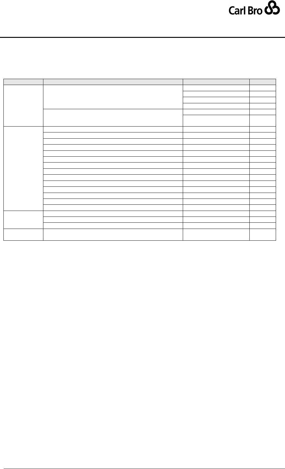
Department for Transport
TransXChange Schema Guide
Part IV
Technical Reference
TransXChangeSchemaGuide-2.1-v-45.pdf.doc
Page 196
24 September 2013
10.4 Use of Attributes
In TransXChange, XML element attributes are generally used only for metadata, that is,
data about data, such as change dates, or internal identifiers. Table 10-1 summarises the
attributes used in TransXChange.
Group
Element
Attribute
Version
TransXChange root element.
CreationDateTime
1.2
ModificationDateTime
1.2
FileName
2.0
SchemaVersion
1.2
StopPoint, StopArea, Service , VehicleJourney, Route,
RouteLink, FlexibleZone, Registration, JourneyPattern,
Operator
Modification,
1.2
RevisionNumber
1.2
id
Route
id
1.2
JourneyPattern
id
1.2
DeadRun
id
2.0
RouteSection
id
2.0
JourneyPatternSection
id
2.0
RouteLink
id
1.2
JourneyPatternTimingLink
id
1.2
VehicleJourneyTimingLink
id
1.2
PositioningLink
id
2.0
JourneyPatternStopUsage
id
1.2
VehicleJourneyTimingLink
id
1.2
JourneyPatternInterchange
id
1.2
VehicleJourneyInterchange
id
1.2
Location
id
1.2
Data
Location
Precision
1.2
JourneyPatternStopUsage
SequenceNumber
2.0
Route / Track / MapSystemReference
MappingSystem
2.0
Language
Text éléments: Name, Description, etc. See section on
National Language Support
xml:lang
2.0
Table 10-1 – TransXChange Attributes
10.5 Implementation of Model Relationships
In TransXChange, some stylistic conventions are used to make clear the mapping of the
reference model relationships into the XML schema.
Significant entities have a uniquely scoped identifier (always an element named
xxxCode, or xxxNumber, or an id attribute).
Relationships are implemented by placing a reference to the identifier as a foreign
key on the referencing element (shown by the navigability arrow in UML diagrams).
The reference has the form xxxRef. For example, StopPoint is identified by an
AtcoCode, and referenced in relationships by a StopPointRef.
Container elements are generally used for significant one-to-many relationships, for
example StopPoints contains the StopPoint elements.

Department for Transport
TransXChange Schema Guide
Part IV
Technical Reference
TransXChangeSchemaGuide-2.1-v-45.pdf.doc
Page 197
24 September 2013
11 NATIONAL LANGUAGE SUPPORT
TransXChange is enabled to allow the coding of schemas in different National Languages,
such as Welsh.
11.1 Text Content Types
The textual data of a TransXChange schedule falls into three different categories:
Fixed Text: National Language Translations of fixed encoded TransXChange values
(for example the TAN area names), and terminology for concepts such as ‘Service’
rendered when using a style sheet to transform a schedule into a published format.
Free Text: The contents of data elements that can be specified as content for textual
elements (having an xml:lang attribute and a type of NaturalLanguageStringType),
for example operator names, route descriptions and other notes.
External Data: The contents of data fetched from external data systems, for
example NaPTAN stop names.
11.1.1 Use of Fixed Text
An overall xml:lang attribute is specified at the schema level on the TransXChange root
element. This specifies the default language for the schedule, i.e. the default implied
language that is to be used to publish the timetable. It defaults to English.
Translations can be established for the text associated with the different fixed
elements.
11.1.2 Use of Free Text
Elements which may contain free text in a natural language (Table 11-1), such as Welsh or
English, have an xml:lang language attribute to indicate the language in which they are in.
English is assumed if no attribute is specified.
The provision of alternative names for a stop in different languages is covered by
NaPTAN, which allows for multiple alternative names.
Group
Element
Note
StopPoint
CommonName
Use NaPTAN
NptgLocalityName
StopArea / Name
Organisation
ServicedOrganisation / Name
FlexibleZone
FlexibleZone / Description
Route
Route / Description
Route / Manoeuvre
Instruction / Summary
Track / Feature / OnwardName
Track / Feature / Description
Service
Origin
Destination
ServiceClassification / OtherService / Description
StopRequirements / NewStopsRequired / Note
Description
Note / NoteText
ToBeMarketedWith / RelatedService / Description
ContractedService / Description
QualityPartnership
JourneyPattern
DestinationDisplay
Block
LayoverPoint / Name
VehicleType / Description
Frequency / Description
JourneyPatternTimingLink / StoppingArrangements

Department for Transport
TransXChange Schema Guide
Part IV
Technical Reference
TransXChangeSchemaGuide-2.1-v-45.pdf.doc
Page 198
24 September 2013
JourneyPatternTimingLink / StopUsage / Note
VehicleJourney
Note
Interchange
Interchange / StoppingArrangements
OperatingProfile
OtherPublicHoliday / Description
Operator
OperatorNameOnLicence
Garage / GarageName
Registration
Author / Position
SubsidyDetails / SubsidisingAuthority
StopRequired
NoteText
Short Notice
Registration
PublicAvailability / NonAvailabilityDescription
ChangeImpact / MinorChangeDescription
ReplaceDiscontinuedService / DiscontinuedService/ Description
LocalHolidayChange / LocalHolidayNote
SpecialOccasion / SpecialOccasionName
RegulationOrderCompliance / TrafficOrderNote
OtherServiceType / Description
ChangeRequestedByExternalAuthority / ChangeRequestDescription
MiscellaneousJustification
Table 11-1 – Elements That May Contain Natural Language Text
11.1.3 External Data
Any national language alternatives of StopPoint and StopArea names are provided by
NaPTAN. The schema xsd:lang attribute should be used to determine the preferred
language alternative to use when rendering names in timetables.
11.2 Publishing or Exchanging Documents
Note that the free text elements may only be in one language at a time in a given document.
In order for the language specific free text elements of a schedule to be exchanged in
multiple languages, the schedule must be republished in each language in turn.

Department for Transport
TransXChange Schema Guide
Part IV
Technical Reference
TransXChangeSchemaGuide-2.1-v-45.pdf.doc
Page 199
24 September 2013
12 VERSIONING
TransXChange schemas and documents must be versioned with an explicit version number
so as to manage change in a distributed operating environment, and in particular to allow
the inter-operability of versions of TransXChange running concurrently on different systems.
12.1 Version Numbering Convention
TransXChange follows the e-Gif convention for version numbering.
Released Version numbers have the form n.m, (e.g. ’3.0’).
Drafts have the form n.mx (e.g. ’3.1a’).
The main version number (n) will be incremented when the change from the
previous version of the schema will cause existing documents to fail to validate.
For example if a new mandatory element is added.
The minor version number (m) will be incremented when the change to the
schema will allow existing documents to continue to validate. However some
new documents may fail to validate against the old version (for example, if a new
optional element is added).
The draft version number (x) indicates that the version is still under discussion
and may be subject to further changes. Generally it will be incremented to
indicate a material change to a previous release or previous draft. Intermediate
drafts will usually be withdrawn once they are superceded.
12.2 Resource Versions
12.2.1 Schema URI Version
In line with W3C practice, a separate directory and URL will be used for each version of the
schemas; the schema name will remain the same (N.B. a directory rather than document
level numbering system is preferred for the leaf schemas because it facilitates the
management of multiple components of a modularised schema, and multiple document
artefacts).
For example
http://www.transxchange.org.uk/schemas/2.0f/TransXChange_registration.xsd
and
http://www.transxchange.org.uk/schemas/3.1/TransXChange_general.xsd
Different versions will coexist at the same time. Old versions will generally first be
deprecated, and then retired.
12.2.2 Namespace URI Version
e-GIF mandates that Namespace URI should not be versioned. (A different URL for the
namespace and the schema) The following URI will be used for namespace.
http://www.transxchange.org.uk/schemas/
12.2.3 Package Versions
TransXChange embeds a number of common type definition packages that are shared with
other UK standards. For convenience, a separate copy of the common packages is
distributed with each standard. The individual package files are given version numbers in
line with the e-GIF system in order to ensure the correct version is used.
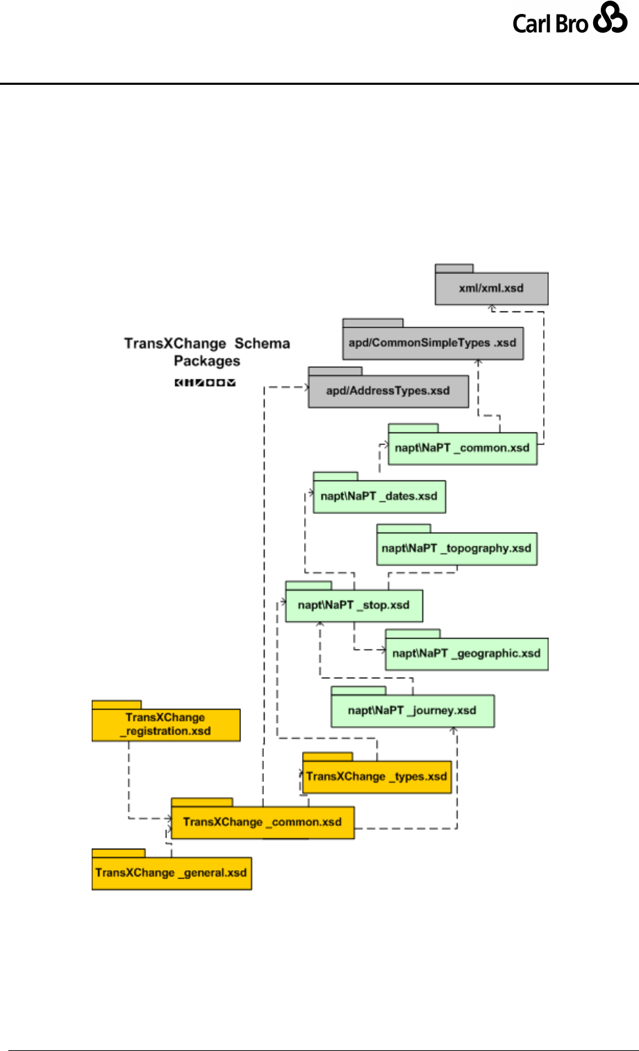
Department for Transport
TransXChange Schema Guide
Part IV
Technical Reference
TransXChangeSchemaGuide-2.1-v-45.pdf.doc
Page 200
24 September 2013
For example, for the shared NaPT stop definition types file might be called NaPT_stop-v1-
0.xsd. It will be distributed in TransXChange as:
http://www.transxchange.org.uk/schemas/2.0/napt/NaPT_stop-v1-0.xsd
12.3 Packages
The TransXChange schema is modularised into a number of packages, with a strict linear
dependency. See Figure 12-1.
Figure 12-1 – TransXChange Packages
The schemas are organised according to package group (see Table 12-1). TransXChange
schemas are placed in the root folder, prerequisite shared schemas are placed in subfolders
(\apd, \napt and \xml).
Department for Transport
TransXChange Schema Guide
Part IV
Technical Reference
TransXChangeSchemaGuide-2.1-v-45.pdf.doc
Page 201
24 September 2013
Standard
Folder
Schemas
Contents
Origin
TransXChange
root
TransXChange_registration.xsd
Terminal schema for
Registrations.
Renamed in 2.0.
root
TransXChange_general.xsd
Terminal schema for General
use.
Renamed in 2.0.
root
TransXChange_common.xsd
Common elements for
TransXChange.
New in 2.0.
root
TransXChange_types.xsd
Shared type declarations specific
to TransXChange.
New in 2.0.
NaPT
\napt
NaPT_common.xsd
Type declarations shared with
other NaPT schema.
New in 2.0.
\napt
NaPT_dates.xsd
Date and time type declarations
shared with other NaPT schema.
New in 2.0.
\napt
NaPT_geographic.xsd
Geographic type declarations
shared with other NaPT schema.
New in 2.0.
\napt
NaPT_journey.xsd
Journey type declarations shared
with JourneyWeb schema.
New in 2.0.
\napt
NaPT_topography.xsd
NPTG type declarations shared
with other NaPT schema.
New in 2.0.
\napt
NaPT_stops.xsd
Stop type declarations shared
with other NaPT schema.
New in 2.0.
GovTalk
\apd
AddessTypes.xsd
UK address types
Referenced in 2.0
\apd
CommonSimpleTypes.xsd
UK simple types
Referenced in 2.0
W3C
\xml
XML.xsd
Standard definitions of types
Referenced in 2.0
Table 12-1 – TransXChange 2.0 Module Names
Department for Transport
TransXChange Schema Guide
Part IV
Technical Reference
TransXChangeSchemaGuide-2.1-v-45.pdf.doc
Page 202
24 September 2013
12.4 Version Identifiers & Change Tracking
12.4.1 Schema Version Identifier
The TransXChange schema has an explicit version attribute on it, as recommended by e-
GIF.
The schema id is “TransXChange”.
The version identifier follows the versioning scheme e.g. ”3.0”.
12.4.2 Indicating Versions on Data
In each XML instance document conforming to TransXChange, the root TransXChange
element has an attribute that is populated to indicate the schema version, as recommended
by e-GIF. This allows any application which processes the document to decide how to
handle the document. See Table 12-2. The Schema version is one of a standard set of
Content change attributes that are specified on the route elements of all NaPT schemas.
Attributes
Value Type
CreationDateTime
Date and Time stamp, ISO format
ModificationDateTime
Date and Time stamp, ISO format
Modification
Nature of modification: one of new, delete, revise
RevisionNumber
Monotonically incrementing number
SchemaVersion
Schema Version number
Table 12-2 – TransXChange Document Version Attributes
12.4.3 Data Element Version
Most significant entities in TransXChange have an optional set of a standard change
attributes on them, including a modification date and revision number that can be used to
specify their version level. See Table 12-3.
Change Attributes
Value Type
CreationDateTime
Date and Time stamp, ISO format
ModificationDateTime
Date and Time stamp, ISO format
Modification
Nature of modification: one of new, delete, revise
RevisionNumber
Monotonically incrementing number
Table 12-3 – Entity Change Tracking Attributes
Timestamps should be in standard ISO format, for example ’2004-04-14T14:20:00-
05:00’’
The RevisionNumber of an element should be incremented (and its Modification
value be set to of ’revised’), if any of its element values, attribute values or contained
values is modified. It may be set to zero for a new entity.
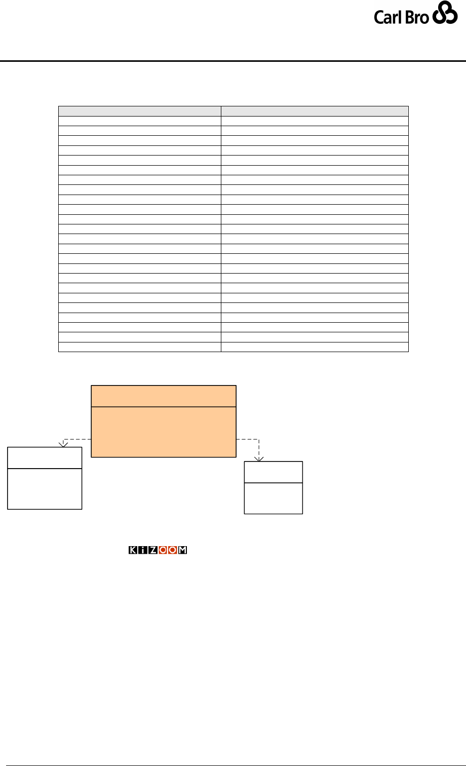
Department for Transport
TransXChange Schema Guide
Part IV
Technical Reference
TransXChangeSchemaGuide-2.1-v-45.pdf.doc
Page 203
24 September 2013
12.4.4 Change Trackable Entities
The TransXChange entities which can be change tracked are shown in Table 12-4.
Entity
Versioning
TransXChange
SchemaVersion + Change Attributes.
StopPoint
Change Attributes.
StopArea
Change Attributes.
NptgLocality
Change Attributes.
FlexibleZone
Change Attributes.
Route
Change Attributes
RouteSection
Change Attributes
RouteLink
Change Attributes
Track
No – within RouteLink.
JourneyPattern
Change Attributes
JourneyPatternSection
Change Attributes
JourneyPatternTimingLink
No – within JourneyPatternSection
JourneyPatternStopUsage
No – within JourneyPatternSection.
JourneyPatternInterchange
Change Attributes.
Operator
Change Attributes.
Service
Change Attributes.
Registration
Change Attributes.
Line
No – within Service.
VehicleJourney
Change Attributes.
VehicleJourneyTimingLink
No – No within VehicleJourney.
VehicleJourneyInterchange
No – No within VehicleJourney.
VehicleJourneyStopUsage
No – No within VehicleJourney.
ServicedOrganisation
Change Attributes.
SupportingDocument
No
Table 12-4 – TransXChange Tracked Data Elements
Figure 12-2 shows the common TransXChange versioing attributes
CreationDateTime() : <unspecified>
ModificationDateTime() : <unspecified>
Modification() : ModificationEnum
RevisionNumber() : <unspecified>
Status() : StatusEnum
«interface»
Versionable
new
revise
delete
archive
«enumeration»
ModificationEnum
active
pending
inactive
«enumeration»
StatusEnum
Versioning
Attributes
Figure 12-2 – UML Diagram of Versioning Attributes
12.5 Names of TransXChange Files
When dealing with a large number of bus schedules, it is helpful for document management
if the file name used for a bus schedule when it is exchanged as an XML document gives an
indication of its contents. The following format is recommended for file names of
TransXChange XML documents:
Line_Operator_Area_ServiceCode_StartDate.xml
Where:

Department for Transport
TransXChange Schema Guide
Part IV
Technical Reference
TransXChangeSchemaGuide-2.1-v-45.pdf.doc
Page 204
24 September 2013
Line is the service number seen by the public, as defined by a Service / Lines/ Line
element within the document. If there is more than one Line associated with a
service, use the first.
Operator identifies the service operator and is either:
The operator code, i.e. RegisteredOperator / OperatorCode element for the
service specified the within the document.
The operator license number, i.e. Operator / LicenceNumber of the
operator registering the service.
Area identifies the service area and is either:
Area Code: Three digit ATCO database code for the district/authority 450.
This is the NPTG AdministrativeArea / AtcoAreaCode.
TAN Code: Two character TAN prefix. This is the Registration /
VosaRegistrationNumber / TanCode specified the within the document.
ServiceCode- is an arbitrary unique identifier for the service as specified by a
Service / ServiceCode element within the document.
StartDate: Is the registered start date of the service as defined by a Service
/OperatingPeriod /StartDate within the document.
So for example, the 757 service operated by Aztecbird (AZT) in West Yorks (450), the
general TransXChange export file name would be:
Using the operator code:
757_AZT_450_4431_20020428.xml
Using the operator licence number:
757_3888_450_4431_20020428.xml
Using the Tan prefix on a registration:
757_3888_PB_4431_20020428.xml
For registrations there should generally be a separate file for each registration change date
i.e. one file for the initial service, one for a new version of the service starting 01/07/2004
and so on.
When exchanging between the authority databases and journey planner and real time
systems, multiple services may be contained in a single file, using the general schema.
In this case there is no preferred naming scheming.

Department for Transport
TransXChange Schema Guide
Part IV
Technical Reference
TransXChangeSchemaGuide-2.1-v-45.pdf.doc
Page 205
24 September 2013
13 TRANSMODEL & TRANSXCHANGE COMPARISON
13.1 Transmodel Principles
TransXChange is based on Transmodel, a general abstract model for describing public
transport information systems, devised on carefully elaborated informational science
principles. Some of the key principles may be summarised as follows:
1. Layered Semantic Models: The efficient modelling of public transport information
requires a number of distinct models, representing different levels of discourse. For
example, (i) the geospatial location (i.e. map) layer, (ii) the network topology layer,
(iii) the service pattern layer, (iv) the timed vehicle journey layer, (v) the operational
running layer, etc.
2. Projection: It should be possibly to combine the different models in order to
compute over them, relating the corresponding elements of different levels of
discourse precisely and unambiguously, using a common frame of reference. For
example, route links should map onto geospatial objects such as roads; timing links
should map onto route links, etc. The establishment of equivalences between distinct
model layers is termed projection.
3. Common Terminology: A standard set of common conceptual entities should be
used for the elements making up the models at each different layer, and a standard
Transmodel terminology should be used. For example, Line, Journey Pattern,
Vehicle Journey, Location.
4. Point and Link Structures: Public Transport Information System models typically
involve complex networks which are modelled in computer systems by graphs; that
is, as networks of nodes (points) and edges (links). Depending on the information of
interest in a particular application, it may be appropriate to use ordered collections of
links, ordered collections of points, or combinations thereof. Links of a given type
should only connect to points of the corresponding semantic level of discourse. Only
one unambiguous sequence of points (whether modelled as a point sequence, or
link sequence) may be used in a given journey or service pattern.
5. Well-defined Data Systems. Elements corresponding to external entities should be
assigned unique identifiers from agreed data reference systems.

Department for Transport
TransXChange Schema Guide
Part IV
Technical Reference
TransXChangeSchemaGuide-2.1-v-45.pdf.doc
Page 206
24 September 2013
13.2 Transmodel Terminology
Wherever possible, TransXChange follows Transmodel terminology for PT concepts. The
equivalences between some key TransXChange elements and their corresponding
Transmodel concepts are shown in Table 13-1. Divergences are highlighted in bold.
Transmodel
TransXChange 2.0
Previously 1.2
ADMINSTRATVIE ZONE / AREA
Administrative Area
--
ACTIVITY
Activity
ActivityFlag
Alight
Set down
Set down
Board
Pick up
Pick up
BLOCK
Block
--
DAY TYPE
OperatingProfile /
RegularDayType
PeriodicDayType
ServicedOrganisationDayType
DayType /
GeneralOpClassification
Periodic
SchoolOp
DEAD RUN
DeadRun
--
DESTINATION DISPLAY
DestinationDisplay
DynamicDestinationDisplay
DISTANCE
Distance
Distance
DIRECTION
Direction
JourneyDirection
FARE STAGE
FareStage
--
FARE ZONE
FareZone
--
JOURNEY PATTERN
JourneyPattern
JourneyPattern
JOURNEY PATTERN TIMING LINK
JourneyPatternTimingLink
JourneyPatternTimingLink
JOURNEY PATTERN LAYOVER
JourneyPattern / Layover
JOURNEY PATTERN RUN TIME
JourneyPattern / RunTime
DefaultRunTime
JOURNEY PATTERN WAIT TIME
JourneyPattern / WaitTime
DefaultWaitTime
LINE
Line
(ServiceId)
(FARE SECTION ) (LINK SEQUENCE)
RouteSection
--
LOCATION
Location
Geocode
LOCATING SYSTEM
LocatingSystem
(Geodata system)
OPERATOR
Operator
Operator
PLACE
Place
Locality
ROUTE
Track (See 13.3.1)
--
ROUTE LINK
TrackLink (See 13.3.1)
--
RUN TIME
Run time
Run time
Section
Section
--
SERVICE
Service, StandardService
FlexibleService
OverallServiceDescription
SERVICE PATTERN
Route (See 13.3.1
Route
SERVICE JOURNEY PATTERN LINK
RouteLink (See 13.3.1
RouteLink
SERVICE JOURNEY PATTERN
INTERCHANGE
JourneyPatternInterchange
JourneyPatternInterchange
SERVICE JOURNEY INTERCHANGE
VehicleJourneyInterchange
VehicleJourneyInterchange
SITE
Landmark
Landmark
STOP POINT
StopPoint
Stop
STOP AREA
StopArea
StopCluster
TIMING LINK
(JourneyPattern) TimingLink
TimingLink
TIME DEMAND
TimeDemand
--
VALIDITY PERIOD
ValidityPeriod
ValidityPeriod
VEHICLE JOURNEY
VehicleJourney
VehicleJourney
VEHICLE JOURNEY TIMING LINK
VehicleJourneyTimingLink
VehicleJourneyTimingLink
VEHICLE JOURNEY RUN TIME
VehicleJourneyTimingLink / RunTime
RunTime
VEHICLE JOURNEY WAIT TIME
VehicleJourneyTimingLink / WaitTime
WaitTime
VEHICLE TYPE
VehicleType
VehicleType
VERSION
(RevisionNumber)
(RevisionNumber)
WAIT TIME
Wait time
Wait time
ZONE
FlexibleZone
--
Table 13-1 – Comparison of Key Transmodel Terms

Department for Transport
TransXChange Schema Guide
Part IV
Technical Reference
TransXChangeSchemaGuide-2.1-v-45.pdf.doc
Page 207
24 September 2013
13.3 Divergences from Transmodel
Version 2.0 of TransXChange converges significantly closer to Transmodel, but still
contains a few significant differences in terminology that reflect TransXChange 1.2 usage,
and the legacy of TransXChange’s orginal ATCO CIF representation. (Note too that
Transmodel has also been subject to further evolution during the period of development of
TransXChange). In addition TransXChange introduces additional convenience elements for
implementation which can mostly be considered as views which compound other elements;
for example a StopUsage groups various attributes that cna be associated with either end
of a TimingLink. The main outstanding differences (which may possibly be reduced in
future), are as follows:
Transmodel uses the term ROUTE to denote a physical path taken by vehicles
through the network, identifying the road sections or track section being used
with each stage. A Transmodel ROUTE LINK corresponds more properly to the
Track (ROUTE LINK) and Mapping (POINT IN ROUTE LINK) elements of the
TransXChange model.
The TransXChange Route and RouteLink are similar to a Transmodel
SERVICE PATTERN, and SERVICE LINK, that is, an abstract journey pattern,
identifying a unique sequence of STOP POINTs in order that define a possible
journey for a line, regardless of any actual timings..
13.3.1 TransXChange Representation of Journey Patterns
Note that TransXChange does not use what Transmodel would term a STOP IN
SEQUENCE (or more specifically, STOP POINT IN JOURNEY PATTERN) representation of
a journey pattern, but rather a Transmodel LINKS IN LINK SEQUENCE representation;
more specifically, a sequence of journey pattern timing links (TIMING LINK IN JOURNEY
PATTERN). The Transmodel abstract model allows for a separate set of SERVICE LINKs
between the stop points of a service pattern or journey pattern that is distinct from the set of
TIMING LINKs of the pattern, permitting multiple timings to be specified for the same route,
and for some of the intermediate timing points not to be stop points (and stop points not to
be timing points). Because TransXChange has historically been primarily concerned with
the exchange of fully timed schedules for registration, all points in a TransXChange
JOURNEY PATTERN are stop points, and TransXChange uses only timing links: the
existence of a service link between two points is implied from the existence of a timing link
between two stops. This simplifies the mapping of the representation to a published matrix
timetable, however a consequence is that it forces a false interpolation of run times in some
usages. For example, if there is a sequence of non-timing stop points in a pattern, for which
there is only an overall run time, the overall run time must be arbitrarily assigned to one or
more of the intermediate links in order to encode it in TransXChange.
In effect TransXChange makes a simplifying assumption that all TIMING POINTs are in
effect also STOP POINTs so is abloe to use a combined Link abstraction that has both
timing and service pattern properties. The StopUsage element
It may be appropriate to add a compatible STOP IN SEQUENCE and separate service and
timing link representations to a future version of TransXChange.
13.3.2 Abbreviated Journey Patterns
In TransXChange, two practical expedients are used also to reduce the amount of data that
has to be exchanged, and in particular the number of journey patterns.

Department for Transport
TransXChange Schema Guide
Part IV
Technical Reference
TransXChangeSchemaGuide-2.1-v-45.pdf.doc
Page 208
24 September 2013
a. Short working of the underlying journey pattern is allowed in TransXChange, i.e.
truncation of one or more stops of the pattern at either or both ends. Transmodel
indicates that a separate journey pattern should be declared for any difference in
stop sequence, which could be strictly interpreted as requiring a separate journey
pattern for each short working vehicle journey variant.
b. Express journeys over a service pattern are allowed in TransXChange – i.e.
provided a journey traverses a link, and goes past a stop, it may specify an activity of
‘pass’ to omit a particular stop.
In both the above cases, there is little or no informational benefit to having a separate
journey pattern, and there is in any case little distinction between the above cases and the
legitimate Transmodel representation of a vehicle following a ‘full’ journey pattern in real-
time that for operational reasons passes stops, or terminates early.
13.3.3 Groups of Links
Another expedient TransXChange, uses to reduce the amount of data that has to be
exchanged is a “link section”, that is, a reusable ordered list of Links that can be reused in
one or more ROUTEs or JOURNEY PATTERN. This is partiucallry useful where there is
corridor route with a long common section but many end variants. Link sections are an
additional abstraction not found in Transmodel but can be seen as equivalent to GROUP
OF LINKs being used in a specific way. Their use amounts to a requirement that there is
always at least one “GROUP OF LINKS” associated with each journey pattern., but need
not conflict in any way with a canonical Transmodel represnetation.

Department for Transport
TransXChange Schema Guide
Part IV
Technical Reference
TransXChangeSchemaGuide-2.1-v-45.pdf.doc
Page 209
24 September 2013
14 INTEGRITY RULES
14.1 Syntactic Integrity Rules
XML’s inbuilt mechanisms, including Keyrefs are used in the TransXChange schema to
enforce a number of basic integrity checks of data within a TransXChange document,
including enforcing uniqueness. A document must satisfy these constraints, or it is not well
formed and will not be processed further by the TransXChange Publisher or other tools.
Data types are specified for dates, times, durations and other common data types.
Restricted values are enforced by enumerations – see individual tables of allowed
values under the schema guide entry for constrained elements.
Some additional rules for encoding formatted elements are enforced by regular
expressions.
Table 14-1 shows the other rules enforced by syntactic constraints.
Group
Element
#
Scope
Reference
Code
Scope
AtcoCode
C1
Codes of local StopPoint
declarations must be unique
within document.
StopPointRef instances must
reference a StopPoint or
AnnotatedStopPoint declaration.
See also External Integrity rule N1.
StopAreaCode
C2
Codes of local StopArea
(Cluster) declarations must be
unique within document.
StopAreaRef – See External
Integrity rule N2.
ServicedOrganisationCode
C3
Codes of
ServicedOrganisation
declarations must be unique
within operator.
ServicedOrganisationRef
instances must reference a local
definition of a
ServicedOrganisation element.
ServiceCode
C4
Code of each Service must be
unique within document.
ServiceRef instances must refer
to a local definition of a Service.
VehicleJourneyCode
C5
Code of each VehicleJourney
& FlexibleVehicleJourney
must be unique within
document.
VehicleJourneyRef instances
must reference a local definition of
a VehicleJourney.
GarageCode
C6
Codes of Garage declarations
must be unique within
document.
GarageCodeRef instances to a
Garage must reference a local
definition of a Garage element.
Identifier
Scope
Route / id
I1
id of each Route must be
unique within document.
RouteRef instances must
reference a local definition of a
Route.
JourneyPattern /id
I2
id of each JourneyPattern
must be unique within
document.
JourneyPatternRef instances
must reference a local definition of
a JourneyPattern.
Line / id
I5
id of each Line must be
unique within document.
LineRef instances must refer to a
local definition of a Line element.
RouteSection / id
I6
id of each RouteSection must
be unique within document.
RouteSectionRef instances must
refer to a local definition of a
RouteSection.
JourneyPatternSection / id
I7
id of each
JourneyPatternSection must
be unique within document.
JourneyPatternSectionRef
instances must refer to a local
definition of a
JourneyPatternSection.
RouteLink/ id
I8
id of each RouteLink must be
unique within document.
RouteLinkRef instances must
reference a local definition of a
RouteLink.
JourneyPatternTimingLink
/ id
I9
id of each
JourneyPatternTimingLink
must be unique within
document.
JourneyPatternRef instances
must reference a local definition of
a JourneyPatternTimingLink.
VehicleJourneyTimingLink
/ id
I10
id of each
VehicleJourneyTimingLink
must be unique within
document.
VehicleJourneyRef instances
must reference a local definition of
a VehicleJourneyTimingLink.

Department for Transport
TransXChange Schema Guide
Part IV
Technical Reference
TransXChangeSchemaGuide-2.1-v-45.pdf.doc
Page 210
24 September 2013
VehicleJourneyStopUsage
/ id
I11
id of each
VehicleJourneyStopUsage
must be unique within
document.
VehicleJourneyStopUsageRef
instances must refer to a local
definition of a
VehicleJourneyStopUsage.
VehicleJourneyStopUsage
/ id
I12
id of each
VehicleJourneyStopUsage
must be unique within
document.
VehicleJourneyStopUsageRef
instances must refer to a local
definition of a
VehicleJourneyStopUsage.
Cyclic
VehicleJourneyRef
X1
VehicleJourney must not
reference itself.
Table 14-1 – Syntactic Integrity Rules
14.2 Semantic Integrity Rules
Table 14-3 shows additional integrity rules that need to be applied by applications parsing a
TransXChange XML document. These are subdivided into two categories:
Intrinsic Constraints: Consistency checks that can be applied without reference to
external data. For many of these, a sensible recovery action can be taken.
Extrinsic Constraints: Checks of data values that require reference to an external
source. Whether these need to be applied depends on the availability of the relevant
data sets, and the purpose of the application.
Rules are assigned a severity (see Table 14-2) that indicates the likely action that an
application such as TransXChange Publisher will take if the rule is not satisfied.
Rules that may affect the correct publishing of a document by the TransXChange Publisher
are marked with a ‘p’.
Severity
Meaning
Action
1
Fundamental Inconsistency – Schedule cannot be
accurately interpreted.
Report as serious error. Reject for registration.
2
Inconsistency – Default Remedial action possible,
but statutory Registration requires clarification.
Report, apply remedy automatically. Reject for
registration.
3
Inconsistency – Default Remedial action possible.
Report, apply remedy automatically.
4
Data reference does not exist in external source.
Report as missing.
5
Ancillary data reference does not exist.
Report as missing.
6
Minor data inconsistency.
Report, leave uncorrected.
Table 14-2 – Severity Codes for Semantic Integrity Rules
Group
#
Rule Name
Description
Cat
Sev
Remedy
Metadata
Dc1
Valid
FileName
File name is made up of recommended
elements.
Int
6
Allow, but give
warning.
NaPTAN
Na1
Valid NaPTAN
Stop
Identifiers.
Stop points referenced by an
AnnotatedStopPointRef must exist in
the NaPTAN database.
Ext
4
Warning.
Na2
Valid NaPTAN
StopArea
Identifiers.
Stop areas referenced by a
StopAreaRef of a local StopPoint
definition must exist in the NaPTAN
database, or be defined locally.
Ext
4
Warning.
Na3
Local NaPTAN
StopAreas .
Stop areas referenced by a
StopAreaRef of a local StopPoint
definition should belong to the same
Admin Area as the StopPoint or to a
national area e.g. 910.
Ext
6
Warning.
Ng3
Valid NPTG
Localities.
NPTG localities referenced by
NptgLocalityRef of local StopPoint
definition must exist in the NPTG
database.
Ext
4
Warning.
Ng4
Valid NPTG
Administrative
Areas.
NPTG administrative areas referenced
by an AdministrativeAreaRef of local
stop point definition must exist in the
NPTG database.
Ext
4
Warning.
Serviced
Organization
Eo1
Valid Serviced
Organizations.
For local authorities, should be a valid
DfE LEA code.
For schools, should be a valid DfE
school code.
Ext
5
Warning.
Department for Transport
TransXChange Schema Guide
Part IV
Technical Reference
TransXChangeSchemaGuide-2.1-v-45.pdf.doc
Page 211
24 September 2013
Eo2
Serviced
Organization
no cyclic
References.
Parent or ancestor should not be self.
Int
3
Ignore parent.
Period
Tp1
Unique
Operation
Profile weeks.
PeriodicDayType/ Weeks should be
distinct.
Int
3,*q
Ignore
overlap.
Tp2
Valid Date
Ranges.
End date should be after start date on
ValidityPeriod and other ranges.
Int
3,*q
Use start date
for both, and
report.
Tp3
Distinct
Periods.
Periods for exclusion suspension should
not overlap.
Int
3
Ignore 2nd
period.
Tp4
Valid Dates
Calendar Dates should lie within Service
Operational period
Int
3,*q
Assume within
operational
period.
Operator
Op1
National
Operator
Code.
NationalOperatorCode should be valid
in future database.
Ext
4
Allow.
Op2
Distinct
Operator
References.
RegisteredOperator of a Service
should not be the same as
AssociatedOperator.
Int
3
Ignore
associated
operator.
Op3
Distinct
Associated
Operator
roles.
Each AssociatedOperator should only
be referenced once by a given service
for a given role.
Int
6
Ignore
duplicate
references.
Op4
Valid garage
code.
GarageCode should be valid for
Operator.
Int
6
Allow.
Service
Sv1
Flexible
Service type.
If FlexibleService component present,
ServiceClassification should include
Flexible.
Int
6
Assume
Flexible Type.
Sv2
Appropriate
Service type.
The following combinations of
ServiceClassification are not allowed.
NormalStopping and any other
type except RuralService.
ExcursionOrTour and any other
type.
Int
2
Reject
Sv3
New stops.
Local stops declared, but registration not
flagged as requiring new stops.
Int
3
Assume
requires new
stops.
Sv4
Missing Map.
Service / SchematicMap is specified
but file not found.
Int
3,*q
Warning.
Sv5
New short
notice
application
can’t exceed
change limit.
if Service / Application-
Classification> is start then Change-
ExceedsLimit cannot be true.
Int
3,*q
Warning.
Route
Rs1
Linear routes.
In a sequence of RouteSection
instances making up a given Route, the
To / StopPoint of the last link of a given
RouteSection should be the same as
the From / StopPoint of the first link of
the succeeding RouteSection in the
Route.
Int
1, p
Reject.
Rs2
Route section
link direction.
All route links in a route section should
have the same Direction.
Int
6, p
Use first
direction
found.
Rs3
Route
Direction
Antithesis.
For a given Service, any explicit
direction values on routes should be an
antithetical pair, i.e. Outbound/Inbound,
Clockwise/Anticlockwise.
Int
6
Treat
Clockwise as
Outbound.
Rl1
Route Link
sequence stop
references.
In a collection of successive route links,
’To’ stop point reference of previous link
should be same as ’From’ stop reference
of next successive link.
Int
3, p
Ignore second
usage.
Rl2
Route Link
distinct
endpoints.
’From’ and ’To’ stop points of a
RouteLink should be distinct, i.e. not the
same
Int
6
Allow, but
issue warning.

Department for Transport
TransXChange Schema Guide
Part IV
Technical Reference
TransXChangeSchemaGuide-2.1-v-45.pdf.doc
Page 212
24 September 2013
Rl3
Track end
points
constrained to
route.
First and last points of Track mapping
should correspond (i.e. be near to) stop
points of parent RouteLink.
Int
3
Ignore points.
R14
Stop Type
Usage
Within a given route Fixed stops (i.e.
stops of type MKD) should not fall within
the area of Hail and Ride stops (i.e.
stops of type HAR)
Int
2
Report as
disallowed
Journey
Pattern
Jp1
Timing
endpoints.
Start and end stops of a journey pattern
should have a StopType TimingStatus
of principle point.
Int
4, p
Treat as PTP
regardless.
Jp2
Distinct
journey
pattern
Interchange
References.
Inbound and outbound journey patterns
at an interchange should normally be
distinct.
Int
6
Allow, but give
warning.
Jp3
Journey
pattern
Direction.
JourneyPattern / Direction should
correspond to one of the Service
direction values. If Service has only a
single direction value, the
JourneyPattern / Direction should
match. If the Service / Direction has a
value of circular or inboundOrOutbound
then JourneyPattern must supply an
explicit override rather than using a
value of inherit?
Int
3
Use Journey
Pattern value
Jps1
Section
Projection.
If there are route sections, then for each
JourneyPatternSection, there should
be a corresponding RouteSection with
the same number of links.
Int
1
Reject.
Jps2
Linear journey
patterns.
In a sequence of
JourneyPatternSection instances
making up a given JourneyPattern, the
To / StopPoint of the last link of a given
JourneyPatternSection should be the
same as the From / StopPoint of the
first link of the succeeding
JourneyPatternSection in the
JourneyPattern.
Int
1, p
Reject.
Jptl1
Journey
Pattern timing
link sequence
stop
references.
In a collection of successive timing links,
’To’ stop reference of previous link
should be same as ’From’ stop reference
of next successive link.
Int
6, p
Ignore second
usage.
Jptl2
Journey
Pattern timing
link distinct
endpoints.
’From’ and ’To’ stops of a timing link
should be distinct, i.e. not the same
Int
6
Allow.
Jptl3
Route Link
Projection.
If a JourneyPatternTimingLink
references a RouteLink, the start and
end stops of both links should
correspond. If the Direction of the
JourneyPatternTimingLink is the same
as that of the RouteLink, the respective
start points should be the same and the
respective ends point should be the
same. If the Direction is opposite, the
JourneyPatternTimingLink start point
should match the RouteLink end point,
and vice versa.
Int
1, p
Reject
Jptl4
Start and end
activity of
journey
pattern timing
link.
Start activity of first stop of a
JourneyPattern should be pickup only;
activity of last stop should be set down.
Unless route is circular, or stop connects
at a JourneyPatternInterchange.
Int
6
Assume.
Jptl5
Fare stages
consistent with
zone numbers.
The FareStage flag on stop usage of a
from stop usage element should be set
to reflect any change in FareStage zone
numbers.
Int
6
Assume zone
numbers are
correct.

Department for Transport
TransXChange Schema Guide
Part IV
Technical Reference
TransXChangeSchemaGuide-2.1-v-45.pdf.doc
Page 213
24 September 2013
Jptl65
RunTime
should be
greater than
zero.
Only in exceptional cases (e.g.
physically adjacent stops) should a
timing link run time be zero
Int
6
Allow
Vehicle
Journey
Vj1
Cyclic vehicle
journey
references.
Referenced VehicleJourney for link
usage should not be self, either directly
or indirectly.
Int
3, p
Ignore
reference.
Vj2
Vehicle
journey link
references.
If a VehicleJourney references a
VehicleJourney for its link usage, there
should be no
VehicleJourneyTimingLink instances
present for the referencing journey.
Int
3, p
Ignore links in
referencing
journey.
Vj3
Mixed
Frequency
Group
In a group of journeys with the same end
making up the same frequent service
period, not all vehicle journeys in the
group have the same minimum,
maximum and scheduled frequencies or
minute spast the hour.
Int
3, p
Use values
from first
Vj4
Vehicle
journey
direction.
Vehicle journey Direction should be
same as the journey pattern Direction.
Int
6
Ignore and
use journey
pattern value.
Vj5
Conflicting
Frequency
Group
In a group of journeys with the same end
making up the same frequent service
period, either all journeys must use
scheduled frequencies or all journeys
must use minutes pas the hour. A
mixture is not allowed.
Int
3, p
Use values
from first
Vji1
Distinct
interchange
references.
Inbound and outbound vehicle journeys
of an interchange should be distinct.
Int
3,*q
Allow, but give
warning.
Vji2
Matching
interchange
journeys.
The vehicle journeys referenced by a
VehicleJourneyInterchange should be
dependents of the corresponding
inbound and outbound journey patterns
referenced by the
JourneyPatternInterchange that the
VehicleJourneyInterchange
references.
Int
3
Reject
Interchange.
Vjtl1
Vehicle
journey timing
link projection.
For each VehicleJourneyTimingLink
there should be a corresponding
JourneyPatternTimingLink.
Int
1
Reject.
Vjtl2
Start and end
activity of
vehicle
journey timing
link.
Start activity of first stop of a
VehicleJourney should be pickup only;
activity of last stop should be set down.
Unless route is circular, or stop connects
at a VehicleJourneyInterchange.
Int
3,*q
Assume.
Vjtl3
Short working
reference.
Any ShortWorking /
JourneyPatternTimingLinkRef
instances should reference a timing link
of the vehicle journey that contains it.
Int
3, p
Ignore short
working.
Vjpl1
Positioning
link distinct
endpoints.
From and to points of a positioning link
should be distinct.
Int
3,*q
Ignore
positioning
link.
Vjpl2
Positioning
link stop point.
One end of a positioning link sequence
should reference a stop in the journey
pattern.
Int
3, p
Ignore
positioning link
sequence.
Vjpl3
Positioning
link reference.
Positioning link references should be
valid.
Any GarageRef instances referenced by
a positioning link should belong to the
Service Operator.
Any Garage Ref, LayoverRef instances
referenced by a positioning link should
belong to the JourneyPattern.
Int
3
Ignore
positioning
link.
Table 14-3 – Intrinsic & Extrinsic Semantic Integrity Rules
Department for Transport
TransXChange Schema Guide
Part IV
Technical Reference
TransXChangeSchemaGuide-2.1-v-45.pdf.doc
Page 214
24 September 2013
14.3 Ordered Relationships
Table 14-4 shows the relationships in TransXChange whose order is semantically
significant.
From
To
Note
Route
RouteSection
Section sequence Link sequence
RouteSection
RouteLink
Route link sequence
JourneyPattern
JourneyPatternSection
Section sequence Link sequence
JourneyPatternSection
JourneyPatternTimingLink
Journey Pattern Timing link sequence
VehicleJourney
VehicleJourneyTimingLink
Vehicle Journey Timing link sequence
DeadRun
PositioningLink
Positioning link sequence
TransXChange
VehicleJourney
Journey ordering
RouteLink
Track
Track sequence
Track / Mapping
Location
Arc of path
Track / Instructions
Feature
Steps to traverse track
StopPoint /../ FlexibleZone
Location
Bounding box of points
FlexibleJourneyPattern
FlexibleZones
Order of visiting zones
Table 14-4 – Ordered Relationships
14.4 Precedence Rules for Combining General Date Elements
Table 14-5 shows the elements governing service dates, in order of precedence. Where
elements cover the same day types or date ranges, higher precedence elements are used
in preference to lower precedence elements. Data conflicts that are considered validation
errors are indicated in a few cases.
Seq
Element
Description
Effect
Error
Sev
1.
Service
Period
Po1
Service / OperatingPeriod
2.
Vehicle
Journey
Interchange
Vi1
VehicleJourney /
VehicleJourneyInterchange/ ValidityPeriod,
exclude
T4 Outside of
Service /
OperatingPeriod
2
3.
Vehicle
Journey
Special
Vx1
VehicleJourney / OperationProfile /
SpecialDaysOperation /
DaysOfNonOperation.
exclude
T4 Outside of
Service /
OperatingPeriod
2
4.
Vx2
VehicleJourney / OperationProfile /
SpecialDaysOperation / DaysOfOperation,
include
T4 Outside of
Service /
OperatingPeriod
2
5.
Vx3
VehicleJourney / OperationProfile /
BankHolidayOperation /
DaysOfNonOperation.
exclude
6.
Vx4
VehicleJourney / SpecialOperationProfile /
BankHolidayOperation / DaysOfOperation.
include
7.
Vehicle
Journey
Normal
Vn1
VehicleJourney / OperationProfile /
ServicedOrganisationDayType /
DaysOfNonOperation
exclude
T4 Outside of
Service /
OperatingPeriod
2
8.
Vn2
VehicleJourney / OperationProfile /
ServicedOrganisationDayType,
DaysOfOperation
include
T4 Outside of
Service /
OperatingPeriod
2
9.
Vn3
VehicleJourney / OperationProfile /
ServicedOrganisationDayType
ServicedOrganisation /
DaysOfNonOperation for the serviced
organisations ancestors, as specified by
ServicedOrganisation / ParentRef.
exclude
10.
Vn4
VehicleJourney / OperationProfile /
ServicedOrganisationDayType, of
ServicedOrganisation / DaysOfOperation
for the serviced organisations ancestors, as
specified by ServicedOrganisation /
ParentRef.
include
11.
Vn5
VehicleJourney / OperationProfile /
PeriodicDayType / WeekOfMonth.
exclude
12.
Vn6
VehicleJourney / OperationProfile /
RegularDayType / Days.
include

Department for Transport
TransXChange Schema Guide
Part IV
Technical Reference
TransXChangeSchemaGuide-2.1-v-45.pdf.doc
Page 215
24 September 2013
13
Journey
Pattern
Special
Jx1
JourneyPattern / OperationProfile /
SpecialDaysOperation /
DaysOfNonOperation.
exclude
T4 Outside of
Service /
OperatingPeriod
2
14.
Jx2
JourneyPattern / OperationProfile /
SpecialDaysOperation / DaysOfOperation,
include
T4 Outside of
Service /
OperatingPeriod
2
15.
Jx3
JourneyPattern / OperationProfile /
BankHolidayOperation /
DaysOfNonOperation.
exclude
16.
Jx4
JourneyPattern / SpecialOperationProfile /
BankHolidayOperation / DaysOfOperation.
include
17.
Journey
Pattern
Normal
Jn1
JourneyPattern / OperationProfile /
ServicedOrganisationDayType /
DaysOfNonOperation
exclude
18.
Jn2
JourneyPattern / OperationProfile /
ServicedOrganisationDayType,
DaysOfOperation
include
19.
Jn3
JourneyPattern / OperationProfile /
ServicedOrganisationDayType
ServicedOrganisation /
DaysOfNonOperation for the serviced
organisations ancestors, as specified by
ServicedOrganisation / ParentRef.
exclude
20.
Jn4
JourneyPattern / OperationProfile /
ServicedOrganisationDayType, of
ServicedOrganisation / DaysOfOperation
for the serviced organisations ancestors, as
specified by ServicedOrganisation /
ParentRef.
include
21.
Jn5
JourneyPattern / OperationProfile /
PeriodicDayType / WeekOfMonth.
exclude
22.
Vn6
JourneyPattern / OperationProfile /
RegularDayType / Days.
include
23.
Journey
Pattern
Interchange
Ji1
Service / JourneyPatternInterchange /
ValidityPeriod, outside of range of Service /
OperatingPeriod
exclude
24.
Service
Profile
Sx1
Service / SpecialOperationProfile /
SpecialDaysOperation /
DaysOfNonOperation
exclude
T4 Outside of
Service /
OperatingPeriod
2
25.
Sx2
Service / SpecialOperationProfile /
SpecialDaysOperation / DaysOfOperation
include
T4 Outside of
Service /
OperatingPeriod
2
26.
Sx3
Service / SpecialOperationProfile /
BankHolidayOperation /
DaysOfNonOperation
exclude
27.
Sx4
Service / SpecialOperationProfile /
BankHolidayOperation / DaysOfOperation
include
28.
Service
Normal
Profile
Sn1
Service / OperationProfile /
ServicedOrganisationDayType /
DaysOfNonOperation
exclude
29.
Sn2
Service / OperationProfile /
ServicedOrganisationDayType, /
DaysOfOperation
include
30.
Sn3
Service / OperationProfile /
ServicedOrganisationDayType, of
ServicedOrganisation /
DaysOfNonOperation for the serviced
organisations ancestors, as specified by
ServicedOrganisation / ParentRef.
exclude
31.
Sn4
Service / OperationProfile /
ServicedOrganisationDayType, of
ServicedOrganisation / DaysOfOperation
for the serviced organisations ancestors, as
specified by ServicedOrganisation /
ParentRef.
include
32.
Sn5
Service / OperationProfile /
PeriodicDayType / WeekOfMonth.
exclude
33.
Sn6
Service / OperationProfile /
RegularDayType / Days.
include

Department for Transport
TransXChange Schema Guide
Part IV
Technical Reference
TransXChangeSchemaGuide-2.1-v-45.pdf.doc
Page 216
24 September 2013
Table 14-5 – Date Elements in Order of Precedence
Department for Transport
TransXChange Schema User Guide
Part V
Appendixes
TransXChangeSchemaGuide-2.1-v-45.pdf.doc
Page 217
24 September 2013
15 APPENDIX A – REFERENCES TO OTHER STANDARDS
15.1 Transport Domain
15.1.1 NaPTAN & NPTG
National Public Transport Access Nodes (NaPTAN) database; NaPTAN seeks to assemble
and maintain a single source of information on the location and naming of bus stops and
other public transport access nodes in England, Wales and Scotland.
http://www.traveline.org.uk/naptan/
UK Department for Transport
Integrated Transport CREATING THE JOURNEYWEB NETWORK
Deliverable Number 04-5
NaPTAN Specification v1.0
National Public Transport Access Nodes (NaPTAN) Database
http://www.traveline.org.uk/naptan/naptan-4.5-Specification-v1.0b97.doc
2002 Nov
WS Atkins
http://www.naptan.org.uk/schema/1.1/NaPtan_all_1.1.zip
Jan 2000
UK Department for Transport
NaPTAN & NPTG Schema User Guide 2.0b
July 2004
Carlbro/Kizoom
http://www.naptan.org.uk/schema/2.0c
15.1.2 JourneyWeb
JourneyWeb is a UK Department for Transport sponsored protocol which defines a national
data standard for the dynamic interchange of transport information, including journey plans,
and timetables. It is used by the Transport Direct Portal project.
UK Department for Transport
JourneyWeb 3.0a Schema USER GUIDE
http://www.kizoom.com/standards/journeyweb/schema/schemas.htm
2004 Jan
Kizoom
15.1.3 Transmodel CEN TC 278
Transmodel is a European Union sponsored abstract standard for describing Public
Transport Information Systems.
French Ministry for Transport
REFERENCE DATA MODEL FOR PUBLIC TRANSPORT
[CEN01] CEN TC278, Reference Data Model For Public Transport,
ENV12896 revised, June 2001.
[CEN97] CEN TC278, Road Transport and Traffic Telematics - Public
Transport -Reference Data Model, prENV 12896 , May 1997
http://www.Transmodel.org
2004 Jan
Kizoom
15.2 Software & General
15.2.1 XML Schema
http://www.w3.org/XML/Schema
XML Schema Part 0: Primer
http://www.w3.org/TR/2001/REC-xmlschema-0-20010502/
2001 May 2
David C. Fallside
XML Schema Part 1: Structures
http://www.w3.org/TR/2001/REC-xmlschema-1-20010502/
2001 May 2
Various
XML Schema Part 2: Datatypes
http://www.w3.org/TR/2001/REC-xmlschema-2-20010502/
2001 May 2
Paul V. Biron and
Ashok Malhotra
15.2.2 ISO Time Formats
D ISO 8601 Date and Time Formats.
http://www.w3.org/TR/xmlschema-2/ – isoformats
2001 May 2
W3C Various
ISO8601:2000(E)
Data elements and interchange formats – Information interchange –
2000 Dec 15
Louis Visser
Department for Transport
TransXChange Schema User Guide
Part V
Appendixes
TransXChangeSchemaGuide-2.1-v-45.pdf.doc
Page 218
24 September 2013
Representation of dates and times Second edition 2000-12-15
http://lists.ebxml.org/archives/ebxml-core/200104/pdf00005.pdf
15.2.3 WGS 1984 Location Referencing
World Geodetic Standard 1984
http://www.wgs84.com/
W3C Various
15.2.4 ISO 639-1 Names of Languages
ISO 639-1:2001. Code for the representation of the names of languages
http://www.oasis-open.org/cover/iso639a.html
Infoterm
15.2.5 Rfc 1766 Tags for the Identification of Languages
rfc1766 – Tags for the Identification of Languages
http://www.ietf.org/rfc/rfc1766.txt
Infoterm
15.2.6 GovTalk XML Coding Standards
GovTalk sets out standards for exchange of data in XML
Office of the e-Envoy
Schema Guidelines
Best Practice Advice Version 2
http://www.govtalk.gov.uk/documents/Schema Guidelines 2.doc
2002 Oct 12
Paul Spencer
e-Government Metadata Standard
e-GMS1.0
http://www.govtalk.gov.uk/documents/e-
Government_Metadata_Standard_v1.pdf
2002 Apr
Office of e-Envoy
15.2.7 UML Unified Modelling Language
Unified Modelling Language is a notation for describing software models managed by the
Object Management Group.
Unified Modelling Language (UML),
version 1.5
http://www.omg.org/technology/documents/formal/uml.htm
formal/2003-03-
01
OMG
Department for Transport
TransXChange Schema User Guide
Part V
Appendixes
TransXChangeSchemaGuide-2.1-v-45.pdf.doc
Page 219
24 September 2013
16 APPENDIX B - NEW FUNCTIONS IN TRANSXCHANGE 2.0 & 2.1
Table 16-1 summarises the changes to TransXChange included in Version 2.0:
Group
Item
Ross
Dixon
Review
Additional
work
undertaken
Review
Compatibility
with other
standards
Naptan
[4.3]
Yes
NPTG
[4.4]
Yes
JourneyWeb
[4.2]
Yes
RTIG/ SIRI
[4.5]
Compatibility with Transmodel
[4.1]
Yes
Internal review
Modularisation
[4.12]
Yes
Schema Style & XML best practice
[4.31]
Yes
Versioning
[4.31]
Yes
Complex Content Models
[4.22]
Yes
Corrections, and
small features
Field Length Truncation
[4.23]
ID and IDREF Datatypes
[4.21]
Yes
Seconds in units of Time
[X2]
Route Segments
[4.29]
Yes
Days of Operation Modification
[4.13]
Yes
Grid References
[4.19]
Yes
Registration Number Modification
[4.12]
Yes
Reconciliation of JourneyPattern and
VehicleJourney Definitions
[4.14]
Yes
Data Integrity
[4.24]
Yes
e-Gif
[4.7]
Yes
Welsh Language
[4.25]
Yes
Bank Holidays
[4.26]
Yes
New Function
New National Operator code
[X3]
Vehicle Operations
[4.27]
Yes
Serviced Organisation / School Dates
[4.28]
Impact of Forthcoming Regulations for
Flexibly Routed Services
[4.8]
Fare stages
[4.30]
Yes
Dead Runs
[X5]
Yes
Dynamic Bay Allocation
[X6]
Yes
Direct Timetable Representation
[4.15]
Yes
Enable for Connecting Services
[X7]
Yes
Improve service description: Add Vias,
PublicUse, Availability, Reversing
Manoeuvres, StopNote, etc
[X9]
Yes
Add extra publisher functions
[X10]
Yes
Remove legacy elements & update
[X11]
Yes
Validation
Test Files
[4.16]
Data integrity checks
[4.24]
Yes
Validation rules
[4.11]
Yes
Forward Compatibility with
TransXChange Processing
Infrastructure
[4.10]
Yes
Style sheets
Consequential Modification
[4.9]
Yes
Documentation
Advice to Receivers and Users of
TransXChange Data
[4.11]
Yes
No action
Enumeration Case Sensitivity
[4.18]
--
Compatibility with TRIDENT
[4.6]
--
Digital Signatures
[4.20]
--
Table 16-1 – Main Changes in TransXChange 2.0 from TransXChange
1.2
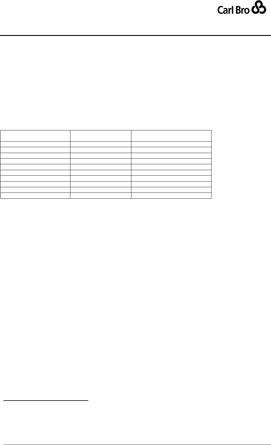
Department for Transport
TransXChange Schema User Guide
Part V
Appendixes
TransXChangeSchemaGuide-2.1-v-45.pdf.doc
Page 220
24 September 2013
16.1 Changes in 2.1
NptgLocality Names cane be specified for new stops using a
AnnotatedNptgLocalityRef
StopPoint Landmark and Street are now optional
17 APPENDIX C – COMPARISON OF TERMINOLOGY TRANSXCHANGE 2.0
The following table compares terminology used in TransXChange 2.0 with terminology in
ATCO CIF & with the AIM exchange format
TransXChange
2.x(Transmodel)
ATCO-CIF
AIM (new model)
Service
Route
ServiceRegistrationGroup
Line
Service
Service
JourneyPattern
-
TripTemplate
JourneyPatternSection
-
TripTemplateSection
VehicleJourney
Journey
Trip
Route
(Track)1
Path
RouteSection
-
PathSection
RouteLink
(Segment)
PathSegment
Track
(Step)
PathStep
Interchange2
Connection
Connection
Table 17-1 – Terminology Cross-Reference
1
Applies to AIM ATCO-CIF extension
2
Interchange has historically been used as a noun to describe a collection of access nodes. This has included
any fixed attributes relating to alighting at one node then boarding at another. The TransXChange 2
terminology is quite different because it refers to the journey-related attributes associated with changing vehicle
