WAM !! Troy Bilt White Outdoor 33 Inch Wide Cut Mower Service Repair Manual
Preview ! Troy-Bilt-White-Outdoor-33-inch-Wide-Cut-Mower-Service-Repair-Manual Gsi Outdoors Lawn Mower Manuals - Lawn Mower Manuals – The Best Lawn Mower Manuals Collection
User Manual: !! Gsi Outdoors Lawn Mower Manuals - Lawn Mower Manuals – The Best Lawn Mower Manuals Collection
Open the PDF directly: View PDF ![]() .
.
Page Count: 23
- 1. Blade drive belt removal
- 2. Deck idler pulley inspection
- 3. Blade Drive belt adjustment
- 4. Blade drive control lever adjustment
- 5. Blade spindle belt replacement
- 6. Blade Brake Replacement
- 7. Wheel drive belt removal and replacement.
- 8. Wheel drive belt adjustment
- 9. Wheel brake adjustment
- 10. Transmission neutral adjustment
- 11. DECK REMOVAL
- 12. Right Spindle removal
- 13. Left Spindle Removal
- 14. Transmission removal
- 15. Installation of Wheel Drive belt Guards - update
- 16. Engine pulley belt guide kit

Service Manual
IMPORTANT: READ SAFETY RULES AND INSTRUCTIONS CAREFULLY
PRINTED IN USA FORM NO.769-00945
This Service Manual is not a substitute for the Operator’s Manual. You must read, understand
and follow all of the directions in this manual as well as the Operator’s Manual before working
on this power equipment.
(10/2003)
753 Wide Cut Mower
TROY-BILT LLC, P.O. BOX 361131, CLEVELAND, OH 44136-0019
www.mymowerparts.com
K&T Saw Shop 606-678-9623 or 606-561-4983
www.mymowerparts.com
K&T Saw Shop 606-678-9623 or 606-561-4983
TABLE OF CONTENTS
Blade Drive Belt Removal ...............................................................................1
Deck Idler Pulley Inspection............................................................................3
Blade Drive Belt Adjustment............................................................................3
Blade Drive Control Lever Adjustment ............................................................4
Blade Spindle Belt Replacement.....................................................................4
Blade Brake Replacement...............................................................................6
Wheel Drive Belt Servicing..............................................................................7
Wheel Drive Belt Adjustment...........................................................................8
Wheel Brake Adjustment.................................................................................9
Transmission Neutral Adjustment....................................................................9
Deck Removal.................................................................................................10
Right Spindle Removal....................................................................................11
Left Spindle Removal ......................................................................................12
Transmission Removal....................................................................................14
Wheel Drive Belt Guards Installation...............................................................16
Engine Pulley Belt Guide Installation...............................................................19
www.mymowerparts.com
K&T Saw Shop 606-678-9623 or 606-561-4983
www.mymowerparts.com
K&T Saw Shop 606-678-9623 or 606-561-4983
Servicing the Troy-Bilt Wide Cut 33” Combination Mower
1
TROY-BILT WIDE CUT MOWER
Model 12A-E753B063 (NEW)
• 9 hp briggs & Stratton I/C OHV engine
• Electric Start
• 33” Deck
• Self-Propelled Multiple Speed Gear Drive
• Peerless Transaxle
• BLade Brake Clutch
• Automatic Parking Brake
• Single Lever Height Adjustment
• 3-in-1 Capacity
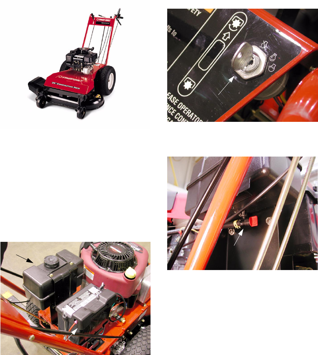
The Model E753B features a standard size battery and
electric start. See Figure 1.
OLDER STYLE ENGINE
Non Electric Start Unit
Figure 1
Gas Tank
Battery
The key switch is located on the right side of the con-
sole. See Figure 2.
The unit also features an oversize fuel tank with a man-
ual shutoff valve. See Figure 3.
Figure 2
Key Switch
Figure 3
Fuel Shutoff
Servicing the Troy-Bilt Wide Cut 33” Combination Mower
www.mymowerparts.com
K&T Saw Shop 606-678-9623 or 606-561-4983
Servicing the Troy-Bilt Wide Cut 33” Combination Mower
2
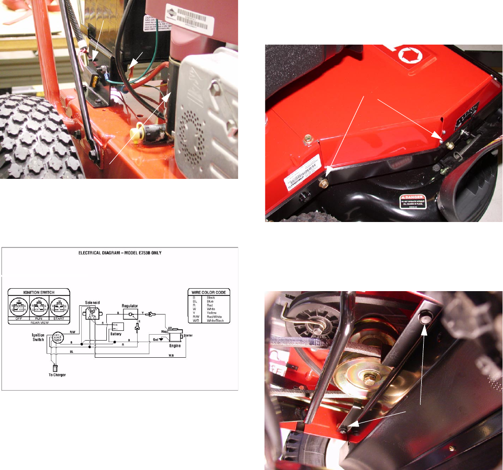
The fuse is located on the right side next to the battery
and the solenoid is mounted on the battery support
bracket under the battery. See Figure 4.
Most electrical problems can be diagnosed using a
ohm meter and checking continuity of the ignition
switch and wires to each component. See Figure 5.
NOTE: The Operator’s Manual that comes with
the unit has a wealth of information regarding
the setup, operation and servicing of this unit.
NOTE: This Service Manual is a supplement to
the Operator’s Manual.
IMPORTANT: Please read, understand and fol-
low all safety procedures listed in the Operator’s
Manual when working on this unit.
CAUTION: Before servicing the unit place it on a
level surface, turn off the engine and let the unit
cool, and disconnect the spark plug wire. On
electric start units, make sure the key is in the
“off” position.
1. BLADE DRIVE BELT REMOVAL
1.1. Make sure the blade drive control is disen-
gaged.
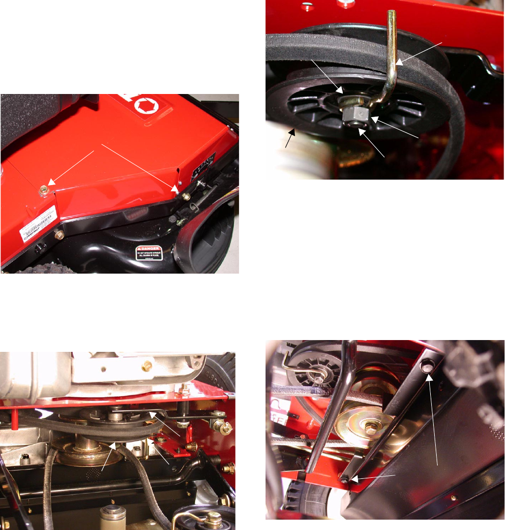
1.2. Using a ½ inch socket remove the four screws
securing the belt cover and removed the cover.
See Figure 6.
1.3. Using a ½ inch socket, remove the two screws
attaching the flap bracket to the frame. Remove
the flap bracket. See Figure 7.
Figure 4
Fuse
Starter Motor
Solenoid
Figure 5
Figure 6
Cover Screws (2 on each side)
Figure 7
Flap Bracket
Mounting Screws
www.mymowerparts.com
K&T Saw Shop 606-678-9623 or 606-561-4983
Servicing the Troy-Bilt Wide Cut 33” Combination Mower
3
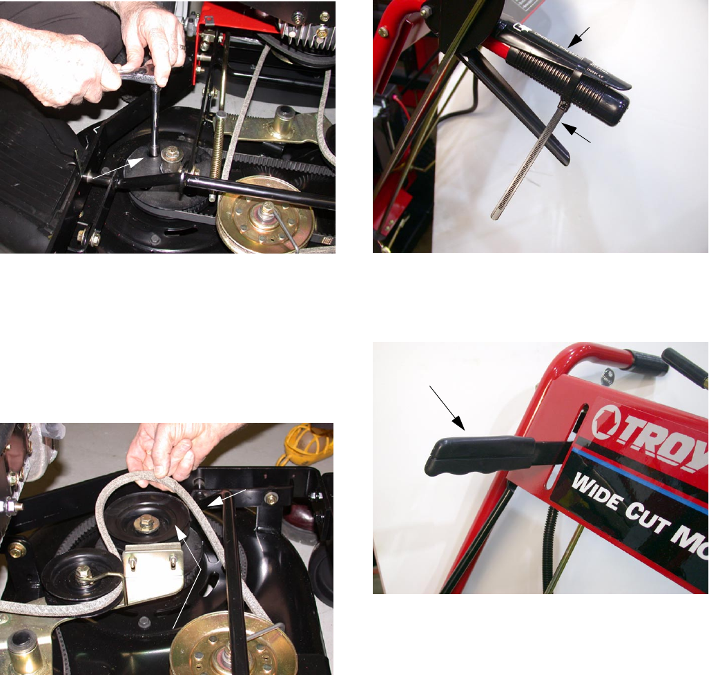
1.4. Using a 9/16 inch socket and opened end
wrench, remove the front idler pulley to allow the
belt to be removed from around the pulley. See
Figure 8.
NOTE: Maintain correct order of parts.
1.5. Using a 9/16 inch socket and opened end
wrench, remove the rear idler pulley to allow the
belt to be removed from around the pulley. See
Figure 8.
NOTE: Maintain correct order of parts. The pul-
ley mounts to the front hole in the idler arm.
1.6. Drop the belt off the engine pulley.
1.7. Replace the belt and assemble in the reverse
order.
NOTE: Maintain orientation of belt guides during
reassembly. See Figure 8.
Figure 8
Front Idler Pulley Rear Idler Pulley
Idler Pulley Mounting Bracket
2. DECK IDLER PULLEY INSPECTION
2.1. Using a 9/16 inch socket and opened end
wrench, remove the front and rear deck idler pul-
leys and inspect for wear.
NOTE: There is a pyramid washer under the
front mounting bracket that helps maintain the
position of the front idler pulley. See Figure 9.
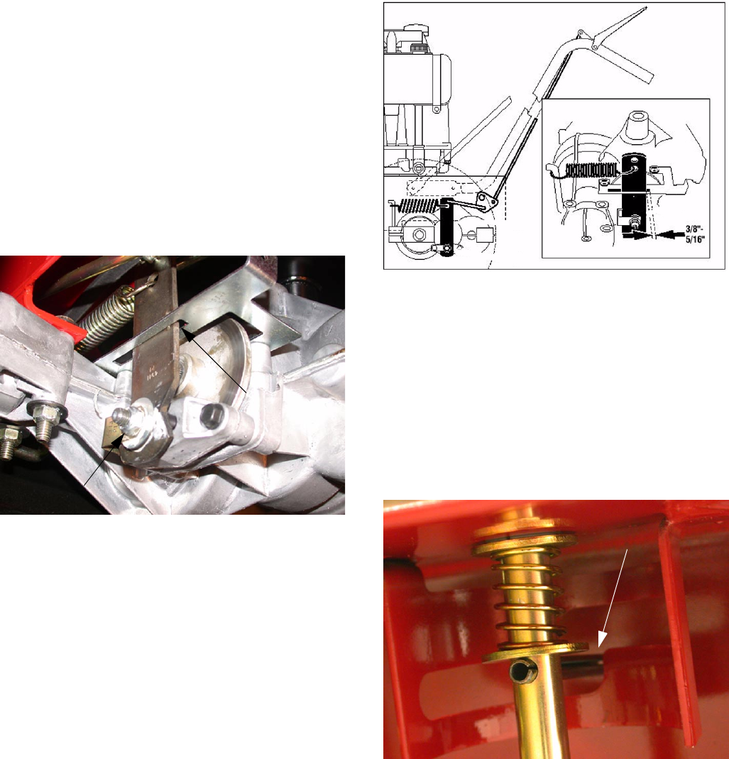
3. BLADE DRIVE BELT ADJUSTMENT
3.1. Using a ½ inch socket remove the four screws
securing the belt cover and remove the cover.
3.2. With mower on level ground, adjust the blade
cutting height to about 3”.
3.3. With the blade drive control disengaged, set a
gap of 1/8” between the spring and the flat
washer on the end of the threaded portion of the
lift crank by adjusting the nut. See Figure 10.
Figure 9
Rear Idler Pulley
Front Idler Pulley
Nut
Nut
Lock Washer
Lock Washer
Flat Washers
Flat Washer
Pyramid Washer
Hex Head
Hex Head
Belt Guide
Belt Guide
Bracket Position
Bracket Position
Cap Screw
Cap Screw
Figure 10
1/8” Gap
www.mymowerparts.com
K&T Saw Shop 606-678-9623 or 606-561-4983
Servicing the Troy-Bilt Wide Cut 33” Combination Mower
4
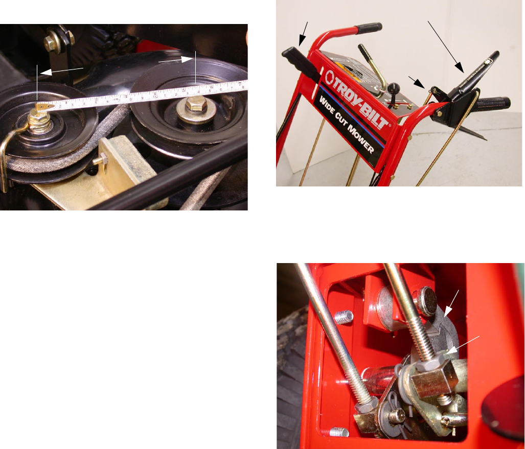
3.4. With the engine OFF have a helper engage the
blade drive. Measure the distance between the
center of the idler pulley and the left drive pulley.
The measurement should be between 5 1/2” and
5 5/8”. See Figure 11.
NOTE: If the blade drive belt slips during opera-
tion it may be necessary to slide the idler pulley
forward in the slot on the idler arm. Loosen the
hardware on the idler pulley and slide the pulley
forward slightly. Tighten the hardware. See Fig-
ure 8.
IMPORTANT: The blades must come to a com-
plete stop when the blade engagement lever is
released.
4. BLADE DRIVE CONTROL LEVER ADJUST-
MENT
NOTE: Make the following adjustment if the
blade drive control lever releases during opera-
tion.
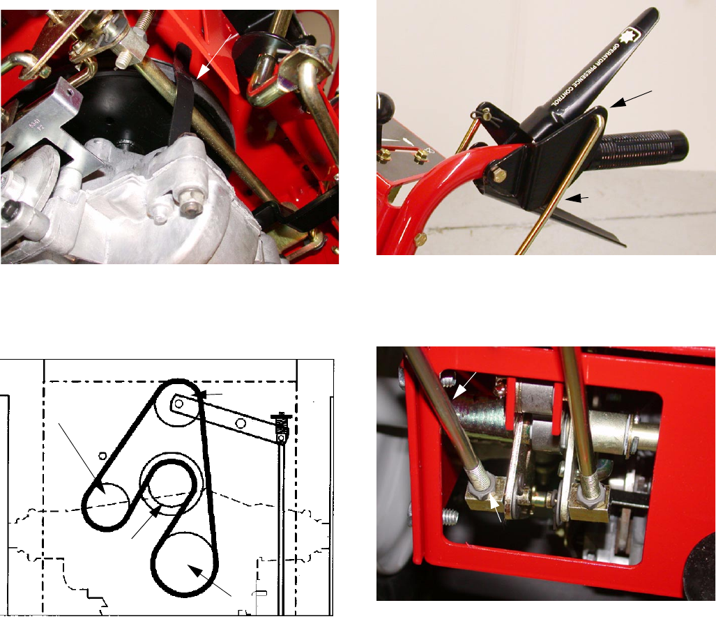
4.1. With the engine off, engage the operator pres-
ence control and the blade drive control. See
Figure 12.
4.2. Without releasing the controls, look inside the
cutout at the left rear of the frame and make sure
that the operators presence control latches are
fully engaged. See Figure 13.
4.3. To adjust, remove the hairpin clip on the upper
end of the operator presence control arm.
4.4. Loosen the hex nut and shorten the rod by one
or two turns. (Do not over adjust.) Tighten the
hex nut securely. See Figure 13.
4.5. If properly adjusted, the blade drive control will
disengage when the operators presence control
is released.
5. BLADE SPINDLE BELT REPLACEMENT
5.1. Using a ½ inch socket remove the four screws
securing the belt cover and removed the cover.
Figure 11
5-1/2” to 5-5/8”
Figure 12
Operator Presence Control
Blade Drive Control
Hairpin Clip
Figure 13
Latched Position
Hex Nut
www.mymowerparts.com
K&T Saw Shop 606-678-9623 or 606-561-4983
Servicing the Troy-Bilt Wide Cut 33” Combination Mower
5
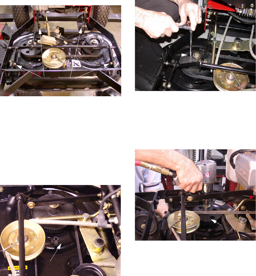
5.2. Using a ½ inch socket loosen the screw securing
the belt tension adjustment bracket and turn it
out of the way. See Figure 14.
5.3. Align the sight holes in the right pulley with the
spindle housing mounting bolts. See Figure 15.
5.4. Using a ½ inch deep socket loosen the four
mounting bolts securing the spindle housing to
the deck. See Figure 15.
5.5. Slide the pulley assembly to the left to loosen
tension on the cogged belt.
5.6. Remove the cogged belt from around the right
cogged pulley.
Figure 14
Belt Tension Adjustment Bracket
Figure 15
Sight Holes (4)
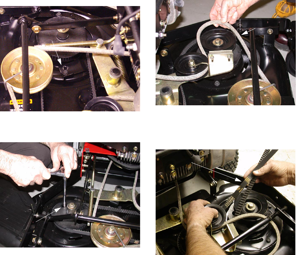
5.7. Temporarily remove the blade drive belt from
around the left blade drive pulley. See Figure 16.
5.8. While holding the Idler arm and brake away from
the left blade drive pulley, remove the toothed
belt from around the left cogged pulley and up
and over the drive pulley. See Figure 17.
5.9. Replace the belt with a new belt.
Figure 16
Blade Drive Belt
Figure 17
Toothed Belt
www.mymowerparts.com
K&T Saw Shop 606-678-9623 or 606-561-4983
Servicing the Troy-Bilt Wide Cut 33” Combination Mower
6
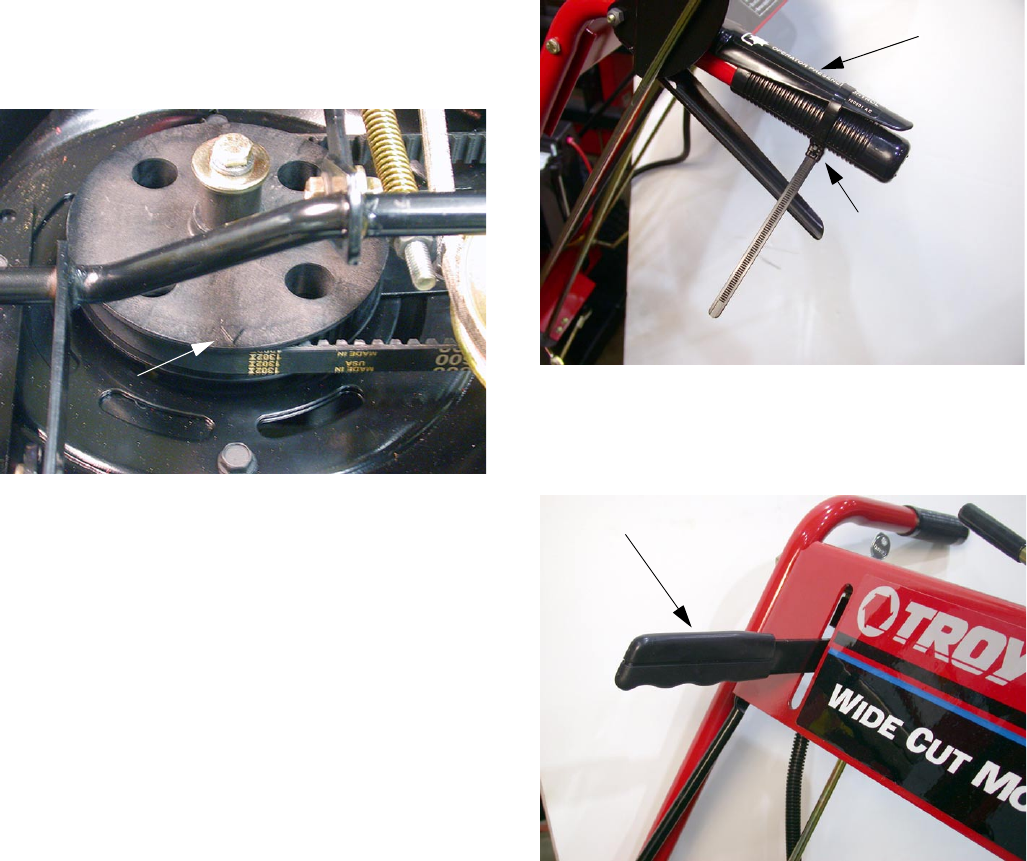
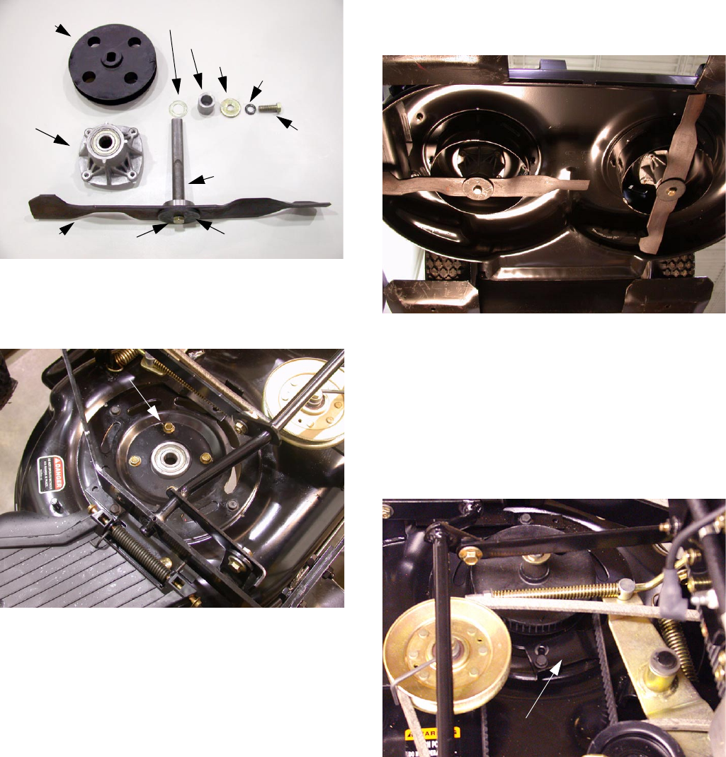
IMPORTANT: Time the blades properly during
reassembly. Set the cutting blades perpendicular
to each other during installation of the toothed
drive belt.There are arrows cast into the cogged
pulleys to help align the blades. Offset these
arrows by 90 degrees. See Figure 18.
NOTE: The arrows do not indicate the blade
position. Blades are 90 degrees offset from the
arrow position.
5.10. Rotate the tension adjustment bracket into posi-
tion and apply tension to the spindle housing
and cogged belt.
5.11. Tighten the adjustment bracket screw.
5.12. Tighten the four spindle mounting bolts to 15 ft.
lbs.
NOTE: Proper belt tension is achieved when the
belt deflects approximately 1/2 inch at the mid-
point between the pulleys when applying moder-
ate finger pressure.
5.13. Reinstall the blade drive belt over the left drive
spindle.
5.14. Install the belt cover.
6. BLADE BRAKE REPLACEMENT
6.1. Using a ½ inch socket remove the four screws
securing the belt cover and removed the cover.
6.2. Secure the operator presence control lever to
the left handlebar using a plastic tie or tape. See
Figure 19.
6.3. Engage the blade control lever to move the
brake pad away from the drive pulley. See Fig-
ure 20.
Figure 18
Blade Alignment Arrow Figure 19
Operator Presence Lever
Plastic Tie
Figure 20
Blade Control Lever Engaged
www.mymowerparts.com
K&T Saw Shop 606-678-9623 or 606-561-4983
Servicing the Troy-Bilt Wide Cut 33” Combination Mower
7
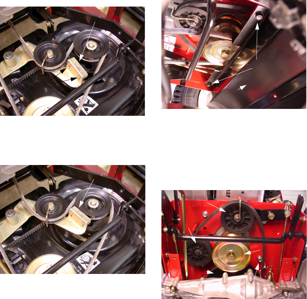
6.4. Using a socket remove the Sems nuts and flat
head screws securing the brake pad to the idler
arm and remove the old brake pad. See Figure
21.
6.5. Loosely install the new brake pad.
6.6. Release the operator presence control and allow
the new brake pad to engage the sheave of the
idler pulley. See Figure 22.
6.7. Tighten the Sems nut to secure the brake pad to
the idler arm.
7. WHEEL DRIVE BELT REMOVAL AND
REPLACEMENT.
NOTE: Some older units may not have all the
belt guides installed.
7.1. Release all mower controls.
Figure 21
Brake Pad
Sems Nuts
Figure 22
Brake pad seats into sheave
7.2. Using a ½ inch socket, remove the two screws
attaching the flap bracket to the frame. Remove
the flap bracket. See Figure 23.
7.3. Using a ½ inch socket remove the four screws
securing the belt cover and remove the cover.
7.4. Temporarily remove the blade drive belt from
around the engine pulley.
7.5. Use a 9/16 inch socket to loosen the locknut
securing the pulley and belt guide to the front
idler bracket. Remove the belt guide and pulley.
See Figure 24.
NOTE: Maintain correct order of parts:
- Pulley
- Washer
- Belt Guide
- Nut
Figure 23
Flap Bracket
Screws
Figure 24
Front Idler Bracket Pulley
Engine Pulley
Trans. Pulley
Backside Idler Pulley
Trans. Pulley Belt Guide Cap Screw
www.mymowerparts.com
K&T Saw Shop 606-678-9623 or 606-561-4983
Servicing the Troy-Bilt Wide Cut 33” Combination Mower
8
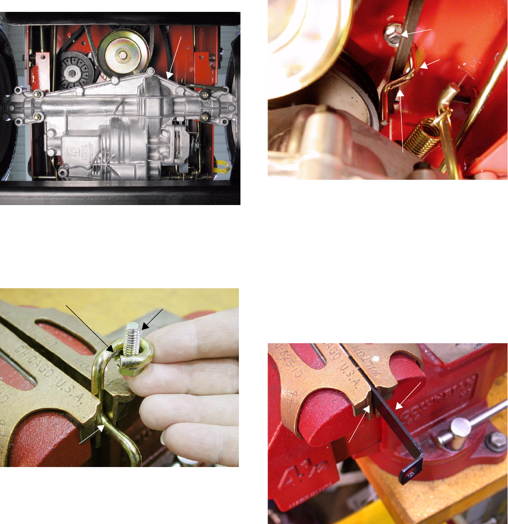
7.6. Use a 9/16 inch socket to loosen the cap screw
securing the transmission pulley belt guide to the
frame and engine mount. Pivot the belt guide
away from the pulley. See Figure 24.
7.7. Using a 1/2 inch socket, loosen the nut securing
the rear belt support bracket to the transmission.
Pivot the belt support away from the belt. See
Figure 25.
7.8. Remove the wheel drive belt from the engine
sheave, backside idler and the transmission pul-
ley. See Figure 26.
7.9. Install a new belt in the reverse order.
NOTE: The new belt must be installed inside
out. The “V” side of the belt lies against the
engine sheave only. The flat side of the belt lies
against the transmission pulley and idler pulleys.
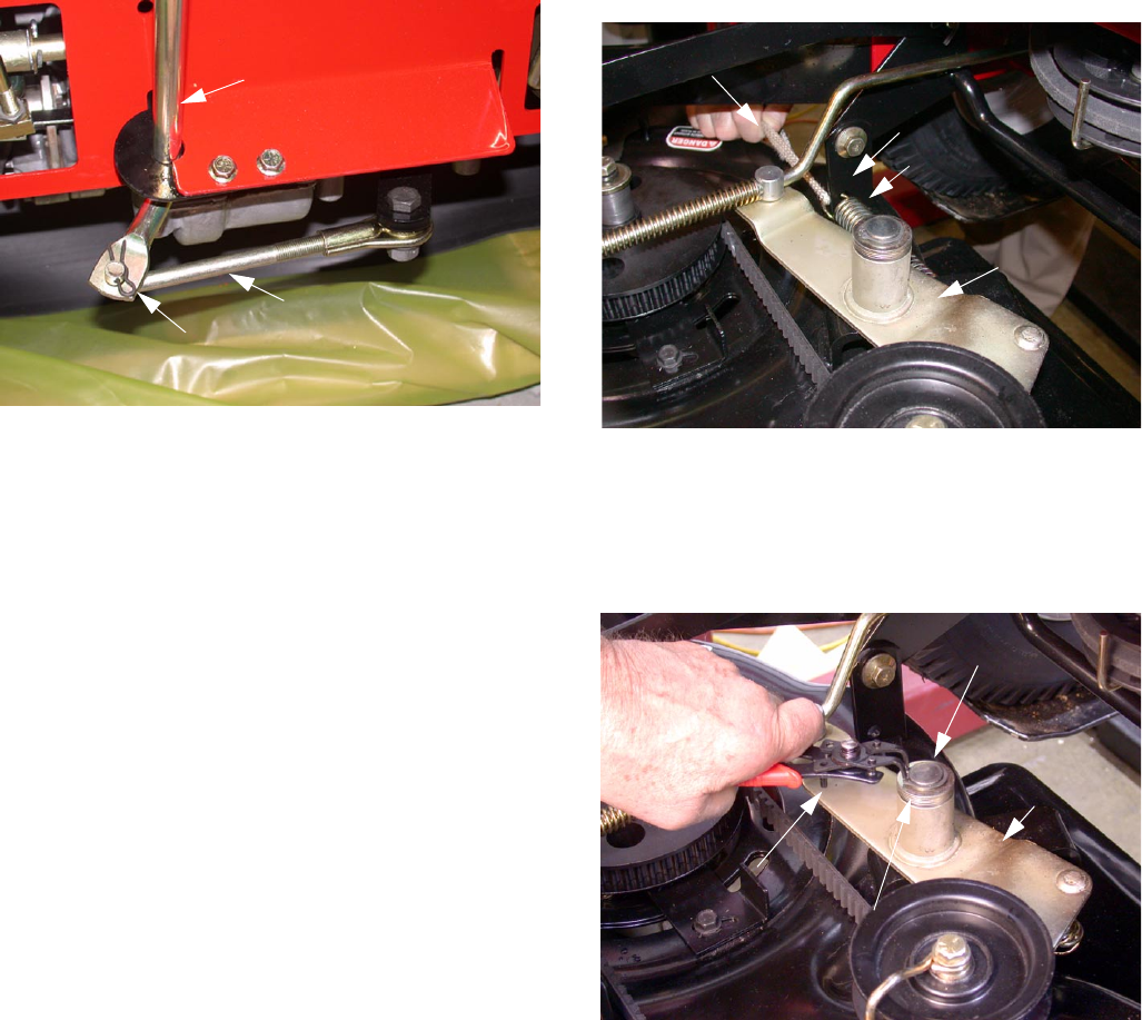
8. WHEEL DRIVE BELT ADJUSTMENT
The wheel drive belt requires adjustment when belt
slippage occurs. This is most noticeable when more
traction is needed (such as going up slopes).
8.1. Remove the hair pin clip from the upper end of
the wheel drive control rod. Slide the rod out of
the lever assembly. See Figure 27.
8.2. Using a 9/16” opened end wrench, loosen the
jam nut on the lower end of the rod. See Figure
28.
8.3. Thread the rod one or two turns clockwise for
more tension.
8.4. Insert the rod back into the hole in the wheel
drive control lever and install the hairpin clip.
Figure 25
Rear Belt Support Bracket
Figure 26
Front Idler
Transmission Pulley
Backside
Idler Pulley
Engine Pulley
INSTALL BELT INSIDE OUT!
Figure 27
Hairpin Clip
Wheel Drive Control
Rod
Figure 28
Jam Nut
Wheel Drive Control Rod
www.mymowerparts.com
K&T Saw Shop 606-678-9623 or 606-561-4983
Servicing the Troy-Bilt Wide Cut 33” Combination Mower
9
8.5. Test the operation of the unit. Repeat the adjust-
ment if necessary.
NOTE: Most comfortable operation will be
obtained when the adjustment allows the lever to
just make contact with the hand grip when suffi-
cient traction is achieved.
8.6. When adjusted properly, tighten the lower jam
nut against the block.
9. WHEEL BRAKE ADJUSTMENT
This adjustment may be required it the unit does not
hold on a hill with the operator presence control disen-
gaged, or if the brake drags with the operator presence
control engaged and the transmission is in neutral.
(The unit should roll freely in this position.)
NOTE: With the operator presence control
released there should be a 3/8” to 5/16” gap
between the back of the brake arm and the
bracket. See Figure 29.
Figure 29
3/8” to 5/16” Gap
Adjustment Nut
9.1. To adjust use a 1/2” wrench to make a small (1/4
turn) adjustment to the brake locknut until the
correct measurement is achieved. It may be nec-
essary to relieve spring tension when decreas-
ing distance. Have an assistant engage the
operator presence control while you adjust the
nut. See Figure 30.
10. TRANSMISSION NEUTRAL ADJUSTMENT
With the unit turned off and the shift lever in the neutral
detent position you should be able to hold down the
operator presence control and roll the unit easily for-
ward and back. Check this from forward and reverse
positions. If the unit is in gear you will need to perform
a neutral adjustment.
10.1. Place the shift lever in the neutral detent position
of the console. See Figure 31.
Figure 30
Figure 31
Shift Lever Roll Pin
in Detent Position
UNDER CONSOLE
www.mymowerparts.com
K&T Saw Shop 606-678-9623 or 606-561-4983
Servicing the Troy-Bilt Wide Cut 33” Combination Mower
10
10.2. Remove the hairpin clip securing the shift link
and lower it from the shift rod. See Figure 32.
10.3. Moved the shift arm back and forth as necessary
into each detent until the transmission is in neu-
tral.
NOTE: Moving the shift arm clockwise all the
way to the left, and then one notch counterclock-
wise should put the transmission in neutral. With
the operator presence control lever down you
should be able to easily roll the unit.
10.4. With the transmission in neutral, rotate the shift
link until the hooked end easily fits into the hole
at the bottom end of the shift rod. See Figure 32.
NOTE: The shift rod must be held in the neutral
position while the shift link is adjusted.
10.5. Secure the shift link into the shift rod with the
hairpin clip removed earlier.
10.6. Recheck the neutral position and readjust i nec-
essary. Check from both the forward and reverse
direction.
11. DECK REMOVAL
11.1. Using a ½ inch socket remove the four screws
securing the belt cover and remove the cover.
11.2. Remove the blade drive belt (see blade drive
belt removal section)
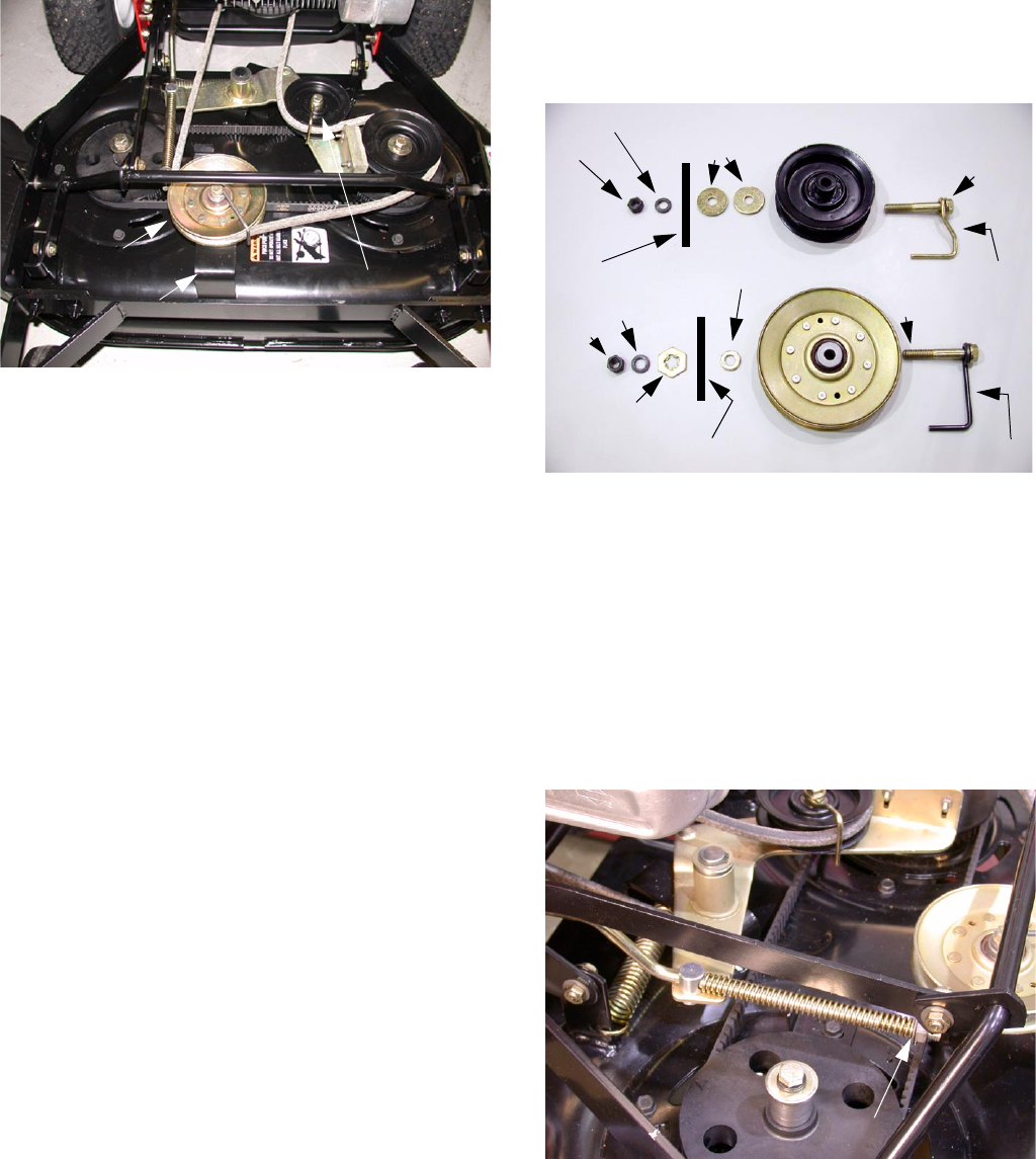
11.3. Using a recoil rope or spring removal tool,
remove the extension spring attached to the
deck bracket and idler arm. See Figure 33.
11.4. Remove the spring from the idler arm.
11.5. Using a medium size 45 degree retaining ring
tool, remove the retaining ring securing the idler
arm to the deck bracket. See Figure 34.
11.6. Remove the flat washers (2-4) and flange bush-
ing from the idler arm. Inspect the flange bush-
ing for wear.
11.7. Remove the idler arm from the deck bracket and
set it on the mower support.
11.8. Support the deck from below.
Figure 32
Shift Rod
Hair Pin Clip
Shift Link
Figure 33
Extension Spring
Recoil Rope
Idler Arm
Deck Bracket
Figure 34
Retaining Ring Pliers
Idler Bracket
Retaining Ring
Flat Washer and Flange Bushing
www.mymowerparts.com
K&T Saw Shop 606-678-9623 or 606-561-4983
Servicing the Troy-Bilt Wide Cut 33” Combination Mower
11
11.9. Using a 9/16 inch socket and open end wrench,
remove the four shoulder bolts, flat washers and
flange locknuts securing the deck to the lift
assemblies. See Figure 35.
NOTE: Maintain the proper orientation of the
shoulder bolts during reassembly.
11.10. Remove the deck from under the unit.
12. RIGHT SPINDLE REMOVAL
12.1. Using a ½ inch socket remove the four screws
securing the belt cover and removed the cover.
12.2. Using a ½ inch socket loosen the screw securing
the belt tension adjustment bracket and turn it
out of the way. See Figure 36.
Figure 35
Shoulder Bolts, Flat Washers and Flange Locknuts
Figure 36
Belt Tension Adjustment Bracket
12.3. Align the sight holes in the right pulley with the
spindle housing deck mounting bolts. See Figure
37.
12.4. Using a ½ inch deep socket loosen the four
mounting bolts securing the right spindle hous-
ing to the deck. See Figure 37.
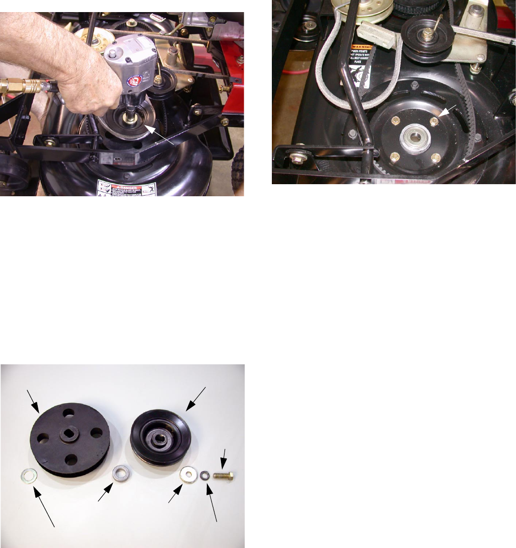
12.5. Using a shop rag to protect your hand, hold the
blade secure while removing the flange lock
screw that secures the spindle shaft with an air
gun and 5/8 inch socket. See Figure 38.
12.6. Remove the cutting blade and spindle shaft from
the spindle housing.
Figure 37
Sight Holes (4)
Figure 38
HOLD BLADE FROM BELOW
Cogged Pulley
www.mymowerparts.com
K&T Saw Shop 606-678-9623 or 606-561-4983
Servicing the Troy-Bilt Wide Cut 33” Combination Mower
12
12.7. Remove the cogged pulley, spacer, washer, lock
washer and screw from the spindle housing.
Components on bench. See Figure 39.
12.8. Using a ½ inch socket remove the four mounting
bolts securing the spindle to the deck. See Fig-
ure 40.
NOTE: Hold the housing from underneath the
deck when removing the final mounting bolt.
Remove the housing from the deck.
12.9. Inspect the housing for excessive wear or dam-
age and replace as needed. See Figure 39.
12.10. Assembly is the reverse order of disassembly.
IMPORTANT: During reassembly place Locktite
242 on the threads of the spindle pulley mount-
ing bolts and torque to 35 ft. lbs. If blades are
removed also torque the blade mounting screws
to 35 ft. lbs.
NOTE: Time the blades properly during reas-
sembly. Set the cutting blades perpendicular to
each other during installation of the toothed drive
belt. See Figure 41.
13. LEFT SPINDLE REMOVAL
13.1. Using a ½ inch socket remove the four screws
securing the belt cover and removed the cover.
13.2. Using a ½ inch socket loosen the screw securing
the belt tension adjustment bracket and turn it
out of the way. See Figure 42.
Figure 39
Cogged Pulley
Spindle
Blade
Spindle Shaft
Blade Mounting Screw Belleville Washer
Special Thrust Washer
Spacer
Flat Washer
Lock Washer
Screw
Figure 40
Spindle Mounting Bolts (4)
Figure 41
Figure 42
Belt Tension Adjustment Bracket
www.mymowerparts.com
K&T Saw Shop 606-678-9623 or 606-561-4983
Servicing the Troy-Bilt Wide Cut 33” Combination Mower
13
13.3. Align the sight holes in the right pulley with the
spindle housing deck mounting bolts. See Figure
43.
13.4. Using a ½ inch deep socket loosen the four
mounting bolts securing the spindle housing to
the deck. See Figure 43.
13.5. Slide the pulley assembly to the left to loosen
tension on the cogged belt.
13.6. Remove the deck drive belt from around the left
spindle pulley. See Figure 44.
Figure 43
Sight Holes
Figure 44
Deck Drive belt
Left Spindle Pulley
13.7. Secure the operator presence control lever to
the left handlebar using a plastic tie or tape. See
Figure 45.
13.8. Engage the blade control lever to move the
brake pad away from the drive pulley. See Fig-
ure 46.
Figure 45
Operator Presence Control
Plastic Tie
Figure 46
Blade Engaged
www.mymowerparts.com
K&T Saw Shop 606-678-9623 or 606-561-4983
Servicing the Troy-Bilt Wide Cut 33” Combination Mower
14
13.9. Using a shop rag to protect your hand, hold the
blade secure while removing the flange lock
screw that secures the left spindle shaft with an
air gun and 5/8 inch socket. See Figure 47.
13.10. Remove the cutting blade and spindle shaft from
the left spindle housing.
NOTE: There will be a lock washer and flat
washer securing the drive pulley to the blade
spindle.
13.11. Remove the drive pulley from the top of the
cogged pulley.
NOTE: There will be a spacer between the drive
pulley and the cogged pulley assembly. See Fig-
ure 48.
13.12. Removed the cogged pulley assembly and spe-
cial thrust washer from the top of the Spindle
assembly.
13.13. Using a ½ inch socket, loosen the four mounting
bolts securing the spindle housing to the deck.
See Figure 49.
NOTE: Hold the housing from underneath the
deck when removing the final mounting bolt.
Remove the housing from the deck.
13.14. Inspect the housing for excessive wear or dam-
age and replace as needed.
13.15. Assembly is the reverse order of disassembly.
IMPORTANT: Torque the spindle housing flange
lock screws to 15 foot pounds during reassem-
bly.
IMPORTANT: During assembly, place Locktite
242 on the threads of the spindle shaft screw
and torque to 35 ft. lbs.
IMPORTANT: Time the blades properly during
reassembly. Set the cutting blades perpendicular
to each other during installation of the toothed
drive belt. Torque the blade mounting screw to
35 ft. lbs.
14. TRANSMISSION REMOVAL
14.1. Remove the blade drive belt (see the Blade
Drive Belt Removal section)
14.2. Remove the wheel drive belt (see the Wheel
Drive Belt Removal section)
NOTE: While it may be possible to remove the
transmission while the deck is installed, it would
be easier to first remove the deck.
14.3. Support the frame off the ground in a way that
allows you to work on the transmission from
Figure 47
HOLD BLADE FROM BELOW
Left Drive Pulley
Figure 48
Cogged Pulley Drive Pulley
Spacer Flat Washer
Lock Washer
Screw
Special Thrust Washer
Figure 49
Spindle Mounting Bolts (4)
www.mymowerparts.com
K&T Saw Shop 606-678-9623 or 606-561-4983
Servicing the Troy-Bilt Wide Cut 33” Combination Mower
15
underneath the unit. You will also be removing
the wheels and transmission from this position.
14.4. Using a ½ inch socket, remove the two screws
attaching the flap bracket to the frame. Remove
the flap bracket. See Figure 50.
14.5. Using a pair of needle nosed pliers, remove the
left rear cotter pin securing the lower brake rod
to the brake arm. See Figure 51.
14.6. Remove the lower brake rod from the brake arm.
Figure 50
Flap Bracket
Mounting Screws
Figure 51
Cotter Pin
Lower Brake Rod
14.7. Using a pair of needle nosed pliers remove the
hair pin securing the shift link rod to the shift rod.
See Figure 52.
14.8. Remove the tang retaining ring securing one of
the wheels. See Figure 53.
14.9. Remove the special washers and the wheel.
NOTE: Additional wheel spacing washers can
be added when required.
Figure 52
Hair Pin
Shift Rod
Shift Link Rod
Figure 53
Tang Retaining Ring
www.mymowerparts.com
K&T Saw Shop 606-678-9623 or 606-561-4983
Servicing the Troy-Bilt Wide Cut 33” Combination Mower
16
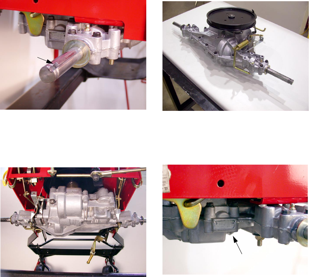
14.10. Remove the square key from the axle. See Fig-
ure 54.
14.11. Repeat for the other wheel.
14.12. Using a ½ inch socket and opened end wrench
remove the top locknuts, flat washers and
screws securing the transmission to the frame.
See Figure 55.
NOTE: Support the transmission during this pro-
cedure.
14.13. Remove the transmission from the unit for ser-
vice. See Figure 56.
NOTE: Contact Tecumseh-Peerless for trans-
mission service information during the warranty
period. Model number information is located on
the right side of the transmission. See Figure
57.
15. INSTALLATION OF WHEEL DRIVE BELT
GUARDS - UPDATE
NOTE: Current production units have additional
belt guards installed at the factory. This update
will cover older units without pulley belt guards.
On older units the long run of the wheel drive belt cre-
ates several issues.
• The belt may come off one of the pulleys.
• The belt may not fully disengage from the engine
pulley, causing engine creep or hard shifting
Figure 54
Square Key
Figure 55
Transmission Mounting Bolts (4)
Figure 56
Figure 57
Transmission Model Number
www.mymowerparts.com
K&T Saw Shop 606-678-9623 or 606-561-4983
Servicing the Troy-Bilt Wide Cut 33” Combination Mower
17
A kit is available to correct these situations.
KIT NUMBER:
Contents:
• Belt Guide - 1760096
• Belt Guide - 1769522
• Belt Support Bracket - 1768381001
Installation procedures are as follows:
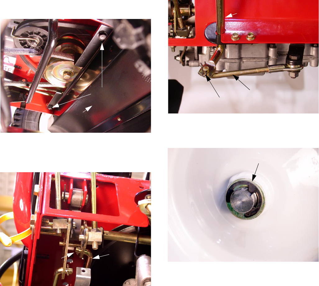
15.1. Using a ½ inch socket, remove the four flange
screws securing the Belt Guard cover to the
mower support frame. See Figure 58.
15.2. Using a 9/16 inch socket remove the lock nut
securing the idler pulley to the idler arm. See
Figure 59.
Figure 58
Flange Screws (two on each side)
Figure 59
Idler Arm
Idler Pulley
Lock Nut
15.3. Reinstall the idler pulley onto the carriage bolt
followed by the original flat washer, the new belt
guide (1760096) and secure it with the original
lock nut. See Figure 60.
NOTE: Face the belt guide towards the front of
the unit. The flat washer must go between the
Guide and the pulley in order to provide clear-
ance for the guide.
15.4. Reinstall the belt guard cover.
15.5. Using a ½ inch socket and extension, remove
the two flange screws that secure the flap
bracket to the frame. Remove the flap bracket
and set it aside. See Figure 61.
Figure 60
Idler Pulley
Belt Guide
Flat Washer
Lock Nut
Carriage Bolt
(Between Guide
and Pulley)
Figure 61
Flange Screws
www.mymowerparts.com
K&T Saw Shop 606-678-9623 or 606-561-4983
Servicing the Troy-Bilt Wide Cut 33” Combination Mower
18
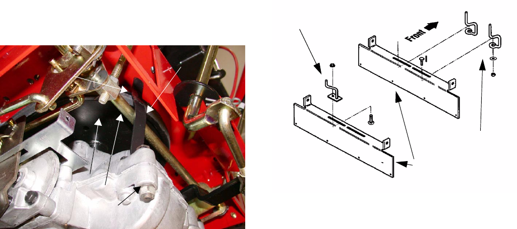
15.6. Using a 9/16 inch socket and extension, remove
the left rear engine mounting hex cap screw.
See Figure 62.
15.7. Place the belt guide (1769522) in a vise and
using a cold chisel, open the eyelet until the hex
cap screws can pass through the opening. See
Figure 63.
15.8. Reinstall the hex cap screw through the frame
and into the engine. See Figure 64.
15.9. Align the belt guide so that the V belt is on the
inside and on top of the guide.
NOTE: Make sure that the V belt does not drag
on the guide when engaged and that the lower
portion of the guide is at least 1/8 inch away
from the pulley.
15.10. Use a vice to straighten the upper bend in the
belt support bracket. (1768381001) See Figure
65.
Figure 62
View from directly below transaxle
Left rear engine mounting cap screw
(Hidden
above
transaxle)
Figure 63
Belt Guide
Hex Cap ScrewPry open
Figure 64
Engine Mounting
Hex Cap Screw
Belt Guide
Belt routing and Guide orientation are important
Figure 65
Upper bend straightened
Belt Support Bracket
www.mymowerparts.com
K&T Saw Shop 606-678-9623 or 606-561-4983
Servicing the Troy-Bilt Wide Cut 33” Combination Mower
19
15.11. Using a 2 inch by ¼ - 20 bolt, lock washer, and
hex nut (not supplied in kit) attach the belt sup-
port bracket to the top of the transaxle using the
empty bolt hole at the left rear of the transaxle.
See Figure 66.
NOTE: The guide must be bent to clear the pivot
shaft assembly while maintaining a distance of
1/8th inch of clearance from the transaxle pulley.
16. ENGINE PULLEY BELT GUIDE KIT
NOTE: Some older units have a flap bracket that
uses removable engine pulley belt guides.
Updated belt guides have been manufactured as
a kit. Part Number 1770557. If your unit uses the
older style guides, obtain the update kit. The kit
Figure 66
Belt Support Bracket
Empty Bolt Hole
Pivot Shaft
1/8” clearance
Transaxle Pulley
contains all installation directions. See Figure
67.
NOTE: The latest production of these units uses
a newer flap bracket that integrates the belt
guides into the metal stamping. This newer flap
bracket will NOT fit on older units.
Figure 67
Flap Bracket
Older Style Guides
Newer Style Guides
www.mymowerparts.com
K&T Saw Shop 606-678-9623 or 606-561-4983
