UDOO BOLT MANUAL
User Manual:
Open the PDF directly: View PDF ![]() .
.
Page Count: 69
BOLT
UDOO BOLT User Manual - Rev. First Edition: 0.1 - Last Edition: 0.4 - Author: S.B. - Reviewed by L.V. Copyright © 2018 SECO S.p.A.
2
This manual is released under Creative Commons Attribution-NonCommercial-ShareAlike 4.0 International (CC BY-NC-SA 4.0) license
Every effort has been made to ensure the accuracy of this manual. However, SECO S.p.A. accepts no responsibility for any inaccuracies, errors or omissions
herein. SECO S.p.A. reserves the right to change precise specifications without prior notice to supply the best product possible.
To get the required assistance for any and possible issues, please contact us using the dedicated web form available at http://www.udoo.org/customer-
care/open.php.
Our team is ready to assist.
Revision
Date
Note
Ref
0.1
12 December 2018
First Internal Release.
SB
0.2
12 December 2018
R&D review suggestions applied
SB
0.3
13 December 2018
LEDs and buttons descriptions added
SB
0.4
18 December 2018
Power consumptions REV B updated
SB
REVISION HISTORY

BOLT
UDOO BOLT User Manual - Rev. First Edition: 0.1 - Last Edition: 0.4 - Author: S.B. - Reviewed by L.V. Copyright © 2018 SECO S.p.A.
3
INDEX
INTRODUCTION .......................................................................................................................................................................... 6 Chapter 1.
1.1 Warranty ........................................................................................................................................................................................................................................ 7
1.2 Information and assistance ............................................................................................................................................................................................................. 8
1.3 RMA number request ..................................................................................................................................................................................................................... 8
1.4 Safety ............................................................................................................................................................................................................................................ 9
1.5 Electrostatic discharges ................................................................................................................................................................................................................. 9
1.6 RoHS compliance .......................................................................................................................................................................................................................... 9
1.7 FCC certification .......................................................................................................................................................................................................................... 10
1.8 ISED certification .......................................................................................................................................................................................................................... 11
1.9 Terminology and definitions .......................................................................................................................................................................................................... 12
1.10 Reference specifications .............................................................................................................................................................................................................. 14
OVERVIEW ............................................................................................................................................................................... 15 Chapter 2.
2.1 Introduction .................................................................................................................................................................................................................................. 16
2.2 Technical specifications ............................................................................................................................................................................................................... 17
2.3 Electrical specifications ................................................................................................................................................................................................................ 18
2.3.1 RTC Battery ................................................................................................................................................................................................................................................ 18
2.3.2 Power consumption ..................................................................................................................................................................................................................................... 19
2.3.3 Power rails naming convention ..................................................................................................................................................................................................................... 20
2.4 Mechanical specifications............................................................................................................................................................................................................. 21
2.5 Block diagram .............................................................................................................................................................................................................................. 22
CONNECTORS ......................................................................................................................................................................... 23 Chapter 3.
3.1 Introduction .................................................................................................................................................................................................................................. 24
3.2 Connectors overview ................................................................................................................................................................................................................... 25
3.3 Connectors description ................................................................................................................................................................................................................ 26
3.3.1 Ethernet connector ...................................................................................................................................................................................................................................... 26
3.3.2 USB ports ................................................................................................................................................................................................................................................... 27
3.3.3 HDMI connectors ........................................................................................................................................................................................................................................ 30
3.3.4 Audio interfaces ........................................................................................................................................................................................................................................... 32
3.3.5 Buttons / LED header .................................................................................................................................................................................................................................. 33
3.3.6 SATA connectors ........................................................................................................................................................................................................................................ 34
3.3.7 M.2 SATA/PCI-e Slot: Socket 2 Key B type 2242/2260 ................................................................................................................................................................................ 35
3.3.8 M.2 Connectivity Slot: Socket 1 Key E Type 2230 ......................................................................................................................................................................................... 36
3.3.9 M.2 NVMe Slot: Socket 3 Key M Type 2280 ................................................................................................................................................................................................. 38

BOLT
UDOO BOLT User Manual - Rev. First Edition: 0.1 - Last Edition: 0.4 - Author: S.B. - Reviewed by L.V. Copyright © 2018 SECO S.p.A.
4
3.3.10 FAN connector ............................................................................................................................................................................................................................................ 39
3.3.11 ARDUINO interface .................................................................................................................................................................................................................................... 40
3.3.12 GROVE connectors ..................................................................................................................................................................................................................................... 41
3.3.13 Embedded Controller I/O Header ................................................................................................................................................................................................................. 42
3.3.14 IR Receiver .................................................................................................................................................................................................................................................. 44
3.3.15 UEFI BIOS Default Restore switch ................................................................................................................................................................................................................. 44
UEFI BIOS SETUP ..................................................................................................................................................................... 45 Chapter 4.
4.1 Aptio setup Utility ......................................................................................................................................................................................................................... 46
4.2 Main menu .................................................................................................................................................................................................................................. 47
4.2.1 System Time / System Date ......................................................................................................................................................................................................................... 47
4.3 Advanced menu .......................................................................................................................................................................................................................... 48
4.3.1 AMD CBS submenu .................................................................................................................................................................................................................................... 49
4.3.2 AMD PBS submenu .................................................................................................................................................................................................................................... 51
4.3.3 Battery Failure Manager submenu ................................................................................................................................................................................................................. 52
4.3.4 Trusted computing submenu ........................................................................................................................................................................................................................ 52
4.3.5 ACPI Settings .............................................................................................................................................................................................................................................. 53
4.3.6 SATA presence submenu ............................................................................................................................................................................................................................ 53
4.3.7 DXIO Settings submenu ............................................................................................................................................................................................................................... 53
4.3.8 S5 RTC Wake Settings submenu ................................................................................................................................................................................................................. 55
4.3.9 Serial Port Console Redirection submenu ..................................................................................................................................................................................................... 56
4.3.10 CPU configuration submenu......................................................................................................................................................................................................................... 57
4.3.11 AMI graphic Output Protocol Policy submenu ................................................................................................................................................................................................ 57
4.3.12 PCI Subsystem Settings submenu ............................................................................................................................................................................................................... 57
4.3.13 Network Stack configuration submenu .......................................................................................................................................................................................................... 58
4.3.14 CSM configuration submenu ........................................................................................................................................................................................................................ 59
4.3.15 NVMe configuration submenu ...................................................................................................................................................................................................................... 59
4.3.16 SDIO configuration submenu ........................................................................................................................................................................................................................ 60
4.3.17 USB configuration submenu ......................................................................................................................................................................................................................... 60
4.3.18 Main Thermal Configuration submenu ........................................................................................................................................................................................................... 61
4.3.19 SMBIOS Information .................................................................................................................................................................................................................................... 61
4.4 Chipset menu .............................................................................................................................................................................................................................. 62
4.4.1 South Bridge Configuration submenu............................................................................................................................................................................................................ 62
4.4.2 North Bridge Configuration submenu ............................................................................................................................................................................................................ 62
4.5 Security menu.............................................................................................................................................................................................................................. 63
4.5.1 Secure Boot submenu ................................................................................................................................................................................................................................. 63
Disabled / Enabled ........................................................................................................................................................................................ 64
4.6 Boot menu .................................................................................................................................................................................................................................. 65

BOLT
UDOO BOLT User Manual - Rev. First Edition: 0.1 - Last Edition: 0.4 - Author: S.B. - Reviewed by L.V. Copyright © 2018 SECO S.p.A.
5
4.7 Save & Exit menu ......................................................................................................................................................................................................................... 66
APPENDICES............................................................................................................................................................................ 67 Chapter 5.
5.1 Accessories ................................................................................................................................................................................................................................. 68
5.1.1 M.2 Dual network modules .......................................................................................................................................................................................................................... 68
5.1.2 I/O Expansion board .................................................................................................................................................................................................................................... 68

BOLT
UDOO BOLT User Manual - Rev. First Edition: 0.1 - Last Edition: 0.4 - Author: S.B. - Reviewed by L.V. Copyright © 2018 SECO S.p.A.
6
Chapter 1.
Warranty
Information and assistance
RMA number request
Safety
Electrostatic discharges
RoHS compliance
Terminology and definitions
Reference specifications
BOLT
UDOO BOLT User Manual - Rev. First Edition: 0.1 - Last Edition: 0.4 - Author: S.B. - Reviewed by L.V. Copyright © 2018 SECO S.p.A.
7
1.1 Warranty
This product is subject to the Italian Law Decree 24/2002, acting European Directive 1999/44/CE on matters of sale and warranties to consumers.
The warranty on this product lasts for 2 years.
Under the warranty period, the Supplier guarantees the buyer assistance and service for repairing, replacing or credit of the item, at the Supplier’s own discretion.
Items cannot be returned unless previously authorized by the supplier.
The authorization is released after completing the specific form available on the web-site http://www.udoo.org/customer-care/ (Open a New Ticket Return
Merchandise Application). The RMA authorization number must be put both on the packaging and on the documents shipped with the items, which must include
all the accessories in their original packaging, with no signs of damage to, or tampering with, any returned item.
The error analysis form identifying the fault type must be completed by the customer and has must accompany the returned item.
Following a technical analysis, the supplier will verify if all the requirements, for which a warranty service applies, are met. If the warranty cannot be applied, the
Supplier will calculate the minimum cost of this initial analysis on the item and the repair costs. Costs for replaced components will be calculated separately.
Warning!
All changes or modifications to the equipment not explicitly approved by SECO S.p.A. could impair the equipment’s functionalities and could
void the warranty

BOLT
UDOO BOLT User Manual - Rev. First Edition: 0.1 - Last Edition: 0.4 - Author: S.B. - Reviewed by L.V. Copyright © 2018 SECO S.p.A.
8
1.2 Information and assistance
What do I have to do if I’m experiencing problems with my product?
The following services are available:
UDOO website: visit http://www.udoo.org to receive the latest information on the product. In most cases it is possible to find useful information to solve the
problem.
UDOO Forum: join to the community of UDOO users. In the forum, available at http://www.udoo.org/forum/, it is possible to search the multiple topics of
the community, and look for other users that had the same kind of problem - and how they solved it. It is also possible to post new topics to ask for
specific help.
Repair centre: it is possible to send the faulty product to the SECO Repair Centre. In this case, follow this procedure:
o Returned items must be accompanied by a RMA Number. Items sent without the RMA number will be not accepted.
o Returned items must be shipped in an appropriate package. SECO is not responsible for damages caused by accidental drop, improper usage, or
customer neglect.
Note: Please have the following information before asking for technical assistance:
Name and serial number of the product;
Description of Customer’s peripheral connections;
Description of Customer’s software (operating system, version, application software, etc.);
A complete description of the problem;
The exact words of every kind of error message encountered.
1.3 RMA number request
To request a RMA number, please visit UDOO web-site. On the bottom of the page, please select “Customer Care”, click on the “Open a New ticket” button and.
A RMA Number will be sent within 1 working day (only for on-line RMA requests).

BOLT
UDOO BOLT User Manual - Rev. First Edition: 0.1 - Last Edition: 0.4 - Author: S.B. - Reviewed by L.V. Copyright © 2018 SECO S.p.A.
9
This product should be operated in a well-ventilated environment and, if used inside a case, the case should not be covered.
This product should be elevated on a stable, flat, electrically non-conductive surface whilst in operation, and clear from any object that can
induce a short-circuit.
Do not expose it to water, moisture or heat from any source; UDOO BOLT is designed for reliable operation at normal ambient room
temperatures.
Avoid handling the warm and moving parts (like the fan) and generally the printed circuit board while it is powered
Only handle by the edges to minimise the risk of electrostatic discharge damage.
Take care whilst handling to avoid mechanical or electrical damage to the printed circuit board and connectors. Also use a grounded
wrist strap or touch a safely grounded object before you handle components.
1.4 Safety
The UDOO BOLT board uses only extremely-low voltages.
While handling the board, please use extreme caution to avoid any kind of risk or damages to electronic components.
CE certification retained using only the UDOO BOLT qualified Power Supply. When not using UDOO BOLT qualified Power Supply, use 19VDC (min 60W power)
PSUs certified for your country (make sure that the power cable is less than 3 mt. long).
1.5 Electrostatic discharges
The UDOO BOLT board, like any other electronic product, is an electrostatic sensitive device: high voltages caused by static electricity could damage some or all
the devices and/or components on-board.
1.6 RoHS compliance
The UDOO BOLT board is designed using RoHS compliant components and is manufactured on a lead-free production line. It is therefore fully RoHS compliant.
BOLT
UDOO BOLT User Manual - Rev. First Edition: 0.1 - Last Edition: 0.4 - Author: S.B. - Reviewed by L.V. Copyright © 2018 SECO S.p.A.
10
1.7 FCC certification
This device complies with part 15 of the FCC Rules. Operation is subject to the following two conditions:
(1) This device may not cause harmful interference, and
(2) this device must accept any interference received, including interference that may cause undesired operation.
This equipment has been tested and found to comply with the limits for a Class B digital device, pursuant to part 15 of the FCC Rules. These limits are designed to
provide reasonable protection against harmful interference in a residential installation. This equipment generates, uses and can radiate radio frequency energy and,
if not installed and used in accordance with the instructions, may cause harmful interference to radio communications. However, there is no guarantee that
interference will not occur in a particular installation. If this equipment does cause harmful interference to radio or television reception, which can be determined by
turning the equipment off and on, the user is encouraged to try to correct the interference by one or more of the following measures:
Reorient or relocate the receiving antenna.
Increase the separation between the equipment and receiver.
Connect the equipment into an outlet on a circuit different from that to which the receiver is connected.
Consult the dealer or an experienced radio/TV technician for help.
To comply with FCC RF exposure compliance requirements, a separation distance of at least 20 cm must be maintained between the antenna of this
device and all nearby persons.
SECO S.p.A.
Model: UDOO BOLT xxxxxxx
FCC ID: xxxxxxx
IC: xxxxxxx
Warning!
Changes or modifications not expressly approved by the party responsible for compliance could void the user’s authority to operate the
equipment.

BOLT
UDOO BOLT User Manual - Rev. First Edition: 0.1 - Last Edition: 0.4 - Author: S.B. - Reviewed by L.V. Copyright © 2018 SECO S.p.A.
11
1.8 ISED certification
This device complies with Industry Canada licence-exempt RSS standard(s).
Operation is subject to the following two conditions:
(1) This device may not cause interference
(2) this device must accept any interference, including interference that may cause undesired operation of the device.
Le présent appareil est conforme aux CNR d’Industrie Canada applicables aux appareils radio exempts de licence.
L’exploitation est autorisée aux deux conditions suivantes:
(1) l’appareil ne doit pas produire de brouillage, et
(2) l’utilisateur de l’appareil doit accepter tout brouillage radioélectrique subi, même si le brouillage est susceptible d’en compromettre le fonctionnement.
Ce dispositif a été conçu pour fonctionner avec les antennes fournies avec ce produit. L’utilisation d’autres antennes peut enfreindre les règles industrielles du
Canada et annuler l’autorité de l’utilisateur quant au fonctionnement de l’équipement.
This device complies with RSS-210, ICES-3(B)/NMB-3(B)

BOLT
UDOO BOLT User Manual - Rev. First Edition: 0.1 - Last Edition: 0.4 - Author: S.B. - Reviewed by L.V. Copyright © 2018 SECO S.p.A.
12
1.9 Terminology and definitions
ACPI Advanced Configuration and Power Interface, an open industrial standard for the board’s devices configuration and power management
AHCI Advanced Host Controller Interface, a standard which defines the operation modes of SATA interface
API Application Program Interface, a set of commands and functions that can be used by programmers for writing software for specific Operating
Systems
BIOS Basic Input / Output System, the Firmware Interface that initializes the board before the OS starts loading
CEC Consumer Electronics Control, an HDMI feature which allows controlling more devices connected together by using only one remote control
DDC Display Data Channel, a kind of I2C interface for digital communication between displays and graphics processing units (GPU)
DDR Double Data Rate, a typology of memory devices which transfer data both on the rising and on the falling edge of the clock
DDR4 DDR, 4th generation
EC Embedded Controller
GbE Gigabit Ethernet
Gbps Gigabits per second
GND Ground
GPI/O General purpose Input/Output
HD Audio High Definition Audio, most recent standard for hardware codecs developed by Intel® in 2004 for higher audio quality
HDMI High Definition Multimedia Interface, a digital audio and video interface
I2C Bus Inter-Integrated Circuit Bus, a simple serial bus consisting only of data and clock line, with multi-master capability
M.2 Specifications for internal expansion modules, which defines many pinouts and sizes for different purposes. Can include SATA, PCI Express,
USB, UART, DP interfaces
Mbps Megabits per second
MMC/eMMC MultiMedia Card / embedded MMC, a type of memory card, having the same interface as the SD card. The eMMC is the embedded version of
the MMC. They are devices that incorporate the flash memories on a single BGA chip.
N.A. Not Applicable
N.C. Not Connected
OpenCL Open Computing Language, a software library based on C99 programming language, conceived explicitly to realise parallel computing using
Graphics Processing Units (GPU)
OpenGL Open Graphics Library, an Open Source API dedicated to 2D and 3D graphics
OS Operating System

BOLT
UDOO BOLT User Manual - Rev. First Edition: 0.1 - Last Edition: 0.4 - Author: S.B. - Reviewed by L.V. Copyright © 2018 SECO S.p.A.
13
PCI-e Peripheral Component Interface Express
PSU Power Supply Unit
PWM Pulse Width Modulation
PWR Power
PXE Preboot Execution Environment, a way to perform the boot from the network ignoring local data storage devices and/or the installed OS
SATA Serial Advance Technology Attachment, a differential full duplex serial interface for Hard Disks
SD Secure Digital, a memory card type
SDHC Secure Digital Host Controller
SDIO Secure Digital Input/Output, an evolution of the SD standard that allows the use of the same SD interface to drive different Input/Output devices,
like cameras, GPS, Tuners and so on
SM Bus System Management Bus, a subset of the I2C bus dedicated to communication with devices for system management, like a smart battery and
other power supply-related devices
SPI Serial Peripheral Interface, a 4-Wire synchronous full-duplex serial interface which is composed of a master and one or more slaves, individually
enabled through a Chip Select line
TBM To Be Measured
TDP Thermal Design Power, an indication of the amount of heat generated by the processor that must be used for the design of the thermal solution.
TMDS Transition-Minimized Differential Signaling, a method for transmitting high speed serial data, normally used on DVI and HDMI interfaces
UEFI Unified Extensible Firmware Interface, a specification defining the interface between the OS and the board’s firmware. It is meant to replace the
original BIOS interface
UMA Unified Memory Architecture, synonym of Integrated Graphics, uses a portion of a computer’s system RAM dedicated to graphics rather than
using dedicated graphics memory only.
USB Universal Serial Bus
V_REF Voltage reference Pin
xHCI eXtensible Host Controller Interface, Host controller for USB 3.0 ports, which can also manage USB 2.0 and USB1.1 ports
BOLT
UDOO BOLT User Manual - Rev. First Edition: 0.1 - Last Edition: 0.4 - Author: S.B. - Reviewed by L.V. Copyright © 2018 SECO S.p.A.
14
1.10 Reference specifications
Here below it is a list of applicable industry specifications and reference documents.
Reference
Link
ACPI
http://www.acpi.info
AHCI
http://www.intel.com/content/www/us/en/io/serial-ata/ahci.html
DDC
http://www.vesa.org
Gigabit Ethernet
http://standards.ieee.org/about/get/802/802.3.html
HD Audio
http://www.intel.com/content/dam/www/public/us/en/documents/product-specifications/high-definition-audio-specification.pdf
HDMI
http://www.hdmi.org/index.aspx
I2C
http://www.nxp.com/documents/other/UM10204_v5.pdf
Intel® Front Panel I/O connectivity DG
http://www.formfactors.org/developer/specs/A2928604-005.pdf
M.2
http://pcisig.com/specifications
MMC/eMMC
http://www.jedec.org/committees/jc-649
OpenCL
http://www.khronos.org/opencl
OpenGL
http://www.opengl.org
PCI Express
http://www.pcisig.com/specifications/pciexpress
SATA
https://www.sata-io.org
SD Card Association
https://www.sdcard.org/home
SM Bus
http://www.smbus.org/specs
TMDS
http://www.siliconimage.com/technologies/tmds
UEFI
http://www.uefi.org
USB 2.0 and USB OTG
http://www.usb.org/developers/docs/usb_20_070113.zip
USB 3.0
http://www.usb.org/developers/docs/usb_30_spec_070113.zip
xHCI
http://www.intel.com/content/www/us/en/io/universal-serial-bus/extensible-host-controler-interface-usb-xhci.html?wapkw=xhci
AMD Ryzen Embedded V1000
https://www.amd.com/en/products/embedded-ryzen-v1000-series

BOLT
UDOO BOLT User Manual - Rev. First Edition: 0.1 - Last Edition: 0.4 - Author: S.B. - Reviewed by L.V. Copyright © 2018 SECO S.p.A.
16
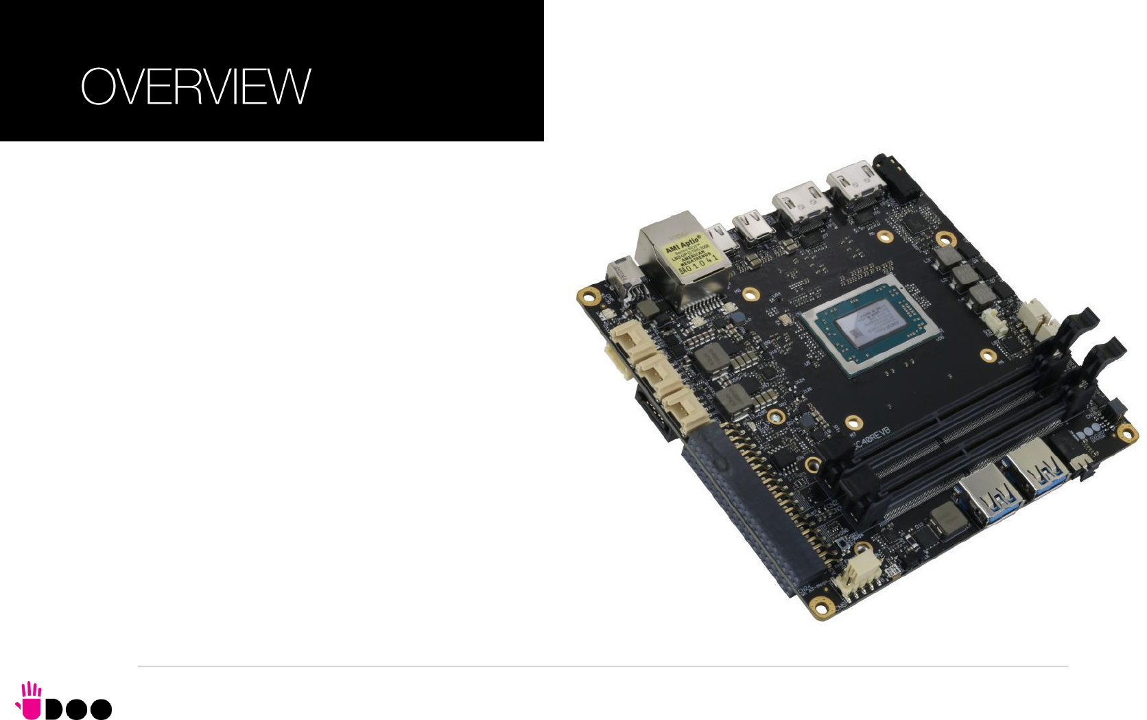
2.1 Introduction
The UDOO BOLT is a portable, breakthrough supercomputer that goes up to 3.6 GHz thanks to the brand-new AMD Ryzen Embedded V1000 SoC, a top-
notch, multicore CPU with a powerful mobile GPU - AMD Radeon Vega 8 or AMD Radeon Vega 3 Graphics, the most incredible GPUs ever seen on a maker
platform and an Arduino Leonardo compatible platform, all wrapped into one.
The UDOO BOLT can mount a Dual-Core Quad-Thread or a Quad-Core eight-thread SoCs, base frequency 2.3 or 2.0 GHz, Turbo boost at 3.2 or 3.6 GHz, with
64-bit instruction set and very low TDP. This single chip solution includes the memory controller, which gives support for up to 32GB of DDR4 memory on two SO-
DIMM Slots, also capable of supporting ECC memory.
All SoCs embed an AMD Radeon Vega Graphics controller, with 3 or 8 Execution units, which offers extremely high graphical performances, supporting also High
Dynamical range (HDR) Imaging. DirectX® 12, EGL 1.4, OpenCL 2.1, OpenGL® ES 1.1/ 2.x / 3.x (Halti), OpenGL® Next (Vulkan®), OpenGL® 4.6 are also
supported by this GPU, which can also offer H.265 10-bit video decoding and 8-bit encoding.
Finally, this embedded GPU is able to drive four 4K independent displays, by using the HDMI and the USB-C interfaces available.
Other features offered by the AMD Ryzen Embedded V1000 SoCs, and included in UDOO BOLT board, are two SATA Revision 3.0 Channels (one used for the
common SATA / SSD drives, the other used to implement a M.2 Socket 2 Key B SSD slot), six USB ports (two USB 3.1 on standard Type-A sockets, two USB
3.1 on standard type-C sockets supporting Display Port Alternate Mode and Power Delivery functions, one USB 2.0 on M.2 Socket 1 Key E Connectivity slot and
another USB 2.0 port used for the communications with the Atmega32u4 microcontroller), HD Audio and eight PCI Express lanes (two lanes are carried out on M.2
Socket 2 Key B SSD slot where they can be used as a single PCI-e x2 port, a PCI express lane is used for the implementation of the Gigabit Ethernet interface,
,another is available on M.2 Socket 1 Key E Connectivity Slot and four PCI-express Graphics lanes are carried to the M.2 Key M Slot for NVMe SSDs, where they
can be used as a single PCI-e x 4 port).
Through the AMD Ryzen Embedded V1000 SoC’s USB interface #5 pass all the communications with the ATMEL ATmgea32u4 microcontroller, which
implements the Arduino Leonardo interface: this situation reproduces exactly the situation of an external Arduino board connected to an x86 PC, with the
advantages given by an integrated board solution.
All these features, combined together, make UDOO BOLT the most powerful maker board ever.
Please refer to following chapter for a complete list of all the integrated peripherals and the characteristics.

2.2 Technical specifications
SoC
AMD Ryzen Embedded V1605B with AMD Radeon Vega 8 Graphics, Quad
Core Dual Thread @ 2.0GHz (3.6 Boost), TDP 12-25W
AMD Ryzen Embedded V1202B with AMD Radeon Vega 3 Graphics, Dual
Core Dual Thread @ 2.3GHz (3.2 Boost), TDP 12-25W
Memory
2x DDR4 SO-DIMM Slots, supporting DDR4-2400 ECC and non-ECC memory
Graphics
AMD Radeon Vega GPU with 8 (V1605B) or 3 (V1202B) Compute Units
4 independent displays supported
DirectX® 12, EGL1.4, OpenCL 2.1, OpenGL® ES 1.1/ 2.x / 3.x (Halti), OpenGL®
Next (Vulkan®), OpenGL® 4.6 supported
H.265 (10-bit) decode and 8-bit video encode
VP9 decode
Video Interfaces
2x HDMI connector, supporting HDMI 1.4 / HDMI 2.0a
2x DP alternate mode interfaces on USB Type-C connectors
Video Resolution
Up to 4K
Mass Storage
32GB eMMC 5.0 drive on-board
SATA 6Gb/s 7p M connector
M.2 Key B SATA SSD slot (Type 2242 or 2260 modules accepted)
M.2 Key M NVMe Slot (PCI-e x4 Gen3 interface)
Networking
Realtek RTL811G Gigabit Ethernet controller
Gigabit Ethernet LAN interface
M.2 Key E Slot for optional Wireless modules
M.2 Key B Slot for optional 2x GbEthernet
USB
2x USB 3.1 Host ports on Type-A sockets
2x USB 3.1 Host ports on Type-C sockets, with DisplayPort Alternate Mode and
Power Delivery Role
1 x USB 2.0 Host port on M.2 Key E slot
PCI-Express
1 x PCI-e x2 port on M.2 Key B SSD Slot
1 x PCI-e x1 port on M.2 Key E slot
1 x PCI-e x4 port on M.2 Key M Slot
Audio
HD Audio Codec Realtek ALC888S
Combo TRSS connector with Mic In and Line out support
S/PDIF or additional headphone signal
2 x Speaker internal headers
Other Interfaces
I2C Grove connectors
Switch/LED Front Panel Header
CIR (Consumer InfraRed) Sensor
Arduino Leonardo compatible interface
Embedded controller I/O header with 2x UART, SPI, 2x I2C, FAN Control,
Keyboard Scan or GPI/O signals
Power supply: +19VDC ± 5% DC Power Jack
USB Type-C Power In
RTC Coin cell Battery
Operating temperature: 0°C ÷ +50°C** (Commercial temperature)
Dimensions: 120 x 120 mm (4.72” x 4.72”).
Supported Operating Systems:
Microsoft® Windows 10
Any Linux distribution for X86 64-bit platform
** Environmental temperature, measured using UDOO BOLT Standard
heatsink with Fan
BOLT
UDOO BOLT User Manual - Rev. First Edition: 0.1 - Last Edition: 0.4 - Author: S.B. - Reviewed by L.V. Copyright © 2018 SECO S.p.A.
18
CAUTION: handling batteries incorrectly or replacing with not-approved devices may present a risk of fire or explosion.
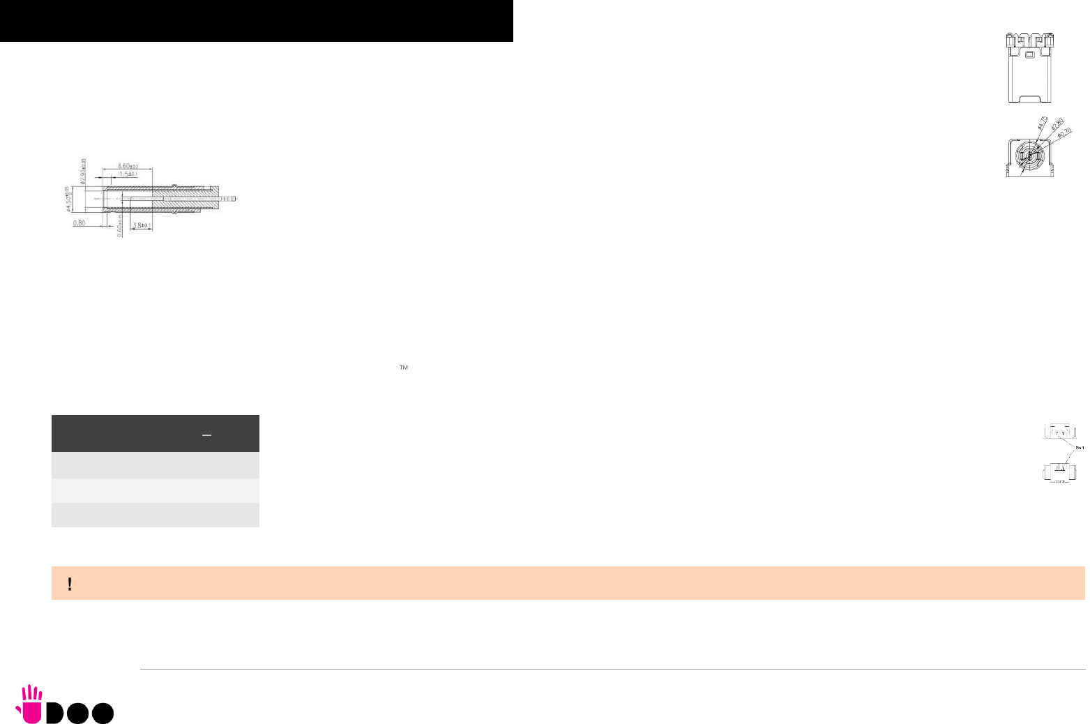
2.3 Electrical specifications
The UDOO BOLT board can be supplied only with an external 19VDC ± 5% power supply, minimum 60W (i.e. min. 3.15A @ 19V) for basic
functionalities recommended. Always make sure that the power cable is less than 3mt. long.
This voltage can be supplied through a DC power jack (CN5) type Singatron p/n 2DC3122-007111F. Internal pin is VIN power line.
Mating DC plug as shown in the picture below (Singatron p/n 45P06CV230-1A00-01 or equivalent).
The Board can also be powered by using a standard USB-C power adapter, with the same minimum wattage (power profile: 20V 3A).
A bicolour Green/Yellow LED is placed near the DC IN power jack to signal the power state of the board. When the board is powered but turned off, then the LED
turns on Yellow, during normal working (S0 State) the LED turns on Green light.
2.3.1 RTC Battery
For the occurrences when the module is not powered with an external power supply, on board there is a cabled coin Lithium Battery to supply, with a 3V voltage,
the Real Time Clock embedded inside the AMD Ryzen Embedded V1000 SoC.
Battery used is a cabled CR2032-LD Lithium coin-cell battery, with a nominal capacity of 220mAh.
The battery is not rechargeable, and can be connected to the board using dedicated connector CN5 which is a 2-pin
p1.27 mm type MOLEX p/n 53261-0271 or equivalent, with pinout shown in the table on the left.
Mating connector: MOLEX 51021-0200 receptacle with MOLEX 50079-8000 female crimp terminals.
In case of exhaustion, the battery should only be replaced with devices of the same type. Always check the orientation before
inserting and make sure that they are aligned correctly and are not damaged or leaking.
Never allow the batteries to become short-circuited during handling.
Batteries supplied with UDOO BOLT are compliant to requirements of European Directive 2006/66/EC regarding batteries and accumulators. When putting out of
order UDOO BOLT, remove the batteries from the board in order to collect and dispose them according to the requirement of the same European Directive above
mentioned. Even when replacing the batteries, the disposal has to be made according to these requirements.
Battery connector CN4
Pin
Signal
1
VRTC
2
GND
BOLT
UDOO BOLT User Manual - Rev. First Edition: 0.1 - Last Edition: 0.4 - Author: S.B. - Reviewed by L.V. Copyright © 2018 SECO S.p.A.
19
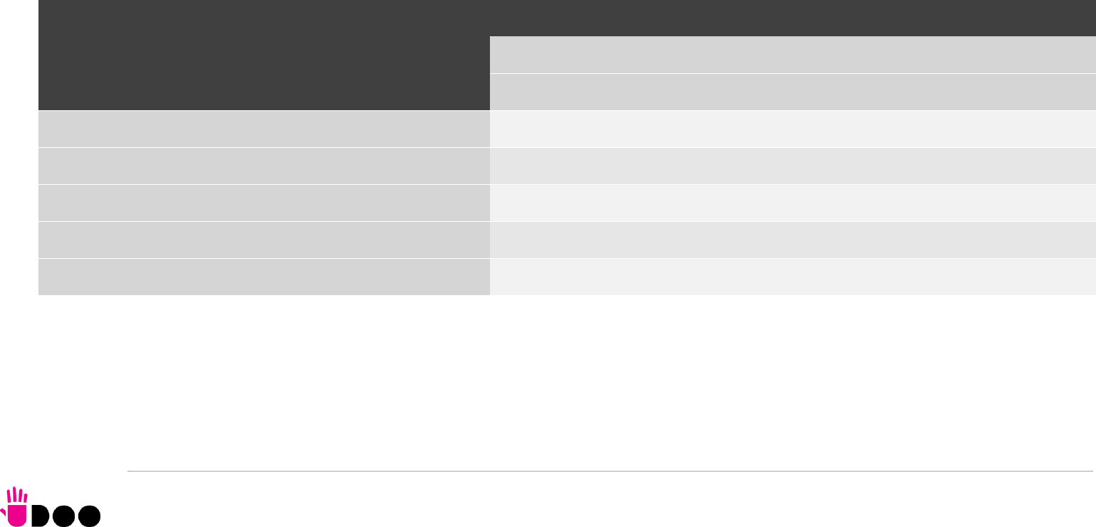
2.3.2 Power consumption
Using the following setup, and using all possible SoCs offered for UDOO BOLT board, the current consumption (RMS) has been measured on the VIN Power line.
The board is supplied with a 19V voltage through DC power jack CN4 using a Keysight DC Power Analyzer model N6700B.
O.S. Windows 10 Professional
32GB eMMC onboard
8GB DDR4-2133 Single Channel Memory
USB mouse and keyboard connected
HDMI display connected
UEFI BIOS Release 1.00 RC 03
Status
SoC V1202B
TDP 12W
TDP 25W
Average (120s)
Peak
Average (120s)
Peak
Idle, power saving configuration
0.357A
0.704A
0.327A
0.674A
OS Boot, power saving configuration
0.838A
1.388A
0.851A
1.450A
Video reproduction@1080p, power saving configuration
0.712A
0.983A
0.722A
1.230A
Video reproduction@4K, power saving configuration
0.822A
1.363A
0.753A
1.380A
Internal Stress Test Tool, package power set at specific TDP
1.411A
1.480A
1.348A
1.634A
BOLT
UDOO BOLT User Manual - Rev. First Edition: 0.1 - Last Edition: 0.4 - Author: S.B. - Reviewed by L.V. Copyright © 2018 SECO S.p.A.
20
Independently by the SoC mounted onboard, the following power consumptions are common to all boards:
Battery Backup power consumption: 3.68μA
Soft-Off State power consumption: TBM
Suspend State power consumption: TBM
Please consider that the power consumption depends strongly on the utilization scenario.
2.3.3 Power rails naming convention
In all the tables contained in this manual, Power rails are named with the following meaning:
_RUN: Switched voltages, i.e. power rails that are active only when the board is in ACPI’s S0 (Working) state. Examples: +3.3V_RUN, +5V_RUN.
_ALW: Always-on voltages, i.e. power rails that are active both in ACPI’s S0 (Working), S3 (Standby) and S5 (Soft Off) state. Examples: +5V_ALW, +3.3V_ALW.
_DSW: Deep Sleep Well voltage, i.e. power rails that remain active also when the _ALW voltages have been turned off, in a state very similar to the Mechanical Off
(G3) but with the possibility of awakening of the module upon a very limited set of events. It is not supported by UDOO Bolt firmware, however.
_SUS: unswitched ACPI S3 voltages, i.e. power rails that are active both in ACPI’s S0 (Working) and S3 (Standby) state. Examples: +1.5V_SUS
Other suffixes are used for application specific power rails, which are derived from same voltage value of voltage switched rails, if it is not differently stated (for
example, +5VHDMI is derived from +5V_RUN, and so on).
Status
SoC V1605B
TDP 12W
TDP 25W
Average (120s)
Peak
Average (120s)
Peak
Idle, power saving configuration
0.345A
0.752A
0.341A
0.635A
OS Boot, power saving configuration
0.797A
1.608A
0.780A
1.899A
Video reproduction@1080p, power saving configuration
0.666A
1.156A
0.593A
1.072A
Video reproduction@4K, power saving configuration
0.847A
1.308A
0.778A
1.424A
Internal Stress Test Tool, package power set at specific TDP
1.293A
1.485A
1.506A
1.943A
BOLT
UDOO BOLT User Manual - Rev. First Edition: 0.1 - Last Edition: 0.4 - Author: S.B. - Reviewed by L.V. Copyright © 2018 SECO S.p.A.
21
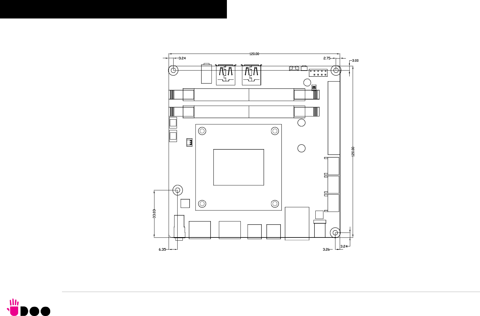
2.4 Mechanical specifications
The board dimensions are 120 x 120 mm (4.72” x 4.72”).
The printed circuit of the board is made of twelve layers, some of them are ground planes, for disturbance rejection.
BOLT
UDOO BOLT User Manual - Rev. First Edition: 0.1 - Last Edition: 0.4 - Author: S.B. - Reviewed by L.V. Copyright © 2018 SECO S.p.A.
22
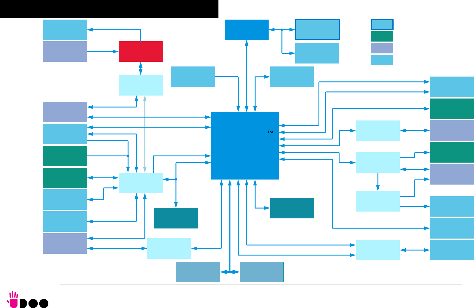
AMD Ryzen
Embedded
V1000 SoC
Power section
DDR4 SO-DIMM
Memory
DDR4 SO-DIMM
Memory
Buttons/LED
Header
IR Receiver
FAN connector
2 x HDMI 2.0
connectors
Gigabit Ethernet
Controller
S/PDIF +
Headphone TRRS
combo connector
2 x USB 3.1
Type-A Socket
Gigabit Ethernet
connector
M.2 Key E slot
Coin Cell Cabled
Battery
SATA connector
HD Audio Codec
Embedded
controller
UEFI BIOS Flash
ATMEL
ATmega32u4
PCI-e #4
eSPI
CIR
CEC
HDMI
2x UART, SPI
Keyboard Scan, 2x I2C
USB SS #1, #2
PCI-e #5
SATA #1
Power Pushbutton
HD Audio
SATA #0
DDI #0 #1
Mic + Line Out
TRRS combo
2x USB Type-C
connector
SATALED#
DDI #3 #2 / USB SS #0 #3
Internal Connector
Frontal Connector
Rear Connector
eMMC Drive
ARDUINO Leonardo
Compatible header
Arduino Interface
HDD power
connector
RSTBTN#, LEDs
M.2 Key B slot
MMC
HDMI 2.0 Redriver
USB-C manager
with PD Controller
PCI-e #0 #1
4-channel 2:1
mux/demux
USB 2.0 #4
M.2 Key M slot
USB 2.0 #5
PCI-e GFX x4
Expansion Header
Grove connectors
RTC Well
Amplified speaker
connectors
3W Class-D Audio
Amplifier + Class AB
Headphone Driver
I2C
Headphone
S/PDIF
PWRBTN#
PWR_BTN#, RST_BTN#
DC Power jack
2.5 Block diagram

BOLT
UDOO BOLT User Manual - Rev. First Edition: 0.1 - Last Edition: 0.4 - Author: S.B. - Reviewed by L.V. Copyright © 2018 SECO S.p.A.
24
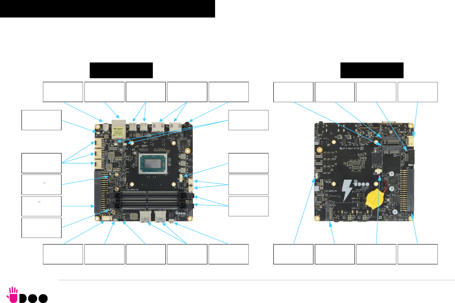
3.1 Introduction
On UDOO BOLT board, there are several connectors located on the upper plane. Standard connectors are placed on the same sides of PCB, so that it is possible
to place them on a panel of an eventual enclosure.
TOP SIDE
BOTTOM SIDE
Gigabit Ethernet
RJ-45
Arduino Leonardo
interface
Buttons/LED
header
DDR4 SODIMM
Slots
DC IN Power jack
Power Button IR Receiver
USB 3.1 Type-A
#1 and #2 TRRS Audio
Headset Jack
FAN Connector
USB 3.1 Type-C
#0 and #3
HDMI connectors
#0 and #1
TRS Headphone
+ S/PDIF
Grove connectors
Speaker internal
connectors
ATMega32u4
Reset Button
Arduino LED
Ethernet LEDs ON/OFF LED
M.2 Connectivity
Slot (Socket 1 key
E)
M.2 SATA/PCIe
Slot (Socket 2
Key B)
SATA Connector
UEFI BIOS default
recovery switch
M.2 NVMe Slot
(Socket 3 Key M)
Cabled RTC
battery connector
Embedded
Controller I/O
Header
SATA Power
Connector

BOLT
UDOO BOLT User Manual - Rev. First Edition: 0.1 - Last Edition: 0.4 - Author: S.B. - Reviewed by L.V. Copyright © 2018 SECO S.p.A.
25
3.2 Connectors overview
Name
Description
Name
Description
CN4
Cabled RTC Battery
CN19
HDMI connector #1
CN5
DC IN Power Jack
CN20
HDMI connector #0
CN6
Buttons/LED Internal Header
CN21
USB 3.1 Type-A Port #1
CN7
FAN Connector
CN22
USB 3.1 Type-A Port #2
CN8
USB Type-C Port #0
CN23
Gigabit Ethernet connector
CN9
USB Type-C Port #3
CN24
Arduino Leonardo interface Connector
CN10
USB C Controller programming header (reserved)
CN25
Embedded Controller I/O Header
CN11
TRRS Audio Headset Jack
CN26
GROVE Analog Connector
CN12
TRS Headphone + S/PDIF
CN27
GROVE Digital / UART Connector
CN14
SATA Port #1 M 7p connector
CN28
GROVE I2C Connector
CN15
SATA Power Connector
CN29
Right Speaker Connector
CN16
M.2 Connectivity Slot (Socket 1 Key E Type 2230)
CN30
Left Speaker Connector
CN17
M.2 NVMe Slot (Socket 3 Key M Type 2280)
SW1
UEFI BIOS default Restore switch
CN18
M.2 SATA/PCI-e Slot (Socket 2 Key B type 2242 or 2260)
U61
IR Receiver
BOLT
UDOO BOLT User Manual - Rev. First Edition: 0.1 - Last Edition: 0.4 - Author: S.B. - Reviewed by L.V. Copyright © 2018 SECO S.p.A.
26
3.3 Connectors description
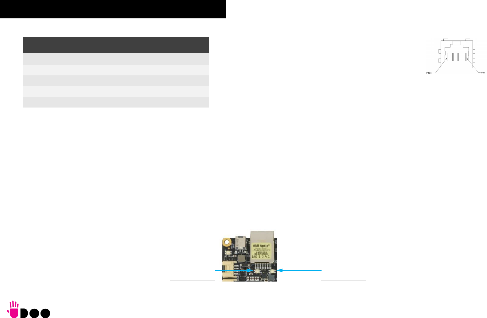
3.3.1 Ethernet connector On board, there is a Gigabit Ethernet connector, for the direct
connection of the UDOO BOLT module to a wired LAN.
The Ethernet connection is managed by a dedicated Realtek RTL8111G
Gigabit Ethernet controller, interfaced to PCI-express port #5.
This interface is compatible both with Gigabit Ethernet (1000Mbps) and
with Fast Ethernet (10/100Mbps) Networks. They will configure automatically to work with the
existing network.
Please be aware that it will work in Gigabit mode only in case that it is connected to Gigabit
Ethernet switches/hubs/routers. For the connection, cables category Cat5e or better are
required. Cables category Cat6 are recommended for noise reduction and EMC compatibility issues, especially when the length of the cable is significant.
GBE_MDI0+/GBE_MDI0-: Ethernet Controller Media Dependent Interface (MDI) I/O differential pair #0. It is the first differential pair in Gigabit Ethernet mode, and the
Transmit differential pair in 10/100 Mbps modes.
GBE_MDI1+/GBE_MDI1-: Ethernet Controller Media Dependent Interface (MDI) I/O differential pair #1. It is the second differential pair in Gigabit Ethernet mode, and
the Receive differential pair in 10/100 Mbps modes.
GBE_MDI2+/GBE_MDI2-: Ethernet Controller Media Dependent Interface (MDI) I/O differential pair #2. It is the third differential pair in Gigabit Ethernet mode; it is not
used in 10/100Mbps modes.
GBE_MDI3+/GBE_MDI3-: Ethernet Controller Media Dependent Interface (MDI) I/O differential pair #3. It is the fourth differential pair in Gigabit Ethernet mode; it is
not used in 10/100Mbps modes.
Placed behind the GbE connector there are also two bicolour Green/Yellow LEDs: LED D159 (Right LED) shows 10/100 or 1000 connection: green means
100Mbps connection, yellow means 1000Mpbs connection, when the LED is Off then 10Mpbs or no connection is available. LED D160 (Left LED) shows
ACTIVITY presence.
Gigabit Ethernet Connector- CN23
Pin
Signal
Pin
Signal
1
GBE_MDI0+
5
GBE_MDI2-
2
GBE_MDI0-
6
GBE_MDI1-
3
GBE_MDI1+
7
GBE_MDI3+
4
GBE_MDI2+
8
GBE_MDI3-
Link LED
Activity LED

BOLT
UDOO BOLT User Manual - Rev. First Edition: 0.1 - Last Edition: 0.4 - Author: S.B. - Reviewed by L.V. Copyright © 2018 SECO S.p.A.
27
3.3.2 USB ports
The AMD Ryzen Embedded V1000 family of Processors used on UDOO BOLT board can manage up to five USB SuperSpeed (i.e., USB 3.1 compliant) ports
and six High Speed (i.e. USB 2.0 compliant) ports. There is only one dedicated High Speed port, the other five ports are shared with the SuperSpeed ports, i.e.
they can be used either by USB 2.0 or USB 3.0.
The USB 3.1 ports #1 and #2 are available on two single USB connectors, CN21 and CN22, placed on the same side of the PCB (“Frontal”), while USB 3.1 ports
#0 and #3 are available on USB connectors CN8 and CN9 placed on the opposite side (“Rear”). “Rear” and “Frontal” terms are used considering a possible
application of this board with an enclosure). The connectors used are standard USB 3.0 type-A receptacles.
USB 3.1 ports’ connectors are standard type-A receptacle, they can be connected to all types of USB 1.1 / USB 2.0 / USB 3.0 devices using standard-A USB
3.x or USB 2.0 plugs.
For USB 3.x connections it is mandatory the use of SuperSpeed certified cables, whose SuperSpeed differential pairs are individually shielded inside the global
cable’s external shielding.
Signal description:
USB_P1+/USB_P1-: USB 2.0 Port #1 differential pair.
USB_SSRX1+/USB_SSRX1-: USB Super Speed Port #1 receive differential pair.
USB_SSTX1+/USB_SSTX1-: USB Super Speed Port #1 transmit differential pair.
USB_P2+/USB_P2-: USB 2.0 Port #2 differential pair.
USB_SSRX1+/USB_SSRX1-: USB Super Speed Port #1 receive differential pair.
USB_SSTX1+/USB_SSTX1-: USB Super Speed Port #1 transmit differential pair.
Common mode chokes are placed on all USB differential pairs for EMI compliance.
For ESD protection, on all data and voltage lines are placed clamping diodes for voltage transient suppression.
USB 3.1 port#1 type A receptacle CN21
Pin
Signal
Pin
Signal
1
+5VUSB1
5
USB_SSRX1-
2
USB_P1-
6
USB_SSRX1+
3
USB_P1+
7
GND
4
GND
8
USB_SSTX1-
9
USB_SSTX1+
USB 3.1 port #2 type-A receptacle CN22
Pin
Signal
Pin
Signal
1
+5VUSB2
5
USB_SSRX2-
2
USB_P2-
6
USB_SSRX2+
3
USB_P2+
7
GND
4
GND
8
USB_SSTX2-
9
USB_SSTX2+
BOLT
UDOO BOLT User Manual - Rev. First Edition: 0.1 - Last Edition: 0.4 - Author: S.B. - Reviewed by L.V. Copyright © 2018 SECO S.p.A.
28
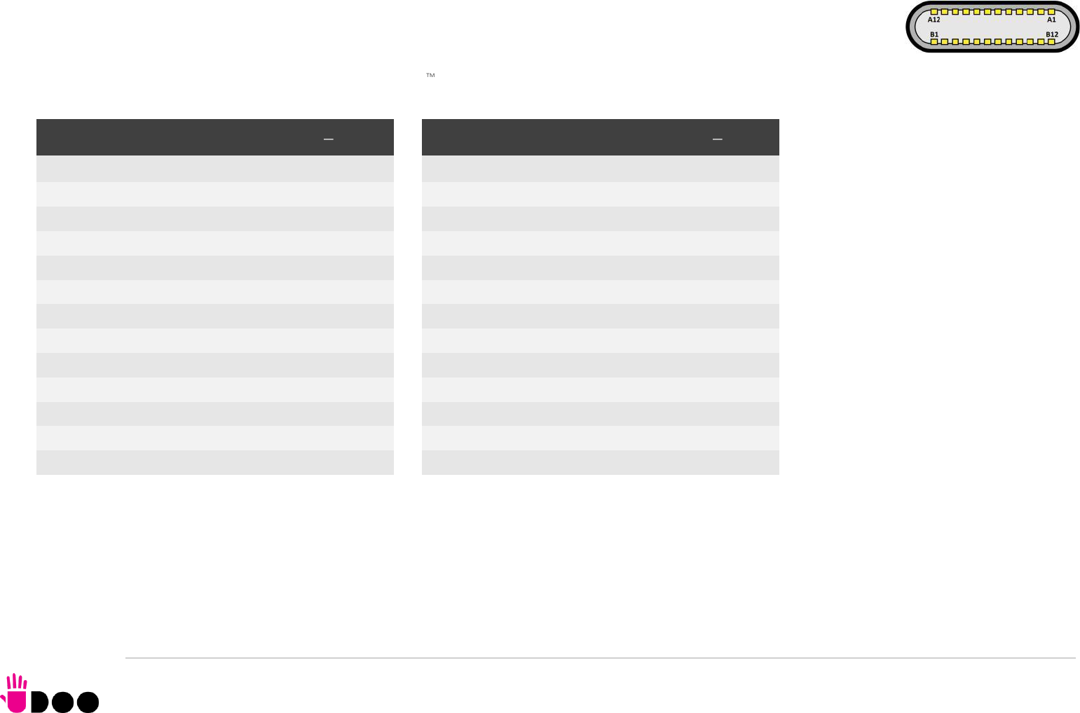
USB ports #0 and #3, instead, are available on standard Type-C connectors (CN8 and CN9), with DisplayPort Alternate Mode and
USB Dual Role Power Delivery (rel. 3.0) additional functionalities. This means that USB type-C connectors can be used to connect
external USB devices, DP/HDMI displays or used to supply the board by using a 60W minimum USB-C Power Adapter (power profile
20V 3A).
USB 3.1 Port #0 is internally multiplexed by the AMD Ryzen Embedded V100 Processor with Display Port #3, USB 3.1 Port #3 is multiplexed with Display Port
#2.
Signal description:
USB0_A+/USB0_A-: USB 2.0 Port #0 differential pair, position 1.
USB0_B+/USB0_B-: USB 2.0 Port #0 differential pair, position 2.
USBC0_SSRXA+/USBC0_SSRXA-: USB Super Speed Port #0 receive first differential pair. When used for DP Alternate mode, this pair carries out Display Port #3
Differential pair #3.
USBC0_SSTXA+/USBC0_SSTXA-: USB Super Speed Port #1 transmit first differential pair. When used for DP Alternate mode, this pair carries out Display Port #3
Differential pair #2.
USB 3.1 port#0 type C receptacle CN8
Pin
Signal
Pin
Signal
A1
GND
B12
GND
A2
USBC0_SSTXA+
B11
USBC0_SSRXA+
A3
USBC0_SSTXA
B10
USBC0_SSRXA-
A4
VBUS_C0
B9
VBUS_C0
A5
USBC0_CC1
B8
USBC0_SBU2
A6
USB0_A+
B7
USB0_B-
A7
USB0_A-
B6
USB0_B+
A8
USBC0_SBU1
B5
USBC0_CC2
A9
VBUS_C0
B4
VBUS_C0
A10
USBC0_SSRXB-
B3
USBC0_SSTXB-
A11
USBC0_SSRXB+
B2
USBC0_SSTXB+
A12
GND
B1
GND
USB 3.1 port #3 type-C receptacle CN9
Pin
Signal
Pin
Signal
A1
GND
B12
GND
A2
USBC3_SSTXA+
B11
USBC3_SSRXA+
A3
USBC3_SSTXA-
B10
USBC3_SSRXA-
A4
VBUS_C3
B9
VBUS _C3
A5
USBC3_CC1
B8
USBC3_SBU2
A6
USB3_A+
B7
USB3_B-
A7
USB3_A-
B6
USB3_B+
A8
USBC3_SBU1
B5
USBC3_CC2
A9
VBUS_C3
B4
VBUS_C3
A10
USBC3_SSRXB-
B3
USBC3_SSTXB-
A11
USBC3_SSRXB+
B2
USBC3_SSTXB+
A12
GND
B1
GND

BOLT
UDOO BOLT User Manual - Rev. First Edition: 0.1 - Last Edition: 0.4 - Author: S.B. - Reviewed by L.V. Copyright © 2018 SECO S.p.A.
29
USBC0_SSRXB+/USBC0_SSRXB-: USB Super Speed Port #0 receive second differential pair. When used for DP Alternate mode, this pair carries out Display
Port #3 Differential pair #0.
USBC0_SSTXB+/USBC0_SSTXB-: USB Super Speed Port #1 transmit second differential pair. When used for DP Alternate mode, this pair carries out Display
Port #3 Differential pair #1.
USBC0_CC1: USB-C Port #0 Configuration Channel #1
USBC0_CC2: USB-C Port #0 Configuration Channel #2
USBC0_SBU1: USB-C Port #0 Sideband Use signal #1 When used for DP Alternate mode, this pair carries out Display Port #3 Aux Signal positive line.
USBC0_SBU2: USB-C Port #0 Sideband Use signal #2. When used for DP Alternate mode, this pair carries out Display Port #3 Aux Signal negative line
VBUS_C0: USB-C Port #0 VBUS power rail. Can be used both for powering client devices with a 5V voltage (power source mode) or to power the whole board
using an USB-C power adapter (power sink mode).
USB3_A+/USB3_A-: USB 2.0 Port #3 differential pair, position 1.
USB3_B+/USB3_B-: USB 2.0 Port #3 differential pair, position 2.
USBC3_SSRXA+/USBC3_SSRXA-: USB Super Speed Port #3 receive first differential pair. When used for DP Alternate mode, this pair carries out Display Port #2
Differential pair #3.
USBC3_SSTXA+/USBC3_SSTXA-: USB Super Speed Port #3 transmit first differential pair. When used for DP Alternate mode, this pair carries out Display Port #2
Differential pair #2.
USBC3_SSRXB+/USBC3_SSRXB-: USB Super Speed Port #3 receive second differential pair. When used for DP Alternate mode, this pair carries out Display
Port #2 Differential pair #0.
USBC3_SSTXB+/USBC3_SSTXB-: USB Super Speed Port #3 transmit second differential pair. When used for DP Alternate mode, this pair carries out Display
Port #2 Differential pair #1.
USBC3_CC1: USB-C Port #3 Configuration Channel #1
USBC3_CC2: USB-C Port #3 Configuration Channel #2
USBC3_SBU1: USB-C Port #3 Sideband Use signal #1 When used for DP Alternate mode, this pair carries out Display Port #2 Aux Signal positive line.
USBC3_SBU2: USB-C Port #3 Sideband Use signal #2. When used for DP Alternate mode, this pair carries out Display Port #2 Aux Signal negative line
VBUS_C3: USB-C Port #3 VBUS power rail. Can be used both for powering client devices with a 5V voltage (power source mode) or to power the whole board
using an USB-C power adapter (power sink mode).
BOLT
UDOO BOLT User Manual - Rev. First Edition: 0.1 - Last Edition: 0.4 - Author: S.B. - Reviewed by L.V. Copyright © 2018 SECO S.p.A.
30
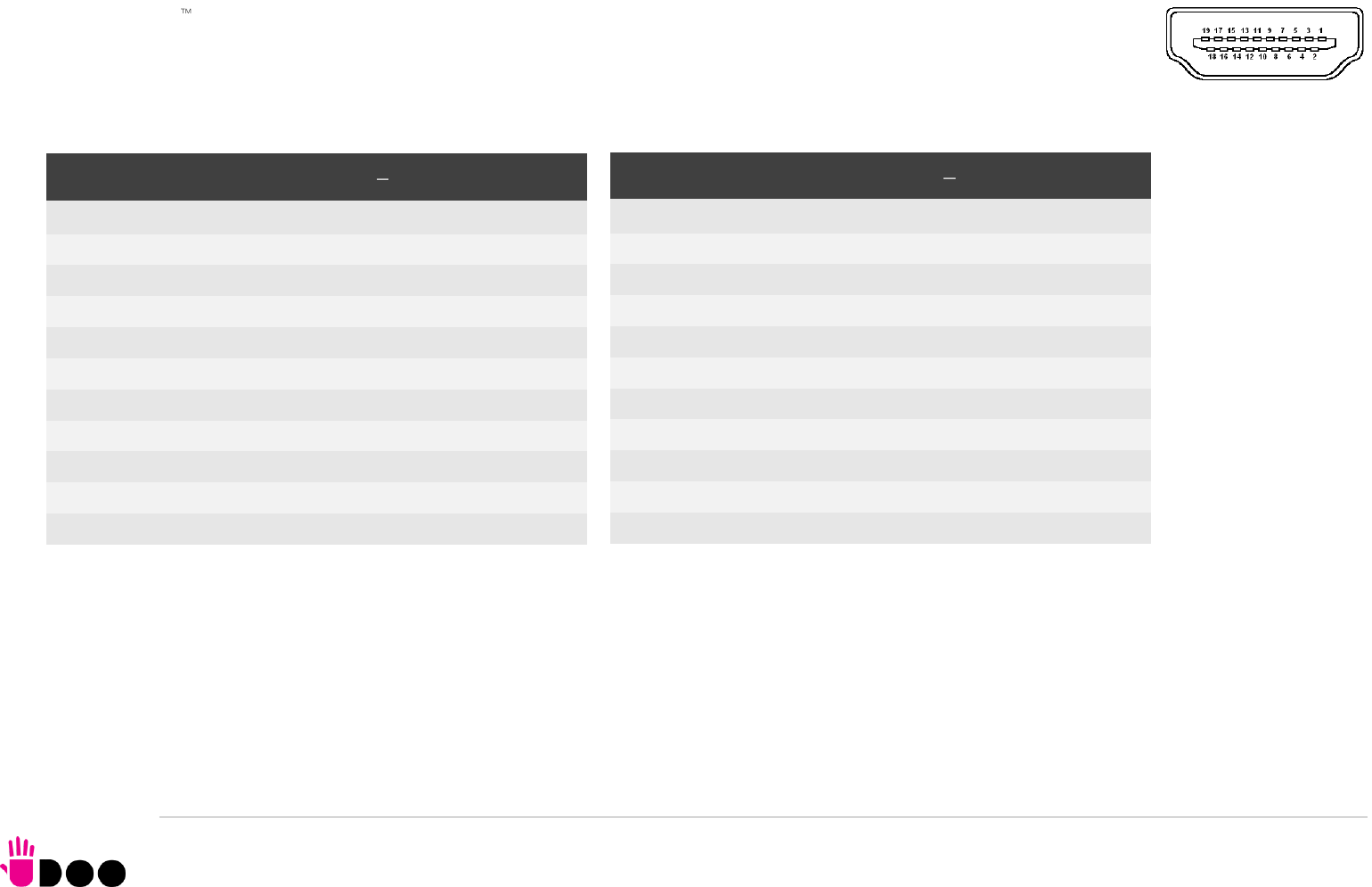
3.3.3 HDMI connectors
The AMD Ryzen Embedded V1000 family of Processors offer four Digital Display Interfaces, configurable to work in HDMI/DVI/DP++
modes.
On the UDOO BOLT board, the Digital Display Interfaces #0 and #1 are used to implement two HDMI 2.0 interfaces through as many
HDMI 2.0 ReDriver / Level shifters and ESD protection + signal conditioning ICs.
Therefore, on-board there are two standard certified HDMI connector, right-angle, type A, MOLEX P/N 47151-1001.
Signals involved in HDMI management are the following:
HDMI0_CLK+/ HDMI0_CLK-: HDMI port #0 differential Clock.
HDMI0_LANE0+/ HDMI0_LANE0-: HDMI port #0 differential pair #0
HDMI0_LANE1+/ HDMI0_LANE1-: HDMI port #0 differential pair #1
HDMI0_LANE2+/HDMI0_LANE2-: HDMI port #0 differential pair #2
HDMI0_SDA: DDC Data line for HDMI port #0. Bidirectional signal, electrical level +5VHDMI0 with a 1k87Ω pull-up resistor.
HDMI0_SCL: DDC Clock line for HDMI port #0. Output signal, electrical level +5VHDMI0 with a 1k87Ω pull-up resistor.
HDMI Connector #1 CN19
Pin
Signal
Pin
Signal
1
HDMI1_LANE2+
2
GND
3
HDMI1_LANE2-
4
HDMI1_LANE1+
5
GND
6
HDMI1_LANE1-
7
HDMI1_LANE0+
8
GND
9
HDMI1_LANE0-
10
HDMI1_CLK+
11
GND
12
HDMI1_CLK-
13
HDMI1_CEC
14
HDMI1_UTILITY
15
HDMI1_SCL
16
HDMI1_SDA
17
GND
18
+5VHDMI1
19
HDMI1_HPD
HDMI Connector #0 CN20
Pin
Signal
Pin
Signal
1
HDMI0_LANE2+
2
GND
3
HDMI0_LANE2-
4
HDMI0_LANE1+
5
GND
6
HDMI0_LANE1-
7
HDMI0_LANE0+
8
GND
9
HDMI0_LANE0-
10
HDMI0_CLK+
11
GND
12
HDMI0_CLK-
13
HDMI0_CEC
14
HDMI0_UTILITY
15
HDMI0_SCL
16
HDMI0_SDA
17
GND
18
+5VHDMI0
19
HDMI0_HPD

BOLT
UDOO BOLT User Manual - Rev. First Edition: 0.1 - Last Edition: 0.4 - Author: S.B. - Reviewed by L.V. Copyright © 2018 SECO S.p.A.
31
HDMI0_CEC: HDMI Consumer Electronics Control (CEC) Line. Bidirectional signal, electrical level +3.3V_DSW with a 27kΩ pull-up resistor and Schottky Diode.
HDMI0_HPD: HDMI Port #0 Hot Plug Detect Input signal. +5VHDMI0 electrical level signal with dynamic pull-down.
HDMI0_UTILITY: HDMI Port #0 Utility Input signal. +5VHDMI0 electrical level signal.
HDMI1_CLK+/ HDMI1_CLK-: HDMI port #1 differential Clock.
HDMI1_LANE0+/ HDMI1_LANE0-: HDMI port #1differential pair #0
HDMI1_LANE1+/ HDMI1_LANE1-: HDMI port #1differential pair #1
HDMI1_LANE2+/HDMI1_LANE2-: HDMI port #1differential pair #2
HDMI1_SDA: DDC Data line for HDMI port #1. Bidirectional signal, electrical level +5VHDMI1 with a 1k87Ω pull-up resistor.
HDMI1_SCL: DDC Clock line for HDMI port #1. Output signal, electrical level +5VHDMI1 with a 1k87Ω pull-up resistor.
HDMI1_CEC: HDMI Consumer Electronics Control (CEC) Line. Bidirectional signal, electrical level +3.3V_DSW with a 27kΩ pull-up resistor and Schottky Diode.
HDMI1_HPD: HDMI Port #1 Hot Plug Detect Input signal. +5VHDMI1 electrical level signal with dynamic pull-down.
HDMI1_UTILITY: HDMI Port #1 Utility Input signal. +5VHDMI1 electrical level signal.
All data and voltage lines are protected against ESD.
Always use HDMI-certified cables for the connection between the board and the HDMI display; a category 2 (High-Speed) cable is recommended for higher
resolutions, category 1 cables can be used for 720p resolution.
BOLT
UDOO BOLT User Manual - Rev. First Edition: 0.1 - Last Edition: 0.4 - Author: S.B. - Reviewed by L.V. Copyright © 2018 SECO S.p.A.
32
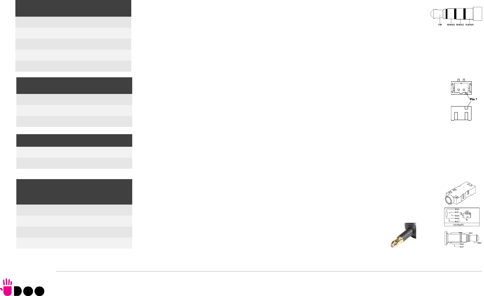
3.3.4 Audio interfaces
In the UDOO BOLT board, audio functionalities are provided by a Realtek ALC888S High Definition Audio Codec.
In order to reduce the space dedicated to connectors, there is a TRRS Combo Audio Socket, i.e.
a single socket which offer both stereo Line Out and Mic In functionalities.
Such TRRS Combo Audio socket can be used with any 4-poles 3.5mm diameter audio jack, with
pinout compatible with the most recent Headsets, shown in the table on the left.
Additionally, it is also possible to connect external stereo speakers by using the dedicated connectors
CN29 and CN30, which are two connectors type HR p/n A2001WV-S-02PD01 or equivalent.
Mating connector: HR p/n A2001H-02P with A2001 series female crimp terminals.
The speaker output available on connectors CN29 and CN30 is Class-D amplified, 3W global power on
4Ohm Load / 1.7W global power on 8Ohm load (recommended).
Furthermore, on the Rear panel Side, there is a combo analogic / digital connector, a TRS 3.5mm
audio socket which integrates also a LED Transmitter for S/PDIF optical connections (Optical 3.5mm
jack). This connector can therefore be used to connect both analog headsets (TRS plug) and digital
audio devices (coaxial optical cable with 3.5mm jack, like in the picture).
TRRS Audio headset jack- CN11
Pin
Signal
TIP
Headphone Out Left Channel
RING1
Headphone Out Right Channel
RING2
MIC-/MIC+
SLEEVE
MIC+/MIC-
Right Speaker Connector- CN29
Pin
Signal
1
Speaker Right Channel +
2
Speaker Right Channel -
Left Speaker Connector- CN30
1
Speaker Left Channel -
2
Speaker Left Channel +
TRS Headphone + S/PDIF -
CN12
Pin
Signal
TIP
Headphone Out Left Channel
RING
Headphone Out Right Channel
SLEEVE
GND
BOLT
UDOO BOLT User Manual - Rev. First Edition: 0.1 - Last Edition: 0.4 - Author: S.B. - Reviewed by L.V. Copyright © 2018 SECO S.p.A.
33
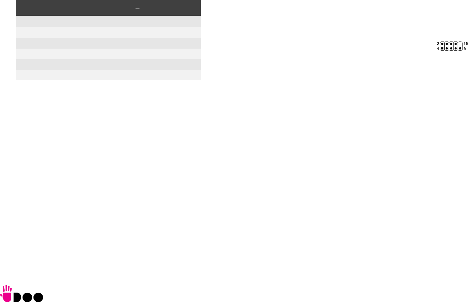
3.3.5 Buttons / LED header
To allow the integration of a UDOO BOLT based system inside a box PC-like, there is a
connector on the board that allows to remote signals for the Power Button (to be used to put
the system in a Soft Off State, or awake from it), for the Reset Button, and the signal for
optional LED signalling activity on SATA Channel and Power On states.
The pinout of this connector complies with Intel® Front Panel I/O connectivity
Design Guide, Switch/LED Front Panel section, chapter 2.2. It is shown in the
table on the left.
Connector CN6 is an internal 9-pin standard male pin header, p 2.54 mm, 5+4 pin, h= 6mm,
type NELTRON p/n 2213S-10G-E10 or equivalent.
Signals Description
HD_LED_P: Hard Disk Activity LED signal’s pull-up to +5V_RUN voltage (510Ω pull-up).
HD_LED_N: Hard Disk Activity LED output signal
RST_SW_N: Reset Button GND
RST_SW_P: Reset button input signal. This signal has to be connected to an external momentary pushbutton (contacts normally open). When the pushbutton is
pressed, the pulse of Reset signal will cause the reset of the board. +3.3V_DSW electrical level with 4k7Ω pull-up.
PWR_SW_P: Power button input signal, +3.3V_DSW electrical level with 4k7Ω pull-up. This signal can be connected to an external momentary pushbutton
(contacts normally open). Upon the pressure of this pushbutton, the pulse of this signal will let the switched voltage rails turn on or off. Please be aware that this
signal is also driven by the momentary pushbutton located on-board, near the header itself (please refer to the picture at page 24).
PWR_SW_N: Power button GND
FP PWR_P/SLP_N: Power/Sleep messaging LED terminal 1 with 510Ω pull-up resistor to +5V_ALW voltage. Connect it to an extremity of a dual-color power LED
for power ON/OFF, sleep and message waiting signalling. Please refer to Intel® Front Panel I/O connectivity Design Guide, chapter 2.2.4, for LED functionalities
and signal meaning.
FP PWR_N/SLP_P: Power/Sleep messaging LED terminal 2 with 510Ω pull-up resistor to +5V_ALW voltage. Connect it to the other extremity of the dual-color
power LED above mentioned.
Buttons / LED Header CN6
Pin
Signal
Pin
Signal
1
HD_LED_P
2
FP PWR_P/SLP_N
3
HD_LED_N
4
FP PWR_N/SLP_P
5
RST_SW_N
6
PWR_SW_P
7
RST_SW_P
8
PWR_SW_N
9
---
BOLT
UDOO BOLT User Manual - Rev. First Edition: 0.1 - Last Edition: 0.4 - Author: S.B. - Reviewed by L.V. Copyright © 2018 SECO S.p.A.
34
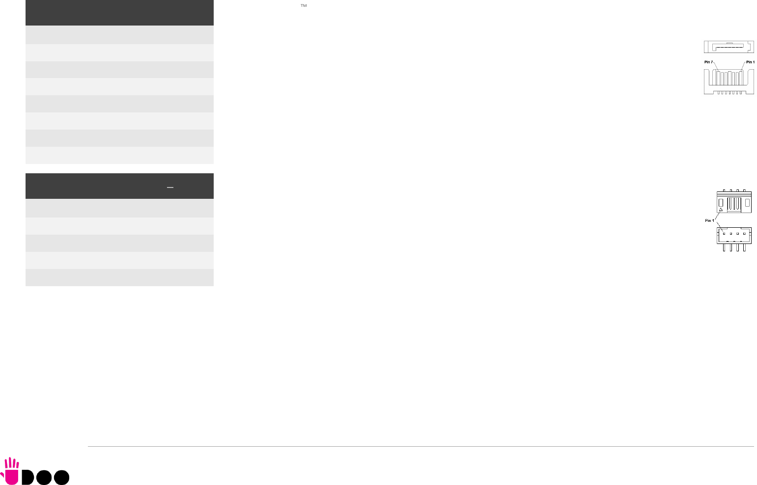
3.3.6 SATA connectors
The AMD Ryzen Embedded V1000 family of Processors embed a SATA Controller, which offers two SATA III, 6.0
Gbps interfaces.
Of these interfaces, one SATA channel is carried out to a standard male S-ATA connector, CN14 (the
other SATA channel is available on the M.2 Key B socket, CN18, please check par. 3.3.7).
Here following the signals related to SATA interface:
SATA1_TX+/SATA1_TX-: Serial ATA Channel #1 Transmit differential pair
SATA1_RX+/SATA1_RX-: Serial ATA Channel #1 Receive differential pair
10nF AC series decoupling capacitors are placed on each line of SATA differential pairs.
A dedicated power connector, CN15, can be used to give supply to external Hard Drives (or Solid State
Drives) connected to the SATA male connector.
The dedicated power connector is a 4-pin male connector, type JST p/n S4B-PH-SM4-TB or
equivalent, with pinout shown in the table on the left.
Mating connector: JST PHR-4 crimp housing with JST SPH-002T-P0.5L crimp terminals.
Maximum allowed power consumption for this connector is 1A.
SATA Connector - CN14
Pin
Signal
1
GND
2
SATA1_Tx+
3
SATA1_Tx-
4
GND
5
SATA1_Rx-
6
SATA1_Rx+
7
GND
S-ATA Power Connector CN15
Pin
Signal
1
---
2
GND
3
GND
4
+5V_RUN
BOLT
UDOO BOLT User Manual - Rev. First Edition: 0.1 - Last Edition: 0.4 - Author: S.B. - Reviewed by L.V. Copyright © 2018 SECO S.p.A.
35
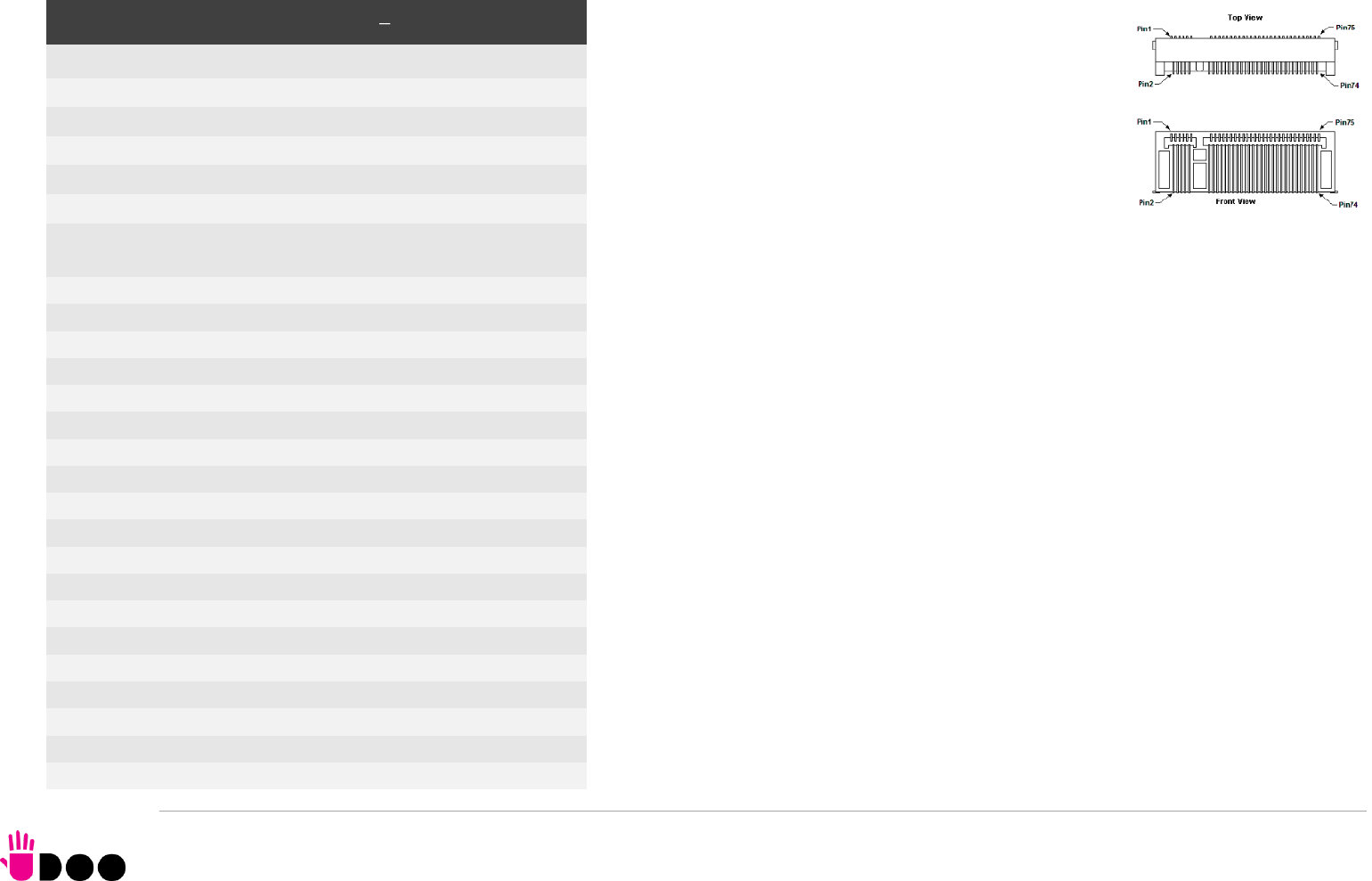
3.3.7 M.2 SATA/PCI-e Slot: Socket 2 Key B type 2242/2260
The mass storage capabilities of the UDOO BOLT are
completed by an M.2 SSD Slot, which allow plugging M.2
Socket 2 Key B Solid State Drives with SATA interface or
PCI-e x2 interface (PCI-e x1 is also supported).
The connector used for the M.2 SATA/PCI-e slot is CN18,
which is a standard 75 pin M.2 Key B connector, type
LOTES p/n APCI0087-P001A, H=8.5mm, with the pinout
shown in the table on the left.
On the UDOO BOLT board there is also a Threaded Spacer
which allows the placement of M.2 Socket 2 Key B
SATA/PCI-e modules in 2260 size.
It is possible to place also modules in 2242 or 2260 size, by using a M/F Spacer which
allows fixing the M.2 module on the spacer already available on the PCB, deemed for the
fixing of the M.2 connectivity slot (see next paragraph)
Here following the signals related to the SATA interface:
SATA0_Tx+/SATA0_Tx-: Serial ATA Channel #0 Transmit differential pair
SATA0_Rx+/SATA0_Rx-: Serial ATA Channel #0 Receive differential pair
10nF AC series decoupling capacitors are placed on each line of SATA differential pairs.
Here following the signals related to the PCI-e interface:
PCIe0_TX+/PCIe0_TX-: PCI Express lane #0, Transmitting Output Differential pair
PCIe0_RX+/PCIe0_RX-: PCI Express lane #0, Receiving Input Differential pair
PCIe1_TX+/PCIe1_TX-: PCI Express lane #1, Transmitting Output Differential pair
PCIe1_RX+/PCIe1_RX-: PCI Express lane #1, Receiving Input Differential pair
PCIe0_Clock+ / PCIe0_Clock-: PCI Express Reference Clock for lane #2, Differential Pair
PLT_RST#: Reset Signal that is sent from the SoC to all PCI-e devices available on the board
(i.e. the GbE controller, the PCI-e based SSD modules plugged in the CN18 slot, the PCI-e
x4 NVMe modules plugged in CN17slot and the connectivity modules plugged in CN16 slot).
It is a 3.3V_RUN active-low signal.
M.2 SATA/PCI-e Slot CN18
Pin
Signal
Pin
Signal
1
---
2
+3.3V_RUN
3
GND
4
+3.3V_RUN
5
GND
6
---
7
---
8
---
9
---
10
---
11
GND
20
---
21
---
22
---
23
---
24
---
25
---
26
---
27
GND
28
---
29
PCIe1_Rx-
30
---
31
PCIe1_Rx+
32
---
33
GND
34
---
35
PCIe1_Tx-
36
---
37
PCIe1_Tx+
38
---
39
GND
40
---
41
SATA0_Rx+/PCIe0_Rx-
42
---
43
SATA0_Rx-/PCIe0_Rx+
44
---
45
GND
46
---
47
SATA0_Tx-/PCIe0_Tx-
48
---
49
SATA0_Tx+/PCIe0_Tx+
50
PLT_RST#
51
GND
52
PCIE_REQ0#
53
PCIe0_Clock-
54
---
55
PCIe0_Clock+
56
---
57
GND
58
---
BOLT
UDOO BOLT User Manual - Rev. First Edition: 0.1 - Last Edition: 0.4 - Author: S.B. - Reviewed by L.V. Copyright © 2018 SECO S.p.A.
36
PCIe_REQ0#: PCI Express Clock Request Input, active low signal. This signal shall be driven
low by any module inserted in the connectivity slot, in order to ensure that the SoC makes
available the reference clock.
CONFIG_1: Configuration input signal, +3.3V_RUN signal with 10kΩ pull-up. This signal is
necessary to switch between the S-ATA and the PCI-e signals on the pins 41/43/47/49 of
connector CN18. When CONFIG_1 signal is high, then PCI-e x 2 interface is available on
connector CN18. When the signal is driven low, then SATA interface will be available. The
selection is automatic, since according to M.2 specifications for Socket2 SSD modules,
CONFIG_1 signal must be low for SSD based modules and high for PCI-e based modules.
The PCI-e x2 interface can be used also for different purposes other than SSD modules, but it
is important that the CONFIG_1 signal is driven properly (it can be left unconnected on PCI-e
based modules, due to the presence of the pull-up resistor on the platform).
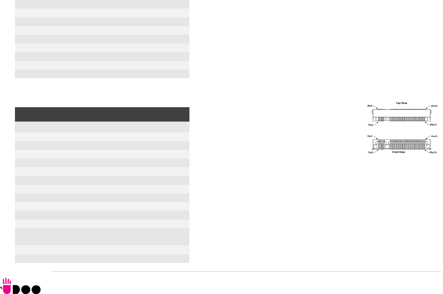
3.3.8 M.2 Connectivity Slot: Socket 1 Key E Type 2230 It is possible to increase the connectivity of the UDOO BOLT
board by using M.2 Socket 1 Key E connectivity modules
(i.e. modules with functionalities like WiFi + Bluetooth).
The connector used for the M.2 Connectivity slot is CN16,
which is a standard 75 pin M.2 Key E connector, type
LOTES p/n APCI0076-P001A, H=4.2mm, with the pinout
shown in the table on the left.
On the UDOO BOLT board there is also a Threaded Spacer which allows the placement of
M.2 Socket 1 Key E connectivity modules in 2230 size.
Here following the signals related to this connectivity interface:
USB_P4+/USB_P4-: USB 2.0 Port #4 differential pair.
PCIe4_TX+/PCIe4_TX-: PCI Express lane #4, Transmitting Output Differential pair
PCIe4_RX+/PCIe4_RX-: PCI Express lane #4, Receiving Input Differential pair
PCIe4_Clock+ / PCIe4_Clock-: PCI Express Reference Clock for lane #4, Differential Pair
M.2_WAKE#: Board’s Wake Input, 3.3V_A active low signal. It must be externally driven by
the Connectivity module plugged in the slot when it requires waking up the system.
PLT_RST#: Reset Signal that is sent from the SoC to all PCI-e devices available on the board
59
---
60
---
61
---
62
---
63
---
64
---
65
---
66
---
67
---
68
---
69
CONFIG_1
70
+3.3V_RUN
71
GND
72
+3.3V_RUN
73
GND
74
+3.3V_RUN
75
---
M.2 Connectivity Slot - CN16
Pin
Signal
Pin
Signal
1
GND
2
+3.3V_ALW
3
USB_P4+
4
+3.3V_ALW
5
USB_P4-
6
---
7
GND
8
---
9
---
10
---
11
---
12
---
13
---
14
---
15
---
16
---
17
---
18
GND
19
---
20
---
21
---
22
---
23
---
32
---
33
GND
34
---
35
PCIe4_Tx+
36
---

BOLT
UDOO BOLT User Manual - Rev. First Edition: 0.1 - Last Edition: 0.4 - Author: S.B. - Reviewed by L.V. Copyright © 2018 SECO S.p.A.
37
(i.e. the GbE controller, the PCI-e based SSD modules plugged in the CN16 slot, the
connectivity modules plugged in CN18 slot, the PCI-e x4 NVMe modules plugged in
CN17slot). It is a 3.3V_RUN active-low signal.
PCIe_REQ4#: PCI Express Clock Request Input, active low signal. This signal shall be driven
low by any module inserted in the connectivity slot, in order to ensure that the SoC makes
available the reference clock.
SUS_CLK: 32.768kHz Clock provided by the UDOO BOLT board to the module plugged in
the slot CN16. +3.3V_ALW electrical level.
BT_DISABLE#: Bluetooth module disable, active low signal, +3.3V_ALW electrical level. This
signal can be used to disable Bluetooth functionalities of any connectivity module plugged in
CN16 Slot.
WIFI_DISABLE#; WiFi module disable, active low signal, +3.3V_ALW electrical level. This
signal can be used to disable WiFi functionalities of any connectivity module plugged in CN16
Slot.
37
PCIe4_Tx-
38
---
39
GND
40
---
41
PCIe4_Rx+
42
---
43
PCIe4_Rx-
44
---
45
GND
46
---
47
PCIe4_CLK+
48
---
49
PCIe4_CLK-
50
SUS_CLK
51
GND
52
PLT_RST#
53
PCIe_REQ4#
54
BT_DISABLE#
55
M.2_WAKE#
56
WIFI_DISABLE
57
GND
58
---
59
---
60
---
61
---
62
---
63
GND
64
---
65
---
66
---
67
---
68
---
69
GND
70
---
71
---
72
+3.3V_ALW
73
---
74
+3.3V_ALW
75
GND
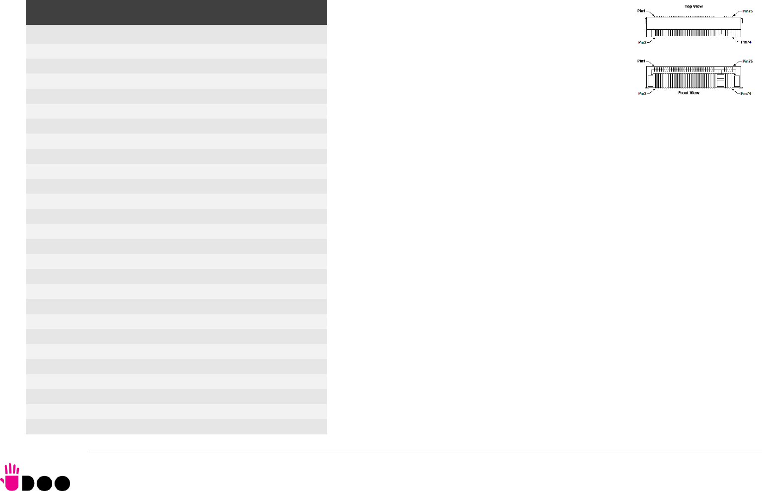
BOLT
UDOO BOLT User Manual - Rev. First Edition: 0.1 - Last Edition: 0.4 - Author: S.B. - Reviewed by L.V. Copyright © 2018 SECO S.p.A.
38
3.3.9 M.2 NVMe Slot: Socket 3 Key M Type 2280 Another possibility for connecting mass storage devices is
given by the M.2 Key M Slot, which allows the plugging of
M.2 High Capacity SSD drives with PCI-e x4 interface.
The connector used for the M.2 SSD slot is CN17, which is a
standard 75 pin M.2 Key M connector, type LOTES p/n
APCI0096-P005H, H=8.5mm, with the pinout shown in the
table on the left.
On the UDOO BOLT board there is also a Threaded Spacer
which allows the placement of M.2 Socket 3 Key M PCI-e SSD modules in 2280 size.
Here following the signals related to this connectivity interface:
GFX_Tx0+/GFX_Tx0-: PCI-e GFX port x4 lane #0, Transmitting Output Differential pair
GFX_Rx0+/GFX_Rx0-: PCI-e GFX port x4 lane #0, Receiving Input Differential pair
GFX_Tx1+/GFX_Tx1-: PCI-e GFX port x4 lane #1, Transmitting Output Differential pair
GFX_Rx1+/GFX_Rx1-: PCI-e GFX port x4 lane #1, Receiving Input Differential pair
GFX_Tx2+/GFX_Tx2-: PCI-e GFX port x4 lane #2, Transmitting Output Differential pair
GFX_Rx2+/GFX_Rx2-: PCI-e GFX port x4 lane #2, Receiving Input Differential pair
GFX_Tx3+/GFX_Tx3-: PCI-e GFX port x4 lane #3, Transmitting Output Differential pair
GFX_Rx3+/GFX_Rx3-: PCI-e GFX port x4 lane #3, Receiving Input Differential pair
PCIe4_Clock+ / PCIe4_Clock-: PCI Express Reference Clock for lane #4, Differential Pair
PLT_RST#: Reset Signal that is sent from the SoC to all PCI-e devices available on the board
(i.e. the GbE controller, the PCI-e based SSD modules plugged in the CN16 slot, the
connectivity modules plugged in CN18 slot, the PCI-e x4 NVMe modules plugged in
CN17slot). It is a 3.3V_RUN active-low signal.
GFX_REQ#: PCI Express GFX Clock Request Input, active low signal. This signal shall be
driven low by any module inserted in the connectivity slot, in order to ensure that the SoC
makes available the reference clock.
M.2 NVMe Slot - CN17
Pin
Signal
Pin
Signal
1
GND
2
+3.3V_RUN
3
GND
4
+3.3V_RUN
5
GFX_Rx3-
6
---
7
GFX_Rx3+
8
---
9
GND
10
---
11
GFX_Tx3-
12
+3.3V_RUN
13
GFX_Tx3+
14
+3.3V_RUN
15
GND
16
+3.3V_RUN
17
GFX_Rx2-
18
+3.3V_RUN
19
GFX_Rx2+
20
---
21
GND
22
---
23
GFX_Tx2-
24
---
25
GFX_Tx2+
26
---
27
GND
28
---
29
GFX_Rx1-
30
---
31
GFX_Rx1+
32
---
33
GND
34
---
35
GFX_Tx1-
36
---
37
GFX_Tx1+
38
---
39
GND
40
---
41
GFX_Rx0-
42
---
43
GFX_Rx0+
44
---
45
GND
46
---
47
GFX_Tx0-
48
---
49
GFX_Tx0+
50
PLT_RST#
51
GND
52
GFX_REQ#
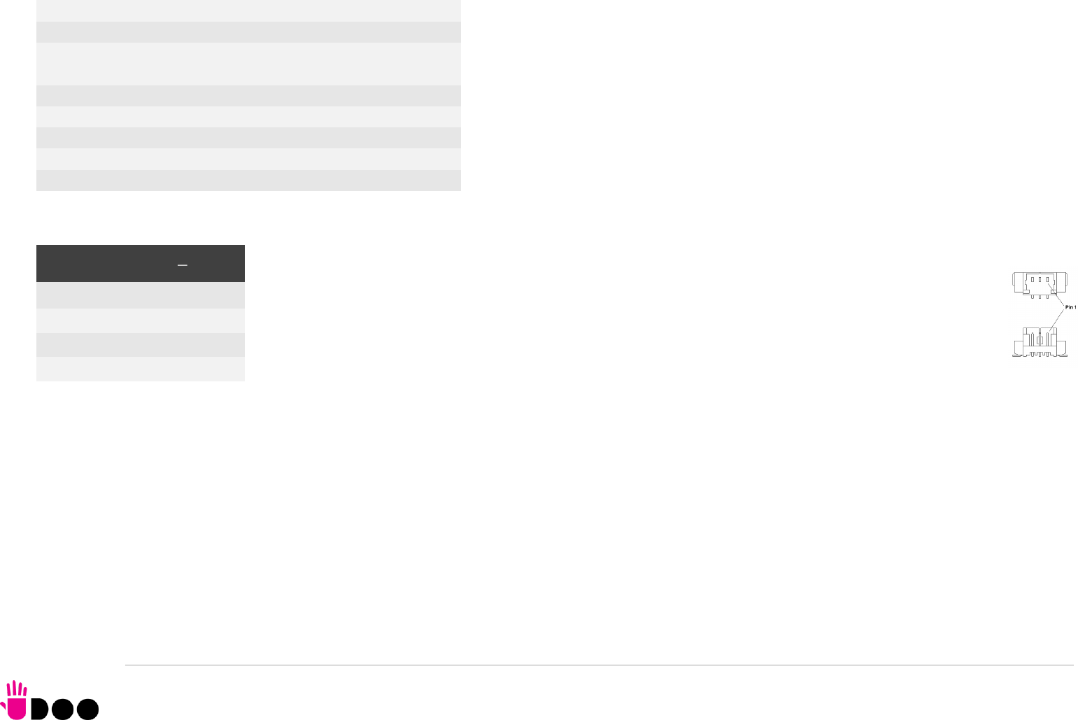
BOLT
UDOO BOLT User Manual - Rev. First Edition: 0.1 - Last Edition: 0.4 - Author: S.B. - Reviewed by L.V. Copyright © 2018 SECO S.p.A.
39
3.3.10 FAN connector
Depending on the usage model of UDOO BOLT, for critical applications/environments on UDOO BOLT it is available a 3-pin
single line SMT connector for an external +5VDC FAN.
The Connector is a type MOLEX 53398-0571 or equivalent, with pinout shown in the table on the left.
Mating connector: MOLEX 51021-0300 receptacle with MOLEX 50079-8000 female crimp terminals.
Please be aware that the use of an external fan depends strongly on customer’s application/installation.
FAN_POWER: +5V_ALW derived power rail for FAN.
FAN_TACHO_IN: tachometric input from the FAN to the embedded microcontroller, +3.3V_RUN electrical level signal with 10kΩ pull-up resistor.
53
PEG_CLK-
54
---
55
PEG_CLK+
56
---
57
GND
58
---
67
---
68
---
69
---
70
+3.3V_RUN
71
GND
72
+3.3V_RUN
73
GND
74
+3.3V_RUN
75
GND
FAN Connector CN7
Pin
Signal
1
GND
2
FAN_POWER
3
FAN_TACHO_IN
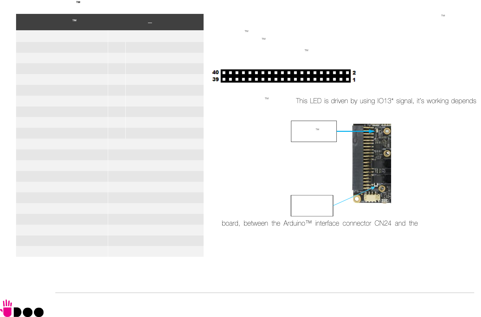
BOLT
UDOO BOLT User Manual - Rev. First Edition: 0.1 - Last Edition: 0.4 - Author: S.B. - Reviewed by L.V. Copyright © 2018 SECO S.p.A.
40
3.3.11 ARDUINO interface
On a dual row p.2.54mm dedicated female header is realised an Arduino Leonardo
interface, which is managed by an ATMEL ATmega32U4 microcontroller, connected to the
AMD Ryzen Embedded V1000 processor via an internal USB. It’s exactly the same thing as
having an Arduino Leonardo board attached via USB to a standard PC.
It is possible to refer to Arduino Leonardo documentation for a description of the signals
available on this connector, and the way to use them.
Near the connector, there is also an integrated Yellow SMT LED, which indicates the proper
working of Arduino section.
on the programming of ATmega32u4 microcontroller.
On- buttons/led header
CN6, it is also available a miniaturized momentary switch, that can be used to reset the
ATmega32u4 microcontroller.
Arduino Interface Connector CN24
Pin
Signal
Pin
Signal
1
A5
2
D0 / RX
3
A4
4
D1 / TX
5
A3
6
D2 / SDA
7
A2
8
D3 / SCL
9
A1
10
D4
11
A0
12
D5*
13
---
14
D6*
15
GND
16
D7
17
GND
18
IO8
19
5V_OUT
20
IO9*
21
3.3V_OUT
22
IO10*
23
RESET#
24
IO11*
25
5V_OUT
26
IO12
27
MISO
28
IO13*
29
MOSI
30
GND
31
SCK
32
AREF
33
GND
34
D2/SDA
35
RXLED
36
D3/SCL
37
TXLED
38
GND
39
5V_OUT
40
5V_OUT
Arduino LED
ATMega32u4
Reset Button
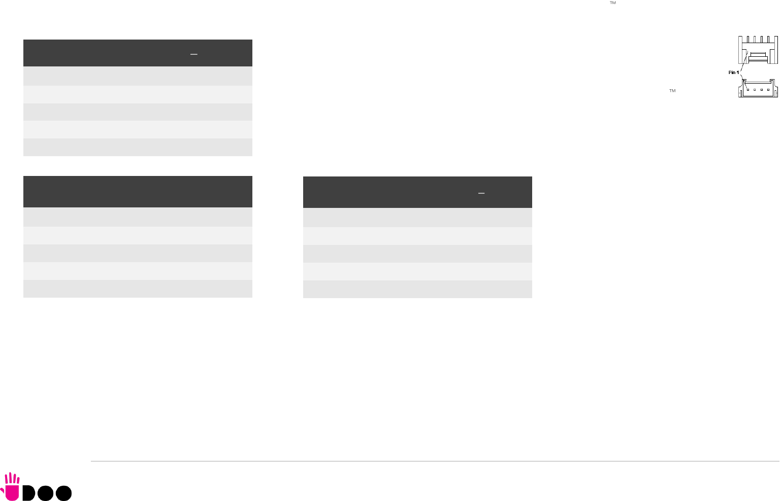
BOLT
UDOO BOLT User Manual - Rev. First Edition: 0.1 - Last Edition: 0.4 - Author: S.B. - Reviewed by L.V. Copyright © 2018 SECO S.p.A.
41
3.3.12 GROVE connectors
The UDOO Bolt board offers the possibility of managing Seeed Technology Grove family of sensors through the Arduino platform by using three dedicated
connectors, directly managed by the ATmega ATmega32u4 controller.
All three connectors are type TKP p/n P20Y1L-04SMT or equivalent, with the pinout shown in
the tables on the left.
Mating connector: TKP receptacle p/n H20Y1-04 with TKP DHT-1S(LF) female crimp terminals.
The signals available on these three connectors are the same available on the Arduino interface
connector CN24.
Please notice that these connectors seems to be mirrored with respect to GROVE standard connectors. Actually, the pinout shown in these tables is referred to
the real pin position #1 engraved on the connector. Cables designed for GROVE sensors will fit into these connectors without needing any change.
GROVE Analog connector CN26
Pin
Signal
GROVE standard ref.
1
GND
4
2
5V_OUT
3
3
A1
2
4
A0
1
GROVE Digital / UART connector - CN27
Pin
Signal
GROVE standard ref.
1
GND
4
2
5V_OUT
3
3
D1/TX
2
4
D0/RX
1
GROVE Digital / I2C connector CN28
Pin
Signal
GROVE standard ref.
1
GND
4
2
5V_OUT
3
3
D2 / SDA
2
4
D3 / SCL
1
BOLT
UDOO BOLT User Manual - Rev. First Edition: 0.1 - Last Edition: 0.4 - Author: S.B. - Reviewed by L.V. Copyright © 2018 SECO S.p.A.
42
3.3.13 Embedded Controller I/O Header
On board’s bottom sidem there is another dual row 40-pin p 2.54mm female header, which makes available
other signals for possible external expansions, that are directly managed by the Embedded Controller.
More specifically, on this connector will be available an SPI interface, a FAN Control interface, two I2C
interfaces, a Matrix scan interface and two UARTs, where some interfaces share the same
pins. Most of these signals can also be used as GPIOs.
Please notice that JTAG interface and Private Flash Interface, described below, are disabled
to the end-users, since they are reserved for manufacturing purposes.
Here following the description of the signals available on this connector:
EC_SPI_MOSI: EC’s SPI #0 interface Master Out Slave In output Signal, electrical level
+3.3V_DSW.
EC_SPI_MISO: EC’s SPI #0 interface Master In Slave Out input Signal, electrical level
+3.3V_DSW
EC_SPI_CS#: EC’s SPI #0 interface Chip Select active low output signal, electrical level
+3.3V_DSW
EC_SPI_CLK: EC’s SPI #0 interface Clock output, electrical level +3.3V_DSW
EC_NRST: EC’s JTAG interface Reset input signal, electrical level +3.3V_DSW with 10kΩ
pull-down resistor
EC_TDO_I2C_SCL2: EC’s JTAG interface Test Data Out output signal / I2C Port #9 Clock
line. Output signal, electrical level +3.V_DSW with 2k2Ω pull-up resistor.
EC_TDI_I2C_SDA2: : EC’s JTAG interface Test Data IN input signal / I2C Port #9 data line.
Bidirectional signal, electrical level +3.3V_DSW with 2k2Ω pull-up resistor.
EC_TMS_I2C_SCL1: EC’s JTAG interface Test Mode Select output signal / I2C Port #8
Clock line. Output signal, electrical level +3.V_DSW with 2k2Ω pull-up resistor
EC_TCK_I2C_SDA1: EC’s JTAG interface Test Clock signal / I2C Port #8 data line.
Bidirectional signal, electrical level +3.3V_DSW with 2k2Ω pull-up resistor.
WAKE# EC Wake# capable Input Signal, electrical level +3.3V_DSW with 2k2Ω pull-up
resistor
FANOUT0: EC PWM #0 Output Signal, electrical level +3.3V_DSW.
Embedded controller Feature header CN25
Pin
Signal
Pin
Signal
1
EC_SPI_MISO
2
EC_SPI_CS#
3
EC_SPI_MOSI
4
EC_SPI_CLK
5
EC_NRST
6
WAKE#
7
EC_TDO_I2C_SCL2
8
EC_TMS_I2C_SCL1
9
EC_TDI_I2C_SDA2
10
EC_TCK_I2C_SDA1
11
FANOUT0
12
FANTACH0
13
EC_KSO0
14
EC_KSI0
15
EC_KSO1
16
EC_KSI1
17
EC_KSO2
18
EC_KSI2
19
EC_KSO3
20
EC_KSI3
21
EC_KSO4
22
EC_KSI4
23
EC_KSO8_PVTIO0
24
EC_KSO11_PVTCS#
25
EC_KSO9_PVTIO1
26
EC_KSO12_PVTCLK
27
EC_KSO10_PVTIO2
28
EC_KSO13_PVTIO3
29
GND
30
+3.3V_OUT
31
GND
32
+3.3V_OUT
33
EC_UART_RxD1
34
EC_UART_RxD0
35
EC_UART_TxD1
36
EC_UART_TxD0
37
EC_UART_RTS#1
38
EC_UART_RTS#0
39
EC_UART_CTS#1
40
EC_UART_CTS#0

BOLT
UDOO BOLT User Manual - Rev. First Edition: 0.1 - Last Edition: 0.4 - Author: S.B. - Reviewed by L.V. Copyright © 2018 SECO S.p.A.
43
FANTACH0: EC FAN Tachometric #0 Input signal, electrical level +3.3V_DSW.
EC_KSO0: EC Keyboard Matrix Scan Output #0, electrical level +3.3V_DSW
EC_KSO1: EC Keyboard Matrix Scan Output #1,electrical level +3.3V_DSW
EC_KSO2: EC Keyboard Matrix Scan Output #2,electrical level +3.3V_DSW
EC_KSO3: EC Keyboard Matrix Scan Output #3, electrical level +3.3V_DSW
EC_KSO4: EC Keyboard Matrix Scan Output #4,electrical level +3.3V_DSW
EC_KSI0: EC Matric Scan Input #0,electrical level +3.3V_DSW
EC_KSI1: EC Keyboard Matrix Scan Input #1,electrical level +3.3V_DSW
EC_KSI2: EC Keyboard Matrix Scan Input #2, electrical level +3.3V_DSW
EC_KSI3: EC Keyboard Matrix Scan Input #3, electrical level +3.3V_DSW
EC_KSI4: EC Keyboard Matrix Scan Input #4, electrical level +3.3V_DSW
EC_KSO8_PVTIO0: EC Keyboard Matrix Scan Output #8 / Private Flash port Data 0, bidirectional signal electrical level +3.3V_DSW
EC_KSO9_PVTIO1: EC Keyboard Matrix Scan Output #9 / Private Flash port Data 1, bidirectional signal electrical level +3.3V_DSW
EC_KSO10_PVTIO2: EC Keyboard Matrix Scan Output #10 / Private Flash port Data 2, bidirectional signal, electrical level +3.3V_DSW
EC_KSO11_PVTCS#: EC Keyboard Matrix Scan Output #11 / Private Flash port Chip Select, output signal, electrical level +3.3V_DSW
EC_KSO12_PVTCLK: EC Keyboard Matrix Scan Output #12 / Private Flash port Clock, output signal electrical level +3.3V_DSW
EC_KSO13_PVTIO3: EC Keyboard Matrix Scan Output #13 / Private Flash port Data 3, bidirectional signal electrical level +3.3V_DSW
EC_UART_RxD0: EC UART #0, Serial data Receive (input) line, +3.3V_DSW electrical level.
EC_UART_TxD0: EC UART #0, Serial data Transmit (output) line, +3.3V_DSW electrical level.
EC_UART_CTS#0: EC UART #0, Handshake signal, Clear to Send (Input) line, +3.3V_DSW electrical level.
EC_UART_RTS#0: EC UART #0, Handshake signal, Request to Send (output) line, +3.3V_DSW electrical level.
EC_UART_RxD1: EC UART #1, Serial data Receive (input) line, +3.3V_DSW electrical level.
EC_UART_TxD1: EC UART #1, Serial data Transmit (output) line, +3.3V_DSW electrical level.
EC_UART_CTS#1: EC UART #1, Handshake signal, Clear to Send (Input) line, +3.3V_DSW electrical level.
EC_UART_RTS#1: EC UART #1, Handshake signal, Request to Send (output) line, +3.3V_DSW electrical level.

BOLT
UDOO BOLT User Manual - Rev. First Edition: 0.1 - Last Edition: 0.4 - Author: S.B. - Reviewed by L.V. Copyright © 2018 SECO S.p.A.
44
3.3.14 IR Receiver
The UDOO BOLT board embeds an IR receiver, which allows using a remote control when the board is placed in an enclosure (like, i.e., on Set Top Boxes).
The Infrared Receiver is SMD Type, p/n TSOP75238TR, and works with 38kHz carrier frequency.
The IR port is managed by the embedded microcontroller.
3.3.15 UEFI BIOS Default Restore switch
In some cases, a wrong configuration of BIOS parameters could lead the module in an unusable state (i.e. no video output, all USB HID devices disabled).
For these cases, on the module it has been placed a 3-way switch which can be used to restore the BIOS to factory default configuration. To do so,
it is necessary to place the contact of the switch in 1-2 position, then turn on the module, wait until the board resets itself then turn off the module.
The contact MUST be now placed back to 2-3 position.
During normal use, the contact MUST be always placed in 2-3 position.


BOLT
UDOO BOLT User Manual - Rev. First Edition: 0.1 - Last Edition: 0.4 - Author: S.B. - Reviewed by L.V. Copyright © 2018 SECO S.p.A.
46
4.1 Aptio setup Utility
Basic setup of the board can be done using American Megatrends, Inc. “Aptio Setup Utility”, that is stored inside an onboard SPI Serial Flash.
It is possible to access to Aptio Setup Utility by pressing the <ESC> key after System power up, during POST phase. On the splash screen that will appear, select
“SCU” icon.
On each menu page, on left frame are shown all the options that can be configured.
Grayed-out options are only for information and cannot be configured.
Only options written in blue can be configured. Selected options are highlighted in white.
Right frame shows the key legend.
KEY LEGEND:
← / → Navigate between various setup screens (Main, Advanced, Security, Power, Boot...)
↑ / ↓ Select a setup item or a submenu
+ / - + and - keys allows to change the field value of highlighted menu item
<F1> The <F1> key allows displaying the General Help screen.
<F2> Previous Values
<F3> <F3> key allows loading Optimised Defaults for the board. After pressing <F3> BIOS Setup utility will request for a confirmation, before loading
such default values. By pressing <ESC> key, this function will be aborted
<F4> <F4> key allows save any changes made and exit Setup. After pressing <F10> key, BIOS Setup utility will request for a confirmation, before
saving and exiting. By pressing <ESC> key, this function will be aborted
<ESC> <Esc> key allows discarding any changes made and exit the Setup. After pressing <ESC> key, BIOS Setup utility will request for a confirmation,
before discarding the changes. By pressing <Cancel> key, this function will be aborted
<ENTER> <Enter> key allows to display or change the setup option listed for a particular setup item. The <Enter> key can also allow displaying the setup
sub- screens.
It is possible to reset the UEFI BIOS Setup to Factory Defaults by using the dedicated switch available on module. Please check par. 3.3.15.

BOLT
UDOO BOLT User Manual - Rev. First Edition: 0.1 - Last Edition: 0.4 - Author: S.B. - Reviewed by L.V. Copyright © 2018 SECO S.p.A.
47
4.2 Main menu
When entering the Setup Utility, the first screen shown is the Main setup screen. It is always possible to return to the Main setup screen by selecting the Main tab.
In this screen, are shown details regarding BIOS version, Processor type, Bus Speed and memory configuration.
Only two options can be configured:
4.2.1 System Time / System Date
Use this option to change the system time and date. Highlight System Time or System Date using the <Arrow> keys. Enter new values directly through the
keyboard, or using + / - keys to increase / reduce displayed values. Press the <Enter> key to move between fields. The date must be entered in MM/DD/YY
format. The time is entered in HH:MM:SS format.
Note: The time is in 24-hour format. For example, 5:30 A.M. appears as 05:30:00, and 5:30 P.M. as 17:30:00.
The system date is in the format mm/dd/yyyy.

BOLT
UDOO BOLT User Manual - Rev. First Edition: 0.1 - Last Edition: 0.4 - Author: S.B. - Reviewed by L.V. Copyright © 2018 SECO S.p.A.
48
4.3 Advanced menu
Menu Item
Options
Description
AMD CBS
See submenu
AMD CBS Setup Page
AMD PBS
See submenu
AMD PBS Setup Page
Battery Failure manager
See submenu
Sets the action to be performed in case of battery failure
Trusted Computing
See submenu
Trusted Computing Settings
ACPI Settings
See submenu
System ACPI parameters
SATA presence
See submenu
SATA devices Configuration
DXIO Settings
See submenu
PEG, PCIE and DDI Lanes configuration
S5 RTC Wake Settings
See submenu
Enable System to wake from S5 using RTC alarm
Serial Port Console Redirection
See submenu
Serial Port Console redirection
CPU Configuration
See submenu
CPU Configuration Parameters
AMI Graphic Output Protocol Policy
See submenu
User Selected Monitor Output by Graphic Output protocol
PCI Subsystem Settings
See submenu
PCI Subsystem Settings
Network Stack Configuration
See submenu
Network Stack Settings
CSM Configuration
See submenu
Compatibility Support Module (CSM) Configuration: Enable/Disable, Option ROM execution Settings, etc...
NVMe Configuration
See submenu
NVMe Device Options Settings
SDIO Configuration
See submenu
SDIO Configuration Parameters
USB Configuration
See submenu
USB Configuration Parameters
Main Thermal Configuration
See submenu
Main thermal Configuration
SMBIOS Information
See submenu
SMBIOS Information
BOLT
UDOO BOLT User Manual - Rev. First Edition: 0.1 - Last Edition: 0.4 - Author: S.B. - Reviewed by L.V. Copyright © 2018 SECO S.p.A.
49
4.3.1 AMD CBS submenu
4.3.1.1
NBIO Common Options submenu
Menu Item
Options
Description
NBIO Common options
See submenu
NorthBridge IO Configuration Options
FCH Common options
See submenu
Firmware Controller Hub Configuration options
Menu Item
Options
Description
GFX Configuration
See submenu
GFX Configuration options
IOMMU
Auto / Disabled /
Enabled
Enable or disable the support for IOMMU (IO Memory Management Unit. Also known as AMD
Virtualization Technology).
PSPP Policy
Disabled
Performance
Balanced-high
Balanced-Low
Power Saving
Auto
PCIe Speed Power policy: the processor can dynamically support the changing to the link frequency due
to changes in system configuration and power policy.
System Configuration
12W POR Configuration/
15W POR Configuration/
25W POR Configuration/
35W POR Configuration/
45W POR Configuration/
54W POR Configuration/
Auto
Allows selecting the Power Scheme configuration for the CPU.
Warning: by selecting a precise configuration, may cause the system to hang, as some System
Configurations may not be supported by your OPN.
Audio Codecs
Enabled
Disabled
Disable/Enable Audio Codecs input signals SDINx

BOLT
UDOO BOLT User Manual - Rev. First Edition: 0.1 - Last Edition: 0.4 - Author: S.B. - Reviewed by L.V. Copyright © 2018 SECO S.p.A.
50
4.3.1.1.1
GFX Configuration submenu
4.3.1.2
FCH Common Options submenu
4.3.1.2.1
SATA Configuration submenu
Menu Item
Options
Description
Integrated Graphics Controller
Auto / Disabled / Forces
Enable Integrated Graphics Controller. If disabled, all the remaining options will disappear
UMA Mode
Auto / UMA_Specified /
UMA_Auto
Only available when Integrated Graphics Controller is set to “Forces”. Allows setting the Unified Memory
Architecture (UMA) Frame Buffer Size or Display Resolution
UMA Version
Legacy / Non-Legacy /
Hybrid Secure / Auto
Only available when Integrated Graphics Controller is set to “Forces”. Sets the supported UMA
compatibility.
UMA Frame Buffer Size
Auto / 256M / 384M /
512M / 768M / 1G / 2G
/ 3G / 4G / 8G / 16G
Only available when “UMA Mode” is set to UMA_Specified.
Sets UMA Frame Buffer Size
Display Resolution
1920X1080 and below /
2560x1600 /
3840x2160 / Auto
Only available when “UMA Mode” is set to UMA_Auto.
Sets Display Resolution
Integrated HD Audio Controller
Auto / Disabled /
Enabled
Enables or disabled integrated HD Audio Controller
Menu Item
Options
Description
SATA Configuration Options
See submenu
SATA Configuration Options
Uart Configuration Options
See submenu
Uart Configuration Options
eMMC Options
See submenu
eMMC Configuration Options
Menu Item
Options
Description
SATA Controller
Auto / Disabled /
Enabled
Enable or Disable on-chip SATA controller
SATA Mode
AHCI
AHCI as ID 0x7904
Auto
RAID
Only available when SATA Controller is set to “Enabled”. Select on-chip SATA Type
BOLT
UDOO BOLT User Manual - Rev. First Edition: 0.1 - Last Edition: 0.4 - Author: S.B. - Reviewed by L.V. Copyright © 2018 SECO S.p.A.
51
4.3.1.2.2
Uart Configuration Options submenu
4.3.1.2.3
eMMC Options submenu
4.3.2 AMD PBS submenu
Menu Item
Options
Description
SER1 Enable
SER0 Enable
Auto
Disabled
Enabled
Enable or Disable SER0 and SER1 ports available on COM Express connector AB.
Menu Item
Options
Description
eMMC/SD Configure
Disabled
eMMC High Speed SDR
eMMC High Speed DDR
eMMC HS200
eMMC HS400
eMMC HS300
Configures eMMC Speed Mode
Driver Type
AMS eMMC Driver
MS Driver
MS eMMC Driver
Auto
BIOS will select MS driver for SD selection
D3 Cold Support
Auto / Disabled /
Enabled
eMMC Boot
Auto / Disabled /
Enabled
Enables or disables the boot from eMMC drive
Menu Item
Options
Description
AMD Firmware Version
Opens an information page with all details about the Firmware
Primary Video Adaptor
Int. Graphics (IGD)
Ext. Graphics (PEG)
Allows to select if Internal Graphics controller (IGD) or external PCI-e Graphic Controller x8 (PEG) should be
used as a Primary display
BOLT
UDOO BOLT User Manual - Rev. First Edition: 0.1 - Last Edition: 0.4 - Author: S.B. - Reviewed by L.V. Copyright © 2018 SECO S.p.A.
52
4.3.3 Battery Failure Manager submenu
4.3.4 Trusted computing submenu
Menu Item
Options
Description
Battery Failure Action
None
Restore Defaults
Restore NVRAM
Sets the action that must be done when a backup battery failure occurs.
None: no action
Restore defaults: restore BIOS factory default, preserving the password(s)
Reset NVRAM: restore all factory defaults, clearing also the password(s)
Menu Item
Options
Description
Security Device Support
Disabled / Enabled
Enables or Disables BIOS Support for security devices. OS will not show Security Device, TCG EFI
protocol and INT1A interface will not be available.
When disabled, all following items will disappear.
SHA-1 PCR Bank
Disabled / Enabled
Enables or Disables SHA-1 PCR Bank
SHA256 PCR Bank
Disabled / Enabled
Enables or Disables SHA256 PCR Bank
Pending operation
None
TPM Clear
Schedule an operation for the Security Device. Note: your computer will reboot during restart in order to
change the State of Security Device.
Platform Hierarchy
Disabled / Enabled
Enable or Disable Platform Hierarchy
Storage Hierarchy
Disabled / Enabled
Enable or Disable Storage Hierarchy
Endorsement Hierarchy
Disabled / Enabled
Enable or Disable Endorsement Hierarchy
TPM2.0 UEFI Spec Version
TCG_1_2
TCG_2
Select the TCG2 Spec version Support.
TCG_1_2 is the compatible mode for Windows 8 and Windows 10
TCG_2 supports the new TCG2 protocol and event format for Windows 10 and later
Physical Presence Spec Version
1.2 / 1.3
Tells the OS to support PPI Spec version 1.2 or 1.3. Note that some HCK tests might not support 1.3
Device Select
Auto
TPM 1.2
TPM 2.0
TPM 1.2 will restrict the support to TPM 1.2 devices only, TPM 2.0 will restrict the support to TPM 2.0
devices only, Auto will support both with the default set to TPM 2.0 devices if not found, TPM 1.2 devices
will be enumerated
BOLT
UDOO BOLT User Manual - Rev. First Edition: 0.1 - Last Edition: 0.4 - Author: S.B. - Reviewed by L.V. Copyright © 2018 SECO S.p.A.
53
4.3.5 ACPI Settings
4.3.6 SATA presence submenu
4.3.7 DXIO Settings submenu
4.3.7.1
DDI Port submenu
Menu Item
Options
Description
Enable ACPI Auto Configuration
Disabled / Enabled
Enables or Disables BIOS ACPI Auto Configuration. The following menu items will appear only when this
menu item is Disabled
Enable Hibernation
Disabled / Enabled
Enables or disables system ability to Hybernate (OS/S4 Sleep State). This option may be not effective with
some OS.
ACPI Sleep State
Suspend Disabled
S3 (Suspend to RAM)
Select the highest ACPI Sleep state the system will enter when the SUSPEND button is pressed.
Lock Legacy resources
Disabled / Enabled
Enables or Disables Lock of Legacy resources
Menu Item
Options
Description
M.2 (CN18 Key B SATA)
Standard (CN14) SATA
Shows information related to eventual devices connected to SATA ports 0 or 1.
Menu Item
Options
Description
DDI Port
See submenu
Allows enabling and configuring the single DDI ports
PEG Port
See submenu
Allows enabling and configuring the PEG port(s)
PCI-E Port
See submenu
Allows enabling and configuring the PCI-e ports
Menu Item
Options
Description
HDMI0 (CN20) State
HDMI1 (CN19) State
USB-C1 (CN9) DP State
USB-C0 (CN8) DP State
Disabled
Enabled
Enable or Disable individually the video interfaces

BOLT
UDOO BOLT User Manual - Rev. First Edition: 0.1 - Last Edition: 0.4 - Author: S.B. - Reviewed by L.V. Copyright © 2018 SECO S.p.A.
54
4.3.7.2
PEG Port submenu
Menu Item
Options
Description
M.2 x4 (CN17 Key M)
Enabled / Disabled
Enable or disable the PEG x4 port available on M.2 Key M (NVMe) slot. When enabled, all following items
will appear.
ASPM Mode Control
Disabled
L0s Entry
L1 Entry
L0s and L1 Entry
Auto
Disable or Enable PCI Express Active State Power Management
Link Speed
PCIe Gen1
PCIe Gen2
Max Speed
Auto
Configures NB Root Port PCIe Link Speed, which can however be overwritten by PSPP Settings
Hot Plug Mode Control
Auto
Disabled
Hotplug Basic
Hotplug Server
Hotplug Enhanced
Hotplug Inboard
PCI Express Root Port Hot Plug Mode Control
Compliance Mode
Enabled / Disabled
If enabled, forces the port into Compliance mode.
BOLT
UDOO BOLT User Manual - Rev. First Edition: 0.1 - Last Edition: 0.4 - Author: S.B. - Reviewed by L.V. Copyright © 2018 SECO S.p.A.
55
4.3.7.3
PCI-E Port submenu
4.3.8 S5 RTC Wake Settings submenu
Menu Item
Options
Description
M.2 x2 (CN18 Key B)
M.2 x1 (CN16 Key E)
Internal LAN
Enabled / Disabled
Enable or disable each single PCIE port .
When enabled, all following items will appear.
ASPM Mode Control
Disabled
L0s Entry
L1 Entry
L0s and L1 Entry
Auto
Disable or Enable PCI Express Active State Power Management
Link Speed
PCIe Gen1
PCIe Gen2
Max Speed
Auto
Configures NB Root Port PCIe Link Speed, which can however be overwritten by PSPP Settings
Hot Plug Mode Control
Auto
Disabled
Hotplug Basic
Hotplug Server
Hotplug Enhanced
Hotplug Inboard
PCI Express Root Port Hot Plug Mode Control
Compliance Mode
Enabled / Disabled
If enabled, forces the port into Compliance mode.
Menu Item
Options
Description
Wake system from S5
Disabled
By Every Day
By Day of Month
Enables or disables System Wake on Alarm event.
The following menu items will appear only when this voice is not set to Disabled
Wake up hour
0..23
Sets the wake up hour in 0..23 format (i.e.,3 means 3am, 15 means 3pm)
Wake up minute
0..59
Sets the wake up minute
Wake up second
0..59
Sets the wake up second
Day of Month
1..31
This item is available only when “Wake system from S5” is set to “By Day of Month”.
Sets the day of month for Wake on Alarm event. Valid range s from 1 to 31, error checking will be done
against month/day/year combinations that are not valid.

BOLT
UDOO BOLT User Manual - Rev. First Edition: 0.1 - Last Edition: 0.4 - Author: S.B. - Reviewed by L.V. Copyright © 2018 SECO S.p.A.
56
4.3.9 Serial Port Console Redirection submenu
4.3.9.1
Console Redirection Settings submenus
Menu Item
Options
Description
Console Redirection
Enabled / Disabled
Enable or disable Console redirection. This can be done both on Serial Port 0 and Serial Port 1 and for
Windows Emergency Management Services (EMS) console.
Console Redirection Settings
See submenu
When any of the Serial port Console Redirections is enabled, this submenu will appear
Menu Item
Options
Description
Terminal Type
VT_100 / VT_100+ /
VT_UTF8 / ANSI
Set Console Redirection terminal type
Bits per second
115200 / 57600 /
38400 / 19200 / 9600
Set Console Redirection baud rate
Data Bits
7 / 8
Set Console Redirection data bits
Parity
None / Even / Odd /
Mark / Space
Set Console Redirection parity bits
Stop Bits
1 / 2
Set Console Redirection stop bits
Flow Control
None
Hardware RTS/CTS
Set Console Redirection flow control type
VT-UTF8 Combo Key Support
Enabled / Disabled
Enable or Disable VT-UTF8 Combination Key Support for ANSI/VT100 terminals
Recorder Mode
Enabled / Disabled
With this mode enabled only text will be sent. This is to capture Terminal data.
Resolution 100x31
Enabled / Disabled
Enables or disables extended terminal resolution
Putty Keypad
VT100 / Linux / XTermr6
/ SCO / ESCN / VT400
Select FunctionKey and KeyPad on Putty
BOLT
UDOO BOLT User Manual - Rev. First Edition: 0.1 - Last Edition: 0.4 - Author: S.B. - Reviewed by L.V. Copyright © 2018 SECO S.p.A.
57
4.3.10 CPU configuration submenu
PSS Support
Enabled / Disabled
Enable/disable the generation of ACPU _PCC, _PSS and _PCT objects
PPC Adjustment
PState 0 / PState 1 /
PState 2
Only Available when PSS Support is enabled
Provide to adjust startup P-state level
NX Mode
Enabled / Disabled
Enables or Disables No-execute Page Protection Function
SVM Mode
Enabled / Disabled
Enables or disables CPU Virtualization
Node 0 Information
Opens an information page with the Memory Information details related to Node 0
4.3.11 AMI graphic Output Protocol Policy submenu
4.3.12 PCI Subsystem Settings submenu
Menu Item
Options
Description
Menu Item
Options
Description
Output Select
List of available /
connected module
’
s
video interfaces
Menu Item
Options
Description
Above 4G Decoding
Disabled / Enabled
Globally Enables or Disables 64-bit capable Devices to be decoded in Address Space above 4GB (only if
system supports 64-bit PCI Decoding).
SR-IOV Support
Disabled / Enabled
If system has SR-IOV capable PCIe Devices, this option Enables or Disables Single Root IO Virtualization
Support.
BME DMA Mitigation
Disabled / Enabled
Re-enable Bus Master Attribute disabled during PCI enumeration for PCI Bridges after SMM has been
locked

BOLT
UDOO BOLT User Manual - Rev. First Edition: 0.1 - Last Edition: 0.4 - Author: S.B. - Reviewed by L.V. Copyright © 2018 SECO S.p.A.
58
4.3.13 Network Stack configuration submenu
Menu Item
Options
Description
Network Stack
Enabled / Disabled
Enables or disables UEFI Network Stack. When enabled, following menu items will appear
Ipv4 PXE Support
Enabled / Disabled
Enables or disables IPV4 PXE Boot Support. If disabled, IPV4 PXE boot option will not be created
Ipv4 HTTP Support
Enabled / Disabled
Enables or disables IPV4 HTTP Boot Support. If disabled, IPV4 HTTP boot option will not be created
Ipv6 PXE Support
Enabled / Disabled
Enables or disables IPV6 PXE Boot Support. If disabled, Ipv6 PXE boot option will not be created
Ipv6 HTTP Support
Enabled / Disabled
Enables or disables IPV6 HTTP Boot Support. If disabled, Ipv6 HTTP boot option will not be created
IPSEC certificate
Enabled / Disabled
Support to Enable/Disable IPSEC certificate for Ikev.
PXE boot wait time
[0..5]
Wait time to press ESC key to abort the PXE boot
Media detect count
[1..50]
Number of times that the presence of media will be checked

BOLT
UDOO BOLT User Manual - Rev. First Edition: 0.1 - Last Edition: 0.4 - Author: S.B. - Reviewed by L.V. Copyright © 2018 SECO S.p.A.
59
4.3.14 CSM configuration submenu
4.3.15 NVMe configuration submenu
NVMe Device Options Settings, depend on NVMe Devices found in the system.
Menu Item
Options
Description
CSM Support
Enabled / Disabled
Enables or disables the Compatibility Support Module (CSM) Support. When enabled, the following menu
items will appear
GateA20 Active
Upon Request
Always
Upon Request: GateA20 can be disabled using BIOS services,
Always: do not allow disabling GateA20; this option is useful when any RT code is executed above 1MB.
INT19 Trap Response
Immediate
Postponed
BIOS Reaction on INT19 trapping by Option ROM:
IMMEDIATE - execute the trap right away;
POSTPONED - execute the trap during legacy boot
Boot option filter
UEFI and Legacy
Legacy only
UEFI only
This option controls Legacy / UEFI ROMs priority
Network
Do not launch
UEFI
Legacy
Controls the execution of UEFI and Legacy PXE OpROM
Storage
Do not launch
UEFI
Legacy
Controls the execution of UEFI and Legacy Storage OpROM
Video
Do not launch
UEFI
Legacy
Controls the execution of UEFI and Legacy Video OpROM
Other PCI devices
Do not launch
UEFI
Legacy
Determines the OpROM execution policy for devices other than Network, Storage and Video
BOLT
UDOO BOLT User Manual - Rev. First Edition: 0.1 - Last Edition: 0.4 - Author: S.B. - Reviewed by L.V. Copyright © 2018 SECO S.p.A.
60
4.3.16 SDIO configuration submenu
4.3.17 USB configuration submenu
Menu Item
Options
Description
SDIO Access Mode
Auto
ADMA
SDMA
PIO
Auto option: Access to SD Device in DMA Mode, if the controller supports it, otherwise in PIO Mode.
DMA option: Access the SD Device in DMA mode only.
PIO option: Access the SD Device in PIOmode only.
MMC
Name and capacity
Auto
Floppy
Forced FDD
Hard Disk
Mass storage device emulation type.
With ‘Auto’, enumerates devices less than 530MB as Floppies.
Forced FDD option can be used to force HDD formatted rive to boot as a FDD.
Menu Item
Options
Description
Legacy USB Support
Enabled / Disabled /
Auto
Enables Legacy USB Support. AUTO Option disables legacy support if no USB devices are connected.
DISABLE option will keep USB devices available only for EFI applications.
XHCI hand-off
Enabled/ Disabled
This is a workaround for OSes without XHCI hand-off support. The XHCI ownership change should be
claimed by XHCI driver.
USB Mass Storage Driver Support
Enabled/ Disabled
Enables or disables USB Mass Storage Driver Support
USB Transfer time-out
1 sec / 5 sec / 10 sec /
20 sec
Sets the time-out value for Control, Bulk and Interrupt transfers
Device reset time-out
10 sec / 20 sec / 30
sec / 40 sec
USB mass storage device Start Unit command time-out
Device power-up delay
Auto / Manual
Sets the maximum time that the device will take before it properly reports itself to the Host controller. ‘Auto’
uses the default vale (for a Root port it is 100ms, for a Hub port the delay is taken from the Hub descriptor).
Device power-up delay in seconds
[1..40]
Delay range in seconds, in one second increment

BOLT
UDOO BOLT User Manual - Rev. First Edition: 0.1 - Last Edition: 0.4 - Author: S.B. - Reviewed by L.V. Copyright © 2018 SECO S.p.A.
61
4.3.18 Main Thermal Configuration submenu
4.3.19 SMBIOS Information
Display only screen, shows information about the module and the Carrier board.
Menu Item
Options
Description
Critical Temperature (°C)
80 .. 100
Above this threshold, an ACPI aware OS will perform a critical shut-down. Allowed range is from 80 to 100,
where 100 means disabled.
Passive Cooling Temperature (°C)
75 .. 90
This value controls the temperature of the ACPI Passive Trip Point - the point in which the OS will begin
lowering the CPU speed. Allowed range is from 75 to 90, where values above Critical Temperature means
Disabled.

BOLT
UDOO BOLT User Manual - Rev. First Edition: 0.1 - Last Edition: 0.4 - Author: S.B. - Reviewed by L.V. Copyright © 2018 SECO S.p.A.
62
4.4 Chipset menu
4.4.1 South Bridge Configuration submenu
4.4.1.1
SB USB Configuration submenu
4.4.2 North Bridge Configuration submenu
Menu Item
Options
Description
South Bridge
See Submenu
South Bridge Parameters
North Bridge
See Submenu
North Bridge Parameters
Menu Item
Options
Description
SB USB Configuration
See submenu
USB configuration Settings
Menu Item
Options
Description
USB-C0 (CN8) USB state
Front Panel USB0 (CN21)
Front Panel USB0 (CN22)
USB-C0 (CN9) USB state
M.2 x1 (CN16 Key E) USB State
Arduino USB state
Enabled / Disabled
Enables or Disables every USB Port
Menu Item
Options
Description
Socket 0 Configuration
Socket 1 Configuration
By selecting this item, an information screen with all information related to the memory module plugged in
Socket #x will appear

BOLT
UDOO BOLT User Manual - Rev. First Edition: 0.1 - Last Edition: 0.4 - Author: S.B. - Reviewed by L.V. Copyright © 2018 SECO S.p.A.
63
4.5 Security menu
4.5.1 Secure Boot submenu
Menu Item
Options
Description
Administrator Password
Set Administrator Password
User Password
Set User Password (possible only if also Administrator Password has been set)
Secure Boot
See Submenu
Customizable Secure Boot Settings
Menu Item
Options
Description
Secure Boot
Enabled / Disabled
Secure Boot is activated when the Platform Key (PK) is enrolled, System Mode is User/Deployed and CSM
function is disabled.
Secure Boot Customization
Standard / Custom
Set UEFI Secure Boot Mode to Standard Mode or Custom mode. In Custom Mode, Secure Boot Policy
variables can be configured by a physically present user without full authentication
Restore Factory Keys
Only accessible when Secure Boot Mode is set to Custom
Force System to User Mode. Install Factory default Secure Boot key databases.
Reset to Setup Mode
Delete all Secure Boot key databases from NVRAM
Key management
See submenu
Only accessible when Secure Boot Mode is set to Custom
Enable expert users to modify Secure Boot Policy variables without full authentication

BOLT
UDOO BOLT User Manual - Rev. First Edition: 0.1 - Last Edition: 0.4 - Author: S.B. - Reviewed by L.V. Copyright © 2018 SECO S.p.A.
64
4.5.1.1
Key Management submenu
Menu Item
Options
Description
Factory Key Provision
Disabled / Enabled
Install factory default Secure Boot Keys after the platform reset and while the System is in Setup Mode
Restore Factory Keys
Force System to User Mode. Install factory Default Secure Boot key databases
Reset to Setup Mode
Delete all Secure Boot key databases from NVRAM
Export Secure Boot variables
Copy NVRAM content of Secure Boot variables to files in a root folder on a file system device
Enrol Efi Image
File System Image
Allow the selected image to run in Secure Boot mode. Enrol SHA256 Hash Certificates of a PE Image into
Authorized Signature Database (db)
Remove ‘UEFI CA’ from DB
Device Guard ready system must not list ‘Microsoft UEFI CA’ Certificate in Authorized Signature Database
(db)
Restore DB defaults
Restore DB variable to factory defaults
Platform key
Key Exchange Keys
Authorized Signatures
Forbidden Signatures
Authorized Timestamps
OS Recovery Signatures
Details
Export
Update
Delete
Enrol factory Defaults or load certificates from a file:
1. Public Key Certificate in:
a) EFI_SIGNATURE_LIST
b) EFI_CERT_X509 (DER encoded)
c) EFI_CERT_RSA2048 (bin)
d) EFI_CERT_SHAXX
2. Authenticated UEFI variables
3. EFI PE/COFF Image (SHA256)
Key Source:
Factory, External, Mixed

BOLT
UDOO BOLT User Manual - Rev. First Edition: 0.1 - Last Edition: 0.4 - Author: S.B. - Reviewed by L.V. Copyright © 2018 SECO S.p.A.
65
4.6 Boot menu
Menu Item
Options
Description
Setup Prompt Timeout
0 .. 65535
Number of seconds to wait for setup activation key. 655535 means indefinite waiting.
Bootup NumLock State
On / Off
Select the Keyboard NumLock State at boot
Quiet Boot
Enabled / Disabled
Enables or Disables Quiet Boot options
Fast Boot
Enabled / Disabled
When Fast Boot is enabled, most probes are skipped to reduce time cost during boot
New Boot Option Policy
Default
Place First
Place Last
Controls the placement of newly detected UEFI boot devices
Boot Mode Select
LEGACY
UEFI
Select the boot mode between Legacy and UEFI
Boot Option #1
Boot Option #2
Boot Option #3
Boot Option #4
Boot Option #5
Boot Option #6
Hard Disk
CD/DVD
SD
USB Device
Network
UEFI Other Device
Disabled
Select the system boot order
Please be aware that by default only UEFI boot is enabled. In this situation, when using legacy MBR drives, the system will not boot from them.
To fully enable the boot form legacy drives, it is necessary to set the following items:
Boot menu “Boot mode select”: must be set to Legacy
Advanced menu CSM Configuration submenu “CSM support” must be Enabled
Advanced menu CSM Configuration submenu “Video” must be set to Legacy

BOLT
UDOO BOLT User Manual - Rev. First Edition: 0.1 - Last Edition: 0.4 - Author: S.B. - Reviewed by L.V. Copyright © 2018 SECO S.p.A.
66
4.7 Save & Exit menu
Menu Item
Options
Description
Save Changes and Exit
Exit system setup after saving the changes.
Discard Changes and Exit
Exit system setup without saving any changes.
Save Changes and Reset
Reset the system after saving the changes.
Discard Changes and Reset
Reset the system without saving any changes.
Save Changes
Save the changes done so far to any of the setup options.
Discard Changes
Discard the changes done so far to any of the setup options.
Restore Defaults
Restore/Load Default values for all the setup options
Save as User Defaults
Save the changes done so far as User Defaults
Restore User Defaults
Restore the User Defaults to all the setup options
Launch EFI Shell from filesystem device
Attempt to Launch the EFI Shell application (Shell.efi) from one of the available filesystem devices


BOLT
UDOO BOLT User Manual - Rev. First Edition: 0.1 - Last Edition: 0.4 - Author: S.B. - Reviewed by L.V. Copyright © 2018 SECO S.p.A.
68
5.1 Accessories
5.1.1 M.2 Dual network modules As a separated accessory, it is available an M.2 Dual Network Set, so composed:
An M.2 2260 module, which embeds a PCI-e packet switch. It virtually separates the PCI-e x2 Port, coming from the
UDOO BOLT board (through M.2 Slot CN18), into two separated PCI-e ports, each one used specifically to manage a Gigabit
Ethernet controller. The Gigabit Ethernet interfaces, coming from the controllers, are then carried to a connector type HR
A1014WVA-S-2x15P or equivalent (2 x 15p, male, straight, P1, low profile, polarised).
A daughter-board, which mounts a connector identical to that available on the main M.2 module and two RJ-45 Gigabit
Ethernet connectors with integrated transformer.
Twisted pairs connecting cable, to connect the M.2 module with the daughter-board.
When this accessory is plugged into M.2 slot CN18, the UDOO BOLT board will offer three different Gigabit Ethernet ports.
5.1.2 I/O Expansion board As a separated accessory, it is available an I/O Expansion board, which can be plugged directly on UDOO BOLT connectors CN24
and CN25, which will offer the interfaces described below.
Controlled by ATmega32u4 controller through CN24 connector
1x Arduino Leonardo Pinout R3
UDOO Bricks Connector
SPI Male pin header (interface managed by on-board ATmega32u4 controller
Controller by the Embedded controller through CN25 connector
4+5 pins male headers for 2x multistandard COM ports (RS-232/RS-422/RS-485 configurable via dip switch)
10-pin male header for 2x I2C
2x I2C EEPROM sockets
2x SPI Flash sockets
1x CAN Bus terminal block connector (realised using an SPI Controller on-module)
1x FAN Connector
1x Pin male connector for the 16x Keyboard Scan signals
4x5 Buttons matrix

BOLT
UDOO BOLT User Manual - Rev. First Edition: 0.1 - Last Edition: 0.4 - Author: S.B. - Reviewed by L.V. Copyright © 2018 SECO S.p.A.
69
SECO S.p.A. - Via Calamandrei 91
52100 Arezzo - ITALY
Ph: +39 0575 26979 - Fax: +39 0575 350210
www.udoo.org
