UG 065 (Rev. A)
User Manual: UG-065
Open the PDF directly: View PDF ![]() .
.
Page Count: 12
Evaluation Board User Guide
UG-065
One Technology Way • P. O. Box 9106 • Norwood, MA 02062-9106, U.S.A. • Tel: 781.329.4700 • Fax: 781.461.3113 • www.analog.com
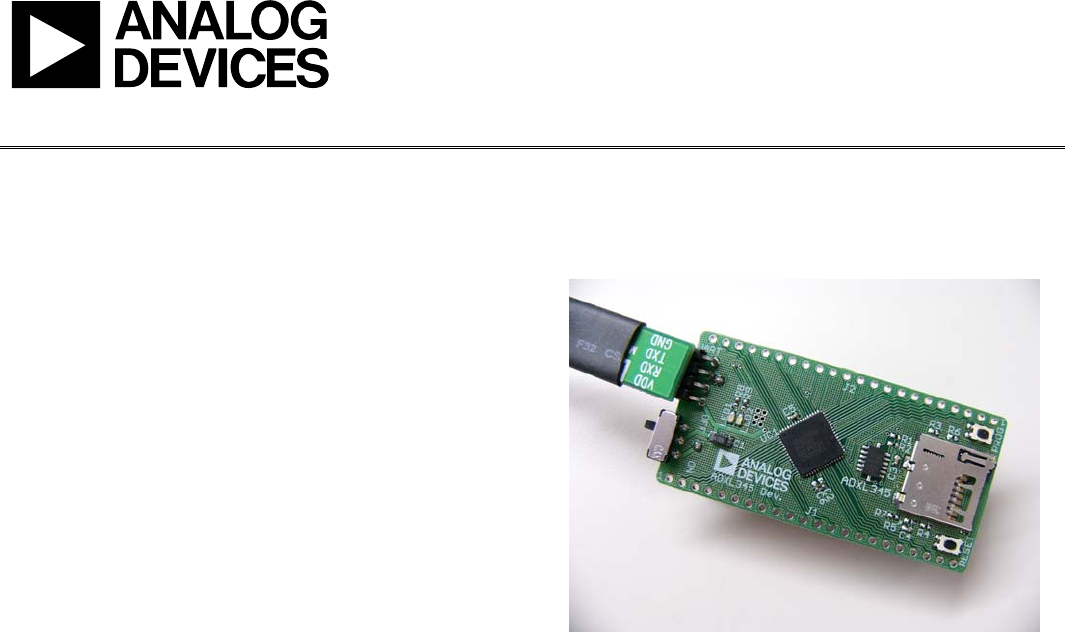
iMEMS ADXL345/ADXL346 Inertial Sensor Datalogger and Development Board
PLEASE SEE THE LAST PAGE FOR AN IMPORTANT
WARNING AND LEGAL TERMS AND CONDITIONS. Rev. A | Page 1 of 12
FEATURES
Ultralow power ADXL345/ADXL346 accelerometer
Inertial sensor development board
Datalogs onto MicroSD card
Fully programmable via serial interface; firmware examples
provided
Battery-powered for portable applications
REQUIREMENTS
2 AAA batteries
MicroSD card and card reader (for datalogging)
Computer with serial port (for programming)
08658-001
Figure 1. ADXL345 Inertial Sensor Development Board
GENERAL DESCRIPTION
It is often a timesaver in hardware development to make progress
on the firmware and the hardware simultaneously. The challenge is
that it proves difficult to develop firmware before the hardware
exists. The iMEMS® ADXL345/ADXL346 development board
is an easy-to-use tool that facilitates prototyping by providing
a platform that can be duplicated in the final application.
Additionally, the development board can be configured as a
datalogger and can be used to gather data for refining algorithms,
tuning thresholds, and generally familiarizing oneself with
accelerometer data.
Two AAA batteries power the development board, and thus it
integrates seamlessly into portable applications. Communications
and processing are done by an ARM7-based ADuC7024 micro-
controller, and the interface provided is fully reprogrammable.
Moreover, all ADuC7024 pins are broken out into headers to
facilitate design of compatible expansion boards. Data is logged
onto a MicroSD memory card, providing essentially unlimited
memory capacity and operating system versatility. Data is stored in
a text file; therefore, there is no need to install any software to
operate the board or read data. Software is provided to assist
with programming the board.

UG-065 Evaluation Board User Guide
Rev. A | Page 2 of 12
TABLE OF CONTENTS
Features .............................................................................................. 1
Requirements .................................................................................... 1
General Description......................................................................... 1
Revision History ............................................................................... 2
Overview............................................................................................ 3
Features.......................................................................................... 3
Using the Board ................................................................................ 4
Getting Started...............................................................................4
Programming the Board...............................................................4
Software Tools................................................................................5
Evaluation Board Schematic and Layout .......................................6
Appendix: Sample Output File ..................................................... 10
REVISION HISTORY
3/11—Rev. 0 to Rev. A
Added ADXL346 Throughout..........................................Universal
Changes to Firmware Section ......................................................... 3
Changes to Figure 7.......................................................................... 8
Changes to Figure 8.......................................................................... 9
Added Appendix............................................................................. 10
6/10—Revision 0: Initial Version
Evaluation Board User Guide UG-065
Rev. A | Page 3 of 12
OVERVIEW
The ADXL345/ADXL346 inertial sensor development board
has the following features:
• A 2-layer printed circuit board (PCB), 1.20 inches ×
2.30 inches form factor
• A two AAA battery power supply
• A 4-pin UART header to connect to an RS-232 interface
cable
• Reset/download push buttons
• Power indicator/general-purpose LEDs
• Access to microcontroller I/Os from the external header
• Demonstration firmware logs 100 Hz acceleration data
FEATURES
Power Supply
A pair of AAA batteries powers the board, and the battery holder is
located on the back of the board. An on/off switch on the lower
left of the front of the board controls power to it. The battery
voltage is not regulated but is decoupled with a 10 μF capacitor
globally and an additional 1 μF capacitor at the device supply
pins to ground.
RS-232 Interface
The ADuC7024 (UC1) P1.1 and P1.0 lines are connected to the
RS-232 interface cable via the connector (UART). The interface
cable generates the required level shifting to allow direct connection
to a PC serial port. Ensure that the supplied cable is connected
to the board correctly; that is, VDD is connected to VDD and
GND is connected to GND.
RESET/PROG Push Buttons
A RESET push button is provided to allow the user to manually
reset the part. When the RESET button is inserted, the RST pin
of the is pulled to GND. Because the ADuC7024 RST pin is
Schmitt-triggered internally, there is no need to use an external
Schmitt trigger on this pin.
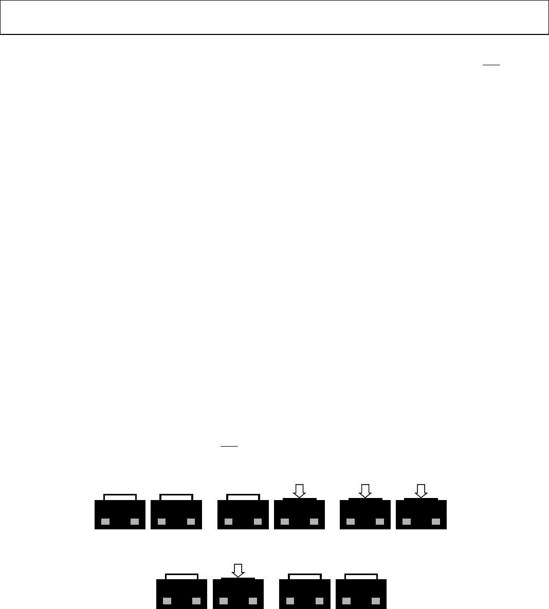
To enter serial download mode, the user must hold the P0.0/BM
pin low while reset is toggled. On the development board, serial
download mode can be easily initiated by holding down the serial
download push button (PROG) while inserting and releasing
the reset button (RESET), as illustrated in Figure 2.
Power Indicator/General-Purpose LEDs
Two general-purpose LEDs are available on the board. A red
LED (LED1) is connected to P4.5 of the ADuC7024, and a green
LED (LED2) is connected to P4.4. Both LEDs can be repurposed
via firmware.
Breakout Header
Many of the ADuC7024 pins are connected to headers on either
side of the board. The headers come unpopulated but can be
populated using standard 0.1 inch header pins.
The thin form factor of the top of the board allows the design
of an expansion board to connect above the development board,
with the header pins providing both electrical and physical
connections.
Firmware
Sample firmware is provided on the ADXL345 product page
under the Development Board heading. The Firmware
link downloads a Keil project that implements the 100 Hz
datalogging firmware. This project can be modified as needed.
08658-002
RESET PROG
(A) RESE
T
AND PROG RELEASED
RESET PROG
(E) RELEASE PROG
RESET PROG
(B) PUSH PROG
RESET PROG
(D) RELEASE RESET
PROG
(C) PUSH RESE
T
RESET
Figure 2. Entering Serial Download Mode to Reprogram the Board
UG-065 Evaluation Board User Guide
Rev. A | Page 4 of 12
USING THE BOARD
GETTING STARTED
The development board comes preprogrammed as a datalogger
at a 100 Hz datarate. To log data, do the following:
1. Insert two AAA batteries into the battery holder.
2. Insert the MicroSD card into the slot. The card should be
formatted with a FAT32 file system; most MicroSD cards
come this way.
3. Push the on/off switch to the on position to power up the
board. The red LED turns on, and the green LED blinks to
indicate that the board is logging data.
4. When logging is completed, slide the on/off switch to the
off position.
5. Remove the card from the slot and insert it into the card
reader.
6. Insert the card reader into the USB port on your computer.
The acceleration log file is written to the path
\XL345\DATA0000.TXT on the MicroSD card. The data in the
text file consists of a set of comma-separated t, x, y, and z values,
where t corresponds to time and x, y, and z correspond to the x-, y-,
and z-axis acceleration data for each time point. Refer to the
Appendix: Sample Output File for an example of a data file.
Acceleration values are logged in LSB, where the nominal scale
factor is 3.9 mg/LSB. To convert an acceleration value from LSB to
mg, simply multiply by 3.9 (nominally, or measure the sensitivity
of the part for a more accurate conversion).
To plot the logged data using Microsoft® Excel, download the
Plotting Tool (XL345DB_DataPlotter.xls) from the ADXL345
product page (under the Development Board heading) and
follow the instructions described in the file. Users are prompted
to browse to their logged data file (DATA0000.TXT), the data is
imported and plotted in a new workbook, and users are then
prompted to save that workbook.
PROGRAMMING THE BOARD
The board can be repurposed with no programming required
using the .hex files provided on the ADXL345 product page. The
.hex files are uploaded onto the board using the ARMWSD program,
which can be downloaded at www.analog.com/static/imported-
files/eval_boards/ARMWSDv1.8.zip. Simply unzip the folder to
a known location and open the ARMWSD.exe file to use the
program. No installation is required.
To reprogram the board, use the cable provided with the board and
follow these instructions:
1. Download the desired .hex file from the ADXL345 product
page to a known location, or locate it on your machine.
2. Open ARMWSD.
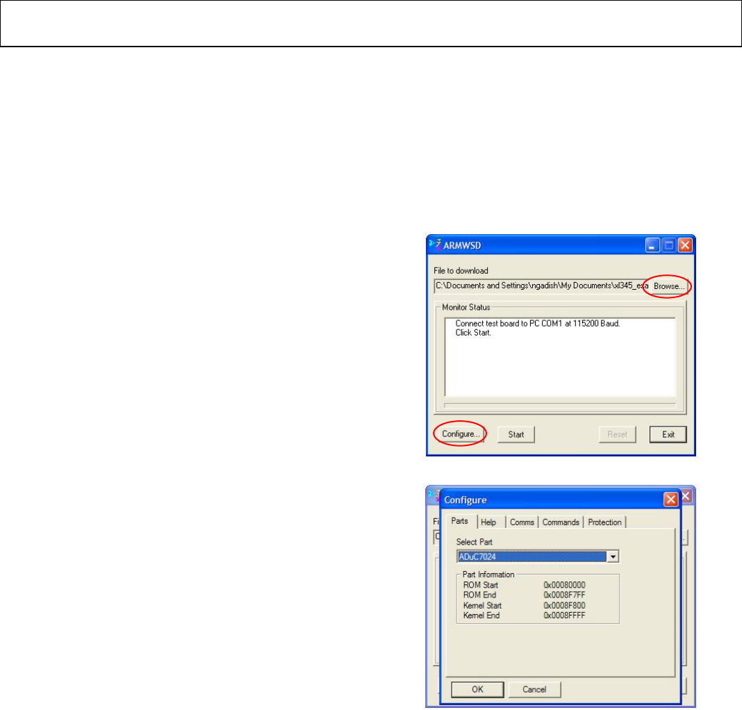
3. Click Configure… (see Figure 3) and select the Parts tab,
shown in Figure 4. Make sure the ADuC7024 is selected in
the Select Part pull-down list (see Figure 4). Additionally, in
the Comms tab, make sure the Baudrate is set to 115200,
and the Serial Port is set to COM1, and then click OK.
4. In the ARMWSD window, click Browse… (see encircled in
Figure 3) and navigate to the location of the .hex file to be
loaded onto the board. Select the file and click Open.
08658-003
Figure 3. ARMWSD Window
08658-005
Figure 4. ARMWSD Configure Window: Parts Tab
5. Connect the programming cable to the serial port on the
PC and to the 4-pin header near the on/off switch on
the board, matching up the corresponding pins.
6. In the ARMWSD window, click Start. The Status
frame then prompts users to Press Download and
pulse Reset on Hardware. Follow the illustrations in
Figure 2.
7. When download is complete, click the Reset button on
the evaluation board. Users can now close the
ARMWSD program.

Evaluation Board User Guide UG-065
Rev. A | Page 5 of 12
SOFTWARE TOOLS
In addition to the ready-to-upload examples provided in the
Firmware link of the Development Board section of the
ADXL345 product page, the development board is fully
modifiable and reprogrammable to allow for easy prototyping and
firmware development. Firmware is written in C, and it is compiled
for the ADuC7024 ARM7 processor.
The firmware examples provided on the ADXL345 product page
were written using Keil Microvision and compiled using the
RealView compiler. A free evaluation version of Keil Microvision
is available online. Additional software suites (Keil, IAR, and
GNU) for writing and compiling code are available.
For instructions on how to install and use the software,
refer to the ADuC702x MicroConverter™ GetStarted Guide.
To reprogram the board, download the ARMWSD program
from the Uploader link in the Development Board section of
the ADXL345 product page.
When Keil Microvision is installed, complete the following steps:
1. Click and download the Sample Project (EVAL-
ADXL345Z-DB Files.zip) file from the ADXL345
Development Board section of the ADXL345 product
page.
2. Unzip the EVAL-ADXL345Z-DB Files.zip file into a
known directory.
3. Navigate into the EVAL-ADXL345Z-DB folder and open
datalogger.uvproj. This Keil Microvision project allows
users to modify and recompile the program.
UG-065 Evaluation Board User Guide
Rev. A | Page 6 of 12
EVALUATION BOARD SCHEMATIC AND LAYOUT
See the appropriate product pages for electronic versions of the layout and schematic files.
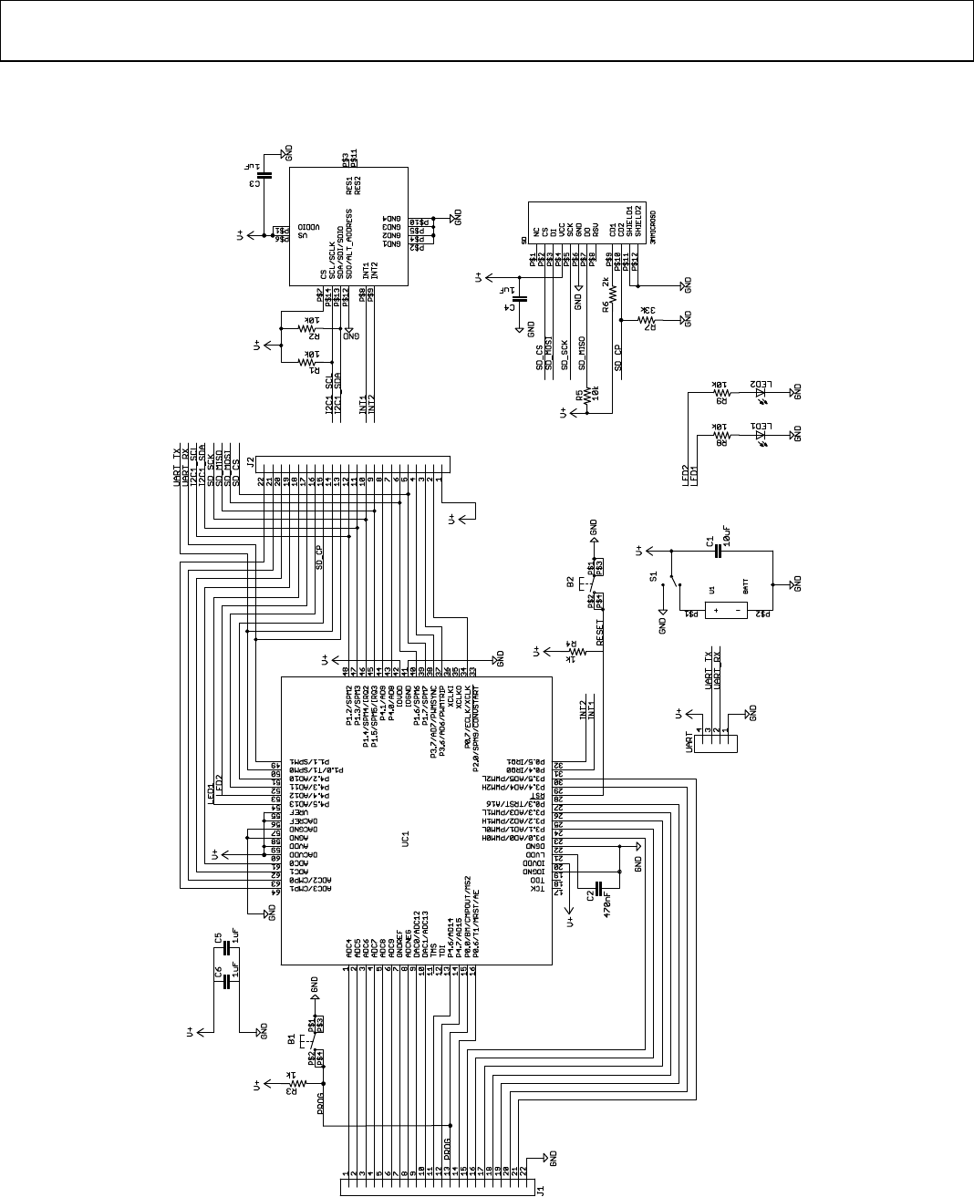
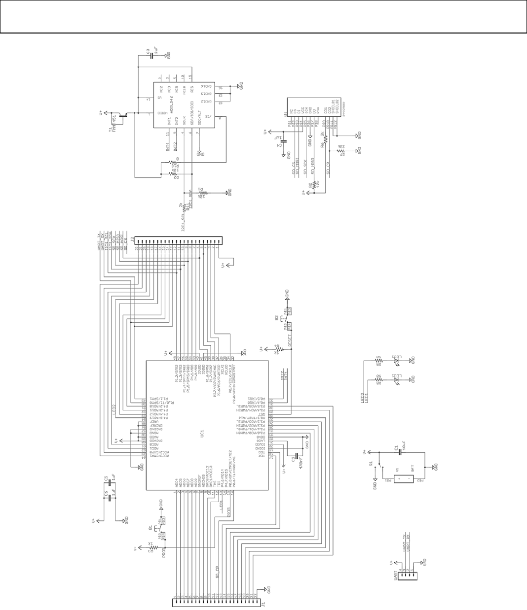
08658-004
Figure 5. ADXL345 Development Board Schematic
Evaluation Board User Guide UG-065
Rev. A | Page 7 of 12
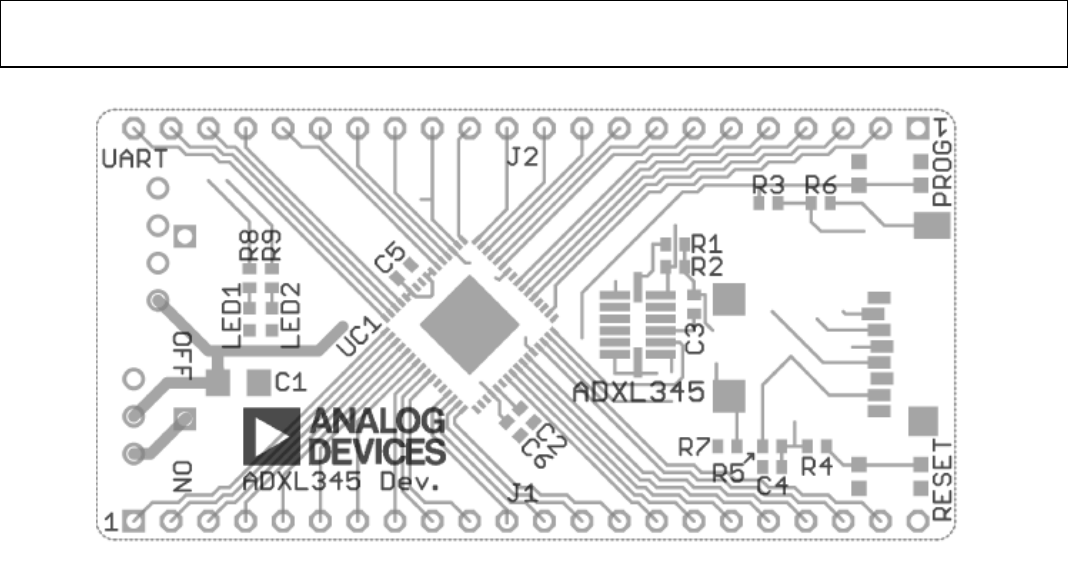
08658-006
Figure 6. ADXL345 Development Board Layout
UG-065 Evaluation Board User Guide
Rev. A | Page 8 of 12
08658-008
Figure 7. ADXL346 Development Board Schematic
Evaluation Board User Guide UG-065
Rev. A | Page 9 of 12
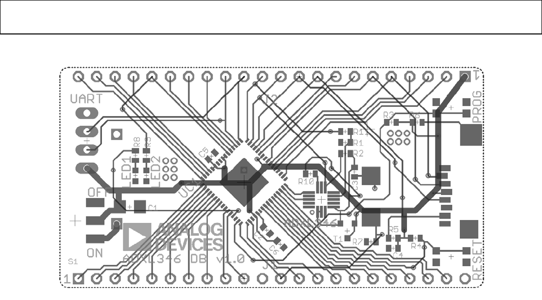
08658-008
Figure 8. ADXL346 Development Board Layout

UG-065 Evaluation Board User Guide
Rev. A | Page 10 of 12
APPENDIX: SAMPLE OUTPUT FILE
t,x,y,z
0,60,20,247
50,60,19,259
100,57,17,258
151,58,18,260
201,61,14,252
252,58,10,252
302,63,21,248
353,66,23,255
403,67,21,243
454,53,35,254
504,63,32,251
555,63,31,241
605,65,33,256
656,59,34,254
706,60,34,247
757,55,41,250
807,56,41,252
858,58,43,245
908,60,40,246
959,60,38,246
1009,66,37,249
1060,64,29,252
1110,69,36,251
1161,68,31,253
1211,66,47,233
1262,63,40,246
1312,59,36,246
1363,48,41,244
1413,49,41,248
1464,46,51,252
1514,52,39,264
1565,47,42,260
1576,47,43,254
1585,25,-5,263
1595,26,-2,263
1605,26,-5,257
1615,26,-4,257
1625,28,-3,258
1634,28,-1,261
1644,24,-2,263
1654,24,1,263
1664,25,0,261
1674,27,0,263
1683,24,-2,263
1693,22,-1,265
1703,23,-2,264
1713,22,0,265
1723,22,0,260
1732,22,-1,261
1742,23,0,258
1752,23,-1,259
1762,25,-1,256
1772,26,-1,256
1781,21,-2,257
1791,21,-4,256
1801,20,-4,259
1811,21,-2,260
1821,19,-5,260
1830,17,-4,258
1840,18,-3,260
1850,20,-5,260
1860,20,-2,260
1870,20,-2,261
1870,20,-2,264
1880,25,2,264
1890,23,2,262
1901,25,-1,260
1911,24,0,264
1922,27,1,263
1932,30,0,265
1942,30,2,265
1953,27,2,263
1963,28,1,263
1974,27,1,264
1984,29,0,261
1994,29,0,263
2005,27,0,261
2015,26,0,259
2026,28,-1,257
2036,26,-3,257
2046,27,-2,259
2057,23,-1,262
2067,24,-3,261

Evaluation Board User Guide UG-065
Rev. A | Page 11 of 12
NOTES
UG-065 Evaluation Board User Guide
Rev. A | Page 12 of 12
NOTES
ESD Caution
ESD (electrostatic discharge) sensitive device. Charged devices and circuit boards can discharge without detection. Although this product features patented or proprietary protection
circuitry, damage may occur on devices subjected to high energy ESD. Therefore, proper ESD precautions should be taken to avoid performance degradation or loss of functionality.
Legal Terms and Conditions
By using the evaluation board discussed herein (together with any tools, components documentation or support materials, the “Evaluation Board”), you are agreeing to be bound by the terms and conditions set
forth below (“Agreement”) unless you have purchased the Evaluation Board, in which case the Analog Devices Standard Terms and Conditions of Sale shall govern. Do not use the Evaluation Board until you have
read and agreed to the Agreement. Your use of the Evaluation Board shall signify your acceptance of the Agreement. This Agreement is made by and between you (“Customer”) and Analog Devices, Inc. (“ADI”),
with its principal place of business at One Technology Way, Norwood, MA 02062, USA. Subject to the terms and conditions of the Agreement, ADI hereby grants to Customer a free, limited, personal, temporary,
non-exclusive, non-sublicensable, non-transferable license to use the Evaluation Board FOR EVALUATION PURPOSES ONLY. Customer understands and agrees that the Evaluation Board is provided for the sole and
exclusive purpose referenced above, and agrees not to use the Evaluation Board for any other purpose. Furthermore, the license granted is expressly made subject to the following additional limitations: Customer
shall not (i) rent, lease, display, sell, transfer, assign, sublicense, or distribute the Evaluation Board; and (ii) permit any Third Party to access the Evaluation Board. As used herein, the term “Third Party” includes any
entity other than ADI, Customer, their employees, affiliates and in-house consultants. The Evaluation Board is NOT sold to Customer; all rights not expressly granted herein, including ownership of the Evaluation
Board, are reserved by ADI. CONFIDENTIALITY. This Agreement and the Evaluation Board shall all be considered the confidential and proprietary information of ADI. Customer may not disclose or transfer any
portion of the Evaluation Board to any other party for any reason. Upon discontinuation of use of the Evaluation Board or termination of this Agreement, Customer agrees to promptly return the Evaluation Board
to ADI. ADDITIONAL RESTRICTIONS. Customer may not disassemble, decompile or reverse engineer chips on the Evaluation Board. Customer shall inform ADI of any occurred damages or any modifications or
alterations it makes to the Evaluation Board, including but not limited to soldering or any other activity that affects the material content of the Evaluation Board. Modifications to the Evaluation Board must comply
with applicable law, including but not limited to the RoHS Directive. TERMINATION. ADI may terminate this Agreement at any time upon giving written notice to Customer. Customer agrees to return to ADI the
Evaluation Board at that time. LIMITATION OF LIABILITY. THE EVALUATION BOARD PROVIDED HEREUNDER IS PROVIDED “AS IS” AND ADI MAKES NO WARRANTIES OR REPRESENTATIONS OF ANY KIND WITH
RESPECT TO IT. ADI SPECIFICALLY DISCLAIMS ANY REPRESENTATIONS, ENDORSEMENTS, GUARANTEES, OR WARRANTIES, EXPRESS OR IMPLIED, RELATED TO THE EVALUATION BOARD INCLUDING, BUT NOT
LIMITED TO, THE IMPLIED WARRANTY OF MERCHANTABILITY, TITLE, FITNESS FOR A PARTICULAR PURPOSE OR NONINFRINGEMENT OF INTELLECTUAL PROPERTY RIGHTS. IN NO EVENT WILL ADI AND ITS
LICENSORS BE LIABLE FOR ANY INCIDENTAL, SPECIAL, INDIRECT, OR CONSEQUENTIAL DAMAGES RESULTING FROM CUSTOMER’S POSSESSION OR USE OF THE EVALUATION BOARD, INCLUDING BUT NOT LIMITED
TO LOST PROFITS, DELAY COSTS, LABOR COSTS OR LOSS OF GOODWILL. ADI’S TOTAL LIABILITY FROM ANY AND ALL CAUSES SHALL BE LIMITED TO THE AMOUNT OF ONE HUNDRED US DOLLARS ($100.00).
EXPORT. Customer agrees that it will not directly or indirectly export the Evaluation Board to another country, and that it will comply with all applicable United States federal laws and regulations relating to
exports. GOVERNING LAW. This Agreement shall be governed by and construed in accordance with the substantive laws of the Commonwealth of Massachusetts (excluding conflict of law rules). Any legal action
regarding this Agreement will be heard in the state or federal courts having jurisdiction in Suffolk County, Massachusetts, and Customer hereby submits to the personal jurisdiction and venue of such courts. The
United Nations Convention on Contracts for the International Sale of Goods shall not apply to this Agreement and is expressly disclaimed.
©2010–2011 Analog Devices, Inc. All rights reserved. Trademarks and
registered trademarks are the property of their respective owners.
UG08658-0-3/11(A)
