UHF Antenna User Manual Rev1.3
UHF_Antenna_User_Manual_Rev1.3
User Manual:
Open the PDF directly: View PDF ![]() .
.
Page Count: 11

USER MANUAL
UHF Antenna

UHF ANTENNA – USER MANUAL
ENDUROSAT
2
1 Change log .......................................................................................................................... 3
2 Acronyms list ....................................................................................................................... 4
3 Overview .............................................................................................................................. 5
4 Highlighted features ............................................................................................................. 5
5 Functional description .......................................................................................................... 5
6 Hardware layout ................................................................................................................... 5
7 Characteristics ..................................................................................................................... 7
7.1 Frequency .................................................................................................................................. 7
7.2 Polarization ................................................................................................................................ 8
7.3 Connectors ................................................................................................................................ 8
7.4 Gain ........................................................................................................................................... 9
8 Electrical characteristic ....................................................................................................... 10
9 Deployment mechanism ..................................................................................................... 10
10 Materials ........................................................................................................................... 10
11 Mechanical and environmental test .................................................................................... 10
12 Included in the shipment ................................................................................................... 10
13 Handling and storage ........................................................................................................ 11
14 Warnings ........................................................................................................................... 11
UHF ANTENNA – USER MANUAL
ENDUROSAT
3
UHF ANTENNA
USER MANUAL
This user manual is specially designed to describe the EnduroSat UHF Antenna module, its functions and
features.
Please read carefully the manual before unpacking the antenna in order to ensure safe and proper use.
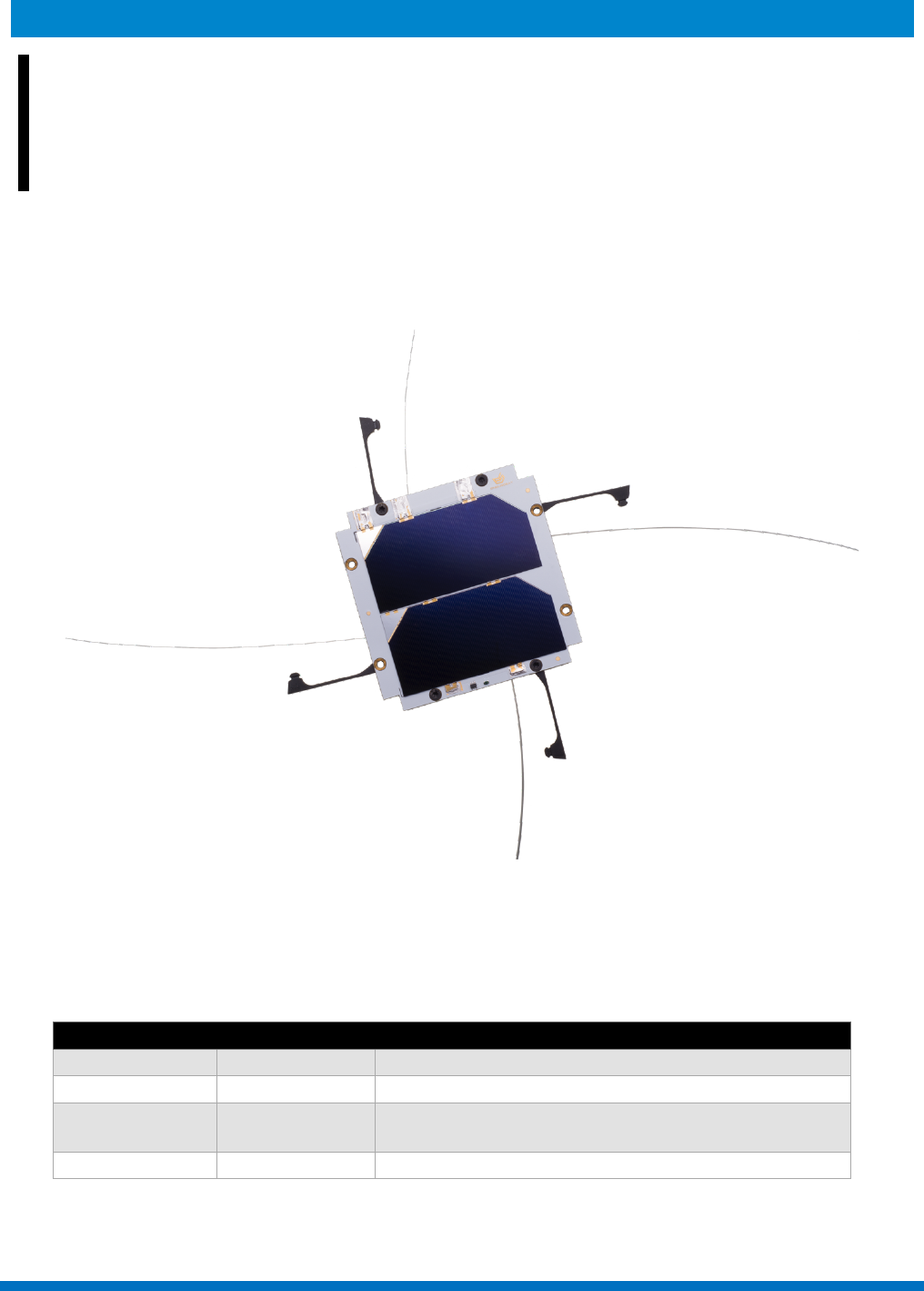
Figure 1 – EnduroSat UHF Antenna (Solar panel is a separate product)
1 CHANGE LOG
Date
Version
Note
10/04/2016
Rev 1
01/08/2017
Rev 1.1
minor text enhancements
02/08/2017
Rev 1.2
power consumption and supply voltage for
deployment added
21/11/2017
Rev 1.3
connectors added

UHF ANTENNA – USER MANUAL
ENDUROSAT
4
2 ACRONYMS LIST
LHCP
RHCP
RF
UHF
PCB
Left Hand Circular Polarization
Right Hand Circular Polarization
Radio Frequency
Ultra-High Frequency
Printed Circuit Board

UHF ANTENNA – USER MANUAL
ENDUROSAT
5
3 OVERVIEW
The antenna is designed to cover the amateur satellite band 435-438 MHz. It has a circular
polarization and uses a redundant burn wire mechanism with feedback for the deployment of the
radiating rods.
4 HIGHLIGHTED FEATURES
• UHF band for amateur satellite communications 435 – 438MHz;
• Compatible with EnduroSat Solar panels;
• Circularly polarized;
• Weight: 85 g;
• Gain > 0dBi*;
• Max RF output power 3.5W;
• Burn wire mechanism with feedback for deployment
• Supply voltage for deployment: 5V
• Max current consumption during deployment: 530mA (primary and back-up burning resistors
working simultaneously)
*from simulation
5 FUNCTIONAL DESCRIPTION
The feed network for the RF part of the antenna is realized using strip lines. Each rod is fed with 90
degrees phase shift so that the antenna has a circular polarization. The antenna has a through hole
for connecting it to EnduroSat’ solar panel Z.
6 HARDWARE LAYOUT
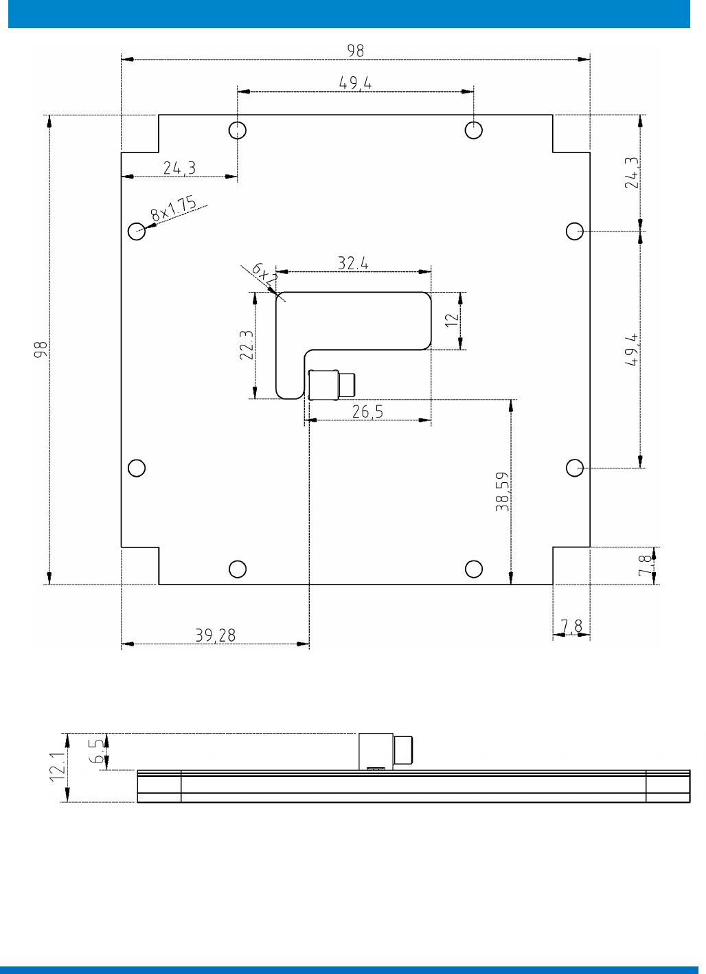
Figure 2 depicts the bottom side of the antenna. All the dimensions are in mm. It uses up to 8 bolts
for mounting to the satellite body (minimum 4 required: in this configuration, the bolts have to be
installed in the proper locations as shown in figure 4). There is an opening in the PCB, through which
an EnduroSat solar panel can be connected. The right angle MCX connector, used for connecting
the antenna to the communication module, is located next to the opening.
The thickness of the antenna and the height of the connector are shown on Figure 3. The overall
thickness (and weight) of the antenna depends on the top cover. It can be a solar panel, a cover or
another module. On figure 3 is shown the thickness of the whole antenna with a top cover of 1.6 mm
UHF ANTENNA – USER MANUAL
ENDUROSAT
6
Figure 2 - Physical layout bottom side - Dimensions in mm.
Figure 3 - Side view - Dimensions in mm.
UHF ANTENNA – USER MANUAL
ENDUROSAT
7
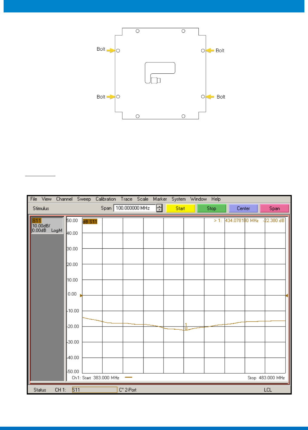
Figure 4 – Proper installation of the 4 bolts configuration.
7 CHARACTERISTICS
7.1 Frequency
Figure 4 shown the measured return loss of the UHF antenna
Figure 5 - measured return loss of the UHF antenna
UHF ANTENNA – USER MANUAL
ENDUROSAT
8
7.2 Polarization
LHCP or RHCP with regards to antenna orientation.
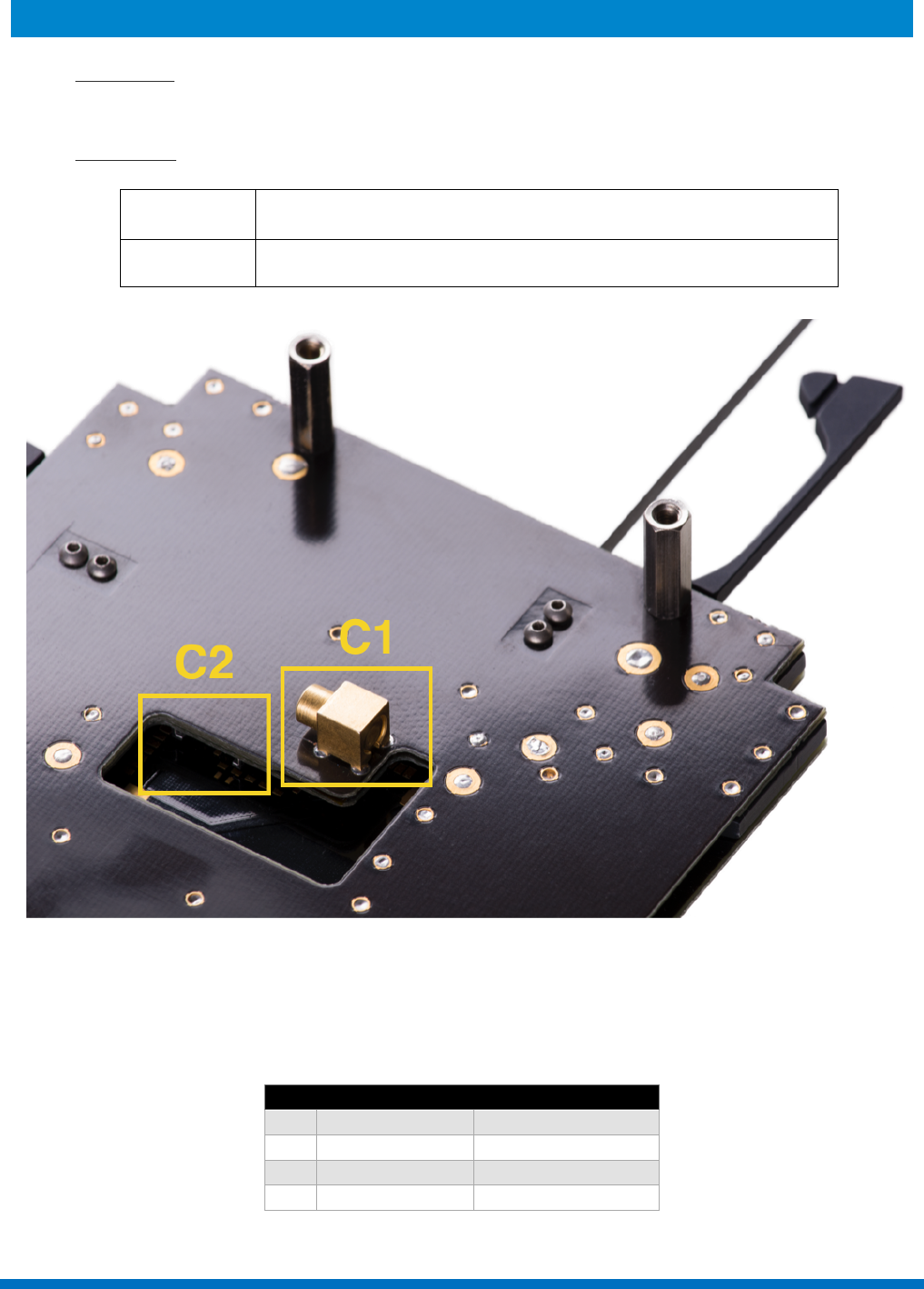
7.3 Connectors
Figure 6 - Bottom Side - Connectors location
In the case of collision between the MCX connector and the structure of the satellite, U.FL connector
on the internal side can be accessed by disassembling the top cover of the antenna.
C2 pinout:
Pin
Mnemonic
Description
1
+5V
Positive
2
I2C SCL
I2C Clock
3
I2C SDA
I2C Data
4
Ground
Ground
C1
MCX right angle (upon request, straight MCX or SMA)
C2
Four pin Molex Pico-Lock™
UHF ANTENNA – USER MANUAL
ENDUROSAT
9
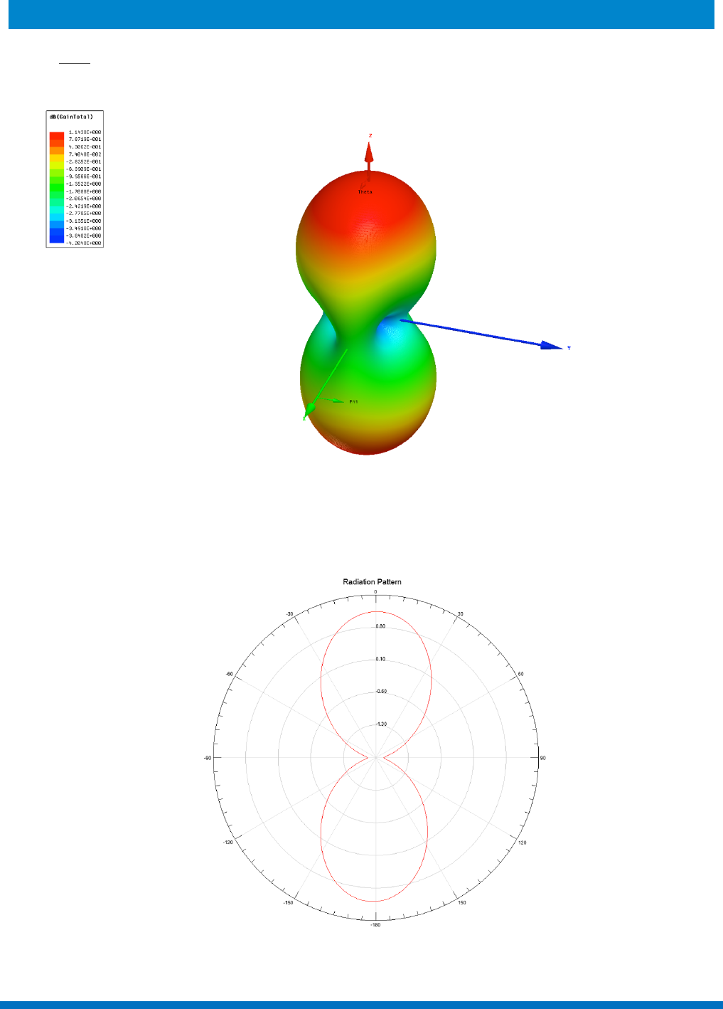
7.4 Gain
Figures 7 and 8 show the radiation pattern of the antenna
Figure 7
Figure 8!

UHF ANTENNA – USER MANUAL
ENDUROSAT
10
8 ELECTRICAL CHARACTERISTIC
Parameter
Condition
Min
Typ
Max
Supply Voltage [V]
5
Current Consumption [mA]
Sleep mode
1
Primary burning resistor
250
Primary and Back-up burning resistor
500
9 DEPLOYMENT MECHANISM
The deployment mechanism uses burn resistors to cut a wire and release the doors holding the
antenna rods. Each antenna rod has two separated circuits of resistors for redundancy. The module
features a feedback network for deployment. It uses a four pin Molex Pico-Lock™ connector with
I2C interface for providing feedback regarding antenna deployment.
10 MATERIALS
The frame and doors used for holding the antenna rods rolled and encapsulated, is made of
aluminum with hard anodization, which prevents a short circuit between the frame and the antenna
rods. Rods are made from SMA – Shape Memory Alloy with super elastic properties to ensure
straight shape after release. All the PCBs are made from FR-4.
11 MECHANICAL AND ENVIRONMENTAL TEST
A full campaign of tests at qualification level was performed on the qualification engineering model.
Qualification tests level and duration follow the ESA standard ECSS-E-ST-10-03C and GEVS: GSFC-
STD-7000A. Test performed:
• Thermal Cycling
• Thermal Vacuum
• Random Vibration
• Sine Vibration
• Shock Test
12 INCLUDED IN THE SHIPMENT
EnduroSat provides along with the UHF antenna:
• 2 Coaxial cable 50 Ohm, MCX to MCX and MCX to SMA connectors
• Power and command cable (PTFE Material Jacket, 24AWG), connector MOLEX 504051-
0401
• USB stick with user manual
Customized cables and connectors can be provided upon request.
UHF ANTENNA – USER MANUAL
ENDUROSAT
11
13 HANDLING AND STORAGE
Particular attention shall be paid to the avoidance of damage to the UHF antenna during handling,
storage and preservation. The handling of the UHF antenna module should be performed in
compliance with the following instructions:
• Handle using PVC, latex, cotton (lint free) or nylon gloves
• The environment where UHF antenna module will be handled shall meet the requirements for
a class environment 100 000, free of contaminants such as dust, oil, grease, fumes and
smoke from any source.
• Store in such a manner as to preclude stress and prevent damage
• To prevent the deterioration, the UHF antenna must be stored in a controlled environment,
i.e. the temperature and humidity levels shall be maintained in the proper ranges:
o Ideal storage temperature range: 15ºC to 27ºC
o Ideal storage humidity range: 30% to 60% relative humidity (RH).
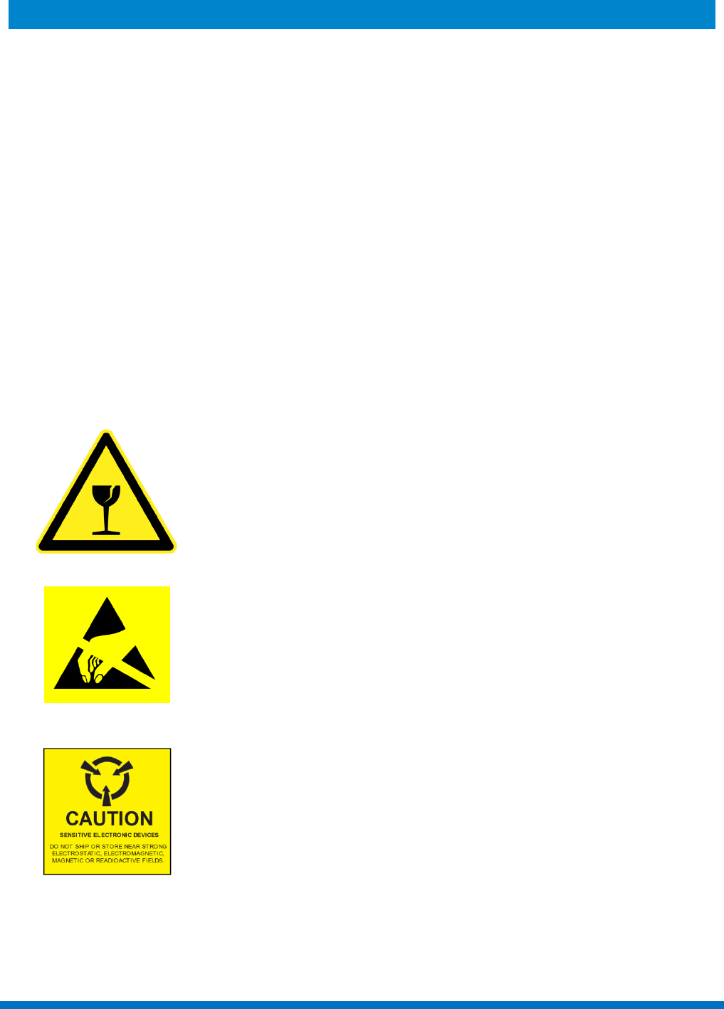
14 WARNINGS
This product uses very fragile components. Observe
precautions for Handling.
This product uses semiconductors that can be
damaged by electrostatic discharge (ESD). Observe
precautions for Handling
Sensitive Electronic device. Do not ship or store near
strong electrostatic, electromagnetic, magnetic or
radioactive fields.
