Oracle Communications Unified Inventory Management Concepts UIM Guide
User Manual:
Open the PDF directly: View PDF ![]() .
.
Page Count: 304 [warning: Documents this large are best viewed by clicking the View PDF Link!]
- Contents
- Preface
- 1 About Unified Inventory Management
- 2 UIM User Interface Overview
- 3 Design Studio Overview
- 4 Life Cycles and Statuses
- 5 Core Functionality
- 6 Planning
- Business Interactions
- Engineering Work Orders
- Projects
- 7 Resource Entity Management
- 8 Services
- 9 Geographic Location
- 10 Equipment and Devices
- Understanding Equipment Modeling
- Understanding Logical Devices
- Understanding Physical Resources
- Associating Physical Devices to Logical Devices
- Associating Devices and Equipment with Network Locations
- 11 Networks
- 12 Connectivity Overview
- 13 Channelized Connectivity
- About Channelized Connectivity
- About Channel Identifiers
- Terminating Channels
- About the UIM Signal Architecture
- Configuring Connectivity Capacity
- Terminating and Enabling a Channelized Connectivity
- About Virtual Connectivity
- Maintaining Channelized Connectivity and Network Resources
- 14 Packet Connectivity
- 15 Service Connectivity
- 16 Pipes
- When to Use Pipes
- Understanding Pipes
- Understanding Capacity and Signal Structure
- Modeling Connectivity in Design Studio and UIM
- Enabling Pipes
- 17 IP Address Management
- 18 Roles
- 19 Telephone Numbers
- 20 Custom Resources
- 21 Parties
- 22 Media Streams
- Glossary
- activity
- address
- address range
- artifact
- bearer
- business interaction
- capacity
- cartridge
- channelized connectivity
- characteristic
- common business entity
- configuration
- configuration item
- connectivity
- connectivity function
- connectivity gap
- constrains relationship
- core platform
- cross-connect
- custom involvement
- custom network address
- custom object
- Data Dictionary
- data element
- Design Studio
- device interface
- enables relationship
- engineering work order
- entity
- entity reference
- entity type
- equipment
- equipment holder
- extension point
- facility
- flow identifier
- flow interface
- Functional Module
- global extension point
- grooming
- hierarchical relationship
- infrastructure network
- inventory group
- interface-bound
- location
- logical device
- logical device account
- measurement type
- media interface
- network
- network edge
- network entity code
- network location
- network location code
- network node
- network target
- Oracle WebLogic Server
- packet connectivity
- packet virtual network
- page
- parent-child relationship
- party
- path analysis
- physical connector
- physical device
- physical port
- pipe
- pipe termination point
- place
- processing signal
- product
- project
- property location
- provides relationship
- rate code
- rehoming
- reservation
- resource
- rider
- role
- role type
- ruleset
- ruleset extension point
- section
- Sequence specification
- service
- service connectivity
- service fulfillment
- service location
- service network
- service trail
- signal architecture
- signal structure
- signal termination point
- SID
- site
- specification
- navigation section
- telephone number
- terminates relationship
- topology
- topology edge
- topology node
- trail
- trail-bound
- unit of measure
- virtual network

[1]
Oracle® Communications
Unified Inventory Management
Concepts
Release 7.3
E56720-01
July 2015
Oracle Communications Unified Inventory Management Concepts, Release 7.3
E56720-01
Copyright © 2009, 2015, Oracle and/or its affiliates. All rights reserved.
This software and related documentation are provided under a license agreement containing restrictions on
use and disclosure and are protected by intellectual property laws. Except as expressly permitted in your
license agreement or allowed by law, you may not use, copy, reproduce, translate, broadcast, modify, license,
transmit, distribute, exhibit, perform, publish, or display any part, in any form, or by any means. Reverse
engineering, disassembly, or decompilation of this software, unless required by law for interoperability, is
prohibited.
The information contained herein is subject to change without notice and is not warranted to be error-free. If
you find any errors, please report them to us in writing.
If this is software or related documentation that is delivered to the U.S. Government or anyone licensing it
on behalf of the U.S. Government, then the following notice is applicable:
U.S. GOVERNMENT END USERS: Oracle programs, including any operating system, integrated software,
any programs installed on the hardware, and/or documentation, delivered to U.S. Government end users
are "commercial computer software" pursuant to the applicable Federal Acquisition Regulation and
agency-specific supplemental regulations. As such, use, duplication, disclosure, modification, and
adaptation of the programs, including any operating system, integrated software, any programs installed on
the hardware, and/or documentation, shall be subject to license terms and license restrictions applicable to
the programs. No other rights are granted to the U.S. Government.
This software or hardware is developed for general use in a variety of information management
applications. It is not developed or intended for use in any inherently dangerous applications, including
applications that may create a risk of personal injury. If you use this software or hardware in dangerous
applications, then you shall be responsible to take all appropriate fail-safe, backup, redundancy, and other
measures to ensure its safe use. Oracle Corporation and its affiliates disclaim any liability for any damages
caused by use of this software or hardware in dangerous applications.
Oracle and Java are registered trademarks of Oracle and/or its affiliates. Other names may be trademarks of
their respective owners.
Intel and Intel Xeon are trademarks or registered trademarks of Intel Corporation. All SPARC trademarks
are used under license and are trademarks or registered trademarks of SPARC International, Inc. AMD,
Opteron, the AMD logo, and the AMD Opteron logo are trademarks or registered trademarks of Advanced
Micro Devices. UNIX is a registered trademark of The Open Group.
This software or hardware and documentation may provide access to or information about content,
products, and services from third parties. Oracle Corporation and its affiliates are not responsible for and
expressly disclaim all warranties of any kind with respect to third-party content, products, and services
unless otherwise set forth in an applicable agreement between you and Oracle. Oracle Corporation and its
affiliates will not be responsible for any loss, costs, or damages incurred due to your access to or use of
third-party content, products, or services, except as set forth in an applicable agreement between you and
Oracle.

iii
Contents
Preface ................................................................................................................................................................. xi
Audience....................................................................................................................................................... xi
Related Documentation.............................................................................................................................. xi
Documentation Accessibility.................................................................................................................... xii
Document Revision History ..................................................................................................................... xii
1 About Unified Inventory Management
Introducing UIM ...................................................................................................................................... 1-1
UIM and Service Fulfillment ............................................................................................................ 1-2
UIM System Architecture ....................................................................................................................... 1-3
Core Platform...................................................................................................................................... 1-4
Functional Modules ........................................................................................................................... 1-5
About Entities and Entity Types .......................................................................................................... 1-6
About the UIM Information Model...................................................................................................... 1-6
Understanding Products and Services............................................................................................ 1-7
Understanding Resources................................................................................................................. 1-8
Understanding Common Business Entities.................................................................................... 1-9
Understanding Common Patterns................................................................................................... 1-9
Understanding UIM Definitions .................................................................................................. 1-10
About Specifications, Data Elements, and Characteristics ................................................ 1-10
About Rulesets ......................................................................................................................... 1-11
About Cartridges ................................................................................................................................... 1-11
2 UIM User Interface Overview
Opening the UIM User Interface........................................................................................................... 2-1
The UIM Main Window.......................................................................................................................... 2-1
Navigation Section............................................................................................................................. 2-2
Pages .................................................................................................................................................... 2-2
Working with Tables .................................................................................................................. 2-4
Menus................................................................................................................................................... 2-5
Using the UIM Help ................................................................................................................................ 2-5
3 Design Studio Overview
About Design Studio ............................................................................................................................... 3-1
About Projects and Cartridges............................................................................................................... 3-1
iv
Understanding the Design Studio Workbench.................................................................................. 3-2
About Views ....................................................................................................................................... 3-2
About Editors...................................................................................................................................... 3-4
Designing Entity Specifications............................................................................................................ 3-4
Understanding Specification Relationships ................................................................................... 3-4
Extending Specifications with Rulesets .......................................................................................... 3-9
Working with Characteristics ................................................................................................................ 3-9
Characteristic Labels....................................................................................................................... 3-10
Design Studio Specification Example............................................................................................... 3-10
Deploying Cartridges into UIM ......................................................................................................... 3-13
4 Life Cycles and Statuses
Resource Life Cycles and Statuses........................................................................................................ 4-1
Resource Inventory Statuses............................................................................................................. 4-1
Inventory Status for Resources in Business Interactions and Work Orders.............................. 4-3
Inventory Status for Pipes and Connectivities in Business Interactions and Work Orders.... 4-5
Resource Assignment Statuses......................................................................................................... 4-8
Service Life Cycles and Statuses ........................................................................................................ 4-10
Configuration Life Cycles and Statuses............................................................................................ 4-13
Status Examples..................................................................................................................................... 4-16
Telephone Number Life Cycle and Statuses ................................................................................... 4-17
Modified Life Cycle for Ported In and Ported Out Telephone Numbers ............................... 4-19
Business Interaction and Engineering Work Order Life Cycles and Statuses.......................... 4-19
Project and Activity Life Cycles and Statuses ................................................................................. 4-21
Activity Life Cycle and Status ....................................................................................................... 4-22
Activity Item Life Cycle and Statuses .......................................................................................... 4-24
Change Item Life Cycle and Statuses.................................................................................... 4-24
About Impact Items ................................................................................................................. 4-25
5 Core Functionality
Searching.................................................................................................................................................... 5-1
Searching by Using Web Services.................................................................................................... 5-3
Configurations .......................................................................................................................................... 5-3
Understanding Configuration Specifications ............................................................................... 5-4
Configuration Example ..................................................................................................................... 5-4
Maintaining Configurations in UIM ............................................................................................... 5-5
Capacity...................................................................................................................................................... 5-5
Defining and Measuring Capacity................................................................................................... 5-6
Configuring Measurement Type .............................................................................................. 5-6
Configuring Units of Measure ................................................................................................. 5-7
Configuring Capacity Type....................................................................................................... 5-8
Configuring Capacity ........................................................................................................................ 5-8
Configuring Capacity Provided................................................................................................ 5-8
Configuring Capacity Required ............................................................................................... 5-9
Consumption.......................................................................................................................................... 5-10
Assignment ...................................................................................................................................... 5-10
About Shared Consumption of Entities................................................................................ 5-11
v
Understanding Entity References................................................................................................. 5-13
Resource Reservations.................................................................................................................... 5-13
Conditions ........................................................................................................................................ 5-14
Involvements.......................................................................................................................................... 5-15
Creating Involvements in UIM ..................................................................................................... 5-16
Topology ................................................................................................................................................. 5-16
About Topology Nodes.................................................................................................................. 5-16
About Topology Edges................................................................................................................... 5-17
Topology Example .......................................................................................................................... 5-17
Aggregating and Expanding Topology Data.............................................................................. 5-20
Entity Identification.............................................................................................................................. 5-24
6 Planning
Business Interactions............................................................................................................................... 6-1
Business Interaction-Enabled Entities............................................................................................. 6-2
Understanding the Business Interaction Life Cycle...................................................................... 6-3
Understanding Business Interaction Contexts............................................................................... 6-5
Understanding Business Interactions with External Systems ..................................................... 6-6
Configuring Business Interaction Specifications........................................................................... 6-7
Working with Business Interactions in UIM.................................................................................. 6-8
Deleting Entities in Business Interactions ............................................................................... 6-8
Engineering Work Orders....................................................................................................................... 6-9
Projects .................................................................................................................................................... 6-11
Project Details Page Overview ...................................................................................................... 6-12
7 Resource Entity Management
Inventory Groups ..................................................................................................................................... 7-1
About Inventory Group Types and Resource Pools ..................................................................... 7-2
Creating Inventory Groups in UIM................................................................................................. 7-2
About Inventory Group Hierarchies............................................................................................... 7-3
Network Address Domains.................................................................................................................... 7-4
8 Services
About Services .......................................................................................................................................... 8-1
Creating a Service and a Service Configuration in UIM .................................................................. 8-1
Service Topology...................................................................................................................................... 8-2
About Network-Oriented Services ....................................................................................................... 8-3
High-Level Steps for Creating a Network-Oriented Service....................................................... 8-4
Automated Validations and Configurations During Network Service Creation..................... 8-5
About Products ......................................................................................................................................... 8-7
9 Geographic Location
Places........................................................................................................................................................... 9-1
Geographic Coordinates ................................................................................................................... 9-2
Understanding Location-Type Place Entities ............................................................................... 9-2
vi
Location Hierarchy ..................................................................................................................... 9-2
Understanding Address-Type Place Entities................................................................................. 9-3
Configuring Address Selections ............................................................................................... 9-4
Understanding Address Ranges ..................................................................................................... 9-5
Understanding Site-Type Place Entities ........................................................................................ 9-5
Place Configurations .................................................................................................................. 9-5
Associating Places with Other Entities .......................................................................................... 9-6
Property Locations.................................................................................................................................... 9-6
About Property Addresses ............................................................................................................... 9-7
About Validating Addresses ..................................................................................................... 9-7
About Geographic Coordinates in Property Locations................................................................ 9-8
About Service Locations.................................................................................................................... 9-8
About Network Locations ................................................................................................................ 9-9
About Network Entities .......................................................................................................... 9-10
10 Equipment and Devices
Understanding Equipment Modeling............................................................................................... 10-1
Understanding Logical Devices.......................................................................................................... 10-3
About Logical Device Hierarchies................................................................................................ 10-3
Understanding Device Interfaces and Sub-Interfaces .............................................................. 10-4
Associating Rate Codes to Device Interfaces ....................................................................... 10-5
About Interface-Bound Cross-Connects............................................................................... 10-6
Cloning and Duplicating Logical Devices............................................................................ 10-6
About Flow Interfaces ............................................................................................................. 10-7
Logical Device Configurations...................................................................................................... 10-7
Understanding Logical Device Accounts .................................................................................... 10-8
About Logical Device Account Configurations................................................................... 10-8
About Associating Logical Device Accounts with Logical Devices ................................. 10-8
Understanding Physical Resources.................................................................................................... 10-9
Configuring Equipment Specifications ....................................................................................... 10-9
Understanding the Visualization Tab................................................................................. 10-10
Configuring Equipment Holder Specifications ................................................................. 10-11
Configuring Card Specifications ......................................................................................... 10-11
Configuring a Shelf Specification ....................................................................................... 10-11
Configuring a Rack Specification ....................................................................................... 10-12
Adding Ports and Connectors .................................................................................................... 10-13
Configuring Physical Port Specifications ........................................................................... 10-14
Configuring Physical Connector Specifications ................................................................ 10-14
Manually Configuring Equipment in UIM ............................................................................... 10-14
Configuring Physical Device Specifications.............................................................................. 10-15
Associating Physical Devices to Logical Devices ......................................................................... 10-15
Associating Devices and Equipment with Network Locations.................................................. 10-16
Associating Logical Devices with Network Locations and Network Entity Locations...... 10-16
Associating Equipment and Physical Device Entities with Network Locations ................. 10-17
Understanding Network Location Code Propagation ............................................................ 10-18
vii
11 Networks
Understanding Networks .................................................................................................................... 11-1
About Network Technologies............................................................................................................. 11-2
About Network Types .......................................................................................................................... 11-2
About Packet Virtual Networks.................................................................................................... 11-2
About Service Networks ................................................................................................................ 11-3
About Network Topologies................................................................................................................. 11-4
SONET and SDH Network Attributes.............................................................................................. 11-4
Selecting the Ring Type.................................................................................................................. 11-5
Selecting the Protection Type ........................................................................................................ 11-5
Understanding Network Nodes ......................................................................................................... 11-6
Understanding Network Edges .......................................................................................................... 11-7
Limiting the Types of Entities Represented by a Network Edge............................................. 11-7
Building Networks in UIM ................................................................................................................. 11-8
Map View................................................................................................................................................ 11-9
12 Connectivity Overview
About Connectivity............................................................................................................................... 12-1
About Connectivity Locations ............................................................................................................ 12-3
About Connectivity Technologies ..................................................................................................... 12-3
About Rate Codes.................................................................................................................................. 12-4
About Rate Code Compatibility.................................................................................................... 12-5
About Connectivity Functions............................................................................................................ 12-5
About Connectivity Identifiers ......................................................................................................... 12-5
Location-Based Connectivity Identifiers ..................................................................................... 12-6
Service-Based Connectivity Identifiers ........................................................................................ 12-6
Custom Connectivity Identifiers................................................................................................... 12-7
About Termination ............................................................................................................................... 12-7
About Connectivity Enablement........................................................................................................ 12-9
Working with Connectivity Entities in UIM ................................................................................... 12-9
Designing Connectivity ..................................................................................................................... 12-10
About Connectivity Design Visualizations ............................................................................... 12-10
About Design Versions................................................................................................................. 12-11
About Connectivity Gaps............................................................................................................. 12-12
Assigning Transport ..................................................................................................................... 12-13
About Interconnections................................................................................................................ 12-15
About Cross-Connects........................................................................................................... 12-15
About Physical Jumpers........................................................................................................ 12-16
13 Channelized Connectivity
About Channelized Connectivity ...................................................................................................... 13-1
About Channel Identifiers .................................................................................................................. 13-2
E-Carrier, J-Carrier, and T-Carrier Channel Identifiers............................................................. 13-2
SONET Channel Identifiers ........................................................................................................... 13-2
SDH Channel Identifiers ................................................................................................................ 13-4
WDM Channel Identifiers.............................................................................................................. 13-4
viii
Terminating Channels.......................................................................................................................... 13-4
Device Interfaces and Channel Termination............................................................................... 13-5
About the UIM Signal Architecture ................................................................................................ 13-10
E-Carrier Signal Architecture ...................................................................................................... 13-11
SONET Signal Architecture ......................................................................................................... 13-12
Wavelength Division Multiplexing Signal Architecture......................................................... 13-13
Configuring Connectivity Capacity................................................................................................. 13-14
Terminating and Enabling a Channelized Connectivity............................................................. 13-15
About Virtual Connectivity............................................................................................................... 13-16
Virtual Termination ...................................................................................................................... 13-17
Maintaining Channelized Connectivity and Network Resources............................................. 13-18
About Change Items and Impact Items ..................................................................................... 13-19
About Connectivity Design Versions and Grooming and Rehoming................................... 13-20
About Grooming ........................................................................................................................... 13-20
Grooming Scenario: lnter-Facility........................................................................................ 13-21
Grooming Scenario: Intra-Facility Grooming for Ethernet Over SDH .......................... 13-22
Grooming Scenario: 2:2 Inter-Facility ................................................................................. 13-24
About the Grooming User Interface.................................................................................... 13-25
About Rehoming ........................................................................................................................... 13-28
About the Rehoming User Interface.................................................................................... 13-30
Inserting and Removing Nodes in Networks .......................................................................... 13-33
Node Insertion User Interface Overview ........................................................................... 13-35
Node Removal User Interface Overview ........................................................................... 13-37
14 Packet Connectivity
About Packet Connectivity.................................................................................................................. 14-1
About Flow Identifiers......................................................................................................................... 14-1
Q-in-Q Stacking ............................................................................................................................... 14-2
VLAN ID Translation ..................................................................................................................... 14-3
Performance Parameters....................................................................................................................... 14-3
Terminating and Enabling Packet Connectivity............................................................................. 14-4
UNI Connectivity Enabled by T-Carrier Channels .................................................................... 14-5
INNI Connectivity Enabled by SDH Channels .......................................................................... 14-7
SDH Network Infrastructure.................................................................................................. 14-7
Creating and Designing the INNI Connectivity.................................................................. 14-8
15 Service Connectivity
About Service Connectivity ................................................................................................................ 15-1
Service Connectivity in Multipoint Services................................................................................... 15-2
Service Connectivities in Point-to-Point Services .......................................................................... 15-3
16 Pipes
When to Use Pipes................................................................................................................................. 16-1
Understanding Pipes ............................................................................................................................ 16-2
Understanding Pipe Relationships............................................................................................... 16-3
Provides Relationships............................................................................................................ 16-3
ix
Enables Relationships.............................................................................................................. 16-3
Provides and Enables Relationships in Combination......................................................... 16-4
About Multiple Enablement................................................................................................... 16-5
Understanding Pipe Configurations ............................................................................................ 16-7
Understanding Pipe Directionality............................................................................................... 16-8
About Connectivity Gaps in Pipe Enablement........................................................................... 16-9
Understanding Capacity and Signal Structure................................................................................ 16-9
Understanding Packet Capacity ................................................................................................. 16-10
Understanding Signal Structures................................................................................................ 16-10
Simple and Complex Signal Structures .............................................................................. 16-11
Modeling Connectivity in Design Studio and UIM..................................................................... 16-15
Defining Pipe Specifications........................................................................................................ 16-15
Creating Pipe Entities in UIM ..................................................................................................... 16-16
Understanding Pipe Models........................................................................................................ 16-17
Cable/Pair Model .................................................................................................................. 16-17
Packet Facility Model ............................................................................................................ 16-17
TDM Facility Model............................................................................................................... 16-17
Designing and Implementing Pipe Configurations................................................................. 16-18
Defining Pipe Configuration Specifications....................................................................... 16-18
Implementing Pipe Configurations in UIM....................................................................... 16-19
Configuring and Implementing Pipe Termination .................................................................. 16-20
Configuring and Implementing Child Pipes for the Cable/Pair Model............................... 16-21
About Pipe Termination and Rate Codes........................................................................... 16-22
Configuring Pipe Capacity .......................................................................................................... 16-22
Configuring Capacity for Packet Facility Pipes................................................................. 16-22
Configuring Capacity with Signal Structures.................................................................... 16-23
Changing the Capacity of Existing Pipes ........................................................................... 16-26
Enabling Pipes ..................................................................................................................................... 16-27
Enabling Pipes Manually ............................................................................................................. 16-27
Enabling Pipes Automatically with Path Analysis .................................................................. 16-27
About Path Analysis Criteria ............................................................................................... 16-29
About Path Analysis Results................................................................................................ 16-30
Understanding Path Analysis Modes ................................................................................. 16-31
Viewing Enablement Information .............................................................................................. 16-31
Viewing a Pipe Enablement Visualization......................................................................... 16-31
17 IP Address Management
Understanding IP Address Management ......................................................................................... 17-1
About Partitioning IP Address Space .......................................................................................... 17-3
About Joining IP Subnets............................................................................................................... 17-4
About Managing IP Addresses ..................................................................................................... 17-4
About Creating IP Networks............................................................................................................... 17-5
Specifying a Network Name ......................................................................................................... 17-6
Specifying an IP Address ............................................................................................................... 17-6
Specifying an IP Domain................................................................................................................ 17-6
Specifying a Network Owner........................................................................................................ 17-6
About IPv6 Address Types............................................................................................................ 17-6
x
About Creating IP Addresses.............................................................................................................. 17-7
18 Roles
About Roles ............................................................................................................................................ 18-1
About Role Types............................................................................................................................ 18-2
Auto-Creating Roles in UIM.......................................................................................................... 18-2
About Role Specifications and Entity Types............................................................................... 18-2
Adding Characteristics to a Role Specification........................................................................... 18-2
About Network Targets ................................................................................................................. 18-3
19 Telephone Numbers
About Assigning Telephone Numbers to Services ........................................................................ 19-1
Managing Geographies and Specialized Numbers........................................................................ 19-1
About Telephone Number Formats................................................................................................... 19-2
Managing Telephone Number Blocks .............................................................................................. 19-3
Telephone Number Aging................................................................................................................... 19-4
Organizing Telephone Numbers ....................................................................................................... 19-4
Telephone Number Portability .......................................................................................................... 19-5
Reserving and Redeeming Telephone Numbers ............................................................................ 19-5
Telephone Number Reporting............................................................................................................ 19-6
20 Custom Resources
About Custom Network Addresses ................................................................................................... 20-1
Custom Objects...................................................................................................................................... 20-1
21 Parties
About Parties.......................................................................................................................................... 21-1
22 Media Streams
About Media Streams........................................................................................................................... 22-1
Glossary

xi
Preface
This guide explains how to use Oracle Communications Unified Inventory
Management (UIM) to manage your telecommunications inventory. Because you use
Design Studio to define the structure used to model your inventory, this guide
includes information about using inventory-related features in that application.
This guide provides a conceptual understanding of UIM. For detailed steps on how to
perform specific tasks see the Design Studio Help and the UIM Help.
Audience
There are multiple audiences for this guide. Some users can be responsible for doing
tasks that involve using both the Design Studio and UIM applications. The audience
should be knowledgeable about their company’s business processes, the resources
they need to model, and any products or services they offer.
■Equipment engineers: They are responsible for creating equipment specifications
and modeling equipment in UIM.
■Network design engineers: They are responsible for creating capacity,
connections, and network specifications, and using those inventory specifications
to build out connections and networks.
■Service designers: They are responsible for creating service specifications and
building out services.
■Customer service representatives: They are responsible for entering or tracking
workflow.
■Developers: They are responsible for extending the application.
Related Documentation
For more information, see the following documents in the Oracle Communications
Unified Inventory Management Release documentation set:
■UIM Installation Guide: Describes the requirements for installing UIM, installation
procedures, and post-installation tasks.
■UIM System Administrator’s Guide: Describes administrative tasks such as working
with cartridges and cartridge packs, maintaining security, managing the database,
configuring Oracle Map Viewer, and troubleshooting.
■UIM Security Guide: Provides guidelines and recommendations for setting up UIM
in a secure configuration.

xii
■UIM Developer’s Guide: Explains how to customize and extend many aspects of
UIM, including the data model, life-cycle management, topology, security, rulesets,
user interface, and localization.
■UIM Web Services Developer’s Guide: Describes the UIM Service Fulfillment Web
Service operations and how to use them, and describes how to create custom Web
services.
■UIM API Overview: Provides detailed information and code examples of numerous
APIs presented within the context of a generic service fulfillment scenario, and
within the context of a channelized connectivity enablement scenario.
■UIM Information Model Reference: Describes the UIM information model entities
and data attributes, and explains patterns that are common across all entities.
■Oracle Communications Information Model Reference: Describes the Oracle
Communications information model entities and data attributes, and explains
patterns that are common across all entities. The information described in this
reference is common across all Oracle Communications products.
■UIM Cartridge Guide: Provides information about how you use cartridges and
cartridge packs with UIM. Describes the content of the base cartridges.
For step-by-step instructions for performing tasks, log in to each application to see the
following:
■Design Studio Help: Provides step-by-step instructions for tasks you perform in
Design Studio.
■UIM Help: Provides step-by-step instructions for tasks you perform in UIM.
Documentation Accessibility
For information about Oracle's commitment to accessibility, visit the Oracle
Accessibility Program website at
http://www.oracle.com/pls/topic/lookup?ctx=acc&id=docacc
.
Access to Oracle Support
Oracle customers that have purchased support have access to electronic support
through My Oracle Support. For information, visit
http://www.oracle.com/pls/topic/lookup?ctx=acc&id=info
or visit
http://www.oracle.com/pls/topic/lookup?ctx=acc&id=trs
if you are hearing
impaired.
Document Revision History
The following table lists the revision history for this book.
Version Date Description
E56720-01 July 2015 Initial release.

1
About Unified Inventory Management 1-1
1
About Unified Inventory Management
This chapter introduces Oracle Communications Unified Inventory Management
(UIM) and provides an overview of its capabilities. The chapter also describes the UIM
system architecture and the information model.
Introducing UIM
UIM is a standards-based telecommunications inventory management application that
enables you to model and manage customers, services, and resources. UIM supports
complex business relationships and provides full life-cycle management of services
and resources.
UIM provides you with a real-time, unified view of customer, service, and resource
inventory, enabling you to develop and introduce new services more quickly and more
cost effectively.
UIM is modular and flexible, so it can replace existing inventory systems or work
cooperatively with them. UIM allows access to its service and network asset data
through cooperation with a carrier’s other systems.
Through integration with other Oracle Communications applications and third-party
systems, UIM plays a vital role in service fulfillment. See "UIM and Service
Fulfillment" for more information.
UIM’s inventory management capabilities include:
■Managing physical and logical resources. You can model and manage hardware
resources such as racks, shelves, cards, ports, and connectors. UIM also enables
you to model and manage logical resources such as network addresses, media
streams, and telephone numbers.
■Managing connectivity. Connectivity is the ability to transfer information to and
from devices and locations. In UIM, you model connectivity by representing
physical and logical resources, the connections between those resources, the
capacity of the resources, and the locations of the resources.
■Managing networks and topology. You can use UIM to model networks logically
and to associate resources to network nodes. You can specify the capacity of
networks by associating them with your connectivity model. Topology features
enable you to design and manage networks graphically and by using maps.
■Managing services. UIM provides support for services and service fulfillment.
You can configure services with resources and update those configurations over
time.
Introducing UIM
1-2 Oracle Communications Unified Inventory Management Concepts
■Managing life cycles. UIM manages the life cycles of resources and services as
they are planned, placed in service, and retired. Different kinds of entities have
different life cycles corresponding to how they are used in the inventory.
■Managing business processes. UIM supports your business processes by
providing features for planning and resource management. For example, you can
use business interactions to plan activities such as service fulfillment or equipment
buildouts.
UIM and Service Fulfillment
Service fulfillment is the process of provisioning services ordered by customers. UIM
plays a vital role in this process by defining the configuration of services and assigning
resources to them. UIM works cooperatively with other Oracle Communications
applications and with third-party systems.
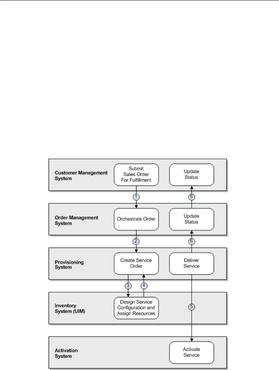
Figure 1–1 shows the provisioning flow of a typical service order involving UIM and
other external applications.
Figure 1–1 Provisioning Flow for a Typical Service Order
1. A customer relationship management system, such as Siebel CRM, captures order
information and submits a sales order to an order management system, such as
Oracle Communications Order and Service Management (OSM).

UIM System Architecture
About Unified Inventory Management 1-3
2. The order management system creates an orchestration plan to determine how the
order is to be provisioned.
The orchestration plan determines which downstream systems, including
provisioning, inventory, and activation systems, are affected by the order. The
order management system sends the appropriate data to these systems.
Downstream systems receive only the sales order data that affects them. For
example, the order management system sends only the line items that require
provisioning to a provisioning system.
3. A provisioning system transforms product actions into service actions and sends
service fulfillment data to UIM by using Web services.
4. Using the input from the provisioning system, UIM creates a service and designs
the service configuration with the resource assignments and other information
necessary to activate the service. UIM returns the service configuration
information to the provisioning system.
5. The provisioning system uses the information returned from UIM to calculate and
execute a delivery plan, then interacts with an activation system to submit an
activation order.
6. As services are provisioned, the provisioning system sends status updates
upstream to the CRM system. The provisioning system also updates UIM via Web
services so that the life-cycle statuses of the appropriate business interactions,
work orders, services, service configurations, and resources can be updated.
UIM System Architecture
UIM is a modular application. You can purchase and install only the modules that you
need. For example, if you are providing a VoIP solution, you can install a different set
of modules than someone providing a VPN service.
UIM comprises two main groups of components:
■Core Platform. The core platform provides basic capabilities such as APIs and data
storage. It also provides functionality used throughout the application, such as
life-cycle management and capacity management. The core platform is required
and is supplied with the purchase of any functional module.
■Functional Modules. Functional modules provide the capability to manage
different kinds of inventory, such as devices or telephone numbers. You can
purchase only the modules required by your business.
Oracle Communications Design Studio is not part of UIM, but it plays a vital role in
designing content for the application. A Design Studio for UIM plug-in provides
application-specific capabilities. See "Design Studio Overview" for more information
about Design Studio.
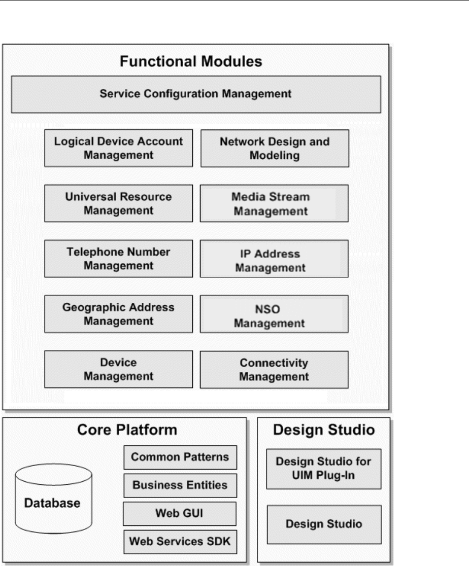
Figure 1–2 illustrates these components and their contents. The components are
discussed in more detail in the sections that follow.
UIM is hosted by Oracle WebLogic Server. WebLogic Server supports several different
application configurations, including single server, clustered servers, and Oracle RAC
(Real Application Cluster). See UIM Installation Guide and UIM System Administrator’s
Guide for more information.
UIM System Architecture
1-4 Oracle Communications Unified Inventory Management Concepts
Figure 1–2 UIM System Architecture
Core Platform
The core platform is the architectural framework of UIM. It is required and is supplied
with the purchase of any functional module. The core platform provides:
■Data storage. The core platform manages the storage of both model data and
entity data in the Oracle DBMS. See UIM Installation Guide and UIM System
Administrator’s Guide for more information.

UIM System Architecture
About Unified Inventory Management 1-5
■Web-based user interface. Users access the application through a Web-based
interface. The UIM interface can be extended with custom pages, fields, and code.
See "UIM User Interface Overview" and the UIM Help for information about using
UIM through the graphical interface. See UIM Developer’s Guide for information
about extending the interface.
■Web services. External systems can interact with UIM by using Web services that
provide access to UIM APIs. For example, an order management system can pass
order data into UIM by using Web services. A selection of Web services is available
by default, but you can write custom code to create new ones. See UIM Web
Services Developer’s Guide for more information.
■Common patterns that enable core functionality. See "Understanding Common
Patterns" for more information.
■Common business entities. These entities enable you to manage resources and
services and to define relationships among them. See "Understanding Common
Business Entities" for more information.
Functional Modules
UIM functional modules manage the end-to-end life cycle of services, logical
resources, and physical resources. You can purchase only the modules that your
business requires.
Each module supplies content to address a specific need. For example, the Device
Management functional module includes support for creating and working with
devices and equipment in your inventory. Both physical and logical resources are
included.
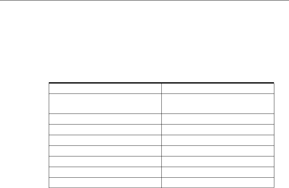
Table 1–1 lists the functional modules and the entities that they support. See "About
Entities and Entity Types" for more information about entities.
Note: Common business entities, such as business interactions,
inventory groups, parties, roles, conditions, and reservations, are
supplied by the core platform rather than functional modules.
Table 1–1 UIM Functional Modules
Functional Module Entity Types
Service Configuration Management Service, Service Configuration, Product
Connectivity Management Connectivity, Pipe, Pipe Termination Point, Pipe Configuration
Device Management Physical Port, Physical Connector, Physical Device, Equipment,
Equipment Holder
Logical Device, Logical Device Configuration, Device Interface,
Topology Node, Topology Edge
Geographic Address Management Place (including Location, Site, Address, and Address Range), Place
Configuration
IP Address Management IP Networks, IP Subnets, IP Addresses
Media Stream Management Media Stream
Telephone Number Management Telephone Number
Universal Resource Management Custom Object, Custom Involvement
About Entities and Entity Types
1-6 Oracle Communications Unified Inventory Management Concepts
About Entities and Entity Types
Understanding entities is fundamental to understanding how you use UIM. UIM
entities represent logical and physical items that are inventoried, such as networks,
logical devices, telephone numbers, and services. They also represent items that are
used for categorizing, grouping, or managing other entities. Examples of these kinds
of entities include reservations, business interactions, and inventory groups.
UIM includes a number of different entity types that correspond to the various
categories of items in your inventory and how you manage them. For example, there is
a Network entity type, a Logical Device entity type, a Service entity type, and so on.
An individual entity is an occurrence or instance of an entity type, such as a specific
network, logical device, or service.
Entities are usually based on specifications that define their basic structure. There are
different specification types corresponding to the entity types. See "About
Specifications, Data Elements, and Characteristics" for more information.
See "About the UIM Information Model" for more information about the different
kinds of entities available in UIM.
About the UIM Information Model
This section explains the fundamentals of the information model that UIM uses to
represent your inventory and business practices. The UIM information model is an
extension of the Oracle Communications Information Model. The Oracle
Communications Information Model is based on industry standards, such as the
Shared Information/Data (SID) model and OSS through Java (OSS/J) developed by
the Telemanagement Forum. Oracle is an active participant in the development and
evolution of these standards.
Adherence to industry standards makes it possible for UIM to model inventories and
business practices without regard to the specifics of the telecommunications
environment, its services, or its resources. The use of industry standards also promotes
more efficient software development, deployment, and integration.
For more information about the Telemanagement Forum and its standards, see their
Web site:
http://www.tmforum.org
For specific, technical details, about the Oracle Communications Information Model
and the UIM information model, see Oracle Communications Information Model Reference
and UIM Information Model Reference.
Logical Device Account Management Logical Device Account
Network Design and Modeling Network, Network Node, Network Edge, Network Configuration,
Custom Network Addresses
NSO Management Enables the lifecycle management of Network Services and Virtual
Network Functions (VNFs) running on a virtualized network
infrastructure. Includes the ability to allocate resources to those
Network Services and VNFs.
Table 1–1 (Cont.) UIM Functional Modules
Functional Module Entity Types
About the UIM Information Model
About Unified Inventory Management 1-7
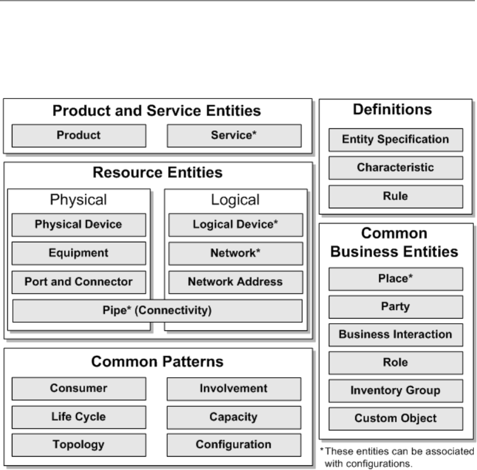
Figure 1–3 provides a simplified view of the Information Model and what it contains.
Some elements are omitted for clarity. See the following sections for information about
each of the categories in the model.
Figure 1–3 UIM Information Model
Understanding Products and Services
Products are entities that represent the items that your business sells. For example, you
might sell wireless phones or online movies.
Because UIM is primarily concerned with inventory, it emphasizes services. Product
entities are included in UIM for backward compatibility with customized solutions
that require mapping services to corresponding products. The UIM navigation section
does not include a Product link unless the user is authorized to access the Product
Search page. Access is turned off by default. See UIM System Administrator’s Guide for
information about authorizing user access.
Service entities represent the ways that products are delivered to your customers. For
example, if you sell a wireless telephony product, the customer receives a wireless
service that you provision.
See "Services" for more information.

About the UIM Information Model
1-8 Oracle Communications Unified Inventory Management Concepts
Understanding Resources
Resources are entities that enable the delivery of services. Broadly speaking, they are
the entities that constitute your inventory. They can be physical objects, such as
network cards or fiber-optic cables. They can also be logical resources, such as service
trails or network addresses.
You often assign resources to service configurations to specify how a service is realized
in your network. For example, if you configure a VoIP service for a customer, you need
to assign resources such as an IP phone, a telephone number, an IP address, a voice
mail account, and a VoIP user account.
Table 1–2 lists the UIM resource entity types and provides links to the sections where
they are discussed in greater detail.
Table 1–2 UIM Resource Entities
Entity Type For More Information
Connectivity About Connectivity
Custom Network Address About Custom Network Addresses
Custom Object Custom Objects
Device Interface Understanding Device Interfaces and
Sub-Interfaces
Equipment Understanding Equipment Modeling
Equipment Holder Configuring Equipment Holder
Specifications
Flow Identifier About Flow Identifiers
IPv6
IPv4
IP Address Management
Logical Device and Logical Device
Configuration
Understanding Logical Devices
Logical Device Account Understanding Logical Device Accounts
Media Stream About Media Streams
Network and Network Configuration Understanding Networks
Network Edge Understanding Network Nodes
Network Node Understanding Network Edges
Physical Connector Adding Ports and Connectors
Physical Device Understanding Physical Resources
Physical Port Adding Ports and Connectors
Pipe and Pipe Configuration Understanding Pipes
Pipe Termination Point Configuring and Implementing Pipe
Termination
Signal Termination Point Understanding Signal Structures
Telephone Number Telephone Numbers
About the UIM Information Model
About Unified Inventory Management 1-9
Understanding Common Business Entities
Common business entities do not represent items in your inventory. Rather, they
represent relationships between or aspects of those items. They are, nevertheless,
entities that have specifications that you define in Design Studio.
Table 1–3 lists the UIM common business entities and provides links to the sections
where they are discussed in greater detail.
Understanding Common Patterns
Core functionality that applies throughout UIM is enabled by common patterns. In
some cases, entities are associated with these patterns. For example, there are several
entities that you use to define and manage capacity.
These are the UIM common patterns:
■Capacity management. You can track bandwidth consumption and requirements
in your network. See "Capacity" for more information.
■Consumption, including the ability to consume, assign, and refer to resources. You
can also reserve resources to ensure that they are available when needed and
apply conditions that limit access to them. See "Consumption" for more
information.
■Topology. UIM manages the geographical and logical topology of your network.
The application provides graphical tools and maps for visualizing and managing
the topology. See "Topology" for more information.
■Life-cycle management. UIM entities transition through life cycles that indicate
their status in the inventory. Some transitions are manual; others occur
automatically. See "Life Cycles and Statuses" for more information.
■Configuration. Some entities can be associated with configurations, making it
possible to maintain versionable collections of information about how the entity is
designed and realized. See "Configurations" for more information.
■Involvement. You can define custom involvements to associate entities that are not
associated in other ways. See "Involvements" for more information.
Table 1–3 UIM Common Business Entity Types
Entity Type For More Information
Business Interaction Business Interactions
Engineering Work Orders
Custom Object Custom Objects
Inventory Group Inventory Groups
Network Domain Network Address Domains
Party About Parties
Place, Place Configuration Places
Property Location Property Locations
Role About Roles

About the UIM Information Model
1-10 Oracle Communications Unified Inventory Management Concepts
Understanding UIM Definitions
In Design Studio, you define artifacts that you use to model and manage your
inventory. Design Studio artifacts include specifications, data elements, characteristics,
and rulesets, among others.
About Specifications, Data Elements, and Characteristics
A specification is a blueprint that determines the information that you store about a
particular group of entities within an entity type. For example, you can define Logical
Device specifications for Cisco 2811 routers and Juniper M7i routers.
Data elements in specifications define the items of information you store about
entities. All specifications for a particular entity type share a default set of data
elements, but each individual specification can include custom data elements
appropriate to that group of entities. These custom data elements are called
characteristics. For example, all Logical Device specifications include a default set of
data elements, but each particular Logical Device specification can include unique
characteristics.
Characteristics can be shared by any number of specifications. For example, if you
define a Postal Code characteristic, you can reuse it in any number of Address
specifications (or any other specifications where it might be appropriate).
Characteristics can even be shared with other Oracle Communications applications to
ensure data uniformity.
You define specifications and characteristics in Design Studio. After you have defined
specifications and characteristics in Design Studio, you deploy them into UIM, where
you use them to create entities. You can also view specifications and characteristics in
UIM in read-only mode.
In UIM, you create entities based on the specifications defined in Design Studio. For
example, if you have a Cisco 2811 specification, you can create an entity based on the
specification for each router of that model in your inventory. Each entity includes
unique information, such as name, ID, serial number, location, configuration details,
and so on.
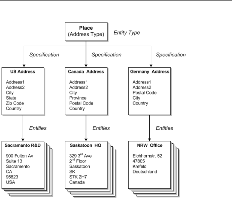
Figure 1–4 shows a simple example of the relationship between the entity type,
specifications based on the type, and entities created from the specifications.
In this example, the entity type is Place. There are several subtypes of Place entities,
including Address, as in this case. Three different specifications have been defined for
three different countries. Each specification is somewhat different, reflecting different
postal conventions. But several characteristics (Address1, Address2, City, and so on)
are shared among all three. Multiple entities have been created from each specification
for places in the three countries.
Note: A default data element from one specification can be reused in
a specification that does not include it by default. In this case, the data
element is tagged as a characteristic and becomes visible in UIM.
Default data elements are visible only as part of specifications in UIM.
Note: You can create entities of some types without using
specifications. Using specifications is more common, however, and is
also a good business practice because it ensures uniformity among
entities.
About Cartridges
About Unified Inventory Management 1-11
Figure 1–4 Specifications and Entities
About Rulesets
You use rulesets to modify or extend UIM functionality dynamically. Rules e ts d ef i ne
one or more business rules that are executed at a particular point, such as when a page
opens or an action is taken. For example, you can use rulesets to validate that entities
have been configured correctly or to format data appropriately for your business. You
could also write a ruleset to automatically configure a service upon creation. You can
define rulesets that apply globally or that are unique to a particular specification. See
UIM Developer’s Guide for more information.
UIM includes default rulesets that you can modify, but you can also define your own.
You use Design Studio to define rulesets and to associate them with the extension
points that determine when they are executed. See "Design Studio Overview" and UIM
Developer’s Guide for more information about rulesets and Design Studio.
About Cartridges
You can extend UIM functionality dynamically without rebuilding the application.
You do so by deploying cartridges into the application. A cartridge is a collection of
entity specifications, characteristics, rulesets, and code that is defined in an Oracle
Communications Design Studio project. The Design Studio project is compiled into a
deployable JAR file known as a cartridge. Cartridges can be bundled together into
cartridge packs that can be deployed in a single operation.

About Cartridges
1-12 Oracle Communications Unified Inventory Management Concepts
When you deploy a cartridge into UIM, the data it contains becomes available in the
application. For example, if you deploy a cartridge that includes several different types
of logical device specifications, those specifications become available for creating
logical device entities in UIM.
You can also create your own custom cartridges in Design Studio. For example, you
can create custom specifications and rulesets that are specific to your business and
technology, and then deploy them to UIM.
Oracle also supplies various kinds of cartridges that extend UIM:
■Base cartridges: Base cartridges provide fundamental capabilities and features
required by other cartridges. For example, there is a base cartridge that defines
measurements such as bandwidth.
■Required cartridges: Some cartridges are required to be open in the Design Studio
workplace when you develop content for UIM.
■Samples: Oracle provides various kinds of sample cartridges and cartridge packs.
You use these samples as a starting point for your own development, testing, and
experimentation.
Some Oracle sample cartridge packs provide extensive support for particular
technology domains. For example, the Carrier Ethernet cartridge (OracleComms_
UIM_CarrierEthernet) provides specifications and rulesets that enable you to
model Carrier Ethernet services. Other samples address channelized connectivity,
DSL, GSM, and Cable TV.
The names of all Oracle-supplied cartridges begin with ora_uim or OracleComms.
Many cartridges, including those supplied by Oracle, have accompanying ZIP archive
files containing the Design Studio project data used to compile the cartridge. You can
import the ZIP files into Design Studio to open the corresponding project for review or
extension.
See UIM Cartridge Guide for information about obtaining and using sample cartridges
and cartridge packs.

2
UIM User Interface Overview 2-1
2
UIM User Interface Overview
This chapter provides an overview of the Oracle Communications Unified Inventory
Management (UIM) user interface. For complete information about the user interface
and the tasks you can complete with it, see the UIM Help.
Opening the UIM User Interface
To open the UIM user interface, you need to obtain the following from a system
administrator:
■User ID
■Password
■The UIM URL, including the server and port
Your user ID will be associated with access permissions that determine which parts of
the application you can see and which actions you can take. All of the pages and
actions described in this guide may not be available to you.
To open UIM:
1. In a supported browser, go to the URL supplied by the system administrator. The
URL is similar to the following:
https://ServerName:Port/inventory
2. Enter your user ID and password.
The UIM main window appears.
The UIM Main Window
When you open UIM, you see the main window, which has a navigation section on the
left that you use for navigation and an area to the right that is populated with pages
when you click links in the navigation section. The main window also includes menus
and a toolbar.
Figure 2–1 shows the main window with a Logical Device Summary page displayed.
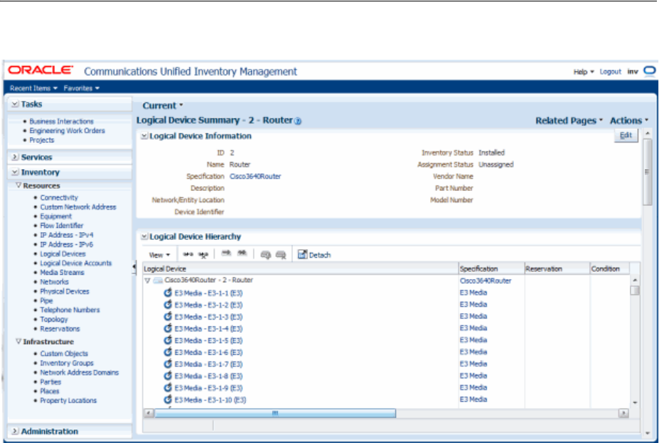
The UIM Main Window
2-2 Oracle Communications Unified Inventory Management Concepts
Figure 2–1 UIM Main Window
Navigation Section
The left side of the main window is called the navigation section. It displays a list of
links that enable you to find entities and other information in UIM. These links are
divided into the following groups:
■The Tasks group contains links to projects, engineering work orders, and business
interactions.
■The Services group contains links to service entities.
■The Inventory group is divided into sub-groups:
–The Resources sub-group contains links that enable you to search for resource
entities, such as connectivities, logical devices, telephone numbers, IP
addresses, networks, and more.
–The Infrastructure sub-group contains links to property locations, custom
objects, inventory groups, parties, and places.
■The Administration group contains for administrative functions such as
rebuilding topology and executing rule sets. It also contains links that enable you
to search for rulesets, sequence specifications, characteristics, and entity
specifications.
To make more room in the main window, you can adjust the size of the navigation
section sliding its border with the main window.
Pages
When you click on a link in the navigation section, the right side of the main window
is displays a page. In most cases, the pages that you open directly from the navigation
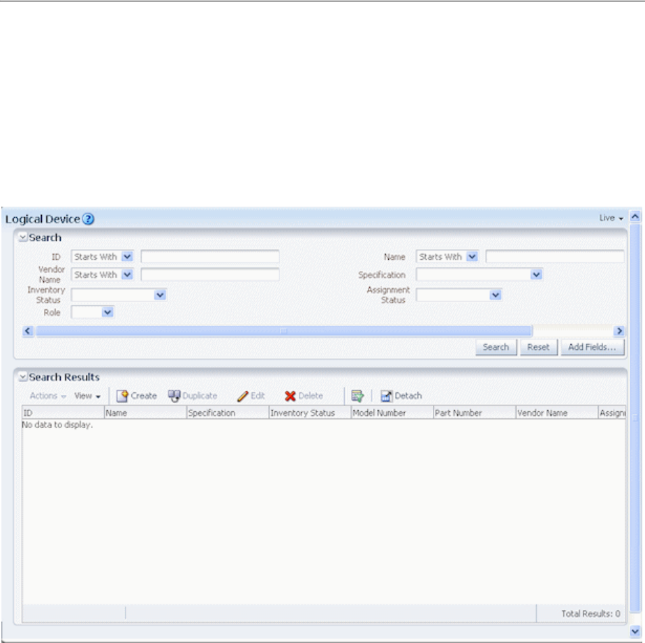
The UIM Main Window
UIM User Interface Overview 2-3
section enable you to search for entities. In other cases, clicking a link opens a page for
completing a task, such as importing inventory.
Figure 2–2 shows the Logical Device page, which you open by clicking the Logical
Device link in the Resources group. You use this page to search for logical devices. You
enter search criteria in the Search section in the upper part of the page and see the
results in the Search Results section in the lower part. See the UIM Help for more
information about searching.
Figure 2–2 Logical Device Page
Other kinds of pages appear as you work with entities in UIM. For example, if you
search for a particular logical device and then open it, you see its Summary page.
Figure 2–3 shows a Logical Device Summary page.
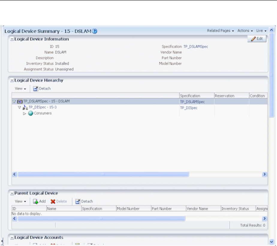
The UIM Main Window
2-4 Oracle Communications Unified Inventory Management Concepts
Figure 2–3 Logical Device Summary Page
Additional pages enable you to perform other tasks. For example, you use the Logical
Device Information page to edit the identifying information about logical devices.
Pages are often divided into sections that contain specific kinds of information. For
example, in the Logical Device Summary page shown in Figure 2–3, there are Logical
Device Information, Logical Device Hierarchy, and Parent Logical Device sections,
among others.
You can save space in a page by collapsing a section. Click the triangle icon in the
upper left corner of the section’s title bar to collapse it. Click the icon again to expand
the section.
Working with Tables
Much of the information shown in pages is displayed in tables. These tables all have
the same basic functionality, although not all features are available in all tables.
You can choose which columns are displayed and the order in which they appear. You
can also filter and sort table contents so that only the most relevant information is
displayed. When there are more rows of data than can be displayed in a section, you
can scroll the table to see the additional rows.
See the UIM Help for detailed instructions about working with tables.

Using the UIM Help
UIM User Interface Overview 2-5
Menus
The toolbar above the navigation section and pages includes several different menus
■Recent Items. Lists the 10 most recently used pages.
■Favorites. Displays pages that you have designated as favorites. See the UIM Help
for complete instructions.
■Help. Select from three different commands:
– Link to Page. Displays the URL of the current UIM page. You can copy the
URL.
– Help Portal. Opens the UIM Help.
UIM includes a Help system that you can access while using the application.
See "Using the UIM Help" for more information.
– About. Displays the release number of the application and its copyright
statement.
Using the UIM Help
UIM includes a Help system that you use to get step-by-step instructions. You can find
the information you need by searching or by navigating through the table of contents.
This section includes information about opening the Help system and finding
information. See the Help system contents for detailed information about all of its
features.
To open Help:
■From the Help menu, select Help Portal.
The Help Portal window appears.
To open Help for the current page:
■Click the question-mark icon in the title bar of a page.
The Help Portal window appears, displaying a reference topic for the current
page.
To browse for information:
1. In the navigation area on the left of the Help Portal window, click Contents.
An expanding table of contents appears in the navigation area.
2. Do one of the following:
■Click a heading in the table of contents to display the introductory topic about
the corresponding section in the reading area.
■Click the triangle next to a heading to expand it to show subheadings and
topics.
To search for information:
1. In the navigation area on the left of the Help Portal window, click Search.
A search area appears in the navigation area.
2. Enter a word or phrase to search for.
3. Select search options:

Using the UIM Help
2-6 Oracle Communications Unified Inventory Management Concepts
■To search for an entire phrase, select All words.
■To search for any of the words you entered, select Any words.
■To include Boolean expressions such as AND or OR, select Boolean
expression.
■To match the capitalization of your search terms, select Case Sensitive.
4. Click Search.
Results are displayed below the search area. The total number matches appears
above the list of matching topics, which are ordered by the number of matches
they contain.

3
Design Studio Overview 3-1
3
Design Studio Overview
This chapter provides introductory information about how Oracle Communications
Design Studio is used with Oracle Communications Unified Inventory Management
(UIM).
Design Studio is a separately licensed product that you install independently of UIM.
For detailed information on how to install Design Studio, see Design Studio Installation
Guide.
About Design Studio
Design Studio is an Eclipse-based development environment that supports several
Oracle Communications applications in addition to UIM. For UIM development, you
must install the Design Studio Platform, Design Studio Domain Modeling, and Design
Studio for Inventory plug-ins.
You use Design Studio to define artifacts such as specifications and rulesets that you
later deploy into UIM. You can define the following kinds of artifacts in Design Studio:
■Entity specifications
■Data elements tagged as characteristics
■Units of measure and measurement types
■Capacity provided, capacity required, and capacity type specifications
■Entity identification specifications
■Rulesets
■Extension points and enabled extension points
■Ruleset extension points and global ruleset extension points
■Sequence specifications
See the Design Studio Help for detailed information about how you work with each of
these types of artifacts.
About Projects and Cartridges
In Design Studio, you create projects to contain the artifacts that you define. Each
project corresponds to a collection of files and folders where data is stored. When a
project is complete, you use Design Studio to build a cartridge that you deploy into
UIM.

Understanding the Design Studio Workbench
3-2 Oracle Communications Unified Inventory Management Concepts
See the Design Studio Help for information about deploying cartridges interactively
from Design Studio. See the Design Studio Developer's Guide for information about
automating cartridge deployment using the Design Studio Cartridge Management
Tool (CMT). See the UIM Cartridge Guide for more information about the Cartridge
Deployer Tool (CDT).
You can also use Design Studio to open, view, and deploy content supplied by Oracle.
For example, you can open the cartridges in an Oracle sample cartridge pack, add
cartridges required for your business, and then deploy the cartridges into UIM.
See UIM Cartridge Guide for information about upgrading and extending cartridges.
Understanding the Design Studio Workbench
The Design Studio Workbench is the environment you use to develop and maintain
specifications, rulesets, and other artifacts. The contents of the Workbench depend on
the perspective that is currently displayed.
Perspectives are arrangements of content optimized for particular purposes. Design
Studio includes several predefined perspectives. The two most commonly used
perspectives are:
■The Studio Design perspective, which provides tools for designing and
maintaining specifications and other artifacts.
■The Studio Environment perspective, which includes views for working with and
deploying cartridges.
When you start Design Studio the first time, the Workbench displays a default
perspective. After that, Design Studio starts up in the last perspective used.
About Views
The tools in the Workbench are smaller, window-like areas called views. Each
perspective has a different set of views and each view is designed for a particular
purpose.
For example, the Studio Design perspective includes the following views:
■Projects: This view shows the project contents grouped alphabetically by
specification type.
Note: You must install two required projects in Design Studio before
you can create UIM projects and deploy them as cartridges. The
following two projects must be open in your workspace:
■ora_uim_model is a read-only project that represents the UIM
model. It supports the ability to define specifications and
characteristics and is also used to validate which entity types can
be assigned or referenced by configuration items.
■ ora_uim_mds is a read-only project that represents the fields that
can be displayed in UIM entities. This project makes it possible to
define the layout of fields in entities.
See UIM Installation Guide and Design Studio Help for more
information about importing these projects.
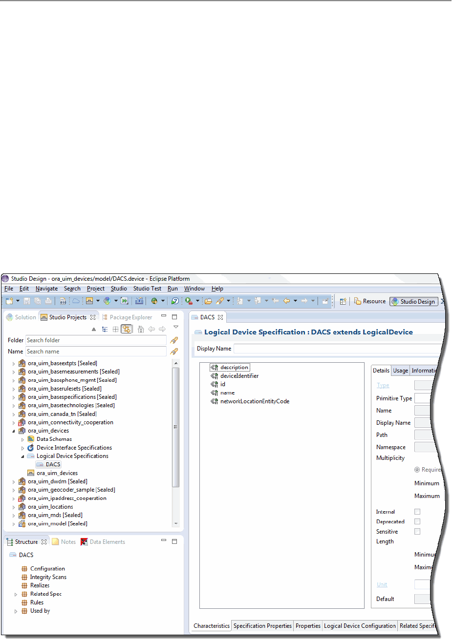
Understanding the Design Studio Workbench
Design Studio Overview 3-3
■Relation: This view shows parent and child relationships for the selected
specification.
■Relation Graph: This view shows a graphical view of a specification’s
relationships.
■Data Element: This view shows all the entities in the project that include data
elements.
■Problems: This view displays information about problems in the cartridge, such as
build errors.
The Studio Design perspective also includes editors, windows in which you do the
actual work of designing and modifying specifications and other artifacts. When you
make a selection in the Studio Projects view or Dictionary view, an editor for the
selected artifact opens. See "About Editors" for more information about editors.
Figure 3–1 displays the Workbench with the Studio Design perspective. In this
window, the Studio Projects, Package Explorer, and Solution views are open with the
Studio Projects view activated. A Logical Device specification is selected in the Studio
Projects view, making the corresponding Logical Device Specification editor active.
Figure 3–1 Studio Design Perspective

Designing Entity Specifications
3-4 Oracle Communications Unified Inventory Management Concepts
See “Workbench User Guide” in Eclipse Help for additional information about views
and editors.
About Editors
Editors are the tools you use to design specifications and other artifacts in Design
Studio. Each editor is tailored for a particular type of artifact. Editors are opened based
on selections you make in views. Although multiple editors can be open
simultaneously, only one is active at a time.
Editors are divided into tabs arranged across the bottom. Some tabs appear in most
editors, but others pertain only to a few.
The editors for the various types of entity specifications vary based on the nature of
the entity, but many contain the following tabs:
■Specification Properties: Defines basic information about the specification, such
as whether the IDs of entities defined by the specification are generated
automatically or manually. See "Entity Identification" for more information about
IDs.
■Characteristics: Defines characteristics associated with the specification. Using
characteristics enables you to store information in addition to the default data
elements for the entity. For example, you can add characteristics to store
vendor-specific information about Equipment entities. See "Characteristic Labels"
for more information.
■Related Specifications: Enables you to define relationships between
specifications. See "Understanding Specification Relationships" for more
information about relating specifications.
■Configuration Spec Usage: Enables you to indicate that an entity based on this
specification can be consumed or referenced in the configuration specifications
listed in the tab.
■Rules: Associates entity specifications with rulesets that customize UIM behavior.
For detailed information and procedures about using extension points and
rulesets, see UIM Developer’s Guide.
■Layouts: Defines how entities based on the specification appear in UIM.
■Media: Defines media files (such as JPG or GIF files) that can be associated with a
specification for display in UIM.
There are additional tabs used with some specifications. In this guide, those tabs are
explained when they are used with a particular specification type.
Designing Entity Specifications
Much of the work you do in Design Studio will likely be designing entity
specifications. The entity specifications you design in Design Studio are blueprints for
the entities you create in UIM to model your inventory.
Understanding Specification Relationships
One of the most important parts of designing a specification is defining relationships
to other specifications. For example, if you design a Logical Device specification, you
can build in a relationship to a Device Interface specification that ensures that a
particular number of interfaces are created automatically when you create a logical
device in UIM.

Designing Entity Specifications
Design Studio Overview 3-5
Related specifications frequently result in provides and constrains relationships among
entities in UIM. For example, when you relate a Logical Device specification to a
Device Interface specification, you establish a provides relationship in UIM between
Logical Device entities based on the specification and Device Interface entities based
on the related specification. If you design a Logical Device specification for an ATM
switch and relate it to an OC-12 Device Interface specification, when you create an
ATM switch entity in UIM, OC-12 device interface entities are created automatically.
The number of device interfaces created depends on a minimum value that you set for
the relationship in the Logical Device specification. A maximum value for the
relationship limits the number of child entities that can be added.
You can customize UIM by using extension points and rulesets so that the
relationships not recognized by default in UIM are meaningful. For example, you can
add rulesets that automatically create child entities based on a related specification
when an entity is created based on a parent specification. See UIM Developer’s Guide for
more information.
A constrains relationship results from relating a Network Node specification to a
Logical Device specification. This relationship limits the types of entities that a
network node can represent in UIM. For example, if you design a Network Node
specification that includes a relationship to a DSLAM Logical Device specification, you
can associate network node entities based on the specification only to entities based on
the DSLAM specification.
You establish most relationships in Design Studio from a specification editor’s Related
Specs tab. Certain types of relationships are handled on different tabs, however. For
entities that can have configurations, for example, you define entity-to-configuration
relationships on the Configurations tab.
Table 3–1 shows the specification relationships in Design Studio that are supported by
default in UIM.
Note: Design Studio enables you to define relationships from any
specification to any other specification, but only a limited number of
these relationships are recognized by default in UIM. The nature and
results of recognized relationships vary depending on the
specifications involved. See Table 3–1 for more information.

Designing Entity Specifications
3-6 Oracle Communications Unified Inventory Management Concepts
Table 3–1 Specification Relationships
Specification
Related
Specifications Usage Minimum and Maximum
Device Interface Device
Interface
UIM creates the sub-interfaces
provided by a new device
interface entity based on these
relationships.
The minimum value on the
relationship determines the number of
device interface entities that UIM
creates and is the minimum number
that must be maintained on the device.
The maximum value constrains the
number of device interface entities that
can be subsequently created.
Equipment Equipment
Holder
Physical Port
Physical
Connector
UIM creates the equipment
holders, physical ports, and
physical connectors provided by
a new equipment entity based
on these relationships.
The minimum value determines the
number of equipment holder, physical
port, and physical connector entities
that UIM creates and it constrains the
user from deleting the physical ports
and physical connectors after the
equipment is created.
The maximum value is not used for
equipment holder because the number
of holders is set by the specification
and cannot be changed after an entity
has been created.
The maximum value is used for ports
and connectors and constrains the
number of ports and connectors
entities that can be subsequently
created.
Inventory Group Inventory
Group
UIM constrains the types of
inventory groups that can be
related as parent and child
inventory groups.
Not applicable.
Custom Network
Address
Custom Object
Equipment
Logical Device
Logical Device
Account
Party
Physical Device
Pipe
Pipe Termination
Point
Product
Service
Telephone
Number
Inventory
Group
UIM constrains the entity to
participate only in inventory
groups created from the related
inventory group specifications.
Not applicable.

Designing Entity Specifications
Design Studio Overview 3-7
Logical Device Device
Interface
UIM creates the device
interfaces provided by a new
logical device entity based on
these relationships.
The minimum value on the
relationship determines the number of
device interface entities that UIM
creates and is the minimum number
that must be maintained on the logical
device. The maximum value constrains
the number of device interfaces that
can be subsequently created.
Logical Device Logical Device
Configuration
UIM constrains the type of
logical device configuration that
can be created for a logical
device.
Not applicable.
Network Network Node
Network Edge
UIM constrains the types of
network nodes and network
edges that can be included in a
network.
Not applicable.
Network Network
Configurations
UIM constrains the type of
network configuration that can
be created for a network.
Not applicable.
Network Edge Pipe
Custom Object
UIM constrains the types of
pipes and custom objects that
can be represented by a network
edge.
Not applicable.
Network Node Custom
Network
Address
Custom Object
Device
Interface
Equipment
Logical Device
Network
Physical Device
Physical Port
UIM constrains the types of
entities that can be represented
by a network node. Party and
Place associations to Network
Node are not currently
constrained by specification
relationships.
Not applicable.
Physical Device Physical Port
Physical
Connector
UIM creates the physical ports
and connectors provided by a
new physical device entity based
on these relationships.
The minimum value on the
relationship determines the number of
port or connector entities that UIM
creates and is the minimum number
that must be maintained on the device.
The maximum value constrains the
number of port and connector entities
that can be subsequently created.
Table 3–1 (Cont.) Specification Relationships
Specification
Related
Specifications Usage Minimum and Maximum

Designing Entity Specifications
3-8 Oracle Communications Unified Inventory Management Concepts
Pipe Pipe
Pipe
Termination
Point
UIM creates child pipes (cable
pairs) or pipe termination points
provided by a new pipe entity
based on this relationship. See
UIM Information Model Reference
for more detailed information
about relating pipe
specifications to pipe
termination point specifications.
The minimum value on the
relationship determines the number of
child pipe entities that UIM
automatically creates and is the
minimum number that must be
maintained on the pipe. The maximum
value constrains the number of child
pipe entities that can be subsequently
created.
Two pipe termination points are
created for all pipe entities; however, if
a pipe termination point specification
is associated with a pipe, the pipe
creates a pipe termination point using
the related pipe termination point
specification.
Pipe Capacity
Provided
UIM creates a capacity provided
for the pipe based on this
relationship when there is not a
signal termination point
specification related to the pipe.
If a signal termination point
specification is associated with
the pipe specification, the
capacity provided is created
based on the capacity provided
specification on the signal
termination point specifications.
Not applicable.
Pipe Capacity
Required
UIM creates a capacity required
for the pipe based on this
relationship.
Not applicable.
Pipe Signal
Termination
Point
UIM creates a signal structure
for the pipe based on this
relationship.
Not applicable.
Pipe Pipe
Configurations
UIM constrains the type of pipe
configuration that can be created
for a pipe.
Not applicable.
Place Place
Configurations
UIM constrains the type of place
configuration that can be created
for a geographic site.
Not applicable.
Product Product
Service
UIM constrains the types of
products and services than can
be added to a product in the
product hierarchy.
UIM validates the minimum and
maximum values in the relationship
against the minimum and maximum
child products and services in the
product hierarchy.
Table 3–1 (Cont.) Specification Relationships
Specification
Related
Specifications Usage Minimum and Maximum

Working with Characteristics
Design Studio Overview 3-9
Extending Specifications with Rulesets
You can use rulesets, extension points, and ruleset extension points to customize how
UIM performs actions related to entities based on a specification.
■An extension point defines when the customized behavior takes place, such as
immediately after an entity based on the specification takes place or when the
Validate command is selected from the Actions menu.
■A ruleset defines what happens at the extension point. For example, you can write
code that automatically creates additional entities or that validates that the entity
is configured properly.
■A ruleset extension point brings together a ruleset and an extension point into a
unit that you add to the Rules tab of an entity specification.
For detailed information and procedures about extending specifications, see UIM
Developer’s Guide.
Working with Characteristics
Characteristics provide a means of storing specific items of information about an entity
that are not present by default. For example, if you define a specification for a
particular type of equipment, you can add characteristics that describe vendor-specific
features of the equipment. When you create entities in UIM based on a specification
that includes characteristics, those characteristics appear automatically in the entities.
From the point of view of Design Studio, characteristics are data elements. You tag
these data elements as characteristics, which makes them available for use in entity
specifications. See the Design Studio Help for more information about data elements.
In Design Studio, characteristics are displayed on the Characteristics tab of
specification editors and are also included in the list of data elements visible in the
Data Schema editor.
In UIM, characteristics appear as fields in which users enter or select information.
Users can expand UIM search parameters to include characteristics in addition to
default data elements.
Service Service
Configurations
UIM constrains the type of
service configuration that can be
created for a service
Not applicable.
Signal Termination
Point
Capacity
Provided
UIM creates a capacity provided
for the signal structure based on
this relationship.
Not applicable.
Signal Termination
Point
Signal
Termination
Point
UIM creates child signal
termination points in a signal
structure based on this
relationship.
The minimum value dictates the
number of provided connection
termination points to be created when
the parent trail termination point or
connection termination point is
created.The maximum value is not
used.UIM does not support creating or
deleting connection termination points
after the signal structure has been
created.
Table 3–1 (Cont.) Specification Relationships
Specification
Related
Specifications Usage Minimum and Maximum

Design Studio Specification Example
3-10 Oracle Communications Unified Inventory Management Concepts
There are four types of characteristics, each of which has specific options that define or
limit the information stored in the characteristic:
■Text fields store alphanumeric characters. You can define what types of characters
can be stored, their format, default values, valid values, and other properties of the
field.
■Check boxes determine whether a characteristic is true or false for the entity.
■Calendar fields enable users to enter or select dates. The properties you specify for
the characteristic define a range of valid dates and a default date.
■List fields display a range of values to select from. In Design Studio, you can
define and sort the possible values for the list in several different ways. See the
Design Studio Help for more information.
Characteristic Labels
Characteristics must have unique names, but they can share the labels displayed for
them in UIM.
For example, you might want all addresses to include a Postal Code field. Because of
differences among national standards for postal codes, however, you may need to
develop specifications for several different countries. A US postal code characteristic
might be numeric with a maximum of nine digits, and a Canadian postal code
characteristic might be alphanumeric with a maximum of six characters. You can
define a unique characteristic for each country’s postal code but have them both
display as Postal Code in UIM.
Design Studio Specification Example
This section outlines the definition of an entity specification. In this example, a Logical
Device specification is defined for an ATM switch that can provide OC-3 and OC-12
device interfaces. For step-by-step instructions for the tasks in the example, see the
Design Studio Help.
You begin by selecting the type of specification you want to define, in this case, a
Logical Device specification.
In the Logical Device specification editor that opens, you use the Specification
Properties tab to enter basic identifying information, including the display name and
validity dates. Figure 3–2 shows the Specification Properties tab. In this case, default
values are being used for most options.
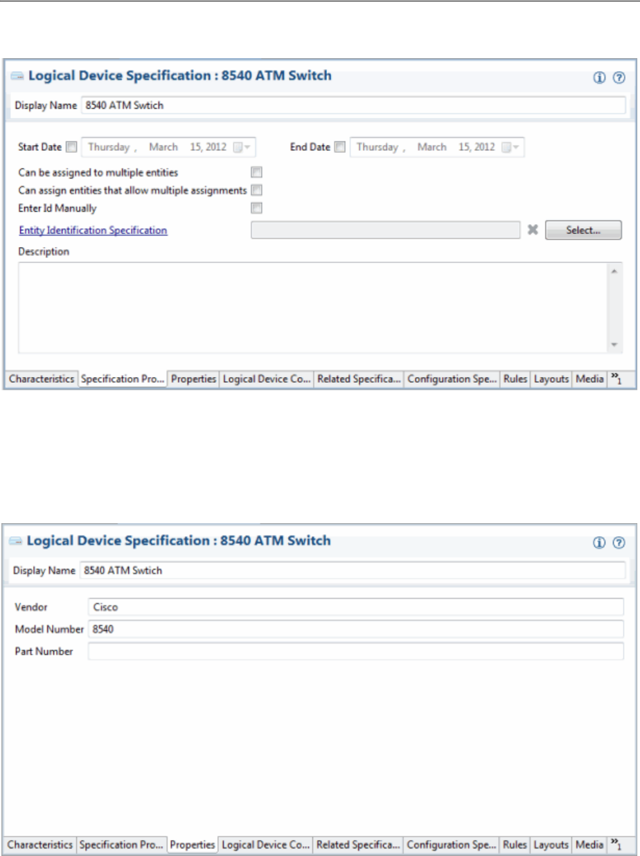
Design Studio Specification Example
Design Studio Overview 3-11
Figure 3–2 Entering Basic Identifying Information
Logical Device specification editors include a tab in which you can enter a vendor,
model, or part number that pertains to the logical device you are modeling. Figure 3–3
shows the Properties tab for a Logical Device specification. Not all specification types
have a Properties tab, and property data elements vary by entity type.
Figure 3–3 Setting Logical Device Properties
You can add characteristics to an entity specification to store data not supplied by
default by the specification type. You can either select from already existing
characteristics or them in the process of adding them. Figure 3–4 shows two
characteristics added to the Characteristics tab of a Logical Device specification.
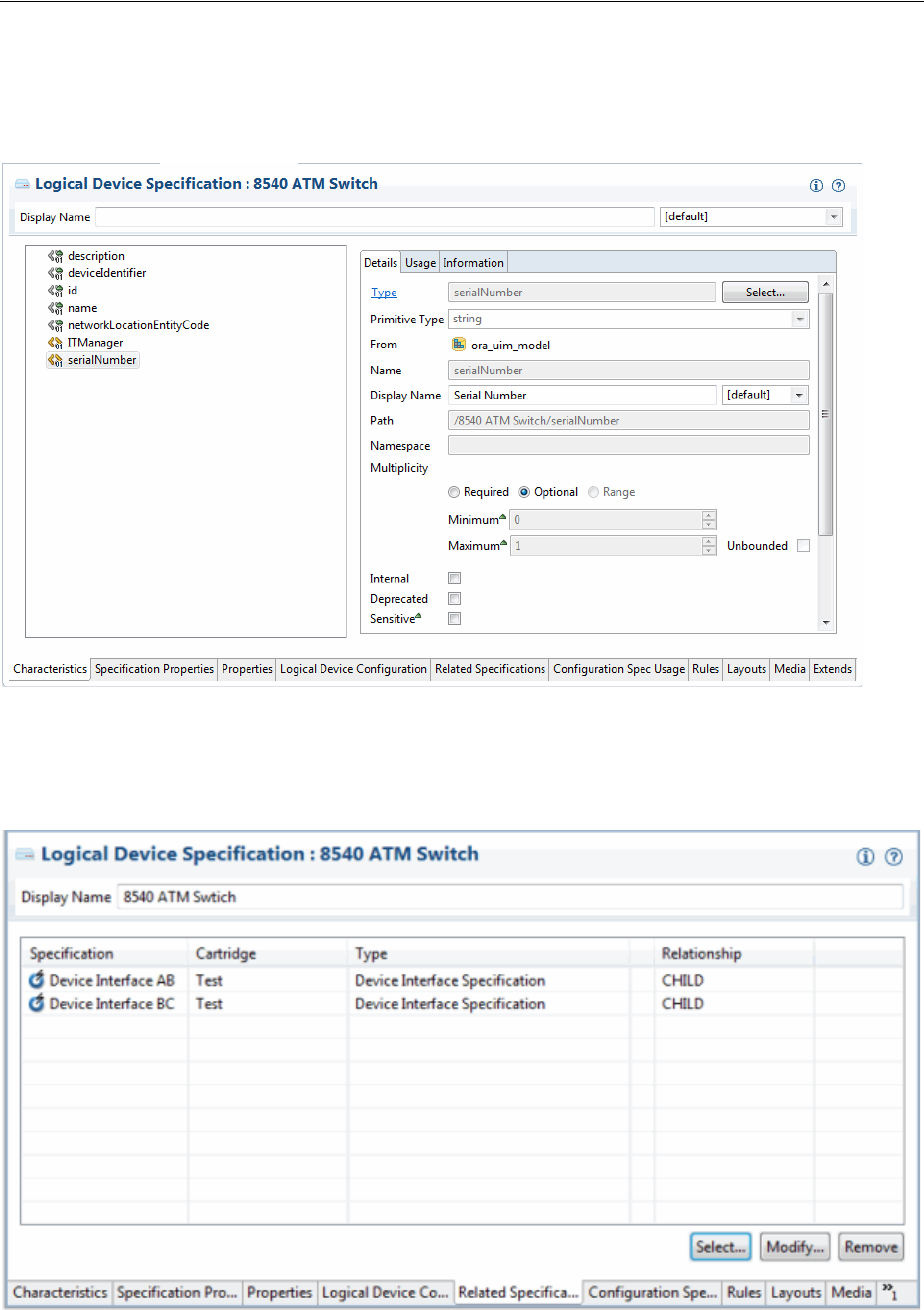
Design Studio Specification Example
3-12 Oracle Communications Unified Inventory Management Concepts
Information about the selected characteristic is displayed in the editor on the right of
the tab.
Figure 3–4 Adding Characteristics
Figure 3–5 illustrates relationships between the Logical Device specification and two
Device Interface specifications.
Figure 3–5 Relating Specifications
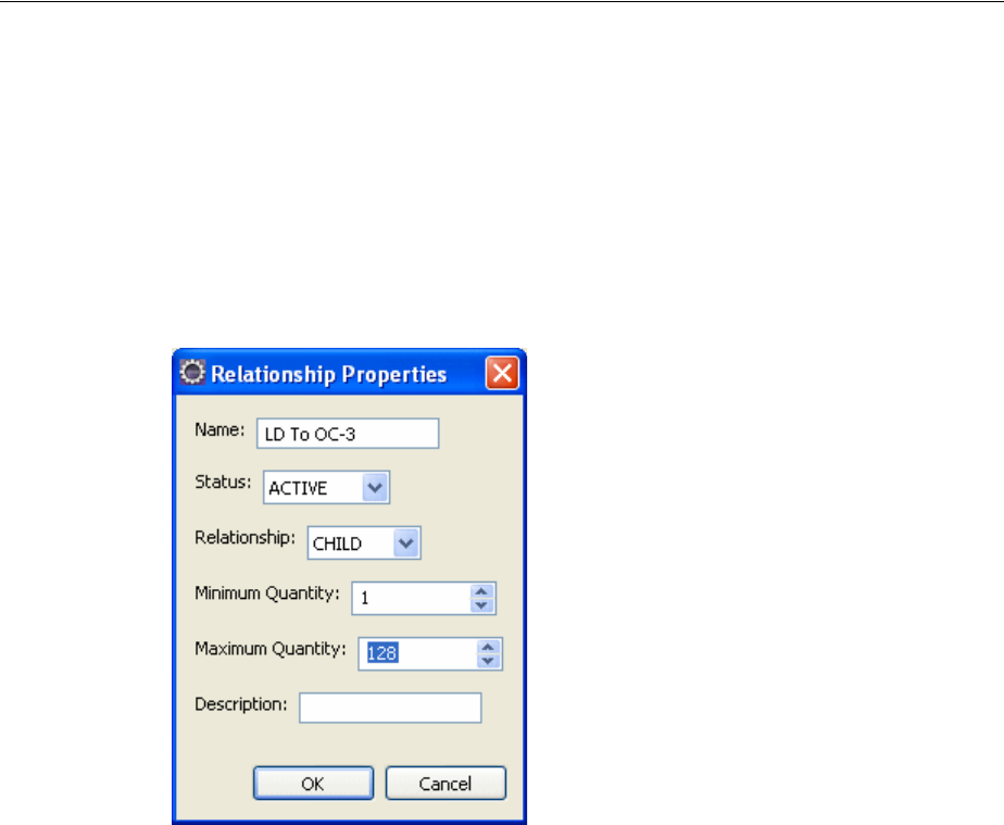
Deploying Cartridges into UIM
Design Studio Overview 3-13
In UIM, these relationships mean that when a logical device is created based on this
specification, device interfaces are created automatically based on the minimum values
defined in the specification. Users can add OC-3 and OC-12 device interfaces up to the
maximum values established in the specification.
Figure 3–6 shows the relationship properties of the OC-3 device interface. The
minimum value means that one OC-3 will be created automatically when a logical
device entity is created based on this specification. The maximum values means that
users can create an additional 127 interfaces for a total of 128.
Figure 3–6 Setting Relationship Properties
Deploying Cartridges into UIM
After you have created a UIM project that includes specifications, rulesets, and other
artifacts, you deploy it into UIM. You can deploy cartridges and cartridge packs into
UIM using the following methods:
■From Design Studio. You can deploy cartridges and cartridge packs interactively
from Design Studio to test environments. Design Studio enables you to manage
cartridges in the test environment consistently, manage common test environment
connection parameters across the design team, and compare cartridge version and
build numbers in the development environment with those of the cartridges
deployed in the test environment. See the Design Studio Help for more
information.
■By using the Design Studio Cartridge Management Tool (CMT). The CMT enables
you to automate cartridge deployment. You can use the CMT to deploy cartridges
into both test and production UIM environments. You can also use it to deploy
cartridges into cluster environments. See the Design Studio Developer's Guide for
more information about the CMT.
■By using the UIM Cartridge Deployer Tool (CDT). The UIM CDT is a GUI-based
tool that enables you to deploy to UIM run-time environments. The Oracle
Universal Installer installs the CDT as part of the UIM installation process. You can
use the CDT to deploy cartridges into both test and production UIM

Deploying Cartridges into UIM
3-14 Oracle Communications Unified Inventory Management Concepts
environments. You can also use it to deploy cartridges into cluster environments.
See the UIM Cartridge Guide for more information.

4
Life Cycles and Statuses 4-1
4
Life Cycles and Statuses
This chapter describes the life cycles and statuses associated with several types of
entities in Oracle Communications Unified Inventory Management (UIM). The life
cycles and statuses listed in this chapter are the defaults. You can extend life cycles and
statuses and associate life cycles with other types of entities, based on your business
processes. For information on how to extend life cycles, see UIM Developer’s Guide.
Resource Life Cycles and Statuses
Resources are managed over their entire life cycle (past, present, and future). Just as
resource inventory is managed over time, the consumption of each resource is also
tracked over time.
Whether a resource is available depends on the time frame referenced. A resource is
available for assignment or reassignment when:
■Its life cycle begins before the resource is consumed
■Its life-cycle state in the inventory allows it to be consumed
■No consumption entity exists during the time interval
Resource Inventory Statuses
The inventory status indicates the stage in the life cycle for the following types of
inventoried resources:
■Connectivities
■Custom network addresses
■Custom objects
■Device interfaces
■Equipment
■Equipment holders
■IP subnets
■IP addresses
■Logical devices
■Logical device accounts
■Media streams
■Networks
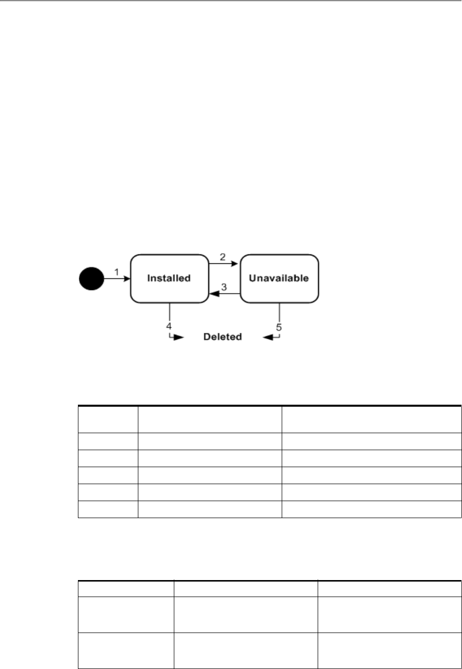
Resource Life Cycles and Statuses
4-2 Oracle Communications Unified Inventory Management Concepts
■Network edges
■Network nodes
■Physical connectors
■Physical devices
■Physical ports
■Pipes
■Pipe termination points
■Telephone numbers
Figure 4–1 shows the resource inventory life cycle when a business interaction or work
order is not used. See Figure 4–2, "Resource Inventory Life Cycle in a Business
Interaction or Work Order Context" for the resource inventory life cycle in the context
of a business interaction or work order.
Figure 4–1 Resource Inventory Life Cycle
Table 4–1 describes the actions associated with each number in Figure 4–1 and the
resulting status changes.
Table 4–2 provides a definition and business context for each resource status.
Table 4–1 Resource Status Flow Outside a Business Interaction or Work Order Context
Label
Number Description Status
1 Create a resource. Installed
2 Deactivate a resource. Unavailable
3 Activate a resource. Installed
4 Delete an installed resource. N/A
5 Delete an unavailable resource. N/A
Table 4–2 Resource Status Definitions Outside a Business Interaction or Work Order
Context
Inventory Status Definition Business Context
Installed The resource is created. An installed resource is available
to support services and other
resources.
Unavailable The resource has been
deactivated.
The resource is deactivated and
unavailable to support services or
other resources.
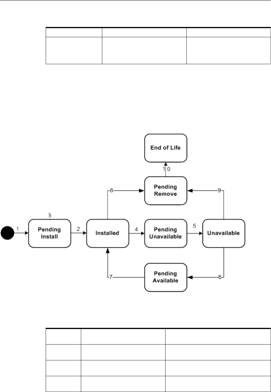
Resource Life Cycles and Statuses
Life Cycles and Statuses 4-3
Inventory Status for Resources in Business Interactions and Work Orders
Resources that are included in business interactions and work orders have a different
life cycle, illustrated in Figure 4–2. Pipes and connectivities have a somewhat different
life cycle from other resources. See "Inventory Status for Pipes and Connectivities in
Business Interactions and Work Orders".
Figure 4–2 Resource Inventory Life Cycle in a Business Interaction or Work Order Context
Table 4–3 describes the actions associated with each number in Figure 4–2 and the
resulting status changes.
Disconnected (Connectivity and Pipe entities
only.) The resource has been
disconnected.
The resource has been
disconnected. All resources
assigned to the entity have been
released (unassigned).
Table 4–3 Resource Status Flow in a Business Interaction or Work Order Context
Label
Number Description Status
1 Create a resource in a business
interaction.
Pending Install (business interaction
context)
2 Complete business interaction to
create a resource.
Installed (Current)
3 Cancel business interaction to
create a resource.
Pending Install (business interaction
context)
Table 4–2 (Cont.) Resource Status Definitions Outside a Business Interaction or Work
Order Context
Inventory Status Definition Business Context

Resource Life Cycles and Statuses
4-4 Oracle Communications Unified Inventory Management Concepts
Table 4–4 provides a definition and business context for each resource status.
4 Deactivate a resource in a
business interaction.
Pending Unavailable (business interaction
context)
5 Complete business interaction to
deactivate a resource.
Unavailable (Current)
6 Activate a resource in a business
interaction.
Pending Available (business interaction
context)
7 Complete business interaction to
activate a resource.
Installed (Current)
8 Delete an installed resource in a
business interaction.
Pending Remove (business interaction
context)
9 Delete an unavailable resource in
a business interaction.
Pending Remove (business interaction
context)
10 Complete business interaction to
delete a resource.
End of Life (Current)
Table 4–4 Resource Status Definitions for Business Interaction and Engineering work
order Contexts
Inventory Status Definition Business Context
Pending Install The resource is created in a
business interaction or work
order that is not yet completed.
A resource created in a business
interaction or work order can be
acted on as an installed resource
while the user is working in that
context. The resource is not
visible outside that context until
the business interaction or work
order is completed.
Installed The resource is created in a
business interaction or work
order that has been completed.
An installed resource is available
to support services or other
resources.
Pending Unavailable The resource has been
deactivated in a business
interaction or work order that is
not completed.
The resource is installed and
available to support services or
other resources outside the
business interaction or work
order context. In that context,
however, the resource is
deactivated and not available.
When the business interaction or
work order is completed, the
resource becomes unavailable in
current inventory.
Unavailable The resource has been
deactivated in a business
interaction or work order that has
been completed.
The resource is deactivated and
unavailable to support services or
other resources.
Table 4–3 (Cont.) Resource Status Flow in a Business Interaction or Work Order Context
Label
Number Description Status

Resource Life Cycles and Statuses
Life Cycles and Statuses 4-5
Inventory Status for Pipes and Connectivities in Business Interactions and Work Orders
Pipes and Connectivities that are included in business interactions and work orders
have a different life cycle from that of other resources, as illustrated in Figure 4–3.
Rather than Pending Remove and End of Life statuses, pipes and connectivities have
Pending Disconnect and Disconnected.
You can disconnect a pipe or connectivity in a Business Interaction context if it is in
Installed state or in Unavailable state.
Disconnection is not allowed when a pipe or connectivity:
■Has riders
■Is associated to a service
■Has an in-progress design version
Pending Remove The resource has been deleted in
a business interaction or work
order that has not been
completed.
The resource maintains its status
in current inventory; however, in
the business interaction or work
order context, the resource is not
available. When the business
interaction or work order is
completed, the resource status
changes to End of Life and the
resource is not available.
End of Life The resource has been deleted in
a business interaction or work
order that has been completed.
This status also applies to a
resource that was created in a
business interaction or work
order that was canceled.
The resource is effectively deleted
and is no longer visible or
available.
Table 4–4 (Cont.) Resource Status Definitions for Business Interaction and Engineering
work order Contexts
Inventory Status Definition Business Context
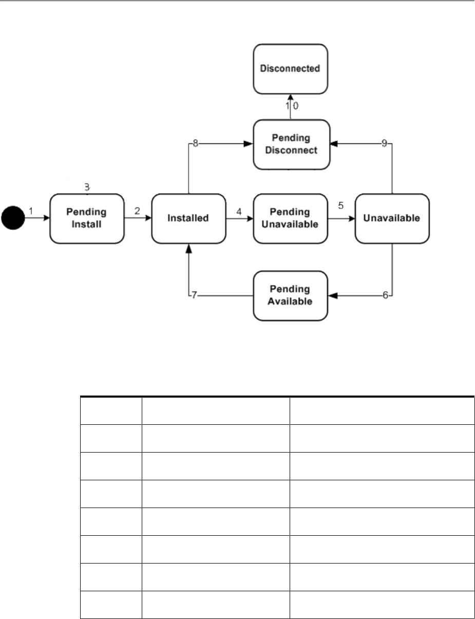
Resource Life Cycles and Statuses
4-6 Oracle Communications Unified Inventory Management Concepts
Figure 4–3 Pipe and Connectivity Inventory Life Cycle in a Business Interaction or Work Order Context
Table 4–5 describes the actions associated with each number in Figure 4–3 and the
resulting status changes.
Table 4–5 Pipe Or Connectivity Status Flow in a Business Interaction or Work Order
Context
Label
Number Description Status
1 Create a pipe or connectivity in a
business interaction.
Pending Install (business interaction
context)
2 Complete business interaction to
create a pipe or connectivity.
Installed (Current)
3 Cancel business interaction to
create a pipe or connectivity.
Pending Install (business interaction
context)
4 Deactivate a pipe or connectivity
in a business interaction.
Pending Unavailable (business interaction
context)
5 Complete business interaction to
deactivate a pipe or connectivity.
Unavailable (Current)
6 Activate a pipe or connectivity in
a business interaction.
Pending Available (business interaction
context)
7 Complete business interaction to
activate a pipe or connectivity.
Installed (Current)

Resource Life Cycles and Statuses
Life Cycles and Statuses 4-7
Table 4–6 provides a definition and business context for each pipe or connectivity
status.
8 Disconnect an installed pipe or
connectivity in a business
interaction.
Pending Disconnect (business interaction
context.
For connectivities and versioned pipes
with design versions in Completed status,
a new version is created by copying the
existing version and setting resource
assignments to Pending Unassign.
If the connectivity or versioned pipe
design version is in In Progress, status,
disconnection is not allowed.
9 Disconnect an unavailable pipe or
connectivity in a business
interaction.
Pending Disconnect (business interaction
context)
For connectivities and versioned pipes
with design versions in Completed status,
a new version is created by copying the
existing version and setting resource
assignments to Pending Unassign.
If the connectivity or versioned pipe
design version is in In Progress, status,
disconnection is not allowed.
10 Complete business interaction to
disconnect a pipe or connectivity.
Disconnected (Current)
Table 4–6 Pipe Or Connectivity Status Definitions for Business Interaction and
Engineering work order Contexts
Inventory Status Definition Business Context
Pending Install The pipe or connectivity is
created in a business interaction
or work order that is not yet
completed.
A pipe or connectivity created in
a business interaction or work
order can be acted on as an
installed pipe or connectivity
while the user is working in that
context. The pipe or connectivity
is not visible outside that context
until the business interaction or
work order is completed.
Installed The pipe or connectivity is
created in a business interaction
or work order that has been
completed.
An installed pipe or connectivity
is available to support services or
other resources.
Table 4–5 (Cont.) Pipe Or Connectivity Status Flow in a Business Interaction or Work
Order Context
Label
Number Description Status

Resource Life Cycles and Statuses
4-8 Oracle Communications Unified Inventory Management Concepts
Resource Assignment Statuses
The resource assignment status indicates the stage in the life cycle of a specific
assignment of a resource to another entity. You can set up resources to be assigned to
multiple entities or set up an entity to allow multiple assignments. The resource
assignment status shown in Figure 4–4, "Resource Assignment Life Cycle" shows the
status for each specific assignment. Summary pages in UIM display only one resource
assignment status even though there can be multiple assignments. If any one of the
resource assignments has the status of assigned, the Summary page will show the
resource as assigned.
The configuration can be any of the following: service, place (geographic site), logical
device, network, pipe, or pipe termination point. The life cycle depicts whether the
resource is consumed by a service, pending consumption by a service, reserved for a
service, pending disconnect, disconnected, and so on. Figure 4–4 shows the resource
assignment statuses that represent the resource assignment life cycle. The status in the
dashed box is not seen in the UIM application.
Pending Unavailable The pipe or connectivity has been
deactivated in a business
interaction or work order that is
not completed.
The pipe or connectivity is
installed and available to support
services or other resources
outside the business interaction
or work order context. In that
context, however, the pipe or
connectivity is deactivated and
not available. When the business
interaction or work order is
completed, the pipe or
connectivity becomes unavailable
in current inventory.
Unavailable The pipe or connectivity has been
deactivated in a business
interaction or work order that has
been completed.
The pipe or connectivity is
deactivated and unavailable to
support services or other
resources.
Pending Disconnect The pipe or connectivity has been
disconnected in a business
interaction or work order that has
not been completed.
The pipe or connectivity
maintains its status in current
inventory; however, in the
business interaction or work
order context, the pipe or
connectivity is not available.
When the business interaction or
work order is completed, the pipe
or connectivity status changes to
Disconnected and the pipe or
connectivity is not available.
Disconnected The resource has been
disconnected in a business
interaction or work order that has
been completed. This status also
applies to a pipe or connectivity
that was created in a business
interaction or work order that
was canceled.
The pipe or connectivity is no
longer visible or available.
Table 4–6 (Cont.) Pipe Or Connectivity Status Definitions for Business Interaction and
Engineering work order Contexts
Inventory Status Definition Business Context
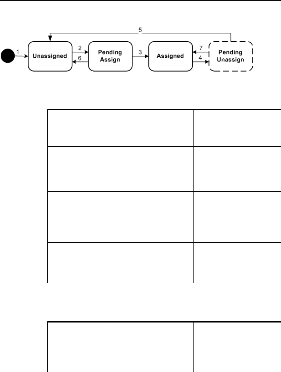
Resource Life Cycles and Statuses
Life Cycles and Statuses 4-9
Figure 4–4 Resource Assignment Life Cycle
Table 4–7 describes the actions associated with each number in Figure 4–4 and the
resulting status changes.
Table 4–8 provides a definition and business context for each resource assignment
status.
Table 4–7 Resource Assignment Status Flow
Label
Number Description Status
1 Create resource Unassigned
2 Assign resource to configuration item. Pending Assign
3 Complete configuration to assign resource. Assigned
4 Unassign resource from a configuration
item.
This status shows as Assigned
when looking at the resource, but
shows Pending Unassign if the
resource is in the context of its
configuration
5 Complete configuration to unassign
resource.
Unassigned
6 Remove a pending assignment for a
resource on an in-progress, designed, or
issued configuration or cancel a
configuration with a pending assigned
resource.
Unassigned
7 Restore resource assignment to pending
unassign. This happens when you remove
the pending unassignment of the resource,
you cancel a pending disconnect
configuration, or you complete a pending
cancel configuration.
Assigned
Table 4–8 Resource Assignment Definitions
Resource
Assignment Status Definition Business Context
Unassigned Resource is not assigned to a
configuration and is available for
assignment.
The resource is installed but not
assigned to a configuration. When
a configuration is assigned, the
resource or entity assignment
status changes to Pending Assign.

Service Life Cycles and Statuses
4-10 Oracle Communications Unified Inventory Management Concepts
Service Life Cycles and Statuses
Service entities are life-cycle managed. As a service transitions through its life-cycle
stages, different service statuses are assigned to the service. The default life cycle and
service transition statuses are delivered with the application; however, you can modify
the wording and extend the life cycles. See UIM Developer’s Guide for more information
on extending service life cycles.
Figure 4–5 shows the default service life cycle and status assigned to a service at each
stage of its life cycle.
Pending Assign Resource is assigned to a
configuration, but the
configuration is not completed.
A resource is assigned to an
entity, but the configuration is not
completed.
When the configuration is
completed, the assignment status
is updated to Assigned. If the
request is canceled, the pending
assignment changes to
Unassigned.
Assigned Resource is assigned to a
configuration and the
configuration is completed.
The assignment status of the
resource that is assigned to a
working configuration. When the
configuration is requested to be
disconnected, the configuration’s
resources have a status of
Pending Unassign.
Pending Unassign Either the resource is assigned to
a service that is in a pending
disconnect status, or the resource
is unassigned from its
configuration and the
configuration is pending
completion.
A service is planned for
disconnection. As a result, all of
its resource assignments are
unassigned from the
configuration.
For telephone numbers, if an
aging period is required, the
status is updated to
Disconnected. If an aging period
is not required, the status is
changed back to Unassigned.
Table 4–8 (Cont.) Resource Assignment Definitions
Resource
Assignment Status Definition Business Context
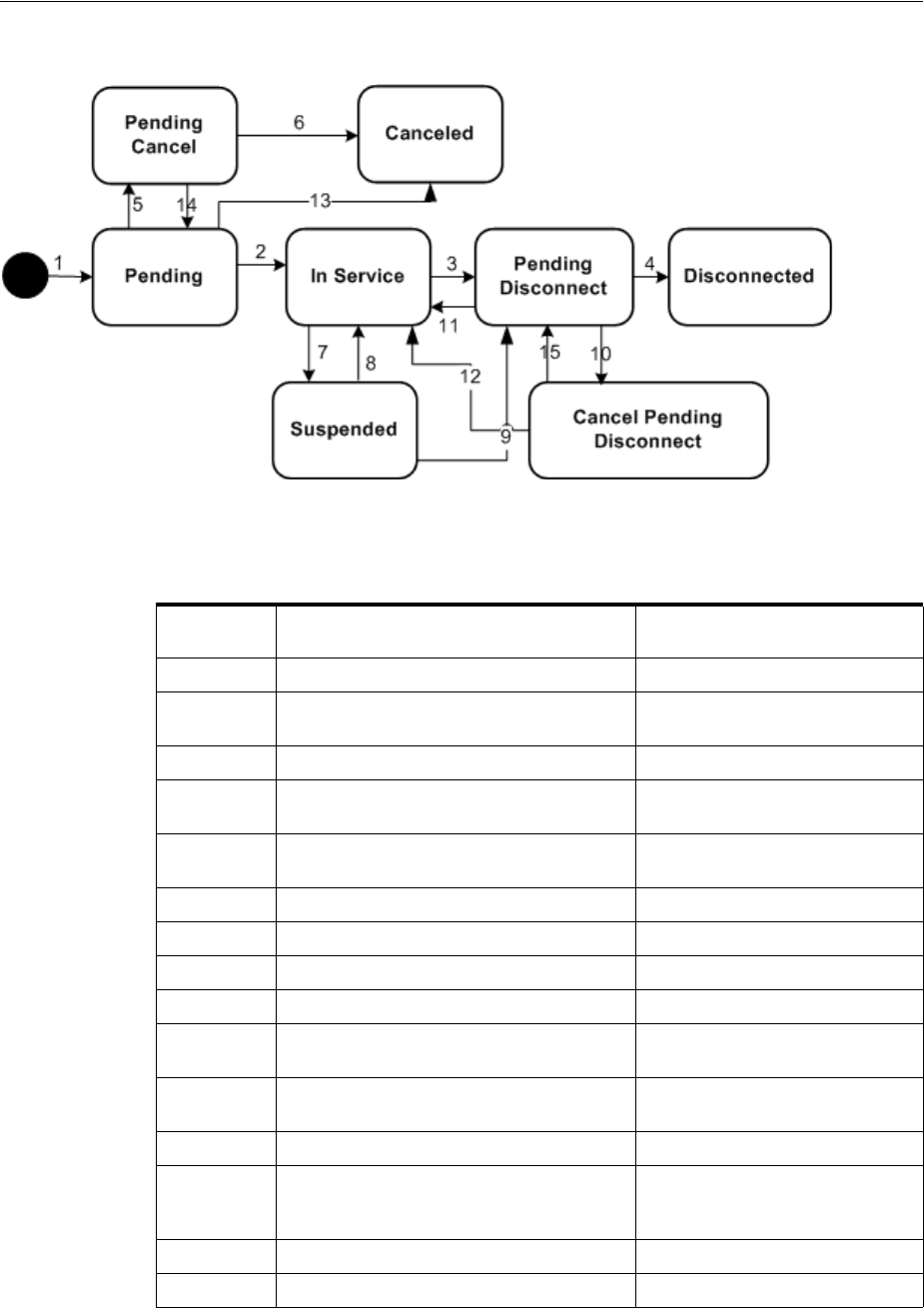
Service Life Cycles and Statuses
Life Cycles and Statuses 4-11
Figure 4–5 Service Life Cycle
Table 4–9 describes the actions associated with each number in Figure 4–5 and the
resulting status changes.
Table 4–10 provides a definition and business context for each service status.
Table 4–9 Service Status Flow
Label
Number Description Status
1 Create service. Pending
2 Complete the first configuration or
complete service with no configuration.
In Service
3 Disconnect service. Pending Disconnect
4 Complete configuration to disconnect
service.
Disconnected
5 Service is canceled after configuration is
issued.
Pending Cancel
6 Complete pending cancel. Canceled
7 Suspend service. Suspended
8 Resume suspended service. In Service
9 Disconnect suspended service. Pending Disconnect
10 Cancel the disconnect of the service when
the configuration has been issued.
Cancel Pending Disconnect
11 Cancel the pending disconnect when the
configuration has not yet been issued.
In Service
12 Complete the cancel pending disconnect. In Service
13 Service is canceled with no configuration
or with one configuration version that has
not yet been issued.
Canceled
14 Cancel a pending cancel service. Pending
15 Cancel the cancel pending disconnect. Pending Disconnect

Service Life Cycles and Statuses
4-12 Oracle Communications Unified Inventory Management Concepts
Table 4–10 Service Status Definitions
Service Status Definition Business Context
Pending The service has been requested
and the design for that service is
being developed.
After the design is completed and
the service is activated, the
service status changes to In
Service.
If service is canceled and there is
no configuration, or the
configuration has not yet been
issued, the status goes to
Canceled.
If service is canceled and
configuration is issued, service
goes to Pending Cancel.
In Service The service has been provisioned
and is in use.
When a request is made to
disconnect the service, the service
status changes to Pending
Disconnect.
If the service is suspended, the
service status is Suspended.
Pending Disconnect A request was made to disconnect
the service.
After the request to disconnect
the service is completed, the
status changes to Disconnected.
If the request to disconnect the
service is canceled and the
configuration has not been issued,
the service status changes to In
Service.
If the request to disconnect the
service is canceled and the
configuration has been issued, the
status changes to Cancel Pending
Disconnect.
Disconnected A service that was functional is
now disconnected.
When a service has this status, a
new service must be created to
re-establish the service.
Suspended A service has been suspended,
but all resource assignments are
still active.
A service that is temporarily
nonfunctional has a status of
Suspended. The resource
assignments are still maintained
with a resource assignment status
of Assigned.
The status will change to one of
these statuses depending on the
action taken:
■Pending Disconnect: If the
service must be
disconnected.
■In Service: If the suspension
was resolved.
Pending Cancel A request has been made to
cancel a service.
When the request to cancel the
service is completed, the status is
changed to Canceled and that
service cannot be revived without
a new service order.
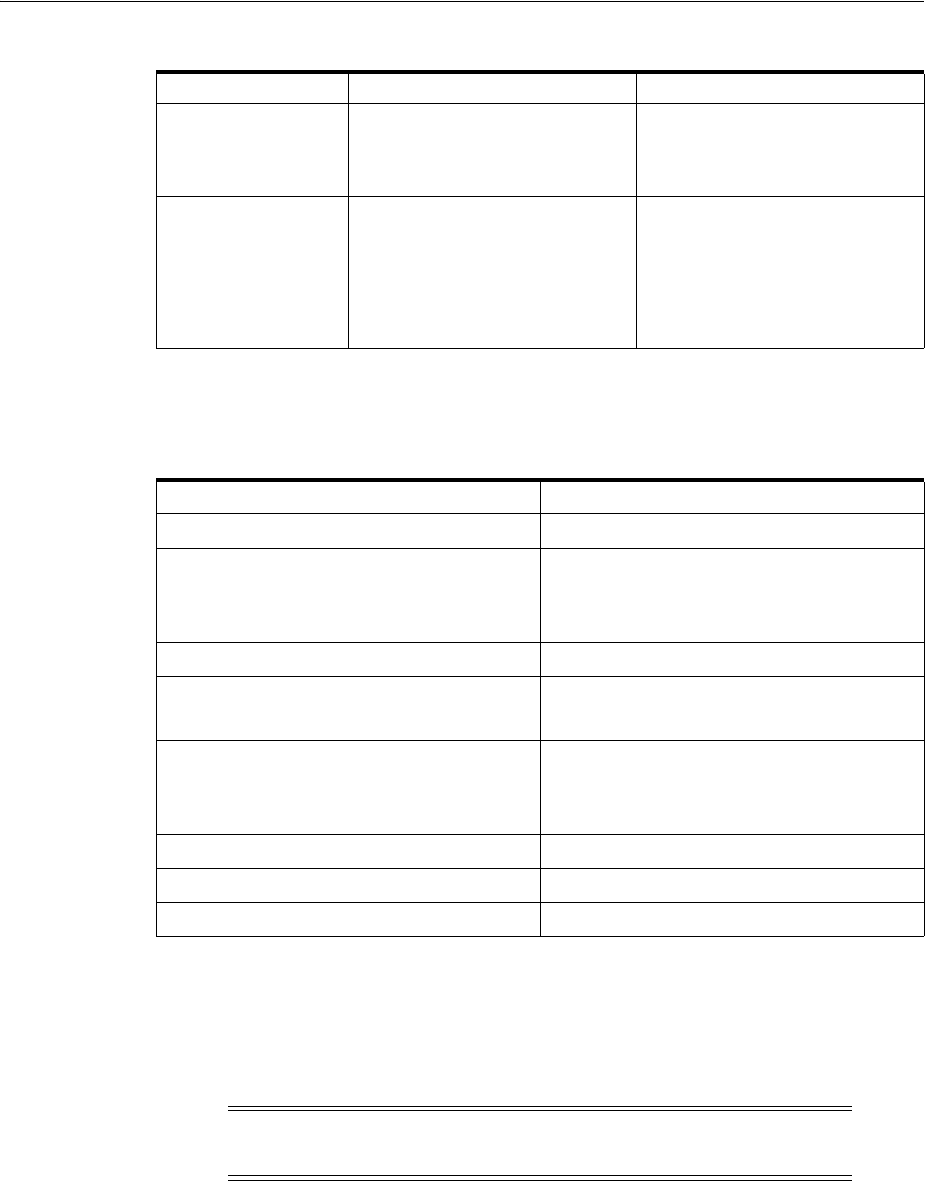
Configuration Life Cycles and Statuses
Life Cycles and Statuses 4-13
Table 4–11 shows valid combinations of statuses that occur for services and their
assigned resources.
Configuration Life Cycles and Statuses
Figure 4–6 shows the configuration statuses used for services, logical devices, logical
device accounts, pipes, places, and networks. Figure 4–6 also shows the design status
assigned to each configuration at each stage of its life cycle.
Canceled A request for a service is canceled
and there is no configuration or
the configuration has not yet been
issued.
When a request for a new service
is canceled, a new service must be
requested to re-establish the
service.
Cancel Pending
Disconnect
A disconnect of a service is
canceled and the configuration
has been issued.
When a cancel pending
disconnect request is completed,
the service goes to In Service.
When a cancel pending
disconnect request is canceled,
the service goes to Pending
Disconnect.
Table 4–11 Service and Resource Assignment Status Combinations
Service Status Resource Assignment Statuses
Pending Pending Assign
In Service Pending Assign
Assigned
Pending Unassign
Pending Disconnect Pending Unassign
Disconnected Disconnected
Unassigned
Suspended Assigned
Pending Unassign
Pending Assign
Canceled To p re v ious stat us
Pending Cancel Pending Assign
Cancel Pending Disconnect Pending Unassign
Note: Connectivity entities do not have configurations, but they
have design versions that follow the same life cycle.
Table 4–10 (Cont.) Service Status Definitions
Service Status Definition Business Context
Configuration Life Cycles and Statuses
4-14 Oracle Communications Unified Inventory Management Concepts
Figure 4–6 Configuration Life Cycle
Table 4–12 describes the actions associated with each number in Figure 4–6 and the
resulting status changes.
Table 4–13 presents a definition and business context for each configuration status.
Table 4–12 Configuration Status Flow
Label
Number Description Status
1 Create configuration. In Progress
2 Approve configuration. Designed
3 Issue configuration. Issued
4 Complete configuration. Completed
5 Cancel issued configuration. Pending Cancel
6 Cancel designed configuration. Canceled
7 Cancel in progress configuration Canceled
8 Complete a pending cancel configuration. Canceled
9 Cancel a pending cancel configuration. Issued
Table 4–13 Configuration Status Definitions
Configuration
Status Definition Business Context
In Progress The configuration for the
requested service has been
started.
This is set automatically when the
configuration is created. The
configuration status changes to
Designed when the service
configuration has been fully
developed. The configuration
status is set to Canceled when an
order that initiated the
configuration is canceled.
Designed The configuration has been fully
developed and is complete.
Transitions from the In Progress
status when the design has been
approved for the configuration.
The configuration status changes
to Issued when sent to the field or
upon activation. The status
changes to Canceled when the
order that initiated the design is
canceled.

Configuration Life Cycles and Statuses
Life Cycles and Statuses 4-15
Table 4–14 lists the combinations of statuses that are possible for services and their
associated service configurations.
Issued The configuration for the
requested service has been sent to
the field for the physical work
and the network element work to
be done.
After the configuration is sent to
the field and the work is
completed, the configuration
status changes to Completed.
If the issued configuration is
incorrect or the service is
canceled, the status changes to
Pending Canceled to allow for
reversal of field work.
Completed The configuration for the
requested service has been
implemented.
After the configuration has been
implemented, the configuration
status changes to Completed and
the service transitions from
Pending to In Service when the
first version is completed.
Completed is an ending state for
the service configuration status
life cycle.
Pending Cancel A request for the service is
canceled after the configuration is
issued or a request to cancel a
configuration is made after the
configuration has been issued.
If a Pending Cancel for a service
configuration is canceled, the
configuration status goes back to
Issued.
If a Pending Cancel for a service
configuration is completed, the
configuration status goes to
Canceled.
Canceled A request for the service or the
service configuration has been
canceled and any field work that
needed to be reversed is
completed.
After the configuration and field
work for a canceled configuration
has been completed, the service
configuration status for that
service changes to Canceled.
Canceled is an ending state for
the service configuration status
life cycle.
Table 4–14 Service and Configuration Status Combinations
Service Status Configuration Statuses
Pending In Progress
Designed
Issued
In Service In Progress
Designed
Issued
Completed
Pending Cancel
Canceled
Pending Cancel Pending Cancel
Table 4–13 (Cont.) Configuration Status Definitions
Configuration
Status Definition Business Context
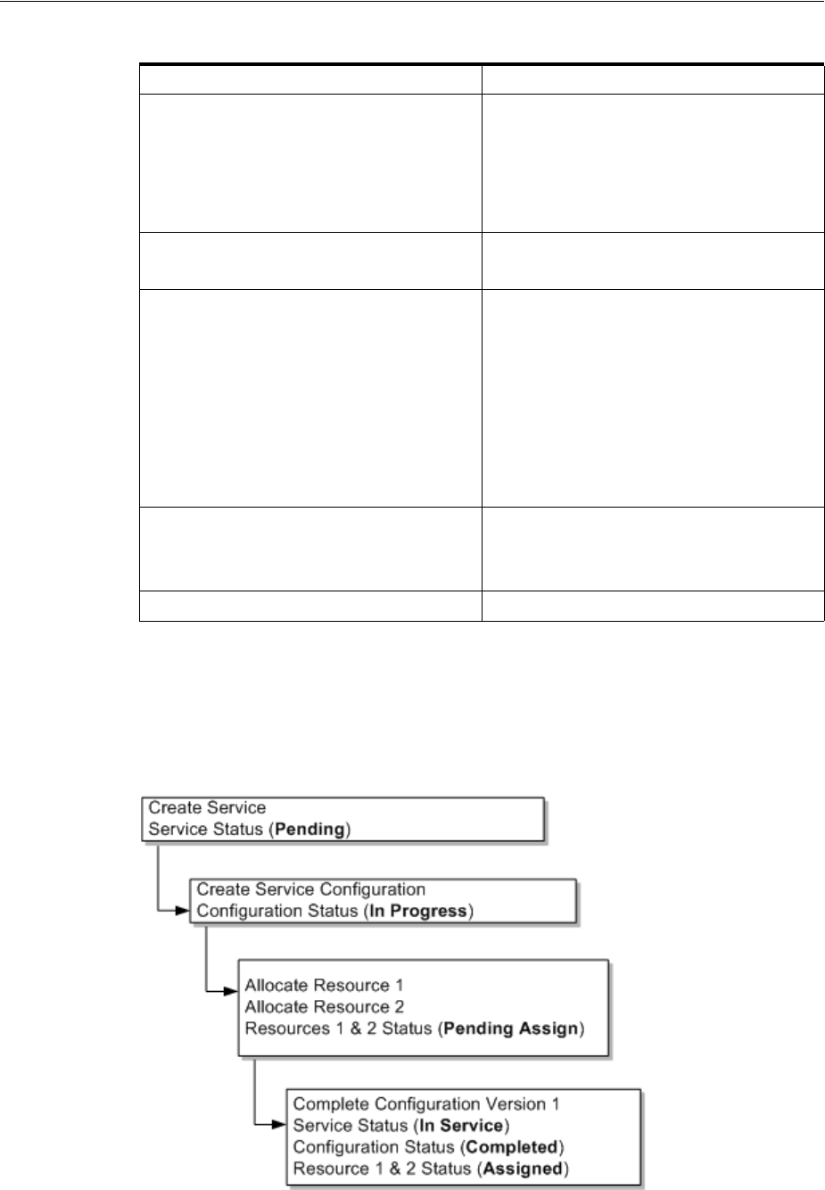
Status Examples
4-16 Oracle Communications Unified Inventory Management Concepts
Status Examples
Figure 4–7 shows the resource assignment statuses as a service is created and goes
through its life cycle.
Figure 4–7 Creating Service and Resource Assignments
Pending Disconnect In Progress
Designed
Issued
Completed
Canceled
Disconnected Completed
Canceled
Suspended In Progress (change requests only that were
performed before suspend)
Designed (change requests only that were
performed before suspend)
Issued
Completed
Pending Cancel (change requests only that
were performed before suspend)
Canceled
Cancel Pending Disconnect Pending Cancel
Canceled
Completed
Canceled Canceled
Table 4–14 (Cont.) Service and Configuration Status Combinations
Service Status Configuration Statuses
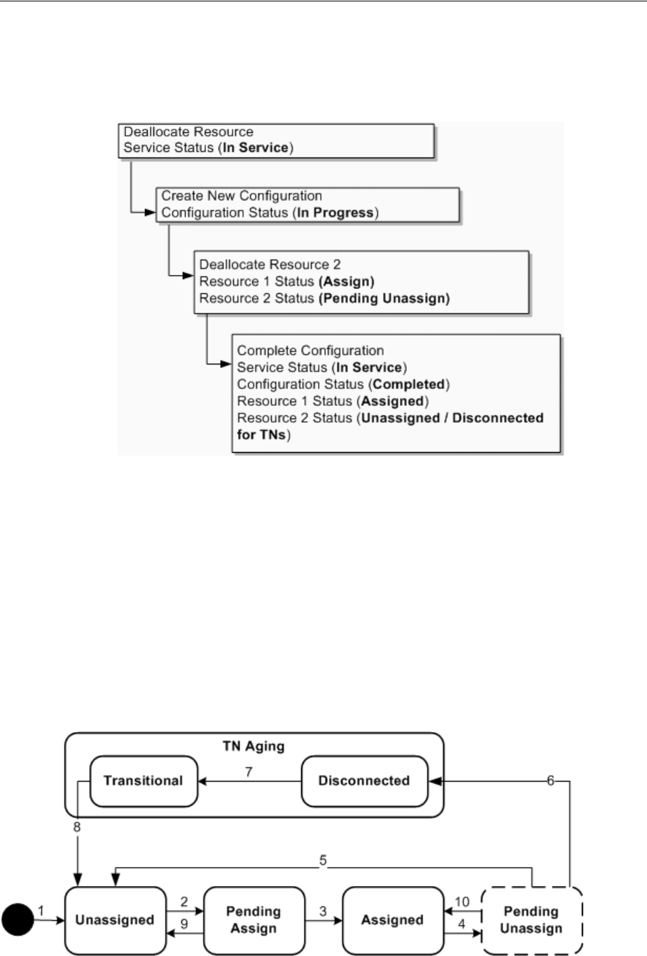
Telephone Number Life Cycle and Statuses
Life Cycles and Statuses 4-17
Figure 4–8 shows the resource assignment statuses as a resource is unassigned from a
service.
Figure 4–8 Unassigning a Resource
Telephone Number Life Cycle and Statuses
Telephone numbers have a default assignment life cycle that is similar to that of other
resources, with the addition of an aging process and two statuses. This life cycle,
including the aging process applies to telephone numbers that are not ported in or out.
UIM uses the TN Type characteristic to identify numbers as ported in or out.
Telephone numbers without a TN Type and those assigned the Owned or Toll Free TN
Type follow the default life cycle. Telephone numbers with the Ported In or Ported Out
TN Type follow the modified life cycle described in "Modified Life Cycle for Ported In
and Ported Out Telephone Numbers".
Figure 4–9 illustrates the default telephone number assignment life cycle.
Figure 4–9 Telephone Number Assignment Life Cycle

Telephone Number Life Cycle and Statuses
4-18 Oracle Communications Unified Inventory Management Concepts
Table 4–15 describes the actions associated with each number in Figure 4–9 and the
resulting status changes.
Table 4–16 lists the telephone assignment statuses. Telephone numbers have the same
inventory status as other resources shown in Table 4–2.
Table 4–15 Telephone Number Assignment Status Flow
Label
Number Description Status
1 Create telephone number Unassigned
2 Assign telephone number to configuration
item.
Pending Assign
3 Complete configuration to assign
telephone number.
Assigned
4 Unassign telephone number from a
configuration item.
This status shows as Assigned
when looking at the resource, but
shows Pending Unassign if the
resource is in the context of its
configuration
5 Complete configuration to unassign
telephone number.
Unassigned
6 Complete configuration to unassign
telephone number.
Disconnected
7 Pass intercept period for a telephone
number.
Transitional
8 Pass transition period for a telephone
number.
Unassigned
9 Remove a pending assignment for a
telephone number on an in-progress,
designed, or issued configuration or cancel
a configuration with a pending assigned
resource.
Unassigned
10 Restore telephone number assignment to
Pending Unassign. This happens when
you remove the pending unassignment of
the resource, you cancel a pending
disconnect configuration, or you complete
a pending cancel configuration.
Assigned
Table 4–16 Telephone Number Assignment Statuses
Assignment Status Definition Business Context
Unassigned The telephone number is
available.
TN recall processing,
readiness, and maintenance
Pending Assign The telephone number is
assigned to a configuration
that has not been completed.
TN assignment
Assigned The telephone number is
assigned to a completed
configuration.
Configuration version and
configuration
Pending Unassign The telephone number has
been unassigned from a
configuration that has not
been completed.
TN assignment
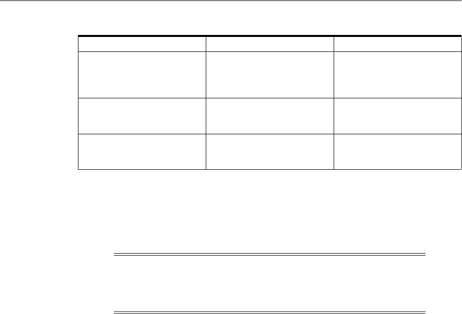
Business Interaction and Engineering Work Order Life Cycles and Statuses
Life Cycles and Statuses 4-19
Modified Life Cycle for Ported In and Ported Out Telephone Numbers
The assignment life cycle is modified somewhat for telephone number that are ported
in or ported out. These numbers are identified by the Ported In or Ported Out TN
Type.
Ported out numbers have their assignment status set to Ported and their inventory
status set to Unavailable.
There are two ways a ported out telephone number can return to the control of the
original service provider:
■A snapback occurs when the customer gives up the number and it returns via the
regulatory process defined for its geography.
■A winback occurs when the customer and the telephone number return to the
original service provider.
The UIM life cycle is the same for both snapbacks and winbacks: UIM changes the TN
Type back to Owned, the assignment status to Unassigned and the inventory status to
Installed. Although the life cycles are the same, UIM includes an optional
characteristic that identifies numbers as winbacks. Some service providers prefer to
track winbacks separately.
For ported-in telephone numbers UIM sets the assignment status to Unassigned and
the inventory status to Unavailable.
Business Interaction and Engineering Work Order Life Cycles and
Statuses
Business interactions and engineering work orders allow you to plan resource changes
that you want to put in service at a later date.
Figure 4–10 shows the life cycle for business interactions and engineering work orders.
See Figure 4–2, "Resource Inventory Life Cycle in a Business Interaction or Work Order
Context" to view the resource life cycles in context of a business interaction.
Disconnected The telephone number has
been unassigned from a
configuration and is being
aged.
Configuration version and
configuration
Transitional The telephone number has
been disconnected and cannot
be reassigned for a period.
TN recall processing
Ported The telephone number has
been ported out to another
provider.
Not applicable
Note: The number portability features described in this section are
available only if the Base Phone Management cartridge is installed.
See "Telephone Number Portability" and UIM Cartridge Guide for more
information.
Table 4–16 (Cont.) Telephone Number Assignment Statuses
Assignment Status Definition Business Context
Business Interaction and Engineering Work Order Life Cycles and Statuses
4-20 Oracle Communications Unified Inventory Management Concepts
Figure 4–10 Business Interaction Life Cycle
Table 4–17 describes the actions associated with each number in Figure 4–10 and the
resulting changes.
Table 4–18 presents a definition and business context for each business interaction or
work order status.
Table 4–17 Business Interaction and Engineering Work order Status Flow
Label
Number Description Status
1 Create business interaction or work order. Created
2 Add items. In Progress
3 Complete business interaction or work
order.
Completed
4 Cancel in progress business interaction or
work order.
Canceled
5 Complete the created business interaction
or work order.
Completed
6 Cancel the created business interaction or
work order.
Canceled
7 Transfer items from one business
interaction or work order to another
business interaction or work order.
In Progress
Table 4–18 Business Interaction and Engineering Work order Status Definitions
Business Interaction Status Definition Business Context
Created The business interaction or
work order is created for a
new project.
A business interaction or
work order is created, but no
work has been started. A
business interaction or work
order can be completed or
canceled from this status.

Project and Activity Life Cycles and Statuses
Life Cycles and Statuses 4-21
Table 4–19 lists valid combinations of business interaction/work order and resource
inventory statuses.
Project and Activity Life Cycles and Statuses
Project entities and the activities that they include have life cycles different from other
UIM entities.
In Progress Work has begun on the
business interaction or work
order.
The business interaction or
work order transitions from
Created when the user adds
items or when a user transfers
items from another business
interaction or work order.
From this status, a user can
complete the business
interaction or work order or
choose to cancel it.
Canceled The user cancels the business
interaction or work order.
A business interaction or
work order can be canceled
when it is in Created or In
Progress status.
Completed Work on all items is complete
and the work can now be
viewed in current inventory.
After work on all the business
interaction or work order
items is finished, the resulting
changes become visible when
you complete the business
interaction or work order.
Table 4–19 Business Interaction Statuses and Resource Inventory Status Combinations
Business Interaction or Work Order Status Resource Inventory Statuses
Created Not applicable because adding items to the
business interaction or work order changes
the status to In Progress.
In Progress Pending Install
Pending Remove
Pending Unavailable
Completed End of Life
Installed
Unavailable
Canceled Installed
Unavailable
The resource assignments revert back to the
previous state when the business interaction
or work order is canceled.
Table 4–18 (Cont.) Business Interaction and Engineering Work order Status Definitions
Business Interaction Status Definition Business Context
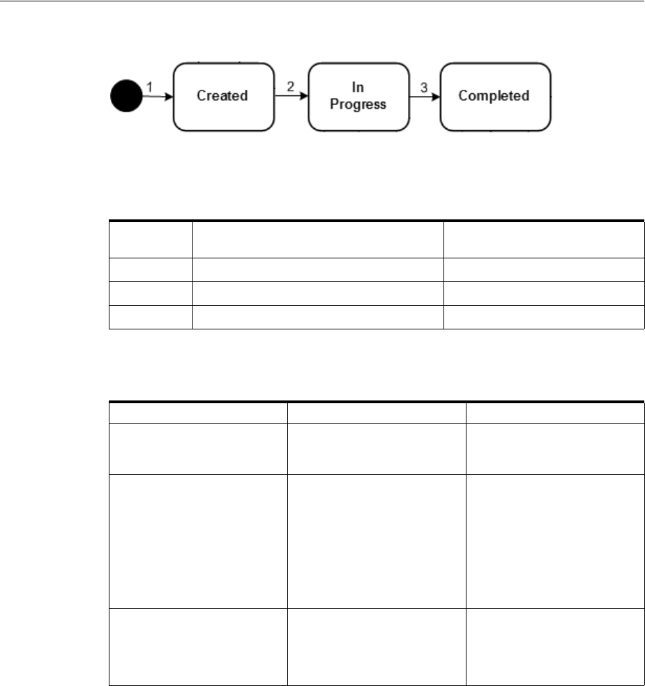
Project and Activity Life Cycles and Statuses
4-22 Oracle Communications Unified Inventory Management Concepts
Figure 4–11 Project Inventory Life Cycle
Table 4–20 describes the actions associated with each number in Figure 4–11 and the
resulting changes.
Table 4–21 presents a definition and business context for each project status.
Activity Life Cycle and Status
Activities are groups of operations that you configure and manage as part of projects.
They have life cycles and statuses independent of the projects to which they belong.
Table 4–20 Project Status Flow
Label
Number Description Status
1 Create project. Created
2 Add activities. In Progress
3 Manually complete project Completed
Table 4–21 Project Status Definitions
Project Status Definition Business Context
Created A new project has been
created.
A project has been created,
but no activities have been
submitted.
In Progress UIM has begun processing
activities in the project.
The projects transitions
automatically to In Progress
from Created the first time an
activity is submitted. The
project does not transition to
In Progress when an activity
is added to it. The project
remains in In Progress status
until it is completed.
Completed All activities in the project are
completed or canceled and
the user has completed the
project.
The transition to Completed
status is a manual action that
is possible only when all
activities in the project are
completed or canceled.
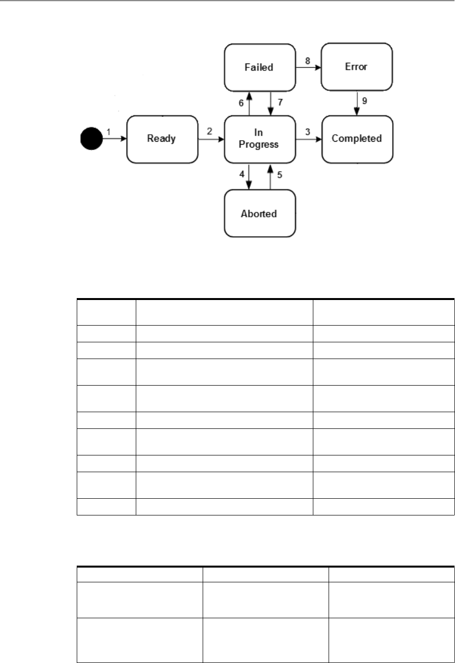
Project and Activity Life Cycles and Statuses
Life Cycles and Statuses 4-23
Figure 4–12 Activity Life Cycle
Table 4–22 describes the actions associated with each number in Figure 4–12 and the
resulting changes.
Table 4–23 presents a definition and business context for each activity status.
Table 4–22 Activity Status Flow
Label
Number Description Status
1 Add activity to project. Ready
2 Submit the activity for processing. In Progress
3 All items in the activity are submitted and
processed successfully.
Completed
4 An in-progress activity is canceled prior to
completion.
Aborted
5 A canceled activity is resubmitted. In Progress
6 One or more items in an activity fails
during processing.
Failed
7 A failed activity is resubmitted. In Progress
8 Rollback of items in a failed activity does
not succeed.
Error
9 The activity is completed. Completed
Table 4–23 Activity Status Definitions
Activity Status Definition Business Context
Ready A new activity has been
added to a project.
An activity has been added to
a project, but has not been
submitted for processing.
In Progress The activity has been
submitted to UIM for
processing.
The activity transitions
automatically to In Progress
status when you submit it for
processing.
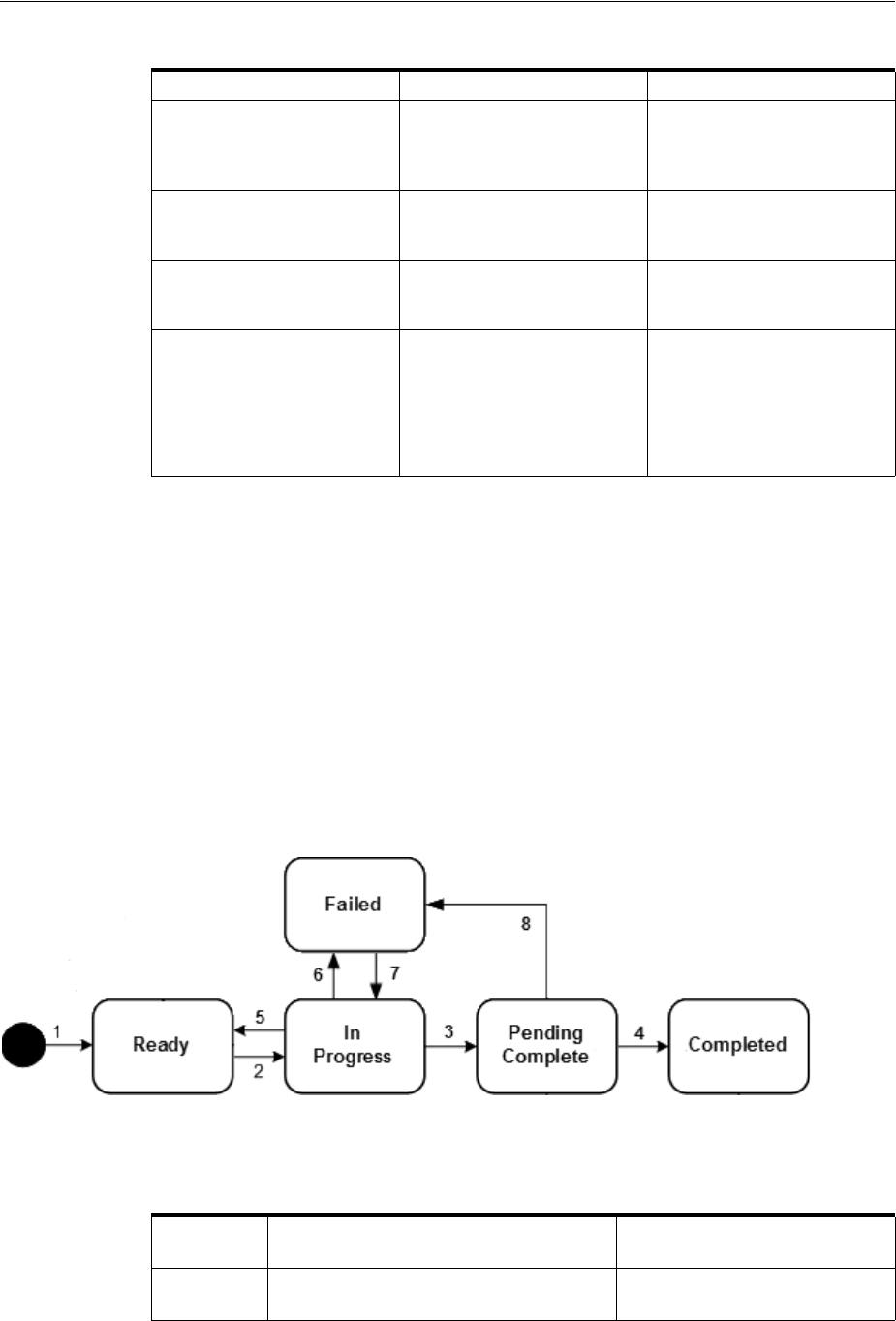
Project and Activity Life Cycles and Statuses
4-24 Oracle Communications Unified Inventory Management Concepts
Activity Item Life Cycle and Statuses
Activity items are individual tasks that must be done to complete an activity. There are
two types of activity items:
■Change items identify entities to be added, changed, or removed when the activity
is processed.
■Impact items identify entities that are added, changed, or removed as a result of
completing change items. Impact items are the indirect results of activities.
Change Item Life Cycle and Statuses
Figure 4–13 illustrates the status flow of change items.
Figure 4–13 Change Item Status Flow
Table 4–24 describes the actions associated with each number in Figure 4–13 and the
resulting changes.
Completed All items in the activity have
been processed successfully.
The activity transitions
automatically to Completed
status when all items have
been completed successfully.
Aborted The activity has been
canceled before completion.
Canceled activities can be
resubmitted as-is or after
modification.
Failed One or more items has failed
to complete successfully.
Failed activities can be
resubmitted as-is or after
modification.
Error One or more transactions
could not be rolled back
when the activity failed. This
can occur when entities are
changed after the activity is
configured but before it is
processed.
It may be necessary to
complete manual actions to
resolve issues caused by the
error.
Table 4–24 Change Item Status Flow
Label
Number Description Status
1 The change item is added as part of
activity configuration.
Ready
Table 4–23 (Cont.) Activity Status Definitions
Activity Status Definition Business Context

Project and Activity Life Cycles and Statuses
Life Cycles and Statuses 4-25
Table 4–25 presents a definition and business context for each change item status.
About Impact Items
Impact items are created as an indirect result of change items. They have a separate life
cycle. Figure 4–14 illustrates the status flow of impact items.
2 UIM submits the change item for
processing.
In Progress
3 The change item has been processed
without any errors
Pending Complete
4 After all change items in the activity are
processed successfully, UIM completes
them.
Complete
5 The parent activity is canceled prior to
completion.
Ready
6 The change item fails during processing
(The parent activity fails as a result.)
Failed
7 The failed parent activity is resubmitted. In Progress
8 The parent activity fails before all change
items are completed.
Failed
Table 4–25 Change Item Status Definitions
Change Item Status Definition Business Context
Ready A new activity has been
added to a project.
An activity has been added to
a project, but has not been
submitted for processing.
In Progress The change item has been
submitted to UIM for
processing.
The change item transitions
automatically to In Progress
status when UIM begins to
process it.
Pending Complete The change item has been
processed but other change
items are still being
processed.
The change item transitions
to this status automatically
after processing.
Completed This change item and other
items in the activity have
been processed successfully.
The change item transitions
automatically to this status
when all items in the activity
have been processed
successfully.
Failed The change item has failed to
complete successfully.
Change items transition to
this status automatically
when they failed to be
processed successfully.
Table 4–24 (Cont.) Change Item Status Flow
Label
Number Description Status
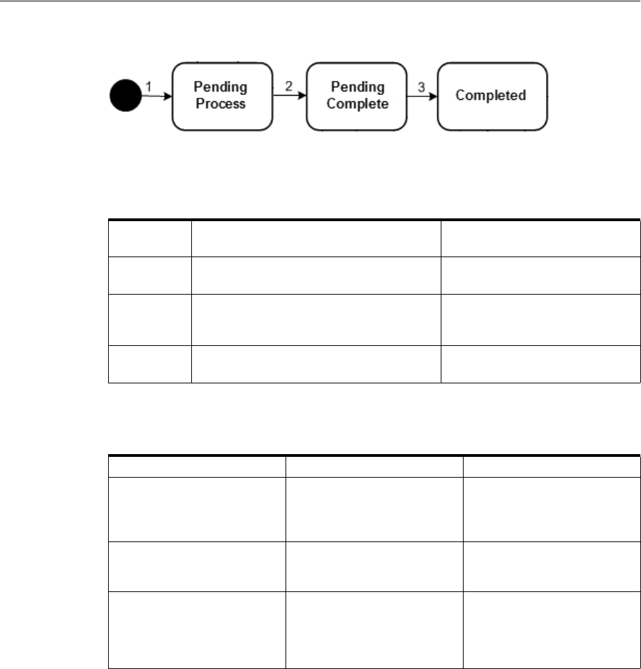
Project and Activity Life Cycles and Statuses
4-26 Oracle Communications Unified Inventory Management Concepts
Figure 4–14 Impact Item Status Flow
Table 4–26 describes the actions associated with each number in Figure 4–14 and the
resulting changes.
Table 4–27 presents a definition and business context for each impact item status.
Table 4–26 Impact Item Status Flow
Label
Number Description Status
1 The impact item is created by UIM during
the processing of an activity.
Pending Process
2 The impact item has been processed
successfully, but other items in the activity
are still being processed.
Pending Complete
3 The impact item and other items in the
activity have been processed successfully.
Completed
Table 4–27 Impact Item Status Definitions
Impact Item Status Definition Business Context
Pending Process The impact item has been
created but not yet processed.
UIM creates impact items in
this status when required
during the processing of an
activity.
Pending Complete The impact item has been
processed successfully.
The impact item transitions
automatically to this status
after it has been processed.
Completed All activities in the project are
completed or canceled and
the user has completed the
project.
The impact item transitions
automatically to this status
when all items in the activity
have been processed
successfully.

5
Core Functionality 5-1
5
Core Functionality
This chapter describes Oracle Communications Design Studio and Oracle
Communications Unified Inventory Management (UIM) core functionality. This
functionality supplies the infrastructure that you use to manage your inventory.
Much of the core functionality is provided by the UIM common patterns and the
entities that enable them. Search functionality is provided by the application
framework. See "Core Platform" for more information.
This chapter includes information about the following functionality:
■Searching
■Configurations
■Capacity
■Consumption
■Involvements
■Topology
■Entity Identification
Lifecycle management is also provided by the core platform, but is covered in a
separate chapter. See "Life Cycles and Statuses" for more information.
Searching
UIM provides a search framework that enables you to find entities based on a wide
variety of criteria that depend on the entity type. You can combine criteria for an even
more specific search. For example, you could search for all Equipment entities that are
based on a particular specification and are in the Pending Install inventory status.
By default, you can search for the data elements that are common to all entities of the
same type. You can also add additional search criteria corresponding to the
characteristics that have been defined in specifications of the same type. By adding
additional fields to the search criteria, you can also search for entities based on
characteristics that have been defined in specifications of a particular entity type.
For example, if one Place specification includes a characteristic called Elevation and
another includes a characteristic called Sales Area, you can include one or both of
those characteristics in a search for Place entities.
For some entity types, you can search by relationships. For example, you can search
for equipment based on relationships to physical devices, logical devices, and places.
You can search for pipes based on relationships to terminating points, networks, and
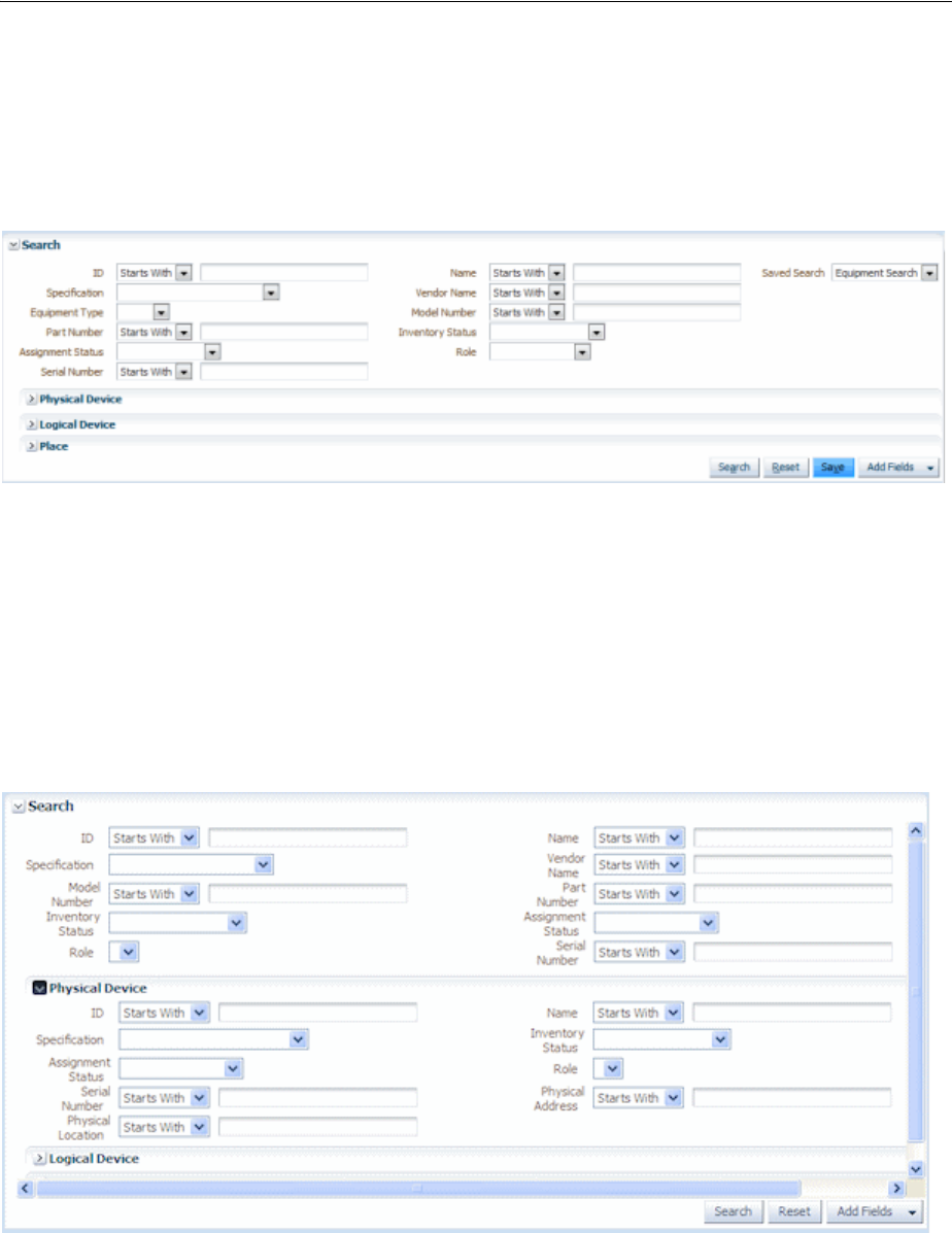
Searching
5-2 Oracle Communications Unified Inventory Management Concepts
logical devices. You can also search for inventory groups based on relationships to
places.
Figure 5–1 shows the Search page for Equipment entities, which enables you to search
on standard equipment data elements.
Figure 5–1 Equipment Search Page
You can save search criteria that you use frequently. For example, if you often search
for Equipment entities of a particular model number and vendor, you can save those
criteria for reuse. You can designate a saved search as the default search for an entity
type. The default search criteria appear automatically when you open the Search page
for that entity type.
You can also expand the Search section to search for equipment based on associations
to a physical device, logical device, or place. Figure 5–2 shows the Physical Device
section expanded.
Figure 5–2 Expanded Entity Search
When the results of a search are displayed, you can select entities and perform actions
on them. The actions you can take depend on entity type. For an Equipment search, for
example, you can apply reservations and conditions from the Search Results section.
Figure 5–3 shows results from a search for Equipment entities.

Configurations
Core Functionality 5-3
Figure 5–3 Search Results Section
See the UIM Help for more information about searching for entities in the UIM Web
interface.
Searching by Using Web Services
You can include searches when you interact with UIM by using Web services. A
custom Web service operations can include calls to the search methods provided by
the Finder class. See UIM Web Services Developer’s Guide for information about creating
and deploying custom Web services.
Configurations
Some entity types can optionally be associated with configurations. A configuration is
a versionable collection of facts about an entity, such as the design details of a service
or the hardware resources associated with a logical device.
For entities that have configurations, basic information that is likely to stay the same
over time, such as the name and description, are stored as part of the entity itself.
Information that can change over time, such as the specific hardware that makes up a
logical device or the resources required to fulfill a service, are stored in the entity
configuration. For example, a customer might maintain a DSL service for a long
period, but the router used for that service could change over time, as could the phone
numbers and associated email accounts.
Configurations can be versioned, enabling you to maintain a history of how the entity
has evolved over time. You can access previous versions in read-only form.
The following entity types can have configurations:
■Flow interfaces
■Logical devices
■Logical device accounts
■Logical device accounts
■Networks
■Pipes
■Places (sites)
■Services
Connectivity entities do not have configurations, but they do have design versions,
which are similar. See "About Design Versions" for more information.
Configurations include configuration items, which you use the specify the details of
the configuration. For example, you use configuration items to specify the resources
that enable a service. You can associate resources to configuration items in two ways:

Configurations
5-4 Oracle Communications Unified Inventory Management Concepts
■Assignment. When you assign a resource to a configuration item, that resource is
consumed. For example, in a consumer VoIP service, you can assign a handset to
the service configuration. In most cases, the resource can be consumed only once,
so allocation places it in Assigned state. See "Consumption" for more information
about consumption.
■Reference. When you reference an entity from a configuration, you indicate that
the configuration has an interest or dependency in the entity but does not
consume it. For example, a cable subscription service requires a cable controller
but does not consume it. In this case, a configuration item would reference the
controller rather than allocating it. See "Understanding Entity References" for more
information about entity references.
Configuration items can also include characteristics that enable you to capture specific
details. To organize configuration items and put them in context, you can arrange
them in a hierarchy.
As the configuration of an entity changes, you create successive configuration versions
that describe its composition at various times. Only one version can be in service at a
time.
Understanding Configuration Specifications
Like other entities, configurations are defined by specifications. You define
configuration specifications and relate them to entity specifications in Design Studio.
Each configuration-enabled entity type has a corresponding configuration type. For
example, you can associate a Logical Device Configuration specification only to a
Logical Device specification.
You can associate a configuration specification with multiple entity specifications of
the same type. You can also associate a single entity specification with multiple
configuration specifications. For example, you can associate multiple Logical Device
specifications with a single Logical Device Configuration specification and you can
associate a single Logical Device specification with multiple Logical Device
Configuration specifications.
When you define a configuration specification, you define its configuration items. The
specification defines how configuration items are organized, whether they are
required, the minimum and maximum number of resources that can be assigned or
referenced in the item, and any characteristics associated with them. See the Design
Studio Help for more information about defining configuration items.
Configuration Example
Figure 5–4 illustrates the relationships among entity specifications, configuration
specifications, entities, and configuration versions. A Service specification for a
telephony service is associated to a Service Configuration specification. The service
itself stores only the subscriber name and the configuration stores the telephone
number, service location, carrier, and so on.
When an Service entity based on the entity specification is created in UIM, successive
configuration versions based on the configuration specification store the relevant
information as it changes over time.
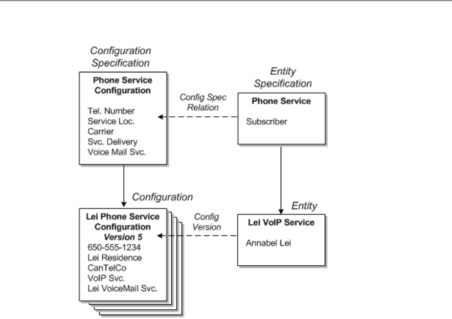
Capacity
Core Functionality 5-5
Figure 5–4 Specifications, Entities, and Configurations
Maintaining Configurations in UIM
When an entity in UIM is associated with a configuration specification, you can create
configuration versions for that entity. The configuration versions are based on the
configuration specification associated with the entity specification. (If an entity
specification is associated with multiple configuration specifications, you select which
configuration specification to use.)
Configuration versions have a life cycle so that you can develop a new configuration
version while a previous one is still valid. See "Configuration Life Cycles and Statuses"
for more information. When you create a new configuration version, the values of the
old one are copied. You modify and add to these values as necessary. When you
complete a configuration version, it becomes active, replacing the previous one.
For example, if you are replacing the handset in a VoIP service, you create a new
configuration version that includes the new device. When the handset is activated, the
new configuration version is complete, replacing the previous version.
Capacity
In UIM, capacity refers to the amount and type of something that entities require or
provide. UIM provides a capacity framework that enables you to define, measure, and
track the usage of capacity.
UIM pipe and signal termination points entities use the capacity framework to manage
bandwidth. Bandwidth specifies the speed and amount of data that can be transferred
from one place to another. See "Pipes" for more information about bandwidth.
You use measurement types, units of measure, and capacity types to define capacity
and how it is measured. See "Defining and Measuring Capacity" for more information.

Capacity
5-6 Oracle Communications Unified Inventory Management Concepts
You associate Capacity Provided and Capacity Required specifications with other
entity specifications to define how they use capacity. See "Configuring Capacity" for
more information.
Table 5–1 list the entities that work together to manage capacity in your network,
along with examples of how they are used for bandwidth.
An additional type of capacity-related entity, the signal termination point, is available
for use with pipes. Signal termination points enable you to define channelized signal
structures that help define capacity for TDM (time-duplex multiplexing) connectivity.
See "Configuring Pipe Capacity" for more information.
Defining and Measuring Capacity
You define capacity by designing measurement types, units of measure, and capacity
types in Design Studio. These artifacts reference each other to form a capacity
definition that you can use with other entities.
The Base Measurements cartridge includes predefined artifacts related to bandwidth.
The cartridge includes a bit rate measurement type, a set of related units of measure
including bps, kbps, Mbps, Gbps, and a bandwidth capacity type. Along with other
base cartridges, the Base Measurements cartridge is delivered in the core UIM
package. You can find it in the following location when UIM is installed:
UIM_Home/cartridges/base/
See UIM Cartridge Guide for more information.
Configuring Measurement Type
Measurement types classify related groups of units of measure. For example, the
measurement type bit rate classifies units of measure such as bits per second (bps),
kilobits per second (kbps), and so on. See the Design Studio Help for detailed
instructions about creating measurement types.
Table 5–1 Capacity Entities and Specification
Entity Definition Bandwidth Example
Measurement Type Classifies how capacity is
measured
Bit rate
Unit of Measure Quantifies how capacity is
measured
Bits per Second (bps), Kilobits per
Second (kbps), Megabits Per
Second (Mbps), Gigabits per
Second (Gbps)
Capacity Type Defines the kind of capacity that
an entity provides or consumes
Bandwidth
Capacity Provided Defines the capacity an entity
offers in terms of a total amount
and a consumable percentage.
The percentage must equal 100%
for channelized pipes but can be
less than or greater than 100% for
packet-switched pipes.
44.736 Mbps at 100%
44.736 Mbps at 200%
Capacity Required Defines the capacity an entity
consumes in terms of an amount
required and a unit of quantity of
the required amount
1.544 Mbps

Capacity
Core Functionality 5-7
Configuring Units of Measure
Units of measure define the units used to measure capacity in UIM. A unit of measure
is a quantity or increment by which something is divided, counted, or described. For
example, kbps is a unit that measures a bit rate. Related units of measure are grouped
into measurement types.
When you define a unit of measure in Design Studio, you configure the following data
elements:
■Display Unit Value: The text that is displayed in menus and lists for this unit of
measure.
■Type of Measurement: The measurement type to which this unit of measure
belongs. You specify this property by selecting or creating a measurement type.
■Default: Determines whether this unit of measure appears as the default value for
its measurement type in menus and lists. Only one unit of measure can be the
default for each measurement type.
■Conversion Factor: A multiplier used to convert this unit of measure to another
unit of measure. For example, for an Mbps unit of measure, you could enter
1000000 as the conversion factor to bps.
The conversion factor is used internally by the UIM capacity framework so that it can
determine how much capacity is available, required, and consumed, even when
different units of measure are involved. For example, different pipe entities could
express their capacity provided or required in kbps and Mbps. Using conversion
factors, the capacity framework can convert their capacities to a common unit of
measure (bps) to determine whether requirements can be met.
Table 5–2 shows some standard conversions for bit rates.
Figure 5–5 shows the Properties tab for the Mbps unit of measure with the conversion
factor.
Table 5–2 Sample Conversion
Unit Conversion Factor
bps 1
kbps 1000
Mbps 1,000,000
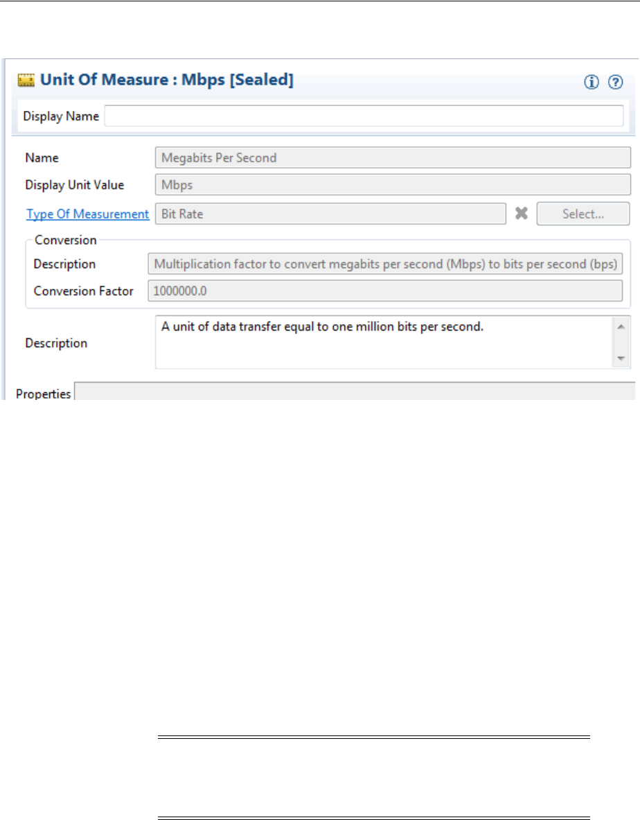
Capacity
5-8 Oracle Communications Unified Inventory Management Concepts
Figure 5–5 Unit of Measure
Configuring Capacity Type
A capacity type defines a kind of capacity that an entity provides or consumes. The
bandwidth capacity type is provided in the Base Measurements cartridge. You
associate a measurement type to a capacity type to specify how the capacity is
measured.
See the Design Studio Help for detailed information about creating and configuring
capacity types.
Configuring Capacity
You define Capacity Provided and Capacity Required specifications to define the
capacity that entities offer and require. When you associate a Capacity Provided
specification with another entity specification, the capacity defined in the Capacity
Provided specification is offered by entities that you create in UIM based on that
specification. Similarly, when you associate a Capacity Required specification with an
entity specification, the capacity defined in the Capacity Required specification
becomes an enablement requirement for entities based on the specification.
Configuring Capacity Provided
Capacity Provided specifications define the capacity that entities offer. When you
configure a Capacity Provided specification, you use the following data elements:
■Capacity Type: Determines the type of capacity offered.
■Total Amount: The amount of the capacity type that an entity can provide.
Note: You cannot associate Capacity Provided specifications with
Pipe entities that are associated with signal structures. These pipes
derive their capacity provided from their signal structures. See
"Understanding Capacity and Signal Structure" for more information.

Capacity
Core Functionality 5-9
■Unit of Measure: The units by which the total amount is measured, defined by a
unit of measure.
■Consumable Percentage: The percentage of the total amount that can be
consumed. A consumable percentage over 100% indicates that the capacity can be
oversubscribed.
For example, bandwidth is a capacity type that is measured by bit rate. Bit rates are
measured in units such as bps or Mbps. Entities such as pipes provide and consume
bandwidth at a bit rate that you specify. An OC3 bandwidth pipe can provide 155.52
Mbps, for example, and packet pipes can consume varying rates of that capacity.
Figure 5–6 shows an example of how the entities are set up for packet type pipes that
are not channelized.
Figure 5–6 Packet Capacity Example
For example, you can define an OC3 Pipe using the Capacity Provided entity that
provides bandwidth of 155.52 Mbps, 100% of which can be consumed. Pipes that can
use that capacity are associated with capacity-required entities.
In UIM, when you create an entity based on a specification that includes a relation to a
Capacity Provided specification, the provided capacity is automatically associated to
the entity. An entity can offer multiple types of capacity, so it can have relationships to
multiple capacity-provided entities. An entity specification can be related to only one
Capacity Provided specification of a given capacity type, however.
For example, a Pipe specification can be related to only one Capacity Provided
specification for the Bandwidth capacity type. If you create another type of capacity
that applies to a pipe, the Pipe specification can also be related to one Capacity
Provided specification of the new capacity type.
Configuring Capacity Required
A Capacity Required specification defines the capacity that an entity requires. When
you configure capacity required, you use the following data elements:
■Capacity Type: Determines the type of capacity required.
■Required Amount: The amount of the capacity type that an entity requires.
■Unit of Measure: The units by which the total amount is measured, defined by
selecting a unit of measure.
■Quantity: The number of units of the required amount value that an entity
requires for a given capacity type. For example, when defining capacity required
for a pipe that is enabled by a facility pipe that supports TDM technology at any
Note: Pipes and signal termination points are the only entities that
can offer capacity by default.

Consumption
5-10 Oracle Communications Unified Inventory Management Concepts
point in its path, you must set the quantity equal to the number of channels
required. Specifying the quantity in this way enables you to use the path analysis
functionality provided by UIM to locate facility pipes for service trails. See
"Enabling Pipes Automatically with Path Analysis" for more information.
For non-TDM technologies, the quantity can be set to 1. Path analysis calculates
the total bandwidth required and finds available packet facilities in addition to
finding available TDM facilities to support the end-to-end enablement of the pipe.
You associate Capacity Required specifications to specifications of entities that require
capacity. For example, you can associate a DS1 Capacity Required specification to a
DS1 Pipe specification.
In UIM, when you create an entity based on a specification that is related to a Capacity
Required specification, the capacity required is automatically created and related to
the entity.
An entity can require multiple types of capacity, so its specification can have
relationships to multiple Capacity Required specifications; however, an entity
specification can be related to only one Capacity Required specification of a given
capacity type. For example, a Pipe specification can be related to only one Capacity
Required specification for the Bandwidth capacity type.
Consumption
Entities in your inventory are used by other entities in various ways. For example, a
handset can be assigned to a VoIP service or a telephone number can be reserved for
use by a customer starting next week.
In UIM, the consumption framework is the mechanism by which you manage how
entities use each other. There are several forms of consumption, including assignment,
reservation, and conditions. See "Resource Reservations" and "Conditions" for more
information. Entity reference is similar to assignment, but does not involve actual
consumption. See "Understanding Entity References" for more information.
Assignment
The most common way the entities consume each other is by assignment. When an
one entity is assigned to another, the first entity is consumed by the second. For
example, consumption occurs when:
■A physical port is assigned to a pipe termination point
■A device interface is assigned to a logical device
■An equipment entity is assigned to a service
In many cases, assignment, and therefore consumption, takes place in entity
configurations. For example, an IP address in the form of a Custom Network Address
entity can be assigned as a configuration item in a logical device configuration.
Table 5–3 lists the entities that can consume entities and the entities that can be
consumed.

Consumption
Core Functionality 5-11
About Shared Consumption of Entities
Entities can be consumed by one entity or by more than one entity. For example, in a
normal POTS service, the service consumes a single telephone number. The service has
only one number and the number can be assigned to only one service. But in a
Table 5–3 Consumers and Consumable Entities
Consumer Entity Consumable Entity
Place
Note: Only Site-type Place entities
can have configurations.
Custom network address
Custom object
Device interface
Place (address, address range, location, site)
Logical device
Physical device
Service
Logical device Custom network address
Custom object
Device interface
Network Custom network address
Custom object
Logical device
Pipe Pipe
Pipe termination point Custom network address
Custom object
Device interface
Equipment
Logical device
Network
Physical connector or port
Physical device
Service Custom network address
Custom object
Device interface
Equipment
Equipment holder
Place (location or site)
Logical device
Logical device account
Media stream
Network
Physical connector or port
Physical device
Pipe
Service
Telephone number
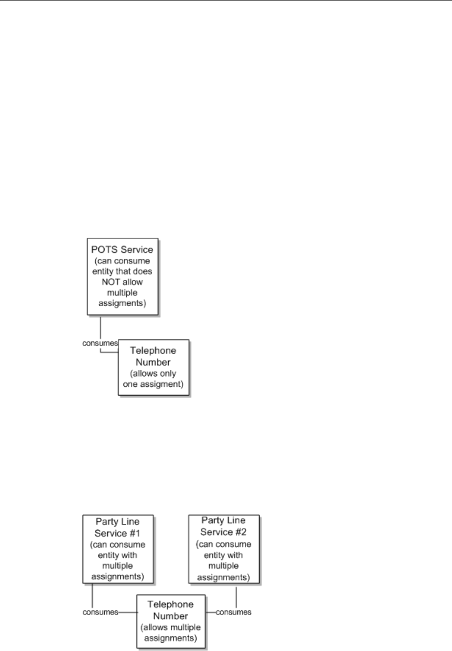
Consumption
5-12 Oracle Communications Unified Inventory Management Concepts
party-line telephone environment, the same number is shared between two or more
services. Each service has only one number, but the same number is shared among
several services.
You configure consumption rules in Design Studio when you define specifications.
You can designate that a consumable entity can be consumed by one or more
consuming entities. You can also designate that a consuming entity can consume one
or more consuming entities.
Figure 5–7 shows an example based on POTS service. A POTS service can consume a
telephone number and the telephone number can be consumed by only one POTS
service. In this case, the Telephone Number specification is configured so that it cannot
be assigned to multiple entities. The Service specification is configured so that it
cannot assign entities that allow multiple assignments. This ensures that the telephone
number cannot be assigned to multiple services and that the service cannot consume a
telephone number that can be assigned to multiple services.
Figure 5–7 POTS Example
Figure 5–8 shows a party line service. A party line service allows customers to share
one telephone number, preventing them from making calls at the same time. In this
case, the Telephone Number specification is configured to allow assignment to
multiple entities. The party line service is configured so that it can consume entities
that allow multiple assignments.
Figure 5–8 Party Line Service Example

Consumption
Core Functionality 5-13
Understanding Entity References
You use entity references to represent an interest or dependency between a
configuration and an entity. An entity reference is similar to an assignment, except that
the referenced entity is not consumed by the configuration.
For example, a mobile GSM service is provisioned on a Home Location Register (HLR)
device. The relationship between the GSM service and the HLR device provides
important information about how the service is realized on the network, but the device
is not consumed by the service. Similarly, a cable TV subscription service requires a
cable controller (modeled as a logical device in UIM), but the service does not
consume the device.
Because referenced entities are not actually consumed, they are not affected by the
Blocked condition. A resource that has a Blocked condition cannot be consumed
(assigned), but it can be referenced.
You define an entity reference in Design Studio when you define a configuration item.
Just as with defining a configuration item for assigning resources, you can limit the
valid options to particular specification types or to entities based particular
specifications. See the Design Studio Help and the UIM Help for more information.
Table 5–4 lists the configurations that can include entity references and the types of
entities that can be referenced. Pipe configurations are not included in the table
because they cannot include entity references.
Resource Reservations
In UIM, you can reserve resources to prevent them from being used by other entities or
processes. You can reserve resources if they are unassigned, not already reserved, and
do not have a condition code that prevents assignments.
Table 5–4 Configurations and Referenceable Entities
Configuration Referenceable Entity
Logical Device
Network
Place (site only)
Service
Business Interaction
Custom Network Address
Custom Object
Device Interface
Equipment
Inventory Group
Logical Device
Logical Device Account
Network
Party
Physical Connector
Physical Device
Place
Pipe
Physical Port
Product
Service
Telephone Number

Consumption
5-14 Oracle Communications Unified Inventory Management Concepts
You can reserve resources for a particular project, user, or service specification.
Reservations can be designated as long-term (30 days by default) or short-term (10
minutes by default). If the reservation is not redeemed by the expiry date, the resource
is released back into inventory. See UIM Developer’s Guide for more information about
defining reservation periods.
In UIM, you redeem a reserved resource when you assign the resource to a
configuration item using a service, logical device, network, or site configuration. By
default, UIM does not validate the redemption to ensure that it matches the
reservation. You can optionally associate a ruleset to the reservation to ensure that
reservation validation occurs. See UIM Developer’s Guide for information about the
RESERVATION_CHECK_REDEEMER ruleset.
You can reserve resources from an entity’s Summary page, or you can use the
Reservation link in the UIM navigation section to reserve multiple resource items on
one reservation.
The following resources can be reserved:
■Custom network addresses
■Custom objects
■Device interfaces
■Equipment
■Equipment holders
■Logical devices
■Logical device accounts
■Media streams
■Networks
■Physical connectors
■Physical devices
■Physical ports
■Services
■Telephone numbers
See the UIM Help for more information about reserving and redeeming resources.
Conditions
Conditions are a way to limit the availability of an entity for a period. A condition
therefore behaves as a consumer of the entity, similar to an assignment. There are three
types of conditions, which are listed in Table 5–5.
Table 5–5 Condition Types
Condition Type Definition
Blocked This condition is used for resources that cannot be consumed
because of some administrative reason. This condition prevents
users from making assignments to this resource.
Blocked resources cannot be consumed, but they can be
referenced. See "Understanding Entity References" for more
information about references.

Involvements
Core Functionality 5-15
See the UIM Help for more information about applying conditions.
Involvements
Many entities in UIM are involved with each other because of the way the inventory is
modeled. For example, a service configuration can include configuration items for one
or more places or resources, and a logical device can provide one or more device
interfaces. These kinds of relationships are explicitly defined in the UIM model and
the application provides tools to manage them.
UIM also enables you to define custom involvements between entities that are not
otherwise associated. You can define Custom Involvement specifications in Design
Studio to define various kinds of associations in your inventory. For example, you
could define Custom Involvement specifications that define involvements between
physical connectors and the ports they support.
UIM provides a default specification for a special kind of custom involvement called a
preconfiguration. A preconfiguration enables you to set up an association among
entities that makes later operations more efficient by linking their consumption.
Preconfigured resources share the same life cycle: when one of the resources is
reserved or assigned, the other is automatically reserved or assigned with it.
For example, in a DSL scenario with telephone service, you can use an involvement to
preconfigure a telephone number, switch port, and cable pair. (In the
telecommunications industry, this preconfiguration is sometimes called a left-in.) The
preconfigured resources are not yet a service, but they facilitate the rapid creation of
the service.
The following types of entities can have custom and preconfigured involvements:
■Custom object
■Custom network address
■Device interface
■Equipment
■Equipment holder
■Logical device
■Logical device account
■Physical connector
■Physical device
■Physical port
■Pipe
■Telephone number
Informational This condition does not affect the availability of a resource, but
it provides additional information about the resource.
Warning This condition supplies additional information about a resource.
A warning condition does not affect the availability of a
resource but warns the user that there may be reasons not to use
it.
Table 5–5 (Cont.) Condition Types
Condition Type Definition
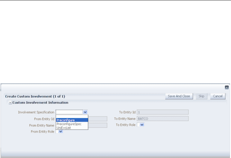
Topology
5-16 Oracle Communications Unified Inventory Management Concepts
Creating Involvements in UIM
In UIM, you can create custom involvements or preconfiguration involvements from a
entity’s Summary page. See the UIM Help for the instructions to create involvements.
Figure 5–9 shows the Create Custom Involvement dialog that you see when you
create an Involvement for an entity. In this example, the user has selected to associate a
DS1 port to an entity and create an involvement. The list displays any Custom
Involvement specifications defined in Design Studio and deployed into UIM, along
with the Preconfigure Spec that is provided as base data with UIM.
Figure 5–9 Adding Involvements in UIM
Topology
The spatial relationships and connectivity among your inventory entities form the
inventory topology. Topology and the features based on it enable you to answer
questions such as:
■Is there connectivity between Texas and Germany?
■Is there a DS3 path from Dallas to San Francisco?
■Is there an OC3 path from Chicago to the United Kingdom?
The UIM topology represents the connectivity entities in your inventory as topology
nodes and topology edges. Topology nodes represent locations, network nodes, or
devices while edges represent pipes or network edges.
UIM provides a graphical representation of topology where you can see your
inventory and its relationships at the level of detail that meets your needs. See
"Aggregating and Expanding Topology Data" and the UIM Help for more information
about the topology visualization. UIM also uses topology during automated pipe
enablement (path analysis). See "Enabling Pipes Automatically with Path Analysis" for
topology more information.
About Topology Nodes
A topology node represents an entity into which information can be transported or
from which information can be transported. A topology node can represent a specific
resource, such as a router, or it can represent something more general or geographic,
such as a VPN site or a city.
The following UIM entities are automatically included as in the topology as nodes:
■Place (location, site, or address)

Topology
Core Functionality 5-17
■Equipment
■Physical device
■Logical device
■Network
■Network node
Because they cannot exist independently in the inventory, the following entity types
are not included in topology:
■Equipment holder (slot)
■Physical port
■Device interface
The topology includes the parents of these entities. For example, a device interface is
not included in the topology, but the logical device that hosts it is included.
You can customize other entities so that they are included in topology. See UIM
Developer’s Guide for more information.
About Topology Edges
A topology edge represents a relationship between topology nodes. Two types of
relationships are represented as edges in the topology:
■Connectivity. Two types of connectivity are represented as topology edges.
–Pipes. For example, a T1 facility pipe that transports information between two
devices or locations is represented as an edge in the topology.
–Connectivity entities, including channelized, packet, and service
connectivities, are represented in the topology as edges.
■Containment. Topology edges represent two types of containment:
–Provides relationships between entities. See "Provides Relationships" for more
information.
–Containment among entities in a hierarchy. The hierarchy can represent:
*Physical containment, such as a card contained in a shelf.
*Logical containment, such as a virtual router contained in a PE (provider
edge) router.
*Geographic containment, such as a city contained within a state contained
within a country.
Topology Example
Figure 5–10 shows an example of business relationships and connectivity among
entities. A Physical Port entity and a Device Interface entity are linked by a pipe. Each
of the two entities is part of a hierarchy and has associations with other entities.
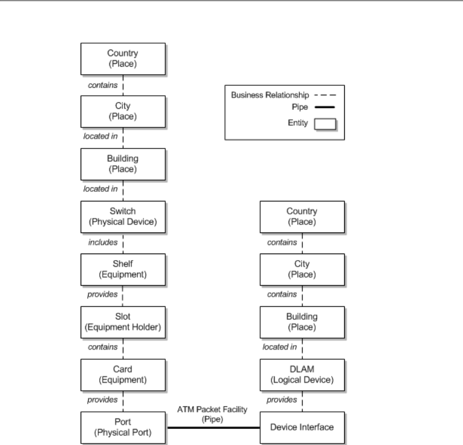
Topology
5-18 Oracle Communications Unified Inventory Management Concepts
Figure 5–10 Business Relationships Example
In the UIM topology, pipes are translated into communication topology edges. The
topology nodes on which a communication topology edge terminates are determined
for each end by going up the hierarchy in the business model starting from the
resource the pipe terminates on and proceeding to the highest level physical device or
logical device. If the highest level physical device maps to a logical device, the
topology edge is terminated on the topology node that represents the logical device. If
no physical or logical device exists in the hierarchy, the topology edge terminates on
the topology node that represents the highest level equipment entity in the equipment
hierarchy.
Containment edges represent the hierarchies. Not all entity types are represented as
topology nodes, however. For example, slots (Equipment Holder entities) are not
represented as topology nodes. As a result, containment topology edges ignore these
entities and they do not appear in the topology. For example, in Figure 5–10, the pipe
terminates on a physical port on one end and on a device interface on the other end.
Neither of these entities is represented by a topology node, so they will not appear in
the topology model.
Figure 5–11 shows the topology model that is generated from the business model in
Figure 5–10. A containment edge connects a card and a shelf, ignoring the slot. A
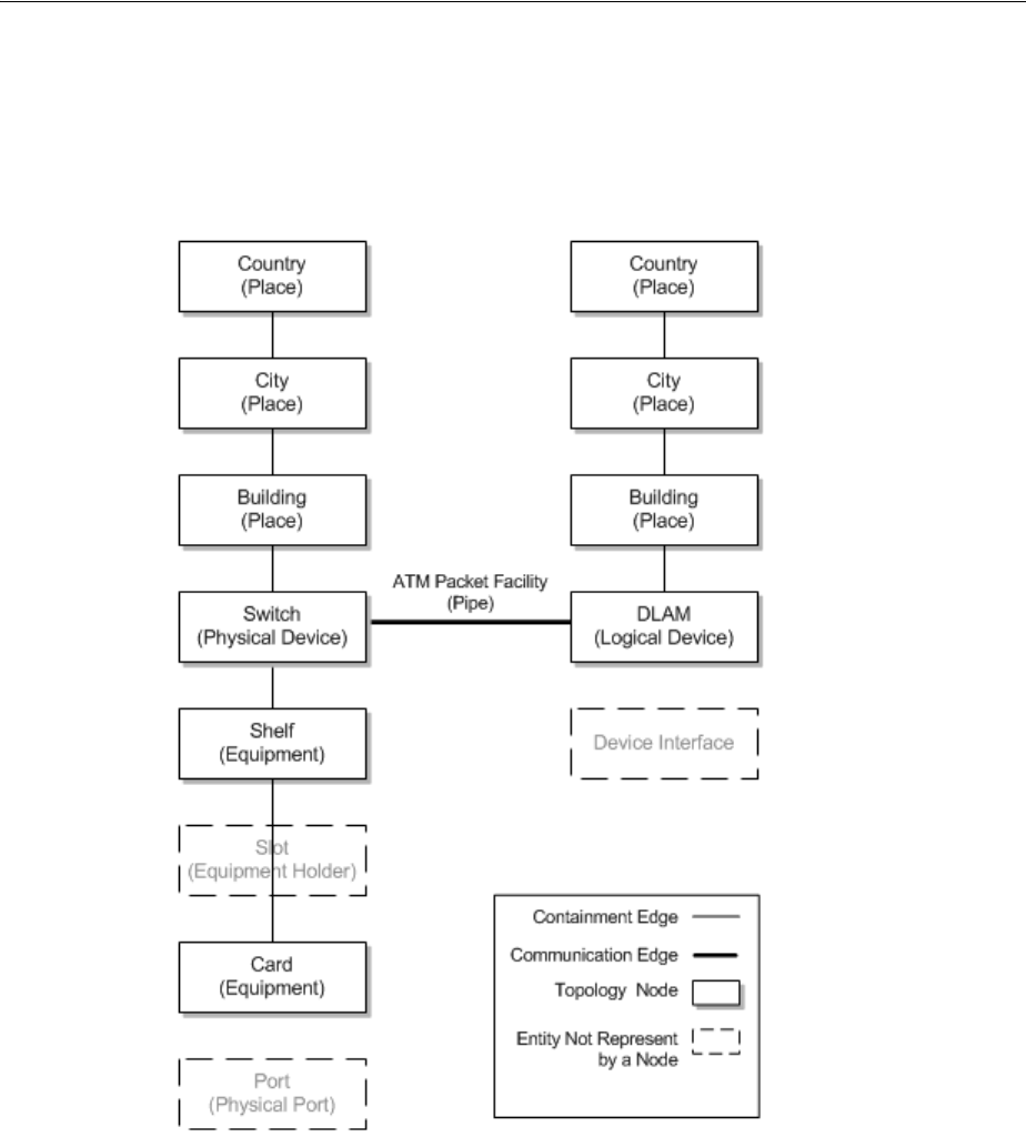
Topology
Core Functionality 5-19
connectivity topology edge representing the pipe runs between topology nodes
representing the physical device (switch) on one end and the logical device (DSLAM)
on the opposite end. These are the highest level physical device and logical device in
the hierarchy from each end of the pipe.
Figure 5–11 Topology of Business Relationships
Figure 5–12 shows the topology represented in Figure 5–11 as it appears in the
Topology page in UIM. Containment edges are shown as actual containment.
Connectivity edges are shown as lines.
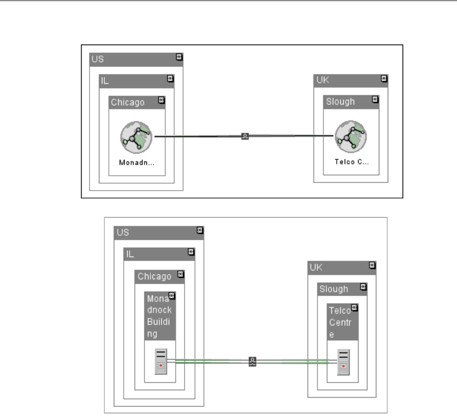
Topology
5-20 Oracle Communications Unified Inventory Management Concepts
Figure 5–12 Topology Example in UIM
Connectivity is shown first at the level of the places to which connected entities are
associated. In this case, that is at the level of the Place entities that represent the
buildings in which the switch and DSLAM are housed. If the switch and DSLAM had
been associated with the City locations, connectivity would be shown at that level.
In the first view, a black line between Place entities for buildings represents general
connectivity without identifying it specifically. In the second view, the Place nodes are
expanded to show the switch and the DSLAM. A green double-line represents the pipe
that connects them.
Aggregating and Expanding Topology Data
The UIM topology automatically reflects the geographical hierarchy that you set up for
your inventory. In some cases, you may have a highly articulated hierarchy that
includes multiple levels such as regions, states or provinces, counties, and cities. In
other cases, you may have a flat hierarchy with all cities directly under countries. UIM
topology works across all kinds of geographical hierarchies.
UIM aggregates topology data automatically so that higher levels in a place hierarchy
reflect the connectivity of their children. For example, devices in Berlin and Buenos
Aires that are connected by pipes are reflected in topology visualizations at the
country level by connections between Germany and Argentina.

Topology
Core Functionality 5-21
Connectivity between places is based on the connectivity of devices and equipment
associated with them. The UIM topology model automatically determines the implied
interconnections between the different levels of the hierarchy based on associations.
The topology visualization reflects the aggregation of topology data. The top level of
the visualization shows only nodes that have no parent nodes. For example, the
visualization might display only the countries in which you operate. As you drill
down by expanding nodes in the visualization, child nodes become visible.
Continuing in this manner, you can expand and explore any node to the level of detail
you need.
For example, suppose your inventory includes logical devices in various locations
connected by pipes as shown in Figure 5–13.
Figure 5–13 Topology Example
If you view this arrangement in the topology visualization with only the top level
showing, you see connectivity between the USA and China and between the US and
Europe. No direct connectivity exists between China and Europe. At this level of
detail, all the connectivity created by underlying pipes, equipment, and devices has
been aggregated into a single edge between places. This uncluttered view enables you
to quickly see the overall relationships between the various communication elements
in the data.
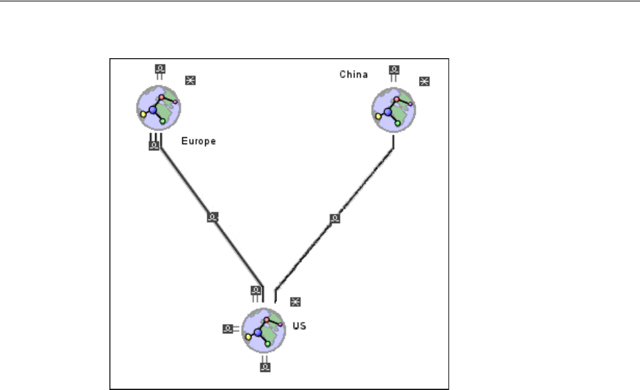
Topology
5-22 Oracle Communications Unified Inventory Management Concepts
Figure 5–14 High-Level Topology View
Expanding nodes in the topology reveals additional connectivity details. You do not
have to expand the entire topology. You can have one node expanded to the finest
level of detail while others remain at the coarsest level. For example, if you expand
Europe node and the Illinois and Texas nodes in the US, you can see that the
connectivity from the Europe to the US flows to and from Texas and Illinois. Traffic to
and from California and Europe is routed through one or both of the US states.
Similarly, the US connection to China is through California.
Figure 5–15 shows a topology visualization with nodes and edges expanded at
different levels.
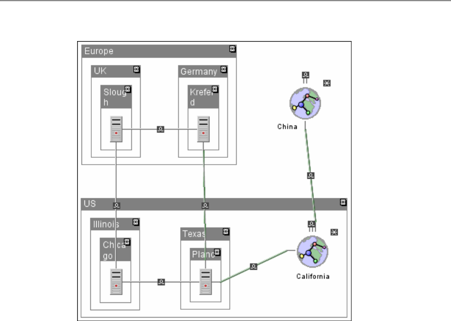
Topology
Core Functionality 5-23
Figure 5–15 Partially Expanded Topology View
When you expand the topology fully, you can see the full details of the connectivity.
As a result, you can see exactly which paths exist between places and entities in your
inventory. Figure 5–16 shows a topology visualization with nodes and edges expanded
fully.
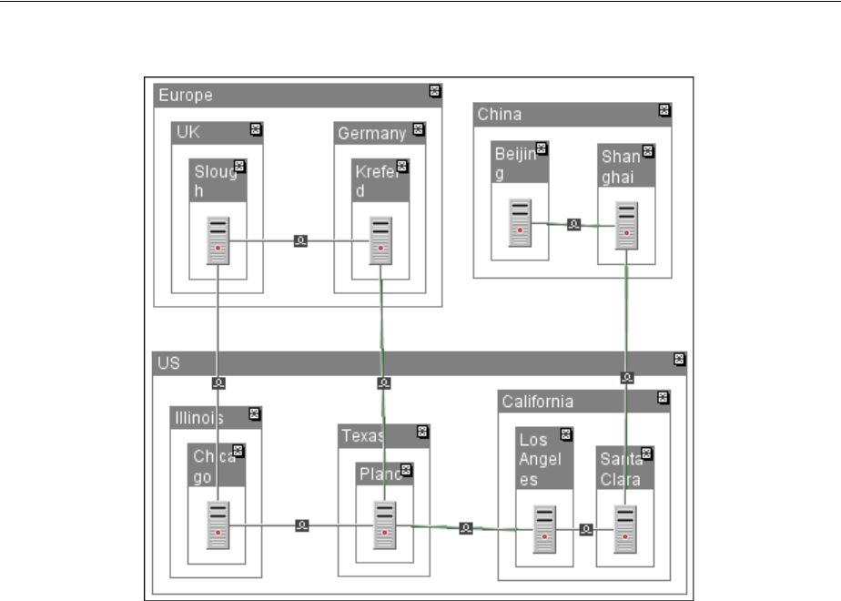
Entity Identification
5-24 Oracle Communications Unified Inventory Management Concepts
Figure 5–16 Fully Expanded Topology View
The aggregation capabilities of UIM are used in areas other than topology
visualization. In path analysis, you can look for connectivity paths between place
nodes on one side and specific devices on the other. For example, you could search for
a connectivity path from Texas to a specific logical device in a city in Europe. You can
also specify that a connectivity path must flow through a particular device or location.
For example, you could require that traffic from Slough to Los Angeles flow through
Plano. See "Enabling Pipes Automatically with Path Analysis" for more information
about path analysis.
See the UIM Help for information about using topology visualization features.
Entity Identification
Most product, service, resource, and common business entities are identified in UIM
with IDs that are unique by entity type. For example, you can have an Equipment
entity and a Logical Device entity with the same ID, but you cannot have two
Equipment entities with the same ID.
Entity IDs are a useful way to distinguish between entities of the same type that are
not uniquely named. For example, you could have many different Equipment entities
for interface cards with similar or identical names, but their IDs make it possible to
identify them uniquely.
By default, entities that require a unique ID are set up to automatically generate IDs as
they are created in UIM. The following entity types are configured for automatic ID
generation by default.
■Business interaction
■Custom network address

Entity Identification
Core Functionality 5-25
■Custom object
■Device interface
■Equipment holder
■Equipment
■Logical device
■Logical device account
■Media stream
■Network
■Party
■Physical connector
■Physical device
■Physical port
■Pipe
■Place
■Product
■Service
In Design Studio, you can configure entity specifications with custom automatic ID
generation that specifies exactly what numbering scheme to use. For example, you
could define prefixes to designate various kinds of logical devices.You can also disable
automatic ID generation so that IDs must be entered manually when entities are
created in UIM. See the Design Studio Help for more information.
In addition, you can use extension points, rulesets, and Sequence specifications to
further customize entity IDs. See UIM Developer’s Guide for more information.

Entity Identification
5-26 Oracle Communications Unified Inventory Management Concepts

6
Planning 6-1
6
Planning
This chapter describes the planning features included in Oracle Communications
Unified Inventory Management (UIM). You can use any combination of the following
features:
■Business Interactions
■Engineering Work Orders
■Projects
Business Interactions
Business interactions make it possible for you to plan UIM actions and then execute
those actions at a time of your choosing. Each business interaction can include a
variety of actions such as fulfilling services, adding entities, changing entity
hierarchies, and so on. The changes resulting from these actions are called business
interaction items.
A business interaction can represent an arrangement such as service fulfillment, a
capital project, a maintenance request, or any other activity that you want to plan in
advance. When you complete a business interaction, all of its items are executed and
the results become available throughout the application.
When you make changes to your inventory while using a business interaction, you are
working in a business interaction context. (Working outside of a business interaction
context is called working in current inventory.) After you enter a business interaction
context, all additions, changes, or deletions you make are visible only in that context
until the business interaction is complete. You cannot see or work with the results of
an incomplete business interaction while working in current inventory.
For example, if the business interaction included the addition of a new entity, that
entity becomes visible in current inventory only when you complete the business
interaction. See "Understanding Business Interaction Contexts", "Understanding the
Business Interaction Life Cycle", and the UIM Help for more information.
Business interactions can include child business interactions. For example, a service
fulfillment business interaction could be organized into multiple separate child
interactions so that changes can be implemented in the right order and at the right
Note: You do not have to use business interactions to make changes
to the inventory. You can also make changes in current inventory. Such
changes are immediately effective and visible.

Business Interactions
6-2 Oracle Communications Unified Inventory Management Concepts
times. You define child business interactions in the hierarchy of the parent business
interaction.
Child business interactions must be complete before parent interactions can be
completed. You can choose to complete business interactions individually or to
complete an entire business interaction hierarchy, starting from the lowest level.
Business interactions are UIM entities and you work with them in much the same way
as you work with other entity types. You define specifications for them in Design
Studio and create entities based on those specifications in UIM. See "Configuring
Business Interaction Specifications", "Working with Business Interactions in UIM", and
the UIM Help for more information.
Business interactions can be created and managed by using Web services. See
"Understanding Business Interactions with External Systems" for more information.
Business Interaction-Enabled Entities
The following entity types are business-interaction enabled, meaning that actions
taken on them can be included as items in business interactions:
■Connectivity (including design versions)
■Custom network address
■Custom object
■Device interface*
■Equipment
■Equipment holder*
■Logical device (including logical device configurations)
■Logical device account (including logical device account configurations)
■Media stream
■Network (including network configurations)
■Network node*
■Network edge*
■Physical connector*
■Physical device
■Physical port*
■Pipe (including pipe configurations)
■Pipe termination point*
■Telephone number
The entities marked with asterisks in the preceding list are not displayed as items in
the Business Interaction Summary page in the UIM user interface. These entities
cannot stand alone; they are always part of another entity. As a result, the Business
Interaction Summary page displays their parent entities.
Entity configurations (and design versions in the case of Connectivity entities) can be
included in business interactions. If you set the business interaction context while
working in the parent entity, any new configurations you create and any changes you
make to existing configurations, are included in the business interaction. You can also

Business Interactions
Planning 6-3
set the business interaction context individually from a configuration page (or Design
Version tab for channelized connectivity.)
Service configurations can also be included in business interactions, but only when the
Service Fulfillment Web services create the business interactions. See "Understanding
Business Interactions with External Systems" for more information.
Understanding the Business Interaction Life Cycle
Business interactions have a life cycle that begins with their creation and ends with
their cancellation or completion. Changing the life cycle status of a business interaction
can affect the inventory status of an entity contained in a business interaction item. For
example, the status of a logical device added through a business interaction changes
from Pending Install to Installed when the business interaction is completed.
The life cycles of resources included in business interactions are different from those of
resources outside a business interaction context. See "Inventory Status for Resources in
Business Interactions and Work Orders" and "Inventory Status for Pipes and
Connectivities in Business Interactions and Work Orders" for more information.
The business interaction statuses are:
■Created
■In Progress
■Canceled
■Completed
See "Business Interaction and Engineering Work Order Life Cycles and Statuses" for
definitions of these status.
You change business interaction statuses with menu commands in the Business
Interaction Summary page or with Web service operations. See "Understanding
Business Interactions with External Systems" for more information. The one exception
is the transition from Created to In Progress status, which occurs automatically when
you add, change, or delete items in the context of a newly created business interaction.
Table 6–1 lists the business interaction status transition changes you can make:

Business Interactions
6-4 Oracle Communications Unified Inventory Management Concepts
Table 6–1 Business Interaction Life Cycle Transitions
Transition
Affect on Business Interaction
Status
Affect on Status of Entities Business Interaction
Items
Approve
Configurations
No change. This action changes service configurations from In
Progress to Designed. Service configurations already
in Designed status are not affected.
The operation fails if any service configuration in the
business interaction is in Issued, Complete, Pending
Cancel, or Canceled status.
Cancel Changes the status from Created or
In Progress to Canceled.
The transition fails if any child
business interactions are in Created
or In Progress status or if the
business interaction has any
completed children.
This action affects service configurations and their
parent services, but the exact result depends on the
combination of statuses of the services and service
configurations. The effect of a business interaction
cancellation is the same as the direct cancellation of
the service configuration. See "Service Life Cycles and
Statuses" for more information.
By default, the operation fails if any service
configuration in the business interaction is in
Completed status. You can configure UIM to allow
cancellation in this situation. See UIM System
Administrator’s Guide for more information.
Cancel Hierarchy Changes the status of the parent
business interaction and all of its
children from Created or In Progress
to Canceled. Children in Completed
or Canceled status are unaffected.
This action affects service configurations and their
parent services, but the exact result depends on the
combination of statuses of the services and service
configurations. The effect of a business interaction
cancellation is the same as the direct cancellation of
the service configuration. See "Service Life Cycles and
Statuses" for more information.
By default, the operation fails if any service
configuration in the business interaction is in
Completed status. You can configure UIM to allow
cancellation in this situation. See UIM System
Administrator’s Guide for more information.

Business Interactions
Planning 6-5
Understanding Business Interaction Contexts
The content of a business interaction is the set of items that represent actions, such as
creating or deleting an entity, that you take while you are in the context of that
business interaction. You can work in only one context at a time.
Changes you make while in a business interaction context are not visible in current
inventory until the business interaction is completed. Similarly, changes you make in
one business interaction are not visible in another business interaction context, even if
the other business interaction is a child of the first.
The inventory status of an entity can be different in different business interaction
contexts. For example, you can deactivate an entity in a business interaction while it
Complete Changes the status from In Progress
to Completed.
The transition fails if any child
business interaction is in Created or
In Progress status.
This action changes the statuses of entities to reflect
the actions defined in the business interaction items.
This action changes the status of service
configurations and their parent services. The general
result is to change service configurations from Issued
to Completed status, which causes the parent services
to change to In Service status.
The exact result depends on the combination of
statuses of the services and service configurations.
The effect of a business interaction completion is the
same as the direct completion of the service
configuration. See "Service Life Cycles and Statuses"
for more information.
The transition fails if any service configuration in the
business interaction is in In Progress or Designed
status.
Complete
Hierarchy
Changes the status of the parent
business interaction and all of its
children from In Progress to
Completed.
This action changes the statuses of entities to reflect
the actions defined in the items in all business
interactions in the hierarchy.
This action changes the status of service
configurations and their parent services. The general
result is to change service configurations from Issued
to Completed status, which causes the parent services
to change to In Service status.
The exact result depends on the combination of
statuses of the services and service configurations.
The effect of a business interaction completion is the
same as the direct completion of the service
configuration. See "Service Life Cycles and Statuses"
for more information.
The transition fails if any service configuration in the
business interaction hierarchy is in In Progress or
Designed status.
Issue
Configurations
No change. This action changes the status of service
configurations from Designed to Issued. Service
configurations already in Issued status are not
affected.
The operation fails if any service configuration in the
business interaction is in In Progress status. Service
configurations in Completed, Pending Cancel, or
Canceled status are skipped.
Table 6–1 (Cont.) Business Interaction Life Cycle Transitions
Transition
Affect on Business Interaction
Status
Affect on Status of Entities Business Interaction
Items
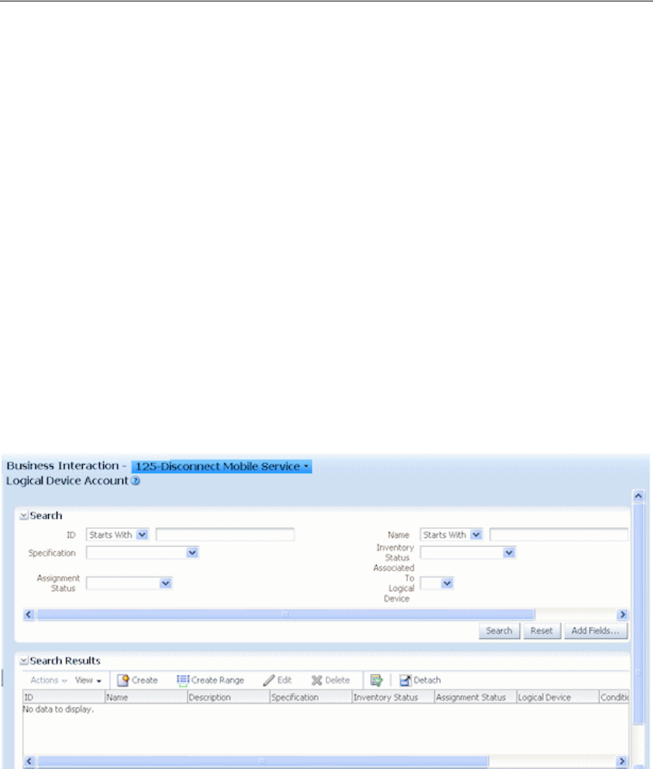
Business Interactions
6-6 Oracle Communications Unified Inventory Management Concepts
remains active in current inventory. The current inventory status is updated to reflect
the business interaction when you complete the interaction.
It is important to be aware of whether you are working in current inventory or in a
business interaction context. In the UIM user interface, the context is displayed in the
about the entity type label in entity pages. If you are working outside of a business
interaction context, the context is shown as Current. If you are working in a business
interaction context, the context indicator displays the name and ID of the current
business interaction. You can switch contexts by selecting from the context indicator.
If you navigate to a Business Interaction Summary page, you are automatically
switched to the context of that business interaction. When you navigate to a Summary
page for an entity that is not business interaction enabled, you automatically exit your
business interaction context and work in current inventory. You switch back to your
previous context when you navigate to a business-interaction-enabled entity.
You cannot create entity configurations while working in a business interaction
context. This restriction applies to the three business-interaction-enabled entity types
that can have configurations: logical device, pipe, and network.
Figure 6–1 shows a Logical Device Account Search page. The context indicator
displays the name and ID of the current business interaction, 125-Disconnect Mobile
Service. See the UIM Help for more information about how to set and change the
business interaction context.
Figure 6–1 Business Interaction Context Indicator
Understanding Business Interactions with External Systems
External systems can cooperate with UIM to complete tasks such as engineering work
orders or service orders. These external systems use Web services to communicate
with UIM. For example, Oracle Communication Order and Service Management
(OSM) can use the Service Fulfillment Web services to send service orders to UIM for
fulfillment. See UIM Web Services Developer’s Guide for more information about Web
services in general and the Service Fulfilment Web services in particular.
In UIM, requests from external systems are modeled as business interactions.
Depending on the nature of a request, it could result in the creation of parent and child

Business Interactions
Planning 6-7
business interactions that represent various aspects of the request. Subsequent requests
can modify the original business interaction.
For example, a service order from OSM requires the creation of one or more service
entities in UIM. UIM responds to the service order request by creating a business
interaction that includes items for the initial service configuration or configurations.
(The service configuration versions are included as items in the business interaction,
but the parent services are not.) Depending on the structure of the service order,
additional child business interactions may be required for additional services involved
in the order.
When all the tasks required for service fulfillment in UIM are complete and approved,
the service order business interaction is completed, which results in the status of the
related service entities being set to In Service.
A subsequent service order could be received from OSM to change or disconnect the
service. This request results in a new service order business interaction that includes
the service configuration version that includes the work required to change or
disconnect the service. This business interaction is separate from the original business
interaction under which the service was created.
Business interactions that are created as the result of requests by Web services are
somewhat different from business interactions created in the UIM user interface:
■Requests from external systems are sent in the form of XML documents. UIM uses
the content of the XML documents to create or update business interactions. The
documents are stored as attachments to the relevant business interactions for
future reference. You can view the XML documents associated with a business
interaction in the Transactions Log area of the Business Interaction Summary
page. See the UIM Help for more information.
■Business interactions managed by Web services can include service configurations
as items. This capability is not available in business interactions created in the user
interface. After a business interaction has been created by Web services, however,
you can use the user interface to work with the service configurations it includes.
■The parent service of a service configuration in a business interaction does not
appear as a business interaction item. The parent service is visible in current
inventory. Business interaction status transitions do cause status transitions in
parent services, however. See Table 6–1, " Business Interaction Life Cycle
Transitions" for more information about these transitions.
Configuring Business Interaction Specifications
Every business interaction entity in UIM must be based on a Business Interaction
specification, including those created by Web services. In Design Studio, you can
define separate specifications for business interactions that represent different types of
activities, such as service orders, infrastructure projects, and so on.
As with other entity specifications, you can add characteristics to describe the business
interaction or provide additional details. For example, you could add an Order Type
characteristic as a list with appropriate values. See the Design Studio Help and the
UIM Help for more information about defining Business Interaction specifications.
A Service Order specification is included in the base cartridges for use as the basis for
service fulfillment activities managed by Web services. The specification includes an
extension point so that you can write a ruleset to automate the actions that are
required to create a service order in UIM. See UIM Cartridge Guide for more
information about this specification.
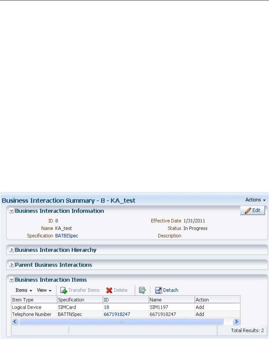
Business Interactions
6-8 Oracle Communications Unified Inventory Management Concepts
Working with Business Interactions in UIM
You can create business interactions in the UIM user interface or by using Web
services. In either case, you can work with them in the user interface using the same
techniques you use with other entities. You can search for business interactions based
on various criteria. You work with business interactions in Business Interaction
Summary pages.
There are three major tasks that you perform in Business Interaction Summary pages:
■You define the contents of the business interaction by creating or modifying
entities in a Business Interaction Summary page. These changes are included in the
business interaction without your having to set the context explicitly.
You can also define the contents of a business interaction by setting the business
interaction context while working elsewhere in UIM. The changes you make while
in a business interaction context are included in the corresponding business
interaction.
■You create child business interactions in the Business Interaction Hierarchy area.
■You change the life cycle status of the business interaction and its items.
Figure 6–2 shows a Business Interaction Summary page for a service fulfillment order.
The business interaction contains items for adding a new telephone number and a new
logical device (a SIM card).
Figure 6–2 Business Interaction with New Items
See the UIM Help for detailed information about working with business interactions
in the UIM user interface.
Deleting Entities in Business Interactions
Some special rules apply to entities that you delete from business interactions:
■If the entity was created in the context of that business interaction, the entity is
deleted entirely when you delete it from the Business Interaction Items section.

Engineering Work Orders
Planning 6-9
■If an entity was created in current inventory updated in a business interaction, it is
listed as Updated in the Business Interact Items section. Deleting it will remove it
from the business interaction, but not from inventory.
If you delete an entity from the Items section in a Business Interaction Summary page,
entities associated with the deleted entity may also be deleted in. To avoid deleting
associated entities, you can:
■Search for the entity while in the business interaction context and delete it from
the Search Results section.
■Manually remove the associations before deleting the entity from the Business
Interaction Summary page.
Engineering Work Orders
Engineering work orders enable you to plan resource infrastructure changes and have
all your changes take effect at the same time.
For example, you could use an engineering work order to create a GSM Base Station
Subsystem (BSS) network. The BSS network could include:
■Network locations to represent Node B cell sites and the RNC (Radio Network
Controller).
■Logical devices to represent RNC and Node B hardware.
■Connectivity entities to represent the ABis connections between the RNC and
Node B locations.
■A network entity, network nodes, and network edges that you use to represent the
BSS network and its elements.
Engineering work orders are closely related to business interactions and share almost
identical functionality. (Engineering work order entities are created using a specially
configured Business Interaction specification.) Unless otherwise noted in the UIM
documentation or Help, you should follow the same procedures when working with
engineering work orders that you do when working with business interactions. See
"Business Interactions" and the UIM Help for more information about business
interactions.
Like business interactions, engineering work orders can be included in Web services,
such as the Service Fulfillment Web service. See UIM Web Services Developer's Guide for
information about implementing Web services.
As with business interactions, entities you add or change while working in an
engineering work order context remain in Pending Install status until you complete
the engineering work order. At that time, the statuses of the entities change to Installed
and the entities become available in live inventory. For example, you could create all
the BSS entities mentioned previously in an engineering work order context and make
them all available at a prearranged time.
Engineering work orders use the same context indicator as business interactions. The
context indicator appears at the top of entity Summary and Configuration Summary
pages. The phrase “Engineering Work Order” appears in the context indicator to
distinguish engineering work orders from business interactions.
Engineering work orders include a number of fields that do not appear in business
interactions. The information stored in these fields enables you to manage and
organize the activities associated with the engineering work order. Figure 6–3 shows
an Engineering Work Order Summary page.
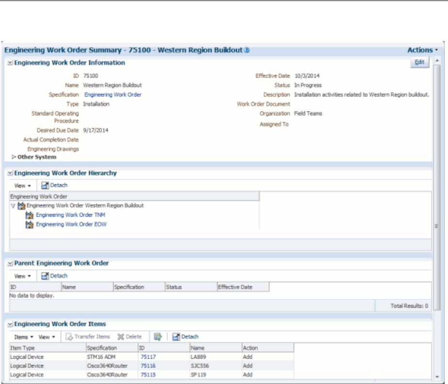
Engineering Work Orders
6-10 Oracle Communications Unified Inventory Management Concepts
Figure 6–3 Engineering Work Order Summary Page
You use the Work Order Type field to categorize engineering work orders. You can
search for engineering work orders by type to monitor progress and assess resource
needs. By default, the following types are available:
■Commissioning
■Decommissioning
■Field Work
■Network Reconfiguration
■Installation
■Upgrade
■Replacement
You can extend the Engineering Work Order specification in Design Studio to add
additional work order types, such as Routine, Preventative, or Emergency. See Design
Studio Help for information about extending specifications.
Engineering Work Order Summary pages also include fields where you can enter
URLs for related documents, such as drawings, schedules, and procedures. There are
three such fields: Work Order Document, Standard Operating Procedure, and
Engineering Drawing.

Projects
Planning 6-11
Engineering work orders are assigned to individuals who perform the tasks required
to complete them. The assigned person is shown in the Assigned To field in an
Engineering Work Order Summary page. You can search for engineering work orders
based on the Assigned To field to produce a simple work list for yourself or another
user.
The Assigned To field is populated with a list of users who are authorized in
WebLogic to access UIM. See UIM System Administrator’s Guide for more information
about WebLogic security.
See UIM Help for more information about the fields in the Engineering Work Order
Summary page.
To enable the use of engineering work orders in UIM, you must install the ora_uim_
workorder base cartridge. This cartridge includes a business interaction specification
that defines engineering work orders. While only a single Engineering Work Order
specification can be used in UIM, it can extended in Design Studio. See UIM
Installation Guide for more information about installing base cartridges. See Design
Studio Help for more information about extending specifications.
Projects
In UIM, you use projects to plan and organize network and channelized connectivity
maintenance activities, such as grooming and rehoming. For example, you could
create a project that includes all the activities related to a particular network
infrastructure change during a specified time period.
Each project can include any number of activities. An activity is a group of actions that
accomplish a goal of a particular type. For example, an activity might be the deletion
of a particular network node. To accomplish this task, the node itself and the logical
device it represents must be removed and connectivities must be groomed to reflect
the change.
When you create a project, it does not include any activities. You add activities
individually, specifying one of four types:
■Groom
■Rehome
■Insert Node
■Remove Node
See "Maintaining Channelized Connectivity and Network Resources" and the UIM
Help for information about each activity type.
Unlike most other entities, all Project entities are based on the same specification. You
can open the Managed Project specification in Design Studio and modify by adding
entity-level characteristics. After you deploy the ora_uim_basespecifications base
cartridge that contains these changes, all Project entities you create in UIM will include
the additional characteristics.
See the Design Studio Help for information about entity-level characteristics.
Note: To avoid confusion, the specification is called Managed Project
in Design Studio. Project entities are not the same thing as Design
Studio projects.

Projects
6-12 Oracle Communications Unified Inventory Management Concepts
Project Details Page Overview
The Project Details page includes basic identifying information about the project as
well as a tab in which you add and manage activities. The page has specialized areas
for each activity type that are displayed when you select an activity of that type. For
example, when you select a rehoming activity, you see a section in which you select a
source logical device and a section in which you select the target logical device. After
you have made these selections, you select a connectivity to rehome to the target.
After you have configured an activity, the Change Items tab in the Project Details page
displays the specific actions that must be completed for the activity. Each change item
includes an entity and the action that must be completed. For example, in Figure 6–4,
the Change Items tab lists two connectivities, each of which has a Rehome action.
When you have finished configuring an activity, you can submit it for processing. You
can submit activities one at a time or in groups. UIM processes activities in the
background and reports its progress in the Percent Complete column in the Activities
tab. When you submit multiple activities, UIM processes them sequentially.
The interval at which UIM refreshes the Percent Complete columns in the Activities
tab and Change items tab is configurable. The default interval is 15 seconds. See UIM
System Administration for information about setting the interval.
Figure 6–4 depicts a Project Details page that contains several activities in various
statuses. A Rehome activity is selected, so Source and Target sections appear. (The
Target section is collapsed to save space.) The Change Items tab lists the connectivities
affected by the rehoming and the actions that will be completed. The Impact Items tab
(not visible in Figure 6–4) is populated as the change items are processed.
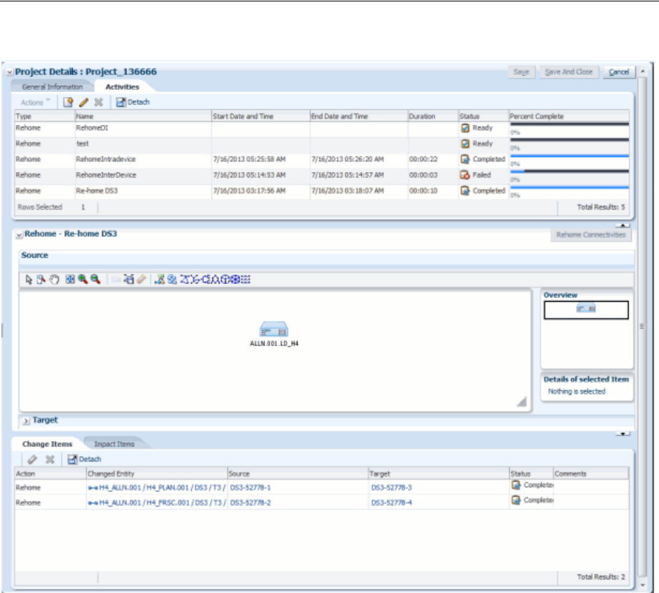
Projects
Planning 6-13
Figure 6–4 Project Details Page

Projects
6-14 Oracle Communications Unified Inventory Management Concepts

7
Resource Entity Management 7-1
7
Resource Entity Management
This chapter explains how you use the resource management features in Oracle
Communications Unified Inventory Management (UIM). UIM includes several
different types of entities that you use to manage resources in various ways:
■Inventory Groups
■Network Address Domains
Inventory Groups
You use inventory groups to organize and correlate entities in your inventory. You can
define inventory groups to organize entities based on criteria such as:
■Geographic area, such as country, district, community, or location on a machine
room floor
■Resource pools
■Serving area
■Billing area
■Service types offered by serving area
■Resources identified for a particular purpose
You can write rulesets to control the behavior of entities in inventory groups. See UIM
Developer’s Guide for information about rulesets and extending the product.
The following entity types can be included in inventory groups:
■Custom Network Addresses
■Custom Object
■Equipment
■Flow Identifier
■IPv4 Address
■IPv4 Subnet
■IPv6 Address
■IPv6 Subnet
■Logical Device
■Logical Device Account
■Party

Inventory Groups
7-2 Oracle Communications Unified Inventory Management Concepts
■Physical Device
■Pipe
■Pipe Termination Point
■Property Location
■Service Specification
■Telephone Number
You are not required to define an Inventory Group specification to create inventory
groups in UIM. You can define Inventory Group specifications to include
characteristics or to associate specific entities with specific inventory groups in UIM.
About Inventory Group Types and Resource Pools
In Design Studio, you can optionally associate Inventory Group specifications with
Inventory Group Type specifications. Inventory group types define specific entities or
groups of entities that can or must be included in the inventory group. Inventory
groups with inventory group type associations are called resource pools. They are
used to manage the assignment of resources in UIM.
For example, you can create a Telephone Number Resource Pool Inventory Group
Type specification in Design Studio, define that only Telephone Number entities can be
included, and specify that these entities are required. You can then associate the
Inventory Group Type specification with appropriate Inventory Group specifications
to define telephone number resource pools. In UIM, you add telephone numbers to
these resource pools and use them to manage assignments.
Two Inventory Group Type specifications are included in the Base Specifications base
cartridge:
■IP Resource Pool
■Flow Identifier Resource Pool
Creating Inventory Groups in UIM
In UIM, you can build inventory groups and add entities to it in two ways: you can
create an inventory group and add entities to it, or start with an entity and add it to an
inventory group.
Figure 7–1 shows an inventory group in UIM with a router associated with it in the
Items section.
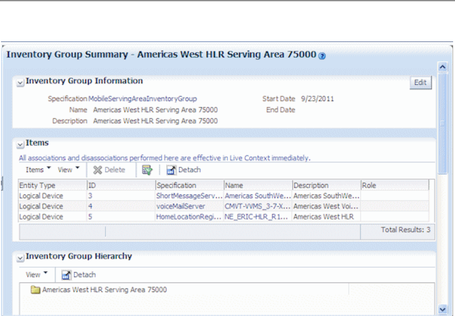
Inventory Groups
Resource Entity Management 7-3
Figure 7–1 Inventory Group with Item
About Inventory Group Hierarchies
You can form hierarchies of inventory groups in UIM. For example, you can use
inventory groups to manage resources for large serving areas and include child
inventory groups in the hierarchy for smaller, included serving areas.
Figure 7–2 shows such an inventory group hierarchy in UIM.
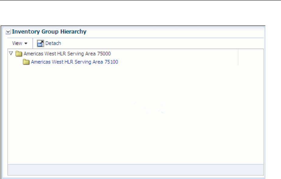
Network Address Domains
7-4 Oracle Communications Unified Inventory Management Concepts
Figure 7–2 Inventory Group Hierarchy
Network Address Domains
Network address domains define a context for the uniqueness of network addresses.
For example, in the public domain, an IP address must be unique among all IP
addresses on the Internet. In contrast, an address can exist in more than one private
routing domains. You can use network address domains to define those private
routing domains. When you search for an IP address, you can use the network address
domain as a search criterion to ensure that you select from the correct addresses.
In UIM, you can use network address domains with the following entities:
■Flow identifiers
■IPv4 addresses
■IPv6 addresses
■IP subnets
■Telephone numbers
Network address domain entities are based on specifications that you define in Design
Studio. Predefined specifications are included in some sample cartridges, such as the
Carrier Ethernet cartridge.
See Design Studio Help for information about defining Network Address Domain
specifications. See "IP Address Management" and "About Flow Identifiers" for
information about how you use network address domains in those contexts.

8
Services 8-1
8
Services
This chapter describes how you model services in Oracle Communications Unified
Inventory Management (UIM).
About Services
A service represents the way that a product is realized and delivered to a customer.
For example, if you sell DSL Gold as a product, it is delivered as a DSL Gold service,
enabled by appropriate resources.
You define Service specifications to record basic information about the service. You
define Service Configuration specifications to record versionable sets of facts about the
service. As these facts evolve over time, you can create new configuration versions. See
"Configurations" for more information.
When you define a Service specification, you determine if the service can be assigned
to multiple entities and if it can assign entities that allow multiple assignments. See
"Consumption" for more information about consumption and shared consumption.
Creating a Service and a Service Configuration in UIM
To create a service and service configuration in UIM, do the following:
■Create a service using the Service specification
■Add a service configuration to the service by selecting a Service Configuration
specification
■Add configuration items to the service configuration
■Modify or enter any characteristics
■Manually assign or reference resources to configuration items or use the auto
configure feature. To use the auto configure feature, you must extend the product.
See UIM Developer’s Guide for information about extending UIM.
■Validate the service configuration and the service. The default validation checks
date integrity, but you can extend the product to include customized validations.
See UIM Developer’s Guide for information about extending UIM.
■Approve, issue, and complete the service configuration using the Actions menu.
See the UIM Help for the detailed steps to create services, to create service
configurations, and to assign resources.
Figure 8–1 shows a Service configuration with several configuration items in UIM.
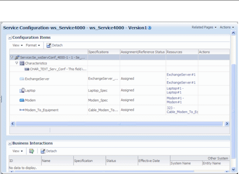
Service Topology
8-2 Oracle Communications Unified Inventory Management Concepts
Figure 8–1 Service Configuration Information in UIM
In the event that there are a large number of configuration items at any level of the
hierarchy, UIM displays a counter. The counter displays the count for the
configuration items currently displayed and enables you to jump to other
configuration items in the list.
Service Topology
The service topology shows the service resources on a graphical canvas similar to the
network topology canvas. You access the service topology from the Related Pages
menu.
See "Networks" for more information about the canvas and the UIM Help for more
detailed information about using the canvas tools.
You can move entities on the canvas and save views. You can also select an entity and
view its summary information. You can also modify the graphics shown for an entity
type by adding a graphic file to the entity specification through the Media tab in
Design Studio.
The service topology displays assigned items that can include equipment, pipes,
logical devices, network nodes and edges, places, and physical devices. UIM can be
extended to include trails and termination points. See UIM Developer’s Guide for more
information about extending UIM.
The service topology in Figure 8–2 shows customer premise equipment, a subscriber
terminal, a switch, and the pipe connecting the terminal and switch.
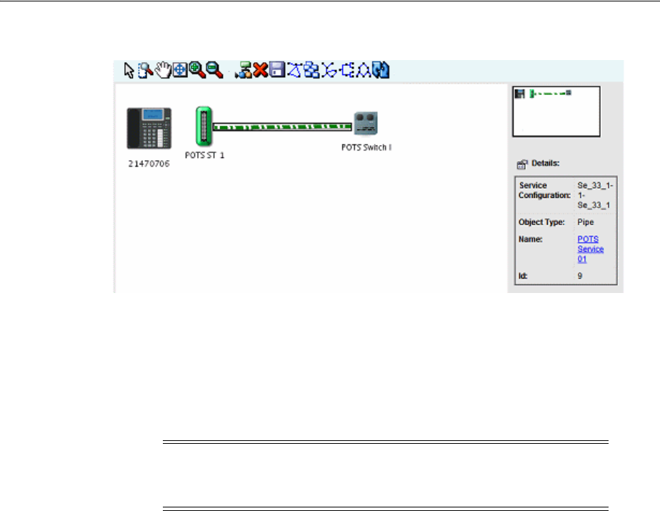
About Network-Oriented Services
Services 8-3
Figure 8–2 Service Topology
About Network-Oriented Services
UIM supports network-oriented services that include multipoint and point-to-point
packet connectivity. For example, the Carrier Ethernet sample cartridge includes
specifications for E-Line, E-LAN, and E-Tree services. Each of these Service
specifications is accompanied by a matching Service Configuration specification.
Similarly, the Packet and DSL sample cartridges contain specifications for services
related to other packet technologies.
A multipoint or rooted multipoint service comprises the following elements, which are
included as configuration items in the service configuration:
■A service network. The service network provides a unified view of the service. It
includes the devices and connectivities that fulfill the service. See "About Service
Networks" for more information.
■Member services. A separate member service is created for each service location.
Each member service includes the service location, network access connectivity,
and packet virtual network (PVN). A member service cannot be created without a
parent network service.
In Design Studio, specifications for member services are defined as configuration
items in the configuration specification associated with the network service
specification.
Point-to-point services do not require separate network and member service entities. A
single Service entity, such as one created from the E-Line Service specification
provided in the Carrier Ethernet sample cartridge, represents the service as a whole.
The point-to-point service configuration includes items for:
■Two service locations
■One or two UNI connectivities. At least one UNI is required. If the second UNI is
not specified, the corresponding service location is considered outside the
provider network.
Note: Network service configurations have a different life cycle from
those of other service configurations. They do not have to be complete
before the creation of a new configuration.

About Network-Oriented Services
8-4 Oracle Communications Unified Inventory Management Concepts
■One to many PVNs. At least one PVN is required. A separate PVN can be used for
each service location, however.
■A single Service connectivity representing the end-to-end connectivity.
Only the Service connectivity is assigned to the service; the remaining items are
referenced.
High-Level Steps for Creating a Network-Oriented Service
You follow a general order of operations when creating and configuring a
network-oriented service. There might be minor variations depending on the
particular technology and service type you are creating.
Depending on your business practices, all or some of these operations can be
completed by Web services rather than manual activities in the UIM user interface.
1. Create service locations and network locations.
Service locations represent customer sites where service is delivered. Network
locations represent sites where you have installed network equipment. See
"Property Locations" for more information.
2. Create logical devices in the relevant locations.
You use Logical Device entities to model routers, multiplexers, DSLAMs, and
other network devices. Sample specifications for packet devices are provided in
the Carrier Ethernet and DSL sample cartridges. You can also design your own
specifications in Design Studio for specific devices used in your network.
See "Associating Logical Devices with Network Locations and Network Entity
Locations" for more information about locating devices.
3. Create and design connectivity between logical devices.
The type of connectivity you use depends on the technology and network type.
For example, a Carrier Ethernet network can include UNI, INNI, and ENNI
connectivities. ATM and Frame Relay technologies have their own connectivities.
See "Packet Connectivity" for more information about packet connectivity. See
UIM Carrier Ethernet Cartridge Guide for detailed information about using the
sample Connectivity specifications provided in that cartridge.
4. Create the PVNs needed for the service. In multipoint services, there may be
multiple PVNs. For point-to-point services, there is usually only one.
Different technologies have different PVNs. The Carrier Ethernet sample cartridge
includes specifications for EVCs, OVCs, and other networks. See "About Packet
Virtual Networks" for more information.
5. Add flow identifiers to PVNs.
Flow identifiers represent the tags used by different technologies to distinguish
packets as they flow through interfaces in the network. Each network technology
has its own set of flow identifiers, such SP-VLAN IDs and CE-VLAN IDs for
Carrier Ethernet or DLCIs for Frame Relay. See "About Flow Identifiers" for more
information.
6. Set class of service, quality of service, and bandwidth profile attributes for the
PVN as a whole and for individual flow interfaces.
In UIM, these attributes are modeled as Custom Object entities with characteristics
that represent the various metrics. Examples of bandwidth profile, class Of service
and other performance parameter specifications are included in the Packet and

About Network-Oriented Services
Services 8-5
Carrier Ethernet cartridges. See "Performance Parameters" for more information.
7. For multipoint services (such as Ethernet E-LAN or E-Tree):
■Configure a member service for each service location.
■Reference a PVN and an access connectivity for each member service.
■Create a Service connectivity for each member service.
■Create the network service and service configuration.
■Assign the member services to the network service configuration.
8. For point-to-point services (such as Ethernet E-Line):
■Create the service and service configuration.
■Reference the PVN and access connectivities.
■Create a Service connectivity.
9. Issue, approve, and complete all services.
Automated Validations and Configurations During Network Service Creation
UIM partially automates the validation and configuration of network-oriented
services. Validation ensures that the Service configuration includes the information
required to automatically create a Service connectivity and a Service network. The
Service network provides an end-to-end view of the service.
In addition to the actions listed in the following sections, UIM performs validations
and automatic life cycle transitions related to deleting, canceling, and disconnecting
services. These validations ensure that all related services and configurations are in
compatible statuses after an action. For example, if you cancel a network service, UIM
validates that all member services are in Disconnected or Canceled status before
setting the network service status to Canceled.
Member Service Automated Validations and Configuration
When you assign a Service connectivity to a member service, UIM:
■Validates that the A service location is provided.
■Validates that the access connectivity is provided.
■Validates that the access connectivity is terminated on a device interface.
■Validates that the PVN is provided.
■Validates that the member service is part of a network service.
■Validates that a service network exists on the network service.
■Validates that a Trunk flow interface exists in the PVN on the same logical device
as the access connectivity device interface termination or that an Internetwork
interface exists in the PVN.
If the validations are successful, UIM automatically:
■Creates and designs the service connectivity.
■Sets the A Location to the service location.
■Sets the Z location to the Z termination of the access connectivity.
■Sets the CIR and MIR (if a bandwidth profile exists in the Service configuration).

About Network-Oriented Services
8-6 Oracle Communications Unified Inventory Management Concepts
■Sets the connectivity function to match the service network function.
■Automatically designs the service connectivity to ride the access connectivity.
■Assigns any flow identifiers assigned in the Service configuration to the service
connectivity.
■Automatically associates the service connectivity to the service network in
Pending Install status.
When you complete a member service, UIM automatically:
■Sets the member service configuration status to Completed.
■Sets the member service status to In Service.
■Sets the service connectivity configuration status to Completed.
■Sets the service connectivity status to Installed.
■Validates the PVN to ensure that:
–All service connectivities are in Assigned or Pending Assigned status.
–All service connectivities are cross-connected to the PVN.
–All connectivities referenced in the service network are in Completed status.
The service connectivity can now be viewed in the Live context and is listed as
Installed in the service network.
Network Service Automated Validation and Configuration
When you create a new network service, UIM automatically:
■Creates a service configuration.
This behavior requires that the uim.entity.autoCreateDefaultVersion system
configuration parameter be set to true. See UIM System Administrator’s Guide for
more information.
■Builds the service network.
■Assigns the service network to the network service.
■Creates a service network configuration.
When you complete a network service, UIM:
■Validates that all member services are in Completed status.
Note that UIM does not automatically complete member services. You must
complete each member service individually.
■Changes the service network configuration from In Progress status to Completed.
■Validates the service network. This validation is the same as a manual validation
of the network.
■Validates that all member services have a service location.
■Validates that all service locations for the member services are in the service
network.
■Validates that all connectivity referenced in the service network is in Completed
status.

About Products
Services 8-7
About Products
Product entities are included in UIM for backward compatibility with customized
solutions that require mapping services to corresponding products.The UIM
navigation section does not include a Product link unless the user is authorized to
access the Product Search page. Access is turned off by default. See UIM System
Administrator’s Guide for information about authorizing user access.
You can clone or modify existing Product specifications in Design Studio. See Design
Studio Help for more information.

About Products
8-8 Oracle Communications Unified Inventory Management Concepts

9
Geographic Location 9-1
9
Geographic Location
This chapter provides information about the Oracle Communications Unified
Inventory Management (UIM) features that enable you to define the geographical
aspects of your inventory. There are two ways to model geographic locations in UIM:
■Place entities are hierarchical in nature. They enable you to define locations as
parts of geographical hierarchies such as Country - Province - City - Area. See
"Places" for more information.
■Property Location entities are optimized for defining the locations of devices and
services in your network. See "Property Locations" for more information.
You can include property locations in the hierarchies of Place entities. For example,
you could create property locations for sites that host equipment and include them in
the hierarchies of Place entities that represent geographic areas.
Places
You use Place specifications to define geographic entities that can be located on a map,
such as a state, city, street, postal address, campus, or building. Place entities answer
the business question of where other inventory entities (such as subscribers, services,
equipment, service terminations, and so on) are located.
There are four types of Place specification that describe different geographical entities:
■Location defines places based on geographic references.
■Address defines ways to locate places based on textual information.
■Address Range defines a group of addresses as a range, such as an address
defined with a low street number and high street number.
■Site defines places that do not have a single, precise location, such as a regional
office. They can also be used for places that may change physical locations over
time., such as a cell site. Because sites are only loosely defined, they can evolve
over time. For example, you might need to plan a VPN without knowing the
specific locations of the VPN sites. You can create configurations to keep track of
the changes.
UIM includes a related entity type, called Location, that you use specifically to
represent locations related to connectivity. See "Property Locations" for more
information.
Note: Location entities and Location-type Place entities are not
equivalent. They are used for different purposes and have different
capabilities.

Places
9-2 Oracle Communications Unified Inventory Management Concepts
Geographic Coordinates
You can add geocodes to Place entities to identify their placement and to enable
geographic visualizations of your network or business. See UIM System Administrator’s
Guide and UIM Developer’s Guide for more information about setting up geocoding.
You can use one of two coordinate systems:
■The universal geographic coordinate system based on latitude and longitude. You
must use decimal degrees to enter latitude and longitude. For example, a Dallas
location can be expressed in decimal degrees of 32.93499 and -97.00791.
■The North American V & H (vertical and horizontal) coordinate system.
Telecommunication companies use the V & H coordinate system to calculate
distances between locations for the purposes of tariffs, call rating, and revenue
sharing. For example, a Dallas location can be expressed as 8398, 4037.
Both coordinate systems are available for a place, but you can enter only one or the
other in UIM. When you enter the coordinates for one type of coordinate system, the
other coordinate system is disabled for that specific place entity.
Understanding Location-Type Place Entities
You use the Location type for places that can be specifically defined by geographic
references. Locations can be very specific places, such as a residence, or more general
places, such as a city.
Location Hierarchy
To view your network components graphically and drill down the view from a high
level to a lower level, you need to create a location hierarchy.
For example, you can set up a structure as address, city, state, and country. For
example, the street address of 5556 Tennyson Parkway could exist in the city of Plano
within the state of Texas within the country of United States. When viewing networks
graphically, you can choose to view networks at the country level, drill down to view
the state level, and then drill down to the city level.
Setting Up Locations in Design Studio
In Oracle Communications Design Studio, you define a Place specification for each
type of place. For example, create a Place specification for address, another for city,
another for state, and one for country. Choose the entity type of Location for each of
them. In UIM, you can create a location hierarchy.
Creating Place Entities and Hierarchies in UIM
First create your place based on the appropriate location specification. For example, to
create the country Ireland, use the Country specification defined in Design Studio. See
the UIM Help for the steps to create locations. Additionally, you can add your
geographic information when creating locations.
In UIM, you create the hierarchies in the Place Hierarchy section of the Place Summary
page. For example, if you create several cities, you open the state in which the cities
reside and assign the cities to the state. Figure 9–1 shows an example of location
hierarchy using country, state, and city. See the UIM Help for the steps to create a place
and associate it to the correct hierarchy.
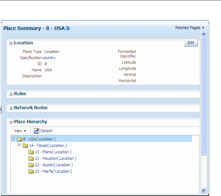
Places
Geographic Location 9-3
Figure 9–1 UIM Place Hierarchy
In UIM, you can also assign roles to places. For example, you can assign the role of
Headquarters to a site. You assign roles to place entities in the Roles section of the
Place Summary page. Role specifications must be defined in Design Studio to enable
their use with Place entities. See "About Roles" for additional information.
Understanding Address-Type Place Entities
An address is a textual way to describe a location or site. Address types are managed
separately from Locations or Site types because a location or site can have more than
one address. For example:
■A campus of many buildings has many addresses
■A building with entrances on more than one street can have more than one
address
An address can define a standard address format to meet your business requirements
and national postal standards. For example, in North America, you could define an
address to include the following information:
■Street address
■City name
■State
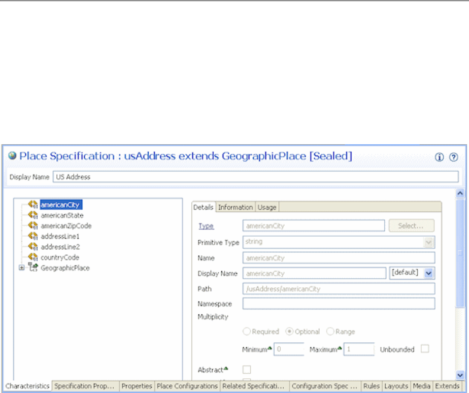
Places
9-4 Oracle Communications Unified Inventory Management Concepts
■Country
■Postal code
These individual pieces of information are called address components. You define
them as characteristics and add them to a Place specification with the entity type of
Address. Figure 9–2 shows an example of an Address specification based on standard
US postal conventions.
Figure 9–2 Standard Address
Configuring Address Selections
When you define Address specifications, you can use features that constrain the
selections that users see in UIM.
For example, you can constrain that the list of countries available for selection in UIM
to only those countries for which entities exist. For example, if only US, UK, and
Canada entities exist in the UIM database, only those countries are available for
selection. You use the entity link feature in Design Studio to configure an Address
specification for this behavior. See the Design Studio Help for more information.
You can also design specifications so that selections are constrained by location
hierarchies. For example, when a user selects Texas in the State field, their choices in
the City field are limited to cities in that state.
Figure 9–3 shows selections in the City field constrained by the selection in the State
field for the creation of an Address entity in UIM.
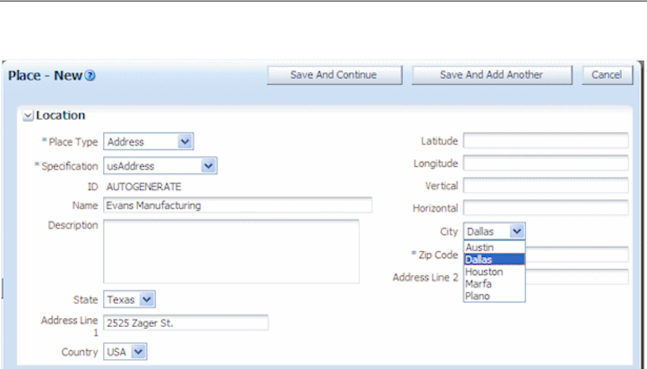
Places
Geographic Location 9-5
Figure 9–3 Address in UIM
Understanding Address Ranges
You use Address Range to define collections of addresses such as those used in MSAG
(Master Street Address Guide) implementations. You define the range by adding
address component characteristics to the Address Range specification. You also
associate the Address Range specification to the Address specification for which it
defines a range.
You can associate an address range to resources or services that serve a range of
addresses. Through the use of rulesets, you can use address ranges to validate that
new addresses are within a range. See UIM Developer’s Guide for more information
about rulesets.
Understanding Site-Type Place Entities
A site is a loosely defined place such as a campus, cell site, or VPN site. Unlike a
location, a site is not necessarily bound to specific geographic coordinates. Because
sites are only loosely defined, they can evolve over time. For example, you might need
to plan a VPN without knowing the specific locations of the VPN sites. You can create
place configurations to keep track of the changes.
If a site includes multiple specific locations, you can include them in a place hierarchy
for the site. For example, if you create a site entity for a campus, you can create
locations for its individual buildings and include them in the site's place hierarchy.
Place Configurations
Place configurations provide a versioning capability that enables you to describe how
a site is realized and what resources are assigned to a site’s configuration items over
time. See "Configurations" for general configuration information.
To track the changes to sites, you define Place Configuration specifications. You can
use the Specifications Options tab to associate entity specifications. This relationship
constrains the types of entities that can be assigned or referenced by the site.

Property Locations
9-6 Oracle Communications Unified Inventory Management Concepts
Associating Places with Other Entities
Some entities are place-enabled, meaning you can associate places to those entities. For
example, you can associate a location to a piece of equipment. In UIM, you make these
associations in the Places section of the Summary page of the entity. In addition, you
can specify the role played by the place in its involvement with the entity. See
"Involvements" for more information about involvements.
The following types of entities are place-enabled:
■Custom network address
■Custom object
■Device interface
■Equipment
■Inventory group
■Logical device
■Logical device account
■Network
■Network node
■Party
■Physical device
■Pipe
■Pipe termination point
■Service
Property Locations
Property Location entities define where resources are located and where connectivity
is terminated.
A Property Location entity represents a piece of land with defined legal boundaries. It
is the lowest-level element in the hierarchy that identifies a location (country,
state/province, city, street address).
When you create a property location, you define it as one or both of the following
types:
■Network location. A network location is one that hosts devices involved in
connectivity. Defining a property location as a network location requires the
assignment of a network location code. See "About Network Locations".
■Service location. A service location is one where a service originates or is
delivered. See "About Service Locations".
Note: Property Location entities are similar to but not equivalent to
Place entities. The two entities have different capabilities. Currently,
Property Location entities are used only with connectivity. Place
entities are used in all other contexts.

Property Locations
Geographic Location 9-7
Property Location entities are different than most other entities because they are all
based on a single specification. You can supplement the default data elements of
Property Location entities by using entity-level characteristics.
A Property Location specification is included in the ora_uim_basetechnologies base
cartridge for this purpose. Entity-level characteristics apply to all Property Location
entities in UIM. See UIM Cartridge Guide for information about ora_uim_
basetechnologies and the Design Studio Help for information about entity-level
characteristics.
You can modify also modify the behavior of Property Locations by using global
rulesets. See UIM Developer’s Guide for more information about using rulesets.
About Property Addresses
A property address provides a textual way of describing how to find a property.
Property addresses are separate entities, but they exist only as part of a property
location. They are created automatically when you create property locations. Property
addresses can be related only to property locations.
When you create a property location, a primary property address is required. The
address fields (Street Address, Apt/Room/Suite, City, Sub Area, State, Postal Code,
and Country) are combined to form the default name value for the property location.
You can override the default value and can choose to set the property name to the
value of the network location code. For service locations, however, the property name
must be unique. If you change the default property name of a service location to a
non-unique value, UIM displays an error.
Country and state values are defined as standard ISO abbreviations in the
country.properties configuration file. You can define a default country value by
editing the system-config.properties file. See UIM System Administrator’s Guide for
more information about configuration files.
You can validate property addresses using a geocoding system, such as Oracle
eLocation. When you validate an address, UIM sets the property address to the value
returned by the geocoding system. See "About Validating Addresses" for more
information.
About Validating Addresses
When you create a Property Location and enter its address, you can choose to validate
the address. Validating addresses ensures accuracy and limits duplication caused by
similar addresses.
When you validate an address, UIM sends the address data to a geocoding system,
such as Oracle eLocation. (You can configure UIM to use a different geocoding system.
See UIM System Administrator’s Guide for more information.)
The geocoding system returns one or more possible address from which you can
select. You can accept one of the suggested addresses; accept the existing,
non-validated address; or choose to neither validate nor accept the address.
■If you select one of the possible addresses, the data from the geocoding system
replaces the values in the address fields. In addition, the latitude and longitude are
updated (unless you have locked the coordinate values). UIM marks the address
as validated and displays a green check mark in the address area.
■If you accept the existing address, the Accept As-Is check box is selected,
indicating that the address does not require validation or correction.

Property Locations
9-8 Oracle Communications Unified Inventory Management Concepts
■If you cancel the validation, the address remains unvalidated and unchanged.
UIM ignores the Apt/Room/Suite field in the address during validation and does not
change it if you select one of the addresses returned by the geocoder.
About Geographic Coordinates in Property Locations
You can enter geographic coordinates for property locations. Geographic coordinates
in Property Location entities are similar to geographic coordinates in Place entities.
(See "Geographic Coordinates" for more information about how coordinates are used
in Place entities.) The are two important differences, however:
■In property locations, when you enter a latitude and longitude position or a V & H
location, UIM automatically converts it to the other system and populates the
corresponding fields. As a result, geographic coordinates are always displayed in
both systems.
■When you accept a validated address from a GIS system, the geographic
coordinates are populated (or replaced) automatically unless you have locked the
geographic coordinate fields. See the UIM Help for information about locking
coordinates.
About Service Locations
You can define a property location as a service location. A service location represents
the place where a service originates or where the service is delivered. (Service
locations are sometimes called customer sites or end-user locations.)
For example, Carrier Ethernet service is delivered to one or more service locations by a
service provider. In UIM, you reference service locations as configuration items in the
configurations of the services that include them. The collection of service locations in a
Carrier Ethernet service constitutes a service network. See "About Service Networks" for
more information.
Service locations can be outside the boundaries of a service provider’s network. For
example, Figure 9–4 illustrates a Carrier Ethernet network in which three service
locations are inside the service provider network and one service location is outside it.
The three service locations inside the provider network are included in an Ethernet
Virtual Connection (EVC) and the other service location is an Operator Virtual
Connection (OVC) connected to the EVC by a connectivity. (Both EVCs and OVCs are
types of private virtual networks (PVNs).)
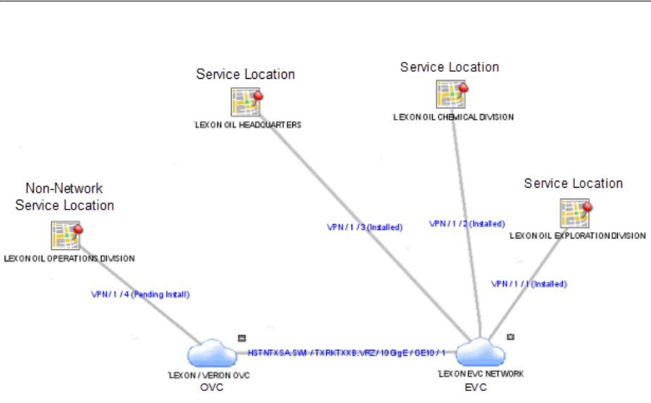
Property Locations
Geographic Location 9-9
Figure 9–4 Carrier Ethernet Network with Service Locations
Because service locations can be outside of the service provider network, they do not
require network location codes or network entity codes. In cases where service
locations are within your provider network, however, you may want to identify a
service location as a network location by assigning it a network location code. In this
scenario, the Property Location entity is both a service location and a network location.
By default, property names for service locations are a concatenation of the address
details, such as 329 BENBOW ST. APT 29 SACRAMENTO CA 95812 US or 200
LOWER HIGH ST, LONDON, GREATER LONDON SE3 1JX, UK. You can override the
default value, but the property name must be unique for service locations because it is
used as an identifier.
If the property location is defined as both a network location and a service location,
the network location code can override the property name.
About Network Locations
You can define a property location as a network location. Network locations are
property locations that host a service provider’s inventoried network infrastructure. In
UIM, network locations host network devices (logical devices associated with that
location). When you define a property location as a network location, you must assign
it a network location code.
Network location codes are strings of up to 10 alphanumeric characters, with letters in
upper case. Network location codes can be CLLI (Common Language Location
Identifier) codes, but UIM does not validate against the CLLI standard.
Oracle recommends an expanded version of the CLLI standard for network location
codes. This version includes an additional two characters to represent the country,
which is not present in CLLI codes. The Oracle-recommended code format is:
MMMMSSCCPP
where:

Property Locations
9-10 Oracle Communications Unified Inventory Management Concepts
■MMMM represents the municipality in four characters (the same as CLLI and
other standards). For example, Plano is PLAN and Cleveland is CLEV. This value
must be unique within the state.
■SS represents the state in two characters, as in the ISO standards.
■CC represents the country in two characters, as in the ISO standards.
■PP represents the property in two characters. This is the same as the CLLI building
or site value and must be unique within the municipality.
For example, PLANTXUSXA identifies a property location (XA) in Plano, Texas, in the
United States.
You can set minimum and maximum values for your system in the system-config.xml
file. See UIM Systems Administrator’s Guide for more information. For example, to
support CLLI coding, you can specify minimum and maximum values of 8. For the
Oracle-recommend format, you could specify minimum and maximum values of 10.
About Network Entities
Network locations can host logical devices that you identify with network entity
codes. Logical devices that are hosted at network locations are called network entities.
Network entity codes must be unique within each network location, but can be
duplicated in the network as a whole. Each network entity code identifies a single
logical device and a logical device can have only one network entity code.
Network entity codes can contain information that identifies the type of entity for
which they are used. For example, codes used for digital cross-connect systems could
begin with the letter K. The entity codes K01 and K02 could be used to identify two
digital cross-connect devices at network location MTVWCAUS99. The same codes
could be used to identify two different digital cross-connect devices at
PLANTXUSXA77.
By default, network entity codes are three characters long. You can set the default
minimum and maximum length in the system-config.xml file. See UIM System
Administrator’s Guide for more information about setting default values.
illustrates the relationship between network locations and network entities.
Note: Physical devices cannot be directly associated with network
locations.You can make an indirect association by associating a
physical device to a logical device at a network location. See
"Associating Physical Devices to Logical Devices" for more
information.
Note: Network entity codes are optional and are typically not used
for devices that do not require activation or management.
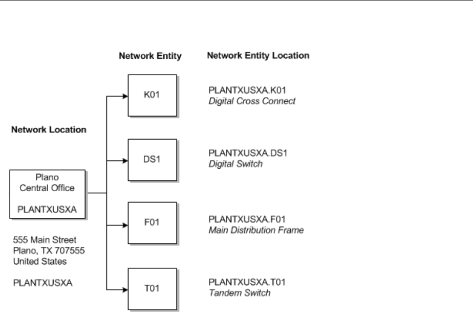
Property Locations
Geographic Location 9-11
Figure 9–5 Network Locations and Network Entities
Network entity codes are always displayed with their parent network location codes
to form a network entity location code. For example, the network entity locations
mentioned previously are displayed as MTVWCAUS99.K01, MTVWCAUS99.K02, and
so on. By default, UIM uses a dot as the delimiter between the network location code
and the network entity code, but you can suppress the display of the delimiter by
changing an entry in the system-config.xml file. See UIM Systems Administrator’s Guide
for more information.
You can select a network location or a network entity location in logical device entities
to establish the relationship between the device and the location. See "Associating
Logical Devices with Network Locations and Network Entity Locations" for more
information.
The endpoints (pipe termination points) of a Connectivity entity can be associated
with a network location, such as PLANTXUS or to a network entity location such as
PLANTXUS.K01. You can associate a network location or a network entity location to
an end point even before the location has been associated to a logical device. See
"About Network Locations" for more information.
If the connectivity end point is associated with a network entity location, the end point
can be terminated only on an interface that is part of the logical device at the location.
The network entity location code is incorporated into the connectivity identifier of the
Connectivity entity. See "About Termination" for more information.

Property Locations
9-12 Oracle Communications Unified Inventory Management Concepts
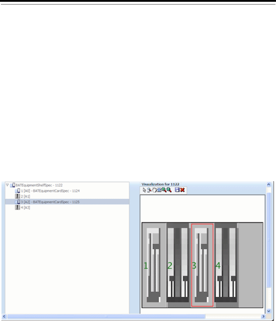
10
Equipment and Devices 10-1
10
Equipment and Devices
This chapter describes how to define Equipment specifications in Oracle
Communications Design Studio and how to use them to model your equipment in
Oracle Communications Unified Inventory Management (UIM).
Understanding Equipment Modeling
In UIM, you can represent equipment in several ways. You can inventory all of your
physical hardware resources down to the port level for asset-tracking purposes and
you can represent your network elements as logical devices for activation purposes.
UIM enables you to capture the physical structure of your equipment visually. In
Design Studio, you can create a prepopulated hierarchical view of your equipment
that can be used in UIM to quickly create racks of populated equipment, or you can
manually build out racks and shelves in UIM.
Figure 10–1 shows a shelf with four slots and two cards in UIM. When a module is
selected in the tree view, the module is highlighted in the graphical view.
Figure 10–1 Equipped Shelf in UIM
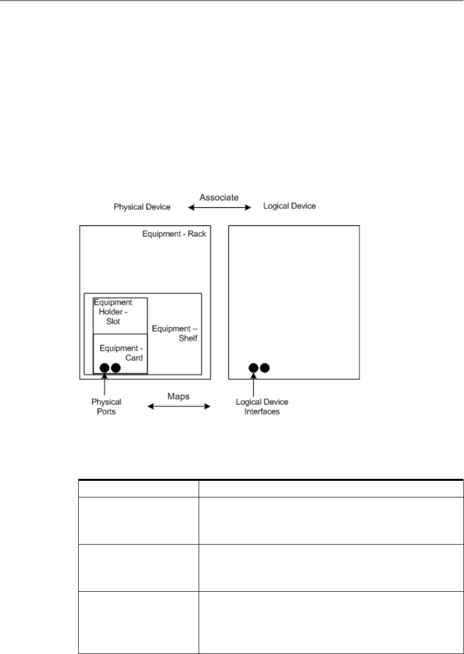
Understanding Equipment Modeling
10-2 Oracle Communications Unified Inventory Management Concepts
You can also choose to model your equipment logically. Modeling equipment logically
enables you to create addressable network elements that can be managed or used with
activation applications.
Figure 10–2 shows the physical and logical representations for a rack of equipment.
The physical representation consists of racks, shelves, slots, cards, and ports and can
be logically grouped into a physical device.
The logical representation consists of a logical device and logical device interfaces. You
can associate a physical device to a logical device and map the physical ports to the
logical device interfaces so that you can have addressable network elements while
inventorying the physical equipment.
Figure 10–2 Physical and Logical Equipment Representations
Table 10–1 lists the equipment specifications used in Design Studio. Each of these
specifications is described in this chapter.
Table 10–1 Equipment Specifications
Specifications Definitions
Logical Device
Device Interface
Logical Device Account
Groups equipment logically by function and enables you to
create addressable network elements.
Physical Device
Physical Port
Physical Connector
Groups multiple pieces of physical equipment so that ports and
connectors can be mapped to device interfaces.
Equipment
Equipment Holder
Physical Port
Physical Connector
Inventories physical equipment, equipment holders, connectors,
and ports.

Understanding Logical Devices
Equipment and Devices 10-3
Understanding Logical Devices
A logical device represents a functional view of a set of resources. The logical device
itself is not physical, but it can be supported by one or more physical resources that act
together logically to perform one or more functions. Logical devices are understood at
the network layer. They provide the ability to be discovered and can support service
provisioning.
In the telecommunications industry, logical devices are often called network elements,
but the terms are not interchangeable. In UIM, a logical device can also be a
non-intelligent device that does not qualify as a network element.
Logical devices can be supported by one hardware item like a desktop router or by
many pieces of hardware such as:
■Central Office (CO) switches
■Digital Cross-Connect Systems (DCSs)
■Digital Subscriber Line Access Multiplexer (DSLAMs)
■Main Distribution Frames (MDFs)
Logical devices can be associated with logical device accounts. For example, a voice
mail server modeled as a logical device can be associated with logical device accounts
that represent voice mail accounts. These associations are governed by associations
between logical device and logical device account specifications. See "About
Associating Logical Device Accounts with Logical Devices" for more information.
About Logical Device Hierarchies
Logical devices frequently include hierarchies of other logical devices and device
interfaces. For example, a logical device entity that represents a router might include
child logical device entities that represent virtual routers.
When you define a Logical Device specification, you can include specification
relationships that you identify as Parent or Child. These specification relationships
govern which logical devices you can add to logical device hierarchies:
■If one or more specification relationships exist between logical device
specifications, then only those relationships are valid for entities based on those
specifications. No other logical devices can be included in that hierarchy. For
example, if Logical Device Specification A has a Parent relationship with Logical
Device Specification B, then the hierarchy of entities based on Logical Device
Specification A can include only logical devices based on Logical Device
Specification B.
■If a logical device does not include any specification relations, its hierarchy can
include any logical device that is not itself constrained by specification
relationships.

Understanding Logical Devices
10-4 Oracle Communications Unified Inventory Management Concepts
Understanding Device Interfaces and Sub-Interfaces
Logical devices can provide device interfaces. A device interface represents an access
point into the device. These device interfaces may be for connectivity, power, timing,
or any other means of access into or out of the device.
Some device interfaces correspond to physical ports while others are virtual. The
virtual device interfaces are used for transmission (connectivity) purposes and are
referred to as sub-interfaces. Device interfaces cannot exist on their own, but they are
provided directly or indirectly by logical devices.
A device interface that represents a physical interface or port that can host a physical
connection is called a media interface. A media interface must be the root interface in its
device interface hierarchy.
You associate Device Interface specifications with Logical Device specifications and
specify the minimum and maximum number of device interfaces that can be added to
a logical device entity created based on a Logical Device specification.
For example, you can define a Logical Device specification that supports a minimum
of 64 Local Area Network (LAN) ports. You can create these ports as device interfaces
and specify the minimum quantity as 64. When a logical device based on this
specification is created in UIM, 64 LAN ports are automatically created.
Similarly, you configure Device Interface specifications to determine which
sub-interfaces they can include along with minimum and maximum quantities.
To create a logical device with device interfaces, perform the following high-level
tasks:
1. Define a Logical Device specification for a device.
2. Define Device Interface specifications for the ports or other connectivity into the
device.
3. On the Related Specifications tab for the Logical Device specification, relate the
Device Interface specification.
4. Modify the properties of the related specification to add a minimum and
maximum number of device interfaces to be created in UIM.
If the minimum quantity is not zero, the device interface is required; the minimum
number of device interfaces are added automatically when you create a logical
device or logical device interface. UIM prevents you from adding more than the
specified maximum number of device interfaces, and you cannot remove device
interfaces if it violates the minimum number required.
See the Design Studio Help for the steps to define specifications, associate related
specifications, and modify relationship properties.
Note: In previous versions of UIM, specification relationships did
not limit which logical devices could be included in a logical device
hierarchy.
If you upgrade from a previous version to UIM 7.3, existing
specifications that include specification relationships govern
hierarchies created after the upgrade. Existing hierarchies will not be
affected unless you modify them. If you modify an existing hierarchy
after upgrading, the changes are governed by the relationships
defined in the affected specifications.
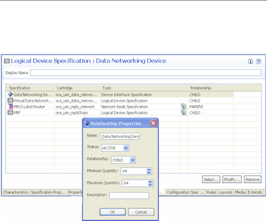
Understanding Logical Devices
Equipment and Devices 10-5
Figure 10–3 shows an example of a Logical Device specification for a Data Networking
Device. On the Related Specifications tab, a Device Interface specification is selected.
The relationship properties are set to a minimum of 64 and a maximum of 64.
Figure 10–3 DSLAM Logical Device Specification in Design Studio
In UIM, when an entity is created based on the Data Networking Device specification,
64 device interfaces will be created based on the associated Device Interface
specification. Because the maximum is set to 64, no additional device interfaces can be
added to the logical device.
Associating Rate Codes to Device Interfaces
You can associate rate codes to device interfaces to define their bit rate and technology.
The rate code associated to a device interface determines which connectivities can be
terminated on the interface. See "About Termination" for more information. (Device
interfaces with rate codes can also terminate Pipe entities. See "Configuring and
Implementing Pipe Termination" for more information.)
For example, an OC1 rate code designates a 51.840 Mb/s SONET signal, while a DS3
rate code identifies a 44.736 Mb/s T-Carrier signal. See "About Rate Codes" for more
information. Device interfaces with those rate codes can terminate only channelized
connectivities with matching rate codes.
You associate rate codes with device interface specifications in Design Studio. When
you create a device interface based on a specification with a rate code association, the
rate code is automatically related to the interface.
The ora_uim_basetechnologies cartridge includes definitions of the supported rate
codes. You must define this cartridge as a dependent cartridge for a project in Design
Studio before you associate rate codes to device interface specifications. If you do not

Understanding Logical Devices
10-6 Oracle Communications Unified Inventory Management Concepts
define the cartridge dependency, rate codes will not be available for selection when
you define Device Interface specifications in Design Studio.
See UIM Cartridge Guide for more information about the base cartridge and see the
Design Studio Help for more information about associating rate codes to device
interface specifications.
About Interface-Bound Cross-Connects
Cross-connects are connectivity entities that participate in the continuity of end-to-end
trail connectivity by interconnecting device interfaces within a logical device.
There are two kinds of cross-connects: interface-bound and trail-bound.
Interface-bound cross-connects are bound to the life of the interfaces it connects and
are created as part of their parent logical devices. See "About Interconnections" for
more information.
For example, an interface-bound cross-connect could represent a D4 channel bank's
multiplexing function, consisting of fixed internal connectivity from the 24 DS0
drop-side interfaces to the 24 DS0 line-side sub-interfaces provided by a high-speed
DS1 line interface. (Line-side and drop-side refer to the high-speed and low-speed
sides of a device.)
You create interface-bound cross-connects for device interfaces by selecting pairs of
device interfaces in a logical device hierarchy. The device interfaces must have the
same rate code. See the UIM Help for more information.
Cloning and Duplicating Logical Devices
You can clone and duplicate logical devices:
■Duplicating the logical device copies only the entity itself. The duplicated entity is
the same as the original except for the entity ID>
■Cloning the device copies the entity and (by default) all of its child logical devices,
associated physical devices, and associated Equipment entities. By default, a
cloned logical device is an exact copy of the original, aside from the entity ID. You
can customize the content of the clone.
By default, the following associations and mappings are copied when you clone a
logical device:
■Device interface hierarchy
■Mapped physical devices
■Equipment associations with physical devices
■Mappings between device interfaces provided by the logical device and ports and
connectors provided by physical devices and equipment
■Cross-connects between device interfaces
You can customize the clone in the following ways:
■Specifying names of logical device, physical device, and equipment created as part
of the cloning operation
■Assigning the cloned device to a different property location
■Excluding specific items in the logical device hierarchy
■Excluding specific physical device mappings and equipment associations

Understanding Logical Devices
Equipment and Devices 10-7
You can begin a logical device cloning operation from physical device search results. In
this situation, the logical device associated to the physical device is cloned. If you want
to copy only the physical device, you can use the existing Duplicate feature.
Equipment entities associated to the physical device are not copied in this scenario,
however.
See the UIM Help for more information about duplicating and cloning logical devices.
About Flow Interfaces
A flow interface is a point in a network through which traffic flows. You use flow
interfaces to partition media interfaces (device interfaces at the top of their hierarchies)
into virtual channels based on bit rate. Flow interfaces are similar to sub-device
interfaces, but can have configurations that capture their attributes.
You use flow interfaces terminate packet connectivity. They specify the termination
type of the connectivities terminated on their parent device interfaces. There are four
termination types defined by flow interface specifications:
■Access. Indicates that the purpose of an interface is to terminate connectivity that
provides access to a service provider network, such as Ethernet UNI connectivity.
■Internetwork. Indicates that the purpose of an interface is to terminate
connectivity that interconnects two service provider networks, such as Ethernet
I-NNI connectivity.
■Trunk. Indicates that the purpose of an interface is to terminate connectivity that
connects equipment and devices in the same network.
■Unknown. Indicates that the purpose of the interface is unknown.
Flow interface configurations can include references to flow identifiers (such as VLAN
IDs) that trace the path of services through the device interfaces and connectivities in
multipoint and point-to-point service arrangements. See "About Flow Identifiers" for
more information. They can also include references to performance parameters such as
bandwiidth profiles and class of service. These performance parameters are modeled
in UIM with Custom Object entities. See "Performance Parameters" for more
information.
A flow interface configuration is created automatically when you create a flow
interface. As with other entities and entity configurations, you specify the flow
interface configuration specification in the flow interface specification. Unlike other
entities, however, flow interface specifications can be associated with only one
configuration specification.
You cannot create flow interfaces directly from the logical device or device interface
hierarchy in a Summary page. Rather, you create them in the packet virtual networks
that include them. See UIM Help for more information about creating flow interfaces.
Logical Device Configurations
A logical device configuration contains information about how the device is realized in
terms of resources that are assigned to it. Logical device configuration items can assign
or reference resources such as:
■Custom network addresses
■Custom objects
■Device interfaces

Understanding Logical Devices
10-8 Oracle Communications Unified Inventory Management Concepts
Typically, logical device configurations consume device interfaces that are on a
different logical device. Logical devices can consume a network address that can
change over time. For example, this could be a route distinguisher address type.
See "Configurations" for more information about configuration specifications.
Understanding Logical Device Accounts
Logical device accounts are a special type of network address that are hosted or
managed by a logical device. You can associate logical device accounts to logical
devices. For example, email account IDs are considered unique to an email domain,
typically managed by a logical domain device. For a mobile wireless service, you can
create a logical device account for a subscriber on the Home Location Register (HLR)
and Voice Messaging System (VMS). Accounts for accessing content on online music
or IPTV servers could also be modeled this way. For a service provider, a logical device
account could be a management account, such as a login name for configuring a
logical device.
Other examples of logical device accounts include:
■Instant messaging (IM) accounts
■RADIUS AAA accounts
■Voice mail (VM) accounts
■Element management accounts
You use Logical Device Account specifications to define these accounts in your
inventory. The information captured in a Logical Device Account specification
depends on the account that you are modeling. For example, you might need to add
characteristics for subscriber information such as a login name, mailbox, or accounting
record.
About Logical Device Account Configurations
Logical Device Account entities can have configurations. You can use logical device
account configurations to maintain a history of subscriber details. For example,
subscriber details for a GSM customer can be stored in a logical device account related
to a Home Subscriber Server (HSS). As the subscriber details evolve over time, you can
use configurations to maintain a history for auditing and validation.
Only telephone numbers and custom network addresses can be assigned to
configuration items in Logical Device Account configurations. You can include
references to all reference-enabled entities, however.
See "Configurations" for more information about how you use configurations.
About Associating Logical Device Accounts with Logical Devices
You can create associations between logical devices and logical device accounts. For
example, you can create an association between a voice mail account (a logical device
account) and a voice mail server (a logical device).
When you define Logical Device specifications, you can include Parent specification
relationships to Logical Device Account specifications. Similarly, when you define
Logical Device Account specifications, you can include Child specification
relationships to Logical Device specifications. See Design Studio Help for more
information about creating specification relationships.
In UIM, these specification relationships govern which logical devices and logical
device accounts you can associate with each other.

Understanding Physical Resources
Equipment and Devices 10-9
■If one or more specification relationships exist between logical device and logical
device account specifications, then only associations based on those relationships
are valid. For example, if Logical Device Specification Y has a Parent relationship
with Logical Device Account Specification Z, then you can make associations only
between entities that are based on these specifications. You cannot make
associations between the logical devices based on Logical Device Specification Y
and logical device accounts based on any specification other than Logical Device
Account Specification Z.
■If a Logical Device or Logical Device Account specification has no specification
relationships, you can create associations freely.
Understanding Physical Resources
Your inventory is likely to include physical hardware items such as routers, DSLAMs,
interface cards, and so on. To enable you to manage these resources in your inventory,
UIM includes several different types of physical resource specifications:
■Physical Devices: A physical device is a collection of hardware resources that
have a common function in the network. It is the physical equivalent to a logical
device. This is required to map physical equipment to logical devices.
■Equipment: Equipment refers to physical units of equipment such as racks,
shelves, circuit cards, field-replaceable units (FRUs), or handheld phones.
■Equipment Holders: Equipment holders are slots or mounting positions that
contain cards.
■Physical Ports: Physical ports are the places where communication begins or ends
on a physical device or equipment.
■Physical Connectors: Physical connectors connect hardware units for signal or
power transmission.
You configure these specifications and the entities based on them to reflect the physical
resource composition of your inventory.
Configuring Equipment Specifications
Equipment specifications represent physical items of hardware such as racks, shelves,
and cards. Shelves can provide slots (modeled with the Equipment Holder
specification) that hold cards or modules. Equipment specifications can also model
self-contained, independent devices such as routers or desktop modules.
You can model your equipment visually in Design Studio so that it is automatically
built out in UIM or you can define the individual Equipment specifications and
manually build out your equipment in UIM. This section describes how to build out
your equipment specifications in Design Studio so that equipment is automatically
built in UIM.
Note: In in releases previous to UIM 7.3, specification relationships
did not limit which logical devices and logical device accounts could
be associated with each other.
If you upgrade from a previous version to UIM 7.3, existing
specifications that include specification relationships govern
associations created after the upgrade. Existing associations will not
be affected unless you modify them.
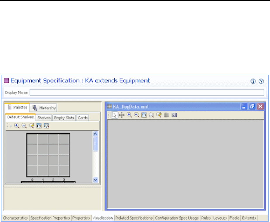
Understanding Physical Resources
10-10 Oracle Communications Unified Inventory Management Concepts
Understanding the Visualization Tab
The equipment category you choose for the equipment specification determines what
appears in the Visualization tab. You can select card, shelf, rack, or leave the
equipment category blank.
Figure 10–4 shows the Visualization tab for a shelf specification.
Figure 10–4 Visualization Tab
The Visualization tab includes several areas that you work in:
■The Palettes tab contains templates that you use to define the basic structure of the
equipment. You drag items from the Palettes tab to the canvas. The Palettes tab
contains subtabs that are based on whether the Equipment specification is defined
as a card, a rack, or a shelf.
■The canvas is the area where you configure the equipment by dragging items from
the Palettes tab.
■The Hierarchy tab displays the equipment configuration in tree-view form. It
reflects the content of the canvas and is updated when you add new items. When
you select an item in the canvas, the corresponding item in the tree view is
highlighted. When you select an item in the tree view, the corresponding item in
the canvas is highlighted.
Typically the easiest way to build your equipment is to start at the equipment holder
and work your way up to cards, shelves, and racks. Model your equipment holders
first, then your cards. Create shelves using the existing cards and finally add racks
using existing shelves of equipment holders and cards.
You can choose to model the ports and connectors at any time because they are not
done through visualization tabs. See "Adding Ports and Connectors" for more
information.

Understanding Physical Resources
Equipment and Devices 10-11
Configuring Equipment Holder Specifications
An Equipment Holder specification defines a slot into which cards can be installed.
The holder itself does no processing. Equipment holders are provided by equipment
and can contain other equipment. For example, a shelf provides an equipment holder.
A LAN card can be installed into the equipment holder.
You can limit the cards that slot can contain by creating a parent-to-child relationship
between its Equipment Holder specification and one or more Card specifications. In
UIM, slots based on the Equipment Holder specification can contain only cards with
which it has a child relationship.
Configuring Card Specifications
When you configure a card specification, you assign a template that determines the
card’s orientation. You can choose a vertical or horizontal orientation. You also
determine how many holders the card requires. This number determines how many
contiguous slots are required when you add the card to a shelf.
Configuring a Shelf Specification
When you configure a shelf specification, you define the shelf arrangement by
choosing a template or by using an existing shelf. You then add card specifications or
empty slot specifications to the shelf.
There are two default templates: shelf and card carrier. The shelf template creates a
shelf. You can change the number of rows and columns. The card carrier template can
be placed on a shelf template to visually change the layout of the shelf when cards
need to be grouped in ways that cannot be changed by changing the rows and
columns.
Figure 10–5 shows the two shelf templates and the card carrier template.
Note: In some cases, an Equipment Holder specification can be a
child of a Card specification rather than the reverse. In this situation,
UIM does not limit the cards that slots based on the Equipment
Holder specification can contain.
Note: You must configure a card specification in the Visualization
tab before it can be added to shelves.
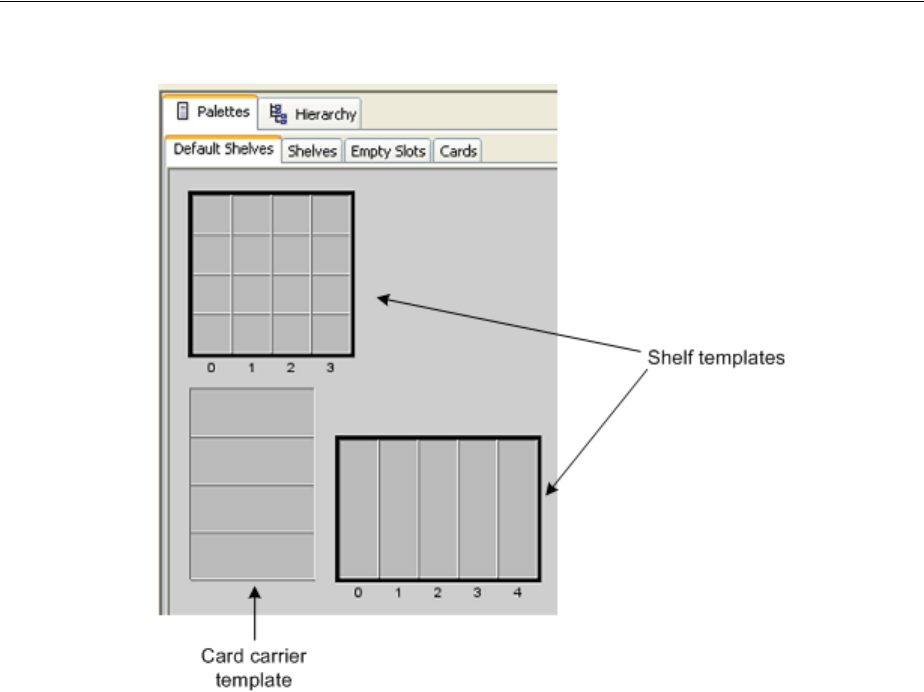
Understanding Physical Resources
10-12 Oracle Communications Unified Inventory Management Concepts
Figure 10–5 Shelf Templates
When you have completed the shelf and card carrier visualization, you can add card
specifications and Equipment Holder specifications. When you add a card
specification to the shelf, you specify the slot it will occupy and the Equipment Holder
specification. If the card specification requires more than one holder, the shelf must
have enough contiguous slots beginning with the selected slot.
In UIM, when you create a new shelf entity, it is prepopulated with the cards defined
in its specification. You can see the equipment in the Equipment visualization. See the
UIM Help for more information about the Equipment visualization.
Configuring a Rack Specification
A rack includes one or more shelves. You can include any of the shelves that have
already been defined in the workspace.
Figure 10–6 shows an Equipment specification for a rack. The Palettes tab lists all
available Equipment specifications for shelves, and the Hierarchy tab shows the racks
visualized in the canvas. In this case, various shelves were dragged from the Palettes
tab to the canvas to create a shelf visualization.
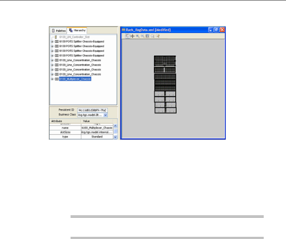
Understanding Physical Resources
Equipment and Devices 10-13
Figure 10–6 Rack in Design Studio
Adding Ports and Connectors
In Design Studio, you can configure an Equipment specification so that entities based
on it automatically include physical ports and physical connectors. You must define
Physical Port specifications and Physical Connector specifications in Design Studio
and then relate them to an Equipment specification on the Related Specifications tab.
Physical connectors and physical ports cannot exist on their own, but they are
provided by equipment or physical devices.
For example, you can associate a Physical Port specification for a LAN port to an
Equipment specification for a LAN interface card. Because equipment typically has a
fixed number of ports and connectors, the minimum and maximum quantity would be
the same. The minimum quantity of ports or physical connectors is automatically
added to the equipment when an equipment entity is created based on the Equipment
specification related to Physical Port or Physical Connector specifications.
In UIM, you can add physical connectors and physical ports to equipment and
physical devices. You can also remove connectors and ports. You maintain these
associations for equipment using the tree view. You maintain them on physical devices
using the Physical Device Summary page.
In the Physical Device Hierarchy section of a Physical Device Summary page, you can
see information about the assignment status, conditions, and consumer of a physical
port. You can follow a link to go to the Summary page of the consuming entity. For
example, if the port is assigned to a configuration item in a Service configuration, the
parent service is shown as a link in the tree view. See the UIM Help for more
information.
Figure 10–7 shows a Physical Device Hierarchy section that includes several ports.
Note: Ports and connectors are not shown on the visual canvas in
Design Studio or UIM.
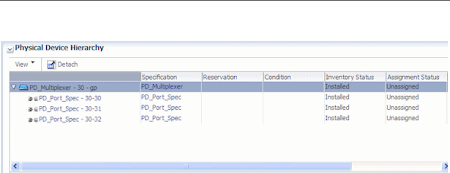
Understanding Physical Resources
10-14 Oracle Communications Unified Inventory Management Concepts
Figure 10–7 Physical Device Hierarchy
Configuring Physical Port Specifications
A Physical Port specification defines a point of entry for communication. A physical
port is where communication begins or ends on a physical device or unit of
equipment. Unlike a physical connector, a physical port performs basic processing,
such as reading transmission data.
Physical ports are provided by physical devices or equipment such as chassis or cards.
For example, a LAN port could be provided by a LAN interface card.
The following are examples of physical ports that can be defined with Physical Port
specifications:
■T1/E1 port
■LAN port
■Switch port
■DSLAM port
Configuring Physical Connector Specifications
You use Physical Connector specifications to model hardware that physically links or
connects hardware units for the transmission of signals or power. Unlike physical
ports, physical connectors have no built-in intelligence; they simply conduct a signal.
Examples include:
■RJ-45 network connector
■MDF terminal block connector
■DB-36 connector
Manually Configuring Equipment in UIM
If you do not build out racks or equipment in Design Studio, you can build your
equipment out manually in UIM. You can also add multiple equipment entities at a
time in UIM by using the Equipment Range link. See the UIM Help for more
information about adding equipment.
In UIM, you can create new equipment and use the tree view to add child equipment.
For example, you can create a new shelf and add cards to the shelf.
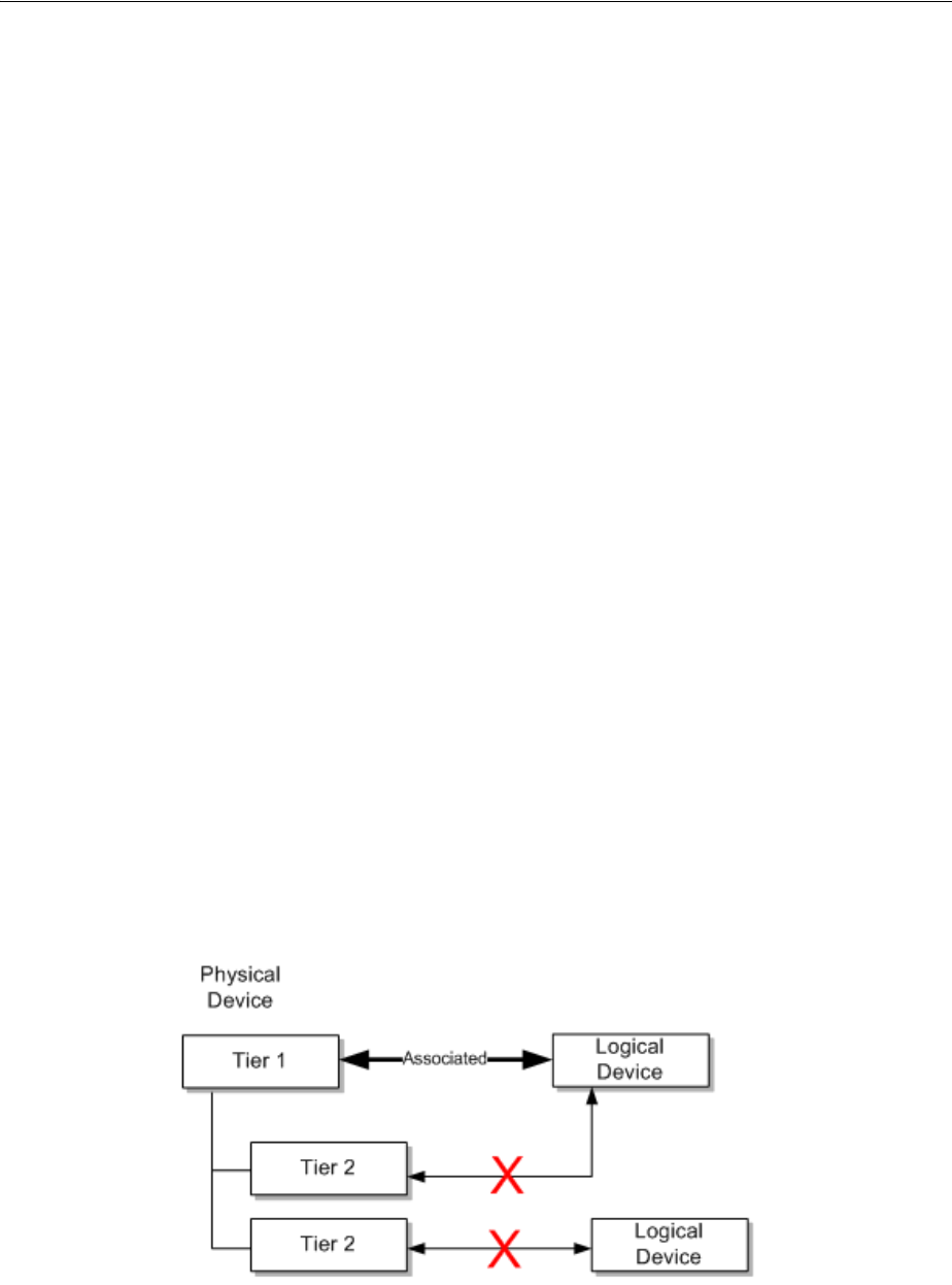
Associating Physical Devices to Logical Devices
Equipment and Devices 10-15
Configuring Physical Device Specifications
Physical devices are aggregations of physical resources that can include other physical
devices and equipment. For example, a physical device can represent a DSLAM that
includes one or more multiplexers and splitters. Physical devices can be related
hierarchically.
In UIM, you can associate a physical device to a corresponding logical device. When
that association is complete, you can map the ports and connectors provided by the
physical device or by the equipment associated with the physical device to the device
interfaces in a logical device.
In Design Studio, you can include Physical Port and Physical Connector specifications
in the Related Specifications tab of a Physical Device specification. Making these
associations means that ports and connectors are included automatically in UIM when
physical devices are created. See "Adding Ports and Connectors" for more information.
In most cases, however, physical ports and connectors are configured with equipment
and not with physical devices.
Associating Physical Devices to Logical Devices
A physical device can be associated to one logical device, but a logical device can be
associated to one or more physical devices. When a physical device is associated to a
logical device, you can map the device interfaces to the physical connectors or ports on
the physical device or to the physical ports and connectors of equipment related to the
physical device. You can also map the ports and connectors of equipment that is down
the hierarchy of the equipment associated to the physical device.
Only top-level device interfaces can be mapped. Each device interface can be mapped
to only one port or connector and ports and connectors can be mapped to only one
device interface. Device sub-interfaces cannot be mapped.
You can associate logical and physical devices at only one tier in the hierarchy. See
Figure 10–8 for an example of associations. In this example, a tier 1 physical device is
associated to a logical device; therefore, the tier 2 physical devices are not available for
association to logical devices.
Figure 10–8 Physical Device Associations
You can associate equipment within a physical device at only one tier within the
hierarchy. See Figure 10–9 for an example. In this example, a shelf (tier 2) in a rack is
associated with a physical device; therefore, associations cannot be made at the rack
(tier 1) or card (tier 3) level.
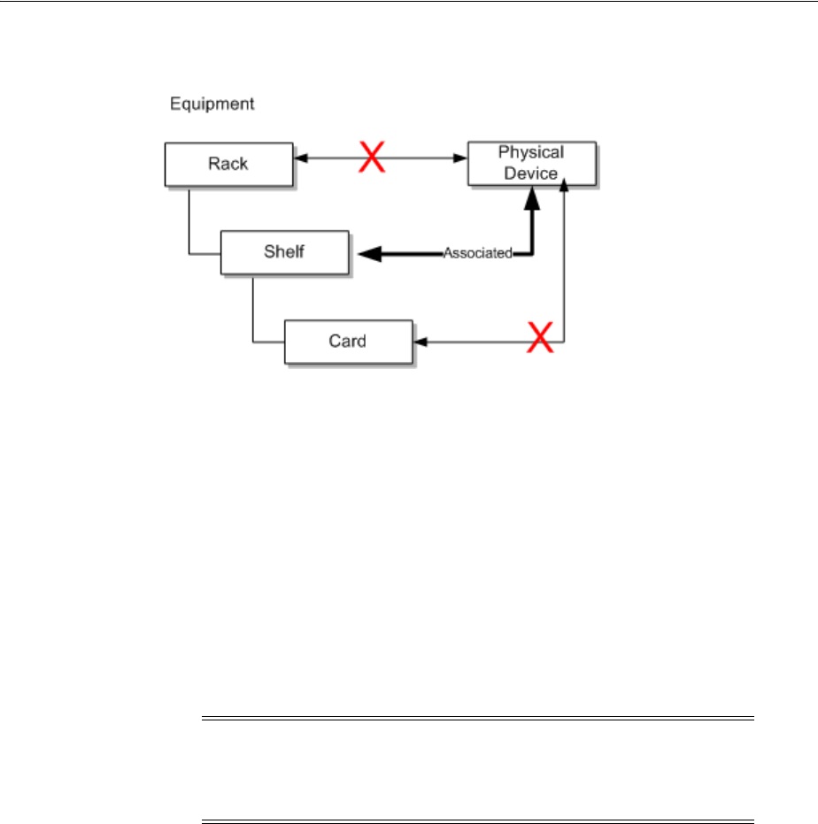
Associating Devices and Equipment with Network Locations
10-16 Oracle Communications Unified Inventory Management Concepts
Figure 10–9 Equipment Associations
You can map device interfaces to ports or connectors provided by equipment or
physical devices either automatically or manually. See the UIM Help for information
about mapping device interfaces to ports and connectors.
Associating Devices and Equipment with Network Locations
You can define the locations of logical devices, physical devices, and Equipment
entities by associating them with network locations. A network location is a Property
Location entity that has been assigned a network location code. See "Property
Locations" for more information.
Network locations are used in modeling channelized connectivity only. The network
location associated to a logical device, physical device, or Equipment entity identifies
the property location where the entity is physically located.
You can associate the network locations directly to the entities. The associations can
also be made automatically as the result of propagation downward through
hierarchies. See "Understanding Network Location Code Propagation" for more
information.
Associating Logical Devices with Network Locations and Network Entity Locations
A logical device that is located at a property location is known as a network device
and it can terminate channelized connectivity. See "About Termination" for more
information.
Unlike physical devices or Equipment entities, you can associate logical devices with
network locations or network entity codes. Network entity codes are used to identify
devices that can enable services at a network location. A network location can be
associated with more than one logical device, but a network entity code can associated
with only a single logical device.
Note: Property Location entities are similar to but not the same as
Place entities. You can associate a logical device to Place entities to
define other kinds of location-oriented relationships, such as the place
where the device is managed.

Associating Devices and Equipment with Network Locations
Equipment and Devices 10-17
Typically, network entity codes are applied to logical devices that are managed by a
network management system (NMS) and that require some configuration to enable
services.
A network entity code is always displayed in combination with the network location
code of its related network location and is referred to as a network entity location. See
"About Network Locations" for more information.
When network entity codes have been defined for a network location, you see them in
the list you use to associate a network location to a logical device. For example, if
network location PLANTXUSXA includes a single network entity code (K01) and
network location PLANTXUSXB includes two network entity codes (K01 and K02),
you see the following choices when you select a network location for a logical device.
PLANTXUSXA
PLANTXUSXA.K01
PLANTXUSXB
PLANTXUSXB.K01
PLANTXUSXB.K02
The list excludes network entity location codes that have already been associated to
logical devices.
When you select a network location, UIM sets a default device identifier that depends
on the network location you select:
■If you select a network entity location code, such as PLANTXUSXB.K01, the device
identifier is set to that value.
■If you select only a network location code, such as PLANTXUSXB, the device
identifier is set to the network location followed by a sequential number in
parentheses. This pattern enables all devices located at the network location
without a network entity code to default to a unique device identifier. For
example, the first default device identifier for PLANTXUSXB is PLANTXUSXB (1).
In either case, you can change the device identifier supplied by UIM with one that
corresponds to your business practices. The identifier must be unique across all logical
devices.
See the UIM Help for more information about selecting network locations and setting
device identifiers.
Associating Equipment and Physical Device Entities with Network Locations
You can define the location of an Equipment entity or physical device by associating it
with a network location (a Property Location entity that has been assigned a network
location code). There are three ways in which these entities can be associated with
network locations:
■By associating a Physical Device or Equipment entity with a logical device that has
a network or network entity code or with a logical device in the hierarchy of a
parent logical device with such a code.
Note: Network entity codes are optional and are typically not used
for devices that do not require activation or management.
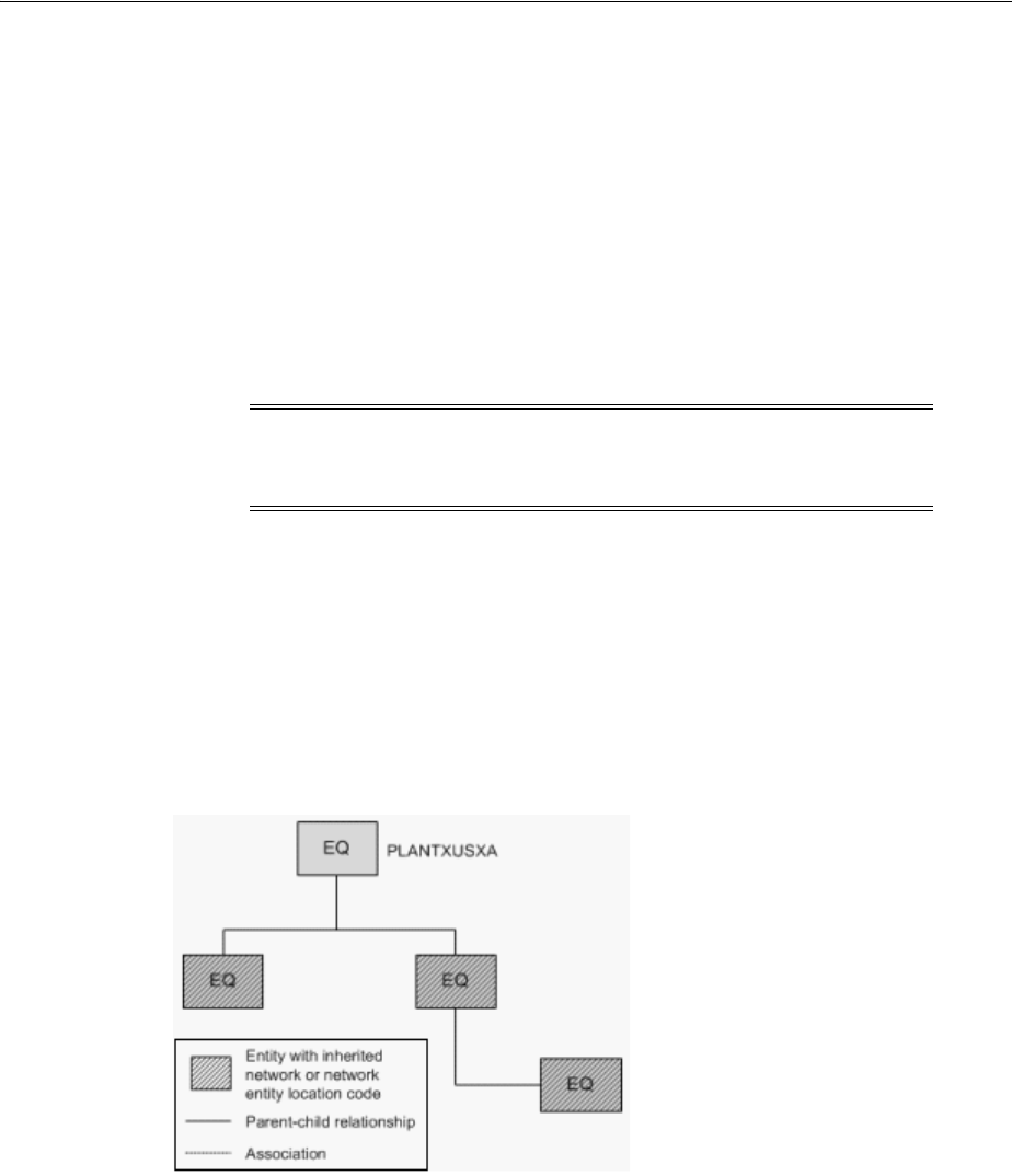
Associating Devices and Equipment with Network Locations
10-18 Oracle Communications Unified Inventory Management Concepts
■By specifying a network location code when you create the entity. A Network
Location field now appears in the Create page for Equipment and Physical Device
entities.
■By editing a Equipment or Physical Device entity to include a network code. A
Network Location field appears in the Information page that you see when you
edit entities of these types.
Understanding Network Location Code Propagation
Network location codes are propagated downward through physical device and
equipment hierarchies. The highest-level entity that has a network location code is the
location parent for the hierarchy.
Because equipment hierarchies can include only other Equipment entities, the
propagation of network location codes is straightforward. All Equipment entities
below the location parent are assigned the network location code assigned to the
parent. You cannot change these codes for the child entities unless you also change the
code for the parent.
Figure 10–10 illustrates a small Equipment hierarchy. All the entities have the network
code PLANTXUSXA.
Figure 10–10 Network Location Code for Equipment Hierarchy
Physical device hierarchies can include other physical devices. In addition, physical
devices can be associated with Equipment entities. In this kind of hierarchy, all
physical devices in the hierarchy and all Equipment entities associated with physical
devices in the hierarchy are automatically assigned the network location code of the
parent physical device. You cannot change the automatically assigned network
location codes.
Figure 10–11 illustrates a physical device hierarchy in which physical devices are
associated with Equipment entities. All of the entities in this hierarchy are assigned the
PLANTXUSXA network code of the parent physical device.
Note: Equipment and Physical Device entities cannot be assigned
network entity codes. Network entity codes are valid only for logical
devices.
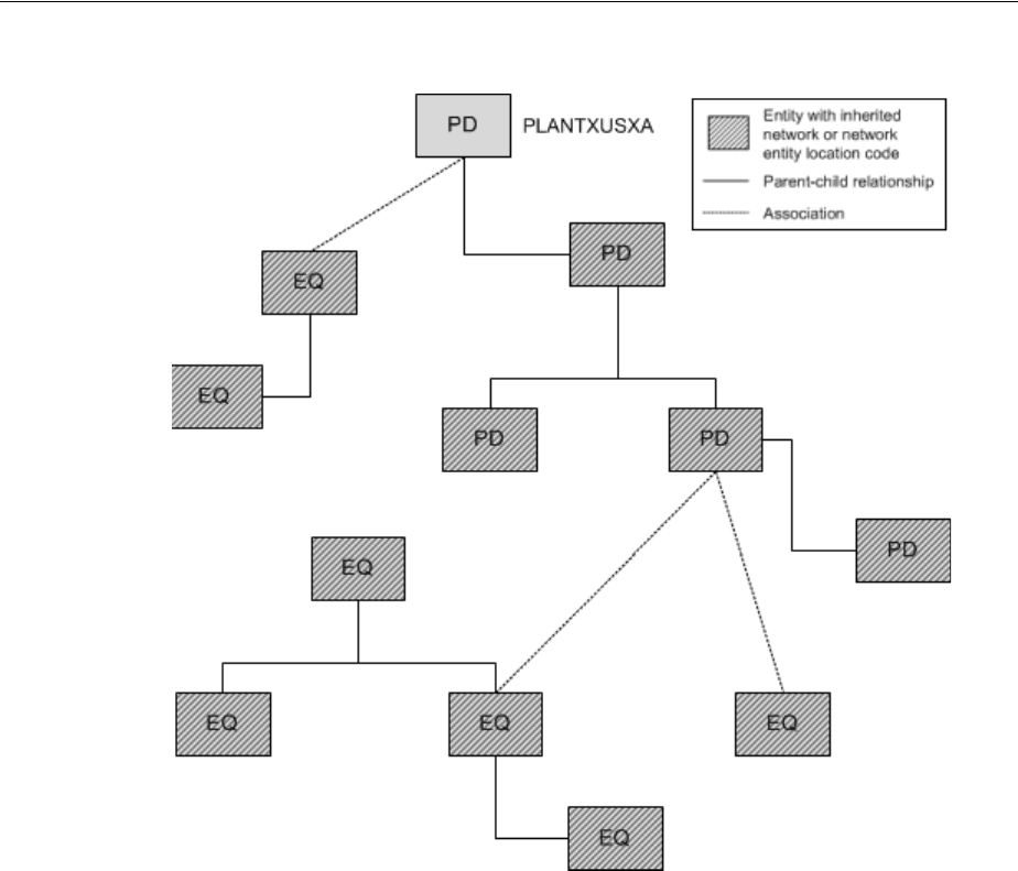
Associating Devices and Equipment with Network Locations
Equipment and Devices 10-19
Figure 10–11 Network Location Code Physical Device Hierarchy
Logical device hierarchies can be complex because logical devices can be associated
with physical devices, which in turn can be associated with Equipment entities. In
addition, logical devices can have network location codes or network entity location
codes.
In a logical device hierarchy, child logical devices inherit the network location code or
network entity location code of the parent logical device. Physical devices and
Equipment entities inherit only the network location code.
In the hierarchy shown in Figure 10–12, the logical devices have inherited the parent
logical device’s network entity location code (PLANTXUSXA.K02). Physical devices
associated with logical devices in the hierarchy inherit only the network location code
(PLANTXUSXA). You cannot change any of the automatically assigned network
location or network entity location codes.
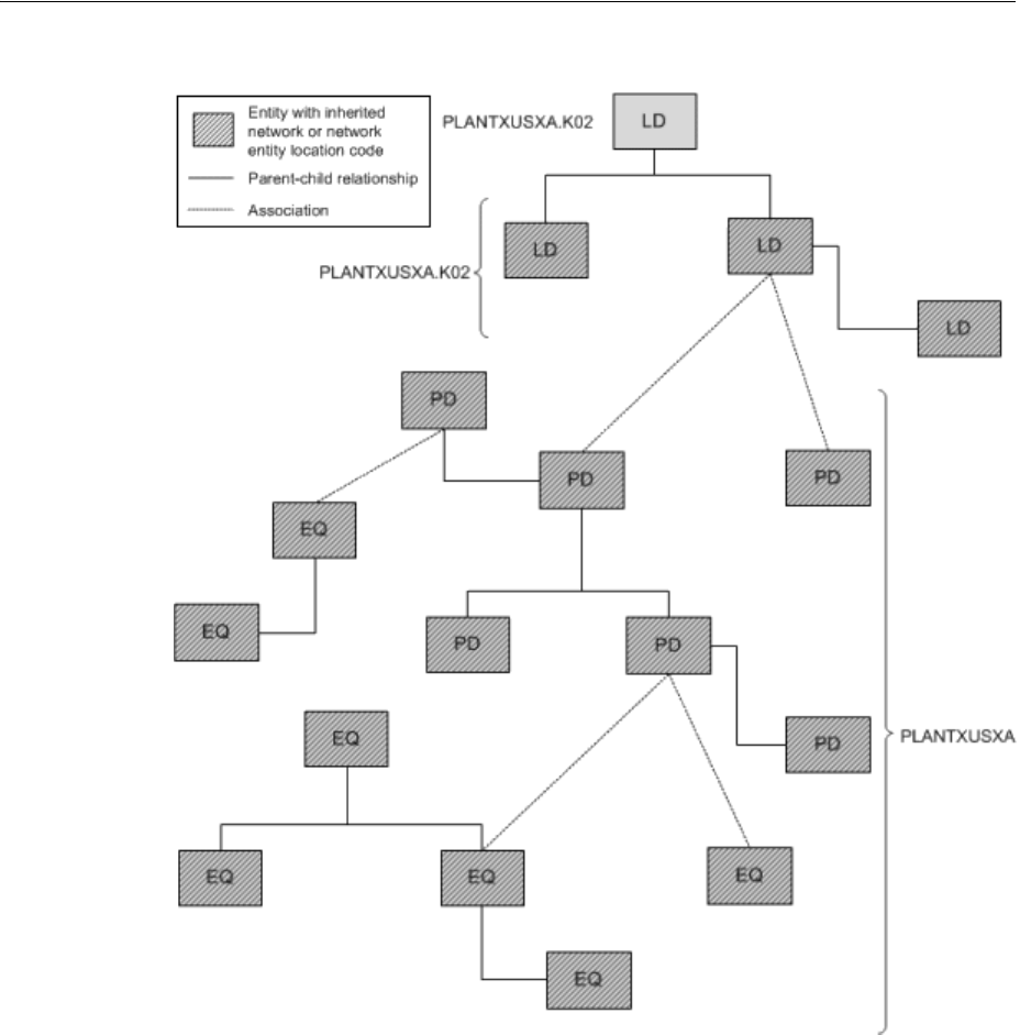
Associating Devices and Equipment with Network Locations
10-20 Oracle Communications Unified Inventory Management Concepts
Figure 10–12 Network and Network Entity Location Codes for Logical Device Hierarchy
Network location associations to Equipment and Physical Device entities cannot be
made if the association currently or potentially conflicts with a network location
association. The conflict does not necessarily have to be direct: it can result from
associations related to hierarchies in which the entity participates.
For example, you cannot directly assign a network location code to an Equipment
entity that is associated to a physical device that has inherited a network location from
a parent physical device. In this situation, the Equipment entity already has a network
location code that it inherits from the associated physical device.
Similarly, you cannot remove or change an inherited network location or network
entity location code without either removing the entity in question from its hierarchy
or association. Alternatively, you can change or remove the network location or
network entity location code from the location parent entity. Removing or changing
that code removes or changes it in all entities that have inherited it.

11
Networks 11-1
11
Networks
This chapter describes how networks are modeled and implemented in Oracle
Communications Unified Inventory Management (UIM). It describes the entities you
use to model networks and how you build a network in UIM by using the network
visualization.
See the UIM and Design Studio Help for detailed instructions about working with the
specifications and entities discussed in this chapter.
Understanding Networks
In UIM, a network is a collection of entities that has a common meaning or purpose.
You use a Network entity to represent the entity as a whole.
You associate other entities to the Network entity to define the contents of the
network. Entities in a network can be physical or logical resources (such as equipment
or logical devices) or they can be non-resources (such as parties or places). A network
can also include other networks.
Network entities can have configurations. Some network types are always created
with configurations. See "About Packet Virtual Networks" and "About Service
Networks" for information about networks that require configurations.
You do many of the tasks related to networks in the UIM network visualization. For
example, you add network nodes and edges in the visualization.
■Network nodes represent specific points in the network that you can associate
with other entities such as places, property locations, equipment, and so on.
■Network edges represent reachability or connectivity between nodes in the
network. You can associate network edges with Connectivity entities and Pipe
entities that represent connections between entities represented as nodes.
There are several ways to approach building a network in UIM. The following general
pattern is a starting place:
1. (Optional) Define Network specifications in Design Studio. Specifications are not
required, but you can use them to add characteristics or rules based on your
business requirements. Several Network specifications are available in UIM
reference cartridges, such as the Carrier Ethernet sample cartridge.
2. Create a network entity in UIM.
3. Create network nodes in UIM. You create network nodes in the network
visualization.
4. Associate network nodes to entities such as logical devices or equipment in UIM.

About Network Technologies
11-2 Oracle Communications Unified Inventory Management Concepts
5. Associate network nodes to places, property locations, and service locations to
specify their geographic location. If these locations include longitude and latitude,
the nodes can appear in the UIM map view.
6. Create network edges that connect network nodes in UIM.
7. Associate connectivities and pipes to network edges in UIM.
You can accomplish many of these tasks in one operation from the Network Topology
view. See "Building Networks in UIM" for more information.
About Network Technologies
When you create a Network entity, you must specify its technology or specify that the
network technology is undefined. The technology cannot be changed after the network
entity has been created, unless you set the technology to Undefined.
When you specify the technology during the creation of a Network entity, UIM filters
the list of specifications you can select from. For example, if you set the Technology
data element to Ethernet, you can select only a specification that is valid for the
Ethernet technology.
Technologies are supplied as part of the Base Technologies cartridge. See UIM
Cartridge Guide for more information.
About Network Types
There are three types of networks in UIM. You specify the type when you define a
Network specification in Design Studio. The network type and the network
technology are interdependent.
■An infrastructure network is a resource-based network such as SDH, ATM, Ethernet,
or MPLS.
■A packet virtual network (PVN) is collection of the interfaces and connectivities that
support a packet-based connectivity service. Multipoint Ethernet virtual circuits
(EVCs) are examples of PVNs. See "About Packet Virtual Networks" for more
information.
■A service network consolidates service locations, network access connectivity, and
supporting virtual networks to provide a unified view of a connection-oriented
service. See "About Service Networks" for more information.
The network type is not displayed on Network entities in UIM, but can be inferred
from the specification on which the entity is based. For example, the Ethernet EVC
Network specification, provided in the Carrier Ethernet sample cartridge, defines a
PVN network. Similarly, the Ethernet Transport Network specification in the same
sample cartridge defines an infrastructure network.
The network type determines the functionality that is available in the network
visualization. For example, the Design Steps feature is available only for PVNs and
service networks.
About Packet Virtual Networks
PVNs represent the elements in a service provider's network that fulfill a
connection-oriented service based on packet technologies such as Ethernet, ATM,
Frame Relay, and MPLS.
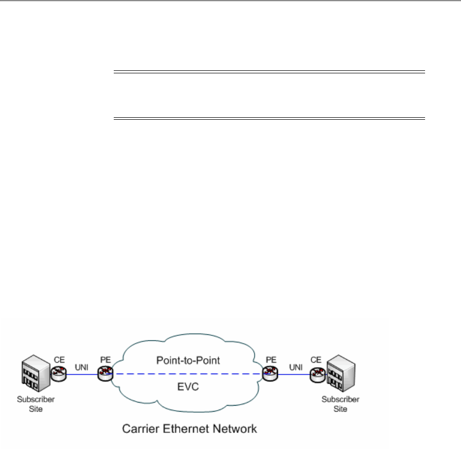
About Network Types
Networks 11-3
A PVN typically includes nodes that represent flow interfaces and edges that represent
packet network connectivity and cross-connects. See "About Flow Interfaces" for more
information about flow interfaces.
PVNs can be referenced by multiple services and are always created with
configurations.
Valid topologies for a Packet Virtual Network are:
■Point to Point
■Multipoint to Multipoint
■Rooted Multipoint
Figure 11–1 illustrates a simple Carrier Ethernet scenario that includes a point-to-point
EVC. Data travels from a customer site through a UNIs to an EVC managed by the
service provider or carrier. The data then flows through the EVC to another UNI and
on to the other customer site.
Figure 11–1 Point-to-point EVC
An EVC Network specification is included in the Carrier Ethernet sample cartridge.
About Service Networks
Service networks are virtual networks that provide an end-to-end view of a
connection-oriented service, such as a multipoint Ethernet service. Unlike other
networks, you create service networks from the service configuration of the parent
service.
For example, if you have a Carrier Ethernet service, its service network is based on the
resources that enable the service.
A service network can include nodes that represent:
■Packet virtual networks that support the service
■Service locations
■Parties that represent service providers who own external networks that support
the service
A service network can include edges that represent:
Note: PVNs are not required to have any edges. They can exist as a
set of nodes that represent flow interfaces with no edge connectivity
modeled.
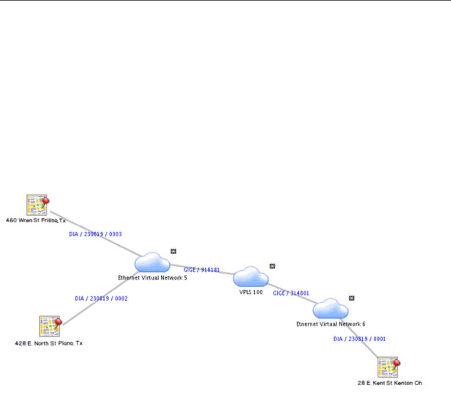
About Network Topologies
11-4 Oracle Communications Unified Inventory Management Concepts
■Service connectivity
■Network access connectivity that links packet virtual networks
A Service Network is always created with a configuration.
The Carrier Ethernet cartridge includes a specification for an Ethernet service network.
This service network comprises the service locations and the packet virtual networks
that are involved in delivering the service. The service network is included as a
configuration item in the Service configuration.
Figure 11–2 illustrates a service network that includes three service locations, three
packet virtual networks, and network access connectivities that connect them.
Figure 11–2 Ethernet Service Network Example
See the UIM Carrier Ethernet Cartridge Guide for more information about using Service
networks.
About Network Topologies
When you create or maintain a network entity in UIM, you can specify a topology to
describe how the network’s nodes are arranged in relation to each other. For example,
you can define the network topology as Mesh, which means that all the nodes in the
network are connected to each other directly or indirectly. Alternatively, you can
define the topology as Ring, meaning that the network is a loop in which signals travel
in a predictable pattern from node to node.
This setting is descriptive by default, but you can customize UIM by adding
validations or other rules associated with the selection.
See UIM Help for a complete list of all the topologies from which you can choose.
SONET and SDH Network Attributes
Networks that are based on the SONET and SDH technologies have several attributes
not shared by other networks. These attributes are included by default in the base
SONET and SDH specifications included in the ora_uim_base_specifications cartridge.
(See UIM Cartridge Guide for more information about base cartridges.)

SONET and SDH Network Attributes
Networks 11-5
■Enforce Same Channel Assignment. This check box determines how UIM
provisions connectivity for pipes that are associated with the network. If the check
box is selected, a trail signal that is enabled by pipes that are associated with edges
in the network must travel on the same channel or time slot in all segments. For
example, a DS3 trail enabled across an STS-3 ring topology would be assigned to
the same channel in each pipe that makes up the ring.
■Ring Type. If you select Ring as the network topology, you can use this data
element to specify the specific architecture of the network, such as simple ring,
single-home subtended, and so on. See "Selecting the Ring Type" for more
information.
■Protection Type. This data element defines how the network implements
protection paths to ensure signal reliability and quality. Protection schemes
include UPSR, SNCP, and so on. See "Selecting the Protection Type" for more
information.
Selecting the Ring Type
You can select from several different ring types if you set the network topology to
Ring. You use set the type to describe the ring’s relationship (if any) to other rings in
your inventory.
For example, you can designate that a ring is either single-homed or dual-homed
subtended. Subtended rings are ones that are dependent on a core network. A
single-homed subtended ring shares only a single node with the core network and is
therefore a complete loop in itself. A dual-homed subtended ring, however, is not a
complete loop because it shares two nodes with the core network.
Subtended rings are used to extend ring networks to support lower-level services. For
example, an OC48 or STM1 core network supports services based on STS1 (51.840
Mbps), DS3 (44.736 Mbps), VC3/TUG3 (51.840), or E3 (34.368 Mbps). It may not
support services based on DS1 (1.544 Mbps) or E1 (2.048 Mbps). Subtended rings act as
network multiplexers to make it possible to support these lower level services.
Another type of interconnected ring type is a virtual ring. A virtual ring is made up of
segments from other rings. The virtual ring takes its capacity from these segments. For
example, an STS1 (51.840 Mbps) virtual ring could be enabled by an OC-48 (2.4832
Gbps) core ring and multiple OC3 (155.52 Mbps) subtended rings interconnected with
it. The virtual ring would be enabled by the signal structures of the rings.
See the UIM Help for a complete list of all the ring types from which you can choose.
Selecting the Protection Type
When you create or maintain a network entity, you can optionally designate its
protection type. SONET and SDH networks include a secondary or protection path by
which a signal can be delivered if the primary path encounters a problem.
The protection types for SONET and SDH are different, but they fall into a few
categories:
■Protection based on dedicated protection paths. This type of protection is called
UPSR (for SONET) or SNCP (for SDH).
■For SDH only, the MSP protection type uses dedicated secondary paths, but
implements them on a segment-by-segment basis rather than on the whole ring.
■Protection based on the re-routing of traffic around nodes that are experiencing
problems. This protection type is called BLSR (in SONET) or MS-SPRing (in SDH).

Understanding Network Nodes
11-6 Oracle Communications Unified Inventory Management Concepts
See the UIM Help for a complete list of all the protection types from which you can
choose.
Understanding Network Nodes
A network node is a specific resource or location in a network. In UIM, nodes and the
resources that they represent are modeled separately. This approach gives you the
flexibility to maintain your inventory as equipment changes. For example, a network
node in Dallas might initially represent a particular kind of DSLAM. When the
DSLAM is upgraded, the node remains in place but the associated resource can be
changed.
Modeling nodes and resources separately also enables you to plan a network without
knowing exactly which devices it will include. For example, you may know that a
planned network must include nodes in Toronto, Ottawa, and Montreal, but not know
which devices will be used for those nodes. In this case, you can model the network’s
nodes in advance and associate resources later.
In Design Studio, you can define Network Node specifications. For example, you can
define a Network Node specification for nodes in a DSL network. This specification
could include characteristics specific to DSL and can limit the node to representing
only DSL-related resources.
You can limit the kinds of entities that a network node can represent by relating entity
specifications to the Network Node specification. In UIM, these relationships restrict
the entity types to which a node can be associated. For example, if the DSL Network
Node specification includes relationships to the DSLAM Logical Device specification,
UIM allows DSLAM network nodes to be associated only with entities based on the
DSLAM Logical Device specification.
If a Network Node specification does not include any relationships to the entity types
a network node can represent, UIM allows nodes to be associated with any of the
allowable entity types.
Network nodes can be associated with the following entity types:
■Custom network address
■Custom object
■Device interface
■Equipment
■Flow interface
■Logical device
■Network
■Place
■Physical device
■Physical port
■Party
■Property Location (including both network locations and service locations)
A network node can be associated with both a logical device and a place or network
location. This situation occurs when you associate the node to a logical device that is
located at a place or network location.
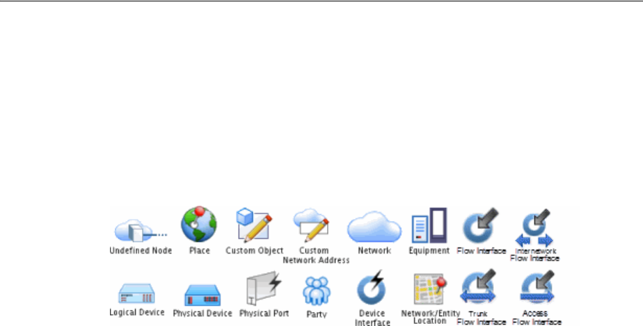
Understanding Network Edges
Networks 11-7
In UIM, you use the Topological View page to add network nodes to a network. A
network node represents a place when it is associated to a place. If you associate the
node that is currently associated to a place to a resource, the node then represents the
resource. For example, if you add a node to a DSL network, you can associate that
node with a particular logical device, such as a DSLAM.
Figure 11–3 illustrates the icons used in the Network Topology View page for network
nodes that represent entities.
Figure 11–3 Network Node Icons
Understanding Network Edges
A network edge represents reachability between two nodes in your network. This can
be represented by one or more pipes or connectivities, or it may be in the form of
traffic over a network where a static route is not defined.
A Network Edge specification describes the behavior and attributes of the edges that
connect nodes in a network. You define different Network Edge specifications for the
different kinds of edges in your inventory. For example, you can define a Network
Edge specification with appropriate characteristics to represent an edge in a DSL
network.
Network edges are modeled separately from pipes or connectivities they represent. As
a result, you can create edges when the resource details are not known and to update
them over time.
You can associate a network edge to one or more pipes or connectivities. You can also
associate a network edge or to one or more custom object entities when the connection
cannot be represented by other entities in the default model. Edges can also represent
cross-connects between flow interfaces in a packet virtual network.You can also leave
the network edge unassociated if the details are unknown or unimportant.
As with network nodes, you use the Topological View page to add network edges
between nodes. The edges are visually expressed as lines that connect network nodes.
The lines are dotted when the edge is not associated with a resource entity and solid
when an association has been made.
Limiting the Types of Entities Represented by a Network Edge
You can associate a network edge to any entity based on a Pipe, Connectivity or
Custom Object specification. In Design Studio, you can relate Network Node
specifications to Network Edge specifications to limit the possible associations in UIM.
For example, to limit the possible associations for a particular Network Edge
specification to entities based on specifications for T1 and T3 pipes, in Design Studio
you include those two specifications in the Related Specifications list for the node.
If no relationship exists in Design Studio between the Network Edge specification and
a resource specification, UIM does not limit the entities a network edge can represent.
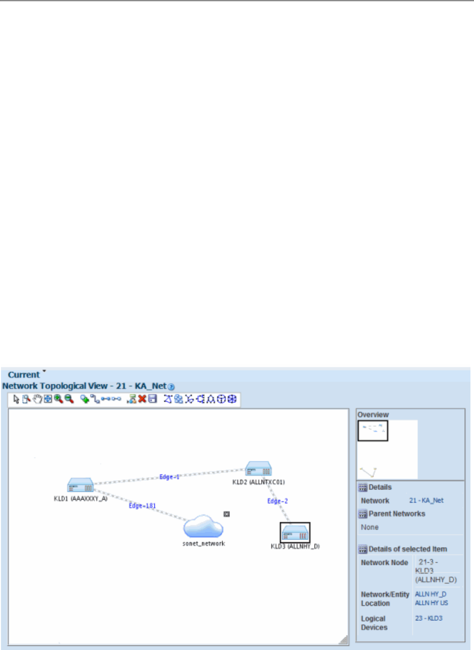
Building Networks in UIM
11-8 Oracle Communications Unified Inventory Management Concepts
Building Networks in UIM
In UIM, you build a network in the network visualization. To create a network in UIM,
you perform the following high-level tasks:
■Create a new network.
■Add network nodes to the canvas.
■Associate network nodes with entities (such as logical devices) and places.
■Add network edges between nodes.
■Associate connectivities and pipes with network edges.
You can accomplish many of these tasks in one operation from the Network Topology
View. You can click the Associate Connectivity button in the toolbar and select all of
the connectivities that should be represented as edges in the network. UIM
automatically creates edges, associates the correct connectivity to each edge, creates
nodes, and associates the correct logical device to each node.
Networks in the Topological View have a drill-down feature that enables you to drill
down from one network into a subnetwork and see the network edges that connect
network nodes in different network levels.
Figure 11–4 depicts a network in the Topological View page. This network includes
network nodes that represent logical devices. One of the devices is selected and its
details are displayed in the Details area to the right. The network also includes a
subnetwork.
Figure 11–4 Topological View
You can save the network visualization as a JPG file that you can view or print. See the
UIM Help for detailed information about this feature and other topological view tools.
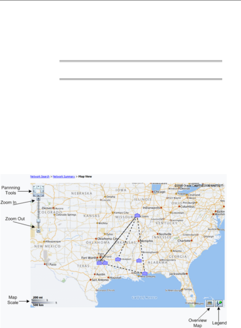
Map View
Networks 11-9
Map View
You can also view the network geographically in the UIM Map View page. In this
view, network nodes and edges are shown on a map based on latitude and longitude.
Network nodes appear in the map view only if they are associated with a place or
network location that includes a latitude and longitude or associated to a place that is
associated with an address that has a latitude and longitude.
You must also select a map profile before a network is shown on a map. There are
additional implementations required to use map functionality. Refer to UIM System
Administrator’s Guide for additional information on setting up UIM to use with maps.
For information about setting up UIM for geocoding, see UIM Developer’s Guide.
You can create custom map views by using map profiles. Map profiles control what a
map displays when it opens for each network. For example, a map can open at the
national level for one network and can be zoomed down to the city level for another
network. See the UIM Help for information about creating a map profile.
Figure 11–5 shows a map view of a network in the US. Nodes are indicated by icons.
Dotted lines indicate network edges and solid lines indicate pipes.
Figure 11–5 Map View Page
See the UIM Help for detailed information on using the tools on the Map View page.
Note: The map view is not supported for packet virtual networks
(PVNs).

Map View
11-10 Oracle Communications Unified Inventory Management Concepts

12
Connectivity Overview 12-1
12
Connectivity Overview
This chapter provides an overview of the connectivity features in Oracle
Communications Unified Inventory Management (UIM).
UIM supports several different types of connectivity. This chapter covers features that
are common to all types of connectivity.
About Connectivity
In the telecommunications industry, connectivity refers to the ability to transport
information to and from devices and locations by using physical or logical media. The
inventory of a telecommunications provider includes networks of routers, switches,
multiplexers, and other devices located in various places. The devices and locations
are connected to each other using various networking technologies, such as Ethernet,
Frame Relay, SONET, and so on.
In UIM, Connectivity entities provide built-in support for a variety of technologies and
can be customized to suit your business needs. UIM supports three types of
Connectivity entities:
■Channelized Connectivity entities support multiplexed technologies such as
E-Carrier, T-Carrier, J-Carrier, SDH, SONET, and WDM. See "Channelized
Connectivity".
■Packet Connectivity entities support packet-based technologies such as Carrier
Ethernet, Frame Relay, ATM, and MPLS. See "Packet Connectivity"
■Service Connectivity entities represent the connectivity requirements of a service,
such as the locations to be connected and the necessary bandwidth. Unlike other
Note: The word connectivity is used in two ways in this guide. It is
used in a general sense to mean the ability to transfer information to
and from devices and locations. It is also used more specifically to
refer to Connectivity entities.
Note: In releases previous to UIM 7.3, all Channelized Connectivity
entities were based on the same specification. This restriction no
longer applies. You can create multiple Channelized Connectivity
specifications in Design Studio and deploy them to UIM. In addition,
a variety of sample Channelized Connectivity specifications are
included in the OracleComms_UIM_Channelized cartridge.
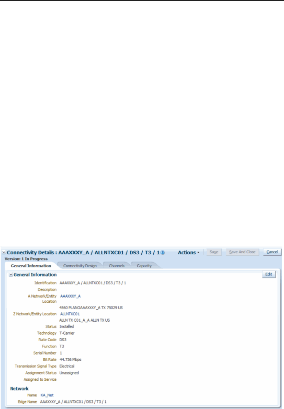
About Connectivity
12-2 Oracle Communications Unified Inventory Management Concepts
connectivity entities, you create Service connectivities in the context of Service
configurations. See "Service Connectivity".
In addition to Connectivity entities, UIM includes Pipe entities that can be used in
scenarios when the more specialized Connectivity entities are not appropriate. Pipe
entities are more generic than Connectivity entities and include fewer features. Pipe
entities and Connectivity entities are not mutually exclusive: you can include them
both in the same network. For example, pipes can enable channelized connectivity. See
"Pipes" for more information.
Connectivity entities cannot be associated with the following:
■Business interactions
■Reservations
■Conditions
■Roles
■Inventory groups
■Custom involvements
■Place entities. (Channelized connectivity can be associated with property locations.
See "About Connectivity Locations" for more information.)
Figure 12–1 shows the General Information tab of a Connectivity Details page for a
Connectivity entity. This Connectivity entity represents DS3 channelized connectivity.
The General Information tab is used for all types of Connectivity entities. It includes
the basic details about the connectivity that were established when the entity was
created. See "Working with Connectivity Entities in UIM" for information about other
tabs in the Connectivity Details page.
Figure 12–1 Connectivity Details: General Information Tab

About Connectivity Technologies
Connectivity Overview 12-3
Although each type of Connectivity entity has specialized capabilities, they also share
functionality and attributes. See the following sections for information about features
common to all Connectivity entities:
■About Connectivity Locations
■About Connectivity Technologies
■About Rate Codes
■About Connectivity Functions
■About Connectivity Identifiers
■Working with Connectivity Entities in UIM
Technologies, rate codes, and connectivity functions are defined by specifications in
the ora_uim_basetechnologies cartridge. You must deploy this cartridge to UIM before
using connectivity features. See UIM Cartridge Guide for information about deploying
cartridges.
About Connectivity Locations
Connectivity entities have A and Z end points that must be geographically located at a
property location. Each end point must be a property location that is one of the
following:
■Network location. A network location is one that hosts devices involved in
connectivity. Defining a property location as a network location requires the
assignment of a network location code. See "About Network Locations".
■Network entity location. Network entity locations define a specific logical device
(a network entity) at a network location. See "About Network Entities".
■Service location. A service location is one where a service originates or is
delivered. Service locations are often outside the service provider network. See
"About Service Locations".
See "About Network Locations" for more information about network locations and
network entity locations.
Most connectivities have both end points on network locations or network entity
locations. Certain types of connectivities, such as those that represent connectivity
from a customer location to the service provider network, have at least one end point
on a service location. For example, the UNI Connectivity specification supplied in the
Carrier Ethernet cartridge has one end point on a service location.
The locations you specify determine where the end points can be terminated. For
example, if you specify a network location for the A end point, the end point must be
terminated on a device interface provided by a network device at that network
location. See "About Termination" for more information. Similarly, if you specify a
service location as the A location of a connectivity, the connectivity can be terminated
only on an interface provided by a device at that location.
The A and Z network locations can be the same, as in an intra-office transmission
facility. In this case, one end is typically located at a network entity location within the
network location.
About Connectivity Technologies
When you create a Connectivity entity, you specify its technology it uses. The
technology you choose determines which specifications you can select for the entity.

About Rate Codes
12-4 Oracle Communications Unified Inventory Management Concepts
For example, if you select the Ethernet technology and have deployed the
OracleComms_UIM_Carrier Ethernet cartridge, you can choose from the three
Ethernet specifications (UNI Connectivity, INNI Connectivity, ENNI Connectivity) and
from any custom specifications that have been assigned the Ethernet technology.
The OracleComms_UIM_Packet sample cartridge includes specifications based on the
following technologies:
■ATM
■Frame Relay
■MPLS
Similarly, when you select a channelized connectivity technology, such as T-Carrier or
SONET, you can select from base or other installed that have been assigned that
technology. The OracleComms_UIM_Channelized sample cartridge includes
specifications that are based on the following technologies.
■SONET
■SDH
■E-Carrier
■T-Carrier
■J-Carrier
■WDM
Selecting the technology of a connectivity also limits the rate codes you can select. For
example, if you set the technology to T-Carrier, rate codes are limited to DS0, DS1, and
so on. Similarly, selecting a rate code limits the technologies from which you can select.
See "About Rate Codes" for more information.
About Rate Codes
UIM uses rate codes to define the technology and bit-rate capacity that apply to
Logical Device, Device Interface, and Connectivity Entity entities.
Each rate code definition includes:
■A name, such as STS1 or VC3
■One or more networking technologies, such as Ethernet, SDH, or SONET
■A bit rate and unit of measure, such as 51.840 Mbps or 48.960 Mbps
Rate codes associated with facility signals can also include a connectivity function,
such as T1, that describes how a connectivity is used.
You assign rate codes to Connectivity entities when you create them. The rate codes
you select from are limited by the connectivity’s technology and specification.
The rate code you select determines other attributes of the connectivity configuration,
including the signal structure. For example, if you specify that a connectivity has a
DS3 rate code, the connectivity signal architecture specifies that you can channelize the
connectivity to either DS2 or DS1.
The rate codes of a connectivity also determines which connectivities can be enabled
by or ride them. For example, a for connectivity entity to be enabled by a channel, its
rate code must match or be compatible with the rate code of the channel. See "About
Rate Code Compatibility" for more information.

About Connectivity Identifiers
Connectivity Overview 12-5
Pipes can also be enabled by channels provided by channelized connectivity, but
compatibility is not based on rate code. Instead, UIM uses the underlying bit-rate
capacity provided by the channel to determine whether enablement is allowed. For
example, a channelized connectivity with a DS1 rate code provides DS0 channels.
These channels can enable a Pipe service trail that requires 64 Kbps because that
capacity matches the 64 Kbps of the DS0 rate code.
You can also apply rate codes to device interfaces. You can terminate a connectivity on
a device interface only if the rate codes match. See "Associating Rate Codes to Device
Interfaces" for more information.
About Rate Code Compatibility
When UIM determines whether one connectivity can enable another, it considers rate
code compatibility. Compatible rate codes are those whose bit-rate capacities and
technologies allow interoperability. For example, the VC12 and E1 rate codes are
compatible because a VC12 channel can transport an E1 signal. Similarly, a Ethernet
UNI connectivity with a rate code of 1 Gbps can be enabled by 16 STS1 Channels
because the rate codes are compatible.
Compatibility is defined in the signal architecture by relationships between Signal
Termination Point specifications. See "About the UIM Signal Architecture" and UIM
Information Model Reference for more information.
About Connectivity Functions
Connectivity functions identify the purpose or role that a Connectivity entity
performs. For example, the T1 connectivity function identifies a connectivity as a
T-Carrier transmission facility operating at the DS1 rate. Similarly, the GE100
connectivity function identifies an Ethernet or MPLS facility operating at the 100GigE
rate (100 Gbps).
Connectivity functions are included in connectivity identifiers. See "About
Connectivity Identifiers" for more information. Connectivity functions are applicable
only to Connectivity Entity entities that represent facilities.
You determine a facility’s function when you assign its rate code. Similarly, if you
select a connectivity function when defining a connectivity, UIM sets the applicable
rate code and technology.
No default behavior is associated with connectivity functions, but you can use them to
extend UIM with rulesets. Supported functions are defined in the ora_uim_
basetechnologies base cartridge.
About Connectivity Identifiers
UIM connectivities can be identified in three ways, depending on the context:
■A location-based format is used for connectivities that are terminated on network
locations. See "Location-Based Connectivity Identifiers".
■A service-based format is used for connectivities in which one end point is
terminated on a service location. See "Service-Based Connectivity Identifiers".
Note: Packet connectivity cannot enable other packet connectivity,
whatever the rate code.

About Connectivity Identifiers
12-6 Oracle Communications Unified Inventory Management Concepts
■A custom format can be used for packet and channelized connectivities to
implement an identification scheme that is specific to your business. See "Custom
Connectivity Identifiers".
Location- based and service-based identifiers comprise a number of attributes or
elements separated by spaces and forward slashes. The information in the identifier is
organized with the most significant information first and the most granular
information last.
Location-Based Connectivity Identifiers
You use the location-based connectivity identifiers for entities that are terminated on
network locations or network entity locations.
These are the five attributes used to construction a location-based connectivity
identifier:
■Network/Entity Location A. The location of the A end point of the connectivity.
This value can be a network location code or a network entity location code. See
"About Network Locations" for more information.
■Network/Entity Location Z. The location of the Z end point of the connectivity.
This value can be a network location code or a network entity location code. See
"About Network Locations" for more information.
■Rate Code. The rate code of the connectivity. See "About Rate Codes" for more
information.
■Function. The functional role that the connectivity plays. See "About Connectivity
Functions" for more information.
■The serial number for the connectivity. The serial number is unique among
connectivities that share the same A Network/Entity, Z Network/Entity, Rate
Code, and Technology values. When you create a connectivity, you can either
accept the automatically generated serial number or enter one of your own.
Forward slashes separate the fields in the identifier. For example, PLANTXUSXA.A01
/ PLANTXUSXA.K01 / DS1 / T1 / 99 identifies a connectivity with endpoints at the
network entities A01 and K01, both at the network location PLANTXUSXA. This
connectivity operates at the DS1 rate code and has the T1 connectivity function. It is
uniquely identified by the serial number 99.
Channels in channelized connectivities are also identified with the location-based
format, with the addition of a unit value. See "About Channel Identifiers" for more
information.
Service-Based Connectivity Identifiers
Connectivities that have at least one end point on a service location use the
service-based identifier format. Service connectivities and packet connectivities
designed for access, such as UNI connectivities, have service-based identifiers.
Note: Channels in Channelized Connectivity also have identifiers.
See "About Channel Identifiers" for more information.
Note: Service connectivities cannot use location-based connectivity
identifiers.

About Termination
Connectivity Overview 12-7
Identifiers in this format are constructed of two or three elements:
■Function. The function the connectivity plays, such as VPN, IPTV, or VoIP.
■Serial Number. The serial number must be unique for all connectivities that share
the same connectivity function.
■Segment. A segment uniquely identifies each termination leg of a multipoint
connectivity arrangement. This element is absent in point-to-point connectivities.
For example, a service connectivity connecting several locations of a bank could have
the service-based connectivity identifier VPN / 001011 / 0001. where VPN is the
connectivity function, 001011 is a serial number shared by all the service connectivities
in the multipoint service, and 0001 is the segment value that identifies the specific
service connectivity.
Custom Connectivity Identifiers
Service providers often have their own naming standards for connectivity. UIM
supports these corporate naming standards by allowing custom identification formats.
If you create a connectivity in UIM that is based on a specification that specifies a
custom identifier format, UIM passes information about the connectivity to a ruleset
that generates the identifier. This information includes:
■A network or service location
■Z location network or service location
■Technology
■Rate code
■Function
■Serial number
■Specification
UIM also generates a unique serial number for the connectivity, which can optionally
be included in the identifier. UIM validates custom identifiers to ensure that they are
unique across all connectivity entities.
About Termination
Connectivity entities must be terminated on media interfaces (logical devices at the top
of their device interface hierarchies.). These media interfaces must be provided by
logical devices hosted at network locations or service locations.
Most connectivities are terminated on media interfaces at the network locations or
network entity locations associated with their end points. For example, Figure 12–2
illustrates a channelized connectivity with its A end point at network location
FRSCTXUSXA and its Z end point at network entity location PLANTXUSXA.K01. The
connectivity is terminated on device interfaces provided by logical devices at those
locations.
Some connectivities, such as Ethernet UNI connectivities can be terminated on media
interfaces of device located at service locations.
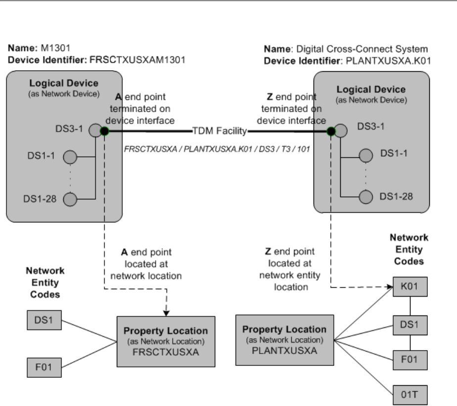
About Termination
12-8 Oracle Communications Unified Inventory Management Concepts
Figure 12–2 Connectivity Termination with Network and Network Entity Locations
In this case, the A end point is terminated on the FRSCTXUSXAM1301 multiplexer,
which is not associated with a network entity location code. Because the A end point is
located at the FRSCTXUSXA network location and not a network entity location, it can
terminate on any device at the location, including devices not associated with a
network entity location code. The Z end point is located at the PLANTXUSXA.K01
network entity location and therefore must terminate on that device.
The interfaces you can choose to terminate the connectivity depend on whether the
end point is at a network location of a network entity location:
■If the end point is located at a network location, the connectivity can be terminated
on the interfaces of any device at the location that has a matching rate code.
■If the end point is located at a network entity location, the connectivity can be
terminated on any interface of that device that has a matching rate code.
Some connectivities, such as Ethernet UNI connectivities can have end points at
service locations. In this situation, you can choose to terminate the connectivity on any
compatible media interface at the service location. If the service location is also a
network location, all of the compatible interfaces associated with the network location
code are also available for terminating the connectivity. See Figure 14–4 for an example
of a connectivity terminated on an interface at a service location.

Working with Connectivity Entities in UIM
Connectivity Overview 12-9
You terminate a connectivity during the connectivity design process. See "Designing
Connectivity" for more information.
About Connectivity Enablement
Connectivities are enabled to specify the resources used to realize end-to-end
continuity. For example, if you use a Channelized Connectivity entity to represent a
DS1 service trail from network location FRSCTXUSXA to network location
PLANTXUSSL, you enable the connectivity to specify how it is realized.
Similarly, if you use a Packet Connectivity entity to represent INNI connectivity in a
Carrier Ethernet solution, you enable it to specify the transport details. For example,
the INNI connectivity could be enabled by one or more channels in a channelized
connectivity.
Several different types of resources can be segments in a connectivity path:
■Channels provided by Channelized Connectivity entities
■Pipes with signal structures (if terminated on device interfaces of devices located
at network locations)
■Interconnections, including cross-connects and jumpers
■Accepted connectivity gaps (segments where the connectivity is not specified)
You enable a connectivity during the connectivity design process. See "Designing
Connectivity" for more information.
Working with Connectivity Entities in UIM
In UIM, you use the Connectivity Details page to enter and view information about
Connectivity entities. Unlike many other UIM pages, the Connectivity Details page is
arranged into several tabs. Each tab is used for a different purpose. The tabs you see
depend on the type of Connectivity entity.
These are the tabs that can be displayed in the Connectivity Details page:
■You use the General Information tab to view and edit basic information about
Connectivity entities. You also use the tab to open the other tabs for editing.
■You use the Connectivity Design tab in the Connectivity Details page to enable
and terminate connectivity. The Connectivity Design tab has two subtabs:
■The Design subtab includes a table that includes rows for each segment in the
connectivity path. The rows display icons and information about the
segments. For example, the connectivity identifier and status are displayed for
each connectivity, channel, or pipe that is assigned to a segment.
■The Schematic subtab of the Connectivity Design tab displays a graphical
representation of the connectivity enablement and termination design created
in the Design subtab. The Design Versions control in the upper-right corner
Note: When you enable a connectivity, you do not necessarily have
to supply transport details. In some cases, those details are irrelevant
to your inventory. For example, you may not need to specify how a
INNI connectivity is enabled because the transport is supplied by a
third party whose resources are outside your network. In this case,
you include an accepted gap in the connectivity design.

Designing Connectivity
12-10 Oracle Communications Unified Inventory Management Concepts
of the Schematic subtab enables you to switch between current and previous
versions of the connectivity design.
■You use the Capacity tab in the Connectivity Details page to configure the capacity
of a channelized connectivity by determining its signal structure. The Capacity tab
displays a hierarchy of nodes and levels. A control section in the upper level
enables you to change how the nodes and levels are displayed.
■You use the Channels tab in the Connectivity Details page of a channelized
connectivity to view the channel hierarchy.
■You use the Riders tab in the Connectivity Details page for packet connectivity
entities to view the pipes and connectivities that are enabled by (or ride) this
connectivity.
The following list shows which tabs are displayed for each connectivity type:
Channelized Connectivity
■General Information Tab
■Connectivity Design Tab
■Channels Tab
■Capacity Tab
Packet Connectivity
■General Information Tab
■Connectivity Design Tab
■Riders Tab
Service Connectivity
■General Information Tab
■Connectivity Design Tab
Designing Connectivity
In UIM, you use the Connectivity Design tab in the Connectivity Details page to
enable and terminate connectivities. Figure 12–3 shows the Connectivity Design tab.
Figure 12–3 Connectivity Design Tab
About Connectivity Design Visualizations
You can see a read-only visualization of a connectivity design in the Schematic subtab
of the Connectivity Design tab. The visualization includes schematic views of the trail
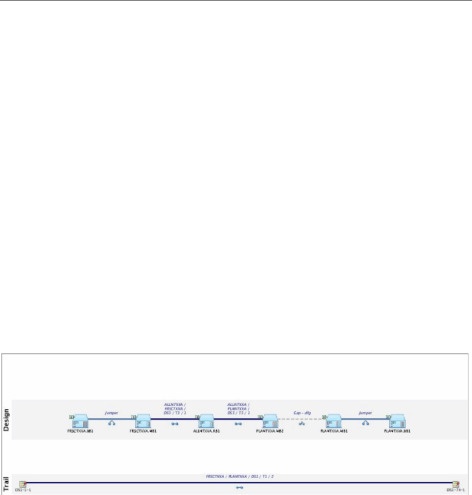
Designing Connectivity
Connectivity Overview 12-11
in the lower part of the canvas and the enabling connectivities in the upper part. You
can choose to display the current design version or a previous design version.
When a trail is enabled by more than one path, such as in a SONET/SDH network,
both paths are displayed. You can choose to highlight one of the paths.
The visualization includes the following:
■Connectivities. Connectivities and channels are shown as thick lines labeled with
their connectivity identifiers.
■Connectivity gaps. If gaps exist in the design, they are shown as dotted lines.
■Devices and network locations. Icons represent A and Z network locations as well
as devices or network locations on which connectivities are terminated. You can
expand the icons to view more detailed termination information. For example, you
can expand a device to see the device interfaces on which connectivities are
terminated and any interconnections between those interfaces.
■Interconnections. Jumpers and cross-connects are shown as thick lines. Icons
indicate whether a line represents a jumper or cross-connect.
The icons in connectivity design visualizations are a combination of those used in the
network visualizations and those used on the Design subtab. See the UIM Help for
more information about the icons.
Figure 12–4 shows a connectivity design visualization that includes logical devices,
connectivities, a gap, and jumpers.
Figure 12–4 Connectivity Design Visualization
See the UIM Help for more information about using the connectivity design
visualization.
About Design Versions
Connectivity entities are versioned. The first design version is created automatically
when you create a connectivity. You create subsequent versions manually. Only one
version can be active at a time; you cannot create a new design version until the
current one is completed or canceled.
You work with design versions in the Connectivity Design tab of the Connectivity
Details page. See the UIM Help for more information.
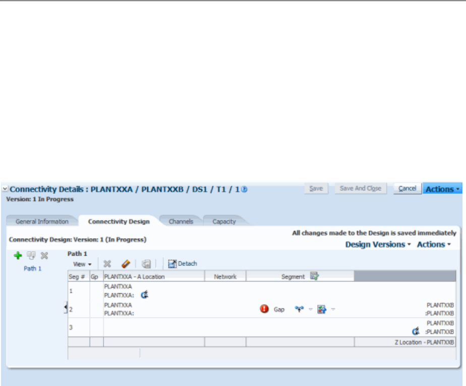
Designing Connectivity
12-12 Oracle Communications Unified Inventory Management Concepts
About Connectivity Gaps
A connectivity gap exists when the details are unknown for a segment of connectivity.
When you design a connectivity, UIM creates Connectivity Gap entities to represent
these segments.
An unresolved gap occurs when the gap has no business validity. For example,
unresolved gaps naturally occur when you have not yet completed a connectivity
design. All connectivity designs begin with an unresolved gap between the A and Z
end points. Figure 12–5 shows a connectivity with an unresolved gap between its two
end points.
Figure 12–5 Unresolved Gap Between End Points
Connectivity designs cannot be completed if there are unresolved gaps. You can
resolve gaps in the following ways:
■By accepting the gap. You can mark a gap as acceptable when knowledge of the
connectivity details are not necessary for your business. For example, an
acceptable gap may exist for the “last mile” of connectivity when one service
provider hands off to another or when transport passes through a third-party
network. When you mark such a gap as acceptable, it can be included as part of a
completed design. See the UIM Help for information about how to accept gaps.
■By assigning transport to a gap. For example, if a gap exists between two network
locations, you can assign a pipe (if it is terminated on device interfaces of devices
located at network locations) or a channel from a channelized connectivity. You
can assign transport manually or use gap analysis to find transport automatically.
■By using interconnections. Interconnections bridge connectivity between device
interfaces. See "About Interconnections".
Figure 12–6 shows a simple, completed connectivity design. In this case, a DS1 trail is
enabled by a channel from a DS3 facility and two cross-connects. The cross-connects
bridge the gaps between device interfaces on a logical devices at the ALLNTXQA
network location.
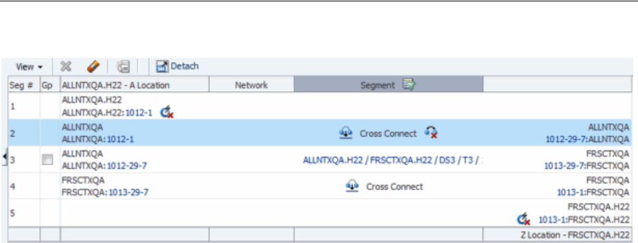
Designing Connectivity
Connectivity Overview 12-13
Figure 12–6 Completed Connectivity Design
Resolving one gap sometimes causes another to be created. For example, if you resolve
a gap by assigning a channel that terminates on a device at a network location, a new
gap may be created if the next segment is terminated on a different device at the same
network location.
Gaps on the ends of the connectivity can be resolved only when the ends are
terminated on device interfaces. For example, in Figure 12–6, the A end point is
terminated on device interface 1012-1 and the Z end point is terminated at device
interface 1013-1.
Assigning Transport
When you assign transport to a segment of a connectivity design, you specify the
details of how the signal is carried from one location to another. For example, if you
are designing a DS1 service trail, you can specify that the signal be carried on (or ride)
a channel provided by a Channelized Connectivity entity that represents a T3 facility.
Similarly, when you are designing an Ethernet INNI connectivity, you can specify that
it be enabled by channels from an SDH facility.
You can also use Pipe entities as transport. For pipes to be used to enable channelized
connectivity, however, the pipes must be terminated on device interfaces of devices
that are located at network locations. That means that the devices have to have been
assigned network location codes or network entity codes.
You can assign transport manually or by using gap or path analysis.
When you assign transport manually, you search for a pipe or channel using the
standard entity-specific Search pages. For example, you can search for all channelized
connectivity entities that have a particular rate code and an end point at a specific
network location. UIM returns all the entities that meet your criteria and you then
select a channel from among those provided by those entities.
Gap analysis enables you to automatically find channelized connectivity channels by
specifying starting and ending criteria. You can optionally include other criteria, such
as an intermediate location and specific device identifiers. Figure 12–7 shows the Gap
Analysis section with a network entity code specified for the starting location and a
network location code for the ending location.
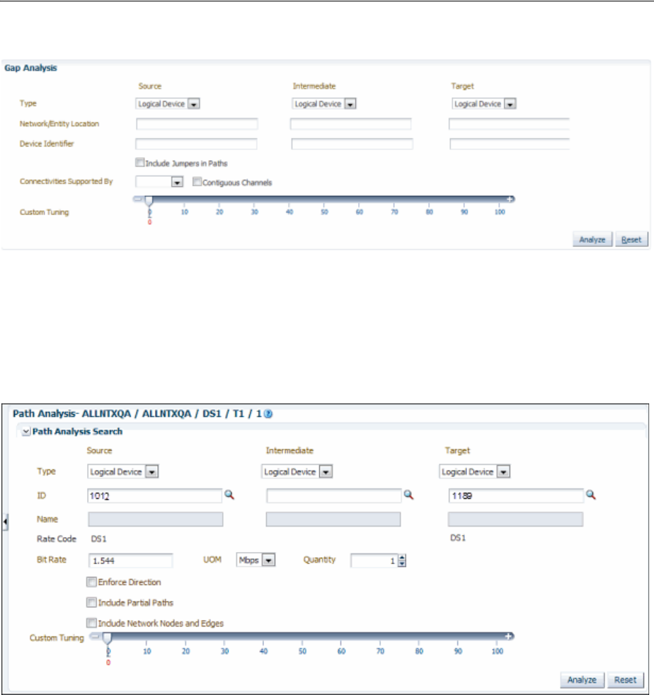
Designing Connectivity
12-14 Oracle Communications Unified Inventory Management Concepts
Figure 12–7 Gap Analysis Criteria
Path analysis is similar to gap analysis except that it finds pipes rather than
channelized connectivities. Path analysis in this context is almost identical to gap
analysis when used to enable pipes. Figure 12–8 shows the Path Analysis section with
the starting point and ending points specifying logical device IDs. See "Enabling Pipes
Automatically with Path Analysis" and the UIM Help for more information.
Figure 12–8 Path Analysis Criteria
Both gap analysis and path analysis return lists of matching connectivity from which
you can select. The results are organized by the number of hops, with the lowest
number listed first. Figure 12–9 shows the results of a gap analysis. In this case, only a
single connectivity met the criteria.
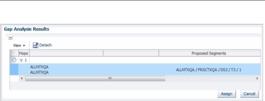
Designing Connectivity
Connectivity Overview 12-15
Figure 12–9 Gap Analysis Results
See UIM Help for instructions about using the features in the Connectivity Design tab
to assign transport.
About Interconnections
Interconnections participate in the continuity of an end-to-end trail by forming bridges
between interfaces on which connectivities are terminated.
There are two types of interconnections: cross-connects and physical jumpers.
About Cross-Connects
A cross-connect represents a software, electrical, or wireless connection between two
device interfaces within a logical device. Cross-connects are logical; they do not
represent physical objects. Cross-connects can enable both Pipe and Connectivity
entities.
Cross-connects can be interface-bound or trail-bound.
■An interface-bound cross-connect is bound to the life of the interface it connects. If
either interface is removed, the cross-connect is also removed. For example, you
could create interface-bound cross-connects between the line and drop interfaces
of an M13 multiplexer logical device. You create interface-bound cross-connects
manually in Device Interface pages. See "About Interface-Bound Cross-Connects"
for more information.
■A trail-bound cross-connect is bound to the life of the trail it enables. If the trail is
removed, the cross-connect is removed. Trail-bound cross-connects are
automatically created during connectivity design when segments are joined at a
common logical device and when an interface-bound cross-connect does not
already exist. You can also create cross-connects manually when you design a
connectivity. For example a trail-bound cross-connect could be used when a DS1
Interface is interconnected to another DS1 interface to enable a trail that passes
through a 3/1/0 DACS.
You cannot change a trail-bound cross-connect into an interface-bound cross-connect
or change an interface-bound cross-connect into a trail-bound cross-connect.
Duplicate cross-connects are not allowed. For example, if there is already an
interface-bound cross-connect between two device interfaces in a multiplexer, a
trail-bound cross-connect cannot be added between those same interfaces. If you use
gap analysis to find connectivity in such a situation, UIM automatically includes the
existing cross-connect.

Designing Connectivity
12-16 Oracle Communications Unified Inventory Management Concepts
If you assign a channel or pipe with an end point that terminates on a device interface
in a device, and then assign another channel or pipe with an end point that terminates
on another interface in the same device, UIM automatically creates a trail-bound
cross-connect between the two interfaces.
Interconnections do not have rate codes because their purpose is to bridge different
interface signals. But rate codes are relevant when determining whether a
cross-connect can be created. Cross-connects are not allowed when only one interface
has a rate code or when the interface rate codes are incompatible. See "About Rate
Code Compatibility" for more information.
About Physical Jumpers
A jumper represents a physical connection between device interfaces (in Logical
Device entities) or ports (in Physical Device and Equipment entities). The device
interfaces or ports can be on the same device or between devices at the same network
location.
For example, a jumper could represent a twisted-pair connection between DSX jack
panels or in an MDF (main distribution frame). A jumper could also represent an
optical connection between fiber distribution panels.
Physical jumpers participate in the end-to-end continuity of a trail design. For
example, when you design a connectivity, a jumper can represent a segment in the
enablement of a facility. Similarly, a jumper can represent one segment in the
enablement of a trail pipe.
Only one physical jumper is allowed per device interface or port. If a jumper already
exists on an interface or port, you cannot add a new one without deleting the existing
one. You can add a physical jumper to a device interface that already has a
cross-connect, however.
Physical jumpers between device interfaces must be between media interfaces (device
interfaces that represent a physical interface or port that can host a physical
connection). A device interface is a media interface when it is the root interface in its
device interface hierarchy.
Rate codes are not required for device interfaces interconnected by a physical jumper.
If both interfaces have rate codes, they must match or be compatible. This same rule
applies to device interfaces mapped to physical ports interconnected by a physical
jumper.
There are two types of physical jumpers:
■Trail-bound jumpers are created by UIM during pipe and connectivity
enablement. For example, if there are two pipes representing twister-pair cables
that are terminated on different ports of the same physical device, UIM creates a
physical jumper when you use the two pipes to enable a trail pipe. These jumpers
exist only in the context of the trails they enable. If a trail is removed, the jumper is
removed.
■Hardwired jumpers are created manually from the Physical Jumper page. You can
open the Physical Jumper page from Logical Device, Physical Device, and
Equipment Summary pages. Jumpers created in this way are tied to the life cycle
of the entities they connect. (They are similar in this respect to interface-bound
cross-connects.) Figure 12–10 illustrates a Physical Jumper page in which a jumper
connects two DS1 device interfaces. See UIM Help for information about creating
jumpers manually.
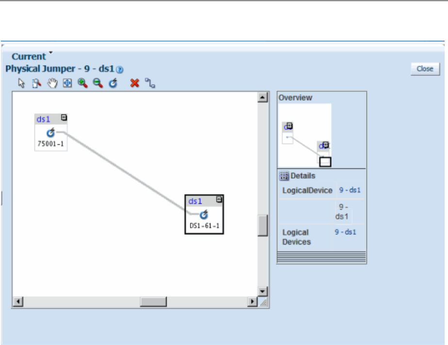
Designing Connectivity
Connectivity Overview 12-17
Figure 12–10 Physical Jumper Page

Designing Connectivity
12-18 Oracle Communications Unified Inventory Management Concepts

13
Channelized Connectivity 13-1
13
Channelized Connectivity
This chapter explains how to use Oracle Communications Unified Inventory
Management (UIM) to implement channelized connectivity. Channelized connectivity
is one of several types of connectivity supported by UIM. See Chapter 12,
"Connectivity Overview" for an introduction.
About Channelized Connectivity
Several different telecommunications technologies break larger-bandwidth signals into
multiple smaller-bandwidth signals or channels that can be used independently. This
process is called multiplexing.
You use Channelized Connectivity entities to represent channelized connectivity in
UIM. Channelized Connectivity entities are based on Connectivity specifications in
which the Connectivity Classification is set to Multiplexed. UIM provides specialized
features that support various multiplexing technologies, including:
■SONET (Synchronous Optical Network)
■SDH (Synchronous Digital Hierarchy)
■WDM (Wavelength Division Multiplexing)
■T-Carrier (TDM carrier)
■E-Carrier (European TDM carrier)
■J-Carrier (Japanese TDM carrier)
Each of these technologies defines a hierarchy of possible channel arrangements that
provide varying bandwidth capacities.
UIM cartridges supply several Channelized Connectivity specifications that you can
use or modify. The OracleComms_UIM_Channelized cartridge includes specifications
for PDH, SDH, SONET, TDM, and WDM connectivities. You can also create your own
Channelized Connectivity specifications.

About Channel Identifiers
13-2 Oracle Communications Unified Inventory Management Concepts
About Channel Identifiers
Channelized Connectivity entities use the location-based connectivity identifier
format. (See "Location-Based Connectivity Identifiers" for more information.
Individual channels also use this format, with the addition of unit values for the
channels.Unit values are based on the address of the channel in the signal structure of
its parent facility.
Different technologies determine the addresses in different ways depending on their
multiplexing schemes. See the following sections and UIM Information Model Reference
for additional information about the signal architectures of the various technologies
and about channel addresses.
E-Carrier, J-Carrier, and T-Carrier Channel Identifiers
E-Carrier, J-Carrier, and T-Carrier facilities can be channelized to only one level, so
channels are numbered sequentially. For example, in a T-Carrier DS1 facility, DS0
channels are addressed sequentially starting at 1 and ending at 24. The 24th DS0
channel in a DS1 facility could have the identifier PLANTXUSXA.A01 /
PLANTXUSXA.K01 / DS1 / T1 / 99 / 24.
SONET Channel Identifiers
The SONET signal/channel addressing format combines the indexes of each STS-n, VT
Group, and VT-n starting from the first signal level to which the SONET facility was
configured. Signal level index numbers are separated by a dash.
Figure 13–1 displays the possible index values for each level in the SONET signal
architecture.
Note: In releases previous to UIM 7.3, all channelized connectivity
entities were based on the same specification, TDM Facility. As part of
the migration to UIM 7.3, all entities based on TDM Facility are
converted to use the Channelized Facility specification that is supplied
in the ora_uim_base_specifications cartridge. In addition, you can use
Design Studio to create additional Channelized Connectivity
specifications. See UIM Cartridge Guide for more information about
base cartridges. See Design Studio Help for information about creating
specifications.
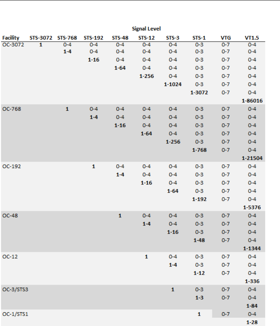
About Channel Identifiers
Channelized Connectivity 13-3
Figure 13–1 SONET Signal Level Index Values
For example:
■15-2-3-6-4 is a VT-1.5 channel in an OC-192 facility (STS-12: 15, STS-3: 2, STS-1: 3,
VT Group: 6, VT-1.5: 4)
■12-0-0-0 is an STS-3 channel in an OC-45 facility (STS-3: 12, STS-1: 0, VT Group: 0,
VT-1.5: 0)
■1-0-0-0 is an STS-3 channel in an OC-3 facility (STS-3: 1, STS-1: 0, VT Group: 0,
VT-1.5: 0)

Terminating Channels
13-4 Oracle Communications Unified Inventory Management Concepts
SDH Channel Identifiers
SDH channel identifiers are in the following format:
J-K-L-M
where:
J is the AUG-1 index (from 1 to 1024)
K is the TUG-3 index (from 1 to 3)
L is the TUG-2 index (from 1 to 7)
M is the TU-n index (from 1 to 4)
Each index is always included in the address and is set to 0 if not applicable.
For example:
3-0-0-0 is the address for a VC-4 channel in the third AUG-1 on an STM-4 facility,
channelized above the TUG and TU signals.
13-2-1-4 is the address for a VC-11 channel on an STM-16 facility: the thirteenth
AUG-1, the second TUG-3, the first TUG-2, the fourth VC-11 on the TUG-2.
WDM Channel Identifiers
WDM facilities channelize to only one level, so a 1.n signal/channel addressing
scheme is used. For example, in a WDM OM40 facility that is channelized to 5 OM8
channels, the channel identifiers are 1 through 5.
Terminating Channels
Like other UIM connectivities, channelized connectivity must be terminated. See
"About Termination" for an overview. In addition, the multiplexed channels provided
by channelized connectivity must also be terminated.
When you terminate a parent connectivity on a device interface, its channels are
automatically terminated on sub-interfaces of that interface if it provides enough
sub-interfaces to terminate all the channels. (Sub-interfaces are created automatically
only if the Device Interface specifications for the sub-interfaces are related to the
parent Device Interface specifications with a minimum and maximum value equal to
the number of sub-interfaces at that level.)
Figure 13–2 shows the FRSCTXUSXA / PLANTXUSXA.K01 / DS3 / T3 / 101
connectivity and its channels. The DS1 channels are provided by the connectivity. The
channels terminate on the sub-interfaces of the interfaces on which the connectivity
terminates. The sub-interfaces are created automatically by UIM (if the device interface
specification includes sub-interfaces).
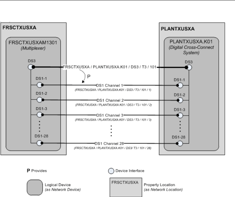
Terminating Channels
Channelized Connectivity 13-5
Figure 13–2 Channel Termination
Device Interfaces and Channel Termination
As shown in Figure 13–2, UIM can automatically terminate channels on sub-interfaces
of the device interfaces on which a facility is terminated. But for this functionality to
work properly, the logical device and device interface hierarchy must be structured to
match the channel hierarchy of the facility. The logical devices must include interfaces
and sub-interfaces for all the channels that a connectivity can provide, even if you do
not plan to use all of the channels.
For T-Carrier and similar technologies, the basic relationship between the device
interface hierarchy and the channel hierarchy is very direct. Figure 13–3 illustrates the
signal hierarchy for the T-Carrier technology
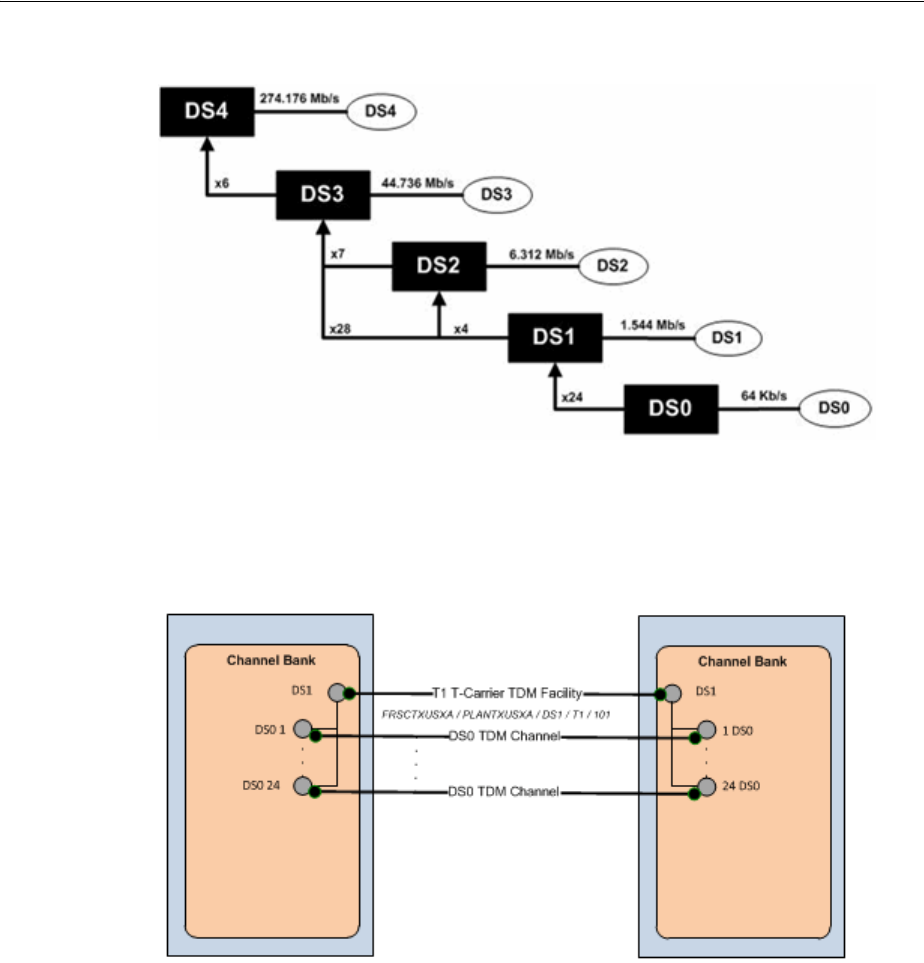
Terminating Channels
13-6 Oracle Communications Unified Inventory Management Concepts
Figure 13–3 T-Carrier Signal Hierarchy
Figure 13–4 illustrates the hierarchy of channels that a connectivity requires to
represent a T1 facility. The DS1 device interfaces on which the facility is terminated
must include 24 DS0 sub-interfaces on which to terminate the channels.
Figure 13–4 DS1 Channel and Device Interface Hierarchy
A T3 scenario is slightly more complicated because a T3 can be multiplexed in two
ways. The signal can be multiplexed in two stages into 7 DS2 signals each of which is
multiplexed to 4 DS1 signals. Alternatively, the signal can be multiplexed directly to 28
DS1 signals, bypassing the intermediate DS2 signals.
In practice, DS2 is an internal multiplexing function and DS2 signals are not exposed
externally. As a result, it is not necessary to include DS2 sub-interfaces when you
design a device interface hierarchy for a T3 facility.
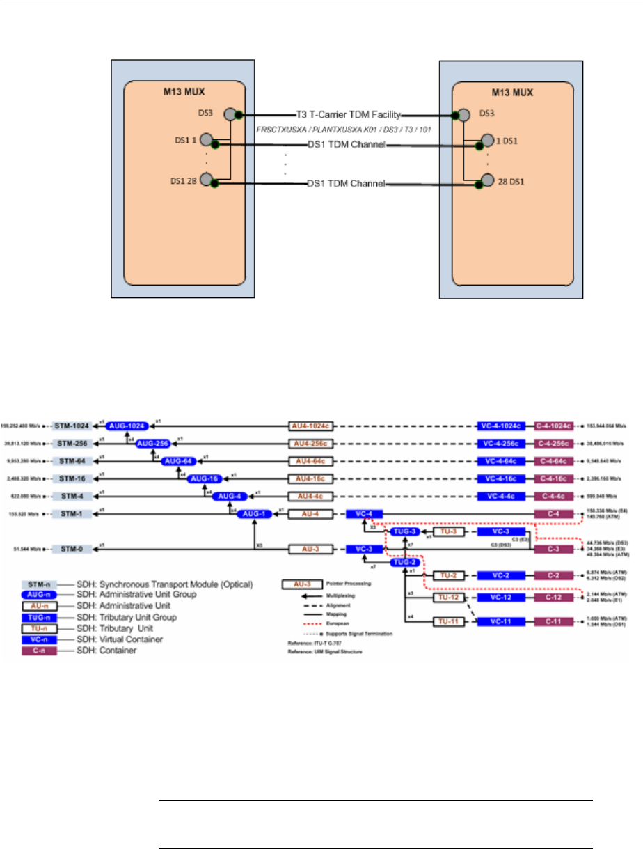
Terminating Channels
Channelized Connectivity 13-7
Figure 13–5 DS3 Channel and Device Interface Hierarchy
SONET and SDH have more complex signal hierarchies. For example, SDH includes
STM-n, AUG-n, AU-n, TUG-n, TU-n, VC-n and C-n signals. All of these are included in
the UIM signal architecture. Figure 13–6 illustrates the SDH signal hierarchy.
Figure 13–6 SDH Signal Hierarchy
When you set up a hierarchy of device interfaces to support an SDH facility, however,
you need to include only the interfaces on which channels are actually terminated.
These interfaces include VC4, VC3, VC12, and so on. These are the interfaces that are
interconnected to other interfaces when an enabling connectivity is passed through a
logical device. Figure 13–7 illustrates the channel and device interface hierarchy for an
STM1 facility.
Note: For visual clarity, some elements of the hierarchy have been
omitted.
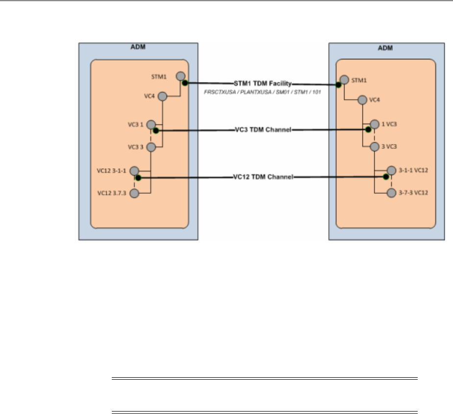
Terminating Channels
13-8 Oracle Communications Unified Inventory Management Concepts
Figure 13–7 STM1 Channel and Device Interface Hierarchy
In a more complex STM16 scenario, you may need to design the device interface
hierarchy to include possible channel signal levels such as VC4-16c and VC-4-4c, even
if you do not expect to use them. (If you definitely do not plan to use the VC4-x levels
you can omit those interfaces.) Figure 13–8 illustrates the channel and device interface
hierarchy for an STM16 facility. This example includesVC4 and VC3 channels that are
terminated on their respective interfaces.
Relative to the full SDH signal hierarchy, the channel and device interface hierarchy is
relatively flat because processing and multiplexing signals are not present as
interfaces.
Note: For visual clarity, some elements of the hierarchy have been
omitted.
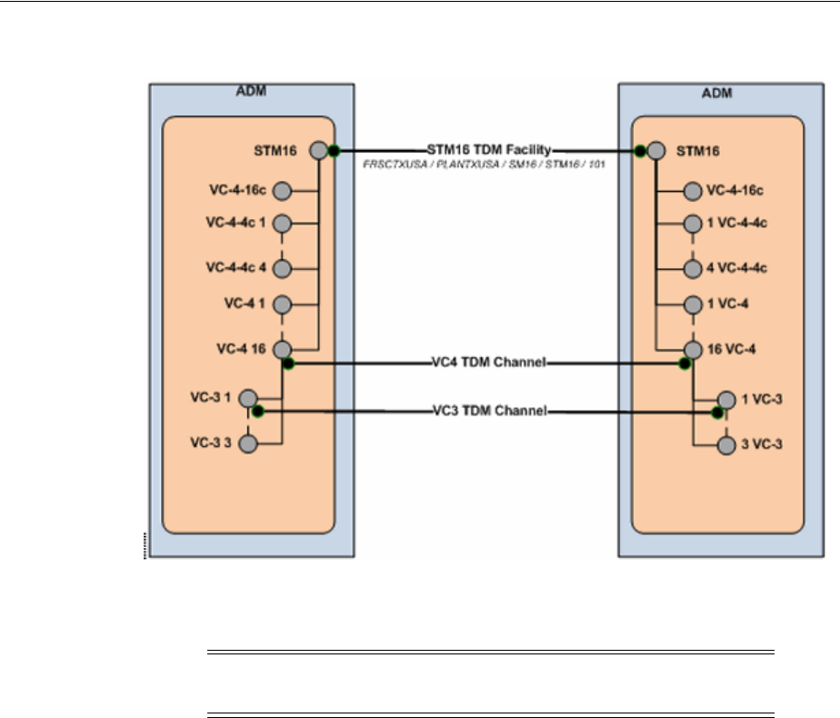
Terminating Channels
Channelized Connectivity 13-9
Figure 13–8 STM16 Channel and Device Interface Hierarchy
Figure 13–9 illustrates an even more complex STM64 example with VC4-16c, VC-4-4c
and VC4 channels terminated on their respective interfaces.
Note: For visual clarity, some elements of the hierarchy have been
omitted.
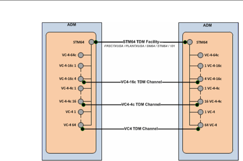
About the UIM Signal Architecture
13-10 Oracle Communications Unified Inventory Management Concepts
Figure 13–9 STM64 Channel and Device Interface Hierarchy
About the UIM Signal Architecture
In both Pipe entities and Connectivity Entity entities, a signal structure defines the
multiplexing hierarchy that allows a signal to be broken into lower-data-rate channels.
A signal structure is defined through a hierarchy of signal specifications that defines
the multiplexing hierarchy of pipe or channelized connectivity. See "Understanding
Signal Structures" for more information about signal structures.
For Connectivity entity entities, signal structures are defined by a set of
Oracle-provided specifications known as the UIM signal architecture. The signal
architecture determines the multiplexing options when you configure channels for a
channelized connectivity.
The rate code associated to a channelized connectivity determines the Connectivity
Signal Termination Point specification for the facility (root) signal in the signal
hierarchy. Connectivity Signal Termination Point specifications and Processing Signal
specifications are hierarchically related in the UIM signal architecture to define the
multiplexing options for the facility signal. You configure the channels of the
channelized connectivity based on the multiplexing options defined by the signal
architecture. Based on your configuration choices, UIM creates a signal structure that
includes entities representing the signals. The signal hierarchy is displayed in the
Channels tab for the channelized connectivity.
The signal architecture also defines compatible signal relationships that enable
channelized connectivity to be transported on the channels of SONET and SDH
facilities. The rate code of the transported connectivity can differ from the rate code of
its assigned channel as long as the channel's signal is compatible with the signal of the
connectivity that rides the channel. For example, in SONET, the VT-1.5 SPE channel
signal, which has a VT1.5 rate code, is compatible with a DS1 signal. That means that a
channelized connectivity with a DS1 rate code can ride a VT-1.5 channel on a SONET
facility, such as an OC-3 facility.
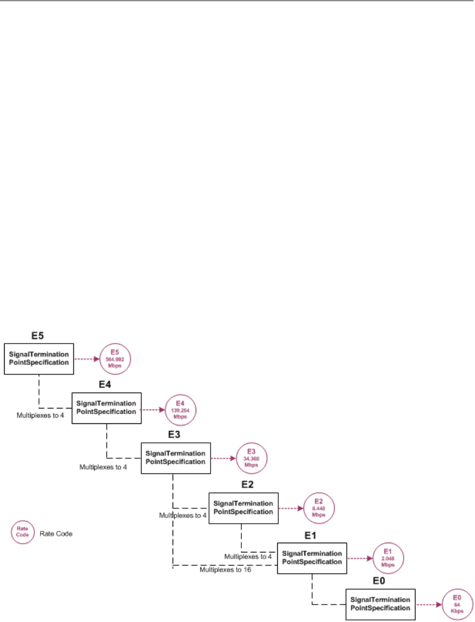
About the UIM Signal Architecture
Channelized Connectivity 13-11
The signal architecture is supplied in the ora_uim_basetechnologies cartridge. You can
view the contents of this cartridge in Design Studio, but you cannot change it or add
specifications. See the Design Studio for UIM Help for more information.
See "E-Carrier Signal Architecture" and "SONET Signal Architecture" for two
examples. See UIM Information Model Reference for detailed information about the
specifications, entities, and relationships involved in the signal architecture.
E-Carrier Signal Architecture
The E-Carrier signal architecture includes six Signal Termination Point specifications
(E5 through E0). Each of these specifications is associated to a rate code that identifies
the technology and bit rate for the signal.
With the exception of the E3 signal, each E-Carrier signal can be channelized only to
the signal below it in the hierarchy. For example, an E4 transmission facility can only
have four E3 channels.
An E3 signal can be multiplexed in two ways: it can multiplex to either four E2 signals
or sixteen E1 signals. The signal multiplexes directly from the E3 to the E1 signal
without including E2 signals.
Figure 13–10 illustrates the hierarchy of specifications that comprise the E-Carrier
signal architecture.
Figure 13–10 E-Carrier Signal Architecture
When you associate a rate code to a Connectivity entity, you determine the signal that
applies to the facility represented by the entity and also determine its multiplexing
options. For example, if you create a Connectivity entity with the E4 rate code, the
facility can be muliplexed only to E3 channels.

About the UIM Signal Architecture
13-12 Oracle Communications Unified Inventory Management Concepts
SONET Signal Architecture
SONET is a multiplexing technology that enables a carrier signal to transport
lower-rate traffic from a variety of sources within one transmission frame.
The signal architecture for SONET includes optical carrier Signal Termination Point
specifications that define facility signals such as OC-1 and OC-3. The signal
architecture also includes corresponding rate codes that you can associate to
Channelized Connectivity entities to define their facility signals and signal structures.
Channel signals are defined by STS-n SPE (synchronous payload envelope) and VT-n
SPE specifications.
The SONET technology uses processing signals to multiplex and align other signals.
The signal architecture includes three Processing Signal specifications:
■Synchronous Transport Signals (STS-n)
■Virtual Tributary Group (VT Group)
■Virtual Tributary (VT-n)
STS-3 and STS-1 signals can serve as both facility signals and processing signals. They
are facility signals when used directly on a channelized connectivity. They are
processing signals when they multiplex from an OC-n or another STS-n signal. The
signal architecture includes specifications for these signals as both Signal Termination
Point and Processing Signal specifications.
Figure 13–11 shows the UIM entities and relationships that comprise an OC-3 signal
structure. This is the signal structure that is associated to a channelized connectivity
when you assign it the OC-3 rate code. See UIM Information Model Reference for more
information.
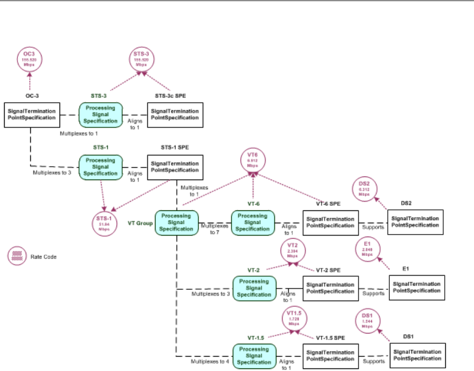
About the UIM Signal Architecture
Channelized Connectivity 13-13
Figure 13–11 OC-3 Signal Structure
Wavelength Division Multiplexing Signal Architecture
Wavelength Division Multiplexing (WDM) is an optical technology used to increase
bandwidth over existing fiber optic backbones. WDM works by combining and
transmitting multiple signals simultaneously at different wavelengths on the same
fiber. WDM-based networks can transmit data in SONET, SDH, or Ethernet, and can
handle bit rates between 100 Mbps and 2.5 Gbps.
UIM supports WDM as channelized connectivity, including the ability to carry
SONET, SDH, and Ethernet in WDM channels. The ora_uim_basetechnologies.jar
cartridge defines the signal hierarchy and rate codes supported by WDM. It also
defines compatibility between WDM rate codes and other rate codes.
You can create WDM channelized connectivities with rate codes from OM160 through
OM4. The signal architecture defined by the WDM cartridge determines how
connectivities can be channelized. Figure 13–12 illustrates the WDM signal
architecture. For example, the illustration shows that an OM-32 connectivity can be
channelized as 2 OM-16 channels, 4 OM-8 channels, 8 OM-4 channels, or 32 OM-1
channels.
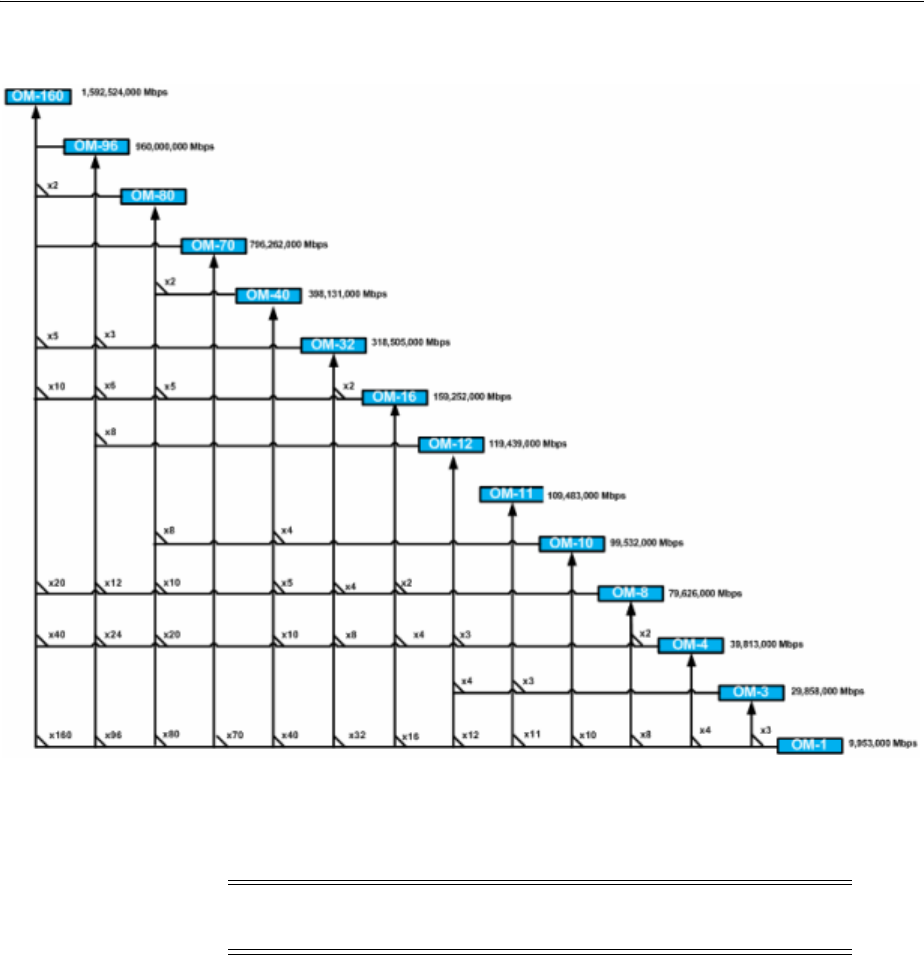
Configuring Connectivity Capacity
13-14 Oracle Communications Unified Inventory Management Concepts
Figure 13–12 WDM Signal Architecture
You can use WDM channels to enable other connectivities. For example, you can
enable an OC192 SONET facility with an OM1 (10 Gbps) channel or a 100 Gbps
Ethernet pipe with an OM10 channel.
Configuring Connectivity Capacity
The signal structure of a channelized connectivity is determined by the rate code you
assign it. In cases where there are no options about channelization, the first level of
channels is created automatically. For example, if you create an E4 connectivity, four
E3 channels are created automatically.
For rate codes that include multiple possible signal structures and for channels below
the first level in all signal structures, you must configure the capacity of the
Channelized Connectivity entity. For example, if you create a DS3 connectivity, you
must choose whether to configure the signal structure to include DS2 channels or to
skip that level and include DS1 channels directly below the DS3.
You view and configure the signal structure of a Channelized Connectivity entity in
the Capacity tab of the Connectivity Details page. Figure 13–13 shows the Capacity tab
of a DS3 connectivity that has been multiplexed to 28 DS1 channels. (Only eight of the
channels are visible in the illustration.)
Note: Only a TDM facility with a transmission signal type of Optical
can be enabled with a WDM channel.
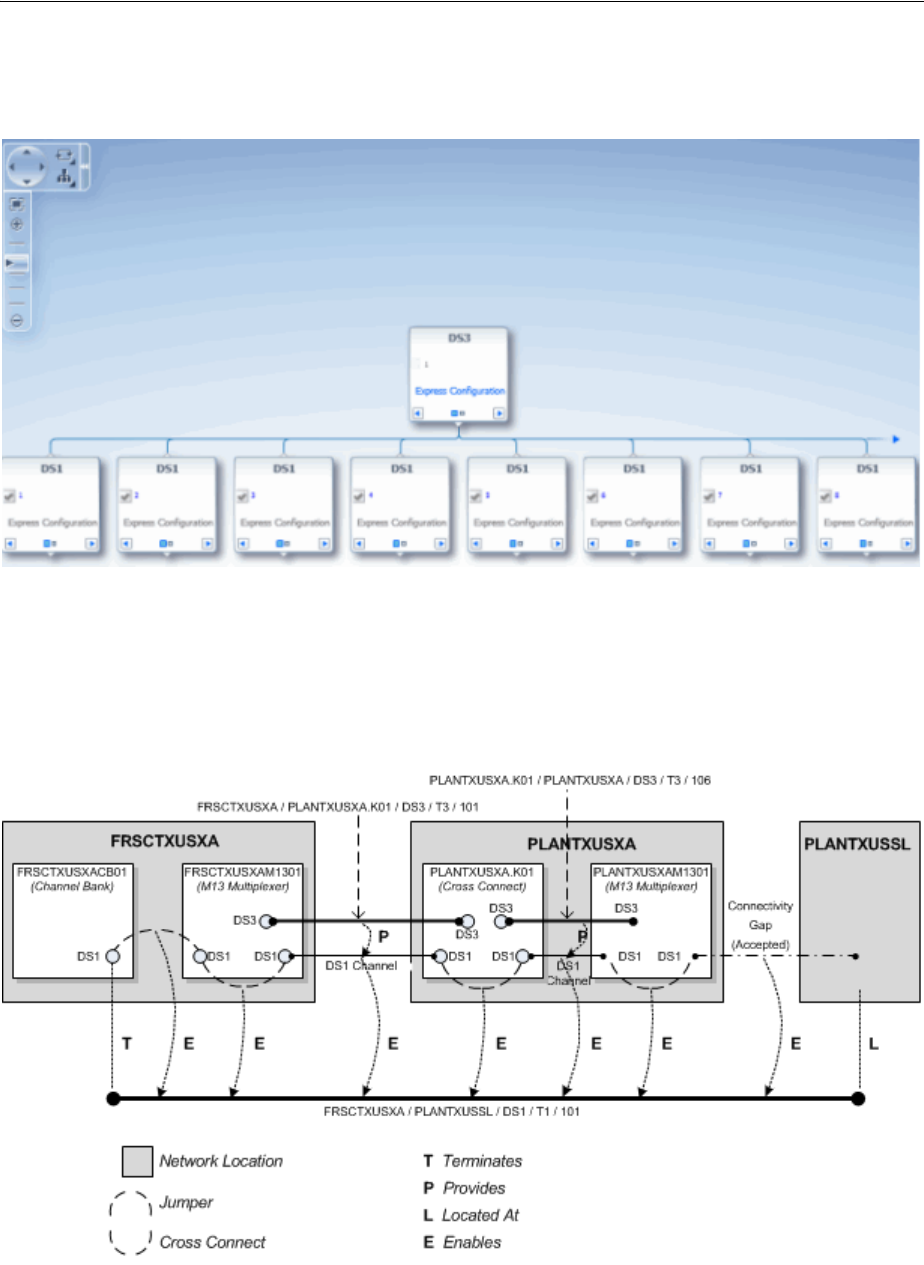
Terminating and Enabling a Channelized Connectivity
Channelized Connectivity 13-15
See the UIM Help for more information about how to use the Capacity tab.
Figure 13–13 DS3 Connectivity in Capacity Tab
Terminating and Enabling a Channelized Connectivity
Figure 13–14 illustrates a channelized connectivity that is enabled by several different
kinds of resources.
Figure 13–14 Enabled Channelized Connectivity
In this example, the FRSCTXUSXA / PLANTXUSSL / DS1 / T1 / 101 facility is
terminated on a device interface in a channel bank located at the network location

About Virtual Connectivity
13-16 Oracle Communications Unified Inventory Management Concepts
FRSCTXUSXA. Seven segments are required to complete the end-to-end connectivity
path:
1. A jumper interconnects a DS1 interface on the FRSCTXUSXACB001 channel bank
to a DS1 interface on the drop side of the FRSCTXUSXAM1301 multiplexer. The
jumper is trail-bound because it was created as part of the connectivity design.
2. A cross-connect interconnects the DS1 interface on the FRSCTXUSXAM1301
multiplexer to a DS1 interface provided by a DS3 interface on the line side of the
same device. This cross-connect is interface-bound because it is considered to be
manufactured into the device.
3. A DS1 channel provided by a DS3 channelized connectivity runs from the
FRSCTXUSXAM1301 multiplexer to a DS1 interface (DS1-3) provided by a DS3
interface on the PLANTXUSXA.K01 digital cross-connect system. The
PLANTXUSSL network location in this example identifies a service location where
the DS1 facility is terminated on a customer-owned device.
4. A trail-bound cross-connect interconnects the DS1-3 interface to the DS1-14
interface provided by another DS3 interface on the opposite side of the
PLANTXUSXA.K01 device.
5. A DS1 channel provided by the PLANTXUSXA.K01 / PLANTXUSXA / DS3 /T3
/106 facility connects the digital cross-connect to a DS1 interface provided by a D3
interface on the drop side of the PLANTXUSXAM1301 multiplexer.
6. An interface-bound cross-connect connects the drop-side interface to a line-side
interface on the PLANTXUSXAM1301multiplexer.
7. An accepted connectivity gap runs from the PLANTXUSXAM1301 multiplexer to
PLANTXUSSL. This segment is treated as an accepted connectivity gap because
the customer-owned device and cable pairs running to it from the PLANTXUSXA
location are not inventoried.
About Virtual Connectivity
UIM supports virtual connectivity and termination. You can create Channelized
Connectivity entities with VC4, VC3, VC2, VC11, and VC12 rate codes.
A connectivity is considered virtual when it terminates on the sub-interfaces of the
device interface on which its parent facility is terminated rather than on its own device
interface.
For example, a VC4 facility is used to abstract out the optical physical transport of
traffic between two points in an SDH network. A VC4 facility effectively delivers a 155
Mb connectivity. This connectivity can be configured to carry lower-order traffic
within lower-order containers (C4, C3s, and C12s) to deliver E4, E3, and E1 services.
VC4 connectivities are used extensively in SDH networks to provide logical
connectivity. A large part of SDH capacity planning is determining VC4 network
location-to-location routes and monitoring the utilization levels of those routes. High
utilization levels of the 63 lower-order (VC12) channels within VC4s is the main driver
for deciding that a new VC4 path is required.
You can configure VC4 and VC3 connectivities to provide capacity at other levels.
VC2, VC11 and VC12 connectivities have single-channel structures defined by the UIM
signal architecture.
You can use gap analysis for VCn connectivities.
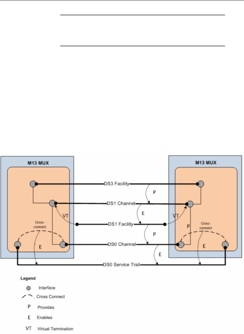
About Virtual Connectivity
Channelized Connectivity 13-17
Virtual Termination
UIM supports the virtual termination of connectivities on device interfaces that
already have channel terminations. Connectivities can be virtually terminated on the
same device interfaces that already terminate its enabling channels. A connectivity that
has a single default channel with the same rate code as its parent can be terminated on
the same device interface that its parent is terminated on.
For example, virtual termination can be used when a DS1 facility rides a DS1 channel
from a DS3 facility. (See Figure 13–15.) The DS1 facility is virtually terminated on the
same DS1 interfaces used to terminate its enabling DS1 channel. A DS0 channel
provided by the DS1 facility is automatically terminated on a sub-interface. The DS0
channel termination is required to create a cross-connect that is part of the enablement
of a DS0 service trail.
Figure 13–15 Virtual Termination on a DS1 Facility
Figure 13–16 provides a simplified view of a STMx facility providing VC4 channels
that enable a VC4 facility. The VC4 facility is virtually terminated on the same
sub-interfaces that already terminate the enabling VC4 channels.
Note: You cannot use a single channel of a facility to enable a
connectivity when all three share the same rate code. For example, a
VC4 channel provided by a VC4 facility cannot be used to enable
another VC4 connectivity.
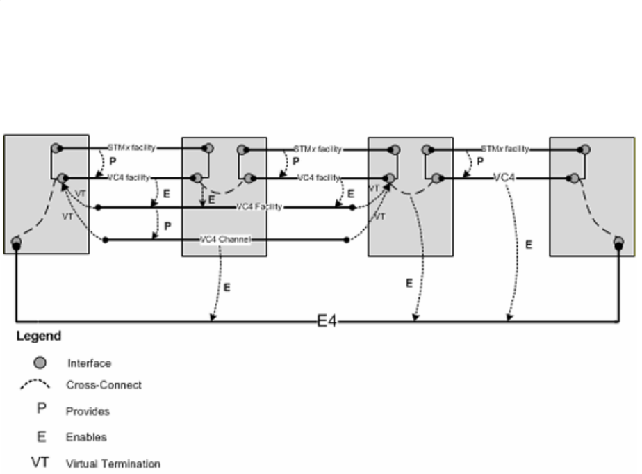
Maintaining Channelized Connectivity and Network Resources
13-18 Oracle Communications Unified Inventory Management Concepts
The VC4 facility is configured to have a single VC4 channel that enables an E4.
Because this single channel has the same rate code as its parent facility, it is virtually
terminated on the same sub-interfaces.
Figure 13–16 Virtual Termination on a VC4 Channel
Maintaining Channelized Connectivity and Network Resources
UIM provides features for optimizing network resource utilization by maintaining
channelized connectivity and reconfiguring network topology:
■You can groom a connectivity to change the riders that consume its channels. For
example, in an OC3 facility, you can move a DS1 rider from one VT 1.5 channel to
another within the facility or to a VT 1.5 channel in another facility.
■You can rehome a channelized connectivity to change its termination. For
example, you can move the termination of a DS3 facility from one device interface
to another. The source and target device interfaces can be on the same device or on
different devices, either at the same location or at different locations. Termination
changes can result in changes to channel assignments, so a grooming activity can
be required as the result of rehoming. See "About Rehoming" for more
information.
■In a network, you can insert a new node that represents a logical device into the
middle of an edge that represents a channelized connectivity. UIM automatically
creates new connectivities, manages the termination changes, and manages
channel reassignments. See "Inserting and Removing Nodes in Networks" for
more information.
■In a network, you can remove a node that represents a logical device on which two
connectivities are terminated. UIM changes terminations and reassigns riders to a
connectivity that replaces the two that were previously terminated on the removed
device. See "Inserting and Removing Nodes in Networks" for more information.
You plan and manage these maintenance activities as parts of projects. For example,
you can define a project for all the grooming and rehoming activities related to a
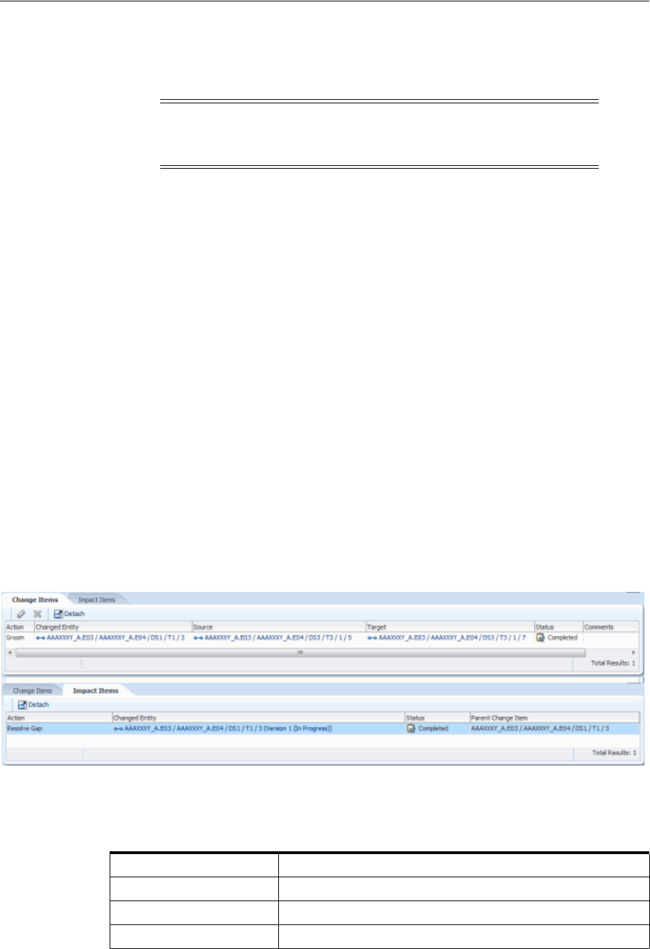
Maintaining Channelized Connectivity and Network Resources
Channelized Connectivity 13-19
particular network infrastructure change. When you submit an activity in a project,
UIM processes it in the background and returns the results. See "Projects" for more
information.
About Change Items and Impact Items
When you configure an activity, UIM determines which entities must be changed as a
direct result of the activity and what actions must be completed. The combination of
an entity and an action is called a change item. The change items for an activity are
displayed in the Change Items tab of the Project Details page when the activity is
selected.
When you submit an activity, UIM processes its change items sequentially. During
processing, UIM creates impact items, which are combinations of entities and actions
that must be completed to make it possible to complete change items. Because impact
items are not known until processing begins, they are displayed only after the activity
is submitted. Impact items are displayed in the Impact Items tab as they are created.
Figure 13–17 shows the Change Items and Impact Items tabs for a grooming activity
that reassigned a T1 facility from one channel of a T3 facility to another channel in the
same facility. A connectivity gap results from this change, as shown in the Impact
Items tab. The Parent Change Item column refers to the change item that generated the
impact item.
In this case, UIM was able to resolve the gap successfully. If UIM could not resolve the
gap, the action would be shown in In Progress status and you would need to resolve
the gap manually.
Figure 13–17 Change Items and Impact Items Tabs
Table 13–1 lists all of the actions that can be taken on entities as part of change items
and impact items.
Caution: While an activity is being processed, you should avoid
making changes to entities that might be modified by the activity.
Changes could result in processing failure.
Table 13–1 Activity Item Actions
Activity Item Action Description
Groom Re-route traffic riding a connectivity.
Rehome Change a connectivity design at an endpoint.
Insert Node Insert a node that represents a logical device into a network

Maintaining Channelized Connectivity and Network Resources
13-20 Oracle Communications Unified Inventory Management Concepts
About Connectivity Design Versions and Grooming and Rehoming
When you groom or rehome a connectivity, a new connectivity design version is
created in some cases:
■If the connectivity design is completed before grooming or rehoming and there is
no in-progress version, a new in-progress version is created. The changes required
by the grooming or rehoming activity occur in this version. If no unresolved gaps
result from the activity, the version is completed automatically. If unresolved gaps
remain after the grooming or rehoming, the new version remains in In Progress
status.
■If the connectivity has an in-progress design version before grooming or
rehoming, that version is used for the changes. This version is not completed
automatically as part of the grooming or rehoming activity.
See "About Design Versions" for more information.
About Grooming
When you groom a connectivity, you change the assignments of its channels. For
example, when you groom an OC3 facility, you can move a DS1 rider from one VT 1.5
channel to another within the same facility or to a VT 1.5 channel in another facility.
These design changes involve unassigning riders from one or more channel segments
along with related gaps, jumpers, and cross-connects. Riders are then reassigned to
new channels. Grooming does not involve changing connectivity termination
(rehoming) except in the case of virtual termination.
Grooming often occurs because of network changes that make new routes available or
make old routes inefficient. For example, if new devices are added to a network, an
existing route may now have an unacceptable number of hops. Planning and
management processes can discover these situations and recommend more efficient
routing to be implemented by grooming.
Grooming is intra-facility when the new channel assignments are in the same bearer
facility as the old channel assignments or inter-facility when the new channel
assignments are in a different bearer facility from the old channel assignments.
Grooming can move a rider from one bearer to two bearers. For example, if you add
device C between existing devices A and B, two new segments are created (A-C and
Remove Node Remove a node that represents a logical device from a network.
Insert Device Insert a logical device into a connectivity design.
Remove Device Remove a logical device from a connectivity design.
Replace Edge Replace one network edge with another network edge.
Resolve Gap Fill a gap in a connectivity design by adding a channel
assignment, cross connect, or jumper.
View Design Viewing the connectivity design related to an Activity Item.
Terminate Define the end point of the connectivity. For example, a
connectivity can be terminated on a device interface.
Unterminate Remove the end point of the connectivity, such as the device
interface on which the connectivity is terminated.
Table 13–1 (Cont.) Activity Item Actions
Activity Item Action Description
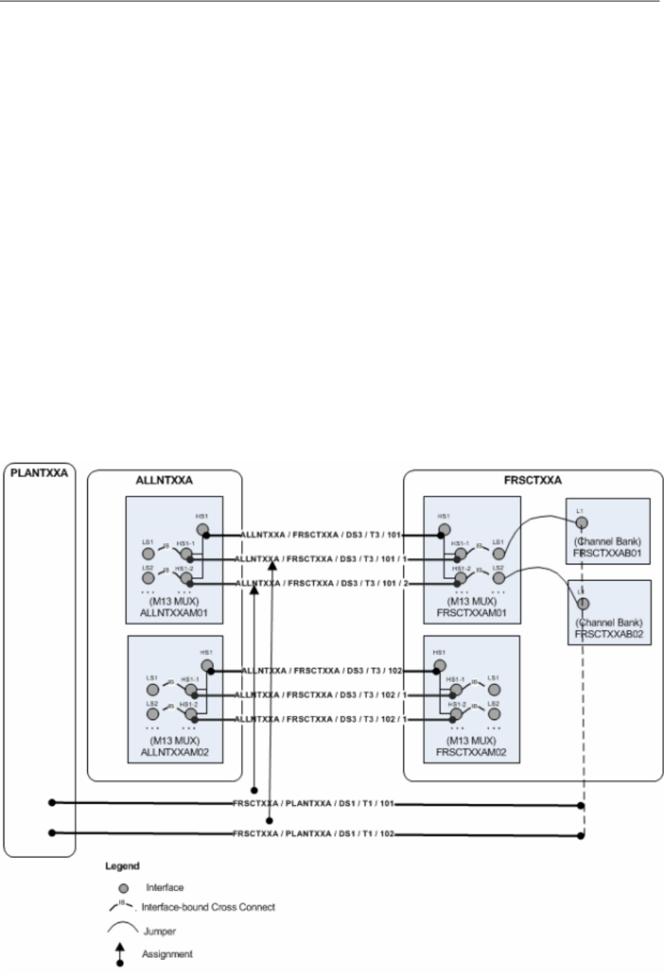
Maintaining Channelized Connectivity and Network Resources
Channelized Connectivity 13-21
C-B). You can groom a connectivity that was riding channels in the original A-B
segment to ride channels in the newly created segments instead. (UIM can
automatically perform this grooming activity when you insert new network nodes. See
"Inserting and Removing Nodes in Networks" for more information.)
Grooming a virtual path connectivity can cause changes to virtual termination if the
changes include the first or last segment in the design.
Before you groom a connectivity, you must ensure that the connectivities are properly
designed and terminated and that the target connectivity has enough capacity to
accommodate all riders that are reassigned to it.
Grooming Scenario: lnter-Facility
This scenario illustrates an inter-facility grooming activity in which two connectivities
are re-assigned from channels in one facility to channels in another facility.
Figure 13–18 illustrates the scenario before grooming takes place. Two T1
connectivities (FRSCTXXA / PLANTXXA /DS1 / T1 /101 and FRSCTXXA /
PLANTXXA /DS1 / T1 /102) are riding channels provided by the ALLNTXXA /
FRSCXXA /DS3 / T3 /101 facility. To free capacity, the T3 facility is groomed to
reassign the T1 connectivities to channels provided by a different facility (ALLNTXXA
/ FRSCXXA /DS3 / T3 /102). Note that the T1 facilities are enabled in part by
cross-connects from the FRSCTXXAM01 MUX to channel banks at the same location.
Figure 13–18 Intra-Facility Grooming: Before
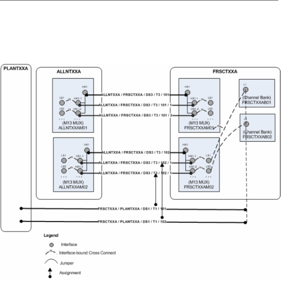
Maintaining Channelized Connectivity and Network Resources
13-22 Oracle Communications Unified Inventory Management Concepts
Figure 13–19 illustrates the results of the grooming activity. The channel reassignments
have occurred. The new channels are terminated on a different MUX, so UIM has
added cross-connects to join the interfaces on the MUX to the channel banks on which
the T1s are terminated.
Figure 13–19 Inter-Facility Grooming: After
Grooming Scenario: Intra-Facility Grooming for Ethernet Over SDH
In this scenario, a new 1 Gbps Ethernet connection (represented in UIM as a pipe) will
be enabled by an existing SDH STM16 facility (represented in UIM as a channelized
connectivity). This arrangement requires the use of 7 VC4 channels, each providing a
bandwidth of 155.520 Mbps. To deliver the bandwidth, the channels must be
concatenated virtually. This virtual concatenation scenario requires that the channels
be contiguous in the SDH facility.
The available capacity in the STM16 facility is more than the required 1 Gbps, but 7
contiguous VC4 channels are not available because of fragmentation. Figure 13–20
illustrates an STM16 facility in which two channels (6 and 12) are currently assigned.
There are 14 unassigned channels, but only 5 contiguous channels are available.
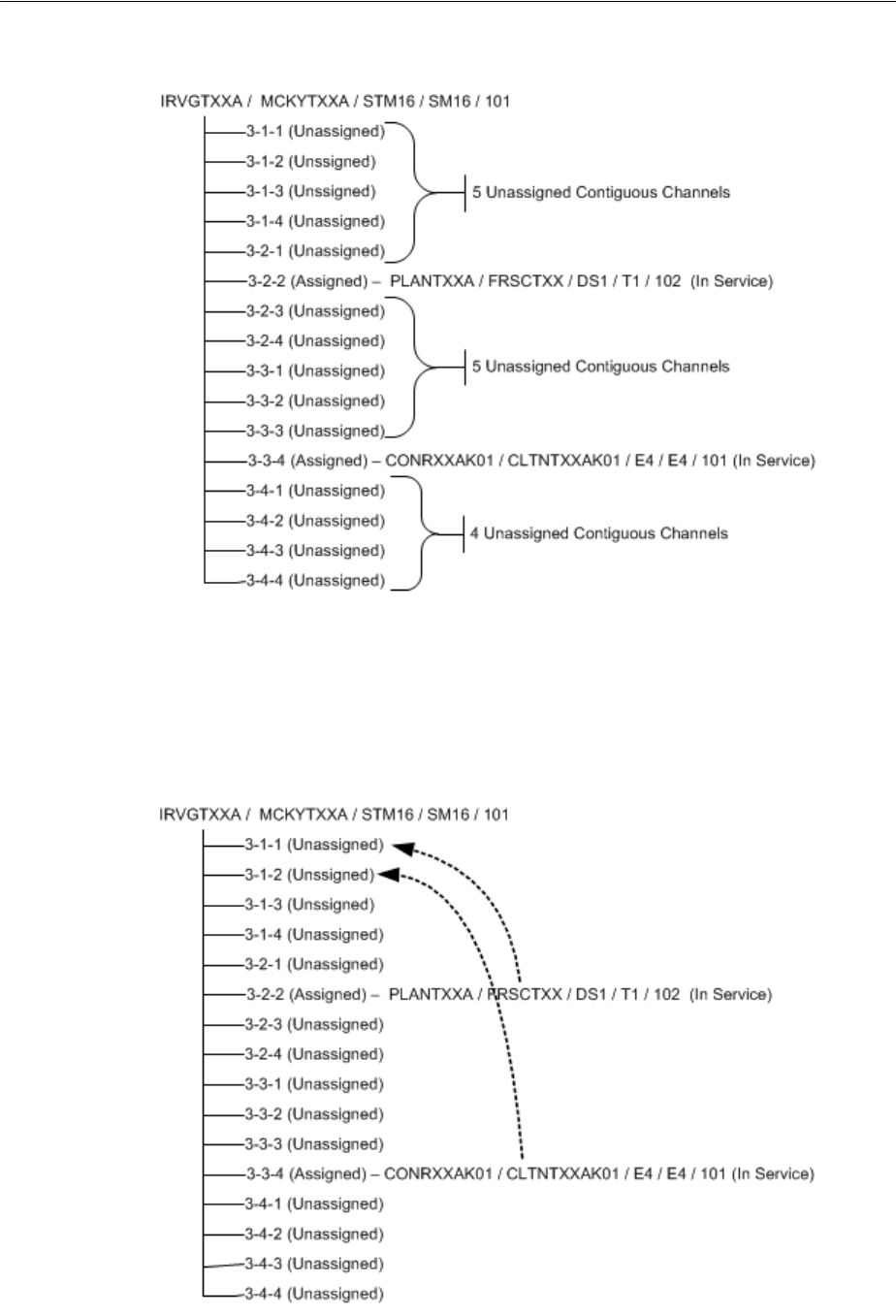
Maintaining Channelized Connectivity and Network Resources
Channelized Connectivity 13-23
Figure 13–20 Intra-Facility Grooming: Before
To free the required number of contiguous channels, the STM16 facility must be
groomed. The channel assignments of the two E4 connectivities must be moved to
make 7 contiguous channels available. The required changes are illustrated in
Figure 13–21.
Figure 13–21 Intra-Facility Grooming: Required Changes
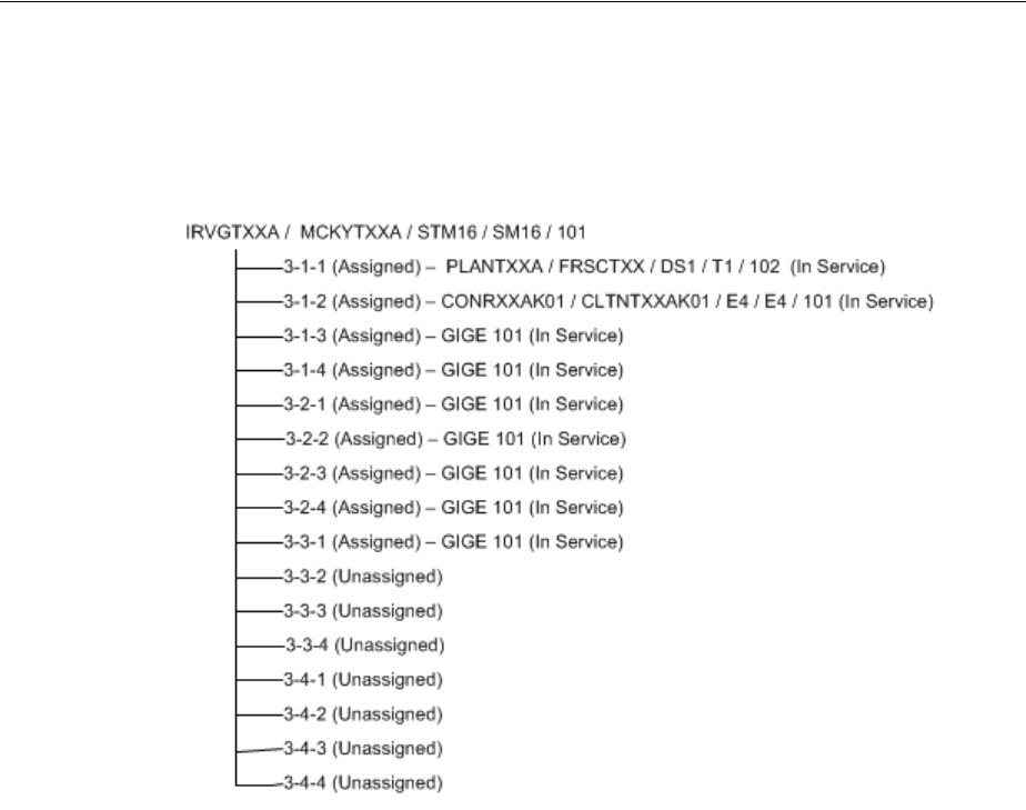
Maintaining Channelized Connectivity and Network Resources
13-24 Oracle Communications Unified Inventory Management Concepts
With these changes, a large contiguous block of channels becomes available, making it
possible to assign them to the Ethernet pipe. Figure 13–22 illustrates these
assignments.
Figure 13–22 Intra-Facility Grooming: After
To reassign the two connectivities to different channels within the STM16, UIM must
also reassign any cross-connects, jumpers, or gaps in the connectivity design.
Grooming Scenario: 2:2 Inter-Facility
You can groom multiple facilities simultaneously to reassign trails that are enabled by
them. For example, a single service trail could be enabled by two separate
connectivities along with cross-connects between interfaces that terminate them.
Figure 13–23 illustrates such a scenario. The FRSCTXXA/PLANTXXA/DS1/T1/1
connectivity is a service trail that is enabled by channels provided by the
ALLNTXXA/FRSCTXXA/DS3/T3/1 and ALLNTXXA/PLANTXXA/DS3/T3/1
facilities. The existing multiplexers that terminate these facilities could be reaching
their capacity, so you may need to groom the facilities to reassign their riders to
channels on other facilities.
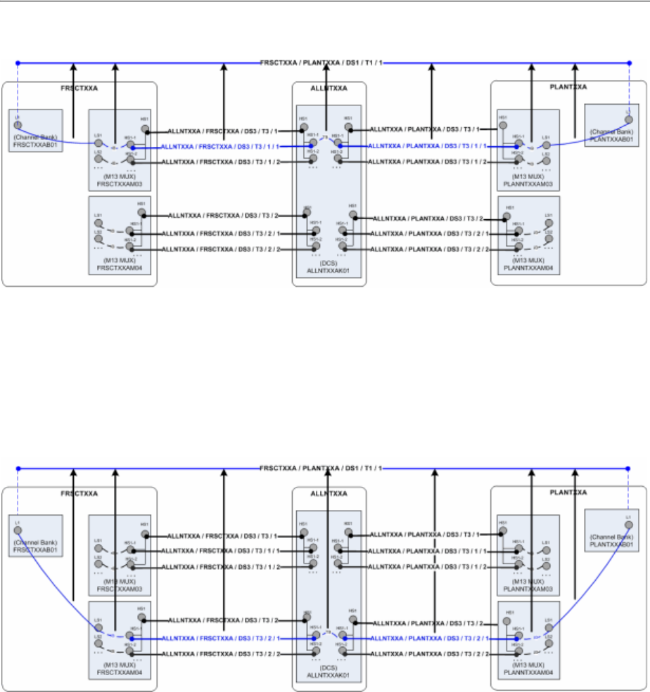
Maintaining Channelized Connectivity and Network Resources
Channelized Connectivity 13-25
Figure 13–23 2:2 Inter-Facility Grooming: Before
Figure 13–24 illustrates the situation after grooming has taken place.
FRSCTXXA/PLANTXXA/DS1/T1/1 is now enabled by channels on other
multiplexers at the same network locations and by interface-bound cross-connects
between interfaces. UIM has automatically created a trail-bound interface between
interfaces on the ALLNTXXK01 DCS. (The trail-bound cross-connect used to enable
the trail previously has been removed.)
Figure 13–24 2:2 Inter-Facility Grooming: After
To perform 2:2 (or n:n) grooming in UIM, you can select multiple facilities when you
configure a grooming activity. See "About the Grooming User Interface" and the UIM
Help for more information.
About the Grooming User Interface
You plan and manage grooming in the Activities tab of the Project Summary page.
When you create or select a grooming activity, you see the Groom section. The Groom
section includes network visualizations in which you select the source (the
connectivity you are grooming) and the target (the connectivity to which you want to
reassign channel riders).
Figure 13–25 shows the Groom section with the source and target selections made.
This is an intra-facility groom, so the source and target connectivities are the same.
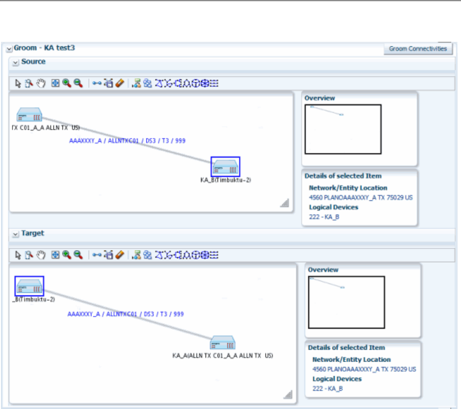
Maintaining Channelized Connectivity and Network Resources
13-26 Oracle Communications Unified Inventory Management Concepts
Figure 13–25 Groom Section
After selecting the source and target connectivities, you use the Groom Connectivities
dialog box to configure the grooming activity. You drill down through the source
connectivity’s channel hierarchy to select the channels whose riders will be reassigned.
You then drill down through the channel hierarchy of the target connectivity to select
the new enabling channels. You can select multiple channels to reassign in the same
activity. Based on your selections, UIM populates the Proposed Changes table with a
list of the entities that will be changed to complete the grooming activity.
Figure 13–26 shows the Groom Connectivities and Proposed Channel sections of the
Groom Connectivities dialog box.
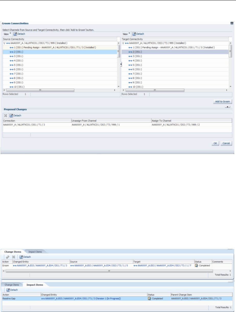
Maintaining Channelized Connectivity and Network Resources
Channelized Connectivity 13-27
Figure 13–26 Groom Connectivities Dialog Box
When you have finished configuring the grooming activity, the Groom Connectivities
dialog box closes. The Change Items tab in the Project Details page is populated with
a list of entities that will change and the actions that will be taken on them. These
change items correspond to the changes displayed in the Proposed Changes section in
the Groom Connectivities dialog box.
Figure 13–27 shows the Change Items and Impact Items tabs for a grooming activity
that reassigned a T1 facility from one channel of a T3 facility to another channel in the
same facility. A connectivity gap results from this change, as shown in the Impact
Items tab. In this case, UIM was able to resolve the gap successfully. If UIM could not
resolve the gap, the action would be shown in In Progress status and you would need
to resolve the gap manually.
Figure 13–27 Change Items and Impact Items Tabs
See "Projects" and the UIM Help for more information about managing projects and
activities.
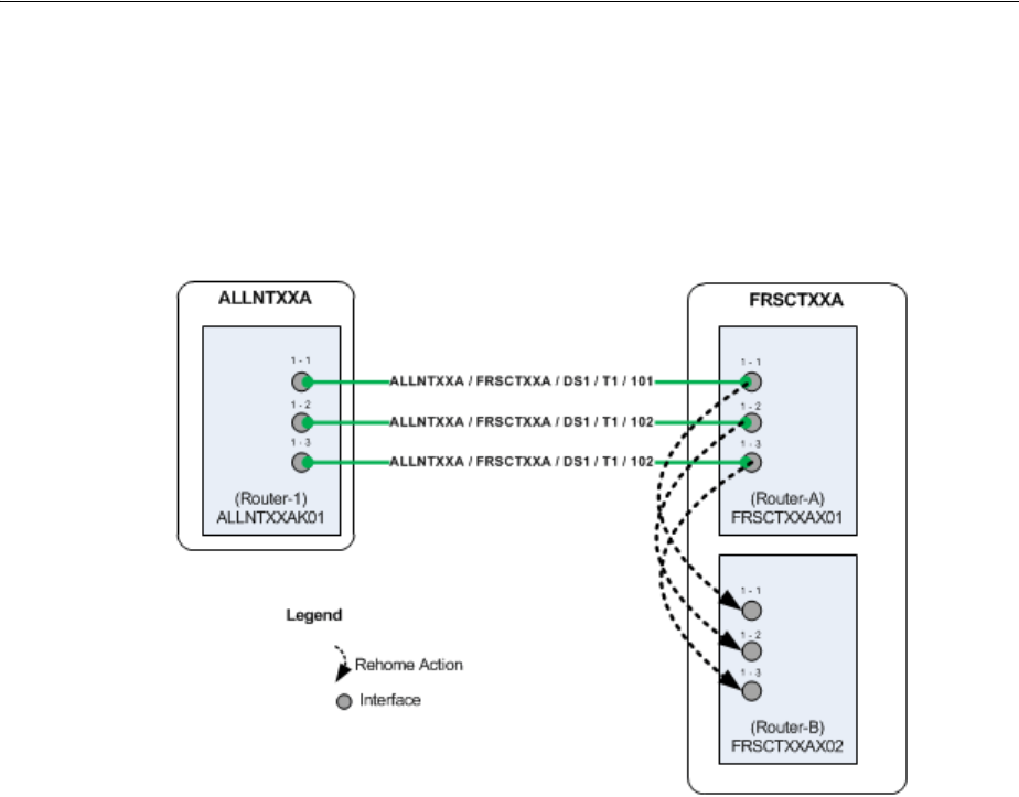
Maintaining Channelized Connectivity and Network Resources
13-28 Oracle Communications Unified Inventory Management Concepts
About Rehoming
When you rehome a connectivity, you change one of its terminations. Rehoming may
be required for load balancing or because of the removal or replacement of devices and
interfaces. Figure 13–28 illustrates a simple scenario in which three T1 facilities are
rehomed from interfaces on one router to interfaces on another router.
Figure 13–28 Simple Rehoming Scenario
Rehoming a facility requires changes to the termination of the facility itself and to any
channels it provides. Channels are re-terminated on sub-device interfaces provided by
the new device interface on which the facility is terminated.
Figure 13–29 illustrates how rehoming a DS3 facility from one interface to another
requires rehoming of its channels to sub-interfaces and therefore the creation of new
cross-connects. For visual clarity, the illustration shows the impact on only one
channel, but all 28 DS1 channels require rehoming and new cross-connects.
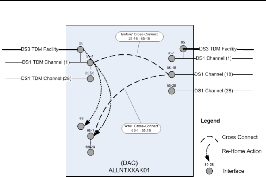
Maintaining Channelized Connectivity and Network Resources
Channelized Connectivity 13-29
Figure 13–29 Rehoming Impact on Cross-Connects
Pipes and connectivities riding channels provided by the rehomed connectivity require
design changes to reflect new interface and cross-connect assignments. To ensure date
integrity in these situations, rehoming must occur recursively throughout the channel
hierarchy of the channelized connectivity.
For example, when you rehome a DS3 facility, there are direct impacts to DS1 riders
enabled by channels provided by the facility. If these riders are virtually terminated to
the same DS1 sub-interfaces used by facility’s DS1 channels, the DS1 riders must be
rehomed to the new DS1 sub-interfaces. If the DS1 riders themselves provide channels
that enable DS0 riders, the DS0 riders must also be rehomed.
Rehoming can result in channel assignment changes that require a grooming activity.
Figure 13–30 illustrates such a scenario. A DS3 facility (NETLOCXX / NETLOCYY /
DS3 / T3 / 333) rides a channel provided by NETLOCAA / NETLOCBB / STM16 /
SM16 / 101. The Z end point of this SM16 facility is being rehomed to a device in
NETLOCGG. The DS3 facility must be reassigned to a different channel as a result of
the rehoming.
Because connectivity identifiers include A and Z network/entity location codes, they
can change when connectivities are rehomed. In Figure 13–30, the connectivity
NETLOCAA / NETLOCBB / STM16 / SM16 / 101 changes to NETLOCAA /
NETLOCGG / STM16 / SM16 / 101. Se"About Connectivity Identifiers"or more
information about how connectivity identifiers are constructed.
The serial number of a connectivity can also change as a result of rehoming.
Connectivity serial numbers must be unique within the context of the A and Z location
pairs, so rehoming can result in a conflict with an existing serial number.
The gray channels in Figure 13–30 indicate the assignments that are removed as the
result of rehoming. The channel reassignment from the NETLOCAA / NETLOCBB /
STM16 / SM16 / 101 / 1-1-1-1 channel to NETLOCAA / NETLOCGG / STM16 /
SM16 / 101 / 1-1-1-1 occurs automatically because rehoming a parent facility also
rehomes its channels.
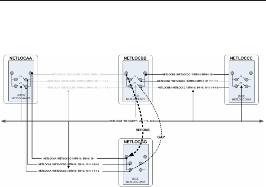
Maintaining Channelized Connectivity and Network Resources
13-30 Oracle Communications Unified Inventory Management Concepts
The DS3 rider has a gap, however, between the device interfaces on NETLOCGG and
the drop side on NETLOCBB. You must resolve this gap separately from the rehoming
activity.
Figure 13–30 Rehoming with Resulting Gap
About the Rehoming User Interface
You plan and manage rehoming in the Rehome section that becomes available when
you create or select a rehoming activity. The Rehome section includes network
visualizations in which you select the source device (the device that provides the
interface on which the connectivity is currently terminated) and the target device (the
device that provides the interface that you want to terminate the connectivity).
Figure 13–31 shows the Rehome section with source and target selections made.
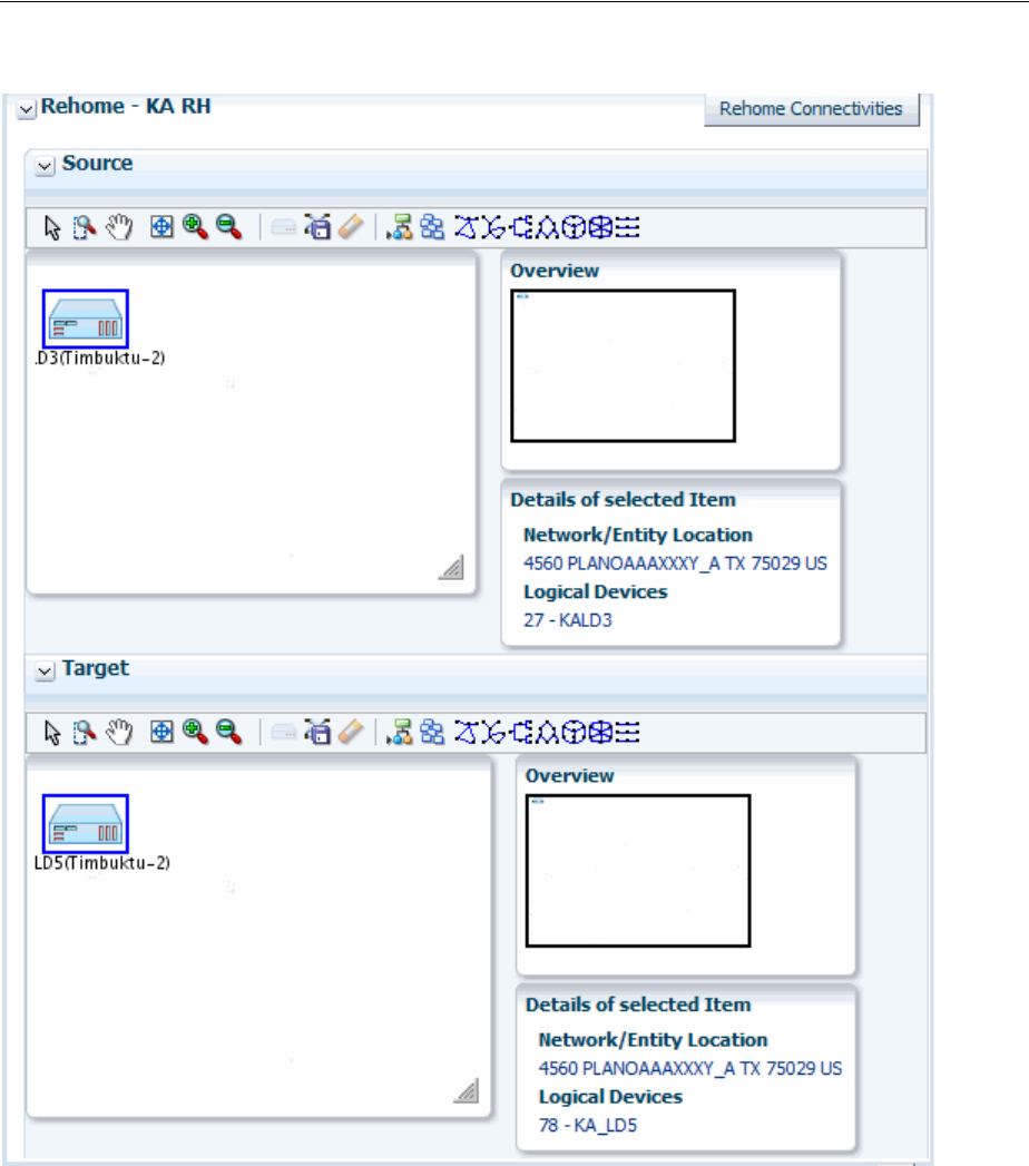
Maintaining Channelized Connectivity and Network Resources
Channelized Connectivity 13-31
Figure 13–31 UIM Rehoming Tools
After selecting the source and target devices, you use the Rehome Connectivities
dialog box to configure the activity. You drill down through the source device’s
hierarchy to select specific the device interface on which the connectivity is
terminated. You then drill down through the hierarchy of the target device to select the
new device interface. You can select multiple pairs of interfaces in the same activity.
Based on your selections, UIM populates the Proposed Changes table with a list of the
entities that will be changed to complete the rehoming activity.
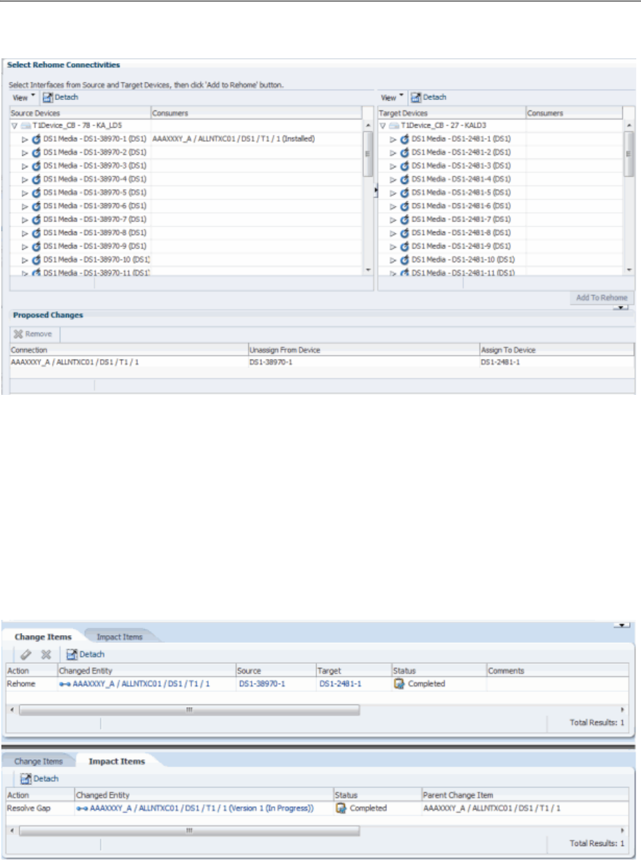
Maintaining Channelized Connectivity and Network Resources
13-32 Oracle Communications Unified Inventory Management Concepts
Figure 13–32 Rehome Connectivities Dialog Box
When you have finished configuring the activity, the Rehome Connectivities dialog
box closes. The Change Items tab in the Project Details page is populated with a list of
actions that corresponds to the proposed entity changes from the dialog box.
Figure 13–33 shows the Change Items and Impact Items tabs for a rehoming activity
in which the end point of a T1 facility is moved from one device interface to another. A
connectivity gap results from this change, as shown in the Impact Items tab. In this
case, UIM was able to resolve the gap successfully. If UIM could not resolve the gap,
the action would be shown in In Progress status and you would need to resolve the
gap manually.
Figure 13–33 Rehoming Change Items and Impact Items Tabs
See "Projects" and the UIM Help for more information about managing projects and
activities.
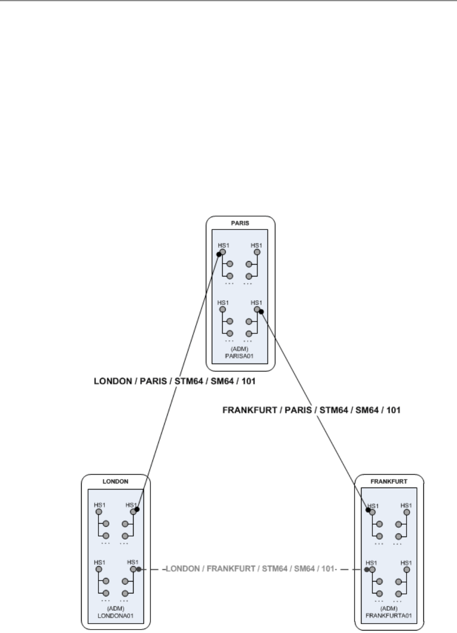
Maintaining Channelized Connectivity and Network Resources
Channelized Connectivity 13-33
Inserting and Removing Nodes in Networks
UIM enables you to insert and remove network nodes that represent logical devices.
UIM manages the required actions, such as channel reassignments and creating
connectivities.
When you insert a node in this way, UIM creates two new connectivities to replace the
existing connectivity. You select a logical device that the inserted node represents and
specify the device interface on which two new connectivities will be terminated.
Figure 13–34 illustrates a simple network scenario in which a new add-drop
multiplexer in Paris is inserted between two existing multiplexers in London and
Frankfurt. The previous London-to-Frankfurt STM16 connectivity is replaced by two
new STM16 connectivities: one from London to Paris and another from Paris to
Frankfurt.
Figure 13–34 Simple Node Insertion Scenario
UIM automatically manages the channel reassignments and termination changes. For
example, when you insert a node and replace a connectivity that has riders, the riders
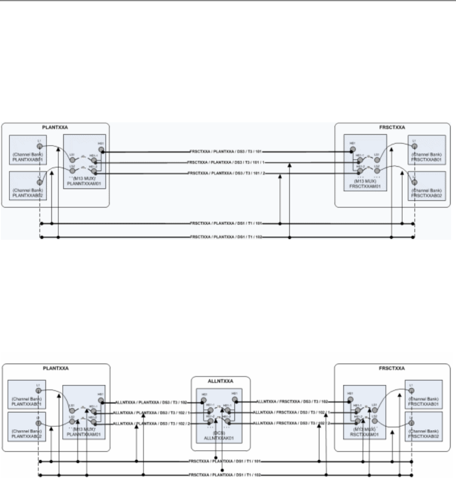
Maintaining Channelized Connectivity and Network Resources
13-34 Oracle Communications Unified Inventory Management Concepts
must be groomed to new channel assignments. UIM manages this grooming
automatically.
Figure 13–35 and Figure 13–36 illustrate this scenario. In this example, the middle
portion of a T1 facility’s path rides a channel provided by the FRSCTXAA /
PLANTXAA DS3 facility. The T1 rider has jumpers and cross-connects at its endpoints.
Figure 13–35 Network Node Insertion: Before
A new device and location are inserted between the PLANTXXA and FRSXTXXA
locations, resulting in the creation of two new T3 facilities to replace the previous T3.
The T1 rider must now be groomed to reflect the network changes. Its terminations on
the channel banks are unchanged, but all of the jumpers, cross-connects, and channel
assignments must be updated as shown in Figure 13–36.
Figure 13–36 Network Node Insertion: After
Connectivities that are assigned to the groomed T1 are unaffected because its
terminations are unchanged. For example, if a DS0 service trail is riding a channel
provided by the T1, its connectivity design requires no modification. It is still assigned
to the same channel, although the parent facility of that channel has been groomed.
Removing a network is the reverse of inserting one. For example, suppose that you
want to remove the node that represents logical device ALLNTXXAK01 in
Figure 13–36. In this scenario, the two connectivities (and their channels) terminated
on the devices must be unterminated and then replaced by a new connectivity that
connects PLANTXXAM01 and FRSCTXXAM01. UIM handles the required termination
changes and channel reassignments. Riders that were enabled by the existing
connectivities are reassigned to the replacement.
You can insert a node into an edge:
■When the edge represents only one connectivity.
■The connectivity is represented by only one edge.
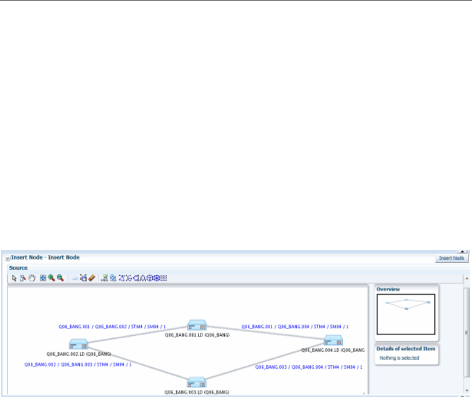
Maintaining Channelized Connectivity and Network Resources
Channelized Connectivity 13-35
■The connectivity is terminated by logical devices on both ends.
You can remove a node:
■When the node has exactly two edges.
■When all of the cross-connects in the device that the node represents are between
the source connectivities represented by the source edges.
Node Insertion User Interface Overview
You manage node insertion in the Insert Node section that becomes available when
you create or select an insert node activity. The section includes a network
visualization in which you select the network that contains the affected nodes and
edges.
Figure 13–37 shows the Insert Node section with a ring network displayed in the
visualization.
Figure 13–37 UIM Insert Node User Interface - Before Activity Configuration
You configure the activity in the Insert Node dialog box. This dialog box includes a
wizard interface in which you:
■Select the network edge into which you want to insert the node. The edge into
which you insert the node must be a facility and not a rider.
■Select the logical device you want the inserted node to represent. The device must
have two free device interfaces that are compatible with the rate code of the
existing connectivity represented by the edge.
■Select the device interfaces on which to terminate the two connectivities that will
be created. The dialog box shows the existing connectivity (the source) and the
new connectivities (the targets) in a table similar to the Connectivity Design tab
used to enable and terminate channelized connectivity. You specify the device
interfaces on which to terminate the Z end point of the first new connectivity and
the A end point of the second. Figure 13–38 shows the Select Interfaces area of the
dialog box. In this case, one device interface has been selected, as indicated by the
green check mark. One device interface has yet to be selected, as indicated by the
red icon.
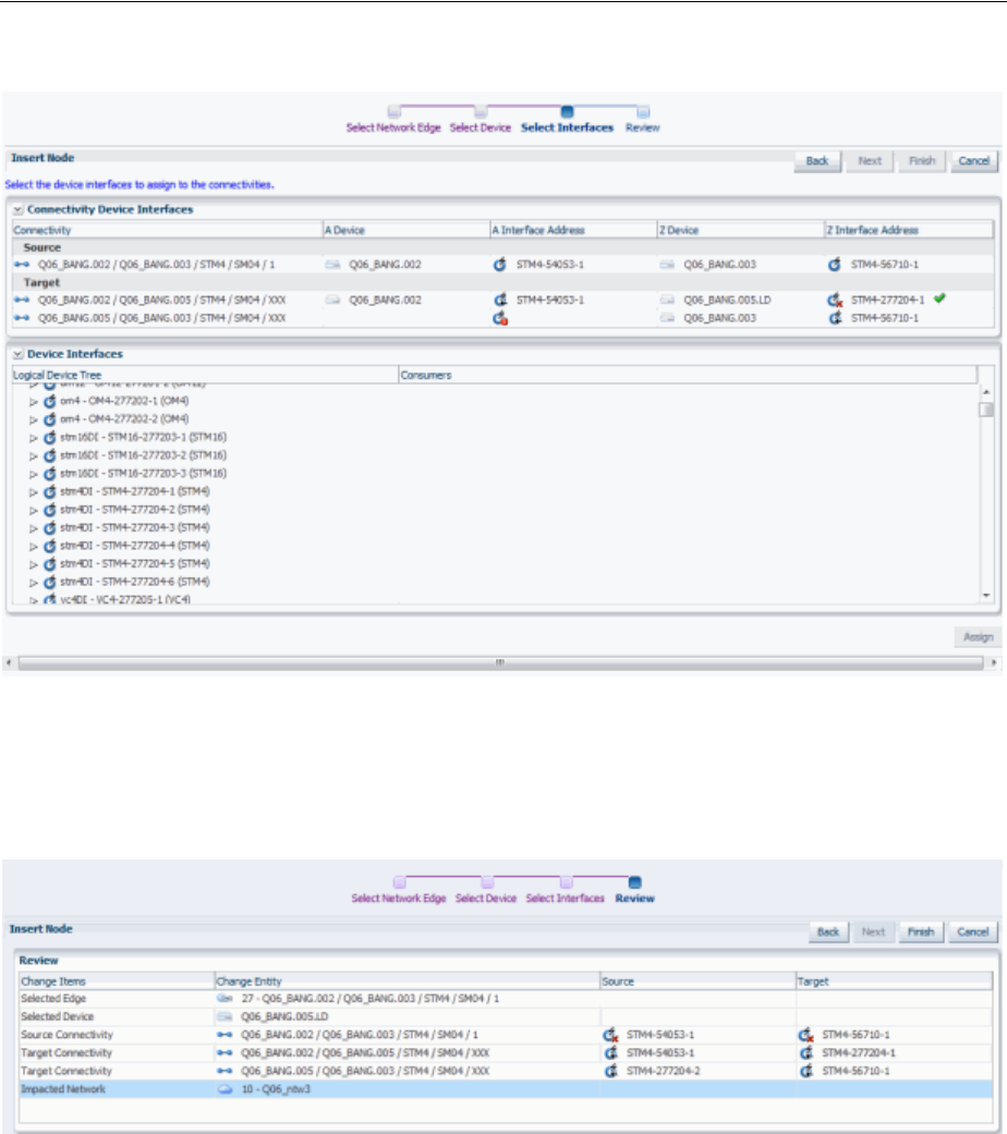
Maintaining Channelized Connectivity and Network Resources
13-36 Oracle Communications Unified Inventory Management Concepts
Figure 13–38 Select Interfaces Area of the Insert Node Dialog Box
■Review proposed changes. The Review area of the dialog box provides a list of the
selections you have made, as shown in Figure 13–39. You can use the Back button
to navigate to previous areas if necessary.
Figure 13–39 Review Area of the Insert Node Dialog Box
Figure 13–40 shows the Insert Node section after the activity has been configured. A
new node representing the Q06_BANG.005.LD logical device will be inserted between
the existing Q06_BANG.002.LD and Q06_BANG.003.LD nodes. The red dotted line
represents the edge that will be replaced while the blue dotted line represents the two
new edges.The Change Items tab shows the entities that will be changed as a result of
the activity. Because the activity has not yet been submitted, the Impact Items tab has
not been populated.
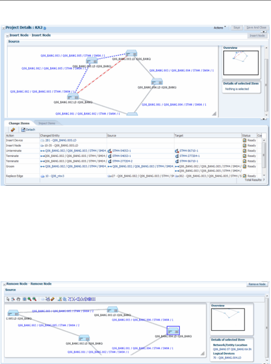
Maintaining Channelized Connectivity and Network Resources
Channelized Connectivity 13-37
Figure 13–40 UIM Insert Node User Interface - After Activity Configuration
After the activity has been processed, UIM saves the activity configuration details,
change items, and impact items so that you can refer to them in the future. For
example, you can view the network visualizations to see where the node was inserted.
Node Removal User Interface Overview
You manage node removal in the Remove Node section that becomes available when
you create or select a remove node activity. The section includes a network
visualization in which you select the network that contains the affected nodes and
edges.
Figure 13–41 Remove Node Section - Before Configuration
You configure the activity in the Remove Node dialog box. This dialog box includes a
wizard interface in which you:
■Select the network node that you want to remove. Figure 13–42 illustrates the
Select Network Node area.
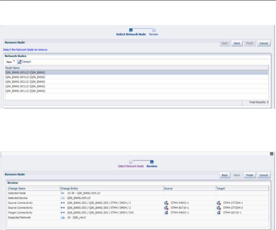
Maintaining Channelized Connectivity and Network Resources
13-38 Oracle Communications Unified Inventory Management Concepts
Figure 13–42 Select Network Node Area of the Remove Node Dialog Box
■Review proposed changes. You can use the Back button to navigate to previous
areas if necessary. Figure 13–43 illustrates the Review area.
Figure 13–43 Review Area of the Remove Node Dialog Box
When you have finished configuring the activity in the Remove Node dialog box, the
network visualization in the Source area in the Remove Node section shows the
planned changes with edges to be removed colored red.The Change Items tab is
populated with a list of actions that corresponds to the proposed entity changes from
the dialog box.
Figure 13–44 illustrates the contents of the Remove Node section after an activity has
been configured.
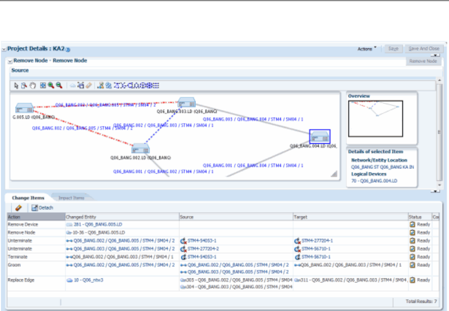
Maintaining Channelized Connectivity and Network Resources
Channelized Connectivity 13-39
Figure 13–44 Remove Node Section - After Configuration
UIM saves the activity configuration details, change items, and impact items so that
you can refer to them in the future. For example, you can view the network
visualizations to see where the node was removed.

Maintaining Channelized Connectivity and Network Resources
13-40 Oracle Communications Unified Inventory Management Concepts

14
Packet Connectivity 14-1
14
Packet Connectivity
This chapter explains how you use packet connectivity features in Oracle
Communications Unified Inventory Management (UIM).
Packet connectivity is one of several types of connectivity supported by UIM. See
"Connectivity Overview" for information about features shared by all Connectivity
entities.
UIM packet connectivity support includes Packet Connectivity entities and other
entities that work together to model an entire service.
About Packet Connectivity
In packet-based connectivity, data is transmitted in blocks called packets or cells.
Because capacity for these technologies is defined by volume or bandwidth rather than
by channels or time-slots, packet connectivity is sometimes called bandwidth
connectivity. Several technologies are based on packet connectivity, including Ethernet,
Frame Relay, Asynchronous Transfer Mode (ATM), and Multiprotocol Label Switching
(MPLS).
In UIM, you use Packet Connectivity entities to represent this type of connectivity.
Packet Connectivity entities are based on Connectivity specifications in which the
Connectivity Classification is set to Packet.
UIM supports all of these technologies and provides extensive support for Carrier
Ethernet in the OracleComms_UIM_CarrierEthernet cartridge. Support for other
packet technologies is provided in the OracleComms_UIM_Packet cartridge. See UIM
Carrier Ethernet Cartridge Guide and UIM Cartridge Guide for more information about
the content of these cartridges.
Packet connectivity can coexist with channelized connectivity and pipes. For example,
a packet facility can be enabled by one or more channels of a T-Carrier channelized
connectivity. Similarly, a packet connectivity can enable or be enabled by a pipe.
UIM cartridges supply a number of Packet Connectivity specifications that you can
use or modify. For example, the Carrier Ethernet sample cartridge includes
specifications for ENNI, INNI, and UNI connectivities. The Packet sample cartridge
includes specifications for ATM, Frame Relay, and other connectivities. You can also
create your own packet connectivities in Design Studio. See Design Studio Help for
more information.
About Flow Identifiers
Packet connectivity technologies use IDs or tags to differentiate network traffic and
make it visible to only the appropriate devices. By isolating network traffic in this way,

About Flow Identifiers
14-2 Oracle Communications Unified Inventory Management Concepts
the same physical or infrastructure network can support multiple virtual networks.
For example, the Carrier Ethernet technology uses VLAN IDs for this purpose. ATM
uses VPI and VCI, while Frame Relay uses DLCI.
In UIM, you use Flow Identifier entities to represent these various types of identifiers.
Flow identifiers are specification-based entities that can be customized to fit your
business and technological requirements.
The Carrier Ethernet and Packet cartridges include Flow Identifier specifications. The
Carrier Ethernet cartridge includes CE-VLAN, Custom-Tag, P-Tag, SP-VLAN, and
W-Tag specifications. The Packet sample cartridge includes VCI, VPI, and DLCI
specifications. You can use these specifications as they are or copy and modify them
for your requirements. You can also create your own Flow Identifier specifications in
Design Studio.
Flow identifiers can be marked as managed or unmanaged in their specifications:
■Managed flow identifiers are grouped into network address domains and resource
pools from which they can be selected and assigned to packet virtual networks
(PVNs) and service networks. For example, the SP-VLAN flow identifier in the
Carrier Ethernet cartridge is managed. See "Network Address Domains" and
"About Inventory Group Types and Resource Pools" for more information.
■Unmanaged flow identifiers are received on a service order and referenced with a
service location on the service. They are provided by customers and therefore not
managed by service providers. For example, the CE-VLAN flow identifier in the
Carrier Ethernet cartridge is unmanaged.
In UIM, you assign flow identifiers to packet virtual network configurations and
service network configurations. When you assign a flow identifier to a network, UIM
automatically assigns the flow identifier to all the flow interfaces in the network. You
can assign flow identifiers to networks either in the Network Topology view or in the
network configuration.
You can manually unassign and assign flow identifiers for individual flow interfaces.
For example, you may want to implement VLAN ID translation. See "VLAN ID
Translation" for more information.
See UIM Help for more information about assigning flow identifiers to networks and
flow interfaces.
Q-in-Q Stacking
UIM flow identifiers support Q-in-Q stacking. Q-in-Q stacking enables VLAN IDs to
be encapsulated (stacked) within each other. Stacking allows traffic from different
service providers with the same VLAN ID to travel safely through a network.
For example, suppose Customer A’s CE- VLAN and Customer B’s CE-VLAN use the
VLAN ID 10. When the traffic enters the service provider network, Customer A’s
traffic can be stacked on the service provider's SP-VLAN ID 50 and Customer B's
traffic can be stacked on the service provider's SP-VLAN ID 100. This stacking enables
the two customer’s traffic to be separated within the network even though their
original VLAN IDs are the same.
In UIM, you implement Q-in-Q stacking by defining stacking levels in Flow Identifier
specifications. For example, the Carrier Ethernet sample cartridge includes a
CE-VLAN Flow Identifier specification with a stacking level of 0 and an SP-VLAN
Flow Identifier specification with a stacking level of 1. That means that flow identifiers
based on the CE-VLAN specification can be stacked within flow identifiers based on
the SP-VLAN specification. To implement Q-in-Q stacking with these specifications,
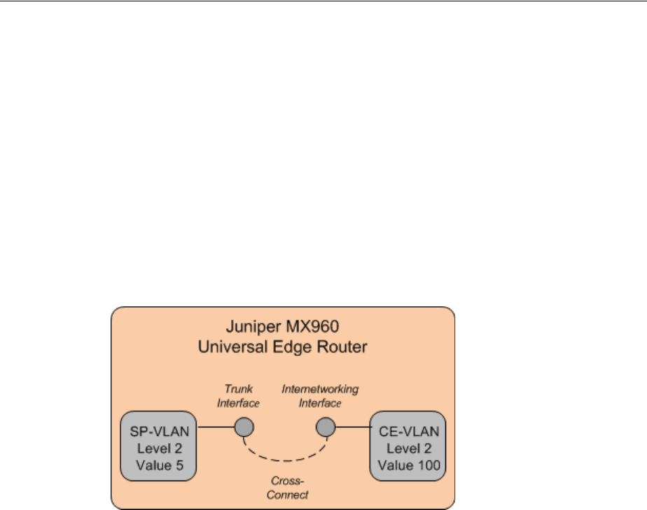
Performance Parameters
Packet Connectivity 14-3
you include a CE-VLAN flow identifier in the Service configuration and add the
SP-VLAN flow identifier to the PVN.
See Design Studio Help for more information about designing Flow Identifier
specifications.
VLAN ID Translation
In Carrier Ethernet networks, VLAN ID translation is sometimes required. VLAN ID
translation involves changing the ID of incoming packets at a switch. For example,
Figure 14–1 illustrates a situation in which an interface on a switch carries traffic from
one direction with VLAN ID 5 and another interface on the same switch carries traffic
from the other direction with VLAN ID 100. The switch receives traffic on one
interface, translates the ID, and then sends the traffic out on the other interface.
Figure 14–1 VLAN ID Translation
To model VLAN ID translation in UIM, you manually assign flow identifiers to flow
interfaces, thereby overriding the flow identifier assignment from the PVN. You assign
the flow identifier from the Network Topology view of the PVN in which the flow
interface appears.
For example, in the example in Figure 14–1, you can model the switch as a logical
device. The logical device has two flow interfaces with a cross-connect between them.
To translate the VLAN ID, you assign an SP-VLAN flow identifier with stacking level
2 and an ID of 5 to one interface and a P-Tag flow identifier with stacking level 100 and
an ID of 100 to the other.
A flow interface can have multiple flow identifiers. For example, an Ethernet flow
interface could have a CE-VLAN flow identifier that identifies traffic coming from a
customer's service location. The same flow interface can have an SP-VLAN flow
identifier that identifies a PVN, such as an EVC.
Performance Parameters
Services based on packet connectivity often include requirements for class of service
(CoS) and quality of service (QoS). These requirements guarantee specific levels of
performance to the subscriber. For example, when a subscriber contracts with a service
provider for Carrier Ethernet service, the service provider guarantees bandwidth and
excess bandwidth levels based on performance parameters.
In UIM, these performance parameters are modeled as Custom Object entities with
characteristics that represent the various metrics.

Terminating and Enabling Packet Connectivity
14-4 Oracle Communications Unified Inventory Management Concepts
For example, the Carrier Ethernet cartridge includes a number of Custom Object
specifications that model the CoS and QoS attributes defined by the Metro Ethernet
Forum (MEF). Specifications for other entities, such as service and network
configurations, include references to the CoS and QoS Custom Object specifications
that apply to them.
Similarly, the Packet Cartridge includes specifications for ATM and Frame Relay QoS
and traffic parameters.
You can also define your own Custom Object specifications for QoS and CoS
requirements not supplied in the cartridges.
See "Custom Objects" for more information about Custom Object entities and UIM
Carrier Ethernet Cartridge Guide for more information about how they are used in
Carrier Ethernet services.
Terminating and Enabling Packet Connectivity
Like other connectivities, you enable and terminate a packet connectivity as part of the
design process. Packet connectivity can be enabled by either channelized connectivity
or pipes.
Enablement by channelized connectivity includes for virtual concatenation (VCAT), a
system in which a subset of channels in a channelized facility are grouped to support
the enablement of packet connectivity.
Without VCAT, bandwidth is wasted because a full facility is used to support
“non-telephony” bit rates. For example, Carrier Ethernet includes a 10 Mbps bit rate.
Without VCAT. a full E3 facility (34.468 Mbps) or DS3 facility (44.736 Mbps) is required
to enable the Carrier Ethernet connectivity.
With VCAT, that 10 Mbps connectivity can be enabled by two of the four E2 channels
in an E3 facility or seven of the 28 DS1 channels in a DS3 facility. The unused channels
can be used for other purposes.
The UIM signal architecture determines which channels can be virtually concatenated
to support which packet connectivities. The valid VCAT combinations are reflected in
the Connectivities Supported By list in the Gap Analysis page. Figure 14–2 shows the
list for a 100 Mbps connectivity.
Figure 14–2 Connectivties Supported By List
When you select a channel arrangement in the Connectivities Supported By list and
select the Contiguous Channels, gap analysis includes those criteria in its search.
See "Designing Connectivity" for more information about the connectivity design
process, including using gap analysis.
The following sections provides two examples of terminating and enabling a packet
connectivity. Both scenarios include VCAT.
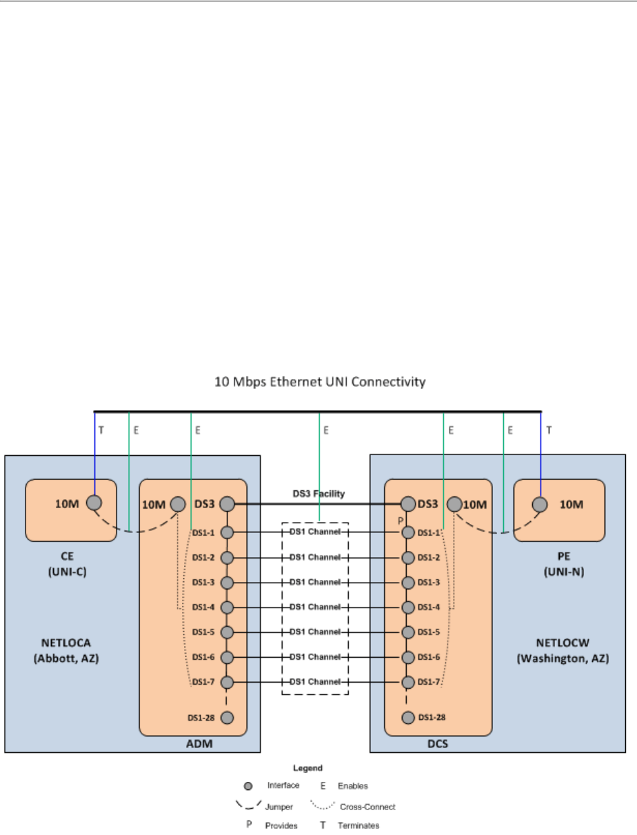
Terminating and Enabling Packet Connectivity
Packet Connectivity 14-5
UNI Connectivity Enabled by T-Carrier Channels
This section provides an example of Ethernet UNI connectivity enabled by virtually
concatenated channels in a T-Carrier facility. The example assumes that you are a
Carrier Ethernet service provider implementing a solution over your own network
infrastructure. No other service providers are involved and you have installed CPE at
the customer site.
The service location on the A side of the UNI connectivity is in Abbot, AZ. Because
you have installed network equipment at this site, you can model it as both a service
location and a network location (NETLOCA). The PE router on the Z side of the
connectivity is at your network location in Washington, AZ (NETLOCW).
Transport is provided by seven channels from a DS3 facility that connects the two
network locations. The channels use VCAT to combine their bandwidth. A jumper
connects a 10 Mbps interface on the CE device to a 10 Mbps interface on the add-drop
multiplexer (ADM) that also provides interfaces for the DS3 facility and its channels. A
similar arrangement of cross-connects and a jumper connect the DCS and PE on the
other end of the connectivity. Figure 14–3 illustrates this enablement scenario.
Figure 14–3 Ethernet UNI Connectivity Enabled by DS1 Channels
Assuming that the DS3 facility already exists, has had its capacity configured, and has
seven contiguous, unassigned channels, do the following to create and design the UNI
connectivity:
1. Create two logical devices based on the Packet Network Device specification to
represent the CPE and the PE.
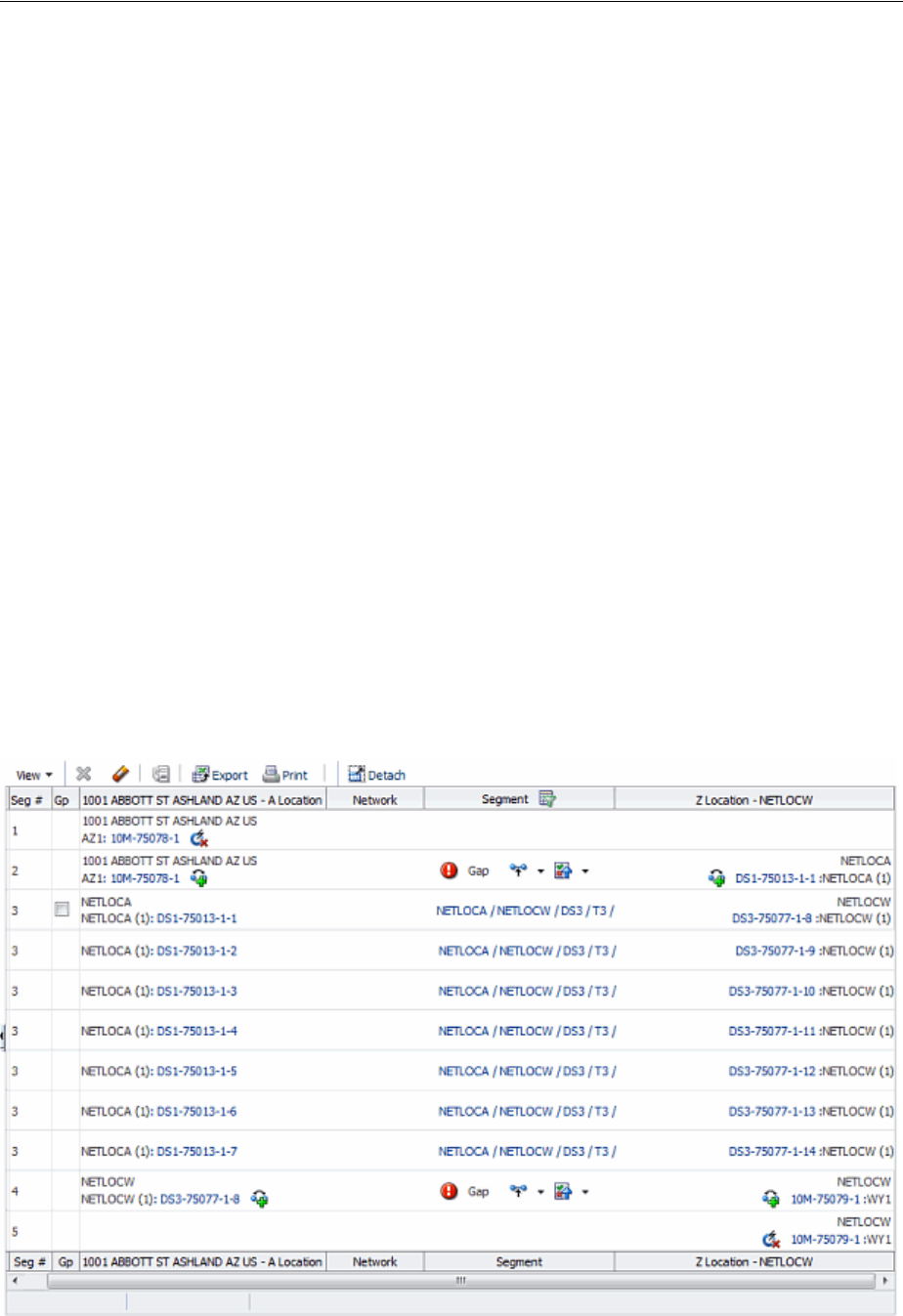
Terminating and Enabling Packet Connectivity
14-6 Oracle Communications Unified Inventory Management Concepts
■Locate the CPE device at the service location in Abbott, AZ.
■Locate the PE device at the NETLOCW network location.
■Create one or more device interfaces with a 10M (10 Mbps) rate code on each
device.
2. Create a connectivity based on the UNI Connectivity specification.
■Specify the A side of the connectivity as the combined network and service
location in Abbott, AZ.
■Specify the Z side of the connectivity as NETLOCW.
■Set the rate code to 10M (10 Mbps).
3. In the Connectivity Design tab of the new connectivity, terminate the connectivity
on 10M device interfaces on the CPE and PE devices.
4. Select the central segment of the path and perform a gap analysis. (See UIM Help
and "Assigning Transport" for more information about gap analysis.)
■Specify NETLOCA and NETLOCW as the Source and Targ e t locations.
■In the Connectivities Supported By area, select (7) DS1 and Contiguous
Channels.
UIM returns a path that includes seven channels in the preexisting DS3 facility.
(Other paths may also be returned depending on the resources in your network.)
5. Assign the path that includes the DS3 facility to the segment.
Figure 14–4 shows the contents of the Connectivity Design tab for a UNI
connectivity enabled in this way.
Figure 14–4 UNI Connectivity Enabled by DS1 Channels
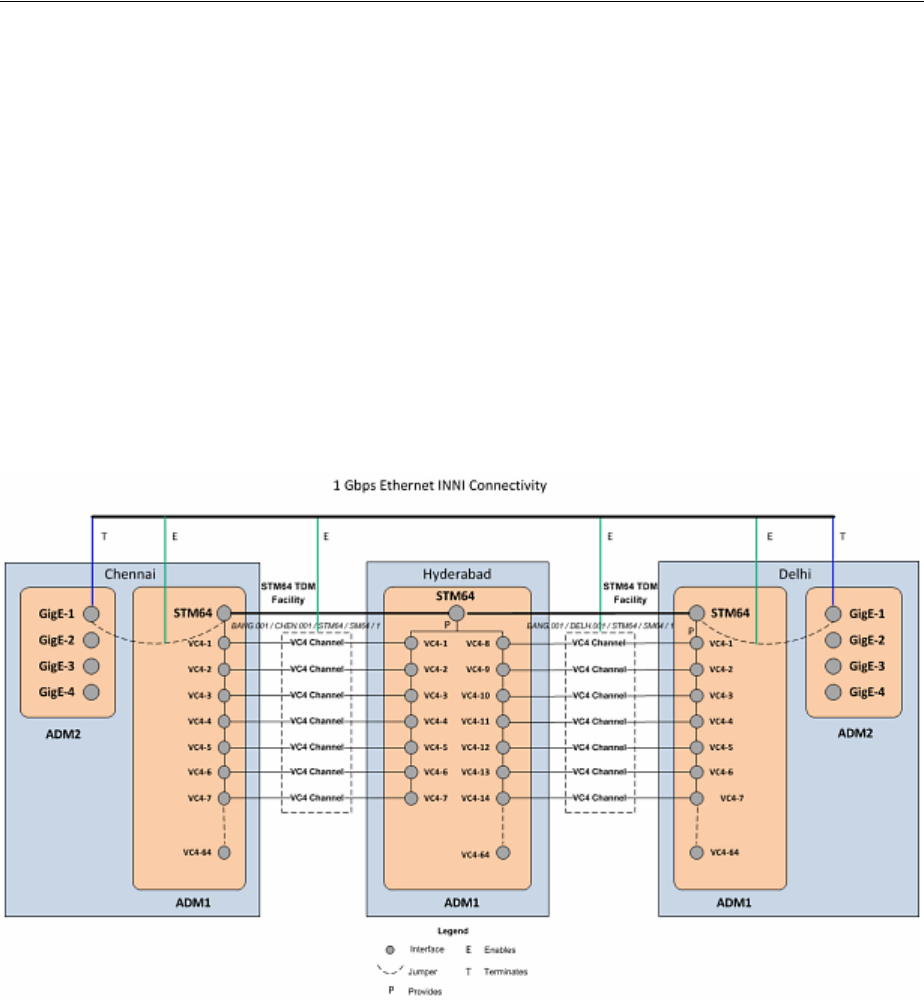
Terminating and Enabling Packet Connectivity
Packet Connectivity 14-7
6. Resolve the remaining gaps by creating jumpers on the A and Z sides of the
connectivity.
7. Complete the connectivity design.
INNI Connectivity Enabled by SDH Channels
This section provides an example of the creation and design of a Gigabit Ethernet
INNI connectivity that is enabled by seven virtually concatenated VC4 channels
provided by an STM64 channelized connectivity. The example assumes that you are an
Ethernet service provider and that no other service providers are involved in the
solution.
An Ethernet INNI connectivity between Chennai and Delhi is enabled by two
segments of an SDH ring network that also connects Bangalore and Hyderabad.
Figure 14–5 illustrates the enablement scenario.
Figure 14–5 Gigabit Ethernet Enabled by VC4 Channels
SDH Network Infrastructure
In this example, an existing SDH ring network connects offices in Bangalore,
Hyderabad, Delhi, and Chennai. These customer sites are represent in UIM by four
property locations:
■BANG
■HYDB
■DELH
■CHEN
There are add-drop multiplexers (ADMs) at each location, represented in UIM by
Logical Device entities with the following network entity codes:
■HYDB.001.ADMLD

Terminating and Enabling Packet Connectivity
14-8 Oracle Communications Unified Inventory Management Concepts
■BANG.001.ADMLD
■DELH.001.ADMLD
■CHEN.001.ADMLD
Each ADM includes a device interface hierarchy that includes two STM64 interfaces,
each with 64 VC4 sub-interfaces.
Connectivity in the ring network is represented by 4 STM64 Channelized Connectivity
entities:
■BANG.001 / CHEN.001 / STM64 / SM64 / 1
■CHEN.001 / HYDB.001 / STM64 / SM64 / 1
■HYDB.001 / DELH.001 / STM64 / SM64 / 1
■BANG.001 / DELH.001 / STM64 / SM64 / 1
The connectivities are terminated on the STM64 interfaces at the property locations.
The capacity of each connectivity is configured to 64 VC4 channels, corresponding to
the 64 VC4 sub-interfaces on each media interface.
Creating and Designing the INNI Connectivity
To represent ADMs for the INNI connectivity, create two Logical Device entities based
on the Packet Network Device specification located at the existing property locations
for Chennai and Delhi. Name these logical devices DELH.002.ADMLD and
CHEN.002.ADMLD. On each logical device, add 4 GigE device interfaces.
Create a Connectivity entity with the following attributes:
■Technology: Ethernet
■Specification: Ethernet INNI Connectivity
■A Network Location: CHEN.002
■Z Network Location: DELH.002
■Rate Code: GigE
■Function: GE1
■Duplex Mode: Full Duplex
■MTU Size: 1522
■Physical Medium: 10BASE-T
In the Connectivity Design tab for the Ethernet INNI connectivity, complete the design
as follows:
1. Terminate the A side of the connectivity on a GigE interface of the
CHEN.002.ADMLD logical device.
2. Terminate the Z side of the connectivity on a GigE interface of the
DELH.002.ADMLD logical device.
3. Use gap analysis with the following details and update the channels:
Source: CHEN.001
Tar g e t: DELH.001
Connectivities Supported By: 7VC4
Contiguous Channels: True

Terminating and Enabling Packet Connectivity
Packet Connectivity 14-9
Gap analysis finds the STM64 connectivities from CHEN.001 to BANG.001 and
from BANG.001 to DELH.001 and assigns seven VC4 channels to the INNI
connectivity.
4. Resolve the remaining gaps by creating jumpers on the A and Z sides of the
connectivity.
5. Complete the connectivity design.

Terminating and Enabling Packet Connectivity
14-10 Oracle Communications Unified Inventory Management Concepts

15
Service Connectivity 15-1
15
Service Connectivity
This chapter explains how you use the service connectivity features in Oracle
Communications Unified Inventory Management (UIM).
About Service Connectivity
A service connectivity represents the connectivity between a service location and the
access location in a service provider's network for a network oriented service. Service
connectivity expresses the requirements of the service in terms of transmission bit
rates and the locations to be connected. This type of connectivity is sometimes called a
service trail. Because a service connectivity represents a requirement rather than
available bandwidth, it cannot have riders. A service connectivity consumes other
types of connectivity and resources, but cannot be consumed itself.
Service connectivity is supported only for services based on packet technology, such as
Carrier Ethernet, ATM, and DSL. You use service connectivities in two contexts with
packet services:
■Connecting service locations to the provider network in multipoint services. For
example, in a Carrier Ethernet E-LAN service, there are separate Ethernet Access
services for each service location. A service connectivity is assigned to the Ethernet
Access service configuration.
■Representing end-to-end service connectivity in point-to-point services. For
example, in a Carrier Ethernet E-Line service, a service connectivity is assigned to
the service configuration.
Service connectivities always have at least one end point at a service location. The
other end point can be at another service location or at a network location. When
assigned to Ethernet Access services, one end point is at a service location and the
other is at a network location. When assigned to a point-to-point service such as an
E-Line service, both end points are at service locations.
Service connectivities are not defined by a technology, so when you create a Service
Connectivity specification in Design Studio, the technology is automatically set to
Undefined. The bit rate of a service connectivity cannot exceed that of its enabling
connectivity.
Unlike other connectivity entities, you do not create service connectivities directly.
Instead, you create them in the process of configuring the services to which they are
assigned. For example, when you design an Ethernet Access service as part of a
Carrier Ethernet E-LAN service, you create a service connectivity. You assign the
service connectivity as a configuration item in the Ethernet Access service
configuration.
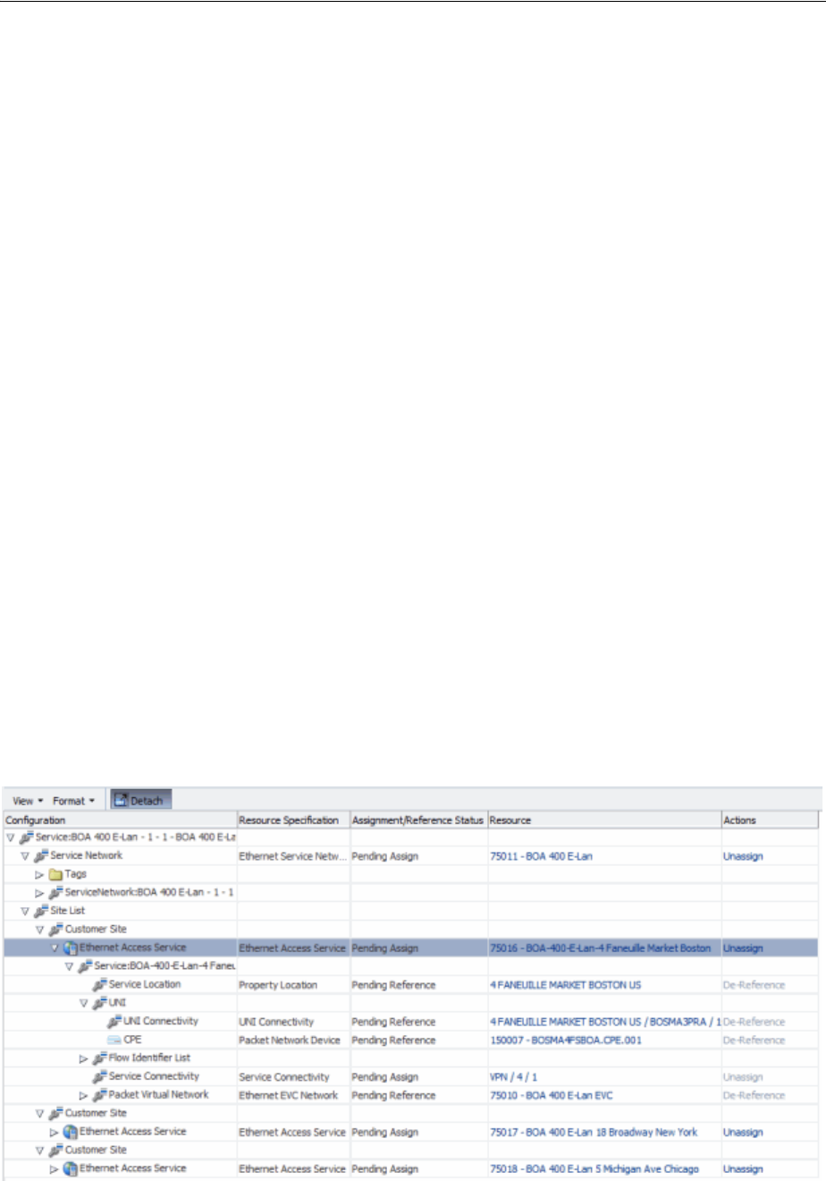
Service Connectivity in Multipoint Services
15-2 Oracle Communications Unified Inventory Management Concepts
The life cycle of a service connectivity is bound to that of the Service configuration to
which it is assigned. When the service connectivity is first created, it can be viewed
only from within the Service configuration. It is in Pending Install status and cannot be
searched for in UIM.
When the Service configuration is completed, the service connectivity is transitioned to
the Live context. It is then visible in searches results.
Similarly when you disconnect a Service, the parent service configuration to Pending
Disconnect status. This transition propagates to the service connectivity and it is also
transitioned to Pending Disconnect. Completing the disconnect of the service
completes the disconnect of the service connectivity.
Service connectivity designs are created automatically based on the configuration of
their parent service. The Connectivity Design tab for service connectivities is
read-only.
See UIM Help for more information about working with service connectivity entities.
See UIM Carrier Ethernet Cartridge Guide for examples of configuring a service,
including service connectivities.
Service Connectivity in Multipoint Services
In a multipoint Carrier Ethernet network, service connectivities are network segments
that connect service locations to a service provider network. For each service location,
there is an Ethernet Access Service with a corresponding service connectivity. The
service connectivity is enabled by the UNI connectivity that connects the CE device at
the service location to the PE device at the provider network.
For example, Figure 15–1 illustrates the configuration of an E-LAN service. The service
has three customer sites in Boston, Chicago, and New York. The Boston location’s
service connectivity is VPN / 4 /1, which is enabled by the 4 FANEUILLE MARKET
BOSTON US/BOSMA3PRA UNI connectivity. Figure 15–2 illustrates the Connectivity
Design tab of the service of VPN / 4 /1.
Figure 15–1 E-LAN Service with Ethernet Access Service and Service Connectivity
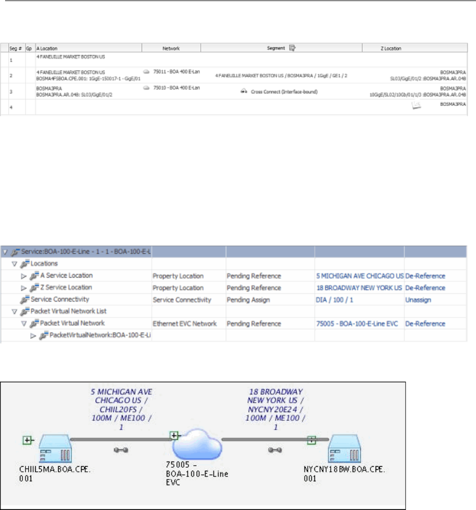
Service Connectivities in Point-to-Point Services
Service Connectivity 15-3
Figure 15–2 Service Connectivity Design Tab
Service Connectivities in Point-to-Point Services
In a point-to-point service, such as an Ethernet E-Line service, the service connectivity
spans the whole service from the A service location to the Z service location.
Figure 15–3 and Figure 15–4 illustrate a service connectivity in the context of an E-Line
service.
Figure 15–3 E-Line Service with Service Connectivity
Figure 15–4 E-Line Service with Service Connectivity - Schematic View
The service connectivity is enabled by UNI connectivities on the service location ends
and network transport inside the service provider networks. Figure 15–5 illustrates the
design of the service connectivity shown in the previous figures.
A gap enables the service connectivity within the provider network because the
service connectivity reflects only the UNI connectivities up to their PVN trunk
interfaces. The gap is automatically labeled Gap – Network Transport.
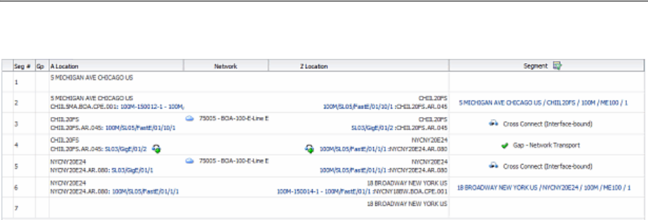
Service Connectivities in Point-to-Point Services
15-4 Oracle Communications Unified Inventory Management Concepts
Figure 15–5 E-Line Service Connectivity Design

16
Pipes 16-1
16
Pipes
This chapter describes how you can use Pipe entities in Oracle Communications
Unified Inventory Management (UIM) to represent connectivity in your inventory.
When to Use Pipes
You can use Pipe entities, Connectivity entities, or both to represent connectivity in
your inventory.
Most common telecommunications connectivity scenarios can be implemented by
using Connectivity entities, which are extensions of Pipe entities. Connectivity entities
include more built-in functionality than pipes.
Pipe entities are designed for maximum flexibility, so you must define all of their
attributes. Connectivity entities, on the other hand, take advantage of pre-defined rate
codes, technologies, functions, and other attributes.
See the following chapters for information about Connectivity entities:
■Connectivity Overview
■Channelized Connectivity
■Packet Connectivity
■Service Connectivity
You can still implement solutions by using pipes directly, however. For example, pipes
might be applicable in situations such as:
■Existing UIM implementations. If you previously modeled connectivity using
pipes, you can continue to use those entities. Pipe and Connectivity entities can
coexist in the same inventory. Pipes can enable Connectivity entities and
Connectivity entities can enable pipes.
■Physical connections, such as cable pairs and local loops.
■Other forms of connectivity not implemented by other entities.
Note: This chapter includes examples of implementing channelized
and packet connectivity by using Pipe entities. These examples are
still valid technically, but Oracle recommends using Connectivity
entities for these technologies. Connectivity entities offer more
functionality and efficiency than pipes. See "When to Use Pipes" for
more information.
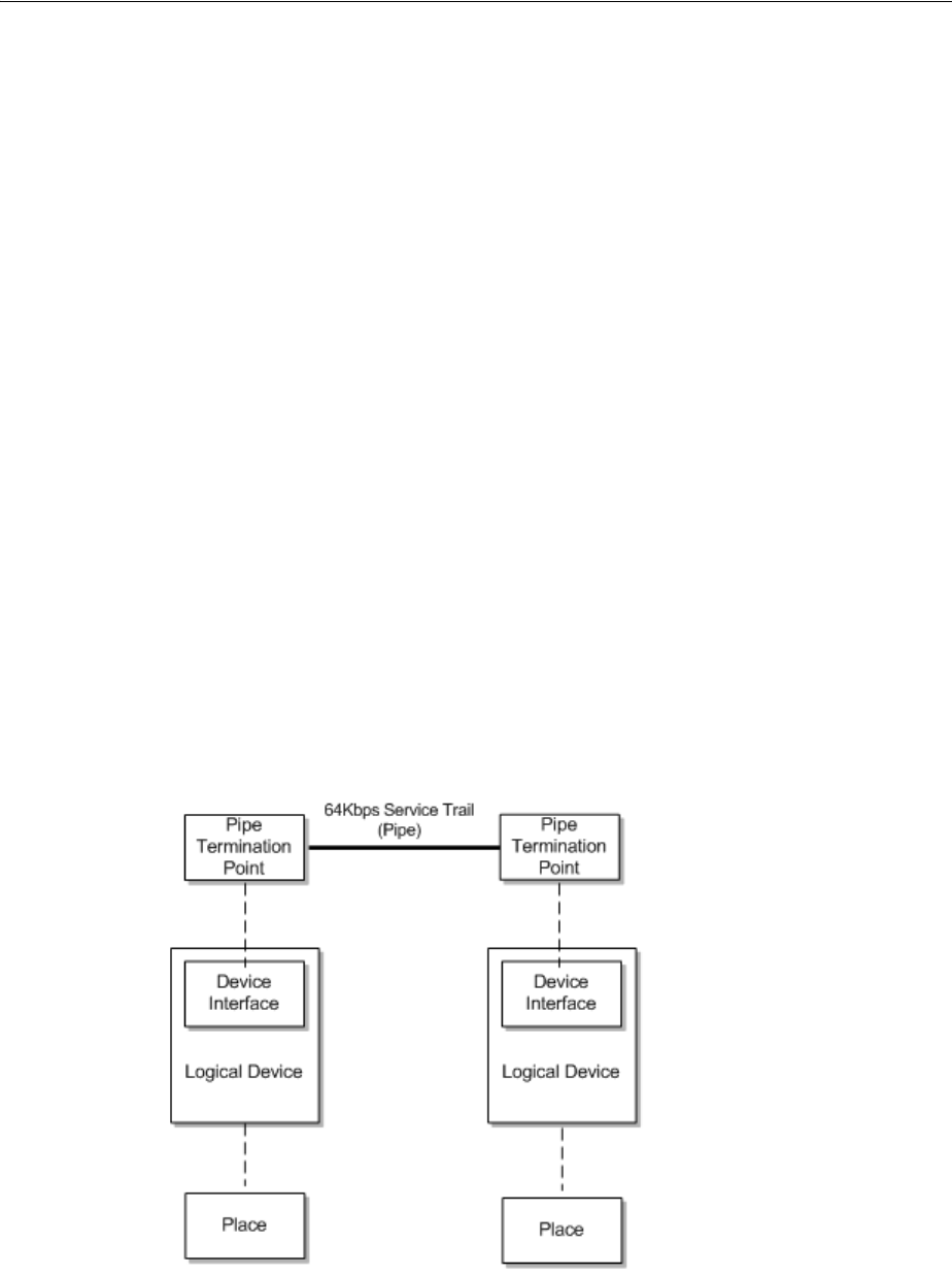
Understanding Pipes
16-2 Oracle Communications Unified Inventory Management Concepts
Understanding Pipes
Pipes are the base entities for representing connectivity in UIM. You can use pipes to
represent both physical connectivity and logical connectivity. For example, you can use
a pipe to represent the logical connectivity of a 64 Kbps PVC (Permanent Virtual
Circuit) service trail. You can also use a pipe to represent the physical connectivity of a
100-pair cable.
Pipes can have bandwidth, a type of capacity that specifies the speed and amount of
data that can be transported over the pipe. In the case of digital signals, capacity is
defined by the speed of the signal. See "Understanding Capacity and Signal Structure"
for more information.
Every pipe has two termination points that represent its two ends. Signals travel over
pipes from one termination point to the other. The termination points are created
automatically when you create a pipe in UIM.
Termination points can be associated to various kinds of entities, such as device
interfaces and ports. This kind of association is called termination. A pipe and its
termination points are terminated on the entities to which the pipe termination points
are associated.
For example, you can terminate a pipe and its termination points on device interfaces
that are provided by logical devices. The logical devices can have place associations to
give the termination a geographic context. The place association ensures that the pipe
and its associated devices are included in the UIM topology. See "Topology" for more
information.
Figure 16–1 shows resource and place terminations for a 64 Kbps service trail pipe’s
termination points.
Figure 16–1 Termination Point Resource Terminations
See "Defining Pipe Specifications" for more information about designing Pipe
specifications and creating Pipe entities.
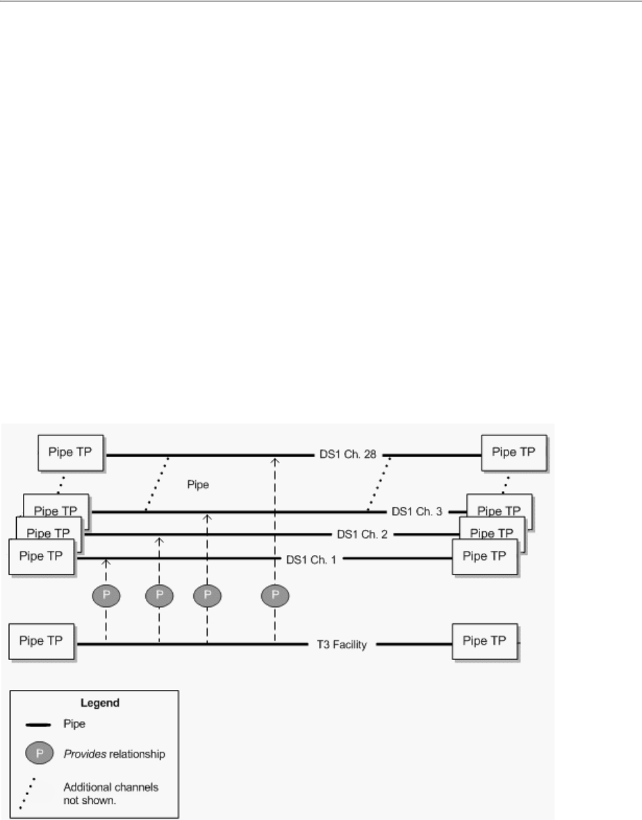
Understanding Pipes
Pipes 16-3
Understanding Pipe Relationships
You use relationships between pipes to define how connectivity is structured in your
inventory. Two important types of pipe relationships are provides and enables.
Provides Relationships
A provides relationship exists when one entity supplies one or more other entities that
cannot exist on their own. You create provides relationships by associating a signal
structure with a pipe or by building parent-child hierarchies of pipes.
For example, a TDM facility pipe provides channel pipes through signal structures. In
this case, UIM automatically builds hierarchies of child pipes based on the signal
structure. See "Understanding Capacity and Signal Structure" for more information
about signal structures.
Similarly, a cable pipe provides cable-pair pipes. The child pipes can be defined by the
parent pipe’s specification. They can also be added manually in UIM. See "Configuring
and Implementing Child Pipes for the Cable/Pair Model" for information about
provides relationships in cable and cable-pair pipes.
Figure 16–2 shows a provides relationship between a T3 facility and the 28 DS1
channels that it provides.
Figure 16–2 Pipe Provides Relationship
Enables Relationships
A pipe enables another pipe when it supports the transport of data by the other pipe.
In its simplest form, enablement refers to the association of a physical resource, such as
a cable pair to a customer service, such as POTS. For example, when you enable a local
loop by associating it with a cable pair, you are specifying the physical resource that
realizes the connectivity of the customer service.

Understanding Pipes
16-4 Oracle Communications Unified Inventory Management Concepts
Similarly, channels provided by a facility can enable a service trail. For example, a 100
Mbps service trail represents the connectivity of some service provided to a customer.
You can enable the service trail by associating it with two STS1 channels.
When a pipe enables another pipe, it can provide capacity to the enabled pipe. For
example, the STS1 channels mentioned in the previous paragraph supply their
capacity, defined in the signal structure of their parent OC3 facility pipe, to the service
trail they enable. See "Understanding Capacity and Signal Structure" for more
information.
Pipes can also be enabled by two separate connectivity paths. For example, multiple
paths can exist in SONET/SDH. See "About Multiple Enablement" for more
information.
Enables relationships also exist between the pipe termination points of enabling and
enabled pipes. In the simplest case, where a single pipe enables another pipe, the
termination points of the enabling pipe enable the termination points of the enabled
pipe. Pipes can also be enabled by a series of connected pipes that form a connectivity
path. The beginning and ending termination points of the connectivity path are
therefore not on the same pipe. In this case, the beginning termination point is on the
first pipe in the connectivity path and the ending termination point is on the last pipe.
You can enable pipes either manually or automatically by using path analysis. See
"Enabling Pipes" for more information.
Provides and Enables Relationships in Combination
Figure 16–3 illustrates how the different types of relationships work together. This
example shows the enablement of a local loop by cable pairs. The cable pairs are
provided by cables. The local loop trail pipe is enabled by three pipes that form a
continuous connectivity path:
■A feeder cable pair that connects an MDF to a cross-connect terminal.
■A cross-connect in the cross-connect terminal. UIM creates cross-connects when
two pipes that enable the same trail pipe are terminated on the same physical
device, equipment, or logical device. See "About Connectivity Gaps in Pipe
Enablement" for more information.
■A distribution cable pair that connects the cross-connect terminal to the subscriber
terminal.
The termination points of the parent cable are mapped to the termination points of the
cable pairs they provide. The originating termination point of the first cable pair
enables the originating termination point of the local loop, while the end termination
point of the second cable pair enables the end termination point of the local loop.
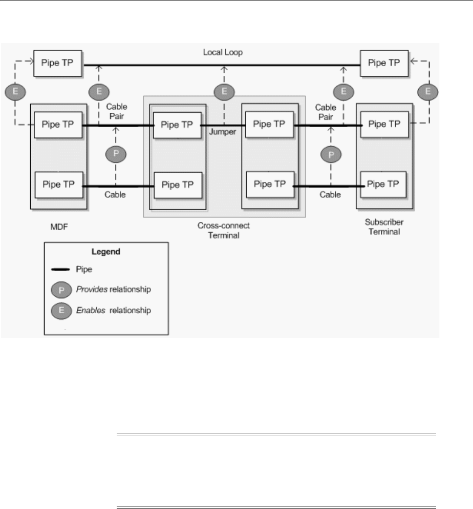
Understanding Pipes
Pipes 16-5
Figure 16–3 Pipe Relationships in a Local Loop Enablement
About Multiple Enablement
The previous examples described the enablement of pipes by a single connectivity
path. It is also possible for a pipe to be enabled by two separate connectivity paths.
This capability is required in ring-based network topologies, such as SONET/SDH,
which include both a primary and a secondary path.
For example, consider a single-ring SDH network with four optical add-drop
multiplexers (OADMs). The four OADMs are modeled as logical devices with device
interfaces on which four STM4 facility pipes are terminated. Figure 16–4 illustrates
such a ring.
Note: This section describes how you can use Pipe entities to
represent an SDH network. Because SDH is a TDM technology, you
can also use Channelized Connectivity entities and their specialized
functionality for this purpose. See "Channelized Connectivity" for
more information.
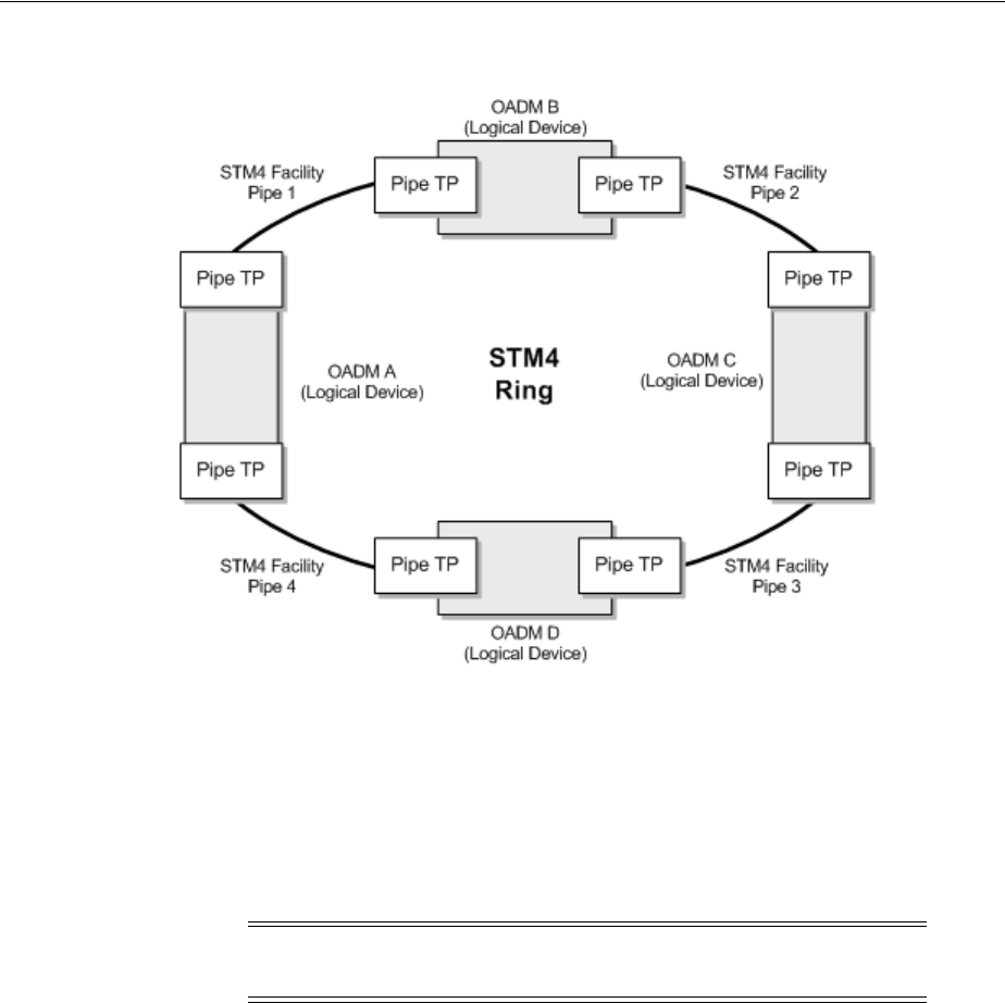
Understanding Pipes
16-6 Oracle Communications Unified Inventory Management Concepts
Figure 16–4 STM4 Ring
To enable an E1 service trail from OADM A to OADM C with both a primary path and
a secondary path, you can use two connectivity paths:
■From OADM A through OADM B to OADM C
■From OADM A through OADM D to OADM C
This connectivity is supplied by VC12 channels provided by the STM4 facility pipes
and by gap pipes as shown in Figure 16–5.
Note: For visual clarity, maps and enables relationships between
pipe termination points are not shown in Figure 16–5.
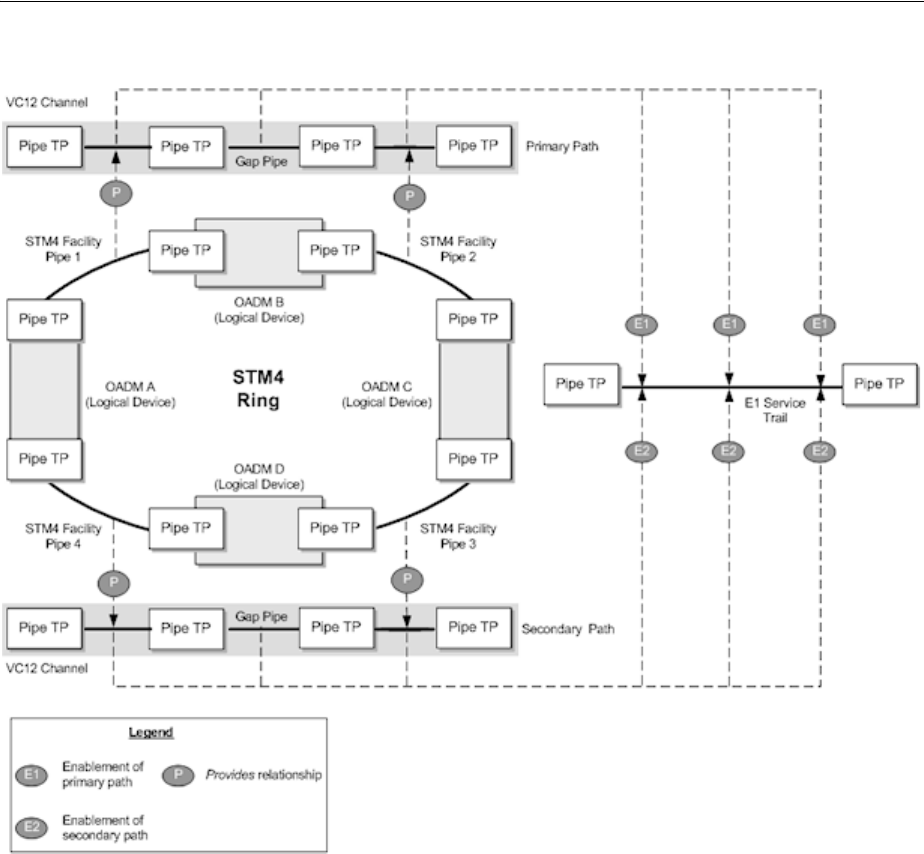
Understanding Pipes
Pipes 16-7
Figure 16–5 Multiple Enablement of an E1 Service Trail
Multiple enablement is also available in more complex ring topologies such as
single-homed and dual-homed subtended rings. See "About Network Topologies" and
the Design Studio Help for more information.
Multiple enablement can be done manually or automatically by using path analysis.
See "Enabling Pipes" for more information.
Understanding Pipe Configurations
Pipe configurations enable you to specify pipe enablements and termination point
resource assignments that change over time. For example, a service trail could be
enabled by a particular connectivity path when it is first created. As the network
evolves, new enablement possibilities may emerge. By versioning the service trail pipe
configurations, you can update the enablement and specify when the change becomes
effective. Pipe configurations can include multiple enablements, as in SONET or SDH.
See "About Multiple Enablement" for more information.
Pipe configurations are similar to other entity configurations in concept, but they have
some special features:
■They are available only for pipes that have specifically been designated as
versionable.

Understanding Pipes
16-8 Oracle Communications Unified Inventory Management Concepts
■Pipe configuration specifications are limited to specification options related to
transport and termination point resource assignment.
–When you define a pipe configuration specification, you can specify that only
entities based on a particular Pipe specification can be used for enablement.
Path analysis returns only pipes based on the designated specifications when
it finds connectivity paths.
–You can specify a particular type of device or equipment that must be
included as an intermediate node in the connectivity path that enables the
pipe. For example, when you enable a DSL service trail pipe from a subscriber
terminal to a local exchange or CO switch, path analysis would normally find
the most direct path between the end points, bypassing the DSLAM. You can
specify that a DSLAM entity must be included as an intermediate node. In this
case, path analysis searches for paths that run from the subscriber terminal to
a DSLAM and from the DSLAM to the switch.
See "Designing and Implementing Pipe Configurations" for information about
designing and implementing pipe configurations. See "Enabling Pipes" for information
about enablement, including path analysis.
Understanding Pipe Directionality
Some pipes have directionality, which defines the direction that signals or routes flow
through a pipe. This might be necessary, for example, if the pipes enabling a service
trail pipe share termination points in a way that causes ambiguity about the
connectivity path. By setting the directionality of the service trail, you can resolve the
ambiguity.
There are two independent directionality settings:
■Signal directionality refers to the direction that signals flow on the pipe. Most
pipes are bi-directional, meaning that signals flow in both directions. Other pipes
are uni-directional, meaning that signals flow in one direction only. Examples of
uni-directional pipes are alarm and control operation connections.
■Routing directionality restricts or enables functions such as path analysis. For
example, you can define a pipe as uni-directional for routing purposes to restrict
the route of a connection from an originating point to a specific terminating point
while avoiding certain path segments.
For example, you use routing directionality to ensure proper routing to and from
the DSLAM in a DSL enablement. DSLAMs normally have two sides, a
cable/subscriber side and a switch/office side. Pipes connect the two DSLAM
sides to the MDF, where connections are made between the cable/subscriber pipe
and the cable pair or local loop and between the switch/office pipe and the POTS
switch. Routing directionality ensures that these MDF connections are made
properly. The routing direction for the cable/subscriber-side pipes is from the
MDF to the DSLAM. The routing direction for the switch/office-side pipes is from
the DSLAM to the MDF.
You set the directionality of a pipe by specifying which termination point is the source
(starting point) and which is the sink (ending point). Signals and routes flow from
source to sink. Path analysis uses this direction information with the source of the
query serving as the subscriber terminal device and the target as the switch device.
See the UIM Help for more information about setting pipe directionality.

Understanding Capacity and Signal Structure
Pipes 16-9
About Connectivity Gaps in Pipe Enablement
A connectivity gap occurs in the design of a pipe trail when there is not sufficient
information or continuity to complete a path.)
UIM can automatically resolve these gaps during enablement in certain situations.
Cross-connects are created when the two enabling pipes are terminated on device
interfaces within the same logical device and at least one terminates on a sub-device
interface. In other situations, UIM cannot resolve the gap and it remains part of the
enablement.
UIM can automatically resolve these gaps during enablement in certain situations:
■A trail-bound cross-connect is created when the two enabling pipes are terminated
on device interfaces within the same logical device and at least one terminates on a
sub-device interface.
■A trail-bound jumper is created when the two enabling pipes are terminated on
ports provided by a single Physical Device or Equipment entity or by two Physical
Device or Equipment entities at the same property location.
In other situations, UIM cannot resolve the gap and it remains part of the enablement.
See "About Interconnections" for more information about cross-connects and jumpers.
Connectivity gaps also exist for channelized connectivity, but are used in somewhat
different ways. See "About Connectivity Gaps" for more information.
Understanding Capacity and Signal Structure
In UIM, capacity refers to the amount and type of resource that entities require or
provide. You define the nature of the capacity, how it is measured, and how it is used.
See "Capacity" for more information about capacity.
In the specific case of connectivity, capacity is bandwidth consumed or provided by
pipes. When a pipe enables another pipe, its bandwidth can be consumed by the
enabled pipe. Pipes can offer capacity in the following ways:
■As a unit. For example, a cable pair’s capacity can only be consumed as a whole by
the pipe it enables. In this case, you do not explicitly define the pipe’s capacity
because it cannot be consumed in fractions or smaller units.
■In fractions of capacity. For example, an ATM DS3 facility pipe provides a total
capacity of 44.736 Mbps. This capacity can be consumed in variable amounts by
pipes enabled by the facility. For example, a PVC service trail could use 64 Kbps of
the DS3 pipe’s bandwidth. See "Understanding Packet Capacity" for more
information.
■In increments, in the form of channels with unit capacity. TDM divides bandwidth
into channels that can be consumed in whole or in part by other pipes. For
example, a T3 facility pipe can provide a total of 44.736 Mbps divided into 28 D1
channel pipes of 1.544 Mbps unit capacity. You provide channelized capacity by
associating a signal structure with the pipe. See "Understanding Signal Structures"
for more information about signal structures.
These ways of providing and consuming capacity correspond to the three pipe models
supported by UIM. See "Understanding Pipe Models" for more information.
Note: Pipes and signal termination points are the only UIM entities
that can use the capacity framework by default.
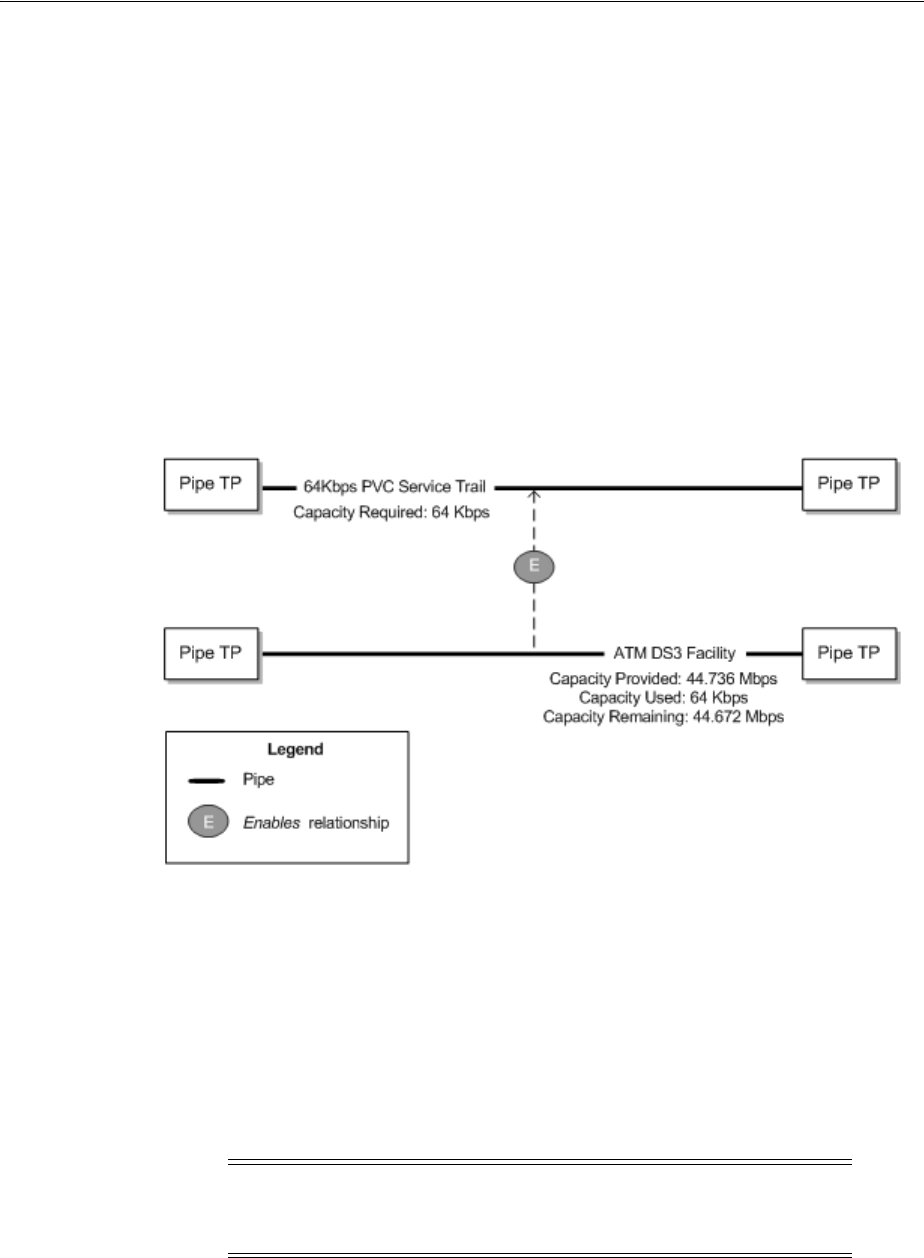
Understanding Capacity and Signal Structure
16-10 Oracle Communications Unified Inventory Management Concepts
Understanding Packet Capacity
For pipes based on packet connectivity, you define capacity by defining the pipe’s
capacity required (the amount of bandwidth it needs for its own enablement) and
capacity provided (the amount of bandwidth it makes available to pipes that it
enables). Some pipes have both capacity required and capacity provided because they
can enable other pipes and also be enabled by other pipes. Other pipes, such as service
trail pipes, have only capacity required because they are not used to enable other
pipes.
Figure 16–6 shows an example of packet capacity usage. It depicts an ATM DS3 facility
pipe enabling a 64 Kbps service trail. The DS3 pipe requires and provides 44.736 Mbps.
The service trail consumes 64 Kbps, leaving the DS3 facility pipe with 44.672 Mbps of
capacity that can enable other pipes. (For simplicity, the enablement of the ATM DS3
pipe is not shown.)
Figure 16–6 Packet Capacity Example
See "Configuring Capacity for Packet Facility Pipes" for information about designing
and implementing capacity for packet pipes.
Understanding Signal Structures
Signal structures support connectivity by defining the capacity and channel hierarchy
of TDM facility pipes. Signal structures can support North American (for example, T1
or OC12) and European (for example, E1 or STM4) digital signal rates. You should be
familiar with the basics of these kinds of digital signal technologies before reading this
section.
When you associate a signal structure to a Pipe specification, the capacity defined in
the signal structure becomes available to pipes based on that specification and to the
pipes they provide. The hierarchy of the signal structure determines the way this
capacity can be distributed. For example, if you create a T3 signal structure comprising
Note: Channelized Connectivity entities use a different system for
defining signal structures. See "About the UIM Signal Architecture"
for more information.

Understanding Capacity and Signal Structure
Pipes 16-11
28 DS1 channels, you can assign it to a T3 facility Pipe specification. That makes the
44.736 Mbps of capacity available to the facility pipe, to be distributed in 28 DS1
channels of 1.544 Mbps each.
You can configure signal structures so that channels can enable pipes that do not have
exactly matching capacities. For example, in SDH, a VC3 channel signal of 51.840
Mbps can support a VC3 facility at 51.840 Mbps facility or an E3 facility at 34.368
Mbps. The entire channel is consumed, even if the enabled pipe uses less than the full
capacity. Any remaining capacity is unavailable. See "Configuring Capacity with
Signal Structures" and the Design Studio Help for more information.
Simple and Complex Signal Structures
Signal structures can be divided into simple and complex categories:
■A simple signal structure has only two levels: a TTP and one level of CTPs. See
"Simple Signal Structures" for an example.
■A complex signal structure has more than two levels: a TTP and two or more
levels of CTPs. Each layer in the structure defines how its parent signal breaks
down to a lower rate. See "Complex Signal Structures" for an example.
The distinction between simple and complex signal structures is important because it
governs how channel pipes associated with signal structures are created in UIM.
■When you create a pipe associated with a simple signal structure, all of the
channels provided by the pipe are created automatically by UIM, even if they are
not currently needed to provide capacity to pipes. Automatic creation of channel
pipes is possible because there is no ambiguity about how these channels can be
used. They can only be used individually.
For example, if a DS3 signal structure is mapped to a facility pipe, the 28 DS1
channel pipes provided by the facility are created automatically when you create a
DS3 facility pipe. There is no ambiguity about how the DS3 will be channelized, so
the channels can be created automatically.
■In complex signal structures, the system cannot know in advance how channels
will be used. A higher-level CTP may be mapped as a whole to a pipe, thus
making its lower-level CTPs unavailable. Alternatively, low-level CTPs may be
mapped individually, thus making its parent CTP unavailable as whole units.
Because of this potential ambiguity, UIM creates channels for pipes with complex
signal structures only when the channels are required.
See "Configuring Capacity with Signal Structures" for more information about
working with signal structures in UIM.
Simple Signal Structures Simple signal structures have a hierarchy with only two levels:
the TTP and one level of CTPs. For example, a T1 signal structure comprises a TTP
with a total capacity of 1.536 Mbps and 28 CTPs representing 64 Kbps DS0 channels.
Figure 16–7 illustrates such a signal structure. Other examples include T3 with 28 DS1
channels and E1 with 30 DS0 voice channels.

Understanding Capacity and Signal Structure
16-12 Oracle Communications Unified Inventory Management Concepts
Figure 16–7 Simple Signal Structure
To supply capacity, the TTP is mapped to the termination points of a pipe. The
individual channels defined by the signal structure can then be used to supply
capacity to pipes provided by the one associated with the TTP. See "Configuring and
Implementing Pipe Termination" for information about mapping signal structures to
pipe termination points.
Figure 16–8 illustrates a simple signal structure mapped to pipes. Each of the 24 DS0
channels defined in the signal structure is mapped to a DS0 channel provided by the
T1 facility to which the signal structure as a whole is mapped.
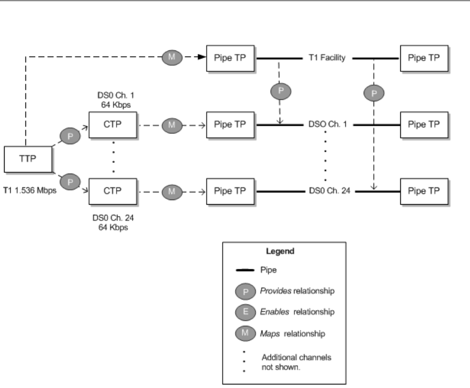
Understanding Capacity and Signal Structure
Pipes 16-13
Figure 16–8 Simple Signal Structure Mapped to Pipes
In UIM, if you create a T1 facility pipe entity with this signal structure, all of its DS0
channels will automatically be created at the same time. See "Defining Pipe
Specifications" for information about creating pipes.
Complex Signal Structures Complex signal structures are those that contain more than
two levels. Examples include OC3, OC12, OC48, and STM1 structures. Figure 16–9
illustrates an OC3 signal structure.
The TTP represents the entire signal structure with 155.52 Mbps capacity. The OC3 is
decomposed into two levels of channels. The first level comprises three STS1 channels,
each with 51.84 Mbps. Each of the STS1 channels is further subdivided into 28 VT1
channels with 1.728 Mbps each. (The total of all of the VT1 channels’ capacity is
slightly less than the total C3 capacity of 155.52 Mbps because of some loss to
overhead.)
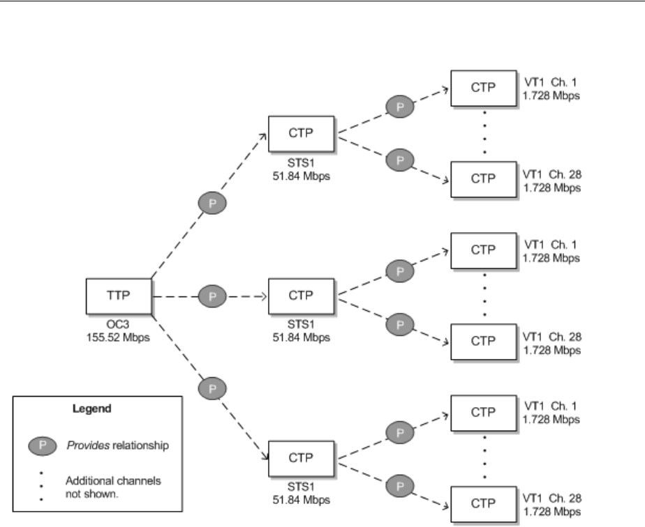
Understanding Capacity and Signal Structure
16-14 Oracle Communications Unified Inventory Management Concepts
Figure 16–9 OC3 Signal Structure
In UIM, the hierarchy of CTPs in the signal structure dictates some rules about how
the structure’s capacity can be used:
■After a channel pipe has been used to enable another pipe, higher-level channels
in the structure no longer have their full capacity available. In other words, the
parent channel cannot be used as a whole unit. For example, if you use one or
more VT1 channels from an STS1 channel in an OC3 signal structure to enable a
service trail, the STS1 channel as a whole is no longer available. Its remaining
unused VT1 channels are available, however.
■Child channels below a parent channel that is being used to enable a pipe are not
available because their cumulative capacity has been used by the parent. For
example, if you use an entire STS1 channel in an OC3 signal structure to enable a
facility pipe, the individual VT1 channels in the STS1 are no longer available.
Figure 16–10 illustrates the OC3 signal structure from Figure 16–9 mapped to an OC3
facility pipe.
■The TTP of the signal structure is mapped to the OC3 facility pipe itself.
■The CTPs for the first seven VT1 channels in the first STS1 channel are mapped to
seven VTS channels provided by the OC3 facility. These seven VTS channels are
then used to enable an 18 Mbps Ethernet facility pipe.
Because some VT1 channels in this STS1 have been used, the STS1 as a whole is
now unavailable. Its remaining VT1s can be used, however.
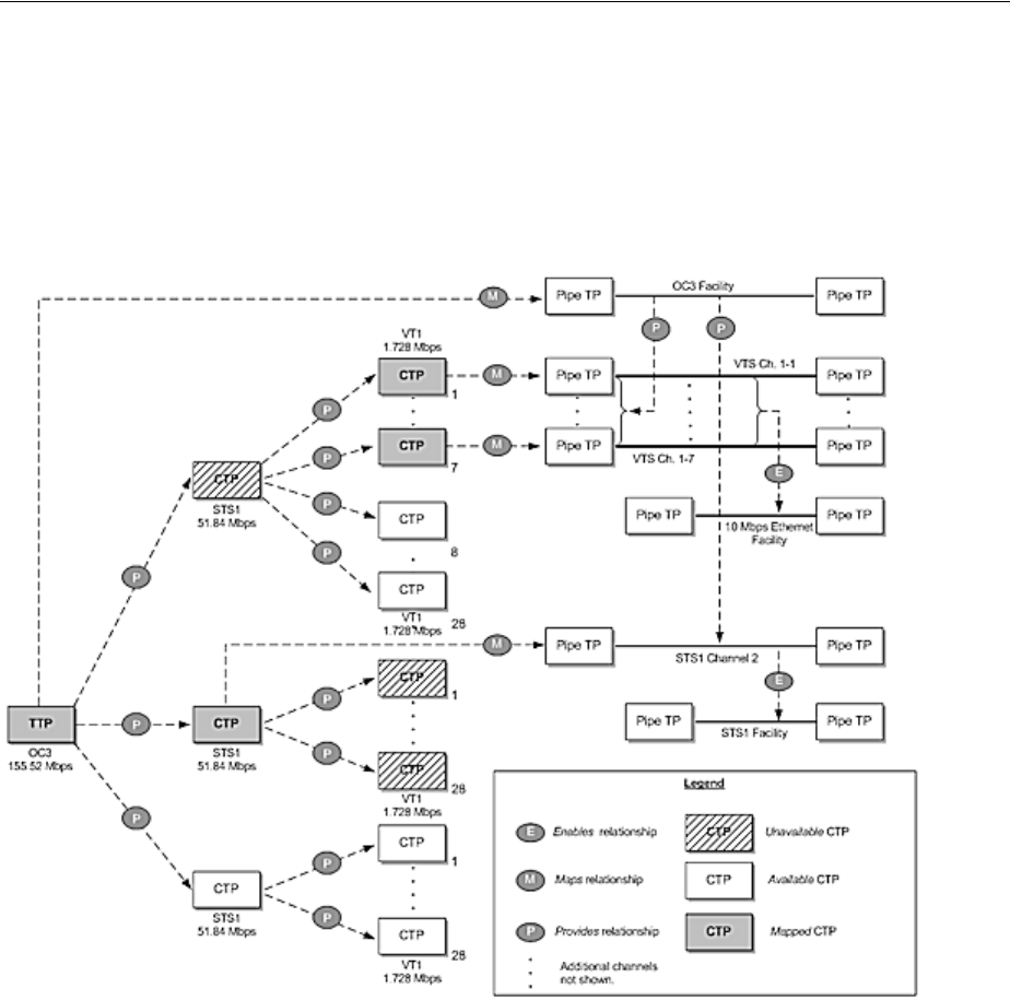
Modeling Connectivity in Design Studio and UIM
Pipes 16-15
■The CTP for the second STS1 channel in the signal structure is mapped to an STS1
channel provided by the OC3 facility. This channel in turn enables an STS1 facility
pipe.
Because the STS1 channel in the signal structure is used as a whole, none of its VT1
channels is available for use.
Figure 16–10 Complex Signal Structure Mapped to an OC3 Facility
Modeling Connectivity in Design Studio and UIM
You define specifications for connectivity entities in Design Studio and create entities
based on those specifications in UIM. The following sections provide high-level
information about designing and implementing connectivity entities. See the Design
Studio Help and the UIM Help for detailed information about using the applications.
Defining Pipe Specifications
You define specifications for pipes in Design Studio. When you create a Pipe
specification, you define several aspects of pipes based on the specification:
■Pipe configurations and versioning. Configurations enable you to create versions
of the pipe in which enablement and resource termination change over time. Pipe
configurations and versioning are optional. See "Designing and Implementing
Pipe Configurations" for more information.

Modeling Connectivity in Design Studio and UIM
16-16 Oracle Communications Unified Inventory Management Concepts
■Child pipes that can be provided by the pipe you are defining, such as cable-pair
pipes provided by a cable. To define child pipes, you associate the specification of
the child pipe to the parent pipe and specify minimum and maximum quantities.
See "Configuring and Implementing Child Pipes for the Cable/Pair Model" for
more information.
■Pipe Termination Point specifications to apply to the pipe’s termination points.
Specifications for pipe termination points are optional. You use them only to
associate characteristics or rulesets with them. You associate Pipe Termination
Point specifications to Pipe specifications because their termination points are
created automatically when the pipe is created. See "Configuring and
Implementing Pipe Termination" for more information.
■Characteristics that are appropriate for the specification. For example, to record
technical details about a pipe, you can add one or more characteristics for that
information. See the Design Studio Help for information about adding
characteristics to specifications.
■The pipe’s capacity. You can define a pipe’s capacity in one of two ways:
–For non-TDM (packet) pipes, by associating Capacity Provided and Capacity
Required specifications to the Pipe specifications. See "Configuring Pipe
Capacity" for more information.
–For TDM pipes, associating a Signal Termination Point specification and signal
structure with the Pipe specification. See "Configuring Capacity with Signal
Structures" for more information.
Different types of pipes include different combinations of these features; no single pipe
includes all of the feature. There are three basic pipe models: cable/pair, packet facility,
and TDM facility. Each model has a distinctive combination of features. See
"Understanding Pipe Models" for more information.
See the Design Studio Help for more information about designing Pipe specifications.
Creating Pipe Entities in UIM
In UIM, when you create a Pipe entity based on a specification, the entity reflects the
configuration choices you made in Design Studio. For example, if the Pipe
specification includes child pipes, the minimum number will be created.
In UIM, you can associate a pipe entity with parties, roles, and other entities. For
example, you can use role and party associations to record that a pipe is leased from
another company, managed by a particular department, and used to support a specific
customer. You can associate the following entity types with pipes:
■Places
■Roles
■Involvements
■Business interactions
■Reservations
■Inventory groups
■Conditions
See the UIM Help for more information.

Modeling Connectivity in Design Studio and UIM
Pipes 16-17
Understanding Pipe Models
UIM supports three different pipe models. The models are defined by how a pipe
provides child pipes and by the way its capacity is structured. Path analysis and other
processes are designed to support these models.
Cable/Pair Model
In this model, a parent pipe represents a copper or fiber cable. This cable pipe provides
child pipes that represent twisted pairs or fiber strands. Cable pipes are configured in
the following way:
■Minimum and maximum quantities for the child pipes are typically identical. As a
result, all of them are created automatically when the parent pipe is created in
UIM.
■No capacity is provided or required. Because cables and cable pairs can be used
only as whole units, no explicit definition of capacity is necessary.
■No signal structure is present.
The cable and cable-pair pipes shown in Figure 16–3, "Pipe Relationships in a Local
Loop Enablement", would be configured according to this model.
Packet Facility Model
This model supports Layer 2 links, such as ATM, Frame Relay, and Ethernet. Pipes
based on this model provide capacity in bulk to pipes that they enable. An enabled
pipe can consume the entire capacity or some smaller quantity depending on its
requirements. The facility pipe can enable any number of pipes as long as its
maximum capacity and usage percentage are not exceeded.
Packet facility pipes are configured in the following way:
■No signal structure is defined.
■The capacity required is the capacity that the pipe needs from another pipe for
enablement.
■The capacity provided is the total capacity provided by the facility pipe.
■No child pipes are defined.
Figure 16–6, "Packet Capacity Example", illustrates a packet enablement scenario. The
facility pipe would be configured according to this model.
TDM Facility Model
This model supports channelized technologies, such as TDM/PDH and SONET/SDH.
In this model, facility pipes provide channels that enable service trails. A signal
structure is associated to the facility pipe to define its capacity and channelization.
Note: Connectivity models other than those described in this section
are not supported by path analysis.
Note: While you can use this pipe-based model to represent
channelized connectivity, specialized capabilities are available when
you use Channelized Connectivity entities. See "Channelized
Connectivity" for more information.

Modeling Connectivity in Design Studio and UIM
16-18 Oracle Communications Unified Inventory Management Concepts
TDM facility pipes are configured in the following way:
■The capacity required is the capacity that is required when enabled by another
pipe.
■The pipe includes a signal structure that defines the pipe’s capacity provided and
how its signal is channelized.
■The capacity provided is not defined directly in the Pipe specification: it is
inherited from the signal structure.
■No child pipes are defined. Child pipes are unnecessary because the signal
structure defines the channelization of the pipe’s signal. Channels are created
either automatically or as needed in UIM depending on how the signal structure is
organized.
Figure 16–6, "Packet Capacity Example", Figure 16–8, "Simple Signal Structure
Mapped to Pipes", and Figure 16–10, "Complex Signal Structure Mapped to an OC3
Facility" illustrate various scenarios that involve pipes based on the TDM facility
model.
Designing and Implementing Pipe Configurations
Pipe configurations allow for versioning in pipe designs. You can use pipe
configurations to record changes to a pipe’s terminations and enablement over time.
See "Configurations" for more information about entity configurations; see
"Understanding Pipe Configurations" for more information about pipe configurations.
Defining Pipe Configuration Specifications
You define Pipe Configuration specifications and associate them to Pipe specifications
in Design Studio. When you create an entity based on the Pipe specification in UIM,
you specify that it is versioned to make possible the creation of pipe configuration
versions. See "Implementing Pipe Configurations in UIM" for more information.
When you design a Pipe Configuration specification, you can add the following
configuration items:
■Termination. Limits the types of resources on which the pipe can be terminated.
You can choose different resources for originating and terminating termination.
■Tra n s port. Limits the types of pipes that can enable the pipe.
■Intermediate Node. Specifies a device or piece of equipment that must be in the
connectivity path that enables the pipe. If you specify an intermediate node, that
node must be included in enablements whether they are done manually or
automatically.
You can constrain the resources that can be used for the Termination, Transport, and
Intermediate Node configuration items by specifying entity specifications as
specification options. The resources available for termination, transport, and
intermediate nodes are limited to entities based on the selected specifications. If you
do not add a configuration item or do not select an entity specification for a
configuration item, any entity of the supported types (such as pipes for the Transport
configuration item) is allowed.
The specification options in a configuration specification are enforced when you
configure enablement or resource assignment. They also apply during automatic
enablement using path analysis.
Figure 16–11 shows a Pipe Configuration specification for an Ethernet service trail
pipe. A Tra n s port configuration item has been added, with a specification option that
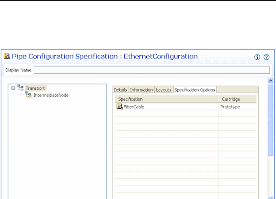
Modeling Connectivity in Design Studio and UIM
Pipes 16-19
defines that only entities based on the FiberCable specification can enable the pipe. An
Intermediate Node configuration item has also been included.
Figure 16–11 Pipe Configuration Specification
Implementing Pipe Configurations in UIM
When you create a pipe in UIM based on a specification that is associated with a Pipe
Configuration specification, you can choose to version the pipe. (You can also
configure a pipe to be versioned after you create it, as long as no resources have been
assigned to it.)
When you add a pipe configuration, the resource assignments you make to terminate
the pipe and the pipes you select to enable it (either manually or through path
analysis) are captured as part of the configuration. The configuration becomes effective
when it is transitioned into Completed state. See "Life Cycles and Statuses", for more
information about life cycles and statuses.
For versioned pipes, you perform manual enablement or automatic enablement (path
analysis) from the Summary page of the pipe configuration. Each version of the pipe
configuration design can have a different enablement; a redesign with different
enablement is often the reason for creating a new version.
After a configuration version has been completed or canceled, you cannot change its
enablement. You must create a new configuration version for the updated enablement.
You use the Pipe Configuration Enablement section in the Pipe Configuration page to
specify the pipes that enable the parent pipe of the configuration.
See "Enabling Pipes" and the UIM Help for more information about enablement.
Figure 16–12 shows the Summary page for a pipe configuration. You use the Pipe
Configuration Enablement section of the page for manual enablement.
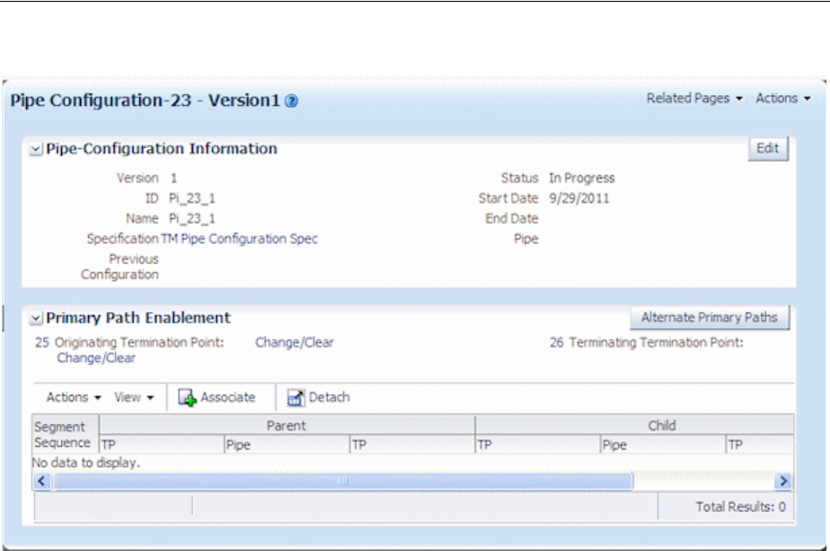
Modeling Connectivity in Design Studio and UIM
16-20 Oracle Communications Unified Inventory Management Concepts
Figure 16–12 Pipe Configuration
Configuring and Implementing Pipe Termination
You can associate Pipe Termination Point specifications to Pipe specifications when
you design a pipe in Design Studio. Pipe Termination Point specifications are
necessary only to add characteristics to capture specific information about the
termination point, to associate rulesets to the termination points, or to limit the types
of resources with which the termination points can be associated. If you do not
associate a Pipe Termination Point specification with the Pipe specification, the pipe’s
termination points are created without specification in UIM.
See the Design Studio Help for more information about creating Pipe Termination
Point specifications and associating them with Pipe specifications.
In UIM, you associate pipe termination points to entities in the inventory to describe
where the pipe terminates. You can associate the following kinds of resources to pipe
termination points:
■Connector
■Device interface
■Equipment
■Logical device
■Network
■Physical Device
■Port
If the pipe termination points were created with a specification, it may limit the type of
resources on which the pipe can terminate. For, example, a Pipe Termination
specification may limit pipe termination to entities based on a particular Device
Interface specification.
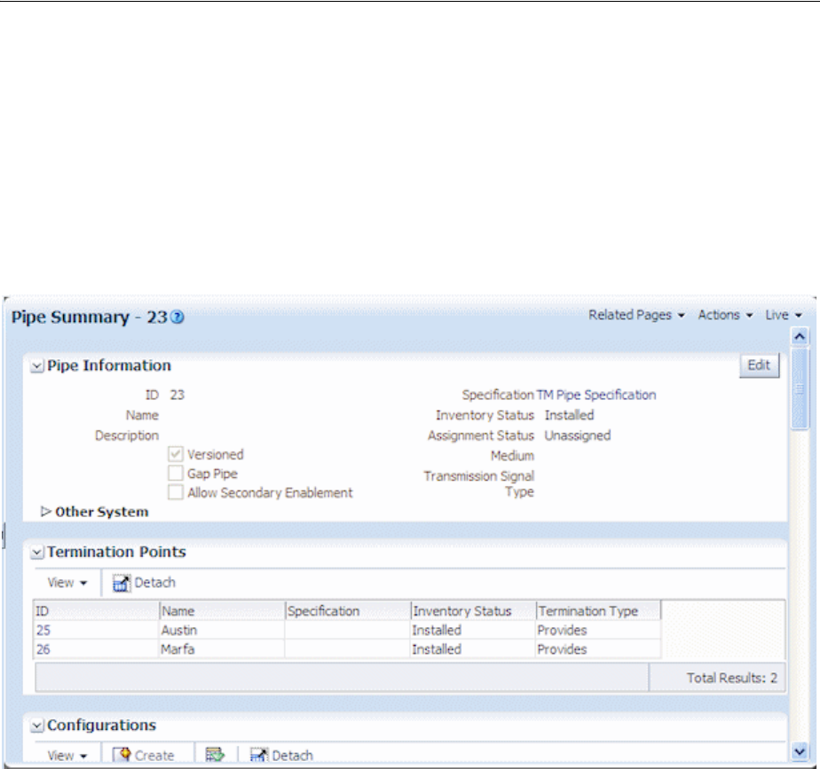
Modeling Connectivity in Design Studio and UIM
Pipes 16-21
The resources that a pipe terminates on are assigned to the pipe and are not available
to be consumed by other services, sites, or resources unless its specification indicates
that it can be assigned to multiple entities. See "Consumption" for more information
about shared consumption.
When pipe termination points are terminated on entities that have place associations,
UIM includes the pipe in the inventory topology. See "Topology" for more information.
Figure 16–13 shows information about the termination points in a UIM Pipe Summary
page. The termination points were created without specification.
Figure 16–13 Pipe Termination Points in UIM
See the UIM Help for more information about managing pipe termination in UIM.
Configuring and Implementing Child Pipes for the Cable/Pair Model
When you design a cable pipe based on the Cable/Pair model in Design Studio, you
specify which Pipe specification should be used for its child pipes. You also specify the
minimum and maximum number of child pipes.
For example, if you are designing a specification for a 25-pair copper cable, you
include the specification for the cable-pair pipes that the cable provides. You specify a
minimum number of cable pairs that will be created automatically when you create an
entity based on the cable specification in UIM. You also specify the maximum number
of cable pairs that the cable can provide. In most cases, you set the minimum and
maximum to the same value to ensure that all the cable pairs are created when the
parent pipe is created.
See the Design Studio Help for information about designing parent and child Pipe
specifications.
After you create a parent pipe and its minimum number of child pipes in UIM, you
can add additional child pipes if the maximum number has not been reached. After

Modeling Connectivity in Design Studio and UIM
16-22 Oracle Communications Unified Inventory Management Concepts
additional child pipes have been added, you can delete them until the minimum is
reached.
You can view a parent pipe’s hierarchy of child pipes in the Pipe Hierarchy section of a
Pipe Summary page. Each child pipe is shown along with the identity, inventory
status, and assignment status of pipes it enables.
See the UIM Help for more information about managing child pipes in UIM.
About Pipe Termination and Rate Codes
Although rate codes apply primarily to channelized connectivity, they are also relevant
when you terminate pipe connectivity. (See "About Rate Codes" for information about
rate codes in general.)
When you terminate a pipe that has bit rate capacity on a device interface that has a
rate code, UIM validates the pipe’s capacity against the device interface’s rate code.
(UIM validates against the pipe’s capacity required first. If no capacity required value
exists, UIM validates against the capacity provided.) If the pipe’s capacity matches the
bit rate of the device interface’s rate code, UIM allows the termination.
You can define a capacity variance that specifies how much the capacity can vary from
the rate code and still be validated successfully. The variance is a percentage that you
specify with the connectivity.capacityVariant parameter in the system-config file. See
UIM System Administrator’s Guide for more information about setting configuration
parameters.
Setting a capacity variance is particularly useful when you have upgraded from a
previous version of UIM. In this situation, you may have existing pipe capacity
defined with bit rates that do not exactly match the rate code bit rates due to rounding.
Configuring Pipe Capacity
Pipes provide and require capacity in the form of bandwidth. You can define pipe
capacity for Pipe specifications in Design Studio in two different ways:
■By associating Capacity Provided and Capacity Required specifications to Pipe
specifications. You use this method of defining capacity for pipes based on the
packet facility model. (See "Packet Facility Model" for more information.) For
example, you use Capacity Provided and Capacity Required specifications for
pipes that represent packet-switched Layer 2 connectivity, such as Frame Relay
and Ethernet. See "Configuring Capacity for Packet Facility Pipes" for more
information.
■By associating signal structures to Pipe specifications. The signal structures define
how the signal is channelized and include a reference to a Capacity Provided
specification. You use signal structures for pipes based on the TDM Facility model.
(See "TDM Facility Model" for more information.) For example, you use signal
structures to define capacity for an OC3 pipe that includes STS1 and VT1 channels.
See "Configuring Capacity with Signal Structures" for more information.
You do not define capacity for pipes based on the Cable/Pair model. Cable pairs offer
themselves as a whole for enablements. Their capacity can be consumed only as a unit,
so there is no need to specify the amount. See "Cable/Pair Model" for more
information about pipes based on this model.
Configuring Capacity for Packet Facility Pipes
Capacity for packet-based connectivity is defined using the standard UIM capacity
capabilities. See "Capacity" for more information.

Modeling Connectivity in Design Studio and UIM
Pipes 16-23
When you define a specification for a packet-based pipe in Design Studio, you
associate it with Capacity Provided and Capacity Required specifications that define
the pipe’s capacity. A pipe can enable other pipes up to the maximum capacity and
consumable percentage defined by the Capacity Provided specification with which it is
associated. To be enabled, a pipe requires the capacity defined in the Capacity
Required specification with which it is associated.
Defining Capacity Required specifications is similar, but no consumable percentage is
involved. See the Design Studio Help for more information.
In UIM, when you create an entity based on a specification that includes a relation to a
Capacity Provided or Capacity Required entity specification, the relevant capacity is
automatically associated to the entity. UIM automatically keeps track of capacity
usage. You are prevented from making enablements that exceed a pipe’s maximum
capacity provided.
Configuring Capacity with Signal Structures
You use signal structures to define capacity for pipes based on the TDM model.
(Channelized Connectivity entities define their signal structures by using the UIM
signal architecture. See "About the UIM Signal Architecture" for more information.)
The signal structure defines how a pipe’s signal is channelized. The signal structure
includes an association to a Capacity Provided specification, meaning that no such
association is required for the pipe itself.
To define signal structures and associate them with Pipe specifications, you create
hierarchies of Signal Termination Point specifications in Design Studio. The
parent-child relationships among the Signal Termination Point specifications
determine the organization of the signal structure.
The hierarchy includes one parent specification to represent the top signal structure as
a whole, along with one or more layers of child specifications. This organization of
Signal Termination Point specifications corresponds to the hierarchy of TTPs and
CTPs. See "Understanding Signal Structures" for more information.
For example, if you are creating a signal structure comprising a T3 parent signal
termination point and 28 T1 child termination points, you must create a T3 Signal
Termination Point specification and a T1 Signal Termination Point specification.
When you design a child Signal Termination Point specification, you define the
capacity unit amount, unit of measure, and number of child signals. (See "Defining
and Measuring Capacity" for more information about units of measure.) In a T3
scenario, there is only one layer of child signals, so the number of child signals is set to
zero for the child Signal Termination Point specification. If there were more layers to
the signal structure, you would specify the number of child signals below this one in
the hierarchy.
You define the total bandwidth for the signal structure by relating a Capacity Provided
specification to the highest-level Signal Termination Point specification in the
structure. You also enter the number of child signals in the first layer of the structure
and select the Signal Termination Point specification for that layer. For example, for the
T3 structure mentioned previously, you would specify 28 child signals and select the
T1 Signal Termination Point specification.
When you define a Signal Termination Point specification, you can include compatible
capacities and units of measure supported by the signal structure. Using this feature,
you can specify that a signal structure can support not only signals of exactly matching
capacity but also signals of lesser capacity. For example, you can specify that a SONET
STS1 channel with a bit rate of 51.840 Mbps can support an STS transmission facility of
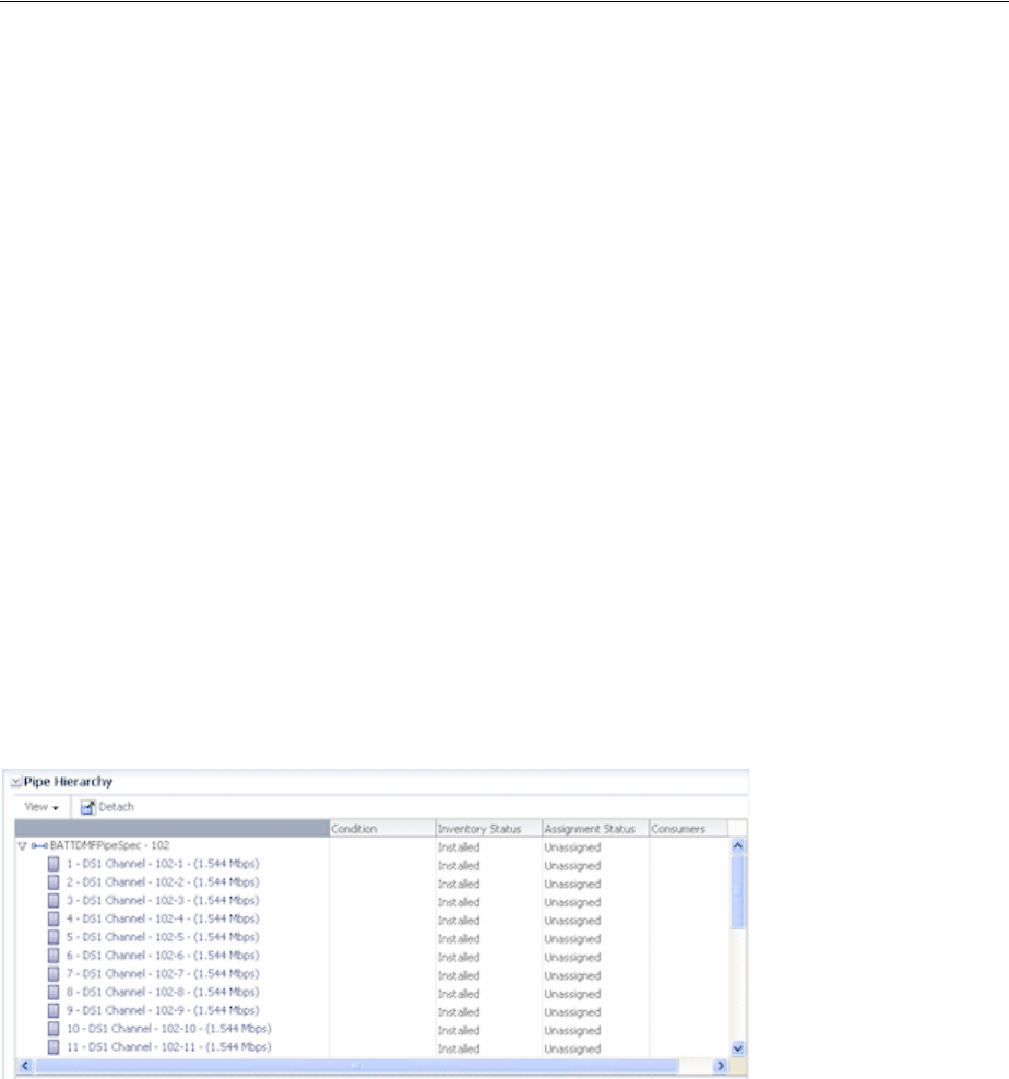
Modeling Connectivity in Design Studio and UIM
16-24 Oracle Communications Unified Inventory Management Concepts
51.840 Mbps capacity or a DS3 facility at a rate of 44.736 Mbps. See the Design Studio
Help for more information about configuring Signal Termination Point specifications
for compatible signals.
You can associate a Signal Termination Point specification with a Pipe specification in
Design Studio. When a pipe entity is created in UIM based on a specification with such
an association, the signal structure is created automatically at the same time. The
channels defined in the signal structure are created immediately for simple signal
structures (those with only one layer of child signals) and as needed for enablement in
complex signal structures.
See the Design Studio Help for more information about how you design Signal
Termination Point specifications.
In UIM, you can manually associate a signal structure with a pipe that does not
already have one. When you make the association, the channels are created under the
same rules used for signal structures associated by specification.
See the UIM Help for more information about associating signal structures with pipes.
Viewing Signal Structure Information in UIM There are several ways in UIM to view
information about a pipe’s signal structure:
■Figure 16–14 shows how the Pipe Hierarchy section of the Pipe Summary page
displays the channel hierarchy defined by the signal structure. Each channel is
shown along with the identity, inventory status, and assignment status of pipes it
enables.
Figure 16–14 Pipe Hierarchy Section
■Figure 16–15 shows how the Pipe Provides page lists all the child pipes that have
been created based on the signal structure.
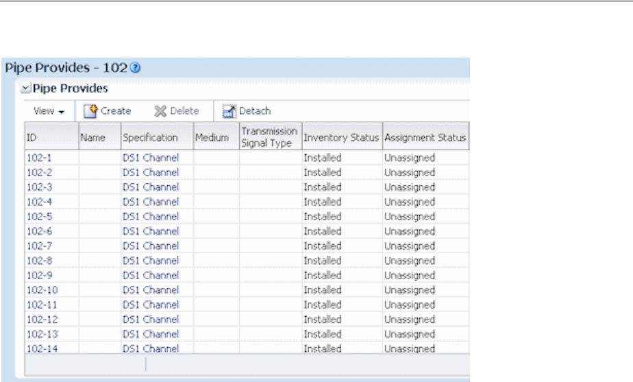
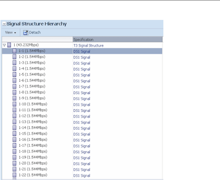
Modeling Connectivity in Design Studio and UIM
16-26 Oracle Communications Unified Inventory Management Concepts
Figure 16–16 Signal Structure Page
See the UIM Help for more information about viewing signal structure information for
pipes.
Changing the Capacity of Existing Pipes
You can change the capacity provided or capacity required after you create a pipe in
UIM. It is unusual to make such a change, but it may be necessary under some
circumstances. For example, you may need to change the capacity of fractional T1 or
E1 pipes with capacities of 256, 384, 512 and 768 Kbps.
The following rules apply to changing the capacity provided amount.
■You cannot change the capacity provided information if the pipe has a signal
structure because the signal structure defines capacity provided.
■If a pipe is not enabling any other pipes (has no capacity consumed), you can
increase or decrease the total capacity provided.
■If a pipe is enabling another pipe (has some capacity consumed), you cannot
decrease its capacity provided; you can only increase it.
The total capacity provided amount factors in the consumable percent value. For
example, if you have a pipe that provides 10 Mbps with 100% consumable, you
could not change its capacity provided to 10 Mbps with 75% consumable if the
pipe is enabling another pipe.
There are no rules about changing the capacity required amount. You can increase the
capacity required after a pipe has been enabled by another pipe, even if you increase it

Enabling Pipes
Pipes 16-27
to more than the capacity available on the enabling pipe. Changing the capacity
required on a pipe that is already enabled by another pipe does not change the amount
of capacity consumed on the enabling pipe.
See the UIM Help for more information about changing capacity in UIM.
Enabling Pipes
You enable a pipe to define how its connectivity is implemented. For example, a POTS
service trail represents the connectivity from a voice switch in a central office to the
subscriber terminal. This service trail is enabled by several different pipes, including
cable pairs between the MDF to a cross-connect terminal and from the cross-connect
terminal to the subscriber terminal. See "Enables Relationships" for conceptual
information about pipe enablement.
In UIM, you can enable pipes in two ways:
■You can manually configure the enablement, which involves specifying the pipes
that comprise the connectivity path. UIM automatically creates cross-connects to
bridge gaps between pipes. See "Enabling Pipes Manually" for more information.
■You can have UIM automatically configure the enablement using path analysis.
Path analysis calculates a least-number-of-hops path between two points that you
specify. See "Enabling Pipes Automatically with Path Analysis" for more
information.
Enabling Pipes Manually
When you manually enable a pipe, you select the pipes that comprise the enabling
connectivity path. For example, in a POTS scenario, you select cable pairs that connect
the MDF to a cross-connect terminal block and the terminal block to the subscriber
terminal.
When you manually configure enablement, UIM automatically creates cross-connects
or connectivity gaps to ensure that there is a continuous path from the originating
termination point to the terminating termination point. A connectivity gap or
cross-connect is required when the enabling pipes you specify do not share a common
termination point. See "About Connectivity Gaps in Pipe Enablement" for more
information.
In the POTS scenario mentioned above, for example, UIM automatically creates a
cross-connect to represent the jumper on the cross-connect terminal block that
connects the two cable pairs.
The way you manually enable pipes varies slightly depending on whether the pipe is
versioned or not. See the UIM Help for more information about enabling pipes
manually.
Enabling Pipes Automatically with Path Analysis
Path analysis is an automated process in UIM that helps you locate and assign pipes
for enablement. You specify the starting point (the source), the ending point (the
target), and a variety of optional criteria, including capacity requirements. Path
analysis evaluates possible paths based on the criteria you provide and returns paths
from which you can select.
For example, to enable a DS1 service trail from Dallas to Orlando, you can use path
analysis to find the available paths between those points.

Enabling Pipes
16-28 Oracle Communications Unified Inventory Management Concepts
Path analysis uses the inventory topology to find paths. The paths it locates are those
that are defined by the UIM topology framework. See "Topology" for more
information.
You can specify any entity that is included in the UIM topology as a source or target
for path analysis. By default, the following entity types are included in the topology:
■Equipment
■Logical devices
■Networks
■Network nodes
■Physical devices
■Places (site and location only)
■Property locations
Path analysis identifies paths by finding pipe termination points that are associated
with the source and target you specify. For example, if you specify a logical device as
the source, path analysis looks for pipes with termination points that are associated
with that logical device. Similarly, if you specify a Place entity such as Santa Clara or
Austin as the target, path analysis looks for pipes with termination points on entities
associated with that place.
To find a path, path analysis must be able to find pipes whose termination points are
associated with devices in common. For example, suppose that Pipe X is terminated on
Device Interface A of Logical Device 1 and Device Interface B of Logical Device 2 and
that Pipe Y is terminated on Device Interface C of Logical Device 2 and Device
Interface D of Logical Device 3. (See Figure 16–17.) In this case, path analysis can find a
path between Logical Device 1 and Logical Device 3.
Figure 16–17 Path Example
The following list includes some points about the way path analysis that you should
keep in mind when you enable a pipe automatically:
■Because path analysis uses connectivity as it is defined by topology, it cannot find
paths on pipes that are terminated directly on places. It is possible to terminate a
pipe in this way, but the topology framework does not create a topology edge for
such an arrangement.
To terminate a pipe on a place and use the pipe for enablement, you must create a
dummy device on which to terminate the pipe. You can then associate that device
with the desired place. This technique is especially useful when you want to
represent connectivity or traffic flow to a place, but do not know or care about the
details. For example, you may want to include connectivity to a third-party
network about which you have little information. In this situation, you can create a
dummy device at the desired place.
■Path analysis can find paths between network nodes by looking for edges that
connect them. Paths between network nodes cannot be used to actually enable
pipes, however. They represent logical rather than actual connectivity.

Enabling Pipes
Pipes 16-29
■If you are searching for paths between entities that have a hierarchical structure,
such as logical devices, physical devices, or equipment, you should use the
highest-level entities for the source and target. For example, to find a path starting
from a port, you should consider the hierarchy in which it is included. In this case,
the port is assigned to a card, which is in turn assigned to a shelf. You should use
the shelf (an Equipment entity) as the starting point for path analysis.
■Path analysis is designed to work with the three supported pipe models:
cable/pair, packet facility, and TDM facility. See "Understanding Pipe Models" for
more information.
About Path Analysis Criteria
When you perform path analysis, you specify criteria in the Path Analysis Search page
to find paths. These criteria determine how path analysis goes about finding
connectivity paths.
The following list provides introductory information about the criteria you can enter.
See the UIM Help for detailed information about the criteria and for step-by-step
instructions about running a path analysis.
■The only required criteria for a path analysis are the source and target types and
IDs. You can enter IDs directly or search for them.
■You can specify an intermediate node that must be included in the path.
For example, if you need a pipe to connect a subscriber terminal and a switch,
path analysis can specify that the path must include a DSLAM by adding it as an
intermediate node.
■You can specify the capacity required from the enabling pipe by entering a bit rate
and unit of measure. For example, if you are enabling a pipe that requires 1.544
Mbps of capacity, you can specify a bit rate of 1.544 and Mbps as the unit of
measure. If the pipe to be enabled is already associated with a Capacity Required
specification, the bit rate and unit of measure are automatically selected.
■In cases where fractional capacity is required, you can include a quantity along
with the bit rate and unit of measure. For example, to enable a 256 Kbps service
trail, you can enter a quantity of 4 and enter a bit rate of 64 Kbps to enable the
service trail over four 64-Kbps channels.
■You can specify that path analysis take pipe directionality into account. By default,
path analysis treats pipes as bi-directional, but you can override that in cases
where directionality is important. See "Understanding Pipe Directionality" for
more information.
■You can choose to include partial paths in the path analysis results. Partial paths
are those that are not currently continuous from source to target. By default, only
continuous paths between source and target are returned.
■You can choose to include network nodes and edges in the path analysis. Network
nodes and edges provide no connectivity, so they cannot be used for enablement.
Including network nodes and edges can help in identifying the best routes,
however.
Note: You must use this option if you specified a network or
network node as the source or target.
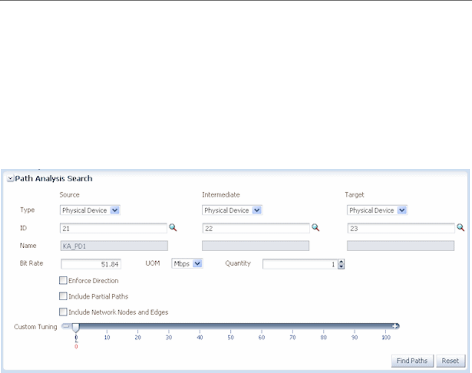
Enabling Pipes
16-30 Oracle Communications Unified Inventory Management Concepts
■You can tune path analysis to control the number of paths returned. The default is
to search for the most direct paths, but you can choose to include more paths.
Processing time increases as you include more paths.
■You can choose to include secondary paths in the path analysis if a pipe is
configured for multiple enablement. Selecting this option means that path analysis
results will include primary paths and the ability to select matching secondary
paths. See "About Multiple Enablement" for more information.
Figure 16–18 shows a Path Analysis Search page with criteria entered.
Figure 16–18 Path Analysis in UIM
In addition to the criteria that you enter, the path analysis can also include filtering
criteria defined in rulesets associated with the specification of the pipe you are
enabling. For example, results may be limited to include only pipes that are based on a
particular specification or that include certain text in their names. A sample cartridge
is supplied with UIM to provide examples of this capability. See UIM Developer’s Guide
for information about customizing path analysis.
Path analysis results are also limited if the pipe that you are enabling has a Pipe
configuration in which a Pipe specification is assigned to the Transport configuration
item. In this case, path analysis results include only pipes based on that specification.
See "Defining Pipe Configuration Specifications" for more information.
About Path Analysis Results
The results of a path analysis are displayed in the Available Paths page. Each path
found between the source and target is shown as a group of rows, with each row
representing a segment of the path. The ID in the From ID column of the first row of
the path represents the source you entered, and the ID in the To ID column of the last
row in the path represents the target.
If the pipe you are enabling is configured for multiple enablement and you want to
include secondary paths, the results include both primary paths and the ability to
select secondary paths. The primary and secondary paths are displayed in separate
tables.
You can open a visualization of the path in the network topology. See the UIM Help
for instructions about using UIM topology features.
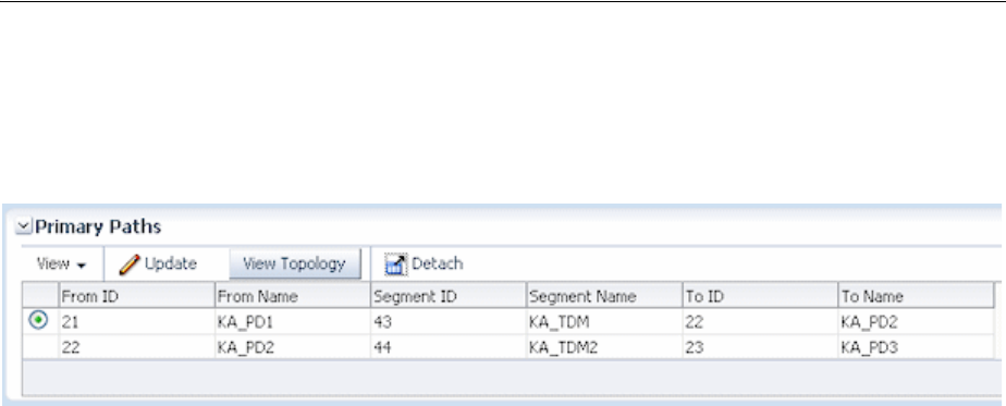
Enabling Pipes
Pipes 16-31
Figure 16–19 shows search results for the criteria entered in Figure 16–18. In this case,
only one path was found. If there were additional paths that met the criteria, they
would be listed in rows below the first path.
Figure 16–19 Path Analysis Results
Understanding Path Analysis Modes
Path analysis can operate in two different modes. The way you run a path analysis is
the same in both modes, but the mode affects which paths are returned and the
amount of processing required.
■In Complex mode (the default), path analysis considers all possible paths between
the source and target, which means evaluating a large number of permutations.
You can use rulesets to limit the amount of data to be processed. This mode of
path analysis is suitable for complex networks with many possible connections.
■In Simple Linear mode, path analysis works by iteratively analyzing paths
working from the end points toward a common node. This mode of analysis is
suited to paths that are inherently linear and have 10 or fewer hops. For example,
Simple Linear analysis is suitable for POTS scenarios. The Simple Linear algorithm
is less processor-intensive than the Complex algorithm.
The analysis mode can be set for UIM as a whole or for specific Pipe specifications.
See UIM Developer’s Guide for more information.
Viewing Enablement Information
After you have enabled a pipe, you can view enablement information in two ways:
■The Pipe Enabled By page lists enabling pipes, including automatically created
cross-connects and connectivity gaps. (The Pipe Configuration page shows the
information for versioned pipes.)
The list includes columns for the sort order, parent pipe information, child pipe
information, and assignment status. The parent and child pipe and termination
point information enables you to see information about all pipes involved in the
enablement, including their parents.
■The Enabled By Visualization page displays the enablement visually. See "Viewing
a Pipe Enablement Visualization" for more information.
Viewing a Pipe Enablement Visualization
The enablement visualization of a pipe or pipe configuration shows schematic views
of the trail pipe in the upper part of the canvas and the enabling pipes in the lower
part. When a pipe is enabled by more than one connectivity path, such as in a
SONET/SDH network, both paths are displayed.
The visualization includes the following:
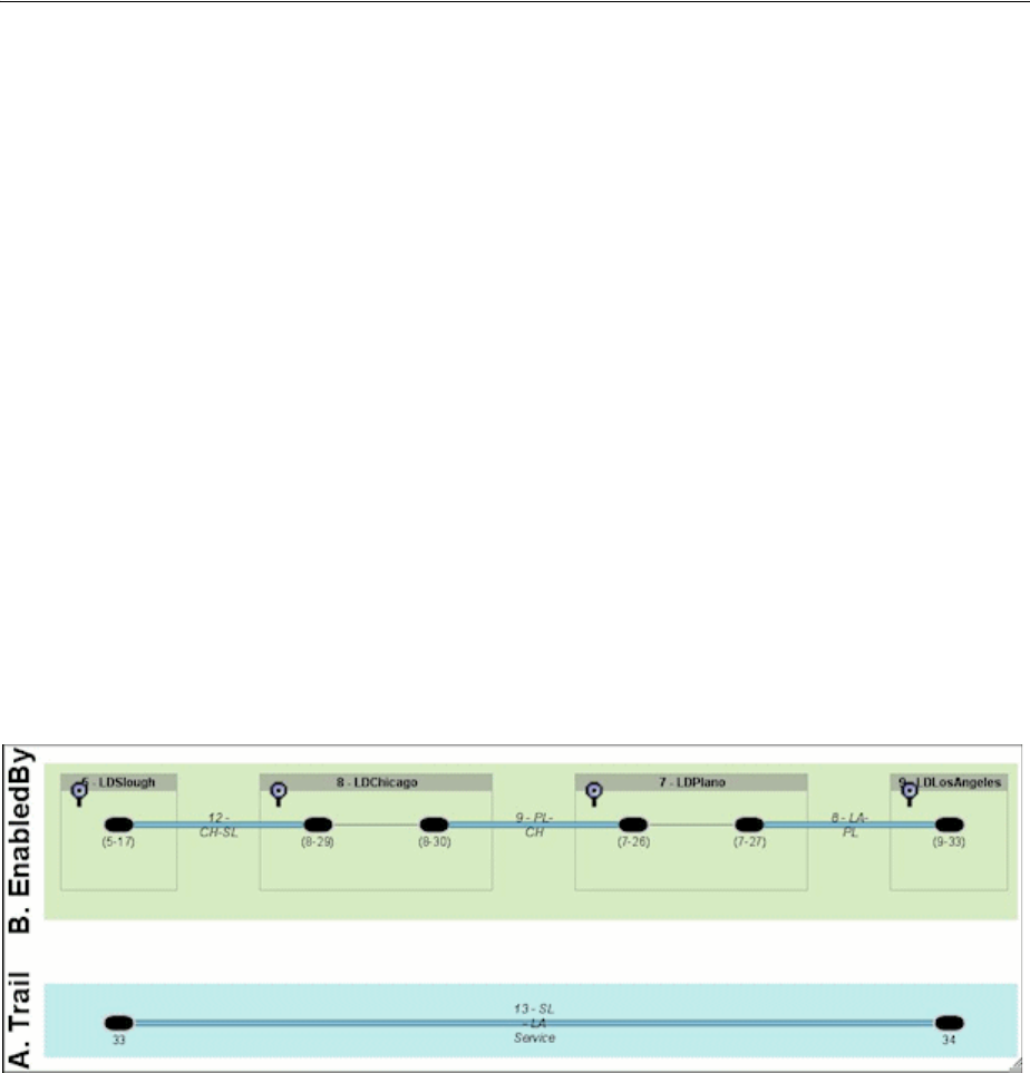
Enabling Pipes
16-32 Oracle Communications Unified Inventory Management Concepts
■Pipes. Pipes are labeled with their IDs and names and the names of their parent
pipes (if any). For example, if the second channel pipe of Facility Pipe LS_BW_A is
included in the enablement, it would be labeled LS_BW_A (LS_BW_A-2) in the
schematic view.
■Connectivity Gaps and Cross-Connects. If connectivity gaps or cross-connects
were created during the enablement, they are shown as thin lines connecting the
thicker lines that represent other pipes.
■Pipe termination points. If the termination points are not terminated on a
resource, they are labeled with their IDs. If they are terminated on a resource, they
are labeled with the ID and name of the resource or its parent. For example, if a
termination point is terminated on a device interface, the visualization displays
the name and ID of the logical device that holds the interface. Boxes representing
parent resources surround the termination points. If two termination points are
terminated on the same parent resource, they are displayed in the same box.
You can expand termination points in the visualization to view their resource
terminations. You can expand individual termination points or all termination
points simultaneously.
Figure 16–20 shows a simple enablement in which a service trail is enabled by a
connectivity path comprising three pipes that are terminated on logical devices in four
locations. Cross-connects have been added on the logical devices that have two pipe
termination points.
Figure 16–20 Pipe Enablement

17
IP Address Management 17-1
17
IP Address Management
This chapter explains how you use the IP address management features in Oracle
Communications Unified Inventory Management (UIM) to allocate, classify, and track
IPv4 and IPv6 addresses.
See the UIM Help for detailed instructions about working with the features and
entities discussed in this chapter.
Understanding IP Address Management
UIM includes entities that represent the three principal components of IP network
infrastructure:
■IP Networks. An IP network is the foundation of IP infrastructure. All IP address
management takes place within an IP network, which you can partition into
subnets that can contain multiple IP address ranges.
You can create and manage IP networks using UIM. In UIM, IP network entities
represent blocks of IP address spaces in your inventory. When you create an IPv4
or a IPv6 network, a default subnet with the same Classless Inter-Domain Routing
(CIDR) number as the network is automatically created. See "About Creating IP
Networks" for more information about creating IP networks.
■IP Subnets. An IP subnet is a range of IP addresses within an IP network. When
you create an IP network, UIM creates a single subnetwork that spans the entire
address space. This subnet is known as the natural subnet.
Subnets cannot be created or deleted directly in UIM. You can edit them, but
subnet address space can be modified only through joins and partitions. See
"About Partitioning IP Address Space" for more information about partitioning
and joining subnets.
■IP Addresses. An IP address is a numerical label assigned to a device, such as a
computer or printer, participating in a network that uses the Internet Protocol for
communication. IP addresses are created within IP subnets. Like subnets, IP
addresses are consumable resources with managed life cycles.
See "About Creating IP Addresses" for more information about creating IP
addresses.
Note: In releases of UIM previous to 7.3, you could only model and
manage IP addresses as Custom Network Addresses. In this release,
you model and manage IP addresses as independent entities.
See "Custom Resources" for more information.
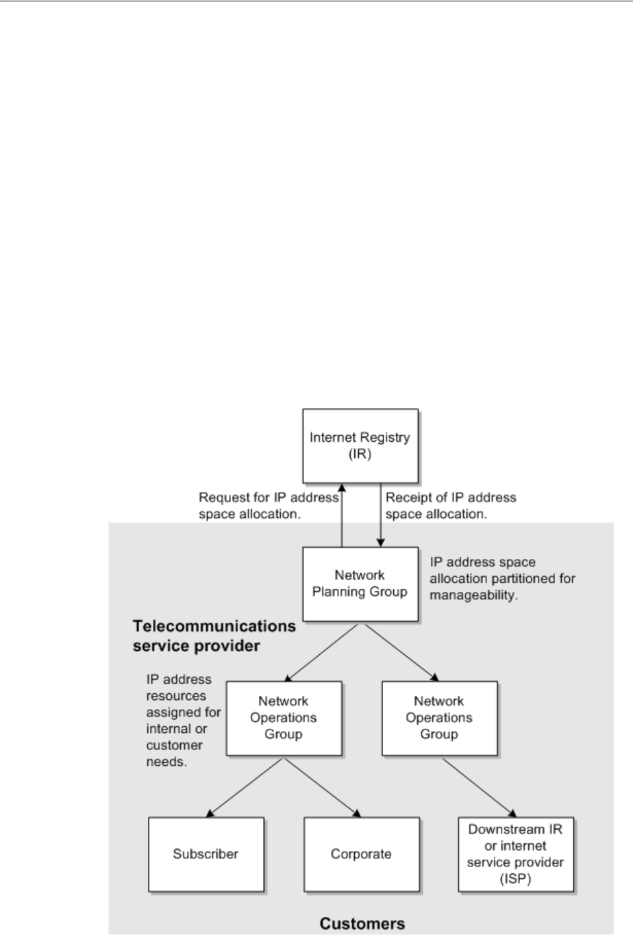
Understanding IP Address Management
17-2 Oracle Communications Unified Inventory Management Concepts
You can use UIM to manage the inventory of IPv4 and IPv6 addresses by:
■Receiving and managing an IP address allocation from an Internet registry (IR).
■Creating IP networks and subnets to manage IP addresses, enhance routing
efficiencies, and improve utilization. See "About Creating IP Networks."
■Allocating IP addresses to subscribers or corporate customers. See "About
Managing IP Addresses."
■Allocating IP addresses to services. See "About Managing IP Addresses."
Figure 17–1 illustrates a simple scenario for using UIM to manage IP address
resources. The telecommunications service provider requests an allocation of public IP
address space from an IR. The address space is partitioned for ease of use and then
allocated to customers or assigned to services. (In this scenario, the service provider
requires public address space so that addresses can be routed externally. Private
address space do not require allocation from an IR.)
In Figure 17–1, the tasks managed by UIM, such as partitioning IP address space and
allocating IP address resources to customers, are represented by the shaded area of the
graphic. The unshaded portion represents an initial business process performed by the
network planning group of a telecommunications service provider.
Figure 17–1 UIM IP Address Management Overview

Understanding IP Address Management
IP Address Management 17-3
About Partitioning IP Address Space
You can partition the address space provided by the IR into subnets to better manage
IP addresses. You can partition the subnet to accommodate your addressing scheme.
Each partition corresponds to a subnet, and you can further partition those subnets
into several smaller subnets. A network using CIDR treats the entire address space as a
partitionable pool of addresses.
You can partition a subnet by specifying the number of subnets you require for a given
CIDR. For example, if you are working with a subnet with a /24 CIDR (such as
10.13.4.0) and you require eight /30 subnets, UIM partitions the eight /30 subnets and
automatically calculates and creates additional subnets and their CIDR numbers from
the remaining address space. In this case, the output looks like the following:
■10.13.4.0 /30
■10.13.4.4 /30
■10.13.4.8 /30
■10.13.4.12 /30
■10.13.4.16 /30
■10.13.4.20 /30
■10.13.4.24 /30
■10.13.4.28 /30
■10.13.4.32 /27
■10.13.4.64 /26
■10.13.4.128 /25
When using UIM to partition an IPv4 or IPv6 network, you must specify a CIDR prefix
length number. Figure 17–2 shows the Partition Details section of the IPv4 Subnet
Partition page. You specify the CIDR prefix length in the Partition CIDR Number field
and optionally select the minimum number of subnets you require from the partition.
The number of subnets created defaults to the maximum number possible given the
specified prefix length.
Figure 17–2 Partitioning An IPv4 Subnet
Subnets that are already assigned or reserved cannot be partitioned. Subnets that
contain assigned or reserved resources (such host addresses) cannot be partitioned.
Because IPv4 hosts are not generally permitted on subnet and loopback network
boundaries (/31 and /32 are exceptions), partitioning is not permitted where any
resulting subnet would have hosts address on these boundaries. Also, address ranges
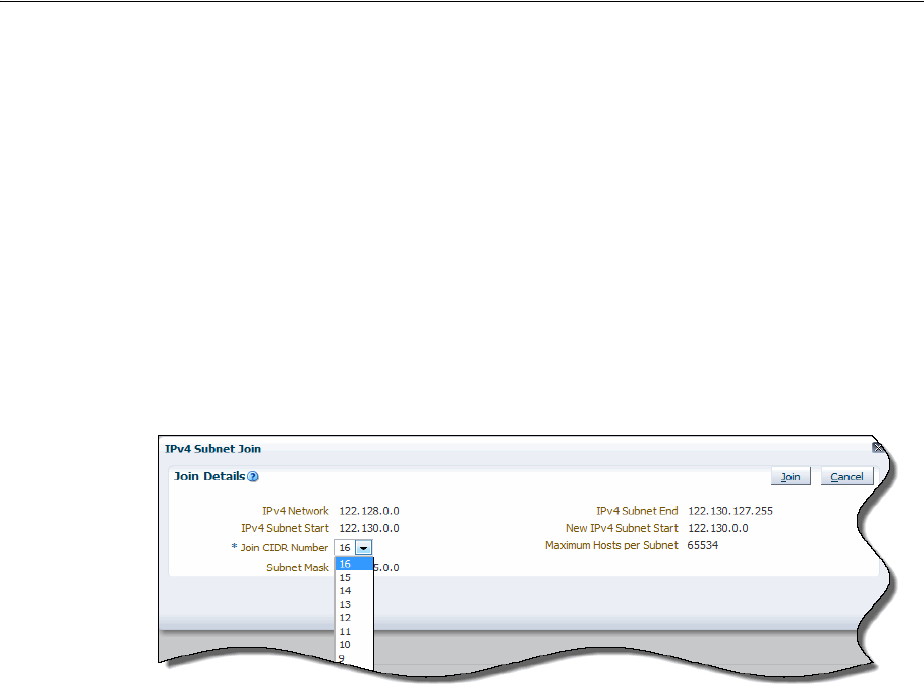
Understanding IP Address Management
17-4 Oracle Communications Unified Inventory Management Concepts
cannot span subnets. When partitioning a subnet, if a host address is on a potential
subnet boundary, or an address range spans a potential subnet partition, the option for
that partition is not displayed.
See the UIM Help for more information about partitioning subnets.
About Joining IP Subnets
You can join (or aggregate) an IP subnet with other contiguous subnets within the
same network. Joining the subnets combines the IP addresses they contain. To join
subnets, they must be contiguous and in an unassigned state.
Figure 17–3 shows the Join Details section of the IPv4 Subnet Join page with a subnet
selected in the Join CIDR Number field.
Figure 17–3 Joining IP Subnets
The following types of subnets cannot be joined:
■Subnets in different networks
■Subnets assigned to or reserved for different customers
■Subnets with assigned or reserved host addresses within their ranges
See the UIM Help for more information about joining subnets.
About Managing IP Addresses
You use UIM to assign IP addresses required for an infrastructure change or extension,
such as adding new equipment or enhancing a specific service offering. For example,
when using UIM to extend your core network with new capacity and new routing
equipment, you need to assign IP addresses for management (loopbacks) and for
interfaces. When assigning addresses, you need to consider the existing address plan,
impacts on routing, the need for public or private addressing, existing traffic filtering
rules, and so on.
IP subnets are inventory resources whose life cycles begin when you activate them.
When you activate an IP subnet, its inventory status changes to Installed. When you
deactivate an IP subnet, all IP addresses within the IP subnet are also deactivated. IP
subnets also have an assignment status that indicates progress in their assignment life
cycle. See "Resource Life Cycles and Statuses" and for more information about life
cycles.
Figure 17–4 shows the inventory status and assignment status of an IPv4 subnet.
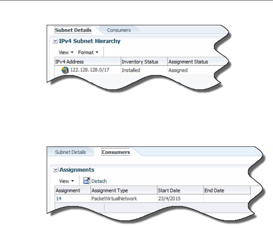
About Creating IP Networks
IP Address Management 17-5
Figure 17–4 IP Subnet Statuses
You view resource assignments in the Consumers tab. Figure 17–5 shows the ID of the
packet virtual network to which the subnet is assigned, the assignment type, and the
date on which the subnet was assigned.
Figure 17–5 IP Subnet Consumers Tab
You also use the Consumers tab also enables you to view and edit reservations.
Reservations are used to restrict the IP subnet from being assigned to other entities or
processes for a period of time. If a subnet or portion of a subnet is already reserved,
you must delete the existing reservation before making a new one.
See the UIM Help for more information about reserving and redeeming resources.
The Consumers tab also enables you to view and edit conditions. Conditions limit the
availability of an IP subnet for a particular reason and period of time. You add
conditions to an IP address resource in the same manner you add conditions to other
resources. Unlike other resources, however, you must delete conditions from IP
addresses from the Consumers tab.
See the UIM Help for more information about adding, editing, and deleting conditions
for IP addresses.
About Creating IP Networks
This following sections provide information about the information you specify when
you create an IP network.

About Creating IP Networks
17-6 Oracle Communications Unified Inventory Management Concepts
Specifying a Network Name
You need to specify a name for the IP network. UIM automatically creates an IP
subnet, but does not propagate the name entered for the IP network. After you create
the network, you can edit the IP subnet to provide a name.
Specifying an IP Address
You specify the starting IP address for the network in standard form for:
■IPv4 addresses must be entered standard dot decimal format, for example 192.0.2.1
■IPv6 addresses can be entered in either compressed or extended format. For
example, you can enter either of the following equivalent addresses:
–2001:0db8:0000:0000:0000:ff00:0042:8329
–2001:db8::ff00:42:8329
Specifying an IP Domain
The list of IP address domains from which to choose are the Network Address Domain
entities that you define prior to creating the IP network. Network address domains
define a context for the uniqueness of network addresses.
For example, in the public domain, an IP address must be unique among all IP
addresses on the Internet. In contrast, the same private IP address can exist in one or
more private routing domains. You use network address domains to define those
private routing domains.
When you search for an IP address, you can use the network address domain as a
search criterion to ensure that you select from the correct addresses. For IPv6 only, the
type of network address domain you select must correspond with the IPv6 address
type you select.
For more information on creating and managing network address domains, see
"Network Address Domains."
Specifying a Network Owner
You can optionally associate an owner with the network to represent the person or
organization who is responsible for it. You select an owner from the Party entities that
you have defined prior to creating the IP network.
In UIM, Party entities represent the people and organizations that interact with your
inventory. For more information, see "About Parties."
About IPv6 Address Types
UIM supports the following IPv6 address types:
■Global Unicast
The Global Unicast Address is the equivalent of a public IP address in IPv4. It is an
IP address that is routed across the whole Internet. The address prefix of a global
IPv6 address is 2000::/3.
■Unique Local Unicast
The Unique Local Unicast address type is equivalent to an IPv4 private address
and cannot be used in the Global IP Address Domain. It can be used in private
networks and networks with no routers.

About Creating IP Addresses
IP Address Management 17-7
About Creating IP Addresses
You can use UIM to create IP addresses within:
■An existing non-partitioned subnet
■A new network
You can create a single address, or specify a range by specifying a starting address and
ending address. Specify or select an IP address domain from the list of Network
Address Domain entities that you have defined prior to creating the IP network.
You can choose to name, or describe, the IP address. You can optionally associate a
manager to the IP address to represent a person or organization with responsibility for
the IP address. You select a manager from the Party entities that you have defined
prior to creating the IP network.
You can specify a manager only when the parent network has an owner. See
"Specifying a Network Owner."
You have the option of specifying a MAC address for the IP address. A MAC address
is a hexadecimal number that uniquely identifies hardware. MAC addresses can be of
the following types:
■Ethernet
■ATM
■Bluetooth
■Fiber Channel
■MAC Type 80211, which refers to the IEEE 802.11 standard
When creating an IP address, much of the IP address configuration information is
based on the selected subnet and its network. If you create the IP address from the IP
Address search result page, this information is not visible during creation; you can see
it only after you have created the address. If you create the IP address from a network
or subnet search result page, information from the parent subnet and network is
visible during creation.

About Creating IP Addresses
17-8 Oracle Communications Unified Inventory Management Concepts

18
Roles 18-1
18
Roles
This chapter explains how to use Role entities in Oracle Communications Unified
Inventory Management (UIM).
About Roles
You use roles to define the parts played by entities in an inventory. For example:
■A Party entity could have the role of subscriber or employee
■A Place entity could have the role of warehouse or data center
■A Logical Device entity could have the role of customer edge (CE) or provider
edge (PE)
■A Logical Device or Party entity could have a network target role
An entity can play multiple roles simultaneously and its roles can change over time.
For example, an entity based on a Party specification called Organization could be
both a supplier and a customer, either at the same time or at different times.
Similarly, a role can apply to multiple entities and multiple entity types. For example,
the role of customer could be assigned to both individual and organization entities.
An entity's role might be relevant to its involvements with other entities. In many
cases, you can specify roles played by entities in their relationships with each other.
This includes relationships to places, parties, and custom involvements where
relationships are created between entities associated with roles. See "Involvements" for
more information about involvements.
The following entity types can be associated with roles and are therefore role-enabled:
■Custom object
■Device interface
■Logical device
■Equipment
■Network
■Network node
■Network edge
■Party
■Physical device
■Physical port

About Roles
18-2 Product Title/BookTitle as a Variable
■Pipe
■Place
Role-enabled entities include a Role section in their Summary pages. This section
includes a list of the roles assigned to the entity, included the role type.
About Role Types
When you define a Role specification, you can optionally select one of the following
role types:
■Technology: This role defines the technology that an entity operates under or
supports. For example, devices and connections that support a Frame Relay WAN
could be assigned a Frame Relay role.
■Function: This role defines the function that an entity plays. For example, a router
can function as a CE device or a PE device.
■Top o l ogy: This role defines the topology type for an entity. For example, you
might want to associate a network entity with a topology role.
■Tar g e t. This role identifies the entity as a target for activation systems. See "About
Network Targets" for more information.
In UIM, the role type is displayed in the Roles section of an entity's Summary page.
Auto-Creating Roles in UIM
When you design a specification for a role-enabled entity in Design Studio, you can
specify that a Target role be automatically created for the entity in UIM.
For example, you could define a Logical Device specification for a voice mail server
that includes a relationship to a Role specification named Voice Mail Activation Target
of type Target. If you select the Auto Generate check box when you create the
relationship, UIM will automatically create and assign the Voice Mail Activation Target
role when you create a voice mail server based on the specification you designed.
See Design Studio Help for more information about creating specification
relationships.
About Role Specifications and Entity Types
When you define a Role specification in Design Studio, you specify the entity types
that can be assigned to that role. In UIM, only the selected entity types can add that
role.
For example, you can define a Role specification called Subscriber and select the entity
type as Party. In UIM, only Party entities can be assigned the Subscriber role.
Adding Characteristics to a Role Specification
You can add characteristics to a Role specification. Using characteristics with Role
specifications enables you to record additional information about the entity as it
applies to the role. Because each Role specification has its own characteristics, different
information can be stored for each of an entity's roles.
For example, if you define a Business role and make it available to the party entity, you
could add a characteristic to record the Dun and Bradstreet Number, Data Universal
Numbering System, (D-U-N-S) of each company. In UIM, when you add the business

About Roles
Roles 18-3
role to an entity based on a Party specification, you would enter the company's
D-U-N-S.
For a prospect role, you could define and add a characteristic called Primary Language
to ensure that the party receives information in the appropriate language.
About Network Targets
A network target is a resource on which services or other resources must be activated.
For example, in a GSM network, a voice mail service must be activated on a voice mail
server. In this scenario, the voice mail server is the target for the voice mail account.
In UIM, you use the Target role type to identify Logical Device or Party entities as
network targets. This capability enables UIM to pass information about network
targets to activation systems.
When you assign a Target role to a Logical Device or Party entity, it becomes a target
for other entities associated with it in various ways.
Logical devices are network targets for:
■Logical device accounts associated with them.
■Logical devices in their hierarchies (unless those logical devices are themselves
network targets).
■Device interfaces in their hierarchies.
■Any entities with which they have custom involvements based on the Manages
(Oracle Provided) base specification.
Parties can be network targets for:
■Any entities associated with them.
■Any entities with which they have custom involvements based on the Manages
(Oracle Provided) base specification.
You can see information about network targets in two places in UIM. The information
displayed always reflects the current network target; no history is maintained.
■In Logical Device and Party Summary pages. The Roles section includes a list of all
roles assigned to the entity. The Type column in the list displays Tar g e t for
network target roles.
■In the Configuration Items section of Configuration pages. When a configuration
includes a resource that has a network target, the Network Target column displays
the ID of the target. For example, if a service configuration includes a
configuration item for a voice mail account (a Logical Device Account entity), the
Configuration Items hierarchy displays the ID of the voice mail server (Logical
Device entity) associated with the account.

About Roles
18-4 Product Title/BookTitle as a Variable

19
Telephone Numbers 19-1
19
Telephone Numbers
This chapter describes how you can use Oracle Communications Unified Inventory
Management (UIM) to create and manage telephone numbers in accordance with your
business practices and with regulatory requirements.
About Assigning Telephone Numbers to Services
In UIM, you assign telephone numbers as configuration items in service
configurations. Each time you make an assignment or unassignment, UIM creates a
configuration version. See "Configurations" and UIM Help for more information about
configurations.
Many regulatory jurisdictions require that you preserve a telephone number’s
assignment history for a prescribed number of years. Because UIM stores service
configuration versions, you can maintain a history of telephone number assignments.
For example, when the number 214-555-5001 is assigned to a service for Mary Good on
January 21, 2012, and unassigned on February 18, 2014, UIM stores both versions of
the service configuration. If the number is assigned to Jim Smith on June 1, 2015, UIM
stores that assignment as part of the service configuration.
By default, you cannot delete telephone numbers that were previously assigned to a
service, even if the numbers are currently unassigned. You can change this default
setting in the consumer.properties configuration file if necessary. See UIM System
Administrator’s Guide for information about changing this setting.
Managing Geographies and Specialized Numbers
Because telephone number formats and requirements vary significantly from country
to country to location, you can use specifications to define telephone numbers for
different geographies.
UIM includes base cartridges that define numbers for five countries:
■United States (ora_uim_us_tn)
■Canada (ora_uim_canada_tn)
■Norway (ora_uim_norway_tn)
■United Kingdom (ora_uim_uk_tn)
■Saudi Arabia (ora_uim_saudi_arabia_tn)
Each cartridge includes a specification for individual telephone numbers and for
telephone number blocks. The cartridges also include rulesets for formatting telephone
numbers and telephone number blocks. See "Managing Telephone Number Blocks"

About Telephone Number Formats
19-2 Oracle Communications Unified Inventory Management Concepts
and "About Telephone Number Formats" for more information.
For each country, the Telephone Number specification includes characteristics for:
■The telephone number type. Valid values include Toll F re e, Ported In, Ported Out,
and Owned. The type can be left undefined.
■The service provider that provides the telephone service.
■The international dialing code, such as 47 for Norway and 1 for the US.
You can use these specifications as-is or modify them as necessary. You can also design
specifications and rulesets in Design Studio for other geographies. You can also design
specifications for special-purpose numbers, such as Centrex numbers.
See the UIM Cartridge Guide for information about the base cartridges. See Design
Studio Help for information about designing specifications.
About Telephone Number Formats
Different geographies have different rules about the length of telephone numbers and
how they are displayed. In UIM, you associate rulesets to Telephone Number
specification to define formatting rules.
In UIM, the unformatted number is stored in the ID field of the Telephone Number
entity and the formatted number is stored in the Phone Number field. For example, a
US phone number might have the ID 6505553434 and be formatted as 650-555-3434.
Rulesets determine both the length of the number and how it is displayed. A base
ruleset (TELEPHONE_NUMBER_FORMATTING) applies to specifications that do not
have a custom ruleset. You can modify this ruleset to change the default behavior. By
default, this ruleset defines telephone numbers as having 10 digits in XXX-XXX-XXXX
format (North American standard).
You can also modify the TELEPHONE_NUMBER_FORMATTING ruleset to include
formats that apply to particular specifications. For example, if you define a Telephone
Number specification called NANPA for North American numbers, you can add code
to the ruleset to define the number length as 11 digits, formatted as +X (XXX)
XXX-XXXX.
Another way to define number formatting for individual specifications is to create
separate rulesets for each specification. Each of the country-specific Telephone
Number specifications provided in the UIM base cartridges has two accompanying
rulesets: one that governs telephone number formatting and one that covers telephone
number block formatting. For example, the specification for Saudi Arabian telephone
numbers is associated with the following two rulesets:
■TELEPHONE_NUMBER_FORMATTING_SATN
■TELEPHONE_NUMBER_BLOCK_FORMATTING_SATN
All of the number formatting rulesets work the same way. You specify an edit mask
using appropriate formatting and hash symbols (#) as placeholders for numbers. For
example, ###-###-#### represents the standard North American format. +1
###-###-#### represents that format with the US international calling code included.
Two aspects of telephone number formatting are governed by system configuration
files:
■The formatting of telephone numbers when neither the base ruleset nor a custom
ruleset is associated with a Telephone Number specification. You specify the

Managing Telephone Number Blocks
Telephone Numbers 19-3
default edit mask (using the same syntax described above for rulesets) in the
number.properties file.
■Whether zeroes are allowed at the beginning of telephone numbers. By default,
leading zeroes are stripped during validation, but you can change the setting to
allow them. Some countries, such as South Africa, use leading zeroes as an integral
part of telephone numbers. You set this option in the system-config.properties
file.
See UIM System Administrator’s Guide for information about modifying these
configuration files.
Managing Telephone Number Blocks
Telephone numbers are often created and managed as blocks or groups. For example,
service providers frequently:
■Receive telephone number blocks from regulatory agency
■Distribute telephone number blocks to other providers
■Release telephone number blocks for assignment purposes
■Assign telephone number blocks to geographic areas
In UIM, you define telephone number blocks using telephone number specifications,
and associate them with rulesets that define the block number formatting.
UIM provides base specifications for telephone number blocks and formatting rulesets
for five supported countries mentioned in the previous section. The number format is
defined along the same lines as the corresponding individual number specification,
with some number of digits missing at the end. The number of missing digits defines
the size of the block.
For example, suppose that the standard telephone number format is 10 digits
formatted as XX-YYYY-ZZZZ. You could define a telephone number block
specification and ruleset that specifies the format as XX-YYYY. This format implies a
block size of 10,000, corresponding to the telephone number XX-YYYY-0000 through
XX-YYYY-9999.
In UIM, Telephone Number entities based on a telephone number block specification
such as this, do not represent the individual numbers that can be assigned to services.
Rather, they represents a group of numbers that you manage as a whole. For example,
you can add a condition to a block and then perform business logic based on that
condition.
The UIM base telephone number block specifications also include characteristics that
enable you to manage blocks more efficiently. Table 19–1 lists these characteristics.
You can design business logic based on the values of these fields. For example, you
could create a ruleset associated with a telephone number block specification (Block
Table 19–1 Block-Related Characteristics
Specification Description
Block Availability Indicates whether a particular telephone number block is available
for assignment
Block Availability Date Identifies the date after which a particular telephone number
block will be available for assignment
Block Indicator Identifies a telephone number block

Telephone Number Aging
19-4 Oracle Communications Unified Inventory Management Concepts
Indicator is checked) that creates individual telephone number entities when the
Block Availability date is reached. So when block 66 665 becomes available, a ruleset
triggers the creation of telephone numbers 66 665-0000 to 66 665-9999.
When you create or use Telephone Number block specifications, you should consider
the following issues.
■Are blocks of telephone numbers designated for specific services?
■Are blocks designated for specific geographic locations?
■Do you have wholesale arrangements with other providers for telephone number
blocks?
■Are there specific regulatory requirements around block management?
Telephone Number Aging
Telephone numbers are subject to an aging process. Numbers previously assigned to
one service cannot be assigned to another service for a period of time. The rules for
aging are define by regulators and vary from country to country. For example, in the
United States, numbers that were assigned to a business or governmental agency are
required to age for at least 360 days. Numbers assigned to individuals are generally
aged for 90 days.
The UIM life cycle for telephone numbers includes an aging process that defines status
in addition to the standard resource statuses. Numbers that move into Disconnected
status are moved by the aging process into Transitional status. where they remain until
they can be reassigned. See "Telephone Number Life Cycle and Statuses" for more
information.
You use configuration files to specify various aspects of the aging process:
■The interval at which the timer process checks the assignment status of telephone
numbers in Disconnected or Transitional status. The default value is 600 seconds.
You can modify this value in the timers.properties configuration file. See UIM
System Administrator’s Guide for more information.
■The number of days a telephone number stays in Disconnected status before
moving to Transitional status. The default value is 30 days. You can modify this
value in the consumer.properties configuration file. See UIM System
Administrator’s Guide for more information.
■The number of days a telephone number stays in Transitional status before
moving to Unassigned status (and therefore exiting the aging process). The default
value is 30 days. You can modify this value in the consumer.properties
configuration file. See UIM System Administrator’s Guide for more information.
Organizing Telephone Numbers
In UIM, you use inventory groups to organize telephone numbers. You can create any
number of inventory groups to organize numbers in any way that makes sense for
your business. Numbers can be grouped by geographic locations such as cities,
counties, or zip codes; by Service specifications, such as Mobile Service or Consumer
VoIP service; or by logical device, such as voice server or a Class 5 switch.
A common way to organize numbers is by service area. You can create an inventory
group for each service area. You associate a place, such as a postal code, with each
inventory group to define it’s geographic location. You then include telephone
numbers and telephone number blocks as items in the inventory groups.

Reserving and Redeeming Telephone Numbers
Telephone Numbers 19-5
You can define rulesets that find numbers for assignment by comparing the postal
code on an incoming service request with postal codes associated with inventory
groups. For example, if a service request comes from the UK postal code E19 C4U, a
ruleset can find the appropriate inventory group and select a number from its items.
See "Inventory Groups" and UIM Help for more information about inventory groups.
Telephone Number Portability
UIM includes features that enable you to manage telephone number portability,
including porting in and porting out. You must deploy the Base Phone Management
cartridge to use these features. See the UIM Cartridge Guide for information about this
base cartridges and about deploying cartridges in general.
The Base Phone Management cartridge.includes a set of characteristics related to
number portability. Table 19–2 lists and describes these characteristics.
The TN Type value help to define how a telephone number is handled by UIM:
■Owned: Telephone numbers owned by a service provider
■Ported in: Telephone numbers owned by a different service provider but used by a
customer after subscribing to the current service provider
■Ported out: Telephone numbers owned by the original service provider but used
by a customer after subscribing to a different service provider
■Tol l f re e: Telephone numbers for which the service provider, instead of the
customer, pays for the usage charges
The type assigned to a telephone number can affect its life cycle. For example, when a
telephone number is ported out, its TN Type value is changed from Owned to Ported
Out, its resource assignment status is set to Ported, and its inventory status is set to
Unavailable. When the customer gives up the ported-out number, it’s TN Type is
returned to Owned, its assignment status is set to Unassigned, and its inventory status
remains Unavailable. The telephone number becomes available again after it is
activated. See "Telephone Number Life Cycle and Statuses" for more information.
A number of entries in the consumer.properties configuration file control various
aspects of the telephone number portability and aging process, including which
characteristic UIM uses to trigger number portability logic. See the UIM System
Administrator’s Guide for a list of these entries.
Reserving and Redeeming Telephone Numbers
Telephone number management often involves the use of reservations. Telephone
numbers are usually provided to subscribers when they order service. Numbers are
reserved at this time, even though the service has not yet been created.
Table 19–2 Phone Management Characteristics
Specification Description
TN Country Code Identifies the originating country of a mobile telephone number
TN Type Indicates the type of telephone number: toll free, owned, ported
in, or ported out
Winback Identifies that a mobile telephone number has been provisioned as
a Winback

Telephone Number Reporting
19-6 Oracle Communications Unified Inventory Management Concepts
Using reservations prevents duplication of telephone number assignments. Because
multiple customer service representatives (CSRs) can launch number requests at the
same time, it is necessary to reserve numbers to lock them from multiple queries and
multiple selections for different subscribers.
For example, if a CSR launches a query for a telephone number for Suzy Quentin, the
query could return 214-555-1234. To protect it from another CSR query, the number is
placed on a short-term reservation. This reservation is redeemed when the service for
Suzy Quentin is created.
You use the standard UIM reservation framework for this purpose. Reservations can
be short-term or long-term. You define the time periods for short- and long-term
reservations based on your business practices.
UIM monitors reservations to determine if their terms have expired. When
reservations, expire telephone numbers become available for further assignment. UIM
can be configured to require that a tag be supplied to identify the appropriate
customer or sales order before a telephone number reservation can be redeemed.
See "Resource Reservations" and UIM Help for more information about reservations.
Telephone Number Reporting
Reports are an important tool in managing telephone numbers. UIM uses Business
Intelligence Publisher 11G (BI Publisher) as its standard reporting tool. UIM includes a
number of sample reports related to telephone number management:
■Utilization report by 1K block
■Utilization report by 10K block
■Utilization report for 1K/10K block by category
■Utilization report by category for toll-free numbers
You can modify the sample reports and create new ones to display the information you
need. See UIM System Administrator’s Guide for more information.

20
Custom Resources 20-1
20
Custom Resources
This chapter describes how to use custom network addresses and custom objects in
Oracle Communications Unified Inventory Management (UIM). These entities enable
you to model different kinds of resources without having to write custom code.
About Custom Network Addresses
A network address is a name, label, or number identifying a location in storage or a
device in a system or network. Several kinds of network addresses are modeled by
default in UIM: telephone numbers, logical device accounts, and IP addresses.
You can create Custom Network Address entities in UIM to model network addresses
that are not included by default in UIM. For example, you may need to include
Custom Network Address entities for Autonomous System Numbers (ASNs) or VPN
IDs.
Custom network addresses are federation-enabled. As a result, UIM allows another
application to own the entity; UIM creates a reference to the external application. For
more information, see the Federation proof of concept white paper available from the
Knowledge Base on My Oracle Support.
Custom Objects
You can build your own custom objects in UIM to represent entities that do not fit into
any of the predefined categories. Using custom objects enables you to create solutions
for specific business issues. For example, you can create a custom object to define a
protocol or policy such as quality of service standards or static routes. Custom objects
are used to model quality of service requirements and bandwidth profiles in the
Carrier Ethernet and Packet sample cartridges.
You can define characteristics to describe a custom object, you can create involvements
with other entities, you can create consumption concepts such as assignments, you can
include it in a business interaction, and you can create behaviors using rulesets and
extension points.
Note: In earlier releases previous to UIM 7.3, custom network
addresses were often used to model IP addresses. You can now model
IP addresses, networks, subnets, and related resources directly with
dedicated entities. See "IP Address Management" for more
information.

Custom Objects
20-2 Oracle Communications Unified Inventory Management Concepts
You can create a custom object with or without a specification. To further describe the
object with characteristics, you must define a Custom Object specification in Design
Studio. Creating custom objects in UIM enables you to extend the inventory model
without having to create a custom schema or redeploy UIM. All the standard features
are available for custom objects. UIM manages the life cycle of custom objects the same
way it manages other entities.
Custom objects are federation-enabled. As a result, UIM allows another application to
own the entity; UIM creates a reference to the external application. For more
information, see the Federation proof of concept white paper available from the
Knowledge Base on My Oracle Support.

21
Parties 21-1
21
Parties
This chapter explains how to use Party entities in Oracle Communications Unified
Inventory Management (UIM).
About Parties
You define Party specifications to model the people or organizations that interact with
your inventory. Party specifications answer the business question of who is involved
in your inventory. For example, you could define a Party specification called
Individual to represent people such as contacts, employees, subscribers, or decision
makers. You could also define a Party specification called Business to represent
organizations such as vendors, resellers, service providers, or customers.
Parties often play specific roles in your inventory. Sometimes the role is implicit in the
definition of a Party specification. For example, if you define a Party specification
called Employee, you may not need to make its role any more explicit.
In other cases, you can assign roles that are defined by Role specifications. In UIM, you
can assign one or more roles to an entity based on a Party specification. For example,
you could create an entity based on the Individual specification and assign it the role
of Contact or Subscriber. See "Roles" for more information about assigning roles to
parties.
You can associate parties to entities and specify the role played by the party in the
involvement. See "Involvements" for more information about involvements.
Entities that can be related to parties include:
■Custom network address
■Custom object
■IP networks
■Network node
■Pipe termination point
■Product
■Service

About Parties
21-2 Oracle Communications Unified Inventory Management Concepts

22
Media Streams 22-1
22
Media Streams
This chapter describes how to use media streams in Oracle Communications Unified
Inventory Management (UIM). These entities enable you to model different kinds of
resources without having to write custom code.
About Media Streams
You use Media Stream specifications to model content such as audio and video media
delivered over cable, satellite, radio, or streaming IP. When you define Media Stream
specifications, you can add characteristics to supplement the default data elements.
For example, you can add an AudioOnly characteristic to define whether a media
stream has only audio content. You can also associate behaviors with media streams by
using rulesets and extension points. See Design Studio Help for more information
about designing Media Stream specifications.
In UIM, you use Media Stream entities to represent media content and to manage its
delivery. For example, you can use Media Stream entities to represent provisionable or
subscription video services such as tiered services and a la carte packages.
You can reserve media streams, assign conditions to them, and include them in
business interactions. UIM manages media stream life cycles the same way it manages
other resource entities.
The Cable TV sample cartridge pack includes specifications and rules for managing
cable television services enabled by media stream entities. See UIM Cable TV Cartridge
Guide for more information.

About Media Streams
22-2 Oracle Communications Unified Inventory Management Concepts

Glossary-1
Glossary
activity
An operation or group of operations of a particular type (grooming, rehoming, insert
node, or remove node) that is managed as part of a project. You configure each activity
individually using tools that are specific to its type.
address
A type of place entity that defines a location or site using textual information. You
define specifications for Address entities to conform to business and national postal
requirements. For example, in North America, an Address entity could include
characteristics for street address, city, state or province, country, and postal code.
See also address range, location, site.
address range
A type of Place entity that defines a group of addresses expressed as a range between
values, such as a low street number and high street number. You can associate an
address range to resources or services that serve multiple addresses.
See also address, location, site.
artifact
A general term for something you can define in Design Studio, such as a
specification, characteristic, or ruleset.
bearer
See facility.
business interaction
A common business entity that represents an arrangement such as service fulfillment,
a capital project, or other activity that you want to plan in advance. Business
interactions make it possible for you to plan UIM actions and then execute those
actions at a time of your choosing.
capacity
In UIM, capacity refers to the amount and type of something that entities require or
provide. By default, bandwidth is the only capacity supported, but you can extend
UIM to define various types of capacity and how they are measured.
cartridge
A collection of entities and data defined in Design Studio and packaged in an archive
file for deployment to a run-time server. In Design Studio, you build cartridges in

channelized connectivity
Glossary-2
cartridge projects. You can create your own custom cartridges to extend Oracle
Communications applications. Additionally, you can obtain customized cartridges
from Oracle that support integration with other common applications and support
specific technology domains.
See also Design Studio.
channelized connectivity
A type of connectivity entity that represents channelized (multiplexed) connectivity.
TDM and WDWM facilities are represented by Channelized Connectivity entities.
Based on the rate code associated with the channelized connectivity, the UIM signal
architecture determines how the connectivity can be multiplexed down to lower-rate
channels. Channelized connectivity is one of three Connectivity entity types supported
by UIM.
See also packet connectivity and service connectivity.
characteristic
A data element that can be added to entity specifications to supplement default data
elements. For example, a Physical Device specification may have a characteristic for
the device serial number. In Design Studio, you define characteristics by defining new
data elements and tagging those elements as characteristics. In UIM, characteristics are
displayed as fields, such as text fields, lists, and check boxes.
common business entity
A UIM entity that describes a business process or a relationship among entities. Unlike
a resource, a common business entity does not represent an item in your inventory.
Examples of common business entities include business interactions and inventory
groups.
configuration
A hierarchically organized collection of facts about a parent entity. Configurations can
versioned so that these facts can be managed as they evolve over time. Configurations
are defined by specifications.
Service, Place, Network, Pipe, and Logical Device entities can have configurations. For
example, a Service entity can have a configuration that stores facts, such as resource
consumption, that describe how the service is realized.
See also configuration item.
configuration item
An element of an entity configuration that specifies a particular fact, such as resource
assignment or reference. Configuration items can also include characteristics that
enable you to capture details. To organize configuration items and put them in context,
you can arrange them in a hierarchy.
connectivity
■In a general sense, the ability to transfer information to and from devices and
locations.
■A UIM entity type that represents connectivity. Connectivity entities are similar to
and derived from pipes, but have different data elements and behaviors.UIM
supports three types of connectivity entities: channelized connectivity, packet
connectivity, and service connectivity.

data element
Glossary-3
connectivity function
A designation that describes the purpose or role that a connectivity performs.
connectivity gap
A segment in an end-to-end trail for which connectivity details are unknown.
A connectivity gap can be acceptable in cases where a third party provides transport,
the details of which are unimportant, or when the trail passes through a network
where ingress and egress are known, but transport details are unknown.
An unacceptable connectivity gap is one that has no business validity, such as when the
design of a trail is incomplete.
constrains relationship
A type of entity relationship in which one entity is limited by another. For example, a
constrains relationship results from associating a Network Node specification to a
Logical Device specification. This relationship limits the types of entities that a
network node can represent in UIM.
core platform
The UIM component that provides the architectural framework and common services,
such as APIs and data storage. It also supplies functionality, such as search, that is
used throughout the application. The core platform is required and is supplied with
the purchase of any Functional Module.
cross-connect
A logical interconnection between two device interfaces that provides continuity in an
end-to-end connectivity trail. Cross-connects can be interface-bound or trail-bound.
custom involvement
A UIM entity that defines a connection or dependency between other entities. You can
assign roles to the entities participating in the custom involvement.
custom network address
A network address is a name, label, or number that identifies a location in storage or a
device in a network. UIM includes entity types for telephone numbers. logical device
accounts, and IP addresses. You model other types of network addresses, such as
Autonomous System Numbers (ASNs) or VPN IDs as custom network addresses.
custom object
A UIM entity that represents an inventory item that does not fall into any of the
predefined entity types. Using custom objects enables you to model such items
without having to modify the data model.
Data Dictionary
A logical collection of data elements and data types in a Design Studio workspace
that enables you to leverage common definitions across an entire Oracle
Communications solution. The Data Dictionary enables you to share data defined for
order templates, atomic actions, and service specifications between OSM, ASAP, and
UIM.
data element
A structured or simple type data definition created in Design Studio. When modeling
data for a project, you create data elements that you can reuse throughout your model.

Design Studio
Glossary-4
There are two types of data elements: simple data elements and structured data
elements. Data elements can be included in a specification.
See also characteristic.
Design Studio
The Oracle Communications service creation environment. Modelers and developers
use Design Studio to define specifications, rulesets, and other artifacts that define how
inventory is modeled in UIM. Design Studio is a separate application from UIM and is
used by other Oracle Communications applications. See UIM Concepts and Design
Studio Help for more information.
device interface
A UIM entity that represents where communications begins or ends on a logical
device. You can map physical connectors to device interfaces to ensure that you have
addressable network elements in your inventory of physical equipment. Device
interfaces are UIM entities, but they cannot exist outside the context of a logical device.
enables relationship
A relationship between entities in which a resource such as a pipe realizes or supports
a service or other resource. For example, a cable pair can enable the local loop for a
POTS service. You can define pipe enablement manually or automatically by using
path analysis.
engineering work order
A specialized kind of business interaction used to manage resource changes that
involve channelized connectivity and logical devices.
entity
A UIM database object that represents an item or relationship in your inventory.
Entities can represent physical or logical resources, such as equipment and telephone
numbers. They can also represent business processes or organizational tools such as
business interactions or resource reservations. Most entities are based on specifications
that are defined in Design Studio.
See also entity reference, specification.
entity reference
A relationship that reflects a connection or interest between a configuration and an
entity. An entity reference is similar to an assignment or allocation relationship except
that the referenced entity is not consumed.
entity type
A group of entities based on technology or function. Entity types include Logical
Device, Service, Network, Telephone Number, and so on. Entities of the same type
share many features, such as search criteria and page layout.
Specifications are based on entity type. When you define a specification, you start with
the entity type and then embellish it with additional data.
See also entity, specification.
equipment
A UIM entity that represents a physical unit such as a rack, shelf, circuit card,
field-replaceable unit (FRU), or handheld phone. Equipment entities are one of several
kinds of entities used to model hardware in UIM.

infrastructure network
Glossary-5
See also equipment holder, physical device, physical port, physical connector.
equipment holder
A UIM entity that represents a slot or mounting position that can contain cards or
similar items. Unlike most other entities, equipment holders cannot exist
independently. They are provided by Equipment entities and can contain Equipment
entities. For example, a shelf is an Equipment entity that provides an equipment
holder that in turn can contain a LAN card, another Equipment entity.
See also equipment, physical connector, physical port.
extension point
An artifact that you define in Design Studio that specifies a place where a ruleset is
executed in UIM. A standard extension point is limited to a particular specification.
You associate an extension point with a ruleset in a ruleset extension point.
See also global extension point.
facility
A connectivity (pipe or channelized connectivity) that provides bandwidth capacity to
other connectivities. Facilities are sometimes called bearers.
flow identifier
A UIM entity that represents identifiers such as VLAN IDs or Tags for Ethernet, VPIA
and VCI for ATM, DLCI for Frame Relay, and VPLS IDs for MPLS. Used with flow
interfaces to track traffic flow through networks.
flow interface
A point in a network through which traffic flows. Flow interfaces are used with flow
identifiers such as VLAN IDs to allow for stacking and translation.
A flow interface always has a device interface parent.
Functional Module
A separately licensed UIM component that manages the end-to-end life cycle of
entities in a specific area, such as connectivity, geographic addresses, and network
modeling. You can purchase only the modules required for your business.
See also core platform.
global extension point
An extension point that can be applied to any specification. In contrast, a standard
extension point applies only to a particular specification.
grooming
The process of re-routing traffic or capacity from one route to another route between
two end points. Grooming is usually done to optimize traffic or in response to network
infrastructure changes. In UIM, you perform grooming as an activity in a project.
hierarchical relationship
See parent-child relationship.
infrastructure network
A resource form of network that is typically backbone in nature. Examples include
Ethernet, MPLS, SDH, SONET, ATM, and Frame Relay.

inventory group
Glossary-6
inventory group
A UIM common business entity that enables you to organize and correlate entities in
your inventory. For example, you can use inventory groups to group telephone
numbers based on the locations to which they are assigned. You can use rulesets to
define behaviors associated with the entities in an inventory group.
interface-bound
Refers to an interconnection (physical jumper or cross-connect) whose existence is
dependent on the lifecycle of a device interface to which it is assigned.
See also trail-bound.
location
A type of place entity that models a spot or area that can be defined by geographic
coordinates. A location can be a specific place such as a residence or office. A location
can also represent a geopolitical area such as a city, state, or country.
See also address, address range, site.
logical device
An entity that represents a collection of physical or logical resources that act together
to perform a function in the network. Using Logical Device entities to model your
inventory enables you create addressable network elements that can be managed with
activation applications.You can associate physical devices to logical devices.
See also device interface, physical device.
logical device account
An entity that represents accounts that are typically hosted or managed by a logical
device. Examples include voice mail accounts, email accounts, and server logins.
Logical device accounts are usually associated to logical devices, but can exist
independently.
measurement type
A group of related units of measure. For example, the bit rate measurement type
includes units of measure such as bits per second (bps), kilobits per second (kbps), and
so on.
media interface
A device interface that represents a physical interface or port that can host a physical
connection. A device interface can be a media interface only when it is the root
interface in its device interface hierarchy.
network
A UIM entity that represents a collection of other entities that have a common
meaning or purpose. The entities in a network can be physical or logical resources,
such as equipment or logical devices, or they can be non-resources, such as parties or
places. A network can also include another network.
There are three network types: infrastructure network, service network, and virtual
network.
See also network edge, network node.

page
Glossary-7
network edge
A UIM entity that represents reachability or connectivity between nodes in a network.
You can associate network edges with pipe entities to specify how that connectivity is
realized.
See also network, network node.
network entity code
A string that uniquely identifies a network entity (such as a logical device) within a
network location. The network entity code is always displayed together with the
network location code of its location. For example, the network entity code K01 is
shown as PLANTXXA,K01 if it is owned by location PLANTXXA.
network location
A property location that has been assigned a network location code.
network location code
An alphanumeric string that uniquely identifies a property location in a network.
When you assign a network location code to a property location, it becomes a network
location.
network node
A UIM entity that represents a specific logical spot in a network. You can associate
network nodes with other entities, such as logical devices, equipment, places, and
parties.
See also network, network edge.
network target
A type of role that identifies a logical device or party entity as a target for activation
systems.
Oracle WebLogic Server
The Oracle application server for deploying enterprise Java EE applications. WebLogic
Server hosts UIM.
packet connectivity
A type of connectivity in which data is transmitted in packets. Packet technologies
include Ethernet, Frame Relay, and ATM. Packet is one of the three types of
Connectivity entity supported by UIM.
See also channelized connectivity and service connectivity.
packet virtual network
A collection of the interfaces and connectivities that support a service based on packet
technology. A packet virtual network can include flow interfaces, device interfaces,
parties, other packet virtual networks, packet connectivity, and cross-connects.
Multipoint EVCs are examples of packet virtual networks.
page
An area of the UIM user interface in which you perform tasks such as searching for
entities. Pages can be divided into one or more sections.

parent-child relationship
Glossary-8
parent-child relationship
A relationship in which an entity (the parent) is superior to one or more other entities
(the children). Many entity types can participate in hierarchies in which they be a
parent, a child, or both.
party
A UIM entity that represents a person or organization that interacts with your
inventory.
See also role.
path analysis
A UIM feature for automatic enablement of pipes based on criteria that you enter. Path
analysis finds the most efficient routes or paths through connectivity in a network and
provides enablement options.
See also enables relationship.
physical connector
A UIM entity that represents an item that connects hardware units for signal or power
transmission. Unlike most other entities, physical connectors cannot exist
independently. They exist only in the context of a Physical Device or Equipment entity.
See also equipment, equipment holder, physical port, physical device.
physical device
A UIM entity that represents a group of physical hardware items; the physical
equivalent of a logical device.
See also equipment.
physical port
A UIM entity that represents where communication begins or ends on a Physical
Device or Equipment entity. Unlike most other entities, physical port cannot exist
independently. They exist only in the context of a Physical Device or Equipment entity.
See also equipment, equipment holder, physical connector, physical device.
pipe
A UIM entity that represents a connections among devices, equipment, or places in
your inventory. Pipes can represent physical connectivity (such as cables, cable pairs,
and jumpers) and logical connectivity (such as service trails, DS1 facilities, and OC3
facilities).
See also connectivity.
pipe termination point
An entity representing one of the two ends of a pipe. Every pipe has two termination
points that represent its ends. Signals travel over pipes from one termination point to
the other. Termination points are created automatically when you create a pipe in UIM.
Termination points can be associated to various kinds of entities, such as device
interfaces, logical devices, equipment, and places.
place
A UIM entity that defines a geographic point, area, or concept, There are four different
types of Place entities: address, address range, location, and site.

resource
Glossary-9
processing signal
A UIM entity that defines how signals can be multiplexed in some signal technologies,
such as SDH and SONET.
product
A conceptual model entity that represents something that your business sells. Because
UIM is primarily used for service fulfillment rather than sales, products are often
identifiers associated with information from other systems.
A UIM Product entity also exists, but is included only for backward compatibility with
previous versions. The Product entity is not visible by default.
project
In UIM, an entity that you use to plan and organize activities, such as grooming and
rehoming. Projects can include any number of activities, each of which defines
operations of particular type. For example, you could create a project that includes all
the activities related to a particular network infrastructure change or the activities
during a specified time period. This UIM entity is also called a managed project.
In Design Studio, an entity that contains artifacts (entities, data, rules, code, and so
on) that you use to model and deploy cartridges.
property location
A physical area with defined legal boundaries that enables the identification of the
location of assets, customers, and services. A property location must be defined as a
network location, a service location, or both.
provides relationship
A relationship in which one entity's existence depends on another entity. For example,
a physical port is provided by a physical device because the port could not be created
or exist without the physical device.
rate code
An entity that defines a technology-specific transmission rate for a connectivity or
device interface to which it is assigned.
For example, the DS-1 rate code identifies a T-Carrier signal that operates at a bit rate
of 1.544 Mbps.
rehoming
Changing a connectivity design at an end point, such as at a device interfaces or port.
In UIM, you perform rehoming as an activity in a project.
reservation
A feature of the UIM consumption pattern that makes it possible to restrict a resource
from being assigned to other entities or processes for a period of time. You redeem a
reservation by allocating the reserved resource to service, logical device, network, or
site configuration before the reservation expires.
resource
A type of UIM entity that represents an item in your inventory. Resources entities can
represent physical objects, such as network cards and fiber-optic cables, or logical
resources, such as service trails and network addresses. Resources enable the delivery
of services.

rider
Glossary-10
In UIM, you often assign resources to service configurations to specify how a service is
realized in your network. For example, if you configure a VoiP service for a customer,
you need to assign resources such as an IP phone, a telephone number, an IP address,
a voice mail account, and a VoIP user account.
See also common business entity.
rider
A connectivity that is enabled by (rides) another channel or connectivity.
See also facility.
role
A UIM common business entity that identifies what part another entity plays in your
inventory. For example, you can associate a Party entity with a role called Customer or
Vendor.
See also role type.
role type
Optional categories to which you can assign roles. There are three role types function,
technology and topology.
ruleset
Java code modules that execute at particular times in UIM. For example, when you
validate a service configuration, a ruleset is used to perform the validation. Some
rulesets are included by default, but custom rulesets can extend UIM. See UIM
Concepts and UIM Developer’s Guide for detailed information.
See also extension point, global extension point, ruleset extension point.
ruleset extension point
A Design Studio artifact that brings together a ruleset and an extension point. You
associate the ruleset extension point with an entity specification to customize how
UIM handles entities based on the specification.
See also global extension point.
section
A portion of the UIM user interface that you can collapse or hide.
Sequence specification
A Design Studio artifact that you use in conjunction with Entity Identification
specifications to customize the way that IDs are assigned to entities. The Sequence
specification defines the minimum and maximum ID values and how the values are
incremented.
service
A UIM entity that represents the way that a product is realized and delivered to a
customer. For example, if you sell DSL Gold as a product, it is delivered as a DSL Gold
service, enabled by appropriate resources.
service connectivity
A connectivity that represents the service consumption of infrastructure resources.
When modeled with pipes, this type of connectivity is called a service trail. Service
connectivity is one of the three types of Connectivity entity types supported in UIM.

specification
Glossary-11
See also channelized connectivity and packet connectivity.
service fulfillment
A business process in which a customer order is accepted and a new service is
provisioned to meet it. UIM plays a key role in service fulfillment by managing the
services and resources used to design and realize the services.
service location
A property location that defines a place where a service is delivered or located.
service network
A type of virtual network that consolidates all service locations, network access
connectivity, and supporting virtual networks into a single unified view of the service.
Although it is tailored for the more complicated multipoint service, it can also display
simplified point-to-point service.
service trail
A type of pipe entity that describes the logical flow of data in a service. You can enable
the service trail to specify the resources with which it is realized.
See also enables relationship, path analysis.
signal architecture
A set of related signal definitions that form the multiplexing hierarchy for a signal
technology. Signal technologies supported in UIM include T-Carrier, E-Carrier,
J-Carrier, SONET, and SDH. In the case of SONET and SDH, the signal definitions
consist of signal termination point specifications and processing signal specifications
that are related in a variety of ways.
signal structure
The way that a TDM pipe’s signal is channelized. For example, a T3 pipe may have 28
T1 channels. You use signal termination points to define the signals.
signal termination point
A UIM entity used to define capacity for pipes based on the TDM model. You use
hierarchies of signal termination points to define signal structures that determine how
a pipe’s signal is channelized.
SID
Shared Information Data Model (SID), a standard that provides the communications
industry with a common vocabulary and set of definitions for next-generation
operations support system (NGOSS) architectures.
site
A type of place entity that models a loosely defined place such as a campus. Unlike
other Place entities, a site is not necessarily bound to specific geographic coordinates.
Sites are only loosely defined, so they can be associated with configurations that
record facts that change over time.
See also address, address range, location.
specification
A blueprint that defines the composition of an entity, including the attributes and
relationships between an entity and other objects. There are different types of
specifications for different types of entities, such as telephone numbers, networks,

navigation section
Glossary-12
customer facing services, and resources. Specifications are defined in Design Studio
and deployed into run-time environments, where entities can be created based on
them.
navigation section
The section of the left side of the UIM user interface that contains links to entity pages
and other features.
telephone number
A UIM entity that represents a telephone number. You can have multiple specifications
that corresponds to number formats for different regions.
terminates relationship
A relationship between the end point of a pipe (a pipe termination point), and an
entity that the pipe terminates on, such as a device interface.
topology
The spatial relationships among inventory entities in UIM. Topology supports the
graphical representation (visualization) of common business entities as well as
advanced features such as path analysis.
See also topology node, topology edge.
topology edge
An entity that represents a relationship between topology nodes. Two types of
relationships are represented as edges: connectivity and containment.
topology node
An entity that represents an object into which information can be transported or from
which information can be transported. A topology node can represent a specific
resource, such as a router, or it can represent something more general or geographic,
such as a VPN site or a city. Topology nodes can be connected by topology edges.
trail
The logical, end-to-end path that describes how a signal travels from one point to
another. A trail is enabled to describe the resources (pipe and connectivity entities)
that realize the trail.
trail-bound
Refers to an interconnection (physical jumper or cross-connect) whose existence is
dependent on the lifecycle of the trail in which it occurs.
See also interface-bound.
unit of measure
A quantity or increment that defines the units used to measure capacity in UIM. For
example, kbps is a unit that measures a bit rate. Related units of measure are grouped
into measurement types.
virtual network
A non-backbone network that relies on the existence of an infrastructure network. A
virtual network's nodes and edges can represent items in an infrastructure network or
virtual items such as flow interfaces.
