766 01 00 PW6000 S3 Tech Spec UPS
User Manual:
Open the PDF directly: View PDF ![]() .
.
Page Count: 22
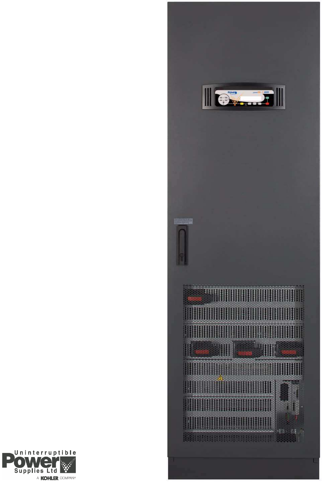
PowerWAVE
6000 Series 3
60-120 kVA
Technical Specification

2UPS766-01-00 PW6000 S3 Technical Specification Dated 20/12/14
INTRODUCTION
Continuous power availability is essential in today’s dynamic IT and process-related work environments. It is equally
important that any installed power protection system is sufficiently resilient and adaptable to handle any requirement
changes brought about by the introduction of new server technologies, migration and centralization.
Such demands are well met by the PowerWave PW6000 S3 UPS system, which provides the foundation for continuous
power availability of network-critical infrastructures both in enterprise data centres, where business continuity has
paramount importance, and in process control environments, where manufacturing continuity is essential.
Offering maximum power protection, the PowerWave PW6000 S3 has a small footprint and uses less energy than
comparable products – thus delivering significant cost savings for the user. Its exceptional design meets all the modern
requirements involved in building and operating energy-efficient and environmentally friendly centres.
The PowerWave PW6000 S3 UPS is available over a model range of 60kVA to 120kVA and can be configured to operate
as a single, stand-alone UPS or as a multi-module UPS system with up to ten UPS cabinets connected in parallel. A multi-
module configuration is generally chosen either to increase the system’s total power capacity or enhance the system’s
overall reliability by providing module redundancy.
Reliability and quality standards
Incorporating the latest technological developments in power engineering, the PowerWave PW6000 S3 represents a
completely new generation of high power three phase UPS systems; its advanced double conversion VFI (Voltage and
Frequency Independent) topology responds fully to both the highest availability and environmentally friendly requirements
compliant with IEC 62040-3 (VFI-SS-111) standards.
Uninterruptible Power Supplies Ltd specialises in the installation and maintenance of Uninterruptible Power Systems; and
this powerful UPS is just one example of our wide range of state-of-the-art power protection devices that will provide your
critical equipment with a steady and reliable power supply for many years.
Key features
High reliability, upgrade-ability, low operating costs and excellent electrical performance are just some of the highlights
afforded by this innovative UPS solution.
Other key features include:
• Compact size – the small foot print offers saving on expensive floor space
• Battery charging management and failure diagnostics – avoids premature deterioration of battery life.
• Highly flexible battery configuration which supports the usage of 42-48 (12V) battery blocks in a string – allows
battery optimization and reduces the need to oversize.
• Best in class ac-ac efficiency, up to 96% – reduces operational costs (TCO).
• Low input power factor (near unity) – results in cost savings during installation and the entire life cycle (TCO).
• Blade-server-friendly power – with full power available over a power factor ranging from 0.9 lead to 0.9 lag there is
no requirement to de-rate the UPS when supplying leading power factor loads.
• Very low input current distortion THDi of < 4.0% @ 100% load – reduces the power demanded from any connected
standby generator resulting in reduced capital and installation costs.
• Front service access – all servicing is carried out from the font of the cabinet which reduces the time needed for
maintenance.
• Cooling air exhaust through the top of the cabinet – no rear cabinet clearance is required for cooling air-flow, which
allows the cabinet to be installed directly against a wall or partition which further reduces the installation footprint.
• System expandability – up to ten UPS cabinets ca be connected as a parallel system. If fewer than ten cabinets are
initially installed, additional cabinets can be added to the system at a later time without disrupting the load.
• Integrated maintenance bypass switch.
Key Point: In a parallel system ALL the connected modules must be of the same output rating – e.g. it is not
permissible to connect 60kVA and 120kVA cabinets together in a parallel system.
UPS766-01-00 PW6000 S3 Technical Specification Dated 20/12/14 3
GENERAL SPECIFICATIONS
MECHANICAL CHARACTERISTICS 60-120kVA (No Battery Enc.)
Rating (kVA) 60 80 100 120
Dimensions (WxHxD) mm 615 x 1954 x 480
Dimensions with elevation kit (WxHxD) mm 615 x 1978 x 480
Weight (without batteries) kg 198 206 228 230
Colour Graphite Grey (RAL 7024)
Batteries Fitted internally with optional external
battery enclosure available
Input and output power cable entry Bottom with front access for connection
Exhaust cooling air Rear
SYSTEM CHARACTERISTICS
Topology On-line, double conversion, Voltage and Frequency Independent (VFI)
Technology Second generation transformerless design
Parallel configuration expansion For added redundancy and/or capacity a parallel system can be extended to
up to 10 modules on request
Double conversion AC/AC efficiency.
With fully charged battery and linear load
(PF = 1)
(Tolerance of ±0.2%)
Load 60 80 100 120
100% 95.5% 95.5% 95.7% 95.7%
75% 95.8% 95.8% 96.0% 96.0%
50% 96.0% 96.0% 96.0% 96.0%
25%. 95.0% 95.0% 95.0% 95.0%
Eco mode efficiency % > 99.0
INPUT CHARACTERISTICS 60 80 100 120
Nominal input voltage V 3x 380/220V+N, 3x 400/230V+N, 3x 415/240V+N
Input voltage tolerance (ref to 3x400/230V)
for Loads in %:
V (-23% to +15%) 3x308/177 V to 3x460/264 V for <100 % load
(-30% to +15%) 3x280/161 V to 3x460/264 V for < 80 % load
(-40% to +15%) 3x240/138 V to 3x460/264 V for < 60 % load
Input frequency Hz 35-70
Inrush current A Limited by soft start
Max. Input Power with rated output power
and charged battery (pf=1.0)
kW 64 85 105 126
Max. Input Current with rated output power
and charged battery (pf=1.0) [@400/230V]
A 92 122 152 183
Max. Input Power with rated output power
and discharged battery (pf=1.0)
kW 70 93 116 139

4UPS766-01-00 PW6000 S3 Technical Specification Dated 20/12/14
Max. Input Current with rated output power
and discharged battery (pf=1.0) @400/230V
A 101 134 167 201
Input power factor (leading) > 0.99 @100% load
Input harmonic distortion (THDi) (%) < 4% @100% load
Rated short time withstand current 10kA for 1.5 seconds
AC Power distribution system TN-S, TN-C, TN-C-S, TT
Required input connection 3 phases an neutral required
Rated short time withstand current 10kA for 1.5 seconds
BATTERY CHARACTERISTICS 60 80 100 120
Battery type Maintenance-free VRLA, vented lead-acid, NiCd
Variable number of 12V battery blocks No. 42-48
Autonomies >60 min are only available for loads < 90%.
For loads between 90-100%, the maximum allowed autonomy is 60 mins.
For autonomy's less than 20 mins UPS supports 42-50 x12 V blocks
Variable number of 1.2V NiCd cells No. 420-480
Autonomies >60 min are only available for loads < 90%.
For loads between 90-100%, the maximum allowed autonomy is 60 mins.
For autonomy's less than 20 mins UPS supports 420-500 x1.2V cells
Max. battery charger current A 37 49 61 61
Max. battery charger power kW 18 24 30 30
Battery float voltage (VRLA / NiCd) VDC 2.25 / 1.40
End of discharge voltage (VRLA / NiCd) VDC 1.65 / 1.05
Temperature controlled charger Yes (temperature sensor optional)
Ripple current (rms) % 2% of the battery capacity
Battery test Automatic and periodic (adjustable)
OUTPUT CHARACTERISTICS 60 80 100 120
Output rated power
(@min 42 battery blocks)
kVA/
kW
60/60 80/80 100/100 120/120
Load power factor rated 1.0
Nominal output current (In)
(PF=1.0) (@min 42 battery blocks)
A 87 116 145 174
Output rated voltage V 3x 380/220 or 3x 400/230 or 3x 415/250
Output waveform Sinewave with 0deg. phase imbalance @100% unbalanced load
Output voltage stability (normal/battery
mode)
% ± 1.5 / ± 1.5
Total harmonic distortion with 100% load
operating in normal mode
% < 2 with linear load
INPUT CHARACTERISTICS (Continued) 60 80 100 120

UPS766-01-00 PW6000 S3 Technical Specification Dated 20/12/14 5
Total harmonic distortion with 100% load
operating in battery mode
% < 2 with linear load
Voltage imbalance and phase displacement
with 100% load imbalance
°0°
Voltage transient and recovery time with
100% step load
%/
sec
< 4% (linear load)
Output frequency Hz 50 or 60
Output frequency tolerance % ±0.1 free-running, quartz oscillator
±2 or ±4 (selectable) with mains synchronised
Frequency slew rate Hz/s 1.0
Max synch phase error ° < 2° (referred to a 360° cycle)
Permissible unbalanced load % 100% (all 3 phases independently regulated)
Overload capability on inverter % /
min
150% load for 30 seconds
125% load for 5 minutes
110% load for 20 minutes
Inverter short circuit capability
(x rated output for 40ms)
A 2.7x 2.0x 2.3x 1.8x
Fault clearing capability (100ms) A 2x In for normal mode and battery mode
Bypass short circuit capability A 10x rated In for 10ms
Crest factor 3:1
Bypass operation V At ±15.0% of nominal input voltage
* With 50 battery blocks only
STATIC BYPASS 60 80 100 120
Transfer time ms < 1.0 Inverter to bypass
< 5.0 bypass to inverter
< 6.0 in Eco mode
Rated current A 87 116 145 174
Bypass mode fault clearing capability A 10x In for 20ms (with recommended fuses fitted)
Overload protection on bypass mode %/
min
150% load for 30 seconds
125% load for 5 minutes
110% load continuously
Maintenance bypass Fitted as standard
Bypass protection fuses or circuit breaker Not included
ENVIRONMENTAL CHARACTERISTICS 60 80 100 120
Audible noise @ 100/50% load dBA < 65 < 69
Ambient temperature for UPS °C 0-40
Ambient temperature for batteries
(recommended)
°C 20
OUTPUT CHARACTERISTICS (Continued) 60 80 100 120

6UPS766-01-00 PW6000 S3 Technical Specification Dated 20/12/14
Battery storage time at ambient temperature Maximum 6 months
Fan assisted cooling air flow Front entry, top exit
Heat dissipation with 100% linear load W 2850 3800 4750 5700
BTU/h 9730 12970 16220 19460
Heat dissipation without load W 410 530 640 640
Relative air-humidity < 95% (non-condensing)
Max altitude above sea level without derating 1000m (3300ft) without derating
De-rating factor for use at altitudes above
1000m sea level according (IEC 62040-3)
Height above sea level (m/ft)
1500 / 4850
2000 / 6600
2500 / 8250
3000 / 9900
STANDARDS
Safety IEC/EN 62040-1
Electromagnetic compatibility IEC/EN 62040-2
Performance EN 62040-3:
Product certification CE
Degree of protections IP20
Manufacturing ISO 9001:2008, ISO 14001:2004
COMMUNICATION OPTIONS
Power Management Display (PMD) LCD display and mimic diagram showing UPS operational status
Customer Interfaces: (Dry Ports) Volt-free output interface provide status and alarm outputs for remote
indication and interfacing with BMS systems.
Together with customer inputs interface for connecting an Emergency Stop,
On Generator status etc.
RS232 on Sub-D9 port For monitoring and integration in network management
RS485 on RJ45 port Remote monitoring system with graphical display (option)
RS485 on RJ45 port For multidrop purposes (option)
Slot for SNMP Card Ethernet card for monitoring and integration in network management (option)
Slot for SNMP Card USB Port and relay card. Customer outputs
ENVIRONMENTAL CHARACTERISTICS 60 80 100 120
UPS766-01-00 PW6000 S3 Technical Specification Dated 20/12/14 7
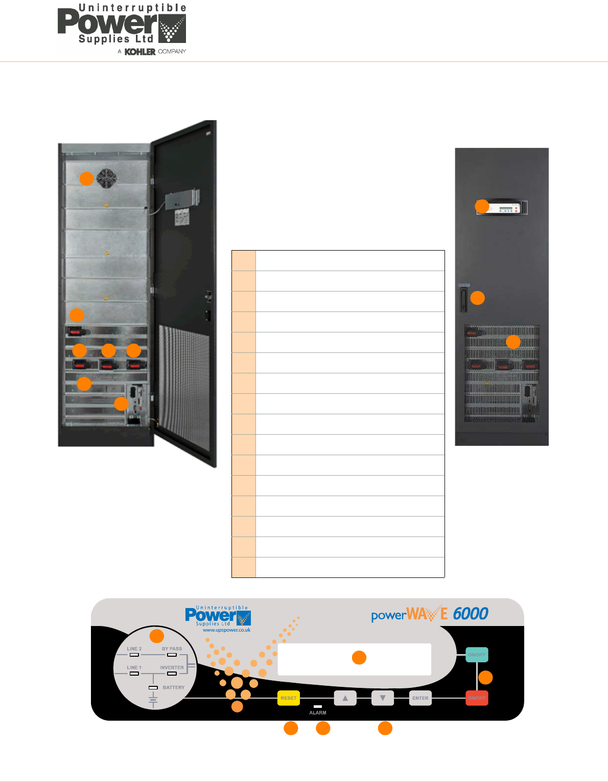
PowerWave PW6000 S3 USER CONTROLS
A
AIA1 – Maintenance bypass isolator
BIA3 – Input supply isolator
CIA4 – Bypass supply isolator
DIA2 – UPS Output (parallel) isolator
EInput/Output/Battery connections (behind cover)
FCommunications interface facilities
GCooling fan (extraction through roof)
HUPS Control panel
IKey-lockable door handle
JCooling air inlet mesh screen
KModule mimic led indicators
LAudio / Alarm reset key
MAlarm led
NMenu navigation keys
OUPS ON/OFF keys
PPower Management Display (PMD) LCD screen
B C D
F
E
G
H
I
J
K
L M N
P
O
8UPS766-01-00 PW6000 S3 Technical Specification Dated 20/12/14
UPS CONTROL PANEL
An LCD control panel located on the front of the cabinet provides the means for day-to-day UPS operation and
performance monitoring.
From the UPS control panel the operator can:
• Stop and start the UPS module
• Transfer the UPS output (load) between the inverter and bypass
• Monitor the UPS input/output voltage, current and frequency
• Monitor the battery charge discharge current and battery status
• Interact with monitored alarm and warning messages
• Configure the UPS operating parameters (service mode)
• Interrogate the UPS operating events and alarm history (service mode)
• Carry out diagnostic actions (service mode)
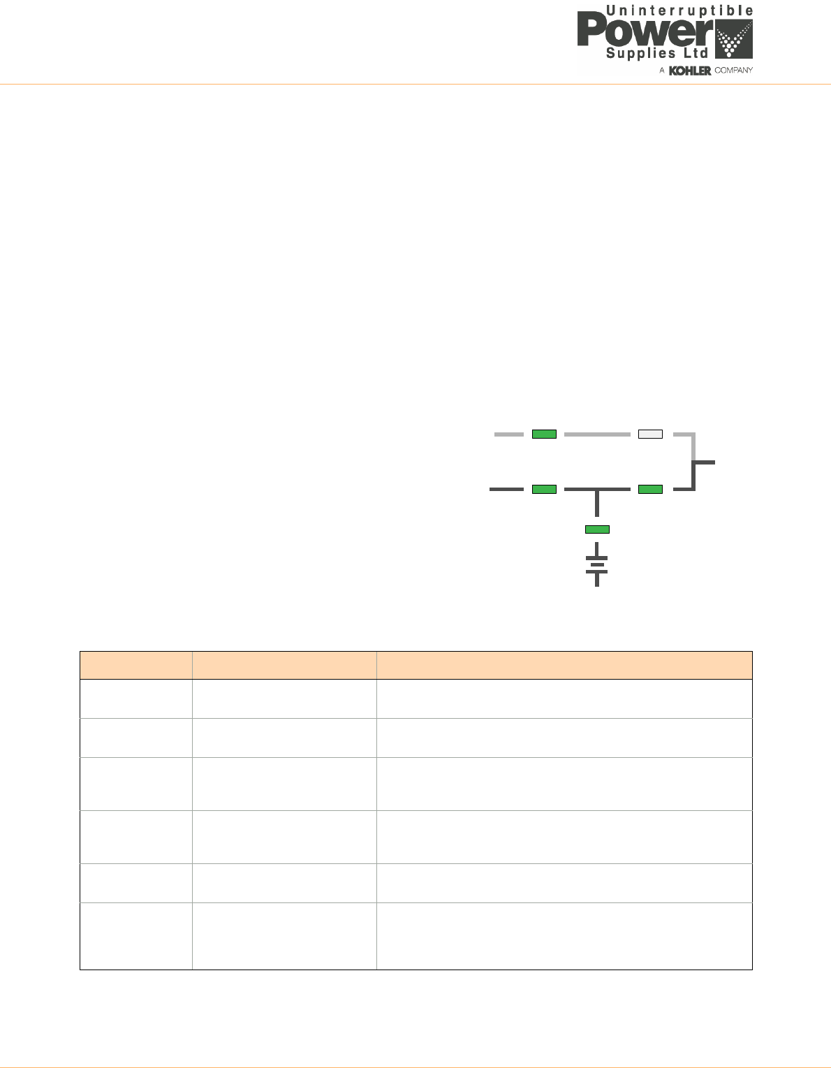
Module mimic LED indicators
The module mimic LEDs change colour between GREEN, RED and OFF
to indicate the operational status of key UPS stages and thereby serve
to show the active power path through the UPS.
•LINE 1 (rectifier) and LINE 2 (bypass) LEDs indicate the
availability of the input mains and bypass mains supplies
•INVERTER and BYPASS leds illuminate green to indicate which
of the two sources is providing the load power
•BATTERY illuminates green when the battery is being charged
and flashes when the battery is discharging – e.g. when
supplying the load following a mains failure
•ALARM provides a visual indication that an internal or external
alarm condition has been detected.
When activated, it is accompanied by an audible alarm
LED Indication summary
INDICATOR STATUS INTERPRETATION
LINE 1 GREEN
RED
Input mains available
Input mains not available
LINE 2 GREEN
RED
Bypass mains bypass OK
Bypass mains not OK or not present
ALARM OFF
Flashing RED + buzzer
RED
No alarm condition
Alarm condition needs attention
Alarm condition accepted (audible alarm has been reset)
INVERTER GREEN
RED
OFF
Load on inverter
Inverter fault
Inverter not operating
BY-PASS GREEN
OFF
Load on bypass
Bypass not operating
BATTERY GREEN
RED
Flashing RED
Flashing GREEN
Battery OK
Battery fault or discharged
Battery fuses blown
On Battery mode (battery supply the load and discharging)
LINE 1
LINE 2 BY PASS
INVERTER
BATTERY
LOAD
UPS766-01-00 PW6000 S3 Technical Specification Dated 20/12/14 9
Operator keys
The operator keys allow the user to:
• Set operating parameters and make adjustments via the menu-driven LCD display
• Start and stop the UPS, and transfer the load between inverter and bypass
• Select the UPS operating voltages, currents, frequencies and other parameters to monitor on the LCD display
Key function summary
ON/OFF keys
The UPS can be switched ON or OFF by simultaneously pressing both ON/OFF keys on the UPS control panel. The
requirement to press both buttons is to help avoid accidental operation.
During normal operation, pressing the two ON/OFF buttons simultaneously will immediately turn off the UPS.
• In a single module installation this will disconnect the UPS output unless the load is first transferred to the
maintenance bypass
• In a parallel module system the UPS module will shutdown and its output will be disconnected from the parallel
load bus. However, the load may or may-not transfer to bypass depending on whether or not the number of
remaining live modules satisfies the system’s redundancy – i.e. if there are a sufficient number of modules
remaining to support the system load then the load will not be transferred.
To shut down all the modules in a parallel system you must press both ON/OFF buttons on every module.
Reset key
If the module experiences a fault, or encounters an abnormal situation, the event is logged and displayed on the LCD
display, the ALARM led turns red and an audible alarm sounds. Pressing the RESET button accepts the alarm and resets
the audible warning but the ALARM led will remain illuminated if the fault condition still exists.
Power Management Display (PMD)
The 2 x 20 character LCD Power management display simplifies communication with the UPS and provides a range of
information concerning the module’s operating status and configuration data, including:
• Event register
• Input and output voltage, current, frequency and power
• Battery run time
• Load transfer from inverter to bypass and vice-versa
• Diagnostic configuration, adjustments and testing (service mode)
• Menu navigation and selection is carried out using the UP, DOWN and ENTER keys
KEYS FUNCTION
ON/OFF
ON/OFF
Used to switch-on or switch-off the UPS
UP )Scroll upwards through a displayed menu
DOWN ( ) Scroll downwards through a displayed menu
RESET Cancels the audible alarm.
ENTER Confirms (selects) a chosen menu item
10 UPS766-01-00 PW6000 S3 Technical Specification Dated 20/12/14
CUSTOMER INTERFACE OPTIONS
Introduction
Each UPS is fitted with a communication interface board which enables various external monitoring and control
applications to be connected to the UPS system to satisfy a particular site’s requirements.
Two leds (D) are located on the communications interface board to indicate its status:
• The green led indicates the UPS cabinet’s master/slave status (only one cabinet can be ‘master’).
– flashing twice/sec = interface is master (1st cabinet of a parallel system).
– flashing once/sec = Interface is slave (2nd,.. 10th cabinet of a parallel system).
• The red led signifies a board malfunction and possibly needs replacement
B
C
D
F
G
A
ASLOT 2 – for optional USB and Relay card.
This card provides UPS/MAINS status monitoring via
volt-free relay contacts.It also provides a USB port which
can be used as an alternative RS232 output to
communicate with a remote computer.
BSLOT 1 – for optional SNMP card.
CJD1 – RS232 Communications for computer interface.
DCommunications interface board operations status leds
EX1 – Customer control inputs
FSW2 – Multidrop configuration DIP switch
GMULTIDROP – JR45 multidrop cable connection
E
UPS766-01-00 PW6000 S3 Technical Specification Dated 20/12/14 11
Customer inputs (X1)
Terminal bock X1 provides a range of standard input interfaces that can be used by the customer as required. All
connections are made to Phoenix spring terminals using wires up to 1.5 mm².
Customer outputs (+USB)
The customer output interfaces are on an optional relay card which can be fitted to Slot 2 on the communications interface
board. The relay card contains 5 relay-switched, volt-free changeover outputs that can by connected to the external site
monitoring/ BMS facilities. The relays are rated at 60VAC and 500mA and the connections are made to Phoenix spring
terminals using wires up to 1.5 mm².
Terminal Contact Signal Function
X1 X1/10 Gnd Gnd +12Vdc Power source (max 200mA)
X1/9 In +12Vdc
X1/8 Gnd Gnd REMOTE SHUTDOWN (Emergency Power Off)
(Do not remove the factory-fitted bridge if this
feature is not used)
X1/7 In +12Vdc
X1/6 Gnd Gnd BATTERY TEMPERATURE SENSING
(If connected this input is battery temperature
dependent)
X1/5 In +3.3V
X1/4 Gnd Gnd CUSTOMER SPECIFIC INPUT
(Function on request to be defined)
X1/3 In +12Vdc
X1/2 Out Gnd GENERATOR OPERATION
(NC = Generator on line)
X1/1 Gnd +12Vdc
Terminal Contact Signal Display Function
X1 X2/15 Com ALARM COMMON_ALARM Common
X2/14 N/C No Alarm Condition
X2/13 N/O Common Alarm (system)
X2/12 Com MES-
SAGE
LOAD_ON_MAINS Common
X2/11 N/C Load On Inverter
X2/10 N/O Load On Bypass (mains)
X2/9 Com ALARM BATTERY_LOW Common
X2/8 N/C Battery OK
X2/7 N/O Battery Low
X2/6 Com MES-
SAGE
LOAD_ON_INV Common
X2/5 N/C Load On Bypass (mains)
X2/4 N/O Load On Inverter
X2/3 Com ALARM MAINS_OK Common
X2/2 N/C Mains Failure
X2/1 N/O Mains Present
1
15
X2
USB
12 UPS766-01-00 PW6000 S3 Technical Specification Dated 20/12/14
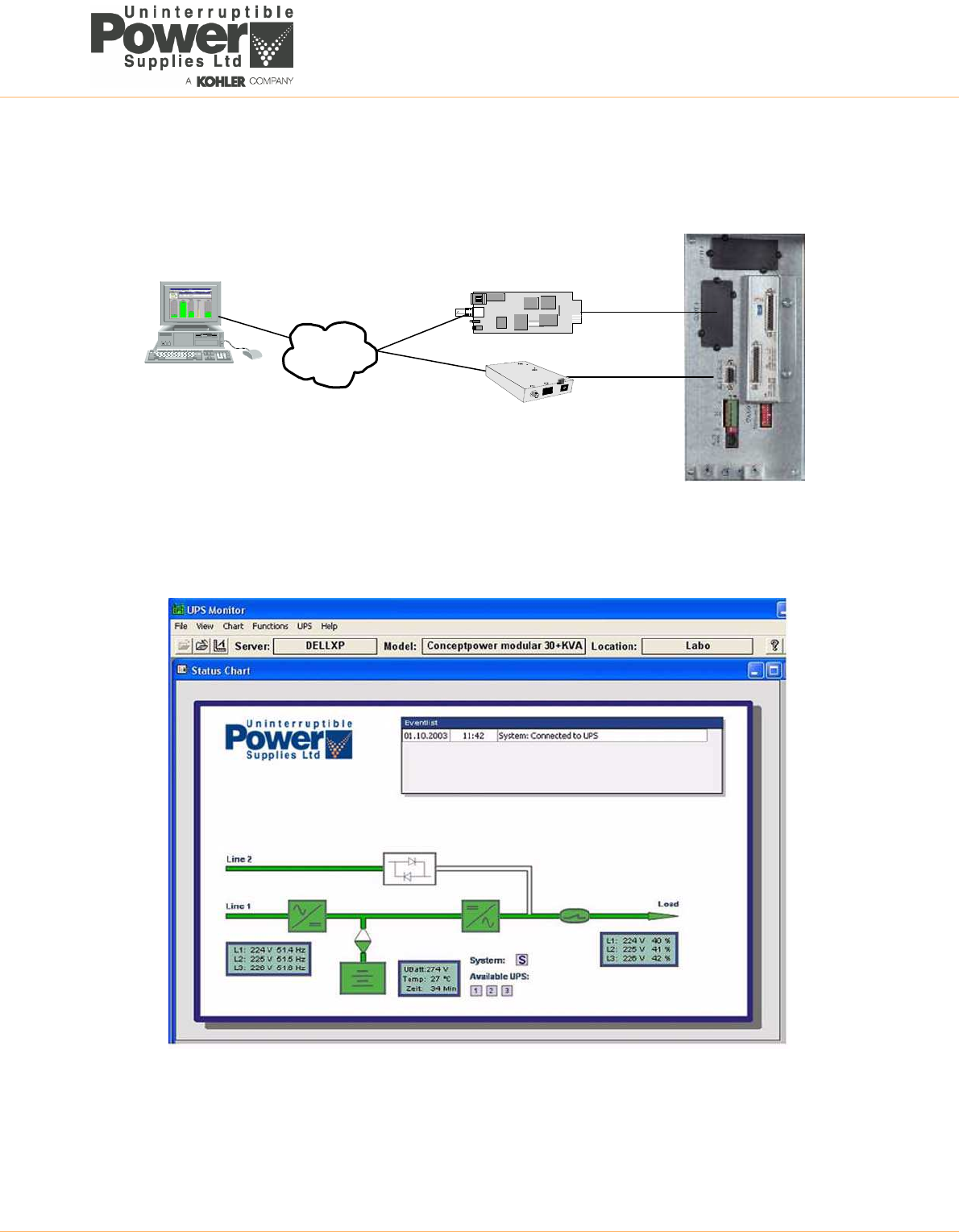
Serial RS232 Computer interface – USB & JD1 (Smart Port)
A serial RS 232 interface, which allows the UPS to be connected to a computer, is available through a standard 9-pin D-
Type female socket (JD1) or via the USB port on the optional relay card fitted to Slot 2. Only one communication port can
be active at a time and the priority is given to the USB port.
When appropriate power management software, such as WAVEMON, is installed, the computer can continuously monitor
the input mains voltage and UPS status, and display a message in response to any UPS system changes.
USB Port
The USB port is compliant with USB 1.1 protocol and can be connected to a computer using the cable provided.
JD1 RS232 Port
JD1 is a standard 9-pin D-Type female socket which provides an intelligent RS-232 serial port. Note that the maximum
length for the interconnecting RS232 cable is 15m.
RS485 Interface for multidrop
Multidrop cables are connected between the modules in a parallel system to enable
the system and individual modules to be remotely monitored over ethernet. The cables
(supplied) are terminated with RJ45 plug connectors that fit into the multi-drop socket
on the communications interface board. An RJ45 splitter plug (supplied with the fitting
kit) is required when fitting the cables to the ‘middle’ cabinets.
SNMP Card slot
Simple Network Management Protocol (SNMP) is a world-wide, standardised communication protocol that can be used to
monitor any network-connected device via a simple control language and display the results in an application running
within a standard web browser.
The PowerWave PW6000 S3 contains an SNMP slot (SLOT 1) which is designed to house a Modem/Ethernet SNMP
adapter card. Alternatively, SNMP connectivity can also be implemented using an external SNMP adapter connected to
the UPS RS232 output (JD1).
The SNMP/Ethernet adapter contains an RJ-45 connector which allows it to be connected to the network using a standard
network cable. Once connected, the UPS-Management software agent, which is already installed in the SNMP adapter,
then monitors the UPS operating parameters and communicates the operating data to the connected PC. In a multi-
module UPS system the SNMP interface can communicate ‘system-wide’ data or data for an individual UPS module.
Pin Signal Description I/O
2 TXD Transmit to external device Output
3 RXD Receive from external device Input
5 GND Ground (tied to chassis) Input
UPS766-01-00 PW6000 S3 Technical Specification Dated 20/12/14 13
The SNMP card enables event/alarm emails, server shutdown (with optional licenses) and other tasks. The SNMP card
can also be integrated with BMS software over a local area network (LAN) for SNMP or Modbus information over IP. An
optional card enables Modbus comms over RS485.
WAVEMON SHUTDOWN AND MONITORING SOFTWARE (INSTEAD OF SNMP CARD)
WAVEMON is designed to operate in conjunction with many of the systems supplied by Uninterruptible Power Supplies
Ltd and features both UPS monitoring and automatic UPS/server shutdown facilities.
WAVEMON comprises a bespoke software package which is installed on a local PC and communicates with the UPS via
the customer interface contacts (X1-X2), optional USB port or the standard RS232 port (JD1) using a serial cable of up to
15m in length. The facilities afforded by this software can be viewed as an alternative to that offered when using the SNMP
adaptor card option, and it is only required when an SNMP card or adapter box is not purchased.
UPS Communications
ETHERNET
SNMP Card
External SNMP
Adaptor
Slot 1
RS232 (JD1)
Interface Board

14 UPS766-01-00 PW6000 S3 Technical Specification Dated 20/12/14
The main features of WAVEMON are:
• On-screen autonomy time/battery time countdown.
• On-screen server log-off and shutdown procedure.
• Time and date stamp event log.
• Extensive logging of all UPS activity and power quality data.
• Permits alarm warnings to be monitored remotely via email.
• Scheduled UPS service mode and other systems status.
• Graphical user interface for Windows-compatible platforms.
• Automatic unattended local shutdown.
• Special modules for MS-Office software to close and save open documents.
• Compatible with all optional modules like UPSDIALER, SNMP adaptors, temperature sensors, etc.
Functional description
WAVEMON is a client/server software application for networks and local workstations. In general, it consists of two parts:
the server module of the UPS management software is UPSMAN, which communicates with the UPS via an RS232/USB
interface. Running as a background application, UPSMAN collects and interprets the messages received from the UPS
and places them at the disposal of the client module UPSMON, as well as any connected SNMP-based instrumentation
and control system.
If UPSMAN detects voltage variations or a power failure, it can execute various ‘system event’ routines, by means of
which, for example, the server is switched off or a warning/alarm is sent to the connected users. These ‘system event’
routines are a part of the management software and can be configured in to suit local application requirements.
The software of your PowerWave PW6000 S3 UPS unit can be integrated into a network in two ways:
1. By the server which is supplied by the UPS itself and has been integrated into the network. In most cases this server
is used as a sub-agent and you only need the WAVEMON software (without an SNMP adapter). You will also need to
establish an RS232/USB connection between the UPS and computer/server.
2. In many cases the use of what is referred to as an ‘SNMP adapter’ is to be preferred in order to integrate the UPS into
the network. In this case up to 50 computers can be shut down in one RCCMD environment. RCCMD (remote console
command) is an additional software module that is used in order to execute a command (typically a shutdown
command) in a remote system.
Licensing
A licence is issued with every software serial number for use of what is known as the ‘UPS service’ on a single server in
connection with one UPS and an unlimited number of connected WINDOWS workstations. For operation with two or more
servers, a further licence is required for each additional server. In this case it is of no importance whether the UPS service
on these servers is active or whether the server was stopped by a remote UPS service. The same applies to the use of
RCCMD with the ‘remote send/receive’ modules for ‘multi-server shutdown’ under NT, UNIX and other operating systems.
The service programs are generally supplied as single licences. In order to use a single CD-ROM for several ‘multi-server
shut-down’ units you must acquire additional licence codes.
RCCMD Server shutdown
In order that remote shutdown of servers can take place, initiated by the SNMP card or WAVEMON software, further
licenses must be purchased. The license is for the RCCMD client (or listening) software that resides in each target server.
PowerREPORTER™ MANAGEMENT SOFTWARE
PowerREPORTER is a remote monitoring and management service which provides peace-of-mind protection by offering
a continuous (24/7/365) watch over mission-critical facilities. Continuous monitoring is an affordable insurance policy to
detect issues and provide an early warning before they develop into a crisis.
The main features and benefits offered by PowerREPORTER are:
• Real time email notification sent directly to UPSL Service Centre in response to alarm/critical events.
• Acquisition of key performance data and productivity information. Empowers you with the details needed to better
understand machine performance and quickly troubleshoot downtime events.
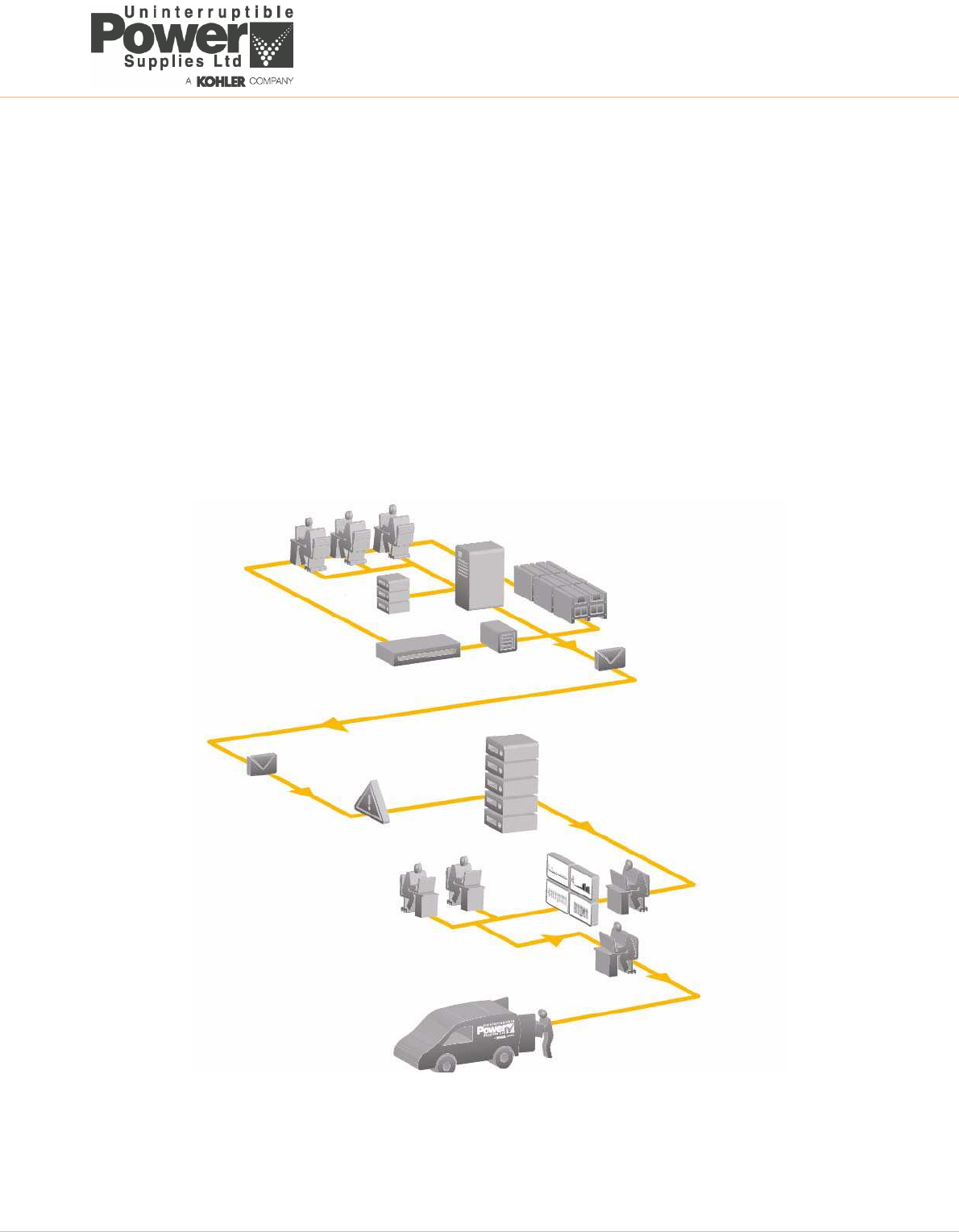
UPS766-01-00 PW6000 S3 Technical Specification Dated 20/12/14 15
• Combined with a service contract, PowerREPORTER improves service levels. The engineer can determine if site
attendance is necessary and bring relevant spare parts.
• Monthly Status Report detailing trends and alarms.
• Optional battery analysis and care service; PowerNSURE - measures battery voltage, temperature, impedance
and prolongs battery service life through the application of battery charge equalization.
Functional description
PowerREPORTER communicates constantly with your UPS system in order to automatically detect any error or alarm
messages. In the event of an incident being detected, PowerREPORTER automatically connects with UPS Limited
Service Centre via an email, transmitting a status message.
The email, which provides details relating to the fault, a snapshot of the UPS performance parameters and a device
identification string, is automatically processed and UPS Limited Service Centre personnel are alerted.
UPS Limited Service Centre personnel are then able to liaise with the company's field service team and will remotely
diagnose the UPS incident before reaching the facility with appropriate spare parts within the contracted service
agreement time-frame.
PowerREPORTER operation
UPS
Server
UPS with
Power REPORTER
Batteries
Email
Battery Care
System
Site manager
UPS Email
server
Alarm Event Data
& monthly report
Servers with
Power REPORTER
software
Consultant
UPSL 24Hr Analyst
Service
co-ordinator
UPS Service
Engineer
Helpdesk
specialists
16 UPS766-01-00 PW6000 S3 Technical Specification Dated 20/12/14
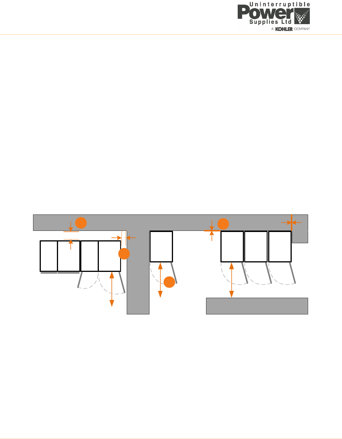
PLANNING THE INSTALLATION (SITE CONSIDERATIONS)
A certain amount of pre-planning will help ensure a smooth and trouble-free installation of the UPS system. The following
guidelines should be taken into account when planning a suitable UPS location and operating environment.
1. The route to the installation location must allow the equipment to be transported in an upright position.
2. The floor at the proposed installation site and en-route from the off-loading point must be able to safely take the weight
of the UPS and battery equipment plus the fork lift during transit.
3. Locations with high ambient temperature, moisture or humidity must be avoided.
a) The installation site humidity should be <95% non-condensing.
b) The prescribed ambient temperature is 0°C to +40°C. An ambient temperature of 20°C to 25°C is recommended
to achieve a long battery life.
c) The prescribed cooling air flow must be available. The air entering the UPS must not exceed +40°C.
d) The air conditioning system must be able to provide a sufficient amount of cooling air to keep the room within the
prescribed temperature range.
4. The following environmental conditions should also be considered:
a) Fire protection standards must be respected.
b) The location must be free of dust and corrosive or explosive gases.
c) The location must be vibration free.
d) If the UPS is located in bayed enclosures, partition walls must be installed.
e) The available space must permit the minimum cabinet clearances shown below.
Clearances
The above diagram illustrates the space requirements when installing a single or multi-module PowerWave PW6000 S3
system, with or without an adjacent battery cabinet(s). All cables enter the UPS via the bottom of the cabinet and no side
or rear access is required for service or installation. All cabinets are force-ventilated by top-mounted extraction fans which
require a minimum of 400mm space at the top of the cabinet to allow adequate exhaust air flow.
A minimum of 1000mm clearance is required at the front of the cabinets for service access (C), and where possible this
should be increased to allow safe passage in front of the UPS with the doors open.
The cabinet(s) do not rear or side clearance (D). However, it is necessary to open the door by slightly more than 90º to
gain access to some components, so if the cabinet is located adjacent to a partition or wall that extends beyond the front
of the cabinet (B) a side clearance of 50-100mm (B) should be provided between the cabinet and the partition/wall to allow
the doors to open adequately. Note that if this is not possible the doors have been designed to be easily removable to aid
the required internal access.
If a battery cabinet forms part of the UPS suite it is normally situated immediately adjacent to the UPS cabinet and
requires a minimum rear clearance of 100mm to allow adequate ventilation (A).
> 100mm
> 100mm
0mm
50-100mm
> 100mm
> 100mm
UPS
CAB
UPS
CAB
UPS
CAB
UPS
CAB
UPS
CAB
UPS
CAB
BATT
CAB
BATT
CAB
0mm
C
B
AD
UPS766-01-00 PW6000 S3 Technical Specification Dated 20/12/14 17
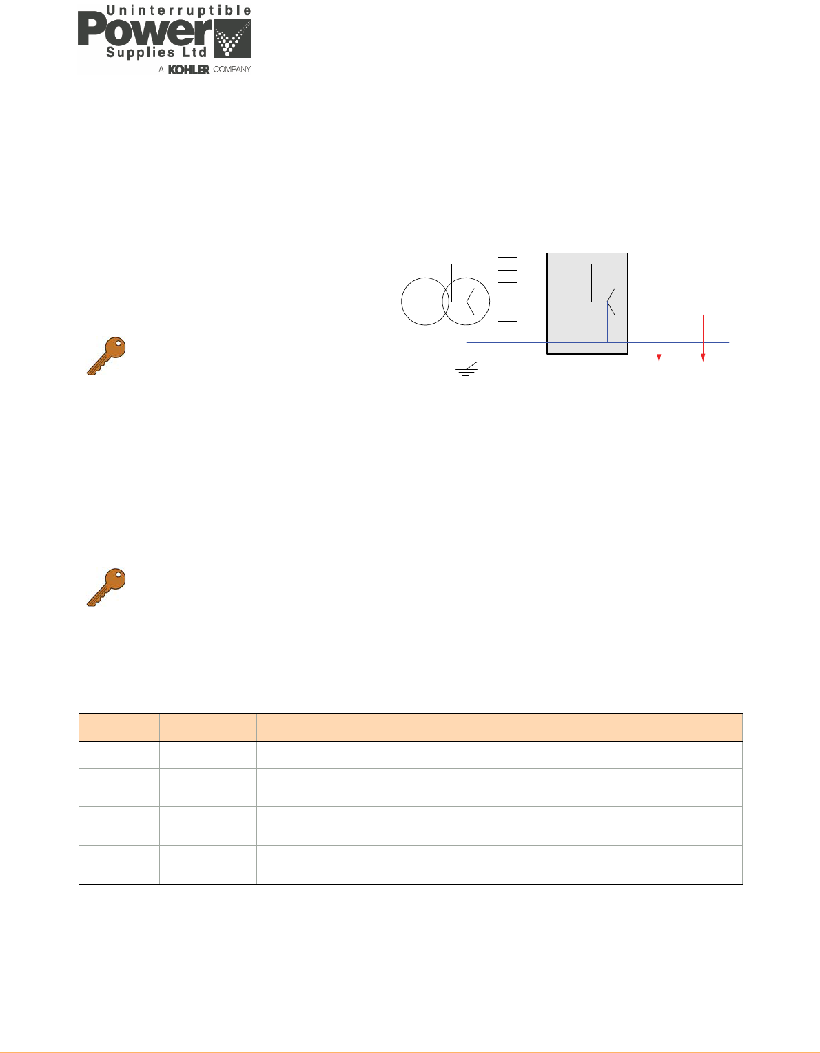
PLANNING THE INSTALLATION (CABLING CONSIDERATIONS)
The UPS input and bypass terminals should be connected to the utility mains supply through a suitable LV-Distribution
board containing a circuit breaker or fused isolator to provide suitable overload protection and a means of isolating the
UPS from the mains supply when required. Similarly, the UPS output supply terminals should be connected to the load
equipment via a suitably fused load distribution board.
Input neutral grounding
A permanently connected input neutral is required to
enable the rectifier to operate correctly and allow the
UPS to function properly when operating on battery. The
input neutral must also be grounded to permit correct
operation when the UPS is running on battery.
Cable and fuse sizing
Single feed / Dual feed inputs
The UPS can be wired for a ‘single feed’ input (standard), whereby the UPS input mains terminals and bypass mains
terminals are internally linked; or it can be wired for a ‘dual feed’ input, where the UPS bypass mains terminals are
connected to a dedicated bypass supply.
Both configurations are shown on pages 18 (single feed) and 19 (dual feed) together with details of the recommended
fuse and cable ratings.
Battery fuses and cables
Battery fuses and cables are bespoke to the installation. The following table is given for guidance only.
Key Point: As the input neutral must be
unswitched and connected to the UPS at all
times, a 4-pole input switch or isolator must
not be used at the LV Distribution board on a
TN-S system.
Key Point: The information on pages 18 and 19 is provided for guidance only:
• Fuse and cable recommendations are to IEC 60950-1:2001.
• All external fuses, isolators and power cables must be rated and installed in accordance with the
prescribed IEC standards or local regulation – e.g. BS7671:2008.
• External DC Cables and battery fuses are bespoke to the installation.
Power (kVA) Fuse E (gl/CB) Cable E (Qty x mm²)
60 2x 160A 2x (1x 50)
80 2x 200A 2x (1x 95) for 42-45 battery blocks
2x (1x 70) for 46-50 battery blocks
100 2x 250A 2x (1x 120) or 2x (2x 50) for 42-45 battery blocks
2x (1x 95) for 46-50 battery blocks
120 2x 300A 2x (1x 150) or 2x (2x 50) for 42-45 battery blocks
2x (1x 120) or 2x (2x 50) for 46-50 battery blocks
0V 230V
UPS
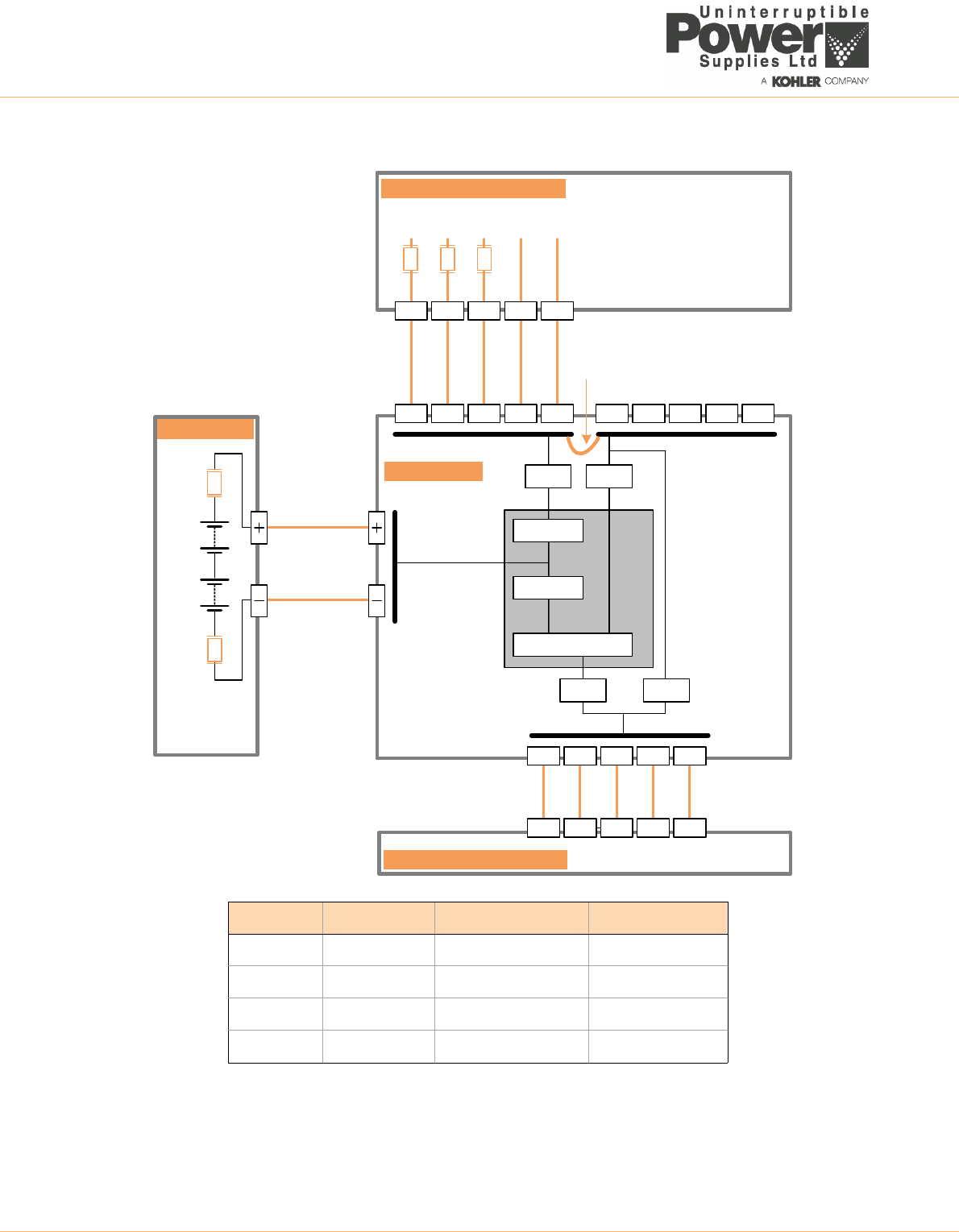
18 UPS766-01-00 PW6000 S3 Technical Specification Dated 20/12/14
Single feed input fuse and cable ratings
CableE
FuseE
Rectifier
Inverter
StaticSwitch
IA2
FuseA
CableD
CableA
MainsSupply(3x380/400/415)
IA1
Maint.
Bypass
1L3 1N PE1L1 1L2 2L3 2N PE2L1 2L2
3L3 3N PE3L1 3L2
L3 NPEL1 L2
UPSCABINET
MAINSDISTRIBUTIONBOARD
UPSMAINSSUPPLY
BATTERYCAB
LOADDISTRIBUTIONBOARD
L3 NPEL1 L2
StaticBypassLine
IA3 IA4
SingleFeed
LinkCables
IMPORTANT NOTE: The UPS does not contain internal fuses to protect the bypass and rectifier mains inputs. It is the customer’s
responsibility to ensure the UPS external supply fuses (or other devices) are correctly sized to provide the recommended level of UPS
protection. We also recommend that a spare set of fuses are held locally to ensure they are easily available if required.
Power (kVA) Fuse A (gl/CB) Cable A (Qty x mm²) Cable D (Qty x mm²)
60 3x100 5x35 5x35
80 3x125 5x50 5x50
100 3x160 5x50 5x50
120 3x200 5x70 5x70
UPS766-01-00 PW6000 S3 Technical Specification Dated 20/12/14 19
Dual feed input fuse and cable ratings
CableE
FuseE
Rectifier
Inverter
StaticSwitch
IA2
FuseB
CableD
CableB
MainsSupply(3x380/400/415)
IA1
Maint.
Bypass
1L3 1N PE1L1 1L2 2L3 2N PE2L1 2L2
3L3 3N PE3L1 3L2
L3 NPEL1 L2
UPSCABINET
MAINSDISTRIBUTIONBOARD
UPSMAINSSUPPLY
BATTERYCAB
LOADDISTRIBUTIONBOARD
L3 NPEL1 L2
FuseC
CableC
MainsSupply(3x380/400/415)
L3 NPEL1 L2
UPSBYPASSSUPPLY
StaticBypassLine
IA3 IA4
IMPORTANT NOTE: The UPS does not contain internal fuses to protect the bypass and rectifier mains inputs. It is the customer’s
responsibility to ensure the UPS external supply fuses (or other devices) are correctly sized to provide the recommended level of UPS
protection. We also recommend that a spare set of fuses are held locally to ensure they are easily available if required.
Power (kVA) Fuse B (gl/CB) Cable B (Qty x mm²) Fuse C (gl/CB) Cable C (Qty x mm²) Cable D (Qty x mm²)
60 3x100 5x35 3x100 5x35 5x35
80 3x125 5x50 3x125 5x50 5x50
100 3x160 5x50 3x160 5x50 5x50
120 3x200 5x70 3x200 5x70 5x70
20 UPS766-01-00 PW6000 S3 Technical Specification Dated 20/12/14
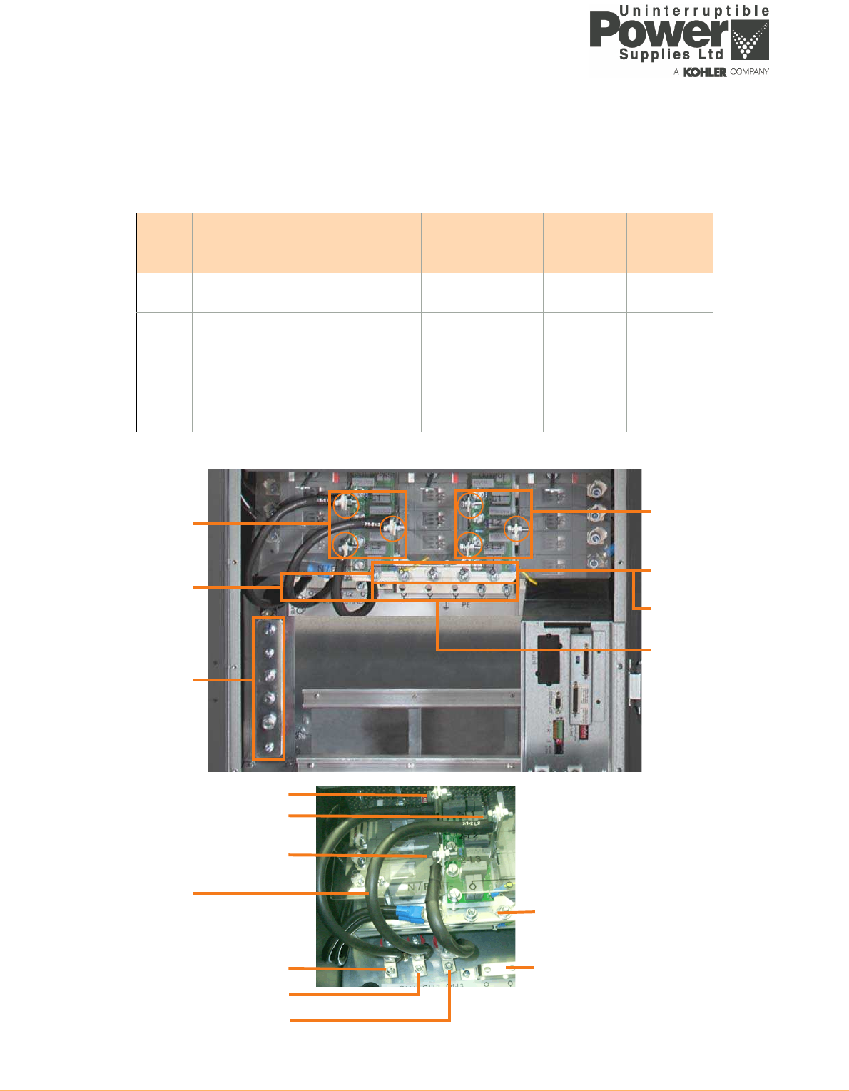
Power cable termination details
All the UPS input/output power cables are bolted to busbar terminals as illustrated below. The table below details the
maximum size of the cable terminations and the correct torque that should be applied to the termination bolts.
UPS Power terminals
Mains Input
(3+N+PE)
Bypass Input
(3+N)
UPS Output
(3+N+PE)
Battery,
Neutral, PE
Tightening
Torque (Nm)
60kVA 2x M8 1x M8 2x M8
1x M10
5x M8 12.3 (M8)
25.1 (M10)
80kVA 2x M8 1x M8 2x M8
1x M10
5x M8 12.3 (M8)
25.1 (M10)
100kVA 2x M8 1x M8 2x M8
1x M10
5x M8 12.3 (M8)
25.1 (M10)
120kVA 2x M8 1x M8 2x M8
1x M10
5x M8 12.3 (M8)
25.1 (M10)
Bypass Supply
(2-L1, 2-L2, 2-L3)
Input Supply
(1-L1, 1-L2, 1-L3)
Battery Positive
(BATT+)
UPS Output
(3-L1, 3-L2, 3-L3)
Neutral
Battery Negative
(BATT-)
Protective Earth
(PE)
(1-N, 2-N, 3-N)
(2-L1)
(2-L2)
(2-L3)
Single Feed Input
(1-L1)
(1-L2)
(1-L3)
Links (x3)
Neutral / BATT-
Protective Earth
UPS766-01-00 PW6000 S3 Technical Specification Dated 20/12/14 21
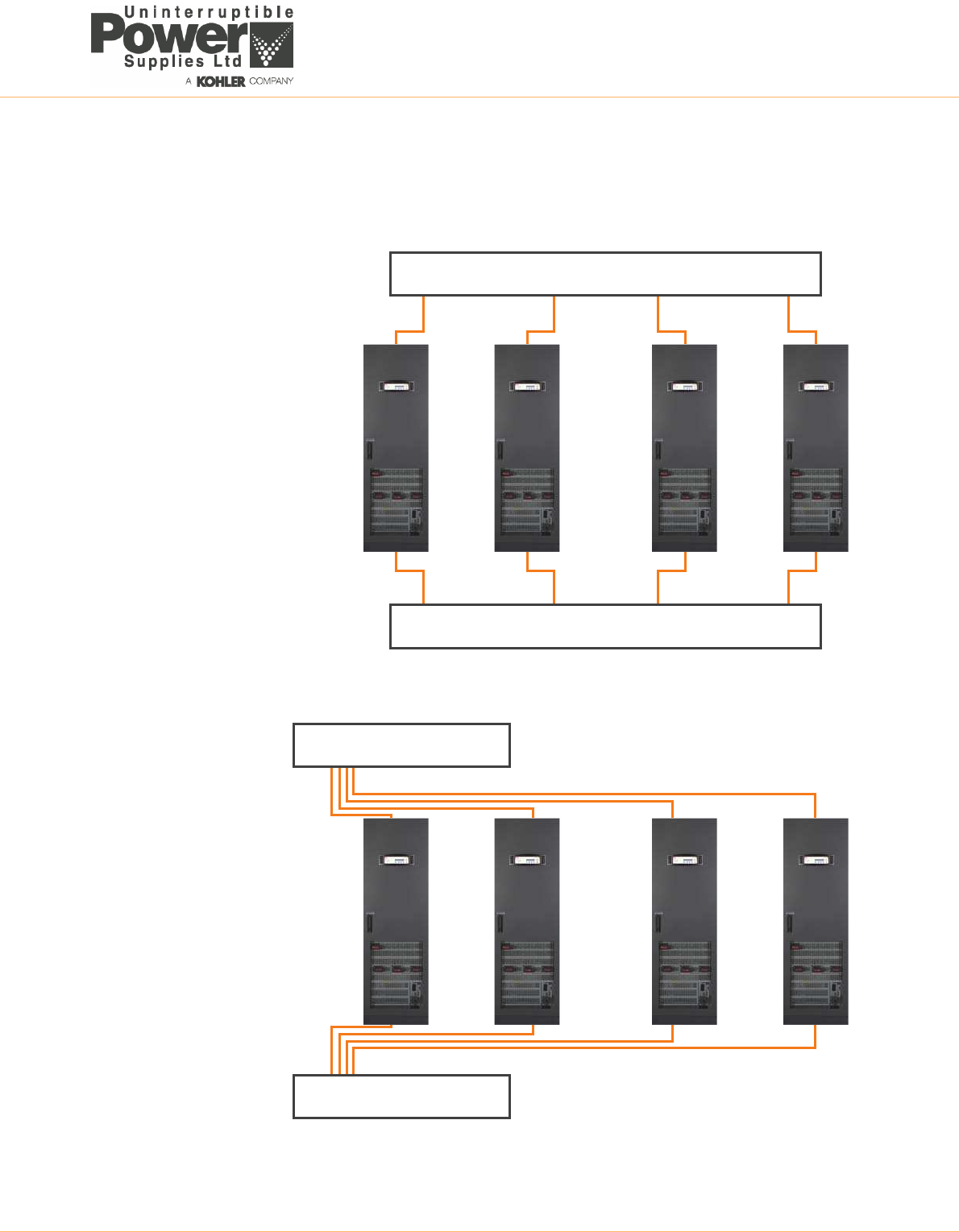
Power cabling in a parallel system
In order to achieve equal load sharing between the various UPS cabinets in a multi-cabinet installation, the input cables
from the mains distribution board to each UPS cabinet should be of equal length. Similarly the UPS output cables to the
load distribution board should be of equal length.
Mains distribution board
Load distribution board
Mains distribution board
Load distribution board
CORRECT
INCORRECT

22 UPS766-01-00 PW6000 S3 Technical Specification Dated 20/12/14
