The UPS Handbook Issue Digital Copy UPSL
UPS-Handbook-Issue_d.. UPS-Handbook-Issue_digital-copy-UPSL
User Manual: UPS-Handbook-Issue digital-copy-UPSL
Open the PDF directly: View PDF ![]() .
.
Page Count: 355 [warning: Documents this large are best viewed by clicking the View PDF Link!]
- Foreword
- 1 Introduction
- 2 Why do I Need a UPS?
- 3 What is a UPS?
- 4 UPS Topologies
- 5 Major UPS Components
- 6 Transformerless UPS Systems
- 7 Parallel UPS Systems
- 8 Energy Storage Devices
- 9 Generators
- 10 UPS Communications
- 11 Planning a UPS Installation
- Introduction
- Sizing and Selecting the Correct UPS
- Choosing a UPS Topology
- Reliability Considerations
- Availability Considerations
- Environmental Considerations
- Total Cost of Ownership
- Installing the UPS
- Delivery and Positioning
- Electrical Installation
- Commissioning
- Sample Commissioning Method Statement
- General Instructions
- Customer Information
- Unit Information
- Equipment Inspection
- Installed Options
- Installation Checks
- UPS Power Up
- Operator Training
- Responsible for Operation and Maintenance
- Notes
- Signatures
- Micro and Mini UPS (250VA - 2kVA)
- Medium UPS (3-20kVA)
- Large UPS (30-400kVA and above)
- Load Bank Testing
- Three Phase UPS Supporting Single Phase Loads
- Installation Drawings
- Using and Maintaining the UPS
- Summary
- 12 System Maintenance
- Introduction
- Emergency Call-out Facilities
- Maintenance and Testing
- Sample Service Agreement
- 13 Applicable Standards
- 14 Glossary of UPS Terminology
- AC - Alternating Current
- Amp or Ampere
- Autonomy
- Blackout
- BMS
- Brownout
- Bunding
- Bypass
- Capacitance
- Circuit Breaker
- Clamping Level
- Clamping Time
- Common Mode Noise
- Crest Factor
- Current
- Current Limit
- DC - Direct Current
- Differential Mode Noise
- Dip
- Distortion
- EMI - Electro-Magnetic Interference
- Ferroresonance
- Ferroresonant Transformer
- Filter
- Float Charging
- Fuel Cell
- Ground Fault
- Harmonic
- Harmonic Distortion
- Hertz or Hz
- Hot-Scalable
- Hot-Swappable
- IGBT - Insulated Gate Bipolar Transistor
- Inductance
- Inrush Current
- Inverter
- Isolation
- Joules
- kVA
- Load
- MOV - Metal Oxide Varistor
- Noise (Electrical)
- Overvoltage
- Phase
- Power Factor
- PWM - Pulse-Width Modulation
- Rectifier/Charger
- Regulation
- RFI - Radio-Frequency Interference
- RMS - Root Mean Square
- RS-232
- Sealed Lead-Acid Battery
- Sinewave
- Slew Rate
- SNMP
- Static Switch
- Stratification
- Surge
- Switching Time
- THDi
- Three Phase
- Total Harmonic Distortion
- Transfer Time
- Transformer
- Transient
- Transverse Mode Noise
- Undervoltage
- UPS - Uninterruptible Power Supply
- VA
- Volt
- Volt-Ampere
- Voltage Regulator
- VRLA - Valve Regulated Lead Acid Batteries
- Watts
- Waveform
- 15 Further Reading
- 16 Sample UPS Specifications
- Introduction
- 7.5 - 12 kVA, single-phase input and output 7.5 - 20kVA, 3-phase input, single-phase output
- 10- 50 kVA, 3-phase input and output
- 40- 200 kVA 3-phase modular system
- 25- 250 kVA 3-phase modular system
- 60, 80, 100kVA 3-phase input and output
- 120, 160, 200, 250, 300kVA, 3-phase input and output
- 400, 500kVA 3-phase input and output
- 100- 500 kVA 3-phase modular system
- Introduction
Edited by
Kenny Green & Mike Jackson
TheUPSHandbook
UninterruptiblePowerSuppliesLtd,AKohlerCompany
Allrightsreserved.Nopartofthispublicationmaybeproduced,storedinaretrievalsystem,ortransmittedinany
formorbyanymeans,electronicormechanical,photocopying,recording,orotherwisewithouttheprior
permissionofthepublisher.
Warning:Thedoingofanunauthorisedactinrelationtoacopyrightworkorwhichamountstothecolourably
similaruseofthetitlemayresultinlegalproceedingsfordamagesand/oraninjunction.
©UninterruptiblePowerSuppliesLimited,AKohlerCompany.
ISBN9780953839834
PublishedinOctober2013–4thedition
UKPublisher:UninterruptiblePowerSuppliesLimited
Forfurtherinformation: UninterruptiblePowerSuppliesLimited
Woodgate,
BartleyWoodBusinessPark
Hook
BerkshireRG279XA
Telephone:01256386700
Fax:01256386701
Email: sales@upspower.co.uk
Theauthorswouldliketoacknowledgethevaluableassistancegivenby:
YuasaBatterySalesUKLtd
AdvancedBatteryCareLtd
MikeElms
PeterBentleyIEngMIEE
AdrianOrr
Intheproductionofthishandbook.

TheUPSHandbook
Editedby:KennyGreenBSc(Hons)ARCSAMInstP
MikeJackson


The UPS Handbook i
Foreword
The UPS Handbook - Fourth Edition
In 2000, UPSL, a Kohler company, published the highly respected UPS
Handbook - the first of its kind for the industry. UPSL has over 16 years of
experience relating to the pressures faced by owners and operators of ICT
equipment and the role UPS play in mitigating these potential issues.
Accordingly, the company wanted to offer engineers, buyers and project
managers a single-source UPS reference; a comprehensive set of theoretical and
practical guidelines, essential to achieving an appropriate, cost-effective and
successful UPS installation.
Unsurprisingly, the UPS and ICT landscape has changed dramatically since
then, leading us to the publication of this, the fourth edition of the UPS
Handbook. Today our objectives remain largely the same - to inform the
specification and installation tasks required for successful UPS power
protection. While doing so, we have endeavoured to highlight the differences
arising from advances in UPS technologies, the changes in user situations and
expectations, and, more recently, green legislative pressure from the political
environment in which organisations of all sizes have to operate.
Our ever-growing dependence on IT is obvious to all, as we conduct increasing
proportions of our business and social lives online, through our smartphones,
tablets and computers. Less obvious to those not involved with ICT, but far
more significant in terms of power protection challenges, is the vital role of data
centres; large scale installations with sufficient capacity to handle future
expansion, as well as existing high volumes of data processing. With their high
processing capacity, data centres have a correspondingly heavy thirst for
electrical power. Such installations' demands are typically measured in MVA
rather than kVA. Add to this the inexorable and continuing rise in energy prices
and it becomes easy to see why maximising energy efficiency throughout the
data centre has assumed top priority for data centre operators.
Cost savings, although very significant, are not the only reasons for eliminating
energy wastage. The Government's Climate Change Act of 2008 sets legally

Foreword
ii The UPS Handbook
binding emissions reduction targets of at least 34% by 2020 and at least 80% by
2050, against a 1990 baseline. This directly affects large public and private
sector organisations through the CRC Energy Efficiency Scheme. Under the
scheme, companies that fail to demonstrate a reduction in carbon emissions are
penalised financially, depending on their shortfall in reduction. However, the
penalty for poor performers is more than just financial. From 2011, an annual
CRC Performance League Table has become publicly available, showing how
each participant has performed compared to others in the scheme. This has a
significant impact on a company's reputation with its customers, employees,
shareholders and suppliers. Therefore, the boards of such organisations are
highly motivated to maximise their green credentials as well as their direct
energy cost savings.
Operators of smaller organisations are equally keen to minimise their energy
costs, due to the increasingly significant sums at stake. In addition, even if the
business falls outside the CRC scheme, it is coming under increasing pressure to
preserve its green performance and reputation. This is simply because such
issues now genuinely matter to customers, employees and shareholders,
influencing their decisions on the organisations they deal with.
As a result, design and operational staff responsible for purchasing and
installing UPS systems need to make informed decisions for achieving
maximum UPS efficiency. The latest edition of the Handbook directly addresses
this need, with detailed information about UPS technology, configuration and
scalability. It describes the use of these factors in minimising energy demand.
While doing so, the Handbook has not forgotten the two remaining key issues
that continue to influence purchase and design decisions - power availability and
lifetime cost.
We referred earlier to society's increasing dependence on ubiquitous,
uninterrupted ICT services. At the time of writing, the far-reaching
consequences of service failure have been rather disturbingly demonstrated.
Loss of availability under any circumstances is simply not acceptable. The
results range from a frustrating interruption to working and social life, to loss of
livelihood and business closures on a large scale.
Fortunately, today's UPS technology and the way it can be deployed give ICT
operators the opportunity to prevent power problems developing into disasters.
Transformerless systems have now been available for several years, and a well-
designed transformerless UPS built with high-quality components can be very
reliable indeed. Moreover, the very highest availability comes from building
reliable UPS units into redundant configurations; systems that support the load
without interruption even if one or more units fail.

Foreword
The UPS Handbook iii
The fact that such high availability systems can so readily be configured for
loads of all sizes is due partly to transformerless technology, but also very much
to how the technology is deployed. UPS units are available in the form of rack-
mounting modules, which allow UPS capacities to be easily and efficiently
matched to load size - and then scaled to track load growth over time. The
modules can also be hot swappable, minimising repair time and boosting
availability.
Another recent trend is the extension of energy efficiency, high availability and
scalability into much larger installations. UPS cabinets of up to 500kVA
capacity are now available, up to 10 of which can be paralleled for a total
capacity of up to 5MVA.
In fact the energy savings, cost savings, power availability and scalability of
modular transformerless solutions are all interrelated. Energy savings, and
therefore operating costs are reduced both because of transformerless
technology's inherently superior efficiency, and because it can be scaled - or
right sized - to match the load size efficiently. Right sizing also reduces capital
costs, and further savings accrue from the reduced size, weight and footprint of
rackmount modular systems. The ability to incrementally add relatively small
modules minimises the cost of achieving redundancy.
Overall, all UPS users seek maximum power availability and efficiency from the
most cost-effective possible solution. We believe that the fourth edition of our
UPS Handbook supplies the theoretical and practical information needed to
achieve the highest availability, most energy efficient and most cost effective
solution, now and into the future.
David Renton
Managing Director, Uninterruptible Power Supplies Ltd,
A Kohler Company.

iv The UPS Handbook

The UPS Handbook v
Table of Contents
4
Foreword i
Chapter 1 Introduction 1
How to Use this Book 1
Readership 1
Chapter 2 Why do I Need a UPS? 3
Introduction 3
Critical Load Applications 4
Power Problems 5
Summary 8
The UPS Solution 9
Chapter 3 What is a UPS? 11
Introduction 11
UPS Rating 12
What is Available? 15
Desktop Systems 15
Micro Systems – up to 1000VA 15
Mini-Systems – 500-2000 VA 16
Medium-Sized Systems – 3-20kVA 17
High-Power Systems (typically 30-500kVA) 18
Chapter 4 UPS Topologies 21
Introduction 21
Off-Line Systems 22

vi The UPS Handbook
Summary 24
Line-Interactive Systems 24
Buck/Boost Transformer Design 24
Ferroresonant Transformer Design 26
Bi-directional Power Converter 27
On-Line Systems 28
What Happens if the UPS Fails? 31
Summary 32
Maintenance Bypass 32
Chapter 5 Major UPS Components 35
Introduction 35
Voltage Conversions 36
Traditional Transformer Solution 37
Example of a Practical UPS Output Circuit 38
DC Busbar (Battery) Voltage 39
Inverter Regulation 39
Rectifier Power Block 40
Introduction 40
Basic Phase-Control Principles 40
Six-Pulse Rectifier 42
Twelve-Pulse Rectifier 45
Input Power Factor 46
Boost Converter – (Transformerless UPS) 46
Reducing Input THDi 49
Inverter Power Block 52
Inverter-Phase ‘Switch’ Analogy 52
DC-AC Conversion (Output AC Voltage Production) 53
Pulse-Width Modulation 57
Inverter Output Detail 62
Static Switch 66
Static Switch Operation 67
Isolation in a UPS System 68
Galvanic Isolation between Input and Output 68
Input Isolation between Mains and Battery 68
DC-Component Output Isolation 68
Chapter 6 Transformerless UPS Systems 73
Introduction 73
Transformer Based Solution 73
Transformerless Solution 74

The UPS Handbook vii
Advantages 75
Conclusion 81
Chapter 7 Parallel UPS Systems 83
Introduction 83
Capacity Systems 83
Redundancy Systems 85
Definition of a Parallel Redundant UPS System 86
Centralised and De-centralised Systems 87
Introduction 87
Centralised Systems 87
De-centralised Systems 91
Conclusion 93
Modular UPS Systems 94
Hot Swappability 94
Availability 95
Scalability and Flexibility 96
Managing a Parallel System 102
Examples of De-centralised UPS Systems 104
System Requirements 104
Example 1 - Using Free-Standing UPS Modules 104
Example 2 - Using Rack Mounted Modular UPS 106
Parallel UPS System Battery Configuration 110
Common Battery Configuration 112
Chapter 8 Energy Storage Devices 115
Introduction 115
Flywheels 115
Hydrogen Fuel Cells 116
Summary 117
Batteries 118
What is a Battery? 118
Nickel-Cadmium (Ni-Cad) Batteries 119
The Lead-Acid Battery 119
Size and Location 120
Configuration 121
UPS with Internal Batteries 126
Additional Battery Cabinets 126
Open Battery Racks 127
Cladded Battery Racks 127

viii The UPS Handbook
Storage, Care and Maintenance 128
Storage 128
Design Life 128
Sulphation/Undercharge 129
Overcharge 129
Temperature 129
Over or ‘Deep’ Discharge 131
AC Ripple 131
UPS Design and Battery ‘Useful Working Life’ 131
Battery Maintenance 132
Choosing the Correct Battery Size 132
Considerations 132
Calculations 133
Charging 134
Battery Safety 134
Disposal/Recycling 135
Chapter 9 Generators 137
Introduction 137
What is a Generator? 138
Diesel Engine 138
Alternator 138
Governing 139
A Generator as a Standby Power Source 139
Do I Need a Generator? 140
Business Implications 140
Mains Supply Reliability 141
UPS Battery Autonomy 142
Mains Failure Detection and Changeover 143
Switching the Neutral Conductor 144
UPS Considerations 149
UPS Compatibility 149
Generator Sizing Guidelines 150
Generator Power Ratings 150
Step Loading 150
Environmental and Physical Constraints 152
Fuel Storage 152
Acoustic Noise 152
Heat Generation 153
Exhaust Fumes 153
Planning Permission 153
Delivery 153
Electrical Installation 154

The UPS Handbook ix
Siting 154
Chapter 10 UPS Communications 155
Introduction 155
UPS Status and Activity Signals 155
Volt-Free Contacts 156
Older Communication Protocols 158
RS-232 158
Modbus (JBus) 161
Computer Networks Auto Shutdown 162
UPS Management Across Networks 163
SNMP 163
Other Network Solutions 166
Parallel UPS Management 166
Off-Site Alarms and Remote Management 168
Emergency Power Off (EPO) 170
Chapter 11 Planning a UPS Installation 171
Introduction 171
Sizing and Selecting the Correct UPS 172
Collating and Calculating Load Data 172
Measuring the Actual Load 174
Problem Loads 175
Distributing the Load 182
Collecting Load Details 182
Site Capacity 183
Future Requirements 183
Choosing a UPS Topology 185
Size of Load 185
Load Type 186
Load Process Requirements 186
Summary 187
Reliability Considerations 188
Availability Considerations 189
Power Availability Index 189
Power Availability (PA) Chart 198
Power Availability (PA) Index 200
Summary 201
Conclusion 201
Environmental Considerations 202

xThe UPS Handbook
Heat 202
Humidity 202
Audible Noise 202
Energy Use and Efficiency 203
Carbon Emissions 204
Saving Energy 204
Rightsizing 204
Partial Load Efficiency 208
Total Cost of Ownership 209
Capital Cost 210
Operating Costs 211
Upgrade Cost 212
Installing the UPS 213
Delivery and Positioning 213
Electrical Installation 217
Commissioning 223
Load Bank Testing 228
Three Phase UPS Supporting Single Phase Loads 228
Installation Drawings 229
Using and Maintaining the UPS 236
Responsibilities 236
Service and Maintenance 236
Summary 237
Chapter 12 System Maintenance 239
Introduction 239
Emergency Call-out Facilities 240
Maintenance and Testing 241
UPS 241
Battery Testing and Maintenance 242
Generators 249
Complete System Testing 250
Sample Service Agreement 251
Chapter 13 Applicable Standards 257
EN 62040 257
Part 1 - General and Safety Requirements 257
Part 2 - Electromagnetic Compatibility 258
Part 3 - Performance 259
UPS Topologies 260
Energy Networks Association ER G5/4-1 264

The UPS Handbook xi
RoHS and WEEE Directives 266
Standards Relevant to UPS Installations 267
Standards Relevant to Lead Acid Batteries 268
Chapter 14 Glossary of UPS Terminology 269
Chapter 15 Further Reading 279
Chapter 16 Sample UPS Specifications 283
Introduction 283
7.5 - 12 kVA, single-phase input and output
7.5 - 20kVA, 3-phase input, single-phase output 301
10- 50 kVA, 3-phase input and output 305
40- 200 kVA 3-phase modular system 310
25- 250 kVA 3-phase modular system 316
60, 80, 100kVA 3-phase input and output 321
120, 160, 200, 250, 300kVA, 3-phase input and output 325
400, 500kVA 3-phase input and output 329
100- 500 kVA 3-phase modular system 333

xii The UPS Handbook

The UPS Handbook 1
1Introduction
How to Use this Book
This book is intended to be a comprehensive source of information to any
individual or organisation needing to establish a totally reliable source of
electrical power. The requirement for this level of electrical power integrity is
most commonly, although not exclusively, to be found in computer based data
processing applications.
Readership
As an information source, the UPS Handbook should be useful to -
• data centre managers
• financial managers
• facilities managers
• building services engineers
• project managers and engineers
•electrical consultants
• electrical engineers
• electrical contractors.
In order to produce this book it has been necessary to try to take into account the
requirements of all of the above professional disciplines, and of course each
have their own specific areas of interest.
The data centre manager’s main objective, for example, may be simply to ensure
that his computers never crash due to mains problems, and that auto-shutdown
software is available to protect his valuable data files in the event of a prolonged
mains blackout. The technicalities of how this is achieved are probably of
secondary interest to him.

Introduction - Readership
2The UPS Handbook
The electrical consultant, on the other hand, may be responsible for ascertaining
which UPS system design technology best meets a particular user’s
requirements, and for ensuring that the systems proposed for installation meet a
pre-defined technical specification.
For these reasons the UPS Handbook has been produced in such a way that the
reader can easily identify the subject matter which is relevant to his
requirements.

The UPS Handbook 3
2Why do I Need a
UPS?
Introduction
A sudden loss of power will disrupt most business operations, and in some cases
lead to a total inability to trade. There are many examples of companies which
have gone into liquidation as a direct result of the consequences of mains power
failures. However, it is not only total mains failures or ‘blackouts’ which can
trigger devastating effects. Many electrical loads, such as computer systems, are
equally susceptible to:
• power sags
• brown-outs
• black-outs
• power spikes and surges
• noise and radio frequency interference
• supply frequency changes.
Such loads are often referred to as ‘critical loads’, partly because their
continuous operation is fundamental to the functioning of the business, and also
because they require a more stable and reliable power source than that generally
offered by the utility mains supply in order to guarantee their correct function.

Why do I Need a UPS? - Critical Load Applications
4The UPS Handbook
Critical Load Applications
The numbers and types of load falling into the ‘critical’ category are rapidly
expanding as an ever increasing range of microprocessor-based equipment
enters both the industrial and commercial marketplaces. This is typified by the
growth of online transaction processing and E-commerce where 24 hour trading
demands absolute power quality with zero downtime.
Among typical critical loads are:
• computers – e.g. data processing and control systems
• industrial process equipment – e.g. precision manufacturing
• medical equipment – e.g. life support and monitoring systems
• telecommunications network equipment – e.g. PABX
• point of sales (POS) terminals – e.g. retailing environment
• online business transactions – e.g. internet shopping.
The effects of an inadequate supply to a critical load can include:
• cessation of the business process – i.e. a total inability to trade and/or
communicate
• data loss or corruption due to software crashing
• expensive hardware failure including component damage – e.g. due
to power sags, spikes etc.
• production loss due to incorrect operation of a manufacturing process
and possible production equipment damage
• inappropriate control system operation
• lost business due to failed POS or telecommunications equipment
• possible time penalty paid to repair/reset affected systems.
Why do I Need a UPS? - Power Problems
The UPS Handbook 5
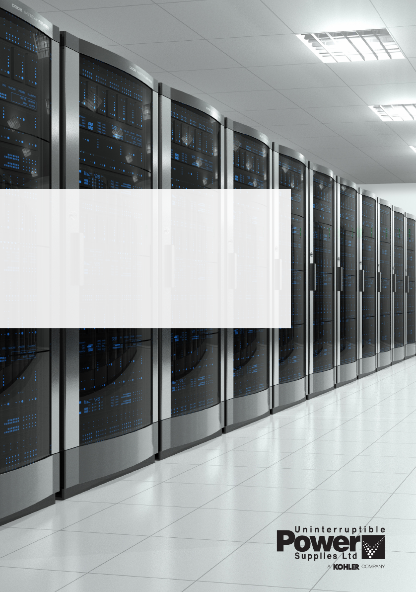
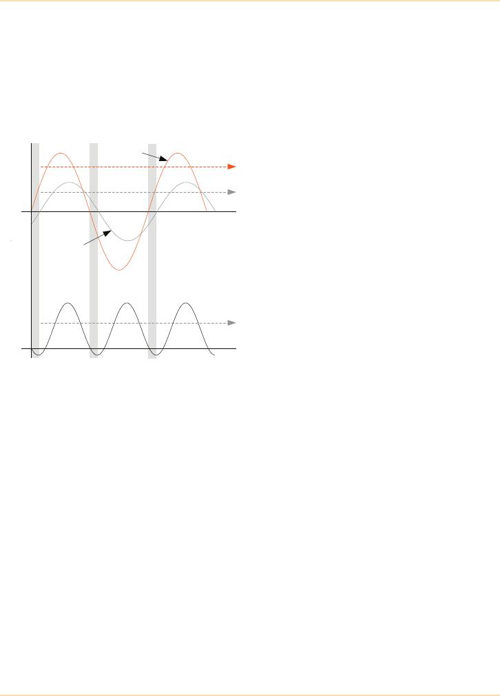
Power Problems
Figure 2.1: Power problems
Spikes
Spikes are short duration rapid voltage transitions superimposed on the mains
waveform. Spikes can inflict both positive and negative voltage excursions and
can damage or destroy electrical/electronic components. Spikes are typically
caused by thermostats or other equipment switching high electrical currents, or
load switching by the power companies. Locally grounded lightning strikes are
without doubt the most serious and dramatic cause of spikes, particularly when
induced into telecommunications cables.
Spikes can damage hardware and corrupt software. Hardware damage is an
inevitable result of exposing sensitive electronic devices to high voltages.
Software damage can be more costly in the long run, as periodically read files
become corrupted and routine system processing may compound the errors.
Normal voltage
240Vac 2 Cycle sag
90Vac
1 Cycle surge
290Vac
Harmonic distortion
Impulse/spike
0.2ms 350Vpk

Why do I Need a UPS? - Power Problems
6The UPS Handbook
Electrical Noise
Common Mode noise is a result of disturbances between the supply lines and
earth. Normal Mode noise is the result of disturbances between line-to-line and
line-to-neutral and can be caused by lightning strikes, load switching, cable
faults, and nearby radio frequency equipment etc.
High frequency noise energy entering the earth line can affect sensitive circuits
that use the supply earth as reference for internal control logic. This type of
interference is not only mains borne but can also be induced through
communications cables and other external connections. It is generally
minimised by fitting surge suppression filters to offending equipment and
implementing proper cable screening and earthing arrangements.
Surges
Surges are sustained voltage increases above the normal mains value that last for
more than one cycle. They typically appear after a large load is switched off or
following load switching at substations.
Sags
Sags are drops in the mains supply that can last for several cycles. They are
similar in generation to negative spikes but have a much longer duration.
Sags are very common occurrences that are usually the result of switching on a
large load, such as air conditioning equipment, or starting rotating machinery.
Electrical Noise can cause computers to ‘hang' and corrupt data.
Due to their relatively long duration, voltage surges can degrade a computer’s
switched mode power supply components and lead to premature failure.
Sags can cause a computer re-boot if the mains voltage falls so low that the
computer believes it has been switched off.

Why do I Need a UPS? - Power Problems
The UPS Handbook 7
Harmonics
Harmonics are generally caused by non-linear loads which pull current from the
mains supply in large peaks. Loads containing controlled rectifiers, switched
mode power supplies, or rotating machines are particularly noted for generating
this type of interference – for example computers, photocopiers, laser printers
and variable-speed motors.
Most PCs are driven by internal switched mode power supplies and the
problems relating to harmonics build up progressively as the number of PCs in a
building increases. In extreme cases the heat generated by the harmonics could
destroy the site’s main neutral busbars unless they are significantly over-rated.
Brownouts
Brownouts are identical to sags but have a much longer duration and are
generally more serious. They are caused when the mains supply is unable to
cope with the present load demand and the generating company drops the
overall network voltage.
Blackouts
Blackouts are complete power losses, where the mains supply fails totally. They
can be caused by supply line faults, accidents, thunderstorms and a range of
other conditions.
Harmonics cause a disproportionate rise in current, resulting in increased
temperatures which can cause component failure, general equipment
overheating etc.
Depending on the supply company response, brownouts could last for several
hours in extreme circumstances.
Blackouts have an obvious, sometimes devastating effect.

Why do I Need a UPS? - Power Problems
8The UPS Handbook
Mains Power Reliability
Power availability has improved in the UK since the turn of the millennium –
due in part to quality of service incentives being imposed on suppliers by
Ofgem.
Ofgem figures show that the number of power interruptions per 100 customers
have reduced to date. However, there are broad indications that this trend will
reverse in the future as a result of greater demands on supply capacity whilst
existing power generation plants (fossil fuel as a well as nuclear) reach their end
of design life and need to be replaced.
Maintaining the energy mix is an area of debate in the UK, and until such plans
are finalised there will be a period of uncertainty in security of supply until at
least the late 2010’s. Ultimately this will lead to greater supply interruptions.
There will be further squeeze if greener approaches to energy generation and use
are required – it will take some time for consumers to modify usage behavior to
meet possible lower availability of supply.
As we have just seen, for users of sensitive electrical equipment a supply
disconnection is not the only electrical supply problem that can adversely affect
the operation of their equipment.
If a mains “failure” is defined only as a complete absence of mains power then
the Mean Time Between Failures (MTBF) of the mains is approximately 10,000
hours (445 days). If a mains “failure” is more broadly defined as the occurrence
of any mains event (spike, noise, surge, sag etc.) that adversely affects the mains
supply then the MTBF of the mains could be as low as 50 hours. In practice the
MTBF of the mains will be somewhere between 50 hours and 10,000 hours as
these figures represent the worst cases and ignore local, site related problems
such as accidental digging up of cables etc.
Summary
A substantial number of possible power disturbances can affect the operation of
a critical load.
The one common aspect to all disturbances is their total unpredictability. Any
measures taken to safeguard the critical load supply must be effective at all
times when the load is in use.
Computers typically have specified upper and lower limits for steady state slow
averaged rms line voltage variations of between ±5% to ±10%, depending on the
manufacturer, but will tolerate short duration line voltage excursions outside

Why do I Need a UPS? - The UPS Solution
The UPS Handbook 9
those limits. The shorter the duration of the excursion, the greater the excursion
which can be tolerated.
Some computers have sufficient energy stored in their internal power supply
reservoir capacitors to sustain the dc supply to logic circuits during line voltage
sags and power line interruptions of up to a 1/2 cycle (10ms), although not all
units have this much ride-through capability.
If the computer user is striving for less downtime and fewer errors, the electrical
environment must be closely controlled.
The UPS Solution
After identifying an item of load equipment as being ‘critical’ the argument for
protecting its power supply is overwhelming. However, to some extent the
necessary degree of protection depends on the particular load application.
Radio frequency noise interference and spikes can be substantially reduced by
fitting suitable filters and some form of isolation transformer in the supply line.
Surges also can be reduced using externally connected components.
Power disruptions of just a few milliseconds may cause some equipment or
operations to fail completely; yet others will ride through several cycles of
mains failure without harmful effects.
Consider the different supply needs of a computer network and an emergency
lighting system. Installing line-conditioning equipment and a standby generator
might afford the most appropriate protection in the latter case.
If the load calls for a particularly close-tolerance supply, or is intended for 24-
hour daily use, there is no alternative but to install a form of Uninterruptible
Power Supply (UPS) to provide it with continuous, processed, clean power.

10 The UPS Handbook
The UPS Handbook 11
3What is a UPS?
Introduction
Figure 3.1: UPS System Installation
The Uninterruptible Power Supply (UPS) systems described in this book cover a
range of solid-state equipment which can be connected between the incoming
mains supply and critical load to protect against supply aberrations including
total mains failures.
Because these systems are solid-state they are often described as static UPS
systems, as opposed to rotary systems which are based on motor/generator
technology. Rotary systems are still available, and have their uses, but in recent
years they have generally been superseded for most applications by the
developing static UPS technology. Therefore this book concentrates on static
UPS systems.
There are several forms of static UPS system available, employing various
power topologies (see Chapter 4). However, irrespective of their category they
all currently use a battery to provide a back-up energy store which can be called
upon if the mains supply fails. Emerging energy storage devices such as
flywheels and hydrogen fuel cells are discussed in Chapter 8 but this book will
focus on the use of batteries in UPS applications because, at the time of writing,
flywheels and fuel cells are very much in their infancy and are unlikely to be
used in mainstream UPS applications within the next 5 to 10 years.
UPS System Load
Mains supply
What is a UPS? - UPS Rating
12 The UPS Handbook
UPS Rating
The power rating of electrical equipment may be stated in Watts (W) or Volt
Amperes (VA) (1kVA=1000VA) but rarely both. UPS manufacturers generally
use VA (or kVA) to describe the UPS output ratings, and it is this rating which
determines the maximum load that can continuously be supported by the UPS
when the mains supply fails.
When selecting a UPS to service a particular load it is important that the
combined load does not exceed the UPS output rating, and if the load equipment
is specified in Watts it is necessary to convert this to VA in order to assess the
UPS/load rating compatibility.
VA and Watts Explained
The terms ‘VA’ and ‘Watts’ are often confused, but an understanding of the
relationship between the two parameters is necessary when matching a UPS to a
combination of load equipment.
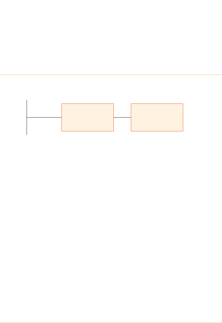
Figure 3.2: VA and Watts in a linear circuit
The VA (Volt Ampere) rating of electrical equipment is calculated by
multiplying the supply voltage (V) by the current (A) drawn from the supply –
using the rms (root mean square) values of voltage and current in each case.
This is illustrated in the upper diagram of Figure 3.2 which shows that a load
drawing 5A from a 240V supply is rated at 1200VA (or 1.2kVA).
Voltage
240 Volts (rms)
5 Amps (rms)
1200VA
(1.2kVA)
Current
V x A
Watts (rms) 1200W
(1.2kW)
What is a UPS? - UPS Rating
The UPS Handbook 13
Watts (W) are a measure of the ‘real power’ consumed by a load. In a dc circuit
this is calculated by multiplying the supply voltage by the load current in exactly
the same way as described above for VA – i.e. (W = A x V). In fact, in an ac
circuit feeding a purely resistive (linear) load, where the supplied voltage and
load current are in phase, the circuit values of VA and Watts are identical. The
lower diagram in Figure 3.3 illustrates an instantaneous power waveform for a
linear load and shows how the r.m.s. wattage value is obtained.
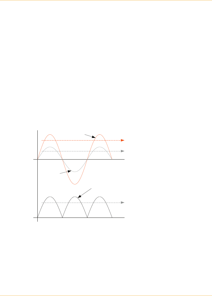
Figure 3.3: VA and Watts in a non-linear circuit
In practice the load connected to an ac circuit is usually far from linear. Typical
ac loads such as transformers, switched mode power supplies, motors etc. are all
inductive in nature and cause the load current to lag behind the applied voltage
by an amount proportional to the load’s reactance. This is illustrated in Figure
3.3, where the current is shown to lag the supply voltage by approximately 36°.
Notice that the VA rating in this example is identical to that calculated in Figure
3.2, because the rms values of the voltage and current waveforms are unaffected
by the relative phase shift and the current drawn from the supply is the same in
both examples. However, the lower diagram in Figure 3.3 shows a reduction in
wattage rating to 960W from the previously calculated 1200W – i.e. the load is
dissipating fewer Watts for the same value of VA.
The reduced wattage is due to the phase relationship between the voltage and
current waveforms in that the product of V x A generates a negative value when
the parameters are of different polarities. This is shown graphically in Figure 3.3
as negative excursions in the ‘Watts’ curve which occur during the shaded areas
of the voltage and current waveforms.
Voltage
240 Volts (rms)
5 Amps (rms)
1200VA
(1.2kVA)
Current
Watts (rms) 960W
(0.96kW)

What is a UPS? - UPS Rating
14 The UPS Handbook
The illustrated negative power excursions are broadly theoretical but represent
‘wasted’ power – i.e. power not dissipated usefully in the load. This is
sometimes referred to as ‘reactive’ power as it is caused by, and is proportional
to, the load’s reactance.
Power Factor (pf)
In an ac circuit the relationship between real and reactive power is known as the
‘power factor’ (pf) and is the ratio of Watts to VA.
The power factor can also be determined by calculating the cosine of the phase
angle between the voltage and current waveforms.
For example, in Figure 3.3 where a phase angle of 36° was assumed, the load
power dissipation (W) could be calculated as:.
Clearly, if two loads of the same wattage rating but different power factors are
connected to the same supply voltage, the load with the lower power factor will
draw more current from the supply in order to produce the same power as its
partner having the higher power factor.
As mentioned at the beginning of this section, it is usual to describe a UPS in
terms of its output VA (kVA) rating. If the UPS output power factor is not
specified it is usual to assume a figure of 0.8 lagging – i.e. where the load
current lags behind the supply voltage. For example a 1kVA UPS would have a
maximum power rating of 800W (0.8kW) and under these circumstances the
total load must not exceed either of these values.
Where large or highly reactive loads are concerned, measures are sometimes
taken to improve the overall power factor, bringing it closer to unity. This is
known as ‘power factor correction’ and is generally achieved by adding a
capacitive load in parallel with the load equipment to reduce the overall circuit
reactance.
Power Factor (pf) Watts
VA
---------------=
Watts VA x36cos 1200 x0.8==
Watts 960=
What is a UPS? - What is Available?
The UPS Handbook 15
What is Available?
The range of UPS modules currently available is vast, beginning with ultra
compact desktop units to modules of hundreds of kVA. Furthermore, some
manufacturers design UPS modules which can be configured as parallel-
controlled multi-module systems, increasing the total system rating to several
thousand kVA – e.g. 2 or 3MVA systems are possible.
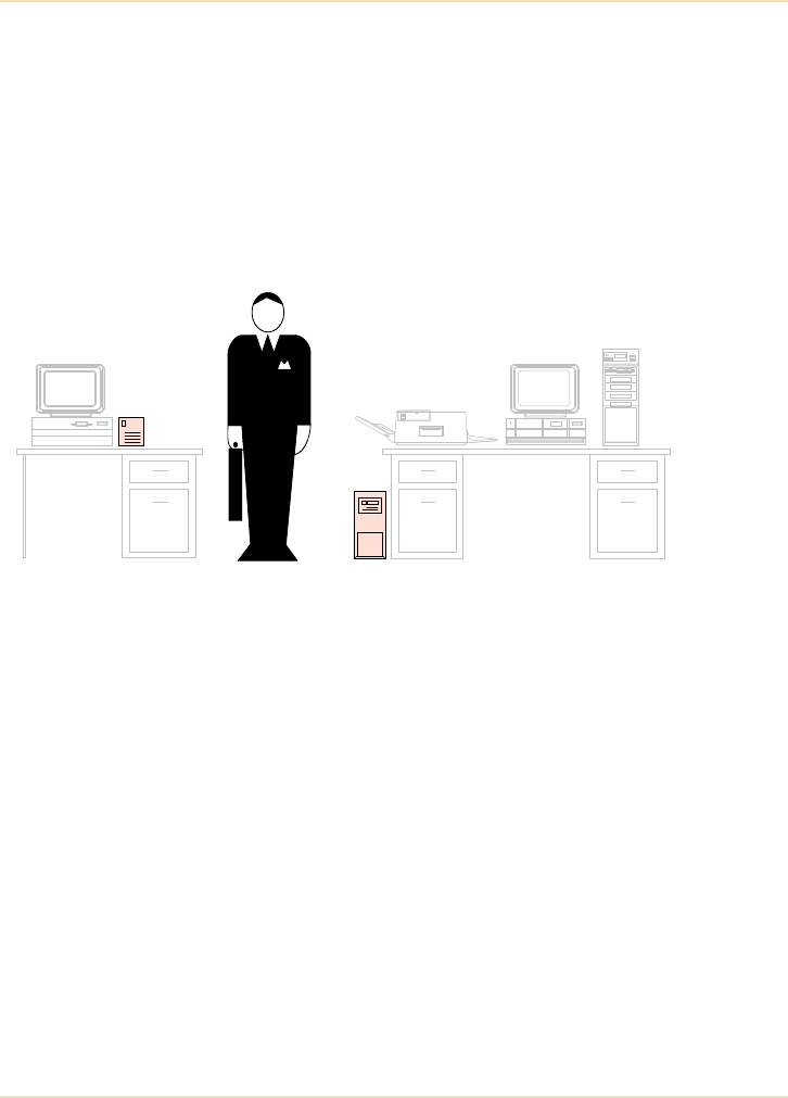
Desktop Systems
Figure 3.4: ‘Desktop’ UPS models
Micro Systems – up to 1000VA
Modules in this power range are typically designed to supply a single personal
computer (PC) workstation and are normally housed in a mini-tower case about
half the size of a typical personal computer system unit. The UPS is connected
to a standard utility mains supply outlet such as a three-pin 13A socket (UK) and
due to their small weight and dimensions can be considered as being portable.
Modules at this power level include on-line, off-line and line interactive designs
(See "UPS Topologies" on page 21) and provide a single point solution to a
particular power need.
Load equipment is usually connected to a standard mains connector (IEC) on the
back of the UPS which is usually protected by a circuit breaker or fuse.
At this power level the batteries are usually integral to the UPS cabinet, and
extended battery cabinets are unlikely to be offered as an optional extra.
250VA
UPS 2kVA
UPS

What is a UPS? - What is Available?
16 The UPS Handbook
Because these modules are designed to be placed adjacent to the load equipment
user it is not generally necessary to provide any remote alarm facilities to warn
the operator of the module’s operational status. However, current practice might
include installing an automatic control interface between the UPS and computer
e.g. SNMP (Simple Network Management Protocol) or automatic shutdown
software (See "UPS Communications" on page 155).
Mini-Systems – 500-2000 VA
Modules in this power range are in many ways similar to the ‘micro’ UPS
systems described above in that they are designed for office use and can be
considered to be portable. However, the increased rating makes these modules
suitable to supply a fileserver or a complete workstation comprising a PC and its
peripheral equipment, such as printer (but not a laser printer), scanner etc.
These modules are again connected to a standard utility mains supply outlet
such as a three-pin 13A socket (UK) and can include on-line, off-line and line
interactive designs (See "UPS Topologies" on page 21).
The load equipment is usually connected to standard mains connectors (IEC) on
the back of the UPS which are usually protected by a circuit breaker or fuse, but
it is likely that several supply outlets are provided to facilitate the connection of
several small items of load equipment.
At this power level the batteries are usually integral to the UPS cabinet, but
some modules might have provision to connect to additional batteries contained
in a purpose built extended battery cabinet to increase the total battery back-up
(autonomy) time. Where this is the case the battery charger within the module is
usually sufficiently rated to provide the additional battery charging current.
However, in extreme circumstances the extended battery cabinet must include a
dedicated charger system to cater for the additional batteries and will therefore
also require connecting to the mains supply.
As with the ‘micro’ UPS systems, it is not generally necessary to provide any
remote alarm facilities for this size of UPS due to the close proximity of the
system to the load operator. However, as with ‘micro’ systems, SNMP or
automatic shutdown software may well be a requirement depending upon the
criticality of the load.
Laser printers may cause harmonic distortion of the UPS output.
Be sure to check the UPS can handle this type of load.
What is a UPS? - What is Available?
The UPS Handbook 17
Medium-Sized Systems – 3-20kVA
Figure 3.5: Medium-Sized Systems
Modules in this power range are designed to offer more than the single point
power provision afforded by the smaller desktop modules, being typically used
to power a complete office network, small server farm or communications
centre.
These modules, which cannot be considered as being portable (especially those
in the upper end of the range), are permanently wired to the mains supply using
medium power switchgear and may require some external input overload
protection device as a standard part of the installation. The larger modules in this
range may require a three-phase input supply – and indeed may even offer a
three-phase output.
5kVA
UPS
Extended
battery
cabinets
(option)
20kVA
UPS
Extended
battery
cabinets
(option)

What is a UPS? - What is Available?
18 The UPS Handbook
The question of batteries varies across this particular power range. At the lower
end the comments concerning the batteries fitted to the desktop systems are still
valid, but when considering modules rated 15-20kVA it may well be that the
batteries are housed in a separate cabinet which is positioned alongside the UPS
module. In fact, most manufacturers offer a series of matching cabinets at this
power level to provide a range of aesthetically appealing equipment that fits into
an office environment.
At the higher power levels the load equipment is either hard wired to
distribution busbars fitted within the module cabinet or the UPS output is fed to
a purpose designed distribution system. At the lower end of the power range it is
possible that the UPS may be fitted with standard utility power outlet sockets in
the same way as the desktop models. Most modules in this power range will
include facilities for remote alarms and status indications.
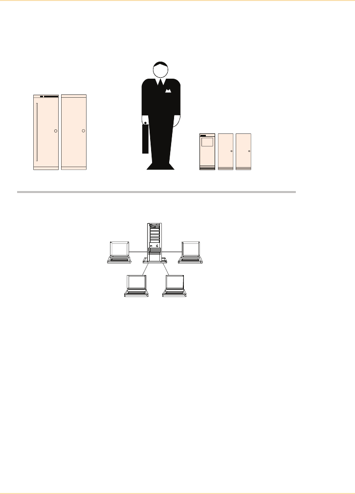
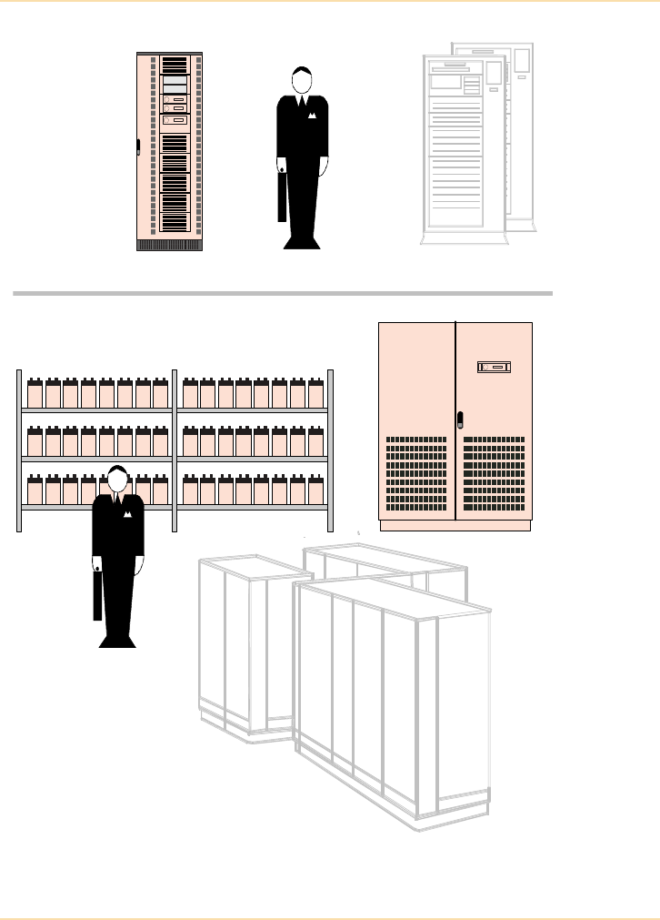
High-Power Systems (typically 30-500kVA)
Modules of this rating can service a major data centre but are not generally
suited to an office environment due to the noise levels associated with their
cooling fans and the heat generated when operating on high loads. Such
modules are therefore usually located in a remote position such as a plant room,
and their outputs connected to numerous loads using a dedicated mains
distribution system incorporating external switchgear and protective devices.
Modules in this power range are almost exclusively of an on-line design and
invariably three-phase input and output.
It is unlikely that the batteries are housed within the UPS module cabinet itself,
and depending on the module rating and projected autonomy time, they may be
housed in a separate cabinet(s) adjacent to the UPS module or, in the case of
very large systems, rack-mounted in a dedicated battery room.
Some of the larger modules in this range may employ a 12-pulse rectifier to
reduce the amount of mains polluting harmonics generated within the UPS and
reflected back to the utility mains supply. Where a 12-pulse rectifier is used it is
usually contained in a separate cabinet which must be positioned immediately
adjacent to the main UPS cabinet, increasing the required system footprint and
weight.
Single modules of up to 800kVA are available, however for the reasons of
efficiency, availability and scalability discussed in Chapter 7, it is becoming
increasingly more common for very large loads (300kVA to >1MVA) to be
powered by UPS systems which comprise several “high power” UPS modules
operating in parallel rather than by just one very large single UPS module.
What is a UPS? - What is Available?
The UPS Handbook 19
Figure 3.6: Large Systems
75kVA UPS
With internal
batteries.
External
battery
cabinets are
often used at
this rating.
AS400 Network
Battery racks
500kVA UPS
Data Centre

What is a UPS? - What is Available?
20 The UPS Handbook
A standby generator may be incorporated into the system design to provide an
alternative source of UPS input power during a utility mains failure. Such a
generator must be self starting and be sufficiently large to maintain a stable
output with the UPS on full load. When selecting a standby generator for this
duty several features must be taken into account in order to ensure proper
operation because the UPS input can present a hostile load to some generator
systems (See "Generators" on page 137).
Due to the module’s location it is usual to include a remote alarm/control panel
with this type of installation, and virtually all modules in this range offer this
facility as a standard feature.
The UPS Handbook 21
4UPS Topologies
Introduction
There are several categories of static UPS systems available. Broadly speaking,
UPS modules fall within one of three operational design architectures, namely
off-line, line interactive and on-line.
However, irrespective of their individual design criteria certain features are
common to all forms of static UPS systems – i.e. they all contain batteries which
store energy when the mains supply is available and a means of converting the
battery charge into an alternating current (ac) supply in times of mains failure.
All systems must therefore include a battery charger and a power inverter
circuit, as illustrated in Figure 4.1.
As described above, the battery provides a power source for the inverter when
the mains supply fails, whereupon it discharges at a rate determined by the
critical load connected to the UPS output. The inverter automatically shuts
down when its dc supply falls below a certain voltage, therefore the duration for
which the critical load can be supported in times of mains failure depends upon
the battery capacity and the percentage applied load.
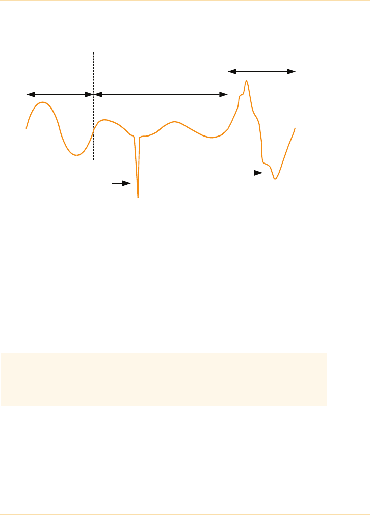
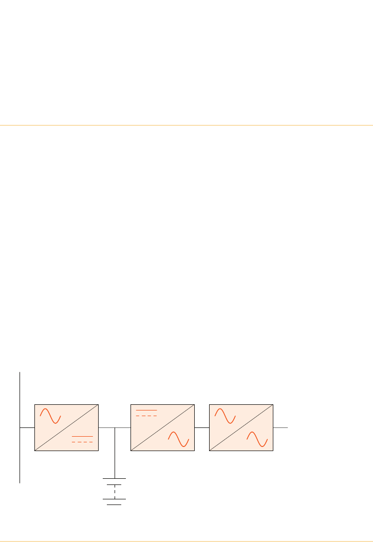
Figure 4.1: Typical UPS Block Diagram
Rectifier/Charger Inverter Static Switch
Battery
Mains Supply
Output to
Critical
Load
DC Bus

UPS Topologies - Off-Line Systems
22 The UPS Handbook
A typical UPS system will contain sufficient battery capacity to support its fully
rated output load for 5 to 15 minutes. However, in most cases this can be
extended by adding further battery cabinets or selecting batteries of a higher
capacity. The battery backup time is often referred to as the autonomy time.
Virtually all UPS contain a ‘bypass’ system which, in conjunction with some
form of output switching circuit, provides a means of connecting the critical
load directly to the mains supply. In most cases the output switching circuit is
implemented using solid-state switching devices, hence the ‘static switch’
annotation to the block diagram in Figure 4.1, but this function is sometimes
carried out using switching relays in smaller units.
The rules governing the static switch control depend on the UPS operating
mode, as described in the remainder of this chapter.
Off-Line Systems
A typical off-line UPS module is shown in Figure 4.2. With this design the
critical load is powered from the bypass line (i.e. raw mains) and transferred to
the inverter if the bypass supply fails or its voltage goes outside preset
acceptable limits. During normal operation the load is subjected to any mains
disturbances that fall within the acceptable bypass voltage range although most
modules of this type include a degree of spike suppression and rf (radio
frequency) filtering in their bypass circuit.
Under normal conditions the battery charger operates continuously to keep the
battery fully charged. In some models the inverter may be turned off to improve
the overall system efficiency, although its control electronics are fully
operational in order to provide a very fast inverter start when called for.
If the bypass voltage falls below a minimum value the inverter is immediately
started (if not already running) and the load transferred to the inverter supply by
the static switch (or output transfer relay). Due to the fact that the bypass supply
is already failing when the transfer sequence is initiated there is an inevitable
load supply break while the transfer takes place, albeit brief and typically in the
range 2 to 10ms. Most loads should, however, ride through this period
satisfactorily without adverse affects. The load is re-transferred to the bypass
line once the bypass supply is restored.
UPS Topologies - Off-Line Systems
The UPS Handbook 23
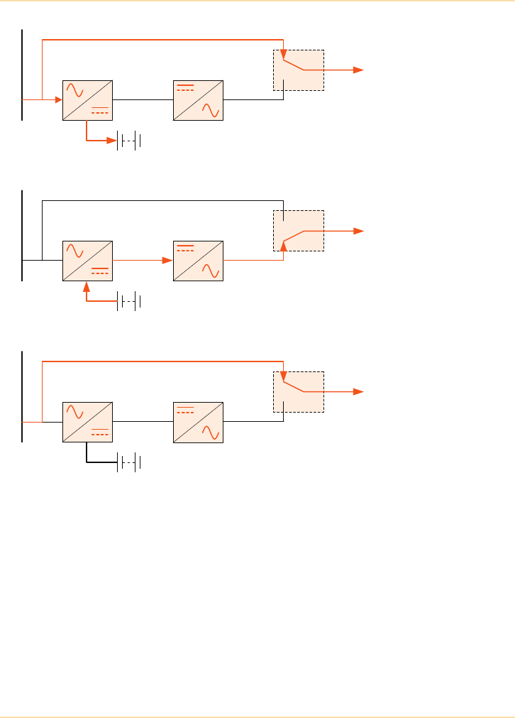
Figure 4.2: Off-line Illustration
Due to the inevitable load break during transfer some purists argue that this type
of system is really a form of standby power supply rather than a true UPS.
When the load is transferred to inverter in this type of module the inverter
immediately operates from battery power and can sustain the load only until the
battery voltage falls to its end-of-discharge level, whereupon the UPS output
supply will fail if the bypass supply is not restored.
Output to
Critical
Load
Mains Supply
Inverter
Battery
Charger
Static Switch
Bypass – common bypass configuration
Normal
operation
Output to
Critical
Load
Inverter
Battery
Charger
Static Switch
Bypass
Mains failure
Output to
Critical
Load
Inverter
Battery
Charger
Static Switch
Bypass
UPS failure
Mains SupplyMains Supply

UPS Topologies - Line-Interactive Systems
24 The UPS Handbook
Summary
The following key points might influence the choice of this system:
• output voltage not closely regulated under normal operation
• 2 to 10ms. load break during load transferring between inverter and
bypass (in either direction) – minimal power protection
• lower capital costs than an on-line system due to lower rated
components/omission of power rectifier
• lower running cost than an on-line system – overall efficiency is
greater due to the fact that the charger and inverter are not
permanently on load.
Line-Interactive Systems
This type of UPS covers a range of hybrid devices that attempt to offer a higher
level of performance than conventional off-line designs by adding voltage
regulation features in the bypass line. The two most popular types of system in
this category employ either a buck/boost transformer (Figure 4.3) or a ferro-
resonant transformer (Figure 4.4).
Like off-line models, line-interactive UPS normally supply the critical load
through the bypass line and transfer it to the inverter in the event of a bypass
supply failure. The battery, charger and inverter power blocks are utilised in the
same manner as in an off-line system but due to the added ‘regulation’ circuits
in the bypass line the load is transferred to the battery-fed inverter supply less
often, making this type of system slightly more efficient in terms of running
costs and battery ‘wear’ compared with an off-line system.
Buck/Boost Transformer Design
One of the drawbacks of the straightforward off-line design is that the load must
be transferred to the inverter immediately the bypass supply voltage reaches the
voltage limits acceptable to the load. This means that the UPS might transfer
between bypass and inverter quite frequently if it is set up to operate with a
critical load having a tight voltage tolerance. Apart from the power break each
time this occurs, this method of operation incurs frequent battery usage which
reduces battery life and might perhaps result in a battery that is inadequately
charged when it is called upon to support a prolonged mains blackout.
A buck/boost transformer connected in the bypass line helps overcome this
problem (see Figure 4.3). The transformer has tapped secondary windings which
UPS Topologies - Line-Interactive Systems
The UPS Handbook 25
are selected by relays to either step-up or step-down the bypass voltage as
appropriate to maintain the UPS output voltage within the required output
voltage limits. This means of controlling the output voltage permits a wider
variation of bypass voltage to exist before the output voltage reaches its limits
and initiates a load transfer to inverter.
A typical UPS in this category will sustain the load voltage over a bypass
voltage range of +20% to -30%.
Note that although the output voltage is maintained within its preferred window
using this method, buck/boost switching unavoidably leads to a degree of step
voltage changes as tap changes take place.
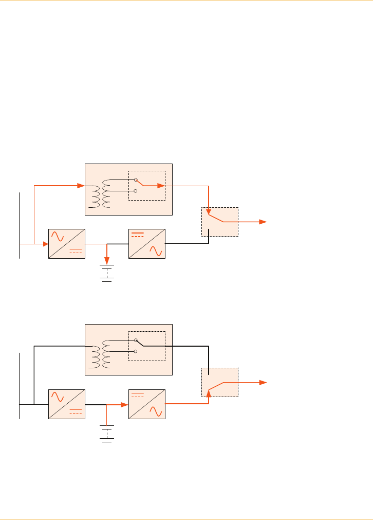
Figure 4.3: Line-Interactive UPS with Buck/Boost Transformer
Output to
Critical
Load
Mains Supply
Inverter
Battery
Charger
Static Switch
Bypass
Normal
operation
Buck/Boost Transformer
Output to
Critical
Load
Mains Supply
Inverter
Battery
Charger
Static Switch
Bypass
Mains failure
Buck/Boost Transformer
UPS Topologies - Line-Interactive Systems
26 The UPS Handbook
Ferroresonant Transformer Design
Figure 4.4 shows this design is similar to the buck/boost system, but in this case
the buck/boost transformer is replaced by a ferro-resonant transformer.
The transformer provides voltage regulation and power conditioning for
disturbances such as electrical line noise and will typically maintain the output
voltage to within 3% of nominal over a bypass voltage range spanning +20% to
-40%. It also stores a reserve of energy that is usually sufficient to power most
computers, i.e. PCs, briefly when a total outage occurs. This keeps the computer
supplied with power within most input requirements until the inverter is
switched on and effectively turns the system into a true on-line system in that
the load is effectively transferred without a power break.
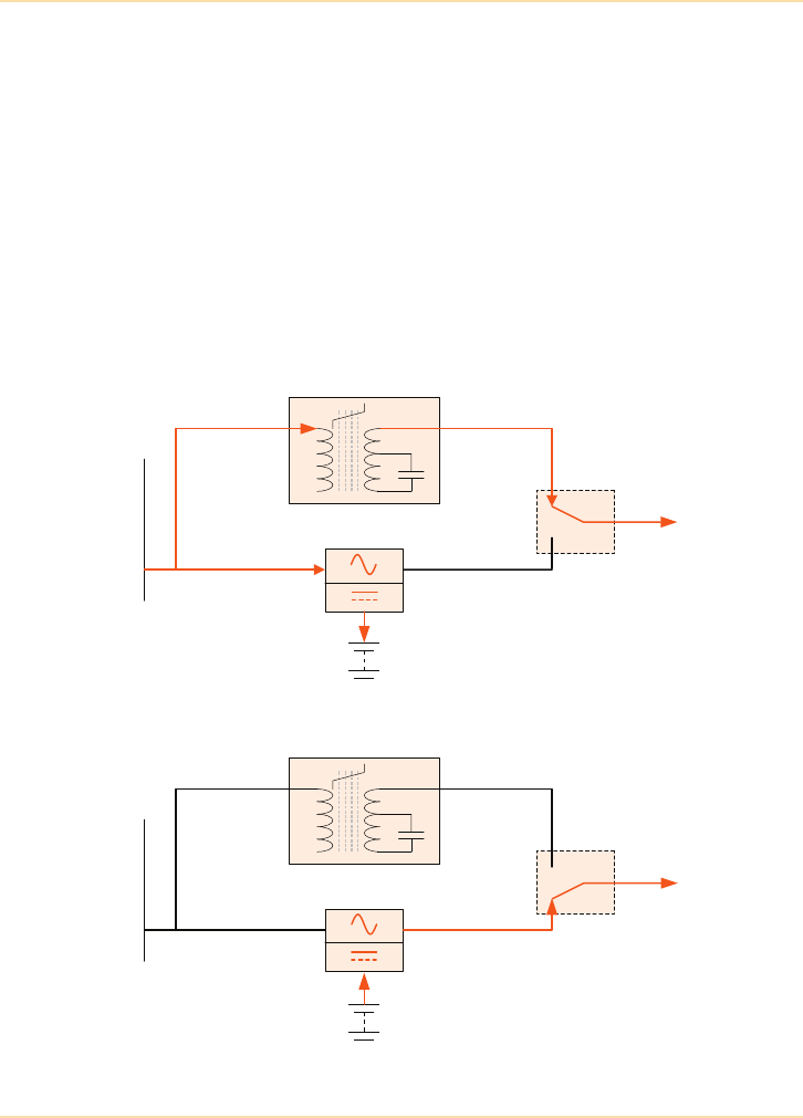
Figure 4.4: Line-Interactive UPS with Ferroresonant Transformer
Output to
Critical
Load
Mains Supply
Battery
Bi Directional
Power Converter
Static Switch
Bypass
Normal
Ferroresonant
Transformer
Output to
Critical
Load
Mains Supply
Battery
Bi Directional
Power Converter
Static Switch
Bypass
Mains failure
Ferroresonant
Transformer

UPS Topologies - Line-Interactive Systems
The UPS Handbook 27
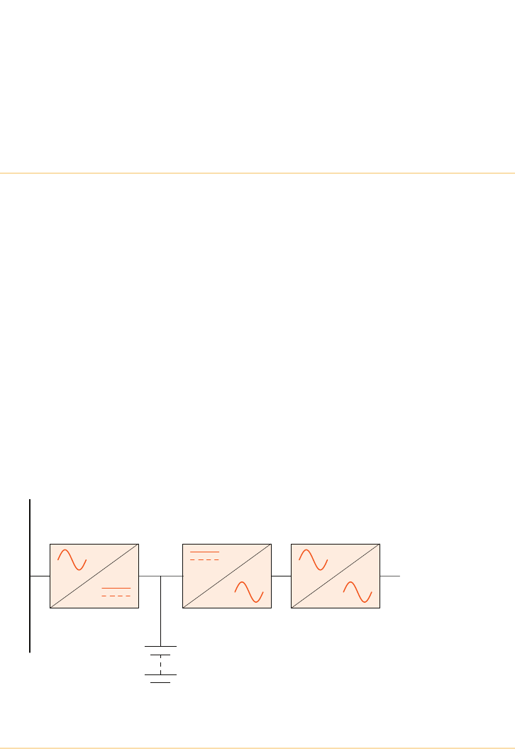
Bi-directional Power Converter
In Figure 4.4 a single block has been used to replace the rectifier/charger and
inverter power block shown in earlier diagrams. As its name suggests, this is a
dual purpose power circuit which acts as a controlled battery charger under
normal circumstances when the load is connected to the bypass, and very
quickly changes over to operate as a power inverter when the bypass supply fails
and the load is transferred to the inverter supply.
This type of design can also be used with the buck/boost circuit shown
previously or indeed any other line-interactive hybrid.
Summary
The following key points might influence the choice of line-interactive systems:
• when comparing line-interactive and on-line systems the advantages/
disadvantages are similar to those described above for off-line
models, with the exception of the advantage of providing a degree of
automatic voltage regulation
• may reduce UPS battery usage in comparison with off-line systems,
and therefore cause less degradation to battery life.

UPS Topologies - On-Line Systems
28 The UPS Handbook
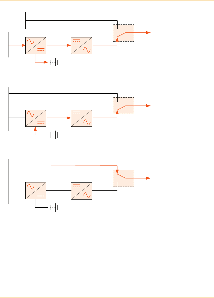
On-Line Systems
A typical on-line UPS module is illustrated in Figure 4.5.
An immediate difference between this design and the off-line systems is that the
battery charger is replaced by a ‘rectifier/charger’ block. The rectifier/charger
may be two separate units or a combined power block. When the mains supply is
present this block float charges the battery and supplies the inverter with a stable
dc voltage. In the absence of the mains supply the charger shuts down and the
inverter dc supply is provided by the battery, which begins to discharge. The
connection between the rectifier/battery and inverter is often known as the dc
busbar, or dc bus.
As part of its control function the rectifier/charger generally includes an input
current limit feature to provide overload protection and a dc overvoltage
shutdown mechanism to protect the battery/inverter and dc filter components.
This UPS design is sometimes referred to as a double conversion UPS, due to its
two conversion stages of AC-DC and DC-AC, and offers the greatest degree of
critical supply integrity in that the load is supplied with processed power at all
times. That is, when the UPS input mains supply is present the rectifier, charger
and inverter power blocks are all active and the load is connected to the inverter
output via the static switch. As the load is powered from the inverter under
normal circumstances it is well protected from input supply aberrations because
the rectifier and inverter act as a barrier to mains borne noise and transient
voltage excursions, in addition to providing a well regulated output voltage.
If the input supply goes outside a preset voltage range (typically +10% to -20%),
or suffers a total failure, the inverter continues operating from battery power and
the event is totally transparent to the load as there is no transfer operation
involved. When operating from battery power the inverter supplies the same
degree of supply regulation as when the mains is present.
If the mains is not restored before the battery reaches its end-of-discharge
voltage the inverter shuts down.
UPS Topologies - On-Line Systems
The UPS Handbook 29
Figure 4.5: On-line UPS Operation
Output to
Critical
Load
Mains Supply
Inverter
Battery
Rectifier
Static Switch
Bypass – split bypass configuration
Normal
operation
Bypass
supply
Output to
Critical
Load
Inverter
Battery
Rectifier
Static Switch
Bypass
Mains failure
Mains Supply
Output to
Critical
Load
Inverter
Battery
Rectifier
Static Switch
Bypass
UPS failure
(on bypass)
Mains Supply
DC Bus
DC Bus
DC Bus
UPS Topologies - On-Line Systems
30 The UPS Handbook
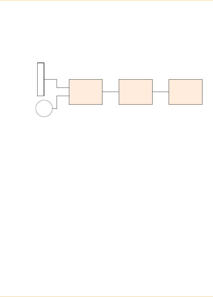
One means of overcoming this potential problem is to include a standby
generator in the system design which provides an alternative source of UPS
input supply during a prolonged utility mains failure. This is connected to the
UPS via an automatic change-over switching circuit which detects the absence
of the mains supply and very quickly brings the generator into operation (see
Figure 4.6).
Figure 4.6: Standby Generator
In this application the generator is started automatically when a monitoring
circuit detects a mains supply failure. Once the generator has run up and
stabilised, the ‘automatic supply selection switch’ changes over to connect the
generator output to the UPS input terminals, thereby replacing the regular mains
supply: whereupon the UPS batteries immediately begin to recharge. Note that
this facility can be used only if the UPS input and bypass supplies are connected
to the same L.V. supply.
Automatic
Supply
Selection
Switch
UPS System Load
50Hz
GEN
Mains Supply

UPS Topologies - On-Line Systems
The UPS Handbook 31
What Happens if the UPS Fails?
A UPS fault is generally seen as the inability of the inverter to provide the
correct voltage or frequency at the UPS output terminals and the resulting
actions that take place may vary between models. Usually, the UPS control logic
will detect the failing output voltage/frequency as the fault occurs and
immediately signal the static switch control system to transfer the load to the
bypass line in a make-before-break fashion, as illustrated in the lower diagram
of Figure 4.5. However, if the inverter is not synchronised to the bypass supply
when the transfer is called for it will be impossible to perform a break-free
transfer operation. Consequently there will be a brief supply break while the
transfer takes place.
These are the only circumstances under which the load is subjected to a (brief)
supply break in a true on-line ups system.
Note that although the break-free transfer to bypass is transparent to the load, it
is no longer supplied with processed power once it is transferred to the bypass
supply; also, if the bypass supply is unavailable when the ‘fault’ transfer is
necessary a total loss of power to the critical load is unavoidable.
Depending on the UPS design, and nature of the problem, the static switch may
transfer the critical load back to the inverter automatically once the inverter fault
clears.
The response of an on-line system to an output overload is usually similar to that
of the UPS failure described above in that the load is transferred to bypass until
the cause of the overload clears, whereupon it automatically re-transfers back to
the inverter. If the bypass supply is unavailable this will lead to a total loss of
load supply (see above). Therefore some systems allow an overload condition to
continue to be supplied from the inverter for a finite time – that is the UPS
equipment is able to supply enough current to a faulty piece of load equipment
to ensure that the load protection fuse or circuit breaker will automatically
disconnect it from the UPS.
While feeding the overload under these circumstances the inverter operates in a
current-limit mode and its output voltage may be reduced deliberately, but in
most cases this is preferable to total power loss and of course conditions will
return to normal if the overload is cleared during the allotted time.
UPS Topologies - On-Line Systems
32 The UPS Handbook
Summary
The following key points might influence the choice of an on-line system:
• offers highest level of critical load protection – the load is supplied
with closely regulated power at all times
• no load break when transferring between inverter and bypass (in
either direction)
• mains failure totally transparent to the load
• most expensive capital cost
• most expensive running cost – system efficiency is lower than the
other types of system due to the fact that the rectifier and inverter are
permanently on load, although advances in on-line efficiency have
been made – See "Transformerless UPS Systems" on page 73.
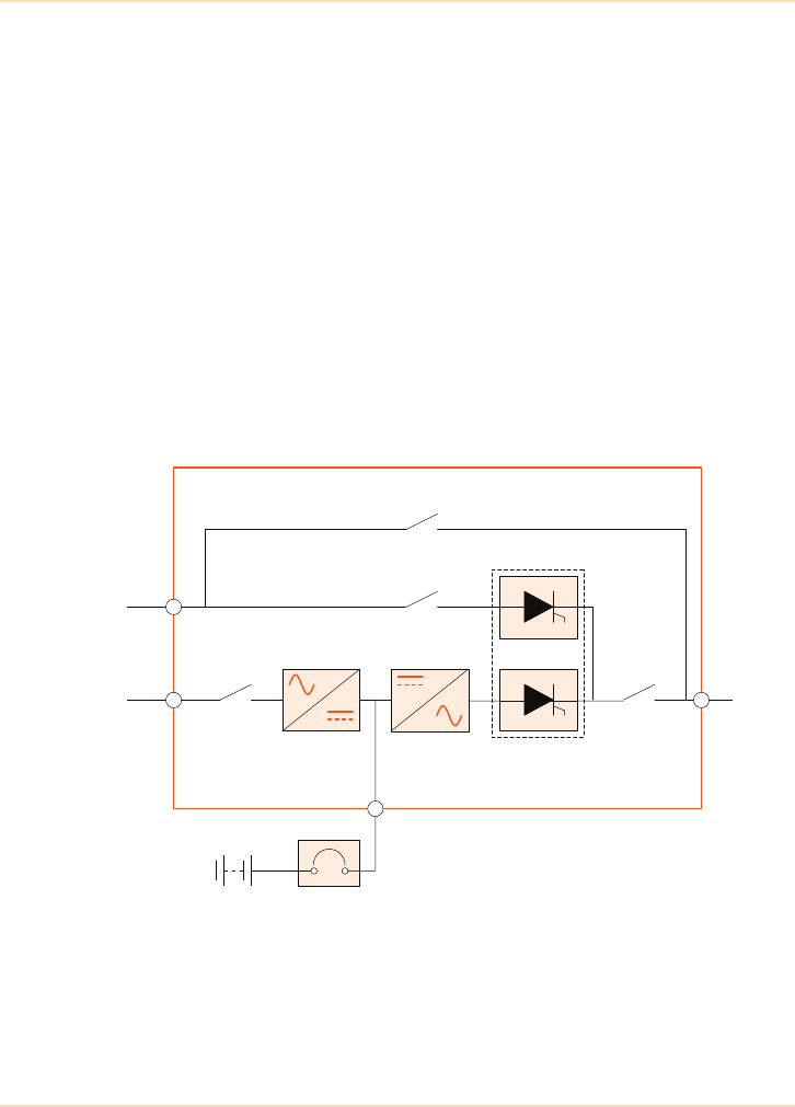
Maintenance Bypass
Figure 4.7: Internal Maintenance Bypass Illustration
A maintenance bypass provides a means of powering the load from an
unprotected bypass supply while the UPS module is isolated for service or
Maintenance bypass isolator
Bypass isolator
InverterRectifier
Input
isolator
Static switch Output
isolator
UPS Module
Battery
Battery circuit
breaker
Mains
supply
Bypass
supply
Output to
Critical
Load
UPS Topologies - On-Line Systems
The UPS Handbook 33
repair. Some modules include an integral maintenance bypass circuit as a
standard design feature while others rely on an external maintenance bypass
isolator being added as part of the UPS electrical installation.
Internal Maintenance Bypass
Figure 4.7 illustrates the isolator configuration of a typical high power, three-
phase on-line module fitted with an internal maintenance bypass facility.
This diagram shows that although the UPS power blocks can be totally isolated
while the load is powered through the maintenance bypass supply, making it
safe to carry out maintenance procedures etc., there will still be live power
within the UPS at its power isolators and input/output terminal connections.
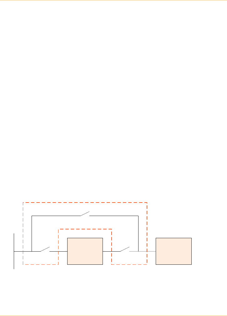
External Maintenance Bypass
An external maintenance bypass system is illustrated in Figure 4.8, which shows
three external isolators connected to the UPS installation. This configuration is
often referred to as a ‘wrap-around’ bypass – for reasons that are readily
apparent from the block diagram.
The illustration clearly shows that the UPS system will be totally isolated when
SW1 and SW2 are open and SW3 is closed. This renders the UPS entirely safe
for maintenance and troubleshooting, to the extent that the complete unit can be
‘swapped-out’ if necessary.
When this type of bypass is implemented the circuit breakers are usually housed
in a purpose designed switchgear cabinet located near to the UPS equipment.
Figure 4.8: External “Wrap-Around” Bypass
UPS System
Mains supply
SW1 SW2
SW3
Load
Bypass switchgear panel

UPS Topologies - On-Line Systems
34 The UPS Handbook
Bypass Interlocking
Interlocking between the maintenance bypass and UPS isolators is required to
ensure that the load is transferred between the two power sources in a controlled
manner. This is necessary to ensure that the load is uninterrupted during the
transfer, and the UPS is not damaged by back-feeding from maintenance bypass
supply into the UPS output terminals while the inverter is on load.
The power isolators within the UPS are invariably electrically interlocked to
prevent such problems occurring. However, when an external maintenance
bypass circuit is employed, additional electrical or mechanical interlocking
devices are usually required.
The UPS Handbook 35
5Major UPS
Components
Introduction
As described elsewhere in this book the only truly uninterruptible UPS is a
double conversion system comprising rectifier/charger and inverter power
blocks operating in an on-line mode – Figure 5.1. The rectifier/charger converts
the input mains to a direct current (dc) supply which provides the inverter power
source and charges the battery when the mains supply is healthy. Alternatively,
when the mains supply is disrupted the battery takes over the role of providing
the inverter power without any switching or break in supply.
When viewed at this basic level the design principles appear straightforward.
However, there are several fundamentally different approaches taken by
manufacturers to implement both rectifier and inverter functions.
This chapter begins by presenting an overview of the conversion processes
performed by the rectifier and inverter power blocks and explains various design
principles including examples of transformer and transformerless UPS
architecture. The chapter continues by describing the operating principles of
typical UPS power modules in common use.
Figure 5.1: Basic Double Conversion UPS Block Diagram
Rectifier/Charger Inverter Static Switch
Battery
Mains Supply
Output to
Critical
Load
DC Bus
Major UPS Components - Introduction
36 The UPS Handbook
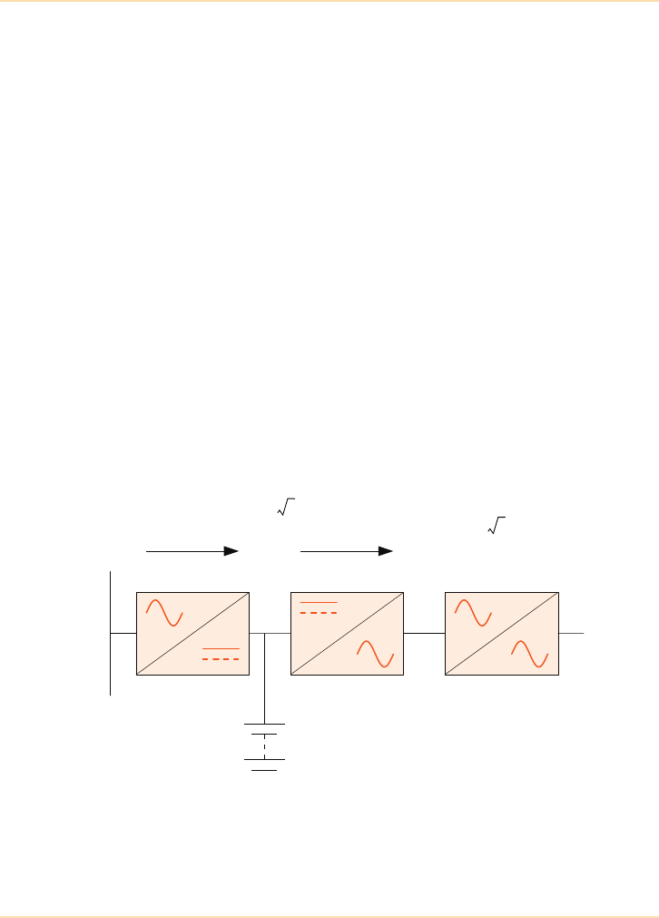
Voltage Conversions
Figure 5.2 illustrates one of the most commonly used UPS power circuit designs
in which the battery is connected directly to the rectifier’s output ‘dc busbar’.
However, due to the rectifier and inverter voltage conversion factors this design
is unusable in its basic form without the addition of a transformer.
For example, consider the case of a 240Vac single-phase fed unit:
If a 240Vac full-wave rectifier is used as the UPS’s rectifier stage, the theoretical
maximum dc busbar is approximately 340Vdc. This is possible only if the dc
busbar is unloaded and the rectifier’s dc filter capacitors (and battery) charge to
a constant level equal to the incoming peak voltage, which is not a practical
proposition. The achievable dc busbar voltage is somewhat less than this in
reality.
As the inverter is a switching circuit connected across the dc busbar, the busbar
voltage dictates the maximum possible peak-to-peak value of the inverter output
voltage. A dc busbar of 340Vdc can be seen to restrict the inverter output
voltage to 170Vpk which allows a maximum of 120Vrms – assuming a sinusoidal
output waveform.
These conditions are shown graphically in Figure 5.3.
Figure 5.2: Voltage Conversion Block Diagram
Rectifier/Charger Inverter Static Switch
Battery
Mains Supply
Output to
Critical
Load
240Vac 340Vdc 120Vac
Vbus 2xVmains
=
Vout
Vbus
22
-----------=

Major UPS Components - Introduction
The UPS Handbook 37
Figure 5.3: Voltage Conversion Waveform Diagram
Clearly, as it stands the circuit is unusable as it requires twice the dc voltage
available from the rectifier if the inverter is to produce a single phase 240Vac
output.
Traditional Transformer Solution
A traditional method of overcoming the problem highlighted above is to include
a transformer at either the input or output of the power circuit. An input
transformer can be used to step-up the mains supply to a level which increases
the dc busbar voltage sufficiently for the inverter to produce its required output.
However the main disadvantage of using this option is the significant number of
extra battery cells required to cope with the increased bus voltage – See "DC
Busbar (Battery) Voltage" on page 39.
Alternatively a transformer can be connected to the inverter output to increase
the UPS output voltage to its nominal level.
In practice both solutions can be used, although the output transformer option is
the more popular.
240Vrms
340Vpk DC busbar 340Vdc
120Vrms
Mains Supply Rectifier Output Inverter Output
Major UPS Components - Introduction
38 The UPS Handbook
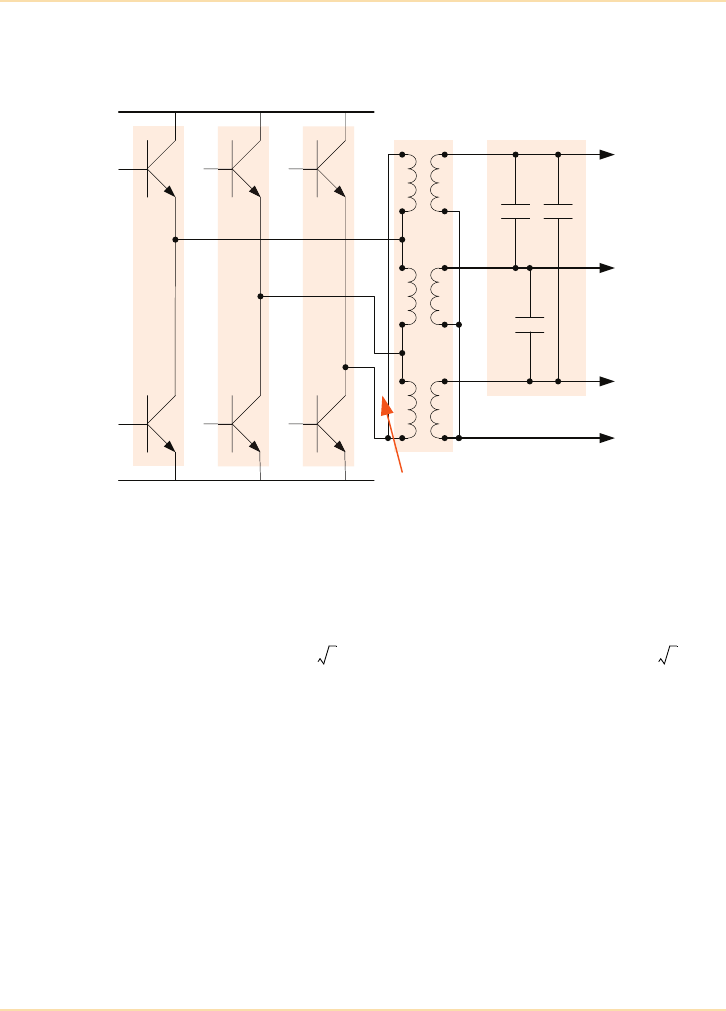
Example of a Practical UPS Output Circuit
Figure 5.4: Output Transformer
Figure 5.4 shows a practical example of a three-phase UPS output section set to
produce 400VL-L output voltage. The output transformer has a 1:2 voltage step-
up ratio, therefore the inverter output is controlled at 200VL-L which is
equivalent to 115VL-N ( ) and approximately 325Vp-p ( ).
As the inverter cannot produce a peak-to-peak output voltage greater than the dc
busbar voltage, the output waveform would clearly be clipped if the dc busbar
falls below this 325V minimum level.
Note that the output transformer does not provide galvanic isolation. The neutral
point of the secondary winding is bonded to the bypass supply neutral (where
used) to provide a common reference point between the two supplies. The
output filter works in conjunction with the output transformer to remove
switching harmonic currents from the output waveform, resulting in a clean
sinusoidal UPS output supply.
TR1 TR1 TR1
TR2 TR2 TR2
A
B
C
DC busbar
Output
Transformer
1:2
Output Filter
A
B
C
N
(115V L-N)
(200V L-L)
(230V L-N)
(400V L-L)
200 3
2x115x2

Major UPS Components - Introduction
The UPS Handbook 39
DC Busbar (Battery) Voltage
As a rule of thumb the type of batteries used in conjunction with UPS systems
are float charged at around 2.25–2.27V/cell when the mains supply is healthy
and allowed to discharge to about 1.65–1.67V/cell when providing the back-up
power source to the inverter. These figures will vary slightly depending on the
actual cell type and manufacturer.
In a typical UPS system the dc busbar voltage will vary by as much as 30%
during ‘on-battery’ operation. However, it is the end-of-discharge battery
voltage which is the limiting factor regarding the inverter output voltage.
For example, in the practical output circuit shown in Figure 5.4 the minimum
permissible dc busbar voltage was calculated to be 325Vdc. To obtain this
minimum voltage when reaching its end-of-discharge state the battery must
comprise approximately 197 cells (i.e. – in practice this could
vary by a cell or two depending on the actual battery specification).
A battery of 197 cells requires a float charge voltage of the order of 443Vdc.
This is well within the operating capabilities of a 415V three-phase power
rectifier as it can produce up to approximately 560V on its output dc busbar.
However, if the battery were to be connected to 560V is would be significantly
overcharged and would suffer catastrophic damage. To present the battery with
its correct float charge voltage the rectifier output must be ‘controllable.’ There
are several rectifier designs which satisfy this criterion but the most popular,
especially in three phase applications, is the ‘phase controlled rectifier’
comprising a full wave SCR bridge. Such a rectifier can be used to regulate the
dc busbar at 443Vdc (see Figure 5.7).
Inverter Regulation
The figures shown in Figure 5.4 illustrate the need for the inverter to provide a
regulated output voltage (115VL-N) over a wide range of dc busbar voltages –
from 443Vdc when the battery is float charged, down to 325Vdc at the end of its
discharge cycle. Some UPS systems offer a battery boost facility to reduce the
time taken to restore the battery to full charge following a discharge cycle. This
is achieved by increasing the dc busbar voltage above the normal float charge
level, and the range of dc voltages applied to the inverter is even greater. Note:
Boost charge is not suitable for all types of battery.
There are several methods of controlling the inverter to enable it to provide a
well regulated output voltage over a wide range of dc input voltages. The most
commonly used method is ‘pulse-width modulation’ (see page 57).
325 1.65196.9=

Major UPS Components - Rectifier Power Block
40 The UPS Handbook
Rectifier Power Block
Introduction
Apart from the obvious, the main difference between transformer and
transformerless UPS designs is the means used to obtain the controlled dc
busbar. Traditional, transformer based UPS designs invariably use a form of
‘phase-controlled’ rectifier to convert the incoming mains supply into a
controlled dc busbar. However, the more recent transformerless designed
systems have abandoned the phase-controlled rectifier and replaced it with a
boost-converter type switched mode power supply (SMPS), which can offer
several advantages.
The following section explains the operation of ‘phase controlled’ and ‘switch-
mode’ rectifier systems and compares the relative advantages of both methods
of implementing controlled rectification.
Basic Phase-Control Principles
This circuit is effectively a form of full-wave rectifier, either single or three
phase fed, that employs silicon controlled rectifiers (SCRs) rather than diodes.
The bridge output is controlled by delaying the SCR turn-on action with respect
to the point at which it becomes forward biased. By doing this the amount of
energy allowed through the rectifier is reduced from that of an equivalent diode
bridge as illustrated. Figure 5.5 shows a single SCR connected in a simple ac
circuit and can be used to illustrate the basic principles of phase control
techniques. Note that the half-wave circuit shown has no practical use but is
shown for simplicity.
The top diagram shows the conditions where the SCR gate is held permanently
positive with respect to its cathode – this is equivalent to providing the SCR
with a permanent turn-on signal. In this condition the SCR passes current during
the whole of the input ac positive half-cycle but blocks the negative half-cycle
because the anode-cathode are reverse biased during the ‘negative’ period. This
results in a ‘half-wave rectified’ voltage being developed across the load
resistor, and the SCR can be seen to perform exactly the same as a normal
rectifier diode. In this example the mean (dc) load voltage is approximately 0.45
times the peak ac voltage, and is shown as a dotted line superimposed on the
output waveform.
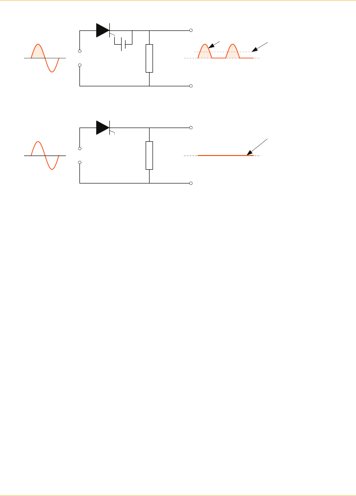
Major UPS Components - Rectifier Power Block
The UPS Handbook 41
Figure 5.5: Basic SCR Principles
In the lower diagram the SCR has no gate drive voltage and, under these
circumstances, is permanently turned off during both halves of the input
waveform. In this case the mean (dc) load voltage is of course zero.
The two conditions illustrate the ‘maximum’ and ‘minimum’ output voltages
obtainable from this simple circuit. However, this voltage can be varied between
these two extremes using phase-control techniques.
The top diagram of Figure 5.6 illustrates the situation where the SCR gate is
triggered when the input waveform is 45° into its positive half-cycle. Under
these conditions the SCR conducts during the period between 45° and 180° only
– i.e. it is not turned on between 0° and 45°, and is turned off by natural
commutation after 180°. As shown in the top waveform diagram, this results in a
mean dc voltage Vdc(mean) that is slightly less than maximum Vdc(max).
In the lower diagram the SCR gate trigger is delayed by a further 45°, to a total
of 90°, which leads to a further reduction in output voltage.
This is the basic principle of a ‘phase-controlled’ rectifier, where the rectifier
output voltage is controlled anywhere between its maximum and minimum
limits by applying a variable phase delay between the point at which the SCR
becomes forward biased and the application of its gate drive signal.
The period for which the SCR is allowed to conduct is often referred to as its
‘conduction angle’.
Input AC
+
RL
Max. output
SCR gate permanently ON
Vdc (max) Vdc (mean)
Input AC
RL
0V
Min. output
SCR gate permanently OFF
Vdc (mean)
0V
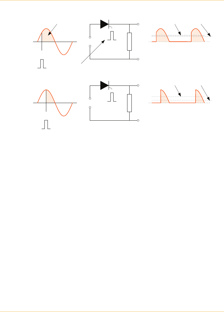
Major UPS Components - Rectifier Power Block
42 The UPS Handbook
Figure 5.6: Phase Control Principles
Six-Pulse Rectifier
Figure 5.7 shows a three-phase full-wave controlled rectifier. Each SCR controls
the rectifier conduction angle during one half-cycle period of an input cycle.
Taking the R phase as an example, the top SCR (A+) controls the A phase
positive half-cycle, and the lower SCR (A–) controls the negative half-cycle. In
the practical circuit all six SCRs are controlled at the same conduction angle in
order to maintain balanced input line conditions.
Looking at the A phase positive half-cycle (A+) in detail, the three-phase
waveform diagram shows that this device is forward-biased only for a 120°
period between 30° and 150° of the incoming A phase waveform. This means
that the bridge output voltage can be controlled over its full range by controlling
the SCR over this conduction angle.
This circuit is sometimes referred to as a ‘six-pulse’ phase-controlled rectifier
because six SCRs are turned on during each complete three-phase cycle.
Input AC
RL
Output waveform at 45° delay -
Vdc(mean) is slightly less than the
max available dc voltage Vdc(max)
Vdc (max) Vdc (mean)
RL
0V
0 90 270180 360
Gate ON
SCR conducts only during
the shaded period of the
input positve half-cycle
SCR turned ON
by gate pulse
0 90 270180 360
Gate ON
Output waveform at 90° delay -
Vdc(mean) is even less than that at
45° delay
Vdc (max) Vdc (mean)
0V
Input AC
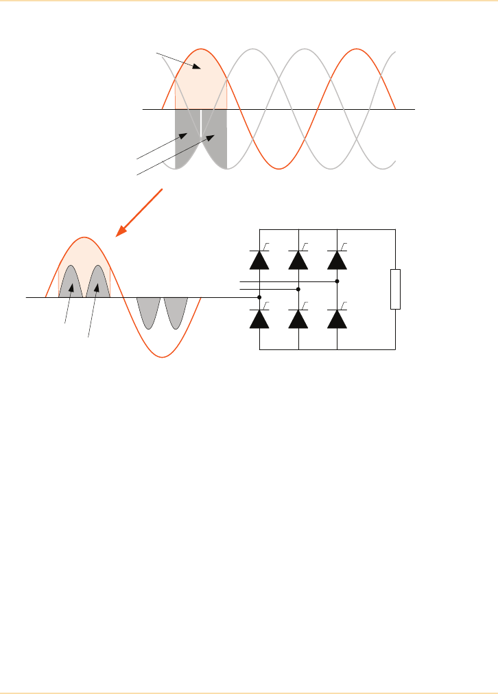
Major UPS Components - Rectifier Power Block
The UPS Handbook 43
Figure 5.7: Three Phase (6-pulse) Phase Controlled Rectifier
Harmonic Current Generation
The A-phase positive SCR current is shown in Figure 5.7 to comprise two
pulses, corresponding to the commutation changeover from the B- and C-
phases.
When the load current is discontinuous or is not proportional to the line voltage,
the overall effect is equivalent to the presence of harmonically related higher
frequency components of current superimposed upon the fundamental 50Hz
sinusoidal current. All these components added together equal the actual current
wave shape. Since each of the current components is not in phase with the line
voltage, the products of voltage and current represent reactive Volt-Amperes.
These harmonic currents interact with the mains power source impedance to
create line voltage distortion. They also reduce the UPS input power factor,
increase loading on the mains power circuits, and create additional electrical
losses. A low impedance power source will minimise line voltage distortion, but
will not correct the source of the problem.
R
L
A+ B+ C+
A-B- C- B- C-
30° 90° 150°
A+ B+ C+
A- B- C-
A+
A-
Shaded area shows A+ SCR
forward bias period
Return path period:
First via B- SCR
then via C- SCR
B current
C current

Major UPS Components - Rectifier Power Block
44 The UPS Handbook
Input Total Harmonic Distortion (THDi)
The level of harmonics created by the rectifier switching is measured as the
input current total harmonic distortion (THDi) and in a six-pulse rectifier will be
typically 30% to 35%. For medium and large UPS systems such high input
current THD will cause site mains voltage distortion that may well adversely
affect the operation of other equipment connected to the mains supply (See
"Applicable Standards" on page 257). Additionally, the power generated by the
harmonics that create the distortion must be supplied by the available mains and
is therefore wasted energy. For these two reasons high input current THD is very
undesirable (see "Reducing Input THDi" on page 49).
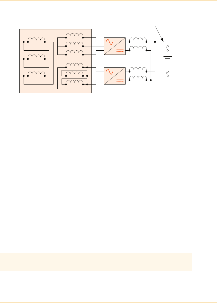
Major UPS Components - Rectifier Power Block
The UPS Handbook 45
Twelve-Pulse Rectifier
Figure 5.8: Twelve-Pulse Rectifier Block Diagram
A costly, but effective, means of reducing the harmonics is to use a twelve-pulse
rectifier which employs two three-phase (six-pulse) rectifiers operating at 30°
with respect to each other. An example circuit is shown in Figure 5.8, which
shows that the phase shift is produced by a suitable transformer connected
between the rectifiers and mains supply. The rectifier output dc busbars are
connected in parallel via large chokes to dampen the load currents and facilitate
current sharing.
This circuit helps attenuate the harmonics in two ways. First, because there are
now twelve SCR switching actions per 50Hz cycle rather than six, the frequency
of the pulses imposed on the mains supply is double but their individual
amplitudes are lower, making it easier to filter the harmonics if a separate filter
circuit is also used. Second, due to the 30° phase shift the triplen harmonics
between the two rectifiers are now in anti-phase and should cancel each other. A
twelve-pulse rectifier will reduce the input current THD from about 30% to
about 10%. For both the input filter and 12-pulse rectifier solutions the size and
cost of the additional components can become significant when dealing with
large UPS modules and will most likely require housing in additional equipment
cabinets.
12 pulse rectifiers are expensive, reduce the UPS system efficiency and
increase the total footprint of the UPS system which adds to installation costs.
Phase Shift Transformer
Rectifier 1
Rectifier 2
A
B
C
A
B
C
A
B
C
Battery
Regulated DC busbar
Mains Supply

Major UPS Components - Rectifier Power Block
46 The UPS Handbook
Input Power Factor
In a phase-controlled rectifier the current waveform progressively lags the input
voltage waveform as the rectifier conduction angle reduces – i.e. as the rectifier
output dc busbar voltage is reduced.
A classical definition of power factor (pf), is that it is equal to the cosine of the
phase angle between the voltage and current in an ac circuit. Therefore the input
power factor is directly affected by changes in the rectifier conduction angle,
falling further from unity as the rectifier phases back.
This concept of power factor is true only if the voltage and current concerned
are sinusoidal and at the same frequency. However, it has already been shown
that the currents associated with the phase-controlled rectifier are not sinusoidal,
but are rich in harmonics which cause a circulation of wattless power within the
circuit. The generated harmonics therefore affect the power factor in addition to
the prevailing rectifier conduction angle.
A typical phase-controlled rectifier used in a UPS application will produce a
power factor of around 0.8 when operating on full load and charging the battery.
The reduced input harmonics attained when using a twelve-pulse rectifier will
typically improve this to around 0.86.
Some of the disadvantages of the phase-controlled rectifier, such as harmonic
generation and less than unity power factor, are addressed by the boost converter
circuit used in the transformerless UPS design.
Boost Converter – (Transformerless UPS)
The boost converter circuit is a form of peak-current switching regulator
normally associated with dc-dc converters rather than the ac-dc conversion
utilised in this application. To understand how the circuit works it is best to
consider the operation of a standard dc-dc converter and then discuss its
additional control features. Figure 5.9 shows a simplified diagram of a boost
converter operating with a dc input supply.
If the input voltage (E) in the circuit above is held constant (i.e. a dc value) and
transistor Q1 is never turned on then clearly all that will happen in the circuit is
that positive dc bus reservoir capacitors C1/C2 will charge to the input voltage
(+E volts) via D1/D3.
If a logic high pulse is applied to Q1 gate it will turn hard on and effectively
ground the right-hand side of L1 (via D1/D2). This will not affect the charge on
C1/C2 as D3 blocks any discharge current. However, it will increase the current
drawn through L1 and D1/D2. The amount of increased current depends on the
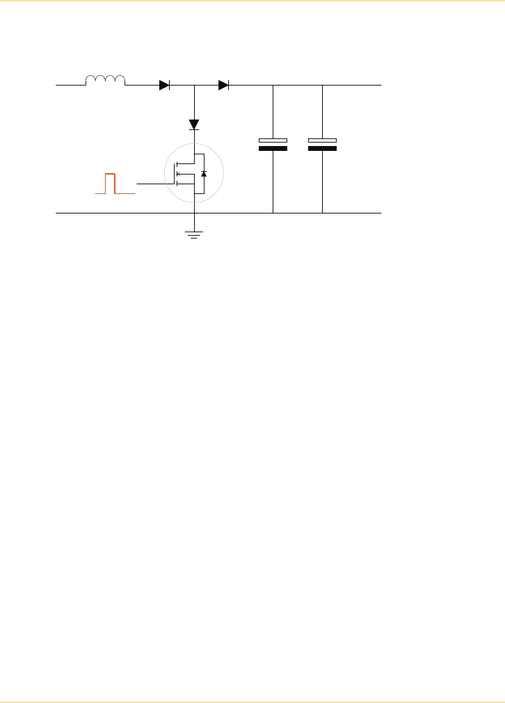
Major UPS Components - Rectifier Power Block
The UPS Handbook 47
values of the input voltage (+E) and the drive pulse width - and can be described
using the formula E = -Li/t .
Figure 5.9: Boost Converter Basic Principles
As the input voltage (E) and inductance are both constant, the current through
L1 increases linearly while Q1 is turned on and therefore reaches a peak value at
the end of Q1’s drive pulse.
Q1 turns off when the drive pulse is removed from its gate. However, the current
through L1 cannot reduce to zero instantaneously (one of the properties of a
choke) and since Q1 now represents an open circuit the only path available for
the decaying current is through D3 and C1/C2, which therefore charge up to a
voltage greater than the input voltage. The voltage across these capacitors forms
the dc busbar voltage.
Another way to view this action is to consider that the energy stored in the
magnetic field around L1 when it draws current (½LI2) is transferred to
capacitors when Q1 turns off.
In the practical UPS boost converter circuit the current passing through D3 not
only charges the capacitors but also supplies the UPS load (via the inverter).
C1/C2 therefore act as a reservoir capacitor, taking on charge when D3 is
passing current (Q1 off) and providing the dc busbar load current when Q1 is
turned on.
In a standard dc-dc converter the output voltage is regulated by comparing it
with a reference level and using any resulting error signal to control the width or
frequency of the drive pulse. For example, if the circuit's output voltage falls
below the reference level, the control circuit would increase the pulse width (or
increase the pulse repetition rate), allowing more current to build up in the
choke and thereby restore the output voltage to its nominal value.
DC
Input
DC
Ouput
+
-
+
-
D1
D2
D3
Q1
C1 C2
L1
“E”

Major UPS Components - Rectifier Power Block
48 The UPS Handbook
Benefits
The boost converter, shown in Chapter 6, in the transformerless UPS block
diagram essentially works in the same way as the dc-dc boost converter. The
major difference between the two circuits is that the input voltage is from the ac
mains supply and not a fixed dc level. To overcome the fact that the circuit is fed
with an ac voltage, the transistor drive pulse is made very narrow compared with
the period of the input supply by using a high switching rate, typically between
20kHz and 100kHz. If for example a 50kHz switching rate is used it will have a
maximum pulse width of 20 µs and the transistor will switch on and off 100
times during a 50Hz mains cycle.
If this is the case, the duration of the turn-on pulse is so short compared with the
incoming ac cycle that the input to the boost converter can be considered to be
constant during the pulse period.
Thus every time the transistor turns on it ‘sees’ a ‘constant’ voltage which is
marginally higher or lower, depending on whether the sinusoidal waveform is
rising or falling, than that which was present at the previous pulse.
The circuit maximises the input power factor by controlling the input current in
such a way as to not only make it sinusoidal but also keep it in phase with the
input voltage. This is achieved by pulse-width modulating the drive signal
applied to Q1 – i.e. by turning Q1 on for shorter periods when the input mains
voltage is at the low points of its waveform, drawing less current, and for longer
periods when it is at the higher points. This means that although Q1’s drive
signal is held at a constant frequency, the mark-to-space ratio (or duty cycle) is
made to vary in sympathy with the input voltage waveform amplitude.
The waveform diagram Figure 5.10 shows the principles of this circuit by
illustrating the rising and falling current pulses superimposed on the input
voltage waveform. However, this diagram shows only a few current pulses (due
to the restriction of the drawing definition) and in practice the current waveform
outline at 50kHz is very smooth in comparison to that shown.
The converter diagram in Figure 5.9 and waveforms in Figure 5.10 help describe
the action only during the positive half-cycle of the input mains supply. In
practice a second, identical converter is used to process the negative mains half-
cycle and the outputs from the two converters are combined to provide a single
dc busbar equal to their collective value.
In addition to the improvements in harmonic generation and input power factor
correction, the advantages of the boost converter over the phase-controlled
rectifier as the UPS front end are clear. Not only does it contain fewer power
components, making it less expensive and lighter, but it also leads to a smaller
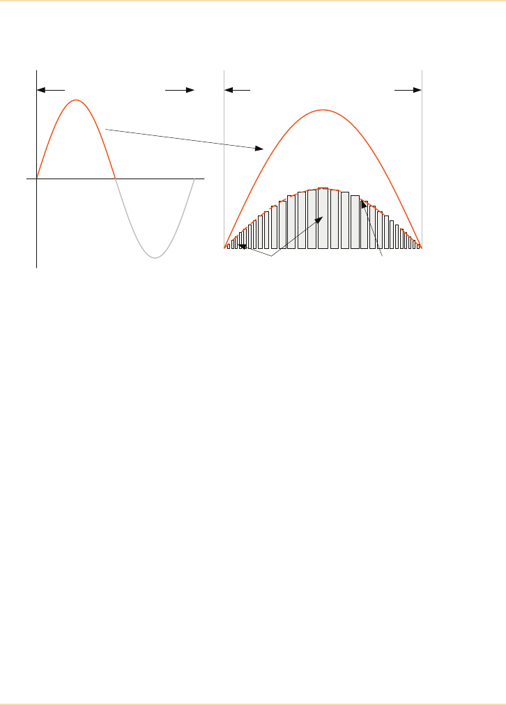
Major UPS Components - Rectifier Power Block
The UPS Handbook 49
UPS cabinet footprint due to the lack of twelve-pulse input transformer and/or
additional heavy harmonic filter components.
Figure 5.10: Power Factor Correction
Reducing Input THDi
The acceptable degree of harmonics generated as a result of connected load
equipment is specified in the Energy Networks Association Engineering
Recommendation G5/4-1 (See page 264). It is therefore necessary to take steps
to reduce such harmonics wherever possible.
Transformer Based UPS
A 6-pulse rectifier generates THDi levels in the region of 30%. This high level
can be reduced to around 10% by utilising a 12-pulse rectifier which can be
lowered even further (to around 5%) by installing passive filtering.
Passive Filters
Passive filtering can be fitted to both 6 and 12 pulse rectifiers but this is not an
inconsequential or inexpensive option as the filter components must be inserted
into the input power cabling and rated at mains voltage and able to carry the full
UPS input current.
20mS period (50Hz)
Individual current pulses
are wider as the mains
voltage rises to a peak
Input current envelope
follows the mains supply
voltage waveform
One 10mS positive half-cycle
of the mains supply
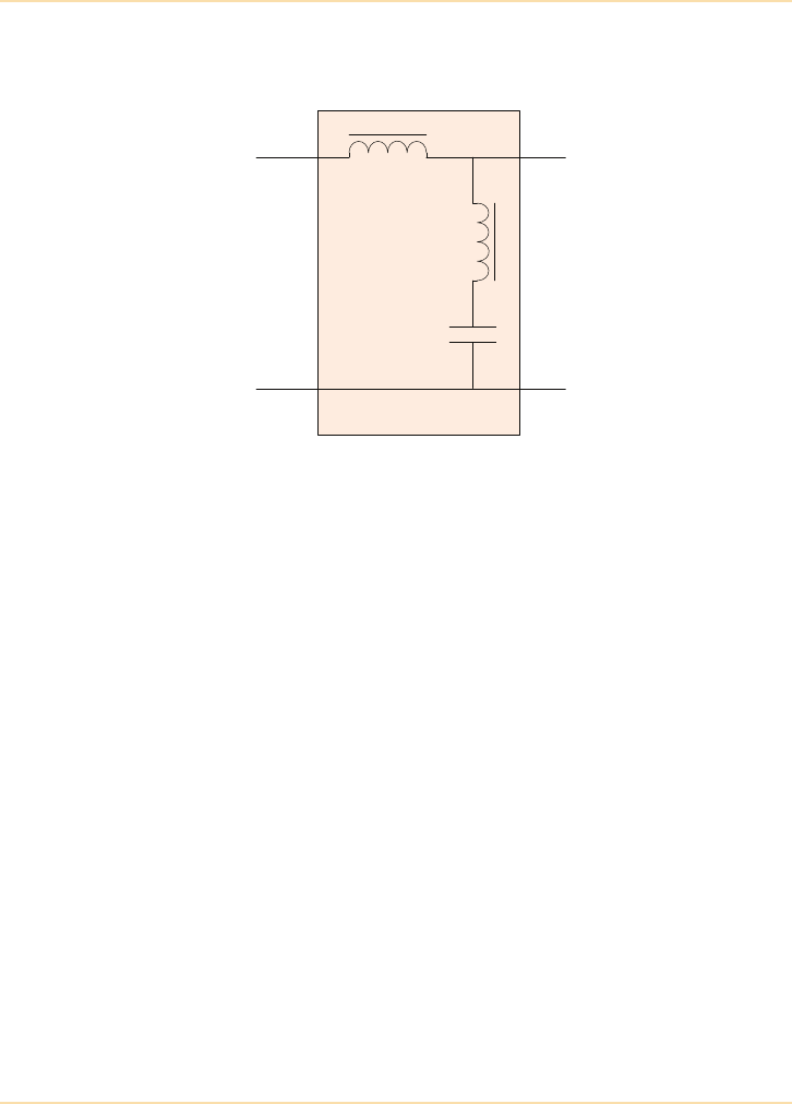
Major UPS Components - Rectifier Power Block
50 The UPS Handbook
Passive filters generally comprise a combination of inductors and capacitors
shunt tuned to the worst offending harmonic.
Figure 5.11: Passive filter arrangement
Passive input filters can cause problems at light UPS loads, since under these
circumstances the only load ‘seen’ by the input mains is the filter circuit itself.
This can cause the UPS input power factor to drift from lagging to leading,
which may present problems for generator alternators.
Transformerless UPS
The latest generation of transformerless UPS systems (See "Transformerless
UPS Systems" on page 73) employ active filters to continuously monitor and
counteract the effects of unwanted harmonics generated by the rectification
process. This can result in THDi levels of less than 2% at full load and around
3.5% at 25% load.
Input Filter
Mains
input
Output to
Rectifier
L1
L2
C1
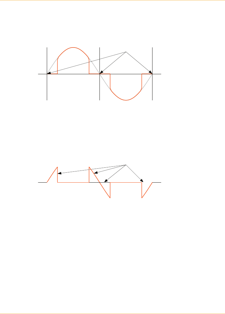
Major UPS Components - Rectifier Power Block
The UPS Handbook 51
Active Filters
An active filter works by monitoring the input current waveform at all times and
“adjusting” it when it varies from the ideal, perfect, sinewave.
Figure 5.12: Zero crossing waveform distortion
The majority of the harmonic distortion occurs at, or near to, the zero crossing
point of the current waveform where almost no current is drawn from the supply
by the rectification process. The active filter purposely draws current during this
period.
Figure 5.13: Active filter current
The sum of the rectification current and the active filter current is a mains-drawn
current waveform approaching the ideal.
The current drawn by the filter is used to charge the UPS battery, reducing the
load requirement of the standard rectifier and maintaining a high efficiency.
Zero Crossing
Points
Active Filter
Current
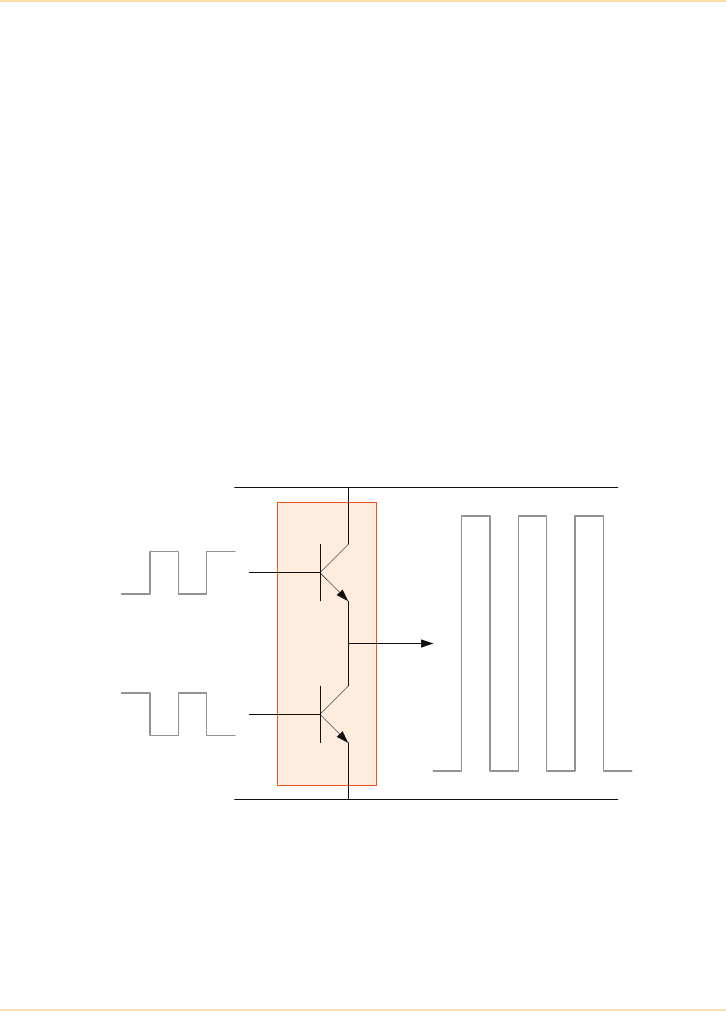
Major UPS Components - Inverter Power Block
52 The UPS Handbook
Inverter Power Block
As previously explained, the purpose of the inverter is to convert the dc busbar
(battery) voltage into an ac output suitable for connecting to the load. In the case
of the double-conversion, on-line UPS models considered in this chapter, the
inverter output is a synthesised 50Hz sine-wave.
Since the inception of solid state UPS the advances in inverter technology have
been vast. Early inverter designs exceeding a few kVA invariably used SCRs as
their base switching components, later to be superseded by bi-polar transistors
when devices with sufficient power rating were introduced – parallel-connected
transistors were often used to meet the inverter power requirements. Today,
modern inverters tend to use Insulated Gate Bipolar Transistors (IGBT) devices,
which offer very reliable high power operation.
Although SCR-based inverters are still operating in the field they have virtually
disappeared from current design briefs, and for this reason the inverters
discussed in this section relate only to those of transistorised design.
Inverter-Phase ‘Switch’ Analogy
Figure 5.14: Inverter Phase Switch Analogy
An inverter is a switching circuit comprising two transistors connected in series
across the dc busbar, as shown in Figure 5.14. In this diagram the transistor
connected to the positive dc busbar is identified as TR1 and the one connected to
the negative dc busbar as TR2. The connection at the junction of the two
transistors provides the inverter output.
Inverter
Phase
Inverter Drive
Waveforms Output
TR1
TR2
DC busbar (+)
DC busbar (-)
DC bus (+)
DC bus (-)

Major UPS Components - Inverter Power Block
The UPS Handbook 53
The inverter power components are usually assembled on a large heatsink which
is often referred to as an ‘inverter phase’.
When this circuit is used as a switch it has two stable states of interest: first,
when TR1 is switched on and TR2 is off the inverter output is effectively
connected to the positive dc busbar. Second, when the transistors are in their
opposite state the output is connected to the negative dc busbar. Ignoring any
voltage drop across the switching devices themselves, by alternating between
these two stable states the inverter output voltage is made to switch between the
dc busbar voltages.
Clearly, the transistors’ low power drive signals must always be in anti-phase for
this circuit to operate as shown, because if both transistors turn on
simultaneously they will create a short circuit on the dc busbar and cause an
equipment failure.
DC-AC Conversion (Output AC Voltage Production)
In Figure 5.14 the two inverter transistors were shown operating with a 50%
duty cycle. That is, the transistor turn-on and turn-off period were equal. This
produces a square-wave output waveform with a peak-to-peak value equal to the
dc busbar voltage and with a frequency determined by the drive signal
frequency.
Note that the dc busbar is usually derived from some form of full-wave
controlled rectifier and is in practice approximately equidistant from neutral –
for example if the bus voltage is 450Vdc the busbars will be approximately
±225Vdc with respect to neutral (ground).
The output waveform shown above is not suitable for supplying the critical load
equipment and it must be converted to a 50Hz sinusoidal format, equivalent to
the mains supply. The method used almost universally to obtain a sinusoidal
inverter output is that of Pulse-Width Modulation (PWM) and is described
below.
Before discussing in depth the pulse-width modulation (PWM) methods
employed to control the inverter output voltage, it is necessary to gain a basic
understanding of the effects of varying the pulse width of the inverter drive
waveforms together with the fundamental principles of the output filter.
Begin by considering the effects on the output waveform of a single inverter
power block when switching the inverter transistors at a constant rate (known as
the ‘modulation frequency’) but at various mark to space ratios.

Major UPS Components - Inverter Power Block
54 The UPS Handbook
This is illustrated in Figure 5.15 overleaf, which shows the inverter output
waveform when TR1 and TR2 are turned on at ratios of 2:1, 1:1, and 1:2
respectively.
The top diagram illustrates the case where the inverter is operating at a constant
2:1 mark-to-space ratio (m:s) – i.e. TR1 ON period being twice that of TR2 –
which results in a ‘mean’ output voltage (with respect to the negative dc busbar)
approximately equal to 66% of the dc busbar voltage.
In the middle illustration the transistors are shown operating at a mark/space
ratio of 1:1 (i.e. equal ON and OFF periods). In this example the inverter output
is a true square wave and has a mean voltage approximately equal to 50% of the
dc busbar voltage – once again with respect to the negative dc busbar.
A m:s ratio of 1:2 is shown in the lower illustration to produce a mean voltage of
approximately 33%.
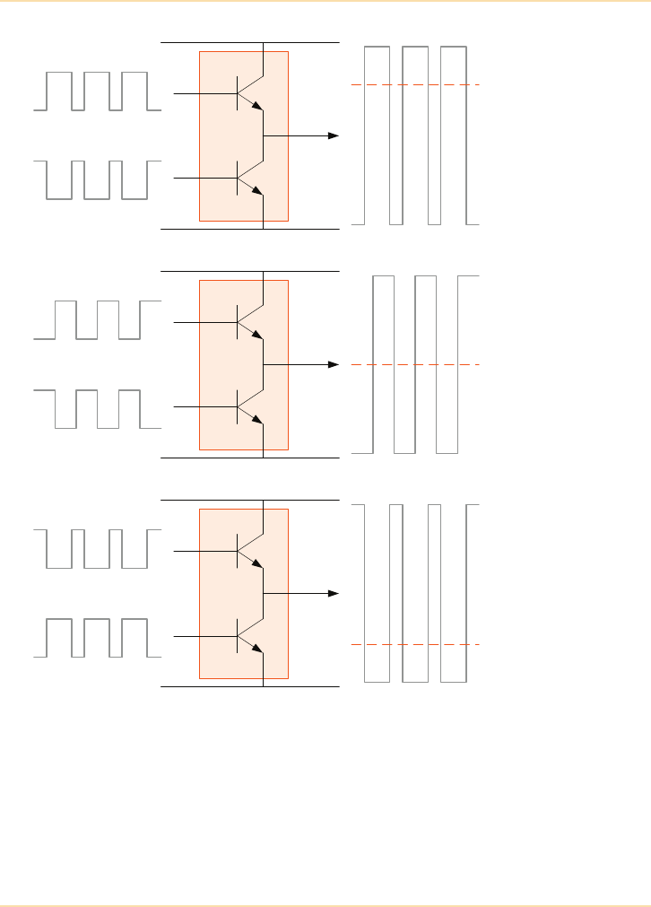
Major UPS Components - Inverter Power Block
The UPS Handbook 55
Figure 5.15: Effects of Varying Drive Signal Mark to Space Ratio
Notice that in the above examples the inverter switching frequency (or
‘modulation frequency’) is constant in all three cases and the ‘mean’ output
voltage is varied by changing the mark-to-space ratio of the drive signals only.
DC bus (+)
DC bus (-)
Inverter
Phase
Inverter Drive
Waveforms 2:1 Output
TR1
TR2
DC busbar (+)
DC busbar (-)
Inverter
Phase
Inverter Drive
Waveforms 1:1 Output
TR1
TR2
DC busbar (+)
DC busbar (-)
Inverter
Phase
Inverter Drive
Waveforms 1:2 Output
TR1
TR2
DC busbar (+)
DC busbar (-)
DC bus (+)
DC bus (-)
DC bus (+)
DC bus (-)
Mean output
66%
Mean output
50%
Mean output
33%
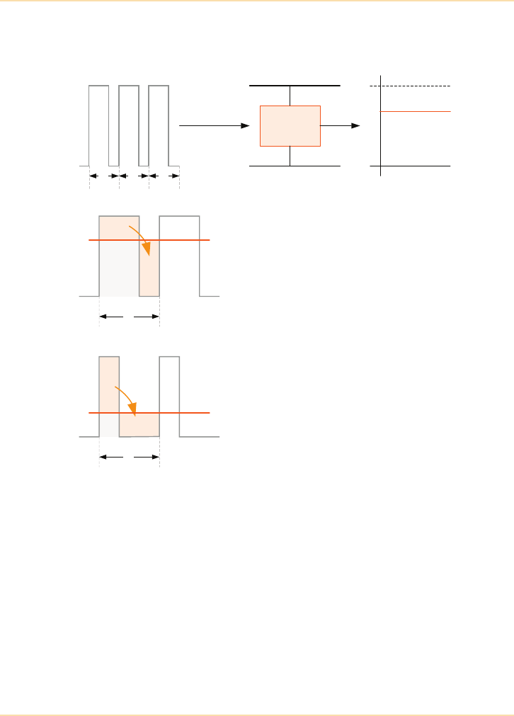
Major UPS Components - Inverter Power Block
56 The UPS Handbook
Basic Filter Principles
Figure 5.16: Basic Filter Action
In the examples shown in Figure 5.15 the ‘mean’ output voltages are obtained
by filtering the variable m:s output waveforms. The filter works by absorbing
energy (charging) when the pulse is present and returning it back to the circuit
(discharging) when the pulse is absent – i.e. energy is stored during the mark
period and returned to the circuit during the space period of the output
waveform. This has the effect of averaging-out the energy provided by each
pulse over the complete pulse period (e.g. P1, P2...), as shown in Figure 5.16 –
i.e. the ‘mean’ value is the integral of the pulse width (shown shaded) taken over
each complete pulse period (P1, P2...). In each of the examples in Figure 5.16
the ‘mean’ voltage produced is proportional to the width of the output voltage
pulse.
A
A
Mark
Space
P1 P2 P3
2:1 M:S
Waveform
DC busbar (+)
DC busbar (+)
Filter
100%
66%
0%
Output
P1
Mean
voltage
B
A
A
P1
Mean
voltage
B
The above 2:1 m:s waveform shows three
pulses of mark + space period ‘P’. The
waveform to the left illustrates the effects
of the filter for period 1 (P1) and shows
how part of the energy (A) absorbed
during the mark period is put back into the
circuit during the space period, leading to
the ‘mean’ voltage shown.
This waveform illustrates the same
principles at a 1:2 mark space ratio. In this
case less energy is stored during the mark
period due to its shorter duration;
therefore the ‘mean’ value is lower.

Major UPS Components - Inverter Power Block
The UPS Handbook 57
Pulse-Width Modulation
Pulse-width modulation entails generating rectilinear output voltage pulses at a
repetition frequency considerably higher than the fundamental frequency
(50 Hz) and modulating their duration so that the integrated value of each pulse
is proportional to the instantaneous value of the required fundamental
component at the time of its occurrence. That is, the pulse duration is modulated
‘sinusoidally’ – as illustrated in Figure 5.17.
In practice, the modulation frequency is typically several kHz. However, for
ease of illustration Figure 5.17 shows a modulation frequency of only 16 times
the output frequency – i.e. eight pulses per output half-cycle.
Figure 5.17A shows an expanded view of a positive half-wave sinewave with
eight instantaneous values plotted at times t0 to t8. These coincide with the
centre of each pulse period: for example, the instantaneous voltage at time t1
coincides with the centre of the period allocated for pulse 2 (P2).
Figure 5.17B shows the individual pulses P1-P9 superimposed on the
instantaneous voltage plot and illustrates how varying pulse widths are
employed to ensure that the ‘mean’ value of the pulse equals the plotted
instantaneous value for the particular pulse period. In each case the pulse
amplitude is identical and comprises a ‘light’ and ‘dark’ shaded area – where the
‘dark’ shaded portion represents the ‘mean’ amplitude. For example, the ‘mean’
value resulting from the m:s ratio of the pulse during P3 equals the
instantaneous voltage plotted at t2. This is shown in more detail in Figure 5.17C,
here the ‘lightly’ shaded portion at the top of pulse P3 is shown to replace the
space left at either side of the pulse.
A representative complete output cycle is shown in Figure 5.18.
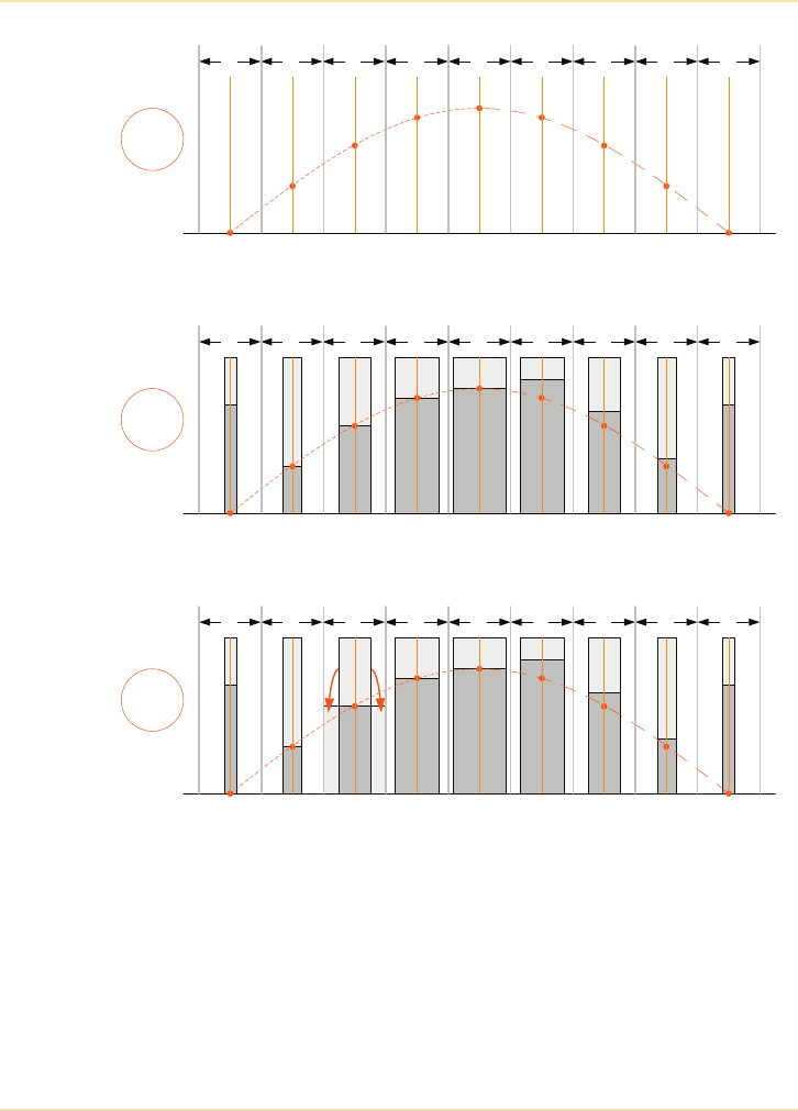
Major UPS Components - Inverter Power Block
58 The UPS Handbook
Figure 5.17: PWM Control Principles
P1 P2 P3 P4 P5 P6 P7 P8 P9
t0t1t2t3t5
t4t6t7t8
0° 90° 180°
P1 P2 P3 P4 P5 P6 P7 P8 P9
t0t1t2t3t5
t4t6t7t8
0° 90° 180°
P1 P2 P3 P4 P5 P6 P7 P8 P9
t0t1t2t3t5
t4t6t7t8
0° 90° 180°
A
B
C
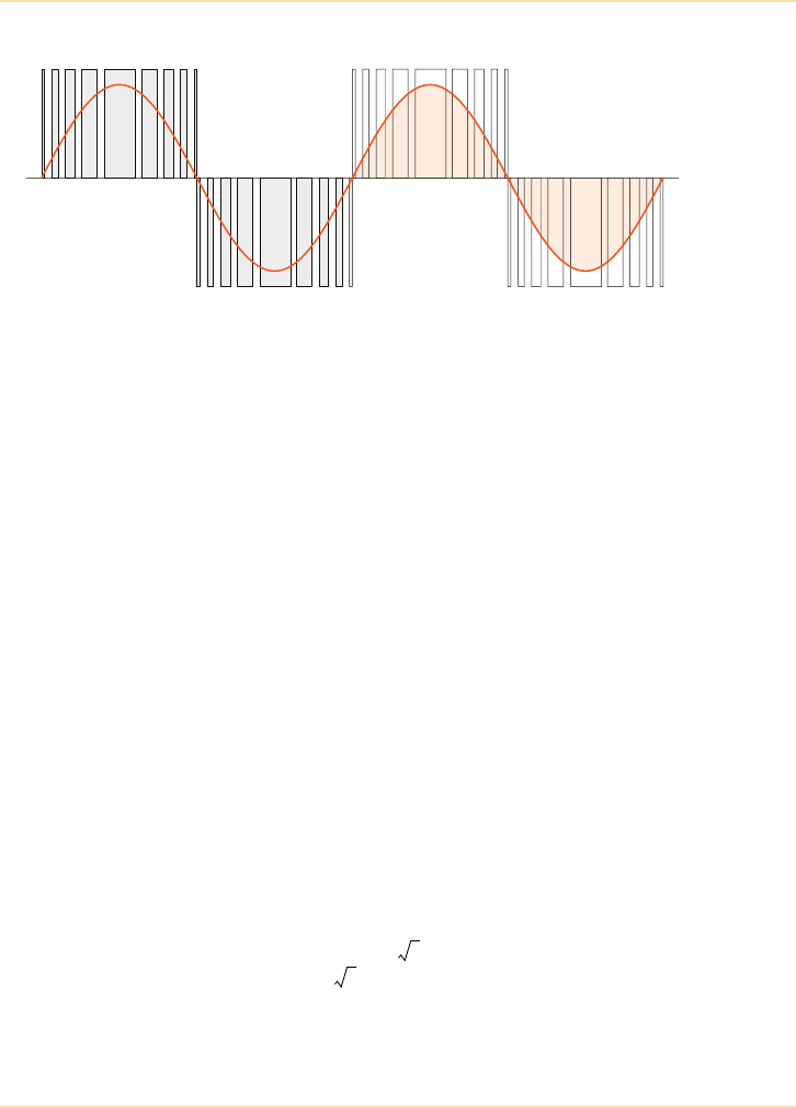
Major UPS Components - Inverter Power Block
The UPS Handbook 59
Inverter PWM Duty Cycle
Figure 5.18: Output Power Derivation
The power delivered to the load by the inverter can be described mathematically
as the integral of the voltage and current:
A PWM-controlled inverter provides load power each time it is turned on.
Therefore the power produced by the inverter during each output cycle is
represented by the total area of the pulses contained in that cycle. Thus, when
dealing with a PWM waveform the integral equation above can be visualised by
considering that the area of the output sinewave is equal to the sum of the areas
of the individual pulses used to generate the sinewave (See Figure 5.18). The
total amount of time the inverter power devices are turned on and delivering
load-power during each output cycle can be described in terms of the inverter’s
duty cycle. As will be shown below, this varies in accordance with the available
dc busbar voltage and the prevailing load current demand.
Effects of the DC Busbar Voltage on the PWM Duty Cycle
Figure 5.19 illustrates a typical UPS output section set to operate at a standard
400Vac output voltage. The output transformer has a 1:2 voltage step-up ratio,
therefore the inverter must operate at 200 VL-L – this example was used earlier
to describe the transformer-based system (See Figure 5.4). A voltage of
200VL-L is equivalent to 115VL-N (i.e. ) which in turn equals
approximately 325Vp-p (i.e. ). This defines the minimum
permissible dc busbar voltage because the inverter cannot produce a peak-to-
peak output voltage greater than the dc busbar voltage itself.
VI td
0
2
200 3
2 1152
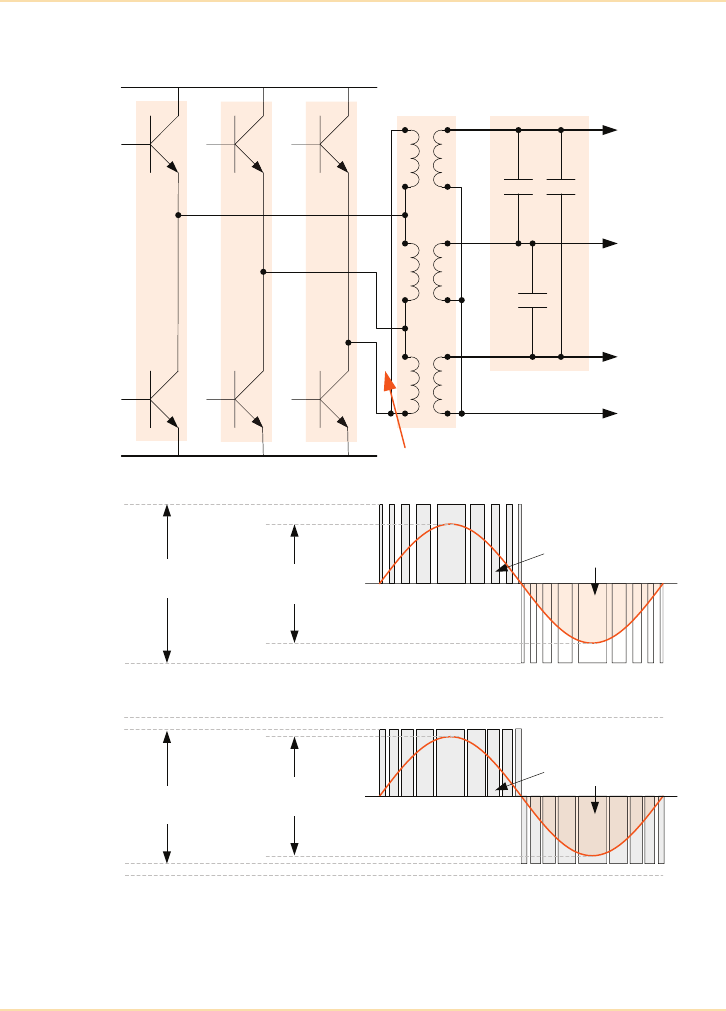
Major UPS Components - Inverter Power Block
60 The UPS Handbook
Figure 5.19: Effects of Falling DC Busbar Voltage on the
PWM Duty-Cycle
Inv Voltage
326Vp-p
DC Busbar
360Vdc
DC bus +225Vdc
DC bus -225Vdc
Combined area of
pulses equals the
area under output
sinewave
DC bus +225Vdc
DC bus -225Vdc
DC Busbar
450Vdc Inv Voltage
326Vp-p
Combined area of
pulses equals the
area under output
sinewave
TR1 TR1 TR1
TR2 TR2 TR2
A
B
C
DC busbar
Output
Transformer
1:2
Output Filter
A
B
C
N
(115V L-N)
(200V L-L)
(230V L-N)
(400V L-L)

Major UPS Components - Inverter Power Block
The UPS Handbook 61
In practice, the minimum dc busbar voltage is usually set to 1.67V per battery
cell, and this example system would typically employ 198 cells under these
circumstances which leads to a minimum dc busbar voltage of 330V.
This results in a dc busbar ranging from 450Vdc when the batteries are being
float charged and 330Vdc at the ‘end-of-discharge’ voltage – at which point the
inverter is shut down.
It has already been shown that in each output cycle the area of the sine-wave is
equal to the combined area of the associated PWM pulses; and also that the
amplitude of the inverter pulses is equal to the dc busbar voltage. Therefore,
when the batteries are on-load, and the dc busbar voltage falls from 450 V to
330 V, the width of the PWM pulses must increase proportionally as their
amplitude decreases in order to maintain a constant output voltage. This is
illustrated in Figure 5.19. Notice that this diagram shows that the peak, and
therefore rms, value of the inverter output remains constant as the bus voltage
falls. Once again, for reasons of clarity the illustration in Figure 5.19 uses only
16 PWM pulses per cycle.
In a typical PWM inverter the duty cycle will vary from 75° when the inverter is
off-load and the dc busbar is operating at its nominal float voltage value, to
about 105° when operating at the end-of-battery-discharge voltage.
Effects of the Load Demand on the PWM Duty Cycle
The PWM waveform duty-cycle is directly affected by variations in the
demanded load current. For example, the previous paragraph illustrated that
when operating off-load from the normal busbar, the duty-cycle is
approximately 75°. However, if the inverter is loaded under these conditions the
PWM pattern would require increased pulse widths to maintain the output
waveform while allowing more power through to the load. In practice, this
would increase the duty-cycle by around 5°.
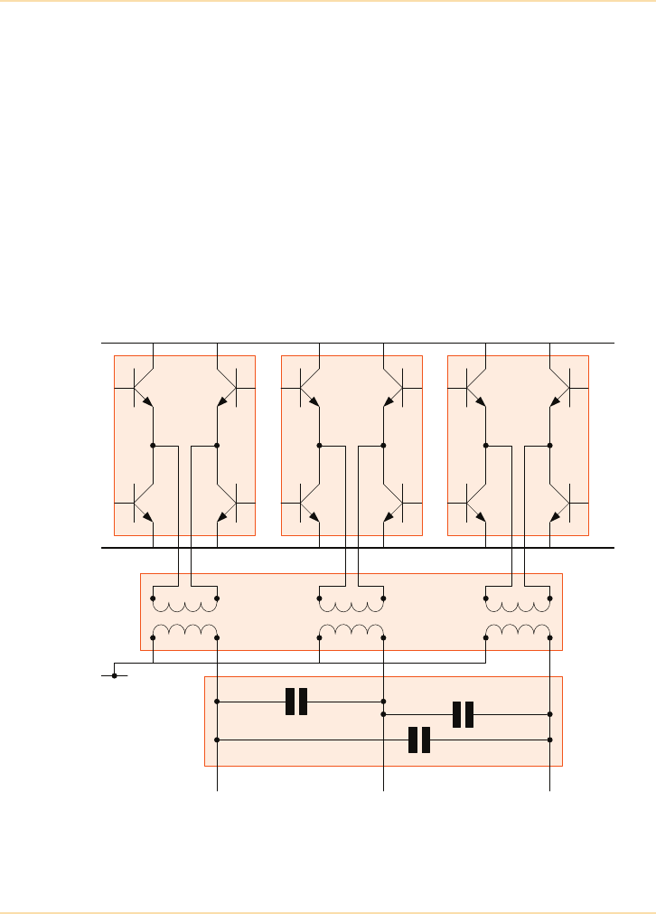
Major UPS Components - Inverter Power Block
62 The UPS Handbook
Inverter Output Detail
In a UPS system fitted with an output transformer to boost the inverter voltage
to that required at the UPS output there are two configurations in common use.
The first contains three inverter phases whose outputs are connected to a delta-
star transformer, as shown previously in this chapter (See Figure 5.19). This
configuration is sometimes referred to as a ‘single-ended’ inverter.
The second configuration employs two inverter switching blocks per output
phase connected in a bridge configuration, as shown in Figure 5.20 – sometimes
referred to as a ‘double-ended’ or ‘bridge’ inverter configuration. A greater
output power can be provided by a ‘bridge’ output than is possible from a
‘single-ended’ inverter operating from the same dc busbar voltage, as explained
below.
Figure 5.20: Inverter Bridge Output Detail
TR1
TR2
A
DC busbar (+)
Output
Filter
TR3
TR4
TR1
TR2
B
TR3
TR4
TR1
TR2
C
TR3
TR4
DC busbar (-)
ABC
Output
Transformer
N
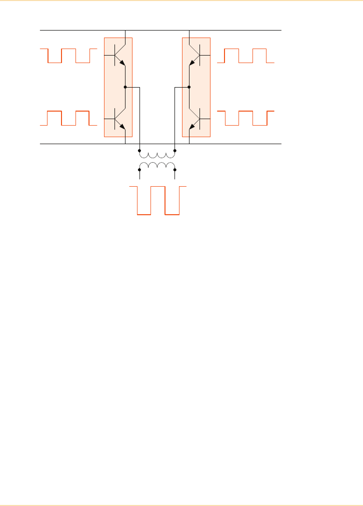
Major UPS Components - Inverter Power Block
The UPS Handbook 63
Figure 5.21: ‘Bridge’ Inverter Operation
Inverter Bridge Operation
Figure 5.21 illustrates the two power inverter blocks associated with one output
phase connected together by a transformer, with inverter block A comprising
TR1/TR2 and block B comprising TR3/TR4. As described earlier, the drive
signals to each pair of transistors within an inverter block are always at 180°
with respect to each other. The diagram in Figure 5.21 also shows that the
signals to the two inverter blocks are also in anti-phase – i.e. the drive signals to
the ‘high’ transistors of Block A (TR1) and Block B (TR3) are in anti-phase, as
are the signals to the two remaining transistors (TR2 and TR4).
At the instant in time highlighted in the top diagram in Figure 5.22, TR1 and
TR4 are both turned ON and TR2 and TR3 are OFF. This leads to the left-hand
side of the output transformer primary winding being connected the positive dc
bus and the right-hand side to the negative dc bus, and current flows through the
primary winding in the direction A-to-B. Although at first glance this circuit
may appear to present a short-circuit across the dc busbar, the current flowing
through the transformer is limited by the impedance presented by the primary
winding – which comprises the impedance of the transformer itself, together
with the reflected impedance of the output filter and load.
TR1
TR2
Block A
DC busbar (+)
TR3
TR4
DC busbar (-)
Block B
AB
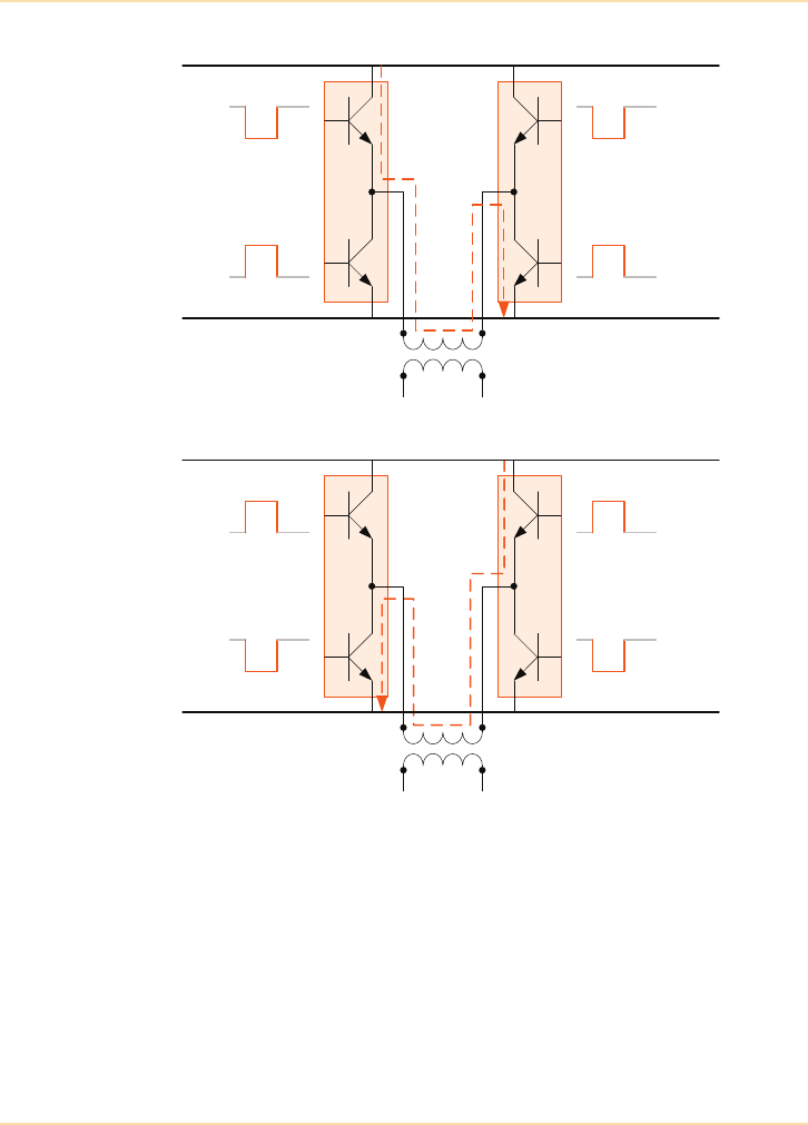
Major UPS Components - Inverter Power Block
64 The UPS Handbook
Figure 5.22: Bridge Operation
When the control electronics reverse, the drive signals to TR1 and TR4 turn
OFF and TR2 and TR3 turn ON. This reverses the polarity across the output
transformer primary and current now flows through the transformer from B-to-
A, as illustrated in the lower diagram in Figure 5.22.
By controlling the relative switching sequence of the two inverter blocks,
current flows through the transformer primary in either direction, this induces an
‘alternating current’ in the transformer secondary and the production of an
(alternating) secondary voltage. In practice the output transformer is of a step-up
design and its secondary voltage represents the required UPS output voltage.
TR1
TR2
Block A
DC busbar (+)
TR3
TR4
DC busbar (-)
Block B
AB
TR1
TR2
Block A
DC busbar (+)
TR3
TR4
DC busbar (-)
Block B
AB
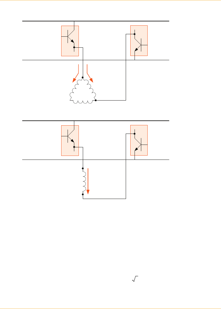
Major UPS Components - Inverter Power Block
The UPS Handbook 65
Figure 5.23: Output Power Comparisons
Figure 5.23 shows the comparative primary current flows in the ‘single-ended’
and ‘bridge’ inverter A-phase output circuits. In the ‘single-ended’ circuit (top
diagram) the transformer primary windings form a closed delta circuit, and the
current supplied by one inverter power block is always shared between two
windings. In the ‘double-ended’ circuit the output transformer primaries are
individually connected between the ‘main’ and ‘auxiliary’ power blocks of their
respective phases and act as three single-phase windings so the full current
passes through each individual winding. The power increase offered by a
double-ended over a single-ended inverter is equal to , i.e. the relationship
between a single-phase and three-phase system.
TR1
A Phase
DC busbar (+)
TR2
DC busbar (-)
B Phase
2 x 400A IGBT
2 x 400A IGBT
800A
I1I2
92kW
200V
TR1
A Phase (Main)
DC busbar (+)
TR2
DC busbar (-)
A Phase (Aux)
2 x 400A IGBT
2 x 400A IGBT
800A
160kW
200V
3
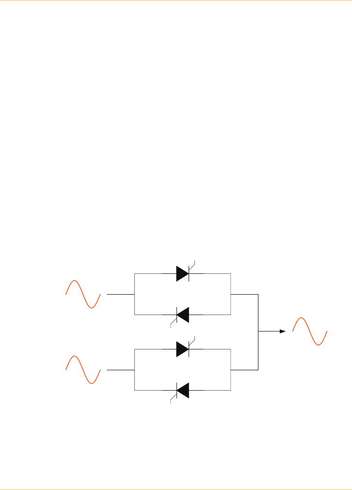
Major UPS Components - Static Switch
66 The UPS Handbook
Static Switch
For a UPS to maintain supply to the critical load even under fault or overload
conditions, the output to the critical load can be supplied either from the UPS
inverter output or from the mains (bypass) supply.
The static switch of an on-line UPS has two operational states, ‘on UPS’ (the
normal condition) and ‘on bypass’. When the UPS is operating on bypass there
will be an accompanying alarm or warning condition as in this state the critical
load is not protected from mains disturbance or interruption. In both cases it is
the job of the static switch to provide a very fast, break-free, transfer between
the inverter output and the bypass.
The static switch can be considered to be an intelligent switch that decides
whether to use the UPSs inverter output voltage or the raw mains to supply the
load. The decision is made by the static switch’s own and/or the UPSs control
logic which continually monitors the bypass (raw mains) and inverter voltages.
The control logic typically controls the phase and frequency of the UPS
inverter(s) to ensure that the bypass and inverter voltages are in phase
(synchronised) with each other. Bi-directional, break-free transfer between the
two supply sources is only possible when the bypass and the inverter are
‘synchronised’.
Figure 5.24: Simplified Static Switch
SCR1
SCR2
SCR3
SCR4
Bypass
supply
Inverter
supply
UPS
output

Major UPS Components - Static Switch
The UPS Handbook 67
Static Switch Operation
The static switch circuit will have two inputs and one output and could comprise
a pair of inverse parallel connected SCRs connected in series with the bypass
and inverter supplies – as shown in Figure 5.24, or alternatively comprise a
system where the inverter side SCRs are replaced by a contactor. Using a
contactor instead of the SCRs has slight system efficiency benefits as there are
less losses associated with a contactor than with SCRs.
Figure 5.24 shows a single phase circuit – in a three phase circuit a pair of SCRs
is connected in series with each of the phases. The bypass (raw mains) supply is
connected to SCRs 1 and 2, and the inverter supply to SCRs 3 and 4. As
previously stated, SCRs 3 and 4 could be replaced by a contactor.
During normal operation, with the inverter supplying the load, SCRs 3 and 4 are
triggered (switched on) and SCRs 1 and 2 are not triggered (switched off). In the
event of an inverter supply problem or an overload condition etc. the static
switch monitoring circuitry would identify that there was a problem and decide
to transfer the critical load from the inverter supply on to the bypass supply. By
stopping the triggering of SCRs 3 and 4 and by starting the triggering of SCRs 1
and 2 a supply to the critical load is maintained. As described earlier (See "Basic
Phase-Control Principles" on page 40), once an SCR is triggered it continues to
conduct until the voltage across it is zero (i.e. in an ac circuit, when the voltage
waveform passes through zero). By triggering SCRs 1 and 2 while SCRs 3 and 4
are still conducting, the bypass and inverter are paralleled for a short time. Such
short term paralleling ensures a break-free transfer between the two supplies and
it is for this reason that the two supplies must be synchronised before the
transfer can take place. If the transfer was allowed regardless of the
synchronisation status of the two supplies then the load would almost certainly
be subjected to a power disturbance.
The manufacturer’s specification should provide details of the synchronisation
limits of the UPS (see "Introduction" on page 283).
As a general rule, the mains voltage supply frequency in the UK is very stable.
However, if a standby generator is feeding the UPS then it is important to ensure
the generator’s output frequency is stable enough for use with a UPS system
(See "UPS Compatibility" on page 149).
To a voi d a po wer dis tur ban ce to the lo a d, if the sy ste m
is not synchronised, a static switch should not allow
a transfer from inverter to bypass, or vice versa.

Major UPS Components - Isolation in a UPS System
68 The UPS Handbook
Isolation in a UPS System
There are three distinct types of isolation in a UPS system:
•the galvanic isolation between input and output
• the input isolation between mains and battery, and
• the isolation between the dc circuit and the UPS output.
It is important to understand the distinction between these types of isolation in
order to avoid misinterpretation of specifications.
Galvanic Isolation between Input and Output
In transformer-based UPS systems the transformer is used to step up the voltage
at the output of the inverter to a voltage compatible with the utility or generator
supply voltage.
A common misconception is that the transformer is also used to provide
galvanic isolation, which is not the case. In transformer-based UPS systems, the
neutral line passes through the bypass line and therefore no galvanic isolation
between UPS input and output is provided. If total galvanic isolation is required
in transformer-based or transformerless UPS, an additional transformer is
necessary at the output of the UPS, so that a galvanic isolation from the load is
provided for both the inverter and bypass. The transformer must be designed
with adequate insulation to prevent the high voltages present at the UPS output
from jumping between windings.
Input Isolation between Mains and Battery
In the early 60s, when only open lead-acid batteries where available, galvanic
isolation was required for safety reasons. Since the late 80s, when the
maintenance-free lead-acid or nickel-cadmium batteries came into use, input
galvanic isolation was abandoned.
Today this isolation is very rare.
DC-Component Output Isolation
Transformer-based technology
As mentioned above, in transformer-based UPS systems the transformer is used
to step up the voltage at the output of the inverter to a voltage compatible with
the utility or generator supply voltage. Furthermore, the transformer isolates DC
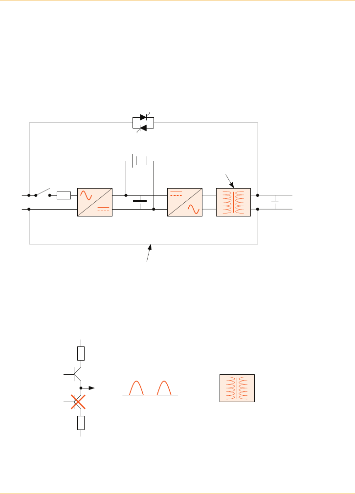
Major UPS Components - Isolation in a UPS System
The UPS Handbook 69
components, and therefore the inverter transformer isolates the DC circuit from
the output load. In older designs, where the PWM profile was not as well
controlled, the output transformer also assists with the reduction of noise
components on the output waveform.
Figure 5.25 shows a block diagram of a transformer-based, double-conversion
UPS system. It can be seen that the transformer is on the output of the inverter
and not on the output of the UPS.
Figure 5.25: Transformer-based UPS
There are two possibilities for the DC component to pass from the UPS to the
load – when there is an inverter IGBT fault or a bypass thyristor fault.
Figure 5.26: Effect of an IGBT fault in a transformer-based UPS
InverterRectifier Output Tx
Battery
+-
Static bypass switch
DC filter AC filter
L
N
L
N
Output transformer steps
up voltage and blocks
DC component
Neutral line connects input and output (no galvanic isolation
between input and output)
Output transformer steps up voltage
and blocks DC component
DC component
due to IGBT fault
IGBT 1
IGBT 2
F1
F2

Major UPS Components - Isolation in a UPS System
70 The UPS Handbook
In the event of an inverter IGBT fault – if, for example, IGBT 2 of the inverter
does not conduct – a DC component will be generated, and in the transformer-
based UPS the output inverter transformer will isolate the inverter DC
component from the load (Figure 5.26).
Figure 5.27: Effect of a bypass thyristor fault in a transformer-based UPS
In the event of a bypass thyristor fault – if, for example, one of the thyristors
does not conduct – a considerable DC component will feed the load as the
transformer does not isolate the bypass. The transformer-based UPS does not
control this DC component (Figure 5.27).
Transformerless Technology
As transformerless UPS technology (Figure 5.28) does not provide an inverter
output transformer, the DC-component issue must be handled differently. The
DC component is blocked at the output by hardware and software regulation and
control so that it cannot be fed to the load. The transformerless UPS behaves as
follows in the two cases.
DC component
passes to the load
Static switchInput sine wave
Thyristor not
conducting
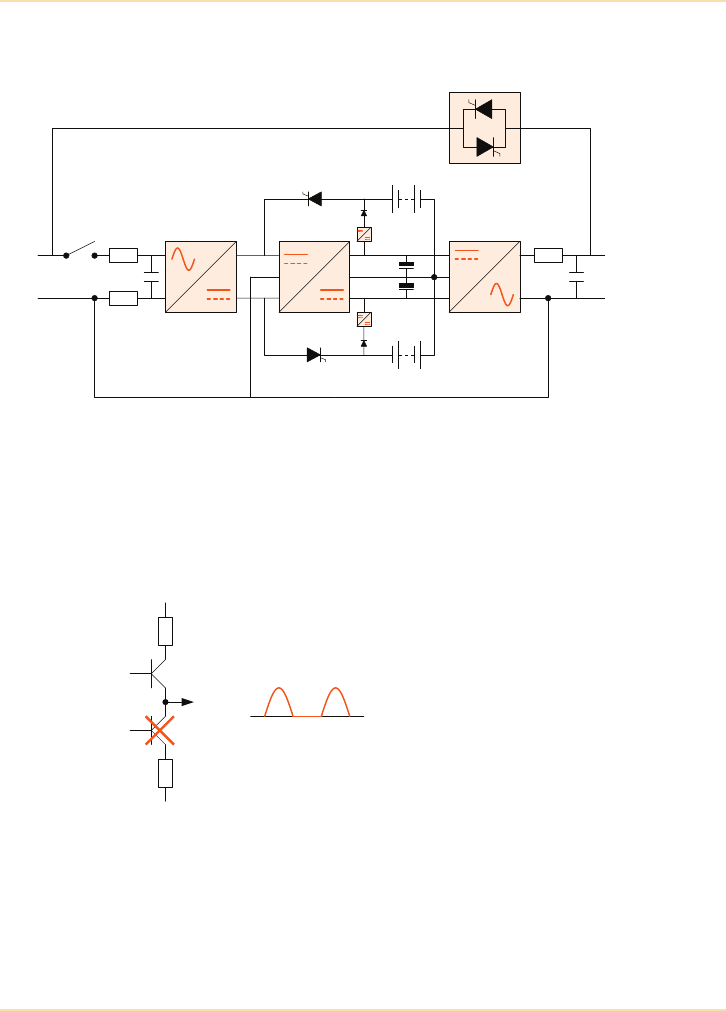
Major UPS Components - Isolation in a UPS System
The UPS Handbook 71
Figure 5.28: Transformerless UPS
In the case of an inverter IGBT fault – if, for example, IGBT 2 of the inverter
does not conduct – a DC component will be generated. Transformerless UPS
technology handles the DC component by means of a fully-redundant EDCP
(electronic dc protection) system, so that the probability of a DC component
appearing at the inverter output is practically zero (Figure 5.29).
Figure 5.29: Effect of an inverter IGBT fault in a transformerless UPS
InverterRectifier
Battery
Static bypass
Booster
AC filter
L
N
L
N
Input filter
Battery
DC component
due to IGBT fault
IGBT 1
IGBT 2
F1
F2
DC detection and control
system blocks the DC
component
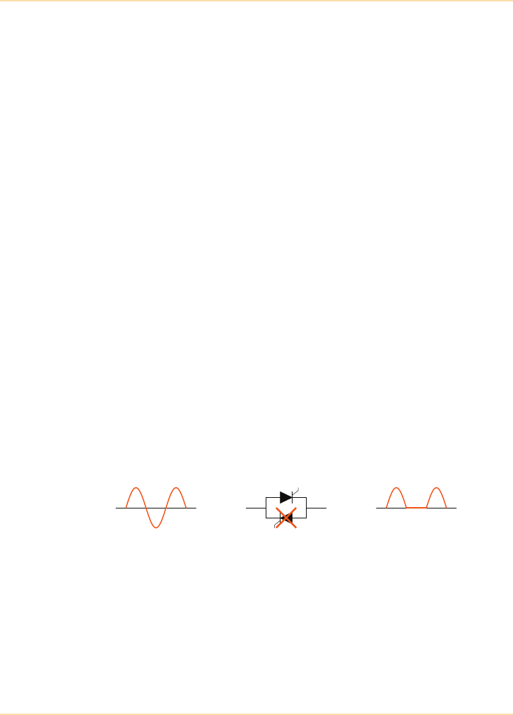
Major UPS Components - Isolation in a UPS System
72 The UPS Handbook
DC Component Protection in Modern UPS
Recent UPS designs provide fully-redundant DC component protection systems
on the inverter side consisting of three parts:
Firstly, redundant DC-component regulation continuously detects and regulates
the DC component within a tolerance of ±10mV - a normal mains supply to
which all non-protected equipment is exposed has a DC-component tolerance of
±300mV.
Secondly, redundant DC-component control continuously detects the DC
component, and if it is higher than 4V, the DC-component control circuit
automatically and instantly transfers the load to bypass. The inverter, rectifier
and booster are switched off, the battery is disconnected and alarms are
signalled. To ensure the DC component does not appear on the load side, the
protection system operates at all times, even if the UPS is on but switched to
bypass. The DC-component detection, regulation and control circuits in modern
UPS are redundant, making the system very safe and secure.
Thirdly, a DC component may appear on the output if one IGBT fuse blows and
the other IGBT continues to conduct. Modern inverter bridges are designed in
such a way that if one of the two fuses (F1 or F2 in Figure 5.29) blows the other
fuse will also automatically blow, preventing the DC component flowing to the
load.
The probability of a DC component passing through a modern transformerless
UPS system is no higher than the probability of a transformer going short circuit
(and allowing the DC component to pass).
Figure 5.30: Effect of a bypass thyristor fault in a transformerless UPS
In the case of a bypass thyristor fault similar protection, on the bypass side,
detects if one of the static bypass SCRs is not conducting. In this event, the load
will be automatically transferred to the inverter within 2 to 5ms in order to avoid
a DC component on the load side.
DC component
passes to the load
Static switchInput sine wave
Thyristor not
conducting
DC detection and control system
transfers the load to inverter
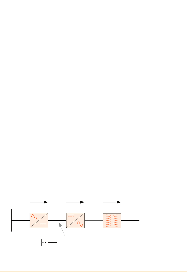
The UPS Handbook 73
6Transformerless
UPS Systems
Introduction
The transformer-based static, double conversion, on-line UPS, utilising an
internal step-up transformer, was first introduced during the seventies and was
widely produced, especially at the very top of the output power range. However,
with advances in power semiconductor technology and improved PWM based
waveform generation, the UPS industry has generally moved towards
transformerless technology, with individual modules now available up to
500kVA.
The examples shown throughout this section are for single phase UPS but apply
equally to three phase systems.
Transformer Based Solution
Figure 6.1 shows the topology of a typical conventional transformer-based,
double-conversion, on-line UPS. The transformer is used to step up the voltage
at the output of the inverter to a voltage compatible with the utility or generator
supply voltage (refer to page 37 which describes the transformer-based
technology in more detail). A common misconception is that the transformer is
also used to provide galvanic isolation, which is not the case.
Figure 6.1: Conventional Transformer-based UPS.
Output to
Critical
Load
Mains supply
Inverter
Battery
Rectifier Output Tx
240Vac 340Vdc 120Vac 240Vac
Regulated
dc busbar
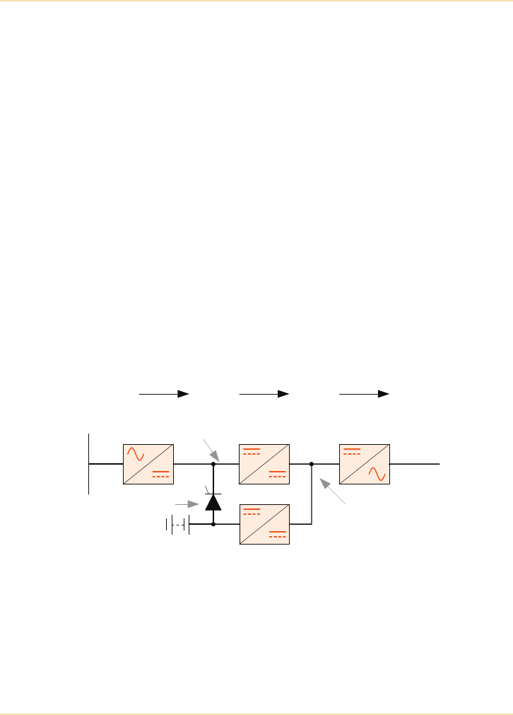
Transformerless UPS Systems - Introduction
74 The UPS Handbook
Transformerless Solution
Recent advances in power semiconductor technology and the introduction of the
Insulated Gate Bipolar Transistor (IGBT) device has made the transformerless
UPS a viable proposition. One such design is shown in Figure 6.2.
In this design the phase controlled rectifier shown in the previous design
example (see ‘Rectifier Power Block’ on page 40) has been replaced by a fixed
rectifier followed by a dc converter which boosts the rectifier output to a much
higher level, thus allowing the inverter to directly produce an output r.m.s
voltage compatible with the rectifier input voltage. The diagram shows the dc
busbar to the inverter input to be 700Vdc.
The rectifier is a standard full-wave diode bridge and its output is therefore
unregulated. Although the figure of 340Vdc shown on the diagram is once again
the theoretical off-load maximum voltage, in practice this value will be
somewhat less.
The dc boost converter is a form of switching regulator circuit which provides a
constant (700Vdc) output over a fairly wide range of input voltages from the
unregulated dc busbar – (see ‘Boost Converter – (Transformerless UPS)’ on
page 46). The regulated busbar is therefore unaffected by mains supply
aberrations within the UPS’s specified limitations.
Figure 6.2: Transformerless UPS Block Diagram
A separate battery charger is shown connected to the regulated dc busbar. The
charger acts as a dc-dc buck converter, reducing the high voltage present on the
regulated dc busbar to a suitable battery float charge voltage.
Output to
Critical
Load
Mains supply
DC Boost
Converter
Battery
Rectifier Inverter
240Vac 340Vdc 700Vdc 240Vac
Battery
Charger
Regulated dc
busbar
Unregulated dc
busbar
Battery switch

Transformerless UPS Systems - Introduction
The UPS Handbook 75
When the mains supply fails the battery is instantaneously connected to the
unregulated dc busbar by some form of switching device – this typically carried
out using an electronic switch such as a fast-acting SCR. The dc boost converter
continues to supply the regulated dc busbar from the discharging battery and the
inverter operation is unaffected. As with the transformer based design, during a
long term mains failure the battery will eventually reach its end-of-discharge
voltage and the inverter will shut down.
One advantage of using an independent battery charger rather than connecting
the battery directly to the inverter’s input bus is that it provides greater
flexibility over the number of battery cells used in the system which allows ‘fine
tuning’ of the system’s autonomy time, if necessary, by the addition/subtraction
of a cell or two. Another advantage is that the dc-dc battery charger eliminates
any ac ripple on the battery charging voltage. AC ripple is a prime cause of
premature battery failure.
Advantages
The impetus towards the transformerless UPS over recent years has been
brought about by the many advantages this design offers over the traditional
transformer-based UPS.
• Improved efficiency
• Higher input power factor
• Lower input current harmonic distortion (THDi)
• Reduced operating costs
• Reduced physical size and weight
• Lower audible noise
• Enhanced battery life
• Reduced capital cost
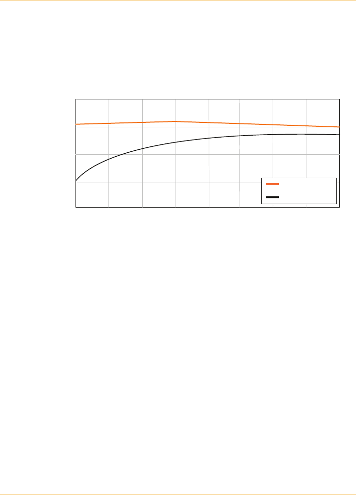
Transformerless UPS Systems - Introduction
76 The UPS Handbook
Improved Efficiency
Eliminating the transformer has a significant impact on overall UPS efficiency,
increasing it by around five percent to yield a substantial reduction in heat loss
and electricity running costs. Figure 6.3 shows typical efficiency curves for
transformerless and transformer-based UPS according to output loading. It can
be seen that the efficiency improvement applies to the whole load spectrum.
Figure 6.3: UPS Efficiency curve (a.c. to a.c.)
Higher Input Power Factor
Transformer-based UPS use a phase-controlled input rectifier to provide a
regulated dc battery charging voltage and a regulated dc supply to the inverter.
The effect of the phase-controlled rectifier is to present a lagging power factor
load to the incoming supply, which falls further from unity as the UPS is lightly
loaded as a result of the rectifier conduction angle phasing back.
It is always advisable to install UPS equipment with an input power factor close
to unity since this will reduce the magnitude of the input currents which in turn
minimises the size of the cabling and switchgear and, in some instances, reduces
the electricity running costs.
The transformerless UPS has a free-running rectifier which, coupled with the
very high frequency switching characteristics of the dc to dc boost converter,
inherently produces an input power factor much closer to unity and less load
dependant than the transformer-based UPS. Figure 6.4 shows the comparison
between the transformer-based and transformerless input power factors and how
they change according to the UPS loading.
Load %
Efficiency %
Transformerless
Transformer-based
25 30 40 50 60 70 80 90 100
80
85
90
95
100

Transformerless UPS Systems - Introduction
The UPS Handbook 77
Figure 6.4: UPS Input Power Factor Comparison
Lower Input Current Harmonic Distortion (THDi)
Replacing the phase-controlled full-wave bridge rectifier with a free running
full-wave bridge rectifier reduces the total input current harmonic distortion
(THDi) in a three-phase UPS from around 30% to <3%, making a considerable
contribution, through limiting harmonic emissions, to meeting the Energy
Networks Association, G5/4-1 recommendations on page 264.
Reduced Operating Costs
Figure 6.5 shows a parallel redundant power protection system supporting a
100kVA load, with two 120kVA UPS modules equally sharing the load (see
‘Parallel UPS Systems’ on page 83). In normal operation, each UPS will be
supplying 42% of its rated output, and is therefore operating at a relatively
disadvantageous point on its efficiency curve.
The table of “Comparative Costs” on page 79 compares the transformerless and
transformer-based UPS alternatives when operating in the parallel redundant
configuration shown in Figure 6.5. It demonstrates the importance of selecting
UPS equipment which will maximize system efficiency to reduce heat losses
and consequently the running costs, not only of the UPS, but also of the
associated air conditioning plant.
Load %
Power Factor
Transformerless
Transformer-based
25 30 40 50 60 70 80 90 100
1.00
0.95
0.90
0.85
0.80
0.75
0.70
0.65
0.60
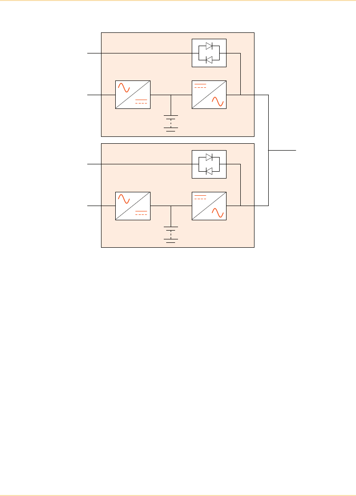
Transformerless UPS Systems - Introduction
78 The UPS Handbook
Figure 6.5: Parallel Redundant UPS System
120kVA
UPS
120kVA
UPS
100kVA
Load

Transformerless UPS Systems - Introduction
The UPS Handbook 79
Table of Comparative Costs
UPS details Transformer
Based
Transformerless
Design
UPS modules in parallel 2 2
UPS module rating (kVA) 120 120
Percentage load 42% 42%
Efficiency 91% 96%
Input power factor 0.8 0.98
User's load (kW@0.8p.f.) 80 80
Tota l UP S i n pu t (k W) 8 8 83
Tota l in put cur re n t/ p ha se ( A) 159 123
Tota l UP S h eat l os s ( k W) 7 . 9 3. 3
Tota l UP S l oss es cos t/y ear £6, 228 £2, 6 02
UPS in an air-conditioned room? Yes Yes
Additional air conditioning
running costs/year £2,047 £862
Total UPS losses + cooling
Cost per year £8,275 £3,464
Cost of Ownership SAVING over Five Years £24,055
Assumptions:
User's actual load (assumed 0.8p.f.) 100kVA
Electricity cost (typical commercial premises) 9.0p/kWh
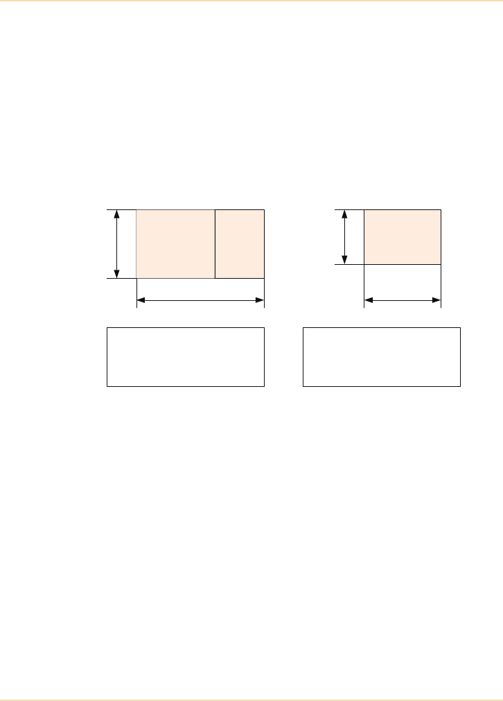
Transformerless UPS Systems - Introduction
80 The UPS Handbook
Reduced System Size and Weight
The most far-reaching effects of transformerless technology are the substantial
reductions in the size and weight of UPS systems. This is achieved not only by
eliminating the transformer itself but also by removing the need for the 12-pulse
rectifier previously required to improve input THDi performance (see ‘Twelve-
Pulse Rectifier’ on page 45). Figure 6.6 compares the space and weight
characteristics of transformer-based and transformerless UPS systems.
Figure 6.6: Size and Weight Comparisons
In the same way that computers have developed from large cumbersome
mainframes into smaller often rack-mounted modules, so modern UPS systems
have evolved from being perceived as plantroom equipment into computer
peripherals.
The size factor has had a profound effect on the development of the UPS and the
entire power protection culture, since it has substantially reduced the footprint
and cost of parallel installations for redundancy, availability and scalability, and
has enabled the development of the ultimate in flexibility and space-saving, the
rackmountable three-phase UPS.
The modern three-phase rack-mounted UPS is based on individual modules with
up to 100kVA output. Such systems offer major benefits in terms of parallel
redundancy and unlimited upgradeability. The capabilities and advantages of
modular systems are examined in Chapter 7"Parallel UPS Systems".
Transformer-based
120kVA
Transformerless
120kVA
Footprint
Total Weight
=
=
1.32m
2
1,200Kg
850mm
120kVA750mm
=
=
0.64m
2
310Kg
Footprint
Total Weight
120kVA 12
Pulse
800mm
1650mm

Transformerless UPS Systems - Conclusion
The UPS Handbook 81
Conclusion
Within the UPS industry, it is accepted that as a result of the many intrinsic
benefits resulting from transformerless UPS topology, this design has become
the standard for all modern day static, double conversion UPS systems,
eventually replacing the traditional transformer based design.
The maximum rating of larger, single unit, transformerless UPS systems is
currently limited by the availability of higher power, higher frequency,
semiconductor devices. However, whilst 500kVA is the largest single unit
transformerless UPS available today this does not preclude larger capacity UPS
installations from being considered to take advantage of transformerless
technology. It is relatively easy, and in some cases advantageous, to connect
multiple transformerless UPS units in parallel to obtain larger capacities or gain
modular redundancy. This can often be accomplished without compromising
floor space or capital cost when compared with single, higher powered,
transformer based UPS systems. For some manufacturers the number of UPS
modules which can be connected in parallel is limited (typically to a maximum
of six for transformer based systems) however, transformerless UPS are now
available where there is no practical limitation on the number of units which
may be connected in parallel.

82 The UPS Handbook

The UPS Handbook 83
7Parallel UPS
Systems
Introduction
This type of system comprises two or more UPS modules operating in parallel to
feed a common critical load bus.
Units forming part of such a multi-module system are almost identical in
operation to that of their corresponding single module counterparts. In fact,
some manufacturers design their UPS modules such that they can be used as
either standalone or parallel modules without the need for complex
modification.
UPS modules are paralleled for two reasons:-
1. to increase the power rating of a UPS system because of an increase
in the size of the critical load. Such parallel systems are known as
capacity systems.
2. to increase the availability of a UPS system because of the
importance of the critical load. Such parallel systems are known
as redundancy systems.
The overwhelming majority of parallel UPS systems are designed to provide
parallel redundancy.
Capacity Systems
A capacity system is implemented by using the appropriate number of modules
of a particular rating necessary to supply full load power when they are all
operating and connected in parallel – for example three 100kVA units might be
used to serve a 270kVA load (see Figure 7.1).
Under normal circumstances each module will supply a maximum of
approximately 90kVA. However, if one module fails the remaining two modules
will each be expected to supply 135kVA and would be substantially overloaded.
In this situation the load will immediately transfer to bypass via the simultaneous
operation of the static switch in each module.
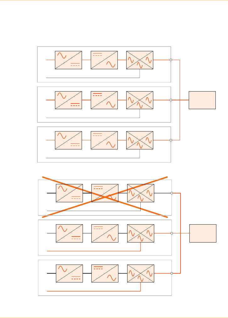
Parallel UPS Systems - Capacity Systems
84 The UPS Handbook
If the faulty module is unable to operate its bypass-side static switch, the static
switches in the remaining healthy modules will ideally be rated to sustain the full
load supply (e.g. 135kVA), as illustrated in Figure 7.2. When the faulty module
has been repaired and all three UPS modules are again operational, the load is
automatically transferred from bypass back to the inverters.
Figure 7.1: Parallel Capacity System.
Figure 7.2: Capacity System On Bypass
100kVA UPS
100kVA UPS
100kVA UPS
270kVA
Load
90kVA
90kVA
90kVA
100kVA UPS
100kVA UPS
270kVA
Load
100kVA UPS
135kVA
135kVA
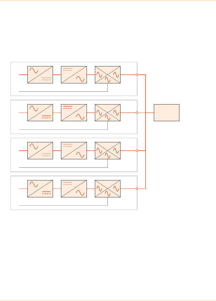
Parallel UPS Systems - Redundancy Systems
The UPS Handbook 85
Redundancy Systems
In a parallel redundant system the number of modules forming the system is a
minimum of one module over and above that required by the ‘capacity’ system
(e.g. 4 x 100kVA modules used to serve a 270kVA load – Figure 7.3). This
allows the system to support the load with inverter power if any one module
shuts down, and thereby increases the system reliability.
Figure 7.3: Parallel Redundant System
In a four module system operating with one redundant module, the load can be
maintained on inverter power if one module fails and will only automatically
transfer to bypass only on the failure of a second module. If extra security is
required, the number of redundant modules can be increased to two (or more).
This configuration is sometimes referred to as an ‘N+1’ (or ‘N+2’) system –
where ‘N’ signifies the minimum number of modules needed to supply the load
and ‘1’ or ‘2’ signifies the number of redundant modules (i.e. the coefficient of
redundancy) in the system.
100kVA UPS
100kVA UPS
100kVA UPS
270kVA
Load
~68kVA
100kVA UPS
~68kVA
~68kVA
~68kVA
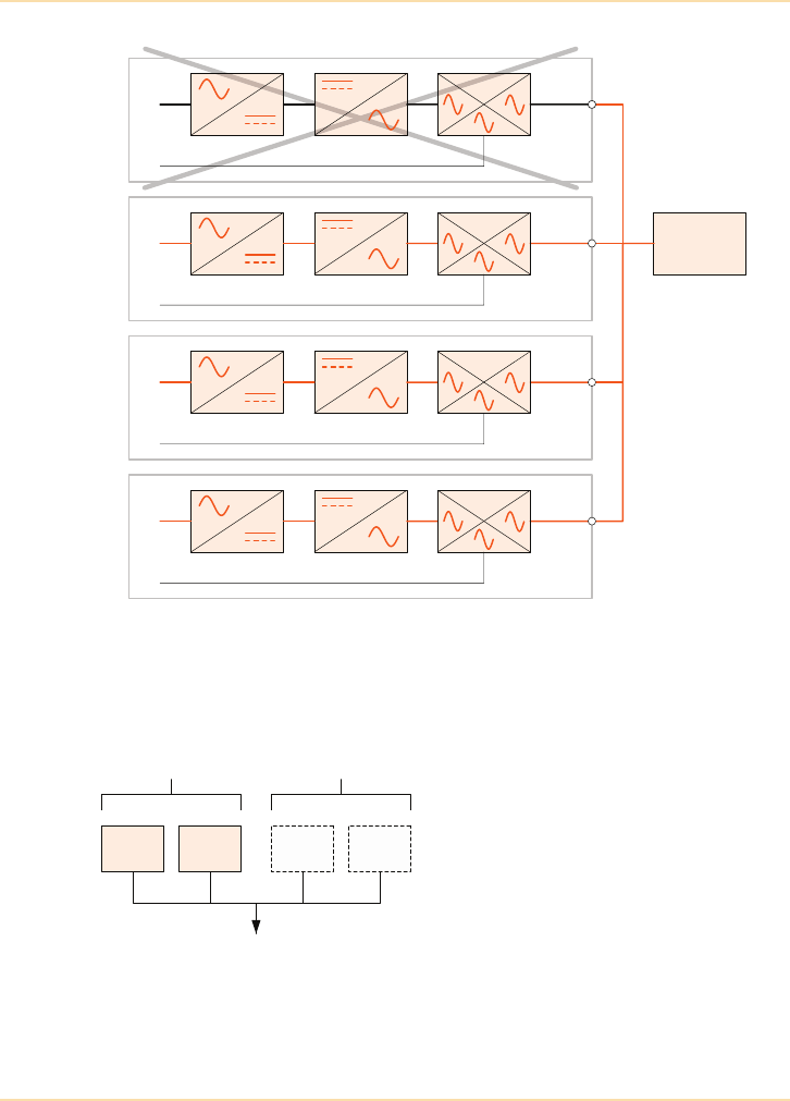
Parallel UPS Systems - Redundancy Systems
86 The UPS Handbook
Figure 7.4: Redundant System with Failed Module
Definition of a Parallel Redundant UPS System
Total number of UPS modules = N + n
Where:
UPSmin= Min. power rating of each
UPS module
Ptot = Total load power requirement
N= Min. number of UPS modules
needed to supply Ptot
n= Min. coefficient of
redundancy
100kVA UPS
100kVA UPS
270kVA
Load
100kVA UPS
~90kVA
~90kVA
~90kVA
100kVA UPS
N
UPS UPS UPS UPS
Coefficient of
Redundancy (n)
Ptot
NPtot
UPSmin
-------------------=

Parallel UPS Systems - Centralised and De-centralised Systems
The UPS Handbook 87
Centralised and De-centralised Systems
Note: In this discussion the term ‘De-centralised System’ is used to describe
the UPS architecture, in that each UPS module incorporates its own
static switch. This should not be confused the interpretation of the term
‘De-centralised System’ often used in data centres to describe the
situation where individual power systems are provided alongside the
various load equipment – e.g. as part of an IT equipment rack.
Introduction
Parallel UPS systems comprise UPS modules that either share common
components with other UPS modules (i.e. they CANNOT operate as a “stand
alone” UPS) or of completely independent UPS modules (i.e. the modules CAN
operate as a “stand alone” UPS).
Parallel UPS systems whose UPS modules operate as a system by sharing
common components are “centralised” systems and are described as having
Centralised Parallel Architecture (CPA). The major benefit of CPA systems is
cost as expensive components such as those used in module control circuitry and
static switches, for example, can be used by all of the modules in the system at
the same time, thereby negating the need for each module to have its own
control circuitry and static switch. The major drawback of CPA systems is that
the “centralised” nature of the control and power switching components
introduces a number of “single points of failure” into the system which
adversely affects the system's availability.
Parallel UPS systems whose UPS modules share no common components are
“de-centralised” systems and are described as having De-centralised Parallel
Architecture (DPA). The major benefit of DPA systems is very high availability
as there are effectively no single points of failure in the system. The major
drawback of DPA systems is cost as each module in the UPS system has its own,
independent, control circuitry and static switch etc.
Centralised Systems
This type of parallel system configuration typically has all the UPS modules
feeding the critical load via a single, centralised static switch (CSS).
Sometimes the CSS is built into the cabinet housing the various UPS modules.
This is often the case with single phase and small three phase UPS systems. For
large three phase systems the CSS is almost always housed in a separate cabinet.
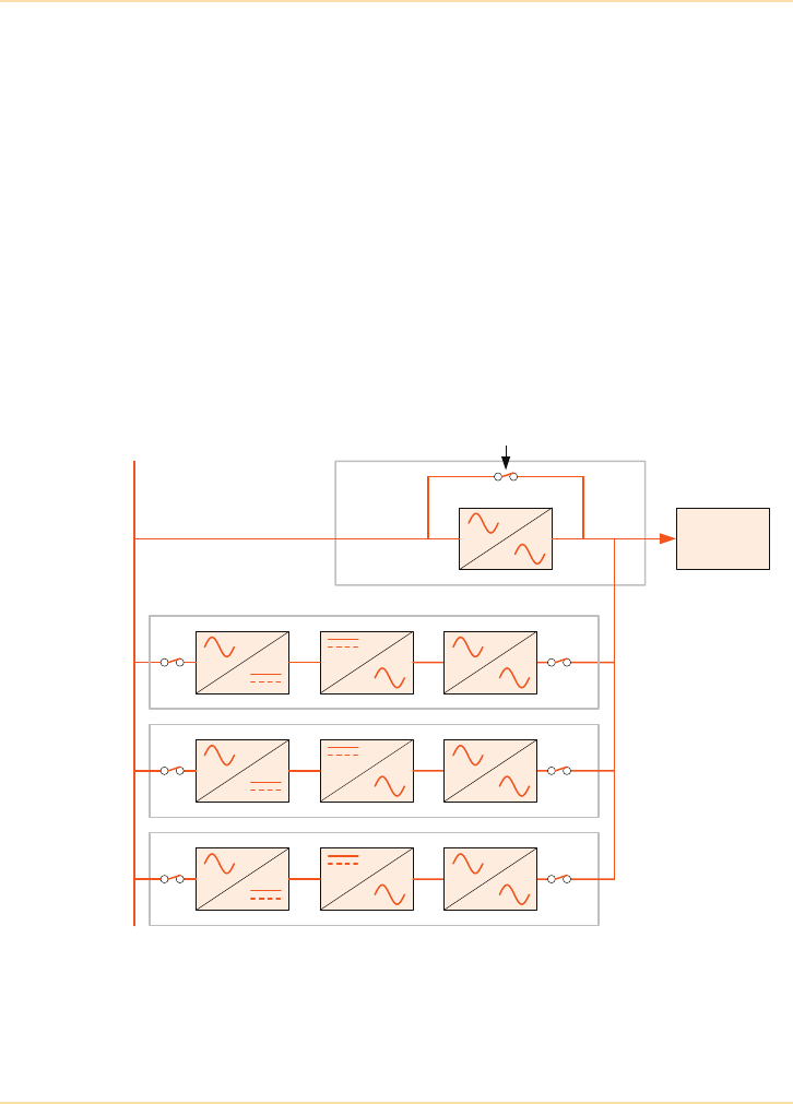
Parallel UPS Systems - Centralised and De-centralised Systems
88 The UPS Handbook
For ease of explanation, the remainder of this chapter will assume that the CSS
is housed in a separate cabinet.
Figure 7.5 shows three UPS modules working in parallel with a centralised
static switch (CSS) which is connected between the UPS outputs and critical
load. The total system capacity depends upon the ratings of the individual UPS
modules and the number of modules used. Additional modules can be added to
the system to cater for future load expansion, provided that the combined
module capacity does not exceed that of the CSS.
UPS modules in centralised parallel systems differ from single UPS modules as
the internal static switch is either disabled or, as shown in Figure 7.5, is
configured to have only one input (the UPS inverter). In this case the internal
static switch effectively becomes a static isolator ensuring very fast isolation of
a faulty UPS from the CSS which provides central control of all system
synchronisation and load transfer functions.
Figure 7.5: Three Module Centralised UPS System
CSS
Critical Load
UPS 2
UPS 3
UPS 1
Mains Supply
Rectifier Inverter Static
Isolator
Maintenance bypass
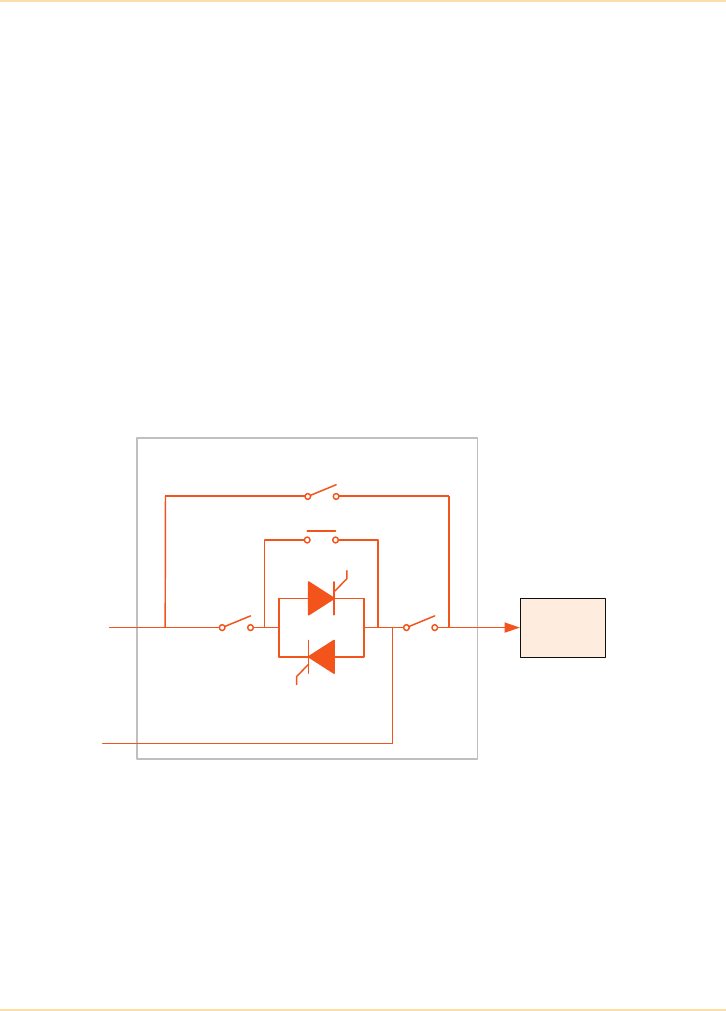
Parallel UPS Systems - Centralised and De-centralised Systems
The UPS Handbook 89
Central Static Switch (CSS)
The CSS in Figure 7.6 provides three possible power paths to the critical load:
• the UPS inverter output.
• raw standby mains via the static bypass switch/contactor.
• raw mains via the maintenance bypass.
Static bypass isolator CB1 connects the standby mains supply to the static
switch and is normally closed enabling the static bypass supply to be instantly
available when required.
System output isolator CB2 is also normally closed allowing either the UPS
output or the static bypass supply to feed the critical load.
The maintenance bypass switch is normally open and is only closed during CSS
maintenance. Control electronics within the CSS and each UPS module sense
the status of all the system's isolators to prevent the back feeding of mains
power, via the maintenance bypass and CB2, to the UPS module terminals.
Figure 7.6: Typical CSS
UPS Output Supply
During normal operation all the UPS modules are on line (i.e. all modules’ static
isolators closed), they are synchronised to one another and also to the standby
mains supply (if present) and share the critical load current equally.
CSS Cabinet
Standby
Mains Supply
UPS Output
Supply
CB1 CB2
Maintenance Bypass
Contactor
Static Bypass
Switch
Critical Load

Parallel UPS Systems - Centralised and De-centralised Systems
90 The UPS Handbook
If a UPS module develops a fault, it automatically isolates itself from the system
by opening its static isolator, the critical load will continue to be supplied by the
remaining healthy modules provided that it does not exceed the available system
capacity. If the critical load is too great for the remaining modules to handle they
will transfer the load to the standby mains via the central static bypass switch.
If the modules and standby mains are synchronised when the load transfer is
required, the modules’ static isolators are opened (turned off) at the same time as
the central static bypass switch is closed (turned on) to provide a “no-break”
load transfer. If however the system is not synchronised at the point of transfer
then the modules’ static isolators are opened before the central static bypass
switch is closed which will result in an unavoidable brief power break and
possible loss of the critical load.
If the standby mains supply is unavailable during an overload critical load loss
may occur.
Central Static Bypass Switch Supply
When activated, an electronically controlled central static switch similar to that
fitted to the UPS modules is used to connect the load to a raw “standby” mains
supply. This supplies the load when the UPS modules are unable to do so, for
example due to overload or inverter failure etc. As this supply is connected via
solid-state switching components, it is known as the “Static Bypass” supply.
Depending upon the power rating of the CSS, the static bypass devices may be
paralleled by a contactor which closes when the devices are turned on. This
reduces the time that the static bypass devices actually pass load current
meaning that relatively low powered (and therefore lower cost) devices can be
used in relatively high powered static switches.
Interlocking circuitry between the CSS and each UPS module prevents the static
bypass turning on while the static switches in each module are on. This is
important because if the static bypass switch and module static switches were to
turn on simultaneously, damage would occur in the modules caused by a back-
feeding of power from the standby mains through the static bypass into the UPS
module output terminals.
To obtain a clean load transfer between the UPS modules and static bypass, the
UPS output and the standby mains supply frequencies must be synchronised.
This is achieved by forcing the inverter frequency to track that of the standby
mains within preset parameters. Furthermore, as the module AC power outputs
are paralleled, it is also necessary to maintain synchronisation between the
individual modules.
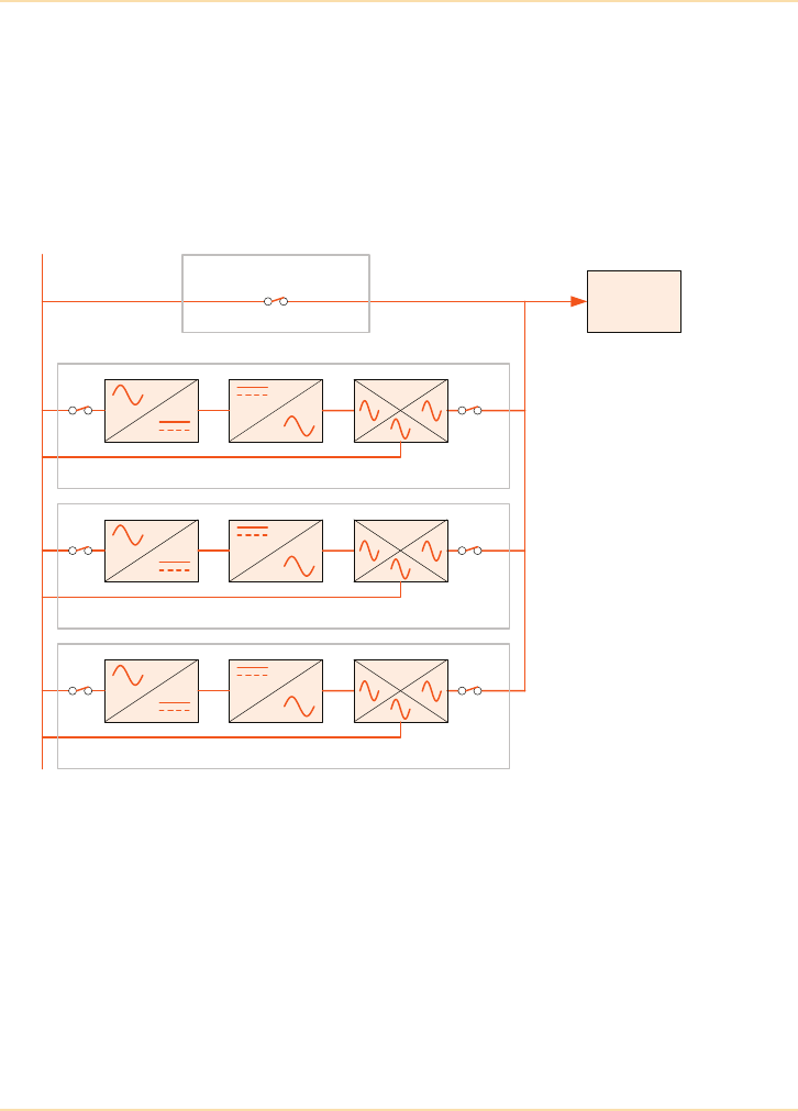
Parallel UPS Systems - Centralised and De-centralised Systems
The UPS Handbook 91
Maintenance Bypass Supply
The ‘maintenance bypass’ (also known as the manual bypass) is manually
selectable. This switch makes it possible to maintain load power (unprotected)
while the UPS system is completely shut down, and is designed to be used when
maintenance or troubleshooting is carried out on the system.
De-centralised Systems
Figure 7.7: Three Module De-centralised UPS System
This type of parallel system configuration has all of the UPS modules feeding
the critical load directly. A block diagram of a typical de-centralised parallel
system is shown in Figure 7.7.
Figure 7.7 shows three UPS modules working in parallel directly feeding the
critical load. The total system capacity depends upon the ratings of the
individual UPS modules and the number of modules used. Additional modules
can be added to the system to cater for future load expansion.
Maintenance bypass
Critical Load
Mains Supply
UPS 1
UPS 2
UPS 3

Parallel UPS Systems - Centralised and De-centralised Systems
92 The UPS Handbook
UPS modules in a de-centralised parallel system are practically identical to a
stand alone UPS and, as previously mentioned, some manufacturers design their
UPS to be used in either configuration without modification.
De-centralised parallel UPS systems always have one Master module with the
other modules in the system being Slaves. If at any time the Master becomes
faulty, or is isolated for maintenance etc., the next UPS in the system (former
Slave) will immediately take over the Master function and the former Master
will switch off.
De-Centralised Static Switch
In a de-centralised system every UPS module is provided with its own static
bypass switch which is rated for the full load capacity (plus overload) of the
UPS module. This means that there is more than one static switch in the system
rather than the single static switch of the centralised system.
As with the centralised system, however, there are still three possible power
paths to the critical load.
• the UPS inverter output.
• raw standby mains via the UPS static bypass switches.
• raw mains via the maintenance bypass.
During normal operation all of the UPS modules are on line and the UPS
inverters are feeding the load via their internal static switches. All of the
inverters are synchronised to each other and to the standby mains supply (if
present) and share the load equally.
If a UPS module develops a fault then it automatically isolates itself from the
critical load by inhibiting the operation of the inverter side of the static switch
(See "Static Switch Operation" on page 67). The critical load will continue to be
supplied from the remaining healthy modules provided that it does not exceed
the available system capacity.
If the critical load is too great for the remaining modules to handle, all of the
modules (including the module with a fault) will transfer the critical load to the
standby mains via their internal static switches. If the system is synchronised the
transfer is break-free and is achieved by enabling the operation of the bypass
side, inhibiting the operation of the inverter side of each module’s static switch.
If the system is not synchronised the UPS modules will not allow any transfer to
take place and will attempt to supply the overload for as long as possible before
switching off to protect themselves.

Parallel UPS Systems - Centralised and De-centralised Systems
The UPS Handbook 93
Conclusion
Originally, centralised parallel systems were the only type of parallel systems
available due to the complexity of data and signal processing required to
effectively control a de-centralised system.
The need for a separate CSS cabinet makes a typical centralised parallel system
physically larger, more complicated to install and more expensive than its de-
centralised counterpart. When this is coupled with the fact that the static switch
and system control components of the CSS provide single points of failure to the
critical load it is clear to see why de-centralised parallel systems are now the
most popular choice.
One argument sometimes advanced in support of the centralised parallel system
is the fault clearing capacity of the Central Static Switch. However, modern de-
centralised systems incorporate internal static bypass switches capable of
matching the fault clearing capacity of the Central Static Switch.

Parallel UPS Systems - Modular UPS Systems
94 The UPS Handbook
Modular UPS Systems
It was the development of transformerless three phase UPS technology as
discussed in chapter 6 that enabled the development of rack mounted, modular
three phase UPS systems. Transformer based three phase UPS modules would
be far too large and heavy to be considered viable in a truly modular system. For
example, excluding batteries, a typical transformer based 50kVA three phase
UPS weighs 400kg whereas the latest modular three phase UPS weighs only
60kg.
It is widely recognised that the introduction of transformerless three phase UPS
in the mid 1990s revolutionised three phase UPS design. This is borne out by the
fact that all major UPS manufacturers now have three phase transformerless
UPS within their product portfolios. It is also widely recognised that modular
three phase UPS technology is revolutionising three phase UPS system design.
This is because only modular UPS systems have the potential to simultaneously
offer the benefits of very high availability, easy scalability and total system
flexibility.
Hot Swappability
A modular UPS system that needs to be either switched off or manually
bypassed to allow the addition or removal of a module (for example, in the event
of a module failure or system upgrade) is undesirable because the overriding
objective of any UPS system is to NEVER expose the critical load to
unprotected power. With this in mind, some manufacturers have designed their
UPS modules to be “hot swappable”.
A module is hot swappable if:
1. It can be inserted or removed from the host UPS system without:
a. removing power from the critical load
b. transferring the critical load to the raw AC mains supply
2. It can be safely electrically disconnected from its host system
using electrically safe connectors.
3. It can be isolated from the rest of the host system without the risk
of human error that may cause damage to the module, the host
system or the critical load.
Modular UPS systems that contain modules that are not hot swappable as
defined above are often described as being “warm swappable”.

Parallel UPS Systems - Modular UPS Systems
The UPS Handbook 95
The single most important benefit of hot swappable UPS modules is the affect
that they have on system mean time to repair (MTTR) and the impact that this
has on system availability.
Availability
Earlier in this chapter it was established that UPS system availability was
significantly increased if individual UPS modules were connected to each other
in a de-centralised, parallel redundant configuration. When the benefit of
significantly reduced MTTR provided by hot swappable modules is added to
such a configuration the result is maximised availability.
The subject of system availability is covered in greater depth in Chapter 11 on
page 189. To avoid excessive duplication of information it is sufficient in this
chapter to simply state that hot swappable modular UPS systems increase
overall system availability by a factor of 10 compared to free standing (non-
modular) UPS systems that are not hot swappable.
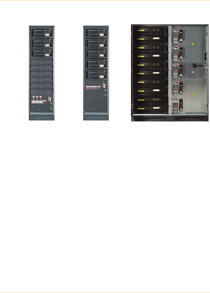
Parallel UPS Systems - Modular UPS Systems
96 The UPS Handbook
Scalability and Flexibility
Figure 7.8: Rackmounted, Transformerless UPS Configuration
Figure 7.8 shows a rack cabinet containing alternative UPS configurations.
Figure 7.8a shows a three module UPS system with integral battery banks.
Figure 7.8b shows an alternative configuration with five UPS modules. In this
configuration the batteries would be housed in a separate cabinet or on a rack.
Figure 7.8c shows a five module system with 100kVA modules.
Both the above arrangements automatically operate in a redundant or capacity
mode according to the size of the load and significantly reduce the required
floorspace.
7.8a 7.8b 7.8c
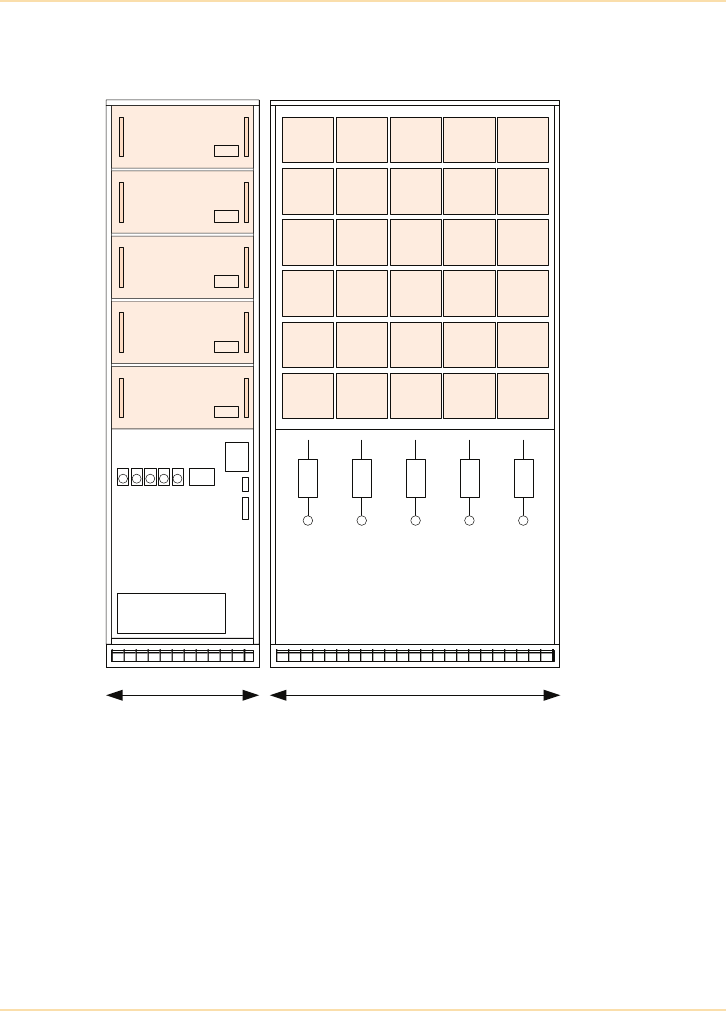
Parallel UPS Systems - Modular UPS Systems
The UPS Handbook 97
Example 1
Figure 7.9: Vertical Scalability
Figure 7.9 shows 5 x 50kVA UPS modules used to support a 200kVA load with
N+1 redundancy. Alternatively, the user could have employed 4 x 50kVA UPS
modules to support a 200kVA load, and could have taken advantage of the
vertical scalability opportunities of the system to upgrade to 250kVA cost-
effectively, and with no disruption to the critical load or footprint penalty, by
adding a further 50kVA module at a later date.
UPS Cabinet Battery Cabinet
730mm 1200mm
200kVA (N+1) - 10 mins
50kVA
50kVA
50kVA
50kVA
50kVA
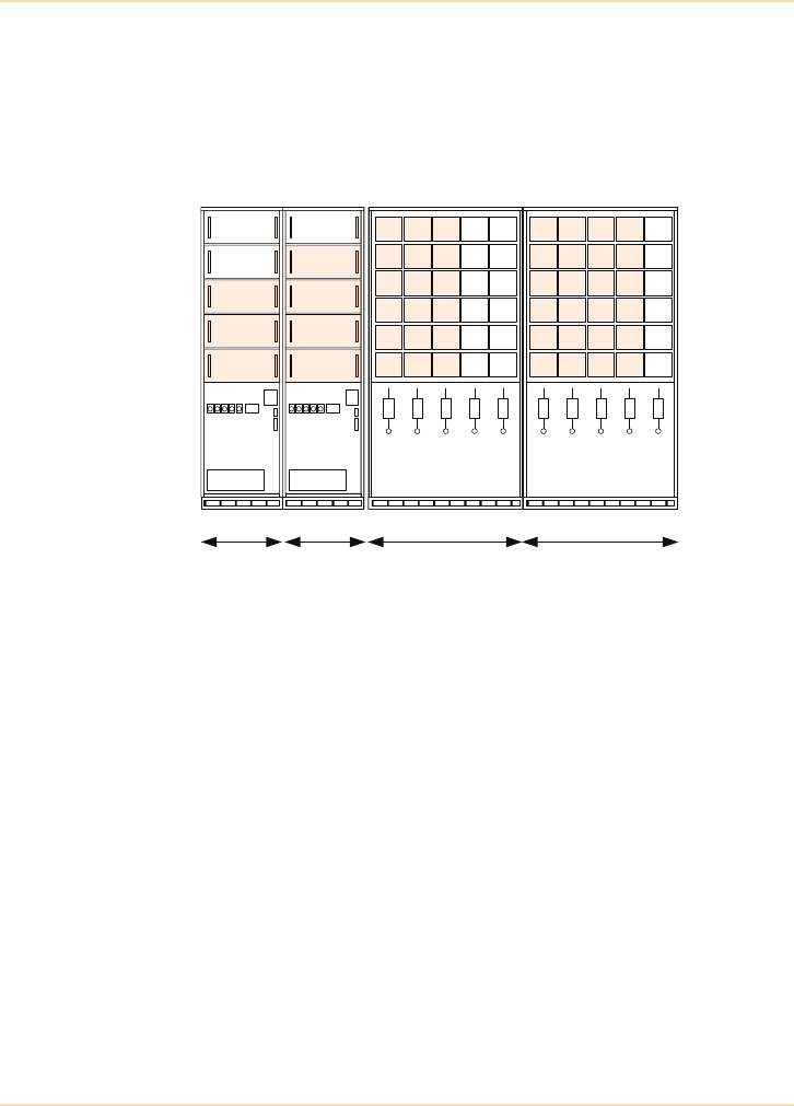
Parallel UPS Systems - Modular UPS Systems
98 The UPS Handbook
Figure 7.10 illustrates a modular UPS system able to support a 300kVA load
with N+1 redundancy, with the ability to expand to 450kVA N+1 or 500kVA
capacity in cost-effective increments and with no extra footprint requirement.
Such a system may be expanded indefinitely by adding relatively small-
footprint UPS and battery cabinets.
Figure 7.10: Horizontal Scalability
Figure 7.11 shows a sophisticated UPS installation utilising rack mounted UPS
modules. On the first floor, a three module UPS is configured with 3 x 50kVA
UPS modules, with redundancy, supporting two server/comms racks. On the
ground floor, 4 x 50kVA modules, with redundancy, support three server/comms
racks and has two spare slots to allow for expansion.
The user decides to move one of the server/comms racks to the ground floor,
overloading the existing power support system there (Figure 7.12).
It is a simple matter to move one UPS module and respective battery to the
ground floor to restore the balance (Figure 7.13). There are spare slots within the
ground and first floor UPS cabinets to allow for future expansion of the
protected system. Further capacity can be obtained by simply introducing
additional UPS modules as and when required. The important point is that all of
these changes can be made with minimum effort, low incremental cost, no
disruption to the critical load and without using any more floor space.
UPS Cabinets Battery Cabinets
730mm 1200mm
300kVA (N+1) - 10 mins
1200mm
Spare
Spare
50kVA
50kVA
50kVA
Spare
50kVA
50kVA
50kVA
50kVA
730mm
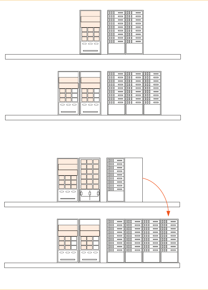
Parallel UPS Systems - Modular UPS Systems
The UPS Handbook 99
Figure 7.11: A Flexible and Upgradeable UPS System (a)
Figure 7.12: A Flexible and Upgradeable UPS System (b)
First floor
Server
Rack
Server
Rack
Server
Rack
Server
Rack
Server
Rack
Ground floor
50kVA
50kVA
50kVA
Spare
50kVA
50kVA
Spare
50kVA
50kVA
First floor
Server
Rack
Server
Rack
Server
Rack
Server
Rack
Ground floor
Server
Rack
Server rack
moved
OVERLOAD ON
GROUND
FLOOR
50kVA
50kVA
50kVA
Spare
50kVA
50kVA
Spare
50kVA
50kVA
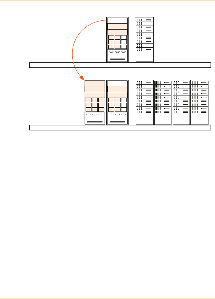
Parallel UPS Systems - Modular UPS Systems
100 The UPS Handbook
Figure 7.13: A Flexible and Upgradeable UPS System (c)
As an added bonus, if one UPS module should develop a fault, the user can
easily arrange for a module to be moved from one floor to the other as an
emergency measure pending service, albeit by temporarily sacrificing
redundancy.
Serviceability is substantially improved by this modular technology because
UPS modules can be swapped out for service and access is only required to the
front of the UPS cabinet. As a result MTTR is significantly reduced.
Fig 5.10b
First floor
Server
Rack
Server
Rack
Server
Rack
Server
Rack
Ground floor
Server
Rack
50kVA module
moved
NO OVERLOAD
Spare
50kVA
50kVA
Spare
50kVA
50kVA
50kVA
50kVA
50kVA
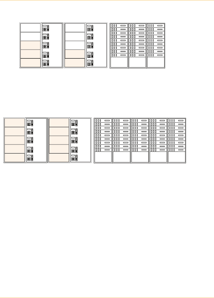
Parallel UPS Systems - Modular UPS Systems
The UPS Handbook 101
Example 2
Figure 7.14: Expandable 1 MVA Modular System
Figures 7.14 and 7.15 illustrate the same flexibility and upgradable facility using
100kVA granular steps rather than 50kVA.
Figure 7.15: Fully Populated 1 MVA System
Server
Rack
Server
Rack
Server
Rack
Spare
Spare
100kVA
100kVA
100kVA
Spare
Spare
Spare
100kVA
100kVA
Server
Rack
Server
Rack
Server
Rack
100kVA
100kVA
100kVA
100kVA
100kVA
100kVA
100kVA
100kVA
100kVA
100kVA Server
Rack
Server
Rack

Parallel UPS Systems - Managing a Parallel System
102 The UPS Handbook
Managing a Parallel System
In the past, parallel systems were managed in a manner less ideal than is
possible today using the latest technology. For example, in some older systems
the module redundancy was often based on ‘module availability’ rather than the
prevailing load itself – i.e. once the number of out of service modules exceeded
the designed number of redundant modules the load transferred to bypass
irrespective of the load current demand and available remaining module kVA.
Modern systems are able to treat the matter of redundancy more intelligently
and effectively.
For example, reconsider the four module (one redundant) system in Figure 7.4.
This shows the situation with one module shut down and the remaining healthy
modules sharing the 270kVA load equally between them at around 90kVA each.
If a second module were to fail the remaining two modules clearly could not
support the load as each would exceed its 100kVA rating. However, if the load
were only 160kVA at the time of failure of the second module there is no reason
why the remaining two modules could not continue operating and maintain the
load on their combined inverters operating at 80kVA each – (see Figure 7.16).
These examples illustrate that when planning a parallel system the effects of
future load requirements should be taken into account, and the choice of UPS
modules must take into consideration the ease of system expansion if and when
necessary.
Traditionally, parallel systems were configured as either ‘capacity’ systems or
‘redundancy’ systems. If a single module failed in a capacity system the critical
load would be transferred to bypass irrespective of the size of the critical load and
the ability of the available module(s) to handle it. Similarly, if the critical load
exceeded the available ‘non-redundant’ power, it would be transferred to bypass
irrespective of the amount of ‘redundant’ power available.
The example shown in Figure 7.3 would be considered a ‘capacity’ system if the
load were between 300kVA and 400kVA, an ‘N+1’ system if the load were
between 200kVA and 300kVA, an ‘N+2’ system if the load were between
100kVA and 200kVA and an ‘N+3’ system if the load were less than 100kVA.
A modern parallel system will automatically adjust its ‘N+n’ status to
accommodate the prevailing load.
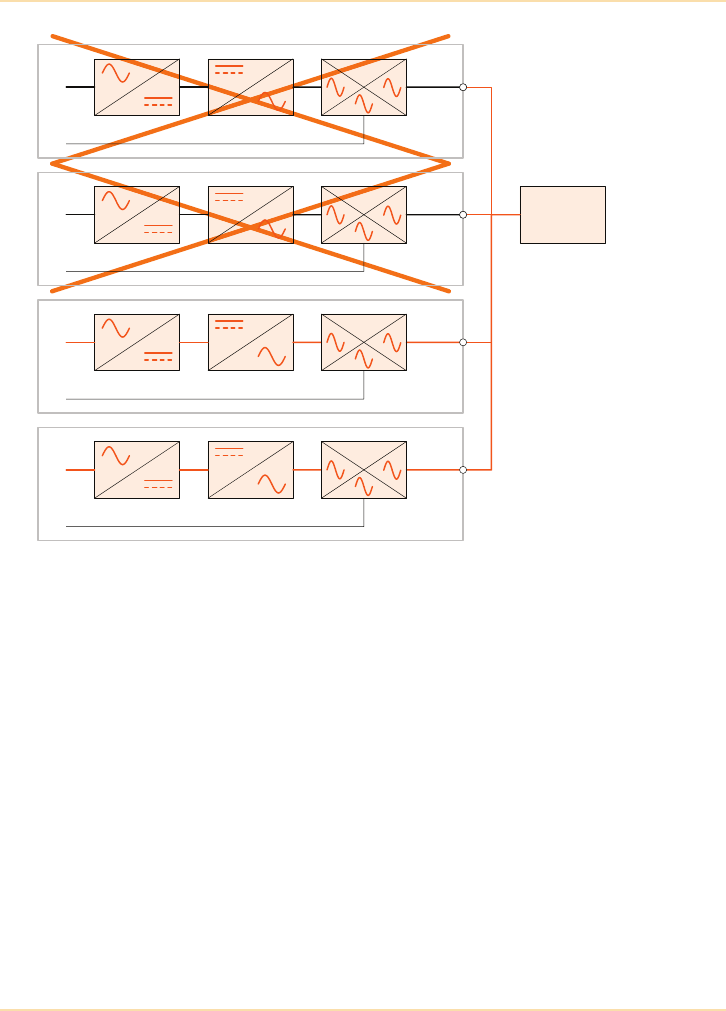
Parallel UPS Systems - Managing a Parallel System
The UPS Handbook 103
Figure 7.16: Redundant System With Two Failed Modules
100kVA UPS
160kVA Load
100kVA UPS
80kVA
80kVA
100kVA UPS
100kVA UPS
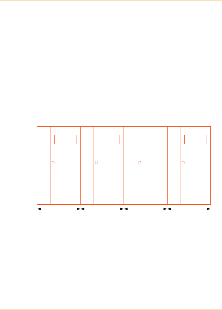
Parallel UPS Systems - Examples of De-centralised UPS Systems
104 The UPS Handbook
Examples of De-centralised UPS Systems
System Requirements
In the following examples the UPS system specification required a 600kVA
parallel redundant UPS with an upgrade path to at least 800kVA parallel
redundant to accommodate potential future growth.
Example 1 - Using Free-Standing UPS Modules
The system proposed comprises 4 off 200kVA UPS modules configured as a
3+1 (i.e. 600kVA parallel redundant) system with a fully integrated switchgear
panel providing all of the required UPS input and output switchgear and
associated electrical and mechanical interlocks with a spare way to enable the
addition of a fourth module at a later date.
Figure 7.17: UPS System Layout (4 off 200kVA UPS)
System and Switchgear Panel Description
Figure 7.18 is a schematic diagram of a 5 way 800kVA “N+1” UPS switchgear
panel in which 4 off 200kVA UPS modules are configured as a “3+1” system to
provide 600kVA parallel redundancy. A spare way is designed into the panel for
the addition of a further 200kVA UPS module to permit future system upgrade
to 800kVA ‘N+1’.
With reference to Figure 7.18 it should be noted that each UPS module has its
own input protection which is sized to ensure adequate discrimination between
1200mm 1200mm 1200mm 1200mm
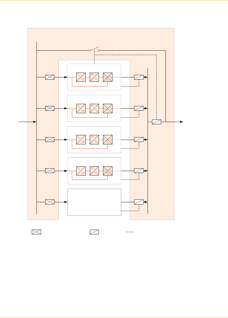
Parallel UPS Systems - Examples of De-centralised UPS Systems
The UPS Handbook 105
the main panel input fuses and the UPS input. The protection also acts as an
input isolator when the respective UPS module requires maintenance etc.
Figure 7.18: UPS Switchgear Panel Schematic
It should also be noted that each UPS module has an output isolator that is
electrically interlocked to the UPS system. In any parallel system it is necessary
to electrically interlock the output isolator to its associated UPS because
whenever the output isolator is open the current sharing circuitry within all of
the UPS modules that form the parallel system need to be aware that one of the
UPS modules is not required to supply current.
Isolator and Bypass Switchgear Panel
UPS 1 - 200kVA
UPS 2 - 200kVA
Spare Way
UPS 3 - 200kVA
1000A Bypass Switch
400/315A
400/315A
400/315A
400/315A
315A
315A
315A
315A
Switch Fuse/MCCB Isolator Electrical Interlock
Mains Input Supply
Output to Critical Load
1000A
UPS 4 - 200kVA
400/315A 315A

Parallel UPS Systems - Examples of De-centralised UPS Systems
106 The UPS Handbook
The 5 off UPS output isolators all feed the parallel bus and connected between
the parallel bus and the load is the main UPS output isolator. This isolator is
required to facilitate full system testing and/or site electrical testing as, in
conjunction with the “wrap around” manual bypass switch, it allows the UPS
system to be completely electrically isolated from the load without a break in
power to the load. The UPS system output isolator and the “wrap around”
manual bypass switch are also electrically interlocked to the UPS system. The
manual bypass switch is electrically interlocked to prevent accidental damage to
the UPS system caused by unauthorised operation of the “wrap around” manual
bypass (if the manual bypass switch is closed whilst the UPS system inverters
are running, the inverters will be stopped and the system will automatically
transfer to static bypass without any break in the supply to the load in order to
prevent inverter damage caused by back feeding). By interconnecting the UPS
output isolator and wrap around manual bypass switch interlocks, it is possible
to fully functionally test the entire UPS system, complete with all paralleling
features, without risk to the load.
Another major benefit of the switchgear panel is that it is possible to
individually electrically isolate any UPS module connected to the panel, thereby
allowing its physical removal and/or physical introduction to the UPS system
whilst the load is running and still fully protected by the UPS system. Using
such a switchgear panel therefore increases the system flexibility and eliminates
the need for the load to ever be exposed to raw mains.
Example 2 - Using Rack Mounted Modular UPS
The proposed system comprises 7 x 100kVA rack mounted UPS modules
configured as a 6+1 (i.e. 600kVA parallel redundant) system with a fully
integrated switchgear panel providing all of the required UPS input and output
switchgear and associated electrical and mechanical interlocks. Note that a spare
way is not required in the switchgear panel as the addition of a module takes
place within the already installed UPS cabinet. This also means that the system
can be upgraded without the requirement for additional floorspace.
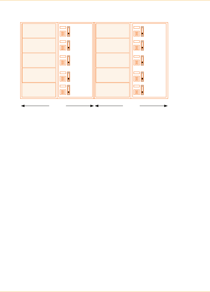
Parallel UPS Systems - Examples of De-centralised UPS Systems
The UPS Handbook 107
Figure 7.19: UPS System Layout (7 off 100kVA rack mounted UPS)
Figure 7.20 is a schematic diagram of a 2 way, 500kVA modular UPS
switchgear panel in which 2 off UPS system cabinets, each capable of housing
up to 5 off 100kVA UPS modules, are configured to provide up to 600kVA
“6+1” parallel redundancy.
The UPS system is shown with 7 off 100kVA modules to provide 600kVA
“6+1” parallel redundancy and has a spare way available to facilitate the
addition of another 100kVA module if system upgrade is ever required.
It should be noted that the UPS switchgear panel in Figure 7.20 is considerably
simpler than the one shown in Figure 7.18. This is because the majority of input
and output switchgear needed by the individual UPS modules is provided within
each of the system cabinets housing the UPS modules. For example, the UPS
system cabinets themselves contain all of the input protection and input and
output isolation required by the UPS modules.
The UPS switchgear panel shown in Figure 7.20 will be physically smaller, less
expensive to purchase and easier to electrically install than the switchgear panel
shown in Figure 7.18. It should also be noted that no additional electrical
installation works will be required to upgrade the system.
Spare
100kVA
100kVA
100kVA
100kVA
1580mm
Spare
Spare
100kVA
100kVA
100kVA
1580mm
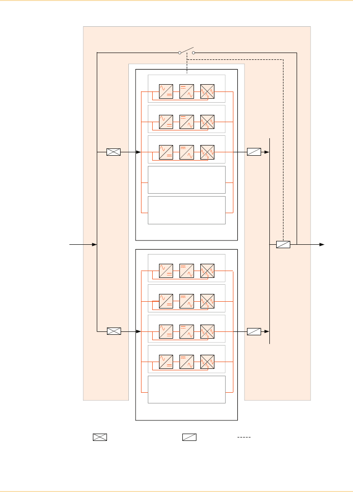
Parallel UPS Systems - Examples of De-centralised UPS Systems
108 The UPS Handbook
Figure 7.20: UPS Switchgear Schematic
Isolator and Bypass Switchgear Panel
1600A Bypass Switch
800A
Switch Fuse/MCCB Isolator Electrical Interlock
Mains Input Supply
800A
1600A
800A
800A
UPS Cabinet 1
UPS Module 1 - 100kVA
UPS Module 2 - 100kVA
UPS Module 3 - 100kVA
UPS Cabinet 2
Spare Way
Spare Way
UPS Module 4 - 100kVA
UPS Module 5 - 100kVA
UPS Module 6 - 100kVA
UPS Module 7 - 100kVA
Spare Way
Output to Critical Load
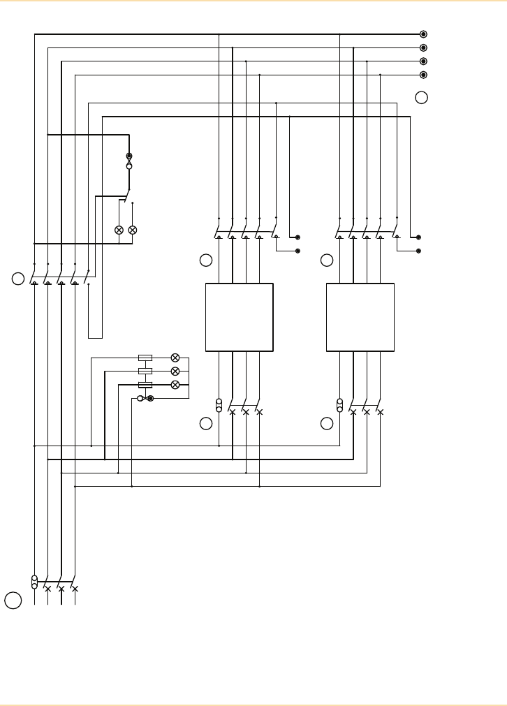
Parallel UPS Systems - Examples of De-centralised UPS Systems
The UPS Handbook 109
Figure 7.21: A Typical Paralleled UPS System Bypass Panel
.*
(3
#,
#3
."*/*/$0.&3
/
."*/5&/"/$&
#:1"44
&"3-:.",&",
614
#:1"44
-0"%0/
-0"%0/
(
3
'N"
#3
(3
#,
/
-0"%065165
#3&",
&"3-:.",&
614*/165
614
$BCJOFU
614065165
*40-"503
#3&",
&"3-:.",&
614*/165
614
$BCJOFU
614065165
*40-"503
."*/
*/$0.*/(
4611-:
"
'5
888
."*/41)"4&4
)&"-5):

Parallel UPS Systems - Examples of De-centralised UPS Systems
110 The UPS Handbook
Figure 7.21 illustrates a flexible yet tidy way of implementing an expandable
parallel UPS system by using a purpose designed panel incorporating input and
output switchgear for each UPS cabinet together with a ‘system’ output isolator
and a wrap-around bypass switch. Whether paralleling is required for
redundancy or scalability, this panel reduces the system design burden,
simplifying cabling and shortening cable runs. It also minimises design and
implementation complexity, saving time and costs.
Spare ways can be made available on the panel to permit the addition of further
UPS modules to provide extra capacity or redundancy at a later date, and
additional UPS can be connected and commissioned without any need to disrupt
the load.
The panel enables electrical and physical isolation of individual UPS modules
for service and maintenance without a break to the load.
Electrical interlocks should be included to prevent the UPS modules from being
‘back-fed’ due to incorrect switching.
Parallel UPS System Battery Configuration
The successful design of any parallel UPS system involves the minimisation of
all the single points of failure.
A potential single point of failure in any UPS system is the battery bank. If a
UPS has single strings of batteries and any one battery cell in the string is faulty
then the batteries may fail to support the load in the event of a mains power
failure. To overcome this problem multiple strings of batteries connected in
parallel are used.
Chapter 8 discusses various battery configurations including parallel strings of
batteries and the use of transition boxes when paralleling batteries. In summary,
parallel strings are used to increase the capacity of a battery system and/or its
resilience (by providing battery redundancy) and transition boxes are used to
simplify wiring and to individually protect each string in the battery system.
Ideally, each UPS module in a parallel UPS system should have its own set of
separately fused paralleled strings of batteries. With large, high powered parallel
UPS systems this could be prohibitively expensive and take up too much space
within the UPS/computer room. Such cost and space pressures can be partially
overcome with careful design of the battery systems by, for example, using more
individual strings of lower capacity battery blocks to achieve the required total
battery capacity. It is invariably cheaper, however, to have a single string of
large batteries rather than multiple strings of smaller batteries.
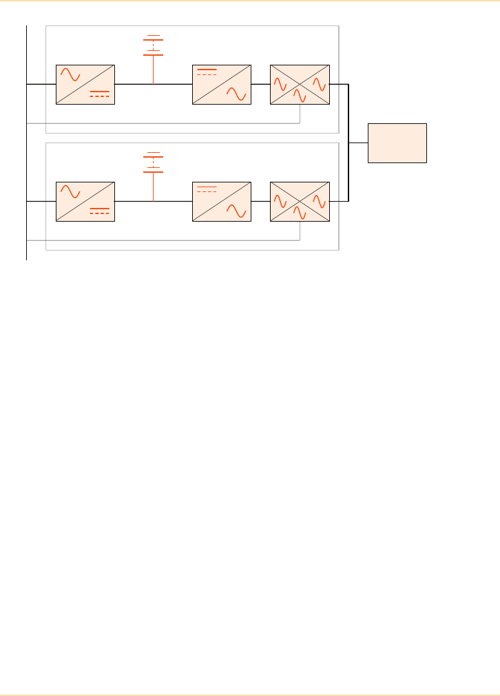
Parallel UPS Systems - Examples of De-centralised UPS Systems
The UPS Handbook 111
Figure 7.22: Parallel UPS System with One Battery String
Figure 7.22 shows a 2 module parallel UPS system where each UPS module has
a single string of batteries. In such a configuration, if any one battery cell is open
circuit in either of the battery strings only one UPS module will be able to
operate in the event of a mains power supply failure. In a capacity parallel
system this may result in the overloading of the UPS module with good batteries
potentially resulting in a load loss. However, in a parallel redundant system the
battery failure will result in redundancy being lost, but the critical load will be
maintained without interruption.
Figure 7.23, shows the same 2 module parallel UPS system but this time each
UPS module has 2 strings of batteries connected in parallel to the UPS. If any
one battery cell in such a configuration is open circuit both UPS modules will
still be able to operate. As both UPS modules equally share the load, the UPS
module with only one good battery string will discharge its good batteries
quicker than the other UPS module but with appropriately rated batteries and
correctly configured auto-shutdown software (See Chapter 10) the critical load
will be protected.
Rectifier/Chargers Inverters Static
Switches
Mains Input Supply
UPS 1
Critical Load
UPS 2
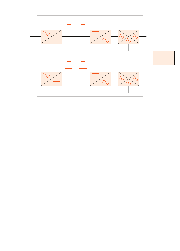
Parallel UPS Systems - Examples of De-centralised UPS Systems
112 The UPS Handbook
Figure 7.23: Parallel UPS System with Dual Battery Strings
Common Battery Configuration
Both the systems shown in Figure 7.22 and Figure 7.23 have batteries that are
configured as “separate batteries” i.e each UPS module has its own set of
batteries and no other UPS module in the system has access to these batteries. It
is possible to configure the same batteries as “common batteries” i.e. all of the
batteries are physically connected to all of the UPS modules in the system.
Common battery configurations utilising multiple strings overcome the
problems presented by open circuit cells as discussed in the earlier paragraphs
but, unless great care is taken with the common battery's DC distribution
system, such a battery configuration can present a single point of failure (e.g. a
short circuit on the DC bus of one of the UPS modules may cause all of the
battery fuses in the system to fail).
An example of a DC distribution system designed to connect all of the system
batteries to all of the UPS modules in the system is shown in Figure 7.24.
Figure 7.24 shows the DC distribution system for a 6 module parallel UPS
system with 4 strings of batteries configured as a common battery. For
illustrative purposes the UPS DC input protection has been rated at 250A and
the battery string protection has been rated at 630A. In a practical application
Rectifier/Chargers Inverters Static
Switches
Mains Input Supply
UPS 1
Critical Load
UPS 2

Parallel UPS Systems - Examples of De-centralised UPS Systems
The UPS Handbook 113
the actual rating of the protection would depend upon the power rating and
quantity of UPS modules and batteries.
It can be seen that a short circuit on the DC bus bars within any of the UPS
modules will not affect any of the other UPS modules or any of the battery
protective devices. It can also be seen that a short circuit within any of the
battery strings will not affect any of the other battery protective devices or any
of the UPS modules.
The only single point of failure of this system are the DC bus bars themselves
but as these are solid copper bars protected and enclosed within a bus bar
chamber it is highly unlikely that a short circuit will be presented here. It is still,
however, a single point of failure within the overall system and if such a single
point of failure is considered unacceptable to the UPS user the batteries must be
configured as separate batteries.
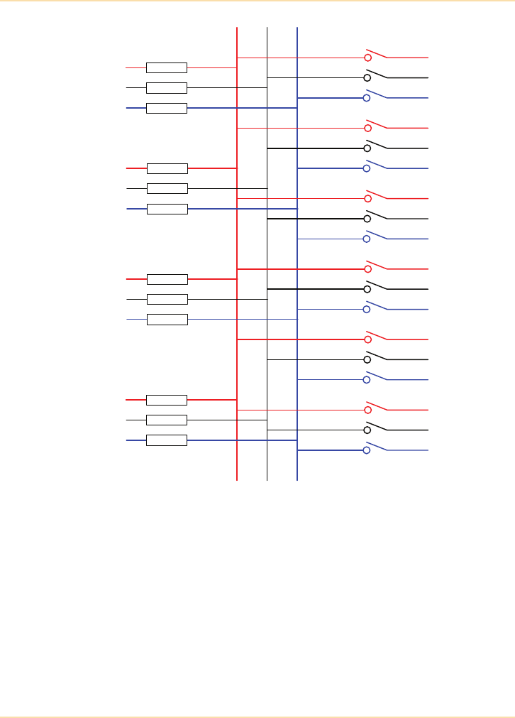
Parallel UPS Systems - Examples of De-centralised UPS Systems
114 The UPS Handbook
Figure 7.24: DC Distribution System for a Common Battery
Optimum Battery Configuration
The optimum battery configuration for a parallel UPS system will vary
depending upon the site facilities (standby generator, available space etc.) and
the load requirements. A good UPS supplier will be able to discuss all of the
options available to allow the UPS user to make an informed decision on the
configuration that best suits their requirement and budget.
Battery
String A
Battery
String B
Battery
String C
Battery
String D
630A DIN Fuses 250A
UPS 1
UPS 2
UPS 3
UPS 4
UPS 5
UPS 6
+ve -ve0

The UPS Handbook 115
8Energy Storage
Devices
Introduction
When mains power fails a UPS must call upon another source of power if it is to
continue providing power to the critical load. This power, or more accurately
energy, has to be safely stored and instantaneously available for use whenever
required. It must also be easily replenishable when mains power returns. With
all this in mind, it is no real surprise that the options for energy storage devices
capable of being used by UPS systems is limited.
Traditionally, batteries have been the energy storage devices used by almost all
UPS manufacturers. There are, however, a couple of technologies that are still
very much in their infancy but may well develop into commercially viable
alternatives to batteries. These technologies are flywheels and hydrogen fuel
cells.
Flywheels
A flywheel is a device that uses mechanical means to store kinetic energy (the
energy of motion). When mains power is available a motor-generator is used to
rotate the flywheel which acts as the storage vessel for the kinetic energy. When
mains power is not available the flywheel's kinetic energy is converted into
electrical energy that supplies power to the UPS DC bus. A typical DC flywheel
and UPS configuration can be seen in Figure 8.1.
The capital cost of a UPS system incorporating a flywheel is likely to be
significantly higher than that of a UPS using more traditional forms of energy
storage devices and, because of physical constraints, is unlikely to ever provide
more than 30 to 45 seconds of “back-up” time. However, flywheels are an
environmentally friendly alternative to devices such as batteries and, unlike
most batteries, can continuously operate at ambient temperatures from 0 to +40
Celsius.
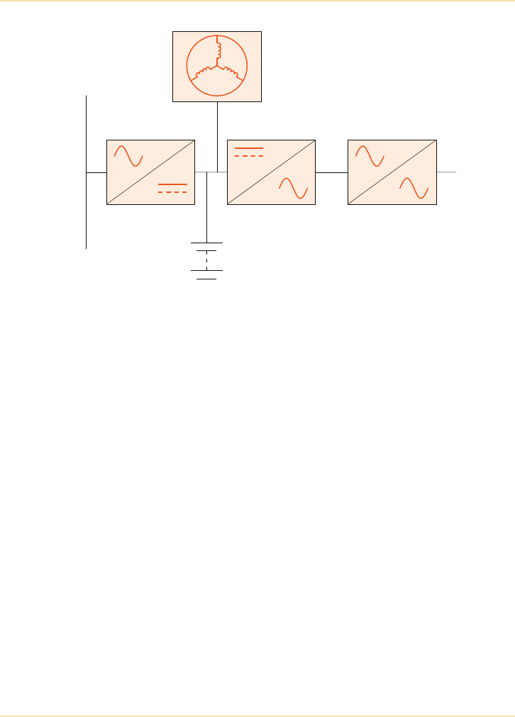
Energy Storage Devices - Hydrogen Fuel Cells
116 The UPS Handbook
Figure 8.1: A typical DC flywheel and UPS
Hydrogen Fuel Cells
When hydrogen and oxygen combine to produce water a chemical reaction
occurs, one by-product of which is electrical energy. Hydrogen fuel cells can
therefore be said to convert hydrogen gas into electrical energy.
Each hydrogen fuel cell has two electrodes, an anode and a cathode, that are
separated by a polymer electrolyte membrane. Oxygen is passed over the
cathode and hydrogen is passed over the anode. The hydrogen molecules are
converted into electrons and protons when they pass over a catalyst (typically
platinum) on the anode. The electrons flow out of the fuel cell as electrical
energy whilst the protons flow through a membrane to the cathode where they
combine with the oxygen to produce pure water. Figure 8.2 shows a typical
hydrogen fuel cell.
Hydrogen fuel cells are significantly more expensive than batteries and, because
hydrogen is an explosive gas, great care has to be taken with its storage. Also,
because hydrogen is currently manufactured from natural gas and energy is
required to make the hydrogen the “environmentally friendly” credentials of
hydrogen fuel cells are currently questionable. Having said this, hydrogen fuel
cells are smaller and lighter than batteries and the research and development
currently taking place into the use of hydrogen fuel cells in automotive
applications will have spin-off benefits for “standby” fuel cell applications.
Flywheel
Rectifier/Charger Inverter Static Switch
Battery
Mains Supply
Output to
Critical
Load
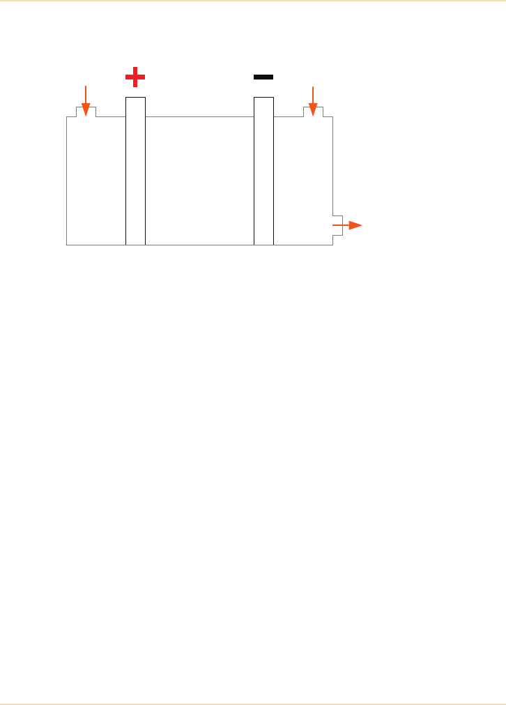
Energy Storage Devices - Hydrogen Fuel Cells
The UPS Handbook 117
Figure 8.2: A typical hydrogen fuel cell
Summary
Whilst the ongoing development of flywheel and hydrogen fuel cell
technologies are of great interest to UPS manufacturers they must be viewed as
emerging technologies as it is unlikely that either of these technologies will be
commercially viable within the next 5 to 10 years. With this in mind, this book
will focus on the use of batteries as energy storage devices for UPS.
Membrane
Anode
Cathode
Hydrogen
Oxygen
Water
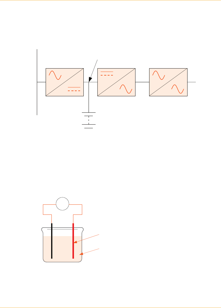
Energy Storage Devices - Batteries
118 The UPS Handbook
Batteries
Batteries are an essential part of any UPS. They provide the reserve or
alternative power source which is used when the mains supply fails or when it is
outside certain limits (See "What is a UPS?" on page 11).
Batteries may be contained within the UPS cabinet, in separate cabinets or on
racks. The actual location depends on site conditions and restrictions and on
both the capacity of the battery and the required back-up or autonomy time. See
"Size and Location" on page 120.
What is a Battery?
A battery is a device that uses chemical means to store electrical energy and can
be found in any number of shapes, sizes, voltages and capacities.
When two materials (usually dissimilar metals) are immersed in a solution
(electrolyte) they conduct electricity between the ‘plates’ causing an electrical
potential. The value of the potential (or voltage) is dependent on the plate
materials and the electrolyte used. Examples are lead acid, nickel cadmium
(Nicad), lithium, silver alkaline.
Rectifier/Charger Inverter Static Switch
Battery
Mains Supply
Output to
Critical
Load
DC Busbar
V
+ve-ve
The diagram shows one battery cell.
The plate with the more positive potential is
known as the positive plate.
Electrolyte
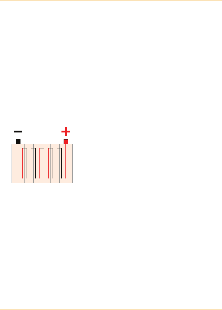
Energy Storage Devices - Batteries
The UPS Handbook 119
Nickel-Cadmium (Ni-Cad) Batteries
Ni-Cad batteries are rarely used in modern UPS applications because of their
high cost and the impact that their Cadmium content has on the environment.
When they are used it is almost always in applications that require the batteries
to operate in extremes of temperature (e.g. from -20 to +40 Celsius) or where
useful working lives in excess of 20 years are essential.
Because of the relative rarity of Ni-Cad batteries in UPS applications this book
is concerned only with the lead acid battery as this type of battery is the most
suitable for general UPS applications within the UK.
The Lead-Acid Battery
The lead acid cell uses lead and lead oxide plates immersed in sulphuric acid
electrolyte. Using this combination each cell develops a nominal 2 volt
potential.
A battery is simply a number of cells connected together with a given voltage
and capacity. The capacity is defined in Ampere hours (Ah), i.e. the power of the
battery or its capability to produce 1 Amp for a certain number of hours. As a
general rule the more cells the higher the battery voltage and the larger the plates
the higher the battery capacity.
For convenience, batteries are made in 12 volt blocks using six cells but are also
available in 6 volt (three cell), 4 volt (two cell) and 2 volt (single cell) blocks.
There are two main types of lead-acid batteries which may be used in UPS
applications:
•open - vented
• sealed or Valve Regulated Lead Acid (VRLA)
The diagram shows six, 2 volt cells
connected in series to form a 12 volt block.

Energy Storage Devices - Batteries
120 The UPS Handbook
Size and Location
UPS suppliers offer a range of standard batteries, all designed to support the full
UPS load but with various back-up/autonomy times.
• UPS suppliers often accommodate the batteries in the UPS cabinet.
• Additional cabinets, which match the UPS, are usually available for
larger battery installations – these may need to be built to order.
• Larger or ‘non-standard’ installations may require separate battery
racks. UPS suppliers may offer cladded or open types to suit a
particular installation. Open racks usually require the batteries to be
kept in a separate battery room with controlled access arrangements.
The table below gives some sample battery sizes and weights.
Open - Vented Sealed - VRLA
Older technology Environmentally friendly
Separate battery room Suitable for office environments
Regular routine maintenance Low regular routine maintenance
Separate safety requirements Self-contained. Safe
Store/use in vertical position Store/use in any orientation
The VRLA Lead-acid battery is now the battery of choice
for modern UPS systems.
UPS Rating
(kVA)
Autonomy
(Minutes)
Size Inc. UPS
H x W x D (mm)
Weight (kg)
inc. UPS
55
45
One off*- 690 x 200 x 690
Two off - 690 x 200 x 690
77
226
15 20 Two off - 690 x 200 x 690 353
30 6
25
One off*- 1400 x 580 x 750
Two off - 1400 x 580 x 750
490
1055
60 8 Two off - 1400 x 580 x 750 1060
120 15 Three off - 1800 x 580 x 750 2960
* Batteries located within the UPS cabinet
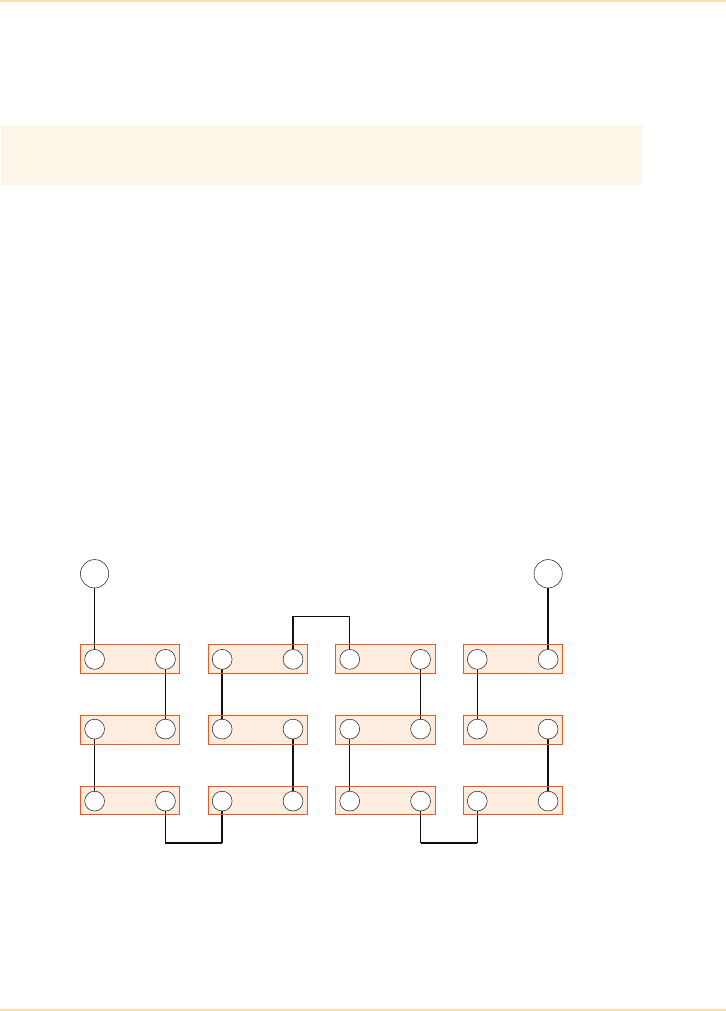
Energy Storage Devices - Batteries
The UPS Handbook 121
Configuration
The configurations shown in this section are samples – on-site arrangements
will obviously differ from site to site.
Serial Strings
A serial string is a single series of blocks connected ‘end-to-end’ to form the
battery. The positive terminal of the first block is connected to the negative
terminal of the second block, the positive terminal of the second is connected to
the negative of the third, etc.
The overall voltage of the battery is the sum of the individual block voltages and
must be arranged to match the float voltage setting of the UPS.
The capacity of the battery is unchanged with this arrangement, being the same
as each individual block.
For example:
If 12 x 12V 10Ah blocks are connected in series, the resulting battery is
144V with a 10Ah capacity.
Figure 8.3: Serial Battery String
In any battery configuration, all of the cells used in a serial string must be
identical to each other.
+-
+-+-+-+-
+-+-+-+-
+-+-+-+-
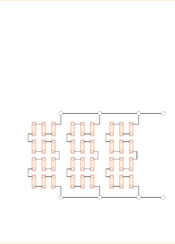
Energy Storage Devices - Batteries
122 The UPS Handbook
Parallel Strings
A parallel string is a combination of two or more serial strings, and each string
must contain the same number of blocks. Batteries are paralleled for two main
reasons: either to increase the resilience of the battery bank so that a single
faulty battery will not cause all of the batteries to be unavailable to the UPS, or
to increase the total capacity (Ah rating) of the battery bank.
The positive terminal of the first battery string is connected to the positive
terminal of the second battery string, the positive terminal of the second is
connected to the positive of the third, etc. The negative terminal of the first
battery string is connected to the negative terminal of the second battery string,
the negative terminal of the second is connected to the negative of the third, etc.
The overall voltage of the battery is the same as the voltage of each string.
The capacity of the battery is the sum of the capacities of the individual strings.
For example:
If 3 strings of 12 x 12V 10Ah batteries are connected in parallel,
the resulting battery is 144V with a 30 Ah capacity.
Figure 8.4: Parallel Battery Strings
Due to potential equalisation problems (i.e. unequal charge being taken on by
individual batteries), it is unusual for more than six battery strings to be
connected in parallel.
+
-
+-+-+-+-
+-+-+-+-
+-+-+-+-
+
-
+-+-+-+-
+-+-+-+-
+-+-+-+-
+
-
+-+-+-+-
+-+-+-+-
+-+-+-+-
+
-

Energy Storage Devices - Batteries
The UPS Handbook 123
Battery Monitoring
Equalisation problems can be minimised using a modern battery monitoring
application, such as the patented Battery Analysis & Care System (BACS),
which can provide integrated battery monitoring and management over an
Ethernet network.
Using web-management technology, the system sequentially checks the internal
resistance, temperature and voltage of each individual battery block and corrects
its charging voltage as required to obtain a balanced charging condition across
the battery string.
By constantly monitoring and controlling the individual charging voltages for
each battery block it ensures they are kept in their optimal voltage operating
range and guarantees the availability of the battery at all times.
Other benefits from using the BACS equalisation system include:
• Avoid overcharging:
Through the equalisation process the unnoticed overcharging of
individual batteries (gassing, dry-out, thermal runaway) is prevented.
• Avoid undercharging:
Through the equalisation process the unnoticed undercharging of
individual batteries (sulphation, loss of capacity) is prevented.
• Indication of battery problems:
Typical battery problems such as sulphation, corrosion, gassing, dry-
out, thermal runaway etc. are visible through a rise of impedance and
temperature.
• Avoid sulphation :
Sulphation is a typical problem for UPS batteries because they are
consistently held at a float charge level for a long time. Its not
guaranteed that ALL batteries have really been fully charged when
the UPS charge switches from boost charging to float charging. The
result maybe that some batteries are overcharged, while others have
never been fully charged. Equalisation avoids sulphation through the
process of bringing the overcharged and undercharged accumulators
to a balanced voltage level.

Energy Storage Devices - Batteries
124 The UPS Handbook
• Show stratification:
BACS warns of a possible stratification of the electrolyte through
detecting increasing impedance and drifting voltages. The
stratification can be removed through a discharge process and the
BACS will indicate this effect through a lower impedance and
improved equalizing.
• Early warning to replace batteries:
Through impedance trending you can see in the early stage that some
battery blocks are damaged or simply weaker than others. The earlier
accumulators are replaced the better for an increased lifetime of the
complete battery system.
• Extension of service life up to 30%:
The service life of all the batteries in a string depends on the weakest
member – i.e. the weakest battery. By equalizing, all batteries are kept
constantly in their ideal voltage window so that all negative
influences of wrong charging voltages and currents within the string
are eliminated.
• Improved maintenance:
A BACS system improves the service quality by providing remote
monitoring through Internet, VPN or other network for downloading
real time data and battery history for analysis. Single, individual
battery tests are now possible without the need to disconnect batteries
from the group. Maintenance and battery testing are able to take place
at any time, under real operating.
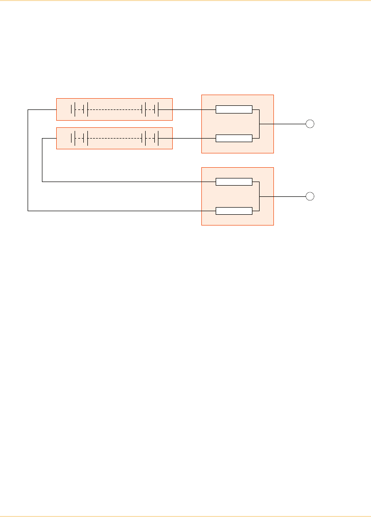
Energy Storage Devices - Batteries
The UPS Handbook 125
Transition Boxes
Transition boxes are used to simplify the connection of a battery to a UPS. In
addition to providing space for the correct termination of battery cables they
also contain suitable fuses to protect the individual battery strings and associated
cabling.
Figure 8.5: Fused Transition Boxes for Two Battery Strings
When two or more parallel battery strings need to be connected to the same
UPS, it is common to use transition boxes. Fused transition boxes allow
individual battery strings and cables to be protected and also enable an
individual battery string to be safely isolated for maintenance or repair without
completely disconnecting the UPS equipment.
It is important to keep the lengths of cables within each battery string
approximately the same to ensure that the impedance (and hence the current
share) of each battery string is approximately the same.
String 1
String 2
Fuses
Fuses
+
-
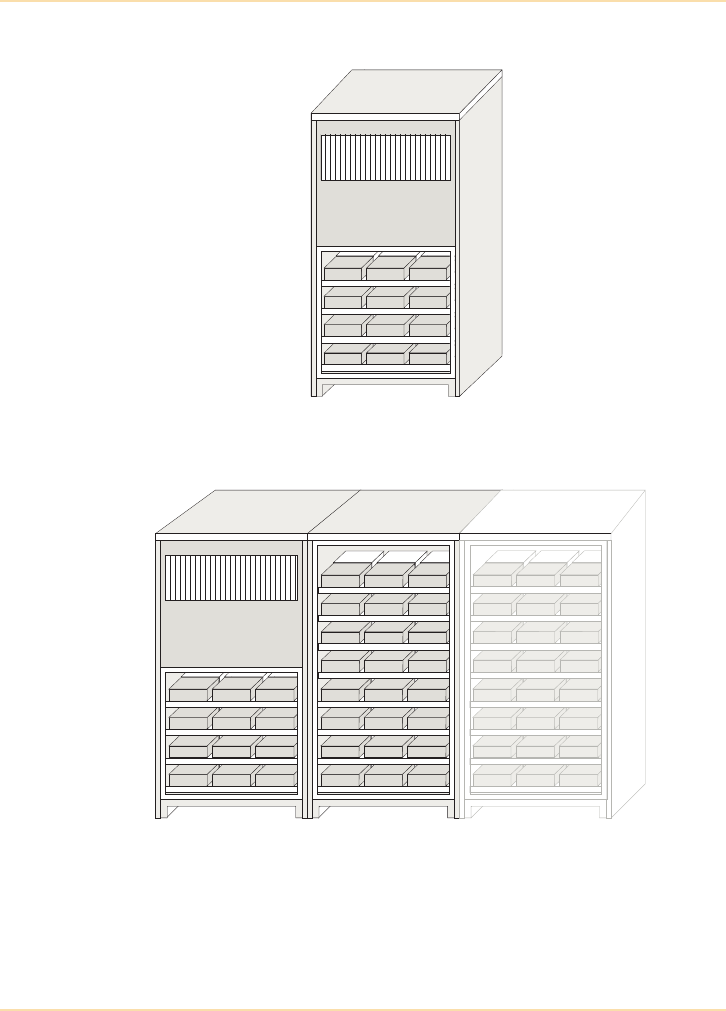
Energy Storage Devices - Batteries
126 The UPS Handbook
UPS with Internal Batteries
Additional Battery Cabinets
!"!"!"
!"!"!"
!"!"!"
!"!"!"
!"!"!"
!"!"!"
!"!"!"
!"!"!"
!"!"!"
!"!"!"
!"!"!"
!"!"!"
!"!"!"
!"!"!"
!"!"!"
!"!"!"
#$%&!&'())*+, -../)/01(2&'())*+,
!"!"!"
!"!"!"
!"!"!"
!"!"!"
!"!"!"
!"!"!"
!"!"!"
!"!"!"
!"!"!"
!"!"!"
!"!"!"
!"!"!"
!"!"!"
!"!"!"
!"!"!"
!"!"!"
!"!"!
!"!"!
!"!"!
!"!"!
!"!"!
!"!"!
!"!"!"
!"!"!"
!"!"!"
!"!"!"
!"!"!"
!"!"!"
!"!"!"
!"!"!"
-../)/01(2&'())*+,
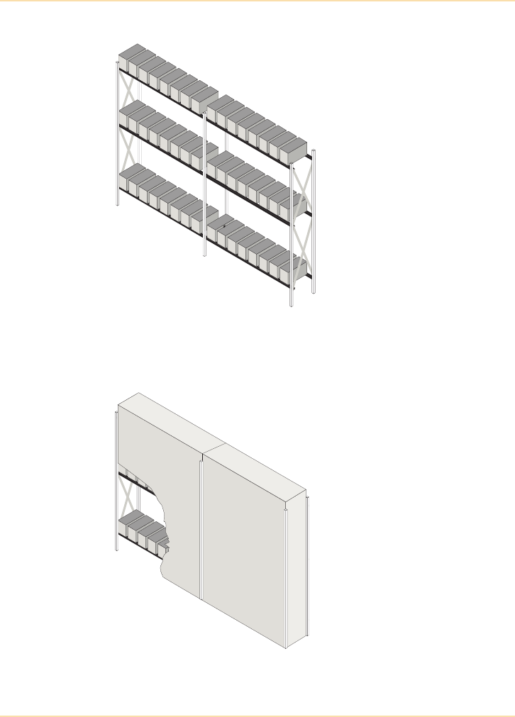
Energy Storage Devices - Batteries
The UPS Handbook 127
Open Battery Racks
Figure 8.6: A 3 Tier, 1 Row Open Battery Rack
Cladded Battery Racks
Figure 8.7: A Fully Clad Battery Rack

Energy Storage Devices - Storage, Care and Maintenance
128 The UPS Handbook
Storage, Care and Maintenance
Batteries should be considered a weak link in any UPS application because they
have a finite useful working life and, if left in service long enough, will
definitely require replacement. How the battery is used and the environment in
which it is kept have an effect upon the useful working life of the battery. For
this reason, great care must be taken when selecting and sizing batteries in a
UPS installation.
The factors which most affect the useful working life of a battery are discussed
below.
Storage
Depending on manufacturer, the storage or shelf life of a VRLA battery is
usually between 3 and 6 months at 20°C, starting from a charged condition.
Always store batteries in a dry, clean, cool environment in their original
packaging.
If storage of 6 months or longer is required supplementary charging will be
necessary.
Design Life
All batteries have a ‘design life’ and this is a figure quoted by the battery
manufacturer based upon certain assumptions about how the battery will be used
and the environment in which it will be kept. Unfortunately, the ‘ideal world’ of
the battery design engineer cannot be matched by the ‘real world’ application of
the UPS system.
The battery manufacturer will specify that under certain charging conditions and
at certain temperatures, with a set number of charge and discharge cycles, their
battery will last X years. In a UPS application, the ambient temperature is
unlikely to be exactly that specified by the battery manufacturer and the
frequency and depth of discharge will be determined by the quality of the site
mains voltage. For these reasons the useful working life of the battery is
invariably less than the ‘design life’ of the battery.
VRLA batteries must NEVER be stored in a discharged
or partially discharged state.

Energy Storage Devices - Storage, Care and Maintenance
The UPS Handbook 129
Sulphation/Undercharge
If a battery has an open-circuit voltage lower than its rated value, then
sulphation may well be the cause.
When a battery is left in a discharged state or for prolonged periods of storage,
lead sulphate crystals begin to form, acting as a barrier to recharge and
preventing normal battery operation.
Depending on the degree of sulphation, a battery may be recovered by constant
current charging at a higher voltage than the standard charge voltage with the
current limited to one tenth of the battery capacity, and for a maximum of 4 to
10 hours.
Note: The applied voltage will exceed the normal recommendation and so the
battery must be monitored (not left unattended) and removed from charge
if excess heat is dissipated. The voltage required to ‘force’ this maximum
current into the battery will reduce as the battery recovers until normal
charging can take place.
In extreme circumstances a battery may never fully recover from sulphation and
must therefore be replaced.
Overcharge
Optimum charging relies mainly on voltage, current and temperature factors
which are interrelated and all of which can cause overcharge.
Excessive charge voltages will force a high overcharge current into the battery,
which will dissipate as heat, and may cause gas emission through the safety
valve (hence the term ‘Valve Regulated’). Within a short period this will corrode
the positive plate material and accelerate the battery towards end-of-life.
Temperature
Most manufacturers recommend a battery operating temperature of 20°C.
Figure 8.8 shows how high temperatures will reduce the battery service life and
in extreme cases will cause thermal runaway, resulting in possible oxygen/
hydrogen gas production and battery swelling. VRLA batteries cannot be
recovered from this condition and should be replaced.
Extreme temperatures will destroy batteries.
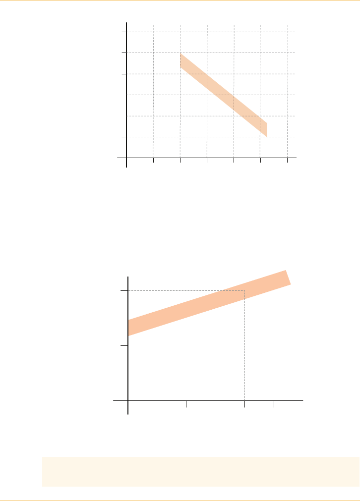
Energy Storage Devices - Storage, Care and Maintenance
130 The UPS Handbook
Figure 8.8: Temp./Life Characteristics of a Typical VRLA Battery
Low temperatures will have little effect on the battery service life but will
reduce the battery performance. Figure 8.8 shows the extrapolated service life
for a typical VRLA battery at different ambient temperatures. As can be seen,
higher ambient temperatures will significantly reduce service life.
Figure 8.9: Temp./Capacity Characteristics of a Typical VRLA Battery
High temperatures give increased performance but reduced service life
Low temperatures give reduced performance but increase service life
10 20 30 40 50 60
Design Life (Years)
20
10
0.5
Temperature (°C)
5
10 20 30 40 50 60
Design Life (Years)
20
10
0.5
Temperature (°C)
5
10 20 25
Output Capacity (%)
100
50
Temperature (°C)

Energy Storage Devices - Storage, Care and Maintenance
The UPS Handbook 131
Over or ‘Deep’ Discharge
When a battery is discharged to the extent that its on-load voltage falls below a
predetermined limit, the battery is considered to be over discharged. Where
extreme over discharging occurs the battery is said to be deep discharged and
both the battery’s capacity and its useful working life will be adversely affected.
Over discharging will cause sulphation of the plates within the battery which
results in an increase in the internal resistance (impedance) of the battery. In
extreme cases of deep discharge the battery may be unable to accept a recharge
and, as such, will be at the end of its useful working life. Depending upon the
depth of over discharge, it may be possible for the battery capacity to be
recovered by very careful recharging. In the majority of critical UPS
applications, however, any battery that has been over discharged will require
replacement.
AC Ripple
Batteries are dc power storage devices and require charging with dc voltage.
Any ac voltage superimposed upon the dc charging voltage is known as ac
ripple and will adversely affect the useful working life of the battery.
UPS Design and Battery ‘Useful Working Life’
UPS design engineers understand how batteries need to be used in a UPS
application, so it is reasonable to assume that the design of the UPS will protect
the batteries from under charging, over charging and over discharging etc.
Modern UPS have battery charging systems that completely eliminate ac ripple.
They also have temperature compensated charging to prevent over charging at
higher than normal temperatures.
The only area of battery life optimisation that the UPS design engineer cannot
directly address is the ambient temperature that the battery will experience
during service. Control of the UPS ambient temperature is entirely the
responsibility of the user. The high efficiencies of the latest generation UPS
assist in the battle against high ambient temperatures by minimising the thermal
effect (heat output) of the UPS on its environment and therefore the batteries.
However, the UPS user must always pay attention to the UPS and battery
ambient temperatures.

Energy Storage Devices - Choosing the Correct Battery Size
132 The UPS Handbook
Battery Maintenance
VRLA batteries require periodic maintenance, see "System Maintenance" on
page 239 for more details.
Choosing the Correct Battery Size
UPS batteries are sized to provide emergency back-up power to the UPS in the
event of a total or partial loss of ac input supply.
A typical UPS battery must be able to support the load for the time determined
by the user and have sufficient additional capacity to allow time for a generator
to start (See "Generators" on page 137), or for an orderly shut down of the
critical load or application (See "UPS Communications" on page 155).
Considerations
The length of back-up time (autonomy) required is primarily a function of the
process being protected. However the following should also be considered:
• what is the history of mains supply problems on the site?
• is there a standby generator and, if so, does it have auto-start
capabilities?
• does the critical load have automatic shutdown software or facilities?
• how long will an orderly shutdown take?
• is the site ‘manned’ 24 hours a day, 7 days each week?
• how much space is available for the batteries?
• are there any budgetary constraints?
• where will the batteries be located?
• does the load have regular step changes – for example are large parts
of the load regularly switched on and off?
Statistically 95% of all mains disturbances last for less than 5 minutes with
anything longer likely to last for many hours.

Energy Storage Devices - Choosing the Correct Battery Size
The UPS Handbook 133
Calculations
To select the correct size of battery requires, as a minimum, two pieces of
information:
• battery load and
• required back-up or autonomy time.
Battery Load
The load on a UPS battery can be calculated by adding the actual UPS load to
the losses in the UPS inverter section.
Example:
If the load connected to the UPS is 40kVA at a power factor of 0.8,
then UPS load = 32kW.
If the UPS Inverter efficiency is 90%,
then the inverter losses = 3.5kW
The battery must then supply 32 + 3.5 = 35.5kW (dc) to support the load.
The very latest generation of on-line UPS have inverter efficiencies of up to
97%, producing longer battery autonomies than could previously be achieved
from the same battery connected to a UPS with a less efficient inverter.
Back-up or Autonomy Time
This is the time that the battery must support the load described above and is
often called autonomy or discharge time – typical systems are sized for 5 to 10
minutes autonomy.
Batteries are sold in discrete sizes with various Ampere hour ratings (Ah) so a
calculation must be performed to establish the correct battery blocks to be used.
The required DC power and autonomy from the battery system will be used to
calculate the capacity (Ah) and number of battery blocks required.
The UPS supplier will normally compute the battery configuration required for
the particular application.

Energy Storage Devices - Charging
134 The UPS Handbook
Charging
Correct charging of a VRLA battery is essential in order to maintain optimum
performance and a long useful life.
Circuitry within the UPS will ensure the correct charging method is used. In
most UPS systems the battery is ‘float charged’ in which case the battery is
continuously on charge with a voltage of between 2.25 and 2.3 Volts/cell with
minimal, or zero, voltage ripple.
Battery Safety
Batteries are electrically live at all times, take great care never to short-circuit
the battery terminals.
High dc voltages can be more dangerous than the mains.
Batteries are heavy – take care when lifting and transporting them. With
weights above 24 kilos lifting aids should be used.
Do not attempt to remove the battery lid or tamper with the battery internal
workings. VRLA batteries are ‘maintenance-free’ requiring no electrolyte top-
up or measurement of Specific Gravity.

Energy Storage Devices - Disposal/Recycling
The UPS Handbook 135
Disposal/Recycling
When a battery has reached the end of its useful working life it must be returned
to the point of sale or to a licensed battery dealer for recycling.
‘Old’ batteries are classified as ‘hazardous waste’ and must be disposed of in
line with current legislation. The originator of the waste is responsible for the
correct (certified) disposal of the batteries and a large fine and/or imprisonment
is the penalty for non-compliance with the legislation.
VRLA batteries contain substances harmful to the environment.
Do not throw batteries in a bin at end-of-life.
Never bury in the ground or incinerate VRLA batteries at end-of-life.
Return expired VRLA batteries to the supplier.

136 The UPS Handbook

The UPS Handbook 137
9Generators
Introduction
For modern critical business activities having a large number of high-value
online transactions, a standby power generator may very well be an essential
requirement.
In the event of a power failure in a critical power system without a standby
generator, the only source of standby power is the UPS battery. The length of
time the load can be supported is entirely dependent on the size of the load and
the capacity of the battery.
During a prolonged mains interruption, the UPS will support the load equipment
for the battery autonomy time and then signal the load to perform an orderly
shutdown (See "UPS Communications" on page 155), assuming that suitable
shutdown software is available and running. The applications will then be
closed and shut down with no loss of data. However, as the data processing and
communications equipment is no longer available, there will be some loss of
productivity and business activity.
If the critical power system includes a generator with automatic mains failure
(AMF) detection, when the mains supply fails the battery will support the load
for the time it takes the generator to start, stabilise, and be switched over to
supply the UPS. Assuming the generator has been correctly sized for the
application, the UPS will accept the generator as a ‘mains replacement’ and start
to recharge the battery and continue to supply the critical load for the duration of
the interruption.
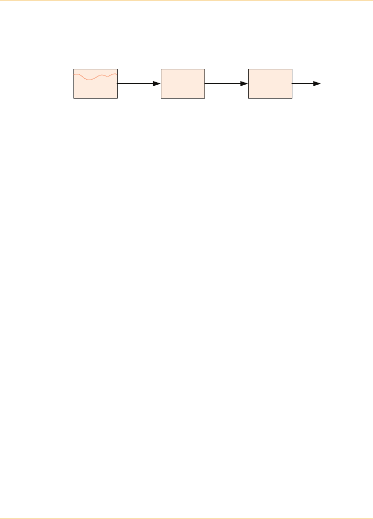
Generators - What is a Generator?
138 The UPS Handbook
What is a Generator?
In very simple terms, a generator is a machine that converts a stored energy
source (fuel) into electrical energy.
Figure 9.1: Block Diagram of a Simple Generator System
The stored energy could be either gas or diesel fuel. Gas powered generators are
typically only used in Combined Heat and Power (CHP) applications. Diesel
generators are normally used for both base load (continuous) and standby
applications. As this chapter is primarily concerned with the role of the
generator in the event of a site power failure (i.e. as a standby power source),
only standby diesel generators will be considered from now on.
Diesel Engine
The engines used in diesel generators are very similar to those found in large
trucks and lorries. Instead of the engine driving a gearbox and prop-shaft in a
motor vehicle it drives an alternator in a generator. Most vehicle owners
understand the basic requirements of keeping their car reliable and ready to use
and the same basic principles apply to the diesel generator. It must:
• be well maintained
• have a supply of fuel
• have a healthy battery for starting
• have sufficient coolant and oil.
Alternator
Alternators convert the mechanical power of the engine into ac electrical power.
In the UK the alternator will typically produce either single phase (230V) or
three phase (400V) voltages and the value of the output voltage is determined by
how the alternator is ‘wound’. The amplitude and stability of the alternator
output voltage is controlled by an Automatic Voltage Regulator (AVR). The
frequency of the output voltage (typically 50Hz in the UK) is determined by the
Fuel Engine Alternator Electrical
Output
Stored energy
source
Converts stored
energy into
mechanical
energy
Converts
mechanical
energy into
electrical energy

Generators - What is a Generator?
The UPS Handbook 139
engine speed. It is usual for an engine speed of 1500rpm to equate to an output
frequency of 50Hz although the speed/frequency relationship is a function of the
design of the alternator. The engine speed and therefore output frequency are
controlled by a ‘governor’ which regulates the amount of fuel going into the
engine (more fuel = higher engine speed = higher output frequency).
Governing
There are two basic methods of generator governing; mechanical and electronic.
A mechanical governor uses springs and spinning weights to regulate the supply
of fuel. Mechanical governors are less expensive than electronic ones but
because of their mechanical nature they are less responsive (slower) and provide
less stable engine speed (frequency) regulation.
An electronic governor works by counting the teeth on the flywheel of the
alternator as it rotates and regulates the fuel flow accordingly. Electronic
governing is highly responsive and offers very stable engine speed regulation.
For this reason it is almost without exception a pre-requisite for any standby
generator being used with a UPS system.
A Generator as a Standby Power Source
As mains power failures cannot be predicted, the generator must always be
ready to start and to support the required load. For this reason the generator is
referred to as a ‘Standby Generator’.
To ensure that the generator is always ready to start it must be kept warm, have a
fully charged battery and sufficient fuel. It must also ‘know’ when the mains has
failed and when it has returned so that it ‘knows’ when to start and stop.
Standby generators are kept warm by ‘engine water heaters’ (sometimes
referred to as jacket heaters) that are powered by the mains supply, and batteries
are trickle charged by a mains powered battery charger. The generator is started
and stopped by signals from its Automatic Mains Failure (AMF) panel (see
page 143). The alternative to an AMF panel is a manually started generator
which relies on someone starting and stopping it whenever it is used.
As a minimum all generators used in UPS applications must have:
• an AMF panel
• an electronic governor
• an engine water heater
• a battery charger.

Generators - Do I Need a Generator?
140 The UPS Handbook
Do I Need a Generator?
A standby generator with automatic mains failure (AMF) detection and
changeover facilities is the only practical source of long term back-up power
during an extended mains outage.
The decision to install a standby generator as part of a critical power system
should be made after considering:
• business implications if the critical application is unavailable for an
extended period
• the reliability of the mains supply
•the UPS battery autonomy
• the physical constraints e.g. suitable space requirements.
Business Implications
If the critical application must be available at all times without interruption then
a standby generator is essential.
As the mains supply is generally quite reliable, there may be situations where
the business can tolerate a loss of application/service on rare occasions (See
"Mains Supply Reliability" on page 141). In this case a UPS fitted with a
standard or extended autonomy battery may provide the required system
integrity. Only the management of the business concerned can make the decision
whether or not generator support is essential.
If the critical application must never be interrupted, a standby generator must
be installed as part of the protected power supply system.
The decision whether or not to install a standby generator is often defined by
the critical application.
There is no point in having several hours UPS battery autonomy if the air
conditioning system cannot keep the computer room cool enough to continue
operating for an extended period when the mains supply fails. In these
circumstances generator support is essential.

Generators - Do I Need a Generator?
The UPS Handbook 141
Mains Supply Reliability
The utility mains supply in the UK is generally very reliable. However, figures
regarding continued supply without disturbance are not available as factors
such as critical load sensitivity and the proximity of other equipment cannot be
determined on a national basis.
Once the need for a UPS has been established (See "Why do I Need a UPS?" on
page 3), the next considerations should be:
• can a UPS with batteries fully protect the critical load? or
• is the load so ‘business critical’ that a standby generator is essential
to keep the load operational during extended periods without mains
supply?
Statistically 95% of all mains disturbances last for less than five minutes with
anything longer likely to last for many hours.
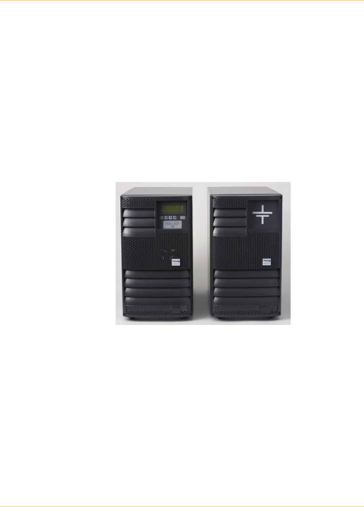
Generators - Do I Need a Generator?
142 The UPS Handbook
UPS Battery Autonomy
UPS batteries are sized to provide emergency back-up power to the UPS in the
event of a total loss of ac input supply.
As a minimum, a UPS battery must have enough capacity to allow time for a
generator to start or for an orderly shutdown of the critical load or application
(See "UPS Communications" on page 155).
Most UPS suppliers can provide battery solutions which will allow the UPS to
support the critical load for longer periods. For example a 10kVA UPS may be
supplied with a 10 minute battery as standard. However by adding another,
matching, cabinet it is possible to extend the autonomy time to 30 minutes.
Some systems allow many external battery cabinets to be connected to achieve
autonomy times extending into several hours.
Figure 9.2: External Battery Cabinets on a 10kVA System
Additional cabinets and batteries obviously take more space and will require
both periodic maintenance and end-of-life replacement (See "System
Maintenance" on page 239).
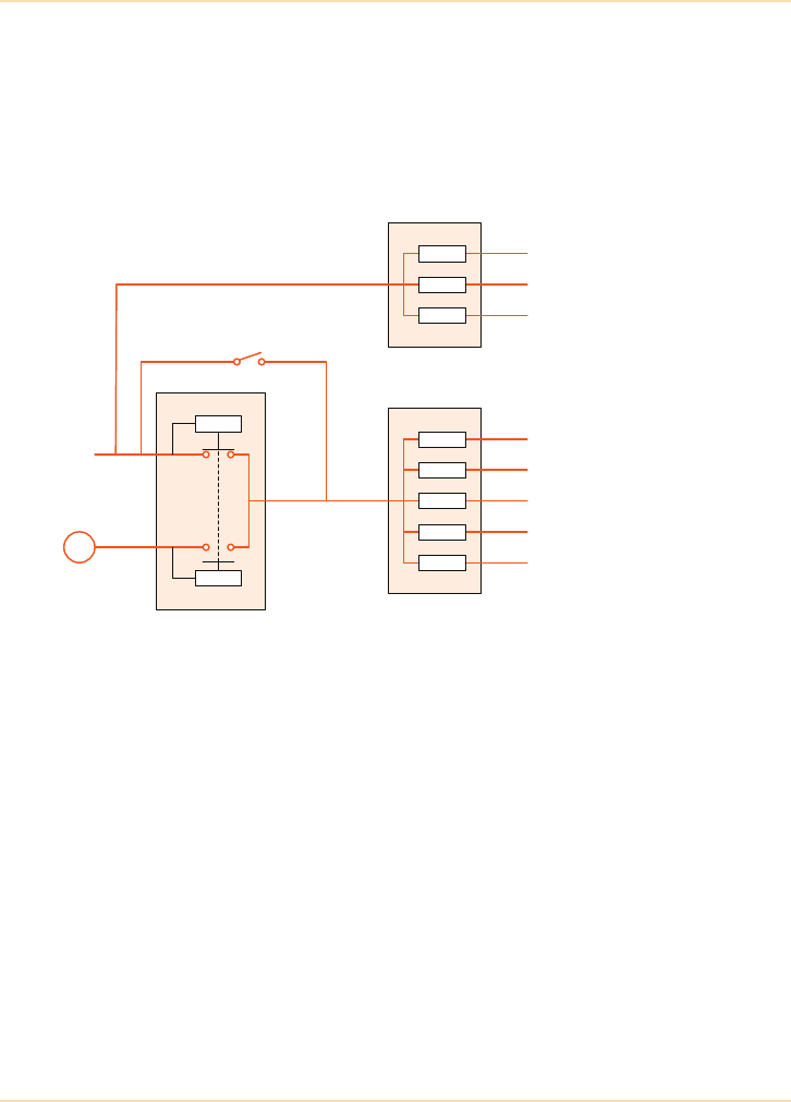
Generators - Mains Failure Detection and Changeover
The UPS Handbook 143
Mains Failure Detection and Changeover
When a generator is used as part of a secure power supply installation it is
essential that it is fitted with control equipment which, in the event of a mains
power failure, will enable it to start automatically. The generator output supply
should then be connected to take the place of the failed mains. Both operations
are usually controlled by an Automatic Mains Failure (AMF) Detection panel.
Figure 9.3: Typical Protected Power Installation with Mains Failure
Detection and Change Over
To avoid the AMF panel starting the generator every time the mains is disturbed,
it is usual to set it to operate only if the mains supply fails for an extended time.
The time delay chosen is typically 2 to 10 seconds.
It is also important to set the AMF so that it does not stop the generator and
switch the UPS equipment back to mains supply as soon as the mains supply is
restored. The mains supply may have been reconnected as part of the utility
company’s fault location procedure or be the result of an automatic breaker
operation – the fault may still exist, in which case the supply will be
disconnected again almost immediately.
Most AMF controlled generators start within 10 seconds of a mains failure and
continue to supply power for a minimum of two minutes after the mains supply
is restored.
Air conditioning
Emergency lighting
Alarm systems
UPS
Etc.
Essential services
distribution
Sensing
Sensing
AMF bypass
switch
G
Mains
supply
AMF Panel
General lighting
General heating
Etc.
Non-Essential services
distribution

Generators - Mains Failure Detection and Changeover
144 The UPS Handbook
In a fully protected system, when the utility mains supply fails:
• the UPS continues to power the load using energy from its battery
• the AMF panel senses the mains failure which, if the interruption
continues for longer than the preset delay, starts the standby generator
and switches its output supply to the UPS
• the UPS system senses that its input mains supply is restored (albeit
now from the generator) and continues to supply the load and
recharges the depleted battery.
The system remains in this state until the utility supply is restored.
When the mains is restored:
• the AMF panel senses the restoration of the mains supply and, after a
preset delay, assumes that the mains is now stable, and switches the
mains supply to the UPS input
• during the transfer back to mains the UPS sees another short power
interruption and supports the load from its battery
• the UPS system then senses that its input mains supply is restored and
continues to supply the load and recharges the depleted battery.
The only user intervention needed during this sequence is to reset or accept the
prevailing alarm indications.
Note that the changeover contactors in the AMF panel (one contactor for the
mains and one for the generator) are electrically and mechanically interlocked as
both contactors must NEVER be closed at the same time.
The AMF bypass switch is required to allow maintenance of the AMF panel
without the need to disturb the power to essential services distribution. The
AMF bypass switch must be interlocked with the generator output circuit
breaker to prevent the generator feeding the load or backfeeding the mains
supply while the AMF bypass switch is closed.
Switching the Neutral Conductor
When considering a mains changeover solution, it is very important to consider
the method used to switch the neutral conductor during the mains failure.
It is normal to employ 4-pole switching in the U.K. Short interruptions in the
neutral plane are accepted as many sites these days have generators and hence 4
pole changeover.

Generators - Mains Failure Detection and Changeover
The UPS Handbook 145
General advice is to keep the changeover time to a minimum. Advice varies
from manufacturer to manufacturer, and product to product; but experience
shows that it is best to aim to keep the changeover to less than 30 seconds. 10-20
seconds is therefore permissible, although if this can be reduced it would of
course be better. This is especially true in the case of a single phase UPS where,
by definition, there is normally a non-zero current flow in the neutral, hence
increasing the N-E potential during 4 pole changeover.
The site should also consider that during the changeover period the electrical
circuit configuration will be modified from TN-S or TN-C-S to an IT or TT
arrangement. This will therefore influence fault and other circuit behaviour
during this time.
It is advisable to contact the local electricity supply company at the planning
stage, as there may be regulations which prohibit or control paralleling and/or
earthing of the neutral conductor.
Solutions available can be grouped into three categories (illustrated in Figures
9.4, 9.5 and 9.6).
The chosen solution is dependent on:
• the requirements of both the UPS and other connected loads,
• local electricity supply regulations.
This section looks at the options available for the UPS. The effects of neutral
interruption on other items of connected load are beyond the scope of this book.
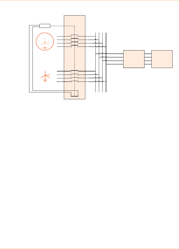
Generators - Mains Failure Detection and Changeover
146 The UPS Handbook
Option 1 - Broken Neutral
Figure 9.4: Auto-Changeover with a Break in the Neutral Supply
The solution illustrated in Figure 9.4 is normally the “least cost” option as it
assumes the connected load, which includes the UPS module(s), can operate
normally with a momentary break in both the phase and the neutral connections
during any supply changeover.
AMF Panel
MAINS
Critical LoadUPS
G
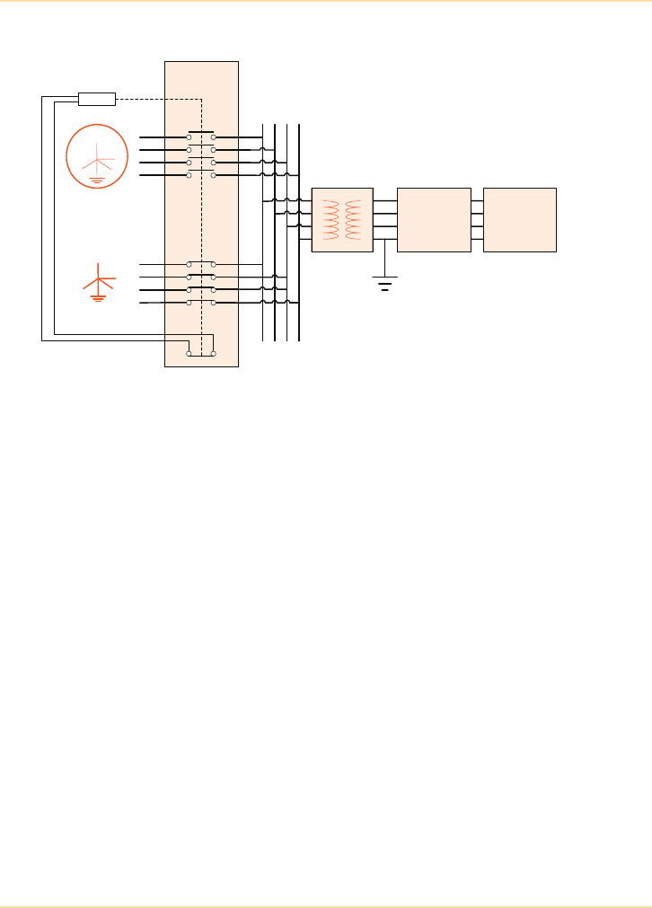
Generators - Mains Failure Detection and Changeover
The UPS Handbook 147
Option 2- Maintained Neutral
Figure 9.5: Auto-Changeover with No Break in the Neutral Supply
The operation of the AMF panel in Figure 9.5 is identical to that shown in
Figure 9.4 however, in this case, the UPS input neutral is provided by
connecting the neutral to the earth on the secondary side of the isolation
transformer. As this “re-grounded” neutral is a solid connection there is no break
in the UPS (and therefore the UPS load) neutral during any mains failure or
mains restoration.
As the isolation transformer is in series with the UPS it must be rated to supply
the overload rating of the UPS plus any battery recharging requirements.
The costs of the isolation transformer and neutral earthing along with the
additional space requirements may make Option 3 more attractive.
AMF Panel
Mains
Critical LoadUPS
G
1:1
Isolation
transformer
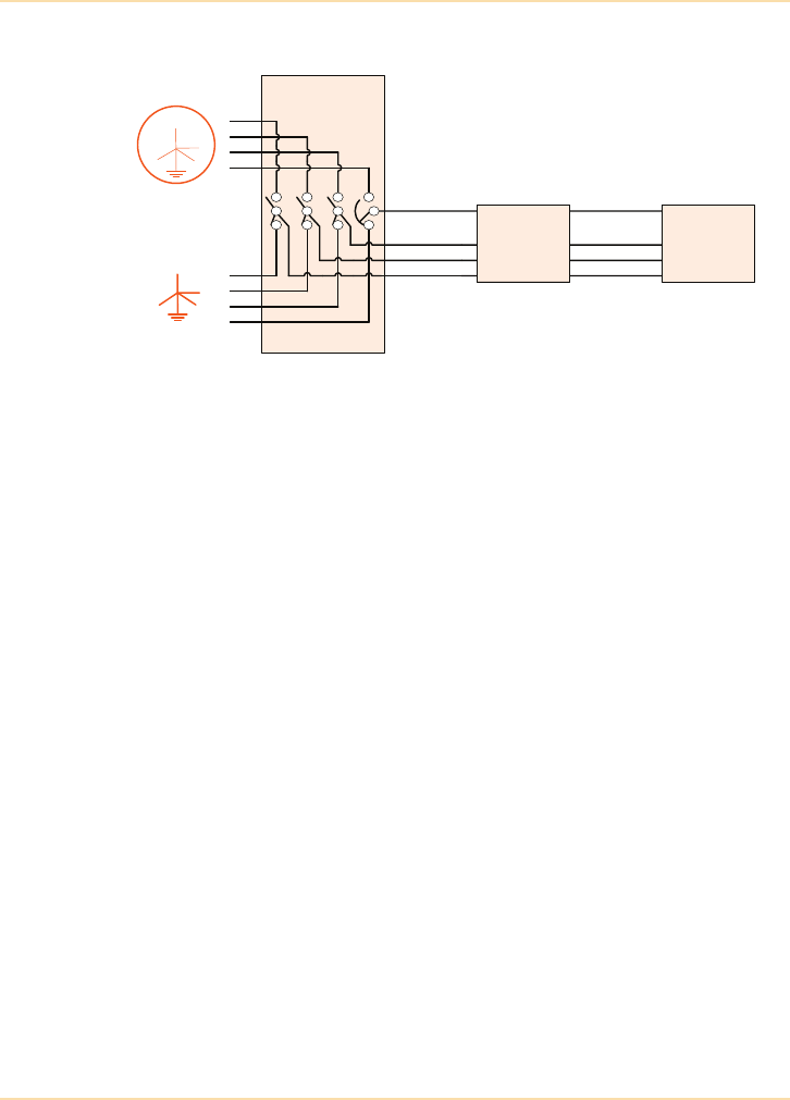
Generators - Mains Failure Detection and Changeover
148 The UPS Handbook
Option 3 - Overlapped Neutral
Figure 9.6: Auto-Changeover with an Overlapping Neutral Supply
The overlapping neutral solution shown in Figure 9.6 relies on a special “ASCO
Switch” which maintains a neutral connection by momentarily paralleling the
Mains supply and the Generator neutral conductors during any changeover
operation – the phase conductors are disconnected normally, as with the
previous examples.
The ASCO Switch can be operated automatically on mains failure or return.
Note that an overlapping neutral would not normally be allowed in the UK
without the local distributor’s permission.
ASCO Switch
Mains
Critical LoadUPS
G

Generators - UPS Considerations
The UPS Handbook 149
UPS Considerations
Constant voltage and frequency are directly proportional to the size and type of
generator. The generators used by the power generation companies produce
consistent power because they are huge. A standby generator, by comparison, is
quite small and cannot supply such consistent power. Any increase in electrical
load requires an instantaneous increase in mechanical power to supply it and
whereas in a large generator many of these variations are ‘absorbed’ by the
inertia of the rotating parts, a small generator set with less inertia will actually
slow down until the engine governor compensates.
UPS Compatibility
There can sometimes be compatibility problems between the generator and the
UPS system.
The generator output voltage may be acceptable to the UPS, but often the
generator’s frequency range is wider than the UPS is designed to accept. In the
worst case the frequency variations of the generator will be such that the UPS
cannot synchronise with it, either because the frequency is outside limits or it is
varying too quickly for the UPS to follow (slew rate) without putting the load at
risk. In this situation most UPS systems will signal a warning alarm to inform
the operator that in the event of a fault the load will not be transferred from the
UPS to the raw generator supply.
This problem can be overcome by ensuring that the generator manufacturer is
aware that the generator will be supplying a UPS and making sure it is fully
tested during commissioning. As previously discussed, modern standby
generators should be fitted with electronic governors that allow the generator to
operate within tight frequency tolerances.
On-line UPS systems can accommodate most generator frequency variations
while a properly sized generator will absorb most load variations. An
electronic governor on the generator will minimise or completely remove
potential problems.

Generators - Generator Sizing Guidelines
150 The UPS Handbook
Generator Sizing Guidelines
There should be an expectation to oversize the generator. In practice, it is
usually necessary to size the generator to handle more than just the UPS. While
the UPS is typically running data processing equipment, the air conditioning
power to cool the equipment must be maintained. Emergency lighting,
communications and alarm systems must also stay operational.
As a ‘rule of thumb’, when sizing a generator:
1.5x the nominal UPS capacity should be allowed for a transformerless UPS.
2.0x the nominal UPS capacity should be allowed for a transformer based UPS.
3.0x the nominal air conditioning running capacity should be allowed for the air
conditioning.
The nominal capacity of all other items to be powered by the generator can be
either read from the manufacturer’s specification (or rating plate) or measured
using a current clamp.
The above are only guidelines and it is recommended that advice should be
sought from the UPS and generator supplier if independently attempting to size
the generator.
Generator Power Ratings
Generators have two power ratings, namely a standby and a continuous (or
prime) rating. A generator's standby rating is typically 10% higher than its
continuous rating because in standby applications the generator is only expected
to be occasionally brought into use and is not expected to be continuously run.
Because standby generators used in a power protection solution can be called
upon at any time and for any duration (depending upon the frequency and
duration of mains power problems) the continuous rating of the generator is the
most appropriate rating to use.
Step Loading
Most generators cannot accept 100% of their load rating in one single step i.e. an
AMF panel cannot present a 100kVA load to a 100kVA generator in one single
“hit”. A generator's ability to take large load steps is a function of its design and
turbo charged generators can, typically, take larger load steps than standard
generators.

Generators - Generator Sizing Guidelines
The UPS Handbook 151
It is good practice to not introduce the entire load to the generator when this load
is >50% of the generator's standby rating. This can be achieved by either over-
sizing the generator, which is a potentially expensive option, or by ensuring that
load equipment such as the UPS and air conditioning has a “soft start” (also
known as “walk-in”) facility or by the clever use of time delay contactors on the
essential services distribution board (see Figure 9.3).

Generators - Environmental and Physical Constraints
152 The UPS Handbook
Environmental and Physical Constraints
The following must be considered when planning a standby generator
installation:
Fuel Storage
In England the Control of Pollution (Oil Storage) (England) Regulations 2001
require oil storage tanks to have a secondary containment facility such as a bund
or drip tray to prevent oil escaping into the water environment. The regulations
apply to all oil storage containers greater that 200 litres located above ground at
an industrial, commercial or institutional site.
In Scotland the Water Environment (Oil Storage) (Scotland) Regulations 2006,
which are different to the English regulations, apply.
In Northern Ireland the DOE Guidance Document for The Control Of Pollution
(Oil Storage) Regulations (Norther Ireland) 2010, which are different to the
English regulations, apply.
There are currently no equivalent regulations in Wales.
For space saving reasons, the majority of standby generators have a “base tank”
that, as the name suggests, forms the base of the generator. This base tank would
typically be double bunded to 110% of the fuel tank capacity to accommodate
the capture of any spilt fuel and would typically be sized to provide between
eight and twenty four hours of full power run-time. A fuel tank of this size is
also known as a “day tank”. If continuous full power run-time of greater than
eight hours is required then either a larger base tank or a bulk fuel tank would be
required.
A generator supplied with a standard double bunded day tank is relatively
straightforward to site and install, however, the siting of bulk fuel tanks with
their associated fire valves and fuel pumps will require specialist advice.
Acoustic Noise
Mains supply disturbances can occur at any time and, consequently, standby
generators may be called upon at any time of the day or night.
During the day the sound of a generator starting and running may not cause any
problems in either the workplace or in adjacent properties but at night the same
sound level will appear much louder and will seem to carry for a much greater
distance. It is also likely that, once the generator has started, it will be
operational for some hours.

Generators - Environmental and Physical Constraints
The UPS Handbook 153
Acoustic housings with various noise attenuation ratings are available for
standby generators, but the higher the attenuation rating the higher the cost.
Heat Generation
When a standby generator is running it will produce heat as well as electrical
power. Almost all standby generators are air cooled, so provision for enough
cooling air must be made. For this reason, the majority of standby generators are
housed outside the building in weatherproof (and acoustic) enclosures.
Exhaust Fumes
Provision must be made to vent generator exhaust gases in a responsible way.
All generators are fitted with exhaust systems, but consideration must be given
as to how and where the system will be fitted in order to avoid disturbance to
others and to ensure that fumes are minimised and vented safely. Where long
exhaust pipe runs or bends in the exhaust pipe are required, it will be necessary
to increase the cross-sectional area of the pipe. If part of the exhaust pipe passes
through a building, it must be lagged to minimise the problems of heat and
fumes. Specialist advice will be required when exhaust pipes pass through, or
attach to, a building.
Planning Permission
Local authority planning permission requirements vary from area to area. It is
essential to check the local regulations before installing or operating a standby
generator. If fuel is to be stored on the site then the local fire officer may also
need to inspect the proposed generator and fuel locations.
It is also necessary to advise the local electricity supply company that a
generator is to be fitted on the site.
Delivery
A ‘small’ standby generator of only 100kVA or so will weigh several tonnes and
be the size of a small car, so consideration must be given to where the generator
is to be positioned and how it is to be delivered into such a position.
For the delivery of large generator systems, special delivery vehicles and lifting
equipment will be required.

Generators - Environmental and Physical Constraints
154 The UPS Handbook
Electrical Installation
As a minimum, a power cable rated to carry full generator power and a signal
cable to carry generator start/stop signals must be run between the generator and
the AMF panel and/or the essential services board.
If the cable from the generator is long then it may be necessary to increase the
cable rating to reduce the ‘volt drop’ along it. This increases the electrical
installation costs of the generator, so the generator should be located as close as
practically possible to the AMF panel and/or the essential services board.
Siting
The generator must be installed on a flat and level surface and it may need to be
securely fixed to the floor. It is therefore common for the generator to be
positioned on a purpose built concrete slab.

The UPS Handbook 155
10 UPS
Communications
Introduction
A UPS provides essential uninterrupted power during a utility mains disturbance
or failure but it is also important that it communicates its status and activity to
monitoring facilities and the critical load.
Computer networks with file servers or clusters of file servers will often depend
upon alarms from the UPS system to invoke orderly and unattended shutdown
procedures, saving vital information and work. Many would argue that a UPS
system that does not communicate with the equipment that it is protecting, is
merely delaying the inevitable system crash in the event of an extended site
power failure beyond the support time of the UPS battery.
UPS Status and Activity Signals
Modern UPS systems contain facilities to signal their operational status and
activity to remote monitoring stations, building management systems and the
critical load equipment.
Simple status information is usually provided by volt-free contacts, with more
detailed information being supplied over an RS-232 serial connection. Modern
systems might also implement these facilities using an internet protocol such as
Simple Network Management Protocol (SNMP) or Modbus over IP. When used
in conjunction with an SNMP adaptor (see page 163), the communication
protocol allows the more detailed information to be sent directly on to a
computer network, where it can provide management information and invoke
shutdown procedures across the network.
Modern UPS systems can also detect failures, or potential failures, in their own
components or sub-systems and are able to initiate automatic service calls to
address the situation. Such calls may be made to land lines, mobile phones or
pagers and will normally include details of the fault. Such capability clearly
adds to the overall reliability of the UPS system.

UPS Communications - Volt-Free Contacts
156 The UPS Handbook
Volt-Free Contacts
UPS alarms and status are usually signalled on the front panel display of the
UPS. In addition, a UPS should have simple ‘volt-free’ contacts to allow
interfacing with remote (but on-site) alarm panels and monitoring systems.
Volt-free contacts provide the simplest form of communication. They provide a
‘true/not true’ signal which is very useful when simple status information is all
that is required for such alarm systems as a Remote Status Panel (RSP) or a site
Building Management System (BMS).
With suitable network software, volt-free contacts can be used to initiate an
orderly shutdown of the PC or network operating systems such as almost all
Windows, Mac, Linux and Unix variants. The software required may be
embedded within the system or purchased from the UPS supplier or the network
operating system supplier.
Many software solutions are available but they all operate in similar ways:
• When the mains supply to the UPS fails the software detects (via the
volt-free contacts) that the UPS is running on battery power and starts
a timer that can be user configured.
• If the mains supply stays off for long enough for the timer to hit the
user configured limit, or the software detects the UPS low battery
alarm, a controlled shutdown of the computer software, hardware and
peripheral equipment is initiated (See "Computer Networks Auto
Shutdown" on page 162).
• If the mains supply returns before the low battery alarm is signalled,
the software again detects this via the contacts and resets the timer.
• If the software is installed on a computer network server, that server
can be designated as ‘master’ and can be used to relay UPS alarms to
other network devices or ‘slaves’ which can also be configured to
respond appropriately.
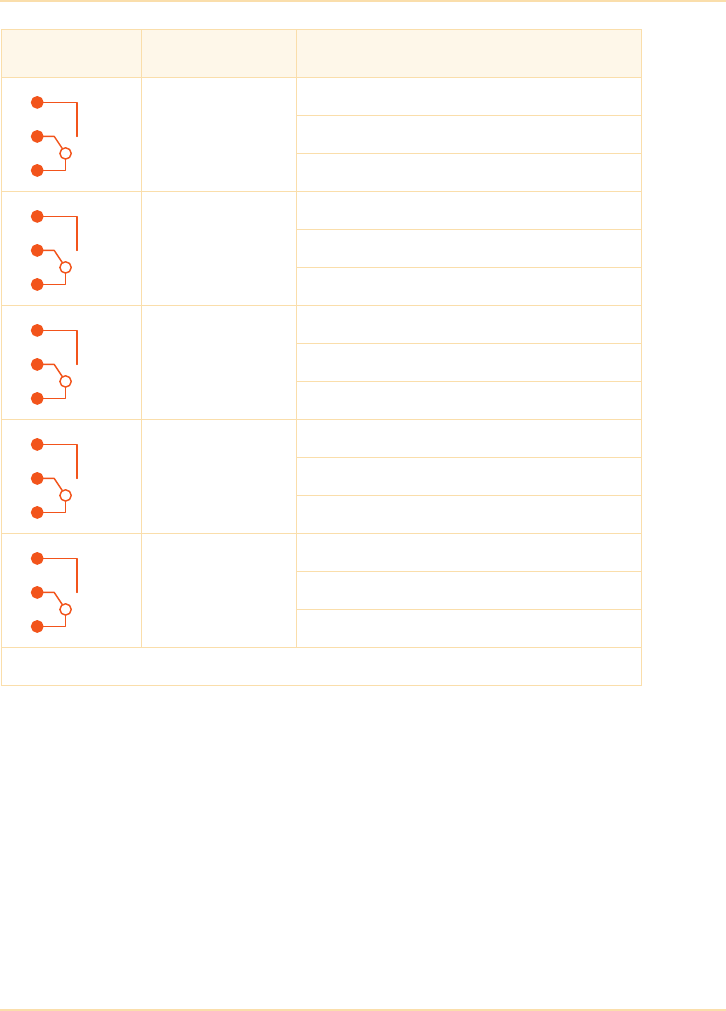
UPS Communications - Volt-Free Contacts
The UPS Handbook 157
Figure 10.1: Sample ‘Volt-Free’ UPS Status Monitors
Contact Signal Function
Alarm
Mains Failure
Mains Present
Common
Message
Load On Inverter
Common
Alarm
Battery Low
Battery OK
Common
Message
Load On Mains
Common
Alarm
Common Alarm
No Alarm Condition
Common
Volt-free contacts are typically rated for 60VAC max. and 500mA max.

UPS Communications - Older Communication Protocols
158 The UPS Handbook
Older Communication Protocols
RS-232
The RS-232 connection provided with many UPS systems is designed to enable
the UPS to be connected to a monitoring computer running suitable software.
Details of the standard RS-232 nine and 25 pin connections are shown in Figure
10.2 and Figure 10.3.
Serial data contained within the RS-232 signals allows for more information to
be monitored than the ‘volt-free’ contacts. Instead of purely true/not true
conditions, RS-232 systems allow analogue values to be monitored; for
example, the following (and more) could be displayed on a remote terminal:
• inverter output voltage, frequency, current, kVA and kW
• bypass voltage, frequency, current, kVA and kW
• battery voltage, charge/discharge current and remaining battery time
• statistics regarding mains failures and UPS operation
Unfortunately there is no European Standard for UPS RS-232 protocol so each
UPS manufacturer uses its own protocol. This means that the UPS user must
normally obtain the relevant RS-232 shutdown software from the UPS supplier.
Using an RS-232 serial connection, a computer can monitor the UPS in real-
time since its operational status can be continually polled for updates. However,
in normal practice, only critical alarms are continually monitored with
operational status being manually requested by a system administrator or
supervisor.
The RS-232 signal from the UPS may be configured to provide a number of
facilities. Most UPS suppliers will also provide proprietary software to make
best use of the serial connection, although the features offered by each
manufacturer may vary.
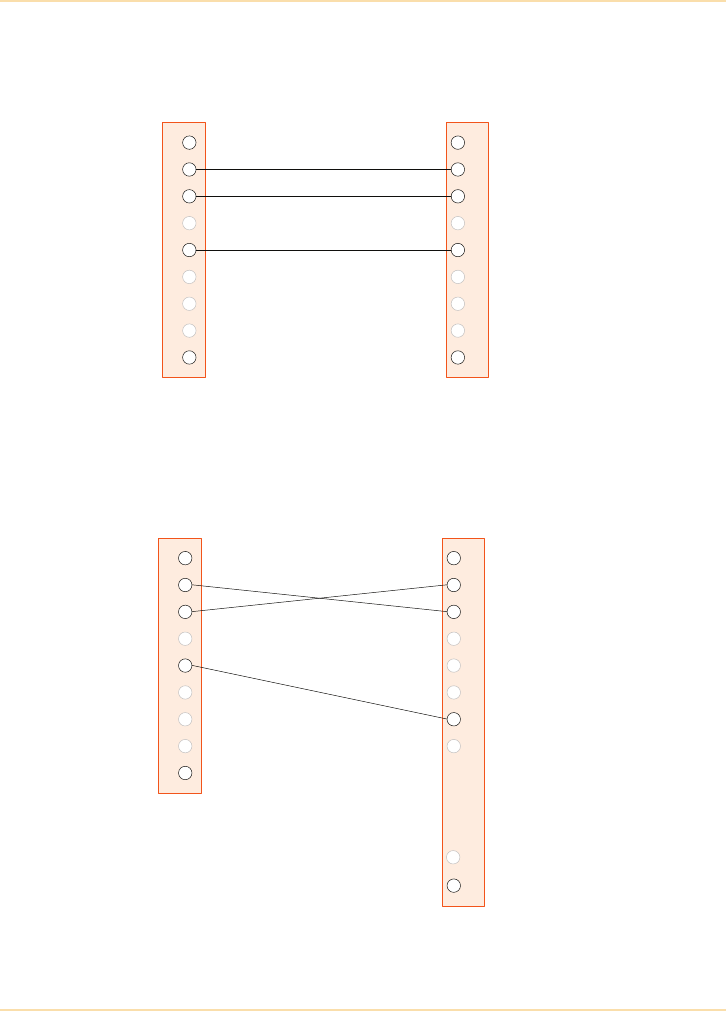
UPS Communications - Older Communication Protocols
The UPS Handbook 159
Figure 10.2: 9-pin to 9-pin RS-232 Interface Cable
Figure 10.3: 9-pin to 25-pin RS-232 Interface Cable
UPS End
(9-Pin, D-Type Male)
Computer End
(9-Pin, D-Type Female)
Connects
to
Computer
Connects
to UPS
1
2
3
5
9
1
2
3
5
9
UPS End
(9-Pin, D-Type Male)
Computer End
(25-Pin, D-Type Female)
Connects
to
Computer
Connects
to UPS
1
2
3
5
9
1
2
3
7
25
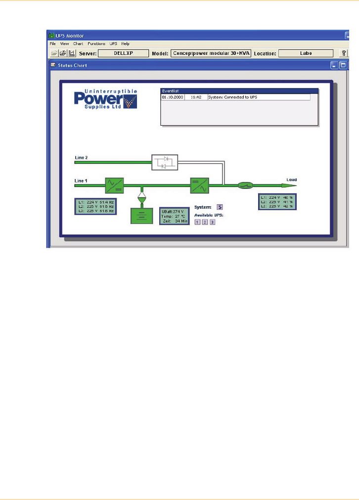
UPS Communications - Older Communication Protocols
160 The UPS Handbook
Figure 10.4: Typical UPS Monitoring Screen
Monitoring software is available for almost all computer operating systems and
its facilities may include:
• a graphical display of UPS status, voltage, current, load, battery
voltage and frequency etc. (See Figure 10.4).
• configurable responses to certain alarms – broadcasts to users etc.
• scheduled diagnostic checks and data logging.
For longer communications distances, RS485 or RS422 type interfaces are often
used, although RS422 is generally favoured since it is a full-duplex system and
introduces less problems.
Modern UPS equipment also incorporates a USB interface to enable real-time
UPS monitoring.

UPS Communications - Older Communication Protocols
The UPS Handbook 161
Modbus (JBus)
Modbus is an application layer serial communications protocol that was
originally designed for use with programmable logic controllers (PLC) and is
commonly used to monitor and control a variety of industrial electronic devices.
It can be implemented over RS485 or IP (Ethernet) to communicate with up to
240 nodes (devices) connected to a common network.
When used in a serial (RS485) environment one node is designated as a ‘master’
device and becomes the only one able to initiate Modbus commands to the
remaining ‘slave’ devices. The installation requires the master device to be
connected via a remote terminal unit (RTU) and for this reason this type of
system is sometimes referred to as “Modbus RTU”.
An RTU is not required when implementing Modbus over IP (Ethernet) – which
is sometimes described as “Modbus TCP”. In this type of installation any of the
connected devices can send a Modbus command; however, although it is
possible to have multiple master devices in this system it is usual to employ a
single master only.
In both Modbus RTU and Modbus TCP systems each slave device is configured
with an individual ID or IP address which allows the master device to access
each one individually.
Data is stored on the slave devices in a number of 16-bit or 1-bit registers that
can be written to, or read, by the master device. For example, in a UPS system,
the 16-bit registers can contain digitised values relating to the existing input
voltage, input current, battery charge current etc., and alarm status data can be
stored in the single-bit registers. These registers can then be polled by the master
device and provide a data feed for a centralised UPS Management station. Note
that the registers can also be configured to receive control inputs from the
master device.
When Modbus is employed in a typical parallel UPS system which incorporates
a centralised UPS Management system, each module is individually addressable
by the UPS Management system, as explained above. Any ‘read’ or ‘write’
command transmitted by the UPS Management system will therefore only be
acted upon by the intended UPS module, even though it might have been
detected by them all.
It is however possible to ‘broadcast’ a command to a base address which is
simultaneously processed by ALL modules – for example to transfer all the UPS
modules to bypass or effect an emergency power off.

UPS Communications - Computer Networks Auto Shutdown
162 The UPS Handbook
Computer Networks Auto Shutdown
During a power failure, the monitoring software collates the UPS remaining
battery time and will initiate a local or network shutdown of the UPS protected
computers.
Remote Control Command (RCCMD) is the most commonly used shutdown
client solution for UPS supported network environments. Many UPS systems
and manufacturers can be supported by a proprietary monitoring solution.
RCCMD will match this diversity and is available for many different operating
systems.
In simple terms, the monitoring software, which can be resident in either a PC or
in an SNMP adapter card, will send out an RCCMD shutdown signal at a pre
configured level of remaining battery run-time. Any remote PC/server with an
installed RCCMD client licence will “recognise” the shutdown signal and
initiate its own shutdown procedure.
By configuring the IT system so that less essential items of equipment are
automatically shut down earlier, the electrical load on the UPS battery can be
reduced, therefore increasing the available back-up time for critical items.
Therefore, with considered planning between the UPS system and the auto-
shutdown facility, the electrical supply can be extended for the longest possible
period to the most essential equipment.

UPS Communications - UPS Management Across Networks
The UPS Handbook 163
UPS Management Across Networks
Networks that are spread out over a large area, Wide Area Networks (WAN),
can cover hundreds, even thousands, of miles. WANs create great advantages for
their users because they allow people to share information that in the past would
have been faxed or mailed. However, a disadvantage of the WAN is that it is
difficult to monitor, manage, and maintain all the computing equipment that is
spread over such a wide area.
Management of unmanned sites has become a big issue on these large networks.
Typically, multiple site networks will not have a network manager at each site. If
a problem should occur while a network manager is not there, irreparable
damage to system hardware and software could occur. SNMP cures this problem
because now a network manager can monitor and control all network devices
from a central location.
SNMP
A modern UPS should come with SNMP compatibility as standard for
interfacing with major Network Management Systems such as HP OpenView or
IBM Tivoli NetView.
Simple Network Management Protocol (SNMP) was created to address the
problem of wide area network management. SNMP is a standard protocol that is
part of the Transmission Control Protocol/Internet Protocol (TCP/IP) suite
which allows all network devices to transmit management variables across
enterprise wide networks. By creating one standard, SNMP allows a network
manager to monitor all remote sites from one central location (See Figure 10.5).
A UPS with SNMP capability becomes an intelligent UPS that can, for example:
• log events
• continuously monitor power quality
• report on battery status, load and temperature
• perform self-diagnostics.
SNMP is vendor and platform-independent and establishes guidelines for what
information will be collected, how it will be structured and how the messages
are formed from the network device to the manager and back. Network devices
then gather information into a management information base (MIB).
A user's operating system software uses SNMP management software to collect
and display the MIB data in an easily understood format.
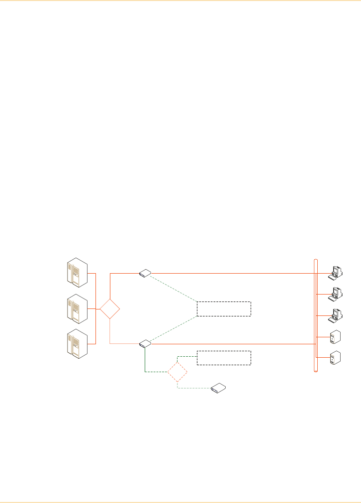
UPS Communications - UPS Management Across Networks
164 The UPS Handbook
An intelligent UPS might have a provision for individually controlling the
devices to which it is connected - for example, turning them off or on. This
could enable the system manager to isolate sections of the system for security
purposes, shut down devices to achieve electrical savings and manage redundant
portions of the system.
Because intelligent UPS systems can condition power as well as provide battery
backup to attached devices, system disruption due to power outages or
disturbances can be dramatically reduced. The system's microprocessor can log
power disturbances, keep track of battery usage, alert system managers to low
battery problems and track the history of power levels. Through SNMP, this
information is available to managers for immediate analysis and to detect
potential problems before they occur.
SNMP allows system managers not only to control the UPS, but also to more
efficiently manage its load. By linking several dozen UPS systems (possibly
from different manufacturers) into the network and feeding status data to the
central network console, power protection and network control becomes that
much more efficient.
Figure 10.5: SNMP Network Interfaces
OR
Modbus ethernet
Modbus RS-485
SNMP Card
Standard on TCP/IP
Option on RS-485
OR
Modem
SNMP Box
UPS System
Up to 6
modules 10/100 Mbps
Ethernet

UPS Communications - UPS Management Across Networks
The UPS Handbook 165
SNMP Adaptors
An SNMP adaptor connects the UPS system directly to the computer network so
that the UPS system becomes a network peripheral device.
SNMP adaptors can be either separate enclosures or slot-in cards (See Figure
10.6) and are usually fitted between the UPS serial communications port and the
computer network, although adaptors are available that can interface between
the UPS volt-free contacts and the network. These convert the contact
information to the correct protocol which can then be read by the rest of the
network. Offering HTTP, SNMP, SMTP, WAP, Telnet, SSL, SSH compatibility
and a console port, SNMP adaptors enable dynamic support for a large variety
of system configurations.
SNMP Software Facilities
Levels of control, monitoring and shutdown facilities vary from manufacturer to
manufacturer, so it is important to understand exactly what functions are
required by a particular installation before choosing an adaptor.
At best the adaptor will allow UPS connection to the network without the use of
a proxy agent, such as a master server, and will therefore not be reliant on the
server to relay information to other devices on behalf of the UPS, thus
increasing system integrity.
The software used with the adaptor needs to be selected carefully as it must be
designed for use with the network operating system. Most major UPS
manufacturers provide versions for use with Windows, Apple, Linux and Unix.
As a minimum, the selected SNMP software should offer:
• Remote control and rebooting of UPS-protected devices over the
network/internet
• Protection of information through automatic and graceful shutdown
of multiple UPS-protected devices during an extended power failure
• Real-time email, mobile phone or SMS alarm notification capability
• SSL and SSH data encryption and authentication
• Web pages served automatically in the selected local language
• Activity and alarm logging

UPS Communications - UPS Management Across Networks
166 The UPS Handbook
Figure 10.6: SNMP Adaptors
SNMP Compatibility
As SNMP is an established and accepted standard, it is possible to control and
monitor UPS from different manufacturers and to display an integrated status
report of all equipment.
Other Network Solutions
While the SNMP/ethernet is the most common networking solution for UPS
systems in a computing or office environment, other solutions do exist.
Manufacturing and industrial facilities often employ other solutions which may
dictate the monitoring and alarm system chosen. Fortunately, these can usually
be interfaced directly using the standard RS-232 ports provided on the UPS.
Parallel UPS Management
Special consideration must be given to parallel UPS installations when selecting
an appropriate communications protocol. It is not sufficient to simply install
independent communication software for each UPS module since the correct
operation of the parallel system as a whole needs to be monitored rather than the
status of each individual module. Likewise in a parallel redundant UPS
configuration, system shutdown should not be initiated as a result of a redundant
UPS module failure.
The UPS manufacturer should be able to provide bespoke hardware and
software to enable the correct communication and management of a parallel
UPS system.
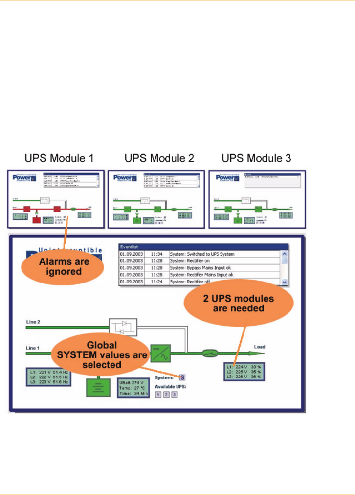
UPS Communications - UPS Management Across Networks
The UPS Handbook 167
Key requirements are:
• Real time value monitoring of the combined, overall, parallel UPS
system as well as each independent module (See Figure 10.7).
• Intelligent communication software control at system level and not at
UPS module level.
• Auto-shutdown software procedures should recognise redundancy
status and only be initiated at system level and not at UPS module
level.
• A single interface port for the overall parallel UPS configuration.
Figure 10.7: Parallel UPS Management
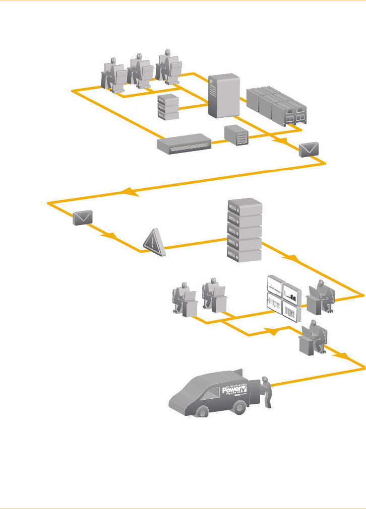
UPS Communications - Off-Site Alarms and Remote Management
168 The UPS Handbook
Off-Site Alarms and Remote Management
Figure 10.8: Automatic Call Out Facility
UPS
Server
UPS with
Power REPORTER
Batteries
Email
Battery Care
System
Site manager
UPS Email
server
Alarm Event Data
& monthly report
Servers with
Power REPORTER
software
Consultant
UPSL 24Hr Analyst
Service
co-ordinator
UPS Service
Engineer
Helpdesk
specialists

UPS Communications - Off-Site Alarms and Remote Management
The UPS Handbook 169
In addition to on-site alarm monitoring via volt-free contacts and RS-232 or
network wide monitoring via SNMP connections, some modern UPS offer
additional facilities which enable fault indications to be signalled to remote
monitoring points. Remote management may effectively be used to:
• alert the client’s on-call engineer via SMS, mobile phone, or over
network
• allow remote, basic UPS interrogation by a service engineer
• automatically signal maintenance requirements
The Management Software can be programmed for extensive alarm dispatching
so when a critical alarm is received, a dedicated customer response can be
initiated. For example, when an alarm is detected, the client’s representative, or
the manufacturer’s service technician, is immediately contacted.
Using a laptop and a simple browser, the on-call service technician is able to
connect to the UPS Management Centre, gain detailed information regarding the
alarm and, if necessary, respond to the fault quickly and fully prepared.
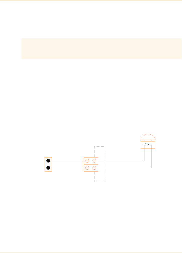
UPS Communications - Emergency Power Off (EPO)
170 The UPS Handbook
Emergency Power Off (EPO)
For Health and Safety reasons, all modern UPS systems have an Emergency
Power Off (EPO) port that can be connected to a suitable fire alarm panel or
push button switch etc.
The EPO facility is often:
• connected to a large red mushroom push-button that can be hit easily
by the last person exiting the room in a fire or disaster situation,
• connected to a suitable relay port in a site fire alarm or building
services management panel.
As emergency stop contacts must be closed during normal UPS operation,
multiple emergency stops must be wired in series – that is, the operation of any
emergency stop button or relay will open the connection to the UPS and initiate
the emergency shutdown.
Figure 10.9: Typical Emergency Stop Wiring
It is advisable to include a link facility in the EPO wiring as this enables a switch
to be replaced without interrupting the supply to the load.
Note: In most cases the EPO facility turns off the UPS electronically under
software control and is often called “Remote Power Off” (RPO). If total
electrical isolation of the UPS is required as part of the EPO operation it
must be implemented using additional contactors.
Emergency stop is usually a normally closed contact which, when opened in
the event of a fire or other emergency, completely turns off the UPS with
immediate loss of supply to the load.
UPS
Emergency Stop Terminal
block
Emergency Stop Switch
(normally closed)
Link facility

The UPS Handbook 171
11 Planning a UPS
Installation
Introduction
This chapter assumes the need for a UPS system has been established.
There are now six main stages which must be completed in order to achieve a
successful UPS installation:
• Sizing and selecting the correct UPS
• Reliability considerations
• Environmental considerations
• Total cost of ownership considerations
• Installing the UPS
•Using and maintaining the UPS
In the text which follows, each of these points is expanded to provide
comprehensive information on all aspects of UPS installation planning.

Planning a UPS Installation - Sizing and Selecting the Correct UPS
172 The UPS Handbook
Sizing and Selecting the Correct UPS
Collating and Calculating Load Data
When planning a UPS installation it is important to gather as much information
as possible about the proposed load and make allowances for future load
expansion. Most items of electrical equipment have labels which carry
information regarding the electrical characteristics of the item.
It is important to collate information for items of the proposed load – you may
find the form ‘Collecting Load Details’ on page 182 useful.
In order to correctly size the UPS certain information about the load is needed -
these include:
• Supply voltage
• Supply frequency
• Number of phases
• Load current
• Power factor
• Power consumption.
Supply Voltage
The ac supply voltage in Volts (V) is normally stated on the label or in the
manufacturer’s literature. In the UK, single phase equipment will normally have
a supply voltage of 230/240Vac and three phase equipment will be 400/415Vac.
Some equipment is designed for international use and the labelling may give a
range of operating voltages.
Supply Frequency
The ac supply frequency in Hertz (Hz) is normally stated on the label or in the
manufacturer’s literature. In the UK, equipment will normally have a supply
frequency of 50 Hz. Some equipment is designed for international use and again
the labelling may give a range of operating frequencies.

Planning a UPS Installation - Sizing and Selecting the Correct UPS
The UPS Handbook 173
Number of Phases
The number of phases will be either single (one) or three. If the equipment label
or literature does not give a value, 230/240Vac devices can be assumed to be
single phase and 400/415Vac three phase.
Load Current
The device load current in Amperes (A) is normally stated on the label or in the
manufacturer’s literature.
Power Factor
In some electrical loads such as motors or computers, current flows into the
equipment without being usefully converted to energy. This happens when the
current drawn by the equipment is not in phase with the applied voltage.
Some equipment draws current which is always in phase with the voltage,
however almost all the equipment likely to be connected to a UPS draws
additional current which is not in phase with the voltage.
Power factor expresses how much of the supply current is in phase with the
voltage and is effectively used.
See "Power Consumption" on page 174 for an example of how to use the power
factor value.
Typically, loads have tended to present a lagging (inductive) power factor to its
supply. Modern Switched Mode Power Supplies (SMPS’s) within items such as
blade servers have shifted this power factor to near unity, and in some cases to a
leading (capacitive) power factor. Care must be taken to ensure that any
potential UPS system can supply leading power factor loads without any form of
derating. In addition, SMPS manufacturers have increased the efficiency of the
SMPS itself but at the expense of increasd harmonic content.
A three phase UPS can supply three phase and single phase loads.
A single phase UPS can ONLY supply single phase loads.
Equipment which draws out of phase current has a power factor of
less than 1.0. The power factor value will usually be between 0.8 and
1.0, and if no figure is stated it is traditional to assume a value of 0.8.

Planning a UPS Installation - Sizing and Selecting the Correct UPS
174 The UPS Handbook
Power Consumption
Power consumption may be stated in Watts (W) or Volt Amperes (VA) but rarely
both. As UPS manufacturers use VA (or kVA) it is useful to obtain the VA rating
of all load items.
If the VA rating is not stated it can be obtained by:
• multiplying the supply voltage (V) by the load current (A) or
• dividing the power consumption (W) by the stated power factor (p.f.).
The VA rating will never be lower than the Watt rating as it is dependent on the
Power Factor of the device (See "Power Factor" on page 173).
Measuring the Actual Load
Obtaining load details from product labelling will give a reasonable indication
of the load power requirements but it cannot give an accurate view of the load
variations over time. The only accurate method of establishing the load ‘profile’
is to perform a site survey.
Many UPS suppliers offer a site survey service which may involve installing
portable measuring and monitoring equipment to record information about the
load over a period of time. The time the monitoring equipment is installed will
be largely dependent upon the load applications. For example, there is little
point in measuring the power demand of an office network after 5 pm or at a
weekend when very few staff will have their PCs switched on.
To calculate the VA r a t i n g f o r a n i t e m r ated at 230V, 6 A
VA Rating = 230 x 6 = 1380VA or 1.38kVA
To calculate the VA r a t i n g f o r a n i t e m r a t e d a t 240V, 1 3 0 W
VA Rating = = = 162.5VA
Using label information gives an indication of expected load but takes
no account of the load variation over time.
W
pf
----
130
0.8
----------

Planning a UPS Installation - Sizing and Selecting the Correct UPS
The UPS Handbook 175
Problem Loads
UPS equipment is generally resilient but there are certain types of load which
require special consideration when connected to a UPS and these include:
• blade servers
• fluorescent/gas discharge lighting
• motors and compressors
• air conditioning equipment
• laser printers
• dimmable lighting systems.
The items above can draw high, or pulsed currents during normal operation or
start-up. This may overload the UPS or cause unintended operation, during start-
up in particular, causing intermittent alarms or possible transfer between
inverter and static bypass mode.
Blade Servers
Data centres are dynamic computer environments. In recent years the increasing
mix of old and new computer technologies has caused the overall power factor
of the computers/servers to shift towards unity. Furthermore with the
introduction of powerful blade servers the overall power factor may even
become leading.
This server evolution is becoming a big challenge for IT managers as most of
the installed legacy UPS systems, with PWM (pulse width modulated) inverter
switching, are designed to provide maximum power at lagging power factors.
These UPS systems are approaching their kW power limits due to the change of
loads from lagging to leading power factors, or may even shift into an overload
condition. The majority of legacy UPS topologies that are installed in IT
environments experience a typical derating up to 30% compared with modern
transformerless topologies.
Derating of UPS topologies with leading loads
Legacy UPS topologies are designed to provide maximum kW power for
lagging loads, typically at 0.8 power factor. If the load shifts from lagging to
leading power factor, legacy double conversion UPS will derate substantially
and hence reach or exceed their rated power.
The PWM inverter switching in most transformer-based UPS systems is slower
and cannot avoid derating when supplying loads with leading power factors.

Planning a UPS Installation - Sizing and Selecting the Correct UPS
176 The UPS Handbook
Transformerless UPS with adaptive inverter switching do not experience
derating at unity and small leading power factors.
Figure 11.1: UPS derating versus leading loads (300kVA)
Figure 11.1 shows typical values of power versus load power factor for both
modern transformerless and legacy UPS topologies. Legacy UPS topologies
(300kVA) typically provide 182kW at 0.90 leading power factors, which
corresponds to 24% derating.
Transformerless UPS (300kVA) experience no derating up to 0.90 leading with
respect to the nominal power at 0.8 lagging, and provide 270kW.
Figure 11.2 shows that the transformerless UPS can provide substantially more
power than equivalent legacy UPS. The 300kVA transformerless UPS provides
up to 88kW more power for a 180kW load with 0.90 leading power factor, than
equivalent legacy UPS, which corresponds to 44% of the total load value.
When new data centre power requirements are assessed it is very important to
evaluate the power that the specified UPS can provide at leading power factors.
The shift to leading power factors gives a clear advantage to transformerless
UPS with respect to legacy UPS. Due to the substantial derating of legacy UPS
when powering loads with leading power factors, in many cases it will be
possible to specify a smaller transformerless UPS against a larger legacy
double-conversion UPS.
300kVA Transformerless UPS 300kVA Legacy double-
conversion UPS
Power Factor
(load)
kW Rating kW Rating
0.80 lead 231kW 152kW
0.85 lead 249kW 166kW
0.90 lead 270kW 182kW
0.95 lead 285kW 214kW
1.00 300kW 240kW
0.95 lag 285kW 240kW
0.90 lag 270kW 240kW
0.85 lag 255kW 240kW
0.80 lag 240kW 240kW
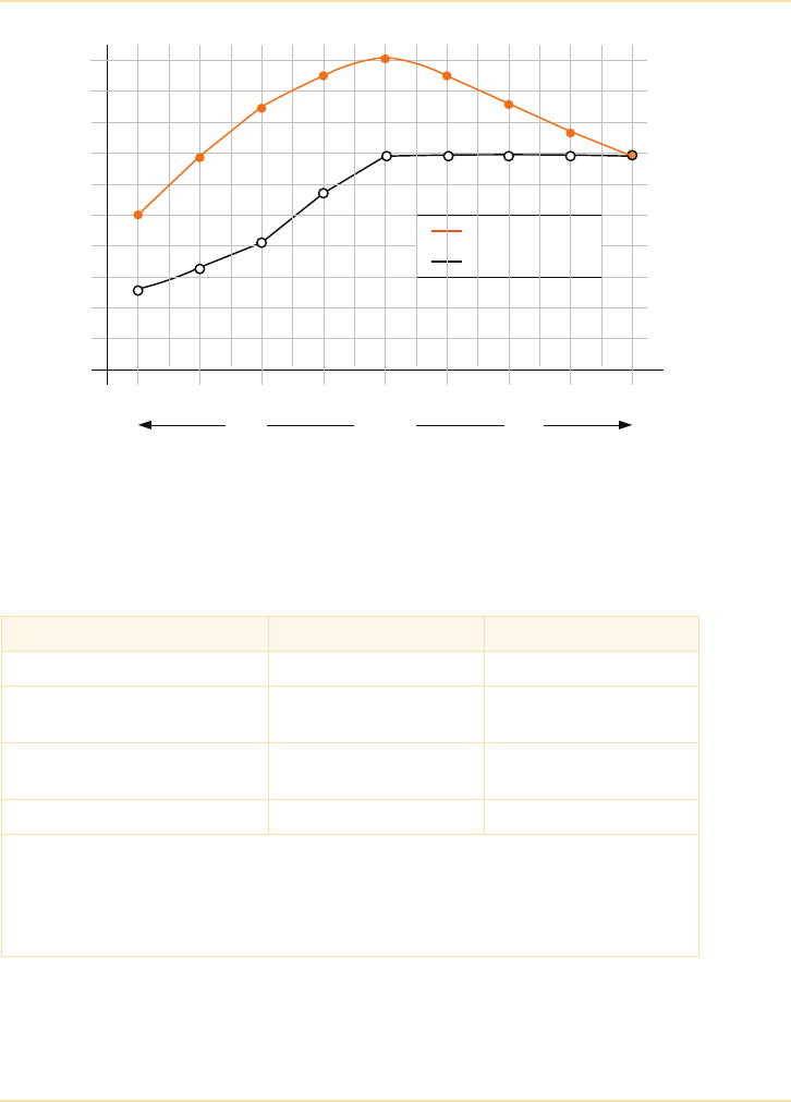
Planning a UPS Installation - Sizing and Selecting the Correct UPS
The UPS Handbook 177
Figure 11.2: Power (kW) versus power factor
Figure 11.3 shows how two typical UPS topologies cope with blade servers with
leading input power factor, which represents a major challenge for legacy
double-conversion UPS.
Figure 11.3: UPS performance with blade servers
(assuming a 200kW load and PF = 0.9 lead)
Transformerless UPS Typical legacy UPS
UPS Rating 300kVA 300kVA
Available power
at PF = 0.9 lead
270kW
(UPS 74% loaded)
182kW
(UPS 10% overloaded)
Losses at full load of 200kW
(0.9 lead, non-linear)
9kW
(95.5% efficiency)
25kW
(89% efficiency)
Generator over-sizing factor 1.5 2.5
Note: Special care should be taken when sizing the generator for leading power factor
loads. It is recommended that advice is sought from the generator manufacturer.
When the generator is supporting the UPS, the power factor presented to the generator is
close to unity (typical for a transformerless UPS). However, if the UPS operates in bypass
mode the leading power factor is presented directly to the generator terminals.
100
120
140
160
180
200
220
240
260
0.8 0.85 0.9 0.95 1.00 0.95 0.9 0.85 0.8
Lagging
Leading
Transformerless UPS
Traditional UPS
kW
280
300

Planning a UPS Installation - Sizing and Selecting the Correct UPS
178 The UPS Handbook
It should also be borne in mind that, irrespective of the UPS topology, should the
UPS system operate in bypass mode, the blade server load with leading power
factor will be presented directly to the output of the standby generator — there is
a risk that leading power factor loads could result in the generator AVR losing
full control of the output voltage.
As data centre loads move towards leading power factors the technical
advantages of transformerless UPS, particularly in the output power range from
60 to 300kVA, become evident.
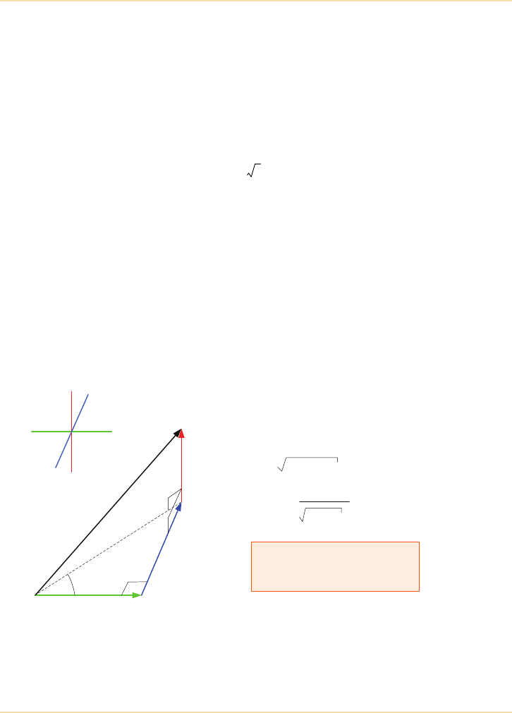
Planning a UPS Installation - Sizing and Selecting the Correct UPS
The UPS Handbook 179
Harmonic Currents
Harmonic currents result only in undesired reactive power and not as active
power and therefore the power factor for this type of load is poor. Nowadays,
many equipment manufacturers include a power factor correction stage, without
which a typical power factor can be 0.7 or less. Another typical characteristic for
this kind of load is the high peak current. This is the peak (or crest) factor which
is the ratio of the peak value to the r.m.s. value of an AC current in steady state.
A factor of 2.5 can be regarded as typical for computer loads. For a normal
linear load the corresponding value is only or 1.42. It is important to pay
attention to these factors when designing a network for computers and
especially when choosing UPS equipment for this purpose.
To comply with the EU standard EN61000-3-2, all computer power supplies
must, at least, include passive power factor correction (PPFC). PPFC can
achieve a power factor of about 0.7 - 0.75.
When calculating with power vectors (apparent, active and reactive) the
difference between the reactive power Q caused by phase shift and D
(distortion) caused by harmonic currents must be observed. Instead of the power
triangle formed by the vectors P, Q and S, a figure in three dimensions also
including the reactive vector of D should be used. The relations within this
configuration are given in Figure 11.4.
Figure 11.4: Three Dimensional Vector Diagram for Power Calculations
2
S = Apparent Power (kVA)
Q = Reactive Power (ind. or cap. (kVA)
D = Reactive Power (harmonic) (kVA)
x
yz
S
D
P
Q
S1
phi
cos phi = P
P2 + Q2
S = P2 + Q2 + D2
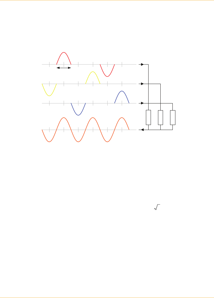
Planning a UPS Installation - Sizing and Selecting the Correct UPS
180 The UPS Handbook
Neutral Current
In a three phase system the current in the neutral conductor is usually the result
of the difference in the three line currents. Typically, in computer networks
however, very high currents are present in the neutral conductor even when the
three currents are equal and the arithmetic sum of their r.m.s. values is zero.
Figure 11.5: Currents in line conductors and neutral conductor
When single-phase computer units with their non-linear load characters are
connected in a three-phase network from lines L1, L2 and L3 to the neutrals no
current balance will take place as it would normally with linear sinusoidal
currents. The situation is illustrated in Figure 11.5 which shows how the three
line currents add-up into the neutral conductor. This results in a current which
will be the root mean square of the three line currents and its frequency is
150Hz. At its maximum this current will be as high as or 1.73 times the line
current. This maximum takes place when the line currents are of the same
magnitude, which they generally are at the optimized loading of a cable.
High peak line currents and the high current in the neutral conductor can cause
over loading of feeders and transformers as well as voltage distortion (top-
flattening of the sinusoidal voltage form) and common mode distortion. Special
care is required – see IEE Wiring Regulations 17th Edition.
Z1 - Z3
Non-Linear Loads
I
L1
I
L2
I
L3
60°
I
N
3
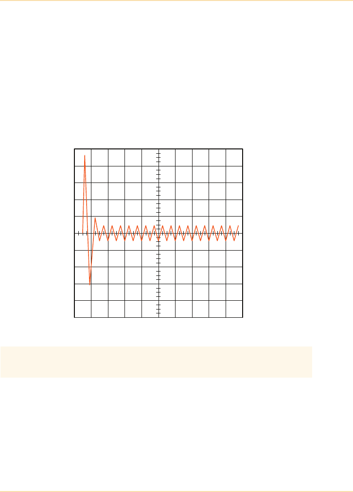
Planning a UPS Installation - Sizing and Selecting the Correct UPS
The UPS Handbook 181
In-Rush Currents
Some computer units have a built-in soft-start circuit but most are switched on
directly causing a high inrush current. In the latter case the situation is similar to
a momentary short circuit, where the current limitation will only be provided by
the line impedance in the power supply.
In-rush currents may also find their way through the neutral conductor and cause
potential variations and transients affecting different areas of the connected
computer network
Figure 11.6 shows typical in-rush current behaviour. These currents may have an
amplitude of 15 to 20 times the nominal r.m.s. value.
Figure 11.6: Typical Computer In-rush Current
Significant oversizing of the UPS system is required if high current
loads such as laser printers and motors are to be powered.

Planning a UPS Installation - Sizing and Selecting the Correct UPS
182 The UPS Handbook
Distributing the Load
If you are planning a three phase UPS installation, once you have collected the
load details, you must decide how the individual items of load will be
distributed across the phases. Balancing the load evenly across the three phases
is good practise as this allows the rating of the UPS to be fully utilised and
presents a balanced load to the mains (or generator – if fitted) whenever the UPS
is bypassed.
For example, a 60 kVA three phase UPS can supply up to 20 kVA on each phase.
Collecting Load Details
You may find it useful to use the following table to collect and collate load
information.
Most modern UPS have independently regulated phase voltages
and do not require careful load balancing across the 3 phases
in order to operate correctly. Even with these systems the load on any
single phase must never exceed 33% of the total UPS rating.
It is permissible to have single phase loads, supplied by different
phases of a three phase UPS, in the same vicinity providing regulation
514-10-01 of BS7671 is enforced - see page 228.
Description
Voltage
(V)
Frequency
(Hz)
Phases
Current
(A)
Power
Power
Factor
WVA

Planning a UPS Installation - Sizing and Selecting the Correct UPS
The UPS Handbook 183
Site Capacity
It is essential that the capacity of the site’s incoming mains supply and its
cabling and switchgear is taken into account when planning any UPS
installation.
If existing equipment is merely to be transferred to a UPS protected supply there
may be only minimal increase in load, but if the site is to be expanded to
include, for example, a new data centre, the load increase will be significant and
the effect on the site’s supply capacity will be important and must be considered.
Increasing the capacity of the mains supply to the site is likely to involve
considerable expenditure so it is important, at this stage, to plan for the future.
It is beyond the scope of this book to give specific advice about increasing the
supply capacity of a site, but the local electricity supply company will be able to
give advice and guidance.
Future Requirements
When all the load information has been collected and collated, the required UPS
capacity will be established. However, it is important to make some spare
capacity contingency when sizing the UPS — 20% is typical.
However, just adding allowance to the measured or calculated capacity is not
enough to cater for any future expansion plans and the topology of the UPS
system is also an important consideration (See "UPS Topologies" on page 21).
Example
If the load measurement and calculation has resulted in a total load requirement
of 120kVA (including a spare capacity contingency) and the critical load/
process dictates that a parallel redundant system is required:
Instead of just considering a 1+1 system comprising 2 off 120kVA UPS,
a more cost effective solution may well be to specify an N+1 system, for
example 3 off 60kVA UPS or 4 off 40kVA etc.
In the 2 UPS 1+1 system, each unit can only ever carry 50% of its full load
capacity while retaining redundancy and may therefore be operating at a low
efficiency.
In an N+1 system, each unit will be more heavily loaded while retaining
redundancy and may well therefore operate at a higher efficiency (See
"Operating Costs" on page 211).

Planning a UPS Installation - Sizing and Selecting the Correct UPS
184 The UPS Handbook
The benefits of the N+1 system are:
• lower running costs
• smaller foot-print
• more easily expandible should the load grow.
An N+1 system may be configured for future expansion by ensuring that
suitable switchgear facilities are included during the initial electrical installation
stages (See "A Typical Paralleled UPS System Bypass Panel" on page 109).
Alternatively, the selection of a rack format, modular UPS configuration enables
a very expedient and cost-effective solution for future capacity upgrades (See
"Modular UPS Systems" on page 94).

Planning a UPS Installation - Choosing a UPS Topology
The UPS Handbook 185
Choosing a UPS Topology
The topology chosen (See "UPS Topologies" on page 21) for a particular UPS
installation is largely governed by:
• the size of the load
• the load type
• resilience and required availability
•CAPEX
•OPEX
Size of Load
The size of the load will influence which type of UPS may be chosen (See
"What is Available?" on page 15).
Examples
If just one PC is to be supported:
The load is single-phase and likely to be less than 250VA therefore a ‘Micro’
UPS would probably be adequate and on-line, off-line and line interactive
designs are available.
If an office network, or communications centre is to be supported:
The load may be either single or three-phase and is likely to be between 3 and
20kVA. It may require a battery backup or autonomy time of perhaps 30 minutes
– in this case a ‘Medium’ sized UPS system is probably most appropriate. A
UPS of this power rating is likely to be available only as an on-line design.
If a major data centre is to be supported:
The load will almost certainly be three-phase and may be between 30kVA and
several hundreds of kVA. The load process may also require power redundancy
and a standby generator to ensure absolute supply security even in the event of a
lengthy mains failure. The only solution in this case is a ‘High-Power’ parallel
system which is only available in an on-line configuration.

Planning a UPS Installation - Choosing a UPS Topology
186 The UPS Handbook
Load Type
The assessment of load type may overrule the UPS type chosen in the ‘Size of
Load’ section. If, for example, during the initial load compilation of calculation
just one piece of three-phase equipment is required then this dictates that a
three-phase UPS must be installed.
If a load that must be connected to the UPS is listed in "Problem Loads" on
page 175, then you must consult your UPS supplier as a special assessment will
be required.
UPS equipment can support almost any type of electrical load but, installing a
much larger UPS than was initially planned may avoid electrical disturbance to
other connected loads and/or constant overload conditions and alarms if
particularly ‘hostile’ loads are to be connected.
Load Process Requirements
The degree of mains supply protection demanded by the load process will often
govern which UPS topology is chosen.
Examples
If the business processes must be protected for the majority of minor mains
disturbances and interruptions but would not be adversely affected if it could be
shut down in a controlled way should the interruption continue for an extended
period, then a solution may be to install:
• a UPS with auto controlled shutdown software facilities
(See "UPS Communications" on page 155).
• an extended battery autonomy
(See "Additional Battery Cabinets" on page 126).
If the supply to the critical load(s) may never be interrupted and the business
process being protected must be available twenty-four hours per day, seven days
per week, then the only viable solution is to install:
A single-phase UPS can only support single-phase loads.
A three-phase UPS can support both single and three-phase loads.
Consult your UPS supplier if any part of the planned load is
listed in "Problem Loads" on page 175

Planning a UPS Installation - Choosing a UPS Topology
The UPS Handbook 187
• an on-line UPS configured as an N+n parallel redundant system
• batteries to support the load during short mains failures
• a standby generator to protect the load during long outages.
Summary
The choice of UPS topology is a complex one and depends on the particular
business process and load to be supported.
Consideration must be given to:
• the size of the load
• the load type
• resilience requirements
•CAPEX
•OPEX
• financial cost to business of any down-time
In addition to the main criteria listed above, two additional items remain – will
the chosen UPS fit in the space allowed for it? and can the equipment be easily
transported into the chosen position? These are discussed in "Delivery and
Positioning" on page 213.

Planning a UPS Installation - Reliability Considerations
188 The UPS Handbook
Reliability Considerations
The overall cost of your UPS system can be affected by the reliability of the
equipment you choose to install. The most important consideration when
comparing manufacturers’ reliability figures is consistency. Make sure that each
manufacturer is performing calculations to the same standards and fully
investigate any figures which differ drastically from the others.
The definitions which follow are generally considered to be the standard.
Ter m Definition
Reliability The reliability of a UPS system is the probability that it can perform its designed
function (supply of interruption-free, clean power) during a certain time period.
Failure Failure denotes the inability of a UPS to perform its designed function. A failure
is caused by internal or environmental faults.
Note: Faults usually cause a degradation of the system but do not always cause
a system failure.
Faults/Errors A fault is an anomalous physical condition e.g. design error, manufacturing
problem, bad material, damage, fatigue etc. An error is a manifestation of a fault
in a system where the state of the system differs from the intended state.
MTBF Mean Time Between Failures is a measure of probability and is the average
failure-free time between subsequent failures.
MTTR Mean Time To Repair is the elapsed time from the error acknowledgement until
repair is completed. MTTR depends on many factors such as size and quality of
the service organisation and the availability of spare parts etc.

Planning a UPS Installation - Availability Considerations
The UPS Handbook 189
Availability Considerations
Power Availability Index
High availability is one of the most important issues in computing today.
Understanding how to achieve the highest possible availability of systems has
been a critical issue in mainframe computing for many years, and now it is just
as important for IT and networking managers of distributed processing. A
certain amount of mystery surrounds the topic of power availability, but
consideration of just a few important points leads to a metric which IT managers
can use to increase their systems and applications availability and make a
rational price/performance purchase decision.
High Systems Availability
Availability is a measure of how much time per year a system is operational and
available. Usually, companies measure application availability because this is a
direct measure of their employees’ productivity. With critical applications, or
parts of critical applications, physically distributed throughout the enterprise,
and even to customer and supplier locations, IT managers need to take the
necessary steps to achieve high applications availability throughout the
enterprise.
Power availability is the largest single component of systems availability and is
a measure of how much time per year a computer system has acceptable power.
Without power, the system, and most likely the application, will not work. Since
power problems are the largest single cause of computer downtime, increasing
power availability is the most effective way for IT managers to increase their
overall systems availability. Power availability, like both systems and
applications availability, has two components: mean time between failures
(MTBF) and mean time to repair (MTTR). The two most important issues in
increasing power availability are therefore increasing the MTBF and decreasing
the MTTR of the power protection system.

Planning a UPS Installation - Availability Considerations
190 The UPS Handbook
Increasing MTBF
MTBF Definitions
MTBF figures for a UPS (MTBFUPS) have little value unless they are given
with values for the mains supply (MTBFMAINS) and the Mean Time To Repair
for the UPS (MTTRUPS).
Failure Rate ()
Failure Rate is the probability that a system which has operated to a certain time
t will not fail in the following time interval (t, t + Dt).
Value Definition
MTBFUPS Calculated using of field statistics and on calculations of the MTBF of all
the UPS component parts based on a recognised standard e.g. MIL-
HDBK-217F. A high quality UPS will have figures in the region of:
MTBFUPS
Single UPS = 125,000 hours
Parallel Redundant (1+1) UPS = 1,250,000 hours
Parallel Redundant (4+1) UPS = 500,000 hours
MTTRUPS = 6 hours
MTBFMAINS = 50 hours (Refer to Chapter 2)
MTTRUPS Is the elapsed time from the error acknowledgement until repair is
completed. MTTR depends on many factors such as size and quality of
the service organisation, availability of spare parts, UPS diagnostic system
etc.
MTBFMAINS Mains quality is an important factor when calculating MTBFUPS values.
An average good quality mains supply has an
MTBFMAINS = 50 hours (Refer to Chapter 2)
Bath Tub
Curve
Displays failure rate as a function of time. There are three distinct periods
on the curve:
Early Failure Period
Constant Failure Period
Wear Out Period
Reliability
Diagram
An event diagram which gives an answer to the question “which elements
of the system must continue to operate in order to maintain the desired
function and which may fail?” (redundancy).
1
MTBF
----------------=
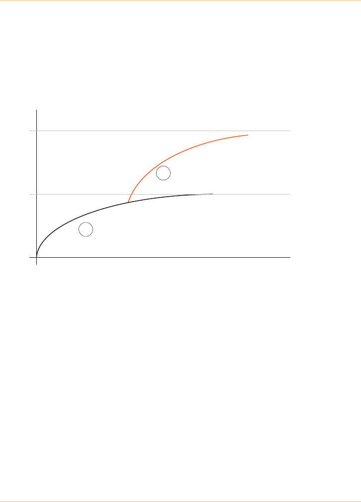
Planning a UPS Installation - Availability Considerations
The UPS Handbook 191
MTBF is the average number of hours it takes for the power protection system
to fail. The MTBF of the system can be increased in two ways: by increasing the
reliability of every component in the system, or by ensuring that the system
remains available even during the failure of an individual component. There is a
finite limit to how reliable individual components can get, even with increased
cost. Today, typical power protection systems that rely only on high component
reliability achieve MTBF between 50 000 hours and 200 000 hours.
Figure 11.7: The diminishing returns of component reliability
By adding a level of redundancy to the system it is possible to achieve a three- to
six-fold improvement in MTBF for power protection devices. Redundancy
means that a single component of a power protection system can fail and the
overall system will remain available and protect the critical load.
Of course, component reliability is a requirement of any system. However,
Figure 11.7 shows the diminishing returns of increasing component reliability.
Line 1 shows the plateau that occurs when MTBF is increased by using more
reliable (and therefore more costly) components. Line 2 shows how redundancy,
in addition to component reliability, can raise MTBF to the next plateau.
Decreasing MTTR
One way that systems downtime can occur is when both the power protection
system and the utility power fails. A shorter MTTR can decrease the risk that
both of these events will occur at the same time. By driving the MTTR towards
zero, it is possible to essentially eliminate this failure mode.
1 MTBF without redundancy
2 MTBF with redundancy
Material Cost
MTBF
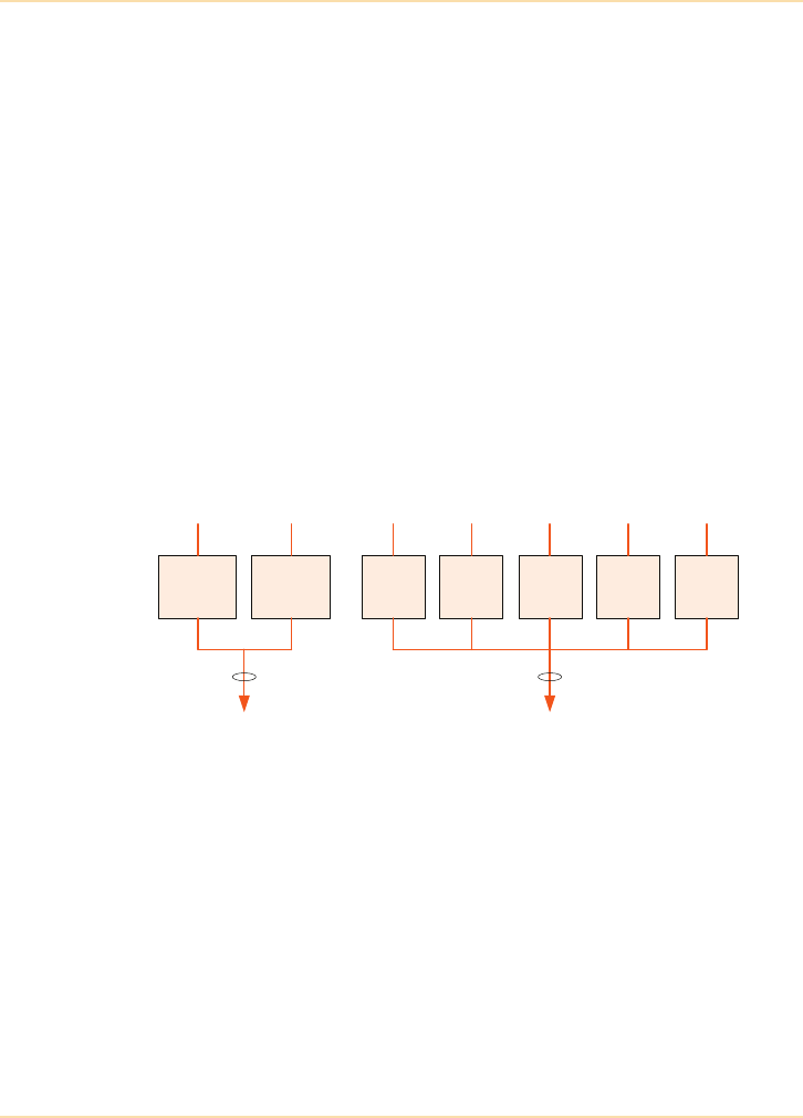
Planning a UPS Installation - Availability Considerations
192 The UPS Handbook
Adding hot-swappability to a power protection system is the most effective way
of decreasing MTTR. Hot-swappability means that if a single component fails, it
can be removed and replaced by the user while the system is up and running.
When hot-swappability is used in conjunction with a redundant system, MTTR
is driven close to zero, since the device is repaired when there is a component
failure but before there is a systems failure.
Availability (A)
Availability is a useful measure (downtime per year) for systems subject to
failure and repair; it is defined as the probability that the system is operational at
time t.
Sample Availability Calculations
This example compares the calculated Availability (A) of the two UPS system
configurations shown above.
As stated previously the Availability (A) of a UPS is defined as:
AMTBF
MTBF MTTR+
---------------------------------------=
UPS 1
120kVA
UPS 2
120kVA
UPS 1
30kVA
UPS 2
30kVA
UPS 3
30kVA
UPS 4
30kVA
UPS 5
30kVA
Load
120kVA
Load
120kVA
Availability Availability
(1+1)
Redundant Configuration
(4+1)
Redundant Configuration
AMTBF
MTBF MTTR+
---------------------------------------=

Planning a UPS Installation - Availability Considerations
The UPS Handbook 193
Taking sample figures from page 190:
The examples show the importance of the MTTR figure if high availabilities are
required. If a UPS module should fail in either of the samples shown, the
systems are immediately non-redundant and rapid repair or replacement of the
faulty UPS is essential.
Example 2 has a much reduced MTTR figure and hence higher availability as it
uses modern, rack mounted modular UPS units (See Chapter 6 and Chapter 7).
This pair of examples illustrates the move away from the, rather futile, search
for a total reliability to the more easily attainable, fault tolerant system.
Example 1
(1+1) Parallel Redundant
Configuration
Free standing UPS units
(4+1) Parallel Redundant
Configuration
Free standing UPS units
MTBF 1,250,000h 500,000h
MTTR 6h 6h
Availability 99.9995% 99.9988
Assumptions:
MTBF of the (1+1) system is higher than that of the (4+1).
MTTR is 6 hours for each configuration.
Results: Availability of the (1+1) system is higher than that of the (4+1).
Example 2
(1+1) Parallel Redundant
Configuration
Free standing UPS units
(4+1) Parallel Redundant
Configuration
Rack mounted UPS units
MTBF 1,250,000h 500,000h
MTTR 6h 0.5h
Availability 99.9995% 99.9999%
Assumptions:
MTBF of the (1+1) system is higher than that of the (4+1).
MTTR of the (4+1) system is shorter than that of the (1+1), achieved using rack mounted
modular UPS units.
Results: Availability of the (4+1) system is higher than that of the (1+1).

Planning a UPS Installation - Availability Considerations
194 The UPS Handbook
High Nines
In the previous examples the availability figures are shown as percentages.
Recent attention to availability calculations has resulted in an additional
expression; “high nines”. A lot of work in this area has been initiated by the
Uptime Institute® (www.upsite.com) and “high nines” has become an accepted
standard to express availability.
Data Centre Tier Rating
The availability figures given previously relate only to the UPS components,
which, when considering a complete installation, can only give part of the
picture. The Uptime Institute® has suggested a tiered approach to data centre
availability and this specifies various system attributes for each tier. A
comprehensive white paper, “Tier Classifications Define Site Infrastructure
Performance”, is available from their website and some extracts are included
here (see "Further Reading" on page 279):
“Nines” Availability (%) Down Time per annum
Two 99 87.5 hours
Three 99.9 8.75 hours
Four 99.99 52.5 minutes
Five 99.999 5.5 minutes
Six 99.9999 32 seconds
Determining a Site’s Tier Rating for Design Topology
Tier Requirement Tier 1 Tier II Tier III Tier IV
Source System System System System + System
System Component
Redundancy
N N+1 N+1 Minimum of N+1
Distribution Paths 1 1 1 normal and 1
alternate
2 simultaneously
active
Compartmentalisation No No No Yes
Concurrently
Maintainable
No No Yes Yes
Fault Tolerance
(single event)
No No No Yes

Planning a UPS Installation - Availability Considerations
The UPS Handbook 195
Simply put, the Tier rating for an entire site is limited to the rating of the weakest
subsystem that will impact site operation. For example, a site with a robust Tier IV UPS
configuration combined with a Tier II chilled water system will yield a Tier II site rating.
This is driven by the need to manage perception in senior management, as well as to
factually report actual site capabilities. If a site is advertised within an organization as
being fault tolerant and concurrently maintainable (Tier IV), it is intolerable to shut the site
down at any time in the future—regardless of what subsystem may have required the shut
down.
There are no partial or fractional Tier ratings. The site’s Tier rating is not the average of the
ratings for the 16 critical site infrastructure subsystems. The site’s tier rating is the
LOWEST of the individual subsystem ratings.
Similarly, the “Tier” cannot be imputed by using calculated Mean Time Between Failure
(MTBF) component statistical reliability to generate a predictive availability and then using
that number to “match” the actual measured availability results shown later in Figure 2.
Even if statistically valid component values existed (and they don’t because product life
cycles are getting shorter and shorter and no independent, industry wide database exists
to collect failures), this approach fails to include people which consistently are involved in
70% of all site failures. A calculated reliability of 0.9999 which ignores human interaction
does NOT define a site as being Tier IV. The only way to determine Tier Level is to
objectively determine a site’s ability to respond to planned and unplanned events.
Tier I: Basic Site Infrastructure
The fundamental requirement
• A Tier I basic data centre has non-redundant capacity components and single non-
redundant path distribution paths serving the site’s computer equipment.
The performance confirmation test(s)
• Any capacity component or distribution path failure will impact the computer systems.
• Planned work will require most or all of the systems to be shut down, impacting the
computer systems.
The operational impact
• The site is susceptible to disruption from both planned and unplanned activities.
• The site infrastructure must be completely shut down on an annual basis to safely
perform necessary preventive maintenance and repair work. Urgent situations may
require more frequent shutdowns. Failure to perform this maintenance work increases
the risk of unplanned disruption as well as the severity of the consequential failure.
• Operation errors or spontaneous failures of site infrastructure components will cause a
data centre disruption.

Planning a UPS Installation - Availability Considerations
196 The UPS Handbook
Tier II: Redundant Capacity Components Site Infrastructure
The fundamental requirement
• A Tier II data centre has redundant capacity components and single non-redundant
distribution paths serving the site’s computer equipment.
The performance confirmation test(s)
• A capacity component failure may impact the computer equipment.
• A distribution path failure will cause the computer equipment to shut down.
The operational impact
• The site is susceptible to disruption from both planned activities and unplanned events.
• Redundant UPS modules and engine generators are required.
•The site infrastructure must be completely shut down on an annual basis to safely
perform preventive maintenance and repair work. Urgent situations may require more
frequent shutdowns. Failure to perform this maintenance work increases the risk of
unplanned disruption as well as the severity of the consequential failure.
• Operation errors or spontaneous failures of site infrastructure components may cause a
data centre disruption.
Tier III: Concurrently Maintainable Site Infrastructure
The fundamental requirement
• A concurrently maintainable data centre has redundant capacity components and
multiple distribution paths one distribution path serves the computer equipment at any
time.
The performance confirmation test
• Each and every capacity component and element of the distribution paths can be
removed from service on a planned basis without causing any of the computer
equipment to be shut down.
The operational impact
• The site is susceptible to disruption from unplanned activities.
• Planned site infrastructure maintenance can be performed by using the redundant
capacity components and distribution paths to safely work on the remaining equipment.
• In order to establish concurrent maintainability of the critical power distribution system
between the UPS and the computer equipment, Tier III sites require all computer
hardware have dual power inputs as defined by the Institute’s Fault Tolerant Power
Compliance Specifications Version 2. Devices such as point-of-use switches must be
incorporated for computer equipment that does not meet this specification.
•During maintenance activities, the risk of disruption may be elevated.
• Operation errors or spontaneous failures of site infrastructure components may cause a
data centre disruption.

Planning a UPS Installation - Availability Considerations
The UPS Handbook 197
Work by the Uptime Institute shows beyond doubt that traditional reliance on
manufacturers figures does not always provide the best approach to system
reliability and availability.
Tier IV: Fault Tolerant Site Infrastructure
The fundamental requirement
• A fault tolerant data centre has redundant capacity systems and multiple distribution
paths simultaneously serving the site’s computer equipment.
• All IT equipment is dual powered and installed properly to be compatible with the
topology of the site’s architecture.
The performance confirmation test(s)
•A single worst-case failure of any capacity system, capacity component or distribution
element will not impact the computer equipment.
• Each and every capacity component and element of the distribution paths must be able
to be removed from service on a planned basis without causing any of the computers to
be shut down.
• In order to establish fault tolerance and concurrent maintainability of the critical power
distribution system between the UPS and the computer equipment, Tier IV sites require
all computer hardware have dual power inputs as defined by the Institute’s Fault
Tol era nt Po we r Com pli an ce Spe cif ica tio ns Version 2. Devices such as point-of-use
switches must be incorporated for computer equipment that does not meet this
specification.
• Complementary systems and distribution paths must be physically separated
(compartmentalized) to prevent any single event from impacting both systems or paths
simultaneously.
The operational impact
• The site is not susceptible to disruption from a single unplanned worst-case event.
• The site in not susceptible to disruption from any planned work activities.
• The site infrastructure maintenance can be performed by using the redundant capacity
components and distribution paths to safely work on the remaining equipment.
• During maintenance activities, the risk of disruption may be elevated.
• Operation of the fire alarm, fire suppression, or the emergency power off (EPO) feature
may cause a data centre disruption.
Traditional non-redundant, non fault tolerant UPS systems and solutions cannot provide reliable
power supplies at the availability levels currently demanded by business critical systems.
TIA-942 Standard
Reference can be made to the TIA-942 standard developed by the Telecommunications Industry
Association (TIA) to define guidelines for planning and building Data Centres, particularly with regard
to Data Centre infrastructure and power management.

Planning a UPS Installation - Availability Considerations
198 The UPS Handbook
Power Availability (PA) Chart
The relationship between power availability, redundancy, and hot-swappability
is easily explained by using the PA Chart, which categorises power protection
systems in quadrants according to how well they meet the requirements of high
power availability – redundancy and hot-swappability. As more components in a
system become hot-swappable, the system moves from the bottom to the top of
the graph (Figure 11.8), and as more components become redundant, it moves
from the left to the right of the graph. IT managers can choose the solution that
is right for them, depending on the need for high availability and the amount of
money they want to spend.
Figure 11.8: Systems categorised by how well they meet the requirement
of high power availability
The PA Chart corresponds to the types of power protection systems available
today as shown in Figure 11.9. The standalone UPS is neither hot swappable nor
redundant. As shown in the table, a standalone UPS provides normal power
availability because uptime is dependent on the reliability of the UPS itself.
The fault tolerant UPS is sometimes described as providing affordable
redundancy. Systems of this type have redundant components but not all of the
major components are hot-swappable. This type of system offers high power
availability because the power protection system will continue to protect the
load when a component fails. But because a failed component often results in
the entire UPS needing replacement, this type of system can have serious
drawbacks, including expensive and time-consuming repair with both systems
Hot-swappable
Neither redundant
nor hot-swappable Redundant
Redundancy (high MTBF)
Hot-swappability (low MTTR)
Redundant and
hot-swappable

Planning a UPS Installation - Availability Considerations
The UPS Handbook 199
downtime and a major inconvenience for IT managers. Fault tolerant UPS
systems may have some hot-swappable components, such as batteries and a
subset of power electronics, but in most cases a high number of critical
components, such as the processor electronics, will not be hot-swappable.
Figure 11.9: Types of UPS mapped onto the PA Chart
Like fault-tolerant UPS, modular UPS offer high power availability. Modular
UPS have multiple hot-swappable components and are typically used for
multiple servers and critical applications equipment. Many modular UPS also
have redundant batteries. Their main advantage over fault-tolerant UPS is that
all of the main components which can potentially fail can be hot-swapped,
eliminating planned downtime due to a service call.
The modern, modular UPS offers the highest level of power protection currently
available where the power electronics, batteries, and processor electronics are
both redundant and hot-swappable. This system provides very high power
availability and the highest level of protection for IT managers’ critical loads.
Modular UPS
Standalone UPS Fault Tolerant UPS
Redundancy
Hot-swappability
Modern, hot-swappable
modular UPS

Planning a UPS Installation - Availability Considerations
200 The UPS Handbook
Power Availability (PA) Index
The different types of power protection systems in the PA Chart can be
measured linearly with the PA Index, according to the power availability they
provide. The PA Index is a tool to explain the difference between power
protection systems. Figure 11.10 shows each of the quadrants from the PA Chart
mapped into a level of the PA Index.
Figure 11.10: Quadrants of the PA Chart mapped into a level of PA Index
Figure 11.11 shows the relative power availability provided by each type of
system. The PA Index maps directly into the PA Chart and makes the different
characteristics of high availability power protection systems clear.
Figure 11.11: The PA Index mapped into the PA Chart
Power
Availability
Index
Definition Power
Availability
PA-1 Not hot-swappable and not redundant Normal
PA-2 Redundant but not hot-swappable High
PA-3 Hot-swappable but not redundant High
PA-4 All main components are redundant and hot-swappable Very high
PA-3
Hot-swappable but not redundant.
High power availability.
PA-1
Neither redundant nor hot-swappable.
Normal power availability.
PA-2
Redundant but not hot-swappable.
High power availability.
Redundancy
Hot-swappability
PA-4
Redundant and hot-swappable.
Very high power availability.

Planning a UPS Installation - Availability Considerations
The UPS Handbook 201
Summary
The PA Chart and the PA Index help to choose the right power protection system
for high availability applications.
The standalone UPS, the modular UPS, and the modern, hot-swappable,
modular UPS all offer real benefits in terms of power availability versus cost.
Although fault-tolerant UPS offer high power availability – and are marketed as
such – they introduce serious drawbacks including a high MTTR and potentially
significant inconveniences for IT managers.
The latest UPS designs are cost effective because they are:
• very efficient - kinder to the environment
• electrically very clean (low input current THD)
• quiet
• physically smaller
• have no requirement for 6/12 pulse rectification.
Conclusion
Think about the future - installing a modular, upgradeable, UPS system may cost
slightly more initially but will save significant costs in the future so before
deciding on a particular UPS configuration, consider:
• possible future load growth – plan for upgrading at the start, consider
installing several smaller paralleled UPS instead of one large single
unit
• flexibility of smaller lighter units which can easily be moved when
the company moves or expands
• a quality UPS should have a useful working life at least 10 years if it
is well maintained (See "System Maintenance" on page 239)
• paralleling for ultimate reliability and high availability may prove to
be a very good investment.

Planning a UPS Installation - Environmental Considerations
202 The UPS Handbook
Environmental Considerations
Heat
All UPS manufacturers will quote a maximum operating temperature for their
equipment (typically +40°C). The air conditioning plant must have sufficient
capacity to maintain the conditions stated. Obviously the overall efficiency of
the UPS will have a significant effect on both the size and the operating cost of
the air conditioning plant. -
Humidity
Again the UPS manufacturer will state maximum permissible relative humidity
levels (typically 95%). Whilst most UPS equipment is well designed, high
relative humidity levels may promote corrosion of cabinets and internal parts.
Simple dehumidification equipment is available for sites where this may be a
problem.
Audible Noise
The unit of sound intensity is the decibel (dB) and it represents the ratio between
the sound level measured with a microphone and a reference sound level, 0db,
which is defined to be approximately equal to the threshold of human hearing.
However as the human ear is less sensitive to very low and very high
frequencies, an additional ‘A’ filter is applied when measuring background or
other intrusive noises, hence the dBA unit used by all UPS manufacturers.
Typical audible noise figures for fully loaded UPS equipment range from
50dBA for 5 kVA to 75dBA at 300 kVA.
Figure 11.12 shows some examples of relative sound intensity.
If the UPS batteries are installed in the same room as the UPS, check
the air cooling system is able to keep the ambient temperature at a
level suitable for the batteries.
(See "Energy Storage Devices" on page 115)
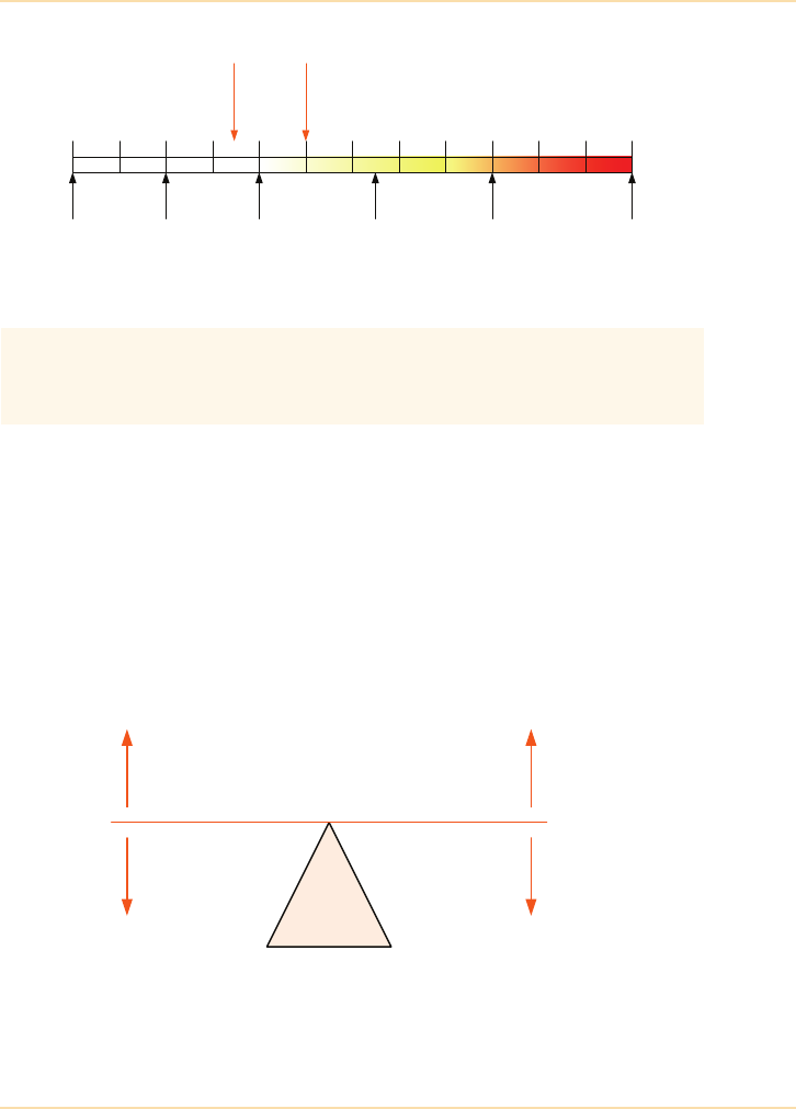
Planning a UPS Installation - Environmental Considerations
The UPS Handbook 203
Figure 11.12: Relative Sound Intensity
Energy Use and Efficiency
Recent studies of the impact of energy use on the world climate and the
anticipated arrival of legislation to improve the efficiency of such usage has led
to increased public and corporate awareness of terms such as: Carbon
Emissions, Greenhouse Gas and Global Warming.
Companies and Corporations, increasingly keen to emphasize their “green
credentials”, are including sound environmental practices in their operational
policies and often include environmental achievements in Annual Reports.
Figure 11.13: Balancing costs and environment
The acceptable audible noise for any UPS depends on the application
and installation location. Check the manufacturer’s quoted level to
ensure the installation will create the minimum disturbance.
Threshold of
hearing
Rustling
leaves
Vacuum
cleaner
Typical
conversation Jet engine Threshold of
pain
0 20 50 75 100 120dba
Typical
UPS
UPS
Costs
High
Low
Environment
High Energy
Waste
Low Energy
Waste

Planning a UPS Installation - Environmental Considerations
204 The UPS Handbook
Carbon Emissions
The majority of the electricity generated in the UK is fueled by the fossil fuels,
coal or natural gas.
Figures obtained for Q3 2012 show:
• 35.4% Coal
• 28.2% Gas
• 22.3% Nuclear
• 11.7% Renewables
• 0.9% Oil
• 1.6% Other
Saving Energy
Choosing the correct UPS system to support a connected critical load is not
simply a matter of matching the output power to that load. The solution must
also take into account, reliability, availability and expandability among others.
Changes in the way UPS systems are designed and made have also highlighted
the benefits to be gained by installing modular, transformerless units. These
modern UPS provide new ways to save energy and thus cost over the lifetime of
the system including. Rightsizing the UPS system over time, higher UPS
efficiency for partial loads, lower cooling requirements and improved input
power factor and input current total harmonic distortion.
Rightsizing
Rightsizing refers to selecting an appropriate UPS to support the load at any
point in time. Until recently it was common practice to size a UPS to cope with
the current load and any anticipated growth.
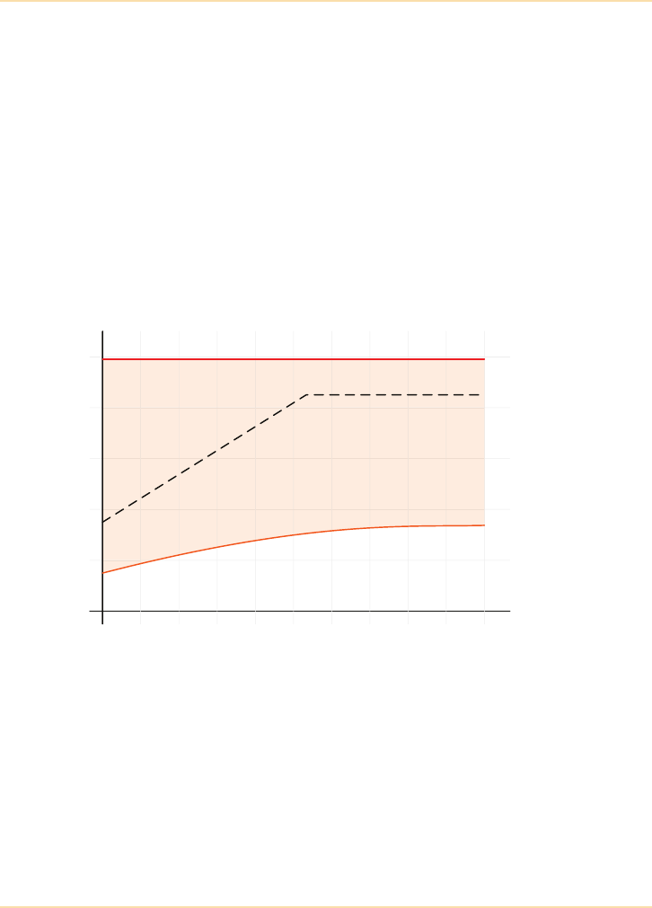
Planning a UPS Installation - Environmental Considerations
The UPS Handbook 205
Example 1 - Traditional Approach
The graph in Figure 11.14 shows an initial expected system load of 35% of the
data centre capacity and it is expected that the load will grow over 10 years to
approach 90%. In the case shown a UPS system capable of supplying the
projected 90% load is installed.
Although the UPS has supported the load, the shaded area on the graph shows it
has been utilized very poorly and has been seriously oversized from the start.
In this example, the UPS system is never more than about 35% loaded and this
has a serious impact on the efficiency.
A legacy UPS has a maximum efficiency of about 93% when fully loaded,
dropping to about 90% at 50% loading and even less at the levels shown in the
graph.
Figure 11.14: Traditional sizing method
01234567 8 9 10
20
40
60
80
100
Years
Capacity (%)
Waste due to oversizing
Expected load
Actual load
Room capacity
Installed UPS capacity
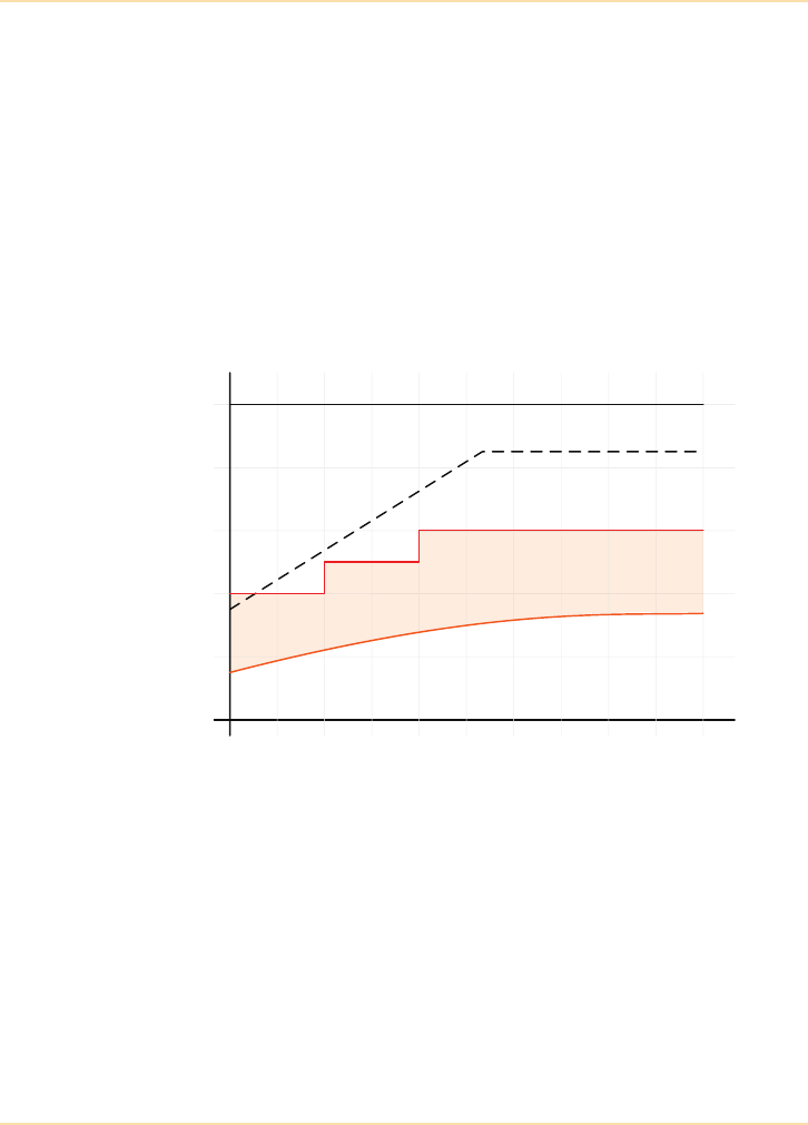
Planning a UPS Installation - Environmental Considerations
206 The UPS Handbook
Example 2 - Modular Approach
The graph in Figure 11.15 shows the same initial expected load and growth rate.
This time the initial load is used as the UPS sizing start point and a modern,
modular UPS is chosen. As the load grows, the UPS can be upgraded by adding
modules (without increasing the UPS footprint) and the system utilization is
greatly improved.
A modern, modular, transformerless design UPS has a maximum efficiency of
about 96% when fully loaded and this drops to about 95% for loads between
25% and 75%.
Correct UPS sizing from the outset is vital to achieve minimum capital outlay
and maximum power savings throughout the useful life of the system.
Figure 11.15: Modern sizing method
Manufacturers have acknowledged that in resilient, and hence redundant, UPS
configurations the UPS units will never be operating at 100% of their capacity.
For example in a single n+1 system with two UPS units operating in parallel and
equally sharing the load their maximum operating percentage will be 50% of
their individual capacity. Hence manufacturers have shifted the maximum
efficiency performance to the actual point of use. Therefore each UPS now will
be most efficient generating at 50% rather than at the usually stated 100%.
The concept of right sizing also brings into consideration the idea of granularity.
With modern transformerless design UPS units, with their associated ‘flat’
01234567 8 9 10
20
40
60
80
100
Years
Capacity (%)
Waste due to oversizing
Expected load
Actual load
Room capacity
Installed UPS capacity

Planning a UPS Installation - Environmental Considerations
The UPS Handbook 207
efficiency curves, the question is “what load steps do I require for my critical IT
system?”. For a small to medium-sized data centre, an IT room of say 200 to
500kVA, then the UPS system which increments in 50 kVA modules may be
ideally suited. However if the data centre is a large facility of several megawatts
then large incremental steps of say 500 kVA would be more appropriate.
Hence the concept of modularity takes into distinct meanings:
1. Slot in/pull out UPS modules contained a in a ‘mother’ frame.
or
2. Large capacity stand-alone UPS units configured in a modular
topology.
Whichever system is most suitable is a combination of facility size, granularity,
coupled with high efficiency UPS units. The increased growth of
transformerless designed UPS units is testament to the drivers of high efficiency
and CSR to be environmentally responsible.

Planning a UPS Installation - Environmental Considerations
208 The UPS Handbook
Partial Load Efficiency
There are, of course, many legacy systems in current operation which do not
take advantage of the higher efficiencies afforded by the modern transformerless
design. Although initial CAPEX may be a little lower, the OPEX’s associated
with an inefficient system design and transformer based UPS units will soon far
outweigh any initial cost savings
The following table shows the comparative running costs for a parallel
redundant UPS installation to support a load of 96kW (120kVA @ 0.8 pf) using
both methods.
UPS Details Legacy (2 x 120kVA)
120kVA N+1
Modular Transformerless
(4 x 40kVA)
120kVA N+1
Load (%) 50 75
Efficiency (%) 91 94.5
Critical Load (kW) 96 96
To ta l U PS I np ut Po we r ( kW ) 10 6 1 02
Total UPS Heat Loss (kW) 10 6.0
UPS Losses - Cost per Year* £7,884 £4,730
Cooling Cost per Year* £5,380 £907
Total Losses + Cooling
Cost per Year*
£13,264 £5,637
Cost of ownership SAVING over FiveYears £38,135
* Costs based on 9.0 p/kWh
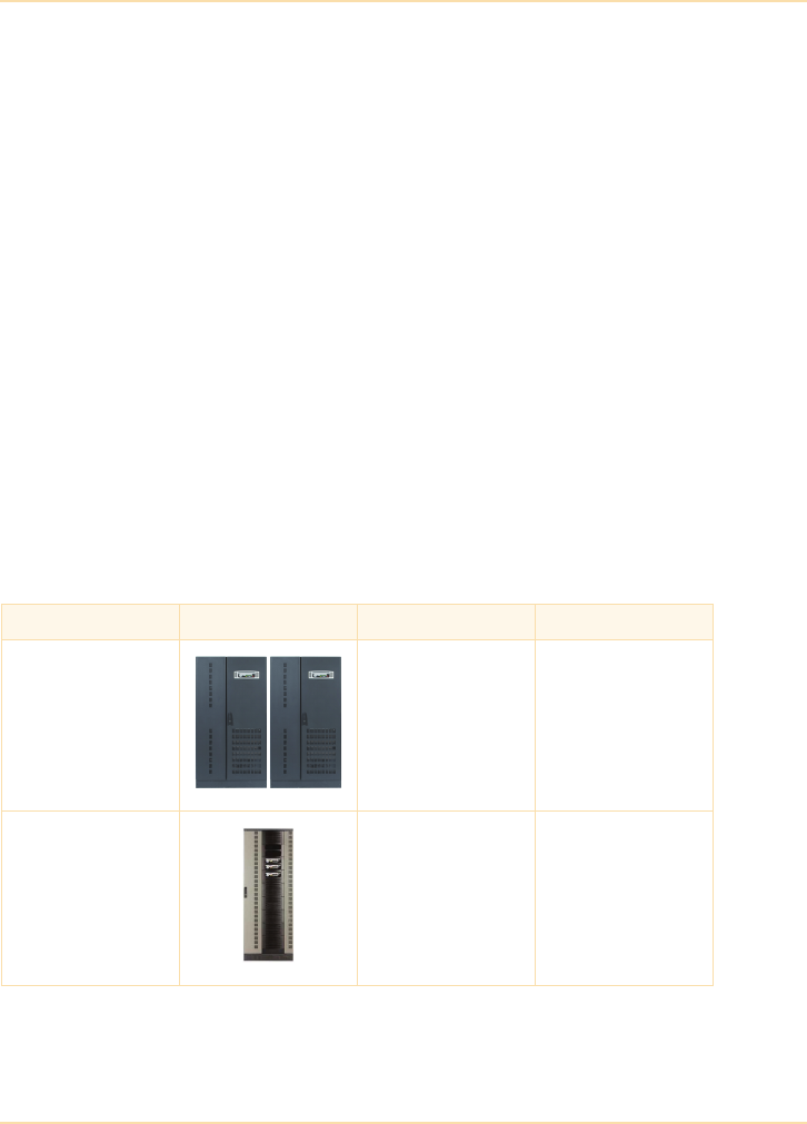
Planning a UPS Installation - Total Cost of Ownership
The UPS Handbook 209
Total Cost of Ownership
It is important to measure the total cost of ownership (TCO) in order to predict
how the investment will be paid back. In the case of a data centre, the individual
cost factors involved in protecting the investment include the necessary
infrastructure for providing power, cooling and IT equipment protection.
Total cost of a UPS system depends not only on the purchase price but also on:
• capital cost including the purchase price and transportation costs
• building/footprint costs including installation cost, power density
(kVA/sq m), and security concept (redundancy, availability)
• operating costs, including energy costs, cooling system energy losses,
maintenance, training for maintenance, and spare parts stock
• upgrade costs.
The major contribution to the total cost of a data centre is usually an oversized
or inefficient UPS system (See "Rightsizing" on page 204). Taking the case of a
UPS system with a load of 80kVA, total costs and performance of a traditional
UPS system are compared with those of an advanced modular UPS system. For
optimum availability, a parallel redundant solution (n+1) is selected. A
traditional parallel configuration of two 80kVA UPS is compared with an
advanced modular parallel configuration of three 40kVA UPS (Figure 11.16).
Figure 11.16: Comparison of configurations of traditional and modular
Load: 80kVA UPS Design Configuration Battery
Traditional Parallel 2 x 80kVA
(1+1) redundant
Mounted within UPS
cabinet
Modular Parallel 3 x 40kVA
(2+1) redundant
Mounted within UPS
cabinet

Planning a UPS Installation - Total Cost of Ownership
210 The UPS Handbook
Capital Cost
Purchase Price
The purchase price of a traditional UPS system would typically be less than that
of an advanced modular UPS system. However, the purchase price is not the
only decisive factor when considering overall costs. The lower purchase price of
traditional UPS technology must be offset against significantly higher operating
costs in comparison with a modular system based on technology which reduces
energy loss costs. The higher cost of the modular system is recovered within the
first year of operation. A comparison of additional long-term costs also favours
modular technology (See page 208).
Transportation Cost
A traditional UPS is usually built with an output transformer, which implies a
total weight up to two or three times higher than that of a transformerless UPS
system. This weight difference can increase transport cost by 100 percent or
more (Figure 11.17).
Figure 11.17: Transport costs dependent upon weight and volume
Building/Footprint Costs
The traditional UPS system based on two UPS units typically needs two to three
times the amount of floorspace in m2 required for an advanced modular UPS.
Figure 11.18: Installation and footprint costs
System (80kVA, n+1) Tot. Weight
(inc Batts) Gross Volume Transport
Cost
Traditional (1 +1) ~ 2 x 1150kg 2x (97x182x75)cm = 2.6m3226%
Modular (2 + 1) ~ 379kg 1x (73x197x80)cm = 1.15m3100%
System (80kVA, n+1) Footprint KVA/m
2
Installation
Cost
Traditional (1 +1) 2x(97x75)cm=1.44 m2160kVA/1.44m2 = 111 186%
Modular (2 +1) 1x (73x80cm=0.58 m2120kVA/0.58m2 = 206 100%

Planning a UPS Installation - Total Cost of Ownership
The UPS Handbook 211
Security Concept (Redundancy, Availability)
System availability is dependent on the mean time between failures (MTBF)
and, even more, on time to repair in the event of a failure, mean time to repair
(MTTR). In modular UPS systems, MTTR can be up to 12 times less in
comparison with traditional UPS systems because a module can be quickly
exchanged without load interruption, increasing the total availability of the UPS
system to 0.999999 (6 nines).
Figure 11.19 illustrates how system MTBF and MTTR affect the availability of
two seemingly equivalent systems and shows the MTBF of the non-modular
system as being higher than the modular system simply because it comprises
two rather than three UPS. If the MTTR of the non-modular and modular
systems were the same (for example, six hours) then the non-modular system
would have the higher availability (because of the higher MTBF). However the
MTTR of the modular system is much lower at 0.5h and has a positive effect on
the system availability.
Figure 11.19: Comparison of system availability
Operating Costs
Spare Part Stock, Logistics and Exchange
Traditional UPS systems are not built as system-modules and therefore it is very
difficult to propose a cost-efficient spare part package. For security reasons,
often the most extensive and expensive spare parts kit will be selected. Even
then, there is no guarantee that the spares kit will be effective or contain the part
required for any or all failures which could arise, and there is a time overhead
for stock management and logistics.
The hot-swappable technology of a modular system eliminates the complication
of choosing the right spare parts kit. All that is required is a single replacement
module, and even when there are different power ranges in operation, holding
Traditional (1+1)
redundant system
Modular (2+1)
redundant system
MTBF 1250,000h 833333h
MTTR 6h 0.5h
Availability = 0.999995 (5 nines) 0.999999 (6 nines)
MTBF
MTBF MTTR+
-----------------------------------------

Planning a UPS Installation - Total Cost of Ownership
212 The UPS Handbook
the highest kVA-rated module as a spare covers all eventualities. Trained
personnel can swap modules within 15 minutes.
Through the use of spare modules, it is possible to save up to 50 percent on
logistics and stock management costs.
Training Costs
If there are many different types of UPS systems within a company, training for
each individual system is time consuming and costly. In contrast, modular
systems over a wide range of output powers will have the same architecture and
mode of operation.
The know-how gained by training on one UPS module system can be applied to
other UPS module systems without additional training.
Upgrade Cost
Upgrading a traditional UPS demands extra space, costly cabling and involves
taking the UPS off line during the upgrade.
With a modular UPS, the upgrade is performed by simply inserting the
additional power modules into the rack. For example, three 20kVA modules
may be replaced by three 30kVA modules, provided the system’s distribution
and frame has been specified for the maximum foreseeable requirement. Such
upgrades can be performed without any interruption to the load, without
increasing the footprint, and with no additional work on site. This flexibility
makes upgrading a system very easy, and with very little additional cost.

Planning a UPS Installation - Installing the UPS
The UPS Handbook 213
Installing the UPS
Delivery and Positioning
The importance of planning the installation and delivery of the UPS system
cannot be overstated. Having chosen a particular system and topology it is
important to decide:
• will the system fit into the space reserved for it?
• is the proposed location suitable?
• how will the system be transported to the location?
Size & Weight
Improvements in UPS technology and design have provided much higher power
densities which, when combined with the flexible installation options for
modern parallel systems, make it much easier to find space for UPS systems.
Also, because the most modern designs no longer need bulky and heavy input
transformers, installation of very powerful UPS systems is no longer limited to
the ground floor or basement plant room.
The manufacturer or supplier will provide details of space requirements and
details of module weights in the UPS system specification (See "Introduction"
on page 283).
A UPS system is not just a big battery box. It contains electronic components
similar to those found in computers and therefore requires careful handling
when being transported. Additionally, large UPS equipment will be heavy and
unwieldy and will require specialist contractors using ‘air-ride’ suspension
vehicles and specialised lifting equipment to unload and position it. The UPS
supplier should be able to recommend handling procedures and suitable
contractors with experience in this field.
Be sure to consider possible future expansion when choosing
a UPS location and if you can allow extra space over and
above the manufacturer’s recommended minimum,
maintenance and service will be easier.

Planning a UPS Installation - Installing the UPS
214 The UPS Handbook
Choosing a Suitable Location
The choice of a particular installation location for the UPS depends on many
things:
• how much space is available?
• can the floor safely support the weight of the equipment?
• will the installation cause continued inconvenience to the existing
personnel and business?
• are the environmental conditions at the chosen location suitable?
• can access to the UPS equipment be made secure yet convenient?
• does the UPS comprise one module or several in parallel?
• what is the effect of the installation on existing air flow and air
conditioning equipment?
• will the switchgear controlling the UPS be in the same area?
• can the chosen area safely accommodate the battery installation?
In general the location chosen for modern UPS can be summarised as follows:
Small UPS – less than about 20kVA, can be installed in a normal office
environment although care should be taken to ensure that the additional
noise and heat does not adversely affect the office environment.
Medium UPS – between 20 and 100kVA are designed to be installed in
computer rooms.
Free-Standing UPS – greater than 100kVA, will often be located either in a
separate UPS room or in an existing plant room.
Modular Rack Format UPS – between 20 and 250kVA are designed to be
installed in computer rooms or a suitable plant room.
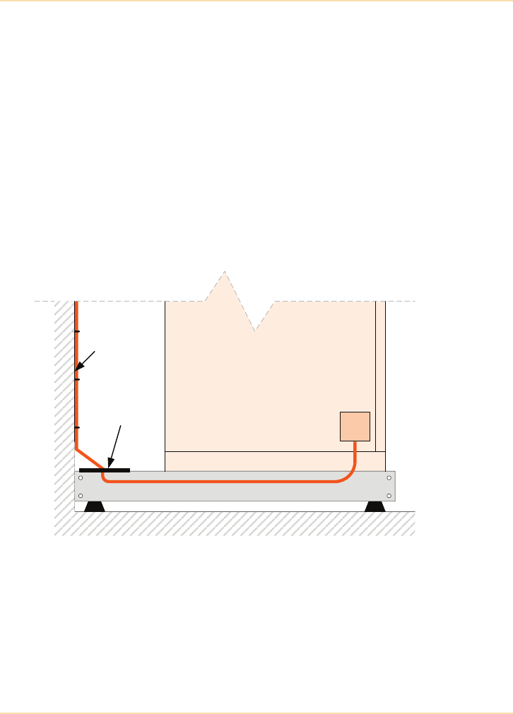
Planning a UPS Installation - Installing the UPS
The UPS Handbook 215
Floors and Cable Entry
Most medium to large UPS require bottom cable entry and consideration needs
to be given when the UPS is located on a solid floor, such as a typical plant room
environment or a raised floor, such as a computer room.
Solid Floors
When locating the UPS on a solid floor, provision needs to be made to permit
the input and output AC cables, and the battery DC cables, to run beneath the
UPS for connection to the UPS terminals. This can be facilitated by either
making a cable trench available within the floor or locating the UPS cabinet on a
steel plinth. The height of the plinth needs to be sufficient to enable satisfactory
cable bend radius through 90°. This is particularly important for large UPS
using large cross sectional area cables.
Figure 11.20: Top Cable Entry Using a Plinth
A steel plinth also serves as a convenient means of glanding steel wire armoured
(SWA) cables and to facilitate top cable entry as shown in Figure 11.20. Some
UPS manufacturers offer a side extension cable-way or busbar chamber to
enable top cable entry but this tends to be costly and increases the UPS floor
area.
UPS
Cable Tray
Gland Plate
Plinth
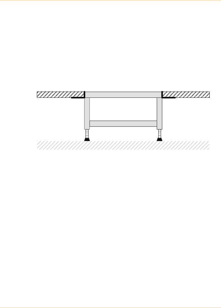
Planning a UPS Installation - Installing the UPS
216 The UPS Handbook
Raised Floors
If the UPS is to be located in the computer room then more often than not the
floor is raised off the sub-floor to permit containment and access for computer
equipment network and power cabling, and also sometimes as a means to
provide under floor cooling. The raised floor therefore provides a convenient
method for gaining bottom access to the UPS for the input and output AC
cables, and the battery DC cables. However, UPS equipment can be very heavy,
particularly if the batteries are also to be located in the computer room either in
the UPS cabinet or in separate matching battery cabinets.
Figure 11.21: Raised Floor
To remove the potential stresses and single point loadings on the raised floor it is
normal practice to locate the UPS cabinet, and if applicable the battery
cabinet(s) on a steel stand that sits on the sub-floor within the floor void as
shown in Figure 11.21. The height of the stand is adjustable so that it can
accommodate any unevenness in the sub-floor and to ensure the top of the stand
is accurately in line with the top of the raised floor. The stand would normally be
provided with a rebate around the top periphery to support adjacent floor tiles
which may need to be cut back into position.
Transporting the System
Having chosen a suitable location for the UPS system it is vital to survey the
proposed site. If a specialist delivery contractor has been employed for the task
they will usually undertake a site access survey before attempting to deliver any
equipment.
Even if the location chosen for the installation could in fact accommodate an
additional three or four UPS, access to the area may prove problematic.
Steel Stand
Base Floor
Raised Floor

Planning a UPS Installation - Installing the UPS
The UPS Handbook 217
Check the access route:
• is the site easily accessible by road? Bear in mind the size of the
delivery vehicle and the equipment required to off-load the UPS.
• are all doorways large enough for the UPS equipment and any
transportation equipment to pass through?
• ensure the equipment can be moved along the entire route especially
around corners
• will the UPS need to be carried across soft or uneven surfaces?
• are there stairs between the off-loading point and the final location?
•if the equipment must be transported using a goods lift, check that the
lift has the required capacity
• ensure that site staff are aware the equipment is being delivered and
have made every effort to ensure that access along the route is
unhindered on the day of delivery.
Electrical Installation
Installation Contractors
Electrically installing a UPS or protected power system is a specialised task and
should only be performed by a qualified and experienced electrical contractor.
The supplier of the UPS equipment should be able to undertake the installation
work or supply a list of suitable contractors who can provide references of
previous installations.
Take the time to:
• check the credentials of the staff who will be installing the equipment
• contact and investigate previous installations and discuss their work
with the staff on the other sites.
It is important to ensure that the installation is carried out in strict accordance
with the supplier’s instructions and that it complies with local and national
electrical installation regulations.

Planning a UPS Installation - Installing the UPS
218 The UPS Handbook
Installation Design
Small and medium sized UPS equipment will probably require very little
installation work and minimal changes to the existing electrical wiring.
However, if larger, high-power UPS equipment is being installed then careful
consideration of the switchgear and cabling arrangements must be made.
Considerable time and therefore cost savings can be made by carefully planning
the electrical installation to allow for possible business growth and the addition
of extra UPS modules.
Using an integrated switchgear and busbar solution, such as that shown in
Figure 7.21 on page 109, makes the installation process for a modern parallel
free-standing UPS system much simpler by:
•providing a single point of entry for the incoming mains supply
• a single point of entry for the bypass mains supply
• a fully interlocked maintenance (or wrap-around) bypass circuit
• correctly sized busbars and circuit breakers
• co-ordinated protection for the load and UPS equipment
• straightforward connection of load distribution panels.
Connecting the Critical Loads
In order to make best use of the UPS equipment and to ensure maximum
protection of the critical load it is important to consider carefully how best to
connect the load components.
Large ring circuits feeding many critical load devices are unsuitable as a fault on
one device may cause the circuit feeding it to trip and consequently disconnect
power to other pieces of important equipment.
Radial wiring with individual devices protected by their own circuit breakers is
a far better approach – in this way a fault in one device will cause that device
only to be disconnected and the remaining critical load elements will remain
undisturbed.
To ensure satisfactory downstream discrimination for static UPS systems, it is
generally recommended that sub-circuit protective devices are sized according
to local regulations, as advised by an electrical contractor.
To avoid confusion, particular attention must be paid to the labelling of circuit
breakers and fuses in the load distribution panels.

Planning a UPS Installation - Installing the UPS
The UPS Handbook 219
A selection of sample installation schematics is included in "Installation
Drawings" on page 229.
External Maintenance Bypass Switch
Whether it is a single free-standing UPS or a multiple parallel UPS system it is
good practice to allow for a separate external maintenance bypass switch
(sometimes referred to as a “wrap-around” bypass switch). Most modern UPS
incorporate an internal maintenance bypass switch which permits the electrical
isolation of the UPS components for maintenance or repair (see page page 32
which illustrates the arrangement). However, it is desirable to allow the UPS to
not only be electrically isolated but also physically isolated for the swap-out or
move without disrupting the load. A suitably designed external maintenance
bypass switch, as shown in the following figures, will facilitate this requirement.
Figure 11.22 and Figure 11.23 show examples of typical “single input” and
“dual input” 3 phase external maintenance bypass switches
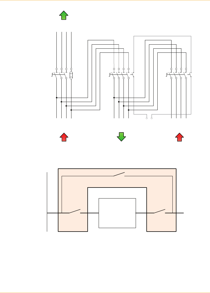
Planning a UPS Installation - Installing the UPS
220 The UPS Handbook
Figure 11.22: Single Input 3 Phase In/Out External
Maintenance Bypass Switch
UPS
Mains Supply
SW1
SW3
SW2 Load
O/PI/P
L1
L2
L3
N
L1
L2
L3
N
L1
L2
L3
N
L1
L2
L3
N
L1
L2
L1
L2
L3
N
L3
N
SUPPLY TO
UPS INPUT
MAINS INPUT
TO UPS
OUTPUT
TO LOAD
UPS
STATIC BYPASS
INTERLOCK
OUTPUT
FROM UPS
SW3 SW2SW1
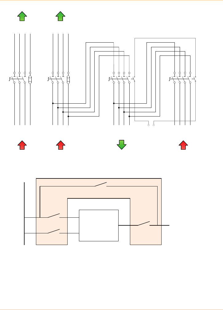
Planning a UPS Installation - Installing the UPS
The UPS Handbook 221
Figure 11.23: Dual Input 3 Phase In/Out External
Maintenance Bypass Switch
UPS
Mains Supply
SW1
SW2
SW4
SW3
Bypass
Rectifier
Load
O/P
L1
L2
L3
N
L1
L2
L3
N
L1
L2
L3
N
L1
L2
L3
N
L1
L2
L1
L2
L3
N
L3
N
L1
L2
L1
L2
L3
N
L3
N
SUPPLY TO
UPS RECTIFIER
SUPPLY TO
UPS BYPASS
MAINS INPUT TO
UPS BYPASS
MAINS INPUT TO
UPS RECTIFIER
OUTPUT
TO LOAD
UPS
STATIC BYPASS
INTERLOCK
OUTPUT
FROM UPS
SW4 SW3SW2SW1
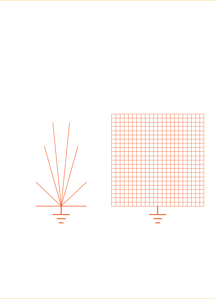
Planning a UPS Installation - Installing the UPS
222 The UPS Handbook
Earthing
In any electrical installation correct earthing is essential for personnel safety and
equipment protection. A protected power installation is no exception, it is
essential to ensure that all earthing points within the system are connected to a
properly planned and secure earthing system.
As a minimum a properly planned and secure earthing system for a computer
and UPS installation must provide:
• protection against electrical shock
• a short, low impedance return path for fault currents
• a path for induced currents caused by high voltages such as lightning
• straightforward connection facilities for future expansion.
Most earthing installations are based on star or grid configurations.
Figure 11.24: Basic Earthing Configurations
In the star system the earth conductor from the incoming mains supply is
brought to a central point and radial earth conductors are distributed to each item
of equipment whereas in the grid arrangement, the earth from the incoming
mains supply is connected to a grid or ‘mat’ of earth conductors which is
installed to cover the entire installation area.
Star Grid

Planning a UPS Installation - Installing the UPS
The UPS Handbook 223
Individual items of equipment may then be connected to the grid with very short
conductors. The grid system is more difficult to install, although computer
rooms with raised floors have made it easier, but it does offer advantages:
• the whole grid is at near earth potential
• the grid offers very low impedance to all frequencies
• equipment connection to the grid is simple.
However, the star system is much easier to install and is therefore the most
common system in use.
Commissioning
Proper commissioning of UPS equipment by the supplier’s trained and
experienced personnel is essential. The small additional cost incurred is
outweighed by the benefits of:
• complete check of system facilities and options
• complete warranty cover on all UPS equipment
• registration of equipment serial numbers with the supplier
• acceptance of environmental conditions
• the user being trained in the operation of the UPS.
A sample of a typical commissioning method statement is given on the
following pages.

Planning a UPS Installation - Installing the UPS
224 The UPS Handbook
Sample Commissioning Method Statement
General Instructions
If any corrective measures are required to commission the UPS they shall be
carried out under warranty and costs will be borne by the supplier and/or the
manufacturer of the UPS. If any corrective measures are needed as a result of
shipping or installation damage they shall be made only after liability for the
damage is clearly established.
Customer Information
Record customer name and other customer details on the Field Service Report.
Unit Information
Take unit type and serial number details from type plate located inside the door or at
the rear of unit and record on FSR.
Equipment Inspection
Check unit and options for damage both externally and internally. If any damage is
found record the nature of the damage on the FSR and advise the customer.
Installed Options
Identify what options the customer has also purchased with the system and note on
FSR.
Installation Checks
Common items
Check and tighten all external connections to UPS, battery and load.
Check phase rotation of ac and polarity of dc connections.
Check all protective earth connections for proper installation and cable area.
Check installation of service switch if fitted.
Rectifier/Converter, Bypass Line, Load
Check that cable area and fuses are correct according to installation manual.
Check that distribution fuses and cable area for distribution cables are correct
according to connected loads.
Note cable areas and fuse ratings in commissioning report.
Computer Interface/Options
Check that installation and connections of all options are made according to the
installation manual and customer requirements.

Planning a UPS Installation - Installing the UPS
The UPS Handbook 225
UPS Power Up
The following activities will be performed with live voltage at the UPS input
and output terminals. Ensure all company Health & Safety procedures and
guidelines are fully complied with at all times.
Line Voltage Rect/Conv
Connect line voltage to UPS Rect/Conv line and measure voltage.
Line Voltage Bypass
Connect line voltage UPS Bypass line and measure voltage.
Unit Started
Perform normal unit start up and check that unit is operating normally.
Output Voltage/Frequency
Measure output voltage and check output voltage waveform and frequency.
SYSTEM TEST
The following activities will be performed with live voltage at the UPS input
and output terminals. Ensure all company Health & Safety procedures and
guidelines are fully complied with at all times.
Front panel display and switches
Check that all LED's illuminate:
Check the MECHANICAL BYPASS switch. Transfer the load from the inverter via
the static switch to the mechanical bypass switch. Check with an oscilloscope the
UPS output voltage and check that the transfer is break-free.
Computer Interface
Test for the correct operation of the following alarms (if fitted):
- BATTERY LOW
- LINE FAILURE
- UPS BYPASSED
- UPS ALARM
Line Failure/Synchronisation Test
Look at the inverter output voltage and line voltage with an oscilloscope. Switch the
bypass line input off and then back on. Check that the inverter synchronises with the
bypass line after 10 sec. and that the phase angle is nominally zero degrees.
Starting Up and Shutting Down
Start up and shut down the UPS by following the start up and shut down procedures
as described in the User's manual.

Planning a UPS Installation - Installing the UPS
226 The UPS Handbook
Function of Installed Options
Test the function of each of the options installed.
UPS Failure Test
Check that UPS transfers the load to the bypass line, when simulating trip of internal
UPS fault. This test is only to be performed if there is no live customer load and the
test can safely be performed on the UPS.
UPS Overload
Check (if possible) that UPS transfers the load to the bypass line, when the load is
>100%.
Operator Training
During the Operator Training sessions make sure that the operators are
acquainted with the user's manual and use it as the training material.
Operating Principles
Explain the operating principles of the UPS in general terms and in the UPS model
specific terms. Explain also the function of all installed options.
- Normal operation
- Mains failure
- Overload
- Bypass switch (Static and Internal).
Safety Information
Review safety information as given in the user's manual and ensure that it is clearly
understood.
Indications and Alarms
Review function and meaning of all indications and alarms.
Review function of computer interface and actions that shall be taken in the event of
a mains failure.
Start and Stop Procedure
Review and let operators perform UPS start up and shut down procedures for the
UPS by following the instructions in the User's manual.
Fault Diagnosis
Review the fault diagnosis activities based on the fault indications from the front
panel as described in the User's manual.
Responsible for Operation and Maintenance
Check the name, title and telephone number of a person(s) responsible for the
operation and/or maintenance of UPS and note in report.

Planning a UPS Installation - Installing the UPS
The UPS Handbook 227
Micro and Mini UPS (250VA - 2kVA)
In general the Micro and Mini sized UPS are supplied fitted with standard mains
plugs and will not require specialist commissioning. In most cases these UPS
are portable and are supplied ‘ready-to-go’ and simply require unpacking and
connecting to the mains supply and the load. However, some suppliers will offer
to deliver and install the equipment and spend some time explaining the
operation of the system.
The output connectors on these small UPS are usually standard IEC sockets, so
it is important to ensure that suitable cables for connection of the load
equipment are available. See "Desktop Systems" on page 15.
Medium UPS (3-20kVA)
Medium sized UPS are designed to support complete office networks or
communications centres. They are not usually portable and are connected to the
mains supply by fixed wiring.
Some medium sized UPS (small single-phase units up to typically 6kVA) are
connected to the mains supply using standard plug and socket arrangements and
are put into service in the same way as the Micro and Mini systems.
Larger power ratings will require connection with fixed wiring and should only
be commissioned by the supplier’s trained and experienced personnel.
Large UPS (30-400kVA and above)
Large UPS equipment will be electrically installed with fixed cabling and
dedicated input and output switchgear and must be commissioned by the
supplier’s trained and experienced personnel.
Notes
Record all relevant site/ unit comments in the notes section of the report and
discuss each note with the customer.
Signatures
Sign and ensure that the customer signs the FSR and the commissioning report.
Give the customer a copy of both reports.

Planning a UPS Installation - Installing the UPS
228 The UPS Handbook
Load Bank Testing
To validate the correct operational performance, and the battery autonomy of the
UPS system on-site and under full load conditions, a dummy load bank is
sometimes utilised. This facility is normally only required on large UPS since
the cost of the provision of a load bank and the engineer's costs become
disproportional to the equipment cost for small and medium size UPS.
The load bank is normally resistive (unity power factor) and comprises heating
elements and fans for cooling. Reactive load banks are also available (typically
0.8 lagging power factor) but tend to be much larger and heavier due to the
wound inductive components. The load bank should be supplied with suitably
rated cables, which allow it to be placed approximately 20 metres from the UPS
terminals or output PDU. Allowance should be made to ensure the heat from the
load bank can be safely dissipated and it should not be located in the vicinity of
sensitive fire alarm and sprinkler systems.
If the load bank is being used to verify the specified battery autonomy it is good
practice to only undertake the tests at least one week after the UPS has been
commissioned to permit the voltage across the battery blocks to equalise and for
the battery to be fully charged. For this reason UPS manufacturers do not
normally include load bank testing as part of the standard commissioning
procedures.
Three Phase UPS Supporting Single Phase Loads
On some occasions it is advantageous to support various single phase loads
across the output phases of a 3-phase UPS. Whilst not essential, it is desirable to
arrange the single phase loads so that the loading on each of the UPS output
phases is equal, or at least close to being equal. This is particularly important to
avoid an unbalanced 3-phase load being presented to a closely rated standby
generator if, or when, the UPS switches to its bypass mode.
It is permissible to have single phase loads, when being supplied by different
phases, in the same vicinity providing Regulation 514-10-01 of BS7671 is
enforced. This regulation generally states that:
“Every item of equipment or enclosure within which a nominal voltage
exceeding 230 volts to earth exists and where the presence of such a voltage
would not normally be expected, shall be so arranged that before access is
gained to a live part, a warning of the maximum voltage present is visible.”

Planning a UPS Installation - Installing the UPS
The UPS Handbook 229
Installation Drawings
The following pages show some typical UPS installation drawings similar to
those which your UPS supplier should be able to provide pre-installation.
The drawings are shown as examples only and should not be used as references
for a particular installation and any cable sizes shown are the minimum
recommended.
Unless the UPS supplier is contracted to electrically install the UPS,
its correct installation will be the sole responsibility of the electrical
contractor.
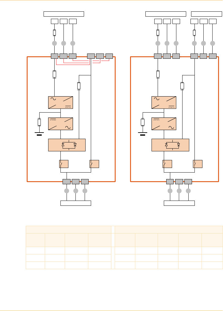
Planning a UPS Installation - Installing the UPS
230 The UPS Handbook
Figure 11.25: Typical 7.5-20kVA Single Phase In/Out UPS
SINGLE INPUT FEED DUAL INPUT FEED
Power
(kVA)
Fuse A
(A)
Cable A
(mm2)
Cable D
(mm2)
Fuse B
(A)
Cable B
(mm2)
Fuse C
(A)
Cable C
(mm2)
Cable D
(A)
7.5 1 x 40 3 x 6 3 x 6 1 x 40 3 x 6 1 x 40 3 x 6 3 x 6
10 1 x 63 3 x 10 3 x 10 1 x 63 3 x 10 1 x 63 3 x 10 3 x 10
12 1 x 63 3 x 10 3 x 10 1 x 63 3 x 10 1 x 80 3 x 16 3 x 16
FuseA
FA1
FA2
FA3
Output
Switch
INPUTMAINSSUPPLY
PENL1
OUTPUTSUPPLY
2L1IL1 1N PE 2N PE
D
A A A
Inputandbypassterminals
internallylinkedforsingle
inputsupply
IA2
Battery
Fuse
Input
Fuse
Rectifier
Bypass
Fuse
Inverter
Static
Switch
3L1 3N PE
DD
Maint .
Bypass
Switch
FuseB
FA1
FA2
FA3
Output
Switch
INPUTMAINSSUPPLY
PENL1
OUTPUTSUPPLY
IL1 1N PE
D
B B B
IA2 IA1
Battery
Fuse
Input
Fuse
Rectifier
Bypass
Fuse
Inverter
Static
Switch
3L1 3N PE
DD
Maint .
Bypass
Switch
FuseC
BYPASSSUPPLY
PENL1
CCC
2L1 2N PE
IA1
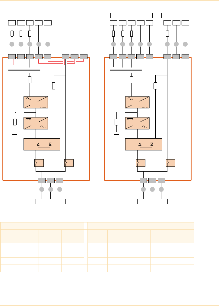
Planning a UPS Installation - Installing the UPS
The UPS Handbook 231
Figure 11.26: Typical 7.5-20kVA Three Phase In / Single Phase Out UPS
SINGLE INPUT FEED DUAL INPUT FEED
Power
(kVA)
Fuse A
(A)
Cable A
(mm2)
Cable D
(mm2)
Fuse B
(A)
Cable B
(mm2)
Fuse C
(A)
Cable C
(mm2)
Cable D
(A)
7.5 3 x 40 5 x 6 3 x 6 3 x 25 5 x 2.5 1 x 40 3 x 6 3 x 6
10 3 x 63 5 x 10 3 x 10 3 x 25 5 x 2.5 1 x 63 3 x 10 3 x 10
15 3 x 80 5 x 16 3 x 16 3 x 40 5 x 6.0 1 x 80 3 x 16 3 x 16
20 3 x 100 5 x 25 3 x 25 3 x 40 5 x 6.0 1 x 100 3 x 25 3 x 25
FA1
FA2
FA3
Output
Switch
INPUTMAINSSUPPLY
PENL3
OUTPUTSUPPLY
2L1 2N PE
D
Inputandbypassterminals
inter nally linkedforsingle
inputsupply
IA2
Battery
Fuse
Input
Fuse
Rectifier
Bypass
Fuse
Inverter
Static
Switch
3L1 3N PE
DD
Maint .
Bypass
Switch
FA2
FA3
Output
Switch
OUTPUTSUPPLY
D
IA2 IA1
Battery
Fuse
Rectifier
Bypass
Fuse
Inverter
Static
Switch
3L1 3N PE
DD
Maint .
Bypass
Switch
FuseC
BYPASSSUPPLY
PENL1
C C C
2L1 2N PE
L2
FuseA
L1
1N PEIL2IL1 IL3
A AA AA
IA1
FA1
INPUTMAINSSUPPLY
PENL3
Input
Fuse
L2
FuseB
L1
1N PEIL2IL1 IL3
B BB BB
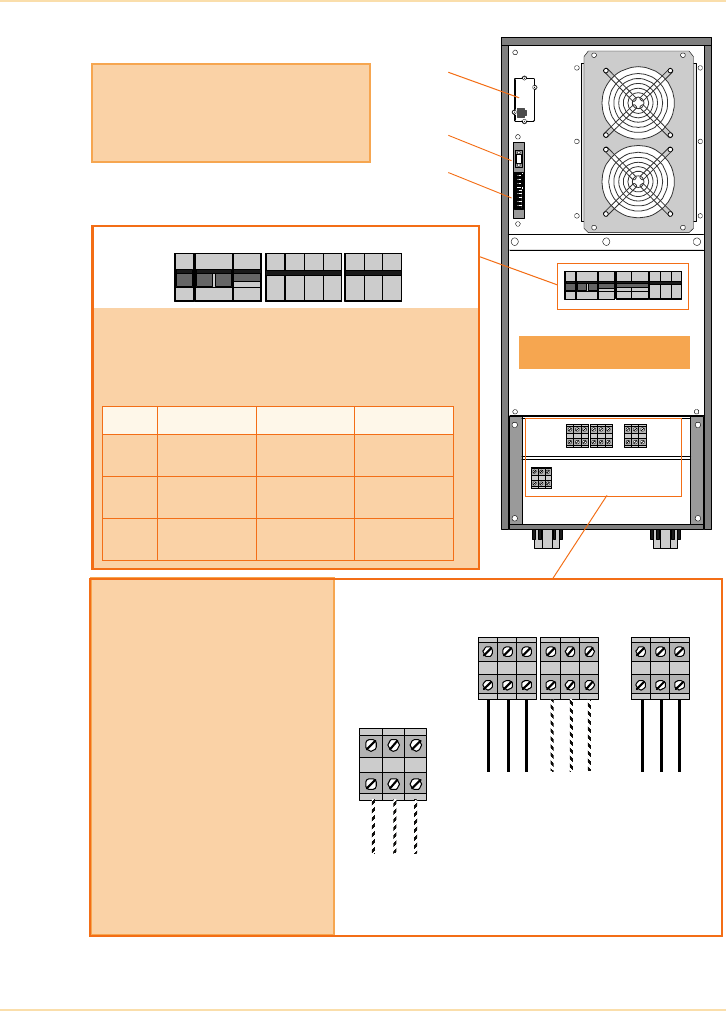
Planning a UPS Installation - Installing the UPS
232 The UPS Handbook
Figure 11.27: Typical 7.5-12kVA Single Phase Input Terminal Block
IA1 – Maintenance Bypass Switch
IA2 – Output Switch
FA2 – Bypass Supply Line Fuse
FA1 – Input Supply line Fuse
FA3 – Battery Fuse
FA1 (A) FA2 (A) FA3 (A)
7.5 50A (14x51)
Ultrafast
50A (14x51)
GL/GC
32A (10x38)
Ultrafast
10 50A (14x51)
Ultrafast
50A (14x51)
GL/GC
32A (10x38)
Ultrafast
15 50A (14x51)
Ultrafast
80A (22x58)
GL/GC
32A (14x51)
Ultrafast
Input/Output Power Connections
* In a ‘single feed’ (standard)
installation terminals 2L1 and 1L1 are
linked by cables fitted to the UPS side
of the terminal blocks.
Terminals 2N and 1N are similarly
linked.
When using a ‘dual feed’ supply these
links should be removed and the
bypass supply cable connected as
shown in this diagram.
** The UPS internal battery is normally
connected to the battery isolator
switch (FA3). If an external battery
cabinet option is used, the internal
batteries are disconnected and the
external battery cabinet is connected
to the terminals shown in this diagram.
3L1
3N
PE
PE
PE
2L1
2N
1N
1L1
+–N
MainsBypass
Supply
(*dual feed
Output
to Load
only)
Supply
External Battery
(**option)
IA1 IA2 FA2 FA1 FA3
Cabinet Rear View
SNMP
JD1
X1-X21
Customer Interface Connections
JD1 – Smart Port RS232 (Sub-D9P/F).
X1-X21 – Dry Port volt-free contacts on
terminal block.
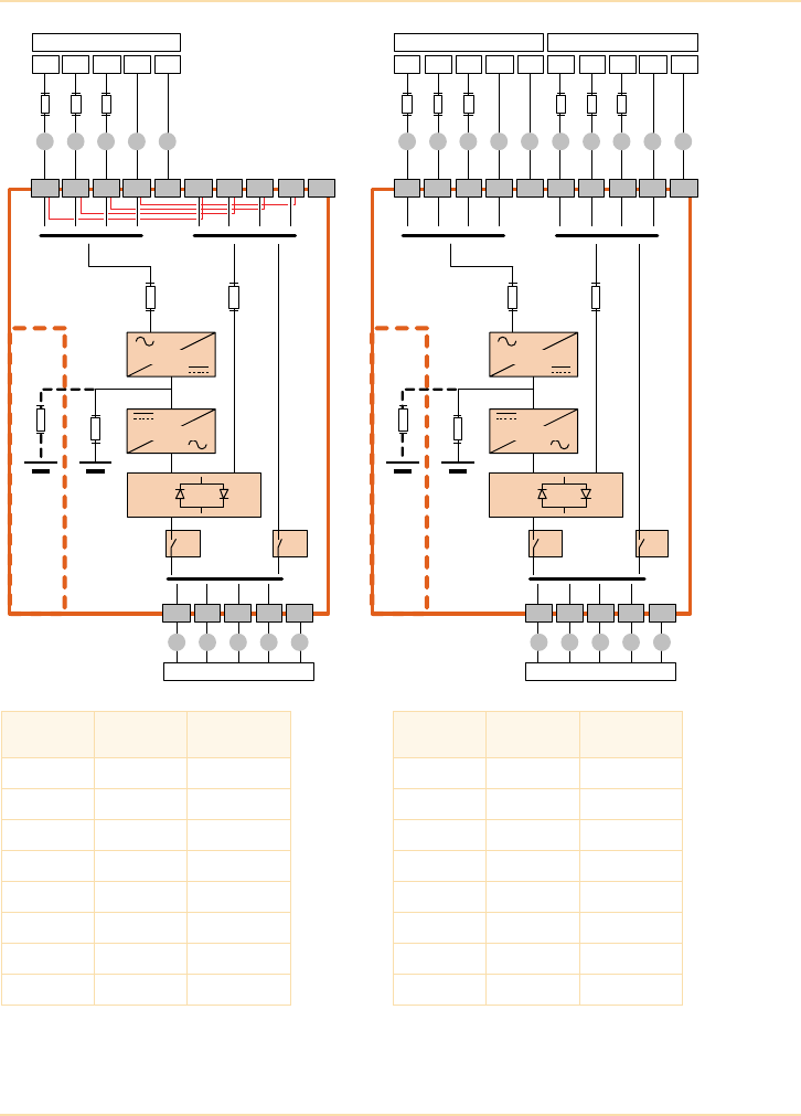
Planning a UPS Installation - Installing the UPS
The UPS Handbook 233
Note: External battery cables and fuses are bespoke to the installation
Figure 11.28: Typical Three-Phase Input/Output UPS
Power
(kVA)
Fuse A,B,C
(A)
Cable A,B,C,D
(mm2)
UPS Power
(kVA)
Fuse A,B,C
(A)
Cable A,B,C,D
(mm2)
10 3x 20 5 x 2.5 120 3 x 200 5x 70
15 3x 25 5 x 4 160 3 x 250 5x 120
20 3x 40 5 x 6 200 3 x 350 5x 185
30 3x 63 5 x 10 250 3 x 400 5x 240
40 3x 80 5 x 25 300 3 x 500 5x (2x120)
60 3x 100 5 x 35 400 3 x 630 5x(3x95)
80 3x 125 5 x 50 400 3 x 630 5x (2x185)
100 3x 160 5 x 50 500 3 x 800 5x (3x 150)
FA2FA1
FA3
Output
Switch
INPUTMAINSSUPPLY
Inputandby passterminals
internallylinkedforsingle
inputfeed
IA2
Battery
Fuse
Input
Fuse
Rectifier
Bypass
Fuse
Inverter
Static
Switch
Maint .
Bypass
Switch
OUTPUTSUPPLY
D
Fu se A
L1
IL1
A
IA1
L2
IL2
A
L3
IL3
A
N
IN
A
PE
PE
A
2L1 2L2 2L3 2N PE
3L1 3L2 3L3 3N PE
D D D D
EXTERNALBATTERY
CABINET(Option)
FA2FA1
FA3
Output
Switch
INPUTMAINSSUPPLY
IA2
Battery
Fuse
Input
Fuse
Rectifier
Bypass
Fuse
Inverter
Static
Switch
Maint .
Bypass
Switch
OUTPUTSUPPLY
D
FuseB
L1
IL1
B
IA1
L2
IL2
B
L3
IL3
B
N
IN
B
PE
PE
B
2L1 2L2 2L3 2N PE
L1 L2 L3 NPE
BYPASSMAINSSUPPLY
3L1 3L2 3L3 3N PE
D D D D
EXTERNALBATTERY
CABINET(Option)
CCCCA
FuseC
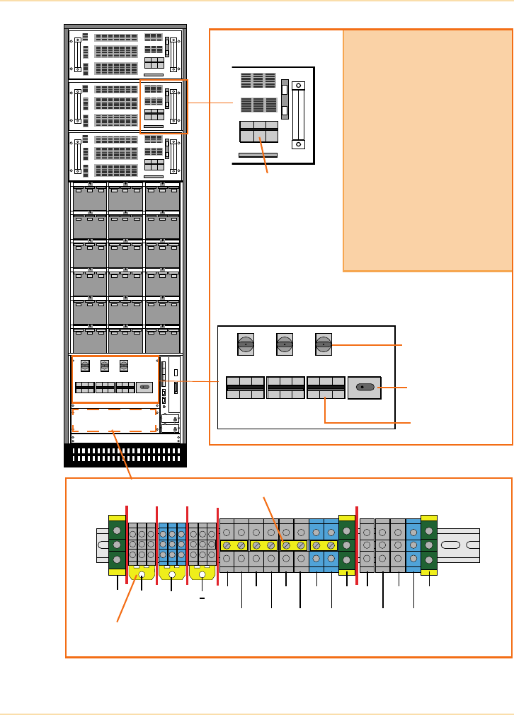
Planning a UPS Installation - Installing the UPS
234 The UPS Handbook
Figure 11.29: Typical 3 phase Input/Output UPS Terminal Block
PE
External Batt.
1L1
N
+
2L1 2L2 2L3 2N 3L2 3N
1L2 1L3 1N PE 3L1 3L3 PE
Common battery links shown fitted
remove these links when using
3 x individual battery strings.
Remove links for dual input feed
UPS Power Module
A bypass supply fused isolator (F2)
is fitted to each UPS Power
Module. The input supply fuses are
fitted within the power module.
On the main switch panel a
separate output isolator is provided
for each UPS Power Module (IA2),
together with a separate battery
isolator (F4/5/6).
A single Maintenance Bypass
switch (IA1) is also fitted on the
main switch panel
F2 (Bypass
(IA1) Maintenance
Bypass Switch
(IA2) UPS Power
Module Output
Isolator
(F4/5/6) Battery
Isolator Fuses
Supply Fuse)
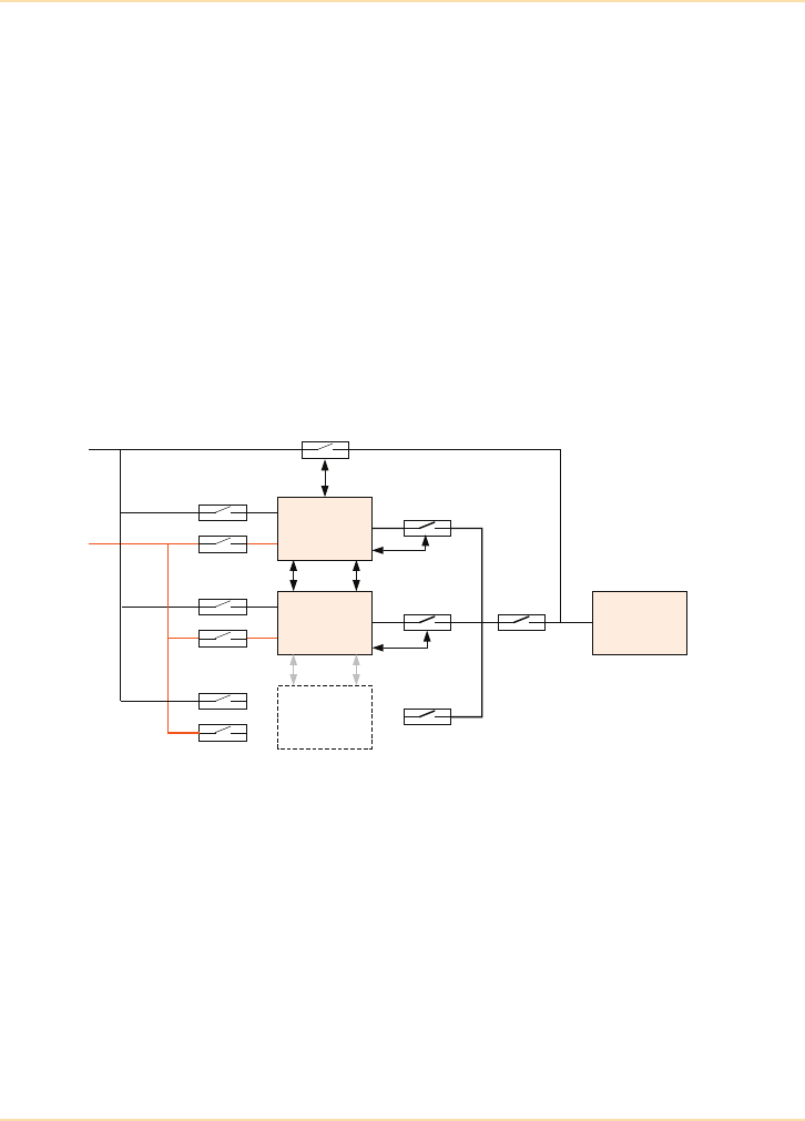
Planning a UPS Installation - Installing the UPS
The UPS Handbook 235
Parallel Systems
Free-standing, parallel, three-phase input/output UPS modules are installed in
much the same way as a single free-standing module shown in Figure 11.25 -
Figure 11.29 except that they also require some inter-module control cabling
and, of course, paralleling switchgear.
In an N+1 parallel UPS system the cabling and protection for each module is the
same as that used for single modules. However, the size of ‘wrap-around’
bypass cabling and the main output isolator will be dictated by the total capacity
of the UPS system. When installing a parallel system consider the future and
ensure that these items are sized accordingly.
Figure 11.30 shows a sample parallel system schematic.
Figure 11.30: Sample Parallel UPS System Schematic
with Spare Way Provided for Future Expansion (UPS 3)
Rack format modular UPS modules lend themselves to paralleling much more
readily since the inter-module control cabling and the paralleling switchgear is
contained within the rack cabinet and requires only the insertion of the UPS
module to facilitate communication and parallel connections.
UPS 1
UPS 2
UPS 3
Critical Load
Maintenance
bypass
Bypass
input
Rectifier
input
Logic
Interlock
Interlock
Input isolators Output isolators
Main output
isolator
Interlock
(Possible Interlock)

Planning a UPS Installation - Using and Maintaining the UPS
236 The UPS Handbook
Using and Maintaining the UPS
Responsibilities
Once the UPS is installed (and commissioned, if appropriate) it is important to
ensure that someone is made responsible for the UPS and its associated
equipment. This need not be an electrical technician, but should be someone
who is invariably on-site and easily contactable and is typically the IT manager
or facilities manager.
Establishing a central contact responsible for protected power provision is
essential to ensure that:
•the UPS is kept in optimum condition
•the UPS or plant room is kept clean, dry, tidy and well lit
• alarms and indications are recorded, logged and reported correctly
• the UPS is correctly maintained
• someone on site knows where the UPS is located.
For small UPS systems, access to the UPS user manual and the phone number of
the UPS supplier is all that is typically required. However, for medium and large
UPS systems that require routine maintenance, a higher degree of user system
awareness is required.
Service and Maintenance
Typically medium sized UPS systems are covered by a service and maintenance
contract and this should be considered essential for large systems.
Information regarding the correct care of UPS systems and detail regarding
service and maintenance contracts is given in Chapter 12.
UPS equipment should only be operated by trained and experienced personnel
as high voltages are present within the UPS cabinets. Also the company
maintaining the UPS equipment should be able to confirm that their service
personnel are fully trained by the manufacturer and that they have full and
unrestricted access to spare parts.

Planning a UPS Installation - Summary
The UPS Handbook 237
Summary
This section has discussed, in some detail, the steps required to achieve a
successful UPS installation.
The correct selection, delivery and positioning, electrical installation,
commissioning and maintenance of a UPS system may not be straightforward.
There are a large number of diverse skills required to complete all aspects of the
installation successfully and within the available budget. The UPS end user may
choose to handle all aspects of the installation or they may appoint a consultant
or experienced electrical contractor to act for them. Alternatively, there are some
UPS suppliers who can offer ‘turnkey’ solutions and the end user may want the
security of knowing that the original specifier, supplier and installer will be
responsible for the continued operation of the UPS system.

238 The UPS Handbook

The UPS Handbook 239
12 System
Maintenance
Introduction
All UPS and associated system components need periodic maintenance and
occasional replacement of parts in order to ensure optimum reliability.
Most UPS equipment suppliers will offer service contracts to ensure the
equipment is kept in optimum condition throughout its useful life.
While the contract details will differ between suppliers, certain items must be
included in order to ensure the continued power protection of the critical load
and applications:
• emergency call-out facilities with defined response times
• maintenance and testing regimes
• end-of-life component replacement.
Critical loads and applications require power protection equipment which in
turn requires regular maintenance.

System Maintenance - Emergency Call-out Facilities
240 The UPS Handbook
Emergency Call-out Facilities
A failure is the inability of an item of equipment to perform its designed
function and is caused by internal or environmental faults.
Note: Faults usually cause a degradation of the system but do not always cause
a system failure.
Unfortunately, no matter how reliable equipment is, at some point it will
probably experience failure or malfunction.
The Sample Service Agreement (on page 251) shows a typical contract.
However, it is not complete as it does not address specific items such as which
equipment is covered, engineer’s response time, spares availability etc. These
would normally be included in a ‘schedule’ which forms part of the contract.
The content of the schedule is site or equipment specific.
The Schedule
When arranging a service agreement careful consideration should be given to
the needs of the critical application and site, to ensure that the combined
Agreement and Schedule closely match those requirements.
The following items should be specified in the Schedule:
• details of the emergency call-out procedure
- contact details - phone, fax, email etc.
- is an engineer available 24 hours per day, 7 days per week?
- what is the response time? and how is it defined?
- can I speak to an engineer at any time?
• details of any automatic facilities
- can the UPS equipment automatically call for emergency response?
• information regarding spares availability
- does the engineer carry full spares?
- are spares required to be held on-site?
• details of emergency call escalation procedures
• details of end-of-life replacement policy.

System Maintenance - Maintenance and Testing
The UPS Handbook 241
Maintenance and Testing
Each UPS, battery and generator supplier will have its own Planned
Maintenance (PM) programmes which will typically include the following:
UPS
• inspect site log for incidents since previous PM visit
• check and record equipment meter readings and verify accuracy
• check that meters and instrumentation operate correctly
• verify the correct status indications for the local and remote
monitoring panels and communication facilities
• check that all indication lamps are operational
• check that all switchgear operates correctly
• check the air flow in and around the equipment
• replace the air filters if fitted
• remove any material and obstructions from around the equipment
• check the environment for abnormal conditions
• check for excessive heat, noise and vibration
• visually inspect all components for signs of damage
• visually inspect power and control wiring
• check for loose connections
• inspect the ac and dc capacitors for swelling and leakage
• check the power supply voltages and the power waveforms
• check the operation of the circuit breakers and associated trips and/or
undervoltage releases
• check the overall operation of the UPS
• maintain the site log with written service reports.
Additional checks and testing will be required if a parallel UPS system is
installed.

System Maintenance - Maintenance and Testing
242 The UPS Handbook
Battery Testing and Maintenance
Traditional battery testing and maintenance consists of:
• checking and recording the open-circuit battery voltage
• verifying that the UPS float voltage is correct
• inspecting all battery terminals and connections for corrosion
• inspecting all batteries for cracks, leaks or swelling
• tightening the intercell connections to manufacturer's specifications
• removing any materials and cleaning around the equipment.
However, in recent years the technology of standby batteries has changed
dramatically and despite the designer’s desire to reduce maintenance it is now
more essential and more sophisticated than ever.
In the 1970s the vast majority of standby systems used flooded lead-acid
batteries. This type of battery had been in use for many decades and the methods
of monitoring and maintenance were well understood. Measurements of the
voltage and the specific gravity of the electrolyte were used to determine the
state of charge. Visual inspection of the plates and internal parts was made
through the glass jar containers. Both the maintenance and the design were
fairly low level technology in comparison with the equipment supported.
The 1980s saw dramatic changes with the introduction of the so called
‘maintenance free’ batteries which, by the end of the 1980s, had captured
probably 90% of the market. However, it soon became apparent that the
batteries were neither sealed nor maintenance free and the current description of
Valve Regulated Lead Acid (VRLA) was introduced.
Most battery maintenance companies continued to treat the batteries in the
traditional manner. However, it was no longer possible to measure the specific
gravity or to visually inspect, as the battery cases were no longer transparent.
Unfortunately the voltage available at the terminals is no indication of true
battery condition. Many battery systems failed both prematurely and without
warning, leading to a serious loss of confidence in the VRLA product generally.
The 1990s saw these problems answered by new test methods that provide
substitute parameters for those which can no longer be measured. The most
significant of these parameters is battery impedance testing.

System Maintenance - Maintenance and Testing
The UPS Handbook 243
Battery Impedance Testing
Batteries start life with a fairly low internal impedance (measured in milli-
ohms). The actual impedance varies between types of battery - for example: A
12 volt battery will have a far higher impedance than a two volt block as the 12
volt block comprises six cells in series, with generally a much smaller plate area.
Generally, differences between high quality batteries of the same type and from
the same manufacturer are small.
As a battery ages its impedance increases marginally due to normal internal
corrosion. This occurs at a similar rate amongst batteries in a string, which is the
most common configuration for standby applications (a parallel battery is
simply a combination of strings – See "Energy Storage Devices" on page 115).
Any battery that shows a deviation from the others in the string would be
suspect. Similarly, should the impedance of a number, or all, of the batteries in
the string rise at a faster rate than would normally be anticipated, the condition
of the batteries must be assumed to be abnormal.
Almost any battery problem leads to a rise in internal impedance. A common
problem is loss of electrolyte due to venting through overcharging, leakage
through seals, or in some designs migration of electrolyte between cells.
Another is excessive corrosion of the ‘gridbars’ to which the plates are
connected which reduces the area of metal and in extreme cases causes the
plates to disconnect from the bar. To find the actual cause of the high
impedance, faulty batteries may be dissected and analysed in a laboratory.
Battery impedance is relatively easy to measure. An ac current of a suitable
level relative to the Ah rating is passed through the battery. The resulting ac
millivolt reading generated between the battery terminals is recorded and used
to calculate the internal impedance.
The advantage of this method is that, unlike load testing, they do not leave the
battery discharged, and if regularly conducted, they track the battery condition,
allowing an accurate prediction regarding the end of reliable operating life.
Results can be computer generated to provide clear reports of the battery
condition (See Figure 12.1 and Figure 12.2).
Figure 12.1 shows a new battery where the float voltages are very similar and
the impedance levels for the individual batteries are also very consistent.
Figure 12.2 shows the same battery at the end of its useful life. Most of the float
voltages appear satisfactory but the impedance readings for blocks 8 and 9 are
particularly high - if load was applied to the battery their voltages would almost
certainly collapse. Block 19 has both higher impedance and a low voltage,
suggesting that one cell in the block is short circuit.
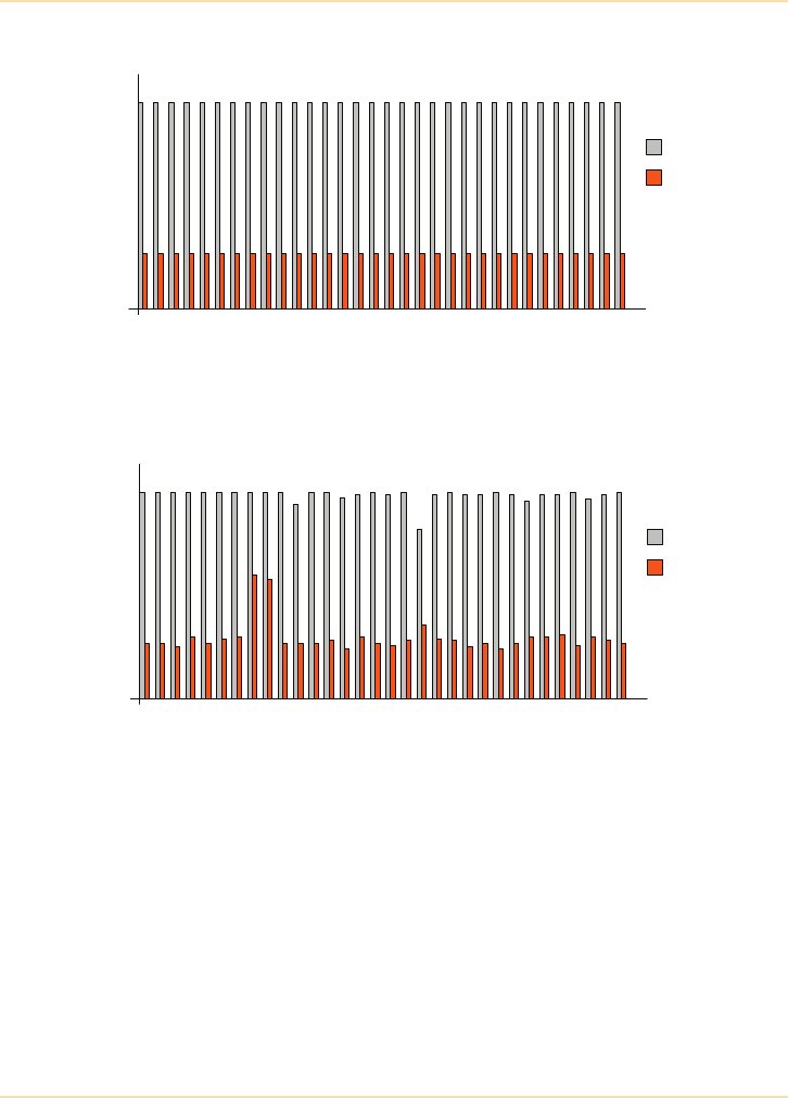
System Maintenance - Maintenance and Testing
244 The UPS Handbook
Figure 12.1: Impedance Graph for a New Battery
Figure 12.2: Impedance Graph for a Battery at the End of its Useful Life
The test results clearly show that simply measuring battery block float voltages
is not an accurate monitor of battery condition as the impedance test has clearly
identified three faulty blocks.
Impedance readings and computer generated reports, in conjunction with other
tried and tested methods such as load testing, can provide information which
gives a clear picture of battery condition. Clear and concise reports on battery
condition and life expectancy can be provided with maintenance costs very little
higher than traditional, less effective, procedures.
14
12
10
8
6
4
2
0
1 322 3 4 5 6 7 8 9 10 11 12 13 14 15 16 17 18 19 20 21 22 23 24 25 26 27 28 29 30 31
Battery block number
OC Volts (dc)
Impedance
(milliohms)
14
12
10
8
6
4
2
0
1 322 3 4 5 6 7 8 9 10 11 12 13 14 15 16 17 18 19 20 21 22 23 24 25 26 27 28 29 30 31
Battery block number
OC Volts (dc)
Impedance
(milliohms)

System Maintenance - Maintenance and Testing
The UPS Handbook 245
Fixed Battery Monitoring
Fixed battery monitoring systems can be permanently fitted to a battery
installation. This is normally done at the time of new battery installation but can
be fitted at any time. This type of battery monitoring system allows the
continuous monitoring of battery voltages, current, temperature and impedance;
and can detect differences between individual battery blocks during any
discharge/charge cycles.
The relatively high cost of fixed battery monitoring systems makes them only
suitable for use in large battery installations or installations that are highly
critical where other forms of battery testing and monitoring are considered
insufficient.
Advanced products such as the patented BACS 'Battery Analysis & Care
System' provides an Ethernet-network integrated battery monitoring and
management system. Using web-management technology, it checks the internal
resistance, the temperature and the voltage of every single accumulator
sequentially: a patented equalisation process then corrects the charging voltage
of each accumulator individually to keep each one in its optimal voltage
operating range.
The constant monitoring and controlling of the individual charging voltages for
each accumulator guarantees the availability of the battery at all times.
In addition, BACS can manage environmental measurements (temperature,
humidity, acid fill level, hydrogen gas concentration, etc.) and appliances (UPS,
inverters and other devices).
Load Bank Testing
Load bank tests are an important part of any battery maintenance programme
and should be used to determine the battery capacity. Load testing should be
used sparingly and in conjunction with impedance testing to assess a battery’s
condition.
Load banks, in a range of sizes and configurations are available for hire or rent
allowing a variety of tests to be conducted. For example, in addition to a full
load test, the UPS performance with step load changes or reactive loads may be
monitored. Most load banks are fitted with remote switching facilities allowing
A load test involves putting the critical load at risk so careful arrangements
and agreements must be made.

System Maintenance - Maintenance and Testing
246 The UPS Handbook
them to be controlled while they are temporarily sited at some distance from the
UPS under test (See "Load Bank Testing" on page 228).
Conducting a Test
In order to perform a full load test, it is usual to connect a system of load banks
to the output of the UPS system. This means you must either disconnect the
critical load or feed it from an alternative source. Choosing the latter option puts
an additional load on the incoming mains supply and you must check the supply
capacity and the fuse and protection settings of that source before proceeding.
During load testing, you may wish to include:
•thermographic testing, see "Thermographic Connection Testing" on
page 247
• full system testing, see "Complete System Testing" on page 250.

System Maintenance - Maintenance and Testing
The UPS Handbook 247
The Advantages of Load Bank Testing
Load testing proves the capacity of the battery at the time of the test and the
integrity of all of the interconnections. For this reason it is useful at specific
times, for instance one week after commissioning, to prove the battery will
support the specified load for the specified time.
A load test is also worthwhile at two-thirds of the expected useful life to confirm
predicted capacity. However, provided the condition of the battery is correctly
monitored and shows it to be healthy, there is no reason to expect that the battery
will not perform as required in an emergency and further load tests are therefore
unnecessary.
The Disadvantages of Load Bank Testing
Limited discharge/charge regimes were good for flooded cells and countered
stratification (electrolyte settling into layers of varying acidity and density), but
this does not apply to VRLA batteries.
Completely discharging the battery actually reduces its life and following a
discharge test the battery is unable to protect the load fully until it is recharged.
Under some circumstances the battery can recharge unevenly leading to serious
problems - such as the undercharging and overcharging of battery blocks within
the same string (See "Energy Storage Devices" on page 115).
Load banks can be large and expensive to purchase or hire, and to transport. A
suitable location has to be found for the load bank, whereas impedance testing
requires the use of handheld equipment and does not affect the ability of the
battery to perform when necessary.
Thermographic Connection Testing
Infrared thermometers measure the surface temperature of an object quickly and
without touching or disturbing that object. This feature is particularly useful
when examining battery installations as there are many connections to check.
Thermographic imaging takes temperature measurement to the next level for
battery installations. In addition to non-contact temperature measurement, an
imager takes a thermal picture of any item and can display or prints it for
immediate use or store it digitally for future reference and comparative
purposes.
Infrared thermometers and imagers can be expensive to buy or rent but the
maintenance cost savings may be considerable.

System Maintenance - Maintenance and Testing
248 The UPS Handbook
Over time and during normal use, battery connections can become loose as on/
off current loading and environmental temperature changes cause heating
(expansion) and cooling (contraction) of connections. Loose connectors have
higher resistance to current flow and, as a result, generate heat. Connection
corrosion has a similar effect.
Knowing the ambient temperature is important when making measurements and
this can also be obtained with an infrared device. Increases of 10°C from
ambient temperature indicate a poor connection, or abnormally high current
flow. Temperatures of 30°C or more above ambient indicate a serious problem
that should be investigated further.
Battery Replacement
All batteries will need to be replaced periodically. There are many factors that
affect how frequently this needs to happen, but eventually, even under ideal
service conditions, they will need to be replaced.
In a typical UPS environment, and depending on the number of discharges
experienced, the ambient temperature, etc.:
• a 5 year ‘design-life’ VRLA battery is expected to last 3 to 4 years
• a 10 year ‘design-life’ VRLA battery is expected to last 7 to 8 years.
Battery cells are consumable items and will require
replacement from time to time.

System Maintenance - Maintenance and Testing
The UPS Handbook 249
Generators
A regular generator service program should include tests and checks of the
following:
• Cooling System
radiator/heat exchanger, coolant, hoses and connections, fan drive
pulley and fan, fan belts, jacket water heater, water pump, thermostats
• Fuel system
fuel tank, water trap/separator, fuel lines and connections, governor
and controls, fuel filters - primary/secondary, fuel pressure, air
induction and exhaust system, air filter, air filter service indicator, air
inlet system, turbocharger, exhaust manifold, valves and valve
rotators
•Lubrication oil system
oil, oil filters, oil pressure, crankcase breather
•Starting system
batteries, battery specific gravity, battery charger, starting motor,
alternator, engine monitor and safety controls, gauges, remote
annunciators/alarms
• Generator
bearings, slip rings and brushes, space heaters, vibration isolators
• Control panel
start controls - manual/auto, voltmeter, ammeter, frequency meter,
circuit breaker, auto transfer switch
• Gas engine
gas lines and connections, carburettor and linkage, magneto/
distributor, ignition system, spark plugs
•Insulation test
main stator, main rotor, exciter stator, exciter rotor
•Load testing
with full load, perform a two to four hour load test.

System Maintenance - Maintenance and Testing
250 The UPS Handbook
Complete System Testing
In addition to Planned Maintenance of each part of the system, consideration
should be given to occasionally testing the entire system (every 2 to 5 years).
Mains Failure Checks (quarterly)
Generator Checks (1-3 months)
A complete system test involves putting the critical load at risk so careful
arrangements and agreements must be made.
Disconnect the mains supply to the UPS equipment and check that:
System
with
Generator
• Automatic Mains Fail (AMF) equipment operates correctly
•generator auto-starts after the expected time
• generator output is correct and within acceptable UPS input
limits and the UPS accepts the generator supply
• battery recharging is normal.
System
with No
Generator
• UPS battery supports the load for the expected autonomy
time
•alarms and control signals are correct
•load responds correctly to signals from the UPS,
e.g. system alarms, orderly shutdown sequence etc.
Reconnect the mains supply to the UPS equipment and check that:
System
with
Generator
• Automatic Mains Fail (AMF) equipment operates correctly
•UPS signals a mains failure during the changeover
•generator shuts down after the expected time
•UPS accepts the restored mains and recharges the batteries
•alarms can be reset.
System
with No
Generator
• System returns to normal operation automatically if the UPS
is fitted with auto-restart facilities, otherwise
•UPS modules can be re-started manually and the system
restored to normal operation
•alarms can be reset.
If it is not possible to carry out a full mains failure check, for example due to
critical load requirements, run the generator and check its correct operation.

System Maintenance - Sample Service Agreement
The UPS Handbook 251
Sample Service Agreement
In addition to the standard warranty offered by the UPS supplier the user may
wish to consider a comprehensive service/maintenance contract, also often
referred to as an ‘Extended Warranty Agreement’ or ‘Service Plan’.
The following is a typical service agreement plan.
Service Plan
Definitions
Maintenance and Support Visits
The Company will provide the following services in respect of the Equipment:
Emergency Visits
The Company will respond to an emergency call-out by the Customer by sending
an Employee to start Remedial Work within the emergency service response
time stated in the Schedule.
‘Agreement’ this Service Plan.
‘Company’ the UPS service company.
‘Customer’ the person obtaining Equipment and/or Remedial Work
and/or Maintenance Service from the Company under
this Agreement.
‘Employee’ any employee of the Company including any agents or
subcontractors.
‘Equipment’ the equipment, or any part of it, specified in the schedule.
‘Maintenance
Service’
the surveillance, preventative upkeep and repair of the
equipment.
‘Remedial Work’ the service of any equipment in response to an
emergency call out.
‘Schedule’ the schedule annexed to this agreement.

System Maintenance - Sample Service Agreement
252 The UPS Handbook
Maintenance Service Visits
The Company will maintain the Equipment in good working order by carrying out
Maintenance Service of each piece of Equipment at regular intervals as stated in
the Schedule.
Maintenance Service visits will be on an appointment basis and the Customer
must give no less than 48 hours notice to the Company to alter the appointment.
Additional Maintenance Service Visits
This agreement does not cover additional Maintenance Service or Remedial
Work to remedy abnormal wear and tear resulting from
1. incorrect use or operation
2. neglect
3. mishandling
4. inappropriate positioning of the Equipment
5. operation of the equipment in an unsuitable environment.
The Company reserves the right to charge for any work required to be done to
remedy faults caused by any of the above at its prevailing list prices.
Aborted Visits
If a visit is aborted because the Company is unable to carry out Remedial Work
or Maintenance Service as a result of
1. inaccessibility of the Customer's premises or Equipment
2. inexact information provided by the Customer
3. unnecessary or undue calls, or
4. insufficient notice, then:
the Customer will immediately make a new appointment with the
Company and the Company reserves the right to charge the Customer
at its prevailing rate for the aborted visit and for any other visit in
response to an emergency call-out after the aborted visit but before
the new appointment with the Company.

System Maintenance - Sample Service Agreement
The UPS Handbook 253
Equipment
New Equipment
The addition of any new Equipment to this Agreement will be subject to an
additional charge, to be notified to the Customer before the first appointment.
The Company reserves the right to charge the Customer at its prevailing rate for
the costs of any investigations and any repairs or adjustments the Company
regards as appropriate to carry out before the new Equipment is introduced into
this Agreement.
Replacement Equipment
The faulty parts of any Equipment replaced during Remedial Work or
Maintenance Service will become the property of the Company.
Unless the Schedule specifically states to the contrary, all replacement parts are
covered by the annual premium. If certain replacement parts are not covered, the
Company reserves the right to charge the Customer at its prevailing list rate.
Batteries and Capacitors
The replacement of batteries or capacitors is not covered by the annual premium
and the Company will charge for any replacement and installation of batteries/
capacitors at its prevailing list price and rate respectively.
Customer Responsibilities
Throughout the term of this Agreement the Customer will:
1. ensure any Employee of the Company has free and sole access to the
Equipment and the Customer's premises
2. ensure that all Equipment complies with any applicable installation,
health and safety and environmental standards
3. ensure that the Equipment is placed on a site with the following
characteristics:
dust-free, dry, well-ventilated, free from vibration;
cooling air temperature maximum 25°C is recommended to optimise
the durability of the Equipment and batteries, calculated at the air
intake point of the Equipment, and
4. comply with the Company's terms and conditions of sale, copies of
which are available on request, when paying any charges specified in
this Agreement.

System Maintenance - Sample Service Agreement
254 The UPS Handbook
Charges
Annual Premium
The Customer will pay the annual premium in advance on signature of this
Agreement, or in the case of new Equipment added thereafter, on the date of the
commissioning of that new Equipment, and on each anniversary of such date.
Late Payment
If the Customer does not make payment in accordance with the Company's
terms and conditions of sale the Company reserves the right to suspend all
services under this Agreement until payment is received in full by the Company.
Annual Premium Increases
The annual premium due on signature of this agreement will be increased each
year by a percentage equal to the annual aggregate percentage increase of the
BEAMA Index relating to electrical labour for the month and year in which the
annual premium becomes due.
Value Added Tax
If applicable, the company will charge Value Added Tax, at the prevailing rate, in
each invoice.
Original Manufacturer
If the Company is not the original manufacturer, the Company reserves the right
to contact the original manufacturer of the Equipment for assistance when
appropriate.
Duration and Termination
This Agreement will come into effect from and including the date of the signature
by a duly authorised representative of the Company and will continue for a term
of ten years unless either party gives the other 90 days advance written notice of
termination, such notice to be given at any time after this Agreement has been in
effect for a period of nine months.

System Maintenance - Sample Service Agreement
The UPS Handbook 255
Liability and Indemnity
The Company will repair damage to property or compensate personal injury only
in the following circumstances:
1. The damage or injury is caused by the negligence of the Company or
its Employee in the course of operating at the Customer's premises
2. The Company's liability for loss or damage to property resulting from
the Company's negligence shall not exceed the annual premium of
this Agreement for each event or series of events arising from the
same cause
3. Except for injury or death to persons resulting from the Company's
negligence, the remedies provided herein shall be the Customer's sole
and exclusive remedies. The Company shall not be liable for any
direct or indirect damages, however based.
Force Majeure
The Company will not be liable for any default under this agreement resulting
from circumstances outside its reasonable control.
For the purposes of this clause, non-exhaustive illustrations of force majeure
include industrial conflicts and the nature or absence of directions from the
Customer.
Entire Agreement
This Agreement, including any amendments, constitutes the entire
understanding of the parties and there are no promises, terms, conditions or
obligations, whether written or oral, express or implied, relating to the Equipment
other than those contained or referred to in this Agreement.
Waiver and Variation
No amendment to, or waiver of, any clause will be valid unless accepted in
writing and signed by the duly authorised representative of both parties.
Jurisdiction
This Agreement will be interpreted in accordance with the law of England and
any dispute arising under it will be submitted to the exclusive jurisdiction of the
English courts.

256 The UPS Handbook

The UPS Handbook 257
13 Applicable
Standards
EN 62040
The UPS Standard EN62040 comprises three parts:
EN62040 - Part 1 (General and Safety Requirements)
EN62040 - Part 2 (EMC-Electromagnetic Compatibility)
EN62040 - Part 3 (Performance)
Part 1 - General and Safety Requirements
This standard applies to electronic indirect AC converter systems with an
electrical energy storage device in the DC link. The primary function of the UPS
covered by this standard is to ensure continuity of an alternating power source.
The UPS systems may also serve to improve the power quality of the power
source by keeping it within specified characteristics.
This standard is applicable to movable, stationary, fixed and built-in UPS for
distribution systems up to 1000Vac.
The standard applies to UPS intended to be installed in any operator accessible
area and specifies requirements to ensure safety for the operator and layman
who may come into contact with the equipment and, where specially stated, for
service personnel.
The standard is intended to ensure the safety of installed equipment, both as a
single or as a system of interconnected units, subject to installing, operating and
maintaining the equipment in the manner prescribed by the manufacturer.
This standard does not cover UPS based on rotating machines.
Normative References to EN 62040-Part 1:
This standard EN 62040-Part 1 is to be used in conjunction with EN 60950:2006
“Safety of information technology equipment including electrical business
equipments.”

Applicable Standards - EN 62040
258 The UPS Handbook
The standard EN 62040-Part 1 incorporates by dated or undated reference,
provisions from other publications. These normative references are cited at the
appropriate places in the text of the standard.
Part 2 - Electromagnetic Compatibility
This EMC standard applies to single UPS intended to be installed in any
operator accessible area or in separated electrical locations, connected to either
industrial or public low voltage supply networks.
This EMC standard will take precedence over all aspects of the Generic
standards and no additional testing is necessary.
The requirements have been selected so as to ensure an adequate level of
electromagnetic compatibility (EMC) for UPS at public and industrial locations.
These levels cannot however cover extreme cases which may occur in any
location, but with extremely low probability of occurrence.
It takes account of the differing test conditions necessary to encompass the
range of physical sizes and power ratings of UPS.
A UPS unit or system shall meet the relevant requirements of this standard as a
stand-alone product. EMC phenomena produced by any customer's load
connected to the output of the UPS equipment shall not be taken into account.
Special installation environments are not covered nor are fault conditions of
UPS taken into account.
This standard does not cover UPS based on rotating machines.
Normative References to EN 62040-Part 2:
The standard EN 62040-Part 2 incorporates by dated or undated reference,
provisions from other publications. These normative references are cited at the
appropriate places in the text of the standard.

Applicable Standards - EN 62040
The UPS Handbook 259
Part 3 - Performance
The standard applies to electronic indirect AC converter systems with an
electrical energy storage device in the DC link. The primary function of the UPS
covered by this standard is to ensure continuity of an alternating power source.
The UPS systems may also serve to improve the power quality of the power
source by keeping it within specified characteristics.
The performance requirements of this standard are for UPS within the scope of
EN 62040-1.
The standard applies to UPS with:
• Single or three phase, fixed frequency, 50/60Hz AC output voltage
• Single or three phase input voltage
• Electrical energy storage device in the DC link, if not otherwise
specified
• With rated voltage not exceeding 1000V AC
• Movable, stationary or fixed equipment.
This standard’s specifics:
• Characteristics of the equipment
• Test methods
• Minimum performance levels.
Normative References to EN 62040-Part 3:
The standard EN 62040-Part 3 incorporates, by dated or undated reference,
provisions from other publications. These normative references are cited at the
appropriate places in the text of the standard.
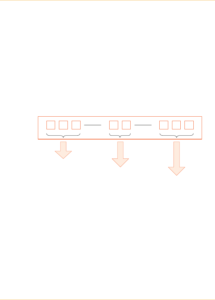
Applicable Standards - EN 62040
260 The UPS Handbook
UPS Topologies
The International Electrotechnical Commission (IEC) established the standard,
IEC 62040-3, to define different UPS topologies and the measurements of
performance. Cenelec, the European standards committee, adopted the IEC
standard as EN 62040-3, which is now recognised as the authoritative definition
of the following three standardised UPS topologies:
• Off-Line - VFD or Class 3 Category
• Line Interactive - VI or Class 2 Category
• On-Line - VFI or Class 1 Category.
UPS Classification - EN 62040-3
Figure 13.1: Classification of UPS - EN 62040-3
Output
dependency Output
waveform Output dynamic
performance
Step 1 Step 2 Step 3
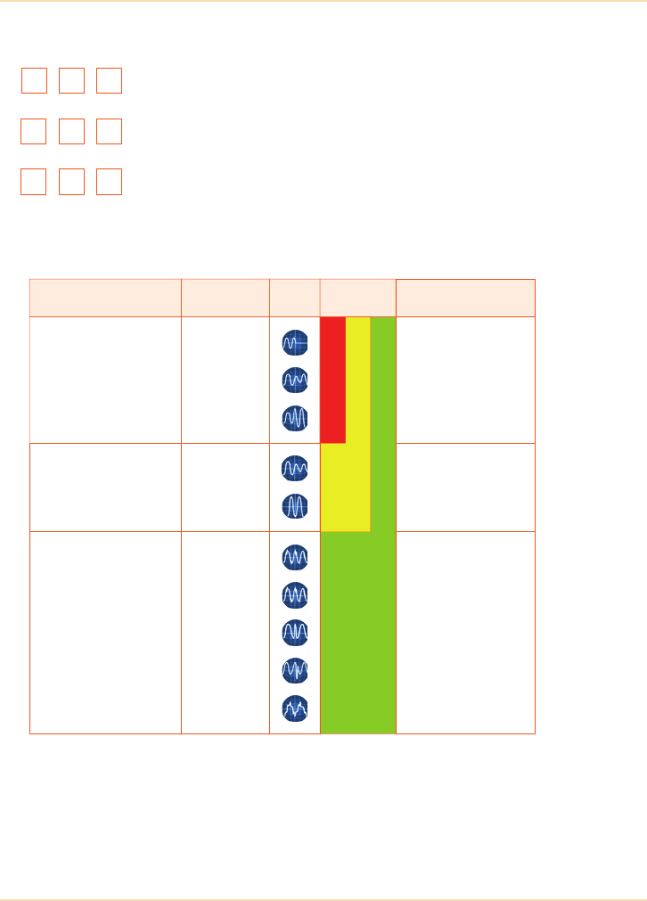
Applicable Standards - EN 62040
The UPS Handbook 261
Classification Code Step 1 - UPS Output Dependency
V F D
V I
V F I
UPS output is Dependant on mains Voltage and Frequency
variations – Off-Line
UPS output is Dependant on mains Frequency variations, mains
Voltage variations are regulated (Independent) – Line Interactive
UPS output is Independent of mains Voltage and Frequency
variations – On-Line
Mains Problem Time
Mains failure
Power sag
Power surge
> 10ms
< 16 ms
< 16 ms
Undervoltage
Overvoltage Continuous
Continuous
Switching transient
Power surge
Frequency variation
Voltage spikes
Harmonic distortion
Intermittent
< 4ms
Intermittent
Periodic
Continuous
E.G.
V
F
D
VI
VFI
EN
50091-3 UPS Solution
Class 3
Off-Line
Class 2
Line Interactive
Delta Conversion
Class 1
On-Line
Double Conversion
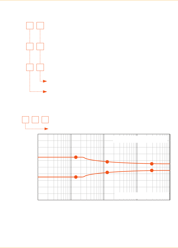
Applicable Standards - EN 62040
262 The UPS Handbook
Classification Code Step 2 - UPS Output Waveform
Classification Code Step 3 - UPS Output Dynamic Performance
Non-Sinusoidal: where the total harmonic factor D> 0.08 and
harmonics within IEC 61000-2-2 under linear/non-linear reference
load conditions
Non-Sinusoidal: where the total harmonic factor D> 0.08 and harmonics
within IEC 61000-2-2 under non-linear reference load conditions
Sinusoidal: where the total harmonic factor D< 0.08 and harmonics
within IEC 61000-2-2 under linear/non-linear reference load conditions
Y Y
X X
S S
On battery operation
On mains operation
Classification 1
1 2
Change of operation mode performance
3
100
80
60
40
20
0
-20
-40
-60
-80
-100
0.1 1.0 10 100 1000
Duration of Transient (mS)
Nominal Value
30%
30%
14%
14%
10%
10%
Transient overvoltage limit
Transient overvoltage limit

Applicable Standards - EN 62040
The UPS Handbook 263
European standard EN 62040-3 is recognised as the correct way to specify
the required UPS topology and performance criteria.
The highest classification of UPS is VFI-SS-111, which is only met by modern,
true on-line, double conversion UPS.
Classification 2
1 2
Step linear load performance in mains/battery mode
3
100
80
60
40
20
0
-20
-40
-60
-80
-100
0.1 1.0 10 100 1000
Duration of Transient (mS)
Nominal Value
30%
14% 10%
30%
14% 10%
Transient overvoltage limit
Transient undervoltage limit
Classification 3
1 2
Step reference non-linear load performance in mains/battery mode
3
100
80
60
40
20
0
-20
-40
-60
-80
-100
0.1 1.0 10 100 1000
Duration of Transient (mS)
Nominal Value
35%
14% 10%
48%
27% 20%
Transient overvoltage limit
Transient undervoltage limit

Applicable Standards - Energy Networks Association ER G5/4-1
264 The UPS Handbook
Energy Networks Association ER G5/4-1
The Electrical Association Engineering Recommendation (ER) G5/4, which was
published in February 2001, has been revised and replaced with the Energy
Networks Association Engineering Recommendation (ER) G5/4-1 This revision
was published in August 2005 after consultation between the Energy Networks
Association members, interested manufacturers and trade associations such as
Gambica.
The Energy Networks Association states that the satisfactory operation of the
electricity supply system and user’s equipment is only obtained where
electromagnetic compatibility (EMC) between them exists. By limiting the
harmonic emissions of customers’ non-linear loads and generating plant, the
Engineering Recommendation G5/4-1 helps to fulfil the technical objective of
the UK EMC Regulations. These Regulations seek to limit the voltage distortion
present in distribution networks to levels below the immunity levels at which
equipment function and performance are likely to be impaired. Equipment
immunity levels are based on a total voltage harmonic distortion (THDv) of 5%
in 400V systems. Engineering Recommendation G5/4-1 sets the planning levels
for harmonic voltage distortion to be used in the process for the connection to
the supply system of non-linear equipment.
Whilst harmonic distortion limits are not governed by statute, it is incumbent
upon the electrical design consultants and manufacturers to ensure equipment
emissions when connected to the supply system do not exceed the planning
levels set by G5/4-1 and that such harmonic distortions are agreeable to the
Network Operating Company (NOC).
Stage 1 of the Engineering Recommendation G5/4-1 sets out the maximum
aggregate value of three-phase convertors or AC regulator equipment, which
may be connected to low voltage (230/240V) networks without further
assessment (See Table 13.1). ‘Aggregate’ is defined as the rating equal to the
sum of the individual non-linear equipment ratings.
Table 13.1: Aggreg ates
For all installations where there are concentrations of non-linear equipment
>16A per phase, the aggregate emissions per phase should not exceed the values
Supply system voltage
at the Point of Common
Coupling (PCC)
Three phase convertors
6 pulse (kVA) 12 pulse (kVA)
400V 12 50

Applicable Standards - Energy Networks Association ER G5/4-1
The UPS Handbook 265
given in Table 13.2. The limits shown are based on a typical supply system fault
level of 10MVA and where the network is not known to have excessive
background levels of harmonic voltage distortion.
Special consideration should therefore be given to transformer based UPS
utilising 6 pulse rectifiers since this equipment produces high emission currents
typically >30% THDi.
Table 13.2: Emi ssion Current s
It is strongly recommended that the reader consults the full requirement of Engineering
Recommendation G5/4-1 at the earliest stage of planning the installation of non linear
equipment.
Harmonic
order ‘h’
Emission
current I
h
Harmonic
order ‘h’
Emission
current I
h
Harmonic
order ‘h’
Emission
current I
h
Harmonic
order ‘h’
Emission
current I
h
228.9 151.4 281.0 411.8
348.1 151.8 293.1 420.3
49.0 1713.6300.5 431.6
528.9 180.8 312.8 440.7
63.0 199.1 320.9 450.3
741.2 201.4 330.4 460.6
87.2 210.7 340.8 471.4
99.6 221.3 352.3 480.3
10 5.8 23 7.5 36 0.4 49 1.3
11 39.4 24 0.6 37 2.1 50 0.6
12 1.2 25 4.0 38 0.8
13 27.8 26 1.1 39 0.4
14 2.1 27 0.5 40 0.7

Applicable Standards - RoHS and WEEE Directives
266 The UPS Handbook
RoHS and WEEE Directives
RoHS (2002/95/EC “Restriction of the use of certain Hazardous Substances
in Electronic Equipment”) and WEEE (2002/96/EEC “Waste of Electrical
and Electronic Equipment”).
RoHS and WEEE directives do not directly apply to UPS systems since
Annexes 1A and 1B of the Directives do not mention UPS anywhere, nor do
they mention any other type of energy conversion equipment. This view has
been confirmed both by the European Commission (FAQ document published
May 2005) and subsequently ORGALIME (guide published February 2006).

Applicable Standards - Standards Relevant to UPS Installations
The UPS Handbook 267
Standards Relevant to UPS Installations
Standard Details
CE
Marking in compliance with the following European
directives:
•Low Voltage Directive 2006/95/EC
•EMC Directive 2004/108/EC
ISO/IEC 27001:2005 Information Security Standards
BS 25999-1:2006 Business continuity management. Part 1: Code of
practice
BS 7698-1:1993, ISO
8528-1:1993
Reciprocating internal combustion engine driven
alternating current generating sets. Specification
for application, ratings and performance
ER G59/1
Recommendations for the connection of
embedded generating plant to the Public Electricity
Suppliers distribution systems. Energy Networks
Association
BS EN 60529:1992
Specification for degrees of protection provided by
enclosures (IP code)
BS EN 60439-4:2004: Low-voltage switchgear and
control gear assemblies
BS 7671:2001 Requirements for electrical installations. IEE
Wiring Regulations. Sixteenth edition
BS EN 50310:2006 Application of equipotential bonding and earthing
in buildings with information technology equipment
BS EN 60439-4:2004 Low-voltage switchgear and control gear
assemblies

Applicable Standards - Standards Relevant to Lead Acid Batteries
268 The UPS Handbook
Standards Relevant to Lead Acid Batteries
Standard Details
BS 6133:1995 Code of practice for safe operation of lead-
acid stationary batteries
BS 6290-4: 1997
Lead-acid stationary cells and batteries.
Specification for classifying valve regulated
types
BS EN 60896-1:1992, IEC
Stationary lead-acid batteries. General
requirements and methods of test. Vented
type
BS EN 60896-2:1996, IEC
Stationary lead-acid batteries. General
requirements and methods of test. Valve
regulated type
BS EN 50272-2:2001 Safety requirements for secondary batteries
and battery installations. Stationary batteries
ANSI/IEEE 450-2002
IEEE recommended practice for
maintenance, testing and replacement of
vented lead-acid batteries for stationary
applications
ANSI/IEEE 1184-1994
IEEE recommended guide for selection and
sizing batteries for Uninterruptible Power
Supplies (UPS)
ANSI/IEEE 1188-1996:
IEEE recommended practice for
maintenance, testing and replacement of
valve-regulated lead-acid (VRLA) batteries
for stationary applications

The UPS Handbook 269
14 Glossary of UPS
Terminology
AC - Alternating Current
Electrical current that continually reverses direction, the frequency of
change in direction being expressed in Hertz (Hz), or cycles per second.
Amp or Ampere
Unit of measurement of electrical current. Abbreviated as A.
Autonomy
This is the time that the battery must support the load and is also often called
back-up or discharge time.
Blackout
A total loss of electrical power.
BMS
UPS systems are often required to interface with the client’s building
management system (BMS) to provide remote indications of the operating
status of the UPS. This is accomplished using the volt-free changeover
contact signals available from the UPS, or where more comprehensive data
is required, via the UPS RS232 communications port.
Brownout
A low voltage condition over an extended period of time.
Bunding
The oil storage regulations (DEFRA - Control of Pollution (Oil Storage)
(England) Regulations 2001) require oil storage tanks to have a secondary
containment facility.

Glossary of UPS Terminology
270 The UPS Handbook
Bypass
An ac power path around a UPS.
An automatic bypass is controlled by a UPS and operates under fault or
overload conditions to maintain power to the protected load.
A manual bypass is a user switch on a UPS allowing a complete electrical
bypass of the unit, used when there is a total UPS failure or when carrying
out maintenance or repair without shutting down the load. Some parts of the
UPS - the input and output terminations for example – may remain live.
A service or maintenance bypass is a manual bypass allowing complete
isolation, maintenance, or removal of the UPS without load shutdown.
Capacitance
The ability of a system or component to store an electric charge. Capacitance
is measured in Farads although, as this a very large unit, the most usual
reference will be the micro Farad (µF).
Circuit Breaker
A protective device that interrupts the flow of current when it exceeds a
specified value.
Clamping Level
The voltage level above which a surge suppression device diverts energy
away from the load.
Clamping Time
The time taken by a surge suppression device to clamp or divert away from
the load a voltage above the clamping level.
Common Mode Noise
Disturbances between the neutral and earth or grounding conductors. Noise
may result from injection into the neutral or grounding wires, wiring faults,
or overloaded power circuits.
Crest Factor
The ratio between the crest (peak or maximum) value of a current to the
root-mean-square (rms) value. A square wave of current has a crest factor of
one. A sine wave has a crest factor of 1.412. Some computer power supplies
draw current with a crest factor of between two and three.

Glossary of UPS Terminology
The UPS Handbook 271
Current
The flow of electricity expressed in Amperes.
Current Limit
The function of a circuit or system that maintains a current within its
prescribed limits. UPS systems have an electrical current limit that regulates
the output current to a value within the UPS limits. Current limiting may
occur when a load demanding high inrush current is switched on.
DC - Direct Current
Electrical current which flows only in one direction.
Differential Mode Noise
Describes noise which occurs between the live and the neutral conductors.
Caused by load switching locally.
Dip
A transient voltage decrease. See also ‘Sag’.
Distortion
The difference between the actual ac voltage waveform delivered and an
ideal sinewave.
EMI - Electro-Magnetic Interference
Electrically induced noise or transients.
Ferroresonance
Occurs when an iron-core inductor is part of an LC circuit and it is driven
into saturation, causing its inductive reactance to increase to equal the
capacitive reactance of the circuit.
Ferroresonant Transformer
A transformer that regulates the output voltage by the principle of
ferroresonance.
Filter
An electronic device that allows only certain frequencies to pass.

Glossary of UPS Terminology
272 The UPS Handbook
Float Charging
A battery charging scheme suitable for UPS batteries. A float charger
maintains a voltage on the battery, known as the float voltage, which is the
ideal voltage for the battery and maximizes battery life. At float voltage, a
current flows into the battery which exactly cancels the battery’s internal self
discharge current.
Fuel Cell
A fuel cell produces electricity from external supplies of fuel and oxidant.
The fuel and the oxidant react in an electrolyte to produce an electrical
output. Fuel cells can operate virtually continuously as long as the flows of
fuel and oxidant are maintained. Unlike batteries, which store energy, fuel
cells must be continually replenished.
Ground Fault
An undesirable connection that allows current to flow from a conductor to
ground.
Harmonic
Voltage or current signals that are not at the desired 50Hz fundamental
frequency, but are at some multiple frequency, such as the third harmonic,
150Hz and the fifth harmonic, 250Hz. Excessive harmonic voltages can
have serious effects on modern equipment power supplies and may cause
overheating.
Harmonic Distortion
Excessive harmonic (a frequency that is a multiple of the fundamental
frequency) content that distorts the normal sinewave.
Hertz or Hz
The unit of measure of the frequency of alternating current (ac), the same as
cycles per second.

Glossary of UPS Terminology
The UPS Handbook 273
Hot-Scalable
A UPS system is hot-scalable if its power capacity can be increased:
• Vertically - by adding hot-swappable UPS modules in a rack without
removing power from the critical load or transferring the critical load
onto the raw AC mains supply.
• Horizontally - by adding free-standing UPS cabinets/racks without
removing power from the critical load or transferring the critical load
onto the raw AC mains supply.
Hot-Swappable
A UPS power module is hot-swappable if:
• it can be inserted or removed from the host UPS system without
removing power from the critical load or transferring the critical load
onto the raw AC mains supply.
• it can be safely electrically disconnected from its host system by
means of electrically safe connectors.
• it can be isolated from the rest of the host system without the risk of
human error that may cause damage to the module, the host system or
the critical load.
IGBT - Insulated Gate Bipolar Transistor
A high power switching transistor used in modern UPS inverters.
Inductance
The property of an electric circuit, or component, that causes an
electromotive force to be generated by a change in the current flowing.
Inductance is measured in Henry (H) although, as this a very large unit, the
most usual references will be the milli Henry (mH) or micro Henry (µH).
Inrush Current
The current drawn by a device when it is first switched on. Computer
equipment often draws inrush currents of three to ten times the nominal
operating value.
Inverter
Part of a UPS that converts the dc into ac power.

Glossary of UPS Terminology
274 The UPS Handbook
Isolation
The degree to which a device like a UPS can electrically separate its input
from its output.
Joules
A measure of the amount of energy delivered by one watt of power in one
second. The Joule rating of a surge protection device is the amount of energy
that it can absorb before it is damaged.
kVA
Thousand VA (See "Volt-Ampere").
Load
Any electrical device connected to a power source is a ‘load’. For a UPS, the
load is the amount of current/power required by the attached electronic
equipment.
MOV - Metal Oxide Varistor
A voltage clamping device capable of absorbing very large currents without
damage.
Noise (Electrical)
Any undesirable electrical signal.
Overvoltage
An abnormally high voltage sustained for an extended period.
Phase
Load current is drawn from a voltage source. In ac systems, the voltage is a
sinewave and for a purely resistive load, the current drawn is also a sinewave
aligned perfectly (in phase) with the voltage sinewave. Most loads, however,
are not purely resistive and the current drawn is delayed and lags behind the
voltage sinewave (out of phase). The lag is measured in degrees. Power
factor is equal to the cosine of this phase difference.
Power Factor
The relationship between actual power (W) and apparent power (VA).
Calculated by dividing Watts by Volt-Amperes (W/VA).

Glossary of UPS Terminology
The UPS Handbook 275
PWM - Pulse-Width Modulation
Process of varying the width of a train of pulses to adjust the rms voltage and
frequency and modify the waveshape, typically to sinusoidal.
Rectifier/Charger
Part of a UPS that converts the incoming ac utility power to dc power for the
inverter and to charge the batteries.
Regulation
Describes the amount that the voltage of an ac power source changes. A UPS
has poor regulation when its average voltage varies or drifts, or if the voltage
varies when a load is applied.
RFI - Radio-Frequency Interference
Electrical noise resulting from some parts of the equipment or wiring acting
as a radio antenna. This noise may be large enough to disrupt
communications or cause computing errors.
RMS - Root Mean Square
The square root of the average value of the squares of all the instantaneous
values of current or voltage during one half cycle of an alternating current.
The rms value of a sinewave is approximately 0.707 times the peak value.
RS-232
A serial communications protocol. It may be used between a UPS and
computer to communicate alarm, status or control signals and instructions.
Sealed Lead-Acid Battery
A battery containing a liquid electrolyte that has no opening for level top-up
(sometimes mistakenly referred to as maintenance free).
Sinewave
A fundamental waveform produced by periodic, regular oscillation that
expresses the sine or cosine of a linear function of time or space or both.

Glossary of UPS Terminology
276 The UPS Handbook
Slew Rate
In order that a UPS can transfer to bypass circuit without load interruption,
the UPS must remain synchronised to the mains supply. However, as sudden
changes in UPS output frequency may cause problems in the load, circuits in
the UPS control the permitted rate of change (slew rate).
SNMP
Simple Network Management Protocol is a set of protocols for managing
complex networks. SNMP works by sending messages, called protocol data
units (PDUs), to different parts of a network. SNMP-compliant devices store
data about themselves in Management Information Bases (MIBs) and return
this data to the SNMP requesters.
Static Switch
A static switch is an ‘intelligent switch’ used to select either the UPS
inverter output voltage or the raw mains to supply the load. The selection is
made by control logic which continually monitors the bypass (raw mains)
and inverter voltages.
Stratification
An undesirable condition which may exist in a battery cell or block where,
over time, the electrolyte settles into layers. Each layer is of a different
density and acidity. Under normal conditions the electrolyte should have a
consistent acidity and density.
Surge
An abnormally high voltage lasting for a short period of time.
Switching Time
The amount of time (usually in milliseconds) taken by a standby or off-line
UPS to switch from utility output to inverter output when the UPS senses a
power interruption.
THDi
THDi is the abbreviation used for the input Total Harmonic Distortion of the
input current waveform. It is generally accepted that the THDi should be
kept low to avoid excessive current distortion at the point of common
coupling within a building due to the cumulative effect of other connected
equipment.

Glossary of UPS Terminology
The UPS Handbook 277
Three Phase
An electrical system with three different voltage lines with sinewave
waveforms that are 120 degrees out of phase from one another.
Total Harmonic Distortion
The ratio of the rms sum of all the harmonic components and the
fundamental signal. See THDi.
Transfer Time
The amount of time (usually in milliseconds) taken by a standby or off-line
UPS to sense a power interruption and switch from utility output to inverter
output.
Transformer
A device used to change the voltage of ac power or to isolate a circuit from
its power source.
Transient
Any abnormal or irregular electrical event, such as a surge or sag.
Transverse Mode Noise
Noise resulting from the conversion of common-mode noise to normal-mode
noise after passing through a transformer.
Undervoltage
An abnormal low voltage lasting for a longer period of time than a sag.
UPS - Uninterruptible Power Supply
A general term used to describe any of the various types of standby power
systems.
VA
See Volt-Ampere.
Volt
The unit of electrical force or potential.

Glossary of UPS Terminology
278 The UPS Handbook
Volt-Ampere
The unit of apparent power that is the traditional unit of measure for rating
UPS. Compare to watts, which is the unit of measure of actual power.
Voltage Regulator
A device providing constant or near-constant output voltage even when the
input voltage fluctuates.
VRLA - Valve Regulated Lead Acid Batteries
Valve regulated batteries emit virtually no gas, require no topping up and
need no special ventilation other than that required by the local building
codes.
Watts
The unit of actual power. Compare with Volt-Amperes (VA), which is the
unit of measure of apparent power.
Waveform
The graphical representation of an electrical signal.

The UPS Handbook 279
15 Further Reading
This final section of the Handbook contains links and details of web sites for
organisations you may find useful.
General Information
Uninterruptible Power Supplies
Ltd
www.upspower.co.uk/resources/
document-downloads.aspx
Power Management Design Line www.powermanagementdesignline.com/
The Uptime Institute www.uptimeinstitute.com/
Modern Building Services modbs.co.uk/
Electrical Times www.electricaltimes.co.uk/
The Institution of Engineering
and Technology www.theiet.org/
Electrical Review www.electricalreview.co.uk/
Electrical Construction and
Maintenance ecmweb.com/
Institute of Electrical and
Electronics Engineers www.ieee.org/portal/site/
Yuasa Industrial Batteries www.yuasa-battery.co.uk/
Energy Bulletin www.energybulletin.net/
British Standards Institute www.bsi-global.com/
Building Design www.buildingdesign.co.uk/

Further Reading
280 The UPS Handbook
UK Government
ECA - Enhanced Capital
Allowance scheme https://etl.decc.gov.uk/etl/site.html
DEFRA - Sustainable Energy www.defra.gov.uk/environment/energy/
Ofgem www.ofgem.gov.uk/
European Union
EU Energy Legislation europa.eu/
European Commission - Energy ec.europa.eu/energy/index_en.htm/
Renewable and Green Energy
CADDET www.caddet.org/
World Renewable Energy
Congress / Network www.wrenuk.co.uk/
Renewable Energy Foundation www.ref.org.uk/
NaREC www.narec.co.uk/
Professional Organisations
Institute of Electrical and
Electronics Engineers www.ieee.org/
IEEE Computer Societywww.computer.org/
Association of Building
Engineers www.abe.org.uk/

Further Reading
The UPS Handbook 281
Chartered Institution of Building
Services Engineers www.cibse.org/
Energy Networks Association www.ena-eng.org/
Professional Organisations

282 The UPS Handbook

The UPS Handbook 283
16 Sample UPS
Specifications
Introduction
The following pages contain sample manufacturers’ specifications for modern
UPS systems, and are provided for guidance only.
When comparing manufacturers’ specifications it is important to consider:
•reliability/availability
• efficiency/running costs
• input current THD
• input power factor
• load power factor derating factor
• UPS topology – be sure to only compare ‘like with like’
• system upgradeability
• size/weight
• flexibility of battery configuration
• serviceability
• reputation of supplier
• installation references
•cost.
The UPS Guide Specification which follows is a comprehensive generic
specification for a contemporary, free-standing, three phase UPS system such as
might be produced by a specialist electrical consultant on behalf of a client. The
specification ensures compliance with relevant international safety, performance
and quality standards in addition to incorporating the latest technological
advances. The specification may be used for stand alone or paralleled, free-
standing UPS systems.
The specifications which appear from page 301 onwards contain technical and
physical data guidelines for UPS systems in particular power ranges which may
be incorporated into specification layouts similar to the full written example.

Sample UPS Specifications
284 The UPS Handbook
UPS Guide Specifications
Three-Phase Uninterruptible Power Supply
System (Static, Free-Standing)
SECTION 1 - GENERAL
1.1 SUMMARY
This specification describes a free standing, continuously rated, solid state
Uninterruptible Power Supply (UPS). The UPS utilises true on-line, double
conversion topology, whereby the output power supplied is derived directly from
the UPS inverter without the need for an internal step-up output transformer. The
UPS will be used to operate in conjunction with the existing building supplies and
shall provide high quality power distribution for critical loads.
1.2 STANDARDS
The product shall have CE marking in compliance with the following European
directives:
•Low Voltage Directive - 2006/95/EC
•EMC Directive - 2004/108/EC
The manufacturer shall demonstrate conformity with the UPS harmonised
standards and directives EN 62040-1-1 (Safety) and EN 62040-2 (EMC).
The UPS shall be designed in accordance with the applicable sections of the
current revision of the following standards. Where a conflict arises between these
documents and statements made herein, the statements in this specification shall
govern.
Safety Standard: EN 62040-1-1:2003
EN 60950-1:2001/A11:2004
Electromagnetic Compatibility Standard (EMC): EN 62040-2:2005
EN 61000-3-2:2000
EN 61000-3-3:2008
EN 61000-6-2:2001
EN 61000-6-4:2007+A1:2011
Performance Standard: EN 62040-3:2001

Sample UPS Specifications
The UPS Handbook 285
1.3 SYSTEM DESCRIPTION
1.3.1 General
The UPS system shall consist of a single UPS unit or the appropriate number of
UPS units connected in parallel for operation in capacity or N+n redundancy
mode. For a parallel installation all UPS units must operate simultaneously and
equally share the load without the need for either a centralised static bypass
switch or system control cabinet.
1.3.2 Parallel Installation
Capacity (non-redundant) system.
All the UPS units connected in parallel are required to supply the full rated load. If
a UPS unit power or control module should malfunction, the load is to be
transferred automatically to the bypass line via each of the UPS units with their
static bypass switches being triggered simultaneously. The battery set should
consist of at least two strings so that in the event of a battery malfunction the
affected string is automatically isolated from the system thereby ensuring battery
autonomy is retained, albeit of a shorter duration.
Redundant operation
The UPS system will operate in an N+n configuration where N is the number of
UPS units connected in parallel to support the load and n is the number of UPS
units connected in parallel to provide the coefficiency of redundancy.
The parallel UPS units shall be capable of operation from a common d.c. bus or
with a separate d.c. supply for each UPS unit. In either case the batteries should
be configured so that the failure of one battery string (common d.c. bus) or the
failure of one battery set (separate d.c. supply for each UPS) provides battery
redundancy whereby the specified autonomy at full load is maintained.
The malfunction of one of the UPS units power or control modules shall cause
that particular UPS unit to be automatically isolated from the system and the
remaining UPS units shall continue to support the load. Replacement or repair of
a UPS unit shall be achieved without disturbance to the connected load.
1.3.3 Modes of Operation
The UPS shall be designed to operate as a true on-line, double conversion,
Voltage and Frequency Independent (VFI) system where the UPS output is
independent of supply (utility/generator) voltage variations, and frequency
variations are controlled within EN 61000-2-2 limits. The following modes of
operation shall apply
ANormal - The critical a.c. load is continuously supplied directly by the UPS
inverter. The UPS input free running rectifier derives power from the utility
or generator a.c. source and supplies d.c. power to the inverter. A
separate but integral battery charger shall maintain a ripple free float-
charge voltage to the battery.

Sample UPS Specifications
286 The UPS Handbook
BBattery - Upon failure of the input a.c. power supply the critical a.c. load is
supplied by the inverter, which obtains power from the battery. There shall
be no interruption in power to the critical load upon failure or restoration of
the utility or generator a.c. source.
CRecharge - Upon restoration of utility or generator a.c. power after a
power outage, the input rectifier shall automatically restart and resume
supplying power to the inverter and the battery charger shall recommence
recharging the battery. The UPS input rectifier shall provide a soft start on
the return of the utility or generator a.c. power. For parallel configurations,
each UPS unit shall switch on sequentially, with a switch on delay of
between approximately 5 to 10 seconds.
DAutomatic Restart - Upon restoration of utility or generator a.c. power,
after an a.c. power outage and after a complete battery discharge, the
UPS unit(s) shall automatically restart and resume supplying power to the
connected load via the inverter.
EStatic Bypass - The static bypass shall provide an alternate path for power
to the connected a.c. load and shall be capable of operating in the
following manner:
Single UPS installation
1 Automatic - In the event of a UPS failure or should the inverter overload
capacity be exceeded the UPS unit shall perform an automatic transfer of
the connected a.c. load from the inverter to the bypass source.
2Eco-Mode - The UPS unit shall be able to operate in Eco-Mode when the
power quality parameters of the by-pass source are within permissible
tolerances. The UPS system shall automatically transfer the load to
normal mode if the by-pass source goes out of permissible tolerances.
Transfer in both directions shall be less than 5mS.
3Manual - Should the UPS unit need to be taken out of service for limited
maintenance or repair, manual activation of the bypass shall cause an
immediate transfer of the connected a.c. load from the inverter to the
bypass source. Full electrical isolation of the UPS system shall therefore
be obtained, without disruption to the critical load, by operation of a
separate wrap-around maintenance bypass.
Parallel UPS installation
1 Automatic - In the event of a UPS failure the faulty UPS unit shall
automatically disconnect itself from the critical bus without affecting the
critical load. If the remaining UPS unit(s) are unable to support the load,
e.g. an overload condition, all the UPS units (including the faulty module)
shall perform an automatic transfer of the connected a.c. load to the
bypass source via each of their internal static bypass switches.

Sample UPS Specifications
The UPS Handbook 287
2Manual - Should all the UPS units need to be taken out of service for
limited maintenance or repair, manual activation of the static bypass
switch on one of the UPS units shall cause an immediate transfer of the
connected a.c. load to the bypass source via each of the UPS units'
internal static bypass switch. Full electrical isolation of the UPS system
shall therefore be obtained, without disruption to the critical load, by
operation of the wrap-around maintenance bypass switch located in the
UPS parallel switch panel.
1.4 PERFORMANCE REQUIREMENTS
The UPS shall be a true on-line double conversion, Voltage and Frequency
Independent (VFI) technology in accordance with Standards IEC 62040-3. The
UPS shall be provided with the facility for paralleling for capacity or redundancy
without limitation on the number of UPS units connected in parallel.
1.4.1 AC Input to UPS
The input voltage window shall be as shown in the table below, based on a
nominal input voltage of 230/400V and according to the output load of the UPS.
Within the input voltage range shown below the UPS shall not draw power from
the batteries to support the load.
Voltage configuration 400/230, 415/240 or 380/220 Vac nominal, three-phase, 4-wire-
plus-ground.
Input frequency 35 to 70Hz, without switching to battery supply
Input current distortion Sinewave <3.5% THDi maximum at 100% rated load,
400/230 Vac
Input power factor Equal to or greater than 0.99 at 100% rated load, 0.98 at 50%
rated load (lagging)
Inrush current Limited by soft-start
Load
(% of UPS rating)
Input voltage
(Lower limit)
Input voltage
(Upper limit)
100 - 20% + 15%
90-99 - 23% + 15%
80-89 - 26% + 15%
70-79 - 30% + 15%
60-69 - 35% + 15%
<60 - 40% + 15%

Sample UPS Specifications
288 The UPS Handbook
1.4.2 AC Output
1.4.3 UPS Efficiency
The overall efficiency (ac-dc-ac, on-line mode) shall not be less than the figures
shown in the table below:
Output Rating Single UPS Installation - Continuously rated at XXX kVA /0.8 p.f.
Parallel UPS Installation - N+1 parallel redundant, continuously
rated at XXX kVA/0.8 p.f.
Voltage configuration 3 x 400/230, 415/240 or 380/220 Vac, three-phase, 4-wire-plus-
ground.
Voltage tolerance static ± 1%, dynamic ± 4% (0-100-0 load steps)
Frequency regulation 50 or 60 Hz, ± 0.1%.
Frequency slew rate 2.0 Hertz per second maximum
Bypass frequency
synch. range
± 2% or ± 4% (programmable)
Voltage Distortion < 3% total harmonic distortion (THD) maximum - 100% linear
load.
< 4% total harmonic distortion (THD) maximum - 100% non-linear
load with crest factor ratio of 3:1.
Load power factor
range
0.9 leading to 0.6 lagging without derating kVA
Load peak (crest)
factor
3:1 minimum
Load imbalance 100% (all 3 inverter phases shall be regulated independently)
Overload capability @ p.f. 1.0 – 110% Load - 10 min, 135% Load - 60 sec
@ p.f. 0.9– 125% Load - 10 min, 150% Load - 60 sec
If the overload limits or times are exceeded the UPS will transfer
the load to bypass (if available) via the static transfer switch
Transient recovery
time
within 1% of steady state output voltage within 20 milliseconds
UPS unit rating Load
100% 75% 50% 25%
<= 60 kVA 95.2 95.5 95.7 94.5
> 60 kVA 95 95.5 96 95.5
Measurement with linear load (p.f. = 1.0.)

Sample UPS Specifications
The UPS Handbook 289
1.4.4 Batteries
AThe battery system shall be sized to support a connected load of XX (0.8
p.f.) for a minimum of XX minutes at an ambient temperature of 20°C.
BThe battery system shall consist of gas recombination, valve regulated,
lead acid cells, compliant with BS6290 Part 4 and BS EN6089-2. Flame
retardant batteries shall be provided, which renders the UPS suitable for
installation inside a computer room.
CThe UPS battery charging circuit shall comprise of a separate battery
charger and not depend on a charge voltage being derived from the UPS
input rectifier. Consequently the battery charging voltage shall have zero
a.c. (ripple) content.
DFor single UPS systems the battery system shall consist of a minimum of
2 parallel strings of multiple cells. Each individual parallel string shall have
its own dedicated means of electrical protection.
For multiple UPS units connected in parallel the battery system shall be
either:
• A common battery feeding all the UPS units. In this case the battery
system shall consist of a minimum of two parallel strings of multiple
cells. Each individual string shall have its own dedicated means of
electrical circuit protection.
•A separate battery system for each individual UPS unit. In this case
each separate battery system may consist of one protected string of
multiple cells. If two or more parallel strings are used then each
individual string shall have its own dedicated means of electrical circuit
protection.
For all the above battery system arrangements the batteries shall be
configured so that in the event of a battery malfunction the affected string
is automatically isolated from the system thereby ensuring battery
autonomy is retained (see System Description 1.3.2).
EThe batteries shall be housed in cabinet/s comprising a floor-standing
steel enclosure with dimensions and paint finish to match the UPS system
cabinet/s to form a continuous suite when standing immediately adjacent
to the UPS system cabinet/s. The battery cabinet/s shall have full width
opening doors to permit ease of access for the purposes of maintenance
and/or repair of the batteries.
Alternatively, the batteries shall be housed on open or cladded racks of a
steel construction, having an epoxy powder-coated finish, with adjustable
feet for levelling and adequately designed to support the weight of the
batteries and permit ease of access for the purposes of maintenance and/
or repair of the batteries. If the battery system is located on open stands
then all individual battery cell terminals shall be fully shrouded to prevent
inadvertent contact.

Sample UPS Specifications
290 The UPS Handbook
FA fully discharged battery system shall be capable of being recharged to
80% of the UPS output capacity within a maximum period of 10 times the
normal total discharge time period, and to 90% of the UPS output capacity
within a maximum period of 4 hours.
GThe UPS d.c. bus voltage shall be variable whereby the number of battery
blocks can be adjusted between 40 to 50 (12 Vdc) or 80 to 100 (6 Vdc) to
enable the battery system to be optimised for size and cost.
1.5 ENVIRONMENTAL CONDITIONS
1.5.1 Temperature and Humidity
The UPS system shall be designed to operate continuously at full load without
degradation of its reliability, operating characteristics or service life in the
following environmental conditions:
•UPS ambient temperature range: 0°C to 40°C
•Battery ambient temperature: 20°C
•Humidity: 5 to 95% RH non-condensing
1.5.2 Altitude
The UPS system shall be designed for operation in altitudes up to 1000 metres
(3300 ft.), without the need for derating or reduction of the above environmental
operating temperatures.
1.5.3 Audible Noise
The audible noise generated by the UPS system >60kVA operating on 100%
load not exceed 71 dBA measured at 1 metre from the surface of the UPS. For a
module <60kVA this shall not exceed 65 dBA
1.5.4 Electrostatic Protection
The UPS system shall be able to withstand a minimum 15kV electrostatic
discharge without affecting the critical load.
1.5.5 Floor Loading
The maximum floor load of the UPS system cabinet (excluding batteries) shall
not exceed a UDL of 8.0 kN/ m2
1.5.6 Dimensions
To p erm it ac ces s t hr o ug h a stan d ar d s ing l e doo rwa y o pen ing , e ith er th e wi dt h o r
the depth of the UPS and battery cabinets shall not exceed 750mm.
1.5.7 Cabinets
The UPS system cabinet shall comprise of a floor standing steel enclosure to
house the power system, control systems, battery connections and all associated
switchgear necessary for the correct operation of the UPS in accordance with the
requirement of the specifications. All switchgear and interconnections must be

Sample UPS Specifications
The UPS Handbook 291
adequately protected to enable an isolated section to be safely maintained or
repaired whilst the remaining system supports the load.
1.5.8 Harmonic Currents
The UPS system shall be designed to limit the injection of current harmonics in to
the incoming utility supply source to within limits acceptable to the Network
Operating Company (NOC) and in accordance with the Electricity Association
Recommendation G5/4.
1.6 USER DOCUMENTATION
The specified UPS system shall be supplied with one (1) user's manual. Manuals
shall include:
• General arrangement of the UPS showing dimensions and weight
•User operating instructions
•Single line schematic diagram with functional description of the
equipment
•Installation drawing along with recommended cable and protective
device sizes
•Safety and maintenance guidelines
1.7 AFTER SALES SERVICE
1.7.1 Warranty
The UPS manufacturer shall warrant the UPS system, including the batteries,
against defects in materials and workmanship for 12 months from the date of
commissioning or 15 months from the date of delivery, whichever is soonest.
Subject to the UPS's being commissioned by the manufacturers trained
engineer, the warranty shall provide free replacement parts and on-site labour.
1.7.2 Extended Warranty
The UPS manufacturer shall provide the facility for enhancing or extending the
warranty by providing an annual maintenance contract. The maintenance
contract shall provide:
•Guaranteed response time
• Two preventative maintenance visits per year
•24 hour telephone support directly from the UPS manufacturer
•Free labour, travelling to site and incurred expenses
•Free replacement parts (excluding batteries outside the warranty
period)

Sample UPS Specifications
292 The UPS Handbook
1.8 QUALITY ASSURANCE
1.8.1 UPS Manufacturer Qualifications
The UPS manufacturer shall have a minimum of 10 year's experience in the
design, manufacture, and testing of solid-state UPS systems.
1.8.2 Factory Testing
Before shipment, the manufacturer shall fully and comprehensively test the
system to assure compliance with the specification. These tests shall include full
functional tests at the UPS rated load and a minimum 12 hour continuous burn in
test at the UPS rated load.

Sample UPS Specifications
The UPS Handbook 293
SECTION 2 - PRODUCT
2.1 FABRICATION
2.1.1 Construction
All materials and components making up the UPS shall be new, of current
manufacture, and shall not have been in prior service except as required during
factory testing. The UPS shall be constructed of replaceable sub-assemblies.
2.1.2 Wiring
Wiring practices, materials, and coding shall be in accordance with the
requirements of the IEC 60950-1:2001 and other applicable British and European
codes and standards.
2.1.3 UPS Cabinet
The UPS system cabinet shall offer a minimum degree of protection to the EN
60529 standard, IP20 code.
The UPS cabinet shall be cleaned, primed and painted in graphite grey (RAL
7024). Either the width or the depth of the UPS cabinet should not exceed
750mm, to permit access through a standard doorway.
2.1.4 Battery Cabinet
The battery cabinet shall offer a minimum degree of protection to the EN 60529
standard, IP20 code.
The battery cabinet shall be cleaned, primed and painted to RAL 7024 and
should match the UPS cabinet(s) in appearance and height. Either the width or
the depth of the battery cabinet should not exceed 750mm to permit access
through a standard doorway.
2.1.5 Battery Racks
The battery racks shall be of a steel construction, having an epoxy powder-
coated finish, with adjustable feet for levelling. Open racks shall not exceed 2
meters in height to the top tier and should not be more than 2 rows deep if it is
not possible to gain rear access, e.g. the rack is placed against a wall.
Cladded racks shall offer a minimum degree of protection to the EN 60529
standard, IP20 code and the panels shall be cleaned, primed and painted to RAL
7024.
2.1.6 Cooling
The UPS shall be forced-air cooled by internally mounted fans.

Sample UPS Specifications
294 The UPS Handbook
2.2 COMPONENTS
2.2.1 Input Converter
AGeneral
Incoming a.c. power shall be converted to a regulated d.c. output by the input
converter for supplying d.c. power to the inverter. The input converter shall
provide input power factor and input current harmonic distortion correction.
12 pulse rectifier and/or filter devices will not be accepted if they have a
detrimental effect on the overall UPS efficiency.
BAC Input Current Limit
The input converter shall be provided with a.c. input over current protection.
C Input Protection
The UPS shall have built-in protection against undervoltage, overcurrent, and
overvoltage conditions, including low-energy surges introduced on the primary
a.c. source and the bypass source. The UPS cabinet shall not contain an input
circuit breaker. The electrical contractor shall supply an input circuit breaker/fuse
sized to supply the rated load and to recharge the battery at the same time.
DBattery Recharge
To prolong battery life, the UPS shall have the facility for automatically adjusting
the battery charging voltage according to the environmental temperature of the
batteries. Battery charger shall be ripple-free avoiding premature battery ageing.
2.2.2 Inverter
AGeneral
The inverter shall convert d.c. power from the input converter output, or the
battery, into precise regulated sinusoidal wave a.c. power for supporting the
critical a.c. load.
BOverload
The inverter shall be capable of supplying current and voltage for overloads
exceeding 100% and up to 150% of full load current. A visual indicator and
audible alarm shall indicate overload operation. The load shall be immediately
transferred to bypass when the load current exceeds this level of overload.
In the event the bypass supply is unavailable (e.g. mains failure), the inverter
shall have electronic current-limiting protection to prevent damage to internal
components. The inverter shall be self-protecting against any magnitude of
connected output overload and the inverter control logic shall sense and
disconnect the inverter from the critical a.c. load within 200 mS.
COutput Frequency
The output frequency of the inverter shall be controlled by an oscillator. The
oscillator shall hold the inverter output frequency to ± 0.1% for steady state and
transient conditions. The inverter shall synchronise with the bypass supply

Sample UPS Specifications
The UPS Handbook 295
assuming the bypass supply stays within the selected range. If the bypass
source fails to remain within the selected range, the inverter shall revert to the
internal oscillator.
D Battery over Deep Discharge Protection
To p rev ent ba tte ry dam ag e f r om de ep discharging, the UPS control logic shall
monitor the discharge voltage and shut the UPS down at a pre-set minimum dc
voltage. This level is dependent on the rate of discharge and battery autonomy
and shall be adjusted at the time of commissioning the UPS equipment. Under
any circumstances it should not be set to less than 1.67V per cell.
2.2.3 Display and Controls
AGeneral
The UPS front panel shall consist of multiple status LEDs, switches, and an
alphanumeric LCD display for additional alarm/configuration information. During
normal operation (on-line), all mimic display LEDs shall be green in colour and
indicate the following:
A UPS fault shall be identified via additional indicators and audible alarms to
notify the user that a UPS fault condition has occurred. During mains failure the
colour of the LED's shall be as follows:
If there is a fault condition, the UPS shall attempt to maintain conditioned power
to the load or at minimum transfer to bypass.
In addition to a visual fault signal (alarm), the UPS shall also record fault
occurrences in a rolling event log. The event log shall record up to 64
occurrences, with the oldest events discarded first, etc. The user shall have
access to the event log through the LCD display. Every alarm and/or event
recorded in the event log will contain a time and date stamp.
Line 1 (a.c. Input rectifier)
Line 2 (a.c. Input by-pass)
Battery (Load supplied from the battery)
On Inverter (Load supplied from the inverter)
On Bypass (Load supplied from the by-pass)
Line 1 (a.c. Input rectifier) red
Line 2 (a.c. Input by-pass) red
Battery (Load supplied from the battery) green
On Inverter (Load supplied from the inverter) green
On Bypass (Load supplied from the by-pass) off (no colour)

Sample UPS Specifications
296 The UPS Handbook
BAudible Alarms
The volume of all audible alarms shall be at least 65 dBA at a distance of one
meter. An audible alarm shall be used in conjunction with the LED/LCD display to
indicate a change in UPS status.
The audible alarms shall warn loss of mains or generator supply, low battery
(whilst on battery), and all other alarm conditions. For all audible alarm
conditions, the display shall identify the cause of error/alarm. All alarm tones
shall be a continual tone until the condition rectifies itself or the alarm is silenced.
Once silenced, the audible alarm shall not sound until a new alarm condition is
present, but the LED indication shall continue to identify the alarm condition.
C Alarm Silence Button
The display panel shall include an audible alarm 'Reset' switch. If the alarm mute
(Reset) switch is pressed for one second, all current audible alarms shall be
disabled. If a new alarm occurs, or a cancelled alarm condition disappears and
then re-appears, the audible alarm is re-enabled.
DLCD Display
The LCD display shall be used to provide the following information to the user
and UPS service engineer:
2.2.4 Automatic Battery Test
The UPS shall initiate an automatic battery testing sequence periodically (default
setting once a month), at a programmed day and time of day, selectable by the
end user. It shall be possible for the user to disable the automatic battery test.
Should a fault with the battery be detected, the UPS will immediately return to
normal mode and a fault status (visual, audible, and remote) shall be indicated.
No audible or remote signal indication of the battery test shall be communicated
during the duration of the automatic battery test.
Phase Voltages: Input to converter
Input to by-pass
UPS output
Battery DC Voltage (voltage to/from battery)
Current: UPS output (line current)
Battery charging/discharging
Frequency: UPS Input
UPS output
Autonomy: Remaining back-up time (minutes)
Battery capacity (%)
Others: UPS output active power (kW)
UPS output reactive power (Kvar)
UPS output apparent power (kVA)
UPS load (% per phase)

Sample UPS Specifications
The UPS Handbook 297
The automatic battery test shall operate if no UPS alarm conditions are present
and if the battery is at least 90% of its full capacity.
2.2.5 Remote Emergency Power Off (EPO)
The remote 'emergency power off' function (EPO) shall allow the user to
immediately shutdown the UPS output supply in an emergency situation. The
EPO shall be able to interface with normally closed, volt-free contacts external to
the UPS. The EPO connection to the UPS shall be to a clearly identified terminal
block type connector.
The UPS EPO shutdown function shall not operate if the UPS internal manual
bypass switch is in the bypass position. When the external EPO function has
been re-set, manual intervention is required to restart the UPS. The electrical
contractor shall include the facility for interfacing the EPO circuit with the supply
feed of the UPS and provide a means of disconnecting all sources of power to
the UPS.
2.2.6 Standby Generator On contact
The UPS shall have the facility whereby, on receipt of a volt free contact closure
start signal from a standby generator supplying the UPS, the UPS system will
automatically inhibit battery recharge (selectable) and Inhibit transfer to bypass
(selectable).
2.2.7 Bypass
A. General
A bypass circuit shall be provided as an integral part of the UPS.
The bypass control logic shall contain an automatic transfer control circuit that
senses the status of the inverter logic signals and operating and alarm
conditions. This control circuit shall provide a transfer of the load to the bypass
source, without exceeding the transient limits specified herein, when an overload
or malfunction occurs within the UPS.
B. Automatic Transfers
The transfer control logic shall automatically activate the bypass, transferring the
critical a.c. load to the bypass source, after the transfer logic senses one of the
following conditions:
•Inverter overload capacity exceeded
•Inverter over temperature
•UPS fault condition (non redundant configuration)
For inverter overload conditions, the transfer control logic shall inhibit an
automatic transfer of the critical load to the bypass source if one of the following
conditions exists:
• Inverter/Bypass voltage difference exceeding preset limits (-20/+15%
of nominal load)
• Bypass frequency out of preset limits (± 4% of nominal frequency)

Sample UPS Specifications
298 The UPS Handbook
C. Automatic Retransfer
Retransfer of the critical a.c. load from the bypass source to the inverter output
shall be automatically initiated unless inhibited by manual control. The transfer
control logic shall inhibit an automatic retransfer of the critical load to the inverter
if one of the following conditions exists:
•Bypass out-of-synchronization range with inverter output
•Overload condition exists in excess of inverter full load rating
•UPS fault condition present (non redundant configuration)
D. Manual Transfer
In addition to the internal static bypass switch, the UPS shall have an internal
manual bypass 'make-before-break' transfer switch. The manual bypass function
shall be provided via a switch, which is accessible from the front of the UPS and
located behind the UPS cabinet door.
The manual bypass switch shall be electrically interlocked to prevent back-
feeding the UPS output in the event of incorrect operation, e.g. transferring the
load to bypass via the manual bypass switch when the load is supplied by the
inverter.
The UPS shall initiate an audible alarm upon transfer to manual bypass. The
alarm shall be capable of being muted by the user. The alarm shall continue to
sound (unless muted) while in bypass mode. This shall provide a reminder to the
user that the load continues to be powered from utility or generator supply alone.
2.2.8 Battery
The battery system shall consist of gas recombination, valve regulated, lead acid
cells, compliant with BS6290 Part 4 and BS EN6089-2. Flame retardant batteries
shall be provided, which renders the UPS suitable for installation inside a
computer room.
The UPS battery charging circuit shall comprise of a separate battery charger
and not depend on a charge voltage being derived from the UPS input rectifier.
Consequently the battery charging voltage shall have zero a.c. (ripple) content.
For single UPS systems the battery system shall consist of a minimum of 2
parallel strings of multiple cells. Each individual parallel string shall have its own
dedicated means of electrical protection.
For multiple UPS units connected in parallel, the battery system shall be either:
•A common battery feeding all the UPS units. In this case the battery
system shall consist of a minimum of 2 parallel strings of multiple cells.
Each individual string shall have its own dedicated means of electrical
circuit protection.

Sample UPS Specifications
The UPS Handbook 299
•A separate battery system for each individual UPS unit. In this case
each separate battery system may consist of one protected string of
multiple cells. If two or more parallel strings are used then each
individual string shall have its own dedicated means of electrical circuit
protection.
For all the above battery system arrangements the batteries shall be configured
so that in the event of a battery malfunction the affected string is automatically
isolated from the system thereby ensuring battery autonomy is retained (see
System Description 1.3.2).
2.3 COMMUNICATIONS
2.3.1 Voltage-Free Contacts
The UPS shall incorporate voltage-free relay contacts suitable for direct
communication with either a computer system, remote alarm panel or the clients
BMS system and an RS-232 communication port for serial communications and
to enable communication via modem equipment.
2.3.2 Relay Contacts
The relay contacts shall be available through one DB-25F communication
connector. The UPS shall communicate, via volt-free relay changeover contacts,
the following status signals:
Pin 1 Mains Failure (normally open)
Pin 2 Mains Failure (normally closed)
Pin 4 Load on inverter (normally closed)
Pin 5 Load on inverter (normally open)
Pin 7 Battery low (normally open)
Pin 8 Battery low (normally closed)
Pin 10 Load on mains (normally open)
Pin 11 Load on mains (normally closed)
Pin 13 Common alarm (normally open)
Pin 14 Common alarm (normally closed)
Pin 23 +12 Vd.c. (max. 100mA)
Pin 22 GND

Sample UPS Specifications
300 The UPS Handbook
2.3.3 Serial Communications
The UPS shall have the facility for communication via an RS-232 port. The pin-
out configuration for RS 232 port shall be as follows:
2.3.4 Network Communications
The UPS unit(s) shall include a facility for installing an optional SNMP adapter
card to the UPS to permit one or more network management systems (NMS) to
monitor the UPS in TCP/IP network environments. 10/100 Mbit Ethernet support
shall be included.
2.3.5 Parallel Operation
It shall be possible to configure the status signals from each UPS unit connected
in parallel to a common signal programmer device whereby, using Boolean logic,
input events or combinations of input events can trigger specified output signal
alarms and status events. It shall be possible to communicate the status of the
parallel UPS configuration over a LAN/WAN network via NMS and provide
modem communication to facilitate remote monitoring via a dedicated telephone
line.
Pin 2 Transmit Data
Pin 3 Receive Data
Pin 5 Common
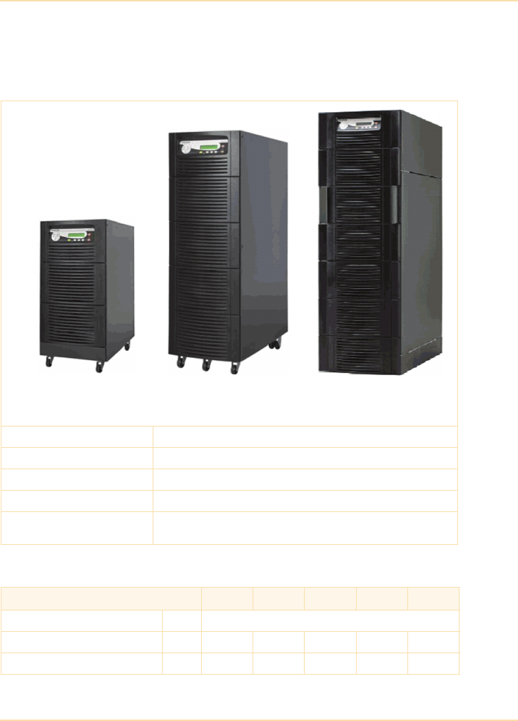
Sample UPS Specifications
The UPS Handbook 301
7.5 - 12 kVA, single-phase input and output
7.5 - 20kVA, 3-phase input, single-phase output
Mechanical data
General data
Cabinet A
7.5kVA, 10kVA, 12kVA
(WxDxH =340 x 800 x 820)
Cabinet B
10kVA, 15kVA, 20kVA
(WxDxH =450 x 860 x 1250)
Cabinet C
10kVA, 15kVA, 20kVA
(WxDxH =550 x 890 x 1650)
Transportation pallet Provided with UPS
Packaging Cardboard (standard)
Accessibility Rear/side access for cabinet A, front/side access for cabinets B & C
Positioning Min. 200mm rear space (required for ventilation)
Input/output power cabling From bottom rear (Cabinet A)
and bottom front (Cabinets B and C)
Module rating (kVA) 7.5 10 12 15 20
Output power factor 0.7
Output rated power @ p.f. 0.7 kW 5.25 7.0 8.4 10.5 14.0
Output current In @ p.f. 0.7 (230V) A 22.83 30.43 36.52 45.65 60.87

Sample UPS Specifications
302 The UPS Handbook
Rectifier data
Topology On-line, double conversion, VFI, with static and
maintenance bypass
Technology Second generation, transformerless
Double conversion AC-AC efficiency
100% / 75% / 50% / 25%
linear load (cos
=0.8ind)
%93.5 / 93.5 / 92 / 8994 / 94 / 92.5 / 9094.5 94.5/
93/91
100% / 75% / 50% / 25%
linear load (cos
= 1)
%93 / 93 / 91.5 / 88.593.5 / 93.5 / 92 / 89.594/94/92/
90
Eco-mode efficiency 100% load
(on by-pass)
%98
Remote signalling and alarms
Dry port (volt-free contacts) standard For remote signalling and automatic computer shutdown
Smart Port (RS 232) For monitoring and integration in network management
Module rating (kVA) 7.5 10 12 15 20
Input voltage 1 : 1 V 1x220V+N, 1x230V+N,
1x240V+N
N/A
Input voltage 3 : 1 V 3x380/220V+N
3x400V/230V+N
3x415/240V+N
N/A 3x380/220V+N
3x400V/230V+N
3x415/240V+N
Input voltage window
(@ 3x400/230V)
V (%) For loads <100% (-23%, +15%)
For loads <80 (-30%, +15%)
For loads <60% (-40%, +15%)
Input frequency window Hz 35 - 70
Input power factor Single-phase in: 0.98 @ 100% load
Three-phase in: 0.95 @ 100% load, 0.98 (inc. filter option)
Input current form Single-phase in THDi <7 - 9% @ 100% load
Three-phase in THDi <25% @ 100% load;
Three-phase in THDi <7 - 9% (with optional filter)
Inrush current Limited by soft start
Input power with rated output
power and charged battery
kW 5.6 7.4 9.4 11.1 14.8
Maximum input power with rated
output power and discharged
battery
kW 6.1 8.1 10.3 12.1 16.2
Module rating (kVA) 7.5 10 12 15 20

Sample UPS Specifications
The UPS Handbook 303
Battery data
Inverter data
Module rating (kVA) 7.5 10 12 15 20
Battery type Lead-acid, maintenance-free VRLA or NiCd
Number of 12V battery blocks 22-50 26-50 30-48 32-50
Battery ambient temperature 20°C (recommended)
Battery storage time Maximum 6 months (at ambient temperature)
Temperature controlled battery charger Not available
Maximum battery charger current 6 A (standard)
Battery charging curve Ripple-free; IU (DIN 41773)
Battery charger ripple < 1%
Battery test Automatic and periodic (adjustable)
Module rating (kVA) 7.5 10 12 15 20
Output rated voltage V 1 x 220V, 1 x 230V, 1 x 240V
Output power factor 0.7
Output waveform Sinewave
Output frequency Hz 50 or 60
Output frequency tolerance Free-running, quartz oscillator <±0.1%
Synchronized with mains <±2% or ±4% (selectable)
Overload capability % 125 for 10 min. and 150 for 1 min.
Crest factor 3 : 1
Output voltage stability
Static % < ± 1
Dynamic (with load step
0-100%, 100-0%)
%< ± 4
Output voltage distortion
With linear load % < 1
With non-linear load % < 3 (EN 62040-3:2001)

Sample UPS Specifications
304 The UPS Handbook
Environmental data
Bypass data
Standards
Module rating (kVA) 7.5 10 12 15 20
Audible noise at 100%/50% load dBA 50/47 53/49
Ambient temperature (UPS) °C 0 to 40
Ambient temperature (Batteries) 20 (recommended)
Relative humidity % Maximum 95% (non-condensing)
Heat Dissipation
100% non-linear load (EN 62040-3) W 460 600 650 800 1120
BTU/h 1638 2048 2218 2730 3822
100% load (cos
=0.8ind) W 380 500 550 700 800
100% load (resistive cos
=1) W 400 550 600 750 960
Cooling Fan-assisted
Recommended airflow (25 - 30°C)
with 100% non-linear load per
range (EN 62040-3)
m3/h 110 150 200
Module rating (kVA) 10 15 20 25 30 40 50
Bypass operation At nominal input voltage of 3x400 V ±15%,
(196 V to 264 V ph-N)
Module rating (kVA) 7.5 10 12 15 20
Safety EN62040-1-1:2003 EN60950-1:2001/A11/;2004
Electromagnetic compatibility IEC/EN 62040-2:2005, IEC/EN61000-3-2:2000,
IEC/EN61000-6-2:2001,
Performance IEC/EN 62040-3:2001
Product certification CE
Degree of protections IP20
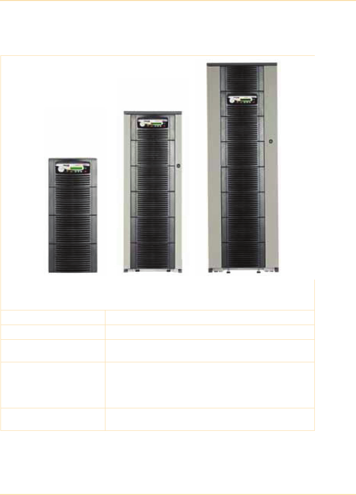
Sample UPS Specifications
The UPS Handbook 305
10- 50 kVA, 3-phase input and output
Mechanical data
Cabinet A
10kVA, 15kVA, 20kVA
(WxDxH =345 x 710 x 720)
Cabinet B
15kVA, 20kVA, 25kVA
(WxDxH =345 x 710 x 1045)
Cabinet C
25kVA, 30kVA, 40kVA, 50kVA
(WxDxH =440 x 910 x 1420)
Transportation pallet Provided with UPS
Packaging Cardboard (standard)
Accessibility (operator) 10kVA – 25kVA in type A or B cabinets require front/rear access
25kVA – 50kVA in type C cabinets require front access only
Positioning Front: A minimum of 900mm for free passage.
Left/Right Side: 600mm required for service access.
Rear: A minimum of 200mm is required for cooling air circulation
and the unit should be cabled such that it can be pulled forward to
allow 600mm rear clearance for service/maintenance.
Input/output power cabling 10kVA – 25kVA in type A or B cabinets cabled at rear
25kVA – 50kVA in type C cabinets are cabled at rear

Sample UPS Specifications
306 The UPS Handbook
General data
Rectifier data
Module rating (kVA) 10 15 20 25 30 40 50
Output power factor 0.9
Output rated power @p.f. 0.9 kW 9.0 13.5 18 22.5 27 36 45
Output Current In @ 400V /0.9 p.f. A 13.0 19.5 26.0 32.5 39.0 52.0 65.0
Output Current In @ 400V /1.0 p.f. A 14.4 21.7 28.9 36.1 43.3 57.7 72.2
Topology On-line, double conversion
Technology Third generation, transformerless
Construction Parallelable (optional)
Parallel configuration Load sharing, decentralized control
Double conversion AC-AC efficiency
100/75/50/25% linear load p.f =1.0 % 95.5/ 95.5/ 95.5/ 94.5
Remote signalling and alarms
Dry port (volt-free contacts) For remote signalling and automatic computer shutdown
Smart port (RS 232) For monitoring and integration in network management
Input terminals EMERGENCY OFF (normally closed)
GENERATOR-ON (normally open)
BATTERY TEMPERATURE SENSOR
Module rating (kVA) 10 15 20 25 30 40 50
Input voltage (factory selectable) V 3x380/220V+N, 3x400/230V+N, 3x415/240V+N
Input voltage tolerance
(ref to 3x400/230V) for loads in %:
(-23% to +15%) for <100 % load
(-30% to +15%) for < 80 % load
(-40% to +15%) for < 60 % load
Other input voltages On request
Input frequency window Hz 35 - 70
Input power factor 0.99 @100% Load
Input current form Sinewave (THD 7 - 9% input voltage dependant)
Inrush current Limited by soft start
Rectifier max. input power/current
With rated output power and
charged battery (output pf = 0.9)
kW 9.6 14.4 19.1 23.9 28.7 38.3 47.9

Sample UPS Specifications
The UPS Handbook 307
Battery data
Inverter data
With rated output power and
charged battery (output pf = 0.9)
A13.920.827.834.741.655.569.4
With rated output power and
discharged battery (output pf = 0.9)
kW 10.5 15.7 21 26.2 31.4 41.9 52.4
With rated output power and
discharged battery (output pf = 0.9)
A15.222.830.437.945.560.775.9
Module rating (kVA) 10 15 20 25 30 40 50
Battery type Lead-acid, maintenance free
Number of 12V battery blocks* 22-50 32-50 32-50 40-50 24-50 32-50 40-50
Battery ambient temperature 20°C
Battery storage time Maximum 6 months (at ambient temperature)
Temperature controlled battery charger Yes (with optional temperature sensor)
Maximum battery charger current 4A 6A
Battery charging curve Ripple free IU (DIN 41773)
Battery charger ripple < 1%
Battery test Automatic and periodic; adjustable
*Depending on the effective load in kW used by the system (numbers shown are for 0.8 - 0.9 pf only)
Module rating (kVA) 10 15 20 25 30 40 50
Output rated voltage V 3x380/220V, 3x400/230V, 3x415/240V
Output power factor 0.9
Output waveform Sinewave
Output frequency Hz 50 or 60
Output frequency tolerance Free-running, quartz oscillator <±0.1%
Synchronized with mains <±2% or ±4% (selectable)
Permissible unbalanced load % 100% (all 3 phases regulated independently)
Overload capability % At p.f. 0.9 110% load 10 min.
At p.f. 0.9 130% load 1 min.
At p.f. 0.8 125% load 10 min.
At p.f. 0.8 150% load 1 min
Module rating (kVA) 10 15 20 25 30 40 50

Sample UPS Specifications
308 The UPS Handbook
Bypass data
Environmental data
Output short capability A Inverter: up to 3 x In during 40 ms
Bypass: 10 x In during 10 ms
Crest - factor 3 : 1
Output voltage tolerance
Static % < ±1
Step load jump (0-100%, 100-0%) % < ±4
Output voltage distortion
With linear load % < ±2
With non-linear load % < ±4
Module rating (kVA) 10 15 20 25 30 40 50
Bypass operation At nominal input voltage of 3x400 V ±15%,
(196 V to 264 V ph-N)
Module rating (kVA) 10 15 20 25 30 40 50
Audible noise @ 100/75% load dBA 55 / 49 57 / 49 58/ 50 59 / 51
Ambient temperature (UPS) °C 0 to 40
Ambient temperature (Batteries) °C 20 (recommended
Relative humidity Maximum 95% at 20°C (non-condensing)
Heat dissipation (EN 62040-3)
100% Non-linear load W 600 900 1100 1400 1700 2300 2900
100% Non-linear load BTU/h 2048 3072 3754 4778 5802 7850 9898
Heat dissipation without load W 120 150 150 170 250 300 350
Airflow (25°C - 30°C) with 100%
non-linear load
m³/h 150 150 150 150 570 570 570
Cooling Fan assisted
Module rating (kVA) 10 15 20 25 30 40 50

Sample UPS Specifications
The UPS Handbook 309
Standards
Module rating (kVA) 10 15 20 25 30 40 50
Safety IEC/EN 62040-1-1:2003, IEC/EN 60950-1:2006+A:2010
Electromagnetic compatibility IEC/EN 62040-2:2006, IEC/EN61000-3-2:2006+A2:2009
IEC/EN 61000-6-2
EMC Classes
C2 domestic or industrial In < 16A
C3 industrial In >16A
C2 C3
Performance IEC/EN62040-3:2001
Product certification CE
Degree of protection IP 20
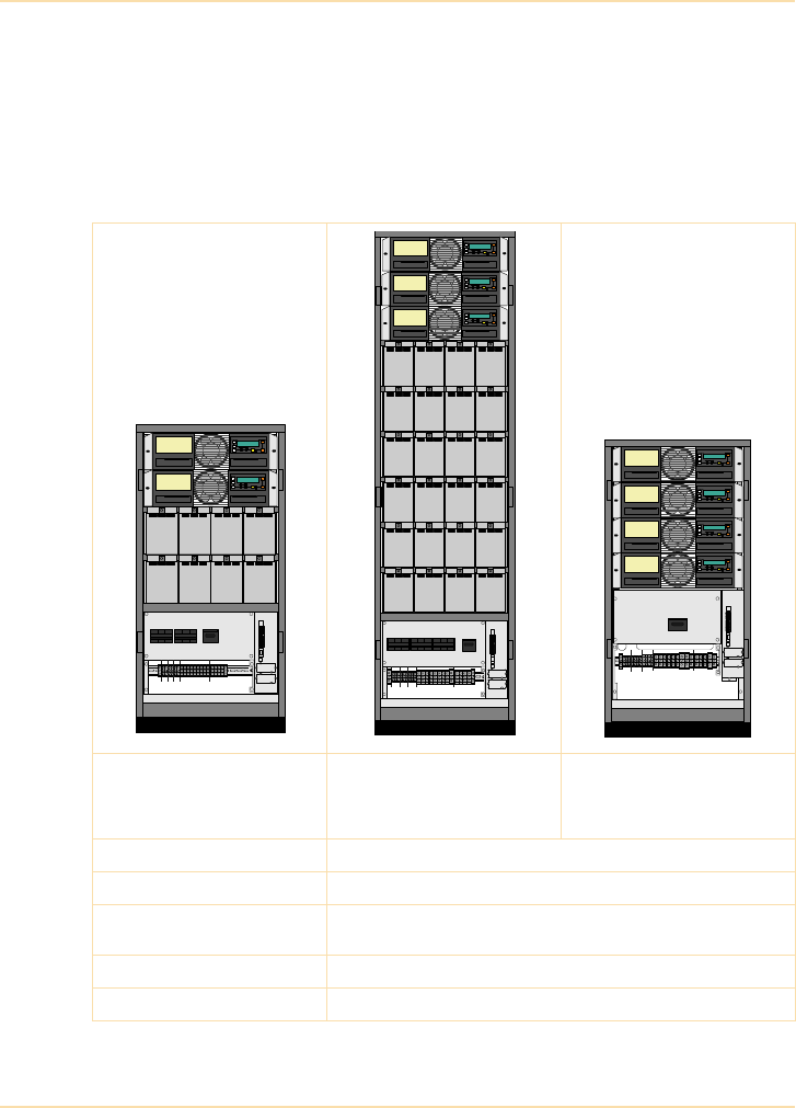
Sample UPS Specifications
310 The UPS Handbook
40- 200 kVA 3-phase modular system
This system comprises a range of cabinets that can be populated with a number
of 10kVA or 20kVA power modules that operate in parallel within the cabinet to
provide the cabinet’s rated output. Each power module is a self-contained UPS
and incorporates a rectifier, inverter and static bypass.
Mechanical data
40KVA
(2x20kVA modules)
(WxDxH 550 x 1135 x770)
Internal battery
60KVA
(3x20kVA modules)
(WxDxH 550 x 1975 x770)
Internal battery
80KVA
(4x20kVA modules)
(WxDxH 550 x 1135 x770)
External battery
Transportation pallet Provided with UPS
Packaging Polythene
Accessibility (operator) Totally front accessibility for service and maintenance (no need for
side, top or rear access)
Positioning Min. 200mm rear space (required for ventilation)
Input/output power cabling From the bottom on the front
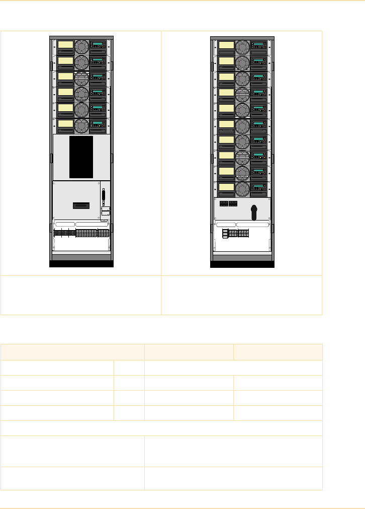
Sample UPS Specifications
The UPS Handbook 311
General data
120KVA
(6x20kVA modules)
(WxDxH 550 x 1975 x770)
External battery
200KVA
(10x20kVA modules)
(WxDxH 550 x 1975 x770)
External battery
Power module rating (kVA) 10 20
Output power factor 1.0
Output rated power @ 0.8 p.f. kVA 10 20
Output rated power @ 1.0 p.f. kW 10 20
Output current In @ 1.0 p.f. A 14.5 (@400 V) 29 (@400 V)
Double conversion AC-AC efficiency
Efficiency AC-AC up to (at Cos 1.0)
(depending on Module power)
Load: 100% 75.0% 50.0% 25.0%
20kVA: 95.5% 95.5% 95.0% 94.5%
10kVA: 95.5% 95.5% 95.0% 94.5%
With linear load at 0.8 p.f. ind.
With non-linear load (EN 62040-1-1:2003)
Typically up to 1% higher of above values
Typically up to 1% lower of above values

Sample UPS Specifications
312 The UPS Handbook
Rectifier data
Battery data
Eco-mode efficiency at 100% load 98%
Remote signalling and alarms
Dry port (volt-free contacts) For remote signalling and automatic computer shutdown
Smart port (RS 232) For monitoring and integration in network management
Input terminals EMERGENCY OFF (normally closed)
GENERATOR-ON (normally open)
BATTERY TEMPERATURE SENSOR
Power module rating (kVA) 10 20
Nominal input voltage V 3x380/220V+N, 3x400V/230V+N, 3x415/240V+N
Input voltage tolerance
(ref to 3x400/230V) for loads in %:
V (-23% to +15%) for <100 % load
(-30% to +15%) for < 80 % load
(-40% to +15%) for < 60 % load
Input frequency Hz 35 – 70
Input power factor PF=0.99 @ 100% load
Inrush current A limited by soft start
Output rated power @ p.f.= 0.8 kVA 10 20
Output rated power @ p.f. = 1.0 kW 10 20
Input distortion THDI Sine-wave THDi = 3% @ 100% load
Max. input power with rated output
power and charged battery (output
p.f. = 1.0)
kW 10.5 21
Max. input current with rated output
power and charged battery (output
p.f. = 1.0)
A15.2 30.4
Max. input power with rated output
power and discharged battery
(output p.f. = 1.0)
kW 11.5 23
Max. input current with rated output
power and discharged battery
(output p.f. = 1.0)
A16.6 33.3
Power module rating (kVA) 10 20
Battery type Maintenance free VRLA or NiCd
Power module rating (kVA) 10 20

Sample UPS Specifications
The UPS Handbook 313
Inverter data
Number of 12V battery blocks No. 24-50 * 36-50 *
Battery ambient temp. °C 20 (recommended)
Battery storage time Maximum 6 months (at ambient temperature)
Temperature controlled battery
charger
Yes (with optional temperature sensor)
Maximum battery charger current A 4 A 4 A
Battery charging curve Ripple free: IU (DIN 41773)
Battery test Automatic and periodically (adjustable)
* Depending of the effective load in kW used by the module
Battery capacity usage 10kVA UPS Module 20kVA UPS Module
Number of battery blocks 24 28 30 34-50 36 40 40 48-50
Max. power in KW 8 8 10 10 16 20 16 20
Max. autonomy (min.) 5 999 5 999 5 5 999 999
Power module rating (kVA) 10 20
Output rated voltage V 3x380/220V or 3x400/230V or 3x415/240V
Output waveform Sinewave
Output frequency Hz 50 Hz or 60 Hz
Output frequency tolerance % Free running, quartz oscillator < ±0.1%
Synchronized with mains < ±2% or < ±4% (selectable)
Permissible unbalanced load % 100% (All 3 phases regulated independently)
Phase angle tolerance Deg. +/- 0 deg. (With 100% unbalanced load)
Inverter overload capability % 125% load for 10 min.
150% load for 60 secs.
Output short capability (RMS) A 3 x In during 40 ms
Crest factor 3: 1
Output voltage stability
Static % < ±1%
Dynamic (with step load 0%-100%
or 100%-0%)
%< ±4%
Output voltage distortion
Power module rating (kVA) 10 20

Sample UPS Specifications
314 The UPS Handbook
Bypass data
Environmental data
With linear load % < 1.5%
With non linear load % < 3% (EN62040-3:2001)
Power module rating (kVA) 10kVA UPS Module 20kVA UPS Module
Bypass operation At nominal input voltage of 3x400 V ±15%,
(196 V to 264 V ph-N)
Bypass short capability (RMS) A 10 x In during 20 ms
Power module rating (kVA) 10 20
Audible noise at 100% / 50% load dBA 55 / 49 57 / 49
Ambient temperature (UPS) °C 0 - 40
Ambient temperature (Batteries) °C 20 (recommended)
Relative air-humidity Max. 95% (non-condensing)
Max. altitude (above sea level) m 1000m (3300ft) without de-rating
Power module rating (kVA) 10 20

Sample UPS Specifications
The UPS Handbook 315
Standards
Derating for altitude
De-rating factor for use at altitudes
above 1000m sea level according
(IEC 62040-3)
Height above sea level
(m / ft)
De-rating factor for power
1500 / 4850 0.95
2000 / 6600 0.91
2500 / 8250 0.86
3000 / 9900 0.82
Heat dissipation with 100% non-
linear load per module
(EN 62040-1-1:2003)
W550 1100
BTU/h 1887 3745
Airflow (25° - 30°C) with non-linear
load per module
(EN 62040-1-1:2003)
m³/h 150 150
Dissipation at no load W 120 150
Power module rating (kVA) 10 20
Safety EN 62040-1-1:2003, EN 60950-1:2001/A11:2004
Electromagnetic compatibility EN 62040-2:2005, EN61000-3-2:2000,
EN61000-3-3:1995/A1:2001, EN61000-6-2:2001
Emission class C2
Immunity class C3
Performance EN62040-3:2001
Product certification CE
Degree of protection IP 20
Power module rating (kVA) 10 20
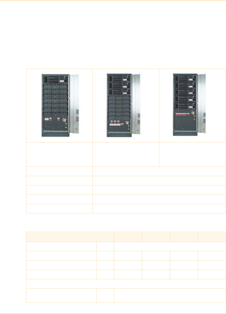
Sample UPS Specifications
316 The UPS Handbook
25- 250 kVA 3-phase modular system
This system comprises a range of cabinets that can be populated with a number
of 25, 30, 40 or 50kVA power modules that operate in parallel within the cabinet
to provide the cabinet’s rated output. Each power module is a self-contained
UPS and incorporates a rectifier/charger, inverter and static bypass.
Mechanical data
General data
25-50kVA
(1 x 25-50kVA module)
Internal Batteries
(WxDxH 730x800x1650)
75-150kVA
(3 x 25-50kVA module)
Internal Batteries
(WxDxH 730x800x1975)
125-250kVA
(5 x 25-50kVA module)
External Batteries
(WxDxH 730x800x1975)
Transportation pallet Provided with UPS
Packaging Polythene
Accessibility Front service access requires minimum 1000mm clearance
Positioning Minimum 200mm rear clearance required for ventilation
Input/output power cabling From bottom front of the cabinet
Power module rating (kVA) 25 30 40 50
Output power factor 0.8
Output Rated Power p.f.=0.8 kVA 25 30 40 50/45*
Output Rated Power p.f.=1.0 kW 20 24 32 40
Output current ln (p.f =1.0 400V) A 29 35 46.5 58
Double conversion AC-AC efficiency
Efficiency with linear load (p.f.=1.0) % Load 25% 50% 75% 100%
Efficiency 93% 94% 94.5% 94.5%

Sample UPS Specifications
The UPS Handbook 317
Rectifier data
Battery data
Remote signalling and alarms
Dry port (volt-free contacts) For remote signalling and automatic computer shutdown
Smart port (RS 232) For monitoring and integration in network management
Input terminals EMERGENCY OFF (normally closed)
GENERATOR-ON (normally open)
BATTERY TEMPERATURE SENSOR
*On-Inverter mode 50kVA/40kW, On-Bypass mode 45kVA/40kW
Power module rating (kVA) 25 30 40 50
Nominal input voltage V 3x380/220V +N, 3x400V/230V +N, 3x415/240V +N
Input voltage tolerance
(ref to 3x400/230V) for loads in %:
V(-23% to +15%) for <100 % load
(-30% to +15%) for < 80 % load
(-40% to +15%) for < 60 % load
Input frequency Hz 35 - 70
Input power factor PF=0.99 @ 100% load
Input distortion THDi Sinewave THDi = < 2% @ 100% load
Max. input power with rated output
power and charged battery per
module (p.f.=1.0)
kW 21.3 25.4 33.9 42.9
Max. input current with rated
output power and charged battery
per module (p.f.=1.0)
A30.8 36.8 49.1 62.1
Max. input power with rated output
power and discharged battery per
module (p.f.=1.0)
kW 23.3 27.8 37.1 46.9
Max. input current with rated
output power and discharged
battery per module (p.f.=1.0)
A33.7 40.3 53.7 68.0
Power module rating 25 30 40 50
Battery type Lead acid maintenance free VRLA or NiCd
Number of 12V battery blocks 48-50
Battery ambient temperature 20°C (recommended)
Battery storage time Maximum 6 months (at ambient temperature)
Power module rating (kVA) 25 30 40 50

Sample UPS Specifications
318 The UPS Handbook
Inverter data
Temperature controlled battery charger Yes (with optional temperature sensor)
Maximum battery charger current 6A Standard
(10A option)
10A Standard
(15A option)
Battery charging curve Ripple-free; IU (DIN 41773)
Battery test Automatic and periodic (adjustable)
Power module rating 25 30 40 50
Output rated voltage V 3x380/220V, 3x400V/230V, 3x415/240V
Output power factor 0.8
Output waveform Sinewave
Output frequency Hz 50 or 60
Output frequency tolerance % Free running = < ±0.15
Synchronised with mains = < ±2 or < ±4 (selectable)
Overload capability 125% Load = 10min
150% Load = 60secs
Output short capability (rms) A Inverter: 2 x In for duration of 250 ms
Permissible unbalanced load 100%, 3 phase regulated independently
Crest factor 3 : 1
Output Voltage Stability
Static < ±1%
Dynamic (step load 0%-100% or 100%-0%) < ±4%
Output Voltage Distortion
With linear load < 2.0%
With non linear load < 3% (EN62040-3:2001)
Power module rating 25 30 40 50

Sample UPS Specifications
The UPS Handbook 319
Bypass data
Environmental data
Power module rating 25 30 40 50
Bypass operation % At nominal input voltage of 3x400 V ±15%,
(196 V to 264 V ph-N)
Output short capability (rms) A 10 x In for duration of 10 ms
Power module rating (kVA) 25 30 40 50
Audible noise at 100% / 50% load dBA 57/49 59/51 65/55 65/55
Ambient temperature (UPS) °C 0 - 40
Ambient temperature (Batteries) °C 20 (recommended)
Relative Air-humidity Max. 95% (non-condensing)
Ambient Temperature for Batteries
(recommended)
°C 20
Max. altitude (above sea level) m 1000m (3300ft) without de-rating
Derating for altitude
De-rating factor for use at altitudes
above 1000m sea level according
(IEC 62040-3)
Height above sea level
(m/ft)
De-rating factor for power
1500 / 4850 0.95
2000 / 6600 0.91
2500 / 8250 0.86
3000 / 9900 0.82
Heat dissipation with 100%
non-linear load
(EN 62040-1-1:2003)
W 1500 1670 2225 2780
BTU/h 5118 5698 7592 9485
Airflow (25° - 30°C) with non-linear
load (EN 62040-1-1:2003)
m³/h 150 380

Sample UPS Specifications
320 The UPS Handbook
Standards
Power module rating (kVA) 25 30 40 50
Safety EN 62040-1-1:2003, EN 60950-1:2001/A11:2004
Electromagnetic compatibility EN 62040-2:2005, EN61000-3-2:2000,
EN61000-3-3:1995/A1:2001, EN61000-6-2:2001
Emission class C2
Immunity class C3
Performance EN62040-3:2001
Product certification CE
Degree of protection IP 20
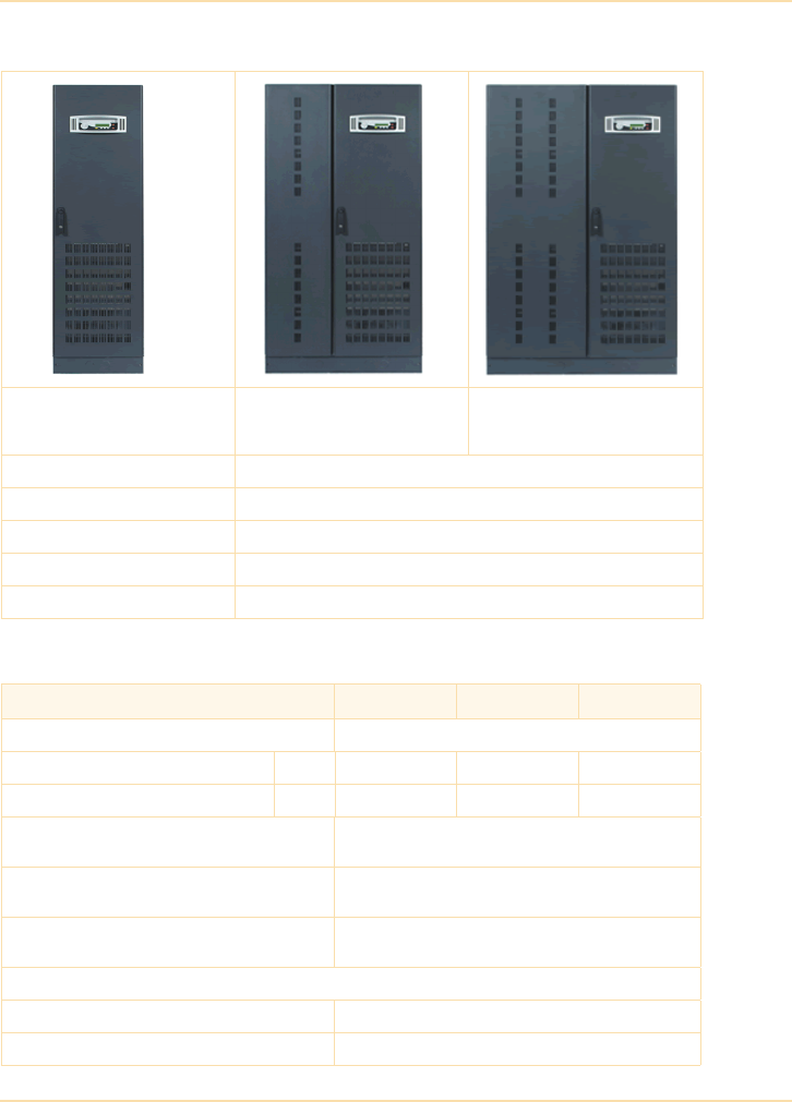
Sample UPS Specifications
The UPS Handbook 321
60, 80, 100kVA 3-phase input and output
General data
60, 80, 100kVA
Without internal batteries
(WxDxH 550 x 750 x 1820)
60, 80, 100kVA
With (80) internal batteries
(WxDxH 970 x 750 x 1820)
60, 80, 100kVA
With (120) internal batteries
(WxDxH 1180 x 750 x 1820)
Transportation pallet Provided with UPS
Packaging Polythene
Accessibility Front access for operator and service
Positioning Min 200mm rear clearance required for ventilation
Input/output power cabling From below UPS, terminations at front
Module rating (kVA) 60 80 100
Power factor 1.0
Output rated power kW 60 80 100
Output current In (PF=1.0) A 87 116 145
Topology and technology On-line, double conversion.
Third generation, transformerless
Parallel configuration For added redundancy and/or capacity a parallel
system can be extended to up to 10 modules
Double conversion AC-AC efficiency with fully
charged battery and linear load (pf=1.0)
Load(%) 25 50 75 100
eff. (%) 95.5 96.0 95.5 95.0
Remote signalling and alarms
Dry port (volt-free contacts) Remote signalling and auto. computer shutdown
Smart Port (RS 232) Remote control/integration in network management

Sample UPS Specifications
322 The UPS Handbook
Rectifier data
Battery data
External inputs Emergency Off (normally closed)
Generator On (normally open)
Module rating (kVA) 60 80 100
Input voltage V 3x380, 3x400, 3x 415 +N
Input voltage tolerance (ref to
3x400/230V) for loads in %:
% (-23% to +15%) for <100 % load
(-30% to +15%) for < 80 % load
(-40% to +15%) for < 60 % load
Other input voltages On Request
Input frequency Hz 35-70
Input power factor 0.99
Inrush current Limited by soft-start
Input current form (100% load) Sinewave <3.5% distortion
Max. input power with charged
battery and rated output power
kW 64 85 107
Max. input current with rated output
power and charged battery (pf=1.0)
A 93 123 154
Max. input power with rated output
power and discharged battery
kW 70 94 117
Max. input current with rated output
power and discharged battery
(pf=1.0)
A102 136 170
Module rating (kVA)
60 80 100
Battery type Lead-acid, maintenance-free
Variable number of 12V battery blocks 44-50 (only even numbers allowed)
Battery ambient temperature 20°C (recommended)
Battery storage time Maximum 6 months (at ambient temperature)
Temperature controlled battery charger Yes (with optional temperature sensor)
Battery charger current (max) (standard) Adjustable up to 25A
Battery charging curve Ripple free, IU (DIN 41773)
Battery test Automatic and periodic, adjustable

Sample UPS Specifications
The UPS Handbook 323
Inverter data
Bypass data
Module rating (kVA) 60 80 100
Output rated voltage V 3x 380/220 or 3x 400/230 or 3x 415/250
Power factor 1.0
Output waveform Sinewave with 0deg. phase imbalance @100%
unbalanced load
Permissible unbalanced load % 100% (all 3 phases independently regulated)
Output frequency Hz 50 or 60
Output frequency tolerance % Free running = < ±0.15
Synchronised with mains = < ±2 or < ±4 (selectable)
Frequency slew rate Hz/s 1.0
Overload capability on inverter % At PF=1.0 110% load for 10 minutes
At PF=1.0 135% load for 1 minute
At PF=0.9 125% load for 10 minutes
At PF=0.9 150% load for 1 minute
Inverter short circuit capability
(x rated output for 40ms)
A2.7x 2.0x 2.3x
Crest-factor 3:1
Output voltage stability
Static % < ± 1.0
Dynamic % < ±4 (with load step 0-100%, 100-0%)
Output voltage distortion
With linear load % < 2 with linear load
With non-linear load % < 4 (EN 62040-3:2001)
Module rating (kVA) 60 80 100
Bypass short capability (RMS) A 10 x In during 10 ms
Load transfer time – inverter to bypass
Load transfer time – bypass to inverter
ms 0.0 ms
< 1.0 ms
Minimum mains voltage before bypass
inhibited
V At nominal input voltage of 3x400 V ±15%,
(196 V to 264 V ph-N)
Integrated maintenance bypass Yes

Sample UPS Specifications
324 The UPS Handbook
Environmental data
Standards
Module rating (kVA) 60 80 100
Audible noise with 100%/75% load dBA <65
Ambient temperature (UPS) ºC 0 - 40
Ambient temperature (Batteries) ºC 20 (recommended)
Cooling
Cooling airflow (25 - 30°C) with
100% non-linear load
m³/h 1300 1500 1700
Heat dissipation
Heat dissipation without load W 850
Heat dissipation with
100% non-linear load
W3830 5106 6368
Heat dissipation with
100% non-linear load
BTU/h 13071 17428 21785
Module rating (kVA) 60 80 100
Safety EN62040-1-1:2003 EN60950-1:2001/A11/;2004
Electromagnetic compatibility IEC/EN 62040-2:2005, IEC/EN61000-3-2:2000,
IEC/EN61000-6-2:2001,
Performance IEC/EN 62040-3:2001
Product certification CE
Degree of protections IP20
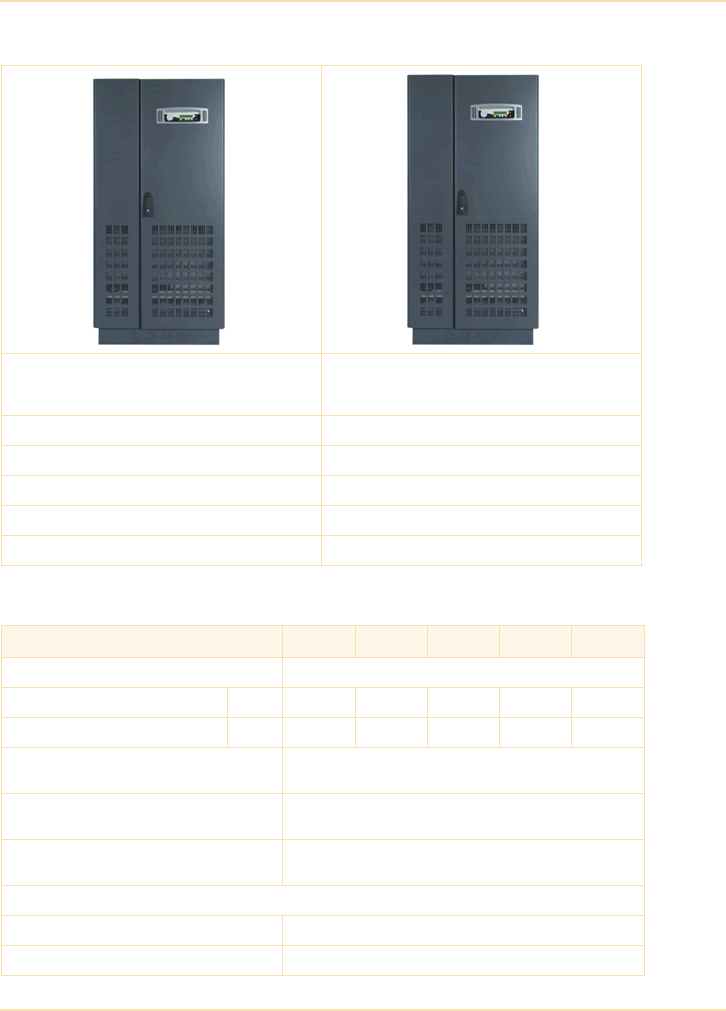
Sample UPS Specifications
The UPS Handbook 325
120, 160, 200, 250, 300kVA, 3-phase input and output
General data
120, 160, 200kVA
Without internal batteries
(WxDxH 850 x 750 x 1820)
250, 300kVA
Without internal batteries
(WxDxH 1100 x 750 x 1920)
Transportation pallet Provided with UPS
Packaging Polythene
Accessibility Front access for operator and service
Positioning Min 200mm rear clearance required for ventilation
Input/output power cabling From below UPS, terminations at front
Module rating (kVA) 120 160 200 250 300
Power factor 1.0
Output rated power kW 120 160 *200 250 300
Output current In (PF=1.0) A 174 232 *290 361 433
Topology and technology On-line, double conversion.
Third generation, transformerless
Parallel configuration For added redundancy and/or capacity a parallel system
can be extended to up to 10 modules
Double conversion AC-AC efficiency with
fully charged battery and linear load (pf=1.0)
Load(%) 25 50 75 100
eff. (%) 95.5 96.0 95.5 95.0
Remote signalling and alarms
Dry port (volt-free contacts) Remote signalling and auto. computer shutdown
Smart Port (RS 232) Remote control/integration in network management

Sample UPS Specifications
326 The UPS Handbook
Rectifier data
Battery data
External inputs EMERGENCY OFF (normally closed)
GENERATOR ON (normally open)
* with 50 battery blocks only
Module rating (kVA) 120 160 200 250 300
Input voltage V 3x380, 3x400, 3x 415 +N
Input voltage tolerance (ref to
3x400/230V) for loads in %:
% (-23% to +15%) for <100 % load
(-30% to +15%) for < 80 % load
(-40% to +15%) for < 60 % load
Other input voltages Available on request
Input frequency Hz 35-70
Input power factor 0.99 @100% load
Inrush current Limited by soft-start
Input current form (100% load) Sinewave <3.5% distortion
Max. input power with charged
battery and rated output power
kW 128 170 213 266 319
Max. input current with rated output
power and charged battery
A185247308386 463
Max. input power with rated output
power and discharged battery
kW 141 187 234 293 351
Max. input current with rated output
power and discharged battery
A204271339424 509
Module rating (kVA) 120 160 200 250 300
Battery type Lead-acid, maintenance-free
Variable number of 12V battery blocks
(only even numbers allowed)
44-50 50 44-50
Battery ambient temperature 20°C (recommended)
Battery storage time Maximum 6 months (at ambient temperature)
Temperature controlled battery charger Yes (with optional temperature sensor)
Battery charger current (adjustable) Up to 50A Up to 60A
Battery charging curve Ripple free, IU (DIN 41773)
Battery test Automatic and periodic, adjustable

Sample UPS Specifications
The UPS Handbook 327
Inverter data
Bypass data
Module rating (kVA) 120 160 200 250 300
Output rated voltage V 3x 380/220 or 3x 400/230 or 3x 415/250
Output power factor 1.0
Output waveform Sinewave with 0deg. phase imbalance @100%
unbalanced load
Permissible unbalanced load % 100% (all 3 phases independently regulated)
Output frequency Hz 50 or 60
Output frequency tolerance % Free running = < ±0.15
Synchronised with mains = < ±2 or < ±4 (selectable)
Frequency slew rate Hz/s 1.0
Overload capability on inverter % At PF=1.0 110% load for 10 minutes
At PF=1.0 135% load for 1 minute
At PF=0.9 125% load for 10 minutes
At PF=0.9 150% load for 1 minute
Inverter short circuit capability
(x rated output for 40ms)
A1.8x1.9x2.1x1.8x2.0x
Crest-factor 3:1
Output voltage stability
Static % < ± 1.0
Dynamic % < ±4 (for load step 0-100%, 100-0%)
Recovery time after load step
(0-100%, 100-0%)
ms 20
Output voltage distortion
With linear load % < 2
With non-linear load % < 4 (EN 62040-3:2001)
Rated output power (kVA) 120 160 200 250 300
Load transfer time – inverter to bypass
Load transfer time – bypass to inverter
0.0 ms
< 1.0 ms
Minimum mains voltage before bypass
inhibited
190V
Integrated maintenance bypass Yes
Bypass short capability (RMS) A 10 x In during 10 ms

Sample UPS Specifications
328 The UPS Handbook
Environmental data
Standards
Rated output power (kVA) 120 160 200 250 300
Audible noise with 100%/75% load dBA <69 71
Ambient temperature (UPS) ºC 0 - 40
Ambient temperature (Batteries) ºC 20 (recommended)
Cooling
Cooling airflow (25 - 30°C) with
100% non-linear load
m³/h 2500 3350
Heat dissipation
Heat dissipation with
100% non-linear load
W 7660 10213 12766 15957 19149
Heat dissipation with
100% non-linear load
BTU/h 26142 34856 43570 54462 65355
Heat dissipation without load W 1500 2300
Rated output power (kVA) 120 160 200 250 300
Safety EN62040-1-1:2003 EN60950-1:2001/A11/;2004
Electromagnetic compatibility IEC/EN 62040-2:2005, IEC/EN61000-3-2:2000,
IEC/EN61000-6-2:2001,
Performance IEC/EN 62040-3:2001
Product certification CE
Degree of protections IP20
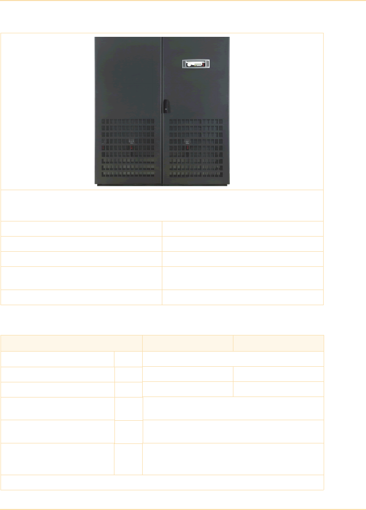
Sample UPS Specifications
The UPS Handbook 329
400, 500kVA 3-phase input and output
General data
400, 500kVA
Without internal batteries
(WxDxH 1650 x 850 x 1940)
Transportation pallet Provided with UPS
Packaging Polythene
Accessibility Front access for operator and service
Positioning Minimum 100mm from side and 400mm top
clearance for fan exhaust. No rear space required.
Input/output power cabling From below UPS, terminations at front
Rated output power (kVA) 400 500
Power factor 1.0
Output rated power kW 400 500
Output current In (PF=1.0) A 577 722
Topology and technology On-line, double conversion.
Third generation, transformerless
Parallel configuration For added redundancy and/or capacity a parallel system
can be extended to up to 10 modules
Double conversion AC-AC
efficiency with fully charged battery
and linear load (pf=1.0)
Load(%) 25 50 75 100
eff. (%) 95.5 96.0 95.5 95.0
Remote signalling and alarms

Sample UPS Specifications
330 The UPS Handbook
Rectifier data
Battery data
Dry port (volt-free contacts) Remote signalling and auto. computer shutdown
Smart Port (RS 232) Remote control/integration in network management
External inputs EMERGENCY OFF (normally closed)
GENERATOR ON (normally open)
MAINTENANCE BYPASS (normally open)
OUTPUT ISOLATOR (normally open)
Module rating (kVA) 400 500
Input voltage V 3x380, 3x400, 3x 415 +N
Input voltage tolerance (ref to
3x400/230V) for loads in %:
%(-23% to +15%) for <100 % load
(-30% to +15%) for < 80 % load
(-40% to +15%) for < 60 % load
Other input voltages Available on request
Input frequency Hz 35-70
Input power factor 0.99 @100% load
Inrush current Limited by soft-start
Input current form (100% load) Sinewave <3.5% distortion
Output voltage tolerance % ± 1
Max. input power with charged
battery and rated output power
kW 426 532
Max. input current with rated output
power and charged battery
A617 771
Max. input power with rated output
power and discharged battery
kW 468 585
Max. input current with rated output
power and discharged battery
A679 848
Rated output power (kVA) 400 500
Battery type Lead-acid, maintenance-free
Variable number of 12V battery blocks
(only even numbers allowed)
44-50
Battery ambient temperature 20°C (recommended)
Battery storage time Maximum 6 months (at ambient temperature)
Temperature controlled battery charger Yes (with optional temperature sensor)

Sample UPS Specifications
The UPS Handbook 331
Inverter data
Battery charger current (adjustable) Up to 60A Up to 100A
Battery charging curve Ripple free, IU (DIN 41773)
Battery test Automatic and periodic, adjustable
Rated output power (kVA) 400 500
Output rated voltage V 3x 380/220 or 3x 400/230 or 3x 415/250
Output power factor 1.0
Output waveform Sinewave with 0deg. phase imbalance @100%
unbalanced load
Permissible unbalanced load % 100% (all 3 phases independently regulated)
Output frequency Hz 50 or 60
Output frequency tolerance % Free running = < ±0.15
Synchronised with mains = < ±2 or < ±4 (selectable)
Frequency slew rate Hz/s 1.0
Overload capability on inverter % At PF=1.0 110% load for 10 minutes
At PF=1.0 135% load for 1 minute
At PF=0.9 125% load for 10 minutes
At PF=0.9 150% load for 1 minute
Inverter short circuit capability
(x rated output for 40ms)
A 2.0 x ln
Crest-factor 3:1
Output voltage stability
Static % < ± 1.0
Dynamic % < ±4 (for load step 0-100%, 100-0%)
Recovery time after load step
(0-100%, 100-0%)
ms 20
Output voltage distortion
With linear load % < 2
With non-linear load % < 4 (EN 62040-3:2001)

Sample UPS Specifications
332 The UPS Handbook
Bypass data
Environmental data
Standards
Rated output power (kVA) 400 500
Load transfer time – inverter to bypass
Load transfer time – bypass to inverter
0.0 ms
< 1.0 ms
Minimum mains voltage before bypass
inhibited
190V
Integrated maintenance bypass Yes (option)
Bypass short capability (RMS) A 10 x In during 10 ms
Rated output power (kVA) 400 500
Audible noise with 100%/75% load dBA
Ambient temperature (UPS) ºC 0 - 40
Ambient temperature (Batteries) ºC 20 (recommended)
Cooling
Cooling airflow (25 - 30°C) with
100% non-linear load
m³/h 6550
Heat dissipation
Heat dissipation with
100% non-linear load
W 24000 30000
Heat dissipation with
100% non-linear load
BTU/h 81913 102389
Heat dissipation without load W 4000
Rated output power (kVA) 400 500
Safety EN62040-1-1:2003 EN60950-1:2001/A11/;2004
Electromagnetic compatibility IEC/EN 62040-2:2005, IEC/EN61000-3-2:2000,
IEC/EN61000-6-2:2001,
Performance IEC/EN 62040-3:2001
Product certification CE
Degree of protections IP20
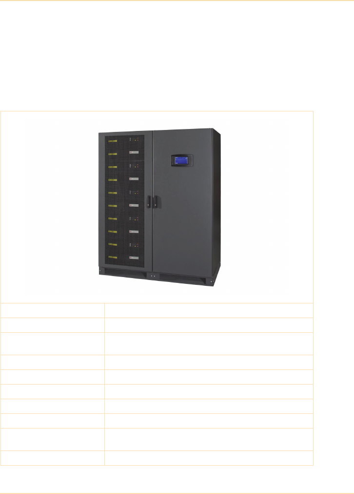
Sample UPS Specifications
The UPS Handbook 333
100- 500 kVA 3-phase modular system
This system comprises a cabinet that can be populated with up to five 100kVA
power modules that operate in parallel within the cabinet to provide the
cabinet’s rated output. Each power module is a self-contained UPS and
incorporates a rectifier, inverter and static bypass. Six of the cabinets shown can
be connected together to form a 3 MVA parallel system.
Mechanical data (cabinet frame)
Maximum cabinet rating 500 kVA / 500kW (with 5 power modules fitted)
Dimensions (W x D x H) mm 1580 x 945 x 1975
UPS Type On-line, transformerless, modular, decentralized parallel
architecture
Parallel capability Up to 6 frames (with up to 5 x 100 kVA modules in each frame)
Battery Not included
Performance specification VFI-SS-111
Weight 975 kg (with five power modules fitted)
Colour Graphite Grey (RAL 7024)
Positioning Min. 200mm rear space (required for ventilation)
Min. 900mm required at front for access
Input/output power cabling From the top or bottom

Sample UPS Specifications
334 The UPS Handbook
Mechanical Data (100 kVA Power Module)
Dimensions (W x H x D) mm 710 x 178 x 750
Weight (kg) 55 (active module) 54 (passive module)
UPS Type On-line, transformerless, modular, decentralized parallel
architecture
General data
100 kVA UPS Module
Output power factor 1.0
Output rated power @ 0.8 p.f. kVA 100
Output rated power @ 1.0 p.f. kW 100
Output current In @ 1.0 p.f. A 145 (@400 V)
Efficiency AC-AC up to (at Cos 1.0) Load: 100% 75.0% 50.0% 25.0%
95.6% 96.0% 96.1% 95.8%
Eco-mode efficiency at 100% load 99% or better
Remote signalling and alarms
Dry port (volt-free contacts) For remote signalling and automatic computer shutdown
Smart port (RS 232) For monitoring and integration in network management
RS485 on RJ45 port For remote monitoring (optional)
RS485 on RJ45 port For multidrop purposes
SNMP card slot For monitoring and integration in network management
Input terminals EMERGENCY OFF (normally closed)
GENERATOR-ON (normally open)
BATTERY TEMPERATURE SENSOR
Active Sub-module Passive Sub-module

Sample UPS Specifications
The UPS Handbook 335
Rectifier data
100 kVA UPS Module
Nominal input voltage V 3x380/220V+N, 3x400V/230V+N, 3x415/240V+N
(Three phases and Neutral required)
Input voltage tolerance
(ref to 3x400/230V) for loads in %:
V (-23% to +15%) for <100 % load
(-30% to +15%) for < 80 % load
(-40% to +15%) for < 60 % load
Input frequency Hz 35 – 90 (nominal 50)
Input power factor PF=0.99 @ 100% load
Inrush current A <100 of rated current, limited by soft start
Input distortion THDI <3.5% @ 100% load
Max. input current with rated output
power and charged battery (output
p.f. = 1.0)
A152
Max. input current with rated output
power and discharged battery
(output p.f. = 1.0)
A167
Battery data (external)
Technology VRLA, vented lead acid, NiCd
Number of 12V blocks (even and odd)
@ 380/220V or 400/230V output 40 to 50
@ 415/240V output 42 to 50
Number of NiCd cells (even and odd)
@ 380/220V or 400/230V output 400 to 500
@ 415/240V output 420 to 500
Charger capability (each module) A 60.0
Ripple current (rms) % < 2.0
Floating voltage VDC 2.25 VLRA / 1.4 (NiCd)
End of discharge voltage VDC 1.65 VLRA / 1.05 (NiCd)
Temperature compensation Optional
Battery test Automatic and periodic (selectable)
Max. input current with rated output
power and discharged battery
(output p.f. = 1.0)
A167

Sample UPS Specifications
336 The UPS Handbook
Inverter data
100 kVA UPS Module
Output voltage (steady state rms) V 3x380/220V or 3x400/230V or 3x415/240V
(Three phase + Neutral)
Output voltage variation % ± 1.5 (Normal and battery mode)
Output waveform Sinewave
Output current (rms rated) A 145
Output frequency Hz 50 Hz or 60 Hz
Output frequency tolerance % Free running, quartz oscillator < ±0.1%
Synchronized with mains < ±2% or < ±4% (selectable)
Permissible unbalanced load % 100% (All 3 phases regulated independently)
Phase angle tolerance Deg. +/- 0 deg. (With 100% unbalanced load)
Inverter overload capability % 110% load for 60 mins.
125% load for 10 mins.
150% load for 30 secs.
Output short capability (rms) A 2.6 x In during 40 ms
Output voltage transient recovery time with 100% step load
Linear % < ±4%
Non linear % < ±4% (EN62040-3)
Output voltage distortion (THD) @100% load (normal and battery mode)
With linear load % < 2.0%
With non linear load % < 4% (EN62040-3)
Static Bypass data
100 kVA UPS Module
Transfer break time ms 1.5
Rated current A160
overload current %110% load for 85 mins.
125% load for 65 mins.
150% load for 50 mins.
Bypass short capability (RMS) A 10 x In during 20 ms

Sample UPS Specifications
The UPS Handbook 337
Environmental data
100 kVA UPS Module
Audible noise at 100% / 50% load dBA
Ambient temperature (UPS) °C 0 to 40
Storage temperature (UPS) °C -25 to +40
Ambient temperature (Batteries) °C 20 (recommended)
Relative air-humidity Max. 95% (non-condensing)
Max. altitude (above sea level) m 1000m (3300ft) without de-rating
Heat dissipation with 100% non-
linear load per module
(EN 62040-1-1:2003)
W4500
BTU/h 15359
Airflow (25° - 30°C) with non-linear
load per module
(EN 62040-1-1:2003)
m³/h 1200
Dissipation at no load W 660
Standards
100 kVA UPS Module
Safety EN 62040-1-1
Electromagnetic compatibility EN 62040-2
Emission class C2
Immunity class C3
Performance EN62040-3
Product certification CE
Degree of protection IP 20

338 The UPS Handbook

RG27 9XA
