AFJQS Cover Letter URC 119 Technician Training Manual
User Manual: URC-119-Technician-Training-Manual Harris
Open the PDF directly: View PDF ![]() .
.
Page Count: 130 [warning: Documents this large are best viewed by clicking the View PDF Link!]
- AF FORM 797
- TRAINER’S GUIDE
- RT-1446 Transceiver Operation
- C-11329 Remote Control Unit (RCU) and CU-2310 Antenna Coupler Operation
- AM-7223/7224 Linear Power Amplifier (LPA) Operation
- Preventive Maintenance Inspections
- Fault Isolation
- RT-1446 Transmit Alignments
- RT-1446 Transmit/Receive (T/R) Alignments
- RT-1446 Receive Alignments
- RT-1446 Reference Frequency Alignments
- RT-1446 Transceiver Control/Power Supply Alignments
- C-11329 Remote Control Unit Alignments
- AM-7223 Linear Power Amplifier Alignments
- CU-2310 Antenna Coupler Alignments
- AM-7224 Linear Power Amplifier Alignments
- Training Completion Certification
- SKILL TRAINING MATERIAL
- KNOWLEDGE EVALUATION PAMPHLET (KEP)

DEPARTMENT OF THE AIR FORCE Air Force Job Qualification
Headquarters US Air Force Standard 2E1X3-206N
Washington DC 20330-1680 2E1X3-206.14
1 October 1999
AN/URC-119(V) HF COMMUNICATIONS SYSTEM
(Ground Radio Communications Journeyman/Craftsman)
SECTION A: GENERAL
1. This Air Force Job Qualification Standard (AFJQS) and attached Air Force Qualification Training
Package (AFQTP) standardize on-the-job training (OJT) tasks and constitute an approved training program
for the AN/URC-119(V). The AFJQS and AFQTP are used by unit training managers, supervisors, trainers,
trainees, and other training functions to plan, conduct, and document OJT on this equipment.
2. Maintain the AFJQS IAW AFI 36-2201, AFI 36-2233, and AFMAN 36-2247. Routine changes will
be accomplished via page changes and urgent changes will be disseminated via message. Enter additional
local tasks in the blank areas on the AFJQS or add forms. Develop Task Training Guides for added tasks;
they should be consistent in content and format with those in the AFQTP. Submit recommended
AFJQS/AFQTP improvements/corrections to the 81 TRSS Qualification Training Flight (81 TRSS/TSQS),
601 D Street, Keesler AFB MS 39534-2229.
3. Review Air Force publishing bulletins and AFIND8 to identify available training materials. Use this
AFJQS in conjunction with other applicable JQSs or the Career Field Education and Training Plan (CFETP)
and locally assigned tasks to identify work center duty positions. Also, use this AFJQS along with other
applicable JQSs and the CFETP to evaluate newly assigned personnel and identify individual training
requirements.
4. Tasks listed on the AFJQS have been selected IAW the Instructional System Development (ISD)
process and are the minimum, mandatory AF training requirements for this equipment/function. The “X”
code in the Core Task column of the AF Form 797 is used to indicate that the individual must be trained and
certified on that particular task. The “X*” code identifies tasks that may not be common to all equipment
configurations; however, the task must be trained if it is assigned to the individual’s duty position. The “—”
code is used to indicate that training on this task is a local determination while ensuring 100% task coverage
within the work center.
5. Trainees must accurately perform each assigned task unassisted IAW Technical References (TR) prior
to being certified. To qualify for skill-level upgrade, trainees must be certified on assigned tasks,
satisfactorily complete career knowledge training, and meet mandatory specialty qualifications IAW AFI 36-
2101, AFI 36-2201, and AFMAN 36-2108. After upgrade, assign individuals to other work center duty
positions and continue qualification training.
____________
Supersedes AFJQS 2E1X3-206N, dated 2 September 1999
OPR: HQ USAF/ILMM
OCR: 81 TRSS/TSQR
DISTRIBUTION: X

SECTION B: DOCUMENTATION
1. AFJQS/CFETP tasks will be compiled in an automated training management system, such as the Core
Automated Maintenance System (CAMS), if available. The system must contain each AFJQS/CFETP title
line with appropriate AFJQS/CFETP numbers, titles, and dates. AFJQS/CFETP and automated
documentation requirements are listed below. The alphanumeric AFJQS number is converted to a dotted
decimal number for use in CAMS. Alphanumeric numbers have been converted by retaining the 200 series
number and changing the alpha character to the corresponding number, i.e., -200B becomes -200.2 and -
201LB becomes -201.12.2.
a. Load applicable tasks in the automated training system or identify training requirements by
circling the task numbers on each individual's AFJQS/CFETP.
b. If task statements contain more than one noun or action verb which precludes certification on the
entire task, load/circle the noun or verb to indicate the individual is being trained only on that portion of the
task.
c. When training is started on a task, enter the start date in the appropriate place. When training is
complete, document training and task certification IAW local certification procedures.
2. The identification blocks listed below are to be used when the trainer is other than the trainee's
immediate supervisor.
TRAINEE'S NAME: INITIALS: SSN:
TRAINER'S NAME, INITIALS, DATE:
TRAINER'S NAME, INITIALS, DATE:
TRAINER'S NAME, INITIALS, DATE:
TRAINER'S NAME, INITIALS, DATE:
TRAINER'S NAME, INITIALS, DATE:
BY ORDER OF THE SECRETARY OF THE AIR FORCE
OFFICIAL JOHN W. HANDY, Lieutenant General, USAF
Deputy Chief of Staff/Installations and Logistics
4 Atch
1. AF Form 797
2. Trainer's Guide
3. Skill Training Material
4. Knowledge Evaluation Pamphlet

JOB QUALIFICATION STANDARD CONTINUATION/COMMAND JQS
CERTIFICATION
TASKS, KNOWLEDGE, AND TECHNICAL REFERENCES
206.14.1 EQUIPMENT OPERATION
206.14.1.1 Operate RT-1446 transceiver
TR: 31R2-2URC-81, pgs 3-1 thru 4-26 X
206.14.1.2 Operate C-11329 remote control unit (RCU)
TR: 31R2-2URC-91, pgs 3-1 thru 4-26 X
206.14.1.3 Operate CU-2310 antenna coupler
TR: 31R2-2URC-111, pgs 3-1 thru 4-2 X
206.14.1.4 Operate AM-7223 Linear Power Amplifier (LPA)
TR: 31R2-2URC-101, pgs 3-1 thru 4-8 X*
206.14.1.5 Operate AM-7224 LPA with PP-7913/URC
TR: 31R2-2URC-121, pgs 3-1 thru 3-3 and 35C1-2-892-1, pgs 3-1 thru
4-3
X*
206.14.2 PREVENTIVE MAINTENANCE INSPECTIONS
206.14.2.1 Perform 56-day inspection
TR: 31R2-2URC-86WC-1, cards 1-001 thru 1-007 and 2-001 thru 2-003; 31R2-
2URC-96WC-1, cards 1-001 thru 1-007; 31R2-2URC-106WC-1, cards 1-001 thru
2-003; 31R2-2URC-116WC-1, cards 1-001 thru 1-007 and 2-001 thru 2-003
X
206.14.2.2 Perform 168-day inspection
TR: 31R2-2URC-106WC-1, cards 2-004 and 2-005; 31R2-2URC-116WC-1,
cards 2-001 thru 2-003; 35C1-2-892-6WC-1, cards 2-004 and 2-005
__
206.14.2.3 Perform 336-day inspection
TR: 31R2-2URC-86WC-1, cards 1-008 and 1-009 __
TRAINEE NAME (Last, First, MI) CFETP/JQS NUMBER
2E1X3-206N PAGE NO1
AF FORM 797, FEB 99 (EF-V1) PREVIOUS EDITIONS ARE OBSOLETE
CORE TASK
START DATE
COMPLETE
DATE
TRAINEE'S
INITIALS
TRAINER'S
INITIALS
CERTIFYING
OFFICIAL'S
INITIALS

JOB QUALIFICATION STANDARD CONTINUATION/COMMAND JQS
CERTIFICATION
TASKS, KNOWLEDGE, AND TECHNICAL REFERENCES
206.14.3 ISOLATE FAULTS
206.14.3.1 Perform fault isolation on RT-1446/URC transceiver
TR: 31R2-2URC-81, pgs 6-2 thru 6-11 __
206.14.3.2 Perform fault isolation on C-11329/URC RCU
TR: 31R2-2URC-91, pgs 6-2 thru 6-6 __
206.14.3.3 Perform fault isolation on AM7223/URC RF amplifier and/or
AM-7224/URC RF amplifier
TR: 31R2-2URC-101, pgs 6-2 thru 6-29; 31R2-2URC-121, pgs 6-3 thru 6-29
__
206.14.3.4 Perform fault isolation on CU-2310/URC antenna coupler
TR: 31R2-2URC-111, pgs 6-2 thru 6-4 __
206.14.4 RT-1446 ALIGNMENTS
TR: 31R2-2URC-81
206.14.4.1 Align exciter assembly A1A1
TR: para 6-30a __
206.14.4.2 Align Intermediate Frequency (IF) filter assembly A1A2
TR: para 6-30b __
206.14.4.3 Align first converter assembly A1A3
TR: para 6-30c __
206.14.4.4 Align low pass filter assembly A1A5
TR: para 6-30e __
TRAINEE NAME (Last, First, MI) CFETP/JQS NUMBER
2E1X3-206N PAGE NO2
AF FORM 797, FEB 99 (EF-V1) PREVIOUS EDITIONS ARE OBSOLETE
CORE TASK
START DATE
COMPLETE
DATE
TRAINEE'S
INITIALS
TRAINER'S
INITIALS
CERTIFYING
OFFICIAL'S
INITIALS

JOB QUALIFICATION STANDARD CONTINUATION/COMMAND JQS
CERTIFICATION
TASKS, KNOWLEDGE, AND TECHNICAL REFERENCES
206.14.4.5 Align Automatic Gain Control (AGC)/Transmit Gain Control
(TGC) assembly A1A6
TR: para 6-30f
__
206.14.4.6 Align receiver assembly A1A7
TR: para 6-30g __
206.14.4.7 Align crystal oscillator assembly A1A8
TR: para 6-30h __
206.14.4.8 Align reference/Beat Frequency Oscillator (BFO) assembly A1A9
TR: para 6-30i __
206.14.4.9 Align synthesizer assembly A1A10
TR: para 6-30j __
206.14.4.10 Align transceiver control assembly A1A12
TR: para 6-30m __
206.14.4.11 Align multivoltage supply assembly A1A14
TR: para 6-30o __
206.14.4.12 Align audio interface assembly A1A16
TR: para 6-30q __
206.14.4.13 Align Audio Frequency Shift Keying (AFSK) module assembly
A1A18
TR: para 6-30s
__
206.14.4.14 Align 13.6VDC power supply assembly A2A2
TR: para 6-30v X
TRAINEE NAME (Last, First, MI) CFETP/JQS NUMBER
2E1X3-206N PAGE NO3
AF FORM 797, FEB 99 (EF-V1) PREVIOUS EDITIONS ARE OBSOLETE
CORE TASK
START DATE
COMPLETE
DATE
TRAINEE'S
INITIALS
TRAINER'S
INITIALS
CERTIFYING
OFFICIAL'S
INITIALS

JOB QUALIFICATION STANDARD CONTINUATION/COMMAND JQS
CERTIFICATION
TASKS, KNOWLEDGE, AND TECHNICAL REFERENCES
206.14.5 C-11329 ALIGNMENTS
TR: 31R2-2URC-91
206.14.5.1 Align multivoltage supply assembly A3
TR: para 6-15c X*
206.14.5.2 Align audio interface assembly A4
TR: para 6-15d X*
206.14.5.3 Align audio/microprocessor assembly A2
TR: para 6-15e X*
206.14.6 AM-7223 LPA ALIGNMENTS
TR: 31R2-2URC-101
206.14.6.1 Align output filter assembly A3
TR: para 6-24c X*
206.14.6.2 Align low voltage power supply assembly A4
TR: para 6-24d X*
206.14.6.3 Align power control assembly A5
TR: para 6-24e X*
206.14.6.4 Align temperature sensor assemblyA10
TR: para 6-24j X*
206.14.7 Align CU-2310 Antenna Coupler
TR: 31R2-2URC-111, paras 6-10a thru 6-10c __
TRAINEE NAME (Last, First, MI) CFETP/JQS NUMBER
2E1X3-206N PAGE NO4
AF FORM 797, FEB 99 (EF-V1) PREVIOUS EDITIONS ARE OBSOLETE
CORE TASK
START DATE
COMPLETE
DATE
TRAINEE'S
INITIALS
TRAINER'S
INITIALS
CERTIFYING
OFFICIAL'S
INITIALS

JOB QUALIFICATION STANDARD CONTINUATION/COMMAND JQS
CERTIFICATION
TASKS, KNOWLEDGE, AND TECHNICAL REFERENCES
206.14.8 AM-7224 LPA ALIGNMENTS
TR: 31R2-2URC-121
206.14.8.1 Align tube assembly A1
TR: paras 6-23 thru 6-23a(5) X*
206.14.8.2 Align Voltage Standing Wave Ratio (VSWR)/Transformer
(XFMR) assembly A3
TR: para 6-23c
X*
206.14.8.3 Align power control assembly A5
TR: para 6-23e X*
TRAINEE NAME (Last, First, MI) CFETP/JQS NUMBER
2E1X3-206N PAGE NO5
AF FORM 797, FEB 99 (EF-V1) PREVIOUS EDITIONS ARE OBSOLETE
CORE TASK
START DATE
COMPLETE
DATE
TRAINEE'S
INITIALS
TRAINER'S
INITIALS
CERTIFYING
OFFICIAL'S
INITIALS

AIR FORCE
QUALIFICATION
TRAINING
PACKAGE
2E1X3-206N
PART OF AFJQS 2E1X3-206N
AN/URC-119(V) HF
COMMUNICATIONS
SYSTEM
TRAINER’S GUIDE
1 OCTOBER 1999
SUPERSEDES AFJQS 2E1X3-206N
DATED 2 SEPTEMBER 1999
FOR OJT USE ONLY

TG 2E1X3-206N, Page i
TRAINER’S GUIDE
CONTENTS
About This Training Package ii
How To Use This Training Package ii
List of Terms vi
TASK TRAINING GUIDES:
TTG 1, RT-1446 Transceiver Operation 1
TTG 2, C-11329 Remote Control Unit (RCU) and CU-2310
Antenna Coupler Operation 5
TTG 3, AM-7223/7224 Linear Power Amplifier (LPA)
Operation 9
TTG 4, Preventive Maintenance Inspections 13
TTG 5, Fault Isolation 19
TTG 6, RT-1446 Transmit Alignments 25
TTG 7, RT-1446 Transmit/Receive (T/R) Alignments 29
TTG 8, RT-1446 Receive Alignments 35
TTG 9, RT-1446 Reference Frequency Alignments 37
TTG 10, RT-1446 Transceiver Control/Power Supply
Alignments 41
TTG 11, C-11329 Remote Control Unit Alignments 47
TTG 12, AM-7223 Linear Power Amplifier Alignments 51
TTG 13, CU-2310 Antenna Coupler Alignments 57
TTG 14, AM-7224 Linear Power Amplifier Alignments 59
Training Completion Certification A-1

Page ii, TG 2E1X3-206N
ABOUT THIS TRAINING PACKAGE
This AFQTP was originally developed by SSgt Carl Alexander.
It was revised by TSgt William S. Mabb, 81 TRSS
Qualification Training Flight. MSgt William E. Bowman was
the Training and Education Specialist. SSgt John C. Pauls of
the 30 CS, Vandenberg AFB, CA, also supported the
development as AN/URC-119(V) subject matter expert. It was
field tested and validated at the 1 CCGP, Lindsey AS, GM.
For more information on the 81 TRSS Qualification Training
Flight and a list of other products that are available, feel free to
visit our home page at http://www.keesler.af.mil/81trss/qflight.
IMPORTANT INFORMATION
The following training guidance is intended for use by qualified
trainers. It is mandatory that trainers complete Air Force
Training Course J6AJI3S251-000 before attempting to train
anyone on this material. Contact your unit training manager to
obtain training on this course.
This training package was developed with four objectives in
mind.
• Standardize on-the-job training.
• Reduce training time while maintaining proficiency
standards.
• Provide trainers and trainees with a logically organized
training plan which yields immediate and measurable
feedback.
• Provide a standard to measure task knowledge and
performance during personnel evaluations.
HOW TO USE THIS TRAINING PACKAGE
PACKAGE DESCRIPTION
This training package consists of
• an AF Form 797 that lists all tasks performed during
development of OJT material that require structured training
and certification.
• a Trainer’s Guide that provides the trainer with instructions
on how to effectively conduct on-the-job training using this
training package. The Trainer’s Guide includes Task
Training Guides (TTG) and covers every task listed on the
AF Form 797. The task evaluation checklists reflect the
major areas of a task which must be performed satisfactorily

TG 2E1X3-206N, Page iii
before certification. A Training Completion Certification is
attached.
• Skill Training Material (STM) which contains training
modules, review questions, performance procedures, and a
review question confirmation key.
• a Knowledge Evaluation Pamphlet (KEP) which contains a
test for each module. Keep the pamphlet separate until you
are ready to administer the tests. Detach and store the KEP
Key and Answer Sheet(s) in a secure place to ensure the
KEP is not compromised.
INSTRUCTIONS FOR USING THIS TRAINING PACKAGE
• Review the trainee’s training record (AF Form 623) and
determine the trainee’s previous training and certification.
• Assign the trainee to a duty position and develop the
trainee’s individual training plan (ITP) (see Figure 1 for an
example of a computer-generated plan). Using the ITP,
select the first task for training and review the applicable
TTG.
• Ensure all training references are available and all
prerequisites for that task are met.
• Discuss with trainee the task objective(s) and training steps.
Assign corresponding STM module for the trainee to
complete.
• When you are satisfied with the trainee’s knowledge of the
material, administer the KEP. (Normally, the trainee is
NOT permitted to use TRs but if TR use is permitted, it will
be stated at the beginning of each KEP test and a score of
100% required. Otherwise, the trainee must score a
minimum of 70% on the KEP tests.) Check the trainee’s
answers against the KEP Confirmation Key and review
missed questions with trainee to ensure understanding of the
material. If the score is less than what is required, have the
trainee restudy the module and retake the test. Using TRs
and the Task Evaluation Checklist as guidance, explain the
task performance procedures to the trainee. Demonstrate
the task procedures to the trainee and answer any questions.
Have the trainee practice and explain the task procedures to
you.
• Have the trainee perform the task procedures unassisted.
Using the Task Evaluation Checklist, evaluate the trainee’s
performance. Should the trainee fail, determine the cause of
unsatisfactory performance. Reevaluate the trainee when
you are satisfied the task can be performed unassisted.
When the trainee performs the task at the desired level of

Page iv, TG 2E1X3-206N
proficiency without assistance, document training and task
certification IAW local certification procedures.
• Using the ITP, assign additional tasks until the trainee
completes the requirements for the duty position. If, before
completing this training package, the trainee is reassigned to
another location which has a need for this training, we
recommend you forward the training material to the gaining
work center.
• Schedule periodic evaluations after the trainee is task
certified. You may use the performance procedures, task
evaluation checklists, or the KEP.
• When training is completed, remove the attached Training
Completion Certification and give it to the trainee so he/she
may make recommendations, suggestions, or offer
corrections to the training package in the comments section.
Mail the completed Training Completion Certification to the
address specified. Upon receipt of a properly completed
training certification, a Certificate of Training will be
forwarded through channels to the trainee.

TG 2E1X3-206N, Page v
INDIVIDUAL TRAINING PLAN
TRAINEE: Amn Smith TRAINER: SSgt Jones
AFJQS NUMBER/
TASK NUMBER
ESTIMATED
TRAINING
TIME
ESTIMATED START
TIME DATE
TRAINING
COMPLETED
REMARKS
XXXXX-XXXX /1
/2
2 days
4 hours
21 Jun 98
24 Jun 98
23 Jun 98
25 Jun 98
Figure 1. Individual Training Plan
EXAMPLE EXAMPLE
This Individual Training Plan is an example only.
It does not reflect accurate training times.

Page vi, TG 2E1X3-206N
LIST OF TERMS
TERM DEFINITION
AFSK Audio Frequency Shift Keying
AGC Automatic Gain Control
AM Amplitude Modulation
AME Amplitude Modulation Equivalent
API Analog Phase Interpolation
AVG Average
BFO Beat Frequency Oscillator
BIT Built-In Test
CW Continuous Wave
FSK Frequency Shift Keying
HF High Frequency
IF Intermediate Frequency
LF Low Frequency
LPA Linear Power Amplifier
LSB Lower Sideband
PEP Peak Envelope Power
RCU Remote Control Unit
SSB Single Sideband
T/R Transmit/Receive
TGC Transmit Gain Control
USB Upper Sideband
VOX Voice Operated Transmit
VSWR Voltage Standing Wave Ratio

TG 2E1X3-206N, Page 1
RT-1446 TRANSCEIVER OPERATION
TASK TRAINING GUIDE
TRAINEE'S NAME________________________________
AFJQS TASK NUMBER(S)
• 206.14.1.1
ESTIMATED TASK TRAINING TIME__________
TRAINING REFERENCE(S)
• TO 31R2-2URC-81
• AFQTP Modules 1 and 2
PREREQUISITE(S)
• Test equipment to be used: None.
• Downtime/user release is/is not required.
TRAINING OBJECTIVE(S)
• Given TO 31R2-2URC-81, operate RT-1446 transceiver IAW pgs 3-1 thru
4-26.
INITIAL TRAINING STEPS (check when completed)
Discuss the objective for the task, including the work center speed and accuracy
standards for performing the task. Also discuss the conditions under which it is
normally performed.
Assign AFQTP Module 1.
Discuss the review questions and answers with the trainee.
Administer the KEP.
Check the KEP answers and review missed questions.
Assign AFQTP Module 2.
Discuss the review questions and answers with the trainee.

Page 2, TG 2E1X3-206N
Administer the KEP.
Check the KEP answers and review missed questions.
OBJECTIVE TRAINING STEPS
Using technical references and the checklist in the Task Evaluation below as
guidance, discuss the task steps for achieving the objective with trainee. Ensure
all Notes, Cautions, and Warnings listed in the TO for each step are covered.
Brief the trainee on all safety precautions and local procedures that apply.
Explain to trainee the purpose of this procedure.
Perform initial checkout.
Operate transceiver in each mode.
Make front panel adjustments (as necessary).
Program channels.
Demonstrate correct task performance.
Review task steps with trainee and answer any questions.
Restore system to normal operating configuration.
Have trainee practice steps and assist as necessary.
TASK 206.14.1.1 EVALUATION
• Have trainee perform task steps unassisted and evaluate performance IAW
the following checklist. (Return to OBJECTIVE TRAINING STEPS if
evaluation is unsatisfactory.)
Performed initial checkout.
Operated transceiver in each mode.
Made front panel adjustments (as necessary).
Programmed channels.
Restored system to normal operating configuration.

TG 2E1X3-206N, Page 3
Trainee is ready to be certified on this AFJQS task. Follow local certification
procedures.
Assign the next task for training.

TG 2E1X3-206N, Page 5
C-11329 REMOTE CONTROL UNIT (RCU) AND
CU-2310 ANTENNA COUPLER OPERATION
TASK TRAINING GUIDE
TRAINEE'S NAME________________________________
AFJQS TASK NUMBER(S)
• 206.14.1.2
• 206.14.1.3
ESTIMATED TASK TRAINING TIME__________
TRAINING REFERENCE(S)
• TO 31R2-2URC-91
• TO 31R2-2URC-111
• AFQTP Module 3
PREREQUISITE(S)
• Test equipment to be used: None.
• Downtime/user release is/is not required.
• Ensure trainee has completed AFQTP Module 1.
TRAINING OBJECTIVE(S)
• OBJECTIVE 1: Given TO 31R2-2URC-91, operate C-11329 RCU IAW
pgs 3-1 thru 4-26.
• OBJECTIVE 2: Given TO 31R2-2URC-111, operate CU-2310 antenna
coupler IAW pgs 3-1 thru 4-2.
INITIAL TRAINING STEPS (check when completed)
Discuss the objective for the task, including the work center speed and accuracy
standards for performing the task. Also discuss the conditions under which it is
normally performed.
Assign AFQTP Module 3.
Discuss the review questions and answers with the trainee.

Page 6, TG 2E1X3-206N
Administer the KEP.
Check the KEP answers and review missed questions.
OBJECTIVE 1 TRAINING STEPS
Using technical references and the checklist in the Task Evaluation below as
guidance, discuss the task steps for achieving objective 1 with trainee. Ensure
all Notes, Cautions, and Warnings listed in the TO for each step are covered.
Brief the trainee on all safety precautions and local procedures that apply.
Explain to trainee the purpose of this procedure.
Connect RCU to transceiver.
Set all applicable switches on the RCU and transceiver.
Operate RCU.
Demonstrate correct task performance.
Review task steps with trainee and answer any questions.
Restore system to normal operating configuration.
Have trainee practice steps and assist as necessary.
TASK 206.14.1.2 EVALUATION
• Have trainee perform task steps unassisted and evaluate performance IAW
the following checklist. (Return to OBJECTIVE 1 TRAINING STEPS if
evaluation is unsatisfactory.)
Connected RCU to transceiver.
Set all applicable switches on the RCU and transceiver.
Operated RCU.
Restored system to normal operating configuration.
Trainee is ready to be certified on this AFJQS task. Follow local certification
procedures.
Assign the next task for training.

TG 2E1X3-206N, Page 7
OBJECTIVE 2 TRAINING STEPS
Using technical references and the checklist in the Task Evaluation below as
guidance, discuss the task steps for achieving objective 2 with trainee. Ensure
all Notes, Cautions, and Warnings listed in the TO for each step are covered.
Brief the trainee on all safety precautions and local procedures that apply.
Explain to trainee the purpose of this procedure.
Connect CU-2310 Antenna Coupler.
Verify antenna coupler operation.
Demonstrate correct task performance.
Review task steps with trainee and answer any questions.
Restore system to normal operating configuration.
Have trainee practice steps and assist as necessary.
TASK 206.14.1.3 EVALUATION
• Have trainee perform task steps unassisted and evaluate performance IAW
the following checklist. (Return to OBJECTIVE 2 TRAINING STEPS if
evaluation is unsatisfactory.)
Connected CU-2310 Antenna Coupler.
Verified antenna coupler operation.
Restored system to normal operating configuration.
Trainee is ready to be certified on this AFJQS task. Follow local certification
procedures.
Assign the next task for training.

TG 2E1X3-206N, Page 9
AM-7223/7224 LINEAR POWER AMPLIFIER (LPA)
OPERATION
TASK TRAINING GUIDE
TRAINEE'S NAME________________________________
AFJQS TASK NUMBER(S)
• 206.14.1.4
• 206.14.1.5
ESTIMATED TASK TRAINING TIME__________
TRAINING REFERENCE(S)
• TO 31R2-2URC-101
• TO 31R2-2URC-121
• TO 35C1-2-892-1
• AFQTP Module 4
PREREQUISITE(S)
• Test equipment to be used: None.
• Downtime/user release is/is not required.
• Ensure trainee has completed AFQTP Module 1.
TRAINING OBJECTIVE(S)
• OBJECTIVE 1: Given TO 31R2-2URC-101, operate AM-7223 LPA IAW
pgs 3-1 thru 4-8.
• OBJECTIVE 2: Given TOs 31R2-2URC-121 and 35C1-2-892-1, operate
AM-7224 LPA with PP-7913/URC IAW pgs 3-1 thru 3-3 of the -121 TO
and pgs 3-1 thru 4-3 of the -1 TO.
INITIAL TRAINING STEPS (check when completed)
Discuss the objective for the task, including the work center speed and accuracy
standards for performing the task. Also discuss the conditions under which it is
normally performed.
Assign AFQTP Module 4.

Page 10, TG 2E1X3-206N
Discuss the review questions and answers with the trainee.
Administer the KEP.
Check the KEP answers and review missed questions.
OBJECTIVE 1 AND 2 TRAINING STEPS
Using technical references and the checklist in the Task Evaluation below as
guidance, discuss the task steps for achieving objective 1 and 2 with trainee.
Ensure all Notes, Cautions, and Warnings listed in the TO for each step are
covered. Brief the trainee on all safety precautions and local procedures that
apply.
Explain to trainee the purpose of this procedure.
Operate AM-7223/7224 LPA in the automatic mode.
Operate AM-7223/7224 LPA in the manual mode.
Perform the self-test on the AM-7223/7224 LPA.
Demonstrate correct task performance.
Review task steps with trainee and answer any questions.
Restore system to normal operating configuration.
Have trainee practice steps and assist as necessary.
NOTE
Since the evaluation procedures for both amplifiers are
the same, only one checklist is provided for both tasks.
TASK 206.14.1.4 AND 206.14.1.5 EVALUATION
• Have trainee perform task steps unassisted and evaluate performance IAW
the following checklist. (Return to OBJECTIVE TRAINING STEPS if
evaluation is unsatisfactory.)
Operated AM-7223/7224 LPA in the automatic mode.
Operated AM-7223/7224 LPA in the manual mode.

TG 2E1X3-206N, Page 11
Performed the self-test on the AM-7223/7224 LPA.
Restored system to normal operating configuration.
Trainee is ready to be certified on AFJQS task 206.14.1.4 and/or 206.14.1.5, as
applicable. Follow local certification procedures.
Assign the next task for training.

TG 2E1X3-206N, Page 13
PREVENTIVE MAINTENANCE INSPECTIONS
TASK TRAINING GUIDE
TRAINEE'S NAME________________________________
AFJQS TASK NUMBER(S)
• 206.14.2.1
• 206.14.2.2
• 206.14.2.3
ESTIMATED TASK TRAINING TIME__________
TRAINING REFERENCE(S)
• TO 31R2-2URC-86WC-1
• TO 31R2-2URC-96WC-1
• TO 31R2-2URC-106WC-1
• TO 31R2-2URC-116WC-1
• TO 35C1-2-892-6WC-1
PREREQUISITE(S)
• Test equipment to be used:
Frequency Counter
Wattmeter
Dummy Load
• Downtime/user release is/is not required.
• Ensure trainee has completed AFQTP Modules 1 thru 4.
TRAINING OBJECTIVE(S)
• OBJECTIVE 1: Given TO 31R2-2URC-86WC-1, cards 1-001 thru
1-007 and 2-001 thru 2-003; TO 31R2-2URC-96WC-1, cards 1-001
thru 1-007; TO 31R2-2URC-106WC-1, cards 1-001 thru 2-003; TO
31R2-2URC-116WC-1, cards 1-001 thru 1-007 and 2-001 thru
2-003, perform 56-day inspection IAW prescribed directives.
• OBJECTIVE 2: Given TO 31R2-2URC-106WC-1, cards 2-004 and
2-005, and/or TO 31R2-2URC-116WC-1, cards 2-001 thru 2-003, and/or

Page 14, TG 2E1X3-206N
TO 35C1-2-892-6WC-1, cards 2-004 and 2-005, perform 168-day inspection
IAW prescribed directives.
• OBJECTIVE 3: Given TO 31R2-2URC-86WC-1, perform 336-day
inspection IAW cards 1-008 and 1-009.
INITIAL TRAINING STEPS (check when completed)
Discuss the objective for the task, including the work center speed and accuracy
standards for performing the task. Also discuss the conditions under which it is
normally performed.
OBJECTIVE 1 TRAINING STEPS
Using technical references and the checklist in the Task Evaluation below as
guidance, discuss the task steps for achieving objective 1 with trainee. Ensure
all Notes, Cautions, and Warnings listed in the TO for each step are covered.
Brief the trainee on all safety precautions and local procedures that apply.
Explain to trainee the purpose of this procedure.
Perform system check.
Perform filter inspection.
Perform BIT on 500 or 1000 watt LPA (when applicable).
Perform BIT on RT-1446 Transceiver.
Perform BIT on CU-2310 Antenna Coupler (when applicable).
Perform BIT on C-11329 RCU (when applicable).
Demonstrate correct task performance.
Review task steps with trainee and answer any questions.
Disconnect all test equipment used and restore system to normal operating
configuration.
Have trainee practice steps and assist as necessary.

TG 2E1X3-206N, Page 15
TASK 206.14.2.1 EVALUATION
• Have trainee perform task steps unassisted and evaluate performance IAW
the following checklist. (Return to OBJECTIVE 1 TRAINING STEPS if
evaluation is unsatisfactory.)
Performed system check.
Performed filter inspection.
Performed Built-In Test (BIT) on 500 or 1000 watt LPA (when applicable).
Performed BIT on RT-1446 Transceiver.
Performed BIT on CU-2310 Antenna Coupler (when applicable).
Performed BIT on C-11329 RCU (when applicable).
Disconnected all test equipment used and restored system to normal operating
configuration.
Trainee is ready to be certified on this AFJQS task. Follow local certification
procedures.
Assign the next task for training.
OBJECTIVE 2 TRAINING STEPS
Using technical references and the checklist in the Task Evaluation below as
guidance, discuss the task steps for achieving objective 2 with trainee. Ensure
all Notes, Cautions, and Warnings listed in the TO for each step are covered.
Brief the trainee on all safety precautions and local procedures that apply.
Explain to trainee the purpose of this procedure.
Ensure power is off and disconnect equipment.
Clean and lubricate 500 or 1000 watt LPA (when applicable).
Clean and lubricate CU-2310 Antenna Coupler (when applicable).
Connect equipment and initiate BIT.
Demonstrate correct task performance.

Page 16, TG 2E1X3-206N
Review task steps with trainee and answer any questions.
Disconnect all test equipment used and restore system to normal operating
configuration.
Have trainee practice steps and assist as necessary.
TASK 206.14.2.2 EVALUATION
• Have trainee perform task steps unassisted and evaluate performance IAW
the following checklist. (Return to OBJECTIVE 2 TRAINING STEPS if
evaluation is unsatisfactory.)
Ensured power was off and disconnected equipment.
Cleaned and lubricated 500 or 1000 watt LPA (when applicable).
Cleaned and lubricated CU-2310 Antenna Coupler (when applicable).
Connected equipment and initiated BIT.
Disconnected all test equipment used and restored system to normal operating
configuration.
Trainee is ready to be certified on this AFJQS task. Follow local certification
procedures.
Assign the next task for training.
OBJECTIVE 3 TRAINING STEPS
Using technical references and the checklist in the Task Evaluation below as
guidance, discuss the task steps for achieving objective 3 with trainee. Ensure
all Notes, Cautions, and Warnings listed in the TO for each step are covered.
Brief the trainee on all safety precautions and local procedures that apply.
Explain to trainee the purpose of this procedure.
Check Frequency Counter for stability and accuracy.
Check frequency standard for offset information.
Check frequency of the standard.
Demonstrate correct task performance.

TG 2E1X3-206N, Page 17
Review task steps with trainee and answer any questions.
Disconnect all test equipment used and restore system to normal operating
configuration.
Have trainee practice steps and assist as necessary.
TASK 206.14.2.3 EVALUATION
• Have trainee perform task steps unassisted and evaluate performance IAW
the following checklist. (Return to OBJECTIVE 3 TRAINING STEPS if
evaluation is unsatisfactory.)
Checked Frequency Counter for stability and accuracy.
Checked frequency standard for offset information.
Checked frequency of the standard.
Disconnected all test equipment used and restored system to normal operating
configuration.
Trainee is ready to be certified on this AFJQS task. Follow local certification
procedures.
Assign the next task for training.

TG 2E1X3-206N, Page 19
FAULT ISOLATION
TASK TRAINING GUIDE
TRAINEE'S NAME________________________________
AFJQS TASK NUMBER(S)
• 206.14.3.1
• 206.14.3.2
• 206.14.3.3
• 206.14.3.4
ESTIMATED TASK TRAINING TIME__________
TRAINING REFERENCE(S)
• TO 31R2-2URC-81
• TO 31R2-2URC-91
• TO 31R2-2URC-101
• TO 31R2-2URC-111
• TO 31R2-2URC-121
PREREQUISITE(S)
• Test equipment to be used: None.
• Downtime/user release is/is not required.
• Ensure trainee has completed AFQTP Modules 1 thru 4.
TRAINING OBJECTIVE(S)
• OBJECTIVE 1: Given TO 31R2-2URC-81, perform fault isolation on
RT-1446/URC transceiver IAW pgs 6-2 thru 6-11.
• OBJECTIVE 2: Given TO 31R2-2URC-91, perform fault isolation on
C-11329/URC RCU IAW pgs 6-2 thru 6-6.
• OBJECTIVE 3: Given TO 31R2-2URC-101 or 31R2-2URC-121, perform
fault isolation on AM7223/URC RF amplifier and/or AM-7224/URC RF
amplifier IAW pgs 6-2 thru 6-29 of the -101 TO or pgs 6-3 thru 6-29 of the
-121 TO.

Page 20, TG 2E1X3-206N
• OBJECTIVE 4: Given TO 31R2-2URC-111, perform fault isolation on
CU-2310/URC antenna coupler IAW pgs 6-2 thru 6-4.
INITIAL TRAINING STEPS (check when completed)
Discuss the objective for the task, including the work center speed and accuracy
standards for performing the task. Also discuss the conditions under which it is
normally performed.
OBJECTIVE 1 TRAINING STEPS
Using technical references and the checklist in the Task Evaluation below as
guidance, discuss the task steps for achieving objective 1 with trainee. Ensure
all Notes, Cautions, and Warnings listed in the TO for each step are covered.
Brief the trainee on all safety precautions and local procedures that apply.
Explain to trainee the purpose of this procedure.
Perform BIT to check transceiver operation.
Troubleshoot transceiver using automatic BIT and/or manual BIT flowchart.
Demonstrate correct task performance.
Review task steps with trainee and answer any questions.
Restore system to normal operating configuration.
Have trainee practice steps and assist as necessary.
NOTE
Based on local system configuration, skip those
paragraphs that do not apply.
TASK 206.14.3.1 EVALUATION
• Have trainee perform task steps unassisted and evaluate performance IAW
the following checklist. (Return to OBJECTIVE 1 TRAINING STEPS if
evaluation is unsatisfactory.)
Performed BIT to check transceiver operation.
Troubleshot transceiver using automatic BIT and/or manual BIT flowchart.

TG 2E1X3-206N, Page 21
Restored system to normal operating configuration.
Trainee is ready to be certified on this AFJQS task. Follow local certification
procedures.
Assign the next task for training.
OBJECTIVE 2 TRAINING STEPS
Using technical references and the checklist in the Task Evaluation below as
guidance, discuss the task steps for achieving objective 2 with trainee. Ensure
all Notes, Cautions, and Warnings listed in the TO for each step are covered.
Brief the trainee on all safety precautions and local procedures that apply.
Explain to trainee the purpose of this procedure.
Perform BIT to check RCU operation.
Troubleshoot RCU using automatic BIT and/or manual BIT flowchart.
Review task steps with trainee and answer any questions.
Restore system to normal operating configuration.
Have trainee practice steps and assist as necessary.
TASK 206.14.3.2 EVALUATION
• Have trainee perform task steps unassisted and evaluate performance IAW
the following checklist. (Return to OBJECTIVE 2 TRAINING STEPS if
evaluation is unsatisfactory.)
Performed BIT to check RCU operation.
Troubleshot RCU using automatic BIT and/or manual BIT flowchart.
Restored system to normal operating configuration.
Trainee is ready to be certified on this AFJQS task. Follow local certification
procedures.
Assign the next task for training.

Page 22, TG 2E1X3-206N
OBJECTIVE 3 TRAINING STEPS
Using technical references and the checklist in the Task Evaluation below as
guidance, discuss the task steps for achieving objective 3 with trainee. Ensure
all Notes, Cautions, and Warnings listed in the TO for each step are covered.
Brief the trainee on all safety precautions and local procedures that apply.
Explain to trainee the purpose of this procedure.
Perform BIT to check 500 or 1000 watt LPA operation.
Troubleshoot 500 or 1000 watt LPA using automatic BIT and/or manual BIT
flowchart.
Demonstrate correct task performance.
Review task steps with trainee and answer any questions.
Restore system to normal operating configuration.
Have trainee practice steps and assist as necessary.
TASK 206.14.3.3 EVALUATION
• Have trainee perform task steps unassisted and evaluate performance IAW
the following checklist. (Return to OBJECTIVE 3 TRAINING STEPS if
evaluation is unsatisfactory.)
Performed BIT to check 500 or 1000 watt LPA operation.
Troubleshot 500 or 1000 watt LPA using automatic BIT and/or manual BIT
flowchart.
Restored system to normal operating configuration.
Trainee is ready to be certified on this AFJQS task. Follow local certification
procedures.
Assign the next task for training.
OBJECTIVE 4 TRAINING STEPS
Using technical references and the checklist in the Task Evaluation below as
guidance, discuss the task steps for achieving objective 4 with trainee. Ensure

TG 2E1X3-206N, Page 23
all Notes, Cautions, and Warnings listed in the TO for each step are covered.
Brief the trainee on all safety precautions and local procedures that apply.
Explain to trainee the purpose of this procedure.
Perform BIT to check CU-2310 Antenna Coupler operation.
Troubleshoot CU-2310 Antenna Coupler using automatic BIT and/or special
procedures.
Demonstrate correct task performance.
Review task steps with trainee and answer any questions.
Restore system to normal operating configuration.
Have trainee practice steps and assist as necessary.
TASK 206.14.3.4 EVALUATION
• Have trainee perform task steps unassisted and evaluate performance IAW
the following checklist. (Return to OBJECTIVE 4 TRAINING STEPS if
evaluation is unsatisfactory.)
Performed BIT to check CU-2310 Antenna Coupler operation.
Troubleshot CU-2310 Antenna Coupler using automatic BIT and/or special
procedures.
Restored system to normal operating configuration.
Trainee is ready to be certified on this AFJQS task. Follow local certification
procedures.
Assign the next task for training.

TG 2E1X3-206N, Page 25
RT-1446 TRANSMIT ALIGNMENTS
TASK TRAINING GUIDE
TRAINEE'S NAME________________________________
AFJQS TASK NUMBER(S)
• 206.14.4.1
ESTIMATED TASK TRAINING TIME__________
TRAINING REFERENCE(S)
• TO 31R2-2URC-81
PREREQUISITE(S)
• Test equipment to be used:
Spectrum Analyzer
Signal Generator
Dummy Load
Oscilloscope
Wattmeter
Audio Oscillator
• Downtime/user release is/is not required.
• Ensure trainee has completed AFQTP Modules 1 and 2.
TRAINING OBJECTIVE(S)
• Given TO 31R2-2URC-81, align exciter assembly A1A1 IAW para 6-30a.
INITIAL TRAINING STEPS (check when completed)
Discuss the objective for the task, including the work center speed and accuracy
standards for performing the task. Also discuss the conditions under which it is
normally performed.
OBJECTIVE TRAINING STEPS
Using technical references and the checklist in the Task Evaluation below as
guidance, discuss the task steps for achieving the objective with trainee. Ensure
all Notes, Cautions, and Warnings listed in the TO for each step are covered.
Brief the trainee on all safety precautions and local procedures that apply.

Page 26, TG 2E1X3-206N
Explain to trainee the purpose of this procedure.
Perform Carrier Null adjustment.
Perform 455kHz Presence Detector Peaking adjustment.
Perform Amplitude Modulation Equivalent (AME) Inserted Carrier Level
adjustment.
Perform Tune Power adjustment.
Perform Bandstop Filter adjustment.
Perform Low Power Threshold adjustment.
Perform LINE and AUDIO 2 adjustment.
Perform Audio Meter Calibration adjustment.
Perform Voice Operated Transmit (VOX) and Continuous Wave (CW) Delay
adjustments.
Perform Clipper Level adjustment.
Demonstrate correct task performance.
Review task steps with trainee and answer any questions.
Disconnect all test equipment used and restore system to normal operating
configuration.
Have trainee practice steps and assist as necessary.
TASK 206.14.4.1 EVALUATION
• Have trainee perform task steps unassisted and evaluate performance IAW
the following checklist. (Return to OBJECTIVE TRAINING STEPS if
evaluation is unsatisfactory.)
Performed Carrier Null adjustment.
Performed 455kHz Presence Detector Peaking adjustment.
Performed AME Inserted Carrier Level adjustment.

TG 2E1X3-206N, Page 27
Performed Tune Power adjustment.
Performed Bandstop Filter adjustment.
Performed Low Power Threshold adjustment.
Performed LINE and AUDIO 2 adjustment.
Performed Audio Meter Calibration adjustment.
Performed VOX and CW Delay adjustments.
Performed Clipper Level adjustment.
Disconnected all test equipment used and restored system to normal operating
configuration.
Trainee is ready to be certified on this AFJQS task. Follow local certification
procedures.
Assign the next task for training.

TG 2E1X3-206N, Page 29
RT-1446 TRANSMIT/RECEIVE (T/R) ALIGNMENTS
TASK TRAINING GUIDE
TRAINEE'S NAME___________________________________
AFJQS TASK NUMBER(S)
• 206.14.4.2
• 206.14.4.3
• 206.14.4.4
• 206.14.4.5
ESTIMATED TASK TRAINING TIME__________
TRAINING REFERENCE(S)
• TO 31R2-2URC-81
PREREQUISITE(S)
• Test equipment to be used:
Spectrum Analyzer
RF Signal Generator
Frequency Counter
RF Wattmeter
DC Voltmeter
Multimeter
Dummy Load
• Downtime/user release is/is not required.
• Ensure trainee has completed AFQTP Modules 1 and 2.
TRAINING OBJECTIVE(S)
• OBJECTIVE 1: Given TO 31R2-2URC-81, align Intermediate Frequency
(IF) filter assembly A1A2 IAW para 6-30b.
• OBJECTIVE 2: Given TO 31R2-2URC-81, align first converter assembly
A1A3 IAW para 6-30c.
• OBJECTIVE 3: Given TO 31R2-2URC-81, align low pass filter assembly
A1A5 IAW para 6-30e.
• OBJECTIVE 4: Given TO 31R2-2URC-81, align Automatic Gain Control
(AGC)/Transmit Gain Control (TGC) assembly A1A6 IAW para 6-30f.

Page 30, TG 2E1X3-206N
INITIAL TRAINING STEPS (check when completed)
Discuss the objective for the task, including the work center speed and accuracy
standards for performing the task. Also discuss the conditions under which it is
normally performed.
OBJECTIVE 1 TRAINING STEPS
Using the technical references and checklist in the Task Evaluation below as
guidance, discuss the task steps for achieving objective 1 with trainee. Ensure
all Notes, Cautions, and Warnings listed in the TO for each step are covered.
Brief the trainee on all safety precautions and local procedures that apply.
Explain to trainee the purpose of this procedure.
Perform L2, 455kHz Filter Input adjustment.
Perform R5, IF Gain adjustment.
Demonstrate correct task performance.
Review task steps with trainee and answer any questions.
Disconnected all test equipment used and restored system to normal operating
configuration.
Have trainee practice task steps and assist as necessary.
TASK 206.14.4.2 EVALUATION
• Have trainee perform task steps unassisted and evaluate performance IAW
the following checklist. (Return to OBJECTIVE 1 TRAINING STEPS if
evaluation is unsatisfactory.)
Performed L2, 455kHz Filter Input adjustment.
Performed R5, IF Gain adjustment.
Disconnected all test equipment used and restored system to normal operating
configuration.
Trainee is ready to be certified on this AFJQS task. Follow local certification
procedures.
Assign the next task for training.

TG 2E1X3-206N, Page 31
OBJECTIVE 2 TRAINING STEPS
Using the technical references and checklist in the Task Evaluation below as
guidance, discuss the task steps for achieving objective 2 with trainee. Ensure
all Notes, Cautions, and Warnings listed in the TO for each step are covered.
Brief the trainee on all safety precautions and local procedures that apply.
Explain to trainee the purpose of this procedure.
Perform 40MHz IF Filter Peaking adjustment.
Perform AGC adjustment.
Perform 40MHz IF Trap adjustment.
Demonstrate correct task performance.
Review task steps with trainee and answer any questions.
Disconnect all test equipment used and restore system to normal operating
configuration.
Have trainee practice task steps and assist as necessary.
TASK 204.14.4.3 EVALUATION
• Have trainee perform task steps unassisted and evaluate performance IAW
the following checklist. (Return to OBJECTIVE 2 TRAINING STEPS if
evaluation is unsatisfactory.)
Performed 40MHz IF Filter Peaking adjustment.
Performed AGC adjustment.
Performed 40MHz IF Trap adjustment.
Disconnected all test equipment used and restored system to normal operating
configuration.
Trainee is ready to be certified on this AFJQS task. Follow local certification
procedures.
Assign the next task for training.

Page 32, TG 2E1X3-206N
OBJECTIVE 3 TRAINING STEPS
Using the technical references and checklist in the Task Evaluation below as
guidance, discuss the task steps for achieving objective 3 with trainee. Ensure
all Notes, Cautions, and Warnings listed in the TO for each step are covered.
Brief the trainee on all safety precautions and local procedures that apply.
Explain to trainee the purpose of this procedure.
Perform Frequency and Level adjustments.
Perform Forward and Reflected Power adjustments.
Demonstrate correct task performance.
Review task steps with trainee and answer any questions.
Disconnect all test equipment used and restore system to normal operating
configuration.
Have trainee practice task steps and assist as necessary.
TASK 206.14.4.4 EVALUATION
• Have trainee perform task steps unassisted and evaluate performance IAW
the following checklist. (Return to OBJECTIVE 3 TRAINING STEPS if
evaluation is unsatisfactory.)
Performed Frequency and Level adjustments.
Performed Forward and Reflected Power adjustments.
Disconnected all test equipment used and restored system to normal operating
configuration.
Trainee is ready to be certified on this AFJQS task. Follow local certification
procedures.
Assign the next task for training.
OBJECTIVE 4 TRAINING STEPS
Using the technical references and checklist in the Task Evaluation below as
guidance, discuss the task steps for achieving objective 4 with trainee. Ensure

TG 2E1X3-206N, Page 33
all Notes, Cautions, and Warnings listed in the TO for each step are covered.
Brief the trainee on all safety precautions and local procedures that apply.
Explain to trainee the purpose of this procedure.
Perform AGC Threshold adjustment.
Perform TGC Clock Frequency adjustment.
Perform 100W Set Point adjustment.
Demonstrate correct task performance.
Review task steps with trainee and answer any questions.
Disconnect all test equipment used and restore system to normal operating
configuration.
Have trainee practice task steps and assist as necessary.
TASK 204.14.4.5 EVALUATION
• Have trainee perform task steps unassisted and evaluate performance IAW
the following checklist. (Return to OBJECTIVE 4 TRAINING STEPS if
evaluation is unsatisfactory.)
Performed AGC Threshold adjustment.
Performed TGC Clock Frequency adjustment.
Performed 100W Set Point adjustment.
Disconnected all test equipment used and restored system to normal operating
configuration.
Trainee is ready to be certified on this AFJQS task. Follow local certification
procedures.
Assign the next task for training.

TG 2E1X3-206N, Page 35
RT-1446 RECEIVE ALIGNMENTS
TASK TRAINING GUIDE
TRAINEE'S NAME________________________________
AFJQS TASK NUMBER(S)
• 206.14.4.6
ESTIMATED TASK TRAINING TIME__________
TRAINING REFERENCE(S)
• TO 31R2-2URC-81
PREREQUISITE(S)
• Test equipment to be used:
RF Signal Generator
Oscilloscope
Digital Voltmeter
Spectrum Analyzer
• Downtime/user release is/is not required.
• Ensure trainee has completed AFQTP Modules 1 and 2.
TRAINING OBJECTIVE(S)
• Given TO 31R2-2URC-81, align receiver assembly A1A7 IAW para 6-30g.
INITIAL TRAINING STEPS (check when completed)
Discuss the objective for the task, including the work center speed and accuracy
standards for performing the task. Also discuss the conditions under which it is
normally performed.
OBJECTIVE TRAINING STEPS
Using technical references and the checklist in the Task Evaluation below as
guidance, discuss the task steps for achieving the objective with trainee. Ensure
all Notes, Cautions, and Warnings listed in the TO for each step are covered.
Brief the trainee on all safety precautions and local procedures that apply.
Explain to trainee the purpose of this procedure.

Page 36, TG 2E1X3-206N
Set up test equipment.
Perform 455kHz IF Peaking adjustment.
Perform Gain adjustment.
Perform AGC adjustment.
Perform 39.545MHz Oscillator Peaking adjustment.
Perform Sidetone Level adjustment.
Demonstrate correct task performance.
Review task steps with trainee and answer any questions.
Disconnect all test equipment used and restore system to normal operating
configuration.
Have trainee practice steps and assist as necessary.
TASK 206.14.4.6 EVALUATION
• Have trainee perform task steps unassisted and evaluate performance IAW
the following checklist. (Return to OBJECTIVE TRAINING STEPS if
evaluation is unsatisfactory.)
Set up test equipment.
Performed 455kHz IF Peaking adjustment.
Performed Gain adjustment.
Performed AGC adjustment.
Performed 39.545MHz Oscillator Peaking adjustment.
Performed Sidetone Level adjustment.
Disconnected all test equipment used and restored system to normal operating
configuration.
Trainee is ready to be certified on this AFJQS task. Follow local certification
procedures.
Assign the next task for training.

TG 2E1X3-206N, Page 37
RT-1446 REFERENCE FREQUENCY ALIGNMENTS
TASK TRAINING GUIDE
TRAINEE'S NAME________________________________
AFJQS TASK NUMBER(S)
• 206.14.4.7
• 206.14.4.8
• 206.14.4.9
ESTIMATED TASK TRAINING TIME__________
TRAINING REFERENCE(S)
• TO 31R2-2URC-81
PREREQUISITE(S)
• Test equipment to be used:
Frequency Counter
Oscilloscope
DC Voltmeter
Spectrum Analyzer
DC Power Supply
• Downtime/user release is/is not required.
• Ensure trainee has completed AFQTP Modules 1 and 2.
TRAINING OBJECTIVE(S)
• OBJECTIVE 1: Given TO 31R2-2URC-81, align crystal oscillator
assembly A1A8 IAW para 6-30h.
• OBJECTIVE 2: Given TO 31R2-2URC-81, align reference/Beat Frequency
Oscillator (BFO) assembly A1A9 IAW para 6-30i.
• OBJECTIVE 3: Given TO 31R2-2URC-81, align synthesizer assembly
A1A10 IAW para 6-30j.
INITIAL TRAINING STEPS (check when completed)
Discuss the objective for the task, including the work center speed and accuracy
standards for performing the task. Also discuss the conditions under which it is
normally performed.

Page 38, TG 2E1X3-206N
OBJECTIVE 1 TRAINING STEPS
Using technical references and the checklist in the Task Evaluation below as
guidance, discuss the task steps for achieving objective 1 with trainee. Ensure
all Notes, Cautions, and Warnings listed in the TO for each step are covered.
Brief the trainee on all safety precautions and local procedures that apply.
Explain to trainee the purpose of this procedure.
Connect test equipment.
Perform Crystal Oscillator adjustment.
Demonstrate correct task performance.
Review task steps with trainee and answer any questions.
Disconnect all test equipment used and restore system to normal operating
configuration.
Have trainee practice steps and assist as necessary.
TASK 206.14.4.7 EVALUATION
• Have trainee perform task steps unassisted and evaluate performance IAW
the following checklist. (Return to OBJECTIVE 1 TRAINING STEPS if
evaluation is unsatisfactory.)
Connected test equipment.
Performed Crystal Oscillator adjustment.
Disconnected all test equipment used and restored system to normal operating
configuration.
Trainee is ready to be certified on this AFJQS task. Follow local certification
procedures.
Assign the next task for training.
OBJECTIVE 2 TRAINING STEPS
Using technical references and the checklist in the Task Evaluation below as
guidance, discuss the task steps for achieving objective 2 with trainee. Ensure

TG 2E1X3-206N, Page 39
all Notes, Cautions, and Warnings listed in the TO for each step are covered.
Brief the trainee on all safety precautions and local procedures that apply.
Explain to trainee the purpose of this procedure.
Connect test equipment.
Perform 40MHz Output Peaking adjustment.
Perform 10MHz Input adjustment.
Demonstrate correct task performance.
Review task steps with trainee and answer any questions.
Disconnect all test equipment used and restore system to normal operating
configuration.
Have trainee practice steps and assist as necessary.
TASK 206.14.4.8 EVALUATION
• Have trainee perform task steps unassisted and evaluate performance IAW
the following checklist. (Return to OBJECTIVE 2 TRAINING STEPS if
evaluation is unsatisfactory.)
Connected test equipment.
Performed 40MHz Output Peaking adjustment.
Performed 10MHz Input adjustment.
Disconnected all test equipment used and restored system to normal operating
configuration.
Trainee is ready to be certified on this AFJQS task. Follow local certification
procedures.
Assign the next task for training.
OBJECTIVE 3 TRAINING STEPS
Using technical references and the checklist in the Task Evaluation below as
guidance, discuss the task steps for achieving objective 3 with trainee. Ensure

Page 40, TG 2E1X3-206N
all Notes, Cautions, and Warnings listed in the TO for each step are covered.
Brief the trainee on all safety precautions and local procedures that apply.
Explain to trainee the purpose of this procedure.
Connect test equipment.
Perform Analog Phase Interpolation (API) adjustment.
Perform the 40.455MHz Trap adjustment.
Perform the 100kHz Sideband Null adjustment.
Demonstrate correct task performance.
Review task steps with trainee and answer any questions.
Disconnect all test equipment used and restore system to normal operating
configuration.
Have trainee practice steps and assist as necessary.
TASK 206.14.4.9 EVALUATION
• Have trainee perform task steps unassisted and evaluate performance IAW
the following checklist. (Return to OBJECTIVE 3 TRAINING STEPS if
evaluation is unsatisfactory.)
Connected test equipment.
Performed API adjustment.
Performed the 40.455MHz Trap adjustment.
Performed the 100kHz Sideband Null adjustment.
Disconnected all test equipment used and restored system to normal operating
configuration.
Trainee is ready to be certified on this AFJQS task. Follow local certification
procedures.
Assign the next task for training.

TG 2E1X3-206N, Page 41
RT-1446 TRANSCEIVER CONTROL/POWER SUPPLY
ALIGNMENTS
TASK TRAINING GUIDE
TRAINEE'S NAME________________________________
AFJQS TASK NUMBER(S)
• 206.14.4.10
• 206.14.4.11
• 206.14.4.12
• 206.14.4.13
• 206.14.4.14
ESTIMATED TASK TRAINING TIME__________
TRAINING REFERENCE(S)
• TO 31R2-2URC-81
PREREQUISITE(S)
• Test equipment to be used:
Multimeter
600 ohm System Termination
Frequency Counter
Audio Oscillator
Oscilloscope
DC Voltmeter
• Downtime/user release is/is not required.
• Ensure trainee has completed AFQTP Modules 1 and 2.
TRAINING OBJECTIVE(S)
• OBJECTIVE 1: Given TO 31R2-2URC-81, align transceiver control
assembly A1A12 IAW para 6-30m.
• OBJECTIVE 2: Given TO 31R2-2URC-81, align multivoltage supply
assembly A1A14 IAW para 6-30o.
• OBJECTIVE 3: Given TO 31R2-2URC-81, align audio interface assembly
A1A16 IAW para 6-30q.

Page 42, TG 2E1X3-206N
• OBJECTIVE 4: Given TO 31R2-2URC-81, align Audio Frequency Shift
Keying (AFSK) module assembly A1A18 IAW para 6-30s.
• OBJECTIVE 5: Given TO 31R2-2URC-81, align 13.6VDC power supply
assembly A2A2 IAW para 6-30v.
INITIAL TRAINING STEPS (check when completed)
Discuss the objective for the task, including the work center speed and accuracy
standards for performing the task. Also discuss the conditions under which it is
normally performed.
OBJECTIVE 1 TRAINING STEPS
Using technical references and the checklist in the Task Evaluation below as
guidance, discuss the task steps for achieving objective 1 with trainee. Ensure
all Notes, Cautions, and Warnings listed in the TO for each step are covered.
Brief the trainee on all safety precautions and local procedures that apply.
Explain to trainee the purpose of this procedure.
Perform Power-Off Reset Potentiometer adjustment.
Demonstrate correct task performance.
Review task steps with trainee and answer any questions.
Disconnect all test equipment used and restore system to normal operating
configuration.
Have trainee practice steps and assist as necessary.
TASK 206.14.4.10 EVALUATION
• Have trainee perform task steps unassisted and evaluate performance IAW
the following checklist. (Return to OBJECTIVE 1 TRAINING STEPS if
evaluation is unsatisfactory.)
Performed Power-Off Reset Potentiometer adjustment.
Disconnected all test equipment used and restored system to normal operating
configuration.
Trainee is ready to be certified on this AFJQS task. Follow local certification
procedures.

TG 2E1X3-206N, Page 43
Assign the next task for training.
OBJECTIVE 2 TRAINING STEPS
Using technical references and the checklist in the Task Evaluation below as
guidance, discuss the task steps for achieving objective 2 with trainee. Ensure
all Notes, Cautions, and Warnings listed in the TO for each step are covered.
Brief the trainee on all safety precautions and local procedures that apply.
Explain to trainee the purpose of this procedure.
Perform +5VDC adjustment.
Perform +15VDC adjustment.
Demonstrate correct task performance.
Review task steps with trainee and answer any questions.
Disconnect all test equipment used and restore system to normal operating
configuration.
Have trainee practice steps and assist as necessary.
TASK 206.14.4.11 EVALUATION
• Have trainee perform task steps unassisted and evaluate performance IAW
the following checklist. (Return to OBJECTIVE 2 TRAINING STEPS if
evaluation is unsatisfactory.)
Performed +5VDC adjustment.
Performed +15VDC adjustment.
Disconnected all test equipment used and restored system to normal operating
configuration.
Trainee is ready to be certified on this AFJQS task. Follow local certification
procedures.
Assign the next task for training.

Page 44, TG 2E1X3-206N
OBJECTIVE 3 TRAINING STEPS
Using technical references and the checklist in the Task Evaluation below as
guidance, discuss the task steps for achieving objective 3 with trainee. Ensure
all Notes, Cautions, and Warnings listed in the TO for each step are covered.
Brief the trainee on all safety precautions and local procedures that apply.
Explain to trainee the purpose of this procedure.
Perform PATCH Nulling adjustment.
Perform LINE Nulling adjustment.
Demonstrate correct task performance.
Review task steps with trainee and answer any questions.
Disconnect all test equipment used and restore system to normal operating
configuration.
Have trainee practice steps and assist as necessary.
TASK 206.14.4.12 EVALUATION
• Have trainee perform task steps unassisted and evaluate performance IAW
the following checklist. (Return to OBJECTIVE 3 TRAINING STEPS if
evaluation is unsatisfactory.)
Connected test equipment.
Performed PATCH Nulling adjustment.
Performed LINE Nulling adjustment.
Disconnected all test equipment used and restored system to normal operating
configuration.
Trainee is ready to be certified on this AFJQS task. Follow local certification
procedures.
Assign the next task for training.
OBJECTIVE 4 TRAINING STEPS:
Using technical references and the checklist in the Task Evaluation below as
guidance, discuss the task steps for achieving objective 4 with trainee. Ensure

TG 2E1X3-206N, Page 45
all Notes, Cautions, and Warnings listed in the TO for each step are covered.
Brief the trainee on all safety precautions and local procedures that apply.
Explain to trainee the purpose of this procedure.
Perform Oscillator Frequency adjustment.
Perform TTL DC Offset adjustment.
Perform Duty Cycle Balance adjustment.
Perform AFSK Meter Balance adjustment.
Perform Detector Threshold adjustment.
Demonstrate correct task performance.
Review task steps with trainee and answer any questions.
Disconnect all test equipment used and restore system to normal operating
configuration.
Have trainee practice steps and assist as necessary.
TASK 206.14.4.13 EVALUATION
• Have trainee perform task steps unassisted and evaluate performance IAW
the following checklist. (Return to OBJECTIVE 4 TRAINING STEPS if
evaluation is unsatisfactory.)
Performed Oscillator Frequency adjustment.
Performed TTL DC Offset adjustment.
Performed Duty Cycle Balance adjustment.
Performed AFSK Meter Balance adjustment.
Performed Detector Threshold adjustment.
Disconnected all test equipment used and restored system to normal operating
configuration.
Trainee is ready to be certified on this AFJQS task. Follow local certification
procedures.

Page 46, TG 2E1X3-206N
Assign the next task for training.
OBJECTIVE 5 TRAINING STEPS
Using technical references and the checklist in the Task Evaluation below as
guidance, discuss the task steps for achieving objective 5 with trainee. Ensure
all Notes, Cautions, and Warnings listed in the TO for each step are covered.
Brief the trainee on all safety precautions and local procedures that apply.
Explain to trainee the purpose of this procedure.
Perform 13.6VDC Voltage adjustment.
Perform AFSK/CW Voltage Cutback adjustment.
Demonstrate correct task performance.
Review task steps with trainee and answer any questions.
Disconnect all test equipment used and restore system to normal operating
configuration.
Have trainee practice steps and assist as necessary.
TASK 206.14.4.14 EVALUATION
• Have trainee perform task steps unassisted and evaluate performance IAW
the following checklist. (Return to OBJECTIVE 5 TRAINING STEPS if
evaluation is unsatisfactory.)
Performed 13.6VDC Voltage adjustment.
Performed AFSK/CW Voltage Cutback adjustment.
Disconnected all test equipment used and restored system to normal operating
configuration.
Trainee is ready to be certified on this AFJQS task. Follow local certification
procedures.
Assign the next task for training.

TG 2E1X3-206N, Page 47
C-11329 REMOTE CONTROL UNIT ALIGNMENTS
TASK TRAINING GUIDE
TRAINEE'S NAME________________________________
AFJQS TASK NUMBER(S)
• 206.14.5.1
• 206.14.5.2
• 206.14.5.3
ESTIMATED TASK TRAINING TIME__________
TRAINING REFERENCE(S)
• TO 31R2-2URC-91
PREREQUISITE(S)
• Test equipment to be used:
Multimeter
RF Signal Generator
Audio Voltmeter
Audio Signal Generator
Oscilloscope
• Downtime/user release is/is not required.
• Ensure trainee has completed AFQTP Modules 1 and 3.
TRAINING OBJECTIVE(S)
• OBJECTIVE 1: Given TO 31R2-2URC-91, align multivoltage supply
assembly A3 IAW para 6-15c.
• OBJECTIVE 2: Given TO 31R2-2URC-91, align audio interface assembly
A4 IAW para 6-15d.
• OBJECTIVE 3: Given TO 31R2-2URC-91, align audio/microprocessor
assembly A2 IAW para 6-15e.
INITIAL TRAINING STEPS (check when completed)
Discuss the objective for the task, including the work center speed and accuracy
standards for performing the task. Also discuss the conditions under which it is
normally performed.

Page 48, TG 2E1X3-206N
OBJECTIVE 1 TRAINING STEPS
Using technical references and the checklist in the Task Evaluation below as
guidance, discuss the task steps for achieving objective 1 with trainee. Ensure
all Notes, Cautions, and Warnings listed in the TO for each step are covered.
Brief the trainee on all safety precautions and local procedures that apply.
Explain to trainee the purpose of this procedure.
Perform +5VDC adjustment.
Perform +15VDC adjustment.
Demonstrate correct task performance.
Review task steps with trainee and answer any questions.
Disconnect all test equipment used and restore system to normal operating
configuration.
Have trainee practice steps and assist as necessary.
TASK 206.14.5.1 EVALUATION
• Have trainee perform task steps unassisted and evaluate performance IAW
the following checklist. (Return to OBJECTIVE 1 TRAINING STEPS if
evaluation is unsatisfactory.)
Performed +5VDC adjustment.
Performed +15VDC adjustment.
Disconnected all test equipment used and restored system to normal operating
configuration.
Trainee is ready to be certified on this AFJQS task. Follow local certification
procedures.
Assign the next task for training.
OBJECTIVE 2 TRAINING STEPS
Using technical references and the checklist in the Task Evaluation below as
guidance, discuss the task steps for achieving objective 2 with trainee. Ensure

TG 2E1X3-206N, Page 49
all Notes, Cautions, and Warnings listed in the TO for each step are covered.
Brief the trainee on all safety precautions and local procedures that apply.
Explain to trainee the purpose of this procedure.
Perform the PATCH Nulling adjustment.
Perform the LINE Nulling adjustment.
Demonstrate correct task performance.
Review task steps with trainee and answer any questions.
Disconnect all test equipment used and restore system to normal operating
configuration.
Have trainee practice steps and assist as necessary.
TASK 206.14.5.2 EVALUATION
• Have trainee perform task steps unassisted and evaluate performance IAW
the following checklist. (Return to OBJECTIVE 2 TRAINING STEPS if
evaluation is unsatisfactory.)
Performed the PATCH Nulling adjustment.
Performed the LINE Nulling adjustment.
Disconnected all test equipment used and restored system to normal operating
configuration.
Trainee is ready to be certified on this AFJQS task. Follow local certification
procedures.
Assign the next task for training.
OBJECTIVE 3 TRAINING STEPS
Using technical references and the checklist in the Task Evaluation below as
guidance, discuss the task steps for achieving objective 3 with trainee. Ensure
all Notes, Cautions, and Warnings listed in the TO for each step are covered.
Brief the trainee on all safety precautions and local procedures that apply.
Explain to trainee the purpose of this procedure.

Page 50, TG 2E1X3-206N
Perform the LINE RX AUDIO adjustment.
Perform the AUDIO 2 RX AUDIO adjustment.
Perform the AUDIO 2 TX AUDIO adjustment.
Perform the VOX Voice Delay adjustment.
Demonstrate correct task performance.
Review task steps with trainee and answer any questions.
Disconnect all test equipment used and restore system to normal operating
configuration.
Have trainee practice steps and assist as necessary.
TASK 206.14.5.3 EVALUATION
• Have trainee perform task steps unassisted and evaluate performance IAW
the following checklist. (Return to OBJECTIVE 3 TRAINING STEPS if
evaluation is unsatisfactory.)
Performed the LINE RX AUDIO adjustment.
Performed the AUDIO 2 RX AUDIO adjustment.
Performed the AUDIO 2 TX AUDIO adjustment.
Performed the VOX Voice Delay adjustment.
Disconnected all test equipment used and restored system to normal operating
configuration.
Trainee is ready to be certified on this AFJQS task. Follow local certification
procedures.
Assign the next task for training.

TG 2E1X3-206N, Page 51
AM-7223 LINEAR POWER AMPLIFIER ALIGNMENTS
TASK TRAINING GUIDE
TRAINEE'S NAME________________________________
AFJQS TASK NUMBER(S)
• 206.14.6.1
• 206.14.6.2
• 206.14.6.3
• 206.14.6.4
ESTIMATED TASK TRAINING TIME__________
TRAINING REFERENCE(S)
• TO 31R2-2URC-101
PREREQUISITE(S)
• Test equipment to be used:
DC Voltmeter
Digital Multimeter
HP-410C AC Voltmeter
Dummy Load
Model 11042A T-connector
• Downtime/user release is/is not required.
• Ensure trainee has completed AFQTP Modules 1 and 4.
TRAINING OBJECTIVE(S)
• OBJECTIVE 1: Given TO 31R2-2URC-101, align output filter assembly
A3 IAW para 6-24c.
• OBJECTIVE 2: Given TO 31R2-2URC-101, align low voltage power
supply assembly A4 IAW para 6-24d.
• OBJECTIVE 3: Given TO 31R2-2URC-101, align power control assembly
A5 IAW para 6-24e.
• OBJECTIVE 4: Given TO 31R2-2URC-101, align temperature sensor
assembly A10 IAW para 6-24j.

Page 52, TG 2E1X3-206N
INITIAL TRAINING STEPS (check when completed)
Discuss the objective for the task, including the work center speed and accuracy
standards for performing the task. Also discuss the conditions under which it is
normally performed.
OBJECTIVE 1 TRAINING STEPS
Using technical references and the checklist in the Task Evaluation below as
guidance, discuss the task steps for achieving objective 1 with trainee. Ensure
all Notes, Cautions, and Warnings listed in the TO for each step are covered.
Brief the trainee on all safety precautions and local procedures that apply.
Explain to trainee the purpose of this procedure.
Perform Null adjustment.
Perform Forward Power Sample adjustment.
Demonstrate correct task performance.
Review task steps with trainee and answer any questions.
Disconnect all test equipment used and restore system to normal operating
configuration.
Have trainee practice steps and assist as necessary.
TASK 206.14.6.1 EVALUATION
• Have trainee perform task steps unassisted and evaluate performance IAW
the following checklist. (Return to OBJECTIVE 1 TRAINING STEPS if
evaluation is unsatisfactory.)
Performed Null adjustment.
Performed Forward Power Sample adjustment.
Disconnected all test equipment used and restored system to normal operating
configuration.
Trainee is ready to be certified on this AFJQS task. Follow local certification
procedures.
Assign the next task for training.

TG 2E1X3-206N, Page 53
OBJECTIVE 2 TRAINING STEPS
Using technical references and the checklist in the Task Evaluation below as
guidance, discuss the task steps for achieving objective 2 with trainee. Ensure
all Notes, Cautions, and Warnings listed in the TO for each step are covered.
Brief the trainee on all safety precautions and local procedures that apply.
Explain to trainee the purpose of this procedure.
Perform +13.5VDC adjustment.
Demonstrate correct task performance.
Review task steps with trainee and answer any questions.
Disconnect all test equipment used and restore system to normal operating
configuration.
Have trainee practice steps and assist as necessary.
TASK 206.14.6.2 EVALUATION
• Have trainee perform task steps unassisted and evaluate performance IAW
the following checklist. (Return to OBJECTIVE 2 TRAINING STEPS if
evaluation is unsatisfactory.)
Performed +13.5VDC adjustment.
Disconnected all test equipment used and restored system to normal operating
configuration.
Trainee is ready to be certified on this AFJQS task. Follow local certification
procedures.
Assign the next task for training.
OBJECTIVE 3 TRAINING STEPS
Using technical references and the checklist in the Task Evaluation below as
guidance, discuss the task steps for achieving objective 3 with trainee. Ensure
all Notes, Cautions, and Warnings listed in the TO for each step are covered.
Brief the trainee on all safety precautions and local procedures that apply.
Explain to trainee the purpose of this procedure.

Page 54, TG 2E1X3-206N
Perform Loop Gain adjustment.
Perform CW/AFSK Power adjustment.
Perform Coupler Tune Power adjustment.
Perform Power Control adjustment.
Perform Max Plate Current adjustment.
Demonstrate correct task performance.
Review task steps with trainee and answer any questions.
Disconnect all test equipment used and restore system to normal operating
configuration.
Have trainee practice steps and assist as necessary.
TASK 206.14.6.3 EVALUATION
• Have trainee perform task steps unassisted and evaluate performance IAW
the following checklist. (Return to OBJECTIVE 3 TRAINING STEPS if
evaluation is unsatisfactory.)
Performed Loop Gain adjustment.
Performed CW/AFSK Power adjustment.
Performed Coupler Tune Power adjustment.
Performed Power Control adjustment.
Performed Max Plate Current adjustment.
Disconnected all test equipment used and restored system to normal operating
configuration.
Trainee is ready to be certified on this AFJQS task. Follow local certification
procedures.
Assign the next task for training.

TG 2E1X3-206N, Page 55
OBJECTIVE 4 TRAINING STEPS
Using technical references and the checklist in the Task Evaluation below as
guidance, discuss the task steps for achieving objective 4 with trainee. Ensure
all Notes, Cautions, and Warnings listed in the TO for each step are covered.
Brief the trainee on all safety precautions and local procedures that apply.
Explain to trainee the purpose of this procedure.
Perform Temperature Sensor Assembly adjustment.
Demonstrate correct task performance.
Review task steps with trainee and answer any questions.
Disconnect all test equipment used and restore system to normal operating
configuration.
Have trainee practice steps and assist as necessary.
TASK 206.14.6.4 EVALUATION
• Have trainee perform task steps unassisted and evaluate performance IAW
the following checklist. (Return to OBJECTIVE 4 TRAINING STEPS if
evaluation is unsatisfactory.)
Performed Temperature Sensor Assembly adjustment.
Disconnected all test equipment used and restored system to normal operating
configuration.
Trainee is ready to be certified on this AFJQS task. Follow local certification
procedures.
Assign the next task for training.

TG 2E1X3-206N, Page 57
CU-2310 ANTENNA COUPLER ALIGNMENTS
TASK TRAINING GUIDE
TRAINEE'S NAME________________________________
AFJQS TASK NUMBER(S)
• 206.14.7
ESTIMATED TASK TRAINING TIME__________
TRAINING REFERENCE(S)
• TO 31R2-2URC-111
PREREQUISITE(S)
• Test equipment to be used:
Dummy Load
HP-410c Voltmeter
• Downtime/user release is/is not required.
• Ensure trainee has completed AFQTP Modules 1 and 3.
TRAINING OBJECTIVE(S)
• Given TO 31R2-2URC-111, align CU-2310 Antenna Coupler IAW paras
6-10a thru 6-10c.
INITIAL TRAINING STEPS (check when completed)
Discuss the objective for the task, including the work center speed and accuracy
standards for performing the task. Also discuss the conditions under which it is
normally performed.
OBJECTIVE TRAINING STEPS
Using technical references and the checklist in the Task Evaluation below as
guidance, discuss the task steps for achieving the objective with trainee. Ensure
all Notes, Cautions, and Warnings listed in the TO for each step are covered.
Brief the trainee on all safety precautions and local procedures that apply.
Explain to trainee the purpose of this procedure.

Page 58, TG 2E1X3-206N
Align Logic Assembly A1.
Perform Variable Coil Limit Switch adjustment.
Perform Variable Coil Roller adjustment.
Perform Variable Capacitor Limit Switch adjustment.
Demonstrate correct task performance.
Review task steps with trainee and answer any questions.
Disconnect all test equipment used and restore system to normal operating
configuration.
Have trainee practice steps and assist as necessary.
TASK 206.14.7 EVALUATION
• Have trainee perform task steps unassisted and evaluate performance IAW
the following checklist. (Return to OBJECTIVE TRAINING STEP if
evaluation is unsatisfactory.)
Aligned Logic Assembly A1.
Performed Variable Coil Limit Switch adjustment.
Performed Variable Coil Roller adjustment.
Performed Variable Capacitor Limit Switch adjustment.
Disconnected all test equipment used and restored system to normal operating
configuration.
Trainee is ready to be certified on this AFJQS task. Follow local certification
procedures.
Assign the next task for training.

TG 2E1X3-206N, Page 59
AM-7224 LINEAR POWER AMPLIFIER ALIGNMENTS
TASK TRAINING GUIDE
TRAINEE'S NAME________________________________
AFJQS TASK NUMBER(S)
• 206.14.8.1
• 206.14.8.2
• 206.14.8.3
ESTIMATED TASK TRAINING TIME__________
TRAINING REFERENCE(S)
• TO 31R2-2URC-121
PREREQUISITE(S)
• Test equipment to be used:
Digital Multimeter
Dummy Load
HP-410C Voltmeter
11042-A T-connector
• Downtime/user release is/is not required.
• Ensure trainee has completed AFQTP Modules 1 and 4.
TRAINING OBJECTIVE(S)
• OBJECTIVE 1: Given TO 31R2-2URC-121, align tube assembly A1 IAW
paras 6-23 thru 6-23a(5).
• OBJECTIVE 2: Given TO 31R2-2URC-121, align Voltage Standing Wave
Ratio (VSWR)/Transformer (XFMR) assembly A3 IAW para 6-23c.
• OBJECTIVE 3: Given TO 31R2-2URC-121, align power control assembly
A5 IAW para 6-23e.
INITIAL TRAINING STEPS (check when completed)
Discuss the objective for the task, including the work center speed and accuracy
standards for performing the task. Also discuss the conditions under which it is
normally performed.

Page 60, TG 2E1X3-206N
OBJECTIVE 1 TRAINING STEPS
Using technical references and the checklist in the Task Evaluation below as
guidance, discuss the task steps for achieving objective 1 with trainee. Ensure
all Notes, Cautions, and Warnings listed in the TO for each step are covered.
Brief the trainee on all safety precautions and local procedures that apply.
Explain to trainee the purpose of this procedure.
Perform RF Plate Sample adjustment.
Demonstrate correct task performance.
Review task steps with trainee and answer any questions.
Disconnect all test equipment used and restore system to normal operating
configuration.
Have trainee practice steps and assist as necessary.
TASK 206.14.8.1 EVALUATION
• Have trainee perform task steps unassisted and evaluate performance IAW
the following checklist. (Return to OBJECTIVE 1 TRAINING STEPS if
evaluation is unsatisfactory.)
Performed RF Plate Sample adjustment.
Disconnected all test equipment used and restored system to normal operating
configuration.
Trainee is ready to be certified on this AFJQS task. Follow local certification
procedures.
Assign the next task for training.
OBJECTIVE 2 TRAINING STEPS
Using technical references and the checklist in the Task Evaluation below as
guidance, discuss the task steps for achieving objective 2 with trainee. Ensure
all Notes, Cautions, and Warnings listed in the TO for each step are covered.
Brief the trainee on all safety precautions and local procedures that apply.
Explain to trainee the purpose of this procedure.

TG 2E1X3-206N, Page 61
Perform Null adjustment.
Perform Forward Power Sample adjustment.
Perform Reflected Power Sample adjustment.
Demonstrate correct task performance.
Review task steps with trainee and answer any questions.
Disconnect all test equipment used and restore system to normal operating
configuration.
Have trainee practice steps and assist as necessary.
TASK 206.14.8.2 EVALUATION
• Have trainee perform task steps unassisted and evaluate performance IAW
the following checklist. (Return to OBJECTIVE 2 TRAINING STEPS if
evaluation is unsatisfactory.)
Performed Null adjustment.
Performed Forward Power Sample adjustment.
Performed Reflected Power Sample adjustment.
Disconnected all test equipment used and restored system to normal operating
configuration.
Trainee is ready to be certified on this AFJQS task. Follow local certification
procedures.
Assign the next task for training.
OBJECTIVE 3 TRAINING STEPS
Using technical references and the checklist in the Task Evaluation below as
guidance, discuss the task steps for achieving objective 3 with trainee. Ensure
all Notes, Cautions, and Warnings listed in the TO for each step are covered.
Brief the trainee on all safety precautions and local procedures that apply.
Explain to trainee the purpose of this procedure.
Perform Loop Gain adjustment.

Page 62, TG 2E1X3-206N
Perform CW/FSK Power adjustment.
Perform Coupler Tune Power adjustment.
Perform Power Control adjustment.
Perform Max Plate Current adjustment.
Demonstrate correct task performance.
Review task steps with trainee and answer any questions.
Disconnect all test equipment used and restore system to normal operating
configuration.
Have trainee practice steps and assist as necessary.
TASK 206.14.8.3 EVALUATION
• Have trainee perform task steps unassisted and evaluate performance IAW
the following checklist. (Return to OBJECTIVE 3 TRAINING STEPS if
evaluation is unsatisfactory.)
Performed Loop Gain adjustment.
Performed CW/FSK Power adjustment.
Performed Coupler Tune Power adjustment.
Performed Power Control adjustment.
Performed Max Plate Current adjustment.
Disconnected all test equipment used and restored system to normal operating
configuration.
Trainee is ready to be certified on this AFJQS task. Follow local certification
procedures.

TG 2E1X3-206N, Page A-1
TRAINING COMPLETION CERTIFICATION FOR
AFJQS/AFQTP 2E1X3-206N
AN/URC-119(V) HF COMMUNICATIONS SYSTEM
I certify that
(Please print trainee’s full name and rank)
completed all requirements for the above AFJQS/AFQTP.
SUPERVISOR'S NAME, RANK, DUTY TITLE, DSN (Please Print)
UNIT MAILING ADDRESS, INCLUDING ZIP CODE (Please Print)
E-MAIL ADDRESS (Please Print)
SUPERVISOR’S SIGNATURE
Please complete the above information, attach the completed and graded KEP
answer sheet(s), and submit to 81 TRSS/TSQS, 601 D Street, Keesler AFB MS
39534-2229 (or FAX your answer sheet(s) to 597-9043).
TRAINER/TRAINEE: You have completed an AFJQS/AFQTP, and we need your
feedback. Please fill out the following survey. If you found any errors or have
suggestions for improvements, please tell us. Take advantage of this opportunity to
express your ideas directly to the AFJQS/AFQTP development teams. List the errors
you discovered in as much detail as possible. If you have product improvement
suggestions, describe your ideas clearly and in a logical order. Thank you for your
time and interest.
In the space provided, indicate your preference by placing the number corresponding
to the following scale:
1. STRONGLY AGREE 2. AGREE 3. UNCERTAIN 4. DISAGREE 5. STRONGLY DISAGREE
TRAINEE
1. Training Material
a. The objectives were easy to understand. ___
b. The instructions were easy to understand. ___
c. The review and test questions reinforced the objective statement. ___
d. This is a high quality training package. ___

TG 2E1X3-206N, Page A-2
2. Training Material Presentation
a. I have easy access to a computer in my workplace. ___
b. Material was easy to read and presented in a logical sequence. ___
3. In my opinion
a. The Q Flight web page helps me stay current with training issues. ___
b. This training package accurately reflects my job requirements. ___
c. This package will help me be proficient in my career field. ___
d. After completing this package, I can do my job better. ___
TRAINER
1. Training Material
a. Instructions in the Trainer’s Guide were clear and concise. ___
b. The objectives in this package were clear and attainable. ___
c. I have all the technical references listed for this package. ___
d. The figures, diagrams, and flowcharts helped student understanding. ___
e. The KEP questions measured the attainment of the objective. ___
2. In my opinion
a. This training package accurately reflects trainee job requirements. ___
b. This package helped make trainees proficient in their career field. ___
c. The Q Flight web page helps me stay current with training issues. ___
d. After completing this package, trainees can do their job better. ___
e. QTPs meet training needs. ___
3. In general
a. How do you receive our products?
QMAIL
Web Page
Other (Specify)
b. Which method of delivery do you prefer?
Electronic
Hard copy
OTHER COMMENTS OR SUGGESTIONS FOR IMPROVEMENT:

AIR FORCE
QUALIFICATION
TRAINING
PACKAGE
2E1X3-206N
PART OF AFJQS 2E1X3-206N
AN/URC-119(V) HF
COMMUNICATIONS
SYSTEM
SKILL TRAINING MATERIAL
1 OCTOBER 1999
SUPERSEDES AFJQS 2E1X3-206N
DATED 2 SEPTEMBER 1999
FOR OJT USE ONLY

STM 2E1X3-206N, Page i
SKILL TRAINING MATERIAL
CONTENTS
About This Training Package ii
How to use This Training Package ii
Module 1, System Overview 1-1
Module 2, RT-1446 Transceiver Operation 2-1
Module 3, CU-11329 Remote Control Unit (LRU) and
CU-2310 Antenna Coupler Operation 3-1
Module 4, AM-7223/7224 Linear Power Amplifier (LPA)
Operation 4-1

Page ii, STM 2E1X3-206N
ABOUT THIS TRAINING PACKAGE
The purpose of this Air Force Qualification Training Package
(AFQTP) is to
• standardize on-the-job training.
• reduce training time while maintaining proficiency
standards.
• provide individuals with a logically organized training plan
which yields immediate and measurable feedback.
• provide a standard to measure task knowledge and
performance during personnel evaluations.
This training package was originally developed by SSgt Carl
Alexander. It was revised by TSgt William S. Mabb, 81 TRSS
Qualification Training Flight, Keesler AFB, MS. The Training
and Education Specialist was MSgt William E. Bowman. It
was validated by the 1 CCGP, Lindsey AS, GM. SSgt John C.
Pauls of the 30 CS, Vandenberg AFB, CA, was the Subject
Matter Expert for the AN/URC-119 HF Communications
System.
For more information on the 81 TRSS Qualification Training
Flight and a list of other products that are available, feel free to
visit our home page at http://www.keesler.af.mil/81trss/qflight.
HOW TO USE THIS TRAINING PACKAGE
INSTRUCTIONS FOR THE TRAINEE
• Ensure your trainer explains how to complete this training
package.
• As you read each section in the module, answer the review
questions pertaining to that section. You may use the
module and technical references to answer the questions.
You’ll find the answers to these review questions at the end
of each module.
• When you finish the module, your trainer will administer
the Knowledge Evaluation Pamphlet (KEP). Answer all
KEP questions and give the answer sheet to your trainer for
grading. Your trainer will discuss any incorrect answers
with you.
• When you complete the AFQTP, your trainer should give
you the Training Completion Certification so you may make
any recommendations, suggestions, or offer corrections to
the training package in the comments section. Your inputs
provide us with valuable feedback which enables us to give
our customers the best possible training materials.

STM 2E1X3-206N, Page 1-1
MODULE 1
SYSTEM OVERVIEW
ABOUT THIS MODULE
This module is an overview of the AN/URC-119(V) System. It
includes system characteristics, system configurations, and
remote control operation.
OBJECTIVE(S)
List the characteristics of the AN/URC-119(V).
Explain system configurations:
• 100 watt (W)
• 500 watt (W)
• 1000 watt (W)
Explain the function of the C-11329 Remote Control Unit
(RCU).
TRAINING REFERENCE(S)
TO 31R2-2URC-81
TO 31R2-2URC-91
TO 31R2-2URC-101
TO 31R2-2URC-111
TO 31R2-2URC-121
TO 35C1-2-892-1
SYSTEM CHARACTERISTICS
The URC-119(V) provides long-range HF voice and data
communications for fixed plant, transportable, shelter, and
mobile stations. The exceptionally rugged industrial/military
design and construction of the URC-119(V) system guarantees
reliable operation under demanding field conditions.
The URC-119(V) is tuned by simply selecting a frequency (or
preset channel) and keying the transceiver. All other tuning
functions, including Linear Power Amplifier (LPA) and antenna
tuning, are performed automatically.
Power for the system can be 115VAC, 230VAC, 12VDC, or
28VDC selectable. The remote controls do not require internal
strapping for the various power requirements.
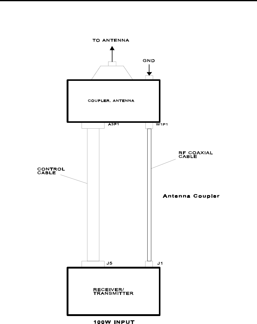
Page 1-2, STM 2E1X3-206N
Figure 1-1. 100W Configuration

STM 2E1X3-206N, Page 1-3
The frequency range of the URC-119(V) is from 1.6000MHz to
29.9999MHz. The modes of operation are USB, LSB,
Amplitude Modulation Equivalent (AME), Continuous Wave
(CW), and Audio Frequency Shift Keying (AFSK), with option
installed. There are several ancillary pieces of equipment that
can used to provide various system configurations. The system
can be configured for 100W by using the transceiver only, or
for 500 or 1000W when used with a LPA.
?
1. What does the URC-119(V) provide?
2. What is the procedure for tuning the URC-119(V) system?
3. What is the frequency range of the URC-119(V)?
4. Which modes of operation are possible with the
URC-119(V)?
SYSTEM CONFIGURATIONS
As shown in Figure 1-1 in this module, the RT-1446
Transceiver, along with the CU-2310 Antenna Coupler, make
up the 100W system.
100W SYSTEM
The RT-1446 is a microprocessor-controlled transceiver,
conservatively rated at 100W Peak Envelope Power (PEP) and
Average (AVG). The solid-state power amplifier ensures
continuous rated output power during keydown operation. All
operating and metering functions of the transceiver are fully
remote controllable over 2/4-wire telephone lines.
Additionally, the built-in telephone patch and internally
mounted AFSK option provide full communication flexibility.
For a simplified functional diagram of the transceiver, refer to
Figure 1-2 in TO 31R2-2URC-81.

Page 1-4, STM 2E1X3-206N
TRANSMIT PATH
In the transmit mode, the 100W transceiver accepts
audio/keyline inputs from a CW key, handset/mic, telephone
line, or other source, and impresses the audio on a 455kHz
intermediate frequency (IF) carrier. The 455kHz IF is raised in
two conversions to the 1.6 to 30MHz transmitting range and
amplified to a signal level of 100W PEP or AVG into a 50-ohm
load.
A directional bridge in the transmit path measures the forward
and reflected power levels. This information is used for front
panel display and for transmitter gain control functions. A
transmit/receive (T/R) switch separates the transmit and receive
paths, which allows connection to a common antenna.
RECEIVE PATH
In the receive mode, the 1.6 to 30MHz received signals bypass
the power amplifier and are reduced to a 455kHz IF using a
double conversion process. The first conversion is made at an
IF of 40.455MHz and band pass filtered to remove undesired
image frequencies. The second conversion is made at an IF of
455kHz and band pass filtered to achieve selectivity. The
resulting 455kHz IF signal is demodulated with an amplitude
detector (Amplitude Modulation (AM) Mode) or product
detector (Single Sideband (SSB) Modes) to obtain the audio
output.
Control of the 100W transceiver is from the front panel or by
remote input. Logic signals are processed by a microprocessor
that provides the necessary memory, control, logic, and timing
to coordinate the functions of the 100W transceiver in all modes
of operation. The microprocessor also controls the detection
and display indications of the Built-In Test (BIT) circuits.
The synthesizer and reference/Beat Frequency Oscillator (BFO)
modules generate the frequencies used in the modulation,
demodulation, and double conversion processes. All reference
frequencies are derived from a stable 10MHz frequency
standard.
The CU-2310 Antenna Coupler automatically matches the
output impedance of the transceiver or 500W LPA to a whip or
long wire antenna over the frequency range of 1.6 to 30MHz.
Operation, including network tuning, is fully automatic. Tuning
time is typically 5 to 8 seconds. The antenna coupler is used
where the required characteristic load impedance is other than
50 ohms.

STM 2E1X3-206N, Page 1-5
Typically, antennas do not exhibit constant 50-ohm impedance
over the 1.6MHz to 30MHz range. The antenna coupler
matches the antenna to the transceiver or 500W LPA so that at
the operating frequency, a 50-ohm load is presented to the
transmitter. Refer to Figure 1-2 in TO 31R2-2URC-111 for a
simplified functional diagram.
RF from the transceiver enters the coupler and is sampled by a
discriminator sampling circuit. An impedance matching
transformer (A1T2) matches the coupler operating impedance
of 12.5 ohms to the standard 50-ohm transmission line. Main
tuning capacitor (A2C1) and main tuning inductor (A2L1) are
placed in the circuit when needed to tune a long wire antenna.
500W SYSTEM
Figure 1-2 in this module shows the equipment that makes up
the 500W system. The only difference between this
configuration and the 100W configuration is the addition of the
AM-7223 RF amplifier. Power for this configuration is
supplied from either an AC or DC source. The output level
delivered by the amplifier is 500W PEP with multiple tone
input signals or 250W AVG with lock keyed CW or a
continuous single tone input signal.
This LPA is designed for continuous operation under severe
environmental conditions in either fixed or mobile applications.
Automatic sensing circuits protect the LPA from damage due to
overdrive, abnormal tuning, high Voltage Standing Wave Ratio
(VSWR) (including open or short circuit conditions), high and
low line voltages, insufficient air flow, and over temperature.
Figure 1-2 in TO 31R2-2URC-101 shows a simplified block
diagram of the AM-7223 RF amplifier. Refer to this figure as
we cover the signal flow of the amplifier.
TRANSMIT PATH
In the transmit mode, the transceiver RF signal is routed by the
T/R relay on the output filter assembly to tube assembly (A1),
where it is amplified. The RF signal then passes through the
tuned 500W tank assembly (A2) to the low pass filter and the
VSWR bridge circuit on the output filter assembly. From the
VSWR bridge circuit, the RF signal is applied to the antenna
connector J5 on the 500W LPA via the T/R relay.

Page 1-6, STM 2E1X3-206N
RECEIVE PATH
In the receive mode, the RF signal from the antenna connector
is routed to the XCVR RF connector via the T/R relay on the
output filter assembly.
1000W SYSTEM
Figure 1-3 in this module shows the equipment that makes up
the 1000W system. The difference between this configuration
and the 500W configuration is: the AM-7223 RF amplifier and
CU-2310 Antenna Coupler are replaced with the AM-7224 RF
amplifier, associated power supply (PP-7913/URC), and the
URA-38 antenna coupler. It is important to remember that an
antenna coupler can be omitted with this RF amplifier in this
particular configuration.
The AM-7224 RF amplifier is a 1000W amplifier used when
100 or 500W applications are not acceptable. Power for the RF
amplifier is provided by the PP-7913 power supply. Refer to
Figure 1-2 in TO 31R2-2URC-121 for a simplified block
diagram of the AM-7224 RF amplifier.
TRANSMIT PATH
In the transmit mode, the XCVR RF signal is routed by the T/R
relay on the VSWR/XFMR assembly to the tube assembly (A1),
where it is amplified. The RF signal then passes through the
tuned 1kW tank assembly to the impedance select circuit on the
VSWR/XFMR assembly. The RF signal is applied through a
VSWR bridge circuit on the VSWR/XFMR assembly to the low
pass filter assembly on the antenna connector of the 1kW LPA.
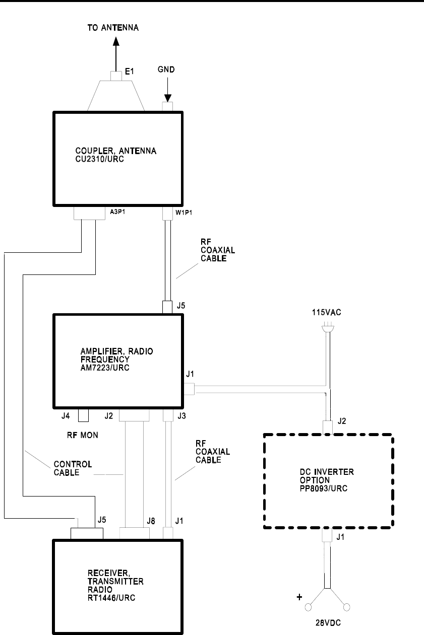
STM 2E1X3-206N, Page 1-7
Figure 1-2. 500W System Configuration
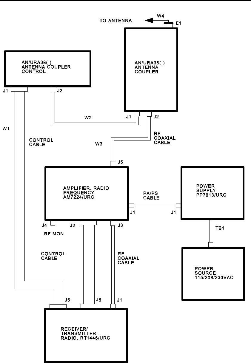
Page 1-8, STM 2E1X3-206N
Figure 1-3. 1000W System Configuration

STM 2E1X3-206N, Page 1-9
RECEIVE PATH
In the receive mode, the RF signal from the antenna connector
of the LPA is routed through the low pass filter assembly to the
XCVR RF connector via the T/R relay on the VSWR/XFMR
assembly.
The PP-7913 power supply produces three output voltages:
+3000VDC at 1A, +13.5VDC at 8A, and 115VAC at 1 amp(A).
These voltages are supplied to the AM-7224 RF amplifier.
The AN/URA-38( ) Coupler and Coupler Control are capable of
handling the output power of the AM-7224 RF amplifier. The
coupler control provides automatic or manual tuning and
impedance matching for the RF signal to the antenna.
?
5. What is the nominal output power of the RT-1446
transceiver?
6. Name the three input sources that can be used when the
transceiver is in the transmit mode.
7. Which component separates the transmit and receive paths
allowing connection to a common antenna for the transceiver?
8. Which process is used to reduce received signals to a
455kHz IF in the transceiver?
9. Which unit processes logic signals?
10. What generates the frequencies used in the modulation,
demodulation, and double conversion processes?
11. What is the purpose of the CU-2310 antenna coupler?

Page 1-10, STM 2E1X3-206N
12. What is the nominal output power of the AM-7223 RF
amplifier?
13. What is the nominal output power of the AM-7224 RF
amplifier?
RCU
The C-11329 RCU can be used with any system configuration
to provide remote operations capability. The three modes of
operation are RS-232, RS-422, and modem. Remember that for
control mode, audio interface, and modem interface selections,
the transceiver/remote control cable wiring must agree. A brief
description of each remote mode follows.
• The RS-232C mode of remote operation is an unbalanced
control line in a digital format useful for direct wire control
at ranges up to 100 feet.
• The RS-422 mode of remote operation is a balanced control
line in a digital format useful for direct wired control at
ranges up to 1 mile.
• The modem mode of remote operation is an analog
Frequency Shift Keying (FSK) format for use over standard
telephone lines/network at unlimited distance.
The remote control interface assembly must be installed in the
transceiver for remote operation. Determine the modes of
remote operation by selecting the appropriate mode on the
remote control assembly in the transceiver and the
audio/microprocessor assembly on the RCU.
In remote operation, control the transceiver by using the front
panel keypad on the remote control. The operator can make
frequency, channel, and mode selections from the keypad (of
the RCU). The remote control can access transceiver memory
that can store up to 100 channels of frequencies and operating
modes. The operator may also adjust analog controls on the
remote control front panel to set audio/RF gain levels, audio
squelch level, and audio input level of the transceiver.

STM 2E1X3-206N, Page 1-11
?
14. Name the three control modes of remote operation.
15. Which assembly must be installed in the transceiver for
remote control operation?
16. Which operations can the operator perform from the RCU
keypad?
SUMMARY
The URC-119(V) operates in the HF range from 1.6000MHz to
29.9999MHz and is tunable in 10Hz increments. It operates in
USB, LSB, AME, CW, and AFSK. AFSK is optional and
requires AFSK card installation. Tuning the URC-119(V) is a
fairly simple two step process: select the window frequency
and key the radio. The rest of the tuning process is done
automatically.
The URC-119(V), Pacer Bounce, can be configured for
100/500/1000W power outputs. The most common
configurations are 100W and 500W setups. The RT-1446
transceiver, along with the CU-2310 Antenna Coupler, make up
the 100W configuration. Adding the AM-7223 RF amplifier
boosts the output to 500Ws. The 1000W configuration is a little
different from the other setups. The AM-7223 RF amplifier and
CU-2310 antenna coupler are replaced by the AM-7224 RF
amplifier, PP-7913/URC Power Supply, and URA-38 Antenna
Coupler.
The C-11329 RCU can be used with any of the system
configurations. For remote operation, it must have the Remote
Interface Card installed in the RT-1446 transceiver. The RCU
front panel and keypad are identical to that of the RT, which
allows the operator to access all functions available to the RT
front panel. When remoting the RCU, make sure the mode
selection switches on the interface cards are set for the same
mode of operation.

Page 1-12, STM 2E1X3-206N
ADDITIONAL INSTRUCTIONS
Compare your responses to the review questions with the
confirmation key in the back of this module. Your responses do
not have to match word-for-word, but should convey the same
basic meaning. Review the applicable portions of this module
for all missed questions. When ready, ask your trainer to
administer the KEP questions for this module. This is a closed-
book test and you must score 70% or more. Your trainer will
check your answers and review any incorrectly answered
questions with you. When you have achieved the KEP
standard, your trainer will assign the next module.

STM 2E1X3-206N, Page 1-13
REVIEW QUESTIONS CONFIRMATION KEY
1. High-performance, long-range communications capability
2. Select a frequency or preset channel and key the transceiver.
3. 1.6 to 29.9999MHz
4. USB, LSB, AME, CW, and AFSK
5. 100Ws
6. CW key, handset/mic, telephone line
7. A T/R switch
8. A double conversion process
9. A microprocessor
10. The synthesizer and reference/BFO modules
11. To automatically match the output impedance of the
transceiver or 500W LPA to a whip or long-wire antenna
over the frequency range of 1.6 to 30MHz
12. 500W
13. 1000W
14. RS-232C, RS-422, and modem
15. The remote control interface assembly
16. Frequency, channel, and mode selections

STM 2E1X3-206N, Page 2-1
MODULE 2
RT-1446 TRANSCEIVER OPERATION
ABOUT THIS MODULE
This module covers the different operating modes and functions
used by the RT-1446 transceiver. Since the transceiver can be
operated with a variety of ancillary equipment, it is the
responsibility of the user to configure the equipment to support
the intended operations.
PREREQUISITE(S)
Must have completed Module 1 of this AFQTP.
OBJECTIVE(S)
Given TO 31R2-2URC-81, operate the RT-1446 Transceiver
IAW pgs 3-1 thru 4-26. (AFJQS TASK 201.14.1.1)
• Explain the RT-1446 transceiver controls and indicators.
• Explain the transceiver modes of operation.
TRAINING REFERENCE(S)
TO 31R2-2URC-81
RT-1446 CONTROLS AND INDICATORS
POWER APPLICATION AND WARM-UP
The RT-1446 is solid state equipment and requires no warm-up,
although a 30-minute warm-up may be required for stabilization
of the frequency standard if it is operated after being in cold
storage. However, operations may be started before the warm-
up period provided you remember T/R frequency errors may be
experienced until stabilization occurs.
ANALOG CONTROLS POSITIONING
Use the analog controls (AUDIO GAIN, RF GAIN, and
SQUELCH) to set up the transceiver for comfortable listening
and signal detection. A brief discussion of each control follows.
• AUDIO GAIN. This control affects the front panel speaker,
headset, and handset. The audio outputs available at the
rear of the transceiver have separate level adjustments. If
the supplied headset is connected to the front panel
HEADSET jack, the front panel speaker is not disconnected.

Page 2-2, STM 2E1X3-206N
If desired, use the front panel switch to disconnect the
speaker.
• RF GAIN. This control is typically placed in the high gain
position, i.e., turn the knob fully clockwise. In this position,
the RF gain of the receiver is determined by normal
Automatic Gain Control (AGC) action. If a condition exists
where normal AGC action is detrimental to reception, turn
the RF GAIN control counterclockwise. The RF GAIN
control then overrides the normal AGC circuit, and
manually adjusts the gain of the receiver.
• SQUELCH. This control is usually placed in the OFF
position. This enables all receive signals to be monitored
regardless of signal strength. If it is desired to monitor only
a received signal that is strong enough to rise above the
background noise, enable the squelch function. If
SQUELCH is desired, find the correct setting of the
SQUELCH control by turning the squelch knob out of
detent in the clockwise direction during a period when only
background noise is present in the speaker. Turn the
SQUELCH control slowly clockwise until the squelch
action just mutes the audio output. An incoming voice
signal, above the noise level, breaks the squelch and can be
heard in the front panel speaker. Squelch action affects the
PATCH and AUD2 audio outputs as well as the front panel
speaker. The LINE receive audio output is not affected by
the squelch circuit. It is important to remember that the
squelch responds only to VOICE signals.
CONTROL OPERATION DURING TRANSMIT
Frequency and channel changes cannot be made when the
transceiver is keyed. Only the controls TEST, S TONE (there is
no front panel display for sidetone), and CLIP (used in voice
modes only) are active when the transceiver is transmitting. A
keyline inhibit signal prevents equipment damage during
frequency and channel changing operations and accidental
keying of the transceiver.
FREQUENCY SELECTION
The frequency range of the transceiver and all associated
ancillary equipment is in the HF spectrum (1.6MHz to
29.99999MHz). In CW mode, a 1kHz offset is entered in the
transmitted frequency. Accomplish frequency selection either
by scrolling or entering the number via the front panel keypad.

STM 2E1X3-206N, Page 2-3
CHANNEL SELECTION
Channel selection (another way to select a different frequency)
is done by programming frequencies into the radio. Up to 100
channels may be programmed. This information remains in
memory after the transceiver is powered off due to an internal
lithium battery. Press the memory erase button at the rear of the
transceiver to clear the memory. This clears all programmed
channels and last parameter information.
?
1. What should you remember if you start operating the
transceiver before the 30-minute warm-up has elapsed?
2. What does the AUDIO GAIN control affect?
3. When would the RF GAIN control be adjusted?
4. How is the channel memory cleared?
MODES OF OPERATION
There are five operating modes. To access each mode, turn the
MODE switch to the desired mode. For USB and LSB modes,
the carrier is fully suppressed. The AME mode is USB plus
carrier, and the CW mode is audio derived with a plus or minus
1kHz carrier frequency offset depending on whether CW-LSB
or CW-USB has been internally selected. For AFSK mode
selection, the AFSK option must be installed.
• USB and LSB Operation. The SSB, USB, and LSB modes
operate with a suppressed carrier. The bandwidth of the
SSB filters is 350Hz to 3050Hz.
• AME Operation. AME operates with carrier and USB. The
carrier is normally 25 watts, but the PEP resulting when
modulated is a full 100Ws. The IF filter for the AME mode
is the same filter used in the USB mode; it has a bandwidth

Page 2-4, STM 2E1X3-206N
of 350Hz - 3050Hz. AME is also known as compatible
AM.
• CW Operation. CW mode (MORSE) is full carrier
transmission without modulation. A frequency offset of
exactly 1kHz automatically results in transmissions 1kHz
above or below the displayed frequency. An internally
adjustable CW hang-time determines the amount of time
that elapses following the last transmitted CW character
before the transceiver switches to receive mode.
• AFSK Operation. It is important to adjust the AFSK
equipment at each end of the radio link for the same
sideband, center frequency, and frequency shift. It must
also have the AFSK option installed in the radio. The
AFSK option has an 850Hz shift with a center frequency of
2000Hz, a 170Hz shift with a center frequency of 2000Hz,
or an 85Hz shift with a center frequency of 2805Hz. Each
of these shifts can be used in LSB and USB. Make shift and
sideband selections at the AFSK Configuration Switch
located on AFSK IF Filter A1A18A2.
An indication of correct tuning of an AFSK received signal may
be obtained by using the AFSK meter function. When receiving
a correctly tuned AFSK transmission, the AFSK meter segment
should be positioned over the central arrow shown on the meter
scale. If this is not the case, the operating frequency of the
transceiver may be changed using the scroll keys until the
correct center indication is obtained.
If sufficient receive signal is not present at the input of the
AFSK module for reliable error free operation, the unit forces a
mark-hold condition to the teleprinter. In certain circumstances,
high receive noise levels may cause the mark-hold to be
released and the teleprinter to print randomly. To stop this,
reduce the RF GAIN control on the front panel until the
teleprinter is forced back into a mark-hold condition.
The normal sense is where a (+) = binary 0 = space, and (-) =
binary 1 = mark. If Keyer Reverse for transmit (KREV) or
Converter Reverse for receive (CREV) is selected, the
respective sense is reversed with (+) = binary 1 = mark, and (-)
= binary 0 = space.
It is possible to compensate at the transceiver for other AFSK
center frequencies by adjusting the operating frequency of the
100W transceiver by the amount of the difference. The
procedure uses the AFSK Relative Center frequency meter scale
where the distant party transmits a series of "RY" characters

STM 2E1X3-206N, Page 2-5
and the receiving party observes the AFSK meter. The
frequency of the transceiver is then adjusted to zero out any
offset.
AUDIO SOURCE SELECTION
In CW and AFSK modes, AUDIO SOURCE has no effect. In
the other modes, when AUDIO: MIC is selected as the audio
source, the microphone audio and push-to-talk keyline
information are from the front panel HANDSET/MIC
connector.
A compression circuit, in series with this input, automatically
compensates for variations in input levels of ±15dB. The input
is designed for use with a dynamic microphone, and carbon type
microphones cannot be used.
AUDIO: AUD2 accepts audio and push-to-talk keyline
information from the rear panel AUD2 J4, such as a KY-65.
There is no compression circuit associated with the AUD2
input, and it is designed to accept a 0dBm average power
speech signal from a 600-ohm source. The sensitivity of the
AUD2 input is adjusted internally.
AUDIO PATCH is used when connection to a 2-wire or 4-wire
telephone is necessary. There is no compression circuit
associated with this input. Both the incoming and outgoing
phone patch audio levels are metered and adjusted via front
panel controls.
AGC SELECTION
There are four options of AGC: AGC OFF, AGC SLOW, AGC
MEDIUM, and AGC FAST. The decay time is slow, medium,
or fast. When a mode of operation is selected, an AGC speed is
automatically selected typical for operations in that mode.
AGC has no affect if the AGC indicator reads AGC OFF.
VOICE OPERATED TRANSMIT (VOX) SELECTION
Use VOX to automatically generate a keyline when transmit
audio is detected. There is a choice of 2 VOX decay time
constants: a long decay for voice signals and a short decay for
data signals. The voice time constant is internally adjustable.
There are two front panel adjustments for the VOX circuit:
VOX and ANTIVOX. The VOX adjustment sets the threshold
level required to trigger the VOX circuit. The ANTIVOX
circuit samples the received speaker audio and counteracts the
effect of the microphone picking up the receive audio signal,
thereby preventing false VOX operation. Adjust the ANTIVOX

Page 2-6, STM 2E1X3-206N
only when the microphone is in a fixed position. VOX VOICE,
VOX DATA, and VOX OFF are the choices available.
BFO SELECTION
Use the BFO to raise or lower the pitch of received audio
signals in all modes except AME. There is no frequency read-
out of the BFO offset. The BFO does not change the pitch of
the received audio signals when operating in the AME mode.
The maximum BFO offset is 1000Hz. BFO offset is entered
with scroll keys with a change of 10Hz per keystroke.
CLIP SELECTION
The CLIP function is selectable only in voice modes from the
MIC and PATCH sources. Use this feature for peak clipping of
the transmit audio levels to increase the average RF output
levels. The clipper is adjustable internally from 0dB to 12dB.
SIDETONE SELECTION
Use the sidetone feature to inject a portion of the transmit audio
into the receive audio path. This is useful for the operator in
voice modes for headset feedback, in CW mode for a 1kHz tone
when the CW key is closed, or to monitor the transmit audio
during any mode of operation. There is no indicator for
sidetone function, and it is automatically selected when
operating in the CW mode.
FSK REV SELECTION
The FSK REV function is selectable only in the AFSK mode.
This feature is used to reverse the sense of the AFSK keyer
(KREV), the AFSK Converter (CREV), or both.
TX KEY SELECTION
The TX KEY function is selectable in all modes of operation.
This feature may be used to generate a keyline whenever the
normal keyline is absent, or to enable transmit BIT for test
procedures, etc. In the CW mode, a CW key closure is also
required to obtain output power. (The transmit key is selected
and the CW key is also closed.)
FRONT PANEL LEVEL ADJUSTMENTS
There are two front panel adjustments for the VOX circuit:
VOX and ANTIVOX. The VOX adjustment sets the threshold
for the audio level required to trigger the transmitter keyline.
The ANTIVOX circuit is there to prevent the receive audio
from keying the radio.

STM 2E1X3-206N, Page 2-7
To set the VOX threshold, connect MIC to the front panel jack
and speak into the microphone. Adjust the VOX potentiometer
until the transmitter keys. To align the ANTIVOX circuit, start
by selecting the VOX feature. With no audio, adjust the
ANTIVOX potentiometer counterclockwise until the transmitter
keys. When this happens, turn the ANTIVOX clockwise until it
unkeys. The VOX and ANTIVOX adjustments interact with
each other so you may have to repeat several times to suit your
needs.
Use PATCH RCV and PATCH XMIT maintenance controls to
set the levels to and from 2-wire/4-wire external telephone
patch connections, respectively. Use TB1 on the rear of the
transceiver to establish phone patch circuits. A telephone line is
provided for use. If the line provider does not know whether
the line is 2- or 4-wire, you have to figure it out. Most
telephone lines are 2-wire; therefore, you should connect the
telephone lines to TB1-2 and 3. If you have a 4-wire phone
line, use TB1-1 through 4. The polarity of the 2-wire line does
not matter. However, when using a 4-wire line, you cannot mix
the line IN with the line OUT. This means there are two wires
for receive and two wires for transmit. The polarity of the
transmit and receive lines does not matter. However, you
cannot connect a receive line with a transmit line or vice versa.
Another important thing to remember is that the screws on TB1
are fragile. Take care when connecting wires to the terminal
board.
The normal adjustment of the PHONE RCV is such that voice
peaks observed on the PATCH meter are -10dBm. This level
may be adjusted upward if the phone user reports weak received
audio. The purpose of the PATCH function is to allow a user to
operate the radio using a telephone. You must key the radio
unless VOX operation is used.
The MIC control is active when the audio source is MIC. The
MIC control adjusts the input transmit audio levels. 0dBm is
the normal setting. Anything above that causes excessive noise
to be transmitted during speech pauses.
Use line adjustments when equipment other than the RCU is
used with the transceiver. The adjustment allows you to set the
line level anywhere from -20 to +10dBm. The RCU is
connected to the transceiver via J9 and has internal adjustments
for the line.

Page 2-8, STM 2E1X3-206N
METER EXPLANATIONS
The "S" scale gives an indication of received signal strength and
ranges from S3 (-100dBm) to +60dBm. This scale is
automatically selected when in the receive mode and the meter
is set to FWD, REF, or VSWR.
The AUDIO meter gives an indication of transmit audio signal
strength. The scale ranges from -20dBm to +10dBm. The
nominal level is 0dBm.
The LINE meter gives an indication of the receive line audio
signal or the remote line input signal when keyed. The scale
ranges from -20dBm to +10dBm.
The PATCH meter gives an indication of the PATCH input
signal (TX) or PATCH output signal (RX). The meter
indication for XMIT occurs when the transceiver is keyed. The
scale is from -20dBm to +10dBm.
The FWD meter gives an indication of forward output power of
the transceiver. The scale is from 0 to 150 Watts. With the 500
or 1000W LPA connected, the scale is multiplied by 10. It also
gives an indication of received signal strength because the "S"
scale is automatically selected when the FWD meter is selected.
The REF meter gives an indication of the transmit reflected
power. The scale is the same as the FWD.
The VSWR meter gives an indication of the VSWR. The scale
ranges from 1 (1:1) to 4 (4:1).
The AFSK meter shows relative center frequency with an arrow
indicating midscale and a bar showing offsets to the left or
right. This meter reading is correct only when the average mark
and space signals of the incoming signal are equal. A steady
mark or space does not yield an accurate reading.
PROGRAMMING CHANNELS
The transceiver has the capability of storing 100 frequencies
and their operating parameters. This is done using the PROG
and LOAD functions on the keypad. After a channel is
programmed, the transceiver displays the operating conditions
that were set before programming started.
?
5. In which operation modes is the carrier fully suppressed?

STM 2E1X3-206N, Page 2-9
6. Briefly describe USB and LSB operation.
7. Which mode of operation uses USB and carrier?
8. What is the normal carrier power when operating in AME
mode?
9. Which mode provides full carrier transmission without
modulation?
10. When is PATCH selection used?
11. What is the purpose of the ANTIVOX circuit?
12. What is the CLIP function used for?
13. What is the purpose of the PATCH maintenance controls?
14. Which terminal board is used to establish a PATCH circuit?
15. How many channels may be programmed?
SUMMARY
Set operating parameters for the RT-1446 by using the front
panel controls and keypad. Three Analog Control knobs (Audio
Gain control, RF Gain control, and Squelch control) allow you
to adjust the RF and audio levels at several different stages in
the receive process. Select frequencies by either scrolling or
entering numbers via the keypad. Up to 100 channels may be

Page 2-10, STM 2E1X3-206N
stored in the RT's memory. You can choose from LSB, USB,
AME, CW, and AFSK for modes of operation. The AFSK
mode is an option that must be installed. When Audio Source is
selected you are given three choices: MIC, AUD2, and Audio
Patch. However, this selection does not affect the CW or AFSK
modes because they contain no audio. There are four AGC
options to choose from: AGC OFF, AGC SLOW, AGC MED,
and AGC FAST. Other settings selectable from the front panel
keypad are the BFO for receive, CLIP function for transmit
MIC and PATCH audio inputs, Sidetone, FSK REV, and the
TX KEY selection. FSK REV is selectable with the AFSK
mode.
As a radio technician, it is imperative to know the function of
each control and indicator. The RT-1446 transceiver has many
capabilities. Knowing what they are and how to apply them
gives you the confidence to be a better technician.
ADDITIONAL INSTRUCTIONS
Compare your responses to the review questions with the
confirmation key in the back of this module. Your responses do
not have to match word-for-word, but should convey the same
basic meaning. Review the applicable portions of this module
for all missed questions. When ready, ask your trainer to
administer the KEP questions for this module. This is a closed-
book test and you must score 70% or more. Your trainer will
check your answers and review any incorrectly answered
questions with you. When you have achieved the KEP
standard, proceed to the performance procedures.
PERFORMANCE PROCEDURES
Your trainer will demonstrate the initial check procedures and
all operating sequences for the transceiver. Following the
demonstration, you will be given an opportunity to practice the
procedure. When you feel comfortable with the procedure, you
will be evaluated on the following:
• Perform the initial check-out procedure for the transceiver.
• Perform all operating sequences for the transceiver.
After you complete these procedures, your trainer will review
your work. When you are proficient in performing the
procedures, you may be certified on the AFJQS. Your trainer
will assign the next task.

STM 2E1X3-206N, Page 2-11
REVIEW QUESTIONS CONFIRMATION KEY
1. T/R frequency errors may be experienced until frequency
standard stabilization
2. The front panel speaker, headset, and handset signal level
3. When a condition exists where normal AGC action is
detrimental to reception
4. By pressing the memory erase button on the rear of the
transceiver
5. USB and LSB
6. The SSB, USB, and LSB modes operate with a suppressed
carrier. The bandwidth of the SSB filters is 350 to 3050Hz.
7. AME only
8. 25 watts
9. CW
10. When connection of a 2- or 4-wire telephone is necessary
11. Counteracts the effect of the microphone picking up the
receive signal
12. Peak clipping of the transmit audio levels to increase the
average RF output levels
13. Used to set the levels to and from the 2- and 4-wire external
telephone patch connections
14. TB1 on the rear of the transceiver
15. 100

STM 2E1X3-206N, Page 3-1
MODULE 3
C-11329 REMOTE CONTROL UNIT (RCU) AND
CU-2310 ANTENNA COUPLER OPERATION
ABOUT THIS MODULE
This module covers the RCU and Antenna Coupler connections
and operation.
PREREQUISITE(S)
Must have completed Modules 1 and 2 of this AFQTP.
OBJECTIVE(S)
Given TO 31R2-2URC-91, operate C-11329 RCU IAW pgs 3-1
thru 4-26. (AFJQS TASK 201.14.1.2)
• Explain how to connect the RCU to the RT-1446
Transceiver.
• Explain RCU operation.
Given TO 31R2-2URC-111, operate CU-2310 Antenna Coupler
IAW pgs 3-1 thru 4-2. (AFJQS TASK 201.14.1.3)
• Explain how to connect the antenna coupler to the RT-1446
Transceiver.
• Explain antenna coupler operation.
TRAINING REFERENCE(S)
TO 31R2-2URC-91
TO 31R2-2URC-111
C-11329 RCU OPERATION
The RCU is normally used when the transceiver and antenna
coupler are collocated at a different location than the RCU. The
different configurations used with the RCU were briefly
discussed in Module 1.
RCU CONNECTION
Refer to TO 31R2-2URC-91, Figure 2-5, for RCU rear panel
connections and to TO 31R2-2URC-81, Figure 4-1, for
transceiver rear view. Figure 3-1 in this module shows all
possible connections for the RCU. Follow these steps for
configuring, and there should be no problems.
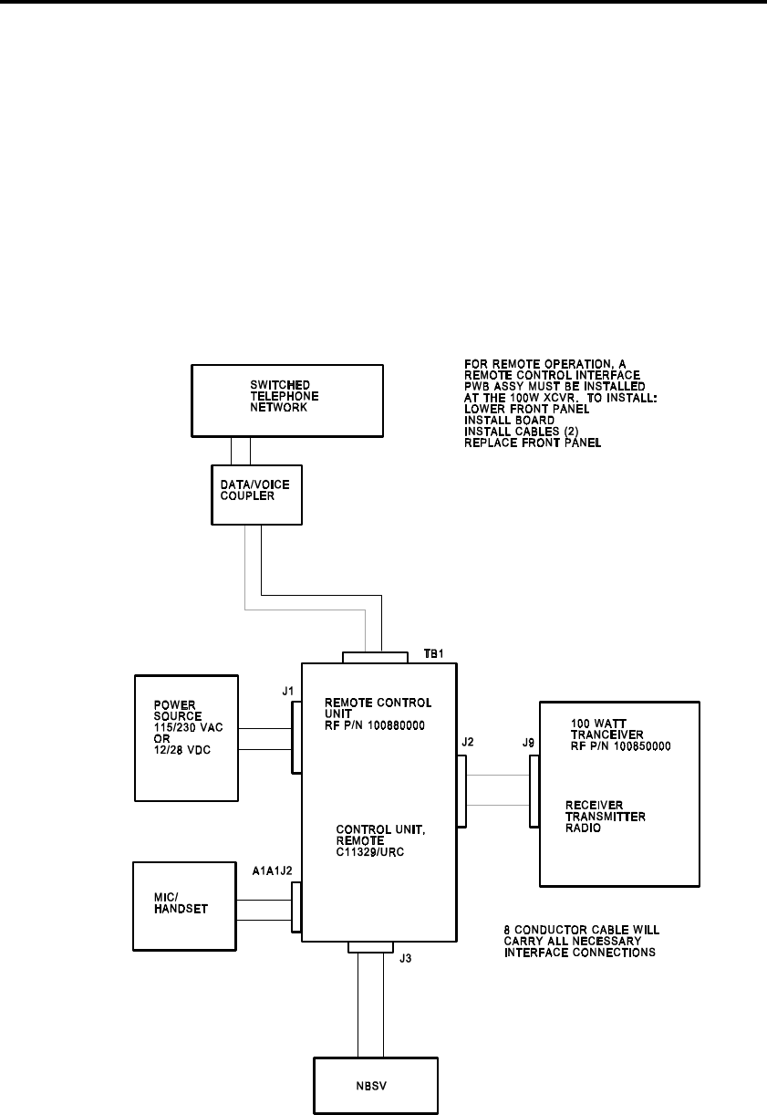
Page 3-2, STM 2E1X3-206N
• Verify that the RT has the Remote Control Interface
Assembly, and if it does not, install one.
• Connect the power cable to the RCU, but do not plug it into
the power source yet.
• Connect J2 on back of the RCU to J9 of the transceiver.
This connection provides interface between the two units.
• Ensure all switch settings on the RCU and transceiver
correspond by removing the covers of each unit and setting
the switches. If the two units are to be separated by a great
distance, set the switches before separating the units.
Figure 3-1. RCU Equipment Connections

STM 2E1X3-206N, Page 3-3
CONTROL MODE SWITCHES
Accomplish control mode selection via switch S4 located on
Audio/Microprocessor Assembly (A2) in the remote control,
and at the transceiver by using switch S2 located on A1A19
Remote Control Interface Assembly. These two switch
positions must match for the unit to operate correctly. The
status of these switches is only read during power up; therefore,
changing the switch positions while the equipment is running is
not recognized. In other words, the units must be turned off
during switch selection.
BAUD RATE SWITCHES
Control is possible at a variety of baud or data rates ranging
from 300 to 9600 baud. Use the 300 baud rate in the modem
mode. In other modes, the 9600 baud rate is generally selected
since the higher data rates provide a more rapid response to
remote commands.
Make baud rate selection via two switches. The first switch, S3,
is located on Audio/Microprocessor Assembly (A2) in the
remote control. The second switch, S1, is located on A1A19
Remote Control Interface Assembly installed in the transceiver.
The baud rate settings must be the same on both assemblies for
proper operation. Again, the status of these switches is only
read during power-up.
AUDIO INTERFACE SWITCHES
The audio interface may be either 2- or 4-wire. Use the 2-wire
configuration when interfacing with standard telephone
lines/networks or when it is desired to minimize the number of
wires between the RCU and transceiver.
Select the audio interface via two switches. The first switch,
S2, is located on Audio Interface Assembly (A4) in the RCU.
The second switch, S2, is located on Audio Interface Assembly
(A1A16) in the transceiver. The switch settings must match for
correct equipment operation.
MODEM INTERFACE SWITCHES
The modem interface may be either 2- or 4-wire. As with the
interface switches, use the 2-wire configuration when
interfacing with standard telephone lines/networks or when it is
desired to minimize the number of wires between the RCU and
the transceiver. Otherwise, use the 4-wire configuration.
Select the modem interface via two switches. The first switch,
S5, is located on Audio Microprocessor Assembly A2 in the

Page 3-4, STM 2E1X3-206N
remote control. The second switch, S5, is located on Remote
Control Interface Assembly A1A19 in the transceiver. The
switch settings must match for correct equipment operation.
RCU OPERATION
As previously mentioned, operation of the RCU is identical to
the transceiver, but with one exception. The only difference is
the AFSK mode, which cannot be operated via the RCU. The
RCU has the same keypad as the transceiver, and all functions
are the same as the transceiver. This completes our discussion
of RCU operation.
?
1. Where is the Remote Control Interface Assembly installed?
2. Which jacks provide interfacing of the RCU and the
transceiver?
3. Which switch provides control mode selection on the RCU?
Transceiver?
4. Where is the Control Mode switch located in the RCU?
Transceiver?
5. Which baud rate provides a more rapid response to remote
commands?
6. Which switch provides baud rate selection on the RCU?
Transceiver?
7. Where is the Audio Interface switch located in the RCU?
Transceiver?

STM 2E1X3-206N, Page 3-5
8. Which mode cannot be controlled via remote operation?
CU-2310 ANTENNA COUPLER
Use the CU-2310 Antenna Coupler with the transceiver in the
100 or 500W configuration. It automatically matches the output
impedance of the transceiver or RF amplifier to an antenna over
the frequency range of 1.6 to 30MHz. Refer to Figure 2-2 in
TO 31R2-2URC-111 for coupler connections.
CU-2310 ANTENNA COUPLER CONNECTION
As you can see from the figure, it is simple to set up the antenna
coupler. Start with the RF coaxial cable; it connects to (J1) on
the RT in 100W mode. In the 500W configuration it connects
to (J5) on the RF Amplifier. The control cable (supplied with
the coupler) always connects to the transceiver. There are no
power connections for the coupler; however, it must be
grounded. The last step in hooking up the coupler is connecting
the antenna wire to E1.
CU-2310 ANTENNA COUPLER OPERATION
Once the coupler is properly connected, operation is controlled
by the transceiver (or RCU, if used) and is fully automatic.
The CU-2310 Antenna Coupler receives power from the
transceiver. The power switch on the transceiver front panel
controls power to the antenna coupler.
To operate the antenna coupler, tune the transceiver to a specific
operating frequency and momentarily key the unit. The antenna
coupler can be heard driving to the HOME position. If nothing
is heard, a fault code should display, or the coupler may already
be tuned. If no faults appear, consider the antenna coupler
operational. This concludes our discussion of the operation of
the CU-2310 Antenna Coupler.
?
9. With which equipment configurations is the CU-2310
Antenna Coupler used?
10. What is the purpose of the CU-2310 Antenna Coupler?

Page 3-6, STM 2E1X3-206N
11. Which unit provides power to the antenna coupler?
12. How is tuning the antenna coupler accomplished?
SUMMARY
The RCU and the transceiver have several switches that must
correspond to each other for proper equipment operation.
Audio/Microprocessor (A2), located in the RCU, is home to all
but one of the switch settings. It houses switches S4 Modem
Control, S3 Baud Rate, and S5 Modem Interface. These switch
settings must match those of S1, S2, and S5 located on Remote
Control Interface PWB Assy (A1A19) in the transceiver. The
other switch setting is the Audio interface switch, located on
Audio Interface Assy (A1A16) in the transceiver and the A4
card in the RCU. Operation of the RCU is the same as the RT
with one exception; you cannot access the AFSK mode in the
remote setup.
The CU-2310 Antenna Coupler can be used in the 100 and
500W configurations. The transeiver supplies power to the
coupler. The front panel keypad or the RCU controls the
antenna coupler when in remote configuration. To tune the
coupler, select a frequency and momentarily key the radio.
ADDITIONAL INSTRUCTIONS
Compare your responses to the review questions with the
confirmation key in the back of this module. Your responses do
not have to match word-for-word, but should convey the same
basic meaning. Review the applicable portions of this module
for all missed questions. When ready, ask your trainer to
administer the KEP questions for this module. You are
permitted to use all available technical references and must
score 100%. Your trainer will check your answers and review
any incorrectly answered questions with you. When you have
achieved the KEP standard, proceed to the performance
procedures.
PERFORMANCE PROCEDURES
Your trainer will demonstrate how to connect/operate the RCU
and the antenna coupler to the transceiver. Following the
demonstration, you will be given an opportunity to practice the

STM 2E1X3-206N, Page 3-7
procedure. When you feel comfortable with the procedure, you
will be evaluated on the following:
• Connect the RCU to the transceiver (if applicable).
• Connect the CU-2310 Antenna Coupler to the transceiver (if
applicable).
• Operate the RCU.
• Operate the CU-2310 Antenna Coupler via the transceiver
or RCU.
After you complete these procedures, your trainer will review
your work. When you are proficient in performing the
procedures, you may be certified on the AFJQS. Your trainer
will assign the next task.

Page 3-8, STM 2E1X3-206N
REVIEW QUESTIONS CONFIRMATION KEY
1. In the transceiver
2. J2 (RCU), J9 (transceiver)
3. S4; S2
4. Audio/Microprocessor Assembly (A2); Remote Control
Interface Assembly A1A19
5. 9600
6. S3; S1
7. Audio Interface Assembly (A4); Audio Interface Assembly
(A1A16)
8. AFSK
9. 100 and 500W
10. Automatically matches the output of the transceiver or LPA
to an antenna over the frequency range of 1.6 to 30MHz
11. Transceiver
12. Tune the transceiver to a specific operating frequency and
momentarily key the unit.

STM 2E1X3-206N, Page 4-1
MODULE 4
AM-7223/7224 LINEAR POWER AMPLIFIER (LPA)
OPERATION
ABOUT THIS MODULE
This module covers the operation of the two LPAs and takes a
look at each control on the front panel of the amplifiers. The
operation of the AM-7223 and 7224 LPAs is similar with a few
exceptions. These similarities may remind you of the RCU and
antenna coupler operational procedures presented in an earlier
module. To assist in troubleshooting the equipment, it is
important to know the operational procedures.
PREREQUISITE(S)
Must have completed Modules 1 through 3 of this AFQTP.
OBJECTIVE(S)
Given TO 31R2-2URC-101, operate the AM-7223 LPA IAW
pgs 3-1 thru 4-8. (AFJQS TASK 201.14.1.4)
• Explain the purpose of the AM-7223 LPA.
• Explain the operating procedures for the AM-7223 LPA.
Given TOs 31R2-2URC-121 and 35C1-2-892-1, operate the
AM-7224 LPA with the PP-7913/URC IAW pgs 3-1 thru 3-3 of
the -121 TO, and pgs 3-1 thru 4-3 of the -1 TO. (AFJQS TASK
201.14.1.5)
• Explain the purpose of the antenna loading switch on the
AM-7224 LPA.
• Explain the function of the PP-7913 Power Supply.
TRAINING REFERENCE(S)
TO 31R2-2URC-101
TO 31R2-2URC-121
TO 35C1-2-892-1
AM-7223 LPA DESCRIPTION
PURPOSE
The AM-7223 LPA is a microprocessor-controlled power
amplifier that amplifies the selected HF input signal from the
RT-1446 in the 1.6 to 30MHz. It delivers 500Ws PEP with

Page 4-2, STM 2E1X3-206N
multiple tone input signals, or 250 watts average with lock
keyed CW or a continuous single tone input signal. The LPA
tunes automatically, in 10 seconds or less, in response to
frequency data from the 100W Transceiver and to its own
internally generated servo signals. It can also be manually
tuned using the front panel controls.
The 500W LPA is usually operated in the auto mode of
operation. During power-up, the circuit breakers on the rear
panel must be on and the POWER ENABLE/OFF switch on the
front panel in the POWER ENABLE position. Since the
1000W LPA is operated with the PP-7913 Power Supply, the
POWER ENABLE/OFF switch needs to be in the POWER
ENABLE position.
If either LPA has been turned off for more than 10 seconds,
there is a 3 minute warm-up period before the LPA can be
placed to OPERATE. During this time, the manual controls
(such as TUNE PWR and LOCAL KEY) are disabled. The
STANDBY LED on the LPA flashes during the warm-up
period and remains steady after the warm-up period.
PROCEDURES
TO 31R2-2URC-101, Figures 1-1 and 2-5 and Table 3-1,
illustrate the AM-7223 LPA controls, outputs, jacks, and initial
control settings. Let's take a look at these controls, starting with
the initial control settings.
INITIAL CONTROL SETTINGS
Initial control settings establish standard positions with which
further operations can be made. Ensure all controls are in the
proper position before attempting to operate the unit. Table 3-1
lists the initial control settings for the AM-7223 LPA.
STEP-BY-STEP SEQUENCE FOR POWER
APPLICATION
Before applying power to the LPA, ensure the LPA is connected
to its associated ancillary equipment. Remember, operation
with a transceiver is an absolute must.
• Once the LPA is connected, begin the power application
sequence by completing the associated transceiver power
application checks. Make sure the transceiver has passed
the BIT.
• Verify the power source for the LPA matches the input
power requirements.

STM 2E1X3-206N, Page 4-3
• Set the POWER ENABLE/OFF switch to the ENABLE
position. This allows the LPA to be powered on at the
transceiver by pressing 2ND AMP PWR. If the LPA has
been off for more than 10 seconds, there will be a 3 minute
warm-up period upon power application before the LPA
goes into the OPERATE mode. The STANDBY indicator
on the LPA flashes during this 3 minute warm-up and
becomes steady after the warm-up time has expired.
STEP-BY-STEP SEQUENCE FOR MANUAL BIT
PROCEDURE
Before performing this procedure, make sure the applicable
antenna coupler is tuned. When performing the manual BIT
procedure, do test initiation with the LPA, not with the
transceiver; however, the transceiver must be connected. To
initiate BIT:
• Set the AUTO/MANUAL switch to the band corresponding
to the frequency selected on the associated transceiver
(bands begin at 0000 and end at 9999).
• Rotate the METER switch to the STATUS/FAULT
position. If the METER switch is not in the
STATUS/FAULT position, the self-test cannot be initiated
at the LPA.
• Press the SELF TEST button (the white push button) on the
LPA front panel.
• If any fault codes are indicated, refer to the fault
isolation portion of the TO for the fault code definition
and procedure for correcting the fault condition.
• If no faults exist, a "PASS" message appears on the
METER display.
• After the test cycle is complete, move the METER switch
out of the STATUS/FAULT position to remove the LPA
from the test mode.
STEP-BY-STEP SEQUENCE FOR AUTOMATIC BIT
PROCEDURE
Initiate the automatic BIT procedure via the transceiver. Clear
LPA faults the same way as in the manual BIT procedure. To
initiate an automatic BIT from the transceiver:
• Power up the LPA by depressing 2ND/AMP PWR.
• After a 3 minute warm-up time, press the 2ND/STB OPR
buttons.
• Momentarily key the transceiver for tuning the LPA.
• Press 2ND/KEY 2ND/TEST.

Page 4-4, STM 2E1X3-206N
• When the BIT test is completed, press 2ND/KEY again to
unkey the transceiver.
• If there are no faults, a "PASSED" message appears on the
transceiver display. This indicates all equipment connected
passed the BIT.
• If any of the fault codes (2-01 through 2-22) are seen on the
display, there is a problem with the LPA. To display a fault
code on the LPA’s LCD display, place the METER switch
to the STATUS/FAULT position. You can clear the fault
code by commanding the LPA amplifier to operate from the
transceiver or by moving the LPA’s METER selector
switch out of the STATUS/FAULT position. However, if a
fault condition still exists that affects the operation of the
LPA, the LPA fault indicator lights and the LPA go into the
BYPASS mode. This means the transceiver output is
routed directly to the coupler or antenna, whichever the
case may be.
STEP-BY-STEP SEQUENCE FOR MANUAL TUNING
PROCEDURE
Use this procedure to check the manual tuning capability of the
LPA. Refer to TO 31R2-2URC-101, Figure 3-1, as we cover
this procedure.
• Connect the equipment to the system configuration at your
location.
• Set the transceiver to the desired operating frequency.
• At the LPA, select the band corresponding to the selected
transceiver frequency using the AUTO/MANUAL BAND
switch.
• Place the METER selector switch to the COIL POS
position.
• Using the TUNE control, preposition the coil to the value
indicated on the manual tune chart (the number will be
observed on the LPA’s LCD display).
• Look at the "frequency" portion of the chart and find the
transceiver frequency.
• Move up to the range line, and then left to the coil
"position" line. This gives you the number that
corresponds to the coil position for that particular
frequency. These coil position segments are 100 points
apart, so approximate the frequency if it falls between
points, e.g., between 600 and 700 on the coil position
scale.
• Once the coil is tuned, set the METER switch to either the
FWD PWR (WATTS) or RF PLATE (VOLTS) position.

STM 2E1X3-206N, Page 4-5
• When the bandswitch has finished tuning the bandswitch
wafer, set the MANUAL TUNE PWR switch to the ON
position. This generates a TUNE POWER REQUEST to
the transceiver, and the LPA is keyed.
• If a fault is detected while this switch is active, the LPA
drops back to STANDBY, and before the fault can be
cleared, the MANUAL TUNE PWR switch must be turned
off.
• While observing the METER display, use the TUNE switch
to tune the servo coil for maximum meter reading.
• Turn off the MANUAL TUNE PWR switch. When the
MANUAL TUNE PWR switch is turned off, the transceiver
is notified that the LPA is tuned whether it actually is or not.
Therefore, before you turn this switch off, ensure you
correctly tuned the LPA. Otherwise, there is the possibility
of a severe mismatch between the LPA and antenna system,
thus resulting in a high VSWR and low forward power.
• Set the MANUAL LOCAL KEY switch to the ON position.
The LPA should go into the OPERATE condition, and the
OPERATE indicator should become a steady light.
STEP-BY-STEP SEQUENCE FOR AUTOMATIC
TUNING PROCEDURE
This procedure checks the ability of the LPA to automatically
tune from the transceiver front panel buttons. After connecting
the equipment:
• Turn the LOCAL KEY switch to OFF.
• Set the AUTO/MANUAL BAND switch to the AUTO
position. This deactivates all manual tune switches.
• On the transceiver, press 2ND STBY/OPR switch to place
the LPA in the operate mode.
• Select a different frequency band (one other than the one
used for the manual tuning procedure) and key the
transceiver. The LPA should tune to the new frequency in
10 seconds or less.
• If it does not tune to a new frequency, a fault code is
displayed on the transceiver LCD. If a fault code is not
encountered, the initial check-out procedure is
completed.
• If a fault code is encountered, refer to the trouble-
shooting portion (Chapter 6) of the appropriate TO.
AUTO/MANUAL BAND SELECTION
This front panel, ten-position, AUTO/MANUAL rotary switch
selects between automatic and manual mode of operation in the

Page 4-6, STM 2E1X3-206N
frequency band selected. In AUTO position, tuning is
automatic and controlled completely by signals from the
transceiver. In this position, the MANUAL TUNE, MANUAL
TUNE POWER, MANUAL LOCAL KEY, and self-test
controls are disabled.
When the AUTO/MANUAL BAND switch is not in the AUTO
position, the LPA is in the manual mode and the current
operating frequency band is selected. (Actually, you select the
operating frequency band with the AUTO/MANUAL BAND
switch.) The 500W LPA has nine operating bands and the
1000W LPA has 10 operating bands. Selecting a new switch
position causes the internal band switch wafer to turn to its
corresponding position. The wafer does not turn unless the
operator has left the band switch in one position for more than
one second. Then the microprocessor sends an RF mute signal
to the transceiver and unkeys the LPA. Also, the bandswitch
does not turn while there is RF power at the XCVR RF input of
the LPA. All manual tuning keys, along with the self-test
control, are disabled while the wafer is turning.
MANUAL TUNE POWER SWITCH
When manual operation is selected, the Manual Tune Power
switch is moved to the ON position. This sends a tune power
request message to the transceiver and keys the LPA. When the
Manual Tune Power switch is activated, any previous fault
indications are cleared. If a fault is detected while this switch is
active, the LPA drops back to STANDBY, and the Manual
Tune Power switch must be turned off before the fault can be
cleared. Activation of the tune mode causes the transceiver to
transmit a CW carrier emission.
MANUAL LOCAL KEY SWITCH
This switch keys and places the LPA in OPERATE when it is
turned on. Also, the switch is active only in the manual mode
and clears any previous fault indications when it is activated. If
this key is activated and a fault condition occurs, the LPA drops
back to STANDBY and must be deactivated before the fault
condition can be cleared. This switch keys only the LPA, so the
transceiver must be keyed independently.
MANUAL TUNE SWITCH
This switch is active only in the manual mode and allows the
operator to fine tune the LPA by controlling the position of the
tune variable coil.

STM 2E1X3-206N, Page 4-7
SELF TEST BUTTON
With the AUTO/MANUAL BAND switch in any position
except AUTO and the METER switch in the STATUS/FAULT
position, push the SELF TEST push button to initiate the BIT
for the LPA only. The BIT tests all functional modules and
displays failures on the meter display (of the LPA) when the
STATUS/ FAULT position of the METER switch is selected.
Other functions of this button are explained later in the BIT
interpretation section.
METER SELECT SWITCH
The METER select switch controls the inputs to the METER
LCD display. There are eleven possible functions for the LPA.
The details of each function were described in an earlier
module.
TRANSCEIVER CONTROLLED OPERATION
Automatic tuning of the LPA is controlled completely by the
transceiver when the AUTO/MANUAL BAND select switch is
in the AUTO position.
METER DISPLAY UPDATE
Periodically, the microprocessor reads the appropriate inputs
and calculates a new value for the METER LCD display. The
meter display routine is inactive during BIT. The analog inputs
are read every 100 milliseconds, and an average or peak value is
displayed every second for the function selected.
?
1. What does the POWER ENABLE/OFF switch allow when
placed to the ENABLE position?
2. What is the range of the frequency bands?
3. Which position must the METER switch be in to initiate the
self-test at the LPA?
4. Where is automatic BIT procedure initiated?

Page 4-8, STM 2E1X3-206N
5. What is the purpose of the manual tuning procedure when
initially checking out the LPA?
6. When is a TUNE POWER REQUEST generated to the
transceiver?
7. When the LPA is tuned (manually), what does turning the
MANUAL LOCAL KEY switch to the ON position do?
8. How long should it normally take for the LPA to tune to a
new frequency?
9. How is tuning controlled during automatic operation?
10. How many operating bands do the 500 and 1000W LPAs
have?
11. How long must the operator leave the AUTO/MANUAL
BAND switch in one position before the wafer will turn?
12. What happens if a fault is detected while the manual tune
power switch is active?
13. What is the only position of the AUTO/MANUAL BAND
switch that will not allow the initiation of a self-test?
14. What controls automatic tuning of the LPA when the
AUTO/MANUAL BAND select switch is in the AUTO position?

STM 2E1X3-206N, Page 4-9
AM-7224 LPA ANTENNA LOADING SWITCH OPERATION
PURPOSE
The 1000W LPA has the capability for antenna loading
selection. The ANTENNA loading switch controls the output
impedance to the antenna for the 1kW LPA in MANUAL mode.
The 1kW LPA microprocessor controls the output impedance to
the antenna in AUTO mode. The manual ANTENNA switch
selects between LOW Z, 50 OHMS, and HIGH Z loading.
When a new ANTENNA switch position is selected in the
manual mode, the 1kW LPA microprocessor does not change
impedance until after an RF MUTE request is sent to the
transceiver and the 1kW LPA is unkeyed. This prevents
damage to the equipment.
PP-7913 POWER SUPPLY FUNCTION
The function and purpose of the PP-7913 Power Supply is to
supply AC and DC voltages to the AM-7224 LPA. The power
supply is a 115/208/230VAC, +10%, single-phase 50/60/400Hz
unit that produces three output voltages: +3000VDC at 1A,
+13.5VDC at 8A, and 115VAC at 1A. After proper
connections are made to the LPA, power is applied when the
PP-7913 power supply is turned on.
?
15. What is the purpose of the ANTENNA loading switch of the
1000W LPA?
16. What is the purpose of the PP-7913 power supply?
SUMMARY
As discussed throughout this module, the AM-7223 and
AM-7224 LPAs are the two RF amplifiers that connect to the
RT-1446. Both are microprocessor controlled amplifiers that
boost a 100W HF signal to either a 500 or 1000W output. They
have identical front panel controls and operate the same except
the AM-7224 LPA must have the PP-7913 Power Supply for
operation.

Page 4-10, STM 2E1X3-206N
ADDITIONAL INSTRUCTIONS
Compare your responses to the review questions with the
confirmation key in the back of this module. Your responses do
not have to match word-for-word, but should convey the same
basic meaning. Review the applicable portions of this module
for all missed questions. When ready, ask your trainer to
administer the KEP questions for this module. This is a closed-
book test and you must score 70% or more. Your trainer will
check your answers and review any incorrectly answered
questions with you. When you have achieved the KEP
standard, proceed to the performance procedures.
PERFORMANCE PROCEDURES
Your trainer will demonstrate how to operate the AM-
7223/7224 in automatic/manual modes, perform the self-test,
and the BIT test. Following the demonstration, you will be
given an opportunity to practice the procedure. When you feel
comfortable with the procedure, you will be evaluated on the
following:
• Operate the AM-7223/7224 LPA in the automatic mode.
• Operate the AM-7223/7224 LPA in the manual mode.
• Perform the self-test on the AM-7223/7224 LPA.
• Perform BIT using the transceiver.
After you complete these procedures, your trainer will review
your work. When you are proficient in performing the
procedures, you may be certified on the AFJQS.

STM 2E1X3-206N, Page 4-11
REVIEW QUESTIONS CONFIRMATION KEY
1. The LPA to be powered on by the transceiver
2. 0000 to 9999
3. STATUS/FAULT
4. At the transceiver
5. To check the manual tuning capability of the LPA
6. When the bandswitch is finished tuning, the bandswitch
wafer and the MANUAL TUNE PWR switch are set to ON.
7. Causes the LPA to go into OPERATE
8. 10 seconds
9. By signals from the transceiver
10. Nine and ten respectively
11. 1 second
12. The LPA will drop back to STANDBY.
13. AUTO
14. The transceiver
15. Controls the output impedance to the antenna in the
MANUAL mode
16. Provides power to the 1000W LPA

AIR FORCE
QUALIFICATION
TRAINING
PACKAGE
2E1X3-206N
PART OF AFJQS 2E1X3-206N
AN/URC-119(V) HF
COMMUNICATIONS
SYSTEM
KNOWLEDGE EVALUATION
PAMPHLET
1 OCTOBER 1999
SUPERSEDES AFJQS 2E1X3-206N
DATED 2 SEPTEMBER 1999
FOR OJT USE ONLY

KEP 2E1X3-206N, Page i
KNOWLEDGE EVALUATION PAMPHLET (KEP)
• This pamphlet should be separated from the package immediately and stored to
prevent compromise of the questions. The answer sheet for the KEP is located at
the back of this pamphlet. This answer sheet may be detached to make it easier to
enter the answers. The KEP confirmation key, also located at the back of this
pamphlet, should be detached and stored until ready for grading.
• After the trainee completes each module, the supervisor/trainer administers the
corresponding KEP test. Using the KEP confirmation key, the supervisor/trainer
checks the trainee's answers and reviews the incorrect responses. If the score is
less than what is required, have the trainee restudy the module and retake the test.
• The trainee's responses to the KEP questions will aid us in evaluating the
effectiveness of this training package. After the questions have been answered for
all the module tests, please attach the completed and graded answer sheets to the
training completion certification and send the package to us at the address
specified.

KEP 2E1X3-206N, Page 1
KEP QUESTIONS - MODULE 1
1. What must be done in order to tune the AN/URC-119(V)?
a. A frequency must be selected in the USB mode.
b. A channel must be selected and transceiver keyed.
c. A mode must be selected and the speaker must be on.
d. AGC must be selected and the MIC must be depressed.
2. In which frequency spectrum does the AN/URC-119(V) operate?
a. LF
b. HF
c. UHF
d. VHF
3. Which modes of operation are available with the AN/URC-119(V)?
a. LSB, USB, AME, CW, and SFSK
b. LSB, USB, AME, CW, and AFSK
c. UUSB, LLSB, AME, CW, and AFSK
d. LF, HF, UHF, VHF, and automatic mode
4. Which units make up the 100 watt configuration?
a. RT-1446 transceiver and CU-2310 antenna coupler
b. RT-1446 transceiver, AM-7223 RF amplifier, and CU-2310 antenna coupler
c. RT-1446 transceiver, AM-7224 RF amplifier, and CU-2310 antenna coupler
d. RT-1446 transceiver, AM-7224 RF amplifier, and URA-38( ) antenna coupler
5. Which units make up the 500 watt configuration?
a. RT-1446 transceiver and CU-2310 antenna coupler
b. RT-1446 transceiver, AM-7223 RF amplifier, and CU-2310 antenna coupler
c. RT-1446 transceiver, AM-7224 RF amplifier, and CU-2310 antenna coupler
d. RT-1446 transceiver, AM-7224 RF amplifier, and URA-38() antenna coupler

Page 2, KEP 2E1X3-206N
6. Which units make up the 1000 watt configuration?
a. RT-1446 transceiver and CU-2310 antenna coupler
b. RT-1446 transceiver, AM-7223 RF amplifier, and CU-2310 antenna coupler
c. RT-1446 transceiver, AM-7224 RF amplifier, and CU-2310 antenna coupler
d. RT-1446 transceiver, AM-7224 RF amplifier, and URA-38() antenna coupler
7. What separates the transmit and receive paths in the transceiver?
a. Antenna
b. T/R switch
c. Directional bridge
d. Capacitor in the RF line
8. Reference frequencies for the transceiver are derived from which frequency
standard?
a. 1MHz
b. 5MHz
c. 10MHz
d. 15MHz
9. What is the maximum output power that the CU-2310 antenna coupler can handle?
a. 1200 watts
b. 1000 watts
c. 500 watts
d. 100 watts
10. What in the CU-2310 antenna coupler samples the RF from the transceiver?
a. An impedance matching transformer
b. A transceiver RF sampling circuit
c. A discriminator sampling circuit
d. A directional bridge

KEP 2E1X3-206N, Page 3
11. How many watts of output power does the AM-7223 RF amplifier provide?
a. 1500
b. 1000
c. 500
d. 100
12. Which piece of equipment has an external power supply?
a. RT-1446
b. CU-2310
c. AM-7223
d. AM-7224
13. How many output voltages does the PP-7913 power supply provide?
a. 3
b. 4
c. 5
d. 6
14. Which mode of remote operation allows unlimited distance for remote operation?
a. RS-232
b. RS-332
c. RS-432
d. Modem
15. The remote control interface assembly is installed in the
a. remote control unit.
b. antenna coupler.
c. RF amplifier.
d. transceiver.

KEP 2E1X3-206N, Page 5
KEP QUESTIONS - MODULE 2
1. Which change(s) cannot be made when the transceiver is keyed?
a. Meter
b. Sidetone
c. VOX and ANTIVOX
d. Frequency and channel
2. PATCH operation is used when connection to which type of equipment is needed?
a. Remote control unit
b. Cryptographic
c. Telephone
d. Audio
3. What is used to raise or lower the pitch of received audio signals?
a. BFO
b. VOX
c. ANTIVOX
d. Frequency scrolling keys
4. Which control is used to increase the average RF output levels?
a. AGC
b. BFO
c. TGC
d. CLIP
5. Which meter scale gives an indication of the received signal strength?
a. AUDIO
b. PATCH
c. LINE
d. "S"

Page 6, KEP 2E1X3-206N
6. Which meter scale gives an indication of the transmit audio signal strength?
a. AUDIO
b. PATCH
c. LINE
d. "S"
7. How many programs may be stored in memory?
a. 25
b. 50
c. 100
d. 150
8. Which information may be stored in memory?
a. Frequency and mode
b. Frequency and meter
c. Channel and audio source
d. Audio source and frequency

KEP 2E1X3-206N, Page 7
KEP QUESTIONS - MODULE 3
You may use all technical references and must score 100%.
1. The connections which provide interfacing of the remote control unit to the
transceiver are
a. J2 and J4.
b. J2 and J9.
c. J9 and J4.
d. J3 and J9.
2. Switch settings between the ___________ and the remote control unit must
correspond.
a. antenna coupler
b. RF amplifier
c. transceiver
d. antenna
3. The Control Mode switches are located on the _________ assembly of the remote
control unit and the ____________ assembly of the transceiver.
a. audio microprocessor; audio interface
b. audio interface; remote control interface
c. remote control interface; audio microprocessor
d. audio microprocessor; remote control interface
4. Which assembly contains the Modem Interface switch on the remote control unit?
a. Exciter
b. Audio interface
c. Audio microprocessor
d. Remote control interface

Page 8, KEP 2E1X3-206N
5. Which mode cannot be controlled using the remote control unit?
a. AFSK
b. BFSK
c. AME
d. USB
6. The CU-2310 antenna coupler can be used with the ______ watt or ______ watt
configurations.
a. 1000; 5000
b. 1000; 500
c. 500; 100
d. 100; 50
7. Connection of the CU-2310 Antenna Coupler to the transceiver is made using an RF
coaxial cable and _______ cable.
a. modem
b. control
c. auxiliary
d. telephone
8. The CU-2310 antenna coupler receives power from the
a. remote control unit.
b. AC power source.
c. RF amplifier.
d. transceiver.

KEP 2E1X3-206N, Page 9
KEP QUESTIONS - MODULE 4
1. Initial control settings are performed
a. prior to operation.
b. on the power supply.
c. on the microprocessor.
d. in step-by-step sequences.
2. The warm-up period when the LPA is initially turned on is _____ minutes.
a. 2
b. 3
c. 4
d. 5
3. If the METER switch on the LPA is not in the STATUS/FAULT position, a self-test
cannot be initiated at the
a. linear power amplifier.
b. remote control unit.
c. transceiver.
d. Both a and b
4. In order to remove the LPA from the test mode, the METER switch must be moved
_____________ position.
a. to the MANUAL
b. from the MANUAL
c. to the STATUS/FAULT
d. from the STATUS/FAULT

Page 10, KEP 2E1X3-206N
5. If a fault code of _______ is seen on the transceiver display, there is a problem with
the LPA.
a. 1-01 thru 1-022
b. 2-01 thru 2-022
c. 3-01 thru 3-022
d. 4-01 thru 4-022
6. If a fault condition exists which affects the operation of the LPA, the fault light
comes on and the RF amplifier goes into the _________ mode.
a. SHUTDOWN
b. OVERRIDE
c. COUPLER
d. BYPASS
7. When the LPA's AUTO/MANUAL BAND switch is in the AUTO position, the
__________ is/are deactivated.
a. antenna coupler
b. automatic tuning
c. LPA manual tune switches
d. transceiver front panel keys
8. The 500 watt LPA has _____ operating bands.
a. 12
b. 11
c. 10
d. 9
9. When the MANUAL TUNE PWR switch is activated, any previous __________
indications/displays are cleared.
a. mode
b. fault
c. status
d. frequency

KEP 2E1X3-206N, Page 11
10. The ___________ switch allows the operator to fine tune the LPA by controlling the
position of the variable coil.
a. MANUAL TUNE
b. MANUAL TUNE PWR
c. MANUAL LOCAL KEY
d. AUTO/MANUAL BAND
11. In order to initiate the BIT procedure for the LPA only, the AUTO/MANUAL
BAND switch must be in any position except AUTO, and the METER switch must be in
the ________ position.
a. COIL POS
b. RF PLATE
c. ANT VSWR
d. STATUS/FAULT
12. The ANTENNA LOADING switch and the PP-7913 power supply make up the
differences between the AM-7223 and AM-7224 LPAs.
a. True
b. False
13. The ANTENNA loading switch controls the output ________ to the antenna for the
1kW LPA.
a. capacitance
b. inductance
c. impedance
d. power
14. When a new ANTENNA switch position is selected, the impedance change will not
be made until a ____________ is sent to the transceiver.
a. tune power request
b. formal message
c. manual key
d. RF mute

KEP 2E1X3-206N, Page 13
KEP CONFIRMATION KEY
MODULE 1
1. b
2. b
3. b
4. a
5. b
6. d
7. b
8. c
9. c
10. c
11. c
12. d
13. a
14. d
15. d
MODULE 2
1. d
2. c
3. a
4. d
5. d
6. a
7. c
8. a
MODULE 3
1. b
2. c
3. d
4. c
5. a
6. c
7. b
8. d
MODULE 4
1. a
2. b
3. a
4. d
5. b
6. d
7. c
8. d
9. b
10. a
11. d
12. a
13. c
14. d

KEP 2E1X3-206N, Page 15
KEP QUESTIONS ANSWER SHEET
NAME_____________________________ RANK________ DAFSC______________
ORGANIZATION_____________________ MAJCOM_______ DSN______________
AFJQS/AFQTP PUBLICATION DATE_________ DATE COMPLETED___________
MODULE 1
1. ____
2. ____
3. ____
4. ____
6. ____
7. ____
8. ____
9. ____
10. ____
11. ____
12. ____
13. ____
14. ____
15. ____
MODULE 2
1. ____
2. ____
3. ____
4. ____
6. ____
7. ____
8. ____
MODULE 3
1. ____
2. ____
3. ____
4. ____
6. ____
7. ____
8. ____
MODULE 4
1. ____
2. ____
3. ____
4. ____
6. ____
7. ____
8. ____
9. ____
10. ____
11. ____
12. ____
13. ____
14. ____
NOTE: After completing and grading all tests, attach this answer sheet to the Training
Completion Certification and send the package to the following address:
81 TRSS/TSQS
601 D STREET
KEESLER AFB MS 39534-2229
