USB2 IQC Users Guide
User Manual:
Open the PDF directly: View PDF ![]() .
.
Page Count: 13

P +1 403.932.4620 F +1
403.932.6521
USB2 IQC Tester
User’s Guide

2 of 13
228 River Avenue, Cochrane, Alberta, Canada. T4C 2C1 thisisant.com
Copyright Information and Usage Notice
This information disclosed herein is the exclusive property of Dynastream Innovations Inc. No part
of this publication may be reproduced or transmitted in any form or by any means including
electronic storage, reproduction, execution or transmission without the prior written consent of
Dynastream Innovations Inc. The recipient of this document by its retention and use agrees to
respect the copyright of the information contained herein.
The information contained in this document is subject to change without notice and should not be
construed as a commitment by Dynastream Innovations Inc. unless such commitment is expressly
given in a covering document.
The Dynastream Innovations Inc. ANT Products described by the information in this document are
not designed, intended, or authorized for use as components in systems intended for surgical
implant into the body, or other applications intended to support or sustain life, or for any other
application in which the failure of the Dynastream product could create a situation where personal
injury or death may occur. If you use the Products for such unintended and unauthorized
applications, you do so at your own risk and you shall indemnify and hold Dynastream and its
officers, employees, subsidiaries, affiliates, and distributors harmless against all claims, costs,
damages, and expenses, and reasonable attorney fees arising out of, directly or indirectly, any
claim of personal injury or death associated with such unintended or unauthorized use, even if
such claim alleges that Dynastream was negligent regarding the design or manufacture of the
Product.
©2010 Dynastream Innovations Inc. All Rights Reserved.
3 of 13
228 River Avenue, Cochrane, Alberta, Canada. T4C 2C1 thisisant.com
1. Introduction
The purpose of this document is to describe the functional verification test method for second generation
ANT USB stick—USB2.
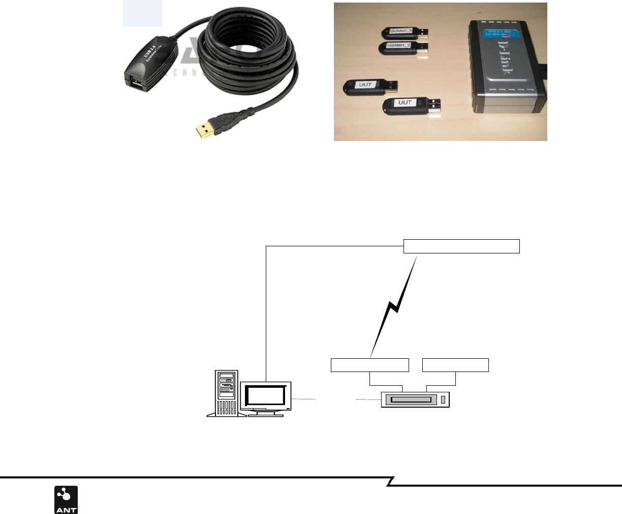
2. Test Hardware
• Three pieces Golden ANT USB2 Stick (Two pieces for use in the test and one for backup; refer to section 4 of this
document for the golden unit acquisition)
• Five Meter USB2 Extension Cable (User can purchase from BAFO technologies: http://www.bafo.com)
• Seven port USB2.0 Hub (User can purchase from D-Link : www.dlink.com)
• Host PC
Figure 1: Test Hardware
2.1 Hardware configuration
Figure 2 shows a diagram of how the test equipment should be set up:
The USB extension cable and Hub connect to the PC USB port directly. One golden unit (e.g. golden unit1) is connected to
the USB extension cable, another golden unit is connected to the USB hub. This will establish an ANT master device and
slave device.
Golden Unit1
Golden Unit2 UUT
RF
Control PC USB2.0 Hub
USB Port
RF
USB Port
5 meters USB
Extension Cable
Figure 2: USB2 Test Configuration Diagram
4 of 13
228 River Avenue, Cochrane, Alberta, Canada. T4C 2C1 thisisant.com
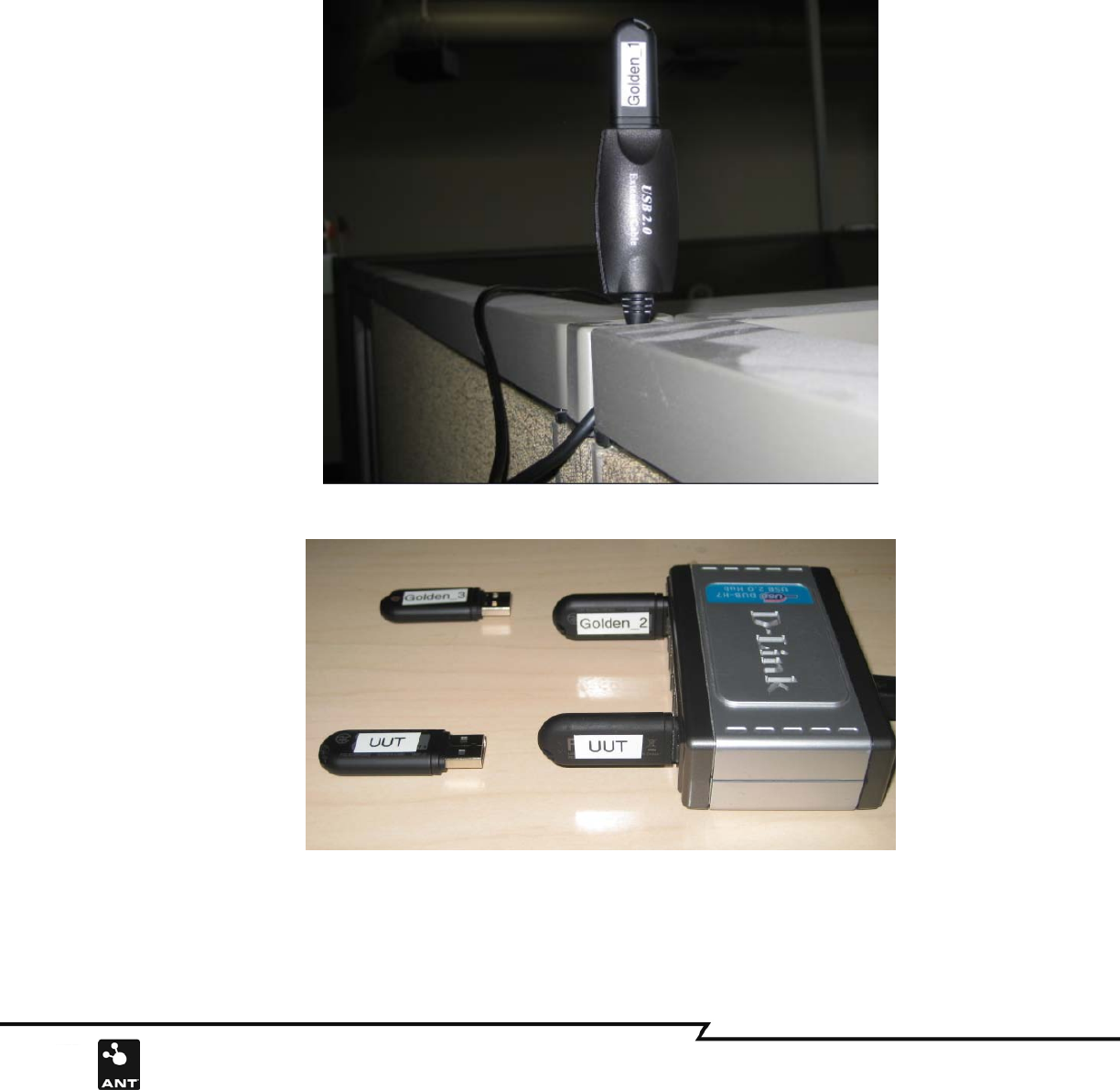
2.2 Hardware Setup
Figure 3a shows how the USB extension cable and USB hub are installed in the test setup. The golden unit
(e.g. golden unit1) is connected on one end of USB extension cable and the other end is connected to the
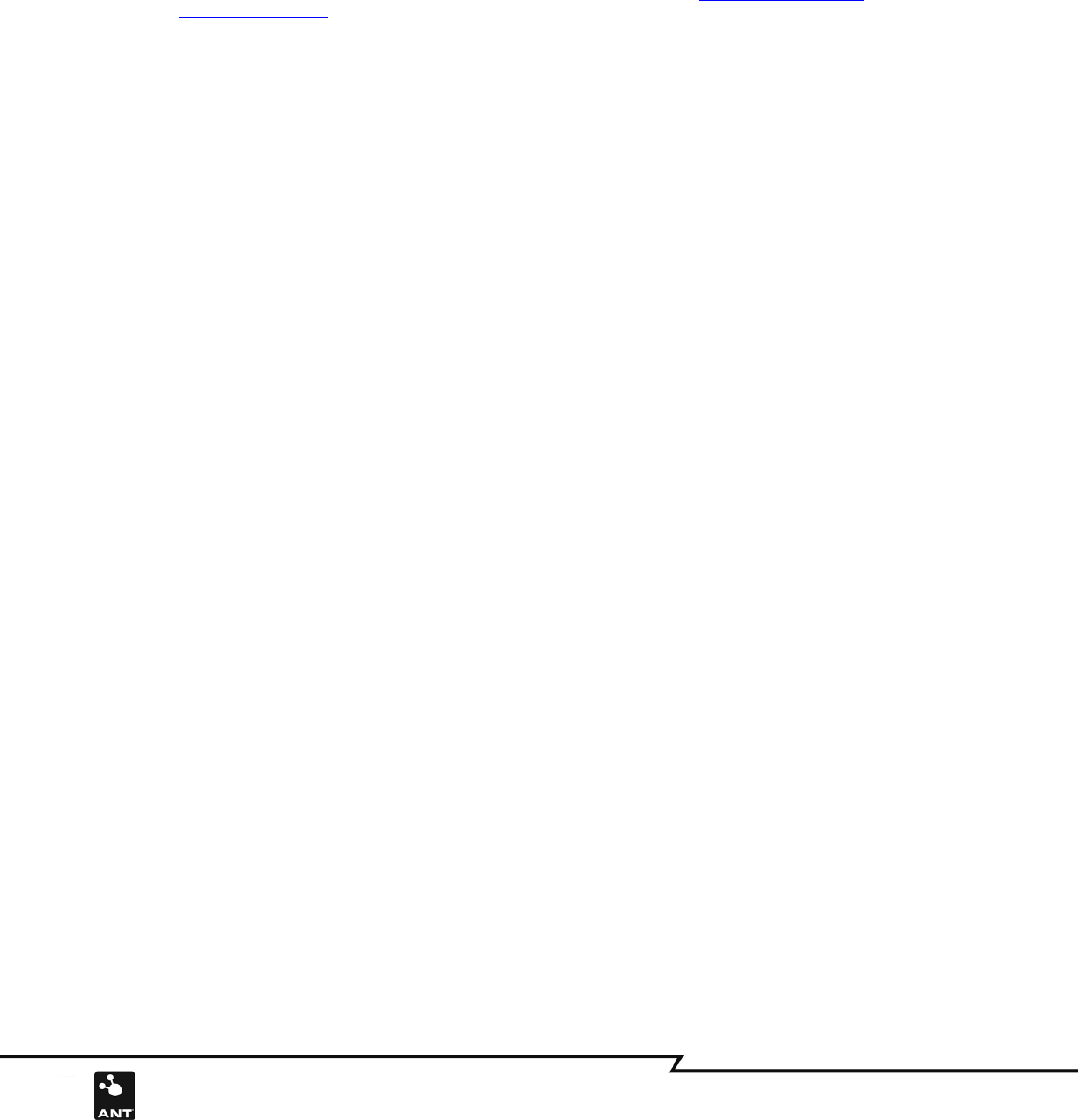
PC USB port directly. The extension cable can be mounted on any convenient area. Another golden unit (e.g.
golden unit2) is connected with a USB hub, and the unit under test (UUT) is connected to the same device
(Figure 3b). The Hub can be put on the test bench near the PC and the golden unit1 connected to the extension end can
be located up to 5 meters away from golden unit2. There should be no moving objects between golden unit1 and golden
unit2 during the test.
Figure 3a: USB2 Extension Cable installation with Golden Unit
Figure 3b: USB2 golden unit and UUT connected with Hub
5 of 13
228 River Avenue, Cochrane, Alberta, Canada. T4C 2C1 thisisant.com
3. System Requirements
In order to use the USB2 IQC Test software, it is necessary to install the Microsoft .NET Framework
Redistributable Package (3.5). A free download of this is available at the Microsoft Download Center.
All files distributed along with the test software should be present in the same directory as the application.
These files include:
• ANT_DLL.dll
• ANT_NET.dll
• ANT_WrappedLib.dll
• DSI_CP210xManufacturing_3_1.dll
• DSI_SiUSBXp_3_1.dll
• USB2_IQC_Test.exe
• ANT_USB2_gold_list.ini
4. Acquiring Golden Units
4.1 Golden units selection
Golden units are strictly selected by a product design engineer in a RF lab environment from a number of
finished products, usually from prototype and pilot manufacturing runs. Units are thoroughly tested using
sophisticated equipment against product specifications or design goals. Depending on purpose of the golden
units, either those units with testing results that marginally meet the specification or those units with the
most consistent measurement (measurement should be labeled on the unit) could be marked as golden unit.
A set of Golden units should be selected and distributed among production lines and facilities. Often more
than one Golden unit should be allocated per test station. These units should be well kept in the form as it
was selected. Any abuse of Golden Units should be avoided, such as opening the housing, and any damage
tests, such as ESD test and dropping and vibration.
There are many factors that may affect the USB2 RF performance. The orientation of the USB2’s strip antenna, and the
placement of the USB2 with respect to noise sources and interference environment, can significantly affect the distance at
vary application. There are no specific requirements and constraints for the golden unit’s selection. The golden units should
be selected through empirical testing in the target application.
4.2 Golden units identification in the test program
In order to work with the identical golden units, the program requires checking the serial number of the
golden units at the starting of the program. For secrecy, an encryption key (0xA7D2F289) is XOR with the
golden serial numbers that show up in the initial file. The program will decrypt the serial numbers with the
same key and verify the golden units.
6 of 13
228 River Avenue, Cochrane, Alberta, Canada. T4C 2C1 thisisant.com
5. The Concept of the test system
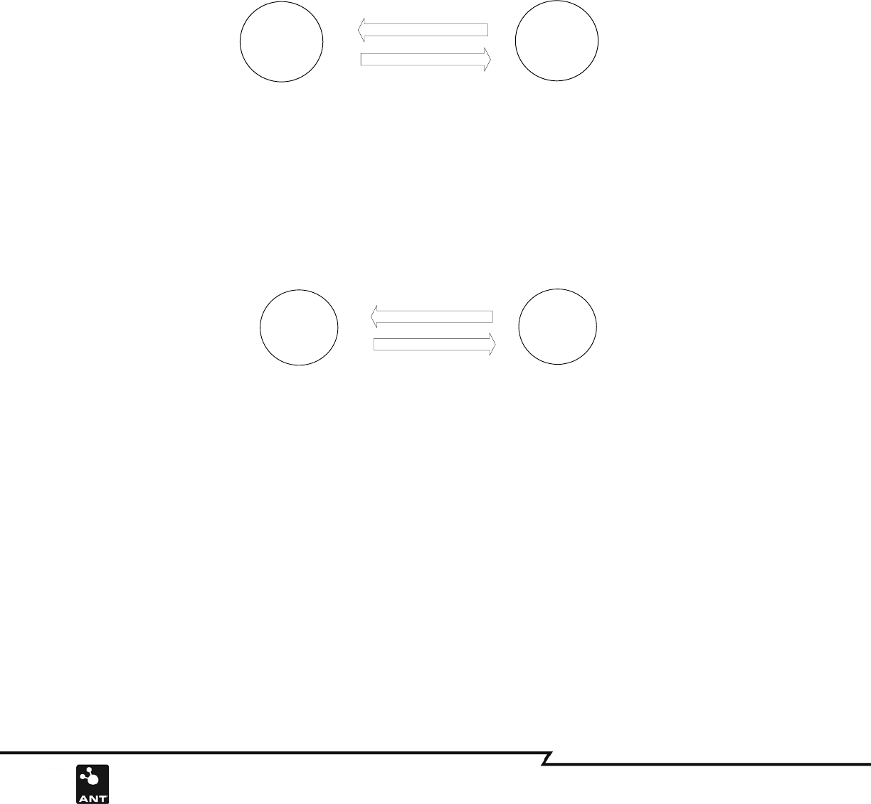
5.1 Calibration
Testing of the unit under test (UUT) is based on the comparison with the golden unit’s performance. To
ensure the comparison proceeds under the same test conditions, the calibration run is enforced at the
beginning of each UUT test. The test software will automatically first calibrate the system and then register
the pass/fail criteria. The calibration run is implemented between two golden units: golden unit1 and
golden unit2, the golden unit1 will send out 50 acknowledge messages, and as response the unit2 will
ideally send same number of Ack back to golden unit1. If the channel degenerates, 100% of the messages
may not be received by the receiver, and the software will count the successfully received messages as the new
threshold. The Figure 4a shows the calibration run.
Ack
Golden Unit2 Golden Unit1
Transmitter Receiver
Acknowledge Messages
50
Figure 4a. Golden units calibration run
5.2 Performance test
The UUT performance test implementation is quite similar to the calibration, except that the UUT is used instead of
golden unit2. Again, messages received are counted, and the max percent difference between UUT and calibration
run will calculated and compared. A defective UUT will be identified by the test. The diagram Figure 4b shows the
UUT test performance
Ack
UUT Golden Unit1
Transmitter Receiver
Acknowledge Messages
Fiture 4b: UUT test implementation
7 of 13
228 River Avenue, Cochrane, Alberta, Canada. T4C 2C1 thisisant.com
6. ANT USB2 Stick Test Procedures
Calibration run
The following step by step instructions describe how to use the test software:
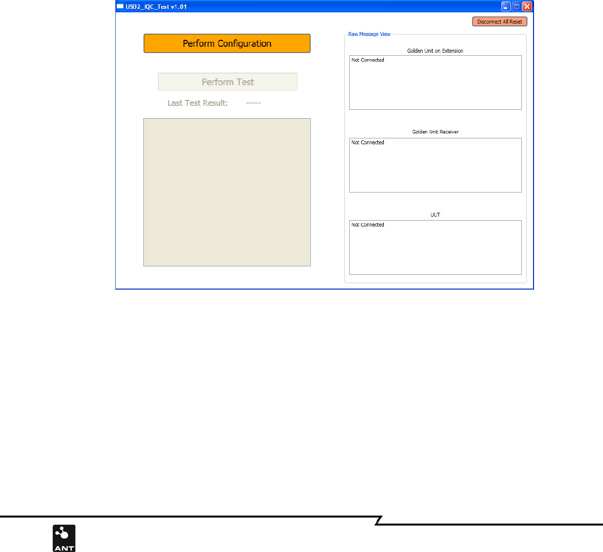
Run the IQC test software. Once the software is started, the GUI will show as in Figure 5. There are three text
boxes on the right side of the GUI which show the ANT device message transaction status and one text box on
the left side which shows test results.
Figure 5: Test software start face
8 of 13
228 River Avenue, Cochrane, Alberta, Canada. T4C 2C1 thisisant.com
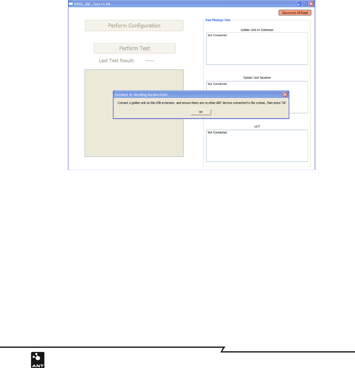
Make sure there are no USB devices attached to the PC USB port, and then click the “Perform Configuration”
button on the GUI. Once the button is clicked, the popup window will display the information, which will lead
you through the next step. Connect the Golden Unit (e.g. golden unit1) with USB extension Cable, and then click
OK as shown in Figure 6.
Figure 6: Connect golden Unit with USB extension Cable
9 of 13
228 River Avenue, Cochrane, Alberta, Canada. T4C 2C1 thisisant.com
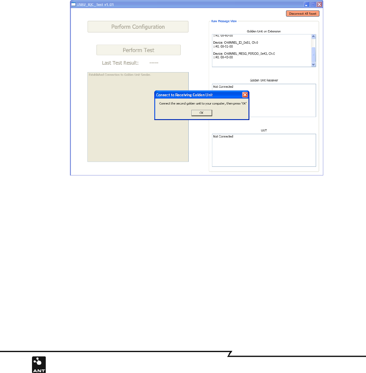
Once the OK button is clicked, the popup window will remind you to connect second golden unit, which shows
on Figure 7. Connect Second golden unit (e.g. golden unit2) to the 7 port USB hub.
Figure 7: Connect the second golden unit to USB hub
10 of 13
228 River Avenue, Cochrane, Alberta, Canada. T4C 2C1 thisisant.com
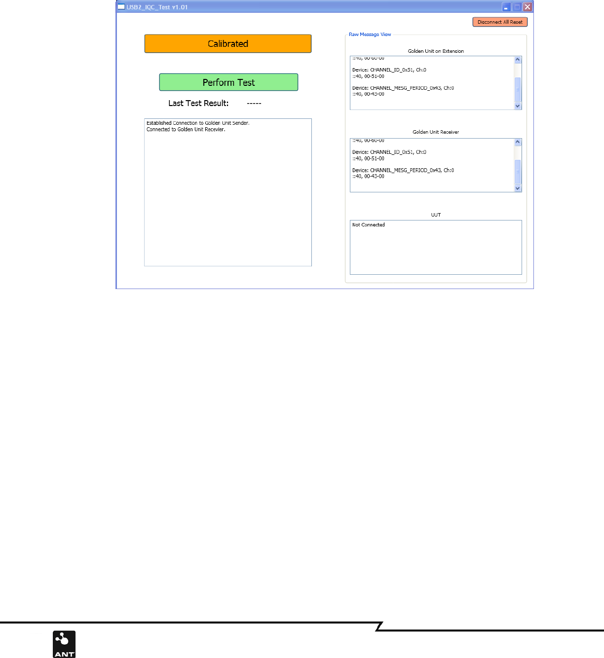
Connect the second golden unit to USB hub, then click OK on the popup window, you will see the window shown
in Figure 8.
Figure 8: Connect the UUT to the USB hub
11 of 13
228 River Avenue, Cochrane, Alberta, Canada. T4C 2C1 thisisant.com
Connect the UUT
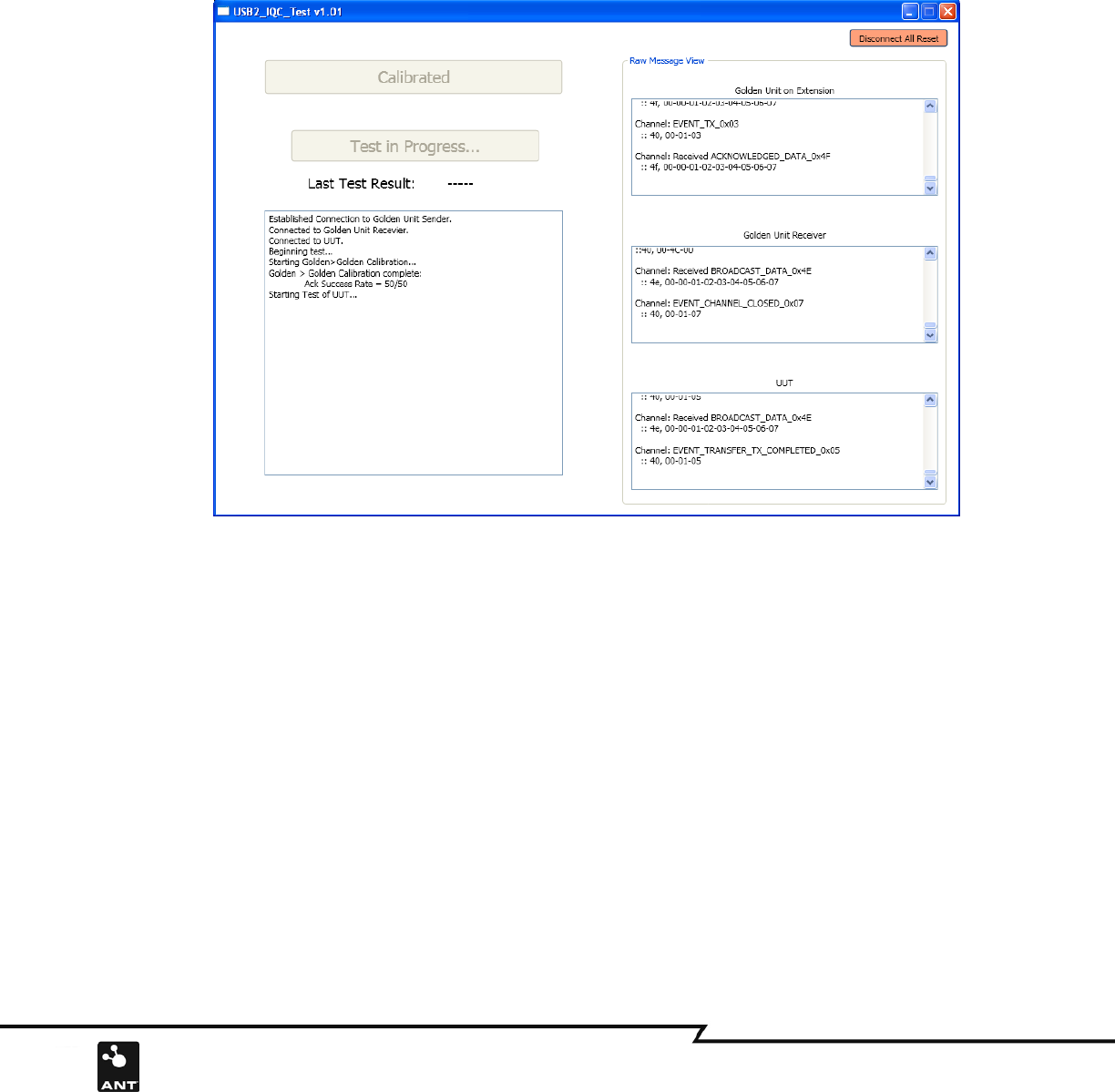
Connect a UUT to the 7 port USB hub, then click “Perform Test” button. If the configuration is correct, the start
test window will show on Figure 9a. If there is any operational error during the configuration, you can click the
“Disconnect All Reset” button on the right corner of the window to restart the configuration sequence.
Figure 9a: Perform UUT test Start
12 of 13
228 River Avenue, Cochrane, Alberta, Canada. T4C 2C1 thisisant.com
Perform Test
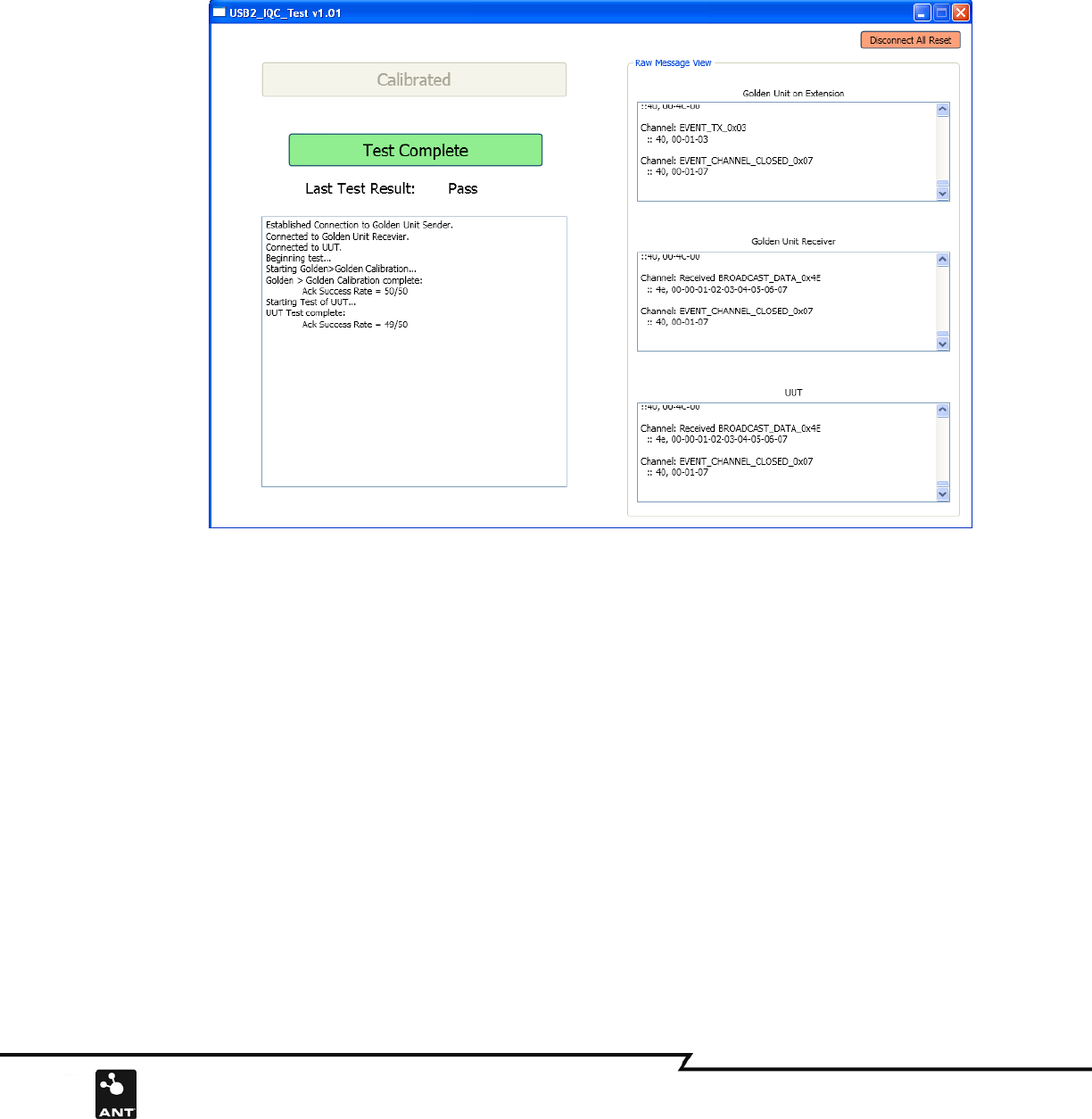
After pressing the “Perform Test” button, the test software will start running. The status will show on the screen
and text boxes. Calibration runs first, if the calibrated data is correct, the UUT perform test will take place next.
If the calibration test fails, the popup window will show “Error” message; you may need to press the “Perform
Test” button again to repeat the same test as seen in Figure 9b.
Figure 9b: Perform UUT test Complete
Pass/Fail
The calibration run and performance test is implemented automatically once the button is pressed. The Test Result
label will show pass or fail. If the UUT fails, you may need to repeat the same test at least once more to confirm
that the failure persists.
Change UUT
After the UUT is tested, you can unplug the UUT, change to a new one, and then press the “Test Complete button”.
The popup window will remind you if the UUT does not plug in as seen in Figure 10.
Repeat the same test operation
The calibration button is disabled during the perform testing. If it is required, you can press the button “Disconnect
All Reset” which will enable the calibration button and allow you to reconfigure the test system.

