Universal Hopper Series Technical Manual
User Manual:
Open the PDF directly: View PDF ![]() .
.
Page Count: 15
Universal
Hopper
Series
RETURN TO MAIN MANUAL
Contents
1 .O GENERAL DESCRIPTION
1.1 Description
1.2 Models
1.2.1 Connector Position
1.2.2 Level Sensing
1.2.3 Connector Options
1.3 Installation
1.4 Safety
2. 0MECHANICAL DESCRIPTION
2. 1 General Mechanical Description
2.2 Differences between Mkll Mklll and
Mk4 Hoppers
2.3 Trackguard Removal/Refitting
2.4 Coinbox x Removal/Refitting
2.5 Track and 12 Pin Plug Access
2.6 PCB Access
3. 0ELECTRONIC DESCRIPTION
3.1 General Electronic Description
3.2 Operating Mode Selection
3.2.1 Mode 0
3.2.2 Mode 1
-
5V Logic Control
3.2.3 Mode 2
-
Coin Counting
3.3 Reset Function
3.4 Optical Sensors
3.5 Optical Security Feature
3.6 Motor Operation
3.7 Motor Current Limit
3.8 Coins with Holes
4. 0ELECTRICAL SPECIFICATION
4.1 Power Supply
4.1. 1
Suggested Connection
4.1. 2 E.M.C.
5. 0APPLICATIONS
5.1
Sensor Output Interfacing
5.2 Motor Switch Off Time
5.3 Security Output
5.4 Level Sense Plates
5.5
IN 1
to IN3 inputs
5.6 LED Indicators
6. 0TECHNICAL SPECIFICATIONS
6.1 Coin Sizes
6.2 Connections
6.3 Motor Supply
6. 4 Logic Supply
6.5 Logic Inputs
6.6 Logic Outputs
6.7 Supply Notes
6.8 Environment
6.9 Overall Dimensions
Universal
Hopper
Series
Coin Controls’ Universal Hoppers
were first introduced in 1984
The
MkII
and Mklll models
proved themselves to be
exceptionally reliable, with high
count accuracy. The Mk4 is the
latest generation of this
extremely successful series.
The Mk4 Universal Hopper can
be used as a direct replacement
for Mkll and Mklll Hoppers. Any
specific variances are clearly
indicated, where.appropriate, in
this manual. When ordering Mk4
Universal Hoppers as a
replacement, it is important to
specify which version is being
replaced.
Safety
Note-
Mk4 Hoppers
only
To meet the requirements for
EN 60950 the equipment must
be installed according to the
following requirements:
The equipment must be
protected by a 3A fuse.
The equipment must be supplied
from a SELV limited power
source.
The equipment must be installed
in an enclosure but positioned so
that it is external to any fire
enclosure area within the main
enclosure.
GENERAL
DESCRIPTION
1.0
1.1
Description
The Universal Hopper is an
“intelligent” large capacity coin
and token dispenser ideal for a
wide range of applications
including Gaming, Vending and
Transportation systems.
Mkll
and Mklll hoppers will
handle most coins in the range
16mm
-
30mm diameter and
1.25mm
-
3.5mm
thick, giving
the following approximate
capacities:-
Coin Size Capacity
DiameterThickness
28.4mm
2.21 mm 800 approximately
24.25mm
1.75mm
1600 approximately
The Mk4 has extended the range
to include 31 mm diameter and
1 mm thick coins.
The rate of payout, whilst being
dependent on the coin
dimensions and also the volumes
of coins in the Hopper at any
given time, is approximately
3 coins per second.
Precise payout is ensured
through optical sensing and
verifying of coin dispensing with
an electronic security signal
which alerts against coin jams,
failed sensors and bad power
supply. LED indicators are
provided for easy visual checking
of power supply, security status
and coin sensors.
The Universal Hopper has the
in-
built facility to operate in 3
modes:-
Mode 0
the direct switching mode.
Mode 1
the hopper is controlled directly
by a LOGIC CONTROL LINE.
When the line is ‘active’, the
motor runs.
Mode 2
the hopper is driven by pulses on
the control line which allows the
hopper to be used in place of a
solenoid payout with no software
and few hardware changes.
1.2
Options
There is a standard Universal
Hopper handling coins in the
diameter range of 21 mm
-
30mm, and the small coin
Universal Hopper handling coins
in the diameter range of 16mm
-
21 mm. Both of these models
can be supplied with a number
of
options:-
1
.2.1
Connector Position
The
12-pin
connector can be in
one of two positions, either on
the opposite side of the coin exit,
known as the standard position,
or on the same side as the coin
exit, known as the adjacent
position.
1.2.2
Level Sensing
Universal Hoppers can be
supplied with a choice of coin
sensing positions, these can be
either:-
High level or
Top level
All Hoppers are automatically
supplied with a low level function
to indicate coin starvation.
1.2.3
Connector Options
Mk4 Universal Hoppers are
available with connectors
compatible with Mkll and Mklll
Hopper installations. It is
important, when ordering, Mk4
Hoppers as a replacement to
specify which version is being
replaced.
All of the above options must be
specified when ordering.
1.3
Installation
Important: Power should not be
applied until the installation is
complete.
1.
Secure the base plate in
position, using the six fixing
holes. The hole positions are
shown in Fig.1 1 b.
2. Wire up the base plate
connector to the host machine
-
see section 6.2 for connector
details, and sections 4
&
5 for
interfacing recommendations.
NOTE:
The
wire to be used should have
a maximum length of 3 metres,
and must be capable of handling
the maximum currents and
voltages specified in section 6.
3. Slide the hopper into the
baseplate and ensure that the
two halves of the connector are
securely mated.
4. Turn on the power.
1.4
Safety
1. Do not put a hand into the
hopper while the motor is running.
2. Static
It is possible for coins paid out to
have a static charge on them.
Coins should be discharged to
earth before being presented to
the user.
IMPORTANT:
The hopper should not be
installed/removed from
baseplate with power connected.
Avoid inhalation of coin dust
during any servicing operations.
MECHANICAL
DESCRIPTION
2.0
2.1
General
The hopper is mounted in a
machine via the base plate.
Electrical connection to the
hopper is made via the 12 pin
socket on the base plate which
mates with the corresponding
plug on the hopper body.
Coins are stored in the
cashbox
section of the hopper and fed
onto the elevator belt via a
passage in the centre plate. The
cut-out in the centre plate has
been designed to regulate the
flow of coins onto the belt. The
stirrer agitates the coins in the
coin box in order to minimise the
occurrence of bridging.
The elevator belt is driven by a
motor, gear box, and idler gear.
Coins are picked up at the
bottom of the belt and carried up
to the exit window. Optical
sensors in the exit window
detect the coins as they roll out
of the hopper.
A cable connects the main
control board to the 12 way
socket and carries all power
supplies and control signals.
2.2
Differences Between
Mkll,
Mklll and Mk4 Hoppers
Feature Mkll Mklll Mk4
Motor
Belt Belt
Direct
drive
Gears
Plastic
Plastic Metal
&
plastic
PCB
Centre
Centre Coin
location plate
plate
box
LEDs
PCB PCB
Exit
location
window
Opto
2 sets
1 set
3 sets
sensors
Track
Blue
Green None
guard
2.3
Trackguard Removal and
Refitting
(Mkll
and Mk Ill only)
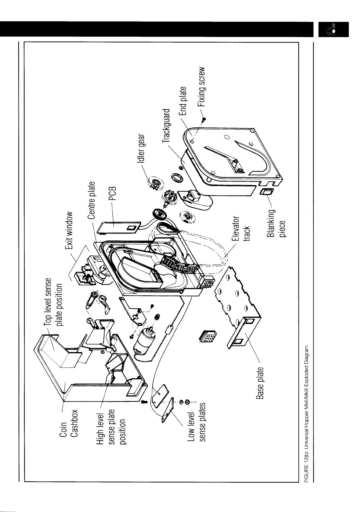
See Fig 12(b)
Firstly, locate cut away slots in
Centre plate and End plate at
the base of the track guard
opposite the PCB.
Push track guard up to reveal a
gap between body moulding and
the guard. Insert broad flat
bladed screw driver or equivalent
into gap and gently lever out the
guard until the leading edge is
above the outside edge of the
body mouldings. Now slide the
guard down towards the cut out
and gradually withdraw it.
Slide back the track guard to refit.
2.4
Coin Box Removal and
Refitting
Removal
1.
2.
3.
4.
Place the hopper flat on a
bench, with the end plate face
down.
Remove the locking nuts from
the level sense plates and
disconnect the wires low level
and high/top level, if fitted.
Remove the fixing screws.
Lift the coin box and stirrer
clear of the end and centre
plates.
Refitting
5.
6.
7.
8.
9.
10.
Place the coin box flat on a
bench.
Fit the stirrer to the coin box,
ensuring that the thin prong
is located in the slot in the
coin box.
Turn the stirrer shaft so that
the square hole is aligned
with the drive shaft which
protrudes from the centre
plate.
Hold the centre plate/end
plate assembly above the
coin box.
Feed the level sense wires
through the holes in the coin
box.
Lower the assembly onto the
coin box and ensure that the
mating walls are correctly
located.
11.
Turn the hopper over.
12. Insert and tighten the fixing
screws.
13. Re-connect the level sense
wires.
With Mk4 hoppers, the PCB also
has to be located when refitting
the coinbox.
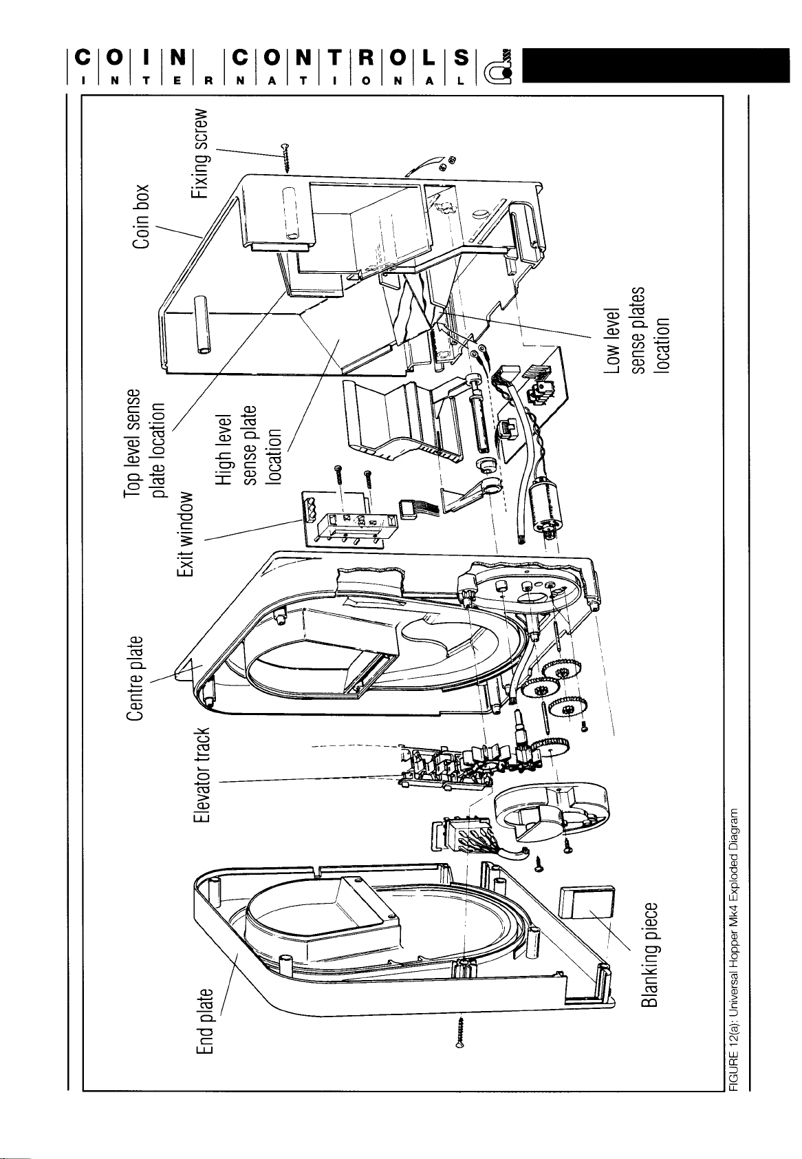
2.5
Track and
12-Pin
Plug
access
To service the track, and 12 Pin
Plug, follow instructions below and
refer to figures 12(a) for Mk4 and
12(b) for Mkll and Mklll.
1.
2.
3.
4.
5.
6.
7.
8.
9.
Mkll and Mklll Hoppers may
be fitted with a metal strut.
Removal of the strut will
require the coin box to be
removed first, see 2.4.
Remove the trackguard if
fitted, see 2.3
Note how wiring is laid out
and whether plug is on the
left or the right of the centre
plate (there should be a plug
blanking plate in the side not
used).
Place flat on a bench (coin
box face down) and remove
the fixing screws.
Remove end plate
Remove idler gear
Pull the track off the centre
plate.
Reassemble by placing the
track in the recess provided
in the centre plate, making
sure that the leg of the ‘L’
shape on the track plate is
against the centre plate. To
test the track is seated
correctly, spin it, if it jams this
means that one or more of
the legs are not in the recess.
Refit idler gear, taking care
not to disturb the track.
1
0.Place
the end plate as
horizontally as possible to the
centre
plate, making
sure that
the track is seated correctly.
Press home and refit the
screws (Bottom first, then
top 2, then middle 3).
Clol’lNl
ICI0
~INITIEII~NIA
If the track jams, dismantle and
start again.
Replace the track guard on
Mkll
and Mk
Ill
hoppers as
described in 2.3.
2.6
PCB Access
Mkll and
Mklll
PCBs are located
between the end and centre
plates.
NOTE:
Mkll
boards are
hard-
wired to the exit window and
cannot be removed without
unsoldering the 12 way header.
The Mk4 PCB is located in the
coin box. To access the board,
remove the coin box as
described in 2.4.
ELECTRONIC
DESCRIPTION
3.0
3.1
General Electronic
Description
Operation of the hopper is
controlled by a
4-bit
micro-
processor. The microprocessor
allows the choice of 3 different
operating modes. It also provides
the motor control drive via a
darlington bridge and an optical
payout detection output.
Separate power supplies are
recommended for the motor
supply input and the logic supply
input.
3.2
Operating Mode Selection
Three modes of operation are
available, selected via inputs IN1
and IN2 (pins 4 and 8 of the 12
way connector). Input signals
may be controlled by the host
machine, or may be hardwired.
Additionally, input IN3 (pin 12) is
the logic control line, used in
modes 1 and 2. These inputs are
passive pull-up active pull-down.
The signals therefore default to
logic ‘1’ if left open circuit.
NOTE:
It is strongly recommended that if
these inputs are to be controlled
by the host machine, then open
collector NPN transistors,
referenced to logic OV (connector
pin 2) be used to set the input
levels to
IN1,
IN2 and IN3.
With the exception of ‘RESET’
mode which can be applied at
any time (with instantaneous
effect) mode selection is
determined at power-up. The
hopper allows a 1
OOms
time-out
after power-up, then reads the
inputs IN1 and
IN2.
The hopper
will remain in the selected mode
until the power is removed, ie,
any further changes in the levels
at IN1 and IN2 will be ignored.
See fig 1
Refer to section 5.5 for
recommendations for driving input
signals on pins
IN1,
IN2 and
IN3.
Mode
IN1
IN2
0
1 1
1
0
0
2
1
0
Reset
0
1
FIGURE 1: Mode selectlon input logic
3.2.1
Mode 0
This is the default operating
Mode, and is selected when all
of the input selectors are left
open circuit.
When the 24V line is established,
the motor starts in the forward
direction and when the 24V
power line is removed, the motor
is braked.
3.2.2
Mode 1-W Logic Control
In this mode the logic and
24V power supplies can be
permanently connected and
motor function is determined via
a logic level on the IN3 input.
When IN1 (pin 4) and IN2 (pin 8)
are pulled down to logic OV at
power up, mode
1
is selected.
The operation of the motor is
now controlled via a logic signal
on IN3 (pin 12). With the 24V
supply present, a low level on
IN3 starts the motor and a high
level on IN3 brakes the motor.
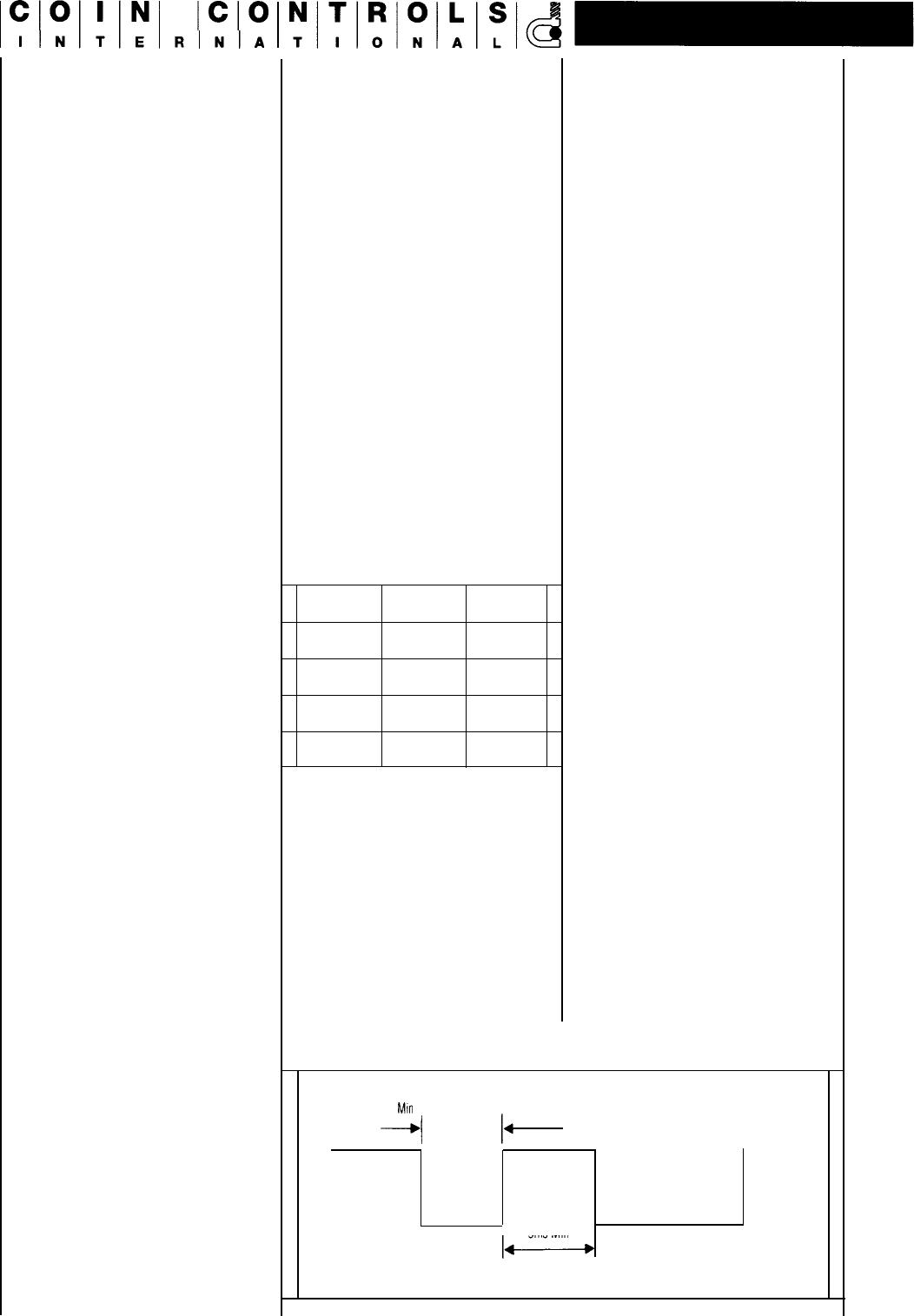
3.2.3
Mode 2
-
Coin Counting
In this mode, the hopper will pay
out a coin for every pulse it
receives on input
IN3.
Mode 2 is selected by setting
IN1
(pin 4) high and IN2 (pin 8)
low at power up. Once selected,
the processor continually scans
input IN3. When a pulse is
detected on
IN3,
an internal
register is incremented. When a
coin is paid out, it is detected
and the register is decremented.
The motor is started when the
internal coin register is non-zero
and is stopped when it returns to
zero. The maximum count for the
coin register is 4095
coins. Should
the 24V line fail at
any point, the motor is braked.
When the 24V line re-appears,
the payout of coins continues
until the coin register returns to
zero. Coin counting on IN3 can
take place while coins are being
paid out.
5ms
Mm
5ms Min
I-
FIGURE 2: Inputs to IN3

A pulse is defined as a falling
edge followed by a rising edge.
Pulse edges may be no closer
than 5ms (see fig.2). This is so
that the processor has adequate
time to poll the IN3 pin and
de-
bounce. This represents a
maximum pulse rate of 1
00Hz.
There is no lower limit. The
waveform duty cycle is
unimportant.
At power-up in mode 2, IN3 is
high. The first falling edge will be
recognised as the first pulse and
the hopper motor will start
running.
Pulsing on IN3 should not
commence earlier than
130ms
after the logic supply has been
established. This will allow for the
power-up time-out of 1
00ms
and
further processing time prior to
running the main program.
3.3
Reset Function
The reset function is available on
Mklll
and, when specified on the
Mk4 version.
In this mode the Hopper is reset,
i.e. processor reset and motor
drive disabled. This function is
provided as added security
enabling the host machine to
immediately stop the Hopper
irrespective of its mode of
operation.
Whilst in this mode connecting
IN3 (Pin 12) to ground turns the
exit window sensor off in order to
test it is operative. Confirmation
would be given as a signal
output on Pin 3 and 11 of the 12
Pin connector.
3.4
Optical Sensors
Optical sensors are fitted in the
exit window to detect coin
payout.
The signal on Pin 11 is the ‘Raw’
coin output signal. A de-bounced
coin output is available on Pin 3.
When no coins are present at the
exit window, the optical sensors
are clear, the output transistors
are open circuit, and the LED
indicator is off. Coins passing the
optical sensors obstruct the light
path causing the output
transistors to pull down to OV
and the LED indicator lights.
3.5
Optical Security Feature
The output of the optical sensor
is monitored by the
microprocessor and if the sensor
remains obstructed for more
than one second, the motor will
be braked and will remain off
until either the sensor is cleared
or power down takes place. This
action will result if a coin jams in
the exit window or if the optical
sensor fails which could be
checked by toggling IN3 in Reset
mode.
If the security feature should
operate, the security output on
output pin 5 and LED2 will be
switched off. The optical security
feature operates identically in all
3 modes.
3.6
Motor Operation
The DC motor is controlled by
the processor via a transistor
bridge. The motor will run
provided that one of the sets of
conditions shown below is met. If
any single condition fails then the
motor is braked and remains so
until all conditions become true,
or a power down occurs.
Mode 0 Motor Start Conditions:
Security feature true
24V line true
Mode 1 Motor Start Conditions:
Security feature true
24V line true
IN3 input low
Mode 2 Motor Start Conditions:
Security line true
24V line true
Internal coin count non-zero
When braking is initiated and for
whatever reason, 50ms braking
is carried out even if the fault
condition recovers before that
time. This guarantees that the
motor is stationary when the
bridge drivers change state, so
that no excess current flows in
the motor windings.
3.7
Motor Current Limit
The motor current is monitored
by the processor. When the
motor initially starts a high
current flows generating
maximum torque to force the
coin belt up to speed. After a
short time the motor current is
reduced to a fraction of the initial
surge current.
At any time after the initial surge,
if the current rises above a preset
value, then a jam is deemed to
have occurred. The motor is
braked for 50ms then reversed
for
150ms.
After a further 50ms
braking, the motor is started in
the forward direction. The current
is tested after 1
00ms
and if the
jam has not been cleared the
reversing cycle will be repeated.
This action will continue until the
jam has cleared. This reversing
action is effective in clearing
jams.
One further action is to test the
current in the reverse direction
during the final 50ms of the
reversing cycle. If during that
time period an overcurrent is
detected, then the motor will be
braked for 50ms and then
disabled for 1 second. This
action limits the duty cycle
sufficiently in the case where a
jam is solid in order to prevent
motor damage.
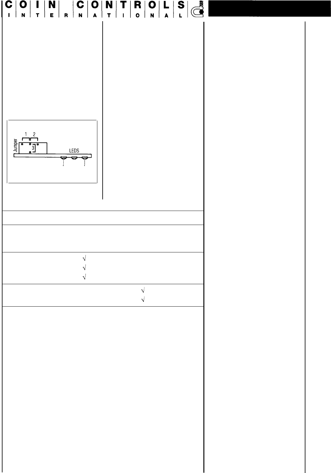
3.8
Coins With Holes
The
Mkll
hopper has not been
designed to handle coins with
holes and cannot be guaranteed
to perform correctly with such
coins.
The Mklll hopper can count most
coins with holes correctly, but
requires a jumper, on the control
board, to be set in the right
position for small or standard
coins
-
see below.
$
I-In
E&_,_,
j
Security
)
Power Sensor
FIGURE 3: Label PCB Edge View
Drawing
TIIIOINIAIL
If a Mklll hopper is converted
from one coin size to the other,
the jumper position must be
altered also. This is achieved by
removing the track guard, as
described in 2.3, placing the
jumper in the required positions,
then refitting the track guard.
Guide to coins catered for within normal build
options:-
Position 2 Position 1
Coinage Small Coin Standard Coin
16-21 mm
21-30mm
Danish 1 Kroner
-\i
Greek 5 Lepta
4
Spanish 5 Peseta
-\i
Danish 2 Kroner
d
Danish 5 Kroner
4
The Mk4 exit window has been designed so that more coins with
holes will be counted correctly. No adjustments are necessary to cope
with standard and small coins.
ELECTRICAL
SPECIFICATION
POWER SUPPLY
REQUIREMENTS
4.0
4.1
Power Supply
For ease of use and maximum
noise suppression, the 0 volt
logic line (pin 2) and the motor 0
volt line (pin 1) are not
commoned
inside the hopper.
This means the outputs from the
hopper (OPT0 and security) are
noise free.
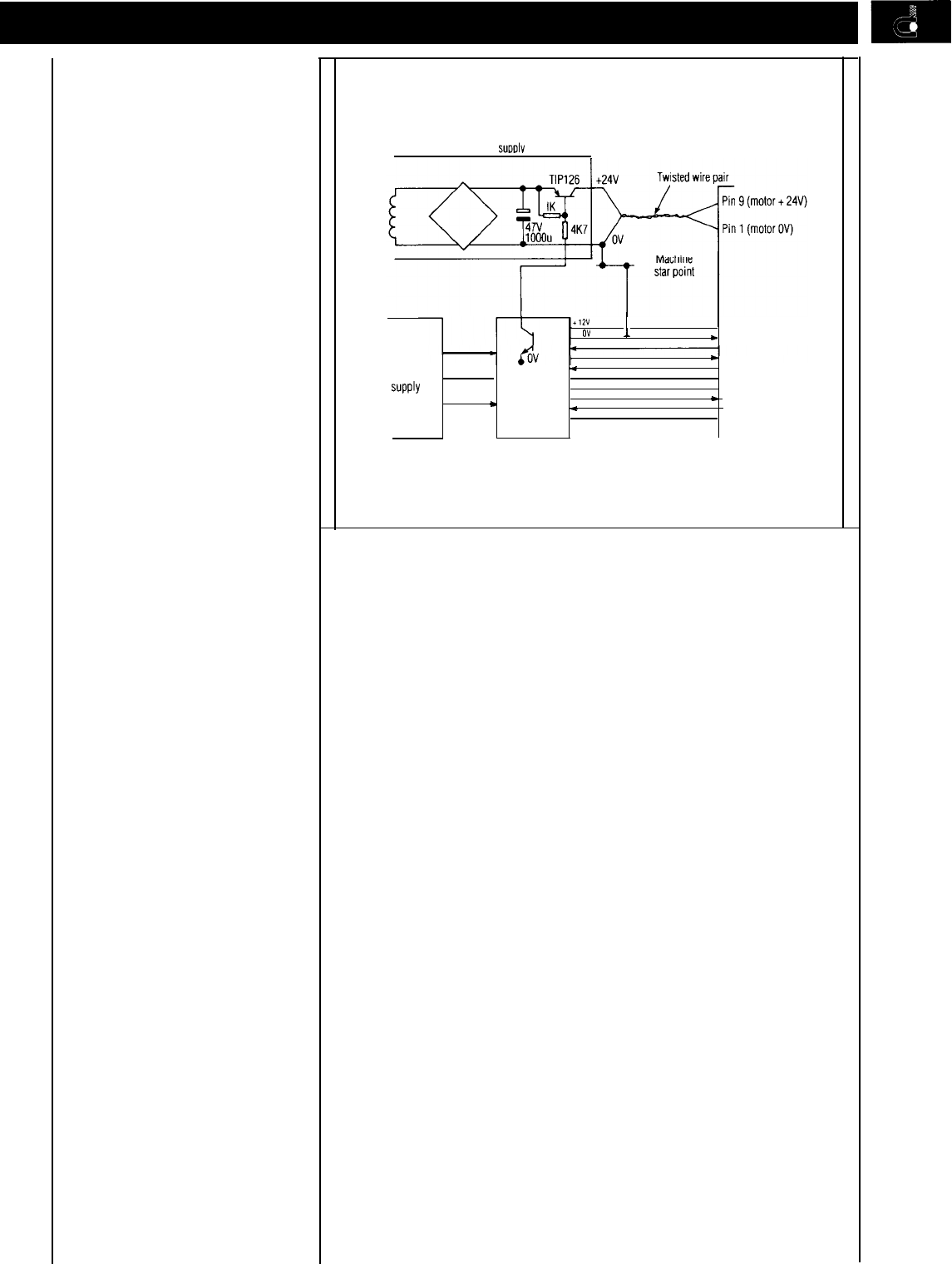
4.1
.1
Suggested Connection
A suggested connection
diagram is shown in fig 4.
A twisted wire pair is
recommended for the motor
power leads to reduce the
radiated noise.
The TIP 126 arrangement shown
would only be required for mode
0 operation where power line
interruption is the method of
motor control. In modes 1 and 2
the power line can be left
permanently on and the TIP 126
and IK and
4K7
resistors can be
omitted.
4.1.2
EMC
The
Mklll
hopper is EMC
hardened. There is a version of
Mk4 hopper which is also EMC
hardened. This is to help users
to meet the European EMC
regulations (EN50081
&
EN50082).
Further precautions should be
taken with the installation to
minimise the effects of electrical
noise, i.e.
-
i) Max cable length = 3 metres
ii) All wires to the hopper should
be bundled together.
iii) Minimum capacitance
between the logic supply rails
=
1OOµF
+ 24V Power
SUDDIV
+,a
0”
1
. Pin 10 (logic + 12V)
*
Pin 2 (logic OV)
Logic
power
SUPPlY
*
I
Host
.
_
machine
-
Hopper
logic
*
GURE 4: Recommended Connection Diagram
APPLICATIONS
5.0
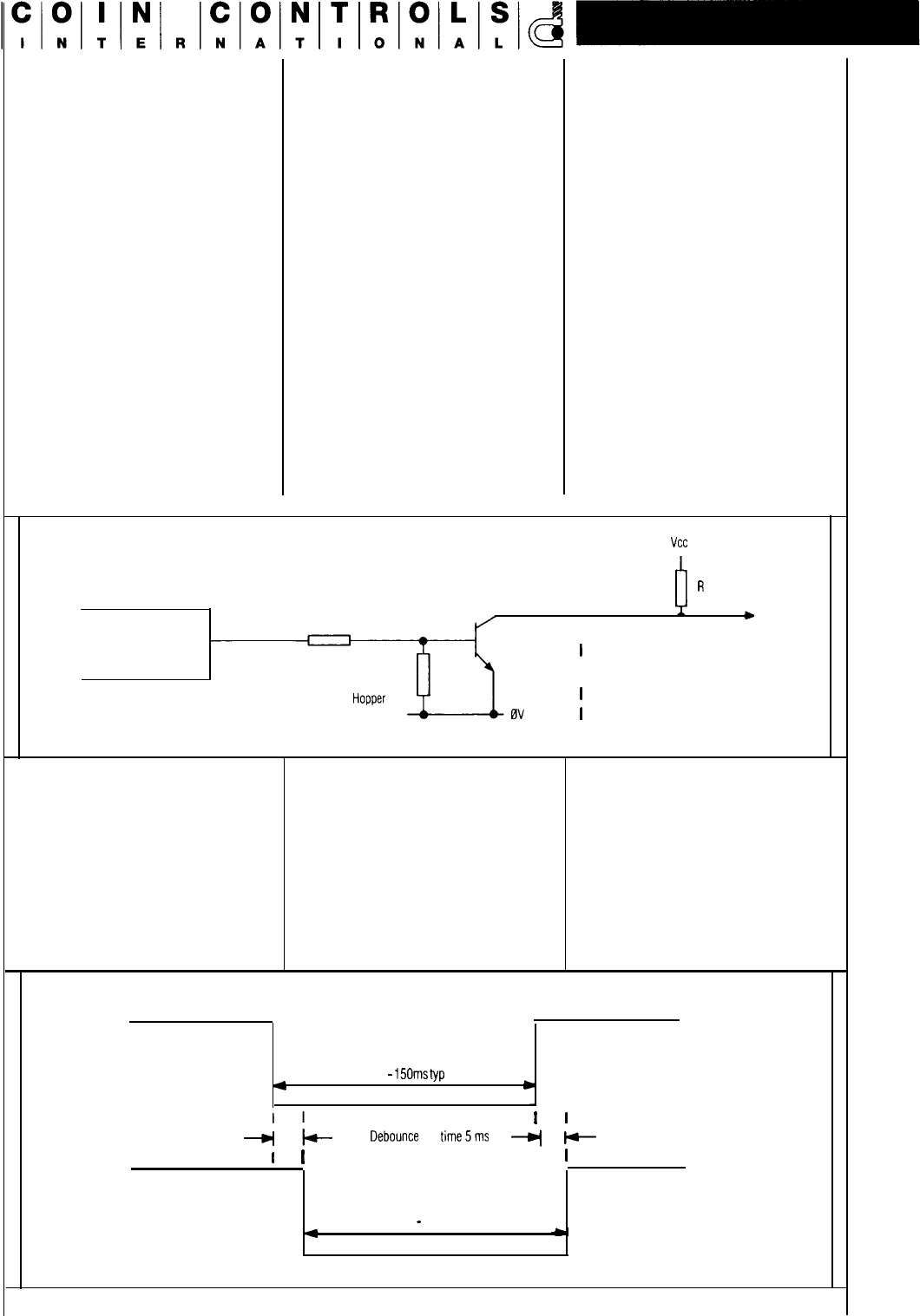
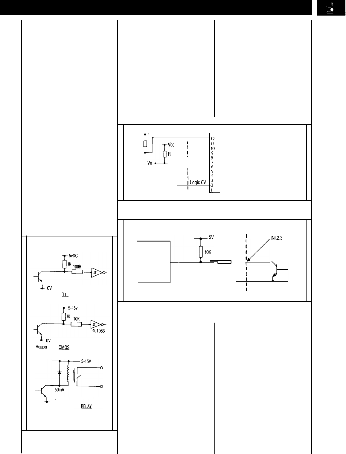
5.1
Output Sensor Interfacing
Both sensor outputs are open
collector NPN transistors, as
shown in Fig.5.
When a coin is paid out, the raw
sensor output will switch on,
connecting output Pin 11 to OV,
The sensor output on Pin 3 will
switch on approximately 5 ms
later
-
see Fig.6. Both outputs
will stay switched on until the
coin has left the exit window.
The open collector outputs are
provided for easy interfacing to
TTL,
CMOS or Relay inputs.
see fig. 7.
NOTE:
A flywheel diode is required on
any output which has an
inductive load connected, e.g. a
relay. A 30V maximum can be
tolerated on these outputs
(positive with respect to
0V).
vcc
I
I
R
I
&
Micro Processor
I
I
I
Host machine
I
I
FIGURE 5: Output Transistor
Arrangement
Output pin 11 (raw)
60 -
150ms
typ
4
c
4
-A-
I
I
Debounce
time5ms
--)(
+
I
I
I
I
Output pin 3
60
-
150ms typ
FIGURE 6: Sensor Output Waveforms
5.2
Motor Switch Off Time
When using the hopper in mode
0 (see section 3.2.1) the host
machine applies power to the
motor and monitors the payout
sensors, disconnecting the
motor power when it has
counted out the correct quantity
of coins. The motor power
should be removed within
10ms
of the leading edge of the o/p.
Similarly, to avoid erroneous
payout in mode 1, IN3 should be
taken high within
10ms
of the
leading edge of the opto output
(pin 3).
5.3
Security Output
The security output is an open
collector NPN transistor which
should be connected as shown
in Fig.5 In normal operation the
transistor will be switched on, i.e.
the output pin will be connected
to OV. The transistor will switch
off if a fault is detected
-
see
Section 3.5.
I
ov
Hopper
.DL
Machine
4
ov
Hopper
C!dQs
Machine
1
ov
Hopper
FIGURE 7: Recommended Sensor
Interfaces
5.4
Level Sense Plates
Brass plates are used for level
sensing. One plate is connected
to the logic 0 volts and the other
plates are wired to the 12 way
connector
-
pin 7 for low level;
pin 6 for either high or top level.
See figure 8. The signal levels on
these pins will be determined by
the presence or absence of an
electrical contact, via the coins,
between the 0 volt plate and the
other plates.
Vcc High or top level sense I2
“cc
I
II
I
IO
R
(50K)
/
9
Low level
87
Coins present Vo (pin 7) is OV
sense _
I
I
t
Coins absent Vo (pin 7) is at VCC
I
4
1
LogicOV
Hopper
:
1
Host
,
machine
-
FIGURE 8: Suggested External Circuitry for level sense plates
Microprocessor
I
I
_
,/
INl.2,3
I
I
470R
I
I
OV logic
f
Hopper
1
Host machine
FIGURE 9:
In1
to In3 Connections
5.5 5.6
IN1
to IN3 Inputs
These are the control signals
from the host to the hopper
which determine the mode of
operation. These are input to the
hopper microprocessor via a
resistor as shown in fig. 9.
IN3,
if used, should always be driven
via an open collector transistor
referred to logic OV. IN1 and IN2
can also be driven via open
collector transistors (see fig. 9) or
if no change of mode is required,
then strapped to logic OV or left
floating (internal pull-up)
depending on the mode
required.
LED Indicators
Three LED indicators are fitted
on the hopper. On
Mkll
and
Mklll
hoppers they are visible under
the trackguard at the top corner,
opposite the coin exit. Mk4
hoppers have the
LEDs
mounted
in the coin exit area. From left to
right, these are designated as
follows:
1.
2.
3.
Logic power ‘supply on’
indicator
Security (optical obstruction)
indicator, normally on.
Coin sensor indicator shows
coin passing the exit window
opto.
TECHNICAL
SPECIFICATIONS
6.0
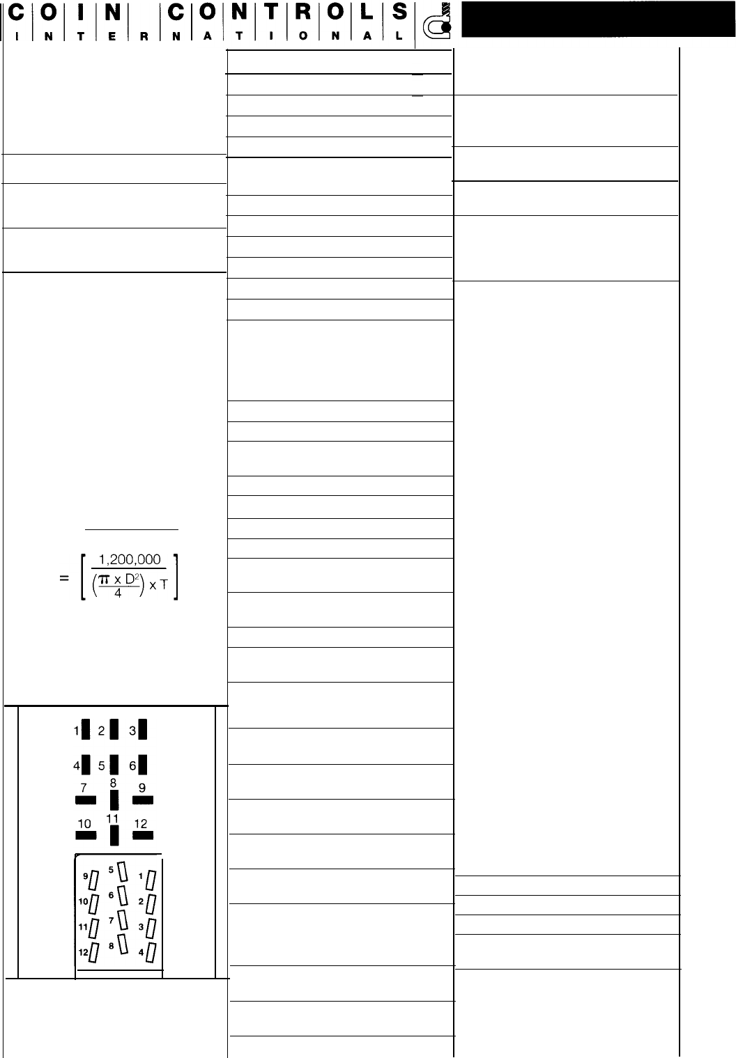
Pin 1
Motor supply 0 volt
Pin 2 Logic 0 volt
Pin 3 Sensor Output
6.1
Pin 4
IN1
Coin Sizes
Pin 5
Security output
Thickness Diameter
Standard
Model
1.25
-
3.5mm
21
-
30mm
Small Coins
Model
1.25
-
3.5mm
16
-
21 mm
The Mk4 hopper however has
extended this range to include
31 mm diameter coins. Coins
falling outside of the above
ranges may be used but would
require special qualification.
For more information contact
Coin Controls Technical Services
Department.
Capacity
Approximate coin capacities can
be estimated by applying the
following formula.
Capacity = Hopper Volume
Coin Volume
Where D = Coin diameter (mm)
T = Coin thickness (mm)
6.2
Connections
FIGURE
I0:
Pin Connections on
External 12 Way
Connectors
Pin 6 High or top level sense
output
Pin 7 Low level sense output
Pin 8
IN2
Pin 9
Motor supply
Pin 10 Logic supply
Pin 11
Raw Sensor Output
Pin 12 IN3
6.3
Motor Supply
Current consumption at 24V
DC:-
Nominal running current
0.5A
Nominal reverse current
l.OA
Nominal cut-out current
durina reverse 1.5A
Nominal start-up current
2.0A
Power supply
requirement:-
24V DC at 2 amps
Nominal voltage 24V DC
Absolute minimum
voltage
18V
DC
Absolute maximum
voltage 27V DC
Maximum rise/fall time 50ms
Absolute worst case
ripple at 24V
+3V/-6V
6.4
Logic Supply
Nominal voltage
12V DC
at
l00mA
Absolute minimum
voltage
11VDC
Absolute maximum
voltage 27V DC
Maximum
rise/fall time
Absolute worst
case ripple
1
00ms
+/-1V
6.5
Logic Inputs (IN1, IN2 and
IN3)
Absolute maximum
logic 0 inputs
V in
<=
0.6V
Absolute minimum
logic 1 input
V in
=>
2.4V
6.6
Logic Outputs
(Sensors, Security)
Absolute maximum
‘true’ output v out<=
0.3V
at 50mA
Absolute maximum
sink current
1
00mA
Absolute maximum
v off
30 Volts
Sensor output
Typical Pulse width
Mkll/lll
50-
1
00ms
Mk4
70-l 20ms
6.7
Supply Notes
1.
2.
3.
4.
Important
The specified maximum
motor and logic + ve voltages
must not be exceeded,
otherwise damage/injury
could result.
Hopper speed (and payout
rate) varies with applied motor
voltage
The power supply fall time is
critical if the hopper is being
used in mode 0. When the
host machine has counted
out the required number of
coins, it must disable the
+24
volt supply. The motor is not
disabled until the power line
falls below a preset level of
18 volts DC, therefore there is
a danger of extra coins being
paid out if the power supply
fall time is greater than 5ms.
A power supply switching
device such as a transistor,
darlington or mosfet is
therefore recommended.
The standby current is the
current drawn when the
motor is disabled, e.g. if the
coin register is zero in mode 2
or if IN3 is high in mode
1.
6.6
Environment
Operating temp 0 to 60°C
Storage temp -20 to 60°C
Life
up to 3 million coins
Mounting
±3°
of vertical in any
direction
NOTE:
Do not use the hopper in an
explosive atmosphere.
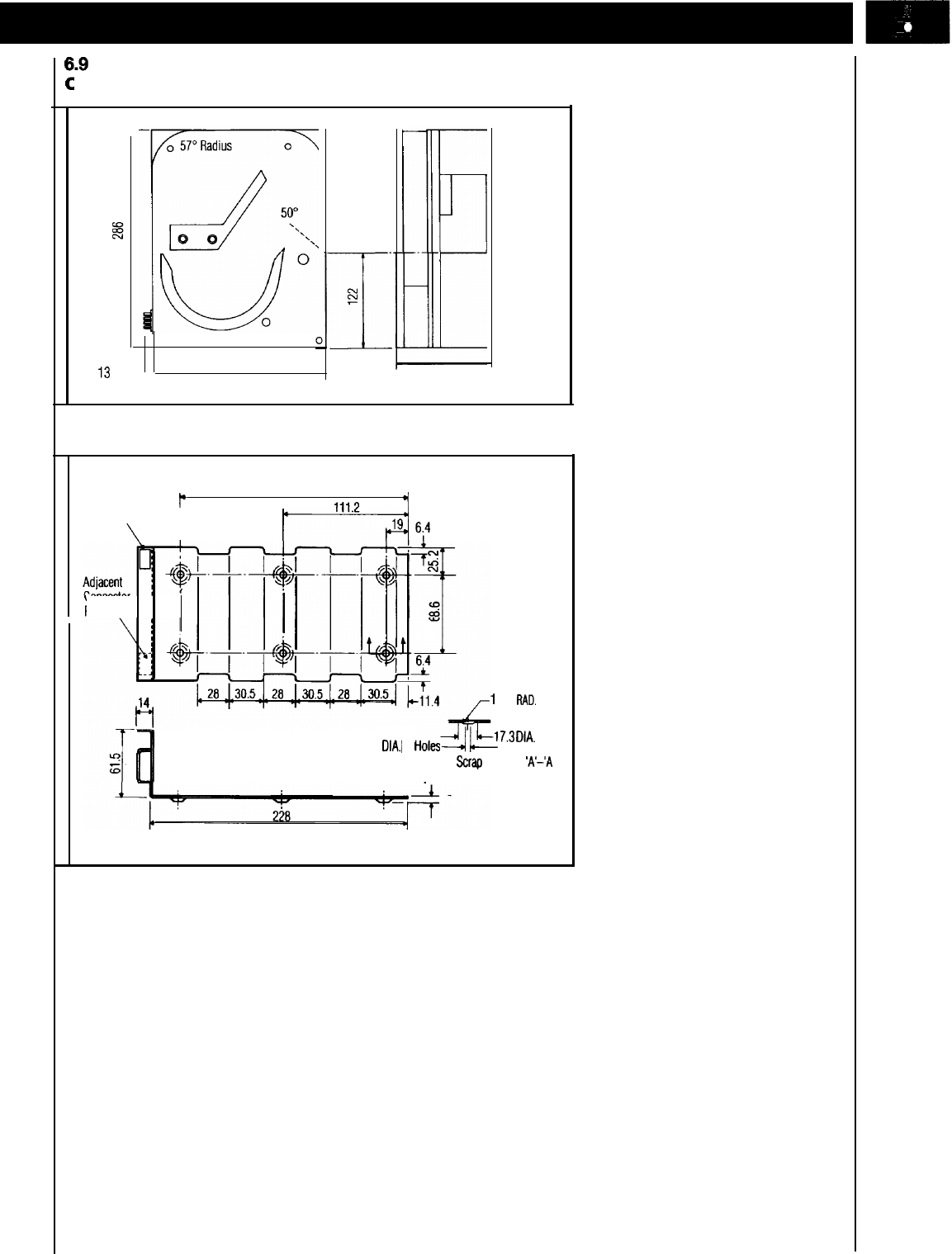
verall
Dimensions
(all dimensions in mm.)
0
226
‘3
1 I
Coin Outlet
126.5
FIGURE 11 a: Overall Dimensions
Standard
Connector
p
203.2
,,,1
+I
Position
\
RAD. 3 typ.
f-4
6;4
Connector
’
Position
,
Mounting Plate
12.7
RAD.
5
D1A.I
6
Holesgti
7.3
DlA’
Scrap
Section
%‘-‘A
3.2 6 Places
FIGURE 11 b: Hopper Mounting Plate

This manual is intended
only
to assist the reader in the use of this product and therefore Coin Controls shall not be liable for any loss or damage
whatsoever arising from the use of any information or particulars in, or any omission from, this manual or any incorrect use of the product.
Coin Controls Limited reserve the right to change product specifications on any item without prior notice.
Coin Controls International
Coin Controls
Ltd
(Corp
HQ)
Royton,Oldham OL2 6JZ,England.
Telephone:44(O)161
678 O111
Fax:44(O)161
6267674
Coin
Controls
Inc.
1850 Howard Street,
Elk Grove Village,
Illinois 60007, USA.
Tel: 1
8472281810
Fax: 1
8472281833
Las
Vegas
Branch
2925 East Patrick Lane,
Suite C, Las Vegas,
Nevada, 89120, USA
Tel: 1 (702) 739 8263
Fax:
1(702)
739 1911
Coin Controls
GmbH
Friedensallee
35,
022765 Hamburg,
Germany.
Tel:
49-4039
1775
Fax:
49-40390
4582
CCI
Issue
1.3
06/97
e-mail:
sales@coincontrols.com
web site:
www.coincontrols.com
Coin Controls SA
Sancho de
Avila
52-58,
5º,
1a
08018 Barcelona,
Spain.
Tel: 34-3 3002496
Fax 34-3 3002608
Coin Controls
Pty
Unit
3.43-51 College St.
Gladesville,
Sydney,
NSW
2111,
Australia
Tel:
61-2-9879 0011
Fax: 61-Z-9879 0111
