Unix System Administration (A Beginner's Guide) Steve Maxwell
User Manual:
Open the PDF directly: View PDF ![]() .
.
Page Count: 697 [warning: Documents this large are best viewed by clicking the View PDF Link!]

TEAMFLY
Team-Fly®
UNIX System
Administration:
A Beginner’s Guide

This page intentionally left blank.
UNIX System
Administration:
A Beginner’s Guide
Steve Maxwell
McGraw-Hill/Osborne
New York Chicago San Francisco
Lisbon London Madrid Mexico City
Milan New Delhi San Juan
Seoul Singapore Sydney Toronto

Copyright © 2002 by The McGraw-Hill Companies, Inc. All rights reserved. Manufactured in the United States of
America. Except as permitted under the United States Copyright Act of 1976, no part of this publication may be
reproduced or distributed in any form or by any means, or stored in a database or retrieval system, without the prior
written permission of the publisher.
0-07-222833-4
The material in this eBook also appears in the print version of this title: 0-07-219486-3
All trademarks are trademarks of their respective owners. Rather than put a trademark symbol after every occur-
rence of a trademarked name, we use names in an editorial fashion only, and to the benefit of the trademark
owner, with no intention of infringement of the trademark. Where such designations appear in this book, they
have been printed with initial caps.
McGraw-Hill eBooks are available at special quantity discounts to use as premiums and sales promotions, or for
use in corporate training programs. For more information, please contact George Hoare, Special Sales, at
george_hoare@mcgraw-hill.com or (212) 904-4069.
TERMS OF USE
This is a copyrighted work and The McGraw-Hill Companies, Inc. (“McGraw-Hill”) and its licensors reserve all
rights in and to the work. Use of this work is subject to these terms. Except as permitted under the Copyright Act
of 1976 and the right to store and retrieve one copy of the work, you may not decompile, disassemble, reverse
engineer, reproduce, modify, create derivative works based upon, transmit, distribute, disseminate, sell, publish
or sublicense the work or any part of it without McGraw-Hill’s prior consent. You may use the work for your
own noncommercial and personal use; any other use of the work is strictly prohibited. Your right to use the work
may be terminated if you fail to comply with these terms.
THE WORK IS PROVIDED “AS IS”. McGRAW-HILL AND ITS LICENSORS MAKE NO GUARANTEES
OR WARRANTIES AS TO THE ACCURACY, ADEQUACY OR COMPLETENESS OF OR RESULTS TO BE
OBTAINED FROM USING THE WORK, INCLUDING ANY INFORMATION THAT CAN BE ACCESSED
THROUGH THE WORK VIA HYPERLINK OR OTHERWISE, AND EXPRESSLY DISCLAIM ANY WAR-
RANTY, EXPRESS OR IMPLIED, INCLUDING BUT NOT LIMITED TO IMPLIED WARRANTIES OF
MERCHANTABILITY OR FITNESS FOR A PARTICULAR PURPOSE. McGraw-Hill and its licensors do not
warrant or guarantee that the functions contained in the work will meet your requirements or that its operation
will be uninterrupted or error free. Neither McGraw-Hill nor its licensors shall be liable to you or anyone else for
any inaccuracy, error or omission, regardless of cause, in the work or for any damages resulting therefrom.
McGraw-Hill has no responsibility for the content of any information accessed through the work. Under no cir-
cumstances shall McGraw-Hill and/or its licensors be liable for any indirect, incidental, special, punitive, conse-
quential or similar damages that result from the use of or inability to use the work, even if any of them has been
advised of the possibility of such damages. This limitation of liability shall apply to any claim or cause whatso-
ever whether such claim or cause arises in contract, tort or otherwise.
DOI: 10.1036/0072228334

This page intentionally left blank.
About the Author
Steve Maxwell has been actively involved with UNIX and computer networking
for the last 20 years. He has worked for a number of companies, institutions,
and organizations in a variety of capacities that have included network design,
software development, and training. Recently, Steve decided that it was time
to join another start-up company, and he now works at FineGround Networks,
Inc., where he is responsible for ensuring that the company delivers quality
software products. Steve welcomes your feedback on any aspect of this book—
please send comments, questions, and suggestions to sjmaxwell@worldnet.att.net.
About the Technical Reviewers
John Tiso is a senior consultant for NIS, a Boston-based integrator of Sun
Microsystems and Cisco Systems. He has a B.S. degree from Adelphi University
and is certified in UNIX from HP, Sun, and IBM. John is also a Cisco CCIE
(CCIE #5162), MCSE, and MCNE. He has published papers in several leading
technical journals, such as Element K and SysAdmin, and has served as a technical
editor for a variety of books. John can be reached at johnt@jtiso.com.
Jim Minatel is a freelance writer and editor with more than 13 years of publishing
experience in mathematics, statistics, and computing. He has authored and
co-authored several books about the Internet and World Wide Web in the early
Netscape era, and most recently served as Editor in Chief for two magazines for
networking professionals and IT managers. He holds undergraduate degrees in
mathematics and physics, and an M.S. in mathematics.
Contents
ACKNOWLEDGMENTS. . . . . . . . . . . . . . . . . . . . . . . . . . . . . . . . . . . . . . . . . xvii
INTRODUCTION . . . . . . . . . . . . . . . . . . . . . . . . . . . . . . . . . . . . . . . . . . . . . . xix
1Introduction to UNIX . . . . . . . . . . . . . . . . . . . . . . . . . . . . . . . . . . . . . . . . . . 1
1. Uncover the History of the UNIX System . . . . . . . . . . . . . . . . . . . . . . . . . 2
2. Explore the Elements of a Computer System . . . . . . . . . . . . . . . . . . . . . . 3
3. Show the UNIX Timeline . . . . . . . . . . . . . . . . . . . . . . . . . . . . . . . . . . . . . 7
AT&T Invents UNIX . . . . . . . . . . . . . . . . . . . . . . . . . . . . . . . . . . . . . 7
BSD Is Born . . . . . . . . . . . . . . . . . . . . . . . . . . . . . . . . . . . . . . . . . . . . 8
The System V Releases . . . . . . . . . . . . . . . . . . . . . . . . . . . . . . . . . . . . 8
AT&T/Sun Deal . . . . . . . . . . . . . . . . . . . . . . . . . . . . . . . . . . . . . . . . . 9
The Internet Worm . . . . . . . . . . . . . . . . . . . . . . . . . . . . . . . . . . . . . . 9
OSF/1 . . . . . . . . . . . . . . . . . . . . . . . . . . . . . . . . . . . . . . . . . . . . . . . . . 9
Mach . . . . . . . . . . . . . . . . . . . . . . . . . . . . . . . . . . . . . . . . . . . . . . . . . 10
Linux Is Introduced . . . . . . . . . . . . . . . . . . . . . . . . . . . . . . . . . . . . . . 10
Red Hat . . . . . . . . . . . . . . . . . . . . . . . . . . . . . . . . . . . . . . . . . . . . . . . 10
Versions of UNIX Today . . . . . . . . . . . . . . . . . . . . . . . . . . . . . . . . . . . . . . . . 10
Why UNIX Is Popular . . . . . . . . . . . . . . . . . . . . . . . . . . . . . . . . . . . . 11
Modular UNIX . . . . . . . . . . . . . . . . . . . . . . . . . . . . . . . . . . . . . . . . . . 15
The Kernel . . . . . . . . . . . . . . . . . . . . . . . . . . . . . . . . . . . . . . . . . . . . . 15
4. Discover the Roles of the UNIX System Administrator . . . . . . . . . . . . . . 18
Support the Network . . . . . . . . . . . . . . . . . . . . . . . . . . . . . . . . . . . . . 19
vii
For more information about this title, click here.
Copyright 2002 by The McGraw-Hill Companies, Inc. Click Here for Terms of Use.

viii UNIX System Administration: A Beginner’s Guide
Handle Peripherals . . . . . . . . . . . . . . . . . . . . . . . . . . . . . . . . . . . . . . 19
Manage System Upgrades . . . . . . . . . . . . . . . . . . . . . . . . . . . . . . . . . 20
Actively Monitor System Security . . . . . . . . . . . . . . . . . . . . . . . . . . . 20
Maintain System Accounts . . . . . . . . . . . . . . . . . . . . . . . . . . . . . . . . 21
Advance Your Knowledge . . . . . . . . . . . . . . . . . . . . . . . . . . . . . . . . . 21
Teacher . . . . . . . . . . . . . . . . . . . . . . . . . . . . . . . . . . . . . . . . . . . . . . . 22
Politician . . . . . . . . . . . . . . . . . . . . . . . . . . . . . . . . . . . . . . . . . . . . . . 22
Parent . . . . . . . . . . . . . . . . . . . . . . . . . . . . . . . . . . . . . . . . . . . . . . . . . 23
Police Officer . . . . . . . . . . . . . . . . . . . . . . . . . . . . . . . . . . . . . . . . . . . 23
Friend . . . . . . . . . . . . . . . . . . . . . . . . . . . . . . . . . . . . . . . . . . . . . . . . 24
Mastery Check . . . . . . . . . . . . . . . . . . . . . . . . . . . . . . . . . . . . . . . . . . . . . . . 25
2Basic UNIX Commands . . . . . . . . . . . . . . . . . . . . . . . . . . . . . . . . . . . . . . . . . 27
1. Explore the UNIX Shell . . . . . . . . . . . . . . . . . . . . . . . . . . . . . . . . . . . . . . . 28
2. Investigate Basic UNIX Commands . . . . . . . . . . . . . . . . . . . . . . . . . . . . . . 31
cat . . . . . . . . . . . . . . . . . . . . . . . . . . . . . . . . . . . . . . . . . . . . . . . . . . . 34
date . . . . . . . . . . . . . . . . . . . . . . . . . . . . . . . . . . . . . . . . . . . . . . . . . . 35
hostname . . . . . . . . . . . . . . . . . . . . . . . . . . . . . . . . . . . . . . . . . . . . . . 37
find . . . . . . . . . . . . . . . . . . . . . . . . . . . . . . . . . . . . . . . . . . . . . . . . . . 38
ls . . . . . . . . . . . . . . . . . . . . . . . . . . . . . . . . . . . . . . . . . . . . . . . . . . . . 42
strings . . . . . . . . . . . . . . . . . . . . . . . . . . . . . . . . . . . . . . . . . . . . . . . . 49
ps . . . . . . . . . . . . . . . . . . . . . . . . . . . . . . . . . . . . . . . . . . . . . . . . . . . . 52
uname . . . . . . . . . . . . . . . . . . . . . . . . . . . . . . . . . . . . . . . . . . . . . . . . 59
Project 2-1 . . . . . . . . . . . . . . . . . . . . . . . . . . . . . . . . . . . . . . . . . . . . . . . . . . . 62
Mastery Check . . . . . . . . . . . . . . . . . . . . . . . . . . . . . . . . . . . . . . . . . . . . . . . 63
3Using System Administration Tools . . . . . . . . . . . . . . . . . . . . . . . . . . . . . . . 65
1. Managing Solaris Using Admintool . . . . . . . . . . . . . . . . . . . . . . . . . . . . . 67
Add a New User . . . . . . . . . . . . . . . . . . . . . . . . . . . . . . . . . . . . . . . . . 67
UNIX Account Example . . . . . . . . . . . . . . . . . . . . . . . . . . . . . . . . . . 72
Modifying a User . . . . . . . . . . . . . . . . . . . . . . . . . . . . . . . . . . . . . . . . 73
Deleting a User . . . . . . . . . . . . . . . . . . . . . . . . . . . . . . . . . . . . . . . . . 74
Adding a New Group . . . . . . . . . . . . . . . . . . . . . . . . . . . . . . . . . . . . . 76
Modifying a Group . . . . . . . . . . . . . . . . . . . . . . . . . . . . . . . . . . . . . . 79
Deleting a Group . . . . . . . . . . . . . . . . . . . . . . . . . . . . . . . . . . . . . . . . 79
2. Manage Linux Accounts with Userconf . . . . . . . . . . . . . . . . . . . . . . . . . . 80
Add a New User . . . . . . . . . . . . . . . . . . . . . . . . . . . . . . . . . . . . . . . . . 80
Modifying a User . . . . . . . . . . . . . . . . . . . . . . . . . . . . . . . . . . . . . . . . 86
Delete an Existing User . . . . . . . . . . . . . . . . . . . . . . . . . . . . . . . . . . . 88
Adding a New Group . . . . . . . . . . . . . . . . . . . . . . . . . . . . . . . . . . . . . 90
3. Manage HP-UX Using SAM . . . . . . . . . . . . . . . . . . . . . . . . . . . . . . . . . . . . 92
Add a New User . . . . . . . . . . . . . . . . . . . . . . . . . . . . . . . . . . . . . . . . . 94
Modifying a User . . . . . . . . . . . . . . . . . . . . . . . . . . . . . . . . . . . . . . . . 98
Delete an Existing User . . . . . . . . . . . . . . . . . . . . . . . . . . . . . . . . . . . 99

Contents ix
Adding a New Group . . . . . . . . . . . . . . . . . . . . . . . . . . . . . . . . . . . . . 101
Deleting an Existing Group . . . . . . . . . . . . . . . . . . . . . . . . . . . . . . . . 103
4. Set Up Better Account Security . . . . . . . . . . . . . . . . . . . . . . . . . . . . . . . . . 105
Expiring a Password Using Admintool . . . . . . . . . . . . . . . . . . . . . . . 106
Expiring a Password Using Userconf . . . . . . . . . . . . . . . . . . . . . . . . 106
Expiring a Password Using SAM . . . . . . . . . . . . . . . . . . . . . . . . . . . . 107
Regular Password Changes Using Admintool . . . . . . . . . . . . . . . . . . 109
Regular Password Changes Using Userconf . . . . . . . . . . . . . . . . . . . 110
Turning Off an Account Using Admintool . . . . . . . . . . . . . . . . . . . . 111
Turning Off an Account Using Userconf . . . . . . . . . . . . . . . . . . . . . . 113
Automatic Account Expiration Using Userconf . . . . . . . . . . . . . . . . 114
Mastery Check . . . . . . . . . . . . . . . . . . . . . . . . . . . . . . . . . . . . . . . . . . . . . . . 116
4Software Package Management Tools . . . . . . . . . . . . . . . . . . . . . . . . . . . . . . 117
1. Discover Solaris Package Tools . . . . . . . . . . . . . . . . . . . . . . . . . . . . . . . . . 119
pkginfo . . . . . . . . . . . . . . . . . . . . . . . . . . . . . . . . . . . . . . . . . . . . . . . . 119
pkgadd . . . . . . . . . . . . . . . . . . . . . . . . . . . . . . . . . . . . . . . . . . . . . . . . 123
pkgrm . . . . . . . . . . . . . . . . . . . . . . . . . . . . . . . . . . . . . . . . . . . . . . . . 124
2. Discover HP-UX Package Tools . . . . . . . . . . . . . . . . . . . . . . . . . . . . . . . . 126
swlist . . . . . . . . . . . . . . . . . . . . . . . . . . . . . . . . . . . . . . . . . . . . . . . . . 126
swinstall . . . . . . . . . . . . . . . . . . . . . . . . . . . . . . . . . . . . . . . . . . . . . . . 130
Project 4-1 . . . . . . . . . . . . . . . . . . . . . . . . . . . . . . . . . . . . . . . . . . . . . . . . . . . 130
swremove . . . . . . . . . . . . . . . . . . . . . . . . . . . . . . . . . . . . . . . . . . . . . . 133
Project 4-2 . . . . . . . . . . . . . . . . . . . . . . . . . . . . . . . . . . . . . . . . . . . . . . . . . . . 133
3. Discover Linux Package Tools . . . . . . . . . . . . . . . . . . . . . . . . . . . . . . . . . 136
Project 4-3 . . . . . . . . . . . . . . . . . . . . . . . . . . . . . . . . . . . . . . . . . . . . . . . . . . . 137
Mastery Check . . . . . . . . . . . . . . . . . . . . . . . . . . . . . . . . . . . . . . . . . . . . . . . 139
5Maintaining UNIX Users . . . . . . . . . . . . . . . . . . . . . . . . . . . . . . . . . . . . . . . . 141
1. Discover the /etc/passwd File . . . . . . . . . . . . . . . . . . . . . . . . . . . . . . . . . . 142
2. Discover the /etc/group File . . . . . . . . . . . . . . . . . . . . . . . . . . . . . . . . . . . 146
3. Discover the /etc/shadow File . . . . . . . . . . . . . . . . . . . . . . . . . . . . . . . . . . 149
4. Explore UNIX Account Tools . . . . . . . . . . . . . . . . . . . . . . . . . . . . . . . . . . 152
passwd . . . . . . . . . . . . . . . . . . . . . . . . . . . . . . . . . . . . . . . . . . . . . . . . 153
pwck . . . . . . . . . . . . . . . . . . . . . . . . . . . . . . . . . . . . . . . . . . . . . . . . . 156
grpck . . . . . . . . . . . . . . . . . . . . . . . . . . . . . . . . . . . . . . . . . . . . . . . . . 159
useradd . . . . . . . . . . . . . . . . . . . . . . . . . . . . . . . . . . . . . . . . . . . . . . . 159
userdel . . . . . . . . . . . . . . . . . . . . . . . . . . . . . . . . . . . . . . . . . . . . . . . . 161
usermod . . . . . . . . . . . . . . . . . . . . . . . . . . . . . . . . . . . . . . . . . . . . . . . 162
groupadd . . . . . . . . . . . . . . . . . . . . . . . . . . . . . . . . . . . . . . . . . . . . . . 163
groupdel . . . . . . . . . . . . . . . . . . . . . . . . . . . . . . . . . . . . . . . . . . . . . . . 164
groupmod . . . . . . . . . . . . . . . . . . . . . . . . . . . . . . . . . . . . . . . . . . . . . 164
logins . . . . . . . . . . . . . . . . . . . . . . . . . . . . . . . . . . . . . . . . . . . . . . . . . 164
vipw . . . . . . . . . . . . . . . . . . . . . . . . . . . . . . . . . . . . . . . . . . . . . . . . . . 166

xUNIX System Administration: A Beginner’s Guide
Project 5-1 . . . . . . . . . . . . . . . . . . . . . . . . . . . . . . . . . . . . . . . . . . . . . . . . . . . 166
Mastery Check . . . . . . . . . . . . . . . . . . . . . . . . . . . . . . . . . . . . . . . . . . . . . . . 168
6File Systems, Disks, and Tools . . . . . . . . . . . . . . . . . . . . . . . . . . . . . . . . . . . 171
1. Explore a UNIX File System . . . . . . . . . . . . . . . . . . . . . . . . . . . . . . . . . . . 172
2. Uncover a Disk Partition . . . . . . . . . . . . . . . . . . . . . . . . . . . . . . . . . . . . . . 176
3. Determine a Mounted File System . . . . . . . . . . . . . . . . . . . . . . . . . . . . . . 179
Creating a New File System . . . . . . . . . . . . . . . . . . . . . . . . . . . . . . . . . . . . . 180
Using the Solaris Format Tool . . . . . . . . . . . . . . . . . . . . . . . . . . . . . . 180
Using the Linux fdisk Tool . . . . . . . . . . . . . . . . . . . . . . . . . . . . . . . . 186
4. Create a New File System . . . . . . . . . . . . . . . . . . . . . . . . . . . . . . . . . . . . . 187
Checking the New File System . . . . . . . . . . . . . . . . . . . . . . . . . . . . . 188
Mounting UNIX File Systems . . . . . . . . . . . . . . . . . . . . . . . . . . . . . . 191
Unmounting a UNIX File System . . . . . . . . . . . . . . . . . . . . . . . . . . . 193
Project 6-1 . . . . . . . . . . . . . . . . . . . . . . . . . . . . . . . . . . . . . . . . . . . . . . . . . . . 193
Mastery Check . . . . . . . . . . . . . . . . . . . . . . . . . . . . . . . . . . . . . . . . . . . . . . . 195
7System Security . . . . . . . . . . . . . . . . . . . . . . . . . . . . . . . . . . . . . . . . . . . . . . . 197
1. Define a Security Policy . . . . . . . . . . . . . . . . . . . . . . . . . . . . . . . . . . . . . . 199
2. Maintain System Patches . . . . . . . . . . . . . . . . . . . . . . . . . . . . . . . . . . . . . . 200
3. Uncover System Hardening . . . . . . . . . . . . . . . . . . . . . . . . . . . . . . . . . . . . 201
Elimination of Unnecessary Services . . . . . . . . . . . . . . . . . . . . . . . . . 201
Configuration System Profiles . . . . . . . . . . . . . . . . . . . . . . . . . . . . . . 202
3. Investigate Security Tools . . . . . . . . . . . . . . . . . . . . . . . . . . . . . . . . . . . . . 205
The NMAP Tool . . . . . . . . . . . . . . . . . . . . . . . . . . . . . . . . . . . . . . . . 206
Project 7-1 . . . . . . . . . . . . . . . . . . . . . . . . . . . . . . . . . . . . . . . . . . . . . . . . . . . 218
The Secure Shell Facility . . . . . . . . . . . . . . . . . . . . . . . . . . . . . . . . . . . . . . . . 220
ssh . . . . . . . . . . . . . . . . . . . . . . . . . . . . . . . . . . . . . . . . . . . . . . . . . . . 222
scp . . . . . . . . . . . . . . . . . . . . . . . . . . . . . . . . . . . . . . . . . . . . . . . . . . . 223
ssh-keygen . . . . . . . . . . . . . . . . . . . . . . . . . . . . . . . . . . . . . . . . . . . . . 223
ssh-agent/ssh-add . . . . . . . . . . . . . . . . . . . . . . . . . . . . . . . . . . . . . . . 225
The Sudo Tool . . . . . . . . . . . . . . . . . . . . . . . . . . . . . . . . . . . . . . . . . . 226
Project 7-2 . . . . . . . . . . . . . . . . . . . . . . . . . . . . . . . . . . . . . . . . . . . . . . . . . . . 228
Mastery Check . . . . . . . . . . . . . . . . . . . . . . . . . . . . . . . . . . . . . . . . . . . . . . . 229
8Backup and Restore . . . . . . . . . . . . . . . . . . . . . . . . . . . . . . . . . . . . . . . . . . . . 231
1. Define Backup Elements . . . . . . . . . . . . . . . . . . . . . . . . . . . . . . . . . . . . . . 232
User Perspective . . . . . . . . . . . . . . . . . . . . . . . . . . . . . . . . . . . . . . . . 233
Density and Form Factor . . . . . . . . . . . . . . . . . . . . . . . . . . . . . . . . . . 233
Network Bandwidth . . . . . . . . . . . . . . . . . . . . . . . . . . . . . . . . . . . . . 235
Remote Sites . . . . . . . . . . . . . . . . . . . . . . . . . . . . . . . . . . . . . . . . . . . 236
Backup Methods . . . . . . . . . . . . . . . . . . . . . . . . . . . . . . . . . . . . . . . . 236
2. Explore Backup Tools . . . . . . . . . . . . . . . . . . . . . . . . . . . . . . . . . . . . . . . . 238
dump . . . . . . . . . . . . . . . . . . . . . . . . . . . . . . . . . . . . . . . . . . . . . . . . . 238
TEAMFLY
Team-Fly®

Contents xi
dd . . . . . . . . . . . . . . . . . . . . . . . . . . . . . . . . . . . . . . . . . . . . . . . . . . . . 240
restore . . . . . . . . . . . . . . . . . . . . . . . . . . . . . . . . . . . . . . . . . . . . . . . . 240
tar . . . . . . . . . . . . . . . . . . . . . . . . . . . . . . . . . . . . . . . . . . . . . . . . . . . . 241
Project 8-1 . . . . . . . . . . . . . . . . . . . . . . . . . . . . . . . . . . . . . . . . . . . . . . . . . . . 243
Mastery Check . . . . . . . . . . . . . . . . . . . . . . . . . . . . . . . . . . . . . . . . . . . . . . . 244
9System Operations . . . . . . . . . . . . . . . . . . . . . . . . . . . . . . . . . . . . . . . . . . . . 247
1. Determine the Boot Process . . . . . . . . . . . . . . . . . . . . . . . . . . . . . . . . . . . 248
2. Explore the Shutdown Process . . . . . . . . . . . . . . . . . . . . . . . . . . . . . . . . . 249
Halting the System . . . . . . . . . . . . . . . . . . . . . . . . . . . . . . . . . . . . . . . 251
Rebooting the System . . . . . . . . . . . . . . . . . . . . . . . . . . . . . . . . . . . . 252
Normal System Shutdown . . . . . . . . . . . . . . . . . . . . . . . . . . . . . . . . . 255
Determining When the System Was Halted . . . . . . . . . . . . . . . . . . . 256
3. Uncover UNIX Operating Levels . . . . . . . . . . . . . . . . . . . . . . . . . . . . . . . . 257
The Default Run Level . . . . . . . . . . . . . . . . . . . . . . . . . . . . . . . . . . . . 261
List the Current Run Level . . . . . . . . . . . . . . . . . . . . . . . . . . . . . . . . 261
Single-User Mode . . . . . . . . . . . . . . . . . . . . . . . . . . . . . . . . . . . . . . . 262
Boot to Single-User Mode . . . . . . . . . . . . . . . . . . . . . . . . . . . . . . . . . 263
Project 9-1 . . . . . . . . . . . . . . . . . . . . . . . . . . . . . . . . . . . . . . . . . . . . . . . . . . . 263
Mastery Check . . . . . . . . . . . . . . . . . . . . . . . . . . . . . . . . . . . . . . . . . . . . . . . 265
10 The TCP/IP Suite . . . . . . . . . . . . . . . . . . . . . . . . . . . . . . . . . . . . . . . . . . . . . . 267
1. Uncover the General Seven-Layer OSI Network Model . . . . . . . . . . . . . . 270
Application Layer . . . . . . . . . . . . . . . . . . . . . . . . . . . . . . . . . . . . . . . 270
Presentation Layer . . . . . . . . . . . . . . . . . . . . . . . . . . . . . . . . . . . . . . . 270
Session Layer . . . . . . . . . . . . . . . . . . . . . . . . . . . . . . . . . . . . . . . . . . . 271
Transport Layer . . . . . . . . . . . . . . . . . . . . . . . . . . . . . . . . . . . . . . . . . 271
Network Layer . . . . . . . . . . . . . . . . . . . . . . . . . . . . . . . . . . . . . . . . . . 271
Data Link Layer . . . . . . . . . . . . . . . . . . . . . . . . . . . . . . . . . . . . . . . . . 271
Physical Layer . . . . . . . . . . . . . . . . . . . . . . . . . . . . . . . . . . . . . . . . . . 271
2. Discover the TCP/IP Protocol Architecture . . . . . . . . . . . . . . . . . . . . . . . 272
Process Layer Services . . . . . . . . . . . . . . . . . . . . . . . . . . . . . . . . . . . . 273
End-User Tools . . . . . . . . . . . . . . . . . . . . . . . . . . . . . . . . . . . . . . . . . 274
Additional Protocols . . . . . . . . . . . . . . . . . . . . . . . . . . . . . . . . . . . . . 274
System Services . . . . . . . . . . . . . . . . . . . . . . . . . . . . . . . . . . . . . . . . . 275
Additional Services . . . . . . . . . . . . . . . . . . . . . . . . . . . . . . . . . . . . . . 280
Host-to-Host Layer . . . . . . . . . . . . . . . . . . . . . . . . . . . . . . . . . . . . . . 281
Internet Layer . . . . . . . . . . . . . . . . . . . . . . . . . . . . . . . . . . . . . . . . . . 292
Internet Control Message Protocol . . . . . . . . . . . . . . . . . . . . . . . . . . 299
3. Discover the Address Resolution Protocol . . . . . . . . . . . . . . . . . . . . . . . . 304
Packet Format . . . . . . . . . . . . . . . . . . . . . . . . . . . . . . . . . . . . . . . . . . 306
ARP Cache . . . . . . . . . . . . . . . . . . . . . . . . . . . . . . . . . . . . . . . . . . . . . 307
Data Link Address Format . . . . . . . . . . . . . . . . . . . . . . . . . . . . . . . . . 308
Mastery Check . . . . . . . . . . . . . . . . . . . . . . . . . . . . . . . . . . . . . . . . . . . . . . . 312

xii UNIX System Administration: A Beginner’s Guide
11 Basic Network Tools . . . . . . . . . . . . . . . . . . . . . . . . . . . . . . . . . . . . . . . . . . . 315
1. Explore the Network Address Table on a UNIX System Using arp . . . . . . . . 316
Displaying the ARP Cache . . . . . . . . . . . . . . . . . . . . . . . . . . . . . . . . . 317
Deleting an ARP Cache . . . . . . . . . . . . . . . . . . . . . . . . . . . . . . . . . . . 321
Adding an ARP Cache Entry . . . . . . . . . . . . . . . . . . . . . . . . . . . . . . . 322
2. Control Network Interfaces Using Ifconfig . . . . . . . . . . . . . . . . . . . . . . . . 324
Listing Available Interfaces . . . . . . . . . . . . . . . . . . . . . . . . . . . . . . . . 325
Controlling Interface State . . . . . . . . . . . . . . . . . . . . . . . . . . . . . . . . 328
Modifying Interface Parameters . . . . . . . . . . . . . . . . . . . . . . . . . . . . . 329
Special Configurations Parameters . . . . . . . . . . . . . . . . . . . . . . . . . . 331
Logical Interfaces . . . . . . . . . . . . . . . . . . . . . . . . . . . . . . . . . . . . . . . . 332
3. Monitor Network Operations using Netstat . . . . . . . . . . . . . . . . . . . . . . . 334
Displaying Active Network Sessions . . . . . . . . . . . . . . . . . . . . . . . . . 335
Displaying Interface Information . . . . . . . . . . . . . . . . . . . . . . . . . . . 340
Display Routing Information . . . . . . . . . . . . . . . . . . . . . . . . . . . . . . . 342
Display Multicast Information . . . . . . . . . . . . . . . . . . . . . . . . . . . . . . 344
Display Protocol Statistics . . . . . . . . . . . . . . . . . . . . . . . . . . . . . . . . . 345
4. Verify Network Connectivity Using Ping . . . . . . . . . . . . . . . . . . . . . . . . . 346
Determine System Availability . . . . . . . . . . . . . . . . . . . . . . . . . . . . . . 347
Show Basic Network Performance . . . . . . . . . . . . . . . . . . . . . . . . . . . 350
Additional Command Options . . . . . . . . . . . . . . . . . . . . . . . . . . . . . 354
5. Gather Network Information with Lanscan . . . . . . . . . . . . . . . . . . . . . . . 356
Project 11-1 . . . . . . . . . . . . . . . . . . . . . . . . . . . . . . . . . . . . . . . . . . . . . . . . . . 357
Mastery Check . . . . . . . . . . . . . . . . . . . . . . . . . . . . . . . . . . . . . . . . . . . . . . . 358
12 Advanced Network Tools . . . . . . . . . . . . . . . . . . . . . . . . . . . . . . . . . . . . . . . 361
1. Monitor Network Traffic with the tcpdump Tool . . . . . . . . . . . . . . . . . . 362
Operating Modes . . . . . . . . . . . . . . . . . . . . . . . . . . . . . . . . . . . . . . . . 364
Display Options . . . . . . . . . . . . . . . . . . . . . . . . . . . . . . . . . . . . . . . . . 368
Using Packet Filters . . . . . . . . . . . . . . . . . . . . . . . . . . . . . . . . . . . . . . 371
Address Primitives . . . . . . . . . . . . . . . . . . . . . . . . . . . . . . . . . . . . . . . 372
Protocol Primitives . . . . . . . . . . . . . . . . . . . . . . . . . . . . . . . . . . . . . . 374
Operators . . . . . . . . . . . . . . . . . . . . . . . . . . . . . . . . . . . . . . . . . . . . . . 375
Miscellaneous Primitives . . . . . . . . . . . . . . . . . . . . . . . . . . . . . . . . . . 377
Qualifiers . . . . . . . . . . . . . . . . . . . . . . . . . . . . . . . . . . . . . . . . . . . . . . 378
Tcpdump Command Examples . . . . . . . . . . . . . . . . . . . . . . . . . . . . . 379
2. Execute the traceroute Command to Show Network Connectivity . . . . . 382
Reading Output . . . . . . . . . . . . . . . . . . . . . . . . . . . . . . . . . . . . . . . . . 384
Changing Characteristics . . . . . . . . . . . . . . . . . . . . . . . . . . . . . . . . . . 387
Display Options . . . . . . . . . . . . . . . . . . . . . . . . . . . . . . . . . . . . . . . . . 389
3. Verify Basic Operations Using the landiag Command . . . . . . . . . . . . . . . 390
Project 12-1 . . . . . . . . . . . . . . . . . . . . . . . . . . . . . . . . . . . . . . . . . . . . . . . . . . 392
Mastery Check . . . . . . . . . . . . . . . . . . . . . . . . . . . . . . . . . . . . . . . . . . . . . . . 393

Contents xiii
13 Overview of SNMP . . . . . . . . . . . . . . . . . . . . . . . . . . . . . . . . . . . . . . . . . . . . 395
1. Discover SNMP Basics . . . . . . . . . . . . . . . . . . . . . . . . . . . . . . . . . . . . . . . . 397
SNMP Applications . . . . . . . . . . . . . . . . . . . . . . . . . . . . . . . . . . . . . . 399
2. Uncover MIBs . . . . . . . . . . . . . . . . . . . . . . . . . . . . . . . . . . . . . . . . . . . . . . 399
Object Types . . . . . . . . . . . . . . . . . . . . . . . . . . . . . . . . . . . . . . . . . . . 401
Sample MIB Object . . . . . . . . . . . . . . . . . . . . . . . . . . . . . . . . . . . . . . 404
SNMP Tables . . . . . . . . . . . . . . . . . . . . . . . . . . . . . . . . . . . . . . . . . . . 406
Accessing Objects . . . . . . . . . . . . . . . . . . . . . . . . . . . . . . . . . . . . . . . 410
Standard and Private MIBs . . . . . . . . . . . . . . . . . . . . . . . . . . . . . . . . 410
SNMP Communities . . . . . . . . . . . . . . . . . . . . . . . . . . . . . . . . . . . . . 411
3. Explore SNMP Versions . . . . . . . . . . . . . . . . . . . . . . . . . . . . . . . . . . . . . . 412
SNMP Protocol Operation . . . . . . . . . . . . . . . . . . . . . . . . . . . . . . . . . 416
SNMP Response Codes . . . . . . . . . . . . . . . . . . . . . . . . . . . . . . . . . . . 422
Transmission of an SNMP Message . . . . . . . . . . . . . . . . . . . . . . . . . . 423
Connectionless Protocol . . . . . . . . . . . . . . . . . . . . . . . . . . . . . . . . . . 424
4. Investigate SNMP Master and Subagent . . . . . . . . . . . . . . . . . . . . . . . . . . 424
Mastery Check . . . . . . . . . . . . . . . . . . . . . . . . . . . . . . . . . . . . . . . . . . . . . . . 427
14 Using the Domain Name System . . . . . . . . . . . . . . . . . . . . . . . . . . . . . . . . . . 431
1. Discover How the Domain Name System Works . . . . . . . . . . . . . . . . . . . 432
2. Explore Both DNS Server and Client Components . . . . . . . . . . . . . . . . . . 435
Domain Files . . . . . . . . . . . . . . . . . . . . . . . . . . . . . . . . . . . . . . . . . . . 435
Processes . . . . . . . . . . . . . . . . . . . . . . . . . . . . . . . . . . . . . . . . . . . . . . 442
DNS Tools . . . . . . . . . . . . . . . . . . . . . . . . . . . . . . . . . . . . . . . . . . . . . 444
Explore DNS Client Components . . . . . . . . . . . . . . . . . . . . . . . . . . . . . . . . . 449
Project 14-1 . . . . . . . . . . . . . . . . . . . . . . . . . . . . . . . . . . . . . . . . . . . . . . . . . . 451
Mastery Check . . . . . . . . . . . . . . . . . . . . . . . . . . . . . . . . . . . . . . . . . . . . . . . 452
15 Using NIS . . . . . . . . . . . . . . . . . . . . . . . . . . . . . . . . . . . . . . . . . . . . . . . . . . . 453
1. Overview of Network Information Services . . . . . . . . . . . . . . . . . . . . . . . 454
2. Discover NIS Components . . . . . . . . . . . . . . . . . . . . . . . . . . . . . . . . . . . . 456
Databases . . . . . . . . . . . . . . . . . . . . . . . . . . . . . . . . . . . . . . . . . . . . . . 456
Processes . . . . . . . . . . . . . . . . . . . . . . . . . . . . . . . . . . . . . . . . . . . . . . 457
Tools . . . . . . . . . . . . . . . . . . . . . . . . . . . . . . . . . . . . . . . . . . . . . . . . . 458
3. Setting Up a NIS Server . . . . . . . . . . . . . . . . . . . . . . . . . . . . . . . . . . . . . . . 463
Project 15-1 . . . . . . . . . . . . . . . . . . . . . . . . . . . . . . . . . . . . . . . . . . . . . . . . . . 463
4. Configure a NIS Client . . . . . . . . . . . . . . . . . . . . . . . . . . . . . . . . . . . . . . . 466
5. Setting Up a Secondary NIS Server . . . . . . . . . . . . . . . . . . . . . . . . . . . . . . 467
Mastery Check . . . . . . . . . . . . . . . . . . . . . . . . . . . . . . . . . . . . . . . . . . . . . . . 469
16 SNMP System Management Tools . . . . . . . . . . . . . . . . . . . . . . . . . . . . . . . . 471
1. Discover Elements of System Management . . . . . . . . . . . . . . . . . . . . . . . 472
System Heartbeat . . . . . . . . . . . . . . . . . . . . . . . . . . . . . . . . . . . . . . . . 473
System Up/Down Messages . . . . . . . . . . . . . . . . . . . . . . . . . . . . . . . . 473

xiv UNIX System Administration: A Beginner’s Guide
System Process Activity . . . . . . . . . . . . . . . . . . . . . . . . . . . . . . . . . . . 474
Network Information . . . . . . . . . . . . . . . . . . . . . . . . . . . . . . . . . . . . . 474
System Configuration Control . . . . . . . . . . . . . . . . . . . . . . . . . . . . . . 474
2. Explore the UCD SNMP Package . . . . . . . . . . . . . . . . . . . . . . . . . . . . . . . 475
Common Command-Line Options . . . . . . . . . . . . . . . . . . . . . . . . . . 476
Environment Variables . . . . . . . . . . . . . . . . . . . . . . . . . . . . . . . . . . . 482
3. Use the UCD Magement Tools . . . . . . . . . . . . . . . . . . . . . . . . . . . . . . . . . 482
Snmpdelta Command . . . . . . . . . . . . . . . . . . . . . . . . . . . . . . . . . . . . 482
Snmpget Command . . . . . . . . . . . . . . . . . . . . . . . . . . . . . . . . . . . . . . 483
Snmpgetnext Command . . . . . . . . . . . . . . . . . . . . . . . . . . . . . . . . . . 485
Snmpnetstat Command . . . . . . . . . . . . . . . . . . . . . . . . . . . . . . . . . . . 486
Snmpset Tool . . . . . . . . . . . . . . . . . . . . . . . . . . . . . . . . . . . . . . . . . . . 491
Snmpstatus Tool . . . . . . . . . . . . . . . . . . . . . . . . . . . . . . . . . . . . . . . . 496
Snmptable Tool . . . . . . . . . . . . . . . . . . . . . . . . . . . . . . . . . . . . . . . . . 497
Snmptest Tool . . . . . . . . . . . . . . . . . . . . . . . . . . . . . . . . . . . . . . . . . . 497
Snmptranslate Tool . . . . . . . . . . . . . . . . . . . . . . . . . . . . . . . . . . . . . . 498
Snmptrap Tool . . . . . . . . . . . . . . . . . . . . . . . . . . . . . . . . . . . . . . . . . . 499
Snmptrapd Server . . . . . . . . . . . . . . . . . . . . . . . . . . . . . . . . . . . . . . . 500
Snmpwalk Tool . . . . . . . . . . . . . . . . . . . . . . . . . . . . . . . . . . . . . . . . . 502
Snmpbulkwalk Tool . . . . . . . . . . . . . . . . . . . . . . . . . . . . . . . . . . . . . 505
Mastery Check . . . . . . . . . . . . . . . . . . . . . . . . . . . . . . . . . . . . . . . . . . . . . . . 507
17 Using Network File System . . . . . . . . . . . . . . . . . . . . . . . . . . . . . . . . . . . . . . 511
Versions of NFS . . . . . . . . . . . . . . . . . . . . . . . . . . . . . . . . . . . . . . . . . 512
1. NFS Server Uncovered . . . . . . . . . . . . . . . . . . . . . . . . . . . . . . . . . . . . . . . 513
The nfsd Process . . . . . . . . . . . . . . . . . . . . . . . . . . . . . . . . . . . . . . . . 513
The lockd Process . . . . . . . . . . . . . . . . . . . . . . . . . . . . . . . . . . . . . . . . 514
The statd Process . . . . . . . . . . . . . . . . . . . . . . . . . . . . . . . . . . . . . . . . 515
The mountd Process . . . . . . . . . . . . . . . . . . . . . . . . . . . . . . . . . . . . . . 515
2. Mounting Remote File System . . . . . . . . . . . . . . . . . . . . . . . . . . . . . . . . . 515
The dfstab/export Files . . . . . . . . . . . . . . . . . . . . . . . . . . . . . . . . . . . 516
Share/Export File Options . . . . . . . . . . . . . . . . . . . . . . . . . . . . . . . . . 517
3. Exploring NFS Tools . . . . . . . . . . . . . . . . . . . . . . . . . . . . . . . . . . . . . . . . . 519
exportfs . . . . . . . . . . . . . . . . . . . . . . . . . . . . . . . . . . . . . . . . . . . . . . . 519
share/unShare (Solaris Only) . . . . . . . . . . . . . . . . . . . . . . . . . . . . . . . 520
showmount . . . . . . . . . . . . . . . . . . . . . . . . . . . . . . . . . . . . . . . . . . . . 521
nfsstat . . . . . . . . . . . . . . . . . . . . . . . . . . . . . . . . . . . . . . . . . . . . . . . . . 522
4. Configuring NFS Clients . . . . . . . . . . . . . . . . . . . . . . . . . . . . . . . . . . . . . . 526
5. Controlling the File System Mount Table . . . . . . . . . . . . . . . . . . . . . . . . . 528
Mastery Check . . . . . . . . . . . . . . . . . . . . . . . . . . . . . . . . . . . . . . . . . . . . . . . 531
18 File Transfer Protocol . . . . . . . . . . . . . . . . . . . . . . . . . . . . . . . . . . . . . . . . . . 533
1. Explore a Sample FTP Session . . . . . . . . . . . . . . . . . . . . . . . . . . . . . . . . . 535
Obtaining a Directory Listing . . . . . . . . . . . . . . . . . . . . . . . . . . . . . . 537
Configuration Options . . . . . . . . . . . . . . . . . . . . . . . . . . . . . . . . . . . 539

Retrieving a File . . . . . . . . . . . . . . . . . . . . . . . . . . . . . . . . . . . . . . . . . 539
Sending a File . . . . . . . . . . . . . . . . . . . . . . . . . . . . . . . . . . . . . . . . . . 540
Monitoring File Transfers . . . . . . . . . . . . . . . . . . . . . . . . . . . . . . . . . 541
2. Discover FTP Commands . . . . . . . . . . . . . . . . . . . . . . . . . . . . . . . . . . . . . 542
3. Controlling FTP Access . . . . . . . . . . . . . . . . . . . . . . . . . . . . . . . . . . . . . . 543
4. Configure Anonymous FTP . . . . . . . . . . . . . . . . . . . . . . . . . . . . . . . . . . . 546
Setting Up Anonymous Access . . . . . . . . . . . . . . . . . . . . . . . . . . . . . 548
5. Log FTP Activity . . . . . . . . . . . . . . . . . . . . . . . . . . . . . . . . . . . . . . . . . . . . 549
Enable FTP logging . . . . . . . . . . . . . . . . . . . . . . . . . . . . . . . . . . . . . . 549
Enable the syslog Facility . . . . . . . . . . . . . . . . . . . . . . . . . . . . . . . . . 551
Project 18-1 . . . . . . . . . . . . . . . . . . . . . . . . . . . . . . . . . . . . . . . . . . . . . . . . . . 553
Mastery Check . . . . . . . . . . . . . . . . . . . . . . . . . . . . . . . . . . . . . . . . . . . . . . . 554
19 Important System Administration Tasks/Information . . . . . . . . . . . . . . . . . 555
1. Communicate with Users on the System . . . . . . . . . . . . . . . . . . . . . . . . . 556
2. Increase System Swap Space . . . . . . . . . . . . . . . . . . . . . . . . . . . . . . . . . . . 558
List Swap Space . . . . . . . . . . . . . . . . . . . . . . . . . . . . . . . . . . . . . . . . . 558
Add More Swap Space . . . . . . . . . . . . . . . . . . . . . . . . . . . . . . . . . . . . 559
3. Control Root Access . . . . . . . . . . . . . . . . . . . . . . . . . . . . . . . . . . . . . . . . . 560
4. Display System Configuration Information . . . . . . . . . . . . . . . . . . . . . . . 561
The /proc Directory . . . . . . . . . . . . . . . . . . . . . . . . . . . . . . . . . . . . . . 564
Project 19-1 . . . . . . . . . . . . . . . . . . . . . . . . . . . . . . . . . . . . . . . . . . . . . . . . . . 568
Mastery Check . . . . . . . . . . . . . . . . . . . . . . . . . . . . . . . . . . . . . . . . . . . . . . . 569
20 Using DHCP . . . . . . . . . . . . . . . . . . . . . . . . . . . . . . . . . . . . . . . . . . . . . . . . . 571
1. Use The Solaris DHCP Configuration Manager . . . . . . . . . . . . . . . . . . . . 574
Starting the Solaris DHCP Configuration Manager . . . . . . . . . . . . . . 574
Configuring DHCP Services for the First Time . . . . . . . . . . . . . . . . . 575
Using the Configuration Manager . . . . . . . . . . . . . . . . . . . . . . . . . . . 583
Adding IP Addresses to the DHCP Server . . . . . . . . . . . . . . . . . . . . . 585
2. Configure DHCP Clients . . . . . . . . . . . . . . . . . . . . . . . . . . . . . . . . . . . . . . 593
Manual DHCP Configuration . . . . . . . . . . . . . . . . . . . . . . . . . . . . . . 593
Set Up Automatic and Permanent DHCP Configuration . . . . . . . . . 594
Obtain DHCP Agent Status Information . . . . . . . . . . . . . . . . . . . . . . 595
Configuration of DHCP Clients . . . . . . . . . . . . . . . . . . . . . . . . . . . . . 596
Viewing Network Information on Windows . . . . . . . . . . . . . . . . . . . 598
Mastery Check . . . . . . . . . . . . . . . . . . . . . . . . . . . . . . . . . . . . . . . . . . . . . . . 604
21 Using rdist . . . . . . . . . . . . . . . . . . . . . . . . . . . . . . . . . . . . . . . . . . . . . . . . . . . 607
1. Create an rdist Distribution File for Synchronizing Files . . . . . . . . . . . . 609
2. Debug an rdist Configuration . . . . . . . . . . . . . . . . . . . . . . . . . . . . . . . . . . 611
3. Investigate rdist Commands . . . . . . . . . . . . . . . . . . . . . . . . . . . . . . . . . . . 612
Task Notifications . . . . . . . . . . . . . . . . . . . . . . . . . . . . . . . . . . . . . . . 614
Excluding Files . . . . . . . . . . . . . . . . . . . . . . . . . . . . . . . . . . . . . . . . . 616
Invoking Commands . . . . . . . . . . . . . . . . . . . . . . . . . . . . . . . . . . . . . 617
Contents xv

4. Explore an rdist Example . . . . . . . . . . . . . . . . . . . . . . . . . . . . . . . . . . . . . 618
Project 21-1 . . . . . . . . . . . . . . . . . . . . . . . . . . . . . . . . . . . . . . . . . . . . . . . . . . 620
Mastery Check . . . . . . . . . . . . . . . . . . . . . . . . . . . . . . . . . . . . . . . . . . . . . . . 623
AAnswers to Mastery Checks . . . . . . . . . . . . . . . . . . . . . . . . . . . . . . . . . . . . . 625
Module 1: Introduction to UNIX . . . . . . . . . . . . . . . . . . . . . . . . . . . . 626
Module 2: Basic UNIX Commands . . . . . . . . . . . . . . . . . . . . . . . . . . 626
Module 3: Using System Administration Tools . . . . . . . . . . . . . . . . . 626
Module 4: Software Package Management Tools . . . . . . . . . . . . . . . 627
Module 5: Maintaining UNIX Users . . . . . . . . . . . . . . . . . . . . . . . . . 627
Module 6: File Systems, Disks, and Tools . . . . . . . . . . . . . . . . . . . . . 628
Module 7: System Security . . . . . . . . . . . . . . . . . . . . . . . . . . . . . . . . 628
Module 8: Backup and Restore . . . . . . . . . . . . . . . . . . . . . . . . . . . . . 629
Module 9: System Operations . . . . . . . . . . . . . . . . . . . . . . . . . . . . . . 629
Module 10: The TCP/IP Suite . . . . . . . . . . . . . . . . . . . . . . . . . . . . . . 629
Module 11: Basic Network Tools . . . . . . . . . . . . . . . . . . . . . . . . . . . 630
Module 12: Advanced Network Tools . . . . . . . . . . . . . . . . . . . . . . . . 630
Module 13: Overview of SNMP . . . . . . . . . . . . . . . . . . . . . . . . . . . . . 631
Module 14: Using Domain Name System . . . . . . . . . . . . . . . . . . . . . 632
Module 15: Using NIS . . . . . . . . . . . . . . . . . . . . . . . . . . . . . . . . . . . . 632
Module 16: SNMP System Management Tools . . . . . . . . . . . . . . . . . 632
Module 17: Using Network File System . . . . . . . . . . . . . . . . . . . . . . 633
Module 18: File Transfer Protocol . . . . . . . . . . . . . . . . . . . . . . . . . . . 633
Module 19: Important System Administration Tasks/Information . . 634
Module 20: Using DHCP . . . . . . . . . . . . . . . . . . . . . . . . . . . . . . . . . . 634
Module 21: Using rdist . . . . . . . . . . . . . . . . . . . . . . . . . . . . . . . . . . . 635
BTools at a Glance . . . . . . . . . . . . . . . . . . . . . . . . . . . . . . . . . . . . . . . . . . . . . . 637
COverview of MIB-II . . . . . . . . . . . . . . . . . . . . . . . . . . . . . . . . . . . . . . . . . . . . 641
Discover MIB-II . . . . . . . . . . . . . . . . . . . . . . . . . . . . . . . . . . . . . . . . . . . . . . . 642
System Group . . . . . . . . . . . . . . . . . . . . . . . . . . . . . . . . . . . . . . . . . . 643
Interfaces Group . . . . . . . . . . . . . . . . . . . . . . . . . . . . . . . . . . . . . . . . 647
Index . . . . . . . . . . . . . . . . . . . . . . . . . . . . . . . . . . . . . . . . . . . . . . . . . . . . . . . . 657
xvi UNIX System Administration: A Beginner’s Guide
Acknowledgments
Iwish to thank my darling wife, Nita, known also as my better half, corporate
buddy, main squeeze, partner in crime, and overall the best companion I have
ever known. You truly are a gift from above! To JC for again talking and walking
with (and sometimes carrying) me when you were the only one that could help.
I also wish to thank the McGraw-Hill production staff for their
outstanding efforts in preparing the manuscript for production. Thanks go
to Lisa Wolters-Broder for handing the many details of chapter preparation
and to Emma Acker for coordinating the book process. Special thanks to
Franny Kelly, my acquistitions editor, for managing the Osborne UNIX series
and coordinating the fine art of book publishing. Thanks also to John Tiso for
reviewing the manuscript and providing critical feedback. Thanks to Jim Minatel
for adding important book elements to the chapters! Finally, special thanks to
Sam Yu for reviewing elements of the manuscript.
xvii
Copyright 2002 by The McGraw-Hill Companies, Inc. Click Here for Terms of Use.

This page intentionally left blank.
Introduction
This book addresses the fundamentals of UNIX system administration and
focuses on the important elements of maintaining a small, medium, or large
network of UNIX systems. It tells you everything you need to know to be
a successful system administrator or manager. Even non-networked environments
are covered so that you are prepared to address the many different issues and
problems that are typically encountered with them.
Enterprise networks (or clusters) of UNIX systems have become the critical
link and key component of the information landscape for corporate America.
UNIX systems have been deployed within every corporate function and within
a broad section of businesses and markets. This widespread acceptance and
deployment means that UNIX systems are now more on the critical path than
ever before. In many corporations and institutions, a system failure or network
outage can have serious implications for the organization’s ability to conduct
standard business activities or communicate with their customers or key partners.
In the financial community as well as other market segments, even a relatively
small system failure or outage can result in significant financial impact or have
other far-reaching implications.
Many of today’s corporate and institutional UNIX sites are characterized
by significant growth in the diversity and the total number of systems installed.
In these heterogeneous computing environments, it is difficult to effectively
xix
Copyright 2002 by The McGraw-Hill Companies, Inc. Click Here for Terms of Use.

manage the many different computer systems and peripherals because much
of the system administration tasks are done in an ad-hoc manner, or lack
comprehensive tools. Sometimes tasks must even be done manually. A critical
system or network failure can significantly impact the use of corporate services
and affect the day-to-day operations of an organization. Many systems have
also been deployed with very little regard for their manageability or upgrade
capabilities. This makes the tasks of the system administrator that much harder
due to the added requirements of legacy systems, where key system tools are
not available with the basic system.
This book will give you the knowledge of important tools, step-by-step
procedures, and the skills necessary to effectively administer UNIX systems. It
is meant to be very practical in nature, and focuses on only the more important
elements to system administration, not esoteric subjects that have little relevance
to the important issues faced by today’s UNIX administrator.
Audience
The primary audience for this book is the beginning system administrator or
network manager, as the title suggests. If you already know the difference
between the netstat and mount commands, then this book might not be
up to your speed. On the other hand, if you have used some of these commands
before, but don’t really understand the bigger picture, or if you want additional
information about the commands or options, then this book will help guide
you. The book focuses more on how to use software tools and administration
procedures than on lengthy descriptions of operating system design or system
architecture. However, where appropriate, some theory of operation and/or
design is provided to ensure that you fully understand the mechanics of critical
services or functions.
UNIX Versions
All of the tools discussed in this book and the examples provided are from
Solaris and Linux, with some tools that are also based on the HP-UX operating
system. Because many of the UNIX tools are available across a wide variety of
versions of UNIX, you will have little difficulty adapting and using the tools in
other environments.
xx UNIX System Administration: A Beginner’s Guide
TEAMFLY
Team-Fly®

Module1
Introduction
to UNIX
Critical Skills
1.1 Uncover the History of the UNIX System
1.2 Explore the Elements of a Computer System
1.3 Show the UNIX Timeline
1.4 Discover the Roles of the UNIX System Administrator
Copyright 2002 by The McGraw-Hill Companies, Inc. Click Here for Terms of Use.

Before you jump in and type your first UNIX command, you’ll benefit from
understanding some general background on how computer architecture is
organized. When you combine that knowledge with a brief history of UNIX and
what features UNIX provides, you’ll begin to understand some of the advantages
UNIX provides over other operating systems. From there, you are ready to learn
what a UNIX system administrator does, and you’ll see not all of those duties are
technical. So to start at the most basic level, you want to know what UNIX is.
1.1 Uncover the History
of the UNIX System
The UNIX system was introduced more than 30 years ago and is still one of the
most widely used and popular operating systems to this day. UNIX is used in
businesses, universities, institutions, and even individual homes to support a
variety of applications and functions. UNIX is quite universal and is used all
over the world by many different types of people for a host of different purposes.
UNIX is supported on a wide range of computer systems—from a single personal
computer to very large, high-end workstations and servers and even mainframe
class systems.
Certainly as expected, UNIX has gone through a myriad of changes and
modifications, which involved a large number of individuals, institutions,
and companies. UNIX has improved in many significant ways and as a result is
much more functional and provides a large pool of applications, tools, utilities,
and other software. The UNIX operating system has been ported to pretty much
every major computing platform and system architecture popular within
the computer industry. UNIX is available for just about all general-purpose
computer systems.
Typically, UNIX can be found on many common computer platforms and
users have direct interaction with the operating system. However, many turnkey
systems simply use UNIX to support one or more applications. The users of
these specialized systems generally interact with the application, but not UNIX
itself. It is very possible that many users of UNIX systems do not actually know
they are using UNIX, because their view of the system is restricted to the
application running on top of the operating system. UNIX has also found its
way and gained popularity in the embedded world, which means, like the
2UNIX System Administration: A Beginner’s Guide

Module 1: Introduction to UNIX 3
1
turnkey approach, UNIX is hidden from the user community. The embedded
world contains a plethora of devices like cameras, controllers, handheld
devices, and just about anything else that supports a computer processor, and
UNIX can be used to provide a scalable, flexible system that can expand as the
device’s capabilities improve over time.
UNIX is constantly being improved, refined, and retooled. In other words,
it is still going through changes and enhancements. That is the beauty of
UNIX; like a fine wine, it gets better with age! As a system administrator, you
will be able to grow with UNIX—as it gets better, so will you as you become
more familiar with the system and specific tools. UNIX is many things to many
people. For the software writer, UNIX is a development platform to build
software. For general users of the system, it is using whatever applications they
need to accomplish their job. For the administrator, it is a system that changes
and must be maintained and improved over time. However, with these changes
comes challenges, and as a system administrator you will need to maintain your
knowledge of UNIX on a consistent basis in order to be effective.
1.2 Explore the Elements
of a Computer System
Every general-purpose computer system, no matter where it was designed or
manufactured, can be divided into functional areas or different modules so that
it can be explained and understood. Today, there is a large selection of computers
on the market. However, despite many different “brands” of systems, many
of them are based on a small number of common components and computer
architecture types. For example, in the personal computer space, the Intel
Pentium processor (and various clones) is one of the most popular throughout
the world. Despite this popularity, other computer systems such as the Apple
Macintosh and others continue to flourish. Generally speaking, every time a
dealer or maker sells a computer, it is shipped with both an operating system
and a set of applications. Without such software, the computer system would be
virtually useless because the user would have no way to interact with the system.
Figure 1-1 shows a diagram of the typical computer system, which contains
the different functional areas or modules within a computer. At the highest
level, applications are designed and written to accomplish very specific business
functions for users. At the lowest level, we have the physical hardware of the
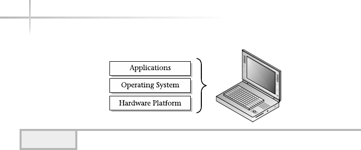
computer. At this level all of the hardware-related services are available, such
as connecting to a network, saving information to secondary storage (that is,
hard disk drive), accessing the CPU, and so forth. Typically, these functions
are very specific to the type or architecture of the system as well as the different
kind of peripheral devices used. For instance, the way memory is allocated for
applications can be somewhat different for the different types of computers
available on the market today.
An operating system or OS can be generally described as software that
provides an interface layer for applications so that they can interact with the
hardware components of the computer. Some examples of popular operating
systems include the Macintosh OS, Windows 2000, Palm OS, and UNIX. Although
each of the operating systems mentioned are different in design and may contain
alternative user interfaces, they all provide most of the same basic features. At
the middle layer or operating system level, many of the hardware functions are
made available for the upper application level. For example, many computers today
come with a DVD or CD drive that can be used to view movies or play compact
discs (CDs) on the computer. The computer provides the ability to play music
though the internals of the system. However, in order to listen to your favorite
music CDs, the operating system must provide some user application that permit
access and control of the DVD or CD drive. The application must provide the
ability to play, stop, skip between tracks, eject the disc, and so forth when
necessary. Thus, the software application must control the hardware in order
for the user to experience the full use of the hardware. Additional examples of
operating system support for hardware include control and access to peripheral
devices such as printers, modems, networks, computer monitors, keyboard,
pointing devices, etc.
4UNIX System Administration: A Beginner’s Guide
Figure 1-1 A diagram of the typical computer system

1
It is important to note that not all hardware functions are always completely
supported by the operating system—or even with certain applications. This
can be due to several factors such as operating system vendors not wishing to
support proprietary hardware designs or even functional defects within the
computer hardware itself. However, sometimes, one of the most common reasons
is that hardware development improvements are not completely synchronized
with operating system releases. In other words, when new computers are sold
and provide newer features and functions, the operating system may not
completely support these improvements because the software may have been
released before the hardware. In this case, the hardware wasn’t available while
the software was being written. As a result, the operating system vendor
might release a “patch” or upgrade, which is a smaller subset of software
(also sometimes called a module) that gives the operating system the means
to exploit the desired new hardware feature. Patches and/or upgrades are also
used to address software defects or other problems within the operating system.
The user must install the new software in order for the operating system to
support the new hardware. Generally speaking, because operating systems
are quite complex, certain patches have been known to cause additional or
unanticipated problems. This is where things can get quite interesting, because
a specific patch may be needed to support some application, but at the same
time it also causes some other problem, which must be addressed as well—
possibly by yet another patch or upgrade!
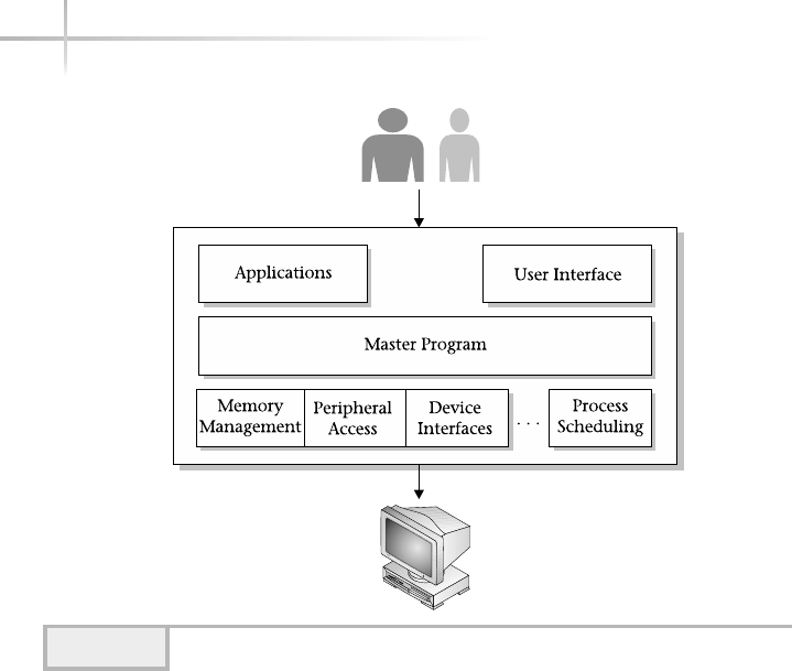
The operating system provides a set of core functions for applications such
as memory management, peripheral access, device interfaces, process scheduling,
and the like. Figure 1-2 contains a pictorial view of a typical operating system.
Each area of the operating system (or module) is responsible for that aspect
of the system, but is usually controlled by a single master program or process.
Instead of applications talking directly to hardware devices, the operating system
layer is defined to make it easier for application designers and writers to produce
less complex software. For example, consider an application that must have
the capability of producing reports to an output device such as a laser printer.
Without an operating system, the application must support the required
functionality by printing to these types of devices. Also, given that many different
kinds of laser printers are available on the market, it is very difficult to support
each of the manufacturers’ models within an application. To remedy this situation,
the operating system can provide a database of laser printers’ description types
and applications can simply use one of the predefined templates.
Module 1: Introduction to UNIX 5
1
6UNIX System Administration: A Beginner’s Guide
As you can see from the figure, many low-level functions are supported
within a typical operating system. Also, of equal importance is the user
interface that is provided. The user interface usually comes in two different
flavors for most operating systems: command line and graphical. The graphical
user interface (GUI) also makes the operating system more “user friendly” by
insulating the details or automating specific tasks or functions. The GUI is
typically used by new users or even by experienced users that choose not to
use the command line. The GUI provides a windowing system or some other
graphical elements to represent functions and tasks within the operating
system. For instance, should the user wish to delete one or more files, a series
of file and/or folder icons are displayed and the user simply selects the files
they wish to remove and uses the appropriate menu item.
The alternative interface, typically called the “command line”, provides a single
“prompt” to the system. Generally, the user must know more details about
the system in order to use this interface, which is usually used to bypass the
Figure 1-2 Diagram of a typical operating system

Module 1: Introduction to UNIX 7
1
GUI to accomplish a very specific task. A “power user” sometimes uses this
method. Power users are individuals who have mastered the system and can
typically use the system without the GUI.
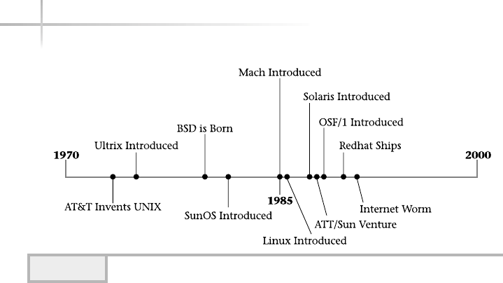
1.3 Show the UNIX Timeline
The UNIX operating system has a long and varied history, which is one of the
major reasons why it is alive and well today. The history behind UNIX and
the many individuals and organizations that helped mold and shape its past
can be quite detailed. As an alternative to providing a rather mundane detailed
listing involving all of the historical events surrounding UNIX, a time line
and description showing the most significant and key events will be provided
instead. Figure 1-3 shows this time line and each of the major events is
described below.
AT&T Invents UNIX
AT&T invented UNIX back in the early 1970s to support their internal
development efforts and to integrate a scalable operating system within their
Ask the ExpertAsk the Expert
Question Why does the operating system layer make it easier
for programmers to write applications to use computer hardware
resources?
Answer Because most personal computers on the market use an
open architecture (the hardware specifications are public and many
vendors can produce various components) there are thousands of
different hard drives, memory modules, video cards, and motherboards
and other components that should all work together if you assemble
them into a system. Very few programmers or application vendors
would have the resources to write code to interact directly with each
of these different pieces of hardware. So, the operating system includes
the programming so it can interface with any one of thousands of hard
drives, but an application programmer can write just one set of code to
access any hard drive throughout the operating system.
8UNIX System Administration: A Beginner’s Guide
communication products. They also released a version of UNIX to corporations
and universities, which supported software development, text processing, and
other user-level applications. One particularly popular release of UNIX was
known as the Programmer Work Bench (PWB). This release provided a wide
variety of development and text processing tools, which became very popular
in the university community.
BSD Is Born
The University of California at Berkeley was contracted by the government to
port AT&T UNIX to the Digital VAX architecture. The subsequent release of
this version of UNIX became known as the Berkeley Standard Distribution (BSD)
release. The BSD operating system introduced many new features and tools,
which played an important role in the future of UNIX. BSD added important
networking features such as TCP/IP networking facilities and virtual memory
support. Among some of the most popular tools included are the Vi editor, a
program called more, the termcap terminal facility and many others. The “r”
family of utilities that provides networking capabilities between UNIX systems
and users was also introduced with BSD.
The System V Releases
AT&T released several major operating system versions of UNIX, which became
known as “System V”. Several large computer manufacturers licensed these
Figure 1-3 The UNIX timeline

Module 1: Introduction to UNIX 9
1
operating systems and provided ports to their own computer hardware platforms.
It was these ports (plus software from BSD) that later would become UNIX
products such as AIX, HP-UX, and Solaris.
AT&T/Sun Deal
Due to industry pressures and other important factors, both AT&T and Sun
Microsystems formed a partnership where Sun would port the System V release
of UNIX onto Sun computer systems. At that time, Sun supported both Motorola-
and Sparc-based computer systems. Over time, however, Sun discontinued
support for Motorola-based computers and focused quite heavily on their Sparc
systems. The porting effort by Sun resulted in the formation of the Solaris
operating system that we have today. Prior to the System V port, Sun used the
BSD release of UNIX, which was called Sun OS. Over time the Sun OS release
was discontinued and Solaris became the dominant operating system. Solaris
incorporates AT&T System V, Sun-specific software enhancements, plus BSD
packages and tools. Today, Solaris is one of the most popular UNIX operating
system in the world.
The Internet Worm
Although the Internet worm of 1988 had much to do with system and network
security, it also involved UNIX in a significant way since this security attack
demonstrated the vulnerabilities of the UNIX operating system and networking
infrastructure of the Internet at that time. The Worm was responsible for
infecting many UNIX systems and used the Internet as the connecting medium.
It was so virulent that is caused many systems to crash due to the high CPU
load that the software consumed when running. Despite the fact that the Worm
didn’t actually corrupt data files on the systems it penetrated, it did cause major
problems since each of the operating systems of the infected systems had to be
reinstalled. This was no small task for system administrators. This was certainly
a major issue for many since automatic software installation wasn’t as good as it
is today and many installations were done manually. As a result of the Worm,
UNIX and the Internet became more secure.
OSF/1
Due to the activities surrounding the AT&T/Sun partnership, several prominent
computer manufactures (HP, Digital Equipment Corporation (DEC), IBM,

and others) decided to attempt to even the playing field by forming a new
organization called the Open Software Foundation (OSF). The organization
was tasked with developing a version of UNIX that would compete with the
AT&T/Sun operating system. The product that ultimately was developed was
called OSF/1, which was based on the Mach operating system. DEC, among
other computer companies, offered the OSF/1 release to their customers. Due
to the popularity of the AT&T/Sun operating system, and changes within the
UNIX industry, OSF/1 was never widely adopted.
Mach
The Mach operating system, developed at Carnegie Mellon University, was
derived from a port of the BSD version of UNIX and introduced in 1985. Mach
provided much needed support for multiprocessors and also included other
important improvements. Several ports of Mach were made by different computer
manufactures, and for a time Mach enjoyed some popularity, but in the long
run the operating system wasn’t widely adopted.
Linux Is Introduced
Back in 1985, Touvus Linus introduced a version of UNIX for the Intel
processor—Linux. Today, Linux (and the variations) stands as a pinnacle
of the open source movement and the achievement of many individuals who
have contributed to the Linux effort.
Red Hat
Released in 1995, the Red Hat Linux operating system combines several aspects
of the Linux system in a popular package. The Red Hat operating system provides
a host of important features, contains many third-party tools and utilities, and
is one of the most popular Linux variants available today.
Versions of UNIX Today
With most things in life, where there is active competition the best will ultimately
survive and triumph. This is the case with several different versions or flavors
10 UNIX System Administration: A Beginner’s Guide
TEAMFLY
Team-Fly®

11
of UNIX. Although many different versions exist, a common design and/or code
base is present in most of them. Also, two major kinds of UNIX operating system
software markets exist today. The commercial market is where customers
generally have to pay for the operating system software and generally may not
get any source code (well, not for free anyway!). The other market is also
commercial, but is considered open source. Open source means that you get full
access to the source code of the system or programs and can make changes or
modifications to that source code as long as you maintain the rights of the
original software owner.
Today, the UNIX leaders include Solaris, Linux, HP-UX, AIX, and SCO.
Why UNIX Is Popular
Many people ask why UNIX is so popular or why it is used so much, in so many
different ways and in so many computing environments. The answer lies with
the very nature of UNIX and the model that was used to design, build, and
continuously improve the operating system.
Availability of Source Code
One of the most significant points of UNIX is the availability of source code for
the system. (For those new to software, source code contains the programming
elements that, when passed through a compiler, will produce a binary program—
which can be executed.) The binary program contains specific computer
instructions, which tells the system “what to do.” When the source code is
available, it means that the system (or any subcomponent) can be modified
without consulting the original author of the program. Access to the source
code is a very positive thing and can result in many benefits. For example, if
software defects (bugs) are found within the source code, they can be fixed
right away—without perhaps waiting for the author to do so.
Another great reason is that new software functions can be integrated into
the source code, thereby increasing the usefulness and the overall functionality
of the software. Having the ability to extend the software to the user’s requirements
is a massive gain for the end user and the software industry as a whole. Over
time, the software can become much more useful. One downside to having
access to the source code is that it can become hard to manage, because it is
possible that many different people could have modified the code in unpredictable
(and perhaps negative) ways. However, this problem is typically addressed by
Module 1: Introduction to UNIX 11

12 UNIX System Administration: A Beginner’s Guide
having a “source code maintainer,” which reviews the source code changes
before the modifications are incorporated into the original version.
Another downside to source code access is that individuals may use this
information with the goal in mind of compromising system or component
security. The Internet Worm of 1988 is one such popular example. The author,
who was a graduate student at Cornell University at the time, was able to
exploit known security problems within the UNIX system to launch a software
program that gained unauthorized access to systems and was able to replicate
itself to many networked computers. The Worm was so successful in attaching
and attacking systems that it caused many of the computers to crash due to the
amount of resources needed to replicate. Although the Worm didn’t actually
cause significant permanent damage to the systems it infected, it opened the
eyes of the UNIX community about the dangers of source code access and
security on the Internet as a whole.
Flexible Design
UNIX was designed to be modular, which makes it a very flexible architecture.
The modularity helps provide a framework that makes it much easier to
introduce new operating system tools, applications, and utilities, or to help
in the migration of the operating system to new computer platforms or other
devices. Although some might argument that UNIX isn’t flexible enough for
their needs, it is quite adaptable and can handle most requirements. This is
evidenced by the fact that UNIX runs on more general computer platforms
and devices than any other operating system.
GNU
The GNU project, started in the early 1980s, was intended to act as a
counterbalance to the widespread activity of corporate greed and adoption
of license agreements for computer software. The “GNU is not UNIX” project
was responsible for producing some of the world’s most popular UNIX software.
This includes the Emacs editor and the gcc compiler. They are the cornerstones
of the many tools that a significant number of developers use every day.
Open Software
UNIX is open, which basically means that no single company, institution, or
individual owns UNIX—nor can it be controlled by a central authority. However,
the UNIX name remains a trademark. Anyone using the Internet may obtain

Module 1: Introduction to UNIX 13
1
open source software, install it, and modify it, and then redistribute the software
without ever having to shell out any money in the process. The open source
movement has gained great advances and has clearly demonstrated that quality
software can, in fact, be free. Granted, it is quite true that certain versions of
UNIX are not open, and you do indeed need to pay to use these operating systems
in the form of an end-user licensing agreement. Generally speaking, vendors
that charge for UNIX represent only a portion of the total number of UNIX
releases available within the UNIX community.
Programming Environment
UNIX provides one of the best development environments available by providing
many of the important tools software developers need. Also, there are software
tools such as compilers and interpreters for just about every major programming
language known in the world. Not only can one write programs in just about
any computer language, UNIX also provides additional development tools such
as text editors, debuggers, linkers, and related software. UNIX was conceived
and developed by programmers for programmers, and it stands to reason that it
will continue to be the programmer’s development platform of choice now and
in the future.
Availability of Many Tools
UNIX comes with a large number of useful applications, utilities, and programs,
which many people consider to be one of UNIX’s greatest strengths. They are
collectively known or commonly referred to as UNIX “tools,” and they cover
a wide range of functions and purposes. One of the most significant aspects of
UNIX is the availability of software to accomplish one or more very specific
tasks. You will find throughout this text that the concept of tools is quite
universal and is used repeatedly. This book not only discusses the subject of
system administration but also provides detailed descriptions of UNIX-based
tools. As a system administrator, you will come to depend on certain tools to
help you do your job. Just as construction workers rely on the tools they use,
so too will the administrator rely on the software that permits them to handle
a wide range of functions, tasks, issues, and problems.
There are tools to handle many system administration tasks that you
might encounter. Also, there are tools for development, graphics manipulation,
text processing, database operations—just about any user- or system-related

requirement. If the basic operating system version doesn’t provide a particular
tool that you need, chances are that someone has already developed the tool
and it would be available via the Internet.
System Libraries
A system library is a collection of software that programmers use to augment
their applications. UNIX comes with quite a large collection of functions
or routines that can be accessed from several different languages to aid the
application writer with a variety of tasks. For example, should the need arise
to sort data, UNIX provides several different sort functions.
Well Documented
UNIX is well documented with both online manuals and with many reference
books and user guides from publishers. Unlike some operating systems, UNIX
provides online main page documentation of all tools that ship with the system.
Also, it is quite customary that open source tools provide good documentation.
Further, the UNIX community provides journals and magazine articles about
UNIX, tools, and related topics of interest.
1-Minute Drill
●Why is source code availability a valuable advantage to UNIX users?
●What are some downsides of source code availability?
14 UNIX System Administration: A Beginner’s Guide
HintHint
There are several popular Web sites that contain a large collection of public
domain and open source tools and applications that are available. These links
can be found in an appendix of this book.
●Users can modify the code to fit their own needs, such as fixing bugs immediately or implementing
new features.
●Tracking and managing multiple versions of code changes can be difficult. Source code availability makes
it easier for unscrupulous users to exploit programming errors, particularly relating to security. (However,
source code availability means users can patch these bugs quickly, even if the original author or vendor
isn’t available to patch them.)
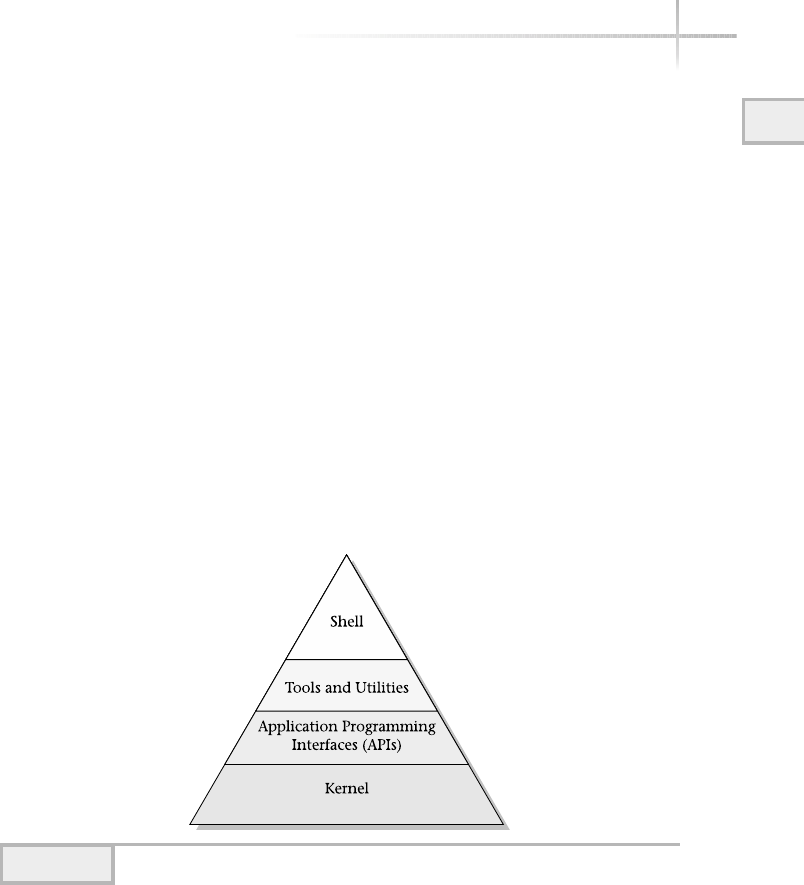
Module 1: Introduction to UNIX 15
1
Modular UNIX
Like all operating systems, UNIX can be divided into functional areas
(components) where each part is responsible for a given set of services.
This modularity is what gives UNIX its appeal and why it is one of the most
popular operating systems in the world. Figure 1-4 shows the overall picture
of where the individual components of the UNIX system fit together. Each of
the major elements is described in more detail below.
The Kernel
Perhaps the most critical element of the operating system, the kernel is
responsible for many of the operating system tasks and services that applications
and users require. The Kernel is the main program that interfaces with all
hardware components, supports the execution of applications, and provides
an environment for users. Very little can be done on a UNIX system without
accessing some Kernel function or resource. It is the controlling entity of
Figure 1-4 UNIX operating system picture

16 UNIX System Administration: A Beginner’s Guide
the system. The kernel itself consists of several parts. From a high-level
standpoint, the kernel performs the following services and functions:
●Interfaces with the computer hardware Using modules called device
drivers, the kernel uses these software components to talk directly to
hardware-level devices. For example, when an application wants to write
data to a secondary storage device such as a hard drive, the kernel “calls” the
driver to write the information specific to that device. Thus, for every hard-
ware device, the kernel must have an associated driver. Since every hardware
device (such as a disk drive or sound card, for example) is vendor specific,
the kernel driver must also be vendor and/or product specific. However,
there are times when a common driver will support a family of products
or devices. This driver concept is used extensively throughout the system;
interfaces to all hardware components use this approach. Some additional
examples of drivers include serial port drivers, printer port drivers,
keyboard and mouse drivers, video display drivers, sound drivers, and
network interface drivers.
●Provides time-sharing services The kernel is responsible for providing
the resources necessary to handle multiple users, applications, and other
processes in what seems like a concurrent, real-time fashion. In other words,
UNIX supports a time-share model where users and applications run all
at the same time regardless of the underlying hardware characteristics.
Computers that support a single processor are said to be uniprocessor
machines, while multiprocessor machines contain more than one processor.
Thus, UNIX supports concurrent logins of different users and these
users may execute different applications or software all at the same time.
However, this reality is an illusion; the kernel makes it appear to the users
that everything is happening in a concurrent fashion, but the hardware may
not support parallel processing or concurrent processing. The kernel was
designed to provide this service regardless of the physical processing
characteristics of the machine in question. When the kernel is running on a
machine that supports more than one processor, the effects are pretty much
the same—multiple users and applications can run in a concurrent fashion.

1
●Implements security model The kernel supports the notion of users and
profiles. All users must be defined on the system before they are permitted
to access or log in to the system, and each user has a particular profile.
User accounts contain information about the user and are used to track
the users’ activities once they are on the system. The kernel ensures that
security between users and between the system and users is always
maintained. For example, it is not possible for one user to delete the files
of another user if the first user protects his or her files. Similarly, a user
will not be able to delete or remove system-related files unless the
administrator permits such activity.
APIs
UNIX provides a large number of application programming interfaces (APIs),
which help programmers write applications or tools that help to take advantage
of the system. Using UNIX APIs makes it easier to write programs and helps
software to integrate with the system.
The Shell
UNIX provides a mechanism for a user to log in to the system using what is
known as a command-line prompt or shell. The shell is a command interpreter,
which takes what the user types in and executes commands, manipulates files,
and so forth on behalf of the user. A large number of different shells are
available for UNIX, and users have the ability to customize the shell to suit
their own personal preferences.
Module 1: Introduction to UNIX 17
1
HintHint
Within UNIX, a special account, called the superuser, is defined. Known as the
“root” account, this is the one login that is usually set up by default on most
systems to have unrestricted access to every service or file within the system.
There isn’t any service, file, directory, or information that the superuser can’t
access. Typically, the system administrator becomes the superuser and uses
this account on a regular basis.

18 UNIX System Administration: A Beginner’s Guide
1.4 Discover the Roles of the
UNIX System Administrator
The job of the system administrator is one of the best in the entire world! It
basically means that you look after the computer systems, and in some cases
the network that interconnects those systems as well. The phrase “looking
after” actually can mean quite a number of different things. From the system
administrator point of view, they are totally responsible for not only the
successful operation of the computers themselves—including the hardware,
operating system, and applications—but must also ensure that the users of
those systems are happy and are using the systems to their full extent. This is
a tall order considering the sheer number of users that systems can support
and also because users have different requirements and individual needs.
From a technical standpoint, the systems administrator will handle one or
more of the following depending on the size, organization structure, and type
of company in which they are employed:
●Manage the computer hardware This includes dealing with hardware-
related problems such as faulty or failed system boards, disk drives,
CPUs, printers, and so forth. Also, if the hardware is covered by a vendor
maintenance contract, you will need to handle the details of maintaining
the coverage and managing the vendor relationship when problems occur.
You might need to “watch over” their activity when they are on-site to
ensure that they address the real problem or don’t cause problems in other
areas. For example, they might replace the wrong disk drive when multiple
drives are contained within a single system.
●System backups You will be responsible for ensuring that regular
backups/archiving of the important system and critical data files are
done. This is perhaps one of the most important functions of the system
administrator and should not be overlooked from a job duty standpoint.
It is also one of the most boring parts of being a system administer!
Successful administrators typically will automate the backup function
so that they might spend more time on more interesting tasks. With the
deployment of specialized network backup systems, storage area networks
(SANs), and other backup solutions, ensuring correct backup procedures
have never been so easy.

●Maintain system capacities Typically, memory, CPU, and disk storage
are the key components that are upgraded when the user base of the systems
increases or the system application functions are expanded. The most
common is that the disk storage might need to be upgraded more often
due to increasing data processing or the addition of users.
Support the Network
With the ever-increasing dependence on computer networking and with the
growth of the largest network (the Internet), administrators are continuously
faced with handling network-related issues and problems. As a result,
administrators not only need to understand their systems but the network
and associated components as well. With this in mind, the administrator must
“bone up” on the networking protocols, devices, and particular network
applications. For example, having a very good understanding of TCP/IP can
come in handy when dealing with interaction between applications or general
network communication problems related to the Internet or a local network.
You might also need to handle hardware-related problems within the network,
such as dealing with failed network components, misconfigured devices, cabling
problems, and so forth. This might include dealing with Internet service
providers (ISPs) or phone companies, depending on how the network topology
and Internet services have been implemented.
Handle Peripherals
In many cases, the administrator will be required to handle the support of
associated devices that might be used with the primary systems. These devices
might include printers, modems, scanners, and just about anything else that
could be used with a UNIX system. Often, systems are purchased with these
add-on devices at the same time, but sometimes they are not—in which case,
the administrator must integrate or install one or more of the peripheral
devices. Printers are one such example, where they might be obtained after the
primary UNIX system was installed. With this in mind, the administrator must
ensure that the UNIX system is configured to use the printers correctly. If
the printer is going to be shared across a number of different systems, the
configuration must be replicated to each system supporting the printer. Equally
important, the printer devices must be set up and configured to work with the
UNIX systems as well. Thus, not only must the administrator understand UNIX,
1
Module 1: Introduction to UNIX 19
1

20 UNIX System Administration: A Beginner’s Guide
but she or he must also have the ability to learn how other devices function and
be able to configure them. Don’t be alarmed—no administrator is expected to
know every type of device that can be integrated with a UNIX system. Rather,
the administrator must be able to learn how to do this when necessary, with the
aid of product manuals, technical support, and other resources.
Manage System Upgrades
Due to the nature of computer technology and the need to support more
functions and perhaps more users, the administrator might be asked to perform
certain (if not all) system upgrades. This will include installing more memory,
disk storage, CPUs, updating the computer firmware, and a host of other
hardware-related tasks. If the UNIX systems are covered under a vendor
maintenance support agreement, the vendor may perform some of the upgrades.
For instance, the firmware, which is used to handle lower-level system functions
and diagnostics, might be upgraded automatically by the system vendor.
Upgrades are not just made to the hardware components of the system, but
also to the operating system, applications, tools, or utilities. Sometimes, dealing
with software upgrades can be more difficult than the hardware due to the
dependencies on different software components. For example, if the operating
system was upgraded to a newer version, it might cause one or more applications
to not function correctly. Normally, application vendors do a good job of
testing their software on different operating system releases to avoid these types
of problems. However, no vendor can guarantee that their product will never
crash or experience problems, regardless of which particular operating system
release is being used.
Actively Monitor System Security
In certain organizations, the system administrator is responsible for handling
all aspects of system security. This includes, for example, ensuring that external
attacks (say, from the Internet) as well as internal ones (from local users) are
prevented as much as possible. There are many aspects of system security—
from running monthly security reports to installing security patches. The most
important component of security is being prepared when security-related issues
or problems strike. Just as when natural disasters hit a particular city, so too
it is very important to be prepared. For example, if it becomes necessary to
TEAMFLY
Team-Fly®

restore user files due to corruption caused by a malicious program, these files
must be restored quickly and accurately. Further, it will be very important
to take steps to prevent security problems in the first place. For example, if
one or more security vulnerabilities have been found with a software module,
application, or utility that is currently being used on the system, that software
should be upgraded in order to minimize any potential security risk.
If you demonstrate a positive security model and communicate the need for
security, others will follow. The administrator has to set the stage and promote
security as a way of life for all users of the system. For example, you might need
to teach users not to leave their workstations logged in while they are away for
extended periods of time. The users of the system will help to implement and
conform to specific security rules, policies, and procedures that you define. In
larger companies or organizations, security might rest with a particular security-
centric group, which is not typically a part of those that administer the systems.
However, the individuals within the security department must work hand in
hand with the administrator to ensure that specific policies and security
measures are implemented on a system wide-basis.
Maintain System Accounts
As part of general security and administration of UNIX, you will need to maintain
a close eye on user accounts, which is the primary way to control access to the
system. UNIX uses a system account files to permit users to gain access to
the system, and it will be your direct responsibility to ensure that only authorized
users are permitted access and that they are set with the correct profiles and
access parameters. Also, it will be important that you delete user profiles when
employees leave or move to another part of the company, or you might need to
adjust user profiles as user access policies change.
Advance Your Knowledge
Believe it or not, you will be asked to learn new technologies, products,
applications, and perhaps a host of other interesting subjects related to your
job. You will be most valuable to your organization when you know just as
much as (or even more than) the vendors that provide your products and
systems. You will need to attend professional development classes, vendor-
offered training, and other training programs and courses. Also, depending on
the company, you might need to seek one or more vendor certification programs,
1
Module 1: Introduction to UNIX 21
1

such as from Red Hat or Sun Microsystems. Also, you may need to supplement
your understanding and technology knowledge by reading great books (such as
from this series!!), trade magazines, journals, and other publications. Further,
you might need to attend special conferences and trade shows to gain more
insight into a particular technology or product, or to learn more about a vendor.
As you can see, being a system administrator means handling many technical
details of the computer systems within your environment. One very interesting
aspect of this is that should the computer environment contain different versions
of UNIX, in what we call a heterogeneous network, this can complicate the
administrator’s job to some degree. In general, UNIX is fairly standard, but
different vendors provide unique tools just for their platform. As a result, it
might be difficult to do certain tasks the same way across different vendors’
UNIX machines. However, in most cases this isn’t a problem because many
of the tools work the same way for most different flavors of UNIX.
The successful administrator not only handles the details of the system but
also in certain cases must be a teacher, police officer, politician, parent, and
friend, and have good organizational skills and a cheerful disposition. Bear in
mind that not all of these skills are absolutely necessary, since many companies
define the job of system administrator in different ways. As a result, different
skills and tasks may be required.
Teacher
As an administrator, you will find yourself showing the users how to use the
system and perhaps giving classes on a wide range of subjects related to the use
or operation of a particular application or system capability. For example, new
users might not know how to log in and access certain applications in order for
them to complete their jobs. You might also need to show experienced users the
best way to archive their files or how to use a new system utility or a recently
installed application.
Politician
Being an administrator means that you must handle and solve a large number of
problems. In certain cases, this might require you to be a politician due to the
issues and people involved. Some of these problems can be a conflict between one
or more users or can be related to how the system is supported or maintained.
The system administrator usually deals with many individuals at all levels of the
22 UNIX System Administration: A Beginner’s Guide

Module 1: Introduction to UNIX 23
1
company. For example, they may deal with administrative assistants, technical
staff, managers, and vice presidents, as well as outside customers, suppliers,
and vendors. As a result, good negotiation and people skills are necessary.
Parent
Sometimes users can be like children, and they require a strong parent to rein
them in. For instance, some users insist that they keep every file they ever used,
and as a result the system disks are filled to capacity. This can be unacceptable
behavior if every user did this because of the amount of time and trouble caused
by having to clean up after these users. Also, since the administrator knows the
system, they might need to give advice to users about how best to solve or
address some particular issue or problem. For instance, a user might need to
obtain a large amount of data for a particular purpose and it must be transferred
from one system to another. In this case, you might need to step in and provide
assistance.
Police Officer
Sometimes being a politician or parent isn’t enough; you might need to become
a police officer to enforce some general rules of behavior or exercise critical
control of the system. For example, you will need to restrict physical access
to the computer system to only those individuals that require it. A curious
user attempting to fix a hardware-related problem could spell disaster for the
administrator, given the complexity and sensitivity of hardware components.
Another good example is system security—should the administrator detect
unauthorized access to the system, then the administrator must take immediate
action to protect the integrity of the system and users. It might, for example,
mean that users are audited to ensure they are not doing bad things on
the system.
HintHint
Generally, security measures are more successful if they are planned in advance
before you need them. For example, user audit trails are most useful when
they capture bad behavior when it is happening.

Friend
If the above duties aren’t enough, you might actually need to be a friend to
your users. For example, one user might be working on a critical project that
requires you to help them with a system-related problem (such as the printer
not functioning correctly) at an unpopular time—say, during the weekend or
in the wee hours of the morning. You might have the option to tell the user to
wait until the official workday starts or handle the issue on the spot. In general,
users are good-natured and happy individuals, but other times they might be
nasty, outrageous, and demanding. It may be in your best interest to help the
individual because you want to be helpful, and that is expected. As with most
things in life, a simple smile and thick skin (for really difficult users) can go
a long way to ensure that a bad situation goes smoothly.
Also, goodwill can flow in both directions. If you help users out of tough
situations, they might help you in turn at some point in the future! You may
find that having friends on the “inside” can work in your favor. Sometimes,
the job of system administrator isn’t very popular because you might need to
make some decisions that affect users in a negative or unpleasant way. Take,
for example, the moment you need to bring the system down for some critical
maintenance task. You will need to ask all the users to log off the system, and
this can be an unpopular thing to do since users might not want to log off—
because, for example, they have their own deadline or other things they must
complete, and this downtime can cause them pain. However, having users who
understand can help to bolster your position about the system outage and
smooth things over for users that might not fully appreciate your need to bring
the system down when it is not convenient for them—they may come to realize
that in the long run it is in their best interest.
The bottom line is that being a system administrator sometimes requires
that one be both technical and have a reasonable knack for dealing with
individuals (users) and all levels of management. Certainly this is the ideal
situation, but the world is full of situations that are far from perfection. As a
result, many successful administrators don’t need to deal with the softer side,
but more the technical. Conversely, some administrators work within teams
where they might not be handling the day-to-day tasks, but rather deal with
more of the management aspects of the job. As you can see, your mileage may
vary and the exact system administrator requirements will be different depending
on the company or the exact job position.
24 UNIX System Administration: A Beginner’s Guide

1
Module 1: Introduction to UNIX 25
1
Mastery Check
1. Name the three functional areas or layers of any computer system,
regardless of brand.
2. Which UNIX component interacts with the system hardware?
A. Kernel
B. APIs
C. Shell
D. Hardware Administrator
3. Which of the following is not a key reason for UNIX’s popularity?
A. Flexible design
B. Proprietary software
C. GNU
D. Well documented
4. A __________ is a collection of software that programmers use to
augment their applications.
5. Which of the following is not a function of the UNIX kernel?
1. Interfaces with the computer hardware
2. Provides time-sharing services
3. Implements security model
4. Maintains system capacities
6. The UNIX __________ is responsible for regular backups/archiving
of important system and critical data files.

This page intentionally left blank.

Module2
Basic UNIX
Commands
Critical Skills
2.1 Explore the UNIX Shell
2.2 Investigate Basic UNIX Commands
Copyright 2002 by The McGraw-Hill Companies, Inc. Click Here for Terms of Use.
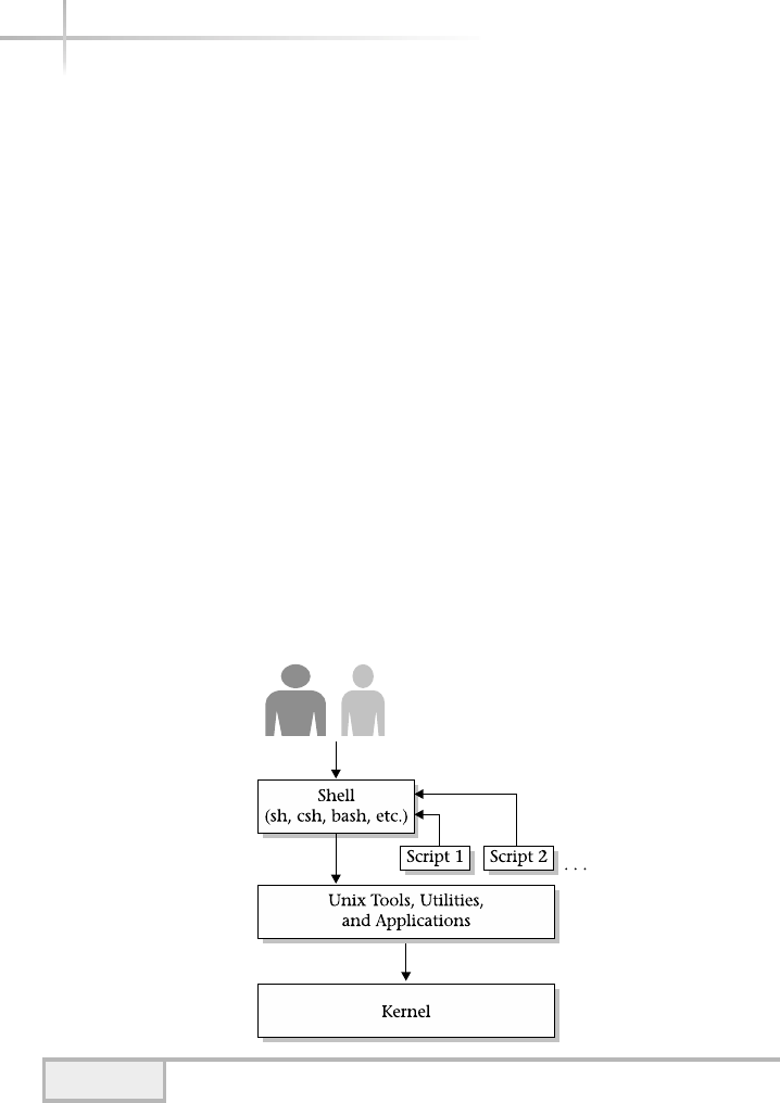
This module provides an introduction into using the standard shell and some
of the basic operating system tools that administrators will need to know to
help them maintain UNIX systems. As the system administrator, you will need
to learn about a variety of utilities and tools to help accomplish administrative
tasks and make your job easier. It will be important that you get familiar with
many of the commands within this module and you are encouraged to try
running these programs within your own environment just so that you get a
feel for the behavior and to begin learning the many program parameters and
command-line options.
2.1 Explore the UNIX Shell
The shell is a rather unique component of the UNIX operating system since it
is one of the primary ways to interact with the system. It is typically through
the shell that users execute other commands or invoke additional functions.
The shell is commonly referred to as a command interpreter and is responsible
for executing tasks on behalf of the user. Figure 2-1 shows a pictorial view of
how the shell fits with the UNIX system. As you can see, the shell operates within
the framework just like any other program. It provides an interface between the
user, the operating system functions, and ultimately the system Kernel.
28 UNIX System Administration: A Beginner’s Guide
Figure 2-1 The UNIX shell

Another powerful feature of the UNIX shell is the ability to support the
development and execution of custom shell scripts. The shell contains a mini
programming language that provides a lightweight way to develop new tools
and utilities without having to be a heavyweight software programmer. A UNIX
shell script is a combination of internal shell commands, regular UNIX
commands, and some shell programming rules.
UNIX supports a large number of different shells, and also many of the
popular ones are freely available on the Internet. Also, many versions of UNIX
come with one or more shells and as the system administrator, you can install
additional shells when necessary and configure the users of the system to use
different shells, depending on specific preferences or requirements. Table 2-1
below lists many of the popular shells and a general description of each.
Once a user has logged into the system, the default shell prompt appears
and the shell simply waits for input from the user. Thus, logging into a Solaris
system as the root user for example, the standard Bourne shell prompt will be
#
The system echoes this prompt to signal that it is ready to receive input from
the keyboard. At this point, this user is free to type in any standard UNIX
command, application, or custom script name and the system will attempt to
execute or run the command. The shell assumes that the first argument given
2
Module 2: Basic UNIX Commands 29
2
Shell Name General Description
Sh Standard Bourne shell, which is one of the most popular shells
around.
Csh Standard shell with C like language support.
Bash GNU Bourne-Again shell that includes elements from the Korn
shell and C shell.
Tcsh Standard C shell with command-line editing and filename
completion capabilities.
Ksh The Korn shell combines the best features of the Bourne and C
shells and includes powerful programming tools.
Zsh Korn shell like, but also provides many more features such as
built-in spell correction and programmable command completion.
Table 2-1 Descriptions of Different UNIX Shells

30 UNIX System Administration: A Beginner’s Guide
on the command line is a program or a special character sequence that is
interpreted by the shell as a command. UNIX supports a large number of
commands, which can be classified into several different groupings that include
generic user-level commands, superuser-level commands, and built-in shell
commands.
User-level commands are those programs that can be run by any user,
regardless of their access level or other user account parameters. The date
command is one such example; generally speaking, no special permission is
required to display the local date and time with the command. UNIX contains a
very large number of these types of commands and they are usually contained
within standard directories such as /usr/bin or /usr/local/bin.
The superuser commands, which can be found in several different system
directories (/usr/bin/usr/sbin, and so forth) are those that require
system-level or privileged access to invoke or execute. For instance, the format
program is used to format storage media such as disk drives. Typically, this type
of administration function is restricted and can’t be invoked by typical UNIX
users due to the destructive nature of the command; it can completely delete
all information from a storage device. Thus, only the superuser can run this
command. UNIX provides a special account called the superuser account,
or also known as root, which is used to permit system or administrative
access. The UNIX administrator will use this account when performing system
maintenance and other important administrative tasks. The superuser account
is a sacred cow—it provides complete and total access to all aspects of the system,
and this account must be guarded at all times; only the administrator will use this
account, and it is usually protected by a secret password.
The built-in shell commands are defined as those functions, which are
not part of the UNIX command set, but instead are interpreted and supported
directly by the shell. They are not stand-alone programs such as date, but are
executed within the shell. For example, the set command, which is used to
define environment variables, is one such internal command. An environment
variable, for example, is one way to pass a program a parameter, which can be
HintHint
Anyone can peruse these directories to obtain a list of the all the available
commands contained within the locations. However, the administrator can
define restricted users, which can’t access common directories or execute a
generic program, but this is something the administrator must purposely do.
TEAMFLY
Team-Fly®

used to control the behavior of the software to achieve some desired result. For
example, you can use an environment variable to contain the user’s default
printer, so that any application can use this information to print to the correct
output device.
2.2 Investigate Basic UNIX
Commands
As you will see in this book, UNIX comes with a large number of commands
that fall under each of the categories listed above for both the generic user and
the system administrator. It is quite hard to list and explain all of the available
UNIX functions and/or commands in a single book. Therefore, a review of some
of the more important user-level commands and functions has been provided
and subsequent modules provide a more in-depth look at system-level
commands. All of the commands discussed below can be run by generic users
and of course by the system administrator. However, one or more subfunctions
of a command may be available only to the system administrator.
Table 2-2 provides a list of standard commands, which are available across
many different versions of UNIX. For example, if we wanted to get a listing of all
the users that are currently logged into the system, the who command can be used.
Module 2: Basic UNIX Commands 31
2
UNIX Command Meaning
cat Show the content of file.
date Show system date and time.
hostname Display name of system.
find Search for a specific file.
grep Search a file for specified pattern.
ls List files in a directory.
more Another command to show content of file.
ps Show status of processes.
strings Show strings within a file.
uname Show system-related information.
who Show current users on the system.
Table 2-2 Basic UNIX Commands

Thus,
# who
will produce a list of the login names for all users presently on the system, such as
bill pts/1 Sep 9 06:41 (pebbles)
root pts/10 Sep 9 09:11 (fred)
sjmaxwell pts/2 Sep 9 08:02 (wilma)
You can find this command (and, of course, many others) on Linux, HP-UX,
Solaris, AIX, and many other versions of UNIX. However, depending on the
version of UNIX, the output might slightly be different. Naturally, this output
shouldn’t really match what is displayed when you execute this command on one
of your systems since the environment and users will be quite different. Despite
this, the command displays basically the same information regardless of which
UNIX system it is executed on. The who command is very interesting because
it shows when the users were logged into the system and from which terminal,
and, if networking services is active, the name of the computer system that the
user originated the connection from. In the example above, bill is logged in
from a system called pebbles, while root and sjmaxwell (yes, that is me!)
are from the systems known as fred and wilma, respectively. Knowing and
understanding commands like who (and many others) makes it much easier
to administer UNIX-based systems. Next to the login name is the terminal
associated with that login. In the example, pts followed by a number indicates
the terminal device number. When a real terminal or network connection is made
to the system, a terminal (real or pseudo if network) is assigned automatically by
the system to the user that logged into the system.
Like most UNIX commands, the who utility provides a number of command-
line arguments, which control the behavior and output of the program. However,
it is not necessary to know all of these arguments to use the basic functions.
Having said that, one of the more useful functions of this program is to identify
the username of the current shell. In other words, which user account am I
logging under? Using the command
# who am i
root pts/8 Dec 27 15:21 (dhcpclient-202)
32 UNIX System Administration: A Beginner’s Guide

will display the login username and other information. This is most useful if
you have started to use a terminal or login session and you don’t know which
user is in fact logged into the system.
Finally, another important function of the who command is to report the
system run mode with the use of the –r option. This argument displays the
current system run level, which can be multiuser, single user, or some
additional level as defined in the /etc/inittab file. See Module 9
for additional information. Thus,
# who -r
. run-level 3 Dec 8 10:41 3 0 S
shows that the system is at run level 3, which is the multiuser mode that the
system typically uses during normal everyday operations.
Those new to operating systems find it strange that UNIX doesn’t provide
positive acknowledgement, with some kind of printed message of successful
execution of a command. For example, when the user removes a file using the rm
command, the system doesn’t respond with a specific message when it is finished,
but instead simply removes the file and returns the shell prompt. Thus, when
# rm records.dat
#
is run, it removes the records.dat file and issues the shell prompt again.
# ls records.dat
records.dat: No such file or directory
#
When the ls command is used against a nonexisting file, it produces an error
message because the file could not be found. Seasoned UNIX administrators
don’t typically check that certain commands were in fact executed because should
Module 2: Basic UNIX Commands 33
22
HintHint
The command didn’t respond by displaying a successful message other than
displaying the prompt again. Alternatively, the user could check to see if the
command did what it was supposed to do. For instanced by running the
following command:
Error Message

34 UNIX System Administration: A Beginner’s Guide
any type of error have occurred during the execution of the rm command, it
would have issued a message stating that a problem had been encountered. For
example, if the records.dat couldn’t be removed because of a file permission
problem, a message would be generated that gives a clue to the problem:
# rm records.dat
rm: records.dat not removed: Permission denied
#
Generally speaking, most UNIX commands give some kind of error/status
message when a problem has been encountered.
cat
The cat command will display the content of one or more text-based files. It
is considered “more-lite” since it doesn’t support fancy scrolling functions like
the more command. The cat program is a fairly simple-minded tool, which
supports a small number of command-line options. However, the most useful
ones are listed in Table 2-3. Note that the above error message typically
wouldn’t be displayed if the command was run by the superuser.
Option Definition
-n Number each line of output.
-b Same as –n, but don’t number blank lines.
-u When displaying text, don’t use buffering (Solaris and
HP-UX only).
-s Don’t display an error when attempting to process nonexisting
files (Solaris only).
-v Display non-printable characters in visual form.
--help Display list of supported command-line options
(Linux only).
Table 2-3 Cat Command-Line Options

Module 2: Basic UNIX Commands 35
2
To show the contents of a sample /etc/passwd file with associated line
numbers, issue the following command:
# cat -n /etc/passwd
1 root:x:0:1:Super-User:/:/sbin/sh
2 smaxwell:x:0:1:Super-User:/:/usr/bin/bash
3 daemon:x:1:1::/:
4 bin:x:2:2::/usr/bin:
5 sys:x:3:3::/:
6 adm:x:4:4:Admin:/var/adm:
7 lp:x:71:8:Line Printer Admin:/usr/spool/lp:
8 uucp:x:5:5:uucp Admin:/usr/lib/uucp:
9 nuucp:x:9:9:uucp Admin:/var/spool/uucppublic:/usr/lib/uucp/uucico
10 listen:x:37:4:Network Admin:/usr/net/nls:
11 nobody:x:60001:60001:Nobody:/:
12 noaccess:x:60002:60002:No Access User:/:
13 nobody4:x:65534:65534:SunOS 4.x Nobody:/:
14 syu:x:100:111::/home/syu:/bin/sh
15 anonymous:x:101:1::/home/anonymous:/bin/sh
16 anonymou:x:102:1::/home/anonymou:/bin/sh
17 samc:x:20001:10:Mr Sam Clinton:/homes/samc:/bin/sh
18 stevem:x:20003:10:Mr. Steve Maxwell:/homes/stevem:/usr/bin/bash
19 anitat:x:20004:102:Ms. Anita Tognazzini:/homes/anitat:/bin/sh
20 samyu:x:20005:10:Mr Samual Yu:/homes/samyu:/bin/sh
The cat program can be used to display any UNIX file. However, it is not
that practical for displaying other types of files such as a software program or
binary file. Why? Because programs or other binary data can’t be displayed in a
meaningful way like text can be. A UNIX tool such as strings is more suited
for this purpose.
date
The date command is used to display the system date and time. Also,
sometimes it is necessary to alter the date or time on the system, and the
command can be used for this purpose as well. Typing the command
# date
directory and
filename to list
Numbers at beginning of each line are from -n
option, not part of the /etc/passwd file
-n option to number
output lines

will show output formatting like the following:
Thu Dec 27 16:59:15 PST 2001
As with most UNIX commands, the date command supports different
command-line options and arguments, which can be used to alter what is
displayed or to control additional functions. For example, to alter the date and
time on the system, and set it to November 5, 2005 at 9:30 AM, the administrator
can use the following command:
# date 110509302005
Sat Nov 5 09:30:00 PST 2005
When the date command is given a correctly formatted date string, it
assumes that the system date should be altered and echoes back the new date.
Due to security concerns, only the superuser (root account) may alter the date
and/or time settings.
36 UNIX System Administration: A Beginner’s Guide
11 This denotes the month of the year
05 This denotes the date of the month
09 This denotes the hour of the day
30 This denotes the minute of the hour
2005 This denotes the year
Ask the ExpertAsk the Expert
Question Why can only the superuser alter the date or time settings?
Answer Well, the view from many system administrators is that
typical users shouldn’t be able to alter the date because it could impact
the system in negative and unexpected ways. For example, some
software license keys are coded to expire on some future date. If
someone changes the date and advances the clock, it could invalidate
the licenses and stop these software packages from operating. Also,
changing the date vicariously can cause problems when files and
directories are created or modified, because they pick up time stamp
information that is not accurate. It could lead, for example, to files
having a future or past date that is in conflict with reality. Also,
consider if an order entry system application is running on a system
where the date was advanced significantly. This action will negatively
impact the ability to handle delivery dates and schedules because of the
incorrect date and time information.

hostname
The hostname command shows the name of the host when it is typically
attached to a network. However, a UNIX system can have a valid hostname
without networking services actually configured or when the system is not
attached to a network. This name can either be a fully qualified domain name
(FQDN) or another name known as a host alias. The FQDN is what has been
defined within the Domain Name System (DNS) server for that particular
system. An alias is simply another name for the FQDN and can be used
interchangeably with the fully qualified name.
To display the hostname of a system, type the following:
# hostname
If the hostname is defined, a string is displayed as in the following example:
pebbles.home.com
In this case, the hostname pebbles.home.com is the defined system
name, and it is this name that should be used when accessing the system over
the network. For example, if the administrator wants to determine if the system
is reachable from another node on the network, this hostname can be used with
the ping command. See Module 11 for additional information on this network
command. Thus,
# ping pebbles.home.com
pebbles.home.com is alive
shows that the system is available on the network.
The hostname command can also be used to name the host or rename
the host if it already has a defined system name. However, on Solaris and other
systems, just running this command doesn’t permanently alter the name of the
2
Module 2: Basic UNIX Commands 37
2
HintHint
This name is known as a fully qualified name because it contains both the
hostname and the domain name. As previously suggested, the hostname may
also be the system alias. Thus, a hostname of pebbles would be just as valid
or correct.

machine across system reboots, nor does it completely change the name of
the machine. In other words, using this command on the command line only
alters the name of the system until the system is rebooted, and without additional
steps would cause the system to not function correctly on the network.
1-Minute Drill
●As a UNIX system administrator, why don’t you need to check to see
if a command executed after issuing it?
●Why isn’t the cat command appropriate for listing the contents of
program files?
find
The find command is used to search the UNIX system for specific files and/or
directories. This command is very useful to recursively search a file system
when you don’t know exactly where a file (or group of files) is located. One
very practical use of this command is to clean up file systems by removing
unneeded files and thus reclaiming disk space. Additional practical uses include
●Identifying files that contain possible security concerns or problems
●Identifying very large files that consume much disk space
●Identifying files that are owned by specific users
●Identifying files that haven’t been accessed in a long time and can be
archived off the system
To search for specific files—for example, all files named core—use the
following command:
# find / -name core
38 UNIX System Administration: A Beginner’s Guide
●You don’t need to check to see if a command executed because if it didn’t, UNIX will return an error
message.
●The cat command only displays text characters properly and doesn’t handle special characters in program
files well.
and if one or more core files are found, a list of files will be produced as
shown in the following example:
/home/sjmaxwell/bin/tools/core
/tmp/core1
/usr/local/utils/core
/var/stream/bin/core
When attempting to clean up disk space, files with the name of core are
particularly useful to locate and remove because they tend to be rather larger
in size. Generally, core files are generated as a result of a binary program that
has stopped under some abnormal condition. The file contains program data
and other information that is useful for tracking down software problems.
Unfortunately, core files can hang around within a file system soaking up
large amounts of disk space and without some kind of cleaning process can
cause a file system to become full and subsequently unusable.
The output of this command shows a series of fully qualified files, each
matching the file string arguments shown in the find command. In this case,
a total of four files have been found. The output of the command is very helpful
when additional inspection of the files is necessary. For example, you can further
examine the file using the ls command with the –al options. The ls command
shows several very useful aspects of a UNIX file as discussed below. Thus, to
see the amount of space the file uses, use the following command:
# ls -al /var/stream/bin/core
-rw------- 1 root other 678876 Jun 29 16:34
/var/stream/bin/core
In our example, we wanted to see the amount of disk space the file consumed.
In this case, the file is using approximately 678K (that is 678,000 bytes, or
more than half of a megabyte) of disk.
The arguments and syntax of the find command include the following:
find path expression
The path argument tells find where to begin searching and will
recursively descend the specified path until it reaches the last directory. Many
times, the /(root) file system is specified, thus telling find to start at the
Module 2: Basic UNIX Commands 39
2
filesize

highest level within the system. The find command will continue to search
each additional mounted file system (because each mounted file system from /)
in order.
The expression argument includes two components: directives and
associated arguments. Directives are action verbs, which tell find what to do
or modify an action or behavior. Table 2-4 shows these directives and any
associated command arguments.
40 UNIX System Administration: A Beginner’s Guide
Command Definition
-atime Checks to see if the file was accessed by nnumber of days.
-cpio Writes the current file on the specified device in the 5120-byte
record format known as cpio (Solaris only).
-ctime Checks to see if the file’s status was changed ndays ago.
-depth Controls how directories are searched.
-exec Executes a command once a file is found.
-follow Causes find to follow symbolic links.
-fstype Search for a file that belongs to a specific file system.
-group Search for a file that belongs to a specific group ID.
-help Display appreciated help on command-line arguments
(Linux only).
-inum Search for a file that contains a specific inode number.
-links Search for a file that has n number of file links.
-local Searches for a file that is on a local file system (Solaris and
HP-UX only).
-ls Prints current path name and any associated stats.
-mount Restricts the search to a specific mounted file system.
-mtime Checks to see if the file’s data was changed n days ago.
-name Search for a file with a specified name.
-newer Search for a file that has been modified more recently than file
argument.
-nogroup Search for a file with the group name not contained with the
/etc/group system file.
-nouser Search for a file with the owner not contained with the
/etc/passwd system file.
-ok Prompts the user to input a positive response to continue with
the specific find command.
-perm Searches for a file that contains a specific file permission pattern.
Table 2-4 Find Action Commands
TEAMFLY
Team-Fly®

Sometimes, it is not desirable to search every file system, but instead to
scan only a specific one. In this case, use the –mount option to restrict the
scan operation to only a single file system tree. For example, the command
# find /var -mount -name core –print
/core
will search the /var file system for all occurrences of the filename core.
Module 2: Basic UNIX Commands 41
2
Command Definition
-path Same as –name, but the full path is used instead of the name
string (HP-UX only).
-print Causes find to print the current path name and is the default
option in some versions of UNIX.
-prune Stops find from entering a directory hierarchy.
-size Searches for a file that is n blocks long using 512 bytes per block.
-type Searches a specific type of file such as block special, character
special, directory, or plain file.
-user Search a specific file owned by a given system user.
-xdev Same as the -mount command.
Table 2-4 Find Action Commands (continued)
Ask the ExpertAsk the Expert
Question Why would you want to search just a specified file system?
Answer One of the biggest reasons is that you may not want to
search file systems that are mounted over the network from other
systems such as NFS volumes. Searching on remote file systems can
take longer if traffic on the network is high or even if the remote system
is overloaded. Even if the remote file system is relatively fast, it just may
not make sense to search a file system due to other considerations such
as it is a NFS read-only file system or in the case of locally mounted
read-only file system contained on a CD-ROM. Searching the contents
of a CD-ROM that contains product documentation when you are
looking for example, user files is totally a waste of time.

42 UNIX System Administration: A Beginner’s Guide
Now that we have a command that searches for core files, let’s assume we
would like to remove those files when they are found. The following command
will accomplish this task:
# find / -name core -atime +10 -exec rm {} \;
It searches the system looking for core files that haven’t been accessed for
at least 10 days and once it finds one, it will remove it.
ls
The ls command is used to list files and/or directories within one or more file
systems. The basic syntax includes
ls [options] [file/directory]
Like other UNIX commands, the ls program has a fairly large number of
command-line options. However, only the most useful ones are presented in
this section. These options are described and summarized in Table 2-5, and
some of them are explained below.
Option Definition
-a List all files within a directory, including .and ..
-b Display nonprinting characters in octal format.
-c Use modification time when displaying files in sort order.
-C Multicolumn output.
-d If the file is a directory, list only its name not its subdirectories
or subfiles.
-F Mark each directory with a trailing “/“ character, an “*“ if file
executable, “@“ if symbolic link, and “|“ if FIFO.
-i For each file/directory, list its corresponding i-node number.
-l Give more verbose output, which includes more information
about file/directory attributes.
Table 2-5 ls Command-Line Options

Module 2: Basic UNIX Commands 43
2
Issuing this command in the current directory will list all files and/or
directories contained with that directory. Thus, if the administrator was
within the /usr directory, issuing the command would yield the following
sample output:
# ls
4lib games local perl5_readme snadm
5bin include mail platform spool
X java man preserve src
bin java1.1 net proc tmp
ccs java1.2 news pub ucb
demo kernel old sadm ucbinclude
dict kvm openwin sbin ucblib
dt lib perl5 share xpg4
The output above includes both individual files and directories, but it is
difficult to draw a distinction between them because no additional information
is provided. To solve this problem, we can use the –l option, which shows a
long listing of file and directory attributes. Thus, running the above command
using this option produces the following:
# ls –l
total 132
drwxr-xr-x 2 root bin 1024 Mar 16 2001 4lib
lrwxrwxrwx 1 root root 5 Mar 16 2001 5bin -> ./bin
lrwxrwxrwx 1 root root 9 Mar 16 2001 X -> ./openwin
gdrwxr-xr-x 4 root bin 8704 Jul 13 15:03 bin
Option Definition
-L If the file is a symbolic link, list the referenced file—not the link itself.
-R Recursively descend and list each subdirectory.
-t Sort by time stamp information instead of by filename.
-u Use last file access time when displaying in sort order.
-1 Display one line for each file shown.
Table 2-5 ls Command-Line Options (continued)
The d at the beginning of this
line shows this is a directory
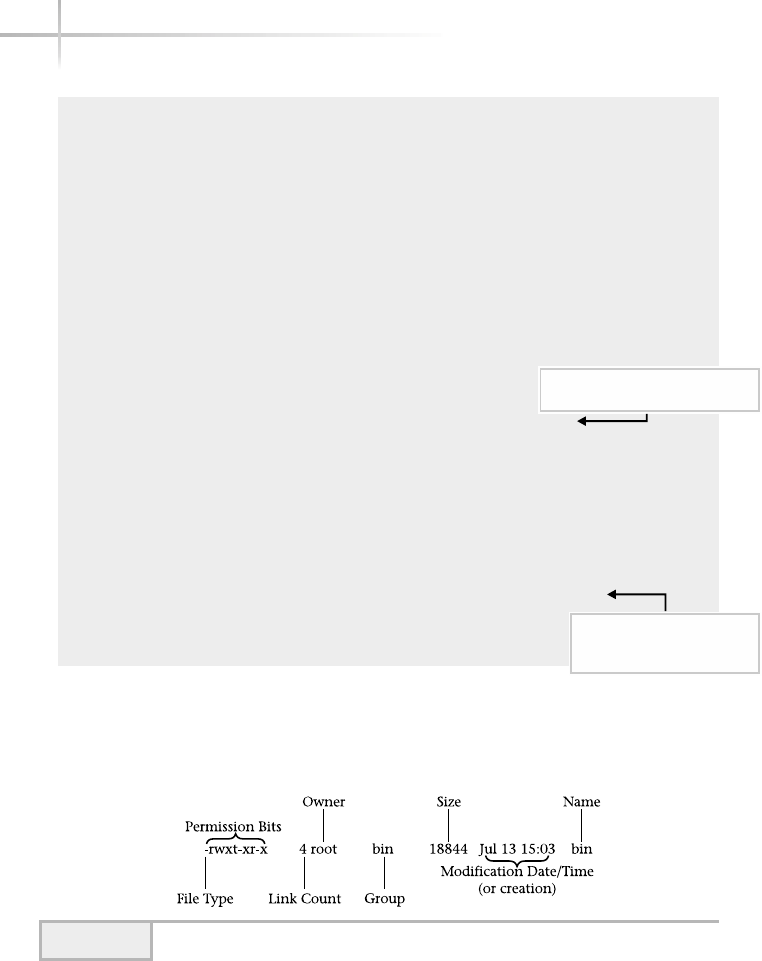
drwxr-xr-x 4 root bin 512 Mar 16 2001 ccs
drwxr-xr-x 8 root bin 512 Mar 16 2001 demo
lrwxrwxrwx 1 root root 16 Mar 16 2001 dict -> ./share/lib/dict
drwxrwxr-x 10 root bin 512 Mar 16 2001 dt
drwxr-xr-x 2 root bin 512 Mar 16 2001 games
drwxr-xr-x 23 root bin 4096 Mar 19 2001 include
lrwxrwxrwx 1 root other 9 Mar 16 2001 java -> ./java1.2
drwxrwxr-x 6 root bin 512 Mar 16 2001 java1.1
drwxr-xr-x 7 root bin 512 Mar 16 2001 java1.2
drwxr-xr-x 9 root sys 512 Mar 16 2001 kernel
drwxr-xr-x 2 root bin 512 Mar 16 2001 kvm
drwxr-xr-x 54 root bin 12288 Mar 19 2001 lib
drwxr-xr-x 8 root sys 512 Sep 25 15:24 local
lrwxrwxrwx 1 root root 11 Mar 16 2001 mail -> ../var/mail
lrwxrwxrwx 1 root root 11 Mar 16 2001 man -> ./share/man
drwxr-xr-x 4 root sys 512 Mar 16 2001 net
lrwxrwxrwx 1 root root 11 Mar 16 2001 news -> ../var/news
drwxr-xr-x 2 root bin 512 Mar 16 2001 old
drwxr-xr-x 8 root bin 512 Mar 16 2001 openwin
drwxr-xr-x 5 root bin 512 Mar 16 2001 perl5
-rw-r--r-- 1 root other 104 Sep 25 18:10 perl5_readme
drwxr-xr-x 15 root sys 1024 Mar 19 2001 platform
lrwxrwxrwx 1 root root 15 Mar 16 2001 preserve -> ../var/preserve
drwxr-xr-x 3 root bin 512 Mar 16 2001 proc
lrwxrwxrwx 1 root root 15 Mar 16 2001 pub -> ./share/lib/pub
drwxr-xr-x 8 root bin 512 Mar 16 2001 sadm
drwxr-xr-x 5 root bin 5120 Mar 19 2001 sbin
drwxr-xr-x 6 root sys 512 Mar 16 2001 share
drwxr-xr-x 5 root bin 512 Mar 16 2001 snadm
lrwxrwxrwx 1 root root 12 Mar 16 2001 spool -> ../var/spool
lrwxrwxrwx 1 root root 11 Mar 16 2001 src -> ./share/src
lrwxrwxrwx 1 root root 10 Mar 16 2001 tmp -> ../var/tmp
drwxr-xr-x 4 root bin 2048 Mar 16 2001 ucb
drwxr-xr-x 4 root bin 512 Mar 16 2001 ucbinclude
drwxr-xr-x 4 root bin 1024 Mar 16 2001 ucblib
drwxr-xr-x 5 root bin 512 Mar 16 2001 xpg4
Although the output above looks quite daunting, each directory and file
contains a fixed number of fields, which is illustrated by Figure 2-2.
44 UNIX System Administration: A Beginner’s Guide
The - at the beginning of this
line shows this is a regular file
The l at the beginning of
this line and the -> show
this is a symbolic link
Figure 2-2 Elements of a UNIX file

As you can see, each element within the listing contains a set of file type and
permission bits, a link count, ownership fields, size, modification date/time,
and name. The first field represents the file type attribute, of which there are two
major types. The first is a directory and the second is a regular file. A directory is
defined as a special file that contains additional file elements. A directory is noted
by a letter “d” in the first field. A regular file contains no flags information and
contains a “-” character. The “-” character can be seen by examining the
perl5_readme file, which is a regular text file.
UNIX supports additional file types, which are shown in Table 2-6. The
block special files are used for access to hardware type devices such as disks
(floppies, hardware drives, and CD-ROMs). These types of devices typically
access information using a certain size, such as 8K worth of information. The
character special files are used for devices such as terminals or printers where
information may be output in units of a single character. The symbolic link file
is simply a pointer to another file, which can span across a different file system.
Both socket and pipe files are used for interprocess communication among
cooperating programs so that they may share information and data.
The remaining bits of the file permission field represent the fundamental
access control mechanism for the file. A total of 9 bits are used to define three
levels of access that include the owner, group, and world. The owner level
represents the actual username associated with the file, such as root. The
group is the group name associated with the file, such as other, and the world
represents everyone else defined on the system.
Within each of these levels, three additional access rights are defined as
shown in Table 2-7.
2
Module 2: Basic UNIX Commands 45
File Flag Meaning
- No specific flag; indicates a regular text file
b Block special file, which is used for hardware-related devices
c Character special file, which is used for hardware-related devices
d Directory
l Symbolic link
s A socket file
p A pipe file
Table 2-6 Standard UNIX File Types

Please note that additional access bits are supported on UNIX. These
include lfor mandatory locking, sfor user/group set-ID, and tfor sticky bit.
The mandatory locking is related to the file’s ability to have reading or writing
permission locked while a program is accessing the file. The sindicates the file
can be executed with the ownership of the file, such as root. This is a way for
the administrator to give normal users access to privileged commands in a
controlled way. The sticky bit provides the ability to have the file referenced
more efficiently.
Each file supports access bits for three security elements for a file or
directory. The first group of three denotes the owner, the next three are the
group, and the final three are for others. This is shown in Figure 2-3. The
administrator can use these permission bits to control access to the file. Also,
the owner of the file may control these permission bits.
Each of the bits controls how the file can be accessed. When the rbit
is present, the file can be read; when the wbit is present, the file is writable;
and when the xbit is present, the file can be executed. In the case of a
directory, the xindicates that the directory can be searched. Of course, the
execution bit is only meaningful when the file represents a binary program
or some type of script.
Table 2-8 contains a few examples of different file permissions that are
possible with UNIX files and/or directories.
46 UNIX System Administration: A Beginner’s Guide
Access Bit Meaning
r The file is readable.
w The file is writable.
x The file can be executed or run as a program. If a directory,
it can be searched.
Table 2-7 File Access Bits
Figure 2-3 File access bits

2
Module 2: Basic UNIX Commands 47
The next field corresponds to the number of links associated with this file,
and in the above example no additional links have been created. This type of
link permits the creation of another file from the original, but they share the
same contents of the first file. A file link appears to be another copy, but in fact
it simply is a pointer to the same file. A modification to one of the files updates
the other one as well. This link is known as a hard link and can’t be used across
different file systems. Symbolic links, as denoted with the “l” character,
accomplish the same thing, but can be used across file systems. The other
difference with symbolic links is that they are one-directional. The symbolically
linked file points to the master file and not vice versa; the master doesn’t point
to the copy.
Note that several files in the above example are symbolic links and are
denoted as such with the “->” string, including ../var/tmp. See Figure 2-2.
Next, the ownership fields represent both the name of the owner and group
membership for the file. Both of these names should be defined within the
/etc/passwd and /etc/group administrative files. If not, then just the user
identification number (UID) and group identification (GID) are shown instead.
The next field shows the actual number of bytes contained within the file,
which is the same as saying how much disk space is used to store the contents
of the file. Typically, only with regular files does this field have meaning; all
other file types (directories, for example) only contain pointers to other files or
Permission Mode Meaning
-rw-r--r-- The file is readable/writable by the owner and only readable
by the group and everyone else.
-rw------- The file is readable/writable only by the owner.
-rw-rw---- The file is both readable/writable only by the owner and
group.
-rwxr-xr-x The file (or directory) is readable, writable, and executable
by the owner and both readable/executable by the group
and everyone else.
-rwx--x--x The file (or directory) is readable, writable, and executable
by the owner and only executable by the group and
everyone else.
Table 2-8 Example File Permission Modes

48 UNIX System Administration: A Beginner’s Guide
information—not user data. Administrators will use this field to determine the
amount of disk space that is consumed by each file. In fact, monitoring disk
space and cleaning up unneeded and/or unused files can occupy a significant
amount of time if not completely automated. The next field that follows is the
file modification field, and it shows when the file was last updated. The
remaining file attribute is the name of the file.
One very powerful argument for the ls command is the –R option. This
tells the program to recursively display all lower directories/files within a given
path name. For example, consider the directory structure shown in Figure 2-4.
When the ls –R command is issued against this directory, we get
# ls –alR local
local:
total 4
drwxr-xr-x 2 root other 512 Sep 25 19:09 bin
drwxr-xr-x 2 root other 512 Sep 25 19:09 etc
local/bin:
total 854
-r-xr-xr-x 1 root other 18844 Sep 25 19:09 ls
-rwx------ 1 root other 409600 Sep 25 19:08 ssh
local/etc:
total 2
-r--r--r-- 1 root other 97 Sep 25 19:09 hosts
With this example, we list a top-level directory called local, and within
this directory we see two subdirectories called bin and etc. Within the bin
directory, two additional files are located, and the etc directory contains a
single file. If we didn’t use the –R option, the ls command would have only
Figure 2-4 Sample directory structure

Module 2: Basic UNIX Commands 49
2
listed the top-level directory local, and not any additional subdirectories
underneath:
# ls -al local
total 8
drwxr-xr-x 4 root other 512 Sep 25 19:09 .
drwxr-xr-x 3 root other 512 Sep 25 19:08 ..
drwxr-xr-x 2 root other 512 Sep 25 19:09 bin
drwxr-xr-x 2 root other 512 Sep 25 19:09 etc
1-Minute Drill
●Explain what it means that a symbolic link is “one-directional.”
●What are the three categories of permissions for a file and what are the three
possible permissions for each category?
strings
The strings command is used to search for ACSII strings within a software
program or binary file. This command is quite helpful when you need to see
within a binary file or program or if you are searching for a specific string
sequence. Normally, if you were to attempt to display a binary file or program
using such UNIX tools as more or cat, you would have difficulty. For
example, imagine that you issue the following command to view the contents
of the ls program:
# more /bin/ls
When this command is executed, the following output would be shown:
Bl°/usr/lib/ld.so.1SbEM'<]^_3
C*Z[a92/KL
●One-directional means that a symbolically linked file points to the master file it is a copy of, but the master
file doesn’t point to the symbolically linked copy.
●Categories: owner, group, others; permissions: read, write, execute.

50 UNIX System Administration: A Beginner’s Guide
Unfortunately, this isn’t the desired result since the more program has
trouble showing binary data to the user’s display, and that is why the strange
output is presented. Also, depending on the display device (that is, terminal)
involved, the characters shown could lock up the terminal, which may result
in the user needing to reset the device or log in from another terminal and kill
their old session.
However, issuing the following strings command would yield the
following:
# strings /bin/ls
SUNW_OST_OSCMD
RaAdC1xmnlogrtucpFbqisfL
usage: ls -1RaAdCxmnlogrtucpFbqisfL [files]
COLUMNS
total %llu
%llu
%3ld
%-8s
%-8lu
%-8s
%-8lu
%3ld,%3ld
%b %e %Y
%b %e %H:%M
->
%s%s
%s%s
%-8lu
%-8lu
%10llu
%llu
%lld
%4lld
%lld
%7lld
%lld
Notice that this command displays all strings within the file and doesn’t
generate strange characters on the display. The command supports a few
command line options, as listed in Table 2-9.
TEAMFLY
Team-Fly®

Module 2: Basic UNIX Commands 51
2
Command Definition
-a Examine the entire file, not just the initialized data area of an
object file.
-n Use the specific number as the default string length, rather than
the value of 4.
-o Abbreviated option for –t d.
-t Display each string with a byte offset in one of the following
formats: dfor decimal, ofor octal, and xfor hexadecimal.
-v Display version information (Linux only).
Table 2-9 Strings Command-Line Options
Ask the ExpertAsk the Expert
Question Why display the contents of a program?
Answer Well, one very good reason is that you might need to search
for some specific information within a program that you might not be
able to obtain any other way. For example, suppose you wanted to find
out which files are used by a given command—say, the more program.
The following command would provide that information:
# strings /usr/bin/more | grep /
Usage: %s [-cdflrsuw] [-lines] [+linenumber] [+/pattern]
[filename ...].
/usr/lib/locale/%s/LC_MESSAGES/more.help
/usr/lib/more.help
/usr/bin/sh
In this example, we search the more binary program and pipe (send
the results to) the output to the grep command to search for a particular
pattern. In this case, we searched for the “/” character, which is used
to denote the start of a file or directory path. As you can see from the
sample output, the more program uses three files.

52 UNIX System Administration: A Beginner’s Guide
If we are interested in knowing where in the file a specific pattern is located,
we can use the –o option, which displays the byte offset from the beginning of
the file. For example, the command
# strings -o /usr/bin/more | grep /
25216 Usage: %s [-cdflrsuw] [-lines] [+linenumber] [+/pattern] [filename ...].
25620 /usr/lib/locale/%s/LC_MESSAGES/more.help
25672 /usr/lib/more.help
27260 /usr/bin/sh
now displays the bytes where the patterns were found within the file. The –o
option is an abbreviation for the –t option. This command-line option takes
either d,o, or xarguments, which represent decimal, octal, or hexadecimal
display values. To list the byte offset in hexadecimal, use the -t with x
parameter:
# strings -t x /usr/bin/more | grep /
6280 Usage: %s [-cdflrsuw] [-lines] [+linenumber] [+/pattern] [filename ...].
6414 /usr/lib/locale/%s/LC_MESSAGES/more.help
6448 /usr/lib/more.help
6a7c /usr/bin/sh
ps
The process status, or ps, command is used to report on currently executing
programs or processes running on the system. System administrators will use
this command to monitor the running processes on the system. Sometimes it
becomes necessary to stop or kill one or more processes because they may be
negatively impacting the system and affecting other processes or the general
heath of the system. For example, a particular process may consume too much
CPU time because it might have encountered an unexpected condition, and as
a result starve other processing on the system. In this case, the administrator
might need to stop this rogue process in order to permit other processes to
continue or complete.
The numbers at the beginning of these
lines show the bytes where the pattern
can be found in the file
The numbers at the beginning of these
lines show the bytes (in hexadecimal
format) where the pattern /usr/bin/more
is found in each file

Module 2: Basic UNIX Commands 53
2
To obtain a snapshot of all the currently executing processes, use the –e
command-line option. Thus,
# ps –e
PID TTY TIME CMD
0 ? 0:07 sched
1 ? 0:00 init
2 ? 0:00 pageout
3 ? 0:12 fsflush
326 ? 0:00 sac
340 ? 0:00 blender
175 ? 0:00 automoun
59 ? 0:00 sysevent
127 ? 0:00 rpcbind
333 ? 0:00 ttymon
206 ? 0:00 nscd
149 ? 0:00 inetd
342 ? 0:00 ffssh-ag
197 ? 0:00 cron
189 ? 0:00 syslogd
329 ? 0:00 sendmail
163 ? 0:00 lockd
164 ? 0:00 statd
212 ? 0:00 lpsched
225 ? 0:00 powerd
250 ? 0:00 sh
257 ? 0:00 cimomboo
235 ? 0:00 utmpd
253 ? 0:25 smanager
259 ? 0:00 vold
327 console 0:00 ttymon
346 ? 0:00 stamper
306 ? 0:00 dtlogin
298 ? 0:00 mountd
300 ? 0:00 nfsd
337 ? 0:00 xntpd
335 ? 0:00 xntpd
317 ? 0:00 dmispd
345 ? 0:00 ffsshd
347 ? 0:00 in.telne
349 pts/1 0:00 sh

389 pts/1 0:00 bash
448 pts/1 0:00 ps
displays a list of all the known processes in a very simple format. A total of
four columns are shown that include PID,TTY,TIME, and CMD. The process
identification (PID) is a reference number to help identify the process and it is
assigned by the system automatically when a new program is started. The PID
is a unique number and can be used to control the process. Specifically, a
process may be stopped, started, killed, or sent additional signals, which can
modify its behavior in some predetermined fashion. The TTY field shows which
terminal device the process started from. When the system first boots, a number
of standard processes are started automatically. As a result, no terminal is
involved when these processes start and that is why a question mark (?) is
assigned in the TTY field for most of the processes listed above. The TIME field
shows how much elapsed CPU time the process has consumed. Finally, the
CMD field shows the command name or process name. With HP-UX, this field is
labeled as COMMAND. Typically, this will be the command name of the program,
which might be a binary program or shell script.
This command has a fairly large number of command-line options.
However, only the most useful ones are presented in this section. These options are
described and summarized in Table 2-10 and some of them are explained below.
54 UNIX System Administration: A Beginner’s Guide
Command Definition
-a Display a listing of all of the most frequently desired processes
currently active on the system (Solaris only).
-A Display information for all processes known to the
system—the same as the –e option.
-C Select those processes executing a particular command with
the name supplied after the argument (HP-UX only).
-e Display a listing about every process currently known to
the system.
-f Display a full listing for all processes known to the system.
-g Display only those group leader IDs that correspond to
specified IDs.
-G Display only those processes that correspond to the specified
group ID.
Table 2-10 Ps Command-Line Options

The –e option lists every process currently known by the system; by
default, without any additional options, just an abbreviated process list is
shown. To capture a full list of not only all processes, but a significant number
of process attributes, use the –f option. Command-line options for this
command may be stacked—that is, they can be grouped together using only
a single “-” symbol. So, the commands
ps –ef and ps –e –f
are functionally the same and produce identical output, as shown in the sample
output below:
UID PID PPID C STIME TTY TIME CMD
root 0 0 0 06:42:05 ? 0:07 sched
root 1 0 0 06:42:05 ? 0:00 /etc/init -
root 2 0 0 06:42:05 ? 0:00 pageout
root 3 0 0 06:42:05 ? 0:00 fsflush
root 326 1 0 06:44:18 ? 0:00 /usr/lib/saf/sac -t 300
root 329 1 0 06:44:18 ? 0:00 /usr/lib/sendmail -bd -q15m
root 206 1 0 06:43:36 ? 0:00 /usr/sbin/nscd
Module 2: Basic UNIX Commands 55
2
Command Definition
--help Displays help screen (Linux only).
-l Display long listing of processes that include a large amount
of information.
-ps List only those process IDs that are specified (Solaris only).
HP-UX, just use –p option.
-o Format output according to specific parameters.
-t Display only those processes that match specified terminal.
-u Display only those processes that match effective user ID or
username.
-U Display only those processes that match real user ID or
username.
-y When –l is used, omits the obsolete F and ADDR columns
and shows an RSS column that reports the resident set size
of the process in kilobytes (Solaris only).
--version Display version information (Linux only).
Table 2-10 Ps Command-Line Options (continued)

56 UNIX System Administration: A Beginner’s Guide
root 59 1 0 06:42:10 ? 0:00 /usr/lib/sysevent/syseventd
root 212 1 0 06:43:37 ? 0:00 /usr/lib/lpsched
root 127 1 0 06:42:14 ? 0:00 /usr/sbin/rpcbind
root 151 1 0 06:42:15 ? 0:00 /usr/sbin/inetd –s
root 175 1 0 06:43:35 ? 0:00 /usr/lib/autofs/automountd
root 336 335 0 06:44:19 ? 0:00 /usr/lib/inet/xntpd
root 197 1 0 06:43:36 ? 0:00 /usr/sbin/cron
root 189 1 0 06:43:36 ? 0:00 /usr/sbin/syslogd
root 163 1 0 06:42:15 ? 0:00 /usr/lib/nfs/lockd
daemon 164 1 0 06:42:15 ? 0:00 /usr/lib/nfs/statd
root 225 1 0 06:43:37 ? 0:00 /usr/lib/power/powerd
root 250 1 0 06:43:38 ? 0:00 /bin/sh
root 257 1 0 06:43:43 ? 0:00 /usr/sadm/lib/wbem/cimomboot start
root 235 1 0 06:43:37 ? 0:00 /usr/lib/utmpd
root 259 1 0 06:43:43 ? 0:00 /usr/sbin/vold
root 335 1 0 06:44:19 ? 0:00 /usr/lib/inet/xntpd
root 317 1 0 06:43:47 ? 0:00 /usr/lib/dmi/dmispd
root 298 1 0 06:43:45 ? 0:00 /usr/lib/nfs/mountd
root 300 1 0 06:43:45 ? 0:00 /usr/lib/nfs/nfsd -a 16
root 307 1 0 06:43:46 ? 0:00 /usr/dt/bin/dtlogin –daemon
root 332 326 0 06:44:18 ? 0:00 /usr/lib/saf/ttymon
root 327 1 0 06:44:18 console 0:00 /usr/lib/saf/ttymon -g -h -p pebb
les.home.com console login: -T vt100 -d /dev/
root 347 151 0 06:48:15 ? 0:00 in.telnetd
root 349 347 0 06:48:20 pts/1 0:00 –sh
root 371 349 0 06:53:15 pts/1 0:00 ps -e –f
Additional columns that are displayed include: UID,PPID,C, and STIME.
The UID column represents the user identification or current owner of the
process. When a process is started, the user that started that process typically
assumes ownership of that process. However, there are instances when a
process starts that it assumes the ownership of root regardless of which user
started the process.
The PPID column shows the parent process identification for each process.
UNIX supports the concept of parent/child relationships within the process
structure. As a result, should a process invoke additional subprocesses, they
are said to be children of the master or parent process. The PPID field identifies
which parent started a given process. Typically, a value of 1 means that the
master program known as init started the process, when the system was first
initialized or rebooted. Also, if you examine the output more closely, you will
see additional processes with the PPID value of 0. These system-related
processes were started by the system very early in the boot process and are vital
to basic system operations.

Module 2: Basic UNIX Commands 57
2
The C field indicates an obsolete and unused scheduling flag.
The STIME fields shows when the process was started. If the process was
started within a 24-hour period, it shows hours, minutes, and seconds. If the
process had begun more than 24 hours before, both the month and day are
given instead.
If you are interested in displaying much of the available process information
for all processes running on the system, use the –l option. This option is very
useful because it provides a significant amount of detail for each process. For
example, the command
# ps –efl
shows the following output:
F S UID PID PPID C PRI NI ADDR SZ WCHAN TTY TIME CMD
19T00000SY ? 0 ? 0:07 sched
8 S 0 1 0 0 41 20 ? 98 ? ? 0:00 init
19S02000SY ? 0 ?? 0:00 pageout
19S03000SY ? 0 ?? 0:00 fsflush
8 S 0 326 1 0 41 20 ? 219 ? ? 0:00 sac
8 S 0 329 1 0 41 20 ? 365 ? ? 0:00 sendmail
8 S 0 206 1 0 41 20 ? 332 ? ? 0:00 nscd
8 S 0 59 1 0 88 20 ? 164 ? ? 0:00 sysevent
8 S 0 212 1 0 59 20 ? 382 ? ? 0:00 lpsched
8 S 0 127 1 0 41 20 ? 278 ? ? 0:00 rpcbind
8 S 0 151 1 0 59 20 ? 297 ? ? 0:00 inetd
8 S 0 175 1 0 41 20 ? 367 ? ? 0:00 automoun
8 S 0 336 335 0 0 RT ? 268 ? ? 0:00 xntpd
8 S 0 197 1 0 49 20 ? 238 ? ? 0:00 cron
8 S 0 189 1 0 89 20 ? 412 ? ? 0:00 syslogd
8 S 0 342 253 0 41 20 ? 222 ? ? 0:00 ffssh-ag
8 S 0 163 1 0 59 20 ? 234 ? ? 0:00 lockd
8 S 1 164 1 0 50 20 ? 336 ? ? 0:00 statd
8 S 0 345 253 0 47 20 ? 306 ? ? 0:00 ffsshd
8 S 0 225 1 0 69 20 ? 171 ? ? 0:00 powerd
8 S 0 250 1 0 99 20 ? 130 ? ? 0:00 sh
8 S 0 257 1 0 49 20 ? 199 ? ? 0:00 cimomboo
8 S 0 235 1 0 40 20 ? 127 ? ? 0:00 utmpd
8 S 0 253 250 1 41 20 ? 1008 ? ? 0:29 smanager
8 S 0 259 1 0 51 20 ? 326 ? ? 0:00 vold
8 S 0 335 1 0 0 RT ? 268 ? ? 0:00 xntpd
8 S 0 340 253 0 40 20 ? 289 ? ? 0:00 blender
8 S 0 317 1 0 57 20 ? 381 ? ? 0:00 dmispd
8 S 0 298 1 0 69 20 ? 334 ? ? 0:00 mountd
8 S 0 300 1 0 46 20 ? 233 ? ? 0:00 nfsd
8 S 0 307 1 0 59 20 ? 614 ? ? 0:00 dtlogin
8 S 0 346 253 0 67 20 ? 231 ? ? 0:00 stamper

58 UNIX System Administration: A Beginner’s Guide
8 S 0 332 326 0 41 20 ? 219 ? ? 0:00 ttymon
8 S 0 327 1 0 61 20 ? 218 ? console 0:00 ttymon
8 S 0 347 151 0 54 20 ? 223 ? ? 0:00 in.telne
8 R 0 349 347 0 51 20 ? 38 pts/1 0:00 sh
8 O 0 412 349 0 41 20 ? 235 pts/1 0:00 ps
This command option shows additional columns that include F,S,PRI,
NI,ADDR,SZ, and WCHAN. The F field is not used and should be ignored. The
S field shows the state of the process and contains one of several different flags,
as shown in Table 2-11.
It is interesting to note that during the life of a process, it can bounce
between one or more states in a relatively short period of time. Depending on
the activities of the system and other factors that impact system load, a process
can toggle between the S and O states. Generally speaking, most processes
remain in the S state since on a uniprocessor system, a single process is running
at any given point in time. A zombie is a process for which the parent is no
longer waiting for the process to terminate and as a result, can’t be terminated
normally. Given the right circumstances, one or more zombie processes can
be created that are largely due to software defects with certain applications.
When this happens, the process (or application) can’t be killed using the kill
program. Instead, the system must be rebooted to clear these processes.
State Flag Meaning
O The process is running.
S The process is in sleep state, waiting for an event to complete.
R The process is in the run queue.
Z The process has terminated abnormally; the parent is not waiting for this
process to finish. This is known as a zombie process.
T The process has stopped either by a signal (via the kill command or job
control) or because the process is being traced.
Table 2-11 Process Status Flags

uname
The uname command displays more detailed information and characteristics
about the system. It can be used to determine basic operating system
information, such as
●The O/S version and name
●The name of the system
●Computer hardware type
●Hardware processor type
When this command is executed without any command-line options, the
name of the operating system is displayed. For example, typing
# uname
SunOS
on a Solaris system will yield the operating system name of SunOS. One of the
most popular options, -a, is used to display basic information in a concise
form. Thus,
# uname -a
SunOS pebbles.home.com 5.8 Generic_108528-06 sun4u sparc
SUNW,UltraAX-i2
shows a string which contains series of fields. The first field is the name of the
operating system, as shown in the previous example. Next, the fully qualified
hostname of the system is displayed, which is the same information as shown
from the hostname command. The third field is the name of the currently
installed kernel. The fourth field displays the machine hardware (class) name as
defined by the computer system vendor. The fifth field is the type of computer
processor. The above example shows that the system is based on Sun’s Sparc
architecture. If this command were run on a Solaris Intel platform, it would
display a processor type of i686. The final field shows the hardware platform
information, which gives more information about the system architecture or
processor type.
Module 2: Basic UNIX Commands 59
2

60 UNIX System Administration: A Beginner’s Guide
The uname command is very useful to the system administrator because
each of the fields listed above can be obtained separately from all other fields by
using command-line options. Table 2-12 shows the available command-line
options for this command.
To display just the hostname of the system, use the –n option:
# uname –n
pebbles.home.com
If you are interested in just seeing the name of the operating system, use the
–s option:
# uname –s
SunOS
Command Definition
-a Displays basic information about the system.
-I Displays the hardware platform information such as Sparc or
i386. For HP-UX, display the system identification number.
-l Display operating license information (HP-UX only).
-m Displays the system hardware name or class of machine.
-n Displays the hostname of the system.
-p Displays the current processor type (Solaris and Linux only).
-r Displays the operating system revision number or level.
-s Displays the name of the operating system such as SunOS,
HP-UX, or Linux.
-S Used to change the hostname of the system.
-v Displays kernel/system version information.
-X Displays system information in concise format separated by
equal signs (Solaris only).
Table 2-12 uname Command-Line Options
TEAMFLY
Team-Fly®

Module 2: Basic UNIX Commands 61
2
Unlike the other operating systems, Solaris provides one additional option
(-X), which can be used to display more concise information about the system
in a format that is more suitable for parsing with a shell script. Thus, the command
# uname –X
would make it very easy to parse the output of uname with a shell script
because the information is separated by a command character, which is the =
(equals) sign as shown below:
System = SunOS
Node = pebbles.home.com
Release = 5.8
KernelID = Generic_108528-06
Machine = sun4u
BusType = <unknown>
Serial = <unknown>
Users = <unknown>
OEM# = 0
Origin# = 1
NumCPU = 1
With HP-UX, the –l and -i options are supported. The –i option displays
the system identification number, or the node name if the ID can’t be
determined. The –l argument is used to display software license information.
Thus, the command
uname –a
is a shorthand way of listing the fields from the following arguments: -s,-n,
-r,-v,-m,-i, and –l.
HintHint
The –S option on certain releases of Solaris doesn’t actually work. This option
does change the name of the host, once the system is rebooted, the old
name still applies. This is because the uname command doesn’t update the
/etc/nodename file, which stores the system hostname.

62 UNIX System Administration: A Beginner’s Guide
This would yield output similar to
HP-UX socrates B.11.00 U 9000/800 545770578 unlimited-user license
The last two fields correspond to the –i (545770578) and –l
(unlimited-user license) fields accordingly.
Project 2-1
This project will familiarize you with the commands from this module and give
you firsthand experience with them on your own system.
Step-by-Step
1. At the default shell prompt, type the following command to determine your
system’s operating system name, hostname, currently installed kernel name,
machine hardware (class) name, processor type, and hardware platform
information. You’ll want to remember this in case your operating system
supports special commands or options mentioned in this book.
# uname -a
2. Use the who command to determine all the users logged onto the system:
# who
3. Determine what user you are currently logged on as using this command:
# who am i
4. List the files in the current directory, including file attribute information:
# ls -l
5. From the list of files, display the smallest normal file onscreen:
# cat filename
6. Find all the files on your system that belong to the admin group and list them:
# find / -group admin
7. Display all the currently running processes on your system that belong to you:
# ps -u yourusername

Module 2: Basic UNIX Commands 63
2
Mastery Check
1. Which of the following is not a UNIX shell?
A. sh
B. csh
C. bash
D. ps
2. What is the command and option syntax to list a text file’s contents,
numbering each line but not numbering blank lines?
3. What is the command and option to change the system date and time to
October 4, 2002 3:30 P.M.?
4. What command do you use just to display a UNIX system’s name?
A. fqdn
B. ps
C. hostname
D. system
5. What command and option syntax would you use to find all the files on
your system you haven’t accessed in the last year?
6. What kind of file and what permissions does this set of attributes indicate:
drwxr-x--x?
7. Which of the following user types’ permissions are not defined by the 9-bit
permission attributes?
A. Administrator
B. Owner
C. Group
D. Others

64 UNIX System Administration: A Beginner’s Guide
8. What does the ? in the following command output indicate?
# ps –ef
UID PID PPID C STIME TTY TIME CMD
root 0 0 0 06:42:05 ? 0:07 sched
root 1 0 0 06:42:05 ? 0:00 /etc/init -
9. What command do you use to display a system’s operating system revision
number?
Mastery Check

Module3
Using System
Administration Tools
Critical Skills
3.1 Manage Solaris with Admintool
3.2 Manage Linux with Userconf
3.3 Manage HP-UX Using SAM
3.4 Set Up Better Account Security
Copyright 2002 by The McGraw-Hill Companies, Inc. Click Here for Terms of Use.

66 UNIX System Administration: A Beginner’s Guide
This section reviews how to perform specific UNIX administration tasks such as
adding new users to the system. As such, it is more procedure oriented versus
providing complicated details about the underlying structure of configuration
files or low-level system function. As the system administrator, it will be very
important that you know which tools to use for a given system administration
function or task. Also, it would be very good for the tools available to be easy to
use in order to help you to be very effective. Sometimes UNIX tools are not easy
to use, nor are they documented very well. However, as with most versions of
UNIX available today, one or more general-purpose GUI-based administration
tools are available—either with the basic operating system or they can be installed
after the operating system has been set up. For example, the Solaris system
provides the admintool program, which can be used to accomplish a variety
of important system administration tasks.
This module reviews the following tools:
admintool (Solaris)
control-panel (Linux)
sam (HP-UX)
Generally, these utilities provide a large number of functions; however,
only the addition and modification of users, accounts will be reviewed.
The tools described in this section share common features: They were
designed to be used by administrators with little experience, and they can
perform important system administration tasks. These tools are most useful
when used against a single system, or in a situation where many systems are
networked to use a single set of system files on a single host and the tools are
used against that single host—in other words, in a computing environment
where the system account files (/etc/passwd, /etc/group, and /etc/shadow)
are locally available and maintained. Additional configuration is necessary
where Network Information Services (NIS) or some other authentication
mechanism is used in conjunction with these local account files. See Module 15
on NIS for more specific information.
Each of the administration tools is a GUI-based program that uses the
X-Window system to display a series of windows for each administrative
function they support. In order to run this command, you will need an
X-Window- compliant workstation, such as a Sun workstation or X-terminal,
or a personal computer running some X-Window-compatible software. Note,
the HP-UX sam tool also supports basic CRT displays as well; thus, an X-Window
system is not required. A very good X-Window-based software package for UNIX

33
and the PC is called VNC. This package is available on the Internet and you
can consult Appendix A for additional information. You must also set the
DISPLAY environment variable to the workstation you want the application
windows to appear.
3.1 Managing Solaris
Using Admintool
To invoke the admintool command, simply type the following on the
command line:
# admintool&
Once this command is run, it will display the base window, as shown in
Figure 3-1. This window contains a total of four menu items: File, Edit, Browse,
and Help. When the window first appears, it shows a scrollable list of defined
users that are contained within the /etc/passwd file.
The Browse menu contains a number of items that correspond to the
specific system administration tasks that the application supports. Table 3-1
lists the Browse menu items and their associated functions. Selecting one of
the items within this menu causes the application to redisplay the main window
with information associated with the menu item.
For example, clicking the Groups item, cause the main window to display a
scrollable list of the all the groups defined within the /etc/group file.
Add a New User
To add a new user to the system, use the following procedure:
1. From the Browse Menu, select the Users item.
2. From the Edit Menu, select the Add item. This will cause another window,
labeled Admintool: Add User, to appear, as shown in Figure 3-2.
Module 3: Using System Administration Tools 67
HintHint
Since VNC is a shareware package, it may not be acceptable to use such
software in certain corporate environments.
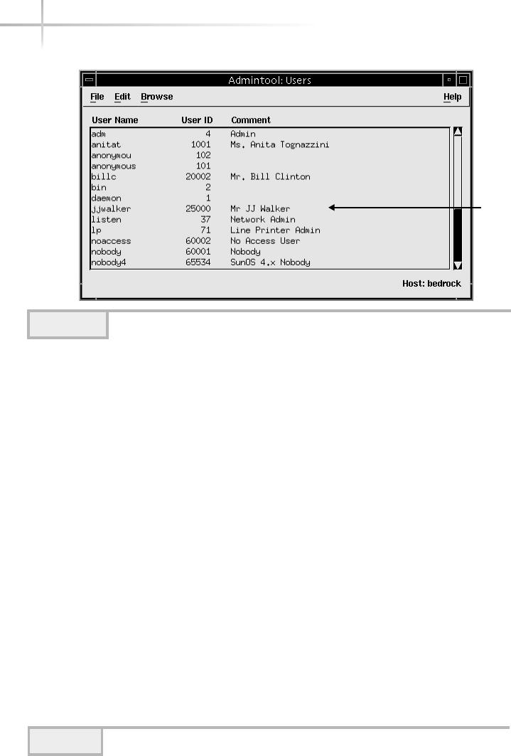
68 UNIX System Administration: A Beginner’s Guide
The window that appears is used to add a new user to the system and
contains a semiblank form of text box for which the administrator must
input information about the new user. This window contains three sections:
User Identity, Account Security, and Home Directory. In general, most of the
Account Security options are optional, while the other sections are required
and must be completed in order to create a valid UNIX user. The user identity
section contains the following input fields: User Name, User ID, Primary
Group, Secondary Groups, and Comment, which are typical elements for a
UNIX account.
Enter the Account Username
The username is the name of the UNIX account, which should represent the
name of the user or purpose of the account. Typically, the name may contain
Users Create/modify system users.
Groups Create /modify system groups.
Host Create/modify the entries in the /etc/hosts file.
Printers Create/modify system printers.
Serial Ports Configure serial interfaces.
Software Administer packages for the system.
Table 3-1 Browser Menu Items
Figure 3-1 Main admintool window
List of
Defined
Users
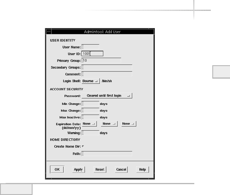
3
Module 3: Using System Administration Tools 69
letters of the alphabet, plus numbers, and is usually limited to eight characters
in length. Many sites use the first initial, middle initial, and last name for the
account name if it represents an actual person. Thus, Bill Jefferson Clinton
would have the associated UNIX login of bjclinton. If the total number of
users on the system is quite small, it is possible to simply use the first name of
the user as the account name. Obviously, if a site has more then one person
named bill, this approach will be a problem. As an alternative, the first name
plus last name initial could be used. So, using our previous example, the new
account would be billc. This approach has been used at many sites. If
the account doesn’t represent a real person—but a group, for example—then
names like support,sales,oreng may be acceptable. Bear in mind that
group type accounts, where multiple individuals share a single account, are
not a very good way to go since you lose the ability to know for certain who
is really using the account at any given time.
Figure 3-2 New User window

70 UNIX System Administration: A Beginner’s Guide
Enter the User ID
This field represents the identification number associated with the User Name
field; the application obtains the next available number. This number is used to
track the activity and to associate which files this particular account owns.
Enter the Primary Group ID
Input the primary group for which this account will be a member. Either the
group name or ID number can be used. Groups are used to define a class of
users that may have something in common. Groups can help control access to
both programs and other files on the system. For example, users from the same
department or those that perform the same type of job may be members of the
same group, where they need access to one or more text or database files. On a
new system, only a small handful of standard groups are defined and are usually
related to system groups. As a result, you will need to create additional user
groups when additional groups are needed. See below for additional information
on group creation.
If you have additional groups defined on the system and the user should
have one or more secondary groups defined by the account, simply list them
in the Secondary Groups text box. The purpose of secondary groups is to
further provide user access to additional groups, since each UNIX account
may only have one primary group membership. Note that in both the Primary
Group and Secondary Group text boxes, an integer is required, not the string
name of the group.
Enter a Comment about the Account
Every account can have some associated free text that can be used to explain
the purpose of the account or establish the true identity of the account holder.
Since this field is simply a string of text, any important information may be
included. For example, the field is often used to store the real full name of
the account holder, such as Steve Maxwell’s Account or The
Department’s Pager Account.
Select a Login Shell
The Login Shell field is used to specify which command interpreter should be
started when the user logs in to the system. The selection list contains four
different choices: Bourne, C, Korn shells, and Other. Using the Other classification
permits the inclusion of the path name of an alternative shell. The administrator
simply inputs the location of the shell.
TEAMFLY
Team-Fly®

Module 3: Using System Administration Tools 71
3
Select the Desired Password Option
The admintool program permits the administrator to control the access to the
account with one of four options as listed and defined in Table 3-2.
Simply choosing the default (thus, no change to the selection field is
needed), Cleared Until First Login, means that once the user has logged into
the system for the first time, they will be required to change their password
before general access to the system is granted. This option is most useful
because it permits the administrator to define a standard temporary password
for each user—and once the user has accessed the system, they will change
their password to their own liking. Note that should the administrator wish to
disable a UNIX account, they simply update the Password text field with the
Account Is Locked option. This will stop the account from being accessed
because it alters the password information. When the user attempts to access
this account with this option, they get a permission denied response.
Input the Home Directory Path
The remaining element that needs to be included is the path to the user’s home
directory. This is the location on a file system where the user will store files and
obtain account configuration information. Note that a Create Home Dir check
box has been provided if the directory doesn’t presently exist.
Selecting the OK Button Will Create This UNIX Account
Any errors will be displayed in a separate dialog box.
Please note: Many administrators copy certain environmental configuration
files to the user’s home directory as this point. These configuration files may
include, for example, a startup file for the shell and other installed utilities.
Also, the system recognizes special initialization files, which can be used to
Account Option Meaning
Cleared Until First Login No password is assigned to the account until the user first
logs in to the system and is prompted automatically for a
password.
Account Is Locked Disables access to the UNIX account.
No Password – Setuid Only No password is assigned to the account, which is generally
not used.
Normal Password The admintool prompts for a standard password when
the account is created.
Table 3-2 Account Security Options
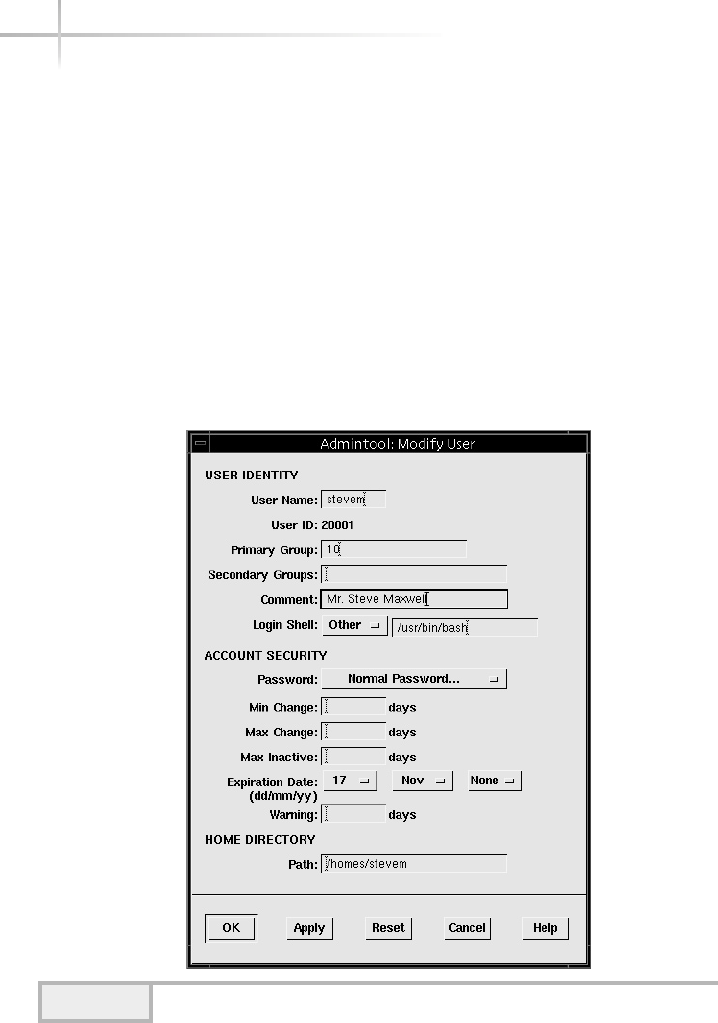
72 UNIX System Administration: A Beginner’s Guide
customize the user’s environment. Among these files are the .login and
.profile files, for example. The .login file is one of the first configuration
files executed when the user first logs in to the system. The .profile file
contains a free format of text that can be used to describe more about the user
of the account, such as the projects they are working on and other related
information. Using the UNIX .finger command will display the contents
of the .profile file associated with the user.
UNIX Account Example
The following section has been provided to further demonstrate using the
“admintool to add a new user to the system. Figure 3-3 shows the Admintool:
Add User window with the required text fields filled in.
Figure 3-3 Sample UNIX account

3
Module 3: Using System Administration Tools 73
3
As you can see, the account called stevem has input with all the required
and associated fields completed. Note the use of the Other category for the
login shell. In this case, the user has been set up to use the bash shell instead
of the other available shells.
We can verify to make sure that the stevem account has been added to
the system as expected. Execute the following command to list the account
information:
# grep stevem /etc/passwd /etc/group
The grep command searches the string stevem in both the /etc/passwd
and /etc/group files. If the user account was added successfully, the following
output should be displayed and should match the information that was displayed
in Figure 3-3.
/etc/passwd:stevem:x:20001:101:Steve Maxwell's Account:/homes/stevem:/usr/bin/bash
/etc/group:betagrp::104:stevem
Also, you can inspect that the home directory was created as well. Thus,
to determine that a directory exists, type the following:
# ls -ald /homes/stevem
drwxr-xr-x 2 stevem dev 512 Oct 22 13:01 /homes/stevem
Using the –d option of the ls command, you can show a directory without
having to issue the change directory command (cd) or list the contents of it. As
you can see, the directory is owned by the stevem, and the group ownership is
configured to be dev, which matches our sample account.
Modifying a User
The admintool is also used to make a variety of changes to user accounts that
have already been established on the system. To make a modification to an
existing account, do the following:
1. Select an account name from the scrollable list and access the Modify…
menu item from the Edit Menu.
2. Or, double-click the account name.

74 UNIX System Administration: A Beginner’s Guide
Once done, the user account information will be displayed in new window
labeled Admintools: Modify User. Just about all account information can
be altered using this window. However, the one notable exception is the
User ID field. Figure 3-4 shows an example account named billc. As
you can see, the User ID field is not editable and thus can’t be altered
using admintool.
3. Make the necessary modification(s).
4. Select the OK button to save the changes.
If you want to actually alter the user ID of an existing account, you will have
to edit the /etc/passwd file directly by hand. However, if the account is new,
another approach is that you can delete the user from the system and reenter
the account information using the new user ID. This user is considered bad
practice if the account was older and contained existing files, and you just
randomly changed this account information. Since the ownership of any
existing files would remain with the older user ID, the administrator would
have to change the ownership of these files to reflect the new user information.
Deleting a User
Deleting an existing user is very easy. However, care should be taken when doing
so since the admintool has the capability of removing the user’s directory.
To remove a user, do the following:
1. Select an account name from the scrollable list and access the Delete
menu item from the Edit menu.
2. You will be presented a dialog box, as shown in Figure 3-4.
HintHint
Exercise extreme caution when removing users; as an important step in
account removal, backing up home directories to secondary storage is a
requirement. Even if you have a relatively new backup, it is very important
that a fresh copy be made to capture any files/directories that have been
modified after the last backup was taken.
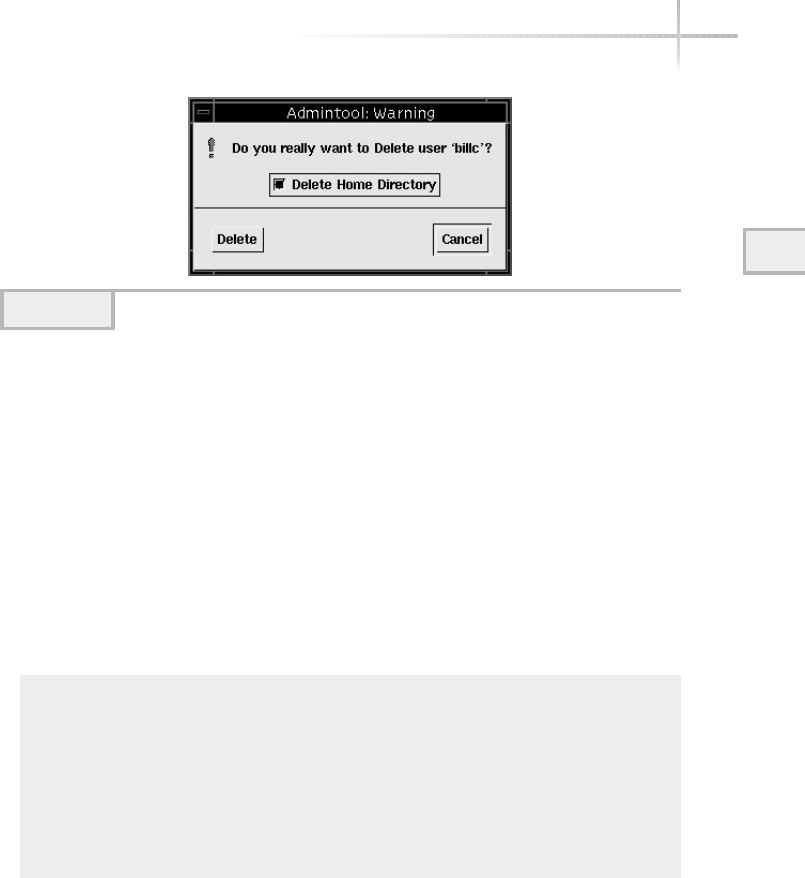
Module 3: Using System Administration Tools 75
3
Clicking the Delete button will remove the account entry from the system.
Also, if you select the Delete Home Directory check box, the home directory
will be removed as well.
3. Once you have determined that, in fact, the account has been backed up
and can be removed, select the Delete button.
If you choose to remove an existing account without deleting the home
directory, then the home directory and any files underneath will be owned by the
user that assumes the previous user’s ID or just the user ID number. For example,
consider the account name of billc with the user ID of 20002. Before the
account is removed, the directory and associated files might look like this:
# ls -al /homes/billc
total 1370
drwxr-xr-x 2 billc exec 512 Oct 22 15:30 .
drwxr-xr-x 4 root other 512 Oct 22 15:29 ..
-rw-r--r-- 1 billc exec 338 Oct 22 15:30 .login
-rw-r--r-- 1 billc exec 582 Oct 22 15:29 .profile
-rw-r--r-- 1 billc exec 192411 Oct 22 15:29 figure3_1
-rw-r--r-- 1 billc exec 230477 Oct 22 15:29 figure3_2
-rw-r--r-- 1 billc exec 230477 Oct 22 15:29 figure3_3
-rw-r--r-- 1 billc exec 338 Oct 22 15:29 sig
Figure 3-4 Delete User warning message
76 UNIX System Administration: A Beginner’s Guide
However, after the account has been removed (but not the home directory),
the files will now look like this:
# ls -al /homes/billc
total 1370
drwxr-xr-x 2 20002 exec 512 Oct 22 15:30 .
drwxr-xr-x 4 root other 512 Oct 22 15:29 ..
-rw-r--r-- 1 20002 exec 338 Oct 22 15:30 .login
-rw-r--r-- 1 20002 exec 582 Oct 22 15:29 .profile
-rw-r--r-- 1 20002 exec 192411 Oct 22 15:29 figure3_1
-rw-r--r-- 1 20002 exec 230477 Oct 22 15:29 figure3_2
-rw-r--r-- 1 20002 exec 230477 Oct 22 15:29 figure3_3
-rw-r--r-- 1 20002 exec 338 Oct 22 15:29 sig
The reason for this is that within UNIX, the ownership of the directories and
files use the user identification number—not the name—and in this case, 20002
is the numerical identification for the account billc. UNIX maps the name of
the account with the defined user ID within the /etc/passwd file. So, when
this mapping is broken—that is, the account name has been removed from the
/etc/passwd file—UNIX no longer knows how to map the name and just
displays the actual account ID instead. Note also that the group name remains
intact. However, should we remove the exec group from the /etc/group file,
we would encounter a similar mapping problem where only the group ID number
will be displayed.
Adding a New Group
The primary purpose of a group is to associate similar users together to
make it easier for those users to share information. Groups are defined with
the /etc/group file and contain a mapping between a group name and all
members of that particular group. To create a new UNIX group, do the following:
1. Select the Groups menu item from the Browser menu. A list of defined
groups will be displayed in a scrollable list, as shown in Figure 3-5.
2. Select the Add menu item from the Edit menu. At this point, a new
window appears labeled Admintool: Add Group, as shown in Figure 3-6.
This window contains three text boxes: Group Name, Group ID, and
Members List. All of the text fields must be filled in before a new group may
billc replaced
with 20002
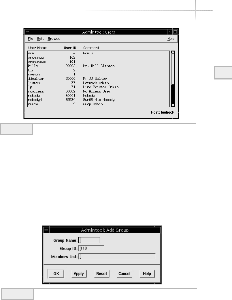
3
Module 3: Using System Administration Tools 77
3
be added to the system. Note that the Group ID field has been automatically
updated with the next-higher numeric value as derived from the /etc/group file.
Enter the Group Name
The group name is simply the name of the group you wish to define. Like the
UNIX account name, the group name is also limited to just eight characters.
The group name can be any string that represents a collection of users. For
example, the group name of devel can represent the development staff within
a particular department. Choose a group name and enter the string within the
Group Name text box.
Figure 3-5 Admintool Groups window
Figure 3-6 List of Groups window
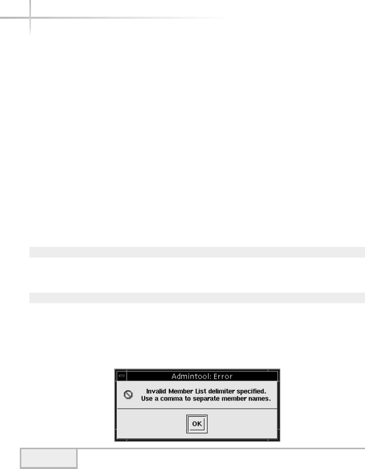
78 UNIX System Administration: A Beginner’s Guide
Accept the Default Group ID Number
or Alter It to Match Your Requirements
The group ID number can range from 1 to 2137483647. In practice, the
number of groups defined on a given system can be quite small—say, fewer
than 100. Therefore, it is reasonable to start numbering group IDs after the
100 starting point.
Input the Group Members
The Members List text box is used to input all the existing account names that
should be a part of this group. You must use commas to separate each of the
account names. Please note that Admintool is quite finicky about the use of
white spaces when more than one string is supplied. As a result, when inputting
more than one account name, don’t include spaces between the names. For
example, consider the following group member lists:
Wrong:
Members List: stevem, anitat, irinav,samyu
Correct:
Members List: stevem,anitat,irinav,samyu
If you use spaces when entering multiple strings, Admintool will display
an error message similar to that shown in Figure 3-6. Just click the OK button
and remove the spaces between each group name.
Figure 3-7 Admintool error regarding white spaces

Modifying a Group
Making changes to a group is similar to making a changes to an established
UNIX account name. To make a modification to an existing group, do the
following:
1. While the groups are being displayed within the “Admintool
main window, select a group name from the scrollable list and
access the Modify menu item from the Edit menu.
2. Or, double-click the group name.
3. Modify the group member information.
4. Apply the changes.
Deleting a Group
Deleting an existing user is also similar to deleting an existing UNIX account. As
an added safeguard, just like deleting an existing UNIX account, Admintool
prompts before actually deleting a predefined group.
1-Minute Drill
●Why is the Cleared Until First Login option useful when
creating new UNIX user accounts?
●What is the important step to take before deleting a user?
Module 3: Using System Administration Tools 79
33
●It is useful because it permits the administrator to define a standard temporary password for each user—
and once the user has accessed the system, they will change their password to their own liking.
●Back up all the associated files and directories for the user.

80 UNIX System Administration: A Beginner’s Guide
3.2 Manage Linux Accounts
with Userconf
Based on the X-Windows system, the userconf tool provides a GUI facility
for managing both user and group accounts on a Linux system. This tool can
be invoked two ways. First, it can be started from the linuxconf application.
Clicking the Users Account selection tab will start the userconf tool. The
second way is from the command line. To start this application, issue the
following command:
userconf&
Using either approach, the userconf application window will appear.
Shown in Figure 3-8, this main window contains four selection tabs and several
functional buttons, and is labeled User Account Configurator. The tabs include
Normal, Special Accounts, Email Aliases, and Policies. The Normal tab, which
is shown by default, provides access to create what are considered normal UNIX
users and groups. Also, the root account password can be changed.
The Special Accounts tab is used to create application specific or special
accounts such as PPP/SLIP, UUCP, and POP accounts for mail. They are special
because they are used for a particular purpose to support a system service,
unlike general login accounts. The Email Aliases tab is used to set up aliases
related to electronic e-mail such as with sendmail. The Policies tab provides
access to define UNIX account policies such as the default base for home
directories and minimum length for passwords.
Add a New User
To add a new user to the system, use the following procedure:
Click the User Accounts Button
This is next to the single penguin. Once this is done, a new window is displayed
as shown in Figure 3-9.
TEAMFLY
Team-Fly®
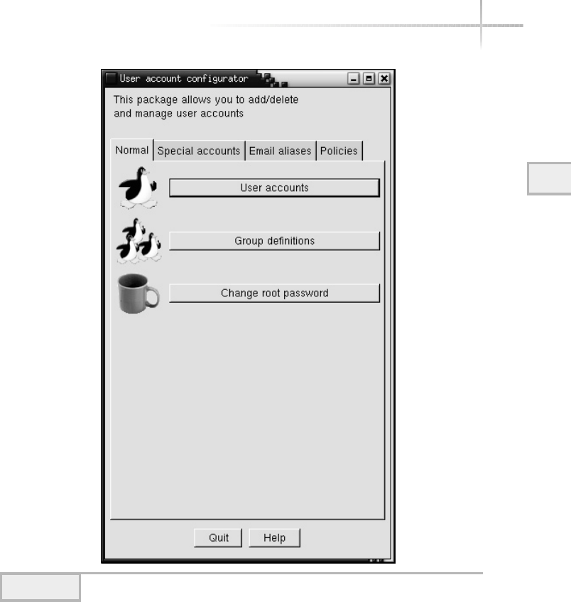
Module 3: Using System Administration Tools 81
3
Figure 3-8 Main userconf window
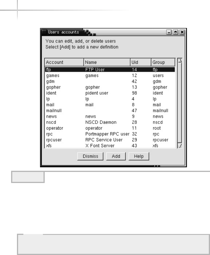
82 UNIX System Administration: A Beginner’s Guide
Click the Add Button on the Users Accounts Window
This is the middle button located at the bottom of the window. When you click
it, another window called the User Account Creation window is presented, as
shown in Figure 3-10.
Input the UNIX Login Name
The login name is the name of the UNIX account, which should represent the
name of the user or purpose of the account. Typically, the name may contain
letters of the alphabet and numbers, and is usually limited to eight characters
in length. Many sites use the first initial, middle initial, and last name for the
account name if it represents an actual person. Thus, George W. Bush would
Figure 3-9 Users Accounts window
HintHint
This window contains four selection tabs: Base Info, Params, Mail Settings,
and Privileges. The Base Info tab is used to begin the login creation process.

Module 3: Using System Administration Tools 83
3
have the associate UNIX login of gwbush. If the total number of users on
the system is quite small, it is possible to simply use the first name of the user
as the account name. Obviously, if a site has more than one person named
george, this approach will be a problem. As an alternative, the first name
plus last name initial could be used. So, using our previous example, the new
account would be georgeb. This approach has been used at many sites. If the
account doesn’t represent a real person—but a group, for example—then names
like support,sales, or eng may be acceptable. Bear in mind that group
type accounts, where multiple individuals share a single account, are not a very
good way to go since you lose the ability to know for certain who is really using
the account at any given time.
Figure 3-10 User Account Creation window

84 UNIX System Administration: A Beginner’s Guide
Add the Full Name of the User
The Full Name field represents the actual name of the account holder. This field
corresponds to the Comment field within the password file. Every account can have
some associated free text that can be used to explain the purpose of the account or
establish the true identify of the account holder. Since this field is simply a string of
text, any important information may be included. For example, the field is often
used to store the real full name of the account holder, such as James Bond’s
Account or The MIS department’s Pager Account.
Select the Account Group
Select the primary group for which this account will be a member using
the pop-up menu. Groups are used to define a class of users that may have
something in common. Groups can help control access to both programs and
other files on the system. For example, users from the same department or
those that perform that same type of job may be members of the same group,
where they need access to one or more text or database files. On a new system,
only a small handful of standard groups are defined and are usually related
to system groups. As a result, you will need to create additional user groups
when additional groups are needed. See the following section for additional
information on group creation.
Add Additional Group Memberships
If you have additional groups defined on the system and the user should have
one or more secondary groups defined by the account, simply list them in the
Supplementary Groups text box. The purpose of secondary groups is to further
provide user access to additional groups since each UNIX account may only
have one primary group membership.
Add the Home Directory
This field defines the location of the home directory for the user. This is the
location on a file system where the user will store files and obtain account
configuration information.
HintHint
Some of the fields within the User Account Creation window are optional, as
depicted with the (opt) string next to the text box label. If you leave these
fields blank, they will be assigned default or appropriate values. For example,
if you leave the Home Directory field empty, the default base directory of
/home plus the username will be used instead. The default home directory
base can be altered under the Policies tab.
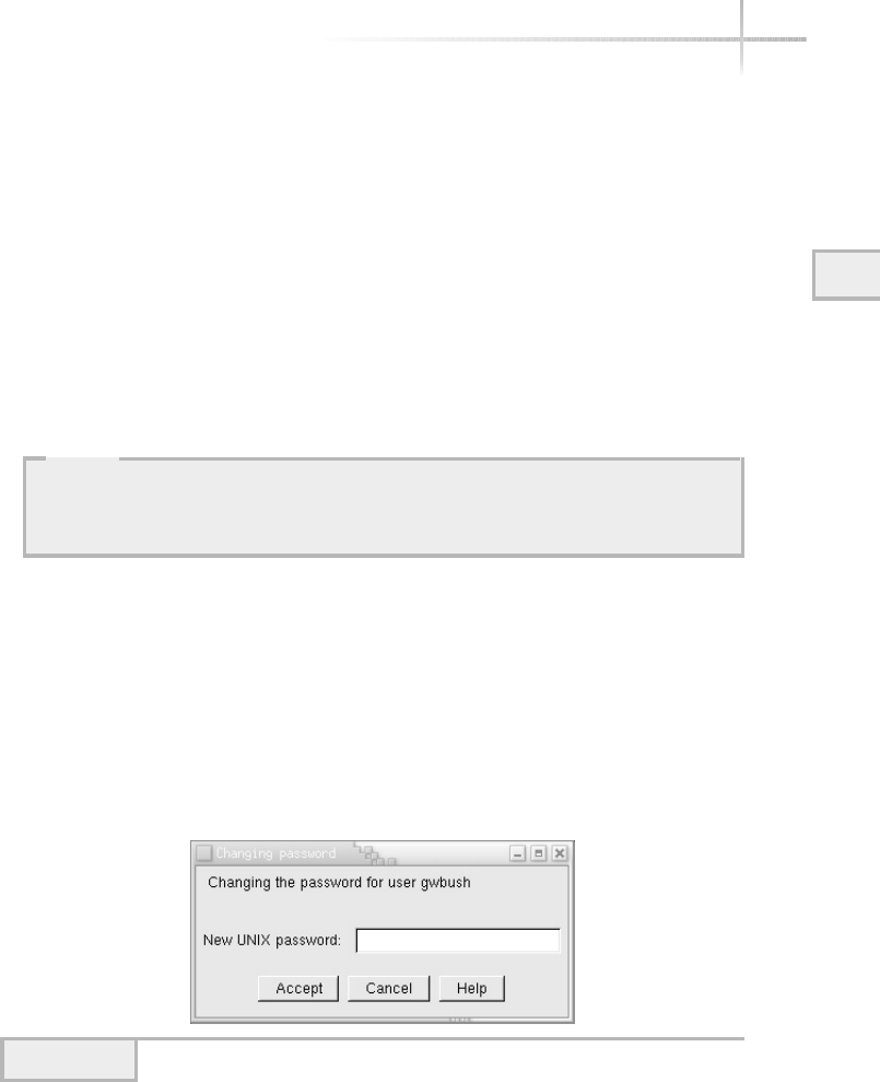
Module 3: Using System Administration Tools 85
3
Select the Login Shell
The Command Interpreter field is used to specify which command shell
should be started when the user logs in to the system. The selection list contains
several different choices that include /bin/bash (bash shell), /bin/sh (Bourne
shell), and /bin/csh (C shell). If you have an alternative shell, you can simply
input the absolute path in the text box.
Input the User ID
This field represents the identification number associated with the login name
and the application obtains the next available number. This number is used to
track the activity and to associate which files this particular account owns.
Click the Accept Button.
You will then be prompted for the account password when the Changing
Password dialog box is displayed, as shown in Figure 3-11.
Enter the Password
Enter the password for this account. If no errors occurred, the new account will
be added to the list of accounts within the Users Accounts window.
HintHint
If you want to disable a newly created account, deselect the The Account Is
Enabled selection box. This action causes the userconf tool to place a login
expiration date within the /etc/shadow file.
Figure 3-11 The Changing Password dialog box
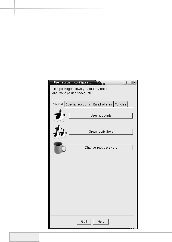
86 UNIX System Administration: A Beginner’s Guide
Modifying a User
The userconf tool can be used to make a variety of changes to user accounts
that have already been established on the system. To make a modification to an
existing account, do the following:
1. Click on the User Accounts button in the User Account Configurator main
window. The User Accounts window that contains a list of the defined
users will be displayed, as in Figure 3-12.
Figure 3-12 User Account Configurator window
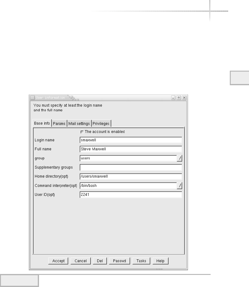
Module 3: Using System Administration Tools 87
3
2. Select the account you wish to modify by clicking it. A new window
displaying the account information is displayed, as shown in Figure 3-13.
In this example, the user account sjmaxwell has been selected.
3. Make the appropriate account change and then click the Accept button.
For instance, change the default login shell to /bin/csh.
Figure 3-13 User information for the sjmaxwell account
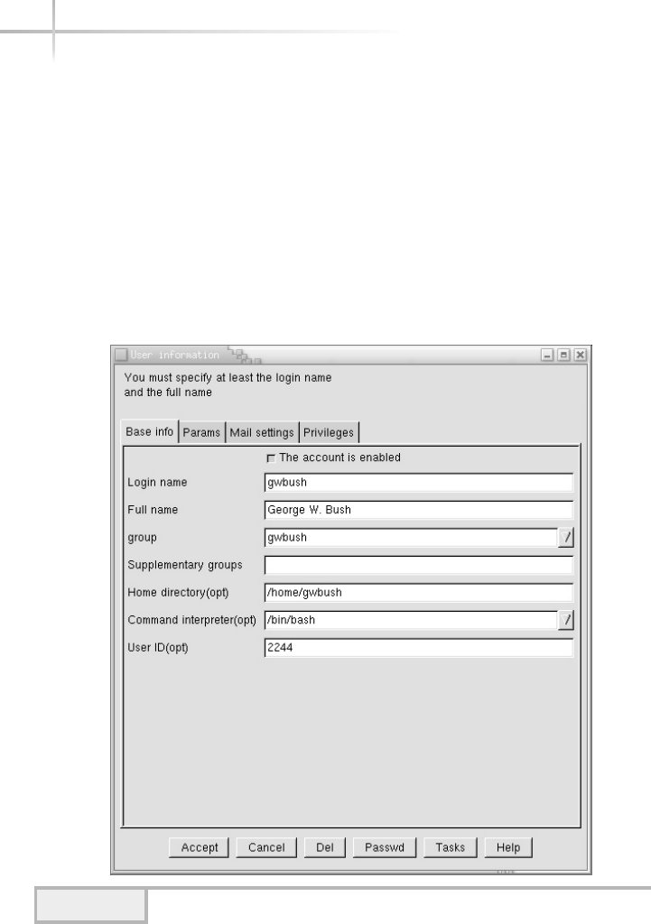
88 UNIX System Administration: A Beginner’s Guide
Delete an Existing User
To delete an existing user from the system, use the following procedure:
1. Click on the User Accounts button in the User Account Configurator
main window.
2. Click the account entry in the User Accounts window that you wish to
delete. By way of example, assume we would like to remove the gwbush
account. Clicking a user account causes the User Information window to
appear, as shown in Figure 3-14 for that account.
Figure 3-14 User Information window
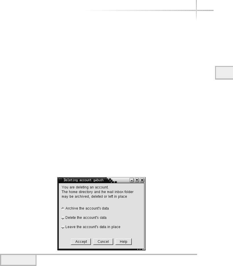
Module 3: Using System Administration Tools 89
3
3. Click the Del button and another window asking for more information
about how to delete the account will be displayed, as shown in Figure 3-15.
In the example, the account of gwbush will be deleted.
The Delete Account window contains three selection items: Archive the
Account’s Data, Delete the Account’s Data, and Leave the Account’s Data in
Place. The default, Archive the Account’s Data, will make a copy of the files
stored in the home directory and the mailbox file of the user and then delete
the account. The userconf tool builds a compressed tar archive of the
home directory (and contents) and places it in the /home/oldaccounts
directory.
The Delete the Account’s Data option will delete the home directory and
all associated files and then delete the account. The Leave the Account’s
Data in Place option will not touch the home directory or its contents,
but will delete the account from the system.
4. Select the desired account deletion option and then click the Accept
button.
Figure 3-15 Delete Account window
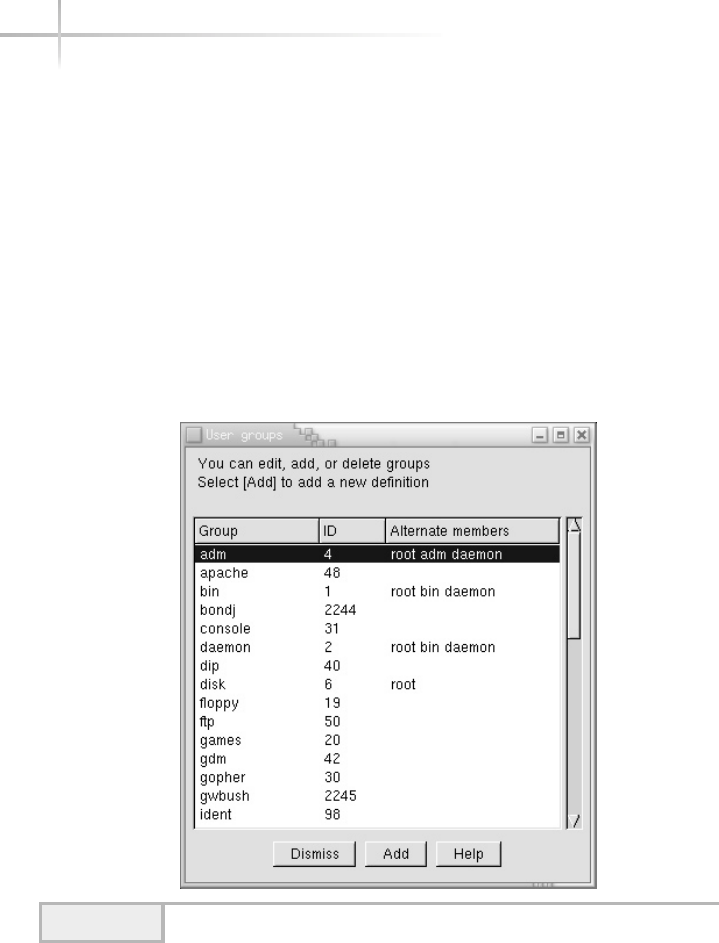
Adding a New Group
The primary purpose of a group is to associate similar users together to
make it easier for those users to share information. Groups are defined with
the /etc/group file and contain a mapping between a group name and all
members of that particular group. To create a new UNIX group, do the following:
1. Click the Group Definitions button located on the User Account
Configurator main window. As a result, a list of groups defined
on the system will be displayed, as shown in Figure 3-16.
2. Click the Add button and a new window, labeled the Group Specification
window, is displayed, as shown in Figure 3-17.
90 UNIX System Administration: A Beginner’s Guide
Figure 3-16 User Groups window
TEAMFLY
Team-Fly®
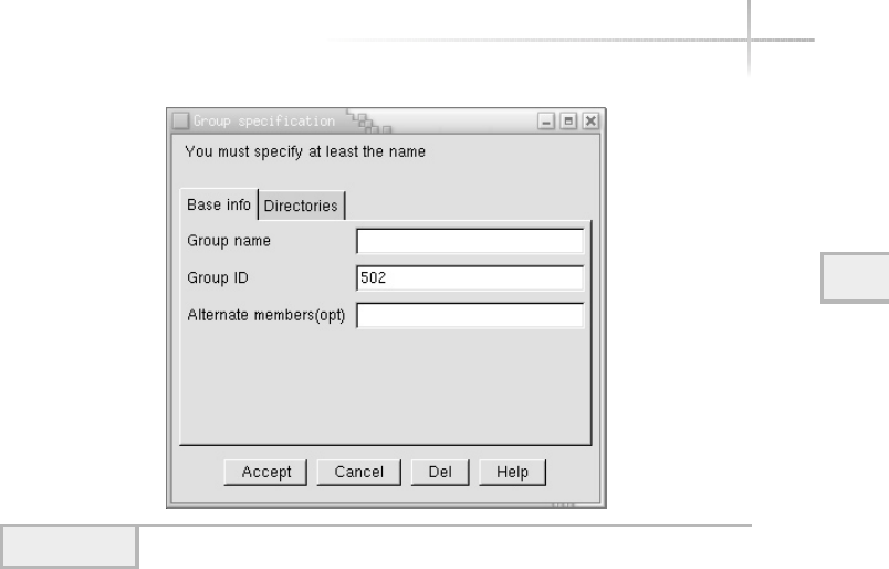
Module 3: Using System Administration Tools 91
3
This window contains three text box fields: Group Name, Group ID, and
Alternate Members. The group name is simply the name of the group you
wish to define. Like the UNIX account name, the group name should be
limited to just eight characters. The group name can be any string that
represents a collection of users. For example, the group name of eng
can represent the development staff within a particular department. The
Alternate Members field is used to contain additional UNIX users that are
members of the group.
3. Type the name of the new group in the Group Name text box.
4. You can accept the default group ID or type a new value. If you input a
new value, make sure that it doesn’t conflict with any existing groups.
5. Add additional UNIX account names to the new group using the Alternate
Members field. For instance, in Figure 3-18 the group name devel is
defined with two members: gwbush and smaxwell.
Figure 3-17 Group Specification window
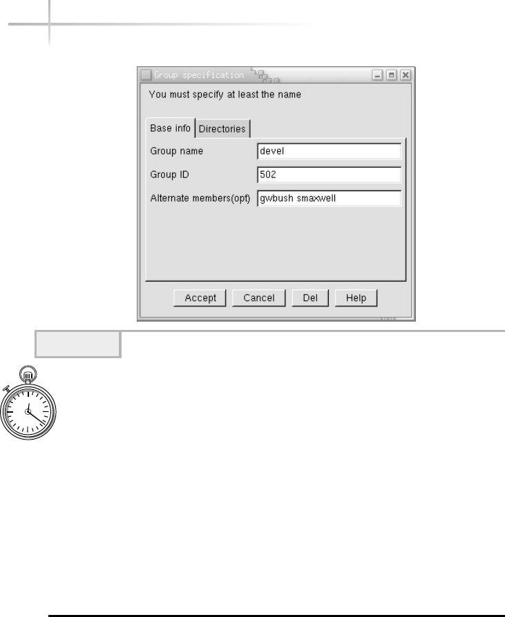
1-Minute Drill
●By default, what does the Linux userconf tool do with user data
when you delete a user account?
●What is the limit for username and group name length?
3.3 Manage HP-UX Using SAM
The sam system management tool provides a one-stop shopping experience for
the system administrator. It supports both the standard X-Windows interface
and also the regular terminal interface. Thus, it can be used with or without a
92 UNIX System Administration: A Beginner’s Guide
Figure 3-18 The Group devel name is defined.
●The userconf tool makes a copy of the files stored in the user’s home directory and mailbox file. It builds a
compressed tar archive of the home directory (and contents) and places it in the /home/oldaccounts
directory.
●Eight characters.
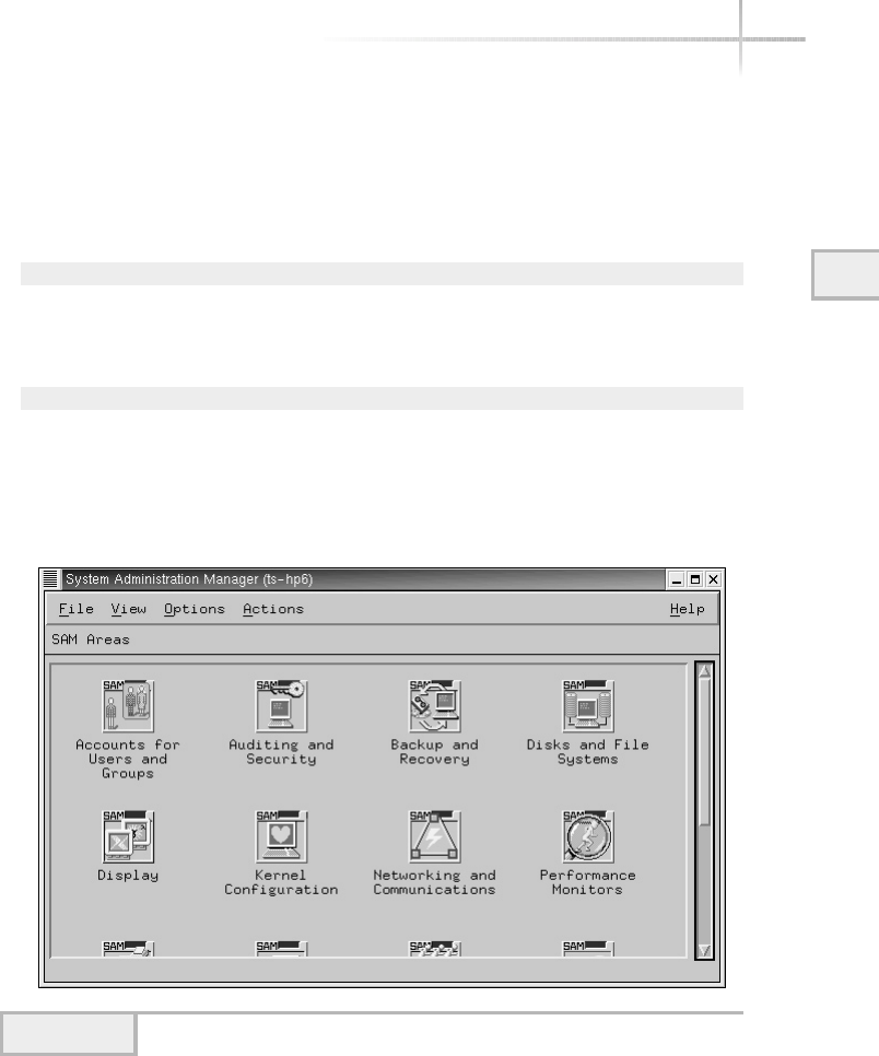
GUI, which makes this a very powerful application. The software contains a large
number of functions that help with a large variety of system administration
tasks. However, this section will review both user administration.
To run sam in the X-Windows mode and to display the console window
on the networked host called ts-hp6, issue the following command:
sam –display ts-hp6:0.0&
If you want to run using the standard non-GUI, just issue the following
command:
sam
When this program is run in X-Windows mode, it displays the main sam
window, as shown in Figure 3-19.
Module 3: Using System Administration Tools 93
3
Figure 3-19 Main sam application window

This main sam window contains four menu items and a number of icons.
The icons represent functional modules or component areas, and double-clicking
the icons will access the feature or function. The functions of the menu items
are listed in Table 3-3.
Add a New User
To add a new user to the system, use the following procedure:
1. Click the Accounts for Users and Groups button from the main sam
window. Once this has been done, a new screen is displayed as shown
in Figure 3-20.
2. Click on the Users icon and then another new window is displayed as
shown in Figure 3-21. This window shows a list of all the defined users
on the system.
3. Select the Add… item from the Actions menu. This will cause the Add a
User Account window to be displayed, as shown in Figure 3-22. Notice
that much of the account information has been filled in on the window
using the system defaults.
4. Input the name of the account in the Login Name field. Optionally, you
can add additional information about the account such as the real user’s
name, office location, and so forth. This information is added to the
optional fields listed at the bottom of the window.
94 UNIX System Administration: A Beginner’s Guide
Menu Item Meaning
File Search sam for specific string and the exit item to close the
application.
View You can change the views of the window by altering the columns.
You can also sort and view by name or icon if desired.
Options Provides access to the sam log, controls logging options, and refreshes
the display.
Actions Contains item-specific actions that can be done against selected
objects. Also, provides access to application customization functions.
Table 3-3 The sam Main Menus
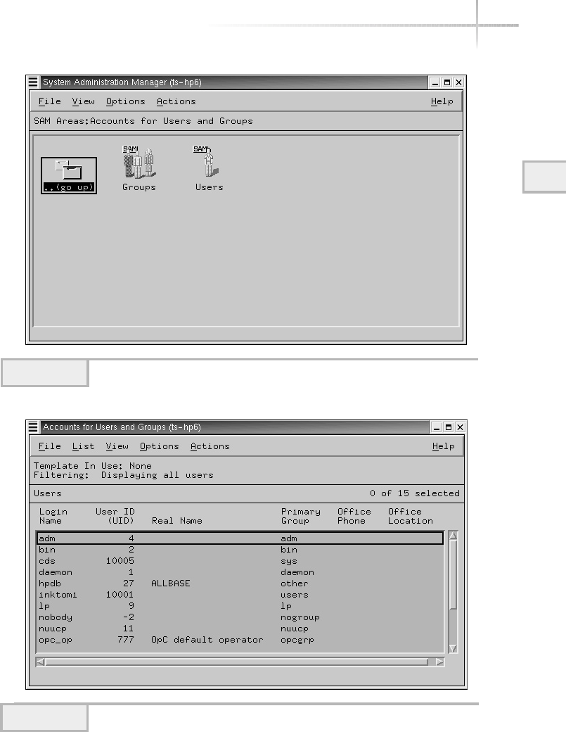
Module 3: Using System Administration Tools 95
3
Figure 3-20 Group/Users window
Figure 3-21 List of UNIX accounts
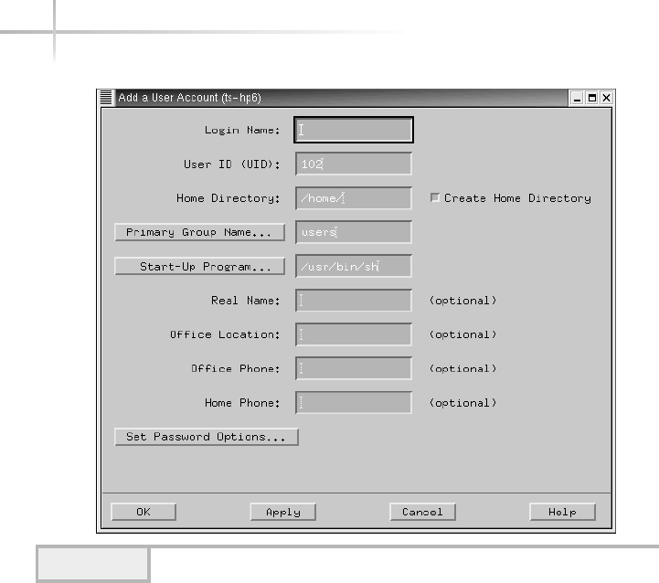
96 UNIX System Administration: A Beginner’s Guide
5. By default, the home directory is taken from the account name, which is
added to the /home entry automatically. Also, the default behavior of sam
is to create the home directory for the user.
6. If you want to change the primary group for this user, type in the group
name or select the group by clicking the Primary Group Name button and
then selecting the appropriate group entry.
7. If you want to change the default login shell, type in the new shell path
and name or select the shell by clicking the Start-Up Program button and
then selecting the appropriate shell entry.
8. Add a password to the account by clicking on the Set Password Options
button. This action will cause a dialog window to be displayed, which is
shown in Figure 3-23.
Figure 3-22 New User Account window
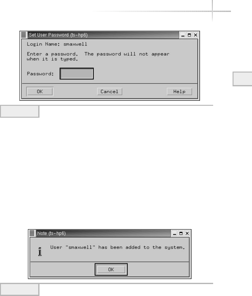
Module 3: Using System Administration Tools 97
3
Type the new password in the Password field. Note the password won’t
be echoed or displayed on the screen when you are typing. Click the OK
button and then you will be prompted to confirm the new password by typing
it in again. Click the OK button when you have entered the password for the
second time.
Assuming that no errors were encountered when the account was added to
the system, sam will display a dialog box showing the confirmation of the new
account, as shown in Figure 3-24.
Once the account has been added to the system, the list of UNIX accounts
will be updated to include the new account. For instance, when the smaxwell
user was added, this name appeared in the account list, as shown in Figure 3-25.
Figure 3-23 Password Dialog window
Figure 3-24 New account confirmation
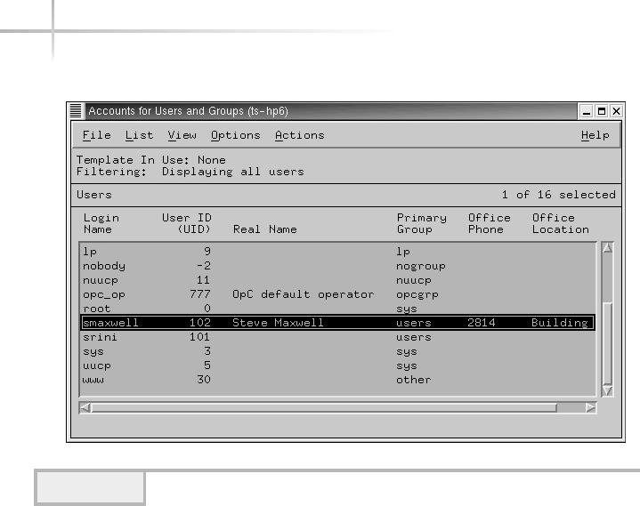
98 UNIX System Administration: A Beginner’s Guide
Modifying a User
The sam application can be used to alter an existing UNIX account. To make a
change to a user, do the following:
1. Click the Accounts for Users and Groups button from the main sam
window. When the list of accounts appears, select the account and access
the Modify menu item from the Actions menu.
2. A new window is displayed that contains detailed information about the
account you selected. Figure 3-26 shows detailed information for the
smaxwell account.
3. Make the appropriate account changes.
4. Save the changes by clicking the OK button.
Figure 3-25 The smaxwell account is displayed in the account list.
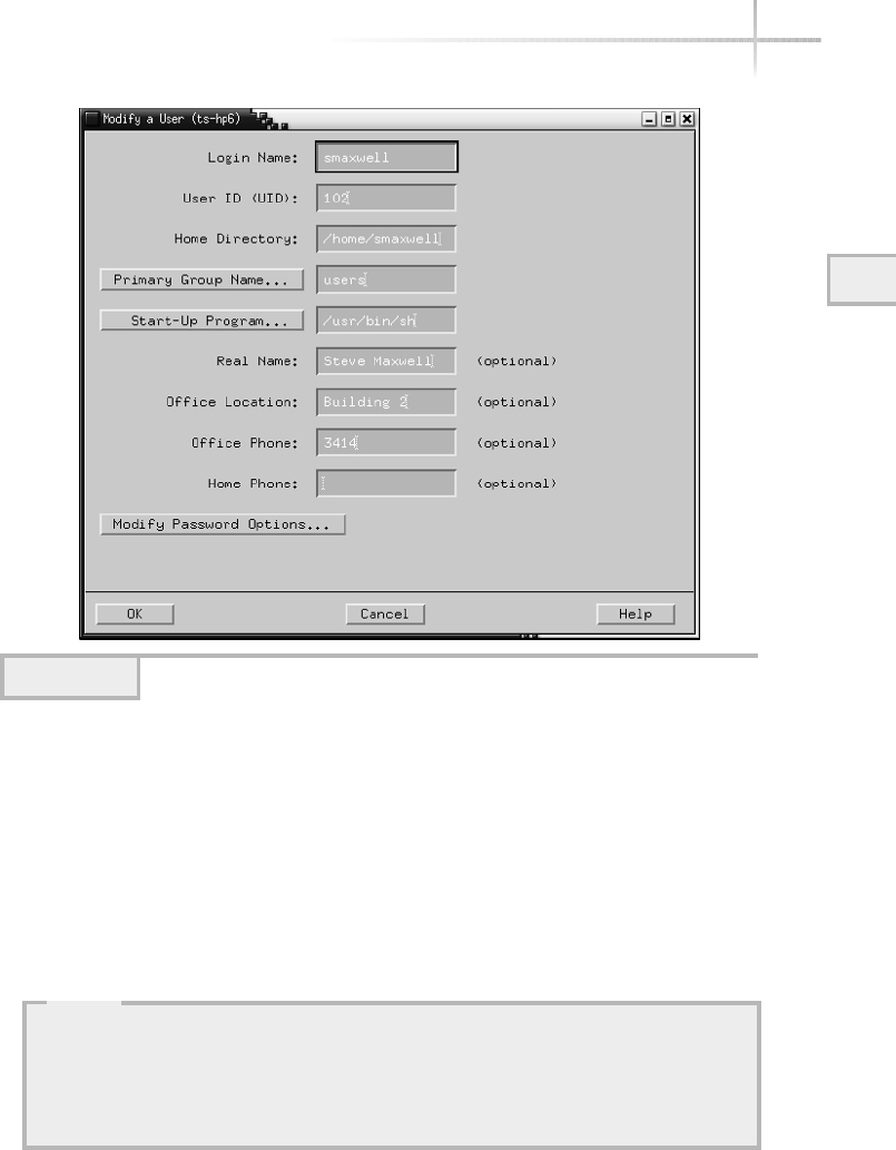
Module 3: Using System Administration Tools 99
3
Delete an Existing User
To delete an existing user from the system, use the following procedure:
1. Select the user you want to delete from the list of accounts contained in
the Accounts for Users and Groups window (shown in Figure 3-25).
2. From the Action menu, select the Remove menu item. The Remove a User
dialog window is shown in Figure 3-27.
Figure 3-26 Detailed account information
HintHint
Exercise extreme caution when removing users; as an important step in account
removal, backing up home directories to secondary storage is a requirement.
Even if you have a relatively new backup, it is very important that a fresh backup
be made to capture any files/directories that have been modified since the last
backup was taken.
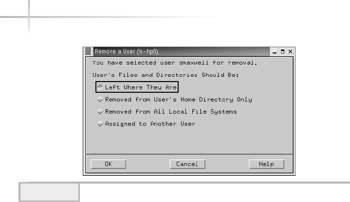
100 UNIX System Administration: A Beginner’s Guide
This window permits the system administrator to have more exact control
over the user’s home directory when the account is removed from the
system. The window contains four choices that include leaving the home
directory untouched (Left Where They Are), deleting the home contents
only (Removed from User’s Home Directory Only), removing all user’s
files within the system (Removed from All Local File Systems), and
assigning the files to another user (Assigned to Another User).
If you select the Removed from User’s Home Directory Only, then only
the files and subdirectories from the home directory will be removed,
but not other files contained in other directories or other file systems.
Selecting the Removed from All Local File Systems means that all files
owned by the user will be deleted from the system, regardless of where
the files are located. If the Assigned to Another User item is selected, a
new field is added to the window to permit you to add the name of the
user that should be assigned the files from the deleted user. This is shown
in Figure 3-28 and as you can see, you can input the username or select it
from a list of defined users by clicking the New Owner button.
3. Click the OK button and the note, as shown in Figure 3-29, will be
displayed, showing that the removal of the account has been done.
Figure 3-27 Remove a User window
TEAMFLY
Team-Fly®
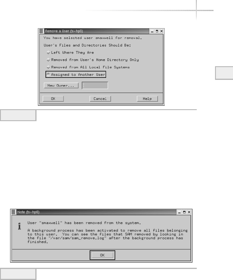
Module 3: Using System Administration Tools 101
3
Adding a New Group
To create a new UNIX group, do the following:
1. Click the Accounts for Users and Groups button from the main sam
window.
2. Click on the Groups icon and then another new window is displayed,
as shown in Figure 3-30. This window shows the list of all the defined
groups on the system.
Figure 3-28 Remove a User window
Figure 3-29 Removal Confirmation window
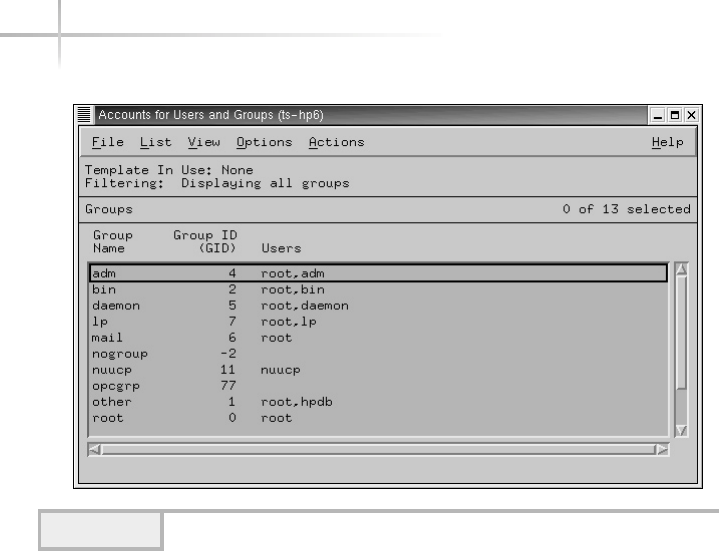
3. When the list of defined groups appears, select the Add menu item
from the Actions menu; a new window is displayed, which is depicted
in Figure 3-31.
4. Input the new group name in the Group Name field.
5. Accept the default group identification number, or input a new value.
Make sure that the new value added doesn’t conflict with any existing
groups already defined on the system.
6. As an option, you can add existing users to the new group by selecting
users from the list of defined users.
7. Click OK to save the new group.
8. Assuming no errors have occurred, a confirmation window will be
displayed, as shown in Figure 3-32, stating that the group was added
successfully.
102 UNIX System Administration: A Beginner’s Guide
Figure 3-30 Defined Groups window
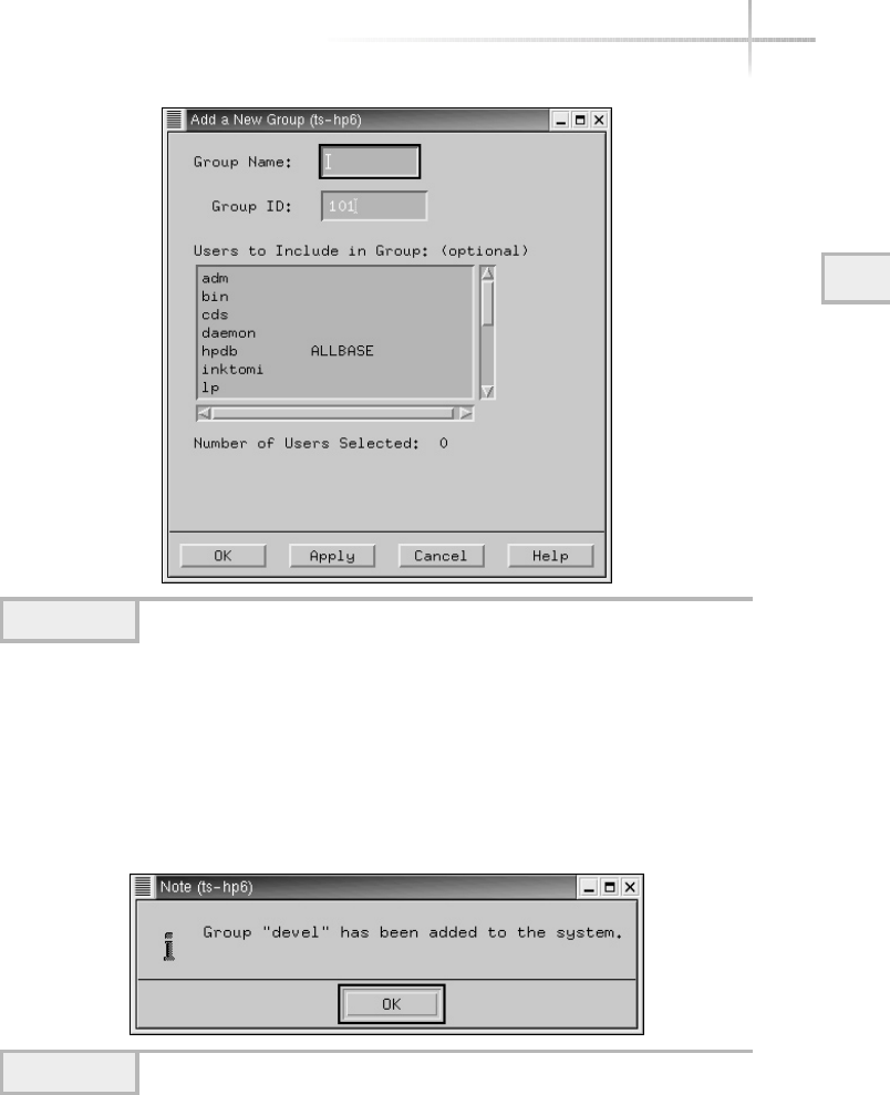
Module 3: Using System Administration Tools 103
3
Deleting an Existing Group
To delete an existing group from the system, use the following procedure:
1. Select the group you want to delete from the list of groups contained in
the Accounts for Users and Groups window (shown in Figure 3-30).
Figure 3-31 New Group window
Figure 3-32 Group Confirmation window
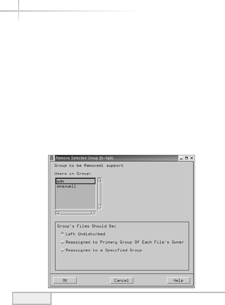
104 UNIX System Administration: A Beginner’s Guide
2. From the Action menu, select the Remove menu item. The Remove
Selected Group dialog window is shown in Figure 3-33.
When deleting a group, you must determine the consequences should files
or directories use this group definition. The Remove Selected Group window
contains three options: Leave the files that use the group untouched (Left
Undisturbed), reassign each file with the primary group of the user (Reassigned
to Primary Group of Each File’s Owner), and assign the files to a new group
(Reassigned to a Specified Group). If you leave the files untouched and remove
the group, the group’s identification number will be used when group
information is displayed.
1. Choose the appropriate action when the group is removed or simply
accept the default, which is the Left Undisturbed item.
2. Click the OK button and then dismiss the Group Confirmation window.
Figure 3-33 Remove the Group support window

Module 3: Using System Administration Tools 105
3
3.4 Set Up Better Account Security
In certain situations and computing environments, it may be necessary to have
the users change their passwords on a more frequent basis. Often, this may be
a part of a larger security regime that involves addressing security on a much
larger scale. No doubt, forcing users to change their passwords on some regular
basis is important, but one overriding factor is choosing the best frequency to
do this. Obviously, changing passwords, say, every week is quite excessive.
Equally unreasonable is permitting users to have the same passwords for many
years. A balance must be struck between maintaining a reasonable level of
security and total chaos. The answer will ultimately depend on the environment,
the view of key management, and the system administrator. The best approach
to account security is to set up a policy and enforce that policy with specific
procedures. For example, assume your policy suggests that every 90 days all
individual account passwords must be changed. As a result, you would use the
admintool,sserconf, or sam to configure accounts accordingly.
Each provides flexible control over how the administration of account
passwords is handled. In particular, you can control the expiration of passwords
for individual user accounts, disable one or more accounts, place boundaries
over the use of accounts, and warn the user of pending password changes.
Ask the ExpertAsk the Expert
Question Why is forcing the users to change their passwords on
a regular basis important?
Answer If users use the same password a long time without changing
it, this increases the chance their password will be compromised either
accidentally or through others intentionally trying to gain unauthorized
access to their account.

106 UNIX System Administration: A Beginner’s Guide
Expiring a Password Using Admintool
To control the expiration of an account password, thus forcing the user to
change the password the next time they log into the system, do the following:
1. Select an account name from the scrollable list and access the Modify
menu item from the Edit menu.
2. Or, double-click the account name and the Admintool: Modify User
window will be displayed.
3. The expiration date for an account can be selected from the Expiration
Date option boxes. The format is day, month, and then year. Use the
mouse to select each of the items until you have a valid date. Also, you
can warn the user ahead of the expiration by adding a positive number in
the Warning text box. This will give the user a “heads up” that they will
need to change their password in the near future. Figure 3-34 shows the
stevem account, which has been configured to expire the password on
October 22, 2002.
Expiring a Password Using Userconf
To control the expiration of an account password, thus forcing the user to
change the password the next time they log into the system, do the following:
1. Select the account from the list of defined UNIX accounts shown in the
Users Accounts window you wish to expire, which is from the User
Accounts button on the main userconf window.
2. Select the Params tab from the User Information window.
3. Input the desired number of days to expire the password in the Must
Keep # Days field, as shown in Figure 3-35.
4. De-select the Ignored item.
5. Click the Accept button.
In the example, the number of days entered was 30. This means that 30 days
from the current date, the system will prompt for a new password automatically.
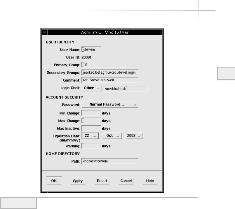
Module 3: Using System Administration Tools 107
3
Expiring a Password Using SAM
To control the expiration of an account password, thus forcing the user to
change the password the next time they log into the system, do the following:
1. Select an account name from the scrollable list, which is found from the
Accounts for Users and Groups window, and select the Modify option
from the Action menu.
2. Click the Set Password Options button on the User Account window.
A new window is displayed, as shown in Figure 3-36.
Figure 3-34 Modify User window with expiration of password
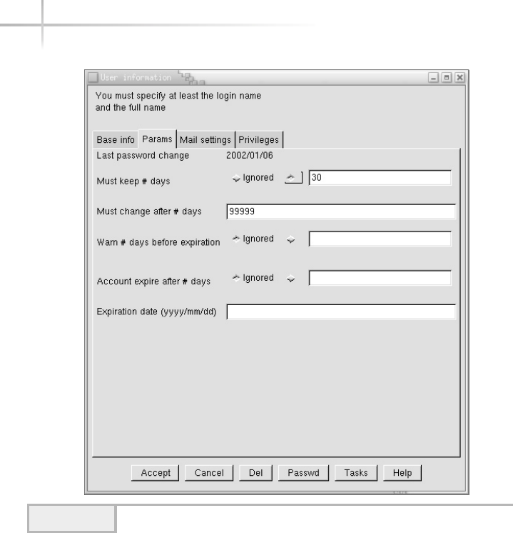
3. Select Enable Password Aging from the Password Options field if it is not
already selected.
4. Enter the expiration time in the Password Expiration Time (1-63 weeks)
field that you require for this account. In this example, two weeks was
entered.
5. Click the OK button to dismiss this window and accept the change.
108 UNIX System Administration: A Beginner’s Guide
Figure 3-35 Params panel
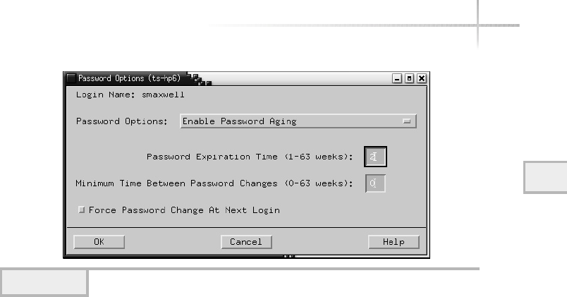
Module 3: Using System Administration Tools 109
3
Regular Password Changes Using Admintool
To incorporate automatic password aging for user accounts, do the following:
1. Select an account name from the scrollable list and access the Modify
menu item from the Edit menu.
2. Or, double-click the account name and the Admintool: Modify User
window will be displayed.
3. Enter the number of days that represents the period of time for the
password to expire in the Max Change field. For example, assume
that you want the password to be changed every 60 days, enter 60
in this field, as shown in Figure 3-37.
4. Enter the number of days to warn the user about the impending
password change.
5. Click the OK button to save this change.
Figure 3-36 Password Options window
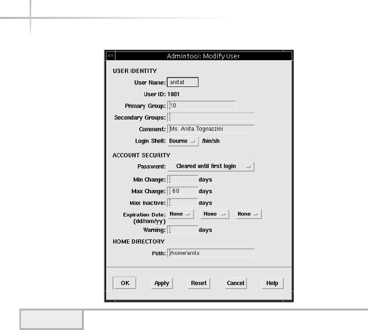
110 UNIX System Administration: A Beginner’s Guide
Regular Password Changes Using Userconf
To set up automatic password aging for user accounts, do the following:
1. Select the account from the list of defined UNIX accounts shown in the
Users Accounts window you wish to change, which is from the User
Accounts button on the main userconf window.
2. Select the Params tab from the User Information window.
3. Input the number of days that the password must be changed in
the Must Change After # Days field.
4. Figure 3-38 shows the value of 45 in this field, which indicates that
every 45 days the user will be prompted to change the password.
5. Click the Accept button.
Figure 3-37 Modify User window with 60-day expiration
TEAMFLY
Team-Fly®

Module 3: Using System Administration Tools 111
3
Turning Off an Account Using Admintool
Sometimes it may become necessary to disable one or more accounts so that
those users don’t have access to the system. This might be due to an employee
leaving the company or department, or even because they simply haven’t used
the system in such a long time that you might need to investigate if they should
have an account at all.
To disable an existing account, do the following procedure:
1. Select an account name from the scrollable list and access the Modify
menu item from the Edit menu.
2. Or, double-click the account name and the Admintool: Modify User
window will be displayed.
Figure 3-38 Force password change every 45 days
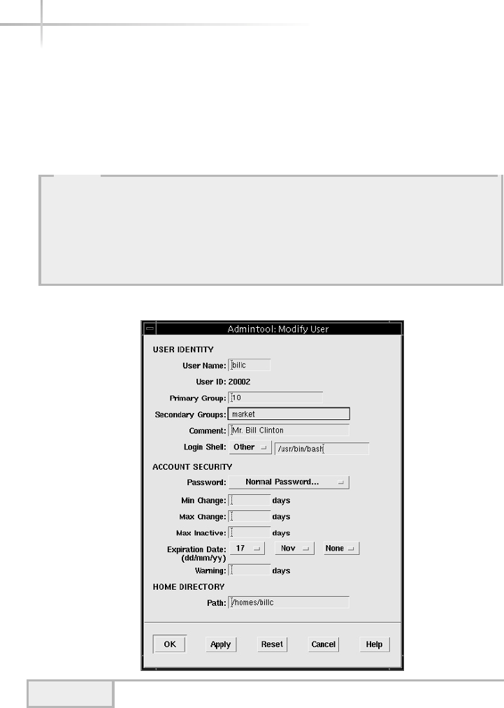
112 UNIX System Administration: A Beginner’s Guide
3. From the Password Selection box, select the Account Is Locked item,
as shown in Figure 3-39. In the example, the account named billc has
been locked.
4. Select the OK button to save the change.
Figure 3-39 Locking the billc UNIX account
HintHint
When a user attempts to access an account that has been locked, no special
message will appear to the user. Instead, they will simple get a Login Incorrect
message. This is a generic message, which can mean other things as well—for
example, that no account is actually present on the system. It will be up to the
user to request additional information as to the actual reason why the account
no longer functions.
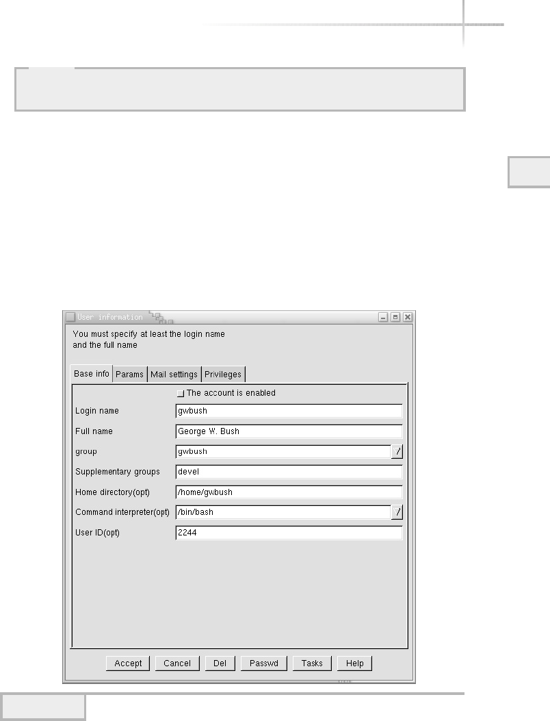
Module 3: Using System Administration Tools 113
3
Turning Off an Account Using Userconf
To disable an existing account, do the following:
1. Select the account from the list of defined UNIX accounts shown in the
Users Accounts window you wish to change, which is from the User
Accounts button on the main userconf window.
2. Click the The Account Is Enabled selection box located on the top of
the User Information window, as shown in Figure 3-40.
3. Click the Accept button.
Figure 3-40 Disabling the smaxwell UNIX account
HintHint
To unlock a locked account select Normal Passwd selection item and input the
new password for this account.

114 UNIX System Administration: A Beginner’s Guide
Automatic Account Expiration Using Userconf
You can automatically expire one or more accounts after some fixed period
of time has elapsed. This means that the system administrator can plan to
have an account disabled in the future. For instance, the account could be
used by a temporary employee that will leave the company after their contract
is complete, and you want to ensure that they no longer have access to the
system. To set up a future expiration date for a UNIX account, do the following:
1. Select the account from the list of defined UNIX accounts shown in the
Users Accounts window you wish to change, which is from the User
Accounts button on the main userconf window.
2. Select the Params tab from the User Information window.
3. Input the future expiration date in the Expiration Date
(yyyy/mm/dd) field.
4. Click the Accept button.
In the example, the expiration date of September 1, 2002
(2002/09/01) has been entered, as shown in Figure 3-41. This means
that on this date, the login will not be accessible any longer.
HintHint
To unlock a disabled account, click the The Account Is Enabled selection box.
HintHint
Another expiration parameter can be entered that includes the number of days
to warn the user before the expiration occurs (Warn # Days Before Expiration).
Also, instead of using a fixed date, you can use the number of future days to
determine when the account should expire. This information is added to the
Account Expire After # Days field.
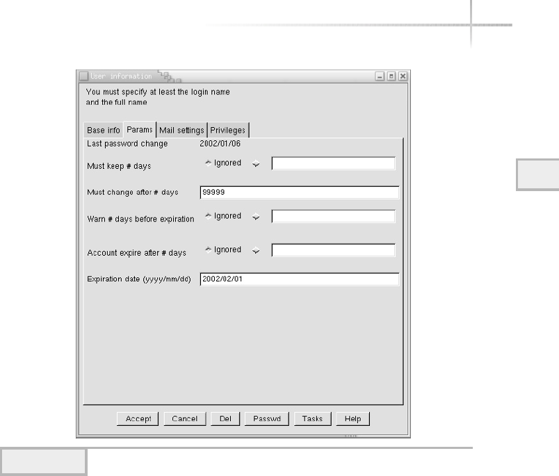
Module 3: Using System Administration Tools 115
3
Figure 3-41 Account Expiration From User Information window

116 UNIX System Administration: A Beginner’s Guide
Mastery Check
1. True or False: When using admintool to add group members, include a
space between each member in the list.
2. When you add a new user account named gwsmith in Linux using the
userconf& tool and don’t specify a home directory, what directory will
userconf& use as the home directory?
3. Which window do you use in admintool to set a password expiration date
for a user?
4. In userconf, which tab and window do you use to set up regular password
change intervals for a user?
5. In userconf, which button do you click to open the window to create a
new group?
6. In HP-UX SAM, what are the menu commands to delete an existing user
account?
7. True or False: When using admintool to add new users, admintool
automatically selects the next available user ID.
8. In the User Accounts window in userconf, the __________ field is used to
specify which command shell should be started when the user logs in to
the system.
9. Which of the following is not an option for what to do with the users files
when deleting a user account in HP-UX with SAM?
A. Left Where They Are
B. Archive the Account’s Data
C. Removed from ALL Local File Systems
D. Assigned to Another User
10. Which UNIX file contains the list of users for the system?
11. Which UNIX file contains the list of groups and the group members for
the system?

Module4
Software Package
Management Tools
Critical Skills
4.1 Discover Solaris Package Tools
4.2 Discover HP-UX Package Tools
4.3 Discover Linux Package Tools
Copyright 2002 by The McGraw-Hill Companies, Inc. Click Here for Terms of Use.

118 UNIX System Administration: A Beginner’s Guide
This module provides an introduction into using the standard package
management tools that are native to the different versions of UNIX. As such,
it provides a step-by-step approach for doing actual package management
functions that include installing, removing, and verifying installed software.
In the early days of UNIX, many of the third-party tools, public domain
software, and commercial applications vendors used to distribute their software
using standard package formats such as tar or cpio. These utilities were great
for handling the archiving of a large number of files, but they failed as a general-
purpose software management mechanism. Today, many UNIX system vendors
use package distribution formats to make it easier to move self-contained software
modules from distribution media, such as CD-ROMs to the system instead of
using tools such as tar. Unfortunately, many of the UNIX vendors support their
own particular format and these are typically not compatible with other vendors’
package structures. As a result, when you purchase a product, say for HP-UX, you
must use the HP-UX installation tools to get the product installed.
Generally speaking, you must use the operating system package utilities to
maintain system level software since many software vendors and public domain
tools support the native package format. However, many public domain tools
generally provide an operating system package and other formats as well. For
example, the SSH secure shell software is available in several package formats,
including for Solaris, HP-UX, and Linux.
Table 4-1 shows a breakdown of the package management tools that are
available for Solaris, HP-UX, and Linux. These individual tools, for each of the
operating systems, are described in the following sections.
Operating System Package Tools
Installation Removal Informational
Solaris pkgadd pkgrm pkginfo
HP-UX swinstall swremove swlist
Linux rpm –-install rpm –-erase rpm --query
Table 4-1 UNIX Software Package Management Tools

4
4.1 Discover Solaris Package Tools
The Solaris system provides the basic package tools that include
pkginfo
pkgadd
pkgrm
pkginfo
The package information tool pkginfo is used to list all of the installed
packages on a system or query information about a package in general, regardless
if it has already been installed. This is most useful if you are not sure if a
particular package is installed or if you want to obtain a working inventory of
packages installed on a series of machines. You must have root privileges to
execute the Solaris package commands.
To see all the packages on a given system, use the following command:
# pkginfo | more
Sample output might include
system FFNrand ffrandom-0.6
application FFNsman FastForward Networks service manager
application NSCPcom Netscape Communicator
application NSCPdecom German Netscape Communicator
application NSCPescom Spanish Netscape Communicator
application NSCPfrcdo French Netscape Communicator (U.S. security)
application NSCPfrcom French Netscape Communicator (International security)
application NSCPitcom Italian Netscape Communicator
application NSCPsvcom Swedish Netscape Communicator
utility OPENssh OpenSSH 2.2.0p1 sparc
system SMEvplr SME platform links
system SMEvplu SME usr/platform links
system SUNW1251f Russian 1251 fonts
ALE SUNW5ttf Traditional Chinese BIG5 True Type Fonts Package
ALE SUNW5xmft Chinese/Taiwan BIG5 X Windows Platform minimum
required Fonts Package
system SUNWaccr System Accounting, (Root)
system SUNWaccu System Accounting, (Usr)
system SUNWadmap System administration applications
4
Module 4: Software Package Management Tools 119
Package description
Package name
Package type
classification

120 UNIX System Administration: A Beginner’s Guide
system SUNWadmc System administration core libraries
system SUNWadmfw System & Network Administration Framework
system SUNWadmj Admin/Install Java Extension Libraries
--More--
When invoked, it shows all the available Solaris packages installed, sorted
by the classification of package types. The output of this command is sent to
the more command, which permits the user to peruse the output one screen
full at a time. Hitting the SPACEBAR on the keyboard displays another screen of
text. When packages are created, they contain a primary category parameter,
which denotes the classification of application the software represents. The
most common categories are system,application, and utility. For
example, as you can see from the preceding output, the Netscape package falls
under the application package calls, which makes complete sense given that
Netscape is a Web browser application. A quick scan of the available packages
installed on a generic system reveals that both system and application are
the most widely installed types of software.
The pkginfo tool (as well as the other tools) supports several important
and common command line options as shown in Table 4-2.
Command Definition
-a Display the architecture of the package.
-c Display all packages that match the specified category.
-d Defines the device, directory name, or individual package name
to query for package information.
-i Display information on complete installed packages.
-l Display additional package information in a long format.
-p Display information on only partially installed packages.
-q Used by an external program to determine if a package is installed.
Doesn’t show any output.
-r Display the installation directory base for any packages that have
been relocated.
-R Defines the directory to be used as the root path for packages.
-v Display packages with the specified version information.
-x Display extract listing information from a package.
Table 4-2 pkginfo Command-Line Options
TEAMFLY
Team-Fly®

444
One of the most important is the –d option, which tells the program
where to look to determine information about one or more packages. This
option is used to specify the hardware device, which contains the packages
(that is, CD-ROMs) or other media. However, it can also be used when a single
package is specified, or even a directory name. For example, let’s assume we
would like to examine the contents of the Solaris 8 Companion CD-ROM,
which contains useful tools and utilities. In general, we need to specify the
directory where the packages are located. The command
# pkginfo -d /cdrom/s8_software_companion/components/i386/Package
shows all the packages available under the /cdrom/s8_software_companion/
components/i386/Package directory. The following output shows a partial
list of the available packages:
system SFWaalib aalib - ASCII Art Library
system SFWaconf autoconf - GNU autoconf
system SFWamake automake - GNU automake
system SFWasclk asclock - the AfterStep clock
system SFWastep afterstep - X11 window manager
system SFWaufl audiofile - audio library
system SFWbdb Berkeley DB - database library
system SFWbison GNU bison - a better yacc
system SFWcdrec cdrecord - record audio or data Compact Discs
system SFWcvs cvs - version control system
system SFWddd DDD - GNU Data Display Debugger
system SFWdiffu diffutils - GNU diffutils
system SFWemacs GNU Emacs - Editor
system SFWenscr GNU enscript - convert text files to PostScript
system SFWesd esound - The Enlightened Sound Daemon
system SFWethrl Ethereal - Interactively browse network traffic
system SFWexpct expect - programmed dialogue with programs
system SFWfile file - determine file type
system SFWflex GNU flex - a lex replacement
system SFWfnlib fnlib - X11 font rendering library
system SFWftype Freetype - Free TrueType Rendering Engine
system SFWfvwm fvwm - X11 virtual window manager
system SFWgawk gawk - pattern scanning and processing language
system SFWgbin binutils - GNU binary utilities
system SFWgcal gcal - the GNU Gregorian calendar program
system SFWgcc gcc - GNU Compiler Collection
system SFWgcmn gcmn - Common GNU package
Module 4: Software Package Management Tools 121
4

122 UNIX System Administration: A Beginner’s Guide
system SFWgdb gdb - GNU source-level debugger
system SFWgfile fileutils - GNU file management utilities
system SFWgfind findutils - GNU find utilities
system SFWgimp gimp - GNU Image Manipulation Program
system SFWglib GLIB - Library of useful routines for C programming
system SFWgm4 GNU m4 - macro processor
system SFWgmake gmake - GNU make
system SFWgnome Gnome - X11 Windowing Environment
system SFWgplot gnuplot - The Gnuplot Plotting Utility
system SFWgrep grep - GNU grep utilities
system SFWgroff GNU groff - document formatting system
system SFWgs GNU Ghostscript - postscript interpreter
system SFWgsfot GNU Ghostscript Fonts - Other Fonts
system SFWgsfst GNU Ghostscript Fonts - Standard Fonts
system SFWgtar gtar - GNU tar
We can also obtain information on individual packages on the command
line. Thus,
# pkginfo -d /cdrom/s8_software_companion/components/i386/Packages SFWtop
system SFWtop top - display information about processes
In this case, we specified the top (SFTop) system-monitoring package, which
provides additional information about the package. To learn even more about
a particular package, the –l option, which displays a long listing, can be used:
# pkginfo -l -d /cdrom/s8_software_companion/components/i386/Packages SFWtop
PKGINST: SFWtop
NAME: top - display information about processes
CATEGORY: system
ARCH: i386
VERSION: 3.5_12,REV=2001.02.19.04.12
BASEDIR: /opt
VENDOR: ftp://ftp.groupsys.com/pub/top
DESC: top - display and update information about the top cpu processes
PSTAMP: freeware20010219074803
HOTLINE: Please contact the owners of this software
STATUS: spooled
FILES: 10 spooled pathnames
4 directories
1 executables
4 package information files
99 blocks used (approx)
2425 blocks used (approx)
Directory where package
will be installed

Module 4: Software Package Management Tools 123
4
The output displayed shows much more information about the package, and
includes information about where the package will be installed, the size of the
package, and other important details.
1-Minute Drill
●Why is the more command useful in conjunction with pkginfo?
pkgadd
When it is necessary to install a new package or upgrade an existing one, the
pkgadd command can be used. This tool uses the same command-line arguments
as pkginfo. For example, to install a single package that is specified on the
command line, we could use the following command:
# pkgadd -d /cdrom/s8_software_companion/components/i386/Packages SFWtop
Processing package instance <SFWtop> from </cdrom/s8_software_companion/components/
i386/Packages>
top - display information about processes
(i386) 3.5_12,REV=2001.02.19.04.12
Top users/processes display for Unix
Version 3
This program may be freely redistributed,
but this entire comment MUST remain intact.
Copyright (c) 1984, 1989, William LeFebvre, Rice University
Copyright (c) 1989 - 1994, William LeFebvre, Northwestern University
Copyright (c) 1994, 1995, William LeFebvre, Argonne National Laboratory
Copyright (c) 1996, William LeFebvre, Group sys Consulting
DISCLAIMER
"top" is distributed free of charge. It should not be considered an
official product of Group sys Consulting. William LeFebvre supports
"top" in his spare time and as time permits.
NO WARRANTY:
BECAUSE "top" IS DISTRIBUTED FREE OF CHARGE, THERE IS ABSOLUTELY NO
WARRANTY PROVIDED, TO THE EXTENT PERMITTED BY APPLICABLE STATE LAW.
EXCEPT WHEN OTHERWISE STATED IN WRITING, GROUP SYS CONSULTING, ARGONNE
NATIONAL LABORATORY, NORTHWESTERN UNIVERSITY, WILLIAM N. LeFEBVRE
AND/OR OTHER PARTIES PROVIDE "top" "AS IS" WITHOUT WARRANTY OF ANY
KIND, EITHER EXPRESSED OR IMPLIED, INCLUDING, BUT NOT LIMITED TO, THE
IMPLIED WARRANTIES OF MERCHANTABILITY AND FITNESS FOR A PARTICULAR
PURPOSE. THE ENTIRE RISK AS TO THE QUALITY AND PERFORMANCE OF THE
PROGRAM IS WITH YOU. SHOULD THE "top" PROGRAM PROVE DEFECTIVE, YOU
ASSUME THE COST OF ALL NECESSARY SERVICING, REPAIR OR CORRECTION.
●If you have a lot of packages installed on your system, piping the results of pkginfo to more makes it easier
to read them by displaying them one screen at a time.
Package name to install

IN NO EVENT WILL GROUP SYS CONSULTING, ARGONNE NATIONAL LABORATORY,
NORTHWESTERN UNIVERSITY, WILLIAM N. LeFEBVRE, AND/OR ANY OTHER PARTY
WHO MAY MODIFY AND REDISTRIBUTE "top", BE LIABLE TO YOU FOR DAMAGES,
INCLUDING ANY LOST PROFITS, LOST MONIES, OR OTHER SPECIAL, INCIDENTAL
OR CONSEQUENTIAL DAMAGES ARISING OUT OF THE USE OR INABILITY TO USE
(INCLUDING BUT NOT LIMITED TO LOSS OF DATA OR DATA BEING RENDERED
INACCURATE OR LOSSES SUSTAINED BY THIRD PARTIES OR A FAILURE OF THE
PROGRAM TO OPERATE WITH OTHER PROGRAMS) THE PROGRAM, EVEN IF YOU HAVE
BEEN ADVISED OF THE POSSIBILITY OF SUCH DAMAGES, OR FOR ANY CLAIM BY
ANY OTHER PARTY.
So there!
YOU MUST OBSERVE ANY AUTHORS' CONDITIONS WITH RESPECT TO
INDIVIDUAL COMPONENTS PROVIDED WITHIN THIS CODE. SUPPORT
FOR THE TECHNOLOGIES AND DOCUMENTATION IS NOT PROVIDED
BY SUN MICROSYSTEMS, INC.
THE TECHNOLOGIES AND DOCUMENTATION ARE PROVIDED "AS IS" WITHOUT TECHNICAL
SUPPORT OR WARRANTY OF ANY KIND, EITHER EXPRESS OR IMPLIED, INCLUDING, BUT NOT
LIMITED TO, THE IMPLIED WARRANTIES OF MERCHANTABILITY, FITNESS FOR A
PARTICULAR PURPOSE, OR NON-INFRINGEMENT.
Using </opt> as the package base directory.
## Processing package information.
## Processing system information.
## Verifying package dependencies.
## Verifying disk space requirements.
## Checking for conflicts with packages already installed.
## Checking for setuid/setgid programs.
This package contains scripts which will be executed with super-user
permission during the process of installing this package.
Do you want to continue with the installation of <SFWtop> [y,n,?] y
Installing top - display information about processes as <SFWtop>
## Installing part 1 of 1.
Installation of <SFWtop> was successful.
The above command installs the top utility on a Solaris system, and as you
can see, a fair amount of output was generated showing all the steps involved
with the installation process. Note that the Solaris package tools are sophisticated
enough to prompt the user should it be necessary to query for additional
information. This is one of the most powerful features of these tools—to install
software components in an intelligent manner regardless of the target platform.
pkgrm
In order to remove one or more packages, use the pkgrm command. The basic
syntax of this command requires the name of the package that should be
removed. For example, to remove the FTP client application, SMCxftp, issue
the following command:
# pkgrm SMCxftp
124 UNIX System Administration: A Beginner’s Guide
Installer prompt waiting for your input before continuing.
Installer message
informing you
where the package
is being installed.

4
The resulting output is shown:
The following package is currently installed:
SMCxftp xftp
(sparc) 2.1
Do you want to remove this package? yes
## Removing installed package instance <SMCxftp>
## Verifying package dependencies.
## Processing package information.
## Removing pathnames in class <none>
/usr/local/man/man1/xftp.1
/usr/local/man/man1 <shared pathname not removed>
/usr/local/man <shared pathname not removed>
/usr/local/lib/XFtp.ad
/usr/local/lib
/usr/local/doc/xftp/README
/usr/local/doc/xftp/NEW_FEATURES
/usr/local/doc/xftp/CHANGES
/usr/local/doc/xftp/BUGS
/usr/local/doc/xftp
/usr/local/doc
/usr/local/bin/xftp
/usr/local/bin <shared pathname not removed>
## Updating system information.
Removal of <SMCxftp> was successful.
As you can see from this output, the pkgrm tool prompts the user to ensure that
removal of the specified package is in fact desired. Once done, it also displays all the
files that are being removed from the system that are associated with this package. Please
note that the pkgrm command must be supplied with the actually package name,
not the file that was used to contain the package. For example,
# pkgrm xftp
pkgrm: ERROR: no package associated with <xftp>
doesn’t work and produces an associated error message. If you don’t know the
actually package name, use the pkginfo command to find out:
# pkginfo -d xftp-2.1-sol8-sparc-local
application SMCxftp xftp
Note that once a package has been removed from the system, any associated
files and/or programs are permanently removed.
Module 4: Software Package Management Tools 125
4
Your response to prompt
Prompt asking
you to confirm
removing package

126 UNIX System Administration: A Beginner’s Guide
4.2 Discover HP-UX Package Tools
The HP-UX system provides the basic package management tools that include
swlist
swinstall
swremove
swlist
To display information about the installed product on a HP-UX system, use the
swlist package management command. This command has a large number of
command line arguments, but the most common ones are listed in Table 4-3.
You must have root privileges to execute the HP-UX package commands.
The most basic use of the command is to show the currently installed
products on a system. The command that you would use is
# swlist
Option Meaning
-a Display a list of products by attribute.
-d Display a list of products that are available from a depot, not from the
local system.
-I Invoke the interactive user interface, which can be used on regular terminals.
-l Display a list of objects that correspond to a specific level. This is how to
show the detailed components that make up a particular package.
-r Display a list of products that are installed on an alternative root file system.
-v Display more detailed information regarding products.
Table 4-3 Common swlist Command-Line Options

Module 4: Software Package Management Tools 127
4
When this command is executed, it displays a list of the currently installed
products on the local system. The example output generated includes
# Initializing...
# Contacting target "boston-srv"...
# Target: boston-srv:/
# Bundle(s):
#
A4929A B.11.00.11 1000Base-T PCI Gigabit Ethernet Driver
A5158A B.11.00.02 HP PCI Tachyon TL Fibre Channel
B3701AA C.02.40.000 HP GlancePlus/UX Pak for s800 11.0
B3901BA B.11.01.20 HP C/ANSI C Developer's Bundle for HP-UX 11.00 (S800)
B3913DB C.03.25 HP aC++ Compiler (S800)
B3919EA_2A5 B.11.00 Special Edition HP-UX Unlimited-User Lic
B3929BA B.11.00 HP OnLineJFS (Advanced VxFS)
B5456CA C.01.18.01 HP-UX Development Kit for Java*
B8342AA B.11.00.03 Netscape Communicator 4.72
B8723AA A.01.02 CIFS/9000 Client Lic. for 9000 Servers
B8725AA A.01.02 CIFS/9000 Server Lic. for 9000 Servers
HPUXEng64RT B.11.00 English HP-UX 64-bit Runtime Environment
OnlineDiag B.11.00.13.16 HPUX 11.0 Support Tools Bundle
XSWECO226 A.1.0 Patch Replacement bundle
XSWGR1100 B.11.00.49.3 HP-UX General Release Patches, June 2000
XSWHWCR1100 B.11.00.49.3 HP-UX Hardware Enablement and Critical Patches, June
2000
#
# Product(s) not contained in a Bundle:
#
PHCO_21492 1.0 Software Distributor (SD-UX) Cumulative Patch
PHKL_22209 1.0 fix f_cred, fork DPFs & accept(2) errors
PHNE_22397 1.0 cumulative ARPA Transport patch
perl 5.6.0 perl
In this example, the system boston-srv was probed with the swlist
command, and it shows that a variety of software packages have been installed
on the system. The list of packages are broken down into two categories:
products contained with a bundle and products that are stand-alone. Products
within a bundle simply mean that the package contains a series of files or
other objects and the name of the bundle is a container. As you can see from
the output, the B8342AA bundle, for instance, corresponds to the Netscape
Communicator 4.72 application, while the nonbundle applications include
the perl 5.6.0 module.

Specifying a package to swlist command, the administrator can drill
down and obtain more detailed information about a product or bundle. Thus,
the command
# swlist A4929A
shows the elements of the A4929A package:
# Initializing...
# Contacting target " boston-srv "...
#
# Target: boston-srv:/
#
# A4929A B.11.00.11 1000Base-T PCI Gigabit Ethernet Driver
# A4929A.GE-DRV B.11.00.11 HP PCI/GSC Gigabit Ethernet Driver
A4929A.GE-DRV.GE-KRN B.11.00.11 Gigabit Ethernet Kernel Software Distribution
A4929A.GE-DRV.GE-RUN B.11.00.11 Gigabit Ethernet Runtime Software Distribution
If we desire even more information and details about this package, we can use
the –v option, which provides quite a fair amount of information for each
element within the package. The command
swlist -v A4929A
will produce the following output for the network driver:
# Initializing...
# Contacting target "boston-srv"...
#
# swlist Installed Software Table of Contents
#
# For host: boston-srv:/
# Date: Mon Dec 31 00:17:38 2001
#
# A4929A
vendor
tag HP
uuid
title "Hewlett-Packard Company"
description "Hewlett-Packard Company
"
end
bundle
128 UNIX System Administration: A Beginner’s Guide
HintHint
The output below was shortened for brevity since several pages were
generated by the above command.

4
tag A4929A
software_spec A4929A,r=B.11.00.11,a=HP-UX_B.11.00_32/64,v=HP
data_model_revision 2.40
instance_id 1
control_directory A4929A
size 1370913
revision B.11.00.11
title 1000Base-T PCI Gigabit Ethernet Driver
description "Vendor Name Hewlett-Packard Company
This bundle contains the software drivers for the HP 1000Base-SX/T
cards A4924A HSC, A4925A HSC EISA, A4926 PCI and A4929A PCI .
This is for systems running version 11.** of the HP-UX operating system.
The bundle has the Gigabit Ethernet product which contains:
Subproduct: Runtime
Filesets : GE-KRN, GE-RUN"
mod_date Thu Oct 26 14:31:27 PDT 2000
mod_time 972595887
create_date Fri Apr 28 16:45:28 PDT 2000
create_time 956965528
install_date 200010261731.27
architecture HP-UX_B.11.00_32/64
machine_type *
os_name HP-UX
os_release ?.11.00
os_version *
install_source m2403jrw.nsr.hp.com:/var/opt/ignite/depots/Rel_B.11.00/apps_800
is_patch false
supersedes
category_tag OrderedApps
vendor_tag HP
directory /
qualifier
layout_version 1.0
is_locatable true
location
copyright
number
contents GE-DRV,r=B.11.00.11,a=HP-UX_B.11.00_32/64,v=HP
is_protected false
is_reference true
associated_bundles
hp_ii "factory_integrate=TRUE;
title=GELAN;
desktop=FALSE"
hp_srdo "swtype=I;user=B;bundle_type=C"
One extremely useful function of the HP-UX package management tool is
that the administrator can query one or more networked remote hosts. It would
be great to scan a series of systems from a central system. For example, consider
the case where we would like to scan two systems called newyork and chicago.
The appropriate swlist command syntax would be
swlist @ newyork chicago
Module 4: Software Package Management Tools 129

As a result, two listings are generated for each of the hosts provided on the
command line. Because of this feature, it is very easy to automate the inventory
of installed software across a network of systems.
swinstall
The swinstall utility is used to install or inspect packages that have been
installed on the system. This tool is fairly sophisticated in its approach to
package management. For example, when program is started, it automatically
scans the system to see if it can find any packages to install.
Project 4-1
Let’s imagine that we would like to install a software program called ethereal.
This tool provides a GUI-based facility to capture a network package. The package
name is ethereal-0.8.20-sd-11.00.depot.
Step-by-Step
1. Start the swinstall program, using the command
swinstall –i
The –i option tells the program to run using the interactive user interface; this
interface will function with a regular term or X-term. We could have ran the
program without the –i option, since the default mode is to use the user
interface. When swinstall is first executed, it displays the following screen:
Starting the terminal version of swinstall...
To move around in swinstall:
- use the "Tab" key to move between screen elements
- use the arrow keys to move within screen elements
- use "Ctrl-F" for context-sensitive help anywhere in swinstall
On screens with a menubar at the top like this:
------------------------------------------------------
|File View Options Actions Help|
| ---- ---- ------- ------------------------------- ---|
- use "Tab" to move from the list to the menubar
- use the arrow keys to move around
- use "Return" to pull down a menu or select a menu item
- use "Tab" to move from the menubar to the list without selecting a menu item
- use the spacebar to select an item in the list
On any screen, press "CTRL-K" for more information on how to use the keyboard.
Press "Return" to continue...
130 UNIX System Administration: A Beginner’s Guide
TEAMFLY
Team-Fly®

4
2. You must hit the ENTER key to continue.
At this point, the swinstall utility checks the local CD-ROM device and
after a short amount of time you are prompted to specify the source of the
package to install. If you have software on the CD-ROM you would like to
install, select it or give the location of a directory that contains the software
package(s). In this example, we are attempting to install the ethereal tool,
which is located in the /tmp directory.
The screen below shows the window contents that will be displayed when it
prompts for the package source:
Specify Source (boston-srv)
Specify the source type, then host name, then path on that host.
Source Depot Type: [ Local Directory ->]
[ Source Host Name... ] boston-srv
[ Source Depot Path... ]
[ Software Filter... ] None
[ OK ] [ Cancel ] [ Help ]
3. You must navigate to the Source Depot Path… Name item using the TAB key
and then enter the full path name and file of the package. Next, TAB to the
OK item and then hit ENTER. Once this has been done, the main window is
displayed with the ethereal package:
SD Install - Software Selection (boston-srv) (1)
File View Options Actions Help
Press CTRL-K for keyboard help.
Source: boston-srv:/tmp/ethereal-0.8.20-sd-11.00.depot
Target: boston-srv:/
Only software compatible with the target is available for selection.
Top (Bundles and Products) 0 of 1 selected
Marked? Name Revision Information Size(Kb)
ethereal -> 0.8.20 ethereal 7414
Module 4: Software Package Management Tools 131
4

132 UNIX System Administration: A Beginner’s Guide
4. Next, you must mark the package so that it will be installed, by selecting the
package using the TAB key and then accessing the Actions menu and selecting
the Mark For Install menu item. Once done, the Marked item on the main
window will indicate that the ethereal package has been marked by with YES
in the field.
5. Using the TAB key, navigate to the ethereal package and use the SPACEBAR to
select it.
6. Then, select the Install (analyze)… menu item from the Actions menu and
a new screen will be displayed to confirm the installation.
7. The installation begins and the following screen is displayed with the status
of the progress:
Install Window (boston-srv) (3)
Press 'Products' and/or 'Logfile' for more target information.
Target : boston-srv:/
Status : Completed
Percent Complete : 100%
Kbytes Installed : 902 of 902
Time Left (minutes): 0
Loading Software :
[ Products... ] [ Logfile... ]
[ Done ] [ Help ]
The Status field will indicate the completion or failure of the installation.
If there were errors, inspect the log file for additional details.
Descripton of package..
Software Description Dialog (boston-srv)
[ Description... ]
Product: ethereal
Revision: 0.8.20
HintHint
You can view detailed package information by selecting the package with
the SPACEBAR and then accessing the Show Description of Software item
from the Actions menu. If the ethereal package was selected, the following
screen is displayed:

Module 4: Software Package Management Tools 133
4
ethereal [ Dependencies... ]
Size: 7414 Kbytes
Vendor:
[ Bundles... ]
Product Number:
Product executes on: HP-UX_B.11.00_700/800
Category: [ Copyright... ]
Product may not be relocated
Default Directory: /opt/ethereal
Will be installed at: /opt/ethereal [ Vendor... ]
Date Copied: Mon Oct 15 07:46:48 2001
Machine: 9000/[678]??
Operating System Name: HP-UX [ Readme... ]
Operating System Release: ?.11.??
[ OK ] [ Help ]
To exit the swinstall application, TAB to the OK item, hit ENTER. Then
using the File menu, select EXIT and hit ENTER.
swremove
To remove one or more packages from a HP-UX system, use the swremove
command.
Project 4-2
Continuing our example from Project 4-1, let’s assume we want to remove the
ethereal utility that was just installed.
Step-by-Step
1. Execute the swremove utility:
swremove
When this tool is invoked, it shows the same screen information as the
swinstall program does. Then, it probes the system to determine all
the installed packages and displays a list as shown here:
SD Remove - Software Selection (boston-srv) (1)
File View Options Actions Help
Press CTRL-K for keyboard help.
Target: boston-srv:/
Target Displaying Software: boston-srv:/

134 UNIX System Administration: A Beginner’s Guide
Top (Bundles and Products) 0 of 21 selected
Marked? Name Revision Information
A4929A -> B.11.00.11 1000Base-T PCI Gigabit E
A5158A -> B.11.00.02 HP PCI Tachyon TL Fibre
B3701AA -> C.02.40.000 HP GlancePlus/UX Pak for
B3901BA -> B.11.01.20 HP C/ANSI C Developer's
B3913DB -> C.03.25 HP aC++ Compiler (S800)
B3919EA_2A5 -> B.11.00 Special Edition HP-UX Un
B3929BA -> B.11.00 HP OnLineJFS (Advanced V
B5456CA -> C.01.18.01 HP-UX Development Kit fo
B8342AA -> B.11.00.03 Netscape Communicator 4.
B8723AA -> A.01.02 CIFS/9000 Client Lic. Fo
2. Navigate to the ethereal package using the DOWN ARROW key and then select
the package using the SPACEBAR. Using the menu shortcut, type the mkey to
mark the package selection. Alternatively, you could have navigated to the
Actions menu and selected the Mark For Remove menu item. Once done,
the screen should look like the following:
SD Remove - Software Selection (boston-srv) (1)
File View Options Actions Help
Target: boston-srv:/
Target Displaying Software: boston-srv:/
Top (Bundles and Products) 1 of 21 selected
Marked? Name Revision Information x
HPUXEng64RT -> B.11.00 English HP-UX 64-bit Run ^ x
OnlineDiag -> B.11.00.13.16 HPUX 11.0 Support Tools x
PHCO_21492 -> 1.0 Software Distributor (SD x
PHKL_22209 -> 1.0 fix f_cred, fork DPFs & x
PHNE_22397 -> 1.0 cumulative ARPA Transpor x
XSWECO226 -> A.1.0 Patch Replacement bundle x
XSWGR1100 -> B.11.00.49.3 HP-UX General Release Pa x
XSWHWCR1100 -> B.11.00.49.3 HP-UX Hardware Enablemen x
ethereal -> 0.8.20 ethereal x
YES perl -> 5.6.0 perl

Module 4: Software Package Management Tools 135
4
3. Navigate to the Actions menu and select the Remove (analysis)… menu item.
4. Once done, the Remove Analysis screen is displayed. Once the Status field
indicates “Ready,” select the OK item.
5. Next, When the confirm screen is displayed, hit the ENTER key.
6. Next, a new screen is displayed which shows the progress of the removal.
If the removal was successful, the Status field will show the “Complete”
message as shown here. If errors occurred, examine the log file for additional
information.
Remove Window (boston-srv) (3)
Press 'Products' and/or 'Logfile' for more target information.
Target : boston-srv:/
Status : Completed
Percent Complete : 100%
Kbytes Removed : 902 of 902
Time Left (minutes): 0
Removing Software :
[ Products... ] [ Logfile... ]
[ Done ] [ Help ]
1-Minute Drill
●Why is the HP-UX package management tool’s ability to query remote
machines useful?
●Why is the interactive mode useful in swinstall?
●It makes it easy to inventory packages on remote systems without having to physically touch those systems.
●Interactive mode is useful if you want to select the package to install using onscreen menus and prompts
rather than specifying all the necessary options on the command line.

4.3 Discover Linux Package Tools
The Linux operating system (and most of the other different versions as well)
supports the Red Hat Package Manager (RPM) format. All the system
administrator’s requirements for package management are contained within
a single utility called rpm. This tool has a large number of command-line
arguments, but only a few options are necessary to maximize the use of the
tool. Therefore, the most common options are listed in Table 4-4. You must
have root privileges to execute this command.
To display a list of the currently installed packages, use the –q or –-query
option. Since the number of packages installed on a given system can be quite
large, it is reasonable to filter the query of packages. For example, assume we
would like to see all the packages that are related to file transfer. Thus, the
command
rpm --query -a | grep ftp
would show the following output from a standard version of RH7.0:
anonftp-3.0-9
ncftp-3.0.1-7
tftp-server-0.17-5
ftp-0.17-6
wu-ftpd-2.6.1-6
gftp-2.0.8-ximian.2
136 UNIX System Administration: A Beginner’s Guide
Option Meaning
--help Display a detailed list of command-line arguments.
--install -I Install the specified package.
--query -q Query mode—displays information about packages.
-a Used with --query option to specify all packages.
--erase -e Erase or uninstall a package.
-v Enable verbose output.
--version Display the software version of rpm.
Table 4-4 Common rpm Command-Line Options

Module 4: Software Package Management Tools 137
4
If we didn’t filter this command in some manner, we would obtain a rather
larger number of packages. For example, let’s send the output from the rpm
command to the wc command. Thus,
[root@socrates /root]# rpm --query -a | wc -l
375
The result from the rpm command is piped to the word count program that
will count each line (-l) to give us a total number of installed packages, which
is 375. Note too, we used the –a option to indicate the all packages should be
displayed; this parameter is required with that --query option.
To install a new rpm, use the –i or –-install command option. For
example, to install the xchat program, do the following:
rpm --install xchat-1.6.3-4.i386.rpm
If no errors occurred during the installation, the prompt would be returned
to you without displaying any error messages. The name of the rpm contains a
few fields to quickly identify the version and supported platform as noted in the
xchat example.
To delete a package, use the –e or –-erase command-line argument.
Thus, to delete the xchat tool from the system, use
rpm --erase xchat-1.6.4
If no errors occurred during the removal process, the prompt would be
returned to you without displaying any error messages.
Project 4-3
This project will help you find all the installed packages on your system.
Step-by-Step
If you are using a Solaris system:
1. Display all the packages on your system.
# pkginfo | more

138 UNIX System Administration: A Beginner’s Guide
2. Choose a package from the step 1 output and display longer information
about it:
# pkginfo -l
packagename
3. Choose a CD-ROM and display all the packages on it:
# pkginfo -d /cdrom/
path
| more
If you are using a HP-UX system:
1. Display all the packages on your system.
# swlist
2. Choose a package from the step 1 output and display longer information
about it:
# swlist -v packagename
3. Choose a depot and display all the packages on it:
# swlist -d @
pathtodepot
If you are using a Linux system:
1. Display all the packages on your system a page at a time.
# rpm --query -a | more
2. Choose a package from the step 1 output and display longer information
about it:
# rpm -qv packagename
3. Display more information about the rpm command:
#rpm --help

Module 4: Software Package Management Tools 139
4
Mastery Check
1. What is the Solaris command to list all the installed packages in the
system category?
2. You must have __________ privileges to execute the package information
commands discussed in this module.
3. The RPM format and rpm utility are used to (choose all that apply):
A. Display information about installed packages
B. Transfer files
C. Install a new package
D. Remove an installed package
4. What would this command do: rpm --erase XFree86?
5. In Solaris, the command to install the SFWgimp package from the
/cdrom/s8_software_companion/components/i386/Package CDROM
path is
A. # pkgadd -d /cdrom/s8_software_companion/components/i386/
Packages SFWgimp
B. # swinstall -d /cdrom/s8_software_companion/components/i386/
Packages SFWgimp
C. # pkginfo -d /cdrom/s8_software_companion/components/i386/
Packages SFWgimp
D. # pkgadd -a /cdrom/s8_software_companion/components/i386/
Packages SFWgimp
6. In HP-UX, what command do you use to install a package in
interactive mode?
A. swinstall
B. swinstall -i
C. swinstall -l
D. swinfo -i

This page intentionally left blank.
TEAMFLY
Team-Fly®

Module5
Maintaining
UNIX Users
Critical Skills
5.1 Discover the /etc/passwd File
5.2 Discover the /etc/group File
5.3 Discover the /etc/shadow File
5.4 Explore UNIX Account Tools
Copyright 2002 by The McGraw-Hill Companies, Inc. Click Here for Terms of Use.

This module focuses on maintaining UNIX user accounts from a nuts and bolts
perspective. As a result, the associated system configuration files, which
UNIX uses to maintain users, are fully described. Further, the additional tools
that are used to manipulate these files directly are discussed.
UNIX is a multifaceted operating system; it provides more than one way to
accomplish a specific task or administrative function. It contains a plethora of
tools for solving a wide range of system-related problems and issues. For instance,
users can be added to the system using a graphical user interface program, and
other tools that operate on the command line can be used as well. Despite the
fact that perhaps these tools provide overlapping functionality and are meant to
address the same problem, they clearly provide a different approach to solving
the particular problem.
Bear in mind also that the administrator isn’t restricted in using the specific
user accounts tools to maintain system accounts. Rather, since the configuration
files are based on normal text, a standard text editor may be used instead—
provided the administrator understands the file formats and can use an editor
to input the required information.
The relevant UNIX account system configuration files are
●/etc/passwd
●/etc/group
●/etc/shadow
5.1 Discover the /etc/passwd File
The /etc/passwd file is the main configuration file for all UNIX users. It
contains an entry for each user defined on the system; a single line within this
file represents a single user. To view a single account, simply use the grep
command to search the file for a specific account. Thus, to view the user
account called stevem, do the following:
# grep stevem /etc/passwd
stevem:x:20003:10:Mr. Steve Maxwell:/homes/stevem:/usr/bin/bash
142 UNIX System Administration: A Beginner’s Guide

Module 5: Maintaining UNIX Users 143
5
The format of the account entry includes seven fields, which are separated
by a colon (:) character. Each field within the file represents one element of the
UNIX account entry. Table 5-1 shows these fields and associated examples.
Username
The username must be a unique string that can consist of both letters and numbers,
and usually can’t be longer than eight characters on most systems. The username
should represent the actual name of the user as much as possible. For example,
Steve Maxwell could be maxwell,smaxwell,stevem, or just steve.
This account name will appear when a list of users is displayed using a command
such as who or ps. Also, once the user has logged into the system, the name is
used to track any account activity. This username will also appear when files
Field Example Meaning
Username stevem This is name of the UNIX account. This is
the name that will be shown when the
user logs into the system.
Password X This is where the password of the account
is stored. If the /etc/shadow file is used,
then this field contains an “x”.
Account UID 20003 This is the user identification number.
Group ID 10 This is the group identification number
that indicates the primary group
membership for this user.
Comment Mr. Steve Maxwell Comments about the account, which
typically contains the real name of the
account holder.
Home Directory /homes/stevem The default directory where the user will
store files and will be placed after logging
into the system.
Shell /usr/bin/bash The program that will be run for the user
when logged into the system. Typically,
this field contains the desired shell, which
acts as the basic command interpreter.
Table 5-1 Fields Within the /etc/passwd File

144 UNIX System Administration: A Beginner’s Guide
and directories are displayed using the long format. For instance, we can examine
the ownership of the /etc/passwd itself:
# ls -al /etc/passwd
-r--r--r-- 1 root sys 861 Oct 22 21:22 /etc/passwd
In this case, the /etc/passwd is owned by the root user, as shown by the
third field in the preceding sample output.
Typically, the username is also the same as the home directory. Thus, in the
example above, the username of sjmaxwell would have the home directory of
the same name. However, this is just a convention—there is no technical reason for
this to be the case. It makes system administration easier if they are the same.
User Password
The Password field holds an encrypted and encoded password string for the
account. This password must be supplied when the user logs into the system.
Without the password, the user can’t log into the system. The exception to this is
that the root user can access any UNIX account without knowing the password.
Normal users can access the root account by using the su command. This
command stands for “substitute user” and running it without any options defaults
to accessing the root account, but you must supply the correct password first.
When creating a new user, this field is left blank and the administrator uses
another program to add the password for the account file. In the example account,
stevem, the Password field contained a single “x” character. This indicates
that the password is stored within the /etc/shadow file instead of the /etc/
passwd file. Once the UNIX account has been set up, the administrator can
add a new password to the account by executing the passwd command. This
command is described later in this module.
HintHint
When adding new users to the system, it will be important that a scan be done
to ensure that no duplicate names are added. To minimize the chance of this
happening, use one of the UNIX administrative tools to add the user directly.
However, if the account is being added manually, simply use the grep
command to ensure that the account doesn’t currently exist.

User Identification
The user ID (UID) is a unique integer number that is used as the primary
mechanism to track the user. The UID is contained within every file and
directory associated with the user account and is how user account activity
is logged by the system. To examine the mapping between the UID and the
account name, use the id command:
# id
UID=0(root) GID=1(other)
As you can see from the output example, the UID of 0 maps directly to the
root user. The maximum value of the UID is 2147483647, while the minimum
value is 0. The value of 0 is reserved and indicates the superuser or root account.
As a result, non-superuser accounts should start above this number.
User Comment
This field contains information about the account and contains any general
information associated with the login. Typically, this field is used to specify
the owner of the account. For example, in the previous example, the string
Mr. Steve Maxwell represents the real name of the account stevem.
Home Directory
This field contains the home directory for the user and is where the users will
typically store all their files. Also, once the system has logged the user in, this
directory is their starting point within the file system. In other words, when the
user executes the pwd command right after logging in, it should display their
home directory. Thus,
# pwd
/homes/stevem
shows the home directory of the user stevem if he just logged into the system
based on the earlier sample /etc/passwd entry.
User Login Shell
This field holds the name of the shell that will be executed when the user logs
into the system. The shell is responsible for providing a facility to execute
additional UNIX commands for the user. The system supports a number of
Module 5: Maintaining UNIX Users 145
5

different shells such as bash (Bourne Again shell), csh (C shell), tcsh
(newer C shell), and sh (Standard shell). If no shell is supplied within this
field, the default shell of sh is used. Sometimes this field may contain a
/bin/false entry, which means that user will never obtain a login shell
because the value returned is always not true.
Also, in certain cases, no shell is included within this field, but another
UNIX program. For example, consider the nuucp UNIX account:
nuucp:x:9:9:uucp Admin:/var/spool/uucppublic:/usr/lib/uucp/uucico
In this case, the shell field contains a path to the uucico program, instead of a
standard shell program that we have seen before. This entry is the file transport
program for the UNIX-to-UNIX copy (UUCP) system. This is by no means a
standard UNIX account since no user will actually use this account—but it is
actually accessed by programs. UUCP provides a facility to transfer files from
one system to another using one or more network or serial communication
mechanisms. When the nuucp login name is accessed, the uucico program is
run to initiate the file transfer, instead of just running a command prompt for a
normal UNIX account.
5.2 Discover the /etc/group File
The /etc/group file contains definitions of groups and their corresponding
group members. Groups provide a way to establish collections of users that share
one or more things in common. For example, the group devel may contain all
the users that are responsible in some way for the development of a particular
product. If a user must be a member of more than one group, the associated
account name can be added to additional groups that are defined within the
/etc/group file A sample group, called devel, is shown here:
devel::107:samyu,irinav,anitat,stevem
Each line within this file represents a single group entry and contains four
fields. The required group fields are described in Table 5-2. Like the /etc/
passwd entries, the fields within the /etc/group file are also separated by
the colon (:) character.
146 UNIX System Administration: A Beginner’s Guide

Group Name
The group name is a string that can consist of both letters and numbers, and
is typically not more than eight characters wide. This group name will appear
within the output of any UNIX program that displays group information. For
example, you can use ls –l command to obtain additional file information on
/etc/group file:
# ls -al /etc/group
-rw-r--r-- 1 root sys 504 Oct 28 16:30 /etc/group
As you can see, the output shows that the file contains the group ownership of
sys. The sys group represents the system group, which is the main group for
UNIX programs and configuration files that generally need root access to
operate correctly or be accessed.
Group Password
This field holds the group password. In practice, a password is not normally
defined for groups.
Group Identification
The group ID (GID) is a unique integer number that is used as the primary
mechanism to track the group. The GID is contained within every file and directory
associated with the user account and is the way group account activity is logged by
the system. The maximum value of the GID is 2147483647, while the minimum
value is 0. The value of 0 is reserved and indicates the superuser or root account.
As a result, non-superuser accounts should start above this number.
Module 5: Maintaining UNIX Users 147
5
Field Example Meaning
Group Name devel The name of the group.
Group Password (blank) The password for the group is stored
in this field.
Group ID 107 The group identification.
Group Members samyu, irinav, anitat, stevem A comma-separated list of group
members are listed in this field.
Table 5-2 Fields Within the /etc/group File

Group Members
The list of individual members within a group is listed within this field. A
comma-separated list of account names can be added to a group entry, thereby
adding these accounts to the membership of the group. In the example above,
the devel group has the following members: samyu,irinav,anitat,
and stevem.
How Group Membership Work
Consider three users (fred,barney, and bambam), and two groups
(flintstone and rubble). The user fred is a member of the flintstone
group while both barney and bambam are members of the rubble group.
Thus, we would see the following entries within the /etc/group file:
flintstone::201:fred
rubble::204:barney,bambam
Let’s also assume that the home directories and file permissions for these users
are defined as follows:
drwxrwx--- 2 barney rubble 512 Oct 2 16:07 barney
drwxrwx--- 2 bambam rubble 512 Oct 27 18:28 bambam
drwxrwx--- 2 fred flintstone 512 Nov 22 15:27 fred
Don’t be alarmed; home directories typically will be named the same name as
the login account name. That is why, for instance, the barney directory is
owned by the user barney.
Note in this example, all the directories are owned by their respective
account names and the directory access permissions are set to rwxrwx----.
These permission modes indicate that both the owner and group have complete
access to search, read, and write files within these directories. In other words,
the users barney and bambam have access to not only their own accounts, but
to each other’s as well. This is made possible because both barney and bambam
belong to the rubble group. Also note, the user fred doesn’t have any access to
either the barney or bambam directories. The same is also true of both barney
and bambam—they can’t access any of the files within the fred directory either.
If we choose to remove the group restrictions as stated above, the following
can be done:
148 UNIX System Administration: A Beginner’s Guide

5
●Add fred to the rubble group. Thus, the rubble group will look like the
following:
rubble::204:barney,bambam,fred
●Change the access permission of the barney and bambam directories to
include other users. In other words, change the directory ownership to
drwxrwxrwx 2 barney rubble 512 Oct 2 16:07 barney
drwxrwxrwx 2 bambam rubble 512 Oct 27 18:28 bambam
In this case, fred can now have full access to
both the barney and bambam directories.
However, bear in mind that this might not be the
best solution since this opens access to a larger
pool of users, which may not be the desired
action. Also, we would need to alter the fred
directory in order to give both barney and
bambam access as well.
5.3 Discover the /etc/shadow File
The /etc/shadow file is used to store account password information and
contains password aging information. In particular, it contains an encrypted
password and related parameters that control elements about the password—
for example, when the account password should expire. Unlike both the /etc/
passwd and /etc/group files, which can be read by any user, the /etc/
shadow file is restricted; only the superuser may list the content of the file. This
is because of the relatively sensitive nature of the information stored within this
file; it is unreasonable to give important account information to just any user.
The contents of the /etc/shadow includes nine fields separated by colons.
Password aging simply means that the password will expire or become invalid
at some future date and the user will be forced to input a new password, which
will correspond to the password policy that the system administrator has set up.
Module 5: Maintaining UNIX Users 149
HintHint
It is entirely reasonable
for a UNIX user to be in
more than one group at
the same time.

A sample password entry for the /etc/shadow file is shown here:
stevem:JcpRL1Irplkuw:11624:::::11615:
This entry is associated with the UNIX account stevem as listed in the
previous examples. All of the fields from the /etc/shadow file are described
in Table 5-3.
150 UNIX System Administration: A Beginner’s Guide
Ask the ExpertAsk the Expert
Question Why are there separate /etc/passwrd and
/etc/shadow files?
Answer From a historical perspective, account passwords used to
be stored in the /etc/passwd file exclusively. Based on additional
improvements within the area of UNIX security, user accounts now
contain new security features as defined within the /etc/shadow file.
Field Example Meaning
Account Name stevem The name of the associated UNIX account as
defined within the /etc/passwd file.
Password JcpRL1Irplkuw This field contains the encrypted password.
Last Changed 11624 When the entry was last modified.
Min Days (blank) The minimum number of days for the password
to be changed.
Max Days (blank) The maximum number of days that the
password will retain value.
Warn Days (blank) The number of days to warn the user of a
pending password expiration.
Inactive Days (blank) The number of days for the account to be
inactive before the account will expire.
Expire Date 11615 The date when the account will no longer be
accessible by the user.
Flag (blank) Reserved for future use and is currently not used.
Table 5-3 Fields Within the /etc/shadow File
TEAMFLY
Team-Fly®

Module 5: Maintaining UNIX Users 151
5
Account Name
This is the name of a valid UNIX account as found within the /etc/passwd
file. It is important that the order of account names match those within the
/etc/shadow file. In other words, both entries should be in the same place
within each file. If you use automated account generation tools such as
admintool or useradd, name ordering shouldn’t be a problem However,
if you edit the account files manually, you will need to specifically watch for
account name ordering.
Password
This field contains a 13-character encrypted password associated with the
account name. The account is locked when the string *LK* is listed within this
field. The passwd command is used to add or modify passwords within this field.
The password string as shown in the example above bears no resemblance to
the actual password string that was used to generate this encrypted form.
Last Changed
This field shows the number of days since this entry was changed. The number
of days is measured from 1/1/1970. Thus, in the example above, a total of
11,624 days have elapses since the 1/1/1970 date.
Min Days
This field dictates the minimum number of days between account password
changes. This is a handy way to control, on a regular basis, when users should
change their passwords.
Max Days
This controls the maximum number of days that a password can remain valid.
Warn Days
This field denotes the number of days that the user will be warned pending an
expired password.
Inactive Days
This is the number of days the account can be inactive before the password will
expire. This metric is reset if the account is accessed before the actual inactivity
timer has expired.

Expire Date
This field denotes the absolute date when the account can’t be used any more.
This type of configuration may be useful for temporary accounts used by
vendors or contractors that are involved with a project where the start and
stop points are known in advance. This number is also in the same format as
the Last Changed field.
1-Minute Drill
●Why can only the superuser display the /etc/shadow file contents?
●Why does reading the password field in the /etc/shadow file not tell you
what the password is?
5.4 Explore UNIX Account Tools
UNIX provides a number of command-line tools to help with account maintenance.
These particular tools are for the “power user” or the advanced administrator,
because they assume a certain level of knowledge and understanding. However,
with the explanations and information presented here, you can effectively use
these tools.
The following tools will be discussed in this section:
●passwd
●pwck
●grpck
●useradd
●userdel
●usermod
●groupadd
152 UNIX System Administration: A Beginner’s Guide
●The /etc/shadow file contains sensitive password information about all users that shouldn’t be read by
anyone other than the superuser.
●The original password is encrypted, and only the encrypted form is saved in the /etc/shadow file.
Module 5: Maintaining UNIX Users 153
5
●groupdel
●groupmod
●logins (Solaris only)
●vipw
passwd
The most common account tool is the passwd command. This utility is used
to change the password of an established account and can be invoked by
generic system users as well as the system administrator. For instance, to
change a password, which is the default behavior, the following procedure
would be followed:
# passwd
passwd: Changing password for stevem
Enter login password:
New password:
Re-enter new password:
passwd (SYSTEM): passwd successfully changed for stevem
The user stevem is asked for the old login
password, plus the new password twice. If the
password change is complete, a message is
displayed indicating success.
When selecting a new password, the following
can be used as a general set of guidelines:
●Each user account password must be a minimum number of characters
long. This minimum is defined within the /etc/default/passwd file.
The PASSLENGTH variable defined within this file is set to 6 on Solaris
HintHint
These tools operate on the local system and they modify or update the files
listed above on the system that these tools are executed on. If you are using
NIS, you must specify alterative files that these tools will operate against the
NIS-related files. See Module 15 for information about using NIS.
System prompt to enter current password
System prompt to enter
new password twice
System response that
password was changed
HintHint
This example should show
what the system will display
when the stevem user
changes his password.

systems. However, the system administrator can change it. Making this
value smaller means that passwords won’t be as tough to forge, while
making it larger means that users will have a harder time remembering
their passwords. This option is system wide; there is currently no way to
alter this variable for individual users.
●A password must have at least one number or special character, plus at
least two alphabetic characters. These characters may include both
uppercase and lowercase.
●A password must be different from the login name or any standard deviation
from the login name. This includes using uppercase letters as well.
●New account passwords must be sufficiently different from the old ones.
The passwd program supports a number of
powerful command-line options. These can be
divided into three categories: those that permit
the user to alter some information within the
account configuration files, those that control
the login account system in some way, and those
that report account information.
Modification to Account Fields
The command-line options, which control modification to the account
configuration files, are listed in Table 5-4.
One of the other really interesting uses of the passwd program is to alter
specific account text fields within either the /etc/passwd or /etc/shadow
154 UNIX System Administration: A Beginner’s Guide
Option Meaning
-e Change the login shell of the user.
-F Use an alternative password file (HP-UX only).
-g Change the comment field of the user.
-h Change the home directory of the user.
-r Specify which repository the change should be made in (HP-UX only).
The supported locations include files, nis, and nisplus.
Table 5-4 passwd Account Modification Options
HintHint
If an account password is
changed by root, the old
password is not
requested.

Module 5: Maintaining UNIX Users 155
5
files. For example, to change the comment field of a particular user, use the –g
option. Thus, given the sample account
stevem:x:20003:10:Mr Stevee Maxwell:/homes/stevem:/usr/bin/bash
we notice that the user’s name is misspelled. To fix this situation, we can use the
passwd command with the option that permits updates to the Comment field:
# passwd -g stevem
Default values are printed inside of '[]'.
To accept the default, type <return>.
To have a blank entry, type the word 'none'.
Name [Mr Stevee Maxwell]: Mr. Steve Maxwell
As shown above, we type in the fully corrected string. To check to ensure that
the change was made, we can do the following:
# grep stevem /etc/passwd
stevem:x:20003:10:Mr. Steve Maxwell:/homes/stevem:/usr/bin/bash
Displaying of Account Information
The command-line options, which show specific information from the account
files, are listed in Table 5-5.
To show the password attributes for all the /etc/passwd account entries,
use the –a and –s options. Thus,
# passwd -a -s
root PS
smaxwell PS
daemon LK
bin LK
sys LK
syu NP
anonymous LK
anonymou LK
Option Meaning
-a Show password attributes for all entries within the /etc/passwd file.
-s Show password attributes for the specified login name.
Table 5-5 passwd Account Display Options
Locked accounts
Normal password accounts

The attributes listed from the output include LK for locked account, PS for
normal password, and NP for no password. Also, the –s option can be used to
list a specific login account name, which must be given on the command line.
Controlling Account Access
The command-line options, which can be used to provide a finer grain of control
over user accounts, are listed in Table 5-6.
To lock out a particular user from the system, you can use the –l option
followed by the user name. Thus,
# passwd -l stevem
locks the stevem account. We can examine the account to see if the lockout
actually occurred:
# grep stevem /etc/shadow
stevem:*LK*:11624:::::11644:
As you can see, the string *LK* has been replaced within the Password field,
which indicates the account has been locked.
pwck
The pwck utility performs a consistence check on the UNIX /etc/passwd
administrative file to ensure that it remains free from syntax errors or doesn’t
contain invalid information. This utility can be used to detect the following:
●Syntax errors
●Invalid fields information
●Incorrect number of fields
Typically, this program would be executed after the /etc/passwd file was
updated. However, if the administrator uses standard tools to manipulate the
password file, then no consistency check is really need. With many of the
system-supplied tools—for example, admintool—it would be very difficult to
introduce a syntax error since these programs were written to catch and resolve
such problems. The only time it would be needed is when /etc/passwd file
156 UNIX System Administration: A Beginner’s Guide

Module 5: Maintaining UNIX Users 157
5
Ask the ExpertAsk the Expert
Question Why are so many guidelines necessary for password
selection?
Answer All of these guidelines are intended to make it more difficult
for another user to guess your password and gain access to your account.
Specifically, mixing numbers, special characters, and alphabetic characters
makes it more difficult to match your password by using a dictionary or
list of common words. Keeping your password very different from your
login name makes it difficult to guess your password by using a list of
variations on your login. And making your new password different from
any old one makes it difficult to guess your current password should
one of your old passwords ever be compromised.
Question Why is it important for a UNIX system administrator to
set password expiration limits for all system users?
Answer The longer a user uses the same password without changing
it, the more chance they will accidentally divulge the password to
someone else (for example, writing it on a sticky note that someone else
finds) or the more chance someone intentionally trying to break into
the system will have enough time to systematically guess until they find
a user’s password, if the user isn’t periodically changing it on their own.
Option Meaning
-d Delete the password from the specified user account (Solaris only).
-f This option forces the user to change their password the next time they
log in to the system.
-l Locks the specified user account immediately.
-n Sets the minimum number of days between password changes.
-w Sets the numbers of days to warn the user of a pending password change.
-x Sets the maximum number of days for the password to be valid.
Table 5-6 passwd Account Controlling Options

158 UNIX System Administration: A Beginner’s Guide
is updated manually. In this case, because the human element is involved, it would
be possible to add an invalid character, which could make the file unusable. It
would also be possible to overlook an important field or have too much
information. If you manually manipulate the /etc/passwd file, it is
recommended that you invoke the pwck utility as the last step in the process.
To perform a scan of the local passwd file, issue the following command:
pwck
Depending on if any problems have been encountered with the file, one or
more messages will be displayed. For example, if a particular entry contains too
many fields, the following message will be shown:
billc:x:20002:10:Mr. Bill Clinton:/homes/billc:::/usr/bin/bash
Too many/few fields
To remedy this problem, edit the passwd file and delete the extra field
separators.
If a UNIX account doesn’t contain a valid home directory, the following
message will be displayed:
stevem:x:20001:10:Mr. Steve Maxwell:/homes/stevem:/usr/bin/bash
Login directory not found
To solve this problem, simply create the necessary directory—or, if the account is
no longer used, delete it.
If you are using a password file that resides in another directory, simply
include the path as an argument to the pwck command:
pwck /var/etc/passwd
The Linux version of pwck is more sophisticated than the UNIX password file
checker; it has the capabilities to delete invalid entries on the fly as they are
encountered. For example, given the invalid UNIX /etc/passwd entry of
jsmith:x:550:100:Joe Smith, which is missing part of the login account
information, the following error output is displayed:
invalid password file entry
delete line ` jsmith:x:550:100:Joe Smith'?
As shown in the output above, the program prompts for the deletion of the
incorrect line, and answering the question with a ywill delete the line, while
any other input will cause the tool to exit without performing any other actions.
With HP-UX, the –s option is supported, which tells pwck to check the
Protected Password database—this provides another level of protection over
and above the /etc/passwd database.
grpck
The grpck utility performs a consistence check on the UNIX /etc/group
administrative file and operates in the same manner as the pwck tool. It
performs similar syntax and field checks on the group file. The syntax is the
same as pwck—simply execute the grpck tool on the command line and it
will scan and report any problems it finds. The Linux version of this tool also
prompts for removal of incorrect or invalid entries.
1-Minute Drill
●Why are the pwck and grpck utilities nice to have available but generally
not needed?
●Why is w1Lma not a good password for an account named wilma?
useradd
The useradd tool provides the ability to add a new UNIX user to the system
from the command line. Each of the required Account fields are specified on
the command line with designated options. This tool has a large number of
command-line arguments, and the most common ones are listed in Table 5-7. This
tool is very useful if you must add a user to the system but don’t have access to a
workstation that can display a GUI tool. Also, if you have the need to automate the
adding of users, this tool can be used as the basis of such automation.
Module 5: Maintaining UNIX Users 159
5
●pwck and grpck are nice to have to perform consistency checks on /etc/passwd and /etc/group in case
you edit these files manually or use scripts to add and modify users and groups. However, you’ll usually use
standard tools to make these changes, and the tools will make the modifications correctly without requiring
a consistency check.
●w1Lma is easily derived from wilma.

160 UNIX System Administration: A Beginner’s Guide
To illustrate the function of the useradd tool, consider that the following
user must be added to the system:
●Login name: tjones
●Comment: Tom Jones
●Shell: /usr/bin/bash
The syntax of the useradd command is as follows:
useradd -u 345 -g 10 -d /home/tjones -s /bin/bash -c "Tom's
Account" tjones
In this case, this command specified both the user ID (345) and the group ID
(10) for the user tjones. However, you can have the system select these
values if necessary. On Solaris, the user ID is defined as the next-highest value
currently within the /etc/passwd file used. For the group ID, the default
value of 1 is used. For instance, assume that the highest user ID value already
contained within the /etc/passwd file is 25000. If the above command was
executed without the –u and –g options, such as
useradd -d /home/tjones -s /bin/bash -c "Tom's Account" tjones
Option Meaning
-c Specifies the account comment
-d Specifies the account home directory
-e Specifies account expiration
-f Specifies the interval for account deactivation
-g Specifies the group of the account
-G Specifies additional account groups
-k Specifies the directory that contains the skeleton information that will be
copied to a new user’s account
-m Instructs to create the user’s home directory if it doesn’t already exist
-s Specifies the full pathname of the login shell
-u Specifies the UID for the user
Table 5-7 Common useradd Command-Line Options
TEAMFLY
Team-Fly®

then the UNIX account for tjones would be defined as follows:
tjones:x:25001:1:Tom's Account:/home/tjones:/usr/bin/bash
With Linux, when the –g option is not specified, it takes the group ID from the
user ID instead. So, the entry would look like this:
tjones:x:25001:25001:Tom's Account:/home/tjones:/bin/bash
Note that the bash shell on Linux is located in the /bin directory, whereas on
Solaris and HP-UX it is located in the /usr/bin directory. The above example
includes the use of the bash from the correct location.
userdel
The userdel tool provides the ability to remove a UNIX user from the system
using the command line. The command supports a single command-line option—
r—which will force the program to remove the home directory of the user.
To remove the tjones account in the previous example, issue the following
command:
userdel tjones
In this case, the home directory for the tjones account (/home/tjones)
was not removed. To remove it when deleting the account use the –r option:
userdel –r tjones
When the above command is run, it will delete the account and remove the
home directory without any prompts. Again, back up the accounts before removal,
unless no user-defined files are there or the user simply doesn’t want the files
anymore. (However, be on the safe side and make a copy just in case.)
Module 5: Maintaining UNIX Users 161
5
HintHint
The removal of users shouldn’t be done lightly, and all user accounts should
not only be backed up on a continued basis. However, when deleting one or
more accounts, these should be backed up just before they are removed.

usermod
The usermod tool is used to make changes to already-defined UNIX accounts.
It uses many of the same command-line arguments as the useradd command
and also supports a few new ones. As a result, only those parameters not listed
in the previous table have been included in Table 5-8.
The usermod tool can be used to alter any of the UNIX account fields. All
account changes should be made when the account is inactive—that is, when
the user is currently not logged into the system. Also, if you are going to change
the user ID of an account, make sure that that user isn’t running any programs
since changing the ID will affect any running processes.
To change the Comment field of the user account named stevex, issue the
following command:
usermod –c "Mr Steve's Account" stevex
To disable the account tjones on a Linux system, do the following:
usermod -L tjones
Next, examine the results with the following command:
# grep tjones /etc/shadow
tjones:!$1$K98bVe3s$1NnaEYqFw8XRF6r25S/A:11690:0:99999:7:::
As you can see, a bang (!) character has been placed in the password file at the
beginning of the Password field entry. This effectively disables the account
162 UNIX System Administration: A Beginner’s Guide
Option Meaning
-l Change the existing user name to a new name.
-L Lock the user account (Linux only).
-m Move the user’s mode directory.
-U Unlock the user account (Linux only).
-u Modify the UID.
Table 5-8 The usermod Command-Line Arguments

because the password supplied by the user will never match the one with the
new character. To enable the account, use the –U option:
usermod -U tjones
and then examine the account again:
# grep tjones /etc/shadow
tjones:$1$K98bVe3s$1NnaEYqFw8XRF6r25S/A:11690:0:99999:7:::
The bang character is now gone.
groupadd
The groupadd command provides the ability to add a new group to the
system using the command line. The command-line options include the –g and
–o arguments. The -g option permits the specification of the group ID number
instead of using the next-highest number defined by the system. The –o option
permits the inclusion of a duplicate group ID number. To add a new group
called support to the system, issue the following command:
groupadd support
To verify the new group, do the following:
bash-2.03# grep support /etc/group
support::1001:
Module 5: Maintaining UNIX Users 163
5
HintHint
Using the –U option on a Red Hat Linux 7.0 system with a new account didn’t
completely remove the bang characters the first time. Instead, the command
needed to be repeated a second time before they were removed. This is
because two bang characters are used when no password has been assigned
to a new account.

164 UNIX System Administration: A Beginner’s Guide
groupdel
The groupdel command provides the inverse of the groupadd command; it
removes an existing UNIX account group. For instance, to remove the support
group that was created above, execute the following command:
groupdel support
To verify the new group was in fact deleted:
# grep support /etc/group
groupmod
The groupmod tool is used to alter the name of an existing group. For example,
if you wanted to change the name of an existing group, you could issue the
following command:
groupmod -n devel support
This would rename the support group to the devel group while keeping the
group membership (that is, the list of account names) intact. The –n option is
used to indicate the name of the new group. This command also supports the
–g and –o options, and they have the same meaning as those options from the
groupadd command.
logins
The Solaris system supports a tool call logins that displays a list of all the
defined users on the system. The tool supports a few command-line options,
and the most useful ones are listed in Table 5-9.
Issuing the logins command without any command-line arguments
displays a list of all the defined accounts on the system sorted by the user ID.
Thus, the command
logins

will show
root 0 1 Super-User
smaxwell 0 1 Super-User
daemon 1 1
bin 2 bin 2
sys 3 sys 3
adm 4 adm 4 Admin
uucp 5 uucp 5 uucp Admin
nuucp 9 nuucp 9 uucp Admin
listen 37 adm 4 Network Admin
lp 71 lp 8 Line Printer Admin
syu 100 111
anonymous 101 1
anonymou 102 1
stevex 345 staff 10 Steve's Account
anitat 1001 staff 10 Ms. Anita
Tognazzini
stevem 20001 staff 10 Mr. Steve Maxwell
billc 20002 staff 10 Mr. Bill Clinton
samc 20110 staff 10 Mr Sam Clinton
jjwalker 25000 1 Mr JJ Walker
nobody 60001 nobody 60001 Nobody
noaccess 60002 noaccess 60002 No Access User
nobody4 65534 nogroup 65534 SunOS 4.x Nobody
Module 5: Maintaining UNIX Users 165
5
Option Meaning
-a Displays two additional password expiration fields to the output
-d Displays only logins with duplicate IDs
-g Displays all accounts matching the specified group name
-l Displays the specified user
-m Shows multiple group members information
-o Displays the information using colon-separated fields with one entry per line
-p Displays logins that contain no passwords
-s Displays only system logins
-t Displays entries sorted by login and not the user ID
-x Displays additional information about each user
Table 5-9 The logins Command-Line Options

The output includes the username of the account in the first field, and the second
is the user identification. The third field is the primary group, the fourth field is
the group ID, and the fifth is the Comment field.
If we wanted to tighten the output from above, we can use the –o option.
We could also use it if we only wanted to display generic user accounts (that is,
no system accounts). We could use the following command:
logins -o –u
This command would show
syu:100::111:
anonymous:101::1:
anonymou:102::1:
stevex:345:staff:10:Steve's Account
anitat:1001:staff:10:Ms. Anita Tognazzini
stevem:20001:staff:10:Mr. Steve Maxwell
billc:20002:staff:10:Mr. Bill Clinton
samc:20110:staff:10:Mr Sam Clinton
jjwalker:25000::1:Mr JJ Walker
nobody:60001:nobody:60001:Nobody
noaccess:60002:noaccess:60002:No Access User
nobody4:65534:nogroup:65534:SunOS 4.x Nobody
Thus, the output has been reduced and only the generic user accounts have
been displayed. A user account is one that contains a user ID above 99.
vipw
The vipw command provides a quick way to edit the password file. Running
the command starts the vi editor with the /etc/passwd file so that you can
edit the contents. Thus, you will need to know how to use the vi editor to
make changes to this file. The Linux system also provides the vigr command,
which provides the same service but with the /etc/group file.
Project 5-1
In this project you learn about your own permissions and group memberships
on your system, and how to manage them and make changes.
166 UNIX System Administration: A Beginner’s Guide

Module 5: Maintaining UNIX Users 167
5
Step-by-Step
1. Display your user account from the /etc/passwd file:
# grep
yourusername
/etc/passwd
2. Find and display all the groups you belong to:
# grep
yourusername
/etc/group
3. Create a new group name flintstones:
#groupadd flintstones
4. Display the group information about the flintstones group:
# grep flintstones /etc/group
5. Create a new user, wilma, with the comment Wilma Flintstone, and make the
home directory for the user /homes/wilma. Let the system specify the user
ID. Make wilma part of the flintstones group you created in the previous steps.
useradd -g flintstones -d /home/wilma -m -c "Wilma Flintstone" wilma
6. Change the wilma user account name to wilmaf:
usermod -l wilmaf wilma
7. Display the group information about the flintstones group to see if wilmaf is
a member:
# grep flintstones /etc/group
8. Delete the wilmaf account and her home directory:
userdel -r wilmaf
9. Delete the flintstones group:
groupdel flintstones

168 UNIX System Administration: A Beginner’s Guide
Mastery Check
1. What account has the user ID value 0?
A. Yours
B. Root
C. Admin
D. Shell
2. What shell will be used by default if no shell is specified for a given user
account in the /etc/passwd file?
A. bash
B. csh
C. tcsh
D. sh
3. __________ provide a way to establish collections of users that share one
or more things in common.
4. In this example from an /etc/shadow file, barney:LtyH4YUn3swer:
11764:30:45:5::11800:, how many days warning will the user get before
the password expires?
A. 30
B. 45
C. 5
D. 0
5. What command would you use to force user wilma to change her
password the next time she logs in?

Module 5: Maintaining UNIX Users 169
5
6. Which file stores information defining the minimum character length for a
password?
A. /etc/default/passwd
B. /etc/passwd
C. /etc/shadow
D. /etc/group
7. In Linux, what command would you use to lock the wilma user account?
8. What is the command to display password attributes for your account?
9. Which of the following is the best new password for the barney account based
on the password criteria in this module if his current password is po82Yq?
A. ruBBle
B. po38Yq
C. KpF4j7
D. bARn3y
Mastery Check

This page intentionally left blank.
TEAMFLY
Team-Fly®

Module6
File Systems, Disks,
and Tools
Critical Skills
6.1 Explore a UNIX File System
6.2 Uncover a Disk Partition
6.3 Determine a Mounted File System
6.4 Create a New File System
Copyright 2002 by The McGraw-Hill Companies, Inc. Click Here for Terms of Use.

172 UNIX System Administration: A Beginner’s Guide
Perhaps one of the most important and somewhat complicated aspects of a
UNIX system administrator involves file systems, peripheral disks, and the
tools used to maintain these file systems, which are placed on storage devices.
As the system administrator, you will be required to handle file system related
problems – such as repairing a corrupt or creating a new file system. Further,
you will need to know how to add additional storage devices to the system and
be able to configure them correctly. The bottom line is that you must be ready
to handle issues, and problems quickly and this module prepares you to address
some of the more common problems and situation that may occur during
day-to-day system operations.
This section covers the software aspect of adding and configuring new storage
to the system; due to the scope of this book, no physical hardware details will
be covered. If you have hardware related questions, you should consult the
documentation materials that were provided by the hardware manufacturer of
the system or peripheral device you are using. Also, as a general rule, when
attempting to determine the source of a problem on UNIX, it becomes paramount
that as the system administrator, you determine if the problem is hardware
based or software. For example, if for some reason one or more particular UNIX
files are not available on the system, several different issues could cause this
problem. Some of the issues could, in fact, be hardware related. Thus, determining
faulty hardware quickly can save valuable time up front instead of assuming the
problem must be related to the configuration or some system software issue.
6.1 Explore a UNIX File System
A file system is simply a collection of objects (files or directories, for example)
that are organized to include the following elements: optimal data access, ensures
data integrity, provides manageable, and can be scalability to support many objects.
UNIX file systems provide these elements and more; they are the foundation
and capstone for all file access on the system, and without a file system, the
UNIX system wouldn’t be that useful.
A file system supports objects or containers such as files, directories, and
hidden data structure elements. A high level view of a file system is shown in
Figure 6-1. Files are defined as individual containers that are used to access text
or data. The text of a file can simply be a collection of strings. As we have already
seen, we have accessed standard text files on UNIX already. For example, the
/etc/passwd file contains a list of users in the form text strings. Files can also

be used to store data. Data within a file can represent almost anything; a UNIX
program, for example, can be considered a data file. In addition, data can take
other forms as well; a database may contain lists of names and addresses or
statistical information.
As the figure above shows, the definition of a file resides within the context
of a directory, which in turn is defined within a file system, and the file system
is stored on a disk drive.
A directory is a container of files and with many operating systems,
directories may contain additional sub-directories. Thus, a directory permits the
file system to become hierarchical. That is to say, directories and sub-directories
can be formed in such a manner as to build a reverse tree-like like structure as
shown in Figure 6-2. As you can see, the root (base) of the tree is at the top and
Module 6: File Systems, Disks, and Tools 173
6
Figure 6-1 File system view
Figure 6-2 Tree structure of a file system

174 UNIX System Administration: A Beginner’s Guide
as additional directories are added, the tree becomes larger by expanding
the branches or leaves at the bottom of the tree.
The remaining file system elements consist of specific data structures that
are used to support and maintain the file system or provide for “housekeeping”
tasks and routines. One of the common data structures that you will hear about
is the i-node table and super block. The i-node table is used to keep track of
all the files within the file system. The i-node contains many of the attributes of
the file (such as the size of the file) and pointers to where the actual data of the
file is located. When you issue the ls command, many of the items contained
within the file’s i-node are displayed.
The super block is an area on the disk which contains important file system
information, such as the state of the file system, the number of i-nodes used, and
when the system was last error-checked. Since the super block is important, it is
automatically replicated to other areas on the disk to ensure that the information
will be available should the disk driver encounter some hardware-related problems
and the file system require repair.
All operating systems support some type of file system organization or
structure. Thus, all operating systems share this element. Since different file
systems exist, in many instances they are incompatible because the structure
and format differ. For example, the file system layout of an IBM mainframe
system contains a different operating system from what is supported on HP-UX.
However, in practice, some of these incompatibilities are minimized by the use
of specialized tools and software. File conversion utilities can be used in some
cases. Also, due to the extreme popularity of networks, many disparate systems
are interconnected and file system objects can be transported from one system
to another without the explicit conversion from different file systems. This
aspect of networking will be covered in detail with modules on FTP and NFS.
You can view all the currently available file systems on the system by issuing
the df –k command. A sample is shown below:
Filesystem kbytes used avail capacity Mounted on
/dev/dsk/c0d0s0 480815 38088 394646 9% /
/dev/dsk/c0d0s6 1587078 628757 910709 41% /usr
/dev/dsk/c0d0p0:boot 10484 1668 8816 16% /boot
/dev/dsk/c0d0s1 384847 22020 324343 7% /var
File system name

swap 1007100 384 1006716 1% /tmp
/dev/dsk/c0d0s5 480815 7016 425718 2% /opt
/dev/dsk/c0d0s7 4225774 268 4183249 1% /export/home
/vol/dev/dsk/c1t0d0/s8_software_companion
622422 622422 0 100%
/cdrom/s8_software_companion
#
The –k option changes the default output of the df command to be more
useful. The output includes the file system name, the size, bytes used, bytes
available, current capacity used, and the mount point. The Filesystem name
presents the actual partition name defined for the disk that file system resides
on. With the first entry, the file system name is /dev/dsk/c0d0s0. With
UNIX, many hardware elements of the system are represented and accessed
with special files. These files don’t contain text or user data. Instead, they are
access points into the drivers that control the hardware components. In the case
of a file system, the special file determines which partition on the disk should
be used when accessing the file system.
The Kbytes represents the total size of the file system that can be used
to store information, while the used column indicates the amount of space
currently used by all files. The avail is the total available space that can be
used for new files. The capacity shows the totally used space as a parentage.
The Mounted on shows which directory each file system is mounted to.
Depending on UNIX operating system version, the file system name or
partition access point can be different. Two major formats are used; for HP-UX
and Solaris, the area on the disk is described with the format c0d0s0, while on
Linux the standard partition name of /dev/hd is used. The meaning of the
first format is shown in Figure 6-3.
The disk controller (c) number corresponds to the interface for which this
particular disk is attached. The disk (d) number identifies which disk out of
the entire attached disks for that particular
controller. The slice (s) number means which
particular partition given all the defined
partitions on the disk. Thus, c0d0s0 is
interpreted as the first partition or slice (s0)
on the first disk drive (d0) from the first disk
controller (c0).
The Linux output of the df command is
quite similar to both HP-UX and Solaris and
Module 6: File Systems, Disks, and Tools 175
6
HintHint
The naming convention
of file system access
points is from the UNIX
system V releases; BSD
derived release uses a
different standard.

contains basically the same fields. However, the major difference is the name of
the file system device files or access points. Thus, when the same df command
is run on Linux, we see
Filesystem 1k-blocks Used Available Use% Mounted on
/dev/hda6 2071384 1111760 854400 57% /
/dev/hda1 2071384 497108 1469052 26% /rh62
/dev/hda5 2071384 391036 1575124 20% /rh61
/dev/hda7 1035660 20 983032 1% /ffn
/dev/hda9 521748 79504 415740 17% /home
The hd simply means “hard drive” and is followed by a letter to indicate
which drive in the system. Next, we see that the partition number is appended
to the end of the file system file name. Thus, the root (/) file system is
contained within the sixth partition of the first drive known as “a”.
6.2 Uncover a Disk Partition
A file system typically is defined within the boundaries of a disk partition. A
disk partition is a fixed area defined on a storage medium for the purposes of
data access. Figure 6-4 shows the high level view of disk partitions. A partition
is also known as the disk layout, partition map, or logical drive. For example,
on Linux, /is the root file system. This particular file system resides within a
physical partition on one of the disks contained in a system. As you can see
from the figure, a disk can have a number of partitions and/or file systems.
176 UNIX System Administration: A Beginner’s Guide
Figure 6-3 File system access point
Partition number
Hard drive letter
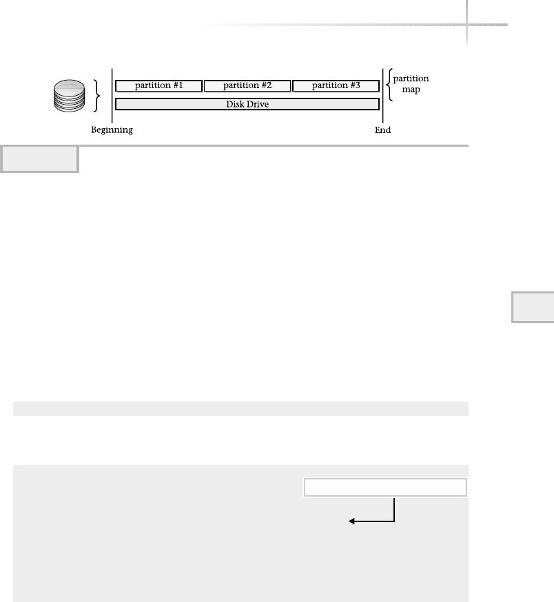
However, most systems limit the number of partitions that can be configured,
and for good reason: attempting to manage a large number of partitions on a
single disk can be difficult. Also, in some cases, the upper limit of the number
of partitions is controlled by the architecture of system in question.
Typically, disk partitions are defined during system installation and
configuration. However, there are times when you need to modify the partition
map or to display all the defined partitions on disk. UNIX provides tools for the
purpose and depending on which UNIX version, the tool will be different. For
example, on the Linux system, the fdisk tool can be used to display the
partition table for a particular disk, while Solaris uses the format command.
Thus, the command
fdisk -l /dev/hda
will show on output similar to
Disk /dev/hda: 255 heads, 63 sectors, 3737 cylinders
Units = cylinders of 16065 * 512 bytes
Device Boot Start End Blocks Id System
/dev/hda1 * 1 262 2104483+ 83 Linux
/dev/hda2 263 1049 6321577+ f Win95 Ext'd (LBA)
/dev/hda5 263 524 2104483+ 83 Linux
/dev/hda6 525 786 2104483+ 83 Linux
/dev/hda7 787 917 1052226 83 Linux
/dev/hda8 918 983 530113+ 82 Linux swap
/dev/hda9 984 1049 530113+ 83 Linux
The output shows each of the partition names (Device), the start
and stop ranges (Start and End), the total size of the partition in blocks
(Blocks), the id for the partition (Id), and the type of file system or use
for the partition (System). The Boot field indicates which partition is
Module 6: File Systems, Disks, and Tools 177
6
Figure 6-4 View of disk partitions
Bootable partition indicated by *

bootable, with an asterisk, so that when the system is restarted, it boots with
the correct partition. In the example, the /dev/hda1 partition (which is the
root file system) is bootable.
Solaris provides the prtvtoc command, which displays the geometry or
layout of the disk with all the defined partitions. For example, the command
# prtvtoc /dev/dsk/c0d0s0
provides the following information:
* /dev/dsk/c0d0s0 partition map
*
* Dimensions:
* 512 bytes/sector
* 63 sectors/track
* 16 tracks/cylinder
* 1008 sectors/cylinder
* 16654 cylinders
* 16652 accessible cylinders
*
* Flags:
* 1: unmountable
* 10: read-only
*
* Unallocated space:
* First Sector Last
* Sector Count Sector
* 16784208 1008 16785215
*
* First Sector Last
* Partition Tag Flags Sector Count Sector Mount Directory
0 2 00 3024 1024128 1027151 /
1 7 00 1027152 819504 1846655 /var
2 5 00 0 16785216 16785215
3 3 01 1846656 2048256 3894911
5 0 00 3894912 1024128 4919039 /opt
6 4 00 4919040 3277008 8196047 /usr
7 8 00 8196048 8588160 16784207
8 1 01 0 1008 1007
9 9 01 1008 2016 3023
This command provides the same information as the fdisk utility, which
includes the mapping of each partition defined on the disk. It also includes more
information about the size of the disk and related information. The prtvtoc
178 UNIX System Administration: A Beginner’s Guide

command requires a special file (or access point) that represents the disk to
probe for the partition information.
1-Minute Drill
●What are some common components of a file system?
●Describe two methods for systems with different operating system file systems
to communicate and exchange files
6.3 Determine a Mounted
File System
In order to use a file system that has been defined, a connection must be made
between the file system itself and the system which will be made available. This
is known as mounting and each file system must be mounted onto the system
before it can be used. Mounting a file system requires two basic components,
the file system and a directory that is used as the access point for the file system.
For example, assume that a file system has been created on the /dev/hda6
partition to store user files, and you would like to make this file system
available to users of the system. We need to mount the partition under the root
(/) file system. Assume also that we would like to associate the home directory
with this file system. So, when users access this file system, the UNIX path
would begin with: /home. Figure 6-5 illustrates the high level view of two
mounted file systems.
Figure 6-5 shows two mounted file systems; hda6 (which is the root file
system) and hda1 (which is for user files). These are combined together, with
what appears to be a single file system. In reality they are two separate file systems.
As you recall, the df command displays information about the file system
and also the mount point. Thus the entry
/dev/hda9 521748 79504 415740 17% /home
shows that the /dev/hda9 file system is mounted on the /home directory.
Module 6: File Systems, Disks, and Tools 179
6
●Files, directories, subdirectories, hidden data file structures
●They could communicate through special file conversion hardware or software tools. Or they could
exchange data through a common network facility such as FTP or NFS.
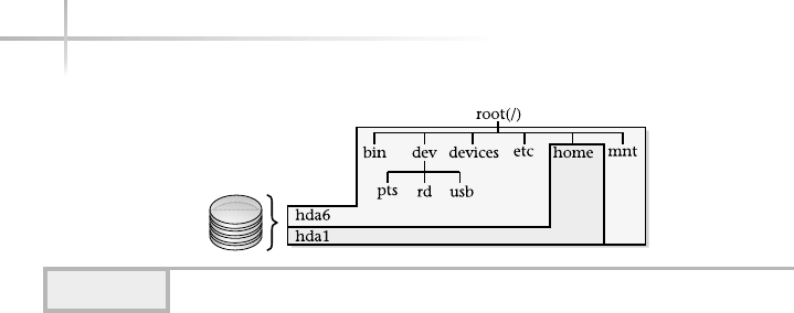
180 UNIX System Administration: A Beginner’s Guide
Creating a New File System
Setting up a new file system is a straightforward process. However, having said
that, care must be taken to ensure that you fully understand what you are doing.
Assuming that you already have the partition map defined, do the following
high level tasks:
1. Determine which partition will contain the file system.
2. Alter the partition map for the file system.
3. Create the file system.
4. Verify that the file system is functional.
5. Make the file system available by mounting it.
To complete steps 1 and 2, consult the sections “Using the Solaris Format Tool”
or “Using the Linux fdisk Tool” depending on the operating system you have.
Steps 3 and 4 are described in this section, “Creating a New File System,” while the
remaining step is covered in “Mounting UNIX File Systems.”
As previously discussed, the partition table could be viewed using various
UNIX commands. On Solaris and HP-UX, use the format command to view
partitions for each disk drive. For Linux, use the fdisk command.
Using the Solaris Format Tool
The format command is used to both modify/define/display a partition table
and also format a disk drive. In this example, the command will be used to
Figure 6-5 Mounting File Systems
TEAMFLY
Team-Fly®

Module 6: File Systems, Disks, and Tools 181
6
display and modify the partition table. To run the command, type the following
at the shell prompt as the super user:
# format
The command displays the following depending on the number of disks
installed on the system:
Searching for disks...done
AVAILABLE DISK SELECTIONS:
0. c0t0d0 <SUN9.0G cyl 4924 alt 2 hd 27 sec 133>
/pci@1f,0/pci@1,1/scsi@2/sd@0,0
1. c0t1d0 <SUN9.0G cyl 4924 alt 2 hd 27 sec 133>
/pci@1f,0/pci@1,1/scsi@2/sd@1,0
Specify disk (enter its number):
In this case, the system contains two disk drives (c0t0d0) and (c0t1d0)
and one must be selected to continue with executing the format command.
Assume that the second disk (disk number 1) is selected. As a result of
selecting this disk, this command outputs the following:
selecting c0t1d0
[disk formatted]
Ask the ExpertAsk the Expert
Question Why should you make changes to the system when it is
not in use and can be taken "off-line" if at all possible?
Answer Making disk changes to a live or production system can be
a very dangerous thing to do! A small change could render the system
unusable. However, sometimes you must make modifications to one or
more critical systems even during peak usage. For example, you might
need to create a new file system for additional users in the middle of the
day because you are out of disk space. In cases like these, please make
sure that you double check your work and also ensure that adequate
backups have been done.
Two disks available to select

FORMAT MENU:
disk - select a disk
type - select (define) a disk type
partition - select (define) a partition table
current - describe the current disk
format - format and analyze the disk
repair - repair a defective sector
label - write label to the disk
analyze - surface analysis
defect - defect list management
backup - search for backup labels
verify - read and display labels
save - save new disk/partition definitions
inquiry - show vendor, product and revision
volname - set 8-character volume name
!<cmd> - execute <cmd>, then return
quit
format>
Display the Partition Table
To show the partition table, type the partition command at the format>
prompt:
format> partition
This command can be abbreviated and the “p” character could have
been used to save on keystrokes. Once this command is input, another
menu is displayed:
PARTITION MENU:
0 - change `0' partition
1 - change `1' partition
2 - change `2' partition
3 - change `3' partition
4 - change `4' partition
5 - change `5' partition
6 - change `6' partition
7 - change `7' partition
select - select a predefined table
modify - modify a predefined partition table
name - name the current table
print - display the current table
182 UNIX System Administration: A Beginner’s Guide

Module 6: File Systems, Disks, and Tools 183
6
label - write partition map and label to the disk
!<cmd> - execute <cmd>, then return
quit
partition>
Use the print command to display the current partition table. Thus,
partition> print
will show the following:
Current partition table (original):
Total disk cylinders available: 4924 + 2 (reserved cylinders)
Part Tag Flag Cylinders Size Blocks
0 root wm 0 - 73 129.75MB (74/0/0) 265734
1 swap wu 74 - 147 129.75MB (74/0/0) 265734
2 backup wu 0 - 4923 8.43GB (4924/0/0) 17682084
3 unassigned wm 0 0 (0/0/0) 0
4 unassigned wm 0 0 (0/0/0) 0
5 unassigned wm 0 0 (0/0/0) 0
6 usr wm 148 - 4923 8.18GB (4776/0/0) 17150616
7 unassigned wm 0 0 (0/0/0) 0
partition>
The output includes six fields that describe each of the partitions. A total of
eight partition slots are available for this disk; and they are numbered 0through
7as displayed in the Part column. Thus, the with Solaris operating system, a
total of eight partitions can be defined per each disk drive. The Tag field indicates
the type of file system or use for the partition. For instance, the first partition
(0) is used as the root file system. This file system is used to boot the system.
The second partition is used for swap space, etc. The unassigned tag means
that the partition is empty or not defined; that is why the remaining fields do
not contain any values. The Flag field is used to specify the access permission
for each partition. The Cylinders field specifies the range of disk offsets that
define the size of the partition. The unit in this case is cylinder groups, which
are vertical addresses of the disk drive. The Size field shows the total storage
capacity of the partition and the Block field specifies the total number of
blocks based on the total size of the partition, which is the rightmost value
8 definable partitions

displayed in the Blocks field. The values in parentheses are the absolute block
numbers/cylinder group pairs.
Modify Partition Size
To alter the size of an existing partition, type the partition number at the
partition> prompt. For example, assume that partition 6will be reduced
in size from approximately 8 gigabytes (GB) to 4 gigabytes:
partition> 6
Part Tag Flag Cylinders Size Blocks
6 usr wm 148 - 4923 8.18GB (4776/0/0) 17150616
When the partition number is typed, the format program echos the
partition definition and then prompts for new information:
Enter partition id tag[usr]: Enter
Keep hitting the Enter key to proceed through the prompts until you are
at the Enter partition size prompt.
Enter partition permission flags[wm]: Enter
Enter new starting cyl[148]: Enter
Enter partition size[17150616b, 4776c, 8374.32mb, 8.18gb]: 4.0gb
At this point we have accepted the previous values and the size of the
partition can be reduced by inputting the desired size. In this case, 4.0 gb has
been added to make the partition roughly half the size it was before. Use the p
command to display the partition map and note the change for partition
number 6:
6 usr wm 148 - 2484 4.00GB (2337/0/0) 8392167
The output shows the expected partition size. Note that the partition size
could be expressed in several different values to include the total number of
blocks, the number of cylinders, in megabytes, and even gigabytes. You must
include one of the unit description characters with the value. For example, to
specify megabytes use the mb character string. The other description strings are
bfor block, cfor cylinder, and gb for gigabytes.
184 UNIX System Administration: A Beginner’s Guide
New partition size

6
Create a New Partition
Defining a new partition is a very simple process. For example, assume that
another new partition must be defined to contain additional space for system
users. With Solaris, the partition maps have been predefined based on the
type of disk installed within the system. As a result, when a new partition must
be set up for an existing pre-installed disk, the process includes specifying
partition parameters and saving the new partition table. For example, based on
the disk partition table shown below, partition number 7is currently unassigned
and thus unused.
Current partition table (original):
Total disk cylinders available: 4924 + 2 (reserved cylinders)
Part Tag Flag Cylinders Size Blocks
0 root wm 0 - 73 129.75MB (74/0/0) 265734
1 swap wu 74 - 147 129.75MB (74/0/0) 265734
2 backup wu 0 - 4923 8.43GB (4924/0/0) 17682084
3 unassigned wm 0 0 (0/0/0) 0
4 unassigned wm 0 0 (0/0/0) 0
5 unassigned wm 0 0 (0/0/0) 0
6 usr wm 148 - 2484 4.00GB (2337/0/0) 8392167
7 unassigned wm 0 0 (0/0/0) 0
We would like to define this partition for the purposes of creating a new
file system. Also, notice that approximately 4 GB of storage is available for this
new partition. This is be determined by examining the total amount of space
reported with the backup partition (2) and comparing this information with
the existing partition’s total disk space sizes. The backup partition (or partition c
on other older systems) typically is defined to cover the entire disk drive. Based
on the total size of this partition, we see the total space is approximately 8.4 GB
of storages. The type of disk and the total disk space was also displayed when
the format command was first invoked.
Save Partition Changes
The next step is to save any partition changes to the disk and this can be done
with the label command. Executing this command will update the disk
Module 6: File Systems, Disks, and Tools 185
6
Two partitions use ~ 260 MB
Total disk size
Unassigned, unused partition

partition that is currently located in a reserved area of the disk, which is usually
the first block.
When you run the label command, the format tool prompts for verification:
partition> label
Ready to label disk, continue? Y
Using the Linux fdisk Tool
The fdisk command is used to make changes to the partition table on the
system. Specifying the special disk file, followed by /dev on the command line,
tells fdisk which disk should be modified:
fdisk /dev/hda
When run, this will display the following:
Command (m for help):
To display a list of the available commands with this tool, use the m
command. When this command is run, it will display the following:
Command action
a toggle a bootable flag
b edit bsd disklabel
c toggle the dos compatibility flag
d delete a partition
l list known partition types
m print this menu
n add a new partition
o create a new empty DOS partition table
p print the partition table
q quit without saving changes
s create a new empty Sun disklabel
t change a partition's system id
u change display/entry units
v verify the partition table
w write table to disk and exit
x extra functionality (experts only)
186 UNIX System Administration: A Beginner’s Guide

6
Module 6: File Systems, Disks, and Tools 187
6
Display the Partition Table
To show the partition table, type the pcommand at the command prompt:
Disk /dev/hda: 255 heads, 63 sectors, 3737 cylinders
Units = cylinders of 16065 * 512 bytes
Device Boot Start End Blocks Id System
/dev/hda1 * 1 262 2104483+ 83 Linux
/dev/hda2 263 1049 6321577+ f Win95 Ext'd (LBA)
/dev/hda5 263 524 2104483+ 83 Linux
/dev/hda6 525 786 2104483+ 83 Linux
/dev/hda7 787 917 1052226 83 Linux
/dev/hda8 918 983 530113+ 82 Linux swap
/dev/hda9 984 1049 530113+ 83 Linux
Command (m for help):
6.4 Create a New File System
There are at least two ways to create a new file system: the easy way and the
hard way. The easy way involves using the newfs command, while the hard
way is to use the mkfs command. Both accomplish the same thing, but the
mkfs command is much harder to use because it requires the administrator
to input the required file system parameters, whereas the newfs requires little
input from the system administrator. The easy way will be shown here. The
required command line option for the newfs command is the special file that
represents the partition the new file system should be created. Assume the new
file system will be set up using the special file c0t1d0s6. The command
newfs /dev/rdsk/c0t1d0s6
will create a new file system, using all the default values. Output of the
command will include
newfs: construct a new file system /dev/rdsk/c0t1d0s6: (y/n)? y
The newfs command will prompt to confirm the procedure and the
administrator must input the required response for the command to continue.
The output of the command includes
Warning: 1 sector(s) in last cylinder unallocated
/dev/rdsk/c0t1d0s6: 8392166 sectors in 2337 cylinders of 27 tracks, 133 sectors

4097.7MB in 147 cyl groups (16 c/g, 28.05MB/g, 3392 i/g)
super-block backups (for fsck -F ufs -o b=#) at:
32, 57632, 115232, 172832, 230432, 288032, 345632, 403232, 460832, 518432,
576032, 633632, 691232, 748832, 806432, 864032, 921632, 979232, 1036832,
1094432, 1152032, 1209632, 1267232, 1324832, 1382432, 1440032, 1497632,
1555232, 1612832, 1670432, 1728032, 1785632, 1838624, 1896224, 1953824,
2011424, 2069024, 2126624, 2184224, 2241824, 2299424, 2357024, 2414624,
2472224, 2529824, 2587424, 2645024, 2702624, 2760224, 2817824, 2875424,
2933024, 2990624, 3048224, 3105824, 3163424, 3221024, 3278624, 3336224,
3393824, 3451424, 3509024, 3566624, 3624224, 3677216, 3734816, 3792416,
3850016, 3907616, 3965216, 4022816, 4080416, 4138016, 4195616, 4253216,
4310816, 4368416, 4426016, 4483616, 4541216, 4598816, 4656416, 4714016,
4771616, 4829216, 4886816, 4944416, 5002016, 5059616, 5117216, 5174816,
5232416, 5290016, 5347616, 5405216, 5462816, 5515808, 5573408, 5631008,
5688608, 5746208, 5803808, 5861408, 5919008, 5976608, 6034208, 6091808,
6149408, 6207008, 6264608, 6322208, 6379808, 6437408, 6495008, 6552608,
6610208, 6667808, 6725408, 6783008, 6840608, 6898208, 6955808, 7013408,
7071008, 7128608, 7186208, 7243808, 7301408, 7354400, 7412000, 7469600,
7527200, 7584800, 7642400, 7700000, 7757600, 7815200, 7872800, 7930400,
7988000, 8045600, 8103200, 8160800, 8218400, 8276000, 8333600, 8391200,
This command displays the disk configura-
tion information, plus a long series of block
numbers. These numbers represent the locations
of backup copies of the super block. Recall, the
super block is the master record for a file system
and contains vital information about the state
and configuration of the file system.
In the example, above, the total disk space
for this file system is 4GB (4097.7 MBs to be
more exact).
Checking the New File System
When a new file system has been created, it is wise to check the file system for
integrity using the file system consistency check (fsck) program. The fsck
program is necessary because a file system can become corrupt for a variety of
reasons and a specialized program is necessary to repair the file system when
necessary. The reason a file system can experience problems is that hardware or
configuration failures can affect the file system in a negative way. For example,
if the physical disk driver media (of which the file system is stored) becomes
unstable due to a hardware problem, and can no longer access parts of the disk,
the file system will be severely affected. This is an extreme case; one that is
more common is that the system crashes before the file system was able to
188 UNIX System Administration: A Beginner’s Guide
HintHint
To use one of the backup
supers, you must specify
the block number (loca-
tion) when checking the
file system with fsck.
This tool is discussed in
the next section.

6
update itself with any changes that were made. This basically means that the
version of the information stored on the disk is now out of sync and will cause
problems unless the situation is rectified.
Typically, during normal system operations, the fsck program is run auto-
matically or when a problem is detected. This is usually when the system is being
rebooted. However, in some situations, it will become necessary to run this
program manually if the errors encountered are serious enough to warrant
this action. This may, for instance, be the case if the root file system is having
problems and requires more attention from the system administrator.
The file system scanned by fsck should be quiescent, that is to say, the file
system shouldn’t be used during the fsck scan process, which means that no
users should be accessing the file system. To ensure that normal system users are
not using the file system, the system can be placed in single user mode. It is
possible to scan a file system during normal system operations; the administra-
tor must ensure that no users will access the system until the scan is complete.
To examine each of the file systems configured on the system, running
the fsck command without any command line arguments will scan each file
system in turn. However, to scan a single file system, include the special file for
that file system on the command line.
fsck /dev/dsk/c0t1d0s6
When run, the following is displayed:
** /dev/rdsk/c0t1d0s6
** Last Mounted on
** Phase 1 - Check Blocks and Sizes
** Phase 2 - Check Pathnames
** Phase 3 - Check Connectivity
** Phase 4 - Check Reference Counts
** Phase 5 - Check Cyl groups
2 files, 9 used, 4131375 free (15 frags, 516420 blocks, 0.0% fragmentation)
The fsck program does a 5-point scan against the file system, which
involves checking various aspects of the file system for problems. These
scanning and checking phases are described in Table 6-1.
The output shows each of the phases, and when no errors are displayed for
that phase, it indicates the phase was completed successfully. When the scan is
Module 6: File Systems, Disks, and Tools 189
6

190 UNIX System Administration: A Beginner’s Guide
complete, the number of files is displayed along with the total free disk space
and additional information about the file system.
The fsck program has a number of command line options depending
on the operating system. These are listed in Table 6-2 list the most common
options for each system.
One of the most useful command line arguments is the yor Yoption.
When fsck is run and a significant number of problems are encountered,
using these arguments will cause all questions prompted by fsck to be answered
in the positive. This is very useful when the system administrator must multitask
between several important duties and also doesn’t want to continue inputting the
same response. Of equal value is the n(or N) command line option that does the
opposite; it answers negatively to any questions posed by fsck.
Phase Description
1Determines if the file system i-nodes are consistent
2Determines if directory entries are correct and file i-nodes are consistent
3Checks to ensure that all directories are connected to the file system
4Makes a comparison of link of (files and directories) counts from Phase 2 and 3
5Checks the free block list and used i-nodes for consistency
Table 6-1 Scanning Phases of fsck Program
Ask the ExpertAsk the Expert
Question Why should you only use fsck to scan unmounted file
systems?
Answer Because if the file system is changing during the scan
process, it will detect inconsistencies with the file system structures,
which will promote more headaches. Since fsck can both detect and fix
problems, using it when the file system is active will cause additional
severe problems over and above the problems that were first encountered
before the scan was started.
TEAMFLY
Team-Fly®

If the super block of a file system gets
corrupt (which is not a common occurrence)
it will be necessary to supply an alternative
location that contains a copy of the original
super block. When the newfs command is
executed to build a new file system, it makes
a series of copies of the super block and places
them in various block locations on the partition.
Using the –o b option, the administrator can
supply the location of one of the copies of the
super block.
Mounting UNIX File Systems
In order for users to access a file system, it must be explicitly made available on
the system for users. The term that is commonly used to describe this step is to
“mount the file system.” Mounting a file system means an association is created
between a specific directory from the root file system and the file system that
is to be mounted. To mount a file system or to display the currently available
6
Module 6: File Systems, Disks, and Tools 191
Option Description
-A Examine the /etc/fstab and attempt to scan each file system listed in
this file (Linux only)
-F Specify the file system type when scanning (Solaris only)
-m Scan the file system, but don’t repair any encountered problems
-n -N Answer all fsck generated questions with a “no” response (Linux: -N will
display what will be done only and doesn’t execute any repairs)
-s Perform the fsck scanning process in a serial fashion (Linux Only)
-t Specify the file system type when scanning (Linux Only)
-V Display the command line but not execute the command
-y -Y Answer all fsck generated questions with a “yes” response
-o Provide values to specific fsck options
-o b Supply an alternate location for the super block
-V Verbose output (Linux only)
Table 6-2 Command Line Options
HintHint
Care must be taken
when using the positive
response with fsck,
since you are approving
that ALL questions be
answered the same way,
which in some cases may
not be what is needed.

192 UNIX System Administration: A Beginner’s Guide
mounted file systems, use the mount command. Without any arguments, this
command will show all of the existing mounted file systems. The command
mount
displays all the mounted file systems on a Solaris machine called bedrock:
/ on /dev/dsk/c0t0d0s0
read/write/setuid/intr/largefiles/onerror=panic/dev=80000
0 on Mon Jan 21 20:10:53 2002
/proc on /proc read/write/setuid/dev=3600000 on Mon Jan 21 20:10:52 2002
/dev/fd on fd read/write/setuid/dev=36c0000 on Mon Jan 21 20:10:54 2002
/tmp on swap read/write/setuid/dev=2 on Mon Jan 21 20:10:57 2002
/export/home on /dev/dsk/c0t0d0s7
read/write/setuid/intr/largefiles/onerror=pani
c/dev=800007 on Mon Jan 21 20:10:57 2002
The mount command requires two pieces of information when mounting
a file system: the special file of the file system and a directory. The directory
becomes the “mount point” for the file system. For example, to mount the file
system contained with the /dev/dsk/c0t1d0s6 partition:
mount /dev/dsk/c0t1d0s6 /src
In this example, this file system is mounted onto the directory called /src.
Note: the target mount point directory must exist before the mount is
executed. This is because the mount will not create the directory before you.
Thus, you must run the following:
mkdir /src
before the mount command is executed. Otherwise, the mount will fail and
an error message similar to “mount: mount-point /src does not
exist.” will be displayed.
Once the mount is done, the file system can be accessed just like any other
file or directory contained on the system. From a user’s standpoint, this new file
system has been plugged into the root file hierarchy and the integration of the
mounted file system appears as an extension to the existing directory branch.
In other words, a mounted file system is connected to the system so that it
appears like a normal directory. The major exception to this rule is a read-only

file system. For example, when a fixed CD-ROM device is mounted on the
system, no data can be written onto the devices. Thus, should a user attempt to
create, remove, or modify a file, an error message will be generated stating that
the file system is “read-only.”
The mount command supports the –a option, which indicates that all file
systems contained within the /etc/vfstab file will be mounted. On Linux,
the file is known as /etc/fstab.
Unmounting a UNIX File System
To do the opposite of mounting a file system, use the umount command. This
command will disassociate the mount point from the file system and as a result
the file system will no longer be available to the system. Typically, a file system
is “un”mounted when the system is halted or when the file system needs some
maintenance performed (during the invocation of the fsck command, for
example). The umount command accepts either the mount point directory of
the special file. For example, assume the following mounted file system:
/mnt (/dev/dsk/c0t1d0s6 ): 8262750 blocks 498620 files
Thus, the command
Umount /mnt
will umount the file system associated with /mnt directory. Also, note that the
command below will accomplish the same thing:
umount /dev/dsk/c0t1d0s6
To unmount all the mounted file systems instead of a single one, use the –a
option. Using this option implies that all file systems defined within the /etc/
vfstab are unmounted. On the Linux system, the /etc/fstab contains the
defined file systems.
Project 6-1
Because making changes to a live file system is not advisable except as absolutely
necessary, in this project you'll focus on gathering information about the file
Module 6: File Systems, Disks, and Tools 193
6

systems on your system rather than on making changes. If you are the
administrator for this system, you might find it useful to keep the information
you gather in a safe place in case you ever need to refer to it for system
information to recover from a catastrophic failure or to determine if damage
was done during a system intrusion.
Step-by-Step
1. Display all the file systems on your system:
df -k
2. From these results, determine if any of the file systems are dangerously close
to being out of unused space.
3. For each drive, determine how many partitions are in use and how much
unused space (if any) isn't allocated to a partition. For Linux do this with
the command
fdisk -l
4. Or if you are using Solaris, perform step 3 with the command
# prtvtoc /dev/dsk/c0d0s0
repeating it for each drive.
194 UNIX System Administration: A Beginner’s Guide

Module 6: File Systems, Disks, and Tools 195
6
Mastery Check
1. A __________ is simply a collection of objects (files or directories, for
example) that are organized to include the following elements: optimal
data access, ensures data integrity, provides manageable, and can be
scalability to support many objects.
2. What keeps track of all the files within the file system?
A. Super block
B. Root
C. i-node table
D. Partition
3. A __________ is a fixed area defined on a storage medium for
the purposes of data access.
4. In this output from the df command on a Linux system, what is the
file system's drive letter and partition number?
/dev/hda9 521748 79504 415740 17% /home
5. In Solaris, which command shows a disk's layout with all of its
defined partitions?
6. What is the term for making a connection between a file system and
the system which the file system will be made available to?
A. Mount
B. Partition
C. Format
D. fdisk

196 UNIX System Administration: A Beginner’s Guide
7. To create a new file system using default values and not entering
additional command line options, which command would you use?
A. mkfs
B. newfs
C. format
D. fdisk
8. What user mode is best to put the system in when running the
fsck command?
9. What command do you use to display all the mounted file systems on
your system?
A. df
B. format
C. mount
D. umount
10. True or false: If the target mount point directory does not exist before you
execute the mount command, mount will create the directory for you.
Mastery Check

Module7
System Security
Critical Skills
7.1 Define a Security Policy
7.2 Maintain System Patches
7.3 Uncover System Hardening
7.4 Investigate Security Tools
Copyright 2002 by The McGraw-Hill Companies, Inc. Click Here for Terms of Use.

This module provides an overview and description of key elements to establishing
a secure computing environment with the UNIX operating system. It provides
procedures, configuration recommendations, and descriptions of tools that will
help make the UNIX computing environment more secure.
In general, there are two broad approaches to maintaining and delivering
on system security. First, the network that interconnects systems can be made
secure by the use of firewalls, proxies, and other mechanisms to ensure that
hackers and other malicious users are barred from accessing protected systems.
The second approach involves focusing the security on the individual systems,
instead of the network. In this case, the system administrator attempts to limit
system access and control access to files and directories, along with other related
measures. The fact of the matter is that both approaches are necessary when
addressing security within the enterprise. Why? Well, the answer is very simple:
Security breaches can come from outside the company (over the Internet or via
dial-up services), internally from the general user community, or even from
business partners.
When the WORM of 1998 struck the Internet, it exposed critical vulnerabilities
to a wider audience, which raised the awareness of both network and system
security. There are certainly more recent examples of security problems on the
Internet, but the WORM was the first of many to follow.
As the system administrator, you will be responsible for ensuring security for
the systems you control; however, depending on the company’s organizational
structure and other factors, the system administrator will need to work with
others to help with the security efforts. For example, in many corporations
security may be handled by a separate security department—or is handled as
part of a network design and/or support group. In any event, complete security
is a team or group effort, and if security is lacking in one important area (say
from a network standpoint), that makes all the attached systems more vulnerable.
198 UNIX System Administration: A Beginner’s Guide
HintHint
At that time, many of the UNIX security vulnerabilities were understood and
accepted. However, at the same time, the WORM redefined the critical duties
of the system administrator because they could no longer ignore operating
system security issues. Today, one of the primary roles of the system
administrator is to ensure that their systems contain the most up-to-date
security and operating system patches available.

The system administrator will need to determine how best to implement
security in their computing environment, which certainly may involve using
both security methods stated above. With this in mind, here are the high-level
steps that are involved with providing robust system security regardless of the
specific computing environment or organization:
1. Develop and publish a security policy (and revisit on a periodic basis).
2. Maintain system patches.
3. Continuously harden the systems.
4. Use security tools.
5. Repeat steps 2, 3, and 4.
7.1 Define a Security Policy
A good security policy has a few basic elements. First, it should clearly define
what is and what is not acceptable behavior with respect to the use of both
network and computing systems. For example, users should not attempt to read
files from other users when they have no business need, and users shouldn’t
leave their workstations unattended when they remain logged into the system.
Module 7: System Security 199
7
Ask the ExpertAsk the Expert
Question How can a security policy help make my systems
more secure?
Answer A security policy can’t make your systems more secure
intrinsically, but it can help you in other ways—which can impact your
security approach or determine how successful you will be in
implementing some of the steps listed above. For example, having a
good policy means it can raise the awareness of senior management of
how important security can be, and as a result you may find it easier to
acquire the funding to purchase security-monitoring tools or hire extra
personnel to help in implementing security tools and procedures.

Second, the policy should clearly state what are guidelines for general-purpose
computing. For example, users should not install modems and connect phone
lines on their system to provide remote access, but should use the corporate
dial-up services—which can be more secure. A how-to of the most common
issue or problem should be listed. Finally, the policy should define the roles,
responsibilities, and procedures to follow when a security issue or incident has
occurred. For instance, when an unauthorized user has gained access to a system,
who should be alerted and how? What kind of documentation is necessary to
record the security breach? These and related questions should be answered
and spelled out in the policy.
The security policy should be published in such a way as to ensure that
everyone knows about it and can access it when necessary. Thus, placing it on the
company’s internal Web site or intranet is the best approach. To ensure that
users in fact read the policy, include it as part of the user account setup
procedures so that before a user account is set up, the user has both read and
understood the policy. Then, they can be granted access to the system.
7.2 Maintain System Patches
One of the most important jobs of the system administrator is to consistently
maintain up-to-date patches on the systems. Maintaining software upgrades and
maintenance releases has positive benefits that include warding off potential
problems, providing a stable computing environment, and simplifying
troubleshooting of system problems and issues.
When system patches are applied on a regular basis, certain problems can
be avoided. For example, installing a security patch that closes one or more
particular security vulnerabilities—say, with the TCP/IP protocol—reduces the
overall security exposure of the system.
In general, installing the required system patches should provide for a more
stable and secure environment. Typically, the administrator is asked to install
the required patches in order for technical support to begin troubleshooting a
particular problem. On the other hand, depending on the vendor, installing
certain patches can cause system problems if the patch is applied incorrectly or
contains one or more software defects. This certainly is the exception and not
the rule, but it can happen. For this reason, it is always best to install any
patches on a test system to determine any potential impact or problem.
200 UNIX System Administration: A Beginner’s Guide
TEAMFLY
Team-Fly®

Vendors include in their support policies the provisions about limiting
technical support for systems that are not running the latest version of their
software or don’t contain the correct system-level patches.
7.3 Uncover System Hardening
The concept of system hardening is not new; the military and other organizations
have used this phase for quite some time as it relates to fortifying their equipment
or armaments and making it less likely that a physical attack will cause serious
damage. In the context of computer systems, it basically means the same thing—
to reduce the vulnerabilities and also fortify the system against known security
issues or attacks.
Limiting any unnecessary system services and also implementing standard
operating system configurations accomplish system hardening. Further,
substituting a better service for an inferior one is also a part of making sure
that systems are secure. For example, the UNIX system supports the Telnet
service, which provides basic terminal accessibility from one system to another
remote system. This particular service has been around for quite some time and
is used by many system administrators. However, the Telnet service has one
significant flaw: The communication path between the client and servers is
unsecured. As a result, using this service poses a security threat that many
consider too risky. To address this problem, Telnet is disabled and the Secure
Shell (SSH) is enabled to provide secure access. SSH provides encryption, which
makes the communication path secure.
The basic goal of system hardening is to eliminate any unnecessary system
services that might pose a security threat, and to configure the system for maximum
security without seriously impacting the user community. Thus, two broad
categories of hardening exist: elimination of nonessential services and
implementing a specific conservative operating profile or configuration. These
classifications are described below.
Elimination of Unnecessary Services
One of the best ways to ensure a basic level of security is to remove unused or
unneeded services that may represent a potential system security risk. For example,
if unrestricted FTP is enabled on a system, but that particular machine doesn’t
really need file transfer capabilities, then it might be prudent to shut off this
Module 7: System Security 201
7

particular service. Table 7-1 lists some of the most common services that can
be either be disabled or replaced with another more secure package or a newer
version of the software, which contain later security features.
Configuration System Profiles
Deploying a set of configuration profiles for how each of the systems will be
configured and maintained is an important element to overall security. For
instance, many organizations install different kinds of systems for various
projects and functions, and as a result, the configuration of those systems will
be set up to match specific user requirements. Consider the system and security
equipment for a software development group versus a sales team. Since these
groups do different things and have different requirements, one or more system
configuration profiles may be necessary. A system configuration profile consists
of specific configuration parameters (such as permitting the root to access the
202 UNIX System Administration: A Beginner’s Guide
Service Action New Service
Disable Replace Upgrade
inetd √Xinetd
with tcp
wrappers
fingerd √
majordomo √Upgrade to
latest version
NIS √NIS+
R family of tools
(rsh, rcp, and
rlogin)
√SSH
rexd √
rpc.statd √Upgrade to
latest version
telnetd √SSH
tftp √
uucp √
Table 7-1 System Services That Require Hardening

console device over the network or the frequency of password expirations for
normal users). Some of the possible configuration profiles are listed below:
Low-Security Profile
This profile represents systems that will have a modest amount of system security
because they are isolated from the network or because they are stand-alone or
maybe contained behind a firewall. These systems also may fall “under the radar”
of corporate security policy, which means that they may not be required to
implement all standard security measures or a high-security profile configuration.
The security configuration of the low-security profile may include a smaller
amount of operating system hardening, no password aging, no security scanning
or auditing, and so forth. Clearly, these types of systems can be a nightmare for
maintaining a robust corporate security model. However, having said that, there
are a small number of instances where using the low-security profile makes sense.
Medium-Security Profile
This profile represents systems that are several layers above the low-security
system in terms of system security. System security is a priority for this system
profile, but is not the only major issue addressed. For example, systems that are
deployed within the customer support or professional services teams may use this
profile type. This profile would contain a fairly robust hardening configuration
and support many of the security logging/scanning software packages, and use
password aging and a variety of other security measures.
High-Security Profile
This profile represents the highest level of security available. The type of system this
profile should be applied to is production systems that handle credit cards or
other highly sensitive information for customers, suppliers, and vendors. This
profile pulls out all the stops in terms of hardening configuration, scanning and
reporting tools, robust authentication, and so forth. It is not uncommon for
corporations to purchase security products to enhance the basic security supported
by the system. For instance, products are available that provide additional password
authentication using tokens and other methods that can increase the user-level
security model quite significantly.
Certainly, additional security profile types may be defined, and modification
to the ones listed above can be set up to closely match your specific environ-
mental requirement. Also, what one site considers medium security may in fact
7
Module 7: System Security 203
7

204 UNIX System Administration: A Beginner’s Guide
be low security to another, depending on the security goals of the organization.
One important point: Whatever profiles you use, apply them consistently to
all systems—that way, you will be in a position to better understand where your
systems are from a security perspective.
Now that a set of security profiles has been defined, it is quite straightforward
to inventory and classify the level of security for each system. In Table 7-2, a small
number of systems have been included to show this example. It is recommended
that a similar table be developed for the systems that you support.
As noted in the table, each type of system will have different system services
and one of the security profiles. With many corporations, it is possible that three
security profiles are not enough; additional ones need to be defined to handle
special cases or additional types of systems. As a system administrator, you will
need to take charge of defining the security attitude and strategy for your area of
control, and compiling an inventory of systems is a great place to start.
Host Name Team Profile Characteristics Service(s)
Low Medium High
station1 Software
development
√C compiler
mailserv Software
development
√Mail server
bedrock Software
development
√NFS, NIS,
and DNS
barney Software
development
√CVS source code
repository
omega Marketing √Mail server
salessrv1 Sales √Web server
Sales intranet
salessrv2 Sales √Sales support
Table 7-2 Inventory of Systems with Security Profile Types

7
1-Minute Drill
●How does writing a security policy help you make your systems more secure?
●What are some of the key principles of system hardening?
7.3 Investigate Security Tools
One key component to a successful security model is to deploy security
monitoring/scanning tools that can probe the system on a regular basis and
provide detailed reports of potential vulnerabilities or other security issues.
There are some very powerful monitoring and scanning tools that are available
today from both the commercial and public domain sectors. However, a review
of specific commercial packages is beyond the scope of this book. On the other
hand, some of the more common public domain tools are discussed in the
section. Table 7-3 lists the tools that will be covered.
The tools listed in this table are all available for Solaris, HP-UX, and Linux.
However, not all of them are shipped with the basic operating system package.
As a result, they must be installed separately. In the case of Linux, all of the
tools are available on the product CDs. For both Solaris and HP-UX, you will
obtain the software from the prospective Internet sites and install them
individually. Each of the packages provides detailed installation instructions.
Naturally, a large number of additional security tools are available for UNIX
to solve a variety of security-related issues and problems.
Module 7: System Security 205
Tool Purpose
nmap Network port scanner and remote host identification program
SSH Provides a remote shell and file copy to specified host using secure connection
sudo Permits regular users to execute privileged commands
Table 7-3 Common Security Tools
●A written security policy helps raise awareness of security issues, it clearly defines what are and aren’t
allowable system uses so there is no ambiguity or uncertainty among users, and it defines roles and
responsibilities for ensuring security and recovering from any potential security breaches.
●System hardening includes establishing a set of standard operating system configurations, eliminating
unnecessary system services, and substituting a more secure service for an inferior one.

The NMAP Tool
The nmap tool is a utility that locates and identifies all available TCP and UDP
ports on a target host system. Also known as a port scanner, this tool will scan
TCP ports from 0 to 1024 (by default) and attempt to determine the service
listening on those ports that will accept a connection. This is a very robust
security tool because it identifies services running on a system so that you can
be alerted about possible security issues or vulnerability.
This tool was designed to help the system administrator determine security
problems on their systems, but if you intend to use this tool on networks,
systems, or sites that you do not control, you should seek permission first.
Remember, having respect for the privacy of networks and systems that you
don’t own means that the favor may be returned to you someday.
On occasion, devices that interfere with normal network operations may be
added to the network. Also, the origin and configuration of these systems may
not be apparent and may represent a potential
security risk. It may become necessary to scan
the devices to learn more about the services they
provide. For instance, let’s assume a device is
added to the network, but because the device
doesn’t seem to support services like telnet,it
is difficult to identify the device.
Aping can be an issue against the device, but this doesn’t really provide
much information about the device itself. The ping command checks to see if
basic network services from the device are operational:
# ping 216.155.202.110
PING 216.155.202.110 (216.155.202.110) from 216.155.202.163 : 56(84) bytes of data.
Warning: time of day goes back, taking countermeasures.
64 bytes from 216.155.202.110: icmp_seq=0 ttl=255 time=1.035 msec
64 bytes from 216.155.202.110: icmp_seq=1 ttl=255 time=229 usec
--- 216.155.202.110 ping statistics ---
206 UNIX System Administration: A Beginner’s Guide
HintHint
The nmap tool is used by those wishing to break into remote computer
systems; thus, when you identify security issues on your systems, you are
proactively short-circuiting the efforts of those that want to cause destruction
to your systems!
HintHint
The ping command
is fully described in
Module 11.

2 packets transmitted, 2 packets received, 0% packet loss
round-trip min/avg/max/mdev = 0.229/0.632/1.035/0.403 ms
As you can see, the device is operational on the network, but we don’t really
have much additional information about the device. We can now attempt to
connect to the device via telnet or ssh, but the connection never makes it
because the device may refuse this type access:
# telnet 216.155.202.110
Trying 216.155.202.110...
telnet: connect to address 216.155.202.110: Connection refuse
Scanning a Host
When it is necessary to find more information about the device, the nmap tool
can be used to probe and inventory the services running, which can give a better
picture about the device in general. Running the command
nmap -O 216.155.202.110
provides the details we need:
Starting nmap V. 2.54BETA22 ( www.insecure.org/nmap/ )
Interesting ports on (216.155.202.110):
(The 1540 ports scanned but not shown below are in state: closed)
Port State Service
139/tcp open netbios-ssn
6000/tcp open X11
Remote OS guesses: Windows Me or Windows 2000 RC1 through final release,
Windows Millenium Edition v4.90.3000
Nmap run completed -- 1 IP address (1 host up) scanned in 28 seconds
The -O option used here tells nmap that we would like it to attempt to
identify the target system using what it calls TCP/IP fingerprinting. What this
basically means is that several different techniques are used to detect differences
within operating systems or the running software contained within the target
device. Using the data obtained from probing the TCP/IP protocols and other
attributes, nmap compares this information with the fingerprints of known
devices and systems. Every device that nmap attempts to identify is compared
to the data stored in a file called nmap-os-fingerprints, which is located
Module 7: System Security 207
7
Two services running
nmap guess for operating
system on the remote device

in the directory /usr/share/nmap by default. This file contains a large number
of fingerprints for systems and networking devices.
As noted in the output from nmap, two network services are running on the
system, plus it has identified the type of system as a Windows Me or Windows
2000 workstation. We are now in a position to
determine if this system represents a security
risk to other systems or the network as a whole.
In this case, since the device is configured to
support NETBIOS services, which provides file
sharing, we should make sure that the system
doesn’t contain any viruses that may be
transmitted within shared documents. Also,
nmap has detected that X Windows (X server)
software is running on the system, which may
not represent a security concern unless the user of this system is accessing
sensitive information without using ssh or some other security software. This
bears some additional investigation with the owner of this system.
Normally, it wouldn’t be easy to determine that a device was a Windows
workstation, but using nmap, most systems can be identified fairly quickly and
easily. The nmap tool can also examine the networking services running on
known systems within the network. This is useful in determining which system
services are available to assist with system hardening efforts. For instance, using
nmap on a Solaris system known as bedrock produced the following output:
Starting nmap V. 2.54BETA22 ( www.insecure.org/nmap/ )
Interesting ports on bedrock.home.com (216.155.202.100):
(The 1511 ports scanned but not shown below are in state: closed)
Port State Service
7/tcp open echo
9/tcp open discard
13/tcp open daytime
19/tcp open chargen
21/tcp open ftp
23/tcp open telnet
25/tcp open smtp
37/tcp open time
79/tcp open finger
111/tcp open sunrpc
512/tcp open exec
513/tcp open login
514/tcp open shell
515/tcp open printer
208 UNIX System Administration: A Beginner’s Guide
HintHint
If you encounter a device
that doesn’t match the
entries in the fingerprints
file, you may want to
consider sending the scan
to the nmap author.

540/tcp open uucp
587/tcp open submission
898/tcp open unknown
2049/tcp open nfs
4045/tcp open lockd
6000/tcp open X11
6112/tcp open dtspc
7100/tcp open font-service
32774/tcp open sometimes-rpc11
32775/tcp open sometimes-rpc13
32776/tcp open sometimes-rpc15
32777/tcp open sometimes-rpc17
32778/tcp open sometimes-rpc19
32779/tcp open sometimes-rpc21
32780/tcp open sometimes-rpc23
32786/tcp open sometimes-rpc25
32787/tcp open sometimes-rpc27
Nmap run completed -- 1 IP address (1 host up) scanned in 0 seconds
As you can see, this system contains a large number of services, some of
which can be deactivated.
Scanning Methods
The nmap software supports a number of important functions and a number
of command-line options. Also, it provides a large number of system scanning
techniques, as shown in Table 7-4. This table also includes the associated
command options and a general description of the process involved with each
scanning method.
7
Module 7: System Security 209
7
Scanning Method
Command-Line
Parameters Description
FTP proxy -b FTP bounce scan; uses proxy feature in FTP
services to attempt connection.
ACK scan -sA Used to scan firewalls to determine the type.
FIN -sF Known as stealth FIN, this scanning
option uses FIN TCP packet in an attempt
to elicit a response. FIN is used to close
a TCP connection.
Reverse indent -I Enables TCP reverse ident scanning,
which requests that the ident server
be running; when enabled, permits the
identification of the owner of the process
that uses a TCP port.
Table 7-4 Nmap Scanning Techniques

210 UNIX System Administration: A Beginner’s Guide
The nmap tool was designed to work very efficiently when probing a large
number of hosts, even if they are on different networks. Also, it is considered
one of the fastest port scanners available within the public domain, and it even
rivals some commercial products.
NMAP Command Options
The command-line options are divided into two categories; the first control the
scanning technique of nmap, and are listed in Table 7-5. The second category is
additional options, which refine or control general behavior of the tool.
Because nmap supports a large number of command-line arguments and
options, use the -help option to list a synopsis of the supported command
arguments. Thus, the command
# nmap -help
will display a list of available commands options and associated meanings.
Scanning Method
Command-Line
Parameters Description
Null scan -sN Similar to FIN, but turns off all TCP flags.
Ping sweep -sP Uses ICMP when scanning probing
systems. This is equivalent to issuing
aping request.
RPC scan -sR Scans to determine Remote Procedure
Call services.
TCP SYN (half) -sS Scans TCP ports using the half-open
technique, which means only one side
of a TCP connection is open and waiting
for acknowledgment.
TCP connect -sT Scans available TCP ports in the range
of 1 to 1024, plus ports listed within
the nmap-services file; uses low-level
connect system call in attempt to establish
connection to target system.
UDP port -sU Scans available UDP ports in the range
of 1 to 1024, plus ports listed within the
nmap-services file.
Window scan -sW Scans for defects within the window sizing
protocol of TCP.
Xmas tree -sX Similar to FIN but turns on FIN, URG, and
PUSH bits within the TCP packet.
Table 7-4 Nmap Scanning Techniques (continued)
TEAMFLY
Team-Fly®

Module 7: System Security 211
7
One of the strengths of nmap is that it supports many different scanning
methodologies. Some scanners only support TCP scanning, which is very useful
but has limitations. For instance, some networking devices don’t provide generic
TCP networking services as traditional UNIX systems do; they may only support
a limited set of UDP services. In this instance, using a port scanner that only
supports TCP would be useless. Consider the following scan and associated output:
# nmap -sT probe.home.com
Starting nmap V. 2.54BETA22 ( www.insecure.org/nmap/ )
Interesting ports on probe.home.com (10.0.2.50):
(Not showing ports in state: filtered)
Port State Protocol Service
Nmap run completed -- 1 IP address (1 host up) scanned in 66 seconds
As you can see in this output, nmap didn’t detect any services on the target
system. However, scanning using the -sU option instructs nmap to scan a
range of UDP ports instead of the default TCP port range. Thus, interestingly
enough, the following:
# nmap -sU probe.home.com
yields the following output when executed:
WARNING: -sU is now UDP scan -- for TCP FIN scan use -sF
Starting nmap V. 2.54BETA22 ( www.insecure.org/nmap/ )
Interesting ports on probe.home.com (10.0.2.50):
Option Description
-F Fast scan mode; nmap only scans the ports found in the nmap-services file.
-iL Obtains target information from a specified file as compared to specifying the
hosts on the command line.
-o Logs program results to specified file.
-p Uses specified port or port range instead of default values.
-v Enables verbose mode, which provides more detailed information.
Table 7-5 General nmap Command Options
No services detected

Port State Protocol Service
161 open udp snmp
Nmap run completed -- 1 IP address (1 host up) scanned in 12 seconds
The scan reveals an SNMP process listening on the standard 161 port. This
tells us that this device only supports SNMP and nothing else. If necessary, the
device could be further queried using SNMP-based tools to determine more
information about the agent that resides within the device. See Module 13 for
additional information about SNMP or related tools.
Scanning TCP and UDP Ports
The default behavior of nmap is to use the TCP port scanning method on the
standard TCP ports that have been included within the associated services file.
Normally the file nmap-services is located in the /usr/share/nmap
directory, and nmap will use these ports plus scan all ports within the range
of 1 to 1024. Using just the default values can be very useful. Consider the
following command:
# nmap rocks
It shows a large amount of information on the host known as rocks:
Starting nmap V. 2.54BETA22 ( www.insecure.org/nmap/ )
Interesting ports on rocks (216.155.202.117):
(The 1515 ports scanned but not shown below are in state: closed)
Port State Service
7/tcp open echo
9/tcp open discard
13/tcp open daytime
19/tcp open chargen
21/tcp open ftp
22/tcp open ssh
23/tcp open telnet
25/tcp open smtp
37/tcp open time
79/tcp open finger
111/tcp open sunrpc
512/tcp open exec
513/tcp open login
514/tcp open shell
515/tcp open printer
540/tcp open uucp
212 UNIX System Administration: A Beginner’s Guide
SNMP service detecting using UDP scan

4045/tcp open lockd
6112/tcp open dtspc
7100/tcp open font-service
32771/tcp open sometimes-rpc5
32772/tcp open sometimes-rpc7
32773/tcp open sometimes-rpc9
32774/tcp open sometimes-rpc11
32775/tcp open sometimes-rpc13
32776/tcp open sometimes-rpc15
32777/tcp open sometimes-rpc17
32778/tcp open sometimes-rpc19
Nmap run completed -- 1 IP address (1 host up) scanned in 0 seconds
The output above was derived from a scan of a Solaris 8 system. As you can
see, this scan shows that many of the standard UNIX services are running. Only
TCP services are listed because this is the default mode; this is equivalent to
using the command-line –sT option. The services running the system include
ftp,telnet,smtp,finger, and many others. From a security standpoint,
some of the services should be disabled and/or replaced with utilities such as
SSH. Also, several ports were not completely identified, and these are marked as
sometimes-rpc because they don’t support the standard RPC functions.
To scan both UDP and TCP ports at the same time, use the -sU and -sT
options together. The command
# nmap -sU -sT rocks
will yield the following:
Starting nmap V. 2.54BETA22 ( www.insecure.org/nmap/ )
Interesting ports on rocks (216.155.202.117):
(The 3076 ports scanned but not shown below are in state: closed)
Port State Service
7/tcp open echo
7/udp open echo
9/tcp open discard
9/udp open discard
13/tcp open daytime
13/udp open daytime
19/tcp open chargen
19/udp open chargen
21/tcp open ftp
22/tcp open ssh
23/tcp open telnet
25/tcp open smtp
37/tcp open time
Module 7: System Security 213
7
Unidentified services
TCP port
UDP port

37/udp open time
42/udp open nameserver
67/udp open bootps
79/tcp open finger
111/tcp open sunrpc
111/udp open sunrpc
123/udp open ntp
161/udp open snmp
177/udp open xdmcp
512/tcp open exec
512/udp open biff
513/tcp open login
514/tcp open shell
514/udp open syslog
515/tcp open printer
517/udp open talk
540/tcp open uucp
6112/tcp open dtspc
7100/tcp open font-service
32771/tcp open sometimes-rpc5
32771/udp open sometimes-rpc6
32772/tcp open sometimes-rpc7
32772/udp open sometimes-rpc8
32773/tcp open sometimes-rpc9
32773/udp open sometimes-rpc10
32774/tcp open sometimes-rpc11
32774/udp open sometimes-rpc12
32775/tcp open sometimes-rpc13
32775/udp open sometimes-rpc14
32776/tcp open sometimes-rpc15
32776/udp open sometimes-rpc16
32777/tcp open sometimes-rpc17
32777/udp open sometimes-rpc18
32778/tcp open sometimes-rpc19
32778/udp open sometimes-rpc20
32779/udp open sometimes-rpc22
32786/udp open sometimes-rpc26
Nmap run completed -- 1 IP address (1 host up) scanned in 226 seconds
Note that now both UDP and TCP ports are displayed, sorted by port number.
Isolating a Specific Service
As with any good port scanner, the ability to scan a particular port is
paramount. One good way to determine if all the systems on a network have a
standard set of network services or a particular function is to scan the network
hosts with a specific port number in mind. For example, assume we would like
214 UNIX System Administration: A Beginner’s Guide
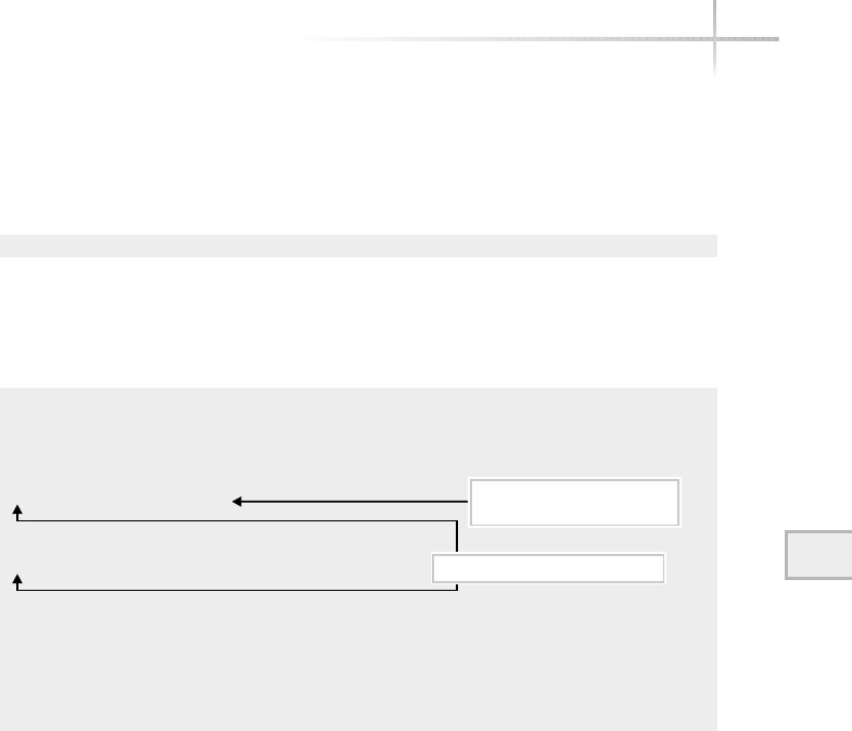
to determine if all the systems on the 216.155.202.0 network support some sort
of SNMP agent. Since SNMP can be a security hole, depending on how it has
been configured, the network should be scanned to determine which device
supports this protocol. The command
# nmap -p 161 -sU -o results 216.155.202/24
tells nmap to scan port 161 (the SNMP port) on network 216.155.202.0 using
UDP and then save the output information in a file called results. If we
display this file, we find the following sample output:
# nmap (V. 2.54BETA22) scan initiated Sat Jan 26 17:01:01 2002 as: nmap -p 161 -
sU -o results 216.155.202.0/24
Host (216.155.202.0) seems to be a subnet broadcast address (returned 2 extra
pings). Skipping host.
Interesting ports on bedrock.home.com (216.155.202.100):
Port State Service
161/udp open snmp
Interesting ports on dino.home.com (216.155.202.110):
Port State Service
161/udp open snmp
The 1 scanned port on didymus.home.com (216.155.202.163) is: closed
The 1 scanned port on (216.155.202.202) is: closed
The 1 scanned port on (216.155.202.204) is: closed
Host (216.155.202.255) seems to be a subnet broadcast address (returned 2 extra
pings). Skipping host.
# Nmap run completed at Sat Jan 26 17:02:21 2002 -- 256 IP addresses (5 hosts up)
scanned in 80 seconds
As it turns out, this is a very reasonable mechanism to use to inventory services
on a grand scale. Any TCP or UDP service can be queried using this approach.
This example demonstrates another powerful feature of this tool. Namely,
we can specify the target systems or networks using a few different notations.
First, we can specify an IP address using a list or ranges for each part of the
address. Thus we can scan an entire IP class with the “*” character. For instance,
128.197.*.* permits the scanning of the whole B class network. Another way to
express this is to use the dash character. Thus 128.197.1-255.1-255 is functionally
the same as using the 128.197.*.* syntax. Second, we can use the mask notation
as shown in the previous nmap command example. Namely, 128.197.0.0/16 will
mask and is equivalent to the two examples using either the “*” or “-” characters.
Finally, we can use a numbered sequence combined with the range syntax.
7
Module 7: System Security 215
7
The system is found in the
address range scanned
161 (SNMP) port found open

216 UNIX System Administration: A Beginner’s Guide
Thus 128.197.90.1, 2, 3, 4, 5, 100-105 will scan the following addresses:
128.197.90.1, 128.197.90.2, 128.197.90.3, 128.197.90.4, and 128.197.90.5,
as well as addresses 128.197.90.100 through 128.197.90.105. Using these IP
formats greatly improves the ease of scanning entire subnets or networks.
When scanning networks, it is sometimes helpful to know exactly what nmap
is doing at all times. For this reason, the -v option has been provided. Bear in
mind that a fair amount of output may be generated as a result, so it might be
important to use this option with caution. In the previous example, we scanned
an entire subnet. If we added the -v option when attempting to scan a single
host, more detailed information is displayed. For example, the command
nmap -v -sU -p 161 bedrock rocks spoons
shows the following sample output:
Starting nmap V. 2.54BETA22 ( www.insecure.org/nmap/ )
Host bedrock.home.com (216.155.202.100) appears to be up ... good.
Initiating UDP Scan against bedrock.home.com (216.155.202.100)
The UDP Scan took 0 seconds to scan 1 ports.
Interesting ports on bedrock.home.com (216.155.202.100):
Port State Service
161/udp open snmp
Host (216.155.202.101) appears to be down, skipping it.
Host (216.155.202.102) appears to be down, skipping it.
Nmap run completed -- 3 IP addresses (1 host up) scanned in 2 seconds
As you can see, more detailed specifics about the port scan are provided.
Also, nmap identified a single device that supports SNMP agent and is
reachable on the network, as noted by the lines containing the string
Host bedrock.home.com (216.155.202.100) appears to be up ... good
Both rocks and spoon are down, and nmap can’t probe the system
for information
Network Ports
The nmap program attempts to probe a standard set of network ports on the
target system. Also, it scans the entire range of ports from 0 to 1024 by default.
The standard TCP/IP and related protocol ports that nmap scans are listed in
Table 7-6 along with the service name and a general description of the network
service or function.

Module 7: System Security 217
7
Ask the ExpertAsk the Expert
Question Why does nmap skip a system if it initially appears to
be down?
Answer nmap is very smart about probing nonexistent or
down systems; it doesn’t spend much time or resources probing
nonresponsive systems. Before nmap attempts to scan a device, it first
determines if it is reachable on the network by performing a ping on
it. This not only reduces the amount of time required to perform the
scan and lessens system resources needed, but it helps to preserve
network bandwidth as well. It is important not to underestimate the
impact that scanning can have on a network, and nmap does a good
job of reducing the network requirements while probing.
Port Service Name Description
7 echo Echoes characters sent to this port; service provided by the
inetd or xinetd process; primarily used for testing
8 discard Discards any data sent to it; acts like /dev/null for
networking services and other networking applications;
primarily used for testing
13 daytime Provides time in human-readable format; primarily used
for testing
19 chargen Character generator; produces ASCII character set;
primarily used for testing
21 ftp File Transfer Protocol server
22 ssh Secure Shell server
23 telnet Telnet server; provides remote login services
25 smtp Simple Mail Transfer Protocol; usually sendmail or similar
server is listening on this port
37 time Provides machine-readable time
53 domain Domain Name Server process
79 finger Finger server process, which provides more information
about a particular user
80 http Web server process
111 sunrpc Sun Remote Procedure Calls service
199 smux SNMP master agent
Table 7-6 Standard NMAP Ports
When nmap sees that a port is active and can’t identify services running on
the port, it specifies the port as "unknown."
1-Minute Drill
●What are some of the key pieces of information you can obtain with the
nmap tool?
●How is nmap useful in helping secure your systems?
Project 7-1
In this project you will create or revise a security policy and you will determine
the port and service usage on your system or any systems in your control. You’ll
then disable any unnecessary ports and services and save the results of a repeat
port scan as documentation to compare against future port scans.
218 UNIX System Administration: A Beginner’s Guide
Port Service Name Description
382 hp-managed-node This process provides network management services for
HP network manager products.
512 exec Remote execution server with authentication
513 login Remote login with authentication
514 shell Remote shell server with authentication
515 printer Remote printer server
540 uucp UUCP server
4045 lockd Lock daemon (for NFS)
6000 x-windows X-Windows server
Table 7-6 Standard NMAP Ports (continued)
●nmap can tell you which systems in a network are up and accepting connections, which ports are open,
whether the ports are running TCP or UDP, what services are running on the open ports, and in some cases
what operating system the system is running.
●Hackers might use nmap (or other similar tools) to search for open systems and ports to launch attacks.
By using it to scan your own networks and systems, you can determine what systems and ports should be
open and accepting connections and if there are systems and ports open that shouldn’t be, harden them by
shutting off those services.

Step-by-Step
1. Find your company’s current security policy. (If your company doesn’t have a
security policy, find example security policies [possible from CERT or other
organizations] and create a draft security policy.) Study the policy for any
weaknesses, outdated sections, or overlooked areas and submit a revised
draft to your IT department manager.
2. Create an inventory of all the current open ports on your system and save
this list to a file (such as portsystemname, where systemname is the name of
your system).
# nmap -sU -sT -o port
systemname
3. Study the results of step 2 and look for any ports running services you don’t
recognize. Be suspicious of any services running on non-standard port numbers
(numbers other than the ones listed for them in table 7-6). Look for any obsolete
or insecure services you can replace with newer or more secure services.
4. Disable any services that you don’t need running after your step 3 investigation.
5. Rerun the command from step 2 and keep the results from this in a secure
place so you can refer to them as a “baseline” to compare results of the same
command to in the future to see if other services have been added or ports
opened without your knowledge.
6. If you are responsible for more than one system, or a group of systems on
a network, repeat step 2 and specify the system names for all the systems
(if there are just a few) or the IP address range (if there are several systems
in the same range). If there are other systems in this IP address range that
you are not the administrator for, don’t use the IP address range method,
as the administrator for those systems probably doesn’t want you running
the nmap command against those systems. The format for this command
would be
# nmap -sU -sT -o portsnetwork
systemname1 systemname2 ...
where systemname1 systemname2 ... are the names of the systems to scan, or
# nmap -sU -sT -o portsnetwork
ipaddressrange
where ipaddressrange is the range of IP addresses to scan using one of the
formats demonstrated earlier.
Module 7: System Security 219
7

7. Repeat steps 3 and 4 for each individual system you are responsible for. If
you notice patterns of ports that are open or services in use that don’t need
to be, these may provide you with information to improve your system
security profiles in your security policy.
8. Repeat step 5 for each system individually, saving the results in a separate
baseline file for each system.
# nmap -sU -sT -o port
systemnamex systemnamex
The Secure Shell Facility
The secure shell service provides strong security features for remote system
access to include file copy and terminal access. It also can be used to provide a
secure connection for X-Windows and other services. SSH is the ideal replacement
for such tools as rsh,rlogin,rcp, and telnet because it provides the same
services, plus it provides a secure connection when passing data so that information
between the client and server is private. For example, as shown in Figure 7-1,
a workstation can access sensitive information from a server, while the data is
traversing the unsecure network, without the worry that a would-be hacker
might capture the information flowing between the workstation and server.
Assuming that the information was in fact captured by someone in the middle,
eavesdropping on the connection, the information captured would be of little
value since the information is encrypted and it would require a significant effort
to decrypt the information to make it useful. This is a powerful feature and
opens up many possibilities for the systems administrator because they can
provide secure access regardless of the client location or level of security within
the network.
In addition, based on the use of host keys, client and server authentication
is greatly enhanced over existing services with the r-commands (rlogin,for
instance) or telnet. The SSH model for establishing security requires the
user to validate her or his identity on the remote system. SSH uses two broad
approaches when authenticating users, which are known as SSH protocol
version 1 and 2. These are described in Table 7-7.
The implementation of SSH is meant to be easy; as a result, SSH supports
the old style of authentication based on trusted hosts (this is described as
Version 1–Option A and B). This was the security model of the r-commands
that were introduced in the BSD version of UNIX many years ago—namely,
220 UNIX System Administration: A Beginner’s Guide
TEAMFLY
Team-Fly®
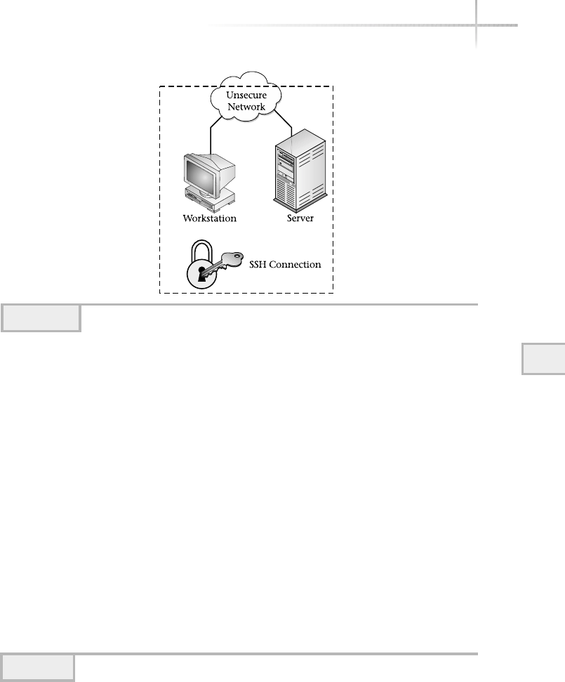
7
Module 7: System Security 221
Figure 7-1 SSH secure network
SSH
Authentication Description Files Consulted
Version 1–Option A If the machine the user is logging
from is listed in one of these files
on the remote system, and the
usernames are the same, the user
is granted access.
/etc/hosts.equiv
/etc/ssh/shosts.equiv
Version 1–Option B If the machine the user is logging
from is listed in one of the user’s files
on the remote system, and contains
the username, the user is granted
access. Note: This may not be true
for all implementations of SSH.
$HOME/.rhosts
$HOME/.shosts
Version 1–Option C Uses RSA-based host authentication
combined with Version 1–Option A
and Version 1–Option B.
/etc/hosts.equiv
/etc/ssh/shosts.equiv
$HOME/.rhosts
$HOME/.shosts
$HOME/.ssh/identity.pub
Table 7-7 SSH Authentication Methods

the use of $HOME/.rhosts and /etc/hosts.equiv files. These files can
contain either a username/host ($HOME/.rhosts) pair or just a hostname
(/etc/hosts.equiv), which was compared to the client’s username and
local hostname. If there is a match, the user is granted access to the remote
system. Although SSH supports these older authentication methods, they
are inherently insecure and their use is severely discouraged. The security
limitations of the r-commands and associated files are widely known (and
have been for quite some time), and have been the cause of a large number
of security-related problems and issues.
The components of SSH are listed in Table 7-8 and the software package is
available for all major operating systems, including Microsoft operating systems.
With SSH support for so many operating systems, it is one of the best choices
for providing secure client/server connectivity.
ssh
The ssh tool provides the capability for logging into a remote machine and
for executing arbitrary commands on the remote system. It provides the same
remote shell access features as the standard rsh or telnet connectivity tools
and also supports strong security elements so that it is possible to permit
sensitive information to flow through an insecure network, such as the Internet.
Like rsh or telnet, when ssh is supplied a valid SSH server name on the
command line, it attempts to make a connection and provide a shell on the
remote machines, if successful. For example, if the remote server called dino
has to be configured to support an SSH server, the command
ssh dino
222 UNIX System Administration: A Beginner’s Guide
Tool Purpose
ssh Provides a remote shell to the specified host using secure connection
scp Provides remote copy facility using secure connection
ssh-keygen Generates an SSH key for authentication of the remote system
ssh-agent Provides a way to preload an SSH key for authentication
ssh-add Adds a passphrase to a running ssh-agent
Table 7-8 SSH Core Elements
Module 7: System Security 223
7
would provide a remote shell to the system, once authentication from the client
to the server has been established. Thus, before a remote shell was made
available, the user would need to authenticate by supplying the remote user’s
password. The following example shows sample output generated when
running the ssh as the root user:
root@dino's password:
Last login: Fri Jan 25 13:25:39 2002 from didymus.home.com
Sun Microsystems Inc. SunOS 5.8 Generic February 2000
No mail.
# dino>
As you can see, the user was required to input the root account password for
the connection to succeed. If the user didn’t know this password, the request
would have been denied after the ssh prompted for the password three times:
root@dino's password:
Permission denied, please try again.
root@dino's password:
Permission denied, please try again.
root@dino's password:
Permission denied.
SSH provides a shortcut for busy system administrators; by placing the
client’s host key on the remote host, it is possible to prevent SSH from
prompting for the remote account password. For example, Figure 7-2 shows a
single client and several SSH servers. By placing the user’s host key on the other
server’s system, whenever the user uses SSH to gain access to those servers, the
user will need to valid her or his identity further.
scp
The scp command provides remote file copy facilities between a client system
and an SSH server. The command provides the same basic features as the rcp
command, plus the data is encrypted to ensure privacy.
ssh-keygen
The ssh-keygen command is used to create an SSH host key for the local
system. This program does a couple of things. First, it generates both a public
Password prompt
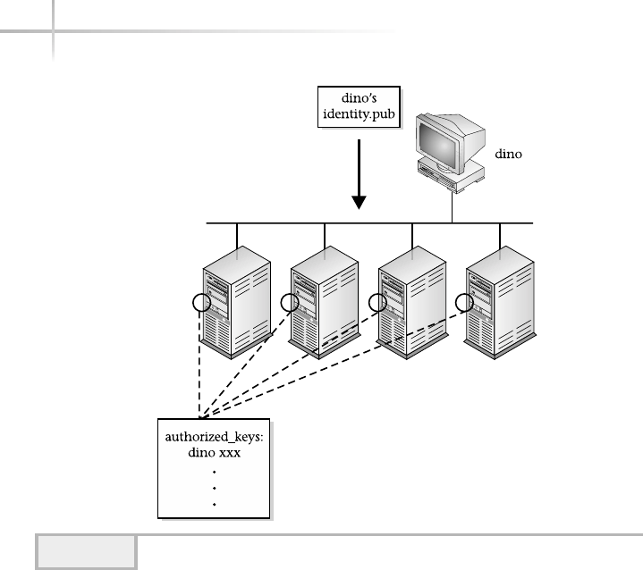
and private key pair associated with a particular user—the user is responsible
for running this command. The private key is stored under the .ssh directory
in a file called .identity (note the dot “.” at the beginning), which is
located within the user’s home directory. It stores the public key in the
identity.pub file under the same directory. These keys are used as part
of the authentication process when the user makes a request to an SSH server.
When a user executes the ssh-keygen program, it asks to specify
which file should be used to save the private key. Typically, the default path
($HOME/.ssh) and filename (identity) are suggested. Then, it prompts
twice for the SSH passphrase (the second is to confirm the first prompt).
Depending on which system this command is invoked on, the output can be
somewhat different. On Solaris, for example, ssh-keygen also displays the
entire public key string, while other systems don’t.
224 UNIX System Administration: A Beginner’s Guide
Figure 7-2 SSH host key placement

Module 7: System Security 225
7
To generate an SSH host key pair, issue the following command
# ssh-keygen
The example shows the output that was generated from a Solaris system:
Initializing random number generator...
Generating p: ............++ (distance 190)
Generating q: ...............................................++ (distance 730)
Computing the keys...
Testing the keys...
Key generation complete.
Enter file in which to save the key (//.ssh/identity):
Enter passphrase:
Enter the same passphrase again:
Your identification has been saved in //.ssh/identity.
Your public key is:
1024 33
1310027470808505525984351817590366936660983333030447140662790561230497737560235105780
3082576600113762558121351675124104962600689209801039269327397031784881422946150905334
0467209527663138399850223963639073057061948822295225599426944591345678523218150262932
928070176515462990304575837519065722636254119188580761 root@dino
Your public key has been saved in //.ssh/identity.pub
When the same command is run from a Linux system, the following sample
output is shown:
Generating public/private rsa1 key pair.
Enter file in which to save the key (/root/.ssh/identity):
Enter passphrase (empty for no passphrase):
Enter same passphrase again:
Your identification has been saved in /root/.ssh/identity.
Your public key has been saved in /root/.ssh/identity.pub.
The key fingerprint is:
2e:0f:a0:97:6a:62:6b:c8:56:89:00:fa:5c:43:bd:2f root@didymus
The major reason for output differences has to do with the versions of SSH.
The SSH release running on Solaris is the newer Version 2, while Version 1 is
running on the Linux system.
ssh-agent/ssh-add
The ssh-agent program is used to hold one or more user authentication keys
on the user’s behalf. The ssh-add command will preload the user’s passphrase

226 UNIX System Administration: A Beginner’s Guide
into a running ssh-agent. When ssh or scp are invoked, these tools check
to see if an ssh-agent is running and queries to see if a user’s host key has
been added. If so, it uses the host key that the ssh-agent provides; otherwise,
the user is prompted for their passphrase. To manually run the ssh-agent,
do the following:
eval `ssh-agent`
Then issue the ssh-add command to add the user’s passphrase:
# ssh-add
The Sudo Tool
The sudo command provides the facility for a generic UNIX user to execute
privileged commands that normally can only be run by the root user. This
security command solves the problem of having different classifications of
system accounts; one or more users can be given access to certain privileged
commands that they must be able to invoke, but without the assistance of the
local system administrator. Figure 7-3 provides a high-level view of how the
sudo command works. By defining sudo users, the administrator can reduce
the total number of tasks that he or she must perform by giving other less-
important duties to others or meet the requirements of certain power users so
that they can perform their jobs satisfactorily. The sudo command provides
detailed logging capabilities so that all commands executed through sudo are
recorded for later inspection and review.
The sudo command uses a single configuration file (/etc/sudousers),
which is used to define users and any associated commands they can invoke.
For example, to give the users anitat and stevem permission to do account
administration on the system, the following entry can be used:
User_Alias SPECIALUSERS = stevem, anitat
Cmnd_Alias USERADMIN = /usr/sbin/useradd, /usr/sbin/userdel, /usr/sbin/usermod
SPECIALUSERS ALL = USERADMIN
For the users (stevem and anitat) to add a new user account to the
system (via the useradd command) using sudo, they would need to execute
the command as follows:
sudo /usr/sbin/useradd
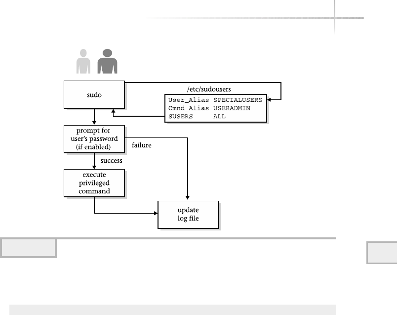
Thus, to add the user georgew to the system, the command
sudo /usr/sbin/useradd georgew
would need to be executed.
The sudo configuration file supports keyword/value directives that control
basic operation and functions. These keywords have associated values or
parameters and are assigned with the equals (=) character. Keywords can be
either aliases or flags. There are four alias types, as listed in Table 7-9. A sudo
alias is a list of elements separated by a comma (,) and contains a group of
strings (such as username). Flags can be variable definitions or options that
alter some default behavior, characteristic, or value.
In the example above, two aliases are defined: User_Alias and Cmnd_
Alias. In the first case, the alias SPECIALUSERS is defined, which contains
the list of users that should be granted privileges. The example includes
two UNIX users (stevem and anitat). Of course, a longer list could have
been constructed.
Module 7: System Security 227
7
Figure 7-3 High-level function of sudo

Project 7-2
In this project you will lock down your system security by finding and removing
any sudo permissions that give users accesses and permissions they don’t need.
Step-by-Step
1. Examine the /etc/sudousers file on your system.
2. Look for any users or commands that you don’t want other users to have
and remove them.
228 UNIX System Administration: A Beginner’s Guide
Keyword Purpose
User_Alias Defines a list of users that can (or can’t) execute a specific command.
Runas_Alias Defines a username to run a specific command.
Host_Alias Defines a list of hosts that a user can (or can’t) execute a specific command on.
Cmnd_Alias Defines a list of commands for invocation by sudo users.
Table 7-9 Sudo Keyword Aliases
HintHint
When using sudo, it will be important to determine which types of commands
should be made available. Also, classifying the users will be important.

Module 7: System Security 229
7
Mastery Check
1. Which of these commands lists open ports and associated services
on a system?
A. nmap
B. find
C. sudo
D. ssh
2. What is the command to probe ports with both TCP and UDP scan and
direct the results to a file named probeports?
3. What word in the services column of an nmap scan indicates nmap wasn’t
able to identify the service on this port?
4. Which of the following would be a correct way to TCP scan all systems on
a network with addresses beginning 192.168.1., checking all ports from
1–1024 and any additional ports in the nmap-services file? (Choose
all that apply.)
A. # nmap -sT 192.168.1.*
B. # nmap -sU 192.168.1.*
C. # nmap -sU 192.168.1.1-255
D. # nmap -sT 192.168.1.1-1024
5. The sudo command provides the facility for a generic UNIX user to
execute __________ commands that normally can only be run by the
root user.
6. Which of the following is not one of the general steps for providing robust
system security?
A. Develop and publish a security policy.
B. Maintain system patches.
C. Do system backups.
D. Use security tools.

230 UNIX System Administration: A Beginner’s Guide
7. __________ is the ideal replacement for such tools as rsh,rlogin,rcp,
and telnet because it provides the same services, plus it provides a
secure connection when passing data so that information between the
client and server is private.
8. What is the correct command to log in securely to the remote system
named bedrock as the user named barney?
A. rlogin bedrock barney
B. ssh barney
C. sudo barney
D. scp bedrock barney
9. What is the Linux command to generate a secure key pair for SSH?
10. A __________ defines what actions groups of users may use their systems
for, how to administer security, and how to recover from security breaches.
Mastery Check
TEAMFLY
Team-Fly®

Module8
Backup and Restore
Critical Skills
8.1 Define Backup Elements
8.2 Explore Backup Tools
Copyright 2002 by The McGraw-Hill Companies, Inc. Click Here for Terms of Use.

232 UNIX System Administration: A Beginner’s Guide
One of the most important (but least enjoyed) duties of the system administrator
is performing backups and retrieving (restoring) users’ files. Having said
that, it is possible to have the entire backup process completely automated to
such a degree that these tasks are not that painful to perform. This, of course,
requires that you develop your own backup scripts or purchase scripts and/or
backup tools that provide these types of services. In fact, many great products
are available on the market today that solve many important backup-related
problems. However, it is beyond the scope of this book to review third-party
commercial tools. Instead, this section reviews some of the standard backup-related
tools that are available with the basic operating system.
The funny thing about system backups is that you typically only need them
when something goes wrong—a faulty hard drive, a user mistakenly deletes
important files, a system crashes and can’t be repaired quickly, and so forth.
These events are not likely to happen every day or even every week, but we
know that eventually the need will arise to retrieve information from backup
tapes or other media. Like car insurance, backups protect against future disasters
and problems when they strike. We don’t know the day or hour when something
is going to happen, so that is why it is important to be prepared.
Before attempting to evaluate backup software, develop backup scripts, or learn
new backup commands, it is important to determine the exact backup and restore
requirements for the computing environment and user community. For example,
the requirements for a stand-alone system with a single user will be different versus
a large system that supports a critical application with many users. In addition to
the user and/or system requirements, there are other important factors that can
impact the backup strategy, such as can the corporate and/or individual subnetwork
handle the backup traffic or will the network require an upgrade to handle the new
load? In most environments, some type of backup solution may already be in place
and any new solution might need to provide backward compatibility.
As you can see, the subject of backups can be a complex one. However,
information contained within this section can be used to develop a backup
approach to address requirements for many different computing environments
and organizations.
8.1 Define Backup Elements
This section reviews some of the specific elements when attempting to
formulate a backup strategy or approach. Like most things in life, having a plan
in place before doing any work is a good thing, since the planning process can
identify critical components and issues that may otherwise not be uncovered

Module 8: Backup and Restore 233
8
until the project is well along, which in some situations can be quite disastrous.
When formulating a backup plan, the following elements should be examined:
●User perspective
●Density and form factors
●Network bandwidth
●Remote sites
User Perspective
Regardless of the tools used to perform backups, it is extremely important that
users understand the backup policies and procedures and any duties that are
required of them. For example, given a network of workstations and servers,
how are the workstations going to be backed up? What happens when a user
reboots her or his system in the middle of the backup process? What should
be done in these cases? These types of questions and associated answers should be
documented for all users. Should a user need to retrieve one or more files from
the backup system, what is the procedure that should be followed? Going further,
what is the response time for retrieving the requested information? Certainly, if
information is needed for some production service, then the response is related
to the importance of the information being retrieved.
In some situations, a user may request that their individual account be
backed up so that the information can be made available to another system.
How should this be done? If the new system is only available on the network
and connectivity can be established between both systems, a simple file transfer
might be sufficient. However, suppose the second system is not on the network.
Then some other approach to getting the user’s information on the system is
needed. Thus, the backup plan should include this if users will be making these
types of requests.
To address some of the above concerns, it is recommended that a FAQ be
developed and made available to the user community. However, this is just
documentation—the user requirements must be taken into consideration
when determining the backup plan.
Density and Form Factor
Determining the amount of information that will need to be backed up is an
important element to the overall backup approach, but this can sometimes be

234 UNIX System Administration: A Beginner’s Guide
difficult to measure or forecast. Why? Because requirements can change very
quickly as the company changes to meet new challenges. However, this is where
having some instincts can come in handy. Since it is not possible to know what
will happen in the future, it is reasonable to make an educated guess about the
backup storage needs given answers to certain questions. For example, how
many systems need to be backed up, what is the total amount of storage on
each system, and on what basis will backups be done. This is the who,what,
and when approach to determining total storage capacity.
The who is how many systems will be a part of the backup plan. This should
include workstations, PCs, servers, and so forth. Let’s assume the following:
20 workstations, 10 PCs, and 4 servers. The what relates to the total disk capacity
of each system that will be backed up. For example, let’s assume that each of
the workstation contains a total of 20 gigabytes of storage, each PC contains
5 gigabytes, and each server has 40 gigabytes. Also, it would be helpful to know
the amount of available disk space. Use the df and du commands to determine
total disk space, plus what is being used. The when is the frequency for when
the backup will be performed on some or on all of the target systems. Will the
systems be backed up every day or on some other interval? Certainly, in the case
of a much-used production system, a very stringent regime will be needed to
ensure the best possible coverage for backups. However, this comes with a price,
because more backup storage will be needed.
Once the total amount of backup capacity has been determined, you must
figure out what kind of backup media to use. Table 8-1 lists some of the
common formats that are available today.
Storage Format Description
Tape Liner magnetic tape; large densities are available such as 80GB of
data with compression. Storage tape comes in all sizes and shapes.
Removable disk Removable media such as Zip, Jazz, and so forth are quite popular.
Storage capacity ranges from 250MB to over 2GB. CD-ROMs and
DVDs are another good example of this type of media.
Fixed hard drive It is becoming more common to back up systems using regular
hard drives contained within a special storage unit. These units
can be magnetic or optical.
Table 8-1 Different Storage Formats

8
Module 8: Backup and Restore 235
8
Network Bandwidth
One factor that is sometimes overlooked when performing backups is the
amount of network bandwidth that is required to back up all the required
systems. This is particularly important when the backup server is centrally
located within the “core” of the network and when most of the systems that are
being backed up are on the “edge” of the network. The edge is defined as being
closest to the user community but farthest from the core of the network. Edge
devices consist of workstations, printers, and so forth, and depending on the
network infrastructure, the performance from the edge to the core may not be
able to handle backup traffic while other activities are in progress. This is one
of the major reasons that many sites do backups at night—because the network
is least busy due to the systems not being used.
One very good way to determine the potential bandwidth that might be used
during a backup session is to examine the performance of the backup server
itself. For example, modern backup systems boast of transferring approximately
20GB per hour onto storage media. This is impressive performance given the
capabilities of systems just a few years ago. However, despite this transfer rate,
the total overall bandwidth is limited by the network interfaces from the backup
server and associated target systems (the systems that need to be backed up).
Thus, if the backup system is attached to the network using relatively seasoned
equipment, network performance will affect how much time it will take to
perform a backup.
Consider a standard 10 MB/s network. You can only get about 1.4 GB per
hour of data transfer. Why? Well, for starters, a 10 MB/s network doesn’t really
deliver that kind of performance. Instead, based on the operating system,
network protocols, and other factors, the performance might be in the range
of 3–4 MB/s, and this might be on the high side. Next, a consideration must
be made for the load on both the server and workstations. This will affect how
network requests are handled by each of these systems. On a heavily loaded
system, the network traffic may suffer because the system can’t keep up with
the network traffic. Finally, local area networks (LANs) are shared resources,
and typically no single device gets all the available network bandwidth, which
means that the backup system will compete with other applications. Of course,
if the backups are done during nonpeak times when other applications are not
running, this issue is negated.
Luckily, newer LAN technology is available, which significantly increases the
network bandwidth and performance that is available for applications such as
backups. However, many corporations haven’t upgraded to the new technology.
Regardless, consideration for the network must be made when determining when
and how to perform backups.

Remote Sites
If it is necessary to back up systems that are located within one or more
remote sites, where network connectivity is limited, then additional planning and
examination of the computing environment is necessary. For example, would it
be possible to install a backup server at the remote site instead of attempting to
back up using a central server located at the corporate site? Another approach
is to upgrade the network connection between the remote site and the corporate
site to support the backup traffic.
Backup Methods
In general, there are several different kinds of backups that you can perform,
and depending on the specific goals you have in mind, you might choose one
method over another. However, it is not uncommon for one or more methods
to be used for different types of systems. Table 8-2 contains a description of the
different backup methods.
Image Backup
These types of backups bypass the file system and access the information using
what is known as “raw” mode. This mode simply copies all the data of a file
system without knowing any specific details of the components and/or elements,
such as files or directories and so forth. Image backups are much faster than
other backup types because no interpretation of the information must be done.
With UNIX, backup tools access the raw version of the file system by using
a special device file.
236 UNIX System Administration: A Beginner’s Guide
Backup Type Description
Image (raw) Copies the raw bits from the disk without using the file system.
File system – full Using the file system, copies all files and directories regardless
of when the last backup was done.
File system – incremental Using the file system, copies only the files that have changes
since the last time a backup was taken.
File archive Using the file system, copies all files and directories regardless
of previous backups.
Table 8-2 Backup Approaches

File System (Full)
Some backup tools access the file system directly when performing backup
activities, which means that they understand the internals of the file system and
maintain complete integrity of the information. This is in contrast to other tools,
which access the raw version of the file system. Such tools lack the understanding
of the specific file system structure and associated elements. Tools that back up
the file system directly usually support one more file system types. For example,
the extdump command supports the EXT file system. Thus, not all tools that
perform file system backups are complete compatible.
File System (Incremental)
An incremental backup is one that captures all of the changes made within a file
system since the last backup was taken. The purpose of incremental backups is
to reduce the amount of time and storage requirements, since only the changes
are captured. As compared to full backups, this can significantly reduce the
backup resources needed. The only problem with doing incremental backups
is that when retrieving files, it can be difficult to find the necessary files, since
they can be located on different incremental backups.
File Archive
The file archive method is the simplest backup format, since it just archives
individual files and directories onto a regular file or other storage media. UNIX
tools that support this backup type are the tar and gnuzip commands.
1-Minute Drill
●Why might you use more than one backup type in your backup plan?
●If you are performing network backups, what factors will limit the amount
of data you can back up in one session?
Module 8: Backup and Restore 237
8
●To conserve backup time but still maximize backup coverage, you might use different backup types. For
example, your plan might implement full file system backups once a week on weekends (or another low
usage time) and daily incremental backups at night. This minimizes the amount of data to back up each
night, ensures a recent backup of all data, and keeps the number of different incremental tapes you’d need
to search to just a week’s worth when restoring.
●In addition to your backup device’s rated speed, the network’s overall speed, the operating system’s ability
to utilize the network, the user and application load on the network during the backup, and competition
for bandwidth between other network devices will all limit network backup performance.

8.2 Explore Backup Tools
The UNIX system provides a powerful set of robust backup tools and for the most
part the same set of tools are available for most of the UNIX versions currently
available on the market today. Some of the most common tools are listed in
Table 8-3. The major benefits for common availablity of the tools are consistency
and compatibility. For instance, the basic operation of the commands is the same
so that if the administrator develops custom scripts, those scripts can be used
across a variety of UNIX systems with major operating system changes. Second,
if the backed up data is compatible with different UNIX versions, backups can be
made on one system and restored on another. This sort of thing isn’t something that
would be done every day, but administrators might like the option of doing so.
dump
The dump command provides one of the best ways to perform file system
backups. It can be used to provide both full and incremental backups of a
number of different file systems. It supports a large number of options to
control how backups should be done. Table 8-4 contains the most common
options. This tool is used at more sites than any other single backup tool.
238 UNIX System Administration: A Beginner’s Guide
Tool Description
dump Performs full and incremental backups of file systems (Solaris, ufsdump—
for Linux and HP-UX, the command is known as dump).
dd Can be used to perform image-type backups.
restore Used to retrieve file and directories from backups taken with the dump
command (Solaris uses ufsrestore;restore for the other operating
systems).
tar General-purpose archiving tool.
volcopy Performs full image backup of a file system for the Solaris platform.
Table 8-3 Backup/Restore Tools
HintHint
Both Linux and HP-UX have an official dump command. However, the Solaris
system uses the ufsdump command instead, but it provides the same basic
services and even supports many of the same command-line arguments. For
simplicity, all of these backup tools will be referred to as just dump. In the cases
where an important command-line or functional difference exists between the
operating system commands, it will be noted.

Module 8: Backup and Restore 239
8
To perform a full backup of the /file system to a local tape unit, use the
following command:
ufsdump 0f /dev/st0 /
When this command is invoked, the following output is generated:
DUMP: Writing 32 Kilobyte records
DUMP: Date of this level 0 dump: Wed Jan 30 11:13:41 2002
DUMP: Date of last level 0 dump: the epoch
DUMP: Dumping /dev/rdsk/c0d0s0 (bedrock:/) to /dev/st0.
Option Description
0-9 The backup dump level to use; this controls which files will be saved.
-D Save the backup to a diskette device. This is somewhat limited since
diskettes are quite small and can’t store much information.
-S Determine the total size of a backup, without actually doing the backup.
-a Specify the archive file to use so that when a restore is performed, it can
be searched to determine if a particular file/directory is contained within
the backup.
-b Use the blocking factor when making the backup. The default is 20 and
is specific to the storage media used.
-f Specifies the dump file, which is usually a storage device such as tape
or disk. When the “-“ character is used, the standard output should be
used instead.
-l Control the backup storage media so that when the dump is complete,
dump will pause to give the storage device time to automatically reload
a new tape or media.
-n Inform the operator when dump requests attention, such as mounting
a new tape.
-t Controls the amount of time to wait for the storage device to autoload
another tape. Used with the –l option.
-v Perform a verification on the backup media as the last step in the process.
-w Issue a warning when dump detects a file system that hasn’t been
backed up.
Table 8-4 Dump Command-Line Options
HintHint
When performing full backups of the system, it is important the system not be
used and the file system be unmounted during this time. Failure to unmount
the file system during a system backup can lead to problems!

240 UNIX System Administration: A Beginner’s Guide
DUMP: Mapping (Pass I) [regular files]
DUMP: Mapping (Pass II) [directories]
DUMP: Estimated 78032 blocks (38.10MB).
DUMP: Dumping (Pass III) [directories]
DUMP: Dumping (Pass IV) [regular files]
DUMP: 78014 blocks (38.09MB) on 1 volume at 638 KB/sec
DUMP: DUMP IS DONE
dd
The dd command can be used to perform image-level backups. However, this is
just one of the many uses for this command. Its primary use is to convert from
different file formats (like ASCIII or EBCDIC). Like dump, this command also
has a large number of command-line options. The most common ones are
described in Table 8-5.
To perform an image-level copy of the root file system to the local tape
drive, do the following:
dd if=/dev/dsk/c0d0s0 of=/dev/rmt/1
When the command has completed, the following will be displayed:
1024128+0 records in
1024128+0 records out
which shows the amount of data that was both read and written.
restore
The restore command is used to retrieve files and directories that were
created using the dump command. One powerful feature of this command is
that it has an interface mode, which can help with restoring specific files and/or
directories. Like dump, this command also has a large number of command line
options. The most common ones are described in Table 8-6.
Option Description
bs Determine both the input and output block size.
if The file (device) to read.
ibs Specify the input block size.
of The file (device) to write.
obs Specify the output block size.
Table 8-5 dd Command-Line Options
TEAMFLY
Team-Fly®

8
To restore a complete file system backup onto a brand new file system
(assume the new file system is contained within c0d0s5 partition), do the
following:
newfs /dev/dsk/c0d0s5
fsck /dev/dsk/c0d0s5
mount /dev/dsk/ c0d0s5 /mnt
restore rf /dev/mnt/1
tar
The tar command can be used to build an archive of files and directories within
a file system. It really isn’t the best approach to performing system backups, but it
does provide some powerful backup-like features. The most common command-
line arguments are described in Table 8-7.
To make an archive of all the files on the system on a local tape, use the
following command:
# tar -cvf /dev/mnt/1 /
Module 8: Backup and Restore 241
8
Option Description
-C Permits the comparison of the files that have been backed up using dump.
-i Use interactive mode.
-r Restores a complete backup onto a new file system.
-t List specific files and/or directories contained on a backup.
-x Retrieve a specific file or directory.
Table 8-6 Restore Command-Line Options
Option Description
-c Create a new archive file.
-f Specifies the file (or backup media) to archive the information onto.
-X Extract files from the archive.
-v Enable verbose mode.
Table 8-7 Common tar Command-Line Options

In this example, the tar command will recursively copy all the files and
directories encountered from the root file system. Using the verbose mode
option v,tar produces a list of all the files/directories that have been copied
successfully to the tape:
a // 0K
a //lost+found/ 0K
a //usr/ 0K
a //usr/lost+found/ 0K
a //usr/X symbolic link to ./openwin
a //usr/lib/ 0K
a //usr/lib/libICE.so symbolic link to ./libICE.so.6
.
.
Because this command produces a significant amount of output, it has been
reduced to save on space.
To extract the archive, use the xoption as shown below:
tar -xvf /dev/mnt/1
To list the contents of an existing archive, use the toption, which shows the
contents within the archive:
# tar -tvf /dev/mnt/1
It will show the following:
drwxr-xr-x 0/0 0 Jan 30 11:20 2002 //
drwx------ 0/0 0 Nov 11 16:00 2001 //lost+found/
drwxr-xr-x 0/3 0 Nov 11 16:55 2001 //usr/
drwx------ 0/0 0 Nov 11 16:01 2001 //usr/lost+found/
lrwxrwxrwx 0/0 9 Nov 11 16:01 2001 //usr/X symbolic link to ./openwin
drwxr-xr-x 0/2 0 Nov 11 16:59 2001 //usr/lib/
lrwxrwxrwx 0/0 13 Nov 11 16:01 2001 //usr/lib/libICE.so symbolic
link to ./libICE.so.6
lrwxrwxrwx 0/0 26 Nov 11 16:01 2001 //usr/lib/libICE.so.6 symbolic link
to ../openwin/lib/libICE.so.6
242 UNIX System Administration: A Beginner’s Guide

Module 8: Backup and Restore 243
8
Project 8-1
This project will familiarize you with the backup and restore commands and
give you some practice preparing a backup.
Step-by-Step
1. Determine the amount of data on your system that you need to back up.
Display all the file systems on your system and the amount of data used by each:
df –k
2. Determine if you have a backup device to create a backup on or if you have
an unused partition with enough free space for a backup.
3. If so, create a full system backup to the device or partition with the dump
command. You’ll use level 0 to indicate a complete backup of all files and
use the appropriate options to create the backup on your backup device
or partition. (Remember, don’t do this at a time when the system is in
heavy use.)
4. After modifying or adding some files (create or copy some dummy test files)
create an incremental backup of just the files created or changed since your
level 0 backup in step 1. Do this as a level 1 dump, with the appropriate
options for your backup device or location.
5. Use the restore command to restore just the files from your level 1
incremental dump, working in interactive mode and follow the prompts:
#restore -i

244 UNIX System Administration: A Beginner’s Guide
Mastery Check
1. What type of backup copies the bits from the disk without using the
file system?
A. Image
B. File system - full
C. Dump
D. File archive
2. A __________backup is one that captures all of the changes made within
a file system since the last backup was taken.
3. Which command is the primary UNIX command most often used for
backup tasks?
A. dump
B. dd
C. restore
D. tar
4. Which command is used to retrieve files backed up with UNIX’s primary
backup command?
A. dump
B. dd
C. restore
D. tar
5. Which command is used primarily to convert data between different
formats but also performs backups?
A. dump
B. dd
C. restore
D. tar

8
Module 8: Backup and Restore 245
8
6. In the following set of steps, what action does each of the first 3 steps
perform?
newfs /dev/dsk/c0d0s5
fsck /dev/dsk/c0d0s5
mount /dev/dsk/ c0d0s5 /mnt
restore rf /dev/mnt/1
7. In this command, what device is the file system being backed up to?
dump 0f /dev/st0 /
Mastery Check

This page intentionally left blank.

Module9
System Operations
Critical Skills
9.1 Determine the Boot Process
9.2 Explore the Shutdown Process
9.3 Uncover UNIX Operating Levels
Copyright 2002 by The McGraw-Hill Companies, Inc. Click Here for Terms of Use.

248 UNIX System Administration: A Beginner’s Guide
The UNIX system is a complex arrangement of tools, applications, and
processes. When the system has booted and is operating normally, certain
key processes and services are automatically activated. As the administrator,
you will need to control and/or alter how the system boots, as well as monitor
and control system processes and services. Sometimes when critical system
administration tasks must be performed, the system will need to be brought
into maintenance mode. This mode provides an environment where the tasks
can be performed while keeping users off the system. When the required
administration tasks are complete, the system can be brought back to the
normal operating mode. Also, depending on the nature of the administration
tasks, it is not always necessary to change the operating mode of the system.
9.1 Determine the Boot Process
When a UNIX system is started, it goes through a series of steps to bring the
system to the desired operating mode. This is known as the UNIX boot process
and is controlled by automated scripts that can be modified by the system
administrator. Typically, the system’s boot process doesn’t change that much
once the system has been set up and configured. However, if new services are
added or removed, the system boot configuration can be modified. Also, if the
system is having problems, the boot process can be altered on the fly so that
the problem can be fixed and system restored to normal operations.
Booting the system basically involves loading
and executing the operating system so that the
normal system is available to the users. As you
might imagine, every operating system contains
booting elements that are different. Despite this,
all operating systems follow the same generic
procedure to start the system. The difference is
in the specifics of how the bootstrap process is
accomplished for each system. For example, the
System V variant operating systems are really
different as compared to the BSD-related versions. Luckily for the system
administrator, most versions of UNIX have a standard boot process, which
is shown in Figure 9-1.
The boot process involves several important steps; first, the UNIX Kernel
program is started which is the master controlling entity within the system.
HintHint
The standard boot
process presented may
not include boot services
or functions, which can
be found in different
releases of UNIX today.
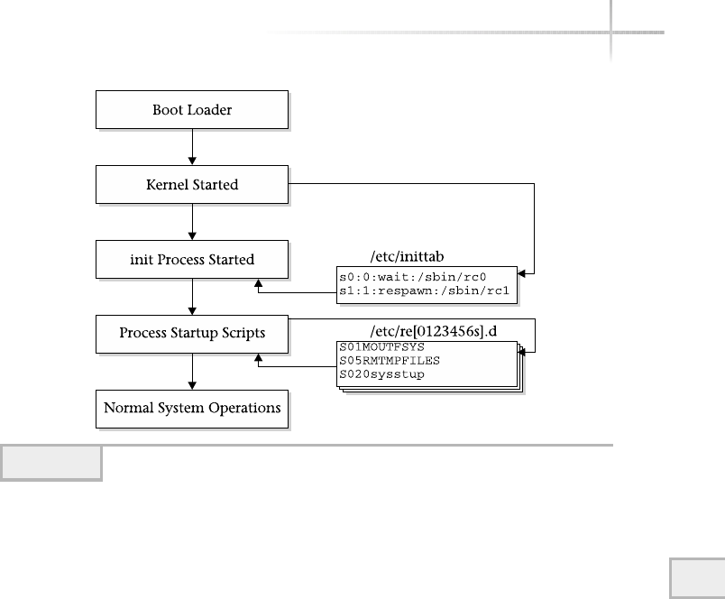
Module 9: System Operations 249
9
Under Linux, for example the LILO boot loader can be used to boot the kernel.
Next, the Kernel starts the init process. This process has the process id of 1 and
is known as the father or master system process. The init process is responsible
for starting all the correct processes by executing specific startup scripts (script
files that begin with “S”) that reside in the /etc directory. Finally, any additional
system processes (such as checking the file systems) are done and the system
starts normal operations.
9.2 Explore the Shutdown Process
The UNIX shutdown process is not completely the reverse of the boot process;
instead, the administrator executes a specific command, which brings the
system down in a graceful fashion. There are several ways to bring the system
down; it really depends on what you really want to accomplish. Table 9-1
shows some of the most common ways to either reboot or halt the system.
Figure 9-2 shows the generic steps involved with bring a UNIX system shutting
down a system. One of the commands listed in the table is executed by the
Figure 9-1 UNIX boot process
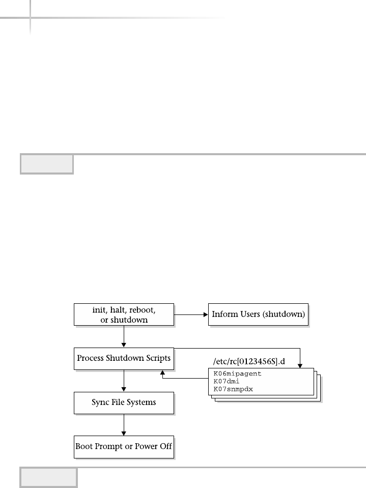
system administrator, which causes a chain reaction to bring the system down.
First, the shutdown scripts (script files that begin with “K”)are invoked in the
/etc directory, which basically stops all the system processes. Next the file
systems are checked (unless the administrator explicitly doesn’t have them
checked) and then the system is halted. Typically, the system is brought to the
boot prompt or boot loader level. At this point, the power to the computer system
can be turned off.
250 UNIX System Administration: A Beginner’s Guide
Command Description
halt Halts the computer; it kills all processes and brings the system to the
boot prompt level.
init Controls the master system process; given a valid run-level argument,
places the system in that run level.
reboot Restarts the system; brings the system down and then restarts the
system, and returns it to default normal operating mode.
shutdown Brings the system to the single-user mode level. All users are asked
to log in off the system.
Table 9-1 Commands to Shut Down the System
Figure 9-2 UNIX shutdown process
TEAMFLY
Team-Fly®

Halting the System
To halt the system basically means to bring the system to lowest boot level.
For example, boot an upgrade program from CD-ROM so that the system
can be updated with newer operating system software. Using this command is
typically one of the fastest ways to safely turn off the system without shutting
down the power. To bring the system down or to halt the system using the
halt command, do the following:
# /etc/halt
When executed on a Solaris Sparc system called dino, the following will be
displayed:
Feb 3 13:50:25 dino halt: halted by root
Feb 3 13:50:25 dino syslogd: going down on signal 15
syncing file systems... done
Program terminated
Ok
The example shows that the root user halted the system, a similar message
was logged to the syslog logging facility, and the file systems were synced.
The most important step here is that the file systems were synced or updated
by the system. This means that all information (data) that was contained within
system buffers was flushed (or written) to all associated disk files.
When this command is executed on Intel Linux system called didymus,
the following is displayed:
Red Hat Linux release 7.2 (Enigma)
Kernel 2.4.7-10 on an i686
9
Module 9: System Operations 251
HintHint
This is not the preferred way to bring the system down when users are logged in.
For many systems, this means placing the system at the computer firmware level
so that the system can be powered down or rebooted in a different manner.
Halting the system when users are logged in and are active is not the best way
to bring the system down.
Important step where
system updates file systems
Root user executed
the halt command

didymus login: cardmgr[626]: shutting down socket 0
cardmgr[628]: executing: 'modprobe –r 3c5745_cs'
unloading Kernel Card Services
md:recovery thread got woken up…
md:recovery thread finished …
md:recovery(8) flushed signals.
Md: stopping all md devices.
System halted.
The halt command provides a few command-line arguments that can
further refine how the system is brought down. The command options are
listed in Table 9-2.
If you need to shut down the system down in the quickest manner possible,
use the –q option.The init command can also be used to halt the system, by
issuing the
init 0
command. The system will be halted in the same manner as when halt command
is used. The init command permits the administrator to control the run-level
the system will be operating under. When the above command is run, the
following will be displayed:
INIT: New run level: 0
The system is coming down. Please wait.
System services are now being stopped.
Print services stopped.
Feb 3 13:44:50 dino syslogd: going down on signal 15
The system is down.
syncing file systems... done
Program terminated
Rebooting the System
The system can be shut down and then restarted using the reboot system
command.
252 UNIX System Administration: A Beginner’s Guide
HintHint
The reboot command is not the preferred way to bring the system down
when users are logged into the system. This command is very handy because
the administrator is given a little more control about how the system is restarted.

When invoked, the reboot command displays the same basic information
as the halt command. The difference between the reboot command and the
halt command is that with reboot, it will automatically restart the system
9
Module 9: System Operations 253
Option Description
-d Instruct the system to perform a system crash dump before the system
is restarted (Solaris and HP-UX only).
-f Don’t call the shutdown command when bringing the system down
(Linux only).
-l Don’t log a message to the system when halting.
-n Don’t run the sync command before halting the system.
-q Don’t gracefully shut down the system; just do it fast.
-w Don’t reboot or halt the system; just update the log file (Linux only).
Table 9-2 The halt Command-Line Options
Ask the ExpertAsk the Expert
Question Why would you need to shut down the system as
quickly as possible with the halt -q command without going through
a complete proper shutdown process?
Answer Only in a rare situation would the administrator need to
halt the system without doing a complete and proper shutdown—for
instance, when a hardware problem has occurred and must be corrected
quickly. Also, if you have physical access to the system, hitting the
power off button would also be necessary.
Question Why would you need to restart the system?
Answer There are a number of reasons for why the system will need
to be shut down and brought back up again. One reason for example,
the administrator introduced some configuration changes to the system
and wants to ensure that the system will boot with no problems despite
these changes.
254 UNIX System Administration: A Beginner’s Guide
after it is brought down. One very useful feature of reboot is that it accepts
additional command-line arguments, which control how the system should be
started back up. For example, to restart the system and place it in single-user
mode, use the following command:
reboot -- -s
In this case, the –s option was preceded by the two dashes (--) to instruct
this command to pass the –s option to the boot process when the system is
restarted. The –s option tells the boot loader program to bring the system up to
single-user(s) mode. Thus, the following output was generated by the command
when run on a Solaris Sparc system:
Feb 3 15:54:09 dino reboot: rebooted by root
Feb 3 15:54:09 dino syslogd: going down on signal 15
syncing file systems... done
rebooting...
Resetting ...
Netra t1 (UltraSPARC-IIi 440MHz), No Keyboard
OpenBoot 3.10.25 ME, 512 MB memory installed, Serial #14242136.
Ethernet address 8:0:20:d9:51:58, Host ID: 80d95158.
Executing last command: boot –s
Boot device: /pci@1f,0/pci@1,1/scsi@2/disk@0,0:a File and args: -s
SunOS Release 5.8 Version Generic_108528-03 64-bit
Copyright 1983-2000 Sun Microsystems, Inc. All rights reserved.
configuring IPv4 interfaces: hme0.
Hostname: dino
INIT: SINGLE USER MODE
Type control-d to proceed with normal startup,
(or give root password for system maintenance):
When the system is placed in single-user mode, the system prompts for the
root password. The output above would be comparable when run on either
the Linux or HP-UX systems. However, the Linux reboot command doesn’t
support the –- option, nor can it pass additional command-line options to the
boot loader program.
The init command can also be used to reboot the system, using the
init 6
After restarting, the system
executes the -s option for
single user mode
System notification that
it is in single user mode
System Prompt
for root password

command. Again, this isn’t the preferred way to reboot the system when the
system has active users.
Normal System Shutdown
When the system is in multi-user mode, users are logged into the system, and
are actively working on the system; the best way to shut the system down is
with the shutdown command. This command provides the users with the
ability to schedule the shutdown at a fixed point in the future, knowing when
the system will become unavailable. Also, a warning message or information
about why the system is coming down can be included with the shutdown
command. For example, assume the system bedrock must be shut down for
some disk maintenance one hour from the current time. On Solaris and HP-UX,
use this command:
shutdown –g 3600 "###### Down for Disk Maintenance: System back in
two hours ######"
The –g option is used to tell the command to wait the supplied number of
seconds before proceeding with shutting down the system. In this example, the
value 3600 is given to represent one hour.
Each user that is logged into the system will be notified for the pending
shutdown. When the shutdown command is first executed, a message like
the following will be sent to all users currently on the system:
Broadcast Message from root (console) on dino Sun Feb 3 15:23:55...
The system dino will be shut down in 1 hour
###### Down for Disk Maintenance: System back in two hours #####
When the time for the system to be brought down approaches, the users are
notified on a periodic basis. The format is similar to the message above.
Module 9: System Operations 255
9
HintHint
In practice, the administrator should give more time than just an hour to the
user community when bringing the system down. However, if the maintenance
task is very important and must be done right away—say, to fix an important
disk failure—giving advance notice to a pending shutdown can’t be done.

The shutdown command also supports the –i option and controls which
run level the system will be placed in when it reboots.
On Linux, the shutdown command is more functional and supports a number
of useful command-line arguments, as listed in Table 9-3.
For instance, to have the system rebooted and not have the file systems
checked on startup, use the following:
shutdown –r -f Down for Disk Maintenence: System back in two hours
Determining When the System Was Halted
When the system is shut down, a record is kept in the /var/adm/messages
file. Simply search for the keyword halt or other related strings. Thus, the
command
# grep halt /var/adm/messages
will yield similar output if the system has been halted in the past:
Oct 30 23:09:31 dino halt: [ID 662345 auth.crit] halted by root
Nov 1 22:51:22 dino halt: [ID 662345 auth.crit] halted by root
Feb 3 13:50:25 dino halt: [ID 662345 auth.crit] halted by root
256 UNIX System Administration: A Beginner’s Guide
HintHint
if you want to cancel the shutdown command once it has started, simply type
a^C (CTRL-C). If the command was placed in the background when executed,
bring it to the foreground or use the kill command with the associated
process ID.
Option Description
-F Make sure that the fsck is done when the system is rebooted.
-f Don’t perform a fsck on the file systems when the system is restarted.
-c Stop a shutdown that is already in progress.
-k Don’t actually shut down the system. Instead, send a warning message
to all users logged into the system.
-r Reboot the system after it has shut down.
Table 9-3 Shutdown Command-Line Options

1-Minute Drill
●What are the key steps in the startup process?
●When might you need to change the system boot settings?
9.3 Uncover UNIX Operating Levels
The UNIX system is a multi-user, time-sharing system that supports different
operating levels or service levels. The system supports a number of different
operating or run-level modes. In general, the system is operating in what is
known as multi-user mode. More specifically, the multi-user mode maps to
run level 2, which is usually the default mode configured when the system
boots. This run level is defined as permitting users to access the system, and
also critical system processes and resources are available. Table 9-4 lists the
available run levels within UNIX.
The UNIX system uses a standard init configuration file to control run
levels and which services are started (or stopped when the system is brought
down) when the system is booted. The /etc/inittab is read by the init
9
Module 9: System Operations 257
●First the UNIX kernel starts, then the kernel starts the init process. The init starts all the correct processes by
executing startup scripts, and finally additional system processes are done.
●When you add or change services or if you are having system problems and need to reconfigure to correct
the problems.
Run Level Description
S or s Place the system in single-user mode. This mode is used for system
maintenance.
0 Causes the system to be halted.
1 Places the system in single-user mode (Linux only).
2 Multi-user mode without NFS (Linux). Multi-user mode, but without
network services (Solaris and HP-UX).
3 Multi-user mode; typically the default run level with full system services.
5 X11 workstation (Linux only) Shut down the system so that the power
can be off (Solaris and HP-UX). This is the default run level for Linux.
6 Causes the system to be rebooted.
Table 9-4 Standard UNIX Operating (Run) Levels

258 UNIX System Administration: A Beginner’s Guide
process during system startup or shutdown. Also, when the system
administrator modifies this file, the init process can reread this file when
necessary. The /etc/inittab files for Solaris, HP-UX, and Linux differ not
so much in syntax, but in contents. In other words, the services started for their
run levels are different, but the basic structure of the files is the same.
On Solaris, the /etc/inittab file contains the following entries:
1 ap::sysinit:/sbin/autopush -f /etc/iu.ap
2 ap::sysinit:/sbin/soconfig -f /etc/sock2path
3 fs::sysinit:/sbin/rcS sysinit >/dev/msglog 2<>/dev/msglog
</dev/console
4 is:3:initdefault:
5 p3:s1234:powerfail:/usr/sbin/shutdown -y -i5 -g0 >/dev/msglog
2<>/dev/msglog
6 sS:s:wait:/sbin/rcS >/dev/msglog 2<>/dev/msglog
</dev/console
7 s0:0:wait:/sbin/rc0 >/dev/msglog 2<>/dev/msglog
</dev/console
8 s1:1:respawn:/sbin/rc1 >/dev/msglog 2<>/dev/msglog
</dev/console
9 s2:23:wait:/sbin/rc2 >/dev/msglog 2<>/dev/msglog
</dev/console
10 s3:3:wait:/sbin/rc3 >/dev/msglog 2<>/dev/msglog
</dev/console
11 s5:5:wait:/sbin/rc5 >/dev/msglog 2<>/dev/msglog
</dev/console
12 s6:6:wait:/sbin/rc6 >/dev/msglog 2<>/dev/msglog
</dev/console
13 fw:0:wait:/sbin/uadmin 2 0 >/dev/msglog 2<>/dev/msglog
</dev/console
14 of:5:wait:/sbin/uadmin 2 6 >/dev/msglog 2<>/dev/msglog
</dev/console
15 rb:6:wait:/sbin/uadmin 2 1 >/dev/msglog 2<>/dev/msglog
</dev/console
16 sc:234:respawn:/usr/lib/saf/sac -t 300
co:234:respawn:/usr/lib/saf/ttymon -g -h -p "`uname -n` console login: " -T
sun-color -d /dev/console -l console -m ldterm,ttcompat
On Linux, the /etc/inittab file contains the following entries:
1 id:5:initdefault:
2
3 # System initialization.
4 si::sysinit:/etc/rc.d/rc.sysinit
5
6 l0:0:wait:/etc/rc.d/rc 0
Entry ID Action keyword Run-level value Process

7 l1:1:wait:/etc/rc.d/rc 1
8 l2:2:wait:/etc/rc.d/rc 2
9 l3:3:wait:/etc/rc.d/rc 3
10 l4:4:wait:/etc/rc.d/rc 4
11 l5:5:wait:/etc/rc.d/rc 5
12 l6:6:wait:/etc/rc.d/rc 6
13
14 # Things to run in every runlevel.
15 ud::once:/sbin/update
16
17 # Trap CTRL-ALT-DELETE
18 ca::ctrlaltdel:/sbin/shutdown -t3 -r now
19
20 pf::powerfail:/sbin/shutdown -f -h +2 "Power Failure; System Shutting
Down"
21
22 # If power was restored before the shutdown kicked in, cancel it.
23 pr:12345:powerokwait:/sbin/shutdown -c "Power Restored; Shutdown
Cancelled"
24
25 Run gettys in standard runlevels
26 1:2345:respawn:/sbin/mingetty tty1
27 2:2345:respawn:/sbin/mingetty tty2
28 3:2345:respawn:/sbin/mingetty tty3
29 4:2345:respawn:/sbin/mingetty tty4
30 5:2345:respawn:/sbin/mingetty tty5
31 6:2345:respawn:/sbin/mingetty tty6
32
33 # Run xdm in runlevel 5
34 # xdm is now a separate service
x:5:respawn:/etc/X11/prefdm –nodaemon
Regardless of the operating system version, /etc/inittab entries contain
a standard set of fields and syntax. Figure 9-3 shows a sample entry and associated
field names.
Each /etc/inittab entry contains the following:
●Entry ID This ID uniquely specifies each entry within the file. Any two
characters can be used.
●Run-level value The run-level value determines which run level this entry
will be invoked. For example, run level 3 indicates multi-user mode.
●Action keyword The action keyword denotes the way that init will
execute the command at the specified run level. The most common action
keywords are listed in Table 9-5.
Module 9: System Operations 259
9
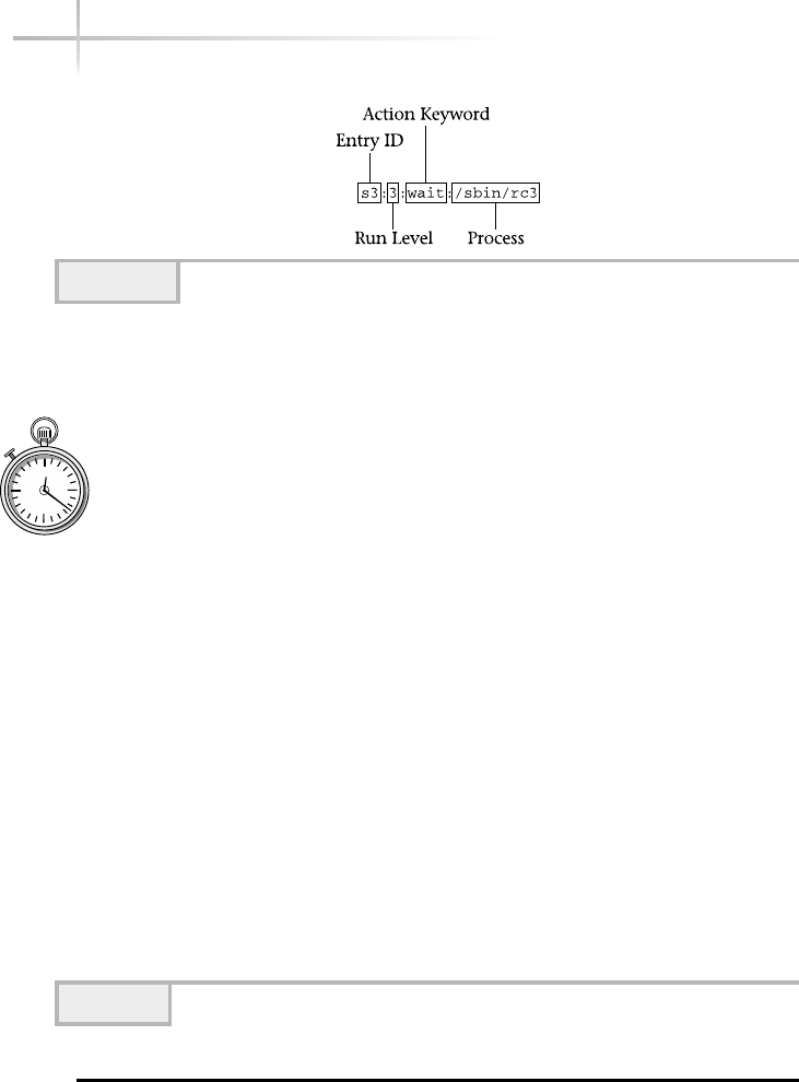
260 UNIX System Administration: A Beginner’s Guide
●Process This field contains the actual program that will be invoked when
the run level is entered. Typically, this invokes the startup scripts that are
associated with each run level.
1-Minute Drill
●Explain how the /etc/inittab files for Solaris, HP-UX, and Linux are similar and
how they are different.
●What’s the difference between run levels 2 and 3?
Figure 9-3 The /etc/inittab entry format
Keyword Meaning
respawn Start the process and don’t wait for it to terminate. Restart the process
when the run level is entered.
wait Star the process, but wait until it terminates.
once When the run level is entered, invoke the process and don’t wait for
the process to finish. If the process terminates, don’t restart it.
boot Process this entry only when the boot phase is started
bootwait Process this entry when the system enters multi-user mode from
single-user mode after the system has booted.
powerfail Invoke this entry when the process associated with this entry is sent
a powerfail signal.
off If the process of this entry is currently running, shut down. Otherwise,
do nothing.
initdefault Specifies the default run level.
Table 9-5 Common /etc/inittab Action Keywords
●They all use the same general syntax but the services each one starts are different.
●Run level 2 and 3 are both multi-user mode run levels but 2 doesn’t include networking services.
TEAMFLY
Team-Fly®

Module 9: System Operations 261
9
The Default Run Level
The default run level is defined within the /etc/inittab file. When the system
is rebooted or started when the power is applied to the system, the system is
restored to the default run level—which for most systems is multi-user mode
(run level 2). If a Linux system is configured to support X11 on the console
device, the default run level is 5. It is at this level that X11 support is active and
users can access the console using a standard X11 login application. Without X11
support configured, the default run level is 3 and the user receives the standard
login prompt. On Solaris and HP-UX, the sample default run-level entry looks
like this:
is:3:initdefault:
While on Linux, the default run-level entry is this:
id:5:initdefault
To change the default run level, change the 3 or 5 value for the run level.
Once the default run level has been changed, use the init command with the
qoption to reread the /etc/inittab configuration file.
List the Current Run Level
It is important to know which run level the system is at. This is especially true
when doing maintenance work at a certain level (such as single-user mode) and
the system needs to be reported to the default mode. In this case, the administrator
should check to make sure that the system is at the correct level.
To show the current run level on both Solaris and HP-UX, use the who
command. Thus,
who –r
shows
. run-level S Feb 3 20:09 S 2 3
In this example, the current run level is (S), which stands for single-user mode.

On Linux, use the runlevel command:
runlevel
3 5
This shows the previous and current run levels. In this example, the system was
previously at run level 3 (multi-user mode without X11), but now the system is
at run level 5 (multi-user mode, with X11).
Single-User Mode
When the system is placed in “s” (S) or single-user mode, regular users are not
able to log into the system. Also, no networking facilities or typical operating
system services are available. In general, this mode is used to conduct system
maintenance tasks such as checking the file systems with fsck, adding new
services, and a host of other related tasks that must be accomplished when the
system is in a quiescent state.
To place the system in this mode when the system has already been booted,
issue the following command:
init s
The following will be displayed when this command is run on a Solaris system:
INIT: New run level: S
The system is coming down for administration. Please wait.
Unmounting remote filesystems: done.
Print services stopped.
Feb 3 20:09:46 dino syslogd: going down on signal 15
Killing user processes: done.
INIT: SINGLE USER MODE
Type control-d to proceed with normal startup,
(or give root password for system maintenance):
As the last step in the process, the system prompts for the root password.
This is a necessary precaution so that unauthorized users can’t access the
system when placed in this mode. When the correct password has been entered,
262 UNIX System Administration: A Beginner’s Guide

a shell prompt is displayed. When a Linux system is brought to single-user
mode, it doesn’t prompt for the root password; instead, it gives a shell prompt.
On HP-UX, different messages are displayed when single-user mode is entered.
To bring the system to the default run-level, type a ^d (CTRL-D) or exit the
shell. At this point, the system will continue to boot to multi-user mode, which
is the default run level for most systems.
Boot to Single-User Mode
If the system must be placed in single-user mode (the system is currently at the
boot prompt)—due to some problems or because some maintenance task must
be performed—use the –s option that is available with most boot loader programs.
Table 9-6 shows the appropriate boot command for each operating system. For
example, at the Linux boot prompt, use the linux -s command to boot the
system in single-user mode.
Project 9-1
This project will familiarize you with the commands from this module and give
you firsthand experience with them on your own system.
Step-by-Step
1. Display the current run level for your system. On Solaris or HP-UX:
# who -r
Or on Linux:
runlevel
Module 9: System Operations 263
9
O/S Boot Command
Linux linux –s
Solaris boot -s
HP-UX b-s
Table 9-6 Single-User Boot Commands

264 UNIX System Administration: A Beginner’s Guide
2. Display all the processes running on your system and identify the init process
and its process ID:
# ps -e
3. Determine what users are currently logged onto your system:
# who
4. If you are the only user logged on, shut down your system giving yourself a
1 minute warning before shutdown. (If other users are logged on, perform
this step at a later time when the system can be shut down without
inconvenience. If this system must remaining running except for emergency
maintenance, skip this step):
# shutdown -g 60 "##### testing shutdown process in 60 seconds #####"
5. Check your system to see when the most recent shutdowns occured:
# grep shutdown /var/adm/messages (Linux/var/log/messages)
6. Restart the system in default mode
# reboot
7. After logging back on to the system, display the default run level in the
/etc/inittab file for your system:
# grep initdefault /etc/inittab
8. Display the current run level for your system. (This should be the same as the
default run level.)
# who -r

Module 9: System Operations 265
9
Mastery Check
1. Which system mode is used for system maintenance?
A. Multi-user mode
B. Single-user mode
C. Maintenance mode
D. Reboot mode
2. The normal or default running mode for most UNIX systems is
__________.
3. What process has the process id of 1 and is known as the father or
master system process?
A. Init
B. Kernel
C. Boot
D. Shutdown
4. What keyword do you use in an inittab entry for a process you want to
restart whenever it terminates?
A. Respawn
B. Init
C. Reboot
D. Boot
5. What user mode is your system in if it displays the following output from
awho -r command?
. run-level 3 Dec 8 10:41 3 0 S

266 UNIX System Administration: A Beginner’s Guide
6. Which command will restart the system after you run the command
to bring the system down?
A. Respawn
B. Halt
C. Reboot
D. Shutdown
7. Which directory contains script files that init runs at startup?
A. /etc/initab
B. /etc
C. /etc/script
D. /etc/startup
8. Which init command is equivalent to the halt command?
A. init 0
B. init 3
C. init 6
D. init s
Mastery Check

Module10
The TCP/IP Suite
Critical Skills
10.1 Uncover the General Seven-Layer OSI Network Model
10.2 Discover the TCP/IP Protocol Architecture
10.3 Learn About the Address Resolution Protocol
Copyright 2002 by The McGraw-Hill Companies, Inc. Click Here for Terms of Use.

As a system administrator, you will be required to handle problems that may
affect one or more networked UNIX systems or involve network services
at a lower level where protocol operation knowledge is necessary. As a result,
direct interaction with TCP/IP and related services might be needed. Therefore,
you will need a good understanding of TCP/IP, associated protocols, and
applications. Today, many corporations, institutions, and other organizations
use TCP/IP extensively and universally to address all aspects of network
connectivity in a multi-vendor environment. It is the protocol family of choice
with networking manufacturers, operating system vendors, and users alike. In
fact, the world’s largest network, the Internet, uses TCP/IP exclusively. UNIX
was the first popular operating system to use TCP/IP, and TCP/IP continues
to be the most widely used set of networking protocols for this and other
operating systems.
If you have accessed the Web using a browser, transferred files using
FTP, accessed a remote NFS file system, or sent email via the Internet, you
have indirectly used TCP/IP. Fundamentally, TCP/IP provides a standard
way to deliver information from one system to another without concern for
operating system differences and network hardware characteristics. TCP/IP
is an acronym that stands for two separate protocols: Transmission Control
Protocol (TCP) and Internet Protocol (IP). However, TCP/IP generally refers
to these protocols, plus a suite of related protocols and services. For example,
the File Transfer Protocol (FTP) uses TCP/IP and provides a basic file transfer
facility between a pair of systems. If the system supports TCP/IP, it is generally
assumed to support FTP and a host of other protocols and services as well.
Today, the TCP/IP suite is supported on every major computer operating
system available. For example, it is supported on HP-UX, Solaris, Linux, AIX, and
many more. As such, it is considered the most popular networking protocol, and
many of the same TCP/IP services are available on different versions of UNIX. This
is good news, because many of the core functions of TCP/IP and applications are
the same across different versions of UNIX. The operations of TCP/IP are
independent of operating system or computer platform. The protocols hide
the underlying operating system details and provides a common framework for
establishing connectivity among systems. For instance, an FTP client program
is normally available across most implementations of TCP/IP, and a result of using
this program, which implements the FTP protocol, is that data files may be
transferred between dissimilar systems. In other words, a file may be copied from,
say, a Windows machine to Solaris (or vice versa) without the need to worry about
how the actual data of the file is stored with each operating system. The client
268 UNIX System Administration: A Beginner’s Guide

Module 10: The TCP/IP Suite 269
10
and/or server processing the file automatically handles the file structure differences
and adjusts accordingly.
The TCP/IP suite is built on industry standards and is documented quite
completely in Request for Comments (RFCs) papers. These documents are widely
available on the Internet from several Web sites, but the general authoritative
source of such information can be obtained from http://www.ietf.org/
rfc.html. TCP/IP is defined within an open standards organization, which
means that the protocols will remain open and common, and no single vendor
can own the protocols or develop proprietary extensions.
TCP/IP is independent of any data link protocol and can be used with many
different networking technologies, including FDDI, Ethernet, ATM, token ring,
Frame Relay, and SMDS. TCP/IP makes it possible to build a truly heterogeneous
network consisting of products and network technologies from many different
vendors and sources. In fact, the Internet, which is considered the world’s largest
network, consists of devices from many networking vendors that operate together
in a uniform fashion. That’s not to say the Internet doesn’t have its share of
networking issues or problems, but, for the most part, many would agree that
interoperability between equipment vendors isn’t a major factor for the established
core set of TCP/IP, protocols, and applications.
From a system administration point of view, many of the tools used to
administer, monitor, and configure TCP/IP on systems are consistent across most
UNIX operating system versions. However, one issue that can be a problem is that
each UNIX operating system vendor can and does implement nonprotocol details
differently. For example, the way IP address and hostname information is stored
on each network device or UNIX systems is not covered by any RFC standard, nor
should it be, since it is an implementation detail. Thus, for Solaris, the system name
is stored in a file called /etc/hostname.device, where device is the name
of the default LAN interface. Other operating systems use different files or other
mechanisms. The present TCP/IP suite provides a mechanism to dynamically assign
IP addresses to devices, and it also mandates that they be uniquely assigned to each
device attached to the network. However, IP addresses are stored on a local system
and are not a protocol matter, but rather a network management or system
configuration issue, which is traditionally resolved at the operating system level.
Each operating system vendor provides its own solutions to how IP address
information or other operating system parameters are to be stored. Since operating
systems are completely nonstandardized between vendors, the name of the file or
its location (or even the presence of a hostname file) varies between different
operating systems and releases.

10.1 Uncover the General
Seven-Layer OSI Network Model
Networking protocols including TCP/IP can be mapped to a general theoretical
network model, which is quite common within the network industry. This
model defines the relationship and services that each protocol will provide to
other associated protocols, services, and applications. The most common
standard network model is based on Open Standard Interconnect (OSI). The
OSI seven-layer model is represented by a series of layers stacked one upon
another, which, when viewed collectively, represent the operation of a single
device within a larger framework of a network of systems. Each layer represents
a unique view of the nodes that make up the network or individual devices
within the network. The layers of the OSI model consist of the following:
●Application
●Presentation
●Session
●Transport
●Network
●Data link
●Physical
Application Layer
The application layer provides services to users that include file transfer,
electronic email, remote host access, among others. This layer might also be
referred to as the end-user layer since end users typically execute application
at this layer.
Presentation Layer
This layer provides a common interface for applications to the lower layers,
which implement common services that may include, for example, encryption,
reformatting, and compression of data.
270 UNIX System Administration: A Beginner’s Guide
TEAMFLY
Team-Fly®

Module 10: The TCP/IP Suite 271
10
Session Layer
The session layer provides the mechanism to establish, maintain, and terminate
sessions between cooperating applications. A session can be viewed as a coupling
of services between a pair of systems.
Transport Layer
The transport layer ensures reliable transparent data transfer, flow control,
error detection, and recovery between two endpoints.
Network Layer
This layer provides upper-layer protocol transparency, because different
network communication methodologies may be used. The network layer is
responsible for establishing, maintaining, and terminating connections for
different networks. This layer is also responsible for address and routing
information between networks.
Data Link Layer
The data link layer provides data transfer service on the physical link using
frames; it also handles error detection, flow control, and related low-level
services. Some common frame types include Ethernet, FDDI, and token ring.
Physical Layer
The physical layer addresses the mechanical connectivity requirements (such as
cables and connectors) and provides transmission of a bit stream that involves
controlling voltage characteristics to produce the appropriate signals for each of
the networking standard. Examples include cabling for Ethernet, Fast Ethernet,
FDDI, and Token Ring. Cabling standards such as 100Base-T, 10Base-T, fiber,
and coax, for example, are implemented on this layer.
1-Minute Drill
●At which OSI layer do the tools most end users interact with most often operate?
●What TCP/IP property makes it possible to build a truly heterogeneous network
consisting of products and network technologies from many different vendors
and sources?
●Application layer
●This is possible because TCP/IP is independent of any data link protocol.
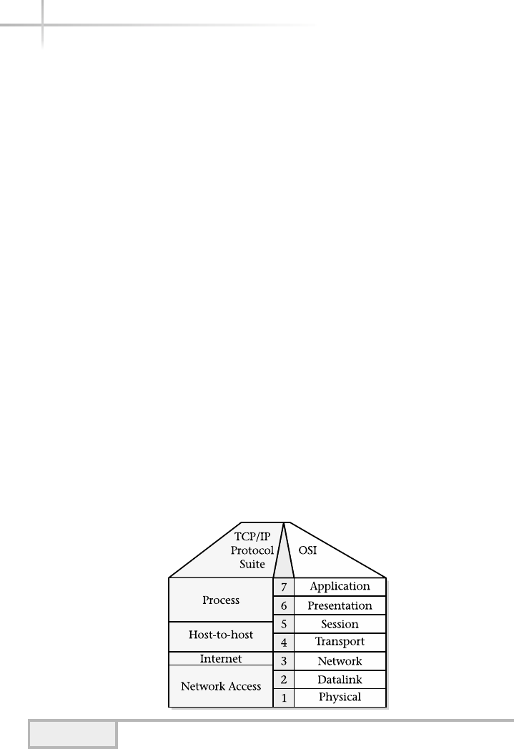
272 UNIX System Administration: A Beginner’s Guide
10.2 Discover the TCP/IP
Protocol Architecture
Placing or overlaying the TCP/IP suite on the OSI model helps demonstrate
TCP/IP’s operation and its relationship to other protocols. Figure 10-1 shows
a pictorial view of where TCP/IP fits into the OSI model.
As shown in Figure 10-1, the TCP/IP model consists of four layers. Each
layer maps to one or more of the OSI layers, which include
●Process
●Host-to-host
●Internet
●Network access
Except for the network access layer, the other three components are
software-based and consist of programmed modules that provide the required
functionality. Typically, these components are incorporated into operating
systems to provide generalized access so that network applications can invoke
basic network services without concern for implementation details.
Process/Application Layer
This layer provides user applications and interfaces with the host-to-host
layer. Additional protocols and services are also found on this layer. The process
Figure 10-1 TCP/IP and the OSI networking model

Module 10: The TCP/IP Suite 273
10
layer maps to the presentation and application layers, which are defined within
the OSI model. Applications on this layer include Telnet, FTP, sendmail, and
many others.
Host-to-Host Layer
This layer is responsible for ensuring that data is reliable and that each higher-level
service obtains the correct information from the sending entity. The protocol
supported on this layer is TCP. The layer maps to the OSI transport layer. The term
used to describe information (units of data) on the host-to-host layer is segment.
Internet Layer
This layer provides an unreliable flow of information from one network to another.
From an OSI standpoint, this layer is defined as the network layer. The Internet
layer (or network) is responsible for routing between different IP networks. The
protocol supported on this layer is IP. The term used to describe the information
processed on this layer is packet.
Network Access Layer
The network access layer involves the physical attachment to a network, which
traditionally requires a hardware interface from the network to a computer’s
internals. This layer includes both physical and data link layers from the OSI
model. The network access component defines the network architecture and
topology. Some examples include Ethernet, FDDI, and Token Ring. The term
used to describe the information on this layer is frame. A small driver program,
which is provided by the network interface manufacturers, is also needed to
connect the hardware to the operating system.
The TCP/IP and associated protocols can also be placed on the OSI seven-layer
model, as shown in Figure 10-2. Here, we can see how the protocols and services
relate to the model. The next few pages further describe the many additional
services provided by the TCP/IP protocol suite.
Process Layer Services
The TCP/IP services on the process layer include end-user tools, additional
protocols, and system services. Found on different UNIX platforms, TCP/IP
provides a common mechanism to share files, send/receive email, access systems
remotely, transfer files between systems, and accomplish other networking tasks.
Although the TCP/IP protocol and application suite is large, many UNIX system
vendors provide a smaller subset of these services.
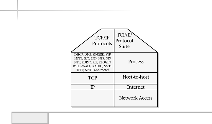
274 UNIX System Administration: A Beginner’s Guide
End-User Tools
The end-user tools, which are common to many UNIX system implementations of
TCP/IP, are applications that are generally available to normal system users. As a
result, these tools do not require system root privileges for operation. For example,
general users without any special consideration from an administration standpoint
can invoke the Telnet and FTP commands. Some services within the TCP/IP suite
refer to both end-user applications and protocols. Telnet is a good example of this
because it represents both a user tool and a communication protocol. In practice,
however, this isn’t a big problem, because end-user applications on UNIX are
lowercase (such as telnet) and protocols are generally written in uppercase.
It is interesting to note that certain organizations disable some TCP/IP
services as a way of tightening security. One organization in particular did not
want its users to have the ability to send or receive email on core development
systems and removed the SMTP servers from those systems. Another way that
organizations typically disable services is by blocking access to system ports
using a firewall device or router.
Additional Protocols
The TCP/IP suite includes additional higher-level protocols that exist above the
network layer and provide the necessary details to ensure that applications can
communicate. For example, the File Transfer Protocol (FTP) defines how files
and associated information are transmitted across the network. The protocol
Figure 10-2 TCP/IP suite and model

handles all the details related to user authorization, naming, and data
representation among heterogeneous systems.
System Services
TCP/IP system services include those facilities that are provided to all users
of the system and can only be controlled by the system administrator. System
services include specific system processes and special configuration files used
by those processes. System network services are usually started automatically
when the system is started, but some start in response to requests.
The TCP/IP protocols and services are listed in Table 10-1, and are further
described here:
Module 10: The TCP/IP Suite 275
10
Service Description
ARP Address Resolution Protocol
RARP Reverse Address Resolution Protocol
DHCP Dynamic Host Configuration Protocol
DNS Domain Name Service
FINGER Look up remote/local user
FTP File Transfer Protocol
HTTP Hypertext Transfer Protocol
ICMP Internet Control Message Protocol
LPD Line Printer Daemon
NFS Network File System
NIS Network Information Services
NTP Network Time Protocol
RDISC Router Discovery Protocol
REXEC Remote execution service
RIP Routing Information Protocol
RLOGIN Remote login service
RPC Remote Procedure Call
RSH Remote Shell Service
RWHO Remote monitoring of users
RWALL Remote message broadcast
RADIO Radio transmitter/receiver
SMTP Simple Mail Transfer Protocol
SSH Secure Shell Services
Table 10-1 Associated TCP/IP Protocols and Services

276 UNIX System Administration: A Beginner’s Guide
ARP
The Address Resolution Protocol provides mapping between lower-level data link
protocols (such as Ethernet and Token Ring) and higher-level protocols such as IP.
ARP maps data link (that is, hardware interface) addresses to IP addresses. The
Reverse Address Resolution Protocol (RARP) is used to go the other way; it maps IP
addresses to data link protocol addresses. ARP and RARP are described fully later in
this section. ARP/RARP operates on the network and data link layers.
DHCP
The Dynamic Host Configuration Protocol provides startup (booting) information
to client systems. DHCP supports IP address information, operating system
configuration information, and other related information. From a network
address standpoint, DHCP is an excellent, efficient, and scalable way to manage IP
addresses across an enterprise. For example, clients can dynamically obtain
IP information while booting, thus removing the burden of having to configure
each machine. This protocol operates on the network layer and uses UDP.
DHCP takes its origins from the BootP (Boot Protocol) server, which was used
to boot diskless workstations over the network.
DNS
The Domain Name System maps between hostnames and IP addresses. The client
side provides the ability to resolve names and addresses by making requests to one
or more DNS servers only. The server-side component, named, listens for requests
and either looks up entries in a local database or contacts another name server for
resolution. DNS is an application layer service and can use either TCP or UDP.
Finger
The finger services permit the lookup of user information on either a local or
a remote system. The finger service isn’t a protocol, just an end-user program
that uses TCP for communication with the in.fingerd server. This service
operates on the application layer.
Service Description
TALK Talk to remote/local user
Telnet Access to remote system
TFTP Trivial File Transfer Protocol
WHOIS Remote Lookup Service
Table 10-1 Associated TCP/IP Protocols and Services (continued)

Module 10: The TCP/IP Suite 277
10
FTP
The File Transfer Protocol transfers files between systems. FTP provides basic
user authorization that includes using the login name and password on the
remote system. The FTP interface is basic, but provides a simple way to transfer
single or multiple files. FTP supports transmission of both binary and ASCII
data files. FTP is an application-based service and uses TCP.
HTTP
The Hypertext Transfer Protocol transmits Web pages and documents from a
Web server to a browser. HTTP uses TCP as its transport facility and operates
on the application layer.
ICMP
The Internet Control Message Protocol is a network diagnostic facility that uses
the IP protocol. The ping tool uses the ICMP echo request/reply protocol to
determine node connectivity. ICMP operates on the network layer and uses IP
for communication.
LPD
The Line Printer Daemon provides a printing facility for either the network or
directly attached printers. This service is an application-based facility and uses TCP.
NFS
The Network File System facility provides file sharing between systems on a
local network. NFS uses UDP and resides on several layers, such as application
and transport layers.
NIS
The Network Information Service is a directory lookup facility that provides
client access to server databases. The types of information typically used within
NIS include login, host, file sharing, and other system configuration information.
NIS is an application layer service.
NTP
The Network Time Protocol provides an excellent way to ensure that time and
date information is synchronized between all networked UNIX systems. NTP is
an application layer service and uses either TCP or UDP.

278 UNIX System Administration: A Beginner’s Guide
RDISC
The ICMP network Router Discovery Protocol finds routers on the local network
and builds a table of routes to attached networks. This protocol operates on the
network layer and uses IP.
REXEC
The Remote Execution Service provides execution of UNIX commands on remote
systems. REXEC uses a specialized authentication procedure that includes reading
both the login name and password and comparing this information with the remote
system. If the login information matches, the UNIX command is executed.
The family of remote commands includes rsh,rwho,rlogin, and others. This
service operates on the application layer and uses TCP. Note that the services are
considered unsecure.
RIP
The Routing Information Protocol propagates routing information between
network system devices such as routers. UNIX systems support RIP as well.
On some UNIX systems, if two or more network interfaces are installed, the
system will automatically perform routing functions. The routing function is
incorporated in the in.routed system process that is started when the system
is initialized. RIP operates on the application and network layers and uses UDP.
RLOGIN
The Remote Login Service accesses a remote UNIX system. It provides the same
basic services as the Telnet program, and operates on the application layer and
uses TCP.
RPC
The Remote Procedure Call is a mechanism and protocol that permits the
execution of procedures across the network in a vendor fashion. This is an
application-layer-based service and uses UDP or TCP.
RSH
The Remote Shell Service provides a shell to the remote system, and operates
on the application layer and uses TCP.
RWHO
RWHO provides a list of logged-in users on a remote system. This command is
similar to the UNIX who command and operates on the application layer and
uses TCP.

Module 10: The TCP/IP Suite 279
10
RWALL
RWALL provides a way to write to users on a remote system. This command is
similar to the UNIX wall command and operates on the application layer and
uses TCP.
RADIO
This is the radio broadcast facility, and operates on the application layer and
uses UDP.
SMTP
The Simple Mail Transfer Protocol provides the mail delivery mechanism that is
used by many electronic mail packages and is the standard mailing protocol for
the Internet. The sendmail system program implements SMTP and is responsible
for mail propagation between systems.
SSH
The Secure Shell provides remote access with some level of security for the
communication channel. User tools include ssh,scp,ssh-keygen, and the
sshd server process. This service operates on the application layer and uses TCP.
TALK
Talk is a two-way communication facility that can be used to talk to other system
users either on local or remote systems. Talk isn’t a protocol, but is just an end-user
system utility that uses the UDP protocol and can be accessed by running the talk
command. This service operates on the application layer and uses TCP.
Telnet
Telnet is the name for a protocol and end-user system utility. The Telnet utility
provides a user interface to a remote UNIX system. Users can log into other
systems over the network and execute commands as if they were local to that
system. Their terminal is connected via the Telnet protocol to the remote system
using the in.telnetd server process. The Telnet protocol defines a network
virtual interface that controls the flow and interpretation of a character stream
between systems. This service operates on the application layer and uses TCP.
TFTP
The Trivial File Transfer Protocol provides a more simplistic file transfer facility
than FTP. TFTP is considered a light version of FTP because it doesn’t support
a robust authorization mechanism or command set. TFTP is used mainly to
download system configuration information or data. This service operates on
the application layer and uses UDP or TCP.

WHOIS
WHOIS is a white pages lookup utility. The WHOIS service will search for
individual users and other information from standard Internet servers. This
service operates on the application layer and uses TCP.
Additional Services
Many public domain TCP/IP services and applications are also available via the
Internet. Some of the resources available are improvements over the existing
core set of services, while other applications provide new services and features.
Table 10-2 lists some of these TCP/IP applications.
AIM
AIM is one of several popular instant messenger services where users are
connected to a central server and can exchange text and voice massages.
ARCHIE
ARCHIE supports a database of anonymous FTP sites and their contents. ARCHIE
keeps track of the entire contents of a very large number of anonymous FTP sites
and allows you to search for files on those sites using various kinds of filename
searches.
GOPHER
This is a document retrieval system that is available via a menu-driven interface
(for character-based devices) and the World Wide Web (WWW).
IRC
Internet Relay Chat is a way to send either public or private text messages to
one or more subscribers in real time.
280 UNIX System Administration: A Beginner’s Guide
Service Description
AIM AOL Instant Messenger
ARCHIE FTP search facility
GOPHER Document retrieval system
IRC Internet Relay Chat service
NNTP Network News Transfer Protocol
Table 10-2 Additional TCP/IP Services
TEAMFLY
Team-Fly®

Module 10: The TCP/IP Suite 281
10
NNTP
The Network News Transfer Protocol provides the ability to transfer news files
(also known as Usenet) between a client and server.
1-Minute Drill
●Which services in Table 10-1 operate on the network layer?
●Which applications and services from Table 10-1 operate on more than
one layer?
Host-to-Host Layer
The host-to-host layer, or OSI network layer, is responsible for providing
a robust data delivery mechanism between different network entities. The
standard that provides this service is the Transmission Control Protocol (TCP).
Within a network, data can be lost or destroyed when transmission errors or
network hardware failures occur. Data can also be delivered out of order and
with significant delays before reaching the final destination. TCP was designed
and developed to address these types of network-related problems. TCP is
responsible for ensuring that data arrives in the correct order and is free from
errors. It accomplishes these tasks by providing the services described in the
following section.
Virtual Connections
TCP provides a virtual connection interface to the network that is analogous to
the way phone calls are established in the telephone network. Conceptually, a
user calls another machine to request data transfer. After all the details of the
connection setup are complete, data transmission can occur between applications.
From an application perspective, the TCP connection looks and behaves as if a
dedicated hardware link has been established. However, this is only an illusion
provided by the TCP streams interface.
●ARP, RARP, DHCP, ICMP, RDISC, RIP
●ARP, RARP, NFS, RIP

282 UNIX System Administration: A Beginner’s Guide
Sequenced Data
To ensure reliable transfer, TCP keeps track of the data it transmits by assigning
a sequence number to each segment. The sequence number uniquely identifies
each data segment within a connection and provides a positive acknowledgment
to the sending entity. No acknowledgment indicates that the message should be
retransmitted. The sequence number is also used to reorder any segments that
might have arrived out of order. How can segments arrive out of order? Consider,
for example, the network in Figure 10-3.
Because more than one network path to node C exists, it is possible that
some TCP segments might travel via router R2 instead of router R1. Should the
path between node C and R1 become temporarily heavily loaded, for example,
segments may be routed via the alternate path. As a result, segments using the
R2 path could arrive at the destination sooner than segments using the R1 path.
Also, if a packet becomes corrupted during transmission, the sequence number
can be used to request that the packet be resent.
Stream Abstraction Interface
From the application layer standpoint, TCP provides a buffered byte-oriented
interface between two applications or processes. The data transmitted from the
source entity is exactly the same information that the destination receives. For
example, if the sending entity transmitted the message “Hello World”, the
destination would receive “Hello World”. As it turns out, this is a very useful
and convenient feature for developing networking applications and services.
Also, the TCP stream is buffered, which means that applications have more
flexibility when it comes to processing the data from the network.
Ports, Sockets, and Connections
TCP ports are addresses that specify a network resource and are used to uniquely
identify an individual application or service on the system. There are quite a
few well-known address ports in use today, and many of them can be found in
the /etc/services file on UNIX systems. Table 10-3 contains a partial list
of some of the most commonly used TCP ports.
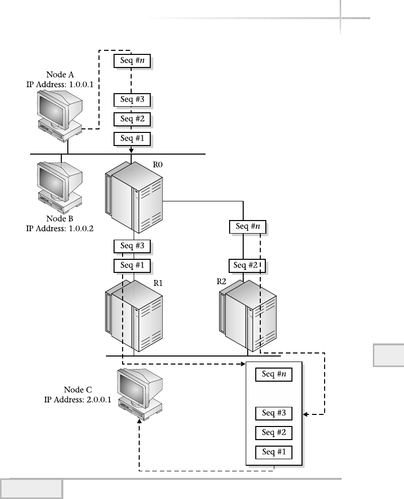
Module 10: The TCP/IP Suite 283
10
Figure 10-3 TCP sequence numbers in action
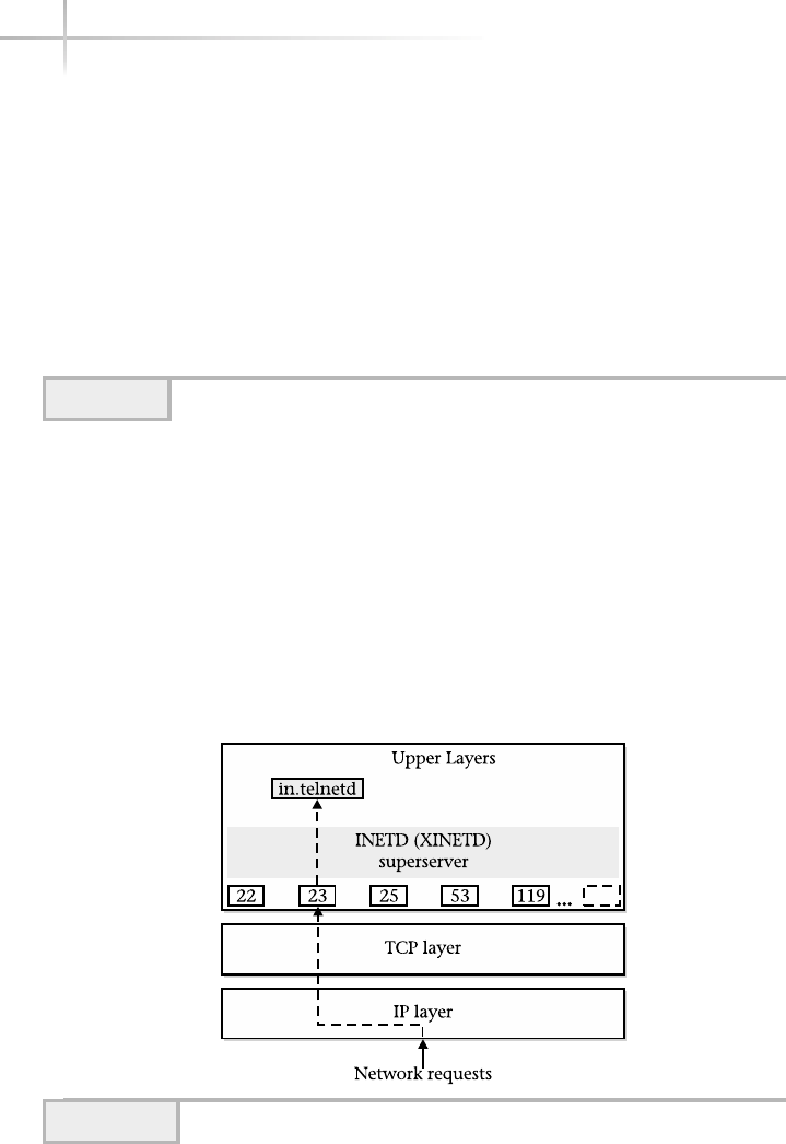
To further understand the function of these ports, consider the services of the
UNIX inetd process or xinetd (for Linux). This process is known as the super
Internet server because it is responsible for connecting service requests from the
network to the actual server program with the operating system. The superserver
knows which process to invoke because it can determine relationships between
ports and services. By processing the /etc/services,/etc/inetd.conf,or
/etc/xinetd.d directory for Linux, these files (inetd or xinetd) can make
the network request to the appropriate service as needed. Figure 10-4 shows the
operation of the superserver when a remote user requests a Telnet session.
284 UNIX System Administration: A Beginner’s Guide
Port Application/Service
20 FTP data
21 FTP
22 SSH
23 Telnet
25 SMTP
53 DNS
119 NNTP
161 SNMP
80 HTTP
Table 10-3 Common TCP Ports and Associated Services
Figure 10-4 inetd operation with a Telnet request

10
Module 10: The TCP/IP Suite 285
10
It is important to understand that TCP uses a connection-oriented model
whereby one network entity may call another to establish either a half- or full-
duplex session. In the full-duplex mode, two independent channels are established
between systems, and data can flow between the systems. In the half-duplex
mode, only a single channel is established. A network entity may first establish
a full-duplex session and then shut down one channel if necessary. On the other
hand, a service may initially establish a single half-duplex session for control
purposes and then start another channel to carry out some specific action or
task. This application behavior might seem a little strange, but the FTP service,
for example, operates in this fashion.
When an FTP session begins, it establishes a single session to the destination
system first. This session is used for user authentication and the command
interface. When the user specifies a file transfer or executes a remote command,
another session is established to service the transfer request. After the transfer is
complete, the newly created session is closed. This process is repeated for each
separate transaction or transfer of files.
Sockets are ports that the system allocates on the user’s behalf when executing
network applications or other services. Because the operating system generates
a unique socket number, no two simultaneously running applications on the same
system will have the same socket number. On some UNIX systems, the allocation
of sockets begins above 1024.
In the context of a connection, TCP uses a total of four elements to uniquely
identify one session from another: source IP address, source port, destination
IP address, and destination port. This is important to remember because many
sessions to the same application or service can be established, even from the same
host. For example, two different users can telnet to the same destination host
without any conflicts among the ports. This is accomplished by the fact that TCP
uses all four addressing elements to distinguish a unique session. Figure 10-5
shows the relationship of the TCP elements in different sessions.
Positive Acknowledgment
TCP provides reliability by ensuring that every message transmitted is confirmed
by the receiving entity. The confirmation of TCP messages is known as positive
acknowledgment and is used to ensure that the receiving entity has obtained all
the segments that have been sent. When a TCP message is sent, the sending entity
starts a timer. If no acknowledgment is received before the time expires, TCP
assumes the message was lost or damaged in some way, preventing its delivery.
As a result, TCP sends another message to replace the first and starts the
timer process over again. This process continues until all segments have been
acknowledged or until an internal error threshold is reached. If the sender
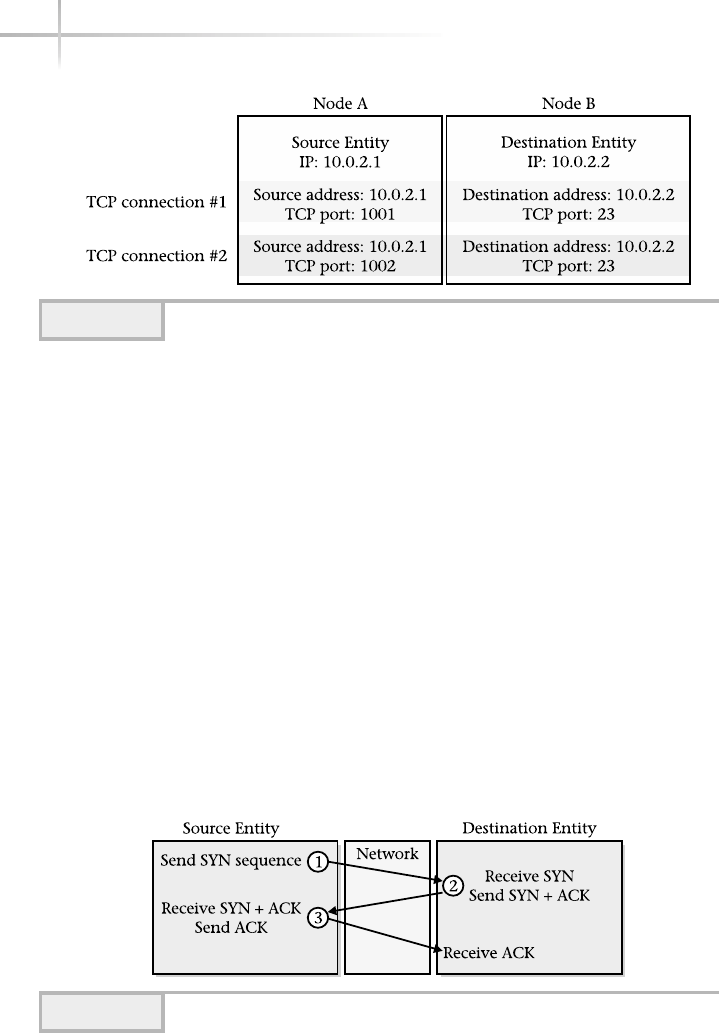
receives no acknowledgment for outstanding segments after the internal error
count has been reached, the connection will be terminated.
Establishing and Closing a TCP Connection
As previously discussed, TCP uses connections that provide a reliable and robust
data transfer facility. The procedure for establishing or shutting down a connection
is not a magical process. Instead, each TCP entity follows the same set of rules
when creating a session or terminating one. To establish a connection, TCP uses
a three-way handshake protocol, outlined in Figure 10-6.
First, the source transmits a SYN message segment. The SYN (pronounced
“sin”) or synchronization is a request to start a TCP session and the SYN bit
set in the code field. Next, the destination responds with an ACK segment that
has both the SYN bit and ACK bits set in the code field, indicating that it has
accepted the request and is continuing the handshake protocol. Finally, the
source sends an ACK segment, which informs the destination that both entities
agree that a connection has been established and that segments can now be
transmitted and received.
286 UNIX System Administration: A Beginner’s Guide
Figure 10-5 Two TCP sessions from the same source/destination
Figure 10-6 Opening a TCP connection using the three-way handshake
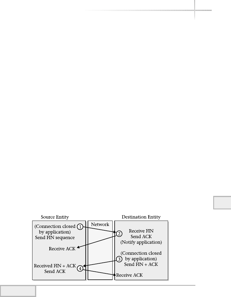
To close an established session, TCP uses a modified three-way handshake,
shown in Figure 10-7. First, the source transmits a FIN or finish segment (the FIN
bit is set in the code field) as a result of the application wishing to close its side of
the connection. Recall that TCP views these connections as full duplex; therefore,
either party may terminate their side of the connection. Once the application on
the destination closes the connection, TCP emits a FIN segment to the source.
Next, the source receives the FIN sequence and sends an acknowledgment. Also,
in special cases, the remote end may emit an RST (reset) packet that automatically
causes the connection to be closed.
Closing a TCP Connection
Please note that it takes three segments to create a TCP connection, and four
additional segments to shut it down. A total of seven messages are required to
operate a TCP connection, not including any data transfer segments.
State Machine
The operation of TCP is best described using a state machine model, which
controls the basic operation of the protocol. Figure 10-8 shows a representative
picture of the TCP state machine, where each TCP connection goes through
a series of defined phases. Movement from one state to another is the result
of an event or transition. The label on each transition shows what TCP receives
to cause the change between states. For instance, we discussed that TCP must
open a connection before data can be transferred. Normally, each TCP side
of the connection starts in the CLOSED state. When a connection is desired, a
transition from the CLOSED to SYN SENT state is made. At this point, the client
side sends a SYN packet. If the SYN packet is accepted, the remote side emits an
Module 10: The TCP/IP Suite 287
10
Figure 10-7 Closing a TCP connection

288 UNIX System Administration: A Beginner’s Guide
ACK, which causes a transition from the SYN SENT to the SYN RECIEVED
state. Once the final ACK has been received, the ESTABLISHED state is reached
and data transfer may begin. When a TCP connection has been made, it will
remain in the ESTABLISHED state until either side wishes to terminate the
connection.
When a TCP connection is terminated (either by the source or destination),
the connection moves to either the CLOSED WAIT or FIN WAIT-1 state. If the
source sends a FIN segment, TCP transitions to the CLOSE WAIT state, which
eventually terminates the connection. When the destination wants to close the
connection, a change is made to the FIN WAIT-1 state. TCP has an elaborate
mechanism to ensure that segments from previous connections do not interfere
with existing ones. TCP maintains a timer, known as the maximum segment
Figure 10-8 TCP state machine diagram
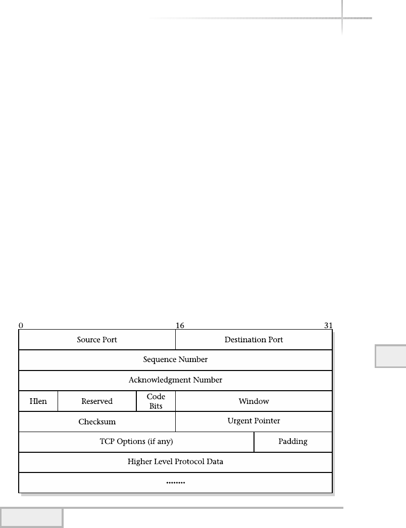
lifetime (MSL), which contains the maximum time an old segment may remain
alive within the network. As a result, TCP moves to the TIMED WAIT state
after closing the connection. It remains within this state for twice the MSL.
After this, if any segments arrive for the connection, they are rejected. Why
do we care about these details? Well, it sometimes is helpful in tracking down
connectivity problems. The netstat command, for example, provides TCP
port state information to assist with this type of activity.
TCP Sequence Format
TCP defines a sequence format that includes all the necessary information to
ensure that segments get to the correct destination, and also contains additional
control information. Figure 10-9 shows the TCP segment format.
The TCP segment fields include the following:
●Source Port The protocol (or service) that sent this segment.
●Destination Port The protocol (or service) that will receive this segment.
●Sequence Number The position in the byte stream of the sender.
●Acknowledgment Number The number of the bytes that the source
expects to receive in the next segment.
Module 10: The TCP/IP Suite 289
10
Figure 10-9 TCP segment format

●Hlen Integer that specifies the length of the segment header.
●Code Bits (C Bits) Details on the purpose and content of the segment.
●Window Specification of how much data TCP is willing to accept.
●Checksum Integer used to verify the TCP header and data integrity.
●Urgent Pointer Field for indicating that this segment should be processed
right away.
●Options Details for negotiating the maximum segment size.
●Data High-level protocols or application-specific information.
Code Bits
These bits indicate the type of TCP segment and how it should be processed.
Table 10-4 shows established codes and their associated meanings. These codes
are analogous to the type field in the Ethernet frame, which means that TCP
segments are self-identifying.
Window
TCP has an elaborate mechanism to handle data buffering, flow control,
and retransmission of unacknowledged segments. The window field helps
TCP determine how much data it is willing to accept in the next segment.
The data size of a transaction can significantly impact overall network and
application performance. To understand why, assume for the moment that a
TCP connection has been established between two nodes named socrates
290 UNIX System Administration: A Beginner’s Guide
Codes Meaning
URG Urgent pointer
ACK Acknowledgment
PSH Request a push
RST Reset
SYN Synchronize sequence numbers and start connection
FIN Reached end of byte stream
Table 10-4 TCP Segment Code Types
TEAMFLY
Team-Fly®

Module 10: The TCP/IP Suite 291
10
and durer. During previous transactions, socrates has specified to
durer a TCP window of 1024 (which is the default). Now, durer begins
to experience high usage and begins to run low on available resources such as
memory. Many reasons can cause this situation. At this time, socrates is still
sending TCP messages to durer, but durer is having trouble acknowledging
(or perhaps even processing) segments from socrates due to the number of
the messages. Because durer is having resource problems, the next segment sent
to socrates contains a smaller window size, which informs socrates that
it must adjust the amount of data contained in subsequent TCP messages. This
mechanism is known as the “back-off” algorithm. After socrates receives the
new window size, it begins sending durer smaller amounts of data.
After the resource limitation has been resolved on durer—either by explicit
action on the part of the system administrator or by the completion of the tasks
that caused the resource problem in the first place—durer sends socrates a
larger window size and resumes processing as before. Without the ability for TCP
to dynamically adjust the size of segments, in the example durer would begin to
drop the messages it couldn’t process. This, in turn, would cause socrates
to retransmit them—not only wasting processing cycles on socrates, but also
wasting networking bandwidth due to the retransmitted messages.
Urgent Pointer
Because TCP provides a streamed interface, it is sometimes important that an
application has a way to send an out-of-band or an urgent message to the other
end of the connection without having to wait for the previous messages to be
processed. An example of why out-of-band is important is when a user wishes
to terminate a remote login session using Telnet. Often terminals provide interrupts
or control signals, which can be used to inform applications that they should
terminate. In this case, TCP uses the URG bit to indicate that this is an out-of-band
segment and sets the urgent pointer to specify the position in the segment where
the urgent data ends.
TCP Options
This field indicates the negotiation of the TCP segment size, which is useful
in a situation when it is possible to establish either a higher or lower maximum
transfer unit (MTU). MTU values can be different on different physical networks.
For example, ATM has a higher MTU than Ethernet.

1-Minute Drill
●Describe the important function of the Transmission Control Protocol (TCP).
●Why is window size an important property in TCP?
Internet Layer
The Internet (or network layer of the OSI model) layer provides a delivery service
that is unreliable and based on a connectionless transfer protocol. As previously
indicated, the Internet Protocol (IP) operates on this layer, providing a best-effort
transfer service, and is responsible for routing packets among different IP networks.
IP packets may be lost, delayed, duplicated, and delivered out of order.
Two versions of the protocol have been defined. The most widely implemented
version is 4 (known as IPv4), and due to protocol deficiencies and resource
limitations of this version, enhancements were made that resulted in a new version
known as IPv6. IPv6 contains a much wider address space (128 bit address) and
provides quality of service facilities. However, version 6 hasn’t been widely
implemented within the networking industry.
The major characteristics and services of IP (version 4) include the following:
●Unreliable delivery
●Connectionless protocol
●Packet travel over different paths
●Address format
●Subnetting
●Routing
Unreliable Delivery
The term unreliable indicates that IP makes no attempt at guaranteeing the
delivery of a packet to its destination. This is in sharp contrast to the behavior
and services of Transmission Control Protocol, which provides a reliable
transfer facility that ensures message delivery. IP, on the other hand, provides
292 UNIX System Administration: A Beginner’s Guide
●TCP is responsible for ensuring that data arrives in the correct order and is free from errors.
●Changing the window size allows a host to alter the amount of data it accepts per segment (making the
window and data per segment smaller when the host is experiencing heavy loads, for example), thus
minimizing the number of segments it receives that it can’t process (and would subsequently need to be
resent) and maximizing the amount of data it can reliably receive per segment (by not making the window
any smaller than necessary).

Module 10: The TCP/IP Suite 293
10
a best-effort delivery facility and does not ensure packet transfer—but it doesn’t
capriciously discard them, either. Despite the fact that IP is not reliable, it
doesn’t mean that data carried with IP isn’t delivered correctly. IP simply uses
an upper-level protocol like TCP to ensure guaranteed data delivery.
Connectionless Protocol
IP is said to be connectionless because it does not establish a connection
through which to transfer packets, which is contrary to the behavior of reliable
transfer protocols. Packet delivery is based on IP address information contained
within the packet itself. Each IP packet is self-contained, independent of any
other packet, and not part of a preestablished agreement between network
entities. Because no connection information is maintained within IP, packet
delivery is simplified and efficient.
Packets over Different Paths
With IP, packets may travel different paths to reach their final destination, even
though each packet might carry a smaller portion of a much larger message. This
behavior is observed when IP packets travel within an Internet. Also, packets
might arrive out of order.
IP Addressing
IP defines the format of addresses and requires that each network entity have its
own unique address. Addresses contain both a network and a node identification
pair, which are expressed as a single number. With IPv4, 32 bits are used to
represent an IP address and are expressed in dotted notation. Each address is
written as four decimal integers separated by decimal points. Five different classes
have been defined within IPv4. However, in practice, only the first three primary
classes are used to define a network/node pair, as shown in Figure 10-10.
Each class specifies the format used to interpret how much of the address is
used to represent the network and how much of the address is used to represent
the node. The interpretations of addresses include the following:
●Class A The first byte is the network identification, and the remaining
bytes specify the node. The network address range (first byte) is 1–127.
●Class B The first two bytes are the network identification, and the
remaining bytes are the node. The network address range is 128–191.
●Class C The first three bytes are the network identification, and the
remaining byte is the node. The network address range is 192–223.

Two additional (D and E) classes are defined, but they are reserved and can’t
be used for normal network addresses. Class D addresses are used for multicast
support, and Class E addresses are reserved for future use. One way to distinguish
the different classes is to use the first byte rule. With this rule, the first byte
determines to which class the address belongs. For example, using the IP address
of 10.1.3.2, 10 is the first byte of this address. The number 10 falls in the
range of 1–127, so this IP address is a Class A type and the network portion
is 10, while the node portion is 1.3.2.
IP also defines some reserved addresses that include loopback and broadcast
addresses. The loopback network is defined as address 127 and is used as a
private network for internal diagnostics and support with an IP device. This
network address is reserved and is not supposed to be used as a genuine network
address. In fact, the IP protocol specifications don’t recommend its use on a live
network. The loopback address can be observed by issuing the UNIX ifconfig
-a command. The broadcast address defined as 255 is also considered special,
because it denotes a shorthand way to address all hosts within a given range. For
example, given the network of 134.110.0.0, which is a B Class network, the
broadcast address of 134.110.255.255 addresses all devices within the entire
134.110 network. Because of the special meaning associated with 255,it
should not be used as a node address.
Assignment of IP addresses is accomplished through a central agency
known as the Network Information Center (NIC)—www.nic.org. The NIC
is responsible for assigning unique IP network addresses to any organization
wishing to connect to the Internet. In many instances, a local Internet service
provider (ISP) will request an IP address on your behalf or provide one of its own.
294 UNIX System Administration: A Beginner’s Guide
Figure 10-10 Three primary IP address classes

Subnetting
Subnetting is a mechanism used to divide a network into smaller subnetworks
or subnets. One major motivation for implementing subnets is to distribute
administration control of IP address allocation. Subnets also permit more
effective use of existing addresses. With subnets, the node portion of the IP
address is divided into two sections: the subnet address and node address, as
shown in Figure 10-11.
To implement subnetting, the following requirements must be met. First, a
subnet mask must be created for use on each of the devices that will participate
within the subnet. This subnet mask is a special 32-bit address, which is expressed
like a normal IP address using dotted decimal notation. As with a regular IP
address, each of the octets within the subnet is in the range of 1to 255. But unlike
IP addresses, the octets represent a set of masked bits that are combined with the
device’s IP address to yield the subnet network. In particular, determining
the subnet involves combining the subnet mask and host IP address with the
Boolean AND operator.
Second, each device that will participate in a subnet must use the same subnet
mask address. In particular, for each interface defined on the local system,
the subnet mask should be defined along with other interface parameters.
For instance, under UNIX, the ifconfig command is invoked on every system
interface installed in the system. The subnet mask information must be included
when this system command is executed.
To further illustrate the implementation of a subnet, consider the sample
network shown in Figure 10-12. In this figure, we have four devices attached to
1010
Module 10: The TCP/IP Suite 295
10
Figure 10-11 IP network classes with subnets addressing
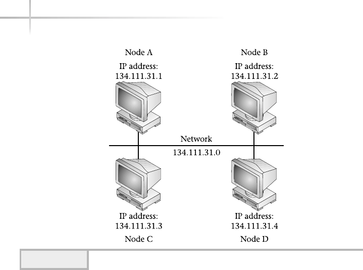
the same network. Each of the devices has already received an IP address, but
now we must determine what the subnet mask should be. We have determined
that the network will grow in the future and need to have enough IP addresses
in the subnet for approximately 200 devices. As a result, we will need to use at
least 8 bits (1 octet) for the subnet.
The IP addresses used in the sample network are of type Class B. Recall that
B Class addresses are in the range of 128–191 and the first two octets are the
network address (134.111), while the remaining two (31.1, for instance) are
node addresses. The only place we can take bits to use for the subnet is from
the host portion of the address. We simply can’t use any of the network address
because that area of the address is restricted. With this in mind, we need to
subdivide the host portion in two, which is where the subnet mask comes into
play. By using all ones (1) in the bits of the subnet fields and all zeros (0) in the
bits of the node field, we can forge the desired subnet address by converting
the IP address and subnet mask into binary:
(decimal) (binary)
134.111.31.1 10000110 01101111 00011111 00000001 (IP address)
255.255.255.0 11111111 11111111 11111111 00000000 (Subnet Mask)
134.111.31.0 10000110 01101111 00011111 00000000 (Subnet Address)
296 UNIX System Administration: A Beginner’s Guide
Figure 10-12 Sample IP subnet

Module 10: The TCP/IP Suite 297
10
Applying the Boolean AND will produce the subnet address of
134.111.31.0. After this subnet mask has been configured on every
device within the subnet, every node will do the required AND calculation
to determine the subnet address to which it belongs. On many (if not all)
UNIX systems, this is an automatic task when the system’s network services
are started. To summarize, to subnet a network, do the following steps:
1. Determine the IP address class of the network you want to subnet.
2. Determine the number of addresses you require for the subnet.
3. Determine if you can use a full octet (with at least a B Class address)
for the subnet address.
4. Perform the Boolean AND on one of the device addresses using the
subnet mask.
5. Apply the subnet mask to all devices that will participate in the subnet.
The subnet mask assignment in this example was relatively straightforward
because a full octet was used for the subnet number. This makes the subnet
calculation (AND) math very simple. However, suppose we change the example
byusingaCClassnetworknumber instead. The addresses we now need to assign
to the sample network in Figure 10-12 include 199.81.23.1–199.81.23.4.
With a C Class address, the range of the first octet falls within 192–223. The
first three octets are the network address (199.81.23), while the remaining
octet (4, in this example) is the node address. This example will complicate the
subnet process a bit, because we must now split the host portion and the subnet
address from just one octet. However, the same procedure applies as stated above.
In order to formulate a subnet address from a Class C network address,
we must borrow some number of bits from the host portion of the address to
represent the subnet number. In doing so, we automatically reduce the number
of IP addresses that will be free for each device within the subnet. Therefore,
we need to know exactly how many devices will be installed on the subnet.
To further refine our example, assume we will only need ten IP addresses for
individual nodes on the subnet.
We can determine the subnet mask and other information by hand, but
it is much easier and faster if we use a software program to do the calculations
for us. We use a calculator which provides the ability to subnet any valid IP
address and shows the calculations and steps involved.

The first field, IP Host Address, requires that we specify the IP address
of one of the hosts on our network. In this case, we give it one of the node
addresses from our second example (that is, 199.81.23.1). Next, we provide
some information about the subnet by entering information in the third box,
labeled Select One of the Following. We can do this in one of four
ways: by specifying the subnet mask directly (Subnet Mask field), the number
of bits for the subnet (Bits field), the maximum number of hosts within the
subnet (Maximum Possible Subnets field), or the number of possible
hosts per subnet (Possible Hosts per Subnet field). Changing one
of these fields changes the other three automatically. For example, when a
subnet mask is changed to 255.255.255.224, the number of bits becomes
3 and the number of possible hosts per subnet goes to 30.
Viewing the Calculations window, shown in Figure 10-13, you can see the
relationship between these fields. This screen contains five sections. The first
shows two lines, each containing three fields: the standard IP Address (Class C
Network field) class in both decimal and binary format, the Subnet and Host
Bits fields, respectively, and the subnet mask. This is the mask that must be
applied to every system that will be involved within the subnet. This subnet mask
uses 28 bits and hence can be referred to as a “28-bit subnet mask.” The second
section contains the subnet number from the logical AND operation of the host
address (199.81.21.1) and subnet mask (255.255.255.224) fields. The
third shows the correct subnet mask, inverted subnet mask, and subnet number
as expressed in binary. The next section contains the subnet directed address and
the broadcast address. The broadcast address directs IP packets to every node on
the local subnet. The final section includes the summary that contains the subnet
address, the available host addresses specified with a range, and the directed
broadcast address. The available host range is important, because it represents
the addresses that can be used by all host systems within the subnet.
1-Minute Drill
●What are two major purposes of subnetting?
●Which IP address class has the largest number of possible node addresses per
network address?
298 UNIX System Administration: A Beginner’s Guide
●One, to distribute administration control of IP address allocation, and two, to permit more effective use of
existing addresses.
●Class A.
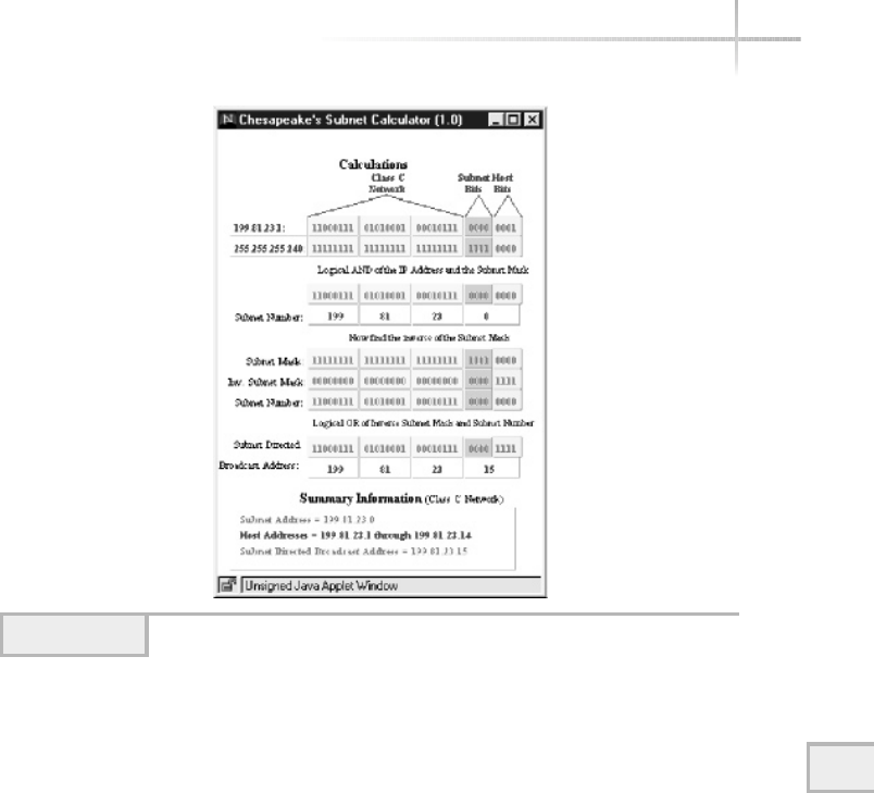
Module 10: The TCP/IP Suite 299
10
Internet Control Message Protocol
As previously discussed, IP provides a best-effort packet delivery mechanism
that doesn’t guarantee data delivery. IP is insulated from the lower-level protocol
details and makes few assumptions about the performance and reliability of the
network. Data delivery is accomplished without any special coordination among
other IP entities and, for the most part, operates quite well. However, conditions
might exist beyond IP’s control that makes delivery difficult or impossible. For
example, a remote host could be temporarily removed from the network or a
router could become overloaded when a network-intensive application is started.
IP needs a way to detect these types of problems.
The Internet Control Message Protocol (ICMP) provides a general error
message facility for the IP protocol and related services. ICMP provides a way
for IP entities that encounter errors to report them to the source that caused the
problem. It is the responsibility of the source entity to correct the error. This
might include, for example, reporting the error to a higher-level application.
Table 10-5 lists some of the ICMP message types.
Figure 10-13 Subnet Calculation window
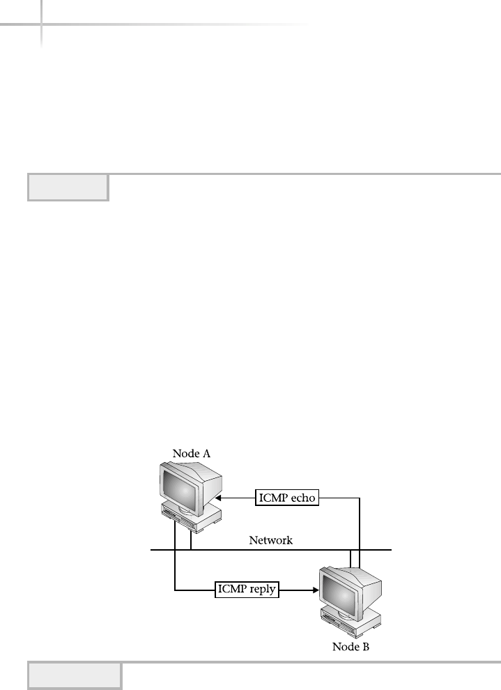
One of the most popular networking debugging utilities, ping, uses ICMP to
determine host reachability. ping uses the echo request and echo reply primitives
that are available within ICMP to determine if a remote host is available and
operating correctly on the network. Figure 10-14 shows the basic operation of the
echo request and reply. A user wants to determine if Node A is available on the
network. From Node B, the user enters a ping command that issues an echo
request to Node A. If Node A is active, it responds back to Node B using an echo
reply. If Node A is not active, then Node B receives no response. In this case, the
request from Node B simply times out. When this occurs, the user is presented
with a time-out message that indicates that Node A didn’t respond to the request.
300 UNIX System Administration: A Beginner’s Guide
Message Type Meaning
Echo request/reply Determine system reachability
Destination unreachable Can’t reach desired destination
Source quench Stop sending data
Redirect Detection of routing error
Time exceeded Stale IP packet
Table 10-5 ICMP Error Message Types
Figure 10-14 ICMP echo request/reply
TEAMFLY
Team-Fly®

Destination Unreachable
When a router can’t deliver or forward a packet to its destination, it will emit an
ICMP destination unreachable message to the sender. Destination unreachable
errors usually imply some sort of routing problem or error (that is, incorrect route
within a routing table). Destinations may be unreachable due to hardware failures
that cause a system to become temporarily unavailable, or when the sender specifies
a nonexistent destination address. Sometimes it is impossible to know that a
destination is unreachable unless the ping system utility is used. For example, if a
user issues a Telnet request to a remote system (which happens to be connected to
an Ethernet LAN, for example), and the system has been disconnected from the
network, this Telnet request will eventually time out because Ethernet doesn’t
support any frame acknowledgments. As a result, no destination unreachable
messages will be generated, because Ethernet assumes data delivery even for a node
that has been temporarily disconnected from the network.
Source Quench
The source quench within ICMP provides a way to handle congestion at the
IP packet level. Congestion within a network can be caused by several factors.
However, one primary cause is when several systems begin transmission of data
that flows through a single router, as shown in Figure 10-15. In this case, the
router itself is overburdened by the combined traffic. Another cause of congestion
is when a more powerful computer system transmits data to a less powerful
system that cannot keep up the pace. If these situations go unchecked, eventually
the router and the underpowered system will begin to discard packets, which in
turn will cause TCP to retransmit them, thus making the situation worse. In this
case, the router and smaller system simply emit a source quench message, which
indicates to the sender that it should stop sending data. As a result, the router and
smaller system have time to process any outstanding packets.
There is no direct way to reverse the effects of the ICMP source quench
message. However, any destination that receives a source quench lowers the
rate at which it transmits packets to the destination. After no additional source
quench messages are received, the remote system begins to gradually increase
the rate of transmission, and eventually normal traffic resumes.
Redirect
The ICMP redirect message informs routers of changes to the routing information
within the network. One of the basic assumptions with TCP/IP is that routers know
10
Module 10: The TCP/IP Suite 301
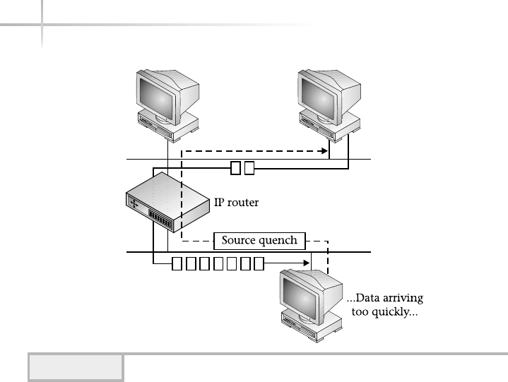
302 UNIX System Administration: A Beginner’s Guide
the routing topology within a network and this information is shared among
participating routers. When a router detects a host using a nonoptimal route, it
emits a redirect message informing the host that a better route is available. It is up
to the host to incorporate this new information within its routing configuration. In
some cases, this is not automatic and must be done by the network administrator.
Figure 10-16 shows an example of where a router will send an ICMP redirect
message. Assume that Node A wants to talk to Node D. In this case, two paths exist
between Node A and Node D, namely R1 and R2. The R1 path is shorter and
contains fewer hops between Node A and Node D. The R2 path contains extra
links, because it also provides connectivity to other networks that include Node B
and Node C. Should Node A attempt to communicate with Node D via R2, then R2
will send the redirect message back to Node A telling it to use R1, which has a
shorter path to Node D. Many times the cause of using the incorrect router rests
with the configuration on the system itself or incorrect routing information emitted
from one or more misconfigured routers. In either event, ICMP redirects help the
network administrator track down these sorts of problems.
Redirect messages do not provide a common mechanism for distributing
routing information, because they are limited to interaction between hosts and
Figure 10-15 ICMP source quench redirect example
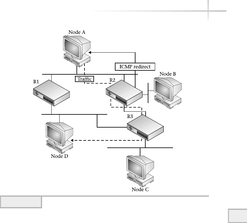
Module 10: The TCP/IP Suite 303
10
routers. Instead, routing protocols such as Routing Information Protocol (RIP)
are used to propagate routing information within a network.
Time Exceeded
Each IP packet contains a time-to-live field, which controls how long a
packet may exist within the network. When a router processes the packet, it
decrements this field before forwarding it. Whenever a router discards a packet
because its time-to-live field is zero or because some other time-out occurred
with the packet, the router emits an ICMP time exceeded message back to
the source of the packet. This is the primary mechanism used to detect
routing loops or excessively long routes within a network. The traceroute
command, for example, uses the time-to-live field to trace the path an IP packet
Figure 10-16 ICMP redirect example

304 UNIX System Administration: A Beginner’s Guide
may take between two points and also measures the amount of time required to
traverse each router along the path to the destination.
10.3 Discover the Address
Resolution Protocol
As we previously discussed, IP imposes a certain structure and format on the
addresses used by networking devices. In version 4 of IP, the address is 32 bits
in length and is expressed in dotted decimal notation. In version 6, the address
is even larger—128 bits. As with any higher-level network protocol such as IP, the
requirement exists for a mechanism to translate these addresses into addresses used
by such protocols as Ethernet, FDDI, or Token Ring. Known as data link protocols,
they each have their own addressing structure and format, which is quite different
from IP. For example, Ethernet uses 48-bit addresses and is expressed using the
colon hexadecimal notation. Thus, 8:0:20:4:cf:2c represents a valid Ethernet
address. In this case, this data link address doesn’t always map easily with addresses
used by IP. This is true for many other data link protocols as well. This creates a
dilemma because, without a way to map IP addresses to physical interfaces,
communication between nodes would not be possible.
It is desirable and very necessary that a simple, flexible, and yet powerful
way to map between IP and data link (physical) addresses be available. The
Address Resolution Protocol (ARP) has been proven to be a very elegant and
robust way to solve the address mapping problem. In particular, ARP was
designed to handle address resolution of any network layer protocol to data
link protocol—not just between IP and Ethernet.
The basic operation of ARP is simple: When Node A wants to determine
the physical address for Node B, Node A will send a special broadcast message
requesting the address of Node B to all devices on the network, as shown in
Figure 10-17. All hosts receive the message, including Node B and Node C,
but only Node B will respond with the correct physical address, as shown in
Figure 10-18. The reason only Node B responds is because it examines the ARP
packet and determines that its own IP address matches the target IP address
that the requester is seeking.
A sister function of ARP—known as Reverse Address Resolution Protocol,
or RARP—does the inverse; given a data link address, it finds the corresponding
IP address. RARP is primarily used when diskless workstations need to determine
their IP addresses during system startup.
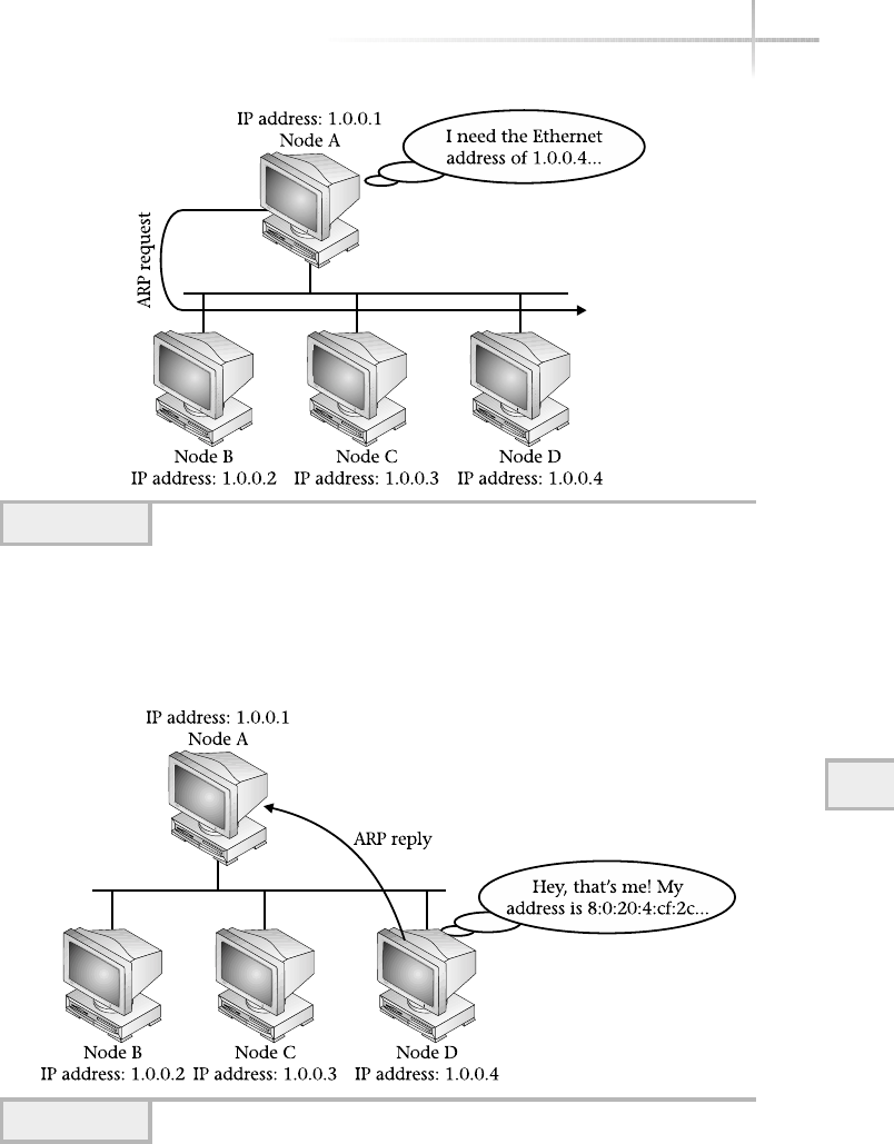
The term broadcast in the above example indicates a locally directed packet
to all network devices on a particular LAN segment. Certain data-link protocols
such as Ethernet provide the facility to transmit broadcast packets to all attached
Module 10: The TCP/IP Suite 305
10
Figure 10-17 ARP request example
Figure 10-18 ARP reply example

306 UNIX System Administration: A Beginner’s Guide
stations using a special destination address. With Ethernet, all 1s (or FFs in
hexadecimal) in the destination address is considered a broadcast. ARP assumes
that the details of getting messages to each station will be handled directly by
the data link protocol.
As you can see, the ARP is very simple. Yet, despite its simplicity, it has
a few profound advantages. First, ARP is dynamic in nature, which obviates
the need to statically track and store IP to physical addresses. This dynamic
resolution behavior frees the network manager from constantly maintaining
and ensuring correct information every time a device is added or removed
from the network. With today’s networks, it would be impossible to accomplish
such a task given the size and growth rate of many networks. Second, ARP is a
standard and is available on every device that supports TCP/IP, regardless of
datalink protocol. That is why, for example, IP can operate on FDDI and Token
Ring. This makes building heterogeneous networks much easier, because ARP
hides the data link addressing details, and the network designer need not be
concerned about physical address resolution when combining different data
link protocols. Third, ARP can be used in IP subnets to provide a very simple
way for devices to communicate within a routed network.
Packet Format
Unlike other networking protocols, ARP packet fields are not all fixed-format
but rather rely on certain fixed fields near the beginning of the packet. ARP
and RARP share the same basic packet format. To make the ARP useful for
other datalink protocols, the length of the fields will depend on the type of
network. Figure 10-19 shows the standard ARP and RARP message format.
The Hardware Type field defines the hardware interface type for which
the sender requires an answer. Standard values include 1for Ethernet and 2for
FDDI. The Protocol Type field specifies the high-level protocol type the sender
is using, which for IP is 0800 in hexadecimal (decimal is 2048). The Operation
field notes if the message is an ARP request (1), ARP response (2), RARP request
(3), or RARP response (4). The Hlen and Plen fields define the hardware and
high-level protocol address field lengths. The Hlen and Plen fields permit ARP to
work with any arbitrary data link protocol, because the sizes of the Hardware
Type and Protocol Type fields can be determined by inspecting the ARP
packet directly. The sending entity will supply, if possible, the Sender HA
and/or Sender IP field information when issuing the request. The Sender
HA field is used with the ARP request, while the Sender IP field is used with
an RARP request. The Target HA field is used when responding to the ARP
message; otherwise, the Target IP field is used when responding to RARP.
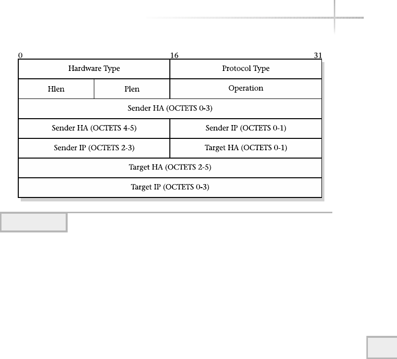
10
ARP Cache
At first glance, the ARP service may seem inefficient because it will send a broadcast
packet each time a device wishes to communicate with another device. However,
ARP implementations on many systems include the use of an ARP cache to
temporarily store address bindings from previous ARP requests. In fact, before
an ARP request is made, the higher-level software scans the ARP cache to see
if the required data link address mapping already exists in the cache. If it does,
the existing binding is used; otherwise, the ARP request is sent. As a result of the
cache, network traffic is reduced because ARP requests are only made when
devices are not known. Also, application performance is improved because the
sender’s ARP request can be satisfied by using the cache instead of transmitting
a packet on the network. Finally, the cache provides the administrator with a way
to view connectivity between the higher-level protocols and the network hardware.
Inspecting the ARP cache can be a powerful way to troubleshoot network and
system problems.
Here is one interesting question regarding the ARP cache: When should the
bindings be discarded from the cache? The answer is not simple. If we presume
to keep the ARP cache populated with entries forever (or until the system is
restarted), the possibility exists that the cache will contain invalid information.
Consider, for example, a network that contains systems monet and rembrandt,
which are in the midst of communicating when the network interface card (NIC)
Module 10: The TCP/IP Suite 307
Figure 10-19 ARP/RARP message format

308 UNIX System Administration: A Beginner’s Guide
fails on rembrandt and is subsequently replaced. The new NIC will contain a
new data link address unless the administrator has changed it after the interface
was installed. As a result, monet can’t talk to rembrandt any longer because
the cache on monet contains an invalid data link address for rembrandt.On
the other hand, we can take the approach that bindings in the ARP cache should
expire in a relatively short period of time, say every 30 seconds. Unfortunately,
this will adversely affect network performance, because more network broadcasts
will be needed because the ARP cache will be very small. However, it will address
the problem of the incorrect bindings for NICs that have recently been replaced,
because the old entry would have been purged in a reasonable period of time after
the new NIC was operational.
Perhaps the best solution to this problem is taking the middle-of-the-road
approach. That is to say, the binding expiration shouldn’t be so small as to be
ineffective but also not too long so that it can address changes in the network
within a reasonable time constraint. In general, most UNIX systems will delete
ARP entries in approximately 20 minutes. Some versions of UNIX also permit
the administrators to change the ARP cache time-out to suit their network
requirements and, when necessary, alter it to address other network-related
problems.
Data Link Address Format
As indicated, data link addresses are expressed in 48 bits (6 bytes) ando
separated by colns. This colon notation is used as the primary method to
represent these hardware addresses. Some UNIX network management tools,
such as the ifconfig and arp commands, use this format. Data link protocol
addresses for FDDI, Ethernet, and Token Ring contain a vendor code identification
number and serial number. This information can be used in node identification
for inventory purposes. The IEEE registry authority assigns the vendor portion
to those organizations that produce networking hardware and have requested a
vendor code. These codes are also referred to as organization unique identifiers
(OUIs). The first three bytes of the address represent the manufacturer or vendor
of the device, and the remaining three bytes represent the serial number of the
unit, as depicted in Figure 10-20.
Often on a multi-homed system, the data link addresses will be shared among
all the defined interfaces. This may even be true for systems that contain different
network interface types (that is, Ethernet and FDDI). Table 10-6 shows some of
the most common vendor codes. Notice that more than one vendor code might
be associated with the same vendor. This may be true, for example, when one
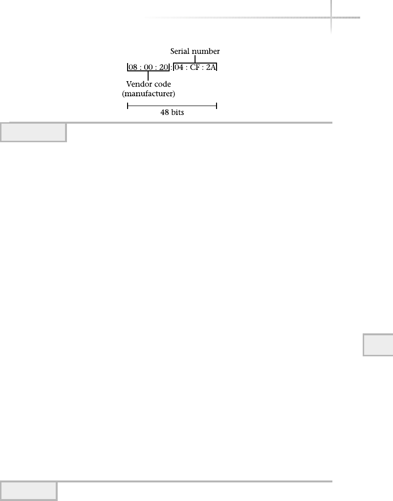
company purchases another company and their products. In this case, the vendor
code of the company that was purchased now falls under the other company. This
is why Table 10-6 contains multiple entries for both 3Com and Cisco. Knowing
a few of these addresses can be very handy during network debugging, to help
identify the type of device and vendor to which a particular packet belongs. If
you are interested in finding a vendor, access the IEEE Web site at http://
standards/ieee.org/regauth/oui/oui.txt.
Module 10: The TCP/IP Suite 309
10
Figure 10-20 Data link address format
Vendor Code Manufacturer
00:20:AF
00-80-3E
00-C0-D4
(many more)
3Com Corporation
Formerly Synernetics, Inc.
Formerly AXON, Inc.
00:00:0C
00-E0-B0
00-E0-F7
00-E0-F9
00-E0-FE
00-06-7C
00-06-C1
00-10-07
(many more)
Cisco Systems, Inc.
(Includes a large list of former companies)
00-60-69 Brocade Corporation
00-E0-B1 Packet Engines, Inc.
08:00:5A IBM Corporation
08:00:20 Sun Microsystems, Inc.
08-00-09 HP Corporation
00-10-E3 Compaq Corporation
Table 10-6 Sample Vendor OUI Codes

Accessing this Universal Resource Locator (URL) will display the entire
OUI file. If you’re not interested in seeing the entire contents of the OUI file,
search for the specific vendor codes you are looking for by accessing the
following URL:
http:/standards.ieee.org/regauth/oui/index.html.
Accessing this URL will display the page shown in Figure 10-21.
310 UNIX System Administration: A Beginner’s Guide
Figure 10-21 IEEE OUI search page
TEAMFLY
Team-Fly®
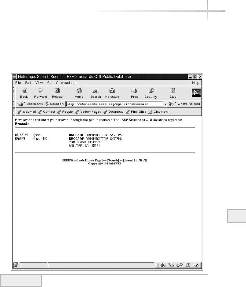
Module 10: The TCP/IP Suite 311
10
Should you wish to search for a vendor, enter the name of the company in
the search text box field. Also, if you know the OUI, but want the vendor, enter
the address instead. Next, click the Search button. Figure 10-22 shows the result
obtained when the Brocade Company was searched.
Figure 10-22 OUI search results

312 UNIX System Administration: A Beginner’s Guide
Mastery Check
1. The most common standard network model is based on ___________
2. Which of the following is not a layer in the OSI model?
A. Application
B. Session
C. Interface
D. Physical
3. Which layer in the OSI model provides services to users that include file
transfer, electronic email, remote host access, and many other services?
A. Application
B. Session
C. Data link
D. Physical
4. Which TCP/IP layer corresponds to the network layer in the OSI model?
5. True or False: Each TCI/IP layer corresponds to one OSI model layer.
6. The ___________ maps between hostnames and IP addresses.
7. Which TCP/IP service do clients use to dynamically obtain IP information
while booting, thus removing the burden of having to configure each
machine?
A. Rlogin
B. BootP
C. DHCP
D. finger
8. In the TCP/IP model, which layer is responsible for providing a robust
data delivery mechanism between different network entities?

Module 10: The TCP/IP Suite 313
10
9. What file on UNIX systems contains port numbers for some well-known
services?
10. True or False: In the TCP/IP model, the Internet layer provides a reliable
flow of information from one network to another.
11. What class does the IP address 198.45.19.151 belong to?
12. ___________ is a mechanism used to divide a network into smaller networks.
13. Which UNIX command, invoked on every system interface installed in the
system, must include the subnet mask information when executed?
14. Using the Chesapeake subnet calculator and the IP address
198.45.19.151, what is the subnet mask if you need a subnet with
40 IP nodes?
15. What popular networking debugging utility uses ICMP to determine host
reachability?
16. What mechanism translates IP addresses into addresses used by such
protocols as Ethernet, FDDI, or token ring?
A. DNS
B. ARP
C. RAPR
D. OUI
Mastery Check

This page intentionally left blank.

Module11
Basic Network Tools
Critical Skills
11.1 Explore the Network Address Table on a UNIX System Using arp
11.2 Control Network Interfaces Using Ifconfig
11.3 Monitor Network Operations Using Netstat
11.4 Verify Network Connectivity Using Ping
11.5 Gather Network Information with Lanscan
Copyright 2002 by The McGraw-Hill Companies, Inc. Click Here for Terms of Use.

316 UNIX System Administration: A Beginner’s Guide
UNIX provides a number of tools for monitoring, debugging, and controlling
network services. The programs listed in this section are considered basic
networking tools because they are available on many systems that support
TCP/IP and provide a minimum amount of monitoring and control. Regular
users can invoke many of the TCP/IP system tools. However, certain features
of some of the tools (such as ability to disable a network interface) can only
be done by the system administrator. The following tools will be reviewed in
this section:
●arp
●ifconfig
●netstat
●ping
●lanscan
11-1 Explore the Network Address
Table on a UNIX System Using arp
The arp command displays and manipulates the network address table on a local
UNIX system. The address resolution protocol table, also known as the ARP
cache, contains a complete list of all data link protocol to IP address mappings
for the local network. The ARP protocol is a dynamic facility that maps data
link addresses such as Ethernet to IP addresses. Whenever a system wants to
transmit a message, it must first know the low-level (that is, data link) address
for the target system. Many networking tools,
such as ssh,ftp, and others, indirectly use
the ARP table.
The arp command provides the ability to
view and modify the ARP cache. Regular UNIX
(nonroot) users may display the ARP cache, but
cannot make any changes. The reason for this
should be obvious: users could make alterations
to the cache that would affect connectivity for
all users.
HintHint
The terms “ARP table”
and “ARP cache” can
be used interchangeably
and refer to the same
information. Also, the
terms “binding” and
“mapping” refer to an
ARP entry as well.

With the arp command, the system administrator can
●Display the ARP cache
●Delete an ARP entry
●Add an ARP entry
The ARP tool provides a number of command-line options. However, only
the most important ones are listed in Table 11-1 and fully discussed and described
below. On Linux, each of these options supports either a single command
character or keyword, along with two dashes at the beginning. For instance,
the -v option has an associated --verbose keyword. These are equivalent
and can be used interchangeably on the command line.
Displaying the ARP Cache
To display the contents of the ARP table, use the arp -v command. When the
table is displayed, it includes the device name, hardware type, physical address,
mask flag, and network interface. A sample from a Linux host is shown here:
# arp -a
Address Hwtype HWaddress Flags Mask Iface
durer.home.com ether 00:60:97:0E:A3:06 C eth0
switch.home.com ether 00:00:1D:0A:5D:01 C eth0
probe.home.com ether 00:C0:D4:00:09:40 C eth0
rembrandt.home.com ether 08:00:20:82:be:05 C eth0
rubens.home.com (incomplete) eth0
monet.home.com ether 08:00:20:04:cf:2c C eth0
Entries: 6 Skipped: 0 Found: 6
When the same command is run from a Solaris system, the following is displayed:
Net to Media Table: IPv4
Device IP Address Mask Flags Phys Addr
------ -------------------- --------------- ----- ---------------
elxl1 dhcpclient-202 255.255.255.255 00:20:78:0e:77:5e
elxl1 didymus.home.com 255.255.255.255 00:60:08:b4:11:89
elxl1 bedrock.home.com 255.255.255.255 SP 00:10:4b:1f:8d:ef
elxl1 224.0.0.0 240.0.0.0 SM 01:00:5e:00:00:00
11
Module 11: Basic Network Tools 317

The Address field (or IP address for Solaris) shows either the hostname
or IP address that corresponds to the ARP entry. This is the address that is used
to search the ARP table to determine if the desired entry exists. When an IP address
(instead of a hostname) is displayed, this indicates that either the IP address
couldn’t be correctly resolved to a hostname or the -n option (Linux only) was
used. This could be the result of an invalid or nonexisting entry within a NIS
server or DNS server or /etc/hosts file, a misconfiguration in either of these,
or connectivity problems to the DNS server.
The HWType field (The other operating systems don’t provides this
information) represents the network interface for which the ARP entry was
obtained. As you can see, the keyword ether represents entries that were
derived from an Ethernet network.
The Flags Mask field (Mask) provides additional details regarding the
ARP entry. Table 11-2 shows the available flags and their associated meanings.
The HWaddress (Phys Addr for Solaris), physical address of the Network
Interface field, contains the low-level address for each node on the local
318 UNIX System Administration: A Beginner’s Guide
Option Description
-a Displays the current ARP entry for a specific host (Linux only). Displays
all of the entries within the ARP table (Solaris and HP-UX).
-d Deletes an ARP entry specified after this option.
-f Loads a file that contains entries to place in the cache.
-i Displays only those entries for specified interface (Linux only).
-n Shows numerical addresses instead of hostnames (Linux only).
-s Creates an ARP entry.
-v Displays ARP cache using verbose mode (Linux only).
Table 11-1 The ARP Command-Line Options
ARP Flag Meaning
CA completed ARP entry
Mor SA permanent (static) ARP entry (Mfor Linux, Sfor Solaris and HP-UX)
PPublish an ARP entry
Table 11-2 ARP Flag Meaning

network and is expressed in six hexadecimal numbers in colon notation. Colon
notation uses hexadecimal number separated by colons, as in
00:10:5a:28:5d:7c
The iface field (Device for Solaris) corresponds to the network interface
that is attached to the local network, for which the ARP entry was obtained. In
practice, most systems contain only a single interface. If a system has more than
one active interface, the arp command would list all entries, regardless of which
interface they came from. The eth stands for Ethernet, which is the name of
the Ethernet hardware device driver. The zero on the end indicates that this
is the first interface defined within the system. For Solaris, the elxl1 interface
represents the second 100-Mbps (Fast Ethernet) LAN connection.
ARP entries that are marked Pare permanent (or static) and have been
defined outside the normal ARP protocol (for example, manually entered with
the arp –s command). Static entries are also used to support networked systems
that don’t support the ARP protocol. Therefore, the address binding must be
manually entered in the ARP table. One problem with this approach is that if the
IP address or hardware address of any of these system mappings is changed,
the ARP information must be manually updated to effect the change. The Cflag
indicates a normal and complete entry, and most if not all ARP entries should
be marked with this flag.
Only the IP addresses associated with genuine interfaces are advertised with
ARP. It is interesting to note that ARP information obtained from other network
devices is not normally published by third-party systems. It is usually the
responsibility of each node on the network to respond to ARP requests with its
own information. There is one special case when a system will respond to ARP
requests on behalf of others. This is known as proxy ARP, which is used with
subnets that use routers, which are special devices that interconnect two or more
IP networks, or other special network configurations. ARP entries typically use
a timer, which controls how long the entry will remain in the ARP cache. By
default, most UNIX systems hold the entry for approximately 20 minutes before
removing it. Some systems permit the administrator to alter this timing value.
The incomplete string (in the Linux example) indicates that an ARP
request is still pending and the mapping is unresolved for the associated host.
In the ARP example above, the system rubens lacks a physical address because
the ARP request didn’t obtain a reply. Many things could cause this condition:
hardware trouble with the device, network wiring problems, or software
11
Module 11: Basic Network Tools 319
11

320 UNIX System Administration: A Beginner’s Guide
configuration issues on the host. The bottom line is that the ARP software wasn’t
able to communicate with the device to obtain the desired information. The
final string that is displayed shows a count of the number of entries in the cache.
In situations where there are many ARP entries, you can use –a (Linux
only) followed by a valid hostname to list a specific system. For Solaris and
HP-UX, one command option is necessary. The following Linux command
will list the ARP mapping for the host called socrates:
# arp -a Socrates
socrates.home.com (10.0.2.201) at 00:60:97:0E:A3:03 [ether] on eth0
Also, you could have used the IP address instead of the hostname. Thus,
the command arp -a 10.0.2.201 would yield the same output.
On Solaris and HP-UX, the arp command also accepts hostnames or IP
addresses without the -a option. Without this command option, each of the
field labels is displayed along with the ARP entry. Thus, the command
# arp bedrock
bedrock (216.155.202.100) at 0:10:4b:1f:8d:ef permanent published
provides the ARP information for a specific host. Another command parameter
that ARP supports on Linux is –n. This option displays either hostnames or
IP addresses within the listings. One reason for choosing to display the ARP
entries using IP addresses is that it will be a little faster. Mapping between IP
addresses and hostnames is usually done with Domain Name Server, and as
a result may take some time to complete. In practice, the delay is negligible
in most situations. However, if the name resolution facility (NIS or DNS, for
instance) experiences delays or some other operational problem, listing the
ARP cache with the -n option will be much faster. The command arp -n will
return the output quicker if name resolution is completely nonfunctional, given
a fairly large ARP cache. The format of the ARP listings using the first example
given in this section will display the following:
# arp -n -v
Address Hwtype HWaddress Flags Mask Iface
10.0.2.10 ether 00:60:97:0E:A3:06 C eth0
10.0.2.60 ether 00:00:1D:0A:5D:01 C eth0
These numeric IP addresses correspond to the
named addresses from the first example.
TEAMFLY
Team-Fly®

1111
10.0.2.50 ether 00:C0:D4:00:09:40 C eth0
10.0.2.127 ether 08:00:20:82:be:05 C eth0
10.0.2.220 (incomplete) eth0
10.0.2.126 ether 08:00:20:04:cf:2c C eth0
Entries: 6 Skipped: 0 Found: 6
As you can see, the IP address of each host has been displayed instead of the
actual hostnames.
As previously mentioned, the arp command displays the interface name
for which the entry was obtained. Given the output above, all of the mappings
were from the eth0 interface. Sometimes a system may contain more than one
interface, as previously suggested. This is known as multi-homing. When the
ARP cache is displayed on these systems, the output contains entries for each
of the interfaces, as in the following example:
Address HWtype HWaddress Flags Mask Iface
durer.home.com ether 00:60:97:0E:A3:06 C eth0
moster.home.com ether 00:60:97:0A:B3:09 C eth1
probe2.home.com ether 00:80:96:0B:C1:01 C eth1
switch.home.com ether 00:00:1D:0A:5D:01 C eth0
probe.home.com ether 00:C0:D4:00:09:40 C eth0
We can see that mapping exists for two interfaces for this system. In this
case, eth0 and eth1 are listed within the output. Since ARP tracks entries by
interface, we can use the -i option to display just mappings from a particular
interface. The command
#arp -i eth1
will display all ARP listings for the eth1 interface:
Address Wtype HWaddress Flags Mask Iface
moster.home.com ether 00:60:97:0A:B3:09 C eth1
probe2.home.com ether 00:80:96:0B:C1:01 C eth1
Deleting an ARP Cache
It might become necessary to delete one or more entries from the ARP table.
For example, should a hardware failure result in the replacement of a network
Module 11: Basic Network Tools 321
These two entries are on a different
interface than the other three.

interface card, the network hardware address of the system will change. In this
case, the existing ARP entry won’t reflect that the low-level address has changed.
As a result, messages sent to this host from other devices will not be picked up
because the hardware address used will not match that of the interface. It is
up to the system administrator to resolve this problem.
To address this, the -doption should be used to delete an ARP entry, as
shown in the following. Because removing ARP bindings can cause network
problems, only the superuser is permitted to remove them. The arp command
expects the -d option to be used with a valid host or IP address. In this example
for Linux, the host durer is removed from the ARP table:
# arp -d durer
If the ARP table were now displayed, the durer entry would not be listed as
shown here:
Address HWtyp HWaddress Flags Mask Iface
durer.home.com (incomplete)
For Solaris, the same command would show
durer.home.com (10.0.2.10) deleted
If a nonroot user attempted to remove this host from the table, an error message
would be displayed:
% arp -d durer
SIOCDARP(priv): Operation not permitted
On Solaris and HP-UX:
SIOCDARP: Not owner
Adding an ARP Cache Entry
Several conditions may warrant manually adding entries to the ARP table. One
such situation occurs when communication with a device is needed, but the device
for some reason doesn’t support ARP, or the implementation is nonfunctional. This
might be the case with a very old system that is still in service. Further, should
322 UNIX System Administration: A Beginner’s Guide

a NIC address change, the table must be manually updated to ensure connectivity.
Finally, it may be necessary to add entries to support proxy ARP services.
To add an ARP entry, use the -s option followed by the hostname (or
address) and the associated physical data link address. For example, let’s say
we would like to add a system called bruegel to the ARP table. The format of
the physical data link is represented by 6 bytes separated by colons (:) where
each byte is a hexadecimal number between 0and FF. To illustrate an example,
the following command could be used:
# arp -s bruegel 08:00:20:82:be:05
If no error message is displayed, it can be assumed that the command was
successful. Alternatively, you could list the ARP cache to see if bruegel
was in fact added:
Solaris/HP-UX:
# arp bruegel
bruegel.home.com (216.155.202.100) at 08:00:20:82:be:05 permanent
Linux:
# arp bruegel
Address HWtype HWaddress Flags Mask Iface
bruegel.home.com ether 08:00:20:82:BE:05 CM eth0
11
Module 11: Basic Network Tools 323
11
HintHint
ARP binding on Linux is labeled with the Mflag while Solaris/HP-UX use the
permanent keyword, which indicates it is a permanent entry because it was
added on the command line. Since permanent mappings are statically defined,
they don’t time out. Unfortunately, permanent entry types are not saved across
system reboots.
Ask the ExpertAsk the Expert
Question Why is modifying the ARP table restricted to only the
superuser?
Answer Consider that when static ARP entries are defined, no direct
linkage exists between this information and the actual devices attached

324 UNIX System Administration: A Beginner’s Guide
1-Minute Drill
●Why can nonroot users only display the ARP table?
●What does an “incomplete” entry in a line in an ARP table indicate?
11.2 Control Network Interfaces
Using Ifconfig
The ifconfig command is short for “interface configuration” and is used to
configure local network interfaces. This command is normally invoked during
system startup to set up each interface with a predefined configuration. The
ifconfig command can also be used to change the network interface parameters
after the system has been booted. This command is often used for debugging and/or
system tuning activities. This command can be used to do the following:
●Lists the configuration of each defined network interface
●Disables/enables any defined network interface
●Modifies network interface configuration parameters
●Creates pseudo-interfaces
to the network. For example, the entry for bruegel was added manually,
but no mechanism is available to ARP to ensure that the physical address
is indeed correct. The arp command assumes the information provided is
accurate and that the device is actually attached to the network. Therefore,
if normal users had the ability to modify the ARP table, more errors would
likely be introduced that would lead to loss of network connectivity.
Should the physical address of a critical network resource (like a server)
be incorrectly changed, all communication between the local system
and the critical system would stop.
●Because making changes to the ARP table affects connectivity for all users, which is something only the root
user should do.
●The incomplete string indicates that an ARP request is still pending and the mapping is unresolved for the
associated host. This could be indicative of hardware, network, or software problems with the device.

The ifconfig program provides a large number of options and keywords
that are used to configure one or more interfaces. Table 11-3 lists the most
important of these options and keywords. The keywords are used as modifiers
with other command-line options.
Listing Available Interfaces
To display all system interfaces, use the ifconfig -a command:
#ifconfig –a
Module 11: Basic Network Tools 325
11
Option Meaning
-a Applies to all interfaces presently installed on the system.
arp
-arp
Enables the use of the Address Resolution Protocol (ARP) on
this interface; disables the use of ARP with the -arp option.
auto-dhcp Use DHCP to obtain IP address for this interface (Solaris and
HP-UX only).
promisc
-promisc
(Linux only) Enables promiscuous (that is, listen for all traffic)
mode on this interface. The -promisc option disables it.
allmulti
-allmulti
(Linux only) Enables all multicast traffic to be received by the
interface. The -allmulti option will disable the reception of
multicast packets.
broadcast
-broadcast
With the argument given, sets or clears the broadcast address
for this interface. This is a network layer broadcast address.
pointtopoint
-pointtopoint
(Linux only) Enables a point-to-point mode for this interface.
The basic assumption is that this is a dedicated link between
two devices. If the address argument is provided, it sets the
protocol address for the other side of the link. Disables the
point-to-point mode with the pointtopoint keyword.
up Causes the interface to be brought up or activated.
down Causes the interface to be shut down or deactivated.
netmask Sets the IP network mask for this interface. The specified
argument can be in the form 255.0.0.0 (dotted decimal)
or 0xff00000 (hexadecimal).
address Sets the IP address for this interface. This must be a unique
IP address not previously assigned to another system.
Table 11-3 Ifconfig Command-Line Options

When this command is run on Linux, the following sample is shown:
eth0 Link encap:Ethernet HWaddr 00:10:5A:28:5D:7C
inet addr:10.0.2.201 Bcast:10.0.2.255 Mask:255.255.255.0
UP BROADCAST RUNNING PROMISC MULTICAST MTU:1500 Metric:1
RX packets:822 errors:1 dropped:0 overruns:0 frame:1
TX packets:108 errors:0 dropped:0 overruns:0 carrier:0
collisions:0 txqueuelen:100
Interrupt:10 Base address:0xfc00
lo Link encap:Local Loopback
inet addr:127.0.0.1 Mask:255.0.0.0
UP LOOPBACK RUNNING MTU:3924 Metric:1
RX packets:92 errors:0 dropped:0 overruns:0 frame:0
TX packets:92 errors:0 dropped:0 overruns:0 carrier:0
collisions:0 txqueuelen:0
ppp0 Link encap:Point-to-Point Protocol
POINTOPOINT NOARP MULTICAST MTU:1500 Metric:1
RX packets:0 errors:0 dropped:0 overruns:0 frame:0
TX packets:0 errors:0 dropped:0 overruns:0 carrier:0
collisions:0 txqueuelen:10
On Solaris:
lo0: flags=1000849<UP,LOOPBACK,RUNNING,MULTICAST,IPv4> mtu 8232 index 1
inet 127.0.0.1 netmask ff000000
elxl1: flags=1000843<UP,BROADCAST,RUNNING,MULTICAST,IPv4> mtu 1500 index 2
inet 216.155.202.100 netmask ffffff00 broadcast 216.155.202.255
ether 0:10:4b:1f:8d:ef
lo0: flags=2000849<UP,LOOPBACK,RUNNING,MULTICAST,IPv6> mtu 8252 index 1
inet6 ::1/128
The -a option indicates that all interfaces installed within the system,
regardless of their present configuration or operational state, should be shown.
The examples displayed above indicate that a number of interfaces are
defined. Note that the system output above is quite similar regardless of which
operating system the command was run against. On Linux, the first eth0 entry
represents the physical hardware interfaces for 10-Mbps Ethernet using the
326 UNIX System Administration: A Beginner’s Guide
Physical hardware interface
Loopback interface for
internal diagnostics
Dial-up interface for
ISP connectivity

Module 11: Basic Network Tools 327
11
3Com Ethernet driver. The second, lo, is the loopback interface, primarily
used for internal communication and diagnostics. The loopback interface can
be used to determine if the TCP/IP software is operating correctly on a local
level. For instance, it is possible to ping the loopback address to determine
valid responses. The final (ppp0) interface represents a point-to-point dial-up
link for connectivity to a local Internet service provider (ISP).
For Solaris, the elxl interface is shown, which represents the Fast Ethernet
interface.
For each interface, the display includes the following fields:
●Link encap This specifies the link encapsulation protocol that the
interface will use when transmitting data link frames. Supported types
include Ethernet, Local Loopback, and Point-to-Point Protocol.
●HWaddr This is the data link address for the encapsulation.
●protocol Ethernet uses the hexadecimal notation, such as in the
entry for the eth0 interface: 00:10:5A:28:5D:7C.
●inet addr This is the IP address associated with this interface.
●Bcast This represents the network layer broadcast address.
●Mask This represents the subnet mask address.
In addition, the display includes the operational parameters for the interface.
These include UP,BROADCAST,RUNNING,PROMISC, and MULTICAST. These
options show the mode and current state of the interface.
Next, the display includes fields that represent the statistical counters,
such as received packets (RX), transmitted packets (TX), number of collisions
(collisions), and so forth. These provide a relatively easy way to benchmark
the performance of the interface. Finally, the remaining fields show the interrupt
number and I/O base address of the interface hardware. Notice, too, that not all
interfaces have an associated interrupt number and I/O address. The loopback
interface lacks these fields because it uses no specific hardware within the system.
HintHint
The Solaris output shows two entries for the loopback interface because one is
for IPv4 IP addresses while the second one is for IPv6 IP addresses.

Controlling Interface State
With ifconfig, it is possible to disable an active interface or enable a disabled
interface while the system is running. In the disabled state, no packets will be
permitted across the interface. This is equivalent to disconnecting the interface
from the network. When an interface is disabled, it is considered down from an
administrative standpoint. To place an interface in the down state, invoke the
ifconfig command with the appropriate interface and the down keyword
option as shown:
# ifconfig eth0 down
The administrator can use the ifconfig command with the interface
name instead of the -a option to list an individual interface. The following
command displays the configuration of the interface that we shut down with
the previous command:
# arp eth0
etho Link encap:Ethernet HWaddr 08:00:20:04:CF:2C
inet addr:10.0.3.127 Bcast:10.0.3.255 Mask:255.255.255.0
BROADCAST MULTICAST MTU:1500 Metric:1
RX packets:3452 errors:0 dropped:0 overruns:0 frame:0
TX packets:3212 errors:1 dropped:0 overruns:0 carrier:1
collisions:0 txqueuelen:100
Interrupt:38 Base address:0x3200
Notice the keywords up and running are now missing from the output.
This is how ifconfig indicates that an interface has been disabled and is not
available for use. To enable or activate this interface, we simply use the up
command option:
# ifconfig eth0 up
When the interface is up, it is available on the network and receiving network
information. Without the indication of the up flag, the interface is operational
and perhaps connected to the network, but no information is flowing to or from
the network.
328 UNIX System Administration: A Beginner’s Guide
Keywords UP and RUNNING are
gone from here now that we
shut this down.

Modifying Interface Parameters
Three methods can be used to modify network interface parameters. First, using
ifconfig directly, changes can be made on the command line and will take
effect immediately. The second approach involves modifying the system startup
and/or system files that ifconfig uses to configure the interface. This approach
ensures that interface changes are made permanently and won’t disappear across
system reboots. Sometimes both approaches are used. Often, a configuration change
must be implemented quickly before the system can be rebooted at a convenient
time. As a result, ifconfig can be used to make the immediate changes.
Normally, when a new interface is installed on a system, this configuration may
be handled by the installation procedure. The third method involves using the
GUI control panel applications, control-panel for Linux and SAM for HP-UX,
to make the changes.
Using ifconfig, the following important information can be changed for
an interface:
●IP address
●Network mask
●Broadcast address
●Data link address
●MTU
The IP address is specified in the normal dotted decimal notation and
represents the unique address for the host on the network to which the system
is attached. The network subnet mask (or netmask) specifies the filter used to
calculate the network and host portions for the subnet. The broadcast address
specifies the IP address to which broadcast packets should be directed. The data
link address represents the unique low-level hardware address used by Ethernet
or FDDI, and is associated with the hardware itself. The maximum transfer unit
(MTU) denotes the maximum message size that the interface can handle. The
standard message size is 1500 for Ethernet, 4096 for FDDI, and 2048 for token
ring. The MTU is rarely modified, and when it is, it can’t be configured to
support values higher than what the hardware will support; only lower values
may be used.
Module 11: Basic Network Tools 329
11

330 UNIX System Administration: A Beginner’s Guide
Let’s suppose that the IP address of a system must be changed because the
system is moved to a different subnet. In this case, the netmask and broadcast
information remain the same. The move to the new network involves changing
the IP address of the interface only. The old IP address is 128.197.9.10
and the new IP address is 128.197.10.1. The following command would
be used to change the network information on the fly:
# ifconfig eth0 128.197.10.1
To make this change permanent, we must modify the /etc/hosts file.
This file contains the mapping between hostname and the associated IP address.
On system startup, the IP address is derived from the file and applied to the
interface. The netmask and broadcast information are the same; we can use
the existing values. The hostname could also be specified on the command line
instead of the IP address. Thus, the command
# ifconfig eth0 fred
accomplishes the same result, assuming that fred has been assigned the IP
address of 128.197.10.1, either in the /etc/hosts file, DNS, or the NIS
hosts database.
As you can see, changing the IP address for an interface is relatively
straightforward. However, changing other interface characteristics requires a
bit more work. To extend the preceding example, let us now assume that we
must change the netmask and broadcast information. To change the interface,
the administrator could use
# ifconfig eth0 128.197.10.1 netmask 255.255.0.0 broadcast 128.197.255.255
In the example above, the netmask and broadcast keywords must be
used to identify the information that follows each keyword. The netmask contains
1s in the bit positions of the 32-bit address that are to be used for the network
and subnet (if applicable) parts, and 0s for the host portion. The netmask/subnet
portion must occupy at least as many bits as is standard for the particular network
class. If no subnets are defined, the standard netmask is used. When using subnets,
they require that more bits than what is normally the host portion of the address
be reserved to identify the subnet. A netmask can be specified in two different
ways: dotted decimal notation and hexadecimal notation.
TEAMFLY
Team-Fly®

The dotted decimal notation is expressed in four single-byte numbers
separated by dots (for example, 255.255.255.0). The hexadecimal format
includes using the 0x prefix followed by a hexadecimal string value. For example,
the hexadecimal value for 255.255.255.0 is 0xffffff00. Since ifconfig
supports both formats, they can be used interchangeably. Each of the standard IP
class addresses has associated default netmask addresses, as shown in Table 11-4.
The broadcast address can be specified in the same ways as the netmask
address. However, the broadcast address is usually formed by turning all the
bits in the host portion of an address to 1s. For example, the broadcast address
for the 128.197.0.0 network is 128.197.255.255.
Special Configurations Parameters
The ifconfig command supports additional parameters. These include
●arp
●multicast
●promiscuous mode
●media type
●point-to-point
Module 11: Basic Network Tools 331
11
HintHint
The addresses in Table 11-4 are just the standard ones used if no subnetting is
implemented. The specific subnet mask addresses used in many sites will differ
from these because the subnets defined use more bits than the standard for
that class.
Class Dotted Decimal Notation Hexadecimal Notation
A255.0.0.0 0xff000000
B255.255.0.0 0xffff0000
C255.255.255.0 0xffffff00
Table 11-4 Standard Netmask Addresses

332 UNIX System Administration: A Beginner’s Guide
The arp keyword specifies that the interface should support an ARP-style
IP address resolution. When an interface is created with ifconfig, the default
is to support ARP. To disable ARP on an interface, use the -arp keyword. On
most networks, ARP must be turned on.
The allmulti keyword enables or disables (-allmulti) all multicast
traffic modes. If enabled, multicast packets (that is, packets with Class D network
addresses) will be received by the interface. Despite the fact that multicast traffic
is available on the interface, an application that supports multicast traffic will
need to be running to make use of this type of traffic. Multicast is used by
multimedia applications to transport packets that contain real-time video and
audio data.
The promisc keyword will enable the interface to receive all network traffic.
It is known as promiscuous mode when all traffic is read, not just the normal
traffic sent to it by other systems on the network. Use the -promisc command
to disable this mode. Certain networking tools such as tcpdump will enable
this mode automatically when in operation.
The media keyword changes the physical connectivity type for the interface.
Not all interfaces support the ability to dynamically change interface media
types. For those that do, many of the most common types may be used, such
as 10Base2 for thin Ethernet, 10BaseT for twisted pair Ethernet, and AUI which
is associated with 10Base5 Ethernet.
The pointtopoint keyword enables the use of a point-to-point link layer
encapsulation protocol, which generally means that direct connectivity will exist
between two systems. The commonly supported protocols, such as PPP or SLIP,
can be used.
Logical Interfaces
The ifconfig command creates and configures logical (also known as virtual
or pseudo) interfaces. These interfaces behave like physical interfaces and can
be used to assign multiple IP addresses to the same system. From a configuration
standpoint, logical interfaces are configured independently but share the same
physical address and interface characteristics as the real physical interface.
To configure a pseudointerface, combine the physical interface with a
logical interface reference number, separated by a colon. For example, to
configure the first logical interface for eth0, use the following command:
# ifconfig eth1:1 10.0.2.128 netmask 0xffffff00 broadcast 10.0.2.255
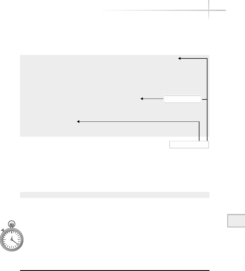
Logical interfaces are displayed just like the physical ones using the
ifconfig -a command. The following output shows one logical interface
defined from the physical interface eth1:
eth1 Link encap:Ethernet HWaddr 08:00:20:04:CF:2C
inet addr:10.0.2.127 Bcast:10.0.2.255
Mask:255.255.255.0
UP BROADCAST RUNNING MULTICAST MTU:1500 Metric:1
RX packets:1810 errors:0 dropped:0 overruns:0 frame:0
TX packets:1173 errors:0 dropped:0 overruns:0 carrier:0
collisions:0 txqueuelen:100
Interrupt:55 Base address:0x3000
eth1:1 Link encap:Ethernet HWaddr 08:00:20:04:CF:2C
inet addr:10.0.2.128 Bcast:10.0.2.255
Mask:255.255.255.0
UP BROADCAST RUNNING MULTICAST MTU:1500 Metric:1
Interrupt:55 Base address:0x3000
Notice the pseudointerface, eth1:1 contains the same Ethernet hardware
address (08:00:20:04:CF:2C) and the same interrupt level (55) as the real
interface. These are additional clues that indicate that this interface is the same
as the eth1 interface.
To remove a logical interface, use the down keyword. Thus, the command
ifconfig -a eth1:1 down
will remove the eth1:1 interface from the system. If this logical interface was
created during system startup, the interface will be configured again when the
system is restarted.
1-Minute Drill
●Why is the loopback interface useful?
●Explain the use of logical interfaces.
Module 11: Basic Network Tools 333
11
Logical interface
Physical interface
●The loopback address is provided so you can run diagnostics on your own computer.
●A logical interface assigns an additional IP address to a system on the same physical network interface.
A logical interface shares all the characteristics of the physical interface except for the different address.

11.3 Monitor Network Operations
using Netstat
The netstat command provides a wealth of information regarding the present
status of network connections, routing information, and other important network-
related data. This tool, short for network status, is strictly for monitoring and is
one of the most popular debugging aids available on UNIX. Different command-
line options control the display behavior of netstat. Given this, the functionality
can be divided into a number of categories and used to accomplish the following:
●List active network sessions
●Show interface information and statistics
●Display routing table information
This tool also provides specific options that control the operation and
output formatting. Table 11-5 contains the major keywords that control the
network information that will be displayed. On Linux, some of the command
options/keywords have a single-character option and a mnemonic string. For
instance, the -h and --help options, which display command-line summary
help, can be used interchangeably.
334 UNIX System Administration: A Beginner’s Guide
Option Description
-i Shows network interface parameters and statistical information
(--interface Linux only).
-g Displays multicast group membership information (--groups Linux only).
-M Lists all sessions that use the masqueraded capabilities within FTP
(--masquerade Linux only).
-r Shows the network routing tables (--route Linux only).
-P Lists connection information for specific network protocol. Supported
protocols include ip,ipv6,icmp,icmpv6,igmp,udp, and rawip
(Solaris and HP-UX).
-t Displays active TCP socket connections. The -tcp option will continuously
display these connections until interrupted by the user (Linux only).
Table 11-5 Netstat Output Data Options

Table 11-6 contains command-line modifiers that either provide additional
information or modify the output when used with the keyword options shown
in the previous table.
Displaying Active Network Sessions
One of the significant services provided by netstat is the ability to view active
connections between systems. Any TCP session between the local host and any
other system can be monitored. Also, any stream sockets that have been created
will be displayed. Streams are used as a program-to-program communication
channel. To display the currently established connections, issue the netstat
command with the –t (Linux only) option as shown here:
# netstat -t
Active Internet connections (w/o servers)
Proto Recv-Q Send-Q Local Address Foreign Address State
tcp 0 0 110.orlando-11-12r:1052 192.215.123.37:www ESTABLISHED
tcp 1 0 110.orlando-11-12r:1051 192.215.123.37:www CLOSE
tcp 0 6 110.orlando-11-12r:1050 postoffice.worldn:pop-3 ESTABLISHED
tcp 0 0 110.orlando-11-12r:1049 www3.yahoo.com:www ESTABLISHED
tcp 0 0 socrates.home.co:telnet durer.home.com:1033 ESTABLISHED
tcp 0 0 socrates.home.co:telnet durer.home.com:1032 ESTABLISHED
Table 11-5 shows that the -t option will display TCP socket activity. As
indicated, the output of the above command includes the connections on the local
system. Each connection includes information regarding the local and remote
Module 11: Basic Network Tools 335
11
Option Description
-a Shows status of all network connections or sockets.
-c (Linux only) Causes the output to be continuously displayed until the user
interrupts the output (–-continue is supported as well).
-h (Linux only) Displays command-line summary information to the user
(--help is supported as well).
-n Displays numeric information (for example, IP addresses) instead of
attempting to resolve to a host, port, or username (--numeric Linux only).
-p (Linux only) Shows the process name and identifier for each network socket
listed (--program is supported as well).
-v (Linux only) Prints additional information (--verbose is supported as well).
Table 11-6 Command Modification Options

336 UNIX System Administration: A Beginner’s Guide
addresses, statistical information, and connection status. The local and
remote addresses are displayed to include hostname and port information
in the format:
host.port
where host can either be an assigned hostname from /etc/hosts (or from
another host resolution mechanism such as NIS or DNS) or a valid IP address.
The port represents either a reserved port, as defined in /etc/services,ora
socket allocated by the system. The local address is the source and the remote
address is the destination.
To obtain the same information from either Solaris or HP-UX, use the –P
option. This option requires adding a network protocol keyword, to be supplied
to show connections based on the network protocol. For example, to show all
connections based on the TCP transport protocol use the following:
netstat –P tcp
TCP: IPv4
Local Address Remote Address Swind Send-Q Rwind Recv-Q State
-------------------- -------------------- ----- ------ ----- ------ -------
bedrock.home.com.32794 bedrock.home.com.32777 73620 0 73620 0 ESTABLISHED
bedrock.home.com.32777 bedrock.home.com.32794 73620 0 73620 0 ESTABLISHED
localhost.32797 localhost.32792 73620 0 73620 0 ESTABLISHED
localhost.32792 localhost.32797 73620 0 73620 0 ESTABLISHED
localhost.32800 localhost.32799 73620 0 73620 0 ESTABLISHED
The other supported protocol keywords are ip,ipv6,icmp,icmpv6,igmp,
udp, and rawip. As shown above, the output is consistent with the previous
Linux output in terms of information that is displayed.
Recall from Module 10 that TCP uses four elements to make up a connection
and uses a state machine model as part of TCP’s overall transport mechanism.
As a result, monet.telnet and rembrandt.1036, for example,are
considered one connection. From the State field, we can see that this
connection is in the ESTABLISHED state, which means that everything is
operating normally.
Since TCP uses a state machine to control each of the defined states, we can
use the netstat command to track and display the state of each TCP connection.
Table 11-7 shows the most common states and includes a general description
of each.
The preceding netstat command only displayed connections that are or
were in the ESTABLISHED state. Sometimes it is helpful to list all services that
are available and active on a system. This can be accomplished by using netstat

with the -a option, as shown below. Please note that the following output
has been reduced to make it more readable. Executing this command on most
systems will produce a larger list because it will include the stream interfaces as
well. However, on Linux, we can use the -t and -u options to further refine the
output to only include TCP and UDP sockets. The following output provides a
list of both UDP and TCP services, regardless of their connection states. This is
useful because it is not always obvious which transport protocol a particular
service uses.
#netstat -a -t -u
Active Internet connections (servers and established)
Proto Recv-Q Send-Q Local Address Foreign Address State
tcp 0 0 socrates.home.co:telnet durer.home.com:1033 ESTABLISHED
tcp 0 0 110.orlando-11-1:domain *:* LISTEN
tcp 0 0 *:1048 *:* LISTEN
tcp 0 0 *:1047 *:* LISTEN
tcp 0 0 *:1046 *:* LISTEN
tcp 0 0 *:1045 *:* LISTEN
tcp 0 0 *:1044 *:* LISTEN
tcp 0 0 *:1037 *:* LISTEN
tcp 0 710 socrates.home.co:telnet durer.home.com:1032 ESTABLISHED
tcp 0 0 *:6000 *:* LISTEN
tcp 0 0 *:nntp *:* LISTEN
tcp 0 0 *:www *:* LISTEN
tcp 0 0 *:smtp *:* LISTEN
tcp 0 0 *:713 *:* LISTEN
tcp 0 0 *:1024 *:* LISTEN
tcp 0 0 *:683 *:* LISTEN
Module 11: Basic Network Tools 337
11
State Description
ESTABLISHED The connection is operational.
LISTEN A service or application is waiting for a client connection.
SYN_SENT Local system wants to open a remote connection.
SYN_RCVD Remote system wants to open a connection.
FIN_WAIT_1 Local system is in the process of closing a connection.
FIN_WAIT_2 Local system is in the process of closing a connection.
CLOSE_WAIT Remote system wants to close a connection.
LAST_ACK Final step to CLOSE_WAIT.
TIMED_WAIT Final step to FIN_WAIT_1 or FIN_WAIT_2.
UNKNOWN The state of the socket is unknown.
Table 11-7 TCP States Displayed with netstat

tcp 0 0 *:678 *:* LISTEN
tcp 0 0 *:673 *:* LISTEN
tcp 0 0 *:652 *:* LISTEN
tcp 0 0 *:printer *:* LISTEN
tcp 0 0 10.0.2.205:domain *:* LISTEN
tcp 0 0 10.0.2.202:domain *:* LISTEN
tcp 0 0 socrates.home.co:domain *:* LISTEN
tcp 0 0 localhost:domain *:* LISTEN
tcp 0 0 *:linuxconf *:* LISTEN
tcp 0 0 *:auth *:* LISTEN
tcp 0 0 *:finger *:* LISTEN
tcp 0 0 *:login *:* LISTEN
tcp 0 0 *:shell *:* LISTEN
tcp 0 0 *:telnet *:* LISTEN
tcp 0 0 *:ftp *:* LISTEN
tcp 0 0 *:sunrpc *:* LISTEN
udp 0 0 110.orlando-11-1:domain *:*
udp 0 0 *:xdmcp *:*
udp 0 0 localhost:1119 *:*
udp 0 0 *:800 *:*
udp 0 0 *:1022 *:*
udp 0 0 *:714 *:*
Under the TCP heading, not only are the two TCP connections displayed
from the previous example, but additional services are included as well. Any
services listed in the LISTEN state are waiting for incoming connections and
are usually known as server-based resources. When a service is waiting for
requests from the network, it is free to access connections from any remote
address. That is why *.* is listed under the Foreign Address field. Servers
also generally place *in the local host portion to further indicate that the server
is free to establish a connection if a client request is made. When a request from
a client is sent to a server, the server makes a copy of itself to handle the request
and continues listening for additional client requests. Thus when this occurs,
netstat displays multiple instances of the same service, as shown here:
netstat -a | grep ftp
tcp 0 0 socrates.home.:ftp-data durer.home.com:1034 TIME_WAIT
tcp 0 0 socrates.home.com:ftp durer.home.com:1033 ESTABLISHED
tcp 0 0 *:ftp *:* LISTEN
The above command issues a netstat and pipes the output into the grep
command, which scans the input for the ftp string. As a result, all lines with
the ftp string are displayed. In the output above, the FTP server is still listening
for incoming connection requests while an FTP session is established to a system
called socrates.
338 UNIX System Administration: A Beginner’s Guide

Under the UDP heading in the previous output example, only a local
address and state field have been displayed; the foreign address is not specified.
This is because UDP is a connectionless protocol and therefore doesn’t list
remote address information. Also, notice that no statistical information is available
for UDP. This is another indication that UDP is fundamentally different by
design and does not produce this type of information.
Despite the rather large amount of information provided with the -a option,
netstat can be used to provide a quick check to ensure that the correct services
are running on a given system. By scanning the output of netstat, the network
administrator can easily notice any service that shouldn’t be running. For
example, many organizations consider the finger facility to be a security risk
because it can provide user account information to anyone requesting it. Once
detected with netstat, the finger service can be disabled by modifying the
/etc/inetd.conf (Solaris)or /etc/xinetd.conf (Linux) network
configuration file.
If you are interested in displaying the streams defined on the system, issue
the netstat command with the --unix option (Linux) or –P with the
rawip option (Solaris and HP-UX). The output includes the UNIX streams
socket interfaces. Since these connections are mainly used for interprocess
communication, their specific use and function won’t be described in great
detail. Since the number of streams used on a UNIX system can be significant,
the output from the netstat command can be rather long. As a result, the
following output shows on a Linux system, just a few lines versus what would
typically be displayed:
unix 1 [ ] STREAM CONNECTED 2399 /dev/log
unix 1 [ ] STREAM CONNECTED 2384 /tmp/.ICE-unix/963
unix 1 [ N ] STREAM CONNECTED 2364 /tmp/.X11-unix/X0
unix 1 [ ] STREAM CONNECTED 2220
/tmp/orbit-root/orb-11931020341330722701
unix 1 [ ] STREAM CONNECTED 2217
/tmp/orbit-root/orb-2122911451756745208
unix 1 [ ] STREAM CONNECTED 2213
/tmp/orbit-root/orb-16956010373298973
unix 1 [ ] STREAM CONNECTED 2206 /tmp/.X11-unix/X0
unix 1 [ ] STREAM CONNECTED 2202
/tmp/orbit-root/orb-2122911451756745208
System programs and other applications create streams as a mechanism to
communicate between themselves and other programs.
11
Module 11: Basic Network Tools 339
11

340 UNIX System Administration: A Beginner’s Guide
One extremely useful feature of netstat
on Linux is the -p option, which will show the
associated process or program name that has run
with the parts opened. The command
# netstat -t -p -a
produces this output:
Active Internet connections (servers and established)
Proto Recv-Q Send-Q Local Address Foreign Address State PID/Program
name
tcp 0 285 socrates.home.co:telnet durer.home.com:1032 ESTABLISHED
906/in.telnetd
tcp 0 0 *:1036 *:* LISTEN
846/gnomepager_appl
tcp 0 0 *:1035 *:* LISTEN
843/gen_util_applet
tcp 0 0 *:1034 *:* LISTEN 821/gmc
tcp 0 0 *:1033 *:* LISTEN
823/gnome-name-serv
tcp 0 0 *:1032 *:* LISTEN 812/panel
tcp 0 0 *:1025 *:* LISTEN
766/gnome-session
tcp 0 0 *:6000 *:* LISTEN 738/X
tcp 0 0 *:nntp *:* LISTEN 685/innd
tcp 0 0 *:www *:* LISTEN 602/httpd
455/lpd
tcp 0 0 10.0.2.205:domain *:* LISTEN 441/named
tcp 0 0 10.0.2.202:domain *:* LISTEN 441/named
tcp 0 0 socrates.home.co:domain *:* LISTEN 441/named
Once executed, additional columns are added to the normal output of
netstat. They include the PID (process identification) and the Program
name fields. As clearly seen from the output above, it is now very easy to track
down sockets and find which process and/or program is using them.
Displaying Interface Information
The netstat command can obtain details on the configuration of the network
interface and rudimentary packet counts as well. The -i command-line option
obtains a list of each defined interface on the system, one interface per line:
HintHint
The -p option is not
supported on either
HP-UX or Solaris.
TEAMFLY
Team-Fly®

11
Module 11: Basic Network Tools 341
11
Linux:
#netstat -I
Kernel Interface table
Iface MTU Met RX-OK RX-ERR RX-DRP RX-OVR TX-OK TX-ERR TX-DRP TX-OVR Flg
eth0 1500 0 0 0 0 0 0 1 0 0 BRU
eth0: 1500 0 - no statistics available - BRU
eth1 1500 0 3946 0 0 0 138 0 0 0 BRU
lo 3924 0 192 0 0 0 192 0 0 0 LRU
Solaris:
Name Mtu Net/Dest Address Ipkts Ierrs Opkts Oerrs Collis Queue
lo0 8232 loopback localhost 1162897 0 1162897 0 0 0
elxl1 1500 216.155.202.0 bedrock.home.com 9663 0 5464 0 12 0
Name Mtu Net/Dest Address Ipkts Ierrs Opkts
Oerrs Collis
lo0 8252 localhost localhost 1162897 0
1162897 0 0
As you can see, the command displays some of the same information
that the ifconfig command provides, plus some basic statistics regarding
operating characteristics of each interface—specifically, the name of the interface,
the maximum transfer unit (MTU), the network or destination address, and the
address of the interface. Also, it displays a count of the total number of input
packets, input error packets, input dropped packets, and input overflow counter.
It contains the same counters for transmitted packets as well. The Flg field
contains a condensed listing of the interface configuration options as enabled
and reported by the ifconfig command.
The RX-OK (received) and TX-OK (transmitted) fields (Ipkts and Opkts
on Solaris/HP-UX) represent the reception and transmission of valid traffic across
the interface, respectively. The next fields, RX-ERR and TX-ERR (Ierrs and
Oerrs on Solaris/HP-UX), indicate any input and output error packets that
have occurred on the interface; this includes, for example, any runt packets
(those that are smaller than the standard size) and other errors. The RX-DRP
and TX-DRP fields are counters that represent problems with the transmission
of packets on the interface. In the output above, note that the interface eth0
reports a number of output packet errors. In this case, these errors are being
generated because the interface is not physically attached to a network, yet the
system is attempting to send out packets. Some UNIX systems can’t detect when
an interface is actually attached to a network. This is also the reason that the
RX-OK and TX-OK fields are zero; this indicates that no traffic has been sent
or received across this interface.

The TX-ERR field indicates the number of collisions (or other transmission
errors) that have occurred as recorded by the system. A collision is when two
or more devices attempt to transmit packets at nearly the same time. After this
happens, a jam signal is sent to inform all devices on the network that a collision
has occurred and that any transmission should stop briefly and then, after randomly
determined intervals of time, be tried again. This is known as back-off and is
the mechanism used by devices to resume normal operations. Collisions only
occur on broadcast network technologies such as Ethernet. When the TX-ERR
field is nonzero, it indicates that the interface has recorded collisions for which
it was directly involved.
The RX-DRP and TX-DRP fields represent packets that were discarded before
being received or transmitted. These fields are useful in situations when the
system is performing routing functions where lost or discarded packets could
cause connectivity problems between systems or networks. Another instance
when it may be important to monitor these counters is when the system is a
server, where the network traffic can be significant. In practice, the fields aren’t
that important for a system that may be used as a single-user workstation. The
RX-OVR and TX-OVR fields provide counters for packets that caused overflow
conditions for the networking software. Again, these are only critical when the
system being monitored is considered critical.
When logical (or pseudo) interfaces are defined on the system, netstat
lists each interface as a separate entry. However, you will notice that given
the example above, netstat doesn’t collect statistical information for these
interfaces. As a result, the message “no statistics available” is displayed. In all
other respects, netstat shows logical interfaces with the same information as
normal interfaces. This includes, for example, the interface (Flg) field codes.
Display Routing Information
The system uses the routing table to determine the path that will be used to send
IP packets to particular hosts or networks. Normally, systems are configured
with a default router so that routing decisions are straightforward and simple.
342 UNIX System Administration: A Beginner’s Guide
HintHint
The TX-ERR field does not represent all collisions that have occurred on the
network because the system may not always count the number of jam messages
transmitted as a result of a collision caused by other systems.

However, there may be instances when a machine has more than one interface
and each is attached to a different IP network. In this case, the system might
also be forwarding IP packets (routing) between these networks. As a result, the
routing function becomes a bit more complex. As part of the overall routing
system, a routing table is defined that can be displayed as the need arises. One
of the primary ways to examine this table is with the -r option:
# netstat -r
Kernel IP routing table
Destination Gateway Genmask Flags MSS Window irtt Iface
199.70.195.41 * 255.255.255.255 UH 0 0 0 ppp0
10.0.2.201 * 255.255.255.255 UH 0 0 0 eth0
10.0.2.0 * 255.255.255.0 U 0 0 0 eth0
127.0.0.0 * 255.0.0.0 U 0 0 0 lo
default 199.70.195.41 0.0.0.0 UG 0 0 0 ppp0
The output above was obtained from a server system that contains two
separate network interfaces. In this example, the routing table includes a
destination network, gateway (or router), network mask, some status flags, two
size fields, a metric value, and the interface with which the route is associated.
The Destination field specifies the network for which the route has been
established. The Gateway field shows the IP address or hostname of the router
that forwards packets to the IP address listed in the Destination column. A
*indicates that the router has not been configured for the associated network.
If an IP address or hostname is shown in this field, a router has been configured.
The Genmask field shows the network mask that has been configured for
this interface. This mask is used like a subnet mask to calculate the network
address specified in the Destination column. The Flags field displays
status information regarding the route. The Uflag indicates that the route is up
and active. The Hflag shows that the route entry refers to a host system, not an
actual router. With UNIX, there is always a route to the local system, which is
used internally by the networking software. The
Gflag indicates that the route is via an external
gateway or router.
When the routing tables are displayed from
a workstation that contains a single interface,
we may see the following entries:
# netstat -r
Kernel IP routing table
Destination Gateway Genmask Flags Metric Ref Use Iface
Module 11: Basic Network Tools 343
11
HintHint
The terms “route” and
“gateway” are used
interchangeably.

199.70.195.41 * 255.255.255.255 UH 0 0 0 ppp0
10.0.2.201 * 255.255.255.255 UH 0 0 0 eth0
10.0.2.0 * 255.255.255.0 U 0 0 0 eth0
127.0.0.0 * 255.0.0.0 U 0 0 0 lo
default 199.70.195.41 0.0.0.0 UG 0 0 0 ppp0
In this case, a default route has been set to 199.70.195.41, which
happens to be a connection to a local ISP using the Point-to-Point Protocol
(PPP). When a system contains a single interface, a default route can be used as
a shorthand method to specify the only way out of the local network. Without
the default entry, every network for which the system must connect will require
a separate routing entry. When the ppp0 link is activated (either manually or
automatically), the default route is installed automatically by the PPP software
that is used.
The MMS field represents the maximum segment size (MSS) for a TCP session
or connection. Normally with netstat, this field contains a zero value. The
Window field controls the TCP window size for a connection using this route;
typically, this is for certain WAN protocols or other network drivers that have
a hard time handling back-to-back frames. Again, this field normally has a value
of zero.
The irtt field shows the initial round-trip time (IRTT) for a TCP session
or connection—again, used for WAN network protocols. The netstat
command shows the value zero. The final field (Iface) shows the network
interface to which that route belongs. It is important to note that within the
routing tables, many routes could use the same interface. In fact, the previous
example shows no less than three routes using the same interface. This is
normal and proper because the routing function is concerned with forwarding
IP packets from one network to another, regardless of which physical network
may be involved or the path that is traversed. This, albeit, in a small way, illustrates
the modularity of the TCP/IP protocols and networking software.
Display Multicast Information
Multicast is a mechanism that supports the delivery of high-volume traffic to
a network and associated workstations in a very efficient manner. A multicast
group is a defined collection of workstations and multicast routers that forward
traffic using a special multicast IP address. The -g option displays multicast
routing information that is related to the routing groups and interfaces that
have been defined on the system. Using this option, the netstat -g command
will show the currently configured multicast groups:
344 UNIX System Administration: A Beginner’s Guide

Module 11: Basic Network Tools 345
11
IPv6/IPv4 Group Memberships
Interface RefCnt Group
--------------- ------ ---------------------
lo 1 224.0.0.1
eth0 1 224.0.0.1
In this example, each of the defined interfaces on this system is
a member of the default multicast group known as 224.0.0.1 or
(ALL-SYSTEMS.MCAST.NET, which is defined on some systems). The
Solaris and HP-UX system provides the same basic output. This group, which
is a standard multicast group, is used to send multicast traffic to all systems
on a local network. So, if any application uses the address of 224.0.0.1 to
transmit traffic, this system would receive the information. When multicast is
deployed using standard multicast applications, additional multicast groups
may be defined to restrict the multicast traffic to only those systems for which
the information is required.
Display Protocol Statistics
The netstat command can be used to display protocol statistics. The
--statistics option, by itself, will display the supported protocols, including
TCP, UDP, and RAW. RAW is a combination of both IP and ICMP packets and
can be displayed separately using the keyword raw.
# netstat -s
Ip:
3003 total packets received
0 forwarded
0 incoming packets discarded
212 incoming packets delivered
2847 requests sent out
Icmp:
489 ICMP messages received
0 input ICMP message failed.
ICMP input histogram:
destination unreachable: 486
echo replies: 3
487 ICMP messages sent
0 ICMP messages failed
ICMP output histogram:
destination unreachable: 487
Tcp:

0 active connections openings
0 passive connection openings
0 failed connection attempts
0 connection resets received
1 connections established
2295 segments received
1700 segments send out
2 segments retransmitted
0 bad segments received.
0 resets sent
Udp:
171 packets received
2 packets to unknown port received.
0 packet receive errors
657 packets sent:
1-Minute Drill
●What’s a situation when the routing table for a system will be complex and it’s
useful to use the netstat -r command to display the routing information?
11.4 Verify Network Connectivity
Using Ping
The ping command provides two basic services. First, it can be used to
determine whether a basic level of connectivity is available between one or
more endpoints or systems. The ping tool can be used to determine if a remote
device is reachable on a network from the local system and help debug connectivity
problems among systems. Second, it can provide rudimentary network performance
statistics, which can be used to diagnose traffic-related network problems. The
term “ping” is derived from the phrase packet internet groper. The ping tool
can be used in one of two ways: by specifying a valid hostname or IP address, or
by using command-line options with a hostname or IP address. Using the first
form, ping provides a handy way to determine that a remote device is available
on the network.
346 UNIX System Administration: A Beginner’s Guide
●A system with more than one interface connected to separate networks will have a more complex routing
table than a single interface system with routing between the two (or more) interfaces.

As discussed in Module 10, ping uses the Internet Control Message Protocol
(ICMP) to emit ICMP requests and waits for valid ICMP replies. Because ICMP
is a required protocol within the TCP/IP family, ping can generally be used
with every device that supports TCP/IP, and is available on many operating
systems and other networking devices. For instance, a Cisco router or UNIX
host provides the capability to ping other devices on the network. The ping
program is a client-side application only; no additional software is needed or
required for it to function and interact directly with the remote system’s
protocol layer to accomplish its task.
Determine System Availability
The ping tool can be used to determine general availability of any TCP/IP device,
even if it doesn’t specifically have a general operating system. For example, to
determine if the host durer is reachable, issue the following ping command:
#ping durer
PING durer.home.com (10.0.2.10): 56 data bytes
64 bytes from 10.0.2.10: icmp_seq=0 ttl=128 time=0.9 ms
64 bytes from 10.0.2.10: icmp_seq=1 ttl=128 time=0.8 ms
64 bytes from 10.0.2.10: icmp_seq=2 ttl=128 time=0.8 ms
64 bytes from 10.0.2.10: icmp_seq=3 ttl=128 time=0.8 ms
--- durer.home.com ping statistics ---
4 packets transmitted, 4 packets received, 0% packet loss
round-trip min/avg/max = 0.8/0.8/0.9 ms
In this case, ping displays no packet loss to durer, which happens to be
a printer. This basically states that durer is alive and operating normally from
an IP perspective. The default behavior of ping on Linux means that the user
must type ^c (CTRL- C) to stop the output. This message generally means that
the TCP/IP software is operational. Although alive indicates that the system is
visible on the network, it is no guarantee that other network services, such as
ftp or telnet, are available. This is an important distinction. The ping tool
can only be used to determine basic protocol connectivity—not the availability
of higher-level applications or services. In fact, some systems will answer a ping
request even before they are fully booted. Keep in mind that no single piece of
software can determine that every TCP/IP application or service is installed and
operating on a system.
Module 11: Basic Network Tools 347
11

The Solaris and HP-UX systems display the following:
durer.home.com is alive
On Linux, if the host durer is not reachable, ping will display the following
message after ^c (CTRL-C)is typed:
PING rubens.home.com (10.0.2.220): 56 data bytes
--- rubens.home.com ping statistics ---
2 packets transmitted, 0 packets received, 100% packet loss
Normally, the Linux ping issues ICMP requests forever, and if no reply is
received, it generates the message shown above only after the user has interrupted
the command. This is somewhat unfortunate, because other versions of ping
will eventually time out without the user having to manually interrupt the
command. Luckily, a maximum number or count of the total number of requests
can be specified, which has the effect of controlling ping so that the user doesn’t
need to manually intervene. On Linux, use the -c command-line option with
an argument of 1and the ping command will issue a single request to rubens:
# ping -c 1 rubens
and will generate the following output if this host is down:
PING rubens.home.com (10.0.2.220): 56 data bytes
--- rubens.home.com ping statistics ---
1 packets transmitted, 0 packets received, 100% packet loss
This is useful so that the user can quickly determine reachability of a host
without wasting additional time or network bandwidth. Reducing the number
of ping requests is generally a good thing for the network. Specifying the count
in this manner is sometimes preferable when using ping within a shell script
where issuing a ^c (CTRL-C) would be difficult or inconvenient. Using the
count option is an ideal way to obtain a very good round-trip delay average
and to determine performance over time.
It is interesting to note that if the host rubens isn’t on the same subnet as
the host issuing the ping, it is possible that the host is functioning correctly,
348 UNIX System Administration: A Beginner’s Guide
0 packets received and 100% packet
loss is an indication the host is down
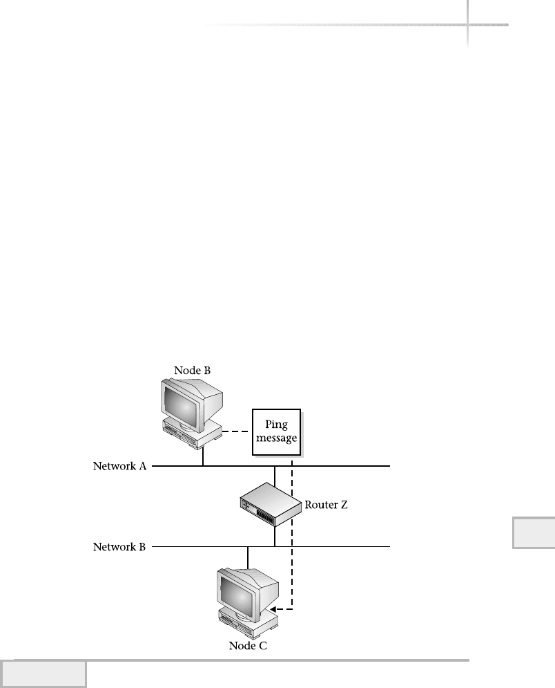
but that an intermediate device, such as a network router, is responsible for the
lack of connectivity. I term this problem “connectivity fussiness.” In this case,
ping can’t determine why rubens is not reachable. To further understand
this problem, consider the sample network in Figure 11-1.
This network diagram shows several devices attached to two different
networks that are interconnected via Router Z. When a ping request is issued
from node B on network A to node C on network B, the request is passed via
router Z. If router Z should stop functioning, the requests will never reach node C.
As a result, node C becomes unreachable from the perspective of node B.
Because ping can check reachability of any TCP/IP device, we can now
issue a ping for router Z to further diagnose the problem. By probing the
router closest to node C, we will learn that the loss of connectivity is most likely
being caused by router Z’s network interface to network B, and not node C itself.
Also, if we ping other devices on network B, this would confirm that all
devices are unreachable and lead us to conclude that there is a problem with
router Z. This example demonstrates that network problems can be caused by
11
Module 11: Basic Network Tools 349
11
Figure 11-1 Using ping to determine node availability

devices other than those easily identified as being the problem. Tools such as
ping help to isolate the sources of routing and many other network failures
or problems.
The second form of the ping command provides a number of options to
control additional functionality. Table 11-8 provides a list of the most popular
command-line options available.
Show Basic Network Performance
The ping command can be used to measure the amount of time required to
transmit a message to a remote destination and the time required to obtain a
response. This use of this command in essence measures the relative performance
of the path between the two devices at a given point in time. It does not, by any
means, provide a detailed analysis of the devices or connectivity between them.
Rather, it provides a glimpse of the general condition of the path at the point it
is measured. It could be said that network performance is like the stock market.
One day it is up and the next it is down. The primary difference with respect to
volatility is whether we are talking in terms of days or milliseconds. A large
number of factors can cause network performance to vary. These include users
that are overly aggressive about using network resources, hardware problems,
software configuration problems, and so forth.
350 UNIX System Administration: A Beginner’s Guide
Option Description
-R Use record route information.
-U Use UDP packet instead of ICMP packet (Solaris only).
-a Issue a ping to all addresses on a multi-home host (Solaris only).
-c Send only a certain number of packets (Linux only).
-f Flood the network with packets.
-i Delay the number of seconds between each request (Linux only).
Specify the outgoing interface (Solaris and HP-UX only).
-n Show network addresses instead of hostname.
-p Specify up to 16 bytes to pad a packet with customized data (Linux only).
Set the base UDP port to use (Solaris only).
-s Issue a single ICMP request per second and collect round-trip statistics
(Solaris and HP-UX only).
Table 11-8 ping Command-Line Options
TEAMFLY
Team-Fly®
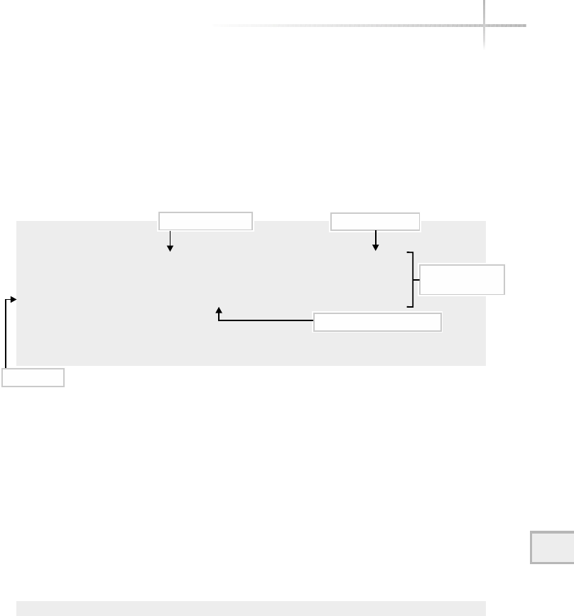
11
The ping command provides a means of determining system response
times as well, but it takes a little more work to determine if the observed
performance problem is related to a specific slow system or a delay in some
other network component. The ping tool shows output that can be used to
measure and report round-trip time and provide packet-loss statistics. By
default, ping issues an ICMP request every second to the destination supplied
on the command line and reports the status of each ICMP reply. Sample output
includes the following:
# ping –s didymus
PING didymus.home.com (10.0.2.127): 56 data bytes
64 bytes from 10.0.2.127: icmp_seq=0 ttl=255 time=1.2 ms
64 bytes from 10.0.2.127: icmp_seq=1 ttl=255 time=1.1 ms
64 bytes from 10.0.2.127: icmp_seq=2 ttl=255 time=1.2 ms
64 bytes from 10.0.2.127: icmp_seq=3 ttl=255 time=1.2 ms
--- didymus.home.com ping statistics ---
4 packets transmitted, 4 packets received, 0% packet loss
round-trip min/avg/max = 1.1/1.1/1.2 ms
This report provides the packet size, the hostname or IP address of the
target device, a sequence number, round-trip time value, and a statistical
summary. The time value shows the round-trip time in milliseconds (1000ths
of a second) for each reply received. The bottom of the report calculates the
minimum, average, and maximum trip times for all replies, also displayed in
milliseconds. The total length of the ICMP packet transmitted to didymus is
64 bytes. This is the default size, which is usually sufficient. However, it might
be necessary to increase the packet size to get a better measure of throughput.
In this case, a large packet size may be specified using the -s command-line
option on Linux. For example, the command
# ping -s 100 didymus
issues the ICMP requests with a packet size of 100 bytes to the target host
didymus. This might be required to obtain a better picture of performance
Module 11: Basic Network Tools 351
11
Packet size
Round trip time
ICMP sequence number
Target IP address
4 packets sent
and received

because network throughput may differ for larger packet sizes versus smaller
values. When executed, this command shows the following:
PING didymus.home.com (10.0.2.127): 100 data bytes
108 bytes from 10.0.2.127: icmp_seq=0 ttl=255 time=2.7 ms
108 bytes from 10.0.2.127: icmp_seq=1 ttl=255 time=1.5 ms
108 bytes from 10.0.2.127: icmp_seq=2 ttl=255 time=1.3 ms
108 bytes from 10.0.2.127: icmp_seq=3 ttl=255 time=1.3 ms
108 bytes from 10.0.2.127: icmp_seq=4 ttl=255 time=1.3 ms
108 bytes from 10.0.2.127: icmp_seq=5 ttl=255 time=1.3 ms
108 bytes from 10.0.2.127: icmp_seq=6 ttl=255 time=1.3 ms
108 bytes from 10.0.2.127: icmp_seq=7 ttl=255 time=1.3 ms
--- didymus.home.com ping statistics ---
8 packets transmitted, 8 packets received, 0% packet loss
round-trip min/avg/max = 1.3/1.5/2.7 ms
On Solaris and HP-UX, use following command to accomplish the same thing:
ping –s didymus 100
In this case, specifying the size of the packet comes after the hostname.
As you can see from this output above, ping adds 8 bytes of overhead for
each packet sent; this is determined by subtracting the 100 bytes specified with
the -s option from the 108 bytes transmitted by ping. Notice that the response
times didn’t change much, despite the fact that we used a large data size. We
would need to increase the size significantly to observe a larger delay in
processing the packets.
You may have noticed that the hostname didymus was used on the command
line, but when ping echoed back the hostname, it showed a different name,
like didymus.home.com. The reason for this is that didymus is an alias of
didymus.home.com and using the alias with many UNIX commands results
in the official name being used instead.
The ping tool uses a sequence number to keep track of requests and
replies. Each request is given the next number in sequence and is then matched
352 UNIX System Administration: A Beginner’s Guide
Packet size equals the 100 bytes specified on
the command line plus 8 bytes overhead

with the corresponding reply. This sequencing is used to determine packet loss
if any requests do not receive an appropriate reply. Generally speaking, packet
loss on a small network should be very rare, and if it does occur, it might indicate
a network- or system-related problem. However, on a large network or internet
(internet with a lowercase i), or on the Internet, packet loss is common and
represents a normal state of affairs. Given a popular Internet site as shown
below, a certain amount of packet loss may be observed:
ping -c 10 www.whitehouse.gov
PING www.whitehouse.com (209.67.27.247): 56 data bytes
64 bytes from 209.67.27.247: icmp_seq=7 ttl=244 time=240.1 ms
64 bytes from 209.67.27.247: icmp_seq=8 ttl=244 time=240.1 ms
64 bytes from 209.67.27.247: icmp_seq=9 ttl=244 time=240.1 ms
--- www.whitehouse.com ping statistics ---
10 packets transmitted, 3 packets received, 70% packet loss
round-trip min/avg/max = 240.1/240.1/240.1 ms
The report above indicates that 70 percent of the packets sent to the
www.whitehouse.gov system did not have corresponding replies! They
were lost. In other words, the program sent ten packets, but only received three
back; seven out of ten is 70 percent. One possible reason for this noticeable
packet loss is that some of the critical Internet routers might be quite busy or
even overloaded with network traffic. As a result, some of the ICMP requests
might be discarded because the requests expired before they were delivered to
the final destination. Also, the relative load of the target device can be a factor
because these systems might not have the computing resources to answer all
network requests as required. Because of the popularity of this site, it is not
unreasonable to think that both the servers and the networks that connect them
are all quite busy or even overloaded. An overloaded condition will occur when
too many users are using resources from the system or network at the same time.
Sometimes it is desirable to provide additional time for acknowledging each
ping request instead of using the default value of one second. If additional time
is desired between successive ICMP requests, the -i option can be used, followed
by the desired value. The interval should be long enough to provide the required
amount of time for the remote system to respond. When we increase the timeout
value as suggested, we will generally notice less packet loss. The command
ping -c 10 www.whitehouse.gov -i 5
Module 11: Basic Network Tools 353
11

354 UNIX System Administration: A Beginner’s Guide
adds a five-second delay to each request, thus providing additional time for the
processing of the requests through the network and to the destination server.
Using the command above, the following was produced:
PING www.whitehouse.com (209.67.27.247): 56 data bytes
64 bytes from 209.67.27.247: icmp_seq=1 ttl=244 time=240.1 ms
64 bytes from 209.67.27.247: icmp_seq=2 ttl=244 time=240.1 ms
64 bytes from 209.67.27.247: icmp_seq=3 ttl=244 time=240.1 ms
64 bytes from 209.67.27.247: icmp_seq=4 ttl=244 time=240.0 ms
64 bytes from 209.67.27.247: icmp_seq=5 ttl=244 time=250.1 ms
64 bytes from 209.67.27.247: icmp_seq=6 ttl=244 time=240.1 ms
64 bytes from 209.67.27.247: icmp_seq=7 ttl=244 time=240.1 ms
64 bytes from 209.67.27.247: icmp_seq=8 ttl=244 time=240.2 ms
64 bytes from 209.67.27.247: icmp_seq=9 ttl=244 time=250.1 ms
--- www.whitehouse.com ping statistics ---
10 packets transmitted, 9 packets received, 10% packet loss
round-trip min/avg/max = 240.0/242.3/250.1 ms
As noted from the output, the packet loss to this site was reduced to 10 percent.
Bear in mind that other factors could have also contributed to the reduction, such
as users leaving the site or the network not being used. In general, increasing the
amount of time for each request should reduce the overall load on the system.
However, this is not guaranteed to always be the case because the system may be
overloaded to the point that no additional amount of time would really help.
Additional Command Options
With the -n option, ping displays IP addresses rather than hostnames. This
is useful, for example, when network problems involving DNS impact the use
of ping. This option instructs ping not to invoke hostname resolution, thus
permitting the tool to function while the name service is slow or temporarily
disabled.
The -R option enables the record route option with the IP protocol. Toggling
the record route informs each router along a path to place its IP address in the
IP header. As a result, a list of routers that were used to reach the final destination
can be obtained. This is the chief mechanism that the traceroute command
utilizes. Another interesting option is flood mode using the -f option, which is

available on Linux. This option tells ping to attempt to flood the network with
ICMP requests approximately 100 times per second or as fast as the remote
destination can process each request.
By the way, a note of caution is in order here: The -f option can be a
dangerous thing. It can consume a significant amount of network bandwidth
and cause systems to disappear from the network because they are too heavily
loaded to respond to other network requests. It is not recommended that this
option be used on a live network when loss of connectivity could impact the
business operations of the individuals that use the network. Also, it is not
reasonable to flood other networks that you are not associated with.
Having said all this, the command
ping -c 100 -f bedrock
displays the following output:
PING bedrock.home.com (216.155.202.100) from 216.155.202.163 : 56(84) bytes of data.
.
--- bedrock.home.com ping statistics ---
100 packets transmitted, 100 packets received, 0% packet loss
round-trip min/avg/max/mdev = 0.203/0.244/0.427/0.040 ms
This sends 100 packets to the host bedrock.
11
Module 11: Basic Network Tools 355
Ask the ExpertAsk the Expert
Question Why use the flood capability anyway?
Answer The reason is simple—attempt to produce a significant
amount of traffic on the network and see what happens. You will find
that in networking, determining how things work sometimes includes
attempting to break things or do things in such a way as to exceed the
practical limitations of a device or system. In the case of networking
devices such as routers or UNIX systems, industry experts and users
want to know what will happen to the device if it is exposed to
high-traffic patterns. Measuring performance and other networking
characteristics when the network is under tremendous load will help
the network manager truly understand the behavior of critical networking
devices and systems when they are deployed in their networks. The
flood option is one easy way to do this.

356 UNIX System Administration: A Beginner’s Guide
11-5 Gather Network Information
with Lanscan
The lanscan command available on HP-UX provides a very quick and easy
way to gather network configuration and performance information from all the
system network interfaces. Issuing the command
# lanscan
displays the following:
Hardware Station Crd Hdw Net-Interface NM MAC HP-DLPI DLPI
Path Address In# State NamePPA ID Type Support Mjr#
0/0/0/0 0x00306E060662 0 UP lan0 snap0 1 ETHER Yes 119
As shown above, the output is very similar to what the ifconfig
command provides, but in this case more information is given about the
low-level data link support (for example, it shows that lan0 is of type ETHER,
which represents Ethernet).
NoteNote
Since the HP-UX version doesn’t support the –a option, this command can be
used to determine the name of all the network interfaces on the system. Using
the –v (verbose) option of the lanscan command, additional information can
be obtained about the system network interfaces:
# lanscan -v
-------------------------------------------------------------------------------
Hardware Station Crd Hdw Net-Interface NM MAC HP-DLPI DLPI
Path Address In# State NamePPA ID Type Support Mjr#
0/0/0/0 0x00306E060662 0 UP lan0 snap0 1 ETHER Yes 119
Extended Station LLC Encapsulation
Address Methods
0x00306E060662 IEEE HPEXTIEEE SNAP ETHER NOVELL
Driver Specific Information
btlan3
This option shows the additional supported data link methods, such as NOVELL
and also the Ethernet driver information (btlan3).

11
Project 11-1
This project steps you through documenting the network settings on your
system and testing your current network connectivity.
Step-by-Step
1. ping your local loopback address to verify that TCP/IP is functional on
your system:
# ping 127.0.0.1
2. Display your ARP table:
# arp
3. If you are using Linux, display the ARP table in numeric format in verbose mode:
# arp -n -v
4. List all the available interfaces for your system:
#ifconfig –a
5. Display all the current network connections:
# netstat -a
6. Search the results of the netstat command to look for instances of specific
services. For example, are you running an FTP server on this system?
netstat -a | grep ftp
7. ping several major hosts to determine your connectivity to them. For example:
ping 198.192.196.56
ping 4.17.168.6
Module 11: Basic Network Tools 357
11

358 UNIX System Administration: A Beginner’s Guide
Mastery Check
1. The _________ contains a complete list of all data link protocol to
IP address mappings for the local network.
2. Which command provides information regarding the present status
of network connections, routing information, and other important
network-related data?
A. ifconfig
B. arp
C. netstat
D. ping
3. Which command can be used to determine if a remote device is reachable
on a network from the local system and help debug connectivity problems
among systems?
A. ifconfig
B. arp
C. netstat
D. ping
4. What does this output from the ping command tell you about the status
of the system pinged?
4 packets transmitted, 4 packets received, 0% packet loss
A. The system is reachable.
B. The system is not available.
C. The system is taking too long to respond to ping requests.
D. No information can be determined from this output.

Module 11: Basic Network Tools 359
11
5. What function is performed with this command?
# arp -s bruegel 08:00:20:82:be:05
A. Displaying the ARP table for the bruegel system
B. Deleting the bruegel system from the ARP table
C. Changing the hardware address in the ARP table for the bruegel system
D. Adding the bruegel system to the ARP table
6. What is the command to disable the interface ppp0?
7. What type of interface does this output from the ifconfig -a
command indicate?
eth1 Link encap:Ethernet HWaddr 08:00:20:04:CF:2C
inet addr:10.0.2.127 Bcast:10.0.2.255
A. Physical
B. Logical
C. Active
D. Inactive
8. What type of interface does this output from the ifconfig -a
command indicate?
UP BROADCAST RUNNING MULTICAST MTU:1500 Metric:1
A. Physical
B. Logical
C. Active
D. Inactive
Mastery Check

360 UNIX System Administration: A Beginner’s Guide
9. What is the command to show all network connections and show them in
numeric format?
10. What command would have produced the following two lines of output?
tcp 0 0 *:sunrpc *:* LISTEN
udp 0 0 110.orlando-11-1:domain *:*
A. netstat -a | grep ftp
B. netstat -a -t -u
C. netstat -a -n
D. netstat -t -p -a
11. What is the command to record each router’s IP address in a ping,
similar to the long lines command?
Mastery Check
TEAMFLY
Team-Fly®

Module12
Advanced
Network Tools
Critical Skills
12.1 Monitor Network Traffic with the tcpdump Tool
12.2 Execute the traceroute Command to Show Network Connectivity
12.3 Verify Basic Operations Using the landiag Command
Copyright 2002 by The McGraw-Hill Companies, Inc. Click Here for Terms of Use.

12.1 Monitor Network Traffic
with the tcpdump Tool
The tcpdump command is a general-purpose network traffic monitor that can
capture and display packets and their contents. This command can be used as a
protocol analyzer, providing one of the best ways to investigate communication
and/or connectivity problems among systems and networking devices. Most of
the time, network troubleshooting focuses on network configuration problems
and diagnosing hardware-related failures. Every once in a while, however, you
will be faced with a protocol-related problem and be forced to delve into the
heart of the particular networking stack to resolve the problem. With tcpdump,
the packets scanned will be displayed with information in either a short or long
format, depending on the command-line options used. Also, this command has
a very powerful filtering mechanism that can search for packets that match
a specific string or criteria.
Depending on the installation options selected, this command will be
available on Linux by default. On Solaris, this command is available on the Solaris
Companion Software CD. When tcpdump is installed from this CD, the default
command path is /opt/sfw/sbin. For HP-UX, it must be downloaded from
the Internet.
Two primary capture modes are provided by this command: promiscuous
and nonpromiscuous. In promiscuous mode, every packet transmitted on the
network is captured, whether or not the packet was sent to the system on which
tcpdump is listening. This is the mode, for instance, that network probes use
when monitoring network traffic. Network probes listen on the network for
traffic and collect protocol information and statistics. Because local area network
(LAN) protocols such as Ethernet are broadcast-based, every frame transmitted
can be seen by any network interface attached to the LAN. Any device can read
every frame transmitted if that device chooses and is configured to do so. When
a device or interface reads every frame from the network, it is said to be in
promiscuous mode. In practice, the interface must be configured for promiscuous
operation and is only used on special occasions when network diagnosis is
required. For this reason, only root may enable promiscuous mode on an
interface. This is the primary reason that nonroot users are not permitted to
invoke tcpdump. When the attempt is made by a nonroot user to execute the
command, the following message is displayed:
tcpdump: socket: Operation not permitted
362 UNIX System Administration: A Beginner’s Guide

12
Module 12: Advanced Network Tools 363
12
If you want to give a regular user the ability to invoke the tcpdump command,
you can setuid the program to run as root or install and configure a program like
sudo. This utility gives specific users access to privileged programs as deemed
appropriate by the system administrator. See Module 7 for more information
about the sudo command.
With nonpromiscuous mode, only broadcast frames and frames addressed to
the local system will be available to the interface. The term “broadcast” actually
refers to both normal broadcast (with all 1s in the destination field) and multicast
traffic. Under normal circumstances, the interface is in nonpromiscuous mode.
When tcpdump is invoked without command-line options, it opens the
primary network interface and begins capturing frames from the local network
and displaying their contents. Because this command can produce a significant
amount of output, the quiet option (-q ) is used to reduce the amount of output
displayed. When executed by root, the command
# tcpdump -q
will display all network frames (packets) in the single-line, nonverbose format.
The format of the output will include a timestamp, source and destination hosts
(or address), the high-level network protocol, some flags, and additional protocol
information, as shown in the following example:
tcpdump: listening on elxl1
15:41:58.055268 durer.home.com.1032 > socrates.home.com.telnet: tcp 0 (DF)
[tos0x50]
15:41:58.055446 socrates.home.com.telnet > durer.home.com.1032: tcp 28 (DF)
15:41:58.274933 durer.home.com.1032 > socrates.home.com.telnet: tcp 0 (DF)
[tos0x50]
15:41:58.275115 socrates.home.com.telnet > durer.home.com.1032: tcp 164 (DF)
15:41:58.494694 durer.home.com.1032 > socrates.home.com.telnet: tcp 0 (DF)
[tos0x50]
15:41:58.494880 socrates.home.com.telnet > durer.home.com.1032: tcp 165 (DF)
15:41:58.544828 socrates.home.com > didymus-gw2.home.com: icmp: echo request
15:41:58.545719 didymus-gw2.home.com > socrates.home.com: icmp: echo
reply5:34:10.601950 socrates.home.com.telnet > durer.home.com.1032: tcp 165
(DF)
8 packets received by filter
0 packets dropped by kernel
The output includes the time, source/destination, protocol port, protocol
contained with the frame, and additional protocol information. In this example,
source host destination host
timestamp packet summary

364 UNIX System Administration: A Beginner’s Guide
durer, the source host, and socrates, the destination host, have a Telnet
session established. We can tell this by looking at the destination port, which
is Telnet. By default, tcpdump captures packets until the user interrupts the
program by issuing ^c. Also, socrates has issued a ping request to didymus-
gw2, and it has responded with a reply. The -> string indicates the direction of
the communication path. Note that tcpdump always orients the communication
path to point to the right, as in the case of the ICMP echo request above. To
indicate communication in the other direction, tcpdump reverses the hosts (not
the pointer), as shown with the ICMP Echo reply entry. The tcpdump command
displays the higher-level protocols in lowercase, as in tcp and icmp, followed
by more specific information pertaining to the protocol, which might include
ports, additional protocol information, and data. The output also includes a
summary of the number of packets obtained before the user terminated the
command.
The end of the output includes a count of the number of packets captured
by and the number of packets that were dropped. In this case, a total of eight
packets were captured and zero packets were discarded.
The tcpdump tool provides a large number of command-line options to
select capture modes, control output, specify filter specifications, and specify
additional operating characteristics. These options are grouped according to
their function and include the following categories:
●Operating modes
●Display options
●Packet filter options
Operating Modes
These options are used to control how tcpdump will capture and display network
traffic. The available options are summarized in Table 12-1 and described
fully below.
Normally, tcpdump will listen for traffic on the primary network interface.
Usually the primary interface has the smallest numeric identifier if the system
contains two or more interfaces of the same type. For example, eth0 is
considered the primary when the system contains two Ethernet interfaces:
eth0 and eth1. However, if you want to run tcpdump on a different

interface, use the -i option and the device name to specify the alternate interface.
For example, to select the point-to-point (ppp0) interface, use the following
command:
# tcpdump -i ppp0
tcpdump: listening on ppp0
As previously indicated, tcpdump will capture packets until ^c is typed
from the controlling terminal (or if placed in the background, until the process
is terminated with the kill command). If you wish to specify the number of
packets to be captured, use the -c option followed by a packet count value. To
capture ten packets from the eth1 interface, use the following command:
tcpdump -t -q -i eth1 -c 10
tcpdump: listening on eth1
chips.home.com > didymus-gw2.home.com: icmp: echo request
didymus-gw2.home.com > chips.home.com: icmp: echo reply
chips.home.com > didymus-gw2.home.com: icmp: echo request
didymus-gw2.home.com > chips.home.com: icmp: echo reply
socrates.home.com.1032 > switch.home.com.snmp: udp 44
switch.home.com.snmp > socrates.home.com.1032: udp 111
socrates.home.com.1032 > switch.home.com.snmp: udp 51
switch.home.com.snmp > socrates.home.com.1032: udp 61
socrates.home.com.1032 > switch.com.snmp: udp 51
switch.com.snmp > socrates.home.com.1032: udp 54
12
Module 12: Advanced Network Tools 365
Option Description
-c Captures specified number of packets and then quits
-F Uses file as source for filter expression
-I Captures packets using alternate network interface
-p Disables capturing in promiscuous mode
-r Reads capture file instead of network interface
-w Saves raw packets to file
Table 12-1 tcpdump Operating Mode Common Options
socrates initiates snmp query 10 lines captured corresponds to 10 packets

366 UNIX System Administration: A Beginner’s Guide
In this case, tcpdump has captured a ping session between socrates
and didymus-gw2, as detected by the first four lines. Also, socrates was
querying a device called switch using SNMP, as denoted by the SNMP port and
the UDP protocol used (the remaining lines). We can confirm the number of
captured packets by counting the number of lines displayed. Specifying the
number of packets to capture is useful when the intent is to monitor a critical
network transaction that uses a fixed number of packet exchanges. This option
is also useful when monitoring packets within a shell script because you don’t
have to be concerned about stopping tcpdump after it has been started. The
-t option, which removes the packet timestamp information, was used in this
example as well.
As previously indicated, tcpdump, by default, opens the network interface
in promiscuous mode to capture all network traffic. Promiscuous mode
means that all network traffic, regardless of the destination of the packet, will
be captured. Sometimes, it is more effective to examine packets delivered to a
specified host than it is to read all packets on the network. If we want to capture
those packets addressed to the host that tcpdump is running on, the -p option
is used to disable promiscuous mode capture. You will see later that we can
tell tcpdump to capture packets coming from or going to a particular host
using filters.
# tcpdump -p
tcpdump: listening on eth0
Unfortunately, the tcpdump command doesn’t confirm the use of the
-p option. As a result, the user has no way of knowing after the command was
executed which mode it is capturing with, except to examine the output to see
the destination addresses. In other words, any packet that isn’t a broadcast or
sent to a local address indicates that tcpdump is capturing with promiscuous
mode enabled.
On a very active network or a busy system, and when using certain command-
line options, tcpdump can produce a large amount of output. To help manage
this, the -w option can be used to redirect the captured information into a file.
One reason to use a file is to save the captured data for later inspection and analysis.
This could include manipulating the data in other ways, possibly using the data
to build specialized reports, and the like.

Module 12: Advanced Network Tools 367
12
To capture network traffic and save it to a file called traffic-data, use
the following command:
# tcpdump -w traffic-data
tcpdump: listening on eth0
The file, traffic-data, is created in the local directory once the command
above is invoked. However, the data captured isn’t written to the file until the
user interrupts the program or the -c option is used. Once the user does this,
the following is displayed:
48 packets received by filter
0 packets dropped by kernel
Ask the ExpertAsk the Expert
Question Why would you disable promiscuous mode with the
-p option anyway?
Answer Sometimes it becomes necessary to examine just the traffic
that arrives normally at a particular system. With this option, we can
see every packet that is destined by the local system, and nothing more.
This can be used to easily detect (by monitoring the incoming packets),
for example, whether a request for a particular service is reaching the
system. Given a client/server environment, we can determine if requests
from client systems are reaching the server (by running tcpdump on
the server) or if a particular client is transmitting requests in the first
place (by running tcpdump on the client). It is true that we can use
filters to accomplish the same thing, but it is more efficient and easier
to just reduce the number of packets in the first place.
HintHint
The traffic-data file created is not an ordinary text file, but rather a
specially formatted data file that only tcpdump and certain other programs
understand. One such program, called tcpslice, can cut out or splice
different tcpdump files together.

368 UNIX System Administration: A Beginner’s Guide
To learn a little bit more about the tcpdump file, use the UNIX file
command. If this is run against the traffic-data file, it reports that it
is associated with the tcpdump command, the version of the software, and
that the data contains packets that are of type Ethernet, with a frame length
of 68 bytes. It is not a human-readable text file. The UNIX command
# file traffic-data
shows the following:
traffic-data: tcpdump capture file (little-endian) - version 2.4 (Ethernet,
capture length 68)
As previously mentioned, it is interesting that tcpdump labels the frame
types that are contained with the data file. In the previous example, the label
indicates that Ethernet frames are stored in this file. Additional types include
raw IP, FDDI, and others. Thus, if a packet capture were done on a point-to-point
link, as in the ppp0 interface, the raw IP packet type would be displayed. If
you were trying to view the file, it would appear to be a long series of strange
characters. However, this file can be read by such programs as the ethereal
tool, which provides a GUI-based approach to protocol capture and analysis.
The tcpdump command does a reasonable job of compressing data stored
in files. For instance, over 3,000 packets consume approximately 260K worth
of disk space. If you are going to save a significant amount of captured data, it
may be necessary to compress the data further using either compress or gzip.
The compress utility manages to reduce the size of this data file to a little over
33K, while the gzip program reduces the byte count down even more to just
over 18K. Not bad from a byte size of over 260K!
To display the packets that have been saved in a data file, use the -r option
followed by the name of the packet capture file. For instance, to replay the
packets saved within the traffic-data file, issue the following command:
# tcpdump -r traffic-data
Display Options
These options control how tcpdump will display packets from the network.
The list of the available options under this category is summarized in Table 12-2.

1212
Sometimes it is useful to determine the length of data link frames. This can
be helpful, for example, when investigating performance problems related to
higher-level applications. The tcpdump tool provides a way to obtain the size
of each frame, including both the header and data portion, with the -e command-
line option. The following sample command and output show a file transfer
session using FTP and ARP broadcasts:
# tcpdump -t -e
0:10:5a:28:5d:7c Broadcast arp 42: arp who-has
didymus-gw2.home.com tell socrates.home.com
0:10:5a:28:5d:7c Broadcast arp 42: arp who-has
didymus-gw2.home.com tell socrates.home.com
0:10:5a:28:5d:7c Broadcast arp 42: arp who-has
didymus-gw2.home.com tell socrates.home.com
0:10:5a:28:5d:7c 0:60:97:e:a3:6 1514: socrates.home.com.ftp-data
durer.home.com.1036: tcp 1448 (DF) [tos 0x8]
0:10:5a:28:5d:7c 0:60:97:e:a3:6 1514: socrates.home.com.ftp-data
durer.home.com.1036: tcp 1448 (DF) [tos 0x8]
As you can see, the length field is displayed next to the protocol, or if no
protocol is shown, after the destination address. It shows the total size of the
frame in bytes. The reason the packets from socrates to durer are greater
than 1,500 bytes is because FTP fills the packet with as much data as it can
hold. Ethernet has a data capacity of approximately 1,500 bytes, not including
the header portion of the frame.
The -x option provides a way to display a hexadecimal dump of network
frames. It displays link-level header information such as source and destination
Module 12: Advanced Network Tools 369
Option Description
-e Prints link-level header information on each line
-v Specifies verbose mode
-q Specifies quick mode, displays short packet information
-t Disables printing of the timestamp
-s Limits the size of packets captured
-x Displays both hexadecimal and ASCII format
Table 12-2 Display Options for tcpdump
Length field

370 UNIX System Administration: A Beginner’s Guide
address. Consider the series of packet exchanges when the host rembrandt
attempts to open an FTP session to a system called durer.Thetcpdump command
tcpdump -d le1 -x 0 tcp and port 21
will capture any FTP activity on the network. When this command is executed
and an FTP session is started, the packets will be captured and displayed as follows:
0:60:97:e:a3:6 0:10:5a:28:5d:7c ip 78: durer.home.com.1044 >
socrates.home.com.ftp:
S 9262138:9262138(0) win 8192 <mss 1460,nop,wscale
0,nop,nop,timestamp[|tcp]
(DF) [tos 0x1d] (ttl 128, id 19970)
451d 0040 4e02 4000 8006 93c6 0a00 020a
0a00 02c9 0414 0015 008d 543a 0000 0000
b002 2000 a43e 0000 0204 05b4 0103 0300
0101 080a 0000
0:10:5a:28:5d:7c 0:60:97:e:a3:6 ip 74: socrates.home.com.ftp
durer.home.com.1044: S 1087677057:1087677057(0) ack 9262139 win 32120 <mss
1460,sackOK,timestamp> 1106589[|tcp]> (DF) (ttl 64, id 490)
4500 003c 01ea 4000 4006 2000 0a00 02c9
0a00 020a 0015 0414 40d4 a281 008d 543b
a012 7d78 92b7 0000 0204 05b4 0402 080a
0010 e29d 0000
0:60:97:e:a3:6 0:10:5a:28:5d:7c ip 66: durer.home.com.1044 >
socrates.home.com.ftp: .ack 1 win 8760 <nop,nop,timestamp 84320 1106589>
(DF) [tos 0x1d] (ttl 128,id 20226)
451d 0034 4f02 4000 8006 92d2 0a00 020a
0a00 02c9 0414 0015 008d 543b 40d4 a282
8010 2238 d35b 0000 0101 080a 0001 4960
0010 e29d
0:10:5a:28:5d:7c 0:60:97:e:a3:6 ip 163: socrates.home.com.ftp
durer.home.com.1044: P 1:98(97) ack 1 win 32120 <nop,nop,timestamp 1106595
84320> (DF) [tos 0x10] (ttl 64, id 493)
4510 0095 01ed 4000 4006 1f94 0a00 02c9
0a00 020a 0015 0414 40d4 a282 008d 543b
8018 7d78 b4a1 0000 0101 080a 0010 e2a3
0001 4960 3232
0:60:97:e:a3:6 0:10:5a:28:5d:7c ip 66: durer.home.com.1044
socrates.home.com.ftp: . ack 98 win 8663 <nop,nop,timestamp 84323 1106595>
(DF) [tos 0x1d] (ttl 128, id 20994)
451d 0034 5202 4000 8006 8fd2 0a00 020a
0a00 02c9 0414 0015 008d 543b 40d4 a2e3
8010 21d7 d352 0000 0101 080a 0001 4963
0010 e2a3
TCP source port
IP Destination Host
Datalink source address
Datalink destination address
TEAMFLY
Team-Fly®

Module 12: Advanced Network Tools 371
12
Please note that some unwanted information has been manually removed
from the output to make it more readable.
As you can see, the output shows a summary lines that contains the Datalink
Source Address, Datalink Destination Address, Highlevel Protocol, Frame Size,
IP Source Host, TCP Source Port, IP Destination Host, and TCP Destination
Port in the first packet in the preceding example.
After the TCP destination port, we see the TCP packet flags. These map to
the standard TCP packet types listed in Module 10. The Sindicates that the
packet is a SYN, or start of a TCP connection, while the Pmeans it is a push of
data. The ack indicates an acknowledgment. The next part of the listing shows
the entire frame in hexadecimal. Unfortunately, it doesn’t do a good job of
showing us the ASCII version of the frame where appropriate. For instance,
when a user starts an FTP session to a host, some valuable information is
displayed along with a login prompt:
# ftp Socrates
220 socrates.home.com FTP server (Version wu-2.4.2-VR17(1) Mon Apr 19 09:21:53 E
DT 1999) ready.
Name (socrates:root):
This information is contained within the frames shown above, but tcpdump
doesn’t show us this information in ASCII.
Using Packet Filters
One very important aspect of network protocol debugging involves the use
of packet filters. A packet filter is a predefined pattern that is compared to
incoming packets and consists of a series of one or more primitives that may be
combined with operators such as and,or,andnot. When the pattern is matched,
that packet is captured and displayed, or else the packet is discarded and not
displayed. Packet filters are useful in searching for a particular protocol type or
any other specific information available within the packet. We first used a packet
filter in the previous example by telling tcpdump that we were interested in
displaying packets that were related to a file transfer.
The tcpdump command supports user-defined packet filters. A filter is
installed by tcpdump when a filter expression is given on the command line.
This filter is placed in memory and will filter according to the rules that have
been defined using the keywords and primitives. Every packet is compared to
the filter, and when a match is found, the packet is displayed. Otherwise, the
packet is discarded. Figure 4-1 shows a high-level overview of a packet filter.
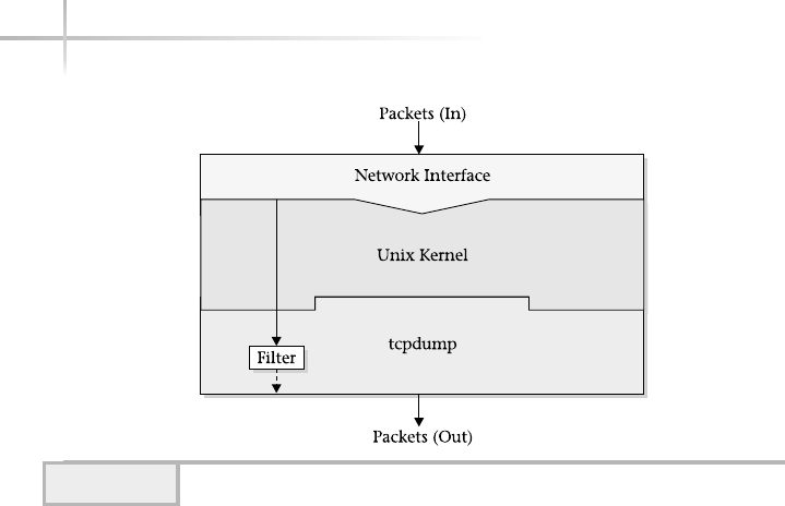
372 UNIX System Administration: A Beginner’s Guide
Normally, network packets are read from the network interface by the
associated driver on behalf of the kernel. Next, tcpdump requests the information
from the kernel using system calls. The tcpdump tool provides a large number
of predefined expressions or primitives that can be used to build very powerful
packet filters. These expressions can be divided into three groups. The first
group, called address primitives, operates on packets using address information
such as IP or data link addresses; the second group, known as protocol primitives,
operates on packets that use different protocols, including IP, AppleTalk, and
others. The final group includes Boolean and arithmetic primitives (or operators)
that can be used with the first two expression types to produce compound
filters. Compound filters include more than one expression type separated by
reserve words such as and,not,andor. These filters can also include arithmetic
operators such as +,-,*, and others. These expressions are evaluated to be
either true or false, and the result will determine what action tcpdump will
take. A description of the primitives follows.
Address Primitives
Expressions that operate on the addressing portions of a packet are listed in
Table 12-3 and described in more detail next.
Figure 12-1 Packet filter diagram

Module 12: Advanced Network Tools 373
12
The gateway primitive selects packets that have been forwarded by a
router. This indicates that the data link address of the packet (either source or
destination) matches that of the router, while the IP address matches that of
the host. Normally, a router will not change the IP address information when
forwarding packets, but the data link address will match the device that forwards
the packet.
The host primitive followed by a valid hostname can select packets that are
either sent to or received from the specified hostname. The host keyword is
mainly used to avoid ambiguity that might arise if you were to specify a hostname
that just happens to be the same as one of the tcpdump existing keywords. For
example, when monitoring the host called gateway, the host keyword must
be used because the gateway keyword will be interpreted as a keyword rather
than as a valid hostname. Thus, the tcpdump command listed next produces
an error because the gateway string is assumed to specify a local gateway:
# tcpdump gateway
tcpdump: parse error
The way to specify the capture of packets from a host called gateway would
be the following:
# tcpdump host gateway
Primitive Description
gateway Selects packets that have been used by a specified host acting
as a gateway
host
ipaddr
Select packets from a specified host or IP address
etheraddr Selects packets from either IP or data link addresses
broadcast Selects broadcast packets that contain all 1s or Fs in either source
or destination fields
multicast Selects packets that are sent to multicast addresses
net Selects packets that contain specified network portions used with
the IP protocol
port Selects packets that contain specified port addresses used with
the IP protocol
Table 12-3 Address-Related Primitives

374 UNIX System Administration: A Beginner’s Guide
The ipaddr and etheraddr options specify actual IP addresses and data link
addresses in dotted and colon formats, respectively. For example, to capture all
packets from the IP address 10.0.2.100, the following command would be used:
# tcpdump ipaddr 10.0.2.100
The ipaddr and etheraddr primitives will match either the source or
destination address. Some data link addresses begin with a letter and will cause
tcpdump to misinterpret these as hostnames rather than true addresses. To avoid
this problem, insert a zero in front when specifying these types of addresses.
To capture broadcast packets, use the broadcast primitive. A broadcast
is a special address that designates that all devices should receive the message.
Several network protocols and services such as ARP, NIS, and RIP use broadcasts
to propagate information across the network. Using broadcast will result in the
capture of broadcast packets from the data link level. This means that any address
that contains 255 or FF values within the source or destination field will be
captured. This includes data link packets that contain broadcasts (such as ARP
requests) and high-level protocol broadcasts (such as an IP broadcast). This
primitive could be used to capture routing data from the Routing Information
Protocol (RIP) because routers periodically broadcast routing updates.
Also, to obtain multicast traffic such as Internet radio, use the multicast
primitive. The standard multicast address of 224.0.0.1 supports this type
of traffic as defined by the multicast standard. Additional addresses (both
physical or IP) can be used at your site. It may be necessary to determine the
exact multicast addresses before you start filtering these types of packets.
Protocol Primitives
The tcpdump application provides protocol primitives as a shorthand way
to select specific network traffic, without requiring or knowing the low-level
protocol information. For example, the ip primitive can be used to capture all
IP traffic. Without this keyword, you would need to use the IP type of x0800,
which is harder to remember. These primitives support the TCP/IP, AppleTalk,
and DECnet family of protocols. Table 12-4 lists and describes these protocol
keywords.

12
To select a protocol family or type that isn’t provided directly by tcpdump,
use the ethertype primitive along with the type code for the desired protocol.
For example, to monitor Novell NetWare packets, which have a type code of
0x8137, use the following command:
# tcpdump ethertype 0x8137
Please note that because tcpdump doesn’t support the Novell protocol
family directly, no packet information can be displayed beyond the data link
layer. If tcpdump finds packets that contain a Novell header, it will list the
data link information only. However, despite this disadvantage, tcpdump is
still useful for identifying certain packet types and providing rudimentary
packet count information.
Operators
The tcpdump command supports several expression (or operator) types and
can be combined with primitives and qualifiers to produce compound filters.
Module 12: Advanced Network Tools 375
Protocol Primitive Description
apple AppleTalk protocol family
arp Address Resolution Protocol—includes both request and reply
fddi FDDI data link protocol
ethertype Another protocol type (used with a type code)
decnet DECnet protocol family
ip Internet Protocol
icmp Internet Control Message Protocol—includes both echo
and reply
rarp Reverse Address Resolution Protocol—includes both request
and reply
tcp Transmission Control Protocol
udp User Datagram Protocol
Table 12-4 Protocol Primitives Supported by tcpdump

These expressions include the arithmetic and Boolean operators listed in
Table 12-5. Operators can build powerful expressions to search for specific
packets. Expressions can be composed of numbers, packet field selections,
length primitives, and arithmetic operators. To use the value of a field in an
expression within a packet, use the following syntax:
primitive [offset [: size] ]
where the word primitive is replaced with ether, ip,udp,tcp, or icmp.
The offset is used in the base of the protocol primitive, and the size specifies
the length of the field. If not supplied, they default to 1.
Packet field sections can be used in a variety of ways. Consider the
following example:
tcpdump "ether[1:4]&0xffffffff = 0xffffffff"
In this example, tcpdump will display all broadcast packets transmitted on
the local network—this means all frames with a destination address of all
376 UNIX System Administration: A Beginner’s Guide
Operator Description
>Greater than
<Less than
>= Greater than or equal to
<= Less than or equal to
=Equal to
!= Not equal
+Plus
-Minus
*Multiply
/Divide
&Bitwise AND
|Bitwise inclusive OR
^Bitwise exclusive OR
and or && Concatenation
or or || Alternation
not or ! Negation
Table 12-5 tcpdump Arithmetic Operators

12
1s (255 in decimal, 0xff in hexadecimal). The 1 in ether[1:4] indicates the
first addressable byte of the frame (the destination address), and the 4 value
specifies the length of this field. Despite the fact that Ethernet addresses are six
bytes, we can examine the first four bytes to determine if it is a broadcast address.
To display all packets that originate from a particular Sun system, for example,
use this command:
tcpdump "ether[6:4]&0xffffffff = 0x08002004"
This tells tcpdump to examine the sixth byte of the frame (the source frame
address) and compare it to the 0x08002004 addresses using the &(and) operator.
This data link address represents the address of a local system called monet.
Recall that Ethernet addresses are six bytes in length, and we can use the first
four bytes to identify the system desired. As a result, all packets transmitted
from monet will be displayed. To identify another system, obtain the data link
address of the system, convert it to hexadecimal, and place it on the right side
of the preceding command.
Miscellaneous Primitives
A few additional primitives are also available from tcpdump that can’t be
classified as either address or protocol primitives. These include the following:
●greater
●less
●length
The greater and less primitives are used in conjunction with other
tcpdump commands to filter, based on the total length of the packet. For
example, to display all packets that are greater than 56 bytes, invoke the
following command:
# tcpdump greater 56
To display all packets that are less than 60 bytes, use the less primitive:
# tcpdump -x less 60
Module 12: Advanced Network Tools 377
12

378 UNIX System Administration: A Beginner’s Guide
This command will display all frames that are less than 60 bytes. For instance,
ARP (Address Resolution Protocol) request frames are smaller than 60 bytes.
Executing this command will display any ARP messages, as shown here:
tcpdump: listening on eth0
23:45:29.240364 arp who-has durer.home.com tell socrates.home.com
0001 0800 0604 0001 0010 5a28 5d7c 0a00
02c9 0000 0000 0000 0a00 020a
Qualifiers
Three qualifiers may be used in conjunction with the primitives listed in the
preceding tables. A qualifier can further define search characteristics to pinpoint
specific network traffic. These qualifiers include the following:
●from or src
●to or dst
The from and src qualifiers are used with the host,net,ipaddr,
etheraddr,port, or rpc primitives to filter based on a specific destination
address or network port. The qualifiers to or dst modify the primitives just
mentioned, but will result in the captured packets going to a particular address
or port. The ether modifier resolves a name to a data link address when used
Ask the ExpertAsk the Expert
Question Why would you use the greater or less commands?
Answer The primary reason is to search for packets based on size,
rather than content. Another primitive, length, can also be used to
handle capturing packets based on their exact size. The length can be
used when the need to capture packets is based on some calculation.
For example, the following command will display any packet that is
not equal to 56:
# tcpdump length != 56

with the host primitive. To illustrate the use of the host keyword, let’s suppose
we want to capture traffic from a particular host only. The following tcpdump
command could be used:
# tcpdump from host monet
Contrast the command above with the following:
# tcpdump host monet
In the latter example, all the traffic involving monet, which includes packets
being sent to and received from monet, will be displayed. In the former example,
only traffic received from monet will be displayed. As you can see, this can
make a big difference when attempting to isolate a network problem.
Tcpdump Command Examples
Listed below are command examples and associated descriptions of actual
tcpdump command syntax. It is hoped that these commands will provide
a quick reference on using tcpdump in real-world situations.
tcpcumpd –w data-file host 216.155.43.1
Captures traffic sent or received by the host with the IP address of 216.155.43.1
and saves that packet information to the file called. data-file.
tcpdump host barney
Will capture and display traffic sent from or delivered to the system called
barney. This command examines both the source and destination address
fields of the IP header.
tcpdump host not barney
Will capture and display traffic from all hosts on the network, except the
system called barney.
tcpdump host barney and host fred and \ (not pebbles\)
Module 12: Advanced Network Tools 379
12

380 UNIX System Administration: A Beginner’s Guide
Will capture and display traffic from hosts barney and fred, but not from the
system called pebbles. The parentheses were added to make the command
more readable. However, each of the tcpdump arithmetical and Boolean
operators has precedence and the parentheses can be used to define command
interpretation ordering.
tcpdump arp
Will capture and display all Address Resolution Protocol (ARP) packets. This
includes both requests and replies.
tcpdump host durer and tcp
Will capture and display all Transmission Control Protocol (TCP) packets
from/to the host durer.
tcpdump host vectra and port 23
Will capture and display all packets using port 23 from or to host vectra. This
amounts to inspecting all Telnet packets going to this system from others on
the network. Recall that port 23 is the Telnet service port for all incoming packets.
tcpdump ether multicast
Will capture and display multicast packets. See the next command for
alternatives.
tcpdump 'ip[16] >= 224'
HintHint
Because the parentheses are special to some shells, they must be escaped
using the backslash (\).
TEAMFLY
Team-Fly®

Module 12: Advanced Network Tools 381
12
Will capture and display all packets that use the multicast address. This
command compares the 16th byte (which is the destination address) of the
IP packet to the value of 224. This prefix is for the standard multicast address
of 224.0.0.1, which means all hosts within the default multicast group.
tcpdump 'ether[0] & 1 = 1'
Will capture and display all broadcast packets. The sequence ether[0]
provides access to the first field of the Ethernet data link destination field and
is compared to the value of 1. If the destination fields contain all 1s (which will
be true if broadcast address, when expressed in binary) and when the and (&)
operator is applied to a positive value, it will yield a value of 1. In this case, the
expression is true and the packets are displayed.
tcpdump 'ip[2:2] > 512'
Will capture and display all IP packets that are larger than 512 bytes. The
sequence ip[2:2] identifies the second byte of the IP header (which is the size
of the packet) and compares this value of 512. The 2: indicates the offset of
the IP packet, while the remaining 2 is the number of bytes within that field.
1-Minute Drill
●When reading tcpdump output, what direction is the communication between
the source and destination oriented in the output lines?
●What are the three main groups of predefined expressions or primitives for
filtering tcpdump results?
●The source and destination are always read left to right and indicated by the > character. If the
communication direction between systems is reversed, the source and host will swap order on
the output line and you still read left to right.
●Address, protocol, operators.

382 UNIX System Administration: A Beginner’s Guide
12.2 Execute the traceroute
Command to Show
Network Connectivity
The traceroute command examines and records the path to a specified
network destination. Within a traditional IP network, one or more routers are
used to provide connectivity between different IP networks. IP routers come in
different shapes and sizes, from a simple multi-homed UNIX system with two
interfaces to an industrial-strength Cisco router series that contains a large
number of interfaces. In each of these cases, the routing function is primarily
the same; it forwards IP packets from one interface to another based on
established routing information.
The traceroute command uses the Time-To-Live (TTL) field contained
within an IP packet and attempts to obtain an ICMP TIME_EXCEEDED message
from each host along the route to the destination. Coupled with an attempt
to attach to the destination at an unreachable port, it will cause a systematic
response from every router along the path to the ultimate destination. It
accomplishes this task by sending out requests (or probes) with a TTL of 1
and increases the TTL by 1 until it either reaches the desired host or exceeds
the maximum TTL value. By default, the TTL is set to 30 hops, but this can
be changed.
This command has a large number of command-line options, but the only
required argument is either a hostname or an IP address of the destination. For
example, to display the IP path between the local system running traceroute
and the destination system called vermeer, issue the following command:
# traceroute vermeer
Figures 12-2 and 12-3 show a sample network that consists of one router and
two network nodes. When the above traceroute command is executed on
monet, the following output will be displayed:
# traceroute Vermeer
traceroute to vermeer (128.197.2.200), 30 hops max, 40 byte packets
1 Router-Z (10.0.2.129) 4.256 ms * 2.899 ms
2 vermeer (128.197.2.200) 7.340 ms 7.433 ms 7.526 ms
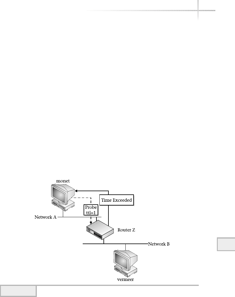
By default, traceroute sends a total of three probes, each with a different
TTL value, to every hop. The first line of the output includes the destination
along with the IP address, the default number of hops used, and the size of the
packets being sent. The second line (with a 1) displays the first hop encountered
by traceroute (see Figure 12-2).
Because vermeer is on a different physical network than monet, a router
must be used to reach this system. Because the default router in this example is
Router-Z, the first packet is sent there. The first packet sent is an ICMP request
packet with the TTL field set to 1. With IP, any packet that reaches the router
decrements the TTL by 1, which makes it zero. When a router gets a packet and
the TTL is zero, it is supposed to discard the packet and notify the sender. This
forces the router to respond with a TIME_EXCEEDED message back to monet.
After this happens, traceroute measures the amount of time between when it
sent the packet and when it obtained the reply. This is known as the round-trip
time, or RTT, and is displayed in milliseconds (1,000th of a second) as shown
after the hostname and IP address information. This implies that the RTT of
the first series of probe packets took 4.25 milliseconds (or .004 seconds), and the
third series took 2.89 milliseconds (or .028 seconds).
The second line details the second routing hop and shows that traceroute
reached the destination system vermeer with slower RTT times than the first
(see Figure 12-3). When the second probe was sent, the router decremented the
12
Module 12: Advanced Network Tools 383
Figure 12-2 Using traceroute with single hop in network
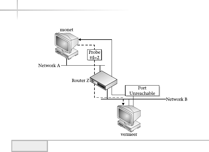
TTL, and then passed this packet to vermeer. Because traceroute is attempting
to access an unused port, vermeer responds with the PORT UNREACHABLE
error. In fact, as a general rule on large (and sometimes small) networks,
performance between systems and networks can (and will) vary a significant
amount even from one moment to the next.
There is no restriction on what constitutes a destination; it can be any kind
of device that ranges from a simple host system to an Internet router. The only
requirement is that it must support IP.
Reading Output
Due to variations and problems with router devices along certain paths, the
general fluctuations of network routes can lead to unpredictable and strange
traceroute output. As a result, certain codes might appear after the timing
information is displayed. Table 12-6 lists these codes and their associated
meanings.
384 UNIX System Administration: A Beginner’s Guide
Figure 12-3 Using traceroute with two hops in network

Module 12: Advanced Network Tools 385
12
Some of these display codes come in handy when you debug network problems.
For example, if a destination is not reachable (like www.whitehouse.gov)
by the system that is running the traceroute command, executing
monet# traceroute www.whitehouse.gov
will produce
traceroute to www.whitehouse.gov (198.137.240.91), 30 hops max, 40 byte
packets
1 monet (10.0.2.126) 4.281 ms !N * 1.896 ms !N
In this example, the network 198.137.240 can’t be reached from the local
system, and traceroute displays the error string !N to indicate this problem.
In this particular case, monet can’t send any packets to 198.137.240 because
no route to that network exists. The *means that the particular probe packet
never received a response; the *is used as a time-out indicator. To further
Code Meaning
*No response to probe packets.
!TTL in the received packet is set to 1.
!H Destination host is unreachable.
!N Destination network is unreachable.
!P Destination protocol is unreachable.
!S The source route option has failed. In practice, this shouldn’t happen,
and if it does, it indicates a bug or problem with the router that generated
the error.
!F Fragmentation was needed for a probe packet. In practice, this shouldn’t
happen, and if it does, it indicates a bug or problem with the router that
generated the error.
!X The path is blocked due to communication being disabled from an
administrative standpoint. In other words, the path is shut down or
blocked from a software standpoint.
!N> An ICMP error code where Nis that number.
Table 12-6 Display Codes for Traceroute

verify these results, use the ping command with the same destination. Thus,
the command
monet# ping www.whitehouse.gov
will show the same problem, except the error is a little more descriptive:
ICMP Net Unreachable from gateway monet (10.0.2.126)
for icmp from monet (10.0.2.126) to www.whitehouse.gov
In the same way, both !H and !P error codes are also used to debug
general network problems. However, in these two cases !H reports when
a host is unreachable and the !P reports when the protocol is unreachable.
The host unreachable message will be displayed, for example, when the
network is also unreachable.
Given the fact that at any point in time the performance or RTT between
networks and systems can change significantly, a trace to the Web site of the
Louvre Museum first reveals the following:
# traceroute 198.137.240.91
traceroute to 198.137.240.91 (198.137.240.91), 30 hops max, 40 byte packets
1 10.0.2.76 (10.0.2.76) 19.906 ms 9.801 ms 8.174 ms
2 199.70.195.38 (199.70.195.38) 197.460 ms 188.000 ms 181.029 ms
3 12.77.194.1 (12.77.194.1) 166.802 ms 184.713 ms 185.857 ms
4 12.127.12.205 (12.127.12.205) 245.026 ms 270.253 ms 266.718 ms
5 12.127.15.145 (12.127.15.145) 215.191 ms 211.920 ms 208.979 ms
6 192.205.31.165 (192.205.31.165) 217.875 ms 232.610 ms 222.274 ms
7 204.6.117.65 (204.6.117.65) 266.797 ms 239.000 ms 215.671 ms
8 38.1.4.69 (38.1.4.69) 235.431 ms 225.447 ms 301.119 ms
9 38.1.25.5 (38.1.25.5) 235.369 ms 236.134 ms 263.557 ms
10 38.1.25.5 (38.1.25.5) 252.172 ms 238.984 ms 263.013 ms
11 38.146.148.45 (38.146.148.45) 241.956 ms 248.091 ms 243.300 ms
12 198.137.240.33 (198.137.240.33) 249.361 ms 228.717 ms 252.927 ms
13 198.137.240.91 (198.137.240.91) 238.799 ms 259.967 ms 236.384 ms
When the trace is repeated later, it shows the following:
traceroute to 198.137.240.91 (198.137.240.91), 30 hops max, 40 byte packets
1 10.0.2.76 (10.0.2.76) 7.619 ms 5.863 ms 6.206 ms
2 199.70.195.42 (199.70.195.42) 177.685 ms 177.691 ms 177.842 ms
3 12.77.242.129 (12.77.242.129) 170.712 ms 177.096 ms 173.517 ms
4 12.127.12.205 (12.127.12.205) 260.239 ms 248.072 ms 252.829 ms
5 12.127.15.145 (12.127.15.145) 219.767 ms 215.645 ms 232.399 ms
386 UNIX System Administration: A Beginner’s Guide
6 192.205.31.165 (192.205.31.165) 232.259 ms 225.243 ms 219.236 ms
7 204.6.117.65 (204.6.117.65) 228.997 ms 218.067 ms 219.365 ms
8 38.1.4.69 (38.1.4.69) 445.758 ms 232.797 ms 276.249 ms
9 38.1.25.5 (38.1.25.5) 245.674 ms 443.611 ms 577.309 ms
10 38.1.25.5 (38.1.25.5) 432.994 ms 222.527 ms 242.844 ms
11 38.146.148.45 (38.146.148.45) 257.668 ms 249.923 ms 263.074 ms
12 198.137.240.33 (198.137.240.33) 276.658 ms 242.361 ms *
13 198.137.240.91 (198.137.240.91) 248.266 ms 245.006 ms 251.071 ms
As you can see, most of the response times are very close. However, significant
delays can be observed with hops 8, 9, and 11. In these cases, the RTT is almost
doubled, which further indicates that performance on a large routed network
(such as the Internet) can and does vary over time.
Changing Characteristics
The traceroute command contains a number of operational parameters
that can be used to affect how it traces a path to the specified destination. Each
of these parameters has an associated command-line option that can alter its
default values. Table 12-7 lists these options.
Module 12: Advanced Network Tools 387
12
Significant
RTT delays
Option Meaning
-I Specifies an alternate interface
-p Sets the alternate port to send probe packets
-g Specifies a router for loose source routing
-f Sets the initial TTL value to be used (Linux only)
-s Uses the specified address as the source address in transmitting
probe packets
-q Sets the number of probe queries
-m Sets the maximum hops
-d Enables debug flag (SO_DEBUG)—this enables socket-level debugging
-F Specifies not to fragment
-t Sets the type of service (TOS) flag
-w Sets the wait time for probe packets
-x Specifies not to calculate checksums
-v Enable verbose mode
Table 12-7 traceroute Operational Command-Line Options

388 UNIX System Administration: A Beginner’s Guide
When the traceroute command is executed on a system that is multi-
homed (that is, a system that contains more than one network interface), it
selects the first interface it encounters. Unfortunately, this might not be the
desired action because the destination network can only be accessed from
another interface. To address this issue, the -i option can be used to force
traceroute to send probe packets using the interface specified with this
option. Thus, the command
traceoute -i hem0
traceroute: Warning: Multiple interfaces found; using 10.0.2.126 @ hme0
will cause traceroute to use the Fast Ethernet interface instead of the default
interface.
In certain situations, the default TTL value of 30 is not enough to reach a
destination that might contain a larger number of routes. When this occurs,
traceroute will never reach the destination. In this situation, use the -m option
to increase the hop count.
When you do a traceroute to certain devices, it might sometimes fail, despite
the fact that the path to the device is operational. Further, using the ping
command against the device will indicate that it is working correctly as well.
Why? Before we answer this question, let’s look at an example:
# traceroute -m 5 128.197.2.200
traceroute to 128.197.2.200 (128.197.2.200), 5 hops max, 40 byte packets
1 rodin (10.0.2.129) 10.193 ms * 2.158 ms
2 * * *
3 * * *
4 * * *
5 * * *
This traceroute produces no response to the probe packets. Note the use of
the -m option to keep the number of probe packets small.
The answer to this problem lies in the fact that, by default, traceroute
sends probe packets based on the UDP protocol. It is most likely that the
destination in question does not support this protocol directly or can’t handle
the UDP destination port used. Also, there could be a firewall device that is
blocking the probe packets. From a TCP/IP standpoint, not all devices are
required to support UDP, and if they do support UDP, they do not necessarily
support the port number used by traceroute.
When traceroute sends out probe packets, it uses, by default, the UDP port
of 33434 and assumes that this port isn’t being used by any other application or

Module 12: Advanced Network Tools 389
12
network service. It uses this high port number in hopes that the destination will
respond with a port unreachable message, thus terminating the route tracing. On
the other hand, if that port is being used, it will cause problems for traceroute.
If this happens, use the -p option followed by another port number, and
traceroute will use that port instead of the default.
# traceroute -p 10 -m 5 128.197.2.200
traceroute to 128.197.2.200 (128.197.2.200), 5 hops max, 40 byte packets
1 rodin (10.0.2.129) 10.193 ms * 2.158 ms
2 * * *
3 * * *
4 * * *
5 * * *
If this still doesn’t do the trick, attempt to use the -I option, which will
instruct traceroute to use the ICMP protocol instead of UDP when sending
probe packets. So, the command
monet# traceroute -m 5 -I 128.197.2.200
with the -I option produces the correct results:
traceroute to 128.197.2.200 (128.197.2.200), 5 hops max, 40 byte packets
1 rodin (10.0.2.129) 4.412 ms * 2.235 ms
2 vermeer (128.197.2.200) 6.875 ms 6.955 ms 6.935 ms
As you can see, this took a bit of trial and error to obtain the desired result.
However, this is not a contrived example; rather, vermeer represents an actual
device—a laser printer. The real point here is that when tracing the route to a
particular destination, there can be many reasons why traceroute fails to reach
a destination. Failure might not mean that the device is down or disconnected
from the network.
Display Options
Two options are available to modify the output of traceroute. The first, -v,
displays for each hop the size and destination of the response packets. The
following shows an example:
# traceroute -v rembrandt
traceroute to rembrandt (10.0.2.75), 30 hops max, 40 byte packets
1 rembrandt (10.0.2.75) 56 bytes to 10.0.2.1 3.450 ms 2.085 ms 2.094 ms

390 UNIX System Administration: A Beginner’s Guide
The second option, -n, displays addresses in numerical form rather than using
the symbolic name. This removes the added task from traceroute of having
to resolve each router’s hostname.
12.3 Verify Basic Operations
Using the landiag Command
The landiag command, which is available only on HP-UX, provides a quick
and easy way to test and verify basic operations of the local network interfaces
on the system.
To run the command, use the following:
# landiag
As a result, the following output will be displayed:
LOCAL AREA NETWORK ONLINE ADMINISTRATION, Version 1.0
Sat, Feb 9,2002 18:02:05
Copyright 1994 Hewlett Packard Company.
All rights are reserved.
Test Selection mode.
lan = LAN Interface Administration
menu = Display this menu
quit = Terminate the Administration
terse = Do not display command menu
verbose = Display command menu
Enter command:
A list of menu items is presented to the administrator. To review additional
features for LAN interfaces, type the lan command and the following will
be shown:
LAN Interface test mode. LAN Interface PPA Number = 0
clear = Clear statistics registers
display = Display LAN Interface status and statistics registers
end = End LAN Interface Administration, return to Test Sele
menu = Display this menu
ppa = PPA Number of the LAN Interface
quit = Terminate the Administration, return to shell
reset = Reset LAN Interface to execute its selftest
Enter command:
TEAMFLY
Team-Fly®

Use the display option to show detailed information about the configuration
and operation state of the system interfaces:
LAN INTERFACE STATUS DISPLAY
Sat, Feb 9,2002 18:02:36
PPA Number = 0
Description = lan0 Hewlett-Packard 10/100 TX Full-Duplex Manual TT = 1
500
Type (value) = ethernet-csmacd(6)
MTU Size = 1500
Speed = 100000000
Station Address = 0x306e060662
Administration Status (value) = up(1)
Operation Status (value) = up(1)
Last Change = 21486
Inbound Octets = 3271707541
Inbound Unicast Packets = 338351587
Inbound Non-Unicast Packets = 6257857
Inbound Discards = 0
Inbound Errors = 60
Inbound Unknown Protocols = 256
Outbound Octets = 1179449614
Outbound Unicast Packets = 312586275
Outbound Non-Unicast Packets = 167
Outbound Discards = 0
Outbound Errors = 0
Outbound Queue Length = 0
Specific = 655367
Press <Return> to continue
Ethernet-like Statistics Group
Index = 1
Alignment Errors = 0
FCS Errors = 0
Single Collision Frames = 0
Multiple Collision Frames = 0
Deferred Transmissions = 0
Late Collisions = 0
Excessive Collisions = 0
Internal MAC Transmit Errors = 0
Carrier Sense Errors = 0
Frames Too Long = 0
Internal MAC Receive Errors = 0
Due to the length of the output, the administrator is prompted to continue
to display the information. The command output above reveals important
information about the configuration of the interface. For instance, the type of
Ethernet hardware is shown in the description field. Also, important statistics
are shown such as the number of bytes read (Inbound Octets) and written
(Outbound Octets) on the network.
12
Module 12: Advanced Network Tools 391
12

Project 12-1
This project familiarizes you with using tcpdump and traceroute on
your system.
Step-by-Step
1. Use the tcpdump command, configured in nonpromiscuous mode, to
capture all the packets to your system’s Web port 80.
# tcpdump -p port 80
2. Open a Web browser and let it load your default home page.
3. Switch to the tcpdump window and examine its output.
4. In the Web browser, navigate to another Web site such as www.whitehouse
.gov and again examine the output in the tcpdump window.
5. Stop the tcpdump capture with ^c.
6. Perform a traceroute without converting the addresses to hostnames
from your system to each of these systems: sans.org and cert.org.
# traceroute -d sans.org
# traceroute -d cert.org
7. Examine the number of hops in the output for each to see which of these
sites your system is more closely connected to on the Internet. Also, compare
them to see if the RTT values for one are significantly slower than the other.
You can use this method to compare other resources—for example, if you
are considering a hosting provider and want to see how well connected you
are to their server compared to another server.
392 UNIX System Administration: A Beginner’s Guide

12
Module 12: Advanced Network Tools 393
12
Mastery Check
1. What is the tcpdump command to run in quiet mode capturing
15 packets from the ppp0 interface?
2. True or False: By default, nonroot users are not permitted to invoke
tcpdump.
3. The __________ command examines and records the path to a specified
network destination.
4. What is the command to display tcpdump data captured to a file named
dump-data?
A. file dump-data
B. tcpdump -r dump-data
C. tcpdump -F dump-data
D. tcpdump -x dump-data
5. Which of the following is not an address primitive for tcpdump filtering?
A. etheraddr
B. ipaddr
C. ethertype
D. port
6. What is the tcpdump syntax to capture traffic from all hosts on the
network, except the system called fred?
7. The __________ primitives group operates on packets that use different
protocols including IP, TCP, FDDI, UDP, and others.
8. What is the command to display the IP path between the local system and
the destination system called barney?
9. What is the command to display the IP path between the local system and
the destination system called www.whitehouse.gov using a maximum
of 20 hops?

394 UNIX System Administration: A Beginner’s Guide
10. In the LAN Interface Test Mode of the HP-UX command, what is the
command to show detailed information about the configuration and
operation state of the system interfaces?
A. display
B. lan
C. ppa
D. interface
11. What tcpdump address primitive filter selects packets that contain all
1s or Fs in either source or destination fields?
12. True or False: The only restriction for a traceroute destination is
that the device must support TCP/IP.
Mastery Check

Module13
Overview of SNMP
Critical Skills
13.1 Discover SNMP Basics
13.2 Uncover MIBs
13.3 Explore SNMP Versions
13.4 Investigate SNMP Master and Subagent
Copyright 2002 by The McGraw-Hill Companies, Inc. Click Here for Terms of Use.

The Simple Network Management Protocol (SNMP) provides the low-level
framework for many network management systems. SNMP is widely
implemented and can be found in a large variety of different networking devices
and systems. Today, SNMP is considered the management protocol of choice
for system administrators, network hardware vendors, network management
vendors, software application developers, and many others that are required to
manage UNIX and other networked systems.
SNMP is popular for several reasons and continues to be enhanced as time
goes on. SNMP is simple to implement compared to other network management
architectures or protocols. The protocol, MIBs, and associated framework can
be run on anything from low-end personal computers (PCs) to high-end
mainframes, servers, and network devices such as routers and switches. An
SNMP agent component doesn’t need to occupy a large footprint in terms of
memory and doesn’t require significant processing power. SNMP can generally
be developed very quickly on target systems, thus increasing the time to market
for new products and enhancements. When SNMP was first introduced, other
management mechanisms were available, but SNMP proved to be more flexible
and easier to implement. It is true that SNMP lacks certain features found in
other network management protocols (such as OSI, for example), but its simple
design, extensibility, and ease of use minimize any possible drawbacks.
SNMP is free and in the public domain. As a result, no single vendor can
claim ownership of the protocol, nor can it be copy protected by any company
or individual. The only way to influence or change SNMP is to engage in the
standards process of the Internet Engineering Task Force (IETF). The IETF
is one of the standards bodies for the Internet. Vendors may choose to make
proprietary changes to SNMP. Such changes may prove futile, however, because
these vendors must lobby other vendors and users to support their nonstandard
enhancements, which defeats the purpose of having a standard in the first place.
SNMP is well documented (via RFCs, articles, and textbooks) and well
understood in the networking and systems industry. This provides an established
foundation for continued enhancement and adoption. Finally, SNMP can be
used to control a variety of devices. It is even finding its way into nontraditional
equipment such as telephone systems, environmental control equipment, and
just about anything else that can be attached to a network and requires
management or control.
396 UNIX System Administration: A Beginner’s Guide

13.1 Discover SNMP Basics
SNMP defines the packet format and information exchange between a network
manager and associated agents. At its core, SNMP manipulates objects within
the MIB of the agent and, as a result, can manage a variety of tasks defined
within the agent. The SNMP protocol and related components are described
in a number of RFCs. Any SNMP-compliant agent can communicate with any
network management system that supports SNMP. The management system is
responsible for asking questions of the agents. This is also known as “polling
the agent.” If the agent supports standard MIBs, then the management system
simply requests one or more objects from the agent. If the agent supports
nonstandard MIBs (that is, vendor-specific MIBs), the manager must have
a copy of the agent MIB to correctly interpret the supported agent objects.
One of the reasons SNMP is considered simple is because it provides three
general-purpose operations that can be applied to agent objects. These operations,
or functions, are at the heart of SNMP; they are set,get, and trap:
●Set A management system may update or change the value of an object
that is contained in an agent. The set operation is a privileged command
because, for example, it can be used to alter a device configuration or
control its operating state.
●Get A management system may obtain or read the value of an object that
is contained within an agent. The get function is the most common SNMP
operation because this is the primary mechanism used to obtain management
information from devices.
●Trap An agent may send an unsolicited message to a network manager.
The purpose of the trap service is to notify a network management system
of a special condition or problem without the management system specifically
requesting this information.
SNMP defines the relationship and message flow between manager and
agent with respect to communications, as shown in Figure 13-1. As you can
see, in most instances the SNMP manager directs the message exchange with
the agent. This is accomplished via either the get or set function. A management
application requests information; the message is translated to SNMP using the
SNMP layer, passed to the network interface layer, and eventually transmitted
Module 13: Overview of SNMP 397
13

on the network. The agent receives the message on the network interface layer,
passes the message to the SNMP for translation, and accesses the desired object
information. The reverse process is used when the agent sends the reply to the
manager.
SNMP provides the ability for the agent to send the manager asynchronous
messages without specifically being polled. This is known as a trap. The trap
provides a convenient and important way for agents to communicate without
specifically being asked, and also to communicate important information, or
special circumstances or events.
SNMP doesn’t define any additional mechanisms outside of the above-listed
SNMP commands to control or issue commands to device agents. The only actions
that can be applied to MIB objects are to set or get a value. For instance, there
is no reboot function defined in SNMP. Instead, agent software can implement
specific commands by associating MIB objects with the internal commands
supported within the device. To reboot a device, the management station would
alter (via the set operation) a specific MIB object to 1, for example. This would
signal the agent to reboot the device and reset the MIB reboot object to its previous
state. Note that no standard set of interfaces (or MIB objects) are currently available
that can manipulate all aspects of device control. Instead, each vendor is
responsible for providing this access using his or her own collection of MIB objects.
398 UNIX System Administration: A Beginner’s Guide
Figure 13-1 Relationship of SNMP agent and manager

SNMP Applications
There are a number of both commercial and public domain SNMP applications
that are available on many different platforms including UNIX and MS Windows.
Several of the commercial SNMP packages are geared toward providing a host
of SNMP management tools for both small and large network enterprise
environments. For example, HP OpenView provides a wide range of functions
that includes management of hosts, network devices such as switches and
routers, and other devices such as printers. On the public domain side, a large
number of tools are available that address many system and network management
functions. For example, the University of California at Davis (UCD) SNMP
agent is available. The SNMP application tools are described in Module 16.
Many of the UNIX operating system vendors provide one or more SNMP
agents that support both standard and vendor-specific MIBs. For example, on
the Solaris system, the Sun SNMP agent is provided and supports both MIB-II
and the Sun enterprise-specific MIBs. For Linux, the UCD SNMP agent is available
and supports standard MIBs like MIB-II. These SNMP agents are described in
Appendix C.
1-Minute Drill
●What are some advantages to SNMP over other network management protocols?
●What is a disadvantage of SNMP compared to some other network management
protocols?
13.2 Uncover MIBs
As previously mentioned, the Management Information Base (MIB) is a
storehouse of information related to configuration, performance, and other
data contained within an agent. MIBs have an organization and common
structure, and may contain a large number of objects separated into groups.
MIB objects are organized in a hierarchical tree structure in which each
branch has a unique name and numeric identifier. Figure 13-2 shows the
Module 13: Overview of SNMP 399
13
●SNMP is free and in the public domain. It is simple to implement. It runs on a wide variety of computers,
network devices, and even devices not traditionally associated with computing such as telephones that are
now increasingly networked. Its memory and processor requirements are small and it is easy to develop
applications for SNMP. SNMP is well documented.
●Some other network management protocols offer more features than SNMP.

standard MIB organization from the root to additional branches. The branches
of the tree serve as logical groupings of related objects. The leaves, or nodes as
they are often called, represent individual objects. Also, subtrees are formed and
represent both additional intermediate branches and connecting leaves. Objects
within a MIB can be referenced by specifying each of the numeric identifiers
starting with the top of the tree (or root) and proceeding to the individual leaf
or object. The root of the branch is commonly written with a “.”(dot).
400 UNIX System Administration: A Beginner’s Guide
Figure 13-2 MIB organization and structure
HintHint
Accessing MIBs is similar to referencing files within the UNIX operating system.
However, one key difference is that UNIX pathnames can be expressed in
absolute or relative terms. MIB objects can only be accessed in an absolute
manner; the relative format is not available.
TEAMFLY
Team-Fly®

For example, Figure 13-2 shows root (.) at the topmost position of the
tree and sysDescr(1) as the leaf. The common method of expressing object
identifiers is to use the dotted notation. This notation requires that a dot separate
each branch name or identifier. Often the root is not expressed, as it is implied.
To access the sysDescr(1) object, the fully qualified identifier would be
written as
iso.org.dod.internet.mgmt.mib-2.system.sysDescr
This identifier is read from left to right. Objects can also be expressed in a
short form by substituting the branch name with the numeric identifier associated
with each identifier name. Thus, iso.org.dod.internet.mgmt.mib-
2.system.sysDescr can also be expressed as 1.3.6.1.2.1.1.1. These
two expressions are functionally equivalent and reference the same MIB object.
By using the structure shown in the figure, an SNMP manager (or MIB
browser tool) can drill down into the MIB in an easy yet concise manner. A
MIB browser is a software application that traverses a MIB tree, usually showing
a graphical display of branches, leaf objects, and associated values. MIB browsers
are great for probing an agent for specific information or learning the structure
and format of new MIBs.
Object Types
Within a MIB, different object types represent data structures or values contained
in an agent. The objects can represent physical agent attributes, configuration
information, or other data. These object types are derived from the Abstract
Syntax Notation (ASN.1) standard rules. ASN.1 provides a detailed standard for
the implementation and encoding of basic data types that are machine independent
and can be transmitted over the network in an unambiguous way.
13
Module 13: Overview of SNMP 401
13
HintHint
The reason to choose one identifier form over the other is a matter of
preference, although the numeric identifier is much more concise. However,
MIB browsers can display MIB objects in either format, thus making it easy to
convert from one format to the other. After using SNMP and MIBs for a short
while, you will become familiar with both methods and have the opportunity
to choose which style is best for you.

For us to understand network management, we must be able to read and
understand MIB objects. Without a good grasp of MIBs, it will be difficult to
use SNMP tools and software to manage a network effectively.
Two object data type classes are defined using ASN.1:
●Universal types
●Application types
The universal class consists of primitive types that can be used to build
additional data types of objects within a MIB. Table 13-1 lists some of the
available simple data types found in the universal class.
402 UNIX System Administration: A Beginner’s Guide
Ask the ExpertAsk the Expert
Question Why are machine independence and unambiguous
network transmission important to SNMP or network management?
Answer Because network management must address a heterogeneous
network environment, a standard way must be provided to ensure that
SNMP messages can be transmitted and understood on different systems
and devices. Because various computer platforms store information
differently, ASN.1 provides a common format. For example, an integer
on one system can be expressed with the most significant digit first,
while on others it might be expressed with the least significant digit
first. Also, ASN.1 data types are found in MIBs.
Question Why is it so important to learn the MIB details in
this module?
Answer The sections in the succeeding modules will focus on using
network management tools that manipulate MIB objects. So it seems
reasonable to present the types of objects that might be encountered. It
is important that the reader understands the different types of objects
and why values from these objects are in a certain format or structure.
Of equal importance is the access mode of MIB objects, which is
discussed in the next section, “Sample MIB Object.”

SNMP derives some application data types from the universal class
type. These application types define additional sub-types that can be used to
represent specific values customized for use within the network management
environment. Table 13-2 describes some of the application data types presently
available in the application class.
Module 13: Overview of SNMP 403
13
ASN.1 Data Type Description
INTEGER A data type representing a cardinal number, where no
limitation is made on the level of precision that might be
required to represent an integer value.
OCTET STRING A data type representing zero or more octets, where each octet
may take any value from 0 to 255.
NULL A data type meant as a placeholder, but currently not used.
OBJECT IDENTIFIER A data type representing an authoritatively named object that
consists of a sequence of values that specify a MIB tree.
SEQUENCE
SEQUENCE OF
A data type used to denote an ordered list of zero or more
elements that contain other ASN.1 types.
SEQUENCE OF contains an ordered list of the same ASN.1 type.
Table 13-1 SNMP Universal Data Types
ASN.1 Data Type Description
Counter
Counter32
A data type that represents a non-negative integer that increases
until it reaches a maximum value and then resets to zero. A
counter is an INTEGER that can take a value between 0 and
4294967295. A counter has no defined starting value.
Counter64 Just like a counter object except that a counter64 is an
INTEGER that can take a value between 0 and
18446744073709551615.
DisplayString A data type representing zero or more octets, where each octet
may take any value from 0 to 255. A DisplayString is like an
OctetString object.
Gauge
Gauge32
A data type that represents a non-negative integer that may
increase or decrease and will trigger at a maximum value.
A gauge is like a counter in every other aspect.
IpAddress Represents an OCTET STRING that has a length of 4 bytes (32 bits)
and where each of the four octets relates to the four bytes of a
standard IP address.
Table 13-2 SNMP Application Data Types

Sample MIB Object
MIB objects are important components of network management, and some of
the modules in this book specifically describe MIB definitions as they relate to
system agents and network management tools. Therefore, when discussing
MIBs, the common format shown below will be used:
●Object Name sysDescr
●OID system.1
●Object Type Octet String
●Access Mode read-only
●Status current
●Description A description of the agent device or entity. This value should
include the full name, identification of the system, hardware type, operating
system, and network software. It is mandatory that this object type contain
only printable ASCII characters. A sample of this object includes the following
obtained for a Solaris system: Sun SNMP Agent.
This format includes the object name, OID string, object type, access mode,
status, and description. The object name is the name used when querying an
agent for this particular object. In this example, the sysDescr object is a
string that contains a general description of the device or agent contained
within the device. The object identifier string, or OID string, shows which
group the object is contained in and its logical position in that MIB hierarchy.
404 UNIX System Administration: A Beginner’s Guide
ASN.1 Data Type Description
Opaque A data type that provides the ability to pass arbitrary information
that uses the OCTET STRING data type.
NetworkAddress Represents an address from one of several network protocol
address standards. Presently, it is the same as IpAddress.
TimeTicks Represents a non-negative integer that counts time in hundredths
of a second since some established epoch. TimeTicks is like
a counter in every other aspect.
Table 13-2 SNMP Application Data Types (continued)

In this case, it is the first object in the system group. This group can be found
within the standard MIB-II definition.
The object type is OctetString and can be as long as 255 characters.
Recall that Table 13-2 lists the definitions of these ASN.1 types. The access
mode indicates how the manager or other tools may manipulate the object.
The status field indicates the current status of the object, for example,
current or historic. The current status means that the object is presently
available within the agent as described within the MIB. That is, if the MIB
represents that agent, then all objects labeled as current will be implemented
within that agent. Other values can also be used to indicate additional states of
the objects. For example, the obsolete reference indicates that the object is
no longer supported within the MIB. The deprecated reference can be used
to aid interoperability with older versions or implementations of the agent.
The description field provides an overview of the object, purpose, and a
sample value if appropriate. In the above example, when the sysDescr object
is queried, it returns the agent operating system (for example, Solaris), the
hostname the agent resides within (socrates), operating system version
information, and date information.
Another way this book describes MIBs is with a hierarchical graph showing
each of the objects laid out in a tree structure. Figure 13-3 shows the general
format that represents a MIB tree. In particular, it shows the MIB-II objects
found under the system group. As you can see, the formatting includes the
use of closed circles ( ) and closed squares ( ). The squares represent
discrete objects such as INTEGER and OCTET STRING, but not tables or
other groups of objects. The circles represent groups of objects or tables.
Also, gray lines and objects that are peripheral further indicate the structure
needed to navigate to the group in question. These objects and associated lines
that are of interest are drawn in black. Included with these objects is the member
index (in parentheses) that shows the relative position of each object within
the tree structure. Thus, sysContact(4) is the fourth object within the
system group.
13
Module 13: Overview of SNMP 405
HintHint
It is very common for those new to SNMP to attempt to alter nonwritable
objects. In this case, attempting to alter the sysDescr object will cause the
agent to respond with not writable or another error message.
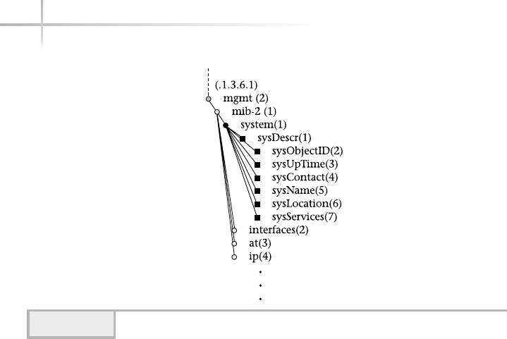
SNMP Tables
As noted above, an MIB may contain objects that represent physical characteristics
of a device or other information contained within an agent. These objects can
either be in the form of discrete elements (i.e., individual objects like sysDescr)
or, in some cases, two-dimensional tables. Tables store related information that
might contain several instances or copies of an MIB object. The best way to
illustrate the use of a table is by examining a table within an actual MIB.
Defined in the MIB-II standard is the interface group that has the object
identifier defined as 1.3.6.1.2.1.2 or iso.org.dod.internet.mgmt
.mib-2.interface. Objects within this group represent physical network
interfaces and related information installed within a networking device.
Performance-related information is also collected and stored within this group.
For each interface within a network device, the following information is used
to describe the characteristics of the interface and associated configuration:
●Description General description of the interface
●Type The type of interface, such as Ethernet or token ring
●Mtu The maximum transmission size
406 UNIX System Administration: A Beginner’s Guide
Figure 13-3 General MIB format

Module 13: Overview of SNMP 407
13
●Speed The transmission speed of the interface
●Physical address The data link protocol or hardware address
●Administration status The current administrative status of the interface
●Operational status The actual operating status of the interface
●Last change The time when the interface became operational
Additional objects within the table store the following performance-
monitoring information:
●Number of octets (bytes) received or sent
●Number of unicast packets delivered to or sent from higher-level software
●Number of non-unicast packets delivered to or sent from higher-level software
●Number of inbound/outbound packets discarded
●Number of inbound/outbound packets containing errors
●Number of inbound/outbound packets discarded due to bad protocol
●Length of the output packet queue
Figure 13-4 shows the structure of the interface group. Tables are used
to contain interface information because networking devices can contain more
than one interface. For example, a router or switch device can contain literally
dozens of interfaces, often supporting different network protocols such as Ethernet,
ATM, or FDDI. Using a table provides a straightforward and convenient way to
access individual objects within a given interface definition.
The interface group includes the ifNumber object, which contains
the total number of network interfaces within the networking device. Using the
sample data contained in Table 13-3, the ifNumber value would be 2. In this
case, the device reports two interfaces: one defined as a pseudointerface and the
other defined as an Ethernet. It is common for networking UNIX systems to
contain a pseudointerface for internal diagnostic purposes.
The rest of the interface group consists of a table called ifTable,
which contains a row for each interface defined within the device. This table is
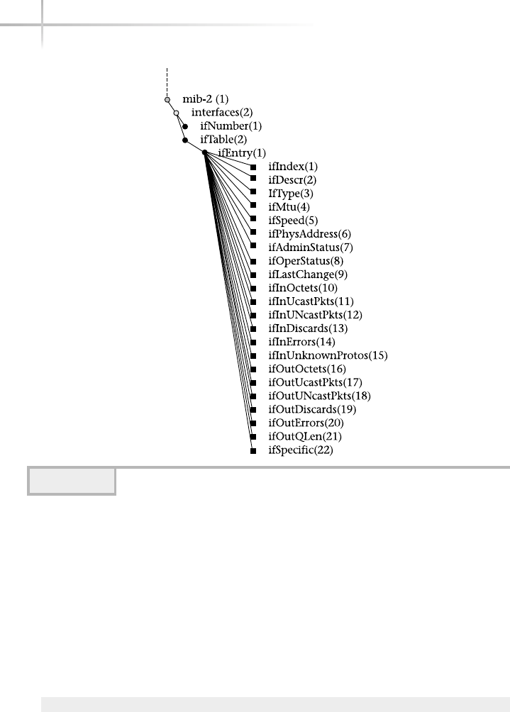
408 UNIX System Administration: A Beginner’s Guide
indexed by ifIndex, which contains a value between the range of 1 and the
value of ifNumber. The ifIndex object uniquely addresses each column of
the table that represents the interface.
Table 13-3 shows the entire interface group in the first column
and associated values taken from an actual network device in the remaining
columns. Each row corresponds to each of the specific MIB objects contained
within the ifEntry table. Each ifEntry instance represents an interface
defined in the table. To access the object ifDescr for the first interface, one
would use the following object identifier (OID)
1.3.6.1.2.1.2.2.1.1
Figure 13-4 Interface group from MIB-II

13
or
iso.org.dod.internet.mgmt.mib-2.interface.ifTable.ifEntry.ifDescr
The ifDescr object provides a general description of the interface.
The objects starting from IfInOctets to IfOutQLen represent traffic
counters for device interfaces and can be used to measure network and system
performance.
Module 13: Overview of SNMP 409
13
MIB Objects
IfEntry
(1.3.6.1.2.1.2.2.1)
IfEntry
(1.3.6.1.2.1.2.2.2)
IfIndex 1 2
ifDescr Pseudo Interface Ethernet
ifType 1 6
ifMtu 1500 1500
IfSpeed 10000000 10000000
ifPhysAddress None 0x00040010ee5d
IfAdminStatus 1 1
IfOperStatus 1 1
IfLastChange 0 0
IfInOctets 0 42617
IfInUcastPkts 445 680
IfInNUcastPkts 0 19
IfInDiscards 0 0
IfInErrors 0 5
IfInUnknown-Protos 0 0
IfOutOctets 0 42600
IfOutUcastPkts 445 570
IfOutNUcastPkts 0 94
IfOutDiscards 0 0
IfOutErrors 0 87
IfOutQLen 0 0
ifSpecific null null
Table 13-3 Interface Group Instance Table

Accessing Objects
MIB objects are defined with access control information that specifies what
kind of operation can be performed on the object. SNMP includes the following
access control information for MIB objects:
●Not-accessible
●Accessible-for-notify
●Read-only
●Read-write
●Read-create
Not-accessible objects defined within the MIB usually reference object
definitions, or other object descriptions that are not objects themselves, that
can be manipulated by an SNMP manager. One good example is the table data
structure, where an object describes the shape or size of the table but not the
actual rows or columns.
Accessible-for-notify objects are only available via a notification to
a network manager or another agent. No direct polling of the object is permitted.
Read-only objects are not alterable by the network management system, but
values may be obtained via a get or trap operation.
Read-write access is necessary when a particular object must be altered
to accomplish some specific goal or must be configured in a certain way. For
example, it might be necessary to disable a router port due to a large number of
errors detected on one of its interfaces. In this case, the network management
system must change the operational status of the interface to 0, thus shutting
down the physical connection until the cause of the errors is determined.
Read-create objects have the same access permission as read-only
and read-write objects. Read-create access is used for objects that may
be created on the fly. Such objects may include table row (also called conceptual
row) instances, for example.
Standard and Private MIBs
As previously mentioned, MIBs are organized under a hierarchical tree structure,
and a number of standard MIBs have been developed and placed under the
410 UNIX System Administration: A Beginner’s Guide
TEAMFLY
Team-Fly®

mgmt(2) branch. Many of these MIBs were developed via the RFC process.
Many different individuals or vendors assisted with their development but don’t
actually own them, nor can they arbitrarily make changes to them. However,
many vendors and third-party software developers have developed additional
MIBs to address specific functionality or services for their particular products.
Many of these MIBs, known as enterprise MIBs, start under the private(4)
branch of the standard MIB tree. Figure 13-5 shows several popular MIBs that
can be found under this branch.
The Internet Assigned Numbers Authority (IANA; www.iana.org) maintains
a list of assigned enterprise numbers. Those wishing to obtain a number make a
request to this organization and obtain a valid number. Table 13-4 shows a small
sample of the numbers that have already been assigned.
SNMP Communities
Typically, a network management system will be deployed in a large network
environment that contains a collection of many different groups of networks
and devices. Thus, it is reasonable for an enterprise network to be divided into
Module 13: Overview of SNMP 411
13
Figure 13-5 Enterprise tree from private branch

412 UNIX System Administration: A Beginner’s Guide
zones or communities of users in order to partition responsibility. As a result,
a community name can be assigned to a class of devices and provide a security
boundary that helps to implement the desired communities or zones. SNMP
supports this kind of security model based on community string information,
which is physically added to each device within the selected community. Some
practical examples include selecting a community that represents all the Cisco
backbone routers or selecting another community that includes devices in just
the sales department.
The current SNMP community-based authentication model is considered
very weak and poses a significant security problem. The major reason is that
older SNMP versions don’t provide any encryption facilities or other mechanisms
to ensure that the community information is not simply copied from the network
during an SNMP packet exchange. Using a packet capture tool, the entire SNMP
packet could be decoded, thus revealing the community name. As a result of this
limitation, many sites disable set operations to many of the agent devices. This
has the unfortunate side effect of limiting SNMP usefulness because it can then
only monitor object values and not alter them.
13.3 Explore SNMP Versions
SNMP became generally available in 1988. Since then, it has seen widespread
use and been implemented in virtually all local area networking (LAN) devices
Number Vendor
2 IBM
9 Cisco Systems
11 Hewlett-Packard
42 Sun Microsystems
43 3Com Corporation
52 Cabletron Systems
1588 Brocade Communications Systems
1598 Tivoli Systems
1751/3729 Lucent Technologies
4475 Rainbow Software Solutions
Table 13-4 Assigned Enterprise MIB Numbers

Module 13: Overview of SNMP 413
13
and on many computer operating systems. This popular version, known as
SNMPv1, accounts for a significant portion of the installed base of agents today.
Despite its popularity, SNMPv1 has several fundamental problems. First, because
it lacks a robust security mechanism, it can’t be used to its full potential.
Ask the ExpertAsk the Expert
Question Why would a change to an MIB object be prohibited?
Answer Certain MIB information will never change during the life
of a product. For example, the MIB object sysDescr, which stands
for system description, contains vendor information for the agent. An
SNMP manager should not modify this information because it would
disassociate the device with the actual product vendor, thus making
agent identification difficult. Also, it can adversely affect the accuracy
of any software-based network inventory mechanisms. Another reason
to make objects read-only is to ensure that performance information
or other statistical data remains accurate rather than getting altered
unintentionally.
Read-write access is necessary when a particular object must be
altered to accomplish some specific goal or must be configured in a
certain way. For example, it might be necessary to disable a router port
due to a large number of errors detected on one of its interfaces. In this
case, the network management system must change the operational
status of the interface to 0, thus shutting down the physical connection
until the cause of the errors is determined.
Question Why develop enterprise MIBs?
Answer Many vendors do so because they may need specific objects
for their devices that may not be defined or available within the standard
MIBs. Also, vendor-specific MIBs don’t need to become standards, since
only that vendor and their customers actually need to use the MIBs. It
only makes sense to develop standard MIBs when many vendors can
implement the same collection of MIBs across a large number of
different devices.

As a result, many vendors limit the set operations on agents to minimize
the potential risk of a security breach. Second, SNMPv1 doesn’t optimize the
processing of large amounts of information, thus further restricting the use of
SNMP. Third, SNMPv1’s relationship between network manager and agent are
well defined— agents play only a single, simplistic role of accepting commands
from more management systems. This significantly limits SNMPv1 when smart
agents are needed to address specific requirements for distributed network
management functions. SNMPv1 also specifies a collection of MIB objects
known as MIB-II. The goal of MIB-II was to provide a collection of objects that
all SNMP agents can support, regardless of which vendor implemented the agent.
To summarize, SNMPv1 provides
●Basic network management framework
●Definition of the MIB-II standard
●Descriptions of the Protocol Data Units (PDUs), which include
GetRequest, GetNextRequest, SetRequest, GetResponse, and Trap
●Description of ASN.1 encoding language
To address some of the deficiencies in SNMPv1, a significant amount of
effort has been made over the past few years to enhance SNMP. The first series
of improvements came in 1993 when a series of 12 RFCs (1441–1452) was
introduced, proposing to add PDUs and enhancements to the SNMP architecture
and security model. This collection of RFCs was known as SNMPv2 Classic. At
that time, many users of SNMP were anticipating these improvements and planned
to implement the new version as soon as it became available.
Unfortunately, there was still much debate about SNMPv2 security and
remote configuration. When it became apparent that not all the original SNMPv2
proposals were going to be widely adopted, additional work was done to define
SNMP security and remote configuration management components. This led to
additional proposals that included a new protocol and new MIB structure elements
(documented in RFCs 1901–1908). These proposals were more popular than
SNMPv2 Classic and became known as community-based SNMPv2 or SNMPv2c.
The problem with SNMPv2c was that, though it was endorsed by the IETF, it
lacked robust security and administration facilities.
Additional improvements to the remote management capability of SNMPv1
resulted in proposals known as SNMPv2usec and SNMPv2, documented in
414 UNIX System Administration: A Beginner’s Guide

Module 13: Overview of SNMP 415
13
RFCs 1909–1910 and RFC 2222, respectively. The SNMPv2usec recommends a
robust security model and administrative framework. One of the problems with
SNMPv2usec is that it lacks endorsement of the IETF, which relinquished the
proposal to a nonstandard. The major functions of SNMPv2 include
●Expanded data types, such as 64-bit counters
●Improved performance and efficiency with the get-bulk PDU
●Event notification with the inform PDU
●Better error handling
●More efficient row creation and deletion
Finally, in an attempt to reach some agreement between the various remote
management and security proposals, another series of RFCs was written, which
later became known as SNMPv3. These RFCs (2271–2275) have been put forth
by the IETF as Proposed Standards, which means that they are available to the
general public for review and discussion. SNMPv3 is SNMPv2c plus provisions
for robust security and administration; it draws upon the SNMPv2c RFCs
(1902–1908). At a high level, the SNMPv3 proposal attempts to
●Put forth a security model based on DES, MD5, and other authentication
protocols
●Define a view-based access control model
●Redefine some of the SNMP concepts and terms
SNMPv3 has enjoyed a certain level of success in the industry at this point,
but the protocols are still quite new. Major networking hardware and software
companies already support SNMPv3. However, SNMPv3 has yet to be deployed
widely within the industry; this is perhaps just a matter of time. One of the
major delays for adoption of this new protocol is the cost-to-benefit ratio.
For those sites that require better security today, they can upgrade to the new
protocols as vendors make their implementation available. However, it may not
be justifiable for everyone to upgrade all existing equipment to support SNMPv3.
The most likely approach will be to migrate slowly over time as newer products
that contain SNMPv3 support are deployed. Eventually, new products will replace
the older ones, and deploying the new management protocols will simply be
a matter of configuration.

SNMP Protocol Operation
An SNMPv1 message contains three major components: a version field, a
community field, and an SNMP protocol data unit (PDU) field. Unlike other
TCP/IP protocols, SNMP packets are not of a fixed length and, instead, rely
on ASN.1 formatting. Figure 13-6 shows this basic SNMP packet structure
and a description of the fields (and sizes) follows.
The format includes field names, shown in bold text, and formatting labels
(type), as shown on the top in gray text. The type shows the basic format for
each of the fields. For instance, the version information is an INTEGER object.
The field names are defined as follows:
●version This field indicates which version of the SNMP protocol is being
used. Presently, version 1 is the most widely implemented and supported
SNMP protocol.
●community name The community is used as the primary security
mechanism to establish authentication from a network manager to agents
within the SNMP. The community name or string is used as a password
for access to objects. This is based on the condition that the network
manager knows the agent’s password. If the agent has been configured
to emit traps, an authenticationFailure trap is generated when a network
manager queries an agent with an invalid community string.
●protocol data units SNMPv1 PDUs can be one of five different types and
consist of request and response components. They include
●GetRequest
●GetNextRequest
●SetRequest
●GetResponse
●Trap
416 UNIX System Administration: A Beginner’s Guide
Figure 13-6 SNMP master/subagent diagram

Module 13: Overview of SNMP 417
13
SNMPv2 defines these additional PDUs:
●GetBulkRequest
●InformRequest
Each of the GetRequest, GetNextRequest, and SetRequest components
elicits from the responding agent a GetResponse that might contain valid data
or an error status.
GetRequest
The GetRequest PDU is issued by an SNMP manager or application to obtain one
or more MIB objects from an SNMP agent. The fields for this packet type include
●pdu type Indicates the PDU type is a GetRequest.
●request-id Unique identifier that permits the SNMP manager to match
paired requests and responses. It also aids in detecting duplicate messages
that may be received when using an unreliable transport service.
●variable-bindings A list of requested MIB objects.
The GetRequest operation is the primary way to obtain information from
agents when the objects in question are known beforehand. For example, should
the network manager decide to retrieve sysDescr and sysUpTime objects
from an agent, we can think of the request as simply a function to include
GetRequest (sysDescr, sysUpTime)
In this case, both of these objects are placed within the variable-binding
field when sent. The sysDescr object represents a string that contains a
general description of the agent, and sysUptime reflects the amount of time
that an agent has been running.
When the agent receives the above message and no errors have occurred, it
will respond with the values of the MIB objects requested via a GetResponse
PDU. The GetRequest operation is atomic. That is, either all the values requested
are returned or no values are returned. When the receiving entity responds to
the GetRequest, it includes the values in the GetResponse variable-binding field.
If, for some reason, at least one of the values cannot be supplied, no values will
be provided.

If the values requested from a manager cannot be returned by the agent, the
agent will respond with an error. For example, the management system might
have requested an MIB object that isn’t implemented in the agent. In this case,
the agent can’t possibly satisfy the request, and thus an error is returned. Also,
in certain situations, returning the value of a requested object fails because it
might be too large to be processed by the manager.
The variable-bindings field includes a list of objects for which values are
requested. When the agent responds via GetResponse, the variable binding
includes the requested objects and associated values. Given the example above,
the following GetResponse would be sent by the agent:
GetResponse(sysDescr="3Com Enterprise Monitor", sysUpTime=0000154477)
In this example, the agent is a 3Com enterprise RMON monitor (or network
probe), as indicated by the sysDescr field. This device collects network
performance and packet contents information for later analysis and reporting.
The sysUpTime object contains the amount of time the agent has been up and
running. The value shown in the example indicates that the device was running
for approximately 15 minutes and 44 seconds.
GetNextRequest
The GetNextRequest PDU is similar to the GetRequest PDU, and the packet
formats are identical. However, the GetNextRequest PDU has one difference: It
is used to retrieve objects when the structure of the MIB tree is unknown. The
GetNextRequest can be a great asset when it is used to discover the exact MIB
structure of an agent. Why would an agent’s MIB structure be unknown to an
SNMP manager? SNMP provides no direct way to determine which MIBs or
MIB structures are supported within an agent. Vendors are, of course, are free
to implement whichever MIBs their devices need. Therefore, the network
manager must discover the supported MIBs by walking the MIB tree in an
automated fashion. When the GetNextRequest is sent with a particular object,
the GetResponse returns the requested object’s value, plus the instance of the
next lexicographic object in the MIB tree. As a result, each GetNextRequest will
reveal the next object within the MIB without the manager knowing what the
next object will be. The GetNextRequest operation also provides a more efficient
mechanism to retrieve objects from an agent than GetRequest because it requires
fewer request/response exchanges.
418 UNIX System Administration: A Beginner’s Guide

SetRequest
The SetRequest operation is used to alter agent information such as the value of
a MIB object. The packet format is the same as GetRequest and GetNextRequest.
Unlike GetRequest or GetNextRequest, SetRequest is used to alter the value of
a MIB object. As mentioned before, the SetRequest requires security privileges,
which are presently mapped via the community string for the SNMPv1 protocol.
Therefore, the agent must validate the SetRequest community string provided
before the operation is permitted. The SetRequest is also atomic; either all the
values can be altered or none can. If the SetRequest is successful, a GetResponse
is returned and the variable-binding list contains the objects with their new
values. This is how the network manager can determine that the set operation
was successful. If the SetRequest was unsuccessful, an error is returned in the
GetResponse.
GetResponse
Each of the SNMP operations, with the exception of the trap, receives a
GetResponse from the agent of the GetResponse packet, which includes the
following fields:
●pdu type Indicates the PDU type, which is GetResponse.
●request-id Unique identifier that permits the pairing of requests
and responses.
●error-status Indicates that an exception condition occurred while
processing the request.
●error-index When an error occurs, indicates which object variable in
the variable-binding list caused the error.
●variable-bindings A list of MIB objects that are involved in the operation.
Trap
A Trap is an unsolicited message from an agent directed to a network management
station that represents a significant event or condition for which notification
to the manager is considered necessary. This type of communication from the
agent is asynchronous as compared to the polling from the manager. The Trap
PDU is quite different from that of the other PDUs defined in SNMP. Unlike the
Module 13: Overview of SNMP 419
13

other SNMP PDUs, Trap does not warrant a response from the receiving network.
The fields from a Trap include
●PDU type Indicates that the PDU type is a Trap.
●Enterprise Contains the MIB object sysObjectID of the sending
agent. The sysObjectID object includes information regarding the
vendor of the agent that sent the Trap.
●Agent-address Represents the IP address of the sending agent.
●Generic-trap One of the predefined Trap values listed in Table 13-5.
●Specific-trap More detailed information about the Trap. This is usually
zero unless the generic-trap is an enterpriseSpecific Trap.
Enterprise Traps are vendor specific and may contain additional agent
information about the condition that caused the Trap in the first place.
●Time-stamp The amount of time between the generation of the Trap and
when the device was last initialized, expressed in tenths of a millisecond.
●Variable-binding Vendor-specific information related to the Trap.
Table 13-5 lists the seven predefined general Trap types. The
enterpriseSpecific Trap type is provided as a mechanism to define
custom or proprietary traps that do not fit within the other generic types.
420 UNIX System Administration: A Beginner’s Guide
Trap Type Description
ColdStart (0) The device is restarting or reinitializing itself such
that the agent or configuration may be changed.
Usually, this indicates a crash or other reboot
condition.
WarmStart (1) The device is restarting or reinitializing itself
such that no changes are made to the agent or
configuration. Usually, this implies a simple refresh
or reboot of the operating system environment.
LinkDown (2) Indicates a failure on one of the device’s
communications (interface) links.
Table 13-5 SNMP Predefined Trap Types
TEAMFLY
Team-Fly®

GetBulkRequest
This PDU is issued by an SNMPv2 manager or application to minimize network
interaction and permit the agent to return larger packets (as compared to
GetNextRequest or GetRequest), thus improving the efficiency of obtaining a
large number of objects from an agent. This uses the same PDU format as most
other SNMPv1 operators. The only difference is the renaming of the error-status
and error-index (from the Response PDU) fields to non-repeaters and max-
repetitions, respectively. These fields are defined as follows:
●non-repeaters The number of MIB objects that should be retrieved
once at most
●max-repetitions The maximum number of times other MIB objects
should be retrieved
InformRequest
The InformRequest PDU is issued by an SNMPv2 entity acting in a manager role
to another SNMPv2 entity acting in the same role for the purpose of providing
network management information. The major function of this PDU is to provide
distributed SNMP management capabilities. Thus, an agent can implement this
PDU to provide management-like services and functions. The format of this PDU
is the same as for GetRequest and other related PDUs.
13
Module 13: Overview of SNMP 421
13
Trap Type Description
LinkUp (3) Indicates that a device’s communication (interface)
link is now up and running.
AuthenticationFailure (4) An authentication or security failure has occurred on
the device. Typically, this indicates that an invalid
SNMP community string has been used.
EgpNeighborLoss (5) Indicates that External Gateway Protocol (EGP)
neighbor, of which the device is a peer, has been
labeled down and the relationship no longer is valid.
EnterpriseSpecific (6) Indicates that some vendor-specific event has
occurred. Vendors use this generic trap type to
represent their own proprietary traps.
Table 13-5 SNMP Predefined Trap Types (continued)

1-Minute Drill
●What are the advantages of SNMPv3 over previous versions and what are its
major current limitations?
●Why is a trap message useful?
SNMP Response Codes
The error codes returned from an SNMPv1 agent are very limited. For
example, if an SNMP manager requested the set operation on a MIB object,
and the agent can’t perform the operation as requested, the agent replies with
noSuchName. With the addition of more error codes in SNMPv2, the agent
will reply with notWritable in this situation. Table 13-6 lists the SNMP
response codes.
422 UNIX System Administration: A Beginner’s Guide
●SNMPv3 increases security over older standards.
●A trap message can inform a network management station about an unexpected problem that the agent
might not otherwise find out about in a timely fashion.
Response Code Description
SNMPv1
tooBig Returned by the agent if the response to a request would be
too large to send.
noSuchName Returned by the agent in either of these two cases: 1) if a set
operation is attempted for an object that is not in the MIB
view, or 2) if a set operation is attempted for an object that
is in the MIB view, but its object is read-only.
badValue Returned by the agent that has detected an error in the PDU
variable binding list.
Read-only Returned by the agent.
genError Returned by the agent when processing of a PDU fails for
a reason other than what is listed in this table.
Table 13-6 SNMP Response Codes

Module 13: Overview of SNMP 423
13
Transmission of an SNMP Message
The following series of events occurs when a network manager formulates an
SNMP message:
1. The basic PDU is constructed.
2. The PDU is passed to the security service layer if available.
Response Code Description
SNMPv2/v3
noAccess The variable is outside the defined MIB view for this operation
to succeed.
notWritable The variable exists within the agent, but the agent is unable to
modify the object.
WrongType The value supplied is of the wrong data type, as defined
by ASN.1.
WrongLength The value supplied is of the wrong length.
WrongEncoding The value supplied was not encoded correctly.
WrongValue The value supplied is not within the range required for the
object type.
NoCreation The object doesn’t exist and the agent is unable to create an
instance of this object.
InconsistentName The object doesn’t exist and the agent is unable to create an
instance of this object because the name is inconsistent with
the values of other related objects.
InconsistentValue The object provided is inconsistent with the values of the
managed objects.
resourceUnavailable A needed resource within the agent can’t be reserved to
complete the request.
Table 13-6 SNMP Response Codes (continued)
HintHint
These codes are important because they can help you track down problems
and issues when using SNMP agents and tools that communicate with agents.
Determining the solution to SNMP problems is aided by knowing these
message codes and understanding the difference between configuration errors
with the agent versus connectivity problems between the manager and agent.

3. The protocol layer formats the message, including the version and
community information.
4. The entire message is now encoded using ASN.1 rules.
5. The message is passed to the transport service so that it will be delivered
to the receiving entity.
The following series of events occurs when an agent device receives an
SNMP message:
1. A basic check is performed to ensure the message is formatted correctly.
The message is discarded if any errors are encountered.
2. The protocol version information is verified. If there is a mismatch, the
message is discarded.
3. The security service attempts to verify the sending entity. If this fails,
a trap is generated and the message is discarded.
4. The PDU is decoded.
5. The PDU is processed.
Connectionless Protocol
SNMP is a connectionless protocol, which means that it doesn’t support the
concept of establishing and controlling a dedicated connection like Telnet or
FTP. SNMP transmits information between an agent and a manager by the use
of requests and return responses. This removes the burden from agents of
having to support additional protocols and processes associated with connection-
based schemes. Therefore, SNMP provides its own mechanism to address
reliability and error detection.
13.5 Investigate SNMP Master and Subagent
When deploying network management software, it is common to have a single
agent installed on each system that will be managed. In the case of networking
devices such as network routers and switches, usually only a single agent is
available. In either case, the agents will communicate with one or more network
424 UNIX System Administration: A Beginner’s Guide

managers using the standard SNMP port of 161. For most needs, a single agent
approach makes sense and is appropriate. However, there are instances when
more than one agent is necessary to achieve the desired level of manageability.
For example, workstation manufacturers will often provide an SNMP agent
within their operating system. In the case of both Solaris and HP-UX, the vendor
provides a master agent and one or more subagents. A single agent is available
on the Linux platform.
Most system agents will usually support a limited number of operating
system functions and parameters. If we wish to manage database services on
this same system via SNMP, this will require that we install another agent to
specifically monitor the database functions. This poses a problem because both
agents will typically be accessed by the SNMP manager using the same SNMP
standard port. Further, when the agents are started by the system, the first agent
will start and open the port 161 and will operate normally. However, when the
second agent starts and attempts to do the same, it will get an error stating that
the port is busy and it should abort operation.
Two possible approaches can be taken to address this port contention problem.
First, one of the agents can be configured to use an alternative port instead of the
standard 161. This solution will work if the agent can be made to support another
port when it is started by the system. Many system agents do support alternative
ports, but this is by no means the rule. The major drawback to this solution is
that any SNMP managers used to poll the agent must now be configured to use
this new port as well. This doesn’t pose a significant problem when only a small
number of nonstandard ports are used. However, if this solution is used on a
large scale—say, with many agents using all nonstandard ports across a large
number of systems—the approach loses its appeal because of the administrative
burden it introduces.
The other solution might be considered more elegant because it involves
using a master agent and one or more subagents. A master agent solves the port
conflict problem by becoming the keeper of the standard SNMP port and forwards
all the SNMP traffic to the appropriate subagent. Subagents are normal SNMP
agents, but they are registered with the master agent and assigned nonstandard
ports that are used to communicate with the master agent. SNMP messages from
managers are sent to the master agent, who in turn delivers the messages to the
correct subagent using the port it assigned to the subagent. Figure 13-6 shows a
diagram of the master/subagent architecture. One major benefit of this solution
is that it alleviates the administration task of modifying the SNMP managers
Module 13: Overview of SNMP 425
13

426 UNIX System Administration: A Beginner’s Guide
cited in the first solution. Also, this solution can scale very well because new
subagents can be added in a straightforward manner.
On the negative side, the master agent can pose a problem because it can crash
or otherwise become inoperative. This would have the adverse effect of disabling
the connectivity to all the subagents. Because this particular problem can be
said of other software systems as well, the risk (although not zero) isn’t
necessarily a significant factor. Also, because the master agent is responsible
for delivering the SNMP to the appropriate subagent, it takes a certain amount
of processing time and overhead. This might be a factor in time-critical
management functions.

Module 13: Overview of SNMP 427
13
Mastery Check
1. Which MIB object class consists of primitive types that can be used to
build additional data types of objects?
2. Which SNMP function notifies a network management system of a special
condition or problem without the management system specifically requesting
this information?
A. Get
B. Set
C. Trap
D. MIB
3. Which class does the IpAddress data type belong to?
4. Which of the following elements does SNMPv1 not provide?
A. Basic network management framework
B. Robust security model
C. Definition of the MIB-II standard
D. Description of ASN.1 encoding language
5. What are the three main components of a SNMPv1 message?
6. In the MIB hierarchical tree structure, the __________ represent
individual objects.
7. What type of objects are not alterable by the network management system,
but allow their values to be obtained with a get operation?
A. Not-accessible
B. Accessible-for-notify
C. Read-only
D. Read-write

428 UNIX System Administration: A Beginner’s Guide
8. What does an SNMP manager or application issue to obtain one or more
MIB objects from a SNMP agent?
9. What does an SNMP manager or application issue to obtain a MIB object
from a SNMP agent when the structure of the MIB tree is unknown?
10. Match each of the data types in the first list (A-D) with its description
from the second list (i-iv):
A. INTEGER
B. NULL
C. OBJECT IDENTIFIER
D. SEQUENCE
i. A data type used to denote an ordered list of zero or more elements that
contain other ASN.1 types
ii. A data type representing a cardinal number
iii. A data type meant as a placeholder, but currently not used
iv. A data type representing an authoritatively named object that consists
of a sequence of values that specify a MIB tree
11. Which of the following is information that would be contained in an SNMP
table for each interface within a network device to describe the nature of the
interface and associated configuration? (choose all that apply)
A. Desciption
B. MTU
C. Protocol data unit
D. Physical address
12. A __________ is an unsolicited message from an agent directed to a
network management station that represents a significant event or
condition for which notification to the manager is considered necessary.
Mastery Check

Module 13: Overview of SNMP 429
13
13. What might you assign to a class of devices to provide a security boundary
for a desired group of devices?
A. Boundary name
B. Community name
C. Security model
D. Encryption facilities
14. Which SNMP operation doesn’t receive a GetResponse from the agent?
15. Which SNMPv2 operation helps minimize network interaction and permits
the agent to return larger packets relative to GetRequest or GetNextRequest?
16. What response code will an SNMPv2 agent receive if the object doesn’t
exist and the agent is unable to create an instance of this object?
Mastery Check

This page intentionally left blank.
TEAMFLY
Team-Fly®

Module14
Using the Domain
Name System
Critical Skills
14.1 Discover How the Domain Name System Works
14.2 Explore Both DNS Server and Client Components
Copyright 2002 by The McGraw-Hill Companies, Inc. Click Here for Terms of Use.

One major issue with TCP/IP networking is how to provide mappings
between system names and their corresponding network addresses.
UNIX provides several ways to facilitate the mapping between hostnames
and IP addresses.
14.1 Discover How the
Domain Name System Works
First, the traditional method involves the use of the /etc/hosts file.
When a network application wishes to resolve a name, it invokes a standard
library routine that looks up the name from this file. The file provides simple
mappings of hostnames on the local level; this particular method has several
problems. The chief issue is that it doesn’t scale well; in other words, it would
be impossible for the system administrator to maintain an /etc/host file
that contains all the possible systems that one would need. When the Internet
was much smaller, it used the /etc/host file approach for name resolution.
However, because of operational problems it became clear that another
mechanism was needed.
The second approach is to use Network Information Services (NIS). Today,
this method is deployed within many companies, largely to handle internal
name resolution for a company. This approach, too, suffers from the same basic
problem as /etc/hosts—scalability. NIS doesn’t provide for host resolution
for a significant number of hosts, such as that contained on the Internet.
The third method uses DNS for name resolution. DNS provides a hierarchical
namespace that contains domains, subdomains, and hostnames. A domain is a
collection or grouping of hostnames strategically defined within the namespace
so that no conflicts arise among different domains. For example, it is possible
that two different companies may have picked identical hostnames for some
of their systems. However, this doesn’t represent a problem because the both
companies are in different domains; thus, the system name overlay is negated.
The Domain Name System (DNS) provides a very critical element for the
Internet—it provides mappings between hostnames and their corresponding
Internet Protocol (IP) addresses. For example, when the URL of the form
432 UNIX System Administration: A Beginner’s Guide
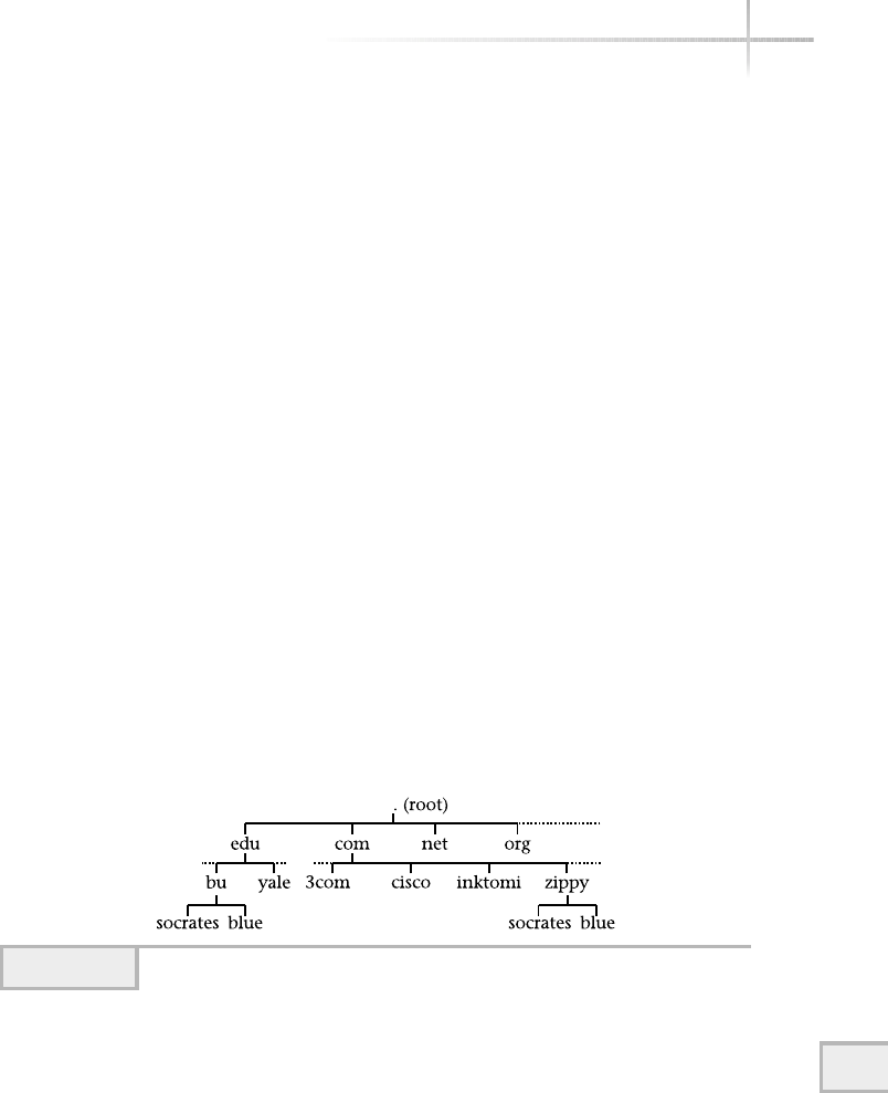
14
http://www.whitehouse.gov is entered within a Web browser, the
browser in turn requests the IP address of this host from a DNS server in order
for the communication between the user’s system (browser) and the remote
Web site to commence. Why does the browser do this? Because communication
between systems on the Internet, for example, must use an Internet Protocol
address. This is true for any TCP/IP network and must include the use of IP
addresses when specifying systems. The term that refers to converting from
a hostname to an IP address is known as host resolution and is completely
transparent for the user. The DNS system available on most UNIX versions is
known as the Berkeley Internet Name Domain (BIND) package and is used
quite extensively on the Internet. BIND has been placed in the public domain
and is freely available at www.isc.org.This module is based on the BIND
version of DNS.
The DNS namespace can be clearly explained by using an inverted tree
structure, which is similar to a UNIX file system. The UNIX file system starts
at the base or root, which is represented with a leading “/”. Within DNS, a
dot “.” is used to represent the base of the tree. Figure 14-1 shows a sample
of the DNS namespace. As you can see from the figure, several of the common
DNS domains are defined that include edu, com, and net. These are known
as “top level” or root domains, and any objects defined below these top levels
are known as subdomains. The placement of companies, corporations, or
institutions largely depends on the type of business the organization is engaged
in. For instance, if a university called Zippy wants to join the Internet, a new
subdomain called zippy will be defined under the edu domain because it is an
education establishment. Standard DNS domains are listed in Table 14-1.
Module 14: Using the Domain Name System 433
14
Figure 14-1 DNS namespace

Note that two systems have been assigned the name socrates; one in the
edu domain and the other in the com domain. This is a perfectly acceptable
and reasonable thing to do; that is, there is no conflict. The UNIX file system
works the same way; two files with the same name can be defined within two
different directories. One reads or interprets a domain and hostname in the
opposite order as a UNIX file and pathname—from right to left. For example,
the host
socrates.mis.zippy.edu
reads as follows: within the edu root domain, an organization called zippy
defines a subdomain called mis, which contains a host called socrates. The
DNS character separator is the dot (“.”), and a dot is implied after each top-level
domain. However, in practice the rightmost dot is not used.
DNS consists of two major elements: the server and the client. The server
provides DNS services to one or more client systems. Whenever the client must
obtain the IP address of a host, it makes a request to a DNS server. The server
responds with a valid answer and the client continues to process the transaction.
Typically, several servers are deployed so that should a failure occur with a
particular DNS server, other backup systems will respond to the client request.
This approach works well and provides a reasonable amount of fault tolerance.
434 UNIX System Administration: A Beginner’s Guide
Domain Purpose
edu Educational: universities, colleges, prep schools, etc.
com Institutions and other organizations that engage in commercial activities
gov Government organizations and institutions
int International organizations
mil Military organizations or those that work with such organizations
net Internet service providers and other network support centers
org Organizations that are noncommercial in nature, such as a nonprofit
institution
country code Each country code based on geographic location
Table 14-1 Top-Level DNS Domains

14.2 Explore Both DNS Server
and Client Components
A DNS server contains the following elements:
●Domain files
●Processes
●Tools
Domain Files
A DNS server is configured to service one or more domains. A domain is a
collection of individual hosts that are grouped according to some arbitrary
criteria. For example, all the systems within a particular department or team
can be defined within a DNS domain. When a new domain is defined on the
DNS server, a new domain file is created that contains records for each host.
When the DNS server is started, it reads each domain file and then knows
how to resolve mapping between names and IP addresses for that domain.
DNS Example
One of the best ways to understand the DNS system is to review an example
configuration. The following listing contains a sample (but fully functional)
domain file for the fictitious home.com domain. Comments can be placed
with the file using the “//”, “#” or “ /* */” characters.
1 //
2 // home.com DNS named.conf file
3 //
4 options {
5 directory "/var/named";
6 allow-transfer {
7 216.155.202.163;
8 216.155.202.100;
9 };
10
11 }; 14
Module 14: Using the Domain Name System 435
14
Specifying the allow
transfer option means
only the two nodes listed
here are allowed to query
this server
The directory option
specifies which UNIX
directory the DNS server
will use to find additional
configuration files and
zone information

436 UNIX System Administration: A Beginner’s Guide
12 //
13 // Our Primary DNS Information
14 //
15 zone "home.com" {
16 type master;
17 file "home.com";
18 };
19 zone "202.155.216.in-addr.arpa" {
20 type master;
21 file "reverse-home.com";
22 };
This listing represents a minimal DNS configuration that would be placed in
the named.conf file. By default the DNS server will look for this file within
the /etc directory, but this can be changed by using the –c command-line
argument. The basic syntax of this DNS configuration includes
statement_keyword “string” {
option keyword;
option Keyword;
};
The statement keywords include high-level directives that define DNS services
and control operational aspects of the server. Table 14-2 lists the supported
keywords.
The basic named.conf file (as shown earlier) includes several sections
that include configuration options, basic initialization, and individual zone
Statement Keyword Meaning
acl Provides an access control mechanism to form an IP address
match list
include Includes another file
logging Controls server logging
options Specific and control global server configuration options
controls Determines how to communicate with the rndc utility
server Defines a new server for a particular
zone Defines a DNS zone. May contain either master or secondary
keywords
Table 14-2 DNS Server Statement Keywords

Module 14: Using the Domain Name System 437
14
configurations. The option section includes operational aspects of the DNS
server. For example, use the directory (lines 4–9) option to specify which
UNIX directory the DNS server will use to find additional configuration files
and zone information. Some of the most common configuration keywords
supported by the DNS server are listed in Tables 14-3 and 14-4. The DNS server
options are divided into two groups: those options that control how the server
interacts on the network (Table 14-3) with other systems, and configuration
options (Table 14-4), which control how the server operates on the local system.
The configuration includes support for two zones: the home.com and the
associated reverse IP domain. The home.com domain is defined within lines
15–18; the reverse domain, 202.155.216.in-addr.arpa is contained
within lines 19–22. Defining a new domain is very simple; all that is required is
Option Keyword Meaning
allow-query IP Addresses Determines which IP addresses are permitted to
query the server. The default is all hosts are allowed.
allow-transfer
IP Addresses
Determines which IP addresses are permitted to
do a zone transfer from the DNS server. By default,
any node can do a zone transfer.
auth-mxdomain yes/no The default value is yes; this tells the server to answer
authoritatively for domain queries on domains that
have SOA records.
check-names type action Tells the server to verify the integrity of domain names.
fake-iquery yes/no The default value is no; the server will simulate the
support for the IQUERY option type.
fetch-glue yes/no The default value is yes; tells the server to query and
cache the necessary DNS records about domains to
which is it not authoritative
forward first only The default value is first; this causes the server to
forward to another DNS server when a client’s query
can’t be resolved.
forwarders ip list Provides a list of IP addresses for the DNS server
to query when it doesn’t have information about
a client request.
multiple-cnames yes/no The default value is no; this permits the server to
support CNAMES and point to other CNAMES.
notify yes/no The default value is yes; this tells the server to emit
a notify message to all secondaries when a zone has
been updated on the server.
recursion yes/no The default value is yes; this instructs the server to
query other DNS servers to resolve a client DNS request.
Table 14-3 Server Interaction Options

438 UNIX System Administration: A Beginner’s Guide
the name of the domain to determine the relationship between the domain
and the DNS server and the resource file, which contains the specific hosts for
that domain.
In this example, the zone keyword is used to tell the server that a new
domain (zone) is being defined. The zone keyword defines a forward mapping
between IP addresses and names. This specific configuration information is
contained within the home.com file. The brackets ({}) are used to delimit
or include additional optional keywords for that domain. The type keyword
defines the relationship between the domain and the DNS server, and in this
case the master word is used.
When a DNS server is a master for a
domain, no other DNS server anywhere will
answer authoritative requests for that domain.
In other words, the master DNS server is
supposed to be the definitive source for the
domain. However, there are cases when additional DNS servers appear to be
answering requests for a domain for which they are not the master. A DNS
server need not be a master for a domain, but rather can be a secondary server.
A secondary DNS server is one that obtains DNS records from a master, but can
answer DNS client queries for that domain. This approach is a great way to
address performance factors in a larger network and by adding load-balancing
features into the DNS namespace.
Option Keyword Meaning
directory path Specifies the working directory for the DNS server.
name-xfer path Specifies the path for the name-xfer program. This
program is responsible for doing a zone transfer.
dump-file path Specifies the path name for where the DNS server should
write database information when it receives a special signal.
memstatistics-file Specifies the name of the file to dump usage statistics when
the DNS server exits, when the deallocate-on-exit
option is set to yes. The default filename is
named.memstats.
Table 14-4 Server Operational Options
HintHint
“Zone” is another term
that means DNS domain.

Next, the reverse map is defined and is called the 202.155.216.in-
addr.arpa domain. The specifics of this zone are contained within
reverse-home.com file. The reverse map is used to convert from an IP
address to hostname. This domain is simply the IP address of a network
for the forward domain plus the in-addr.arpa extension tacked on the
end. Although this domain isn’t strictly required to operate a DNS server,
other sites require the ability to review maps from a particular host to ensure
that an individual system is from a particular domain. This forms the basis
of a rudimentary security policy for DNS servers.
Certain security measures can be implemented using the allow-transfer
keyword (lines 6–9) to control which other systems can “talk” to the DNS
server to obtain wholesale information about one or more domains. In this case,
two nodes (216.155.202.163 and 216.155.202.100) have permission to query
the DNS server.
DNS Records
A DNS server contains one or more host records, which contain information so
that correct mappings between hostnames and IP addresses can be done and
also records to provide mappings in the opposite direction. Further, the DNS
server can be used to provide additional information to clients that include
additional fields about host records. For example, the DNS server can provide
the name of the mail server that should be used when attempting to send mail
to a system contained within the DNS namespace. The standard DNS record
types are listed in Table 14-5.
Digging Deeper
At this point, both of the associated zone files listed in the example above haven’t
been discussed. In the previous example, lines 17 and 21 refer to external files:
home.com and reverse-home.com. The home.com file contains the
forward DNS records of this domain, while the reverse-home.com contains
the reverse mappings. It is typical to place each zone within a separate file; this 14
Module 14: Using the Domain Name System 439
HintHint
allow-transfer is not for generic DNS resolver (client) queries, but for
other systems that may wish to interrogate the DNS server. Later in this
module, you will learn to use debugging tools to query DNS servers for
a variety of useful and important information.

440 UNIX System Administration: A Beginner’s Guide
makes administration of the domain that much easier. The home.com file
contains the following:
1 $TTL 86400
2 @ IN SOA home.com sjmaxwell.home.com. (
3 2002021500; serial number
4 10800; refresh every 3 hours
5 1800; retry every 30 minutes
6 1209600; rexpire in 2 weeks
7 604800); mimimum 1 week
8 IN NS didymus.home.com.
9 IN MX 10 mail.home.com.
10 bedrock IN A 216.155.202.100 ; NIS server
11 rocks IN A 216.155.202.101 ; web server
12 dino IN A 216.155.202.110 ; web server
13 didymus IN A 216.155.202.163 ; name server
Whenever a DNS server is master for a particular domain, it must contain a
Start of Authority (SOA) record. The SOA record is contained within lines 2–7
in the example above and is used to specify the operational parameters for the
domain, such as the email address for the administrator and other important
timing elements. The SOA records contains the following:
●Email address of domain administrator
●Serial number of the domain
●Zone refresh metric
DNS Record Type Description
AAn address record; used to provide a mapping between
a hostname and IP address
CNAME A conical name record; used to designate an alias for an
Arecord
NS Name server records define a new DNS server that will provide
authoritative information about a particular domain
MX Mail exchanger record; used to indicate the mail server for
a particular domain
PTR A pointer record; used to provide reverse mapping between
an IP address and hostname
RP Responsible person record; specifies the contact information
about a particular host
TXT A text record; can be used to provide additional information
about a host
Table 14-5 DNS Record Types
Domain administrator
email address (see Hint)
Start of Authority
(SOA) record
TEAMFLY
Team-Fly®

●Zone retry metric
●Zone expiration metric
This information controls the interface between the primary DNS server and
any secondary servers that have been configured.
The reverse-home.com file contains the following:
1 $TTL 86400
2 @ IN SOA 202.155.216.in-addr.arpa sjmaxwell.home.com (
3 2002021500; serial number
4 10800; refresh every 3 hours
5 1800; retry every 30 minutes
6 1209600; rexpire in 2 weeks
7 604800 ) ; mimimum 1 week
8 IN NS didymus.home.com.
9 100 IN PTR bedrock.home.com.
10 101 IN PTR rocks.home.com.
11 110 IN PTR dino.home.com.
12 163 IN PTR didymus.home.com.
As you can see, the format used is the same as the forward mapping home.com
file, but instead of using Arecords, PTR records are used. Also, the name of each
record is the last byte of the IP address, not the hostname of the system.
1-Minute Drill
●What benefit does the Domain Name System (DNS) provide for mappings
between system names and their corresponding network addresses that both
a UNIX /etc/host file approach and Network Information Service (NIS) lack
for a system like the Internet?
●What is the DNS reverse map used for?
●Explain a DNS master server.
Module 14: Using the Domain Name System 441
14
HintHint
In the email address, the @ that is usually in the address is replaced by a period
(.), so in this example the email address sjmaxwell.home.com corresponds
to sjmaxwell@home.com.
●Scalability
●The DNS reverse map converts from an IP address to hostname.
●When DNS server is a master for a domain, that means that no other DNS server anywhere will answer
authoritative requests for that domain by clients.

442 UNIX System Administration: A Beginner’s Guide
Processes
On the DNS server, a program listens on port 53 and waits for DNS client
requests. For Linux, the server is called named, but on both Solaris and
HP-UX the server is known as in.named. Despite the name difference, each
of the servers provides the same basic functions and also each of the programs
supports many of the command-line options. The DNS servers are available by
default for each platform; however, this will depend on the type of installation
that was performed. To ensure that DNS server has been installed, do the
following:
Linux: ls –al /usr/sbin/named
Solaris/HP-UX: ls –al /usr/sbin/in.named
If the DNS server program is not found within these locations, the package
hasn’t been installed. Use the native installation programs to install the DNS
package—for Linux, use gnoprm; for Solaris, use pkgadd; and for HP-UX use
swinstall. See Module 4 for additional information on these tools.
When the system is started and DNS services have been installed, the
DNS server is typically started as one of the standard processes. On Linux,
/etc/rc.d/init.d/named is the primary startup script. Symbolic links
are placed within each of the run-level directories to this script; this includes
both Sand Kscripts. Thus, the following (for example) should be installed:
/etc/rc.d/rc5.d/K45named
/etc/rc.d/rc5.d/S45named
On Solaris and HP-UX, the script /etc/init.d/inetsvc brings up the
DNS server when the system boots and contains the following linked files:
/etc/rc0.d/K42inetsvc
/etc/rc2.d/S72inetsvc
Verify DNS Server Is Running
As the administrator, you can verify that the server is running and listening on
the correct network port.

To verify that the server is running on the system, use the ps command
(Linux):
# ps -ef | grep name
named 867 1 0 21:53 ? 00:00:00 named -u named
named 869 867 0 21:53 ? 00:00:00 named -u named
named 870 869 0 21:53 ? 00:00:00 named -u named
named 871 869 0 21:53 ? 00:00:00 named -u named
named 872 869 0 21:53 ? 00:00:00 named -u named
The named process for Linux is multithreaded, which when listed with the ps
command, shows the command with multiple processes. However, only a single
process is actually running.
For Solaris/HP-UX, use the following:
# ps -ef | grep in.named
root 220 1 0 23:53:10 ? 0:00 /usr/sbin/in.named
To show which ports the DNS server is listening on, use the following
commands (Linux):
# netstat -p -a | grep name
Proto Recv-Q Send-Q Local Address Foreign Address State
PID/Program name
tcp 0 0 didymus.home.com:domain *:* LISTEN
867/named
tcp 0 0 localhost:domain *:* LISTEN
867/named
udp 0 0 didymus.home.com:domain *:*
867/named
udp 0 0 localhost:domain *:*
867/named
The output above may suggest that several different named processes are
running when, in fact, only a single process is running. Examine the PID field—
it shows a single process ID, which in this case is 867. Using the netstat
command, both the port and DNS process can be listed. In the output above,
processes are listed for both TCP and UDP ports. This means that DNS
requests are available using both TCP and UDP transport protocols. The string
didymus.home.com:domain contains both the local address hostname (or
address) and port component. In this example, domain refers to port 53, which
is mapped in the /etc/services file.
Module 14: Using the Domain Name System 443
14

444 UNIX System Administration: A Beginner’s Guide
The Foreign Address indicates which remote address the network
connection is attached to. Here we see that “*:*” is used, and this means that
any remote address will be accepted.
For Solaris/HP-UX, use the following:
# netstat -a | grep domain
localhost.domain Idle
bedrock.home.com.domain Idle
localhost.domain *.* 0 0 65536 0 LISTEN
bedrock.home.com.domain *.* 0 0 65536 0 LISTEN
The output for both Solaris and HP-UX systems looks different from
the Linux output, but the same basic information is provided, just using
a modified format.
DNS Tools
The BIND package includes several useful tools for debugging and verifying
DNS server operations. The tools include
●nslookup
●dig
●host
nslookup
The nslookup command provides a mechanism to query a DNS server from
the command line. The nslookup command is available across a wide number
of UNIX systems; however, on Linux it is being depreciated and will be replaced
by other tools such as host and dig. On Solaris and HP-UX nslookup ships
HintHint
On Linux, the –p option is available, which gives the name of the program
that is listening on a specific port. The other versions of UNIX don’t support
this option.

Module 14: Using the Domain Name System 445
14
with the basic operating system and is the standard DNS debugging tool for
these platforms. The command has two basic modes: simple query and complex
command interface mode. To use simple query mode, provide a hostname for
DNS resolution as an option to the command (Linux):
# nslookup dino.home.com
Note: nslookup is deprecated and may be removed from future releases.
Consider using the `dig' or `host' programs instead. Run nslookup with
the `-sil[ent]' option to prevent this message from appearing.
Server: 216.155.202.163
Address: 216.155.202.163#53
Name: dino.home.com
Address: 216.155.202.110
On Linux, we get a warning message about the fate of the nslookup command,
but on Solaris and HP-UX, the following is displayed:
# nslookup dino.home.com
Server: didymus.home.com
Address: 216.155.202.163
Name: dino.home.com
Address: 216.155.202.110
In the examples above, we obtain the same basic information about the
dino.home.com host: the IP address of the host called dino.home.com.
This is the fundamental purpose of simply query mode.
To use complete query mode; issue the nslookup command without
any options:
# nslookup
Default Server: didymus.home.com
Address: 216.155.202.163
>
As a result, the command displays the default DNS server, associated IP address
of the DNS server, and a command prompt (>). At this point, nslookup will

446 UNIX System Administration: A Beginner’s Guide
accept command options that control how and what to query from the DNS
server. Typing the ?command (help) will show all the supported commands:
> ?
Commands: (identifiers are shown in uppercase, [] means optional)
NAME - print info about the host/domain NAME using default server
NAME1 NAME2 - as above, but use NAME2 as server
help or ? - print info on common commands; see nslookup(1) for details
set OPTION - set an option
all - print options, current server and host
[no]debug - print debugging information
[no]d2 - print exhaustive debugging information
[no]defname - append domain name to each query
[no]recurse - ask for recursive answer to query
[no]vc - always use a virtual circuit
domain=NAME - set default domain name to NAME
srchlist=N1[/N2/.../N6] - set domain to N1 and search list to N1,N2,
etc.
root=NAME - set root server to NAME
retry=X - set number of retries to X
timeout=X - set initial time-out interval to X seconds
querytype=X - set query type, e.g.,
A,ANY,CNAME,HINFO,MX,PX,NS,PTR,SOA,TXT,WKS
port=X - set port number to send query on
type=X - synonym for querytype
class=X - set query class to one of IN (Internet), CHAOS, HESIOD or
ANY
server NAME - set default server to NAME, using current default server
lserver NAME - set default server to NAME, using initial server
finger [USER] - finger the optional USER at the current default host
root - set current default server to the root
ls [opt] DOMAIN [> FILE] - list addresses in DOMAIN (optional: output to
FILE)
-a - list canonical names and aliases
-h - list HINFO (CPU type and operating system)
-s - list well-known services
-d - list all records
-t TYPE - list records of the given type (e.g., A,CNAME,MX, etc.)
view FILE - sort an 'ls' output file and view it with more
exit - exit the program, ^D also exits
Although the list of command-line options appears complicated, using
nslookup in this mode is quite easy. At the command prompt, a hostname
can be typed to obtain DNS resolution:
> bedrock
Server: didymus.home.com
Address: 216.155.202.163
Name: bedrock.home.com
Address: 216.155.202.100
>

Module 14: Using the Domain Name System 447
14
As the output shows, the nslookup command displays the DNS server
information and the resolution for a host called bedrock.home.com. Two
very useful features of nslookup are that another DNS server can be queried
and different types of information can be obtained from the specified server.
To change the DNS server while in command mode, do the following:
> server 216.155.202.100
Default Server: bedrock.home.com
Address: 216.155.202.100
Either the IP address or the hostname of an alternate DNS server can be
specified using the server command. The example above shows the
IP address. To instruct nslookup to display the SOA record for a particular
domain, change the query type:
> set type=soa
>
This tells the server to request the Start of Authority record instead of a host
record. Then, type a domain name:
> home.com
Server: bedrock.home.com
Address: 216.155.202.100
home.com
origin = home.com
mail addr = sjmaxwell.home.com
serial = 2002021500
refresh = 10800 (3H)
retry = 1800 (30M)
expire = 1209600 (2W)
minimum ttl = 604800 (1W)
home.com nameserver = didymus.home.com
didymus.home.com internet address = 216.155.202.163
The information obtained about the SOA record will match what has been
placed with the zone file for this domain.
dig
The dig command provides a mechanism to query a DNS server from the
command line, just like the nslookup command. However, it provides much

448 UNIX System Administration: A Beginner’s Guide
more information about the underlying interaction between the client and DNS
server. This command is available with the BIND package, but it doesn’t come
standard on either Solaris or HP-UX. It is available out of the box for Linux:
# dig dino.home.com
; <<>> DiG 9.1.3 <<>> dino.home.com
;; global options: printcmd
;; Got answer:
;; ->>HEADER<<- opcode: QUERY, status: NOERROR, id: 19633
;; flags: qr aa rd ra; QUERY: 1, ANSWER: 1, AUTHORITY: 1, ADDITIONAL: 1
;; QUESTION SECTION:
;dino.home.com. IN A
;; ANSWER SECTION:
dino.home.com. 86400 IN A 216.155.202.110
;; AUTHORITY SECTION:
home.com. 86400 IN NS didymus.home.com.
;; ADDITIONAL SECTION:
didymus.home.com. 86400 IN A 216.155.202.163
;; Query time: 22 msec
;; SERVER: 216.155.202.163#53(216.155.202.163)
;; WHEN: Mon Feb 18 23:30:55 2002
;; MSG SIZE rcvd: 85
host
The host command is relatively new to the DNS community and comes with the
basic Linux operating system. It provides the same basic services as both
nslookup and dig. However, it provides a few handy command-line options
to make it easier to obtain DNS information. For example, it supports the –l
option that will list all the hosts within a specified domain. It also supports basic
hostname resolution. Thus, using this command with a valid DNS name yields
# host dino
dino.home.com. has address 216.155.202.110
Typing the host command without any arguments causes a listing of the
command-line arguments to be displayed:

# host
Usage: host [-aCdlrTwv] [-c class] [-n] [-N ndots] [-t type] [-W time]
[-R number] hostname [server]
-a is equivalent to -v -t *
-c specifies query class for non-IN data
-C compares SOA records on authoritative nameservers
-d is equivalent to -v
-l lists all hosts in a domain, using AXFR
-n Use the nibble form of IPv6 reverse lookup
-N changes the number of dots allowed before root lookup is done
-r disables recursive processing
-R specifies number of retries for UDP packets
-t specifies the query type
-T enables TCP/IP mode
-v enables verbose output
-w specifies to wait forever for a reply
-W specifies how long to wait for a reply
Explore DNS Client Components
In order for a UNIX client to use a DNS server, two files must be configured
correctly. The first is the /etc/nsswitch.conf file and the second is the
/etc/resolv.conf file. The nsswitch.conf file determines how the system
should obtain important information such as login information and host
information. Consider a partial file listing from the default nsswitch.conf
file from Solaris:
passwd: files
group: files
hosts: files
The file includes a string label, which represents a network or system service
(or system database) and a number of associated arguments. The arguments include
the directives that tell the system to use one or more mechanisms to obtain the
needed information. For example, the entry passwd: files means that when
login information is needed (when a user logs in to the system, for instance),
the system should consult the local files for user authentication. The entry
passwd: nisplus files now means that the system should first attempt
to authenticate the user using NIS+ services, and if that fails use the local files.
Table 14-6 lists all the supported nsswitch.conf directives. 14
Module 14: Using the Domain Name System 449
14

In the same way, before the UNIX client will use a DNS server, the hosts;
entry must include a dns directive:
hosts; dns files
The /etc/resolv.conf file is used to provide specific information
about the DNS configuration for the local machine. The basic syntax of the
file includes adding which domain the client is a member of and one or
more nameservers to query. The example
domain home.com
nameserver 216.155.202.163
indicates that the local machine should use the home.com domain when
making queries to the DNS server with the IP address of 216.155.202.163.
In practice, usually two DNS server entries are added to this file so that the
client may query the second server should the first one be unavailable.
450 UNIX System Administration: A Beginner’s Guide
Directive Meaning
files Consult the local database files that include /etc/passwd,
/etc/group,/etc/shadow, and /etc/hosts.
nis Query a NIS server for authentication or other database information.
nisplus Query a NIS+ server for authentication or other database information.
ldap Query an LDAP database for authentication or other database
information.
dns Use a DNS server when attempting to resolve hostnames or IP addresses.
compat Used with both the /etc/passwd and /etc/group files that support
the “+” and “-“ directives.
Table 14-6 The nsswitch.conf Directives
HintHint
The nameserver command must be accomplished by a valid IP address
of the DNS server and not the hostname of the server. Why? Because if the
hostname of the DNS were supplied, there would be no way to resolve the
name to an IP address since this entry is supposed to provide DNS resolution
for the system. When nslookup or other DNS tools are invoked, they consult
this file for nameserver and domain information.
TEAMFLY
Team-Fly®

14
Module 14: Using the Domain Name System 451
14
You can place one or more nameserver entries in the file so that should
one of the primary DNS servers fail, another one may be used so that client
request will be answered. Typically, each client system should have at least
two nameserver definitions to ensure a reasonable amount of redundancy.
Project 14-1
In this project, you will examine the DNS configuration on your system and
practice using DNS tools.
Step-by-Step
1. Display the contents of your system's DNS configuration file:
# more /etc/named.conf
2. Identify the directory where additional DNS configuration files are stored on
your system by looking for a directory option line.
3. Display the contents of your system's master zone file and reverse zone
file, substituting your correct directory for /var/named and your correct
domain name and reverse domain name for sjmaxwell.org and
192.168.1.in-addr.arpa, remembering to use the IP address for
your network in the latter:
# more /var/named/sjmaxwell.org
# more /var/named/192.168.1.in-addr.arpa
4. Verify that your system's DNS server is running. For Linux systems, use
# ps -ef | grep name
For Solaris, use
# ps -ef | grep in.named
5. Display the ports your system's DNS server is listening on. For Linux systems, use
# netstat -p -a | grep name
For Solaris, use
# netstat -a | grep domain
6. Display the hostname and IP address for your system:
# nslookup

452 UNIX System Administration: A Beginner’s Guide
Mastery Check
1. DNS provides a __________namespace that contains domains,
subdomains, and hostnames.
2. True or False: If two companies with different domains choose the same
hostnames for some of their systems, one of the companies will need to
change the hostnames to avoid DNS conflicts.
3. Converting from a hostname to an IP address is __________.
4. What are the domain, organization, subdomain, and host in this
hostname?
www.athletics.indiana.edu
5. Which command provides a mechanism to query a DNS server from the
command line?
6. When using nslookup in command mode, what is the command to
change the DNS server to the DNS server at 192.168.1.215?
7. What two commands might you consider using instead of nslookup
that both provide the same information as nslookup as well as
additional DNS information?
8. Which DNS configuration file provides specific information about the
DNS configuration for the local machine?
9. Which DNS configuration file determines the how the system should
obtain important system information such as login information and
host information?

Module15
Using NIS
Critical Skills
15.1 Overview of Network Information Services
15.2 Discover NIS Components
15.3 Setting Up a NIS Server
15.4 Configure a NIS Client
15.5 Setting Up a Secondary NIS Server
Copyright 2002 by The McGraw-Hill Companies, Inc. Click Here for Terms of Use.

454 UNIX System Administration: A Beginner’s Guide
In previous modules, the administration of user accounts was reviewed with
particular emphasis on manipulation of text files on stand-alone UNIX systems. In
this section, the Network Information Services (NIS) facility, which was developed
by Sun Microsystems, is explored and discussed. NIS supports a centralized
management approach to such things as account management and hostname
resolution. The NIS service provides a distributed database for UNIX accounts as
well as other important services. NIS is a general text file lookup facility. In general,
NIS provides a namespace domain where objects elements are defined on a server
and are then made available across a network in a distributed fashion. The
information can be stored on several servers to build a robust, mission-critical
database service that can be used across a large enterprise of systems. Clients make
requests for objects (such as a UNIX login) from the network and one of the NIS
servers answers and responds with the correct information.
15.1 Overview of Network
Information Services
A NIS server can be configured to serve a variety of database files that include
/etc/hosts,/etc/passwd, and /etc/group. A default list of NIS
services is shown in Table 15-1 along with any associated configuration files.
The NIS databases are derived from the standard UNIX configuration files.
To support these NIS services, one or more NIS
servers are installed on the network and are used to
support a cluster or domain of machines, which
consist of servers and clients. When NIS systems
are set up, a NIS domain must be defined, which
determines the scope of machines involved. For
example, if the engineering department wishes
to deploy a number of NIS servers and clients,
a domain call eng can be defined on each of the
machines. A NIS domain is simply a collection
of machines that have something in common.
Each server is configured to support one
or more NIS domains that service requests for
information from NIS clients within that domain.
However, a NIS server may support more than one NIS domain, but there should
be only a single NIS master as primary per domain. A NIS master is simply a
machine that acts as an authorative server for a partner NIS domain. In a typical
HintHint
A NIS server doesn’t
necessarily have to
serve all of the database
files listed in the table,
but rather only those
deemed required by the
administrator. It will be
up to the administrator to
determine which databases
are needed within the
NIS domain.

configuration, at least two NIS servers are deployed for each domain: one as
a primary master and the other as secondary. The secondary contains the exact
same information as the primary, but all changes are made on the primary.
Module 15: Using NIS 455
15
HintHint
When NIS was first introduced, it was called “Yellow Pages,” but due to a
conflict with a company that already has the right to that name, Sun changed
the service to NIS. However, many of the tools and software programs still
contain the “yp” string, which stood for “Yellow Pages.”
HintHint
This section describes version 2 of the NIS system; a newer version of NIS
is available, but not reviewed in this module. The new version of NIS (called
NIS+) provides increased security, the ability to scale to larger networks, and
enhanced administrative functions.
Services Description
Hostname resolution Maps name to IP addresses and IP addresses to names;
replaces the local /etc/hosts database file; reverse
mapping that replaces the local /etc/ethers file.
UNIX account
authentication
Provides UNIX login services with central account
authentication; replaces the /etc/passwd,
/etc/group, and /etc/shadow local files.
Group level security Provides rudimentary authentication based on groups.
IP network masks Provides a mapping between subnet networks and
their corresponding network masks; replaces the
/etc/netmasks file.
IP networks name Maps network names to IP networks; replaces the
local /etc/networks file.
Mail aliases Supports mail aliases, which are obtained from the
local /etc/aliases file.
Network protocols Maps network protocol names to numbers.
Network services Maps network services to network ports.
Time zone definition Contains the time zone of the local network; uses
the /etc/timezone file.
Table 15-1 NIS Services and Associated UNIX Files

456 UNIX System Administration: A Beginner’s Guide
When a change is made on the primary NIS server, the information is “pushed” to
the secondary automatically.
When a client system boots, it binds to one of the NIS servers within the client’s
domain. All requests for database information, such as UNIX authentication or host
resolution, are sent to the server for which the client is bound.
15.2 Discover NIS Components
A NIS server contains the following:
●Databases
●Processes
●Tools
Databases
The NIS server maintains a database for each type of file or network service
available on UNIX. For example, for name resolution, the /etc/hosts file is
used and NIS database files are constructed from this file. When the NIS server
is set up, each of the local files on the NIS server is used as the basis for the NIS
databases. Each NIS database served by a NIS server is known as a NIS map and
these maps are located within the /var/yp directory. For each NIS service, one
or more DBM database files are created to provide very quick access to the contents.
For instance, for the /etc/hosts file, the following DBM files are created:
-rw------- 1 root 1 4096 Feb 25 22:06 hosts.byaddr.dir
-rw------- 1 root 1 4096 Feb 25 22:06 hosts.byaddr.pag
-rw------- 1 root 1 4096 Feb 25 22:06 hosts.byname.dir
-rw------- 1 root 1 3072 Feb 25 22:06 hosts.byname.pag
These files support key/content pairs that make up the database. The .dir
files contain a bit map of the file data, while the actual data is stored with the
.pag files. In the case of the /etc/hosts file, two separate database files are
maintained: one that sorts the database by IP address (hosts.byaddr), while
the other does so by hostname (host.byname).
To determine which services and/or files are supported by a particular NIS
server, examine the /var/yp/<domain> directory, where <domain> is the
NIS domain—for example, home.com. Thus, the command
ls -l /var/yp/home.com/*.pag

Module 15: Using NIS 457
15
shows all the maps for the home.com domain:
/var/yp/home.com/auto.home.pag
/var/yp/home.com/auto.master.pag
/var/yp/home.com/group.bygid.pag
/var/yp/home.com/group.byname.pag
/var/yp/home.com/hosts.byaddr.pag
/var/yp/home.com/hosts.byname.pag
/var/yp/home.com/ipnodes.byaddr.pag
/var/yp/home.com/ipnodes.byname.pag
/var/yp/home.com/mail.aliases.pag
/var/yp/home.com/mail.byaddr.pag
/var/yp/home.com/netgroup.byhost.pag
/var/yp/home.com/netgroup.byuser.pag
/var/yp/home.com/netgroup.pag
/var/yp/home.com/netid.byname.pag
/var/yp/home.com/netmasks.byaddr.pag
/var/yp/home.com/networks.byaddr.pag
/var/yp/home.com/networks.byname.pag
/var/yp/home.com/passwd.byname.pag
/var/yp/home.com/passwd.byuid.pag
/var/yp/home.com/protocols.byname.pag
/var/yp/home.com/protocols.bynumber.pag
/var/yp/home.com/publickey.byname.pag
/var/yp/home.com/rpc.bynumber.pag
/var/yp/home.com/services.byname.pag
/var/yp/home.com/services.byservicename.pag
/var/yp/home.com/timezone.byname.pag
/var/yp/home.com/ypservers.pag
Processes
A NIS server is a machine that has been configured to run NIS server software
and contains one or more NIS databases files. The configuration of a NIS server
involves the ypinit script which builds NIS databases and starts the appropriate
NIS processes. On a standard NIS server, the following processes are necessary:
●ypserv
●ypxfrd
●ypbind
●rpc.yppasswdd
A NIS client will typically run a subset of these processes. The programs
are started automatically when the NIS server is configured. Thus, manual

manipulation of these processes is not normally necessary. However, on Solaris
and HP-UX, a script called /usr/lib/netsvc/yp/ypstart is provided to
start the NIS server manually. To stop the server, use ypstop. On Linux, use
the /etc/rc.d/init.d/ypbind script with the stop option.
ypserv
This is the main NIS server process; it listens on the network for NIS requests
and performs database lookups on objects, and returns responses to clients. The
interaction between the client and server are by means of remote procedure
calls (RPCs).
ypxfrd
When it becomes necessary to transfer an entire NIS map from one host to
another, the ypxfrd process is the most efficient means of doing so. It is
typically run when the ypserv is started to handle any transfer of database
maps between the primary and any secondary servers.
ypbind
This process is typically run on client systems and is the vehicle by which clients
talk to NIS servers. A client system is said to be bound to a particular NIS server
when the ypbind process is started; this is usually at system startup. A client
may bind to a specific server or whichever server responds to a bind request.
rpc.yppasswdd
This program is used to handle UNIX password changes across the NIS domain.
This program is run on each client system (and any NIS server if necessary) to
process passwd requests on the behalf of normal UNIX users.
Tools
NIS provides a standard set of tools for managing NIS servers, verifying NIS
operations, and debugging problems. Table 15-2 show the most important and
relevant NIS tools sorted by generic functional types.
ypcat
The ypcat command is used to retrieve a NIS map from a server. When supplied
with a name of a map filename, it obtains the latest copy of the NIS map from the
458 UNIX System Administration: A Beginner’s Guide

server to which the local system is bound. For example, the following command
can be used to obtain the passwd map from the NIS server:
# ypcat passwd
The sample output includes
anonymou:*LK*:102:1::/home/anonymou:/bin/sh
nobody:ZVgYQwi9shwvI:60001:60001:Nobody:/:
daemon:NP:1:1::/:
anitat::1001:10:Ms. Anita Tognazzini:/home/anita:/bin/sh
nuucp:NP:9:9:uucp Admin:/var/spool/uucppublic:/usr/lib/uucp/uucico
root:gFcK3fd1xU8K6:0:1:Super-User:/:/sbin/sh
adm:NP:4:4:Admin:/var/adm:
noaccess:NP:60002:60002:No Access User:/:
jjwalker:*LK*:25000:1:Mr JJ Walker:/home/jj:/bin/sh
nobody4:NP:65534:65534:SunOS 4.x Nobody:/:
stevem:2OsoeROlKBFLQ:20001:10:Mr. Steve
Maxwell:/homes/stevem:/usr/bin/bash
listen:*LK*:37:4:Network Admin:/usr/net/nls:
billc:88kn2zz5.roeE:20002:10:Mr. Bill
Clinton:/homes/billc:/usr/bin/bash
Module 15: Using NIS 459
15
NIS Tools Description
Verification and Lookup
ypcat Retrieves the contents of a NIS map.
ypwhich Shows to which NIS server a client is bound.
ypmatch Displays the values of the keys from one or more
NIS maps.
General Operations
yppasswd Changes a user’s NIS password.
ypmake Updates the NIS maps across all NIS servers.
ypxfr Transfers a entire NIS map.
ypset Forces a NIS client to bind to a specific server.
yppush Pushes out update maps to all NIS servers.
Debugging
yppoll Determines information about a specific NIS map.
Table 15-2 Standard NIS Tools

460 UNIX System Administration: A Beginner’s Guide
uucp:NP:5:5:uucp Admin:/usr/lib/uucp:
samc::20110:10:Mr Sam Clinton:/homes/samc:/bin/sh
sys:NP:3:3::/:
bin:NP:2:2::/usr/bin:
lp:NP:71:8:Line Printer Admin:/usr/spool/lp:
This NIS map will contain all the UNIX accounts that have been established
on the NIS server. Assuming this command was run on a NIS client, the fact
that the transfer was successful means that the NIS server is able to deliver this
particular NIS map to the requesting system.
ypwhich
The ypwhich command is used to show to which NIS server a client is bound;
it provides a handy way to determine if the client is connected to a NIS server.
The command
ypwhich
will show the name of a valid NIS server if the client was able to bind to a NIS
server during the boot process or if the bind was invoked after booting. This
command can also be used to list all the defined NIS map nicknames. A NIS
nickname is simply another name for the NIS map. The –x option displays all
the defined NIS nicknames:
# ypwhich -x
Use "ethers" for map "ethers.byname"
Use "aliases" for map "mail.aliases"
Use "services" for map "services.byname"
Use "protocols" for map "protocols.bynumber"
Use "hosts" for map "hosts.byname"
Use "networks" for map "networks.byaddr"
Use "group" for map "group.byname"
Use "passwd" for map "passwd.byname"
These nicknames are found in the /var/yp/nickname file. On Linux, this
file by default contains the above mapping, while on Solaris and HP-UX the file
is empty.
HintHint
Being able to retrieve a particular map from the NIS server does indicate that
the server is functional. However, it doesn’t mean that other maps can be
retrieved or that a map contains correct information.
TEAMFLY
Team-Fly®

Module 15: Using NIS 461
15
yppasswd
The yppasswd command is used to change a UNIX account password on the
NIS master server. Actually, on Solaris this command is a link to the passwd
command. Normally, when the passwd command is used it will change the
user’s password on the local system. This is not what is needed since the
password change is only for the local machine. As the administrator, it will
be your job to instruct users to use the yppasswd command to change their
passwords for the NIS environment. The following example shows the output
when the NIS user stevem changes his password:
# yppasswd stevem
New password:
Re-enter new password:
NIS passwd/attributes changed on bedrock
In this case, bedrock is a NIS master server.
ypmake
The ypmake command doesn’t actually exist; it is just a shorthand reference
to update the NIS maps on the NIS master. The administrator must invoke the
make command within the /var/yp directory. Executing the make command
within this directory causes the NIS Makefile to be parsed, which results in
NIS maps being updated and pushed to secondary (slave) NIS servers.
This command would be run after one or more of the UNIX system files
have been updated on the NIS master so that the changes can take effect and be
pushed out to the other NIS servers. For example, when a new user is added to
the /etc/passwd file on the NIS master and the make command is executed,
the following would be displayed:
# make
updated passwd
pushed passwd
The output of this command means the passwd NIS map was updated
successfully.
ypxfr
The ypxfr command is used to retrieve one or more NIS maps from a NIS server
to another host on the network. Typically, this command is run from the root
crontab file to transfer NIS maps automatically on a periodic basis. Several scripts

462 UNIX System Administration: A Beginner’s Guide
are provided with NIS to aid in automating the NIS map transfer function.
The scripts are located within the /usr/lib/netsvc/yp directory.
ypset
The ypset command is used to force a client to bind to a particular NIS server.
This command is used in situations where no NIS server exists on the local
network and the NIS broadcast option is not used or the network infrastructure
doesn’t support broadcast facilities.
yppush
This command is used to push or update all secondary NIS servers with changes
from the master. It is not normally invoked by the administrator; instead, the make
command via the NIS update process invokes this command.
yppoll
The yppoll command is used to determine the order number for a NIS map.
This can be used to determine when maps are being updated either on the NIS
master or any secondary. For example, the command
# yppoll group.byname
shows the following:
Domain home.com is supported.
Map group.byname has order number 1014880132.
The master server is bedrock.
The order number is used like a serial number so that a new version of NIS
maps can be detected. In this example, the order number for the group map is
1014880132. Thus, when this map is updated on the NIS master, such as
# touch /etc/group
# cd /var/yp;make
updated group
pushed group
updated netid
pushed netid
and we again run the yppoll command, we see that the order number has
been incremented:
# yppoll group.byname
Domain home.com is supported.
Module 15: Using NIS 463
15
Map group.byname has order number 1014880550.
The master server is bedrock.
1-Minute Drill
●If you are a system administrator using NIS on your network for account
authentication, what is something you need to let users know about
their accounts?
●What three components does a NIS server have?
15.3 Setting Up a NIS Server
When configuring one or more NIS servers, use the ypinit command to
configure the NIS server. This command is used to set up both NIS master and
secondary servers. This command creates the /var/yp directory structure and
the NIS database files.
Project 15-1
In this project, you’ll set up a NIS server. You should substitute the names of
your domains and NIS servers for the NIS domain home.com and the NIS
servers bedrock and dino used in the example.
Step-by-Step
1. Set the system domain name:
On Solaris and HP-UX, edit the /etc/defaultdomain file and add the
NIS domain name. In this case, the home.com name is added to this file. On
Linux, add the NIS_DOMAIN variable to the /etc/sysconfig/network file.
●You need to let them know to change their password with the yppasswd command instead of passwd.
●Databases, processes, tools
HintHint
Certain versions of Linux don’t support this method. As a result, add the
command nisdomainname with the appropriate domain string to the
/etc/rc.d/init.t/ypserv file. For example, the line nisdomainname
home.com added to the beginning of the ypserv script ensures that when
this startup script is executed during system boot, the NIS domain name is
set automatically.
Order number is
incremented from
first example

464 UNIX System Administration: A Beginner’s Guide
2. Execute the ypinit –m command on the NIS master machine. When done,
similar output will be displayed:
In order for NIS to operate sucessfully, we have to construct a list of the
NIS servers. Please continue to add the names for YP servers in order of
preference, one per line. When you are done with the list, type a <control D>
or a return on a line by itself.
next host to add: bedrock
next host to add:
The current list of yp servers looks like this:
bedrock
Is this correct? [y/n: y]
Installing the YP database will require that you answer a few questions.
Questions will all be asked at the beginning of the procedure.
Do you want this procedure to quit on non-fatal errors? [y/n: n]
OK, please remember to go back and redo manually whatever fails. If you
don't, some part of the system (perhaps the yp itself) won't work.
The yp domain directory is /var/yp/home.com
Can we destroy the existing /var/yp/home.com and its contents? [y/n: n] yes
There will be no further questions. The remainder of the procedure should take
5 to 10 minutes.
Building /var/yp/home.com/ypservers...
Running /var/yp /Makefile...
updated passwd
updated group
updated hosts
updated ipnodes
updated ethers
updated networks
updated rpc
updated services
updated protocols
updated netgroup
/var/yp/home.com/mail.aliases: 4 aliases, longest 25 bytes, 80 bytes total
/usr/lib/netsvc/yp/mkalias /var/yp/`domainname`/mail.aliases
/var/yp/`domainname`/mail.byaddr;
updated aliases
updated publickey
updated netid
/usr/sbin/makedbm /etc/netmasks /var/yp/`domainname`/netmasks.byaddr;
updated netmasks
updated timezone
updated auto.master
updated auto.home
bedrock has been set up as a yp master server without any errors.
If there are running slave yp servers, run yppush now for any data bases
which have been changed. If there are no running slaves, run ypinit on
those hosts which are to be slave servers. Enter the NIS server and answer
the remaining questions.

Module 15: Using NIS 465
15
3. Reboot the NIS server, or on Solaris and HP-UX, run the command /usr/lib
/netsvc/yp/ypstart. For Linux, run the /etc/rc.d/init.d/ypserv
command. When executed, the following will be displayed:
Solaris:
starting NIS (YP server) services: ypserv ypbind ypxfrd rpc.yppasswdd done.
Linux:
Starting YP server services: [ OK ]
Errors may be encountered when the ypinit command is executed, such as
the following:
make: Warning: Don't know how to make target `/etc/ethers'
make: Warning: Target `all' not remade because of errors
Current working directory /var/yp
*** Error code 1
make: Fatal error: Command failed for target `k'
Error running Makefile.
bedrock has been set up as a yp master server with errors. Please remember
to figure out what went wrong, and fix it.
This error is displayed because one of the local files (/etc/ethers, in this
case) can’t be found on the system. However, the administrator can choose
which files are maintained by the NIS server; thus, it is not necessary to have
the /etc/ethers file. The problem can be fixed in one of two ways: create
a dummy /etc/ethers file or edit the NIS Makefile that is located within
the /var/yp directory and strip out the ethers entry.
4. Verify NIS server functionality. On a NIS client system, execute the following
commands: ypwhich and ypcat. Thus,
dino# ypwhich
bedrock
This command shows to which NIS server the client is bound, and in this
example the client dino is bound to the NIS server called bedrock. The
ypcat command displays the contents of a NIS map that is located on
the NIS primary server. For example, to view the contents of the group
map database, use the following command:
ypcat group
If the ypwhich command shows the correct server and the ypcat command
yields the correct contents, the NIS server is functional. Note that any NIS
map database name can be supplied with the ypcat command.

466 UNIX System Administration: A Beginner’s Guide
15.4 Configure a NIS Client
Many versions of UNIX support NIS client functionality. In particular, the setup
of clients for HP-UX and Solaris is the same. However, the configuration needed
for Linux is different. In general, the configuration of a NIS client system is a
very straightforward procedure as compared to the server setup. The process
includes the following for Solaris and HP-UX:
1. Set the NIS domain.
2. Make sure the client can talk to the NIS server via ping.
3. Modify the /etc/nsswitch.conf file to use NIS services.
4. Execute the ypinit script—just run the ypinit script with the –c
option for Solaris and HP-UX. Thus, the command
# ypinit -c
shows the following:
In order for NIS to operate sucessfully, we have to construct a list of
the
NIS servers. Please continue to add the names for YP servers in order of
preference, one per line. When you are done with the list, type a
<control D>
or a return on a line by itself.
next host to add: bedrock
next host to add:
The current list of yp servers looks like this:
bedrock
Is this correct? [y/n: y] y
For Linux, do the following:
1. Modify the /etc/yp.conf file and set the NIS domain and server.
2. Modify the /etc/nsswitch.conf file to use NIS services.
3. Execute lete/rc.d/init.d/ypbnd.
To ensure that the NIS client can talk to the NIS server, do the following:
●Execute the ypwhich command to ensure that the correct server is reported.
Add a server name as
here when prompted
Type control D here to
end adding list entries

Module 15: Using NIS 467
15
15.5 Setting Up a
Secondary NIS Server
Although a NIS secondary or slave server is not specifically required, it is highly
recommended that at least one secondary system be set up to ensure that no
single point of failure causes NIS clients to become inoperable should a NIS
server fail. In practice, it is common to deploy several secondary NIS servers
within a corporate enterprise network to increase resiliency and to handle
rudimentary load balancing for NIS clients.
To set up a NIS secondary, do the following:
1. Make sure the NIS domain has been set up on the NIS secondary server.
2. Make sure that the secondary can talk to the primary NIS server via ping.
3. Execute the ypinit script on the NIS secondary server and supply the
NIS master machine using the –s option:
# ypinit -s bedrock
Installing the YP database will require that you answer a few questions.
Questions will all be asked at the beginning of the procedure.
Do you want this procedure to quit on non-fatal errors? [y/n: n]
OK, please remember to go back and redo manually whatever fails. If you
don't, some part of the system (perhaps the yp itself) won't work.
The yp domain directory is /var/yp/home.com
Can we destroy the existing /var/yp/home.com and its contents? [y/n: n] yes
There will be no further questions. The remainder of the procedure should take
a few minutes, to copy the data bases from bedrock.
Transferring auto.home...
Transferring auto.master...
Transferring timezone.byname...
Transferring netmasks.byaddr...
Transferring netid.byname...
Transferring mail.byaddr...
Transferring mail.aliases...
Transferring netgroup.byhost...
Transferring netgroup.byuser...
Transferring netgroup...
Transferring protocols.byname...
Transferring protocols.bynumber...
Transferring services.byservicename...
Transferring services.byname...
Transferring rpc.bynumber...
Transferring networks.byaddr...
Transferring networks.byname...
Transferring ethers.byname...
Transferring ethers.byaddr...
bedrock is the NIS master server

468 UNIX System Administration: A Beginner’s Guide
Transferring ipnodes.byaddr...
Transferring publickey.byname...
Transferring ipnodes.byname...
Transferring hosts.byaddr...
Transferring hosts.byname...
Transferring group.bygid...
Transferring group.byname...
Transferring passwd.byuid...
Transferring passwd.byname...
Transferring ypservers...
dino's nis data base has been set up
without any errors.
In this example installation, the machine called dino has been set up as a
NIS secondary server for the home.com domain. All of the NIS maps have
been transferred to the secondary, as shown by the “Transferring”
messages.
4. Finally, on the NIS master, add the hostname of the NIS secondary
to the ypservers file, which on Solaris and HP-UX is located in the
/var/yp/binding/<domainname>/ directory, while on Linux
the location of the file is /var/yp. This file contains a list of all the
NIS servers (including the master itself) that the master should push
updates to when NIS maps are modified. For the home.com domain,
the file contains the following:
bedrock
dino
HintHint
By default, when the NIS master has been set up (when the ypinit –m
command has been executed), this file is automatically created and contains
the name of the NIS master server; thus, when adding NIS secondary servers,
the file should already be available for editing.

Module 15: Using NIS 469
15
Mastery Check
1. True/False: The ypmake command updates the NIS maps on the
NIS master.
2. What command is used to change a UNIX account password on the NIS
master server?
3. For NIS database files, the actual data is stored within _________ files.
4. For NIS database files, the _________ files contain a bit map of the
file data.
5. What is the command that shows which server a client is bound to?
6. What is the command to configure a secondary NIS server if the secondary
server is named barney and the master server is fred?
A. # ypinit -s fred
B. #ypinit -s barney
C. #ypinit -m barney
D. #ypinit -m
7. What is the command to configure a NIS client named barney if the
master NIS server is named fred?
A. # ypinit -c fred
B. #ypinit -c barney
C. #ypinit -m barney
D. #ypinit -c
8. What command discussed in this module produces the following line
of output?
Use "protocols" for map "protocols.bynumber"

470 UNIX System Administration: A Beginner’s Guide
9. What command discussed in this module produces the following line
of output?
Transferring protocols.byname...
10. The __________ is used in situations where no NIS server exists on the
local network and the NIS broadcast option is not used or the network
infrastructure doesn’t support broadcast facilities.
Mastery Check
TEAMFLY
Team-Fly®

Module16
SNMP System
Management Tools
Critical Skills
16.1 Discover Elements of System Management
16.2 Explore the UCD SNMP Package
16.3 Use the UCD Management Tools
Copyright 2002 by The McGraw-Hill Companies, Inc. Click Here for Terms of Use.

When addressing system management from a more global or even group
basis, it is important that robust and scalable solutions be available to
handle the many different aspects of system management. For example, consider
the potential impact of a UNIX server failure, which means that an important
system is unusable until it can be fixed and brought back in service.
16.1 Discover Elements of
System Management
Every moment the system is down, it can financially impact the company. If the
failed system went down in the middle of the night, this might not be detected
until the next morning when users attempted to access the system. In this case,
a significant amount of time has gone by and the problem should have been
detected much earlier (just as the system went down). This is the job of a system
or network management application.
As previously mentioned, SNMP is a powerful protocol that provides both
system and network management functions. However, SNMP by itself is just
a set of rules for how to obtain information and provide control for systems
and network devices; the administrator needs specific tools to help manage
systems that support SNMP. Due to the popularity of SNMP, several robust
and functional SNMP applications are available for UNIX. These tools can be
used to provide system management functions such as system heartbeat, system
up/down messages, system process activity, network information (protocol
statistics, interface performance, and routing information), system information,
and configuration control.
Although the subject of the book is
centered on UNIX system administration,
it is helpful to review some elements of
networking that involve other devices,
since more and more system administrators
are called upon to manage networking
components as well. Thus, some of the
examples provided involve configuration
of networking devices such as routers.
472 UNIX System Administration: A Beginner’s Guide
HintHint
From a network management
standpoint, the management of
UNIX systems is very similar
to the management of
networking devices such as
routers, switches, and other
networking components that
support SNMP.

System Heartbeat
A system heartbeat is used to determine the general health of a system. In the
case of SNMP, a system manager application uses a get request message to
determine the general reachability of an agent and the system. For example,
the system administrator may poll the system
clock MIB variable of the agent to determine that
each successive poll is more recent than the
previous one. Each successive poll should
indicate that time is moving forward. The MIB
variable that may be polled is the unixTime
object, which is part of the sunSystem group
of the Sun system agent. As an alternative, the sysUpTime object may be
polled from the MIB-2 system group, which should be supported on all
SNMP agents.
System Up/Down Messages
Should the system be brought down and rebooted for any reason, a message
will be sent to the designated network management system in the form of
an SNMP trap. Recall that a trap is an unsolicited message emitted from the
agent indicating some special condition or event. By receiving these messages,
the manager is informed (for example) of system outages and can take
appropriate action. The Linux agent, for example, uses a configuration file,
and additional tools can be used to forward trap messages to one or more
network management systems.
16
Module 16: SNMP System Management Tools 473
16
HintHint
The SNMP tools described here come standard on Linux, but must be installed
on other UNIX versions such as Solaris and HP-UX.
HintHint
Specific MIB agent
information is available in
Appendix C under “Using
UNIX SNMP Agents.”
HintHint
Polling a single SNMP MIB object can serve as the means by which a system
heartbeat can be established. Thus, when a series of polls fail, either the
SNMP agent isn’t working or the system is having trouble communicating
on the network.

474 UNIX System Administration: A Beginner’s Guide
System Process Activity
The SNMP agents support the management of critical system activities and
other aspects of system administration. With the Sun MIB and the UCD agent,
the monitoring of system processes is possible. Thus, with the SNMP agent,
the administrator may obtain a detailed list of processes on the system. This
functionality is analogous to executing the ps command remotely. Additional
agent functions can establish the overall health of the system or the condition
of an individual component by monitoring critical processes and other related
information.
Network Information
Many SNMP agents support the MIB-II standard, which means that protocol
performance monitoring and basic system monitoring are possible. This includes
monitoring of IP, ICMP, TCP, SNMP, network interface counters, and additional
agent system performance objects. Also, additional network protocol MIBs are
supported by the agents, which provide even greater information and control of
the network and system elements. For example, route-monitoring MIB objects
can report the routing configuration of a system and report any errors found.
Or, if an organization has determined that each UNIX workstation must have
a default route, this can be verified by probing the SNMP agent within these
systems. Agents also provide objects that contain performance information for
each of the network interfaces installed within the system. With this information,
it is possible to report on network performance of all active interfaces.
System Configuration Control
Many networked systems (for example, UNIX workstations, printers, and so
forth) must be configured before they can be effectively used. For example,
the configuration of important services like DNS client configuration can be
managed with an SNMP agent. Also, as network requirements change, so too
the configurations within these systems must change. SNMP tools can be used
to alter system configuration in an automated fashion, thus reducing the interaction
and tasks from the system administrator’s point of view. Today, most versions
of UNIX support one or more SNMP agents. With
Linux, the UCD package is provided by default,
while on Solaris the Sun SNMP agent is available.
On HP-UX, the Emanate SNMP agent is provided.
HintHint
All of these agents
support MIB-II objects.

16.2 Explore the
UCD SNMP Package
The University of California at Davis (UCD) package provides not only a robust
and powerful SNMP agent, but it also provides a series of handy tools that can
be used to manage SNMP-enabled systems and query any SNMP agent. These
tools support SNMPv1, SNMPv2, and SNMPv3 management protocols, and
each SNMP version is available using command-line options. These command-line
tools can be used to build scripts or other programs
to accomplish management functions or other
customized tasks. For example, the snmpget
command can monitor critical server network
interfaces to determine if one or more of them
become inoperable. In such a case, the system
administrator can be notified automatically should
a failure occur. The UCD package includes tools
that obtain MIB information and also tools to alter MIB objects. Table 16-1 lists
all the commands that are provided by the UCD package.
Module 16: SNMP System Management Tools 475
16
HintHint
Only the most common
UCD package tools are
fully described in this
module.
Command Description
snmpconf Configures SNMP agent based on configuration file.
snmpdelta Monitors changes of SNMP variables.
snmpget Obtains one or more MIB object values.
snmpgetnext Continuously walks an SNMP MIB tree and obtains
MIB object values.
snmpnetstat Obtains agent interface configuration information.
snmpset Sets one or more MIB objects to specified value.
snmpstatus Obtains important MIB object information.
snmptable Obtains a complete SNMP table.
snmptest Communicates with an SNMP agent entity.
snmptranslate Converts MIB objects into more meaningful information.
snmptrap Sends SNMP trap messages to one or more managers.
snmptrapd Retrieves SNMP traps from the network.
snmpwalk Obtains a group of related MIB objects.
snmpbulkwalk Obtains a MIB object with SNMP bulk request.
Table 16-1 UCD SNMP Applications

476 UNIX System Administration: A Beginner’s Guide
The basic syntax of most of the UCD tools includes the following:
snmpcmd protocol_version [additional_options] hostname community object [object]
The snmpcmd is a placeholder and represents one of the commands
listed in Table 16-1. The word protocol_version determines which SNMP
protocol version should be used and can be 1,2c,or3. The command-line
option 1represents the standard SNMPv1 format, which includes the use of a
simple password for authentication. The 2c option indicates differences within
the supported SNMP protocol data units, but uses the same community-based
approach as in SNMPv1. The final option, 3, indicates the use of the SNMPv3
security model, which provides the most advanced security model available
for SNMP.
The additional_options placeholder represents options that control
both display attributes and operational behavior of the tools. The most commonly
used command-line options are described next. Luckily, most of the tools support
these common options. The hostname can be replaced with the name of
any system on the network that contains an SNMP agent that matches the
protocol_version information specified on the command line. Also,
a valid IP address, expressed in dotted notation, may be used instead of a
hostname. The community represents the password strings for authentication
if version 1 or 2c is used.
The object represents the MIB OID that should be retrieved (in the case
of an SNMP get request) or altered (in the case of an SNMP set request). It may
be expressed in either dotted numeric or dotted named notation. In the case of
an SNMP set request operation, additional object information will be required.
Note that one or more MIB objects may be specified on the command line.
Common Command-Line Options
UCD tools share a number of common command-line arguments. Having a core
set of options makes them easier to remember and use. The arguments supported
by all the commands are divided into two categories: operational options and
display options. The operational options control the behavior of each of the
tools, while the display options control how the MIB objects, associated values,
and other information are displayed.
HintHint
Instead of using the native SNMP agents from different vendors, and because
the UCD SNMP package is functional on many different releases of UNIX, it is
recommended that this agent can be deployed across most (if not all) of the
important systems. Using a single agent will simplify many aspects of system
management and configuration.

Application Display Options
Table 16-2 lists the display arguments that control some aspect of the output.
Note that the table does not fully describe each of the available options. For
instance, the -h option, which displays a help string of the command-line
arguments, is not described because it is fairly intuitive.
Three of these options provide control over how MIB object path information
is formatted and displayed: -f,-s, and -S. The -f option displays the full
object identifier path information. Thus, this option will display the object
system.sysContact.0
with the full MIB path
.iso.org.dod.internet.mgmt.mib-2.system.sysContact.0
The -s option permits only the suffix component of the OID to be printed;
the last symbolic portion of the MIB object identifier will be shown. For example,
the –s option will display the object
.iso.org.dod.internet.mgmt.mib-2.system.sysName.0
in the following format:
sysName.0
Module 16: SNMP System Management Tools 477
16
Option Description
-D Displays debugging information.
-S Displays both suffix identifiers and MIB name.
-V Displays version information for the tools.
-d Dumps SNMP packets to the display.
-f Displays the full object identifier path.
-h Displays a help message.
-q Makes the output easier to parse for programs.
-s Displays only suffix identifiers.
Table 16-2 Common UCD Application Command-Line Options

478 UNIX System Administration: A Beginner’s Guide
Finally, the -S option requests that the MIB object be printed with both
suffix and the MIB name. Thus, when this option is displayed,
.iso.org.dod.internet.mgmt.mib-2.system.sysUpTime.0
the following will be shown:
SNMPv2-MIB:sysUpTime.0
NoteNote
In this example, the sysUpTime object is found within the SNMPv2-MIB; this is
true when the UCD tools are used. Traditionally, however, this object is found in
the MIB-II tree.
If you need to collect SNMP information from a system and use this
information as input into another program, the -q option will come in handy.
Normally, MIB object information is displayed as shown:
system.sysObjectID.0 = OID: enterprises.9.1.17
system.sysUpTime.0 = Timeticks: (139494644) 16 days, 3:29:06.44
system.sysContact.0 = Matthew Maxwell
system.sysName.0 = remote-gw5
system.sysLocation.0 = Remote Sales Office (San Jose)
system.sysServices.0 = 6
This option, which stands for quick format, causes the output from the
UCD tools to be formatted differently. First, the equal sign (=) is removed; this
makes it easier to parse because the data is now in columnar format. Second,
notice that both the sysObjectID and sysUptime formats have been altered.
The information for these two objects in the preceding example is interpreted,
while, in the following example, only the raw data is displayed:
system.sysObjectID.0 enterprises.9.1.17
system.sysUpTime.0 16:3:24:11.44
system.sysContact.0 Matthew Maxwell
HintHint
Use the –q option to format the output so that it will be suitable as input to
other UNIX tools and programs.

system.sysName.0 remote-gw5
system.sysLocation.0 Remote Sales Office (San Jose)
system.sysServices.0 6
To display debugging information, use the -d option. This shows the packet
information, including the size and destination, and also provides a hexadecimal
and ASCII dump of the packet. The output shown here is the result of an SNMP
get request of the system.sysContact MIB object:
sending 51 bytes to 10.0.2.220:161:
0000: 30 82 00 2F 02 01 00 04 06 70 75 62 6C 69 63 A0 0../.....public.
0016: 82 00 20 02 04 41 C9 4A 92 02 01 00 02 01 00 30 .. ..A.J.......0
0032: 82 00 10 30 82 00 0C 06 08 2B 06 01 02 01 01 04 ...0.....+......
0048: 00 05 00 ...
received 60 bytes from 10.0.2.220:161:
0000: 30 82 00 38 02 01 00 04 06 70 75 62 6C 69 63 A2 0..8.....public.
0016: 2B 02 04 41 C9 4A 92 02 01 00 02 01 00 30 1D 30 +..A.J.......0.0
0032: 1B 06 08 2B 06 01 02 01 01 04 00 04 0F 4D 61 74 ...+.........Mat
0048: 74 68 65 77 20 4D 61 78 77 65 6C 6C thew Maxwell
system.sysContact.0 = Matthew Maxwell
The first part of the output is the request packet, as indicated by the string
sending 51 bytes to 10.0.2.220:161, which are in the standard SNMP
packet format. Note the echoing of the community string of public. The
receiving packet is the response from the agent and it, too, uses the standard
SNMP packet format. In this case, we see both the community string public
and the sysContact object string. The second part is the response, which
starts with the string receiving 60 bytes from 10.0.2.220:161.
Operational Options
Table 16-3 lists many of the available operational arguments for the UCD
applications.
Module 16: SNMP System Management Tools 479
16
HintHint
Some of the options in Table 16-3 are not fully described because their use is
somewhat limited. For instance, the -c option, which controls the ability to
define the clock values with SNMPv2 authentication messages, is not a critical
function for using the tools and is not described. However, some of the more
useful options are described.

480 UNIX System Administration: A Beginner’s Guide
By default, MIB objects are located in standard, well-known places within
the MIB tree. Consider, for example, the system.sysContact.0 MIB
object, which is normally found within the following tree:
.iso.org.dod.internet.mgmt.mib-2 tree
The UCD tools support a concept of random access MIBs. Using this approach,
the system.sysContact MIB object may be entered as sysContact—
without the system group name prefix. To specify a single search of a MIB object,
because it might appear more than once, specify the name of the MIB followed
by the object, such as SNMPv2-MIB:sysContact.0. To enable random access,
use the -R command-line option. This feature is most useful when searching
for MIB objects that are not located in standard places and when more than one
instance of the same object name exists within the agent.
As with any software tool that communicates with an SNMP agent, some
method must be provided to convert the numeric dotted notation (such as
.1.3.6.1) of the MIB object tree into the notation that uses names (such
as .iso.org.dod.internet.mgmt.mib-2). Normally, without the MIB
files, the UCD tools display MIB information using the numeric form. This is
because these tools obtain only the numeric form from the agent; they don’t
know how to map these identifiers into the corresponding string names. For
example, when an SNMP get request is done against an agent with the MIB files
not available, the following output snippet may be displayed:
.iso.3.6.1.2.1.1.1.0 = "Linux didymus 2.4.7-10 #1 Thu Sep 6 17:27:27 EDT 2001 i686"
.iso.3.6.1.2.1.1.2.0 = OID: .iso.3.6.1.4.1.2021.250.10
.iso.3.6.1.2.1.1.3.0 = Timeticks: (219939) 0:36:39.39
.iso.3.6.1.2.1.1.4.0 = "Anita Maxwell"
.iso.3.6.1.2.1.1.5.0 = "didymus"
Option Description
-R Requests random access to the agent MIB table.
-c Sets the clock values.
-m Specifies a list of MIB modules to load.
-M Specifies a list of directories in which to search for MIB files.
-p Uses the specified port to communicate with the agent.
-r Specifies the number of retries.
-t Specifies the time-out between retry attempts.
-v Specifies the protocol version.
Table 16-3 SNMP Application Operational Options
TEAMFLY
Team-Fly®

Module 16: SNMP System Management Tools 481
16
.iso.3.6.1.2.1.1.6.0 = "Graphics Lab"
.iso.3.6.1.2.1.1.8.0 = Timeticks: (0) 0:00:00.00
This output is from a query of a UNIX server, and, as you can see, the MIB
object path information contains numeric strings only after the iso name. This
string was included in the output because the UCD tools know only the starting
point of the MIB tree. When it comes to nonstandard or vendor-specific MIBs,
only the numeric form is available. To address this issue, the -m and -M options
are provided. The -m option specifies a list of MIB modules that should be loaded
before the UCD tool attempts any SNMP queries on an agent. When more than
one MIB module is listed, the modules must be separated by a colon (:). A MIB
module is just a file that contains the MIB definitions for an agent. Using the
-m option, we can supply the correct MIB modules so that our output snippet
above will contain all string names. This option helps because we can supply
a list of directories in which to search for MIB files. Thus, the command
# snmpwalk -M /var/mibs cisco-gw1 public system
will search the directory /var/mibs. Assuming that it finds the standard MIB
files, it will display the following:
system.sysDescr.0 = Cisco Internetwork Operating System Software
IOS (tm) 4500 Software (C4500-J-M), Version 11.1(5), RELEASE SOFTWARE (fc1)
Copyright (c) 1986-1996 by cisco Systems, Inc.
Compiled Mon 05-Aug-96 13:17 by mkamson
system.sysObjectID.0 = OID: enterprises.9.1.50
system.sysUpTime.0 = Timeticks: (99487614) 11 days, 12:21:16.14
system.sysContact.0 = Nita Maxwell
system.sysName.0 = remote-gw
system.sysLocation.0 = Remote Sales Office (Florida)
system.sysServices.0 = 78
There is also a shorthand way to specify all MIB modules (as opposed to
supplying a list)—by using the all command. This overrides the MIBS
environment variable, which is discussed in the next section.
1-Minute Drill
●What is a system heartbeat used for?
●What are the two categories of arguments supported by all the UCD tool
commands?
●To determine the general system health
●Operational and display

482 UNIX System Administration: A Beginner’s Guide
Environment Variables
Each of the UCD applications uses a small set of environment variables that
help establish global values for certain operating parameters and shortcuts for
command-line options. These include the following variables:
●MIBS
●MIBDIR
●PREFIX
●SUFFIX
The MIBS and MIBDIR variables provide a way to load in additional MIB
modules. The variable MIBS provides the same function as the -m command-line
option. The MIBDIR variable functions the same as the -M option. Both are
convenient because they work with all UCD management applications.
The SUFFIX variable toggles the -s command-line option, which displays
the suffix, or last, component of the MIB object path. The PREFIX variable
provides a standard way to define the prefix of MIB object identifiers. The
default value is
.iso.org.dod.internet.mgmt.mib-2
If this variable is defined, the contents of the variable are added to the
beginning of the MIB object being referenced when using one of the UCD tools.
Defining this value will help in situations where nonstandard MIBs are used.
16.3 Use the UCD Magement Tools
The following tools are provided within the UCD package; these applications
make up the bulk of services provided by the UCD software.
Snmpdelta Command
The snmpdelta command collects changes in MIB integer values from an
SNMP agent entity. This command monitors the specified integer objects and
displays changes to the objects that occur over time. This is very useful in
tracking networking errors. It might be necessary, for example, to determine the
number of packets discarded from an interface—as with the ifInDiscards

Module 16: SNMP System Management Tools 483
16
MIB-II object. When the number of discarded packets is high on an interface, this
could indicate trouble for the system. To monitor this object from the device
called bedrock, the following command may be used:
# snmpdelta -IR bedrock public ifInDiscards.1
When invoked, this command will produce the following:
ifInDiscards.1 /1 sec: 12
ifInDiscards.1 /1 sec: 0
ifInDiscards.1 /1 sec: 0
ifInDiscards.1 /1 sec: 0
ifInDiscards.1 /1 sec: 3
ifInDiscards.1 /1 sec: 0
ifInDiscards.1 /1 sec: 0
ifInDiscards.1 /1 sec: 8
ifInDiscards.1 /1 sec: 2
Without user interaction, the above command continually polls the agent
until a CTRL-C (^c) is issued by the user. Note that in the command we have
used, the -IR option activates random access to the agent MIB. This makes it
easy to obtain the desired MIB objects. A high discard rate may indicate trouble
with the interface. This trouble could be caused by a hardware problem related
to cabling or even a software configuration error. In the example above, the
discard rate is changed and is not zero, thus indicating a problem.
Snmpget Command
The snmpget command retrieves information from an SNMP agent entity. It
uses the SNMP get request with one or more MIB object names as arguments
and returns their associated MIB values. If an error occurs, a descriptive message
will be shown to help pinpoint the problem. If a list of objects is specified on
the command line, only those objects that are contained within the agent’s MIB
will be returned.
The command syntax is as follows:
snmpget [common arguments] host community_string MIB-object [MIB-object]
To retrieve the MIB objects sysDescr and sysContact from a Solaris
system, the following command could be used:
# snmpget bedrock public system.sysDescr.0 system.sysUpTime.0

Depending on the model and configuration, this command would display
output like the following:
system.sysDescr.0 = Sun SNMP Agent, Netra 1 Server
system.sysUpTime.0 = Timeticks: (69212467) 8 days, 0:15:24.67
In this example, the system bedrock is a Netra server and has been up for
the last eight days.
Sometimes when accessing objects from certain devices, errors may be
encountered that might lead us to believe that the device is not working, For
example, consider the following command that is executed against a Linux
system called monet:
# snmpget monet private-write system.sysDescr.0
The command produces the following:
system.sysDescr.0 = Linux monet 2.4.7-10 #1 Thu Sep 6 17:27:27 EDT 2001 i686
However, running the same command against the same system but using
a different community string produces the following:
# snmpget monet bad-password system.sysDescr.0
Timeout: No Response from monet
In the last example, the error message isn’t clear about what is going on; the
message suggests that the object being requested does not exist within the agent.
Obviously, from the first example, the object (system.sysDescr.0) does
exist and has an associated MIB value. This error message is displayed because
when the community string doesn’t match the password configured within it, an
SNMPv1 agent disregards the request. If authentication traps are enabled, it then
sends an associated trap. The important thing to remember is that when polling
for specific objects, don’t assume that objects are not available despite the
generation of error messages suggesting that they are unavailable. It might be
helpful to execute an snmpwalk against the agent if questions come up regarding
which objects are indeed supported by the agent.
484 UNIX System Administration: A Beginner’s Guide
HintHint
When querying a device that doesn’t respond to SNMP requests, try to ping
the device to see if it is reachable on the network. If the device responds with
ping, but not with SNMP, then either the agent isn’t running or you are using
the wrong SNMP authentication—such as an incorrect community string.

Module 16: SNMP System Management Tools 485
16
Snmpgetnext Command
The snmpgetnext command retrieves one or more MIB objects using the SNMP
getnext request. For each object specified on the command line, snmpgetnext
gets the next lexicographical MIB object found in the MIB tree. This tool is very
useful for returning a series of objects when the exact structure of the MIB
object that is being retrieved is unknown. For example, the SNMP command
# snmpgetnext probe public system.sysContact.0
will obtain the next MIB object after the sysContact.0 object:
system.sysName.0 = "AXON" Hex: 41 58 4F 4E
The sysName.0 object is displayed because it is lexicographically next to
the sysContract.0 object. How do we know this for sure? Well, the simplest
approach is to display the entire system group. An snmpwalk of the group
displays the following:
system.sysDescr.0 = "AXON LANServant - Ethernet (4.16)"
system.sysObjectID.0 = OID: enterprises.370.2.2
system.sysUpTime.0 = Timeticks: (868306) 2:24:43.06
system.sysContact.0 = "3Com Corporation"
system.sysName.0 = "AXON" Hex: 41 58 4F 4E
system.sysLocation.0 = ""
system.sysServices.0 = 15
The primary purpose of the snmpwalk command is to retrieve an agent
table in a more effective manner. Consider the udp table from MIB-II, which
contains information related to any open sockets using the User Datagram
Protocol. Polling this SNMP table on a Linux system displays the partial output
shown here:
1 udp.udpInDatagrams.0 = 860
2 udp.udpNoPorts.0 = 5
3 udp.udpInErrors.0 = 0
4 udp.udpOutDatagrams.0 = 911
5 udp.udpTable.udpEntry.udpLocalAddress.0.0.0.0.111 = IpAddress: 0.0.0.0
Note that the line numbers in this output were not generated by the same
command.
next object

6 udp.udpTable.udpEntry.udpLocalAddress.0.0.0.0.161 = IpAddress: 0.0.0.0
7 udp.udpTable.udpEntry.udpLocalAddress.0.0.0.0.162 = IpAddress: 0.0.0.0
8 udp.udpTable.udpEntry.udpLocalAddress.0.0.0.0.177 = IpAddress: 0.0.0.0
9 udp.udpTable.udpEntry.udpLocalAddress.0.0.0.0.517 = IpAddress: 0.0.0.0
10 udp.udpTable.udpEntry.udpLocalAddress.0.0.0.0.518 = IpAddress: 0.0.0.0
11 udp.udpTable.udpEntry.udpLocalAddress.0.0.0.0.624 = IpAddress: 0.0.0.0
12 udp.udpTable.udpEntry.udpLocalAddress.0.0.0.0.635 = IpAddress: 0.0.0.0
13 udp.udpTable.udpEntry.udpLocalPort.0.0.0.0.111 = 111
14 udp.udpTable.udpEntry.udpLocalPort.0.0.0.0.161 = 161
15 udp.udpTable.udpEntry.udpLocalPort.0.0.0.0.162 = 162
16 udp.udpTable.udpEntry.udpLocalPort.0.0.0.0.177 = 177
17 udp.udpTable.udpEntry.udpLocalPort.0.0.0.0.517 = 517
18 udp.udpTable.udpEntry.udpLocalPort.0.0.0.0.518 = 518
19 udp.udpTable.udpEntry.udpLocalPort.0.0.0.0.624 = 624
20 udp.udpTable.udpEntry.udpLocalPort.0.0.0.0.635 = 635
The listing above includes table objects that contain related information, but
don’t have an associated index to retrieve each object when needed. As you can
see, the objects are referenced by the IP address (0.0.0.0) being used—as
shown on line 5, for example. This entry contains the local IP and port address
for this socket. The IP is used as an index into the object listed in line 13,
which contains the UDP port information. The ability to retrieve MIB objects
based on lexicographical ordering is the only way to discover each object in
order as indexed from the MIB.
Snmpnetstat Command
The snmpnetstat command is similar to the UNIX netstat utility and
provides some of the same basic information about attached device interfaces
and routing. What is remarkable about this tool is that it provides an easy
way to obtain interface information from any SNMP-compliant system. This
includes, for example, devices such as UNIX workstations and servers, printers,
networking devices, and other devices that support the MIB-II standard. This
is a very powerful tool because interface information can be collected without
the use of complicated command sequences. Also, it removes the barrier requiring
the use of vendor-specific interfaces when a network consists of a large number
of different vendor products. In other words, regardless of the vendor system
or device, the information obtained is similar and in the same format.
Like its UNIX counterpart, snmpnetstat supports a number of command-
line options that control basic operations and output. Table 16-4 lists the available
command options. As you can see, many of these options are consistent with
those of the netstat command.
486 UNIX System Administration: A Beginner’s Guide

16
Displaying Interface Information
To show the configuration of all the functional network interfaces on the system,
use the -i option. In the following example, the snmpnetstat command
queries a HP-UX system called nfs-server:
# snmpnetstat -i nfs-server public
Name Mtu Network Address Ipkts Ierrs Opkts Oerrs Queue
Ethern 1500 10.0.2 10.0.2.1 13377 315 132503 501 15
The output should be familiar; it mirrors the UNIX netstat command
output. The only major differences are the names of the interfaces and the removal
of the column that represents the total number of collisions on the interface.
To list the available interfaces in an abbreviated form, use the -s option.
As you can see from the following output, only the columns of incoming and
outgoing octets (bytes) are listed. Compare this to what is displayed with the
-i option in the previous example.
# snmpnetstat -o nfs-server public
Name Network Address Ioctets Ooctets
Ethern 10.0.2 10.0.2.1 487708 12778317
The nfs-server device contains a single interface: called Ethern, which
represents an Ethernet interface. If we query a network device such as a network
Module 16: SNMP System Management Tools 487
Option Description
-I Displays information on the specified network interface.
-a Shows the state of all socket connections.
-i Shows the state of all interfaces defined on the system.
-o Displays an abbreviated status of interfaces.
-n Displays network addresses as numbers.
-p Shows statistics sorted by the network protocol.
-r Displays routing table information.
-s Shows per-protocol network statistics.
Table 16-4 Command-Line Options for the snmpnetstat Command

router, we might see a large number of interfaces. Typically, Cisco routers
and switches (and other vendor devices, too) may contain a large number of
interfaces. For example, executing the above snmpnetstat command on
a Cisco 7000 router will yield the following:
Name Network Address Ioctets Ooctets
Fddi0/ 10.10.1 10.10.1.1 3723440280 1783534532
Fddi1/ 10.11.2 10.11.2.1 2560994642 2783361340
Ethern 10.0.2 10.0.2.254 2141819815 1555401237
Ethern* none none 0 0
Ethern* none none 0 0
Ethern* none none 0 0
Ethern* none none 0 0
Ethern* none none 0 0
Fddi3/ 10.14.1 10.14.1.1 2248945512 2083011069
Serial 10.250.10 10.250.10.1 1401691701 870256641
Serial* none none 592331671 3226921185
Serial* none none 0 0
Serial* none none 0 0
FastEt 19.80.8 19.82.8.1 4086327200 421590301
FastEt 19.80.9 19.82.9.1 4017448469 3080615899
FastEt 19.80.10 19.82.10.1 269162560 1781784403
FastEt* none none 0 0
The actual number of interfaces will depend on the model of the router and
installed interface cards. In this example, 17 interfaces have been listed. In the
output, four different interface types have been listed: Serial,Ether,Fast,
and FDDI. This output was polled from a core backbone router, which explains
the high utilization on many of the interfaces.
To list an individual interface, use the -I option followed by the interface
name. This option is also used in conjunction with the interval option. When
snmpnetstat is invoked with the interval argument, it shows a running
count of network statistics relating to the interface specified. The information
displayed includes one column for the specified interface and another column
summarizing information for all other interfaces. The first line of output
presents a summary of information since the device was last rebooted. All
additional lines represent values that are changing over the specified interval.
The command
# snmpnetstat -I Ethernet cisco-gw3 public 10
488 UNIX System Administration: A Beginner’s Guide

will show the following:
input (Ether) output input (Total) output
packets errs packets errs colls packets errs packets errs colls
68355 39800 131733 198 0 499131 3924 648945 730 0
178 62 93 68 0 376 255
236 22 0
46 58 142 84 0 172
167 268 42 0
93 63 67 60 0 210
134 359 14 0
119 49 169 85 0 326
187 385 18 0
This display includes a running count of packet activity on the Ether
interface contained in the cisco-gw3. The command will continue displaying
this output until a CTRL-C (^c) is typed. The first two columns represent the
number of input packets and input errors, while the next two represent the number
of output packets and output errors. The fifth column provides the number of
collisions. The remaining five columns are cumulative totals for all interfaces
defined within the device.
Display Routing Information
To display the routing information from the same device, use the -r option, as
in the following example:
# snmpnetstat -r cisco-gw3 public
The option will display the following:
Routing tables
Destination Gateway Flags Interface
default 161.135.59.1 UG if0
155.161.75/25 161.135.59.9 U Serial0
155.161.114.128/26 rembrandt U Ethernet0
161.135 161.135.59.1 UG if0
161.135.59/26 161.135.59.9 U Serial0
161.135.59.64/26 161.135.59.8 UG if0
161.135.59.128/26 rembrandt U Ethernet0
170.5 161.135.59.1 UG if0
Module 16: SNMP System Management Tools 489
16

The statistics for each network protocol are supported with this command.
Thus, the -s (shows statistics for each protocol) and -P (shows statistics sorted
by each protocol) options can be used to show detailed protocol performance
data. To see just the statistics for each protocol, use the following command:
# snmpnetstat -s monet public
This command will produce the following sample output:
udp:
8606737 total datagrams received
7727372 datagrams to invalid port
1 datagram dropped due to errors
851929 output datagram requests
tcp:
0 active opens
8 passive opens
0 failed attempts
1 reset of established connections
0 current established connections
645 segments received
476 segments sent
0 segments retransmitted
icmp:
9741 total messages received
0 messages dropped due to errors
10042 ouput message requests
0 output messages discarded
Output Histogram:
Destination unreachable: 310
Echo Reply: 9732
Input Histogram:
Destination unreachable: 9
Echo Request: 9732
ip:
22222667 total datagrams received
0 datagrams with header errors
0 datagrams with an invalid destination address
0 datagrams forwarded
0 datagrams with unknown protocol
0 datagrams discarded
22222673 datagrams delivered
0 output datagram requests
490 UNIX System Administration: A Beginner’s Guide
This unusually high
number of datagrams
to an invalid port
indicates some kind
of problem
TEAMFLY
Team-Fly®

16
0 output datagrams discarded
0 datagrams with no route
0 fragments received
0 datagrams reassembled
0 reassembly failures
0 datagrams fragmented
0 fragmentation failures
0 fragments created
This output provides a quick snapshot of the network performance and the
activity of each of the networking protocols. Many of the counters appear to
represent normal network usage. However, one metric value, 7727372 datagrams
to an invalid port, may represent a significant problem. For some unknown
reason, data is arriving into this system, from possibly several other machines,
to one or more UDP ports that are invalid. One possible cause for this situation
is that an application that should receive data from another source is not running,
but the other end hasn’t been able to detect this condition. Another reason might
be that a remote application is attempting to send information to this system
but is misconfigured and attempting to send information to a nonexistent port.
One positive way to track down the cause of this problem is to capture
traffic on the same network as this system and attempt to learn which remote
device is sending the traffic. Once you get the identity of the remote system,
investigating which application is causing this problem is simply a matter of
notifying the owner of the system. It is easy to see why using the snmpnetstat
command is a good way to determine potential network problems before they
get out of hand.
Snmpset Tool
The snmpset command is one of the most useful and powerful commands
within the UCD package. Many of the tools in this module focus on obtaining
object values from an SNMP agent. However, this tool is used to alter modifiable
(writable) MIB agent objects. The ability to alter a MIB object is profound in
its implications because doing so changes the configuration or operating state
of a system.
This tool represents a power mechanism for controlling agents on a global
scale. The ability to change the configuration of a large number of devices
provides an important facility that every network manager or system administrator
Module 16: SNMP System Management Tools 491
16

492 UNIX System Administration: A Beginner’s Guide
must have. Having the power to control many devices can represent a liability
as well. Consider, for example, a router with several interfaces that serve as
remote connection points between important distant office networks. A single
snmpset command (with the appropriate security password) executed against
one or more interfaces on this router could disable network connectivity
between the local network and the remote office(s). Obviously, this could have
disastrous consequence for business, to say nothing of your reputation. This
same problem can happen for a cluster of UNIX systems; a single setting could
result in some loss of system service.
Another liability is related to making a global change to a series of systems
when the new configuration is incorrect or causes some service outage due to
the nature of the change. Because the snmpset command is powerful, exercise
caution when using this command on an active network. It can never be said
too often that the first rule of thumb in networking is to review the proposed
changes in a test environment first. That way, when the changes are deployed
on the real network, failures and other nasty surprises are kept to a minimum.
The basic syntax of the snmpset command is as follows:
snmpset [common arguments] MIB-objectID type value [MIB-objectID type value]
The MIB-objectID is the MIB object that
will be given a new value. The type argument
represents the type of object that should be
altered, and the value represents the new
object value. The type is a single character that
represents one of the object types listed in Table 16-5.
From a system administration or general networking standpoint, SNMP can be
used to handle a variety of management tasks. For example, SNMP can be used to
●Disable or enable a network interface.
●Update a device with new administration information (sysContact,
for example).
HintHint
When attempting to configure a service or object using SNMP, use a test
system or test agent before attempting to implement the management
function on a production or live system.
HintHint
Module 13 presents and
discusses these object types.

●Reset certain network traffic counters.
●Restart a device or agent.
●Modify some configuration parameter.
●Monitor critical processes.
●Monitor system logs
You may recall an earlier scenario in which a disabled interface caused a
network problem. There are also situations when not disabling an interface can
cause additional network problems. For example, during a broadcast storm or
when a cracker is attempting to penetrate a UNIX system, shutting down a network
or interface might be the only way to prevent the problem from spreading to
other parts of the company. However, before resorting to turning off interfaces,
watch out for the “set of no return” syndrome. Consider the sample network
shown in Figure 16-1.
In this sample network, we have two routers, R1 and R2. R2 is located in the
San Francisco Office, while the other is located in the Chicago Office. Our only
access to R2 is via router R1, using the serial1 interface. From device Node A,
we issue an snmpset command to disable the serial of R1 interface. This stops
the broadcast storm but also causes a connectivity loss from the remote office.
The problem is now: How do we enable the interface on R1 after the broadcast
storm has been fixed? The “set of no return” means that the only means of
access to the device has been cut off. Remote access to the router has been lost,
unless some out-of-band management capability such as dial-up can be used.
16
Module 16: SNMP System Management Tools 493
16
Code Object Type
I INTEGER
s STRING
x HEXADECIMAL STRING
d DECIMAL STRING
n NULL OBJECT
o OBJECTID
t TIMETICKS
a IPADDRESS
Table 16-5 Snmpset Object Types
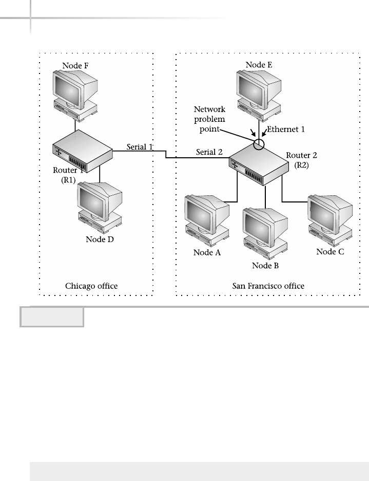
In this case, the port must be enabled from the local side, which could require
instructing an assistant to enable the port or reboot the device to reset the port.
The best way to avoid the “set of no return” is to disable the local serial2
interface on R2 or the remote ethernet1 interface on R1. This way, the broadcast
problem is contained, yet we still maintain access to the devices. To disable
a serial interface on router R1, a modification to the ifOperStatus object
must be made. This includes setting the object to zero (0) to disable the interface
from an administrative perspective. Set this object using the following command:
# snmpset router1 private interfaces.ifTable.ifEntry.ifAdminStatus.2 i 0\
interfaces.ifTable.ifEntry.ifAdminStatus.3 = 0
494 UNIX System Administration: A Beginner’s Guide
Figure 16-1 Problem of SNMP “Set of no return”

When executed, the command will disable the flow of traffic to and from
this interface. With most agents, this object change is not permanent, meaning
that a system reboot will reset this object back to the default (enabled) value.
However, without a system reset, the only other way to restore network
connectivity will be to enable the interface using the snmpset command.
The snmpset command can alter other MIB objects within the agent. For
example, consider the sysContact and sysLocation objects that are
contained with one of the UNIX SNMP agents. Let’s assign new values to these
objects using a single snmpset command:
# snmpset bedrock private system.sysContact.0 s "NCC Support"\
system.sysLocation.0 s "3rd Floor Closet"
Due to the nature of UNIX SNMP agents, the MIB assignments made above may
not be permanent and thus, when the system is rebooted, these values may pick
their default values.
When the above command has been executed, it returns the following:
system.sysContact.0 = "NCC Support"
system.sysLocation.0 = "3rd Floor Closet"
1-Minute Drill
●Name three useful features of the snmpnetstat tool.
●What is the “set of no return” problem?
Module 16: SNMP System Management Tools 495
16
●1) It provides an easy way to obtain interface information from any SNMP-compliant system. 2) Interface
information can be collected without the use of complicated command sequences. 3) It makes it easier to
work with multi-vendor networks.
●“Set of no return” means making a change to a network device remotely via SNMP such as disabling an
interface that prevents you from further communicating with the device remotely, thus requiring local
access to make additional configuration changes.
HintHint
These MIB objects can also be assigned values using the SNMP agent
configuration file.

Snmpstatus Tool
The snmpstatus command obtains important information from an SNMP
network entity using the SNMP get request operation. The syntax of the
command is as follows:
snmpstatus host community
When the remote agent utilizes the generic community string of public,
the string need not be specified from the SNMP commands because public is
used by default. By the way, the use of the public community string is highly
discouraged, because it is very unsecure.
When the snmpstatus command is used against a device, it displays the
following information:
●IP address of the device
●sysDescr MIB object
●sysUpTime MIB object
●Number of packets received and transmitted on all active interfaces (that is,
the sum of ifInUCastPkts.* and ifInNUCastPkts.* objects)
●Number of IP packets received and transmitted (that is, ipInReceives.0
and ipOutRequests.0)
●Number of active interfaces
●Number of interfaces that have been disabled
Thus, running the command
# snmpstatus didymus private
on the UNIX system called didymus displays the output as shown below:
[216.155.202.100]=>[Sun SNMP Agent, Netra 1 Server] Up: 11 days, 7:13:30.52
Interfaces: 2, Recv/Trans packets: 1177200/1144224 | IP: 89044/65055
Using this command is a good way to obtain a quick snapshot of a network
device without knowing a lot about the node or some of the specific MIB objects
496 UNIX System Administration: A Beginner’s Guide

to poll. The device has been running for over 10 days. Notice that snmpstatus
has detected two interfaces, which is common for the Netra series of systems.
Snmptable Tool
The snmptable command probes an agent and displays a MIB table using the
SNMP getnext request operation. The syntax of the command is as follows:
snmptable [common options ] [additional options] host community tableID
The minimum required arguments include host,community, and tableID.
The tableID must be a real SNMP table, such as interfaces.ifTable.
The ifTable table contains a series of MIB objects that contain performance
information and other characteristics of the interfaces within a device. The basic
purpose of this command is to give the user the ability to display SNMP tables
and import the data into other programs for additional reporting and manipulation.
Snmptest Tool
The snmptest command provides a simple shell-like facility that makes it
easy to communicate with a network entity using SNMP. Unlike most other
SNMP tools, this command is interactive, prompting for information to accomplish
one or more tasks.
The software supports three operating modes—snmp-get, snmp-getnext,
and snmp-set—and uses a simple command structure to issue tasks. Issuing the
$N command will place snmptest in snmp-getnext mode, while using the $S
puts the command in snmp-set mode. To get back to snmp-get mode, use the
$G command. By default, snmptest is placed in snmp-get mode, in which
the user is prompted for a MIB object to retrieve from an SNMP agent.
For example, the following command sequence will obtain the sysUpTime
object from a system called monet:
# snmptest monet stevewrite
Variable: system.sysUpTime.0
Variable:
Received Get Response from monet
requestid 0x4362F60A errstat 0x0 errindex 0x0
system.sysUpTime.0 = Timeticks: (379613) 1:03:16.13
Variable: ^c
16
Module 16: SNMP System Management Tools 497
16

498 UNIX System Administration: A Beginner’s Guide
Clearly, this is a rudimentary interface for issuing basic SNMP operations to
SNMP agents. It is somewhat useful if a large number of tasks must be performed
against the same network target. Note that to exit the program, you simply use
the CTRL-C (^c) command sequence.
Snmptranslate Tool
The snmptranslate tool translates SNMP MIB objects into a more user-
friendly and readable format. When this command is run with a MIB object, it
will translate the object into either the SMI value or symbolic form. When no
options are specified, it defaults to displaying the SMI value. The primary use of
the command is to help display the full characteristics of MIB objects, without
resorting to reading the appropriate MIB definition files.
By default, snmptranslate displays the numeric dotted object notation.
Thus, translation of the system.sysDescr MIB object can be accomplished
with the command
# snmptranslate system.sysDescr
which results in the following:
.1.3.6.1.2.1.1.1
To display a fairly complete description of a MIB object, use the -Td option.
For example, consider the following command:
# snmptranslate -Td system.sysDescr
When executed, the command will produce the following:
.1.3.6.1.2.1.1.1
sysDescr OBJECT-TYPE
-- FROM SNMPv2-MIB, RFC1213-MIB
-- TEXTUAL CONVENTION DisplayString
SYNTAX OCTET STRING (0..255)
DISPLAY-HINT "255a"
MAX-ACCESS read-only
STATUS current
DESCRIPTION "A textual description of the entity. This value should
include the full name and version identification of the
system's hardware type, software operating-system, and
networking software."
::= { iso(1) org(3) dod(6) internet(1) mgmt(2) mib-2(1) system(1) 1 }

Module 16: SNMP System Management Tools 499
16
As shown, a complete reference of the MIB object can be obtained. This
information is taken from the MIB definition files that the agent references. In
this case, the file RFC1213-MIB.txt, which is located in the /usr/share/
snmp/mibs directory, was used.
Snmptrap Tool
The snmptrap command will emit an SNMP trap to one or more designated
SNMP manager applications or systems. This tool is very useful when embedded
within a shell script or other program that handles traps. One or more object
identifiers can be specified on the command line, plus the type and value must
accompany each object. Recall that an SNMP trap is an unsolicited message sent
by an SNMP agent to a network manager application or system. The basic syntax
of the command is as follows:
snmptrap -v 1 [command arguments] enterprise-oid agent generic-trap\ specific-trap
uptime [object ID type value]
The enterprise-oid field identifies the network management subsystem
that generated the trap. The agent is the host that emits the trap. The generic-trap
corresponds to one of the predefined SNMP traps listed in Module 13. The
specific-trap value indicates more specifically the nature of the trap.
The uptime field is used as a timestamp between the last initialization of the
device and the issuance of the trap. The object ID,type, and value fields
provide additional information relating to the trap. These additional fields are
known as the variable binding and may contain any type of information that
is related to the trap.
The enterprise-oid,agent, and uptime fields need not be specified
on the command line. Instead, the empty character sequence ‘‘ may be used to
specify the default values for these fields. The default agent value is the hostname
of the machine running the snmptrap command. The uptime is obtained from
the local system’s MIB object system.sysUpTime.0.
Consider, for example, that we would like to emit a link-down trap to a network
management system called rembrandt. Further, if we want to communicate
that a particular port has gone down, we include the port within the variable
bindings of the trap. We can use the following command:
# snmptrap -v 1 public '' monet 2 0 '' interfaces.iftable.ifentry.\
ifindex.1 i 1

500 UNIX System Administration: A Beginner’s Guide
In this example, we use the default values for the enterprise-oid
and uptime fields. Also, we specify the particular interface (ifindex.1)
and set the value to 1 (which indicates the second interface with the device).
The 2 represents the link-down trap, and 0 provides a null value for the
specific-trap value.
If we review the traps on rembrandt, we will see output like the
following:
Feb 24 17:51:27 monet snmptrapd[385]: 10.0.2.201: Link Down
Trap (0) Uptime:2:26:59, interfaces.ifTable.ifEntry.
ifIndex.1 = 1
In practice, most link-down messages are not that meaningful or interesting.
However, when they come from critical devices, such as core routers or switches,
a disabled interface could spell disaster for the network.
Care should be taken when configuring traps from network devices because
doing so can cause a trap flood. This condition occurs when a large number of
traps are sent in response to a particular recurring event. For example, within a
LAN Ethernet switch, a port’s link state may bounce up and down many times
per second due to a hardware malfunction. This type of problem can yield a
large number of traps. In practice, trap notification should be enabled only on
critical devices or UNIX systems. In this case, if possible, traps should be disabled
for linkup/link-down events from generic network devices.
Snmptrapd Server
The snmptrapd server will receive and log SNMP traps obtained from
other devices. Traps that are sent on port 162 are either logged to the UNIX
syslog facility or displayed on the terminal. These messages are sent using
LOG_WARNING and the LOG_LOCAL0 logging levels. The snmptrapd
command must be run as superuser because it listens on a reserved system
port. Executing the command without any options will cause it to be placed
in the background and detached from the calling shell.
The snmptrapd command supports several command-line arguments,
including -P (display trap), -D (more debugging), -d (detailed packet
information), and –q (verbose output). The -P option will instruct snmptrapd
TEAMFLY
Team-Fly®

Module 16: SNMP System Management Tools 501
16
to display any traps received on the standard output, and the -d option will
display a detailed dump of the trap packet. Thus, to show received traps
and display the contents of trap packets, use the following command:
# snmptrapd -P -d
Executing this command, using the previous example on the host
rembrandt, will display the following output:
2002-02-27 22:56:47 UCD-snmp version 4.0.1
received 69 bytes from 10.0.3.126:-32566:
0000: 30 82 00 41 02 01 00 04 06 70 75 62 6C 69 63 A4 0..A.....public.
0016: 82 00 32 06 08 2B 06 01 04 01 03 01 01 40 04 0A ..2..+.......@..
0032: 00 03 7E 02 01 02 02 01 00 43 03 24 5C 96 30 82 ..~......C.$\.0.
0048: 00 13 30 82 00 0F 06 0A 2B 06 01 02 01 02 02 01 ..0.....+.......
0064: 01 01 02 01 01 .....
1999-11-27 22:56:51 monet [10.0.3.126] enterprises.3.1.1:
Link Down Trap (0) Uptime: 6:37:09
interfaces.ifTable.ifEntry.ifIndex.1 = 1
end annotated syntax
The first line shows the current version and when the snmptrapd process
was run. Next, the output displays the number of bytes in the trap packet, the
host the trap was sent from (monetIP:10.0.3.126), and the UDP port
(32566, in this case). The contents of the trap include both hexadecimal and
ASCII characters. Finally, the trap information, including the variable-binding
information, is shown.
The -D option will display additional debugging information that includes
the parsing of MIB files. The -q option provides a more verbose output.
The snmptrapd command can be used as a focal point for reception of traps
for a large number of UNIX systems. However, it must be running continuously
in order to receive traps from the network. By default, this tool is not started by
When snmptrapd was run SNMP version
Port
Host trap was sent from
Bytes in the trap packet
Trap contents

502 UNIX System Administration: A Beginner’s Guide
the system. To enable this command on system startup, you should add it to the
existing UCD agent startup script called snmpd.
1-Minute Drill
●What does the snmptrapd server do?
●What command provides a good way to obtain a quick snapshot of a network
device without knowing a lot about the node or some of the specific MIB
objects to poll?
Snmpwalk Tool
The snmpwalk command will walk an agent MIB tree using the SNMP getnext
request. Why use this command instead of the snmpget tool? Well, the
snmpwalk command can discover the entire MIB store contained within the agent
automatically. With snmpget, you need to explicitly specify an object to obtain
a value. With the snmpwalk command, you can start at a given point and
move through the agent’s MIB to the end. An object variable may be given on
the command line to specify with which portion of the MIB space the search
will begin. Without a MIB object argument, snmpwalk searches and starts
with the MIB-II object store. Thus, the command
# snmpwalk monet public
will walk the entire system agent on the device monet. Since MIB-II contains a
large number of objects, the command will produce a rather long listing. Instead
of listing every object supported by the agent, we can limit the search and
display only a single group of objects. Thus, we can list all the objects found
within the MIB-II system group using the following command:
# snmpwalk bedrock public system
●It receives and logs SNMP traps obtained from other devices.
●snmpstatus

Module 16: SNMP System Management Tools 503
16
Executing this command against a UNIX system generates the following
sample output:
system.sysDescr.0 = Linux didymus 2.4.7-10 #1 Thu Sep 6 17:27:27 EDT 2001 i686
system.sysObjectID.0 = OID: enterprises.ucdavis.ucdSnmpAgent.linux
system.sysUpTime.0 = Timeticks: (168468) 0:28:04.68
system.sysContact.0 = Steve Maxwell (sjmaxwell@worldnet.att.net)
system.sysName.0 = didymus
system.sysLocation.0 = Graphics Lab
system.sysORLastChange.0 = Timeticks: (0) 0:00:00.00
system.sysORTable.sysOREntry.sysORID.1 = OID: ifMIB
system.sysORTable.sysOREntry.sysORID.2 = OID:
.iso.org.dod.internet.snmpV2.snmpModules.snmpMIB
system.sysORTable.sysOREntry.sysORID.3 = OID: tcpMIB
system.sysORTable.sysOREntry.sysORID.4 = OID: ip
system.sysORTable.sysOREntry.sysORID.5 = OID: udpMIB
system.sysORTable.sysOREntry.sysORID.6 = OID:
.iso.org.dod.internet.snmpV2.snmpModules.snmpVacmMIB.vacmMIBConformance.vacmMIBGroups
.vacmBasicGroup
system.sysORTable.sysOREntry.sysORID.7 = OID: .iso.org.dod.internet.snmpV2.snmpM
odules.snmpFrameworkMIB.snmpFrameworkMIBConformance.snmpFrameworkMIBCompliances.snmpF
rameworkMIBCompliance
system.sysORTable.sysOREntry.sysORID.8 = OID: .iso.org.dod.internet.snmpV2.snmpM
odules.snmpMPDMIB.snmpMPDMIBConformance.snmpMPDMIBCompliances.snmpMPDCompliance
system.sysORTable.sysOREntry.sysORID.9 = OID: .iso.org.dod.internet.snmpV2.snmpM
odules.snmpUsmMIB.usmMIBConformance.usmMIBCompliances.usmMIBCompliance
system.sysORTable.sysOREntry.sysORDescr.1 = The MIB module to describe generic o
bjects for network interface sub-layers
system.sysORTable.sysOREntry.sysORDescr.2 = The MIB module for SNMPv2 entities
system.sysORTable.sysOREntry.sysORDescr.3 = The MIB module for managing TCP impl
ementations
system.sysORTable.sysOREntry.sysORDescr.4 = The MIB module for managing IP and ICMP
implementations
system.sysORTable.sysOREntry.sysORDescr.5 = The MIB module for managing UDP
implementations
system.sysORTable.sysOREntry.sysORDescr.6 = View-based Access Control Model for SNMP.
system.sysORTable.sysOREntry.sysORDescr.7 = The SNMP Management Architecture MIB.
system.sysORTable.sysOREntry.sysORDescr.8 = The MIB for Message Processing and D
ispatching.
system.sysORTable.sysOREntry.sysORDescr.9 = The management information definitions
for the SNMP User-based Security Model.
system.sysORTable.sysOREntry.sysORUpTime.1 = Timeticks: (0) 0:00:00.00
system.sysORTable.sysOREntry.sysORUpTime.2 = Timeticks: (0) 0:00:00.00
system.sysORTable.sysOREntry.sysORUpTime.3 = Timeticks: (0) 0:00:00.00
system.sysORTable.sysOREntry.sysORUpTime.4 = Timeticks: (0) 0:00:00.00
system.sysORTable.sysOREntry.sysORUpTime.5 = Timeticks: (0) 0:00:00.00
system.sysORTable.sysOREntry.sysORUpTime.6 = Timeticks: (0) 0:00:00.00
system.sysORTable.sysOREntry.sysORUpTime.7 = Timeticks: (0) 0:00:00.00
system.sysORTable.sysOREntry.sysORUpTime.8 = Timeticks: (0) 0:00:00.00
system.sysORTable.sysOREntry.sysORUpTime.9 = Timeticks: (0) 0:00:00.00
End of MIB

To walk the entire MIB within a given agent and save the output to a file,
use the following command:
# snmpwalk bedrock public .1 > walk.out
This command uses the .1 as the starting point to begin listing objects.
Doing this ensures that every object will be displayed because .1 is the root
of the entire MIB tree and all objects are accessible from this point. Walking
the entire MIB tree with an agent helps identify certain MIB objects or gives
you an idea of exactly how many objects a particular agent may support. To see
the approximate number of objects that the Linux agent supports, count the
number of lines in the file. Because the snmpwalk command displays each MIB
object on its own line (unless the line is longer than the maximum number
of characters for a line), we can then use the UNIX wc command to total the
number of lines within the walk.out file. Thus, the command
# wc -l walk.out
produces the following output:
2242 walk.out
This command output shows that the agent contained within the Linux
agent supports roughly 2242 MIB objects. When no object is specified with the
snmpwalk command, it will search the MIB-II object tree by default. When
the snmpwalk command reaches the end of the MIB within the agent, it will
display the message End of MIB.
Note that the use of this command is a rather inefficient means to obtain
a large number of MIB objects from an agent. This is because the command
continuously queries a single MIB object to obtain an associated value. It is
recommended that the snmpbulkwalk command be used whenever possible
to reduce network traffic and load on the agent system. This command significantly
reduces the work involved, from a lower-level standpoint, to obtain a large amount
of information from an agent. See the following snmpbulkwalk section for
additional information.
504 UNIX System Administration: A Beginner’s Guide

Module 16: SNMP System Management Tools 505
16
Snmpbulkwalk Tool
The snmpbulkwalk tool communicates with a network entity using the SNMPv2
bulk request. Like the snmpwalk tool, snmpbulkwalk will walk a MIB tree
until the end of the MIB is reached or an error occurs. The bulk request provides
a more efficient mechanism to transfer a large amount of data than the regular
SNMPv1 get request. For example, assume we would like to retrieve the entire
MIB-II interface group from a Linux server. We would issue the following
command:
# snmpwalk monet public interfaces
This command will result in a series of SNMP getnext requests to the interface’s
MIB group against a network node called monet. The SNMPv1 snmpwalk
(which uses a normal get request) command will obtain the information using
136 packets. How do we know this? Just before the snmpwalk command was
executed, a packet capture was started using the following command:
# tcpdump host monet -w output.file
The tcpdump command, which is described in Module 12, will capture all
packets coming from or going to the host called monet. These packets are saved
in the file called output.file. Once the snmpwalk command has finished,
the tcpdump command is manually stopped. Next, we simply count the number
of packets that were captured within the output.file file. Thus, with
# tcpdump -r output.file | wc -l
136
we see that a total of 136 packets were captured. This is the number of packets
needed to retrieve the interfaces table. Please note that depending on the
number of interfaces defined within a device, more or fewer packets would be
required. However, if we query the same device using the snmpbulkwalk
command instead,
# snmpbulkwalk -v 2c monet public interfaces
we will poll the same interface’s group information but only use two packets!

506 UNIX System Administration: A Beginner’s Guide
This is a tremendous savings in terms of network bandwidth and increased
SNMP performance for both the agent and manager. The SNMP bulk-request
option is efficient because it attempts to place as many MIB OID values as possible
within the variable-binding field of the SNMP response packet(s). The
only limit to the amount of data that can be placed within the SNMP packet is
the maximum packet size of the underlying protocols.
To walk the entire MIB tree of the device called cisco-gw1, use the
following command:
# snmpbulkwalk -v 2c CISCO-gwl public
The snmpbulkwalk command only works with SNMPv2 or SNMPv3 agents.
This is because the bulk-request facility specification came after the widespread
deployment of SNMPv1. Using this command on an SNMPv1 agent will,
therefore, generate an error.
For instance, the following command attempts to walk the MIB tree of a
device called -gw starting from the system group. In this example, monet
supports only the SNMPv1:
# snmpbulkwalk -v 2c monet public system
Since this device doesn’t understand the SNMP bulk request, it eventually
times out, and the following message is displayed following the snmpbulkwalk
command:
Timeout: No Response from monet
A timeout error condition occurs because the requests are issued to the
device, but the agent residing in the device doesn’t understand the SNMP
bulk-request format. As a result, the packet is not answered by the agent and
the command simply times out. In practice, many networking devices have
been upgraded to support the bulk-request operation. Therefore, this problem
will diminish over time as older devices are replaced or upgraded.
Note that snmpbulkwalk requires that you use either the 2c or 2p security
options. If you attempt to invoke snmpbulkwalk without specifying which
version of the SNMP protocol is to be used, the following error will be displayed:
snmpbulkwalk: Cannot send V1 PDU on V2 session

Module 16: SNMP System Management Tools 507
16
By default, the snmpbulkwalk command will search the entire MIB-II
tree if a MIB object or group isn’t specified on the command line. From a
practical standpoint, this makes the tool a little easier to use if the complete
MIB-II objects store is desired.
Mastery Check
1. In the following command example, what is the -M /var/mibs option
used for?
# snmpwalk -M /var/mibs cisco-gw1 public system
A. Specifies a list of MIB modules to load.
B. Supplies a list of directories for the command to search for MIB files.
C. Directs output to the specified directory.
D. Runs the SNMP scripts found in the specified directory.
2. The __________command collects changes in MIB integer values from an
SNMP agent entity.
3. If a device doesn’t respond to SNMP requests, what command might you
try to see if the device is reachable on the network?
A. snmpwalk
B. snmptrap
C. snmpnetstat
D. ping
4. What command is similar to the UNIX netstat utility and provides
some of the same basic information about attached device interfaces and
routing information?

508 UNIX System Administration: A Beginner’s Guide
5. Which of the following management tasks isn’t something SNMP is
useful for?
A. Reset a user password
B. Disable or enable a network interface
C. Restart a device or agent
D. Monitor critical processes
6. What is the correct syntax for the snmpstatus command?
A. snmpstatus host community
B. snmpstatus community host
C. snmpstatus interface community
D. snmpstatus community interface
7. The snmptrapd server will receive and log SNMP __________ obtained
from other devices.
8. What command option is used to generate output shown in the second
example line instead of the first, using the same input command?
system.sysUpTime.0 = Timeticks: (139494644) 16 days, 3:29:06.44
system.sysUpTime.0 16:3:24:11.44
A. -S
B. -s
C. -f
D. -q
9. True/False: It might be helpful to execute an snmpwalk against the
agent if questions come up regarding which objects are indeed supported
by the agent.
Mastery Check

Module 16: SNMP System Management Tools 509
16
10. The __________ tool will walk a MIB tree until the end of the MIB is
reached or an error occurs and provides a more efficient mechanism
to transfer a large amount of data than the snmpwalk tool.
11. True/False: snmpnetstat only works with Unix workstations
and servers.
Mastery Check

This page intentionally left blank.
TEAMFLY
Team-Fly®

Module17
Using Network
File System
Critical Skills
17.1 NFS Server Uncovered
17.2 Mounting Remote File System
17.3 Exploring NFS Tools
17.4 Configuring NFS Clients
17.5 Controlling the File System Mount Table
Copyright 2002 by The McGraw-Hill Companies, Inc. Click Here for Terms of Use.

512 UNIX System Administration: A Beginner’s Guide
The Network File System (NFS) is a service that provides file sharing across
a network of systems. NFS was first implemented by Sun Microsystems and
was supported only on the Sun version of UNIX, which at the time was called
SunOS. Today, it is supported across most, if not all, versions of UNIX that are
available today. Also, NFS is supported on a number of non-UNIX platforms
such as Windows and Macintosh. On UNIX systems, NFS behaves and is
configured in much the same way regardless of which version of UNIX is used.
In recent years, network appliance servers have been developed, which are
systems that provide NFS services on dedicated, high-performance hardware
platforms. Typically, these servers are built to support only a smaller number of
services (such as NFS) and are not meant to support a wide range of additional
network services.
File sharing is a concept that has been around for quite some time; it means
that one or more files may be shared across a number of different systems
and by any number of users. The basic premise is that read-only file access can
be shared by any number of users when the file in question is stored within
NFS. Updating or writing to a file with multiple users is an entirely different
issue, and NFS provides the same services that are available with the operating
system. NFS files appear to the system as if they were stored locally. In other
words, NFS is implemented in such as way as to provide the same facilities for
files as if they were stored on the local file system.
NFS can be divided into two broad sections: the server and client. The server
component consists of several elements that include server processes and
configuration files. The client component includes a single-server process. The
details of the server and client are described below.
Versions of NFS
NFS has seen some important improvements since it was first introduced back
in 1984. The features and improvements of the protocols are presented here:
●Version 1 This version only existed within Sun Microsystems and was
never actually released as a product.
●Version 2 The first official release of the protocol was shipped with
SunOS 2.0, and it had the following limitations:
●Didn’t support files greater than 2GB
●Maximum transfer rate of only 8K
●Limitation on performance due to client/server interaction
●Poor security features

17
Module 17: Using Network File System 513
●Version 3 This version has been out for a number of years and addresses
some of the most important issues that plagued version 2. In addition,
version 3 handles the following:
●Reliable asynchronous write
●Reduces protocol overhead
●Maintains backward compatibility with version 2
However, security remained a significant problem for the earlier
versions of NFS.
●Version 4 Back in 1999, Sun published a technical brief describing new
features for NFS. Also, RFC3010 was developed, which described technical
details regarding this new version. Basically, version 4 will provide better
security, improve operation over WAN networks, provide better cross-
platform interoperability, and include extensions to the protocol.
17.1 NFS Server Uncovered
The NFS server consist of several programs and services, which include
●nfsd
●lockd
●statd
●mountd
Also, the server contains a standard NFS configuration file, which lists all
the file systems that are made available to NFS clients. The process of making
one or more file systems available to NFS clients on the network is called “file
system exporting” or “sharing.”
The nfsd Process
The nfsd process handles NFS remote file system requests from client systems.
Typically, this process is started automatically on system startup. On Solaris,
the /etc/init.d/nfs.server startup script is used, while on Linux the
/etc/rc.d/init.d/nfsd script is used. For HP-UX, the /etc/init.d/
nfs.server is used. By default, NFS servers use both TCP and UDP transport

protocols. However, depending on site requirements, the transport protocol may
be selected using the -p option, followed by the protocol (such as tcp or udp).
One of the most important aspects of the NFS server configuration is the
number of concurrent requests that it can handle from clients. In large networks
or otherwise demanding computing environments, where many systems will
access NFS servers, it is important to ensure that each server is operating in the
most efficient manner possible. One way to increase server performance is to set
the maximum number of parallel NFS servers that should be run to handle NFS
requests. The number of NFS servers that are used is derived from the command-
line parameter within the server startup script. By default, only a single server
instance is started.
NoteNote
Depending on the implementation of the NFS server, it may use lightweight
processes (kernel threads) which, when the ps or top commands are used to
inspect processes, system usage will not appear for the NFS server. Thus, either
zero CPU or a smaller amount than was actually used may be displayed. In general,
it is not uncommon to have as many as 10 or more NFS processes in a demanding
environment.
To increase the number of NFS server instances, edit the startup script
and place the desired number of instances after the nfsd process command
line. For example, to instruct the NFS server to start with eight instances, the
following would be used:
nfsd 8
To have this change take effect, restart the NFS process using the appropriate
startup script.
The lockd Process
The lockd process implements record locks for NFS files. Record locking
is a mechanism to restrict access to an individual file record or the entire file
when changes are being made. This is necessary when more than one user
or application is updating a file. The lockd process is also known as the lock
manager and handles lock requests from the fcntl system call, which is issued
from client systems.
514 UNIX System Administration: A Beginner’s Guide

The statd Process
The statd process is used in conjunction with the lockd process to handle
cases when the NFS server crashes and requires recovery. The statd process
keeps track of clients that spawn processes that hold locks on files from the
NFS server. Should the NFS server reboot after a crash, statd sends a message
to each client indicating that the NFS server has rebooted. Then, the lockd
process on the client attempts to reclaim any pending locks from the server.
The mountd Process
The mountd process is used to handle remote NFS mount requests from
clients. It is responsible for determining which file systems are available and
interacts with the client to provide file and directory information. By default,
this service is running when NFS services are activated.
If the system supports auto-mounting, such as in Solaris, the automountd
process is also active and provides the same basic services for clients as mountd.
The auto-mount facility provides a way to set up automatic mounting of file
systems when users access one or more files or directories.
17.2 Mounting Remote File System
One very interesting aspect of NFS is that it provides complete transparency of
remote file systems for the average user. In fact, from a file system perspective,
there is no difference between a remotely mounted file system and one that is
mounted from a local disk. For example, consider the following listing from
/usr/docs directory:
drwxr-xr-x 6 root root 4096 Apr 1 22:01 .
drwxr-xr-x 6 root 1 512 Apr 1 23:03 ..
drwxr-xr-x 2 root root 4096 Apr 1 22:01 html
drwxr-xr-x 2 root root 4096 Apr 1 22:00 man
drwxr-xr-x 2 root root 4096 Apr 1 22:00 pdf
drwxr-xr-x 2 root root 4096 Apr 1 22:00 postscript
In the list above, four directories are shown using the ls –al command.
Can you identify which directories are stored locally versus those that are
actually stored on a remote NFS server? From this listing, it is impossible for
17
Module 17: Using Network File System 515

516 UNIX System Administration: A Beginner’s Guide
anyone to determine which directories are made available via NFS—they all
appear as if they are from the local file system.
To show which file systems are mounted locally versus remotely using NFS,
use the df command. This command shows interesting file system information
for all mounted file systems on the system. For example, issuing this command
on the system that contained the above /usr/docs directory shows
Filesystem kbytes used avail capacity Mounted on
/dev/dsk/c0d0s0 480815 39338 393396 10% /
/dev/dsk/c0d0s6 1587078 811771 727695 53% /usr
/dev/dsk/c0d0s1 384847 117108 229255 34% /var
/dev/dsk/c0d0s5 480815 337833 94901 79% /opt
didymus:/docs 2522552 1665304 729108 70% /usr/docs/pdf
As you can see from the output, the pdf directory is a remotely mounted
NFS file system from the system called didymus.
Just as when mounting a file system that is stored on a local disk, the mount
command can be used to connect NFS volumes to the local system. To mount the
file system called /share from the NFS server bedrock on the local directory
called /files, use the following command:
mount bedrock:/share /files
The mount command shown here does provide only a temporary mount
of this volume. This means that the /share volume will not be mounted
automatically when the system is rebooted; thus, this NFS volume will go away
should the system called didymus be restarted. To address this issue, the
NFS mount must be defined within the standard NFS configuration file, such
as /etc/exports. Review the next section, “Share/Export File Options,” to
find out how to set up permanent NFS mounts.
The dfstab/export Files
In order for a UNIX NFS server to make local files available to clients,
each file system must be exported or shared on the network. On Solaris,
the /etc/dfs/dfstab is used to specify that the file systems should be
made available to clients on a permanent basis. On Linux and HPUX, the
/etc/exports file is used instead. Both of these files contain pretty much
the same information; however, the supported command options do differ.

For example, the way to indicate if the file system access should be read-only
would be to use the string –orofor dfstab, while (ro) is used for exports
file. A file system is exported or shared when it is made available to other systems
for mounting across the network. The process of exporting or sharing a file
system includes adding the designated file system to the exports or dfstab
and then issuing a command to make the file system “live” on the network.
A sample /etc/dfs/dfstab file is shown below:
share -F nfs -o rw /usr
share -F nfs -o ro /docs
In this example, two file systems, /usr and /docs, are being exported.
Note that the share string is included, which is the actual command that
makes the file system available. The share command on Solaris is used to
provide access to the file system resource for remote clients. The /usr file
system contains the file access option of rw. This indicates that both read and
write file access will be granted to NFS clients. The /docs file system is made
available read only due to the ro option.
A sample /etc/exports file includes the following:
/ (rw)
/docs (ro)
Share/Export File Options
Both the /etc/dfs/dfstab and /etc/exportfs configuration files are
used to provide automatic setup of NFS volumes to client systems. Each of
these files supports a number of similar options and also some unique ones.
Table 17-1 shows some of the most important command line options.
Module 17: Using Network File System 517
17
Option Description
anon=uid Sets the UID on the server to be the effective user ID of any unknown
users. By default, all unknown users are given the UID of 60001.
-F (dfstab) Specifies the type of file system for the NFS volume. Use
the keyword nfs for NFS-type file systems.
-d (dfstab) Provides a descriptive string of the NFS volume.
log (dfstab) Enables NFS logging for the given file system.
Table 17-1 Share/Export NFS Options

In order to gain a better understanding of some possible dfstab and
exports configuration options, a series of examples are provided in Table 17-2.
Each example shows the necessary options for both configuration files.
518 UNIX System Administration: A Beginner’s Guide
Option Description
rw (Both) The associated pathname is read/write to all clients; this is
the default behavior if no option is provided (This default behavior
is for Solaris)
rw=client_host (dfstab) A client system name may be specified with the NFS
volume permission. For Linux, the syntax includes client(rw).
ro (Both) The associated pathname is read-only to all clients.
ro=client_host (dfstab) A client system name may be specified with the NFS
volume permission. For Linux, the syntax includes client(rw).
root_squash (exportfs) Maps any requests from the root user (UID of 0) to the
anonymous UID.
secure (dfstab) Requires that NFS client requests originate on a network
port that is less than 1024. By default this option is enabled. Disable
by using the insecure option.
sync Requests that all file write transactions be completed to the underlying
hardware before the write request has been completed. This means
that requests are buffered before the write requests are returned.
Table 17-1 Share/Export NFS Options (continued)
/etc/dfs/dfstab Configuration /etc/exports Configuration
/usr didymus(ro) chips(rw) share –F nfs –o rw=chips,ro=didymus /usr
Explanation Provide read-only access to the client called didymus and read-write access to the
client called chips for the /usr file system.
/src (rw,anonuid=70000) share –F nfs –o rw,anon=70000 /src
Explanation Provide read-write access to all clients for the /src file system and also map the
anonymous users to the UID of 70000.
/home (rw,log,root=bedrock) share –Fnfs–o rw,log,root=bedrock /home
Explanation Provide read-write access to all clients for the /home file system, enable NFS logging,
and also permit root access from the host called bedrock.
Table 17-2 Configuration File Options

17.3 Exploring NFS Tools
UNIX provides additional tools for monitoring and controlling NFS services.
These tools include
●exportfs
●share/unshare
●showmount
●nfsstat
exportfs
The exportfs command is provided on Linux to make one or more file
systems available to clients on an NFS server. The file systems must be specified
within the /etc/exports file. The command supports a few command-line
options and they are shown in Table 17-3.
To export all file systems contained within the /etc/exports file, issue
the following command:
exportfs –a
If you wanted to unexport all the file systems, issue the above command
again; this will assume that file systems have already been exported. If not, it
Module 17: Using Network File System 519
17
Option Description
-a Export or unexport all file systems contained within the /etc/exports file.
-o Specify a list of options when exporting file systems. See Table 17-1 for
additional information.
-r Reexport all file systems contained within the /etc/exports file.
-u Unexport one or more file systems.
-v Provide verbose output when exporting or unexporting file systems.
Table 17-3 Export Command-Line Options

520 UNIX System Administration: A Beginner’s Guide
simply exports them. The other approach is to use the –u option. You can also
specify the individual file systems that you want to export without having to
add them to the /etc/export file. Just list the file system as an option to the
exportfs command. For example, to provide NFS access to the /prod file
system to the client didymus, use the following command:
exportfs didymus:/prod
To display a list of all exported file systems, just issue the exportfs
command without any options. Note that issuing this command doesn’t make
the export permanent. In order to make it last across reboots, the lete/export
file must be updated. Thus, the command
exportfs
will show all file systems that are available to clients:
/docs dino.home.com
/ bedrock.home.com
/prod *.home.com
In this example, the *character is shown; this is a shorthand notation to specify
a wildcard, which is interpreted as all hosts within the home.com domain.
share/unShare (Solaris Only)
Use the share command on the Solaris system to make NFS volumes available
over the network to client systems. To make NFS volumes available on a permanent
basis, use the /etc/dfs/dfstab file. To remove shared file systems, use the
unshare command.
Issuing the share command without any arguments shows the currently
available NFS volumes that are being shared. For example, the command
share
shows the following sample file systems:
- /usr rw "user home directories"
- /docs ro "system documentation"
- /src rw "source tree"
TEAMFLY
Team-Fly®

To share a particular volume, specify it on the command line with the share
command. Also, the shareall command is provided to share all the NFS
volumes currently defined within the /etc/dfs/dfstab configuration file.
NoteNote
Sharing a file system without it being defined within the dfstab file means that it
will not be shared when the NFS server is rebooted.
To remove or unshare a volume, use the unshared or unshareall
commands. Thus, either command would prohibit NFS client access. If one or
more client’s systems were accessing an NFS volume when it was unshared, the
client would get a stale NFS file handle and the operation would not
complete; thus, care should be taken when removing NFS access from critical
file systems.
showmount
The showmount command is used to provide information about clients that
have mounted any file systems on the NFS server. For example, to display all
the clients that have mounted the file systems on a Solaris system called bedrock,
issue the following command:
showmount –a
The –a option formats the output to show hostname: directory for
each file system and client. The sample output
didymus.home.com:/usr
didymus.home.com:/docs
chips.home.com:/usr
chips.home.com:/src
shows two client systems that have mounted file systems from bedrock. The
first client, didymus, has mounted both the /usr and /docs file systems.
The second system, called chips, mounted the /usr and /src file systems,
respectively. The showmount command can also be used to show the available
mounted file systems on the local NFS server. For example, if the showmount
Module 17: Using Network File System 521
17

command is run with the –d option, on the system bedrock, the following
would be shown:
/docs
/usr
The output above shows all the file systems that have been made available
to NFS clients. In this case, the output is similar to what is provided with the
share command.
nfsstat
The nfsstat command provides NFS server-based statistic and performance
information on NFS activities. The following categories of information can be
displayed:
●Server RPC statistics
●Server NFS statistics
●Client RPC statistics
●Client NFS statistics
The statistics that are displayed are determined by the command-line options,
which are listed in Table 17-4. Issuing the command without any parameters
will result in the-csnrc options being activated and the corresponding output
displayed for each statistic.
522 UNIX System Administration: A Beginner’s Guide
Option Description
-a Show NFS access control list (ACL) information.
-c Show client-side information for NFS, RPC, and ACL.
-m Show configuration and stats for each NFS mounted file system.
-n Show both client and server NFS information.
-r Show only remote procedure call (RPC) information.
-s Show only server information.
-z Reset all statistic counters. This can only be run by the superuser.
Table 17-4 The nfsstat Command-Line Options

The output of nfsstat is not that user friendly, but it does contain some
important information on the activities and configuration of the NFS server.
For example, the –m option displays statistical information on each mounted
file system, such as
/mnt/bedrock/docs from bedrock:/docs
Flags:
vers=3,proto=tcp,sec=sys,hard,intr,link,symlink,acl,rsize=32768,\
wsize=32768,retrans=5,timeo=600
Attr cache: acregmin=3,acregmax=60,acdirmin=30,acdirmax=60
In this example, the /mnt/bedrock/docs file system is mounted from
the server called bedrock and the associated file system configuration
information is also displayed. The Flags fields shows specific configuration
(either by default or manually configured) from the NFS server. From the
output we notice that, for instance, this file system is mounted with the hard
option on the client. A hard mount is one that ensures that a client system will
block any pending NFS activity should the file system become unavailable. This
is meant to ensure a certain level of file system integrity on the client system.
The Attr field contains file system cache attributes, which are used to control
the amount of time certain file elements (such as file’s owner) are stored in the
NFS server cache. The remaining mount flag options and associated descriptions
are listed in Table 17-5.
Module 17: Using Network File System 523
17
NFS Mount
Options Description
vers The version of the NFS protocol.
proto The NFS lower-layer transport protocol. Can be either Transmission
Control Protocol (TCP) or User Datagram Protocol (UDP).
sec The security model used; values include none (no authentication),
sys (standard UNIX authentication based on UID and GID), short
(alternative UNIX-style authentication), dh (DES-based authentication),
and kbr (Kerberos v4, v5, or v5i).
hard Hard NFS mount; ensures that should the NFS server not respond due to
some kind of failure, the client will block file transactions until the server
file system is restored.
soft soft NFS mount; does the inverse of a hard mount; instructs the client to
not block NFS transactions to the server, but lets them time out, instead.
Table 17-5 The nfsstat Mount Options

524 UNIX System Administration: A Beginner’s Guide
NoteNote
With regard to hard versus soft mounts, when hard mounts are used on client
systems, and the server experiences a problem that causes an interruption of
NFS services, the client can lock up until the server problem has been fixed.
The solution to address this is to use soft mounts. However, although using
soft mounts will help with the lockup problem, it doesn’t specifically address
any server problem since any pending NFS activity will simply time out. When
a timeout occurs, the client system will generate one or more error messages.
This could result in application-related problems.
To show specific NFS activity, use the following command:
nfsstat –n
The –n option displays NFS stats for both clients and the server. Sample
output is shown below and can be divided into two broad categories: specific
stats from the NFS server and from the client standpoint. The first part of
the listing includes server information that contains stats for both versions
2 and 3 of the NFS protocol. For each type of activity received by the server,
NFS Mount
Options Description
intr Permits the client to interrupt a process when a transaction is pending
on the server.
link The server supports file links.
acl Access control list (ACL) that applies to the file system; no assignment
means no authentication is used.
rsize The size of the read buffer.
wsize The size of the write buffer.
retrans The retransmission delay in tenths of a second.
timeo The transaction timeout in tenths of a second.
acregmin The minimum amount of time (in seconds) to store cached file attributes.
acregmax The maximum amount of time (in seconds) to store cached file attributes.
acdirmin The minimum amount of time (in seconds) to store cached directory
attributes.
acdirmax The maximum amount of time (in seconds) to store cached directory
attributes.
Table 17-5 The nfsstat Mount Options (continued)

Module 17: Using Network File System 525
17
a counter is maintained. Also, for each counter, the percent of the total number
of transactions received is calculated. For example, the getattr attribute
consists of 35 percent of the total number of transactions received by the server.
The getattr is used when the specific file information is needed by a NFS
client system.
Server nfs:
calls badcalls
478088 5
Version 2: (14 calls)
null getattr setattr root lookup readlink
0 0% 5 35% 0 0% 0 0% 0 0% 0 0%
read wrcache write create remove rename
0 0% 0 0% 0 0% 0 0% 0 0% 0 0%
link symlink mkdir rmdir readdir statfs
0 0% 0 0% 0 0% 0 0% 3 21% 6 42%
Version 3: (478074 calls)
null getattr setattr lookup access readlink
1 0% 23 0% 0 0% 57321 11% 414682 86% 2058 0%
read write create mkdir symlink mknod
0 0% 0 0% 0 0% 0 0% 0 0% 0 0%
remove rmdir rename link readdir readdirplus
0 0% 0 0% 0 0% 0 0% 3943 0% 1 0%
fsstat fsinfo pathconf commit
24 0% 21 0% 0 0% 0 0%
A listing and description of the individual counter fields are provided in
Table 17-6.
Client nfs:
calls badcalls clgets cltoomany
79 1 79 0
Version 2: (63 calls)
null getattr setattr root lookup readlink
0 0% 55 87% 0 0% 0 0% 7 11% 0 0%
read wrcache write create remove rename
0 0% 0 0% 0 0% 0 0% 0 0% 0 0%
link symlink mkdir rmdir readdir statfs
0 0% 0 0% 0 0% 0 0% 0 0% 1 1%
Version 3: (15 calls)
null getattr setattr lookup access readlink
0 0% 3 20% 0 0% 0 0% 1 6% 0 0%
read write create mkdir symlink mknod
0 0% 0 0% 0 0% 0 0% 0 0% 0 0%
remove rmdir rename link readdir readdirplus
0 0% 0 0% 0 0% 0 0% 0 0% 1 6%
fsstat fsinfo pathconf commit
8 53% 2 13% 0 0% 0 0%

526 UNIX System Administration: A Beginner’s Guide
17.4 Configuring NFS Clients
The client component consists of a single background process, standard UNIX
directories for the mounts, and a configuration file. The mountd process must
be running on the client systems that issue NFS mount requests to the NFS
Field Description
calls The total number of NFS calls received.
badcalls The total number of NFS call that were rejected.
null The total number of times an NFS call was made but not received.
getattr The total number of file attribute lookup calls that were made. For
example, obtaining information about the size of a file.
setattr The total number of file set attribute calls that were made. For example,
updating the modification date of a file.
root The total number of root user requests that were made.
lookup The total number of file/directory lookup requests that were made.
readlink The total number of readlink (file link) requests that were made.
read The total number of read requests that were made.
wrcache The total number of write to cache requests that were made.
write The total number of write requests that were made.
create The total number of create (file or directory) requests that were made.
remove The total number of remove requests that were made.
rename The total number of rename requests that were made.
link The total number of link (hard) requests that were made.
symlink The total number of link (symbolic) requests that were made.
mkdir The total number of create directory requests that were made.
rmdir The total number of delete directory requests that were made.
readdir The total number of read directory requests that were made.
statfs The total number of file system status requests that were made.
readdirplus The total number of read directory requests that were made.
fsstat The total number of file status operation requests that were made.
fsinfo The total number of file system status queries that were made.
pathconf The total number of read path requests that were made.
commit The total number of commit requests that were made.
Table 17-6 The nfsstat NFS Field Descriptions

Module 17: Using Network File System 527
17
server. In order for the client to use the remote file system, it must be mounted
onto an existing UNIX directory and the client has to have the associated
permission on the NFS server to access the remote file system. Finally, a
configuration file is needed to have the NFS mounts remembered between
system reboots.
Typically, the administrator doesn’t need to worry about any associated
processes for client NFS systems, because any required services are started
automatically when client requests are issued. Instead, the main area of concern
are making sure a client can access the NFS server if security has been enabled
and that the client is configured to mount one or more file systems automatically.
The mounting of a file system on a standard UNIX client from an NFS server
involves several simple steps. These steps are described in the following procedure.
In particular, the example shows the /docs file system being mounted on the
client system called chips, from the NFS server called bedrock.
NoteNote
Assume the system chips has already been installed on the network and network
connectivity and services are fully operational. For example, chips has been
placed within the NIS or DNS services and can talk to the NFS server bedrock
using such tools as ping.
1. Create the target directory that will be used for the associated mount point
from the remote file system. For example, the remote file system is called
/docs. As the administrator, you must determine the name of the local
directory that will be used to access the files from the docs directory. In
our example, let’s assume we are going to use the new target directory
called /usr/docs.
Thus, the UNIX command mkdir /usr/docs must be executed on the
client system; this will create the target directory mount point for the client.
2. Attempt to mount the file system manually using the UNIX command line.
The following command would be used:
mount bedrock:/docs /usr/docs
When mounting an NFS file system, the hostname is specified in front of
the name of the remote file system, followed by the target directory. In this
example, bedrock:/docs specifies the name of the NFS server, plus the
file system name.

528 UNIX System Administration: A Beginner’s Guide
3. Verify access to the newly mounted system by listing the files using the
ls-1/usr/docs command. If you see files, the mount was successful.
4. Edit the associated system configuration file to make the NFS mount
permanent across system reboots. For Linux, the /etc/fstab file
is used, and for both Solaris and HP-UX, the /etc/vfstab is used.
Regardless which operating system is involved, the NFS mount entry is
very similar. Consider the file syntax depending on the UNIX system:
●Linux (/etc/fstab):
bedrock:/docs /mnt/bedrock/docs nfs bg,soft 0 0
●Solaris/HP-UX (/etc/vfstab):
didymus:/docs - /mnt/didymus/docs nfs - yes bg,soft
Review the section “Controlling the File System Mount Table” below for
additional information on the syntax of these files.
17.5 Controlling the File System
Mount Table
The syntax of the file system table is used to indicate which local and remote
file systems should be mounted when the system is brought from single-user
mode to multi-user mode or when the system is rebooted and brought to
normal operational status. For Linux, the /etc/fstab file is used, while on
both Solaris and HP-UX, the /etc/vfstab file is used. In both cases, the
contents of these files are static by nature and will be maintained by the system
administrator. When new file systems are added to the system, or when new
NFS volumes are made available on the network, these files must be updated
for the client system to use these new file systems.
The file system mount table consists of several fields, which describe the file
systems that are either mounted locally or from remote NFS servers. In the case
of NFS, additional options are used to control how the file systems are mounted.
In general, the mount table consist of the following fields:
●file_system [NFS host:file system] mount_point type
additional_options Some fields may contain one or more optional
parameters or keywords. The fields include
●file_system This represents the name of the file system or
partition name—for example, the entry /dev/dsk/c1d0s2. With

Module 17: Using Network File System 529
17
NFS, this contains the name of the NFS server followed by the name
of the remote file system—for instance, the entry bedrock:/usr.
NoteNote
The colon character (:) is needed as a string separator.
●mount_point The mount point represents the directory that the
file system will be mounted on—for instance, /usr/docs. The target
directory should be empty and the administrator should check to
determine the status of an existing directory before mounting.
NoteNote
If a file system is mounted onto a directory that contains additional directories or
files, these become invisible while the new file system is mounted. Thus, to gain
access to these files or directories, the file system should be unmounted.
The mount point is the directory that the file system will be associated
with and that is used by the users to navigate the mounted file system.
The purpose of the target directory is the same regardless if the file
system is local or from an NFS server.
●type The type field represents the type of file system that should
be mounted. For example, the keyword ufs represents a local file
system, while the nfs keyword is used for remote NFS file systems.
Additional keyword types are supported, and the most common ones
are listed in Table 17-7.
●additional_options The additional options section represents
a few fields that further control the mounting of file systems. For
example, for NFS file systems, the client can mount the volume using
File system Description
auto (Linux only) File systems that are mounted via the automounter (for
example, floppy disk).
ext3 (Linux only) Extended file system.
proc The process file system, which maps both system and process information
onto directories and files.
nfs Network File System.
swap Swap file.
ufs Universal File System—this file system will be local to the system.
Table 17-7 File System Types

either hard or soft modes. The NFS hard mode instructs the client
system to cause any pending process to sleep when the NFS volume
becomes unavailable. This might be necessary, for example, to ensure
that a critical transaction will complete when the NFS volume is made
available again. The soft mode causes the inverse to occur—any pending
process will simply time out due to an NFS volume that becomes
unavailable. In general, the soft mode can be used in most cases and
computing environments.
A sample /etc/fstab that was obtained from a Linux system contains the
following:
LABEL=/ / ext3 defaults 1 1
/dev/fd0 /mnt/floppy auto noauto,owner 0 0
none /proc proc defaults 0 0
none /dev/shm tmpfs defaults 0 0
none /dev/pts devpts gid=5,mode=620 0 0
/dev/hda5 swap swap defaults 0 0
bedrock:/docs /mnt/bedrock/docs nfs bg,soft 0 0
bedrock:/usr /mnt/bedrock/usr nfs bg,soft 0 0
A sample /etc/vfstab file that is available on a Solaris system contains
the following:
#device device mount FS fsck mountmount
#to mount to fsck point type pass at boot options
#
#/dev/dsk/c1d0s2 /dev/rdsk/c1d0s2 /usr ufs 1 yes -
fd - /dev/fd fd - no -
/proc - /proc proc - no -
/dev/dsk/c0d0s3 - - swap - no -
/dev/dsk/c0d0s0 /dev/rdsk/c0d0s0 / ufs 1 no -
/dev/dsk/c0d0s6 /dev/rdsk/c0d0s6 /usr ufs 1 no -
/dev/dsk/c0d0s1 /dev/rdsk/c0d0s1 /var ufs 1 no -
/dev/dsk/c0d0p0:boot - /boot pcfs - no -
/dev/dsk/c0d0s7 /dev/rdsk/c0d0s7 /export/home ufs 2 no -
/dev/dsk/c0d0s5 /dev/rdsk/c0d0s5 /opt ufs 2 yes -
swap - /tmp tmpfs - yes -
didymus:/ - /mnt/didymus/root nfs - yes bg,soft
didymus:/docs - /mnt/didymus/docs nfs - yes bg,soft
530 UNIX System Administration: A Beginner’s Guide
TEAMFLY
Team-Fly®

Module 17: Using Network File System 531
17
Mastery Check
1. What command would you use in the NFS startup script to start the server
with four processes?
2. The __________process restricts access to an individual file record or the
entire file when changes are being made.
3. True/False: From a file system perspective there is a difference between a
remotely mounted file system and one that is mounted from a local disk.
4. On a Solaris NFS server, what configuration file specifies which file
systems should be made available to clients on a permanent basis?
A. /etc/dfs/dfstab
B. /etc/exports
C. /etc/fstab
D. /etc/vfstab
5. What command provides NFS server-based statistics and performance
information on NFS activities?
6. On a Linux system, what is the file system table used to indicate which
local and remote file systems should be mounted when the system is
brought from single-user mode to multi-user mode or when the system
is rebooted and brought to normal operational status?
A. /etc/dfs/dfstab
B. /etc/exports
C. /etc/fstab
D. /etc/vfstab
Please refer to the following output for questions 7-8:
Server nfs:
calls badcalls
478088 5
Version 2: (14 calls)
null getattr setattr root lookup readlink

532 UNIX System Administration: A Beginner’s Guide
0 0% 5 35% 0 0% 0 0% 0 0% 0 0%
read wrcache write create remove rename
0 0% 0 0% 0 0% 0 0% 0 0% 0 0%
link symlink mkdir rmdir readdir statfs
0 0% 0 0% 0 0% 0 0% 3 21% 6 42%
Version 3: (478074 calls)
null getattr setattr lookup access readlink
1 0% 23 0% 0 0% 57321 11% 414682 86% 2058 0%
read write create mkdir symlink mknod
0 0% 0 0% 0 0% 0 0% 0 0% 0 0%
remove rmdir rename link readdir readdirplus
0 0% 0 0% 0 0% 0 0% 3943 0% 1 0%
fsstat fsinfo pathconf commit
24 0% 21 0% 0 0% 0 0%
7. How many version 3 read directory requests were made?
8. What percent of the total version 2 requests were write to cache requests?
Please refer to the following configuration file for questions 9-11:
LABEL=/ / ext3 defaults 1 1
/dev/fd0 /mnt/floppy auto noauto,owner 0 0
none /proc proc defaults 0 0
none /dev/shm tmpfs defaults 0 0
none /dev/pts devpts gid=5,mode=620 0 0
/dev/hda5 swap swap defaults 0 0
bedrock:/docs /mnt/bedrock/docs nfs
bg,soft 0 0
9. What is the system name of the device that is being mounted with NFS?
10. What is the mount point for the file system mounted with NFS?
11. Is the NFS mount in this example a hard or a soft mount?
Mastery Check

Module18
File Transfer
Protocol
Critical Skills
18.1 Explore a Sample FTP Session
18.2 Discover FTP Commands
18.3 Controlling FTP Access
18.4 Configure Anonymous FTP
18.5 Log FTP Activity
Copyright 2002 by The McGraw-Hill Companies, Inc. Click Here for Terms of Use.

534 UNIX System Administration: A Beginner’s Guide
The File Transfer Protocol (FTP) is a widely implemented file transfer
mechanism that provides access to files on a central server from one or more
FTP client applications. FTP itself is a collection of rules on how to physically
transfer files (either text or binary) from one system to another, without the
worry about file system differences or the operating systems involved. For
example, a Windows PC can transfer a file from a UNIX system, despite that
fact that both operating systems involved catalog and store files differently.
The FTP server consists of one or more FTP server processes that handle
requests for each FTP session. A session is one that has been issued by an FTP
client to a server; there is a corresponding match between the number of clients
and the FTP server process. Every time a client makes a new session, a new FTP
process is started to handle the client connection.
The FTP server and client application are built using the standard client/
server model, where the client issues one or more requests and the server
attempts to fulfill those requests. The basic FTP interaction includes the
following:
1. A user invokes a client FTP application that requests to log in to an FTP
server; the application opens a connection to the server.
2. The user specifies the authentication parameters (such as login name and
password) to the server.
3. The server validates the authentication information, and if acceptable,
permits the user to access the server.
4. The user accesses the files on the FTP server and can list, retrieve, or place
files on the server, depending specific permissions and configuration options.
5. The user logs off the FTP server and closes the session connection.
Many FTP sites that support FTP provide general anonymous login access,
which basically means that any user can access files on the server when they
use the anonymous username. This is done to provide a general server without
the need of defining specific user accounts.

Module 18: File Transfer Protocol 535
18
NoteNote
In general, anonymous FTP access can be dangerous. It is important that
anonymous FTP access be set up correctly; otherwise, the server can be more
susceptible to increased security-related problems from malicious Internet users.
The Linux FTP server software is from Washington University and is typically
referred to as wu.ftpd. However, on later releases of Linux (such as Red Hat 7.2),
the server is simply called ftpd. On Solaris and HP-UX, the FTP server is called
in.ftpd and comes directly from the operating system provider. However, it
is quite common for the system administrator to download the wu-ftpd software
to run on these environments instead of the default packages.
1.1 Explore a Sample FTP Session
To further understand the basic operation of FTP services, a sample FTP session
has been provided. In this example, a FTP server is running on a system called
bedrock, while the client session is invoked from a system called didymus.
This is shown in Figure 18-1.
In this example, both systems are UNIX systems, but it doesn’t always have
to be that way; the client system can be running any software that supports FTP
client software. For example, Windows ships with an FTP client. On the server
side, again, any operating system can be used provided that an FTP server is
running on the system.
HintHint
On many (if not all) UNIX systems, the FTP server is not started automatically
when the system boots, like other network services such as DHCP. Instead, the
FTP server is invoked from the inetd network master service found on both
HP-UX and Solaris (or xnetd on Linux). Once a client FTP session is activated, a
server process is started to handle the client connection, and when the client
closes the connection, the server exits and no longer runs. Configuration of
the FTP server using either inetd or xnetd is discussed later in this module.
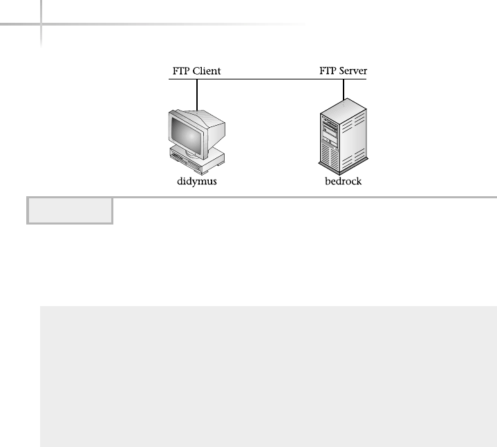
On the client side (didymus), the user invokes the FTP session to the
server (bedrock) using the standard UNIX ftp client program:
[root@didymus /]# ftp bedrock
Connected to bedrock (216.155.202.100).
220 bedrock FTP server (Eng Server) ready.
Name (bedrock:root): root
331 Password required for root.
Password:
230 User root logged in.
Remote system type is UNIX.
Using binary mode to transfer files.
ftp>
In the example above the ftp command includes the name of the FTP
server to access. Once the connection has been made, the server responds with
some server-side information to include the name of the server (for instance,
Connected to bedrock (216.155.202.100).) and a login prompt
(Name (bedrock:root):). At this point, it is up to the user, via the client
software, to provide authentication information (login name and password) to
gain access to the FTP server.
In the output above, the root account and associated password was used
to gain access to the FTP server. This demonstrates that the FTP server works
with the standard UNIX account login procedures. Typically, it you are going
to provide FTP over the Internet, you will set up an anonymous account access;
otherwise, you will need to create accounts for FTP only users.
536 UNIX System Administration: A Beginner’s Guide
Figure 18-1 Sample FTP session

18
NoteNote
By default, many UNIX systems permit users to access FTP services without
additional configuration or setup. Configuring anonymous access for FTP will be
discussed later in this module.
Once the user has been authenticated to the FTP server, it echoes a message
indicating the user has been logged in like the following:
230 User root logged in.
At this point, the FTP server indicates the type of system the server is
running on (Remote system type is UNIX.) and provides some additional
configuration information on the connection (Using binary mode to
transfer files.). The “binary mode” message indicates that any file
transfer will be done in such a way as to ensure that binary data is transferred
accurately.
Finally, the standard FTP server prompt is provided: ftp>, which indicates
the FTP client shell. This informs the user that the server is ready to accept FTP
commands. At the prompt, the user may list available FTP commands, obtain
a directory listing of either the remote or local current directories, get a remote
file from the server, or put a local file on the server. Some of these activities
depend on having certain privileges or configuration parameters set on the FTP
server side.
Obtaining a Directory Listing
The FTP service provides the ability to navigate the directories on the remote
FTP server using the dir FTP command. For example, the following output
shows this command:
ftp> dir
227 Entering Passive Mode (216,155,202,100,128,164)
150 ASCII data connection for /bin/ls (216.155.202.163,1048) (0 bytes).
total 28
drwxrwxr-x 7 root sys 512 Feb 2 13:37 .
drwxr-xr-x 32 root root 1024 Apr 19 12:39 ..
drwxr-xr-x 6 root sys 512 Nov 11 16:37 SUNWebnfs
Module 18: File Transfer Protocol 537
18

538 UNIX System Administration: A Beginner’s Guide
drwxrwxr-x 3 bin bin 512 Nov 11 16:11 SUNWits
drwxr-xr-x 3 root 1 512 Feb 2 13:37 answerbooks
drwx------ 2 root root 8192 Nov 11 16:00 lost+found
drwxr-xr-x 20 root sys 512 Jan 24 23:20 sfw
-r--r--r-- 1 root 1 916 Apr 20 17:09 xtrace
-r--r--r-- 1 root 1 1016 Apr 20 15:10 yellow
226 ASCII Transfer complete.
ftp>
The output generated is from the /bin/ls command; thus, this file listing
should be familiar to the reader at this point. The ftp client program supports
wildcard matching and other regular expressions characters such as “[]“, “*“,
and “?“.The dir command can be combined with UNIX expressions to list
only certain files and/or directories. Thus, the command
ftp> dir SUN*
will yield the following output, which is based on the directory listing from above:
227 Entering Passive Mode (216,155,202,100,128,172)
150 ASCII data connection for /bin/ls (216.155.202.163,1049) (0 bytes).
SUNWebnfs:
total 524
drwxr-xr-x 6 root sys 512 Nov 11 16:37 .
drwxrwxr-x 7 root sys 512 Feb 2 13:37 ..
drwxr-xr-x 4 root sys 512 Nov 11 16:37 JFileChooser-patch
drwxr-xr-x 4 root sys 512 Nov 11 16:37 demos
drwxr-xr-x 3 root sys 512 Nov 11 16:37 javadoc
drwxr-xr-x 2 root sys 512 Nov 11 16:37 sample
-rw-r--r-- 1 root sys 122052 May 28 1999 webnfs.zip
-rw-r--r-- 1 root sys 121613 May 28 1999 xfilechooser.jar
SUNWits:
total 6
drwxrwxr-x 3 bin bin 512 Nov 11 16:11 .
drwxrwxr-x 7 root sys 512 Feb 2 13:37 ..
drwxrwxr-x 3 bin bin 512 Nov 11 16:11 Graphics-sw
226 ASCII Transfer complete.
ftp>
As you can see, the contents of the directories named SUNWebnfs and
SUNWits were listed. In addition, other expressions are supported, such as
listing just certain files using file range name matching. The command
ftp> dir [x-y]*

Module 18: File Transfer Protocol 539
18
will show only those files (or any directories) that start with xthrough y
characters:
227 Entering Passive Mode (216,155,202,100,128,184)
150 ASCII data connection for /bin/ls (216.155.202.163,1061) (0 bytes).
-r--r--r-- 1 root 1 916 Apr 20 17:09 xtrace
-r--r--r-- 1 root 1 1016 Apr 20 15:10 yellow
226 ASCII Transfer complete.
ftp>
In this case, both the xtrace and yellow files were listed. The “?“ character
is used to match a single character within a filename.
Configuration Options
The FTP client application in conjunction with the remote FTP service can
negotiate certain file transfer options or configuration parameters. For example,
the client can request that a file transfer should be done in binary mode versus
text (ASCII) mode. Binary mode file transfer means that the contents of a file
are sent to the remote server without any conversion of characters. This mode
is also called raw or image mode, and is used to transfer files that contain
programs or other files that must not be converted to the ASCII character set.
By default, most FTP servers configure the connection to support ASCII
transfer mode. Thus, to set the connection to binary mode, use the binary
command:
ftp> binary
Once executed, the ftp client issues a response indicating that its transfer
mode is now image:
200 Type set to I.
To go back to ASCII mode, use the ascii command.
Retrieving a File
When obtaining or retrieving files from the server, it is helpful to think of the server
as the “remote” end of the FTP connection, while the client side is the “local”
end. In our example above, the remote end is bedrock, while the local end is

540 UNIX System Administration: A Beginner’s Guide
didymus. With FTP, to transfer a file from the remote end to the local end,
you would use the get FTP command. Thus, to transfer the file yellow from
the bedrock server to the local system, use the following command while in the
FTP shell:
ftp> get yellow
The client session will show the following:
227 Entering Passive Mode (216,155,202,100,128,206)
150 ASCII data connection for yellow (216.155.202.163,1047) (916 bytes).
226 ASCII Transfer complete.
938 bytes received in 0.000418 secs (2.2e+03 Kbytes/sec)
ftp>
As you can see, the output includes the name of the file, the size of the file,
and the amount of time it took to transfer the contents of the file. Also, the
relative network performance was shown.
To verify that the file was actually transferred, inspect the local system by
using the !ls –l yellow command. The !(bang) character is supported
on many UNIX FTP client programs, which permits the execution of a local
command (in this case, the ls –l command, which lists files and/or directories).
Thus, when this command is run within the FTP client shell, and when no
errors were generated during the file transfer, the following should be displayed:
-rw-r--r-- 1 root root 916 Apr 25 02:03 yellow
NoteNote
The byte counts for the file yellow match the number of bytes transferred with
the FTP program.
Sending a File
To send a local file to the remote host, use the put FTP command. Thus,
to place a new file called steve.dat onto the bedrock system, use the
following command:
ftp> put steve.dat
TEAMFLY
Team-Fly®

18
When the command is executed, the following is displayed by the client
program:
local: steve.dat remote: steve.dat
227 Entering Passive Mode (216,155,202,100,128,208)
150 ASCII data connection for steve.dat (216.155.202.163,1050).
226 Transfer complete.
18396 bytes sent in 0.0124 secs (1.5e+03 Kbytes/sec)
ftp>
Again, much of the same information is shown as in the previous transfer
example. To verify the file was sent (which, in most cases, is not necessary),
use the dir command with the filename:
ftp> dir steve.dat
227 Entering Passive Mode (216,155,202,100,128,210)
150 ASCII data connection for /bin/ls (216.155.202.163,1052) (0 bytes).
-rw-r--r-- 1 root 1 17884 Apr 24 15:23 steve.dat
226 ASCII Transfer complete.
ftp>
As you can see, the file is listed on the remote end, confirming the transfer.
Monitoring File Transfers
When transferring very large files, it is hard to determine if the transfer is
progressing or has stopped for some reason. As a result, most FTP clients
support the hash command. When enabled, the hash command tells the FTP
client to echo a “#“ character every time a block of information was successfully
retrieved. For example, the command
ftp> hash
shows the following:
Hash mark printing on (1024 bytes/hash mark).
Thus, when each chunk of the file is transferred, a new pound sign is displayed.
Here is what will be shown when a file called records.dat is transferred:
ftp> put record.dat
local: record.dat remote: record.dat
Module 18: File Transfer Protocol 541
18

542 UNIX System Administration: A Beginner’s Guide
227 Entering Passive Mode (216,155,202,100,128,213)
150 ASCII data connection for record.dat (216.155.202.163,1055).
############################################################################
############################################################################
############################################################################
######
226 Transfer complete.
240902 bytes sent in 0.257 secs (9.1e+02 Kbytes/sec
Due to the size of the file, a number of hash characters were displayed—thus
providing a visual way to see the FTP activity. Use the byte command to close
the FTP session. This logs you off the server and exits the FTP client program.
18.2 Discover FTP Commands
The FTP facility supports a large number of commands. However, the most
important and popular ones are listed and described in Table 18-1. Note, too,
that some of the listed commands may or may not be supported on either the
FTP client or server end. Typing the “?“ (or help) command will provide a list
FTP Command Description
ascii Enable ASCII transfer mode; this mode is used to copy regular
text files.
binary Enable binary transfer mode; this is used to copy programs and
other data files—for example, tar or gzip archive files.
bye Log off the FTP server.
cd Change working directory.
chmod Change the mode of a file or directory.
close Close the FTP session.
delete Delete a file or directory.
debug Enable debug mode, which will display more information about
each transaction.
dir Display the current directory listing or individual file.
exit Same as bye.
get Transfer a file from the remote server to the local client.
glob Enable specific character matching for files and directories.
Table 18-1 Command FTP Commands

18
of supported commands for the client side, but these may not all be available on
the server side.
18.3 Controlling FTP Access
On the FTP server, the /etc/ftpusers file can be used to control access to
the FTP server.
NoteNote
On Linux, this file is replaced by the /etc/ftpaccess configuration file.
On Solaris, by default, the file contains the following entries:
●daemon
●bin
Module 18: File Transfer Protocol 543
18
FTP Command Description
hash Enable hash mode; displays a # character for each 8K block of
data that has been transferred.
help Display a list of FTP commands.
image Same as binary command.
lcd Change working directory on local client system.
ls Like dir command.
mdelete Delete multiple files and directories.
mget Transfer multiple files from the remote server to the local client.
mput Transfer multiple files from the client to the server.
open Open a new FTP session.
prompt Toggle the prompting of confirmation before transfer begins.
When enabled, it will prompt for each file before transfer begins.
pwd Print the working directory.
quit Same as bye.
rmdir Remove a directory on the server side.
send Same as put.
status Show the FTP session status.
verbose Display additional information for each transaction (like debug,
but not as much information).
Table 18-1 Command FTP Commands (continued)

●sys
●adm
●lp
●uucp
●nuucp
●listen
●nobody
●noaccess
●nobody4
Each of the login names defined within this file is blocked from using the
FTP facility. Note that each name is on a separate line by itself and there is no
special ordering—the file is simply processed from beginning to end whenever
a user accesses the FTP server. If a user that is listed within this file attempts
to access the FTP server, they get a login incorrect message. When a
change is made to the /etc/ftpuser file, it takes effect immediately and no
additional steps are necessary to restrict users.
When the wu-ftpd server is deployed, the /etc/ftpaccess file can be
used to replace the function of the /etc/ftpusers file. Also, the /etc/
ftpaccess provides additional configuration options as well. The wu-ftpd
server comes standard with Linux. The /etc/ftpaccess configuration file
can be used to control the following:
●Access to the FTP server
●Which command a user may execute
●The logging of FTP access
●General FTP configuration
The default entries for this file are shown here:
# This file controls the behavior of the wu-ftpd
# ftp server.
544 UNIX System Administration: A Beginner’s Guide

Module 18: File Transfer Protocol 545
18
#
# If you're looking for a graphical frontend to
# editing it, try kwuftpd from the kdeadmin
# package.
# Don't allow system accounts to log in over ftp
#deny-uid %-99 %65534-
#deny-gid %-99 %65534-
allow-uid ftp
allow-gid ftp
# The ftpchroot group doesn't exist by default, this
# entry is just supplied as an example.
# To chroot a user, modify the line below or create
# the ftpchroot group and add the user to it.
#
# You will need to setup the required applications
# and libraries in the root directory (set using
# guest-root).
#
# Look at the anonftp package for the files you'll need.
guestgroup ftpchroot
# User classes...
class all real,guest,anonymous *
# Set this to your email address
email root@localhost
# Allow 5 mistyped passwords
loginfails 5
# Notify the users of README files at login and when
# changing to a different directory
readme README* login
readme README* cwd=*
# Messages displayed to the user
message /welcome.msg login
message .message cwd=*
# Allow on-the-fly compression and tarring
compress yes all
tar yes all

546 UNIX System Administration: A Beginner’s Guide
# Prevent anonymous users (and partially guest users)
# from executing dangerous commands
chmod no guest,anonymous
delete no anonymous
overwrite no anonymous
rename no anonymous
# Turn on logging to /var/log/xferlog
log transfers anonymous,guest,real inbound,outbound
# If /etc/shutmsg exists, don't allow logins
# see ftpshut man page
shutdown /etc/shutmsg
# Ask users to use their email address as anonymous
# password
passwd-check rfc822 warn
18.4 Configure Anonymous FTP
On the Internet, many sites offer free FTP access to the public; this is known
as anonymous FTP. Basically, anyone can log in an FTP service using a generic
login and password. This type of access can be dangerous, since you really don’t
know the true identity of the user accessing the server.
Here is an anonymous login session using the "ftp.cisco.com" server:
# ftp ftp.cisco.com
Connected to ftp.cisco.com.
220-
220- Cisco Connection Online | | Cisco Systems, Inc.
220- Email: cco-team@cisco.com ||| ||| 170 West Tasman Drive
220- Phone: +1.800.553.2447 .:|||||:..:|||||:. San Jose, CA 95134
220-
220- You may login with:
220- + Your CCO username and password, or
220- + A special access code followed by your e-mail address, or
220- + "anonymous" followed by your e-mail address for guest access.
220-
220-
220 ftp-poc-2 FTP server (CIOESD #422 Wed May 1 14:15:23 PDT 2002) ready.

Module 18: File Transfer Protocol 547
18
At this point, the anonymous username is entered and the FTP server responds
with the standard password which is typical of the e-mail address of the user:
User (ftp.cisco.com:(none)): anonymous
331 Guest login ok, send your complete e-mail address as password.
Password:
If the login name and password are accepted, the FTP server grants access to
the system, and displays a welcome message.
NoteNote
Not all FTP servers display these types of informative messages.
230- <======[+]> FTP.CISCO.COM <[+]=======>
230-
230-Welcome to the Cisco Systems CCO FTP server.
230-
230-Local time is currently Wed May 8 23:03:09 2002.
230-
230-There are currently 20 users out of 120 maximum logged in.
230-
230-This server has a number of restrictions. If you are not familiar
230-with these, please first get and read the /README or /README.TXT file.
230-
230-If you have any odd problems, try logging in with a minus sign (-) as
230-the first character of your password. This will turn off a feature that
230-may be confusing your ftp client program.
230-
230-Please send any questions, comments, or problem reports about this
230-server to cco-team@cisco.com.
230-
230-You are logged in with guest (anonymous) level access.
230-
230-
230-Please read the file README
230- it was last modified on Mon Jul 5 21:31:32 1999 - 1037 days ago
230 Guest login ok, access restrictions apply.
Once logged into the system, you can retrieve or place files according to the
corresponding site permissions and/or directory structure.

Setting Up Anonymous Access
Configuring anonymous FTP access on a server is a fairly straightforward
process. However, having said that, care must be taken to ensure that every
step is executed correctly and that no configuration-related problems result.
NoteNote
Providing anonymous FTP on the Internet or even locally can be a potential security
risk. The risk is even compounded when the configuration is not complete or has
not been done correctly. One good way to minimize problems is to have other
knowledgeable people help test the final configuration before going live. Also,
continuously consult the relevant security web sites (such as www.cert.org) about
FTP security issues and problems. Using these approaches, you may help to reduce
the number of problems that would-be hackers might exploit.
The basic process for anonymous account setup includes the following:
1. Create the FTP login in the /etc/passwd and /etc/shadow files.
2. Make sure the FTP account name does not appear in the /etc/
ftpusers file.
3. Set up the required FTP environment.
4. Test the account.
Some of the above procedure need not be executed manually. For example,
the setup of the FTP environment can be done with an automated script. On
Solaris, the ftpd manual (that is, man ftpd) gives a listing of a script to handle
all the required steps. Just copy this output and save it to a file for execution.
Other operating systems such as Linux provide a list of steps via the ftpd man
page and provide an RPM (anonftp-4.0.9.i386.sp) to handle the details
of setting up the correct configuration.
Once the anonymous account and configuration has been set up, test the
account to ensure that basic FTP services are functional and work as expected
(such as retrieving files). Next, make sure that the anonymous user can’t do
things such as remove system files or execute unauthorized commands. Finally,
monitor the FTP log file for any suspicious activities, such as a larger number of
requests for login within a short period of time. This could indicate that someone
548 UNIX System Administration: A Beginner’s Guide

Module 18: File Transfer Protocol 549
18
is attempting to log in to the server using a program or script, which may
indicate an attempted denial service attack being done against your server.
18.5 Log FTP Activity
One important aspect of system administration is keeping track of activity on
your systems. That is why, for example, critical services like FTP should be
monitored on a continued basis. As a result, FTP activity should be logged to
a special file so that later inspection and monitoring can be done in the most
efficient manner. Most of the available FTP servers support robust logging
facilities. In particular, the ability to monitor each FTP session is important.
Also, some FTP servers (for example, the Linux wu-ftpd server) provide a
way to view each FTP command executed by a FTP user. With this capability,
it becomes much easier to identify possible nonfriendly behavior toward your
FTP services.
To activate FTP logging, the following will need to be done:
1. Enable FTP server logging.
2. Enable logging via the syslog facility.
3. Test that logging is functional.
Enable FTP logging
To activate FTP logging, the proper command-line argument(s) must be supplied
to the FTP server process when it is invoked by the system. For example, on
Solaris, the in.ftpd FTP server supports the –l option, which tells the server
to record every active session when a user logs into the FTP server. Typically,
the FTP server will send this monitoring information to the general-purpose
system logging process via the syslogd process. See below for additional
details about syslog logging facility.
To enable logging on Solaris and HP-UX, edit the /etc/inetd.conf
network services configuration file and modify the in.ftpd entry. For
example, the default FTP entry on Solaris contains the following:
ftp stream tcp6 nowait root /usr/sbin/in.ftpd in.ftpd

550 UNIX System Administration: A Beginner’s Guide
In order to have logging, place a –l option in front of the in.ftpd command.
Thus, the new entry should be
ftp stream tcp6 nowait root /usr/sbin/in.ftpdin.ftpd –l
In order for this change to take effect, the inetd process must be told to reread
its configuration file. Thus, to find the process identification of the inetd
process, issue the following command:
ps -ef | grep inetd | grep -v grep
This will show
root 209 1 0 14:48:39 ? 0:00 /usr/sbin/inetd –s
Then, when you have the process ID, issue the following:
kill -SIGHUP 209
Thus, any changes made to the inetd.conf file should now be active.
To activate logging on Linux, edit the /etc/xinetd.d/wu-ftpd
configuration file and alter the relevant line as shown here:
server_args = -a
NoteNote
Depending on the version of Linux you have, the –l option may already be in this
file. If that is the case, you are all set for session logging. However, if you want
more detailed logging in addition to session logging, add the –L option. The –L
option will provide logging for each FTP command that is typed by the user after
they log into the server. Thus, the new wu-ftpd configuration should be as follows:
server_args = -a –l –L
In order for this change to take effect, the xinetd process must be told to reread
its configuration file. Thus, to find the process identification of the xinetd process,
issue the following command:
ps -ef | grep inetd | grep -v grep
TEAMFLY
Team-Fly®

Module 18: File Transfer Protocol 551
18
NoteNote
The Linux xinetd program requires the SIGUSR2 signal to be issued to reread its
configuration file.
Then, determine the process identification and supply it on the command
line as shown here:
kill –SIGUSR2 [pid]
Enable the syslog Facility
Now that the FTP servers are configured to log activity, we need to set up the
system to support FTP activity from a syslog facility point of view. This is
because the FTP servers will forward logging information onto syslog
automatically, but unless we set up the syslog configuration to specifically
process FTP messages, we may not see the logging output.
The syslog logging facility is a general-purpose log aggregator, which
funnels messages from many different operating system components on to
small number of log files, with both the component name and time stamp
information included. For example, a typical FTP session message might
include the following:
Apr 17 14:55:46 bedrock in.ftpd[605]: [ID 373804 daemon.info] connection
from didymus.home.com at Wed Apr 17 14:55:46 2002
The syslog server (syslogd) handles the processing of messages that
have been sent by other programs; in the example above, the message was sent
by the in.ftpd server. As you can see from the message, the relevant information
includes the date and time that the transaction was initiated and also the
systems involved.
The syslogd process uses the /etc/syslog.conf configuration file
for how to funnel messages. The logging of messages is divided into different
categories and levels depending on the type of message and associated severity.
Table 18-2 shows the logging categories and their associated meanings.
The syslog facility includes severity or levels of priority for each category;
these range from emergency (emerg) to debug (debug), and can be thought
of as the type of message. For example, the emerg category is used to denote
very critical panic types of conditions, which informs the administrator of some
important event. Additional types include alert for situations that should be

552 UNIX System Administration: A Beginner’s Guide
corrected immediately; crit for warnings about important conditions, such
as hardware errors; err for other types of errors, and warning messages
about important problems; notice messages that reflect an important
situation, but may require special handling; info, which are information
types of messages; debug messages that represent debug information within
a program; and none messages, where no types of messages are sent.
To make it easier to identify FTP and other related activities with the
logging facility, group FTP server (and related daemon processes) messages
into a single file. For example, the syslog.conf file, which has been
configured to capture FTP transactions, can include the following:
daemon.notice /var/adm/services
daemon.info /var/adm/services
In this case, the /var/log/services file is used to store messages that
come from the daemon message category, using both notice and info
messages types. To verify that messages are flowing to this file, access the FTP
server from another client and then inspect the file for log activity. Thus, the
command
grep ftp /var/log/services
Category Meaning
auth Messages related to system authorization from such programs as
login, su, and getty. (getty is used on Solaris and HP-UX, and
agetty is used on Linux.)
cron Messages related to cron or at services from such programs crontab,
at, and cron.
daemon Messages related to server processes in.ftpd and in.dhcpd.
kern Messages generated by the kernel
lpr Messages generated by the printer spooler system from programs as
lpr,lpc, and lpd.
mail Messages related to the mail system.
news Messages related to the news system.
local0-7 Message levels for custom applications.
uucp Messages related to the uucp system.
Table 18-2 Syslog Message Categories

Module 18: File Transfer Protocol 553
18
will show lines containing FTP transactions, like the following:
May 11 14:51:07 bedrock in.ftpd[1395]: [ID 373804 daemon.info]
connection from socs.home.com at Sat May 11 14:51:07 2002
May 11 14:56:00 bedrock in.ftpd[1399]: [ID 373804 daemon.info]
connection from socs.home.com at Sat May 11 14:56:00 2002
May 11 14:56:28 bedrock in.ftpd[1402]: [ID 373804 daemon.info]
connection from socs.home.com at Sat May 11 14:56:28 2002
May 11 15:18:28 bedrock in.ftpd[1453]: [ID 373804 daemon.info]
connection from socs.home.com at Sat May 11 15:18:28 2002
May 11 15:23:00 bedrock in.ftpd[1461]: [ID 373804 daemon.info]
connection from socs.home.com at Sat May 11 15:23:00 2002
May 11 15:23:11 bedrock in.ftpd[1464]: [ID 373804 daemon.info]
connection from bedrock.home.com at Sat May 11 15:23:11 2002
May 11 15:38:11 bedrock in.ftpd[1464]: [ID 639925 daemon.info]
User unknown timed out after 900 seconds at Sat May 11 15:38:11 2002
Project 18-1
This project will help you check your FTP server configuration and also help you
make sure it is current with the latest versions and security patches.
Step-by-Step
1. Is there an FTP server currently running on your system? To check, do:
# ps -ef | grep ftp
2. If you don’t want FTP running on this system, comment out or remove the
FTP line in /etc/inetd.conf so that it won’t run the next time you restart
the system.
3. If there is an FTP server running, check to see if anonymous access is enabled
by using another system and attempting to FTP anonymously to your system.
4. If anonymous FTP access is enabled and you don’t want it to be, add
ftp
on a line by itself in the /etc/ftpusers file (or in the /etc/ftpaccess
file in Linux).
5. If you are using the FTP server supplied with your operating system, check
your operating system’s vendor’s Web site to ensure you have the latest
version and patches. If you have installed a different FTP server, such as
wu-ftpd, check frequently for updates and check security sites for new
vulnerabilities you need to patch for.

554 UNIX System Administration: A Beginner’s Guide
Mastery Check
1. What type of FTP server access allows access without requiring
a specific account?
2. What is the FTP command syntax to list the files and directories
that start with the letters J-M?
3. What FTP command do you use to send a file from a client to an
FTP server?
A. send
B. get
C. put
D. ascii
4. The __________ command tells the FTP client to echo a "#" character
every time a block of information was successfully retrieved.
5. What is the purpose of each entry in the Solaris /etc/ftpusers file?
A. Grant access to that user
B. Deny access to that user
C. Define that user’s account
D. Define user groups
6. With the wu-ftpd server, what configuration file controls access to the
FTP server, determines commands a user may execute, and specifies FTP
access logging?
7. What does the -l entry at the end of this Solaris /etc/inetd.conf
network services configuration file do?
ftp stream tcp6 nowait root /usr/sbin/in.ftpd
in.ftpd –l
8. What syslog category do login messages belong to?

Module19
Important System
Administration
Tasks/Information
Critical Skills
19.1 Communicate with Users on the System
19.2 Increase System Swap Space
19.3 Control Root Access
19.4 Display System Configuration Information
Copyright 2002 by The McGraw-Hill Companies, Inc. Click Here for Terms of Use.

Unlike many of the other modules contained within this book that focus on
a specific topic or area, this module provides solutions to specific UNIX
system tasks and administrative problems.
19.1 Communicate with Users
on the System
As the system administrator, you will need to, on occasion, communicate
with users on the system, using the talk,wall, or write commands. The
talk command provides a visual mechanism to “talk” to a single user,
the wall command can send a message to a number of users at once,
and the write command can also be used to talk to an individual user,
using line-by-line mode.
The talk syntax includes
talk user [@hostname]
where user is an existing UNIX user currently logged into the system. If user
is on a different system as compared to local originator, the user’s hostname
must be specified.
Assuming the root user would like to talk with the user billc that is
currently on the local system, the following command would be used:
talk billc
Once this command has been executed, the following will be displayed:
[Waiting for your party to respond]
_______________________________________________________________________
The command clears the screen and places a line in the middle of display to
divide the screen. The top portion is use to contain the text that root will send
to billc, while the bottom part is for billc’s responses to root.
On billc’s terminal, the following is displayed:
Message from Talk_Daemon@socrates at 11:27 ...
talk: connection requested by root@socrates.
talk: respond with: talk root@socrates
556 UNIX System Administration: A Beginner’s Guide

Module 19: Important System Administration Tasks/Information 557
19
Once billc responds using the above comand, his screen is updated and
the message [Connection established] is displayed to indicate that
communication is now possible.
Here is what the root’s screen will look like when the question is asked
“How are you?”
How are you?
_______________________________________________________________________
Bill responds with:
I'm fine! and you?
_______________________________________________________________________
NoteNote
Either party may close the talk session by issuing a control-c (^-c).
To communicate to all users on the system at the same time, use the wall
command. For example, the command
wall –a
system needs to be rebooted; back in 20 minutes....
(^d)
The administrator types the above message after the wall command,
followed by control-c (^-c).
The –a option tells wall to send the message to all users attached via
pseudo-terminals and to the system console. When this command is run, the
following will be displayed to all users logging in:
Broadcast Message from root (pts/8) on bedrock Mon May 27 19:40:55...
system needs to be rebooted; back in 20 minutes....
NoteNote
You must end the wall command with a CONTROL-d (^D) to tell the command
you entered the desired message.
Issue Control D to end the wall session.

558 UNIX System Administration: A Beginner’s Guide
19.2 Increase System Swap Space
A file system or swap file represents a location on a disk drive that is used to
support swap space and other important temporary storage functions for UNIX.
In many instances, the swap area was defined when the system was first installed
and configured. It is quite common for the system administrator to increase the
amount of swap space for a system after it has been set up. In fact, sometimes
the sizing of critical resources like swap space are much more accurate only
after the system has been deployed and is actively being used.
For most versions of UNIX, the requirements for swap space are the same;
the versions discussed all require a minimum amount of space for the system
to operate. The actual size of the swap area is highly dependent on the number
of users of the system and the actual services or applications being supported.
Also, the tools used to manage swap space are somewhat different. Table 19-1
shows the relevant swap management commands for each operating system.
List Swap Space
It is important to know how much swap space is actually being used. Use either
the swapon command for Linux or the swap command for Solaris. For HP-UX,
use the swapinfo command. Each of these commands will show information
about how much space has been defined on the system and any associated use.
For example, the Solaris swap command will show the following when used
with the –s option:
total: 39488k bytes allocated + 12520k reserved = 52008k used,
1062656k available
Function Linux Solaris HP-UX
Add swap space swapon -a swap swapon -a
Create swap area using
a regular file
mkswap mkfile
List swap usage swapon -s swap -l swapinfo -ta
Delete swap area swapoff swap -d
Table 19-1 UNIX Swap Commands
Total kbytes swap space currently used
Total kbytes space configured as swap space

This shows the total amount of swap space currently used on the system—in
this case, 52,008K (or 52008000 bytes). The total amount of configured swap on
the system is 1,062,656K. When the used space approaches the total amount of
available space on the system, it is time to increase the amount of swap space. Also,
it is not uncommon to increase swap space even if the currently used space is quite
a bit smaller than that available—perhaps because the system administrator wants
additional performance gains, one or more additional drives are configured to
support swapping. In this way, the swap activities are spread across additional
physical disk drive, thereby increasing system performance.
Using the swapon -s command on Linux shows the available and swap
space sizes:
Filename Type Size Used Priority
/dev/hda5 partition 740840 14048 -1
Add More Swap Space
To add more space to the system, use either the swapon or swap commands,
depending on the system in question. Adding more swap space can be
accomplished by increasing the size of the current swap area or by adding an
additional swap file or disk partition. In general, the installation procedures for
most UNIX systems describe implementing swap space using a separate disk
partition. For example, given the snippet of the /etc/fstab file from a Linux
system, we see the following:
none /proc proc defaults 0 0
none /dev/shm tmpfs defaults 0 0
none /dev/pts devpts gid=5,mode=620 0 0
/dev/hda5 swap swap defaults 0 0
bedrock:/docs /mnt/bedrock/docs nfs bg,hard 0 0
bedrock:/usr /mnt/bedrock/usr nfs bg,soft 0 0
The swap partition is defined by /dev/hda5, and it is possible to use
tools such as fdisk (for Linux, for instance) to increase the size of the
partition, assuming that extra unused space is available on the disk.
Another approach to increasing the swap space is to define another partition
that should be used for swap and simply add the partition to the mounted file
Module 19: Important System Administration Tasks/Information 559
19
HintHint
The system should be placed in single-user mode when attempting to adjust
the size of the swap partition; this precaution should be standard procedure
for making critical types of changes to the system.

560 UNIX System Administration: A Beginner’s Guide
system table, such as /etc/vfstab (Solaris). Using this approach, the system
would need to be rebooted before the new swap area could be used. On the other
hand, if you want to use the space without rebooting the system, use the swap
command. For example, assume that you would like to use the /dev/dsk/
c0d0s0 partition for swapping. Thus, this command (on Solaris) could be used:
# swap -a /dev/dsk/c0d0s0
When the swap –l command is run, it shows the total mount of swap space
allocated and used, and we see additional swap has been added to the system:
swapfile dev swaplo blocks free
/dev/dsk/c0d0s3 102,3 8 2048248 2048248
/dev/dsk/c0d0s7 102,7 8 4194288 4194288
The final approach to increasing swap space is to create a simple UNIX file
using the mkfile (on Solaris) command, which creates a file the size of the
swap space that is needed. Once this has been done, issue the swap command
with the file as the argument instead of the disk partition.
19.3 Control Root Access
Most versions of UNIX have a mechanism to control when the root user can
access the system from the network versus just from the system console. For
example, by default, it is not possible for the root user to access a Solaris
system over the network when first installed. In other words, when attempting
to telnet to a Solaris system and log in as root, this account is blocked. Why?
Well, there are those who believe that accessing the root account over the
network represents a security concern. There are a few ways to handle this
problem. First, one solution is to install the SSH package and use the ssh
program to provide remote connectivity for root access. Second, connect the
system to a terminal server and access the console over the network as supported
by the terminal server. Third, enable root access to the system over the network
by modifying the /etc/default/login file. This file contains a single-line
parameter that controls if root can access non-console ports.
A portion of this file is shown here:
# If CONSOLE is set, root can only login on that device.
# Comment this line out to allow remote login by root.
#
CONSOLE=/dev/console
New swap allocated
TEAMFLY
Team-Fly®

19
As you can see from the comments, the CONSOLE variable should be
commented out with a #character, should the administrator desire to enable
remote login for the root user.
19.4 Display System
Configuration Information
Sometimes, when attempting to debug system problems or if it is necessary to
determine a specific software version and/or other system information, it will
be necessary use one or more system tools. Also, with many newer versions of
UNIX, the /proc file system has been introduced, which makes it very easy
to probe the system for a host of configuration and operating information.
On Solaris, the prtconf tool can be used, which provides both low-level and
operating system configuration information. When the tool is run without any
command-line arguments, the following is produced:
System Configuration: Sun Microsystems i86pc
Memory size: 128 Megabytes
System Peripherals (Software Nodes):
i86pc
+boot (driver not attached)
memory (driver not attached)
aliases (driver not attached)
chosen (driver not attached)
i86pc-memory (driver not attached)
i86pc-mmu (driver not attached)
openprom (driver not attached)
options, instance #0
packages (driver not attached)
delayed-writes (driver not attached)
itu-props (driver not attached)
isa, instance #0
motherboard (driver not attached)
asy, instance #0 (driver not attached)
lp (driver not attached)
asy, instance #1 (driver not attached)
fdc, instance #0
fd, instance #0
fd, instance #1 (driver not attached)
i8042, instance #0
Module 19: Important System Administration Tasks/Information 561
19
System Info. (system
architecture and memory)

keyboard, instance #0
mouse, instance #0
bios (driver not attached)
bios (driver not attached)
pci, instance #0
pci8086,7190 (driver not attached)
pci8086,7191, instance #0
display, instance #0
pci8086,7110 (driver not attached)
pci-ide, instance #0
ide, instance #0
cmdk, instance #0
ide, instance #1
sd, instance #0
pci8086,7112, instance #0
pci8086,7113 (driver not attached)
pci10b7,9050, instance #1
used-resources (driver not attached)
objmgr, instance #0
cpu, instance #0 (driver not attached)
pseudo, instance #0
Not all the information generated from this command is really useful.
However, the command does provide some general information about the system
architecture and installed memory, and detailed information about the number
of different devices installed on the system. In general, the message “driver not
attached” indicates that no device was found and thus no driver was loaded to
handle the hardware component. The prtconf tool provides a fair number of
command-line options, but only the most common options are listed in Table 19-2.
562 UNIX System Administration: A Beginner’s Guide
Command Option Description
-B Shows device driver information.
-F Shows frame buffer information.
-v Enables verbose mode.
Table 19-2 prtconf Command-Line Options

Another very useful Solaris command is showrev. This is the output of
this command:
Hostname: bedrock
Hostid: 1e056f4b
Release: 5.8
Kernel architecture: i86pc
Application architecture: i386
Hardware provider:
Domain: home.com
Kernel version: SunOS 5.8 Generic 108529-07 February 2001
As seen from the output, this command provides some useful information
about the system. In addition, one very good command-line option with this
command is –c. This instructs the command to list detailed version information
about a particular UNIX command when specified. For example, the command
showrev -c ls
shows the following:
PATH is:
/usr/sbin:/usr/bin:/usr/dt/bin:/usr/openwin/bin:/bin:/usr/ucb
PWD is:
/
LD_LIBRARY_PATH is not set in the current environment
________________________________________________________________________
File: /usr/bin/ls
=================
File type: ELF 32-bit LSB executable 80386 Version 1, dynamically linked, stripped
Command version: SunOS 5.8 Generic February 2000
File mode: r-xr-xr-x
User owning file: root
Group owning file: bin
Library information:
libc.so.1 => /usr/lib/libc.so.1
libdl.so.1 => /usr/lib/libdl.so.1
Sum: 43151
________________________________________________________________________
File: /bin/ls
=============
File type: ELF 32-bit LSB executable 80386 Version 1, dynamically linked, stripped
Command version: SunOS 5.8 Generic February 2000
File mode: r-xr-xr-x
User owning file: root
Group owning file: bin
Library information:
libc.so.1 => /usr/lib/libc.so.1
Module 19: Important System Administration Tasks/Information 563
19
Determine information about a UNIX command.

564 UNIX System Administration: A Beginner’s Guide
libdl.so.1 => /usr/lib/libdl.so.1
Sum: 43151
________________________________________________________________________
File: /usr/ucb/ls
=================
File type: ELF 32-bit LSB executable 80386 Version 1, dynamically linked, stripped
Command version: SunOS 5.8 Generic February 2000
File mode: rwxr-xr-x
User owning file: root
Group owning file: bin
Library information:
libc.so.1 => /usr/lib/libc.so.1
libdl.so.1 => /usr/lib/libdl.so.1
Sum: 42882
________________________________________________________________________
This might be more information than most people want, but when tracking
down problems, having this kind of detail can be quite invaluable.
The /proc Directory
The /proc directory or file system is another very good way to obtain
important configuration and other information from the system. The /proc
directory is a tree hierarchy, which contains both additional subdirectories and
individual files that represent some aspect of the system or running process.
When the ls command is used to list the contents of the /proc file system
on Linux, you may see something like this:
1 1267 1456 1589 1662 512 680 922 ide mounts
1102 1268 1458 1593 1663 517 681 940 interrupts mtrr
1121 1269 1460 1622 1664 537 682 975 iomem net
1139 1270 1462 1624 1919 565 683 982 ioports partitions
1185 1271 1464 1629 1921 589 7 bus irq pci
12 1272 1466 1630 1923 6 710 cmdline kcore self
1214 1279 1469 1631 1924 664 8 cpuinfo kmsg slabinfo
1254 1280 1470 1632 2 669 87 devices ksyms stat
1255 1291 1471 1633 2077 674 880 dma loadavg swaps
1256 1417 1472 1654 2102 675 897 driver locks sys
1257 1419 1473 1655 2108 676 899 execdomains mdstat sysvipc
1258 1432 1474 1656 3 677 900 fb meminfo tty
1259 1450 1475 1657 4 678 901 filesystems misc uptime
1266 1454 1481 1658 5 679 902 fs modules version
Each number in this list corresponds to a
PID for a currently running process (which
you can see with the ps command)

Module 19: Important System Administration Tasks/Information 565
19
What is shown is a series of directories (for example, 1102), which represent
the currently running processes on the system. These are the directories that have
numbers as the names. Naturally, when you examine the /proc directory on your
system, you will see different directories. Other directories—such as mounts,for
instance—show specific system configurations
instead of running processes.
To see how the /proc directory can be
useful, let’s examine several examples The
directory 2120 represents a system process.
When we list the contents of this directory
using the ls –l command, we see the
following files:
total 0
dr-xr-xr-x 3 root root 0 May 16 11:37 .
dr-xr-xr-x 112 root root 0 May 16 01:16 ..
-r--r--r-- 1 root root 0 May 16 11:42 cmdline
lrwxrwxrwx 1 root root 0 May 16 11:42 cwd -> /etc/default
-r-------- 1 root root 0 May 16 11:42 environ
lrwxrwxrwx 1 root root 0 May 16 11:42 exe -> /bin/vi
dr-x------ 2 root root 0 May 16 11:42 fd
-r--r--r-- 1 root root 0 May 16 11:42 maps
-rw------- 1 root root 0 May 16 11:42 mem
lrwxrwxrwx 1 root root 0 May 16 11:42 root -> /
-r--r--r-- 1 root root 0 May 16 11:42 stat
-r--r--r-- 1 root root 0 May 16 11:42 statm
-r--r--r-- 1 root root 0 May 16 11:42 status
If we wanted to see which command was running, the cmdline command
can be examined. Thus, using the command
more cmdline
will show the following:
vi/etc/ftpusers
As shown, the process 2102 represents an edit session for the /etc/ftpuser
file. If it was necessary to validate this process, to really see what was running,
the ps command followed by the process ID (which in the case is 1102) could
be used.
HintHint
The /proc directory
on Solaris only shows
processes, not system
configuration files, like
other versions of UNIX.

Thus, the command
ps 1102
shows
PID TTY STAT TIME COMMAND
1102 pts/5 S 0:00 vi /etc/ftpusers
which is exactly what would be expected.
Additional information can be obtained about processes such as the shell
environment that the command has been run in, the status of the process,
and so on.
To view the process status, which is similar to what can be obtained with
the ps command, examine the status file.
This file contains the following:
Name: vi
State: S (sleeping)
Pid: 1102
PPid: 1923
TracerPid: 0
Uid: 0 0 0 0
Gid: 0 0 0 0
FDSize: 256
Groups: 0 1 2 3 4 6 10
VmSize: 2216 kB
VmLck: 0 kB
VmRSS: 968 kB
VmData: 208 kB
VmStk: 20 kB
VmExe: 332 kB
VmLib: 1364 kB
SigPnd: 0000000000000000
SigBlk: 0000000000000000
SigIgn: 8000000000003000
SigCgt: 000000004f804eff
CapInh: 0000000000000000
CapPrm: 00000000fffffeff
CapEff: 00000000fffffeff
566 UNIX System Administration: A Beginner’s Guide

As far as system configuration is concerned, the /proc directory provides
a generous amount of information. Table 19-3 lists some of the most useful
directories and/or filenames and their corresponding information. Note that
all versions of UNIX support each to the file or directories.
By way of example, the /proc file system can show some very interesting
information. For example, the interrupts file shows all the system’s devices
and their associated interrupt vectors:
CPU0
0: 1340342 XT-PIC timer
1: 525 XT-PIC keyboard
2: 0 XT-PIC cascade
3: 39351 XT-PIC 3c574_cs
5: 1904 XT-PIC usb-uhci, Allegro
8: 1 XT-PIC rtc
9: 0 XT-PIC Texas Instruments PCI1410 PC card Cardbus Controller
14: 40799 XT-PIC ide0
15: 293668 XT-PIC ide1
NMI: 0
ERR: 1
19
Module 19: Important System Administration Tasks/Information 567
HintHint
Many of the directories and files, with few exceptions, show a byte size greater
than 0; this is because these are not really normal directories or files in the
typical file system sense. Instead, they represent pointers to where specific
information is stored.
Directory/File Description
devices Shows a detailed list of all the installed devices.
ioports Contains a listing of all the memory vectors used by each
system device.
interrupts Shows the low-level device interrupts for the system.
meminfo Provides a detailed breakdown of system memory.
partitions Shows a detailed listing of the defined partition maps
on system.
swaps Shows swap information.
version Displays system version information.
Table 19-3 Subdirectories of the /proc Directory

Another example is the partitions file, which shows all the defined disk
partitions on the system:
major minor #blocks name rio rmerge rsect ruse wio wmerge wsect wuse running use aveq
3 0 5866560 hda 28345 16900 361900 461290 12600 22212 279128 1546840 0 520430 2008490
3 1 2562808 hda1801611000000110110
3 2 2562840 hda2 28162 15377 348354 454620 12388 19340 254456 1444150 0 517910 1899130
3 3 1hda300000000000
3 5 740848 hda5 172 1517 13512 6500 212 2872 24672 102690 0 14960 109190
Project 19-1
In this project you’ll familiarize yourself with your system and the toolbox of
commands presented in this module.
Step-by-Step
1. List your current swap space configuration and usage.
Linux:
# swapon -s
Solaris/HP-UX:
# swap -l
2. Check your /etc/default/login file. Unless you have a specific reason
to allow remote root access, ensure that the CONSOLE=/dev/console line
exists and is not commented out.
3. You may find it helpful to keep some basic system information handy in
printed form in case you ever have major system problems and need to
know, for example, your kernel version. Print the results of this command
and keep it in a safe place:
Solaris:
# showrev
For Linux users, this command will produce similar but less detailed results:
# uname -a
568 UNIX System Administration: A Beginner’s Guide

Module 19: Important System Administration Tasks/Information 569
19
4. Generate a list of your currently running processes:
# ps a
5. Show the contents of the /proc directory:
# ls /proc
Mastery Check
1. Which command can an admin use to communicate with all currently
logged in users at once?
a. talk
b. write
c. wall
d. email
2. Referring to the following output line, how much swap space is
currently used?
total: 39488k bytes allocated + 12520k reserved = 52008k used, 1062656k available
3. What is the Linux command to create a swap file?
a. mkswap
b. swapon
c. swapoff
d. mkfile
4. What Linux file system tool is useful in adjusting swap files?
5. On Solaris, the _________ tool can be used, which provides both low-level
and operating system configuration information.

570 UNIX System Administration: A Beginner’s Guide
6. Which command discussed in this module would have generated the
following line of output?
Kernel version: SunOS 5.8 Generic 108529-07 February 2001
a. prtconf
b. showrev
c. showrev -c
d. ls /proc
7. In the /proc directory, what do numbered subdirectories represent?
a. User IDs
b. Group IDs
c. Process IDs
d. Protocol IDs
8. The /proc/__________ directory shows a detailed listing of the defined
partition maps on the system.
Mastery Check
TEAMFLY
Team-Fly®

Module20
Using DHCP
Critical Skills
20.1 Use the Solaris DHCP Configuration Manager
20.2 Configure DHCP Clients
Copyright 2002 by The McGraw-Hill Companies, Inc. Click Here for Terms of Use.

572 UNIX System Administration: A Beginner’s Guide
The Dynamic Host Configuration Protocol (DHCP) is a facility that supports
Internet Protocol (IP) allocation and diskless boot capabilities to network
client systems. In both small and large organizations, DHCP is one of the best
ways to manage the corporate IP address space. This facility is responsible for
dynamically assigning addresses to client host systems as they are brought on
the network, thus making it much easier to manage connectivity to the corporate
network. DHCP can be used to support both local and remote systems that range
from dial-up to LAN-based connectivity. When configured, the DHCP server also
supports the BootP protocol, which means that client systems can obtain boot
information from the server. In certain situations, having clients boot from a
server can be both an effective and a cost-effective deployment strategy.
The DHCP service can be divided into two sections: the client and the server.
The client portion makes requests to a server for IP address information specific
to the local network to which the client is attached and network and/or booting
information or data. The client obtains network information by negotiation with
the server. For example, the server will determine how long the information can
be used on the network, thus placing an expiration date for client access. This is
known as a “lease”—the client can only use the information for a fixed period
of time. In practice, for generic LAN-based connectivity, the server is configured
to support an open-end lease—that is, one that really never expires.
The DHCP client component available on Solaris is known as dhcpagent
and is used to make requests from the network. The dhcpagent program has
been integrated with the ifconfig command. As you recall, ifconfig is
used to set up one or more network interfaces on the local system. Thus, when
the system normally boots, the appropriate network information is obtained
from a DHCP server (via the ifconfig command) and then the system
continues to boot normally.
Because DHCP support is available on a wide variety of systems, any
compatible DHCP client can request services from the DHCP server.
For example, a Windows system that has been configured to request an
IP address from the network can be supported using the Solaris DHCP server.
The server component consists of several different modules: the server
process, a configuration file, and the configuration manager. The server process
receives DHCP/BootP requests from the network and emits responses back to

clients. The server, known as in.dhcpd (on Solaris)continuously runs in
the background, waiting to service DHCP requests. The DHCP server generally
behaves like many of the other network-related processes—it provides command-
line arguments that control, for example, both logging and debugging facilities.
The server supports two modes of operation: normal DHCP/BootP mode and
BootP relay mode. The BootP relay mode is used to provide client connection
across one or more subnetworks.
The Solaris DHCP server uses a configuration file called /var/dhcp/
dhcptab, which contains information about the address space that clients will
use when they become active on the network. Before basic DHCP services can
be used, this file must be updated to include IP addresses that will be allocated
to clients. However, the DHCP configuration need not be defined manually;
rather, a configuration manager tool has been provided that can assist the
administrator when setting up DHCP services.
A number of applications and tools are used to support DHCP on each of
the different operating systems. Table 20-1 lists each of the tools and provides
a quick summary.
As you can see from the table, several different tools are available for the
management of DHCP services. For example, to show the DHCP client information
on the Linux system, the pump utility is provided. To view the same type of
information on Solaris, use the ifconfig command. The tools used to configure
and manage DHCP services are described in the following sections.
Module 20: Using DHCP 573
20
DHCP Service
Operating
System DHCP Server
Configuration
Application Tools
Solaris in.dhcpd dhcpmgr ifconfig
HP-UX dhcpd sam lanscan
Linux dhcpd none pump
Table 20-1 DHCP Tools by Operating System

574 UNIX System Administration: A Beginner’s Guide
20.1 Use The Solaris DHCP
Configuration Manager
The configuration manager can be used to define and control DHCP services for
client systems. The configuration manager provides an X-Windows-compatible
GUI tool that maintains configuration information for a local and/or NIS DHCP
database. The manager can be used to accomplish the following:
●Configure DHCP services
●Configure BootP relay services
●Control DHCP/BootP processes
●Manage DHCP addresses
The DHCP configuration manager provides a wizard-like interface to handle
many of the configuration aspects for deploying a DHCP server. If the DHCP
facility is not set up when the configuration manager is invoked, it begins the
configuration process by guiding you through the steps necessary to set up a
functional server. This procedure is presented only when a DHCP server hasn’t
been configured on this system. If you start the configuration manager after the
basic DHCP services are set up, you will see a different window that shows
the defined IP address ranges and not the DHCP Configuration Wizard.
Starting the Solaris DHCP
Configuration Manager
To invoke the DHCP configuration manager, issue the following command:
/usr/sadm/admin/bin/dhcpmgr
Since this program supports X-Windows, it can be run either from a system
that contains an attached display or from a system that doesn’t have a display
device, and the display is redirected (using the DISPLAY variable) to another
system that does support X-Windows and has an attached display device. When
this command is executed before any basic DHCP services have been configured,
you should see a window, as shown in Figure 20-1. Otherwise, if the DHCP
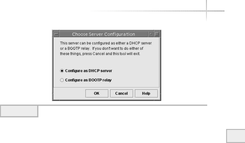
Module 20: Using DHCP 575
20
service has been set up, a different window will appear. See “Configuring
DHCP Service for the First Time” for more information about how to provide
an initial configuration for DHCP services.
Configuring DHCP Services for the First Time
In Figure 20-1, the window displayed asks how you would like to configure
the DHCP server. Two options exist: as a normal DHCP server or as a relay for
BootP requests. The BootP option basically means that you can forward BootP
requests from one or more networks. For the purposes of understanding the
DHCP facility, we want to set up a normal DHCP server. Thus, to configure
normal DHCP services, make sure the Configure as DHCP Server item is
selected and click the OK button.
Once this has been done, a new window is displayed that replaces the
previous one. This window represents the DHCP Configuration Wizard,
which will provide a step-by-step process to configure basic DHCP services.
This window is labeled the “DHCP Configuration Wizard,” and is shown
in Figure 20-2.
The Configuration Wizard window is divided into two sections: the list of
required steps is on the left, and specific questions that must be answered are on
the right. As you can see, a total of eight steps are required to define basic DHCP
services. When the wizard goes through each step, that step is highlighted. Thus,
Figure 20-1 Initial DHCP configuration manager window

the first step (selecting the data storage location) is marked with a colored bar.
Using the control buttons at the bottom, you can navigate between each of the
defined steps. Complete the following to set up the basic DHCP server:
1. Choose the location to store the DHCP configuration data.
2. Determine the DHCP lease policy.
3. Provide the DNS domain servers.
4. Provide basic network address information.
5. Determine network configuration.
6. Provide NIS or NIS+ domain server information.
7. Review the configuration.
576 UNIX System Administration: A Beginner’s Guide
Figure 20-2 DHCP Configuration Wizard window

Step 1: DHCP Configuration Location
In this step, the wizard asks at which location it should store the DHCP
configuration information. If NIS is not running, a local directory is preselected
for you. However, if NIS is operational, you can use a NIS location instead. The
default is the /var/dhcp directory, and when NIS isn’t running, it should be
used unless there is some overwhelming reason to change it. If you desire to
change the directory location, type the new name in the text box and click the >
button to accept this configuration option and proceed to the next step.
NoteNote
In the examples provided in this section, it is assumed that NIS is not running and
only a local DHCP configuration is necessary.
Step 2: Determine the DHCP Lease Policy
At this point, the wizard wants the administrator to determine the length of the
address lease for each client that will request an IP address. The lease indicates
how long a client may use an IP address once it has been assigned. Once the
lease is up, the IP address will become invalid and the client will need to
request another IP address.
As an option, the DHCP server can permit a client to renew their existing
lease for the allocated IP address. In this case, the client sends a renew notice to
the server so that the client may continue to use the existing IP address. Without
this option selected, when the client’s lease expires, the client will be forced to
request another IP address. Permitting clients to renew leases effectively means
that they don’t have to obtain a new IP address every time the address expires.
The only exception to this is when the client boots, it must request a new IP
address (or it can request to use its previous assigned IP address).
The lease section is shown in Figure 20-3. The lease value may be expressed
in hours, days, or weeks. The default value is one day, which is reasonable when
the Renew check box is selected. From a practical standpoint, using a lease of
either days or weeks might be the best way to go, but you will need to determine
the best configuration as dictated by the requirements of your site. In general,
unless you want to maintain fairly tight control over the IP assignment process,
the best configuration would be to renew the IP address on a weekly or monthly
basis. In Figure 20-3, the lease value has been configured for one week.
Module 20: Using DHCP 577
20
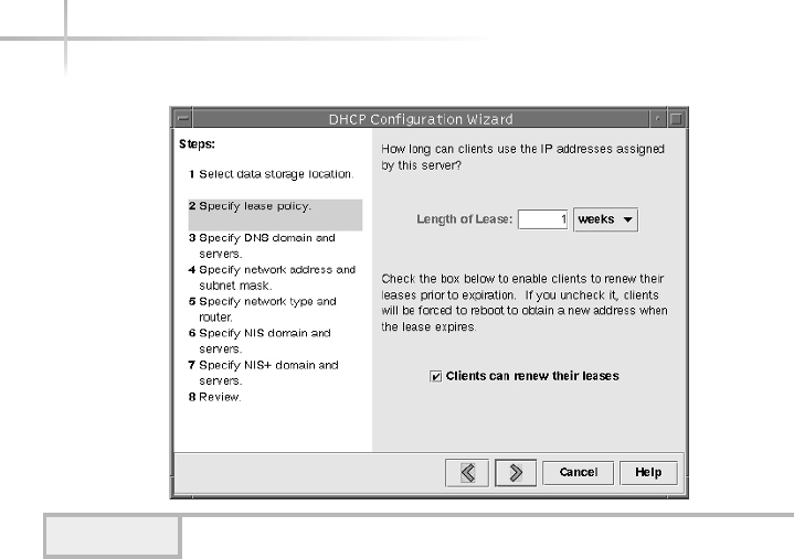
578 UNIX System Administration: A Beginner’s Guide
Step 3: Provide the DNS Domain Servers
Next, you must provide DNS information if the DHCP server is going to use
DNS services, as shown in Figure 20-4. See Module 14 on DNS for more
information about setting up or configuring a domain name server.
As you can see, two different elements are needed to complete this step.
First, the DNS domain is required, and one or more DNS server IP addresses
are needed. In the example, the DNS domain is called home.com and two
DNS servers have been defined: 216.155.202.10 and 216.155.202.11.
The DNS name refers to the domain to which the local system belongs.
sWhen the Configuration Wizard window is displayed, it includes any DNS
information found within the /etc/resolv.conf file.
When adding a DNS server, type the IP address of the server in the
appropriate text box and click the ADD button. You must include a valid IP
addresses within this field; hostnames are not permitted. If you have added
more than one DNS server, you can change the order in which the servers are
queried. You can use the ∧or ∨buttons to reposition the servers within the list
as required.
Click the >button to accept any DNS information entered and move to the
next step to continue configuring DHCP services.
Figure 20-3 Lease Value window
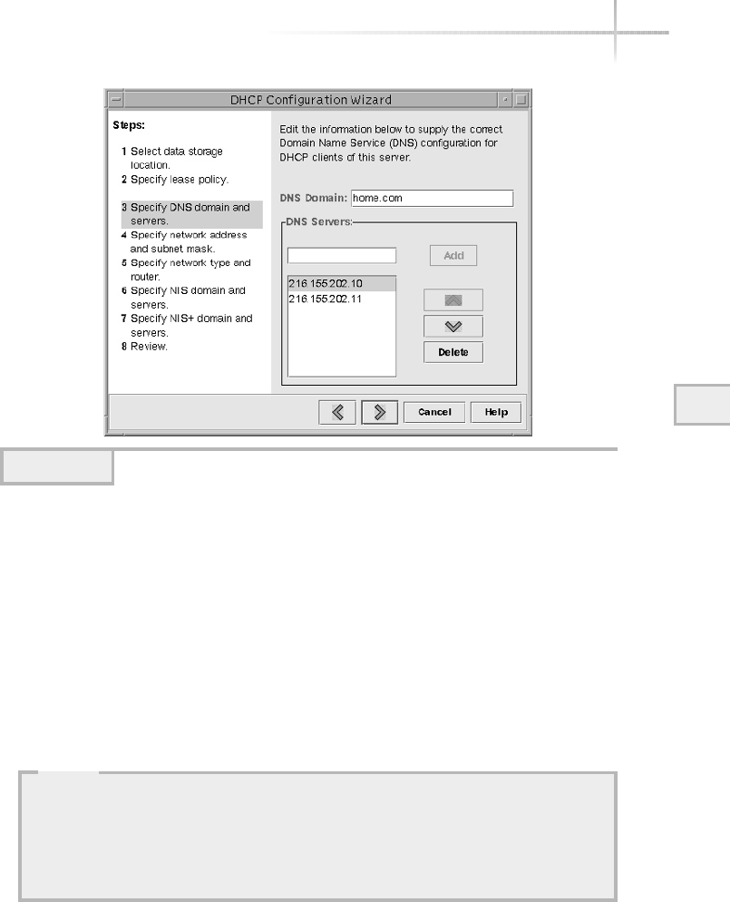
Step 4: Provide Basic Network Address Information
The next window displayed, as shown in Figure 20-5, is used to specify the IP
network and associated subnet mask for the network served by the DHCP
server. See Module 10 for additional information on IP networking that
includes a description of IP addresses and subnet masks. The network address
information is obtained from the defined system network interfaces. This is
used to tell the DHCP server which IP network should be used to allocate IP
addresses to clients.
Module 20: Using DHCP 579
20
Figure 20-4 Supply DNS information
HintHint
You don’t actually need any DNS facilities running to configure or use DHCP
services. Without any DNS, the DHCP server would simply use IP addresses
when displaying information about DHCP clients. However, it is recommended
that you use domain name resolution services because it will make DHCP
administration easier.
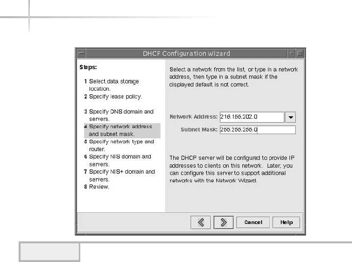
If the system only has a single network interface, only a single network
entry will be displayed in the Network Address selection box. By default, the
entry contains the network address of the primary network interface. If multiple
IP networks are defined on the system, you can only select one from a list of
addresses. Once the basic configuration setup of the DHCP server have been
accomplished, additional IP networks may be assigned.
Input the desired subnet mask value within the Subnet Mask text box. By
default, the assigned subnet mask is taken from the previously defined network
configuration parameters as reported by the ifconfig command.
Click the >button to accept the network information shown in the window
and move to the next step in the process.
Step 5: Determine Network Configuration
The next step involves selecting the type of network and additional routing
parameters that will be used with the DHCP server and for associated DHCP
clients, as shown in Figure 20-6. The Network Type box includes either local-
area (LAN) or point-to-point selections. The local-area (LAN) selection
580 UNIX System Administration: A Beginner’s Guide
Figure 20-5 Network Address Information window
TEAMFLY
Team-Fly®
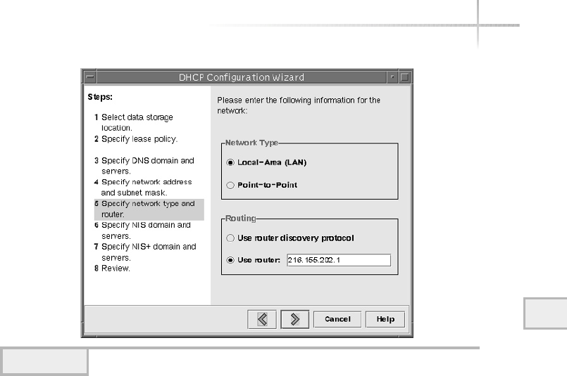
indicates that DHCP will operate under the local data link protocols (such as
Ethernet or FDDI).
By default, the LAN network type is selected, and this should be what is
used unless you are configuring DHCP to operate within a fixed point-to-
point network topology. Next, the window provides the option to specify a
default network router to obtain routing information. This information is
provided to the client systems when they request DHCP services. If you
don’t know a default router, then select to use the router discovery process.
This way, the clients, when necessary, will discover all local routers. If you
have a default router attached to the local system, enter the IP address of
the device within the Use Router text box.
Click the >button to accept the network information and proceed to the
next step.
Step 6: Provide NIS or NIS+ Domain Server Information
The next two steps involve specifying the NIS or NIS+ domain names and any
associated NIS/NIS+ servers. This is very useful for those sites that use NIS,
Module 20: Using DHCP 581
20
Figure 20-6 Network Type/Routing Information window
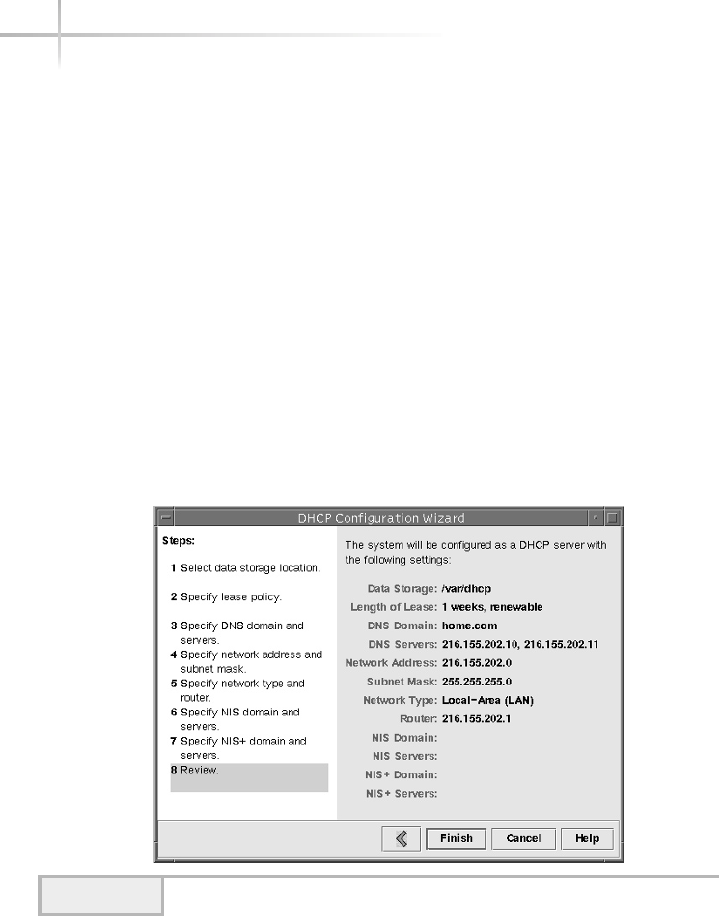
because this information can be supplied to any client when they request DHCP
services. If you have either NIS or NIS+ operating within your network, add this
information to this window. Otherwise, leave the fields blank. Click the >
button to proceed to the final configuration step.
Step 7: Review the Configuration
The final step involves verifying all the information that has been entered from
the previous steps. If you find that something must be changed, use the <button
to go to the step where the incorrect information can be changed. When the
configuration information is correct, click the > button to the review step and
click the Finish button to accept the information. Figure 20-7 shows the review
step with all the configuration information from the preceding examples.
Next, a dialog box will be displayed, as shown in Figure 20-8, which
indicates that you must configure a list of addresses for allocation to
clients, and it asks if it should start the Address Wizard for this purpose.
582 UNIX System Administration: A Beginner’s Guide
Figure 20-7 The DHCP Configuration Summary window
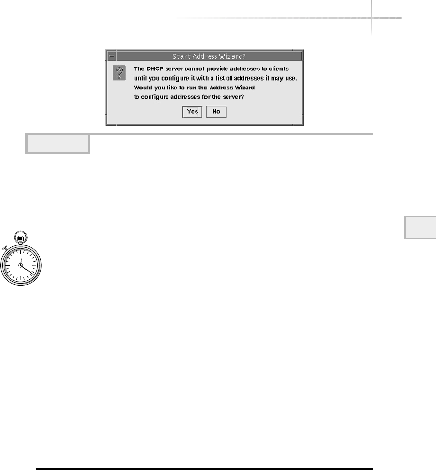
Answering Yes to the dialog box question causes another window to be
displayed. This window represents another setup wizard, which will guide
you through the process of adding IP addresses to the DHCP server. See the
section “Adding IP Addresses to the DHCP Server” later in this module for
a detailed description and explanation of the Address Wizard.
1-Minute Drill
●What are the UNIX DHCP server component modules?
●What does the DHCP lease policy define?
Using the Configuration Manager
The DHCP configuration manager is used to administer and configure DHCP
services. This section reviews the menus and functions that this application
supports. The high-level menus are listed in Table 20-2.
The application contain the following submenus.
File Menu
Contains just a single menu element—Exit. This item is the standard way to
close the configuration manager.
Module 20: Using DHCP 583
20
Figure 20-8 Start Address Wizard Dialog window
●Server process, configuration file, configuration manager
●How long a client’s DHCP-obtained IP address is valid before the client must recontact the server for a
new address

584 UNIX System Administration: A Beginner’s Guide
Edit Menu
The Edit menu contains the following items:
Create Set up a new IP address range for DHCP client systems.
Delete Remove an existing IP address range.
Duplicate Make a copy of an existing IP address range.
Properties Display the properties of an existing IP address range.
Address Wizard Step-by-step process for IP address range creation.
Release Addresses Clear the lease of an existing assigned IP address.
Network Wizard Step-by-step process for creating a new network that can
be used with the DHCP server.
Delete Networks Delete an existing network.
View Menu
The View menu contains the following items:
●Refresh Refreshes the display.
●Show Addresses Displays the IP address of the DHCP clients instead
of hostnames.
●Show Grid Displays grid lines for the main DHCP configuration screen.
These lines make it easier to view each DHCP client entry.
Service Menu
The Services menu contains the following items:
●Restart Restarts an already existing dhcpd process.
●Stop Shuts down the dhcpd process.
Menu Description
File Contains the Exit menu item; used to quit the configuration manager
Edit Used to manage the IP address space for DHCP clients
View Toggles IP address and grid elements
Service Controls the DHCP server process and configuration
Help Online help facility.
Table 20-2 Configuration Manager Menu Items

Module 20: Using DHCP 585
20
●Start Enables the dhcpd process.
●Disable Permanently disables the dhcp process from executing.
●Enable Reverses the disable function.
●Modify Alters some of the DHCP server options.
●Unconfigure Removes DHCP server configuration information from
the system.
Help Menu
The Help menu contains on-line help for the configuration manager. The help
facility uses HTML, which means you will need to have a Web browser installed
on the system to view the help files. The submenu items include the following:
●Overview Provides an overview of DHCP configuration manager.
●How To Provides a topical index to how to accomplish specific tasks
with the configuration manager.
●Index Provides an index to all of the help sections with links so that
the administrator can navigate the entire online book.
●On Service Explains what the DHCP or BootP facilities do, and how
to use and configure them.
●On Addresses Shows how to configure and use IP addresses for
DHCP clients.
Adding IP Addresses to the DHCP Server
Before the DHCP server can allocate addresses for DHCP clients, a range of IP
addresses must be configured within the server. If you are configuring the DHCP
server for the first time, you were prompted to start the Address Wizard or you
have selected the Address Wizard from the main Edit menu. After you have
started the wizard, you will see a window similar to that shown in Figure 20-9.
As you can see, this wizard will help you configure an address range for
DHCP clients; like the previous wizard, the specific steps are on the left while
the questions are located on the right-hand side of the window. A total of six
steps are necessary to accomplish the IP address configuration, and they are
described in the following sections.
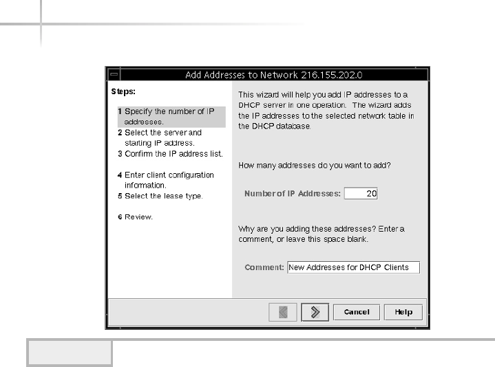
Step 1: Determine the Number of IP Addresses
Within the Number of IP Addresses text box, you must indicate the total
number of addresses you will need to support all the DHCP clients for this IP
network. Several factors can affect how many addresses are allocated for DHCP
services. For example, are all the clients active during the same period of time,
or how many addresses are currently unallocated within the network? That is,
if this IP network is used for other purposes and addresses have already been
assigned to systems, how many IP addresses are available for DHCP? If the
clients represent nomadic users that access the network on an infrequent or
ad hoc basis, the total number of IP address may be much lower as compared
to users that access the network on a more regular and frequent basis.
Note that the total number of addresses for DHCP must be contiguous within
an IP network. That is, they must all be within a specific range of addresses.
For example, as shown in Figure 20-9, if you entered 20 within the Number
of IP Addresses text box, then you are saying that 20 continuous addresses
are available within the network, such as 216.155.202.200 through
216.155.202.219. This is an important point, since you can’t specify gaps
586 UNIX System Administration: A Beginner’s Guide
Figure 20-9 Address Wizard window
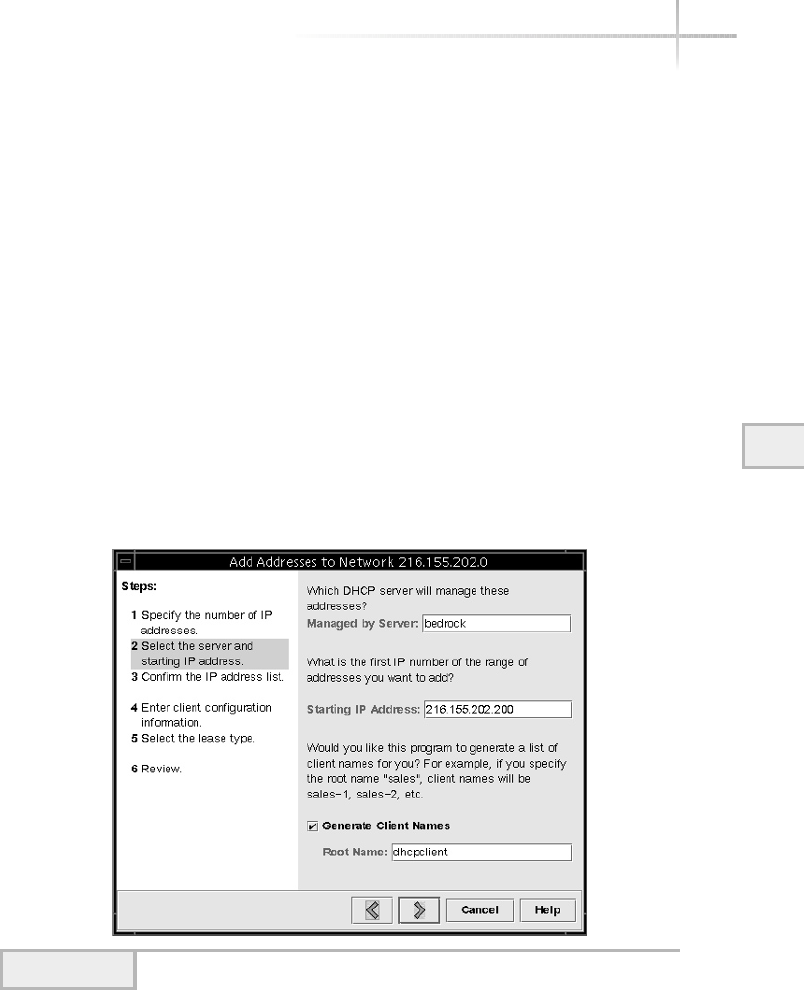
of ranges within an IP network. Also, notice that the range above (200-219)
represents 20 addresses. One might think that this only represents 19 addresses,
but in fact, we must count 216.155.202.200 as the first address.
Once the number of addresses has been determined, the configuration
manager provides a comment field to help track when changes are made to the
configuration. Use this field to record any changes to the ranges of IP addresses
that have been configured with the DHCP server.
Selecting the >button will move the wizard to the next step.
Step 2: Select the Starting IP Address
Once the wizard has moved to the next step, a new window is displayed.
This window will be similar to what is shown in Figure 21-10. As you can see,
several important configuration parameters are required. First, you must
make sure that the correct DHCP server is listed within the Managed by
Server text field. By default, the hostname of the system, which is running the
configuration manager, is added to this text box. Using Figure 20-10 as
the example, we see that the system called bedrock is the DHCP server.
20
Module 20: Using DHCP 587
20
Figure 20-10 Starting IP Address window

588 UNIX System Administration: A Beginner’s Guide
Second, the administrator must determine the starting point or first IP
address that will be used for DHCP clients. In other words, what is the start of
the address range that the DHCP server will be using when allocating addresses
to clients? Also, remember that we specified the total number of addresses that
will be allocated with the IP address range. Thus, the DHCP server simply
determines the IP address range by adding the total number of addresses to the
address starting point.
Third, as an option, the configuration manager can automatically assign
hostnames to the range of IP addresses for DHCP clients. Select the Generate
Client Names check box if you want to enable this option. As you can see, the
administrator can configure a prefix string that will be added to the beginning
for each hostname. In this example, the Root Name text box contains the string
dhcpclient. This tells the DHCP server to add this string to the start of
each hostname. The DHCP server will automatically number each of the hosts
defined. Thus, if ten systems were specified with the IP address range, then
the DHCP server will define the following hostnames:
●dhcpclient-1
●dhcpclient-2
●dhcpclient-3
●dhcpclient-4
●dhcpclient-5
●dhcpclient-6
●dhcpclient-7
●dhcpclient-8
●dhcpclient-9
●dhcpclient-10
Selecting the >button will move the wizard to the next step.
Step 3: Confirm the IP Address List
The wizard now asks the administrator to confirm the list of added IP addresses
and corresponding hostnames. Assuming that a total of 20 addresses were
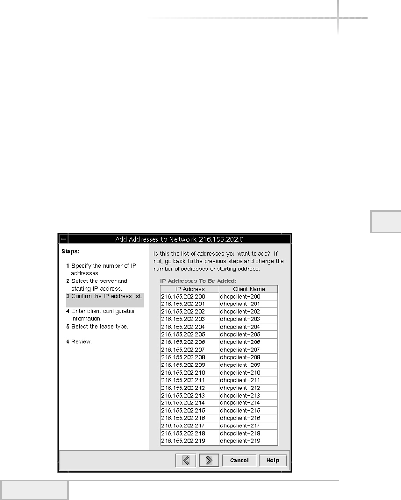
defined with the starting IP address of 216.155.202.200 and that the
dhcpclient string was added to the Root Name text box from the last step,
you should see a window similar to that shown in Figure 20-11.
As previously indicated, for each IP address, a hostname was defined. The
hostname string name contains the last byte of the IP address so that it is very
easy to identify the IP address from the hostname itself. Selecting the >button
will accept this configuration and move the wizard to the next step.
Step 4: Define Client Information
The configuration manager supports the concept of a configuration macro, and
basically a macro provides the specific parameter information to each DHCP
client. The next step using the wizard is shown in Figure 20-12. A default
macro name, which represents the network address, is set up automatically.
Module 20: Using DHCP 589
20
Figure 20-11 The IP address list with associated hostnames
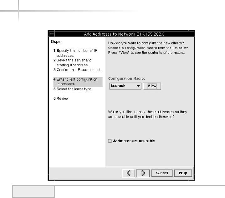
590 UNIX System Administration: A Beginner’s Guide
Examples of a macro include DNS information, lease configuration, and so
forth. Click the View item to see the details information contained with the
macro. Figure 20-13 shows the default bedrock macro. Select the default
configuration by selecting the clicking the >button.
Step 5: Select the DHCP Lease Type
You have the option of selecting either a dynamic lease or a permanent
(static) lease, as depicted in Figure 20-14. A dynamic lease means that it can
be assigned to different clients over a period of time, whereas the static lease
is assigned to a single client just once. However, you can alter the lease types
after you have configured the DHCP server. The most common type is the
dynamic lease.
Click the >button to move to the next and final step in the Add Address
Wizard process.
Figure 20-12 DHCP server macro
TEAMFLY
Team-Fly®

20
Module 20: Using DHCP 591
Figure 20-13 Detailed macro information
Figure 20-14 Select the appropriate DHCP lease type
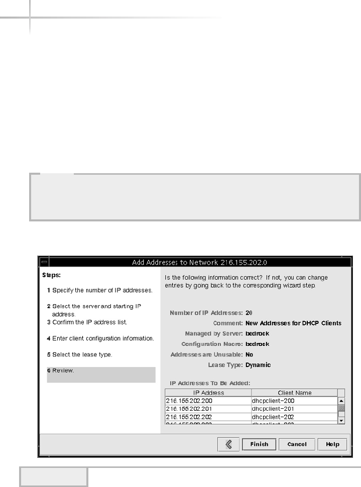
Step 6: Review the DHCP Configuration
The final step is to review the DHCP configuration information. A window is
displayed that contains all of the configuration details that were specified in the
previous steps. The example configuration is shown in Figure 20-15.
Click the Finish button to accept the configuration or use the <button to
move back through the process to alter any necessary parameters.
Once the wizard process is complete and the new address range is added,
the main configuration window is updated with a new network icon.
592 UNIX System Administration: A Beginner’s Guide
Figure 20-15 Review window
HintHint
One of the more important things to check is the assignment of IP addresses
and hostnames. You can use the window to scroll through the list of IP
addresses to make sure the range that was selected is correct.

20.2 Configure DHCP Clients
This section reviews the procedures involved with both manually and
automatically configuring UNIX systems as DHCP clients. Depending on the
operating system, different sets of steps will be necessary.
Manual DHCP Configuration
If you would like to manually configure DHCP on UNIX, you must use the
appropriate DHCP network tools. For instance, on Solaris, you must use the
ifconfig tool to configure an interface that uses DHCP. On Linux, you
would use the dhcpcd command, and on HP-UX, you would use the
dhcpclient command.
To manually configure DHCP on Solaris, execute the ifconfig with the
interface name followed by the dhcp keyword. Thus, the command
ifconfig hem0 dhcp
will manually configure the hme0 interface (100-Mbps Ethernet interface on
most Sparc systems).
On Linux, use the dhcpcd command:
dhcpcd eth0
The HP-UX system works the same way, but the command to use is
dhcpclient. The same rule applies to this tool as to the dhcpcd command
on Linux when attempting to run the command manually.
20
Module 20: Using DHCP 593
20
HintHint
The Linux dhcpcd command will only function when the interface is being set
up for the first time or when the dhcpcd process is not running. Normally, the
system starts this process automatically when the system detects an interface
that has been configured to use DHCP.

Set Up Automatic and Permanent
DHCP Configuration
Configuring DHCP client services on UNIX to be both automatic and
permanent (that is, it will persist across system reboots) generally is a
straightforward and simple process. On the Solaris system, if the machine
has already been installed on the network, the procedure is quite easy—
simply create a special file within the /etc directory. The filename is
important—the format is dhcp.
interface
, where interface is the
name of the UNIX network interface which DHCP services should be
configured. For example, on Solaris, the first 100-Mbps Ethernet interface
might be eri0. Thus, the command
touch /etc/dhcp.eri0
will create an empty file called dhcp.eri0. When the system is rebooted,
the existence of this file will tell the system to issue DHCP requests to the
network for network configuration information.
When the system boots, you should see the following message on
the console:
starting DHCP on primary interface eri0
For HP-UX, modify the value of the keyword DHCP_ENABLE that is
contained within the /etc/rc.config.d/netconf file. Assigning the
value of 1 to this keyword enables DHCP on the associated network interface.
The sample output of this file is shown here:
HOSTNAME=mb-auto-1
OPERATING_SYSTEM=HP-UX
LOOPBACK_ADDRESS=127.0.0.1
INTERFACE_NAME[0]=lan0
IP_ADDRESS[0]=216.155.202.171
SUBNET_MASK[0]=
BROADCAST_ADDRESS[0]=216.155.202.255
INTERFACE_STATE[0]=up
DHCP_ENABLE[0]=0
As you can see, the variables are self-explanatory based on the individual name.
For example, the HOSTNAME variable represents the name of the host.
On Linux, modify the value of the keyword BOOTPROTO that is contained
within the /etc/sysconfig/network-scripts/ifcfg-eth0 file. This
594 UNIX System Administration: A Beginner’s Guide
Set to "r" to enable DHCP client

file, ifcfg-eth0, corresponds to the first Ethernet interface on the system.
Your system may have multiple interfaces, in which case you will see more than
one of these files. Select the appropriate file when configuring DHCP client
services. If the interface was previously configured with an IP address, you must
change the keyword from static to dhcp. If the keyword isn’t present in the
file, simply add it with the correct keyword of dhcp. The sample output shows
the correct entry in the ifcfg-eth0 file:
DEVICE=eth0
BOOTPROTO=dhcp
ONBOOT=yes
TYPE=Ethernet
PEERDNS=no
When the system reboots, it will attempt to obtain DHCP configuration for
the eth0 interface. If you want to stop using DHCP, change the BOOTPROTO
keyword to have the value of static and add the following additional
keywords if they are not present in the file:
IPADDR=216.155.202.163
IPGATEWAY=216.155.202.129
NETMASK=255.255.255.0
Assign the appropriate keyword values that match your network environment.
Obtain DHCP Agent Status Information
Once the interface has been configured to use DHCP, the administrator can
view the status of the interface using the ifconfig command. For example,
to view the status on Solaris, use the following:
# ifconfig -a dhcp status
ifconfig: lo0: interface is not under DHCP control
Interface State Sent Recv Declined Flags
eri0 BOUND 2 1 0 [PRIMARY]
(Began, Expires, Renew) = (12/11/2001 22:47, 12/18/2001 22:47, 12/15/2001
10:47)
ifconfig: eri1: interface is not under DHCP control
Module 20: Using DHCP 595
20
-a option returns results
for all network interfaces
This interface is not
configured to use DHCP.
The eri0 interface is configured to use
DHCP and is the primary network interface.
another network interface
not using DHCP

596 UNIX System Administration: A Beginner’s Guide
On Linux, the pump command is used to obtain status and configuration
information about the interface that is using DHCP. Thus, the command
pump –s
when executed, will shown all the information for each interface that is
configured to use DHCP. The sample pump output might look like this:
Device eth0
IP: 216.155.202.200
Netmask: 255.255.255.0
Broadcast: 216.155.202.255
Network: 216.155.202.0
Boot server 216.155.202.100
Next server 0.0.0.0
Gateway: 216.155.202.1
Hostname: dhcpclient-200
Domain: home.com
Nameservers: 216.155.202.10 216.155.202.11
Renewal time: Fri Jan 18 01:39:23 2002
Expiration time: Fri Jan 18 03:09:23 2002
In this example, all the relevant DHCP information is obtained for eth0
interface and, naturally, the IP address, network, and lease information will be
different depending on which network the DHCP server is running on.
On the Windows family of operating systems, the ipconfig command can
be used just like the UNIX ifconfig command, which is discussed next.
1-Minute Drill
●What type of DHCP lease assigns an IP address to different clients over a period
of time?
●In Linux, how does the dhcpcd process normally start?
Configuration of DHCP Clients
This section will help you configure client DHCP services on other platforms.
More specifically, Linux and Windows operating systems will be covered. Like
●Dynamic
●The system starts this process automatically if an interface is configured to use DHCP.

20
other UNIX operating systems, DHCP is supported on Microsoft’s family of
operating systems. In particular, Windows 98, Windows Me, Windows 2000,
and Windows XP are all supported. Although these operating systems provide
different features and run on a large number of computer systems, the DHCP
support is generally uniform. To configure a Windows 2000 system to support
DHCP, perform the following steps.
Step 1: Access the Network and Dial-up Connections Panel
Using the Start menu, select the Network and Dial-up Connections item from
the Setting submenu. When done, a new window will be displayed that
contains at least one network icon and a Make New Connection icon. A LAN
connection known as Local Area Connection 5 has been defined. This
window is used to add new networking connections or display configuration
information for one or more existing network interfaces.
Step 2: Display the Status of the LAN Connection
Double-click the network icon appropriate for your system. When done, a new
window is displayed. This window shows basic network status and performance
information and can be used to navigate to more detailed network information.
Step 3: Display the Properties of the LAN Connection
Next, select the Properties button on the Local Area Connection window.
Once this has been done, a new window is displayed. This window provides
information about the higher-level protocols and services that are bound to
the network interface. The 3com3cs74 TXFast EthernetPC card is the
LAN interface that is used. Note that three different services are configured
for this card: Microsoft Networks Client software, file and printer sharing
software, and TCP/IP.
Step 4: Display the Properties of the TCP/IP
Highlight the Internet Protocol (TCP/IP) item and then click the Properties
button. When this is done, the Internet Protocol (TCP/IP) Properties window
is displayed.
Module 20: Using DHCP 597
20
HintHint
The assumption in these steps is that you have already installed a NIC and that
basic networking services are already operational.

Click the Obtain an IP Address Automatically selection (if it isn’t already
checked) and then click the OK button. This instructs Windows to request an
IP address for the DHCP server using the DHCP protocol.
Next, select the OK button and close the LAN Properties window. Then,
close the LAN Status window by clicking the Close button.
You should reboot the system for this networking change to take effect, and
when the system reboots it will attempt to obtain network information from a
DHCP server.
Viewing Network Information on Windows
The Windows family of systems provides the means to display network
configuration information using a command-line tool called ipconfig. This
utility provides two basic services: to show network configuration information
and to exercise limited control over the behavior of the DHCP client. Depend-
ing on the version of Windows you are using, the ipconfig options will be
slightly different. However, the basic options are supported on most of the
versions of Windows. This tool can show both static and dynamic (such as
from a DHCP server) networking parameters for all defined interfaces on the
system. This command is basically equivalent to the UNIX ifconfig utility,
but it provides only a small number of services as compared to the UNIX
version. To invoke this tool, open a command prompt window and type the
ipconfig command.
The ipconfig command was invoked with the /help option, which
displays a list of the available command-line options that are supported. This
command provides a small number of command-line arguments, as described
in Table 20-3.
598 UNIX System Administration: A Beginner’s Guide
Option Meaning
/? Displays a list of command-line options.
/help Displays a list of command-line options.
/all Displays all the configuration information available.
/release Releases the IP address for the specified network interface.
/renew Obtains (renews) a new expiration date for the assigned IP address.
/Batch Writes the output to a file.
/renew_all Renews all interfaces that are configured with DHCP.
/release_all Releases each IP address for all interfaces configured with DHCP.
Table 20-3 ipconfig command-line options

20
View DHCP Information
To view network configuration for each defined interface on the system, such
as IP addresses, DHCP information, or generic networking parameters, use the
/all option. For example, issuing the command
C:\WINDOWS>ipconfig /all
displays output similar to that shown next.
Although the second Ethernet adapter is configured to use DHCP, the
missing IP address and lease information indicates this dial-up adapter is not
currently connected to the network and therefore has not obtained an address
through DHCP lease information.
C:\WINDOWS>ipconfig /all
Windows IP Configuration
Host Name . . . . . . . . . : SOCRATES.home.com
DNS Servers . . . . . . . . : 216.155.202.10
216.155.202.11
Node Type . . . . . . . . . : Broadcast
NetBIOS Scope ID. . . . . . :
IP Routing Enabled. . . . . : No
WINS Proxy Enabled. . . . . : No
NetBIOS Resolution Uses DNS : No
0 Ethernet adapter :
Description . . . . . . . . : Linksys LNE100TX Fast EtheE100TX v4)
NDIS5 Driver
Physical Address. . . . . . : 00-20-78-0E-77-5E
DHCP Enabled. . . . . . . . : Yes
IP Address. . . . . . . . . : 216.155.202.202
Subnet Mask . . . . . . . . : 255.255.255.0
Default Gateway . . . . . . : 216.155.202.1
DHCP Server . . . . . . . . : 216.155.202.100
Primary WINS Server . . . . :
Secondary WINS Server . . . :
Lease Obtained. . . . . . . : 12 23 01 12:15:38 AM
Lease Expires . . . . . . . : 12 30 01 12:15:38 AM
1 Ethernet adapter :
Description . . . . . . . . : PPP Adapter.
Physical Address. . . . . . : 44-45-53-54-00-00
DHCP Enabled. . . . . . . . : Yes
IP Address. . . . . . . . . : 0.0.0.0
Subnet Mask . . . . . . . . : 0.0.0.0
Default Gateway . . . . . . :
DHCP Server . . . . . . . . : 255.255.255.255
Primary WINS Server . . . . :
Secondary WINS Server . . . :
Lease Obtained. . . . . . . :
Lease Expires . . . . . . . :
Module 20: Using DHCP 599
Uses DHCP
Doesn't use
DHCP

600 UNIX System Administration: A Beginner’s Guide
In the example output, three sections are displayed: Windows IP
Configuration,0 Ethernet adapter, and 1 Ethernet adapter. The
first section lists generic network information related to the system. For instance,
the system name and DNS servers are shown, which are socrates.home.com,
216.155.202.10, and 216.155.202.11, respectively. The next two
sections show specific configuration information related to each of the defined
network interfaces on the system. This includes
●Description
●Physical address
●DHCP flag
●IP address
●Subnet mask
●Default gateway
●Lease obtained date
●Lease expiration date
Description The description string includes the type of interface hardware
that has been installed on the system. In this case, the ipconfig command
identifies a Linksys LNE100TX Fast EtheE100TX as the type of card.
Physical Address This shows the physical data link protocol address
associated with the network interface hardware. In this example, the type of
hardware supports the Ethernet data link protocol and has the address of
00-20-78-0E-77-5E.
DHCP Flag This flag indicates if the network interface has been configured
to use DHCP. If so, then DHCP should be configured to Yes, and IP lease
information should also be listed.
IP Address If DHCP has been configured on the interface, the IP address
has been assigned dynamically from a DHCP server. Otherwise, the IP address has
been assigned statically using the Network Control Panel icon. The IP address is
used to communicate with the local network.
TEAMFLY
Team-Fly®

Module 20: Using DHCP 601
20
Subnet Mask If DHCP has been configured on the interface, the subnet
mask has been assigned dynamically from a DHCP server. Otherwise, it has
been assigned statically using the Network Control Panel icon. The subnet
mask is used to determine how to interpret the IP address for the local network.
Default Gateway The default gateway is used to permit the local system
to communicate with other nodes on remote networks. If DHCP has been
configured on the interface, generally the default gateway has been assigned
dynamically from a DHCP server. Otherwise, it has been assigned statically
using the Network Control Panel icon.
Lease Obtained Date When DHCP is used, the Lease Obtained field
indicates when the network configuration for this interface was obtained from
the DHCP server. In the earlier example, the 12 23 02 12:15:38 AM string is
read as December 23, 2002 at 12:15:38 A.M.
Lease Expiration Date When DHCP is used, the Lease Expires field
indicates when the network configuration for this interface expires; that is,
when the configuration information will no longer be valid and the DHCP
client must request newer configuration information from the DHCP server.
The other two fields, Primary WINS Server and Secondary WINS Server,
are used to support Microsoft-specific networking services and protocols.
Moving a Workstation Between Networks
In an environment where users move to different parts of the network, it is very
common for DHCP to be deployed across the entire network enterprise. Thus, if a
user moves from one building to another (or even one floor to another), DHCP
services can be used to provide connectivity—regardless of physical location for
mobile users. However, if, for example, a workstation has been attached to
different parts of the network when DHCP is used, it is important to reconfigure
the network interface when a workstation is moved around.
For example, consider the diagram shown in Figure 20-16 that shows two
networks and one workstation. Both networks have DHCP services enabled;
Network A uses the IP network of 216.155.202, while Network B uses the
IP network of 216.155.203. When the workstation was attached to Network
A, it obtained the address of 216.155.202.100. Over some period of time,
the user moves the workstation to Network B with rebooting the system.
Unfortunately, without any network reconfiguration, the workstation won’t be
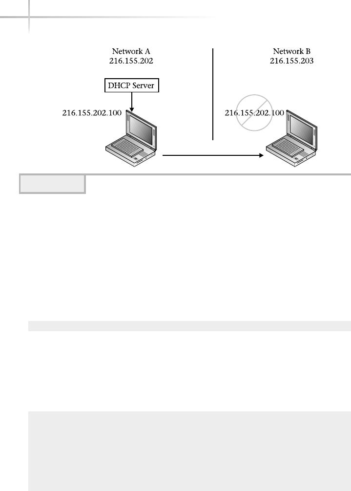
602 UNIX System Administration: A Beginner’s Guide
able to communicate on Network B because Network B uses a different network
address and the workstation is still using the addresses it obtained from
Network A.
To resolve this problem, issue the ipconfig with the /release option
and then execute the ipconfig, again with the /renew option. This tells the
DHCP client to release (or let go of) the existing DHCP configuration and then
to request a new IP address and associated configuration from the local DHCP
server. Thus,
C:\WINDOWS>ipconfig /release 0
will drop or delete the existing DHCP configuration (that is, the IP address of
216.155.202.100 and so forth) from the first network interface, which is
expressed with zero. When using the /release option, ipconfig must be
given which interface to release. When this command is executed, it should
display the interfaces with empty values:
Windows IP Configuration
0 Ethernet adapter :
IP Address. . . . . . . . . : 0.0.0.0
Subnet Mask . . . . . . . . : 0.0.0.0
Default Gateway . . . . . . :
Figure 20-16 DHCP network with moved workstation

20
Module 20: Using DHCP 603
1 Ethernet adapter :
IP Address. . . . . . . . . : 0.0.0.0
Subnet Mask . . . . . . . . : 0.0.0.0
Once the IP address and associated information has been released, we can
now request a new IP address from the local DHCP server by using the /renew
option. When using /renew, the network interface must be supplied. Thus,
the command
C:\WINDOWS>ipconfig /renew 0
indicates that ipconfig should attempt to obtain up-to-date DHCP
configuration information for the first interface on the system. When executed,
this command would show output similar to this:
Windows IP Configuration
0 Ethernet adapter :
IP Address. . . . . . . . . : 216.155.203.100
Subnet Mask . . . . . . . . : 255.255.255.0
Default Gateway . . . . . . : 216.155.203.1
1 Ethernet adapter :
IP Address. . . . . . . . . : 0.0.0.0
Subnet Mask . . . . . . . . : 0.0.0.0
Default Gateway . . . . . . :
The “release/renew” steps are depicted in Figure 20-17, and when the
ipconfig command is executed with the /renew option, it displays the new
DHCP configuration obtained from the DHCP server. In this example, the new IP
address will permit the mobile workstation to communicate with all nodes on
Network B because it now contains the correct address.
HintHint
Sometimes, despite running the ipconfig /release, the DHCP configuration
isn’t always released right away, and therefore it may be necessary to run this
command more than once to ensure that this step is complete.
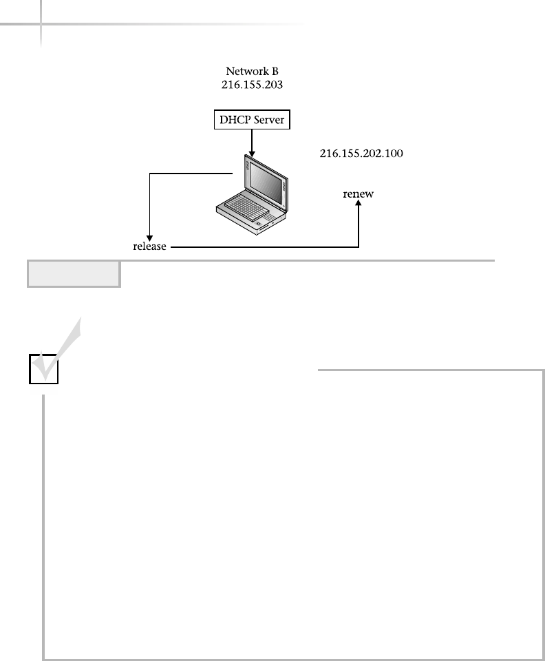
604 UNIX System Administration: A Beginner’s Guide
Figure 20-17 The DHCP release/renew steps
Mastery Check
1. True/False: A Windows system cannot get an IP address from a
UNIX-based DHCP server.
2. What is the default directory for Solaris DHCP configuration information?
a. /etc/resolv.conf
b. /var/dhcp
c. /etc/dhcp
d. /etc/dhcpd.conf
3. The __________ indicates how long a client may use an IP address once it
has been assigned by a DHCP server.
4. True/False: When adding IP addresses for a DHCP server to assign, you
can use any available valid addresses on your network.

Module 20: Using DHCP 605
20
5. A __________ DHCP lease is assigned to a single client just once.
6. By default, what Linux file contains DHCP configuration information?
a. /etc/resolv.conf
b. /var/dhcp
c. /etc/dhcp
d. /etc/dhcpd.conf
7. What is the proper tool for manual DHCP client configuration on each of
these platforms: Solaris? Linux? HP-UX?
8. On a Solaris client, what is the command to configure DHCP permanently,
so it persists when the system reboots, assuming the interface to configure
it for is named ei0?
9. On a Windows 2000 client, what is the TCP/IP option to use DHCP to
obtain an IP address?
a. Obtain an IP address automatically
b. Configure DHCP
c. ipconfig
d. Use the following IP address
10. On a Windows 2000 client, what is the command to view DHCP and
IP information?
a. Obtain an IP address automatically
b. Configure DHCP
c. ipconfig
d. Use the following IP address
Mastery Check

This page intentionally left blank.

Module21
Using rdist
Critical Skills
21.1 Create an rdist Distribution File for Synchronizing Files
21.2 Debug an rdist Configuration
21.3 Investigate rdist Commands
21.4 Explore an rdist Example
Copyright 2002 by The McGraw-Hill Companies, Inc. Click Here for Terms of Use.

The rdist tool provides a software distribution facility for a cluster of
UNIX systems. In particular, it ensures that files and/or directories are
synchronized based on a configuration file stored on the software distribution
server. The tool pushes new files when one or more file elements, such as file
access time, have been changed on the master copy. Maintaining up-to-date
files across a number of different systems is a challenge for the system
administrator. Why is this type of synchronization important? Consider, for
example, a cluster of systems that all use DNS. To configure DNS client
services, a correct /etc/resolv.conf file must be placed on every system.
Now, suppose that you have to make periodic changes to one or more entries
within this file. Without some sort of software distribution mechanism, you
would have to manually copy the updated file to each of the target systems.
It is simply not efficient to maintain a set of files using a manual approach based
on the number of systems deployed at many sites. For example, to manually
copy files when they are modified is both time-consuming and error prone.
Certainly, a manual approach is possible when the number of systems are quite
small. However, when a larger number of systems are involved, things become
much harder and more complex. Consider, for instance, having to update a file
on a bunch of systems on a regular basis, not
just one time. Why not automate the task and
make life easy, versus having to do this
particular function over and over?
The rdist tool supports a number of
command-line options. However, the most
important ones are described and listed in
Table 21-1.
608 UNIX System Administration: A Beginner’s Guide
HintHint
Due to the incompatibilities
of this tool with both Linux
and HP-UX, only the Solaris
version has been covered.
Command Option Meaning
-b Do a binary comparison of the target files rather than
comparing both the size and date of the source files.
-D Turn on verbose debugging output.
-h Process symbolic link so that the target file is copied rather
than the link itself.
-n Echo the rdist commands without actually doing any work.
This is used for debugging purposes.
-q Does not display any of the files being processed; quiet mode.
Table 21-1 rdist Command-Line Options

Module 21: Using rdist 609
21
21.1 Create an rdist Distribution
File for Synchronizing Files
The rdist command supports a configuration file that can be used to
automate the software distribution mechanism. The rdist configuration file is a
self-contained description of the hosts, files, and specific directives for keeping
files up-to-date across a number of target systems. The command directives are
keyword strings and associated values, which then can be used like macros or
shell variables. A working sample distribution file has been included here:
HOSTS = ( dino fred )
FILES = ( /etc/hosts
/etc/resolv.conf )
(${FILES}) -> (${HOSTS})
install -R ;
In this example, we have defined two string variables—HOSTS and
FILES—and associated values. The HOSTS variable contains a list of target
Command Option Meaning
-R Removes unnecessary files on the target system, which don’t
match entries on the local system. This is used to maintain the
exact directory structure from the master to each target system.
-V Verification mode; checks to see if all files are updated on the
target systems and any discrepancies are displayed. However,
no files are updated on the target systems, nor is any
notification sent.
-y Does not update remote files on the target systems that are
younger than the files located on the server system. This is
known as younger mode.
-d macroname=value Defines a macro with a specific value. This causes the
macroname to be overridden with a new definition value,
which is contained within the distribution file.
-f distfile Specifies the distribution file to be processed. If no distribution
file is specified on the command line, the tool looks into the
current directory for a distribution file called distfile.
Table 21-1 rdist Command-Line Options (continued)

remote hosts that should be updated with the list of files contained within
the FILES variable. In this case, the target hosts are dino and fred. The
list of files defined with the FILES variable copied to the remote hosts are
/etc/hosts and. /etc/resolv.conf. Naturally, these hosts must be
official node names that are contained within /etc/hosts, NIS, or DNS.
Also, the files must exist on the local system, which is the system where the
rdist command will be executed.
The way rdist variables are accessed by enclosing the variable name within
brackets and adding the dollar sign in front of the name, thus ${FILES} or
${HOSTS} are both valid. Additional parentheses, such as (${FILES}) are
needed around variables when they are used with certain rdist directives, as
shown in the above example.
We use the rdist string -> to signify that we would like to copy the contents
of the FILES variable to the target machines contained with the HOSTS variable.
The install keyword string indicates that the files should be installed on
the remote hosts. To invoke the above configuration, assume that we have
saved this information to a text file called network-dist and use the rdist
command as shown here:
# rdist -f network-dist
updating host dino
updating: /etc/hosts
updating: /etc/resolv.conf
updating host fred
updating: /etc/hosts
updating: /etc/resolv.conf
The –f option informs rdist to read the accompanying configuration file
from the command line. By default, rdist will search the local directory for a file
called distfile and, if found, will attempt to process this file for software
distribution directives. Thus, if we rename the network-dist file to distfile
and run the rdist command again without any arguments, it will accomplish
the same work as shown in the above example. As you can see from the output,
both hosts are listed and the associated files were updated on each host. If we
were to execute the command again, we would find different output:
# rdist -f network-dist-3
updating host dino
updating host barney
610 UNIX System Administration: A Beginner’s Guide
TEAMFLY
Team-Fly®

The reason for this is that rdist automatically checks to see if the local files
have changed with respect to the remote copies. If no change has been made
to the local files, and the command is run again, the result of the rdist
command differs from the first rdist example because it hasn’t updated the
remote files. Instead, it simply displays that each host has been updated, but
in actuality the rdist tool found that it didn’t really need to sync up the files
because they didn’t change.
How does rdist determine if a file has changes? That is a very good question!
By default, it uses two methods—first, if the file size has been altered since the
last copy, and second, if the modification time of the file has changed with
respect to the last copy.
21.2 Debug an rdist Configuration
If we are having trouble getting a particular rdist configuration working, we
have two ways to debug the problem. First, we can use the –n option that
shows the steps rdist will take when supplied a configuration file. Second, we
can use the –D option to display a verbose listing of debugging output during
execution of the rdist command.
If we are interested in only displaying which files would be updated on a
given target versus actually doing the software syncing, we can use the –n
option. This option just outputs the files that would be updated versus actually
physically copying these files over. Thus,
# rdist -n -f network-dist-5
updating host barney
install -R /etc/hosts /etc/hosts
install -R /etc/resolv.conf /etc/resolv.conf
updating host fred
install -R /etc/hosts /etc/hosts
install -R /etc/resolv.conf /etc/resolv.conf
From this example, you can see that both systems (barney and fred) would
be updated with both /etc/hosts and /etc/resolv.conf files. The
–D option shows much more information about the steps rdist follows when
doing work. Unfortunately, some of the displayed messages can be rather
cryptic, which make them hard to interpret. For example, the rdist command
from the previous example is run with the debug command-line option. This
Module 21: Using rdist 611
21

612 UNIX System Administration: A Beginner’s Guide
command-line option is most useful in debugging rdist when more advanced
or complex directives or options are used.
bash-2.03# rdist -D -f network-dist-7 | cat -n
1 lookup(HOSTS, 1, 33860)
2 lookup(FILES, 1, 338a0)
3 expand(338c0, 3)
4 list = ( ${FILES} )
5 lookup(FILES, 0, 0)
6 expanded list = ( /etc/hosts /etc/resolv.conf )
7 expand(338d0, 7)
8 list = ( ${HOSTS} )
9 lookup(HOSTS, 0, 0)
10 expanded list = ( dino barney )
11 insert: files = ( /etc/hosts /etc/resolv.conf )
insert: hosts = ( dino barney )
13 insert: cmds NULL
14 docmds: cmds c_type ARROW, c_name dino, c_label NULL, c_files (
/etc/hosts /etc/resolv.conf )
15 sc_type INSTALL, sc_options 16<REMOVE>, sc_name NULL, sc_args ( )
16 c_type ARROW, c_name barney, c_label NULL, c_files ( /etc/hosts
/etc/resolv.conf )
17 sc_type INSTALL, sc_options 16<REMOVE>, sc_name NULL, sc_args ( )
18 doarrow(338e0, dino, 350d0)
19 makeconn(dino)
20 updating host dino
21 port = 514, luser = root, ruser = root
22 buf = /usr/ucb/rdist -Server
23 install -R /etc/hosts /etc/hosts
24 target = /etc/hosts, rname = hosts
In this example, the rdist command is run and the output is sent to the
cat command using the –n option. Recall that this option displays the associated
line number within the output, which makes it easier to read. As you can see,
the output is quite verbose and has been truncated to only a portion of lines
that were actually displayed. However, the output can be used to get a general
idea of how the rdist tool is parsing and handling the configuration file.
21.3 Investigate rdist Commands
As previously mentioned, rdist supports a number of directives that control
how the installation of remote files is done and helps determine whether other
related tasks should be done as well. All of the supported rdist command
directives are listed in Table 21-2.

Module 21: Using rdist 613
21
We have seen the install directive at work in previous examples. However,
this rdist command supports a few options that correspond to the regular
rdist command-line options—namely, the –b,-h,-i,-R,-v,-w, and –y
options, which are listed in Table 21-1 above. One of the more useful options,
-R, provides the ability for rdist to maintain truly identical copies of directory
structures from the local system to the remote target systems. Consider the
following example configuration:
HOSTS = ( dino barney )
FILES = ( /stream/bin
/stream/etc
/stream/movies)
(${FILES}) -> (${HOSTS})
install -R ;
In this case, we are syncing three different directories under the /stream
directory and when we run rdist—these three directories (and their contents)
will be copied to the remote systems dino and barney. Let’s display the
contents of the /stream/movies directory on the system called dino:
# rsh dino ls -al /stream/movies
total 196604
drwxr-xr-x 2 root root 512 Nov 3 16:16 .
drwxr-xr-x 5 root other 512 Nov 3 16:16 ..
-rw-r--r-- 1 root root 6662846 Oct 11 2000 matrix-1.mov
-rw-r--r-- 1 root root 62020733 Oct 11 2000 powers.mov
-rw-r--r-- 1 root root 91878 Oct 30 2000 rtspam.mov
-rw-r--r-- 1 root root 91878 Oct 12 2000 sample.mov
Directive Meaning
install [options] Copy any out-of-date files and/or directories to the
target systems.
notify address Send email to the specified users.
except filename Exclude a file from being updated. This file is supplied
with the filename argument.
except_pat pattern Exclude one or more files from being updated that
match a specific regular expression listed in pattern.
special [commandgrep ] Invoke a shell command on the remote target machine
when one or more files have been successfully copied.
Table 21-2 rdist Command Directives

-rw-r--r-- 1 root root 5893937 Oct 12 2000 swtrailer-1.mov
-rw-r--r-- 1 root root 5863261 Oct 12 2000 swtrailer-2.mov
-rw-r--r-- 1 root root 19929586 Oct 12 2000 swtrailer-3.mov
#
Let’s now assume that we have removed some of the files stored within
the /stream/moves directory on the local system and we would like to
resynchronize the other target systems. When we rerun the rdist command,
we get the following:
# rdist -f directory-dist
updating host dino
removed /stream/movies/swtrailer-1.mov
removed /stream/movies/swtrailer-2.mov
removed /stream/movies/swtrailer-3.mov
updating host barney
removed /stream/movies/swtrailer-1.mov
removed /stream/movies/swtrailer-2.mov
removed /stream/movies/swtrailer-3.mov
As you can see, rdist reported that these files were removed from the remote
systems as expected. Sure enough, if we again display the contents of the
/stream/movies directory on one of the target systems, we get
# rsh barney ls -al /stream/movies
total 134620
drwxr-xr-x 2 root root 512 Nov 4 11:37 .
drwxr-xr-x 5 root other 512 Nov 3 16:13 ..
-rw-r--r-- 1 root root 6662846 Oct 11 2000 matrix-1.mov
-rw-r--r-- 1 root root 62020733 Oct 11 2000 powers.mov
-rw-r--r-- 1 root root 91878 Oct 30 2000 rtspam.mov
-rw-r--r-- 1 root root 91878 Oct 12 2000 sample.mov
Task Notifications
You can use the notify directive to send email when one or more tasks are
completed. Email can be sent when a specific task is complete or a group of
tasks have been done. For instance, using the example above, we can add the
following directive to the end of the rdist configuration file:
notify root@pebbles ;
614 UNIX System Administration: A Beginner’s Guide

This instructs rdist to send email to the root user on the host pebbles.
When we resynchronized the /stream/movies directory for the dino host,
the following email was sent:
From root Mon Nov 5 17:04:37 2001
Date: Mon, 5 Nov 2001 17:04:37 -0800 (PST)
From: rdist (Remote distribution program)
To: root@pebbles.home.com
Subject: files updated by rdist from pebbles.home.com to dino
removed /stream/movies/swtrailer-1.mov
removed /stream/movies/swtrailer-2.mov
removed /stream/movies/swtrailer-3.mov
The output clearly shows what the rdist command has accomplished; it
shows that it removed three movies files from the remote target called dino.
Also, a duplicate message was sent for the other host barney. Thus, rdist is
fairly verbose about what tasks it reports when sending email.
If you wanted to send to several users, you can simply add the required
number of notify directives, such as
notify root@bedrock ;
notify anitat@bedrock ;
notify stevem@pebbles ;
However, if you find that a larger number of users might be interested in
receiving rdist-specific messages, it might be easier to use a mail alias. For
instance, we might create a new alias called dist-list. In this case, we
update the /etc/mail/aliases file with the following entry:
dist-list:root@bedrock,anitat@bedrock,stevem@pebbles
Once done, we can update the rdist configuration file with notify
dist-list@mail-host, where mail-host is the name of the mail server.
If a notify directive doesn’t contain a host portion of an email address,
rdist uses the target system as the destination host to send the mail. Thus,
HOSTS = ( peaches cream )
FILES = ( /src )
(${FILES}) -> (${HOSTS})
Module 21: Using rdist 615
21
install -R ;
notify root ;
notify dist-list ;
will send mail to the accounts of root and dist-list on both systems called
peaches and cream.
1-Minute Drill
●Why is using rdist preferable to manually copying files when many systems
are involved?
●What is the point of the notify directive?
Excluding Files
The rdist command is great for copying entire directories to remote systems.
However, suppose you want to copy most of the files within a directory, but not
all files? One approach would be to include every file you wanted. However,
this might be both time-consuming and hard to maintain going forward because
if files are added and/or deleted on a regular basis, this will be hard to track.
Also, consider if the directory contains a larger number of files. We need a
better solution, and fortunately rdist provides one! The best way to address this
type of problem is to simply exclude the files you don’t want copied to the
target systems. For example, consider the following:
HOSTS = (peaches cream)
FILES = ( /src/package
/src/bin )
(${FILES}) -> (${HOSTS})
except /src/package/a.out ;
install -R ;
notify root@pebbles ;
616 UNIX System Administration: A Beginner’s Guide
●rdist saves time and reduces the possibility of error when more than a few files or systems are involved. The
time savings are multiplied if the systems need to be synchronized repeatedly, such as a regularly scheduled
nightly or weekly synchronization.
●To inform users or administrators when rdist makes changes on their systems so they aren’t surprised by the
file changes.
Excluded file within synchronized directory
Directories to synchronize

Module 21: Using rdist 617
21
On the previous page, two directories (/src/packages and /src/bin)
are being synchronized on target systems peaches and cream. However, the
/src/package/a.out file is exclude from the list of files that are copied to
both systems. If we find that a larger number of files must be excluded from a
particular directory, we can define a variable similar to the HOSTS or FILES
objects. Thus,
EXCLUDE_FILES = (/src/package/a.out
/src/package/libc.ar
/usr/package/libc_test.ar
/usr/package/message.o
/usr/package/message.as)
Here, the variable EXCLUDE_FILES is defined with the files that should
not be copied to any target systems. We can use this variable with the except
rdist directive:
except (${EXCLUDE_FILES}) ;
You can also exclude files that match a particular pattern using the
except_pat command directive. This command supports matching on
shell-type regular expressions. However, the characters “\” and “$” must be
escaped if they are going to be used in the rdist configuration file. Typical
examples include except_pat “*.h”and except_pat “.??*”,
which will not copy any files that have an .h extension and no files that begin
with leading dot (.) followed by a number of characters (which is usually
the case with initialization files).
Invoking Commands
Sometimes it might be necessary to invoke a specific UNIX command when a
particular file or a group of files has been updated on a remote system. Consider an
example where you synchronize a configuration file that a process requires, and
once the file has been updated the process must be restarted in order to use the new
configuration file. Several UNIX system programs use this model; you must inform
or kill a system process before it will pick up any changes made to its configuration
file. To expand on this, note the following rdist configuration file:
HOSTS = ( dino wilma )
FILES = ( /etc/inet/inetd.conf )

618 UNIX System Administration: A Beginner’s Guide
(${FILES}) -> (${HOSTS})
install -R ;
notify root@pebbles ;
special "/usr/bin/pkill -HUP inetd" ;
This configuration will push the /etc/inet/inetd.conf configuration
file to both dino and wilma. Once done, it will execute the pkill command
on both systems using the special rdist directive. This special
command takes a single command argument and executes it on all target
systems. The UNIX pkill command will send a signal to the inetd process,
which causes this process to reread its configuration. Thus, any changes to the
newly pushed /etc/inet/inetd.conf file will take effect immediately. As
you can see, the rdist tool makes it very easy to execute a specific function as
part of the overall file distribution mechanism.
21.4 Explore an rdist Example
To further explain how rdist might be used in a real world and even perhaps
in a product-like environment, a more elaborate example has been provided.
Naturally, this configuration example file represents one possible way of
addressing the requirements that a typical UNIX shop might have. Some of
the requirements for this example include
●Sync a different set of files to different systems
●Provide notification when files change and when synchronization is
complete
To address these requirements, the following rdist configuration is supplied:
1 SERVERS = ( dino pebbles barney )
2 WORKSTATIONS = ( pebbles1 pebbles2 pebbles3 pebbles4 )
3 NETWORK_FILES = (
4 /etc/foo
5 /etc/hosts
6 /etc/resolv.conf
7 /etc/defaultrouter
8 /etc/nsswitch.conf
9 /etc/inetd.conf
10 /etc/netmasks
11 /etc/networks Defining two different sets of systems for
different synchronization requirements

Module 21: Using rdist 619
21
12 /etc/inet/ntp.conf
13 /etc/inet/ntp.server
14 /etc/snmp
15 )
16 GENERAL_FILES = (
17 /bar
18 /etc/passwd
19 /etc/group
20 /etc/shadow
21 /etc/aliases
22 /etc/profile
23 /etc/projects
24 /etc/syslog.conf
25 )
26 SECURITY_FILES = (
27 /me
28 /etc/ftpusers
29 /etc/default/login
30 /etc/hosts.equiv
31 /.rhosts
32 )
33
34 MEDIA_FILES = (
35 /streams/mov
36 /streams/asf
37
38 )
39 APPS = (
40 /packages/vnc
41 /packages/ssh
42 /packages/mrgt
43 )
44
45 (${NETWORK_FILES}) -> (${SERVERS})
46 install -R ;
47 notify root@pebbles ;
48 special "/usr/bin/pkill -HUP xinetd" ;
49 (${GENERAL_FILES}) -> (${SERVERS})
50 install -R ;
51 notify root@pebbles ;
52 (${MEDIA_FILES}) -> (${WORKSTATIONS})
53 install -R ;
54 notify root@pebbles ;
55 ${SECURITY_FILES} :: /dist/timestamp
56 notify dist-list@pebbles ;
Defining one
of several sets
of files for the
different
synchronization
requirements
Synchronizing the different sets of files to different sets of systems
Sending a
notification
for each
synchronization

One clear requirement for most environments is to copy a set of files for a
given class, type, or functional system on the network. For example, let’s say
you want to copy certain security-related files to only key file servers, or you
may want to maintain a specific system configuration for just Web servers.
To accomplish this with rdist, it is simply a matter of creating one or more
variables to hold the files for each category. In the example above, the following
file classifications are defined: NETWORK_FILES,GENERAL_FILES,SECURITY_
FILES,MEDIA_FILES, and APP_FILES. Each of these groupings is defined
and contains a collection of associated files, as shown in lines 3–43.
Next, we need to define one or more different types of target systems, and in
the example we have both servers and workstations—rdist variables SERVERS
and WORKSTATIONS, respectively—which are defined on lines 1–2.
Naturally, the breakdown of systems can be any arbitrary classification that you
can imagine. The point here is to define the classification that most suits your
particular environment and that you feel most comfortable with.
Once the systems and files are defined, we need to determine the exact
requirements for the copy component and also how the notification will be
handled. Based on the way rdist works, we must have redundant sections for
each file list definition. In other words, each copy action directive (->) must
have its own install and notify commands. The notify portion is
optional, but the install isn’t. If you want to sync the files, you must have
this command.
Further, rdist supports the ability to detect when files have changed
based on a particular milestone or baseline. This is used, for example, to
send notification when files have been updated since a given time. Thus,
in the example, whenever any security-related files (defined within the
SECURITY_FILES variable) have been updated after the date stamp of the
/dist/timestamp file, notification is sent to dist-list@pebble.
Project 21-1
This project provides a template for you to use to create your own rdist
configuration file to control distribution for several different system types.
Step-by-Step
Refer to the following code listing for all the steps in this project. The line
numbers are for reference only. Do not include them in your configuration file.
Please note that some numbers are intentionally skipped in this line numbering.
620 UNIX System Administration: A Beginner’s Guide
TEAMFLY
Team-Fly®

1 SYSTEMTYPE1 = ( )
2 SYSTEMTYPE2 = ( )
3 FILEGROUP1 = (
4
10 )
11 FILEGROUP2 = (
12
20 )
21 FILEGROUP3 = (
22
30 )
31 EXCLUDEFILES1 = (
32
40 )
41 (${FILEGROUP1}) -> (${SYSTEMTYPE1})
42 except (${EXCLUDEFILES1}) ;
43 install -R ;
44 notify ;
51 (${FILEGROUP2}) -> (${SYSTEMTYPE2})
52 except (${EXCLUDEFILES2}) ;
53 install -R ;
54 notify ;
61 (${FILEGROUP3}) -> (${SYSTEMTYPE1})
62 except (${EXCLUDEFILES3}) ;
63 install -R ;
64 notify ;
1. On line 1, enter the names of all the systems to include in the first
synchronization category between the parentheses. If you want, change
the name systemtype1 to a more meaningful name for this group.
2. Repeat step 1 on line 2 for the second group of systems.
3. If you need to define more than two system types, add additional lines
like 1 and 2 with the additional group names and system names.
4. Beginning on line 4, add a directory of files to be synchronized for
SYSTEMTYPE1. Add as many additional lines as needed between lines 4
and 10. If you want, change the FILEGROUP1 name on line 3 to a more
meaningful name.
5. Repeat step 4 to define additional synchronization directory groupings on
lines 12, and 22, renaming the groups on line 11 and 21 if desired and
adding as many lines after lines 12 and 22 as needed for each group.
Module 21: Using rdist 621
21

6. If you need additional file groupings, add additional sections modeled after
steps 4 and 5.
7. If you need to exclude files from the directories in any of the groups, add
the first set of files, using a filename or pattern matching on line 32. Add
additional lines after line 32 for any additional exclusions for this grouping
and rename line 31 to something more meaningful if needed.
8. If needed, add and name additional exclusion sets modeled after step 7.
9. On lines 41, 51, and 61, change the names of the file groups and system
names to match the files you want synchronized to each group.
10. If you have exclusions to make, change the name of the exclusion groups on
lines 42, 52, and 62 to match the set of files you defined to exclude for that
group. If you don’t have any files to exclude for a particular synchronization,
you can delete that line.
11. On lines 43, 53, and 63, leave the -R option on if you want extra files in the
target directories removed. Remove this -R option if you don’t want extra
files deleted.
12. On lines 44, 54, and 64, specify the user account (or distribution list) to send
a notification to for each synchronization.
622 UNIX System Administration: A Beginner’s Guide

Module 21: Using rdist 623
21
Mastery Check
1. What is the command to send an email that rdist has made an update to a
system?
A. install
B. notify
C. host
D. file
Please refer to the following rdist configuration file example for questions 2-5.
HOSTS = ( dino barney )
FILES = ( /stream/bin
/stream/etc
/stream/movies)
(${FILES}) -> (${HOSTS})
install -R ;
2. What systems will this configuration file synchronize files to?
3. What directories will be synchronized on the target systems?
4. On the target systems, what will happen to files in the synchronization
directories that aren’t in the synchronization directories in the local system?
5. Who will email be sent to for each system when a synchronization is
executed?
6. What is the rdist directive to exclude specific files in a synchronization
directory from being synchronized?
7. What is the command to execute a system command within an rdist
configuration file?
A. install
B. command
C. execute
D. special

624 UNIX System Administration: A Beginner’s Guide
8. By default, what does rdist compare to determine if a file on a target
system has changed and needs to be synchronized?
A. File size and modification time
B. Binary content
C. Modification time and binary contents
D. Owner and permissions
9. What does the -h command-line option for the rdist command copy?
A. Process symbolic link so that the target file is copied rather than the
link itself.
B. Copy the symbolic link rather than the target file.
C. Copy all files modified by the currently logged on user.
D. Copy only files matching the specified pattern, in this case beginning
with “h”.
10. What rdist command-line option checks to see if all files are updated on
the target systems and displays any discrepancies, but doesn’t update any
files on the target systems or send any notification?
Mastery Check

AppendixA
Answers to
Mastery Checks
Copyright 2002 by The McGraw-Hill Companies, Inc. Click Here for Terms of Use.

626 UNIX System Administration: A Beginner’s Guide
Module 1: Introduction to UNIX
1. Physical hardware, operating system, and applications
2. A. Kernel
3. B. Proprietary software
4. System Library
5. D. Maintains system capacities
6. System administrator
Module 2: Basic UNIX Commands
1. D. ps
2. cat -b
3. date 100415302002
4. C. hostname
5. find/-atime+365
6. File type is directory. Permissions are read, write, and executable for owner,
read and executable for group, and only executable for others.
7. A. Administrator
8. The ? designates that no terminal was involved when a process started.
9. uname -r
Module 3: Using System Administration Tools
1. False
2. /home/gwsmith
3. Modify user
4. Params tab in the User Information window

5. Group definitions button
6. On the Action menu, select the Remove item
7. True
8. Command Interpreter
9. B. Archive the Account’s Data
10. /etc/passwrd
11. /etc/group
Module 4: Software Package
Management Tools
1. pkginfo -c system
2. root
3. A, C, D
4. This would delete the XFree86 package from your system if it is installed
5. A. pkgadd -d /cdrom/s8_software_companion/components/
i386/Packages SFWgimp
6. B. swinstall -i (A. swinstall is also correct because the interactive
mode is the default mode for swinstall)
Module 5: Maintaining UNIX Users
1. B. root
2. D. sh
3. Groups
4. B. 45
5. passwd -f wilma
6. /etc/default/passwd
7. usermod -L wilma
A
Appendix A: Answers to Mastery Checks 627

628 UNIX System Administration: A Beginner’s Guide
8. passwd -s yourusername
9. C. KpF4j7. (Ais a bad choice because it doesn’t contain any numbers or
special characters. Bis a bad choice because it is too similar to the current
password. Dis a bad choice because it is based on the username.)
Module 6: File Systems, Disks, and Tools
1. file system
2. C. i-node table
3. disk partition
4. drive letter a, partition 9
5. prtvtoc
6. A. mount
7. B. newfs
8. Single user mode
9. C. mount
10. False
Module 7: System Security
1. A. nmap
2. nmap -sU -sT -o proberes
3. sometimes
4. A. nmap -sT 192.168.1.*
5. privileged
6. C. configure the firewall
7. SSH
8. B. ssh barney
9. ssh-keygen
10. security policy

A
Appendix A: Answers to Mastery Checks 629
Module 8: Backup and Restore
1. A. Image
2. Incremental
3. A. dump
4. C. restore
5. B. dd
6. First step creates a new file system, second step checks the file system,
and third step mounts the file system.
7. /dev/st0
Module 9: System Operations
1. B. single user mode
2. multi-user mode
3. A. init
4. A. respawn
5. multi-user mode
6. C. reboot
7. B. /etc
8. A. init 0
Module 10: The TCP/IP Suite
1. Open Standard Interconnect
2. C. Interface
3. A. Application
4. Internet layer
5. False. Some TCP/IP layers map to more than one OSI layer.
6. Domain Name System
7. C. DHCP

630 UNIX System Administration: A Beginner’s Guide
8. Host-to-host layer
9. /etc/services
10. False. The flow provided by the Internet layer is described as “unreliable.”
11. Class C
12. Subnetting
13. ifconfig
14. 255.255.255.192 will work providing 62 addresses, and the next smallest
subnet, 255.255.255.224, only provides 30 addresses.
15. ping
16. B. ARP
Module 11: Basic Network Tools
1. Address Resolution Protocol table or ARP cache
2. C. netstat
3. D. ping
4. A. The system is reachable.
5. D. Adding the bruegel system to the ARP table
6. ifconfig ppp0 down
7. A. Ethernet
8. C. Active
9. netstat -a -n
10. B. netstat -a -t -u
11. ping -R
Module 12: Advanced Network Tools
1. tcpdump -q -i ppp0 -c 15
2. True
3. traceroute
TEAMFLY
Team-Fly®

A
Appendix A: Answers to Mastery Checks 631
A
4. B. tcpdump -r dump-data
5. C. ethertype
6. tcpdump host not fred
7. protocol
8. traceroute barney
9. traceroute -m 20 www.whitehouse.gov
10. A. display
11. Broadcast
12. False. The only restriction is that it must support IP.
Module 13: Overview of SNMP
1. Universal
2. Application
3. C. Trap
4. B. Robust security model
5. version field, community field, SNMP protocol data unit (PDU) field
6. nodes
7. C. read-only
8. GetRequest
9. GetNextRequest
10. A: ii; B: iii; C: iv; D: i
11. A. Description; B. MTU; D. Physical address
12. trap
13. B. Community name
14. trap
15. GetBulkRequest
16. NoCreation

632 UNIX System Administration: A Beginner’s Guide
Module 14: Using Domain Name System
1. Hierarchical
2. False. Because the companies have different domains, DNS will not
have conflicts.
3. Host Resolution
4. Domain: edu; organization: indiana; subdomain: athletics; host: www
5. nslookup
6. Server 192.168.1.215
7. host and dig
8. /etc/resolv.conf
9. /etc/nsswitch.conf
Module 15: Using NIS
1. False. The ypmake command doesn’t actually exist. Updating the NIS maps
on the NIS master is done by running make in the /var/yp directory.
2. yppasswd
3. .pag
4. .dir
5. ypwhich
6. A. # ypinit -s fred
7. D. #ypinit -c
8. ypwhich
9. ypinit -s
10. ypset
Module 16: SNMP System Management Tools
1. B. Supplies a list of directories for the command to search for MIB files.
2. snmpdelta

A
Appendix A: Answers to Mastery Checks 633
3. D. ping
4. snmpnetstat
5. A. Reset a user password
6. A. snapstatus host community
7. traps
8. D. -q
9. True
10. snmpbulkwalk
11. False. snmpnetstat also works with printers, network devices, and any
other device that supports the MIB-II standard.
Module 17: Using Network File System
1. nfsd 4
2. lockd
3. False
4. A. /etc/dfs/dfstab
5. nfsstat
6. C. /etc/fstab
7. 3943
8. 0%
9. bedrock
10. /mnt/bedrock/docs
11. Soft
Module 18: File Transfer Protocol
1. anonymous
2. dir [j-m]*
3. C. put

634 UNIX System Administration: A Beginner’s Guide
4. hash
5. B. Deny access to that user
6. /etc/ftpaccess
7. Turns on logging of all FTP activity
8. auth
Module 19: Important System Administration
Tasks/Information
1. C. wall
2. 52,008KB
3. A. mkswap
4. fdisk
5. prtconf
6. B. showrev
7. C. process IDs
8. partitions
Module 20: Using DHCP
1. False
2. B. /var/dhcp
3. Lease
4. False. The IP addresses must be contiguous, no skips or gaps.
5. Static

6. D. /etc/dhcpd.conf
7. Solaris: ifconfig; Linux: dhcpcd; HP-UX: dhcpclient
8. touch /etc/dhcp.ei0
9. A. Obtain an IP address automatically
10. C. ipconfig
Module 21: Using rdist
1. B. notify
2. dino,barney
3. /stream/bin, /stream/etc, /stream/movies
4. Extra files will be removed from the target synchronization directories.
5. No one. No notify command is specified.
6. except
7. D. special
8. A. file size and modification time
9. A. Process symbolic link so that the target file is copied rather than the
link itself.
10. -v
A
Appendix A: Answers to Mastery Checks 635

This page intentionally left blank.

AppendixB
Tools at a Glance
Copyright 2002 by The McGraw-Hill Companies, Inc. Click Here for Terms of Use.

This section contains a quick summary of the tools reviewed and discussed
within this book.
638 UNIX System Administration: A Beginner’s Guide
Name Description Module
admintool Solaris administration tool. 3
arp Monitors and controls ARP cache. 11
cat Show the content of file. 2
control-panel Linux administration tool. 3
date Show system date and time. 2
dd Image backup tool. 8
dhcpmgr Solaris GUI tool for managing DHCP server. 20
dig Query DNS server for information. 14
dump Performs backups of a file system. 8
exportfs Make a file system available over the network. 17
fdisk Linux disk partition tool. 6
find Search for a specific file. 2
format Disk partition tool on Solaris. 6
fsck File system check program. 6
ftp Client File transfer protocol program. 18
grep Search a file for specified pattern. 2
groupadd Add a new group to the system. 5
groupdel Delete an existing group from the system. 5
groupmod Make changes to an existing group. 5
grpck Consistence check for the /etc/group file. 5
halt Halt the system. 9
host Look up DNS host information. 14
hostname Display name of system. 2
landiag Show network diagnostic information on HP-UX. 12
lanscan Show network information on HP-UX system. 11
ifconfig Interface configuration. 11
init Control the master system program. 9
logins Show user on a Solaris system. 5
ls List files in a directory. 2
netstat Display network connections. 12
nfsstat Show NFS stats. 17
nmap Network port scanner. 7
Table B-1 Tools Found in this Book

B
Appendix B: Tools at a Glance 639
B
Name Description Module
nslookup Look up DNS entry. 14
more Show the content of file. 2
mount Make a file system available. 6
mkfs Make a new file system. 6
newfs Simple command to make a new file system. 6
passwd Change a user password. 5
ping Determine network node reachability. 11
pkgadd Add a package on Solaris. 4
pkgrm Remove a package on Solaris. 4
pkginfo Query a Solaris package. 4
prtconf Display configuration information on Solaris system. 19
prtvtoc Show disk partition information on Solaris. 6
ps Show status of processes. 2
pump Show DHCP information on Linux system. 20
pwck Consistency check for the /etc/passwd file. 5
rdist Automatic distribution of directories/files. 21
reboot Restart the system. 9
restore Retrieve a backup from a dump archive. 8
rpm Red Hat package manager. 4
sam HP-UX administration tool. 3
scp Secure copy command. 7
share Make a file system available over the network. 17
showmount Show which clients have mounted NFS file systems. 17
showrev Show version information for Solaris command. 19
snmpbulkwalk Obtains a MIB object with SNMP bulk request. 16
snmpconf Automated SNMP configurations. 16
snmpdelta Formats SNMP data. 16
snmpget Regular SNMP retrieval. 16
snmpgetnext Retrieves multiple SNMP objects in order. 16
snmpnetstat Retrieves network statistics from SNMP entity. 16
snmpset Alters SNMP configuration information. 16
snmpstatus Retrieves important SNMP data. 16
snmptable Retrieves SNMP table objects. 16
snmptest Tests SNMP connectivity. 16
snmptranslate Converts MIB objects into more meaningful
information.
16
snmptrap Sends an SNMP trap message. 16
Table B-1 Tools Found in this Book (continued)

640 UNIX System Administration: A Beginner’s Guide
Name Description Module
snmptrapd Receipt of SNMP traps from network. 16
snmpwalk Retrieves either a group or entire MIB tree of objects. 16
ssh Secure remote shell. 7
shutdown Place the system to single-user mode. 9
strings Show strings within a file. 2
swap Control swap space on Solaris/HPUX systems. 19
swapon Add swap space on the system. 19
swapoff Remove swap space from the system. 19
swinstall Add an HP-UX package. 4
swlist Show HP-UX package information. 4
swremove Remove an HP-UX package. 4
sudo Execute privileged commands. 7
talk Communicate with a user on the system. 19
tar General-purpose file archiving tool. 8
tcpdump Show network packets. 12
traceroute Show network path between two nodes. 12
tripwire Detect and report file system change. 7
umount Remove access to a file system. 6
uname Show system-related information. 2
useradd Add a new user to the system. 5
userdel Delete an existing user from the system. 5
usermod Modify an existing user. 5
vipw Edit the /etc/passwd file using the Vi editor 5
volcopy Image backup tool for Solaris. 8
who Show current users on the system. 2
ypbind Force NIS client to bind to a specific server. 15
ypcat Show contents of NIS map. 15
yppasswd Change password field of NIS passwd file. 15
ypmatch Show the values of a key from a NIS server. 15
ypmake Update one or more NIS maps. 15
yppoll Show information about a NIS map. 15
yppush Push out updates to NIS servers. 15
ypxfr Transfer a NIS map. 15
ypwhich Show to which NIS server a client is bound. 15
unshare Stop sharing a file system over the network. 17
Table B-1 Tools Found in this Book (continued)
TEAMFLY
Team-Fly®

AppendixC
Overview of MIB-II
Copyright 2002 by The McGraw-Hill Companies, Inc. Click Here for Terms of Use.

Discover MIB-II
This section provides a short overview of SNMP MIB-II. Since MIB-II is a standard,
the MIB objects are available from a wide variety of sources, including Sun,
Linux Red Hat and many others such as 3Com and Cisco. In fact, any device
that claims to support SNMP is required to support MIB-II. Important information
about a particular device or group of devices can be obtained by querying specific
MIB-II objects. The objects contained within MIB-II provide both system
configuration and network performance information.
The SNMP standards define a collection of Management Information Base
(MIB) objects that each SNMP agent supports. The first set of objects was
known as MIB-I and was documented in RFC 1156. Over time, these objects
were expanded and the collection of objects became known as MIB-II, described
in RFC 1213. The MIB-II objects provide generic information about the state
of the networking aspect of the device. This MIB is divided into a collection of
groups, described in Table C-1.
642 UNIX System Administration: A Beginner’s Guide
Group Name Description
system Provides overall information about the device or system on which
the agent is running.
interfaces Contains information about the operating network interfaces
contained within the system.
at Address translation table for Internet IP addresses to data link
addresses. Note that this is a deprecated group.
ip Contains statistical information about the Internet Protocol (IP) of
the device.
icmp Contains statistical information about the Internet Control Message
Protocol (ICMP) of the device.
tcp Contains statistical information about the Transmission Control
Protocol (TCP) of the device.
udp Contains statistical information about the User Datagram Protocol
(UDP) of the device.
egp Contains statistical information about the Exterior Gateway Protocol
(EGP) of the device.
dot3 Provides information regarding the transmission and access
protocols for each network interface.
snmp Contains statistical information about the Simple Network
Management Protocol (SNMP) of the device.
Table C-1 MIB-II Object Groups

CC
Appendix C: Overview of MIB-II 643
The collection of MIB-II groups can also be displayed graphically. The
mib-2 group is shown as a tree structure with group members branching off
to the right. The associated number or index for each object identifies the
location within the tree hierarchy. Each of the associated mib-2 groups
described in this appendix have additional subgroups or objects beneath them
and are displayed in the tree view format. The use of circles next to the object
represents a subgroup (where additional subgroups or individual objects may
be defined), while the square represents individual discrete objects. This makes
it easy to distinguish a collection of objects from individual objects.
System Group
The system group consists of objects that provide generic information
about the device or system on which the agent is running. The sysServices,
sysUpTime, and sysOR prefixed objects require additional explanation.
The sysServices object represents a 7-bit code that corresponds to the
value of the combined services the device provides. Each bit within the code is
associated with one of the layers of the OSI model, and if the device offers a service
on a particular layer, the bit for that layer is set. For example, consider a device
that provides routing functions. The associated sysServices value for this
device is 72. The value of sysServices is the sum of the bit values, where
the value of any particular bit is 2 raised to the power L−1 (where L is the layer).
Thus, for a UNIX system that is a layer 4 and 7 device, we get
For a network switch device that is a layer 1 and 2 device, we get
We include layer 4 in this equation because an application server (such as
a UNIX system) provides services on both layer 7 and layer 4.
Functional layers used to determine sysServices are listed in Table C-2.
HintHint
Definitions for layers 5 and 6 do not currently exist.

The sysUpTime object indicates the amount of time that has transpired
since the network management agent was last started. This doesn’t necessarily
mean that the device itself has been operating since that time. Take, for example,
an agent running on top of an operating system. The agent can be restarted
independently of the system, and therefore may not represent the true amount
of time the system has been in operation. However, with some devices, the
agent can’t be started or stopped independent of the system. In this case, this
object agent should be more accurate.
The system group also contains a few objects related to SNMPv2 devices
acting in an agent role. These objects have names that begin with the prefix
sysOR and are supported with SNMPv2 (or later) agents. The objects control
the dynamic configuration of agent resources. Because these objects were
introduced with the SNMPv2 standards, SNMPv1 agents don’t support them.
The system group contains the following set of objects:
Object Name: sysDescr
OID: system.1
Object Type: Display String [255]
Access Mode: read-only
Description: A description of the device or entity, such as the type
of device, hardware characteristics, operating system
information, and so forth
644 UNIX System Administration: A Beginner’s Guide
Layer Number Device Functionality
1Physical: A device that operates on this layer is known as
a network repeater.
2Data link and/or subnetwork layer: A device that operates
on this layer includes a network bridge or switch.
3Internet/network: A device that operates on this layer is
a gateway or router.
4End-to-end services, such as an IP host.
7Application services, such as mail relays, DNS server, and
so forth.
Table C-2 SysServices Layer Definitions

CC
Object Name: sysObjectID
OID: system.2
Object Type: Object Identifier
Access Mode: read-only
Description: The authoritative identification of the vendor of the device
Object Name: sysUpTime
OID: system.3
Object Type: TimeTick
Access Mode: read-only
Description: The amount of time since the network management portion
of the system (agent) was last reinitialized
Object Name: sysContact
OID: system.4
Object Type: Display String [255]
Access Mode: read-write
Description: Information noting the contact person and/or other
organization that provides support for this device
Object Name: sysName
OID: system.5
Object Type: Display String [255]
Access Mode: read-write
Description: The name of the device; may be the official hostname or
another administratively assigned name
Object Name: sysLocation
OID: system.6
Object Type: Display String [255]
Access Mode: read-write
Description: The physical location where the device has been installed
Object Name: sysServices
OID: system.7
Object Type: Integer
Access Mode: read-only
Description: The services this device provides
Appendix C: Overview of MIB-II 645
C

646 UNIX System Administration: A Beginner’s Guide
Object Name: sysOrLastChange
OID: system.8
Object Type: TimeStamp
Access Mode: read-only
Description: The value of the sysUpTime object at the time of the most
recent change made in any instance of the sysORID object
Object Name: sysORTable
OID: system.9
Object Type: Sequence of SysOREntry
Access Mode: read-only
Description: A table of dynamically configurable object resources within
an SNMPv2 system acting in an agent role
Object Name: sysOREntry
OID: SysORTable.1
Object Type: Sequence
Access Mode: read-only
Description: Information on a specific configurable object
Object Name: sysORIndex
OID: sysOREntry.1
Object Type: Object Identifier
Access Mode: read-only
Description: Used as an index into the sysORTable
Object Name: sysORID
OID: sysOREntry.2
Object Type: Display String [255]
Access Mode: read-only
Description: The OID of this entry, analogous to the sysObjectID object
Object Name: sysORDescr
OID: sysOREntry.3
Object Type: Display String [255]
Access Mode: read-only
Description: A description of the object resource, analogous to the
sysDescr object

C
Appendix C: Overview of MIB-II 647
C
Object Name: sysORUpTime
OID: sysOREntry.4
Object Type: TimeStamp
Access Mode: read-only
Description: Contains the value of the sysUpTime object at the time
this instance (row) was last updated or instantiated
When the system group from a Linux system is queried, the following
objects with their associated values are returned:
system.sysDescr.0 = Linux didymus 2.4.7-10 #1 Thu Sep 6 17:27:27 EDT 2001 i686
system.sysObjectID.0 = OID: enterprises.ucdavis.ucdSnmpAgent.linux
system.sysUpTime.0 = Timeticks: (107689) 0:17:56.89
system.sysContact.0 = Steve Maxwell (sjmaxwell@worldnet.att.net)
system.sysservices.0 = 72
system.sysLocation.0 = Graphics Lab
In this example, the sysDescr object includes information about the
system on which the agent is running. The string provides the same basic
information that is obtained from the UNIX uname command:
uname -a
Linux didymus 2.4.7-10 #1 Thu Sep 6 17:27:27 EDT 2001 i686 unknown
The sysObject object contains an OID of the Linux branch that identifies
the agent. The sysContact shows that the agent has been running for
approximately 17 minutes and 56 seconds. The sysContact,sysName, and
sysLocation objects contain specific information about the owner (Steve
Maxwell), name (didymus), and location (Graphics Lab) of the device.
Finally, the sysServices object shows that the device provides layer 4 and
layer 7 services.
Interfaces Group
The interfaces group provides both configuration and statistical information
regarding the network interfaces installed within the device. As discussed in
Module 13, this group has an ifNumber object that contains the total number
of network interfaces installed on the system, regardless of the operating state
of any particular interface. The other object, ifTable, is a table that contains
a row for each interface. The table is indexed by the ifIndex object and

contains a value between 1 and the value of the ifNumber object. The ifIndex
number can address each column or interface directly. The ifTable contains 22
objects that provide the following:
●Type, capacity, and other interface characteristics
●Operational information
●Performance and statistical information
Querying the interfaces table against a Linux system displays output similar
to the following:
interfaces.ifNumber.0 = 2
interfaces.ifTable.ifEntry.ifIndex.1 = 1
interfaces.ifTable.ifEntry.ifIndex.2 = 2
interfaces.ifTable.ifEntry.ifDescr.1 = lo0
interfaces.ifTable.ifEntry.ifDescr.2 = hme0
interfaces.ifTable.ifEntry.ifType.1 = softwareLoopback(24)
interfaces.ifTable.ifEntry.ifType.2 = ethernet-csmacd(6)
interfaces.ifTable.ifEntry.ifMtu.1 = 3924
interfaces.ifTable.ifEntry.ifMtu.2 = 1500
interfaces.ifTable.ifEntry.ifSpeed.1 = Gauge: 10000000
interfaces.ifTable.ifEntry.ifSpeed.2 = Gauge: 10000000
interfaces.ifTable.ifEntry.ifPhysAddress.1 = ""
interfaces.ifTable.ifEntry.ifPhysAddress.2 = Hex: 0 10 5A 28 5D 7C
interfaces.ifTable.ifEntry.ifAdminStatus.1 = up(1)
interfaces.ifTable.ifEntry.ifAdminStatus.2 = up(1)
interfaces.ifTable.ifEntry.ifOperStatus.1 = up(1)
interfaces.ifTable.ifEntry.ifOperStatus.2 = up(1)
interfaces.ifTable.ifEntry.ifLastChange.1 = Timeticks: (0) 0:00:00.00
interfaces.ifTable.ifEntry.ifLastChange.2 = Timeticks: (0) 0:00:00.00
interfaces.ifTable.ifEntry.ifInOctets.1 = 373912
interfaces.ifTable.ifEntry.ifInOctets.2 = 50204
interfaces.ifTable.ifEntry.ifInUcastPkts.1 = 1218
interfaces.ifTable.ifEntry.ifInUcastPkts.2 = 163
interfaces.ifTable.ifEntry.ifInNUcastPkts.1 = 0
interfaces.ifTable.ifEntry.ifInNUcastPkts.2 = 0
interfaces.ifTable.ifEntry.ifInDiscards.1 = 0
interfaces.ifTable.ifEntry.ifInDiscards.2 = 0
interfaces.ifTable.ifEntry.ifInErrors.1 = 0
interfaces.ifTable.ifEntry.ifInErrors.2 = 0
interfaces.ifTable.ifEntry.ifInUnknownProtos.1 = 0
interfaces.ifTable.ifEntry.ifInUnknownProtos.2 = 0
648 UNIX System Administration: A Beginner’s Guide
Maximum data unit
size for each interface
Two interfaces defined on the system
Administrative and
operational status
of each interface
Maximum speed for
each interface

C
interfaces.ifTable.ifEntry.ifOutOctets.1 = 381304
interfaces.ifTable.ifEntry.ifOutOctets.2 = 174020
interfaces.ifTable.ifEntry.ifOutUcastPkts.1 = 1242
interfaces.ifTable.ifEntry.ifOutUcastPkts.2 = 565
interfaces.ifTable.ifEntry.ifOutNUcastPkts.1 = 0
interfaces.ifTable.ifEntry.ifOutNUcastPkts.2 = 0
interfaces.ifTable.ifEntry.ifOutDiscards.1 = 0
interfaces.ifTable.ifEntry.ifOutDiscards.2 = 0
interfaces.ifTable.ifEntry.ifOutErrors.1 = 0
interfaces.ifTable.ifEntry.ifOutErrors.2 = 0
interfaces.ifTable.ifEntry.ifOutQLen.1 = Gauge: 0
interfaces.ifTable.ifEntry.ifOutQLen.2 = Gauge: 0
interfaces.ifTable.ifEntry.ifSpecific.1 = OID: .ccitt.nullOID
interfaces.ifTable.ifEntry.ifSpecific.2 = OID: .ccitt.nullOID
Notice that the ifNumber object equals 2 because a total of two interfaces
are defined on the system. As a result, the ifIndex.1and ifIndex.2 objects
are set to 1 and 2, respectively, so that they can be used to index each interface
separately. The ifDescr object contains the name of the interface as it is known
by the agent running within the device. For instance, using the output above, the
first Ethernet interface is known as eth0. As a result, the ifDescr object will
contain this interface name, with each character converted to hexadecimal
(“eth0” Hex: 65 74 68 30 ). Thus the hexadecimal value of eth0 is 65 74 68 30.
The interface names provided by the agent are the same strings displayed when
using the ifconfig or netstat commands.
The ifType object records the type of the network interface using a single
integer identifier. The number can be mapped to a keyword string that gives
more descriptive information regarding the actual interface used. A large number
of network interface types have been defined by the MIB-II standard. Consult
RFC 1213 for a complete list. The ifMtu object, or the maximum transfer unit
(MTU), identifies the maximum size of the protocol data unit (PDU) or frame
that is allowed for the interface. Standard Ethernet is 1500, while the software
loopback is much higher at 3924. Different systems may implement the MTU
for the software loopback with various values as deemed appropriate for each
system. The ifSpeed object shows the maximum capacity of the interface. In
the example, both interfaces contain the same speed of 10000000. This value
represents the theoretical performance of an Ethernet LAN that is 10 Mbps.
Other interfaces will show either higher or lower capacities, depending on
the interface type. Here is a case in point: A serial interface that supports PPP
contains an ifSpeed of 9600, which represents 9,600 bits per second that can
be supported, given the hardware characteristics of a serial RS-232 interface.
Appendix C: Overview of MIB-II 649

The ifPhysAddress object identifies the data link protocol address (where
appropriate) for the interface. The eth0 interface has an ifPhysAddress of
00 10 5A 28 5D 7C, while the ifPhysAddress contains a null string value
(“”). The reason for this is that the software loopback doesn’t use any hardware,
and no data link address is needed or required. The address contained within
the ifPhysAddress is used for low-level network communications between
systems. Every time a packet is emitted from this interface, this address is used
as the source of the packet.
The ifAdminStatus and ifOperStatus objects show the administrative
status and operational status of the interface. The network administrator uses
the administrative status to control the interface. This object provides the ability
to control when the interface is marked as up or down. Also, a third state,
testing, can be set. The up state means that packets are permitted to flow across
the interface, while the down state implies that no packets are to be received or
sent from this interface. This is regardless of the state of the physical connection
to the interface. In other words, a network interface may be connected to an
operating network, but if it is marked down, no network traffic will be read
by the interface. The testing state enables internal interface diagnostics to
validate the correct operation of the interface. The ifOperStatus object
shows the current status of the interface, which is one of the defined states
represented by the ifAdminStatus object. This object obtains the state of
a particular interface.
The access of the ifAdminStatus object is read-write; all of the other
objects in the interface group can’t be modified by a network manager because
they have read-only access. The reason for this is quite natural and straightforward.
It is reasonable that counters and descriptive information about an interface
should not be changed, because it is important to maintain interface type
information to avoid networking configuration problems and because it
provides accurate performance metrics.
The interfaces group contains the following set of objects:
650 UNIX System Administration: A Beginner’s Guide
HintHint
The ifSpecific objects contain the value of ccitt.nullOID, which
represents a valid but null OID string.
TEAMFLY
Team-Fly®

C
Appendix C: Overview of MIB-II 651
Object Name: ifNumber
OID: interfaces.1
Object Type: Integer
Access Mode:
Description:
read-only
The total number of network interfaces contained within the
local system
Object Name: ifTable
OID: interfaces.2
Object Type: Sequence of ifEntry
Access Mode: not accessible
Description: A list or row of the interface entries for this table
Object Name: ifEntry
OID: interface.ifTable
Object Type: Sequence
Access Mode: not accessible
Description: A specific interface entry that contains all the objects defined
below it
Object Name: ifIndex
OID: ifEntry.1
Object Type: Integer
Access Mode: read-only
Description: An MIB reference definition that is specific to a particular
media type that is used to access the network interface
Object Name: ifDescr
OID: ifEntry.2
Object Type: DisplayString [255]
Access Mode: read-only
Description: A string description of the interface that includes the name of
the interface from an operating system standpoint; possible
values include eth0,ppp0, and lo0

Object Name: ifType
OID: ifEntry.3
Object Type: DisplayString [255]
Access Mode: read-only
Description: The type of interface. Table 6-3 lists specific types.
Object Name:
OID:
ifEntry.4
Object Type: Integer
Access Mode: read-only
Description: The maximum transmission unit of the interface. This
represents the largest frame that can be sent and/or received
on the interface.
Object Name: ifSpeed
OID: ifEntry.5
Object Type: Gauge
Access Mode: read-only
Description: The data rate (capacity) of the interface
Object Name: ifPhysAddress
OID: ifEntry.6
Object Type: PhysAddress
Access Mode: read-only
Description: The data link address of the interface
Object Name: ifAdminStatus
OID: ifEntry.7
Object Type: Integer
Access Mode: read-only
Description: The administrative status of the interface, which is one of the
defined states listed in the ifOpe0rStatus object. The owner
of the device can control the interface with this object.
652 UNIX System Administration: A Beginner’s Guide

CC
Object Name: ifOperStatus
OID: ifEntry.8
Object Type: Integer
Access Mode: read-only
Description: The present operational state of the interface. The defined
states include up(1), down(2), and testing(3).
Object Name: ifLastChange
OID: ifEntry.9
Object Type: TimeTicks
Access Mode: read-only
Description: The time when the interface was last updated to its present
operating state
Object Name: ifInOctets
OID: ifEntry.10
Object Type: Counter
Access Mode: read-only
Description: The number of octets (bytes) received on the interface,
including any data link framing bytes
Object Name: ifInUcastPkts
OID: ifEntry.11
Object Type: Counter
Access Mode: read-only
Description: The number of unicast packets delivered via a higher-level
protocol to a subnet
Object Name: ifInNUcastPkts
OID: ifEntry.12
Object Type: Counter
Access Mode: read-only
Description: The number of non-unicast packets that were delivered to
a higher-level networking protocol
Appendix C: Overview of MIB-II 653
C

654 UNIX System Administration: A Beginner’s Guide
Object Name: ifInDiscards
OID: ifEntry.13
Object Type: Counter
Access Mode: read-only
Description: The number of inbound packets discarded (despite no
errors), and that will not be delivered to a higher-level
networking protocol
Object Name: ifInErrors
OID: ifEntry.14
Object Type: Counter
Access Mode: read-only
Description: The number of inbound packets with errors that caused them
not to be delivered to a higher-level networking protocol
Object Name: ifInUnknownProtos
OID: ifEntry.15
Object Type: Counter
Access Mode: read-only
Description: The number of inbound packets discarded due to an
unknown or unsupported networking protocol
Object Name: ifOutOctets
OID: ifEntry.16
Object Type: Counter
Access Mode: read-only
Description: The number of octets (bytes) transmitted on the interface.
This includes any data link framing bytes as well.
Object Name: ifOutUcastPkts
OID: ifEntry.17
Object Type: Counter
Access Mode: read-only
Description: The number of packets that higher-level protocols (such as
IP) requested be transmitted to a network unicast address.
This includes those that were discarded or otherwise not sent.

C
Object Name: ifOutNUcastPkts
OID: ifEntry.18
Object Type: Counter
Access Mode: read-only
Description: The number of packets that higher-level protocols (such as
IP) requested to be transmitted to a non-unicast address. This
also includes packets that were discarded or, for some other
reason, not sent.
Object Name: ifOutDiscards
OID: ifEntry.19
Object Type: Counter
Access Mode: read-only
Description: The number of packets that could not be transmitted due to
some reason unrelated to a specific error condition. This
could be caused, for example, by the TTL of a packet
expiring.
Object Name: ifOutErrors
OID: ifEntry.20
Object Type: Counter
Access Mode: read-only
Description: The number of packets that could not be transmitted due
to errors
Object Name: ifOutQLen
OID: ifEntry.21
Object Type: Gauge
Access Mode: read-only
Description: The length of the output packet queue on the device
Object Name: ifSpecific
OID: ifEntry.22
Object Type: Object Identifier
Access Mode: read-only
Description: The MIB reference definition that is specific to the particular
media type used to realize the network interface
Appendix C: Overview of MIB-II 655

This page intentionally left blank.

Index
$home/identity.pub file, 224
$home/.identity file, 224
$home/.rhosts file, 221-222
$home/.shosts file, 221
$home/.ssh/identity.pub file, 221
/bin/false entry, 146
/dev/hda5, 559
/etc directory
shutdown (K) scripts in, 250, 442
startup (S) scripts in, 249
/etc/default/login file, modifying, 560
/etc/dfs/dfstab file, 516-518
/etc/exports file, 516-518
/etc/fstab file, 193, 528-530
/etc/ftpaccess file, 543-544
/etc/ftpusers file, 543-544
/etc/group file, 76-77, 90, 146-149
consistency check on, 159
editing with vigr, 166
fields in, 147-148
/etc/hostname.device file, 269
/etc/hosts file, 330, 432, 610-611
/etc/hosts.equiv file, 221-222
/etc/inetd.conf file, 339, 549, 618
/etc/init.d/inetsvc, 442
/etc/inittab file, 257-260
action keywords, 260
default run level in, 261
entries, 259-260
entry format, 260
/etc/mail/aliases file, 615
/etc/passwd file, 142-146
vs. /etc/shadow file, 150
consistency check on, 156, 158-159
editing with vipw, 166
fields in, 143-146
/etc/rc.config.d/netconf file, 594
/etc/rc.d/init.d/named, 442
/etc/resolv.conf file, 450, 608, 610-611
/etc/services file, 282, 443
/etc/shadow file, 149-152
vs. /etc/password file, 150
fields in, 150-152
passwords stored in, 144, 149
/etc/ssh/shosts.equiv file, 221
/etc/sudousers file, 226
/etc/syslog.conf file, 551-552
/etc/vfstab file, 193, 528-530
/etc/xinetd.conf file, 339
/proc (directory/file system), 561, 564-568
/proc subdirectories, 567
/var/adm/messages file, 256
/var/dhcp/dhcptab file, 573
Copyright 2002 by The McGraw-Hill Companies, Inc. Click Here for Terms of Use.

A
Access bits, 46
Access permissions (directory), 148-149
Account Name field (/etc/shadow), 151
Account UID field (/etc/passwd), 145
Accounts (user). See Users (user accounts)
ACK message segment (TCP), 286, 288
Active network sessions, displaying, 335-340
Address primitives (tcpdump), 372-374
Address Wizard (DHCP server), 585-586
Address Wizard window (DHCP server), 586
Administration tools, 65-116
Admintool Groups window, 77
Admintool main window, 68
Admintool Modify User window with password
expiration, 107
Admintool Modify User window with 60-day
expiration, 110
Admintool New User window, 69
admintool utility
account security options, 71
adding a new group, 76-78
adding a new user, 67-73
browser menu items, 68
Delete User warning message, 75
deleting a group, 79
deleting a user, 74-76
entering an account comment, 70
entering a primary group ID, 70
entering a user ID, 70
entering a username, 68-69
error regarding white spaces, 78
expiring a password, 106-107, 110
group ID number, 78
group members, 78
inputting the home directory path, 71
modifying a group, 79
modifying a user, 73-74
selecting a login shell, 70
selecting a password option, 71
turning off an account, 111-112
using to manage Solaris, 67-79
AIM, 280
allmulti keyword (with ifconfig), 332
allow-transfer keyword, 439
AND operator, 295, 297
Anonyomus FTP, 280, 534-535, 546-549
Answers to Mastery Checks, 625-635
APIs, 17
Apple Macintosh, 3
Application data types (ASN.1), 402-404
Application layer (OSI), 270
ARCHIE, 280
Archiving system files to a local tape, 241
Arithmetic operators (tcpdump), 376
ARP (Address Resolution Protocol), 276, 304-311, 378
address bindings, 307-308, 316, 323
binding expiration, 308
data link address format, 308-311
dynamic resolution, 306
packet fields, 306
packet format, 306
reply example, 305
request example, 305
ARP cache, 307-308, 316
deleting, 321-322
displaying, 317-321
ARP cache entry, adding, 322-324
arp command, 316-324
arp command-line options, 318
-a option, 317, 320
-d option, 322
-i option, 321
-n option, 320
-s option, 323
ARP entries, permanent/static, 319
ARP flag meanings, 318
arp keyword (with ifconfig), 332
ARP messages, 378
ARP packets, tcpdump capture and display of, 380
ARP table, 316
ARP/RARP message format, 307
ASCII file transfer mode, 539
ASCII strings, searching for, 49
ASN.1 (Abstract Syntax Notation) standard, 401
ASN.1 object data type classes, 402
AT&T, UNIX and, 7-8
Authenticating users
in SNMP, 412
with SSH, 220-222
Authentication keys, holding for users, 225
B
Backup capacity, 234
Backup elements, 232-237
Backup media, 234
Backup methods, 236-237
Backup partition, 185
Backup policies and procedures, 233
Backup and restore, 231-245
Backup and restore tools, 238-242
Backup strategy, 232
Backups
density and form factor, 233-234
managing, 18
658 UNIX System Administration: A Beginner’s Guide

and network bandwidth, 235
remote sites and, 236
Back-off, explained, 342
Back-off algorithm, 291
Bang (!) character, 162, 540
Best-effort packet delivery (IP), 299
Binary mode file transfer, 539
BIND package for DNS server, 433, 444-449
Binding (ARP), 307-308, 316, 323
Block special files, 45
Boolean AND operator, 295, 297
Boolean operators, tcpdump use of, 376
Boot process, 248-249
Booting the kernel, 248-249
Booting to single-user mode, 263
Booting the system, explained, 248-249
BootP (Boot Protocol), 276, 572
BootP option (DHCP services), 575
BootP relay mode (.dhcpd server), 573
BOOTPROTO keyword, 594
Broadcast address, 294, 331
Broadcast frames, 363
Broadcast keyword, 330
Broadcast on a LAN segment, 305
Broadcast packets, capture and display of, 381
broadcast primitive (tcpdump), 374
BSD (Berkeley Standard Distribution) UNIX, 8
Built-in shell commands, 30-31
C
cat command, 34-35
cat command-line options, 34
cd (change directory) command, 73
Character special files, 45
Chesapeake Subnet Calculator, 297, 299
Cisco routers, 382
Class A IP addressing, 293
Class B IP addressing, 293, 296-297
Class C IP addressing, 293, 297-298
Class D IP addressing, 294
Class E IP addressing, 294
cmdline command, 565
Code bits field (TCP segment), 290
Collisions, explained, 342
Colon notation to represent hardware addresses, 308
Command directives are keyword strings and
values, 609
Command interpreter. See Shells (UNIX)
Command-line interface, 6
Commands (basic UNIX), 27-64
Comment field (/etc/passwd), 145
Communities of users, 412
Community name (SNMP), 412, 416
Community string (SNMP), 412
Community-based SNMPv2, 412-416
Complete query mode (nslookup), 445
compress utility, 368
Computer hardware, managing, 18
Computer system
diagram of typical, 4
elements of, 3-7
Configuration profiles (system), 202-204
Congestion (network), causes of, 301
Connectionless protocol
IPv4 as, 293
SNMP as, 424
Connectivity
displaying, 382-390
verifying with ping, 346-355
Connectivity fussiness, 349
Containers, explained, 172-173
Control-C (^C), 256, 347-348, 557
Control-D (^D), 263, 557
Copy action directive (->), rdist, 610, 620
Copying files. See rdist
Core files, searching for, 39-41
cpio utility, 118
D
Data delivery (IP), 299
Data file, 173
Data link address format, 308-311
Data link addresses, 308-311, 329, 377
Data link frames, determining length of, 369
Data link and IP address mapping, 304-311
Data link layer (OSI), 271
Data link protocol address (physical), 600
Data structures, 174
Databases (NIS), 456
date command, 35-36
dd command, 240
dd command-line options, 240
Default gateway, 601
Description strings, 184
Destination unreachable (ICMP), 301
Device drivers, 16
Device information, from MIB-II object queries, 642
Devices and interrupt vectors, displaying, 567
df command, 174-176, 234, 516
for file system and mount point, 179
on Linux, 176
df -k command, 174-175
DHCP agent status information, obtaining, 595-596
DHCP client, 572
Index 659

DHCP client configuration, automatic and
permanent, 594-595
DHCP client configuration (Windows), 596-598
DHCP client information, defining, 589-591
DHCP clients, configuring, 593-604
DHCP configuration
DNS domain servers, 578
lease policy, 577
location, 577
manual, 593
network address information, 579-580
network configuration, 580-581
NIS or NIS+ domain server, 581-582
reviewing, 582-583, 592
DHCP configuration manager, 574-592
initial window, 575
menus and functions, 583-585
starting, 574-575
DHCP Configuration Summary window, 582
DHCP Configuration Wizard window, 575-576
DHCP (Dynamic Host Configuration Protocol),
276, 571-605
DHCP flag, 600
DHCP information, viewing on Windows, 599-601
DHCP interface file, in /etc directory, 594
DHCP lease, 572, 577-578, 591, 601
DHCP lease expiration date, 601
DHCP lease obtained date, 601
DHCP lease policy, setting up, 577
DHCP lease type, selecting, 591
DHCP release/renew, 602-604
DHCP server, 572-573
adding IP addresses, 585-592
setup steps, 576-583
DHCP server macro, 590-591
DHCP server modules, 572
DHCP services, configuring, 575-583
DHCP tools by operating system, 573
dhcpagent program, 572
DHCP/BootP mode (.dhcpd server), 573
dhcpcd command, 593
dhcpclient command, 593
.dhcpd server, 573
.dhcpd server modes, 573
DHCP_ENABLE keyword, 594
dig command, 447-448
dir command (FTP), 537-538
Directories
as mount points, 192
defined, 45, 173
searching for, 38-42
synchronizing, 608
Directory access permissions, 148-149
Directory listing, obtaining, 537-539
Directory structure, 48
Disabling a UNIX account, 113
Disk changes, to live or production system, 181
Disk layout, 176
Disk partition table, 185
Disk partitions, 176-179
adding, 559
creating, 185
displaying, 177, 568
limit on number of, 177
use of first and second, 183
Disk space, monitoring, 48
Diskless boot capabilities, 572
Distribution file (rdist), creating, 609-611
DNS client, 434, 449-451
DNS client components, 449-451
DNS (Domain Name System), 276, 431-452, 608
DNS domain servers, setting up, 578
DNS namespace, 433
DNS record types, 440
DNS records, 439-440
DNS resolution, 446, 450
DNS server, 37, 434
as a standard process, 442
BIND package for, 444-449
configuration zones, 437
determining installed, 442
domain files, 435-441
interaction options, 437
operational options, 438
processes on, 442-444
querying, 444-447
statement keywords, 436
verifying that it is running, 442-444
DNS server components, 435-449
DNS tools, 444-449
DNS top-level domains, 434
Domain files (DNS server), 435-441
Domains, top-level DNS, 434
Dotted decimal notation, 331, 401
down keyword (with ifconfig), 333
Driver concept (devices), 16
du command, 234
dump command, 238-239
dump command-line options, 239
E
Edge devices, 235
Edit menu (DHCP configuration manager), 584
Emacs editor, 12
Encrypted password, 149
Enterprise MIB assigned numbers, 412
660 UNIX System Administration: A Beginner’s Guide
TEAMFLY
Team-Fly®

Enterprise MIBs, use of, 412-413
Enterprise network, zones/communities of users, 412
Enterprise tree from private branch, 411
Equals (=) sign, 61
Error message facility for IP. See ICMP
etheraddr primitive (tcpdump), 374
ethereal tool, 368
Ethernet addresses, 377
Ethernet data capacity, 369
ethertype primitive (tcpdump), 375
EXCLUDE_FILES variable (rdist), 617
Expire Date field (/etc/shadow), 152
exportfs command, 519-520
exportfs command-line options, 519
F
fdisk tool (Linux), 177-178, 186, 559
File access bits, 46
File archive, 237
file command, 368
File copying. See rdist
File links, 47
File menu (DHCP configuration manager), 583
File permission modes, 47
File permissions, 46-47
File synchronization. See rdist
File system access point, 175-176
File system access point names, 175
File system backup, 237
File system information, df command for, 179
File system master record, 188
File system mount table, controlling, 528-530
File system names, 175
File system types, 529
File system (UNIX), 172-176. See also NFS
capacity of, 175
checking, 188-191
compatibility of, 174
corrupted, 188
creating, 187-193
defined, 172
mounted, 175, 179-187
mounting, 191-193
mounting remote, 515-518
quiescent, 189
repairing, 188
root (/), 176
searching in, 41
in single user mode, 189
synced or updated by the system, 251
total disk space for, 188
total size of, 175
tree structure of, 173
unmounting, 193
viewing currently available, 174
File system view, 173
File system-related problems, 172
File transfer modes (FTP), 539
File transfers. See FTP
File types, standard UNIX, 45
File updates, listing, 48
Files
available space for new, 175
defined, 172
elements of, 44
searching for, 38-42
up-to-date across the system, 608
FILES variable (rdist), 609-610
filesystem name, 175
Filter expression, 371
FIN message segment (TCP), 287-288
find command, 38-42
actions (directives), 40-41
-mount option, 41
finger services, 276
Flood mode (ping), 354-355
format command (Solaris), 177, 180-186
FQDN (fully qualified domain name), 37
Frame, defined, 273
Friend, system administrator as, 24
from qualifier, with tcpdump primitives, 378-379
fsck (file system consistency check) program,
188-191
command-line options, 191
n (or N) option, 190
scanning phases of, 190
using on an active file system, 190
y (or Y) option, 190
FTP client program, 268
ftp command, 536
FTP (File Transfer Protocol), 268, 274, 277, 533-554
activity logging, 549-553
anonymous, 548-549, 534-535
basic interaction, 534
command list, 542-543
configuration options, 539
configuring anonymous, 546-549
controlling access, 543-546
file transfer modes, 539
monitoring file transfers, 541-542
obtaining a directory listing, 537-539
retrieving a file, 539-540
sample session, 535-542
sending a file, 540-541
setting up anonymous access, 548-549
FTP logging, enabling, 549-551
Index 661

FTP server, 277, 534, 537
FTP server prompt, 537
FTP sites, 280
ftpd server, 535
Full backup, 237
Full-duplex mode (TCP), 285
G
Gateway
default, 601
explained, 343
gateway primitive (tcpdump), 373
gcc compiler, 12
get command (FTP), 540
get function (SNMP), 397
GetBulkRequest PDU (SNMPv2), 421
GetNextRequest PDU (SNMPv2), 418
GetRequest PDU (SNMPv2), 417-418
GetResponse PDU (SNMPv2), 419
GID (group ID), 47, 147
GNU project, 12
GOPHER, 280
greater primitive (tcpdump), 377-378
grep command, 73, 142, 338
Group ID field (/etc/group), 147
Group level of access, 45
Group Members field (/etc/group), 148
Group membership, explained, 148-149
Group name, entering with admintool, 77
Group Name field (/etc/group), 147
Group Password field (/etc/group), 147
Group (of users)
adding with admintool, 76-78
adding with groupadd, 163
adding with sam, 101, 102-103
adding with userconf, 90-92
deleting with admintool, 79
deleting with groupdel, 164
deleting with sam, 103-104
modifying with admintool, 79
naming, 69, 83, 91-92
renaming with groupmod, 164
use of, 70
groupadd command, 163
-g option, 163
-o option, 163
groupdel command, 164
groupmod tool, 164
grpck utility, 159
GUI (graphical user interface), 6
gzip program, 368
H
Half-duplex mode (TCP), 285
halt command, 251-252
-q option, 252-253
vs. reboot command, 253
halt command-line options, 252-253
halt keyword, 256
Halted system, determining when it stopped, 256
Halting the system, 251-253, 256
Hard links (file), 47
Hardening, categories of, 201
Hardening (system), 201-205
Hardware interface, 16
Hardware processor type, viewing, 59
Hardware type, viewing, 59
Hardware upgrades, managing, 20
Hardware-related vs. software-related problem, 172
hash command (FTP), 541-542
Heartbeat (system), 473
Hexadecimal dump of network frames, 369-370
Hexadecimal format, 331
High-security configuration profiles, 203
History of the UNIX system, 2-3, 7-10
Home directory
keeping for deleted user, 75-76
username and, 144
Home Directory field (/etc/passwd), 145
home.com, 437, 439-440, 450
host command, 448-449
Host key, placing on another server, 223
host primitive (tcpdump), 373
Host resolution, explained, 433
hostname command, 37-38
HOSTS variable (rdist), 609-610
Host-to-host layer (TCP/IP), 273, 281-291
HP OpenView, 399
HP-UX package tools, 126-135
HP-UX-specific information
/etc/rc.config.d/netconf file, 594
configuring a NIS client, 466
dhcpclient command, 593
in.named server, 442
landiag command, 390-391
sam management, 92-104
swapinfo command, 558
HTTP (Hypertext Transfer Protocol), 277
I
IANA (Internet Assigned Numbers Authority), 411
ICMP echo reply, 364
ICMP echo request, 364
662 UNIX System Administration: A Beginner’s Guide

ICMP error message types, 300
ICMP (Internet Control Message Protocol), 277,
299-304, 347
destination unreachable, 301
echo request and reply primitives, 300
redirect message, 301-303
source quench redirect, 301-302
time exceeded, 303-304, 382-383
TIME_EXCEEDED message, 382-383
traceroute using, 389
ICMP request and reply, 351, 364
ICMP Router Discovery Protocol (RDISC), 278
id command, 145
IEEE OUI search page, 310
IEEE Web site, 309
IETF (Internet Engineering Task Force), 396
IETF SNMPv3 proposed standard, 415
IETF standards, 396
ifAdminStatus object, 650, 652
ifcfg-eth0 file, 595
ifconfig -a command, 294, 325-326
ifconfig command-line options, 294, 325-326
ifconfig tool, 295, 324-333, 572-573, 593
additional parameters, 331-332
controlling interface state, 328
data link address format, 308-311
listing available interfaces, 325-327
for logical interfaces, 332-333
modifying interface parameters, 329-331
uses for, 324
ifDescr object, 649, 651
ifEntry object, 651
ifIndex object, 647-648, 651
ifInDiscards object, 654
ifInErrors object, 654
ifInNUcastPkts object, 653
ifInOctets object, 653
ifInUcastPkts object, 653
ifInUnknownProtos object, 654
ifLastChange object, 653
ifMtu object, 649
ifNumber object, 647-649, 651
ifOperStatus object, 650, 653
ifOutDiscards object, 655
ifOutErrors object, 655
ifOutNUcastPkts object, 655
ifOutOctets object, 654
ifOutQLen object, 655
ifOutUcastPkts object, 654
ifPhysAddress object, 650, 652
ifSpecific object, 655
ifSpeed object, 649, 652
ifTable object, 647-648, 651
ifType object, 649, 652
Image backup, 236
Inactive days field (/etc/shadow), 151
Incremental backup, 237
inetd operation with a Telnet request, 284
inetd process, 284
in.fingerd server, 276
InformRequest PDU (SNMPv2), 421
in.ftpd server, 277, 550
init command
q option, 261
s option, 262
using to halt the system, 252
using to reboot the system, 254-255
init configuration file, to control run levels, 257
init process, 249, 257-258
in.named server, 442
i-node table, 174
install directive (rdist), 610, 613, 620
Intel Pentium processor, 3
in.telnetd server, 279
Interface group instance table (MIB-II), 409
Interface group (MIB-II), 406-409
Interface information, displaying with netstat,
340-342
Interface information (Windows), 600-601
Interface parameters, modifying with ifconfig,
329-331
Interface state, controlling with ifconfig, 328
Interfaces
configuring, 324-333
listing available, 325-327
Interfaces group (MIB-II), 647-655
Interfaces table, querying, 648-650
Internet layer (TCP/IP), 273, 292-298
Internet Worm (of 1998), 9, 198
Interrupt vectors for devices, displaying, 567
Interrupts file, 567
Inventory of system (for security), 204
IP address assignment, 294
IP address list, confirming, 588-589
IP address list with associated hostnames, 589
IP address resolution with ARP, 304-311
IP address space, managing, 572
IP addresses, 269, 276, 329
adding to DHCP server, 585-592
changing for an interface, 330
determining the number of, 586-587
DHCP, 600
selecting starting, 587-588
specifying with nmap, 215-216
with subnet mask, 295-298, 329-331, 601
IP addressing (IPv4), 293-294
IP allocation, 572
IP and data link address mapping, 304-311
Index 663

IP error message facility. See ICMP
IP (Internet Protocol), 268, 292-293. See also IPv4
IP packet delivery (IPv4), 293
IP packets
tcpdump capture and display of, 381
TTL (time-to-live) field, 303, 382, 388
IP primitive (tcpdump), 374
IP routers, 382
IP vs. TCP, 292-293
ipaddr primitive (tcpdump), 374
ipconfig command, 596
/all option, 599
/release option, 602-603
/renew option, 602-604
ipconfig command-line options, 598
IPv4
assignment of IP addresses, 294
characteristics and services, 292-299
classes, 293-294
a connectionless protocol, 293
IP addressing, 293-294
packet delivery, 293
reserved addresses, 294
subnetting, 295-299
unreliable delivery, 292-293
IPv6, 292
IRC (Internet Relay Chat), 280
IRTT (initial round-trip time), 344
ISPs (Internet service providers), 294, 327
K
K (shutdown) scripts, 250, 442
Kbytes, 175
Kernel, 15-17
booting, 248-249
interface with computer hardware, 16
security model implementation, 17
services and functions, 16-17
time-sharing services, 16
Key pair, public and private, 223-225
kill command, 256
L
label command, 185-186
lan command, 390
LAN connection properties (Windows), 597
LAN connection status (Windows), 597
LAN (local area network) protocols, 362
landiag command, 390-391
lanscan command, 356
lanscan -v command, 356
Last Changed field (/etc/shadow), 151
Lease (DHCP), 572, 577-578, 591, 601
Lease expiration date (DHCP), 601
Lease obtained date (DHCP), 601
Lease policy (DHCP), 577
Lease type (DHCP), selecting, 591
Lease Value window (DHCP), 578
length primitive (tcpdump), 378
less primitive (tcpdump), 377-378
Levels of access, 45
LILO boot loader, 249
Links (file), 47
Linux, introduction of, 10
Linux package tools, 136-138
linux -s command, 263
Linux-specific commands and features
account management with userconf, 80-92
arp -a command, 317, 320
arp -n command, 320
command options/keywords, 334
configuring a NIS client, 466
dhcpcd command, 593
fdisk command, 177-178, 186
FTP server, 535
ifcfg-eth0 file, 594-595
ifconfig -a command, 326
inittab file, 258-259
named server, 442
netstat -p command, 336, 339-340
netstat -t command, 335, 337
pump utility, 573, 596
querying the interfaces table, 648-650
runlevel command, 262
SSH host key pair on, 225
swapon command, 558-559
use of command options or keywords, 317
vigr command, 166
List of Groups window, 77
lockd process (NFS server), 514
Locking, mandatory, 46
Locking a UNIX account, 46, 112
Log aggregator, 551-552
Logical drive, 176
Logical interfaces (pseudointerfaces), 332-333, 342
ifconfig for, 332-333
removing, 333
.login file, 72
Login shell. See Shells (UNIX)
logins command-line options, 165
-o option, 166
-u option, 166
logins tool (Solaris), 164-166
Loopback address, 294, 327
664 UNIX System Administration: A Beginner’s Guide

Loopback interface, 327
Loopback network, explained, 294
Lost or discarded packets, 342
Low-security configuration profiles, 203
LPD (Line Printer Daemon), 277
ls command, 33, 42-49, 174, 564
ls command-line options, 42-43
-al options, 39
-d option, 73
-l option, 43, 565
-R option, 48
M
m command, 186
Mach operating system, 10
Maintenance mode (system), 248
Maintenance releases, 200
Maintenance tasks, in single-user mode, 262
Management, system administrator and, 24
Mandatory locking, 46
Mapping (ARP), 316
Master record for a file system, 188
Master system process, 249
Mastery Check answers, 625-635
Max Days field (/etc/shadow), 151
media keyword (with ifconfig), 332
Medium-security configuration profiles, 203
MIB agent, 418, 473
MIB agent structure, 418
MIB (Management Information Base), 399
MIB object types, 401-404
MIB tree, 406
MIB-I, 642
MIBs (MIB objects), 399-412, 642
accessed in absolute format, 400
accessible-for-notify objects, 410
accessing, 410
actions that can be applied to, 398
altering the value of, 419
assigned numbers, 412
with changes prohibited, 413
common format, 404-406
not-accessible objects, 410
OID string, 404, 408
organization and structure, 399-400
polling, 473
read-create objects, 410
read-only objects, 410
read-write objects, 410
standard and private, 410-411
tables within, 406-409
types of, 401-404
MIB-II, 641-655
explained, 414
interface group, 406-409, 647-655
object group, 642
object querying, 642
system group, 643-647
Min Days field (/etc/shadow), 151
mkfile command, 560
mkfs command vs. newfs command, 187
Modular UNIX, 15
more utility, 49-50
mount -a command, 193
mount command, 192-193, 516
Mount point, directory as, 192
Mount point information, df command for, 179
Mount table (file system), 528-530
mountd process (NFS server), 515
Mounted file systems, 179-187
Mounting a file system, 179, 191-193, 515-518
Mounting a remote file system, 515-518
MSL (maximum segment lifetime), 288-289
MSS (maximum segment size), 344
MTU (maximum transfer unit), 291, 329, 341, 649
Multicast information, displaying with netstat,
344-345
Multicast packets, capture and display of, 380-381
multicast primitive (tcpdump), 374
Multicast traffic, 363
Multi-homing, explained, 321
Multiprocessor machines, 16
Multi-user mode, 257
N
named server (Linux), 442
named.conf file, 436
nameserver command, 450
Netmask addresses, 331
netmask keyword, 330
Netmasks (subnet masks), 295-298, 329-331, 601
netstat command-line options, 335
-a option, 337, 339
-g option, 344
-i option, 340
-p option, 336, 339-340
-r option, 343
-s option, 345
-t option, 335, 337
-u option, 337, 339
netstat tool, 289, 334-346
displaying active sessions, 335-340
displaying interface information, 340-342
displaying multicast information, 344-345
Index 665

displaying protocol statistics, 345-346
displaying routing information, 342-344
output data options, 334
vs. snmpnetstat, 487
TCP states displayed with, 337
Network access layer (TCP/IP), 273
Network Address Information window (DHCP), 580
Network address (IP), 294
Network address table, 316-324
Network bandwidth, backups and, 235
Network connectivity
displaying, 382-390
verifying with ping, 346-355
Network and Dial-Up Connections panel
(Windows), 597
Network information
from lanscan, 356
from SNMP, 474
viewing on Windows, 598-603
Network interfaces. See Interfaces
Network layer of the OSI model, 271, 292
Network management application. See SNMP
Network operations, monitoring with netstat,
334-346
Network performance, showing with ping, 350-354
Network probes, 362
Network security. See Security
Network tools (basic), 315-360
Network traffic, monitoring, 362-381
Network Type/Routing Information window
(DCHP), 581
Networking services. See Services
Networks, moving a workstation between, 601-604
newfs command, 187, 191
newfs vs. mkfs command, 187
NFS activity, displaying, 524-525
NFS clients, configuring, 526-528
NFS (Network File System), 277, 511-532
NFS server, 513-515
NFS tools, 519-526
NFS versions, 512-513
nfsstat command, 522-526
command-line options, 522
mount options, 523-524
NFS field descriptions, 526
NICs (Network Information Centers), 294, 308
NIS client, configuring, 466
NIS databases, 456
NIS DHCP database, 574
NIS domains, 454
NIS (Network Information Services), 66, 153, 277,
432, 453-470
components of, 456-463
previously named Yellow Pages, 455
NIS or NIS+ domain server, 581-582
NIS processes, 457-458
NIS server, 454
setting up, 463-465
setting up secondary, 467-468
verifying functionality, 465
NIS services and associated UNIX files, 455
NIS tools, 458-462
nmap command-line options, 210-212
-help option, 210
-O option, 207
-sT option, 213
-sU option, 211, 213
-v option, 216
nmap tool, 206-220
examining running networking services, 208
getting detailed specifics, 216
host scanning, 207-209
identifying systems, 208
isolating a specific service, 214-216
listing command arguments, 210
network port scanning, 216-218
and ports specified as unknown, 218
probing nonexistent or down systems, 217
scan revealing SNMP process, 212
scanning methods, 209-211
on Solaris, 208-209
specifying target systems or networks, 215
standard ports, 217-218
nmap-os-fingerprints file, 207
nmap-services file, 212
NNTP (Network News Transfer Protocol), 281
Node availability, determining with ping, 349
Nodes (in MIB structure), 400
Nonpromiscuous mode (tcpdump), 363
notify directive (rdist), 614-616, 620
Novell Netware packet monitoring, 375
nsfd process (NFS server), 513-514
nslookup command, 444-447, 450
nslookup query modes, 445
nsswitch.conf directives, 450
nsswitch.conf file, 449-450
NTP (Network Time Protocol), 277
Numeric identifier, in dotted notation, 401
O
OID (object identifier) string, 404, 408
Open software, 12-13
Open source, defined, 11
Open source movement, 13
Operating levels. See Run levels (system)
Operating mode of the system, changing, 248
666 UNIX System Administration: A Beginner’s Guide

Operating system security, 198
Operating system version and name, viewing, 59
Operating systems (OSs), 4-7
diagram of typical, 6
patches and upgrades, 5
user interface, 6
Operators (tcpdump), 375-377
OSF (Open Software Foundation), 10
OSF/1, 9-10
OSI networking model, TCP/IP and, 272
OSI (Open Standard Interconnect), 270-271
OSI seven-layer model, 270-271
OUIs (organization unique identifiers), 308-311
Out-of-band or urgent message, 291
Owner level of access, 45
P
p command, 187
Package management tools, 117-139
Packet, defined, 273
Packet delivery (IPv4), 293
Packet filter, defined, 371
Packet filter diagram, 372
Packet loss, determining, 353-354
Parent to users, system administrator as, 23
Partition access point names, 175
Partition changes, saving, 185-186
partition command, 182
Partition map, 176
displaying, 184
modifying, 177
Partition size, changing, 184
Partition slots, 183
Partition table
changing with fdisk, 186
displaying, 182, 187
Partitions (disk), 176-179
adding, 559
creating, 185
displaying, 177, 568
limit on number of, 177
use of first and second, 183
partitions file, 568
passwd command, 144, 153-156
account control options, 157
account display options, 155
account modification options, 154
passwd command-line options
-a option, 155
-g option, 155
-l option, 156
-s option, 155
Password aging, explained, 149
Password field (/etc/passwd), 144
Password field (/etc/shadow), 151
Password security, 105-111
Passwords
changing, 153
encrypted, 149
expiring using admintool, 106-107
expiring using sam, 107-109
expiring using userconf, 106
forcing changes using admintool, 109-110
forcing changes using userconf, 110-111
guidelines for, 153-154
need for expiration, 157
need for strict guidelines, 157
setting temporary, 71
storing in etc/shadow file, 144, 149
Patches (software and OS), 5, 200-201
Pattern matching (rdist), 617
PDUs (protocol data units), 416-421, 649
Performance
of the network, 350-354
of the path between two devices, 350
Peripherals, handling, 19-20
Permanent (P) ARP entries, 319
Permission bits, 46
Permission modes (file), 47
Permissions (file), 46-47
Physical layer (OSI), 271
PID (process ID), 54, 340, 443, 551
ping command-line options, 350
-c option, 348, 353
-f option, 354-355
-i option, 353
-n option, 354
-R option, 354
-s option, 352
ping (packet internet groper) tool, 206, 346-355, 386
determining node availability, 349
determining system availability, 347-350
showing basic network performance, 350-354
use of ICMP, 300-301
pkgadd tool, 123-124
pkginfo command-line options, 120
-d option, 121
-l option, 122
pkginfo tool, 119-123
pkgrm tool, 124-125
pkill command, 618
Point-to-point dial-up link, 327
pointtopoint keyword (with ifconfig), 332
Point-to-Point Protocol (PPP), 344
Police officer, system administrator as, 23
Politician, system administrator as, 22-23
Index 667

Polling the agent (SNMP), 397
Port contention, SNMP agent, 425
Port scanner (nmap), 206-220
PORT UNREACHABLE error, 384
Ports
displaying all packets using specific, 380
finding which one DNS server is listening
on, 443
Positive acknowledgement (TCP), 285-286
Power user account tools, 152-166
Power users, 7
PPID column/field (ps command output), 56
Presentation layer (OSI), 270
print command, 183
Printers, handling, 19
Process id of 1, 249
Process layer services (TCP/IP), 273
Process status, viewing, 566
Process status flags, 58
Process/application layer (TCP/IP), 272-273
Processes, 249, 474
on DNS server, 442-444
NIS, 457-458
S and O states of, 58
snapshot of executing, 53, 55
zombie, 58
Professional development classes, 21
.profile file, 72
Programming environment (UNIX), 13
promisc keyword (with ifconfig), 332
Promiscuous mode capture, disabling, 366-367
Promiscuous mode (tcpdump), 362, 366-367
Prompt (OS), 6
Prompt (shell), 29
Protocol analyzer. See tcpdump tool
Protocol connectivity, determining, 347
Protocol primitives (tcpdump), 374-375
Protocol statistics, displaying with netstat, 345-346
Protocol-related problems, 362
prtconf command-line options, 562
prtconf tool, 561-562
prtvtoc command (Solaris), 178-179
ps command-line options, 54
-e option, 53, 55
-f option, 55
-l option, 57
ps (process status) command, 52-58, 443, 565
Pseudointerfaces (logical interfaces), 332-333, 342
Public and private key pair, 223-225
pump command, 573, 596
pump -s command, 596
put command (FTP), 540
pwck utility, 156, 158-159
R
RADIO, 279
RARP (Reverse Address Resolution Protocol),
276, 304
Raw mode backup, 236
RDISC protocol, 278
rdist, 607-624
copy action directive (- >), 610, 620
detecting when files have changed, 620
example configuration file, 618-620
excluding files, 616-617
invoking commands, 617-618
notification of synchronization, 619
pattern matching, 617
synchronization requirements, 619
task notifications, 614-616
rdist command directives, 613
rdist command-line options, 608-609
-D option, 611
-f option, 610
-n option, 611-612
-R option, 613
rdist commands, 612-618
rdist configuration, debugging, 611-612
rdist distribution file, creating, 609-611
rdist variables, 609-610
Read-only file system, 192-193
reboot command, 252, 254
vs. halt command, 253
-s option, 254
Rebooting the system, 252-255
Red Hat Linux, 10, 136-137
Redirect message (ICMP), 301-303
Remote file system, mounting, 515-518
Remote sites, backups and, 236
Restarting the system, need for, 253
restore command, 240-241
restore command-line options, 241
Reverse map, 439
reverse-home.com file, 437, 439, 441
REXEC (Remote Execution Service), 278
RFCs (Request for Comments) papers, 269
RIP (Routing Information Protocol), 278, 303
RLOGIN (Remote Login Service), 278
rm command, 33-34
Root (/) file system, 176
Root access, controlling, 560-561
Root account password, 223
Root account (superuser account), 17, 223, 560
Root user, 223, 362, 560
Route, explained, 343
668 UNIX System Administration: A Beginner’s Guide

Routers
detecting host using nonoptimal route, 302
ICMP time exceeded message, 303
SNMP agents for, 424
Routing information, displaying with netstat,
342-344
Routing problems or errors, detecting, 301
RPC (Remote Procedure Call), 278
rpc.yppasswdd process, 458
rpm command-line options, 136
-e option, 137
-q option, 136-137
RPM (Red Hat Package Manager), 136
RSA-based host authentication, 221
RSH (Remote Shell Service), 278
RTT (round-trip time), 351, 383, 386-387
Run level modes, 257
Run level 2, 257
Run levels (system), 257-263
bringing system to default, 263
changing the default, 261
default, 261
determining, 33
listing current, 261
runlevel command (Linux), 262
RWALL, 279
RWHO, 278
S
S (Startup) scripts, 249, 442
sam (system management tool), 92-104
account displayed in account list, 98
adding a group, 101-103
adding a new user, 94-98
Defined Groups window, 102
deleting a group, 103-104
deleting a user, 99-101
detailed account information, 99
expiring a password, 107-109
Group Confirmation window, 103
Group/Users window, 95
listing UNIX accounts, 95
main application window, 93
main menus, 94
managing HP-UX using, 92-104
modifying a user, 98
New account confirmation, 97
New Group window, 103
New User Account window, 96
Password Dialog window, 97
Password Options window, 109
Removal Confirmation window, 101
Remove the Group support window, 104
Remove a User window, 100-101
scp command (remote file copy), 223
Searching for ASCII strings, 49-52
Searching for files or directories, 38-42
Security, 197-230
account, 105-115
actively monitoring, 20-21
as a team or group effort, 198
high level steps for system, 199
kernel implementation of, 17
password, 105-111
SNMP communities and, 412
SNMPv1 and, 413
SNMPv2 and, 414
Security monitoring/scanning tools, 205-228
Security options (admintool account), 71
Security policy, defining, 199-200
Security profile types, 203-204
Security role of system administrator, 23
Security threats, 198, 201
Security tools (public domain), 205-228
Segment, defined, 273
Sequenced data (TCP), 282-283
SERVERS variable (rdist), 620
Service levels, 257
Service menu (DHCP configuration manager),
584-585
Services
elimination of unnecessary, 201-202
examining running with nmap, 208
TCP/IP, 275-280
that require hardening, 202
Session layer (OSI), 271
set function (SNMP), 397
Set of no return syndrome (SNMP), 493-494
SetRequest PDU (SNMPv2), 419
Seven-layer OSI network model, 270-271
sh default shell, 146
share command, 520-521
shareall command, 521
share/export NFS options, 517-518
Shell commands, built-in, 30-31
Shell field (/etc/passwd), 145-146
Shell prompt, 29
Shell scripts, 29
Shells (UNIX), 17, 28-31
list of, 29
sh default, 146
showmount command, 521-522
showrev -c command, 563
showrev command, 563
Shutdown, giving advance notice of pending, 255
shutdown command, 255-256
shutdown command-line options, 255-256
-g option, 255
-i option, 256
Index 669

Shutdown (K) scripts, 250, 442
Shutdown process, 249-257
Shutting down the system, commands for, 250
Simple query mode (nslookup), 445
Single-user boot commands, 263
Single-user (S) mode, 261-263
booting to, 263
file system in, 189
maintenance tasks in, 262
rebooting in, 254
SMTP (Simple Mail Transfer Protocol), 279
Snapshot of executing processes, 53, 55
SNMP agents, 396
and management objects/applications, 398
master and subagents, 424-426
receiving an SNMP message, 424
SNMP applications, 399
SNMP communities, 411-412
SNMP message, transmission of, 423-424
SNMP MIB objects. See MIBs
SNMP MIB-II standard. See MIB-II
SNMP package (UCD). See UCD SNMP package
SNMP process, nmap scan revealing, 212
SNMP (Simple Network Management Protocol),
395-429
application data types, 402-404
as a connectionless protocol, 424
community-based authentication model, 412
free and in the public domain, 399
master and subagents, 416, 424-426
master/subagent diagram, 416
message exchange diagram, 398
network information, 474
packet formatting, 416
PDUs, 416-421
polling the agent, 397
predefined trap types, 420-421
protocol operation, 416-422
response/error codes, 422-423
scanning for devices supporting, 215
set of no return syndrome, 493-494
system agents, 425
system configuration control, 474
system management tools, 471-510
system process activity, 474
universal data types, 402-403
versions, 412-424
SNMP tables, 406-409
SNMP trap, 473, 499-502
snmpbulkwalk command (UCD SNMP), 505-507
snmpdelta command (UCD SNMP), 482-483
snmpget command (UCD SNMP), 483-484
snmpgetnext command (UCD SNMP), 485-486
snmpnetstat command (UCD SNMP), 486-491
command-line options, 487
displaying interface information, 487-489
displaying routing information, 489-491
vs. netstat, 487
snmpset command object types, 493
snmpset command (UCD SNMP), 491-495
snmpstatus command (UCD SNMP), 496-497
snmptable command (UCD SNMP), 497
snmptest command (UCD SNMP), 497-498
snmptranslate command (UCD SNMP), 498-499
snmptrap command (UCD SNMP), 499-500
snmptrapd server (UCD SNMP), 500-502
SNMPv1
lack of robust security, 413
major functions of, 414
response/error codes, 422
SNMPv1 message, major components of, 416
SNMPv3 proposal, 415
cost-to-benefit ratio, 415
features of, 415
SNMPv2
major functions of, 415
PDUs, 416-421
response/error codes, 422
security and remote configuration, 414
SNMPv2 Classic, 414
SNMPv2 devices, 644
SNMPv2c, 414
SNMPv2usec, 414-415
snmpwalk command (UCD SNMP), 485, 502-504
SOA (Start of Authority) record, 440, 447
Socket numbers, 285
Sockets, explained, 285
Software, running the latest verison of, 201
Software distribution. See rdist
Software package management tools, 117-139
Software upgrades, 20, 200
Software-related vs. hardware-related problem, 172
Solaris, 9
Solaris 8 system scan, 213
Solaris package tools, 119-125
Solaris-specific commands and features
configuring a NIS client, 466
DHCP configuration manager, 574-592
format command, 177, 180-186
hostname.device file, 269
ifconfig -a command, 326
ifconfig tool, 326, 593
inittab file, 258
in.named server, 442
logins tool, 164
managing using admintool, 67-79
nmap on, 208-209
prtconf tool, 561-562
670 UNIX System Administration: A Beginner’s Guide
TEAMFLY
Team-Fly®

prtvtoc command, 178-179
rdist on, 607-624
showrev command, 563
SSH host key pair on, 225
swap command, 558
ufsdump command, 238-239
Source code, availability of, 11-12, 14
Source quench redirect (ICMP), 301-302
Sparc systems, 9
special directive (rdist), 618
src qualifier, with tcpdump primitives, 378
ssh command, 207, 560
SSH protocol versions 1 and 2, 220-221
SSH (Secure Shell), 201, 220-226, 279
authenticating users, 220-222
authentication methods, 221-222
core elements, 222
creating a local system host key, 223
host key pair, 225
host key placement, 224
host keys, 220, 224-225
passphrase, 224
running as the root user, 223
trusted hosts, 220, 222
versions of, 225
ssh-add command, 225-226
ssh-agent program, 225-226
ssh-keygen program, 223-225
Start Address Wizard window (DHCP), 583
Starting IP Address window, 587
Startup (S) scripts, 249, 442
statd process (NFS server), 515
State machine model (TCP), 287-289
Static (P) ARP entries, 319
Status file, viewing, 566
Sticky bit, 46
STIME fields (ps command output), 57
Storage capacity, backups and, 234
Storage formats for backups, 234
Stream abstraction interface (TCP), 282
Stream sockets, 335
Streams, 335, 339
strings command, 49-52
-o option, 52
-t option, 52
strings command-line options, 51-52
su (substitute user) command, 144
Sub-directories, 173
Subnet Calculator (Chesapeake), 297, 299
Subnet (mask) address, 295-298
Subnet masks (netmasks), 295-298, 329-331, 601
Subnets (IP subnetworks)
diagrammed, 296
explained, 295
Subnetting (IPv4), 295-299
sudo keyword aliases, 227-228
sudo tool, 226-228, 363
high level function of, 227
keyword/value directives, 227
sudo users, 226
Sun OS, 9
Sun SNMP agent, 399
Sun system, displaying all packets from, 377
Super block, 174, 188, 191
Superserver (super Internet server), 284
Superuser account (root account), 17, 223, 560
Superuser commands, 30
Swap area, 558
Swap area size, increasing, 559
swap command, 558, 560
Swap file, adding, 559
swap -l command, 560
Swap partition, 559
swap -s command, 558
Swap space
adding, 559-560
increasing, 558-560
knowing when to increase, 559
listing, 558-559
swapinfo command, 558
swapon command, 558
swapon -s command (Linux), 559
swinstall -i command, 130
swinstall utility, 130-133
Switches, SNMP agents for, 424
swlist command-line options, 126, 128
swlist tool, 126-130
swlist -v command, 128
swremove utility, 133-135
Symbolic links, 45, 47, 442
SYN message segment (TCP), 286, 288
SYN packet (TCP), 287
Synchronized files and directories, 608
Synchronizing files. See rdist
sysContact object, 645, 647
sysDescr object, 644, 647
sysLocation object, 645, 647
syslog logging, enabling, 551-552
syslog message categories, 552
syslog.conf file, 551-552
syslogd process, 551
syslogd server, 551
sysName object, 645, 647
sysObject object, 647
sysObjectID object, 645
sysORDescr object, 646
sysOREntry object, 646
sysORID object, 646
sysORIndex object, 646
Index 671

SysORLastChange object, 646
sysORTable object, 646
sysORUpTime object, 647
sysServices layer definitions, 644
sysServices object, 643-645
System account files, 21
System administration tools, 65-116
System administrator
advancing your knowledge, 21-22
roles of, 18-24
System availability, determining, 347-350
System backup and restore, 18, 231-245
System capacities, maintaining, 19
System configuration control, SNMP, 474
System configuration information, displaying,
561-568
System configuration profiles, 202-204
System domain name, setting, 463
System V UNIX releases, 8-9
System group (MIB-II), 643-647
System hardening, 201-205
System heartbeat, 473
System libraries (UNIX), 14
System maintenance tasks, in single-user mode, 262
System management, elements of, 472-474
System name, viewing, 59
System operation, 247-266
System patches, maintaining, 200-201
System processes, 249, 474
on DNS server, 442-444
NIS, 457-458
S and O states of, 58
snapshot of executing, 53, 55
zombie, 58
System prompt, 6
System response times, determining, 351
System run level, 257, 261
bringing system to default, 263
changing the default, 261
default, 261
determining, 33
listing current, 261
System security. See Security
System services. See Services
System shutdown (normal), 255-256
System swap space. See Swap space
System up/down messages, 473
sysUptime object, 644-645
T
talk command, 279, 556
tar command, 118, 241-242
tar command-line options, 241
-t option, 242
-v option, 242
-x option, 242
Task notifications (rdist), 614-616
TCP heading, 338
TCP options field (TCP segment), 291
TCP packet flags, 371
TCP packets, tcpdump capture and display of, 380
TCP ports, 282, 284, 443
identifying on a system, 206
scanning, 212-214
TCP segment code types, 290
TCP services, 284
TCP sessions, displaying active, 335
TCP states displayed with netstat, 337
TCP (Transmission Control Protocol), 268
closing a connection, 287
confirmation of messages, 285
connection-oriented model, 285
establishing a connection, 286-287
vs. IP, 292-293
ports/sockets/connections, 282
positive acknowledgement, 285-286
segment fields, 289-291
segment format, 289
segment size, 291
sequence format, 289-291
sequence numbers, 282-283
session identification, 285
sessions diagram, 286
state machine, 287-289
state machine diagram, 288
stream abstraction interface, 282
three-way handshake protocol, 286
virtual connections, 281
TCP transport protocols, 443
tcpdump command-line options, 364-372
-c option, 365, 367
-e option, 369
-i option, 365
-p option, 366-367
-q option, 363
-r option, 368
-t option, 366
-w option, 366
-x option, 369-370
tcpdump tool, 362-381
address primitives, 372-374
arithmetic operators, 376
capture modes, 362-363
command examples, 379-381
command-line options, 364-372
determining length of data link frames, 369
672 UNIX System Administration: A Beginner’s Guide

disabling promiscuous mode capture, 366-367
display options, 368-371
displaying saved packets, 368
expressions/primitives, 372-379
hexadecimal dump of network frames,
369-370
labeling frame types, 368
listening on primary network interface, 364
only root user can invoke, 362
operating mode common options, 365
operating modes, 364-368
operators, 375-377
packet filter options, 371-372
protocol primitives, 374-375
qualifiers used with primitives, 378-379
redirecting captured information to a file, 366
removing packet timestamp information, 366
specifying an alternate interface, 365
specifying number of packets to capture, 365
TCP/IP
end-user tools, 274
host-to-host layer, 273, 281-291
independence from data link protocol, 269
independence from OS or platform, 268
indirect use of, 268
Internet layer, 273, 292-298
network access layer, 273
and the OSI networking model, 272
process/application layer, 272-273
protocols, 274-275
services, 274-275, 280-281
system services, 275-280
TCP/IP applications, 280-281
TCP/IP fingerprinting, 207
TCP/IP model, layers of, 272-273
TCP/IP properties (Windows), 597-598
TCP/IP protocol architecture, 272-304
TCP/IP protocols and services, list of, 275
TCP/IP services, disabling, 274
TCP/IP suite, 267-313
TCP/IP suite and model, diagram of, 274
Teacher, system administrator as, 22-23
telnet request, inetd operation with, 284
telnet service, unsecured communication with, 201
telnet session, 364
telnet utility, 201, 207, 279, 284, 364
Text editor, using to maintain accounts, 142
TFTP (Trivial File Transfer Protocol), 279
Three-way handshake protocol (TCP), 286
TIME_EXCEEDED message, 382-383
Time-sharing services (kernel), 16
Tools in this book, 638-640
Tools (UNIX), 13-14, 638-640
traceroute command, 303-304, 382-390
changing characteristics of, 387-389
display codes for, 385
display options for, 389-390
on a multihomed system, 388
operational command-line options, 387
reading output, 384-387
required argument, 382
with single hop in network, 383
TIME_EXCEEDED message, 382-383
unreachable port, 389
using ICMP protocol, 389
using UDP protocol, 388
when destination is unreachable, 385
when host is unreachable, 386
when protocol is unreachable, 386
with two hops in network, 384
traceroute command-line options
-i option, 388-389
-m option, 388
-n option, 390
-p option, 389
-v option, 389
Transport layer (OSI), 271
trap function (SNMP), 397
Trap PDU (SNMPv2), 419-421
Trap (SNMP), 398, 473, 499-502
Tree structure of a file system, 173
TTL (time-to-live) field, in IP packet, 303, 382, 388
TTY field (ps command output), 54
U
UCD SNMP agent, 399
UCD SNMP applications, 475
UCD (University of California Davis) SNMP package,
475-507
application display options, 477-479
application operational options, 479-481
command syntax, 476
command-line options, 476-481
environment variables, 482
snmpbulkwalk command, 505-507
snmpdelta command, 482-483
snmpget command, 483-484
snmpgetnext command, 485-486
snmpnetstat command, 486-491
snmpset command, 491-495
snmpstatus command, 496-497
snmptable command, 497
snmptest command, 497-498
snmptranslate command, 498-499
snmptrap command, 499-500
snmptrapd server, 500-502
Index 673

snmpwalk command, 485, 502-504
using, 482-507
UDP heading, 339
UDP ports, 443
identifying, 206
scanning, 212-214
UDP transport protocols, 388, 443
ufsdump command (Solaris), 238-239
UID column/field (ps command output), 56
UID (user ID), 47, 56, 145
umount -a command, 193
umount command, 193
uname command, 59-62, 647
uname command-line options, 60
-a option, 59, 61
-i option, 61
-l option, 61
-n option, 60
-s option, 60
-x option, 61
Uniprocessor machines, 16
Unit description characters, 184
Universal data types (ASN.1), 402-403
UNIX
as well documented, 14
AT&T invention of, 7-8
availability of source code, 11-12, 14
components of, 15
current versions of, 10-17
flexible design of, 12
history of, 2-3, 7-10
introduction to, 1-25
open software, 12-13
popularity of, 11-14
programming environment, 13
system libraries, 14
timeline, 7-10
UNIX commands (basic), 27-64
UNIX file, elements of, 44
UNIX file system. See File system (UNIX)
UNIX file types, standard, 45
UNIX operating system picture, 15
UNIX shells, 17, 28-31
list of, 29
sh default, 146
UNIX software package management tools, 117-139
UNIX system administrator
gaining knowledge, 21-22
roles of, 18-24
UNIX System V releases, 8-9
UNIX tools, 13-14
Unmounting a UNIX file system, 193
unshareall command, 521
unshared command, 521
Updates (of files), listing, 48
Up-to-date files across the system, 608
URG bit (TCP), 291
Urgent pointer (TCP), 291
URL (Universal Resource Locator), 310
User authentication
in SNMP, 412
with SSH, 220-222
User authentication keys, 225
User group. See Group (of users)
User interface (OS), 6
User profiles, 17
useradd command-line options, 160-161
-g option, 160-161
-u option, 160
useradd tool, 159-161
userconf (Linux account management), 80-92
adding a home directory, 84
adding a new group, 90-92
adding a new user, 80-85
additional group memberships, 84
automatic account expiration, 114-115
Changing Password dialog box, 85
Delete Account window, 89
deleting a user, 88-89
entering a password, 85
expiring a password, 106, 111
full name of user, 84
Group Specification window, 91
main window, 81
modifying a user, 86-87
Params panel, 108
selecting the account group, 84
selecting the login shell, 85
turning off an account, 113
UNIX login name, 82-83
User Account configurator window, 86
User Account Creation window, 83
User Accounts button, 80
User Accounts window, 82
User Accounts window Add button, 82
User Groups window, 90
user ID, 85
user information for an account, 84, 87-88
User Information window, 88
User-defined packet filters, 371
userdel -r command, 161
userdel tool, 161
User-level commands, 30
usermod command-line arguments, 162
usermod tool, 162-163
usermod -U command, 163
Username field (/etc/passwd), 143-144
674 UNIX System Administration: A Beginner’s Guide

usernames
avoiding duplicate, 144
home directory and, 144
Users (end-users)
communicating to all, 557
communicating with, 556-557
giving advance notice of pending
shutdown, 255
security policy for, 199-200
system administrator and, 23-24
TCP/IP tools for, 274
Users (user accounts). See also Passwords
adding with admintool, 67-73
adding with sam, 94-98
adding with useradd, 159-161
adding with userconf, 80-85
automatic expiration using userconf, 114-115
controlling access to, 156
deleting with admintool, 74-76
deleting with sam, 99-101
deleting with userconf, 88-89
deleting with userdel, 161
disabling, 162
displaying information about, 155
enabling disabled, 163
listing with logins tool, 164-166
locking, 112
maintaining, 141-169
modifying with admintool, 73-74
modifying with sam, 98
modifying with userconf, 86-87
modifying with usermod, 162-163
naming, 69, 83
security, 71, 105-115
tools for, 152-166
turning off using admintool, 111-112
turning off using userconf, 113
viewing, 142
uucico program, 146
UUCP (UNIX-to-UNIX copy), 146
V
Variables (rdist), 609-610
Vendor certification programs, 21
Vendor OUI codes, 308-311
Versions of UNIX today, 10-17
View menu (DHCP configuration manager), 584
vigr command (Linux), 166
vipw command, 166
Virtual connections (TCP), 281
VNC shareware package, 67
W
WAIS, 281
wall -a command, 557
wall command, 557
Warn Days field (etc/shadow), 151
Well-known address ports, 282
who am i command, 32
who command, 32-33, 261
WHOIS lookup utility, 280
Window field (TCP segment), 290-291
Windows
DHCP client configuration, 596-598
viewing network information, 598-603
Workstation, moving between networks, 601-604
WORKSTATIONS variable (rdist), 620
World level of access, 45
wu.ftpd server, 535
WWW (World Wide Web), 280
X
X11 support, at run level 5, 261
xinetd program, 284, 550-551
X-Windows, 66, 574
Y
yp string, 455
ypbind process, 458
ypcat command, 458, 460
ypinit -m command, 464
ypinit script on secondary server, 467
ypmake command, 461
yppasswd command, 460-461
yppoll command, 462
yppush command, 462
ypserv process, 458
ypset command, 461
ypwhich command, 460
ypxfr command, 461
ypxfrd process, 458
Z
Zombie processes, 58
Zone (DNS domain), 438
zone keyword, 438
Zones/communities of users, 412
Index 675
INTERNATIONAL CONTACT INFORMATION
AUSTRALIA
McGraw-Hill Book Company Australia Pty. Ltd.
TEL +61-2-9415-9899
FAX +61-2-9415-5687
http://www.mcgraw-hill.com.au
books-it_sydney@mcgraw-hill.com
CANADA
McGraw-Hill Ryerson Ltd.
TEL +905-430-5000
FAX +905-430-5020
http://www.mcgrawhill.ca
GREECE, MIDDLE EAST,
NORTHERN AFRICA
McGraw-Hill Hellas
TEL +30-1-656-0990-3-4
FAX +30-1-654-5525
MEXICO (Also serving Latin America)
McGraw-Hill Interamericana Editores S.A. de C.V.
TEL +525-117-1583
FAX +525-117-1589
http://www.mcgraw-hill.com.mx
fernando_castellanos@mcgraw-hill.com
SINGAPORE (Serving Asia)
McGraw-Hill Book Company
TEL +65-863-1580
FAX +65-862-3354
http://www.mcgraw-hill.com.sg
mghasia@mcgraw-hill.com
SOUTH AFRICA
McGraw-Hill South Africa
TEL +27-11-622-7512
FAX +27-11-622-9045
robyn_swanepoel@mcgraw-hill.com
UNITED KINGDOM & EUROPE
(Excluding Southern Europe)
McGraw-Hill Education Europe
TEL +44-1-628-502500
FAX +44-1-628-770224
http://www.mcgraw-hill.co.uk
computing_neurope@mcgraw-hill.com
ALL OTHER INQUIRIES Contact:
Osborne/McGraw-Hill
TEL +1-510-549-6600
FAX +1-510-883-7600
http://www.osborne.com
omg_international@mcgraw-hill.com
