Updated Guide On How To Program An Attiny13 Or 13a With The Arduino IDE
User Manual:
Open the PDF directly: View PDF ![]() .
.
Page Count: 9
instructables
Updated Guide on How to Program an Attiny13 or 13a With the Arduino IDE
by NotoriousRapper2Chainz
The ATtiny13 series chips are extremely cheap and useful chips for small projects that don't need a full Arduino,
but due to very outdated tutorials and a lack of information, it took me the better part of a day to figure out how to
program these with the Arduino IDE.
To fix this lack of information, in this Instructable, I will show you how to program your ATtiny13 or ATtiny13a with
an up to date version of the Arduino IDE.
Updated Guide on How to Program an Attiny13 or 13a With the Arduino IDE: Page 1
Step 1: The Hardware You Need
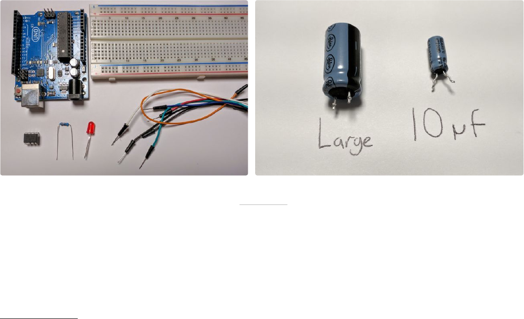
Required Hardware
• Arduino (Uno is the easiest, but any Arduino will work)
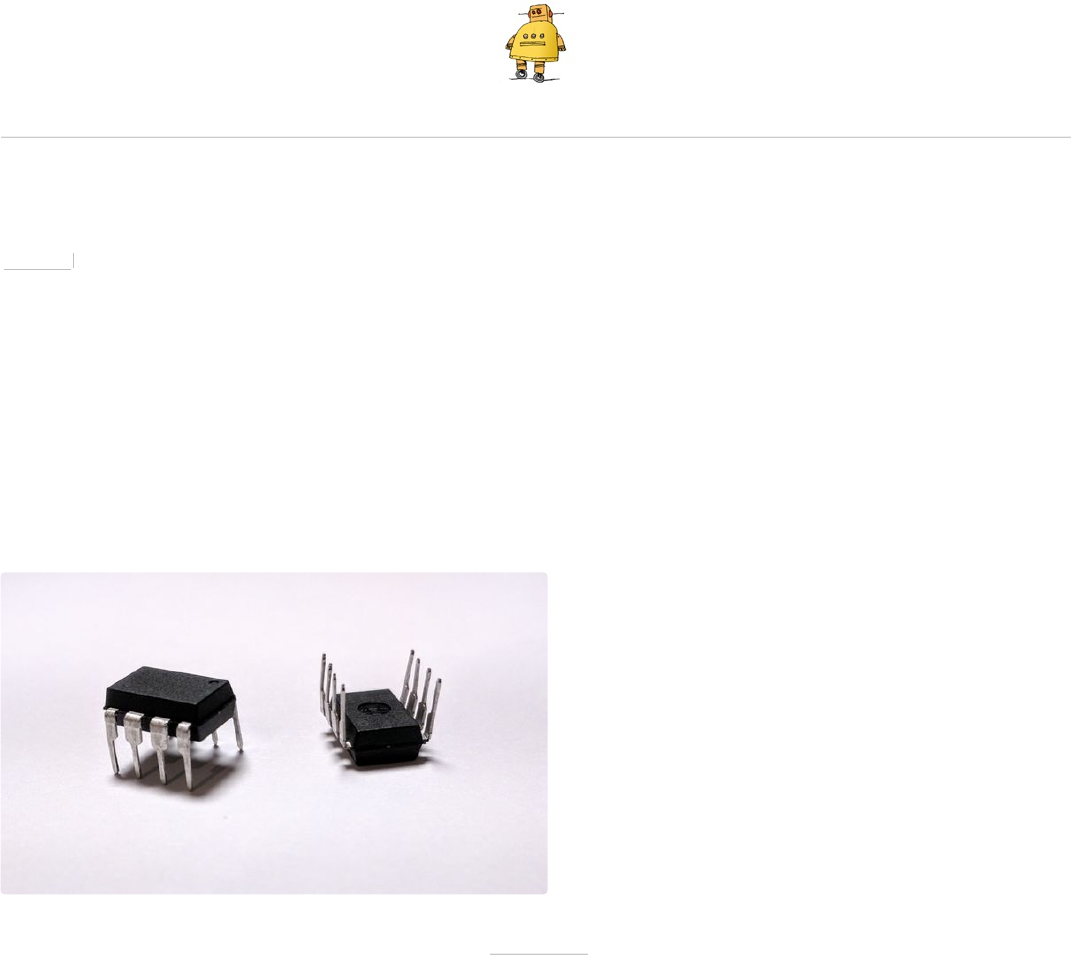
• ATtiny13 or 13a
• Breadboard
• Jumper Wires
Troubleshooting Hardware (not necessarily required)
• 10uf electrolytic capacitor
• Any large electrolytic capacitor (mine is 1000uf, but any capacitance 100uf and above will work best)
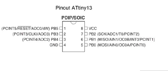
Step 2: Setting Up the Hardware
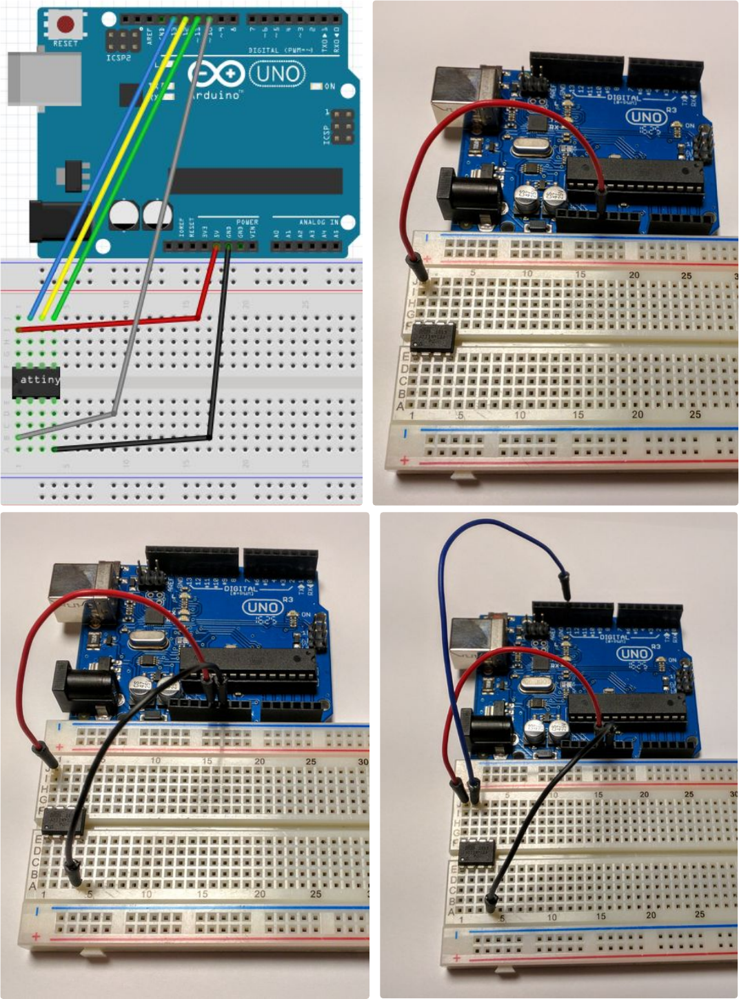
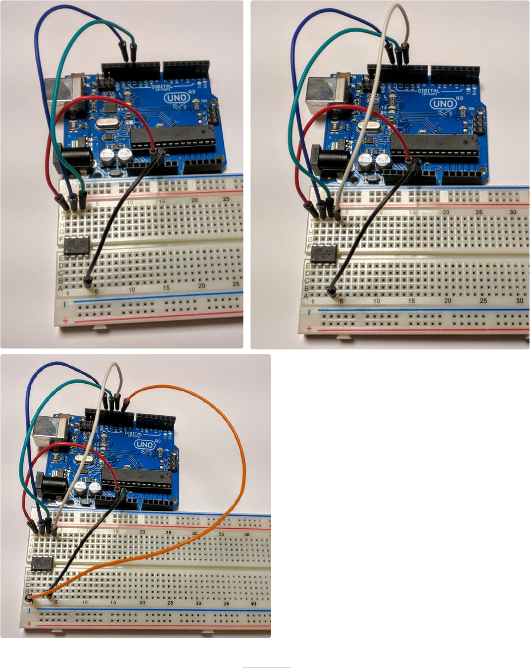
Connect the pins of the Arduino to the ATtiny as
shown in the image or table below.
Important Note:Make sure to orient your ATtiny such
that the indicator dot on your chip is in the bottom left
corner as shown in the images (across from the 5v
line). Orienting your ATtiny the opposite way can hurt
the chip.
Arduino____________ATtiny13(a)
5v----------------------------Pin 8
GND------------------------Pin 4
Pin 13-----------------------Pin 7
Pin 12-----------------------Pin 6
Pin 11-----------------------Pin 5
Pin 10-----------------------Pin 1
Updated Guide on How to Program an Attiny13 or 13a With the Arduino IDE: Page 2
Updated Guide on How to Program an Attiny13 or 13a With the Arduino IDE: Page 3
Updated Guide on How to Program an Attiny13 or 13a With the Arduino IDE: Page 4
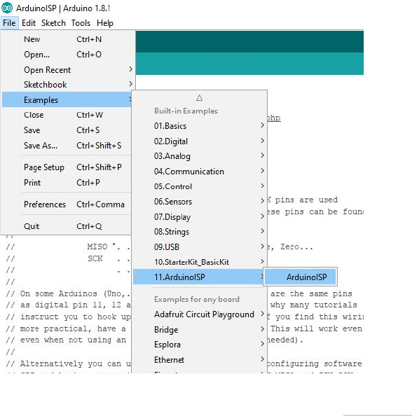
Step 3: Setting Up the Arduino As ISP
Navigate to Files-Examples-ArduinoISP and click on ArduinoISP. Upload this sketch to your Arduino. Now your
Arduino is set up as a programmer for programming other chips.
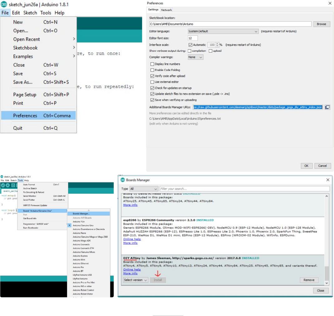
Step 4: Downloading the Attiny13(a) Core Files
To program the ATtiny13 or 13a, you will need to
install the core files. For this we will be using the core
files created by sleepmanj, which I find to be the
easiest to install and the best to use.
To install these files, open your Arduino IDE and
navigate to the files drop-down menu, then select
preferences. Paste this URL
"https://raw.githubusercontent.com/sleemanj/optiboot/
master/dists/package_gogo_diy_attiny_index.json"
where it says "Additional Boards Manager URLs:".
If you already have a URL here and want to add
more, separate the URLs with a comma and a space.
Now navigate to tools-board and click on Boards
Manager.... Now scroll down until you see DIY
ATtiny and click the install button (it will default to the
newest version).
Updated Guide on How to Program an Attiny13 or 13a With the Arduino IDE: Page 5
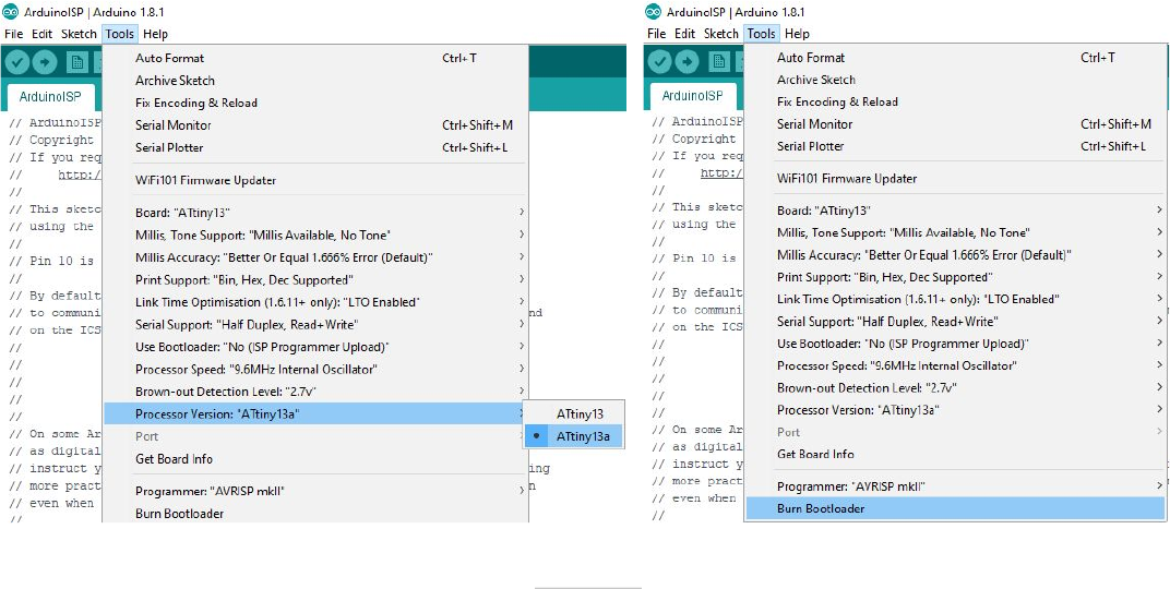
Step 5: Burning the Bootloader to the Attiny
Go to Tools-Board and select ATtiny13. After selecting ATtiny13, navigate to Tools-Processor Version and
select either ATtiny13 or ATtiny13a depending on your chip. Do not change any other settings until you know
what they do, they can mess up what you are trying to accomplish. Finally, click the Burn Bootloader button at
the bottom of the tools drop-down menu.
Updated Guide on How to Program an Attiny13 or 13a With the Arduino IDE: Page 6
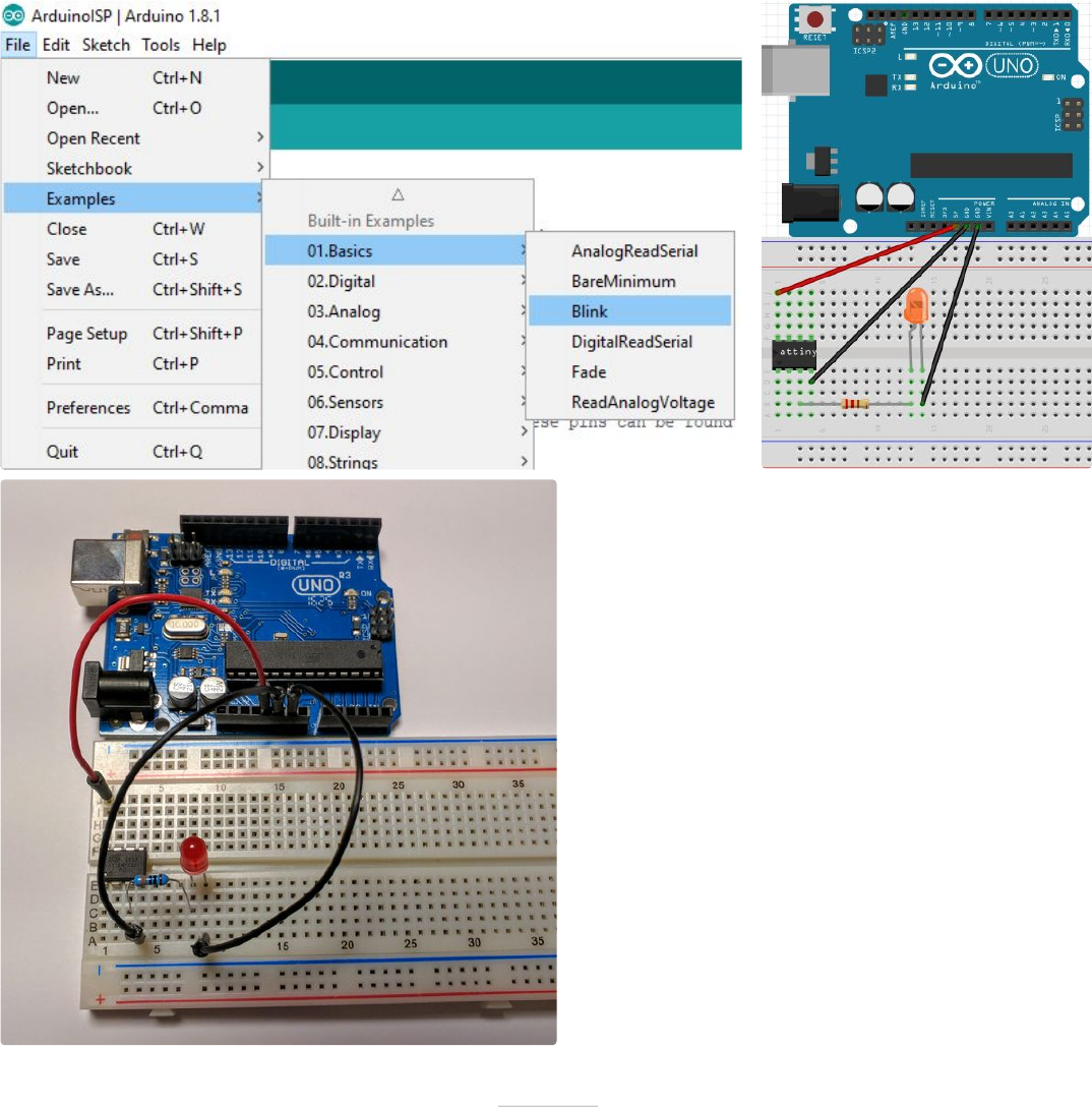
Step 6: Programming the Chip
You're at the homestretch! To make sure everything
is working, let's upload the blink sketch to the ATtiny.
Navigate to Files-Examples-Basics and select
Blink.
There are a few changes we will need to make
though. In the program, change every instance of
"LED_BUILTIN" to "4" because our ATtiny doesn't
have a built in LED. This "4" corresponds to pin 3 of
the ATtiny (This can get confusing, you can reference
what number in the IDE corresponds to what pin on
the diagram in the "Troubleshooting" step. Now you
can upload this code to your ATtiny through your
Arduino by clicking the upload button.
To test to see if it worked, connect an LED (along
with an appropriate resistor) between pin 3 on the
ATtiny and ground as shown in the diagram and
image above. The LED should be blinking on and off.
If it is, congratulations! You now know how to
program an ATtiny13 or 13a! You can now disconnect
all wires except the 5v and ground.
If your LED isn't blinking, don't worry, proceed to the
troubleshooting step to fix your problems.
Updated Guide on How to Program an Attiny13 or 13a With the Arduino IDE: Page 7
Updated Guide on How to Program an Attiny13 or 13a With the Arduino IDE: Page 8
Step 7: Troubleshooting
Something always goes wrong when working with
new things, that's ok! Let's try to fix these issues. Try
these in the order they show up.
• Double check all of your connections and your
orientation of the ATtiny and LED.
• Re-upload the ArduinoISP sketch to your Arduino.
• Connect a 10uf electrolytic capacitor between
ground and reset on your Arduino. Make sure to plug
in the capacitor in the correct orientation, negative
goes to ground.
• Connect any large capacitor between the 5v and
ground on the breadboard, this will help smooth out
any voltage spikes.
• Make sure enough power is getting to the Arduino
that is programming the ATtiny, a 9 volt battery might
not work.
• Switch out your Arduino with a different Arduino
• Make sure you're using an up to date IDE and up to
date core files
• Click on tools and make sure the drop down menu
looks the same as the menu shown in the "Burn the
Bootloader" step. If something is different, change it
and re-burn the bootloader.
Step 8: Great Job!
Congratulations on programming your ATtiny and thanks for reading my Instructable!
Updated Guide on How to Program an Attiny13 or 13a With the Arduino IDE: Page 9
