User Guide LDC Tool Freescale
User%20Guide%20-%20LDC-Tool%20-%20Freescale
User Manual:
Open the PDF directly: View PDF ![]() .
.
Page Count: 24
LIN Software
Version 2.0.4.1
LDC - tool
1 / 24
User Guide
ihr
GmbH
Airport Boulevard B210
77836 Rheinmuenster
Tel.: +49 7229 / 18475-0
Fax: +49 7229 / 18475-11
homepage: http://www.ihr.de
e-mail: support@ihr.de
© 2013 ihr GmbH

LIN Software
Version 2.0.4.1
LDC - tool
2 / 24
1 LDC – LIN DRIVER AND CONFIGURATION TOOL 4
1.1 P
REFACE
4
1.2 P
URPOSE OF THE
LDC-T
OOL
4
1.3 C
ODE GENERATION
5
2 INSTALLATION 6
2.1 H
OST
S
YSTEM
R
EQUIREMENTS
6
2.2 I
NSTALL THE
T
OOL
6
2.3 S
ETUP THE
T
OOL
6
2.4 S
ETUP THE
L
ICENSE
C
ODE
7
2.4.1 E
NTER
E
VALUATION
L
ICENSE
8
2.4.2 G
ET AN UNRESTRICTED LICENSE
9
3 USING THE LDC 11
3.1 T
HE USER INTERFACE
11
3.2 T
AB
“P
ROJECT
S
ETTINGS
” 12
3.2.1 S
ELECT
C
ONFIGURATION
F
ILE
: 12
3.2.2 L
OAD
C
ONFIGURATION
: 12
3.2.3 S
AVE
C
ONFIGURATION
: 13
3.2.4 C
LEAR
C
ONFIGURATION
: 13
3.2.5 S
ELECT
D
ESTINATION
P
ATH
: 13
3.3 T
AB
"O
PERATION
M
ODE
" 14
3.4 T
AB
"LIN
C
ONFIGURATION
" 15
3.4.1 S
ELECT
LDF 15
3.4.2 E
DIT
LDF 15
3.4.3 R
ELOAD
LDF 15
3.4.4 S
ELECT
N
ODE
15
3.4.5 J2602
O
PTION
15
3.5 T
AB
"D
IAGNOSTICS
" 16
3.5.1 LIN
S
TANDARD
D
IAGNOSTIC
16
3.5.1.1 Cooked API 16
3.5.1.2 Raw API 16
3.5.2 U
SER DEFINED
D
IAGNOSTIC
16
3.5.2.1 Mandatory Services 16
3.6 T
AB
"N
ODE
C
ONFIGURATION
" 17
3.6.1 A
SSIGN
NAD 17
3.6.2 F
IXED
I
NITIALIZED
NAD 17
3.6.3 C
ONDITIONAL
C
HANGED
NAD 17
3.6.4 P
RECONFIGURED
P
ROTECTED
ID
S
17
3.6.5 D
ATA
D
UMP
18
3.6.6 R
EAD
ECU
S
ERIAL
N
UMBER
18
3.6.7 S
AVE
C
ONFIGURATION
18
3.6.8 E
NABLE
U
SER
D
EFINED
18
3.6.9 A
SSIGN
F
RAME
ID 18
3.6.10 R
EAD
M
ESSAGE
ID 18
LIN Software
Version 2.0.4.1
LDC - tool
3 / 24
3.6.11 A
SSIGN
NAD
VIA
SNPD 18
3.7 T
AB
"H
ARDWARE
S
ETTINGS
" 19
3.7.1 T
HE
H
ARDWARE
P
AGE
19
3.7.1.1 Select Controller 19
3.7.1.2 Select LIN IO/UART 19
3.7.1.3 Controller Speed 19
3.7.1.4 Baudrate Synchronisation 19
3.7.1.5 16bit Free Timer Counter Address 19
3.7.1.6 Timer Prescaler Value (1-128) 20
3.7.1.7 Set positive Baudrate Register Range 20
3.7.1.8 Set negative Baudrate Register Range 20
4 LIN CONFORMANCE 21
5 GLOSSARY 22
6 DOCUMENT REFERENCES 22
7 CHANGE HISTORY 23

LIN Software
Version 2.0.4.1
LDC - tool
4 / 24
1 LDC – LIN Driver and Configuration Tool
1.1 Preface
ihr GmbH is an associated member to the LIN consortium since the beginning and member of
the LIN testing workgroup since 2003. ihr GmbH is a well known supplier for premium LIN
emulators and LIN measurement equipment. Since 2004 ihr GmbH performs conformance
tests as an accredited test house. We have seen a lot of LIN applications and we know the
always repeating customer demands related to the LIN topic.
Since ihr has a long and strong relationship over many years with microcontroller
manufacturers, the idea arose for the LIN Driver and Configuration Tool (LDC-Tool) for
microcontrollers.
1.2 Purpose of the LDC-Tool
Without special LIN expertise, designers can easily add a LIN interface to their applications
using microcontrollers (MCUs). The LIN configuration tool supports LIN specifications 1.3, 2.0
and 2.1. In the version 2.0.0 the tool supports LIN 1.3 and LIN 2.x (also J2602) slave and
master applications for many microcontroller families.
The configuration tool simply needs basic information such as:
- The MCU derivate
- The LIN Description File (LDF)
- The node to be implemented (as per LDF)
- Some controller hardware dependant settings
Additionally, designers can select optional services as per LIN specifications separate for each
node. Experienced users can change hardware-specific settings. The tool then generates C
Code for the embedded project. The configuration can be stored for later usage. The
generated driver files are integrated into project workspace, and the code generated supports
the specified compliant LIN API.
Therefore, the software designers can concentrate on the applications and rely on the LIN
conform driver under the terms stated in the ihr EULA (see document reference no. 5).

LIN Software
Version 2.0.4.1
LDC - tool
5 / 24
1.3 Code generation
The code generated by the LDC is compliant to the MISRA standard C2004. It fulfils all
required rules except:
o Rule 1.1: „All code shall conform to ISO 9899:1990“
All the compilers used for embedded designs support microcontroller specific language
extensions, which are to be used by the hardware related driver code.
o Rule 6.4: „Bit fields shall only be defined to be of type unsigned int or signed int“
This rule does not apply to small microcontrollers. For saving resources, especially on 8 bit
microcontrollers, we make use of byte variables of type „char“ or „unsigned char“ for bit
fields.
o Rule 18.4 „Unions shall not be used“
A communication driver has to handle buffers for data reception and sending. Protocol data
units stored in that buffers are self describing data structures. So the data type of a PDU
stored in a buffer must be detected on runtime. We use unions as overlay on the buffers, to
access the data. This is a state of the art programming technique for communication
drivers and protocol stacks.
LIN Software
Version 2.0.4.1
LDC - tool
6 / 24
2 Installation
2.1 Host System Requirements
To install and run the program the host system need to fulfil the following requirements:
- PC-compatible system
- Microsoft® Windows 2000, XP, Vista, 7 (32Bit)
- Microsoft® Framework 3.5 or higher.
2.2 Install the Tool
Copy the folder with the LDC-Tool to the preferred location on your hard drive (preferable:
C:\Program Files\IHR GmbH\LDC_Tool). Please make sure that the “LDFapi3.dll” and the
“IHRLicenseDLL.dll” is located in the same folder as the “LinDriverConfigurator.exe”. Also the
language extension subdirectories must be copied to the target directory. To start the LDC-
Tool please double click the “LinDriverConfigurator.exe” Icon. You may also create a shortcut
or program icon on your desktop.
2.3 Setup the Tool
Before you start the program for the first time, login as a system administrator. Then start the
LDC application explicit as a System Administrator. Click with the right mouse button on the
program file and select the line “Execute as an administrator”. Then you will see the screen
below:
LIN Software
Version 2.0.4.1
LDC - tool
7 / 24
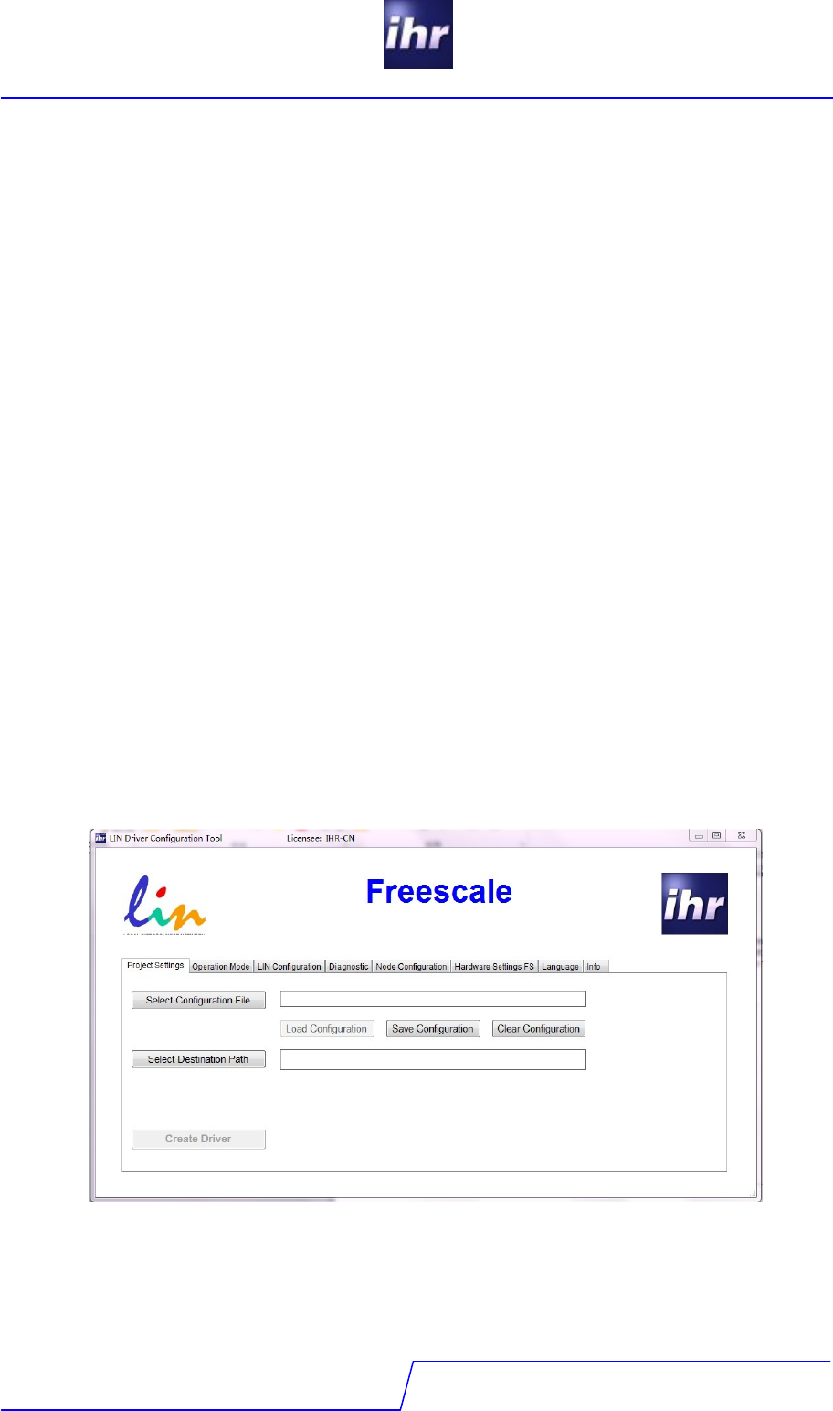
On the “Language” tab you may now select your preferred language.
2.4 Setup the License Code
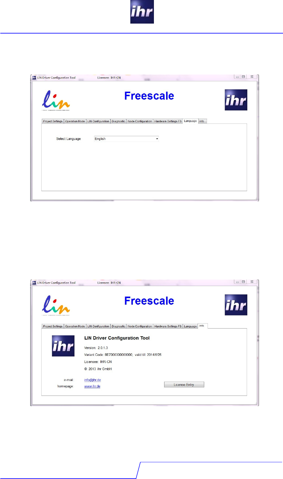
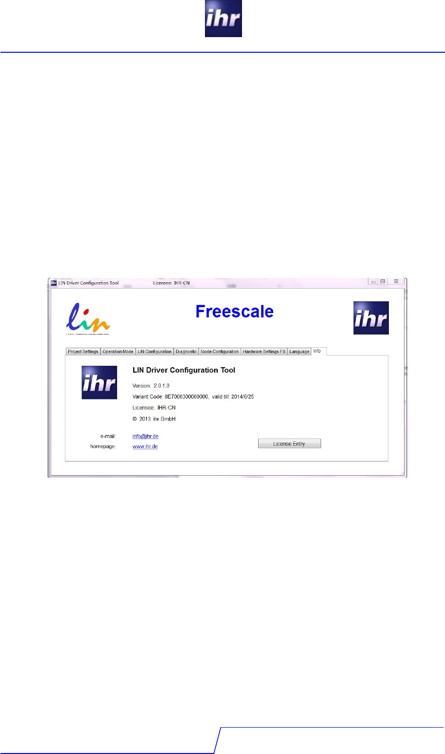
You should be logged in as a system administrator. Start the application explicit as a system
administrator. Click with the right mouse button on the program file and select the line “Execute
as an administrator”. Then select the “Info” tab. You’ll see this screen.
LIN Software
Version 2.0.4.1
LDC - tool
8 / 24
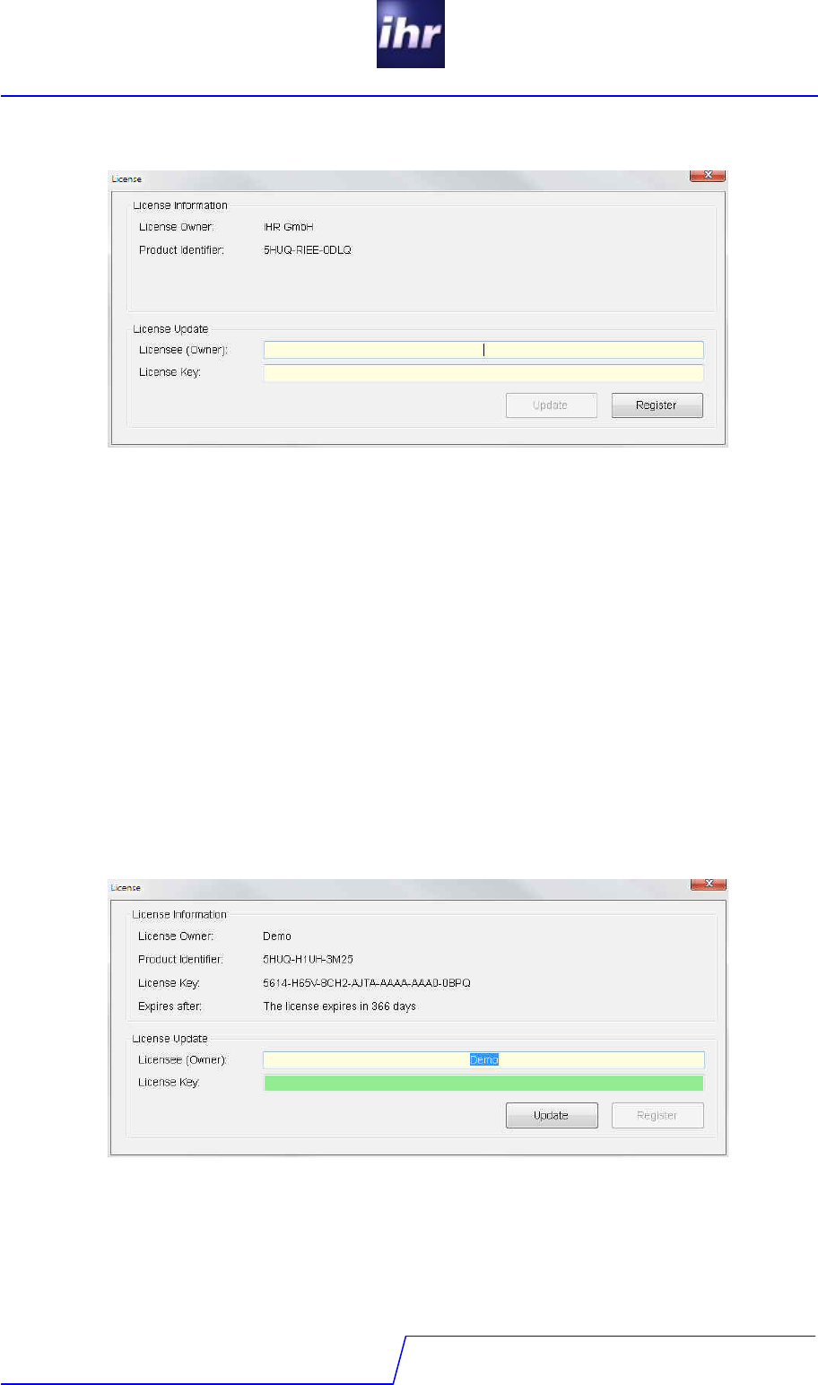
Click the “License Entry” Button. This license dialog window comes up:
Now there are two choices:
- Enter a evaluation license
- Get a unrestricted license
2.4.1 Enter Evaluation License
An evaluation license code is available on the ihr GmbH internet page for different
microcontroller families. This license code normally is valid for one up to two years. All the
features of the LDC tool are available but the LIN network is limited to a maximum of three LIN
nodes. The license code looks like this
5614-55B2-078E-A9TA-AAAA-AAA0-0DO1
Take the actual evaluation license code and enter it into the lower input line, preferable by
copy and paste. In the upper line for the name of the licensee enter the string “Demo”. Please
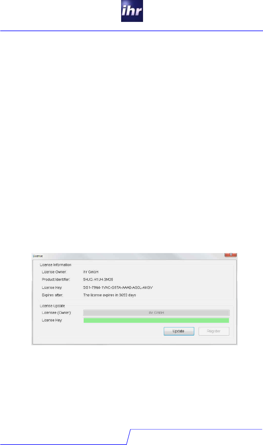
take care of the letter cases. Then click on the “Register” button. Now you’ll see a screen like
this.
The license code is successful registered now and you may use the tool till expiration date.
Before usage of the tool, exit the program and restart it again. Now it can be used without
administrator rights. This procedure may be repeated as often as you need. You are also free,
to change the microcontroller family without reinstallation of the LDC tool.
LIN Software
Version 2.0.4.1
LDC - tool
9 / 24
2.4.2 Get an unrestricted license
To get an unrestricted license, please send a order to ihr GmbH sales department. The order
should contain all the options or capabilities of the LIN stack which you need for your
application. Additional add the “Product Identifier” and your e-mail address on your order
sheet. The product identifier is bound to the computer and can be found on the license dialog
after first installation of the tool. It looks like this:
5HUQ-G7HR-CB4Q.
The ihr GmbH sales department can create a license code for you only with this product
identifier available. After the order is accepted by ihr GmbH, you’ll receive an e-mail with the
license code. After you received the code, proceed in this way:
- Login as a system administrator.
- Then start the LDC application explicit as a System Administrator. Click with the
right mouse button on the program file and select the line “Execute as an
administrator”.
- Then select the “Info” tab and open the “License Entry” dialog window.
- Enter your user name in the upper line for licensee or owner. Take the user name
as it is in the email, preferable by copy and past. If the user name is not identical,
the license code will not work.
- Enter the license code in the lower line.
If it is the first license, press the register button. If you used already an evaluation license or
the license code is an update for a previous installed license code, press the “Update” button.
On successful registration of the license code you’ll see a screen like this:
If the license registration fails, please check:
- Did you log in as an administrator?
- Did you start the program with administrator rights?
- Did you enter the user name correct (upper and lower case)?
- Is the license code correct?
LIN Software
Version 2.0.4.1
LDC - tool
10 / 24
Please be aware of:
- A license code is bound to one computer and can not be moved between different
computers.
- A license code is granted to one licensee or user. The licensee can not be changed
after first license code registration.
- If a license code is to be updated (except an evaluation license), an update must
always have the same licensee registered.
- An update of the tool does not require a new license code registration.
- If you register a license code without administrator rights, the license will be valid
only for this user, but not for all users of this computer!
If you exit the license dialog, you’ll see a screen like this:
The info tab shows all license and copyright related information about the LDC tool.

LIN Software
Version 2.0.4.1
LDC - tool
11 / 24
3 Using the LDC
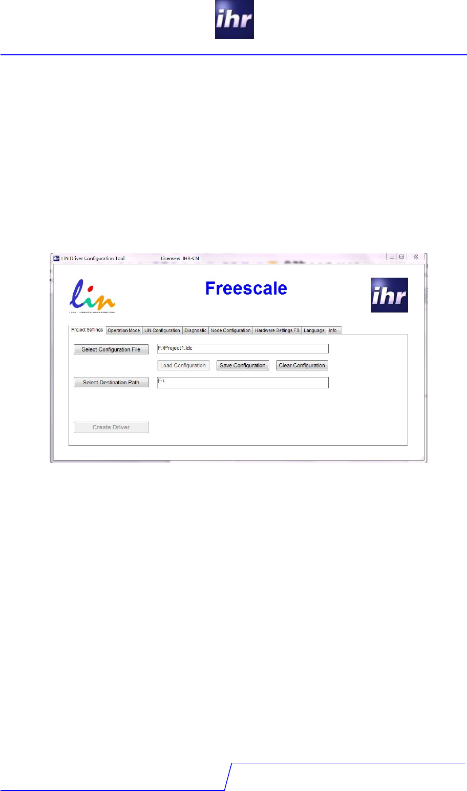
3.1 The user interface
The LDC Tool offers a tabbed dialog with eight tabs. The tabs seven (Language) and eight
(Info) are for administrative purpose and regular only used during setup phase.
The Tabs are:
1. Project settings
Setting, saving and loading of project configuration files, setting of working directory
2. Operation Mode
Application dependent run time parameter settings for the driver
3. LIN Configuration
Administration of the related “LIN Description File”, Selection of LIN-Node
4. Diagnostic
Settings for LIN diagnostic functionality
5. Node Configuration
Individual settings of node operation and node specific parameters
6. Hardware settings
Configuration of the hardware abstraction layer
7. Language
Select your preferred language for the tool
8. Info
Copyright and license information display
To configure a LIN driver straight forward, we recommend to select the tabs 1 to 6 and to fill in
the forms strictly selecting the tabs from the left to the right side.
At the bottom in the first tab (project settings) there is a “Create Driver” button. At the
beginning this button is not enabled. As soon as there is sufficient and consistent information
available to create a functional driver, the button becomes enabled and changes color to
green.
LIN Software
Version 2.0.4.1
LDC - tool
12 / 24
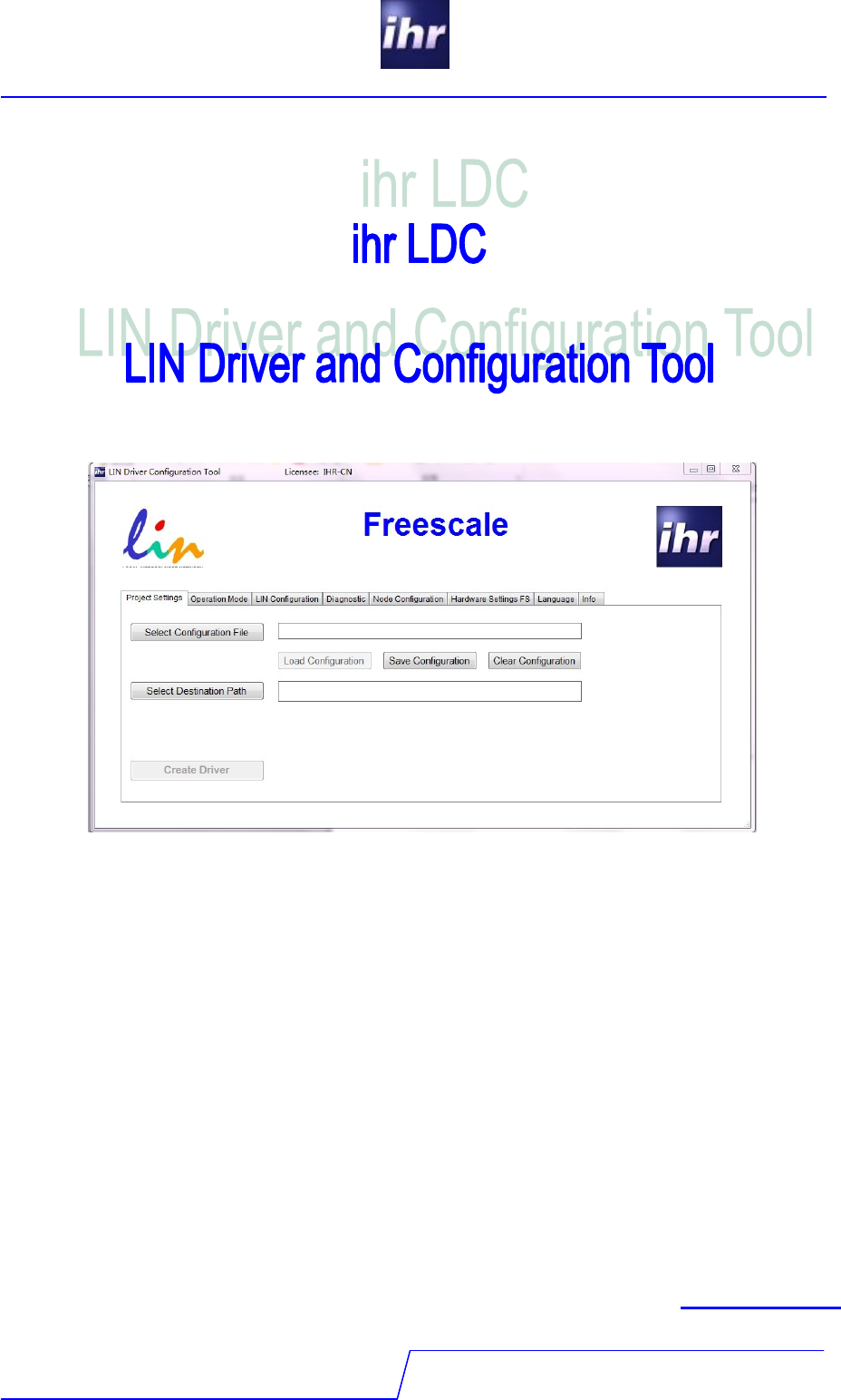
3.2 Tab “Project Settings”
On this screen you may:
- Select and load an existing LDC configuration file.
A LDC configuration file has the suffix *.ldc
- Define a new LDC configuration file
- Load an existing configuration from a selected LDC configuration file
- Save a configuration into a LDC configuration file
- Clear a previous configuration
- Set path where LDC output should be stored.
Normally this is your source code area for the LIN driver.
3.2.1 Select Configuration File:
If you want to use an existing configuration file, click the “Select Configuration File” button and
a windows file dialog is opened. Select the desired file and close the file selection dialog.
3.2.2 Load Configuration:
Now you can reload the selected file using the “Load Configuration” button and you can save
modifications of the configuration into the selected file using the “Save Configuration” button.
Configuration files have the suffix *.ldc. A selected file stays active as long as no other file is
selected.

LIN Software
Version 2.0.4.1
LDC - tool
13 / 24
3.2.3 Save Configuration:
If you want to create a new configuration file, enter the filename and path into the field to the
right of the “Select Configuration File” button and click the “Save Configuration” button.
A configuration may only be saved, when it is checked as a valid configuration. If the
configuration is not consistent, the “Save Configuration” button is disabled, to prevent you from
possibly overwriting a valid configuration by mistake.
3.2.4 Clear Configuration:
The “Clear Configuration” button erases all previous entered or loaded configuration data and
creates a new empty configuration.
3.2.5 Select Destination Path:
To tell the LDC where the created code files are to be stored, select a working directory for
your project by the “Select Destination Path” button. This opens a windows directory selection
dialog to select the desired path or to create a new one.
LIN Software
Version 2.0.4.1
LDC - tool
14 / 24
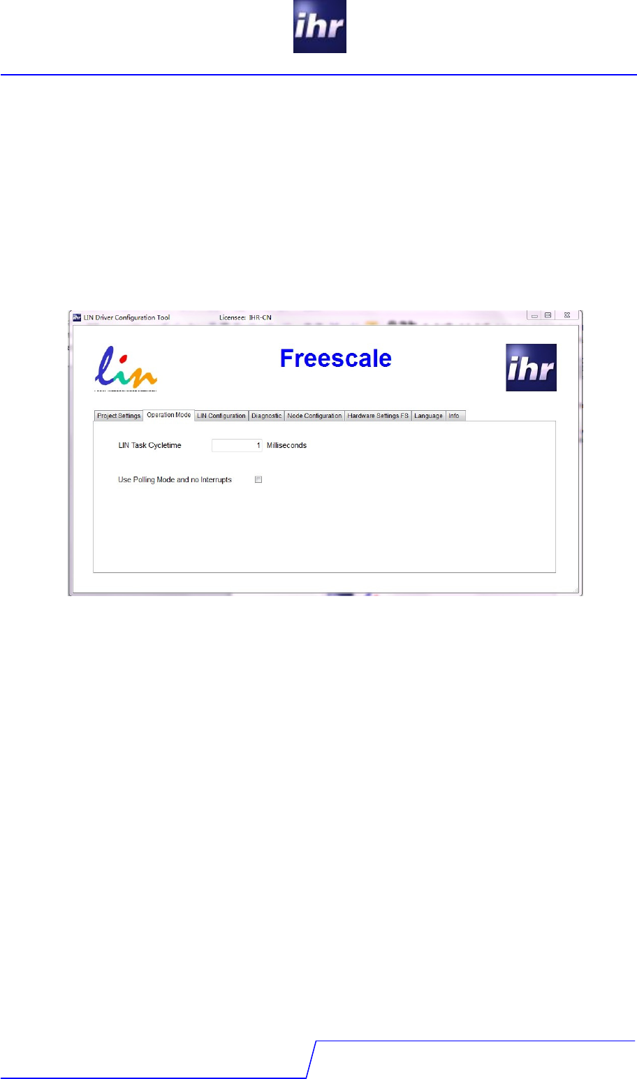
3.3 Tab "Operation Mode"
This page configures how you integrate the LIN driver into your application. Currently there are
two choices only:
- You have to give the time slice, how often the LIN task will be called by your
application. Fill in the time period in milliseconds at which the “ld_task” will be called
in your application. Typical values are between 1 to 5 milliseconds.
- You can select polling mode if you do not use interrupts.
For details please refer to the LIN driver start up guide.
LIN Software
Version 2.0.4.1
LDC - tool
15 / 24
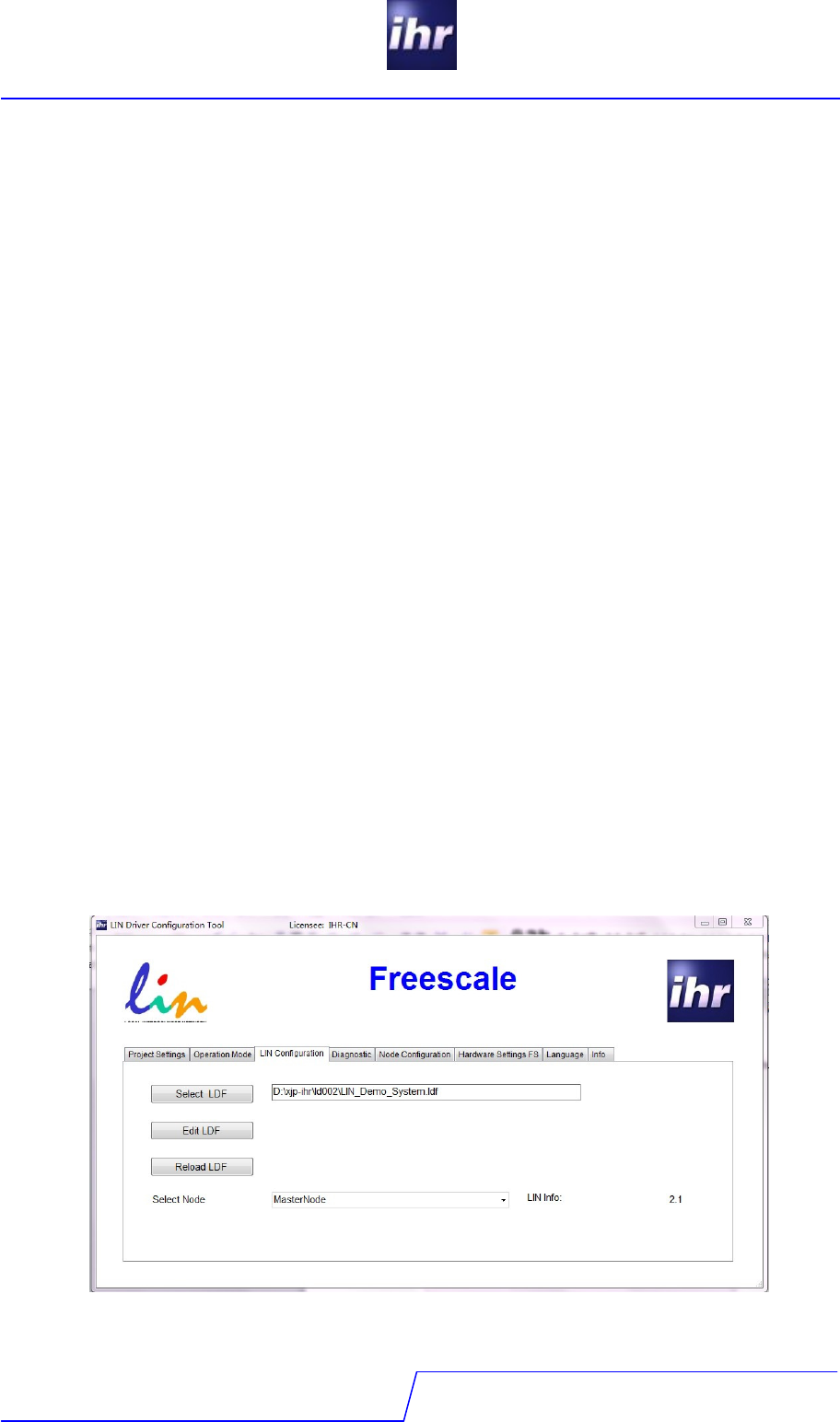
3.4 Tab "LIN Configuration"
3.4.1 Select LDF
Selects the “LIN Description File” (LDF) file of the LIN network. Select the LDF file
corresponding to the project. The internal LIN-parser checks the syntax of the LDF file. If the
LDF parser detects errors in the LDF file, a corresponding error message is displayed. The
LDF parser accepts LDF files as per Standard LIN 1.3, 2.0, 2.1, and J2602 dependent on your
license capabilities.
3.4.2 Edit LDF
With "Edit LDF" the Windows editor opens the selected LDF file to view and modify the LDF file
if modifications are required. The program will remind to reload the LDF file to overtake the
modifications into the LDC database.
3.4.3 Reload LDF
If the LDF file was modified, clicking this button reloads the file to overtake the modifications
into the LDC database. If the LDF was modified outside the LDC-Tool the reminder to reload
will not pop up.
3.4.4 Select Node
Select node chooses the node you want to design. Master nodes are only visible, if your
license supports master nodes.
3.4.5 J2602 Option
This option depends on your license capabilities. If your node is not a standard LIN but a
J2602 node, select this check box
LIN Software
Version 2.0.4.1
LDC - tool
16 / 24
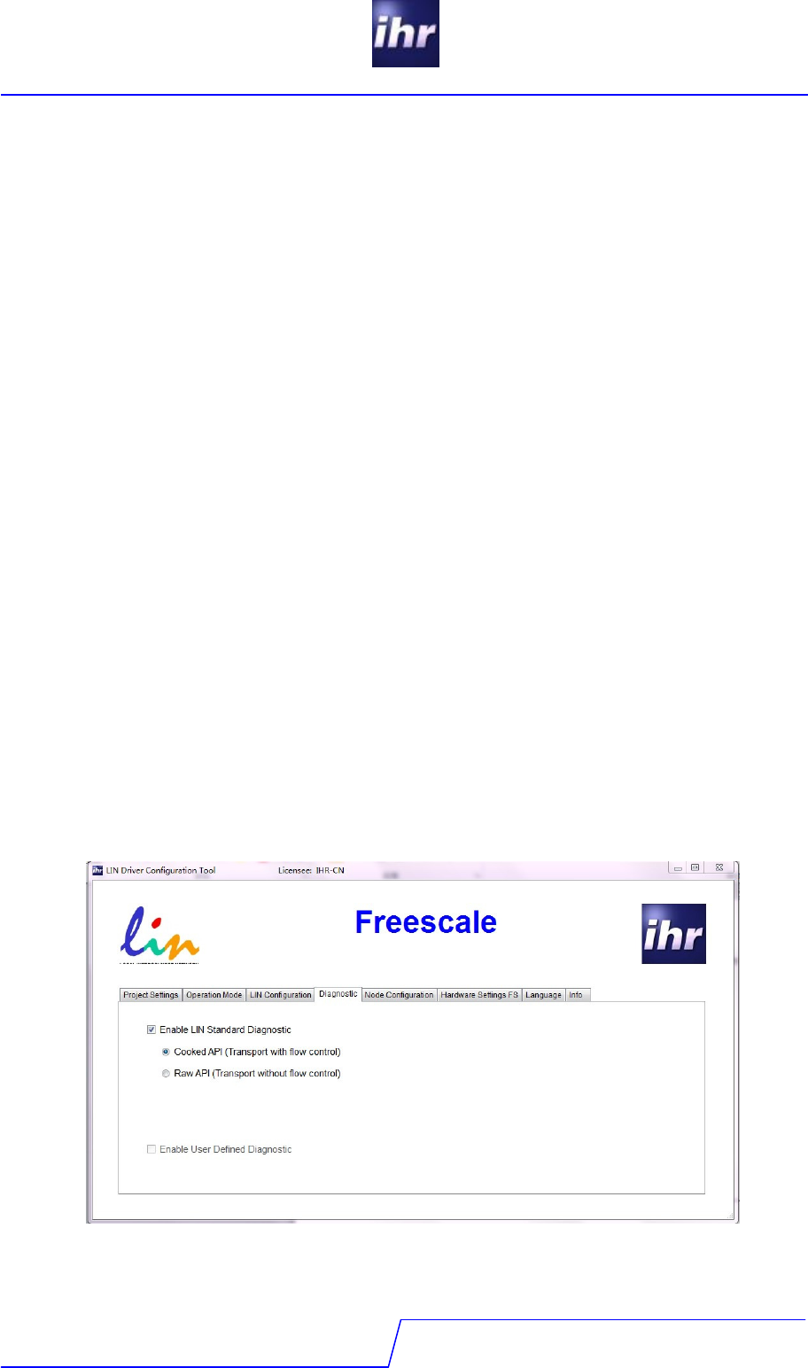
3.5 Tab "Diagnostics"
Diagnostic settings according to your LIN project.
3.5.1 LIN Standard Diagnostic
3.5.1.1 Cooked API
In the mode "Cooked API" the transport protocol layer is implemented in the LIN driver with a
good flow control. The application exchanges the complete diagnostic messages to the drives.
The driver handles the fragmentation and assembly of long messages (more than 5 data
bytes). The buffers are available for application use during times without diagnostics.
3.5.1.2 Raw API
In the mode "Raw API" the driver exchanges whole frames, the transport protocol layer is also
implemented in the LIN driver, but the flow control is not as good as with the Cooked API. The
fragmentation of messages and formatting has to be done by the application itself. This if very
useful if the first 2-4 bytes (depending on length of message) should not be reserved for the
message overhead. The values "Receiver Queue Size" and Transmit Queue Size" need to be
defined for memory resource allocation. The buffers are not available for application use.
3.5.2 User defined Diagnostic
Diagnosis services are to be implemented by the application as needed. This is useful, when
the application use its own transport protocol layer or to reduce memory use in case of low
level diagnostics. Complete flow control and transport layer have to be implemented in the
application.
3.5.2.1 Mandatory Services
The standard mandatory LIN diagnosis services and only these will be implemented by the LIN
stack (Read by ID – identifier 0 and depending on LIN 2.0 / 2.1 the assign frame ID or assign
frame ID range service).
LIN Software
Version 2.0.4.1
LDC - tool
17 / 24
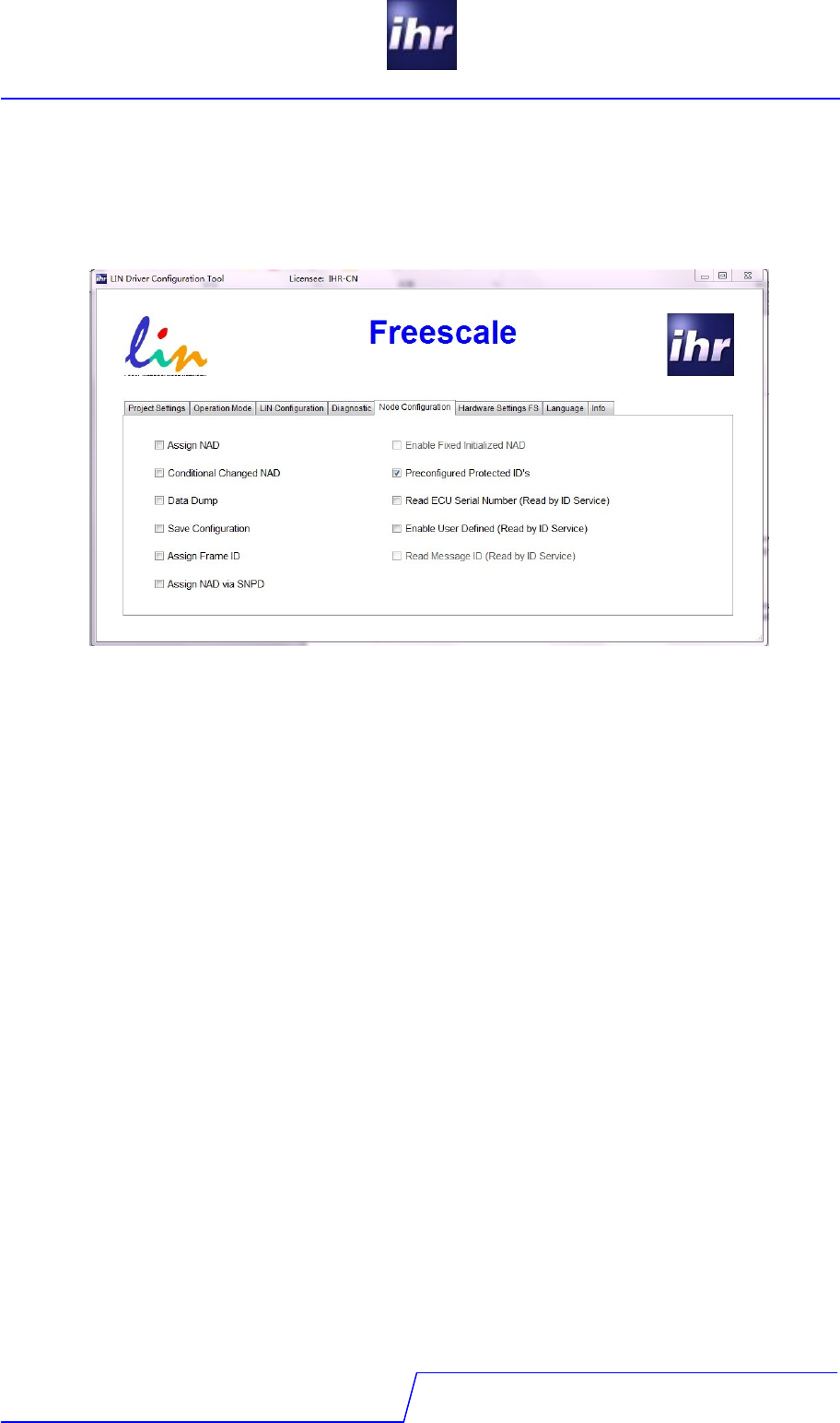
3.6 Tab "Node Configuration"
Enables or disables some functionalities of the driver assigned to the specific node.
3.6.1 Assign NAD
This will enable the service “Assign NAD” (specified in the LIN specification 2.x). The service
will be handled by the driver stack without intervention from the application. But saving the
NAD in the NVM is still in the responsibility of the application.
3.6.2 Fixed Initialized NAD
This will set the initial NAD (as specified in LIN 2.1) to a value defined in the LDC regardless of
the setting in the LDF. If the value is not set by the tool the value defined by the LDF will be
taken. This can also be set for LIN 2.0.
3.6.3 Conditional Changed NAD
This will enable the service Conditional Assign NAD (specified in the LIN Specification 2.x).
The service will be handled by the driver stack without intervention from the application. Saving
the NAD in the NVM is still in the duty of the application.
3.6.4 Preconfigured Protected IDs
This will set the PIDs to the values defined in the LDF. If this option is unchecked, the PIDs will
be set to zero and the node will not respond to any frame header. An initial configuration
sequence has to be executed after first startup. There are several approaches to accomplish
this. for example a configuration via LIN (assign frame ID / assign frame ID range are
mandatory services for LIN 2.0 / 2.1).

LIN Software
Version 2.0.4.1
LDC - tool
18 / 24
3.6.5 Data Dump
This option enables the service Data Dump (specified in the LIN Specification 2.x). The driver
stack will provide a declaration for a call-back function to treat the data received. The function
has to be implemented by the application.
3.6.6 Read ECU Serial Number
This option enables the Read by ID service with identifier 1. The driver stack will provide a
declaration for a call-back function to support the driver with the correct data. The function has
to be implemented by the application.
3.6.7 Save Configuration
This option enables the service Save Configuration (specified in the LIN Specification 2.1). The
status word will indicate a received request with the appropriate flag. It is in the responsibility to
save the configuration.
3.6.8 Enable User Defined
This option enables the Read by ID services for identifiers 32-63 (specified in the LIN
Specification 2.x). The driver stack will provide a declaration for a call-back function to supply
the correct response for the received identifier. Please be aware that LIN 2.0 specification
does not provide the possibility of a negative response when this feature is activated!
3.6.9 Assign Frame ID
This option enables the Assign Frame ID services (specified in LIN specification 2.0). On LIN
2.1 networks this option should be selected only for master nodes to ensure that compatibility
with 2.0 slave nodes is given. For 2.0 nodes this service is mandatory and will be automatically
generated. On LIN 2.1 slave nodes this function will not work correctly because the message
identifiers needed for this service are not given.
3.6.10 Read Message ID
This option enables the Read by ID service for identifiers 16-31 (specified in LIN specification
2.0).
3.6.11 Assign NAD via SNPD
This option enables the Assign NAD via SNPD service. The driver stack will provide a callback
function to the application to handle the requested service (start, stop, and configuration
messages). This is not part of the standard driver but a separate add-on.
LIN Software
Version 2.0.4.1
LDC - tool
19 / 24
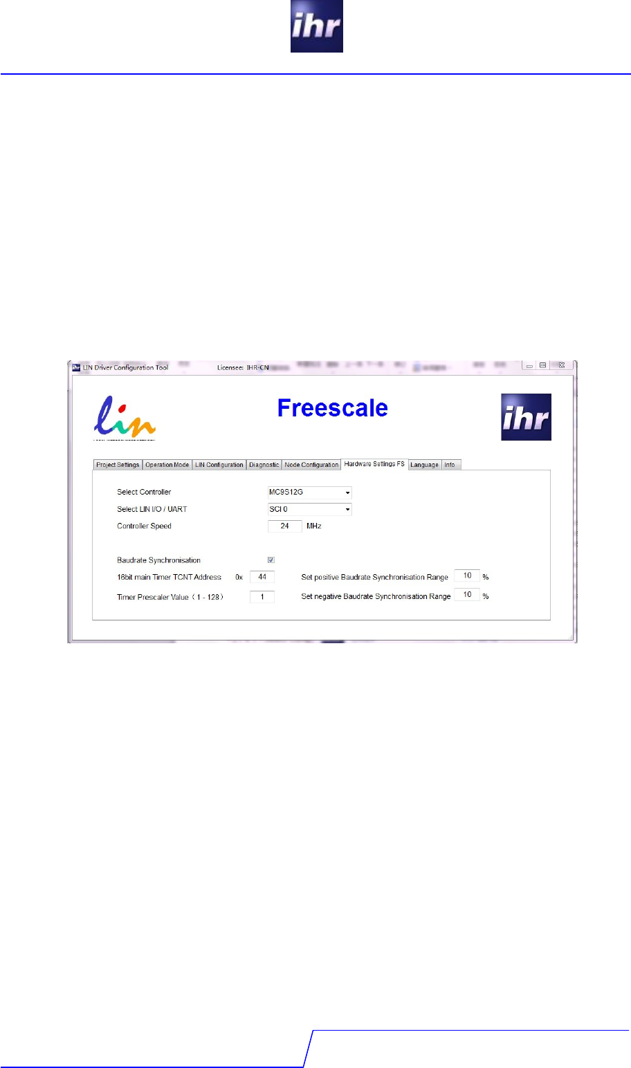
3.7 Tab "Hardware Settings"
This tab page depends on the microcontroller manufacturer supported by your license or, if
your LDC is licensed for more than one microcontroller supplier, of the supplier selected on the
“Project Settings” tab.
Ihr GmbH is permanently extending the number of supported microcontrollers. For details of
hardware specific settings please refer to your microcontroller handbook. This chapter shows
some samples of hardware setting pages, just to explain how settings should be done.
3.7.1 The Hardware Page
3.7.1.1 Select Controller
Select the controller family. The drop down box will show all microcontroller families from
Freescale which are supported by the driver.
3.7.1.2 Select LIN IO/UART
Select the SCI serial number. This will be used to select corresponding SCI register.
3.7.1.3 Controller Speed
Enter the clock rate on which the controller is running. This will be used to calculate the
baudrate register value. A higher MCU speed leads to a more accurate synchronized
baudrate.
3.7.1.4 Baudrate Synchronisation
Choose to enable the baudrate synchronisation setting.
3.7.1.5 16bit Free Timer Counter Address
The 16-bit main timer of the Timer Module is a free running up counter. This will be used to
calculate the synchronized baudrate value.

LIN Software
Version 2.0.4.1
LDC - tool
20 / 24
3.7.1.6 Timer Prescaler Value (1-128)
The value is the prescaler of the Timer Module. It is based on the user’s application, but should
be within 1-128. A small prescaler leads to a more accurate synchronized baudrate.
3.7.1.7 Set positive Baudrate Register Range
Positive offset value. Define the max positive synchronize range.
3.7.1.8 Set negative Baudrate Register Range
Negative offset value. Define the max negative synchronize range.

LIN Software
Version 2.0.4.1
LDC - tool
21 / 24
4 LIN Conformance
The LIN driver is pre-tested:
- This means the driver has been tested embedded into a test application.
- A conformance report always states the tested components, only! Usually the report
indicates the HW and SW release, so the report is valid for the certified
configuration only!
- The application can have an influence on the operation of the LIN stack. Therefore
each integration of the LIN driver has to be tested inside of its application.
- Some adjustments in the driver configuration can effect the LIN communication e.g.
controller specific settings
LIN Software
Version 2.0.4.1
LDC - tool
22 / 24
5 Glossary
API = Application Programming Interface
ASIC = Application Specific Integrated Circuit
DUT = Device under Test
ECU = Electronic Control Unit
ETF = Event Triggered Frame
ID = Identifier (6 Bit without Parity Bits)
LIN = Local Interconnect Network
LDF = LIN Description File
NAD = Node Address
NVM = Non volatile Memory
NCF = Node Capability File
OTP = On time Programmable
PCI = Protocol Control Information
PID = Protected Identifier (6 Bits identifier + 2 Parity Bits)
SBC = System Basis Chip
SCI = Serial Communication Interface
SOC = System on Chip
UART = Universal Asynchronous Receiver/Transmitter
6 Document References
No
.
Document/Description Comment Rev./
Date
1 ReleaseNote LDC-Tool.pdf Updated for each LDC-Tool release
containing the most recent changes as
well as change history
2.x.x.x
2 LIN Specification 1.3 1.3
3 LIN Specification 2.0 2.0
4 LIN Specification 2.1 2.1
5 ihr_EULA_vx.x.pdf current version is part of this delivery

LIN Software
Version 2.0.4.1
LDC - tool
23 / 24
7 Change History
Status
Date
by
Remark
created 2013.07.11 JX Initial draft
updated 2013.07.15 BR Format update
reviewed
released
LIN Software
Version 2.0.4.1
LDC - tool
24 / 24
IHR
IHRIHR
IHR GmbH
Airport Boulevard B210
D-77836 Rheinmuenster
Tel. +49 7229 18475 - 0
Fax. +49 7229 18475 - 11
Email support@ihr.de
Web www.ihr.de
