User Manual
User Manual:
Open the PDF directly: View PDF ![]() .
.
Page Count: 9
Automated Locker
User Manual
By
Alex Kim, Redwan Ibne Seraj Khan,
Hang Lin, Jay Chen, Weijin Zhu,
Kevin Cheung, Keming Kuang,
Huangwei Ding
School of Engineering and Applied Sciences
University at Buffalo, The State University of New York
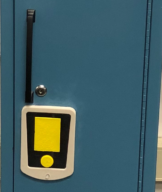
Figure 1: Overview of Automated Locker

Automated Locker User Manual
Contents
1 Introduction 2
2 Overview of System 2
2.1 SystemDescriptions ......................................... 2
2.2 SystemComponents ......................................... 2
3 Using the Locker 5
3.1 TurningontheLocker ........................................ 5
3.2 UnlockingtheLocker......................................... 5
3.3 LockingtheLocker.......................................... 5
3.4 MechanicalKeyOverride ...................................... 6
3.5 ChargingtheBattery......................................... 7
3.6 Modifications Made to the Locker . . . . . . . . . . . . . . . . . . . . . . . . . . . . . . . . . . 8
3.7 UserRequiredMaintenance ..................................... 8
4 Ordering Additional RFID Tags 8
5 Troubleshooting 8
6 Safety & Caution Statements 8
1
Automated Locker User Manual
1 Introduction
2 Overview of System
2.1 System Descriptions
We have modified a locker in from Depew High School in Depew, NY 14043. We modified with an electronic
system that replaces the old locking mechanism. The system allows a user to unlock the door by scanning
a pre-registered RFID (Radio-Frequency Identification) tag. After 5 seconds of being unlocked, the locking
mechanism automatically locks again.
Even if the locking mechanism has already locked while the door is open, the door can be closed by simply
pushing it to the frame. In case of system failure (e.g, dead battery or switch malfunction), we have also
implemented a mechanical key override, which can be used to open and close the door manually.
2.2 System Components
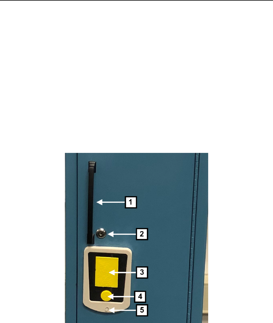
Figure 2: Front View of Automated Locker
•1. Door Handle
•2. Mechanical Key Override
•3. RFID Tag Reader
•4. Power Button
•5. LED Indicator
2
Automated Locker User Manual
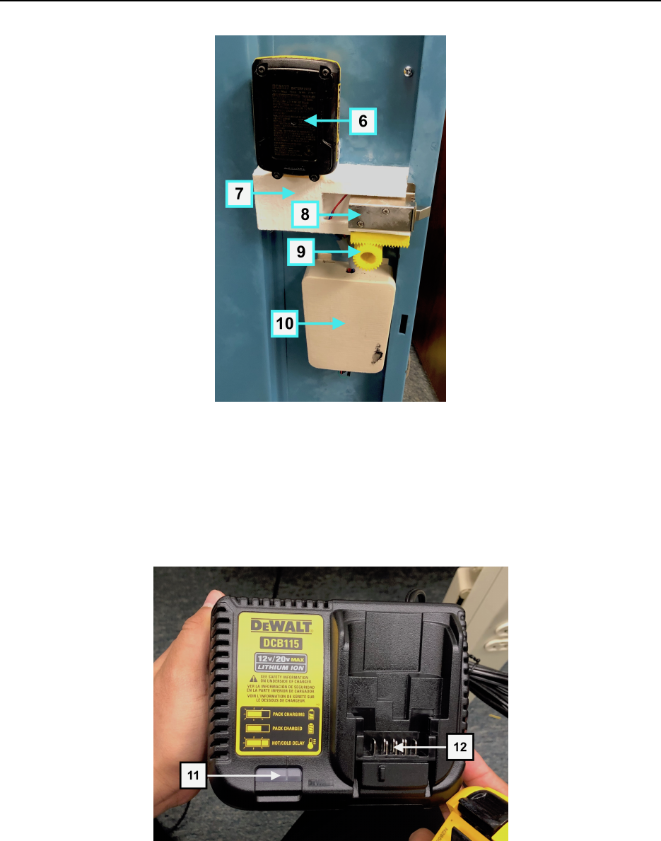
Figure 3: Rear View of Automated Locker
•6. Battery
•7. Lock Frame
•8. Lock
•9. Sliding Mechanism
•10. Hardware Frame (RFID Tag Reader with Arduino & Power Button)
Figure 4: Battery cradle (Located Inside Locker)
•11. Battery Cradle
•12. Battery Connectors
3
Automated Locker User Manual
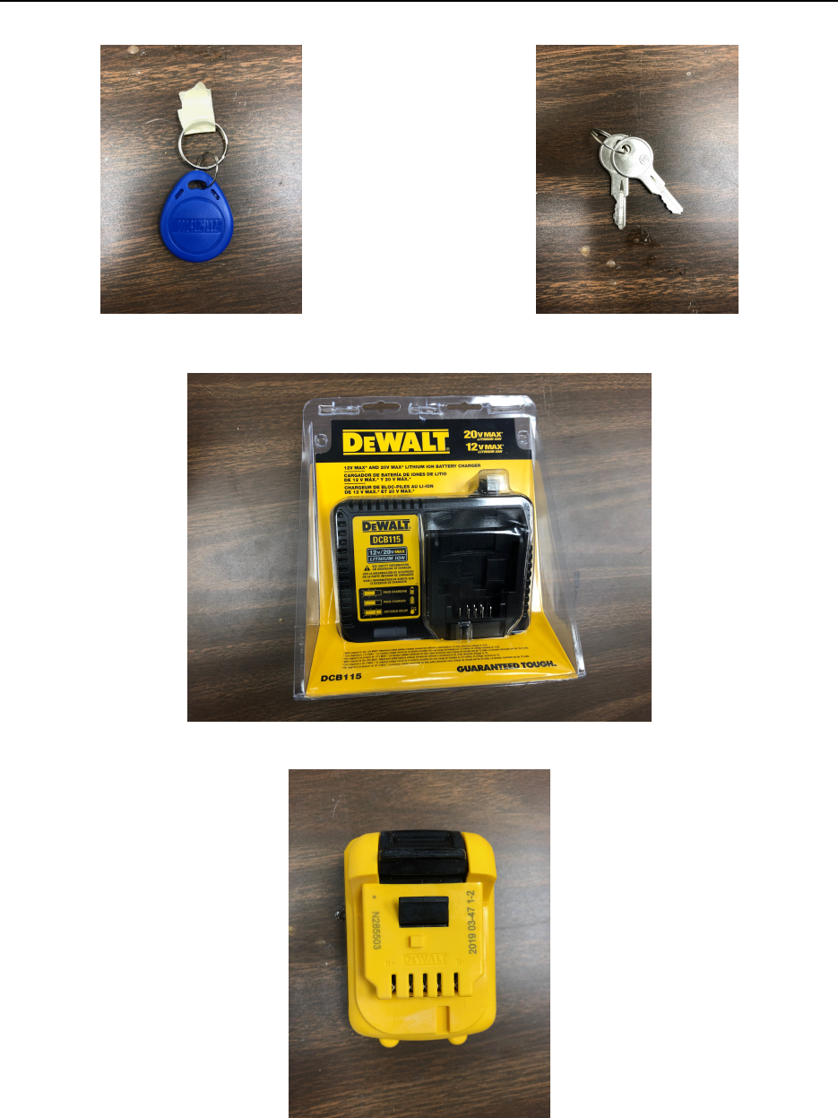
Figure 5: RFID Key Tag Figure 6: Mechanical Override Key
Figure 7. Dewalt Battery Charger
Figure 8. Dewalt Rechargeable 12V Battery
4
Automated Locker User Manual
3 Using the Locker
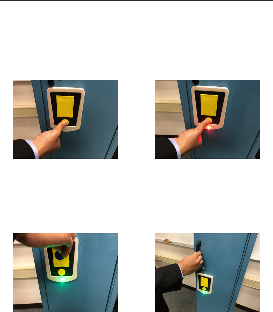
3.1 Turning on the Locker
The system is powered by Dewalt Rechargeable 12V battery that resides inside the locker. Pressing the large
round yellow power button (Figure 2, item 4) on the front of the locker door turns on the system. Then,
LED light (Figure 2, item 5) will turn on as red, indicating the system has been turned on, but the door is
locked.
Figure 9: Pressing Power Button Figure 10: LED Light Turns On
3.2 Unlocking the Locker
The user has to place the RFID Tag in front of the reader (Figure 2, item 2). After successful attempt,
the LED light will turn green, signaling the locker has been unlocked. The user needs to pull off the door
slightly using the door handle (Figure 2, item 1). The system will time out and locks automatically after 5
seconds of inactivity.
Figure 11: Scan Successful Figure 12: Opening the unlocked door
3.3 Locking the Locker
After 5 seconds of opening the lock, if the user didn’t pull the door, the locker will automatically get locked
again. If the user has opened the door within 5 seconds, and wishes to close it again, he just need to press
the door against the frame and the locker will get locked again.
5
Automated Locker User Manual
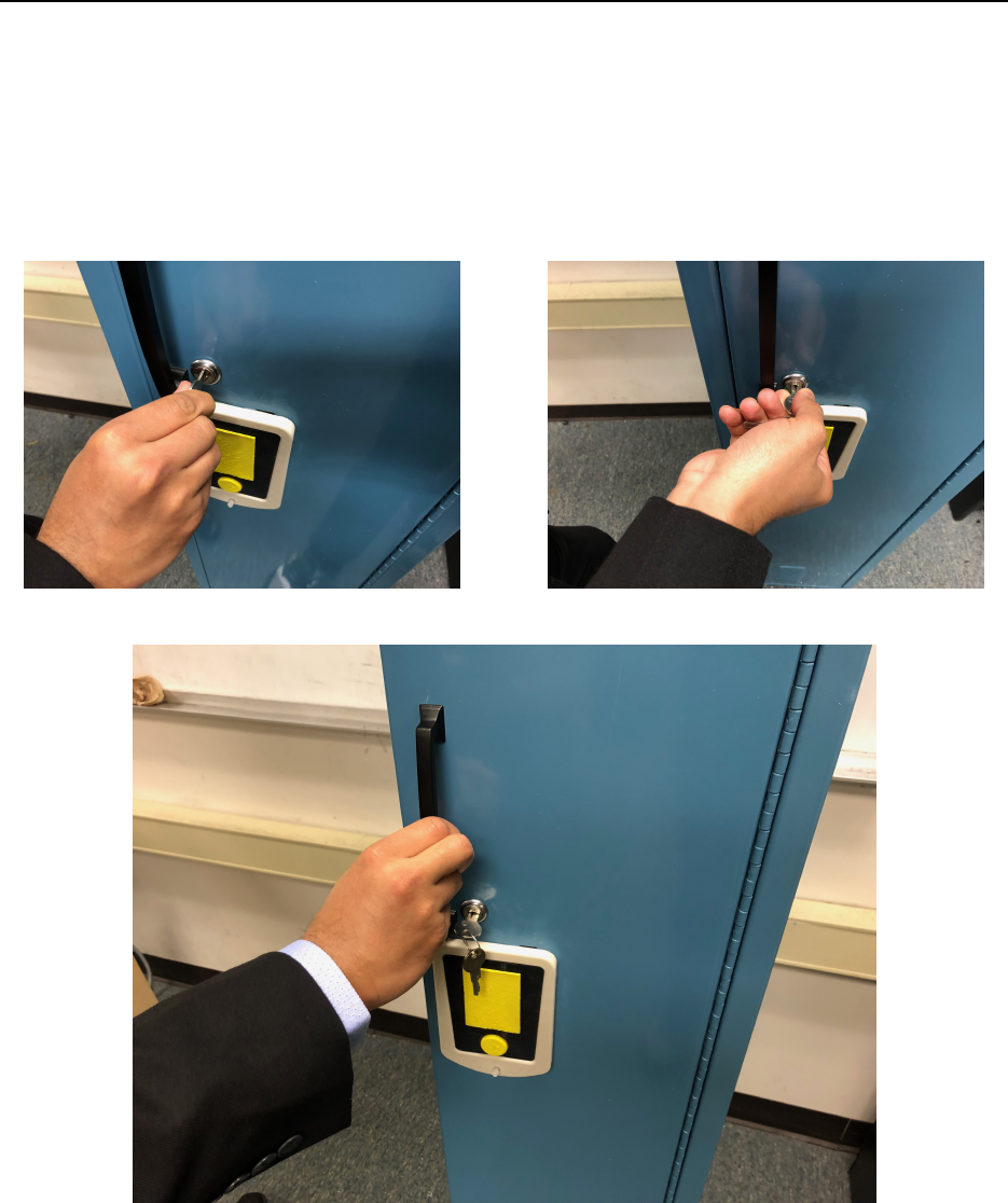
3.4 Mechanical Key Override
If there’s any power failure of Dewalt Rechargeable 12v Battery, the user can use an external override key
(Figure 6) to unlock the locker. The key needs to be inserted in the lock (Figure 2, item 2) and it has to
be turned right to unlock, and pull off the door handle (Figure 2, item 1). After the door has been opened,
the user has to turn the key to the left to place the locker in the right position and push the door to lock it
completely.
Figure 13: Inserting the Key Figure 14: Unlocking the lock
Figure 15. Opening the unlocked door
6
Automated Locker User Manual
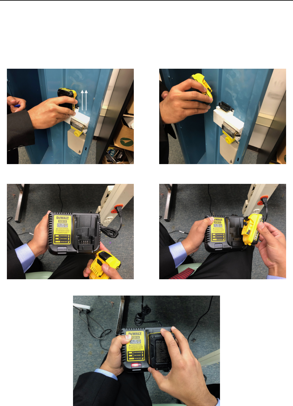
3.5 Charging the Battery
Confirm that the system is powered off before changing the battery. Hold the battery firmly and lift it off
slightly from the Locker Frame (Figure 3, item 7). Then, take the battery and place it on the Dewalt Battery
Charger (Figure 4), so that the pins in the cradle (Figure 4, item 12) go into the grooves of the battery.
Plug in the charger to power outlet and see whether the light indicator (Figure 4, item 11) turns red.
Figure 16: Pulling Off the Battery Figure 17: Removal of the Battery
Figure 18: Dewalt Battery Charger Figure 19: Plugging Battery into the Cradle
Figure 20. Light Indicator Turned Red
7

Automated Locker User Manual
3.6 Modifications Made to the Locker
Please refer to the design documentation for modifications and part specifications.
3.7 User Required Maintenance
The system requires users to charge the battery often and keep the RFID tags in a secure place. For more
details about charging the battery or replacing the dead battery, please refer to the ’Charging the Battery’
section. If the battery is dead while the door is locked, refer to ’Mechanical Key Override’ section. If there’s
any damage to any component, please refer to the design documentation for more parts details.
4 Ordering Additional RFID Tags
Please use the link below to order more RFID tags from Amazon. You’ll need expert support to program
your purchased RFID tags to be used with the automated locker. In that case, the expert needs to look into
the design documentation.
https://www.amazon.com/Smart-Keyfobs-Keychain-Mifare-Arduino/dp/B01N06OLMJ
5 Troubleshooting
If the LED light (Figure 2, item 5) doesn’t light up after pressing the power button (Figure 2, item 4), try
to press it a few more times with a little more force and see if it lights up. If it doesn’t light up, there’s
high possibility that the battery is dead. Therefore, charge the dead battery. If it doesn’t work after that,
it probably means that there’s a damage to the internal electronics. In that case, the user needs to use the
mechanical override key (Figure 6) to access the inside of the locker.
6 Safety & Caution Statements
PRODUCT SAFETY NOTICE: If the substitute replacement component does not meet with the same
properties as the recommended replacement one, shown in the parts list in the Design Documentation, it
may result shock, fire, or other hazards. User might get electrocuted if any liquid gets inside the charger.
User should never use wet hands while operating on the locker. If the component gets wet, do not use the
system until it’s completely dry. User must only use approved Dewalt Battery of the exact model number
listed in the Design Documentation with the provided Dewalt Battery Charger only. Use of any other models
might result in personal injury and damage. Refrain from misplacing the locker frame in any way. Do NOT
attempt to make any modifications or changes without consulting a trained expert.
8
