User Manual
User Manual:
Open the PDF directly: View PDF ![]() .
.
Page Count: 12
Reh@panel Unity3D Client User Manual
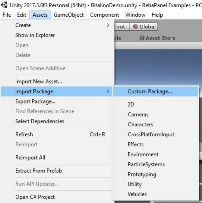
How to import the package
Download the package from the asset store [LINK]. Import all the content of the
package to you Unity3D project.
There is an example scene you can check. Go to the folder Assets->Neurorehablab-
>Scenes e open the scene MapperDemo.
If you want to add the Reh@Mapper to your scene, just drage the prefab
“DeviceMapperPrefab” to your scene. The prefab is located in the folder Assets-
>Neurorehablab->Prefabs.
In both scenarios, either if you added the mapper to your scene or if you are exploring
the example scene, the configuration steps are always the same.
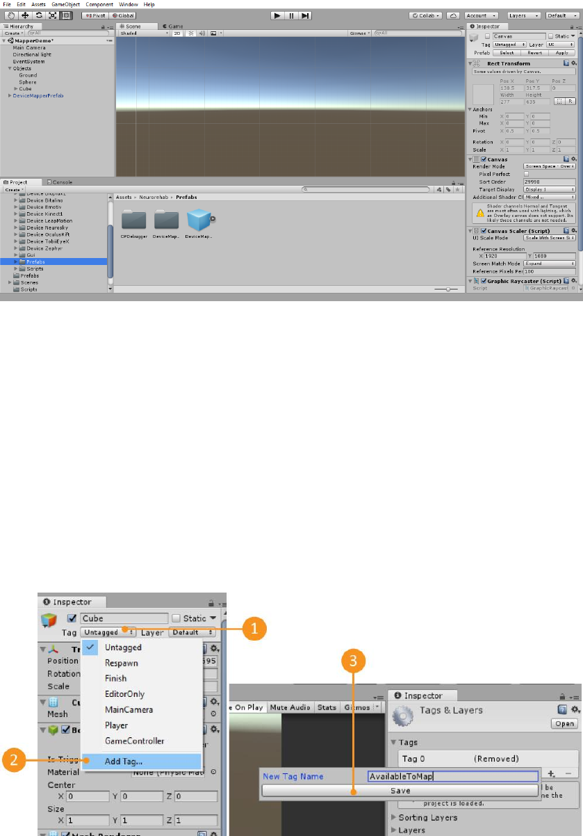
First time using the client
To correctly configure the Reh@Panel Unity client, you must first create a Tag
(“AvailableToMap”) and a layer to track the objects (any name is valid for the layer).
The Tag, that must be name “AvailabeToMap”, identifies the objects in the scene that
are mapped by the Reh@Panel Unity client. The Layer will only be used to display a
preview of the object in the scene. If you need to create this Tag and Layer, follow the
next steps:
Create a tag named “AvailableToMap” (1, 2 e 3)
Add a new layer named “previewCamera” (4,5 e 6)
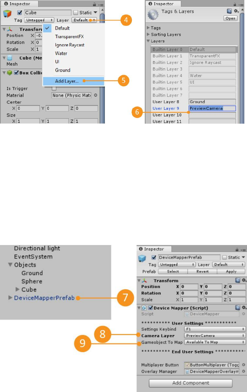
There are a few settings that you can change in the editor. Select the Reh@Panel Unity
client prefab located in the folder Assets.>Neurorehablab->Prefabs (or click it in the
hierarchy). In the inspector, you can change the default shortcut to display the
Reh@Panel Unity client, choose which layer will be used to display the object preview
and which tag will be used to map the objects (must be the tag AvailableToMap).
Change settings:
1. Select the prefab in the hierarchy (7)
2. Choose Camera Layer = PreviewCamera (8)
3. Choose Gameobject to map = Available To Map (9)
Settings Keybind
Shortcut to show or hide the Reh@Panel Unity client inside the
game.
Camera Layer
The layer used to show the preview of the selected file.
Gameobject to
Map
Tag used to identify the objects available to be mapped by the
Mapper. This tag can be modified, but to do so you need to change
the Mapper source code. It is recommended to use the predefined
tag ‘AvailableToMap’.
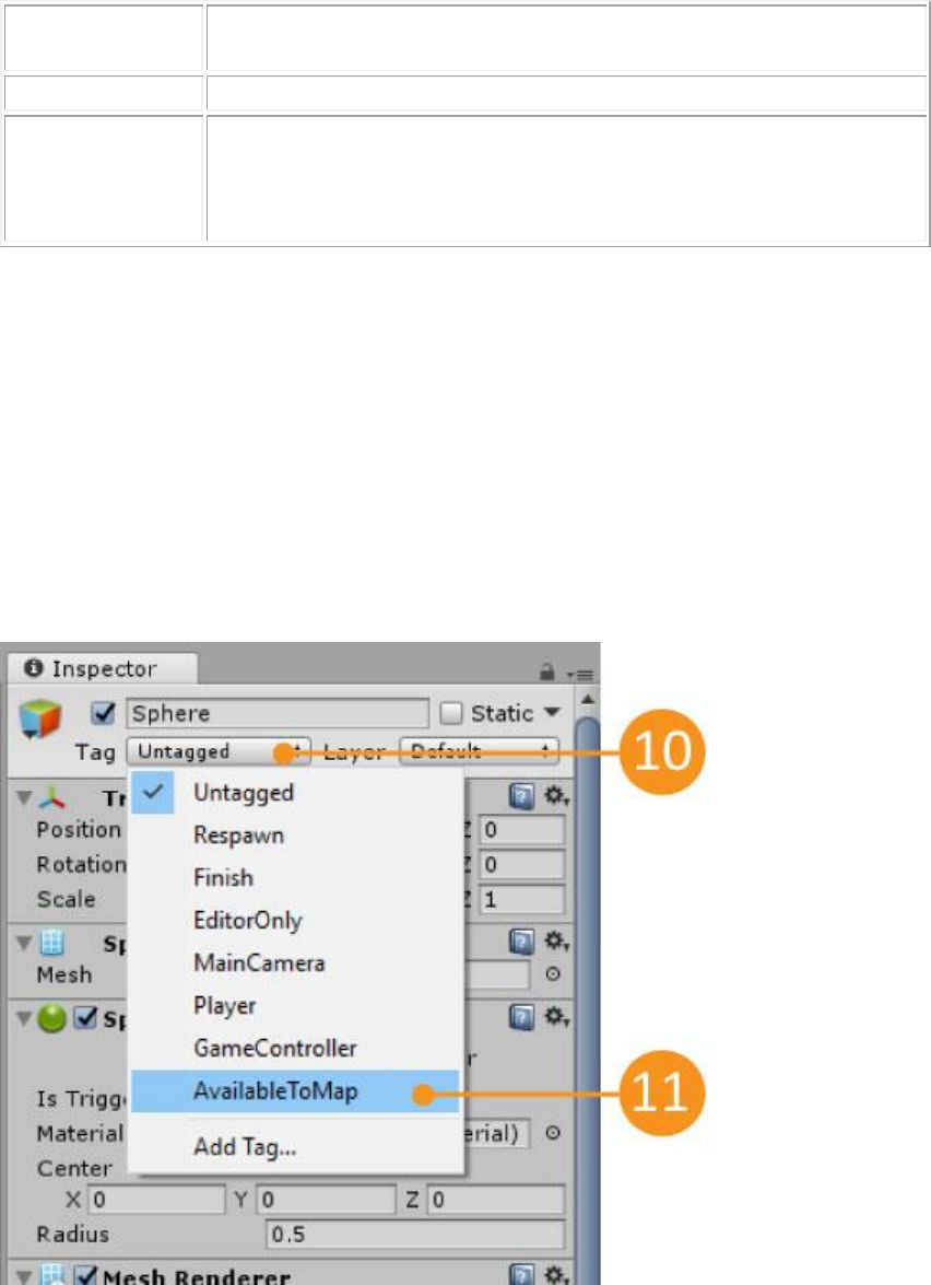
After completing these configurations, you still have to add the tag ‘AvailableToMap’
to all the objects you want the mapper to track.
Add the tag to all objects that will be mapped
1. Choose an object and click on the dropdown next to the label ‘Tag’(10)
2. Choose the tag ‘AvailableToMap’ (11)
Connecting received data to a property
Once the scene is ready, you can run the game by pressing the button ‘Play’ and start
calibrating the Mapper. To display the Mapper main window, press the shortcut key
(default is ‘1’). Note that once you open the Mapper, the game will be automatically
paused. To resume the game you can close the Mapper window (by pressing the ‘X’ or
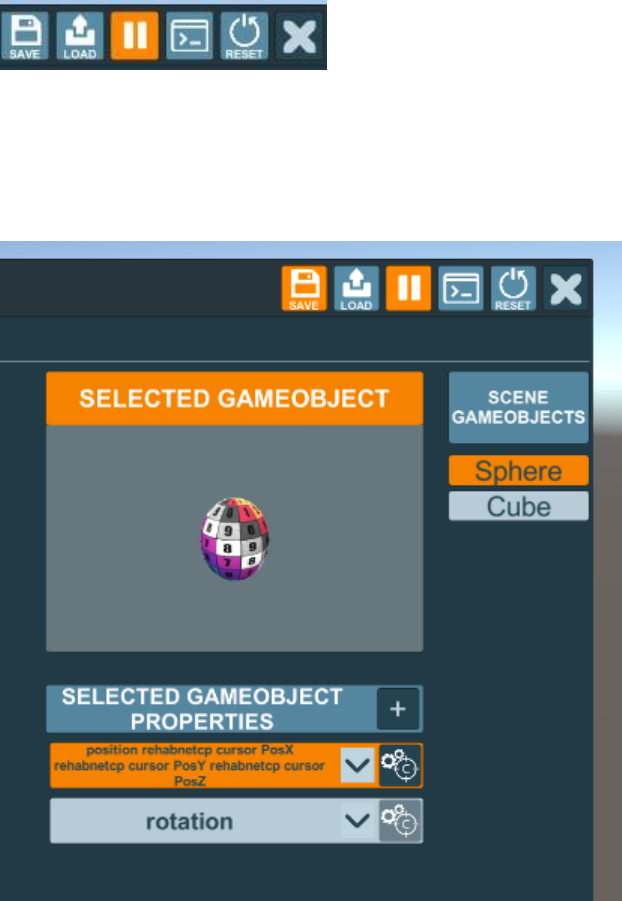
pressing the shortcut key again) or you can press the mapper pause button (the ‘||’
button or the shortcut ‘F12’). All these controls are located on the top right of the
mapper window.
After you open the Mapper, you can choose an object from the list of objects to the
right. After you choose an object, this will be displayed in the window ‘Selected
GameObject’. You can add Mapper properties to the to the object by clicking the ‘+’
button.
There are 4 types of properties: Positions, Rotations, Values and Booleans. Pressing on
these buttons adds or remove properties.
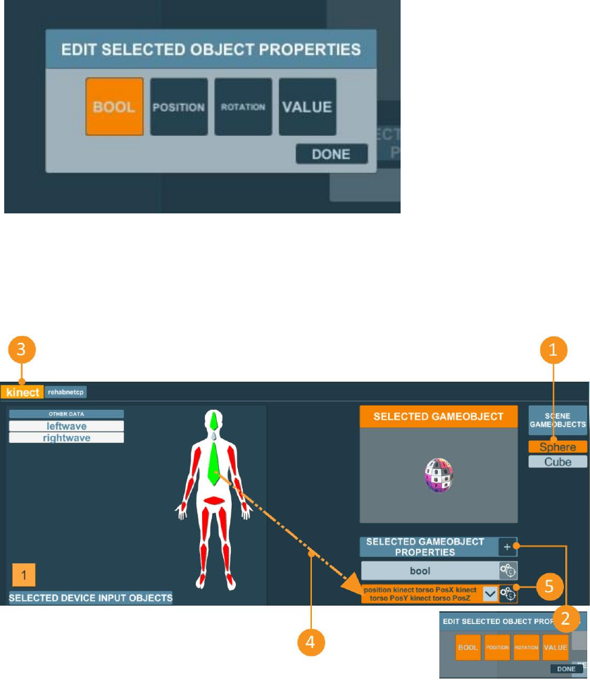
To map an input to a property, select the device from the device list and drag one of its
inputs to the property you want to map. The input will change colour to green and the
property to orange. This indicates that the input is being used (and its information is
being received at the moment) and the property has something mapped to it.
1. Select one object from the list of objects (1)
2. Add a property to that object (2)
3. Select the desired device from the device list (3)
4. Drag & drop the input on the property (4)
5. Press the calibration button to perform the calibration (5)
Once the editor window is open, you must choose the source in the Reading From
section and click the calibration button. You must also fill the output limit values to
calibrate between the real-world readings and the game world values.
Explore the example scene to see the mapper working.
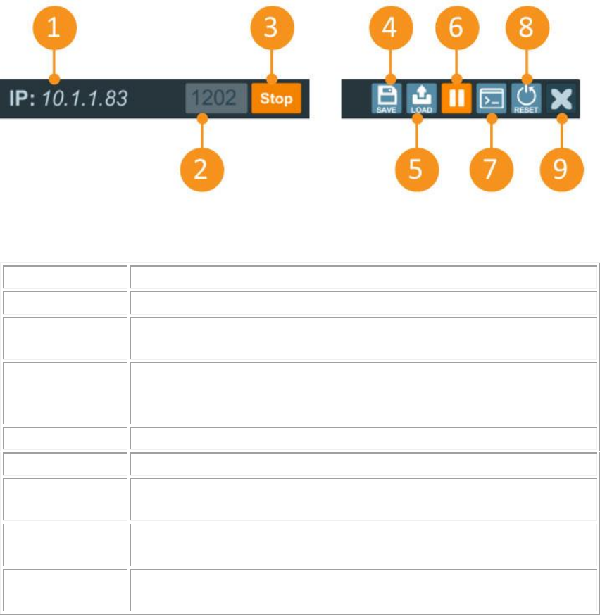
Graphical User Interface
The connectivity options are in the top left, while the general options are in the top
right.
1 - UDP
The IP address of the machine that is running the Mapper.
2 - Components
The UDP port the Mapper is listening to.
3 - Kinect
Prefab
Start/Stop the data reception via UDP
4 - Save
Saves the current configuration in a json file, so it can be used later.
The last saved configuration will he automatically loaded the next
time the game is executed.
5 - Load
Loads a configuration stored in a json file.
6 - Pause
Pauses or resumes the game
7 - Console
Shows the Mapper console. Any error related with the Mapper will
be displayed here.
8 - Reset
Resets all the configurations. removes all the properties of all the
mapped objects.
9 - Close
Closes the Mapper window. Has the same effect as pressing the
default shortcut (‘1’).
The client main panel is located just below the top panel. In the left, we can find
information about all the devices that are communicating with the client and in the right
we can see the information about the mapped objects.
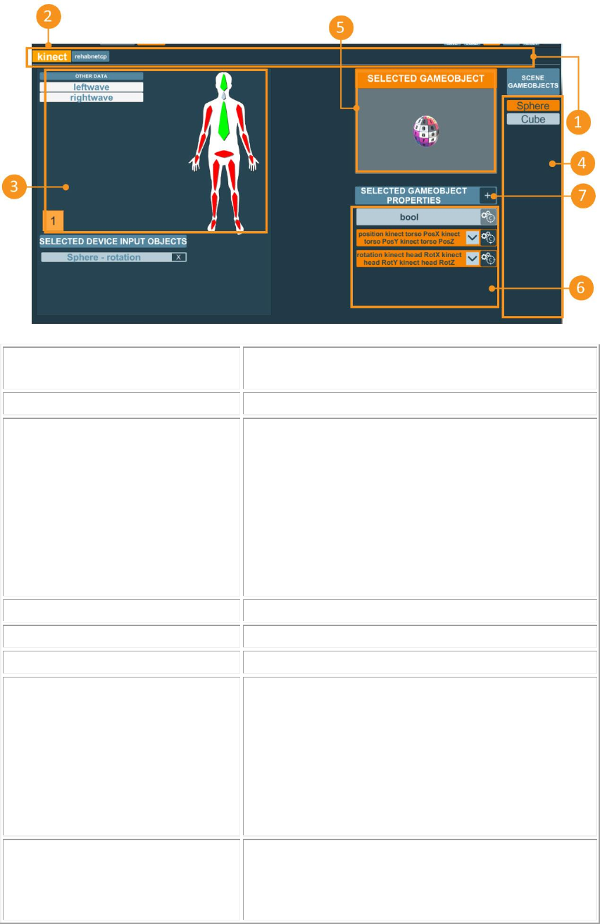
1 – Devices
List of all the devices that are being received via
UDP.
2 – Selected Device
The currently selected device.
3 – List of data from the
selected device
Each input is represented by a label/drawing. To
connect the input to a property, just drag & drop it
in the property.
The inputs that are being received at the moment
are represented in Blue.
The inputs that are known by the device but are not
being received is represented in Red.
The inputs that are being used in any property are
Green.
4 – Unity3D objects
Lists of objects with the client tag in the game.
5 – Selected object
Currently selected object.
6 – List of properties
Properties activated in the selected object.
7 – Add property
Adds a property to the selected object:
• Position
• Rotation
• Value
• Boolean
• Sample
8 – Edit/Calibrate property
Opens the property editor window. This allows you
to change the calibration values for this property.
Can only be clicked after a property has been
mapped to an input.
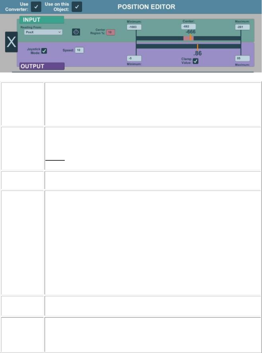
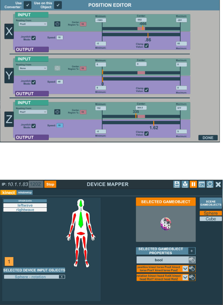
Position/Rotation/Value editor Window
When you click in the calibration button, the Editor window will open. The Position,
Rotation and Value editors look the same.
Use
Converter
Indicates if the values are to be converted or used passed directly.
Check -> Use the minimum and maximum values of the Output window
to convert the input values into Output values.
Uncheck -> The values are not converted, and the values read in the
input are the same values passed to the output.
Use on this
object
Indicates if the values are to be applied to the selected object or not.
Check -> Apply on this object.
Uncheck -> Do not apply on this object.
NOTE: the data is always stored in the Value variable inside the
respective interpreter for both choices.
Axis (X)
Ingame world axis of this information. In the image, we are calibrating
from any real-world axis into the X axis ingame.
Reading
From
The real-world axis where the information is being read:
• PosX – Axis position X
• PosY – Axis position Y
• PosZ – Axis position Z
• RotX – Axis rotation X
• RotY – Axis rotation Y
• RotZ – Axis rotation Z
• Value
• Bool
Calibration
Button
Button to calibrate the min and max values for the ‘reading from’
selection.
Invert Logic
Indicates if the reading values should be inverted (swap minimum and
maximum).
Check -> Swaps the minimum and maximum reads.
Uncheck -> Keeps the original values.
Center
Region
The ‘dead zone’ for the reading values. While the reading values are kept
inside this area, the mapped values will not be changed. Value in
percentile (0-100%).
Minimum
The minimum value that was read after the calibration.
Can be changed directly without the need of reading it from the
calibration process.
Center
The centre value of the current calibration. If the ‘Reading From’ is a
rotation, the centre value is read from the calibration process. If it is not
from a rotation, then the Centre will be middle point between the
minimum and maximum. Every time the maximum and minimum are
changed, the centre is recalculated.
This value can be set directly without the need of a calibration.
Maximum
The maximum value that was read after the calibration.
Can be changed directly without the need of reading it from the
calibration process.
Joystick
Mode
Indicates if the mapping will be applied as a joystick or not.
This mode moves the game object like a joystick of a gamepad: while it
is pointing to a direction, it keeps moving in that direction.
Check -> Turns joystick mode on.
Uncheck -> Turns joystick mode off.
Speed
The maximum speed that the mapped value will be modified. Can only
be changed if the Joystick Mode is turned on.
Minimum
The minimum value for the world border.
Must be added manually.
Clamp
Value
Indicates if the mapped value must be clamped between the world
minimum and maximum.
Check -> Clamp the values.
Uncheck -> Don’t clamp the values.
Maximum
The maximum value for the world border.
Must be added manually.
Boolean Editor
The boolean editor is slightly different from the other editors but uses the same logic as
the other editors.
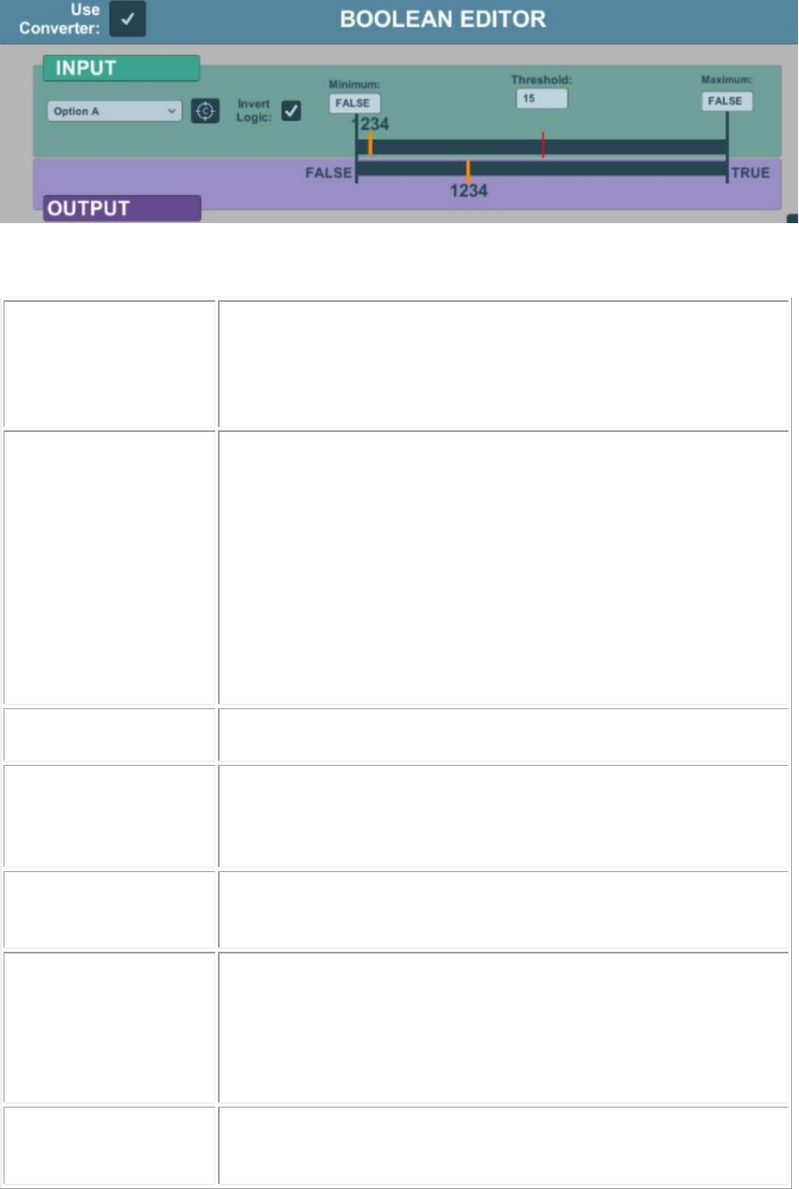
Use Converter
Indicates if the values are to be converted or used passed directly.
Check -> Use the minimum and maximum values of the Output
window to convert the input values into Output values.
Uncheck -> The values are not converted, and the values read in
the input are the same values passed to the output.
Reading From
The real-world axis where the information is being read:
• PosX – Axis position X
• PosY – Axis position Y
• PosZ – Axis position Z
• RotX – Axis rotation X
• RotY – Axis rotation Y
• RotZ – Axis rotation Z
• Value
• Bool
Calibration Button
Button to calibrate the min and max values for the ‘reading from’
selection.
Invert Logic
Indicates if the reading values should be inverted (swap minimum
and maximum).
Check -> Swaps the minimum and maximum reads.
Uncheck -> Keeps the original values.
Minimum
The minimum value that was read after the calibration.
Can be changed directly without the need of reading it from the
calibration process.
Threshold
It indicates from which value the boolean will pass from false to
true.
After the maximum or minimum calibration, the threshold is
always equals to the arithmetic centre of both values.
Can be changed manually by the user. Must be a value between
the minimum and maximum values.
Maximum
The maximum value that was read after the calibration.
Can be changed directly without the need of reading it from the
calibration process.
