User Manual For DP5 Family Product
User Manual:
Open the PDF directly: View PDF ![]() .
.
Page Count: 25

Products for
Your
Imagination
AMPTEK, Inc. 14 DeAngelo Drive, Bedford, MA 01730-2204 USA
+1 781 275-2242 Fax: +1 781 275-3470 www.amptek.com sales@amptek.com
User Manual for Amptek’s DP5 Product Family
1 Introduction .......................................................................................................................................... 2
1.1 DP5 Family .................................................................................................................................... 2
1.2 DP5 family documentation ........................................................................................................... 2
1.3 DP5 Core Technology .................................................................................................................... 3
2 DP5 Product Family ............................................................................................................................... 5
3 Quick Start Instructions......................................................................................................................... 6
3.1 Precautions ................................................................................................................................... 6
3.2 Install software.............................................................................................................................. 6
3.3 Configure the device ..................................................................................................................... 7
3.4 Acquire data .................................................................................................................................. 7
3.5 Display, analyze, save data ........................................................................................................... 7
4 Specifications ........................................................................................................................................ 8
4.1 Specification table ......................................................................................................................... 8
4.2 Performance ............................................................................................................................... 11
5 Electrical Interfaces ............................................................................................................................. 13
5.1 Serial Communications ............................................................................................................... 13
5.2 Input Signal Interface .................................................................................................................. 14
5.3 Power Interface ........................................................................................................................... 14
5.4 Auxiliary I/O ................................................................................................................................ 14
6 Software Interface .............................................................................................................................. 15
6.1 Embedded firmware ................................................................................................................... 15
6.2 DPPMCA ...................................................................................................................................... 15
6.3 FW5 vs FW6................................................................................................................................. 15
6.4 Firmware manager ...................................................................................................................... 16
6.5 Analysis software (XRS-FP, SODIGAM, and GAMMA-W) ............................................................ 16
6.6 Software developer’s kit ............................................................................................................. 16
7 Application Notes ................................................................................................................................ 17
7.1 Selection Advice .......................................................................................................................... 17
7.2 Typical Oscilloscope Traces ......................................................................................................... 19
7.3 Auxiliary Output Signals .............................................................................................................. 24
Products for
Your
Imagination
2
1 Introduction
1.1 DP5 Family
Amptek has a family of products based on its core DP5 digital pulse processing technology. This
“family wide” user manual describes those elements which are common across the product family; each
product has its own specification and user manual, which describes those elements unique to it.
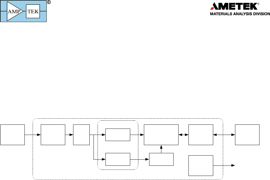
The DP5 technology is designed for pulse height spectroscopy. It was originally designed for the
detection of ionizing radiation, principally X-ray and gamma-ray spectroscopy. A generic system,
illustrated below, includes a sensor (a.k.a. detector), a charge sensitive preamplifier, analog prefilter
circuitry, an ADC, an FPGA which implements pulse shaping and multichannel analysis, a
communications interface, power supplies, data acquisition and control software, and analysis software.
Detector and
Preamplifier
Analog
Prefilter ADC Slow
Channel
Peak Detect
Histogram Logic
Counters
Pulse
Selection
C and
Interface
Auxiliary
Signals
Computer
Oscilloscope or
external logic
Digital Processor (DPP)
Fast
Channel
Digital Pulse Shaping
The core technology shared by all the family of products includes the ADC, the FPGA, the
communication interface, and the data acquisition and control software. All products in the DP5
product family include nearly the same digital signal processing algorithms, the same communication
interfaces (both the primary serial interfaces and the auxiliary I/O), run the same firmware (FW6), and
use the same data acquisition and control software. The DPPMCA software package is a complete,
compiled data acquisition and control software package used across the family; Amptek also offers an
SDK for custom software solutions.
The products in the DP5 family differ in the sensor for which they are designed, which leads to
changes in the analog prefilter, power supplies, and form factor. They also differ in their completeness:
some of Amptek’s products are “complete”, while others offer only a portion of the functionality for the
user to integrate into a complete system.
The first product Amptek developed in this family was the DP5, a digital pulse processor optimized
for high performance semiconductor X-ray detectors. A variety of other products was spun out of this
core, which is why we call it the “DP5 family”. These products do not contain the DP5 itself and in fact
some are quite different. They all use the same communication protocol (known as “FW6”) so an
alternate name would be the “FW6 family,” but for historical reasons we call them the “DP5 family”.
1.2 DP5 family documentation
This “family wide” user manual will focus on the digital signal processing and the communication
interface which are common to the entire DP5 family of products.
The document “Understanding the DP5 Processor” provides much background information,
applicable to the entire DP5 family. The HELP file of the DPPMCA software also has valuable “family
wide” information. Further documentation is provided in the SDK for custom software and in the “DP5
Programmer’s Guide” (which provides details of the software interface).
Products for
Your
Imagination
3
Each product has a “product specific” user manual. These focus on the sensor and preamplifier
either included or intended for use, the analog prefilter, the power supplies, the form factor of the
specific product, and application suggestions.
On the Installation CD is a section of “application notes.” Two are of special note, being applicable
across the entire family. These include the “Trouble-shooting guide to Amptek’s digital pulse
processors” and “Interference.” There is also a folder with additional help topics, which is
recommended.
1.3 DP5 Core Technology
The DP5 is a second generation digital pulse processor (DPP) which replaces both the shaping
amplifier and MCA found in analog systems. The digital technology improves several key parameters:
1) Better performance, specifically better resolution, higher count rates, better pileup rejection,
and more accurate measurement of input count rates
2) Greater flexibility since more configuration options are available, selected by software,
3) Improved stability and reproducibility.
A DPP digitizes the preamplifier output, applies real-time digital processing to the signal, detects
the peak amplitude, and bins this in its histogram memory. The spectrum is then transmitted to the
user’s computer. In addition to the spectrum, various other data streams are available in the DP5 family
(counts, MCS mode, list mode, SCA outputs, various auxiliary signals, etc).
The DP5 products require a serial communication (USB, RS232, and Ethernet are all supported) and
power (which can be via USB, PoE in some products, or DC power (typically +5V)). The DP5 products
interface with the DPPMCA data acquisition and control software, along with an SDK of interface
routines, to integrate the unit with custom software. Optional accessories include software for
analyzing X-ray spectra, software for analyzing gamma-ray or alpha particle spectra, several collimation
and mounting options, and X-ray tubes to complete a compact system for X-ray fluorescence.

Products for
Your
Imagination
4
Products for
Your
Imagination
5
2 DP5 Product Family
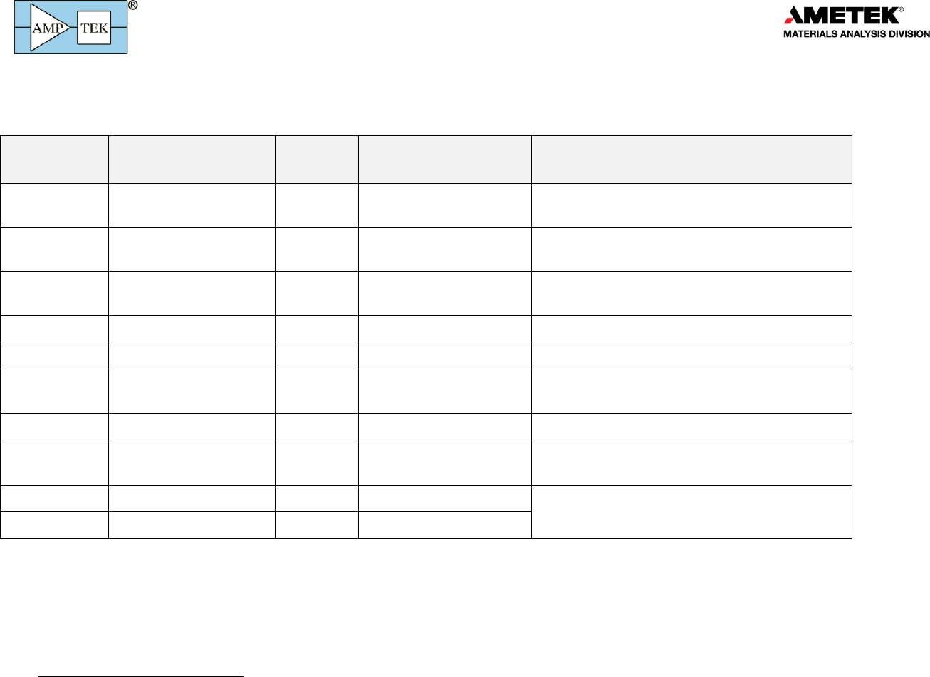
The table below lists the DP5 family of products, as of Feb 2015.
Product
Name
Primary Application
Type 1
Variants
Comments
X-123
X-ray spectroscopy
System
SDD, FastSDD®, Si-PIN,
CdTe
Available with vacuum adapters, with several length
extenders, and in various other options
DP5
Semiconductor detectors
Board
Analog prefilter can be
adapted widely
Available with PC5, which provides power to
detectors and preamplifiers
DP5 & PA210
X-ray spectroscopy
Board level
system
SDD, FastSDD®, Si-PIN,
CdTe
Designed for OEMs embedding in an instrument
PX5
Semiconductor detectors
Module
Primarily for laboratory users
PX5-HPGe
--ray spectroscopy
Module
For use with customer-supplied HPGe detector
Gamma-Rad5
--ray spectroscopy
System
NaI(Tl) is standard but
many options available
Includes scintillator and PMT
TB-5
--ray spectroscopy
Module
User provides scintillator and PMT.
DP5G
--ray spectroscopy
Board
Available with PCG, which includes low voltage
power supplies and communication connectors
MCA8000D
Spectroscopy
Module
Does not include pulse shaping but only the MCA
function.
MCA8000D - PA
Particle counting
Module
11
A “system” includes all elements above, including detector. A “module” is only a part of the system (usually excluding at least the detector) but is packaged.
A “board” is a part of the system but is not packaged; it is a printed circuit board.

Products for
Your
Imagination
6
3 Quick Start Instructions
Each DP5 product has its own, specific quick start instructions yet they all share a common core:
3.1 Precautions
o DO NOT TOUCH THE THIN WINDOWS. Many of these products contain delicate windows, which
may be made of a few microns beryllium or even 20 nanometers of silicon nitride. Any contact
with the windows may destroy them. Such damage is not covered by warranty.
o HIGH VOLTAGE MAY BE PRESENT. Most radiation detectors require bias voltages, from 100 to
5,000V. Current limiting is generally used but high voltage remains possibly dangerous.
o IONIZING RADIATION IS HAZARDOUS. Although these products do not produce ionizing
radiation, they are generally used to detect it. It is the customer’s responsibility to meet the
radiation safety requirements of his/her institution and to be mindful of radiation safety.
3.2 Install software
o Software is provided on your installation CD. A current version of all software is also
available from http://www.amptek.com/software-download-page/
o Installation instructions are at http://www.amptek.com/dpp-installation-instructions/
Step 1: Install WinUSB Drivers
1) IT IS STRONGLY RECOMMENDED THAT YOU USE WINDOWS UPDATE TO INSTALL THE WINUSB
DRIVERS, IF YOUR DEVICE SUPPORTS THIS. Manual installation is possible; see the instructions.
2) The actual screens look slightly different for Win7, XP, etc. See the instructions for details.
Step 2: Install the DPPMCA data acquisition and control software
DPPMCA.EXE is the primary data acquisition and control software used with all products in the DP5
family (with one exception noted below). This program is on the installation CD that was provided with
your system or can be downloaded from Amptek’s website.
1) Locate the DPPMCA directory and copy and paste it to your local machine. Then run the
executable in the directory. There is no “setup,” it is a simple copy and paste to the local
computer. Amptek recommends copying the software to “Program Files/Amptek.”
2) TIP: Right click on the DPPMCA.EXE file and select create shortcut. Then drag the shortcut to
your desktop for easy access.
3) You must have full read/write access to the DPPMCA directory. These programs cannot be run
from the CD.
Step 3: Launch the DPPMCA program
Step 4: Connect to the DPP
1) The connection dialog will appear when DPPMCA is launched.
2) Select which interface you will use (USB, Ethernet, or RS232).
3) If more than one device is available, select the device you want.
4) Click "connect". You can tell if you connected because the software will show the serial number
of the processor at the top right and will show an icon (USB, Ethernet, etc) at the bottom.

Products for
Your
Imagination
7
3.3 Configure the device
o The DPP stores its configuration, so when powering the system initially, the factory
configuration is loaded. If you modify the configuration, the last configuration is loaded. For
the PX5, hold the power button down until it beeps twice to use the configuration in memory.
TIP: We recommend that you save the initial configuration, which was used at the factory to test
the unit, before making changes so you can return to it if necessary. Open DPP Setup and click
"Save configuration to file".
o The most commonly changed parameters are the gain and the thresholds.
To quickly change the gain, use the gain increment (decrement) buttons on the toolbar.
After changing the gain, remove all excitation sources, start an acquisition, then click the
"Tune Slow/Fast Thresholds" button on the toolbar.
Refer to the DPPMCA Help for further suggestions.
3.4 Acquire data
1) Place a source in front of the detector.
2) To start or stop acquisition, toggle the "traffic light" icon in the toolbar or press the space bar.
3) To clear the data and time, press the icon to the right of the "traffic light" or press "A".
Data Acquisition Tips
It can take minutes for an Amptek detector to stabilize after power has been applied or a
configuration changed. If the spectrum looks odd, clear the data and restart.
You can tell that data are being acquired if (a) the spectrum appears in the window, (b) the
input and total counts are increasing, (c) the accumulation time is increasing, and (d) the
"status" in the right hand Info Panel reads "acquiring".
3.5 Display, analyze, save data
o The spectrum, counts, and accumulation time are automatically displayed as data are acquired.
If a region of interest is defined and selected, its net area and other properties are also shown.
o DPPMCA includes basic spectrum analysis functions: defining regions of interest, calibrating the
energy scale, simple mathematical expressions, and a simple peak search algorithm. For more
sophisticated spectrum analysis, additional software must be used. For XRF, the XRS-FP analysis
software package can be purchased from Amptek.
o To calibrate the system, you must first acquire a spectrum with two or more photopeaks of a
known energy. DPPMCA will perform a linear regression between the centroids of these peaks
and the known energies.
o To save a data file, press "Ctrl-S" or click the "File Save" icon. Data are saved in an ASCII file
format, described below, which includes the counts in each channel, slow and fast counts, ROI
and calibration data, and the DPP configuration parameters.
o DPPMCA’s Help File contains more information on regions of interest, energy calibration, etc.
o A “Troubleshooting Guide” is contained on your CD and is on the Amptek website, in case you
have difficulties.

Products for
Your
Imagination
8
4 Specifications
4.1 Specification table
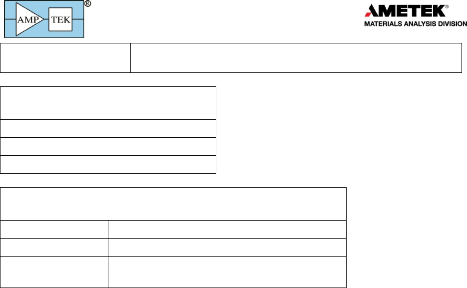
Pulse Processor
Applies to all DP5 products except MCA8000D
Gain
Product of coarse gain (from amplifiers) and fine gain (in
FPGA)
Coarse Gain Values
Depends on product
Fine Gain
Software selectable, 0.75 to 1.25, 13 bit resolution
Full Scale
1000 mV at ADC. Corresponding processor input
depends on gain
Gain Stability
20 ppm/C (typical). This is the stability of the DPP.
Sensors, preamplifiers, and other components may
exhibit much larger temperature coefficients.
Pulse Shape
Trapezoidal
ADC Clock Rate
20 or 80 MHz, 12 bit ADC
Peaking Time
Software selectable peaking times between 0.05 and 102
µs, corresponding to semi-Gaussian shaping times of
0.02 to 45 µs.
ADC clock (20 or 80 MHz) determines the range; <0.8 µs
requires 80 MHz.
Flat Top
63 software selectable values for each peaking time
(depends on the peaking time), > 0.05 µs.
Baseline Restoration
Asymmetric, 16 software selectable slew rate settings
Fast Channel Peaking Time
0.05, 0.1, 0.2, 0.4, 0.8 µs (80 MHz) and 4x at 20 MHz
Fast Channel Pulse Pair Resolving Time
Tfast plus pulse risetime
Dead Time Per Pulse
1.05 times the Tpeak+Tflat. No conversion time.
Maximum Count Rate
8x10⁶ sec-1 (periodic). Output count rate of 1.4x10⁶ sec-1
for a random input of 3.8x10⁶ sec-1 (80 MHz)
Dead Time Correction
Manual correction based on Fast Channel measurement
of ICR. Accurate to 1% for ICR < 1 Mcps under typical
conditions.
Pulse Selection Options
Pile-up rejection, risetime discrimination, gate
Multichannel Analyzer
Applies to all DP5 products.
Number of channels
256, 512, 1024, 2048, 4096, or 8192 channels.
Bytes per channel
3 bytes (24 bits) - 16.7M counts
Acquisition Time
10 ms to 466 days

Products for
Your
Imagination
9
Data Transfer Time
1k channels in 5 ms (USB), 35 ms (Ethernet) or 280 ms (RS-232)
See DP5 Programmer’s Guide for further details
Conversion Time
None
Presets
Time, total counts, counts in an ROI, counts in a channel
MCS Timebase
10 ms/channel to 300 s/channel
External MCA Controls
Gate input: Pulses accepted only when gated on by external logic. Input
can be active high or active low. Software controlled.
Counters
Slow channel events accepted by MCA, Incoming counts (fast channel
counts above threshold), SCA8 counts, event rejected by selection logic,
and external event counter. Sixteen ROI counters.
Operating Modes
Applies to all DP5 products.
MCA mode
Most common operating mode. The DPP acquires a pulse height
spectrum, using the MCA in the FPGA, and reads this to the computer,
over one of the interfaces, one software request. Readout intervals
usually range from 0.1 s to a few seconds.
MCS mode
The DPP acquire a “multichannel scaling (MCS)” histogram, which has the
number of counts in successive time bins. Used for measuring count rate
versus time with high precision
Counting mode
By reading only the status packet over one of the interfaces, one can
obtain the input and output count rates at much shorter intervals than the
entire spectrum can be read. Requires custom software.
SCA mode
List mode
Streaming mode
External counters
Auxiliary Inputs/Output
The availability and connectors depend on the product
Single Channel Analyzers
8 SCAs, independent software selectable LLDs and ULDs, LVCMOS
(3.3V) level (TTL compatible)
Digital Outputs
Two independent outputs, software selectable between 8 settings
including INCOMING_COUNT, PILEUP, MCS_TIMEBASE, etc. LVCMOS
(3.3V) levels (TTL compatible).
Digital Inputs
Two independent inputs, software selectable for MCA_GATE,
EXTERNAL_COUNTER
Digital Oscilloscope
Displays oscilloscope traces on the computer. Software selectable to
Products for
Your
Imagination
10
show shaped output, ADC input, etc., to assist in debugging or
optimizing configurations.
Communications
Applies to all DP5 products.
USB 2.0 full speed (12 Mbps)
RS-232 at 115.2k or 57.6k baud
Ethernet (10base-T)
Hardware
Applies to all DP5 products.
Microprocessor
Silicon Labs 8051F340 (8051-compatible core)
External Memory
512kB low-power SRAM
Firmware
Signal processing is programmed via firmware,
which can be upgraded in the field.
Products for
Your
Imagination
11
General & Environmental
Operating temperature
-40 °C to +65 °C (for the electronics)
All electronic components in the DP5 family are rated for the
industrial range, up to +85oC. Components are warmer than the
ambient and thus we recommend limiting the ambient
temperature to <65oC.
Some detectors may have tighter temperature limits; even
where they operate over a wide range, performance is usually a
strong function of detector temperature.
Warranty Period
1 Year
Typical Device Lifetime
5 to 10 years, depending on use
Storage and Shipping
Long term storage: 10+ years in dry environment
Typical Storage and Shipping: -40 °C to +85 °C, 10 to 90% humidity
non condensing
Compliance
RoHS Compliant
Power and physical specifications vary with the product so the power specifications are included in each
product’s user manual.
4.2 Performance
Energy resolution
The energy resolution is not specified for the processor family; it depends most strongly on the
detector, the type of radiation, and on the exact configuration settings of the processor. In general:
o In many detectors, the resolution is dominated by the interaction of the particle with the
detector so is independent of the electronics. In semiconductor X-ray and gamma-ray
detectors, Fano broadening which arises from fluctuations in the radiation interaction often
dominate resolution. In a scintillator, Poisson fluctuations in the photon production dominate
the energy resolution.
o In many systems, electronic noise is also important. The output electronic noise depends on
many parameters: the design of the pulse shaper, the peaking time of the pulse shaper, the
detector’s capacitance, leakage current, and temperature, the design of the preamplifier, etc.
o There are additional factors which impact resolution: charge loss, ballistic deficit, and others.
The noise filtering properties of the DP5 family are discussed in the document entitled
“Understanding the DP5 Processor Family”. The other factors depend on the detector and preamplifier
so are discussed in each product’s user manual.
Products for
Your
Imagination
12
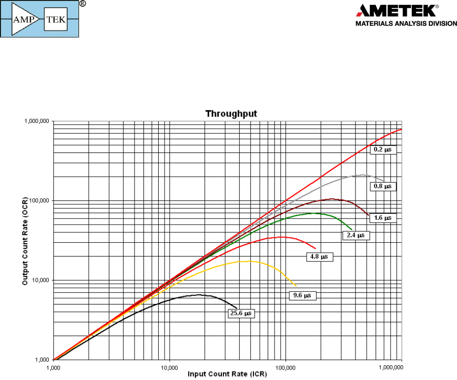
Count rates
Unlike the resolution, the dead time per pulse is independent of the detector (assuming the
detector’s risetime is negligible) and so can be specified for the entire DP5 family. The curves below
show the output count rate versus input count rate, for several different peaking times.
If Rin is the input count rate, Rout is the output count rate, Tpeak is the peaking time, and pile-up
rejection is enabled, these curves follow closely the equation
2in peak
RT
out
Re
For further information on input count rates, output count rates, and dead times, refer to
“Understanding the DP5 Processor Family”.
Products for
Your
Imagination
13
5 Electrical Interfaces
5.1 Serial Communications
5.1.1 USB
o The USB interface follows the USB 2.0 Full Speed (12 MBPS) specifications.
o The USB transceiver is internal to the C8051F340 from Silicon Laboratories. If technical
specifications are required, please refer to the Silicon Laboratories website.
5.1.2 Ethernet
o The DP5 products incorporate a 10base-T Ethernet controller and embedded TCP/IP stack to
provide internet support via a standard RJ45 jack.
o The DP5 supports auto-negotiation for half- and full-duplex. Only 10 Mbit/s is supported.
o By default, the DP5 products are configured to use a dynamic IP address from a DHCP server. A
fixed IP address can be programmed via any of the interfaces (USB, RS232, or Ethernet). For
more information, refer to the application note “Using Ethernet with Amptek Digital Devices”.
o The DP5 products work poorly when connected directly to a PC’s Ethernet port. Communication
is much more reliable if connected via an Ethernet hub or switch.
5.1.3 RS232
RS-232
Symbol
Min
Typ
Max
Units
Conditions
RX input range
-25
+25
V
RX threshold low
0.6
1.2
V
RX threshold high
1.5
2.4
V
RX hysteresis
0.5
V
RX input resistance
3
5
7
K
TX voltage swing
+/- 5
+/- 5.4
V
3 K to ground
TX output resistance
300
10 M
Unpowered
TX short-circuit current
+/- 60
mA
baud rate
57.6
115.2
Kbaud
baud rate accuracy
+1.5%
o The RS232 interface uses only RXD/TXD lines (no hand-shaking).
o The transceiver is a MAX3227. Please refer to the MAXIM data sheet for further specifications.
5.1.4 Data transfer times
This is discussed in detail in the DP5 Programmer’s Guide and is only summarized here.
o When the computer requests a spectrum, the DPP briefly shuts off data acquisition to make a
copy of spectrum memory; when the copy is complete, acquisition is re-enabled. The duration
of this deadtime is a function of the number of channels selected and FPGA clock speed; with
common settings it is about 1 ms. The acquisition time is stopped during this readout.
o There is also a time duration required to transfer the data from the DPP to the PC. This depends
on the number of channels, clock speed, and interface chosen. For 2k channels via USB at 80
MHz, it is 7.5 ms. Ethernet takes about 10x as long and RS232 about 5x longer still.

Products for
Your
Imagination
14
5.2 Input Signal Interface
The input signal interface varies considerably from one product to the next so is discussed in each
product’s user manual.
5.3 Power Interface
The power interface varies considerably from one product to the next so is discussed in each
product’s user manual.
5.4 Auxiliary I/O
The DP5 family can route any one of several signals to the auxiliary input and output connectors.
Instructions on configuring the auxiliary outputs, through DPPMCA, are found on the installation CD,
under the DPPMCA “Additional Help” folder. The complete list of possible signals is contained in the
DP5 programmer’s guide. Each product uses different physical connectors and places them in different
locations but all share the same set of signals, described here. Refer to your product’s manual for the
actual connectors and pinouts for your product.
AUX_OUT_1 and _2
Each of these lines can be configured, via software, to output any one of several logic signals in
the FPGA. These logic signals are associated with pulses processed by the FPGA.
AUX_IN_1 and _2
Each of these two lines can be configured, via software, to input any one of several logic
signals in the FPGA. These logic signals are associated with pulses processed by the FPGA.
Single Channel Analyzers (SCAs)
Each of the eight SCAs has an independently assignable LLD and a ULD. If the shaped pulse
peaks within the range of an SCA, between its LLD and ULD, then a logic signal is output.
In “streaming mode”, the SCA outputs are re-assigned for use as a parallel data bus. Please
refer to the Programmer’s Guide for more information.
Analog Output
The analog output is used to display diagnostic signals. Various points in the FPGA processing
pipeline are connected to a multiplexer. Any of these lines can be selected and sent to the
DAC producing the analog output.
The same signal which goes to the analog output also goes, via the selected communications
interface, to the diagnostic oscilloscope mode in DPPMCA. Though the data are the same,
DPPMCA’s internal oscilloscope has limited triggering and other capabilities. Connecting a real
oscilloscope to the analog output is the best tool for analyzing pulse shapes.
ANALOG OUT
Output Range
VDAC
+1.0
0
V
Output Impedance
499

Products for
Your
Imagination
15
6 Software Interface
6.1 Embedded firmware
There are two types of firmware embedded in the DP5 digital processors: an FPGA image and code
running on the microcontroller. There are product specific versions of these, that is, the FPGA image
differs between that running on the DP5, used with most X-ray detectors, and that on the PX5, and that
on the DP5G for scintillators.
The “DP5 Programmer’s Guide” contains much detailed information on the interfaces to these two
firmware packages. Amptek updates both on occasion, to fix bugs and to add features. The latest
versions can always be found on Amptek’s website. The Firmware Manager program, described below,
permits the user to upload new versions of both packages in the field.
6.2 DPPMCA
DPPMCA is a Windows software application that provides data acquisition, display, and control for
the DP5 family of Amptek’s signal processors. Features include:
o Full control of all hardware features. Typically includes acquisition presets, gain, peaking time,
detector HV, detector temperature, number of channels, risetime discrimination parameters,
and many more.
o Live display of the spectrum with many options. Includes linear and logarithmic vertical scaling,
manual or auto-ranging, and zoom on the horizontal scale. Displays live spectrum and multiple
stored or processed spectra.
o Spectral analysis features include energy calibration, setting regions of interest (ROI), computing
ROI information (centroid, total area, net area, FWHM), spectrum smoothing, summing of
spectra, subtraction and scaling of background spectra.
o Active link to the XRS-FP Quantitative Analysis Software Package using fundamental parameters,
which can be purchased separately.
o Supports Microsoft Windows XP, Vista, and Windows 7.
6.3 FW5 vs FW6
When the DP5 was first released, it used a software interface which was almost backward
compatible with Amptek’s prior digital pulse processor technology, the DP4 and PX4. This provided a
convenient bridge for users. This version of the firmware was known as FW5 and it used the
ADMCA.EXE data acquisition and control software package, with an associated DLL and API. But FW5
was limited to supporting only those features found in the older generation. Sometime later, we added
quite a few features and capabilities and fixed various bugs. The new firmware is called FW6. This has a
completely different communications protocol. What this means is that new interface software is
required: the DPPMCA.EXE software package and an associated SDK.
The software to communicate with the two versions is completely incompatible. The DP5 can still
be programmed with FW5 and the old software used but it has greatly limited features. The
performance at high count rates is particularly limited. The communication protocol is far less robust
(much less error checking). It does not support Ethernet. And Amptek no longer supports FW5.
FW5 only works with the DP5 processor board and the products using it, e.g. the X-123. The PX5,
the GammaRad-5, TB-5, DP5G, and MCA8000D are not compatible with FW5, only FW6.

Products for
Your
Imagination
16
6.4 Firmware manager
Firmware manager is used to update the FPGA and µC code. It can upgrade a DP5 from FW5 to
FW6, or downgrade from FW6 to FW5, or to install newer releases of the firmware. Firmware manager
works over all interfaces (RS232, USB, and Ethernet). But it is fastest and most reliable over USB. Also
note that upgrading from FW5 can only be done via RS232. Firmware manager can be downloaded from
Amptek’s website. By default, when it is used, it checks Amptek’s website for the latest firmware
versions and will indicate if a new version is available.
6.5 Analysis software (XRS-FP, SODIGAM, and GAMMA-W)
XRS-FP is used for X-ray fluorescence (XRF) analysis. XRF is a common and powerful tool for
elemental analysis: X-rays excite the atoms in a sample, causing them to emit characteristic X-rays. The
energy of the X-ray indicates the elements; the intensity of the X-ray lines indicates the amount of that
element present. XRS-FP takes the raw spectra, processes the spectra to correct for a host of processes,
fits the photopeaks, and then uses the intensities of the photopeaks to identify the elements present
and to quantify the concentrations of the elements. XRS-FP is a very powerful tool. It supports the
“fundamental parameters” analytical method, support standardless and calibrated methods, and
various other options. It is provided by CrossRoads Scientific and sold by Amptek.
SODIGAM and GAMMA-W are used for gamma-ray analysis with scintillators and high purity
germanium (HPGe) detectors, respectively. The spectrum of gamma-rays emitted from a radioactive
sample is measured. These software packages also process the raw spectra, fit the photopeaks, and the
use the intensities to identify the radioisotopes present and to quantify the concentrations. This
software is provided by Dr. Westmeier, GmbH, and sold by Amptek.
6.6 Software developer’s kit
Along with the compiled, executable, DPPMCA software, Amptek provides a software developer’s
kit (SDK) with examples of the code used to connect to, control, and read data from the DP5 products.
This software is generally used by customers who need to embed the DP5 interface in their own analysis
or display software. The SDK includes examples in several different languages and several operating
systems.

Products for
Your
Imagination
17
7 Application Notes
7.1 Selection Advice
Amptek, Inc. has several different signal processing and power supply options available, and each
can be configured for use with each of the different detectors and preamplifiers. They all share the
same core functions but are packaged differently and provide different auxiliary outputs (for advanced
interfacing) and may have more flexible controls.
All of Amptek’s signal processors provide trapezoidal pulse shaping, with commandable peaking
times from 0.1 to 100 µs and commandable flat top durations. They support up to 4 Mcps (periodic).
They include pile-up rejection and measurement of the incoming count rate through a fast channel.
They support 1k to 8k MCA channels.
All of Amptek’s signal processing support USB, Ethernet, and RS232 interfaces. Their primary
output is the MCA spectrum along with some key status data (total counts, fast counts, etc). But all the
processors provide many configurable inputs and outputs. This includes a “list mode” (useful for high
time resolution measurements), several hardware single channel analyzers, timing signals, a gate, etc.
All the processors run from 5 VDC, drawing about 0.5A for 2.5W dissipation. Amptek supplies a 5V
AC/DC wall adapter.
Amptek’s DPPMCA software, which can be downloaded from the website, provides a complete
data acquisition and control interface. It provides access to all functions in the processors and the same
software package works with all of Amptek’s current generation of processors. Amptek also provides a
software developer’s kit (SDK) for users wanting to interface to the processor from their own software
environment.
PX5
The PX5 is recommended for most laboratory users. It is a benchtop module, 6.5 x 5.5 x 1.5 inches
in size. It includes the signal processing (pulse shaping and MCA) and the power supply functions. Of
Amptek’s processors, it is the easiest to configure for special applications and provides the easiest
access to all of the auxiliary functions. A single PX5 can be readily used with Amptek’s SDDs or Si-PINs.
The PX5 can be used with other detectors also. A special PX5 configuration, the PX5-HPGe, has been
developed for use with HPGe and Si(Li) cryogenic detectors. The input to the PX5 must be the output of
a charge sensitive preamplifier.
X123
The X123 is recommended when a compact system is most important. It is a compact module, 2.7
x 3.9 x 1 inches. It includes the detector and preamplifier along with the signal processing and power
supply functions. As a single module, one need only plug in the 5 VDC and the communication
connector and it is ready to run. But because the detector and preamplifier are integrated, changing
detector and preamplifier are difficult, so it is less flexible for research. It also has fewer auxiliary I/O
signals available and fewer configuration options.
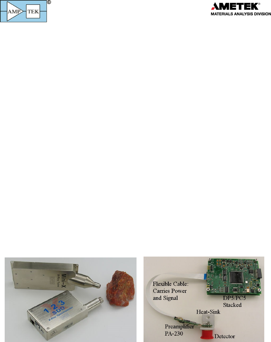
DP5 and PC5
The DP5/PC5 module is recommended for OEM applications involving semiconductor detectors,
where the units will be built in a complete system. The DP5 is a board level signal processor. The PC5 is
a board level power supply. The two are used in the X123 so together provide the same functionality as
the X123. But since they are printed circuit boards, the user is responsible for packaging and for
providing appropriate grounding, EMI shielding, thermal dissipation, etc.

Products for
Your
Imagination
18
A user can purchase the DP5 and provide his/her own power supplies or can purchase the PC5 and
provide his/her own pulse processing. The DP5 can also be configured for use with many different
detectors, e.g. HPGe, Si(Li), proportional counters, etc. Amptek has a special variant of the DP5, the
DP5G, for use with scintillator/PMT systems. The input to the standard DP5 must be the output of a
charge sensitive preamplifier.
MCA8000D
The MCA8000D is recommended for use with analog pulse shaping electronics. This product only
implements the multichannel analysis function and does not include pulse shaping.
DP5G
The DP5G is recommended for OEM applications in scintillation spectroscopy. It is a variant of the
DP5 which includes a charge amp suitable for use with scintillator/PMT systems. The DP5G is used in
Amptek’s TB5 and Gamma-Rad5 products.
TB5 and Gamma-Rad5
The TB-5 is recommended for scintillation spectroscopy for customers providing their own
scintillator and PMT while the Gamma-Rad5 is recommended for customers needing a complete
scintillation spectroscopy system.
Products for
Your
Imagination
19
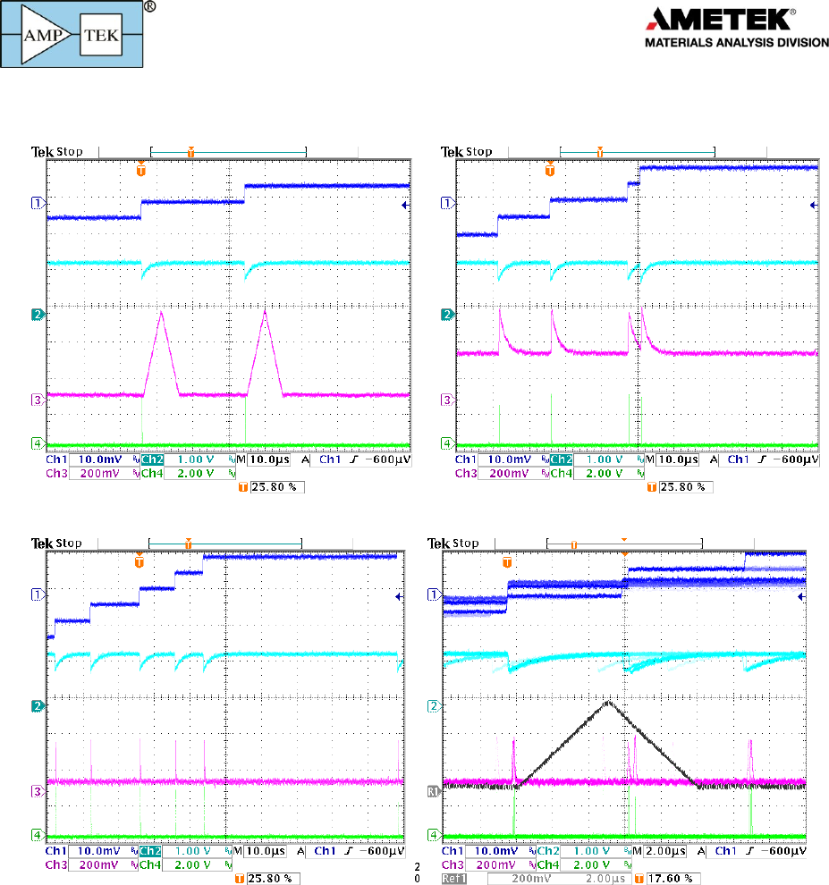
7.2 Typical Oscilloscope Traces
The following images show typical oscilloscope traces for various detectors and signal processors.
They cannot capture every instance but do show common examples.
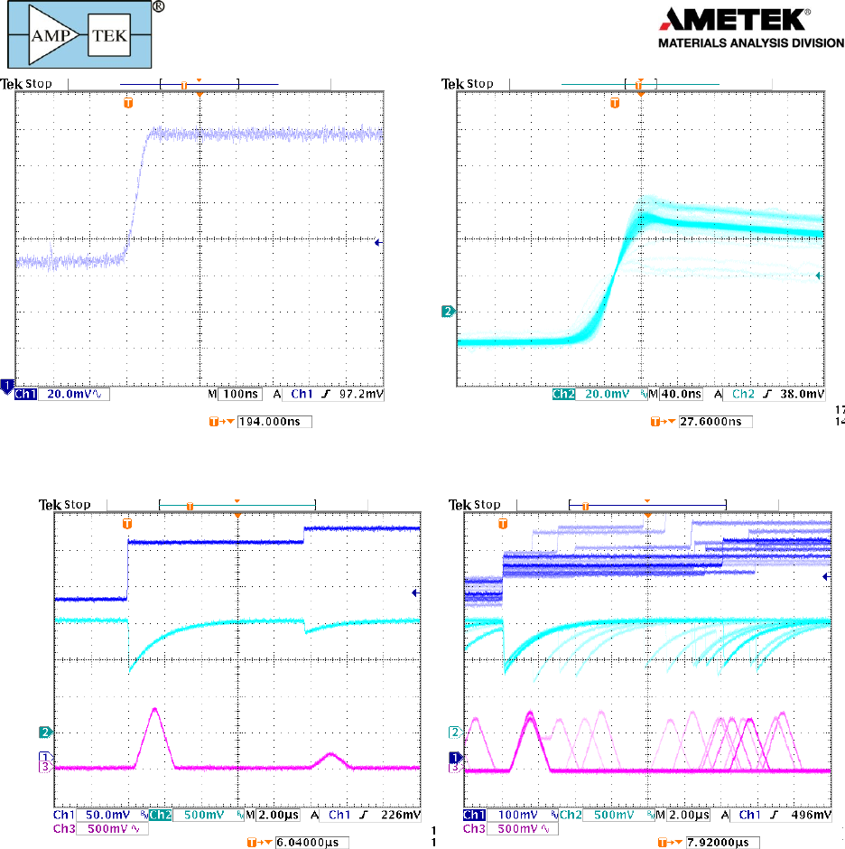
Preamplifier outputs. These traces illustrate typical output pulses with Amptek’s X-ray detectors, which use reset preamps.
The plot on the left is for a FastSDD® detector; each X-ray interaction results in a positive going step of ~3.7 mV/keV. One can
distinguish the 5.9 and the 22.1 keV steps. The plot on the right is for a Si-PIN, which produces negative going pulses with a
gain of 1 mV/keV.
Preamplifier output. These traces also shows the preamp output but on a different voltage and time scale to illustrate the
reset. The small steps from each signal integrate towards the rail, where a reset signal is generated. This results in a sawtooth
of several volts amplitude. The period depends on the total current through the detector (signal current plus leakage current).
The plot on the left (right) is for a FastSDD® with PA210, that on the right for a Si-PIN with an XR-100.
Products for
Your
Imagination
20
Preamplifier risetime. The plot on the left shows the trace from the preamplifier for a single pulse at a short time scale, while
the trace on the right shows the input to the ADC from several pulses. These are for a FastSDD® with 55Fe. The distinct traces
for the K and K energies are visible.
Signals. These traces show the preamplifier output (dark blue), the input to the ADC (light blue) and the shaped output
(magenta) for typical pulses. The shaped output is on the DAC output. The trace on the left shows two pulses which are well
separated in time. The plot on the right shows several pulses, illustrating the random timing and occasional pulse pileup.
Products for
Your
Imagination
21
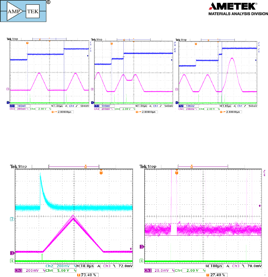
Pileup and deadtime losses. These traces illustrate pulse pile-up. On the left, the two interactions are well separated in time.
Both are counts and both amplitudes are measured accurately. In the middle trace, two pulses are closer in time. The shaped
pulses overlap but they are far enough apart, more than Tpeak+Tflat, so their pulse heights are not affected. Both amplitudes are
measured accurately. In the right trace, two pulses are close enough together that the peak shape is affected. This is termed
pile-up. They are far enough apart in time that the logic can detect the pile-up and reject the signals, avoiding an erroneous
pulse height. If two pulses are so close together that they overlap in the fast channel, which yields a shaped pulse height equal
to the sum of the individual heights, this will be recorded.
Noise. These traces illustrate intrinsic noise. The very small current pulses from the detector are superimposed on a signal
which varies randomly in time, due to intrinsic noise: shot noise in the detector, thermal noise in the input FET, etc. This noise
degrades resolution and affects counting thresholds; the pulse shaping filters the noise. In the plot on the left, the blue trace
shows the input to the ADC. The band is wide because of the wideband input noise. The shaped output, the triangle, is much
shaper because the noise has been filtered. This is a low pass noise filter. The separation between the K and Kb lines is clear
in the shaped output but not visible before shaping. The plot on the right shows the noisy baseline on which the signal is
superimposed; the pulse height cannot be measured more accurately than the width of this band. This also affects counting
and thresholds: if the threshold were placed in the noise band, say 5 mV here, the system would be constantly triggered due to
noise fluctuations.
Products for
Your
Imagination
22
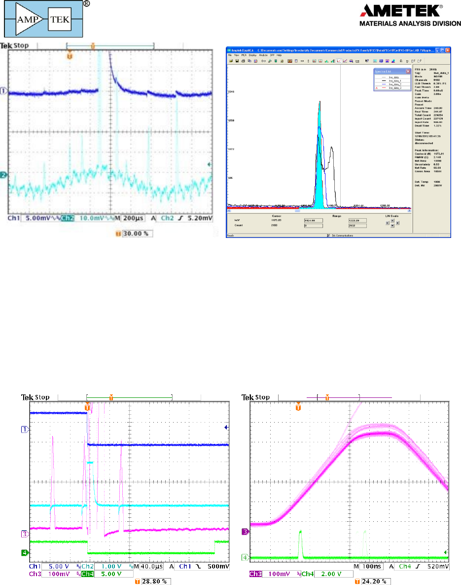
Interference. The trace on the left illustrates interference: since the detector produces very small current pulses, even a small
amount of ripple coupling in via a ground path or radiated to the signal line can degrade performance. This plot shows both
high and low frequency interference. Every time the baseline peaks, the system records a pulse, so the measured count rate is
very high, with many counts in the low channels (the left edge of the histogram). Moreover, since the peak amplitude is shifted
up and down, resolution is degraded. The plot on the right shows photopeaks with no interference (filled), a little interference
(blue) and then with ripple exceeding intrinsic noise (the double peak).
Reset: The trace below left shows the output for an SDD after a preamp reset (dark blue trace). When it resets, the ADC input
(light blue) has polarity opposite that of the signal and is very large, so the amplifiers saturate. The signal requires some time to
recover, as can be seen in the magenta trace: the pulse occurring 60 µs after reset starts from a low baseline yielding an
incorrect pulse height. Acquisition should be shut off until the baseline recovers (this is the “reset lockout period”). The green
trace is the output of the DETRES from AUX2, showing the lockout period.
Ballistic Deficit and Trapezoidal shaping: The magenta trace above right shows the shaped pulse for a detector with a risetime
which varies and is longer than 100 ns. Notice the variation in the shape of the rising edge: some of the pulses require a longer
time to peak. These are pulses with a slower charge collection time. If Tflat is shorter than the charge collection time, the pulse
does not reach full amplitude, resulting in an error in pulse measurement (termed “ballistic deficit”). It is important to set Tflat
longer than the charge collection time of the slowest pulses. The effect is more important at short Tpeak.
Products for
Your
Imagination
23
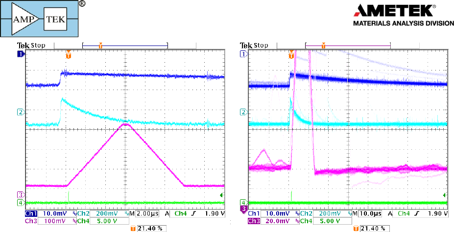
Pole zero correction: The traces above show signals from a detector with resistive feedback, in this case an HPGe detector with
a 50 µs tail. The dark blue trace, the preamp output, drops exponentially to baseline rather than exhibiting the steps of the
reset preamplifier. Circuitry in the DP5 cancels this tail (known technically as pole-zero cancellation) so that the light blue trace
exhibits a strictly exponential recover, yielding the magenta trapezoid.
The plot on the right shows the result of incorrect pole cancellation: the magenta trace overshoots, dropping below baseline,
and then recovering. If a pulse occurs shortly after another, the second starts from the incorrect baseline, leading to an
erroneous pulse height measurement. This causes loss of resolution at high count rates.
There are several time constants in the digital processor which must be correctly adjusted for proper operation. Incorrect
adjustment leads to the response seen here or else to an undershoot with a slow recover.
Products for
Your
Imagination
24
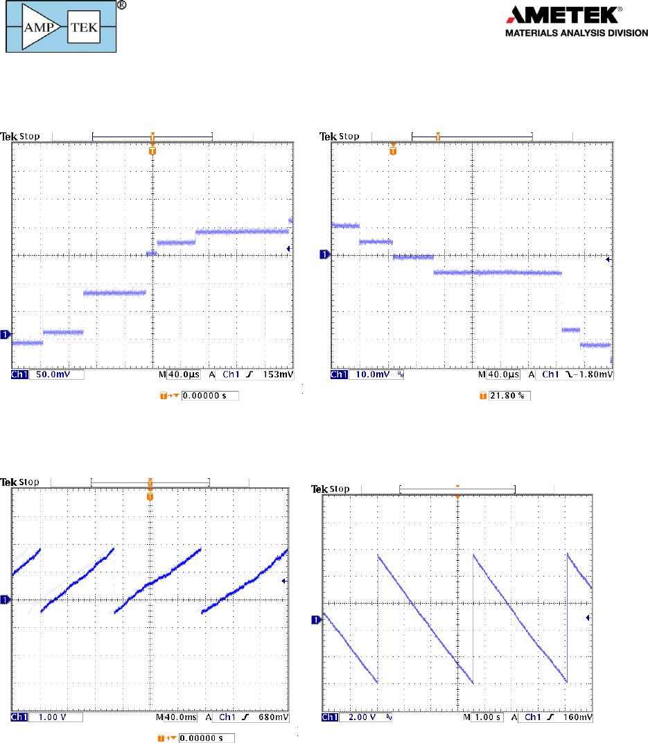
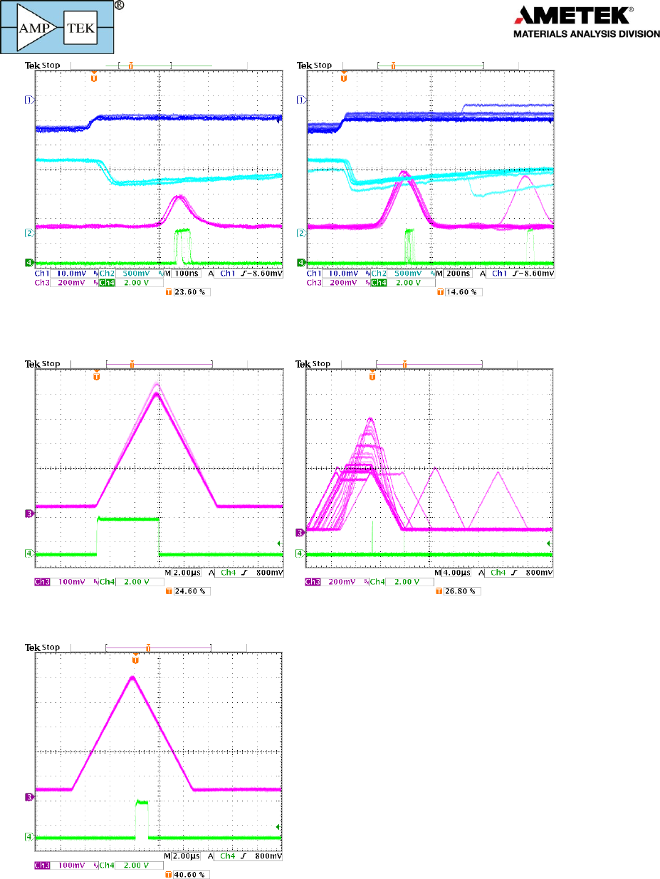
7.3 Auxiliary Output Signals
These traces show the most commonly used auxiliary outputs.
DAC (analog) outputs: The analog, DAC output is used to show diagnostic signals representing the waveform during the signal
processing. In all these plots, the dark blue trace shows the preamp output and the light blue trace shows the ADC input.
At the top left, the magenta trace shows the shaped pulse. In the top right, the magenta trace shows the signal labeled input
(note that the polarity and offset have been adjusted to keep the signal in range). At the bottom left, the magenta trace shows
the fast pulse: it is shaped but with a much shorter peaking time. This allows the fast channel to detect piled up pulses and to
accurately count pulses but at the cost of higher noise bandwidth. The bottom right trace compares fast and slow signals.
Products for
Your
Imagination
25
ICR: These traces illustrate the ICR (Incoming Count Rate) pulse. This is produced by a comparator operating on the fast
channel. Any pulses which exceeds the fast threshold will generate an ICR pulse. This is used to produce the fast or input count
rate and in the pile-up reject logic.
Peak Hold: The green trace on the left shows the peak hold signal, indicating when the logic was searching for the peak.
Pileup: The green trace on the right is produced when two pulses pile-up, at the time of the peak of the second pulse.
SCA8: The green trace shows the output of an SCA, in this case SCA 8. It is produced by a pulse with a peak amplitude within
the SCA range (set in software). Its rising edge is at the time the peak is detected. Its width is commandable to 0.1 or 1 µs.
