User Guide Vol1
User Manual:
Open the PDF directly: View PDF ![]() .
.
Page Count: 312 [warning: Documents this large are best viewed by clicking the View PDF Link!]
- User Guide
- Introduction
- Fundamental Types
- Initialization & Resource Management
- Plugin Creation & Usage
- The Camera
- Rasters, Images and Textures
- Immediate Mode
- Serialization
- File Systems
- The Dictionary Toolkit
- Debugging and Error Handling
- World and Static Models
- Dynamic Models
- Lights
User Guide
Volume I
Copyright © 2003 – Criterion Software Ltd.

User Guide
I-2 11 February 2004
Contact Us
Criterion Software Ltd.
For general information about RenderWare Graphics e-mail info@csl.com.
Developer Relations
For information regarding Support please email devrels@csl.com.
Sales
For sales information contact: rw-sales@csl.com
Acknowledgements
Contributors RenderWare Graphics Development and Documentation
Teams
The information in this document is subject to change without notice and does not represent a commitment on the part
of Criterion Software Ltd. The software described in this document is furnished under a license agreement or a non-
disclosure agreement. The software may be used or copied only in accordance with the terms of the agreement. It is
against the law to copy the software on any medium except as specifically allowed in the license or non-disclosure
agreement. No part of this manual may be reproduced or transmitted in any form or by any means for any purpose
without the express written permission of Criterion Software Ltd.
Copyright © 1993 - 2003 Criterion Software Ltd. All rights reserved.
Canon and RenderWare are registered trademarks of Canon Inc. Nintendo is a registered trademark and NINTENDO
GAMECUBE a trademark of Nintendo Co., Ltd. Microsoft is a registered trademark and Xbox is a trademark of Microsoft
Corporation. PlayStation is a registered trademark of Sony Computer Entertainment Inc. All other trademark mentioned
herein are the property of their respective companies.
Foreword
About the User Guide
This is the RenderWare User Guide for release 3.7. The documentation has been
updated for 3.7 and is organized into three volumes of general, platform independent
material. Volume III includes Maestro documentation and a Recommended Reading
appendix .
Xbox, GameCube and PlayStation 2 have a separate platform specific addendum,
containing material which is only useful for that platform and which has been updated
for 3.7.
Volume I contains the core library and the world library, giving basic immediate mode
and retained mode functionality.
• Introduction
From the core library:
• Fundamental Types
• Initialization & Resource Management
• Plugin Creation and Usage
• The Camera, covering the basics of rendering
• Rasters, Images and Textures
• Immediate Mode
• Serialization
• Debugging & Error Handling
From the world library:
• World and Static Models
• Dynamic Models
• Lights
In Volume II elements of the animation systems, special effects and world management
functionality are discussed
• Skinning
• Fundamental Types for Animation
• The Animation Toolkit
• Hierarchical Animation
• Morph
• Delta Morphing
• Material Effects
• Lightmaps
• PTank
• Standard Particles (RpPrtStd)
• B-splines and Bézier Patches
• Collision Detection
• Potentially Visible Sets (PVS)
• Geometry Conditioning

Foreword
I-4 11 February 2004
Volume III covers the utility libraries, which offer a variety of useful functionality and
an in-depth coverage of PowerPipe, the key to customizing RenderWare for ultimate
performance and unique functionality for your application.
• 2D Graphics Toolkits
• Maestro
• The User Data Plugin, on exporting user data
• PowerPipe Overview
• Pipeline Nodes
Platform specific documentation is included for PlayStation 2, Xbox and GameCube.
PlayStation 2:
• PS2All Overview
• Pipeline Delivery System (PDS)
Xbox:
• Multi-texturing in MatFX
• Multi-texturing on Xbox
• Xbox State Cache
• Xbox Pixel Shaders
• Xbox Vertex Format Compression
GameCube:
• Multi-texturing in MatFX
• Multi-texturing on GameCube
We realize that this User Guide does not cover every single feature in RenderWare
Graphics, but we hope you will find it useful.
Please let us know what you think and feel free to offer any suggestions.
Regards,
The RenderWare Graphics Team
Table of Contents
Chapter 1 - Introduction ....................................................................................... 13
1.1 Welcome to RenderWare Graphics .................................................................14
1.1.1 What you Should Know ...................................................................... 14
1.1.2 What is RenderWare Graphics? ........................................................... 15
1.1.3 Design philosophy ............................................................................. 16
1.2 The RenderWare Graphics SDK......................................................................18
1.2.1 Libraries and Header Files .................................................................. 18
1.2.2 Examples ......................................................................................... 19
1.2.3 Documentation ................................................................................. 20
1.2.4 Artists Tools ..................................................................................... 21
1.2.5 Open Export Framework .................................................................... 21
1.3 RenderWare Graphics Architecture .................................................................22
1.3.1 The Core Library, Plugins and Toolkits ................................................. 22
1.3.2 PowerPipe ........................................................................................ 25
1.3.3 Namespaces ..................................................................................... 25
1.3.4 Just Graphics.................................................................................... 26
1.3.5 Objects ............................................................................................ 26
1.3.6 File I/O ............................................................................................ 27
1.4 Using RenderWare Graphics ..........................................................................28
1.4.1 Creating a scene ............................................................................... 28
1.4.2 Creating prototypes........................................................................... 29
Part A - Core Library ............................................................................................. 31
Chapter 2 - Fundamental Types............................................................................. 33
2.1 Introduction ................................................................................................34
2.2 RenderWare Graphics & Objects ....................................................................35
2.2.1 RenderWare Graphics Objects............................................................. 35
2.2.2 Object Instantiation........................................................................... 35
2.2.3 Object Destruction & Reference Counters ............................................. 36
2.3 The Boolean Type ........................................................................................38
2.4 Characters ..................................................................................................39
2.5 Integer Types..............................................................................................40
2.6 Real Types ..................................................................................................42
2.7 Vectors.......................................................................................................43
2.7.1 Two Dimensional Vectors ................................................................... 43
2.7.2 Three Dimensional Vectors ................................................................. 44
2.8 Coordinate Systems .....................................................................................45
2.8.1 Right-handed Coordinates .................................................................. 45
2.8.2 Object Space .................................................................................... 47
2.8.3 World Space ..................................................................................... 48
2.8.4 Camera Space .................................................................................. 48
2.8.5 Device Space.................................................................................... 48

User Guide
I-6 11 February 2004
2.9 Matrices ..................................................................................................... 50
2.9.1 Matrix Mathematics in RenderWare Graphics ........................................ 50
2.10 Frames....................................................................................................... 52
2.10.1 Hierarchical Models & RenderWare Graphics ....................................... 53
2.10.2 Traversing Frame Hierarchies ........................................................... 54
2.10.3 Matrix Combination Flags in RenderWare Graphics .............................. 55
2.11 Bounding Boxes........................................................................................... 57
2.12 Lines .......................................................................................................... 58
2.13 Rectangles.................................................................................................. 59
2.14 Spheres...................................................................................................... 60
2.15 Colors ........................................................................................................ 61
Chapter 3 - Initialization & Resource Management ............................................... 63
3.1 Introduction ................................................................................................ 64
3.2 Basic Housekeeping ..................................................................................... 65
3.2.1 Initialization ..................................................................................... 65
3.2.2 Shutting down RenderWare Graphics................................................... 70
3.2.3 Changing Video Modes after Initialization ............................................. 71
3.3 Memory Management................................................................................... 72
3.3.1 The OS-level Memory Interface........................................................... 72
3.3.2 FreeLists .......................................................................................... 73
3.3.3 Memory Hints ................................................................................... 75
3.3.4 Resource Arenas ............................................................................... 76
3.3.5 Locking and Unlocking data ................................................................ 77
3.4 Summary ................................................................................................... 79
3.4.1 Starting The Engine........................................................................... 79
3.4.2 Shutting Down The Engine ................................................................. 79
3.4.3 Memory Handling.............................................................................. 80
3.4.4 Plugins ............................................................................................ 80
Chapter 4 - Plugin Creation & Usage ..................................................................... 81
4.1 Introduction ................................................................................................ 82
4.1.1 Toolkits ........................................................................................... 82
4.1.2 Plugins and Streaming....................................................................... 82
4.2 Using Plugins .............................................................................................. 83
4.2.1 Attaching Plugins .............................................................................. 83
4.3 Creating Your Own Plugins............................................................................ 85
4.3.1 Introduction ..................................................................................... 85
4.3.2 Anatomy of a Plugin .......................................................................... 85
4.3.3 The "Plugin" Example ........................................................................ 85
4.3.4 Using the Physics Plugin .................................................................... 88
4.4 Plugin Design .............................................................................................. 91
4.4.1 Introduction ..................................................................................... 91
4.4.2 Extension vs. Derivation .................................................................... 91
4.4.3 Deriving new objects ......................................................................... 91
4.4.4 Plugins & C++ .................................................................................. 92

Table of Contents
RenderWare Graphics 3.7 I-7
Chapter 5 - The Camera ........................................................................................ 95
5.1 Introduction ................................................................................................96
5.1.1 The Camera Example ......................................................................... 96
5.2 The RenderWare Graphics Camera object .......................................................97
5.2.1 Camera Properties............................................................................. 97
5.2.2 The View Frustum ............................................................................. 98
5.2.3 The View Window .............................................................................. 99
5.2.4 The View Offset .............................................................................. 102
5.2.5 Fog ............................................................................................... 102
5.3 The Camera View Matrix ............................................................................. 105
5.4 Rasters & Cameras .................................................................................... 106
5.4.1 Z Buffer Accuracy............................................................................ 106
5.5 Creating a Camera ..................................................................................... 107
5.5.1 Orienting and Positioning a Camera in Scene Space............................. 107
5.6 Rendering to a Camera............................................................................... 109
5.6.1 Destroying a Camera ....................................................................... 110
5.7 Sub-Rasters .............................................................................................. 111
5.8 Other Features .......................................................................................... 112
5.8.1 Clearing the Buffers......................................................................... 112
5.8.2 Cloning a Camera............................................................................ 112
5.9 World Plugin Extensions.............................................................................. 113
5.9.1 About the Extensions....................................................................... 113
5.9.2 Automatic & Manual Culling .............................................................. 113
5.9.3 Clump Cameras .............................................................................. 113
5.9.4 Iterators ........................................................................................ 113
Chapter 6 - Rasters, Images and Textures .......................................................... 115
6.1 Introduction .............................................................................................. 116
6.2 Bitmaps & Textures.................................................................................... 117
6.2.1 Bitmaps ......................................................................................... 117
6.2.2 Images .......................................................................................... 117
6.2.3 Rasters .......................................................................................... 117
6.2.4 Textures ........................................................................................ 118
6.3 The Image Object ...................................................................................... 119
6.3.1 Image Dimensions .......................................................................... 119
6.3.2 Stride ............................................................................................ 119
6.3.3 Palettes ......................................................................................... 119
6.3.4 Gamma Correction .......................................................................... 119
6.3.5 Creating Images ............................................................................. 120
6.3.6 Example: Reading a BMP file ............................................................ 121
6.3.7 Reading the Image .......................................................................... 122
6.3.8 Image Processing............................................................................ 123
6.3.9 Raster Conversion ........................................................................... 125
6.3.10 Destroying Images ........................................................................ 125
6.4 The Raster Object ...................................................................................... 126
6.4.1 Basic Properties .............................................................................. 126

User Guide
I-8 11 February 2004
6.4.2 The Raster as a Display Device ......................................................... 129
6.4.3 Rendering Rasters........................................................................... 130
6.4.4 Accessing Rasters ........................................................................... 131
6.4.5 Reading Rasters from disk................................................................ 131
6.5 Textures & Rasters .................................................................................... 132
6.5.1 Introducing Textures ....................................................................... 132
6.5.2 Loading Textures ............................................................................ 136
6.5.3 Texture Dictionaries ........................................................................ 138
6.5.4 Using Texture Dictionaries................................................................ 139
6.5.5 Platform independent texture dictionaries .......................................... 140
6.5.6 Using PI texture dictionaries............................................................. 140
6.5.7 Non-fixed hardware issues with texture dictionaries ............................ 141
6.5.8 Textures & Binary Streams............................................................... 141
Chapter 7 - Immediate Mode ...............................................................................143
7.1 Introduction .............................................................................................. 144
7.1.1 Properties & Render States .............................................................. 144
7.2 2D Immediate Mode................................................................................... 145
7.2.1 Basic Concepts ............................................................................... 145
7.2.2 Initializing an RwIm2DVertex object.................................................. 147
7.2.3 Primitives....................................................................................... 149
7.2.4 Triangle Winding Order .................................................................... 150
7.2.5 Primitives vs. Indexed Primitives....................................................... 151
7.2.6 Example 1: Rendering A Line............................................................ 152
7.3 3D Immediate Mode................................................................................... 154
7.3.1 Preparation for Rendering ................................................................ 154
7.3.2 Rendering ...................................................................................... 156
7.3.3 Closing the pipeline ......................................................................... 158
7.3.4 3D Immediate Mode & PowerPipe...................................................... 158
7.3.5 Platform Specific Information ........................................................... 159
7.3.6 Camera-space and Z-buffer depth equations ...................................... 160
7.3.7 Rt2D ............................................................................................. 161
7.4 Render States ........................................................................................... 162
7.4.1 Key Features .................................................................................. 162
7.4.2 API................................................................................................ 162
7.4.3 Blending ........................................................................................ 165
7.4.4 Sorting Alpha Primitives................................................................... 166
Chapter 8 - Serialization ......................................................................................167
8.1 Introduction .............................................................................................. 168
8.2 File I/O API ............................................................................................... 169
8.3 RenderWare Binary Streams ....................................................................... 171
8.3.1 Binary Stream Structure .................................................................. 171
8.3.2 Serializing Objects .......................................................................... 173
8.3.3 Explicit Streaming Functions............................................................. 178
8.3.4 RWS files ....................................................................................... 182
8.3.5 Stream Types ................................................................................. 186

Table of Contents
RenderWare Graphics 3.7 I-9
8.4 Summary.................................................................................................. 187
8.4.1 File I/O API .................................................................................... 187
8.4.2 RenderWare Binary Streams............................................................. 187
Chapter 9 - File Systems ..................................................................................... 191
9.1 Introduction .............................................................................................. 192
9.2 File System Management ............................................................................ 193
9.3 The File Systems ....................................................................................... 194
9.3.1 The Generic File System................................................................... 194
9.3.2 OS-Specific File Systems.................................................................. 195
9.4 Using the RenderWare File System............................................................... 196
9.4.1 Basic Usage.................................................................................... 196
9.4.2 Synchronous vs. Asynchronous Access............................................... 198
9.4.3 File System Specific Remarks ........................................................... 199
9.4.4 Creating your Own File System ......................................................... 200
Chapter 10 - The Dictionary Toolkit..................................................................... 203
10.1 Introduction .............................................................................................. 204
10.1.1 This Document.............................................................................. 204
10.1.2 Other Resources............................................................................ 205
10.2 Basic Dictionary Schema Usage ................................................................... 206
10.2.1 Getting the Current Dictionary for a Schema..................................... 206
10.2.2 Setting the Current Dictionary for a Schema ..................................... 206
10.3 Creating and Streaming Dictionaries ............................................................ 207
10.3.1 Dictionary Creation........................................................................ 207
10.3.2 Reading a Dictionary from a Stream ................................................ 207
10.3.3 Writing a Dictionary to a Stream ..................................................... 207
10.4 Dictionary Entries ...................................................................................... 209
10.4.1 Adding Entries to a Dictionary ......................................................... 209
10.4.2 Removing an Entry from a Dictionary............................................... 209
10.4.3 Locating an Entry by Name............................................................. 210
10.5 Advanced Dictionary Schema Usage ............................................................. 211
10.5.1 Schema Structure ......................................................................... 211
10.5.2 Initializing a Schema ..................................................................... 212
10.6 Summary.................................................................................................. 214
Chapter 11 - Debugging and Error Handling........................................................ 215
11.1 RenderWare Graphics Errors ....................................................................... 216
11.2 RenderWare Graphics Builds ....................................................................... 217
11.3 The Debug Object ...................................................................................... 218
11.3.1 The Default Debug Stream Handler.................................................. 218
11.3.2 Sending a Message to the Debug Stream ......................................... 219
11.4 Tracing RenderWare Graphics Activity .......................................................... 220
11.5 Replacing The Stream Handler.......................................................................... 222
11.5.1 Example....................................................................................... 222
Part B - World Library ......................................................................................... 225

User Guide
I-10 11 February 2004
Chapter 12 - World and Static Models ..................................................................227
12.1 Introduction .............................................................................................. 228
12.2 Scenes & Static Models............................................................................... 229
12.2.1 Scenes......................................................................................... 229
12.2.2 RpWorld Object............................................................................. 229
12.2.3 RpWorldSector Object.................................................................... 230
12.3 Iterator Functions ...................................................................................... 231
12.3.1 RpWorld Iterators.......................................................................... 231
12.3.2 RpWorldSector Iterators................................................................. 232
12.3.3 Collision Detection......................................................................... 232
12.4 Modeling Tools .......................................................................................... 233
12.4.1 Viewers........................................................................................ 233
12.5 Creating Worlds......................................................................................... 234
12.5.1 Creating Worlds from Foreign Data .................................................. 234
12.5.2 What is Pre-lighting? ..................................................................... 240
12.6 Rendering................................................................................................. 242
12.6.1 How to Render Worlds ................................................................... 242
12.6.2 Instancing .................................................................................... 242
12.6.3 Pre-instancing Static Geometry ....................................................... 243
12.7 Serialization.............................................................................................. 245
12.7.1 Writing......................................................................................... 246
12.7.2 Reading ....................................................................................... 247
12.8 Destruction ............................................................................................... 248
Chapter 13 - Dynamic Models...............................................................................249
13.1 Introduction .............................................................................................. 250
13.2 The World Plugin ....................................................................................... 251
13.2.1 The Geometry Object..................................................................... 251
13.2.2 The Atomic Object ......................................................................... 251
13.2.3 The Clump Object.......................................................................... 252
13.2.4 Clump Destruction......................................................................... 254
13.3 Creation of Dynamic Models ........................................................................ 255
13.3.1 Model Creation Overview................................................................ 255
13.4 Modeling Tools .......................................................................................... 256
13.4.1 Exporters ..................................................................................... 256
13.4.2 Viewers........................................................................................ 256
13.4.3 Procedural Model Creation .............................................................. 257
13.4.4 Vertices & Triangles....................................................................... 257
13.4.5 Textures & Materials...................................................................... 259
13.4.6 Surface Properties & Geometry ....................................................... 261
13.4.7 Morph Targets .............................................................................. 262
13.4.8 Pentagons & Hexagons .................................................................. 263
13.4.9 Bounding Spheres & Transformations .............................................. 264
13.4.10 Atomics and Clumps ...................................................................... 266
13.5 Objects in more detail ................................................................................ 267
13.5.1 Reference Counting ....................................................................... 267
13.5.2 Texture coordinates....................................................................... 267

Table of Contents
RenderWare Graphics 3.7 I-11
13.5.3 Prelighting.................................................................................... 268
13.5.4 Surface properties ......................................................................... 268
13.5.5 Meshes ........................................................................................ 268
13.6 Atomics, Clumps & Transformations ............................................................. 270
13.6.1 Worlds ......................................................................................... 270
13.6.2 Cloning ........................................................................................ 270
13.6.3 Iterator functions .......................................................................... 271
13.6.4 Sorting Geometry objects by Material .............................................. 273
13.6.5 Animation..................................................................................... 274
13.6.6 Skinned Models ............................................................................. 275
13.7 Optimization ............................................................................................. 276
13.8 Rendering ................................................................................................. 277
13.8.1 How to Render Dynamic Objects ..................................................... 277
13.8.2 Instancing .................................................................................... 278
13.8.3 Pre-instancing Dynamic Geometry ................................................... 279
13.8.4 Converting Model Data to RenderWare Graphics................................ 281
Chapter 14 - Lights ............................................................................................. 285
14.1 Introduction .............................................................................................. 286
14.1.1 Other Documentation..................................................................... 286
14.2 Dynamic Lights.......................................................................................... 287
14.2.1 Dynamic Lights Representation ....................................................... 288
14.2.2 Creating a dynamic light ................................................................ 289
14.2.3 Clump Lights & Streaming .............................................................. 292
14.2.4 Platform-Specific Lighting Models .................................................... 292
14.3 Static Lights using RpLight .......................................................................... 294
14.3.1 Creating Static Lights..................................................................... 294
14.3.2 Static Lighting Techniques .............................................................. 295
14.4 Related Examples ...................................................................................... 297
14.5 Summary.................................................................................................. 300
14.5.1 Dynamic Lights ............................................................................. 300
14.5.2 Static Lights ................................................................................. 301
Index .................................................................................................................. 303

Chapter 1
Introduction

Chapter 1 - Introduction
I-14 11 February 2004
1.1 Welcome to RenderWare Graphics
Welcome to the RenderWare Graphics User Guide!
RenderWare Graphics is a powerful 3D graphics library. This User Guide is
aimed at helping newcomers to RenderWare Graphics become familiar with
the product. This is in addition to the on-line help, and support that is
offered with the purchase of any RenderWare Platform component.
RenderWare Graphics is the result of many years of development, which
began in 1991. The power and flexibility of the product has been increased
with every release. RenderWare Graphics is a multi-platform Application
Programming Interface (API), which is constantly being improved and
updated to keep it at the cutting edge of 3D graphics.
To support the community of developers in the field, we offer our Fully
Managed Support System. Accessible via a personalized web interface, this
allows our technical support personnel to be contacted, the status of
outstanding queries to be tracked, and our knowledge base to be searched
and viewed, plus lots of other useful information. To find out more and
register for the service, point your browser at
https://support.renderware.com/.
If you are new to RenderWare Graphics, it is strongly suggested that you
read this User Guide as you go along to acquaint yourself with its
operation.
Similarly, if you've already been using RenderWare Graphics for a while,
stick around! The User Guide is written by the people who created the
library, so you might gain new insights, tricks and tips. Additionally it has
been revised and expanded to cover all our latest new technology.
RenderWare Graphics is a module of Criterion Software's RenderWare
Platform, the tailored set of open and extensible middleware tools which
allows you to focus on content and gameplay. For further information on
the other Components (including RenderWare Audio, RenderWare AI and
RenderWare Physics) please visit www.renderware.com or contact your
account manager.
1.1.1 What you Should Know
This User Guide makes some assumptions about your level of proficiency
with real-time 3D graphics programming:
• This Guide is not aimed at complete newcomers to the field of computer
graphics. If you are new to all this, check out the Recommended
Reading appendix for links to online articles and books you can use as
a starting point.

Welcome to RenderWare Graphics
RenderWare Graphics 3.7 I-15
• Secondly, this User Guide will not go into detail about the mathematics
upon which most 3D graphics programming is founded. The whole
point of graphics libraries such as RenderWare Graphics is to do the
math for you.
That said, some college-level math is required to understand some
concepts. If your knowledge of the principles and practices of matrix
and vector manipulation is limited, the Recommended Reading
appendix contains pointers to relevant texts that can help you with this
area.
• This User Guide assumes you are an experienced programmer with a
thorough knowledge of the C (or C++) programming language. You
should also be comfortable with the concepts behind object-oriented
programming.
• The User Guide is platform-neutral so it will not cover any specific
development environment. Platform-specific variations and optimization
notes will be provided in an appendix.
1.1.2 What is RenderWare Graphics?
• A graphics library
RenderWare Graphics is a 2D and 3D graphics API. It is used by
programmers to create real-time 3D graphics applications, such as
computer games and simulations.
• Multi-platform
RenderWare Graphics has multi-platform, portable API that allows high
level functionality to be achieved on all platforms, with platform specific
optimizations to get the best from the hardware pipelines.
RenderWare Graphics is available for Sony PlayStation 2, Microsoft
Xbox, NINTENDO GAMECUBE, Microsoft Windows (Direct3D 8),
Microsoft Windows (OpenGL) and Apple MacOS (OpenGL).
• Customizable
RenderWare Graphics has a component-based approach to its
architecture based around a small-footprint, thin-layer core library,
supplemented by a number of Plugins and Toolkits.
Plugins are the key to RenderWare Graphics' power; they can extend
existing objects and add new objects of their own that can also be
further extended.
Even the Retained Mode API is a Plugin, which gives RenderWare
Graphics the unique feature of being the only 3D graphics library that
can support any number of Retained Mode APIs.

Chapter 1 - Introduction
I-16 11 February 2004
Further, this Plugin mechanism is fully exposed. You can write your
own Plugins, extending and adding objects, for your own requirements -
we even encourage you to do so, as we do not claim to have thought of
everything!
• Compatible with many third-party tools and middleware
RenderWare Graphics is a module of Criterion Software's RenderWare
Platform, the tailored set of middleware tools offering a tightly
integrated game development framework, which includes graphics,
audio and physics modules, with other Components planned for
availability in the future.
1.1.3 Design philosophy
The design brief for RenderWare Graphics was to create a 3D graphics
library that would never be obtrusive. We have tried hard to make sure the
library is the most powerful multi-platform 3D library available.
Platform Independent Development
RenderWare Graphics has been designed from the ground up to let you get
the most out of all its supported platforms – with no compromises. APIs are
provided which expose low-level features and optimization opportunities to
the developer, so the best performance can be obtained from your projects.
The price for this is a little extra work during the porting process: each
platform has different hardware, and different advantages and
disadvantages. RenderWare Graphics gives you the freedom to choose how
far you go down the optimization route:
• Need to create a product quickly for more than one platform? No
problem: use the common API features – the facilities provided as
standard across all platforms – and treat it as an ordinary cross-
platform library.
• Alternatively, writing custom PowerPipe nodes and plugins enables
RenderWare Graphics to be fine-tuned to specialized performance
requirements. The purchase of a source code license gives the developer
ultimate control over RenderWare Graphics.
RenderWare Graphics gives you the freedom to take either route, or indeed
any path between these two extremes.
Such flexibility does come at a price: where platform-specific features of
RenderWare Graphics are chosen, the code for each target platform will
need to be changed when porting.
C vs. C++
One of the most common questions asked about RenderWare Graphics is
the choice of programming language: C.

Welcome to RenderWare Graphics
RenderWare Graphics 3.7 I-17
There are two reasons for choosing to write RenderWare Graphics in the C
programming language. The first is that there is no standard for C++
libraries; RenderWare Graphics would have to be shipped as a separate set
of libraries for each supported compiler, as well as each platform. Clearly,
this would complicate product support.
Secondly, while C++ has many, many great features, most new platforms –
particularly consoles – don't get a stable, mature C++ compiler until long
after they get a good C compiler. In order for a new platform to be worked
on as soon as possible, the fastest way to achieve this is to use a mixture of
highly optimized C and assembly language.
That said, it is quite possible to mix C and C++. The Plugin mechanism lets
you add space for 'this' pointers to RenderWare Graphics objects with
minimal fuss, and all RenderWare Graphics' header files have the requisite
"extern 'C'" directives to allow the two languages to mix seamlessly.
Several of our licensees have also produced their own C++ wrapper classes
to encapsulate RenderWare Graphics in order to develop in a 'pure' C++
environment.

Chapter 1 - Introduction
I-18 11 February 2004
1.2 The RenderWare Graphics SDK
1.2.1 Libraries and Header Files
RenderWare Graphics is supplied as a number of libraries on the Software
Development Kit (SDK). Applications will need to link against these libraries
and #include the associated header files.
All RenderWare Graphics libraries are static.
Each platform is provided with its own headers and libraries. In addition,
the SDK contains null libraries, which are used by exporters and other
tools. These are provided with all platforms. The null libraries contain all
the PC functionality, but do not perform any rendering.
A NULL target DLL is also provided that the art tools exporters make use of.
This DLL contains almost all of the static NULL libraries.
Note that the static NULL libraries, contained in a RenderWare Graphics
(version 3.5 and above) installation, if linked into an application, require
the multithreaded DLL runtimes.
✎
Null Libraries
On Xbox, GameCube and PlayStation 2 null and nullplatform libraries are also built. For
example, PlayStation 2 RenderWare Graphics SDK is supplied with null and nullsky
libraries. These PC libraries are required for certain tools that process platform specific
data. They can be used for the generation of texture dictionaries.
It should be noted that nullplatform libraries can not create pre-instanced and geometry
data.
Debug, Metrics and Release Libraries
For each platform, separate debug, metrics and release builds of the
RenderWare Graphics libraries are also provided. Debug, release and
metrics libraries live in separate folders inside the rwsdk/lib folder.
RWDEBUG and RWMETRICS preprocessor symbols must be used to indicate
which build is being used.
It is crucial that you do not mix symbols and libraries between these
builds. To illustrate, some API calls are implemented in release builds as
macros. In debug builds these calls are really implemented as functions.
This can mean that if you define the RWDEBUG preprocessor symbol, but link
with the release build of the library you will get numerous "undefined
symbol" link errors.
Compilers supported
Please see the appropriate platform specific top-level readme files supplied
with the RenderWare Graphics SDK for information on the compilers
supported by RenderWare Graphics.

The RenderWare Graphics SDK
RenderWare Graphics 3.7 I-19
SN Systems, Visual Studio IDE integration and Project Files
The RenderWare Graphics SDK provides full support for the SN Systems
Visual Studio Integration features.
Project Build Target settings are included for all platforms supported via
Visual Studio. Developers should ensure the correct Project Build Target is
selected.
1.2.2 Examples
The SDK contains nearly 50 source code examples. Examples are small and
designed to illustrate a particular technique or feature of the RenderWare
Graphics API. They are intended as a means of education: we encourage
you to look through the source code and play with them.
Tools & Viewers
Also included are tools and viewers for you to use during development. Of
particular note is the RenderWare Visualizer viewer, which allows you to
easily view RenderWare Graphics artwork on any target hardware.
Two other viewers are also available for viewing artwork: 'wrldview', and
'clmpview'. 'wrldview' displays static models created for the Retained
Mode API, and 'clmpview' displays dynamic models.
RenderWare Graphics uses a single file format, using chunk-IDs, which is
capable of storing any one or more RenderWare Graphics objects. The
RenderWare Graphics Binary Stream format can be viewed using the
'strview' applet supplied with the SDK.
A Microsoft Visual Studio 6 AppWizard is also supplied with RenderWare
Graphics that can be used to generate an MFC framework-based clump or
world viewer. This AppWizard can be incorporated into Microsoft Visual
C++ and used in the same manner as the standard Microsoft AppWizards.
Please see the accompanying documentation describing how to build a
RenderWare Graphics viewer.
Building the Examples
The examples that are shipped on the SDK should not need compiling to
run them. If you modify them, you will want to re-build the executables.
The Project files provided with the tools and examples are not necessarily
set for your particular platform so make sure you select the correct build
configuration prior to compilation. The two screen shots below show the
Integrated Development Environments (IDEs) and the build targets that
they offer. In Visual Studio, you will need to select the correct Project
Configuration; in CodeWarrior, you must select the correct Target. Further,
there are separate release, debug, and metrics builds. Unless you have
good reason not to, it is suggested that you select:
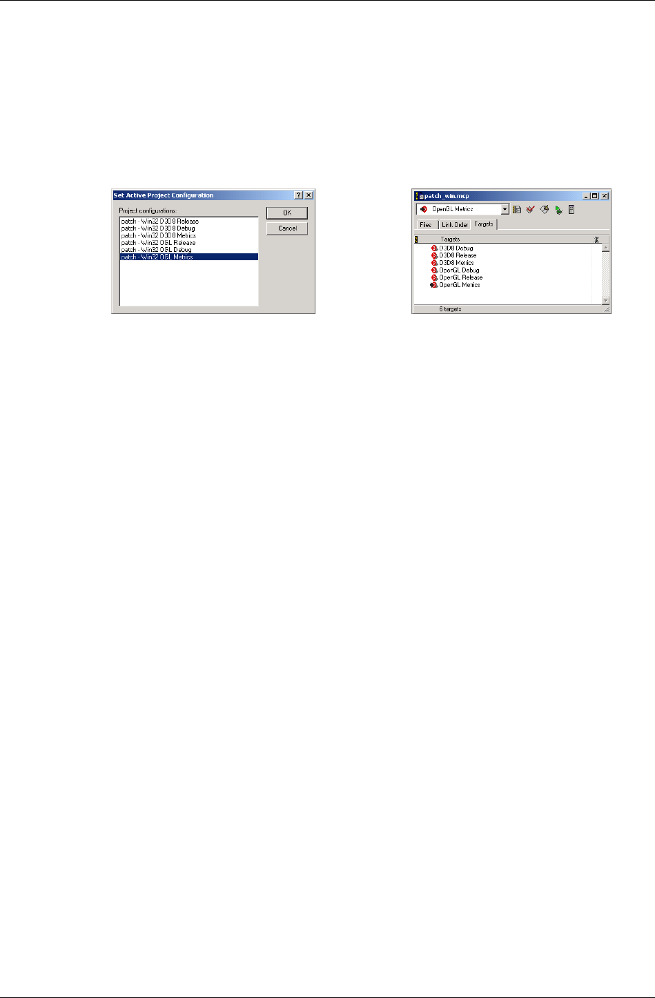
Chapter 1 - Introduction
I-20 11 February 2004
• Win32 D3D8 or D3D9 Release project in Visual Studio for the PC
• Xbox Release in Visual Studio for Xbox
• PS2 Release in CodeWarrior for the PlayStation 2
• GCN Release in CodeWarrior for GameCube
Visual Studio CodeWarrior
1.2.3 Documentation
Documentation is provided in both online and PDF formats. The PDF
format is intended for printing only and is not hyperlinked. The PDF files
have been setup for double sided printing.
The following documentation is provided in the SDK:
• This User Guide
• API Reference
• Tutorials (PC only)
• White Papers
• Exporter Guides for artists and programmers
• Tools and Viewers documentation
• Examples document listing all examples with brief explanation
• readme_xxx.pdf
All the examples and tools have a related readme.txt file. It is highly
recommended that you read these for information about any last-minute
changes or features.
There is also the top-level SDK readme_xx.pdf file, where xxx is the
platform name, which lists last-minute changes, fixes and known issues
and can be found in the root of the SDK.

The RenderWare Graphics SDK
RenderWare Graphics 3.7 I-21
1.2.4 Artists Tools
The RenderWare Graphics installer can be used to install the artists' tools.
These tools are exporter plugins for exporting 3D model data from packages
such as 3ds max and Maya.
When installed, artists will find:
• The modeling package's RenderWare Graphics exporter plugin(s)
• Sample artwork demonstrating optimal modeling techniques
• Documentation covering how to create and export models successfully for
RenderWare Graphics.
✎
✎✎
✎ It is strongly recommended that programmers also read the documentation supplied with
the artists tools. The installer adds links to these docs from the start menu.
1.2.5 Open Export Framework
The RenderWare Graphics programmer installer can be used to install the
Open Export SDK that gives you a powerful way of extending the exporters.
Consisting of a series of modular libraries and custom code hooks, you
could soon be introducing new common classes to the modelers, changing
behaviors or creating new object handlers under our plugin architecture.
To get you started, we have provided the Getting Started section in the
Open Export API Reference document. In addition, we have included six
examples of what you can do with the SDK:
• ExportObject - An example of a custom object exporter optimizes the
exported textures, by making sure that all texture sizes are beneath a
certain threshold.
• MaxSimple - An example of how to write your own custom builder and
export application. To demonstrate this we used a simplified 3dsmax
exporter.
• PostProcess – An example demonstrates how to post process the entire
list of exported RenderWare Graphics assets, and how to customize the
stream process for streaming them out.
• ScaleAnim - This example adds support for animated scale to the
RwExp layer.
• TravAction - Demonstrates the use of traverse actions together with
traverse lists that filters out all nodes containing a certain name.
• VertexFilter - An example of a vertex filter which pre-lights a scene by
applying per vertex operations.

Chapter 1 - Introduction
I-22 11 February 2004
1.3 RenderWare Graphics Architecture
The diagram below shows how the RenderWare Graphics library fits into a
typical application.
Hardware
RwCore
RpWorld
RW Plugin
Plugin
RW Toolkit
RW Plugin
RW Toolkit
Toolkit
Application
Abstracting the underlying hardware is the RenderWare Graphics Core
Library. Above this is the world plugin. This is the largest and most widely
used of the optional RenderWare Graphics modules. Various plugins
provided with the SDK are shown adding functionality. Also shown are
toolkits, both supplied with the SDK, and non-RenderWare Graphics
Toolkits supplied by third parties. A third party plugin is also shown. Above
these components is the application which uses the services (functions)
exposed by the various components.
The gray boxes above that labeled RwCore are optional. Unlike monolithic
3D graphics libraries, most of the higher-level features can be omitted.
Although it's not explicitly stated in the diagram, RpWorld, which provides
the Retained Mode API, is itself just a Plugin.
1.3.1 The Core Library, Plugins and Toolkits
The RenderWare Graphics components can be broken down:
1. Core Library
2. Plugins
3. Toolkits
The first is the Core Library. The Core Library must always be linked into
your application as it provides the glue that joins all the components
together, as well as basic rendering functionality.

RenderWare Graphics Architecture
RenderWare Graphics 3.7 I-23
Plugins
These are the keys to RenderWare Graphics extensibility. Plugins can
extend existing objects in both the Core Library and other Plugins – and
add their own objects. This feature is what differentiates them from
ordinary libraries. RenderWare Graphics' high-level APIs are all
implemented as Plugins.
Supplied Plugins
The following Plugins are supplied as standard with all releases of the SDK:
PLUGIN DESCRIPTION
RpADC Address Control flag generation
RpAnisot Anisotropy extension for extending textures
RpCollision Collision-detection extensions
RpDMorph Delta morphing and delta animation extensions
RpHAnim Hierarchical animation plugin
RpLODAtomic Level Of Detail extensions for RpWorld's "RpAtomic"
object
RpLtMap Render geometry using detailed static lighting
information from lightmap textures.
RpMatFX Multi-pass special effects, such as environmental
mapping, bump mapping, 2-pass
RpMipmapKL Texture mipmap "K" and "L" value extensions
RpMorph Morph-target animation extensions
RpPatch Bézier patch rendering engine
RpPrtStd Particle animation plugin
RpPTank Creation, management and rendering of user
customizable particles
RpPVS Fast visibility culling extension for RpWorld, using
Potentially Visible Sets
RpRandom Platform-neutral random number generator
RpSkin Skinned model rendering extensions with multiple bone
weights per vertex
RpSpline Spline manipulation extensions
RpUserData Provides functionality for storing user defined data with
geometry
RpUVAnim Attaches UV animations to materials
RpWorld Provides RenderWare Graphics' Retained Mode API –
specifically, the scene graph portion of it

Chapter 1 - Introduction
I-24 11 February 2004
Toolkits
A Toolkit is an ordinary library that just happens to make use of
RenderWare Graphics features. A Toolkit usually provides conversion
functions or other utilities.
Supplied Toolkits
The following Toolkits are supplied as standard with all releases of the SDK:
TOOLKIT DESCRIPTION
Rt2d Advanced 2D Graphics API utilizing underlying 3D
graphics hardware
Rt2dAnim Animation of 2D objects
RtAnim Create, stream and play keyframe animation.
RtBary Mapping points between the barycentric space and
Cartesian space
RtBezPat Bézier patch generation utility library
RtBMP Microsoft® Windows® Bitmap image format handling
RtCharset A bitmapped character library
RtCmpKey Keyframe system supporting compressed matrix
animation
RtDict Generic containers of named objects
RtFSyst File system manager and custom file systems
RtGCond Geometry Conditioning
RtIntersection Polygon and line intersection testing functions
RtLtMap Generation of lightmap textures - used with RpLtMap
RtMipK Texture mipmap "K" value calculation functions
RtPick Object-picking functions
RtPITexd Platform independent texture dictionary streaming
RtPNG Portable Network Graphics image format handling
RtQuat Quaternion manipulation functions
RtRAS Sun® Raster image format handling
RtRay Ray-casting functions used for picking
RtSkinSplit Skin & Geometry splitter for large bone count models
RtSlerp Spherical Linear Interpolation functions
RtSplinePVS Utility functions to allow PVS generation using spline
paths
RtTIFF Tag Image File Format image format handling
RtTile Tiled rendering functions (used mainly for very high-
resolution renderings)
RtTOC Table Of Contents for a stream
RtVCAT Vertex Cache Aware Tri-stripper
RtWing Winged edge/half-edge
RtWorld Utility functions to be used in conjunction with RpWorld
RenderWare Graphics Architecture
RenderWare Graphics 3.7 I-25
RtWorldImport Utilities for creating RpWorld objects from foreign data
formats
1.3.2 PowerPipe
PowerPipe provides a means of overloading the rendering subsystem either
wholly or piecemeal. You can replace or even create entirely new rendering
pipeline nodes and clusters.
1.3.3 Namespaces
All the RenderWare Graphics functions and objects carry two-letter prefixes
to prevent naming clashes with your own code. This has been used to
provide the best compromise between readability and name length.
The prefixes depend on whether the object in question is part of the Core
Library, part of a Plug-in, or part of a Toolkit. They are:
PREFIX DESCRIPTION
'Rw' Indicates a function situated in the RenderWare Graphics
Core Library ("rwcore.h" / "rwcore.lib"). These functions
are always available as long as the core RenderWare
Graphics library is linked to your application.
Examples:
RwEngineStart() RwCameraCreate()
'Rp' Indicates a function situated in a Plugin library (e.g.
RpMorph.) In most cases, the name of the Plugin follows the
prefix, but this guideline is sometimes ignored to keep
function names sensible.
The appropriate Plugin must be attached if you intend to use
these functions and linked to the appropriate header and
library files.
Examples:
RpMorphPluginAttach() RpPVSAtomicVisible()
'Rt' Indicates a Toolkit. Syntax is similar to that of Plugins,
described above.
Many Toolkits rely on one or more Plugins being attached,
but Toolkits themselves do not need to be attached.
Examples:
RtSlerpCreate() RtTileRender()
'Rx' Used by the PowerPipe API.
Examples:
RxHeapFree() RxPipelineExecute()
'Rs' Source code to a simple (and very basic) platform abstraction
layer used for all examples is provided. Major functions in
this layer use an 'Rs' prefix.

Chapter 1 - Introduction
I-26 11 February 2004
Exceptions These include constants, such as #defines and enum
values. These generally use the same prefixes as above, but
entirely in lower case, followed by an all-caps name, such as:
rwRASTERTYPECAMERA.
1.3.4 Just Graphics
This may seem obvious, but it is important to remember that RenderWare
Graphics only provides multi-platform 3D graphics features. While some
utilities are provided, such as an abstraction layer known as the 'Skeleton',
this code is not officially supported.
Most developers will create their own abstraction layers and write suitable
plugins for RenderWare Graphics to provide a consistent programming
interface across their supported platforms.
1.3.5 Objects
As RenderWare Graphics is written in C and assembler, it makes object-
oriented design that little bit harder to implement. C++ classes might need
to be written to wrap the RenderWare Graphics API.
One important issue to consider is the definition of an object in RenderWare
Graphics.
In C++, objects are an explicit part of the language's design. RenderWare
Graphics 'objects' are either intrinsic, such as int and char, or an ordinary
C struct. These usually have a noun for a name – e.g. World, Clump, and
Vector. The methods or member functions associated with these objects are
ordinary C functions that live outside these structures, but with names
that begin with the same name as the 'object'.
For instance, a hypothetical object called RwThing might have methods
with names like RwThingGetProperty().
RenderWare Graphics objects have been designed to operate in much the
same way as C++ objects. The main difference is that there are no member
selection operators to separate object names from their associated methods.
RenderWare Graphics Architecture
RenderWare Graphics 3.7 I-27
Objects & Properties
Transparent vs. Opaque Objects
RenderWare Graphics developers sometimes make a simple object
transparent. For such objects, you will find complete documentation of the
internals of the object in the API Reference, and often no property-access
function information. This reduces unnecessary function calling overheads:
you are free to directly change the individual object elements.
This reveals the element of trust enshrined with RenderWare Graphics'
design: where a data structure is not explicitly documented, it should be
considered an opaque object. Usually, such objects will have no
documentation for their individual members, so only their associated
property access methods (using the traditional 'Get' and 'Set' convention)
should be used.
The table below shows some examples of opaque objects and access to their
members:
OBJECT PROPERTY 'METHOD' NAME
RwCamera ViewWindow RwCameraGetViewWindow()
RwCameraSetViewWindow()
RpAtomic Geometry RpAtomicGetGeometry()
RpAtomicSetGeometry()
The object’s name always forms the root of the function name. This pattern
is followed consistently throughout the RenderWare Graphics API.
Obviously, the various header files document all members of a particular
struct. In general, these members should not be modified in your code,
but instead use the functions that are supplied in the library.
✎
✎✎
✎ Of course, C doesn't automatically pass the object instance to the functions, so you still
have to do this explicitly. Usually, the first parameter of a function will be a pointer to the
object.
1.3.6 File I/O
File handling is an important facet of RenderWare Graphics and for this
reason, we provide a file system that can be overloaded. The
RwOsGetFileInterface() can be used to obtain a structure containing
the pointers to the file operation functions. The file pointers in this
structure can be replaced by pointers to your own, which makes it easier to
divert file-handling to the DVD, host machine and possibly even over a
TCP/IP link.
File I/O is enhanced by the file system toolkit, which is composed of a file
system manager, and a set of custom file systems for specific platforms.
More information on this toolkit can be found the File System Chapter.

Chapter 1 - Introduction
I-28 11 February 2004
1.4 Using RenderWare Graphics
1.4.1 Creating a scene
To render scenes in RenderWare Graphics applications, a number of steps
need to be performed:
1. Create assets in a modeling package.
This includes the background scenery and all the characters, props and
other animated models that will populate that scenery. Textures may
need creating in a paint package.
2. Export assets in the RenderWare Graphics format.
The RenderWare Graphics Retained Mode API supports two kinds of
model: static models that live in World objects, and dynamic models that
live in Atomic objects.
Backgrounds and other fixed scenery models are generally considered
static; all other models are dynamic. To add dynamic scenery elements, you
should use dynamic models and position them in the scene accordingly.
These objects are part of the high-level RpWorld Plugin that encapsulates
our Retained Mode API. More on this powerful Plugin can be found in the
two chapters: Worlds & Static Models and Dynamic Models.
3. Load assets into the RenderWare Graphics application.
RenderWare Graphics includes a multi-platform file serialization API –
RwStream – that is used for this purpose.
4. Position them using frames.
Frames, described in the Fundamental Types chapter, are an essential
feature of the RenderWare Graphics architecture. They are attached to
objects so they can be positioned in world space. Frames also manage
model hierarchies.
5. Create lights.
RenderWare Graphics supports a number of lighting models, as well as
both static and dynamic lights, and the standard light model can be
overridden.
6. Create a camera object and orient it.
RenderWare Graphics uses the standard virtual camera metaphor in
the Retained Mode API. This API, and Cameras in general, can be found
in the following chapters: Cameras; Worlds & Static Models and
Dynamic Models.
7. Take a picture.

Using RenderWare Graphics
RenderWare Graphics 3.7 I-29
This process involves the actual rendering of the scene.
8. Update the scene.
If you're producing real-time animation in 3D, you will need to update
the models between renderings.
9. Repeat steps 7 and 8 until the user tells the application to quit.
This is the rendering process in short. Aside from some of the
terminology specific to RenderWare Graphics, this is much the same as
in any other 3D graphics API.
1.4.2 Creating prototypes
In order to be able to write our examples and other sample code just once,
without the need to rewrite it for each target platform, the hardware
abstraction layer called the 'Skeleton' has been developed. Almost all the
sample code supplied with the SDK will use this code as its foundation.
The Skeleton was developed for our sample code. It is not suitable for
anything other than similarly simplistic test-beds and prototyping. It is
absolutely, categorically not intended for use as the basis for a professional
application. However, it does provide a convenient set of functions that can
be used for rapid prototyping of games.
The Skeleton code is completely unsupported. The source code to it is
provided to show you that (a) it can be done, and (b) so that all our tools
and examples can be presented in a consistent way.
Put another way: the Skeleton is provided as-is and with no guarantee for
any suitability or fitness for purpose. You use it entirely at your own risk.

Part A
Core Library

Chapter 2
Fundamental
Types

Chapter 2 - Fundamental Types
I-34 11 February 2004
2.1 Introduction
This chapter covers many of the basic types that are exposed by
RenderWare Graphics.
Some types are simple and transparent, meaning you can access them and
their elements directly. Others may be opaque and you should use the API
provided to manipulate them.
If your development is intended to run on multiple platforms then it is
suggested that you use RenderWare Graphics' data types throughout your
application. The Core Library implements a number of basic data types,
such as RwChar, RwUInt16 and so on, which means that you can rely on
RenderWare Graphics to ensure that on the different platforms the sizes of
these types are correct.
For example, you can rely on the RwChar to be the correct size on a
particular platform to store characters as these are not guaranteed to be
eight bits on all supported platforms.

RenderWare Graphics & Objects
RenderWare Graphics 3.7 I-35
2.2 RenderWare Graphics & Objects
The first chapter explained that RenderWare Graphics is designed along
object-oriented principles. As a result, the concept of objects plays an
important part in understanding how the API works.
Before covering the basic data types then, it is worth looking at the
ramifications of this design in a little more detail.
2.2.1 RenderWare Graphics Objects
C is not an object-oriented language, so one question frequently asked of
the development team is why use C? This question was answered in the
previous chapter, but it leaves open the question of how an object-oriented
design is implemented.
By design, the API looks rather like a C++ based one, without all the extra
punctuation. By necessity, the API supports a plugin mechanism which is
used to extend the "objects". This extension mechanism is managed
programmatically rather than as an intrinsic feature of the programming
language.
For example, a look at the RpWorld plugin's API will reveal a number of
base objects: RwTexture, RpClump, RpWorld and so on. Each of these
objects is actually defined as a standard C struct datatype with their
"methods" – functions – defined as ordinary functions separate from the
data structure.
2.2.2 Object Instantiation
This is usually a two-stage process. The first is to define a variable of the
object's type. For example:
RwTexture myTexture;
It is rare for developers to create automatic instances; allocation on the
heap is far more common. This example therefore defines myTexture as an
object of type RwTexture.
However, C does not support a constructor mechanism in the way C++
does, so myTexture has no valid data in it.
To reduce bugs caused by referencing uninitialized objects, RenderWare
Graphics' API usually provides some form of default object creation
function. In the case of Texture objects, the function is
RwTextureCreate(), which generates a new Texture from the given Raster
object and returns a pointer to the Texture on success.
RwTexture myTexture;
RwTexture * pmyTexture = RwTextureCreate();

Chapter 2 - Fundamental Types
I-36 11 February 2004
Similar creator functions are provided for most RenderWare Graphics
objects and it is advisable to use them where possible.
2.2.3 Object Destruction & Reference Counters
As in C++, RenderWare Graphics objects must be destroyed when you are
finished with them. This is particularly important if you are working on
platforms with limited memory available. However, care is needed to ensure
that you do not destroy objects that are still being referenced elsewhere in
your code…
Although the documentation for RenderWare Graphics talks about things
like container objects, these just boil down to objects that contain lists of
pointers to the objects they contain. The word pointer is emphasized here
because it implies that an object can be referenced by more than one
object.
For example, a Texture can be "contained" by multiple Materials (part of the
World Plugin and a useful container object for Textures), but this just
means these Materials would each contain a pointer to the same Texture.
So far, so obvious, but multiple references can be a problem when it comes
to destroying objects. If a Texture is referenced by multiple objects, some
method is needed to prevent it being destroyed before the other objects
have finished with it.
To avoid this, RenderWare Graphics uses a fairly standard reference
counting system.
For example, if a Texture is referenced by another object, the Texture's
reference counter will be incremented using a call to the Texture's
…AddRef() method. (RwTextureAddRef()) When the Texture is removed
from that object, its counter is decremented. So if the Texture is referenced
by, say, five other objects, its counter will be equal to five.
When the Texture is no longer needed by an object, it should be destroyed
by calling the object's …Destroy() method. (For Textures, the full function
name is RwTextureDestroy().) This function will decrement the reference
counter and, if it is zero, finally destroy the object referred to.
It is important to note that the reference counting system is not fully
automatic. For example, you will need to call …AddRef() and …Destroy()
methods directly if you add a reference to a RenderWare Graphics object to
a structure of your own.
Destruction & Destruction Order
The order in which objects are destroyed is an important consideration.
RenderWare Graphics programming often involves the use of a number of
container objects. A common bug can be brought about by deleting such
containers before deleting the contained objects.

RenderWare Graphics & Objects
RenderWare Graphics 3.7 I-37
For example, take the Clump and Atomic objects. These are part of the
scene graph API provided by the World Plugin (RpWorld). For now, it's
important to know only that Clumps are container objects for Atomics.
A common cause of bugs is to destroy a Clump, then destroy each of its
contained objects by referencing through the Clump. Obviously, the Clump
no longer exists at this point, but many programmers assume that the
pointer is still valid as no code has been executed to overwrite the data yet.
This is a bad assumption to make: some platforms, including Microsoft
Windows, have background tasks running which can easily trigger the
overwriting of such data. This is a common cause of intermittent bugs and
crashes, so you should always destroy objects in the correct order.

Chapter 2 - Fundamental Types
I-38 11 February 2004
2.3 The Boolean Type
RenderWare Graphics supports one Boolean type:
TYPE DESCRIPTION RANGE SIZE
RwBool A standard Boolean type with the
usual two states
FALSE,
TRUE
32 bits

Characters
RenderWare Graphics 3.7 I-39
2.4 Characters
TYPE DESCRIPTION RANGE SIZE
RwChar Character type, in either ANSI or
Unicode format
8 bits (ANSI
char) or 16
bits (Unicode)
RwChar is intended solely for storing individual characters and character
strings (usually 8-bit for ANSI libraries and 16-bit for Unicode libraries).
✎
✎✎
✎ You should never use RwChar * as pointers to memory as it is wrong to assume it will be
equivalent to the C Language "char" type.
Use RwInt8 * or RwUInt8 * instead.

Chapter 2 - Fundamental Types
I-40 11 February 2004
2.5 Integer Types
RenderWare Graphics is intended to run on a number of platforms. To
ensure consistent behavior, new types are defined to replace the base C
Language ones. The RenderWare Graphics replacements are designed to
behave as consistently as possible over all supported platforms.
RenderWare Graphics defines a number of integer types for specific bit
widths, which are shown in the table on the following page.
These data types are designed to behave identically across all supported
platforms. It therefore makes sense to use these instead of the standard C
data types in your own applications.

Integer Types
RenderWare Graphics 3.7 I-41
Integer types:
TYPE DESCRIPTION RANGE
RwInt8 signed byte (8 bits) -128 to +127
RwUInt8 unsigned byte (8 bits) 0 to 255
RwInt16 signed word (16 bits) RwInt16MINVAL (-32768) to
RwInt16MAXVAL (32767)
RwUInt16 unsigned word (16 bits) RwUInt16MINVAL (0) to
RwUInt16MAXVAL (65535)
RwInt32 signed long (32 bits) RwInt32MINVAL (-231) to
RwInt32MAXVAL (231-1)
RwUInt32 unsigned long (32 bits) RwUInt32MINVAL (0) to
RwUInt32MAXVAL (232-1)
RwInt64 64 bit, signed integers should only ever be
used on platforms with native and
compiler support for 64 bit data types.
On other platforms, this data type is
defined using a struct so no mathematical
operations are available.
-263 to 263-1. No range
defining macros are
defined.
RwUInt64 64 bit, unsigned integers should only ever
be used on platforms with native and
compiler support for 64-bit data types.
On other platforms, this data type is
defined using a struct so no mathematical
operations are available.
0 to 264-1. No range
defining macros are
defined.
RwInt128 128 bit, signed integers should only ever
be used on platforms with native and
compiler support for 128 bit data types.
On other platforms, this data type is
defined using a struct so no mathematical
operations are available.
-2127 to 2127-1. No range
defining macros are
defined.
RwUInt128 128 bit, unsigned integers should only
ever be used on platforms with native and
compiler support for 128 bit data types.
On other platforms, this data type is
defined using a struct so no mathematical
operations are available.
0 to 2128-1. No range
defining macros are
defined.

Chapter 2 - Fundamental Types
I-42 11 February 2004
2.6 Real Types
RenderWare Graphics supports the following real number types:
TYPE DESCRIPTION RANGE SIZE
RwReal Usually equivalent to the C
Language's single-precision
"float" type.
RwRealMINVAL to
RwRealMAXVAL
32
bits
RwFixed 16 bit integer, 16 bit fractional
fixed point value.
Rarely used, as true floating-
point math is usually faster in
current hardware.
RWFIX_MIN to
RWFIX_MAX
32
bits
A common mistake is to forget to provide a trailing "f" on floating point
constants. Some platforms have no double precision hardware support. If
the "f" is omitted from an expression compiled for these platforms the
expression will be assumed to be double precision and it will be emulated
in software. This can dramatically reduce performance. It is recommended
that you get into the habit of either using type prefixes:
RwReal g = 9.8f;
RwReal f = m * g;
or make use of type-casting in expressions, which is more portable:
RwReal g = 9.8;
RwReal f = m * (RwReal)g

Vectors
RenderWare Graphics 3.7 I-43
2.7 Vectors
RenderWare Graphics supports two and three dimensional vector types and
arithmetic.
These types should be considered opaque as they can sometimes map
directly onto underlying hardware vector processing units.
2.7.1 Two Dimensional Vectors
The 2D Vector type is RwV2d. It contains x and y coordinates.
The following functions are provided to manipulate 2D Vectors:
FUNCTION OPERATION
RwV2dAssign() Assignment (Copy) from a source vector to a
target vector
RwV2dAdd() Addition
RwV2dSub() Subtraction
RwV2dLength() Length
RwV2dNormalize() Return a unit normal vector calculated from the
original vector
RwV2dLineNormal() Find a Unit Normal line between two vectors
RwV2dScale() Scale
RwV2dDotProduct() Calculate Dot Product
RwV2dPerp() Calculate a 2D vector perpendicular to the given
2D vector

Chapter 2 - Fundamental Types
I-44 11 February 2004
2.7.2 Three Dimensional Vectors
The 3D Vector type is RwV3d. It contains x, y and z coordinates.
The table below shows the functions available to work with these vectors:
FUNCTION OPERATION
RwV3dAssign() Assignment (Copy) from a source vector
to a target vector
RwV3dAdd() Addition
RwV3dSub() Subtraction
RwV3dLength() Length
RwV3dNormalize() Calculate unit normal vector from the
original vector
RwV3dScale() Scale
RwV3dIncrementScaled() Multiplies the second 3D vector by the
given scalar then adds the resulting
vector to the first vector
RwV3dDotProduct() Calculate Dot Product
RwV3dCrossProduct() Calculate Cross Product
RwV3dNegate() Negation
RwV3dTransformPoints() Transform an array of points or vertices
by the specified matrix
RwV3dTransformVectors() Transform an array of vectors or normals
by the specified matrix
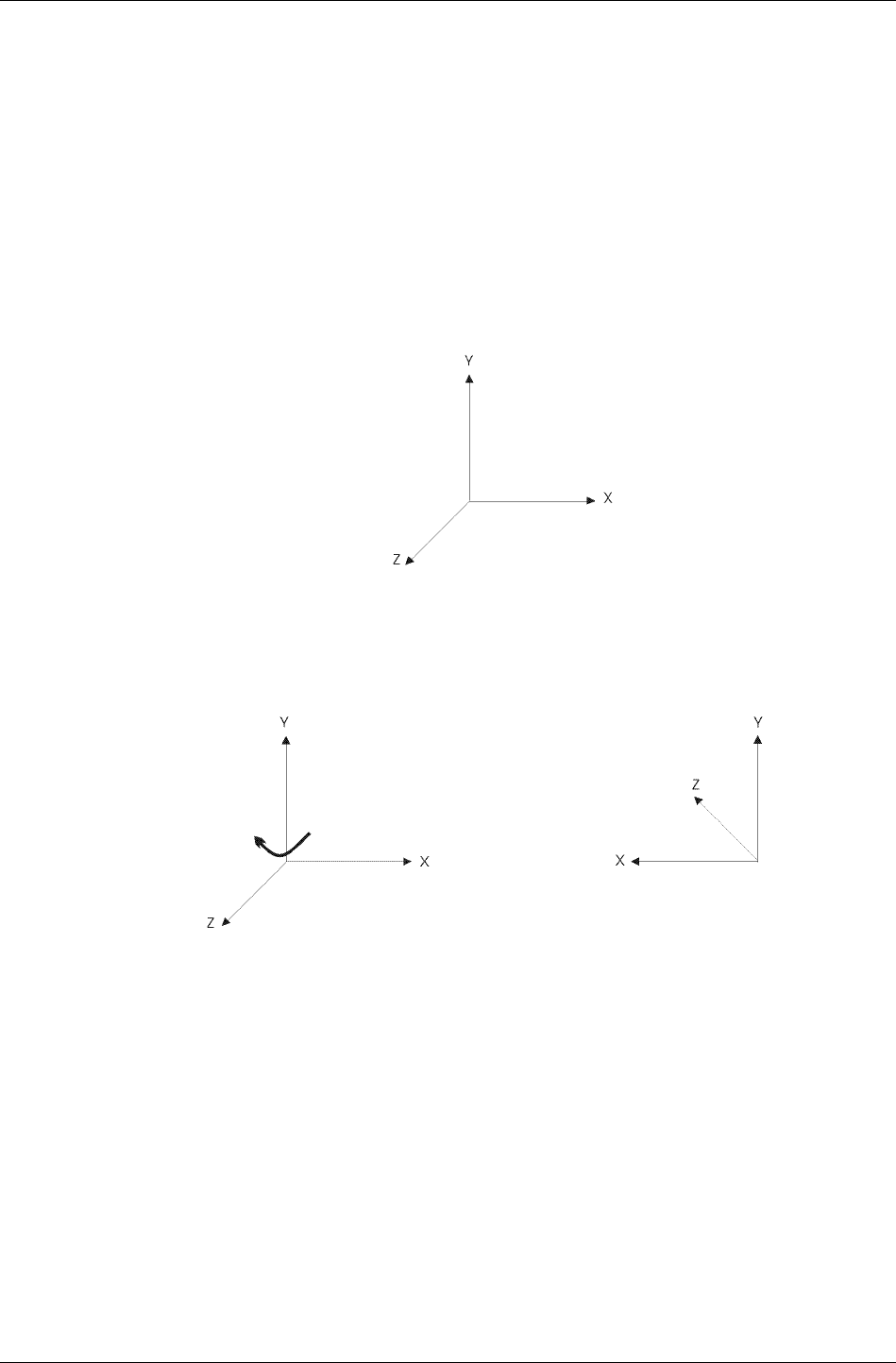
Coordinate Systems
RenderWare Graphics 3.7 I-45
2.8 Coordinate Systems
3D graphics programming requires understanding of a number of common
coordinate systems, known as spaces. Some basic conventions need to be
covered.
2.8.1 Right-handed Coordinates
RenderWare Graphics uses an orthogonal right-handed coordinate system
for its 3D spaces.
Typical right-handed coordinate system
The figure above displays the positive directions of x, y, and z axes with z
pointing away from the screen.
Rotate right-handed coordinate
system about y axis
RenderWare Graphics right-handed
coordinate system
The RenderWare Graphics coordinate system is rotated about the y axis
and the figure on the right displays the positive directions of the x, y and z
axes. The positive z axis points into the screen and the positive x axis
points to the left.
As all the axes are rotated together the coordinate system is always
right-handed.

Chapter 2 - Fundamental Types
I-46 11 February 2004
Axis Naming Conventions
The three axes are defined in RenderWare Graphics by three vectors. By
convention, the axis names used are:
AXIS VECTOR REPRESENTATION
X "Right"
Y "Up"
Z "At"
The vector is sometimes prefixed with the work "look", as in "look-at". This is
commonly used when referring to the camera object which "looks" along the
z axis.
The RenderWare Graphics' coordinate system is right-handed and the x
axis is represented by the right vector. However, as the RenderWare
Graphics coordinate system is rotated the x axis positive direction points to
the left.
For example, the RenderWare Graphics camera faces into the screen,
therefore we're effectively standing behind it. The camera's right vector
points left as the RenderWare Graphics coordinate system has been rotated
about the y axis so that z is pointing into the screen. Therefore moving the
camera, by incrementing its x axis, results in the camera moving further to
the left, along the positive x axis.
✎ In 3D Graphics terminology, the z axis, represented by the "at" vector, is sometimes
referred to as the "front" vector.
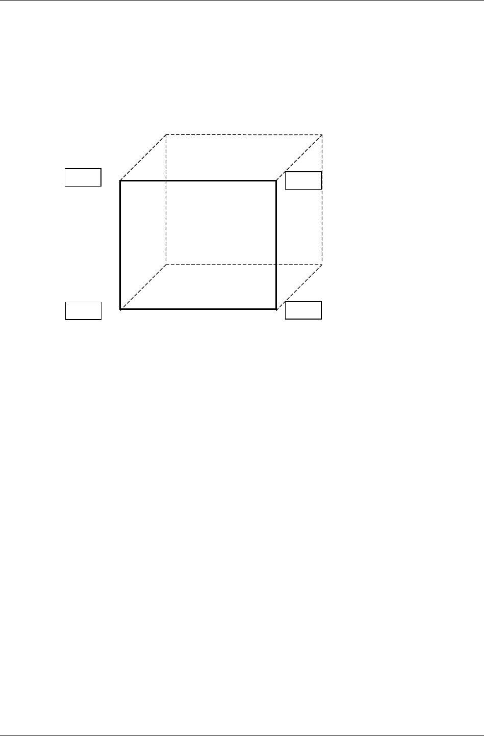
Coordinate Systems
RenderWare Graphics 3.7 I-47
2.8.2 Object Space
Dynamic models in RenderWare Graphics are defined in terms of Object
Space. This means that the vertices that define the model are relative to an
arbitrary origin.
For example, the front face of a cube of unit size could be defined thus:
(0,0,0) (1,0,0)
(1,1,0)
(0,1,0)
The origin in this case is the lower-left corner of the front face. However, the
origin could be anywhere – even the center of the cube. This could be
achieved by subtracting (0.5, 0.5, 0.5) from each vertex.
The location of the origin can be important, as it is easier to align models if
their origins are on a shared edge or a corner rather than at some arbitrary
point in the middle or outside the models.

Chapter 2 - Fundamental Types
I-48 11 February 2004
2.8.3 World Space
Dynamic models, defined in Object Space, need to have a frame of reference
so that they can be positioned relative to other models and scene graph
objects. This frame of reference is World Space.
Objects positioned relative to this system are said to reside in world space.
This coordinate system is used, for example, to specify the position of
cameras and lights. Geometry can be positioned in world space using
transformations described later.
A bounding box defines the World Space limits. This is either generated by
a modeling package exporter when exporting World data, or explicitly by the
developer when calling RpWorldCreate().
Frames
The RenderWare Graphics object that allows us to position objects in World
Space is called the Frame (RwFrame). Many RenderWare Graphics objects
require a Frame to be attached before they can be positioned within a
World.
2.8.4 Camera Space
Cameras, like many RenderWare Graphics objects, require a Frame to
define their position and orientation. However, there is another system
called Camera Space which defines the Camera's viewing coordinate
system. A normalized Camera Frustum defines Camera Space as follows:
• for a parallel projection model the Camera Frustum space has side
planes at x = 0, x = 1, y = 0 and y = 1
• for a Perspective Projection model, it has side planes at x = 0, x = z, y =
0 and y = z
Camera Space is also a right-handed system with an origin at the Camera's
position (given by the Frame's pos vector). The positive z axis of Camera
Space is given by the view direction, which points in the direction of the
Frame's at vector. The units of Camera Space z coordinates are the same as
those for World Space.
RenderWare Graphics also recognizes a two-dimensional coordinate
system.
2.8.5 Device Space
The device coordinate system defines a device space. Its units are those of
the display (screen or window) to which the camera's image buffer is copied
and as such, it has coordinates that only take discrete (or integer) values.

Coordinate Systems
RenderWare Graphics 3.7 I-49
The origin of device space is located at the top-left of the display with the x-
values running from left to right and the y-values running from top to
bottom, as shown in the diagram:
+X
+Y
(0,0)
Device space can also be considered to have a depth component that is
used in the Z buffer.

Chapter 2 - Fundamental Types
I-50 11 February 2004
2.9 Matrices
RenderWare Graphics defines a pseudo-4x4 homogeneous Matrix
(RwMatrix) object to represent 3D transformations. The Frame object, see
2.10 below, makes heavy use of matrices. Matrices in RenderWare Graphics
appear as shown below:
1
0
0
0
zyx
zyx
zyx
zyx
PPP
AAA
UUU
RRR
The row vector (Rx, Ry, Rz) contains the components of the look-right vector,
(Ux, Uy, Uz) are those of the look-up vector, (Ax, Ay, Az) for the look-at vector
and (Px, Py, Pz) are the components of the pos vector. The components of a
matrix are available to the application programmer by using
RwMatrixGetRight(), RwMatrixGetUp(), RwMatrixGetAt() and
RwMatrixGetPos().
2.9.1 Matrix Mathematics in RenderWare Graphics
Matrices are treated as quadruples of row vectors. Each row vector is a
triple of real values. The vectors are the right, up and at vectors, which
orient a Cartesian coordinate system, and the pos vector that positions this
coordinate system with respect to a parent coordinate system. In
conventional 4×4 matrix form, there is an implied last column of (0,0,0,1)T.
The equations for matrix multiplication can then be expanded as shown
below.
×
=
+⋅+⋅+⋅+⋅+⋅+⋅+⋅+⋅+⋅
⋅+⋅+⋅⋅+⋅+⋅⋅+⋅+⋅
⋅+⋅+⋅⋅+⋅+⋅⋅+⋅+⋅
⋅+⋅+⋅⋅+⋅+⋅⋅+⋅+⋅
×=
1
0
0
0
1
0
0
0
1
0
0
0
B
z
B
y
B
x
B
z
B
y
B
x
B
z
B
y
B
x
B
z
B
y
B
x
A
z
A
y
A
x
A
z
A
y
A
x
A
z
A
y
A
x
A
z
A
y
A
x
B
z
B
z
A
z
B
z
A
y
B
z
A
x
B
y
B
y
A
z
B
y
A
y
B
y
A
x
B
x
B
x
A
z
B
x
A
y
B
x
A
x
B
z
A
z
B
z
A
y
B
z
A
x
B
y
A
z
B
y
A
y
B
y
A
x
B
x
A
z
B
x
A
y
B
x
A
x
B
z
A
z
B
z
A
y
B
z
A
x
B
y
A
z
B
y
A
y
B
y
A
x
B
x
A
z
B
x
A
y
B
x
A
x
B
z
A
z
B
z
A
y
B
z
A
x
B
y
A
z
B
y
A
y
B
y
A
x
B
x
A
z
B
x
A
y
B
x
A
x
PPP
AAA
UUU
RRR
PPP
AAA
UUU
RRR
PAPUPRPPAPUPRPPAPUPRP
AAUARAAAUARAAAUARA
AUUURUAUUURUAUUURU
ARURRRARURRRARURRR
BAC
Matrix multiplication is not commutative so, the order of the arguments
passed to RwMatrixMultiply() is significant. Transformation of a position
is performed mathematically in the following manner:

Matrices
RenderWare Graphics 3.7 I-51
()
×=
+⋅+⋅+⋅
+⋅+⋅+⋅
+⋅+⋅+⋅
×=
1
0
0
0
1
1zyx
zyx
zyx
zyx
zyx
T
zzzzyzx
yyzyyyx
xxzxyxx
PPP
AAA
UUU
RRR
uuu
PAuUuRu
PAuUuRu
PAuUuRu
Muv
This is the operation performed by RwV3dTransformPoints(). This
function is used to transform position vectors. There is also an
RwV3dTransformVectors() function, which transforms vectors (e.g.
normals). In this case, the matrix is assumed to contain a zero position
vector and so does not contribute to the output vectors.
✎
✎✎
✎ Put another way: a direction vector is never translated, but only rotated.
Using RwV3dTransformPoints() with normals, or RwV3dTransformVectors() with
vertices will give strange results.
The order of matrix transformations has an effect on the visible orientation
of Atomics, as discussed (see 2.10.3 below).

Chapter 2 - Fundamental Types
I-52 11 February 2004
2.10 Frames
RwFrame objects contain two matrices. These are the Local Transformation
Matrix (or LTM), and the Modeling Matrix. These two matrices can be
retrieved using RwFrameGetLTM() and RwFrameGetMatrix(), respectively.
When transformations are performed on a frame (see next paragraph), it is
the Modeling Matrix that is affected. (The LTM describes the total
transformation from Object Space to World Space.) Unless the Frame
belongs to a hierarchy, the Modeling and Local Transformation Matrices are
identical. Otherwise, the Modeling Matrix is relative to the Frame's parent.
Frames can be transformed using RwFrameTranslate(),
RwFrameRotate(), RwFrameScale() and RwFrameTransform(). Rotation
and scaling is accrued in the top-left 3x3 sub-matrix, while translation is
accumulated in the bottom row.
Given a transformation matrix, individual points and vectors (both of type
RwV3d) can be transformed using RwV3dTransformPoints() and
RwV3dTransformVectors().
Hierarchical modeling is the process of building models that preserve the
hierarchical structure of objects and allow the position and orientation of
an object in the hierarchy to be specified relative to its parent.
Frames
RenderWare Graphics 3.7 I-53
2.10.1 Hierarchical Models & RenderWare Graphics
Hierarchical modeling explicitly models articulation, or joints, connecting
objects. In RenderWare Graphics, these joints are represented by frames
(RwFrame). These only define the hierarchy itself. The model data itself is
sectioned, with each section stored in an atomic (RpAtomic). An atomic
can be linked to a frame, with collections of atomics and frames thus
forming a hierarchical model.
Consider, for example, the modeling of a robot arm consisting of an upper-
arm, lower-arm and a hand represented by three atomics. We wish to
model the arm so that movement of the upper-arm is transferred to the
lower-arm and hand whilst movement of the lower-arm only affects the
hand. Assume each atomic has its own frame (see API function
RpAtomicSetFrame()). Then the required articulation can be achieved by
attaching the lower-arm's frame as a child of the upper-arm's frame and,
similarly, attaching the hand's frame as a child of the lower-arm's frame.
The API function RwFrameAddChild is used to accomplish this.
Atomic1 Atomic2 Atomic3
Upper Arm Lower Arm Hand
Frame1 Frame 2 Frame 3
The modeling matrix of each frame is now described relative to the Frame's
parent Frame object and the corresponding LTM becomes the
concatenation of all the modeling matrices up to the root Frame, in this
case the Frame on the upper-arm's atomic.
For each case we have:
LTM1=MM1
LTM2=MM2⊗LTM1
LTM3=MM3⊗LTM2
(where LTM = local transformation matrix and MM = modeling matrix.)
Only the root Frame's modeling and local transformation matrices are
identical.
The object hierarchy is shown schematically above. Frame1 is the parent of
Frame2 (therefore, Frame2 is the child of Frame1), while Frame2 is the
parent of Frame3. Note that the arrangement of the Atomics is determined
entirely by the frame hierarchy. If these Atomics were all added to a single
Clump object, the Clump would impose no organization. Because a Clump
is designed as a container for Atomics, it can be assumed that the Clump
must order its Atomics but, as you can see, this is not how it works.

Chapter 2 - Fundamental Types
I-54 11 February 2004
To model the robot hand in more detail by adding some fingers:
• give the hand three fingers represented by three more Atomics.
• build the hand hierarchy by attaching all the fingers' Frames as children
of the hand's Frame (see diagram above).
All the fingers' Frames (frame4, frame5, frame6) are child frames of the
hand's frame and siblings of each other. In terms of the LTMs we have, for
example:
LTM4=MM4⊗ LTM3
This means the LTM of frame4 is the concatenation of the modeling
matrices of Frames Frame1, Frame2, Frame3 and Frame4 – this is the same
for the other fingers. Movement of the hand is now automatically
transferred to all the fingers.
It is recommended, though it is by no means required, that the hierarchy is
encapsulated within a Clump which has its own Frame – see
RpClumpSetFrame() – acting as the root of the Frame hierarchy. For
example, Frame1 would be attached to the Clump's frame (say, Frame0,) as
a child of that Frame. Also, each of the Atomics must be added the Clump
using RpClumpAddAtomic() for this organization to work correctly.
Frames and the Local Transformation Matrix
Frame objects contain a matrix called the Local Transformation Matrix,
(usually abbreviated to "LTM"). This matrix is used when working with
hierarchies of Frame objects.
Local Transformation Matrices are constructed by traversing the hierarchy
from top to bottom. At each level in the hierarchy, the modeling matrix is
pre-multiplied into the local transformation matrix from the level above to
form the LTM for the current level. Because the LTM is used to post
multiply vectors this means that the transformation stored in the lowest
frame in the hierarchy affects the vertex first of all:
011 MMMMVU nn ⋅⋅⋅⋅⋅= −Λ
In this equation, the Local Transformation Matrix at the root of the
hierarchy is M0 and that at the bottom of the hierarchy is Mn, where there
are n+1 levels in the hierarchy.
2.10.2 Traversing Frame Hierarchies
There are two methods for traversing an object hierarchy depending on
whether it is Frames or the objects hanging from them. It is assumed that a
hierarchy of Frames and Atomics assembled into a Clump where the
Clump's Frame acts as the root of the hierarchy.

Frames
RenderWare Graphics 3.7 I-55
All Frames in the hierarchy may be iterated over using the
RwFrameForAllChildren() iterator. Starting at the root Frame, this
function will apply a user-defined callback to all first generation child
Frames. Repeating RwFrameForAllChildren() on each callback will then
iterate over all second generation, i.e. grandchild, frames, and so on. Also,
for each Frame encountered a call to RwFrameForAllObjects() applies a
callback to each object attached to the Frame.
✎
✎✎
✎ RwFrameForAllChildren() will only take you down one level in a hierarchy. You must
use your callback function to call RwFrameForAllChildren()again to go down the
hierarchy another level, so your callback should be designed for recursion.
If the Frame hierarchy is not important, a call to the
RpClumpForAllAtomics() iterator will iterate over all the Atomics
registered with a Clump. The supplied user-defined callback function will
be applied to each Atomic in turn.
2.10.3 Matrix Combination Flags in RenderWare
Graphics
Matrix and frame transformation functions in RenderWare Graphics (for
example, RwFrameTransform()and RwMatrixRotate()) take a parameter,
combineOp. This parameter is used to control the order in which the
transform is applied to the matrix or Frame.
The available combine operators are: replace, pre-concatenate, and post-
concatenate.
• rwCOMBINEREPLACE assigns the new transformation to the matrix.
The original contents of the matrix are entirely replaced by the new
transform.
RwMatrixTranslate(M, t, rwCOMBINEREPLACE) builds a new
matrix containing only a translation, and stores this matrix in M. Any
rotation component in the matrix M is overwritten with a 3x3 identity
sub-matrix. This is true for all matrix-transforming functions where
the rwCOMBINEREPLACE flag is used.
• rwCOMBINEPRECONCAT causes the transform matrix to be pre-
concatenated onto the matrix. This has the effect of applying the
transformation before the transformation already in the matrix. Put
another way: this operator causes the transformation to be made in
object space (or the coordinate space of the matrix).
• rwCOMBINEPOSTCONCAT instructs RenderWare Graphics to post-
multiply the transformation into the matrix. The new transformation
will take effect after the transform already in the matrix. In other
words, the transformation takes place in world space.
Chapter 2 - Fundamental Types
I-56 11 February 2004
Example
Consider a call made to RwFrameScale() with a Frame F, and a vector S
encoding the scale. The effect of changing the combination operator will be
looked at. Firstly, however, it should be pointed out that the function alters
the modeling matrix in the frame.
✎
✎✎
✎ A RenderWare Graphics application should never modify the LTM matrix directly, since
the library is responsible for computing this matrix from the Modeling Matrix and the
LTMs of the Frame hierarchy.
In this example the modeling matrix, denoted M, is stored in Frame F.
Notionally, the RwFrameScale() function computes a scale transformation
matrix, S. This will be a 4x4 zero matrix with a diagonal encoding the
elements from the scale vector, and 1:
=
1000
000
000
000
z
y
x
s
s
s
S
The table below illustrates the result of varying the combine operator on the
matrix M.
OPERATOR RESULTING MATRIX (M)
rwCOMBINEREPLACE S
rwCOMBINEPRECONCAT SM
rwCOMBINEPOSTCONCAT MS
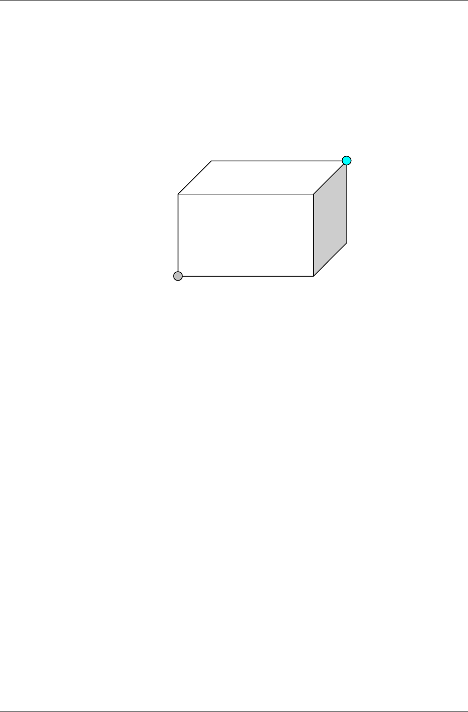
Bounding Boxes
RenderWare Graphics 3.7 I-57
2.11 Bounding Boxes
The Bounding Box (RwBBox) object defines a bounding box using two
points: sup (supremum) and inf (infimum). These two points define
diametrically opposite corners of the box, such that for any axis, the value
in the inf coordinate is never larger than the value in the sup coordinate.
The illustration below shows how this works in practice:
Sup
Inf
The resulting box therefore represents a 3D axis aligned cuboid volume.
Bounding boxes provide the basis for simple tests to determine whether
specific coordinates in the coordinate space are bounded by the volume.
The box may also be expanded to include another point within its volume,
using the RwBBoxAddPoint() function.
Another test available is RwBBoxContainsPoint(), which can be used to
check if a vertex is inside or outside a Bounding Box.
RwBBoxAddPoint() can also be used together with the
RwBBoxInitialize() function. This takes a single vertex and initializes
both the inf and sup elements to this point. RwBBoxAddPoint() can be
called repeatedly to expand the Bounding Box to contain any arbitrary
number of points. This technique is useful if the number of points involved
is unknown.
If, on the other hand, you do have a fixed-length array of vertices, you can
use the RwBBoxCalculate() function to perform a similar operation to the
above. This function is usually the more efficient of the two systems.

Chapter 2 - Fundamental Types
I-58 11 February 2004
2.12 Lines
RenderWare Graphics naturally supports a basic line type. This is called
RwLine and it is defined by two RwV3d objects denoting the start and end
vertices. The RwLine object is used typically as an intersection primitive. Do
not confuse the RwLine object with an immediate mode line, which is a
renderable object.

Rectangles
RenderWare Graphics 3.7 I-59
2.13 Rectangles
Rectangles are defined by the RwRect type. This type takes a positioning
vector to locate the rectangle, as well as two parameters defining its width
and height. As with lines above, the RwRect object is not renderable.
Rectangles are typically used to define sub-regions of the screen.

Chapter 2 - Fundamental Types
I-60 11 February 2004
2.14 Spheres
RenderWare Graphics defines the RwSphere type. This contains both a
center and a radius as elements to define the location and size of the
sphere.
Spheres are heavily used during Retained Mode rendering to determine
which models are within the Camera Frustum. Using spheres for the initial
tests makes for rapid culling. Once this coarse-level checking has been
performed, the remaining models can then be tested and clipped more
accurately.
Note that this object is not renderable, and is used primarily for
intersection testing.

Colors
RenderWare Graphics 3.7 I-61
2.15 Colors
RenderWare Graphics defines two color representation types: RwRGBA,
which is an integer-based primitive for describing colors, and RwRGBAReal,
which defines colors using real numbers rather than integers.
The RwRGBA form is the most used as it corresponds closely with most of
our supported platforms. This structure contains four RwUInt8 elements,
one for each of the Red, Green, Blue and Alpha components.
Although the RwRGBA format is fixed, the bitmap facilities offered by
RenderWare Graphics are not and may differ widely in color element
format. It is therefore possible that conversion may be needed when
extracting or modifying individual pixels in a bitmap and such processing
should thus be kept to a minimum.
See the chapter on Rasters, Images and Textures for information on these
items and their colors.
RwRGBAReal defines four RwReal elements for red, green, blue and alpha.
It is intended to be used in cases where high orders of accuracy are needed
while processing colors. Values range from 0.0f to 1.0f.

Chapter 3
Initialization &
Resource
Management

Chapter 3- Initialization & Resource Management
I-64 11 February 2004
3.1 Introduction
RenderWare Graphics Core Library contains the base feature-set of the API.
All other features are optional, provided in the form of either Plugins or
Toolkits.
The Core Library's functionality is divided up into the following broad
categories:
• Memory management
• OS-level file and memory management
• Plugin management
• Basic objects and intrinsic types, such as RwInt32, RwBBox, RwMatrix,
RwImage, etc.
• 2D and 3D immediate modes
• PowerPipe extensible rendering pipeline
• Platform-Specific APIs (where applicable)
• Managing rendering time through the Lock and Unlock commands.
This chapter focuses on the memory management, plugin management and
file management features of the core library.

Basic Housekeeping
RenderWare Graphics 3.7 I-65
3.2 Basic Housekeeping
At the heart of RenderWare Graphics is the RwEngine object. This engine
performs a number of housekeeping functions, including:
• Initialization and shut-down procedures
• Selecting the display device and video mode
• Querying the underlying hardware about its capabilities
• Updating metrics information (when linked to the Metrics libraries)
• Managing Plugins
All RenderWare Graphics applications have to initialize the engine before
calling any other RenderWare Graphics functions. We'll look at this process
next.
3.2.1 Initialization
Getting the RenderWare Graphics engine up and running is a three-step
process:
1. Initialization of memory management and default file system interface
2. Setting the video mode
3. Plugins and starting RenderWare Graphics
and there are three functions you need to call:
1. RwEngineInit()
2. RwEngineOpen()
3. RwEngineStart()
These functions must be called in the above order and you cannot start
rendering until after the RwEngineStart() call.
Why the three steps?
RenderWare Graphics has to make allowances for the many platforms it
supports. Splitting the start-up process into three stages lets us open up
such features as file and memory management, as well enabling the plugin
architecture to operate properly.
Let's look at these steps in terms of what they're for…

Chapter 3- Initialization & Resource Management
I-66 11 February 2004
Step 1 - Initialization of Memory Management and Default
File System Interface
This first step concerns the API function RwEngineInit() and involves
setting up the memory and file-handling subsystems.
Why Does the Engine need to be Initialized First?
RwEngineInit() must always be the first RenderWare Graphics function
your application calls as all other functions assume the memory
management facilities have been set up. For example, the plugin
mechanism needs to access these memory functions, so they need to be set
up before any Plugins are attached.
Similarly, the display device your application will use may also need some
memory allocated for it. So again, we have to make sure the memory
subsystem is ready first.
The Memory Functions
By default, RenderWare Graphics uses the standard ANSI memory
functions, as implemented by the target platform's compiler, so any
replacement functions must have identical prototypes to their ANSI
counterparts.
In theory, the application can replace the default RenderWare Graphics
handlers with its own at any time. In practice the application should
change the memory handler only at this initialization stage, rather than
later.
Changing the memory and file handling subsystems within the main loop of
your application is possible, but not recommended as it can make
debugging much more difficult.
Pointers to the functions are stored in the RwMemoryFunctions structure
returned by RwOsGetMemoryInterface(). If necessary, the entries in this
structure can be overwritten directly with your own function pointers, but
this is not recommended as the change takes place immediately—if memory
has already been allocated with the original functions, then it is likely that
memory will be "lost" to your application.
Your application should create a new RwMemoryFunctions structure with
pointers to your own functions, then pass a pointer to the structure to
RwEngineInit().
The File Functions
The file system is implemented in a similar way to the memory system, with
a structure containing pointers to default POSIX functions used by default.
Again, any replacement functions will need to share the same prototypes as
the functions they will be replacing.

Basic Housekeeping
RenderWare Graphics 3.7 I-67
A file functions structure filled with the default functions can be retrieved
using RwOsGetFileInterface(). To replace these default function
pointers with your own, overwrite the entries in the structure. Your
functions will then be used when accessing files.
Step 2 - Setting the Video Mode
At this stage, you will need to:
• Open the RenderWare Graphics Engine
• Determine which graphics subsystem the application should be
using, as some platforms can support more than one
• Determine the video display mode the application should use.
Video hardware varies greatly from platform to platform, so this procedure
requires some additional steps of its own.
Opening the RenderWare Graphics Engine
The RenderWare Graphics Engine can be opened using RwEngineOpen().
Choosing the Graphics Subsystem
The RenderWare Graphics API represents a graphics device as a graphics
subsystem.
The application must first determine how many graphics subsystems are
available. This requires a call to RwEngineGetNumSubSystems().
With this information, the application iterates through the available
subsystems, checking each one for suitability. This is achieved by calling
RwEngineGetSubSystemInfo() and interrogating the structure returned.
The following code fragment illustrates this process by printing out the
identifying names of all graphics subsystems on a particular platform:
RwInt32 numSubSystems, i;
RwSubSystemInfo ssInfo;
numSubSystems = RwEngineGetNumSubSystems();
for(i=0; i<numSubSystems; i++)
{
RwSubSystemInfo ssInfo;
if( RwEngineGetSubSystemInfo(&ssInfo, i) )
{
printf("SubSystem %d: %s\n", i, ssInfo.name );
}
}

Chapter 3- Initialization & Resource Management
I-68 11 February 2004
(The RwSubSystemInfo structure contains only the name element.)
Once the subsystem has been chosen, the application must inform
RenderWare Graphics of its choice by calling RwEngineSetSubSystem()
with the requisite index number.
Setting the Video Mode
With the graphics subsystem selected, the application must now set the
video mode. The first step is to determine how many video modes are
supported, and what these modes are.
To determine the number of video modes supported, the application should
call RwEngineGetNumVideoModes(), then iterate through the available
modes by calling RwEngineGetVideoModeInfo().
The code fragment below iterates through the available video modes and
prints the information for each one to stdio.
RwInt32 numVideoModes, j;
RwVideoMode vmodeInfo;
numVideoModes = RwEngineGetNumVideoModes();
for(j=0; j<numVideoModes; j++)
{
if( RwEngineGetVideoModeInfo(&vmodeInfo, j) )
{
printf("Video Mode %d: %dx%dx%d %s\n", j,
vmodeInfo.width, vmodeInfo.height, vmodeInfo.depth,
(vmodeInfo.flags & rwVIDEOMODEEXCLUSIVE)
? "(EXCLUSIVE)" : "" );
}
}
The RwVideoMode object contains the following elements:
• width – the width, in pixels, of the video mode;
• height – the height, in pixels, of the video mode;
• depth – the number of bits per pixel supported by the video mode;
• refRate – approximate vertical refresh rate;
• format – pixel format of the display buffer. See also:
RwRasterFormat.
• flags – contains one or more of the following flags:

Basic Housekeeping
RenderWare Graphics 3.7 I-69
− rwVIDEOMODEEXCLUSIVE – if set, the video mode is full-screen
rather than windowed.
Windowed modes are only available on DirectX and OpenGL
platforms.
− rwVIDEOMODEINTERLACE – if set, the video mode is interlaced,
with alternate fields being displayed each frame.
Interlaced video modes are more common on platforms that use
televisions for their video output.
− rwVIDEOMODEFFINTERLACE – if set, the video mode is interlaced,
but the signal is processed to reduce or eliminate the flickering
normally associated with interlaced video modes.
Interlaced video modes are more common on platforms that use
televisions for their video output.
Owing to differences in hardware design, the flags shown above are not
supported on all platforms. Detailed below are the platform-specific video
mode flags. Please refer to the platform-specific documentation in the API
Reference for additional information on any flags.
- rwVIDEOMODE_XBOX_WIDESCREEN – (Xbox specific) if set, wide screen is
used. The application will also need to adjust the transform matrix to
provide a 16:9 display aspect ratio rather than the more common 4:3
display aspect ratio.
- rwVIDEOMODE_XBOX_PROGRESSIVE – (Xbox specific) if set, progressive
scan is used. Currently the supported progressive scan video modes are
480p and 720p HDTV modes.
- rwVIDEOMODE_XBOX_FIELD – (Xbox specific) field rendering is a special
video mode where the back buffer size is assumed to be half the vertical
height of the output display and the output format is defined to be
interlaced. In this mode, the even lines of the display are rendered
during one field and the odd lines are rendered during the next field.
When using field rendering, the flicker filter is disabled. Field rendering
can reduce the fill-rate and bandwidth requirements of a game
substantially; however, since there is no flicker filter, display quality can
also be degraded.
- rwVIDEOMODE_XBOX_10X11PIXELASPECT – (Xbox specific) if set, the
frame buffer is centered on the display. On a television where the
resolution is 704 pixels across, this would leave a 32 pixel black border
on the left and a 32 pixel black border on the right.
− rwVIDEOMODE_PS2_FSAASHRINKBLIT – (PlayStation 2 specific) if
set, this video mode is full-screen anti-aliased by a scaled blit
from the draw buffer to the display buffer.

Chapter 3- Initialization & Resource Management
I-70 11 February 2004
− RwVIDEOMODE_PS2_FSAAREADCIRCUIT – (PlayStation 2 specific)
if set, this video mode uses read circuit scan line blending for
flicker reduction.
The video mode is set with a call to RwEngineSetVideoMode(), which
requires the index number of the desired video mode.
Step 3 – Plugins and starting RenderWare Graphics
Plugins are one of the keys to RenderWare Graphics power. Before
RenderWare Graphics can be started, plugins need to be attached. Plugins
usually extend or add objects and provide new functionality. The Retained
Mode API, for example, is exposed by the RpWorld plugin.
RenderWare Graphics is written in C, not C++, so object extensions must
be handled explicitly. One of the most important procedures is attaching a
plugin. This process performs the following steps:
• Linking a plugin with any existing RenderWare Graphics objects;
• Adding any extensions to those objects;
• Informing the RenderWare Graphics engine about any additional
memory the extended objects will need.
Attaching must take place prior to starting the RenderWare Graphics
engine with RwEngineStart().
3.2.2 Shutting down RenderWare Graphics
Each of the three start-up functions has a matching shutdown function,
which also needs to be called in the following order when the application
terminates:
1. RwEngineStop()
2. RwEngineClose()
3. RwEngineTerm()
Each of these functions needs to be called in turn to close down and exit a
RenderWare Graphics application.
Applications running on consoles, such as the PlayStation 2 or Xbox, do
not need to concern themselves with exiting cleanly as console users just
switch off the machine. But developers targeting multi-purpose platforms
like Windows and MacOS will need to use these functions.
A good reason for shutting down is to trigger debugging functions, which
notify the developer of any memory leaks. As these are often tied to the
memory handling functions set up by RwEngineInit(), it may be
necessary to perform a complete shutdown of RenderWare Graphics to
trigger the leakage tests.

Basic Housekeeping
RenderWare Graphics 3.7 I-71
3.2.3 Changing Video Modes after Initialization
Changing video modes after the initialization steps described so far is
tricky. To do so, you will need to partially shut down the RenderWare
Graphics Engine by calling both RwEngineStop() and RwEngineClose(),
then set your new video mode by calling RwEngineOpen() and
RwEngineStart() to restart the RenderWare Graphics Engine.
This procedure requires the deletion and re-initialization of many active
RenderWare Graphics bitmap objects, as hardware issues may require your
graphics data to be in a different format for some display modes.

Chapter 3- Initialization & Resource Management
I-72 11 February 2004
3.3 Memory Management
RenderWare Graphics supports two memory management features, as well
access to those of the underlying platform.
In this part of the chapter, we will take a look at these features, which are:
• The OS-level memory interface
• The Freelist memory management system
• Memory Hints
• The Resource Arena
3.3.1 The OS-level Memory Interface
As we've already seen, the RenderWare Graphics initialization function,
RwEngineInit(), lets you set up the memory management subsystem
used by the RenderWare Graphics API. This is a useful feature as you will
be in a far better position to understand your application's memory usage
patterns and can therefore replace the RenderWare Graphics memory
manager with your own, more optimized one if you require.
You can access these functions in your application through an
RwOsGetMemoryInterface() API call. This returns a pointer to an
RwMemoryFunctions structure. The structure contains the default
RenderWare Graphics memory function pointers which map to OS-specific
implementations of the ANSI C malloc(), free(), realloc() and
calloc() functions.
RenderWare Graphics provides macros to directly access these default
memory functions, which are named as follows:
• RwMalloc()
• RwFree()
• RwRealloc()
• RwCalloc()
In addition, debug versions of these functions will be substituted in the
macros if a debug build is specified.
Your application can override these default functions by passing a
structure populated with your own function pointers to RwEngineInit().
Your functions will obviously need to take the same parameters as the
RenderWare Graphics ones, please refer to the API Reference for specific
details. Note that once you override these function you will be responsible
for aligning the memory properly. Memory alignment differs between the
various platforms and it can also affect the application performance.

Memory Management
RenderWare Graphics 3.7 I-73
If you want to cut down on porting issues, it's worth using the default
RenderWare Graphics functions, rather than calling the OS ones directly.
This also means your code can seamlessly switch to another memory-
management system if you should decide to replace the default RenderWare
Graphics functions with your own.
3.3.2 FreeLists
In addition to the OS-level memory-management functions, RenderWare
Graphics provides an additional memory-management systems. It’s defined
by the RwFreeList object and is active by default.
A value of rwENGINEINITNOFREELISTS can be passed in the flag parameter
for RwEngineInit(). This will tell RenderWare Graphics to use the default
memory functions (RwMalloc and RwFree) in place of the FreeList functions
instead.
How FreeLists work
FreeLists are initialized with a block size – call it s – and a number – call it
n – which specifies the minimum number of such blocks to allocate at a
time. When you allocate your first object, the FreeList grabs enough
memory to hold n blocks. You're free to allocate and free any of these
blocks as often as you like.
If the FreeList is full and you try and allocate a new block, the FreeList
grabs another (s * n) bytes of memory.
As you develop your application, you should monitor your usage of
FreeLists to determine the best balance between speed and efficient
memory usage.
Why FreeLists are useful
FreeList objects manage blocks of memory of the same size. Applications
often spend most of their time creating and destroying groups of related
objects. Grouping similar objects together under one FreeList object gives
an economy of scale. Instead of allocating lots of small chunks of memory,
the object allocates in bulk, grabbing another big chunk only if the previous
chunk is completely filled. Because a FreeList knows all the objects it
contains are the same size, it can allocate space for an object in a block
much more quickly than the standard system heap allocators that must
handle objects of mixed sizes.

Chapter 3- Initialization & Resource Management
I-74 11 February 2004
FreeLists can also be useful for avoiding memory fragmentation, which can
be particularly problematic on consoles that don't use virtual addressing
systems. If you know how much space your game is likely to need for a
certain type of object, setting aside this space early on and allocating into it
at run time is often better than doing heap allocations at run time.
Depending on the state of the heap and how long allocations stay before
they are deallocated again, you can end up with memory with many small
holes and no contiguous space large enough for allocations you may need
later. Even though there may be enough memory in total, it is fragmented
and therefore unusable. It is possible to "lose" megabytes of memory to
this. RenderWare FreeLists provide a way of setting aside memory at
startup for future allocations to help avoid this problem.
As an example, take a game that needs to instantiate groups of missiles.
Each missile structure requires the same amount of space as that for any
of the other missiles, so it makes sense to avoid multiple RwMalloc() calls
and use a single FreeList object to handle the missiles in batches instead.
We might also know that the game will only ever have a maximum of 64
missiles in play at any one time so we can set aside enough space for all of
them when we create the FreeList and be sure no more allocations for
missiles will occur after then.
In code, our initialization for the missiles FreeList might look something
like this…
RwBool
InitializeMissiles(void)
{
/* First, set up an RwFreeList structure for our missiles... */
/* "TMissile" is our missile structure (wrapped into a typedef).
* We want to allocate them in batches of 64 at a time.
* We need them aligned to 4-byte boundaries,
* ask for one block of these to be set aside now,
* and provide space for the RwFreeList structure itself,
* rather than mallocing it too. */
RwFreeList *ok;
ok = RwFreeListCreateAndPreallocateSpace(
sizeof(TMissile), 64, 4, 1, &Globals.missilesList,
rwMEMHINTDUR_EVENT);
return (ok != NULL);
}
Now, to use our FreeList mechanism, we can do something like this:
...
/* Need a new missile... */

Memory Management
RenderWare Graphics 3.7 I-75
TMissile *myMissile;
myMissile = (TMissile *)RwFreeListAlloc(&Globals.missilesList,
rwMEMHINTDUR);
if (myMissile)
{
/* Do something here with the missile. */
}
And, when we're done with all our missiles, we can destroy our FreeList
storage:
void
DestroyMissilesList(void)
{
RwFreeListDestroy( &Globals.missilesList );
}
You can see that the FreeList allocation and destroy functions are similar to
RwMalloc() and RwFree(), with the important difference that they result
in far fewer calls to those low-level functions.
✎
If you prefer that RwFreeLists don't allocate any memory until you start using them, you
can pass 0 as the number of blocks to allocate on creation. Had we done this for our
example above, the big block allocation would take place during the call to
RwFreeListAlloc(). However, it is probably better to allocate space on start up to avoid
heap fragmentation during run time, as mentioned above.
FreeList usage within RenderWare Graphics
FreeLists are used extensively by RenderWare Graphics for its internal
memory management, particularly for managing groups of textures,
cameras, clumps and other objects. These lists are not accessible directly
by the application. However because the optimal number of objects to
reserve space for is application specific, you can configure the sizes of the
FreeLists RenderWare Graphics uses to suit your application. This should
allow you to have no wasted space and no more allocations than absolutely
necessary. See the RwFreeList overview in the API reference for a list of
functions you may call to configure internal FreeList sizes, e.g.
RwTextureSetFreeListCreateParams.
3.3.3 Memory Hints
All RenderWare Graphics memory-management functions that allocate
memory take an additional RwUInt32 parameter which is a memory hint.
The following RenderWare Graphics functions have this additional memory
hint parameter: RwMalloc, RwRealloc, RwCalloc, RwFreeListCreate,
RwFreeListCreateAndPreallocateSpace, and RwFreeListAlloc.

Chapter 3- Initialization & Resource Management
I-76 11 February 2004
The main purpose of the hints is to help improve memory management,
such as preventing memory fragmentation. To use the memory hints, you
should have provided your own memory-management function through the
RwEngineInit() function. For example, you might want to have a
separate memory heap just for the RwMatrix or RpGeometry objects, or a
separate heap for all temporary allocations inside RenderWare Graphics. As
always, memory-management is very specific to each application and has to
be organized and tuned for each one.
A memory hint contains the following information:
1. Duration. If we are allocating temporary memory which will be
freed inside the function scope, the value for
RwMemoryHintDuration will be rwMEMHINTDUR_FUNCTION. If a
memory is allocated for a duration of a frame the value is
rwMEMHINTDUR_FRAME. For all global allocations, happening on
and before RwEngineStart and which are freed on and after
RwEngineStop, the value is rwMEMHINTDUR_GLOBAL. All
allocations which persist for longer than per frame, but are not
global, have rwMEMHINTDUR_EVENT. This can be per level or per
event.
2. ChunkID. This is the id of either the object for which a memory
request came, or of the module a call for allocation belongs to.
Refer to the memory hints API Reference documentation for a
list of all RenderWare Graphics IDs.
3. Flags. Currently we have only one flag for memory that will
potentially be resized with RwRealloc.
We have three macros for extracting information from a hint:
RwMemoryHintGetDuration(), RwMemoryHintGetChunkID() and
RwMemoryHintGetFlags().
You can extend all of these fields using specific values for duration, object
IDs, flags and create custom hints that can be passed to all the memory
allocation calls you make.
3.3.4 Resource Arenas
The Resource Arena is a cache and only one is supported in an application.
When rendering geometry, RenderWare Graphics will create a platform-
specific version of that geometry—a process known as instancing—in the
Resource Arena. RenderWare Graphics can then use the cached instance of
the geometry directly rather than re-generate the platform-specific data for
each rendering cycle. This is faster than re-instancing the geometry data
every cycle.
This system is most efficient if the model geometry changes infrequently—a
common situation in many 3D graphics applications.

Memory Management
RenderWare Graphics 3.7 I-77
There are some important points to understand:
• If you make your Resource Arena too small, your application will suffer
from slowdown by a process known as arena thrashing. This occurs
when objects that are being instanced require that another, previously
instanced object, be kicked out to make room. This kicked out object
will have to be re-instanced in the next rendering frame. This will result
in another object being evicted from the cache, and so on.
• Conversely, making the Resource Arena too big makes less than efficient
use of your platform's memory. On platforms like the PC, this is not
such a big issue, but when it comes to consoles, every byte counts.
The answer, as with FreeLists, is to spend some time optimizing the
parameters you use when setting up your Resource Arena.
The Resource Arena API
The RwResources object represents the Resource Arena. This object
represents a list of RwResEntry structures, each describing a block of
memory in the Resource Arena. The API itself is centered on the
RwResources object.
A Resource Arena is always present when using RenderWare Graphics. The
size of the arena is set during RwEngineInit(), which is passed in the
resArenaSize parameter. The arena size can be set to zero if it is not
needed.
Also present in this particular API is the equivalent get function –
RwResourcesGetArenaSize() – which returns the size of the Resource
Arena. This can be used together with RwResourcesGetArenaUsage() to
determine the optimum Arena size. This last should be called just before a
call to RwCameraShowRaster() to obtain meaningful results.
RwResourcesGetArenaUsage() returns the memory used by instancing
and can return a value greater than the maximum value you set. If it does
so, it means that arena thrashing is taking place – geometry is being
instanced, thrown away then re-instanced again because there isn't enough
space to store all the instanced data needed for the frame. You should
increase the maximum size of the Arena to prevent this or, if memory is
tight, reduce the complexity of your geometry to keep the size of the
instanced data down.
✎ RwResourcesSetArenaSize() now determines the size the Resource Arena, which is a
single block of allocated memory. This will free the current resource arena heap, if one
exists, and allocate a new heap.
3.3.5 Locking and Unlocking data
The process of instancing display data into platform-dependent form
generally takes a lot of processing time. The Lock and Unlock functions
that are part of most plugins allow the developer to control this process.

Chapter 3- Initialization & Resource Management
I-78 11 February 2004
The Lock function tells RenderWare Graphics that the developer wants to
access and change some data, like a geometry, texture or palette, and have
it re-instanced so that it can be rendered efficiently. The Unlock function
allows re-instancing, which is generally slow (though for some data, like
vertex positions and colors, re-instancing is postponed until just before
rendering).
Many Lock functions have flags to indicate precisely which data is being
altered and thus avoid recalculating unchanged data.
So the Lock functions should be used judiciously and be avoided when
possible.

Summary
RenderWare Graphics 3.7 I-79
3.4 Summary
3.4.1 Starting The Engine
The initialization phase of your application needs to perform the following
steps to start the RenderWare Graphics engine:
1. Call RwEngineInit(), passing an RwMemoryFunctions structure if
required.
The rwENGINEINITNOFREELISTS flag should also be specified if the
FreeList mechanism is not required, pass the resArenaSize parameter
for the Resource Arena size;
2. Enumerate the available graphics subsystems and use
RwEngineSetSubSystem() to select the subsystem required by the
application;
3. Enumerate the available video modes and use
RwEngineSetVideoMode() to select the video mode required by the
application;
4. Call RwEngineOpen();
5. Attach any required plugins;
6. Call RwEngineStart().
The RenderWare Graphics engine is now started and rendering can take
place.
3.4.2 Shutting Down The Engine
When running on platforms that run multi-tasking operating systems such
as Windows or MacOS, applications should exit gracefully. This is achieved
by calling the following functions in the order shown:
1. RwEngineStop()
2. RwEngineClose()
(At this point, it is possible to change the graphics subsystem and video
mode and restart the engine.)
3. RwEngineTerm()

Chapter 3- Initialization & Resource Management
I-80 11 February 2004
3.4.3 Memory Handling
Default Memory Handlers
RenderWare Graphics provides two default, general-purpose memory-
management mechanisms, only one of which is available at any one time:
• FreeList memory management (default);
• ANSI-standard memory management functions—RwEngineInit() must
be called with the rwENGINEINITNOFREELISTS flag set;
You can replace the memory-management functions by creating an
RwMemoryFunctions structure with pointers to your own functions, then
passing this structure to RwEngineInit().
The Resource Arena
When rendering takes place, platform-specific instances of the geometry
data are created in the Resource Arena, which acts as a cache. If the same
geometry data is required later, the cached data in the Resource Arena will
be used directly.
3.4.4 Plugins
Plugins extend existing RenderWare Graphics objects and/or create new
ones. In order for this mechanism to work, the memory management
system needs to be in place.
The plugin must also be attached, by calling its associated
...PluginAttach() function prior to the call to RwEngineStart().

Chapter 4
Plugin Creation
& Usage

Chapter 4- Plugin Creation & Usage
I-82 11 February 2004
4.1 Introduction
Plugins are an important feature of RenderWare Graphics. By providing a
mechanism to extend and enhance the in-built objects of RenderWare
Graphics, they give us the flexibility to consistently meet your needs in a
fast-moving industry. The entire Retained Mode functionality for
RenderWare Graphics is, in fact, provided as a plugin.
4.1.1 Toolkits
Toolkits don't extend any core objects or datatypes at all, and usually
provide a set of utility functions.
In fact, a Toolkit is just a library that requires RenderWare Graphics to
work. The RenderWare Graphics team uses the "Toolkit" term to
differentiate a simple utility library from the more complex Plugins, which
must be handled more carefully.
4.1.2 Plugins and Streaming
Streaming is covered in the Serialization chapter.

Using Plugins
RenderWare Graphics 3.7 I-83
4.2 Using Plugins
This part of the chapter focuses on how to use plugins and how they work.
4.2.1 Attaching Plugins
Plugins have to be registered with RenderWare Graphics Core Library. The
reason for this is so that any object extensions have the chance to hook
into the memory handler and allocate space for their additional data
structures. For example, if you wanted a plugin to extend camera objects
by 64 bytes, then RenderWare Graphics needs to be told this before any
cameras are created.
Most RenderWare Graphics applications follow a start-up process along the
following lines (some error checking has been removed for clarity):
...
/* Platform-specific initialization */
... some code ...
/* Initialize RenderWare Graphics Engine: */
/* use default memory handler with Freelists
* and set arena size */
RwEngineInit(NULL, 0, resArenaSize);
/* Attach Plugins */
if (!RpWorldPluginAttach())
{
/* Something went wrong so, */
/* either display an error message, */
/* or just crash.*/
return FALSE;
}
Other plugins should be attached at the same point in the start-up
sequence. After this, accessing a plugin's API is the same as calling any
other function.
After all necessary plugins are attached, the RenderWare Graphics engine
can be opened and started:
...code to choose display device, format and other parameters ...

Chapter 4- Plugin Creation & Usage
I-84 11 February 2004
RwEngineOpen(&openParams);
/* Start Engine */
RwEngineStart(); /* "We have ignition!" */
With the plugins attached, calling their functions is now possible:
...
/* Render World */
RpWorldRender(); /* Render the RpWorld object. */
...
✎ As with toolkits, plugins also have to have associated libraries and header files that must
be included in your build. Merely attaching them is not enough.
Dependencies
Plugins must be attached in the right order. If plugin B relies on plugin A
being present then plugin A should be attached before plugin B.
For example, the World plugin (RpWorld) is required by a number of other
plugins. RpWorld must therefore be attached first.

Creating Your Own Plugins
RenderWare Graphics 3.7 I-85
4.3 Creating Your Own Plugins
4.3.1 Introduction
Your application is not limited to using the plugins supplied with the
RenderWare Graphics SDK. Plugins can be written by any licensed
developer.
In this part of the chapter, we will see how this is done.
4.3.2 Anatomy of a Plugin
A RenderWare Graphics plugin is divided in two parts.
The first part is the exposed API that users of the plugin will have access to.
This API is the one other developers will use: it's the reason for writing the
plugin.
The second part is not usually seen by the plugin's user and performs the
housekeeping tasks: it performs any initialization and shut-down processes
required by the plugin; it tells the core engine how much memory it needs
for the new data structures, and also attaches itself to other plugin objects
if needed.
For instance, when calling RpWorldPluginAttach() to attach the World
plugin, it is the housekeeping functions that are called to create the
extended objects and initialize any data structures.
4.3.3 The "Plugin" Example
Path: examples/plugin
This example defines both a plugin and a simple demo to exercise it.
The main.c file contains the demo program which exercises the plugin.
The plugin code is in physics.c and physics.h.
The physics.h exports the plugin's "public" API. As you can see from the
plugin's API, the plugin extends the World plugin's RpClump object by
adding some basic physical properties.
The base object name for this extension is "ClumpPhysics", so the public
API uses an "RpClumpPhysics…()" prefix.
Defining the Plugin
Near the start of the physics.c file, we see the first requirement for a
plugin, the Plugin ID:

Chapter 4- Plugin Creation & Usage
I-86 11 February 2004
#define rwID_EXAMPLE 0xff
This example uses an ID of 255, but most developers will produce more
than one plugin and so will use ID numbers starting from 0 upwards.
The ID shown above is only part of the full Plugin ID. The complete ID is
created using the MAKECHUNKID macro, which combines your Vendor ID
with the Plugin ID number.
You can see this used in the RpClumpPhysicsPluginAttach() function.
This function is the one called by the application just after
RwEngineOpen(). It performs the operations required to extend the core
library and any other extensible objects.
✎
Plugin & Vendor Ids
The maximum number of plugins possible is 256 per Vendor ID. If you need more than
this, you should contact Criterion Software Ltd. for another Vendor ID.
(Contact devrels@csl.com for your Vendor ID.)
Extensible Objects
These are objects which have a function in their API ending with
"PluginAttach()". Without this functionality, it is impossible to directly
extend such an object.
Because of this, a number of the core library objects, such as RwBBox, are
not directly extensible using the plugin mechanism. Instead, you will need
to define a new, extensible container object with one of the inextensible
objects as a member—a wrapper object—which you can then extend.
New structures
The next step is to define the new structures with which we will extend the
core engine and any other extensible objects.
In this example, we are adding some new global variables (at the core
library, or "global", level), and extending the World plugin's RpClump object
(the "local" level) to support some basic physics variables. Hence, we now
define two structures: PhysicsGlobals and PhysicsLocals.
The global-level structure defines storage for a caption, gravity and a
minimum speed. The caption is there because it is easy to spot when
debugging.
Global structures are added to the core RenderWare Graphics engine itself.
The Local structures in this plugin are attached to each RpClump object
created by the application.

Creating Your Own Plugins
RenderWare Graphics 3.7 I-87
If we were extending other objects, such as Atomics, we'd also need to
define Local structures for them along with associated copiers, constructors
and destructors.
Data Access Macros
One of the original design goals for C++ was that all of its functionality
could be implemented using standard C. The upshot of this is that you can
do object-oriented programming in C. It's just nowhere near as elegant,
natural or pretty.
An important issue is the need for some macros to make accessing the new
"members" of extended objects as painless as possible. In the case of the
Physics example, these macros are defined at the top of the physics.c
code: PHYSICSGLOBAL and PHYSICSLOCAL.
These macros provide access to the base address of the new data structures
within the RpClump object. By using these macros, it is possible to access
the relevant structures directly without having to add the overhead of a
function call. It also makes the code a lot more readable.
Registering the Plugin
While object creation and destruction is relatively trivial stuff for a C++
expert, this kind of thing requires a bit more work when using good, old-
fashioned C. In particular, we have to explicitly define constructors, copiers
and destructors because there are no defaults for these purposes.
Going back to the physics.c code, you'll find functions with words like
"constructor", "destructor" and "copier" in their names. These
functions are defined in the first half of the file and represent the
housekeeping part of the plugin's API.
Just for completeness, we also define functions for serializing the data to
and from RenderWare Graphics binary streams.
As you can see from the source code, we need to produce constructor and
destructor functionality for both the global and local data structures, but
only the local data structures need copiers as well.
Stream reading and writing functionality should only be provided if the
base object also supports streaming. This can be determined by looking for
a function name ending in "…RegisterPluginStream()". If it doesn't, you
should create a new wrapper object containing the base object and provide
full streaming support through this.
The stream support functionality needed is: Read(), Write() and
GetSize() – the last allows the RenderWare Graphics binary stream
functions to work out how much data will be read or written to the stream.

Chapter 4- Plugin Creation & Usage
I-88 11 February 2004
How do we tell RenderWare Graphics about these functions? This is why we
need the plugin attachment process to attach a plugin and register it with
the core library. Once registered in this way, RenderWare Graphics will
automatically call the new functions as callbacks.
Take a look at the RpClumpPhysicsPluginAttach() function. A cursory
glance shows that it is split into three very similar sections:
Registering the Global-Level Extensions
Here, we use the Core Library's RwEngineRegisterPlugin() function to
add the new global variables to the engine and register the constructor and
destructor functions for them.
The return value is the offset into the RenderWare Graphics engine's global
data structure where the new variables will be stored.
This value is very important: it's needed by the data access macros (see
Data Access Macros on page 87.)
Registering the Clump Object Extensions
This section uses the RpClumpRegisterPlugin() function – part of the
World plugin's API. The main difference between this section and the
global-level extensions section is the additional need to register a copier
function which will be called when clumps are copied or cloned.
Registering the Clump's Binary Stream Extensions
Again, very similar except that functions that hook into the stream handler
are registered instead of constructors, destructors or copiers.
Finishing Touches
The rest of the physics.c file consists of the remaining publicly-exposed
API functions. These implement a Newtonian physics model using our new
structures to store the state of each extended clump object.
In keeping with the object-oriented design philosophy behind RenderWare
Graphics, these functions provide access to the new data members.
At this stage, we know how to create a simple plugin; now let's take a look
at the other side of the coin and see the new plugin in action…
4.3.4 Using the Physics Plugin
The example plugin is used by the code found in main.c.
✎ As with all of the other RenderWare Graphics Examples, the "plugin" example is built on
top of a simple platform abstraction layer called "The Skeleton". This is spread through a
number of files and is used to provide a platform-neutral framework for all our sample
code.

Creating Your Own Plugins
RenderWare Graphics 3.7 I-89
For clarity, this chapter only discusses the relevant functions specific to the "plugin"
example.
The full source code to the Skeleton is available for you to peruse and examine. It can be
found in: shared/skel/
The ClumpPhysics Demo
The new plugin – called RpClumpPhysics – is used in a simple demo which
drops some wooden buckyballs onto a simple surface. Each buckyball is
stored in a clump which has been extended using the new plugin. The
physics attributes are used to give each buckyball a random bounciness
and initial speed.
At this point, you should build and run the demo and play with it for a bit.
Stepping through functions with the debugger is also advised so you can
get an idea of the program execution flow.
Most of the code is basic stuff: create a floor, create the buckyballs,
initialize it all and then enter the main event loop.
✎
"Buckyballs
A "buckyball" is a nickname given to any structure or object that looks like a C60 molecule.
The molecule's fully qualified name is Buckminsterfullerene and was named after Richard
Buckminster Fuller (1895-1983), an inventor, architect, engineer, mathematician, poet
and cosmologist. His most famous invention was the geodesic dome, a structure similar to
that of C60.
Preparation
We have already learned that the first thing you need to do when using
plugins is to make sure they're attached. The Skeleton used as a framework
for this example application can make it difficult to see where this process
takes place.
You'll find the plugin being attached within the aptly-named
AttachPlugins() function. This function gets called by the Skeleton's
event handler at the appropriate point during the startup phase and, as
you can see, our plugin isn't the only one being attached.
Dependencies
You'll note that the World plugin, which provides RenderWare Graphics
Retained Mode features, gets attached before our RpClumpPhysics plugin.
This is because our new plugin has to extend the features of the RpClump
object—an object that is only available when the World plugin is attached.
It is important to bear this dependency issue in mind when developing your
own plugins.

Chapter 4- Plugin Creation & Usage
I-90 11 February 2004
Exercising the Plugin
The demo consists of a bunch of buckyballs, dropped from a height onto a
surface and allowed to bounce.
The code which sets up the World itself sets up the lighting, the camera
and the floor. You can see this being done in the CreateScene() function.
See the two chapters, Worlds & Static Models and Dynamic Models, for more
information on scene creation.
The interesting bit begins when the buckyballs are initialized:
The ClumpPhysics plugin is used to add storage space to each of the
buckyballs for some basic physical attributes relating to speed and
"bounciness" – elasticity in technical terms.
This initialization process takes place in the InitClumps() function found
in the main.c file. Look at the section following the "/* Initialize user
plugin data... */" comment and you'll see the new ClumpPhysics
plugin in use.
In this case, we're using the exposed property get/set functions we saw in
physics.c, setting most of the attributes using a random number
generator. (The Active flag we added to the clump object is used to keep a
note on which of the buckyballs is still bouncing.)
Once the initialization phase is completed, the demo starts the main update
cycle. The physics calculations are handled in UpdateClumpDynamics().
Here, the basic Newtonian Laws of Motion are applied to make the
buckyballs behave in a manner approximating reality.

Plugin Design
RenderWare Graphics 3.7 I-91
4.4 Plugin Design
4.4.1 Introduction
The Physics example we have looked at is pretty simple. Most real-world
plugins won't be so trivial as to contain the plugin code within the test-bed
itself: full plugins are usually created as standalone libraries that are linked
into your application like any other library.
In this section, we will look at some design issues that you'll likely come
across when designing your own extensions.
4.4.2 Extension vs. Derivation
The RpClumpPhysics plugin extends an existing object. This is great for
small-scale additions, but this design does have a serious drawback: all
RpClump objects will have these extra data structures attached.
This means that the buckyballs are not the only ones affected: the floor
itself is also a clump and, therefore, it too has the storage space allocated
for our RpClumpPhysics extensions. While this kind of overhead is
acceptable for such basic examples as ClumpPhysics, clearly this is going to
be a problem if memory is tight—as is the case on a number of our
supported platforms.
The trick, then, is to find some way of optimizing the design such that only
objects that actually need the additional data will have it available. By far
the most efficient way of doing this with RenderWare Graphics is to create a
plugin that creates a new object instead of just extending an existing one.
This is the equivalent of C++'s derivation mechanism and most of the
plugins supplied with RenderWare Graphics derive new objects rather than
extending existing ones.
One notable exception is RpWorld's extensions to the RwCamera object. It
adds new functions that retain the "RwCamera" prefix, rather than using
"RpCamera".
4.4.3 Deriving new objects
The process of creating derived objects is not very different from what
you've seen already.
The first step is to decide how to link the new object to its parent object so
that the two can be used to share data efficiently. Thanks to the design of
the C programming language, three options are available to the developer:
1. The object can be extended
2. A container object can be created

Chapter 4- Plugin Creation & Usage
I-92 11 February 2004
3. An extended container object can be created—a combination of options
1 and 2.
Object Extensions
This technique is the one used by the ClumpPhysics example, covered
earlier in this chapter.
The base object is extended by adding a pointer to it which connects that
object to the extended data. Multiple pointers can be used if there are
multiple derivations. In addition, you could add a second pointer so that a
child object can access its parent. This gives you increased flexibility for
such things as iterator functions, without sacrificing too much valuable
memory.
The drawback is the overhead of forcing all instances of the parent object to
have a pointer that may not always be used.
Container Objects
This technique involves creating a master object through which accesses to
the base and derived objects are made. It would usually be a simple
construct such as a pair of linked lists. The RpAtomic object found in the
World plugin is an example of this technique.
Container objects have advantages where you need to derive a large
number of interrelated objects from a single base object with a one-to-many
relationship: the use of a separate linking object removes the need to store
a large number of pointers in the base object.
The disadvantage with this technique is that all access to the interesting
objects must be made via this link object to maintain integrity. The linking
mechanism must therefore be designed carefully to keep access time
overheads as low as possible.
Extended Container Objects
This option sometimes makes sense when the base object has a wildly
variable number of derived objects. The disadvantage is that access to the
derived objects through the list will be relatively slow. In addition, the links
can be tricky to maintain when there are a large number of interdependent
objects.
4.4.4 Plugins & C++
RenderWare Graphics plugin mechanism can make life a lot easier if you're
using C++ as your primary development language.

Plugin Design
RenderWare Graphics 3.7 I-93
As an example, let's assume you're writing a wrapper class for RenderWare
Graphics clump (RpClump) object. Ignoring constructor/destructor methods
and other side-issues, your class might look something like this:
class CClump
{
...
// private data
...
private:
RpClump *myClump;
RwInt32 someData;
...
}
A problem arises when you need to pass the clump data to one of the
RenderWare Graphics iterator functions, such as
RpWorldForAllClumps(). These functions trigger a callback which expects
an RpClump parameter, not your CClump class. So how does the callback
used by the iterator function get a reference to the wrapper class?
The answer is to extend the clump object, using the plugin mechanism, and
add a pointer which your wrapper class then initializes with a pointer to
itself. Now your callback function can get at the rest of the class' data,
(usually by calling a plugin-supplied access function).

Chapter 5
The Camera

Chapter 5 - The Camera
I-96 11 February 2004
5.1 Introduction
Wander into any movie studio's sound stages and you'll see a common set-
up: static sets, props and actors, all lit by a lighting rig and performing in
front of one or more cameras.
RenderWare Graphics defines equivalents for most of these elements:
• static sets (static models) are covered in the chapter Worlds & Static
Models;
• dynamic elements, such as props and actors, are covered by the chapter
on Dynamic Models;
• lighting is covered in the chapter on Lights;
• …and the Camera is covered here.
5.1.1 The Camera Example
Computer software has the useful ability to be interactive and can therefore
be used to great effect as an educational tool in its own right. With this in
mind, our RenderWare Graphics Demos Team has created a number of
educational examples that demonstrate particular features of the SDK and
let you play with them to see how they work and interact. The 'camera'
example is one such, and provides an interactive illustration of the Camera
object's features.
This Example will be referred to frequently to highlight the many properties
of the Camera object. In the second part of this chapter, the source code
will be discussed, to understand, how it all fits together.
The Camera Example is in the examples/camera/ folder. (Open up the text
file to view the user interface instructions as these vary from platform to
platform.)
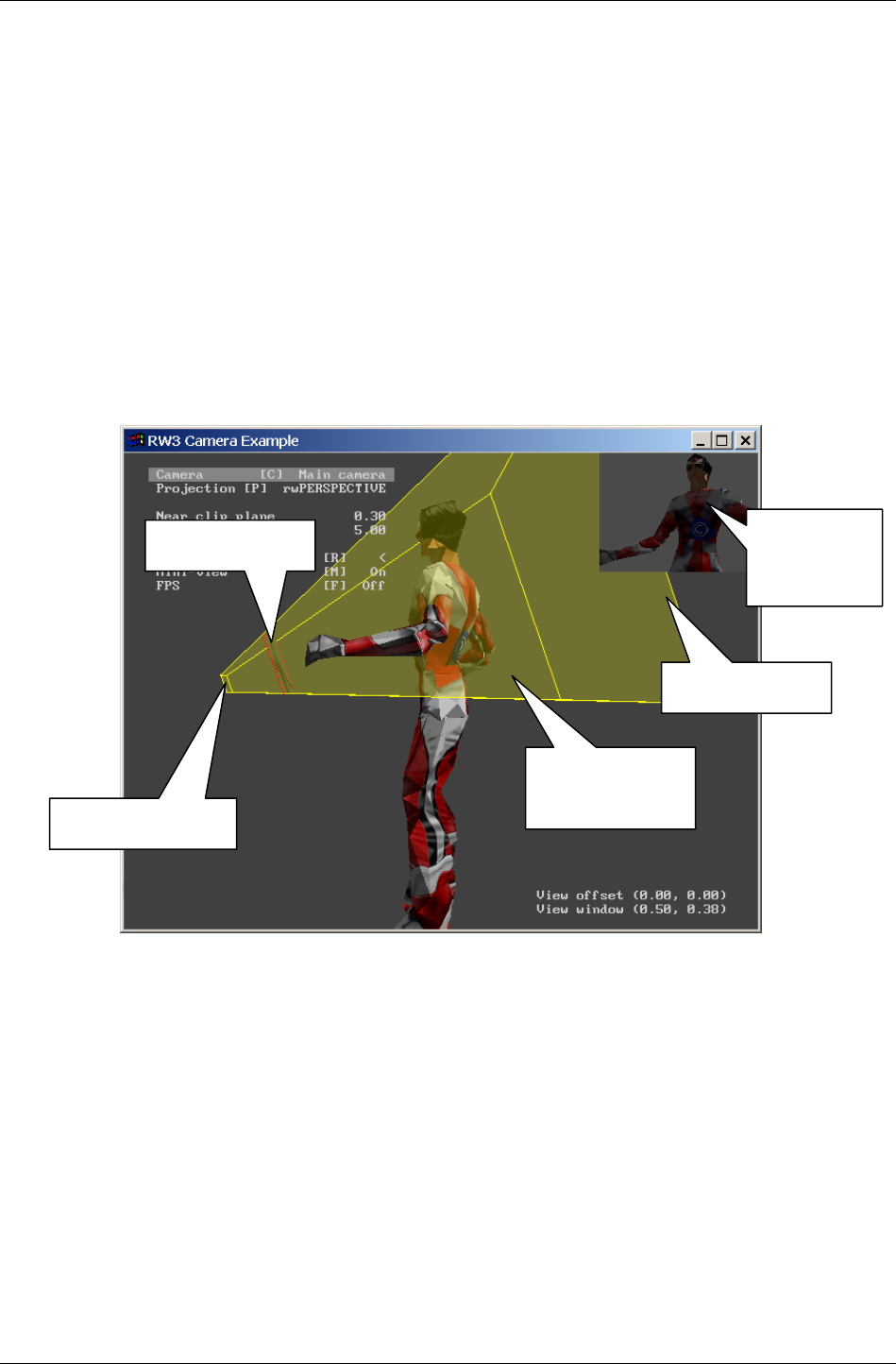
The RenderWare Graphics Camera object
RenderWare Graphics 3.7 I-97
5.2 The RenderWare Graphics Camera
object
The RenderWare Graphics Camera (RwCamera) object is part of the Core
Library. It is the target of all 3D rendering operations and therefore plays
an important part in any 3D graphics application built on RenderWare
Graphics.
5.2.1 Camera Properties
The screenshot below is taken from the 'camera' Example and it has been
annotated to show the primary features of the Camera object:
Other Camera properties, such as projection modes, frame buffers, and fog
handling, will be covered later.
View
Frustum
Far Clip Plane
Near Clip Plane
View Window Actual view
from observed
Camera

Chapter 5 - The Camera
I-98 11 February 2004
5.2.2 The View Frustum
The highlighted volume in the diagram on the previous page represents the
volume in front of the Camera within which a renderable object is
considered visible. This is the View Frustum, defined by the near clip
plane, the far clip plane and the four planes passing through the
Viewpoint and the edges of the View Window. RenderWare Graphics uses
the bounding sphere of the object to determine whether it intersects or lies
within the view frustum. This course-grain visibility test is then used to
determine whether or not to draw the object, and whether the object is
clipped or unclipped. Clipping is a fine-grain visibility test.
✎
✎✎
✎ If a model does not have a valid bounding sphere, the RenderWare Graphics engine may
produce unexpected results.
The Clipping Planes
Two clip planes define the near and far extents of the view frustum.
The far clip plane defines the point along the Camera Space Z axis, beyond
which objects will not be rendered.
The far clip plane is responsible for the infamous 'pop-up' found in older 3D
games, whereby model geometry suddenly appears on the horizon as if from
nowhere. If a platform has enough 3D graphics processing power, this
plane can be pushed back so far that the 'pop-up' simply isn't visible.
The near clip plane defines the point along the Camera Space Z axis,
nearer than which, objects will not be rendered. It is parallel to the far clip
plane and on the opposite side of the view frustum. Again, this is just a
point along the Z-axis running through the center of the camera object and
into Camera Space.
The near clip plane controls clipping of polygons close to the camera object.
Without it, even models behind the camera might be considered visible by
the engine and be rendered to the camera's frame buffer.
✎
✎✎
✎ Pushing the Near Clip Plane away from the Camera improves Z Buffer resolution. When
feasible, the Near Clip Plane should be positioned as far away from the Camera as possible
without introducing visible clipping artifacts. The distance at which this will occur
depends on the zoom factor currently applied to the Camera. As a rule of thumb, dividing
the distance of the far clip plane from the camera by the distance of the near clip plane
from the camera should ideally result in a value of less than 1000.
The Viewpoint
When the Camera is set to the more usual Perspective view the View
Frustum defines a section through a pyramid. The apex of this pyramid is
the Viewpoint.
The Viewpoint is the center of projection when using a camera set to
Perspective mode. It is, literally, the 'point of view' – the eye – in the scene.
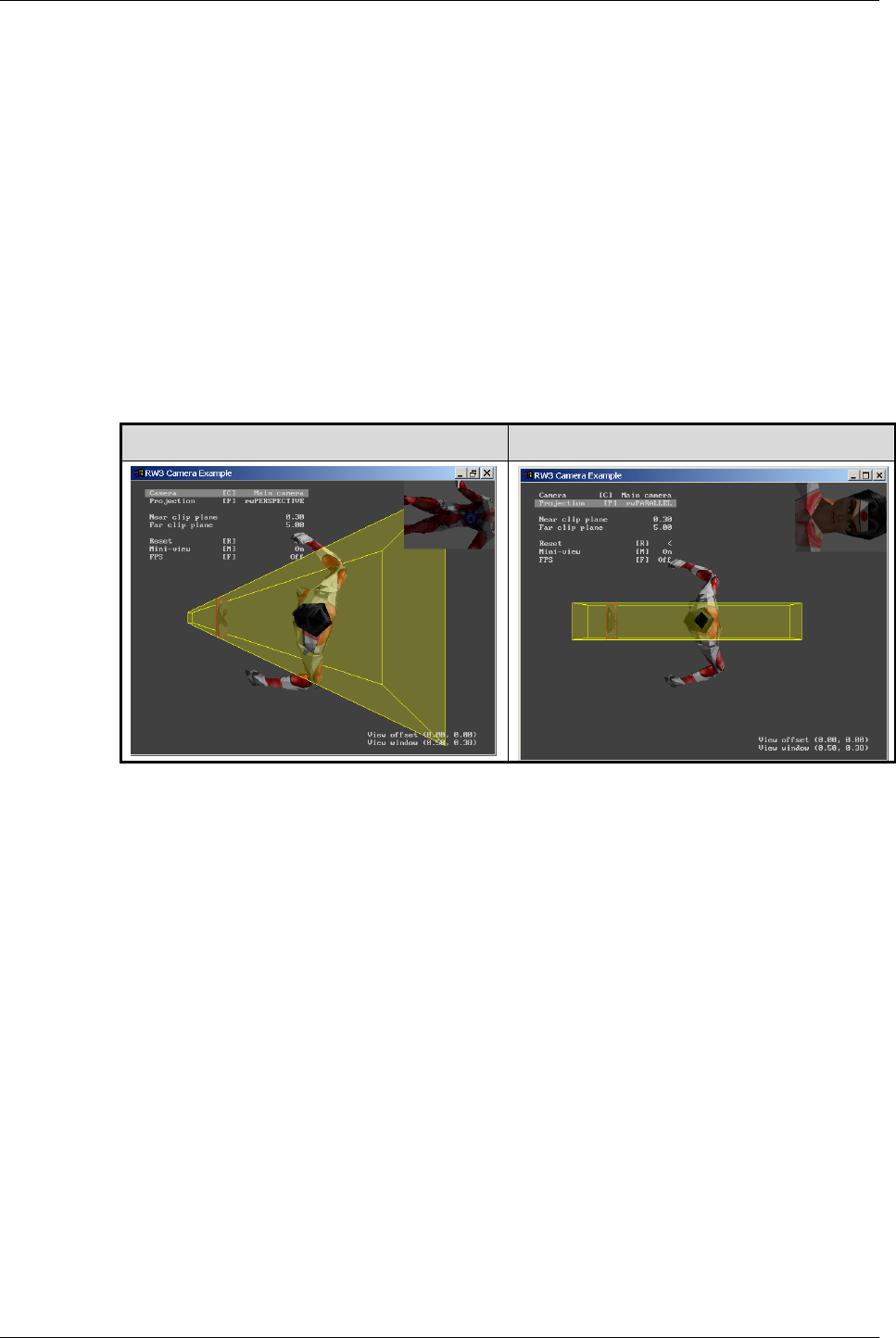
The RenderWare Graphics Camera object
RenderWare Graphics 3.7 I-99
Projection Modes
RenderWare Graphics provides two Projection Modes: Perspective and
Parallel. Perspective projection is the most generally used and is the
projection system assumed throughout most of this chapter. That said,
Parallel projection mode, while not so frequently used in apps, does lend
itself to a number of more specialist rendering tasks.
Perspective projection makes objects that are more distant (from the
camera) appear smaller on the screen as they do in real life. The angular
field of view may be controlled by calling the RwCameraSetViewWindow()
function, as described in the API Reference Manual.
Parallel projection mode, which can be selected using the
RwCameraSetProjection() function, changes the View Frustum to a View
Cuboid.
PERSPECTIVE PROJECTION PARALLEL PROJECTION
As you can see from the screenshots above, the main difference between
Perspective and Parallel projection modes is that the latter does not scale
vertices in the Z axis – no matter how far away a model is, it won't get any
smaller.
This mode is most often used for orthographic views or for projecting
shadows from area light sources, but it can also be used to duplicate some
popular 2D graphics rendering techniques, such as parallax scrolling. This
has the advantage of using the 3D acceleration hardware features available
on your target platform.
5.2.3 The View Window
Earlier, the Viewpoint was described as being a virtual 'eye' looking into a
scene. If we continue with this analogy, the View Window becomes a
virtual 'retina'. Where the analogy falls down is that the View Window is in
front of the Viewpoint.
Let's go back to the 'camera' Example.
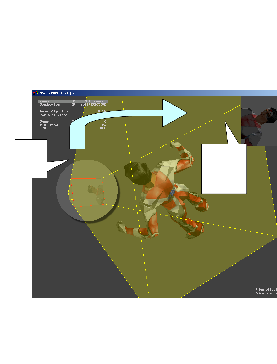
Chapter 5 - The Camera
I-100 11 February 2004
With the 'camera' Example running, you can move the model around and
see its image rendered into the view window. This is shown inside a red
outline close to the near clip plane.
This View Window represents the frame buffer – our virtual retina – upon
which the actual scene is rendered. The picture below shows this
happening.
A useful feature of the 'camera' Example is that it displays the view from
the observed Camera inset at the top-right corner of the screen. (Because of
our view of the Camera object, the image shown in the View Window
appears to be reversed because it is facing away from us.)
It is the contents of the frame buffer the View Window represents which the
end-user gets to see.
View Windows & Aspect Ratio
Aspect ratio is defined by a combination of the View Window's dimensions
and those of the frame buffer Raster.
T
he View
Window.
(Seen from
the rear).
Rendered image
from frame buffer.
(What the
observed Camera
'sees'.)

The RenderWare Graphics Camera object
RenderWare Graphics 3.7 I-101
While you can set the View Window to any arbitrary dimensions, the
resulting image must still fit into the supplied frame buffer. Therefore,
RenderWare Graphics scales the output so that it always fits into the frame
buffer Raster.
This opens up a useful feature of the Camera: by manipulating the
dimensions of the View Window and frame buffer Raster, we can:
• Zoom into a scene by decreasing the dimensions of the View Window;
• Zoom out of a scene by increasing the dimensions of the View Window;
• Duplicate an anamorphic lens by adjusting the dimensions of both the
View Window and the frame buffer and Z buffer Rasters.
This last feature can be used to implement a typical requirement for a
console game: support for anamorphic wide screen displays: Setting the
View Window to a 16:9 aspect ratio, but keeping the frame buffer's
dimensions to the traditional 4:3 TV standard achieves this. The rendered
scenes will be squashed to fit into the frame buffer's smaller width. The
resulting frame buffer can then be displayed on a wide screen TV using its
anamorphic (i.e. 'stretched') setting. The result is that the squeezed frame
buffer image becomes stretched across the entire width of the wide screen
TV's display, restoring it to its intended aspect ratio.
The advantages of this technique are two-fold:
1. It saves memory. By removing the need for a wide screen frame buffer,
we save on precious video RAM.
2. The lower memory overhead typically results in faster performance as
system bus bandwidth requirements are reduced.
This technique can also be used to produce distortion effects.
✎
✎✎
✎ The View Window is defined as being always one unit away from the Viewpoint mentioned
briefly above.
The Camera View Window API
The View Window is set using an RwV2d vector set to half the required
dimensions in each axis. The function call is RwCameraSetViewWindow().
The property retrieval function is RwCameraGetViewWindow(). Again, the
returned RwV2d vector is set to half the actual dimensions.
The Raster object, used to provide the frame buffer and the Z buffer for
Cameras, is covered in the Rasters, Images & Textures chapter.
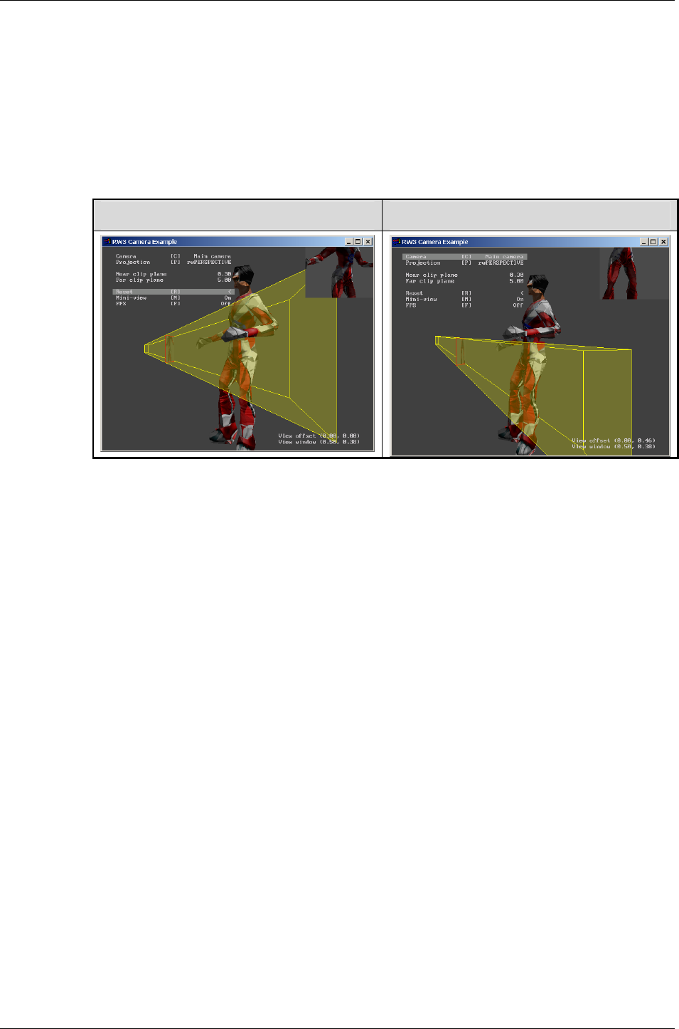
Chapter 5 - The Camera
I-102 11 February 2004
5.2.4 The View Offset
The View Offset is used to shear the Camera's view frustum. This is done by
specifying an X and Y (Camera Space) offset for the frustum's apex – the
point defining the center of the far end of the frustum.
The screenshot below, left, shows an un-offset View Frustum. The
screenshot to the right shows the View Frustum with a View Offset of 0.46
in the Y axis:
NO OFFSET OFFSET IN Y AXIS
Notice how the Viewpoint – the apex of the View Frustum – is offset
vertically relative to its original position. The result is the shearing of the
View Frustum so that the View Window renders the lower portion of the
model instead of the middle portion.
This feature can be explored in the 'camera' example (see the associated
readme.txt file for the user interface functions needed to manipulate the
View Offset).
The offsets are absolute values, so repeated calls to
RwCameraSetViewOffset() will not be accumulated.
This function has advantages for such activities as supporting stereoscopic
display devices and tiled rendering to a high resolution output device.
Camera View Offset API
Two functions are supplied for this feature: RwCameraSetViewOffset()
and RwCameraGetViewOffset(). Both take an RwV2d vector to set or store
the offset.
5.2.5 Fog
Fog effects in RenderWare Graphics are tightly coupled to the Camera
model.

The RenderWare Graphics Camera object
RenderWare Graphics 3.7 I-103
A number of different fog models are supported by RenderWare Graphics:
Linear, Exponential, Exponential2 and Table. However, some of these fog
types are only supported on a sub-set of platforms.
Basic Fog Controls
Fogging starts at the distance set by RwCameraSetFogDistance() for
Linear and Table fog types. Also, for the same fog types, the full fog effect is
achieved at the far clip plane.
✎
✎✎
✎ Fog Distance should never be set to zero.
Most of the fog handling is done through the RwRenderState API, so let's
take a quick look at what's available…
Fog Render State
Fog is controlled through both the RwCamera and RwRenderState APIs. The
Render State API provides the following fog control functionality:
• rwRENDERSTATEFOGENABLE
Turns on fogging. All polygons rendered from this point onwards will be
modified by fog processing. Clear this flag to disable fogging.
• rwRENDERSTATEFOGCOLOR
The target color for fogging. The denser the fog around a particular
polygon, the closer the polygon's color will be to this target color.
• rwRENDERSTATEFOGTYPE
The type of fogging to use. The fog types defined are:
• rwFOGTYPELINEAR
Selects the Linear fogging type.
• rwFOGTYPEEXPONENTIAL
Selects the first Exponential fog type. This is available on most of
our supported platforms. If the fog effect is represented by f then the
function is:
f = 1 / e(d * density)
(where d is the distance from the Camera's View Point.)
• rwFOGTYPEEXPONENTIAL2
Selects the second Exponential fog type. This is using a higher
exponent in the formula to make the fog get denser faster. The
formula is as above except that the exponent – (d * density) – is
further raised to the power of two.
• rwRENDERSTATEFOGDENSITY
Select the density of Exponential and Exponential2 fogging. The higher
the value, the denser the fog.

Chapter 5 - The Camera
I-104 11 February 2004
• rwRENDERSTATEFOGTABLE
This is the Table form of fogging. The parameter is a 256-entry fog table
placed between fog distance and far clip plane. The table format is not
fixed, so check your platform-specific documentation to see what format
to use if this fog type is supported.
Note that Render States can return FALSE for a number of reasons. Check
the platform-specific information in the API Reference to ensure that a
particular fog type is supported for a particular platform.
The Render State API, consisting of the two RwRenderStateSet() and
RwRenderStateGet() functions should be used to set the fogging as
appropriate.
✎
✎✎
✎ The Render State represents the RenderWare Graphics state machine and is a shared
resource. This means, when a particular render state is set, it stays set until it is cleared
again, either by your own code, or by code elsewhere in RenderWare Graphics.
RenderWare Graphics makes heavy use of its rendering engine. Check the Render State flags
if you find effects being applied inappropriately – like fog being applied to displaying text.

The Camera View Matrix
RenderWare Graphics 3.7 I-105
5.3 The Camera View Matrix
This matrix transforms world space coordinates to camera clip space. The
camera's clip space is bounded by the near and far clip planes, and side
planes defined as follows:
x = 0, x = z, y = 0 and y = z for a Perspective projection model;
x = 0, x = 1, y = 0 and y = 1 for a Parallel projection model.
☛ Camera View Matrix API
The View Matrix is accessed through the RwCameraGetViewMatrix() function.

Chapter 5 - The Camera
I-106 11 February 2004
5.4 Rasters & Cameras
In order to be useful, a Camera object has a couple of optional buffers
attached to it that are used to store the resulting rendered image. These
provide storage for both a Z Buffer and the frame buffer itself. In
RenderWare Graphics, the Raster object is used for both of these buffers.
✎
✎✎
✎ Rasters are a key feature of RenderWare Graphics and are covered in much greater detail in
the Rasters, Images & Textures chapter.
The Raster types must be rwRASTERTYPEZBUFFER, for the Z-buffer, and of
type rwRASTERTYPECAMERA for the frame buffer.
The frame buffer Raster holds the rendered image. Since RenderWare
Graphics provides a double-buffered model, this image is stored off-screen
and is displayed when rendering is completed by the
RwCameraShowRaster() function.
5.4.1 Z Buffer Accuracy
This can vary quite dramatically from platform to platform and application
to application.
The Z buffer range is effectively dictated by both the spacing of the near
and far clip planes, and the definition of the Z buffer Raster. This last
might use anything from an array of 8-bit bytes to a map constructed from
IEEE-standard double-precision floating-point values.
Clearly, this means you need to take care when setting up the view frustum
as placing the near and far clip planes too far apart may result in rounding
errors and related problems.

Creating a Camera
RenderWare Graphics 3.7 I-107
5.5 Creating a Camera
The process of constructing a RenderWare Graphics camera is typically as
follows:
• Create and allocate a Raster of type rwRASTERTYPECAMERA
• Create and allocate another Raster of type rwRASTERTYPEZBUFFER
• Create a Camera object using RwCameraCreate()
• Attach the two Rasters to the Camera object using
RwCameraSetRaster() and RwCameraSetZRaster()
• Create a Frame object and attach it to the Camera object using
RwCameraSetFrame(). The Frame allows for the control of the position
and orientation of the Camera.
• Finally, if you're using the RpWorld Retained Mode API, you will need to
'add' the Camera to the World. (See the two Retained Mode API
chapters, Worlds & Static Models and Dynamic Models for more on this.)
At this point, the Camera is ready to use.
5.5.1 Orienting and Positioning a Camera in Scene
Space
A quick skim through the Fundamental Types chapter reminds us that the
Frame object is a container for the matrices used to position and orient
objects in a virtual space.
Cameras use frames to define:
• Where they are positioned
• Which direction they are facing
The Camera will always face along the Frame's look-at vector. The look-up
vector always points at the top of the View Window.
✎
✎✎
✎ One oddity is that, because the Camera is facing away from us, its look-right vector is
invariably pointing to the left from the user's point of view.
Transformations
Frames attached to Cameras behave just like Frames attached to anything
else. Transformations are performed by using the RwFrame API and are
used to position and orient a Camera.

Chapter 5 - The Camera
I-108 11 February 2004
Frame Origin
When attached to a Camera, the Frame's origin will be coincident with the
Viewpoint. Note that this means the View Window will always be located
exactly one unit along the look-at vector.

Rendering to a Camera
RenderWare Graphics 3.7 I-109
5.6 Rendering to a Camera
3D graphics rendering takes place between an RwCameraBeginUpdate() /
RwCameraEndUpdate() pair. All rendering must take place between these
two functions, although you can have more than one Begin/End pair
operation before displaying the rendered image using
RwCameraShowRaster().
As many RenderWare Graphics applications use the Retained Mode
(RpWorld) Plugin, a typical render cycle may look like this:
if ( RwCameraBeginUpdate(mainCamera) )
This line prepares the Camera for rendering, pushing its frame buffer
Raster onto the context stack. The top-most Raster on this stack is used as
the target for rendering. (Rasters are covered in more detail in the Rasters,
Images and Textures chapter.)
The context stack is described in more detail in the "Immediate Mode"
chapter.
At this point, Frame objects marked as 'dirty' will also have their Local
Transformation Matrices (LTM) resynchronized. Any hierarchies hanging off
the Frames are also updated. This ensures any rendered objects attached
to the Frames are positioned and oriented correctly.
{
RpWorldRender(gameWorld); /* Render the main game world */
We'll cover the RpWorld Retained Mode API in detail in later chapters. For
now, suffice to say that this function will render an entire scene.
/* Now render any UI overlays, such as HUDs, high score */
… some more rendering code…
At this stage, you may want to add some special effects, such as lens flare
or other visual gloss. Many such effects are often best achieved using the
Immediate Mode APIs.
RwCameraEndUpdate(mainCamera);
/* End of rendering cycle. */
At this point, RenderWare Graphics will pop the Camera's Raster off the
context stack. It also cleans up after itself and performs any necessary
housekeeping.
We do not, however, have a visible result: the rendering has taken place,
but because RenderWare Graphics uses double buffering, we need to swap
the buffers over so we can see the results of our toil...
/* Display the results of the rendering. */
RwCameraShowRaster(mainCamera, (void *)win32Handle,
rwRASTERFLIPWAITVSYNC);
}

Chapter 5 - The Camera
I-110 11 February 2004
This function performs the buffer-swap needed to display our rendered
scene. The parameters are, in order: the Camera object, a platform-specific
parameter (in this case, a HWND container as the Win32 SDK is being used
in this example), and finally, a flag can be specified to tell RenderWare
Graphics to wait for the vertical blanking interrupt. (This last should only
be used in a full-screen application.)
We can now update our scene ready for the next rendering cycle.
5.6.1 Destroying a Camera
Camera objects need to be explicitly destroyed when you are finished with
them. Because the Camera contains references to other objects, these also
need to be destroyed explicitly as RwCameraDestroy() will not destroy
these for you.
So:
1. Obtain pointers to any Rasters attached to the Camera – use
RwCameraGetRaster() and RwCameraGetZRaster() for this.
2. Destroy these Rasters using RwRasterDestroy().
3. Use RwCameraGetFrame() to extract the Frame object and destroy that
also.
4. Destroy the Camera object itself using RwCameraDestroy().

Sub-Rasters
RenderWare Graphics 3.7 I-111
5.7 Sub-Rasters
Sub-Rasters can be used with Cameras to provide the following:
• Split-screen views, often seen in multi-player games
• Picture-in-picture and other inset effects, such as rear-view mirrors in
driving games
These effects are achieved by sharing a single Raster across multiple
Camera objects.
✎
✎✎
✎ For full details on how Sub-Rasters work, see the Rasters, Images & Textures chapter.

Chapter 5 - The Camera
I-112 11 February 2004
5.8 Other Features
5.8.1 Clearing the Buffers
This process should be performed at the beginning of each frame unless
your scene rendering is refreshing each pixel in the buffer every cycle
anyway.
The function for this procedure is RwCameraClear(). Refer to the API
Reference Manual for more details.
5.8.2 Cloning a Camera
RenderWare Graphics provides the RwCameraClone() function for this
purpose.
As with most other 'clone' operations in RenderWare Graphics, this means
both the source Camera and the target Camera objects will share the
Frame, frame buffer Raster and Z-buffer Raster. Also, if the source Camera
had been added to a World (RpWorld) object, the cloned Camera will also
be in that World.

World Plugin Extensions
RenderWare Graphics 3.7 I-113
5.9 World Plugin Extensions
5.9.1 About the Extensions
The World Plugin adds a number of additional functions to the Core
Library's Camera API. These are described here.
5.9.2 Automatic & Manual Culling
When rendering scenes using the World Plugin (RpWorld) API, the Plugin
will automatically cull any Atomics and World Sectors that are located
outside the Camera's view frustum. It will also cull any dynamic Lights
whose spheres of influence are inapplicable within the view frustum.
However, this only applies to model data that has been explicitly 'added' to
the World object. If you need to render an object, such as an Atomic,
explicitly – and this is sometimes desirable – then you will need to perform
the culling yourself.
This can be achieved using the RwCameraFrustumTestSphere() function,
which will test a Bounding Sphere (RwSphere) object passed to it and tell
you whether it is inside, outside or intersecting the specified Camera's view
frustum. The values it will return are: rwSPHEREINSIDE, rwSPHEREOUTSIDE
and rwSPHEREBOUNDARY respectively.
5.9.3 Clump Cameras
An RpClump is a container for dynamic objects that are associated with a
frame hierarchy, and are described in more detail in a later chapter. It is
possible to add Cameras to a Clump using the function
RpClumpAddCamera(). Such Cameras are streamed with the Clump, and
their location within the frame hierarchy preserved. This mechanism is
used whenever Cameras are exported from the modeling packages.
5.9.4 Iterators
A number of useful iterator functions are provided to access model data
that falls either within or outside the Camera's view frustum. The iterators
cover a number of object types.
In all cases, the iterators can rely Bounding Spheres to perform their tests.
World Sectors
These represent static model geometry. One iterator is supplied:
RwCameraForAllSectorsInFrustum(). This will iterate through all World
Sectors that are either partially or entirely within the view frustum, calling
a specified callback function for each one it finds.

Chapter 5 - The Camera
I-114 11 February 2004
The World Sector functions include a number of iterators for locating
objects that lie within them, such as Atomics and Lights.
Clumps
Clumps represent dynamic objects and a frustum iterator is supplied:
RwCameraForAllClumpsInFrustum(). Like the World Sector form
described above, this function will iterate through all Clumps that contain
Atomics either partially or entirely within the view frustum. For each such
Clump, it will call the specified callback function.
The callback function is of type RpClumpCallBack().

Chapter 6
Rasters, Images
and Textures

Chapter 6 - Rasters, Images and Textures
I-116 11 February 2004
6.1 Introduction
This chapter discusses bitmaps, images, rasters and textures and explains
when and where they are used. These objects can all be found in the Core
Library:
• RwImage
• RwRaster
• RwTexDictionary
• RwTexture
In addition, platform independent texture dictionaries are explained here,
and these require the use of the RtPITexD toolkit.

Bitmaps & Textures
RenderWare Graphics 3.7 I-117
6.2 Bitmaps & Textures
Bitmaps play a major part in any 3D graphics engine. They form the basis
for texture maps.
6.2.1 Bitmaps
RenderWare Graphics' Core Library supports two different types of bitmap
objects: Images and Rasters.
While the APIs for these objects are superficially similar, there is one very
important difference. The Image (RwImage) object is platform independent;
the Raster (RwRaster) is not.
The reason for this duality is to give you the most flexibility without
sacrificing power. Images can be easily processed and manipulated, but
cannot be displayed until they have been converted to Rasters. Rasters
have minimal manipulation and processing facilities, but are highly
optimized for the underlying hardware.
6.2.2 Images
Images provide a platform-independent object for manipulating bitmap
data.
Images are used to load bitmaps from disk or other media storage prior to
conversion to a platform-optimized Raster object, which can then be
manipulated.
6.2.3 Rasters
Rasters provide a platform dependent form of image and are used to hold
image data. Rasters are frequently found inside other RenderWare Graphics
objects. Of particular note are the Camera (RwCamera) and Texture
(RwTexture) objects. For more information about cameras see the chapter
on The Camera.
Rasters are the only form of bitmap that RenderWare Graphics can actually
render to a display device. Image objects are normally used as
intermediaries.

Chapter 6 - Rasters, Images and Textures
I-118 11 February 2004
6.2.4 Textures
A texture is a bitmap that is stretched across a polygon. Textures use
Rasters to store the actual bitmap data. The Rasters are also used to store
mipmaps.
✎
✎✎
✎ It is the Raster itself that supports mipmapping, not the Texture object.

The Image Object
RenderWare Graphics 3.7 I-119
6.3 The Image Object
Images represent a platform-independent bitmap.
They can support most common image formats and this makes them ideally
suited as intermediaries.
For example, when you load a bitmap, such as a PNG or BMP, from disk, it
ends up in an Image object.
6.3.1 Image Dimensions
Image objects can have any width or height. Dimensions are limited only by
available memory. The color depth can be four, eight or thirty-two bits per
pixel.
Images do not support packed pixel formats. This means that the bitmap
actually stores only one pixel per byte, even if only four of the bits in each
byte are significant.
6.3.2 Stride
An Image is associated with a stride. A stride defines the physical number
of bytes needed to get from one pixel in the bitmap to the one directly
below.
The stride allows a bitmap to be defined as a portion of a larger bitmap.
This kind of usage is popular as it reduces loading times by combining
smaller images into one larger one.
6.3.3 Palettes
Four-bit and eight-bit Image depths require palettes.
Palettes consist of:
• 16 entries for 4-bit formats
• Up to 256 entries for 8-bit formats.
Each entry is an RGBA value defining a color.
6.3.4 Gamma Correction
Image objects also support a gamma correction value. This value defines
the gamma curve of the device upon which the bitmap is to be displayed.
Changing this value and applying the gamma correction enables you to
adjust the gamma of the bitmap.

Chapter 6 - Rasters, Images and Textures
I-120 11 February 2004
What is Gamma Correction?
This process exists to make graphics appear as close to the original as
possible, regardless of any differences or gamut limitations in the display
device used. Gamma correction is similar to the "contrast" control on a
television set or monitor.
When applied, the RGB values are multiplied by the gamma correction
value to increase or decrease the effective level of an image's pixels.
✎
✎✎
✎ Consumer video devices, such as televisions, have a higher native gamma than dedicated
computer monitors. This means that graphics drawn on a monitor will tend to look
brighter on a television set. This may not be what the graphics artist intended, hence the
provision for gamma correction.
6.3.5 Creating Images
Image objects can be created either by allocating memory for the data and
assigning that data to an Image, or by reading the object from a
RenderWare Graphics Binary Stream.
Creating Images by Assigning Data to an Image
Initialization is fairly straightforward: a call to RwImageCreate() is made,
supplying width, height and depth values.
This gives a dummy image object with all its members except those that
point at the actual bitmap data. To include these
RwImageAllocatePixels() is used. This looks at the width, depth and
height of the image and calculates the memory required to store this Image.
✎
✎✎
✎ If your Image uses a palette format then space also needs to be allocated for the palette.
RwImageAllocatePixels() will handle this for us automatically by looking up the
settings in the Image object.
For example, a depth of 8 bits will result in the creation of a 256-entry palette.
Loading Images
Image objects are most commonly loaded. They act as containers for
bitmaps loaded from a disk or CD. Usually, bitmaps are drawn by an artist
and then loaded into the game ready-made.
Bitmap files include standard formats, for example, Windows Bitmap
(.BMP), Portable Network Graphics (.PNG).
RenderWare Graphics doesn't support any of these formats and
RwImageRead() routine does not support any standard formats by default.
RenderWare Graphics does, however, have four toolkits, which add support
for four popular file formats: RtPNG, RtRAS, RtTIFF and RtBMP. These
provide a single callback function, which the RenderWare Graphics Image
Streaming API uses to handle a particular file extension.
More information about these Toolkits is in the table below:
The Image Object
RenderWare Graphics 3.7 I-121
FORMAT EXTENSION TOOLKIT SUPPORTED
FEATURES
Microsoft®
Windows®
Bitmap format
.bmp RtBMP
Palette-based, 24-bit
RGB and grayscale.
No Alpha support.
Portable
Network
Graphics
.png RtPNG
8-bit palette-based and
various RGBA formats.
Alpha is supported.
Sun
Microsystems®
"Raster" format
.ras RtRAS
Palette-based formats,
32-bit BGR and RGB
formats supported.
No Alpha support.
Aldus
Corporation
Tagged Image
File Format
.tif
.tiff
RtTIFF Palette-based (8-bit),
grayscale (8-bit), RGB
(24-bit) and RGBA (32-
bit). Supports Stripped,
LZW and both big
endian and little endian
formats.
Win32 and
PlayStation®2 platforms
only.
This open architecture means that you can write your own image format
handler to handle any image file format and add it to RenderWare Graphics
Toolkits and include that Toolkit in your application.
The "imgformt" example shows you how to do this by implementing a
minimal Targa Image File (.tga) file format handler.
✎
✎✎
✎ Bitmaps & RenderWare Graphics Binary Streams
It is worth pointing out that Image objects do not make any use of the RenderWare
Graphics Binary Stream system. The only bitmap object that supports this API is the
Raster.
6.3.6 Example: Reading a BMP file
This section will show you the procedure involved with reading a Microsoft
Windows Bitmap format file, usually stored with the ".BMP" file extension.
Writing Images is essentially identical to that for reading except
RwImageWrite() is used instead of RwImageRead(), so the following
example can be easily applied to both processes.
Registering an image file format
To start with, the image format needs to be chosen and then linked to the
appropriate Toolkit and registering it with the
RwImageRegisterImageFormat() function. This allows RenderWare
Graphics' Image streaming functions to access image file formats
transparently.

Chapter 6 - Rasters, Images and Textures
I-122 11 February 2004
For this example the Windows Bitmap (.bmp) file format will be used:
1. Add the appropriate header – rtbmp.h – and ensure our application is
linked with the associated Toolkit library. (For Win32 developers, this
library is "rtbmp.lib".)
2. Register the RtBMP Toolkit's supplied callback functions with the Core
Library so it knows which functions to call in order to read or write
BMP-format images using the RwImageRegisterImageFormat()
function. This takes a string containing the associated filename
extension, a pointer to the image reading function and another pointer
to the image write function.
In this instance, the registration code would look like this:
RwImageRegisterImageFormat("bmp", RtBMPImageRead,
RtBMPImageWrite);
Any number of additional image formats can be registered in this way.
When reading or writing Images, RenderWare Graphics will look up the
supplied filename extension against the registered extensions in its
database and call the appropriate callback functions.
Search Paths
Before an image can be read we have to ensure RenderWare Graphics
knows where to look for it. For this purpose, RenderWare Graphics' Core
Library provides the RwImageSetPath() function. This accepts a string
containing one or more search paths separated by semicolons. RenderWare
Graphics will use this to find the Image filename supplied to the read
function.
✎
✎✎
✎ For obvious reasons, the RwImageWrite() function requires an absolute, fully qualified
path, filename and extension. It makes no reference to the search path.
6.3.7 Reading the Image
It is now possible to read or write an Image object using the
RwImageRead() and RwImageWrite() functions.
These work by passing a filename to the function and, if successful, it will
return a pointer to an RwImage object with your image in it. If you pass a
filename without a path, RenderWare Graphics will use the search paths to
attempt to locate the file.
✎
✎✎
✎ Two important points to note are:
1. If you haven't registered the image file format you're trying to read or write the
function call will fail.
2. The RwImageRead() function requires the file extension so RenderWare Graphics
can work out which registered reader function to use.

The Image Object
RenderWare Graphics 3.7 I-123
For example, a "BMP"-format image file is being read, we would perform the
registration process just detailed, then call the RwImageRead() function to
perform the Image reading, as below.
{
…
/* BMP Registration must have been done prior to this point. */
myImage = RwImageRead("myimage.bmp");
if (!myImage)
{
/* Failed to read the image. Handle error condition. */
}
…
}
Assuming all went well, a pointer to a ready-to-use Image object should be
stored in myImage.
Any image processing or manipulation can be performed on our Image.
✎
✎✎
✎ Masked Images
RenderWare Graphics can use Image alpha channels as masks when available. (The "A" in
RGBA formats represents the alpha/mask data). Masks are covered later in this chapter.
6.3.8 Image Processing
The RwImage API supports a number of basic image manipulation
functions. These cover such processes as re-sampling, copying, gamma
correction, masking (for basic alpha channel effects) and resizing.
Creating an Image object
Sometimes, you'll need to create an empty Image object, which is to be
populated with data and bitmaps later in its life-cycle. This process can be
a one- or two-stage process, depending on what the object is to be used for.
To instantiate the Image object itself:
1. Call the RwImageCreate() function and pass it the dimensions you
need and it will return an Image object that is almost, but not entirely,
complete.
2. Allocate the memory for the bitmap and the palette (if this is a palletized
Image). This is achieved using RwImageAllocatePixels(). This will
look at the dimensions of the Image object and use these data to work
out how much memory the Image will need. It will also allocate memory
for the palette if one is required.

Chapter 6 - Rasters, Images and Textures
I-124 11 February 2004
✎
✎✎
✎ The reason for this two-step process is to allow multiple Image objects to share a single
bitmap. This is a useful feature as you can, for instance, have a number of sprites stored
within a single bitmap. To make access to each of these sprites easier, you can define
multiple Images which share the same physical bitmap and point at individual sprites.
You can therefore set the bitmap data pointer in an Image object directly using
RwImageSetPixels().
Re-sampling
There are two re-sampling functions. Both take an original Image object
and produce another Image of a different width and/or height. The main
difference between them is that the first function creates and allocates a
new re-sampled Image object for you, while the second does not:
• RwImageCreateResample() function allocates and creates a new Image
for the re-sampled bitmap.
• RwImageResample() requires that you supply a valid RwImage object
for both the source and the destination. You will need to use both
RwImageCreate() and RwImageAllocatePixels() to create the Image
objects.
RwImageCreateResample() also differs in that it allows you to specify a
palletized image as the source. However, the result is always an Image
of 32-bit depth.
Re-sampling actually re-scales the source image to fit the new
dimensions. RenderWare Graphics always uses the CPU to perform this
operation.
Accessing and modifying Image properties
RenderWare Graphics' Image API provides get functions to access Width,
Height, Depth and other properties. These are RwImageGet[PROPERTY]()
form. For example:
RwImageGetHeight(), RwImageGetDepth(), RwImageGetStride()
Most of these have equivalent Set forms. The only exceptions being Width,
Height and Depth. These are set through the RwImageResize() function
which takes all three as parameters.
Copying
RwImageCopy() will copy a source Image into a destination Image. Both
Image objects must already be created (using RwImageCreate()), and
bitmap memory allocated (using RwImageAllocatePixels()), as this
copying function will not create the destination Image for you.

The Image Object
RenderWare Graphics 3.7 I-125
Alpha Channel Masks
All Image objects have storage for alpha channel information, either directly
in the bitmap (32-bit formats), or in the palette table (4-bit and 8-bit
formats). While some image file formats support alpha channels directly,
many others do not so the RwImage API includes functionality to get around
this and allows you to transfer alpha channel data from one Image to
another.
In particular, functions are provided for loading masks stored in a separate
file (RwImageReadMaskedImage()); creating masks from pixel data
(RwImageMakeMask()); and applying a mask stored in one Image to another
(RwImageApplyMask()).
At the time of writing, RenderWare Graphics supports two image file
formats that can handle alpha channel data:
• the Portable Network Graphics format (.PNG), supported by the "RtPNG"
Toolkit
• the TIFF format (.TIFF), supported by "RtTIFF".
These can read a 32-bit RGBA PNG-format or TIFF-format file complete
with alpha channel. A single Image is returned.
6.3.9 Raster Conversion
So far, Rasters haven't been covered in detail. The RwImage API also
provides functionality to convert a Raster to an Image object and vice versa.
The function that performs this magic is RwImageSetFromRaster(). This
function will take a Raster and convert it into an Image of the same
dimensions. The target Image must be valid, initialized to the right
dimensions and allocated enough memory for the pixel data.
A complementary function, RwRasterSetFromImage() also exists to
perform the reverse conversion. This is covered in more detail in the section
on Rasters.
☛ Palletized bitmaps can be more efficient on some platforms. RGBA formats may work
better on others. You should refer to platform-specific documentation to determine which
bitmap formats are best suited to your target platform.
6.3.10 Destroying Images
Any RenderWare Graphics image objects you have explicitly created must
be destroyed.
Images should be destroyed using the RwImageDestroy() function. If the
bitmap and palette data were allocated using the
RwImageAllocatePixels() function, the destructor function will also free
this memory. Otherwise, you will need to free it yourself.

Chapter 6 - Rasters, Images and Textures
I-126 11 February 2004
6.4 The Raster Object
Images must be first converted into a platform-dependent format if they are
to be rendered. This platform-dependent format is known as the Raster
(RwRaster).
Rasters also provide the foundation for RenderWare Graphics' virtual
camera as well as its texture-mapping features. This makes the Raster one
of the most important objects in RenderWare Graphics.
6.4.1 Basic Properties
Like Images, Rasters represent bitmaps. Therefore, they contain all the
basic features of a bitmap: width, height, depth, palette data (if applicable)
and the bitmap data itself. As with Images, Rasters can also support alpha
channel data, if, the platform supports it.
The main difference between Rasters and Images is the lack of control
available to you over format and other basic properties. There's a good
reason for this:
Rasters will support only the formats most suited to the underlying platform,
and nothing else.
This platform-dependence is a very important aspect. A few points
regarding platform-dependence are below:
• Just because you managed to get a 16-bit Raster on one platform, there
is no guarantee that you will be able to get that same format on another
platform. In fact, there is nothing to prevent Rasters using such non-
RGB formats as DYUV or similar.
• Another related point is that some platforms may only support Rasters
with dimensions that are a power of 2 or some other arbitrary
limitation.
• Never rely on being able to obtain a particular Raster format.
In fact, it is quite possible for later versions of RenderWare Graphics to
switch to another Raster format for a particular task.
✎
✎✎
✎ Developers should also note that RenderWare Graphics treats PC and Apple Macintosh
graphics cards as separate platforms in their own right. Rasters are optimized for specific
hardware, not specific operating systems.
Creating Rasters
Rasters are created using the RwRasterCreate() function. This takes the
usual width, height and depth settings. It also takes a flags value that
determines what the Raster is to be used for.

The Raster Object
RenderWare Graphics 3.7 I-127
Rasters are primarily defined by their purpose. For example, a Raster can
be used as storage for texture data so setting the rwRASTERTYPETEXTURE
flag would produce a Raster with additional storage space for mip-levels (on
platforms that support mipmaps).
An important point to note is that the width, height and depth values are
limited to those supported by the underlying platform. For instance, some
platforms may require that all Rasters have dimensions that are exact
multiples of two.
In short: be prepared to have this function fail if you attempt to create an
unsupported Raster format.
It is common for developers to leave the depth setting to zero as this lets
RenderWare Graphics choose the best depth for the platform and means
the function call is more likely to succeed.
Creating Rasters from Images
Bitmaps are often loaded from a file on disk. As Rasters cannot be read
directly from any of the popular file formats – only Image objects can do
this – this means that bitmaps intended for use as Rasters will need to be
read as Image objects first.
The RwRaster API provides the RwRasterSetFromImage() function for this
purpose. As with many other RenderWare Graphics conversion functions, a
valid, initialized RwRaster object needs to be provided as a destination. The
function will not allocate a new Raster.
✎
✎✎
✎ RwImageFindRasterFormat()
This function accepts an Image and a hint flag telling it what the Image data is to be used
for. It uses this information to determine the best available Raster pixel format for the
Image.
Creating Mipmap Rasters
Rasters can contain multiple bitmaps – known as mipmaps. This is a
popular system used for texturing 3D models. A mipmap stores a base
bitmap and zero or more re-scaled versions of the same bitmap. The
rendering engine can choose to upload a smaller bitmap if the texture is
being viewed from a distance, as the smaller bitmap's lower detail won't be
noticed.
This has the advantage of reducing the memory bandwidth required to
render the texture and, over a whole scene, this technique can dramatically
increase efficiency. (Another use for mipmaps is to reduce the effects of
aliasing.)
Creating Mipmap Rasters can be done in two ways:
1. Manually, by reading individual Image files for each mipmap level.
2. Automatically, by specifying the base image and telling RenderWare
Graphics to create the remaining mipmap levels itself.

Chapter 6 - Rasters, Images and Textures
I-128 11 February 2004
To enable mipmapping, create a Raster including the
rwRASTERFORMATMIPMAP flag.
1. Choose to lock the Raster at each mipmap in turn.
2. Call RwRasterSetFromImage() with the requisite Image to store the
mipmaps.
3. Unlock the Raster.
4. Repeat the lock/unlock process for each of the levels until the Raster is
ready.
If the flag rwRASTERFORMATAUTOMIPMAP is also used at the Raster's
creation, you can:
1. Lock the Raster.
2. Then, read in the base Image bitmap using RwRasterSetFromImage().
3. Unlock the Raster.
RenderWare Graphics will generate the remaining mipmaps for you using a
simple re-scale algorithm. This issue is covered in more detail in the
Textures section, later in this chapter.
Accessing Raster Properties
There is only one "set" function in the RwRaster functions in the API
Reference. This is a conversion function.
The reasons for this were covered in the Basic Properties section earlier:
Rasters are designed primarily as "look but don't touch" objects. Changing
their properties is likely to impact on performance, so the RwRaster
functions are designed to avoid that by not providing property-setting
functions in the first place!
Pixels and palette data can be accessed. The only problem with this is that
the data may be compressed or in some strange format so the Raster
bitmap data may not be easily manipulated.
Palette data may also be marked as volatile passing the
rwRASTERPALETTEVOLATILE flag to RwRasterCreate. Currently, only
RenderWare Graphics for PlayStation 2 makes use of this flag.
To get at the data the Raster needs to be locked. This process is also used
to tell RenderWare Graphics if you intend to read and/or write to the data.
If you write data into the Raster, RenderWare Graphics may need to re-
generate mipmaps if the Raster is of type rwRASTERFORMATAUTOMIPMAP
(this should be avoided wherever possible).
While most of the basic properties – width, height, depth, stride, etc. – are
the same as their RwImage equivalents, the following four need more
explanation:

The Raster Object
RenderWare Graphics 3.7 I-129
1. NumLevels
This property defines the number of MIP-levels defined in a Raster when
a Texture object is using it. Such Rasters can contain multiple bitmaps.
The function to access this property is RwRasterGetNumLevels().
2. Format
The Format of a Raster is usually dictated by the underlying hardware –
particularly its bit-depth. The Format property can be used to query the
actual bit-depth and format of the Raster palette.
For instance, a 16-bit Raster using a 1555 form for ARGB will return
rwRASTERFORMAT1555.
A current list of valid formats can be found in the API Reference. See
the entry for RwRasterGetFormat().
3. CurrentContext
The current Context is a pointer to the Raster used as the target for 2D
rendering by RenderWare Graphics' rendering engine.
The Context mechanism uses a stack, consisting of two functions
RwRasterPushContext() and RwRasterPopContext().
4. Parent
There is a special kind of Raster, called a sub-Raster, which is simply a
Raster that shares another Rasters bitmap data. The sub-Raster must
therefore keep track of which Raster its actual bitmap data is stored in,
hence the "Parent" property.
Sub-Rasters come into their own when used with Camera objects. For
instance, split-screen rendering is usually achieved by using sub-
Rasters. This is covered in the chapter on The Camera.
The RwRasterSubRaster() function is used to create these.
RwRasterGetParent() will return the parent Raster containing the
actual bitmap data.
6.4.2 The Raster as a Display Device
While Rasters can be used as sprites and textures, a Raster also represents
the display device itself. This means that Rasters spend most of their time
being rendered onto other Rasters.
RenderWare Graphics' rendering engine uses double buffering. This means
that rendering takes place off-screen and you don't see anything updated
until you explicitly swap the buffers over. (Most hardware supports this by
simply flipping memory addresses, although some older devices require a
physical blit operation instead.)

Chapter 6 - Rasters, Images and Textures
I-130 11 February 2004
When 3D graphics are rendered to the virtual camera object, this is actually
rendering to a Raster. This is why, once the rendering cycle is completed,
the RwRasterShowRaster() function needs to be called in order to see
anything. This performs the buffer swap needed for double-buffering to
work.
The RwRasterShowRaster() function also takes a flag which lets you tell
RenderWare Graphics to wait for the vertical blank interrupt ("Vsync" or
"VBI") before performing the switch.
✎
✎✎
✎ Rasters used as targets for 3D rendering are always attached to Camera objects. This
means they must have the rwRASTERTYPECAMERA Raster type.
6.4.3 Rendering Rasters
Rendering Rasters is a 2D render process and therefore involves an
RwRasterPushContext() / RwRasterPopContext() function pair. All 2D
rendering must be topped and tailed by these two functions.
In other words, the code should be structured something like this:
...
if (RwRasterPushContext(DestRaster))
{
/* Do any rendering of Rasters here.*/
RwRasterPopContext(); /* Done with our 2D rendering. */
}
...
There are three functions provided for Raster rendering.
1. RwRasterRender(), this performs a simple blit operation, copying the
Raster to the target Raster – the Context – and taking the alpha channel
transparency into account while doing so.
2. RwRasterRenderFast(), performs a faster blit operation, but takes no
account of the alpha channel. This makes it considerably faster on most
platforms.
3. RwRasterRenderScaled(), this operates much like RwRasterRender()
while also taking an RwRect parameter defining the target rectangle to
blit to. The Raster will be scaled during the blit operation to match the
target rectangle. (The original data is not changed; the scaling takes
place during the blit itself.)
✎
✎✎
✎ In all three cases, the Z-buffer is ignored.
If you need this functionality, you should use Textures and the Immediate Mode APIs.

The Raster Object
RenderWare Graphics 3.7 I-131
6.4.4 Accessing Rasters
Rasters do not support many processing functions. Two bitmap clearing
functions exist:
• RwRasterClear() - clears the entire bitmap array
• RwRasterClearRect() - clears a defined rectangle within the bitmap.
A Raster might be using a non-standard format, so, Rasters need to be
locked before any major processing is performed.
Locking is done using the RwRasterLock() function. The function takes
both a MIP-level and lock mode. The MIP-level specifies the MIP-map level
desired from the Raster. (0 is the highest resolution – the level displayed
when the texture is close to the Camera.) The lock mode enables you to tell
RenderWare Graphics what you intend to do with the Raster:
• rwRASTERLOCKREAD
• rwRASTERLOCKWRITE
• rwRASTERLOCKREADWRITE
• rwRASTERLOCKNOFETCH. This mode lets you tell RenderWare Graphics
that you intend to overwrite all the bitmap data without reading any of
it. This can speed things up considerably on some platforms.
Once locked, the Raster can have its pixels accessed and manipulated.
☛ Of course, if the Raster is in some non-standard format, it makes more sense to convert it
to a more useful one. Usually, this is achieved by converting the Raster to an Image using
RwImageSetFromRaster().
This is a procedure often used for creating screen dumps, avoiding the need to point
cameras at screens in order to create screenshots for packaging. In such cases, you simply
lock the Camera Raster and convert it into a known Image format before either storing it
somewhere in memory, or writing it to disk using one of the Image format Toolkits.
RwRasterUnlock() will reverse the locking process.
✎
✎✎
✎ If your Raster has a palette, you will need to use the RwRasterLockPalette() and
RwRasterUnlockPalette() functions as well if you need access to it.
RwRasterGetFormat() will tell you if you have a paletted Raster.
6.4.5 Reading Rasters from disk
Rasters can be read and written to disk using the RwRasterRead() and
RwRasterReadMaskedRaster() functions. Both will read an Image from
disk (using the RwImage API) and convert that Image to a Raster of type
rwRASTERTYPENORMAL.
These functions are most often used to read data such as sprites or UI
elements.

Chapter 6 - Rasters, Images and Textures
I-132 11 February 2004
6.5 Textures & Rasters
RenderWare Graphics has a Texture (RwTexture) object. This is, as you
would expect, used to provide the texture handling features in RenderWare
Graphics.
Textures are actually thin wrappers for Rasters, which means Textures
shouldn't be considered as entirely autonomous entities. For instance, we
have already seen that mipmap features are actually handled at the Raster
level.
✎
✎✎
✎ The number of mipmap levels is returned by RwRasterGetNumLevels().
Rasters that are to be used as mipmaps should have either the rwRASTERFORMATMIPMAP or
rwRASTERFORMATAUTOMIPMAP Raster Type.
In this section, we'll take a close look at RenderWare Graphics' Textures
and how they relate to Rasters.
6.5.1 Introducing Textures
Textures add some additional properties to the Raster:
• Filtering
This determines how mipmaps are to be used (if at all) and rendered. A
number of Filter Modes are provided and are listed in the Mipmaps
section, below.
• Addressing modes
This determines how the texture is mapped to the polygons. "Texture
Space" is always defined as running between 0 and 1, so that for any
given Texture, the Texture's own U and V coordinates will be as follows:
0,0
1,1
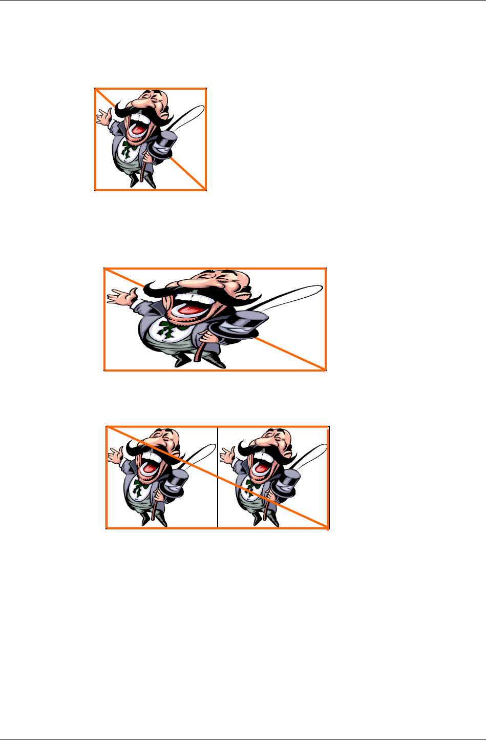
Textures & Rasters
RenderWare Graphics 3.7 I-133
This Texture Space is mapped onto polygons during rendering by mapping
the Texture's own U and V coordinates to those linked to each Material
and/or Vertex. Thus, rendering the Texture with the U and V coordinates
shown below would result in the Texture being drawn actual size:
But you can use the U and V mapping to stretch or shrink the Texture in
one or two axes, or even to tile it or produce mirrored reflections of it
depending on the Addressing Mode. The diagrams below show some options
available:
Here, the Texture is stretched across a wide polygon (built using two
triangles). Stretching is simply a matter of stretching the polygons while
retaining the same U/V mapping.
This is the same texture rendered using a tiled addressing mode called
"rwTEXTUREADDRESSWRAP". Note the right-most U coordinates are set to 2,
which is exactly twice the size of Texture Space, hence the Texture is
repeated exactly once.
(0,0) (1,0)
(1,1) (0,1)
(0,0) (1,0)
(1,1) (0,1)
(0,0) (2,0)
(2,1) (0,1)

Chapter 6 - Rasters, Images and Textures
I-134 11 February 2004
Other addressing modes let you modify this tiling behavior. For instance, if
the addressing mode were set to rwTEXTUREADDRESSMIRROR, the result
might look like this:
☛ You can use the texadrss example to experiment with different addressing modes and see
their effects.
The full list of addressing modes is listed in the Addressing Modes section,
below.
Mipmaps
These are simply individual bitmaps, which are used to make up a texture.
In RenderWare Graphics' case, all mipmaps for a particular Texture object
are stored in a single Raster.
The purpose of mipmaps is to allow a Texture to use different bitmaps
according to its distance from the virtual camera. This technique allows
smaller, less-detailed bitmaps to be used when a model – and, hence, its
Textures – are a long way from the camera.
Mipmaps are divided into MIP levels. Level 0 is the default and is always
present in a Raster, which means that it is also always present in a
Texture. Level 0 is usually the largest of the bitmaps with each additional
MIP level half the size of the previous one.
Mipmaps are enabled or disabled explicitly on a per-texture basis using the
RwTextureSetMipmapping() function.
During the rendering process, RenderWare Graphics will use the Texture's
Filtering settings to determine which MIP level(s) should be used. These are
detailed below.
Filtering
Filtering is the process used to determine how – and if – the Texture object
selects and displays individual MIP levels.
It is usual for the MIP levels to be blended smoothly from one to the other
across the level threshold rather than simply switching between two states
and the last two Filters listed below can be used to support this where
available.
(0,0) (2,0)
(2,1) (0,1)

Textures & Rasters
RenderWare Graphics 3.7 I-135
FILTER EFFECT
rwFILTERNEAREST No MIP mapping.
Point-sampled textures.
rwFILTERLINEAR No MIP mapping. Bilinear interpolated
textures.
rwFILTERMIPNEAREST Point-sampled MIP mapped textures.
Individual mipmaps are drawn using
point-sampling and will simply flip
from one image to the next as the level
changes over distance.
rwFILTERMIPLINEAR Bilinear interpolated MIP mapped
textures. Mipmaps are drawn using
bilinear interpolation. They still flip
from one image to the next as the level
changes over distance.
rwFILTERLINEARMIPNEAREST Mipmaps are interpolated between
levels so giving a smooth blend from
step to step rather than simply flipping
from one image to the next at the
threshold.
Mipmaps are drawn using point-
sampling.
rwFILTERLINEARMIPLINEAR Tri-linear interpolated textures.
Interpolation works in three
dimensions, running through U, V and
MIP level axes.
Gives the best visual results but can be
expensive on some hardware.
The first two of these Filter types are for Textures that are not MIP mapped
and therefore only have their MIP-level 0 bitmap defined. The remaining
Filter types are mipmap blend modes, listed in order of complexity and
visual quality, from least to best.
An ideal world would have every Texture mapped using the best quality
Filtering – in this case, tri-linear interpolation. But this Filter can require a
lot of processing power, so you will need to balance your mix of Filter
modes.
☛ SDK-Examples: "MIPMAP"
This Example demonstrates mipmap filters available on your platform.
✎
✎✎
✎ Some filters may be unsupported on certain platforms. Attempting to use unsupported
Filters may result in an error condition being returned from the
RwTextureSetFilterMode() function.
Addressing Modes
Addressing modes define the process used to determine a particular texel
color. These modes define how the indexing along the texture map's U and
V axes behaves when the edge of the texture map is reached.

Chapter 6 - Rasters, Images and Textures
I-136 11 February 2004
The addressing modes defined by RenderWare Graphics are:
ADDRESSING MODE EFFECT
rwTEXTUREADDRESSWRAP This mode is the default. When the edge
of a texture map is reached, RenderWare
Graphics wraps back to the opposite
edge. The result is that the texture map
is tiled.
rwTEXTUREADDRESSMIRROR This is similar to the default mode except
that alternate tiles are mirror images of
the original.
rwTEXTUREADDRESSCLAMP This mode clamps the U and V indices at
the edges so that the edge-most pixel is
repeated across the remainder of the
surface. It is sometimes used for one-off
decals.
rwTEXTUREADDRESSBORDER This mode is similar to the Clamp mode.
However, this mode applies the
BORDERCOLOR Render State color to
the polygon where the U and V indices
fall outside the bitmap's range.
☛ examples\texadrss
This Example demonstrates all the Addressing Modes available on your platform.
Addressing Modes can be varied by U/V axis. There are three API functions
available to set the Addressing Mode for a Texture:
RwTextureSetAddressing() applies an Addressing Mode across both U
and V axes so that behavior in both directions is the same. The appropriate
property interrogator is RwTextureGetAddressing().
RwTextureSetAddressingU() applies an Addressing Mode across the U
axis only. The appropriate property interrogator is
RwTextureGetAddressingU().
RwTextureSetAddressingV() applies an Addressing Mode across the V
axis only. The appropriate property interrogator is
RwTextureGetAddressingV().
✎
✎✎
✎ A couple of important notes:
Firstly, if you are using different Addressing Modes across each axis, the
RwTextureGetAddressing() function will return rwTEXTUREADDRESSNATEXTUREADDRESS.
Secondly, some Addressing Modes may be unsupported on particular platforms and will
cause RwTextureSetAddressing(), RwTextureSetAddressingU() and
RwTextureSetAddressingV() to return an error condition.
6.5.2 Loading Textures
Textures are loaded using the RwTextureRead() function.

Textures & Rasters
RenderWare Graphics 3.7 I-137
This function makes use of the RwImage API, so you must register any
image file format readers with RwImageRegisterImageFormat() before
attempting to load Textures.
It is important to note that RwTextureRead() will also perform some
additional operations:
• A search is made in the default Texture Dictionary (RwTexDictionary)
for an existing Texture with the same filename stored in its "name"
property. If no such Texture is found, the function attempts to load it as
expected. However, if a matching Texture is located, the function simply
returns a pointer to this Texture.
• On the first attempt to read a Texture, the function will, if the data was
read successfully, store the filename in the Texture's "name" property.
• The function also adds the Texture to the default Texture Dictionary if it
is not already in there.
That last point is important: it means Textures will only ever be loaded
once, unless you explicitly change the Texture's "name" property.
Texture Dictionaries are covered a little later on.
✎
Platform Specific Information
RenderWare Graphics uses the platform's conventions for pixel and texel
centers. These may vary per platform. For an example, look at the
imshadow example.
Mipmap Generation
During the load process, mipmaps can be generated automatically or
additional mipmaps images can be read and added to the Texture. The first
step is to tell RenderWare Graphics whether we want mipmaps generated at
all. This is done through a call to RwTextureSetMipmapping().
If you want mipmaps to be generated for your Textures, you need to call
RwTextureSetAutoMipmapping(). This lets you choose:
1. To let RenderWare Graphics generate all mipmaps levels automatically
from a single bitmap loaded from disk.
Call RwTextureRead() with the filename of the bitmap to load.
RenderWare Graphics will then generate the MIP-levels itself by re-
sampling the original image as required for each level.
2. To load all the individual mipmaps directly from disk.
Individual images are named something like: "image_m?.ext", where
"image" is the name of your image, "?" is a number between 1 and 9
inclusive and "ext" is the three-letter extension of the image file format
used.

Chapter 6 - Rasters, Images and Textures
I-138 11 February 2004
☛ The Third Way: Generating mipmaps yourself
This system can be overridden by supplying the
RwTextureSetMipmapGenerationCallBack() function with a pointer to a function that
will be called to generate each MIP layer. (See the API Reference for the callback's
prototype.)
Your callback function will be given a pointer to the destination Raster and the source
Image: what it does with them is up to you.
This naming system is restricted by the ISO 9660 filename convention. ISO
9660 dictates an 8.3 format, which limits image filenames to a maximum of
five useful characters on most platforms.
✎
✎✎
✎ RwTextureSetMipmapping() and RwTextureSetAutoMipmapping() affect only the
loading of Textures using the RwTextureRead() functionality. These settings will have no
effect whatsoever on automatic Texture loading by Clumps, Worlds and other RenderWare
Graphics objects.
Accessing mipmaps
Individual mipmaps can be accessed at the Raster level using the RwRaster
API's RwRasterLock() and RwRasterUnlock() functions, as well as their
palette equivalents. These were described in more detail in the section on
Rasters.
6.5.3 Texture Dictionaries
It is often convenient to group Textures together using some form of simple
database to make it easier to manage them. For this purpose, RenderWare
Graphics provides the Texture Dictionary (RwTexDictionary) object.
Texture Dictionaries are collections of Textures. The Textures are indexed
via their "name" property. (API functions: RwTextureGetName() to retrieve;
RwTextureSetName() to set.)
Names are associated with both Textures and their Masks and, to keep
object sizes constant, names are limited to a maximum of thirty-two
characters in length.
✎
✎✎
✎ The 32-character limit for Texture names may appear to contradict the earlier point about
the ISO-9660 filename convention.
In fact, Texture names are not directly linked to filenames and can therefore provide a
more convenient means of accessing Textures. You can use the RwTextureSetName(),
RwTextureGetName() and the two Mask name equivalents; RwTextureSetMaskName()
and RwTextureGetMaskName(), to manipulate and change Texture names directly.

Textures & Rasters
RenderWare Graphics 3.7 I-139
Streaming Texture Dictionaries
In the section about loading Textures, RenderWare Graphics automatically
maintains a default Texture Dictionary (RwTexDictionary) object was
mentioned. This prevents RenderWare Graphics from making unnecessary
reads from a disk or CD as it can check to see if the Texture is already
loaded and just return a pointer to that if so.
Reading a Texture Dictionary from a binary stream is a very quick way of
getting all Textures and Rasters into memory. It eliminates the need to load
each individual Texture from its own file and perform the conversion of the
bitmap from an Image to a device-dependent Raster.
If textures are being loaded individually, the time needed to locate and read
each one from the storage media—usually a CD or DVD disk—the seek time
alone slows the loading process down dramatically.
Generation of mipmaps can be particularly expensive on CPU time and
system resources, so it should be kept to a minimum. This is why the
Texture Dictionary mechanism was created: you can create them just once
for a particular platform, store all the Textures into a Texture Dictionary
object, and then stream the object out for re-use in your application.
☛ examples\texdict
This SDK example exercises the Texture Dictionary API and shows how to construct, write
and then read a Texture Dictionary.
It can be found in the examples folder.
6.5.4 Using Texture Dictionaries
When you write a Texture Dictionary to a binary stream, the result is a file
containing all your Textures with their associated Rasters ready for use.
The API functions to use Texture Dictionaries with RenderWare Graphics
Binary Streams are the standard three:
RwTexDictionaryStreamGetSize(), RwTexDictionaryStreamRead() and
RwTexDictionaryStreamWrite().
Using Texture Dictionaries
It is possible to create your own Texture Dictionaries rather than using the
default one created by RenderWare Graphics. This lets you have, for
example, a separate Texture Dictionary for each level in a game. Multiple
Texture Dictionaries can also be loaded into memory.
To get a pointer to the active Texture Dictionary, use
RwTexDictionaryGetCurrent(). Which can also access the default
database created by RenderWare Graphics.

Chapter 6 - Rasters, Images and Textures
I-140 11 February 2004
To set the current active database RwTexDictionarySetCurrent()
function needs to be called. Pass NULL if you do not want RenderWare
Graphics to use a Texture Dictionary at all. (This can also be used to
disable the default database created by RenderWare Graphics.)
✎
✎✎
✎ Platform dependent texture dictionaries for PS2, Xbox and GCN can be generated on the
PC using nullsky, nullxbox or nullgcn libraries. They do not have to be generated on
the target platform.
Other API features are:
• Adding and removing Textures from the database is achieved through
the RwTexDictionaryAddTexture() and
RwTexDictionaryRemoveTexture() functions.
• To locate a Texture in the database by name, use
RwTexDictionaryFindNamedTexture().
• An iterator function, RwTexDictionaryForAllTextures(), uses the
standard RenderWare Graphics callback mechanism to give you access
to all Textures within the Texture Dictionary.
6.5.5 Platform independent texture dictionaries
The convenience of platform specific (PS) texture dictionaries to improve
texture load performance has been explored in the previous sections.
However, since RenderWare Graphics is a multi-platform solution, it may
be that original artwork needs to exist for multiple platforms. For a final
product, it makes sense to create PS texture dictionaries, but during
development, a single set of artwork, compatible across all targeted
platforms would be of more use. Platform independent (PI) texture
dictionaries provide a solution.
The API functions to use PI texture dictionaries with RenderWare Graphics
Binary Streams are the standard three:
RtPITexDictionaryStreamGetSize(),
RtPITexDictionaryStreamRead() and
RtPITexDictionaryStreamWrite().
These are exposed in the RtPITexD toolkit.
6.5.6 Using PI texture dictionaries
Whereas PS texture dictionaries save RwTexture data, PI texture
dictionaries save RwImage data along with some texture addressing and
filtering flags.
In order to stream out a PI texture dictionary, a PS texture dictionary
should exist in memory.

Textures & Rasters
RenderWare Graphics 3.7 I-141
All mip levels of every texture in the PS texture dictionary is streamed as a
separate RwImage in the PI texture dictionary. This avoids the need to
regenerate mip levels when the PI texture dictionary is streamed back in.
There is support for platforms that can automatically generate all required
mip levels, in hardware, from a top-level mip. This support is enabled when
a texture in the PI texture dictionary contains a single mip level but with a
mipped filter mode. The texture’s raster is flagged to automatically generate
the remaining mip levels. Note that on platforms that do not support
hardware mip generation, the remaining mip levels will be created by
RenderWare Graphics.
Gamma correction is also removed when a PI texture is written, and
reapplied when it is read, to avoid cumulative gamma corrections.
In addition, any plugin extension data associated with each RwTexture is
also streamed with the PI texture dictionary.
When a PI texture dictionary is streamed in, a PS texture dictionary is
created that can subsequently be used on the target platform.
6.5.7 Non-fixed hardware issues with texture
dictionaries
For non-fixed hardware platforms that RenderWare Graphics’ supports,
such as PC and Macintosh, platform specific texture dictionaries may not
be the best method of distributing final artwork with a product.
This is because the format of the platform specific textures will nearly
always be dependent on the capabilities of the video card on which the
product is being used on, which can significantly vary from one computer
to another.
Hence, one solution is to distribute platform independent texture
dictionaries (and possibly other associated source artwork) and generate
platform specific versions at application specified times. For example, this
may be at installation time, load time, or when the user changes some
video settings. The application should be aware of what situations require a
rebuild of the PS texture dictionary.
6.5.8 Textures & Binary Streams
While Textures can be read directly from disk or stored in Texture
Dictionaries, they can also be streamed to and from RenderWare Graphics
Binary Streams.
Once opened using the standard RwStream API the
RwTextureStreamRead() and RwTextureStreamWrite() functions can be
used to read and write Texture objects to the stream.

Chapter 6 - Rasters, Images and Textures
I-142 11 February 2004
It is important to note that Textures are not serialized with their Raster
data. Instead, writing a Texture object results in a data stream containing
the Texture's settings and properties along with the filename from which
the Texture's Raster was created. Therefore a reference to the filenames
needs to be made by opening each one using the Image object API and
performing the conversion into a Raster for the Texture to use.
Because of this, most developers will prefer to use the Texture Dictionary
mechanism as it provides a much neater way of performing this task.

Chapter 7
Immediate Mode

Chapter 7 - Immediate Mode
I-144 11 February 2004
7.1 Introduction
Immediate Mode contains 2D and 3D graphics functionality. The API
functions can be found in the Core Library. There are two Immediate Mode
APIs RwIm2D and RwIm3D. They provide low-level control over the underlying
hardware through a multi-platform API.
A quick glance at the API Reference reveals that both the Immediate Mode
APIs are based around the rapid manipulation and rendering of primitives.
Primitives are built up of lines or filled triangles. All other polygons are built
up of combinations of triangles. The line-drawing features are typically
used for very specialized effects, such as wire frame rendering or GUI
features.
7.1.1 Properties & Render States
Before Immediate Mode features are looked at in more detail, there are
some very important points to note that apply to both these 2D and 3D
APIs. In particular, the properties of any and all RenderWare Graphics
primitives are specified and defined by the developer.
These properties include:
• Color
• Position
• Render State
• Texture Coordinates
Colors are specified on a per-vertex basis for most rendering tasks. For
example, a line drawn with a red vertex at the start and a blue vertex at the
end will be drawn with the color blending smoothly from red to blue along
the line.
To position vertices, you need to perform transformation operations on
those vertices. RenderWare Graphics includes RwV2d, RwV3d and RwMatrix
data types as well as the API to manipulate them.
Perhaps the most important property of the two Immediate Modes is the
Render State. The Render State is a collective term for a group of settings
that define how primitives are to be rendered. It is accessed through the
RwRenderStateSet() and RwRenderStateGet() functions. It manages
issues such as texturing, fogging and alpha blending.
The Render State system has its own API and this will be covered in more
detail later in this chapter.

2D Immediate Mode
RenderWare Graphics 3.7 I-145
7.2 2D Immediate Mode
This mode forms the basis of RenderWare Graphics' rendering engine.
There are relatively few functions to grasp because the 2D Immediate Mode
API performs line and triangle rendering. These basic shapes, known as
primitives, form the basis of the Immediate Mode APIs.
Lines and triangles are built up using vertices stored as RwIm2DVertex
objects. The properties of this object will be examined shortly, but first,
fundamental concepts behind 2D Immediate Mode will be covered.
7.2.1 Basic Concepts
Coordinates
RenderWare Graphics' 2D Immediate Mode API works in screen space, also
known as device space. This means that you work directly with display
device coordinates and, in turn, this means the output is resolution and
platform dependent.
The RwIm2DVertex object stores coordinates as RwReal types, making them
floating point values rather than integers. This makes it easier to handle
features, such as anti-aliasing, which require sub-pixel precision in order
to work.
Coordinates can also be defined in terms of the camera space. This is of use
mainly for layering rendered imagery over a previous rendering. (For
example, layering an effect over a model rendered by a Retained Mode
plugin.) Camera Space rendering takes place in a 3D co-ordinate system
with the origin and orientation defined by the current Camera position and
orientation.
✎
✎✎
✎ Rt2d Toolkit
This resolution-dependency is what separates 2D Immediate Mode from the Rt2d Toolkit.
The Rt2d Toolkit provides a higher-level 2D graphics API that is resolution independent. It
also makes heavy use of the 3D graphics facilities in RenderWare Graphics to support a
number of powerful hardware-accelerated features, including rotation, translation and
alpha blending.
Clipping
The 2D Immediate Mode API does not make any attempt at clipping. If you
attempt to draw using invalid coordinates, the results will be undefined and
a crash is quite possible. You should make full use of debug builds when
testing Immediate Mode applications.

Chapter 7 - Immediate Mode
I-146 11 February 2004
Z-Buffers
The output of 2D Immediate Mode can make use of Z-buffers. This lets you
position your 2D renderings along the Z-axis. In theory, a Z-axis is taken to
point 'into' the screen.
However, in practice, hardware implementations of Z-buffers vary greatly
from platform to platform. For instance, some may define the range of Z
coordinates as running between 0 and 1 with values specified in floating
point. Others may use integers running from 0 to –32768.
The upshot of this is that the RenderWare Graphics Z-buffer may work
differently from platform to platform.
Near & Far Z
A common requirement for 2D graphics is the need to place the rendered
imagery at either the closest or furthest point along the Z-axis. These limits
are defined by the underlying hardware, which dictates the resolution of the
Z-buffer.
Two functions are provided to support these requirements:
RwIm2DGetFarScreenZ() and RwIm2DGetNearScreenZ(). These will
return the minimum and maximum possible Z coordinates for the active
Raster as a RwReal value. You should ensure any Z values are clipped to
this range.
Perspective Projection
Camera space is a space with the origin at the camera, looking along the
camera's at vector, with the up vector roughly upwards. This is completely
separate from screen coordinates, which are computed by performing a
perspective projection.
If you have a coordinate in world space, use the camera view matrix to
transform it into camera space. Then, if outx/outy/outz are the elements
of the camera space vertex, project to screen space using:
X = outX * recipZ * W + offX
Y = outY * recipZ * H + offY
Z = recipZ * Z + offZ
where recipZ = 1/outZ, W/H are the width/height of the camera raster,
offX and offY are raster offsets (pull them from the camera's raster) and Z
and offZ are computed from the near/far clip planes. Use
camera->zScale and camera->zShift for Z and offZ respectively.
This is the technique used by the non-hardware T&L version of RenderWare
Graphics.

2D Immediate Mode
RenderWare Graphics 3.7 I-147
Vertices
While the result of working with 2D Immediate Mode is primitives rendered
on a display, your code will actually work directly with vertices, so let's take
a look at these now.
The vertex is the main data type for RenderWare Graphics' Immediate Mode
APIs. There are two such types, one each for 2D and 3D Modes.
The 2D Immediate Mode form is RwIm2DVertex. As with its RwIm3DVertex
counterpart, this data type's physical format is platform-dependent, so you
shouldn't try to access it directly. Instead, the API provides a complete set
of functions to prepare and manipulate the vertex. Note: These functions
are implemented as C Macros in most cases to provide optimum
performance.
7.2.2 Initializing an RwIm2DVertex object
As mentioned earlier, this object is defined in a platform-specific way. This
prevents us from documenting its structure. Initializing such objects is
therefore performed entirely through the API.
An RwIm2DVertex object contains the following properties:
• Red, Green, Blue and Alpha components
• Camera-space coordinates (X, Y and Z)
• Reciprocal of Camera's Z coordinate
• Screen-space coordinates (X, Y and Z)
• U and V coordinates
Setting & Retrieving Coordinates
2D Immediate Mode vertices are usually in screen space and this means
the RwIm2DVertex objects are also known as "device vertices". Since this
vertex object is not exposed as a structure, you need to use the API
functions, RwIm2DVertexSetScreenX(), RwIm2DVertexSetScreenY() and
RwIm2DVertexSetScreenZ(), to set these coordinates programmatically.
These functions have counterparts that can be used to retrieve these same
values: RwIm2DVertexGetScreenX(), RwIm2DVertexGetScreenY() and
RwIm2DVertexGetScreenZ().
It is also possible to specify coordinates in terms of camera space – the
functions are: RwIm2DVertexSetCameraX(), RwIm2DVertexSetCameraY(),
RwIm2DVertexGetCameraX() and RwIm2DVertexGetCameraY().

Chapter 7 - Immediate Mode
I-148 11 February 2004
Reciprocal Camera Z, Texture Coordinates & Platform
Dependence
The underlying platform's hardware has a great impact on the vertex object.
Often, the RwIm2DVertex (and its 3D Immediate Mode counterpart) are
simply wrappers for a hardware-specific data type.
This means that even the format of the colors can change. For instance,
some platforms require colors to be specified in floating point form while
others prefer integer values. This is why, if you look at the API Reference
entries for the two Immediate Mode APIs, you'll find color setting functions
that accept both formats. This gives you the option of either sticking to one
color format – the functions will convert where necessary – or changing the
format from platform to platform if you prefer that level of control.
In order for some rendering techniques, including Gouraud shading and
perspective-correct texture mapping, to work correctly, you may need to
specify the reciprocal camera-space Z coordinate of a vector and/or the
actual camera-space Z coordinate itself.
This is an important facet of Immediate Mode programming: some functions
simply don't exist on some platforms; on others, different functions may be
required to achieve the same effects.
In the case of the reciprocal of Camera Z, the function (if available) to
obtain this is RwIm2DVertexGetRecipCameraZ(). (There is an equivalent
RwIm2DVertexSetRecipCameraZ() function too if the former is available.)
The reciprocal camera Z value is generally required to enforce perspective-
correct texture mapping. Texture coordinates can therefore also be specified
if your primitive(s) are to be so rendered. Currently, the vertex object will
only support one texture – multi-texturing is planned – so setting the U and
V coordinates is a matter of calling the appropriate RwIm2DVertexSetU()
and RwIm2DVertexSetV() functions respectively.
✎
✎✎
✎ The API Reference is rebuilt specifically for each platform so it will only contain the
relevant platform-specific entries. Other platforms have different builds of the API
Reference with different platform-specific entries as appropriate.

2D Immediate Mode
RenderWare Graphics 3.7 I-149
7.2.3 Primitives
RenderWare Graphics supports two major types of primitive: Lines and
Triangles. These are in turn split into subtypes. Lines are split into line lists
and poly-lines.
Line Lists
These are lists of vertex pairs defining the start and endpoints of lines. This
data format is ideal for rendering groups of unconnected lines.
Poly-lines
This is a list consisting of one start point, followed by any number of
endpoints. The Immediate Mode rendering engine will start at the first
point, draw a line to the first endpoint and draw another from the end of
that line to the next endpoint in the list. This primitive is ideal for
sequences of connected lines.
Except for the first line, the poly-line primitive type does not require two
vertices to be processed per line. This means it needs the least data to work
and is therefore the most efficient of the line primitives. If possible, use this
primitive type when working with lines.
✎
✎✎
✎ Rendering individual lines can be done using RwIm2DRenderLine(). This function allows
you to draw individual lines between arbitrary vertices. (See the API Reference for more
details.)
It should be noted, however, that drawing individual lines in this way is not recommended
as it can be slow.
RenderWare Graphics also supports a number of triangle primitives:
Triangle Lists ("Tri-List")
These are similar to the Line Lists mentioned earlier. They consist of triplets
of vertices defining individual triangles. This implies that triangles in a tri-
list are entirely independent of each other.
Triangle Strips ("Tri-Strip")
These define strips of adjacent triangles, each sharing an edge with
another. This form requires fewer vertices than the Triangle Lists type as,
after the first triangle is defined, only one additional vertex is needed to
define each subsequent triangle. This has significant performance benefits
on most platforms.
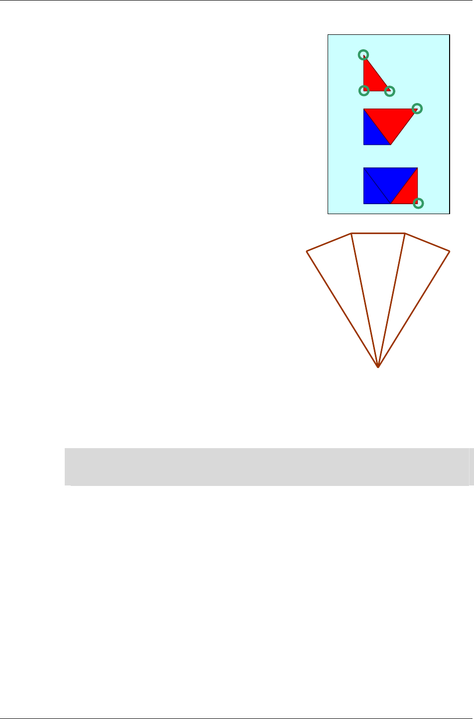
Chapter 7 - Immediate Mode
I-150 11 February 2004
The diagram to the right demonstrates the advantage of tri-strips. Once the
first three vertices (shown as rings in the
diagram) have defined the first triangle, only
one additional vertex is required to add each
new triangle to the strip.
In the diagram, the second step shows a fourth
vertex defining the second triangle (shown in
red) and in the third step, we have just five
vertices defining three triangles.
Obviously, this format is more efficient as you
add more triangles.
Triangle Fans ("Tri-fan")
These are similar in concept to triangle
strips, relying on contiguous triangles to
reduce the number of vertices that need to
moved around and processed.
As you can see from the example to the
right, a triangle fan requires that all
triangles share a vertex and are
contiguous. This form has much the same
advantages as triangle strips.
Both the strip and fan forms are popular with transform and lighting
processing hardware, so RenderWare Graphics is biased somewhat in their
favor on most supported platforms.
✎
✎✎
✎ The triangle fan and triangle strip primitives are not built on the fly by RenderWare
Graphics' rendering engine. The RenderWare Graphics modeler exporter plugins allow you
to export geometry optimized for triangle strips and/or fans.
7.2.4 Triangle Winding Order
Throughout RenderWare Graphics, the ordering of the vertices defining a
triangle – the winding order – also define its visibility. RenderWare
Graphics' use of a right-handed coordinate system means triangles with
vertices defined in clockwise order (relative to the camera) have a normal
pointing away from the camera and are therefore not visible, so they will
not be drawn.
In summary: visible Triangles must have vertices defined in anti-clockwise
order, relative to the camera, as the normal to the Triangle is pointing
towards the camera.

2D Immediate Mode
RenderWare Graphics 3.7 I-151
7.2.5 Primitives vs. Indexed Primitives
2D Immediate Mode can work directly with arrays of primitives, which are
in any case just arrays of vertices. It can also work with arrays of indices to
such arrays of vertices. This second technique is particularly important as
it opens up more efficient use of system memory. In particular, it lets you
re-use vertices rather than having define duplicates.
The SDK includes a number of Examples, including the im2d Example.
This illustrates 2D Immediate Mode by rendering a number of different
primitives, including indexed and non-indexed forms.

Chapter 7 - Immediate Mode
I-152 11 February 2004
7.2.6 Example 1: Rendering A Line.
This code fragment renders a single, simple, opaque red line:
RwIm2DVertex vertex[2];
// Set up the vertices...
RwIm2DVertexSetScreenX(&vertex[0], 20.0f );
RwIm2DVertexSetScreenY(&vertex[0], 20.0f );
RwIm2DVertexSetScreenZ(&vertex[0], 3276.0f );
RwIm2DVertexSetRecipCameraZ(&vertex[0], (1.0f/6.0f) );
RwIm2DVertexSetScreenX(&vertex[1], 620.0f );
RwIm2DVertexSetScreenY(&vertex[1], 460.0f );
RwIm2DVertexSetScreenZ(&vertex[1], 3276.0f );
RwIm2DVertexSetRecipCameraZ(&vertex[1], 1.0f/6.0f );
// Opaque red...
RwIm2DVertexSetIntRGBA(&vertex[0], 255, 0, 0, 255);
// ...and the same for the second vertex.
RwIm2DVertexSetIntRGBA(&vertex[1], 255, 0, 0, 255);
// Texturing off...
RwRenderStateSet(rwRENDERSTATETEXTURERASTER, NULL);
// Flat shading on...
RwRenderStateSet(rwRENDERSTATESHADEMODE, (void
*)rwSHADEMODEFLAT);
// Alpha-transparency off...
RwRenderStateSet(rwRENDERSTATEVERTEXALPHAENABLE, (void
*)FALSE);
//Render line...
RwIm2DRenderLine(vertex, 2, 0, 1);
✎
✎✎
✎ Release Builds
There appear to be a lot of function calls involved in this code, but the overhead is not as
bad as it first appears.
The RenderWare Graphics libraries are supplied in three builds: Release, Metrics and
Debug.
Release builds redefine many trivial functions as macros. The upshot is that almost all
property setting and access functions, such as those above, are inlined.

2D Immediate Mode
RenderWare Graphics 3.7 I-153
Example 2: Rendering A Triangle.
This code fragment renders a simple, yellow, flat shaded triangle:
RwIm2DVertex vertex[3];
//Set up the vertices...
RwIm2DVertexSetScreenX(&vertex[0], 20.0f );
RwIm2DVertexSetScreenY(&vertex[0], 20.0f );
RwIm2DVertexSetScreenZ(&vertex[0], 3276.0f );
RwIm2DVertexSetRecipCameraZ(&vertex[0], (1.0f/6.0f) );
RwIm2DVertexSetScreenX(&vertex[1], 20.0f );
RwIm2DVertexSetScreenY(&vertex[1], 40.0f );
RwIm2DVertexSetScreenZ(&vertex[1], 3276.0f );
RwIm2DVertexSetRecipCameraZ(&vertex[1], (1.0f/6.0f) );
RwIm2DVertexSetScreenX(&vertex[2], 40.0f );
RwIm2DVertexSetScreenY(&vertex[2], 40.0f );
RwIm2DVertexSetScreenZ(&vertex[2], 3276.0f );
RwIm2DVertexSetRecipCameraZ(&vertex[2], (1.0f/6.0f) );
// Opaque yellow...
RwIm2DVertexSetIntRGBA(&vertex[0], 255, 255, 0, 255);
// Opaque yellow...
RwIm2DVertexSetIntRGBA(&vertex[1], 255, 255, 0, 255);
// ...and, once again, opaque yellow...
RwIm2DVertexSetIntRGBA(&vertex[2], 255, 255, 0, 255);
// Texturing off...
RwRenderStateSet(rwRENDERSTATETEXTURERASTER, NULL);
// Flat shading mode...
RwRenderStateSet(rwRENDERSTATESHADEMODE, (void
*)rwSHADEMODEFLAT);
// Alpha-transparency off...
RwRenderStateSet(rwRENDERSTATEVERTEXALPHAENABLE, (void
*)FALSE);
// Render triangle...
RwIm2DRenderTriangle(vertex, 3, 0, 1, 2);
As you can see from the examples above, there is an overhead involved in
setting up the RenderState data. Because of this, it makes sense to group
all your primitives by RenderState to speed up the rendering process.

Chapter 7 - Immediate Mode
I-154 11 February 2004
7.3 3D Immediate Mode
3D Immediate Mode provides low-level 3D rendering facilities. It is designed
around the same concepts as its 2D counterpart, including the concepts of
vertex lists, index lists and primitives. In addition, it makes heavy use of
RenderWare Graphics' Render State API to control the rendering process.
7.3.1 Preparation for Rendering
Vertices & Indices
3D Immediate Mode has its own vertex object: RwIm3DVertex. This holds
coordinates defined using either world space (also known as 'scene space'),
or in object space. This distinction is covered in more detail later.
As with the 2D Immediate Mode's own vertex object, RwIm3DVertex is also
an opaque, platform-dependent type. Access is entirely through the API.
In fact, there isn't all that much to say about the 3D vertex object: aside
from the extra dimension, it's relatively straightforward and the API is
similar to that for 2D Immediate Mode's own RwIm2DVertex object.
Where the 3D Immediate Mode API does differ slightly from the 2D one is
that setting coordinates is done through a single function call:
RwIm3DVertexSetPos(). This takes the X, Y and Z coordinates as well as a
pointer to the RwIm3DVertex where they are to be stored. A retrieval
function, RwIm3DVertexGetPos(), is also provided.
As with the 2D Immediate Mode, 3D Immediate Mode expects vertices to be
stored in arrays. These arrays can be referenced either directly or using an
index array. The latter has the expected advantage of requiring fewer
vertices, but can cause problems if your model geometry is to be adjusted
in real-time.
✎
✎✎
✎ Unlike its 2D counterpart, the 3D Immediate Mode API provides clipping.
Transforming Space
To determine how a particular vertex maps to the display device, the 3D
Immediate Mode API provides a function that takes an array of 3D vertices
and transforms them to camera space (which is much the same thing as
device space).
The function that performs this feat is the RwIm3DTransform() function.
This takes four parameters, the third of which is an optional parameter
specifying an additional transformation matrix to be applied.
This transformation matrix should be set when working with vertex arrays,
which use object space. The matrix will be used to map the object to world
space and then to camera/device space.

3D Immediate Mode
RenderWare Graphics 3.7 I-155
The RwIm3DTransform() function normally produces two new arrays, one
of camera space vertices and – for those vertices that lie within the camera
frustum – an array of device space (device-dependent) vertices.
Access to these intermediate data representations should be performed very
carefully. They are platform-dependent, some hardware accelerators may
store these new arrays in strange formats – or even not at all.
Additional Vertex Properties
As well as the usual three coordinates, each 3D Immediate Mode vertex can
store RGBA values. These are set using the RwIm3DVertexSetRGBA()
function. (The function accepts 8-bit unsigned integers, so floating point
RGBA formats will need to be converted first.)
The remaining two properties are U and V coordinates for texturing. The
functions for setting these are RwIm3DVertexSetU() and
RwIm3DVertexSetV() respectively. Both functions take an RwReal value for
the texture coordinates.
☛ The 'impick' Example
This example lets you pick and drag vertices in wireframe 3D Immediate Mode models.
The commented code therefore illustrates a wide variety of Immediate Mode programming
techniques.
Lighting
Lights are not supported in 3D Immediate Mode. You can simulate them by
manipulating the vertex colors in accordance with a custom lighting model.
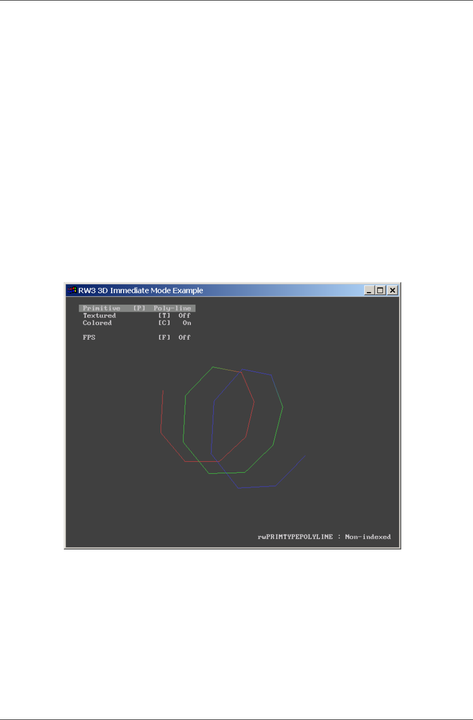
Chapter 7 - Immediate Mode
I-156 11 February 2004
7.3.2 Rendering
Rendering in 3D Immediate Mode requires following this sequence:
1. Transform the primitives into camera space
2. Perform any rendering with the primitives
3. Terminate pipeline execution
The primitives supported by 3D Immediate Mode are simply extensions of
those found in the 2D mode: line lists, polylines, triangle lists, triangle
strips and triangle fans. Again, the same trade-offs apply.
The screenshots below illustrate some of the primitives in action. All are
from the im3d Example.
This first shot is the polyline form in action. (The code used to display this
is contained within the polyline.c source file.)
The next shot shows the triangle list primitive. (The code that exercises this
primitive can be found in trilist.c.)

3D Immediate Mode
RenderWare Graphics 3.7 I-157
We recommend you take a look through and modify the code that makes up
this Example as it illustrates the salient features of this particular API.
Render States
3D Immediate Mode rendering makes heavy use of render state settings.
More on these in 7.4 Render States. As with the 2D Immediate Mode API,
the most efficient way to handle render states is to group primitives with
the same state and render them in batches, switching render states
between each batch.
Rendering primitives
Two rendering functions are available for this: RwIm3DRenderPrimitive(),
which renders non-indexed primitive types, and its counterpart
RwIm3DRenderIndexedPrimitive(), which renders indexed ones.
For instance, the following line…
RwIm3DRenderIndexedPrimitive(rwPRIMTYPETRILIST, myIndices, 8);
…would be used to render an indexed triangle list. The relevant array
indices are stored in the myIndices array, and there are 8 such indices to
render.
✎
✎✎
✎ Remember that the RwIm3DTransform() function has already taken this array and
transformed it into camera-space vertices. The PowerPipe Transform node caches these
internally. It is these converted vertices that are referenced during any rendering.
If your target platform allows it, it may be possible to access these converted vertex arrays
using RenderWare Graphics' platform-specific API. The exact functionality available will
likely vary from platform to platform.

Chapter 7 - Immediate Mode
I-158 11 February 2004
7.3.3 Closing the pipeline
Once rendering of your array of primitives is complete, you must call
RwIm3DEnd() to close and flush the rendering pipeline.
7.3.4 3D Immediate Mode & PowerPipe
3D Immediate Mode rendering makes use of RenderWare Graphics'
PowerPipe rendering technology. When you transform an array of vertices
with RwIm3DTransform(), you are actually firing up PowerPipe and calling
its default pipeline.
✎
✎✎
✎ Many of our platforms are provided only with generic transform and render nodes. These
nodes do not support all of the primitives. For instance, the generic transform node will
expand triangle fans into ordinary triangle lists.
The transform node also does not support unindexed primitives and will create indices for
them, so you should use indexed rendering wherever possible.
However, all PowerPipe nodes can be overridden by your own, so two functions are
provided to give you direct access to the Transform and Rendering nodes. They are,
respectively, RwIm3DGetTransformPipeline() and RwIm3DGetRenderPipeline().
Should you wish to revert to the generic nodes, you can obtain pointers to the generic
transform and render nodes using RwIm3DGetGenericTransformPipeline() and
RwIm3DgetGenericRenderPipeline().
On platforms that support Transform & Lighting in hardware, overloading the generic node
will cause a software pipeline to be used. This will have a negative impact on performance
so you may need to write your own hardware T&L node.
Once the pipeline is fired up, it transforms and renders the supplied
vertices.
It's important to understand that the only way to transform some more
vertices at this stage is to close down the pipeline using RwIm3DEnd() and
restart it with RwIm3DTransform(). This is not the obstacle it appears, as
you will usually render batches of primitives sorted by Render State
anyway. It is not possible to nest Transform/End sequences.
As you can see, efficient management of this process is the key to getting
maximum performance out of RenderWare Graphics' 3D Immediate Mode.
Uses for 3D Immediate Mode
RenderWare Graphics provides a very rich Retained Mode API, which would
lead many to suspect 3D Immediate Mode of being of relatively little use.
Nothing could be further from the truth!
3D Immediate Mode is ideally suited to the rendering of program-generated
data. For example, particle system explosions and other scenery effects are
often added to a scene using this API.
Other techniques include producing pseudo-3D imagery, such as that seen
in some real-time strategy games. (Although produced long before
RenderWare Graphics was released, Cavedog's "Total Annihilation" series is
a good example of pseudo-3D.)

3D Immediate Mode
RenderWare Graphics 3.7 I-159
An important use is for rendering of scientific data or mathematical models
that don't map easily to traditional modeling paradigms. One of our
developers has taken advantage of this aspect of 3D Immediate Mode to
create a groovy multicolor lava lamp simulator using a marching cube
algorithm.
7.3.5 Platform Specific Information
Some platforms do their vertex transforms in hardware and cannot provide
access to the transformed vertices. You should refer to the platform-specific
documentation to see what functionality is available in this regard.
Similarly, texture coordinates may have restrictions imposed by their
underlying hardware. Again, you should refer to the platform-specific
documentation to see if this applies to your target platform.

Chapter 7 - Immediate Mode
I-160 11 February 2004
7.3.6 Camera-space and Z-buffer depth equations
The mapping functions that convert from camera space to screen depth
space are provided here for information:
Perspective Camera:
()
z
R
Rz
RR
ZZ
ZzZ max
min
minmax
minmax
min
)( −
−
−
+=
Parallel Camera:
()
min
minmax
minmax
min
)( Rz
RR
ZZ
ZzZ −
−
−
+=
Where:
• Z(z) is the Z-buffer value corresponding to a camera space z-coordinate z.
• Zmax, Zmin are the maximum and minimum Z-buffer values, respectively.
They correspond to the Z-buffer values given by Z(Rmax) and Z(Rmin). Their
values may be queried using the API functions
RwIm2DGetFarScreenZ() and RwIm2DGetNearScreenZ().
• Rmin, Rmax are the distances to the far and near clip planes, respectively.
Their values may be queried using the API functions
RwCameraGetFarClipPlane() and RwCameraGetNearClipPlane().

3D Immediate Mode
RenderWare Graphics 3.7 I-161
7.3.7 Rt2D
This Toolkit provides a 2D graphics API. Its power is such that it could
justifiably be considered a kind of Retained Mode API for 2D graphics.
Unlike 2D Immediate Mode, which deals solely with the most basic
rendering chores, the 2D Toolkit also supports features such as resolution-
independence, scaleable fonts, paths, textured polygons, anti-aliasing,
alpha blending effects, free rotation and scaling, clipping, rendering to any
arbitrary Camera object, and more.
Its power is derived from RenderWare Graphics' 3D graphics capabilities.
This means it can make full use of any 3D graphics acceleration hardware
to produce great 2D imagery.
So why use 2D Immediate Mode?
2D Immediate Mode is a thin API. This makes it much better suited to fast,
simple 2D operations of the type often required to create a user interface.
Icons, debugging messages, quick bitmap font routines, side-panels, simple
sprites and so forth are generally easier to produce using the 2D Immediate
Mode API.

Chapter 7 - Immediate Mode
I-162 11 February 2004
7.4 Render States
Briefly, the Render State object is a basic state machine. It is an opaque
object, with two API functions provided to access its properties:
RwRenderStateSet() and RwRenderStateGet().
7.4.1 Key Features
• Render States are a shared hardware resource.
There is only one Render State structure and it is shared throughout
RenderWare Graphics. Therefore, 2D Immediate Mode shares this with
both the 2D and 3D Retained Mode APIs – Rt2D and RpWorld,
respectively.
• There is no multi-platform default setting for the Render State
structure.
This is because some platforms may not support all the Render State
settings, or support them in different ways. Instead, the default setting
for the Render State varies from platform to platform.
• The application is responsible for ensuring any required state(s) are set
correctly.
Some high-level portions of the RenderWare Graphics API, such as
RpWorld, may change the Render State settings if they need to. You
should not assume that a particular Render State has been left
untouched by, say, a call to RpWorldRender().
• Some Render State settings are unsupported on certain platforms.
RenderWare Graphics does not provide any software emulation as such,
so if a platform does not support a particular Render State feature,
setting it will have no effect.
7.4.2 API
The Render State API (RwRenderState) differs from most other APIs in that
there is only one Set/Get pair of functions. They are RwRenderStateSet()
and RwRenderStateGet() respectively.
Both functions take two parameters: an enumerated type and a void
pointer. The enum or 'render state specifier' determines which render state
the function is to set or get. The void pointer holds the data. So the void
pointer is used as an arbitrary 32-bit value whose contents depend on the
value of the render state specifier. The programmer is responsible for
checking the type of this parameter as the compiler will not check the type
of void pointers. (Types cast to void in these function calls include
RwRaster *, RwBool, and other enumerated types.)

Render States
RenderWare Graphics 3.7 I-163
Currently, the following render states are supported:
• rwRENDERSTATETEXTURERASTER
Use this render state to set the Raster object to texture with.
For example:
RwRaster * myRaster;
RwRasterCreate( myRaster );
RwRenderStateSet( rwRENDERSTATETEXTURERASTER,
(void *)myRaster);
• rwRENDERSTATETEXTUREADDRESS
Use this render state to tell RenderWare Graphics how to handle the
texture coordinate space. The options are: rwTEXTUREADDRESSWRAP,
rwTEXTUREADDRESSCLAMP, rwTEXTUREADDRESSMIRROR or
rwTEXTUREADDRESSBORDER.
The values to pass as the void pointer are those described in the API
Reference under RwTextureGetAddressing().
This render state will set both U and V handling to the same operation.
The following two enumerated values can be used to set the U and V
spaces individually so you can have different behavior for each:
- rwRENDERSTATETEXTUREADDRESSU,
- rwRENDERSTATETEXTUREADDRESSV,
Example 1: Set both U and V coordinate spaces to Clamp mode:
RwRenderStateSet( rwRENDERSTATETEXTUREADDRESS, (void *)
rwTEXTUREADDRESSCLAMP);
Example 2: Set V coordinate space to Wrap mode:
RwRenderStateSet( rwRENDERSTATETEXTUREADDRESSV, (void *)
rwTEXTUREADDRESSWRAP);
• rwRENDERSTATETEXTUREPERSPECTIVE
Pass TRUE or FALSE in the void pointer. TRUE enables perspective
correction.
• rwRENDERSTATEZTESTENABLE
Pass TRUE or FALSE in the void pointer. TRUE enables Z-buffer tests.
• rwRENDERSTATESHADEMODE
Can be set to either rwSHADEMODEFLAT or rwSHADEMODEGOURAUD.
• rwRENDERSTATEZWRITEENABLE
Pass TRUE or FALSE in the void pointer. TRUE enables Z-buffer writes.

Chapter 7 - Immediate Mode
I-164 11 February 2004
• rwRENDERSTATETEXTUREFILTER
Texture filtering method. The values you can pass are as follows:
- rwFILTERNEAREST,
- rwFILTERLINEAR,
- rwFILTERMIPNEAREST,
- rwFILTERMIPLINEAR,
- rwFILTERLINEARMIPNEAREST,
- rwFILTERLINEARMIPLINEAR
See the Rasters, Images and Textures chapter for more detailed
information on these.
• rwRENDERSTATESRCBLEND
Used to set the source blending factor.
• rwRENDERSTATEDESTBLEND
Used to set the destination blending factor.
• rwRENDERSTATEVERTEXALPHAENABLE
Pass TRUE or FALSE in the void pointer. TRUE enables vertex alpha
transparency.
• rwRENDERSTATEBORDERCOLOR
Border color for texturing with borders. The argument should be RGBA
components packed into an RwRGBA value and cast to a void pointer.
• rwRENDERSTATEFOGENABLE
Pass TRUE or FALSE in the void pointer. TRUE enables fogging effects. (All
polygons rendered from this point on until this is set to FALSE will be
affected.)
• rwRENDERSTATEFOGCOLOR
Color used for fogging. The argument should be RGBA components
packed into an RwRGB value cast to a void pointer.
• rwRENDERSTATEFOGTYPE
Select the type of fogging to use. Valid arguments are:
- rwFOGTYPELINEAR,
- rwFOGTYPEEXPONENTIAL,
- rwFOGTYPEEXPONENTIAL2
The precise algorithms used vary from platform to platform, but are
broadly similar. Read the documentation supplied with your target
platform for more details on how fogging is implemented.

Render States
RenderWare Graphics 3.7 I-165
On current platforms, linear fog will be faster than exponential forms.
✎
✎✎
✎ Not all platforms support all three fogging formats.
• rwRENDERSTATEFOGDENSITY
Defines the density of exp and exp2 fogging. The density should be an
RwReal value cast to a void pointer. See the platform-specific
documentation for the range(s) allowed.
• rwRENDERSTATEALPHATESTFUNCTION
Defines the alpha test function to accept or reject a pixel depending on
it’s alpha value. Valid arguments are:
- rwALPHATESTFUNCTIONNEVER,
- rwALPHATESTFUNCTIONLESS,
- rwALPHATESTFUNCTIONEQUAL,
- rwALPHATESTFUNCTIONLESSEQUAL,
- rwALPHATESTFUNCTIONGREATER,
- rwALPHATESTFUNCTIONNOTEQUAL,
- rwALPHATESTFUNCTIONGREATEREQUAL,
- rwALPHATESTFUNCTIONALWAYS
• rwRENDERSTATEALPHATESTFUNCTIONREF
Defines the alpha test reference value associated with the alpha test
function. Valid argument range is between 0 and 255, inclusive.
✎
✎✎
✎ In all cases, the RwRenderStateGet() and RwRenderStateSet() functions will return
FALSE if a particular render state is unsupported.
7.4.3 Blending
The Render State structure includes two blending settings,
rwRENDERSTATESRCBLEND and rwRENDERSTATEDESTBLEND. These functions
are used to control the blending of the rendered imagery with the data
already extant in the target Raster.
The components of the final pixel color value in the frame buffer are
obtained according to the formula:
buffer) (frame color ndestinatio
factor blend ndestinatio :
color source
factor blend source :
A)B, G, R, (for
:
:
)()()()()(
Dest
Dest
Src
Src
i
Dest
i
Dest
i
Src
i
Src
i
Out
C
B
C
B
iCBCBC =+=

Chapter 7 - Immediate Mode
I-166 11 February 2004
Several options are available for the source and destination blend factors,
but there are some platform specific restrictions.The following are available
for all platforms:
rwBLENDZERO (0, 0, 0, 0)
rwBLENDONE (1, 1, 1, 1)
rwBLENDSRCALPHA (As, As, As, As)
rwBLENDINVSRCALPHA (1-As, 1-As, 1-As, 1-As)
rwBLENDDESTALPHA (Ad, Ad, Ad, Ad)
rwBLENDINVDESTALPHA (1-Ad, 1-Ad, 1-Ad, 1-Ad)
As and Ad are the source and destination alpha values respectively. On
PlayStation 2, certain combinations of these factors for source and
destination cannot be used together due to the underlying blend equation.
See the API reference for more details. Note also that the DESTALPHA
modes are only valid when the frame buffer actually contains an alpha
channel.
The following color blend factors are supported in any combination in
RenderWare Graphics for Xbox, D3D8 and D3D9 but have more limited
availability on other platforms:-
rwBLENDSRCCOLOR (Rs, Gs, Bs, As)
rwBLENDINVSRCCOLOR (1-Rs, 1-Gs, 1-Bs, 1-As)
rwBLENDDESTCOLOR (Rd, Gd, Bd, Ad)
rwBLENDINVDESTCOLOR (1-Rd, 1-Gd, 1-Bd, 1-Ad)
PlayStation 2 does not support them at all. OpenGL and GameCube only
support DESTCOLOR factors for SRCBLEND and SRCCOLOR factors for
DESTBLEND.
One further mode is supported for Xbox and D3D8:
• rwBLENDSRCALPHASAT (f, f, f, 1), where f = min(As, 1- Ad)
7.4.4 Sorting Alpha Primitives
Current versions of RenderWare Graphics do not support sorting of alpha
primitives for you. It is therefore necessary to perform such processing
explicitly in your application. This issue is explored in one of our FAQ.

Chapter 8
Serialization

Chapter 8- Serialization
I-168 11 February 2004
8.1 Introduction
RenderWare Graphics supports both a low-level file I/O API and a high-
level streaming API which is used for serialization of objects.
This chapter covers the low-level file I/O API, which is similar in design to
most ANSI-based operating system APIs. However, the main focus is on the
streaming API.

File I/O API
RenderWare Graphics 3.7 I-169
8.2 File I/O API
The low-level file I/O API deals with file-level access to storage devices. It
exposes a file I/O interface based on the standard ANSI interface included
with most C compilers.
The interface is exposed through the RwFileFunctions structure, a pointer
to which can be obtained through a call to RwOsGetFileInterface(). This
structure contains pointers to the file I/O functions and a default set is
installed by default by RenderWare Graphics upon initialization.
The default functions implement the functionality either by using the
platform's C compiler's default implementation (if available), or by passing
the file I/O requests to a platform's underlying operating system.
The following table lists the RwFileFunctions element names, its
associated ANSI file I/O function, and its purpose. Due to the popularity of
the ANSI file I/O interface, it is assumed developers are familiar with these
functions and their usage.
STRUCTURE
ENTRY ANSI NAME PURPOSE
rwfexist fexist() Returns TRUE if the file exists
rwfopen fopen () Opens a file for reading/writing
rwfclose fclose () Closes an opened file
rwfread fread () Reads data from a file
rwfwrite fwrite () Writes data to a file
rwfgets() fgets () Reads a null-terminated string from a
file
rwfputs() fputs () Writes a null-terminated string to a
file
rwfeof() feof () Returns TRUE if the end of the file has
been passed
rwfseek() fseek () Moves the file pointer to the specified
point in the file
rwfflush() fflush () Flushes any data written to a file from
the internal cache
rwftell() ftell () Returns the current position of the file
pointer in a file
The application can replace the default functions by overwriting the entries
in the RwFileFunctions structure with pointers to custom functions.
The replacements must use the relevant function prototype. For this
purpose, suitable prototype typedefs have been defined. These typedefs
are highlighted in bold within the function prototypes given in the table
below.

Chapter 8- Serialization
I-170 11 February 2004
ANSI NAME PROTOTYPE
fexist() RwBool (*rwFnFexist)(const RwChar *name);
fopen() void *(*rwFnFopen)(const RwChar *name, const
RwChar *access);
fclose() int (*rwFnFclose)(void *fptr);
fread() size_t (*rwFnFread)(void *addr, size_t size,
size_t count, void *fptr);
fwrite() size_t (*rwFnFwrite)(const void *addr, size_t
size, size_t count, void *fptr);
fgets() RwChar *(*rwFnFgets)(RwChar *buffer, int maxLen,
void *fptr);
fputs() int (*rwFnFputs)(const RwChar *buffer, void
*fptr);
feof() int (*rwFnFeof)(void *fptr);
fseek() int (*rwFnFseek)(void *fptr, long offset, int
origin);
fflush() int (*rwFnFflush)(void *fptr);
ftell() int (*rwFnFtell)(void *fptr);

RenderWare Binary Streams
RenderWare Graphics 3.7 I-171
8.3 RenderWare Binary Streams
RenderWare Graphics supports the concept of binary streams.
A binary stream is a data format which allows data to be streamed to files
or through a network connection. Only the former is supported explicitly.
The binary stream mechanism is also used to support serialization of
objects and this API relies on the low-level file I/O API described earlier, in
section 1.2.
8.3.1 Binary Stream Structure
The binary stream format is used when serializing all serializable objects.
For example, static worlds (RpWorld) can be serialized to a binary stream
and so can dynamic models (RpClump).
Binary streams are normally written to, or read from, files. Such files can
contain one or more serializable objects, so a system of chunk IDs—also
known as object type IDs—is used to identify the specific entities within the
stream.
For example, the RenderWare Graphics SDK comes with a number of
demonstrations and examples. Most of these load model geometry and
other related data from individual files with an extension of either ".dff"
for dynamic models, or ".bsp" for static models. Both of these file
extensions are used purely to remind the programmer what is in each file.
Both file types are fundamentally the same: both are binary streams and
accessed using the same binary stream API.
Note that from RenderWare Graphics 3.5, some file types are now
considered "legacy": .dff and .bsp are among these. The default file type
for new RenderWare Graphics binary streams is .rws. These .rws files
encapsulate the data that the legacy file types would have contained and
group related binary data together into a single container. The binary
streaming methods remain unchanged however. See 8.3.4 RWS files for
more information on .rws files.
✎ The meaning of "legacy" file types is that in the future, the RenderWare Graphics exporters
may not export to these file types. However, the binary format of these files continues to
be supported, and this version of RenderWare Graphics will read them. There is no need
to re-export existing DFF/BSP/etc. artwork as RWS files.
Although the examples provided with the SDK use individual files for each
dynamic model or world, an application could keep all its data in a single
binary stream if needed. This is one such use for an .rws file.
The Header
When an object is serialized, the data is preceded by a chunk header,
represented by the RwChunkHeaderInfo structure:

Chapter 8- Serialization
I-172 11 February 2004
• length – length of the chunk data in bytes
• type – chunk ID, which can either be one of the following or a custom
application-created ID:
−
−−
−
rwID_ATOMIC - an atomic (type RpAtomic).
−
−−
−
rwID_CAMERA - a camera (type RwCamera).
−
−−
−
rwID_CLUMP - a clump (type RpClump).
−
−−
−
rwID_GEOMETRY - a geometry (type RpGeometry).
−
−−
−
rwID_IMAGE - an image (type RwImage).
−
−−
−
rwID_LIGHT - a light (type RpLight).
−
−−
−
rwID_MATERIAL - a material (type RpMaterial).
−
−−
−
rwID_MATRIX - a matrix (type RwMatrix).
−
−−
−
rwID_TEXDICTIONARY - a texture dictionary (type
RwTexDictionary).
−
−−
−
rwID_TEXTURE - a texture (type RwTexture).
−
−−
−
rwID_WORLD - a world (type RpWorld).
−
−−
−
rwID_CHUNKGROUPSTART – start of a chunk group (type
RwChunkGroup)
−
−−
−
rwID_CHUNKGROUPEND – end of a chunk group (type RwChunkGroup)
• version – version of the chunk data
Chunk Types
The key to the streaming mechanism is in the type element. This element
denotes the type of object stored in the chunk referred to by the chunk
header. When a plugin is attached, it registers its supported object type IDs
with the streaming API.
The type ID should be created using the MAKECHUNKID macro. This macro is
also used to create plugin IDs, but plugins rarely implement more than one
serializable object, so the plugin ID can also be used as the object type ID.
✎ If a custom plugin does implement more than one object, you should ensure that the
additional object IDs are unique. If you need more than 256 unique IDs, you should
contact Criterion Software Ltd. to obtain additional Vendor IDs, each of which can be used
to create a further 256 unique IDs.
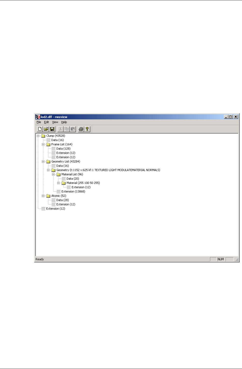
RenderWare Binary Streams
RenderWare Graphics 3.7 I-173
Complex Chunks
Chunks can contain other chunks, so a complete stream can be parsed as
a tree-like hierarchy. Such chunks are known as complex chunks.
The strview applet, which can be located in [SDK-ROOT]/tool/strview,
illustrates this aspect of RenderWare Graphics' binary streams by
displaying the structure of any valid stream as a hierarchical view. An
example of the stream viewer in action can be seen in the screenshot on the
next page.
Complex chunks are handled transparently by callbacks which are
registered with the streaming API. In the screenshot below, the structure of
a typical RpClump container object is clearly visible, with its list of RwFrame
objects, RpGeometry objects and RpAtomic objects.
The stream viewer applet
8.3.2 Serializing Objects
Although there is a trend towards originating 3D graphics data
algorithmically, most 3D graphics data is streamed into memory from a
storage device. Given RenderWare Graphics' target market, this is usually
either a CD, DVD or hard disk.
The streaming of extended or derived object data requires the creation of
additional functions. We saw these in the Plugin example (see the Plugins:
Creation & Usage chapter), but didn't see them in action.

Chapter 8- Serialization
I-174 11 February 2004
Look for TestPluginStream() in the ClumpPhysics example's main.c file.
This function, which is predicated on a build-time #define called
TESTSTREAM, was included in this source code so you can see how the
RenderWare Graphics Binary Stream facility is used.
You may want to activate it, by defining the TESTSTREAM constant, and step
through the code in your debugger to watch what it does.
Registering the Stream Functions
If you look at the source code, you'll notice that none of the three stream
functions created for the new plugin appear to be called directly. This is
because these functions are called directly by the clump object's own
stream functions.
Objects that support extension via the plugin mechanism and support for
binary streams have two registration functions. Respectively, these are:
• Rp[PLUGIN-NAME]RegisterPlugin()
• Rp[PLUGIN-NAME]RegisterPluginStream()
In the ClumpPhysics plugin example, both functions are called in the
RpClumpPhysicsPluginAttach() function. The second of the two
registration functions, RpClumpRegisterPluginStream(), is the one that
tells the clump object about our own stream functions.
The RpClumpRegisterPluginStream() function accepts three function
pointers. Respectively, these are for reading, writing and returning the size
of the additional data our functions will place into the stream.
✎
It is important to note that RpClumpRegisterPluginStream()is part of the RpClump
plugin, not the ClumpPhysics plugin. All plugins that need to support extension of their
binary streams must implement their own registration function to allow this. For example,
the ClumpPhysics plugin would need to implement an
RpClumpPhysicsRegisterPluginStream() function.
Determining the Size of a Chunk
A stream chunk is not assumed to be fixed in size.
One reason for this is that plugins may extend existing chunk types rather
than utilizing their own. Another issue is that some platforms work better if
data is padded to a certain minimum block size. (This is often the case on
consoles which make heavy use of caches and other hardware tricks.)
Every chunk type needs to have its own chunk size function. This function
will call the chunk size functions for any extensions within that chunk so, if
another plugin extends the same chunk, it too must implement a chunk
size function.
This gives RenderWare Graphics a means by which it can determine the full
size of a chunk: adding up the results of all the chunk size functions
implemented for a chunk type gives the total size of the complex chunk.
RenderWare Binary Streams
RenderWare Graphics 3.7 I-175
Reading and Writing
Writing platform independent data to a stream is not as straightforward as
it sounds. RenderWare Graphics' multi-platform nature means we have to
take into account such things as packing sizes, default datatype sizes and
even the endian-ness of the data. Otherwise, data written out on one
platform may not be readable on another.
Endian-ness
Depending on the processor used at the heart of your target platform, data
can be stored in one of two formats: big-endian or little-endian. This defines
the byte-order of datatypes larger than a single byte when these are stored
in RAM.
The table below uses hexadecimal notation to show the difference between
the two forms when storing the hexadecimal 4-byte number "0x12345678":
BIG-ENDIAN LITTLE-ENDIAN
0x12 0x34 0x56 0x78 0x78 0x56 0x34 0x12
As you can see, all the endian-ness means is which order bytes are stored.
Little-endian format places the least significant byte ("LSB") first, while big-
endian format places the most significant byte ("MSB") first.
This means you cannot simply throw your data structures at the stream as
there's no guarantee that the raw bytes will be read back correctly on
another platform. The solution is to standardize on some basic datatypes
and make sure the endian-ness of the streamed data is consistent across
all platforms.
In RenderWare Graphics, we've chosen little-endian format as our
standard. This was picked mainly because we use PCs to develop on and
these use little-endian format. This standard is used for all streams,
regardless of platform, so streams written on a big-endian platform will be
converted to little-endian form. On platforms that use little-endian format,
no endian-ness conversion takes place.
The table below shows which of our key platforms uses which storage
format:
PLATFORM CPU STORAGE FORMAT
Sony PlayStation 2 MIPS-based core Little-endian
Microsoft Xbox Intel Pentium III Little-endian
PC
(Direct3D / OpenGL)
Various x86-
compatible CPUs
Little-endian
MacOS (OpenGL) Motorola / IBM
PowerPC
Big-endian
NINTENDO
GAMECUBE
Motorola / IBM
PowerPC
Big-endian

Chapter 8- Serialization
I-176 11 February 2004
Endian-ness Conversion
The endian-ness of individual platforms makes it impossible to create data
streams that are cross-platform compatible without some conversion work.
The RwMem part of the core library API provides such conversion functions.
Some of the streaming functions—see the next section—perform these
conversions internally. However, you must use the conversion functions
described here if your application uses only the basic
RwStreamRead()/RwStreamWrite() functions.
An important point to note is that none of the RwMem conversion functions
will change the physical size of the data being converted, so a "Float32"
occupies the same number of bytes as an RwReal value. This makes
calculating the size of the data to be read or written easier.
The functions are:
•
••
•
RwMemFloat32ToReal()
Used when reading from the stream: this function reverses the
conversion process performed by RwMemRealToFloat32() and gives you
back your original array of RwReal values. The RwMemNative32()
function should be called first.
•
••
•
RwMemLittleEndian32()
RwMemLittleEndian16()
Used when writing to the stream: this function converts the integer data
you've pointed it at and converts the data to little-endian format if
necessary. (On platforms that natively use little-endian format, this
function has no effect.)
•
••
•
RwMemNative32()
RwMemNative16()
Used when reading from the stream: this function converts the little-
endian data read in from the stream into the native endian-ness of the
platform. (As with its counterpart, this function has no effect if the
platform uses little-endian format.)
•
••
•
RwMemRealToFloat32()
Used when writing to the stream: this function converts an array of
RwReals to a standard 32-bit floating point format for streaming. The
appropriate RwMemLittleEndian32() function should be called after
this.
Reading & Writing to a Stream
Once the data has been converted, the RwStream API is used to write the
individual data elements to the stream. When reading data, the process is
reversed.

RenderWare Binary Streams
RenderWare Graphics 3.7 I-177
Endian-ness Conversion
Endian-ness conversion must be performed explicitly if using the
RwStreamRead()/RwStreamWrite() functions. However, when using the
streaming functions that know about their type—such as
RwStreamReadInt32() or RwStreamWriteReal()—you do not need to
perform explicit endian-ness conversion: these functions perform the
conversion internally. It is usual for developers to avoid using
RwStreamRead()/RwStreamWrite() wherever possible.
The following two tables list the read and write functions respectively.
Stream Reading Functions
These functions read data from a binary stream. Those functions with an
explicit datatype as part of their name will perform any endian-ness
conversions internally, if necessary.
READ FUNCTION PURPOSE
RwStreamRead() Reads the specified number of
bytes from the specified stream
into the given data buffer.
This function requires explicit
endian-ness conversion.
RwStreamReadChunkHeaderInfo() Reads the Chunk Header
information and stores it into the
RwChunkHeaderInfo structure
provided. (Intended mainly for
diagnostics.)
RwStreamReadInt16() Reads an array of 16-bit RwInt16
values from the stream into the
specified buffer.
RwStreamReadInt32() Reads an array of 32-bit RwInt32
values from the stream into the
specified buffer.
RwStreamReadReal() Used to read an array of RwReal
data values from the stream into
the specified buffer.
RwStreamSkip() Used to skip the specified number
of bytes in the given stream.

Chapter 8- Serialization
I-178 11 February 2004
Stream Writing Functions
These functions write data to a binary stream. Those functions with an
explicit datatype as part of their name will perform any endian-ness
conversions internally, if necessary.
WRITE FUNCTION PURPOSE
RwStreamWrite() Writes the specified number of bytes
to the specified stream from the given
data buffer.
This function requires explicit endian-
ness conversion.
RwStreamWriteChunkHeader() Used to write a chunk header to the
specified stream. This function would
typically be used by an application
wishing to write application specific
data to a file.
RwStreamWriteInt16() Writes an array of 16-bit RwInt16
values to the stream from the specified
buffer.
RwStreamWriteInt32() Writes an array of 32-bit RwInt32
values to the stream from the specified
buffer.
RwStreamWriteReal() Used to write an array of RwReal
values to the stream from the specified
buffer.
8.3.3 Explicit Streaming Functions
In many cases, RenderWare Graphics' supplied plugins implement and
expose streaming functions to serialize their objects explicitly. The
RpClumpStreamRead() function is an example of such a function.
When developing custom plugins and objects, it is worth considering
exposing similar, high-level functions. This makes it easier for developers
using the plugin to stream the plugin's data without having to explicitly
parse its individual components—a task which becomes a chore if the
plugin is a complex one.
Another, very important, advantage of implementing high-level functions in
this way is so that the function can perform any required pre- or post-
processing transparently. This avoids the need for developers to remember
to perform such processes explicitly.
In most cases, you will have already implemented the necessary low-level
functionality needed to implement high-level functions, so adding them to
your plugin's API is usually trivial.

RenderWare Binary Streams
RenderWare Graphics 3.7 I-179
Using Explicit Streaming Functions
In the previous section, 8.3.2 Serializing Objects, we looked at serialization
from within a plugin. This is important to know, but what if your
application needs to read or write an object to a stream directly?
Although it is not entirely necessary for it to do so, it is good practice for
your plugin to implement high-level stream-read and stream-write
functions. The application to which the plugin is attached should be
responsible for managing the streams.
This is best illustrated with an example.
Reading a Clump Object
The clump (RpClump) object, part of the World plugin (RpWorld), is a
complex object, containing additional objects such as frames (RwFrame) and
atomics (RpAtomic).
All this complexity is handled by callback functions set up by the plugin
itself when it is attached to your application. This makes reading a clump
object very simple.
First, we need to declare our stream and clump objects:
RwStream *stream;
RpClump *newClump;
Next, we open our binary stream:
stream = RwStreamOpen(rwSTREAMFILENAME, rwSTREAMREAD,
"myclump.rws");
(Remember, the .rws filename extension is purely a reminder that this is a
RenderWare Graphics binary stream.)
Now we can check that the stream was opened and locate our clump object
within the stream:
if( stream )
{
if( RwStreamFindChunk(
stream, rwID_CLUMP, NULL, NULL) )
The RwStreamFindChunk() function call above locates the first occurrence
of a chunk with a chunk ID of rwID_CLUMP. An .rws file may contain more
than one clump, so it may be necessary to identify each clump unless the
developer is aware of the exact contents of the file. One method by which
the identification may take place is by using a table of contents (TOC). See
8.3.4 RWS files for information about TOCs in .rws files.

Chapter 8- Serialization
I-180 11 February 2004
With the correct chunk located, the application can now read the clump
data.
{
newClump = RpClumpStreamRead(stream);
}
Finally, we should close the stream as we no longer need to read anything
else from it.
RwStreamClose(stream, NULL);
}
Writing a Clump Object
This process is rare within a game, but applications written as part of a
tool-chain, such as an exporter for a modeling package, will need to
perform this operation frequently.
Writing an object is very similar to reading one. Again, we'll use a clump
object for our example, which will assume that myClump contains a valid
clump object for writing.
First, we need to declare our stream object:
RwStream *stream;
Next, we need to open a stream for writing. This uses the same function as
for reading, but with a different flag. (These flags are covered in section
8.3.5, Stream Types.)
stream = RwStreamOpen(rwSTREAMFILENAME, rwSTREAMWRITE,
"myclump.rws");
At this point we should check that the stream was opened:
if( stream )
{
Now the data can be written to the stream:
RpClumpStreamWrite( myClump, stream );
}
Finally, the stream should be closed:
RwStreamClose(stream, NULL);
Designing an Explicit Streaming API
It is not a requirement that a plugin exposes a high-level streaming API as
there are a number of different ways in which a plugin can be implemented.
Two examples of plugins that may not need such an API are:

RenderWare Binary Streams
RenderWare Graphics 3.7 I-181
• Plugins that extend existing objects – if a plugin extends an existing
object, there is usually no need for a high-level API. This is because
streaming the original object will automatically cause RenderWare
Graphics' streaming API to call the appropriate callbacks for the
extended data.
• Plugins that implement objects that do not need to be streamed – for
instance, a plugin designed for run-time diagnostics may not need to
serialize its objects at all.
If there is nothing to be gained by allowing your plugin to stream its
objects, don't implement a streaming API for it. However, if you decide your
plugin does need to support explicit serialization of its objects, you will
need to use the RwStreamRead() and RwStreamWrite() functions—as
outlined in 8.3.2 Serializing Objects.
Chunk Headers
Any object that supports streaming must explicitly write a header chunk by
calling RwStreamWriteChunkHeader() with both the chunk ID (discussed
in 8.3.1 Binary Stream Structure) and the size of the object's data.
It is important to note that reading the object data from a stream does not
require the reading of the chunk header as the call to
RwStreamFindChunk()—made by the calling application—performs this
process.

Chapter 8- Serialization
I-182 11 February 2004
8.3.4 RWS files
RWS files, identified by the .rws extension, extend the concept of
RenderWare Graphics' binary streams to group related streams together
into a single stream. An .rws file is designed to contain any number of
clumps, worlds, texture dictionaries, etc. For example, it would be common
to find a world and its textures together in an .rws file.
There are no specific streaming functions for .rws files. The developer
should just use the standard RenderWare Graphics read/write streaming
functions described in this chapter on a single stream.
The default export option in the RenderWare Graphics exporters for
3dsmax and Maya are to save .rws files. The Visualizer viewer also is
capable of reading .rws files.
Given broad uses of grouping related streams together, a single .rws file
may contain many objects.
.rws files may contain marker blocks called ‘chunk groups’ which bracket
groups of chunks between ‘start’ and ‘end’ chunks. The ‘start’ chunks also
contain asset names as specified from within the exporters. These marker
blocks may be used from within your own toolchain to locate assets by
name.
.rws files also usually contain another type of object at their head called an
RtTOC, or Table of Contents (TOC), to keep track of what the .rws file
contains.
Chunk Group
A chunk group, RwChunkGroup, is a marker added to a stream to group and
identify other data chunks. Its purpose is to add a name to a single or a
group of chunks not available with RwChunkHeaderInfo.
These can be used by the toolchain applications to identify groups of
chunks that correspond to assets named within the exporters.
A RwChunkGroup is created by the function RwChunkGroupCreate() and
destroyed by RwChunkGroupDestroy(). A RwChunkGroup contains a fixed
length string. This string is set by the user using RwChunkGroupSetName()
and is used to label other data chunks in the stream.
A group of data chunks is labeled by wrapping it between a group header
and group trailer chunk. The group header chunk consists of a standard
RwChunkHeaderInfo, with ID rwID_CHUNKGROUPSTART, and a data block
with the RwChunkGroup data. The group trailer chunk just consists of the
chunk header, rwID_CHUNKGROUPEND. No extra data blocks are currently
written out for the group trailer chunk.

RenderWare Binary Streams
RenderWare Graphics 3.7 I-183
To write out label information for a group of data chunk, the group header
chunk must first be written out. This is achieved by calling the function,
RwChunkGroupBeginStreamWrite(). Data chunks belonging to this group
are then written out as normal using the appropriate streaming functions.
Finally the group trailer chunk is written immediately after the last data
chunk using RwChunkGroupEndStreamWrite().
The following is an example snippet of code to write out a group of data
chunks with a chunk group label.
/* First write out the header. */
if (RwChunkGroupBeginStreamWrite(stream, group)) == group)
{
/* Write out any data chunks here. */
/* Write out the trailer. */
if (RwChunkGroupEndStreamWrite(stream, group) == group)
{
/* Success. */
}
else
{
/* Write trailer chunk error. */
}
}
else
{
/*Write header chunk error. */
}
Reading a header chunk is similar to reading a standard data chunk. Once
a header chunk is found, by the chunk header ID,
rwID_CHUNKGROUPSTART, the function, RwChunkGroupBeginStreamRead()
is used to read in a RwChunkGroup. A matching trailer chunk,
rwID_CHUNKGROUPEND, will be read to mark the end of group.
Example code to read a RwChunkGroup and its group of data chunks:
/* First read in the chunk header. */
if (RwStreamReadChunkHeaderInfo(stream, &chunkInfo)
== stream)
{
/* Check the type. */
if (chunkInfo.type == rwID_CHUNKGROUPSTART)
{
/* Read in the group header. */
group = RwChunkGroupBeginStreamRead(stream);
if (group)
{
/* Read in any data chunks. */

Chapter 8- Serialization
I-184 11 February 2004
/* Read in the group trailer. */
if (RwStreamReadChunkHeaderInfo(
stream, &chunkInfo) == stream)
{
/* Check the type. */
if (chunkInfo.type ==
rwID_CHUNKGROUPEND)
{
/* Success. */
}
else
{
/* Possible error.
* Unless it is nested.
*/
}
}
else
{
/* Read chunk header error. */
}
}
else
{
/* Read chunk group data error.*/
}
}
}
else
{
/* Read chunk header error. */
}
Groups can be nested inside each other to represent a hierarchical
arrangement of data in the binary stream if required.
Table of Contents Creation
Given an existing stream containing many chunks, a TOC may be created
using RtTOCCreate() that parses this stream constructing an entry per
chunk. This TOC may then be prefixed to the original stream using
RtTOCStreamWrite().
The entries in the TOC contain the ID of the chunk and a byte offset from
the beginning of the stream to the entry's chunk header. This convention is
used so that if a TOC entry's offset is used to skip through a stream, the
usual RenderWare Graphics stream reading conventions can then be used
to read the required chunk, as if the stream had been read sequentially.

RenderWare Binary Streams
RenderWare Graphics 3.7 I-185
✎ The TOC entries also contain a GUID that uniquely identifies the chunk. A GUID is
automatically created by the RenderWare Graphics exporters for each new asset created
in a supported modeling package. One such use of the GUID is to identify a unique chunk
in an RWS file that contains many chunks of the same ID.
Using a Table of Contents
There are several uses and usage approaches for the TOC in an .rws file.
The first is to quickly scan what an .rws file contains.
1. Open the .rws file for reading using RwStreamOpen() and the
rwSTREAMREAD flag.
2. Find the TOC using RwStreamFindChunk() with the rwID_TOC ID.
3. Read the RtTOC using RtTOCStreamRead().
4. Close the stream using RwStreamClose().
RtTOCGetNumEntries() can be used to query how many entries there are
in the TOC. RtTOCGetEntry() can be used to obtain an entry in the TOC,
identified by its zero-based index. The use of this entry is then application
specific. For example, an ordered list of the chunk types can be obtained by
simply looping through all TOC entries enumerating their ID.
The second use for a TOC is to read entries from the stream. The
application should be aware of whether the entries are to be read
sequentially or non-sequentially.
For a sequential read, the TOC need only be used to predetermine the
chunk ID of the next entry. A single RWS load function would only be
needed to cater for all chunk types, rather than individual load functions
per chunk type.
For a non-sequential read, the TOC can be used to skip regions of the
stream to gain access to a specific chunk without having to perform a
search using RwStreamFindChunk(). The usefulness of this becomes
apparent when an .rws file contains multiple instances of the same chunk
ID, e.g. two (rwID_WORLD) worlds, as you can preprocess the TOC entry
without having to perform expensive stream operations.
The byte offset of the TOC entry's chunk header is relative to the beginning
of the stream. Hence, before that offset can be used in RwStreamSkip(),
the stream position must be reset to the beginning. To do this, the stream
must be closed and then re-opened.
After a skip has been performed, the chunk should be read in the same
manner as if it had been read sequentially from the stream. This is because
the offset is to the chunk's header, as mentioned earlier.
Whatever the TOC may be used for, it should be destroyed with
RtTOCDestroy once finished with.
Chapter 8- Serialization
I-186 11 February 2004
8.3.5 Stream Types
RenderWare binary streams are not limited to file-based streams.
The RwStreamOpen() function therefore has two flag parameters. The first
defines the type of stream to use and the possible flags are listed in the
table below:
FLAG PURPOSE
rwSTREAMFILE The stream is to a disk file that has been set
up by the user. The access mode should
match that used when the file was opened.
The type-specific argument should be set to
the file's pointer (usually of type FILE *).
rwSTREAMFILENAME The stream is to a disk file that has not been
set up by the user. The type-specific
argument should be set to the desired
filename.
rwSTREAMMEMORY The stream is to a chunk of memory. If
access type is rwSTREAMAPPEND then the
chunk of memory must have been created
using RwMalloc as RenderWare may
subsequently try to use RwRealloc to gain
more memory. The type specific argument
should be a pointer to the memory chunk
(RwMemory *) giving the position and size of
the chunk to use.
The second flag parameter determines how the stream is opened:
FLAG PURPOSE
rwSTREAMREAD Opens a stream for reading only.
rwSTREAMWRITE Opens a stream for writing only. If the
stream is of type rwSTREAMFILE or
rwSTREAMFILENAME the file size will be
reduced to zero when the stream is opened.
rwSTREAMAPPEND Opens a stream to which data will be
appended.

Summary
RenderWare Graphics 3.7 I-187
8.4 Summary
RenderWare Graphics supports both a low-level file I/O API and a high-
level streaming API.
8.4.1 File I/O API
Low-level access to files on disk is accessed through the RwFileFunctions
structure. This structure, which can be overwritten with custom functions,
exposes an ANSI-compliant set of file I/O functions:
8.4.2 RenderWare Binary Streams
Binary streams can contain simple objects, or complex ones. Complex
objects can contain other objects—including other complex objects—so a
stream's structure can be viewed as a tree.
The Stream Viewer application, strview.exe, can be used to examine
binary streams. It can be found in the [SDK-ROOT]/tool/strview/ folder.
Stream Types
RenderWare binary streams are usually file-based, but memory-based
streams are also supported.
Chunk IDs
All objects are stored in chunks, which are the building-blocks of
RenderWare binary stream. A chunk for a particular object is identified by
its chunk ID.
Chunk IDs are generated using the MAKECHUNKID() macro, which takes
your vendor ID (used to log-in to the developer support website) and an
object ID—between 0 and 255—which identifies the object itself. This is the
same mechanism used for plugin IDs, so care should be taken not to
confuse the two.
Serializing Objects
Object serialization is the responsibility of the plugin within which the
object resides.
Serializable objects must implement the three callback functions necessary
for RwRegisterPluginStream(). These functions are:
• a chunk read function;
• a chunk write function;

Chapter 8- Serialization
I-188 11 February 2004
• a function that returns the size of the chunk.
The developer can choose to implement an object as either:
• a container object, (e.g. RpClump and RpWorld)
• an extension to another object, (e.g. RpMatFX)
• a stand-alone object (e.g. RpLight).
Container objects should expose a high-level serialization API, as should
stand-alone objects. Objects that extend an existing object rarely need to
expose a high-level serialization API, unless the object can also be used as a
stand-alone object.
In all cases, callback functions for serialization are necessary if the object is
to support serialization at all.
Registering the Stream Functions
Plugin objects that support both the RenderWare Graphics binary stream
API and extension via the plugin mechanism must call two plugin
registration functions.
The first function will be either one of two choices:
• RwRegisterPlugin(), which registers the plugin with the core directly
and is used only if the plugin does not extend other objects itself, or
• ...RegisterPlugin(), which belongs to the API of the object which
the plugin is to extend.
The second function, ...RegisterPluginStream(), belongs to the API of
the plugin that contains the object to be extended. It registers the
serialization callback functions with that base object, so that it knows how
to load the extended data.
Endian-ness
Data in a stream uses a little-endian storage format, so conversion
functions—supplied by the RwMem API—must be used to ensure all the
streamed data is in the right format.
RWS files
The concept of the RenderWare Graphics binary stream can be extended to
RWS files that may contain all art assets packaged together.
Assets saved out from the exporters into .rws files are bracketed within
‘start’ and ‘end’ marker blocks which may be accessed via the
RwChunkGroup functions.

Summary
RenderWare Graphics 3.7 I-189
To keep track of the contents of an RWS file, a Table of Contents is
attached to the beginning of the file.

Chapter 9
File Systems

Chapter 9- File Systems
I-192 11 February 2004
9.1 Introduction
The RenderWare file system toolkit is composed of a file system manager,
and a set of custom file systems for specific platforms. The file system
manager is a high level interface, responsible for managing all file
operations on a given platform. Each custom file system has a unique user-
defined name from which it can be accessed via the file system manager.
The file system manager handles file system registration, and provides a
generic approach to all file operations. For example, it is the responsibility
of the manager to find an appropriate file system on which to open a
specific file, amongst the list of registered file systems. As opposed to any
previous implementation, this toolkit enables asynchronous access to a file.
The toolkit deals with all file-level access to storage devices. Other
RenderWare modules, such as Streaming (used for the serialization of
objects), are naturally affected by this new toolkit. Note that, when the file
system manager is initialized it installs a generic interface to the standard
RenderWare interface. All streaming functions remain unchanged as they
simply rely on this standard file interface.
This document details the components of the RenderWare file system
toolkit, and shows you how custom file systems are used.
File System Management
RenderWare Graphics 3.7 I-193
9.2 File System Management
The RenderWare file system manager provides a generic interface through
which all RenderWare I/O operations are processed. This constitutes the
first layer of the file system API. It supports multiple file systems, each
representing a particular device type available on a specific platform, e.g.
Playstation 2 host. In other words, the toolkit is designed to provide a
common file transfer interface for all hardware devices.
The second layer consists of custom file systems, which need to be
registered (see figure below) with the file system manager. This step is
necessary as file operations, e.g. file open, will automatically attempt to find
an appropriate file system in the file system manager list of registered file
systems. This step is performed by looking for the device name (see
Changing the File System Device Name) attached to the front of the file
name or by getting the default file system, should one be specified.
RenderWare
File System
Manager
Custom File
System
1
Custom File
System
2
Registers
with
File System Registration
Chapter 9- File Systems
I-194 11 February 2004
9.3 The File Systems
The RenderWare file system toolkit provides a common interface to all OS
specific file systems. It allows the definition of custom device names,
thereby providing a powerful way to switch between different registered file
systems.
9.3.1 The Generic File System
The figure below illustrates the process that takes place during a file open
operation. It shows that, from a user’s point of view, opening a file consists
of getting the standard RenderWare file interface, and calling the rwfopen
function.
The whole opening process is undertaken via the file system manager.
When the file system manager is initialized, it installs a set of generic
functions that are used by all RenderWare file calls. Depending on the
device name passed during the file system initialization, the appropriate file
system is retrieved and the file open operation attempted.
Get RW File
Interface
by calling
RwOSGetFileInterface
Returns pointer to
Open a file
by calling
rwfopen
Points to
RW Generic FS
rwfsFOpen
calls
Generic FS
RwFSManagerFOpen
Get FS from
filename
from
File System
Manager
Returns registered
custom FS
If slot available in
FS call
Custom File System
(FS)
On Initialise
Register FS
with
If generic FS not
installed, install
it with
Registered once
by calling
RwFSInstallToRW
Implement
Functionality
Open Read Write
...
Use Case Diagram - File Open

The File Systems
RenderWare Graphics 3.7 I-195
9.3.2 OS-Specific File Systems
File System Naming
Once registered, each file system can be accessed by name using the file
system manager function, RtFSManagerGetFileSystemFromName. You
must specify the file system name on initialization. This provides an easy
way to access any registered file systems in a user-defined way.
This allows quick access to any registered file system, and provides the
ability to manipulate the file system itself, although you do so at your own
risk.
Naming File System Devices
A useful aspect of this file system is the ability to specify user-defined
device names. This constitutes an easy way to switch between file systems.
Registering a file system with a custom device name provides the ability to
have files with path names that guarantee a specific file will be opened in a
certain way. Consider the case where a file system is registered with the
tdn: device name. Any files with a file name using this device name, e.g.
tdn:./model/world.dff will automatically be opened on this file system.
Note that file system device names are case sensitive.

Chapter 9- File Systems
I-196 11 February 2004
9.4 Using the RenderWare File System
9.4.1 Basic Usage
Initializing and Registering File Systems
The sample code below illustrates the different steps needed to initialize
and register a file system. Before any custom file system can be registered,
the file system manager needs to be initialized using RtFSManagerOpen.
Following this call, the appropriate file system initialization function needs
to be called. All custom file system initialization functions return a pointer
to the file system itself or NULL if the initialization failed. Once the
initialization has succeeded, the file system needs to be registered by
calling RtFSManagerRegister, and passing the pointer returned by
RtFSManagerInit.
RtFileSystem *hfs;
RwChar hBuffer[MAX_NB_FILES_PER_FS * READ_BUFFER_SIZE];
RwChar fsName[RTFS_MAX_NAME_LENGTH];
RwChar *hstDeviceName = "hst:";
/* Setup the file system manager */
RtFSManagerOpen(RWFSMAN_UNLIMITED_NUM_FS);
rwstrcpy(fsName, "hst");
/* Init and register the host file system */
if ((hfs = RtSkyHSTFSystemInit(MAX_NB_FILES_PER_FS,
hBuffer, READ_BUFFER_SIZE,
hstDeviceName, fsName))
!= NULL)
{
/* Now actually register the file system */
if (RtFSManagerRegister(hfs) == FALSE)
{
/* Registration Failed */
}
else
{
/* Registration Succeeded: maybe set this file
* system as the default one */
}
}
else
{
/* Initialization Failed */
return;
}

Using the RenderWare File System
RenderWare Graphics 3.7 I-197
Note that hBuffer is simply a memory block that will be used as a buffer by
the file system. The size of this buffer must be equal to the maximum
number of concurrently opened files, multiplied by the maximum read-size
specified. This buffer will be internally segmented, and each part assigned
to a per-file file buffer.
Please refer to the API reference for the particular calls in the file system
initialization function.
✎ Note that the file system name size must not exceed RTFS_MAX_NAME_LENGTH.
Opening a File
You can open a file directly via the standard RenderWare file interface. The
file system manager initialization process installs a generic file system to
the existing RenderWare file interface. As a result, a file can be opened as
follows:
RtFile *file;
RwFileFunctions *fileFunctions = RwOsGetFileInterface();
file = fileFunctions->rwfopen(fileName, "r");
Reading from a file
As for opening files, reading and writing can be done directly from the
RenderWare file interface as follows:
fileFunctions->rwfread(readb, READ_CHUNK_SIZE, 1, file);
This way, none of your current synchronous RenderWare I/O calls need to
be changed.
The file system sits below the streaming interface and, as a result,
RenderWare streams are read as they always have been, i.e. using the
RwStream functions.
Registering a Default File System
The current API allows you to set a default file system amongst the set of
file systems registered. The default file system is the one that will be used
as a last resort when trying to open a file. This means that, if no file system
is found that matches the device-name when opening a file, i.e. your path
may be relative, the file system manager will automatically attempt to open
the specified file on the default file system. Setting the default file system
can be done by calling the RtFSManagerSetDefaultFileSystem function,
and passing the appropriate file system pointer to it:
RtFSManagerSetDefaultFileSystem (myFileSystemPtr);
In the case where the default file system is not set, and no appropriate file
system is found during a file open, the file open operation will fail at the file
system manager level. This will cause the rwfopen call to return NULL, and
set the file system manager error to RTFSM_ERROR_NOFS.

Chapter 9- File Systems
I-198 11 February 2004
✎
If your file path name does not include the device name, you will need to set a default file
system in order to avoid any failure at the file system manager level. This is because the
process of opening a file consists of looking for whether the file system’s device name
matches the path name’s device name. If your file name does not include this device
name, the default file system will automatically be used.
Changing the File System Device Name
The file system API allows you to change the device name used at any time.
Remember that the initial device name is set during the file system
initialization. Changing the file system name can be done in the following
way:
/* Get a registered file system */
RtFileSystem *fs = RtFSManagerGetFileSystemFromName("myfs")
if (fs != NULL)
{
/* Set the new device name */
RtFileSystemSetDeviceName(fs, "test:");
}
This example will set a new device name for a custom file system with the
name “myfs”. This is particularly useful for Windows based file systems as
it allows you to specify the drive on which to read from or write to.
✎ Note that the actual device name size can be of any size.
Registering Multiple File Systems
The file system toolkit allows you to register several file systems of the same
type. For example, the toolkit allows you to initialize, and register, several
Windows file systems. The usefulness of this functionality is particularly
evident on Windows based file systems. For example, it provides you with
the ability to have a file system per valid partition or device. This prevents
you from potentially having to constantly change the device name in your
code. Naturally, initializing and registering several file systems of the same
type will require more memory, and may not constitute the optimal
solution.
9.4.2 Synchronous vs. Asynchronous Access
As opposed to synchronous file access, where a specific file operation being
executed must complete before the function call returns, in asynchronous
mode the operation returns immediately. An application can check whether
an asynchronous operation is in progress by querying the
RtFileSystemFileFunctionTable sync method provided.

Using the RenderWare File System
RenderWare Graphics 3.7 I-199
Opening a File in Asynchronous Mode
To access a particular file in asynchronous mode, set your access flags
accordingly, and open the file via the file system manager. This can be done
as follows:
flags |= RWFILE_ACCESS_OPEN_ASYNC;
file = RtFSManagerFOpen(fileName, flags);
Note that it is usually common practice to use the file system in
synchronous mode, and manage asynchronous operations in a separate
thread. This guarantees an optimal control on the asynchronous operations
you wish to perform. As a result, the RtFSManagerFOpen function should
only be used when you want to directly open a file asynchronously, and use
the internal asynchronous functionality.
Defaulting a File System to Synchronous/Asynchronous
On initialization file systems default to synchronous access mode. However,
this default may be changed to a specific access mode. This can be done via
the file system RtFileSystemDefaultToAsync function. A call to this
function will automatically default all future operations to the specific mode
chosen. For example, if TRUE is passed to this function all file operations
following the next open will be done asynchronously. On the other hand, if
FALSE is specified, these operations will be done synchronously. This
function cannot be used for individual files; it is a per file system setting.
The following code will default myFileSystemPtr to asynchronous:
RtFileSystemDefaultToAsync(myFileSystemPtr, TRUE);
9.4.3 File System Specific Remarks
Windows File System
For the windows file system, the device name specified during initialization
must be a valid device name, i.e. an existing drive or partition. This is to
enable access to any valid drive on your hard disk(s).
Playstation2 DVD File System
This file system requires the loading of the rtfsiop irx module. This must
be done before the file system initialization.
Playstation 2 ATMon File System
This file system requires a valid ATMon IP address to be passed during
initialization.
Chapter 9- File Systems
I-200 11 February 2004
GCN USB File System
This file system uses an external tool called viewer_server (normally
found in “your_dolphin_sdk”\X86\hiodemo). This tool needs to be
started and properly configured, i.e. its FIO path needs to be set to your
project directory in order for the file system to find a channel with a USB
adapter. Note that this tool needs to be opened before your own application,
and the server must be started once your application is running.
9.4.4 Creating your Own File System
To create your own custom file system, you must implement a set of file
system methods.
Below are the required file system methods:
RtFileSystemGetFileFunc fsGetObject;
RtFileSystemCloseFunc fsClose;
File system methods
to implement
RtFileSystemGetDeviceNameFunc fsGetDeviceName;
Each file system contains a file function table. This structure, called
RtFileSystemFileFunctionTable, contains all the file system specific file
functions. So, a complete file function table must be implemented by any
custom file system. The methods to implement are described below:
RtFileOpenFunc open;
RtFileCloseFunc close;
RtFileReadFunc read;
RtFileWriteFunc write;
RtFileSetPositionFunc setPosition;
RtFileSyncFunc sync;
RtFileAbortFunc abort;
RtFileEofFunc isEOF;
RtFileGetStatusFunc getStatus;
File methods to implement
RtFileExistsFunc fExists;

Using the RenderWare File System
RenderWare Graphics 3.7 I-201
Additionally, every custom file system initialization function must call the
_rtFSInit file system function. This function will actually perform some
necessary internal initialization steps such as checking whether the file
system can be initialized and setting the device name. It must be called in
the following manner, after having allocated memory for the actual file
system (here myfs):
if (_rtFSInit((RtFileSystem *)myfs, maxNbOpenFiles,
(RwChar *)fileSystemName, deviceName))
!= RTFS_ERROR_NOERROR)
{
/* Internal Initialization Failed */
/* Free all Memory Allocated */
}
Also note that all custom file system initialization functions must return a
pointer to the newly created file system when initialization succeeds. If
initialization fails, the function must return NULL.
For more details, please refer to any of the custom OS-specific file systems,
as well as the API reference.

Chapter 10
The Dictionary
Toolkit
Chapter 10- The Dictionary Toolkit
II-204 11 February 2004
10.1 Introduction
The dictionary toolkit, RtDict, provides support for generic containers of
objects that may be identified by name.
RtDict works off two main objects: RtDictSchema and RtDict.
The schema holds the layout of a dictionary of a user-specified object. It
contains callbacks that are used to manage entries with dictionaries for
that object type.
In general, a schema is needed for dictionaries of each different object type.
The schema can be used to create, or stream in, dictionaries of that schema
type. It also maintains a ‘current’ dictionary for the contained object type.
Each individual dictionary is managed within an RtDict structure.
RtDict is used internally by RenderWare in systems such as the UV
animation plugin, RpUVAnim, but is also available for your own usage.
10.1.1 This Document
This document describes the usage of the generic dictionary toolkit, RtDict.
For general operation of this toolkit in conjunction with other RenderWare
modules that use it, read sections 10.2, 10.4 and 10.4.
Section 10.5 describes how to set up schemas for your own custom
dictionaries.
RtDictSchema
schema1 RtDictSchema
schema2
RtDict of
TypeA RtDict of
T
ypeB
RtDict of
TypeA
RtDict of
TypeA
RtDict of
TypeB
T
ypeA
entry1
T
ypeA
entry2
T
ypeA
entry1
T
ypeA
entry2
T
ypeA
entry1
T
ypeB
entry1
T
ypeB
entry2
T
ypeB
entry2

Introduction
RenderWare Graphics 3.7 II-205
10.1.2 Other Resources
The API Reference:
• RtDict toolkit
• RpUVAnim plugin uses RtDict
The uvanim example also uses dictionaries.

Chapter 10- The Dictionary Toolkit
II-206 11 February 2004
10.2 Basic Dictionary Schema Usage
Before operations can be performed with a dictionary, an appropriate
schema for that kind of dictionary must be obtained.
RenderWare toolkits and plugins that use dictionaries provide functions
that return schemas for those dictionaries. For example, the UV animation
plugin, rpuvanim, has the function RpUVAnimGetDictSchema.
As well as dictionary creation and stream reading (see section 10.3), a
schema maintains a ‘current’ dictionary and a list of all dictionaries of that
type.
✎ By default, the current dictionary for a schema is NULL. It is completely up to the creator
of the schema to provide a current dictionary, and by no means necessary.
10.2.1 Getting the Current Dictionary for a Schema
The current dictionary for a given schema may be obtained with
RtDictSchemaGetCurrentDict:
RtDict *dict = RtDictSchemaGetCurrentDict(&mySchema);
if (!dict)
{
/*There is no current dictionary */
}
10.2.2 Setting the Current Dictionary for a Schema
The current dictionary for a given schema may be set with
RtDictSchemaSetCurrentDict:
RtDictSchemaSetCurrentDict(&mySchema, dict);
It’s okay to set NULL as the current dictionary. This indicates that there is
no current dictionary for the schema.

Creating and Streaming Dictionaries
RenderWare Graphics 3.7 II-207
10.3 Creating and Streaming Dictionaries
Any dictionary creation or reading from streams must be done via an
appropriate RtDictSchema (see section 10.5).
Dictionaries may be streamed out or destroyed directly.
✎
This convention, of creating or reading dictionaries based on a schema, means that the
Dictionary streaming API differs from other RenderWare object streaming functions. The
creation and streaming functions are RtDictSchemaCreateDict,
RtDictSchemaStreamReadDict rather than RtDictCreate and
RtDictStreamRead.
Once created, the dictionary knows what its schema is. The dictionary destruction and
stream-writing functions, RtDictDestroy and RtDictStreamWrite, don’t need to be
told which schema to use.
✎ Dictionary schemas cannot be streamed.
10.3.1 Dictionary Creation
Create a dictionary via an appropriate schema with the
RtDictSchemaCreateDict function:
RtDict *myDict = RtDictSchemaCreateDict(&mySchema);
Multiple dictionaries may be created from the same schema:
RtDict *myDict2 = RtDictSchemaCreateDict(&mySchema);
When you have finished with the dictionary, for example on program
shutdown, you must destroy it with the RtDictDestroy function:
RtDictDestroy(myDict);
10.3.2 Reading a Dictionary from a Stream
Dictionaries may be read from streams with the
RtDictSchemaStreamReadDict function:
RtDict *myDict = RtDictSchemaStreamReadDict(&mySchema, stream);
The caller is responsible for the newly read dictionary, and must destroy it
with RtDictDestroy when the dictionary is no longer needed.
10.3.3 Writing a Dictionary to a Stream
Dictionaries may be written to streams with the RtDictStreamWrite
function:
if (!RtDictStreamWrite(dict, stream))
{
return NULL; /* failure */
}

Chapter 10- The Dictionary Toolkit
II-208 11 February 2004
A function is also provided to determine how many bytes will be written to
the stream:
RwUInt32 size = RtDictStreamGetSize(dict);

Dictionary Entries
RenderWare Graphics 3.7 II-209
10.4 Dictionary Entries
Dictionaries store pointers to the objects they contain. These objects are
referred to as ‘entries’.
Entries may be added to or removed from the dictionary.
The dictionary manages the lifetime and ownership of entries via AddRef
and Destroy callbacks in the dictionary’s schema.
The dictionary can also be used to look up entries based on their name. The
dictionary uses a GetName callback to obtain each entry’s name.
It is assumed that an entry’s name does not change while it is in a
dictionary.
10.4.1 Adding Entries to a Dictionary
To add an entry to a dictionary, use the RtDictAddEntry function:
if (!RtDictAddEntry(dict, myEntry))
{
return NULL; /* failure */
}
Since the dictionary assumes ownership of the entry and increments the
entry’s internal reference count with the dictionary schema’s AddRef
callback, the entry can usually be destroyed at this point:
EntryDestroy(myEntry); /* entry destruction function */
✎
EntryDestroy is the entry-type-specific destruction function.
In this case, it’s assumed that myEntry is a reference-counted entry. The dictionary has
registered that it has a reference to the entry, and the caller of RtDictAddEntry already
has a reference.
If the caller is finished with the entry they can relinquish control with their EntryDestroy
function. This won’t actually destroy the entry, because the dictionary still has a
reference.
10.4.2 Removing an Entry from a Dictionary
To remove an entry from a dictionary, use RtDictRemoveEntry:
if (!RtDictRemoveEntry(dict, entry))
{
/* entry was not found in dictionary */
}
This also registers the fact that the dictionary no longer has a reference to
the entry by calling the entry’s Destroy function. If you need to remove the
entry from the dictionary, but retain ownership, you will need to AddRef the
entry prior to calling RtDictRemoveEntry.

Chapter 10- The Dictionary Toolkit
II-210 11 February 2004
✎ A direct pointer comparison is used to identify the entry in the dictionary.
10.4.3 Locating an Entry by Name
To find an entry by name, call RtDictFindNamedEntry:
DictEntryType *entry = (DictEntryType *)
RtDictFindNamedEntry(dict, “MyEntry”);
if (!entry)
{
/* entry was not found */
}
✎ DictEntryType is your user-defined dictionary entry type

Advanced Dictionary Schema Usage
RenderWare Graphics 3.7 II-211
10.5 Advanced Dictionary Schema Usage
If you wish to create dictionaries of your own objects, you must initialize a
schema that will describe and manage those dictionaries. In particular, you
must setup the callbacks that are used to manage and stream the
dictionary entries.
10.5.1 Schema Structure
The schema structure is as follows:
struct RtDictSchema
{
const RwChar *name;
RwUInt32 dictChunkType;
RwUInt32 entryChunkType;
RwUInt32 compatibilityVersion;
RwSList *dictionaries;
RtDict *current;
RtDictEntryAddRefCallBack *addRefCB;
RtDictEntryDestroyCallBack *destroyCB;
RtDictEntryGetNameCallBack *getNameCB;
RtDictEntryStreamGetSizeCallBack *streamGetSizeCB;
RtDictEntryStreamReadCallBack *streamReadCB;
RtDictStreamReadCompatibilityCallBack
*streamReadCompatibilityCB;
RtDictEntryStreamWriteCallBack *streamWriteCB;
};
The data members are described below.
const RwChar *name
Name of the schema. Handy for debugging.
RwUInt32 dictChunkType;
Chunk type of the dictionary in a stream; used for the initial chunk
header by RtDictStreamWrite.
RwUInt32 entryChunkType;
Chunk type of the dictionary entries in a stream. Used for streaming the
dictionary in.
RwUInt32 compatibilityVersion;
Used for inner version check when streaming in dictionaries. If the
dictionary's version is less than this, the streamReadCompatibilityCB will
be used for reading in the contents.
RwSList *dictionaries;
List of dictionaries that have been created using this schema.
RtDict *current;

Chapter 10- The Dictionary Toolkit
II-212 11 February 2004
Current dictionary of this schema type.
RtDictEntryAddRefCallBack *addRefCB;
Callback used to register that the dictionary has a reference to an entry.
RtDictEntryDestroyCallBack *destroyCB;
Callback used to register that the dictionary no longer has a reference to
an entry
RtDictEntryGetNameCallBack *getNameCB;
Callback used to obtain the name of an entry
RtDictEntryStreamGetSizeCallBack *streamGetSizeCB;
Callback used to obtain the size of an entry
RtDictEntryStreamReadCallBack *streamReadCB;
Callback used to stream in an entry
RtDictStreamReadCompatibilityCallBack *streamReadCompatibilityCB;
Callback used to stream in an old version of the dictionary. This is mainly
for RenderWare’s internal use; it may be set to NULL
RtDictEntryStreamWriteCallBack *streamWriteCB;
Callback used to stream out an entry
10.5.2 Initializing a Schema
Define a schema structure by direct initialization:
RtDictSchema mySchema = {
= {
"MyDictionarySchema",
ID_MYDICTCHUNKID,
ID_MYDICTENTRYCHUNKID,
rwLIBRARYBASEVERSION, /* you could safely use 0 */
NULL, /* dictionaries */
NULL, /* current dictionary */
(RtDictEntryAddRefCallBack *)&MyEntryAddRef,
(RtDictEntryDestroyCallBack *)&MyEntryDestroy,
(RtDictEntryGetNameCallBack *)&MyEntryGetName,
(RtDictEntryStreamGetSizeCallBack *)&MyEntryStreamGetSize,
(RtDictEntryStreamReadCallBack *)&MyEntryStreamRead,
NULL, /* streamReadCompatibilityCB */
(RtDictEntryStreamWriteCallBack *)MyEntryStreamWrite
};
};
You must call RtDictSchemaInit before using the schema to create
dictionaries. Among other things, this initializes the master list of
dictionaries of this schema type:
RtDictSchemaInit(&mySchema);

Advanced Dictionary Schema Usage
RenderWare Graphics 3.7 II-213
On program shutdown, all schemas that you initialized must be destructed.
RtDictSchemaDestruct(&mySchema);

Chapter 10- The Dictionary Toolkit
II-214 11 February 2004
10.6 Summary
This chapter has dealt with running the RtDict generic dictionary system,
including:
• Basic usage of the RtDictSchema objects that manage RtDict dictionary
objects.
• Creation and streaming of RtDict objects.
• Access of entries within dictionaries.
• Finally, creation of custom RtDictSchema objects.

Chapter 11
Debugging and
Error Handling

Chapter 11- Debugging and Error Handling
I-216 11 February 2004
11.1 RenderWare Graphics Errors
RenderWare Graphics functions return error codes using the RwError API.
This is a simple, minimal impact, general-purpose error reporting
mechanism that has minimal impact on application performance even if
heavily used.
The API has two functions, RwErrorSet() and RwErrorGet(), which are
used to set or retrieve error codes respectively.
By convention, most RenderWare Graphics functions will return:
• a pointer to an object if successful;
• NULL to represent failure.
Should an API function fail, developers can check what the error code of the
last function was using RwErrorGet().
Error codes take the form of an integer matching an enumerated value,
such as E_RW_INVRASTERSIZE, ("Invalid Raster Size").
Error code enumerations can be found in the appropriate [SDK-
ROOT]/rwsdk/include/ folder corresponding to the build target. The files
have one of two extensions:
• .def – for common error codes and those used by the core library;
• .rpe – for error codes used by specific plugins and toolkits.

RenderWare Graphics Builds
RenderWare Graphics 3.7 I-217
11.2 RenderWare Graphics Builds
RenderWare Graphics libraries are supplied in three different builds:
Release, Metrics and Debug.
Release Build, as its name implies, is for release builds of your
applications. It has no debugging information or unnecessary hooks; it's a
lean, mean rendering machine.
Metrics Build is a modified version of the Release Build, exposing hooks in
the rendering engine that can be queried with RwEngineGetMetrics(). The
metrics structure accumulates values since the last call to either
RwCameraShowRaster() or RwRasterShowRaster(), and is most useful
when examined immediately before calls to these functions.
The format of the data structure returned by this function will vary by
platform – on Sony's PlayStation 2, for instance, it will cover aspects such
as DMA and Vector Unit utilization.
Finally, we come to the Debug Build. This set of libraries has been built
with debug message logging enabled, so that a log file (with a file extension
of .log) is created while running. This log file lists assert messages, errors,
bad arguments and similar reports generated by the RenderWare Graphics
API.
The log file is generated through the RwDebug object, which we'll look at
shortly.

Chapter 11- Debugging and Error Handling
I-218 11 February 2004
11.3 The Debug Object
When using a Debug Build of RenderWare Graphics, the RwDebug object
becomes active. In the other library builds, the object does nothing.
This object maintains a simple debugging information reporting system,
with output being handled by a Debug Stream Handler function. The
default function simply diverts the messages to a file called "rwdebug.log",
or, in the case of some console platforms, it sends the data across a
network or other target/host link.
This handler can be replaced by your own function with the
RwDebugSetHandler() function. This function controls output for all
RenderWare Graphics messages, including those emitted by assert and
trace (covered in 11.4) messages. These messages are all disabled in release
and metrics builds.
An important, but often missed, point to understand is that a Debug Build
of RenderWare Graphics is designed to behave exactly as if it were a
Release Build. The only difference is the activation of the RwDebug API and
the logging of any asserts and errors raised while running.
This is an intentional design feature. Our view is that if an application is
going to crash in Release Build, it should also crash in Debug Build. This
may sound extreme, but it has the advantage of dramatically reducing
unpleasant surprises when you're ready to build a release. In particular, it
avoids the problem of bugs that cannot be repeated in a debug build.
It is also important to note that overuse of the RwDebug functionality is very
likely to affect performance, particularly if the output is being streamed to a
file. For example, we do not advise placing long, descriptive messages in the
stream for functions likely to be frequently called within the inner loop of a
rendering cycle.
11.3.1 The Default Debug Stream Handler
As we saw earlier, the default Debug Stream Handler outputs to a log file
named "rwdebug.log". This file is either stored in the current working
directory, or, on platforms where this isn't possible, is transmitted to the
host (development) computer.
If you have replaced the default debug stream handler with your own
functionality, then passing NULL to RwDebugSetHandler() will re-instate
it.

The Debug Object
RenderWare Graphics 3.7 I-219
11.3.2 Sending a Message to the Debug Stream
The Debug Stream is not limited to RenderWare Graphics' own functions:
you can send your own messages to the stream using
RwDebugSendMessage(). These messages will be chronologically ordered
with any other messages, including those resulting from asserts and the
trace message mechanism.
The function takes the following parameters:
Type – Signifies whether this message is an Assert, an Error message, an
informational Message, or a simple Trace ("where am I?") message. These
are defined as rwDEBUGASSERT, rwDEBUGERROR, rwDEBUGMESSAGE and
rwDEBUGTRACE respectively.
Filename – The filename from where the message was sent. Usually, this is
the source file containing the function sending the message and can be
obtained using the ANSI C compiler directive __FILE__.
Line – The line number where this particular call to
RwDebugSendMessage() is taking place. Again, this is usually obtained
using the ANSI C compiler directive __LINE__.
Function Name – The name of the function from whence the message was
sent.
Message – The message itself.
These are the arguments passed to RwDebugSendMessage(). Most of this
information is combined before passing to the Debug Stream Handler itself.
The stream handler only receives two parameters: the Type and a Message.
The Message is a single string, usually containing the information outlined
above.

Chapter 11- Debugging and Error Handling
I-220 11 February 2004
11.4 Tracing RenderWare Graphics
Activity
RenderWare Graphics' functions can be made to output simple Trace
messages using the RwDebugSendMessage() mechanism.
Trace messages are simple, informational "I Am Here" messages which can
be used during debugging to track the flow of execution of your application.
They are specified by passing rwDEBUGTRACE as the Type parameter to
RwDebugSendMessage().
To enable these Trace messages, use:
RwDebugSetTraceState(TRUE);
Passing FALSE will disable them.
All of RenderWare Graphics public API will output Trace messages when
the Trace State is TRUE. (This can impact performance, so the default
Trace State is FALSE.) Messages are output both on entry to and on exit
from each function.
The text below is an extract from an example Debug log with Trace enabled:
...
D:/rel/rwsdk/world/baclump.c(1740): TRACE: RpClumpForAllAtomics:
Enter
d:/rel/rwsdk/plugin/morph/rpmorph.c(1151): TRACE:
RpMorphAtomicAddTime: Enter
d:/rel/rwsdk/plugin/morph/rpmorph.c(1203): TRACE:
RpMorphAtomicAddTime: Exit
D:/rel/rwsdk/world/baclump.c(1763): TRACE: RpClumpForAllAtomics: Exit
D:/rel/rwsdk/src/bacamera.c(1580): TRACE: RwCameraClear: Enter
D:/rel/rwsdk/src/bacamera.c(1592): TRACE: RwCameraClear: Exit
D:/rel/rwsdk/src/bacamera.c(957): TRACE: RwCameraBeginUpdate: Enter
D:/rel/rwsdk/src/bacamera.c(961): TRACE: RwCameraBeginUpdate: Exit
D:/rel/rwsdk/world/baworobj.c(331): TRACE: WorldCameraBeginUpdate:
Enter
D:/rel/rwsdk/world/baworobj.c(342): TRACE: WorldCameraBeginUpdate:
Exit
D:/rel/rwsdk/src/bacamera.c(776): TRACE: CameraBeginUpdate: Enter
D:/rel/rwsdk/src/bacamera.c(810): TRACE: CameraBeginUpdate: Exit
D:/rel/rwsdk/world/baworld.c(1874): TRACE: RpWorldRender: Enter
D:/rel/rwsdk/world/baworld.c(1885): TRACE: RpWorldRender: Exit
D:/rel/rwsdk/src/bacamera.c(1118): TRACE: RwCameraGetRaster: Enter
D:/rel/rwsdk/src/bacamera.c(1123): TRACE: RwCameraGetRaster: Exit
D:/rel/rwsdk/src/baraster.c(347): TRACE: RwRasterGetWidth: Enter
D:/rel/rwsdk/src/baraster.c(351): TRACE: RwRasterGetWidth: Exit
D:/rel/rwsdk/src/bacamera.c(1118): TRACE: RwCameraGetRaster: Enter
D:/rel/rwsdk/src/bacamera.c(1123): TRACE: RwCameraGetRaster: Exit
D:/rel/rwsdk/src/baraster.c(371): TRACE: RwRasterGetHeight: Enter

Tracing RenderWare Graphics Activity
RenderWare Graphics 3.7 I-221
D:/rel/rwsdk/src/baraster.c(375): TRACE: RwRasterGetHeight: Exit
d:/rel/rwsdk/tool/charse/rtcharse.c(943): TRACE: RtCharsetGetDesc:
Enter
d:/rel/rwsdk/tool/charse/rtcharse.c(953): TRACE: RtCharsetGetDesc:
Exit
...

Chapter 11- Debugging and Error Handling
I-222 11 February 2004
11.5 Replacing The Stream Handler
We saw earlier that the Debug Stream Handler can be replaced by your own
code. This is achieved through a standard callback mechanism.
The callback function prototype is defined by a typedef named
RwDebugHandler. Your callback function's prototype must match this.
Secondly, either your main program or your handler will need to open or
create any files it intends to use. Disabling the default handler will close the
"rwdebug.log" file it uses automatically, so your new handler cannot make
the assumption that it is still open for writing.
To replace the default RenderWare Graphics handler with your own, you
should call RwDebugSetHandler(), passing a pointer to your replacement
callback function as the parameter.
11.5.1 Example
The following code replaces the existing handler with a dummy handler that
outputs the supplied text only if it is an rwDEBUGTRACE type.
(This example assumes your program's global data is stored in a structure
called GlobalData and that this structure has an entry named debugFile
representing a FILE * type.)
static void
MyDebugHandler(RwDebugType type, const RwChar * debugText)
{
/* First check if output file is available... */
if ( !GlobalData.debugFile )
{
/*
* output file not initialized, better create it...
*/
GlobalData.debugFile) = RwFopen(RWSTRING("bug_out.txt"),
RWSTRING("at"));
}
/* Output message if it's the right type... */
if ( (GlobalData.debugFile) && (rwDEBUGTRACE == type) )
{
RwFwrite(debugText, (rwstrlen(debugText) * sizeof (RwChar)), 1,
RWSRCGLOBAL(debugFile));
RwFwrite(cr, (rwstrlen(cr) * sizeof (RwChar)), 1,

Replacing The Stream Handler
RenderWare Graphics 3.7 I-223
RWSRCGLOBAL(debugFile));
RwFflush(RWSRCGLOBAL(debugFile));
}
return;
}
✎ This example handler is for illustration purposes only and has little error checking of its
own. Naturally you will want to remedy this in production code.
Setting the above handler in your RenderWare Graphics application would
be achieved by adding the following line to your code after the Engine has
been initialized:
RwDebugSetHandler(MyDebugHandler);
We can reset the default debug handler by passing NULL to the above
function, therefore there is no need to store the returned function pointer
unless you are using multiple handlers.

Part B
World Library

Chapter 12
World and Static
Models

Chapter 12 - World and Static Models
I-228 11 February 2004
12.1 Introduction
This chapter explains scenes and static models, which are represented by
RpWorld and RpWorldSector. These objects are part of the World plugin
(RpWorld) which provides RenderWare Graphics' Retained Mode API.
This Plugin provides the following objects:
RpAtomic; RpClump; RpGeometry; RpInterpolator; RpLight;
RpMaterial; RpMorphTarget; RpWorld and RpWorldSector. It also adds
some extensions to the Core Library's RwCamera API.
These objects can be further extended through the plugin mechanism.

Scenes & Static Models
RenderWare Graphics 3.7 I-229
12.2 Scenes & Static Models
12.2.1 Scenes
A typical scene will consist of:
• Static models – the ‘scenery’
• Dynamic models – objects that can be moved or animated
• Dynamic lights
• Cameras – one or more depending on the number of views required
This chapter is primarily concerned with static models. Separate chapters
are devoted to dynamic models (Atomics), Lights and Cameras.
12.2.2 RpWorld Object
The RpWorld object is a container for scenes. It links the dynamic and
static components and provides a cohesive world space in which they can
exist.
A World is bounded by a single box, which is internally subdivided into
static sectors (RpWorldSector objects). Each of these defines a cuboid
volume within the scene, and encloses a section of the static scenery.
The sectors are created by dividing up the static scenery using a binary
space partition (BSP) tree and this sectorization process is usually
performed at the exporter stage using the functions supplied by the
RtWorldImport Toolkit. This structure is used to speed up the rendering
process.
Dynamic objects such as Atomics, Lights and Cameras can be added to a
World and this allows links to be maintained between the objects and any
World Sectors to which they are relevant. When dynamic objects are moved
around, the World plugin will decide which World Sector(s) they should be
linked to, based on their location. This makes the rendering process more
efficient since:
• Only World Sectors that are visible from the Camera need be rendered.
• Dynamic objects that lie entirely within non-visible sectors can be
eliminated.
• Only the dynamic lights affecting visible sectors need be considered in
lighting calculations.

Chapter 12 - World and Static Models
I-230 11 February 2004
12.2.3 RpWorldSector Object
A World Sector is the static counterpart to the Geometry object, which is
used for dynamic models.
A World Sector performs two tasks:
1. Contains all Vertices, Triangles, Materials and other data that define
the scenery within the World Sector's space.
2. Maintains links with Atomics, Cameras and Lights that have been
positioned within the World Sector.
The data for the static scenery is usually divided up across multiple World
Sectors to increase the rendering engine's efficiency. This division is in the
form of a binary space partitioning ('BSP') tree.
Binary Space Partitioning
The World is sectorized by recursively slicing the geometry along axis-
aligned planes to produce a BSP tree. The resulting box regions are sectors.
Geometry cannot always be cleanly divided and sectors often overlap
slightly.
RenderWare Graphics uses a modified form of BSP, known as a K
Dimensional Tree (KD-tree). The difference between the two forms is that
KD-trees are always axis-aligned.
Normals & Bounding Boxes
Normals and bounding boxes are encountered when creating import and
conversion tools for World and World Sector objects.
• Normals
These are required for lighting calculations. During the world creation
process, the normals are stored as RwV3d for full floating-point
precision, but in the final World Sectors they are compressed to triples
of type RwInt8.
• Bounding Box
World Sectors have bounding boxes (RwBBox). Since models can rarely
be cut into neat, straight lines, the bounding boxes of neighboring
World Sectors often overlap.

Iterator Functions
RenderWare Graphics 3.7 I-231
12.3 Iterator Functions
A number of simple iterator functions are provided to access the contents of
both RpWorld and RpWorldSector objects:
12.3.1 RpWorld Iterators
There are four RpWorld iterators:
1. RpWorldForAllClumps()
This function takes a callback (type RpClumpCallBack()), which is
called for each Clump within the specified RpWorld object. This function
will only locate Clumps that have been added to the World using
RpWorldAddClump().
2. RpWorldForAllLights()
This function takes a callback (type RpLightCallBack()), which is
called for each Light within the specified RpWorld object. This function
will only locate Lights that have been added to the World using
RpWorldAddLight().
3. RpWorldForAllMaterials()
This function takes a callback (type RpMaterialCallBack()), which is
called for each Material object within the specified RpWorld object. This
function iterates only through Materials contained within World Sectors.
Materials define how a model's surface should be rendered and are
covered in more detail in the Dynamic Models chapter.
4. RpWorldForAllWorldSectors()
This function takes a callback (type RpWorldSectorCallBack()), which
is called for each World Sector within the specified RpWorld object.
☛
This function is one of the most often-used iterators and it is often used together with
RpWorldSectorForAllAtomics().

Chapter 12 - World and Static Models
I-232 11 February 2004
12.3.2 RpWorldSector Iterators
There are three RpWorldSector iterators:
1. RpWorldSectorForAllAtomics()
This function takes a callback (type RpAtomicCallBack()), which is
called for each Atomic within the specified RpWorldSector object. This
function will only locate Atomics that have been added to the World
either explicitly, using RpWorldAddAtomic(), or implicitly using
RpWorldAddClump(). It is often used in conjunction with
RpWorldForAllWorldSectors() to access all Atomics with in a World.
2. RpWorldSectorForAllLights()
This function takes a callback (type RpLightCallBack()), which is
called for each Light within the specified RpWorldSector object. This
function will only locate Lights that have been added to the World using
RpWorldAddLight().
3. RpWorldSectorForAllMeshes()
This function takes a callback (type RpMeshCallBack()), which is called
for each Mesh within the specified RpWorldSector object. This function
will only locate Meshes that are part of the static model data.
12.3.3 Collision Detection
Originally, the RpWorld API contained some basic collision detection
functionality. This has now been moved into a separate RenderWare
Graphics Plugin: RpCollision.
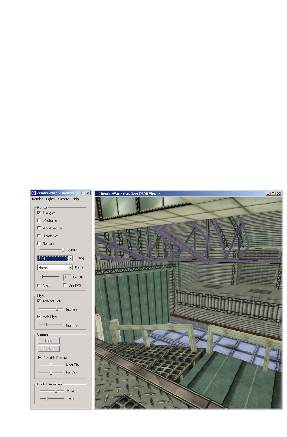
Modeling Tools
RenderWare Graphics 3.7 I-233
12.4 Modeling Tools
The RenderWare Graphics modeling package exporters supplied with the
SDK can be used to export static models. Artists should read the associated
documentation installed with these exporters for details on how they work.
Developers are also advised to read these documents, as exporters for
particular modelers may not necessarily support all features.
Exported files can be read by applications.
12.4.1 Viewers
The static models exported by artists can be tested using the RenderWare
Visualizer viewer supplied with the RenderWare Graphics SDK. Using the
RenderWare Visualizer is covered in the RenderWare Visualizer Viewers
document.
The screenshot below shows this viewer displaying a static model of a
building's interior.
This viewer can display most serialized RenderWare Graphics objects
including those supported directly by the World Plugin.

Chapter 12 - World and Static Models
I-234 11 February 2004
12.5 Creating Worlds
12.5.1 Creating Worlds from Foreign Data
This process is essentially the same as that performed by the RenderWare
Graphics modeling package exporters, the main difference is that such
modeling packages usually supply their own API to assist in the process.
The exporters take the model data, in the format the modeling package
exposes it, and converts it into RenderWare Graphics Worlds, Clumps,
Atomics, Morph Targets, Skinning data, etc.
The source code for these exporters is provided to give some insight into
how to write your own converter tools.
Creating Worlds
The SDK contains the World Import Toolkit (RtWorldImport). This Toolkit
provides API functions for creating an RtWorldImport object.
A RtWorldImport object is a fully exposed, un-optimized, uncompressed
format of a world. It is suitable for easy creation of a new World and its
static model data. The model data is exposed in the form of RenderWare
Graphics Vertices, Triangles, Materials, Normals etc.
The RtWorldImport object can then be converted by the World Import
Toolkit into an optimized, compressed RpWorld structure, and written to
disk. The toolkit provides controls for how this process is performed. In
addition, an optional callback is available to provide progress information
as the compression and optimization processing may take some time.
This process is illustrated by the world SDK-Example supplied with the
SDK. This creates a "buckyball" static model given the raw data and uses
the model to create a valid RpWorld object.
First, locate the world project files and open the world.c source file in
your preferred editor. The first part of the file contains model data, stored
in a bunch of ordinary arrays.
The first function in the source code is CreateWorldImport().
The steps involved are explained below:
1. Create an RtWorldImport object by calling RtWorldImportCreate().
This is the very first thing the CreateWorldImport() function does.
Once it's defined all the variables it needs, we see the following code:
worldImport = RtWorldImportCreate();
if( worldImport == NULL )
{
return NULL;

Creating Worlds
RenderWare Graphics 3.7 I-235
}
2. Interrogate the modeling tool to find the number of triangles and
vertices in the model to be exported then call
RtWorldImportAddNumTriangles() and
RtWorldImportAddNumVertices() to create memory for your data.
The world Example is working with its own arbitrary, hand-typed data
rather than from a modeling package's internal data structures, but the
procedure remains the same…
/*
* Allocate the memory to store the world's vertices and
triangles...
*/
RtWorldImportAddNumVertices(worldImport, NOV);
RtWorldImportAddNumTriangles(worldImport, NOT);
NOV - defines the number of vertices; NOT – defines the number of
triangles
3. Call RtWorldImportGetVertices() and
RtWorldImportGetTriangles() to obtain pointers to the vertex and
triangle arrays.
4. The world example has to first generate some Textures and some
Materials to put them in, so the vertices and triangles get added later:
vertices = RtWorldImportGetVertices(worldImport);
triangles = RtWorldImportGetTriangles(worldImport);
These lines appear immediately after the two loops that generate the
texture U/V coordinates for each vertex. If you are working with a
modeling package's own data, you may be able to take these coordinates
straight out of an existing data structure.
5. Iterate over the vertex array, copying the required data from your
modeler data into the RtWorldImport object's vertices.
In the Example, this copying takes place in the middle of two long for…
loops, which also define surface normals. The code looks like this
fragment, taken from the first (pentagons) loop:
/*
* Initialize the vertices with a world-space vertex
position,
* a normal, texture coordinates and a material...
*/
vertices->OC = VertexList[PentagonList[i]];
vertices->normal = normal;
vertices->texCoords = uvPentagon[0];
vertices->matIndex = pentagonMatIndex;
vertices++;
…etc.

Chapter 12 - World and Static Models
I-236 11 February 2004
6. Similarly, iterate through the triangles and store these in the triangle
array.
The same for… loops also have code like this for the triangles:
/*
* Initialize the triangles with indices into the vertex list
* and a material...
*/
triangles->vertIndex[0] = j;
triangles->vertIndex[1] = j + 2;
triangles->vertIndex[2] = j + 1;
triangles->matIndex = pentagonMatIndex;
triangles++;
…etc.
This is only a small fragment of the triangle copying code; refer to the
source code to see the full code.
7. Use the RtWorldImportAddMaterial() and
RtWorldImportForAllMaterials() functions to manage adding
Materials to the RtWorldImport object. The return value from
RtWorldImportAddMaterial() is the Material index. Materials are
linked to triangles, so Material indices need to be copied to the
appropriate elements in the RtWorldImport triangles array.
The world Example actually performs this before the vertex copying
steps. The programmer creates a standard RpMaterial object and
populates it with the Texture loaded earlier…
hexagonMaterial = RpMaterialCreate();
RpMaterialSetTexture(hexagonMaterial, hexagonTexture);
Now the Material is added to the World Import data structure…
hexagonMatIndex = RtWorldImportAddMaterial(worldImport,
hexagonMaterial);
And the process is repeated for the pentagons. (Buckyballs are built out
of hexagons and pentagons)…
pentagonMaterial = RpMaterialCreate();
RpMaterialSetTexture(pentagonMaterial, pentagonTexture);
pentagonMatIndex = RtWorldImportAddMaterial(worldImport,
pentagonMaterial);
The following two steps are optional and the world Example only
performs Step 8 as the model takes very little time to convert.
8. You can now optionally establish a callback procedure to handle the
messages sent by the converter to advise on progress. To do this, you
can use the RtWorldImportSetProgressCallback() function to
specify the function that your exporter provides. The API Reference lists
the messages that are sent.

Creating Worlds
RenderWare Graphics 3.7 I-237
9. Modify the parameters used to control the export process, using
RtWorldImportParametersInit().
This is done in the CreateWorld() function which is also in the same
source file. The relevant code is reproduced below:
static RtWorldImportParameters params;
RtWorldImportParametersInit(¶ms);
params.flags = rpWORLDTEXTURED | rpWORLDNORMALS |
rpWORLDLIGHT;
params.conditionGeometry = FALSE;
params.calcNormals = FALSE;
10. Call RtWorldImportCreateWorld() to perform the conversion of the
RtWorldImport object into an optimized, compressed RpWorld object.
A single line of code performs this task in the Example:
world = RtWorldImportCreateWorld(worldImport, ¶ms);
This will build your world with the default scheme, one that tries to
balance the world and reduce splits to geometry and materials.
The default scheme works by examining a number of candidate
partitions for each axis, the default is 20. To change this value, to 50 in
the example below, the following code should be called before
RtWorldImportCreateWorld():
RwInt32 maxClosestCheck = 50; /* required value */
RtWorldImportSetStandardBuildPartitionSelector(
rwBUILDPARTITIONSELECTOR_DEFAULT,
(void*)&maxClosestCheck);
RtWorldImport provides the mechanisms necessary to create a world
that is partitioned in a way that is specific to your own requirements
and there are a diverse set of functions that let you partition the world
as controllably as you want. Details of these are in the white paper "BSP
trees".

Chapter 12 - World and Static Models
I-238 11 February 2004
The params structure is defined as follows:
PARAMETER PURPOSE
WorldSectorMaxSize
(RwReal)
Defines the maximum size of World
Sector.
This is generally a trade-off between
storage space and speed.
MaxWorldSectorPolygons
(RwInt32)
Maximum number of polygons in a
World Sector.
TerminatorCheck (RwBool)
Set to TRUE to check the world for
validity during the build process
CalcNormals (RwBool) Set to TRUE to recalculate all normals.
MaxOverlapPercent
(RwReal)
Maximum amount by which World
Sectors are allowed to overlap.
ConditionGeometry
(RwBool)
Set to TRUE to perform welding and other
optimizations. (See the geometry
conditioning white paper.)
UserSpecifiedBBox
(RwBool)
Set to TRUE if you want to specify a
minimum Bounding Box for the World.
UserBBox (RwBool) Minimum Bounding Box (See above).
FixTJunctions
(RwBool)
Set to TRUE to enable fixing of
T-junctions created during World
generation.
Flags
(RwInt32)
Flags to be used for the World. These
are:
rpWORLDLIGHT
rpWORLDNORMALS
rpWORLDTRISTRIP
rpWORLDTEXTURED
rpWORLDMODULATEMATERIALCOLOR
rpWORLDPRELIT
Finally, the RpWorld object can be serialized.
Converting custom formats
You can use a custom file format for your models, or have legacy objects for
which the original modeling tool files have become lost or incompatible with
newer tools. In such cases, it is more convenient to write a format converter
and the world Example explained earlier in this chapter.
✎
✎✎
✎
RenderWare Graphics separates static and dynamic geometry into Worlds and
Atomics/Clumps. It would therefore make little sense to convert a legacy car model into an
RpWorld object, or a complex building into an RpAtomic. RenderWare Graphics can
perform intelligent scene management with an RpWorld, and can efficiently animate
dynamic RpAtomics.

Creating Worlds
RenderWare Graphics 3.7 I-239
Creating an Empty World
It is sometimes useful to create a "blank" World object that contains no
scenery data. Such usage is common in viewer utilities and many of the
viewers supplied with the RenderWare Graphics SDK do use empty Worlds.
These Worlds contain only an empty World Sector that fills the entire world
space and can be easily created using the RpWorldCreate() function. This
takes a bounding box (RwBBox) parameter, which defines the extents of the
single World Sector. You will find this function used frequently in the many
SDK Examples supplied on the CD.
Creation Flags
A World's model data can be handled in a number of different ways. For
instance, you might want to avoid lighting it dynamically using Lights and
just use pre-lit vertices. Or, you may want to tell the rendering pipeline that
the data is organized as triangle strips so it can run faster on the target
platform.
✎
✎✎
✎
It is not normal to change these flags once the World has been created or loaded. Doing so
may have a detrimental effect on performance.
These and other settings are made using the RpWorldSetFlags() function.
This exposes the following flags:
• rpWORLDTEXTURED
The World has textures applied. Texture coordinates are specified on a
per vertex basis.
If reading World data from a stream, you will need to either setup the
search path for the Textures using RwImageSetPath(), or load a
Texture Dictionary containing the Textures first.
• rpWORLDPRELIT
The World has prelit colors.
The modeling package exporters provide full support for prelights. See
the Artists Guides supplied with the exporters for details.
• rpWORLDNORMALS
The World has vertex normals.
Normals are a requirement if you intend to have dynamic Light objects
that affect the scenery. The rpWORLDLIGHT flag should also be set in
such cases.
• rpWORLDLIGHT
Dynamic Light objects will light the World.

Chapter 12 - World and Static Models
I-240 11 February 2004
Setting this flag tells RenderWare Graphics to allow dynamic Lights to
affect the static geometry. As this form of lighting requires additional
processing, you should take care when using this.
Dynamic Lights also need normals for the lighting calculations, so you
should also set the rpWORLDNORMALS flag as well.
Using dynamic Lights does not preclude the use of prelights, but you
may need to set the rpWORLDMODULATEMATERIALCOLOR flag if you intend
to mix the two forms to best effect.
• rpWORLDTRISTRIP
World's static geometry can be rendered as triangle strips.
This is a hint to the rendering pipeline that the model data is optimized
as triangle strips. Triangle strips are an option available on the
RenderWare Graphics modeling package exporters.
• rpWORLDMODULATEMATERIALCOLOR
This flag tells the rendering pipeline to take (a) lighting, (b) prelights and
(c) Material colors into account when rendering the model data. This
usually gives the most accurate rendering results, but can be expensive
in terms of processing power.
12.5.2 What is Pre-lighting?
The distinction between static and dynamic models is not the only such
division. RenderWare Graphics also supports both dynamic and static
lights.
Static lighting doesn't actually involve a separate object, as the data is
stored directly in the vertex data as arrays of RwRGBA color values. During
the rendering cycle, the pipeline will simply combine this vertex prelight
data with the Material for that vertex and extrapolate across the surface of
the triangles.
Prelights are defined by the artist in their modeling package. The artist can
position supported lighting types at the appropriate locations in their
model. Artists must then tag all static lights using a "prelight" tag (the exact
method for doing this varies from modeling package to modeling package).
At the export stage, the artist selects the appropriate option in the
RenderWare Graphics exporter's options dialog box and the exporter then
sets up the vertex lighting arrays and writes them out with the rest of the
model data.
✎
✎✎
✎
The nature of the pre-lighting processing means only some of the modeling package's full
complement of lights can be used for this purpose. See the artist documentation for
modeler-specific details.

Creating Worlds
RenderWare Graphics 3.7 I-241
Creating Prelights using the World Import Toolkit
The World Import Toolkit exposes the RtWorldImportVertex object. This is
defined as follows:
typedef struct RtWorldImportVertexTAG
{
RwV3d OC; /* World space vertex position */
RwV3d normal; /* World space vertex normal */
RwRGBA preLitCol; /* Vertex Pre-light color */
RwTexCoords texCoords; /* Vertex texture coordinates */
RwInt32 clipFlags; /* Internal use only */
RwInt32 matIndex; /* Vertex material index */
} RtWorldImportVertex;
As you can see, setting the prelight color is simply a case of modifying the
preLitCol element.
Static Lights
Static model prelights work a little differently compared to its dynamic
model variant. RenderWare Graphics assumes static models are completely
static – including any prelight data – so prelight colors cannot be
manipulated directly.
If you need lights that flicker, or any similar such effects, you will need to
use either dynamic lights or Atomics placed over the static model.

Chapter 12 - World and Static Models
I-242 11 February 2004
12.6 Rendering
12.6.1 How to Render Worlds
Rendering a World object will render its contents. This means that, usually,
rendering a complete scene can be achieved with a single call to
RpWorldRender().
The Rendering Process
When you call RpWorldRender(), the BSP tree is searched and the visible
World Sectors are rendered in turn.
The following points should be taken into consideration:
• When each World Sector is rendered, each Atomic and Light in that
sector is rendered before the next visible World Sector is processed.
• Rendering is performed either back-to-front, or front-to-back depending
on which is faster on that particular platform.
• Local dynamic Light objects may only affect some World Sectors. Use
the bounding-box-to-sphere intersection collision detection functions to
identify these.
✎
✎✎
✎
Rendering World Sectors
World Sectors are rendered automatically by calls to RpWorldRender(). It is not possible
to explicitly render a specific World Sector object.
Render Callback
It is possible to hook into the World Sector rendering process by providing a
callback function to RpWorldSetSectorRenderCallBack(). This callback
function, of type RpWorldSectorCallBackRender(), will then be triggered
prior to rendering each sector.
This allows you to include your own optimization techniques. The RpPVS
visibility culling Plugin uses this hook.
12.6.2 Instancing
A static geometry in RenderWare Graphics has two representations: a
platform-independent (PI) representation (also known as platform neutral)
and a platform-specific (PS) representation (also known as native data)
optimized for the underlying hardware. The process of converting from
platform neutral data to native data is called instancing. This process
normally happens only during the first rendering of the world.

Rendering
RenderWare Graphics 3.7 I-243
Native data is not actually stored within the geometry itself. Instead, it is
allocated space in the Resource Arena. This is a cache that only stores
native data. The caching metaphor is particularly apt since existing native
data can be thrown out if there isn't enough space left to create new
instances of other geometries that need to be rendered. This can result in a
problem known as arena thrashing, whereby performance is crippled by the
need to re-instance the geometry every frame.
The Resource Arena's size is set during the start-up phase by calling the
RwEngineInit() function. Exactly what size you should set is heavily
dependent on your application, so you will need to experiment to get a good
balance between speed and efficiency. The ideal is as small as possible
without arena thrashing ever occurring during application execution.
12.6.3 Pre-instancing Static Geometry
One optimization of the above instancing scheme can be performed if it is
known that the platform independent (PI) representation will not be used at
run-time, and that is to use solely pre-instanced platform specific (PS)
representation, rather than creating it at run-time. This has the advantages
that no CPU cycles are used to instance data on their first rendering, which
gives a minor performance improvement, but also means that space is not
required for storage of the platform neutral data. In the case of static
geometry this is strongly recommended.
The RpWorldInstance() function is used to generate a persistent copy of
the native data, so at that time both representations of the world exist. The
PI representation exists as before and the PS representation both exist
outside the resource arena. When rendering occurs the platform specific
representation is always used and the resource arena is now not used by
the world during rendering.
The platform specific data generated should be considered opaque and
highly volatile as the format is subject to change between versions.
Worlds with pre-instanced geometry are serialized slightly differently from
those without. If the world is serialized, the function for writing the
geometry to the stream RpWorldStreamWrite() does not export platform
neutral data when persistent native data is present, and consequently
when the world is loaded into memory with RpGeometryStreamRead()the
PI data is lost. This is where the memory saving occurs.
As the instancing process has already been performed and is not performed
at run-time, the resource arena is never used, and the resource arena size
may be reduced accordingly. The resource arena may be eliminated
altogether if no instancing occurs, which would require any dynamic
geometry to be pre-instanced too, see the Dynamic Models chapter of this
guide.
This means that features which use the PI data will no longer work, and
functions to get PI data will return failure codes. For instance, static PVS
creation should be undertaken before pre-instancing. Collision detection is
not possible, though a lower resolution collision geometry, which is never
rendered, could be used to test for collisions.

Chapter 12 - World and Static Models
I-244 11 February 2004
The only exception to this is that the number of vertices and triangles in
the geometry are preserved and can be read using
RpGeometryGetNumVertices() and RpGeometryGetNumTriangles()
respectively. These are stored mainly so that sensible metrics can be
observed with PS data, and the actual PI triangle data itself is not present.
Using RpWorldInstance()
Firstly the availability of pre-instancing of worlds varies from platform to
platform, and so please check the platform specific documentation for your
platform to determine if this feature is supported for your platform.
To pre-instance a world, it is required that the world plugin is attached.
Also the correct rendering pipelines must be attached to the world and any
materials it uses before the RpWorldInstance() function is called. These
rendering pipelines may introduce PS data which is required to give the
desired effect during rendering
The RpWorldInstance() function must be called within the
RwCameraBeginUpdate() and RwCameraEndUpdate() pair of calls within
the rendering loop, as the render pipelines must be executed to ensure that
all the relevant data is created. In practice the RpWorldInstance()
function is similar to the RpWorldRender() function but that the PS data is
not created in the resource arena but allocated from the heap, ensuring
that the data is persistent. Clipping and culling are never performed so that
all instanced data is generated even if not inside the camera’s view frustum.
Save the world to disk using serialization functions as described below and
use this as the asset for loading from the game disk. If loading of the PS
data fails, it is sensible during development to automatically fallback to
loading a platform independent version of the asset, and flag it for pre-
instancing in the render loop. Then save the new pre-instanced version over
the top of the one that failed to load. This will cope with any changes to the
binary format of pre-instanced data caused by updating your version of
RenderWare Graphics.
✎ Pre-instancing should not be attempted when PVS is enabled.

Serialization
RenderWare Graphics 3.7 I-245
12.7 Serialization
The RpWorld object supports serialization through the standard
RenderWare Graphics Binary Stream system.
✎
✎✎
✎
Filename Extensions
The ".BSP" file extension is not obligatory. RenderWare Graphics has only one file format
as such: the RenderWare Graphics Binary Stream. Different extensions are used as a
memory aid.
The functions provided by the RpWorld API for this purpose are:
• RpWorldStreamGetSize()
This returns the size, in bytes, of the binary stream representation of
the given RpWorld object excluding dynamic objects.
✎
✎✎
✎
The size returned by this function is not the same as the size of an actual RpWorld object.
• RpWorldStreamRead()
Reads an RpWorld object, and all the RpWorldSector objects it
contains, from the specified RenderWare Graphics binary stream.
• RpWorldStreamWrite()
Writes an RpWorld object, all the RpWorldSector objects it contains, to
the specified RenderWare Graphics binary stream.
• RpWorldSetStreamAlwaysCallBack()
You provide a callback function, which will be called after any
RpWorldStreamRead() operations. This function is designed to allow
plugins that extend RpWorld to initialize structures based on data read
from the stream.
The callback is called after all World Sectors have been read.
There is also an equivalent function for RpWorldSector objects, named
RpWorldSectorSetStreamAlwaysCallBack(). This exists for similar
reasons to the RpWorld function, but is called after each World Sector is
read.
✎
✎✎
✎
It is important to remember that only the static model data is referenced when serializing
RpWorld objects. Dynamic models must be written separately by explicit calls to the
appropriate …StreamRead/Write() functions.

Chapter 12 - World and Static Models
I-246 11 February 2004
12.7.1 Writing
The world SDK Example includes the code needed to serialize the World
object it creates. This code is near the end of the world.c file. (The code
fragments below show only the relevant code for clarity.)
First, open a RenderWare Graphics binary stream…
RwStream *stream;
RwChar *path;
path = RsPathnameCreate(RWSTRING ("./world.bsp"));
stream = RwStreamOpen(rwSTREAMFILENAME, rwSTREAMWRITE, path);
…the stream needs to be writeable, hence the rwSTREAMWRITE flag…
RsPathnameDestroy(path);
if( stream )
{
RpWorldStreamWrite(world, stream);
…now the RpWorldStreamWrite() function to write the RpWorld's static
model data to the stream.
✎
✎✎
✎
It is important to note that this function only writes static model data – the World Sectors
– to the stream. No dynamic model data is written.
At this point, all that is left is to close the stream thus:
RwStreamClose(stream, NULL);
}
These steps should result in a file on disk with the name specified in the
RwStreamOpen(). (In the code fragment above, the file would be named
"world.bsp".)
Dragging this file onto the "clmpview" viewer or the "RenderWare
Visualizer" viewer should also display the buckyball.
✎
✎✎
✎
Note that the textures are not saved with the World data as they are treated separately. In
most cases, they are already on the disk as either individually-serialized Textures (rare) or
stored together in groups as a Texture Dictionary.

Serialization
RenderWare Graphics 3.7 I-247
12.7.2 Reading
The most common use of static models is as scenery. Normally, you will
want to read such models from a RenderWare Graphics binary stream and
render the resulting RpWorld object.
The process is:
1. Ensure the path to any Texture images has been set using
RwImageSetPath().
2. Open a RenderWare Graphics binary stream using the standard
RwStreamOpen() API.
3. Read the RpWorld object from the stream.
4. Close the stream.
5. Render the object.

Chapter 12 - World and Static Models
I-248 11 February 2004
12.8 Destruction
C does not provide intrinsic support for object destructors, which means
that any objects created in a program must be destroyed explicitly.
Any objects associated with a World - the Atomics, Lights, Cameras and
static scenery - will need to be destroyed and it is important that this is
done in the correct order, as follows:
1. Remove and destroy any Clumps. These may contain collections of
Atomics, Lights, and Cameras that are automatically removed from a
World and destroyed during this process.
2. Remove and destroy any remaining Atomics, Lights, and Cameras that
were added individually to the World.
3. Finally destroy the World itself. This automatically destroys the World
Sectors and the static geometry they contain.

Chapter 13
Dynamic Models

Chapter 13 - Dynamic Models
I-250 11 February 2004
13.1 Introduction
RenderWare Graphics' Retained Mode API distinguishes between two types
of model: static and dynamic. For example, in a theater, static models are
the "scenery" and dynamic models are the "actors". A racing game would
therefore use a static model for the racing track and dynamic models for
the cars.
RenderWare Graphics assumes that a dynamic model is likely to be
manipulated in real time by the application. For example, they may be
moved around a world by animating the position and rotation of their
frames, or their vertex colors or vertex normals could be changed to adjust
the appearance of the object.
Most real-time 3D graphics programming will make use of dynamic models.

The World Plugin
RenderWare Graphics 3.7 I-251
13.2 The World Plugin
RenderWare Graphics' Retained Mode API is contained within the world
plugin (RpWorld). This plugin defines many new object types. In this
chapter, however, we are interested in the three primary dynamic model
objects: the clump (RpClump), the atomic (RpAtomic) and the geometry
(RpGeometry). Of these new objects, only the geometry object actually
stores vertex and polygon information. The clump and atomic object are
used to help manage the geometry.
13.2.1 The Geometry Object
The geometry object contains the vertices, triangle indices, texture
coordinates and all other necessary components needed to create a model.
It represents a model, or, a part of one, and is the actual object that is
rendered.
The geometry, however, has no linkage for a frame (RwFrame) object, which
is required for positioning within a scene.
(Frames are covered in detail in the Fundamental Types chapter.)
13.2.2 The Atomic Object
An atomic contains pointers to a geometry object and a frame object. It also
contains a bounding sphere. This helps RenderWare Graphics determine
quickly whether the atomic (strictly the geometry it points to) is visible.
The atomic object provides the link between the geometry and a frame,
which allows a geometry to be located within the scene.
It is important to realize the difference between the atomic and the
geometry. The atomic is a container for geometry. The geometry defines the
data.

Chapter 13 - Dynamic Models
I-252 11 February 2004
13.2.3 The Clump Object
Models tend to be quite complex and it is common for them to be broken
down into smaller separate parts, particularly with hierarchical models. In
RenderWare Graphics, a complete model is constructed from more than one
geometry object. This means that multiple atomics need to be kept track of
to manage complex models.
A clump is a container for dynamic objects that are associated with a frame
hierarchy. This usually just means atomics, but a clump might also contain
cameras and lights. A clump is a convenient place to store, say, a football
player's hierarchical model data together in one place. A clump can:
1. Add and remove atomics using RpClumpAddAtomic()and
RpClumpRemoveAtomic().
2. Render atomics in a clump using RpClumpRender().
3. Get and Set frames in a clump using RpClumpGetFrame() and
RpClumpSetFrame().
4. Load and save clumps.
We can attach a frame to a clump and link that frame to the top frame in
the model's hierarchy. This way, transforming the clump's frame will
transform the clump and the hierarchical model it contains. Be careful to
avoid falling into the trap of thinking that the clump defines the
relationship between atomics it holds. In fact, the hierarchical relationship
is determined completely by the frame hierarchy.
A Typical Clump Hierarchy of Atomics
clump frame
frame frame
frame
atomic
atomic
atomic
atomic
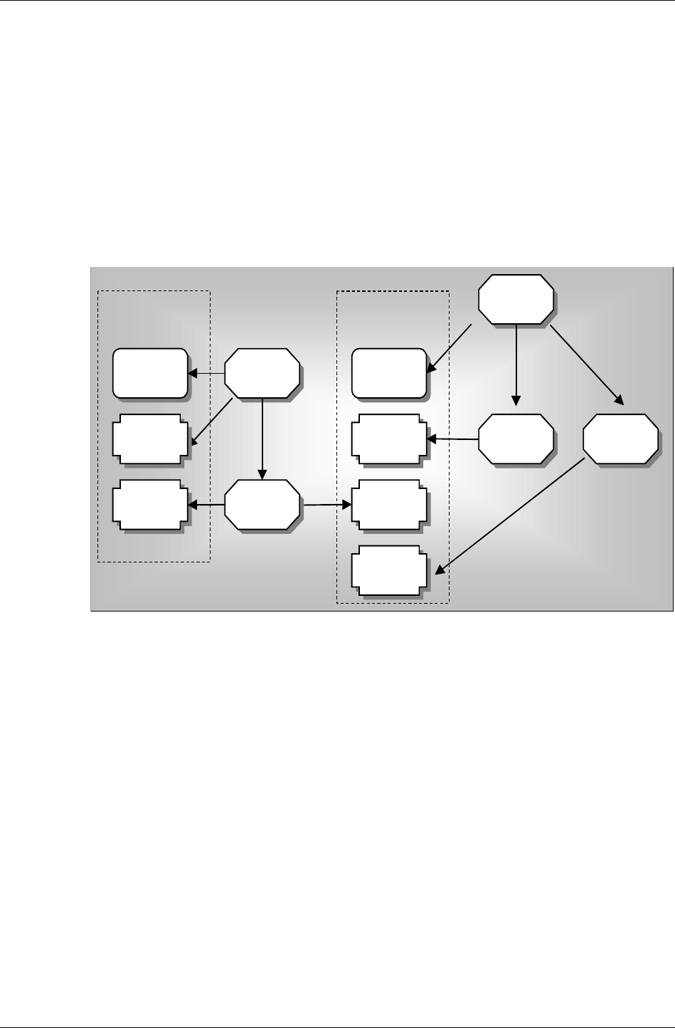
The World Plugin
RenderWare Graphics 3.7 I-253
In the figure above, a relationship between clumps, atomics and frames is
shown. A single clump contains four atomics. The clump and first atomic
share their frame. This frame is itself a parent of a hierarchy of frames and
the clump points at the root frame for convenience. The frames in the tree
are used by the remaining three atomics. Any changes made to clump's
frame since it's the root frame, in this example, will affect all atomics.
Frames are parents of atomics, clumps and other objects, for example,
camera and lights and more information on frames can be found in the
Fundamental Types chapter.
A Complicated Clump Hierarchy of Atomics
clump frame
atomic
atomic
atomic frame atomic
frame
frameframe
clump
atomic
Clump 1 Clump 2
The figure above illustrates a more complicated clump hierarchy of atomics.
The figure above shows a clump containing atomics, although the objects
could just as easily be lights or cameras. Clumps and atomics can be
attached to frames. A clump's frame can be the parent of an atomic's frame
or a frame can be the parent of multiple atomics and multiple clumps.
Why Use Clumps?
It is not written in stone that atomics must be grouped in clumps. If you
prefer to manage atomics yourself, you are perfectly free to do so; clumps
were designed merely as a convenient container object.

Chapter 13 - Dynamic Models
I-254 11 February 2004
That said, it can be useful to group atomics of a certain type together, even
if they are not otherwise related. For instance, you may want to keep track
of all atomics that use a particular Material so that you can get at them
easily, or you may have atomics that have special attributes – e.g., they
represent collectable items in a game. Again, clumps can be used for this.
Attaching a frame to a clump is only required if you intend to render it
using RpClumpRender(). You do not need to set up a frame otherwise.
The main reason for using clumps is to make use of their iterator functions,
which usually make managing hierarchies and arbitrary groups of atomics
easier.
✎
✎✎
✎
".DFF" Files
Files with the extension DFF are considered to be legacy file types from RenderWare
Graphics 3.5. These files were generally used to store clumps, but could actually contain
anything that could be streamed through the RenderWare Graphics Binary Stream API. By
definitions, a DFF would contain a single clump.
RWS files are the default binary stream file type now. These files may contain many
clumps. See the Serialization chapter for more details on RWS files.
13.2.4 Clump Destruction
RpClumpDestroy() destroys all atomics (and other objects) in the clump,
and all the frames in the hierarchy of the clump, but will not destroy the
frames of the atomics in the clump if those frames are not in the clump
hierarchy.

Creation of Dynamic Models
RenderWare Graphics 3.7 I-255
13.3 Creation of Dynamic Models
13.3.1 Model Creation Overview
Clumps, atomics and dynamic model geometry must be created before they
can be used in a RenderWare Graphics application. Although these objects
can be created dynamically at run time, it is more common to create them
offline. Typically, one of the supported modeling packages will be used for
this process. The steps involved in exporting dynamic models from
modeling package to a file that can be read by a RenderWare Graphics
application are described in the documentation supplied with the
appropriate exporter plugins. This documentation is supplied with the Art
Tools and covers the model creation and export processes.
The end result of the export process is, by default, an ".RWS" file of the kind
we looked at briefly in the previous section. By convention, these files may
contain any number of clump objects. The RenderWare Graphics streaming
API can be used to find a clump in this RWS file. This clump will contain
one or more atomics and frames.
☛
You can test whether the export process worked by clicking RenderWare
Æ
View in 3ds
max or Maya to launch the RenderWare Visualizer.

Chapter 13 - Dynamic Models
I-256 11 February 2004
13.4 Modeling Tools
Most developers will be working with models built in a professional
modeling package by an artist. To this end, RenderWare Graphics is
supplied with a set of exporters for popular modeling packages, as well as
some tools to view and test the output from these exporters.
13.4.1 Exporters
RenderWare Graphics exporters are available for the following modeling
packages:
• Discreet 3ds max - support for versions 5 and 6.
• Alias|Wavefront Maya - support for versions 4 and 5.
Other modeling packages are not supported directly, but a number of
RenderWare Graphics Toolkits have been provided to make it easier for you
to develop your own exporters and tools.
Artist and Programmer documentation are available for the RenderWare
Graphics exporters at installation time.
13.4.2 Viewers
The RenderWare Graphics SDK comes with three viewer applets. The
viewers are RenderWare Visualizer, wrldview and clmpview. RenderWare
Visualizer allows you to easily view RenderWare Graphics artwork on any
target hardware. wrldview and clmpview deal with static and dynamic
model data respectively, using the legacy file types .BSP and .DFF.
✎ The meaning of “legacy” file types is that in the future, RenderWare Graphics exporters
may not export to these file types. However, the binary format of these files continues to
be supported and this version of RenderWare Graphics will continue to read them. There
is no need to re-export existing DFF/BSP/etc. artwork as RWS files.
All viewers will accept files for viewing on the target platform. The Win32
builds for wrldview and clmpview are drag-and-drop enabled for legacy
file types. You can drop a .BSP (for wrldview) or .DFF file (for clmpview)
onto the window to view the file.
These viewers are a useful means of testing your artists' exported models to
ensure they look the way they're supposed to and contain valid data.
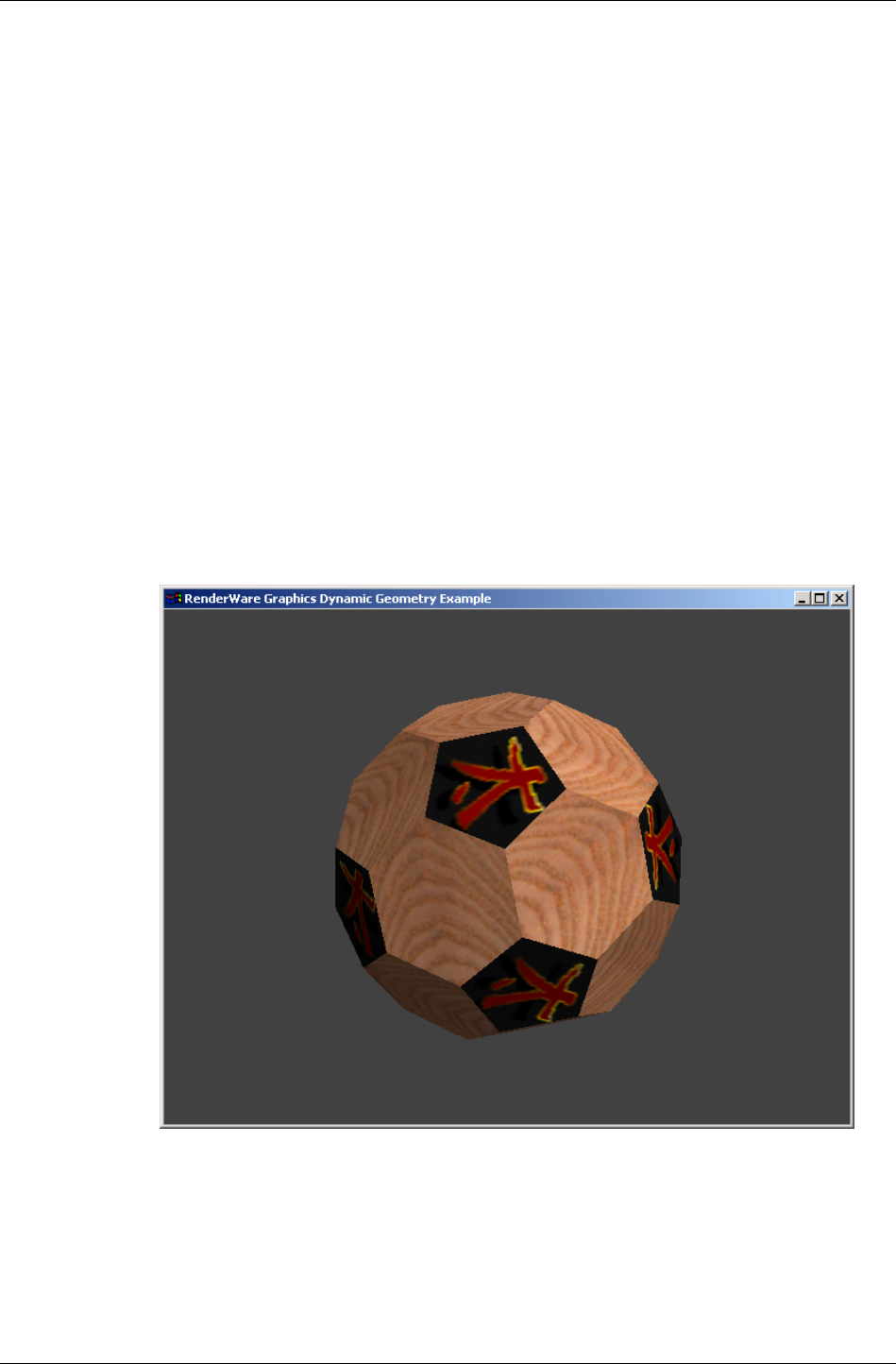
Modeling Tools
RenderWare Graphics 3.7 I-257
13.4.3 Procedural Model Creation
Creating models during the execution of your game (procedural generation)
is rare. Normally, you will only ever need to load models exported from a
modeling package. However, it is always useful to understand why an
object works as it does or needs to be used in a particular way. Also, it is
important to realize that the exporters supplied with the RenderWare
Graphics SDK are regular RenderWare Graphics applications that make
calls into the API. To this end, this section will walk you through the
"geometry" SDK example. This example shows you how to build a clump
using the API function calls.
For simplicity, we will ignore the rendering process of the example, and
concentrate on the clump creation code.
Overview
The code in the example/geometry the geometry.c source file concerns
itself with the construction of a simple buckyball object, as shown in the
screen shot below. The "buckyball" is a "truncated icosahedron". The model
is built from interconnected hexagons and pentagons.
buckyball
13.4.4 Vertices & Triangles
The first stage in model creation is to define the data.

Chapter 13 - Dynamic Models
I-258 11 February 2004
All 3D geometry is defined in terms of vertices. These vertices are linked
together to form polygons. The RenderWare Graphics geometry object
supports only triangles, which is why the RenderWare Graphics' geometry
objects are defined in terms of triangle (RpTriangle) objects.
The first section of the geometry.c source file therefore consists of long
lists of coordinates (vertices) and array indices, which define our buckyball
object. The first list defines 60 vertices:
static RwV3d BuckyBallVertexList[60] =
{
{ 0.00f, 145.60f, 30.00f },
{ 0.00f, 145.60f, -30.00f },
This list of vertices is indexed by subsequent arrays that use these vertices
to define pentagons and hexagons in terms of triangles:
static RwUInt16 BuckyBallPentagonList[5*NOP] =
{
0, 2, 4, 6, 8,
and:
static RwUInt16 BuckyBallHexagonList[6*NOH] =
{
0, 1, 20, 21, 3, 2,
Note that at this point in the example we are not defining the polygons
(triangles) that RenderWare Graphics will use, merely defining data that we
shall later use.
Object Space
The vertices that make up the buckyball model are defined in object space.
This means they are relative to the origin of the object itself and have no
relationship with the world coordinate system. The result, in this case, is
that the origin of the buckyball model is in the center of the model.

Modeling Tools
RenderWare Graphics 3.7 I-259
13.4.5 Textures & Materials
Textures
The geometry.c source file contains one long function:
CreateBuckyBall(). This function processes the data and creates the
objects.
The first step is to load in the textures that will decorate the buckyball.
First, the programmer sets the search path for the texture data. This is
done using the Skeleton's RsPathnameCreate() function to create a valid,
platform-dependent path. This path is then fed to the RwImageSetPath()
function so that RenderWare Graphics knows where to search for the
texture map files. RenderWare Graphics will use the path name(s) to
determine where on the file system to look for images. (This is similar in
concept to the PATH variable found in many CLI-based operating systems.)
In RenderWare Graphics, multiple locations can be specified, by separating
the paths by semi-colons.
Next comes the actual creation of the texture objects with the
RwTextureRead() function. The calls to RwTextureSetFilterMode() tells
RenderWare Graphics that these textures are to use the "linear" filter mode.
The filter mode that is set for each triangle is used by the rendering
hardware to control how to texture map the surface. A linear filter mode
helps "soften" the texture.
In the code below, we load two textures from disk. These textures will be
used to texture map the pentagon polygons, and the hexagon polygons
respectively.
/*
* Create the bucky-ball textures...
*/
path = RsPathnameCreate(RWSTRING("./textures/"));
RwImageSetPath(path);
RsPathnameDestroy(path);
pentagonTexture = RwTextureRead(RWSTRING("dai"), NULL);
RwTextureSetFilterMode(pentagonTexture, rwFILTERLINEAR);
hexagonTexture = RwTextureRead(RWSTRING("whiteash"), NULL);
RwTextureSetFilterMode(hexagonTexture, rwFILTERLINEAR);
Textures are no use on their own. They need to be linked to the model data
in some way so that RenderWare Graphics knows when and how they
should be rendered.

Chapter 13 - Dynamic Models
I-260 11 February 2004
Materials
Textures require two links with the model data. The first are the texture
coordinates (U and V) defining where the texture is applied. Texture
coordinates are stored on a per-vertex basis.
For RenderWare Graphics' Retained Mode API, the remaining link is the
material (RpMaterial) object and we can see that, indeed, the textures are
being added to two such material objects just after they are loaded:
/*
* ...and materials...
*/
pentagonMaterial = RpMaterialCreate();
RpMaterialSetTexture(pentagonMaterial, pentagonTexture);
hexagonMaterial = RpMaterialCreate();
RpMaterialSetTexture(hexagonMaterial, hexagonTexture);
A buckyball is made up of pentagons and hexagons and the example's
designer has decided to define two material objects, one each for the
pentagons and hexagons. Pentagons will therefore all share one material
(and its texture), while hexagons will share the other.
With the textures now added to a material object, the texture coordinates
need calculating for use later. These are calculated in the two subsequent
for… loops. (This is documented in the function's source code.)
Material Color
To use material colors the rpGEOMETRYMODULATEMATERIALCOLOR flag needs
to be set (see RpGeometryFlag). If a model is exported with material color
255, 255, 255, 255 the rpGEOMETRYMODULATEMATERIALCOLOR flag is not set
and the material color will not be used.
✎
Using the RenderWare Graphics exporters (3ds max or Maya), if all the materials used are
colored white, then the rpGEOMETRYMODULATEMATERIALCOLOR flag is set to OFF, otherwise
the flag is set to ON.
For worlds and patches, the flags rpWORLDMODULATEMATERIALCOLOR and
rpPATCHMESHMODULATEMATERIALCOLOR are used respectively. They are applied in the
same way as rpGEOMETRYMODULATEMATERIALCOLOR.

Modeling Tools
RenderWare Graphics 3.7 I-261
13.4.6 Surface Properties & Geometry
The instantiation of the actual geometry object is trivial, although it is
worth noting the flags parameter. The full set of available flags is as follows:
• rpGEOMETRYTRISTRIP
This geometry's meshes can be rendered as strips of triangles. This is
an optimization technique available on a number of platforms.
☛
Sony PlayStation2 Optimization Tip
Tri-strips are practically mandatory on this platform due to the hardware's design.
• rpGEOMETRYTEXTURED
This geometry has textures applied. Including this flag means the
renderer will expect texture objects to be used.
• rpGEOMETRYPRELIT
This geometry has pre-calculated lighting data.
• rpGEOMETRYNORMALS
This geometry has normals. If your model is never going to be lit by
RenderWare Graphics' dynamic light (RpLight) objects, you can save on
system resources by not storing normals. This is particularly useful for
pre-lit models.
• rpGEOMETRYLIGHT
This geometry will be lit by dynamic light objects.
• rpGEOMETRYMODULATEMATERIALCOLOR
Modulate material color with vertex colors (pre-lit + lit), allowing
prelight vertex colors and dynamic lighting to be blended with the
underlying material color.
Also defined in this part of the source code is the surface property
(RwSurfaceProperty) data for the model.
Surface properties define how surfaces reflect light. The three components,
as you can see from the code, are ambient, specular and diffuse.
Respectively, they determine how much ambient light is reflected by the
object, how smooth and shiny the surface is, and how the light is spread
over the surface.
Surface properties are stored in material objects. Currently in RenderWare
Graphics, the lighting does not compute a specular contribution.

Chapter 13 - Dynamic Models
I-262 11 February 2004
13.4.7 Morph Targets
Geometry objects are essentially containers, similar to atomics. Their
design is such that geometry will contain all the necessary data for a model,
or portion of a model. One of the objects the geometry contains is the morph
target (RpMorphTarget) object.
RenderWare Graphics' Retained Mode Plugin, RpWorld, is intended to
provide scene graph facilities with support for animation plugins. The
morph target object plays a part in this by supporting morph-target (also
known as "keyframe-interpolated") animation. While it is possible to
perform morph-target animation directly with RpWorld, most will use the
Morph plugin (RpMorph) to perform this kind of animation.
For morph-target animation to work, all geometry objects have at least one
morph target object. If there was no keyframe-interpolated animation
sequence exported from the modeling package then the geometry object will
contain exactly one morph target object.
The morph target and geometry objects divide the model data between
them. The triangle objects, which only reference vertices, are stored in the
geometry object. The actual vertex positions and normals themselves are
stored in the morph target(s). The prelight and UV texture coordinates for
each vertex live in the geometry object.
☛
Why?
Morph Targets exist because only the vertices need to be manipulated, not the model
topology itself.

Modeling Tools
RenderWare Graphics 3.7 I-263
13.4.8 Pentagons & Hexagons
After retrieving the necessary pointers to the data structures, the
geometry.c then proceeds to set up the data for the pentagons. The for…
loop runs through each pentagon in the BuckyBallPentagonList array.
The loop is divided into three parts:
1. Calculate the normal for the pentagon;
2. Initialize the vertex, normal and texture coordinates for each vertex in
the polygon;
3. Assign the vertices to the triangles, which will define the pentagon, and
assign the Material object to these triangles.
These processes are performed in the next for… loop for the hexagons as
well and the result of all this processing is an almost-complete geometry.
Triangle Winding Order
It is important that triangles are defined in a specific order. During
rendering, RenderWare Graphics looks at the vertices of a Triangle and will
only render those with coordinates arranged in a counter-clockwise
sequence relative to the camera. If the sequence is clockwise, the triangle is
assumed to be facing away from the virtual camera and is not rendered
(culled).

Chapter 13 - Dynamic Models
I-264 11 February 2004
13.4.9 Bounding Spheres & Transformations
In this example, we want to condition the geometry such that it has an
origin at the center of the model, and has a known physical size. The next
steps perform these tasks.
The next section of code finishes off the construction of the geometry object.
It is worth closer inspection…
if( normalize )
(The calling function sets this to TRUE.)
{
/*
* Center and scale to unit size...
*/
RwSphere boundingSphere;
RwMatrix *matrix;
RwV3d temp;
RpMorphTargetCalcBoundingSphere(morphTarget,
&boundingSphere);
This function calculates a sphere that is just big enough to contain the
entire buckyball model. The RenderWare Graphics core library and the
world plugin both use bounding spheres heavily. In particular, the
bounding sphere is used to determine whether the object is within the
camera object's view frustum.
Also, if you are making use of the static geometry functionality provided by
RpWorld, the sphere is used to check which world sector(s) the model
resides in.
✎
✎✎
✎
RwSphere is a simple exposed data-type. You can find its definition in the API Reference.
Continuing with the bounding sphere calculations:
matrix = RwMatrixCreate();
RwV3dScale(&temp, &boundingSphere.center, (RwReal)-1.0f);
RwMatrixTranslate(matrix, &temp, rwCOMBINEREPLACE);
temp.x = temp.y = temp.z = (RwReal)1.0f /
boundingSphere.radius;
RwMatrixScale(matrix, &temp, rwCOMBINEPOSTCONCAT);
At this point, we have a matrix that contains two operations:
1. A translation that positions the object coordinate system origin at the
center of the buckyball;
2. A scaling operation that will shrink our buckyball model to a unit size.

Modeling Tools
RenderWare Graphics 3.7 I-265
This means that we now have a matrix that can be used to translate and
rescale our buckyball model ready for viewing.
✎
✎✎
✎
This scaling is being done because the vertex list was calculated with paper and pen,
rather than a 3D-modeling package.
The next step is to apply the transformation matrix to our geometry object
and then to destroy the matrix itself as we no longer need it. The call into
RpGeometryTransform() will compute and set the bounding sphere for all
morph targets on our behalf.
/*
* This will re-calculate and set the new bounding sphere
* and also unlock the geometry...
*/
RpGeometryTransform(geometry, matrix);
RwMatrixDestroy(matrix);
}
If you take a look at the code branch that is taken if normalize is not set,
then you can see what code is necessary to compute and set bounding
spheres:
RwSphere boundingSphere;
RpMorphTargetCalcBoundingSphere(morphTarget, &boundingSphere);
RpMorphTargetSetBoundingSphere(morphTarget, &boundingSphere);
Note that each separate morph target in a model requires a bounding
sphere to be calculated and set. In this example, the code assumes
(correctly) that there is only a single morph target.
Locking, Unlocking
Geometry objects are created in a locked state. Geometry objects have to be
locked while they are having their actual content changed. (They can be
translated and transformed using frames without locking them.)
Unlocking the geometry will usually result in RenderWare Graphics
creating new mesh (RpMesh) objects if the model data has been
fundamentally changed. Mesh objects are covered in detail later in this
chapter.

Chapter 13 - Dynamic Models
I-266 11 February 2004
13.4.10 Atomics and Clumps
We've only created a geometry object so far.
The next few lines of code put the geometry in a clump.
/*
* That's it...stick it in a single-atomic clump and return..
*/
clump = RpClumpCreate();
frame = RwFrameCreate();
RpClumpSetFrame(clump, frame);
At this point, we have an empty clump object with a frame. Clumps need
frames so that they can be moved around.
Now for the atomic…
atomic = RpAtomicCreate();
frame = RwFrameCreate();
RpAtomicSetFrame(atomic, frame);
This code has been used to create an empty atomic object with its own
frame.
RpAtomicSetGeometry(atomic, geometry, 0);
This line links the geometry to the atomic. Atomics can only contain one
geometry, so for a more complex model, multiple atomics would be needed,
each with their own geometry.
✎
✎✎
✎
The third parameter to RpAtomicSetGeometry is a flag which should only be set to TRUE if
you want to retain the bounding sphere from a previous geometry object stored in the
atomic. This is an unusual situation, and possibly, one you will never encounter.
RpClumpAddAtomic(clump, atomic);
This links the atomic with the clump, so now we have our clump, atomic
and geometry all nicely packaged. One final step remains:
RwFrameAddChild(RpClumpGetFrame(clump), frame);
This line links the clump's frame to that of the atomic.
Without this, moving the clump around will have no effect whatsoever on
the model itself; frames must be linked hierarchically like this for
transformations to grow correctly.
✎
✎✎
✎
This point is an important one. Clumps do not actually manage hierarchies themselves;
they're just dumb containers that make it easier to manage complex models.
Our clump has been now completed and the only thing left to do is to
return it to the calling function.
return clump;

Objects in more detail
RenderWare Graphics 3.7 I-267
13.5 Objects in more detail
In this section, we'll examine some of the objects we've encountered and
look at them in more detail.
13.5.1 Reference Counting
Many RenderWare Graphics objects use a reference counting system to
avoid being destroyed prematurely. This involves objects maintaining a
counter that is incremented whenever a reference is made to the object and
the counter decremented when a reference is removed.
RenderWare Graphics provides an …AddRef() function for each object
which supports a reference counter. This function must be called when
adding a reference to an object.
To delete an object, use the equivalent …Destroy() function. This function
will only destroy the object if the reference count is at zero, otherwise it just
decrements the count.
All objects defined by the World plugin must be destroyed explicitly after
use.
For example, you cannot simply destroy an RpWorld object on the
assumption that it will automatically destroy all objects it contains as the
results of this are undefined.
Instead, you must iterate through all the contained objects, call the
appropriate RpWorldRemove…() method on each, destroy it (if required)
using the object's own …Destroy() method, and repeat for the remaining
objects in the World.
While this sounds overly complicated, it does allow objects to be reused
more easily. In the end, the benefits outweigh the costs.
13.5.2 Texture coordinates
By default, RenderWare Graphics' 3D Immediate Mode and Retained Mode
supports only one (U,V) pair per vertex. A geometry does, however, have the
ability to store up to 8 sets of UV pairs. If you need more than this, which is
highly unlikely, the plugin mechanism can be used to extend the geometry
structure.
A textured geometry must be created by passing in the appropriate flags to
RpGeometryCreate. For a single texture, use rpGEOMETRYTEXTURED. For
more textures, use rpGEOMETRYTEXCOORDSETS(n) where n is the number of
required texture coordinate sets. After the geometry is created, the storage
for each set of texture coordinates specified can be access by calling the
RpGeometryGetVertexTexCoords() API. This returns a pointer to an array
of texture coordinate pairs, RwTexCoord. There is no equivalent “set”
function.

Chapter 13 - Dynamic Models
I-268 11 February 2004
Whenever the geometry is locked, you have write access to the contents of
this array. (Note however that the geometry must be locked in a mode that
supports access to texture coordinates, i.e. rpGEOMETRYLOCKTEXCOORDS,
rpGEOMETRYLOCKTEXCOORDSn, rpGEOMETRYLOCKTEXCOORDSALL, or
rpGEOMETRYLOCKALL). At all times, you have read access to this array.
How you use texture coordinates (RwTexCoords) is heavily influenced by
the target platform as well as the modeling package. For instance, ranges
might be different from platform to platform because some consoles place
limits according to their specific chipset designs.
13.5.3 Prelighting
This is a form of static lighting and full details are given in the Worlds &
Static Models chapter.
In brief, prelighting involves pre-calculating the lighting values of vertices at
design-time and storing the colors in the geometry. No further calculation is
then required for the rendering.
The major problem with this technique is that the lighting isn't "real" in any
sense: if you position another model nearby, the prelit model will not cast
any light or shadow upon it.
As we saw in the example earlier, a simple flag setting can be used to
determine if an atomic should be affected by dynamic lighting. This applies
equally to prelit and unlit models.
It should be noted that if the models are animated or transformed then
prelighting data may no longer be valid. RenderWare Graphics will continue
to use this data however.
13.5.4 Surface properties
These are stored in material objects.
Surface properties (RwSurfaceProperties) are used in dynamic lighting
calculations and basically describe how lighting reflects from the surface of
a model: whether it's shiny and just leaves a bright spot of color, or
whether it's matte and spreads the light around a bit more.
This mechanism is becoming superseded by PowerPipe API provided by
RenderWare Graphics. This API gives more control over the rendering
process.
13.5.5 Meshes
The mesh (RpMesh) object is elusive. It hides inside the geometry object and
is only barely exposed.
Objects in more detail
RenderWare Graphics 3.7 I-269
This object is actually an internal, optimized representation of the model
topology. It is the reason why geometry objects have to be locked and
unlocked. When the model is unlocked by the application, RenderWare
Graphics will take the model data and convert it into one or more mesh
objects.
Each mesh contains a group of triangles sharing the same material object.
This minimizes render state changes required during rendering since
RenderWare Graphics will render each mesh to completion before rendering
the next.
The mesh is stored as triangle lists, triangle fans or triangle strips. The API
function RpMeshSetTristripMethod() lets you supply a callback function
to perform the tri-stripping according to your own requirements.
The choice between using tri-lists and tri-strips can be made using the
RpGeometrySetFlags() function. If rpGEOMETRYTRISTRIP is set, triangle
strips will be used, otherwise triangle lists will be used. At this time, you
cannot construct meshes that use triangle fans to represent the object.
Note that triangle strips may result in the creation of degenerate triangles,
as shown in the diagram below.
A
C
B
X
Y
Z
ABC
BCC
CCX
CXX
XXY
XYZ
In this example, there are two geometrically partitioned sections of the
strip, the ends of which are shown: one on the left and one on the right.
Since the triangle strip has to be continuous, four additional degenerate
triangles are created, the vertices of which are listed in gray. Each new
degenerate triangle introduces a duplicated vertex. RenderWare Graphics
relies on graphics hardware being accurate enough to know that a zero-
area triangle cannot cover any pixel. This is certainly true on PlayStation2.

Chapter 13 - Dynamic Models
I-270 11 February 2004
13.6 Atomics, Clumps & Transformations
Frames are important when dealing with atomics and clumps. They define
the links that join hierarchical model elements together. They also give the
atomics – and therefore, their contained geometry objects – a sense of place
by giving them storage for position and orientation.
The clump, atomic and frame objects have already been covered in some
detail. This section will look at them in the context of Dynamic Models.
13.6.1 Worlds
In order to render a clump or an atomic, we usually need to add the object
to a world. Doing this gives RenderWare Graphics a frame of reference to
work with and lets RenderWare Graphics work out whether the object is
visible.
For more information on the world object, read the World & Static Models
chapter.
✎
✎✎
✎
One important point to note is that RenderWare Graphics relies on the bounding sphere
defined for each atomic to determine (a) whether it is within the World, and (b) whether it
should be rendered. A common mistake when creating atomics is to forget the calculation
of the bounding sphere and this will often result in their not being rendered, no matter
what you try and do with them!
13.6.2 Cloning
Clumps and atomics cannot be copied directly, but they can be cloned. The
functions for this are RpClumpClone() and RpAtomicClone().
What is Cloning?
The cloning process will copy the interpolator, bounding sphere, render
callback and a reference to (i.e. pointers to) the geometry object. The fact
that pointers are copied means that a cloned object will share the exact
same geometry object as the original. Changes made to the geometry affect
all clones that reference it.
✎
✎✎
✎
Cloned atomics will have no attached frame: you'll need to create and add one yourself.
Cloned clumps will copy the entire frame hierarchy.
The RpClumpClone version naturally calls RpAtomicClone for all atomics
contained in the original clump.

Atomics, Clumps & Transformations
RenderWare Graphics 3.7 I-271
13.6.3 Iterator functions
General Iterators
RenderWare Graphics supplies iterator functions for accessing atomics
within clumps, materials within geometry objects, and so on. It is extremely
common for these iterator functions to be used together.
• RpClumpForAllAtomics()
This iterator will call your supplied callback function on each atomic
the clump contains. You can pass a (void *) data pointer to your
callback through the iterator function to support user data. A simple
use of this iterator function would be to visit every atomic that a clump
contained, and increment a variable for each. This is a simple way to
determine how many atomics the clump contains. It is common for a
clump to contain just a single atomic. In this scenario, using the
callback mechanism is the only way to get from the clump to the
atomic. This can be inconvenient, although it is easy for an application
to extend the clump object to contain a pointer to the (single) atomic.
• RpAtomicForAllWorldSectors()
We learned earlier that atomics, when added to worlds, are linked to
world sectors so that RenderWare Graphics can work out which
atomics can be ignored during the rendering process.
This function will iterate through all the world sectors with which the
atomic intersects, calling your supplied callback function. An example
use of this iterator would be to examine which world sectors the atomic
spans. Other iterator functions can get from a world sector to any lights
that it contains, and so these functions can locate lights that affect the
atomic.
• RpWorldForAllClumps()
This iterator will call your supplied callback function on each clump the
world contains. You can pass a (void *) data pointer to your callback
through the iterator function to support user data. If in your game you
wanted to fade out every dynamic object, at the end of a level, say, you
could use this function to visit every clump. Other callback functions
could then be used to modify every material that each clump used.

Chapter 13 - Dynamic Models
I-272 11 February 2004
• RpWorldSectorForAllAtomics()
This iterator will call your supplied callback function on each atomic
intersecting the specified world sector. You can pass a (void *) data
pointer to your callback through the iterator function to support user
data.
• RpGeometryForAllMaterials()
This iterator will call your supplied callback function on each material
object within the specified geometry. You can pass a (void *) data
pointer to your callback through the iterator function to support user
data. This function is typically used by an application as it gets access
to the texture that each material holds.
• RpGeometryForAllMeshes()
This iterator will call your supplied callback function on each mesh
object within the specified geometry. You can pass a (void *) data
pointer to your callback through the iterator function to support user
data.
• RwCameraForAllClumpsInFrustum()
This iterator will call each clump's registered callback function on all
clumps that can be seen by the specified camera object. You can pass a
(void *) data pointer to your callback through the iterator function to
support user data.
The clump's callback function is specified by the
RpClumpSetCallBack() function. You will need to set this to an
appropriate callback of your own for all clumps that you need to
intercept.
Intersection test iterator
The atomic object supports some collision-detection functionality in the
form of the following iterator:
• RpAtomicForAllIntersections()
Requires a callback defined as type
RpIntersectionCallBackAtomic().
This callback function is triggered for each intersection found between
the atomic and the requested collision type, defined as an
RpIntersectionType enumeration.
RpIntersection defined
The collision type mentioned above is an enumeration that identifies the
type of collision primitive to test for. The types currently supported are:

Atomics, Clumps & Transformations
RenderWare Graphics 3.7 I-273
• rpINTERSECTLINE: Line intersections.
• rpINTERSECTPOINT: Point intersections.
• rpINTERSECTSPHERE: Sphere intersections.
• rpINTERSECTBOX: Box intersection.
• rpINTERSECTATOMIC: Atomic intersections
Atomic Rendering Callback
It is possible to set a rendering callback for individual atomics. This
callback, RpAtomicCallBackRender(), will be triggered when the atomic is
about to be rendered, either by the RpWorldRender() function, or directly
via RpAtomicRender(). This callback can be used, for example, to handle
animations on a per-atomic basis.
The callback is set using RpAtomicSetRenderCallBack().
Using atomic render callbacks can produce some very powerful techniques.
Typically an application will want to store away the atomic render callback
that is currently being used (with RpAtomicGetRenderCallBack()). This
gives the application a way to continue with the atomic rendering. In
RenderWare Graphics, this technique is called chaining function calls, or
hooking functions. One example use might be if the application wanted to
perform some high level culling. The application would store the current
atomic render function and selectively call the stored function pointer if it
wanted the atomic to be drawn. It might make the decision based on the
distance of the atomic from the viewer or some other parameter. (In fact,
this technique is exactly how the PVS plugin is implemented.)
13.6.4 Sorting Geometry objects by Material
RpGeometrySortByMaterial() is used to create a modified clone of the
specified geometry object. The modification involves sorting vertices by
material and duplicating them along material boundaries where necessary.
If the source geometry contains any RenderWare Graphics plugin
extensions, the application must provide an
RpGeometrySortByMaterialCallBack() callback function to update the
extended data as appropriate. The callback will receive pointers to:
• the original geometry;
• the new geometry;
• a mapping array that links every vertex in the new geometry with that of
the corresponding vertex in the source geometry using vertex indices,
and…

Chapter 13 - Dynamic Models
I-274 11 February 2004
• the length of the mapping array, the number of vertices in the new
geometry.
On completion, each material's mesh references an independent set of
vertices within the larger vertex array of the geometry. No vertices are
shared between materials. The new geometry is returned in an unlocked
state.
13.6.5 Animation
RenderWare Graphics supports a number of animation techniques. The
World plugin itself supports only a subset of these directly: other plugins
need to be attached to use the others.
In this section, we'll look at the forms of animation available directly to the
World plugin.
Frame-based
We have already seen how frames affect the position and orientation of their
associated atomic or clump. It is worth reiterating that hierarchies of
frames can also be animated, either in whole or in part, by simply applying
transformations and rotations to the individual frames.
Using this technique, it is possible to animate hierarchical models
procedurally by simply adjusting the appropriate frame objects.
Vertex-based
Vertex-based animation is usually best left to the morph target plugin
(RpMorph). This plugin uses keyframes, defined in terms of morph target
objects, with linear interpolation between these simple animations of an
atomic.
The API does expose some functionality that will let you access the vertex
data directly. A number of animation techniques can be applied using this
API, such as UV morphing, procedural vertex animations etc.
However, there are some important notes that you need to read before you
attempt such animation:
• Geometry objects must be locked before you change any vertices.
• Geometry objects must be unlocked after you've made your changes.
• This lock-unlock cycle can be very slow. RenderWare Graphics may have
to convert and/or re-instance the model data during the cycle and this
can drastically impact performance.

Atomics, Clumps & Transformations
RenderWare Graphics 3.7 I-275
• The only time the lock-unlock cycle is not needed is when changing
material data. The only exception to this is for PC targets, when you
want to change the material color and the modulate flag is set; this
requires the geometry prelight to be locked.
13.6.6 Skinned Models
"Skinning" is a form of model representation that applies weights to vertices
and uses these weights to morph vertices. The technique is particularly
applicable to organic character models such as humans, animals and
others with flexible skin. This form of model representation is provided by
the skin plugin (RpSkin).

Chapter 13 - Dynamic Models
I-276 11 February 2004
13.7 Optimization
A RenderWare Graphics Toolkit, RtWorld, exists to provide a number of
functions for world objects.
Usually, the modeling package's RenderWare Graphics exporter plugin will
use these when writing models out in RenderWare Graphics format.
However, you can also use the functionality yourself in your own tools and
utilities.
The function of interest to us at this point is:
• RtGeometryCalculateVertexNormals()
This function is used to calculate a normal vector for each vertex
defining the specified geometry. The geometry must have been created
with the rpGEOMETRYNORMALS flag so that the data array holding the
vertex normals is available.
A vertex normal is calculated by averaging the face normals of all
connecting polygons that share the vertex, weighted by the angle
subtended by each polygon at the vertex. If the vertex is not shared, a
normal equal to the face normal is used. The resulting vertex normals
are set to unit length.
Note that the geometry is unlocked after the vertex normals have been
calculated.

Rendering
RenderWare Graphics 3.7 I-277
13.8 Rendering
13.8.1 How to Render Dynamic Objects
There are two ways to render a dynamic object: directly or indirectly. In
either case, the functions described need to be called between
RwCameraBeginUpdate() and RwCameraEndUpdate() pair.
Rendering Atomics and Clumps directly
Assuming you have a camera to render into, you can render directly using
either RpAtomicRender() or RpClumpRender(). You don't need to create a
world object first, although rendering without one is rare.
If you do have a world, some platforms will apply dynamic lighting to your
model, regardless of whether you added it to the world object. See the
platform-specific documentation supplied with the SDK for more details on
this.
✎
✎✎
✎
RenderWare Graphics assumes you have handled visibility calculations when rendering
directly, so it will attempt to render the model regardless of whether it is actually visible.
Although rendering the model when it isn't visible will not cause any crashes, this can be
a common cause of inefficient rendering and generally strange behavior.
Render CallBack issues
It is important to realize that rendering models with these functions will
trigger any attached render callbacks regardless of visibility. If your
callback functions are being called, but you cannot see the model on
screen, this is probably the reason.
RpWorldRender()
This function is among the most powerful, most useful functions within the
RenderWare Graphics API.
A glance at the API Reference for RpWorld will reveal functions for adding
clumps, atomics, lights and even cameras to a specified world object. When
these functions are used, they add references to the specified object to any
World Sectors within which they are located or intersect.
✎
✎✎
✎
Local & Global Lights
There are two kinds of dynamic lights: local lights, which need to have a frame attached to
them, and global lights, which do not.
Local lights include spotlights and point lights. These need a frame object to define
position and orientation. These lights are added to a world sector in the same way as an
atomic, camera or clump. This allows the rendering engine to determine which world
sector(s) are affected by the light. The number of world sector(s) affected by a Local light
depends upon their radius of effect.
Global lights include ambient and directional lights, which are assumed to affect the entire
world. These should still be added to a world, but on some platforms, they will affect all
worlds, regardless of whether they have been added to them or not.

Chapter 13 - Dynamic Models
I-278 11 February 2004
The RpWorldRender() function can then be used to render an entire scene
with a single function call.
It first determines where the target camera is so it can then iterate through
all visible world sector objects within the world and render them. As it
renders each world sector, it checks it for any references to atomics,
clumps and so forth and renders any it finds.
This makes rendering a lot easier as you can just add clumps and atomics
to a world and not have to worry about render order, frustum testing,
culling, visibility etc: the RpWorldRender() function will do this for you.
✎
✎✎
✎
There is an exception to this: models with transparent materials often need a second
rendering cycle for those materials on some platforms to ensure that models are rendered
in the right order. Z sorting on the fly is not done by RenderWare Graphics.
See the "alphasrt" example to see how this situation is handled.
13.8.2 Instancing
A model in RenderWare Graphics has two representations: the platform-
independent geometry/morph target data you get to play with and apply for
collision detection, and an internal, platform-dependent "instanced" form
optimized for the underlying hardware. This instantiation process usually
happens once, on first rendering the model. RenderWare Graphics performs
best when the vertices of your models stay put so it doesn't have to convert
them to the platform-specific internal form again.
Changing vertices is possible, but you have to lock the geometry first and
inform RenderWare Graphics how – or if – the data is about to change
using the lock flags. You are then free to change the vertices within the
constraints you set yourself. Once you've done that, you must unlock the
geometry. At this point, the platform-specific data is in a kind of limbo: only
when – or, indeed, if – it is rendered will RenderWare Graphics'
instantiation process kick in to convert your changed vertices into the
platform-specific form needed to keep things running fast.
Instanced data is not actually stored within the geometry itself. Instead, it
is allocated space in the Resource Arena. This is a cache that only stores
instanced data. Some platforms may store portions of instanced data in
dedicated hardware video memory for efficiency.
The caching metaphor is particularly apt since existing instanced data can
be thrown out if there isn't enough space left to create new instances. This
can result in a problem known as arena thrashing, whereby performance is
crippled by the need to repeatedly re-instance the same geometry data
during a rendering cycle because there isn't enough space to store a full
scene's instanced data.
The Resource Arena's size is set during the start-up phase by calling the
RwEngineInit() function. Exactly what size you should set is heavily
dependent on your application, so you will need to experiment to get a good
balance between speed and efficiency.
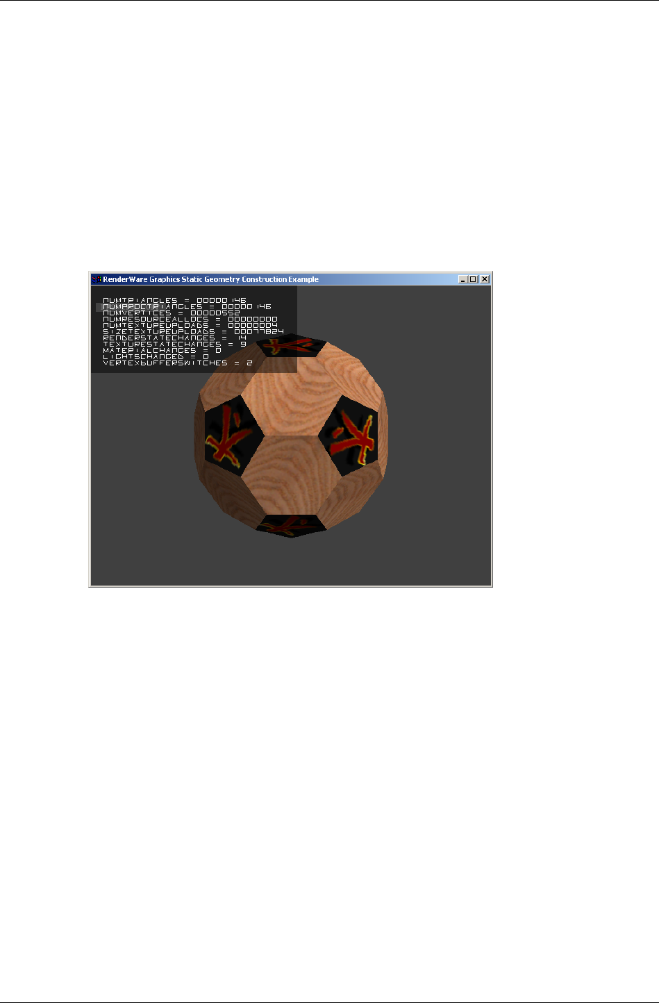
Rendering
RenderWare Graphics 3.7 I-279
Optimizing with a Metrics Build
Determining the best Resource Arena size requires knowing how it is being
used. The metrics build of the RenderWare Graphics libraries can help you
decide on the best trade-off between speed and hardware resources by
displaying resource usage on your target platform.
The RwMetrics structure varies from platform to platform so you should
see the platform-specific documentation for more details on what is
supported on your target hardware.
This screenshot shows the Win32, Direct3D metrics build in use in the
"world" example.
13.8.3 Pre-instancing Dynamic Geometry
One optimization of the above instancing scheme can be performed if it is
known that the platform independent (PI) representation will not be used at
run-time, and that is to use solely pre-instanced platform specific (PS)
representation, rather than creating it at run-time. This has the advantages
that no CPU cycles are used to instance data on their first rendering, which
gives a minor performance improvement, but also means that space is not
required for storage of the platform independent copy of the data.
The RpAtomicInstance() function is used to generate a persistent copy of
the platform specific data, so at that time, two representations of the atomic
exist. The platform independent data and the platform specific data both
exist outside the resource arena. When rendering occurs the platform
specific representation is always used and the resource arena is now not
used by the atomic during rendering.
The platform specific data generated should be considered opaque and
highly volatile as the format is subject to change between versions.

Chapter 13 - Dynamic Models
I-280 11 February 2004
Atomics with pre-instanced geometry are serialized slightly differently from
those without. If the atomic is serialized, the function for writing the
geometry to the stream RpGeometryStreamWrite() is called internally
from RpAtomicStreamWrite(). RpGeometryStreamWrite() does not
export PI data when persistent PS data is present, and consequently when
the atomic is loaded into memory with RpAtomicStreamRead() or
RpGeometryStreamRead() only the PI data is lost. This is where the
memory saving occurs.
As the instancing process has already been performed offline, and is not
performed at run-time, the resource arena is never used, and the resource
arena size may be reduced accordingly. The resource arena may be
eliminated altogether if no instancing occurs, which would require any
static geometry to be pre-instanced too, see the Worlds and Static Models
Chapter of this guide.
This does mean that features which use the PI data will no longer work and
functions to get PI data will return failure codes. For instance RpMorph and
RpDMorph will not function, and static PVS creation should be undertaken
before pre-instancing. Collision detection is not possible, though a lower
resolution collision atomic which is never rendered could be used to test for
collisions.
The only exceptions to this is that the number of vertices in the geometry,
and the number of triangles in the geometry, are preserved and can be read
using RpGeometryGetNumVertices() and
RpGeometryGetNumTriangles() respectively. These are stored mainly so
that sensible metrics can be observed with PS data, and the actual PI
triangle data itself is not present.
Using RpAtomicInstance()
Firstly the availability of pre-instancing of atomics varies from platform to
platform, and so please check the platform specific documentation for your
platform to determine if this feature is supported for your platform.
To pre-instance an atomic, it is required that the world plugin is attached.
Also the correct rendering pipelines are attached to the atomic and
materials before the RpAtomicInstance() function is called. Those
rendering pipelines may introduce PS data which is required to give the
desired effect during rendering.
The RpAtomicInstance() function must be called within the
RwCameraBeginUpdate() and RwCameraEndUpdate() pair of calls within
the rendering loop, as the render pipelines must be executed to ensure that
all the relevant data is created. In practice the RpAtomicInstance()
function is similar to the RpAtomicRender() function but that the PS data
is not created in the resource arena but allocated from the heap, ensuring
that the data is persistent. Clipping and culling are never performed so that
all instanced data is generated even if not inside the camera’s view frustum.

Rendering
RenderWare Graphics 3.7 I-281
Save the atomic and use this as the asset for loading from the game disk. If
loading of the PS data fails, it is sensible during development to
automatically fallback to loading a platform independent version of the
asset, and flag it for pre-instancing in the render loop. Then save the new
pre-instanced version over the top of the one that failed to load. This will
cope with any changes to the binary format of pre-instanced data caused by
updating your version of RenderWare Graphics.
13.8.4 Converting Model Data to RenderWare
Graphics
RenderWare Graphics' reliance on its own data format means you may have
data that needs to be converted. This is not a particularly difficult task as a
number of utility functions are provided to assist in the conversion process.
Usually, you will want to feed in the data in one format and have valid
clump or atomic data produced as a result. This is explained below.
Conversion Overview
The steps necessary to create an atomic or clump are roughly similar. No
intermediate data type is necessary, and the exporter can create atomics
directly.
The steps involved are:
1. Create an atomic by calling RpAtomicCreate().
2. Create a geometry object by calling RpGeometryCreate().
This function requires the number of vertices and triangles needed by
the model, as well as a set of flags.
The number of vertices and triangles can be obtained from the source
data or, if developing an exporter for a modeling package, a suitable
conversion API function.
The flags should also be set up as required. For the purposes of
simplicity, it is assumed that the geometry contains normals, texture
coordinates and lighting values.
3. Obtain the default morph target object (which has an index of zero)
from the geometry using RpGeometryGetMorphTarget(). This is where
the vertices and normals are stored.
4. The UV coordinates are shared across all key-frames and can be found
in the geometry object itself, so get a pointer to them using
RpGeometryGetVertexTexCoords(). There is a one-to-one relationship
between these and the vertex array in any related morph targets.
5. Obtain the vertex and normal arrays from the morph target using
RpMorphTargetGetVertices(), and
RpMorphTargetGetVertexNormals() respectively.

Chapter 13 - Dynamic Models
I-282 11 February 2004
6. Iterate over the vertices in your model, copying vertex, normal and
texture co-ordinate data from the model into the geometry arrays.
7. Create all the material objects that your model requires, taking care to
read any textures necessary from disk and setting material colors
correctly. (255 indicates a full intensity color RGB component and also
a fully opaque (non-alpha) material.)
✎
✎✎
✎
You may wish to build a Texture Dictionary object if the Null driver supports your target
platform's bitmap formats. Alternatively, you may build a Platform Independent Texture
Dictionary that can be used on any target platform. See the Rasters, Images and Textures
chapter in this guide.
8. Iterate over the triangles in your model, setting the vertex indices and
materials for all triangles in the geometry. You will need to use
RpGeometryGetTriangles() to obtain the start address in memory
where triangles are stored, and the various triangle object API functions
to prepare and store them.
9. Calculate and set a bounding sphere for your morph target, using the
API calls RpMorphTargetCalcBoundingSphere() and
RpMorphTargetSetBoundingSphere(). (This step is often forgotten,
but it is absolutely essential.)
10. Unlock the geometry.
11. Attach the geometry to the atomic with RpAtomicSetGeometry().
Take a look at the geometry example in examples folder to see the
above construction process in action on hand-made model data.
✎
✎✎
✎
Null Libraries
The Null Libraries supplied on the SDK are specifically designed for conversion work. For
instance, we use them to build our modeling package exporters.
These libraries are almost identical to the standard Release ones, with the exception that
all actual rendering functionality is removed or diverted to a null driver. This is because
conversion programs rarely need to render their output to the display while the conversion
is taking place.
In addition, it means that functionality or output formats that may not otherwise be
supported on a particular platform can be included.
Null libraries for each platform are also supplied with the SDK (for example, nullxbox).
These are PC libraries used for building certain tools that process platform specific data.
They can be used to build platform specific texture dictionaries.
It should be noted that Null platform libraries can not create pre-instanced world and
geometry data.

Chapter 14
Lights

Chapter 14- Lights
I-286 11 February 2004
14.1 Introduction
RenderWare Graphics has two kinds of lighting models: dynamic and static.
This chapter covers static lighting using RpLight. Static lighting can also be
achieved using RpLtMap.
The dynamic lighting model is the closest in behavior to real-world lighting,
with lights being independent from the model geometry.
Five light types are supported by the dynamic lighting model:
• ambient
• point
• directional
• spot
• soft spot
Static lighting—not to be confused with static geometry—is less flexible, but
requires far fewer resources to use. This lighting model is tied to model
geometry and is implemented in one of two ways, depending on whether the
geometry itself is static or dynamic.
14.1.1 Other Documentation
• See the API Reference Lighting section for more information about lights
and lightmaps.
Modules
Æ
Lighting
• Lightmaps user guide chapter

Dynamic Lights
RenderWare Graphics 3.7 I-287
14.2 Dynamic Lights
Dynamic lights represent the most flexible light model in RenderWare
Graphics. They can:
• be fully controlled and manipulated at run-time
• be positioned at will and oriented in any direction
• selectively illuminate both static and dynamic models
• support a number of light types
• make use of hardware transform and lighting features
Dynamic lights have one important disadvantage: the processing power
needed to implement them. On platforms with no hardware transform and
lighting support, dynamic lights will eat up a substantial proportion of
processing time, effectively limiting the number of dynamic lights your
application can use.
Another disadvantage is that hardware transform and lighting stages on
different platforms generally make use of different algorithms. The result is
that the same settings for a particular light can produce varied results
across different platforms. RenderWare Graphics therefore supports both
reference and platform-specific forms of dynamic lighting.
The reference set supports all five light types. The platform-specific models
usually support the same light types, but use the light types defined in the
underlying hardware to perform the illumination calculations. This means
the platform-specific lighting models are unlikely to give the same results
across different platforms.
The reference set light types are designed to produce very similar results
across all supported platforms. On some platforms, they may be wholly or
partially implemented using hardware lighting facilities. In other cases, the
light types are implemented in software.
Platform-specific dynamic lighting is provided mainly to enable access to all
the light types available on the platform's hardware.
✎ There are no platform-specific APIs for static lighting.

Chapter 14- Lights
I-288 11 February 2004
14.2.1 Dynamic Lights Representation
Objects
RenderWare Graphics dynamic lighting models are controlled through two
objects: RpLight and RpMaterial.
The first object, RpLight, provides control over the light source itself. By
linking this to an RwFrame, the light can be positioned within an RpWorld
and, if necessary, oriented towards its target. In addition, the RpLight
object exposes a number of functions, which allow the developer to modify
the light's properties.
Effective lighting requires consideration of both the light itself and the
materials of the models it is illuminating.
The RpMaterial object defines materials that are applied to models and
therefore defines how models reflect light. This object is covered in detail in
the Dynamic Models chapter, so this chapter will only touch upon the
features that directly apply to dynamic lights.
Dynamic Lighting Models
A dynamic light is created using the RpLightCreate() function. This
function takes a constant defining the light types to be used when
processing the dynamic light.
The table on the following page lists the constants and describes the
reference light types. These are always available, regardless of the platform.
Platform-specific lighting models
Platform-specific light types are documented in the relevant section of the
API Reference and usually map directly onto light types implemented in the
platform's hardware.
✎ On the PlayStation 2 platform, all lighting models, including the reference models listed in
the table below, are implemented using custom VU code.

Dynamic Lights
RenderWare Graphics 3.7 I-289
Reference Dynamic Light Types
NAME LIGHTING TYPES
rpLIGHTAMBIENT Ambient light type.
This type provides lighting from all
directions. The light source is omnipresent.
Cannot be positioned or oriented.
rpLIGHTDIRECTIONAL Directional light type.
This model simulates a light source at
infinite distance from the world.
Cannot be positioned, but can be oriented.
rpLIGHTPOINT Point light type.
This type simulates a point source of
lighting. The light is emitted from this
source in a sphere.
Cannot be oriented, but can be positioned.
rpLIGHTSPOT
Spot light type.
This light type simulate spotlight sources,
which emit a cone of light from a specific
source in a particular direction, resulting in
a spot of light on the target.
Can be positioned and oriented.
rpLIGHTSOFTSPOT Soft spot light type.
As rpLIGHTSPOT.
The "soft spot" type adds a soft edge so that
the light falls off smoothly at the edge of the
spot.
Can be positioned and oriented.
14.2.2 Creating a dynamic light
The following code fragment creates an RpLight object named myLight. It
contains a dynamic light using the soft spot light (rpLIGHTSOFTSPOT)
reference light type:
RpLight *myLight;
myLight = RpLightCreate( rpLIGHTSOFTSPOT );
At this point, myLight has been created, but has not yet been initialized.
Initialization
The initialization necessary for a particular light depends on the light types
it is using. For instance, the ambient reference light type (rpLIGHTAMBIENT)
needs only a color to be set.

Chapter 14- Lights
I-290 11 February 2004
In most cases however, the first step will be to attach a frame object to the
RpLight object, so it can be positioned and/or oriented within a world. Of
all the reference light types, only the ambient light type can be used
without a frame.
Position & Orientation
Assuming the myFrame frame object contains a valid, initialized RwFrame
object, the following code fragment would attach it to the light:
RpLightSetFrame( myLight, myFrame );
Attaching a frame to a light allows you to move and orient the light as
required. The features of the RwFrame object also mean this light could
easily be included in an RwFrame hierarchy along with model geometry.
Color
The next step is to set the color of the light. The RpLightSetColor()
function performs this task. It takes an RwRGBAReal value defining the RGB
and Alpha components.
Assuming that lightColor has been initialized to the required color, our
initialization continues:
RpLightSetColor( myLight, &lightColor );
Sphere of illumination
Aside from those using the ambient and directional light types, most lights
affect models within a finite sphere of illumination. This sphere is defined by
the light object's radius, an RwReal value. This can be set thus:
RpLightSetRadius( myLight, 5.0f );
This radius defines the distance over which the lighting model acts, with
the light falling off over distance according to the formula:
When the distance is zero, the light's intensity is at its highest. The
intensity is zero when the distance traveled is equal to the radius.
Cone Angle
Spotlights also have a cone angle property, which defines the angle of the
light cone. A wide angle results in a wide spot of light; a narrow angle gives
a smaller spot of light.
The cone angle is an RwReal value and may be set as follows:
/* 0.785 is equivalent to PI / 4, about 45 degrees */
RpLightSetConeAngle( myLight, 0.785f );
intensity = max (
, 0 )
radius – distance
radius

Dynamic Lights
RenderWare Graphics 3.7 I-291
Adding the light to a world
At this stage, the light is ready. All that remains is to add it to an RpWorld
object. The fragment below assumes that the world object has been
initialized:
RpWorldAddLight( myWorld, myLight );
The application is now free to move and orient the light within the world as
well as modify its other properties.
Dynamic Lights & World Sectors
When a dynamic light is added to a world, the RpWorldAddLight()
function positions the light within a world sector object.
The light's sphere of illumination is used to determine which world sectors
the light affects. As such, a light may be referenced by more than one world
sector.
Light object flags
Light objects also include a flags property. Currently, this can be used to
inform the rendering engine which geometry types the light will affect: static
and/or dynamic.
Two flags are defined: rpLIGHTLIGHTATOMICS and rpLIGHTLIGHTWORLD.
The former, if enabled, means the light will affect dynamic models. The
latter, if enabled, means the light will affect static models. The flags should
be logically ORed together if both are needed.
The function to set or reset the flags is RpLightSetFlags(). An example of
its use appears below. The example sets the light created earlier to
illuminate both static and dynamic models:
RpLightSetFlags( myLight, rpLIGHTLIGHTATOMICS | rpLIGHTLIGHTWORLD);
Dynamic Lights, Geometry & Materials
It is possible to modify the behavior of lighting at the RpGeometry level by
manipulating the geometry flags. This lets applications enable or disable
lighting for individual atomics. The flags are exposed by the RpGeometry
object through the RpGeometrySetFlags() function.
It is important to understand that these flags are specific to the geometry
object, not an atomic. The geometry will always be illuminated according to
these flag settings.
There are two geometry flags relevant to lighting, as shown in the table
below:

Chapter 14- Lights
I-292 11 February 2004
FLAG DESCRIPTION
rpGEOMETRYLIGHT If set, dynamic lights will illuminate the
geometry.
If cleared, dynamic lights will not
illuminate the geometry.
rpGEOMETRYMODULATEM
ATERIALCOLOR
If set, the geometry will reflect
illumination appropriately by combining
both dynamic and static lighting to
render the correct colors.
If cleared, the geometry will not be lit at
all. Instead, the geometry will be
rendered using its material object's own
color property alone.
Iterator functions
The RpLight object exposes an iterator function,
RpLightForAllWorldSectors(), which will call a user-supplied callback
function for each world sector the light affects.
14.2.3 Clump Lights & Streaming
An RpClump is a container for dynamic objects that are associated with a
Frame hierarchy, and this includes dynamic Lights. Lights can be added to
Clumps using the RpClumpAddLight() function.
• They will be automatically streamed with the Clump and their position
within the Frame hierarchy of the Clump preserved.
• They will be automatically destroyed with the Clump when
RpClumpDestroy() is called.
• They will be added to and removed from Worlds with the Clump when
the functions RpWorldAddClump() and RpWorldRemoveClump() are
used.
This mechanism is used whenever dynamic Lights are exported from one of
the modeling packages. The artist is able to set up and position Lights
within a world. Once exported within a Clump, the positions are stored in
the Frame hierarchy.
14.2.4 Platform-Specific Lighting Models
Many platforms support hardware acceleration for lighting. However this
support is not identical across platforms. Such hardware often provides its
own implementation of lighting and this means lights can produce different
results on different platforms, even though they are initialized with the
same values.

Dynamic Lights
RenderWare Graphics 3.7 I-293
The reference light types provide a means of ensuring consistent lighting
across supported platforms, but their performance will vary from platform
to platform.
RenderWare Graphics therefore exposes any platform-specific lighting
models using the same API—only the lighting type constant changes.
Platform-specific lighting types are available for Nintendo GameCube,
Microsoft DirectX (both Windows and Xbox) and OpenGL. The Sony
PlayStation 2 supports the reference lighting models in hardware.
The RenderWare Graphics API for PlayStation 2 uses VU code to perform all
rendering, so the reference lighting models are all accelerated.

Chapter 14- Lights
I-294 11 February 2004
14.3 Static Lights using RpLight
Regardless of whether they are supported in hardware or software, dynamic
lights require substantial processing. So, it is wise to avoid using too many
dynamic lights.
Static lights—also known as prelights—provide a form of lighting that
avoids high processing overheads. They are a much simpler, faster,
alternative to dynamic lights. The trade-off is that static lights are very
limited in their abilities.
Static lighting can be applied to:
• Static models – i.e. worlds. The data is stored in RpWorldSector objects.
• Dynamic models – i.e. atomics, clumps, etc. The data is stored in
RpGeometry objects.
The first usage is by far the most common as RenderWare Graphics
modeling package exporter tools support static lighting features directly.
Artists tag model geometry and apply lighting to it. When the model is
exported, the RenderWare Graphics exporter encodes vertex lighting data
right into the geometry.
✎ The exact tagging mechanism used varies from package to package. See the art tools
documentation for full details.
At run-time, all that is needed is to load and render the geometry. The
static lighting is applied automatically when the relevant RpWorld object is
rendered.
For dynamic models, there is currently no support for exporting static
lighting data directly from the modeling package. Exporters will allocate the
necessary space for an array of RwRGBA values, but initialization of these
values must be performed explicitly, either in a custom tool, in a modified
build of the exporter, or at run-time.
Static lighting is decreasing in importance as modern graphics hardware
transform and light engines are reducing the need for processing dynamic
lighting in the CPU.
14.3.1 Creating Static Lights
Static models
Static lighting is stored as fixed vertex lighting values. In static models—i.e.
RpWorldSector data—these values are completely fixed and not exposed by
the RenderWare Graphics API. This is a requirement of the static model
rendering optimizations of RenderWare Graphics.

Static Lights using RpLight
RenderWare Graphics 3.7 I-295
Developers building their own tools or creating static models from scratch
will find that the RtWorld and RtWorldImport toolkits support creation of
static lighting data as well as the model geometry itself.
Dynamic models
For dynamic models, static lighting is stored within RpGeometry objects.
The data is represented by an array of RwRGBA values, which can be
retrieved using RpGeometryGetPreLightColors().
The array only exists if the geometry has been created using the
rpGEOMETRYPRELIT flag. Space for the prelight array must be explicitly
allocated if you are creating geometry objects, as setting the flag will not
perform this procedure automatically.
The prelighting colors reside within the geometry's topology, at one color
per vertex, and are therefore shared between all morph targets.
14.3.2 Static Lighting Techniques
Static lights are very fast, using a negligible amount of processing power
regardless of how many such lights are used. However, limitations in their
design means that they are most often used in tandem with dynamic lights.
Some common techniques are covered next, illustrating how the illusion of
full lighting can be created without using too many dynamic lights.
Interactive static lighting
One of the most important limitations of static lighting models is that static
lights do not actually cast any light. The process creates the illusion that
light is striking the model. Static lighting affects only the vertices of the
world sector or geometry objects in which the lighting information resides.
As a result, a dynamic model passing through a statically-lit world will not
be illuminated by static lighting.
If you need to create the effect of static lights casting lights on other
models, you will need to use a dynamic light as well. In most cases, the
dynamic light can be a temporary creation, used only when the light would
be visible to the camera and an object is near enough to it.
Modifying static lights on static models
There are occasions when static lights need to be disabled or modified in
some way at run-time. This is trivial when working with statically-lit
dynamic models, but the most common use for static lights is to light static
models.
The fixed nature of static lights in static models means modification is
impossible so the effect must be achieved by using dynamic models for
areas where the static lights need to be modifiable.

Chapter 14- Lights
I-296 11 February 2004
Static lights in dynamic models
Static lighting in geometry objects can be modified at run-time to simulate
glowing or pulsating lights and other similar lighting effects.
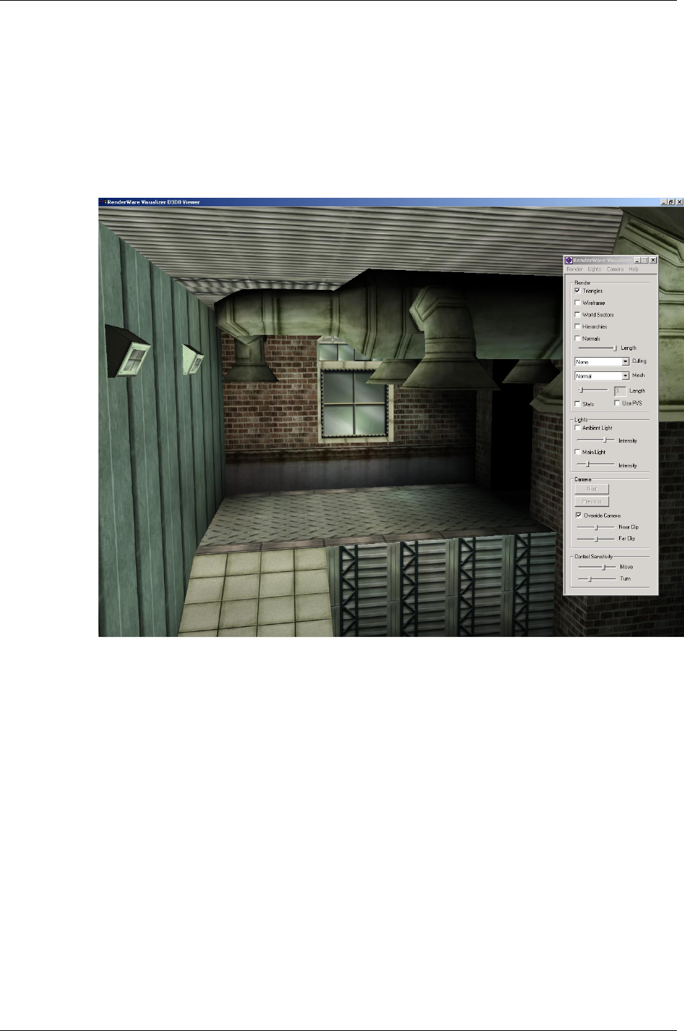
Related Examples
RenderWare Graphics 3.7 I-297
14.4 Related Examples
Static lights are not demonstrated by any one specific example. However, a
model which has been exported from a modeling package with static
lighting can be found in the texdict example. The model can be found in
models/dungeon.bsp. RenderWare Visualizer can be used to view the
model.
RenderWare Visualizer showing a model with static lighting
The SDK includes two examples covering dynamic lights: lights and
lights2.
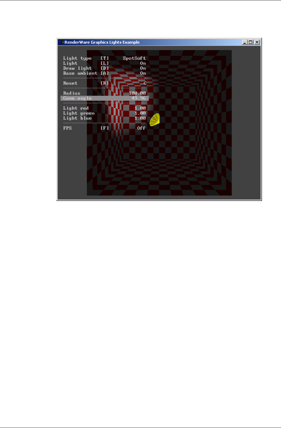
Chapter 14- Lights
I-298 11 February 2004
The lights example illustrates the different light types available for
dynamic lights. Use the menu options to choose different types and
combinations.
The lights example
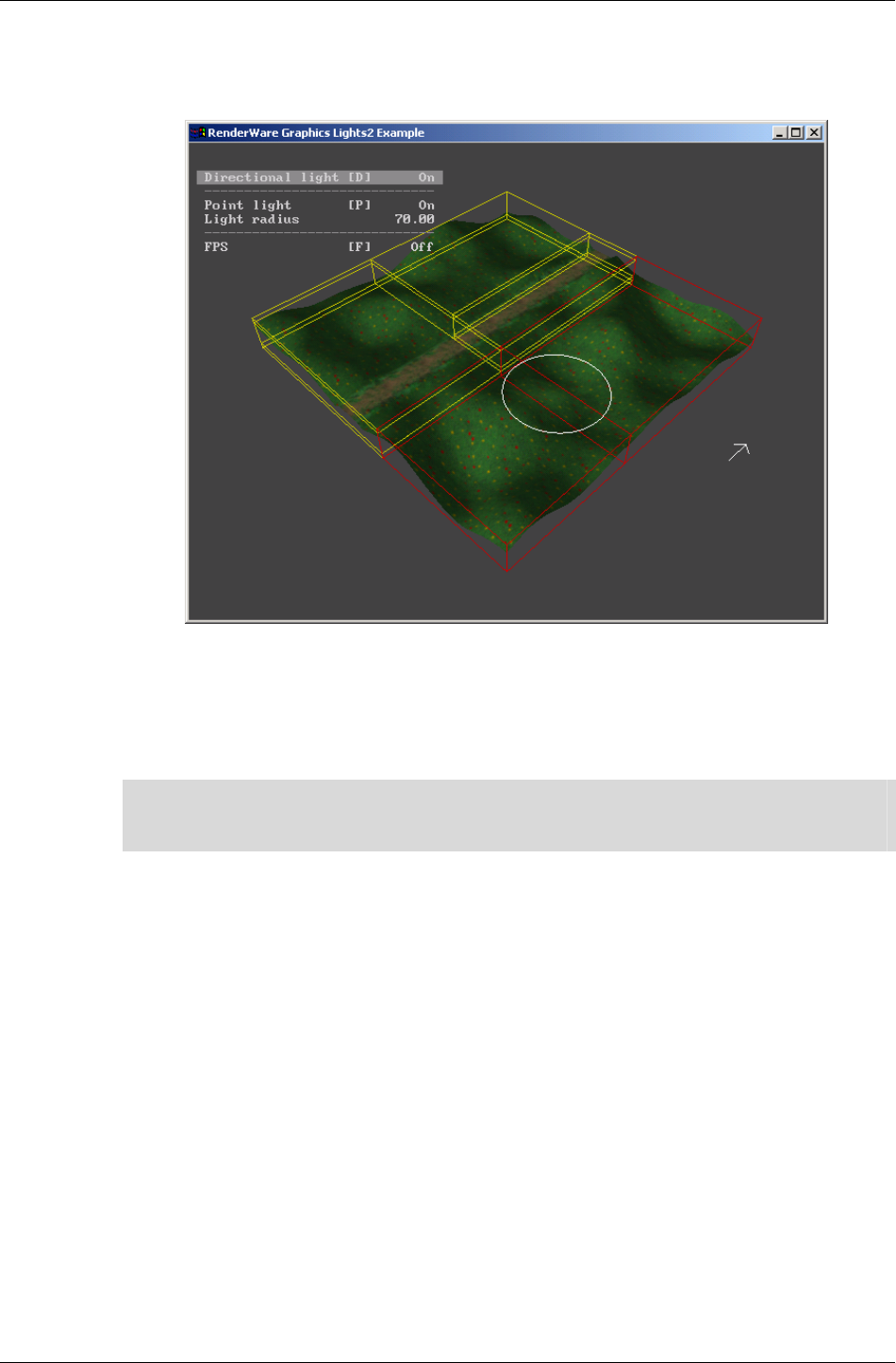
Related Examples
RenderWare Graphics 3.7 I-299
The lights2 example illustrates how lights interact with world sectors.
When run, you will see a small landscape overlaid by wire-frame
representations of the world sectors into which it has been divided.
The lights2 example
Move the dynamic light around the scene to see how RenderWare Graphics
links the light to world sectors according to the radius of its sphere of
illumination.
✎ The world sectors shown in the lights2 example were created deliberately to show this
effect; in normal usage, such a simple landscape would not make use of more than one
world sector.
Chapter 14- Lights
I-300 11 February 2004
14.5 Summary
14.5.1 Dynamic Lights
Properties table
The table below lists the main properties of the reference dynamic lighting
models. Additional properties may be added for platform-specific dynamic
lighting models.
PROPERTY AMB. DIR. POINT SPOT SOFTSPOT
Color 9 9 9 9 9
Flags 9 9 9 9 9
Frame 9 9 9 9
Radius
9 9 9
ConeAngle
9 9
Dynamic Lighting: Main Features
• Five reference light types:
• rpLIGHTAMBIENT – ambient
• rpLIGHTDIRECTIONAL – directional
• rpLIGHTPOINT – point-source
• rpLIGHTSPOT – spot
• rpLIGHTSOFTSPOT – soft-edged spot
• Platform-specific light types are provided where necessary for access to
hardware lighting.
• Ambient lights do not require frames.
• Directional, point lights, spot lights and soft spot lights always require
frames.
• All lights must be added to a world using RpWorldAddLight() if they
are to affect the geometry within that world.
• All lights can selectively illuminate both static and dynamic geometry.
• The default light settings are intended to be "safe" on all supported
platforms, but of little use in practice: you should explicitly set all of a
dynamic light's properties on creation.

Summary
RenderWare Graphics 3.7 I-301
14.5.2 Static Lights
Static Lights: Main Features
• Also known as prelights or prelighting.
• A statically-lit model is known as a prelit model.
• Cheaper in terms of processing power.
• Prelit static models can be readily exported from modeling packages.
• Prelit dynamic models must have their prelight data initialized by the
developer either in a custom tool, or at run-time.
• Prelights are not real lights. They are fixed vertex illumination levels and
have no effect on nearby models.
• Prelights in static models cannot be changed or modified in any way
whatsoever. They are not exposed.
• A pointer to the prelight data in dynamic models can be retrieved using
RpGeometryGetPreLightColors().

Index

Index
I-304 11 February 2004
Index
Page numbers in bold face indicate the most important reference to the subject, where
multiple references exist. The page numbers shown below refer to Volume I of the User
Guide.
2
2D graphics toolkit ..........................................................161
3
3ds max .............................................................................21
A
actors ................................................. See dynamic geometry
animation.........................................................................274
keyframe animation ....................See keyframe animation
morph target................................................................274
of the frame hierarchy.................................................274
of vertices ...................................................................274
ANSI character strings ......................................................39
aspect ratio.......................................................................100
at vector.............................................................................50
atomic..............................................................................251
animation ....................................................................274
bounding sphere..........................................................270
cloning........................................................................270
culling from frustum....................................... See culling
frame................................................................. See frame
geometry......................................................See geometry
intercepting rendering.................................................273
iterating over...............................................232, 271, 272
rendering directly........................................................277
B
bilinear filtering...............................................................134
binary space partition (BSP)....................................229, 230
binary streams..............................................See serialization
bitmap........................................... 117. See raster. See raster
blend modes.....................................................................165
blitting ................................................... See raster rendering
bounding box.............................................................57, 230
bounds test....................................................................57
enlarging.......................................................................57
build
debug ....................................................................18, 217
metrics ..........................................................18, 217, 279
release...................................................................18, 217
C
C standard data types ........................................................ 40
C++ wrapper classes ......................................................... 17
plugins.......................................................................... 92
camera ....................................................................... 95, 229
anamorphic lens effect................................................ 101
cloning........................................................................ 112
creation of .................................................................. 107
destruction of.............................................................. 110
frame buffer................................................................ 106
orientation .................................................................. 107
orthographic views .......................................................99
positioning.................................................................. 107
projection .................................................. See projection
raster........................................................................... 106
space........................................................................... 146
sub-rasters ................................................ See sub-rasters
telephoto zoom........................................................... 101
view matrix................................................................. 105
view offset.................................................................. 102
view window................................................................ 99
viewpoint...................................................................... 98
camera space .......................................48, 98, 145, 154, 160
chaining function calls .................................................... 273
character data type............................................................. 39
clipping
2D immediate mode ................................................... 145
immediate mode ......................................................... 154
clipping planes .................................................................. 98
clmpview viewer ....................................................... 19, 256
clump .............................................................................. 252
adding to worlds......................................................... 270
atomic, adding an ....................................................... 266
cloning........................................................................ 270
culling from frustum........................................See culling
destroying................................................................... 254
hierarchy of atomics ................................................... 252
iterating over ...................................... 114, 231, 271, 272
procedural generation................................................. 257
rendering directly ....................................................... 277
clumps
using........................................................................... 253
CodeWarrior ................................................... See compilers
collision detection ........................................................... 232
color .................................................................................. 61

Index
RenderWare Graphics 3.7 I-305
alpha component .......................................................... 61
blending...................................................................... 165
palettes ....................................................................... 119
compilers
CodeWarrior................................................................. 19
Microsoft Visual C....................................................... 19
context stack ................................................................... 109
converting model data..................................................... 281
co-ordinate systems........................................................... 45
axes .............................................................................. 46
camera space .........................................See camera space
device space ...........................................See device space
handedness ................................................................... 45
object space............................................ See object space
scene space..............................................See world space
screen space............................................See device space
world space .............................................See world space
core library, the ................................................................. 22
culling ............................................................................. 113
custom file systems ................................................... 27, 192
D
data types
fixed point .................................................................... 42
floating point ................................................................ 42
integer .......................................................................... 40
RwBool ........................................................................ 38
RwChar .................................................................. 34, 39
RwFixed....................................................................... 42
RwIm2DVertex.................................................. 145, 147
RwIm3DVertex.......................................................... 154
RwInt128...................................................................... 41
RwInt16........................................................................ 41
RwInt32........................................................................ 41
RwInt64........................................................................ 41
RwInt8.......................................................................... 41
RwReal......................................................................... 42
RwRGBA................................................................... 240
RwUInt128................................................................... 41
RwUInt16............................................................... 34, 41
RwUInt32..................................................................... 41
RwUInt64..................................................................... 41
RwUInt8....................................................................... 41
debugging........................................................................ 218
build ........................................................................... 217
messages .................................................................... 219
trace messages ....................................................... 220
streaming............................................................ 218, 219
degenerate triangles......................................................... 269
device space .............................................................. 48, 145
dictionary ........................................................................ 204
schema........................................................................ 211
displaying models ............................................................. 19
documentation .................................................................. 20
artists'................................................................... 21, 233
double buffering ............................................................. 109
double precision arithmetic............................................... 42
dynamic geometry .................................................. 250, 267
bounding .................................................................... 264
example...................................................................... 257
platform independent representation.......................... 279
platform specific representation......................... 243, 279
prelighting.................................................................. 268
dynamic lights..........................................................See light
dynamic models.................................See dynamic geometry
E
engine
closing.................................................................... 70, 71
initializing........................................................ 65, 66, 71
opening ............................................................ 65, 67, 71
shut down............................................................... 70, 79
starting ................................................................... 65, 79
stopping ................................................................. 70, 71
terminating................................................................... 70
error handling ................................................................. 216
examples
building........................................................................ 19
camera.......................................................................... 96
geometry .................................................................... 257
im2d........................................................................... 151
im3d........................................................................... 156
images........................................................................ 121
lights .................................................................. 297, 299
mipmap ...................................................................... 135
plugin........................................................................... 85
SDK ............................................................................. 19
texadrss .............................................................. 134, 136
world.................................................................. 234, 279
exporters ................................................................... 21, 256
Open Export framework .............................................. 21
writing........................................................................ 234
extensions
object ........................................................................... 92
F
file format
Aldus Tag Image File Format (*.TIF)........................ 121
image handlers
registration ............................................................ 121
writing................................................................... 121
Microsoft Windows bitmap (*.BMP)......................... 121
Portable Document Format (*.PDF) ............................ 20
Portable Network Graphics (*.PNG) ................. 121, 125

Index
I-306 11 February 2004
RenderWare Dive File Format (*.DFF)......................254
RenderWare Stream Format (*.RWS) ........................182
Sun Microsystems Raster Format (*.RAS).................121
Targa (*.TGA)............................................................121
file I/O function...............................................................169
fclose ..........................................................................169
feof .............................................................................169
fexist ...........................................................................169
fflush...........................................................................169
fgets ............................................................................169
fopen...........................................................................169
fputs............................................................................169
fread............................................................................169
fseek ...........................................................................169
ftell .............................................................................169
fwrite ..........................................................................169
serialization ................................................................187
file system .........................................................................27
access mode................................................................199
generic ........................................................................194
initializing...................................................................196
manager ................................................................27, 192
naming........................................................................195
OS-Specific ................................................................195
overloading...................................................................27
registering...................................................................197
system methods ..........................................................200
toolkit ...................................................................27, 192
files
image search paths......................................................122
ISO 9660 convention..................................................138
fog ...................................................................................102
density ........................................................................103
distance.......................................................................103
enabling ......................................................................103
exponential .................................................................103
fog table......................................................................104
linear...........................................................................103
setting color ................................................................103
frame
dirty ............................................................................109
hierarchy.......................................................53, 252, 270
child frame...............................................................53
parent frame.............................................................53
root frame ................................................................53
siblings.....................................................................54
traversal ...................................................................54
local transformation matrix (LTM).........................52, 54
modeling matrix............................................................52
synchronizing LTMs...................................................109
frame buffer.............................................................100, 129
clearing.......................................................................112
frames................................................................................52
freelists.............................................................................. 73
front vector........................................................See at vector
frustum........................................................................ 48, 98
clipping.............................................. See clipping planes
culling from.....................................................See culling
test sphere................................................................... 113
Fully Managed Support Services (FMSS)......................... 14
website .........................................................................14
G
gamma correction............................................................ 119
geometry ......................................................................... 251
bounding..................................................................... 264
dynamic lighting flag ................................................. 261
example ...................................................................... 257
flags............................................................................ 261
locking........................................................................ 265
material color modulation flag ................................... 261
mesh ...................................................................265, 268
morph target .......................................... See morph target
normals flag................................................................ 261
offline generation ....................................................... 255
prelighting flag ........................................................... 261
texture co-ordinates.................................................... 267
texturing flag .............................................................. 261
tri-strip flag................................................................. 261
tri-strip method........................................................... 269
unlocking.................................................................... 265
H
hardware abstraction ................................................... 22, 29
hooking functions............................................................ 273
I
image....................................................................... 117, 119
attaching bitmap to..................................................... 123
conversion
from raster ............................................................. 125
to raster.......................................................... 125, 127
copying....................................................................... 124
creating............................................................... 120, 123
destruction.................................................................. 125
example ...................................................................... 121
file format handlers
registration............................................................. 121
writing ................................................................... 121
loading................................................................ 120, 122
mask ...................................................................123, 125
multiply referencing bitmaps...................................... 124
quantization................................................................ 124
resampling.................................................................. 124

Index
RenderWare Graphics 3.7 I-307
resizing....................................................................... 124
saving......................................................................... 122
search path.................................................................. 122
size ............................................................................. 124
stride................................................................... 119, 124
immediate mode.............................................................. 144
2D145
2D line lists ................................................................ 149
2D polylines ............................................................... 149
2D primitives.............................................................. 149
2D tri-fans .................................................................. 150
2D trilists.................................................................... 149
2D tri-strips ................................................................ 149
2D vertices ................................................................. 147
3D154
3D example ................................................................ 156
3D indexed primitives ........................................ 154, 157
3D line lists ................................................................ 156
3D pipeline................................................................. 158
3D polylines ............................................................... 156
3D primitives...................................................... 156, 157
3D tri-fans .................................................................. 156
3D tri-lists .................................................................. 156
3D tri-strips ................................................................ 156
3D vertex positioning................................................. 154
3D vertices ................................................................. 154
lighting .................................................................. 155
properties............................................................... 155
3D, applications for.................................................... 158
clipping .............................................................. 145, 154
destruction, 3D........................................................... 158
im2d example............................................................. 151
index lists ................................................................... 154
indexed primitives...................................................... 151
platform dependence issues........................................ 148
primitives ................................................................... 154
render states................................................................ 144
rendering a line example ............................................ 152
rendering a triangle example ...................................... 153
rendering cycle........................................................... 156
rendering primitives ................................................... 157
rendering transformed points...................................... 156
transforming 3D primitives ........................................ 154
vertex lists .................................................................. 154
z-buffer....................................................................... 146
indexed primitives........................................................... 151
infinite loop......................................................See recursion
initialization ...................................................................... 65
attaching plugins .......................................................... 70
file management........................................................... 66
plugins.......................................................................... 85
subsystem ..................................................................... 67
video mode................................................................... 67
changing.................................................................. 71
enumeration............................................................. 68
setting...................................................................... 68
instancing................................................................ 242, 278
intersection ..................................................................... 272
iterating over.............................................................. 272
iterators................................................................... 113, 271
atomic ........................................................ 232, 271, 272
clump ................................................. 114, 231, 271, 272
frame............................................................................ 55
intersection................................................................. 272
light.................................................................... 231, 232
material .............................................................. 231, 272
mesh................................................................... 232, 272
world.......................................................................... 231
world sector ....................................... 113, 231, 232, 271
K
K dimensional (KD) tree...............See binary space partition
keyframe animation
interpolator................................................................. 204
L
language
ANSI C ........................................................................ 16
C++.............................................................................. 16
libraries
dynamically linked....................................................... 18
null....................................................................... 18, 282
statically linked............................................................ 18
library
core, the ............................................ See core library, the
light
color........................................................................... 290
dynamic ............................................. 242, 286, 287, 300
ambient.......................................................... 286, 289
cone angle ............................................................. 290
creating.................................................................. 288
directional ..................................................... 286, 289
initializing ............................................................. 289
point .............................................................. 286, 289
processing time ..................................................... 287
soft spot......................................................... 286, 289
sphere of illumination ........................................... 290
spot................................................................ 286, 289
example...................................................................... 297
geometry dynamic lighting flag ................................. 261
geometry prelit flag.................................................... 261
iterating over...................................................... 231, 232
light types .................................................................. 289
models........................................................................ 286
platform-specific........................................................ 292

Index
I-308 11 February 2004
static ...........................................................286, 294, 301
changing.................................................................295
creating ..................................................................294
world
adding to ................................................................291
world dynamic lighting flag........................................239
world normals flag......................................................239
world prelit flag ..........................................................239
line.....................................................................................58
link errors ..........................................................................18
M
material............................................................................260
geometry material modulation flag.............................261
iterating over.......................................................231, 272
world modulate material flag......................................240
matrix ................................................................................50
post-concatenate ...........................................................55
pre-concatenate.............................................................55
replace ..........................................................................55
transformation...............................................................50
combining....................................................53, 54, 55
transforming points..................................................51
transforming vectors ................................................51
Maya..................................................................................21
memory
freelists .........................................................................73
management..................................................................72
OS-level ...................................................................72
plugins ..........................................................................83
resource arena.........................................................75, 76
memory management ........................................................80
mesh ........................................................................265, 268
iterating over.......................................................232, 272
tri-strip method ...........................................................269
metrics.............................................................................279
Microsoft Visual C ..........................................See compilers
mipmaps ..........................................................................134
automatic generation...................................................127
example ......................................................................135
filtering.......................................................................134
generation ...................................................................137
loading........................................................................137
manual generation.......................................................127
mip levels ...................................................................134
number of levels .........................................................129
writing a mip level generator......................................138
models
creating.........................................................................21
exporting.......................................................................21
morph target ....................................................................262
N
native data ....................................................................... 242
normals............................................................................ 230
geometry normals flag................................................ 261
vertex, calculating ...................................................... 276
vertex, smoothing....................................................... 276
O
object space....................................................... 47, 154, 258
objects
destroying..................................................................... 36
member functions......................................................... 26
methods........................................................................ 26
opaque.......................................................................... 27
passing instances to functions ...................................... 27
property access methods............................................... 27
reference counters ........................................................ 36
RenderWare.................................................................. 26
RpAtomic ................................................................... 251
RpClump .................................................................... 252
RpGeometry ....................................................... 251, 291
RpIntersection ............................................................ 272
RpLight .............................................................. 288, 292
RpMaterial ................................................................. 288
RpMorphTarget.......................................................... 262
RpTriangle ................................................................. 258
RpWorld..................................................................... 229
RpWorldSector........................................................... 230
RwBBox..................................................................... 230
RwDebug ................................................................... 218
RwEngine..................................................................... 65
RwError...................................................................... 216
RwFrame.................................................................... 288
RwIm2d...................................................................... 144
RwIm3d...................................................................... 144
RwImage .................................................... 116, 117, 119
RwRaster............................................................ 116, 117
RwResources................................................................ 77
RwSurfaceProperty .................................................... 261
RwTexDictionary....................................... 116, 117, 138
RwTexture.................................................. 116, 117, 132
RwVideoMode .............................................................68
transparent.................................................................... 27
optimization .................................................................... 276
P
palettes ............................................................................ 119
parallax scrolling............................................................... 99
PI data ..................................................................... 242, 279
platform
Apple Macintosh .......................................................... 15

Index
RenderWare Graphics 3.7 I-309
Direct3D 8.................................................................... 15
Microsoft Windows...................................................... 15
Microsoft Xbox ............................................................ 15
NINTENDO GAMECUBE.......................................... 15
OpenGL........................................................................ 15
Sony PlayStation 2 ....................................................... 15
platform independent
texture dictionaries..................................................... 140
plugins............................................................................... 23
attaching........................................................... 70, 83, 85
memory ................................................................... 83
creating......................................................................... 85
defining ........................................................................ 85
dependencies ................................................................ 84
example ........................................................................ 85
exposed ........................................................................ 85
initialization ................................................................. 85
registering .................................................................... 87
RpADC ........................................................................ 23
RpAnisot ...................................................................... 23
RpCollision .......................................................... 23, 232
RpDMorph ................................................................... 23
RpHAnim..................................................................... 23
RpLODAtomic............................................................. 23
RpLtMap...................................................................... 23
RpMaterialEffects ........................................................ 23
RpMipmapKL .............................................................. 23
RpMorph...................................................................... 23
RpPatch........................................................................ 23
RpPrtStd....................................................................... 23
RpPTank ...................................................................... 23
RpPVS.......................................................................... 23
RpRandom ................................................................... 23
RpSkin.................................................................. 23, 275
RpSpline....................................................................... 23
RpUserData.................................................................. 23
RpUVAnim.................................................................. 23
RpWorld....................................................... 23, 228, 251
shut down..................................................................... 85
supplied........................................................................ 23
using............................................................................. 83
porting............................................................................... 16
pos vector.......................................................................... 50
PowerPipe......................................................................... 25
pre-instancing.......................................................... 243, 279
atomics ....................................................................... 279
worlds......................................................................... 243
pre-lighting...................................................................... 240
static geometry ........................................................... 241
using RtWorldImport ................................................. 241
projection
parallel............................................................ 48, 99, 160
perspective ............................................. 48, 99, 146, 160
shadows ....................................................................... 99
PS data............................................................................ 242
R
raster ....................................................................... 117, 126
camera................................................... See camera raster
clearing ...................................................................... 131
context stack ...................................................... 109, 129
conversion
from image ............................................................ 125
from images .......................................................... 127
to image................................................................. 125
creating ...................................................................... 126
determining valid formats .......................................... 127
format......................................................................... 129
loading ....................................................................... 131
lock modes ................................................................. 131
locking ....................................................................... 131
locking palettized....................................................... 131
mipmaps..................................................................... 127
number of Mipmap levels .......................................... 129
platform dependence.................................................. 126
rendering.................................................................... 130
sub-rasters................................................. See sub-rasters
unlocking ................................................................... 131
unlocking palettized................................................... 131
reciprocal camera Z ........................................................ 148
rectangle ........................................................................... 59
recursion ..................................................... See infinite loop
registering
custom file systems.................................................... 193
extensions .................................................................... 88
plugins ......................................................................... 87
render callback........................................................ 273, 277
render state.............................................................. 144, 162
exhaustive list ............................................................ 162
getting ........................................................................ 162
rwRENDERSTATEBORDERCOLOR ..................... 164
rwRENDERSTATEDESTBLEND.................... 164, 165
rwRENDERSTATEFOGCOLOR.............................. 164
rwRENDERSTATEFOGDENSITY .......................... 165
rwRENDERSTATEFOGENABLE ........................... 164
rwRENDERSTATEFOGTYPE ................................. 164
rwRENDERSTATESHADEMODE .......................... 163
rwRENDERSTATESRCBLEND ...................... 164, 165
rwRENDERSTATETEXTUREADDRESS............... 163
rwRENDERSTATETEXTUREADDRESSU ............ 163
rwRENDERSTATETEXTUREADDRESSV ............ 163
rwRENDERSTATETEXTUREFILTER ................... 164
rwRENDERSTATETEXTUREPERSPECTIVE ....... 163
rwRENDERSTATETEXTURERASTER.................. 163
rwRENDERSTATEVERTEXALPHAENABLE....... 164

Index
I-310 11 February 2004
rwRENDERSTATEZTESTENABLE ........................163
rwRENDERSTATEZWRITEENABLE .....................163
setting .........................................................................162
render states.....................................................................157
fog...............................................................................103
using ...........................................................................104
rendering
a step by step guide.......................................................28
atomics directly ..........................................................277
begin an update...................................................109, 277
clumps directly ...........................................................277
double buffering .........................................................129
end an update......................................................109, 277
immediate mode .........................................................109
intercepting for atomics ..............................................273
rasters .............................................See rasters, rendering
static geometry............................................................242
to multiple viewports................................ See sub-rasters
worlds.........................................................................277
RenderWare
components.............................................................22–27
RenderWare AI..................................................................14
RenderWare Audio............................................................14
RenderWare Graphics .......................................................14
RenderWare Physics..........................................................14
RenderWare Platform........................................................14
resource arena................................75, 76, 80, 243, 278, 279
right vector ..................................................................46, 50
RtAnim............................................See keyframe animation
RtTOC .................................................. See table of contents
RtWorldImport, using......................................................234
RwBBox............................................................................57
RwCamera.........................................................................97
RwEngineClose.....................................................70, 71, 79
RwEngineInit ..................................................65, 66, 71, 79
RwEngineOpen ...............................................65, 67, 71, 79
RwEngineStart.............................................................65, 79
RwEngineStop.......................................................70, 71, 79
RwEngineTerm ...........................................................70, 79
RwLine..............................................................................58
RwRect..............................................................................59
RwRGBA ..........................................................................61
rws (RenderWare stream file format) ..............................182
RwSphere ..........................................................................60
RwVideoMode ..................................................................68
S
saving memory ........................................................243, 279
scaleable fonts .................................................................161
scene creation ....................................................................28
scene space .................................................. See world space
scenes ............................ See static geometry or world sector
screen dump .................................................................... 131
screen space ................................................See device space
SDK
examples............................................See examples, SDK
serialization ..................................................................... 168
atomics ............................................................... 173, 179
binary streams ............................................................ 171
chunk ID................................................................ 171
BSP ............................................................................ 171
chunk headers..................................................... 171, 181
chunk IDs ................................................................... 187
chunk size................................................................... 174
chunk type .................................................................. 172
clumps ........................................................173, 179, 180
DFF ............................................................................ 171
endian-ness......................................................... 177, 188
big-endian.............................................................. 175
little-endian............................................................ 175
file functions............................................................... 169
file I/O function.......................................... 168, 169, 187
fclose ..................................................................... 169
feof ........................................................................ 169
fexist...................................................................... 169
fflush ..................................................................... 169
fgets....................................................................... 169
fopen...................................................................... 169
fputs....................................................................... 169
fread....................................................................... 169
fseek ...................................................................... 169
ftell ........................................................................ 169
fwrite ..................................................................... 169
file interface ............................................................... 169
frames................................................................. 173, 179
geometry..................................................................... 173
reading worlds............................................................ 247
rws...................................................................... 182, 188
streaming .................................................... 174, 180, 187
reading................................................... 175, 176, 177
registering.............................................................. 188
types .............................................................. 186, 187
writing ................................................... 175, 176, 178
strview viewer ............................................................ 173
writing worlds ............................................................ 246
shut down
plugins.......................................................................... 85
RenderWare Graphics .................................................. 70
skeleton ............................................................................. 29
skinning........................................................................... 275
SN Systems Visual Studio Integration .............................. 19
sorting
by material.................................................................. 273
customizing ........................................................... 273
sorting alpha primitives................................................... 166

Index
RenderWare Graphics 3.7 I-311
source code
skeleton ........................................................................ 29
source code license............................................................ 16
sphere................................................................................ 60
split screen .....................................................See sub-rasters
static geometry................................................................ 228
platform independent representation .................. 242, 243
pre-lighting................................................................. 241
rendering .................................................................... 242
sectors .................................................... See world sector
tools............................................................................ 233
viewing....................................................................... 233
static lighting........................................................... See light
static models ...........................................See static geometry
streaming..................................................... See serialization
string data type.................................................................. 39
strview viewer........................................................... 19, 173
sub-rasters ............................................................... 111, 129
subsystem
enumeration.................................................................. 67
initialization ................................................................. 67
surface properties.................................................... 261, 268
T
table of contents .............................................................. 182
creating....................................................................... 184
streaming.................................................................... 184
texture ............................................................. 118, 132, 259
addressing example ............................................ 134, 136
addressing modes ............................................... 132, 135
addressing U axis independently ................................ 136
addressing V axis independently ................................ 136
bordering.................................................................... 136
clamping..................................................................... 136
filtering............................................................... 132, 134
geometry textured flag ............................................... 261
geometry, storage of co-ordinates in .......................... 267
immediate mode......................................................... 148
loading................................................................ 136, 141
mipmap ...................................................................... 137
mirroring ............................................................ 134, 136
saving......................................................................... 141
streaming.................................................................... 141
stretching.................................................................... 133
tiling........................................................................... 133
world texturing flag.................................................... 239
wrapping .................................................................... 136
texture co-ordinates......................................................... 132
texture dictionary .................................................... 138, 139
adding textures to ....................................................... 140
current ........................................................................ 139
finding textures .......................................................... 140
platform independent ................................................. 140
streaming ................................................................... 139
TOC ......................................................See table of contents
toolkits .............................................................................. 24
Rt2d ..................................................................... 24, 145
Rt2D .......................................................................... 161
Rt2dAnim .................................................................... 24
RtAnim ................................................................ 24, 204
RtBary.......................................................................... 24
RtBezPat ...................................................................... 24
RtBMP................................................................. 24, 120
RtCharset ..................................................................... 24
RtCmpKey ................................................................... 24
RtDict........................................................................... 24
RtFSyst ........................................................................ 24
RtGCond...................................................................... 24
RtIntersection............................................................... 24
RtLtMap....................................................................... 24
RtMipK........................................................................ 24
RtPick .......................................................................... 24
RtPITexD................................................................... 140
RtPNG ................................................................. 24, 120
RtQuat.......................................................................... 24
RtRAS.................................................................. 24, 120
RtRay........................................................................... 24
RtSkinSplit................................................................... 24
RtSlerp......................................................................... 24
RtSplinePVS................................................................ 24
RtTIFF ................................................................. 24, 120
RtTile........................................................................... 24
RtTOC ................................................................. 24, 182
RtVCAT....................................................................... 24
RtWing......................................................................... 24
RtWorld ............................................................... 24, 276
RtWorldImport ............................................ 25, 229, 234
supplied........................................................................ 24
tools
artists'........................................................................... 21
skeleton, the ................................................................. 26
topology.................................................................. 262, 269
triangles .......................................................................... 258
winding order............................................................. 263
trilinear filtering.............................................................. 134
tri-strip
method ....................................................................... 269
world tri-strip flag...................................................... 240
U
Unicode character strings.................................................. 39
up vector..................................................................... 46, 50
UV co-ordinates.............................................................. 132
immediate mode......................................................... 148

Index
I-312 11 February 2004
V
vectors ...............................................................................43
2D operations................................................................43
3D operations................................................................44
at See at vector
pos .............................................................See pos vector
right .........................................................See right vector
three dimensional..........................................................44
two dimensional............................................................43
up See up vector
vertical blank interrupt (VBI)..........................................130
vertices ............................................................................258
video mode
changing .......................................................................71
enumeration ..................................................................68
flags ..............................................................................68
initialization..................................................................67
setting ...........................................................................68
viewers
clmpview ..............................................................19, 256
strview ..................................................................19, 173
visualizer ......................................................................19
Visualizer....................................................................256
wrldview.......................................................................19
wrldview.....................................................................256
Visual Studio Integration...................................................19
visualizer ...........................................................................19
visualizer viewer..............................................................256
vsync pulse ................................. See vertical blank interrupt
W
winding order ..................................................................263
world ...............................................................................229
adding
atomics ..................................................................229
cameras.................................................................. 229
lights...................................................................... 229
adding clumps ............................................................ 270
creating....................................................................... 234
creating empty............................................................ 239
destroying................................................................... 248
dynamic lighting......................................................... 239
example ...................................................................... 234
flags............................................................................ 239
importing data ............................................................ 234
loading........................................................................ 247
modulating material color .......................................... 240
normals....................................................................... 239
prelit ...........................................................................239
properties.................................................................... 239
rendering ............................................................ 242, 277
saving .........................................................................246
serialization ................................................................ 245
texturing .....................................................................239
tri-stripping................................................................. 240
world sector..................................................................... 230
culling from frustum........................................See culling
iterating over .............................................. 113, 231, 271
modeling..................................................................... 233
world space ...............................................................48, 154
placing in using frames................................................. 48
wrldview viewer.............................................................. 256
wrldview viewer................................................................ 19
Z
z sorting........................................................................... 166
z-buffer.................................................................... 106, 160
immediate mode ......................................................... 146
resolution...................................................................... 98
