User Guide Vol3
User Manual:
Open the PDF directly: View PDF ![]() .
.
Page Count: 181 [warning: Documents this large are best viewed by clicking the View PDF Link!]
- User Guide
- 2D Graphics Toolkits
- Maestro
- The User Data Plugin
- PowerPipe Overview
- Pipeline Nodes
- Recommended Reading

User Guide
Volume III
Copyright © 2003 – Criterion Software Ltd.

User Guide
III-2 11 February 2004
Contact Us
Criterion Software Ltd.
For general information about RenderWare Graphics e-mail info@csl.com.
Developer Relations
For information regarding Support please email devrels@csl.com.
Sales
For sales information contact: rw-sales@csl.com
Acknowledgements
Contributors RenderWare Graphics Development and Documentation
Teams
The information in this document is subject to change without notice and does not represent a commitment on the part
of Criterion Software Ltd. The software described in this document is furnished under a license agreement or a non-
disclosure agreement. The software may be used or copied only in accordance with the terms of the agreement. It is
against the law to copy the software on any medium except as specifically allowed in the license or non-disclosure
agreement. No part of this manual may be reproduced or transmitted in any form or by any means for any purpose
without the express written permission of Criterion Software Ltd.
Copyright © 1993 - 2003 Criterion Software Ltd. All rights reserved.
Canon and RenderWare are registered trademarks of Canon Inc. Nintendo is a registered trademark and NINTENDO
GAMECUBE a trademark of Nintendo Co., Ltd. Microsoft is a registered trademark and Xbox is a trademark of Microsoft
Corporation. PlayStation is a registered trademark of Sony Computer Entertainment Inc. All other trademark mentioned
herein are the property of their respective companies.
Table of Contents
Part F - Utility Libraries........................................................................................... 7
Chapter 30 - 2D Graphics Toolkits ........................................................................... 9
30.1 Introduction ................................................................................................10
30.1.1 The 2D Toolkit ................................................................................ 10
30.1.2 2D Objects ..................................................................................... 10
30.1.3 The Character Set Toolkit ................................................................. 10
30.2 Using the 2D Toolkit.....................................................................................11
30.2.1 Initialization.................................................................................... 11
30.2.2 Device Abstraction........................................................................... 11
30.2.3 The Current Transformation Matrix .................................................... 12
30.2.4 Paths ............................................................................................. 13
30.2.5 Brushes.......................................................................................... 16
30.2.6 The Current Transformation Matrix .................................................... 17
30.2.7 Fonts ............................................................................................. 19
30.3 2D Objects..................................................................................................23
30.3.1 Introduction.................................................................................... 23
30.3.2 Creating Objects ............................................................................. 23
30.3.3 Adding Objects to a Scene................................................................ 26
30.3.4 Object Serialization.......................................................................... 28
30.3.5 Object Manipulation......................................................................... 28
30.3.6 Object Rendering ............................................................................ 30
30.3.7 Object Destruction........................................................................... 30
30.3.8 Objects .......................................................................................... 30
30.4 The Character Set Toolkit .............................................................................32
30.4.1 Initialization.................................................................................... 32
30.4.2 The Font Descriptor ......................................................................... 32
30.4.3 Rendering....................................................................................... 33
30.4.4 Destroying the font.......................................................................... 33
30.5 Font File Formats .........................................................................................34
30.5.1 "Metrics 1" (Bitmap) ........................................................................ 34
30.5.2 "Metrics 2" (Bitmap) ........................................................................ 34
30.5.3 "Metrics 3" (Outline) ........................................................................ 35
30.6 Summary....................................................................................................38
30.6.1 2D Toolkit ...................................................................................... 38
30.6.2 Key Points ...................................................................................... 38
30.6.3 Paths & Brushes .............................................................................. 38
30.6.4 The Camera .................................................................................... 38
30.6.5 Current Transformation Matrix .......................................................... 39
30.6.6 Fonts ............................................................................................. 39
30.6.7 Rt2dObjects.................................................................................... 39
30.6.8 Character Set Toolkit ....................................................................... 39

User Guide
III-4 11 February 2004
Chapter 31 - Maestro ............................................................................................ 41
31.1 Introduction ................................................................................................ 42
31.1.1 Maestro Overview ........................................................................... 42
31.1.2 This document ................................................................................ 44
31.1.3 Other Resources ............................................................................. 44
31.1.4 Using the maestro1 Example ............................................................ 44
31.2 Flash and RenderWare Graphics .................................................................... 46
31.2.1 Supported Features ......................................................................... 46
31.2.2 Unsupported Features...................................................................... 47
31.3 Creating 2D Content for Use Within RenderWare Graphics ................................ 49
31.3.1 Publishing an SWF........................................................................... 49
31.3.2 Elements of a User Interface............................................................. 50
31.3.3 Virtual Controllers and Console Artwork ............................................. 55
31.4 Importing Flash Files into RenderWare Graphics .............................................. 57
31.4.1 Importing the SWF into RenderWare Graphics .................................... 57
31.4.2 2d Viewer....................................................................................... 58
31.5 Developing With Maestro ..............................................................................59
31.5.1 Introduction ................................................................................... 59
31.5.2 Playback of an ANM file in RenderWare Graphics ................................. 60
31.5.3 String Labels .................................................................................. 63
31.5.4 Messages ....................................................................................... 65
31.5.5 Hooking a custom message handler................................................... 67
31.5.6 Triggering button transitions by name ............................................... 68
31.5.7 Mouse Interaction on a PC................................................................ 69
31.6 Summary ................................................................................................... 72
31.7 Appendix I – Planning a Menu System............................................................ 73
31.7.1 Planning a Menu.............................................................................. 73
31.7.2 Main Menu Frames .......................................................................... 74
31.8 Appendix II – Naming Conventions ................................................................ 75
Chapter 32 - The User Data Plugin ........................................................................ 77
32.1 Introduction ................................................................................................ 78
32.2 Plugin Features ........................................................................................... 79
32.2.1 User Data Arrays............................................................................. 79
32.3 Storing User Data ........................................................................................ 81
32.3.1 Exporters ....................................................................................... 81
32.3.2 Procedural Generation ..................................................................... 82
32.3.3 Accessing User Data ........................................................................ 83
32.3.4 Deleting User Data .......................................................................... 85
32.4 Summary ................................................................................................... 86
32.4.1 Main Properties ............................................................................... 86
32.4.2 Access functions.............................................................................. 86
32.4.3 Creation ......................................................................................... 87
Part G - PowerPipe................................................................................................ 89
Chapter 33 - PowerPipe Overview......................................................................... 91

Table of Contents
RenderWare Graphics 3.7 III-5
33.1 Introduction ................................................................................................92
33.1.1 What is PowerPipe? ......................................................................... 92
33.1.2 Pipelines and Nodes......................................................................... 92
33.1.3 PowerPipe Usage in the Real World .................................................... 93
33.1.4 Other Documents ............................................................................ 93
33.2 Pipelines .....................................................................................................94
33.2.1 Pipeline Usage ................................................................................ 94
33.2.2 Pipeline Structure ............................................................................ 95
33.2.3 Dataflow in Pipelines........................................................................ 97
33.2.4 Pipeline Construction ....................................................................... 99
33.3 Generic Pipelines ....................................................................................... 104
33.3.1 RwIm3D....................................................................................... 104
33.3.2 RpAtomic ..................................................................................... 108
33.3.3 RpWorldSector .............................................................................. 109
33.3.4 RpMaterial .................................................................................... 110
33.4 Platform Specific Pipelines .......................................................................... 112
33.5 Common Traps and Pitfalls.......................................................................... 113
33.6 Summary.................................................................................................. 114
Chapter 34 - Pipeline Nodes ................................................................................ 115
34.1 Introduction .............................................................................................. 116
34.1.1 The Node Definition ....................................................................... 116
34.1.2 Node Methods ............................................................................... 116
34.1.3 Other Documents .......................................................................... 117
34.2 The Node Definition.................................................................................... 118
34.2.1 Example Code............................................................................... 118
34.2.2 Structures .................................................................................... 120
34.2.3 Input Requirements and Outputs..................................................... 121
34.2.4 Node Methods ............................................................................... 125
34.3 The Node Body Method............................................................................... 128
34.3.1 Packet Manipulation....................................................................... 129
34.3.2 Cluster Manipulation ...................................................................... 130
34.3.3 Example Code............................................................................... 134
34.4 Provided Nodes ......................................................................................... 138
34.4.1 The Standard Clusters.................................................................... 138
34.4.2 The Generic Nodes ........................................................................ 145
34.5 Common Traps and Pitfalls.......................................................................... 161
34.5.1 Pipeline Construction Problems ....................................................... 161
34.5.2 Pipeline Performance ..................................................................... 162
34.5.3 RxCluster->numUsed..................................................................... 162
34.6 Summary.................................................................................................. 164
Appendix - Recommended Reading ..................................................................... 165
Index .................................................................................................................. 177

Part F
Utility Libraries

Chapter 30
2D Graphics
Toolkits

Chapter 30- 2D Graphics Toolkits
III-10 11 February 2004
30.1 Introduction
This chapter covers two 2D graphics toolkits: Rt2d and RtCharset.
30.1.1 The 2D Toolkit
Rt2d, the 2D Toolkit, provides a rich 2D graphics API that makes full use of
the acceleration provided by today's 3D graphics hardware. This provides
support for features including:
• blending
• anti-aliasing
• transparency
• fast rotation
• bitmap and outline font support
30.1.2 2D Objects
The 2D objects section in the chapter builds upon the 2D Toolkit section,
explaining how to save objects that contain brushes, paths and fonts so
that you are able to reuse and manipulate them. The 2D objects that can
be created are:
• shapes
• scenes
• pick regions
• object strings
30.1.3 The Character Set Toolkit
RtCharset, the Character Set Toolkit, provides support for displaying text
using a basic, fast bitmapped font. Its speed makes it useful for displaying
debugging and metrics information.
The Character Set Toolkit is a no-frills toolkit which makes it relatively
inflexible and unsuitable for use in most released products.

Using the 2D Toolkit
RenderWare Graphics 3.7 III-11
30.2 Using the 2D Toolkit
The Rt2d API lets the developer create 2D graphics imagery using the full
power of the RenderWare Graphics engine. The 2D Toolkit makes use of
traditional 2D graphics primitives, such as brushes and paths, to make
working with the toolkit easier.
30.2.1 Initialization
The Rt2dOpen() function initializes the 2D Toolkit. However, the 2D Toolkit
needs to be told which camera to use before any rendering can be
performed. The Rt2dOpen() function therefore takes an RwCamera pointer
as its only parameter.
This function must be called before any 2D functions in the toolkit can be
used.
After Rt2dOpen()has been called, it is possible to replace the current
camera with another using the Rt2dDeviceSetCamera() function.
All rendering is performed on the chosen camera. Rendering to a camera
that has a raster attached to it for later use as a texture
(rwRASTERTYPECAMERATEXTURE) is also supported.
✎ Cameras
RenderWare Graphics' virtual camera object is covered in full detail in the chapter
entitled: The Camera.
Closing the 2D Toolkit
This must be done before terminating RenderWare Graphics itself and is
achieved using Rt2dClose().
30.2.2 Device Abstraction
With a camera now set up as a target for rendering, the next step is to
interrogate it and determine its dimensions and other useful properties. For
this purpose, the 2D Toolkit API includes a set of Rt2dDevice…()
functions.
Coordinate Mapping
A camera uses an RwRaster for the rendered graphics. As this raster object
can be of arbitrary size, the Rt2dDeviceGetMetric() function can be used
to obtain the current origin and width/height mappings:
success = Rt2dDeviceGetMetric ( &x, &y, &width, &height );
The variables x, y, width and height are RwReal values that will receive
the output device's origin (x and y) and its width and height.

Chapter 30- 2D Graphics Toolkits
III-12 11 February 2004
It is also possible to use the Rt2dDeviceSetMetric() function to change
these values, so that the application can work at a lower or higher
resolution internally.
The 2D Toolkit can render 2D graphics at any scale. It may also render
graphics to a plane set at an arbitrary distance from the camera (see
Layering, below), so another device function, Rt2dDeviceGetStep(), is
provided to determine how big a pixel is at the current depth and scale.
The Rt2dDeviceGetStep() function fills two 2D-vectors representing a
one-pixel step in the x and y axes, and fills a third vector with the offset to
the origin.
Layering
The 2D Toolkit renders to a plane parallel to the camera view-plane. The
plane's depth—its distance from the camera—can be changed using
Rt2dDeviceSetLayerDepth().
By default, the plane is at a depth of 1.0 units. Any new value should be
greater than zero.
Pipeline Flags
Rt2dSetPipelineFlags() takes a combination of flags defining how
rendering is to be performed. The flags are defined by the
RwIm3DTransformFlags enumerations, although only the rwIM3D_NOCLIP
and rwIM3D_ALLOPAQUE flags produce useful results.
Values are logically ORed with the current immediate mode flag settings.
30.2.3 The Current Transformation Matrix
The 2D Toolkit relies on the underlying 3D graphics engine. This means 2D
coordinates must be transformed into 3D space before any rendering can
be performed.
The Current Transformation Matrix (CTM) is used to convert 2D data into 3D
space. Multiple CTMs are supported using a stack-based mechanism.
• Rt2dCTMPush() pushes a new CTM onto the stack, making it the active
CTM.
• Rt2dCTMPop() removes the top CTM from the stack and destroys it,
making the next CTM on the stack active.
The CTM can be rotated, scaled and translated. These transformations
affect the rendered imagery accordingly, allowing layering, rotating and
scrolling of 2D graphics.

Using the 2D Toolkit
RenderWare Graphics 3.7 III-13
30.2.4 Paths
An Rt2dPath object defines a path in 2D space. The path can contain one
or more lines or curves and can be either open-ended or closed.
Rendering a path involves specifying a brush (covered in 30.2.5 Brushes)
that is used to paint the path.
A brush defines the color and texture used when drawing (known as
stroking) or filling a path.
Creating Paths
The Rt2dPathCreate() function returns a pointer to an empty path object
(Rt2dPath). When the path is created it is locked.
Once created, the path information is added to the object using one or more
of the functions listed in the following table.
USE TO
Rt2dPathMoveto() Move to a specific coordinate
Rt2dPathLineto() Draw a line from the current location to
another
Rt2dPathRLineto() Draw a line from the current location to
another (uses relative coordinates)
Rt2dPathCurveto() Draw a curve from the current location to
another
Rt2dPathRCurveto() Draw a curve from the current location to
another (control points given in relative
coordinates)
Rt2dPathRect() Add a rectangle to the path
Rt2dPathRoundRect() Add a rounded rectangle to the path
Rt2dPathOval() Add an oval to the path
Locking and Unlocking Paths
Paths can be locked using Rt2dPathLock() and unlocked using
Rt2dPathUnlock().
Open and Closed Paths
An open path has two distinct ends at separate locations.
A closed path describes a closed polygon and starts and ends at the same
location.
An open path can be closed by calling Rt2dPathClose(). This function will
add an extra line connecting the two ends of the path.

Chapter 30- 2D Graphics Toolkits
III-14 11 February 2004
Deleting Paths
When your application has finished with a path object, it needs to be
destroyed. This is performed by a call to Rt2dPathDestroy().
Rendering Paths
A path can be rendered either by stroking it, or by filling it.
Stroking a path—whereby the path is drawn as a line—involves specifying a
brush which defines the color and/or texture to be used during rendering.
The texture will be tiled or stretched along the path according to the UV
mapping set with Rt2dBrushSetUV(). The width of the stroke is set by a
call to Rt2dBrushSetWidth().
To paint a path, call Rt2dPathStroke(), which takes a pointer to both the
path and the brush.
Filled Paths
Filling treats the path as a window through which a brush will be visible.
The brush is rendered as a texture of the same size as the path's bounding
box. The path itself is used as a mask so that the parts of the texture that
are outside the path are not rendered.
Rt2dPathFill() is used to fill the specified path using the colors and
texture coordinates of the given brush. The path must be closed for this
function to work properly. The fill color for each point within the path is
determined by bilinear interpolation of the colors of the brush assuming
they represent the colors of the four corners of the path's bounding box.
Hence, the fill color depends on the relative distance of each interior point
from the corner points of the path's bounding box. If the brush also
specifies texture coordinates and a texture image, the path is filled with the
image assuming that the bounding box corners have the texture
coordinates of the brush.
✎ Due to the algorithm used, Rt2dPathFill() will produce undefined results if the path
specified is concave or crosses over itself.
The Inset Value
The 2D Toolkit supports an inset value for each path. This value specifies
an offset from the center of the path's stroke. This offset is used when
rendering, so that a path can be re-rendered inset or outset from a previous
rendering of the same path.
For example, a path describing a simple rectangle could be rendered once,
then re-rendered with its inset value modified so that a second box appears
inside the original.

Using the 2D Toolkit
RenderWare Graphics 3.7 III-15
Flattening Curves
It is necessary to replace curves with short line segments—a process known
as flattening—so that the curve can be rendered. In such cases, the
Rt2dPathFlatten() function can be used to convert the curves in a path
into straight line segments. A tolerance value which governs the number of
resulting straight lines produced can be modified using
Rt2dPathSetFlat(). This value is set to 0.5 by default.
Ideally, flattening should be performed only once per curve as repeated
calls to Rt2dPathFlatten() may impact heavily on performance.
Bounding Boxes
Paths have a bounding box, which is a 2D box with boundaries that
completely contains the path. This box is important when rendering the
shape described by a path as the brush used to fill the shape will be scaled
to match the dimensions of the path's bounding box.
The Rt2dPathGetBBox() function is used to obtain the bounding box for a
specified path. This bounding box uses an Rt2dBBox structure, which
defines a two-dimensional box.
{
RwReal x; /* x coordinate of lower-left corner */
RwReal y; /* y coordinate of lower-left corner */
RwReal w; /* width */
RwReal h; /* height */
}
Clipping Paths
RenderWare Graphics will avoid performing clipping operations if the
underlying platform allows it to do so. (This is the case on the PlayStation®2
platform, for instance.) However, your application may need to perform
clipping itself for its own purposes. For this reason, a clipping path
representing the area within which all rendering takes place, can be
obtained using Rt2dDeviceGetClippath(). 2D graphics rendering with
the 2D Toolkit will not be visible outside this path, which can therefore be
used for clipping calculations.
The clipping path is an ordinary Rt2dPath object and will usually be a
rectangle.
Emptying & Copying Paths
An existing path can be emptied with a call to Rt2dPathEmpty(). This
function will delete all existing path data from the structure.

Chapter 30- 2D Graphics Toolkits
III-16 11 February 2004
Copying paths can be performed by a call to Rt2dPathCopy(). This
function will call Rt2dPathEmpty() on the destination path; concatenation
is not performed. The destination path must have been created using
Rt2dPathCreate().
30.2.5 Brushes
The brush object (Rt2dBrush) represents color and texture information
used when stroking or filling a path. In addition, a brush can be given a
width which defines the width of a stroked path.
Creating Brushes
Brushes are created using Rt2dBrushCreate(), which returns a pointer to
a valid brush object. This object then needs to be initialized with useful
data.
Properties
A brush object contains a number of properties that can be set by the
application. The properties, with the functions used to set them, are listed
in the following table. These properties must be set by the application prior
to using the brush for rendering.
PROPERTY API FUNCTIONS
RGBA. Four color vectors are used. These
define the color at each of the four corners
of the brush. The colors are bi-linearly
interpolated when rendering.
Rt2dBrushSetRGBA()
Texture. this defines a bitmap which will be
used when rendering the brush. The
texture will be stretched and/or tiled
according to the brush's UV values (see
next entry).
Rt2dBrushSetTexture()
Texture coordinates. Four UV pairs are
stored in a brush. For painting, they define
the texture coordinates at the corners of
the resulting primitive. When filling a path,
they define the texture coordinates at the
corners of the path's bounding box. In both
cases, corner texture coordinates are
ordered anti-clockwise and interior
coordinates are determined by bilinear
interpolation.
Rt2dBrushSetUV()
Width. This defines the width of a stroked
path.
Rt2dBrushSetWidth()
Rt2dBrushGetWidth()

Using the 2D Toolkit
RenderWare Graphics 3.7 III-17
Rendering
It is important to note that brushes can only be rendered with paths. For
example, a billboard (also known as a sprite by some 2D games
programmers) would be created as follows:
1. Define a brush with a texture
2. Set UV values according to requirements
3. Define a path in the shape of a simple rectangle
4. Render the path using the brush and Rt2dPathFill()
Rendering is performed using the RenderWare Graphics' 3D engine, so
texture data can contain alpha information, enabling translucency and
transparency effects.
30.2.6 The Current Transformation Matrix
A transformation matrix is used to transform vertices from one space—such
as local or object space—to another—usually the device space. The 2D
Toolkit makes use of transformation matrices during rendering, passing all
the vertices it processes through a transformation matrix when rendering.
The 2D Toolkit maintains a stack of transformation matrices and the top
matrix on the stack is the current transformation matrix (CTM). The CTM is
the matrix used during rendering, but other matrices can be added or
removed from the stack arbitrarily.
For example, a speedometer in a racing car could be rendered directly onto
a 3D-rendered dashboard at the correct angle, scale and distance from the
camera using the 2D Toolkit alone. It would achieve this by setting up the
necessary transformation within the CTM.
The Rendering Process
Rendering with the 2D Toolkit is concerned mainly with paths being
stroked or filled by brushes. When rendering a path, the 2D Toolkit
converts the path into triangle strips which can then be rendered.
Object Spaces
Paths are defined in a local object space. This means that the first vertex in
a path is always the origin for that path; subsequent vertices within the
same path are defined relative to this local origin.
In order to render a path, its vertices must therefore be transformed into
device space. This involves processing the path through the CTM. The
processed vertices are then converted into 3D Immediate Mode triangle
strips and rendered according to the brush's settings.

Chapter 30- 2D Graphics Toolkits
III-18 11 February 2004
The CTM therefore defines the transformation needed to move the path's
object space vertices to screen space.
The CTM Stack
When the Rt2dOpen() function is called, a CTM stack is initialized,
containing one CTM.
Initializing a CTM
The default transformation matrix is the identity matrix. You can reset the
current transformation matrix.
As all paths are defined in object space, it is likely that a number of
transformation matrices will be needed by your application—often one for
each path. For this reason, the 2D Toolkit exposes a CTM stack API to help
manage transformation matrices.
The transformation matrices are stored as full RwMatrix objects. The CTM
can therefore be copied into an RwMatrix object with a call to
Rt2dCTMRead().
The use of RwMatrix objects means that transformations can use all three
axes: x, y and z. The transformation and rendering of 2D graphics using
the 2D Toolkit is performed in hardware wherever possible, so a number of
techniques are made available to the 2D graphics programmer that would
previously have required CPU-intensive processing, such as rotation and
layering.
Using the CTM Stack
Earlier, we saw that the CTM is the top-most matrix on the stack. When a
new transformation matrix is needed, the current transformation matrix
can be pushed down the stack and a new CTM placed at the top of the
stack. This is achieved by a call to Rt2dCTMPush(). The new CTM is a copy
of the pushed transformation matrix.
To revert to a previous transformation matrix, the current matrix can be
popped off the stack—deleting it in the process—so that the next matrix in
the stack becomes the current transformation matrix. This is performed by
a call to Rt2dCTMPop().
The 2D Toolkit always renders using the current transformation matrix—
i.e. the top-most transformation matrix on the CTM stack.
Setting Transformations
When a valid CTM is on the stack, the 2D Toolkit can be used to set the
transformations required by the application. In most cases, the application
will only need to transform vertices in a 2D plane. Dedicated 2D
transformation functions are therefore provided, as shown in the following
table:

Using the 2D Toolkit
RenderWare Graphics 3.7 III-19
TO USE
Apply a translation to the current
transformation matrix (CTM) using the
specified x- and y-components
Rt2dCTMTranslate()
Apply a scale transformation to the
current transformation matrix using the
specified x- and y-scale factors
Rt2dCTMScale()
Apply a rotation to the current
transformation matrix using the specified
angle of rotation
Rt2dCTMRotate()
All transformations are pre-concatenated with the CTM.
Rendering & Cameras
Rt2d rendering functions need to be called within
RwCameraBeginUpdate() and RwCameraEndUpdate() using the last
camera set for Rt2d operations via the Rt2dOpen() or
Rt2dDeviceSetCamera().
30.2.7 Fonts
The 2D Toolkit supports three specific types of font:
1. Metrics 1 – A bitmap font format which requires a bitmap image (an
optional mask can also be specified). An associated .met file—a text
file—is used to define the positions of each character within the bitmap.
2. Metrics 2 – A variant of Metrics 1. This format uses marker pixels within
the bitmap to determine the location of each character, removing the
need to specify them explicitly in the .met text file.
A major advantage of this format is support for multiple bitmap files and
a larger number of characters. This makes it better suited to
applications where non-Roman characters must be used (e.g. Chinese,
Greek, Japanese or Korean character sets).
3. Metrics 3 – An outline font. This format is based loosely on the Adobe®
Type 1 font format in that each character is defined explicitly as paths
using text instructions within the .met file.
The file formats are described fully in section 30.5 Font File Formats, at the
end of this chapter.
✎ Rendering outline fonts
It is important to note that outline fonts are always stroked. It is not possible to render
filled characters.

Chapter 30- 2D Graphics Toolkits
III-20 11 February 2004
Using Fonts
Before a font can be used, it must first be read. This is performed by a call
to Rt2dFontRead(). This function takes the name of a .met file. A search
path for the font metrics file should be set prior to this call using
Rt2dFontSetPath(). The result is a pointer to an Rt2dFont object.
Alternatively, a binary font can be loaded from a RwStream using
Rt2dFontStreamRead(). This loads just the font data and returns an
Rt2dFont object. Both outline and bitmap fonts are loaded with the same
method. If the font is a bitmap, any associated textures will be loaded into a
texture dictionary, if not already present. The font data chunk is identified
by the chunk header rwID_2DFONT.
A Rt2dFont object is written out to a RwStream using
Rt2dFontStreamWrite(). Rt2dFontStreamGetSize() can be used to
query the size, in bytes, of the Rt2dFont data chunk in an RwStream.
When working with outline fonts, the height parameter in most Rt2dFont
functions determines the scaling factor at which the font is to be rendered,
as well as the upper bound of its bounding box. For bitmap fonts, the
height defines only the upper bound of a bounding box. Scaling of bitmap
fonts should be performed by setting a scale transform in the CTM.
There are two functions provided for rendering text using the chosen font:
1. Rt2dFontShow() renders a string displayed using the specified font and
rendered using the specified brush. A 2D vector specifying the lower-left
coordinate of the text's bounding box—and therefore, its position on the
screen—must also be specified, as well as a height for the rendered text.
The 2D vector is updated to point to the end of the string’s position on
screen. This is so that any following strings will be rendered in the
correct position after the current string.
Only one line is displayed, clipped and transformed using the current
transformation matrix.
2. Rt2dFontFlow() is similar to Rt2dFontShow(), except that it renders
the string into a box (Rt2dBBox), flowing the text according to the
justification specified. The 2D Toolkit will flow the text into the box until
it either runs out of text, or it runs out of space. In the latter case, the
text will be truncated.
The supported justification flags for Rt2dFontFlow() are listed in the
following table:
FLAG RESULT
rt2dJUSTIFYLEFT Lines are aligned with the left edge of the
bounding box
rt2dJUSTIFYCENTER Lines are centered within the bounding box
rt2dJUSTIFYRIGHT Lines are aligned with the right edge of the
bounding box

Using the 2D Toolkit
RenderWare Graphics 3.7 III-21
Destroying a Font
When your application has finished using a particular font, the Rt2dFont
object needs to be destroyed with a call to Rt2dFontDestroy().
Font Texture Dictionary
All the textures for bitmap fonts are stored in a texture dictionary,
RwTextDictionary. This dictionary can be the main dictionary or a local
dictionary just for the font textures.
Rt2dFontTextDictionarySet() is used to set the active dictionary for
storing the font textures. Rt2dFontTextDictionaryGet() is used to query
the current active dictionary.
Unicode Font
Unicode allows 1 million unique characters to be represented and are
supported in a Rt2dFont object. Rt2dFont only supports the first 64,000
characters which can be encoded using two bytes per character. This is still
sufficient to encode most of the major language’s characters.
There are no explicit functions to enable Unicode support. A Rt2dFont is
classed as a Unicode font automatically when reading the font’s metric file.
If the metric file contains characters that are outside the ASCII character
set, the font will be classed as a Unicode font, otherwise it is classed as an
ASCII font.
The classification of the font is important since this affects the processing
of the string. Strings using a Unicode font needs to be in double byte
format, so Unicode characters can be encoded. This also include the ASCII
characters in string. Strings using a ASCII font are assumed to be in single
byte.
Rendering a Unicode string is done using the standard string rendering
functions, Rt2dFontFlow() and Rt2dFontShow().
Utility Functions
The 2D Toolkit's font API includes some additional functions to help
determine where and how to render a string:
• Rt2dFontGetHeight() will return the real height of a bitmap font as it
would appear when rendered, taking into account the font's CTM and
the view settings. Using the bitmap font height when rendering text
ensures there is a one-to-one mapping to the display; hence the text's
rendered size remains independent of current transformations. (For
outline fonts, the Rt2dFontGetHeight() function will always return a
value of 1.0.)

Chapter 30- 2D Graphics Toolkits
III-22 11 February 2004
• Rt2dFontGetStringWidth() is a utility function that returns the width
of a given string if it were rendered with the specified font and height.
• Rt2dFontSetIntergapSpacing() sets the spacing between the
individual characters when rendering the font. This allows characters to
be set further apart or closer together than normal.
• Rt2dFontIsUnicode() is a utility function to query if a font is classed as
a Unicode font, containing Unicode characters. Strings using a Unicode
font must be in double byte format. Strings using a pure ASCII font
must be in single byte format.

2D Objects
RenderWare Graphics 3.7 III-23
30.3 2D Objects
30.3.1 Introduction
The previous section of this chapter dealt with the creation and usage of
brushes, paths and fonts. This section shows you how you can save objects
that contain brushes, paths and fonts so that you are able to reuse and
manipulate them. Groups of objects can be added to scenes where they can
be manipulated together.
There are four objects that can be used to store brush, path and text data.
These objects can be manipulated and rendered.
The four objects are:
1. Shapes: shapes are a collection of brushes and paths that are added
together using nodes. Shapes can be saved and added to scenes. This
chapter has already covered how to create paths and brushes.
2. Object Strings: an object string is an object that contains text. This
chapter has already covered how to create brushes and use fonts.
3. Pick Regions: a pick region is an area on a screen. They are invisible
and can be used, for example, for buttons and clickable areas. Pick
regions are not rendered, and need another object, for example a shape,
to represent them in a scene.
4. Scenes: a scene is a container of Rt2d objects that can be manipulated
and rendered. A scene is also an Rt2d object.
30.3.2 Creating Objects
How to create each object type is described below.
Creating a Shape
The following steps describe the procedure needed to create a shape.
1. Rt2dShapeCreate() creates a shape.
2. Rt2dBrushCreate() creates a brush using the functions described
earlier in this chapter. Brushes must be created for filling and stroking.
3. Rt2dPathCreate() creates a path.
a. Rt2dPathLock() locks the path. When the path is created it is
locked.
b. Build the path for the required shape.
c. Rt2dPathUnlock() unlocks the path.

Chapter 30- 2D Graphics Toolkits
III-24 11 February 2004
4. Rt2dShapeAddNode() adds the shape, path, brush fill and brush
strokes together. Rt2dShapeGetNodeCount() can be used to find out
the number of nodes.
Code Example
/*
* Rectangle
*/
{
Rt2dObject *shape;
Rt2dPath *path;
Rt2dBrush *strokeBrush;
Rt2dCTMPush();
Rt2dCTMTranslate(WinBBox.w * 0.2f, WinBBox.h * 0.7f);
shape = Rt2dShapeCreate();
path = Rt2dPathCreate();
Rt2dPathLock(path);
Rt2dPathRect(path, -0.1f, -0.1f, 0.2f, 0.2f);
Rt2dPathUnlock(path);
strokeBrush = Rt2dBrushCreate();
Rt2dBrushSetRGBA(strokeBrush, &col[6], &col[6}, &col[2],
&col[2]);
Rt2dBrushSetWidth(strokeBrush, 0.03f);
Rt2dShapeAddNode(shape, rt2dSHAPENODEFLAGNONE, path,
strokeBrush);
Rt2dObjectApplyCTM(shape);
Rt2dObjectSetVisible(shape, TRUE);
Rt2dCTMPop();
}
Creating a String
The following steps describe the procedure needed to create an object
string.
1. Rt2dObjectStringCreate() creates an object string.
2. Rt2dObjectStringGetBrush() gets a brush used for rendering a
string. The brush affects the color/fill of the text and width of the
drawing.

2D Objects
RenderWare Graphics 3.7 III-25
Code Example
{
Rt2dObject *string;
Rt2dBrush *strokeBrush;
Rt2dCTMPush();
Rt2dCTMTranslate(WinBBox.w * 0.2f, WinBBox.h * 0.2f);
/* set font */
string = Rt2dObjectStringCreate("Hello World",
RWSTRING("helv"));
strokeBrush = Rt2dObjectStringGetBrush(string);
Rt2dBrushSetRGBA(strokeBrush, &col[6], &col[6], &col[2],
&col[2]);
Rt2dBrushSetWidth(strokeBrush, 0.01f);
Rt2dObjectStringSetHeight(string, 0.2f);
Rt2dObjectApplyCTM(string);
Rt2dObjectSetVisible(string, TRUE);
Rt2dCTMPop();
}
Creating a Pick Region
The following steps describe the procedure needed to create a pick region.
1. Rt2dPickRegionCreate() creates a pick region.
2. Rt2dPickRegionGetPath() returns a path.
a. Rt2dPathLock() locks the path. When the path is created, it is
locked.
b. Build the path for the required pick region.
c. Rt2dPathUnlock() unlocks the path.
Code Example
{
Rt2dObject *pickregion;
Rt2dPath *path;
Rt2dCTMPush();
Rt2dCTMTranslate(WinBBox.w * 0.45f, WinBBox.h * 0.45f);

Chapter 30- 2D Graphics Toolkits
III-26 11 February 2004
pickregion = Rt2dPickRegionCreate();
path = Rt2dPickRegionGetPath(pickregion);
Rt2dPathLock(path);
Rt2dPathRect(path, 0.4f,0.4f,0.4f, 0.4f);
Rt2dPathUnlock(path);
Rt2dObjectApplyCTM(pickregion);
Rt2dCTMPop();
}
Creating a Scene
Rt2dSceneCreate() creates a scene. By default the scene is locked.
MainScene = Rt2dSceneCreate();
Working with scenes is described in more detail in the next section.
30.3.3 Adding Objects to a Scene
Objects can be added to a scene using one of two methods:
Method 1
1. Rt2dSceneLock() locks the scene. Immediately after a scene has been
created, the scene is locked by default.
2. Create objects using Rt2dShapeCreate(), Rt2dPickRegionCreate(),
Rt2dObjectStringCreate() or Rt2dSceneCreate().
3. Rt2dSceneAddChild() adds Rt2dObjects to a scene. After a child
object has been added to a scene, the scene takes ownership of the
object.
4. Rt2dSceneGetChildCount() is used to obtain the child count.
5. Call Rt2dSceneUnlock() to unlock the scene.
Code Example
Rt2dSceneLock(MainScene);
Rt2dSceneAddChild(MainScene, shape);
Rt2dSceneUnlock(MainScene);

2D Objects
RenderWare Graphics 3.7 III-27
/* shape may have moved during unlock */
shape = Rt2dSceneGetChildByIndex(MainScene, 0);
Rt2dObjectMTMSetIdentity(MainScene);
Method 2
1. Rt2dSceneLock() locks the scene. Immediately after the
scene has been created, the scene is locked.
2. Create objects using Rt2dSceneGetNewChildShape(),
Rt2dSceneGetNewChildPickRegion(),
Rt2dSceneGetNewChildObjectString() or
Rt2dSceneGetNewChildScene().
3. Rt2dSceneUnlock() to unlock the scene.
Code Example
{
Rt2dObject *zigzag;
Rt2dPath *path;
Rt2dBrush *strokeBrush;
Rt2dCTMPush();
Rt2dCTMTranslate(WinBBox.w * 0.3f, WinBBox.h * 0.3f);
Rt2dSceneLock(MainScene);
zigzag = Rt2dSceneGetNewChildShape(MainScene);
/* set path */
path = Rt2dPathCreate();
/* set brush */
strokeBrush = Rt2dBrushCreate();
Rt2dShapeAddNode(zigzag, path, NULL, strokeBrush);
Rt2dObjectApplyCTM(zigzag);
Rt2dObjectSetVisible(zigzag, TRUE);
Rt2dSceneUnlock(MainScene);
/* shape may have moved during unlock */
zigzag = Rt2dSceneGetChildByIndex(MainScene, 1);
Rt2dCTMPop();

Chapter 30- 2D Graphics Toolkits
III-28 11 February 2004
}
30.3.4 Object Serialization
All objects can be streamed. Refer to Explicit Streaming Functions in the
Serialization chapter. All objects should be unlocked before streaming.
For shapes use:
• Rt2dShapeStreamRead()
• Rt2dShapeStreamWrite()
• Rt2dShapeStreamGetSize()
For object strings use:
• Rt2dObjectStringStreamRead()
• Rt2dObjectStringStreamWrite()
• Rt2dObjectStringStreamGetSize()
For pick regions use:
• Rt2dPickRegionStreamRead()
• Rt2dPickRegionStreamWrite()
• Rt2dPickRegionStreamGetSize()
For scenes use:
• Rt2dSceneStreamRead()
• Rt2dSceneStreamWrite()
• Rt2dSceneStreamGetSize()
30.3.5 Object Manipulation
Manipulating an Object in a Scene
To manipulate an object within a scene the following steps need to be
taken:

2D Objects
RenderWare Graphics 3.7 III-29
1. Rt2dSceneUnlock() unlocks the scene. This is not necessary
but it is recommended.
2. Rt2dSceneGetChildByIndex() obtains a pointer to a particular object
or Rt2dSceneForAllChildren() obtains pointers to all objects.
3. Manipulate an object using these functions: Rt2dObjectMTMRotate(),
Rt2dObjectMTMScale(), Rt2dObjectMTMTranslate(),
Rt2dObjectSetColorMultiplier(), Rt2dObjectSetColorOffset(),
Rt2dObjectSetDepth(), Rt2dObjectSetVisible().
Object strings can be manipulated using
Rt2dObjectStringSetBrush(), Rt2dObjectStringSetFont(),
Rt2dObjectStringSetHeight() and Rt2dObjectStringSetText().
4. Rt2dObjectApplyCTM() copies the current transformation matrix
(CTM) to the object modeling transformation matrix (MTM). This is
necessary to apply camera changes i.e. changing the viewpoint.
5. Rt2dSceneUpdateLTM() updates the LTM because the scene MTM has
changed and may need to be recalculated for rendering. If the LTM does
not need updating, for example for collision detection, you can wait
until after rendering because the rendering functions update the LTM.
6. Rt2dSceneSetDepthDirty() tells the scene that the next time it
renders, that object depths may have changed. This function is required
if Rt2dObjectSetDepth() has been used to manipulate an object.
Code Example
Rt2dSceneUnlock(MainScene);
Rt2dSceneGetChildByIndex(MainScene , 2);
Rt2dObjectMTMScale(zigzag, 0.6f, 0.6f);
color.red =0.5f;
color.green = 1.0f;
color.blue= 0.5f;
color.alpha = 1.0f;
Rt2dObjectSetColorMultiplier(zigzag, &color);
Manipulating Objects not in a Scene
Objects that are not in a scene can be manipulated as above and using
Rt2dObjectCopy().

Chapter 30- 2D Graphics Toolkits
III-30 11 February 2004
30.3.6 Object Rendering
All objects that have Rt2dObjectSetVisible(TRUE) can be rendered
individually or within a scene.
The rendering functions are as follows:
• Rt2dShapeRender()
• Rt2dObjectStringRender()
• Rt2dSceneRender()
30.3.7 Object Destruction
Objects can be destroyed in one of two ways depending on whether or not
they are part of a scene.
If the object is not part of a scene use the following functions to destroy the
object:
• Rt2dObjectStringDestroy()
• Rt2dPickRegionDestroy()
• Rt2dShapeDestroy()
If the object has been added to a scene the scene is the owner of the object.
In this instance use Rt2dSceneDestroy() to destroy the entire scene and
all child objects.
30.3.8 Objects
Object Type
The following functions can be used to determine what type an object is:
• Rt2dObjectGetObjectType()
• Rt2dObjectIsObjectString()
• Rt2dObjectIsPickRegion()
• Rt2dObjectIsScene()
• Rt2dObjectIsShape()
Matrix Functions
Matrices can be manipulated using the following functions:

2D Objects
RenderWare Graphics 3.7 III-31
• Rt2dObjectGetLTM() – return the world matrix
• Rt2dObjectGetMTM() – return object matrix
• Rt2dObjectMTMChanged() – updates the object when the MTM has
changed
• Rt2dObjectSetMTM() – sets the MTM from an RwMatrix
Using Pick Regions
RtPickRegionIsPointIn() is used to test a 2d point against the pick
region. It returns TRUE if the point is inside the pick region or FALSE if not.
The 2d point should be passed using normalized screen coordinates.
For example:
2D point coordinate Screen Coordinate
0Æ1 0Æ640
È È
1 480

Chapter 30- 2D Graphics Toolkits
III-32 11 February 2004
30.4 The Character Set Toolkit
The Character Set Toolkit (RtCharset) contains a simplified text output
API. The font is a mono-spaced font design which is embedded in the toolkit
library file and cannot be changed without access to the source code. The
Character Set Toolkit's primary purpose is for displaying run-time
debugging, testing and diagnostics messages.
The toolkit supports ASCII text strings exclusively. Unicode and other
multi-byte formats cannot be used.
30.4.1 Initialization
Before rendering any text strings, the Character Set Toolkit needs to be
initialized. This is performed through a call to RtCharsetCreate(), which
returns a pointer to an RtCharset object.
The parameters to RtCharsetCreate() allow the application to choose
foreground and background colors for the font, which is a single-color
bitmapped font. To redefine these colors later in your application, use
RtCharsetSetColors().
30.4.2 The Font Descriptor
The Character Set Toolkit can be rebuilt with different fonts, so source-code
licensees of RenderWare Graphics should not assume that the same font
will always be embedded in the toolkit binaries.
The API provides a method which can be used to determine the embedded
font's properties: RtCharsetGetDesc(). This function returns a pointer to
an RtCharsetDesc object, which contains the following elements,
describing the embedded font:
• count – the number of characters in the set
• height – the height, in pixels, of each character
• tileheight – the height of the raster in characters
• tilewidth – the width of the raster in characters
• width – the width, in pixels, of each character
All are of type RwInt32.
As the font is always mono-spaced, this information can be used to
determine the screen area required for a rendered string.

The Character Set Toolkit
RenderWare Graphics 3.7 III-33
30.4.3 Rendering
Two string-rendering functions are provided: RtCharsetPrint() and
RtCharsetPrintBuffered().
Both functions take the same parameters: a pointer to a valid RtCharset
object; a pointer to the text string itself, and the x and y coordinates of the
top-left corner of the string to be displayed on screen.
The buffered print function, RtCharsetPrintBuffered(), will not render
the string immediately. Instead, the output is buffered. This buffer should
be flushed by a call to RtCharsetBufferFlush() once the printing is
completed.
As the font rendering process uses immediate mode triangles, RtCharset
rendering functions must be placed between calls to
RwCameraBeginUpdate() and RwCameraEndUpdate().
30.4.4 Destroying the font
When the font, contained in the RtCharset object, is no longer required, it
must be destroyed with a call to RtCharsetDestroy().

Chapter 30- 2D Graphics Toolkits
III-34 11 February 2004
30.5 Font File Formats
This section describes the three font formats supported by the 2D Toolkit's
.met ("metrics") files.
The metrics files must be in UTF-8 format. Unicode characters are encoded
using the UTF-8 format in the character code section.
30.5.1 "Metrics 1" (Bitmap)
A "Metrics 1" font is a bitmap font and requires a bitmap image. An optional
mask can be specified after the image file. The image and mask filenames
must not contain any spaces. The .met file is used to define the characters
available and their dimensions. The position values are the pixel
coordinates in the image.
The format of a "Metrics 1" file is as follows:
METRICS1
<font bitmap> [<font mask bitmap>]
<base line>
<character code> <left> <top> <right> <bottom>
<character code> <left> <top> <right> <bottom>
...
A fragment of a Metrics 1 file is shown below. This fragment is taken from
the "cn12.met" file, which defines a 12-point "Courier New"-style font with
both a font bitmap ("cn12.bmp") and a mask ("mcn12.bmp").
METRICS1
cn12.bmp mcn12.bmp
5
32 0 0 10 18 # ' '
33 11 0 21 18 # '!'
34 22 0 32 18 # '"'
35 33 0 43 18 # '#'
…
30.5.2 "Metrics 2" (Bitmap)
"Metrics 2" is also a bitmap font format requiring a bitmap image. An
optional mask can be specified after the image file. The image and mask
filenames must not contain any spaces.
The "Metrics 2" .met file only lists the characters available in the bitmap.
Each character's dimensions are encoded in the image font.

Font File Formats
RenderWare Graphics 3.7 III-35
Each character in the image is surrounded by a boundary. This marks the
dimension of the character's bitmap. The start of a character's bitmap is
denoted by a marker pixel at the top left of each boundary. It is therefore
important that the color values of the marker pixel and the boundary are
not used elsewhere, otherwise the character will use an incorrect area of
the bitmap for the character.
The same marker pixel must also be present at the bottom left corner for
the first character's bitmap. This is used to determine the height of the font
set. Otherwise the font will not be loaded correctly.
The area used for the character’s bitmap is inset by 2 pixels from the four
boundaries. This is to prevent the boundary pixels from appearing when
displaying the character.
"Metrics 2" also supports multiple bitmaps for the font so a font can be
spread over more than one bitmap. This can be used to break up a large
image into smaller sections, or it can be used to support fonts that have a
large number of characters, such as Greek, Chinese or Japanese Kanji.
Up to four image bitmaps can be specified.
The format of a "Metrics 2" file is as follows:
METRICS2
<font bitmap> [<font mask bitmap>]
<base line>
<characters>
[<font bitmap>] [<font mask bitmap>]
[<base line>]
[<characters>]
A fragment of a "Metrics 2" file is shown below. This fragment is taken from
the "illum.met" file, which defines a font which uses two bitmap/mask
pairs.
METRICS2
illum0.bmp illum0m.bmp
10
ABCDEFGHIJKLMNOPQRSTUVWXYZ
gold1.bmp gold1m.bmp
10
abcdefghijklmnopqrstuvwxy;z,.!:?- 0123456789
30.5.3 "Metrics 3" (Outline)
"Metrics 3" is an outline font format. Each character uses a series of 2D
vector commands to describe the geometric shape of the character.

Chapter 30- 2D Graphics Toolkits
III-36 11 February 2004
Each font character begins with the character string. The geometric
description begins with the begin keyword and ends with end keyword.
There is no limit to number of 2D commands for the font. A final moveto
command is used to set the width of the character—the resulting location
being the position where the next character should begin.
The format of a "Metrics 3" file is:
METRICS3
<font name>
'<character>'
begin
moveto <x> <y>
lineto <x> <y>
curveto <x0> <y0> <x1> <y1> <x2> <y2>
closepath
moveto <x> <y>
end
A fragment of one of the "Metrics 3" files is shown below. This fragment is
taken from the "ch.met" file, which defines an outline font.
Characters that are part of the ASCII standard, but which are not defined
in the font itself, should be defined with a single moveto instruction (as for
the '!' character in the example shown), rather than omitted entirely.
METRICS3
ch
' '
begin
moveto 0.999 0.0
end
'!'
begin
moveto 0.28 0.0
end
'"'
begin
moveto 0.09 0.215
lineto 0.115 0.175
lineto 0.14 0.125
lineto 0.16 0.075
lineto 0.185 0.015
lineto 0.205 -0.035
lineto 0.24 -0.085
lineto 0.275 -0.09
lineto 0.305 -0.075
lineto 0.32 -0.025
lineto 0.33 0.025
lineto 0.325 0.08
lineto 0.285 0.125
lineto 0.24 0.155

Font File Formats
RenderWare Graphics 3.7 III-37
lineto 0.185 0.185
lineto 0.12 0.22
closepath
moveto 0.998 0.0
end

Chapter 30- 2D Graphics Toolkits
III-38 11 February 2004
30.6 Summary
This chapter has covered both the 2D Toolkit and the Character Set Toolkit.
30.6.1 2D Toolkit
Uses the Rt2d object.
30.6.2 Key Points
• Hardware-accelerated 2D graphics on supported platforms
• Brushes define textures and colors
• Paths are primitives which can be any combination of lines and Bezier
curves
• Primitives are always rendered to a camera
• A transformation matrix is required to render paths to device space
• Bitmap and outline fonts are supported for both ASCII and multi-byte
character sets (including Unicode)
30.6.3 Paths & Brushes
• Curves in brushes must be flattened before rendering
• A brush is required to render a path
• Paths can be stroked or filled
• Stroking a path uses a brush to draw along the path, so a line is
produced
• Filling a path creates a window in the shape of the path through which
the brush is seen
• A brush can contain colors and/or a texture
• Rendering a brush defined using multiple colors results in a gradient fill
effect
30.6.4 The Camera
The 2D Graphics Toolkit works by rendering to a camera (RwCamera) object.
The rendering functions must be placed between calls to
RwCameraBeginUpdate() and RwCameraEndUpdate()using the last camera
set for Rt2d operations via the Rt2dOpen() or Rt2dDeviceSetCamera().

Summary
RenderWare Graphics 3.7 III-39
30.6.5 Current Transformation Matrix
• The 2D Toolkit uses a transformation matrix stack to convert its 2D
vertices from local (object) space to device space.
• The top-most matrix on this stack is called the current transformation
matrix (CTM).
• The CTM is used for all 2D Toolkit rendering
30.6.6 Fonts
• Two bitmap font formats are supported: "Metrics 1" & "Metrics 2"
• One outline font format is supported: "Metrics 3"
• Text strings are rendered inside bounding boxes
• Text can be rendered justified left, right or centered
30.6.7 Rt2dObjects
This section explained what objects are and how they can be created and
used.
There are four objects:
1. Shapes
2. Object Strings
3. Pick Regions
4. Scenes
These objects can be manipulated, rendered and destroyed individually or
as part of a scene.
30.6.8 Character Set Toolkit
Key Points
• The Character Set Toolkit (RtCharset) is primarily intended for
debugging and diagnostics use.
• It is fast, but inflexible and only supports ASCII text.
• The font used by RtCharset is embedded within the library and cannot
be changed.

Chapter 31
Maestro

Chapter 31- Maestro
III-42 11 February 2004
31.1 Introduction
31.1.1 Maestro Overview
Maestro is a collection of components that can be used for the design and
playback of 2D user interfaces in games. The user interface is typically
designed using Macromedia Flash. Published swf files can be processed
into a form suitable for run-time playback in RenderWare Graphics.
Examples of Maestro's usage include menu systems and screens for
navigation, system setup and character selection.
Maestro is not a Flash or swf player. Flash is used as an authoring route
for 2D user interfaces. This is similar to the 3ds max and Maya exporters,
which do not support all features of 3ds max and Maya.
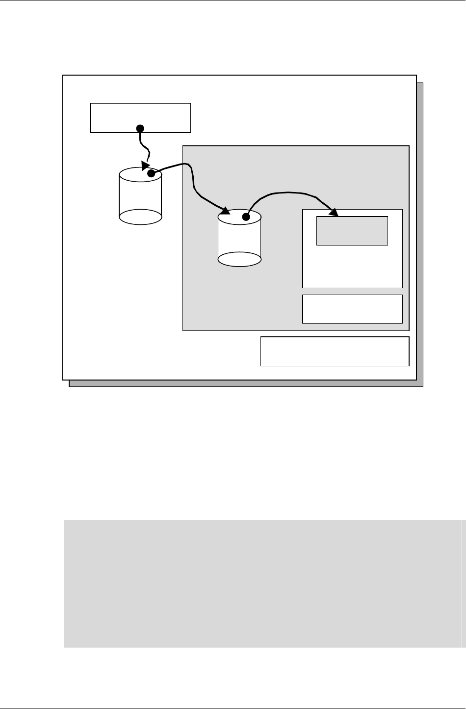
Maestro-related components include the following, which are shown
diagrammatically on the next page.
• 2dconvrt
a command-line tool that is used to convert swf animations into a
format that can be read by RenderWare Graphics
• Rt2d
a toolkit that implements low-level 2d functions
• Rt2dAnim
a toolkit that extends the functions of the Rt2d toolkit to include
animations. It contains an object called Rt2dMaestro. This object
coordinates playback of the 2d animations, and could be considered the
nerve center of the Maestro components.
• 2dviewer
a viewer, to play Maestro animations. Can be used for testing exported
.anm files. Code is provided, and demonstrates how to play back .anm
files.
✎ By convention, assets used by the Maestro player have an .anm file extension
• maestro1
an example demonstrating the use of Maestro to playback a user
interface authored in Flash.
The Flash features that Maestro supports are those that are implemented
in the Rt2d and Rt2dAnim toolkits. The 2dconvrt tool strips out all features
of the swf file that cannot be supported at run-time.
Introduction
RenderWare Graphics 3.7 III-43
As a simple example, the 2d toolkits do not support sound. Any sound
effects that are stored in the swf file are not reproduced by the run-time
components of Maestro. Sound effects can still be triggered; they just aren't
imported using the Maestro file format.
RenderWare Core and World
Rt2d
Rt2dAn im
Rt2d Mae s tro
anm
file
Flash
swf
file
Publish
2dconvert
Maestro Components
When an animation is created and saved in Flash an fla file is produced.
To be able to use the fla file in RenderWare Graphics the following steps
need to be followed:
1. Publish the fla file. This creates a swf file.
2. Convert the swf file to an anm file.
3. Read in and playback the anm file in RenderWare Graphics.
✎
Regarding multiple platform development, ideally the same .fla and .swf files should be
used.
Sequencing of user interfaces for console games is much more restrictive than for PCs due
to the lack of a mouse. It is advisable to author the Flash animation as if it were intended
for a console. This dictates the control flow and layout of the animation.
After a console-compatible interface has been completed, a PC overlay can be constructed
for each screen.
The PC-based Flash content will not, in general, resemble an ordinary PC Flash
production. This is due to the need to remain platform independent at the sequencing
level.

Chapter 31- Maestro
III-44 11 February 2004
31.1.2 This document
This document consists of six sections.
It is aimed at both artists and programmers. Artists should read sections
31.1, 31.2 and 31.3. Programmers should read the entire document.
The first section is this; the introduction.
The second section lists those features of Flash that are supported in
RenderWare Graphics and those that are not.
The third describes the content generation and publishing process. User
interface design for Maestro is detailed.
The fourth shows how to import content and view it using RenderWare
Graphics.
The fifth five describes the playback mechanism, specifically what hooks
exist for the developer. Topics include how to get information to and from
the player while it is playing.
The last section summarizes the major topics.
31.1.3 Other Resources
API Reference
− Rt2d toolkit
− Rt2dAnim toolkit
• 2d Graphics Toolkit Chapter in the User Guide
• 2dconvrt tool documentation, in docs\tools\2dconverter.pdf.
• 2dviewer viewer
• maestro1 example, a brief description of which is in section
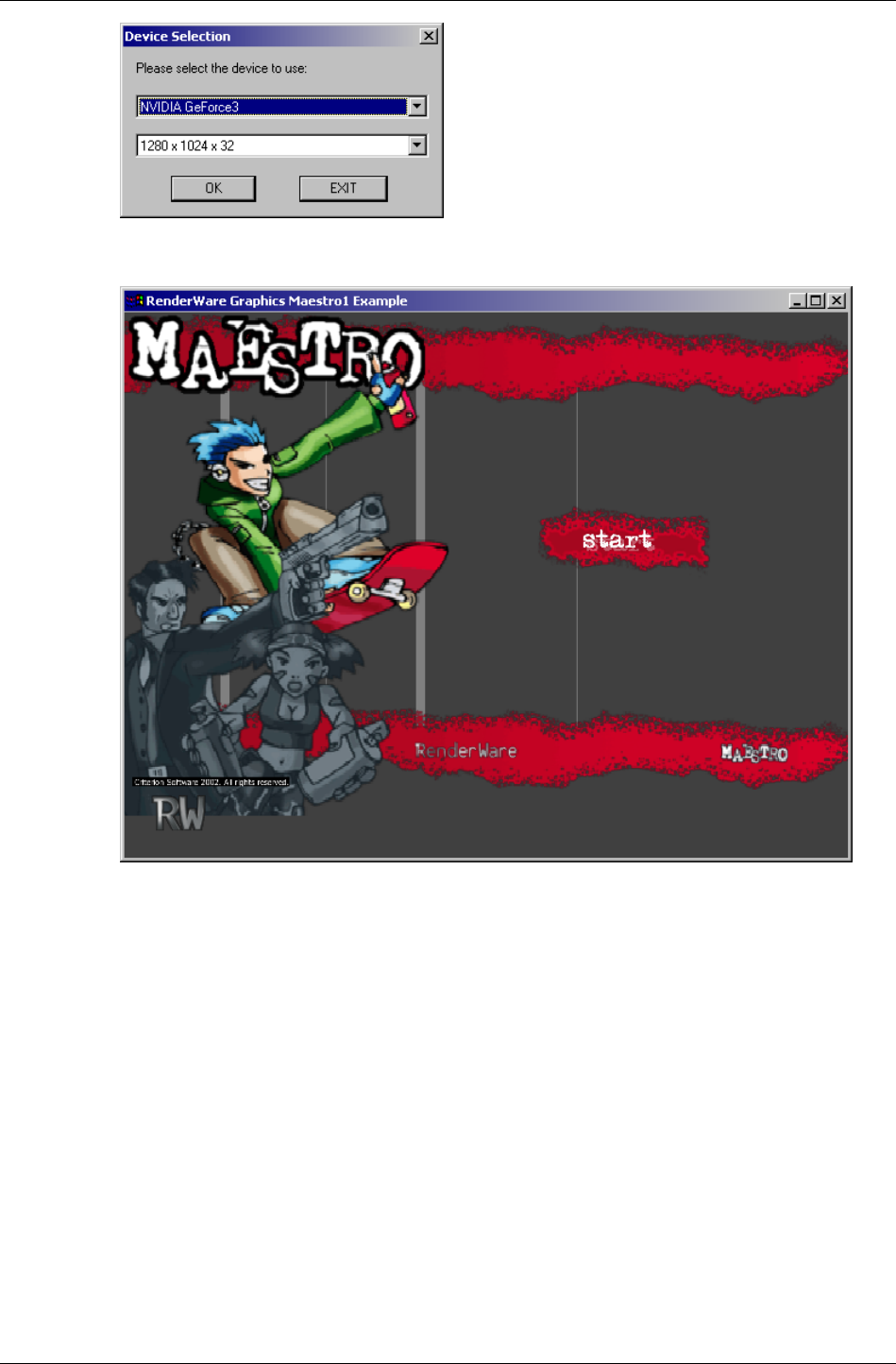
31.1.4 Using the maestro1 Example
The maestro1 example is accessed from the Windows Start Menu, under
Programs
Æ
RenderWare
Æ
Graphics <platform>
Æ
SDK
Æ
Examples.
Double-click on the maestro1 folder, then run either the
maestro1_d3d8.exe, maestro1_d3d9.exe or the maestro1_opengl.exe
executable.
The following dialogue should show:
Introduction
RenderWare Graphics 3.7 III-45
Click OK, and the example will start with the following:
At this point, the example will respond to keypresses such as ENTER,
BACKSPACE and the arrow keys. ENTER corresponds to SELECT and
backspace to CANCEL on a console.
Pressing ENTER on this screen will take you into the main part of the
example.

Chapter 31- Maestro
III-46 11 February 2004
31.2 Flash and RenderWare Graphics
The Flash-to-.ANM converter has been designed to support Flash 3. This
limits the actions that can be performed from a later version of Flash.
We chose the Flash 3 version because it closely matches the features that
Maestro supports. If you use a more recent version of the Flash authoring
application, then you must export the swf using the Flash 3 file format.
The range of supported and unsupported features is primarily due to the
feature set of the Rt2d and Rt2dAnim toolkits. The conversion process from
swf to the RenderWare Graphics format ignores those effects that the
toolkits cannot support.
31.2.1 Supported Features
The supported features in the Flash importer are:
• Bitmap fills in .png format.
✎ Power-of-2 height and width bitmaps should be used for bitmap fills, for example 256*256
or 128*512. Most modern hardware requires this. Within Maestro non-power-of-2 sized
bitmaps are resampled. It's better for the artist to resize their textures rather than let it
happen automatically.
• Static 2D vector-based content
− Line styles
− Solid fill styles
− Curved paths
− Alpha transparency
− Basic text strings
✎
The best results are obtained through converting vector-based artwork to small
bitmapped artwork.
Vector-based artwork is supported in order to make it easy to import initial artwork
roughs. Artwork of this form will load and run less efficiently than bitmap-based artwork.
Since vector-based art can consume large amounts of memory, it's recommended that you
measure this early in the UI creation process and make sure you have the memory budget
for it.
• Mapping of RenderWare Graphics fonts to Flash fonts.
• Animations on static content
• Utilization of 3D hardware to accelerate rendering
• Z-ordering / layering
• User interactivity including buttons

Flash and RenderWare Graphics
RenderWare Graphics 3.7 III-47
• A subset of Flash 3 actions including ActionGoToLabel,
ActionSetTarget (non-relative), ActionGotoFrame, ActionGetURL,
ActionNextFrame, ActionPreviousFrame, ActionPlay, ActionStop.
✎ Inside Maestro there are corresponding messages that may be intercepted by developer
code. See section 31.5.4.
• Actions may be triggered as frame actions or on button transitions
• Button export linkage is utilized. This allows console controller button
pushes to trigger the actions associated with a Flash button. See
section 31.5.6 for details.
• Comprehensive import tool, allowing extraction of data ranging from
simple static objects to complex interactive content
31.2.2 Unsupported Features
The unsupported features in the Flash importer are listed below. Where
possible, workarounds are detailed.
• Flash 4.0 and Flash 5.0 specific features.
• ActionScript introduced in Flash 4.0. Replace this with code written in
C. This may be triggered from Flash the "GetURL" trigger mechanism.
See section 31.5.4.
• Gradient and radial fills. Bitmap fills can be used to approximate a
gradient. Bitmaps may be stretched, so small bitmaps will work.
• Clipping layers.
• Movies within buttons. A separate movie clip can be triggered by a
transparent (yet active) button. This applies to the MouseOver state, so
movies cannot be played in the button when a mouse hovers over the
button.
• Relative targets in buttons. The only relative target supported is the
direct parent of a sprite.
• Bitmap fills in .jpg or .jpeg format. Store in lossless format once in
Flash. To do this:
- From the menu bar, select Window
Æ
Library.
- Right click the image's name to access the context menu
- Choose properties from the menu
- For "Compression", choose "Lossless"
• Sounds. "GetURL" triggers can be used to synchronize sound events.
Chapter 31- Maestro
III-48 11 February 2004
• Flash native and TrueType fonts. Use the fontalias.txt file to setup
RenderWare Graphics font aliases.
• Slanting transforms on text is not supported in RenderWare Graphics.
• Morph shapes. Break up the morph into individual positioning
keyframes. Consider using the Rt2dAnim interpolation feature (see
Rt2dAnim API reference) to make animations play exceptionally
smoothly.
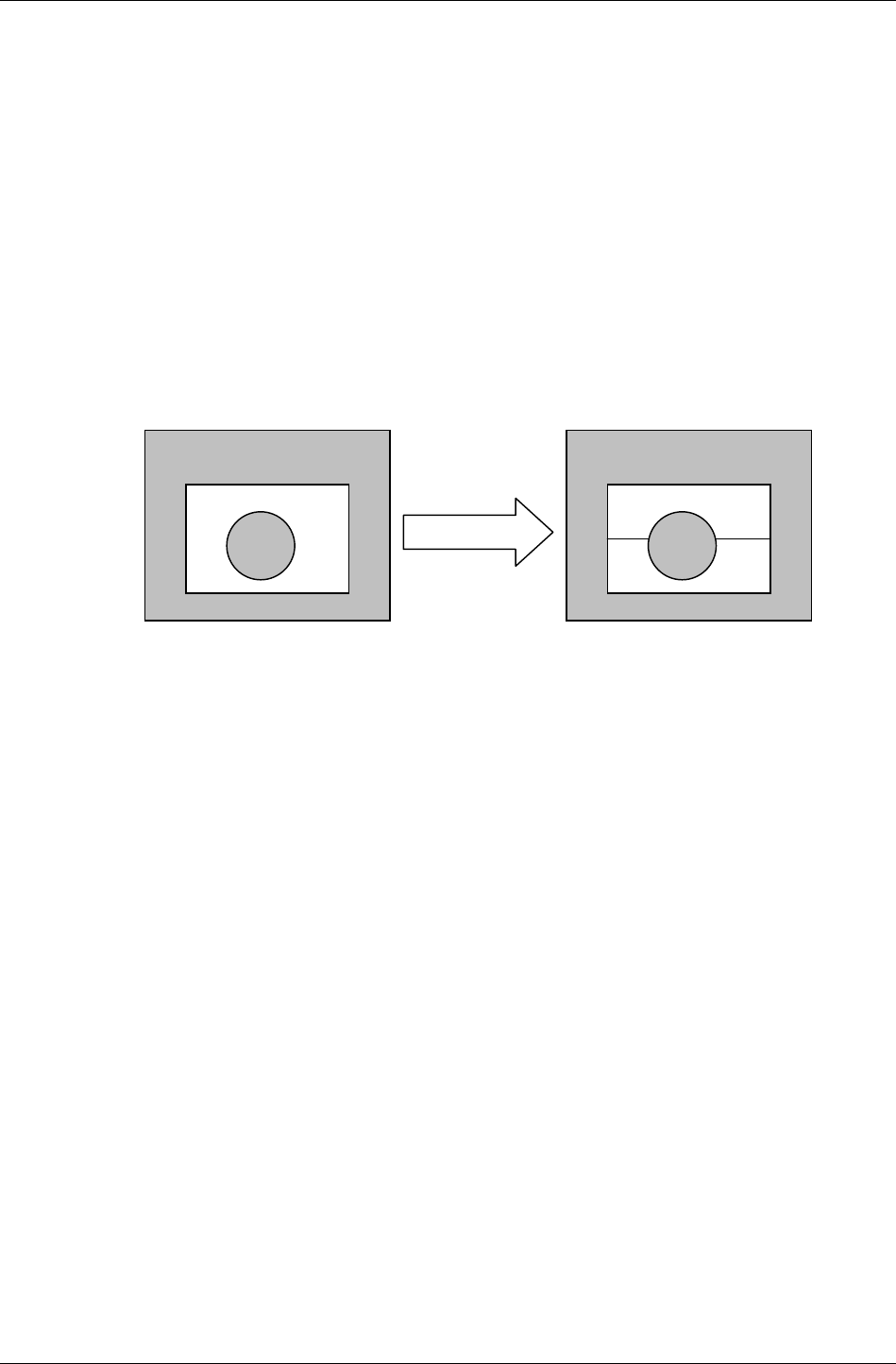
• Objects with non-edge-touching holes. A common practice in Flash is to
create a "frame" with a cutout in the center. Because 2D shapes are
plotted as large, continuous areas in RenderWare Graphics, these
regions are opaque. Break the object into two separate objects in
different layers, and it will plot correctly.
• Complex concave curved regions. Usually these will render correctly,
but in a few cases there will be minor overfill errors. Splitting up the
curves that form the edges of the concave regions should help alleviate
this.
Background Background

Creating 2D Content for Use Within RenderWare Graphics
RenderWare Graphics 3.7 III-49
31.3 Creating 2D Content for Use Within
RenderWare Graphics
This section describes:
• publishing a Flash fla file to a Flash swf file
• elements of a user interface
• creating and using a virtual controller in order to test the user interface
as it would be navigated on the console
• use of naming conventions to simplify development
Additionally, the maestro1 example demonstrates a user interface in
action. Appendix I shows some of the sequencing planning that was carried
out for maestro1.
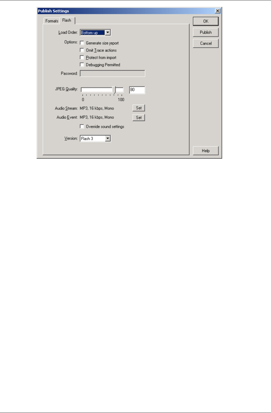
31.3.1 Publishing an SWF
Flash fla files need to be published as swfs to be imported into
RenderWare Graphics. To convert an fla to a swf file the fla file needs to
be published in the Flash 3 format.
RenderWare Graphics supports a subset of Flash 3. In Flash 5, Publish
Settings can be changed and set to Flash 3 and any options that are not
supported in Flash 3 are highlighted.
To ensure that when you are creating something in Flash you are only
using Flash 3 functionality, in Flash setup the following:
File
Æ
Publish Settings
Æ
Flash tab
Ensure that Version is set to Flash 3.
Chapter 31- Maestro
III-50 11 February 2004
Every time the movie is run only the object window will appear stating if
any non-Flash 3 actions have been used.
Publishing
The swf can be published in two ways:
1. File
Æ
Publish Settings
Æ
Flash tab click on Publish
2. File
Æ
Publish
31.3.2 Elements of a User Interface
The following Flash elements may be useful in creating a user interface:
• symbols
• buttons
• movie clips
• labeling
• actions
• graphics
• text
• naming conventions

Creating 2D Content for Use Within RenderWare Graphics
RenderWare Graphics 3.7 III-51
Symbols
It's convenient to set up most items in Flash Movies as symbols. This
makes editing easier, especially when a symbol is repeatedly used.
If an identical piece of text is used in multiple scenes, a symbol containing
that text could be defined. Updating that symbol would update the text in
all the places where that symbol is used.
✎ Symbol names aren't saved in .swf files, and consequently are inaccessible from code.
Buttons
IMPORTANT: Most consoles have no mouse. The design of most Maestro-
based user interfaces must take this into account. They cannot be authored
in exactly the same way as web-based user interfaces, since there is no
concept of a mouse position and active button.
Buttons are used to put together a 'virtual controller' that may be used to
simulate a console controller. The buttons' purpose is to serve as
placeholders for Flash actions that will be assigned to them during content
creation. This is described in section 31.3.3.
It is common in Maestro to author buttons with just a hit state, so that
they do not appear. Images of different button states should be dependant
on the current movie frame, rather than on a mouse-dependant button
state.
Unless you are developing for a platform with a mouse, the only button
events that are useful to assign actions to are 'press' and 'release'.
Buttons created must also have linkage properties set. The linkage
properties are used when the buttons are exported from Flash and then
imported into RenderWare Graphics.
✎ Programs using Maestro animations will need to refer to buttons by names. See section
31.5.6 to see why. The linkage properties can be used to make the button names get
exported.
To assign an identifier string to a button:
Select the button symbol in the Library.
Right click the symbol name and choose Linkage
Select Export this symbol and enter an identifier string.

Chapter 31- Maestro
III-52 11 February 2004
Movie Clips
Movie clips are animations that play inside other animations. They can be
played within the main animation or other movie clips. They may contain
any of the Flash elements detailed in this section.
Movie clips can be used to put together simple animation sequences. These
may then be placed as a single objects within larger animations. This
simplifies the design of the larger animation by breaking it up into parts.
Although movie clips are usually animated, they can be 'stopped' so that
they stay on a particular frame.
This makes them useful to implement user interface aspects such as slider
positions or displayed control states.
✎
For the programmer, movie clips correspond loosely to Rt2dAnims with additional features
like actions, frame labels and buttons.
Movie clip instance names are exported, which means that specific movies can be looked
up in code. See the section on string labels (31.5.3) for information on how to do this.
Since movie clip names are exported and symbol names are not, movie clips are actually
the only way of naming graphics so they can be found in code.
Possible uses of movie clips:
• looking up the current frame of the movie. You could use this method to get a slider
position. The maestro1 example uses this method on the player name edit screen.
• locating an object so that you can change its displayed position in code
• locating an object so that you can look up and change a texture
• locating a text string so that you can modify it in code. You can also do this by
traversing the main scene tree, as is done in the maestro1 example to find some
marker text.
Labeling
Movie clips need to be meticulously labeled. The instance labels are used
when actions are created for the select buttons to run movie clips. Labeling
movie clips allows them to be controlled with Flash actions from other
movie clips.
✎ Labels are accessible from within RenderWare Graphics. See section 31.5.3.
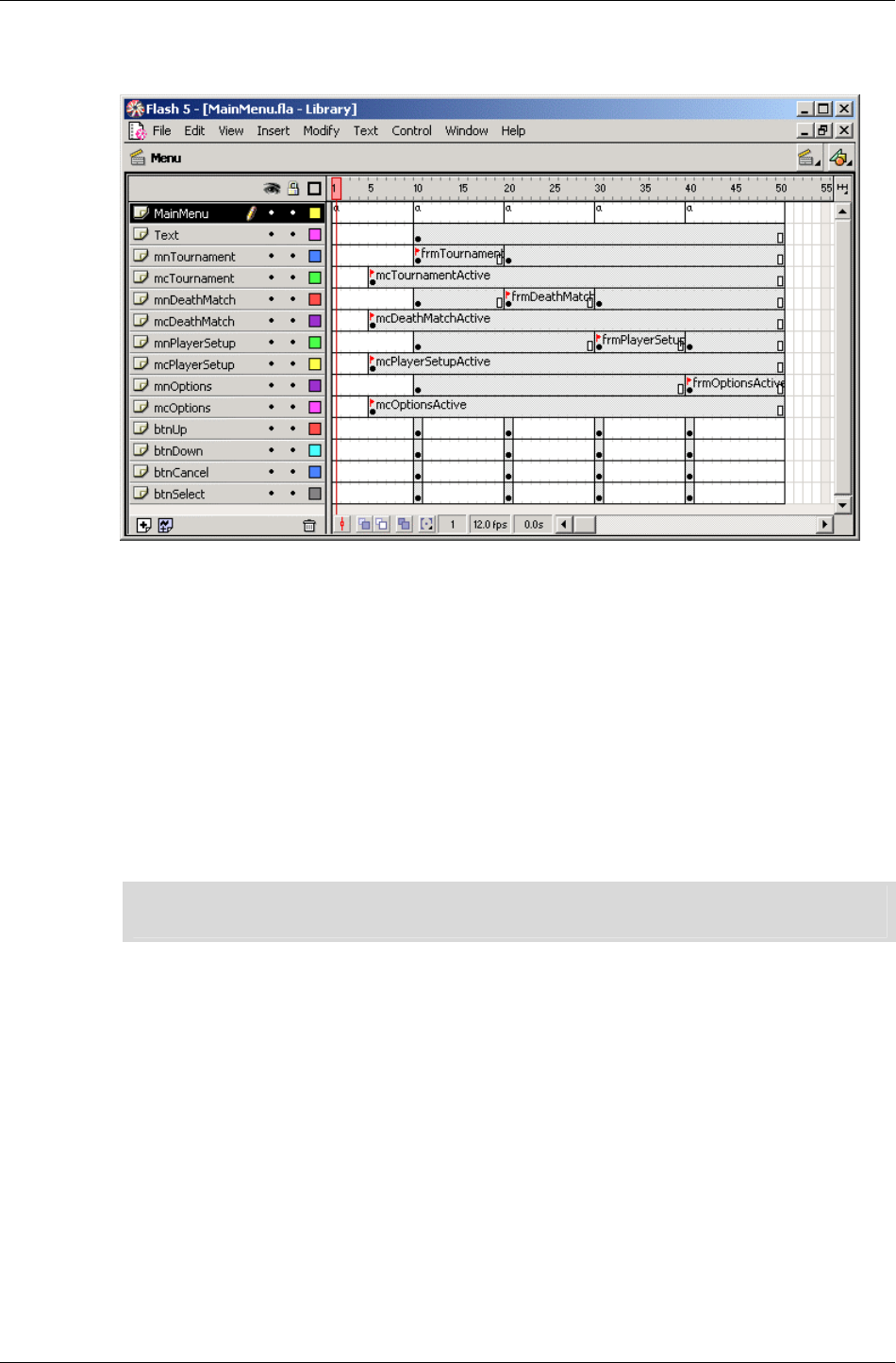
Creating 2D Content for Use Within RenderWare Graphics
RenderWare Graphics 3.7 III-53
Individual frames may be labeled within movie clips. Actions may be used
to make playback jump to a new frame.
Actions
With the publish settings set to Flash 3 (see Publishing an SWF), Flash
displays illegal actions in yellow. Available actions remain unshaded. All
the "Basic Actions" are available, and a limited number of "Actions".
Actions can be triggered by a particular frame of an animation being
played, or by a button transition such as 'on (press)' or 'on (release)'.
Actions that are useful are 'Go To', 'Play', 'Stop', 'Get URL', 'Tell Target', 'On
Mouse Event' and 'GetURL'. The other actions are not exported, and so are
ignored.
✎ GetURL is particularly important, as it provides a way of triggering actions in the calling
program. See the maestro1 example and section 31.5.4.
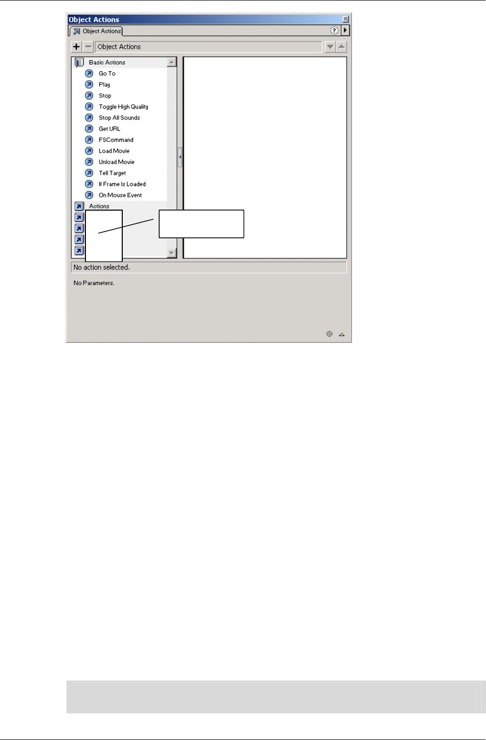
Chapter 31- Maestro
III-54 11 February 2004
Graphics
Bitmap fills are very effective in space and speed.
If the .swf will be used on multiple platforms, it may not be possible to get
a one to one relationship between the bitmap and screen. Using a higher
resolution than is strictly required may help.
When objects will be resized through animation, vector artwork will be
better. Artwork in this form is size independent.
The downside of vector artwork is that it can become inefficient without
appearing that way in Flash.
A common practice in Flash is to convert a bitmap to vector art. This is
definitely something to avoid for Maestro, as such an object will be much
less efficient to store and render.
Text
Text may be added with Flash's text tool. Some care must be taken in
choosing fonts, as these will have to be imported into RenderWare Graphics
in order to display correctly.
✎ For programmers, the 2dconvrt utility has the ability to map fonts within Flash to fonts
within RenderWare Graphics. Consult the 2dconvrt documentation for more information.
unavailable
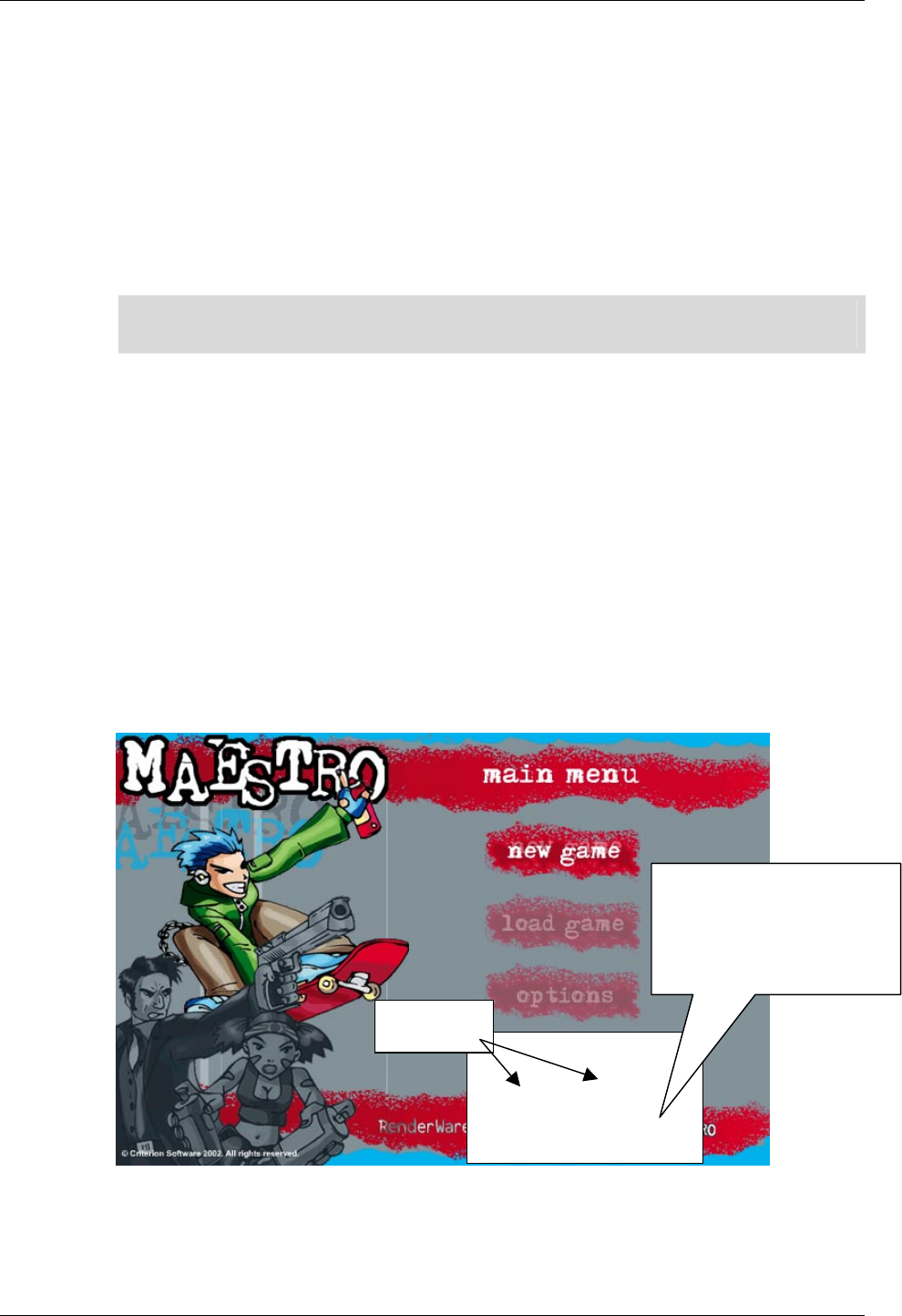
Creating 2D Content for Use Within RenderWare Graphics
RenderWare Graphics 3.7 III-55
Naming Conventions
For convenience and clarity, it is useful to adopt a naming standard for
Flash objects. It may not be apparent from the name what kind of object is
being referred to.
Prefixing a name with an indication of the object type makes it easier to
work with Flash files through the whole content creation and import
process.
Appendix II contains suggested naming conventions.
✎ Programmers are invited to consider this analogous to file extensions, but not Hungarian
notation
31.3.3 Virtual Controllers and Console Artwork
IMPORTANT: Most consoles have no mouse. The design of most Maestro-
based user interfaces must take this into account.
Due to the lack of a mouse pointer, buttons that react to mouse clicks
cannot be used on consoles. Images or animations displaying button
pictures may be used, but usually they won't be Flash buttons.
To provide a place-holder for user input, a virtual controller must be used
during content creation (see figure below). This virtual controller serves as a
mock-up of the console's control pad. It has duplicate versions of the
controller direction buttons (up, down, left right) and also the select and
cancel buttons.
Having the virtual controller present during development allows actions to be
assigned to button pushes. For example "select" pressed on Frame1 with
'options' highlighted could have actions to take the player to Frame10 with
'Options Menu' displaying.
virtual controlle
r
(only appears in .swf,
not in exported
interface)
Buttons

Chapter 31- Maestro
III-56 11 February 2004
Content created for Maestro will have 'controls' displayed as 'active' on
separate frames in preference to controls that react to mouse-overs and
mouse button pushes.
The virtual controller graphics will not be exported for the production
version of your artwork, but its button actions will be. The button actions
may be directly forced from within code, as described in section 1.4.
The other button images present in this figure ("new game", "load game",
"options") are not Flash buttons; they are ordinary graphics and
animations.

Importing Flash Files into RenderWare Graphics
RenderWare Graphics 3.7 III-57
31.4 Importing Flash Files into
RenderWare Graphics
Once a Flash file has been published to a .swf file, this .swf must be
converted into a form ready for use inside RenderWare Graphics.
The conversion is performed by a command-line tool, 2dconvrt. The result
of conversion is a RenderWare Graphics .anm file, which may be played
back inside a program or by using the 2dviewer program.
This section is aimed at programmers, and describes
• converting a Flash swf file to a RenderWare Graphics anm file
• viewing a RenderWare Graphics anm file with the 2dviewer program
31.4.1 Importing the SWF into RenderWare
Graphics
Flash swfs are converted to anms using the 2dconvrt tool.
The 2dconvrt tool is described in detail in the 2dconvrt tool documentation.
Using the 2dconvrt Tool
The 2dconvrt tool converts swfs to anms. anms can be played back and
manipulated within RenderWare Graphics.
The 2dconvrt tool is a command line tool; it has no graphical user
interface.
By default, 2dconvrt exports bitmaps and an anm file containing all scenes,
animations and user interactivity information needed to play the Flash
animation.
Converting an SWF
Using the commands described in the 2dconvrt documentation, .swfs
may be converted as follows at the command line:
• Type 2dconvrt <example>.swf
This creates an anm file, <example>.anm
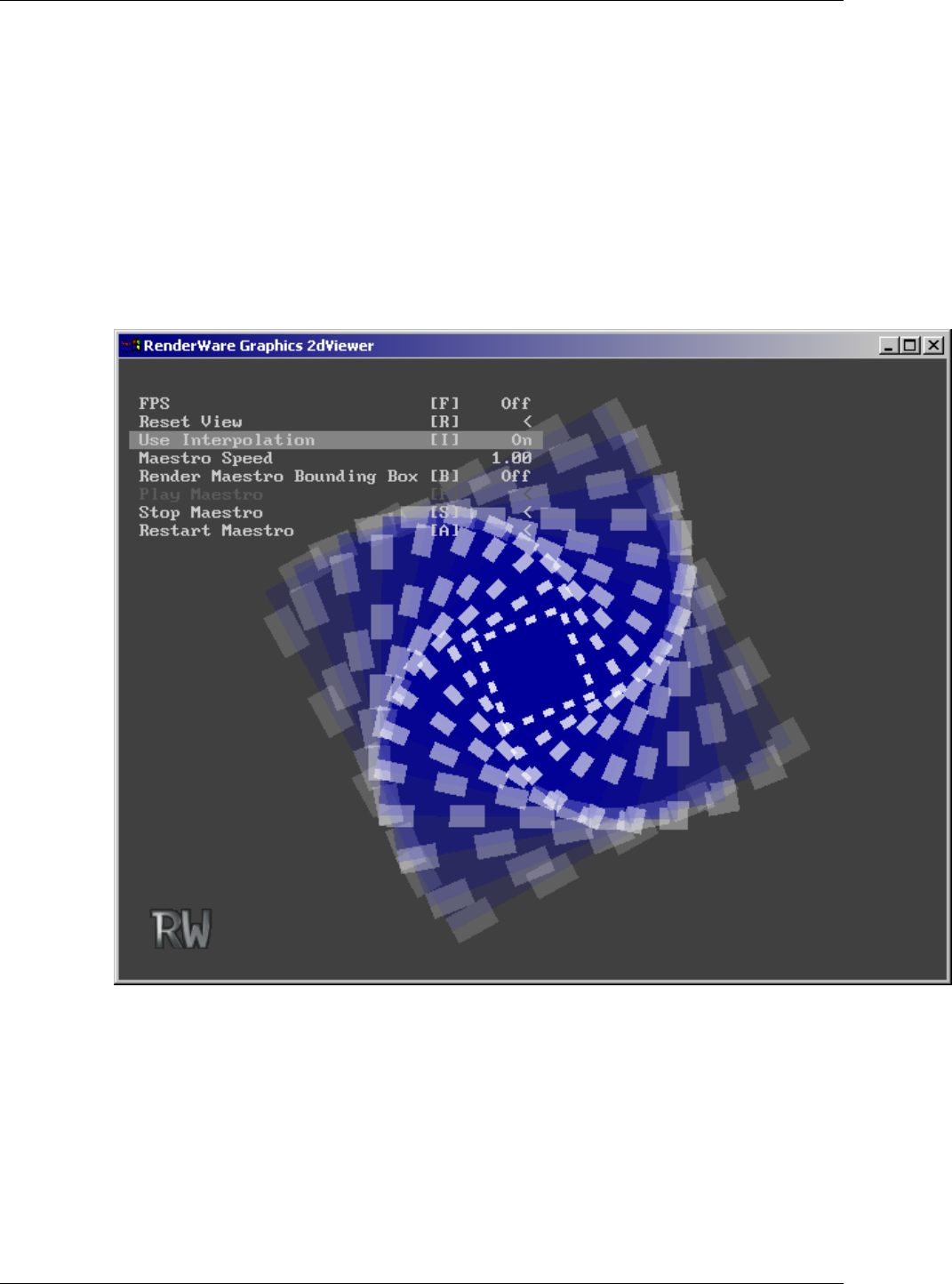
Chapter 31- Maestro
III-58 11 February 2004
31.4.2 2d Viewer
As with the 3D parts of RenderWare Graphics, we supply a simple viewer to
allow the converted anm file to be easily viewed. Both a platform specific and
Win32 version of the viewer are provided in the SDK. The source code to
this application is also included.
To display the anm file in RenderWare Graphics:
1. Run the 2dviewer tool.
2. Click and drag the anm file onto the 2dviewer.
2dviewer with default animation, swirly.anm

Developing With Maestro
RenderWare Graphics 3.7 III-59
31.5 Developing With Maestro
This section details how to develop with Maestro.
Streaming and playback of a Maestro animation is described.
Also described are methods of getting information into and out of Maestro
while it's playing an animation. This can be handy for linking up
controllers, or reacting to events within the animation.
Maestro provides efficient and convenient means of getting handles to
internal data by name.
Finally, use of mouse inputs is described. This is useful in the event that
you're authoring interfaces for the PC.
31.5.1 Introduction
The Maestro API consists of streaming, time update and rendering
functions.
Also exposed is a callback-based message-passing mechanism, by which
events internal to the Flash animation can be passed back to the calling
code. A custom message handler may be chained before the default
message handler. This allows user code to be notified of events internal to
the animation.
The user may also post external events into the animation via the message
passing interface. Rt2dMessage structures can be passed to Maestro to
make Maestro do actions that weren't specified in the Flash file.
Rt2dMessages can also be intercepted by hooking a custom message
handler. In this manner messages can be examined as they flow through
the message processing handler.
Once Flash content has been created and loaded for playback inside
Maestro, the problem arises as to how to link up code to elements that were
authored in the Flash environment. For example, if an animation called
"/imcSubAnim1/Slider1/" exists in the Flash file, how can the current
frame of that animation be determined?
In order to address this issue and others, it's possible to access many Flash
elements by name in the exported .anm file. This is implemented through
the use of a string label table, which allows the lookup of names that were
exported from Flash. The various Rt2dStringLabel functions allow access
to this data.
This section describes how to use those parts of the Rt2dAnim library that
pertain to Rt2dMaestro.

Chapter 31- Maestro
III-60 11 February 2004
All of the 2D animation APIs build on the hierarchical scene functionality
provided in the Rt2d toolkit. See the 2D Graphics Toolkit user guide
chapter, and Rt2d and Rt2dAnim sections in the API reference for more
information.
Because Maestro has no memory, virtual keyboards, toggles and sliders
require some code support. In most cases this is in order to get information
out of the animation, for example the fact that a slider has moved. At other
times, it may be desirable to externally set the position of a slider on entry
to the screen displaying that slider.
As a rule, it's easier to author the navigation from inside Flash, rather than
try to write C/C++ code that mimics the navigation of a menu system.
31.5.2 Playback of an ANM file in RenderWare
Graphics
The Rt2dAnim toolkit contains Rt2dMaestro functions to playback an anm
file in RenderWare Graphics.
Before any Rt2dMaestro functions may be called, the Rt2dAnim toolkit
must be opened with the Rt2dAnimOpen function. On shutdown, after all
Maestro objects have been destroyed, Rt2dAnimClose must be called.
Rt2dMaestro controls the sequencing of 2D animation with user
interaction. Rt2dMaestro contains a scene. A scene holds 2D objects that
can be manipulated.
The following Rt2dMaestro functionality is discussed::
1. Serialization of the maestro and the maestro scene
2. Positioning the maestro scene on the display
3. Applying time updates
4. Message handling
5. Rendering
6. Destroying the maestro
Serialization
It is assumed that a Maestro animation will be provided from an external
source such as the 2d conversion tool 2dconvrt. Once a Maestro animation
is available in a .anm file, it may be streamed in as per standard
RenderWare Graphics practice.

Developing With Maestro
RenderWare Graphics 3.7 III-61
Care should be taken to ensure that the font and texture paths have been
set correctly prior to streaming in the Rt2dMaestro. Note that particular
font or textures may be required by the animation, but may not be in the
same directory as the animation itself.
The following code streams in an animation, assuming that the font and
texture paths have been set beforehand:
RwStream *stream = NULL;
Rt2dMaestro *maestro = NULL;
stream = RwStreamOpen(rwSTREAMFILENAME, rwSTREAMREAD,
<streamName>);
if( !stream )
{
return (Rt2dMaestro *)NULL;
}
if (!RwStreamFindChunk(stream, rwID_2DMAESTRO,
(RwUInt32 *)NULL, (RwUInt32 *)NULL)
{
return (Rt2dMaestro *)NULL;
}
maestro = Rt2dMaestroStreamRead(NULL,stream);
return maestro;
Positioning Maestro Rendering on the Display
The maestro scene needs to be positioned on the display. In the example
below the scale and translations needed to position the Maestro have been
chosen in advance. You will need to determine values that work with your
user interface.
Rt2dObject *MaestroScene = Rt2dMaestroGetScene(Maestro);
Rt2dObjectMTMScale(MaestroScene, 0.002f, 0.002f);
Rt2dObjectMTMTranslate(MaestroScene, 100.0f, 100.0f);
✎ The maestro1 example demonstrates another way this could be done.
Maestro builds on top of the Rt2d library. The standard
Rt2dCTM<operation> library functions can also be used to position
Maestro's displayed output.

Chapter 31- Maestro
III-62 11 February 2004
Applying Time Updates
During playback, it is necessary to inform Maestro that time is passing.
Fast paging through animations can be carried out without having to
update the scene.
The next step is to instruct Maestro to update the scene that will be
rendered.
If the state of a scene is required before rendering (e.g. for collision
detection), it can be examined after this scene update step.
/* Inform the Maestro how much time has passed */
Rt2dMaestroAddDeltaTime(<Maestro>, <deltaTime>);
/* Cause the Maestro to apply any updates to the scene it
* controls. This does not update the LTM of the scene
* controlled by the Maestro. If collision detection was to
* be performed prior to rendering, Rt2dSceneUpdateLTM would
* have to be called first on the scene obtained from
* Rt2dMaestroGetScene
*/
Rt2dMaestroUpdateAnimations(<Maestro>);
Message Handling
Maestro's way of communicating with calling code is through a messaging
interface. Messages may be passed to and from Maestro.
Maestro may generate messages during the time-update phase in the
course of doing an Rt2dMaestroAddDeltaTime.
Maestro can be provided with a custom message handler
Rt2dMaestroSetMessageHandler in order to intercept these messages.
Message may also be sent to Maestro with the Rt2dMaestroPostMessage
API. They won't be processed until Rt2dMaestroProcessMessage is called.
Section 31.5.4 describes this process in detail, as does the Rt2dAnim toolkit
API reference.
Rendering
Once the positions of the displayed objects have been updated in Maestro's
scene, that scene may now be rendered.
/* If changes to the viewpoint are made externally, the base
* level of the scene must be updated. This is common in
* most of the examples, which may be rotated, zoomed in etc
*/
if( <ViewChanged> )
{

Developing With Maestro
RenderWare Graphics 3.7 III-63
Rt2dObject *MaestroScene =
Rt2dMaestroGetScene(<Maestro>);
Rt2dObjectMTMChanged(MaestroScene);
<ViewChanged> = FALSE;
}
/* Draw the scene controlled by the maestro */
Rt2dMaestroRender(<Maestro>);
Destruction
The maestro is destroyed by:
Rt2dMaestroDestroy(Maestro);
The maestro scene is also destroyed as the maestro owns the scene.
31.5.3 String Labels
Rt2dStringLabel is a string reference structure that is used by
Rt2dMaestro to allow linking of internal and external data by name
without a performance hit.
Rt2dMaestro stores a table of string labels. When an Rt2dMaestro is
created or streamed in, the string label table is populated. The calling
function can then look up names of interest within the table. The index that
indicates where the name was found can be used as a handle to identify
that name.
✎ The strings appear in the .anm file. You can check that the names have exported using
any hex editor or VisualStudio.
Additionally, an identifier is stored within the table to note what kind of
data is being referenced by the name. The user may store additional data in
the table against each name. This provides a convenient location to place
callbacks or flag locations. This would then be used by a custom message
handler hooked to the Rt2dMaestro.
Rt2dStringLabel entity types
A string label may label one of several different entity types within the
Rt2dMaestro. When searching for a particular string label, an entity type
can be provided by the programmer. Allowed entity types are
rt2dANIMLABELTYPEANIM Animation label
rt2dANIMLABELTYPEFRAME Frame label
rt2dANIMLABELTYPEBUTTON Button label
rt2dANIMLABELTYPEURL URL label; used for extensions

Chapter 31- Maestro
III-64 11 February 2004
rt2dANIMLABELTYPEURL is the type used for a Rt2dStringLabel exported
for a "GetURL" action in the Flash generated content. It is handy in the
representation of user-defined named triggers.
Usually the text contained within a string label is the same as that listed in
the Flash editor.
Animation instance names, denoted by rt2dANIMLABELTYPEANIM, are a
special case. Flash movie clips can be contained within other movie clips,
giving rise to a 'tree' of named animations.
Animation instance names may be set via the 'Instance' panel within Flash.
They are similar in operation to directory names.
The names get exported in their fully qualified form. The "/" character is
used as a separator. Leading and trailing separators are added
automatically. Examples are shown in the table below.
ANIMATION LABEL DESCRIPTION
/ main animation
/imcSubMovie1/ sub animation of main animation
/imcSubMovie1/imcSlider1/ animation within the first sub animation
/imcSubMovie1/imcOnOff1/ animation within the first sub animation
/imcSubMovie2/ sub animation of main animation
/imcSubMovie2/imcSlider1/ animation within the second sub
animation
Using Rt2dStringLabel access functions
The Rt2dMaestroFindStringLabel function may be used to locate a string
label stored in the string label table inside an Rt2dMaestro.
Rt2dStringLabel *label;
RwInt32 index;
label = Rt2dMaestroFindStringLabel(
<maestro>, rt2dANIMLABELTYPEURL, "startGameTrigger",
&index");
The index that's returned is the index of the string label within Maestro's
internal string label table. This index is stored as one of the integer
parameters for several Maestro messages (see the Rt2dAnim API reference
for details).
A custom message handler that watches messages passing through the
system can look at the parameters of these messages. Some messages use
a string label index as a parameter, for example rt2dMESSAGETYPEPLAY
Once the string label has been located, its properties can be modified
directly through the pointer returned,
/* Store some user data */
Rt2dStringLabelSetUserData(<label>, &<startGameEvent> ) ;

Developing With Maestro
RenderWare Graphics 3.7 III-65
In this case, <startGameEvent> is arbitrary programmer-specified data. Ids
or callbacks could be stored there, for example. This stored user data could
then be used in a custom message handle.
The index within the string label table itself may be stored and later used to
regain the pointer.
/* Retrieve user data */
RwBool *flag;
Rt2dStringLabel *label;
label = Rt2dMaestroGetStringLabelByIndex(
<Maestro>, <index>);
flag = Rt2dStringLabelGetUserData(label);
The pointer itself should not be stored for extended periods, as
Rt2dMaestro may move the string table around in memory.
31.5.4 Messages
Rt2dMessage is a message structure that is used by Rt2dMaestro to
coordinate animation sequences.
External code may also be use Rt2dMessage to notify Maestro of external
events.
This is carried out through the use of the Rt2dMaestroPostMessages and
Rt2dMaestroProcessMessages functions. After being posted to
Rt2dMaestro, Rt2dMessages are held within a queue. Calling
Rt2dMaestroProcessMessages causes the messages in the queue to be
processed until there the queue is empty.
The processing of each message by Rt2dMaestro is carried out by an
internal message loop.
It is possible to hook a custom message handler to Rt2dMaestro.
Rt2dMessage structures are passed to that handler. These may be
examined to determine when particular animation events have occurred,
before being passed on to the default message handler.
Rt2dMessage
Rt2dMessage contains several pieces of information.
struct Rt2dMessage
{
Rt2dMessageType messageType; /* message identifier */
RwInt32 index; /* index of the stringlable name
* of the animation the message
* applies to
*/
RwInt32 intParam1; /* first param (message dependant) */
RwInt32 intParam2; /* second param (message dependant)*/

Chapter 31- Maestro
III-66 11 February 2004
};
The messageType identifies how Rt2dMaestro will interpret the message.
The following are the most important messages:
rt2dMESSAGETYPEGETURL
used to trigger external events from within a Flash animation
rt2dMESSAGETYPEBUTTONBYLABEL
used to trigger actions associated with a button inside the Flash
animation.
Other messages are described in the API reference.
This message type identifies how the other parameters are to be
interpreted.
index is generally used to identify which animation within Rt2dMaestro
that the message applies to. It isn't the animation number itself, but rather
the index of the string label name for that animation.
Messages posted externally may be sent to specific animations.
Message types
The following is a description of all message parameters and their basic
usage.
All the objects are always addressed by their indexes except when specified.
rt2dMESSAGETYPEGETURL:
index Animation index
IntParam1 Index of GetURL's StringLabel
IntParam2 Unused
This message is always sent outwards from Maestro with the intention
that outside code will react to it.
This message should be used as an extension mechanism. During
content generation, a "GetURL" action may be specified with a string, e.g.
"GetURL("StartGame")".
By hooking a custom message handler, the "GetURL" message may be
intercepted and used to trigger in-game events. The default handler does
nothing with this message. See section 31.5.3 for more detail about
Rt2dStringLabels.
rt2dMESSAGETYPEBUTTONBYLABEL:
index Animation, should be –1
IntParam1 Index of button's StringLabel
IntParam2 Transition
This message is always send inwards to Maestro from calling code via the
Rt2dMaestroPostMessage function.

Developing With Maestro
RenderWare Graphics 3.7 III-67
This message triggers the actions associated with a button transition on a
button identified by a string label. It may be used to pipe in external
button presses to specific buttons identified by a name registered in a
string label. See section 1.4.4 for more detail about StringLabels.
This message should be passed to all visible animations by using the
Rt2dMaestroForAllVisibleAnimations function with an appropriate
callback.
The two transitions that are of interest are
rt2dANIMBUTTONSTATEIDLETOOVERDOWN and
rt2dANIMBUTTONSTATEOVERDOWNTOIDLE. These correspond to 'button
pressed' and 'button released'.
See section 31.5.6 for more detail about
rt2dMESSAGETYPEBUTTONBYLABEL.
Other message parameters are described in the API reference.
31.5.5 Hooking a custom message handler
The following is a sample custom message handler:
static Rt2dMessage *
ViewerMessageHandler(
Rt2dMaestro *maestro, Rt2dMessage *message)
{
switch(message->messageType)
{
case rt2dMESSAGETYPESTOP:
<MaestroRunning> = FALSE;
break;
case rt2dMESSAGETYPEPLAY:
<MaestroRunning> = TRUE;
break;
default:
break;
}
return Rt2dMessageHandlerDefaultCallBack(
maestro,message);
}
It would be supplied to the Maestro during initialization:
Rt2dMaestroSetMessageHandler(<Maestro>,
ViewerMessageHandler);
In this case, the default message handler is called directly at the end of the
custom handler.

Chapter 31- Maestro
III-68 11 February 2004
Alternatively, the original message handler could have been obtained with
Rt2dMaestroGetMessageHandler. The pointer returned could have been
stored and later called in the custom message handler via the stored
pointer.
This would have the advantage of enabling chaining of multiple custom
message handlers.
31.5.6 Triggering button transitions by name
Sometimes a mouse-driven point-and-click interface is inappropriate for
use on particular platforms; consoles in particular.
In these instances it is more appropriate to directly trigger button-click
events in the interactive animation. For example, if a button on a console
controller were pressed, it would be convenient to trigger the actions on a
particular button within the animation.
Flash can be made to export the name of a button for external linkage. If
this is done, the button may be triggered by name through the use of the
rt2dMESSAGETYPEBUTTONBYLABEL message.
After loading the Maestro, but preferably before playback, the index of the
button named "btnDown" is obtained.
RwInt32 lookup;
Rt2dMaestroFindStringLabel(
Maestro, rt2dANIMLABELTYPEBUTTON,
"btnDown", &lookup
);
Later during playback, a message may be setup indicating a button push.
This message must be posted to all visible animations, and for this purpose
the Rt2dMaestroForAllVisibleAnimations API function may be used.
/* Define a structure for use withn the
* Rt2dMaestroForAllVisibleAnimations
* callback */
typedef struct ButtonByLabelPacket ButtonByLabelPacket;
struct ButtonByLabelPacket
{
RwInt32 buttonID;
RwUInt32 animButtonState;
};
/* Callback to post the message to a particular animation */
Rt2dMaestro* BtnCallBack (Rt2dMaestro *maestro, Rt2dAnim *anim,
Rt2dAnimProps *props, void *pData)
{
Rt2dMessage message;

Developing With Maestro
RenderWare Graphics 3.7 III-69
message.messageType = rt2dMESSAGETYPEBUTTONBYLABEL;
message.index = -1; /* This will be replaced with a */
/* 'current' animation number when */
/* used in conjunction with */
/* Rt2dAnimForAllVisibleAnimations */
message.intParam1
= ((ButtonByLabelPacket *)pData)->buttonID;
/* button label index */
message.intParam2
= ((ButtonByLabelPacket *)pData)->animButtonState;
/* Post message */
Rt2dMaestroPostMessages(maestro, &message, 1);
return maestro;
}
...
/* and the code that posts the message for all animations */
...
ButtonByLabelPacket packet;
packet.buttonID = lookup;
packet.animButtonState = animButtonState;
Rt2dMaestroForAllVisibleAnimations(
<Maestro>, BtnCallBack,(void*)&packet);
...
/* Cause the Maestro to act upon the message */
Rt2dMaestroProcessMessages(<Maestro>);
31.5.7 Mouse Interaction on a PC
Maestro-based user interfaces should initially be designed so they may be
used on consoles, where a mouse and pointer is unavailable. Consoles
suffer from limitations that PCs don't have, so it is easier to port an
interface from a console to a PC rather than from a PC to a console.
For interfaces on PCs, mouse interactivity is desired. It becomes necessary
to inform Maestro of mouse position and button status changes.
Maestro provides messages for the purpose of delivering mouse position
and button state updates. These messages are
rt2dMESSAGETYPEMOUSEBUTTONSTATE and rt2dMESSAGETYPEMOUSEMOVE.
Although it's possible to use Rt2dMaestro simply as an animation playback
mechanism, it is designed to support full user interactivity in the form of
mouse events.

Chapter 31- Maestro
III-70 11 February 2004
The Maestro may be informed that the mouse button has been pushed:
if (<leftButtonPushed>)
{
Rt2dMessage message;
message.messageType = rt2dMESSAGETYPEMOUSEBUTTONSTATE;
message.index = -1;
message.intParam1 = (RwInt32)TRUE; /* Button pushed */
Rt2dMaestroPostMessages(<Maestro>, &message, 1);
}

Developing With Maestro
RenderWare Graphics 3.7 III-71
or that the mouse has been moved:
message.messageType = rt2dMESSAGETYPEMOUSEMOVETO;
message.index = 0;
message.intParam1 = (RwInt32)mouseStatus->pos.x;
message.intParam2 = (RwInt32)mouseStatus->pos.y;
Rt2dMaestroPostMessages(Maestro, &message, 1);
After the messages are posted, the Maestro should be informed by calling
the Rt2dMaestroProcessMessages function.
Rt2dMaestroProcessMessages(Maestro);
Note that only one pair of mouse move and button push messages may be
submitted per time-update / update-animations / render cycle. This is due
to button actions being able to change the set of visible buttons that must
be checked during the message processing operation.

Chapter 31- Maestro
III-72 11 February 2004
31.6 Summary
Maestro is not a Flash player. It is an import tool chain for 2D user
interfaces. Maestro supports a subset of Flash 3 features. Most of the
features that are unsupported have workarounds of some description.
The steps importing a user interface were described, including publishing a
Flash file, converting it into a form readable by RenderWare Graphics and a
method of viewing the converted file were described.
Elements of user interfaces built with Flash and Maestro were discussed.
These included symbols, layers, buttons, static graphics and movie clips,
actions and text. Use of the RenderWare Graphics API for playback of 2d
animations and user interfaces was also detailed.
Maestro-based user interfaces should initially be targeted at consoles, as
it's easier to port from a console to a PC than vice-versa.
A 'virtual controller' may be used as a placeholder for the actions to be
associated with a real console's controller. This controller is useful during
testing.
Rt2dMaestro is layered upon a simpler animation system in Rt2dAnim,
which in turn is layered upon the hierarchical 2D scene management
system in the Rt2d toolkit.
Rt2dMaestro objects can be streamed inside standard RenderWare
Graphics streams.
Messages are used internally by Rt2dMaestro to coordinate animation
sequences. Rt2dMaestro's default message handler loop can be chained
with a custom message handler.
The active part of an animation loop consists of three steps – informing
Rt2dMaestro time has passed, updating positions of displayable elements
and then rendering those elements.
Rt2dStringLabel may be used to register and lookup strings exported
from Flash.
Actions associated with button pushes can be triggered with the
rt2dMESSAGETYPEBUTTONBYLABEL message. This enables linking console
buttons to named buttons within an animation.
Mouse events may be passed to Rt2dMaestro via messages.

Appendix I – Planning a Menu System
RenderWare Graphics 3.7 III-73
31.7 Appendix I – Planning a Menu
System
This appendix details
• planning and creating a menu system in Flash
31.7.1 Planning a Menu
When setting up menus it is a good idea to plan exactly what you want to
do. Throughout this section the Flash files from the maestro1 example
have been used: combination.fla and combination.swf.
Have a look at combination.swf to see how the movie has been organized.
The virtual controller buttons can be used for navigation through the menu
system. On export the controller graphic is removed, but the buttons
remain so they may be triggered from code.
State diagrams can be a useful tool to use in the planning stages of menus.
A state diagram based on the maestro1 example has been created; see next
page.
Chapter 31- Maestro
III-74 11 February 2004
31.7.2 Main Menu Frames
New Gamet
Load Game
Options
Displaying
New Game
Scene
Load Game
Scene
Options
Scene
SELECT
SELECT
SELECT
CANCEL
CANCEL
CANCEL
UP DOWN
UP DOWN

Appendix II – Naming Conventions
RenderWare Graphics 3.7 III-75
31.8 Appendix II – Naming Conventions
This appendix describes a suggested naming convention for objects within
Flash.
For convenience and clarity, it is useful to adopt a naming standard for
Flash objects. It may not be apparent from the name what kind of object is
being referred to.
Prefixing a name with an indication of the object type makes it easier to
work with Flash files through the whole content creation and import
process.
PREFIX DATA/SYMBOL TYPE
btn button
frm frame
gr graphic
mc movie clip
imc named instance of a movie clip
mn menu
smn sub menu
txt text
It is recommended that names should:
• avoid spaces or special characters
• start a variable or object name with a letter
• use unique names
• use a system for identifying type and scope
Refer to www.macromedia.com for more information.

Chapter 32
The User Data
Plugin

Chapter 32- The User Data Plugin
III-78 11 February 2004
32.1 Introduction
The User Data plugin allows certain RenderWare Graphics objects to be
extended with user-defined data structures. The extensible objects are:
• RpWorld
• RwFrame
• RpGeometry
RenderWare Graphics supports export of user-defined data within its
modeling package exporter tools.
Typical uses include:
• Defining physical characteristics of model geometry, such as physical
properties of polygons
• Denoting the stiffness of joints in a skinned model's skeleton
• Setting application-specific attributes of RenderWare Graphics objects,
such as the number of entities allowed in a world sector, or whether a
special effect should be applied to a particular model

Plugin Features
RenderWare Graphics 3.7 III-79
32.2 Plugin Features
The User Data plugin is represented by RpUserData and must be attached,
as with any other RenderWare Graphics plugin, before use.
32.2.1 User Data Arrays
The User Data plugin provides an API that lets an application define data
structures in terms of one or more of three primitive types: ints, reals and
strings. These types are stored in arrays.
The array is the fundamental data-type within the RpUserData plugin as
there is no explicit RpUserData object. All user data is stored in arrays
which are attached to the desired object.
Each array can only contain one type of primitive, so if your application
needs to store more than one type of data, it will need to define an
equivalent number of arrays of each type.
An array is contained within a structure containing these elements:
• A name
– accessed by RpUserDataArrayGetName()
• A data format
– accessed by RpUserDataArrayGetFormat()
• An element count
– accessed by RpUserDataArrayGetNumElements()
• One or more array entries
– accessed by one of the access functions listed in Section 32.4.2
It should be noted that RpUserData makes no effort to link the array
entries to particular vertices or other entities. The plugin just stores arrays
of data; it is up to the application to retain any association.
Array names
Each array supports a name element. The name can be any zero-
terminated ASCII character string.
As the User Data plugin does not maintain any extra data about what the
data is associated with—(vertices or polygons, for example),—the name is
often used to store this information. When working with the RenderWare
Graphics model exporters, the name field is usually filled with the name of
a property.

Chapter 32- The User Data Plugin
III-80 11 February 2004
The Data Format
This element defines the format of the data array—whether it is an array of
integers, real values, or strings.
The data format is specified using one of three constants:
• rpINTUSERDATA – for 32-bit integer data
• rpREALUSERDATA – for 32-bit real (floating point) data
• rpSTRINGUSERDATA – (unsigned char *), used for strings
Number of Entries
This defines the length of the array.
An array can contain one or more values of the same type.
Array Entries
The array entries represent the custom data.
It is an opaque datatype, so entries must be added and manipulated solely
through the User Data plugin's API. When string array entries are added
the user string is copied and the plugin handles memory allocation.

Storing User Data
RenderWare Graphics 3.7 III-81
32.3 Storing User Data
User data is usually created by artists within their modeling package. The
RenderWare Graphics exporter tools support the export of such custom
data from both 3ds max and Maya.
In addition, developers can use custom tools to add custom data either
offline, as a post-process or at runtime.
32.3.1 Exporters
The model exporters supplied with RenderWare Graphics provide a means
of inserting custom data entered within the modeler into the exported
model file. However, different exporters support this in different ways.
User Data support in the two major modeling packages is outlined below.
Full details can be found in the Artist Guide for the relevant modeling
package.
3ds max
The 3ds max modeling package supports exporting of user data only on
RwFrame objects. The custom data can be exported using one of two
methods:
1. User Properties. This produces an array of rpSTRINGUSERDATA entries.
2. Custom Attributes. This is the most flexible option. The array names will
be derived from the attribute labels and the attribute type will be
converted to one of the three User Data array types. However, it can be
more time-consuming to set up and use.
The exporter dialog box allows the artist the choice of which of the two
methods the User Data is to be created from. Both methods can be used if
needed.
Maya
The RenderWare Graphics exporter for Maya supports inclusion of User
Data on RwFrame, RpGeometry and RpWorldSector objects.
The custom data is entered by the artist using the Blind Data mechanism
in Maya. The RenderWare Graphics exporter for Maya will convert the types
to equivalent User Data types during the export phase.
As Maya uses techniques such as vertex welding and interpolation during
the export process, a direct one-to-one correspondence between model data
and custom data is not guaranteed.
Chapter 32- The User Data Plugin
III-82 11 February 2004
32.3.2 Procedural Generation
Custom user data can be created procedurally using the RpUserData API.
The process involves the following steps:
1. allocating space for the data in the target object
2. getting a pointer to the array
3. populating the array with data
This section explains the process with an example that adds a user data
array to an RpGeometry object.
The example code assumes:
• RpUserData and RpWorld plugins have been attached;
• the myGeometry object has already been created and initialized.
Allocating the Array
Space for a user data array must be allocated on an object before it can be
populated. This is achieved using one of three functions:
FOR: USE:
Geometry objects RpGeometryAddUserDataArray()
World Sectors RpWorldSectorAddUserDataArray()
Frames RwFrameAddUserDataArray()
Our example uses the RpGeometry object, so the first function is used. As
we will need the index returned by the RpGeometryAddUserDataArray()
function later, we store this in arrayIndex—an RwInt32 variable.
First, some constants and variables need to be initialized:
#define NUMARRAYELEMENTS 10
/* The data we want to store in the array: */
RwInt32 myData[]={ 1, 3, 5, 7, 9, 5, 2, 3, 1, 19, 21 };
char * arrayName = "Example Array";
RpUserDataArray *myArray;
RwInt32 i, arrayIndex;
RpGeometry *myGeometry;
...
Next, the RpGeometry object needs to be initialized with a call to the World
plugin's RpGeometryCreate() function. (See the Dynamic Models chapter
for details on this function.)

Storing User Data
RenderWare Graphics 3.7 III-83
The application can now create the space for a user data array on the
RpGeometry object:
arrayIndex = RpGeometryAddUserDataArray( myGeometry, arrayName,
rpINTUSERDATA, NUMARRAYELEMENTS );
Populating the Array
At this stage, space for the array has been allocated.
The flag passed in the third parameter of the call to
RpGeometryAddUserDataArray() tells the function to define space for an
array of integers, but the array does not yet contain any values. To
populate this array, we need to obtain a pointer to the new array.
Multiple user data arrays can be added to an object, so the RpUserData API
provides the ...GetUserDataArray() functions to access them by index:
myArray = RpGeometryGetUserDataArray( myGeometry, arrayIndex);
Assuming myArray does not contain a null value, indicating an error, the
application can now populate the array.
In this example, the array is filled by copying data from the RwInt32 array,
myData[]. Each of the three user data types—integer, real and string—has
its dedicated access functions. In this instance, we need to use
RpUserDataArraySetInt():
for (i = 0; i< NUMARRAYELEMENTS; i++)
{
RpUserDataArraySetInt(myArray, i, myData[i]);
}
32.3.3 Accessing User Data
Extracting data from an array attached to an arbitrary object is usually
performed at run-time. For example, a user data array representing
polygons in a world sector might be interrogated during collision-detection.
In the following example, a user data array, contained with an
RpWorldSector object, is located and accessed.
The index number of the array is not known in advance, so the example will
locate the desired array by checking its name.
✎ In this example, the initialization of variables has been omitted for clarity.
Finding the Array
Assuming worldSector contains a pointer to a valid RpWorldSector object
containing our user data array, we must first determine how many arrays
are contained within it. This is achieved with a call to
RpWorldSectorGetUserDataArrayCount():

Chapter 32- The User Data Plugin
III-84 11 February 2004
numUserDataArrays =
RpWorldSectorGetUserDataArrayCount(worldSector);
The application can now loop through the arrays within the world sector
and check the name of each one. The function call needed for this is
RpWorldSectorGetUserDataArray():
for ( i=0; i<numUserDataArrays; i++ )
{
userDataArray=RpWorldSectorGetUserDataArray(worldSector, i);
Checking the Array Name
In this example, we're only interested in the array named "Slipperiness", so
the C standard function is used to compare with the string returned by
RpUserDataArrayGetName():
if (strcmp(RpUserDataArrayGetName(userDataArray),
"Slipperiness")==0)
{
Checking the Array Format
To determine if the array represents the data it is interested in, the program
now makes the following tests:
• Is the array format the rpINTUSERDATA type?
• Does the number of elements within the array match the number of
polygons in the world sector object?
/* The array has been located. Check data is valid: */
if ( RpUserDataArrayGetFormat(userDataArray)==
rpINTUSERDATA &&
RpUserDataArrayGetNumElements(userDataArray)==
worldSector->numPolygons)
If the array passes these tests, all that remains is to extract the data.
Extracting the Data
Each supported custom data type—integer, real and string—is supported
with a dedicated access function. In this example, we are accessing
integers, so we use the RpUserDataArrayGetInt() function:
{
slipperiness = RpUserDataArrayGetInt(userDataArray,
polyIndex);
}
}
}
The access functions for the different data types are listed in the table
below.

Storing User Data
RenderWare Graphics 3.7 III-85
ARRAY TYPE ACCESS FUNCTIONS
rpINTUSERDATA RpUserDataArrayGetInt()
RpUserDataArraySetInt()
rpREALUSERDATA RpUserDataArrayGetReal()
RpUserDataArraySetReal()
rpSTRINGUSERDATA RpUserDataArrayGetString()
RpUserDataArraySetString()
32.3.4 Deleting User Data
Your application may wish to remove user data that has been added to a
RenderWare Graphics object. For instance, you may store data that is
converted to an internal format on application startup and need to remove
the User Data save memory later.
Removing the Array
FOR: USE:
Geometry objects RpGeometryRemoveUserDataArray()
World Sectors RpWorldSectorRemoveUserDataArray()
Frames RwFrameRemoveUserDataArray()
As well as a pointer to the object containing the array, these functions take
an index number for the User Data array to be removed. This index number
must be obtained either by storing the index returned by the add functions
or by searching the arrays for a given name as detailed in the Accessing
User Data section.
The User Data remove functions will return a pointer to the object that the
array has been removed from on success and NULL on failure.
Removing a User Data array does not invalidate the array indices still in
use. The index of the removed array may be returned by a subsequent call
to one of the add functions.

Chapter 32- The User Data Plugin
III-86 11 February 2004
32.4 Summary
32.4.1 Main Properties
The User Data plugin is used to attach custom data to one of three
RenderWare Graphics objects:
• RpGeometry
• RpWorldSector
• RwFrame
User Data Array Structure
Custom data is stored within an RpUserDataArray structure, comprising
the following elements:
• A name
– accessed by RpUserDataArrayGetName()
• A data format
– accessed by RpUserDataArrayGetFormat()
• An element count
– accessed by RpUserDataArrayGetNumElements()
• One or more array entries
– accessed by one of the access functions listed in section 1.4.2
Data types
An array's data format can be one of the following three types:
• Integer values (type rpINTUSERDATA)
• Real values (type rpREALUSERDATA)
• Strings (type rpSTRINGUSERDATA)
32.4.2 Access functions
An array can be defined to store three types of data: integers, floating point
values (reals), or strings. Access functions are provided for each type, as
shown in the following table:

Summary
RenderWare Graphics 3.7 III-87
ARRAY TYPE ACCESS FUNCTIONS
rpINTUSERDATA RpUserDataArrayGetInt()
RpUserDataArraySetInt()
rpREALUSERDATA RpUserDataArrayGetReal()
RpUserDataArraySetReal()
rpSTRINGUSERDATA RpUserDataArrayGetString()
RpUserDataArraySetString()
32.4.3 Creation
Using exporters
Two modeling packages, 3ds max and Maya, support export of user data
arrays. Methods for achieving this vary between the two packages; so see
the Artist Guide for each modeling package for details specific to each
modeler.
Procedural creation
Creation of an array requires three steps:
1. Create the space for one or more arrays within the object, using one of
the following functions:
• RpGeometryAddUserDataArray()
• RpWorldSectorAddUserDataArray()
• RwFrameAddUserDataArray()
2. Assign names to the arrays and set their data formats
3. Populate the arrays with data using the access functions listed in 1.4.2.

Part G
PowerPipe

Chapter 33
PowerPipe
Overview

Chapter 33- PowerPipe Overview
III-92 11 February 2004
33.1 Introduction
33.1.1 What is PowerPipe?
PowerPipe is an architecture for data processing. It is a very general
architecture capable of processing virtually any form of data (for example,
HTML, network packets or data from a force-feedback joystick could all be
processed by PowerPipe) but within the context of RenderWare Graphics, it
is used to process 3D geometrical data, i.e. to render it.
PowerPipe allows the specification of "pipelines" that are constructed to
process a particular type of input data and to produce a particular output
rendering effect. Pipelines encapsulate this rendering functionality in a
convenient manner, such that it can be treated similarly to textures or
materials for the purposes of application content development.
33.1.2 Pipelines and Nodes
PowerPipe pipelines are constructed from a series of "nodes" that process
data in packets. The packets are sourced from the input data and passed
from node to node in the pipeline. Each node contains methods to process a
subset of the data in the packet before passing it on down the pipeline. The
pipeline may branch and recombine such that different behavior may be
activated depending on the details of the input data.
Nodes encapsulate small components of rendering functionality. For
instance, one node might transform 3D points in world-space into camera-
space and another might clip triangles to the camera's view frustum. This
encapsulation of rendering functionality in nodes within pipelines has
many significant benefits:
• it enables convenient and simple construction of custom rendering
effects with off-the-shelf component nodes;
• it allows efficient re-use of rendering code;
• it facilitates inter-operation between code (nodes) written by different
authors for different purposes;
• basing rendering processes upon pipelines, nodes and packets makes
them scale well to highly parallel, multi-processor systems;
• it allows the construction of varied and complex rendering effects with
minimal development overhead;
• platform-independent rendering pipelines provide instant portability.

Introduction
RenderWare Graphics 3.7 III-93
33.1.3 PowerPipe Usage in the Real World
PowerPipe enables rapid development of and experimentation with custom
rendering functionality. In real-world development, however (and especially
games development), rendering performance is of great importance.
Because PowerPipe is such a general architecture, pipeline nodes may
encapsulate rendering functionality in as fine-grained or as coarse-grained
a manner as is desired. In order to rapidly prototype a rendering effect, a
developer may combine several existing nodes, optionally adding a new
node of their own. Custom pipelines are also a convenient way to perform
"visual debugging" during development (for example, a custom "debugging
pipeline" may render vertex normals in a model, highlighting errant
normals by changing their color over time). When the final set of rendering
effects for the application has been chosen, tested and tweaked, however,
the developer may then wish to optimize performance-critical pipelines by
combining all nodes in each pipeline into a single node.
In the cases of the platforms currently supported by RenderWare Graphics,
most of the processing involved in rendering is now performed by a
hardware graphics subsystem (such as the VU1 vector processor in the PS2
console), often referred to as "hardware transformation and lighting" (or
"HW T&L"). This means that in final, high-performance code, PowerPipe
pipelines perform little processing (usually no more than render state
setup) before passing geometrical data to this rendering subsystem. Within
this document, the descriptions of PowerPipe usage will be relevant mainly
to platform-independent pipeline development, so as to cover more of the
available PowerPipe functionality. The generic (platform-independent)
pipelines and nodes provided with RenderWare Graphics are akin to the
Direct3D reference rasterizer, providing baseline support for all hardware.
Later chapters will cover the creation and usage of optimized, platform-
specific rendering pipelines which can achieve far higher performance on
their target platform.
33.1.4 Other Documents
Here are some other documents, relevant to PowerPipe, to which you may
wish to refer:
• The following chapter in this user guide, entitled Pipeline Nodes, follows
on from this chapter and covers the details of PowerPipe nodes.
• The API reference on PowerPipe and the Platform-Specific sections.
• There is a PS2-specific PowerPipe chapter in this user guide, entitled
PS2All Overview.

Chapter 33- PowerPipe Overview
III-94 11 February 2004
33.2 Pipelines
This section will cover the following topics relating to PowerPipe pipelines:
• the usage of pipelines;
• the possibilities for pipeline structure;
• dataflow within pipelines;
• the construction of pipelines.
We'll look at these now…
33.2.1 Pipeline Usage
Pipeline Execution
A PowerPipe pipeline may be executed through the function
RxPipelineExecute(), where the data to be processed (usually a
RenderWare Graphics object such as an RpAtomic) is passed in as one of
the parameters. However, RxPipelineExecute() will usually be called
from within another API function, such as RpAtomicRender(). The
convention within RenderWare Graphics is that PowerPipe pipelines are
attached to objects that they are able to render. Such hooks for pipelines
are provided for RwIm3D, RpAtomics, RpWorldSectors and RpMaterials
(as well as for various other objects in plugins). The default pipelines
provided in each of these cases is described in the section Generic Pipelines
below.
Material Pipelines
The nature of pipelines attached to RpMaterials needs explaining further.
As you know, both RpAtomics and RpWorldSectors may have many
RpMaterials attached to their geometry (an RpMaterial is associated with
each triangle in the object when it is constructed, at run-time or in a
modelling package). Because grouping triangles by material is essential in
obtaining acceptable rendering performance, the geometry is subdivided
into RpMeshs, one for each RpMaterial that is used. Each RpMaterial has
an associated PowerPipe pipeline, so this defines how RpMeshs using that
RpMaterial are to be rendered. This pipeline is referred to as simply a
"material pipeline".

Pipelines
RenderWare Graphics 3.7 III-95
Object Pipelines
RpAtomics and RpWorldSectors also have associated PowerPipe pipelines,
these being referred to as "object pipelines". The intention is that object
pipelines take care of all object-level processing (such as setting up the
object's transformation matrix, determining which lights affect it or
extracting relevant per-object plugin data) and then pass on one packet of
geometric data per RpMesh to the associated material pipeline.
Pipelines Vs Render CallBacks
RpAtomics and RpWorldSectors also contain render callbacks, which are
functions called whenever the object is to be rendered. This function in
turn (in the case of the default callbacks, in any case) executes the object's
pipeline. Depending on the developer's needs, it may be more convenient to
perform some object-rendering-related tasks by overloading this callback
rather than by creating a custom PowerPipe pipeline.
Here follows a list of API functions used to retrieve and specify the pipelines
and render callbacks for RpAtomics, RpWorldSectors and RpMaterials.
Refer to the API reference for further details:
• RpAtomicGetPipeline()
• RpAtomicSetPipeline()
• RpAtomicGetRenderCallBack()
• RpAtomicSetRenderCallBack()
• RpWorldSectorGetPipeline()
• RpWorldSectorSetPipeline()
• RpWorldGetSectorRenderCallBack()
• RpWorldSetSectorRenderCallBack()
33.2.2 Pipeline Structure
PowerPipe pipelines are described by the RxPipeline structure. The
developer need never access the contents of this structure directly, as all
members are set up by API functions used in the construction of pipelines.
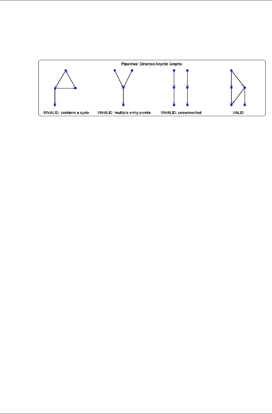
Chapter 33- PowerPipe Overview
III-96 11 February 2004
The structure of the nodes within a pipeline is constrained to be a "directed,
acyclic graph". This means that links between nodes have a clear direction
(node A passes packets to node B but not vice versa) and that no loops may
be formed by following these links. Additionally, pipelines are required to
have one entry-point node (this is where execution begins or where packets
are passed to if coming from another pipeline).
Given these constraints, complex pipeline structures may be formed (this is
useful, for example, where the necessary rendering functionality is context-
specific for a particular object type and rendering effect), containing
branches which may either terminate in a "dead-end" or converge with
other branches. To facilitate this, each node has one "input" and one or
more "outputs", through which packets may pass.
After processing a packet, a pipeline node may dispatch it down any of the
branches leading out of the node, each such branch corresponding to an
"output" of the node. Most outputs lead to other nodes in the pipeline, but
an output may also be defined which passes packets to another pipeline.
This is especially useful in the case of an object pipeline, which has to pass
packets to the appropriate material pipeline for each RpMesh in the object.
The pipeline attached to an RpMaterial may change at run-time, so the
links between the object and material pipelines cannot be created during
pipeline construction. Doing so is feasible in principal but may require the
creation of a very large number of pipelines (the product of the number of
object pipelines and the number of material pipelines), each with many
branches. Whilst these pipelines would not be inefficient, this is hardly
convenient, so in most cases object and material pipelines remain separate.
One drawback of passing packets between pipelines, however, is that it may
be fairly slow (depending on the current platform) because the pre-
processing of data-flow within a pipeline (as described in the following
section), which is performed when the pipeline is constructed, has not been
performed for the passage of data between pipelines.

Pipelines
RenderWare Graphics 3.7 III-97
33.2.3 Dataflow in Pipelines
Each node in a PowerPipe pipeline expects to find certain types of data
within the packets that it processes. For instance, a node that transforms
vertices from object-space to camera-space will expect to find object-space
vertices in the packets it receives. The data in packets is therefore broken
up into "clusters" – a cluster being simply an array of a particular type of
data. In this instance, the packet would include a cluster containing a list
of object-space vertices.
✎ The data contained in packets and clusters is allocated using the PowerPipe heap – this is
described in the following chapter, Pipeline Nodes, in the section The Pipeline Heap.
The RxClusterDefinition structure
The RxClusterDefinition structure defines a cluster. This structure is
shown here:
struct RxClusterDefinition
{
RwChar *name;
RwUInt32 defaultStride;
RwUInt32 defaultAttributes;
const char *attributeSet;
};
To create a cluster within the packets flowing down a pipeline, it is
necessary to create an RxClusterDefinition structure and to refer to that
structure in the definition of one or more of the nodes in the pipeline. The
definition of nodes is described in detail in the chapter Pipeline Nodes. The
name of a cluster merely acts as an identification label. The defaultStride
member is the stride of its associated data type (a larger stride may be used
to ensure alignment of data elements and a smaller stride may be used to
truncate unnecessary terminal members of data elements). A cluster's
defaultAttributes are flags defining platform-specific properties of the
cluster. The attributeSet member is a string defining the set of attributes
to which the cluster's attributes belong (for example, for PS2-specific
clusters, the attribute set is "PS2") such that they may be interpreted
correctly.
Cluster Dependencies
Within a packet, there may be many clusters, each one referring to an
RxClusterDefinition. Each pipeline node will access only those clusters
whose data types it knows how to interpret. Within the pipeline, one node
may initialize the data in a cluster (from data contained in the source
object) and another may destroy the cluster. In-between, other nodes may
modify the data in the cluster or change the length of the cluster array.

Chapter 33- PowerPipe Overview
III-98 11 February 2004
When a node is defined (again, this will be dealt with in depth in the
chapter Pipeline Nodes), the clusters that it needs to access are specified. A
node may specify one or more of the following things about its access to a
given cluster:
• The node requires the cluster's data to have been initialized before
reaching this node;
• The node wishes to initialize the cluster's data itself;
• The node wishes to terminate the cluster;
• The node will make use of the cluster if present but will still function
correctly in its absence.
This information is used, during pipeline construction, to optimize run-time
dataflow within the pipeline and to check that all the requirements of the
nodes within the pipeline can be satisfied. This process is known as
"dependency-chasing" and occurs during the function
RxPipelineUnlock(). As an example, if a node requires object-space
normals then dependency-chasing checks, for all packets entering the
node, that the object-space normals cluster will have been initialized by a
prior node in the pipeline. In a RWDEBUG build, error and warning messages
will be issued to help debug pipeline construction problems at this stage.
Pipeline construction is described in the following section.
The Pipeline Execution Model
It should be noted that, in order to improve pipeline execution efficiency,
the following packet dispatch model has been adopted: when a node
dispatches a packet to a following node in the current pipeline (or to the
head node of another pipeline), program execution actually passes to the
body method of that node. This means that node body execution is nested,
which implies that only one packet actually exists at any given time.
To elucidate on this implication, once a packet has been fully processed (its
triangles and vertices have been submitted to the rasterization API), the
current node body will exit, as will the node body which called it (passed
the packet to it) and so on, back up to the node that created the packet in
the first place (usually ImmInstance.csl, AtomicInstance.csl or
WorldSectorInstance.csl – these nodes are introduced later, in the section
Generic Pipelines). At this point, another packet may be created and
dispatched down the pipeline, though only one packet will ever exist at a
time during a pipeline's execution. It is for this reason that the node
Clone.csl was created. Its purpose is to clone incoming packets and
dispatch the clones to multiple outputs (this node is described in greater
detail in the next chapter, Pipeline Nodes).
Given this execution model, it is necessary for node authors to think
carefully about state. Changes in state (e.g. render state) caused by
subsequent nodes in the pipeline will be in effect once a packet has been
dispatched and the packet will most likely no longer contain valid data.

Pipelines
RenderWare Graphics 3.7 III-99
33.2.4 Pipeline Construction
The construction of a PowerPipe pipeline is comprised of the following
steps:
1. Create a pipeline;
2. Lock it for editing;
3. Specify the pipeline's nodes and topology by adding fragments and
connecting paths between them;
4. Perform pre-unlock setup of nodes through their APIs;
5. Unlock the pipeline (dependency chasing is performed);
6. Perform post-unlock setup of nodes through their APIs.
RxPipelineCreate()
Pipelines are created with the function RxPipelineCreate(). Once
created, pipelines are blank (they contain no nodes) and are in the
"unlocked" form (in the same sense as unlocked RpGeometrys).
RxPipelineLock()
In order to be edited, a pipeline must be locked with the function
RxPipelineLock(). Editing is used to specify a pipeline's nodes and
topology and to initialize each node, using any API functions that it may
have.
RxLockedPipeAddFragment() and RxLockedPipeAddPath()
The key functions used in adding nodes to a pipeline and creating the
desired structure are RxLockedPipeAddFragment() and
RxLockedPipeAddPath(). RxLockedPipeAddFragment() is used to add a
linear chain of nodes, called a "fragment", to a pipeline. Within this chain,
each node is connected to the next by its first output. This fragment is
initially not connected to any other fragments that have been added to the
pipeline.
✎ The maximum number of nodes that a pipeline may contain is by default given by the
value RXPIPELINEDEFAULTMAXNODES. This value may be overridden by changing the value
of _rxPipelineMaxNodes before RenderWare Graphics is initialized.
RxLockedPipeAddPath() is used to attach an output of one node to the
input of another node, thus potentially linking up separate fragments and
creating or recombining branches.

Chapter 33- PowerPipe Overview
III-100 11 February 2004
In order to prepare the parameters for these functions, use the following
helper functions: RxPipelineFindNodeByName(),
RxPipelineNodeFindInput() and RxPipelineNodeFindOutputByName().
These locate nodes, node inputs and node outputs in the pipeline, either
prior to or after the pipeline is unlocked (these things move around when
the pipeline is unlocked).
RxPipelineUnlock()
When the editing of a pipeline is complete, the pipeline should be unlocked
with the function RxPipelineUnlock(). This function performs the
"dependency-chasing" introduced in the prior section Dataflow in Pipelines.
RxPipelineUnlock() automatically determines the entry-point to a
pipeline (if it cannot do so then the pipeline structure is invalid), but this
can be overridden by calling RxLockedPipeSetEntryPoint() before
RxPipelineUnlock().
After a pipeline has been unlocked, some further setup of individual nodes
within the pipeline may be performed, using any API functions that those
nodes may have.
This pre-unlock and post-unlock setup of nodes is explained in the chapter
Pipeline Nodes (in brief, the purpose is to set up private data which is
owned by nodes and used during node execution).
Example Code
Here is an example pipeline creation function which links fictitious nodes
together into a pipeline with two branches that split from the first node and
then recombine at the terminal node:
RxPipeline *
CreateMyPipeline(void)
{
RxPipeline *newPipe;
/* Create a blank pipeline */
newPipe = RxPipelineCreate();
if (NULL != newPipe)
{
RxLockedPipe *lockedPipe;
/* Lock the new pipeline for editing */
lockedPipe = RxPipelineLock(newPipe);
if (NULL != lockedPipe)
{
RxNodeDefinition *inspectNode, *shineNode;
RxNodeDefinition *glowNode, *completeNode;

Pipelines
RenderWare Graphics 3.7 III-101
RxNodeInput input;
RxNodeOutput output;
RxPipeline *result;
/* Retrieve pointers to the definitions
* of the nodes you wish to use */
inspectNode = RxNodeDefinitionGetInspect();
assert(NULL != inspectNode);
shineNode = RxNodeDefinitionGetShine();
assert(NULL != shineNode);
glowNode = RxNodeDefinitionGetGlow();
assert(NULL != glowNode);
completeNode = RxNodeDefinitionGetComplete();
assert(NULL != completeNode);
/* Add a linear chain of three nodes to the pipeline */
lockedPipe = RxLockedPipeAddFragment(lockedPipe,
NULL,
inspectNode,
shineNode,
completeNode,
NULL);
assert(NULL != lockedPipe);
/* Add another node to the pipeline */
lockedPipe = RxLockedPipeAddFragment(lockedPipe,
NULL,
glowNode);
assert(NULL != lockedPipe);
/* Link the lone node to the original fragment */
plNode = RxPipelineFindNodeByName(
lockedPipe, "Inspect.csl", NULL, NULL);
assert(NULL != plNode);
plNode2 = RxPipelineFindNodeByName(
lockedPipe, "Glow.csl", NULL, NULL);
assert(NULL != plNode2);
output = RxPipelineNodeFindOutputByName(
plNode, "GlowingOut");
input = RxPipelineNodeFindInput(plNode2);
result = RxLockedPipeAddPath(
lockedPipe, output, input);
assert(NULL != result);
plNode = plNode2;
plNode2 = RxPipelineFindNodeByName(
lockedPipe, "Complete.csl", NULL, NULL);
assert(NULL != plNode2);
output = RxPipelineNodeFindOutputByName(

Chapter 33- PowerPipe Overview
III-102 11 February 2004
plNode, "StandardOut");
input = RxPipelineNodeFindInput(plNode2);
result = RxLockedPipeAddPath(
lockedPipe, output, input);
assert(NULL != result);
/* Perform pre-unlock pipeline node setup here */
result = RxLockedPipeUnlock(lockedPipe);
if (NULL != result)
{
/* Perform post-unlock pipeline node setup here */
return(result);
}
}
RxPipelineDestroy(newPipe);
}
return(NULL);
}
Here is a list of API functions used in pipeline construction, many of which
are mentioned in the chapter Pipeline Nodes. Refer to their documentation
in the API reference for further details:
Functions for Manipulating Pipelines:
• RxPipelineCreate()
• RxPipelineDestroy()
• RxPipelineClone()
• RxPipelineLock()
Functions for Manipulating Locked Pipelines:
• RxLockedPipeUnlock()
• RxLockedPipeAddFragment()
• RxLockedPipeAddPath()
• RxLockedPipeDeletePath()
• RxLockedPipeDeleteNode()
• RxLockedPipeReplaceNode()
• RxLockedPipeGetEntryPoint()

Pipelines
RenderWare Graphics 3.7 III-103
• RxLockedPipeSetEntryPoint()
Functions for Manipulating Pipeline Nodes:
• RxPipelineFindNodeByName()
• RxPipelineFindNodeByIndex()
• RxPipelineNodeFindInput()
• RxPipelineNodeFindOutputByName()
• RxPipelineNodeFindOutputByIndex()
• RxPipelineNodeCloneNodeDefinition()
• RxPipelineNodeRequestCluster()
• RxPipelineNodeReplaceCluster()
• RxPipelineNodeGetInitData()
• RxPipelineNodeCreateInitData()

Chapter 33- PowerPipe Overview
III-104 11 February 2004
33.3 Generic Pipelines
As described above in the above section on Pipeline Usage, RenderWare
Graphics associates pipelines with RwIm3D, RpAtomics, RpWorldSectors
and RpMaterials. For each of these, there is a supplied "generic" pipeline -
that is, one which renders these things in a "standard" manner and which
will run on all platforms (though probably not optimally on any of them).
These pipelines are provided in the RtGenCPipe toolkit.
Each of these pipelines is described in the current section, along with a list
of API functions used to retrieve these pipelines and set other defaults in
their place. Platform-specific pipelines are dealt with in the following
section. These will be the actual defaults on any given platform, though the
generic pipelines will always be available.
It should also be noted that whilst the division of object and material
pipelines is the approach adopted by default, it is possible to create object
pipelines which are "all in one", i.e. which perform all the work of rendering
the object, ignoring material pipelines completely. This is often more
efficient, though of course less flexible.
33.3.1 RwIm3D
There are two types of pipeline used in RwIm3D rendering:
1. RwIm3DTransform() uses a pipeline to transform vertices from world-
space (or object-space now that there is an optional RwMatrix
parameter to this function) into screen-space;
2. RwIm3DRenderPrimitive() and RwIm3DRenderIndexedPrimitive()
both submit triangles, made from the transformed vertices, to the
rasterization API.
In reality, on current systems that have HW T&L capabilities,
RwIm3DTransform() merely caches a pointer to the source vertices, which
is then available to render functions that perform vertex transformation
themselves. The pipeline within RwIm3DTransform() is generally composed
of just one node and performs very little processing. However, the generic
pipelines do work in the "old-fashioned" way (i.e. all on the main CPU) and
that is what is to be described in this section.
The behavior of the RwIm3D transform and render pipelines with respect to
render state is merely to allow all render state to persist. So, before calling
RwIm3DRenderPrimitive() or RwIm3DRenderIndexedPrimitive() (or
executing the render pipeline directly), you should set up all render state
that you need – such as a texture raster and alpha blending modes. The
pipeline will not modify this render state during its execution.

Generic Pipelines
RenderWare Graphics 3.7 III-105
Generic RwIm3D Transform Pipeline
Here is the structure of the generic RwIm3D transform pipeline:
ImmInstance.csl
↓
Transform.csl
↓
ImmStash.csl
ImmInstance.csl
The purpose of the ImmInstance.csl node is to initialize a packet,
containing several standard clusters (these are described in the chapter
Pipeline Nodes), from the data passed in from RwIm3DTransform().
Transform.csl
The Transform.csl node transforms object-space vertices into camera-space
and generates both camera-space and screen-space vertices, as well as
performing per-vertex frustum tests to be used later in triangle clipping.
ImmStash.csl
The ImmStash.csl node "stashes" the contents of incoming packets in a
global structure, for use in subsequently executed RwIm3D render pipelines.
✎ The extension ".csl" in node name strings is used to identify nodes as originating from
Criterion Software Ltd.
Generic RwIm3D Triangle Render Pipeline
Here is the structure of the generic RwIm3D render pipeline for triangle-
based primitives:
ImmRenderSetup.csl
↓
ImmMangleTriangleIndices.csl
↓
CullTriangle.csl
↓
ClipTriangle.csl
↓
SubmitTriangle.csl

Chapter 33- PowerPipe Overview
III-106 11 February 2004
ImmRenderSetup.csl
The purpose of the ImmRenderSetup.csl node is to initialize a packet from
the data "stashed" by a prior RwIm3D transform pipeline, and to add indices
passed in from the calling RwIm3D render function.
ImmMangleTriangleIndices.csl
ImmMangleTriangleIndices.csl converts indices from tri-strip and tri-fan
primitives into those for a tri-list primitive. This is because most triangle-
handling generic nodes can only process tri-lists.
CullTriangle.csl
CullTriangle.csl removes invisible triangles from the packet, i.e. those
which are back-face culled or entirely outside the current camera's view
frustum.
ClipTriangle.csl
ClipTriangle.csl clips triangles to the view frustum.
SubmitTriangle.csl
SubmitTriangle.csl sets up render state and submits 2D triangles to the
rasterization API.
Generic RwIm3D Line Render Pipeline
Here is the structure of the generic RwIm3D render pipeline for line-based
primitives:
ImmRenderSetup.csl
↓
ImmMangleLineIndices.csl
↓
ClipLine.csl
↓
SubmitLine.csl
ImmMangleLineIndices.csl
ImmMangleLineIndices.csl is similar in function to
ImmMangleTriangleIndices.csl, converting indices from poly-line primitives
into those for a line-list primitive.

Generic Pipelines
RenderWare Graphics 3.7 III-107
ClipLine.csl
ClipLine.csl clips lines to the view frustum.
SubmitLine.csl
SubmitLine.csl sets up render state and submits lines to the rasterization
API.
More detail on each of the nodes mentioned in this section may be found in
the API reference for the following functions:
• RxNodeDefinitionGetImmInstance()
• RxNodeDefinitionGetTransform()
• RxNodeDefinitionGetImmStash()
• RxNodeDefinitionGetImmRenderSetup()
• RnodeDefinitionGetImmMangleTriangleIndices()
• RxNodeDefinitionGetImmMangleLineIndices()
• RxNodeDefinitionGetCullTriangle()
• RxNodeDefinitionGetClipTriangle()
• RxNodeDefinitionGetClipLine()
• RxNodeDefinitionGetSubmitTriangle()
• RxNodeDefinitionGetSubmitLine()
Here is a list of API functions used for retrieving the generic pipelines used
in RwIm3D as well as retrieving and specifying the pipelines currently in
use:
• RwIm3DGetGenericTransformPipeline()
• RwIm3DGetGenericRenderPipeline()
• RwIm3DGetTransformPipeline()
• RwIm3DGetRenderPipeline()
• RwIm3DSetTransformPipeline()
• RwIm3DSetRenderPipeline()

Chapter 33- PowerPipe Overview
III-108 11 February 2004
Note that when retrieving or specifying an RwIm3D render pipeline, the API
functions require a parameter specifying the RwPrimitiveType to which
the pipeline should apply. There is no default pipeline to deal with the
rwPRIMTYPEPOINTLIST primitive type, since there is no "standard" way in
which such primitives should be rendered. We provide support for this
primitive type because it is a convenient structure to build custom
pipelines around (especially for objects such as particle systems).
33.3.2 RpAtomic
The generic RpAtomic and RpWorldSector object pipelines use the same
generic material pipeline, so that will be described in a subsequent section.
Generic RpAtomic Object Pipeline
Here is the structure of the generic RpAtomic object pipeline:
AtomicInstance.csl
↓
AtomicEnumerateLights.csl
↓
MaterialScatter.csl
AtomicInstance.csl
The purpose of the AtomicInstance.csl node is to instance vertex and
triangle data into an RwResEntry and to create one packet per RpMesh in
the object, the clusters of which reference this instance data. If the current
RpAtomic is morph animated, key-frame interpolation will occur during
instancing (hence reinstancing must occur every time the animation state
of the RpAtomic changes). Triangle indices are created as tri-lists even if
the topology of the source RpAtomic is specified with tri-strips. This is
because most triangle-handling generic nodes can only process tri-lists.
AtomicEnumerateLights.csl
AtomicEnumerateLights.csl creates a lights cluster containing pointers to
RpLights for all global lights and local lights whose regions of influence
overlap the RpWorldSectors which the current RpAtomic intersects.
MaterialScatter.csl
The MaterialScatter.csl node sends the current packet to the material
pipeline specified in the RpMaterial of the current RpMesh.
More detail on each of the nodes mentioned in this section may be found in
the API reference for the following functions:

Generic Pipelines
RenderWare Graphics 3.7 III-109
• RxNodeDefinitionGetAtomicInstance()
• RxNodeDefinitionGetAtomicEnumerateLights()
• RxNodeDefinitionGetMaterialScatter()
Here is a list of API functions used for retrieving the generic RpAtomic
object pipeline as well as retrieving and specifying the default pipelines:
• RpAtomicGetGenericPipeline()
• RpAtomicGetDefaultPipeline()
• RpAtomicSetDefaultPipeline()
33.3.3 RpWorldSector
As mentioned above, the generic RpWorldSector and RpAtomic object
pipelines use the same generic material pipeline, so that will be described
in a subsequent section.
Generic RpWorldSector Object Pipeline
Here is the structure of the generic RpWorldSector object pipeline:
WorldSectorInstance.csl
↓
WorldSectorEnumerateLights.csl
↓
MaterialScatter.csl
WorldSectorInstance.csl
The purpose of the WorldSectorInstance.csl node is to instance vertex and
triangle data into an RwResEntry and to create one packet per RpMesh in
the object, the clusters of which reference this instance data. Triangle
indices are created as tri-lists even if the topology of the source
RpWorldSector is specified with tri-strips. This is because most triangle-
handling generic nodes can only process tri-lists.
WorldSectorEnumerateLights.csl
WorldSectorEnumerateLights.csl creates a lights cluster containing
pointers to RpLights for all global lights and local lights whose regions of
influence overlap the current RpWorldSector.

Chapter 33- PowerPipe Overview
III-110 11 February 2004
More detail on each of the nodes mentioned in this section may be found in
the API reference for the following functions:
• RxNodeDefinitionGetWorldSectorInstance()
• RxNodeDefinitionGetWorldSectorEnumerateLights()
• RxNodeDefinitionGetMaterialScatter()
Here is a list of API functions used for retrieving the generic
RpWorldSector object pipeline as well as retrieving and specifying the
default pipeline and the default pipeline for a specific RpWorld:
• RpWorldGetGenericSectorPipeline()
• RpWorldGetDefaultSectorPipeline()
• RpWorldSetDefaultSectorPipeline()
• RpWorldGetSectorPipeline()
• RpWorldSetSectorPipeline()
33.3.4 RpMaterial
As mentioned above, the generic material pipeline is used by both the
RpWorldSector and RpAtomic generic object pipelines.
Generic Material Pipeline
Here is the structure of the generic material pipeline:
Transform.csl
↓
CullTriangle.csl
↓
Light.csl
↓
PostLight.csl
↓
ClipTriangle.csl
↓
SubmitTriangle.csl

Generic Pipelines
RenderWare Graphics 3.7 III-111
Light.csl
The Light.csl node adds the light contributions from each RpLight in the
lights cluster (created by AtomicEnumerateLights.csl or
WorldSectorEnumerateLights.csl as described above) to the vertex color of
each vertex in the current packet. If prelighting colors are present in the
source object, vertex colors will have been initialized to take these into
account by the transform node. If no prelighting colors are present in the
source object then the instancing node will have initialized the vertex colors
to opaque black).
PostLight.csl
The PostLight.csl node clamps vertex color values to the range [0-255] and
converts the RwRGBAReal values accumulated by the Light node into
RwRGBA values which will be used in the vertices submitted to the
rasterization API. The ClipTriangle.csl node must come after the lighting
nodes because it must interpolate (for clipped triangles) final vertex colors.
More detail on each of the nodes mentioned in this section may be found in
the API reference for the following functions:
• RxNodeDefinitionGetTransform()
• RxNodeDefinitionGetCullTriangle()
• RxNodeDefinitionGetPreLight()
• RxNodeDefinitionGetLight()
• RxNodeDefinitionGetPostLight()
• RxNodeDefinitionGetClipTriangle()
• RxNodeDefinitionGetSubmitTriangle()
Here is a list of API functions used for retrieving the generic material
pipelines as well as retrieving and specifying the default pipeline:
• RpMaterialGetGenericPipeline()
• RpMaterialGetDefaultPipeline()
• RpMaterialSetDefaultPipeline()

Chapter 33- PowerPipe Overview
III-112 11 February 2004
33.4 Platform Specific Pipelines
Platform-specific pipelines and pipeline nodes are necessary for two main
reasons. Firstly, different platforms use different hardware and hardware
architectures. In the creation of a common, cross-platform API, this
requires the use of different code on different platforms to produce the
same results. Often, entirely different approaches are required on different
platforms for the sake of utilizing each platform as efficiently as possible.
Secondly, platform-specific pipelines and pipeline nodes may be used to
expose any unique capabilities of a given platform.
An example of platform-specific pipeline code is the PS2All architecture
used to construct pipelines for PS2. In the case of PS2, most rendering
processing is performed on the VU1 vector processor. This means that it is
necessary to create instance data in the appropriate form for transfer to
this processor by the DMA engine and to manage the microcode executed
on VU1. Because CPU code execution costs can be very high on PS2 (due to
its small CPU caches), PS2All has been designed to perform as little work as
possible on the main CPU when setting up VU1 and the data which it will
process. PS2All has also been designed to be highly customizable so that
developers may reduce the CPU load of rendering even further by taking
advantage of application-specific knowledge.
Within this User Guide, there is a chapter entitled PS2All Overview,
covering the platform-specific pipelines used on PS2. Chapters describing
the details of the pipelines created for use on other platforms will be added
in due course. For now, the API reference documentation contains much
platform-specific documentation. Some starting-points are:
• Modules →
→→
→ PowerPipe →
→→
→ World Extensions →
→→
→ PS2 All
• Modules →
→→
→ Platform-Specific

Common Traps and Pitfalls
RenderWare Graphics 3.7 III-113
33.5 Common Traps and Pitfalls
The common problems encountered when constructing PowerPipe pipelines
will be covered in the following chapter Pipeline Nodes.
When constructing custom pipelines, it is highly recommended that you
read the API reference documentation pertaining to the relevant API
functions and pipeline nodes. Whilst this chapter gives a useful, top-down
overview of PowerPipe, it is a complement rather than a substitute for the
API reference documentation, which is detailed and comprehensive.

Chapter 33- PowerPipe Overview
III-114 11 February 2004
33.6 Summary
This chapter has provided an overview of the PowerPipe architecture. It has
introduced the purpose and benefits of PowerPipe and the basic concepts of
pipelines, nodes and packets. It has covered the usage of pipelines within
RenderWare Graphics. It has covered the possible structures of pipelines,
the rudimentary aspects of dataflow within pipelines and it has covered the
construction of pipelines. It has described the generic pipelines supplied
with RenderWare Graphics and it has discussed platform-specific pipelines.
In the following chapter, entitled Pipeline Nodes, the details of the creation
of custom pipeline nodes will be covered. More detail will be given on the
generic nodes supplied with RenderWare Graphics (including some not
mentioned in this chapter).

Chapter 34
Pipeline Nodes

Chapter 34- Pipeline Nodes
III-116 11 February 2004
34.1 Introduction
✎ Before reading this chapter, you should first read the chapter PowerPipe Overview, as this
chapter refers to concepts introduced therein.
This chapter will cover the steps involved in creating a PowerPipe pipeline
node: the creation of a "node definition" and node methods. It will also
introduce the generic (platform-independent) nodes supplied with
RenderWare Graphics and the clusters that they use.
34.1.1 The Node Definition
The node definition defines how a node links up to other nodes in a
pipeline. When a node is added to a pipeline, this is done via a reference to
its node definition, which is of type RxNodeDefinition. An "instance" of a
node within a particular pipeline is called a pipeline node, and is of type
RxPipelineNode.
As mentioned in the previous chapter, PowerPipe Overview, the data
processed by a particular node (i.e. the "clusters" that it accesses) will be
linked up to other nodes in the pipeline when the pipeline is "unlocked"
during pipeline construction. The "dependency-chasing" process that this
entails will be dealt with in more detail in this chapter.
34.1.2 Node Methods
Node methods provide functionality during pipeline construction and
execution. All but one of a node's methods are initialization methods, which
are used during pipeline construction to set up the node's private data
area. This area is of arbitrary size and used to store data that will be used
during the execution of the node body method. It is a general way of
parameterizing an RxPipelineNode, in order to make its behavior specific
to the particular pipeline in which it lives. A node may have an additional
set of API functions, which may be used during pipeline construction (or
afterwards in some cases) to modify the node's private data and thus
change its run-time behavior.
The final node method is its "body" method (of type RxNodeBodyFn), and is
the method that defines the node's run-time behavior (i.e. how it processes
data and how it affects the flow of data down the pipeline).
It should be noted that, as was the case with the previous chapter,
PowerPipe Overview, the descriptions of PowerPipe usage in this chapter
will be relevant mainly to platform-independent pipeline development, so as
to cover more of the available PowerPipe functionality. Later chapters will
cover the creation and usage of optimized, platform-specific nodes and
rendering pipelines which can achieve far higher performance on their
target platform.

Introduction
RenderWare Graphics 3.7 III-117
34.1.3 Other Documents
Here are some other documents, relevant to PowerPipe, to which you may
wish to refer:
• The prior chapter in this user guide, entitled PowerPipe Overview,
should be read before this chapter and covers the details of PowerPipe
pipelines and their construction.
• The API reference on PowerPipe and the Platform-Specific sections.
• There is a PS2-specific PowerPipe chapter in this user guide, entitled
PS2All Overview.

Chapter 34- Pipeline Nodes
III-118 11 February 2004
34.2 The Node Definition
This section contains the following items:
• Example code demonstrating RxNodeDefinition creation, for reference
through the following two sub-sections;
• The structures of the types used in the example code;
• A description of the specification of a node's input requirements and
outputs;
• A description of the methods associated with a node.
We'll look at these now…
34.2.1 Example Code
Here follows some example code, demonstrating the creation of a node
definition, to refer to as you read the next two sub-sections. The example
used is the node definition for the UVInterp.csl node:
RxNodeDefinition *
RxNodeDefinitionGetUVInterp(void)
{
static RxClusterRef clOfInterest[] =
{ {&RxClScrSpace2DVertices, rxCLALLOWABSENT, rxCLRESERVED},
{&RxClRenderState, rxCLALLOWABSENT, rxCLRESERVED},
{&RxClInterpolants, rxCLALLOWABSENT, rxCLRESERVED},
{&RxClUVs, rxCLALLOWABSENT, rxCLRESERVED} };
#define NUMCLUSTERSOFINTEREST \
(sizeof(clOfInterest) / sizeof(clOfInterest[0]))
static RxClusterValidityReq inputReqs[NUMCLUSTERSOFINTEREST] =
{ rxCLREQ_REQUIRED,
rxCLREQ_REQUIRED,
rxCLREQ_REQUIRED,
rxCLREQ_OPTIONAL };
static RxClusterValid output1Clusters[NUMCLUSTERSOFINTEREST] =
{ rxCLVALID_VALID,
rxCLVALID_VALID,
rxCLVALID_VALID,
rxCLVALID_VALID };
static RxClusterValid output2Clusters[NUMCLUSTERSOFINTEREST] =
{ rxCLVALID_VALID,
rxCLVALID_VALID,

The Node Definition
RenderWare Graphics 3.7 III-119
rxCLVALID_NOCHANGE,
rxCLVALID_NOCHANGE };
static RwChar UVsOut[] = RWSTRING("UVsOut");
static RwChar PassThrough[] = RWSTRING("PassThrough");
static RxOutputSpec outputs[] =
{ {UVsOut, output1Clusters, rxCLVALID_NOCHANGE},
{PassThrough, output2Clusters, rxCLVALID_NOCHANGE} };
#define NUMOUTPUTS \
(sizeof(outputs) / sizeof(outputs))
static RwChar UVInterp_csl[] = "UVInterp.csl";
static RxNodeDefinition nodeUVInterpCSL =
{ RwChar *UVInterp_csl,
{ (RxNodeBodyFn) UVInterpNode,
(RxNodeInitFn) NULL,
(RxNodeTermFn) NULL,
(RxPipelineNodeInitFn) _UVInterpNodePipelineNodeInitFn,
(RxPipelineNodeTermFn) NULL,
(RxPipelineNodeConfigFn)NULL,
(RxConfigMsgHandlerFn) NULL },
{ (RwUInt32) NUMCLUSTERSOFINTEREST,
(RxClusterRef) clOfInterest,
(RxClusterValidityReq) inputReqs,
(RwUInt32) NUMOUTPUTS,
(RxOutputSpec) outputs },
(RwUInt32) sizeof(RxNodeUVInterpSettings),
(RxNodeDefEditable) FALSE,
(RwInt32) 0 };
RxNodeDefinition *result = &nodeUVInterpCSL;
RWAPIFUNCTION(RWSTRING("RxNodeDefinitionGetUVInterp"));
RWRETURN(result);
};
Note that the usage of #define demonstrated in this example code is
common practice in the creation of node definitions for the nodes provided
with RenderWare Graphics. The intention is merely to reduce the possibility
of introducing errors in node definitions when editing them.

Chapter 34- Pipeline Nodes
III-120 11 February 2004
34.2.2 Structures
RxNodeDefinition
Here is the structure of the RxNodeDefinition type, as filled in by the
above example code:
struct RxNodeDefinition
{
RwChar *name;
RxNodeMethods nodeMethods;
RxIoSpec io;
RwUInt32 pipelineNodePrivateDataSize;
RxNodeDefEditable editable;
RwInt32 InputPipesCnt;
};
RxNodeMethods
Here is the structure of RxNodeMethods, sub-type of RxNodeDefinition:
struct RxNodeMethods
{
RxNodeBodyFn nodeBody;
RxNodeInitFn nodeInit;
RxNodeTermFn nodeTerm;
RxPipelineNodeInitFn pipelineNodeInit;
RxPipelineNodeTermFn pipelineNodeTerm;
RxPipelineNodeConfigFn pipelineNodeConfig;
RxConfigMsgHandlerFn configMsgHandler;
};
RxIoSpec
Here is the structure of RxIoSpec, sub-type of RxNodeDefinition:
struct RxIoSpec
{
RwUInt32 numClustersOfInterest;
RxClusterRef *clustersOfInterest;
RxClusterValidityReq *inputRequirements;
RwUInt32 numOutputs;
RxOutputSpec *outputs;
};

The Node Definition
RenderWare Graphics 3.7 III-121
RxClusterRef
Here is the structure of RxClusterRef, sub-type of RxIoSpec:
struct RxClusterRef
{
RxClusterDefinition *clusterDef;
RxClusterForcePresent forcePresent;
RwUInt32 reserved;
};
RxOutputSpec
Here is the structure of RxOutputSpec, sub-type of RxIoSpec:
struct RxOutputSpec
{
RwChar *name;
RxClusterValid *outputClusters;
RxClusterValid allOtherClusters;
};
The members of all these types will be described in the following two sub-
sections.
34.2.3 Input Requirements and Outputs
In order that it can be correctly inserted into the dataflow within a pipeline,
a node must precisely specify its input requirements and outputs. A node's
input requirements are the requirements that the node has for the data in
any packets which enter the node. Each of the many outputs that a node
may have can be specified in terms of the state of the data in packets that
leave the node through that output.
Clusters of Interest
In order to specify a node's input requirements and outputs, you must first
specify which clusters the node has an interest in. These are the clusters
that the node (in any of its states of behavior) may choose to create, write
to, read from or destroy. These clusters of interest are specified in the array
clustersOfInterest (type RxClusterRef) in the io member (type
RxIoSpec) of the RxNodeDefinition. The number of clusters of interest is
specified in the numClustersOfInterest member of io. The maximum
number of clusters of interest allowed is specified by
RXNODEMAXCLUSTERSOFINTEREST.
For each cluster of interest, there should be one RxClusterRef entry in
this array. Each entry contains three things:

Chapter 34- Pipeline Nodes
III-122 11 February 2004
1. A pointer to the definition of the cluster of interest (type
RxClusterDefinition) to identify it;
2. The enumerated value forcePresent (type RxClusterForcePresent),
which may in most cases be set to rxCLALLOWABSENT. This will be
explained further later;
3. The RwUInt32 value reserved, which unsurprisingly is reserved for
internal use and which should just be set to rxCLRESERVED.
✎ The maximum number of clusters of interest that an RxNodeDefinition may specify is
given by the value RXNODEMAXCLUSTERSOFINTEREST.
In the Example Code above, clOfInterest is the clusters of interest array.
It expresses an interest in four clusters:
• Screen-space 2D vertices;
• Render state;
• Interpolants (generated by clipping to accelerate multi-pass rendering –
see the API reference documentation for
RxNodeDefinitionGetClipTriangle() for further details);
• A second set of texture UVs (the first set is within the screen-space
vertices).
None of these clusters are specified to be forced present.
Input Requirements Specification
A node's input requirements are specified in the array inputRequirements
(enumerated type RxClusterValidityReq) in the io member of the
RxNodeDefinition. This array should contain one entry for each cluster of
interest, the values of which may be one of the following:
• rxCLREQ_DONTWANT - a node should use this value if it
intends to use the cluster in question but will not use
any data that may already be present in the cluster. This
usually means that the node will overwrite or re-
initialize the cluster's data.
• rxCLREQ_REQUIRED - a node should use this value if it
requires the cluster to contain valid data on entry to the
node.
• rxCLREQ_OPTIONAL - a node should use this value if it is
able to use any data which may already be present in the
cluster (say if the data may be used to optimize the
operation of the node) but does not need to do so in order
to function.

The Node Definition
RenderWare Graphics 3.7 III-123
In the above Example Code, inputReqs is the input requirements array. It
specifies that all clusters of interest are required to enter the node with
valid data, with the exception of the additional UVs cluster, which may be
absent.
Outputs Specification
Each of the outputs of a node should be specified in an entry of the
outputs array (type RxOutputSpec) of the io member of the
RxNodeDefinition. The number of outputs should be specified in the
numOutputs member of io. The maximum number of outputs allowed is
specified by RXNODEMAXOUTPUTS.
The RxOutputSpec contains three members:
1. name contains a string used for identifying the output. This is used
during pipeline construction, while editing the pipeline's topology (see
the example code in the prior chapter, PowerPipe Overview);
2. The array outputClusters (of type RxClusterValid);
3. allOtherClusters (also of type RxClusterValid).
The outputClusters array should contain one entry for each cluster of
interest, the values of which may be one of the following:
• rxCLVALID_NOCHANGE – this value specifies that a cluster will be in the
same state (i.e. containing valid data or not), on exit from the node
through the current output, as it was when it entered the node.
• rxCLVALID_VALID – this value specifies that a cluster will contain valid
data when it exits the node through the current output.
• rxCLVALID_INVALID – this value specifies that a cluster will not contain
valid data when it exits the node through the current output.
Any clusters in the current packet that are not one of the node's clusters of
interest will be dealt with as specified by allOtherClusters. This gives the
node the opportunity to kill off all other clusters in the packet, by setting
the value to rxCLVALID_INVALID, though in most cases it is set to
rxCLVALID_NOCHANGE.
✎ The maximum number of outputs that an RxNodeDefinition may specify is given by the
value RXNODEMAXOUTPUTS.

Chapter 34- Pipeline Nodes
III-124 11 February 2004
In the above Example Code, two outputs are defined, in the outputs array,
named "UVsOut" and "PassThrough". The output1Clusters array specifies
the state of clusters passing through "UVsOut" – all clusters will contain
valid data. output2Clusters specifies the state of clusters passing through
"PassThrough" – the first two clusters will contain valid data and the last
two clusters will retain their state from when they entered the node. The
outputs array references these output specifications.
Dependency Chasing
The input and output specifications of a node are used in the dependency
chasing process (introduced in the pipeline construction section of the prior
chapter, PowerPipe Overview) which occurs when a pipeline near the end of
pipeline construction, inside the function RxPipelineUnlock.
The purpose of dependency chasing is to analyze where each cluster is used
in the pipeline and in doing so optimize the dataflow within the pipeline at
run-time. Additionally, it checks that all the requirements of the nodes
within the pipeline can be satisfied (for example, if a node requires object-
space normals then, for all packets entering the node, the object-space
normals cluster must have been initialized by a prior node in the pipeline).
Dependency chasing is composed of the following stages:
1. The pipeline structure is "unfolded" into a linear array of nodes. This
process is known as topological sorting;
2. Topological sorting should always produce a unique result because
PowerPipe pipelines are restricted to have a connected, acyclic graph
structure and to have only one entry-point. Hence, if topological sorting
fails then the pipeline is not a connected acyclic graph with one entry-
point and so is invalid;
3. The lifetime of each cluster is traced through the possible execution
paths within the pipeline. A node will be determined to create a cluster,
for a particular execution path, if it is the first node in the path for
which the cluster exits through an output that flags the cluster as
rxCLVALID_VALID. A node will be determined to destroy a cluster if it is
the last node in a path whose input specification lists the cluster as
rxCLREQ_REQUIRED or rxCLREQ_OPTIONAL or if the node's output flags
the cluster as rxCLVALID_INVALID;
4. Unfulfilled node dependencies are detected. If a node requests a cluster
as rxCLVALID_VALID at a point in a path where the cluster is
determined to be "dead" then the pipeline is invalid. If two or more
execution paths converge at a node that requests a cluster as
rxCLVALID_VALID and the cluster is not valid for every incoming path,
then the pipeline is invalid. This is because pipelines in which node
requirements might not be fulfilled at run-time are not allowed.

The Node Definition
RenderWare Graphics 3.7 III-125
5. Once pipeline validity has been determined, the lifetimes of clusters in
different paths will be combined and for each node in the pipeline a
minimal list of currently active clusters will be compiled and stored in
the RxPipelineNode structure.
Generating minimal lists of active clusters has two benefits. Firstly and
trivially, less memory is used in storing these lists and this may provide a
minor speed boost to nodes as they access the lists at run-time. Secondly,
the memory used by dead clusters can be freed as soon as possible in the
pipeline.
34.2.4 Node Methods
The node body method (type RxNodeBodyFn) will be covered in the next
section (it is after all where all run-time data processing occurs, after all).
This section will cover the remaining node methods, whose function,
broadly speaking, is usually just to initialize the private data area of a
pipeline node.
RxNodeInitFn
The RxNodeInitFn of a given node (i.e. RxNodeDefinition), is called
during RxPipelineUnlock() the first time that a pipeline containing that
node (i.e. referencing its RxNodeDefinition) is unlocked. The expected use
of this function is to set up some global work-space memory or perhaps a
look-up-table. This may then be used by the node's body function, during
pipeline execution, for all the pipelines in which it appears.
Here follows the prototype for the RxNodeInitFn:
typedef RwBool (*RxNodeInitFn)
( RxNodeDefinition * self );
The only parameter is a pointer to the definition of the owning node. A
return value of FALSE will signify an error and cause RxPipelineUnlock()
to fail.
RxNodeTermFn
The RxNodeTermFn is a complement to the RxNodeInitFn. For a given
node, it is called for the last time that a pipeline containing that node is
locked or destroyed. The use of this is expected to be simply to free memory
allocated in the complementary RxNodeInitFn.
Here follows the prototype for the RxNodeTermFn:
typedef void (*RxNodeTermFn)
( RxNodeDefinition * self );
The only parameter is a pointer to the definition of the owning node.

Chapter 34- Pipeline Nodes
III-126 11 February 2004
RxPipelineNodeInitFn
For a given node, its RxPipelineNodeInitFn is called during
RxPipelineUnlock() (after the RxNodeInitFn, if present) for any pipeline
containing the node. The expected use of this function is to set up the
private data area of the node, which is allocated by RxPipelineUnlock().
Here follows the prototype for the RxPipelineNodeInitFn:
typedef RwBool (*RxPipelineNodeInitFn)
( RxPipelineNode * self );
The only parameter is a pointer to the owning pipeline node. A return value
of FALSE will signify an error and cause RxPipelineUnlock() to fail.
The RxPipelineNodeInitFn used in the Example Code above was
_UVInterpNodePipelineNodeInitFn.
A node's private data area will be allocated during RxPipelineUnlock(),
before its RxPipelineNodeInitFn is called. The size of this memory area
should be specified in the pipelineNodePrivateDataSize member of the
RxNodeDefinition.
The functions RxPipelineNodeCreateInitData() and
RxPipelineNodeGetInitData() may be used to allocate and retrieve
"initialization data" for a pipeline node prior to calling
RxPipelineUnlock() for the containing pipeline. This may be used to set
up information that will parameterize the private data setup performed by
the node's RxPipelineNodeInitFn. This is obviously not necessary (as
private data setup could easily be performed after calling
RxPipelineUnlock()) but may be convenient in some cases. See the API
reference documentation for RxPipelineNodeCreateInitData() for
further details.
The initial purpose of the initialization data scheme was to support the
function RxPipelineClone(). The basic idea is that a pipeline created in
external code will have been set up by unknown API calls. Initialization
data can effectively "remember" the effect of these calls and thus facilitate
the automatic initialization of a pipeline node in a clone pipeline. The use of
RxPipelineClone() is no longer recommended and it may be removed
from the API in future revisions.
RxPipelineNodeTermFn
The RxPipelineNodeTermFn is a complement to the
RxPipelineNodeInitFn. For a given node, it is called (before the
RxNodeTermFn, if present) when a pipeline containing that node is locked or
destroyed. The expected use of this function is to free allocations referenced
in the node's private data area.

The Node Definition
RenderWare Graphics 3.7 III-127
Here follows the prototype for the RxPipelineNodeTermFn:
typedef void (*RxPipelineNodeTermFn)
( RxPipelineNode * self );
The only parameter is a pointer to the owning pipeline node.
A node's private data area will be deallocated during RxPipelineLock()or
RxPipelineDestroy(), after its RxPipelineNodeTermFn is called.
The API reference documentation for the RxPipelineNodeConfigFn and
RxConfigMsgHandlerFn types and the function
RxPipelineNodeSendConfigMsg() give details on their uses. They are not
currently used by any pipeline nodes supplied with RenderWare Graphics
and it is not likely that developers will require them. They may be removed
from the API in later revisions.

Chapter 34- Pipeline Nodes
III-128 11 February 2004
34.3 The Node Body Method
The RxNodeBodyFn contains the data-processing functionality that defines
a node's run-time behavior. A node body function may do many things:
• A node may create packets;
• It may destroy or modify packets entering it;
• It may terminate pipeline execution;
• It may pass incoming packets to its outputs;
• It may create, modify or destroy cluster data contained within packets;
• It may access data within the node's private area or entirely outside the
scope of the pipeline;
• It may access RenderWare Graphics API functions or platform-specific
functions.
There is very little limitation upon the actions that may be performed inside
an RxNodeBodyFn, though there are a few restrictions:
• RxPipelineExecute() should not be called;
• The containing pipeline should not be edited or destroyed (pretty
obvious, that one);
• Only one packet may exist at any one time.
This last point is mentioned in the prior chapter, PowerPipe Overview, in
the section Dataflow in Pipelines. It is recommended that you review this
briefly before continuing.
Here follows the prototype for the RxNodeBodyFn:
typedef RwBool (*RxPipelineNodeBodyFn)
( RxPipelineNode * self,
const RxPipelineNodeParam *params );
The self parameter points to the current pipeline node. The params
parameter points to a structure of type RxPipelineNodeParams, as shown
here:
struct RxPipelineNodeParam
{
void *dataParam;
RxHeap *heap;
};

The Node Body Method
RenderWare Graphics 3.7 III-129
The purpose of encapsulating node parameters in this structure is simply
to allow the parameter list of nodes to be transparently extended in future
revisions of RenderWare Graphics (and without increasing the cost of calls
to RxNodeBodyFn functions). The API macros
RxPipelineNodeParamGetData() and RxPipelineNodeParamGetHeap()
should be used to retrieve the two members of this structure. The
dataParam member contains the data pointer passed to
RxPipelineExecute(). The heap member contains a pointer to the heap (a
custom memory allocator) in use for the current pipeline execution – this
will be explained further in The Pipeline Heap below.
If an RxNodeBodyFn returns FALSE then this signifies an error. This will
cause the pipeline to exit as soon as possible (no further node body
functions will be executed) and RxPipelineExecute() will return NULL.
✎
Note that returning TRUE prematurely (i.e. before dispatching the packet entering the
current node) may not always cause the pipeline to exit without executing any further
node bodies. For example, the node that dispatched a packet to the current node may
create a new packet and dispatch that to another node.
The RxNodeBodyFn used by the Example Code above is UVInterpNode.
The following two sub-sections will deal with the API used within the
RxNodeBodyFn to process packets and clusters. Following this will be a
code sample containing a complete RxNodeBodyFn, which will give an
example of how the API might be used in practice.
34.3.1 Packet Manipulation
RxPacketFetch()
If a node expects to receive a packet from the previous node in the pipeline,
it can fetch this packet using the function RxPacketFetch(). A node
should check (in a debug build at least) for the presence of this packet
before using it. Prior nodes in the pipeline might not be behaving as
expected.
RxPacketCreate()
If a node does not receive, or does not expect to receive, a packet, then it
may instead create one by calling RxPacketCreate(). Note that due to the
nested node body execution model (described in the Dataflow in Pipelines
section of the chapter PowerPipe Overview) only one packet may exist at a
time. Hence, you must destroy an existing packet before creating a new
one.

Chapter 34- Pipeline Nodes
III-130 11 February 2004
RxPacketDispatch() and RxPacketDispatchToPipeline()
Dispatching a packet through one of the outputs of the current node may
be achieved using the function RxPacketDispatch(). The output to which
the packet should be dispatched is specified simply as a zero-based index
into the outputs array contained in the io member of the node's
RxNodeDefinition (to avoid using the wrong index, it may be useful to use
an obviously-named #define as the index and to use this #define in the
function which initializes the node's RxNodeDefinition). Dispatching a
packet to another pipeline may be achieved using the function
RxPacketDispatchToPipeline().
Both RxPacketDispatch() and RxPacketDispatchToPipeline() may be
passed a NULL packet pointer. This allows a node to transfer execution to a
new node or pipeline without necessarily having to create or fetch a packet.
A good example of a node which neither creates nor fetches packets is the
PVSWorldSector.csl node (introduced in the chapter Potentially Visible
Sets), whose sole purpose is to prematurely terminate a pipeline on the
basis of visibility information in plugin data of the object being rendered
(i.e. if the object is occluded, the PVS node ensures that it is not rendered).
✎
Note that due, again, to the nested node body execution model, the dispatch of a packet
causes the destruction of that packet. This is because execution will proceed, within the
dispatch, all the way to the end of the pipeline, at which point packets are automatically
destroyed. Hence an alternative to destroying one packet before creating a new one is to
dispatch the first packet.
34.3.2 Cluster Manipulation
Within an RxNodeBodyFn, a cluster is encapsulated within the RxCluster
structure, as shown here:
struct RxCluster
{
RwUInt16 flags;
RwUInt16 stride;
void *data;
void *currentData;
RwUInt32 numAlloced;
RwUInt32 numUsed;
RxPipelineCluster *clusterRef;
RwUInt32 attributes;
RwUInt32 pad[1];
}
The pad member merely pads the structure to a nice even 32 bytes and the
clusterRef member is for internal use. The rest of the members will be
described as part of the following descriptions of the cluster-manipulation
API.

The Node Body Method
RenderWare Graphics 3.7 III-131
Cluster Data Initialization
A cluster (as described in the Dataflow in Pipelines section of the prior
chapter PowerPipe Overview) merely contains an array of data elements.
The stride of these data elements is stored in the stride member of the
RxCluster. This value is set when the cluster's data is initialized, which
can be performed in one of two ways.
Firstly, RxClusterInitializeData() may be used to initialize a cluster's
data array, with a new allocation, to a given length and a given stride. If the
cluster already contained data, it will first be freed. The data member will
point to the new array and the numAlloced member will record its length.
See the API reference for RxClusterInitializeData() for further details.
Secondly, an RxCluster may be made to point at an existing data array
using either RxClusterSetData() or RxClusterSetExternalData(). As
explained in more detail in the API reference documentation for these two
functions, a cluster's data may be "internal" or "external". By default, a
cluster will have "internal" data, which means that it is allocated (usually
by RxClusterInitializeData()) in the heap which is in use for the
current pipeline execution (the heap will be explained shortly). A cluster's
data is "external" if it is allocated outside of the current heap. PowerPipe is
able to allocate, reallocate and free internal, heap data but not external
data, so external data is protected from modification.
A cluster's data array may be resized using the function
RxClusterResizeData(). This retains the stride and data of the existing
array (this may involve a copy, as per RwRealloc()).
Cluster Status Flags
The status of a cluster's data as either "internal" or "external" is stored in
the flags member of the RxCluster structure. The flags of a cluster are of
type RwUInt16, used as a bitfield, which may contain the following flags:
• rxCLFLAGS_CLUSTERVALID – if this flag is set, it basically means that
this cluster's data array has been initialized and not yet destroyed. If
this flag is not set, all other members of the RxCluster structure
should be assumed to be invalid.
• rxCLFLAGS_EXTERNAL – this flag signifies that a cluster's data is
"external", i.e. not allocated from the current heap.
• rxCLFLAGS_EXTERNALMODIFIABLE – this flag (which is in fact a new flag
ORed with the rxCLFLAGS_EXTERNAL flag) signifies that, whilst the
cluster's data is external to the current heap, and so may not be freed
or resized, it may be edited in-place.
• rxCLFLAGS_MODIFIED – this flag is set every time that
RxClusterLockWrite() (see Cluster Locking below) is called. Basically,
it may be used to monitor whether a cluster's data has been modified.

Chapter 34- Pipeline Nodes
III-132 11 February 2004
A cluster's data may be destroyed with the function
RxClusterDestroyData(). This function frees the cluster's data (if it is
internal) and then marks the cluster as being invalid by clearing its
rxCLFLAGS_EXTERNAL flag.
Cluster Locking
In order to retrieve an RxCluster pointer from a packet, for the purposes of
using and/or modifying its data, you may use the functions
RxClusterLockRead() and RxClusterLockWrite().
RxClusterLockWrite() must be used if a cluster's data is to be modified
in any way (this includes resizing or destroying the cluster's data array).
Note that RxClusterUnlock() exists, but for now it does so merely to
provide symmetry by mirroring RxClusterLockRead() and
RxClusterLockWrite().
When a cluster with external data is locked for writing, its data is copied
into the current heap so that the cluster can be made internal. Resizing of
cluster data will also make the cluster internal. Destruction of external data
will not free the data, merely flag the cluster as invalid.
The Pipeline Heap
The "current heap", mentioned several times above, is a memory area and
custom allocator designed specifically for use with PowerPipe. It has been
optimized to provide very fast allocations, based on three conditions that
are commonly encountered in the execution of PowerPipe pipelines:
1. When a pipeline's execution completes, all memory allocations used
during its execution, which are still present within the heap, may safely
be thrown away;
2. Any deallocations of memory blocks will occur in approximately the
reverse order to that in which those memory blocks were initially
allocated;
3. Only a small number of allocations will be made.
The heap in use during a pipeline's execution may be retrieved, as
mentioned above, by passing the RxPipelineNodeParam parameter of the
RxNodeBodyFn to RxPipelineNodeParamGetHeap(). You may use this
heap for fast allocation of temporary working space if you so wish.
PowerPipe currently uses a single global heap for all pipeline executions,
which will grow automatically if required. Only one heap is necessary
because RenderWare Graphics is not currently multi-threaded, so only one
pipeline can be executing at a given time. You may retrieve the global heap
with the function RxHeapGetGlobalHeap(). If using a heap would be
useful in other areas of your application, you can create one using the
function RxHeapCreate(). Further details are in the API reference
documentation for this and other heap API functions.

The Node Body Method
RenderWare Graphics 3.7 III-133
Each time that RxPipelineExecute() is called, it will clear the global heap
before pipeline execution commences. To allow heap data to persist from
one pipeline execution to the next, the Boolean parameter to
RxPipelineExecute(), heapReset, may be set to FALSE. This capability
is used in RwIm3D (on some platforms), where data generated by the
pipeline executed in RwIm3DTransform() must be able to persist through
several calls to RwIm3DRenderPrimitive() or
RwIm3DRenderIndexedPrimitive(), each of which executes a pipeline
that makes use of the cached data.
Cluster Data Access
In order to facilitate access to data elements in a cluster (for either reading
or writing), there is an additional pointer member in the RxCluster
structure, currentData. This acts as a "cursor" for the current point of
access to the cluster's data. This cursor can be reset to point at the first
entry in the cluster's data array using RxClusterResetCursor(). The
following functions all cause a cluster's cursor to be reset:
RxClusterLockRead(), RxClusterLockWrite(),
RxClusterInitializeData(), RxClusterResizeData(),
RxClusterSetData() and RxClusterSetExternalData().
RxClusterGetCursorData() may be used to access the data (of the
appropriate type) at a cluster's cursor. RxClusterGetIndexedData() may
be used to directly access a particular element of a cluster's data array.
To increment the cursor position by one element in a cluster's data array,
use RxClusterIncCursor(). To decrement the cursor by the same
amount, use RxClusterDecCursor(). Note that no bounds checking is
performed, even in a debug build.
Cluster Data Array Usage
The numUsed member of an RxCluster is used to track the number of
elements in the cluster's data array which have been used (a node body will
not necessarily know in advance how many cluster elements it will need to
use, so it may allocate a conservatively large data array). Note that this
assumes that a cluster's data array is filled contiguously, from the
beginning towards the end. The macro RxClusterGetFreeIndex() will
return the current value of numUsed and then increment its value, the
intention being to point at the first free element of a cluster's data array,
with the assumption that it is about to be used.
RxClusterSetData() and RxClusterSetExternalData() both set
numUsed to be equal to numAlloced. RxClusterInitializeData() sets
numUsed to zero and RxClusterResizeData() reduces numUsed if
necessary (it should never be greater than numAlloced!).
It is a node body's responsibility to ensure that the numUsed member is
kept up-to-date – this is important, as failing to do so may result in data
corruption further down the pipeline.

Chapter 34- Pipeline Nodes
III-134 11 February 2004
34.3.3 Example Code
Here follows some example code demonstrating common tasks performed
within an RxNodeBodyFn:
RwBool
MyNodeBody(RxPipelineNode *self,
RxPipelineNodeParam *params)
{
RxPacket *packet;
RxCluster *clNorms, *clCols;
MyPvtData *data;
RwReal scale;
data = (MyPvtData *)self->privateData;
assert(NULL != data);
scale = data->scale;
packet = RxPacketFetch(self);
if (NULL != packet)
{
clNorms = RxClusterLockRead(packet, CLNORMALSINDEX);
assert(NULL != clNorms);
clCols = RxClusterLockWrite(packet, CLCOLORSINDEX, self);
assert(NULL != clCols);
assert(clNorms->numUsed == clCols->numUsed);
if ((NULL != RxClusterGetCursorData(clNorms, RwV3d)) &&
(NULL != RxClusterGetCursorData(clCols, RwRGBA)))
{
RwUInt32 clSize, i;
RwRGBA color = {0, 0, 0, 255};
RwReal rTemp;
clSize = clNorms->numUsed;
for (i = 0;i < clSize;i++)
{
rTemp = RxClusterGetCursorData(clNorms, RwV3d)->x;
assert((rTemp <= 1.0f) && (rTemp >= -1.0f));
rTemp = 0.5f*(1.0f + rTemp)*scale;
color.red = (RwUInt8)(255.0f*rTemp);
*RxClusterGetCursorData(clCols, RwRGBA) = color;
RxClusterIncCursor(clNorms);
RxClusterIncCursor(clCols);
}

The Node Body Method
RenderWare Graphics 3.7 III-135
RxPacketDispatch(packet, RENDEROUTPUT, self);
return(TRUE);
}
}
else
{
RpAtomic *object;
object = RxPipelineNodeParamGetData(params);
assert(NULL != object);
packet = RxPacketCreate(self);
assert(NULL != packet);
if ((NULL != packet) && (NULL != object))
{
clNorms = RxClusterLockWrite(
packet, CLNORMALSINDEX, self);
assert(NULL != clNorms);
clCols = RxClusterLockWrite(
packet, CLCOLORSINDEX, self);
assert(NULL != clCols);
clNorms = RxClusterInitializeData(
clNorms, 1, sizeof(RwV3d));
clCols = RxClusterInitializeData(
clCols, 1, sizeof(RwRGBA));
if ((NULL != RxClusterGetCursorData(clNorms, RwV3d)) &&
(NULL != RxClusterGetCursorData(clCols, RwRGBA)) )
{
RwV3d defaultNormal;
RwRGBA defaultColor;
defaultNormal = *RpAtomicMyPluginGetNormal(object);
defaultColor = RpAtomicMyPluginGetColor( object);
*RxClusterGetCursorData(clNorms, RwV3d) =
defaultNormal;
clNorms->numUsed = 1;
*RxClusterGetCursorData(clCols, RwRGBA) =
defaultColor;
clCols->numUsed = 1;
RxPacketDispatch(packet, GEOMGENOUTPUT, self);
return(TRUE);
}

Chapter 34- Pipeline Nodes
III-136 11 February 2004
}
}
return(FALSE);
}
The node body shown above has two clusters of interest, the "normals"
cluster and the "colors" cluster. The aim of the node is to set up the colors
cluster on the basis of the x-coordinate of the vectors stored in the normals
cluster. It proceeds as follows:
1. The first action of the node is to access its private data area, fetching a
scaling factor used in its main calculations.
2. Next, the node attempts to fetch the current packet. If no such packet
exists, the node proceeds to step 4. Assuming the packet does exist, the
node will lock the normals cluster for reading and the colors cluster for
writing. It checks that the two clusters contain the same number of
used elements, because its processing requires a one-to-one mapping
between these elements.
3. The node checks that data exists for the two clusters and then proceeds
to step through the data elements of each cluster, setting the color
elements to values determined by the x-coordinates of the normal
cluster vector elements and the scale factor from the node's private data
area. After this processing has been performed, the packet is dispatched
to the node's first output. This is assumed to lead to nodes that will use
the packet's color cluster in rendering the geometry data contained in
the other clusters of the packet.
4. If a packet is not found to exist on entry to this node, the node will
create a new packet. It will initialize both the normals and colors
clusters to contain one element each, of values determined by plugin
data in the object (an RpAtomic) currently being rendered. It will then
dispatch the new packet to the node's second output. This is assumed
to lead to nodes which will generate some geometry, using the normal
and color values set up here.
Here follows a list of functions for use within an RxNodeBodyFn. The API
reference documentation for these functions may be consulted for further
details:
RxPipelineNodeParam Manipulation Functions
• RxPipelineNodeParamGetData()
• RxPipelineNodeParamGetHeap()
RxPacket Manipulation Functions
• RxPacketCreate()

The Node Body Method
RenderWare Graphics 3.7 III-137
• RxPacketDestroy()
• RxPacketFetch()
• RxPacketDispatch()
• RxPacketDispatchToPipeline()
RxCluster Manipulation Functions
• RxClusterLockRead()
• RxClusterLockWrite()
• RxClusterUnlock()
• RxClusterInitializeData()
• RxClusterResizeData()
• RxClusterDestroyData()
• RxClusterSetData()
• RxClusterSetExternalData()
• RxClusterSetStride()
• RxClusterGetCursorData()
• RxClusterGetIndexedData()
• RxClusterGetFreeIndex()
• RxClusterResetCursor()
• RxClusterIncCursor()
• RxClusterDecCursor()

Chapter 34- Pipeline Nodes
III-138 11 February 2004
34.4 Provided Nodes
This section will provide brief descriptions of the generic (that is, platform-
independent) nodes supplied with RenderWare Graphics in the RtGenCPipe
toolkit. Before it does this, though, it will introduce the standard clusters
that are used by these nodes. Platform-dependent clusters and nodes will
be introduced in later chapters.
34.4.1 The Standard Clusters
This section contains an introduction to each of the clusters used by the
generic nodes:
• RxClMeshState
• RxClRenderState
• RxClObjSpace3DVertices
• RxClCamSpace3DVertices
• RxClScrSpace2DVertices
• RxClIndices
• RxClUVs
• RxClRGBAs
• RxClCamNorms
• RxClInterpolants
• RxClVSteps
• RxClLights
• RxClScatter

Provided Nodes
RenderWare Graphics 3.7 III-139
RxClMeshState
The RxClMeshState cluster contains data of type RxMeshStateVector, as
shown here:
struct RxMeshStateVector
{
RwInt32 Flags;
void *SourceObject;
RwMatrix Obj2World;
RwMatrix Obj2Cam;
RwTexture *Texture;
RwRGBA MatCol;
RxPipeline *Pipeline;
RwPrimitiveType PrimType;
RwUInt32 NumElements;
RwUInt32 NumVertices;
RwInt32 ClipFlagsOr;
RwInt32 ClipFlagsAnd;
void *SourceMesh;
void *DataObject;
};
The purpose of the mesh state cluster is to track some common features of
the geometry contained within the current packet. Usually, the mesh state
cluster's data array will contain only one element. The members of the
RxMeshStateVector structure will now be described:
• The Flags member holds flags of type RxGeometryFlag, which closely
resembles RpGeometryFlag and RpWorldFlag. These flags will be set
up by an instance node (the generic instance nodes are
ImmInstance.csl, AtomicInstance.csl and WorldSectorInstance.csl).
• SourceObject is set up by ImmInstance.csl to point to an internal
structure (of type rwIm3DPool, used by RwIm3DTransform()). It is set
up by AtomicInstance.csl and WorldSectorInstance.csl to point to the
RpMaterial associated with the RpMesh from which the current packet
was created. AtomicInstance.csl and WorldSectorInstance.csl set up
SourceMesh to point to the source RpMesh and DataObject to mirror
the void pointer passed to RxPipelineExecute() (which is also
accessible through RxPipelineNodeParamGetData()), whereas
ImmInstance.csl leaves these values uninitialized.
• Obj2World and Obj2Cam are matrices holding, respectively, an object-
space to world-space transformation and an object-space to camera-
space transformation. These matrices will be set up by an instance
node.

Chapter 34- Pipeline Nodes
III-140 11 February 2004
• Texture, MatCol and Pipeline are texture, material color and material
pipeline. AtomicInstance.csl and WorldSectorInstance.csl will set these
up from the source RpMesh of the current packet. ImmInstance.csl will
initialize these values to NULL, opaque white and NULL respectively.
• PrimType is the primitive type of the current packet's geometry.
NumElements is the number of elements of that primitive type contained
in the packet's indices (e.g. 17 for a triangle-based primitive means 17
triangles, which converts to 51 indices for a tri-list and 19 indices for a
tri-strip or tri-fan). NumVertices is the number of vertices contained in
the packet's vertices cluster(s). Be sure to update these values where
appropriate when resizing clusters and changing the number of used
entries in each cluster's data array. These values will be initialized by
an instance node.
• ClipFlagsOr and ClipFlagsAnd are cleared to zero by instance nodes
(ImmInstance.csl, AtomicInstance.csl, etc) and then set up by
Transform.csl. They are, respectively, the bitwise OR and bitwise AND of
the clipFlags of all the vertices in the current packet. ClipFlagsOr
can be used to determine if any of the packet's vertices lies outside a
particular one of the current camera's clipping planes and
ClipFlagsAnd can be used to determine if all of the packet's vertices lie
outside a certain plane. The type of the clipFlags (which are stored in
camera-space vertices – see the description of the
RxClCamSpace3DVertices cluster below) used is RwClipFlag. These
flags are only meaningful once transformation with respect to a
camera's view frustum has been performed.
RxClRenderState
The RxClRenderState cluster contains data of type
RxRenderStateVector, as shown here:
struct RxRenderStateVector
{
RwUInt32 Flags;
RwShadeMode ShadeMode;
RwBlendFunction SrcBlend;
RwBlendFunction DestBlend;
RwRaster *TextureRaster;
RwTextureAddressMode AddressModeU;
RwTextureAddressMode AddressModeV;
RwTextureFilterMode FilterMode;
RwRGBA BorderColor;
RwFogType FogType;
RwRGBA FogColor;
RwUInt8 *FogTable;
};

Provided Nodes
RenderWare Graphics 3.7 III-141
The purpose of the render state cluster is to attach various render state
settings to the geometry contained within the current packet. Usually, the
render state cluster's data array will contain only one element.
The use of this cluster has changed over time. It was initially created
because the original model for packet dispatch was different to the current
system (with its nested node body execution) and it required that the
setting of render state be deferred until the terminal "submit" node in a
pipeline. This is no longer the case, and RenderWare Graphics now adopts
a persistent render state model, where it is the responsibility of any given
piece of code to set up the render state that it needs, but it is not its
responsibility to restore prior render state. Hence, most nodes now set
render state as they execute rather than putting the render state into the
render state cluster for deferred setting.
The TextureRaster, AddressModeU, AddressModeV and FilterMode
members of the render state cluster are still honored by submit nodes, as is
the rxRENDERSTATEFLAG_VERTEXALPHAENABLE flag in the Flags member.
This merely retains the render state behavior of pre-PowerPipe render
pipelines.
The members of the RxRenderStateVector structure will now be
described.
The Flags member contains flags of type RxRenderStateFlag, which
combine many Boolean render states for efficiency.
ShadeMode contains the desired triangle shading mode, of type
RwShadeMode.
SrcBlend and DestBlend contain the desired source and destination
fragment blending modes, of type RwBlendFunction.
AddressModeU and AddressModeV are texture U and V addressing modes,
of type RwTextureAddressMode. FilterMode is a texture filtering mode, of
type RwTextureFilterMode and BorderColor is the desired texture border
color.
FogType is the described fog type, of type RwFogType. FogColor is the
desired color for fog and FogTable is a 256-entry RwUInt8 fog table.
These functions form the API for the RxRenderStateVector type:
• RxRenderStateVectorCreate()
• RxRenderStateVectorDestroy()
• RxRenderStateVectorGetDefaultRenderStateVector()
• RxRenderStateVectorSetDefaultRenderStateVector()
• RxRenderStateVectorLoadDriverState()

Chapter 34- Pipeline Nodes
III-142 11 February 2004
RxClObjSpace3DVertices
The RxClObjSpace3DVertices cluster uses the RxObjSpace3DVertex
type, which is defined differently for each platform but is accessible through
a common set of API functions (each of which begins with
"RxObjSpace3DVertex"). This vertex type describes 3D vertices in object-
space, including position, color, normal and texture coordinates. The vertex
data produced by instancing, on most platforms, is of this type.
RxClCamSpace3DVertices
The RxClCamSpace3DVertices cluster uses the RxCamSpace3DVertex
type, as shown here:
struct RxCamSpace3DVertex
{
RwV3d cameraVertex;
RwUInt8 clipFlags;
RwUInt8 pad[3];
RwRGBAReal col;
RwReal u;
RwReal v;
};
This vertex type is modifiable through a set of API functions (each of which
begins with "RxCamSpace3DVertex"). It describes 3D vertices in camera-
space and descriptions of its members will now follow:
CameraVertex is the 3D, camera-space coordinate of a vertex.
Col is a floating-point color that is used during lighting to accumulate light
contributions from all the light sources affecting the current vertex.
U and V are texture coordinates for the current vertex.
ClipFlags is of type RwClipFlag. This encodes the relationship between
the position of the current vertex and the view frustum planes.
RxClScrSpace2DVertices
The RxClScrSpace2DVertices cluster uses the RxScrSpace2DVertex
type, which is defined differently for each platform but is accessible through
a common set of API functions (each of which begins with
"RxScrSpace2DVertex"). This vertex type describes 2D vertices in screen-
space, including color, position and texture coordinates. The position will
contain a screen-space Z value (this will map to the ZBuffer) and may on
some platforms contain a camera-space 3D position and reciprocal Z
position. The texture coordinates may on some platforms be pre-multiplied
by reciprocal camera Z position. The RxScrSpace2DVertex type is that
which is submitted to the 2D rasterization API (it's the same as the
RwIm2DVertex).

Provided Nodes
RenderWare Graphics 3.7 III-143
RxClIndices
The RxClIndices cluster uses the RxVertexIndex type. This cluster holds
vertex indices that define the topology of the current packet's geometry, to
be interpreted as the primitive type specified in the mesh state cluster's
primType member. The indices index into the data arrays of the
RxClObjSpace3DVertices, RxClCamSpace3DVertices and
RxClScrSpace2DVertices clusters. Note that (as mentioned in the Generic
Pipelines section of the previous chapter, PowerPipe Overview) most generic
PowerPipe nodes can deal only with tri-list indices (line-specific nodes can
mostly deal only with line-list indices).
RxClUVs
The RxClUVs cluster uses the RxUV type, as shown here:
struct RxUV
{
RwReal u;
RwReal v;
};
This cluster is used to include an extra set of vertex texture coordinates in
the pipeline (its usage will be described further in the description of the
UVInterp.csl node below). Its data array should be parallel to those of the
RxClObjSpace3DVertices, RxClCamSpace3DVertices and
RxClScrSpace2DVertices clusters.
RxClRGBAs
The RxClRGBAs cluster uses the RwRGBAReal type. This cluster is used to
include an extra set of vertex colors in the pipeline (its usage will be
described further in the description of the RGBAInterp.csl node below). Its
data array should be parallel to those of the RxClObjSpace3DVertices,
RxClCamSpace3DVertices and RxClScrSpace2DVertices clusters.
RxClCamNorms
The RxClCamNorms cluster uses the RxCamNorm type, which is the same as
the RwV3D type. Its purpose is to hold camera-space normals (useful for
rendering effects such as environment-mapping), which are not included in
the RxClCamSpace3DVertices cluster.

Chapter 34- Pipeline Nodes
III-144 11 February 2004
RxClInterpolants
The RxClInterpolants cluster uses the RxInterp type, as shown here:
struct RxInterp
{
RxVertexIndex originalVert;
RxVertexIndex parentVert1;
RxVertexIndex parentVert2;
RwReal interp;
};
This cluster contains information that can be used to accelerate triangle
clipping during multi-pass rendering. It is (optionally) created by the
ClipTriangle.csl node and used by the UVInterp.csl and RGBAInterp.csl
nodes. Its usage will be described in further detail in the sections covering
these nodes below.
RxClVSteps
The RxClVSteps cluster uses the RxVStep type, as shown here:
struct RxVStep
{
RwUInt8 step;
};
This cluster may be used to skip the processing of unused vertices in a
packet, thus accelerating the operation of nodes which would otherwise
process all of the packet's vertices. For example, PreLight.csl, Light.csl and
PostLight.csl all request this cluster as rxCLREQ_OPTIONAL. If it is present,
then they will skip the processing of "unused" vertices. Such vertices may
be, for example, those belonging only to back-facing (i.e. invisible and
therefore unrendered) triangles.
Each element in the RxClVSteps cluster's array contains a step value,
which is: the number of vertices, after the previously-processed vertex,
which can be skipped. To use these values, start at the beginning of the
RxVStep and vertex arrays and proceed as follows:
1. Process one vertex;
2. Skip "step" vertices;
3. Increment the cursor of the RxVStep array by one element.
Repeat this process until the entire vertex array has been processed. If the
RxVStep array contains valid data, you should not have to bounds-check
its cursor.

Provided Nodes
RenderWare Graphics 3.7 III-145
RxClLights
The RxClLights cluster uses the RxLight type, which is just a pointer to
an RpLight.
RxClScatter
The RxClScatter cluster uses the RxScatter type, as shown here:
struct RxScatter
{
RxPipeline *pipeline;
RxPipelineNode *node;
};
This cluster is used to guide a packet down a particular path in a pipeline.
It is used by the Scatter.csl node, which is described below.
34.4.2 The Generic Nodes
This section contains an introduction to each of the generic nodes included
with RenderWare Graphics in the RtGenCPipe toolkit. They are listed here,
in approximately the order encountered in the generic pipelines (as
described in the chapter PowerPipe Overview):
• ImmInstance.csl
• Transform.csl
• ImmStash.csl
• ImmRenderSetup.csl
• ImmMangleLineIndices.csl
• ImmMangleTriangleIndices.csl
• CullTriangle.csl
• ClipTriangle.csl
• ClipLine.csl
• SubmitTriangle.csl
• SubmitLine.csl
• AtomicInstance.csl

Chapter 34- Pipeline Nodes
III-146 11 February 2004
• AtomicEnumerateLights.csl
• WorldSectorInstance.csl
• WorldSectorEnumerateLights.csl
• MaterialScatter.csl
• Scatter.csl
• PreLight.csl
• Light.csl
• PostLight.csl
• FastPathSplitter.csl
• RGBAInterp.csl
• UVInterp.csl
• Clone.csl
There is also an introduction to Debug Nodes.
✎ The extension ".csl" in node name strings is used to identify the node as originating from
Criterion Software Ltd.
ImmInstance.csl
The purpose of ImmInstance.csl is to create and initialize a packet. It
instances the data passed to RwIm3DTransform() into the
RxClObjSpace3DVertices cluster and initializes the RxClMeshState and
RxClRenderState clusters accordingly. The node has one output, through
which initialized packets pass. The input requirements of this node are:
RxClObjSpace3DVertices - rxCLREQ_DONTWANT
RxClMeshState - rxCLREQ_DONTWANT
RxClRenderState - rxCLREQ_DONTWANT
The characteristics of this node's first output are:
RxClObjSpace3DVertices - rxCLVALID_VALID
RxClMeshState - rxCLVALID_VALID
RxClRenderState - rxCLVALID_VALID
See the API reference documentation for
RxNodeDefinitionGetImmInstance() for further details.

Provided Nodes
RenderWare Graphics 3.7 III-147
Transform.csl
The purpose of Transform.csl is to transform object-space vertices into
camera-space and, where possible, screen-space. It initializes the
RxClCamSpace3DVertices and RxClScrSpace2DVertices clusters from
the RxClObjSpace3DVertices cluster; all will end up with the same
number of elements in their data arrays (such that the vertex indices in an
RxClIndices cluster would apply equally to all three). Clipping flags are
generated for each vertex and stored in the RxClCamSpace3DVertices
cluster. The ClipFlagsOr and ClipFlagsAnd members of the
RxClMeshState cluster (see the section on that above) are set up by
combining the flags of all vertices in the packet. This node also performs
the same lighting setup as PreLight.csl (see the section on that below for
further details).
The node has two outputs. The input requirements of this node:
RxClObjSpace3DVertices - rxCLREQ_REQUIRED
RxClCamSpace3DVertices - rxCLREQ_DONTWANT
RxClScrSpace2DVertices - rxCLREQ_DONTWANT
RxClMeshState - rxCLREQ_REQUIRED
The characteristics of this node's first output:
RxClObjSpace3DVertices - rxCLVALID_NOCHANGE
RxClCamSpace3DVertices - rxCLVALID_VALID
RxClScrSpace2DVertices - rxCLVALID_VALID
RxClMeshState - rxCLVALID_VALID
The characteristics of this node's second output:
RxClObjSpace3DVertices - rxCLVALID_NOCHANGE
RxClCamSpace3DVertices - rxCLVALID_VALID
RxClScrSpace2DVertices - rxCLVALID_VALID
RxClMeshState - rxCLVALID_VALID
See the API reference documentation for
RxNodeDefinitionGetTranform() for further details.
ImmStash.csl
The purpose of ImmStash.csl is to "stash" the contents of the incoming
packet (all the clusters listed below) in a global state structure, such that
the packet can be reconstructed in subsequent RwIm3D render pipelines by
the ImmRenderSetup.csl node (see below).
This node has no outputs. Incoming packets are destroyed after their
contents have been stashed. The input requirements of this node:
RxClObjSpace3DVertices - rxCLREQ_OPTIONAL
RxClCamSpace3DVertices - rxCLREQ_OPTIONAL
RxClScrSpace2DVertices - rxCLREQ_OPTIONAL
RxClMeshState - rxCLREQ_OPTIONAL
RxClRenderState - rxCLREQ_OPTIONAL

Chapter 34- Pipeline Nodes
III-148 11 February 2004
See the API reference documentation for
RxNodeDefinitionGetImmStash() for further details.
ImmRenderSetup.csl
ImmRenderSetup.csl creates a packet and initializes it from global "stash"
data created in a previous RwIm3D transform pipeline by the ImmStash.csl
node.
This node has two outputs. Packets with indices pass through the first
output and packets without indices pass through the second output. The
input requirements of this node:
RxClObjSpace3DVertices - rxCLREQ_DONTWANT
RxClCamSpace3DVertices - rxCLREQ_DONTWANT
RxClScrSpace2DVertices - rxCLREQ_DONTWANT
RxClMeshState - rxCLREQ_DONTWANT
RxClRenderState - rxCLREQ_DONTWANT
RxClIndices - rxCLREQ_DONTWANT
The characteristics of this node's first output:
RxClObjSpace3DVertices - rxCLVALID_VALID
RxClCamSpace3DVertices - rxCLVALID_VALID
RxClScrSpace2DVertices - rxCLVALID_VALID
RxClMeshState - rxCLVALID_VALID
RxClRenderState - rxCLVALID_VALID
RxClIndices - rxCLVALID_VALID
The characteristics of this node's second output:
RxClObjSpace3DVertices - rxCLVALID_VALID
RxClCamSpace3DVertices - rxCLVALID_VALID
RxClScrSpace2DVertices - rxCLVALID_VALID
RxClMeshState - rxCLVALID_VALID
RxClRenderState - rxCLVALID_VALID
RxClIndices - rxCLVALID_INVALID
See the API reference documentation for
RxNodeDefinitionGetImmRenderSetup() for further details.
ImmMangleTriangleIndices.csl
The purpose of ImmMangleTriangleIndices.csl is to convert indices in tri-
strip or tri-fan form into tri-list form, or to generate tri-list indices if no
indices are currently present. This is necessary because most triangle-
processing generic nodes handle only the tri-list primitive and cannot
handle unindexed tri-lists. If this changes in the future, this node may be
removed.
This node has one output. The input requirements of this node:
RxClMeshState - rxCLREQ_REQUIRED
RxClIndices - rxCLREQ_OPTIONAL

Provided Nodes
RenderWare Graphics 3.7 III-149
The characteristics of this node's first output:
RxClMeshState - rxCLVALID_VALID
RxClIndices - rxCLVALID_VALID
See the API reference documentation for
RxNodeDefinitionGetImmMangleTriangleIndices() for further details.
ImmMangleLineIndices.csl
The purpose of ImmMangleLineIndices.csl is to convert indices in poly-line
form into line-list form, or to generate line-list indices if no indices are
currently present. This is necessary because most line-processing generic
nodes handle only the line-list primitive and cannot handle unindexed line-
lists. If this changes in the future, this node may be removed.
This node has one output. The input requirements of this node:
RxClMeshState - rxCLREQ_REQUIRED
RxClIndices - rxCLREQ_OPTIONAL
The characteristics of this node's first output:
RxClMeshState - rxCLVALID_VALID
RxClIndices - rxCLVALID_VALID
See the API reference documentation for
RxNodeDefinitionGetImmMangleLineIndices() for further details.
CullTriangle.csl
This node removes triangles from the indices cluster if they are back-facing
with respect to the current camera. Triangles wholly off-screen (outside the
view frustum) are also deleted.
The node has two outputs. Packets in which all triangles are culled are sent
to the second output. The input requirements of this node:
RxClCamSpace3DVertices - rxCLREQ_REQUIRED
RxClScrSpace2DVertices - rxCLREQ_REQUIRED
RxClIndices - rxCLREQ_REQUIRED
RxClMeshState - rxCLREQ_REQUIRED
The characteristics of the first of this node's outputs:
RxClCamSpace3DVertices - rxCLVALID_VALID
RxClScrSpace2DVertices - rxCLVALID_VALID
RxClIndices - rxCLVALID_VALID
RxClMeshState - rxCLVALID_VALID
The characteristics of the second of this node's outputs:
RxClCamSpace3DVertices - rxCLVALID_VALID
RxClScrSpace2DVertices - rxCLVALID_VALID
RxClIndices - rxCLVALID_INVALID
RxClMeshState - rxCLVALID_VALID

Chapter 34- Pipeline Nodes
III-150 11 February 2004
See the API reference documentation for
RxNodeDefinitionGetCullTriangle() for further details.
ClipTriangle.csl
ClipTriangle.csl clips triangles to the frustum of the current camera. Any
new vertices generated during clipping are projected (so that both camera-
space and screen-space positions and texture coordinates are correct) and
added to the ends of the RxClCamSpace3DVertices and
RxClScrSpace2DVertices cluster's vertex arrays, and the RxClMeshState
clusters' NumVertices member is updated. New triangles are added to the
RxClIndices cluster and the RxClMeshState cluster's NumElements
member is updated. The RxClInterpolants cluster which is output is
used to accelerate multi-pass rendering (see the sections on UVInterp.csl
and RGBAInterp.csl below).
The node has two outputs. Packets in which all triangles are clipped away
are sent to the second output. The input requirements of this node:
RxClCamSpace3DVertices - rxCLREQ_REQUIRED
RxClScrSpace2DVertices - rxCLREQ_REQUIRED
RxClIndices - rxCLREQ_REQUIRED
RxClMeshState - rxCLREQ_REQUIRED
RxClRenderState - rxCLREQ_OPTIONAL
RxClInterpolants - rxCLREQ_DONTWANT
The characteristics of the first of this node's output's:
RxClCamSpace3DVertices - rxCLVALID_VALID
RxClScrSpace2DVertices - rxCLVALID_VALID
RxClIndices - rxCLVALID_VALID
RxClMeshState - rxCLVALID_VALID
RxClRenderState - rxCLVALID_NOCHANGE
RxClInterpolants - rxCLVALID_VALID
The characteristics of the second of this node's output's:
RxClCamSpace3DVertices - rxCLVALID_VALID
RxClScrSpace2DVertices - rxCLVALID_VALID
RxClIndices - rxCLVALID_INVALID
RxClMeshState - rxCLVALID_VALID
RxClRenderState - rxCLVALID_NOCHANGE
RxClInterpolants - rxCLVALID_INVALID
See the API reference documentation for
RxNodeDefinitionGetClipTriangle() for further details.

Provided Nodes
RenderWare Graphics 3.7 III-151
ClipLine.csl
ClipLine.csl clips lines to the frustum of the current camera. Any new
vertices generated during clipping are projected (so that both camera-space
and screen-space positions and texture coordinates are correct) and added
to the ends of the RxClCamSpace3DVertices and
RxClScrSpace2DVertices clusters' vertex arrays, and the RxClMeshState
cluster's NumVertices member is updated. New lines are added to the
RxClIndices cluster and the RxClMeshState cluster's NumElements
member is updated.
The node has two outputs. Packets in which all lines are clipped away are
sent to the second output. The input requirements of this node:
RxClCamSpace3DVertices - rxCLREQ_REQUIRED
RxClScrSpace2DVertices - rxCLREQ_REQUIRED
RxClIndices - rxCLREQ_REQUIRED
RxClMeshState - rxCLREQ_REQUIRED
RxClRenderState - rxCLREQ_OPTIONAL
The characteristics of the first of this node's outputs:
RxClCamSpace3DVertices - rxCLVALID_VALID
RxClScrSpace2DVertices - rxCLVALID_VALID
RxClIndices - rxCLVALID_VALID
RxClMeshState - rxCLVALID_VALID
RxClRenderState - rxCLVALID_NOCHANGE
The characteristics of the second of this node's outputs:
RxClCamSpace3DVertices - rxCLVALID_VALID
RxClScrSpace2DVertices - rxCLVALID_VALID
RxClIndices - rxCLVALID_INVALID
RxClMeshState - rxCLVALID_VALID
RxClRenderState - rxCLVALID_NOCHANGE
See the API reference documentation for
RxNodeDefinitionGetClipLine() for further details.
SubmitTriangle.csl
SubmitTriangle.csl submits 2D triangles to the rasterization API. The node
has a single output and packets pass unchanged through this. The purpose
of this is to allow packets to be modified and submitted again later on in
the pipeline to perform multi-pass rendering.
The behavior of SubmitTriangle.csl with respect to render state is: it sets up
the texture raster, texture filter mode, texture addressing modes and the
vertex alpha flag all from the incoming RxClRenderStateVector cluster.
All other render state persists as is. These states are set to keep render
state behavior the same as it was in pre-PowerPipe pipelines.
✎ Note that whilst the generic submit nodes submit 2D primitives to the RwIm2D
rasterization API, platform-specific nodes may take advantage of HW T&L and submit 3D
primitives directly to hardware. In this case, culling, transformation, clipping and lighting

Chapter 34- Pipeline Nodes
III-152 11 February 2004
will be performed by the hardware and they will be omitted from the pipeline.
The node has a single output, through which packets pass unchanged. The
input requirements of this node:
RxClScrSpace2DVertices - rxCLREQ_REQUIRED
RxClIndices - rxCLREQ_OPTIONAL
RxClMeshState - rxCLREQ_REQUIRED
RxClRenderState - rxCLREQ_OPTIONAL
The characteristics of this node's first output:
RxClScrSpace2DVertices - rxCLVALID_VALID
RxClIndices - rxCLVALID_NOCHANGE
RxClMeshState - rxCLVALID_VALID
RxClRenderState - rxCLVALID_NOCHANGE
See the API reference documentation for
RxNodeDefinitionGetSubmitTriangle() for further details.
SubmitLine.csl
SubmitLine.csl submits 2D lines to the rasterization API. The node has a
single output and packets pass unchanged through this. The purpose of
this is to allow packets to be modified and submitted again later on in the
pipeline to perform multi-pass rendering.
The behavior of SubmitLine.csl with respect to render state is: it sets up the
texture raster, texture filter mode, texture addressing modes and the vertex
alpha flag all from the incoming RxClRenderStateVector cluster. All other
render state persists as is. These states are set to keep render state
behavior the same as it was in pre-PowerPipe pipelines.
✎
Note that whilst the generic submit nodes submit 2D primitives to the RwIm2D
rasterization API, platform-specific nodes may take advantage of HW T&L and submit 3D
primitives directly to hardware. In this case, culling, transformation, clipping and lighting
will be performed by the hardware and they will be omitted from the pipeline.
The node has a single output, through which packets pass unchanged. The
input requirements of this node:
RxClScrSpace2DVertices - rxCLREQ_REQUIRED
RxClIndices - rxCLREQ_OPTIONAL
RxClMeshState - rxCLREQ_REQUIRED
RxClRenderState - rxCLREQ_OPTIONAL
The characteristics of this node's first output:
RxClScrSpace2DVertices - rxCLVALID_VALID
RxClIndices - rxCLVALID_NOCHANGE
RxClMeshState - rxCLVALID_VALID
RxClRenderState - rxCLVALID_NOCHANGE
See the API reference documentation for
RxNodeDefinitionGetSubmitLine() for further details.

Provided Nodes
RenderWare Graphics 3.7 III-153
AtomicInstance.csl
AtomicInstance.csl creates one packet per RpMesh in the source
RpGeometry. It instances geometric data into RxClObjSpace3DVertices
and RxClIndices clusters and initializes RxClMeshState and
RxClRenderState clusters with appropriate values. Note that indices
created will always be as for a tri-list primitive. Conversion will be
performed if the source RpGeometry uses a different RwPrimitiveType.
The node has one output, through which the instanced geometry passes.
The input requirements of this node:
RxClObjSpace3DVertices - rxCLREQ_DONTWANT
RxClIndices - rxCLREQ_DONTWANT
RxClMeshState - rxCLREQ_DONTWANT
RxClRenderState - rxCLREQ_DONTWANT
The characteristics of this node's first output:
RxClObjSpace3DVertices - rxCLVALID_VALID
RxClIndices - rxCLVALID_VALID
RxClMeshState - rxCLVALID_VALID
RxClRenderState - rxCLVALID_VALID
See the API reference documentation for
RxNodeDefinitionGetAtomicInstance() for further details.
WorldSectorInstance.csl
WorldSectorInstance.csl creates one packet per RpMesh in the source
RpWorldSector. It instances geometric data into
RxClObjSpace3DVertices and RxClIndices clusters and initializes
RxClMeshState and RxClRenderState clusters with appropriate values.
Note that indices created will always be as for a tri-list primitive.
Conversion will be performed if the source RpWorldSector uses a different
RwPrimitiveType.
The node has one output, through which the instanced geometry passes.
The input requirements of this node:
RxClObjSpace3DVertices - rxCLREQ_DONTWANT
RxClIndices - rxCLREQ_DONTWANT
RxClMeshState - rxCLREQ_DONTWANT
RxClRenderState - rxCLREQ_DONTWANT
The characteristics of this node's first output:
RxClObjSpace3DVertices - rxCLVALID_VALID
RxClIndices - rxCLVALID_VALID
RxClMeshState - rxCLVALID_VALID
RxClRenderState - rxCLVALID_VALID
See the API reference documentation for
RxNodeDefinitionGetWorldSectorInstance() for further details.

Chapter 34- Pipeline Nodes
III-154 11 February 2004
AtomicEnumerateLights.csl
The purpose of AtomicEnumerateLights.csl is to work out which lights in
the world illuminate the current RpAtomic and to place pointers to each of
these lights in an RxLight cluster (the RxLight structure is just a pointer
to an RpLight).
The node has one output, through which the packets pass with their new
RxLight cluster. The input requirements of this node:
RxClLights - rxCLREQ_REQUIRED
The characteristics of this node's first output:
RxClLights - rxCLVALID_VALID
See the API reference documentation for
RxNodeDefinitionGetAtomicEnumerateLights() for further details.
WorldSectorEnumerateLights.csl
The purpose of WorldSectorEnumerateLights.csl is to work out which lights
in the world illuminate the current RpWorldSector and to place pointers to
each of these lights in an RxLight cluster (the RxLight structure is just a
pointer to an RpLight).
The node has one output, through which the packets pass with their new
RxLight cluster. The input requirements of this node:
RxClLights - rxCLREQ_REQUIRED
The characteristics of this node's first output:
RxClLights - rxCLVALID_VALID
See the API reference documentation for
RxNodeDefinitionGetWorldSectorEnumerateLights() for further
details.
MaterialScatter.csl
The purpose of the MaterialScatter.csl node is to distribute packets to
material pipelines on the basis of the pipeline pointer in their
RxClMeshState cluster. This node requires as rxCLREQ_OPTIONAL many
standard clusters, such that, if they are present in the pipeline, they will
propagate from this node to the destination material pipeline (as opposed to
being terminated before this node by dependency-chasing – see the above
Dependency Chasing section). For any other clusters which you want to
propagate to the end of the current pipeline and then to material pipelines,
use RxPipelineNodeRequestCluster() during pipeline construction to
change the requirements of the MaterialScatter.csl node.

Provided Nodes
RenderWare Graphics 3.7 III-155
The node has no outputs; all packets pass from it to other pipelines. The
input requirements of this node:
RxClMeshState - rxCLREQ_REQUIRED
RxClObjSpace3DVertices - rxCLREQ_OPTIONAL
RxClIndices - rxCLREQ_OPTIONAL
RxClRenderState - rxCLREQ_OPTIONAL
RxClLights - rxCLREQ_OPTIONAL
See the API reference documentation for
RxNodeDefinitionGetMaterialScatter() for further details.
Scatter.csl
The Scatter.csl node dispatches packets down certain branches of a
pipeline, dependent on either data in each packet's (optional) RxScatter
cluster, or on the node's private data (itself an RxScatter structure).
The node has 32 outputs (the maximum allowed) to facilitate extreme
branching of the pipeline. None need actually be connected. The input
requirements of this node:
RxClScatter - rxCLREQ_OPTIONAL
The characteristics of all this node's outputs:
RxClScatter - rxCLVALID_NOCHANGE
See the API reference documentation for RxNodeDefinitionGetScatter()
for further details.
PreLight.csl
The Prelight.csl initializes the color values in the RxClCamSpace3DVertices
cluster prior to lighting. It may use an optional RxClVSteps cluster
(generated, for example by a back-face culling node) to accelerate this
process by skipping unused vertices.
The node has one output, through which the pre-lit vertices pass. The input
requirements of this node:
RxClMeshState - rxCLREQ_REQUIRED
RxClObjSpace3DVertices - rxCLREQ_REQUIRED
RxClCamSpace3DVertices - rxCLREQ_REQUIRED
RxClVSteps - rxCLREQ_OPTIONAL
The characteristics of this node's first output:
RxClMeshState - rxCLVALID_VALID
RxClObjSpace3DVertices - rxCLVALID_VALID
RxClCamSpace3DVertices - rxCLVALID_VALID
RxClVSteps - rxCLVALID_NOCHANGE
See the API reference documentation for
RxNodeDefinitionGetPreLight() for further details.

Chapter 34- Pipeline Nodes
III-156 11 February 2004
Light.csl
For every light in the RxClLights cluster, the Light.csl node accumulates
light (using the appropriate lighting function - ambient, point, etc.) in the
vertex colors of the RxClCamSpace3DVertices cluster. It may use an
optional RxClVsteps cluster (generated, for example by a back-face culling
node) to accelerate this process by skipping unused vertices.
The node has one output, through which the lit vertices pass. The input
requirements of this node:
RxClMeshState - rxCLREQ_REQUIRED
RxClObjSpace3DVertices - rxCLREQ_REQUIRED
RxClCamSpace3DVertices - rxCLREQ_REQUIRED
RxClLights - rxCLREQ_OPTIONAL
RxClVSteps - rxCLREQ_OPTIONAL
The characteristics of this node's first output:
RxClMeshState - rxCLVALID_NOCHANGE
RxClObjSpace3DVertices - rxCLVALID_NOCHANGE
RxClCamSpace3DVertices - rxCLVALID_VALID
RxClLights - rxCLVALID_NOCHANGE
RxClVSteps - rxCLVALID_NOCHANGE
See the API reference documentation for RxNodeDefinitionGetLight() for
further details.
PostLight.csl
The PostLight.csl node clamps color values in the
RxClCamSpace3DVertices cluster to the range [0,255] and then copies
these values into the RxClScrSpace2DVertices cluster. If the material
color of the geometry is not {255, 255, 255, 255} then the lighting value for
each vertex is multiplied by the material color (normalized by 1/255) before
the clamping and copying is performed. The node may use an optional
RxClVsteps cluster (generated, for example by a back-face culling node) to
accelerate this process by skipping unused vertices.
The node has one output, through which the post-lit vertices pass. The
input requirements of this node:
RxClMeshState - rxCLREQ_REQUIRED
RxClCamSpace3DVertices - rxCLREQ_REQUIRED
RxClScrSpace2DVertices - rxCLREQ_REQUIRED
RxClVSteps - rxCLREQ_OPTIONAL
The characteristics of this node's first output:
RxClMeshState - rxCLVALID_NOCHANGE
RxClCamSpace3DVertices - rxCLVALID_VALID
RxClScrSpace2DVertices - rxCLVALID_VALID
RxClVSteps - rxCLVALID_NOCHANGE

Provided Nodes
RenderWare Graphics 3.7 III-157
See the API reference documentation for
RxNodeDefinitionGetPostLight() for further details.
FastPathSplitter.csl
The FastPathSplitter.csl node is for use with RpWorldSectors. It
determines whether the bounding box of the sector from which the current
packet was created lies entirely within the current camera's view frustum. If
so, it dispatches the packet to a second output which should skip the
clipping node used in the current pipeline.
The node has two outputs. Packets are sent through the second output if
all vertices lie within the view frustum and hence the clipping stage of the
pipeline can be skipped. The input requirements of this node:
RxClMeshState - rxCLREQ_REQUIRED
The characteristics of this node's first output:
RxClMeshState - rxCLVALID_NOCHANGE
The characteristics of this node's second output:
RxClMeshState - rxCLVALID_NOCHANGE
See the API reference documentation for
RxNodeDefinitionGetFastPathSplitter() for further details.
UVInterp.csl
UVInterp.csl updates the RxClScrSpace2DVertices cluster with a new set
of correctly clipped texture coordinates. It uses an optional
RxClInterpolants cluster (generated by ClipTriangle.csl) to interpolate
texture coordinates for clipped triangles. The private data of this node may
be used to turn it on and off at run-time and to modify render state.
The node has two outputs. Packets are sent unmodified to the second
output if the Boolean uvInterpOn in the node's private data is set to FALSE.
The input requirements of this node:
RxClScrSpace2DVertices - rxCLREQ_REQUIRED
RxClRenderState - rxCLREQ_REQUIRED
RxClInterpolants - rxCLREQ_OPTIONAL
RxClUVs - rxCLREQ_REQUIRED
The characteristics of this node's first output:
RxClScrSpace2DVertices - rxCLVALID_VALID
RxClRenderState - rxCLVALID_VALID
RxClInterpolants - rxCLVALID_NOCHANGE
RxClUVs - rxCLVALID_VALID

Chapter 34- Pipeline Nodes
III-158 11 February 2004
The characteristics of this node's second output:
RxClScrSpace2DVertices - rxCLVALID_NOCHANGE
RxClRenderState - rxCLVALID_NOCHANGE
RxClInterpolants - rxCLVALID_NOCHANGE
RxClUVs - rxCLVALID_NOCHANGE
See the API reference documentation for
RxNodeDefinitionGetUVInterp() for further details.
RGBAInterp.csl
RGBAInterp.csl updates the RxClScrSpace2DVertices cluster with a new
set of correctly clipped colors. It uses an optional RxClInterpolants
cluster (generated by ClipTriangle.csl) to interpolate texture coordinates for
clipped triangles. The private data of this node may be used to turn it on
and off at run-time and to modify render state.
The node has two outputs. The second output will be used if the Boolean
rgbaInterpOn in the node's private data is set to FALSE, or if the
RwRGBAReal cluster is missing or empty. The input requirements of this
node:
RxClScrSpace2DVertices - rxCLREQ_REQUIRED
RxClRenderState - rxCLREQ_DONTWANT
RxClInterpolants - rxCLREQ_OPTIONAL
RxClRGBAs - rxCLREQ_OPTIONAL
The characteristics of this node's first output:
RxClScrSpace2DVertices - rxCLVALID_VALID
RxClRenderState - rxCLVALID_VALID
RxClInterpolants - rxCLVALID_NOCHANGE
RxClRGBAs - rxCLVALID_VALID
The characteristics of this node's second output:
RxClScrSpace2DVertices - rxCLVALID_NOCHANGE
RxClRenderState - rxCLVALID_NOCHANGE
RxClInterpolants - rxCLVALID_NOCHANGE
RxClRGBAs - rxCLVALID_NOCHANGE
See the API reference documentation for
RxNodeDefinitionGetRGBAInterp() for further details.

Provided Nodes
RenderWare Graphics 3.7 III-159
Clone.csl
Due to the nested pipeline execution mechanism (see the Dataflow in
Pipelines section of the prior chapter, PowerPipe Overview), only one packet
can exist at a given time. It is the purpose of Clone.csl to create clones of
each packet that enters it and to dispatch them to various outputs of the
node. Clone.csl is an unusual node, in that it has no fixed
RxNodeDefinition. Instead, the user must create an RxNodeDefinition
through the function RxNodeDefinitionCloneCreate(), specifying the
number of outputs and those to which packet clones should be dispatched
in one or more modes of operation (which may be switched in-between
pipeline executions).
Clone.csl may be useful where a pipeline needs to modify source data in
two or more different ways in order to achieve the desired rendering effect.
Rather than generate the source data twice, Clone.csl can generate multiple
clones from each packet and send each of them down a different branch of
the pipeline.
Note that, if the clone node is being used merely to allow a cluster's data to
be modified but restored to its original state further down the pipeline,
there is an alternative that will in most cases be simpler and more efficient.
This is to create an auxiliary cluster to hold a reference to the original
cluster's data and to flag the original cluster as "external". This will ensure
that any modification of its data causes a copy, so that the original,
unmodified data is still accessible through the auxiliary cluster. The copy
may be more costly than the clone node, though the clone node will not
actually prevent the copy and is not always particularly cheap to execute.
Clone.csl will try to optimize the flags of clusters in packet clones so that,
where clusters do not need to be marked as "external" (which causes a
cluster's data to be copied if a node further down the pipeline modifies it),
they are not.
See the API reference documentation for the following functions for further
details:
• RxNodeDefinitionCloneCreate()
• RxNodeDefinitionCloneDestroy()
• RxPipelineNodeCloneDefineModes()
• RxPipelineNodeCloneOptimize()
• RxPacketCacheCreate()
• RxPacketCacheClone()
• RxPacketCacheDestroy()

Chapter 34- Pipeline Nodes
III-160 11 February 2004
Debug Nodes
In order to debug the execution of a pipeline, it is often useful to insert a
"debug" node into the pipeline, which monitors the contents of packets
passing through it. RxPipelineInsertDebugNode() allows you to insert
any node of your choosing into an existing pipeline. At the point where the
node is to be inserted, RxPipelineInsertDebugNode() determines which
clusters are active and contain valid data in the original pipeline. It then
modifies the node's definition such that it requests only these clusters. This
ensures that the new node will not cause any alteration to cluster
dependencies in the pipeline.
See the API reference documentation for RxPipelineInsertDebugNode()
for further details.

Common Traps and Pitfalls
RenderWare Graphics 3.7 III-161
34.5 Common Traps and Pitfalls
34.5.1 Pipeline Construction Problems
When users begin constructing pipelines and custom nodes, they often find
that RxPipelineUnlock() fails, meaning that the pipeline is invalid in
some way. Here follow a few things to check when this happens:
First of all, make sure you are using a debug version of the RenderWare
Graphics libraries and check the debug stream. RxPipelineUnlock() will
output error messages which should help you to determine where the
problem lies in your pipeline. It may have found a trivial error in the
pipeline (such as it containing no nodes!) or a pipeline node (such as it
containing no body method, too many clusters of interest or too many
outputs – note that a node may validly have zero outputs).
It is worth checking that the array lengths in your RxNodeDefinition
make sense. A frequent mistake is to add an extra cluster of interest to a
node without extending the input and output specification arrays.
Errors may have occurred during dependency chasing due to an error in
the pipeline's topology – it has more than one entry-point or contains
cycles or disconnected sub-graphs. If this occurs, check your use of
functions like RxPipelineAddFragment() and RxLockedPipeAddPath()
during pipeline construction.
The most common problem with pipeline construction is the failure of
dependency chasing due to unfulfilled node input requirements. In this
case, the node and cluster in question should be mentioned in the debug
stream. On the basis of this information, you will need to work out why the
node is not getting what it expects from the cluster in question.
One possibility is that the node requires the cluster to contain valid data on
entry to the node and yet no other prior node (on any execution path,
remember) has initialized the cluster. Perhaps a prior node has destroyed
the cluster (flagging it as rxCLVALID_INVALID for one output).
A subtle possibility is that only one node in the pipeline uses a given
cluster. In this case, the cluster will not be created for use in the pipeline,
unless the forcePresent member of the clustersOfInterest array of the
node input specification is set to rxCLFORCEPRESENT (as opposed to the
usual rxCLALLOWABSENT) for this cluster.

Chapter 34- Pipeline Nodes
III-162 11 February 2004
It is unusual for a node to require a cluster to be present unless the data
created for that cluster is to be passed to a subsequent node in the
pipeline, though it may be a valid request. If a node wished to allocate some
memory as temporary work-space for use during its data processing then it
could do so without putting the data in a cluster. However, if the node
wants to allow the data that it creates to be used by subsequent nodes if
they can make use of it, then it will put the data in a cluster. In this case
(given that it cannot reasonably be expected to look ahead in the pipeline at
run-time to determine if any subsequent nodes can make use of the cluster
in question), the node will require the cluster to be present whether its data
is used by subsequent nodes or not.
A related case is that of terminal pipeline nodes (nodes at the end of a
pipeline branch) which dispatch packets to other pipelines. An example of
such a node is the MaterialScatter.csl node. This node does not perform
any data processing; it merely sends packets to the appropriate material
pipeline for the current RpMesh. However, in order to ensure that the
cluster data, for the clusters required by the receiving pipeline, lasts long
enough to reach this node, it has to request these clusters to be present in
its input requirements. All of them are requested as rxCLVALID_OPTIONAL
in case they really are not present for some acceptable reason.
In the case that a user-created cluster (for the sake of argument per-vertex
"temperature" values) needs to be distributed to custom material pipelines
by MaterialScatter.csl, the cluster may be added to the node's input
requirements by the function RxPipelineNodeRequestCluster(). This
should be done during pipeline construction, before RxPipelineUnlock()
is called. See the API reference documentation for
RxPipelineNodeRequestCluster() for further details.
This section may be augmented over time if further common pipeline
construction problems come to light.
34.5.2 Pipeline Performance
Two things to remember when trying to improve pipeline performance are:
1. When a cluster's data is flagged as "external", any modifications to the
data will cause it to be copied in its entirety. This is likely to be costly.
2. Random-access to a cluster's data (using
RxClusterGetIndexedData()) will be slower than sequential access
(using RxClusterGetCursorData() and RxClusterIncCursor()).
34.5.3 RxCluster->numUsed
It is a node body's responsibility to ensure that the numUsed member of
RxCluster is kept up-to-date – this is important, as failing to do so may
result in data corruption further down the pipeline.
Note that if numUsed is reduced to zero for a cluster, the node currently
processing it has two choices:

Common Traps and Pitfalls
RenderWare Graphics 3.7 III-163
1. Destroy the cluster's data with RxClusterDestroyData(), to signify
that the cluster contains no valid data and so is invalid/dead,
2. Leave the cluster as is, to signify that the cluster is still valid even
though it contains no used elements.
The difference between these two cluster states may easily be tested in
subsequent nodes to determine if the cluster is still valid (yet contains no
used elements) or is invalid (has no data array allocated). It will usually be
simpler and more convenient, though, if the predication on cluster state
can be performed implicitly by a pipeline branch. For example, the node
which can empty the cluster array may be specified with two outputs, for
one of which the cluster exits in an invalid state and for the other of which
the cluster exits in the valid state.

Chapter 34- Pipeline Nodes
III-164 11 February 2004
34.6 Summary
This chapter has provided an overview of the construction of custom
PowerPipe nodes. It has covered the elements involved in creating a node
definition: the specification of node inputs and outputs, node methods and
other values. It has explained the details of node cluster requirements and
the dependency-chasing process. It has described the uses of the various
node methods. For the node body method, it provided example code and
discussed packet processing and pipeline execution order, in addition to
covering the details of cluster creation, access and modification. It finally
introduced the clusters used by the generic nodes supplied with
RenderWare Graphics, followed by the nodes themselves.
As mentioned elsewhere, the creation and usage of optimized, platform-
specific nodes and rendering pipelines will be covered in later chapters
(PS2All Overview, for example, is already available).

Appendix
Recommended
Reading

Appendix - Recommended Reading
III-166 11 February 2004
Introduction
This appendix contains a list of books, magazines and online resources
recommended by the RenderWare Graphics development team.
Traditional reviews of these books have not been attempted as such can be
found on the Internet – particularly in online bookstores. Instead, an
approximate "reader level" has been given, which is divided as follows:
• Beginner
Assumes no prior knowledge of 3D graphics programming;
• Intermediate
Assumes some 3D graphics programming experience;
• Advanced
For gurus only!
Some of the books are aimed specifically at university students and fluency
with mathematics is required for these.
It is important to note that all the books listed require some understanding
of computer programming. It is also safe to say that if you have never
programmed a 2D graphics application, you will likely find 3D graphics an
uphill struggle.
If you have never worked with 2D graphics rendering, there are a number of
online and printed resources available to you. This is a field of computer
graphics that is very well-served with literature.
Other Documentation
For further information on RenderWare Graphics refer to:
• the RenderWare Graphics API Reference for your target platform
• the RenderWare Graphics PDFs
• your customer account on RenderWare Graphics' Fully Managed
Support System https://support.renderware.com and its searchable
knowledge base
☛
For those who are completely new to the field of computer graphics, or managers and
producers who just want to know what it's all about, "The Way Computer Graphics
Works", by Olin Lathrop (Wiley Computer Publishing. ISBN: 0471130400) is recommend
as a good primer. This book does not assume an understanding of computer programming
or mathematics.

Books
RenderWare Graphics 3.7 III-167
Books
Textbooks
"Computer Graphics: Principles & Practice" (2nd Edition, in
C)
Authors: Foley, Van Dam, et al.
Publisher: Addison Wesley Longman Publishing Co.
ISBN: 0201848406
Reader Level: Beginner.
Notes: This is considered the standard textbook on the subject. Aimed at
university students.
"Advanced Animation and Rendering Techniques: Theory
and Practice"
Authors: Alan Watt, Mark Watt
Publisher: Addison Wesley Longman Publishing Co.
ISBN: 0201544121
Reader Level: Intermediate.
Notes: "Watt & Watt" covers many algorithms and techniques used in the
field and is considered a must-have reference book by most 3D graphics
programmers. Recommended background reading for splines and patches.
"Real-Time Rendering" (2nd Edition)
Authors: Tomas Moller, Eric Haines.
Publisher: A. K. Peters Ltd.
ISBN: 1568811829
Reader Level: Intermediate.
Notes: Explores many of the algorithms used in the field, giving pros and
cons for most.

Appendix - Recommended Reading
III-168 11 February 2004
"3D Games: Volume 1: Real-Time Rendering and Software
Technology"
Authors: Alan Watt, Fabio Policarpo
Publisher: Addison-Wesley Pub Co
ISBN: 0201619210
Reader Level: Intermediate / Advanced.
Reference Books
"3D Game Engine Design"
Author: Dave Eberly
Publisher: Morgan Kaufmann
ISBN: 1558605932
Reader Level: Intermediate / Advanced.
Notes: Highly rated book on the subject. Heavy on theory – particularly math.
API/platform-neutral. Probably one of the most complete and well-written on
this particular subject.
"Game Programming Gems"
Editor: Mark DeLoura
Publisher: Charles River Media
ISBN: 1584500492
Reader Level: Intermediate / Advanced.
Notes: Similar in concept to the seminal Graphics Gems books (see below),
this tome contains a wide variety of algorithms, tips, tricks and techniques
covering most aspects of computer game programming, design and
development.
"Game Programming Gems 2"
Editor: Mark DeLoura
Publisher: Charles River Media
ISBN: 1584500549

Books
RenderWare Graphics 3.7 III-169
Reader Level: Intermediate / Advanced.
Notes: The second volume, with over 70 completely new articles written by
over 40 programming experts. It has six comprehensive sections including a
new section of sound programming.
"Game Programming Gems 3"
Editor: Dante Treglia
Publisher: Charles River Media
ISBN: 1584500549
Reader Level: Intermediate / Advanced.
"Graphics Gems" (Volumes I - V)
Authors: (Various)
Publisher: Academic Press
ISBN: 0122861663
Reader Level: Intermediate / Advanced.
Notes: This is a very popular series of books, each containing a multitude of
algorithms, tricks of the trade and other nuggets of useful information.
"Computer Graphics and Virtual Environments From
Realism to Real-Time"
Authors: Mel Salter, Anthony Steed, Yiorgos Chrysanthou
Publisher: Addison-Wesley Pub Co
ISBN: 0201624206
Reader Level: Intermediate / Advanced.

Appendix - Recommended Reading
III-170 11 February 2004
Books (API / Platform-specific)
OpenGL
"OpenGL Programming Guide"
Authors: Mason Woo, Jackie Neider, Tom Davis, Open Architecture Review
Board
Publisher: Addison Wesley Longman Publishing Co.
ISBN: 0201604582
Reader Level: Beginner / Intermediate.
Notes: Also referred to as "The Red Book", this is considered the definitive
guide to OpenGL and 3D graphics programming.
"OpenGL Reference Manual" (Third Edition)
Author: OpenGL Architecture Review Board (Editor: Dave Shreiner).
Publisher: Addison Wesley Longman Publishing Co.
ISBN: 0201657651
Reader Level: Beginner / Intermediate.
Notes: The official reference manual for OpenGL.

Books (API / Platform-specific)
RenderWare Graphics 3.7 III-171
Microsoft DirectX/Direct3D
"Advanced 3D Game Programming With DirectX 8.0"
Author: Peter Walsh, Adrian Perez
Publisher: Wordware Publishing
ISBN: 155622513X
Reader Level: Intermediate.
Notes: Assumes some games programming experience (and knowledge of
C++), but has good coverage of Direct3D. A full review can be found on
GameDev.Net. See www.gamedev.net
"Inside DirectX"
Author: Bradley Bargen, Terence Peter Donnelly
Publisher: Microsoft Press
ISBN: 1572316969
Reader Level: Beginner.
Notes: Covers the fundamentals of DirectX programming. This book does not
cover Direct3D and 3D graphics, but is recommended for developers who
have no prior experience with DirectX.
"Real Time Rendering Tricks and Techniques in DirectX"
Author: Dempski
Publisher: Premier Press
ISBN: 1931841276
Reader Level: Intermediate.
Notes: Provides explanations on how to implement commonly asked for
features using the DirectX 8 API, this text should be of interest to both
graphic designers and games programmers. Great book for those wanting a
reference title to vertex shaders and pixel shaders"
"Special Effects Game Programming with DirectX 8.0"
Author: McCuskey
Publisher: Premier Press

Appendix - Recommended Reading
III-172 11 February 2004
ISBN: 1931841063
Reader Level: Intermediate.
Notes: "This book teaches readers everything they will need to know about
seventeen awesome effects for game programming; including dynamically
generated landscapes, fog, motion blur, and environment mapping. Detailed
explanations of each trick, along with easily dissected sample code, allow
readers to turn their games from everyday doldrums into bleeding edge eye
candy"
"The Microsoft DirectX 9 Programmable Graphics Pipeline"
Author: Corporation Microsoft
Publisher: Microsoft Press
ISBN: 0735616531
Reader Level: Intermediate / Advanced.

Magazines
RenderWare Graphics 3.7 III-173
Magazines
"Journal of graphics tools" (A. K. Peters, Ltd.)
A quarterly journal spawned by the "Graphics Gems" book series listed
above. From their website:
"The journal of graphics tools is a quarterly journal whose primary mission
is to provide the computer graphics research, development, and production
community with practical ideas and techniques that solve real problems."
Their website is at: www.acm.org/jgt/
"Game Developer Magazine" (CMP Game Media Group)
Covers all aspects of computer game development. For more information,
see www.gdmag.com.
Additionally, Game Developer Magazine Article Companion is a collection of
interesting articles published electronically from the magazine. See
www.darwin3d.com/gamedev.htm
"Dr. Dobb's Journal" (Miller Freeman, Inc.)
Dr. Dobb's is one of the longest-running general programming magazines
available. Covers all aspects of IT, not just computer graphics. Online at
www.ddj.com

Appendix - Recommended Reading
III-174 11 February 2004
Websites
"MSDN Online" – Microsoft Developer Network website.
msdn.microsoft.com
"OpenGL.Org" Website – Official OpenGL website.
www.opengl.org
"Gamasutra" – Game Developer Magazine's online alter-ego. The
introductory material on patches is good, amongst other things.
www.gamasutra.com
www.gamasutra.com/features/20000530/sharp_pfv.htm.
Flipcode, another computer game development website with a host of
resources and articles:
www.flipcode.com
"GameDev.Net", a computer game development website containing reams
of references and articles, as well as hosting a 3D Algorithm mailing list:
www.gamedev.net
"Binary Space Partitioning for Accelerated Hidden Surface Removal
and Rendering of Static Environments", a doctoral thesis, covers BSP
trees, level of detail, the rendering pipeline, potentially visible sets, portals
and other topics.
www.acm.org/tog/editors/erich/bsp/aj.pdf
Japanese Websites
For general computer technologies, this is a great site to learn common IT
related information and techniques.
www.atmarkit.co.jp
The most valuable information is game product itself and industry news.
For example,
www.zdnet.co.jp (ZD net Japan) and www.famitsu.com
These sites may be valuable for any developers who read Japanese.
RenderWare Graphics Japanese documentation can be downloaded from:
www.criterion.co.jp - Japanese Criterion Software website (in Japanese)

USENET Newsgroups
RenderWare Graphics 3.7 III-175
USENET Newsgroups
The comp.* hierarchy contains a wide variety of other newsgroups related
to such fields as AI, physics modeling and so forth. This is just a small
selection…
General Computer Graphics groups
These newsgroups are for discussion of various aspects of 3D graphics
programming:
comp.graphics.algorithms
comp.graphics.animation
comp.graphics.misc
comp.graphics.rendering.misc
Computer Game Development groups
These groups are for discussion of computer game design and development
as well as the industry itself:
comp.games.development.art
comp.games.development.audio
comp.games.development.design
comp.games.development.industry
comp.games.development.programming
comp.games.development.programming.misc

Index

Index
III-178 11 February 2004
Index
Page numbers in bold face indicate the most important reference to the subject, where
multiple references exist. The page numbers shown below refer to Volume III of the
User Guide.
2
2D
rendering.................................... See immediate mode:2D
2D toolkit...........................................................................10
anit-aliasing ..................................................................10
blending........................................................................10
brushes....................................................................11, 16
creating ....................................................................16
rendering..................................................................17
cameras...................................................................11, 19
closing ..........................................................................11
coordinate mapping ......................................................11
current transformation matrix .................................12, 17
initializing................................................................18
pop .....................................................................12, 18
push....................................................................12, 18
setting ......................................................................18
stack.........................................................................18
device ...........................................................................11
fonts........................................................................10, 19
alignment .................................................................20
destroying ................................................................21
file formats...............................................................34
height .......................................................................21
intergap spacing.......................................................22
reading .....................................................................20
setting paths .............................................................20
width........................................................................22
initialization..................................................................11
layering.........................................................................12
MET .......................................................................19, 34
objects...........................................................................23
destroying ................................................................30
manipulation ............................................................28
matrix.......................................................................30
pick regions..............................................................23
creating .........................................................25, 27
rendering..................................................................30
scenes.......................................................................23
adding objects .....................................................26
creating .........................................................26, 27
serialization..............................................................28
shapes ......................................................................23
creating ...............................................................23
strings ......................................................................23
creating ......................................................... 24, 27
paths ....................................................................... 11, 13
bounding boxes........................................................ 15
clipping.................................................................... 15
closing ..................................................................... 13
copying.................................................................... 15
deleting.............................................................. 14, 15
filling....................................................................... 14
flattening curves ...................................................... 15
opening.................................................................... 13
rendering..................................................................14
stroking.................................................................... 14
pick regions .................................................................. 31
rendering ................. 12, 17, 19. See immediate mode:2D
rotation ......................................................................... 10
transparency ................................................................. 10
3
3ds max ............................................................................. 81
A
atomic
pipelines ................................. See PowerPipe→pipelines
generic ....... See generic pipelines & nodes→pipelines
B
backface culling ...................................................See culling
bounding box
paths, 2D toolkit ........................................................... 15
C
character set ......................................................................32
destroying..................................................................... 33
fonts.............................................................................. 32
initializing .................................................................... 32
rendering ...................................................................... 33
clipping
in pipelines ............................................... See PowerPipe
CTM
see current transformation matrix................................. 12
culling
in pipelines ............................................... See PowerPipe

Index
RenderWare Graphics 3.7 III-179
D
debugging
pipelines .......................See PowerPipe→troubleshooting
E
examples
maestro......................................................................... 44
F
file format
Macromedia Flash (*.FLA).......................................... 43
RenderWare font metrics (*.MET)............................... 19
Shockwave File Format (*.SWF)................................. 42
fonts ............................................................................ 10, 19
alignment...................................................................... 20
destroying..................................................................... 21
file formats ................................................................... 34
height............................................................................ 21
intergap spacing ........................................................... 22
reading.......................................................................... 20
setting paths.................................................................. 20
unicode......................................................................... 21
width ............................................................................ 22
G
generic pipelines & nodes
clipping .............................................................. 150, 151
culling ........................................................................ 149
instancing........................................... 139, 140, 146, 153
lighting....... 142, 144, 145, 147, 151, 152, 154, 155, 156
nodes .................................................................. 138, 145
pipelines ..................................................................... 104
atomic.................................... 108, 153, 154, 155, 156
immediate mode .................... 104, 146, 147, 148, 149
material.......................................................... 110, 154
world sector................... 109, 153, 154, 155, 156, 157
primitives supported........................................... 148, 149
rasterization........................................................ 151, 152
transformation ............................................................ 147
I
immediate mode
pipelines ................................. See PowerPipe→pipelines
generic....... See generic pipelines & nodes→pipelines
indices .......................................................See vertex indices
instancing
in pipelines ............................................... See PowerPipe
L
light
in pipelines................................................See PowerPipe
M
maestro ............................................................................. 42
2dconvrt tool.................................................... 42, 54, 57
converting swf to anm............................................. 57
2dviewer ................................................................ 42, 57
using........................................................................ 58
viewing anm file...................................................... 57
anm file format ............................................................ 43
destroying .................................................................... 63
example.................................................................. 44, 52
fla file format ......................................................... 43, 49
Flash ............................................................................ 46
suggested naming conventions................................ 75
supported features ................................................... 46
unsupported features ............................................... 47
interaction
button ...................................................................... 68
mouse...................................................................... 69
menu system
diagram ................................................................... 74
planning .................................................................. 73
messages .......................................................... 59, 62, 65
hooking ................................................................... 67
orientation.................................................................... 61
playback....................................................................... 60
rendering...................................................................... 62
serialization.................................................................. 60
string labels............................................................ 59, 63
swf file format........................................................ 42, 43
converting to anm.................................................... 57
publishing................................................................ 49
user interface
actions..................................................................... 53
buttons..................................................................... 51
creating.................................................................... 50
graphics................................................................... 54
labels....................................................................... 52
movie clips.............................................................. 52
naming conventions ................................................ 55
symbols ................................................................... 51
text .......................................................................... 54
virtual controller .......................................................... 55
material
pipelines..................................See PowerPipe→pipelines
generic........See generic pipelines & nodes→pipelines
matrix
current transformation matrix (CTM) .................... 12, 17
Maya................................................................................. 81
mesh
pipeline packets......................... See PowerPipe→packets

Index
III-180 11 February 2004
N
nodes ............................................................. See PowerPipe
O
objects
RpGeometry ...........................................................78, 81
RpWorld .......................................................................78
RpWorldSector.............................................................81
RwFrame ................................................................78, 81
P
packets........................................................... See PowerPipe
paths ............................................................................11, 13
bounding boxes.............................................................15
clipping.........................................................................15
closing ..........................................................................13
copying .........................................................................15
creating.........................................................................13
deleting...................................................................14, 15
filling ............................................................................14
flattening curves ...........................................................15
locking..........................................................................13
opening.........................................................................13
rendering.......................................................................14
stroking.........................................................................14
unlocking......................................................................13
pipelines ........................................................ See PowerPipe
plugins
RpUserData ..................................................................79
PowerPipe..........................................................................92
2D vs 3D primitives............................................151, 152
benefits of.....................................................................92
clipping
generic ...........................................................150, 151
clusters........................................................................130
array usage.............................................................133
attributes ..................................................................97
data access .............................................................133
data array ...............................................................131
definition..................................................................97
flags .......................................................................131
locking ...................................................................132
standard clusters.....................................................138
UV co-ordinates................................................138
vertex indices ....................................................138
vertices ..............................................................138
stride ........................................................................97
unlocking ...............................................................132
culling
generic ...................................................................149
generic ............................. See generic pipelines & nodes
heap............................................................................ 132
instancing ................................................................... 142
generic........................................... 139, 140, 146, 153
lighting ....................................................................... 145
generic ........... 142, 144, 147, 151, 152, 154, 155, 156
nodes .................................................................... 92, 116
body method .................................................. 116, 128
input requirements................................. 121, 122, 162
node definition............................................... 116, 118
node methods................................................. 116, 125
outputs............................................. 96, 121, 123, 130
private data .................................................... 125, 126
requirements .......................................................... 121
packets.............................................. 92, 97, 98, 129, 130
cloning................................................................... 159
dispatch.................................................................... 96
mesh ........................................................................ 95
pipelines ................................................................. 92, 94
atomic ........................................................ 94, 95, 154
attachment to objects ............................................... 95
construction ............................................... 98, 99, 161
dependencies ........................................... 97, 124, 161
execution of ............................................... 94, 95, 133
execution order within ............................. 98, 128, 130
immediate mode .............................................. 94, 104
material....................................................................94
object vs material pipelines ............................... 94, 95
structure................................................................... 95
termination .................................................... 129, 130
world sector ............................................... 94, 95, 154
platform-independent ................See PowerPipe→generic
platform-specific .......................................... 93, 104, 112
rasterization
generic........................................................... 151, 152
render state ................................... 98, 104, 140, 151, 152
transformation
generic ................................................................... 147
troubleshooting........................................... 113, 160, 161
vertex indices ........................... See PowerPipe→clusters
vertices ..................................... See PowerPipe→clusters
projection
in pipelines .................... See PowerPipe→transformation
R
rasterization
in pipelines ............................................... See PowerPipe
render state
in pipelines ............................................... See PowerPipe
rendering
pipelines ................................................... See PowerPipe

Index
RenderWare Graphics 3.7 III-181
T
toolkits
Rt2d........................................................................ 10, 42
Rt2dAnim..................................................................... 42
RtCharset................................................................ 10, 32
tools
2d convrt ...................................................................... 42
transformation.................................................See projection
U
user data............................................................................ 79
3ds max ........................................................................ 81
custom attributes ..................................................... 81
user properties ......................................................... 81
array ............................................................................. 79
allocating................................................................. 82
array name ............................................................... 84
extracting data ......................................................... 83
finding ............................................................... 83, 85
format ...................................................................... 84
populating................................................................ 83
array entries.................................................................. 79
creating................................................................... 82, 87
data types ......................................................... 79, 80, 86
deleting ........................................................................ 85
element count............................................................... 79
exporters ................................................................ 81, 87
frames .......................................................................... 81
geometry ................................................................ 81, 82
Maya ............................................................................ 81
storing .......................................................................... 81
world sector ................................................................. 81
UV co-ordinates
in pipelines................................See PowerPipe→clusters
V
vertex indices
in pipelines................................See PowerPipe→clusters
vertices
in pipelines................................See PowerPipe→clusters
viewers
2dviewer ...................................................................... 42
W
world sector
pipelines..................................See PowerPipe→pipelines
generic........See generic pipelines & nodes→pipelines
