User Manual
User Manual:
Open the PDF directly: View PDF ![]() .
.
Page Count: 18

User Manual
for
Lunar Rover Mapping Robot
Version 1.0
Group: UG12

User Manual for Lunar Rover Mapping Robot Page i
Contents
List of Figures ii
1 Overview 1
1.1 Introduction...................................... 1
1.2 SystemRequirement ................................. 1
1.3 Definitions, Acronyms, and Abbreviations . . . . . . . . . . . . . . . . . . . . . 1
2 Robot EV3 2
2.1 EV3Brick....................................... 2
2.2 ColorSensor...................................... 2
2.3 GyroscopicSensor................................... 2
2.4 LargeMotors ..................................... 3
2.5 MediumMotor .................................... 3
3 GUI 4
3.1 Connectionscreen................................... 4
3.2 MainScreen...................................... 5
3.2.1 ControlPanel................................. 5
3.2.2 SwitchPanel ................................. 7
3.2.3 MapPanel................................... 7
4 Building Connection 10
4.1 Cable.......................................... 10
4.2 Bluetooth ....................................... 10
4.3 WiFi.......................................... 10
4.4 Frequent Problems On Connection . . . . . . . . . . . . . . . . . . . . . . . . . 10
5 Manual Control 11
5.1 SwitchtoManualcontrol............................... 11
5.2 AssociatedKey .................................... 11
6 Autonomous 12
6.1 SwitchtoAutonomous ................................ 12
6.2 Settingupdestination ................................ 12
7 Map Display 13
7.1 DisplayofMapFeature................................ 13
7.2 CreatetheNoGoZones ............................... 13
7.3 DiscardtheCreations................................. 14
7.4 XMLImport ..................................... 14
7.5 XMLExport ..................................... 14
Index 15
User Manual for Lunar Rover Mapping Robot Page ii
Revision History
Version Date Reason for changes
1.0 28/10/2017 Final version
List of Figures
1 Ev3Brick ....................................... 2
2 ColorSensor...................................... 2
3 GyroSensor...................................... 3
4 LargeMotor...................................... 3
5 MediumMotor .................................... 3
6 ConnectionScreen .................................. 4
7 MainScreen...................................... 5
8 MovingControl.................................... 5
9 ColorSensorMoveControl.............................. 6
10 EmergencyStop.................................... 6
11 Autonomous and Manual Switch . . . . . . . . . . . . . . . . . . . . . . . . . . 7
12 ResetandStartNew ................................. 7
13 MapDisplay...................................... 8
14 MapEditingbuttons ................................. 8
15 ZoomIn/ZoomOut.................................. 8
16 SaveMap ....................................... 9
17 CloseButton ..................................... 9
18 RobotControlPanel ................................. 11
19 Destination icon shown on the map display region . . . . . . . . . . . . . . . . . 12
20 Destinationconfirm ................................. 12
21 ExampleofMapDisplay............................... 13
22 Example of No Go Zone creation . . . . . . . . . . . . . . . . . . . . . . . . . . 14

User Manual for Lunar Rover Mapping Robot Page 1
1 Overview
1.1 Introduction
This document is a user guide for use of Lunar Rover Mapping Project and provide guidance
on both the robot and server side. The document also provide necessary information for user
to deal with some frequent problem that may occur during the operation.
1.2 System Requirement
Before we get started, the following describe the necessary requirements to run the application.
Computer requirements
•WiFi
•Bluetooth
•At least 500MB of RAM
•At least 200MB of HDD
•Java 7
Robot Requirement
•Robot EV3 Brick
•EV3 Ultrasonic sensor
•EV3 Gyro sensor
•Color Sensor
•EV3 Motors
•USB WiFi adapter
1.3 Definitions, Acronyms, and Abbreviations
•CPU: Central Processing Unit
•GPU: Graphics Processing Unit
•GUI: Graphical User Interface
•HDD: Hard Disk Drive
•RAM: Random Access Memory
•UI: User Interface
User Manual for Lunar Rover Mapping Robot Page 2
2 Robot EV3
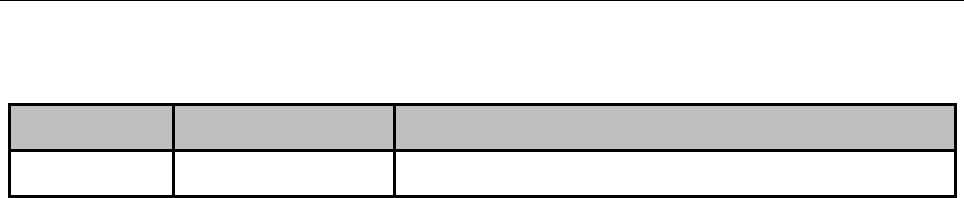
2.1 EV3 Brick
The EV3 Brick (Figure 1) is the control center and power station for the robot. All sensors
and motors must be connected to the EV3 brick before starting the application. To start the
brick, hold the center button for 2 to 3 sec and ”leJOS EV3” will be displayed on the brick
screen. The booting normally needs around 110 sec.
Figure 1: Ev3 Brick
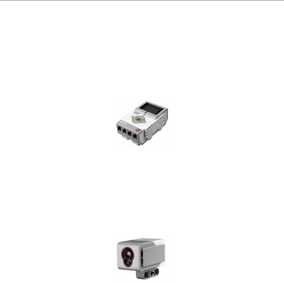
2.2 Color Sensor
The color sensor (Figure 2) recognizes the different colors and measures light intensity. The
application requires the color sensor to be connected to port 1 of the brick. Otherwise, the
application will fail to set up the color sensor.
Figure 2: Color Sensor
2.3 Gyroscopic Sensor
The EV3 Gyro Sensor (Figure 3) measures the robot’s rotational motion. The application
requires the Gyro Sensor to be connected to port 4 of the brick. Otherwise, the application
will fail to set up the Gyro Sensor.
User Manual for Lunar Rover Mapping Robot Page 3
Figure 3: Gyro Sensor
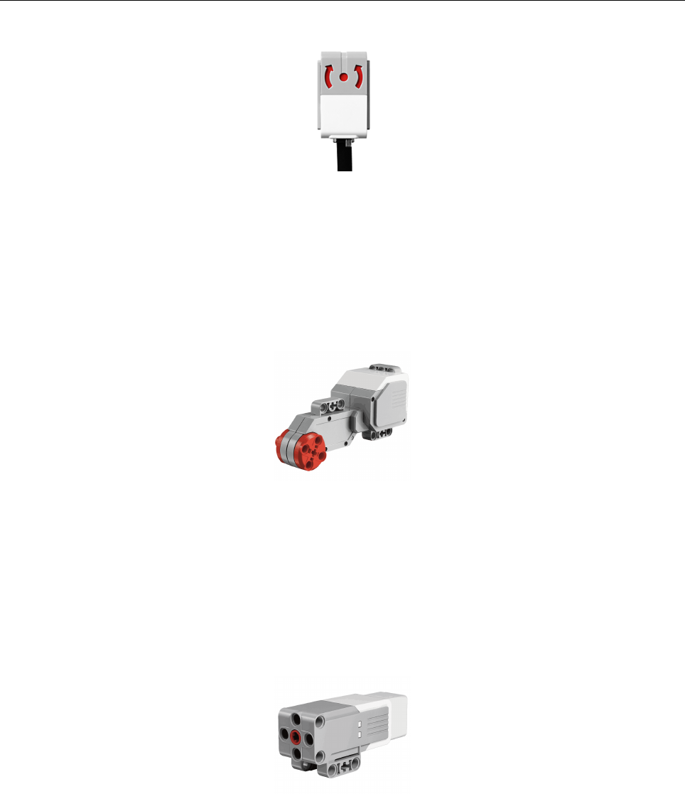
2.4 Large Motors
Large Motors (Figure 4) controls the movement of the robot. The application requires the
left motor to be connected to port D and the right motor connected to port A. Otherwise,the
application will fail to set up the motors.
Figure 4: Large Motor
2.5 Medium Motor
In this application, the Medium Motor (Figure 5) control the movement of color sensor. The
application requires it to be connected to port C. Otherwise,the application will fail to set up
the Medium Motor.
Figure 5: Medium Motor
User Manual for Lunar Rover Mapping Robot Page 4
3 GUI
On the server side, the Lunar Rover Mapping Project includes a GUI that provides a window to
allow the user to interact with the application. The GUI has two screens: a connection screen,
and a main screen. The connection screen will pop out at the launch of application. The main
screen will only displayed after the connection is successfully built.
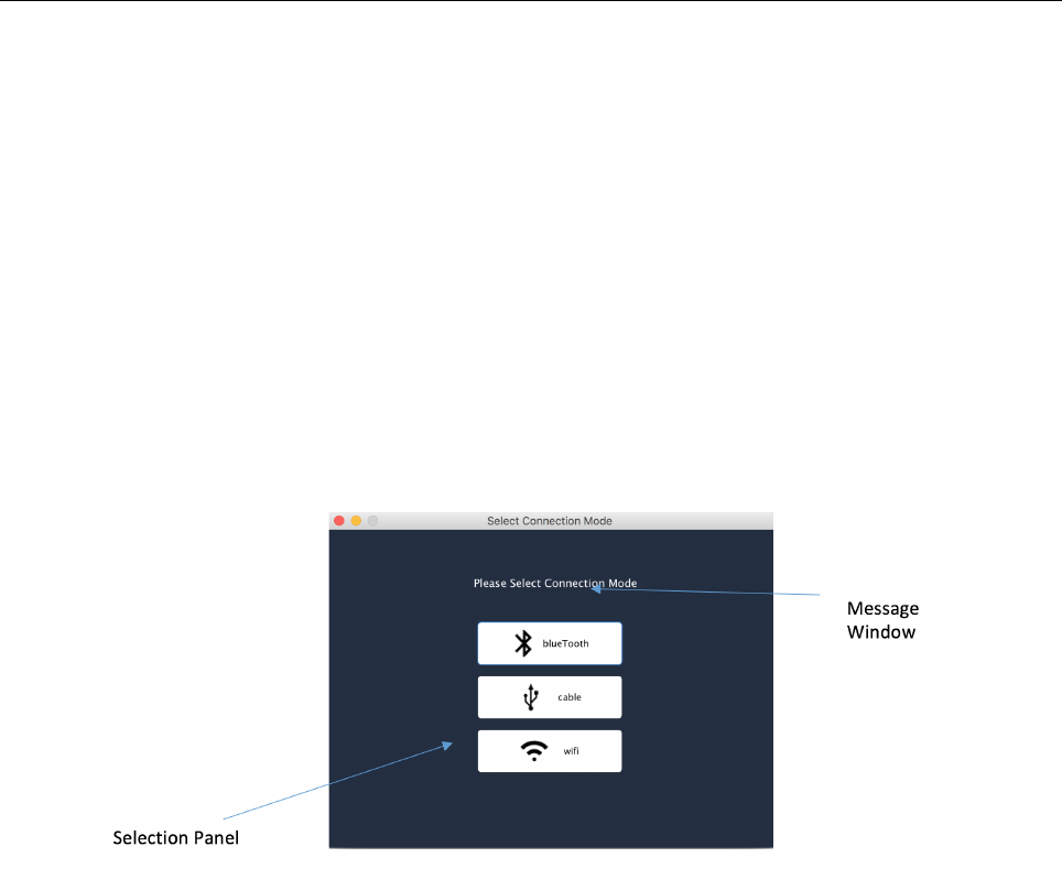
3.1 Connection screen
The connection screen (Figure 6) is comprised of two sections. The message window displays
the setting up information for each senor and motor. The selection panel is used for selecting
the connection method.
Figure 6: Connection Screen
•”Bluetooth” button should be selected when the connection is via Bluetooth. The robot
will have the IP address 10.0.1.1.
•”Cable” button should be selected when the connection is via a USB cable. The robot
will have the IP address 10.0.1.1.
•”WiFi” button should be selected when the connection is via WiFi. The robot will be
assigned an IP address and it is displayed on the brick screen. It will pop up a prompt
to ask the user to enter the IP address.
User Manual for Lunar Rover Mapping Robot Page 5
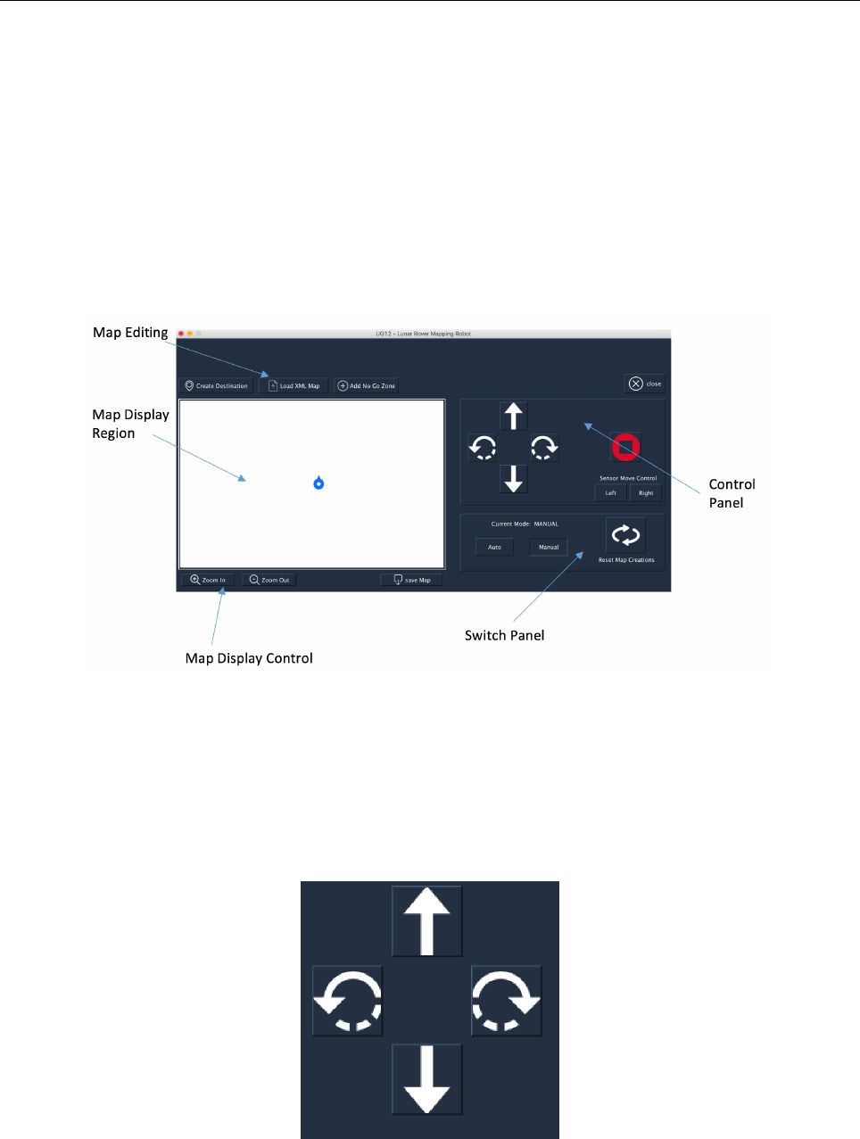
3.2 Main Screen
The layout of the main screen (Figure 7) is comprised of the following sections: the control
panel, switch panel, and map display region. The control panel provides buttons that allow
the user to manually control the movement of the robot. The switch panel provides buttons to
switch between the manual and autonomous mode of the robot, and clear the map creations
e.g. destinations. The map display region renders the map structure and presents a graphical
representation of the map to user.
Figure 7: Main Screen
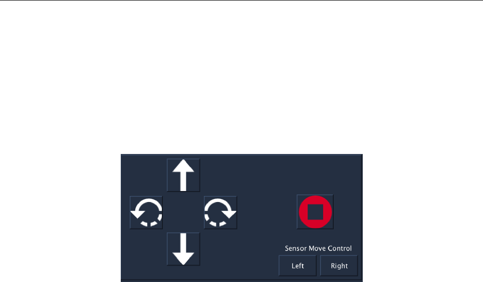
3.2.1 Control Panel
3.2.1.1 Robot movement control
Figure 8: Moving Control
The movement controls (Figure 8) are as follows:
User Manual for Lunar Rover Mapping Robot Page 6
•The button with the up arrow will send a forward command when the user clicks on it or
presses the up arrow key on the keyboard.
•The button with the down arrow will send a backward command when user clicks on it
or presses the down arrow key on the keyboard.
•The button with the left rotate arrow will send a left rotate command when the user
clicks on it or presses the left arrow key on the keyboard.
•The button with the right rotate arrow will send a right rotate command when user clicks
on it or presses the right arrow key on the keyboard.
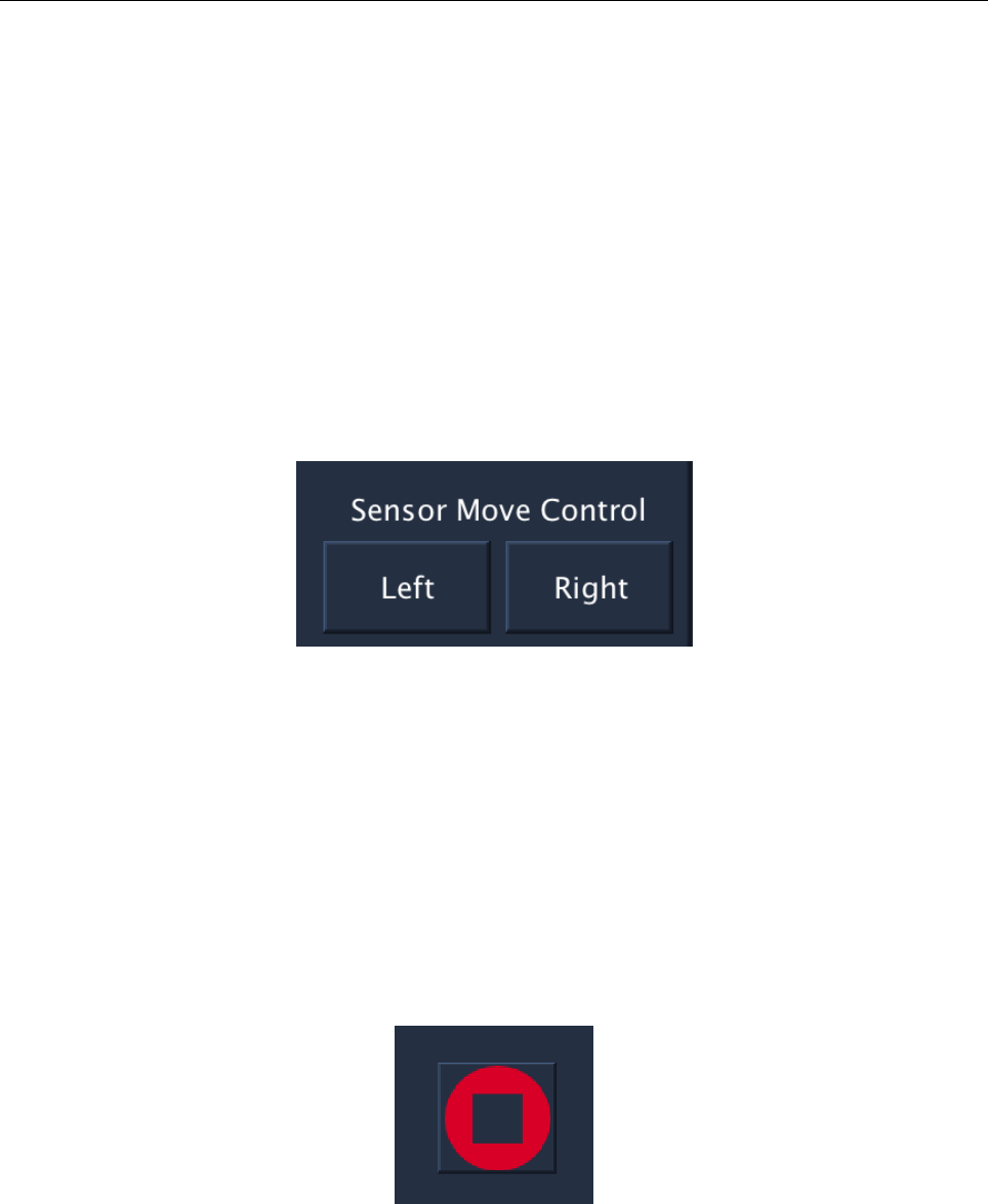
3.2.1.2 Color Sensor movement
Figure 9: Color Sensor Move Control
The color sensor movement controls (Figure 9) are as follows:
•The left button will send a left move command to move the color sensor when the user
clicks on it.
•The right button will send a right move command to move the color sensor when the user
clicks on it.
3.2.1.3 Emergency Stop
Figure 10: Emergency Stop
•The Emergency Stop button (Figure 10) will send an emergency stop command to the
robot to stop the robot from movement immediately.
User Manual for Lunar Rover Mapping Robot Page 7
3.2.2 Switch Panel
3.2.2.1 Autonomous and Manual Switch
Autonomous and Manual Switch (Figure 11) (R01 Manual Control and R02 Autonomous Con-
trol)
Figure 11: Autonomous and Manual Switch
•When the manual button is selected, the robot will switch to the manual mode which
allows the user to manually control the robot and enable the sending of robot movement
commands.
•When Auto button is selected, the robot will switch to the autonomous mode which
enables self path finding of the robot and disables the sending of robot movement com-
mands.
•The current mode can be viewed on the status window.
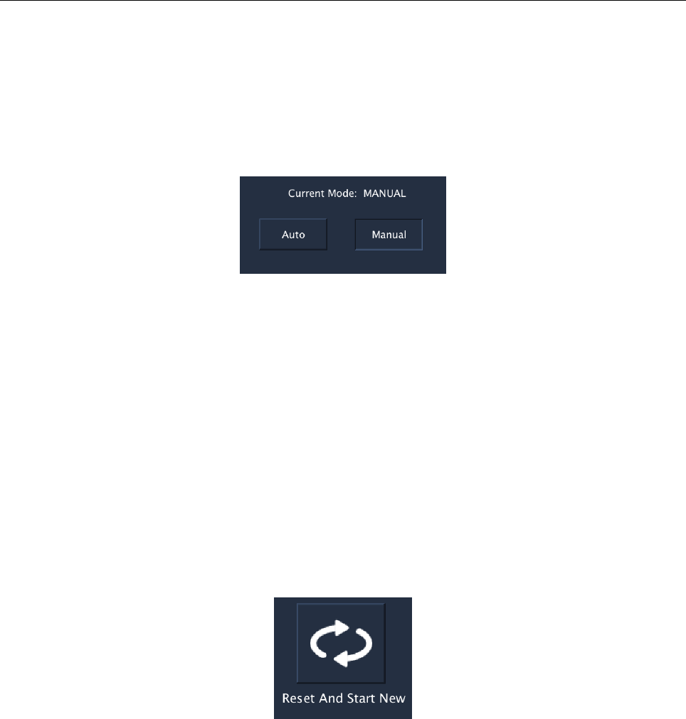
3.2.2.2 Reset and Start New
Figure 12: Reset and Start New
•When the robot has reached the destination, the Reset and Start New button (Figure 12)
allows the User to reset the figures of map.
3.2.3 Map Panel
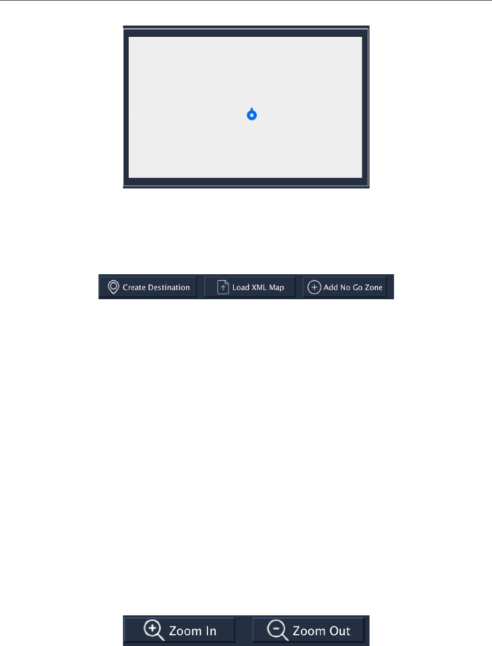
3.2.3.1 Map display region
•This region (Figure 13) will display the map visualization by rendering the map data. It
displays the robot position and map features. It also allows the user to modify the map
by marking no go zones or creating destinations.
User Manual for Lunar Rover Mapping Robot Page 8
Figure 13: Map Display
3.2.3.2 Map Editing Buttons
Figure 14: Map Editing buttons
•The map editing buttons (Figure 14 are placed above the map display region. They have
the functionalities to allow the user to modify the map.
•When the ”Create Destination” button is clicked, it allows the user to create a destination
by clicking a specific point on map. The text on this button will become ”Confirm”, and
the user needs to click on it to confirm the destination.
•When the ”Load XML map” button is clicked, it allows the user to load the data of
DTD.xml into the map structure. The DTD.xml will also be rendered and displayed to
the user at the same time.
•When the ”Add No Go Zone” button is clicked, it allows the user to mark the NGZs on
the map. This is done by using the mouse to drag a shape on the map display region. The
text on this button will become ”Confirm”, and the user needs to click on it to confirm
the NGZ.
3.2.3.3 Zoom In/Out
Figure 15: Zoom In/Zoom Out
User Manual for Lunar Rover Mapping Robot Page 9
•One click on the ”Zoom In” button (Figure 15) will enlarge the components displayed in
the map by 10%.
•One click on the ”Zoom Out” button (Figure 15) will narrow the components displayed
in the map by 10%.
•When the map is zoomed in, user can click on the map to move the camera.
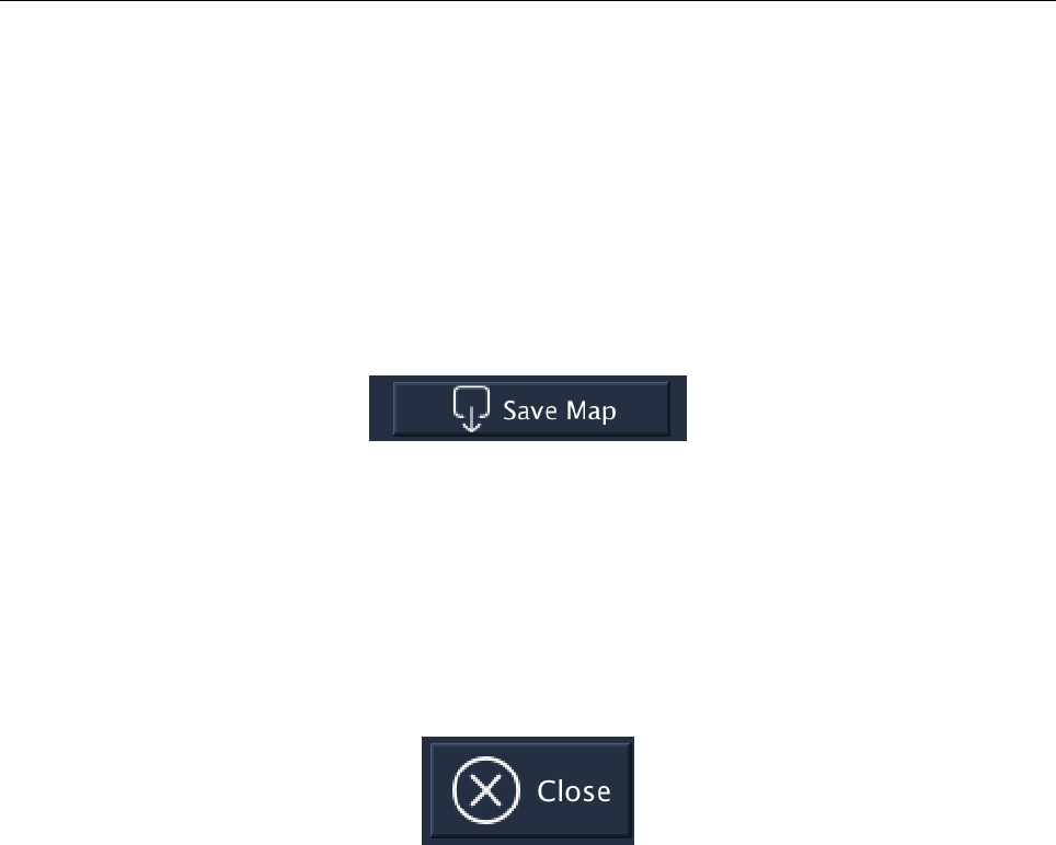
3.2.3.4 Save Map
Figure 16: Save Map
•”Save Map” Button (Figure 16) allows user to save the data of current map. All features
of the map will be rendered into XML format.
3.2.3.5 Close button
Figure 17: Close Button
•When the user clicks the ”Close” button (Figure 17), it will send command to close all
the motor and sensor ports and then exit the program.

User Manual for Lunar Rover Mapping Robot Page 10
4 Building Connection
4.1 Cable
This is the simplest way to connect the robot. User needs to plug the USB cable on the robot
USB port and the computer. The user can then launch the application and select ”Cable” on
connection screen. Upon successful connection, the main screen will pop up.
4.2 Bluetooth
To connect the robot via Bluetooth, user needs to firstly turn on the Bluetooth on the computer
then enter the Bluetooth setting on the EV3 brick. The brick should show your device name
after searching. Then the user should confirm the device and there will be a pin shown on the
brick screen. After entering this pin on the computer, the robot should connect to the computer.
Then the user shall click Bluetooth on the connection screen. Upon successful connection, the
main screen will pop up.
4.3 WiFi
To connect the robot via WiFi, user needs to make sure the robot and the computer are
connected to the same network via WiFi. There will be an assigned IP address displayed on
brick. Then user shall click WiFi on the connection screen and enter the IP address displayed
on the brick. Upon successful connection, the main screen will pop up.
4.4 Frequent Problems On Connection
In case the main screen didn’t pop up and it stays on connection screen, It means the connection
is not built. There are following ways to resolve this problem:
1. Try another connection method.
2. Check the message shown on the connection screen and make sure sensors and motors
are correctly connected to the ports.
3. Enter brick setting, reset and try again.
User Manual for Lunar Rover Mapping Robot Page 11
5 Manual Control
5.1 Switch to Manual control
Manual control is the default mode at the launch of the application. Under this mode, User can
control the robot manually. The buttons associated with manual control will be enabled. The
user can click the buttons to control the movement of the robot in the control panel. Holding
the button will make robot movement continuously.
Figure 18: Robot Control Panel
5.2 Associated Key
•Moving forward - Up Arrow Key
•Moving Backward - Down Arrow Key
•Turn Clockwise - Right Arrow Key
•Turn Anti Clockwise - Left Arrow Key
•Emergency Stop - Space
NOTE : The manual control buttons except Emergency stop will be disabled in Au-
tonomous mode.
User Manual for Lunar Rover Mapping Robot Page 12
6 Autonomous
6.1 Switch to Autonomous
The user can switch to Autonomous mode by clicking the ”Auto” button in the switch panel.
In this mode, the manual control buttons, except Emergency stop, will be disabled. The user
can select a position on map display region by clicking to create a destination. If the path
between the destination and the robot position is not blocked, the robot will automatically
move to this destination through a shortest path.
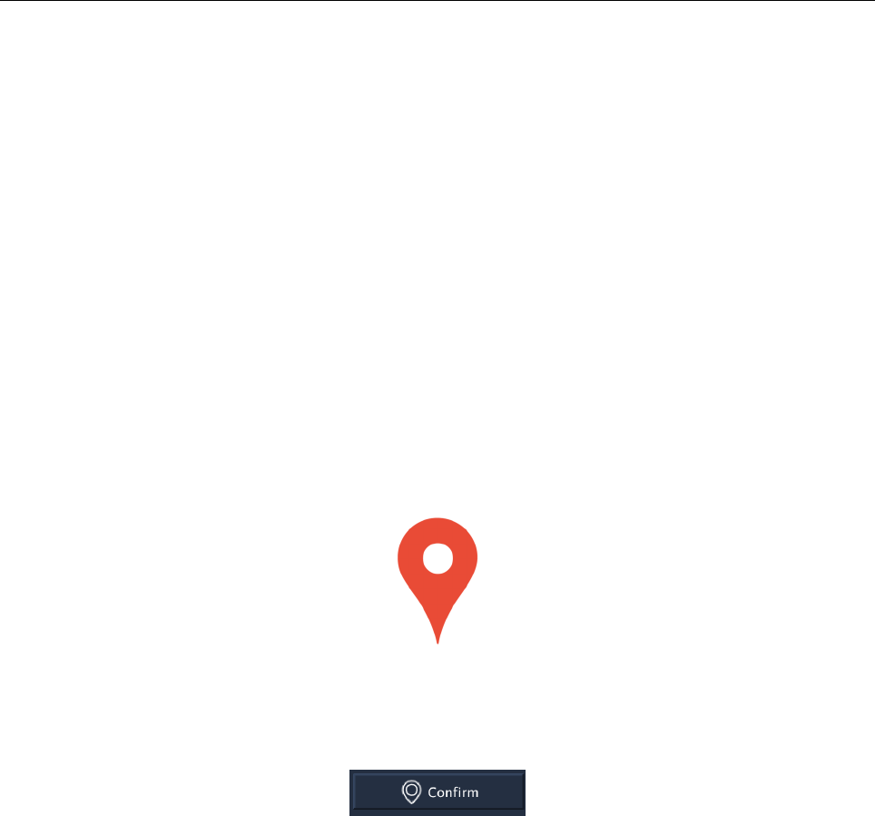
6.2 Setting up destination
To set up a destination, the user needs to click the ”Create Destination” button and select the
destination (shown in Figure 19) on the Map display region. After the first click on ”create
destination”, the text of this button will be changed to ”confirm” (shown on the Figure 20).
User can click this button to confirm the destination position and then the robot will be moving
to this position if the path is not blocked.
Figure 19: Destination icon shown on the map display region
is not blocked
Figure 20: Destination confirm
User Manual for Lunar Rover Mapping Robot Page 13
7 Map Display
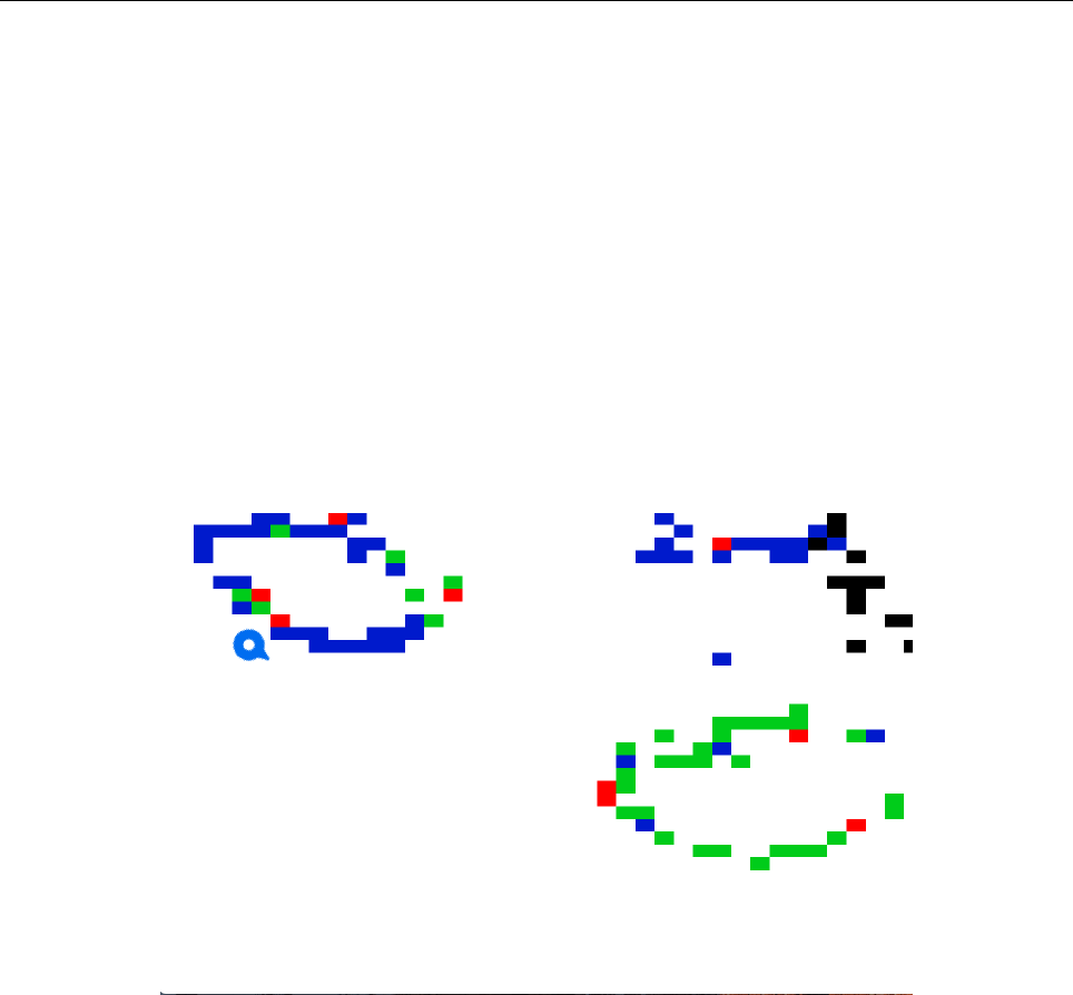
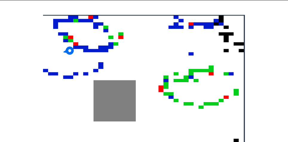
7.1 Display of Map Feature
The map is updated regularly and the GUI displays the map in real time. When the robot
detects the feature on the map, it will be shown on the map with the associated color:
•Border = Blue
•Radiation = Green
•Tracks = Purple
•Craters = Black
Figure 21: Example of Map Display
7.2 Create the No Go Zones
The user can create No Go zones by clicking the ”Add No Go zone”. It allows the user to
drag a rectangular shape on the map and designate this region to be a No Go zone in the map
structure. The user can add more than one No Go zones on the map.
User Manual for Lunar Rover Mapping Robot Page 14
Figure 22: Example of No Go Zone creation
7.3 Discard the Creations
The user can also disregard the creations on the map including Destination and No Go zones
by clicking the ”reset” button on the switch panel (refer to Section 3.2.2.2).
7.4 XML Import
User can import the XML into map structure by clicking ”import XML file” on map editing
section (refer to Section 3.2.3.2).
7.5 XML Export
User can export the XML into map structure by clicking ”save the map” on map display control
section (refer to Section 3.2.3.4).
INDEX 15
Index
A
Arrow keys - Control Panel, 6
Arrow Keys - Manual Control, 11
Autonomous Mode Control, 12
Autonomous Mode Switching Button, 7
B
Bluetooth Connection Information, 4
Bluetooth Connection Instructions, 10
C
Cable Connection Information, 4
Cable Connection instructions, 10
Close program, 9
Color Sensor, 2
Color Sensor Movement, 6
Computer Requirements, 1
Connection Problems, 10
Connection Screen, 4
Control Panel, 5
D
Destination Create Button, 8
Destination Creation, 12
E
Edit map, 8
Emergency Stop, 6
EV3 Brick Setup, 2
Export XML Button, 9
G
Gyroscopic Sensor, 2
L
Large Motors, 3
M
Main screen, 5
Manual Mode Control, 11
Manual Mode Switching Button, 7
Map - Remove features, 14
Map colors, 13
Map Display, 13
Map Display Panel, 7
Map editing buttons, 8
Map Panel, 7
Medium Motor, 3
Movement control, 5
N
No Go Zone Button, 8
No Go Zone Creation, 13
R
Reset map, 7
Robot Requirement, 1
S
Save Map, 9
Switch Panel, 7
W
WiFi Connection Information, 4
WiFi Connection Instructions, 10
X
XML Export, 14
XML Import, 14
XML Map Load Button, 8
Z
Zoom In, 8
Zoom Out, 9
