H_88 2329 01_P User_guide User Guide
User Manual: User_guide user guide pdf - FTP File Search (17/20)
Open the PDF directly: View PDF ![]() .
.
Page Count: 180 [warning: Documents this large are best viewed by clicking the View PDF Link!]
Operator’s Manual
Copyright Information
CG Triumvirate is a trademark of Agfa Corporation.
CG Times based upon Times New Roman under license from the Monotype Corporation.
Windows is a registered trademark of the Microsoft Corporation.
Ethernet is a registered trademark of Xerox Corporation.
All other brand and product names are trademarks, service marks, registered trademarks,
or registered service marks of their respective companies.
Limitation of Liability
In no event shall Datamax-O’Neil be liable to the purchaser for any indirect, special or
consequential damages or lost profits arising out of or relating to Datamax-O’Neil’s
products, or the performance or a breach thereof, even if Datamax-O’Neil has been advised
of the possibility thereof. Datamax-O’Neil’s liability, if any, to the purchaser or to the
customer of the purchaser hereunder shall in no event exceed the total amounts paid to
Datamax-O’Neil hereunder by the purchaser for a defective product.
In no event shall Datamax-O’Neil be liable to the purchaser for any damages resulting from
or related to any failure or delay of Datamax-O’Neil in the delivery or installation of the
computer hardware, supplies or software or in the performance of any services.
Some states do not permit the exclusion of incidental or consequential damages, and in
those states the foregoing limitations may not apply. The warranties here give you specific
legal rights, and you may have other legal rights which vary from state to state.
Firmware (Software) Agreement
The enclosed Firmware (Software) resident in the Printer is owned by Licensor or its
suppliers and is licensed for used only on a single printer in the user’s Trade or Business.
The User agrees not to, and not to authorize or permit any other person or party to
duplicate, or copy the Firmware or the information contained in the non-volatile or
programmable memory. The firmware (Software) is protected by applicable copyright
laws and Licensor retains all rights not expressly granted. In no event will Licensor or its
suppliers be liable for any damages or loss, including direct, incidental, economic, special, or
consequential damages arising out of the use or inability to use the Firmware (Software).
Information in this document is subject to change without notice and does not represent a
commitment on the part of Datamax-O’Neil Corporation. No part of this manual may be
reproduced or transmitted in any form or by any means, for any purpose other than the
purchaser’s personal use, without the expressed written permission of Datamax-O’Neil
Corporation.
All rights reserved
Copyright © 2013, Datamax-O’Neil
Part Number 88-2329-01, Revision R

Agency Compliance and Approvals
C US
Listed
UL60950-1: 2003 2nd Edition Information Technology Equipment
CSA C22.2 No. 60950-1-07 2nd Edition
The manufacturer declares under sole responsibility that this product conforms to the
following standards or other normative documents:
EMC: 2004/108/EC
EN 55022 (2006, A1 :2007) Class B
EN 50024 (1998, A1:2001, A2:2003)
Safety: This product complies with IEC 60950-1, 2nd Edition, 2005-12
ROHS: 2002/95/EC
LVD: 2006/95/EC
Customs Union – Russia, Kazakhstan, Belarus
GB4943.1-2011, GB9254-2008, and GB17625.1-2003
H-4212 and H-6308 models:
The foregoing equipment has been registered under the Clause 3, Article 58-2 of Radio
Waves Act
FCC: This device complies with FCC CFR 47 Part 15 Class A.
Note: This equipment has been tested and found to comply with the limits for a Class A digital
device, pursuant to Part 15 of the FCC Rules. These limits are designed to provide reasonable
protection against harmful interference when the equipment is operated in a commercial
environment. This equipment generates, uses, and can radiate radio frequency energy, and if
not installed and used in accordance with the instructions in this manual, it may cause harmful
interference to radio communications. Operation of this equipment in a residential area is likely
to cause harmful interference in which case the user will be required to correct the interference
at their own expense.

Important Safety Instructions
The exclamation point within an equilateral triangle is intended to alert you to
the presence of important operating and maintenance instructions.
This unit has been carefully designed to provide years of safe, reliable performance. As with
all electrical equipment, however, there are some basic precautions that you should follow
to avoid personal injury or printer damage:
Before using the printer, carefully read all the installation and operating instructions.
Observe all warning instruction labels on the printer.
Install the printer on a flat, firm surface.
Do not place the printer upon or near a heat source.
Never insert anything into the ventilation slots and openings of the printer.
Do not use the printer near water or spill liquid into it.
Ensure that the AC power source matches the ratings listed for the printer. (If
unsure, check with your dealer or local utility provider.)
Do not step on the AC power cord. If the AC power cord becomes damaged or
frayed, replace it immediately.
If the printer needs repair, consult only qualified, trained service personnel. No user-
serviceable parts are inside; do not remove the cover.
Special Instructions
The green check box is intended to alert you to notable details regarding
printer operation or to conventions used within this manual.
Applicability
The procedures, functions, and parameters described in this document are written according
to an Application Version of printer firmware. To identify the Application Version that
corresponds to this text, see Print Configuration in Section 4.3.5. To update the Application
Version of your printer, visit our website at www.datamax-oneil.com to download firmware.

i
Contents
Overview.....................................................................................................1
1.1 About the Printer ............................................................................... 1
1.1.1 Standard Features .................................................................... 1
1.1.2 Optional Features ..................................................................... 3
Getting Started ...........................................................................................7
2.1 Unpacking ........................................................................................ 7
2.1.1 Additional Requirements ........................................................... 8
2.2 Installation ....................................................................................... 8
2.2.1 Connecting the Power Cord ........................................................ 8
2.2.2 Connecting an Interface Cable.................................................... 9
2.2.3 Connecting to the SDIO Slot and USB Host Ports......................... 10
Setting up the Printer ...............................................................................13
3.1 Media Loading................................................................................. 13
3.1.1 Internal Media Sources........................................................... 15
3.1.2 External Media Sources .......................................................... 17
3.1.3 Rewinding Media ................................................................... 19
3.2 Media Sensor Adjustment ................................................................. 25
3.3 Ribbon Loading ............................................................................... 26
3.4 Quick Calibration ............................................................................. 29
3.5 Print Quality Controls ....................................................................... 29
Using the Control Panel.............................................................................31
4.1 Layout ........................................................................................... 31

ii
4.1.1 The Display ........................................................................... 32
4.1.2 Keypad Functions ................................................................... 33
4.2 The System Menu............................................................................ 34
4.2.1 Media Settings ....................................................................... 35
4.2.2 Print Control .......................................................................... 38
4.2.3 Printer Options....................................................................... 40
4.2.4 System Settings ..................................................................... 51
4.2.5 Communications..................................................................... 61
4.2.6 Diagnostics............................................................................ 69
4.2.7 MCL Options .......................................................................... 72
4.3 The Test Menu ................................................................................ 73
4.3.1 Print Quality Label .................................................................. 73
4.3.2 Ribbon Test Label ................................................................... 74
4.3.3 Test Label ............................................................................. 74
4.3.4 Validation Label...................................................................... 74
4.3.5 Print Configuration.................................................................. 75
4.3.6 Print Last Label ...................................................................... 75
4.3.7 User-Defined Label ................................................................. 75
Operating, Adjusting and Maintaining the Printer .....................................77
5.1 Displayed Messages ......................................................................... 77
5.1.1 Prompts and Condition Messages .............................................. 77
5.2 Calibration...................................................................................... 80
5.2.1 Standard Calibration ............................................................... 80
5.2.2 Advanced Entry Calibration ...................................................... 82

iii
5.3 Reset Methods ................................................................................ 89
5.3.1 Soft Reset ............................................................................. 89
5.3.2 Level One Reset ..................................................................... 90
5.3.3 Level Two Reset ..................................................................... 90
5.4 Printhead Assembly Adjustments ....................................................... 90
5.4.1 Leveling Cam Adjustment ........................................................ 90
5.4.2 Printhead Pressure Adjustment................................................. 92
5.5 Maintenance ................................................................................... 92
5.5.1 Cleaning the Printhead ............................................................ 94
5.5.2 Cleaning the Fan Filter ............................................................ 96
5.5.3 Cleaning the Interior Compartment ........................................... 96
5.5.4 Cleaning the Media Sensing Components ................................... 97
5.5.5 Cleaning the Platen and Assist Rollers........................................ 97
5.5.6 Cleaning the Ribbon Path Components....................................... 98
5.5.7 Cleaning the Exterior Surfaces.................................................100
5.6 Updating the Firmware ....................................................................100
5.7 Updating the Boot Loader ................................................................101
5.8 Downloading Fonts .........................................................................102
5.9 Replacing the Printhead...................................................................105
Troubleshooting......................................................................................107
6.1 Problem Resolution .........................................................................107
6.1.1 General Resolutions ...............................................................107
6.1.2 Warning and Fault Messages ...................................................111
6.2 Hex Dump Mode.............................................................................117

iv
Specifications..........................................................................................119
7.1 General.........................................................................................119
7.2 Model-Specific Specifications............................................................120
7.3 Approved Media and Ribbon .............................................................130
Appendix A..............................................................................................133
Module Assignments, and File Handling Definitions and Messages ................133
Appendix B..............................................................................................137
Resolutions, Widths, Speeds, Emulations, & Custom Adjustments ................137
Appendix C..............................................................................................141
RS-422/485 Port Configuration ...............................................................141
Appendix D .............................................................................................143
Changing the Menu Language .................................................................143
Appendix E..............................................................................................147
Saving a Configuration File .....................................................................147
Appendix F..............................................................................................149
Ethernet Setup .....................................................................................149
Appendix G..............................................................................................153
Printer Driver and Port Setup ..................................................................153
Glossary..................................................................................................167
H-Class 1
1 Overview
1.1 About the Printer
Congratulations on your purchase of an H-Class printer (hereafter referred to as “the
printer”). This manual provides information regarding printer setup, operation, and care.
To print label formats, refer to the instructions provided with your labeling software; or, if
you wish to write custom programs, a copy of the Class Series 2 Programmer’s Manual can
be found on the Accessories CD-ROM and at our web site at http://www.datamax-oneil.com
As detailed below, available standard and optional features can meet all of your labeling
requirements.
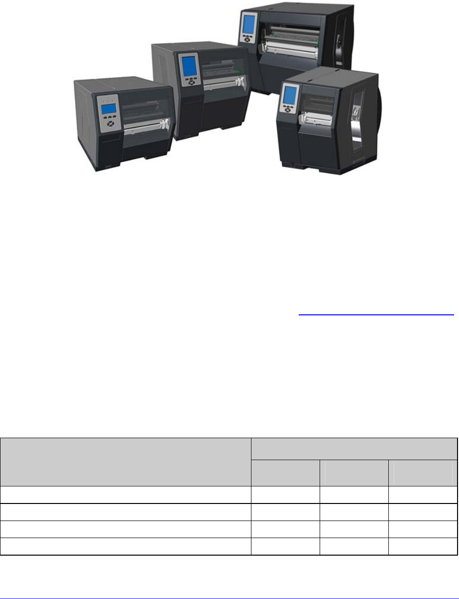
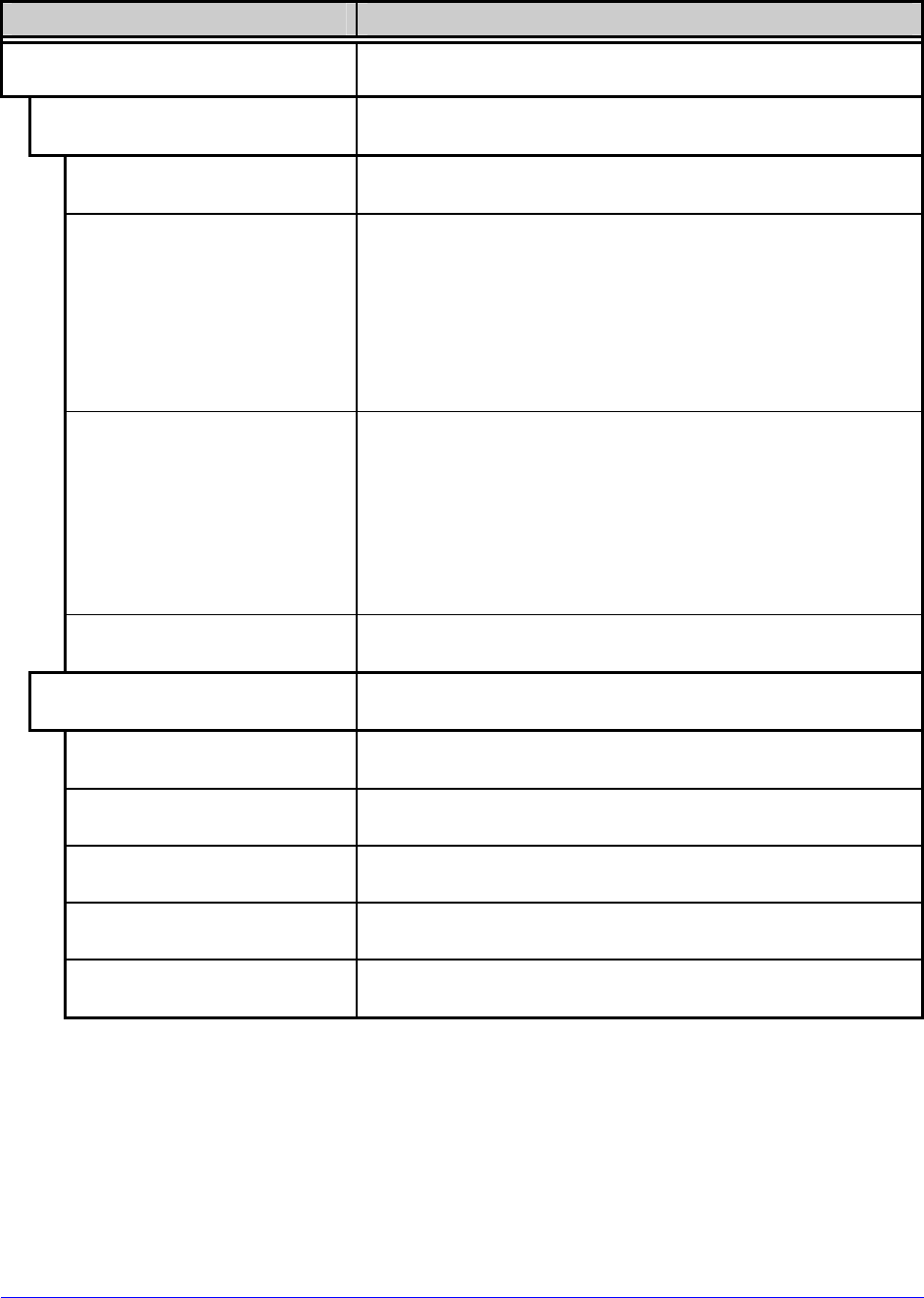
1.1.1 Standard Features
Depending upon the model and type, the printer offers the following standard features:
Model and Type
Feature H-4xxx
Standard H-6xxx
Standard H-xxxxX
Tall
Control Panel Security X X X
Default Configuration Restorable X X X
Diagnostic Display and Modes X X X
Die Cast Media Hub N/A N/A X
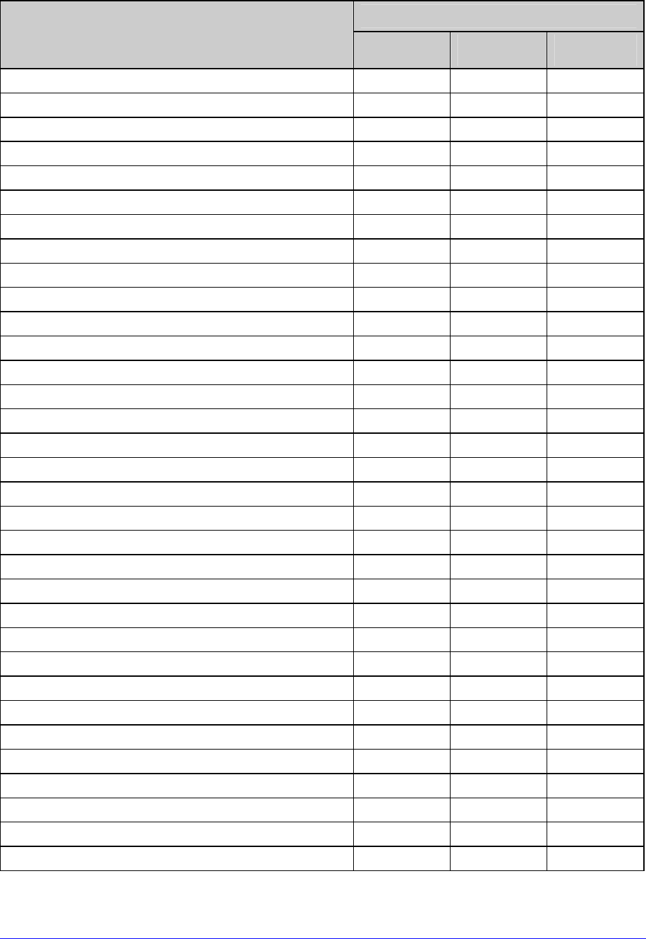
2 H-Class
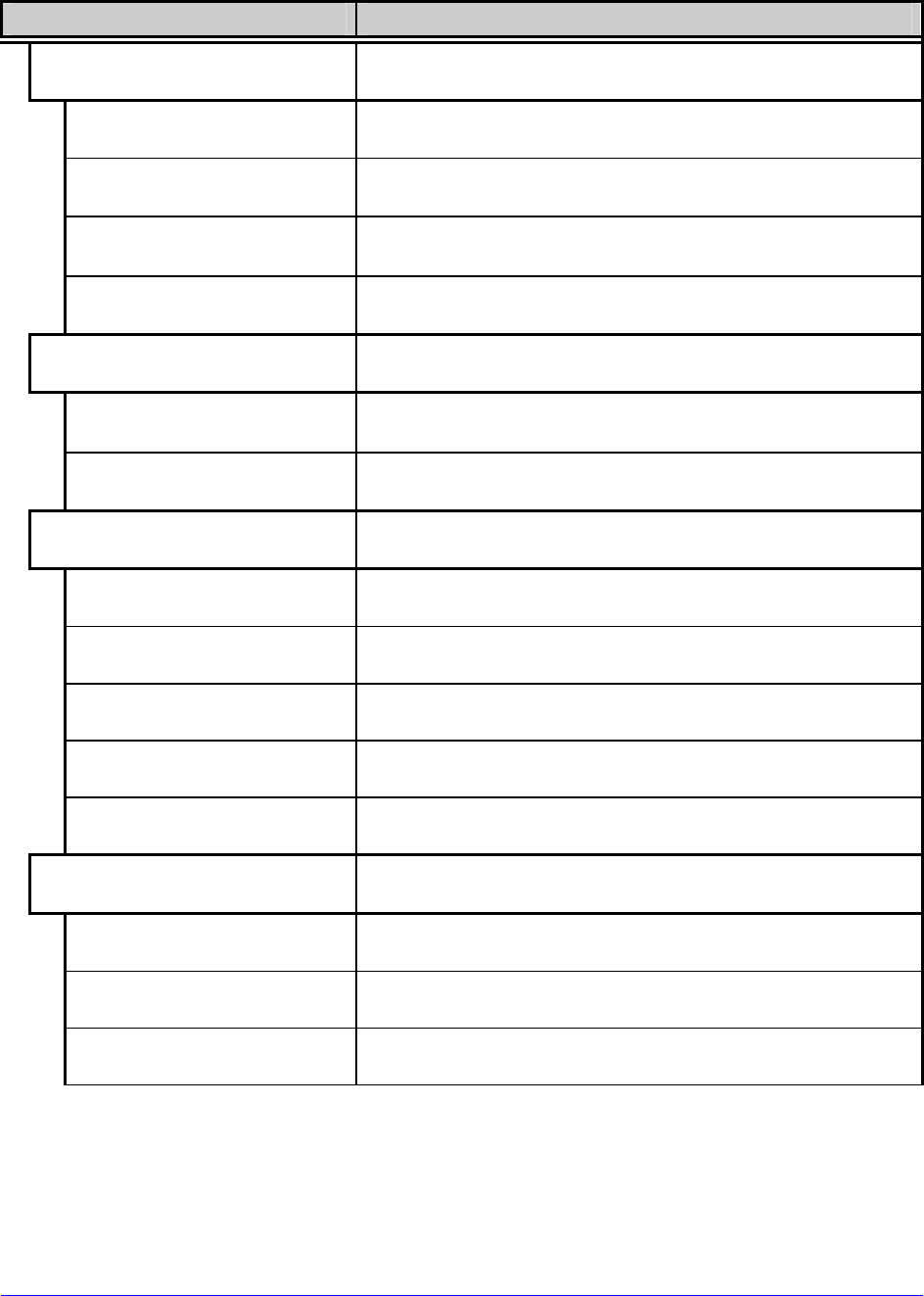
Model and Type
Feature (continued) H-4xxx
Standard H-6xxx
Standard H-xxxxX
Tall
Direct Thermal Printing X X X
Downloadable Firmware Upgrades X X X
DRAM Memory (MB) 16 16 16
EFIGS Multi-Language Support X X X
Ethernet LAN X X X
Fault Handling with Reprint & Void X X X
Flash Memory (MB) 8 8 8
Graphics Display (128 x 64 pixels) X X N/A
Graphics Display (240 X 320 pixels) Optional Optional X
Host-Accessible Memory X X X
IEEE 1284 Compliant Parallel Interface X X X
IntelliSEAQ Printhead X X X
Internal Test & Configuration Labels X X X
Label Retract Control after Print X X X
Line Mode (ASCII Text Input) Printing X X X
Media Counters X X X
Media Tear Bar X X X
Option Hardware Auto-Detection X X X
On-Demand and Batch Printing X X X
Power-up Diagnostics X X X
Resident Multiple Setup and Restore X X X
Resident Option Hardware Diagnostics X X X
RFID Upgrade Availability X X X
Ribbon Low Detection and Warning X X X
Scalable Font Engine X X X
SDIO Interface (internal remote) Optional X X
Serial RS-232/422 Interface X X X
Text, Bar Code, Graphics, and Image Printing X X X
Three-Inch Media Hub X X X
Time and Date Battery Backup X X X
Time Stamping X X X
USB (device) Interface, Version 2.0 X X X
USB Host Ports (2) (internal remote) Optional X X

H-Class 3
1.1.2 Optional Features (available except as noted)
The following optional features are offered for the printer:
40 mm Media Hub (H-4xxx and H-4xxxX models only)
A media hub that accommodates 40-millimeter cores.
DMXrfNetII
A WiFi Ethernet card with many features, including:
802.11b WiFi LAN standards-based technology
Integrated module with radio, baseband, MAC, and application processors
Built-in TCP/IP and UDP for flexible LAN connectivity options
Built-in Web server for drop-in LAN and internet connectivity
Built in WEP security protocol
Integrated command interface that eliminates complicated software drivers
External Media Rewinders
Precision-crafted, bi-directional rewinding mechanisms with device-dependant features:
DMXREW1 - accepts 1 to 4 inch (25 to 101 mm) diameter core that is up to 4.5
inches wide (114 mm), and rewinds to an 8-inch (203 mm) maximum outer
diameter at 10 inches per second.
DMXREW2 – accepts a 3-inch (76 mm) diameter core that is up to 9.5 inches wide
(241 mm), and rewinds to a 12-inch (304 mm) maximum outer diameter at 30
inches per second.
ILPC Fonts
Font sets that allow International Language Print Capability, consisting of one of the
following:
CG-Times (western European) Scalable
Kanji Gothic B Scalable
Simplified Chinese GB Scalable
Korean Hangul
Internal Rewinder, Power-Assisted (Standard models only)
An internal mechanism to wind printed labels, or backing material when using a Peel and
Present option, into a maximum outer diameter roll of five and half inches (139 mm).
Internal Rewinder, Powered "Full Roll" (Tall models only)
A motorized internal mechanism to wind printed labels, or pull the backing material when
using a Peel and Present option, into to a maximum outer diameter roll of eight inches (203
mm).

4 H-Class
Linear Scanner (H-4xxx and H-4xxxX models only)
A CCD scanning device with data capture and integrated label voiding features to ensure the
integrity of printed bar codes.
Media Cutter
A rotary-type device that cuts material with a maximum thickness of .01 inch (.254 mm)
into lengths as small as 1.25 inches (31.8 mm).
Peel and Present Mechanism, High Performance
(H-4xxx and H-4xxxX models only, Internal Rewind optional)
A device that peels labels with aggressive adhesives from the backing material for
immediate application, regulated by previous label removal (Minimum label length is 1.5
inches [38 mm]).
Peel and Present Mechanism, Standard (Internal Rewind required)
A device that peels labels from the backing material for immediate application, regulated by
previous label removal (Minimum label length is 1.5 inches [38 mm]).
Present Sensor
An output regulator that inhibits printing when a label is presented.
RFID (All models except H-8308X)
An integrated Ultra High Frequency (UHF) RFID encoding and reading device with data
capture, available in three different configurations:
Factory Installed - complete, ready to use from the factory.
Ready - factory installed antenna, requiring installation of a module and hardware.
Full Upgrade - antenna, RFID module, and hardware require installation.
SDIO Interface and USB Host Ports
Interface ports that allow the printer to accept external SDIO and USB memory devices for
storing graphics, label formats, fonts, and firmware; and that allow USB keyboard
connections (and USB scanning device connections for MCL users) for direct data input
applications.
Thermal Transfer
A hub assembly that allows printing with ribbon for exceptional image clarity and durability,
as compared to most direct thermal media types.
H-Class 5
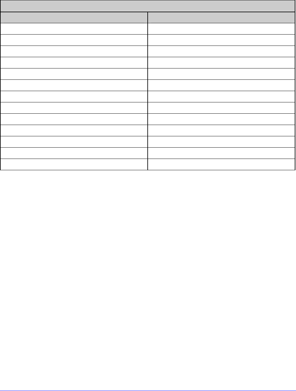
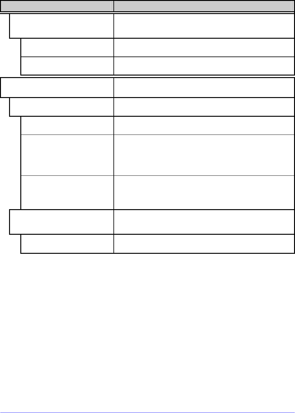
Option Installation
The table below lists the experience needed to install the options described above. For more
information, contact your dealer or Datamax-O’Neil.
Option Installation
Option Recommended Installer
40 mm Media Hub Factory only
Cover Dampener DMX Certified Technician
External Media Rewinder Operator
Graphics Display DMX Certified Technician
ILPC Fonts DMX Certified Technician
Internal Rewinder Operator
Linear Scanner DMX Certified Technician
Media Cutter Operator
Peel and Present Mechanism Operator
Present Sensor Operator
RFID (Ready and Full Upgrade) DMX Certified Technician
SDIO Interface and USB Host Ports DMX Certified Technician
Thermal Transfer Operator

6 H-Class

H-Class 7
2 Getting Started
2.1 Unpacking
The printer has been carefully packaged to prevent transit damage. (Inspect the container
for damage and, if evident, notify the shipping company before acceptance.)
After removing the packaging, check the contents of the shipment.
The following items are included:
Printer
Power Cord
Quick Start Guide
Accessories CD-ROM
Warranty Card
Any special or additionally purchased items
Save the carton and packing material for future use.
8 H-Class
2.1.1 Additional Requirements
Other items can also be needed for operation:
An interface cable (see Section 2.2.2);
Applicable media (see Section 7.3); and,
Applicable software (consult the Accessories CD-ROM, your dealer, or Datamax-
O’Neil).
2.2 Installation
The printer features an auto-ranging power supply and several different interface types for
easy installation.
Ensure that the Power Switch is OFF when making printer connections.
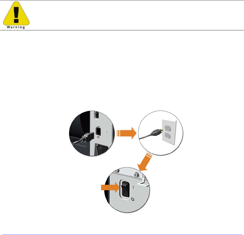
2.2.1 Connecting the Power Cord
With printer placed upon a firm and level surface, connect the Power Cord as follows:
A. Ensure that the Power Switch is turned OFF.
B. Connect the Power Cord to the AC receptacle on the printer, and then to a properly
rated and grounded AC outlet.
H-Class 9
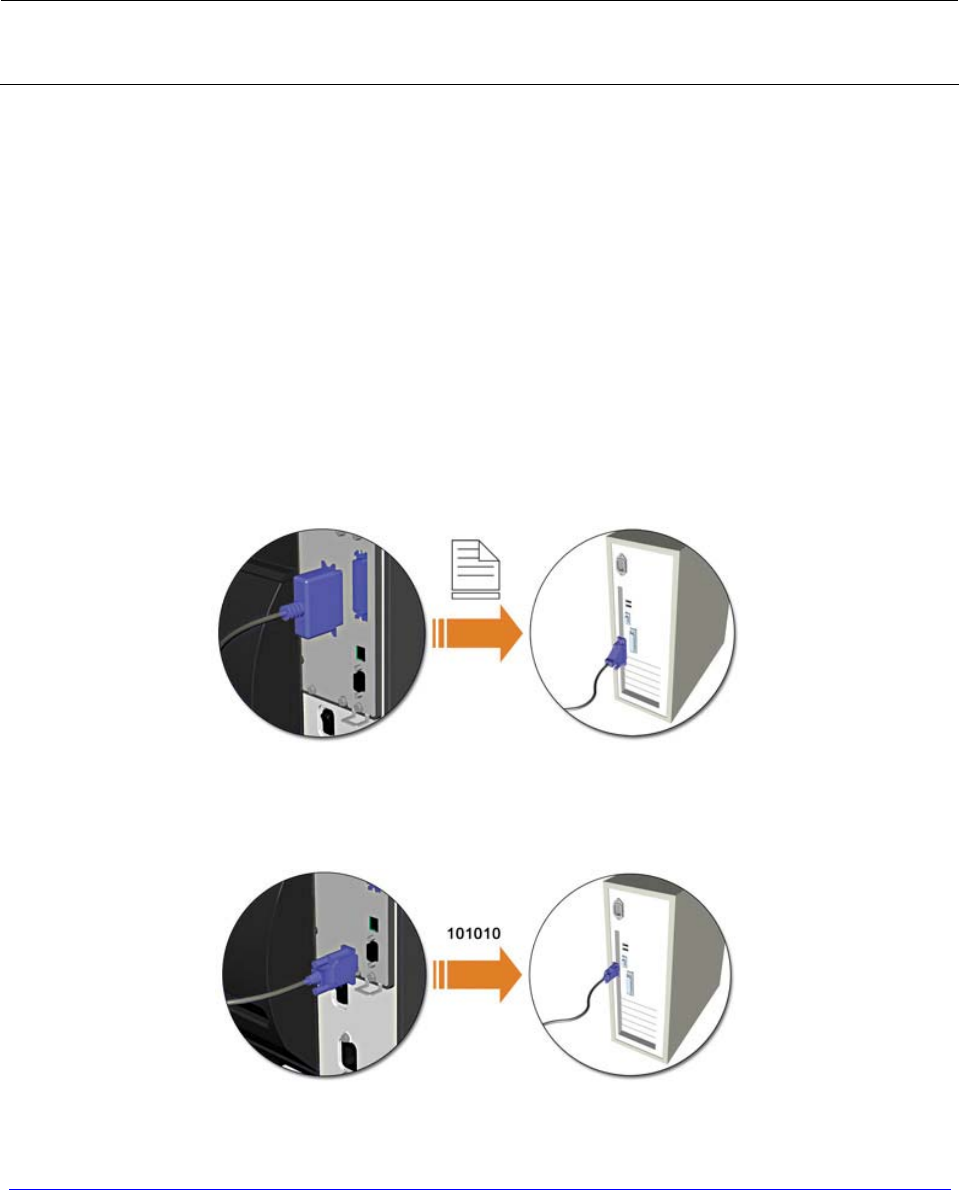
2.2.2 Connecting an Interface Cable
The printer can be interfaced to a host device via Ethernet, Parallel, Serial, and USB ports.
Following power-up (or after inactivity), interface port selection occurs automatically upon
detection of valid data. If incoming data flow stops as the Host Timeout period (see Section
4.2.5) is met, partially received formats will be ignored and the port selection repeated.
• To change an active port immediately, cycle the power OFF and ON.
• For alternate data processing options, see INPUT MODE, Section 4.2.4.
Ethernet Connection
The Ethernet interface supports several menu-selectable modes. Depending on the length,
the cable should be Category / Type 3 or better. Refer to Appendix F for setup information.
Parallel Connection
The parallel interface supports directional communications. Choose and connect cabling as
follows:
• For unidirectional communication, use a Centronics IEEE 1284 cable with a 36-pin
male connector; or,
• For bi-directional communication, use an IEEE 1284 Compliant cable with a 36-pin
male connector (and supporting host software).
Serial Connection
The serial interface supports RS-232C, RS-422, and RS-485 communications (see Appendix
C for RS-422/485 details).
10 H-Class
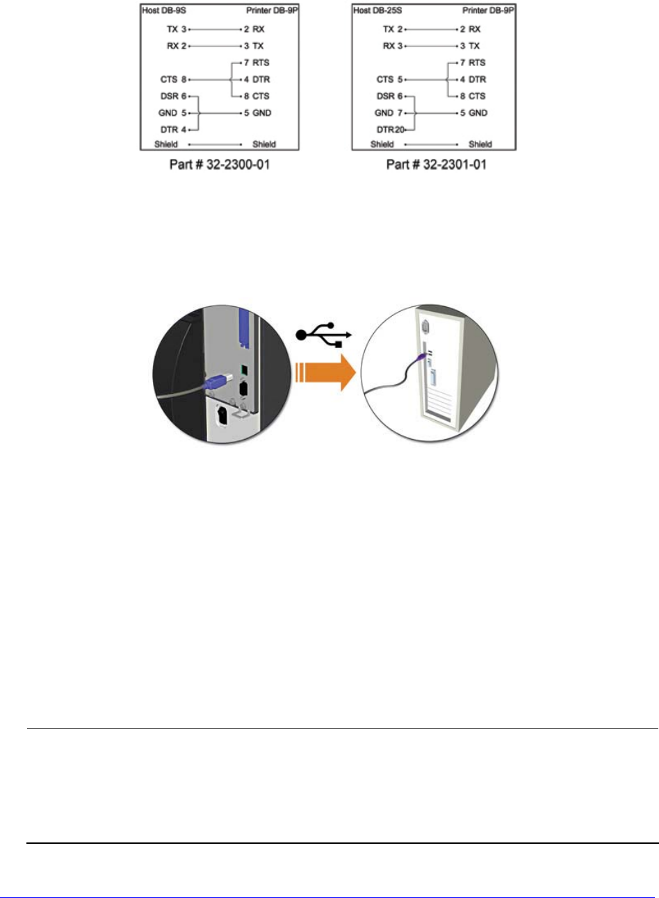
RS-232C cabling configurations and part numbers are shown below (contact your reseller
for ordering information).
USB Connection
The USB interface connection may differ slightly depending upon the operating system and
hardware configuration of the host computer. Basic connections are shown below.
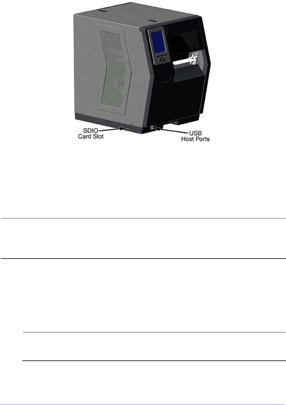
2.2.3 Connecting to the SDIO Slot and USB Host Ports
If equipped with the Secure Digital Input Output (SDIO) and USB Host Ports, the printer can
accept external storage devices for fonts, graphics, label formats, and firmware files. The
USB Host Port also accepts a USB keyboard for standalone, direct data (Line mode) input
applications; see the Class Series 2 Programmer’s Manual for examples.
SDIO Connections - When installing an SDIO Card, turn OFF the printer then slide the
card into the slot. Module “F” will be recognized by the printer. When removing a card,
turn OFF the printer then press inward on the card to release it.
USB Host Port Connections - The USB Host Ports support plug and play device
installation and removal. Module “H” and Module “I” will be recognized by the printer.
• Memory device sizes up to 16 GB are supported.
• If equipped on the memory device, ensure that the Write Protect Switch is
OFF.
• Before initial use, format the external memory device; see Section 4.2.3.
• Always allow process completion before removing modules.
H-Class 11
Using Memory Functions
Download your files to the device using Windows Explorer or DMX Config; see FILE
HANDLING DEFINITIONS in Appendix A. The following examples highlight several ways to
use memory devices; unless otherwise noted, see MODULES in Section 4.2.3 for details
about function selections.
• Files that reside in Module “X” cannot be copied; see Appendix A for module
details.
• For access to all functions, ensure that the Advanced Menu is selected: Press
System Settings select Menu Mode and then Advanced Menu.
To copy files stored on a module to or from the printer:
1. Press the MENU button then select Printer Options.
2. Select Modules and then Copy File.
3. Select the file to copy and then the destination module ID.
When sharing configuration files between printers, use Restore As Current
(see CONFIGURATION FILE, Section 4.2.4) and perform calibration (see
Section 5.2).

12 H-Class
To copy firmware stored on a module to the printer:
1. Press the TEST button then select User Defined Label.
2. Select the module ID and the firmware file.
To print files stored on a module:
1. Press the TEST button and then select User Defined Label.
2. Select the module ID then the file to print.
To print directly from stored files at power-up, see User Label Mode in
Section 4.2.4.
To print a previous label format that is stored in memory:
1. Press the MENU button then select Printer Options.
2. Select Modules and then Print File.
H-Class 13
3 Setting up the Printer
3.1 Media Loading
Load media according to its type and source, after performing these prerequisites:
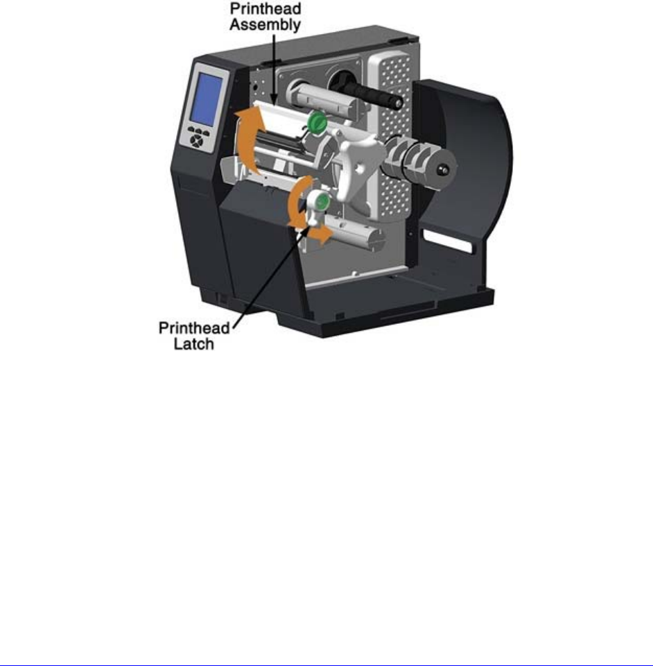
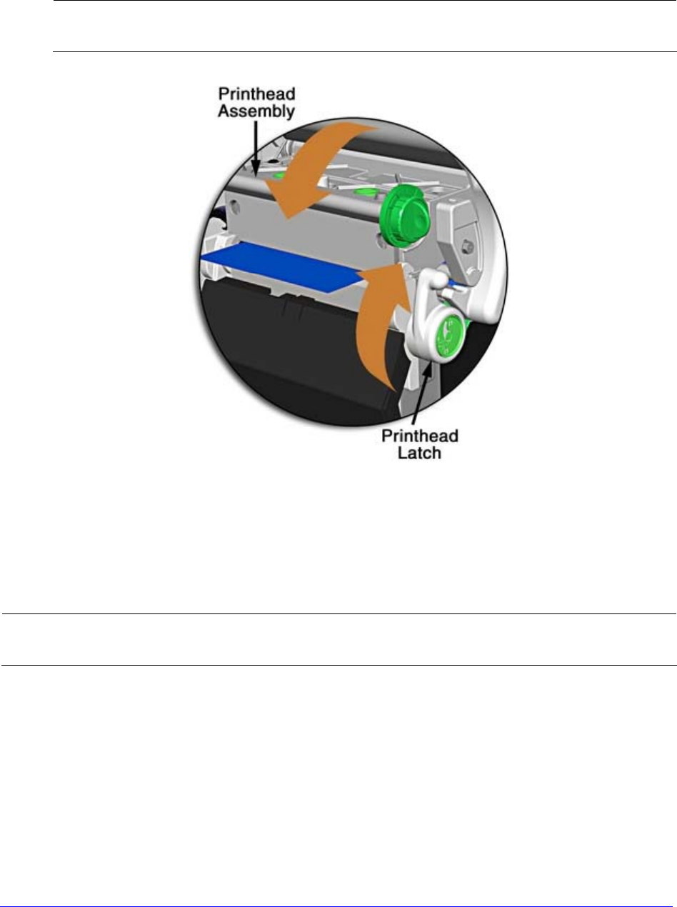
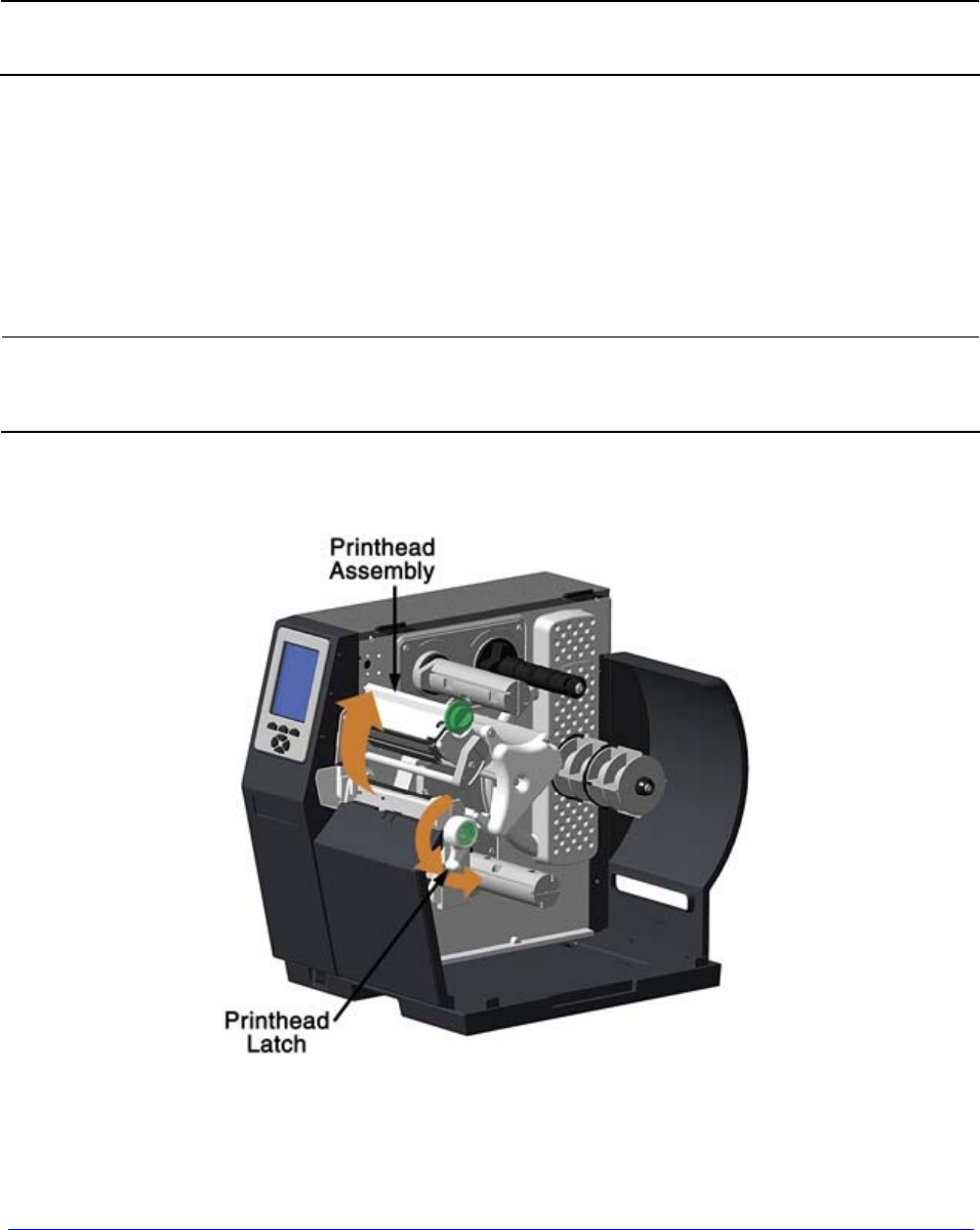
A. Raise the cover.
B. Rotate the Printhead Latch counterclockwise then raise the Printhead Assembly.
14 H-Class
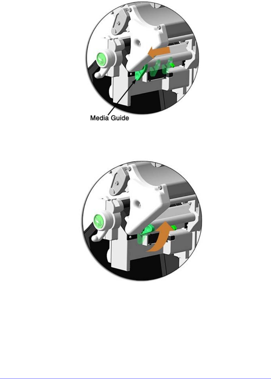
C. Slide the Media Guide outward.
D. Rotate the Media Guide upward.
E. Proceed according to the source of the media being installed:
• If using internally supplied (roll media) sources, see Section 3.1.1; or,
• If using externally supplied sources (e.g., boxed fanfold stock), see Section
3.1.2.
H-Class 15
3.1.1 Internal Media Sources
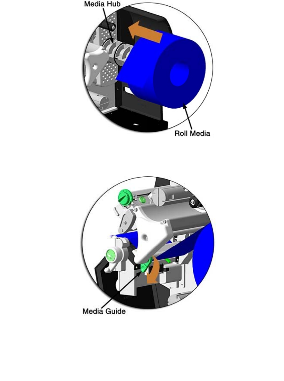
A. Slide Roll Media completely onto the Media Hub.
B. Route the media under the Media Guide Extrusion then out the front of the printer,
as shown.
C. Rotate the Media Guide into the DOWN position and then slide the guide inward until
it rests lightly against the edge of the media.
16 H-Class
D. If loading media for the first time, or if switching media types, widths, or
configurations, position the Media Sensor as detailed in Section 3.2; otherwise, go to
Step E.
If loading thermal transfer media, also load ribbon; see Section 3.3.
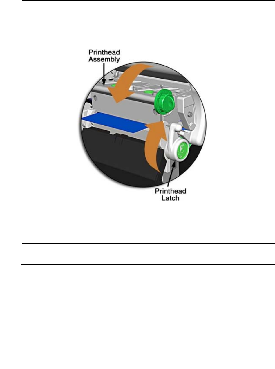
E. Lower the Printhead Assembly then rotate the Printhead Latch completely clockwise.
F. Close the cover. With READY displayed, press and hold the FEED Key until at least
one gap (or mark) advances; see Section 3.4.
If your media is less than the width of the printhead, adjust the Leveling
Cam; see Section 5.4.1.
H-Class 17
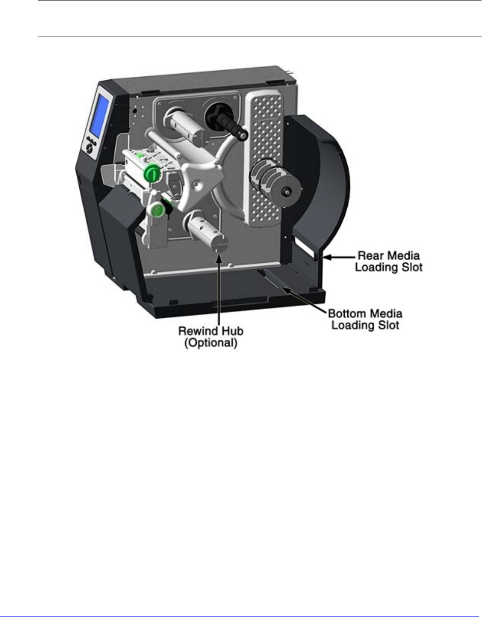
3.1.2 External Media Sources
A. Place the media supply (box or roll) parallel to and in-line with the Rear Media
Loading Slot or Bottom Media Loading Slot, in a position that will not cause the
media to twist or turn as it feeds from the source.
If loading reflective media, be sure that the material enters the printer with
the black marks facing down.
B. Route the media into the printer through the Rear Media Loading Slot or Bottom
Media Loading Slot, and if equipped over the Rewind Hub.
C. Route the media under the Media Guide Extrusion then out of the printer, as shown
in the previous section.
D. Rotate the Media Guide into the DOWN position and then slide the guide inward until
it rests lightly against the edge of the media, as shown in the previous section.
18 H-Class
E. If loading media for the first time, or when switching media types, widths, or
configurations, position the Media Sensor as detailed in Section 3.2; otherwise, go to
Step F.
If loading thermal transfer media, also load ribbon; see Section 3.3.
F. Lower the Printhead Assembly then rotate the Printhead Latch completely clockwise.
G. Close the cover. With READY displayed, press and hold the FEED Key until at least
one gap (or mark) advances; see Section 3.4.
If your media is less than the width of the printhead, adjust the Leveling Cam; see
Section 5.4.1.
H-Class 19
3.1.3 Rewinding Media
When equipped with the Internal Rewind option, outputs can be rewound or, with the
addition of a Peel and Present option, dispensed automatically for application. If equipped,
follow the instructions below to begin using the Internal Rewinder:
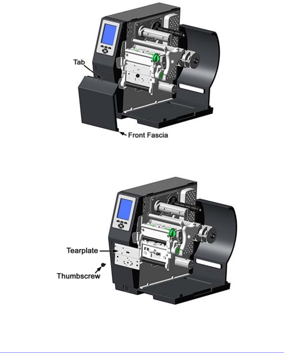
A. Press down on the Tab then pull outward to remove the Front Fascia.
B. Remove Thumbscrew and Tear Plate.
20 H-Class
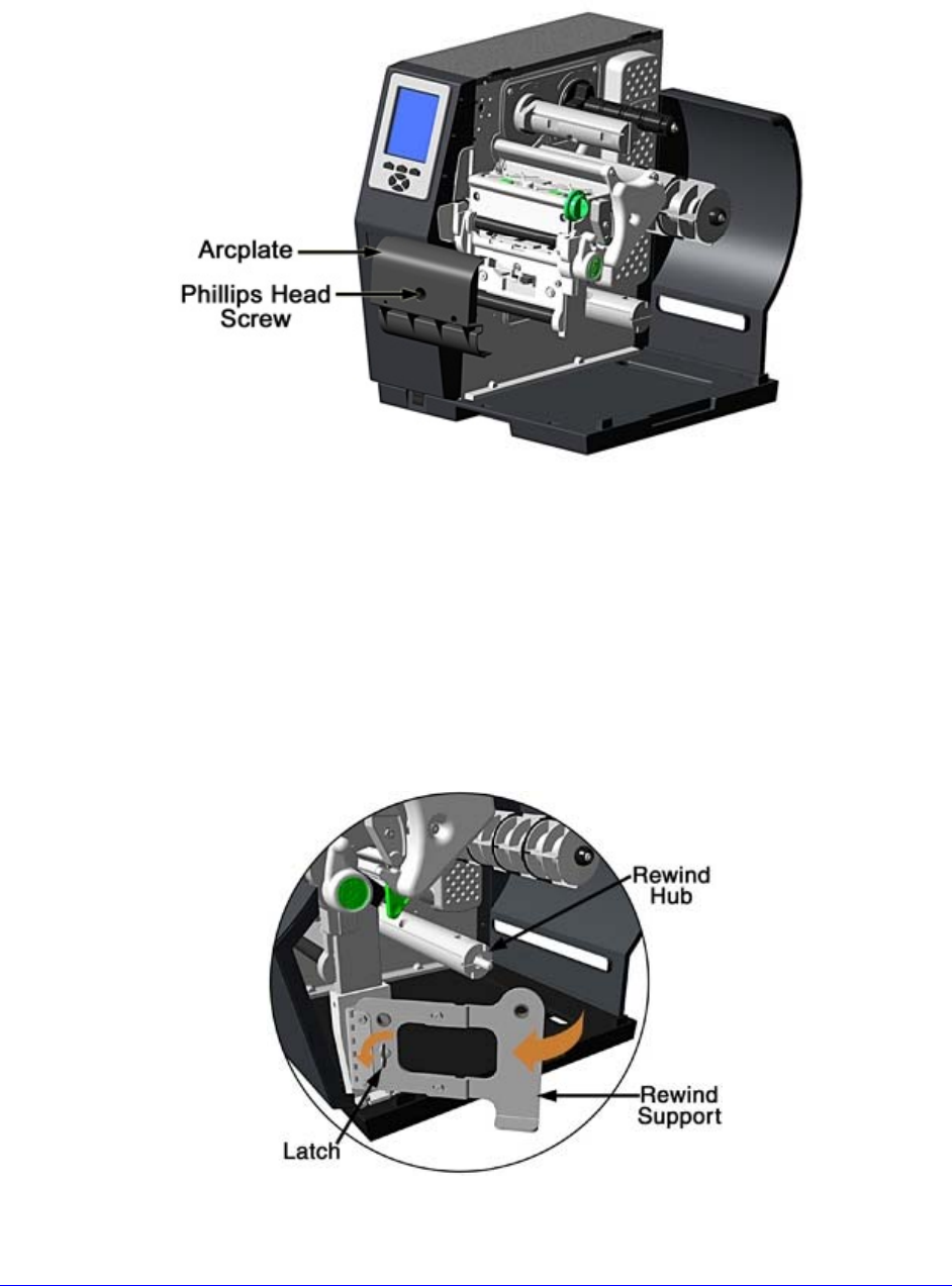
C. Place the Arcplate on the front of the printer (as shown below) and tighten the
Phillips Head Screw to secure it; or, to use the Peel and Present option attach that
device.
D. Proceed according to your application:
• To rewind labels onto an empty media core (tall models only), go to Step E.
• To dispense labels using a Peel and Present option, refer to the instructions
included with that option.
E. H-8308X users (all others go to Step F), rotate the latch 1/4 turn counterclockwise to
release the Rewind Support from the Rewind Hub then swing the Rewind Support
outward.
H-Class 21
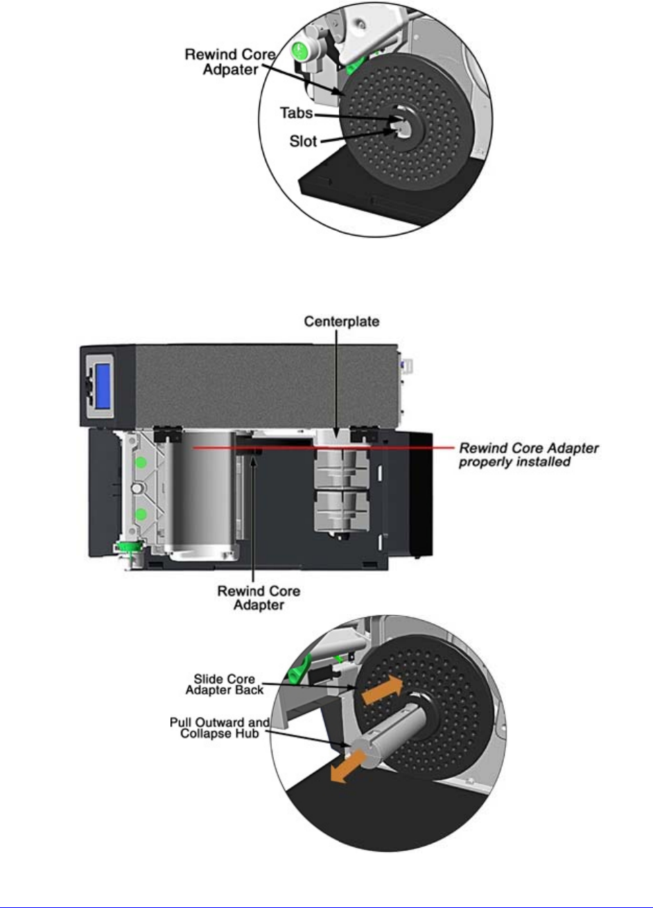
F. Align the Tabs on the Rewind Core Adapter to the Slots in the hub, and then slide the
Rewind Core Adapter onto the middle of the hub.
G. Grasp the end of the hub and, while pulling outward, squeeze the hub together until
it collapses then slide Rewind Core Adapter toward the Centerplate until it locks in
place.
22 H-Class
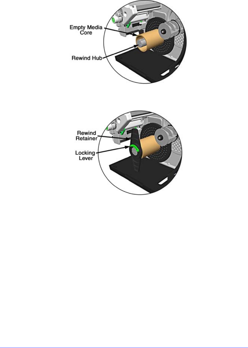
H. Slide an Empty Media Core (3” diameter) onto the Rewind Core Adapter.
I. Slide the Rewind Retainer into the Empty Media Core then close the Locking Lever.
J. H-8308X users (all others go to Step K), close the Rewind Support then rotate the
latch 1/4 turn clockwise to lock the Rewind Support.
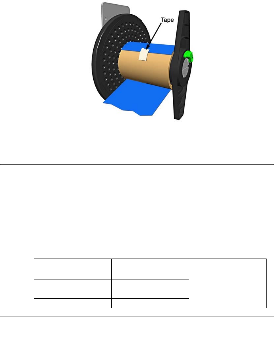
K. With label stock installed as described in Loading Roll Media, repeatedly press the
FEED Key until about 20 inches (50 cm) of media has been output.
H-Class 23
L. Route the media back into the printer and around the media core (as shown below)
then tape the leading edge to the media core. Rotate the Hub by hand to take up
any slack in the media. There should be at least 2 or 3 full wraps of the media on the
empty core before starting printing to ensure tight rewinded rolls.
M. Enter the menu, go to PRINTER OPTIONS / REWINDER, and select Enable. Exit the
menu and save your changes. (The rewinder will turn slowly for about 30 seconds to
tension the material and afterward rotate as labels are advanced.)
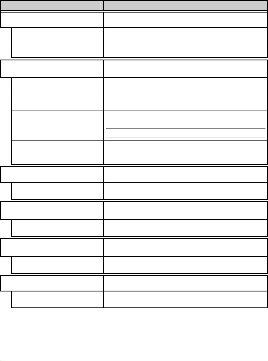
If dispensing narrow or small labels using a Peel and Present option, the following
settings may require adjustment:
• To maintain Top Of Form accuracy, it may be necessary (depending upon the
print speed) to reduce the torque; see PRINTER OPTIONS / REWINDER
ADJUSTMENT.
• To maintain image sizing accuracy, it may be necessary to adjust CUSTOM
ADJUSTMENTS / ROW ADJUST to a negative value.
For example, while peeling 2 inch wide by 1 inch long labels using an H-8308, the
following settings were used to maintain accuracies; your results may vary:
Print Speed (IPS) Rewinder Adjustment Row Adjust
2 -30%
4 -20%
6 -10%
8 -10%
-40 Dots
24 H-Class
Unloading the Internal Rewinder
To unload the Internal Rewinder, open the Locking Lever, remove the Rewind Retainer, and
slip the roll of labels (and core) off the Rewind Core Adapter.
Removing the Adapter Core
To switch from label rewinding to label peeling, remove the Rewind Core Adapter as follows:
A. Remove labels from the Internal Rewinder. Open the Rewind Support (8" wide
models only).
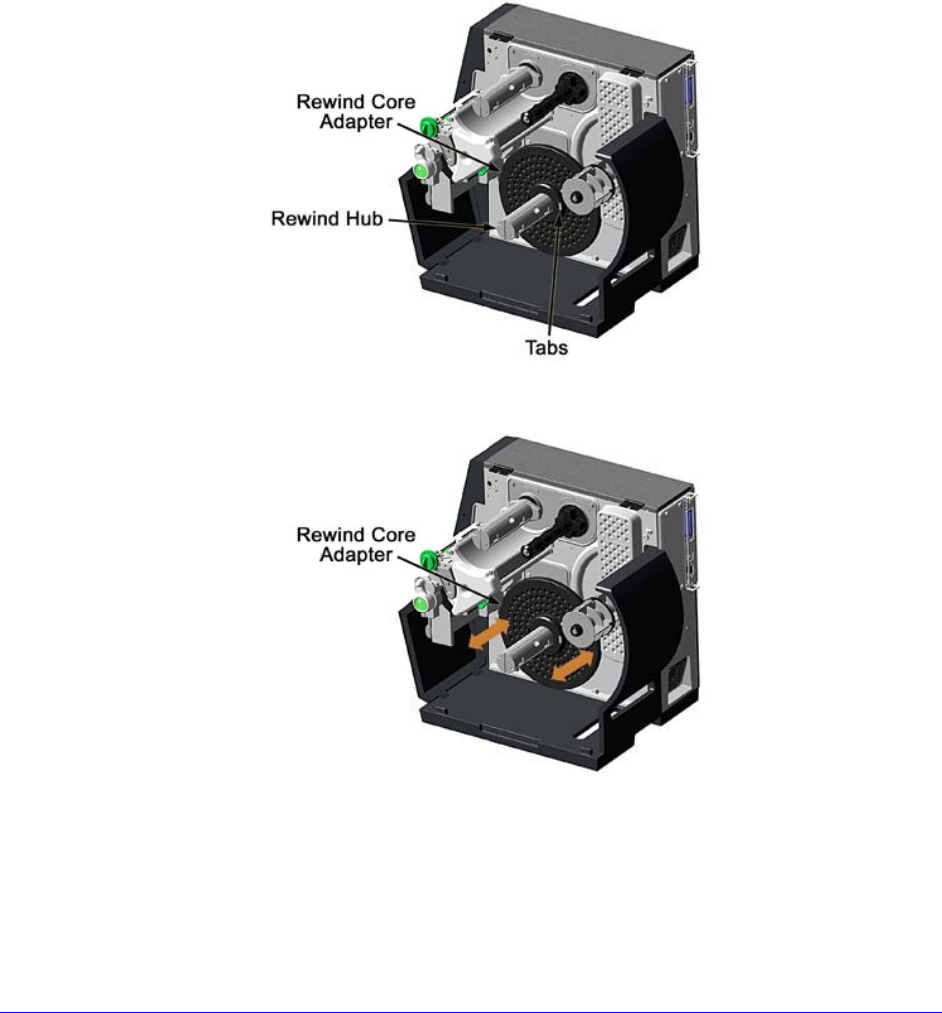
B. Rotate the Rewind Hub so that the Tabs are in a horizontal position, as shown.
C. Using both hands, grasp the Rewind Core Adapter and, with a gentle back-and-forth
rocking motion, pull the Rewind Core Adapter off the Rewind Hub.
H-Class 25
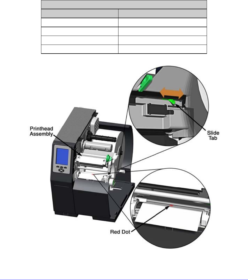
3.2 Media Sensor Adjustment
Position the Media Sensor for proper label detection:
A. Raise the Printhead Assembly. Note the Red Dot (see illustration below) that
identifies the location of the Media Sensor.
B. Grasp the Slide Tab to position the Red Dot according to the Media Type, as detailed
below.
Media Sensor Adjustment
Media Type Red Dot Position
Die-cut Centered over a label
Notched Centered over a notch
Reflective Centered over a black mark
Continuous Centered over the material
26 H-Class
C. Lower the Printhead Assembly then rotate the Printhead Latch completely clockwise.
D. If necessary, return to Media Loading to complete the setup process; otherwise,
close the cover. With READY displayed, press and hold the FEED Key until at least
one gap (or mark) advances; see Section 3.4.
If using REFLECTIVE or CONTINUOUS media, select the appropriate SENSOR TYPE;
see Section 4.2.1.
3.3 Ribbon Loading
Ribbon, required when printing on thermal transfer media, should be loaded as follows:
The use of ribbon slightly wider than the media (and liner, if any) is recommended
to help protect against abrasive wear.
A. Rotate the Printhead Latch counterclockwise then raise the Printhead Assembly.
H-Class 27
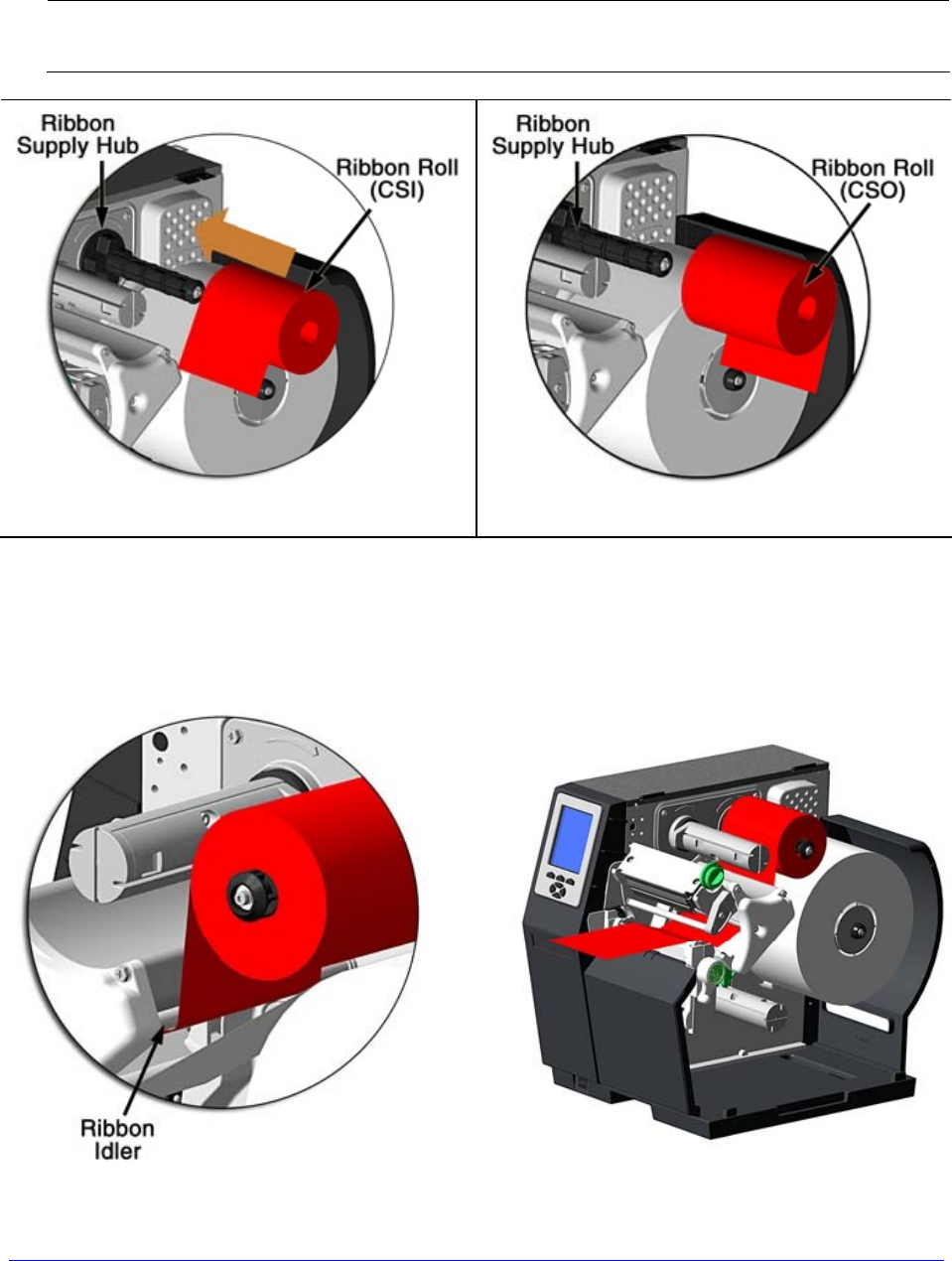
B. In the direction appropriate for the ribbon type being installed (Coated Side In or
Coated Side Out), slide a Ribbon Roll completely onto the Ribbon Supply Hub, as
shown below.
The coated (inked) side of the ribbon must face the media.
Coated Side In (CSI) Ribbon Coated Side Out (CSO) Ribbon
C. Route the ribbon under the Ribbon Idler then out the front of the printer.
28 H-Class
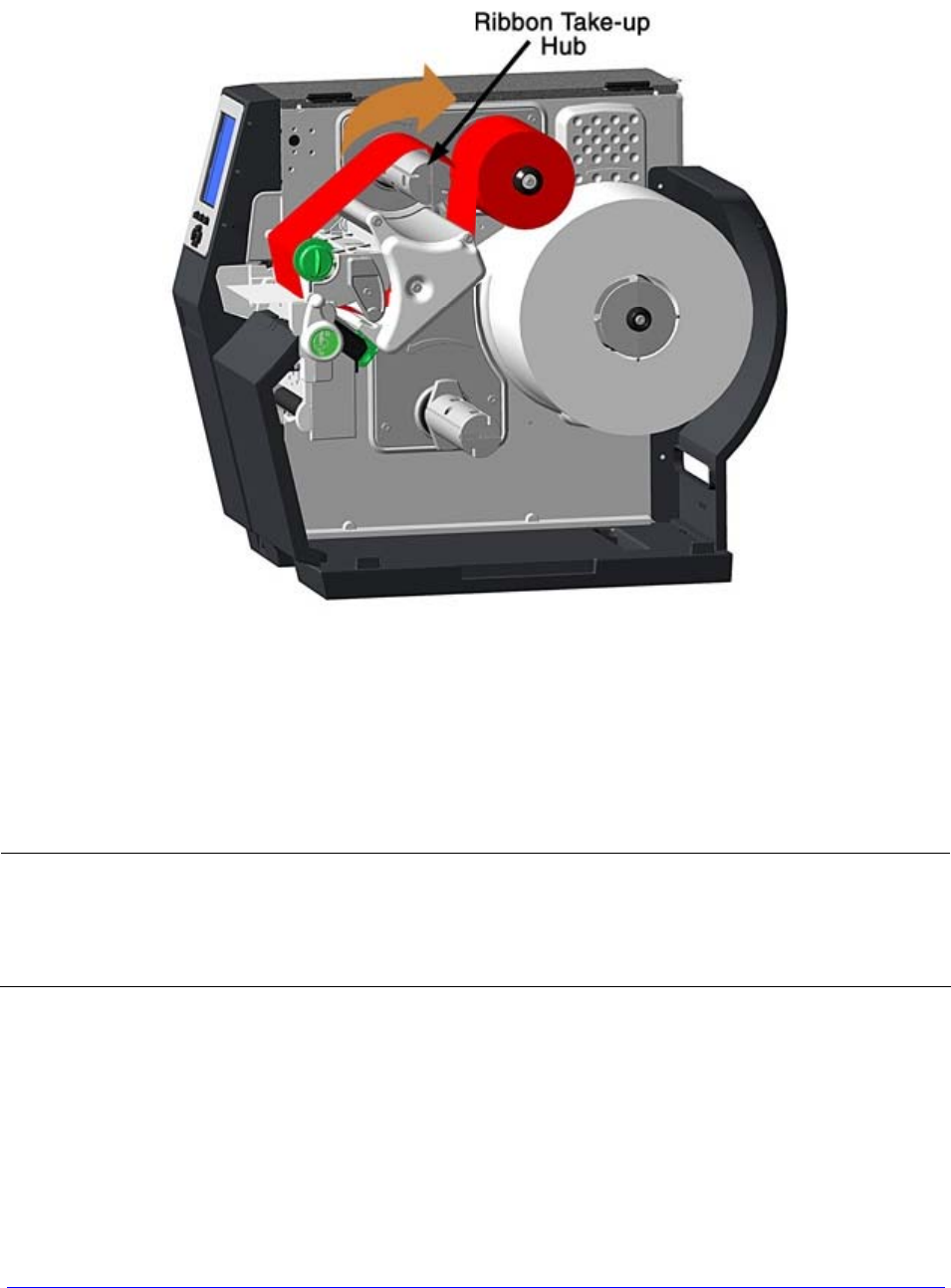
D. Route the ribbon up and around the Ribbon Take-Up Hub. Wrap the ribbon several
times clockwise (as indicated by the directional arrows) around the hub to secure it.
E. Lower the Printhead Assembly then rotate the Printhead Latch completely clockwise.
F. Close the cover. With READY displayed, press and hold the FEED Key until at least
one gap (or mark) advances; see Section 3.4.
Remove used ribbon when the Ribbon Roll is depleted: Pull the empty core from the
Ribbon Supply Hub. Grasp the used roll on Ribbon Take-Up Hub then pull and
squeeze to remove the spent ribbon. (To remove partially depleted rolls, cut the
ribbon then remove the roll as described above and discard any used ribbon.)

H-Class 29
3.4 Quick Calibration
Quick Calibration fine-tunes the printer for your media and should be performed during
initial setup or after switching media. With media installed and the sensor position adjusted,
perform calibration as follows:
With the printer idle, press and hold the FEED Key until one complete label advances
and then release the key.
Upon successful completion, CALIBRATION COMPLETED will be displayed followed by
READY.
• If the printer displays CANNOT CALIBRATE or stops feeding mid-label,
press and hold the FEED Key until two (or more) labels are advanced
before releasing the key. If this method also fails, see Media Sensor
Calibration (Section 5.2).
• WARNING LOW BACKING may appear if using notched media, or media
with a transparent liner; however, calibration was successful.
• Media containing large gaps may require a change in the PAPER EMPTY
DISTANCE; see Section 4.2.1.
3.5 Print Quality Controls
The printer provides flexible print controls. Of these, the amount of heat applied and the
rate of media movement will have the most effect on the printed output. Four settings are
available via PRINT CONTROL (see Section 4.2.2):
• HEAT sets the printing energy level, where lower amounts lighten the image and
higher amounts darken it;
• PRINT SPEED adjusts throughput, where slow speeds allow more time for energy
transfer and fast speeds may require more HEAT to achieve the desired contrast;
• CONTRAST fine-tunes the gray (shaded) areas of the image; and,
• DARKNESS fine-tunes the black areas of the image.
Heat and Speed commands from the host software may override the printer’s menu
setting; see HOST SETTINGS, Section 4.2.5.

30 H-Class
H-Class 31
4
Using the Control Panel
4.1 Layout
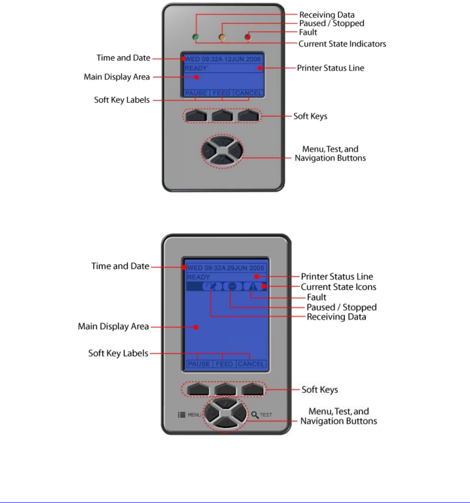
The Control Panel is an event-driven user interface composed of a graphics display and
keypad. Depending upon the size, the display layout and composition differs:
Small Display
Large Display
32 H-Class
4.1.1 The Display
The Display (see Section 4.1) provides printer information:
• Current time and date;
• Soft Key Labels to denote Soft Key functions;
• Label counts during batch jobs;
• When in Menu Mode, the System Menu;
• When in Test Mode, the Test Menu;
• Various messages; and,
• Real-time status notifications (see below).
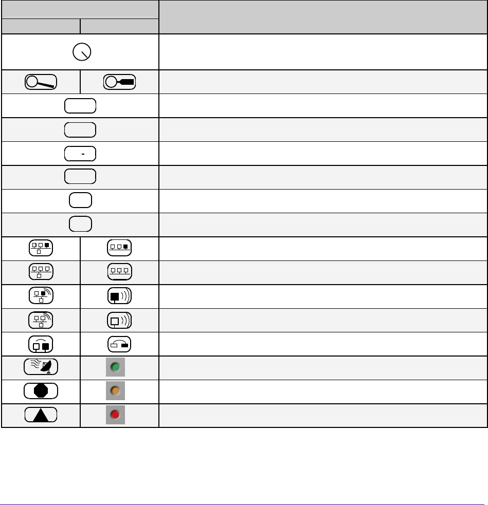
Display Size
Large Small Current State Icons*
Initialization, typically brief (but a damaged or invalid
printhead can delay the process).
M
ENU
Display large fonts; see Section 4.1.2.
DPL Input Mode – DPL; see Section 4.2.4.
LINE Input Mode – LINE; see Section 4.2.4.
PL Z Input Mode – PL-Z; see Section 4.2.4.
RFID RFID detected.
SD SD memory card detected.
USB
HOST USB memory (or keyboard) detected.
Wired network detected.
Server inaccessible.
WLAN associated with Access Point.
WLAN not associated with Access Point.
WLAN ADHOC Mode.
** Receiving data.
STOP
** Paused.
!
** Faulted, see Section 6.1.2.
*Also see ICON DESCRIPTIONS, Section 4.2.6.
**LED
H-Class 33
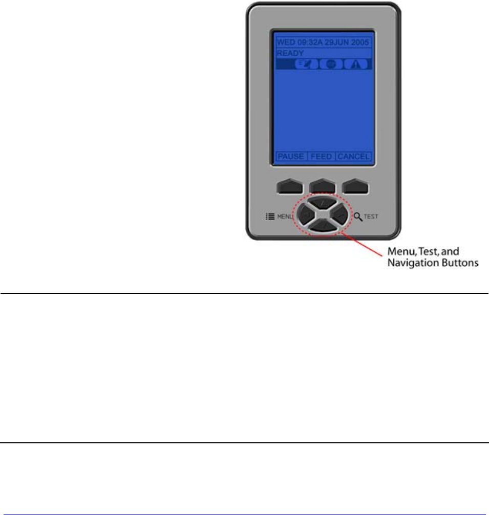
4.1.2 Keypad Functions
The Keys and Buttons of the Keypad (see Section 4.1) control printer functions:
• The Soft Keys are mode-dependent, changing functions as needed; and,
• The Navigation Buttons allow movement through and changes to menu items and
parameters, where the highlighted item is selectable (by pressing ENTER) or enabled
(e.g., a default setting).
Depending upon the printer’s state, many functions can be accessed by pressing (or
pressing and holding for various durations) the keys and buttons:
Keypad Functions
Function Printer
State Pressing Sequence Related
Section
Calibration, Empty Value Idle Long PAUSE & FEED 5.2
Calibration, RFID Option Idle Long FEED & TEST 4.2.3
Calibration, Quick Idle Long FEED 3.4
Display Contrast Adjustment Idle Hold MENU 4.1
Display large fonts Idle DOWN ARROW 4.1.1
Feed / Clear Fault Idle FEED 4.1
Pause Idle PAUSE 4.1
Print Label, Configuration Idle FEED & CANCEL 4.3.5
Print Label, Network Idle PAUSE, FEED, & CANCEL 4.2.5
Print Label, Quality Idle PAUSE & FEED 4.3.1
Reset, Soft Idle Long CANCEL 5.3.1
System Menu Idle MENU 4.2
Test Menu Idle TEST 4.3
Boot Mode Power-Up Hold PAUSE & TEST 5.7
Hex Dump Mode Power-Up Hold FEED 6.2
Reset, Level 1 Power-Up PAUSE & FEED 5.3.2
Reset, Level 2 Power-Up Hold PAUSE, FEED, & CANCEL 5.3.3
34 H-Class
4.2 The System Menu
The System Menu is composed of seven menu branches:
MEDIA SETTINGS
PRINT CONTROL
PRINTER OPTIONS
SYSTEM SETTINGS
COMMUNICATIONS
DIAGNOSTICS
MCL OPTIONS
To enter the System Menu, press the Menu
Button.
(This places the printer in Menu Mode,
taking it offline, halting the processing of
new data.)
• Prompts may appear before menu access is granted or before changes are
enacted; see Section 5.1.1.
• MENU MODE controls the access level; see Section 4.2.4.
• Host software commands may, in some cases, override menu settings; see
Section 4.2.5.
• Depending upon the firmware and options, some menu items may not be
present or may indicate NOT INSTALLED.
• In the descriptions below “” denotes a firmware default setting, while “ ”
denotes a setting only modifiable via the menu.
H-Class 35
4.2.1 Media Settings
The Media Settings menu contains label and ribbon settings, and printhead maintenance
selections.
Menu Item Details
MEDIA TYPE
Selects the printing method, where:
DIRECT THERMAL
Sets printing for heat reactive media.
THERMAL TRANSFER
Sets printing for media that requires ribbon to produce
an image.
SENSOR TYPE
Selects the Top Of Form (TOF) sensing method used
to determine the leading edge of the label, where:
GAP
Senses the gaps or notches in the media.
CONTINUOUS
Uses the LABEL LENGTH (see below) to determine the
TOF.
REFLECTIVE
Senses the reflective (black) marks on the underside
of the media.
LABEL LENGTH
Determines the length of the label when the SENSOR
TYPE is set to CONTINUOUS, where:
(0 – 99.99 in.)
04.00
Is the desired length of the format.
MAXIMUM LABEL LENGTH
Sets the distance that the printer will feed GAP or
REFLECTIVE media before declaring a TOF fault,
where:
(0 – 99.99 in.)
16.00
Is the length of travel to detect a TOF gap or mark.
This distance should be 2.5 to 3 times the label
length.
PAPER EMPTY DISTANCE
Sets the distance the printer will attempt to feed
media before declaring an Out Of Stock fault, where:
(0 – 99.99 in.)
00.25
Is the length of travel to detect the presence of media.
If using transparent or translucent media, this
setting should be longer than the label length.
LABEL WIDTH
Sets the maximum printable width. Objects extending
beyond this limit will NOT print, where:
(X.XX – X.XX in.)
X.XX
Is the maximum width; see Appendix B for the model
dependant default and range.

36 H-Class
Media Settings (continued)
Menu Item Details
RIBBON LOW OPTIONS
Defines the response when THERMAL TRANSFER is
selected and the ribbon supply diminishes, where:
RIBBON LOW DIAMETER
Sets the threshold that will trigger a Low Ribbon
Warning prompt, where:
(1.0 0 – 2.00 in.)
1.38
Is the outer diameter size of the roll.
PAUSE ON RIBBON LOW
Sets the printer to pause when the Ribbon Low
Diameter setting is met, where:
ENABLED
Forces you to press the PAUSE Key to proceed with the
print job.
DISABLED
Allows printing to continue until ribbon empty is
declared.
SENSOR CALIBRATION
Selects the method that is used to calibrate the media
sensor (see Section 5.2), where:
PERFORM CALIBRATION
Allows automatic calibration, where:
YES
Establishes the best values based on sampled
readings.
NO
Exits the menu item without changing the current
settings.
ADVANCED ENTRY
Sets the values via manual entry process, where:
PAPER SENSOR LEVEL
170 (0 – 255)
Establishes the threshold value for standard paper.
REFL PAPER LEVEL
020 (0 – 255)
Establishes the threshold value for reflective paper.
GAP SENSOR LEVEL
016 (0 – 255)
Establishes the threshold value for the gap/notch.
MARK SENSOR LEVEL
230 (0 – 255)
Establishes the threshold value for the reflective mark.
EMPTY SENSOR LEVEL
009 (0 – 255)
Establishes the threshold value for the empty
condition.
TRAN SENSOR GAIN
31 (0 – 31)
Establishes the sensitivity of the gap/notch sensor.
REFL SENSOR GAIN
13 (0 – 31)
Establishes the sensitivity of the reflective sensor.
H-Class 37
Media Settings (continued)
Menu Item Details
PRINTHEAD CLEANING
Controls printhead cleaning alerts and functions,
where:
CLEAN HEAD SCHEDULE
0 – 200 in.(* 1000)
000
Specifies the inch (or centimeter) count (multiplied by
one thousand) at which to clean the printhead. If this
count is exceeded three times, a Head Cleaning Fault
will occur.
Zero (000) disables this function.
CLEAN HEAD COUNTER
Indicates the number of inches (or centimeters) since
a cleaning was last initiated.
RESET COUNTER
Allows the Clean Head Schedule to restart the count,
where:
YES
Resets the CLEAN HEAD COUNTER.
NO
Exits the menu item without changing the current
setting.
CLEAN HEAD NOW
Allows cleaning to begin, where:
YES
Initiates the cleaning process and resets the Clean
Head Counter (see Section 5.5.1).
NO
Exits the menu item without cleaning.
38 H-Class
4.2.2 Print Control
The Print Control menu contains print quality, throughput and formatting functions:
Menu Item Details
HEAT
Controls the burn-time of the printhead (selectable as
“Heat” in most labeling programs), where:
(0 – 30)
10
Is the number based on duration, corresponding to
print darkness.
PRINT SPEED
Controls the rate of label movement during printing,
where:
XX.X in/sec Is the speed; see Appendix C for the model dependant
default and range.
Slower rates may be needed for detailed images,
while faster rates may require an increased HEAT
setting for sufficient energy transfer.
FEED SPEED
Controls the rate of label movement between printing
areas, where:
XX.X in/sec
Is the speed; see Appendix C for the model dependant
default and range.
REVERSE SPEED
Controls the rate of label movement during backup
positioning, where:
X.X in/sec
Is the speed; see Appendix C for the default and
range.
SLEW SPEED
Controls the rate of label movement between printing
areas when using the optional Applicator Interface
Card’s GPIO function, where:
XX.X in/sec
Is the speed; see Appendix C for the default and
range.
ROW OFFSET
Shifts the vertical SOP position on the label, where:
(0 – 99.99 in.)
00.00
Is the offset distance; see Section 7 for label details.
COLUMN OFFSET
Shifts the horizontal, left-justified SOP position to the
right without shifting the Label Width termination point
to the right, where:
(0 – 99.99 in.)
00.00
Is the offset distance; see Section 7 for label details.
H-Class 39
Print Control (continued)
Menu Item Details
PRESENT DISTANCE
Sets the label stop position, where:
(0 – 4.00 in.)
AUTO 0.00
Is the label output distance. The default setting (Auto)
configures this distance according to the positioning
requirements of the attached device (e.g., tear bar,
cutter, etc).
When set to 0.01 in., NONE is assumed; a zero (0)
positioning value will be used.
TOF PRECEDENCE
Allows an override of label format data when the form
length is exceeded, where:
DISABLED
Prints labels formats without TOF truncating.
ENABLED
Ends the label at the next TOF, truncating any print
data that extends past this mark.
CUSTOM ADJUSTMENTS
Allows slight, printer-specific adjustments, where:
DARKNESS
32 (1 – 64)
Controls the printhead strobe time (see HEAT) to fine-
tune the solid areas of an image.
CONTRAST
32 (1 – 64)
Fine-tunes the gray areas of an image.
ROW ADJUST
0000 (–XXX – XXXX DOTS)
Shifts the vertical SOP position to fine-tune ROW
OFFSET; see Appendix B.
If shifting in the negative direction, modify
PRESENT ADJUST (below) by the same amount.
COLUMN ADJUST
000 (–XXX – XXX DOTS)
Shifts both the horizontal SOP position and the LABEL
WIDTH termination point to the right to fine-tune
COLUMN OFFSET; see Appendix B.
PRESENT ADJUST
000 (–XXX – XXXX DOTS)
Adjusts the label stopping position to fine-tune
PRESENT DISTANCE; see Appendix B.
40 H-Class
4.2.3 Printer Options
The Printer Options menu contains module, file handling, and option functions:
Menu Item Details
MODULES
Controls memory handling functions, where:
DIRECTORY
Allows viewing and printing of available space and file
types (including plug-ins) present on a module. Only
detected modules will be listed, and selecting ALL will
display all results; see Appendix A.
PRINT FILE
Prints selections from listings of available files,
including .dlb, .dpl, .prn and .txt formats; see File
Handling Definitions, Appendix A.
PROCESS FILE
Processes a selected file for use by the printer; see File
Handling Definitions, Appendix A.
Formats a selected module; see Appendix A. FORMAT MODULE
FORMAT MODULE will erase all data in the
selected module.
DELETE FILE
Deletes a file from a list of available files; see File
Handling Messages, Appendix A.
Protected modules will not be displayed, and
space will not be recovered until packed.
COPY FILE
Selects from a list of available files and prompts for
the destination module before copying; see File
Handling Messages, Appendix A.
UNPROTECT MODULE
Selects from a list of available modules then prompts
regarding the unprotect attempt; see File Handling
Messages, Appendix A.
H-Class 41
Printer Options (continued)
Menu Item Details
PRESENT SENSOR
Controls the Present Sensor or the Peel and Present
option, where:
MODE
Sets the detection method and response of the printer,
where:
DISABLED
Disables the option.
AUTO
Detects, enables, and sets the label stop location for
the sensor option; if not detected, the option will be
ignored.
ENABLED
Enables and sets the label stop location for the option;
if not detected, a fault will be generated.
RETRACT DELAY
Programs a time delay for the retraction of the next
label in the print process, where:
(1 – 255 x10mS)
070
Is the duration, times 10 milliseconds.
CUTTER
Controls the Cutter option, where:
MODE
Sets the detection method and response of the printer,
where:
DISABLED
Disables the option.
AUTO
Detects, enables, and sets the label stop location for
the cutter; if not detected, the option will be ignored.
ENABLED
Enables and sets the label stop location for the cutter;
if not detected, a fault will be generated.
CUT BEHIND
Allows a number of small labels to queue before a cut
is performed, increasing throughput, where:
This mode can be used without a cutter to allow
the presentation of an extra label, with retraction
occurring upon the next job or feed operation.
(0 – 2)
0
Is the queue number.
After a fault or unknown label position, a leading
edge cut will be performed to ensure against extra
length on the first label; otherwise, cutting will
occur only as specified.
42 H-Class
Printer Options (continued)
Menu Item Details
SCANNER
Controls the Linear Scanner option (see the Class
Series 2 Programmer’s Manual for bar code
applicability), where:
MODE
Sets the detection method and response of the printer,
where:
DISABLED
Disables the option.
AUTO
Detects and enables the scanner; if not detected, the
option will be ignored.
ENABLED
Enables the scanner; if not detected, a fault will be
generated.
BARCODES
Specifies the bar code type(s) for scanning, where:
Enabling only the types to be checked helps
maximize throughput.
CODE 39
IATA
CODABAR
INTERLEAVED 2 OF 5
INDUSTRIAL 2 OF 5
CODE 93
CODE 128
MSI/PLESSEY
EAN(13/8)
EAN(13/8)+2
EAN(13/8)+5
UPC(A/E)
UPC(A/E)+2
UPC(A/E)+5
Is / are the bar code type(s) to be checked; see the
Class Series 2 Programmer’s Manual for symbology
details.
BARCODE COUNT
Specifies the number of bar codes per label then
generates a fault if the number present is incorrect,
where:
(0 - 99)
00
Sets the number of bar codes to count, where 00
(Auto Mode) allows a variable number.
If bar codes are bitmaps, enter the minimum
number to be read on each label (check your
software application if questioning the bar code
generation method).
H-Class 43
Printer Options (continued)
Menu Item Details
MIN READABLE HEIGHT
Ensures bar code integrity by setting a minimum
distance for identical decodes, where:
DISABLED Uses REDUNDANCY LEVEL to ensure bar code
integrity.
1/16 – ½ in.
(1.5 – 12.5 mm)
Sets the read height (e.g., a setting of ¼ requires .25
inches of the bar code height be 100% readable).
This distance should not exceed 50% of the
measured bar code height.
REDUNDANCY LEVEL
Ensures bar code integrity by specifying a consecutive
number of identical decodes, where:
(1X – 6X)
3X
Sets the read count (e.g., a 3X setting requires three
identical decodes to pass).
High redundancy rates and fast print speeds can
cause erroneous failures when scanning small or
multiple bar codes.
AUTO Uses MIN READABLE HEIGHT to ensure bar code
integrity.
IGNORE NO DATA
Allows an override of the verification function, where:
DISABLED
Checks for correct bar code data in the bar code(s).
ENABLED
Ignores the data present in the bar code(s).
SET DEFAULTS
Allows the scanner default values to be restored,
where:
YES
Restores the default settings.
NO
Exits the menu item without changing the current
settings.
44 H-Class
Printer Options (continued)
Menu Item Details
RFID
Controls the RFID option, where:
If not detected, this selection will result in a
DISABLED message.
RFID MODULE
Sets the mode of RFID operation, where:
DISABLED
Disables the option.
HF
Selects the High Frequency (13.56 MHz) option.
UHF MULTI-PROTOCOL
Selects the Ultra High Frequency (868-956 MHz)
option.
RFID POSITION
Sets the RFID encoding position, where:
(1.10 - 4.00 in.)
1.10
Is the inlay location (as referenced from the leading
edge of the tag moving forward through the printer),
where 0.00 uses the print position to encode tag and
values greater use the present position (subject to
change).
HF SETTINGS
Sets the HF encoding parameters, where:
TAG TYPE
Selects the HF tag type, where:
ISO 15693
TI
PHILIPS
ST LRI512
ST LRI64
Is the type to be encoded.
AFI VALUE
Sets the Application Family Identifier value, where:
(00 – FF)
00
Is the hex value.
AFI LOCK
Locks the Application Family Identifier value, where:
ENABLED
Is write-protected.
DISABLED
Is not protected.
H-Class 45
Printer Options (continued)
Menu Item Details
DSFID VALUE
Sets the Data Storage Format Identifier value, where:
(00 – FF)
00
Is the hex value.
DSFID LOCK
Locks the Data Storage Format Identifier value,
where:
ENABLED
Is write-protected.
DISABLED
Is not protected.
EAS VALUE
Selects the Electronic Article Surveillance value,
where:
(00 – FF)
00
Is the hex value.
AUDIO INDICATOR
Controls the buzzer, where:
ENABLED
Allows sound.
DISABLED
Inhibits sound.
ERASE ON FAULT
Controls tag erasure if errors are detected, where:
ENABLED
Erases data.
DISABLED
Retains faulty data.
UHF SETTINGS
Sets the UHF encoding parameters, where:
TAG TYPE
Selects the tag type, where:
EPC 0
EPC 0+ MATRICS
EPC 0+ IMPINJ
EPC 1
UCODE EPC 1.19
EM 4022/4222
GEN 2
Is the type to be encoded.
46 H-Class
Printer Options (continued)
Menu Item Details
TAG DATA SIZE
Sets the tag data size, where:
96-BIT
Selects 96 bits (24 hexadecimal characters or 12
ACSII characters).
64-BIT
Selects 64 bits (16 hexadecimal characters or 8 ACSII
characters).
POWER ADJUST
Adjusts the applied power, where:
(-04 04)
000
Is the power level, in 1.0 dBm increments.
KILL CODE
Sets the code to permanently deactivate the tag,
where:
00 00 00 00
Is the code, in the form B3, B2, B1, B0.
ACCESS CODE
Sets the code to protect tag memory contents, where:
00 00 00 00
Is the code, in the form B3, B2, B1, B0.
GEN 2 LOCK ACTION
Sets the lock for Gen 2 tags, where:
NONE
Does not lock the tag.
PERMALOCK
Locks data permanently.
PWD-READ/WRITE
Locks data with password-protection for writing data.
BOTH
Allows both Permalock and PWD-Lock to be used.
PAD/TRUNC. EPC DATA
Allows padding or truncating of data with nulls
(represented as “00”) in order to fit the selected EPC
Tag Data Size, where:
DISABLED
Does not pad or truncate data.
LEADING
Adds nulls to the front (left) of the data if less than the
size, or cuts the data if greater.
TRAILING
Adds nulls to the end (right) of the data if less than
the size, or cuts the data if greater.
H-Class 47
Printer Options (continued)
Menu Item Details
LOCK AFTER WRITE
Allows the tag to be locked after programming, where:
ENABLED
Locks the tag.
DISABLED
Does not lock the tag.
RETRY ATTEMPTS
Sets the number of retry attempts, where:
(0 - 9)
3
Is the retry count before a fault is declared.
PERFORM CALIBRATION
Allows the printer to establish the tag to transducer
distance and nominal power setting, where:
YES
Initiates the process; CALIBRATING RFID will be
displayed as media is scanned for the tag location and
power, followed by TOF positioning and the
operational results where, if successful, the database
parameters will be updated.
NO
Exits the menu item without calibration.
SET DEFAULTS
Allows the RFID default values to be restored, where:
YES
Restores the default settings.
NO
Exits the menu item without changing the current
settings.
48 H-Class
Printer Options (continued)
Menu Item Details
GPIO PORT
Controls the optional Applicator Interface Card’s GPIO
function, where:
GPIO DEVICE
Sets the option to work with a specific device type,
where:
DISABLED
Disables the option.
APPLICATOR
Enables parameters for related label applicator
functions:
• Completion upon last SOP, de-asserts Data Ready
(DRDY);
• FEED allowed at any time; and,
• DRDY upon PAUSE.
APPLICATOR 2
Enables parameters for alternate label applicator
functions:
• Completion upon 1 msec. overlap of Data Ready
(DRDY) and End of Print (EOP);
• DRDY signal end inhibits FEED; and,
• De-asserts DRDY upon PAUSE or FAULT.
BARCODE VERIFIER
Enables the parameters for bar code verifier functions.
START OF PRINT
Selects the type of input signal required to initiate
printing, where:
LOW PULSE
Triggers printing with a low pulse.
HIGH PULSE
Triggers printing with a high pulse.
ACTIVE LOW
Triggers printing with a low signal.
ACTIVE HIGH
Triggers printing with a high signal.
EDGE
Triggers printing with a signal edge transition.
H-Class 49
Printer Options (continued)
Menu Item Details
END OF PRINT
Sets the type of output signal generated to indicate
EOP, where:
LOW PULSE
Outputs a low pulse upon completion.
HIGH PULSE
Outputs a high pulse upon completion.
ACTIVE LOW
Outputs a logic low upon completion.
ACTIVE HIGH
Outputs a logic high upon completion.
RIBBON LOW
Sets the low ribbon signal (as determined by RIBBON
LOW OPTIONS; see Section 4.2.1), where:
ACTIVE LOW
Outputs a logic low when the roll size reaches the
setting.
ACTIVE HIGH
Outputs a logic high when the roll size reaches the
setting.
SLEW ENABLE
Selects the type of input signal required to initiate
label slew, where:
STANDARD
Triggers slew with a low signal.
LOW PULSE
Triggers slew with a low pulse.
HIGH PULSE
Triggers slew with a high pulse.
ACTIVE LOW
Triggers slew with a low signal.
ACTIVE HIGH
Triggers slew with a high signal.
BACKUP LABEL
Determines reverse label motion when the GPIO option
is installed and enabled, where:
DISABLED
Disables backup.
ACTIVE LOW Triggers backup with a low signal.
ACTIVE HIGH
Triggers backup with a high signal.
50 H-Class
Printer Options (continued)
Menu Item Details
ERR ON PAUSE (APP2)
Sets the output when a service required fault occurs
(Applicator Interface Card Type 2 equipped only),
where:
ENABLED
Enables the output signal.
DISABLED
Disables the output signal.
REWINDER
Controls the Powered Internal Rewinder option, where:
MODE
Sets the detection method and response of the printer,
where:
DISABLED
Disables the option.
AUTO
Enables the rewinder only when a Peel and Present
option is installed; however, no error will be generated
when the Peel and Present option is not attached.
(Upon power-up, the rewinder will turn slowly to
tension the material.)
ENABLED
Enables the rewinder and generates an error if it
cannot be detected. Upon power-up, the rewinder will
turn slowly (for about 30 seconds) to tension the
material and then whenever labels move.
REWINDER ADJUSTMENT
Adjusts the amount of rewinding tension to minimize
TOF registration drift (sometimes evident when using
narrow media), where:
(-30 – 15 %)
00
Decreases or increases the nominal torque by the
percentage selected.
H-Class 51
4.2.4 System Settings
The System Settings menu contains operating, control, and formatting functions:
Menu Item Details
MENU MODE
Sets the menu access level, where:
USER MENU
Accesses limited basic menu items.
ADVANCED MENU
Accesses all menu items.
CONFIGURATION FILE
Controls the creation, storage, and recall of printer
configuration files (see Appendix E), where:
RESTORE AS CURRENT
Lists the files available and then, after selection,
reconfigures the printer according to that file.
SAVE SETTING AS
Saves the effective printer configuration to a named
file of up to nineteen characters.
DELETE FILE
Lists the files available and then after selection,
removes that file from memory.
An active file cannot be deleted.
FACTORY SETTING FILE
Lists the files available, and then after selection, that
file will be restored whenever a Level One reset is
performed; see Section 5.3.2.
INTERNAL MODULE
Allocates a number of 1KB memory blocks to the
internal memory module; where:
(XXX – XXXX KB)
1024
Is the memory allocation; see Appendix A.
DEFAULT MODULE
Designates the storage module when no memory
location is specified; where:
G
D
Is the module; see Appendix A for availability.
SCALEABLE FONT CACHE
Configures the number of 1KB memory blocks for the
scalable font engine; where:
(XXX – XXXX KB)
0511
Is the memory allocation; see Appendix A for
availability.
SINGLE BYTE SYMBOLS
Sets the code page used for single byte fonts, where:
PC▪850 MULTILINGUAL
Is the selected code page. (See the Class Series 2
Programmer’s Manual for a complete listing.)
52 H-Class
System Settings (continued)
Menu Item Details
DOUBLE BYTE SYMBOLS
Selects the code page (see the Class Series 2
Programmer’s Manual) used for the ILPC option
(unless otherwise specified), where:
JIS
Selects Japanese Industry Standard.
SHIFT JIS
Selects Shift Japanese Industry Standard.
EUC
Selects Extended UNIX Code.
UNICODE
Selects Unicode (including Korean).
GB
Selects Government Bureau Industry Standard,
Chinese (PRC).
BIG 5
Selects Taiwan encoded.
TIME AND DATE
Sets the time and date, where:
SET HOUR
06:30 AM
01 FEB 2005
Enters the time and date information.
MEDIA COUNTERS
Displays and controls various internal counters,
where:
ABSOLUTE COUNTER
Are the total inches printed and the set date. (Non-
resettable)
PRINTHEAD COUNTER
Is the total number of inches printed. (Non-resettable)
RESETTABLE COUNTER
Are the inches printed and the last reset date.
RESET COUNTER
Returns the RESETTABLE COUNTER to zero.
PRINT CONFIGURATION
Prints current database information; see Section 4.3.5.
CONFIGURATION LEVEL
Displays the hardware and software levels of the
printer, where:
This data is also provided on the Configuration
Label; see Section 4.3.5.
H-Class 53
System Settings (continued)
Menu Item Details
Identifies the unique key number of the printer, in the
form:
vvvv-cwxx-yyyyyy-zzz
Where:
vvvv –
Represents the printer model number.
cwxx –
Represents the hardware and software
levels, where:
c – Is the printer class.
w – Is the main board hardware level.
xx – Is the software feature level:
10 = Standard DPL
20 = Internal CG Times Font
Increases beyond the feature level
require authorization.
yyyyyy –
Is a manufacturing date code.
PRINTER KEY
zzz –
Is a unique time stamp.
APPLICATION VERSION
Displays the firmware program number, version, and
date.
BOOT LOADER
Displays the Boot Loader version and date.
UPGRADE PRINTER CODE
0 0 0 0 0 0
Upgrades the printer to the corresponding features
level with the correct code entry (where authorization
may be required).
UNLOCK FEATURE
0 0 0 0 0 0
Unlocks a feature with the correct code entry.
SET FACTORY DEFAULTS
Returns the factory-programmed values or the Factory
Setting File values, where:
YES
Restores the default settings, or if selected the Factory
Setting File.
A reset will occur and, if no Factory Setting File is
used, all settings returned except CUSTOM
ADJUSTMENTS and calibrations.
NO
Exits the menu item without changing the current
settings.
54 H-Class
System Settings (continued)
Menu Item Details
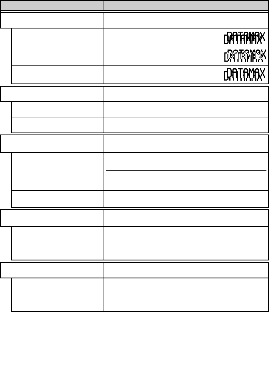
FORMAT ATTRIBUTES
Defines the way overlapping text, bar codes, and
graphics are printed, where:
TRANSPARENT
Prints intersecting areas, for example:
XOR
Obliterates intersecting areas, for
example:
OPAQUE
Overwrites intersecting areas with
those last formatted, for example:
LABEL ROTATION
Allows the label format to be flipped 180 degrees,
where:
ENABLED
Prints formats after 180° rotation.
DISABLED
Prints formats without rotation.
IMAGING MODE
Determines the process used to format labels, where:
MULTIPLE LABEL Formats multiple images, as memory permits, for the
fastest throughput.
Time stamps will indicate the moment of imaging
rather than printing.
SINGLE LABEL Formats an image only after a previous format has
been printed (for the most accurate time stamps).
PAUSE MODE
Allows interactive print control, where:
ENABLED
Prints only as the PAUSE Key is pressed.
DISABLED
Prints normally, without user intervention.
PEEL MODE
Allows the SOP signal to initiate (via the optional GPIO
port) the feeding of labels, where:
ENABLED
Feeds labels only after SOP is received.
DISABLED
Feeds labels regardless of SOP.
H-Class 55
System Settings (continued)
Menu Item Details
SECURITY
Allows menu password protection, where:
SELECT SECURITY
Enables or disables the security feature, where:
The default password must be changed to activate.
DISABLED
Accesses all areas.
SECURE MENU
Sets a password requirement for menu access.
MENU AND TEST
Sets a password requirement for menu and test
access.
ADVANCED MENU
Sets a password requirement for Advanced Menu
access.
After enabling this selection, return MENU MODE to
the USER MENU setting.
MODIFY PASSWORD
Modifies the security password, where:
YES
Allows entry of a four-digit password (after
confirmation).
The default password is 0000.
NO
Exits the menu item without changing the current
settings.
UNITS OF MEASURE
Sets the measurement standard of the printer, where:
IMPERIAL
Uses inches.
METRIC
Uses millimeters and centimeters.
56 H-Class
System Settings (continued)
Menu Item Details
INPUT MODE
Defines the type of processing that occurs when data
is received, where:
See the Class Series 2 Programmer’s Manual for
detailed information.
DPL
Processes data for standard DPL printing.
LINE
Processes data for Line Mode (template) printing.
PL-Z
Processes data for PL-Z printing.
AUTO
Identifies then activates the appropriate emulation
parser for the data.
Correct identification can be dependent upon the
HOST SETTINGS / HOST TIMEOUT (see Section
4.2.5). Also, extraneous characters may, in some
cases, render the data unrecognizable, thus
requiring manual selection of the mode.
USER LABEL MODE
Sets the printer to power-up as default, where:
ENABLED
Functions in standalone mode for quick access to user
defined formats; see Section 4.3.7.
This mode will remain active until disabled.
DISABLED
Functions in normal mode, awaiting commands from a
host.
DPL EMULATION
Allows legacy printer emulation, where:
Ignores label commands A, M, n & T; see the Class
Series 2 Programmer’s Manual for information.
STANDARD
Uses no legacy emulation, all commands recognized.
ALLEGRO
Emulates the Allegro®.
PRODIGY PLUS
Emulates the Prodigy Plus®.
PRODIGY
Emulates the Prodigy™.
H-Class 57
System Settings (continued)
Menu Item Details
COLUMN EMULATION
Allows the column dot count to be adjusted, where:
(XXX – XXX DOTS)
XXX
Is the printed number of dots per inch (or mm)
thereby reducing the width of the produced format;
see Appendix B.
No adjustment occurs at the default setting.
ROW EMULATION
Allows the row dot count to be adjusted, where:
(XXX – XXX DOTS)
XXX
Is the printed number of dots per inch (or mm)
thereby reducing or enlarging the length of the
produced format; see Appendix B.
No adjustment occurs at the default setting.
SOP EMULATION
Allows SOP functions with backward compatibility
when printing legacy model label formats, where:
Two labels will automatically feed to establish the
selected position.
DISABLED
Uses the standard print position.
110 (PRODPLUS)
Emulates the Prodigy Plus® print position.
220 (ALLEGRO)
Emulates the Allegro® print position.
250 (PRODIGY)
Emulates the Prodigy™ print position.
BACK AFTER PRINT
Determines media movement when a cutter, present
sensor, peel and present, or GPIO is enabled, where:
MODE
Repositions media, where:
DISABLED
Movement occurs only when the next label is ready to
print, minimizing edge curling.
ENABLED
Movement occurs according to BACKUP DELAY timing
after a cut, cleared sensor, or SOP to allow fastest
throughput.
BACKUP DELAY (1/50s)
Determines repositioning timing, where:
(0 – 255)
000
Is the specified lapse (in fiftieths of a second) between
new format processing and label retraction.
58 H-Class
System Settings (continued)
Menu Item Details
FONT EMULATION
Allows font substitution, where:
STANDARD FONTS
Prints using standard (internal) fonts.
CGTIMES
Prints using CG Times font.
USER ID S50
Prints using a downloaded font.
LABEL STORE
Determines the data content when retrieving stored
label formats, where:
STATE & FIELDS
Recalls the printer state (i.e., heat, speeds, etc.) and
the formatting commands for a stored label.
FIELDS ONLY
Recalls the formatting commands for a stored label.
MENU LANGUAGE
Selects the language for the System Menu and
Configuration Label, where:
Only resident languages will be selectable; see
Appendix D.
ENGLISH
Is standard.
DISPLAY SETTINGS
Determines the appearance of the items in the Main
Display Area of the LCD, where:
GRAPHIC DISPLAY MODE
Determines the magnification of the items, where:
STANDARD
Is the normal setting.
ENHANCED
Is the enlarged setting.
DISPLAY UNITS
Determines the displayed type of distance information,
where:
STANDARD
Displays the information according to the UNITS OF
MEASURE setting (see above).
IMPERIAL
Displays the information in inches.
METRIC
Displays the information in millimeters and
centimeters.
H-Class 59
System Settings (continued)
Menu Item Details
FAULT HANDLING
Determines the label disposition and user action if a
fault occurs, where:
LEVEL
Sets the printer response upon declaration of a fault,
where:
NO REPRINT
Stops printing and declares a fault. Then, following
correction of the problem, the FEED Key must be
pressed to clear the fault.
STANDARD
Stops printing and declares a fault. Then, following
correction of the problem, the FEED Key must be
pressed to clear the fault and reprint the label in
process.
VOID AND RETRY
Actions depend upon the RETRY COUNT:
• If the count has not been exceeded, VOID is printed
on the failed label and reprinting automatically
occurs;
• If the count has been exceeded, printing stops and
a fault message is displayed. Then, following
correction of the problem, the FEED Key must be
pressed to clear the fault and reprint the label in
process; or,
• If the CANCEL Key is pressed, reprinting is optional:
press NO to reprint; or, press YES to cancel the
reprint (and press YES again to cancel the batch.)
Linear Scanner or RFID required.
DELAYED SCAN FAULT Increases throughput when bar codes reside near the
trailing edge of the label (in the direction of FEED).
Linear Scanner or RFID required.
• If unreadable, the fault will occur after the next
label prints;
• The label immediately following a faulted label is
not scanned for errors; and,
• VOID AND RETRY and REPRINT are automatically
disabled; the job can only be cancelled.
VOID RETRY & CONT.
VOID is printed on a faulted label, with reprint
attempts occurring automatically, until the RETRY
COUNT has been exceeded and then that label will be
skipped (discarded) and printing will continue to the
next label in queue.
Linear Scanner or RFID required.
60 H-Class
System Settings (continued)
Menu Item Details
VOID DISTANCE
Sets the distance to print VOID on a faulted label,
where:
(0.10 to 2.00 in.)
0.50
Is the distance, measured from the trailing edge,
which establishes the text size.
VOID will not be printed if insufficient text space
exists or if the fault occurred after printing
completed. Also, the text can be customized; see
the Class Series 2 Programmer’s Manual.
RETRY COUNT
Sets the number of printing attempts before declaring
a fault, where:
(0 – 3)
1
Is the count.
Greater than 1 (one) counts are valid only when
Linear Scanner or RFID equipped.
BACKFEED ON CLEAR
Determines positioning after a fault is cleared, where:
ENABLED
Automatically positions the label.
DISABLED
No label positioning occurs, as the location is assumed
correct.
If reloading, you must place the media at the SOP
position.
SCL FONT BOLD FACTOR
Sets a scalable font boldfacing amount, where:
(1 – 36)
08
Is the setting, based on an incrementing scale where
eight (08) is nominal.
H-Class 61
4.2.5 Communications
The Communications menu contains interface port and host control functions:
Menu Item Details
SERIAL PORT A
Controls the RS-232 communications settings for
Serial Port A, where:
BAUD RATE
Sets the serial communication rate, where:
1200 BPS
2400 BPS
4800 BPS
9600 BPS
19200 BPS
28800 BPS
38400 BPS
57600 BPS
115000 BPS
Is the serial speed in Bits Per Second.
PROTOCOL
Sets the data flow control method (handshaking),
where:
BOTH
Uses XON/XOFF and CTS/DTR.
SOFTWARE
Uses XON/XOFF.
HARDWARE
Uses CTS/DTR.
NONE
Disables flow control.
PARITY
Sets word parity, where:
NONE
Uses parity.
ODD
Uses Odd parity.
EVEN
Uses Even parity.
DATA BITS
Sets Word length, where:
(7 – 8)
8
Is the number of bits in the word.
STOP BITS
Sets the stop bit count, where:
(1 – 2)
1
Is number of stop bits.
62 H-Class
Communications (continued)
Menu Item Details
SERIAL PORT C
Controls the settings for the optional Applicator
Interface COM C (J4) port, where the settings are the
same as those given for the SERIAL PORT A.
The maximum baud is 38.4K BPS.
SERIAL PORT D
Controls the settings for the optional Applicator
Interface COM D (J3) port, where the settings are the
same as those given for the SERIAL PORT A.
The maximum baud is 38.4K BPS.
PARALLEL PORT A
Controls the communications settings for Parallel Port
A, where:
PORT DIRECTION
Allows printer data to be returned to the host, where:
UNI-DIRECTIONAL
Returns no data (one-way communication).
BI-DIRECTIONAL
Returns data (compliant back-channel operation); see
Section 2.2.2 for cable requirements.
NIC ADAPTER
Controls the communications settings for the network
interface, where:
QUICK SETUP
Selects settings to configure basic Wired or WiFi
operations, where:
WIRED DHCP
Selects Wired operation, where:
NO Exits the menu item without changing the current
settings.
YES Returns the NIC Adapter to defaults then sets Wired
Discovery to “Enable” and Wireless to “Disable.”
H-Class 63
Communications (continued)
Menu Item Details
WLAN UNSECURED
Selects WiFi operation, where:
NO Exits the menu item without changing the current
settings.
YES Returns the NIC Adapter default values then sets
Discovery to “Enable,” SSID to “Any,” and WLAN
network type to “Infrastructure.”
WLAN ADHOC
Selects the DMXrfNetII default parameters, where:
NO Exits the menu item without changing the current
settings.
YES Restores WiFi defaults and initiates infrastructure
mode with an SSID of “Any.” All existing access point
associations will be deleted then established with the
closest available. (Useful when moving the printer to a
geographically distant location.)
SET FACTORY DEFAULTS
Returns the factory-programmed values, where:
NO
Exits the menu item without changing the current
settings.
YES
Restores the default settings.
WLAN
Controls the communications settings for the
DMXfNetII Card, where:
MODE
Selects between Wired or WiFi operation, where:
ENABLED
Enables the WiFi interface.
DISABLED
Enables the wired interface.
BSS ADDRESS
Specifies the static IP address of the WiFi bridge
module.
If DHCP is Enabled, this parameter will be ignored.
000.000.000.000
Is the address in standard octet format.
SIGNAL READINGS
Displays the WLAN signal and noise ratios.
IP ADDRESS
Specifies the static IP Address; where:
192.168.010.026
Is the address in standard octet format.
64 H-Class
Communications (continued)
Menu Item Details
SUBNET MASK
Specifies the static Subnet Mask Address, where:
255.255.255.000
Is the address in standard octet format.
GATEWAY
Specifies the network Gateway Address, where:
192.168.010.026
Is the address in standard octet format.
SNMPTRAP DESTINATION
Specifies the SNMP Trap Address, where:
000.000.000.000
Is the address in standard octet format where SNMP
traps will be sent when SNMP service is installed on
your receiver.
When zeroed, no traps are sent.
IP DISCOVERY
Controls IP Address discovery, where:
Broadcasts over the network at startup to receive
addresses from the responsible server. Manual
modifications to IP Address, Subnet Mask, or Gateway
are not allowed; and, if no server is found, the
specified static value will be used.
ENABLED
A server assigned IP address takes
precedence over any static address stored
in the interface.
DISABLED
Uses the stored static IP, Subnet Mask, and / or
Gateway Address.
SNMP
Allows management protocols, where:
ENABLED
Sends messages to SNMP-compliant devices.
DISABLED
Sends no messages.
ADVANCED
Sets advanced networking functions and parameters,
where:
TELNET
Sets Telnet protocol to transfer data, where:
ENABLED
Allows Telnet.
DISABLED
Disables Telnet.
H-Class 65
Communications (continued)
Menu Item Details
FTP
Sets File Transfer Protocol to transfer data, where:
ENABLED
Allows FTP.
DISABLED
Disables FTP.
MTU
Sets the Maximum Transmission Unit packet size,
where:
(512 - 65515)
01500
Is the packet size, in bytes.
GRATUITOUS ARP
Sets the Address Resolution Protocol notification rate,
where:
(0 - 2048)
0000
Is the time, in minutes.
PORT NUMBER
Sets the network communications port, where:
(1 - 65535)
09100
Is the Port Number.
TCP KEEPALIVE Allows monitoring of an open connection to detect any
disconnects not properly closed, including reset access
points and unplugged printers, where:
ENABLED
Keeps monitoring active.
DISABLED
Closes such a disconnection after 2.5 minutes.
DUPLEX CAPABILITY
Sets the communication capability for the Wired
network, where:
AUTO-NEGOTIATE
Automatically selects the best type.
100BASET HALF
Selects 100 Mbit/s half duplex (in both directions, one
way at a time) operation.
100BASET FULL
Selects 100 Mbit/s full duplex (in both directions,
simultaneously) operation.
10BASET HALF
Selects 10 Mbit/s half duplex (in both directions, one
way at a time) operation.
10BASET FULL
Selects 10 Mbit/s full duplex (in both directions,
simultaneously) operation.
ADVERTISE CAPABILITY Transmits the printer’s communication capability for
the Wired network, where:
AUTOMATIC Advertises the DUPLEX CAPABILITY set value.
ALL CAPABILITIES Advertises all possible values for DUPLEX CAPABILITY.
66 H-Class
Communications (continued)
Menu Item Details
NETWORK REPORT
Allows viewing or printing of the network status
report, where:
VIEW Displays the report.
PRINT
Prints the report:
NETWORK REPORT
WED 03:15PM 23JUL2008
CURRENT PRINTER INFO
MACO: 00:0D:70:0B:8B:B9
IP ADDRESS: 192.168.10.26
SUBNET MASK: 255.255.255.0
GATEWAY: 192.168.10.26
DHCP: ENABLED
SNMP: ENABLED
PORT NUMBER: 9100
NETBIOS NAME: DMX_038BB9
WLAN MODULE
MODULE FW VERSION: 4.3.0.24
RADIO FW VERSION: 1.1.1.111.8.4.0.145
PORT STATUS: CONNECTED: ESS
SSID: 000B2802D55E
MACR: 00:0B:28:02:D5:5E
BSS ADDRESS: PROVIDED BY DHCP
SET FACTORY DEFAULTS
Returns the factory-programmed values, where:
YES
Restores the default settings.
A reset will occur and all settings will be restored
except CUSTOM ADJUSTMENTS and calibrations.
NO
Exits without changing the current settings.
HOST SETTINGS
Sets host communication parameters, where:
HOST TIMEOUT
Sets the period that an interface port can be idle
before timeout occurs, where:
(1 – 60 SEC)
10
Is the time (in seconds) when downloads timeout, and
that must elapse before alternate port or alternate
parser processing can occur.
CONTROL CODES
Allows changes to the software command
interpretation controls, where:
STANDARD CODES
Sets these interpretation codes: Hex 01 = SOH
command; Hex 02 = STX command; count-by = ^;
Hex 1B = ESC; Hex 0x0D = Carriage Return
ALTERNATE CODES
Sets these interpretation codes: Hex 5E = SOH
command; Hex 7E = STX command; count-by = @;
Hex 1B = ESC; Hex 0x0D = Carriage Return
ALTERNATE CODES 2
Sets these interpretation codes: Hex 5E = SOH
command; Hex 7E = STX command; count-by = @;
Hex 1B = ESC; Hex 0x7C = Carriage Return
CUSTOM CODES
Sets interpretation codes, where:
STANDARD CODES
SOH STX CR CNTBY
01 02 0D 5E
Are the codes according to your definition.
Standard codes serve as default placeholders.
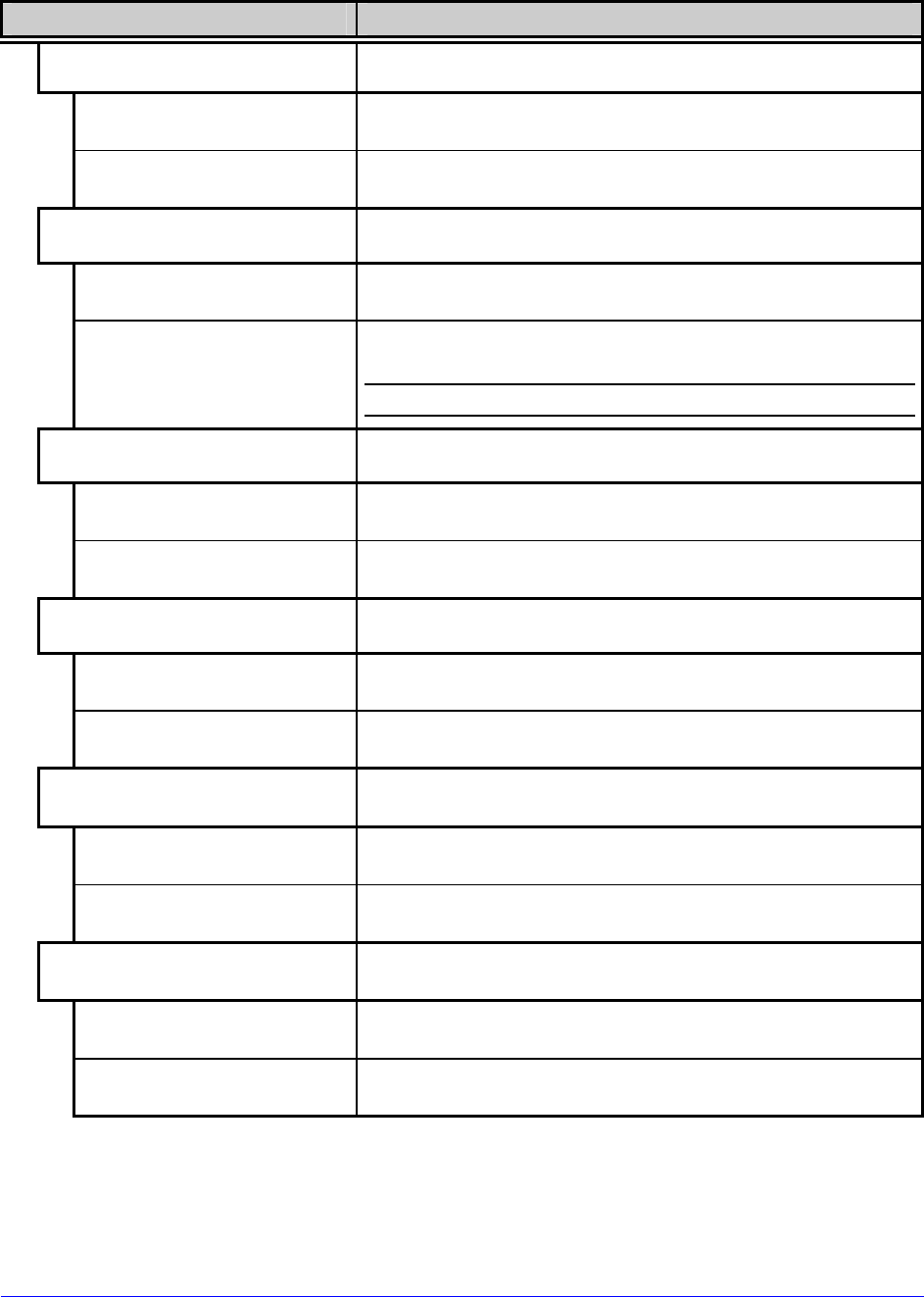
H-Class 67
Communications (continued)
Menu Item Details
FEEDBACK CHARACTERS
Allows the return of printer codes, where:
ENABLED
Sends the host a Hex 1E (RS) after each label and a
Hex 1F (US) after each batch successfully prints.
DISABLED
Sends no feedback characters.
ESC SEQUENCES
Sets handling for data containing invalid ESC
sequences, where:
ENABLED
Processes commands normally.
DISABLED
Ignores ESC control codes during processing (as some
systems send “banners” to the printer).
Bitmapped font downloads will be disabled.
HEAT COMMAND
Determines how host Heat commands are handled,
where:
ENABLED
Processes software commands normally.
DISABLED
Controls Heat via the menu setting; see Section 4.2.2.
SPEED COMMANDS
Determines how host Print, Feed, Reverse, and Slew
commands are handled, where:
ENABLED
Processes software commands normally.
DISABLED
Controls speeds via the menu setting; see Section
4.2.2.
TOF SENSING COMMANDS
Determines how host Gap, Continuous, and Reflective
commands are handled, where:
ENABLED
Processes software commands normally.
DISABLED
Controls the Sensor Type via the menu setting; see
Section 4.2.2.
SYMBOL SET COMMAND
Determines how host Single and Double Symbol Set
commands are handled, where:
ENABLED
Processes software commands normally.
DISABLED
Controls Symbol Set selection via the menu setting;
see Section 4.2.4.
68 H-Class
Communications (continued)
Menu Item Details
CNTRL-CODES (DATA)
Determines how host Control Codes are handled,
where:
ENABLED
Processes software commands normally.
DISABLED
Controls the setting via the menu; see CONTROL
CODES, above.
STX-V SW SETTINGS
Determines how a host option enable command is
handled, where:
ENABLED
Processes the command normally.
DISABLED
Controls settings via the menu; see Section 4.2.3.
MAX LENGTH COMMAND
Determines how a host Maximum Label Length
(<STX>M) command is handled, where:
ENABLED
Processes software commands normally.
DISABLED
Controls the setting via the menu; see Section 4.2.1.
OPTION FEEDBACK
Allows feedback characters from an optional device to
be returned to the host device, in the format of
<A;B;C;D;E;F>[CR], where:
A - Is the device type: R = RFID; and, S = Linear Scanner
B - Is the status: C = entire label complete; F = faulted
(failed) label; and, U = unknown
C - Is the number of expected reads, given in two
characters.
D - Is the number of good reads, given in two characters.
E - Is the internal Job and Sub Job Identifier, given in four
characters each.
F - Is the data read, delimited with semicolons (;) if
multiple reads.
DISABLED
Reports no data.
SCANNER
Reports Linear Scanner data.
RFID HEX
Reports RFID data in hexadecimal format.
RFID ASCII
Reports RFID data in an ASCII format.
H-Class 69
Communications (continued)
Menu Item Details
PROCESS SOH (DATA)
Determines the response to an Immediate Command
(e.g., Get Status, Module Storage, etc.), where:
DISABLED
Processes commands normally.
ENABLED Interrupts operations upon SOH receipt to process the
command.
4.2.6 Diagnostics
The Diagnostics menu contains testing functions:
Menu Item Details
HEX DUMP MODE
Determines how the printer handles host data, where:
DISABLED
Processes data normally.
ENABLED
Prints received ASCII data without interpretation or
processing; see Section 6.2.
FILE CAPTURE
Saves received data to Module G (or Module H, if
present) in the form dmx_xxx_yyy.dpl where the
count (yyy) is incremented for every capture and a
unique time stamp (xxx) is assigned.
OPTIONS TESTING
Performs option diagnostics, where:
TEST PRESENT SENSOR
Tests the Present Sensor (including the sensor in the
Peel & Present option), where:
LABEL PRESENTED
Is displayed when the sensor is blocked.
LABEL NOT PRESENTED
Is displayed when the sensor is not blocked.
TEST CUTTER
Tests the Cutter, where:
PERFORM TEST
001 TIMES
Selects the number of cuts (1 – 999) to perform and
then displays the PASS / FAIL results for each
attempt.
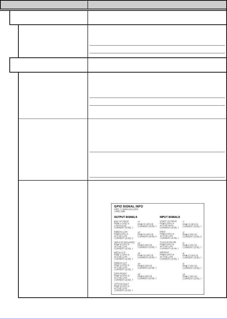
70 H-Class
Diagnostics (continued)
Menu Item Details
TEST REWINDER
Tests the Powered Internal Rewinder, where:
PERFORM TEST
001 TIMES
Selects the number of rotations (0 - 999) to perform
and then displays the PASS / FAIL results for each
attempt.
Remove media from the rewinder before testing.
TEST GPIO
Tests the Applicator Interface Card’s GPIO function,
where:
MONITOR GPIO INPUT
SOP FEED PAUSE REPRT
1 1 1 1
i1 i2 i3 i4 i5 i6
1 1 1 1 1 1
Displays input signal logic values for Start of Print
(SOP), Feed, Pause, Reprint, and six unassigned input
lines. (The values given here are examples only.)
Unconnected lines may display a zero or one.
TEST GPIO OUTPUT
EP RL SR MO RO DR OF
1 1 1 1 1 1 1
o1 o2 o3 o4 o5 o6
1 1 1 1 1 1
Displays output signal logic values for End of Print
(EP), Ribbon Low (RL), Service Required (SR), Media
Out (MO), Ribbon Out (RO), Data Ready (DR), Option
Fault (OF), and six unassigned output lines. (The
values given here are examples only.)
To change an output signal, cursor over the
displayed state to select and then toggle it using
the UP or Down Arrow Buttons, except Data Ready
which cannot be toggled.
PRINT SIGNAL INFO
Prints a reference label (see sample below) containing
GPIO signal names, pin and port assignments,
programmed settings, and current signal states.
H-Class 71
Diagnostics (continued)
Menu Item Details
TEST SCANNER
Tests the Linear Scanner, where:
ALIGNMENT TEST
Reads a bar code then displays the decoded data, the
code type and scan count, repeating.
SCAN TEST
Reads a bar code then displays the decoded data, the
code type and scan count, non-repeating.
TEST RFID
Tests RFID, where:
TAG DATA
Reads the data encoded on a tag.
DEVICE VERSION
Displays the type and version of the encoding device.
TAG ID – HF ONLY
Reads then displays the High Frequency Tag ID.
PRINT TEST RATE (min)
Allows a label-to-label delay when batch printing Test
Labels, where:
(0 – 120)
000
Is the selected interval, in minutes.
SENSOR READINGS
Displays various sensor values (0 – 255), where:
THR TRAN RIBM 24V
127 159 093 175
PS HD RANK
000 254 125
Are readings for the printhead thermistor sensor
(THR), media “gap” sensor (TRAN) or “reflective”
sensor (REFL), ribbon sensor (RIBM), 24VDC power
supply sensor (24V), present sensor (PS), printhead
assembly sensor (HD) and, printhead ranking resistor
(RANK). (The values given here are examples only.)
RIBBON SENSOR LIMITS
Displays ribbon sensor values (0 – 255) for thermal
transfer equipped printers, where:
RIBBON ADC LOW
9
RIBBON ADC HIGH
245
Are the sensor readings. (The values given here are
examples only.)
iPH REPORT
Displays the IntelliSEAQ™ data (including the
printhead serial number, and installation and
maintenance dates), where:
VIEW
Displays the data.
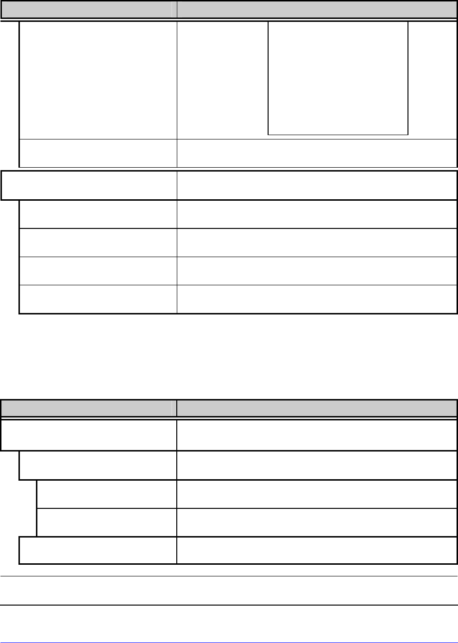
72 H-Class
Diagnostics (continued)
Menu Item Details
PRINT
Prints the data:
SAVE
Saves the data to an external storage device; see
Section 2.2.3.
ICON DESCRIPTIONS
Identifies the printer icons (see Section 4.1.1), where:
SYSTEM ICONS
Displays system glyphs.
NETWORK ICONS
Displays network glyphs.
INPUT TYPE ICONS
Displays input mode glyphs.
OPTIONS ICONS
Displays detected option glyphs.
4.2.7 MCL Options
The MCL Options menu contains alternate operating selections:
Menu Item Details
MCL OPTIONS
Allows the printer to use the optional MCL tool suite to
accept peripheral device input data, where:
MCL AT POWER-UP
Allows MCL start-up, where:
ENABLED
Sets MCL operation after power is cycled OFF and ON.
DISABLED
Sets standard printer functions.
START MCL
Starts MCL after exiting the menu.
Consult your MCL provider for details regarding operation and support.
iPH REPORT
TUE 12:44PM 23MAY2006
4212-HE25-060224-090
PRINTHEAD SERIAL #: 5x-00289
PRINTHEAD MODEL # 163
PRINTER SERIAL # 60430014
PRINTHEAD INCHES 1334900
INSTALLATION DATE - INITIAL 02/02/2006
INSTALLATION DATE - LAST 08/06/2006
PRINTHEAD CLEANING
CLEAN PROCEDURES: 5
CLEAN COUNTER RESET 5
NUMBER OF INCHES LAST- 0
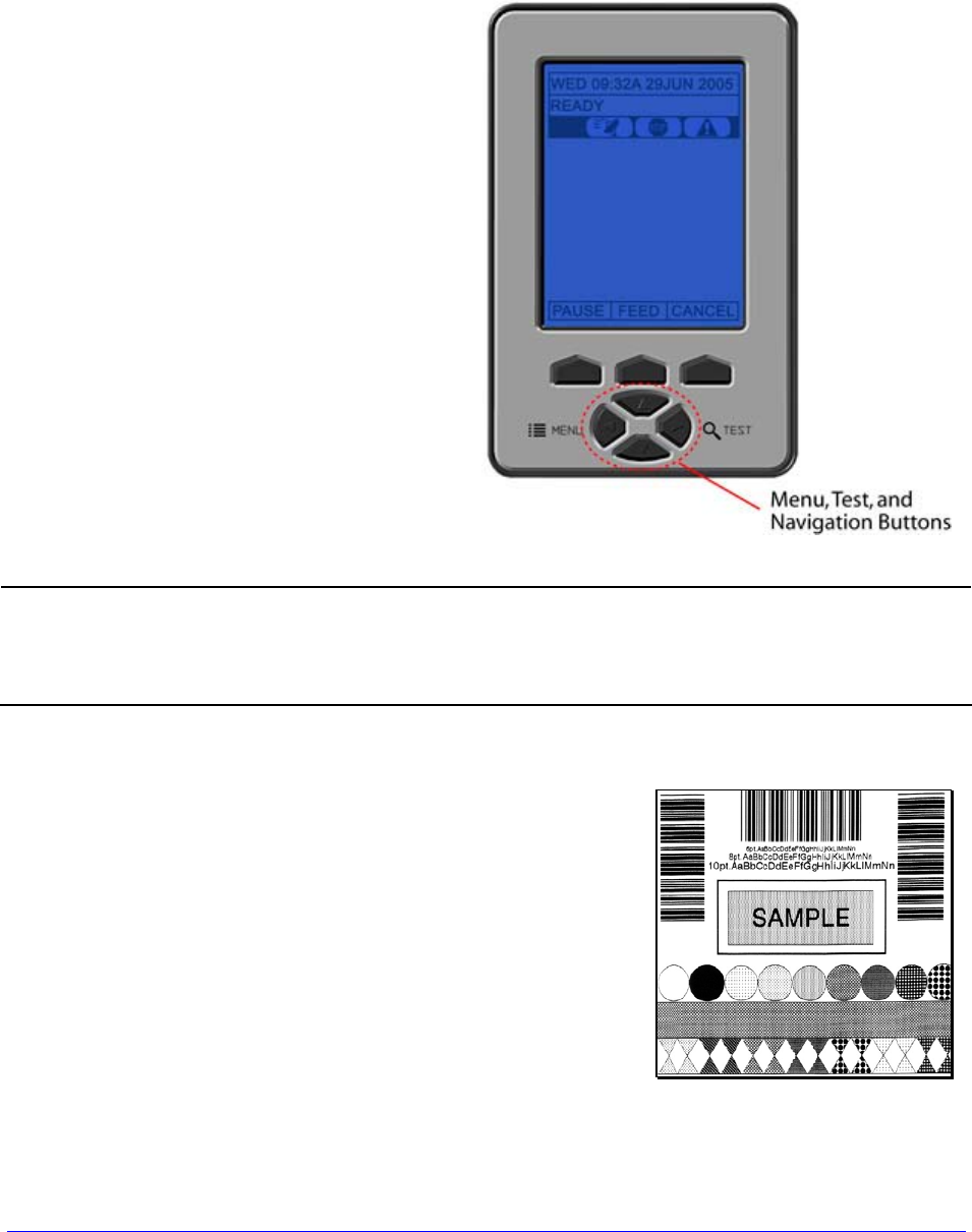
H-Class 73
4.3 The Test Menu
The (Quick) Test Menu contains resident format selections that are printed at selected heat
and speed settings. Use full width media to capture the entire format; otherwise, adjust the
printer and set the Label Width.
To enter the Test Menu, press the TEST
Button.
(In Test Mode the printer is offline, halting
the processing of new data.)
•
To print a format, scroll to that item then input a quantity and press ENTER.
• To stop printing press CANCEL.
• A printing delay can be set; see Print Test Rate, Section 4.2.6.
4.3.1 Print Quality Label
The Print Quality Label serves as an overall quality
indicator. Consisting of compliant fence and ladder bar
codes, assorted font sizes, and fill patterns, this format can
be used to ensure conformance as well as aesthetics.
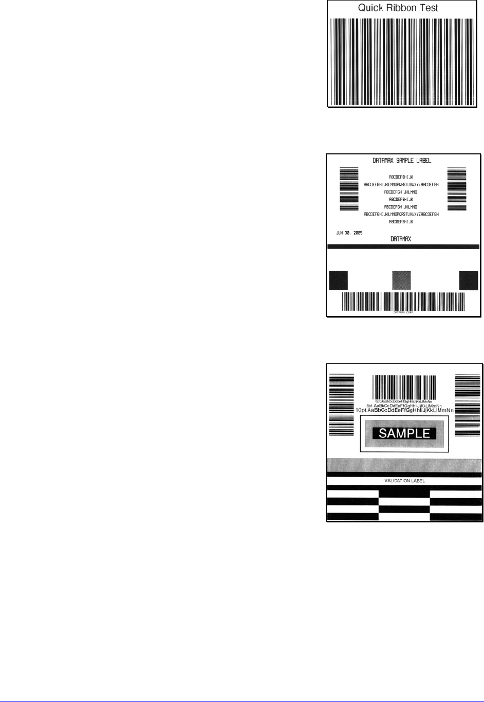
74 H-Class
4.3.2 Ribbon Test Label
The Ribbon Test Label serves as a transfer function indicator
for printers equipped with the thermal transfer option.
Consisting of a fence-oriented bar code, this format can be
used to ensure component functions and ribbon path
alignment.
4.3.3 Test Label
The Test Label serves as an indicator of printhead
functionality. The format consists of patterns that exercise
all thermal elements.
4.3.4 Validation Label
The Validation Label serves as an overall quality indicator.
Consisting of compliant fence and ladder bar codes, assorted
font sizes, and black fill patterns, this format can be used to
ensure conformance as well as aesthetics.
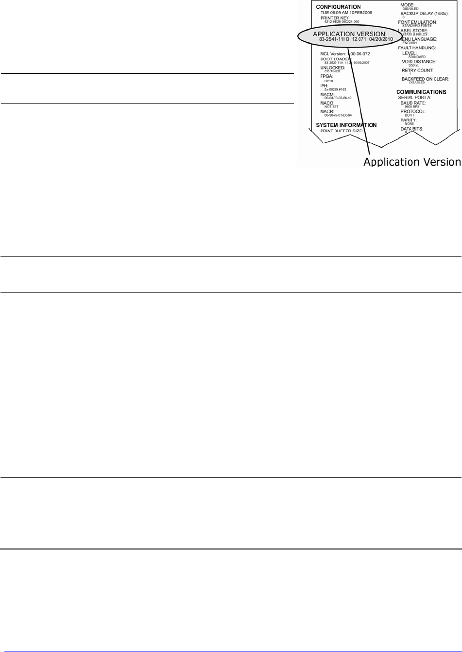
H-Class 75
4.3.5 Print Configuration
The Configuration Label provides current database
information, including the Application Version, which can
be output as a label or as a file.
Bulleted items indicate host changes not yet
saved.
4.3.6 Print Last Label
Print Last Label reprints the most recent format output by the printer.
If a job was cancelled prior to completion, or if power was removed since the last
print job and this label request, VOID will be printed.
4.3.7 User-Defined Label
The User-Defined Label allows a template to be populated by variable data (via the
printer’s control panel or a USB QWERTY keyboard). The template is a stored label format,
where fields delimited by an ampersand (&) become variable.
The printer will prompt you to enter the variable field data. For example, the stored label
format could contain the data 19131423443&ENTER NAME&
Afterward, when recalled from memory, the printer’s display will indicate the variable field:
ENTER NAME
• Variable data can be any part of the DPL format - font ID, positioning, etc.
• No error checking will be performed.
• Supports .dlb, .dpl, .prn, and .txt file types.

76 H-Class

H-Class 77
5 Operating, Adjusting and
Maintaining the Printer
5.1 Displayed Messages
During operation the printer (when not in Menu or Test Mode) displays several types of
information:
• Prompts and Condition Messages (see Section 5.1.1); and,
• Fault and Warning Messages (see Section 6.1.2).
5.1.1 Prompts and Condition Messages
Prompts appear as the result of an action or when an action is required during operation,
while Condition Messages indicate an operational state.
Prompts and Condition Messages
Displayed Message Description Action / State
ACCESS DENIED
The password used to
access a secured menu was
incorrect.
Enter the correct password.
CALIBRATING
SENSOR LEVELS
Media calibration is being
performed.
Allow the process to
complete.
CALIBRATION COMPLETE Media calibration has
successfully finished. The printer is calibrated.
CANCEL BATCH
ENTER KEY = YES
The CANCEL or TEST Key
was pressed during a
multiple label job.
Press ENTER to cancel all
remaining labels in the job.
CANCEL REPRINT
ENTER KEY = YES
The CANCEL or TEST Key
was pressed during a fault.
(See FAULT HANDLING /
VOID AND RETRY, Section
4.2.4.)
Press ENTER to cancel the
reprint.

78 H-Class
Prompts and Condition Messages (continued)
Displayed Message Description Action / State
CLEARING FAULTS
The FEED Key was pressed
following a fault and now
the printer is attempting to
clear the condition.
No action is required.
DMXNET INITIALIZING
The network card is
initializing, a normal
condition following power-up
or a reset.
No action is required.
Depending upon the
settings, it may take a few
minutes.
ENTER PASSWORD
0 - - -
This is the menu gateway
when security is enabled. A
four-digit password must be
entered for access.
Enter the correct password.
INVALID ENTRY An incorrect entry has been
made.
Enter a valid parameter to
continue.
NOT INSTALLED The selected option or
feature cannot be found.
Verify that the option or
feature is correctly installed.
If so, call for service.
OFFLINE The printer is in Menu or
Test Mode.
The Menu or Test Button
was pressed.
PAUSED The printer is in a paused
condition.
The PAUSE Key was pressed
or Pause Mode is enabled.
PRINTHEAD CLEANING
The TEST Key was pressed
and held, or CLEAN HEAD
NOW was selected, and now
printhead cleaning is in
progress.
No action is required.
READY
The printer is waiting to
receive label formats,
downloads, etc.
Send a label format,
download, etc.

H-Class 79
Prompts and Condition Messages (continued)
Displayed Message Description Action / State
REMOVE RIBBON
PRESS ANY KEY
The TEST Key was pressed
and held, or CLEAN HEAD
NOW was selected, but
ribbon is installed.
Remove ribbon and press
any key to proceed.
SAVE CHANGES?
Database changes were
made that require
confirmation.
Press YES to accept the
changes, or NO to discard
them.
If changes require a
reset, it will automatically be
invoked.
SUCCESSFUL
PRESS ANY KEY
The selected operation was
successfully completed. Press any key to continue.
SYSTEM RESET
IN PROGRESS
A reset has occurred.
No action is required. Wait
briefly while the process
completes.
UNCALIBRATED The Media Sensor is not
calibrated.
Perform calibration; see
Section 5.2.
WAITING FOR DATA
The SOP signal has been
received, but the printer
awaits label data.
Send a format from the
host.
WAITING FOR SIGNAL The printer awaits a SOP
signal.
Send the SOP signal from
the applicator to the GPIO
port.
XXXX OF XXXX
PRINTING
A print job is in process, as
indicated by the batch total
and remaining label count.
No action is required.

80 H-Class
5.2 Calibration
Calibration ensures correct media detection. Use Standard Calibration if the quick method
(see Section 3.4) fails.
5.2.1 Standard Calibration
Standard Calibration provides dynamic readings, which can be helpful when using media
with small position-critical notches or marks. Three calibration samples are required:
Empty – with nothing over the sensor;
Gap (or Mark) – with media liner, a notch, or a mark over the sensor; and,
Paper – with the label (and liner, if any) over the sensor.
Calibrate the Media Sensor using the steps below:
Before proceeding, ensure that the ADVANCED MENU is enabled (see Section
4.2.4) and that the SENSOR TYPE is selected (see Section 4.2.1).
Step
Action Displayed Message Comment
A Turn ON the printer.
CANNOT CALIBRATE
-or-
UNCALIBRATED
Wait briefly for
initialization to complete;
see Section 4.1.1.
B
Press ENTER to access
MEDIA SETTINGS. Then
using the UP Button, scroll
to SENSOR CALIBRATION.
MEDIA SETTINGS
ADVANCED MENU must
be enabled to access the
calibration selections.
C
Press ENTER to access
SENSOR CALIBRATION.
Press ENTER again to
select PERFORM
CALIBRATION and then
press YES to proceed.
PERFORM CALIBRATION Press NO to abort this
procedure.
D With no media installed,
press ESC.
REMOVE LABEL STOCK
PRESS ESC KEY
yyy
This sets the empty
value, where “yyy”
represents the current
sensor reading.

H-Class 81
Standard Calibration (continued)
Step
Action Displayed Message Comment
E
Proceed according to the
media type:
• Die-Cut – Remove a
label or two from the
liner then install the
media. Position the
Media Sensor under the
liner area and press ESC.
• Notched (or Reflective) –
Install media. Position
the Media Sensor under
a notch (or black mark)
and press ESC.
• Continuous – Press ESC
then proceed to Step F.
For die-cut media:
SCAN BACKING
PRESS ESC KEY
yyy
- Or, for reflective media:
SCAN MARK
PRESS ESC KEY
yyy
- Or, for continuous
media:
REMOVE LABEL STOCK
PRESS ESC KEY
yyy
This sets the gap (or
mark) value, where “yyy”
represents the current
sensor reading.
(1) See Section 3.2 for
sensor adjustment
instructions.
(2) Do not position a
perforation over the
sensor when taking
the sample.
(3) For small notches or
reflective marks,
ensure that the labels
exit straight from the
printer.
(4) Unless otherwise
noted, do not move
the Media Sensor
after this step.
F
Proceed according to the
media type:
• All media except
Continuous – Position
label material (and liner,
if any) over the sensor
then press the ESC Key.
• Continuous – Install
media. Position the
Media Sensor under the
stock and press ESC.
SCAN PAPER
PRESS ESC KEY
yyy
This sets the paper
value, where “yyy”
represents the current
sensor reading.
(1) If using preprinted
media, ensure that
the area placed over
the sensor is free of
text, graphics, or
borders.
(2) See Section 3.2 for
sensor adjustment
instructions.
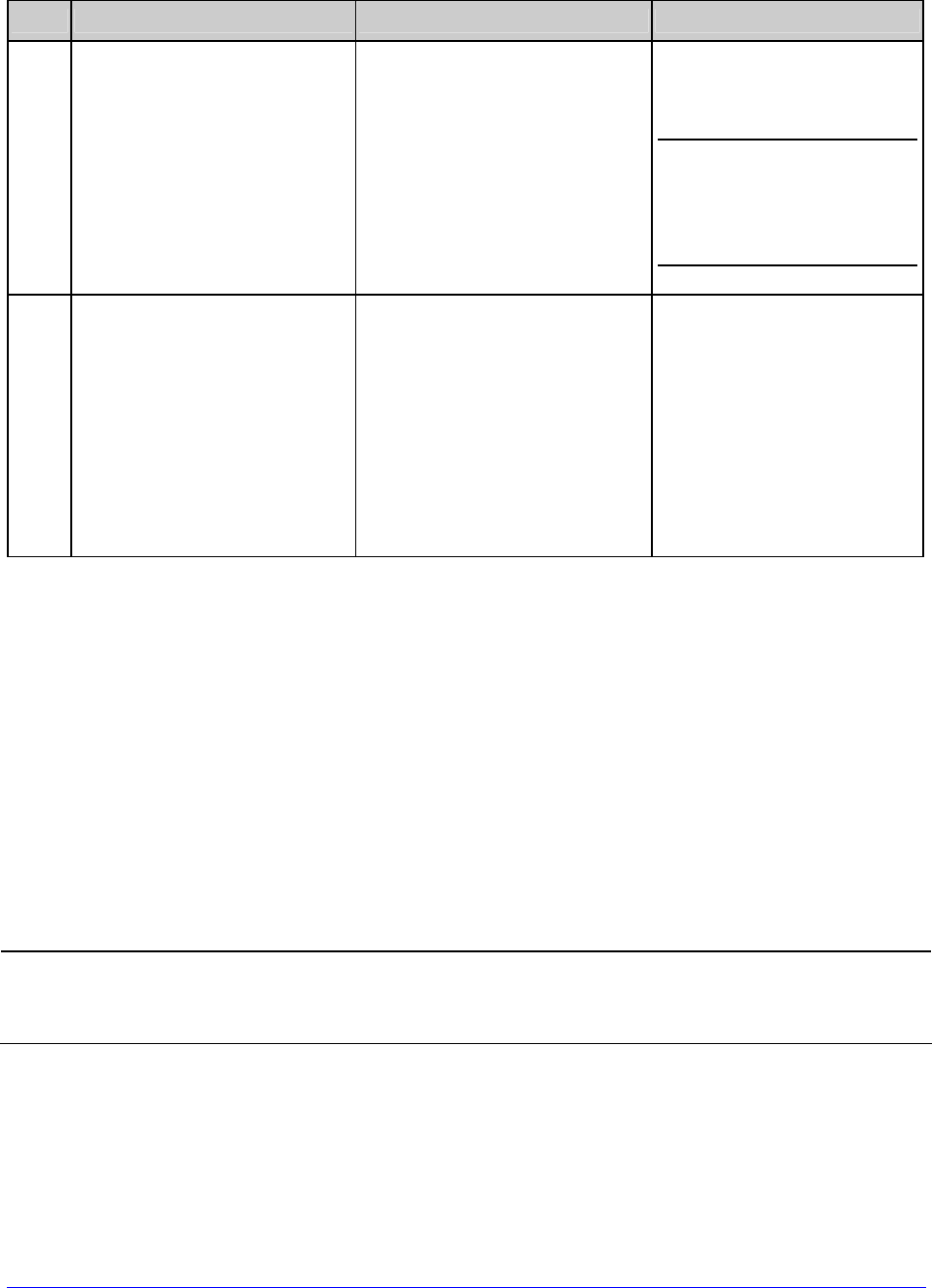
82 H-Class
Standard Calibration (continued)
Step
Action Displayed Message Comment
G Observe the calibration
result. CALIBRATION COMPLETE
Calibration was
successful.
If WARNING LOW
BACKING is displayed,
calibration was successful
(for possible messages
see Section 5.1).
H
Press ESC then EXIT to
return to READY.
When calibrating gap or
reflective media, press and
hold the FEED Key until at
least one label is output.
CALIBRATION COMPLETE
Followed by...
READY
The printer is now ready
for use.
5.2.2 Advanced Entry Calibration
Advanced Entry is an alternate calibration method for special-case media types, where
sensor readings are taken using different sampling algorithms and from a list of these
readings the best algorithm is selected for manual entry into the database.
Advanced Entry Calibration should be used only when Standard Calibration proves
unsuccessful. Also, before proceeding, ensure that the ADVANCED MENU is enabled
(see Section 4.2.4) and that the SENSOR TYPE is selected (see Section 4.2.1).
Calibrate the Media Sensor using the steps below:

H-Class 83
Advanced Entry Calibration
Step
Action Displayed Message Comment
A Turn ON the printer.
CANNOT CALIBRATE
-or-
UNCALIBRATED
Wait briefly for
initialization to complete;
see Section 4.1.1.
B
Press ENTER to access
MEDIA SETTINGS. Then
using the UP Button, scroll
to SENSOR CALIBRATION.
MEDIA SETTINGS
ADVANCED MENU must
be enabled to access the
calibration selections.
C
Press ENTER to access
SENSOR CALIBRATION.
Using the DOWN Button,
highlight ADVANCED
ENTRY then press ENTER.
ADVANCED ENTRY Press EXIT to abort this
procedure.
D
Scroll to TRAN SENSOR
GAIN (or REFL SENSOR
GAIN, if using reflective
media) then press ENTER.
TRAN SENSOR GAIN
yyy (0 - 31)
25
The following examples
detail die-cut media
calibration; however,
unless otherwise noted,
the reflective media
procedure is the same.
E
Install media. Position the
Media Sensor under the
label, then lower and latch
the Printhead Assembly.
TRAN SENSOR GAIN
yyy (0 - 31)
25
See Section 3.2 for
sensor adjustment
instructions.
Do not position the
Media Sensor under a
perforation; and if
using preprinted
media, ensure the
label area placed over
the sensor is free of
text, graphics, lines,
etc.
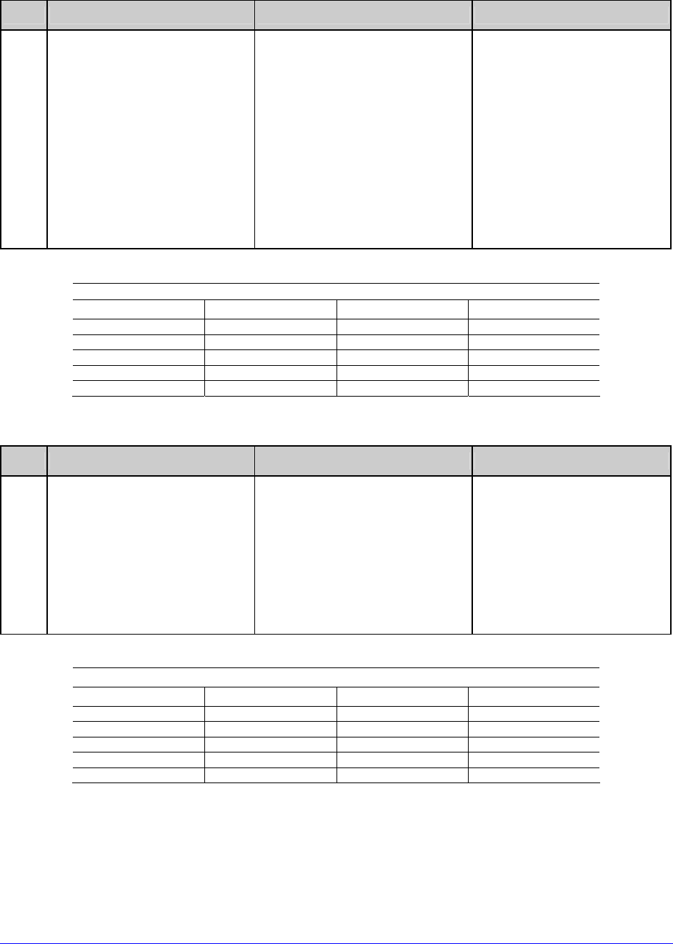
84 H-Class
Advanced Entry Calibration (continued)
Step
Action Displayed Message Comment
F
Use the buttons to set the
Gain Number to 00 and
then press ENTER.
Record the sensor reading
as a Label Value for Gain
Number 00 in a table (32
rows by four columns,
with headings similar to
those shown below.)
TRAN SENSOR GAIN
yyy (0 - 31)
00
This is the Label Value for
a gain setting of 00,
where “yyy” represents
the current sensor
reading.
Sample Calibration Table
Gain Number Label Value TOF Value Difference Value
00 252
01
02
…
31
Step
Action Displayed Message Comment
G
Use the buttons to
increment the Gain
Number by one and then
press ENTER. Record the
Label Value. Repeat this
process for each Gain
Number.
TRAN SENSOR GAIN
yyy (0 - 31)
01
These are Label Values,
where “yyy” represents
the current sensor
reading.
Sample Calibration Table
Gain Number Label Value TOF Value Difference Value
00 252
01 250
02 248
… …
31 09
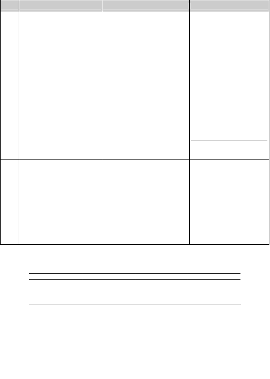
H-Class 85
Advanced Entry Calibration (continued)
Step
Action Displayed Message Comment
H
Raise the printhead
assembly then proceed
according to the media
type:
• Die-cut – Remove a label
or two from the liner
then position that area
over the Media Sensor.
Adjust the Media Sensor
under the liner area.
• Notched – Position the
Media Sensor under the
notch.
• Reflective – Position the
Media Sensor under the
black mark.
TRAN SENSOR GAIN
yyy (0 - 31)
31
(1) Do not position the
Media Sensor under a
perforation; and if
using preprinted
media, ensure the
label area placed over
the sensor is free of
text, graphics, lines,
etc.
(2) Do not move the
Media Sensor after
this step.
I
Lower and latch the
Printhead Assembly.
Using the buttons set the
Gain Number to 00, and
then press ENTER.
Record the reading as a
TOF Value for Gain
Number 00 in the table.
TRAN SENSOR GAIN
yyy (0 - 31)
00
This is the TOF Value for
a gain setting of 00,
where “yyy” represents
the current sensor
reading.
Sample Calibration Table
Gain Number Label Value TOF Value Difference Value
00 252 248
01 250
02 248
… …
31 09
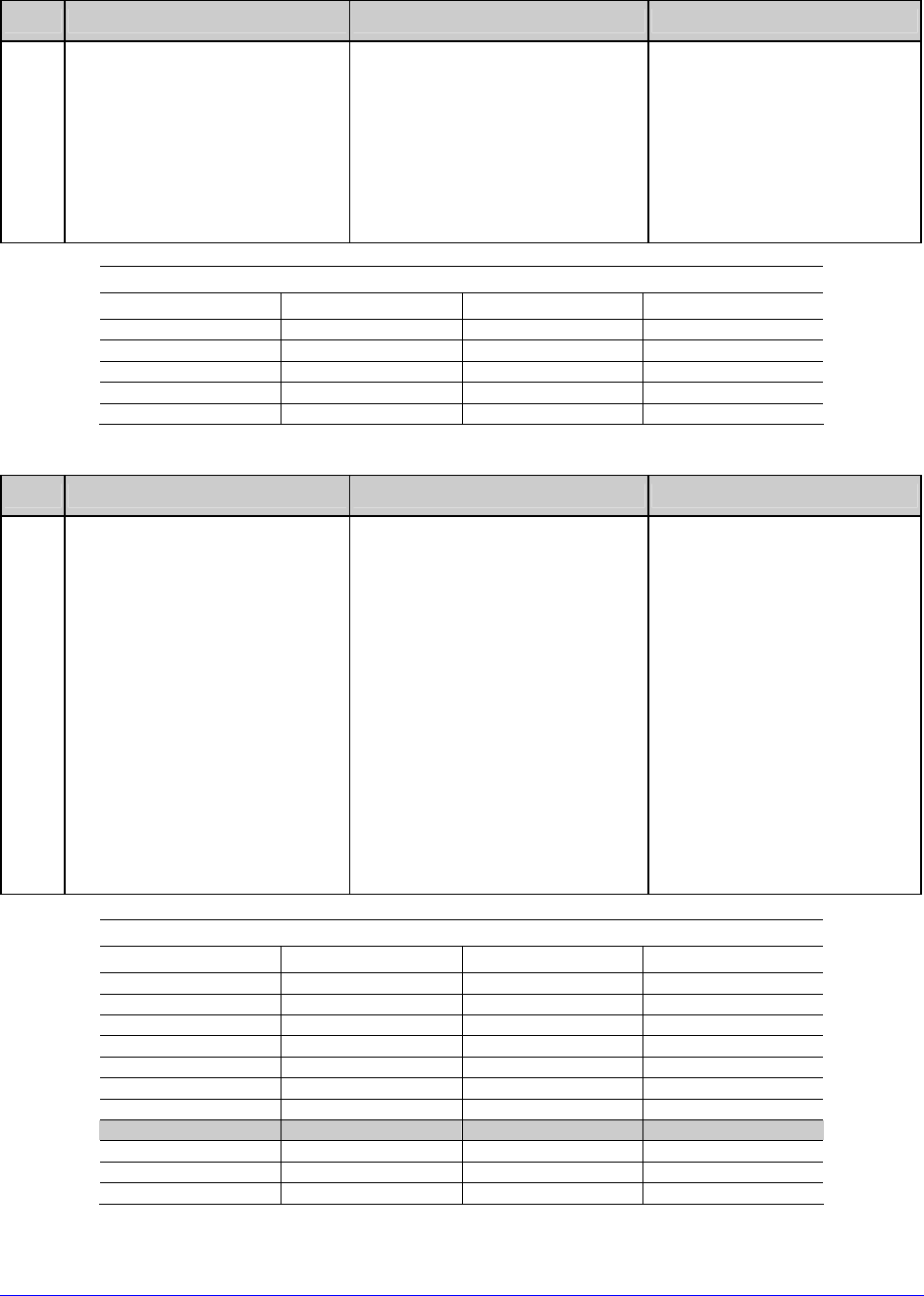
86 H-Class
Advanced Entry Calibration (continued)
Step
Action Displayed Message Comment
J
Use the buttons to
increment the Gain
Number by one and then
press ENTER. Record the
TOF Value. Repeat this
process for each Gain
Number.
TRAN SENSOR GAIN
yyy (0 - 31)
01
These are TOF Values,
where “yyy” represents
the current sensor
reading.
Sample Calibration Table
Gain Number Label Value TOF Value Difference Value
00 252 248
01 250 245
02 248 234
… … …
31 09 14
Step
Action Displayed Message Comment
K
In your sample calibration
table, where both the
Label Value and TOF Value
are at least 20, subtract
the amounts and record
the result as a Difference
Value (see below).
Identify the largest
Difference Value and the
corresponding Gain
Number. This Gain
Number will be used to
resample the media.
TRAN SENSOR GAIN
yyy (0 - 31)
31
In this example, Gain
Number 18 is chosen
because, where both
values are at least
twenty, it has the highest
Difference Value.
Sample Calibration Table
Gain Number Label Value TOF Value Difference Value
00 252 248 4
01 250 245 5
02 248 234 14
… … … …
15 188 63 125
16 184 51 133
17 179 38 141
18 174 25 149
19 170 19 N/A
… … … …
31 132 14 N/A
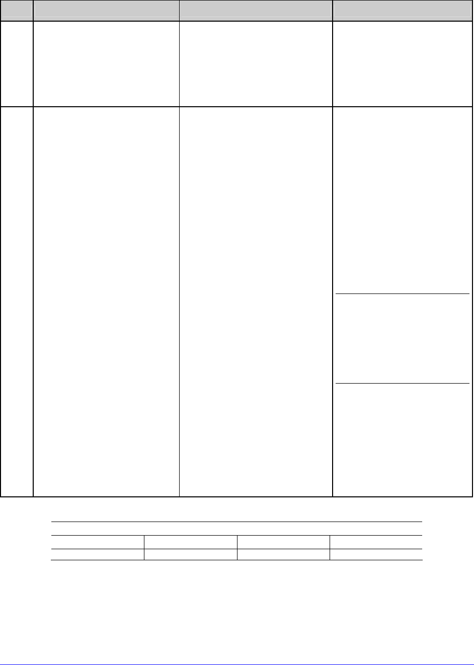
H-Class 87
Advanced Entry Calibration (continued)
Step
Action Displayed Message Comment
L
Use the buttons to set the
Gain Number determined
in the previous step. Press
ENTER to enable the
setting.
TRAN SENSOR GAIN
yyy (0 - 31)
18
This example uses Gain
Number 18.
M
Complete a table (see
example below) using new
measurements, as
follows:
(A) Raise the Printhead
Assembly. Place the
label over the Media
Sensor then lower and
latch the Printhead
Assembly. Record the
sensor reading as P.
(B) Raise the Printhead
Assembly. Place the
liner, notch, or mark
over the Media Sensor
then lower and latch
the Printhead
Assembly. Record the
sensor reading as G
(or M).
(C) Raise the Printhead
Assembly. Remove all
media from the Media
Sensor then lower and
latch the Printhead
Assembly. Record the
sensor reading as E.
TRAN SENSOR GAIN
yyy (0 - 31)
18
Where “yyy” is a
numerical value
representing the current
sensor reading.
The re-sampled
values may differ
from those
previously noted.
This is normal; do
not readjust the
Media Sensor.
Selected Gain Table
Gain Number Paper Gap (or Mark) Empty
18 173 42 9

88 H-Class
Advanced Entry Calibration (continued)
Step
Action Displayed Message Comment
N
Press the ESC Key.
Use the buttons to scroll
to PAPER SENSOR LEVEL
(or if using reflective
media, REFL PAPER
LEVEL) and then press
ENTER.
Use the buttons to set the
Paper value determined in
Step M and then press
ENTER.
PAPER SENSOR LEVEL
(0 - 255)
173
This is the Paper value.
O
Press the ESC Key.
Scroll to GAP SENSOR
LEVEL (or, if using
reflective media, MARK
SENSOR LEVEL) and then
press ENTER.
Set the Gap (or Mark)
value determined in Step
M and then press ENTER.
GAP SENSOR LEVEL
(0 - 255)
042
This is the Gap (or Mark)
value.
P
Press the ESC Key.
Scroll to EMPTY SENSOR
LEVEL and then press
ENTER.
Set the Empty value
determined in Step M and
then press ENTER.
EMPTY SENSOR LEVEL
(0 - 255)
009
This is the Empty value.
Q
Press the EXIT Key and,
when prompted, press
YES at the SAVE
CHANGES prompt.
OFFLINE
The procedure is
finished, the process
almost complete.
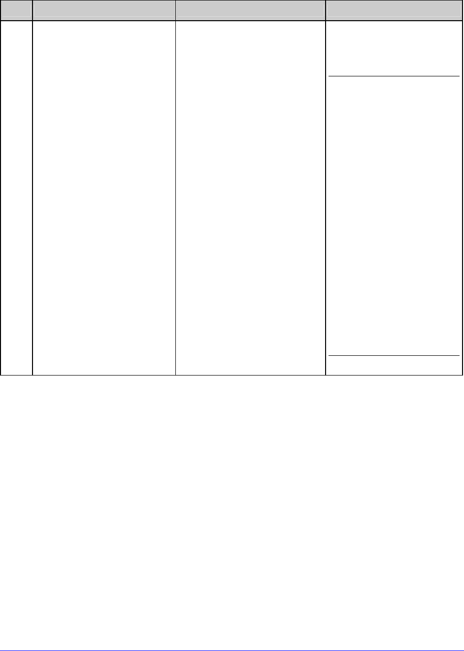
H-Class 89
Advanced Entry Calibration (continued)
Step
Action Displayed Message Comment
R
Press and hold the FEED
Key until at least one label
has been output.
CALIBRATION COMPLETE
Followed by...
READY
The printer is ready for
use.
If the calibration
attempt fails, try
desensitizing the
sensor as follows:
Re-enter the
ADVANCED MENU. Go
to MEDIA SETTINGS /
SENSOR
CALIBRATION /
ADVANCED ENTRY /
TRAN (or REFL)
SENSOR GAIN and
lower the
corresponding GAIN
SETTING by one. Exit
the menu and save
your changes. Test
your media at the
new setting. If
necessary, repeat
until a usable Gain
Setting is obtained.
5.3 Reset Methods
There are three reset levels for the printer.
5.3.1 Soft Reset
Soft Reset clears temporary host settings. To perform a Soft Reset:
• Press and hold the CANCEL Key (see Section 4.1) for approximately four seconds.

90 H-Class
5.3.2 Level One Reset
Level One reset returns the factory default settings, or if saved a Factory Setting File. To
perform a Level One Reset:
• Select SET FACTORY DEFAULTS in the menu; see Section 4.2.4.
5.3.3 Level Two Reset
Level Two reset returns the printer to the firmware default settings and clears all
parameters. To perform a Level Two Reset:
• While turning ON the printer, press and hold the three Soft Keys (see Section 4.1)
until the SYSTEM RESET message flashes.
Calibration will be required; see Section 5.2.
5.4 Printhead Assembly Adjustments
Printhead Assembly Adjustments permit the mechanical compensation sometimes needed to
maintain print quality across the wide range of media types and sizes. The applicability and
adjustment methods for the printhead are described below.
5.4.1 Leveling Cam Adjustment
Whenever using narrow media (sizes that are less than the width of the printhead), adjust
the Leveling Cam for even pressure distribution.
If changing media sizes, readjust the Leveling Cam.
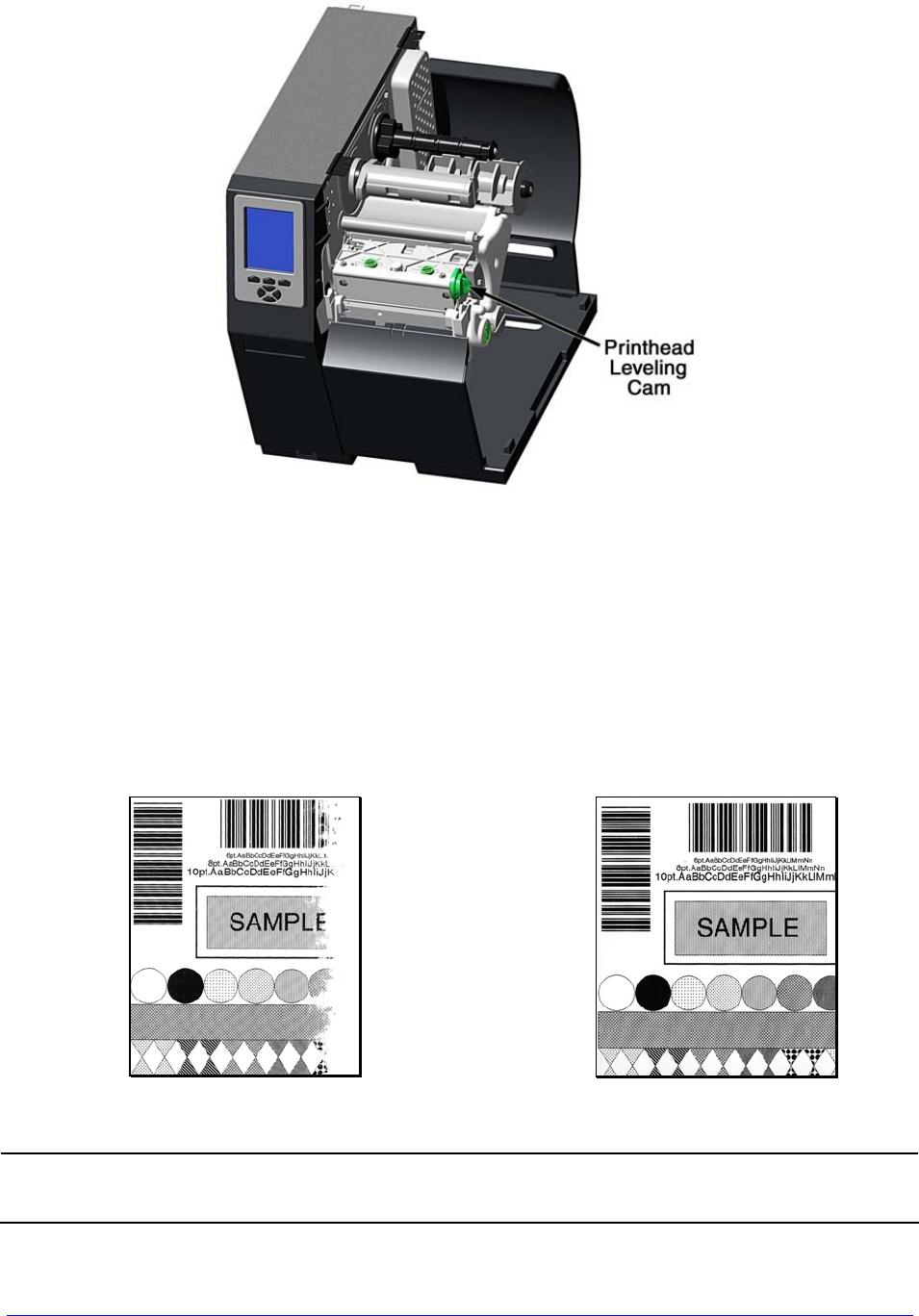
H-Class 91
Adjust the Printhead Leveling Cam as follows:
A. With media loaded, download your label format (or use a Test Menu format) then
begin printing a small batch of labels.
B. While observing the printed output, rotate the Leveling Cam counter-clockwise until
the image fades across the label, as shown in Example 1 (below).
C. While observing the printed output, rotate the Leveling Cam clockwise until the
image is complete, with even contrast, as shown in Example 2 (below).
Example 1 – Too much adjustment Example 2 – Correct adjustment
Under-adjustment of the Leveling Cam can cause problems that include ribbon
wrinkling, label tracking, and excessive platen and printhead wear.
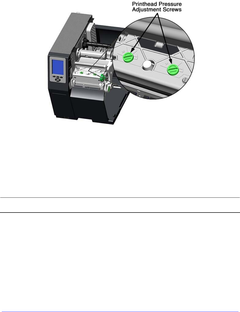
92 H-Class
5.4.2 Printhead Pressure Adjustment
Printhead Pressure Adjustment should only be performed after attempting to improve print
quality through the use of other print quality controls (see Section 3.5).
A. With media loaded, download your label format (or use a Test Menu format) then
begin printing a small batch of labels.
B. While observing the printed output, turn each Pressure Adjustment Screw (use a
small coin or screwdriver) by the same amount until the image is complete, with
even contrast:
• Counterclockwise (+) to increase applied pressure, or;
• Clockwise (-) to decrease applied pressure.
Ensure that each arrow points in the same direction.
5.5 Maintenance
This section details the recommended maintenance supplies, schedules, and methods.
Supplies
These items will help to safely and effectively clean the printer:

H-Class 93
• Isopropyl alcohol • Soapy water/mild detergent
• Cotton swabs • Compressed air
• Clean, lint-free cloth • Printhead Cleaning Cards or Printhead Cleaning Film
• Lens tissue • Vacuum Cleaner
• Soft-bristle brush
Schedule
The following table details the recommended cleaning schedules:
Recommended Cleaning Schedule*
Component / Area Cleaning Interval** Supplies / Method
Exterior Surfaces As needed, based on a weekly visual
inspection.
Mild detergent applied
with a dampened cloth;
see Section 5.5.7.
Fan Filter
(tall models only)
As needed, based on a weekly visual
inspection.
Vacuum; see Section
5.5.2.
Interior Compartment As needed, based on a weekly visual
inspection.
Compressed air or a soft
brush; see Section 5.5.3.
Media Sensing
Components
As needed, based on a weekly visual
inspection.
Compressed air, soft
brush, lens tissue and /
or isopropyl alcohol; see
Section 5.5.4.
Platen and Assist
Rollers
After each roll of media or ribbon;
sooner if needed.
Cotton swab or a cloth
dampened with isopropyl
alcohol; see Section
5.5.5.
Printhead
Varies according to the media type:
• Thermal transfer media – after
each roll of ribbon.
• Direct thermal media – after
each roll of media, or as needed.
Isopropyl alcohol, and if
necessary Cleaning Cards
or Cleaning Film; see
Section 5.5.1.
Ribbon Path
Components
(equipped models only)
As needed, based on a weekly visual
inspection.
Cotton swab or a cloth
dampened with isopropyl
alcohol; see Section
5.5.6.
*For optional equipment, refer to the documentation that accompanied the item(s).
**Whichever interval comes first.
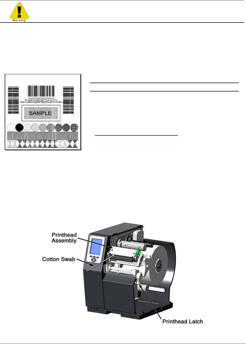
94 H-Class
5.5.1 Cleaning the Printhead
Never use a sharp, hard or abrasive object on the printhead.
If print quality declines (symptoms can include unreadable bar codes or streaks through
text and graphics), the typical cause is debris buildup on the printhead which, left
unattended, can lead to premature dot failure. To help you remember this important
procedure, the printer can be programmed to prompt you for cleaning; see Section 4.2.1.
Depending upon the supplies and printing parameters used, different cleaning methods are
recommended.
Streaks can indicate a dirty or faulty printhead.
Proper cleaning is critical. To maintain peak
performance of the printer, Datamax-O’Neil offers a
complete line of cleaning products including pens,
cards, films and swabs. Visit our website at
http://www.datamax-oneil.com to learn more.
Certified Datamax-O’Neil – The worry free choice
for optimal printer performance.
Cotton Swab Procedure (for users of direct thermal media, or thermal transfer media
with wax ribbon):
A. Turn OFF the Power Switch and unplug the printer. Raise the cover, then raise the
Printhead Assembly and wait briefly for the printhead to cool.
B. Remove media and ribbon. Using a Cotton Swab moistened (not soaked) with
isopropyl alcohol, thoroughly clean the printhead.

H-Class 95
C. Allow the printhead to dry. Reinstall media (and ribbon, if needed). Plug in the
printer and turn ON the Power Switch. Run a few sample labels and examine them. If
streaking is still present, use Cleaning Card Procedure, below; otherwise, this
completes cleaning. If the CLEAN HEAD SCHEDULE has been set, enter the menu
and select RESET COUNTER; see Section 4.2.1.
Cleaning Card Procedure (for users of direct thermal media, or thermal transfer media
with wax/resin ribbon combinations; also for unsuccessful Cotton Swab cleaning attempts):
A. Raise the cover, then raise the Printhead Assembly and wait briefly for the
printhead to cool.
B. Remove media and ribbon then place a Cleaning Card under the printhead. (Part
number 70-2013-01 for 4-inch cards; and, 70-2014-01 for 6-inch cards)
C. Close and lock the Printhead Latch and disengage the Leveling Cam.
D. Close the cover then press and hold the TEST Button to initiate cleaning. (As an
alternate, select CLEAN HEAD NOW see Section 4.2.1.)
E. After the cleaning card has been run through the printer, reinstall media (and ribbon,
if needed). Plug in and turn ON the printer. Run a few sample labels and examine
them. If streaking is still present, use the Cleaning Film Procedure, below; otherwise,
this completes cleaning.
Cleaning Film Procedure (for users of thermal transfer media and resin ribbon, when
printing with a Heat Value of 22 or higher, or when other methods prove unsuccessful):
A. Raise the cover, then raise the Printhead Assembly and wait briefly for the
printhead to cool.
B. Remove media and ribbon then place a sheet of Cleaning Film under the printhead.
(Part number 70-2087-01 for 4-inch film; 70-2087-02 for 6-inch film; and, 70-2087-
03 for 8-inch film)
C. Close and lock the Printhead Latch and disengage the Leveling Cam.
D. Close the cover then press and hold the TEST Button to initiate cleaning. (As an
alternate, select CLEAN HEAD NOW see Section 4.2.1.)
E. After the cleaning film has been run through the printer, turn OFF the Power Switch
and unplug the printer. Open the cover then raise the Printhead Assembly and wait
briefly for the printhead to cool. Using a cotton swab moistened (not soaked)
with isopropyl alcohol, clean the printhead then allow it to dry.
F. Reinstall media (and ribbon, if needed). Plug in and turn ON the printer. Run a few
sample labels and examine them. If streaking is still present the printhead may need
to be replaced; see Section 5.9.
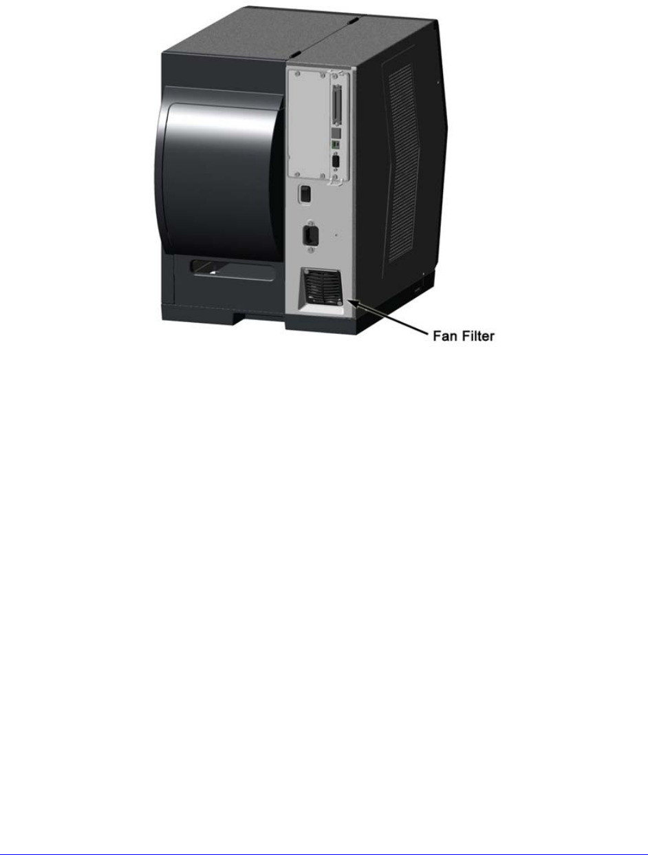
96 H-Class
5.5.2 Cleaning the Fan Filter
On equipped models, a Fan Filter keeps dust and debris from entering the printer. To assure
continued airflow through the printer, clean the Fan Filter as follows:
A. Turn OFF the Power Switch and unplug the power cord from the AC Receptacle.
B. Using a vacuum, clean the Fan Filter.
5.5.3 Cleaning the Interior Compartment
Inside the printer, paper dust from the media can accumulate to produce small voids in the
print. To assure continued void free printing, clean the Interior Compartment as follows:
A. Turn OFF the Power Switch and unplug the power cord from the AC Receptacle.
B. Raise the Cover then remove media and ribbon.
C. Remove all media and ribbon.
D. Using compressed air (or a soft brush), clean all debris from Interior Compartment.
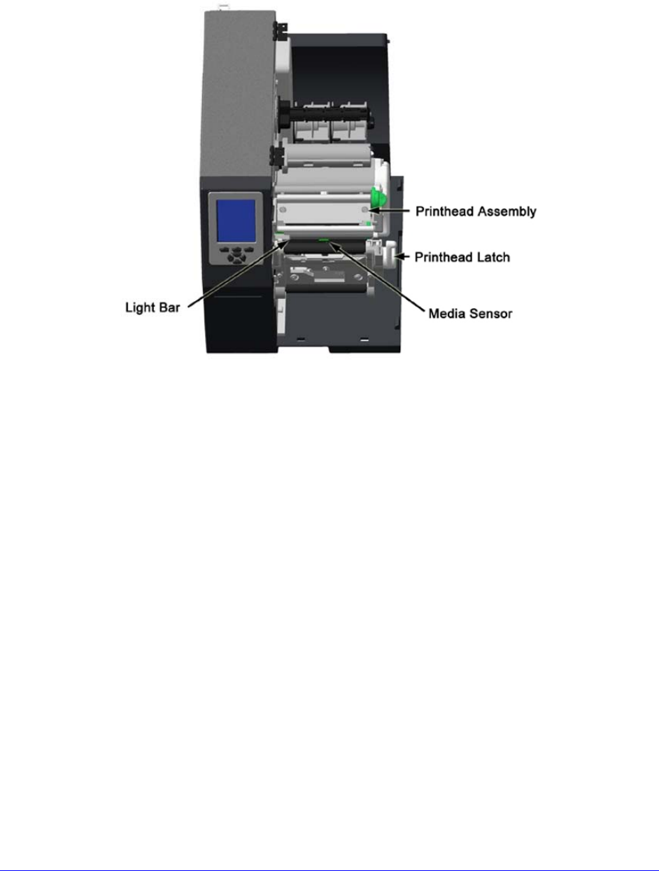
H-Class 97
5.5.4 Cleaning the Media Sensing Components
Paper dust and adhesive from the media can accumulate on the sensing components and
produce TOF problems. To avoid problems, clean the Media Sensor and Light Bar as follows:
A. Turn OFF the Power Switch and unplug the power cord from the AC Receptacle.
B. Unlock the Printhead Latch, raise the Printhead Assembly, and remove media.
C. Using compressed air, clean all debris from the Media Sensor and the Light Bar. (In
cases of extreme buildup, a Cotton Swab or lens tissue dampened with isopropyl
alcohol can be used.)
5.5.5 Cleaning the Platen and Assist Rollers
Rollers contaminated with grit, label adhesive, or ink can lead to a decline in print quality
and, in extreme cases, cause labels to adhere and wrap the roller. Clean the Platen and
Assist Rollers as follows:
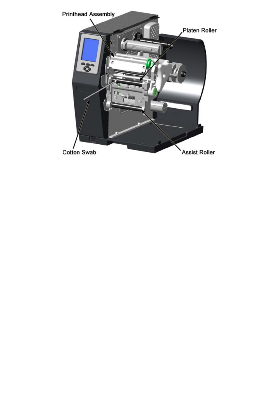
98 H-Class
A. Turn OFF the Power Switch and unplug the power cord from the AC Receptacle.
B. Raise the Cover then remove the Door and tearbar. Unlock the Printhead Latch and
raise the Printhead Assembly.
C. Remove media and ribbon.
D. Using a Cotton Swab (or lint-free cloth) dampened with isopropyl alcohol, wipe the
Platen and the Assist Roller clean. Manually rotate the rollers as necessary, wiping,
rotating, and repeating until the surfaces of each are clean.
5.5.6 Cleaning the Ribbon Path Components (Thermal Transfer equipped)
Smooth ribbon flow can become impeded if the components are dirty. Clean them as follows:
A. Turn OFF the Power Switch and unplug the power cord from the AC Receptacle. Raise
the Cover then remove media and ribbon.
B. Using a Cotton Swab dampened with alcohol, wipe the Ribbon Idlers clean.
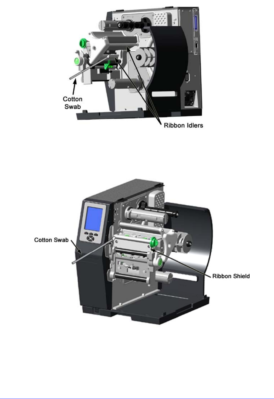
H-Class 99
C. Using a Cotton Swab dampened with alcohol, wipe the Ribbon Shield clean.
D. Reload media and ribbon then close the Cover.
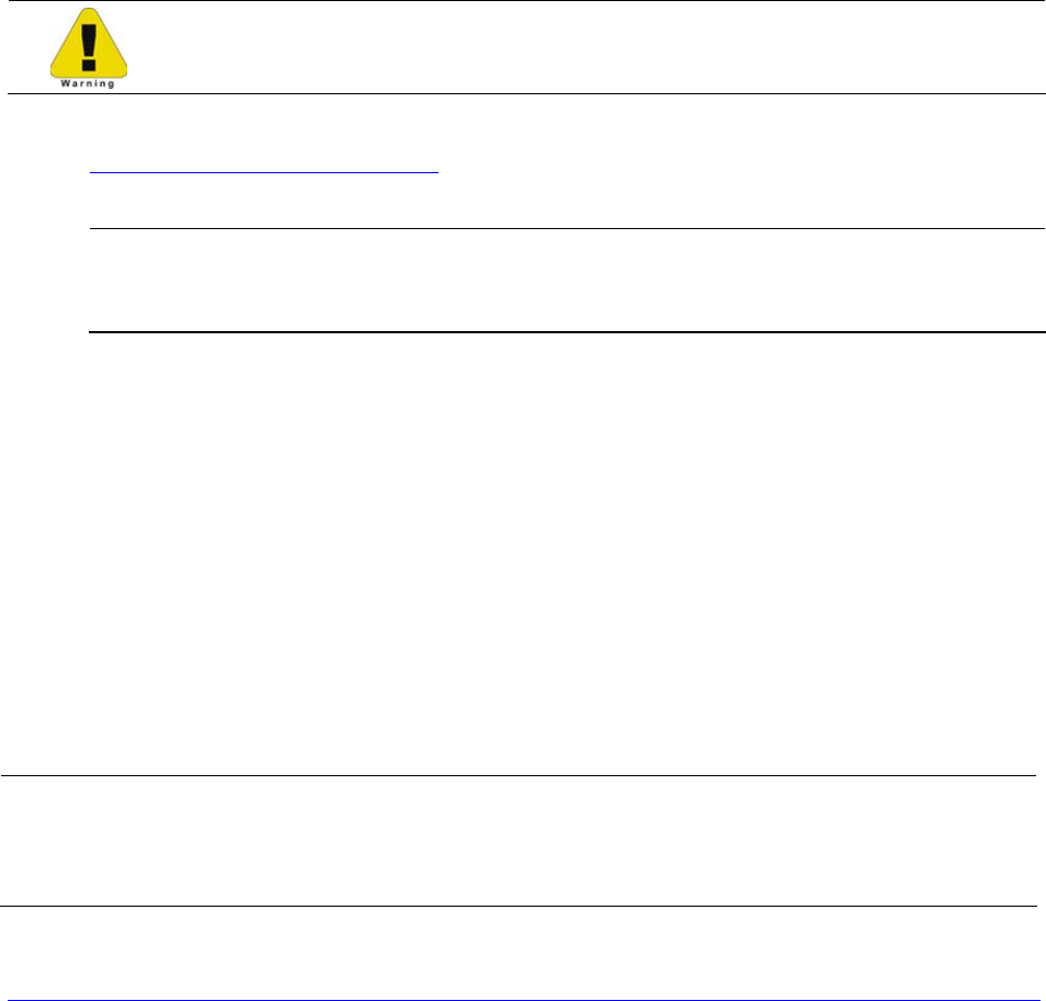
100 H-Class
5.5.7 Cleaning the Exterior Surfaces
When soiled, the exterior surfaces of the printer should be cleaned using a general-purpose
cleanser. Never use abrasive cleansers or solvents, and never pour a cleanser directly onto
the printer.
A. Turn OFF the Power Switch and unplug the power cord from the AC Receptacle.
B. Using a soft cloth (or sponge) dampened with a non-abrasive cleanser, wipe the
exterior surfaces clean.
C. Allow the surfaces to dry before reconnecting power.
5.6 Updating the Firmware
The printer’s operating application (firmware) can be updated as follows:
Depending upon the firmware version, stored data on Modules G & X can be
lost when performing an update.
A. Identify the desired version of firmware for the printer from our web site at
http://www.datamax-oneil.com and then download that file onto your computer’s
hard drive.
If updating to version 11.021 or greater, the Boot Loader must be updated
before proceeding; see Section 5.7. And, disconnect any USB keyboard from
the USB port.
B. Turn OFF the printer. Connect your computer to the printer via the parallel or USB
port, and then turn ON the printer.
C. Using the Windows print driver, open the Printer Properties box and select the
“Tools” tab. Then, from the “Action” drop-down box, select “Send File to Printer.”
D. When prompted, browse to the file downloaded onto your computer’s hard drive and
send it to the printer.
Following a successful download, the printer will reset. Unless substantial data structure
changes have occurred as a result of the firmware upgrade, the previous printer setup will
remain intact; otherwise, you may need to calibrate the printer and enter any custom
settings. To verify the new firmware version and current database configuration, print a
Configuration Label (see Section 4.3.5).
If the download was unsuccessful, the printer will perform a “warm reset” and the
original firmware will remain operational. (If the reset fails to occur, cycle the
Power Switch OFF and ON.) A list of error messages and possible solutions is given
below.
H-Class 101
Use the following list of solutions if errors occur when attempting an update:
Firmware Updating Error Messages
Displayed Message Descriptions / Possible Causes / Solutions
DECOMPRESSION ERROR
An error occurred during the decompression and transfer of
file data from cache storage into the Flash memory. Confirm
the firmware version and try the download again; however, if
the problem continues call for service.
ERROR ERASING FLASH
Flash memory could not successfully be erased. Defective
Flash memory is a possible cause. Try the download again;
however, if the problem continues call for service.
ERROR WRITING FLASH
The program could not successfully be written into Flash
memory. Defective Flash memory is a possible cause. Try the
download again; however, if the problem continues call for
service.
HARDWARE MISMATCH
The firmware downloaded is not compatible with the Main
Logic Card, is for a different model printer, or is not supported
by the Boot Loader version. See Configuration Level.
INVALID SOFTWARE
A error was detected during download, possible causes and
solutions include:
• An invalid or corrupted file was downloading. Try resaving
the file to the host. Download the file to the printer.
• A communications error occurred. Recheck the cabling and
port settings.
SOFTWARE MISMATCH The software level being installed is not authorized for this
printer. See the Printer Key information; Section 4.2.4.
5.7 Updating the Boot Loader
Boot Loader updates can be found at ftp://ftp.datamax-oneil.com. Before proceeding,
identify the printer’s current Boot Loader version by printing a Configuration Label (see
Section 4.3.5). Compare the current version to those available from the FTP site.
Download the desired version onto your computer’s hard drive then follow the steps below
to install the program.
If power is lost while UPGRADING SOFTWARE is displayed, the printer will
become non-functional and will require factory programming or a main logic
card.
102 H-Class
Boot Loader Update Procedure
Step
Displayed Message Action Comment(s)
A READY
Using the DOS copy
command (where
“filename” is the
program to be loaded
and “lpt1” is the selected
interface port), enter the
following:
copy filename lpt1:
As an example, this would be
entered as:
copy BOOTHE99_1101.bs lpt1
(Where lpt1 can differ to include
other ports, as available.)
The Ready Indicator will flash
as data is received.
B UPGRADING
SOFTWARE
The new program is being
stored and verified.
C H4212.173
07/04/2006 The printer has reset.
D READY
No action required.
The new application is now
running.
If UNCALIBRATED is
displayed, see Section 3.4.
If the update failed, press and hold PAUSE and TEST while turning ON the printer
(see Section 4.1) then release the buttons after SEND SOFTWARE is displayed and
send the file as described above.
5.8 Fonts
Downloading Kanji, Hangul and Chinese Fonts
Fonts (KANJI, HANGUL and CHINESE) can be downloaded and stored in a printer module.
Font files are identified by part number and are protected by lock bits, which unlocked by
entering the correct 6-digit code via the control panel.
The printer can be easily and quickly updated:
A. Identify the desired version of firmware for the printer from our web site at
http://www.datamax-oneil.com and then download that file onto your computer’s
hard drive.

H-Class 103
B. Call to get the unlock code and enter it into the printer. Turn OFF the printer.
C. Turn OFF the printer. Connect your computer to the printer via the parallel or USB
port, and then turn ON the printer.
D. Using the Windows print driver, open the Printer Properties box and select the
“Tools” tab. Then, from the “Action” drop-down box, select “Send File to Printer.”
E. When prompted, browse to the downloaded font file on your computer’s hard drive
and then send that file to the printer.
If protected, the destination module must first be unprotected.
With a successful download and installation, the printer will reset. Installed fonts can be
identified by part number and appear on the Configuration Label (and System Display).
The following table lists possible font downloading messages:
Font Download Messages
Displayed Message Descriptions / Possible Causes / Solutions
ACCESS DENIED
FILE EXISTS A font file of the same name already exists in memory.
ACCESS DENIED
SOFTWARE MISMATCH
The printer has an insufficient configuration level for an
encrypted plug-in, an unlocked font bit, or key mismatch.
Verify the Configuration Level of the printer by examining the
Printer Key then compare it to the software level requirement
for the file being installed.
INVALID HEADER
A wrong file format, file header is corrupt or a transmission
error has occurred. Confirm the font version and try the
download again; however, if the problem continues call for
service.
INVALID IMAGE
The download content was corrupted or a transmission error
occurred. Check for corruption by printing a Configuration
Label (see Section 4.3.5) or by looking at the system window;
a double question mark before the plug-in part number
indicates corruption. Try the download again; however, if the
problem continues call for service.
SUCCESSFUL The file was successfully installed; the printer will perform an
automatic reset.

104 H-Class
Font Download Messages (continued)
Displayed Message Descriptions / Possible Causes / Solutions
SYSTEM FAULT
Insufficient memory space for the file exists in the destination
module. Try selecting a different destination module or clear
some space on the module and perform the download again.
WRITING FLASH The file was successfully decrypted, verified, and is now being
written into the destination module.
WRITING FLASH
FAILED
The file failed checksum verification after being written to the
module. Try the download again; however, if the problem
continues call for service.
Processing TrueType Fonts
To process TrueType fonts (.TTF) on an external module for use by the printer:
1.Use Windows Explorer to download the font to a module.
2.Install the module in the printer.
3. Press the MENU button then select Printer Options.
4. Select Modules and then Process File.
5.Select the module ID and the font file.
6.When prompted enter a 2 character font ID, and then the destination module ID.
7.Ensure that your label formats use the same font ID as assigned in Step 5.
Copying TrueType Fonts
To copy TrueType fonts (.TTF) to an external module for use by the printer:
1.Use Windows Explorer to download the font to the module.
2.Add a 2 digit DPL font ID to the file name (50-99, 9A-9Z, 9a-9z) then change the
file extension to .dtf (for example, arial50.dtf); see Scalable Font Downloading in
the Class Series 2 Programmer’s Manual.
3.Install the module in the printer.
4.Ensure that your label formats use the same font ID as assigned in Step 2.
Removing Fonts
When deleting a plug-in, all files contained within that directory will be deleted as well; see
MODULES / DELETE FILE, Section 4.2.3.
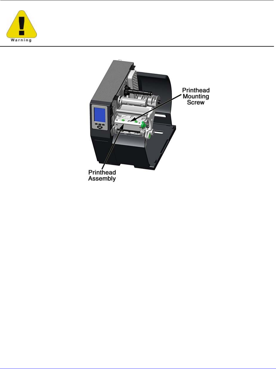
H-Class 105
5.9 Replacing the Printhead
If the printhead needs to be replaced, follow the procedure below:
• Only use a Datamax-O’Neil IntelliSEAQ™ printhead.
• Printheads are fragile; handle with extreme care and never use sharp
objects on the surface.
• If you have questions, contact a qualified technician or Datamax-O’Neil
Technical Support before proceeding.
A. Turn OFF the Power Switch then touch a bare metal printer surface (e.g., the frame)
to discharge any static electricity present on your body.
B. Unplug the printer and open the access cover. If ribbon is installed, remove it.
C. Lower the Printhead Assembly and loosen the Printhead Mounting Screw. (If using an
H-8308X model, loosen both mounting screws.)
D. Carefully raise the Printhead Assembly. Grasp the printhead then disconnect the two
cables and remove the printhead.
E. Position a new printhead under the Printhead Assembly and connect the previously
removed cables.
F. After ensuring that the printhead cables are not pinched, place the printhead onto
the locating pins under the Printhead Assembly and secure it by tightening the
Printhead Mounting Screw(s). [Do not over-tighten the screw(s)].
G. Using a Cotton Swab moistened (not soaked) with isopropyl alcohol, clean the
printhead then allow it to dry.
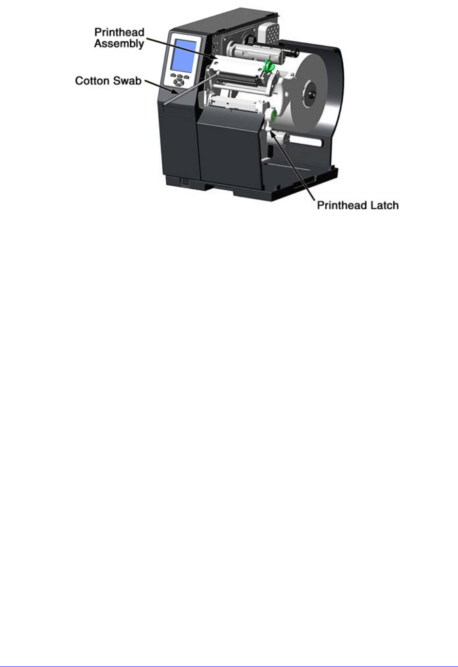
106 H-Class
H. If removed, reinstall ribbon. Lower and lock the Printhead Assembly. Plug in the
printer and turn ON the Power Switch. Print a Validation Label (see Section 4.3.4)
then compare the contrast levels between the current label and a previously printed
label; if necessary, adjust the DARKNESS setting (see Section 4.2.2) until similar
black levels are produced.
H-Class 107
6
Troubleshooting
6.1 Problem Resolution
When a problem is encountered, the information in this section will help resolve it. Locate
the description of the problem to find an appropriate solution. For problems that are
accompanied by a displayed message, see Section 6.1.2.
Depending on your labeling program and the printer's menu settings, some
commands and selections can be ignored. See HOST SETTINGS (Section 4.2.5) for
more information and consult your software vendor for program information. If you
have questions or if problems persist, contact a qualified technician or Datamax-
O’Neil Technical Support.
6.1.1 General Resolutions
The following table lists problems that may not be accompanied by a displayed message:
If experiencing this
problem… Try this solution…
Blank display (but the
backlight is ON):
Check the following possibilities:
• The display contrast may set too low (press and hold the
MENU Button until the contrast is acceptable); or,
• Disconnect any device attached to the optional SDIO Slot or
USB Host Port.
Erratic feeding:
The printer may require calibration (see Section 3.4).
Erratic printing:
Check the following possibilities:
• If in Hex Dump Mode, disable it (see Section 6.2); or,
• If using serial communications, check the host and printer
port settings; the printer may be set to eight data bits while
the host is set to 7, or vice versa (see Section 4.2.5).

108 H-Class
General Resolutions (continued)
If experiencing this
problem… Try this solution…
External memory device
is not recognized:
With the memory device properly installed (see Section 2.2.3)
in the printer, observe the display and proceed accordingly:
• If the appropriate Current State Icon (see Section 4.1.1) is
present, ensure that the module has been formatted.
• If the Current State Icon is not present, ensure that the
device is a recognizable type.
Intellifont will not
print:
You may be using an incorrect type – Intellifont format is
Little/Big Endian specific and the printer uses Big Endian; refer
to your font supplier for information.
Light print on the side
of the label:
Check the following possibilities:
• The Leveling Cam may be incorrectly adjusted (see Section
5.4.1); or,
• The Platen may be dirty or worn (see Section 5.5.5).
Missing label
information:
Check the following possibilities:
• Check the label format for character or image placement
outside the label dimensions. All row / column values must
allow space for the characters and bar codes to be printed
within the format size;
• Available memory may have been exceeded by the format
requirements. Try reducing the memory allocation to either
INTERNAL MODULE or SCALEABLE FONT (see Section
4.2.4); or,
• If using serial communications, ensure that the interface
cable meets the printer’s requirements (see Section 2.2.2).

H-Class 109
General Resolutions (continued)
If experiencing this
problem… Try this solution…
No power:
Check the following possibilities:
• Verify that the AC power cord is connected to the outlet and
to the printer, and that the Power Switch is ON;
• Verify that the AC outlet is functioning, or move the printer
to another location on a different circuit;
• Replace a possibly damaged AC cord;
• The line fuse may be blown (call for service); or,
• If using a tall model, possible disconnected or defective fan;
call for service.
No print using direct
thermal media (labels
advance normally):
Test the labels to be sure they react to heat then proceed
accordingly:
• If reactive, increase the HEAT setting in the software
program or via the menu (see Section 4.2.2); or,
• If not reactive, install direct thermal media.
No print using thermal
transfer media (labels
advance normally):
Examine the used ribbon for an image, then proceed
accordingly:
• If an image is on the used ribbon, verify that the ribbon was
properly loaded. (To identify the coated side, press the
sticky side of a label against the ribbon surfaces -- ink will
lift from the coated side.) Clean the printhead (see Section
5.5.1) and reinstall the ribbon (see Section 3.3); or,
• If no image is on the used ribbon, try the following:
Run a Test label, and if an image printed then ensure that
the protocol and port settings for the printer and host
match; see Section 4.2.5.
Increase the HEAT setting; see Section 4.2.2.
Verify that the media and ribbon combination is compatible;
see Section 7.3.

110 H-Class
General Resolutions (continued)
If experiencing this
problem… Try this solution…
No print when using a
software program (Test
labels print normally):
Ensure that the printer is at READY then observe the display
when sending your label format to the printer and proceed
accordingly:
• If Receiving Data (see Section 4.1.1) is not indicated, check
the protocol, port settings and / or IP Address between the
printer and host. If networking, check for the appropriate
Current State Icon. Also, ensure that the interface cable
meets the requirements of the printer and host, and that it
is properly connected; or,
• If Receiving Data is indicated, enter COMMUNICATIONS /
ESC SEQUENCES and disable the setting (see Section
4.2.5).
Poor print quality:
Check the following possibilities:
• Adjust the Leveling Cam (see Section 5.4.1);
• Adjust the Heat and Print Speed settings (see Section
4.2.2);
• If using thermal transfer, ensure media and ribbon
compatibility (see Section 7.3); and,
• Clean the printhead (see Section 5.5.1).
Skips labels when
printing:
Check the following possibilities:
• Perform calibration; (see Section 3.4);
• Adjust the Media Sensor (see Section 3.2); and,
• If the label format is within 1/8 inch of the media’s edge,
reduce or move the format slightly.
H-Class 111
6.1.2 Warning and Fault Messages
The printer displays messages when the possibility of a problem or an actual fault occurs.
Depending upon the displayed message, find the possible action or solution in the tables
below.
Warning and Fault Messages do not appear when in Menu or Test Mode.
Warning Messages
Displayed for about three seconds, Warning Messages assume a low priority and indicate a
pending change in printer configuration, or an operating condition that could lead to a fault.
Warning Messages
Displayed Message Description Possible Solution(s)
24V OUT OF TOLERANCE
The printer has detected
a drop in the 24-volt
power supply.
No action is required. If the
problem continues, cycle the
power OFF and ON.
DOT FAILURE
Defective printhead
elements have been
detected.
Replace the printhead if print
quality becomes unacceptable.
GAP MODE
WARNING LOW BACKING
Only a small difference
exists between the
measured Empty and
Gap readings.
No action is required. During
calibration, labels mounted on a
transparent liner or notched
media may give this indication.
A slight delay in the OUT OF
STOCK message may occur.
GOODBYE
Power has been removed
and printer shutdown is
in progress.
AC line voltage has been lost.
The Power Switch was turned
OFF or the line fuse has blown.
If unable to restore power, try
moving the printer to another
location and if the condition
persists, call for service.

112 H-Class
Warning Messages Fault Messages (continued)
Displayed Message Description Possible Solution(s)
HEAD NEEDS CLEANING
The scheduled printhead
cleaning distance has
been reached.
Clean the printhead (see
Section 5.5.1).
To change the cleaning setting,
enter ADVANCED MENU /
MEDIA SETTINGS / PRINTHEAD
CLEANING MENU.
HOST CHANGES PENDING
The host has changed
the configuration of the
printer, but those
changes cannot take
effect until a “host reset
command” is issued.
To save these changes, send a
host reset command (in DPL);
or, to discard the changes,
perform a soft reset (see
Section 5.3.1).
INVALID ENTRY
The selection you are
attempting to make is
not valid or is not within
the acceptable
parameter range.
Enter a different setting or
parameter that falls within the
acceptable range.
LOW VOLTAGE
The printer has detected
a low operating voltage.
Possible low or fluctuating line
voltage levels have been
sensed. If the condition
persists, try moving the printer
to another outlet, or call for
service.
REWINDER FULL
The internal rewinder is
nearing capacity.
Unload the internal rewinder
soon.
RIBBON LOW
The ribbon supply is
almost empty.
Load a new roll of ribbon soon.
RTC RAM FAILURE
The printer was unable
to save settings in
permanent memory.
Possible faulty Main Logic Card.
Retry your save. If the
condition persists, call for
service.
TEMPERATURE PAUSE
A high printhead
temperature has been
detected.
Wait for the printhead to cool.
Afterward, printer operations
will automatically resume when
the printhead reaches an
acceptable temperature.
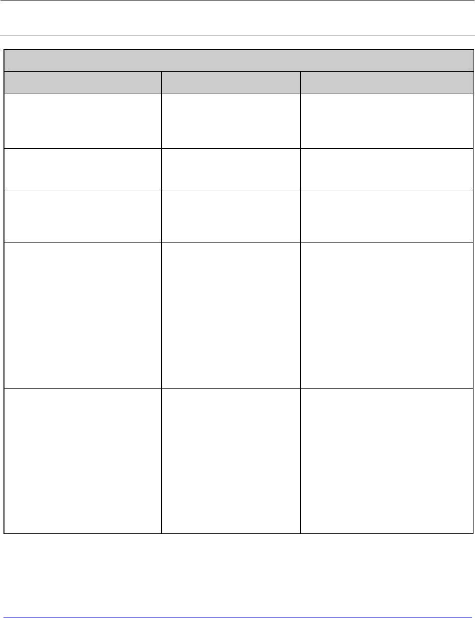
H-Class 113
Fault Messages
These high priority messages alert you to a printer fault condition. (Alternate messages may
occur when downloading font, firmware, or Boot Loader files.)
To return operation after a fault occurs, the fault must be corrected and the FEED
Key pressed.
Fault Messages
Displayed Message Description Possible Solution(s)
ADC FAULT
The printer has detected
an analog to digital
circuit converter failure.
Cycle printer power OFF and
ON. If the fault does not clear,
call for service.
CLOSE HEAD LATCH The Printhead is not
latched.
Lock the Printhead Latch (see
Section 3.1).
DMA FAULT
The printer has detected
a Direct Memory Access
failure.
Cycle printer power OFF and
ON. If the fault does not clear,
call for service.
GAP MODE
CANNOT CALIBRATE
Consistently low sensor
readings have been
detected for the media.
Press any key to continue.
Ensure that media was removed
from the media sensor during
the appropriate calibration steps
(see Section 5.2); also, ensure
that ribbon has been correctly
loaded and that the sensor is
clean (see Section 5.5.4). Retry
the calibration. If the problem
persists, try Advanced Entry
Calibration (see Section 5.2.2).
GAP MODE
FAULTY SENSOR
Consistently high sensor
readings have been
detected for the media.
Press any key to continue.
Ensure that media was removed
from the media sensor during
the appropriate calibration steps
(see Section 5.2); also, ensure
that ribbon has been correctly
loaded and that the sensor is
clean (see Section 5.5.4). Retry
the calibration. If the problem
persists, call for service.

114 H-Class
Fault Messages (continued)
Displayed Message Description Possible Solution(s)
HEAD CLEANING FAULT
The scheduled
printhead cleaning has
been exceeded by an
amount equal to three
times the pre-
programmed distance.
Clean the printhead (see
Section 5.5.1).
To change the cleaning setting,
enter ADVANCED MENU /
MEDIA SETTINGS / PRINTHEAD
CLEANING MENU.
OUT OF STOCK
The printer cannot
detect the presence of
media.
Examine the printer for media
then proceed accordingly:
• If the printer is out of
stock, load media; or,
• If stock is loaded, ensure
that the Media Sensor is
calibrated (see Section
3.4), properly positioned
(see Section 3.2) and, if
the media has large gaps,
that the Paper Empty
Distance is adjusted (see
Section 4.2.1).
POSITION FAULT
Possible causes of this
fault include a firmware
update, a power failure
or reset during a ribbon,
out of stock or TOF fault,
and an incomplete
calibration process.
Press the FEED Key in an
attempt to identify and then
clear the fault. Perform
calibration (see Section 3.4).
PRINT ENGINE FAULT
A problem within the
print logic has been
detected.
Cycle printer power OFF and
ON. If the fault does not clear,
call for service.
RAM FAULT A memory failure has
been detected.
Cycle printer power OFF and
ON. If the fault does not clear,
call for service.

H-Class 115
Fault Messages (continued)
Displayed Message Description Possible Solution(s)
REFLECTIVE MODE
CANNOT CALIBRATE
Consistently low sensor
readings were detected.
Press any key to continue.
Ensure that the reflective mark
was inserted face down. Also,
ensure that the sensor is clean
and that the reflective mark is
made from carbon-based ink.
Retry calibration (see Section
5.2).
REFLECTIVE MODE
FAULTY SENSOR
Consistently high sensor
readings were detected.
Press any key to continue.
Ensure that media was removed
from the media sensor during
the appropriate calibration
steps; also ensure that no
labels are stuck in the media
sensor. Retry calibration (see
Section 5.2). If the problem
persists, call for service.
REWINDER FAULT No rewinder movement
is detected.
Examine the rewinder then
proceed accordingly:
• If full, unload the internal
rewinder then press the
FEED Key to clear the fault;
or,
• If not full, cycle printer
power OFF and ON. If the
fault does not clear, call for
service.
To continue printing, enter
the menu then go to
PRINTER OPTIONS /
REWINDER and disable the
option (see Section 4.2.3).
REWINDER FULL
The internal rewinder is
at capacity and has
stopped turning.
Unload the internal rewinder
then press the FEED Key to
clear the fault.

116 H-Class
Fault Messages (continued)
Displayed Message Description Possible Solution(s)
RIBBON FAULT
Two causes are possible:
(1) The Thermal Transfer
media type has been
selected, but no ribbon
movement or only
sporadic movement has
been detected.
(2) The ribbon sensor
values have changed.
If using direct thermal stock,
change the Media Type setting
to Direct Thermal; otherwise
ensure that ribbon is installed.
Press the FEED Key to clear the
fault -- if the fault does not
clear check the Ribbon Hubs for
free movement. Also, ensure
that the ribbon core fits snugly
onto the supply hub, and that
the ribbon is not slipping or
stalling as labels print. If no
binding, slipping, or stalling is
apparent press and hold the
FEED Key until at least three
labels have been output. If the
fault does not clear, call for
service.
TEMPERATURE FAULT
The printer has
shutdown due to the
printhead temperature.
Turn OFF the printer. Ensure
that the printer has been
installed within an acceptable
environment. DO NOT restart
until the printhead cools.
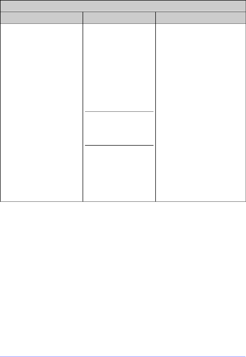
H-Class 117
Fault Messages (continued)
Displayed Message Description Possible Solution(s)
TOP OF FORM FAULT
The printer could not find
a TOF mark within the
maximum length setting,
or TOF was encountered
in an unexpected place.
When the SENSOR
TYPE is REFLECTIVE,
this indication is
given for Out Of
Stock.
Check the following
possibilities:
• Calibration may be
necessary (see Section
3.4);
• The Media Sensor may need
adjustment (see Section
3.2);
• The Media Guide may need
adjustment (see Section
3.1);
• The Leveling Cam may need
adjustment (see Section
5.4.1);
• The MAXIMUM LABEL
LENGTH may need to be
increased (see Section
4.2.1); or
• The Media Sensor may need
to be cleaned (see Section
5.5.4).
6.2 Hex Dump Mode
Hex Dump Mode is a useful tool for diagnosing problems and debugging label formats as
received host data strings are printed without interpretation by the printer. These strings
can be analyzed for content and, by repeatedly sending a format, handshaking problems
(sections of missing data) can become apparent.
• To enter Hex Dump Mode, press the MENU Button and select DIAGNOSTICS. Go to
HEX DUMP MODE then select ENABLE and press the ENTER Key. Exit the menu,
saving your changes.
Afterward, HEX DUMP MODE will be displayed and all received data will be output in
hexadecimal code (along with the ASCII equivalents), printed or saved to a file (see
FILE CAPTURE, Section 4.2.6). The example below illustrates a Hex Dump label
output:

118 H-Class
To decode data strings the Class Series 2 Programmer’s Manual is an essential reference
(see the Accessories CD-ROM). Also, some software programs use bit mapping, which can
make diagnosis difficult – contact Datamax-O’Neil Technical Support with any questions.
To return Operating Mode, enter the DIAGNOSTICS and disable HEX DUMP MODE.
Exit the menu and save the changes.

H-Class 119
7
Specifications
7.1 General
This section identifies shared parameters and features of the printer models.
Embedded Bar Codes & Fonts
See the Class Series 2 Programmer’s Manual for details.
Communications
Interface Types: USB; RS-232, RS-422/485 (DB-9); IEEE 1284 Compliant
Parallel (Centronics); and, Ethernet
Serial Data Rates (RS-232):
1200 to 115,000 bits per second
Handshaking:
Xon/Xoff; CTS/DTR
Parity:
Even, Odd, or None
Stop Bits:
1 or 2
Data Bits:
7 or 8
Electrical
AC Input Voltage Range: 90 - 132 VAC, and 180 - 264 VAC @ 47 - 63 Hz
Power Consumption: Typical operating: 150 Watts; Standby: 21 Watts
Power Supply: Auto ranging switching type.
Printhead Protection: Thermistor protected to temporarily halt printing upon
high temperature detection then resume after cool-
down.

120 H-Class
Environmental
Operating Temperature Range: 32° to 100° F (0° to 38° C)
Storage Temperature: 0° F – 140° F (-17° C to 60° C)
Humidity Range: 10% – 95% non-condensing
Dust: Non-conducting, non-corrosive
Electromagnetic Radiation: Moderate RF fields can be tolerated.
7.2 Model-Specific Specifications
This section identifies unique parameters and features of the printer models, where X
denotes the tall version of the model.
H-4212, H-4310, H-4408, & H-4606 Models
Mechanical
Height: 13 inches (329.7 mm)
Width: 12.6 inches (321.1 mm)
Depth: 18.9 inches (480.1 mm)
Weight: 40 pounds (18.1 kg)
Electrical
Display: Graphics (128 X 64 pixels) with backlight; or
(Optional) Graphics (240 X 320 pixels) with backlight.
Printing
Method: Direct Thermal or (optional) Thermal Transfer
Speed: 2 - 12 IPS (51 - 305 MMPS); H-4212
2 - 10 IPS (51 - 254 MMPS); H-4310
2 - 8 IPS (51 - 203 MMPS); H-4408
2 - 6 IPS (51 - 152 MMPS); H-4606
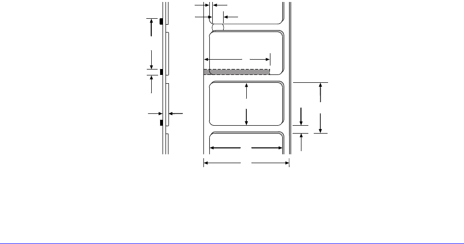
H-Class 121
Printing (continued)
Resolution: 203 DPI (8 dots/mm); H-4212
300 DPI (12 dots/mm); H-4310
406 DPI (16 dots/mm); H-4408
600 DPI (23.6 dots/mm); H-4606
Dot Size (nominal): .0043" X .0052" (.11 mm x .13 mm); H-4212
.0027" X .0043" (.07 mm x .11 mm); H-4310
.0013" X .0018" (.03 mm x .05 mm); H-4408
.0008" X .0015" (.02 mm x .04 mm); H-4606
Tear Bar: Downward tear
Media
Types: Die-Cut, Notched, Continuous, and Reflective
(Roll or Fanfold)
Internal Capacity: 8-inch (203mm) Outer Diameter Roll (on a standard 3-inch
core; or, on a 40 mm core with the optional supply hub)
Ribbon Width Range: 1 inch - 4.65 inches (25 mm – 118 mm)
Ribbon Length: 1968 feet (600 m)
Dimensions: Reference the drawing and table below:
E
J
I
C
K
A
B
D
H
F
G
Side View Top View

122 H-Class
Media (continued)
H-4212, H-4310, H-4408, & H-4606 Media Dimensional Requirements [1]
Minimum Maximum
Designator Description inches mm inches mm
A Label width 1.00 25 4.65 118
B Liner width 1.00 25 4.65 118
C Gap (or notch) between labels[3] .08 2 – –
D Label length[3] .25 6 – –
E Media thickness .0025 .06 .01 .25
F Notch opening width .08 2 – –
G Media edge to sensor aperture .20 5 2.25 70
H Reflective mark width[2] .47 12 4.65 118
I Distance between reflective marks[3]
.25 6 – –
J Reflective mark length[3] .08 2 – –
K Label repeat distance[3] .33 8 – –
[1]
Units of measure are referenced by the direction of label feed.
[2]
The reflective (black) mark must be carbon based, placed on the backside of the stock, and the
reflectance shall be less than 10% at wavelengths of 950 and 640 nm.
[3]
The maximum allowable length of the combined label and gap (or mark) measurement cannot
exceed 99.99 inches.
H-4212X, H-4310X, & H-4606X Models
Mechanical
Height: 16.4 inches (415.3 mm)
Width: 12.6 inches (321.1 mm)
Depth: 19.3 inches (489 mm)
Weight: 47 pounds (21.3 kg)
Electrical
Display: Graphics (240 X 320 pixels) with backlight.
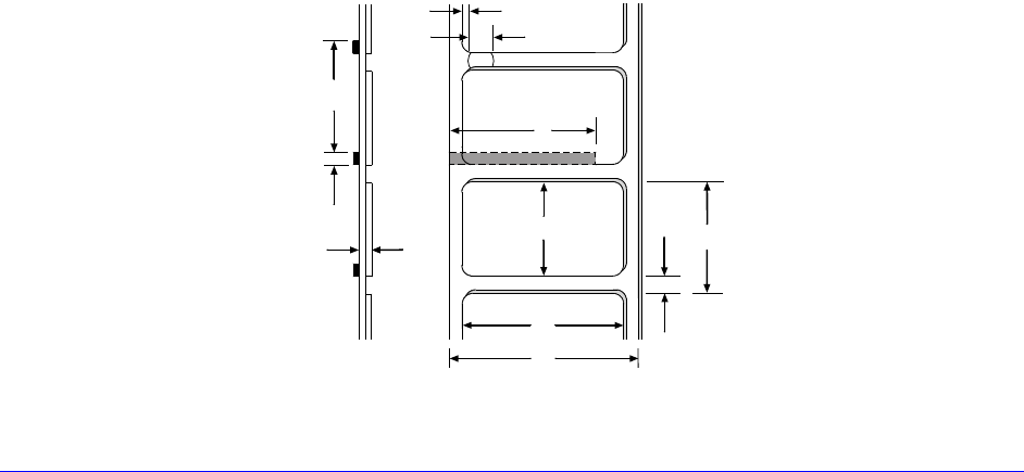
H-Class 123
Printing
Method: Direct Thermal or (optional) Thermal Transfer
Speed: 2 - 12 IPS (51 - 305 MMPS); H-4212X
2 - 10 IPS (51 - 254 MMPS); H-4310X
2 - 6 IPS (51 - 152 MMPS); H-4606X
Resolution: 203 DPI (8 dots/mm); H-4212X
300 DPI (12 dots/mm); H-4310X
600 DPI (23.6 dots/mm); H-4606X
Dot Size (nominal): .0043" X .0052" (.11 mm x .13 mm); H-4212X
.0027" X .0043" (.07 mm x .11 mm); H-4310X
.0008" X .0015" (.02 mm x .04 mm); H-4606X
Tear Bar: Downward tear
Media
Types: Die-Cut, Notched, Continuous, and Reflective
(Roll or Fanfold)
Internal Capacity: 8-inch (203mm) Outer Diameter Roll (on a standard 3-inch
core; or, on a 40 mm core with the optional supply hub)
Ribbon Width Range: 1 inch - 4.65 inches (25 mm – 118 mm)
Ribbon Length: 1968 feet (600 m)
Dimensions: Reference the drawing and table below:
E
J
I
C
K
A
B
D
H
F
G
Side View Top View
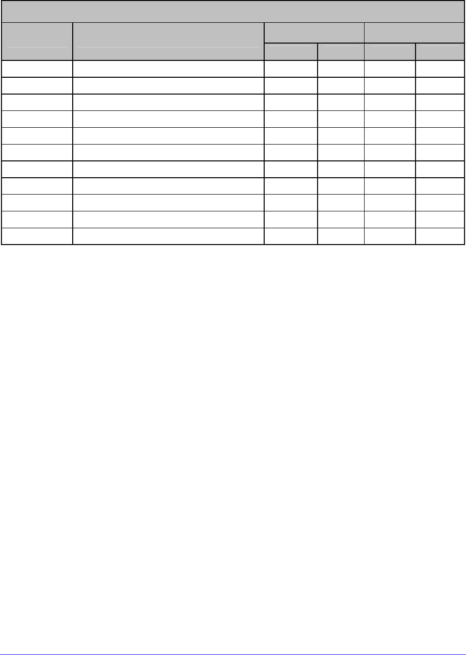
124 H-Class
Media (continued)
H-4212X, H-4310X, & H-4606X Media Dimensional Requirements [1]
Minimum Maximum
Designator Description inches mm inches mm
A Label width 1.00 25 4.65 118
B Liner width 1.00 25 4.65 118
C Gap (or notch) between labels[3] .08 2 – –
D Label length[3] .25 6 – –
E Media thickness .0025 .06 .01 .25
F Notch opening width .08 2 – –
G Media edge to sensor aperture .20 5 2.25 70
H Reflective mark width[2] .47 12 4.65 118
I Distance between reflective marks[3]
.25 6 – –
J Reflective mark length[3] .08 2 – –
K Label repeat distance[3] .33 8 – –
[1]
Units of measure are referenced by the direction of label feed.
[2]
The reflective (black) mark must be carbon based, placed on the backside of the stock, and the
reflectance shall be less than 10% at wavelengths of 950 and 640 nm.
[3]
The maximum allowable length of the combined label and gap (or mark) measurement cannot
exceed 99.99 inches.
H-6210 & H-6308 Models
Mechanical
Height: 13 inches (329.7 mm)
Width: 15 inches (381 mm)
Depth: 18.9 inches (480.1 mm)
Weight: 47 pounds (21.3 kg)
Electrical
Display: Graphics (128 X 64 pixels) with backlight; or
(Optional) Graphics (240 X 320 pixels) with backlight.

H-Class 125
Printing
Method: Direct Thermal or (optional) Thermal Transfer
Speed: 2 - 10 IPS (51 - 254 MMPS); H-6210
2 - 8 IPS (51 - 203 MMPS); H-6308
Resolution: 203 DPI (8 dots/mm); H-6210
300 DPI (12 dots/mm); H-6308
Dot Size (nominal): .0043" X .0052" (.11 mm x .13 mm); H-6210
.0027" X .0043" (.07 mm x .11 mm); H-6308
Tear Bar: Downward tear
Media
Types: Die-Cut, Notched, Continuous, and Reflective
(Roll or Fanfold)
Internal Capacity: 8-inch (203mm) Outer Diameter Roll (on a standard 3-inch
core; or, on a 40 mm core with the optional supply hub)
Ribbon Width Range: 2 inches - 6.7 inches (51 mm – 170 mm)
Ribbon Length: 1968 feet (600 m)
Dimensions: Reference the drawing and table below:
E
J
I
C
K
A
B
D
H
F
G
Side View Top View

126 H-Class
Media (continued)
H-6210 & H-6308 Media Dimensional Requirements [1]
Minimum Maximum
Designator Description inches mm inches mm
A Label width 2.00 51 6.7 170
B Liner width 2.00 51 6.7 170
C Gap (or notch) between labels[3] .08 2 – –
D Label length[3] .25 6 – –
E Media thickness .0025 .06 .01 .25
F Notch opening width .08 2 – –
G Media edge to sensor aperture .20 5 2.25 70
H Reflective mark width[2] .47 12 6.7 170
I Distance between reflective marks[3]
.25 6 – –
J Reflective mark length[3] .08 2 – –
K Label repeat distance[3] .33 8 – –
[1]
Units of measure are referenced by the direction of label feed.
[2]
The reflective (black) mark must be carbon based, placed on the backside of the stock, and the
reflectance shall be less than 10% at wavelengths of 950 and 640 nm.
[3]
The maximum allowable length of the combined label and gap (or mark) measurement cannot
exceed 99.99 inches.
H-6212X & H-6310X Models
Mechanical
Height: 16.4 inches (415.3 mm)
Width: 15 inches (381 mm)
Depth: 19.3 inches (489 mm)
Weight: 53 pounds (24 kg)
Electrical
Display: Graphics (240 X 320 pixels) with backlight.
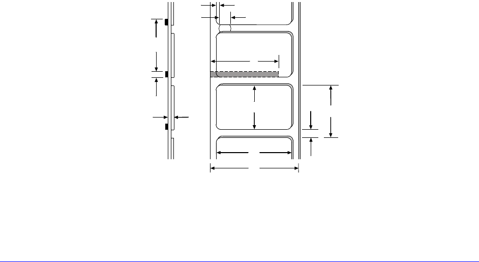
H-Class 127
Printing
Method: Direct Thermal or (optional) Thermal Transfer
Speed: 2 - 12 IPS (51 - 305 MMPS); H-6212X
2 - 10 IPS (51 - 254 MMPS); H-6310X
Resolution: 203 DPI (8 dots/mm); H-6212X
300 DPI (12 dots/mm); H-6310X
Dot Size (nominal): .0043" X .0052" (.11 mm x .13 mm); H-6212X
.0027" X .0043" (.07 mm x .11 mm); H-6310X
Tear Bar: Downward tear
Media
Types: Die-Cut, Notched, Continuous, and Reflective
(Roll or Fanfold)
Internal Capacity: 8-inch (203 mm) Outer Diameter Roll (on a standard 3-inch
core; or, on a 40 mm core with the optional supply hub)
Ribbon Width Range: 2 inches - 6.7 inches (51 mm – 170 mm)
Ribbon Length: 1968 feet (600 m)
Dimensions: Reference the drawing and table below:
E
J
I
C
K
A
B
D
H
F
G
Side View Top View

128 H-Class
Media (continued)
H-6212X & H-6310X Media Dimensional Requirements [1]
Minimum Maximum
Designator Description inches mm inches mm
A Label width 2.00 51 6.7 170
B Liner width 2.00 51 6.7 170
C Gap (or notch) between labels[3] .08 2 – –
D Label length[3] .25 6 – –
E Media thickness .0025 .06 .01 .25
F Notch opening width .08 2 – –
G Media edge to sensor aperture .20 5 2.25 70
H Reflective mark width[2] .47 12 6.7 170
I Distance between reflective marks[3]
.25 6 – –
J Reflective mark length[3] .08 2 – –
K Label repeat distance[3] .33 8 – –
[1]
Units of measure are referenced by the direction of label feed.
[2]
The reflective (black) mark must be carbon based, placed on the backside of the stock, and the
reflectance shall be less than 10% at wavelengths of 950 and 640 nm.
[3]
The maximum allowable length of the combined label and gap (or mark) measurement cannot
exceed 99.99 inches.
H-8308X Model
Mechanical
Height: 16.4 inches (415.3 mm)
Width: 17 inches (432.8 mm)
Depth: 19.3 inches (489 mm)
Weight: 59 pounds (26.8 kg)
Electrical
Display: Graphics (240 X 320 pixels) with backlight.
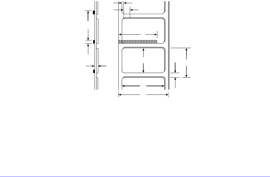
H-Class 129
Printing
Method: Direct Thermal or (optional) Thermal Transfer
Speed: 2 - 8 IPS (51 – 203 MMPS)
Resolution: 300 DPI (12 dots/mm)
Dot Size (nominal): .0027" X .0039" (.07 mm X .10 mm)
Tear Bar: Downward tear
Media
Types: Die-Cut, Notched, Continuous, and Reflective
(Roll or Fanfold)
Internal Capacity: 8-inch (203 mm) Outer Diameter Roll (on a standard 3-inch
core; or, on a 40 mm core with the optional supply hub)
Ribbon Width Range: 3 inches - 9 inches (76 mm – 228 mm)
Ribbon Length: 1968 feet (600 m)
Dimensions: Reference the drawing and table below:
E
J
I
C
K
A
B
D
H
F
G
Side View Top View
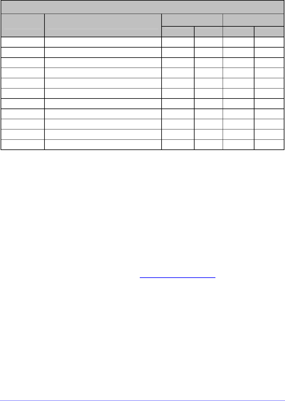
130 H-Class
Media (continued)
H-8308X Media Dimensional Requirements [1]
Minimum Maximum
Designator Description inches mm inches mm
A Label width 3.00 76 9 228
B Liner width 3.00 76 9 228
C Gap (or notch) between labels[3] .08 2 – –
D Label length[3] .25 6 – –
E Media thickness .0025 .06 .01 .25
F Notch opening width .08 2 – –
G Media edge to sensor aperture .20 5 2.25 70
H Reflective mark width[2] .47 12 9 228
I Distance between reflective marks[3]
.25 6 – –
J Reflective mark length[3] .08 2 – –
K Label repeat distance[3] .33 8 – –
[1]
Units of measure are referenced by the direction of label feed.
[2]
The reflective (black) mark must be carbon based, placed on the backside of the stock, and the
reflectance shall be less than 10% at wavelengths of 950 and 640 nm.
[3]
The maximum allowable length of the combined label and gap (or mark) measurement cannot
exceed 99.99 inches.
7.3 Approved Media and Ribbon
Media (and ribbon for thermal transfer) is an important determinant in the throughput,
quality, and performance of the printed product. The following overview is an introduction to
the different types of material that can be used in the printer. For complete information and
advice regarding a specific application, consult a qualified media specialist or a Datamax-
O’Neil Media Representative. Also available is an informative white paper, A Brief
Introduction to Media, which can be found at www.datamax-oneil.com
Direct Thermal
Consider three important factors when selecting direct thermal stock:
• The abrasive qualities of the material that covers the thermal reactive layer of the
paper;
• The amount of heat required to start the chemical reaction; and,
• The ability of the media to control that chemical reaction.
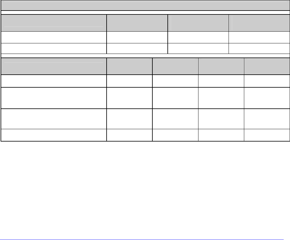
H-Class 131
Thermal Transfer
Consider three important factors when selecting thermal transfer media and ribbon
combinations:
• Label top coating and ribbon combinations may affect image quality;
• Ribbon backcoating can provide printhead protection and, depending upon the
formula, help reduce static buildup; and,
• The ribbon width, when slightly wider than the media, can also guard the printhead
against media abrasion.
Media and Ribbon Selection
To achieve optimum print quality and maximum printhead life, we specify the use of
DATAMAX-O’NEIL brand media. These supplies are specially formulated for use in our
printers; use of non-Datamax-O’Neil supplies may affect the print quality, performance, and
life of the printer or its components. For a current list of approved media, please contact a
Media Representative at (407) 523-5650.
Suggested direct thermal and thermal transfer applications are listed below:
Media and Ribbon Overview
Direct Thermal Media Print
Speed* Print
Energy Image
Durability
Datamax-O’Neil DTL-HSM 10 – 12** Medium Low
Datamax-O’Neil DTL-HSH 10 – 12** Medium Low
Thermal Transfer Media Ribbon
Type Print
Speed* Print
Energy Image
Durability
Great Label TTL GPR Plus 10 – 12** Medium Medium
Coated and uncoated paper, tag
stock, some films and synthetics
Wax
GPRPlus 2 – 10 Low Low
Coated and glossy paper, tag
stock, some films and synthetics
Wax/Resin
PGR+ 2 – 8 Medium High
Synthetics and films Resin SDR 4 – 6 High High
* Given in inches per second.
** Highly recommended for optimum quality at speeds above 10 IPS.

132 H-Class
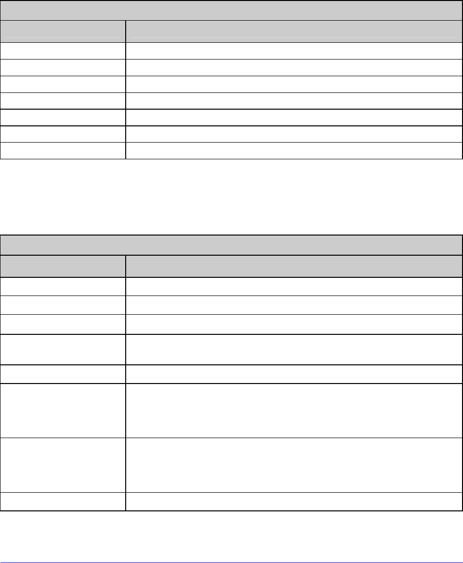
H-Class 133
Appendix A
Module Assignments, and File Handling Definitions and Messages
Module Assignments
Memory Module
Designator Definition / Location
D DRAM (Main Logic Card)
F SD Memory Card (Optional, for port-equipped models only)
G FLASH (Main Logic Card)
H USB Thumbdrive (Optional, for port-equipped models only)
I USB Thumbdrive (Optional, for port-equipped models only)
X FLASH (Main Logic Card)
Y FLASH (Main Logic Card)
File Handling Definitions
The following file types are supported and, as noted, converted by the printer.
Process File Handling (see Section 4.2.3)
File Type Definition / Requirements
BMP, PCX, and IMG Industry standard black and white graphics formats.
BS Boot Loader upgrade file.
F7B A 7-bit image load file.
LS Language message file in a single or double byte format
generated from an Excel spread sheet via macros.
PLG A file group containing hidden, encrypted, or normal files.
SFL and SFP
Industry standard portrait and landscape bit-mapped font
formats, where the label name should contain the Font ID as
last three digits before the file extension to allow automated
conversion (see DBM, below).
TTF
Industry standard true type / scalable font formats, where the
label name should contain the Font ID as last two digits before
the file extension to allow automated conversion (see DTT,
below).
ZS and ZG A compressed firmware upgrade file.
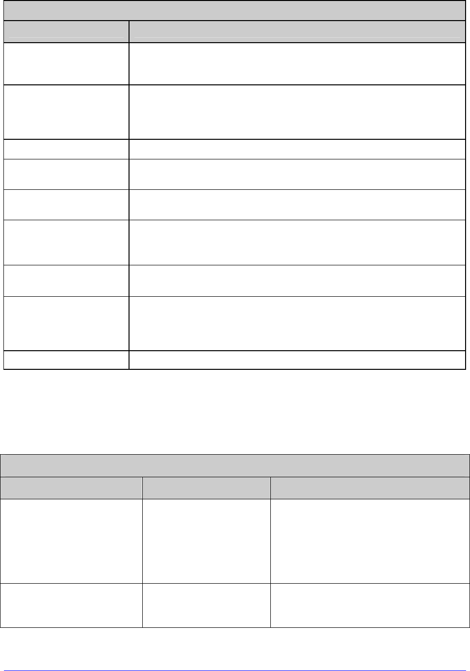
134 H-Class
Print File Types (see Section 4.2.3)
File Type Definition / Requirements
DBM
A bit-mapped font file, created after download using “Font
Loading Commands” (see the Class Series 2 Programmer's
Manual) or PROCESS FILE (above) for use as label typeface.
DCM
A configuration file for custom printer setup, savable and
restorable via the menu or DPL commands (see the Class Series
2 Programmer's Manual for details). This file cannot be copied
from the Y Module.
DIM A converted BMP, PCX, IMG, or F7B file for use in label formats.
DLB A label format file, recallable and printable (see <STX>L in the
Class Series 2 Programmer's Manual for details).
DLN A language message file containing printer language
translations.
DMS
A database or miscellaneous file for custom option or feature
setup, automatically created by the printer (cannot be copied
from the Y module).
DPL A file containing control and / or label data as typically
generated by printer driver software.
DTT
A true type or scalable font file created after download using the
<STX>i command (see the Class Series 2 Programmer's
Manual) or "Process File" (see PRINTER OPTIONS / MODULES,
Section 4.2.3). This can be used for label or display fonts.
PLU A converted PLG file. (Encrypted types cannot be copied.)
File Handling Messages
Depending upon the module and operation selected, several messages are possible when
using the file handling system:
File Handling Messages
Displayed Message Description Possible Solution(s)
FAILED The copy or format
request has failed.
Not enough space exists on the
module to store the file or the module
may be protected - try storing the
data to a different location. (If the
problem persists, this could indicate a
hardware problem.)
FILE EXISTS,
OVERWRITE?
An existing file of the
same name and type
was found.
Select YES to overwrite or NO to exit.
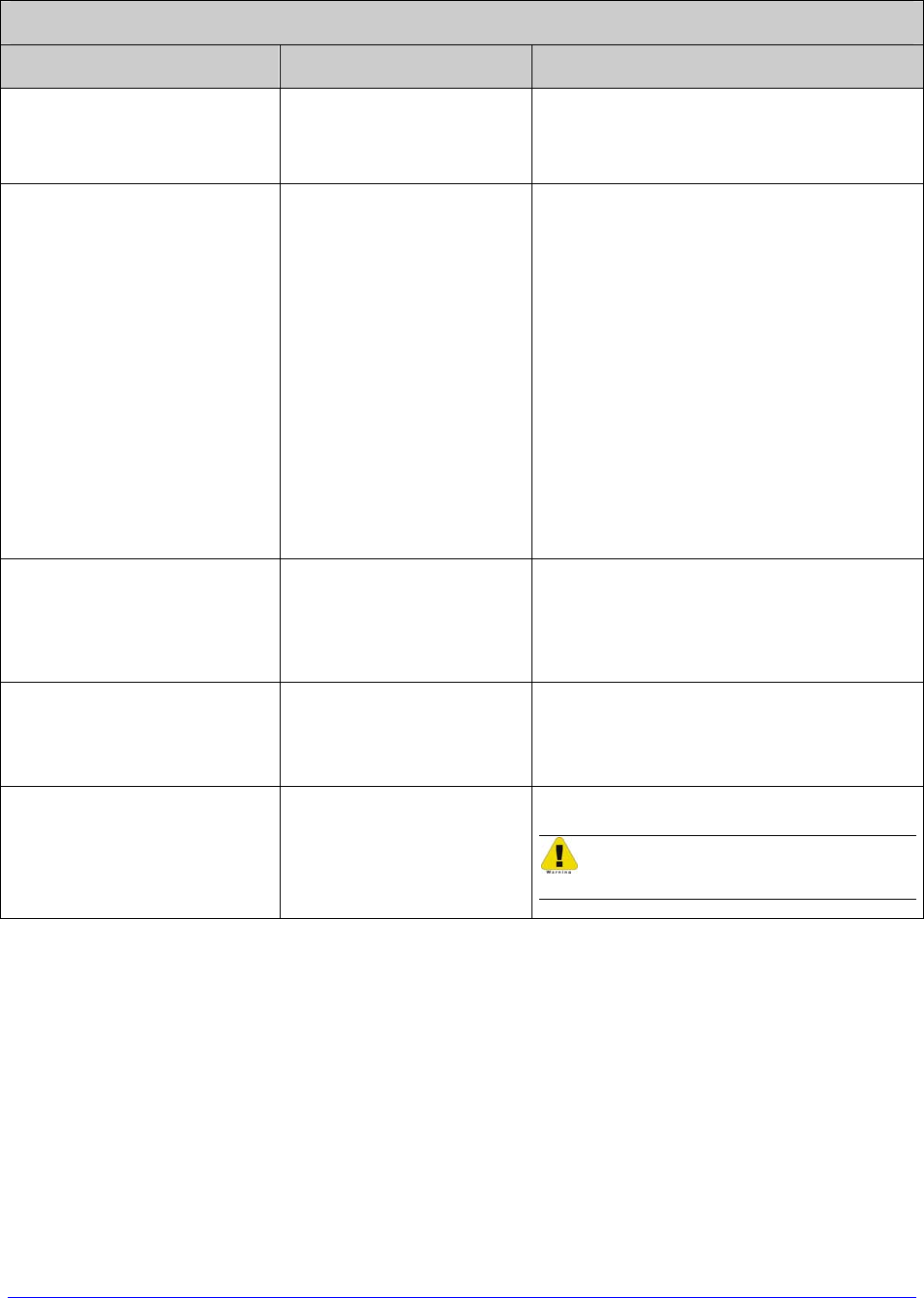
H-Class 135
File Handling Messages (continued)
Displayed Message Description Possible Solution(s)
MODULE PROTECTED
The request has been
denied because the
module is protected.
Unprotect the module.
NO FILES AVAILABLE
No associated files can
be found to perform
the requested action.
Ensure the file is present:
• Following a Print File request, this
is normal when no print files exist
(also, some files will only print the
file name);
• Following a Process File request,
this is normal when no files are
available for processing (also,
some files may not display); or,
• Following a Copy File request, this
is normal when no files are
available for copying (also, internal
database files cannot be copied).
NOT SUPPORTED The file requested is
not a supported type.
Recheck the file type requested, and
ensure that it is available for that
function; see File Handling
Definitions, Appendix A.
PROTECTED, PROTECTED
COPY FILE?
The file requested will
be copied to a
PROTECTED module.
Select YES to override protection and
copy the file, or NO to exit.
UNFORMATTED The module is not
formatted.
Format the module.
Choosing FORMAT MODULE will
erase all module data.

136 H-Class

H-Class 137
Appendix B
Resolutions, Widths, Speeds, Emulations, & Custom Adjustments
Print Resolutions and Widths
Resolutions and Widths
Maximum Print Width
Model Printhead
Resolution Inches Millimeters Default
Setting
H-4212 &
H-4212X
203 dots/inch
(8 dots/mm) 4.10 104.1 4.10
H-4310 &
H-4310X
300 dots/inch
(12 dots/mm) 4.16 105.7 4.16
H-4408 406 dots/inch
(16 dots/mm) 4.10 104.1 4.10
H-4606 &
H-4606X
600 dots/inch
(23.6 dots/mm) 4.16 105.7 4.16
H-6210 &
H-6212X
203 dots/inch
(8 dots/mm) 6.61 167.90 6.62
H-6308 &
H-6310X
300 dots/inch
(12 dots/mm) 6.40 162.60 6.64
H-8308X 300 dots/inch
(12 dots/mm) 8.52 216.40 8.52
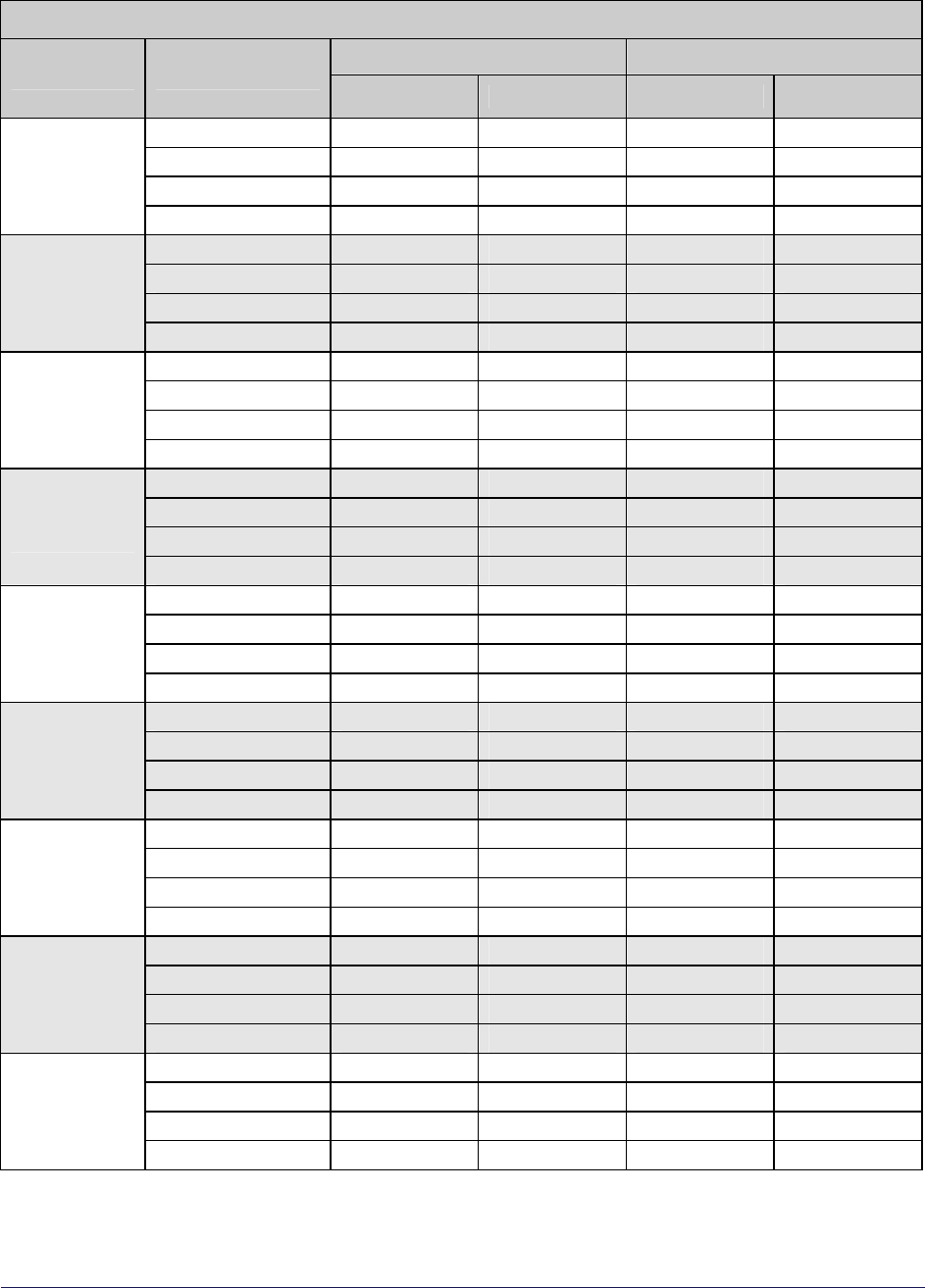
138 H-Class
Speed Ranges
Speed Ranges and Defaults
Speed Range Default Setting
Model Function IPS MMPS IPS MMPS
Print 2 – 12 51 – 305 8 203
Feed 2 – 12 51 – 305 8 203
Reverse 2 – 4 51 – 102 4 102
H-4212 &
H-4212X
Slew 2 – 16 51 – 406 8 203
Print 2 – 10 51 – 254 8 203
Feed 2 – 12 51 – 305 8 203
Reverse 2 – 4 51 – 102 4 102
H-4310 &
H-4310X
Slew 2 – 16 51 – 406 8 203
Print 2 – 8 51 – 203 6 152
Feed 2 – 10 51 – 254 6 152
Reverse 2 – 4 51 – 102 4 102
H-4408
Slew 2 – 16 51 – 406 6 152
Print 2 – 6 51 – 152 4 102
Feed 2 – 8 51 – 203 4 102
Reverse 2 – 4 51 – 102 4 102
H-4606 &
H-4606X
Slew 2 – 16 51 – 406 4 102
Print 2 – 10 51 – 254 6 152
Feed 2 – 12 51 – 305 6 152
Reverse 2 – 4 51 – 102 4 102
H-6210
Slew 2 – 12 51 – 305 6 152
Print 2 – 12 51 – 305 8 203
Feed 2 – 12 51 – 305 8 203
Reverse 2 – 4 51 – 102 4 102
H-6212X
Slew 2 – 14 51 – 356 8 203
Print 2 – 8 51 – 203 6 152
Feed 2 – 10 51 – 254 6 152
Reverse 2 – 4 51 – 102 4 102
H-6308
Slew 2 – 10 51 – 254 6 152
Print 2 – 10 51 – 254 8 203
Feed 2 – 12 51 – 305 8 203
Reverse 2 – 4 51 – 102 4 102
H-6310X
Slew 2 – 14 51 – 356 8 203
Print 2 – 8 51 – 203 6 152
Feed 2 – 10 51 – 254 6 152
Reverse 2 – 4 51 – 102 4 102
H-8308X
Slew 2 – 12 51 – 305 6 152
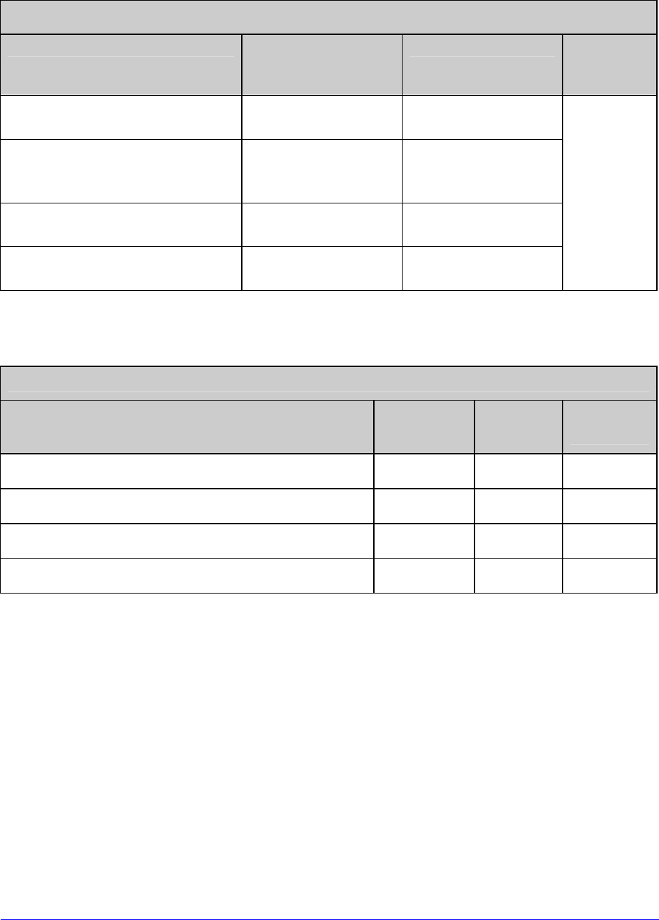
H-Class 139
Custom Adjustment Ranges
Row, Column, and Present Adjust Ranges (in dots)
Model Row Adjust and
Present Adjust Column Adjust Default
Setting
H-4212, H-4212X & H-6212X -100 – 2030 -100 – 100
H-4310, H-4310X, H-6308,
H-6310X, & H-8308X -150 – 3000 -150 – 150
H-4408 -200 – 4060 -200 – 200
H-4606 & H-4606X -300 – 6000 -300 – 300
000
Column & Row Emulation Ranges
Emulation Ranges (in dots)
Model Column Row Default
Setting
H-4212, H-4212X & H-6212X 153 – 203 103 – 303 203
H-4310, H-4310X, H-6308, H-6310X, & H-8308X 250 – 300 200 – 400
300
H-4408 356 – 406 306 – 506 406
H-4606 & H-4606X 550 – 600 500 – 700 600

140 H-Class
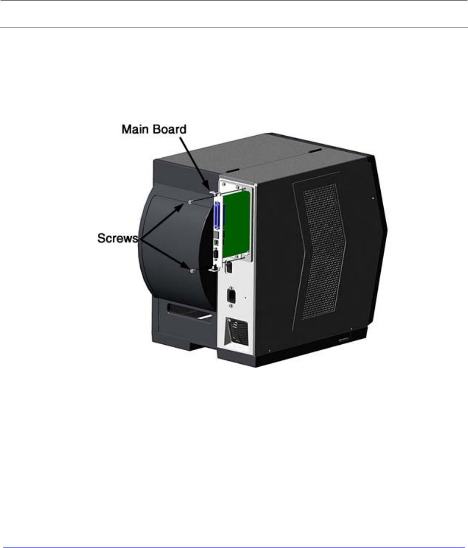
H-Class 141
Appendix C
RS-422/485 Port Configuration
The serial port can be configured for RS-422/485 communications, and / or a +5VDC (@
0.5A maximum) source for powering external devices.
The Serial Port default configuration is "RS-232" and Pin 1 "Not Connected."
1. Turn OFF the printer and unplug the power cord.
2. Remove the communication cables from the Main Board.
3. Loosen and remove the two Screws securing the Main Board to the printer.
4. Slide the Main Board out of the printer then move the jumpers according the needs
of the application:
• For RS-422/485 operation, place the jumper across pins E4 and E5;
• For +5VDC on Pin 1, place the jumper across pins E1 and E2; or,
• For RS-232 operation (default), place the jumper across pins E5 and E6;
• For no voltage on Pin 1 (default), place the jumper across pins E2 and E3.
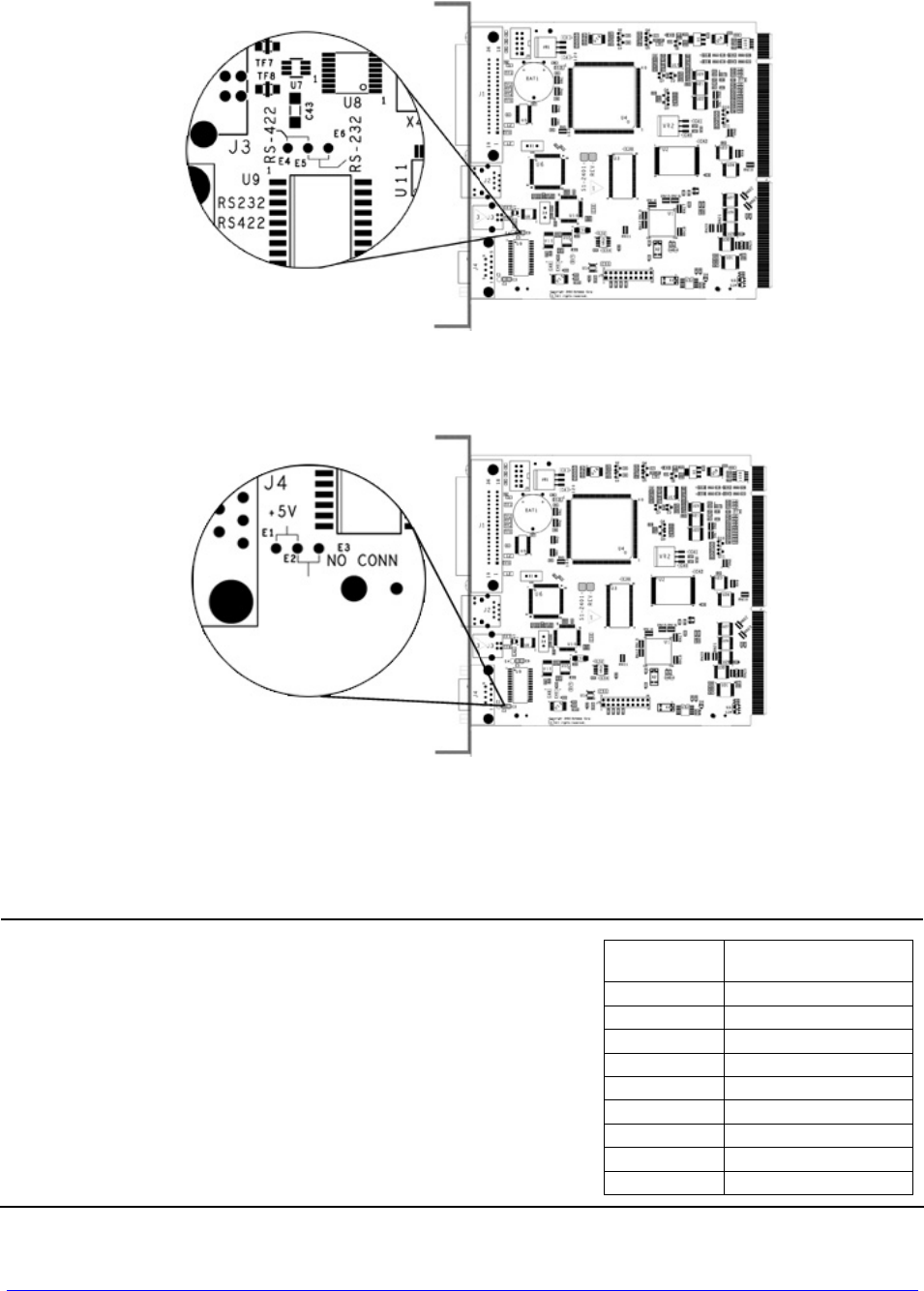
142 H-Class
Communication Jumper Locations
+5 Volts Jumper Location
5. Slide the Main Board into the printer and secure it with the two previously removed
Screws.
6. Connect communication cables to the Main Board and plug in the power cord.
For RS-422/485 communications, ensure that
your cable meets the requirements (per the table,
right) for proper data transfer.
Serial Port
Pin Number RS-422 & RS-485
Function
1 ---
2 RX-
3 TX+
4 ---
5 GND
6 ---
7 TX-
8 RX+
9 ---
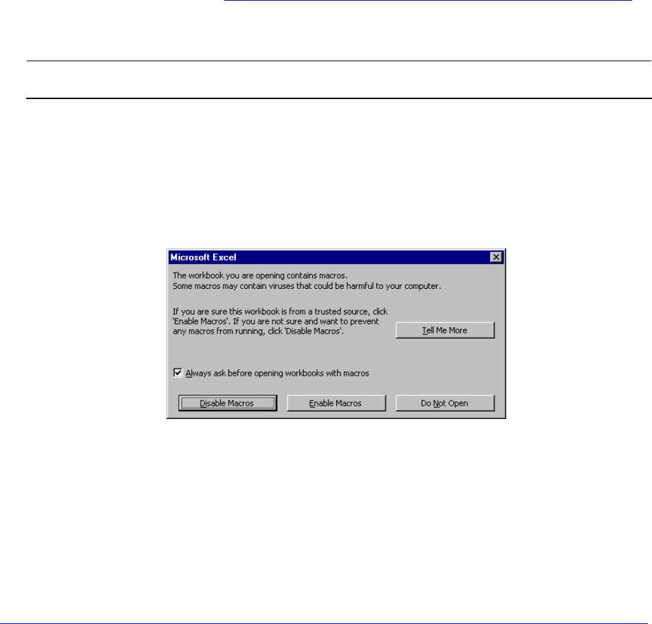
H-Class 143
Appendix D
Changing the Menu Language
Different languages and / or Datamax-O’Neil-provided translations can be downloaded to
replace the standard (English) menu of the printer by changing the spreadsheet that defines
the system dictionary. To change the language you will add a new language column (or
modify the existing column) in the spreadsheet, click on the “Generate DPL file(s)” radio
button, and then send that file(s) to the printer.
Software requirements for modifying the menu language are as follows:
• Microsoft® Excel must be purchased by user;
• Img2dl.exe (provided at ftp://ftp.datamax-oneil.com/Anonymous/Firmware/EFIGS/)
is a program used during the process to create the DPL file; and,
• Common.xls (also provided at the web site above) is the Menu Dictionary.
Place Img2dl.exe and Common.xls in the same directory.
Create a Menu Language by following these steps:
A. Invoke Excel and open the Common.xls file. After the file opens, the following screen
appears:
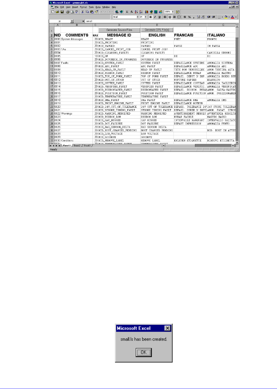
144 H-Class
B. Click the “Enable Macro” box. The following screen appears:
C. Click On Column J and enter the new language, or modify an existing one. Some tips
on this process:
• Message Size – When entering new messages, reference the “MAX” column: this
is the maximum number of characters allowed for this field. (Warnings are
displayed when the number of characters is exceeded, or when trying to modify
the MAX value; however, if “cutting and pasting” fields, this warning system may
be defeated.)
• Two Line Messages – Some of the message are displayed as two lines. These are
indicated in the comment fields.
• Comments – This field can be modified with no effect.
D. After editing is complete, highlight all of the columns to be created by pressing the
letter above the column (more than one column can be selected).
E. Press the Generate DPL File(s) radio button. A file will be generated for each of the
selected columns and Excel will provide confirmation (for example, as shown below,
small.ls).
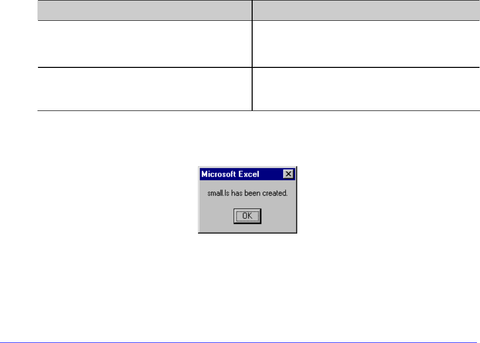
H-Class 145
F. Download the generated files to the printer – one method is the DOS copy
command:
copy small.ls lpt1: /b
G. Reset the printer by pressing and holding the CANCEL Key for approximately four
seconds.
H. After resetting, verify operation by printing a Configuration Label (see Section 4.3.5).
New language information will be printed under SYSTEM INFORMATION / OPTIONAL
LANGUAGES. (Also, the new language will appear on the display as a menu item in
SYSTEM SETTINGS / MENU LANGUAGE. These are the only methods to determine a
successful download.)
Enable the new language. Enter the menu system and go to SYSTEM SETTINGS /
MENU LANGUAGE and select the new language (A reset will occur as font validation
is performed.)
Afterward, reenter the menu system and go to SYSTEM SETTINGS / MENU
LANGUAGE and select the desired font for the language. Save the changes when
prompted.
An error has occurred if the printer displays the new language selection, but all
messages remain in English. In this case, re-check your process or contact Datamax-
O’Neil Technical Support (be ready to provide the Common.xls and DPL download
files created). Other error messages are also possible:
Menu Language Error Message Description
Please select the entire column(s) or
the desired language(s), by clicking on
the column letter(s)
After pressing the Generate DPL File(s)
radio button, the languages to convert
were not correctly selected.
Message text may not exceed MAX =
xx designated characters for this MID
The entered message exceeds the
number of characters specified in column
C. You may not modify this number.
I. Repeat Steps A – H using the filename misc.xls to translate printer option items. This
will output small20.ls.
Advanced File Handling Information
• The standard printer leaves the factory with EFIGS loaded into Module Y. At this
point, Module Y is LOCKED and will only accept additional language downloads.
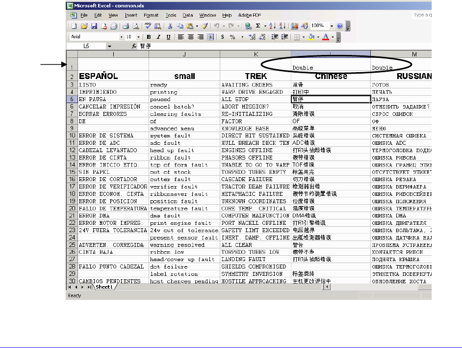
146 H-Class
• After downloading a language update, Module Y is left UNLOCKED until the printer is
reset or power is cycled. In this state, Module Y will accept font, image and label
format downloads. The module will also honor the Clear Module request. Therefore,
following an update it is recommended that a reset be performed to lock the module;
otherwise, a software package may “Clear All Modules” thus destroying the new
menu language(s).
• Module Y can be UNLOCKED by sending this DPL string: <STX>KpY0
• To restore the factory generated EFIGS image, download the file *832296.01A to the
printer. This file is located on the Datamax-O’Neil FTP site. The letter at the end of
the file name (e.g., A) specifies the revision. The latest revision will be available on
the FTP site.
• Downloading the same language twice will automatically delete the first occurrence,
but will not free the memory space.
• Deletion of the selected language will reset the printer to English. The total number
of languages that the printer can now accept is limited to 10, but this number is
dependent upon the size of each language translation. The translation size will vary
with the number of messages that are translated for that particular language.
Current complete language files are about 7,000 bytes each; but with product
growth, the total number of languages is expected to drop to five.
• The screen shot below is an example of Unicode defined Languages, Chinese &
Russian. Note the only additional information required is the “double” in row 1.

H-Class 147
Appendix E
Saving a Configuration File
Configuration files save and restore printer settings, eliminating the need for special
repeated printer setups. Unique filenames can be assigned and settings restored via the
host or printer menu. The following example saves a media calibration as a configuration
file:
If file sharing among multiple printers, DO NOT include unique parameters (such as
calibrations and adjustments).
Step Action Displayed Message
A With the printer set for the configuration to be
saved, press the any Navigation Button. SELECT FUNCTION
B
Scroll to ADVANCED MENU and then press the
RIGHT Button. (Or, to quit this procedure press
the EXIT Key.)
ADVANCED MENU
C Scroll to SYSTEM SETTINGS and then press the
RIGHT Button. SYSTEM SETTINGS
D Press the RIGHT Button. CONFIGURATION FILE
E Scroll to SAVE SETTING AS then press the RIGHT
Button. SAVE SETTING AS
F
Use the buttons to assign a name to the
Configuration File; up to eight characters can be
used.
SAVE SETTING AS
G Press the ENTER Key to save. SUCCESSFUL
To restore a configuration file via the menu, see Section 4.2.4.

148 H-Class

H-Class 149
Appendix F
Ethernet Setup
Because the Print Server makes IP requests at power-up, before making a network
connection to the printer consider how your IP Addressing needs to be assigned.
IP Addressing of the Internal Ethernet Print Server can be configured two ways:
• Using a static IP Address; or,
• Using IP Discovery (DHCP, BootP, or RARP).
Proceed according to the desired addressing method:
At factory default settings, IP DISCOVERY is DISABLED.
Configuration Using a Static IP Address
Assign a static IP Address by following the steps below:
A. Without connecting the Ethernet cable, turn ON the printer.
B. Press the MENU Button then scroll to COMMUNICATIONS / NIC ADAPTER / IP
ADDRESS.
• For access to all functions, ensure that the Advanced Menu is selected: Press
System Settings select Menu Mode and then Advanced Menu.
C. Use the UP and DOWN Buttons to increment or decrement each numeric value, and
use the RIGHT button to move to the cursor to the next digit. After all fields have
been input, press ENTER.
D. Scroll to SUBNET MASK and set that address (see Step C, above).
E. Scroll to GATEWAY and set that address (see Step C, above).
F. If needed, set your SNMPTRAP DESTINATION address (see Step C, above, or use the
HTML pages, see Appendix G).
G. After entering the addresses, press EXIT and save your changes when prompted.
H. Turn OFF the printer and connect the Ethernet cable. Turn ON the printer and then
install the port and printer driver using the Windows “Add a Printer Wizard” and
Driver and Port Setup (see Appendix H).
150 H-Class
Configuration Using IP Discovery
DHCP, BootP, and RARP are services that provide a method for assigning and maintaining IP
Addresses. With IP Discovery enabled, the Print Server obtains IP information from this
service. IP Discovery must first be enabled for use. Assign IP Discovery by following the
steps below:
When IP DISCOVERY is ENABLED you will not be able to change the IP ADDRESS,
SUBNET MASK, or GATEWAY.
A. Without connecting the Ethernet cable, turn ON the printer. Press the MENU Button.
B. Scroll to COMMUNICATIONS > NIC ADAPTER > IP DISCOVERY. Select ENABLED and
press ENTER.
C. Press EXIT and save your changes when prompted.
D. Turn OFF the printer. Connect the Ethernet cable and turn ON the printer.
E. After the connection is established, obtain the Assigned IP Address (see below) by
printing a Configuration Label; see Section 4.3.5.
PRINT CONTROL
HEAT:
10
PRINT SPEED:
8.0 in/sec
FEED SPEED:
8.0 in/sec
REVERSE SPEED:
4.0 in/sec
SLEW SPEED:
8.0 in/sec
PRINTER OPTIONS
MODULES:
D: FORMATTED
G: FORMATTED
X: FORMATTED
Y: FORMATTED
PRESENT SENSOR:
NOT INSTALLED
ROW OFFSET:
00.00 in.
COLUMN OFFSET:
00.00 in.
PRESENT DISTANCE:
AUTO
CUSTOM ADJUSTMENTS:
DARKNESS:
32
CONTRAST:
32
ROW ADJUST:
0 DOTS
COLUMN ADJUST:
0 DOTS
PRESENT ADJUST:
0 DOTS
COMMUNICATIONS
NIC ADAPTER:
MAC:00-0d-70-00-30-15
WLAN:
MODE:
DISABLED
BSS ADDRESS:
192.168.10.1
IP ADDRESS:
192.168.10.26
SUBNET MASK:
255.255.255.000
GATEWAY:
192.168.10.26
SNMPTRAP DESTINATION:
0.0.0.0
IP DISCOVERY:
ENABLED
SNMP:
ENABLED
ADVANCED:
TELNET:
ENABLED
FTP:
ENABLED
MTU:
1500
GRATUITOUS ARP:
0
PORT NUMBER:
9100
DUPLEX CAPABILITY:
AUTO-NEGOTIATE
ADVERTISE CAPABILITY:
AUTOMATIC
Assigned IP Address
Depending upon your server, it may take a minute or two for the Assigned IP
Address to appear on the label.
F. After the Assigned IP Address has been obtained, install the port and printer driver
using the Windows “Add a Printer Wizard” and Driver and Port Setup (see Appendix
H).

H-Class 151
Using the HTML Pages
The resident HTML (Web) pages allow configuration of network and printer settings, status
queries, and diagnostic tests. To configure the Print Server and other internal printer
settings, you can access the printer via HTML pages using any Web browser. Samples and
comment text is given in the screenshots that follow.
Access the HTML Pages as follows:
A. In your Web browser, choose File > Open.
B. Enter the IP address of the Print Server and press Enter. (The default IP Address is
192.168.10.2)
Consult with your system administrator for address, printer, and protocol
information. The authentication password for setting changes is sysadm

152 H-Class
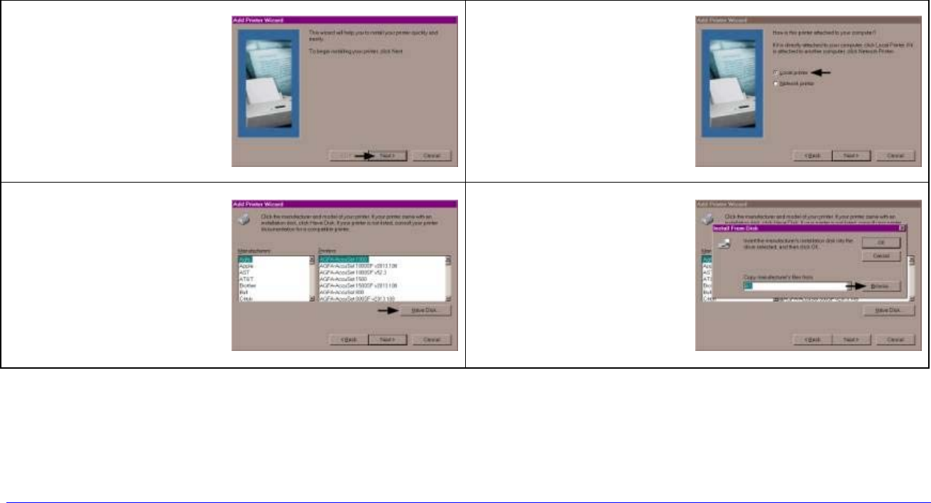
H-Class 153
Appendix G
Printer Driver and Port Setup
Install the Printer Driver and Port software according to the host’s operating system.
Windows 95/98 Driver and Port Installation
1
Start the Windows
“Add Printer
Wizard” and this
screen should
appear. Click
Next>.
2 Ensure that Local
Printer is selected
and then click Next.
3 Click on Have Disk.
4 Insert the
Accessories CD-
ROM and click
Browse.
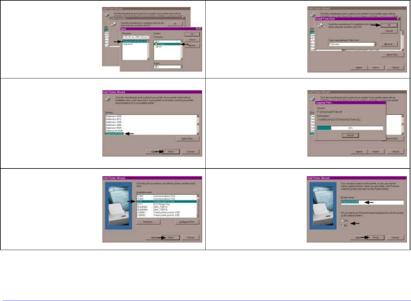
154 H-Class
Windows 95/98 Driver and Port Installation (continued)
5 Browse to the
“\DRIVERS\Seagull”
folder on the CD-
ROM, ensure the
file “xp.inf” is
selected and click
OK.
6 Click OK.
7 Select your printer
from the list and
then click Next.
8 Your computer will
now copy the
necessary files from
the CD-ROM.
9 When prompted to
choose a port,
select FILE and
click Next. (Later,
you will setup the
network port from
the printer
properties.)
10
Name your printer
in the Printer
Name: field. Next
select whether or
not to set this
printer as your
default printer.
Then Click Finish.
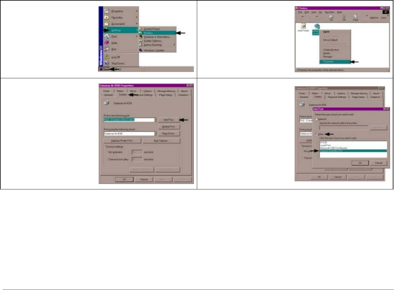
H-Class 155
Windows 95/98 Driver and Port Installation (continued)
11 From the Windows
desktop click Start /
Settings / Printers.
12
After the Printers
window opens,
right-click on the
printer icon and
select Properties
from the drop down
menu.
13 Click on the Details
tab and then click
Add Port.
14
In the Add Port
window, Select
Other and “Seagull
Scientific Port” and
then click OK.
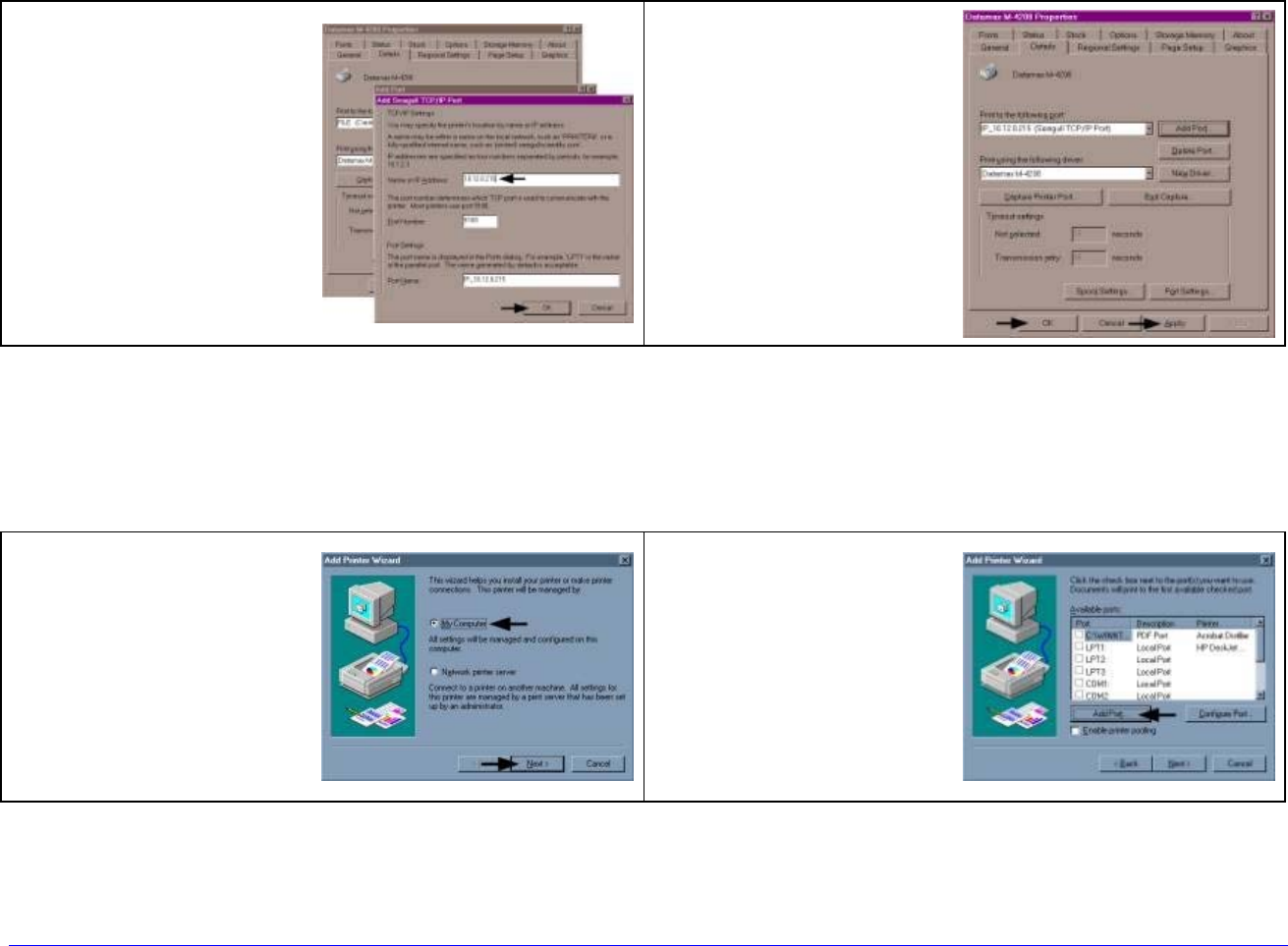
156 H-Class
Windows 95/98 Driver and Port Installation (continued)
15 In the Name or IP
Address: field,
enter the IP
address of your
printer. The Port
Number and Port
Name fields do not
need to be
changed. When
finished click OK.
16
Click Apply and
then click OK.
The driver and port
installation is now
complete. The
printer can be
selected through
any Window’s
application.
Windows NT 4.0 Driver and Port Installation
1 Start the Windows
“Add Printer
Wizard”. Ensure
that My Computer
is selected and then
click Next.
2 Click Add Port.
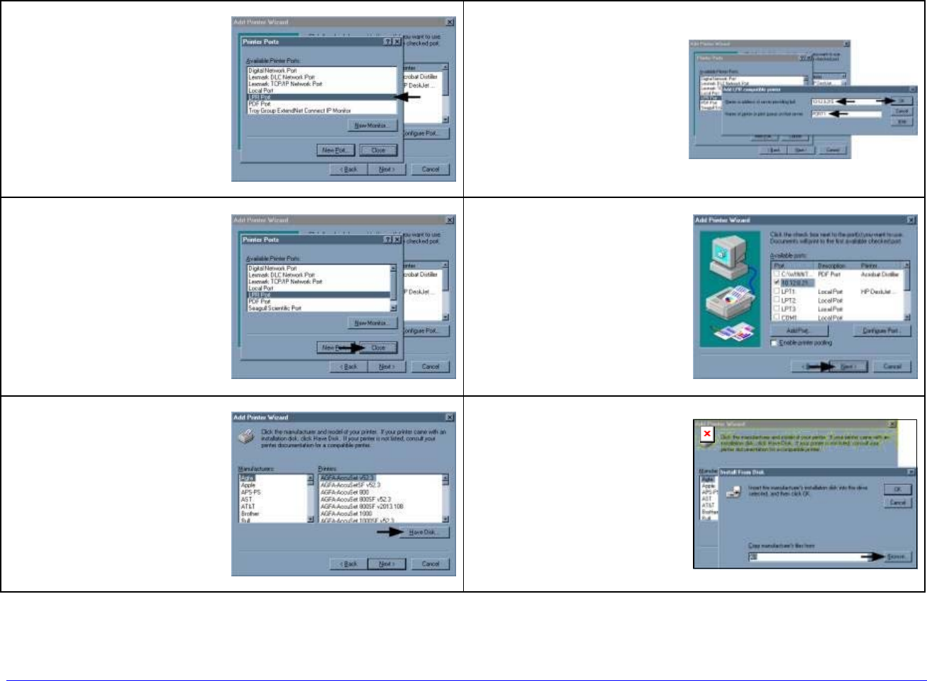
H-Class 157
Windows NT 4.0 Driver and Port Installation (continued)
3 Double-click LPR
Port.
4 In the top field
enter the IP
address of your
printer. In the
bottom field enter
PORT1. When
finished click OK.
5 Click Close.
6 Click Next.
7 Click on Have Disk.
8 Insert the
Accessories CD-
ROM and click
Browse.
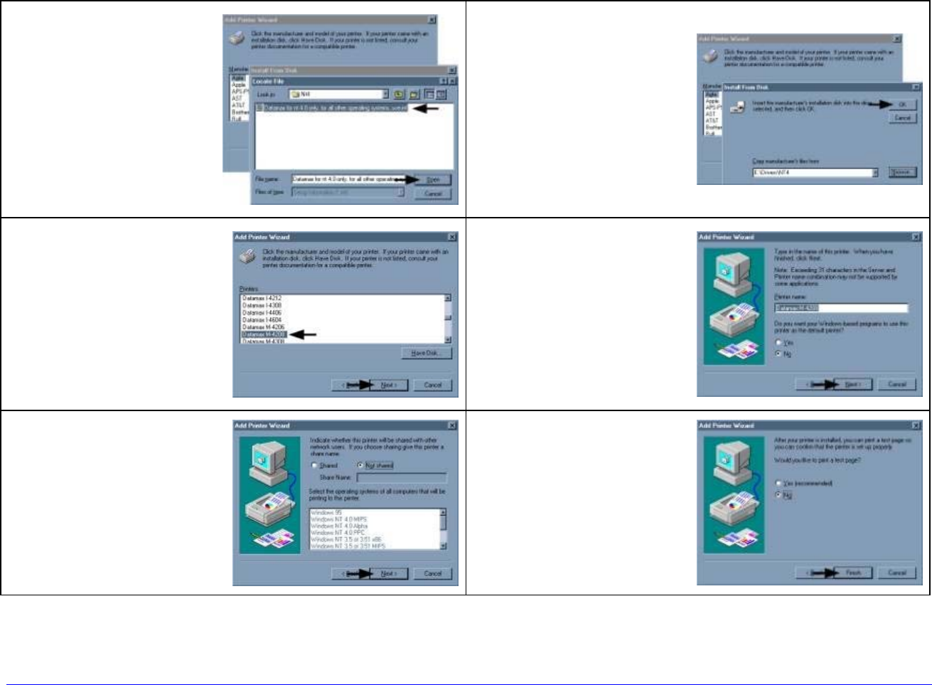
158 H-Class
Windows NT 4.0 Driver and Port Installation (continued)
9 Browse to the
“\DRIVERS\Seagull\
Nt4\” folder on the
CD-ROM, ensure
the file “for nt 4.0
only…” is selected
and click Open.
10
Click OK.
11 Select your printer
from the list and
then click Next.
12
Name your printer
in the Printer
name: field. Next
select whether or
not to set this
printer as your
default printer.
Then Click Next.
13 Select whether or
not to share this
printer on your
network. Then Click
Next.
14
Select No then Click
Finish.
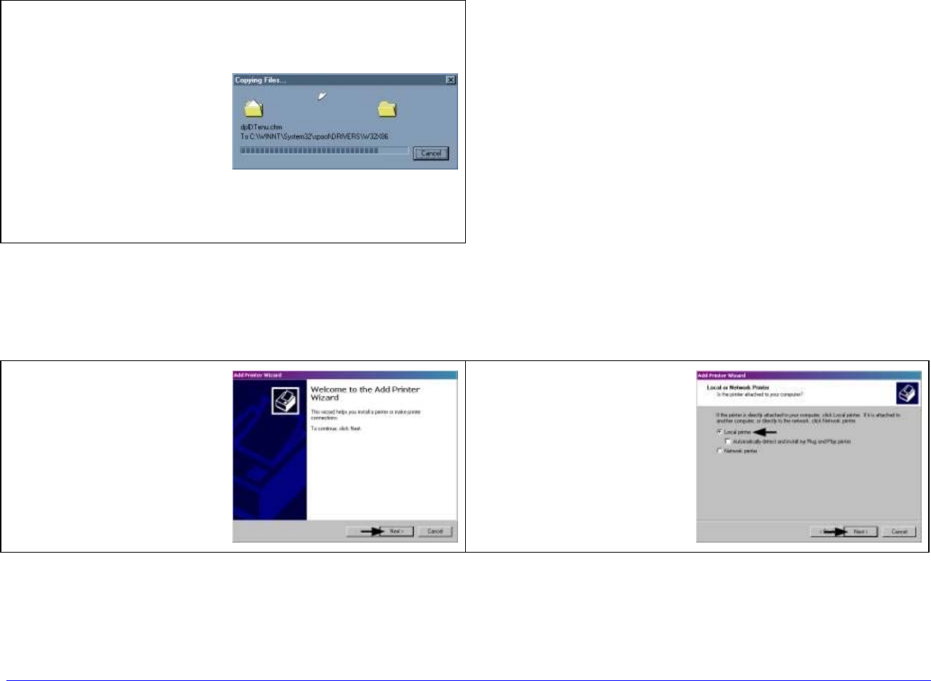
H-Class 159
Windows NT 4.0 Driver and Port Installation (continued)
15 Your computer will
now copy the
necessary files from
the CD-ROM.
The driver and port
installation is now
complete. The
printer can be
selected through
any Window’s
application.
Windows 2000 Driver and Port Installation
1 Start the Windows
“Add Printer
Wizard”. The
following screen
should appear, click
Next>.
2 Ensure that Local
Printer is selected
and then click Next.
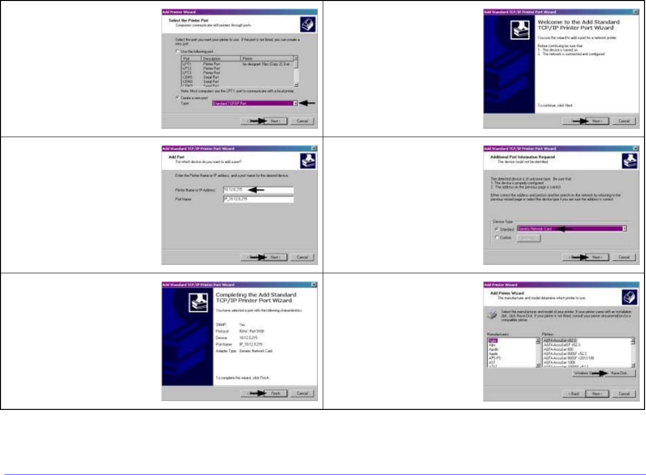
160 H-Class
Windows 2000 Driver and Port Installation (continued)
3 Select on Create a
new port: and then
select Standard
TCP/IP Port from
the drop down
menu. Click Next.
4 Click Next.
5 In the Printer Name
or IP Address: field
enter the IP
address of your
printer. The Port
Name field does not
need to be
changed. When
finished click Next.
6 Ensure Standard is
selected and then
click Next.
7 Confirm your
settings and then
click Finish.
8 Click on Have Disk.
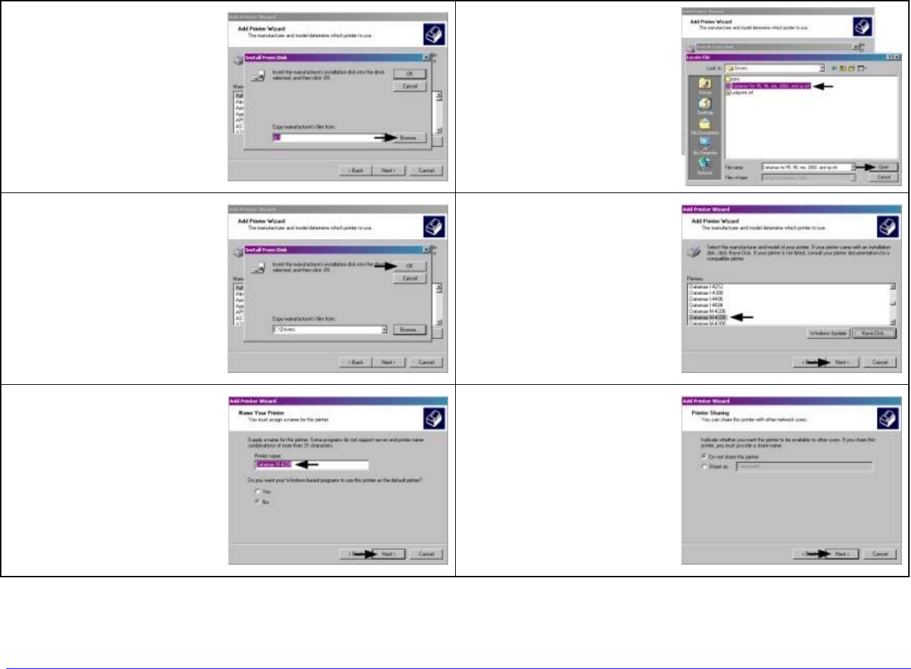
H-Class 161
Windows 2000 Driver and Port Installation (continued)
9 Insert the
Accessories CD-
ROM and click
Browse.
10
Browse to the
“\DRIVERS\Seagull”
folder on the CD-
ROM, ensure the
file “xp.inf” is
selected and click
OK.
11 Click OK. 12
Select your printer
from the list and
then click Next.
13 Name your printer
in the Printer
name: field. Next
select whether or
not to set this
printer as your
default printer.
Then Click Next.
14
Select whether or
not to share this
printer on your
network. Then Click
Next.
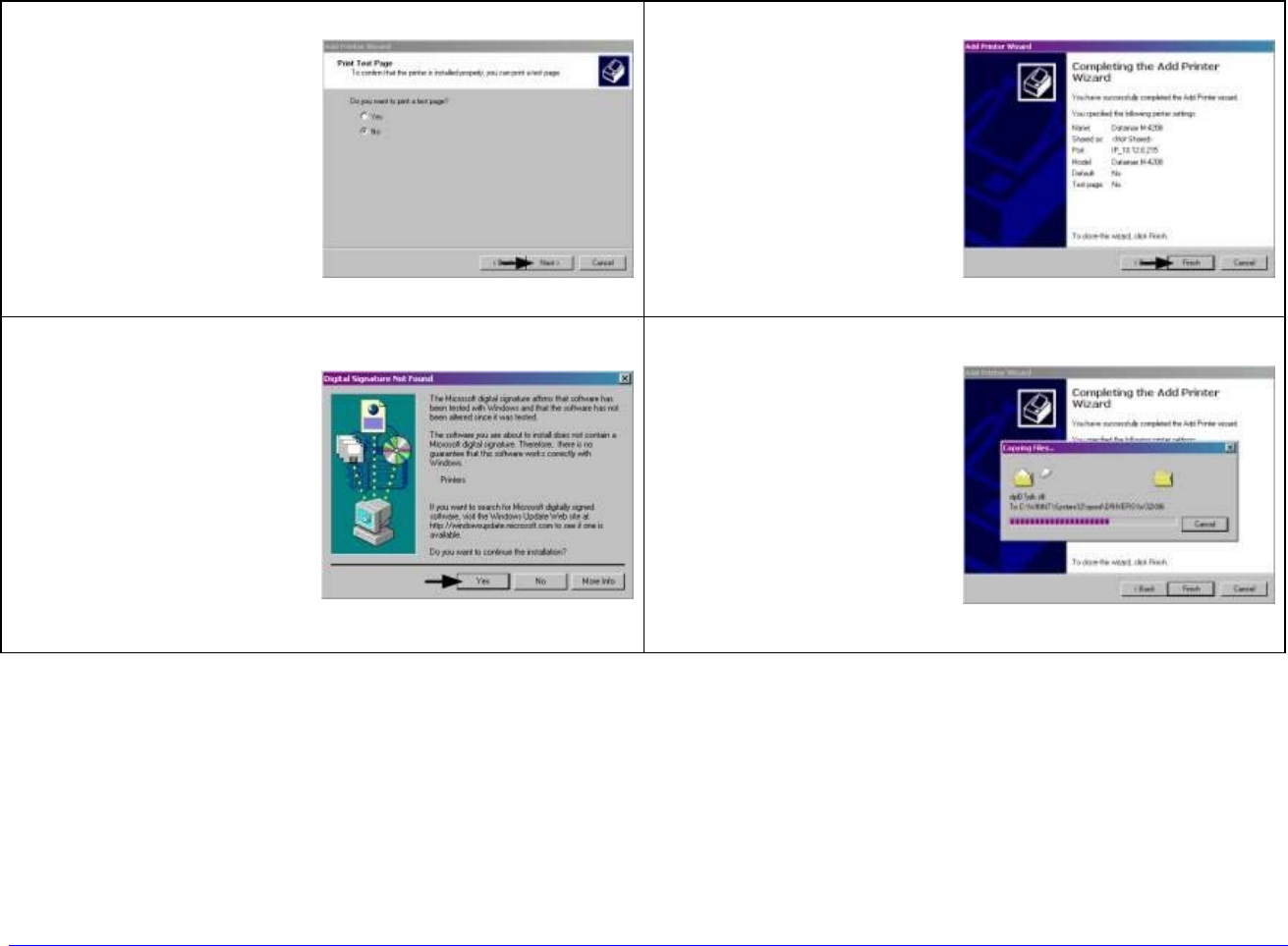
162 H-Class
Windows 2000 Driver and Port Installation (continued)
15 Select No then Click
Next. 16
Confirm your
settings and then
click Finish.
17 If prompted with
the "Digital
Signature Not
Found" window,
click Yes to
continue
installation.
18
Your computer will
now copy the
necessary files from
the CD-ROM.
The driver and port
installation is now
complete. The
printer can be
selected through
any Window’s
application.
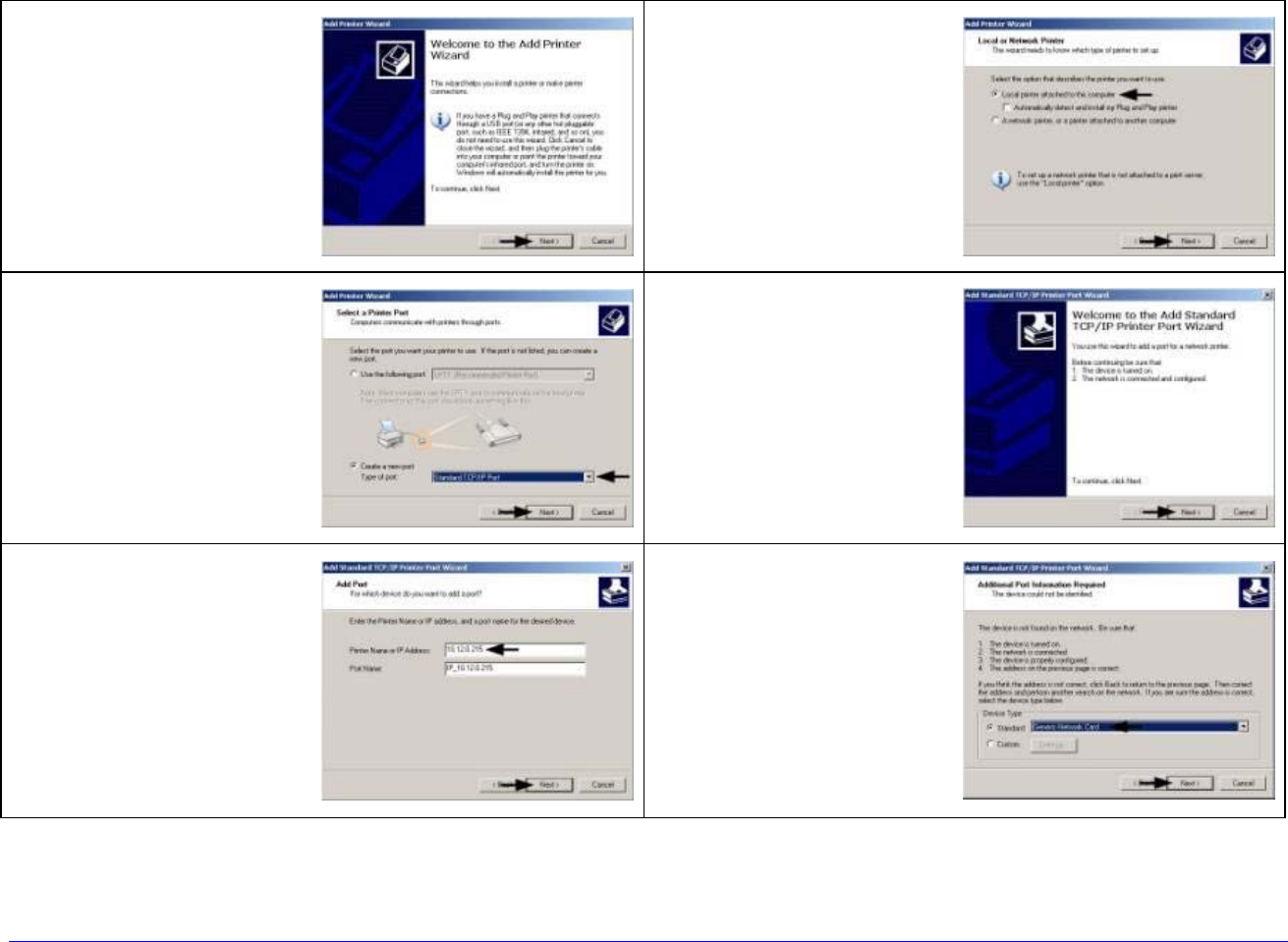
H-Class 163
Windows XP Driver and Port Installation
1 Start the Windows
“Add Printer
Wizard.” The
following screen
should appear.
Click Next>.
2 Ensure that Local
Printer is selected
and then click Next.
3 Select on Create a
new port: and then
select Standard
TCP/IP Port from
the drop down
menu. Click Next.
4 Click Next.
5 In the Printer Name
or IP Address field
enter the IP
address of your
printer. The Port
Name field does not
need to be
changed. When
finished click Next.
6 Ensure Standard is
selected and then
click Next.
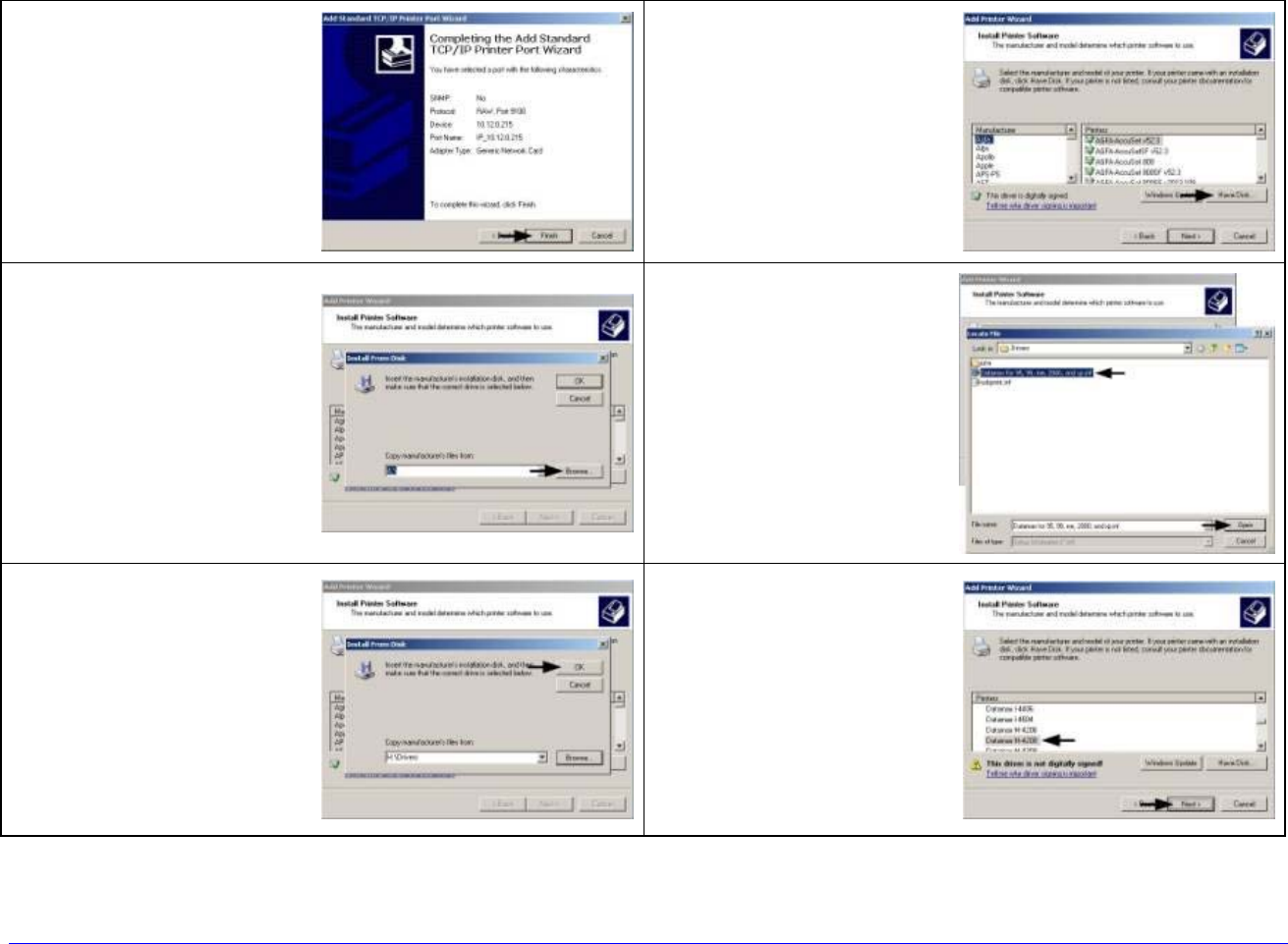
164 H-Class
Windows XP Driver and Port Installation (continued)
7 Confirm your
settings and then
click Finish.
8 Click on Have Disk.
9 Insert the
Accessories CD-
ROM and click
Browse.
10
Browse to the
“\DRIVERS\Seagull”
folder on the CD-
ROM, ensure the
file “xp.inf” is
selected and click
OK.
11 Click OK. 12
Select your printer
from the list and
then click Next.
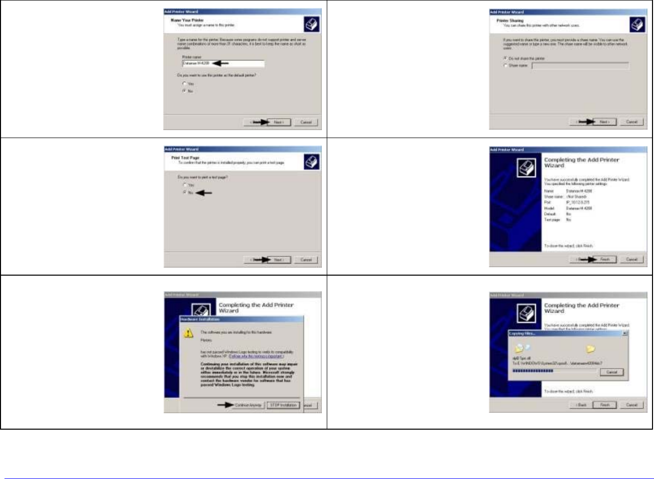
H-Class 165
Windows XP Driver and Port Installation (continued)
13 Name your printer
in the Printer
name: field. Next
select whether or
not to set this
printer as your
default printer.
Then Click Next.
14
Select whether or
not to share this
printer on your
network. Then Click
Next.
15 Select No then Click
Next. 16
Confirm your
settings and then
click Finish.
17 If prompted with
the "Digital
Signature Not
Found" window,
click Continue
Anyway to continue
installation.
18
Your computer will
now copy the
necessary files from
the CD-ROM.
The driver and port
installation is now
complete. The
printer can be
selected through
any Window’s
application.

166 H-Class

H-Class 167
Glossary
alphanumeric Consisting of alphabetic, numeric, and other symbols.
backing material The silicon-coated paper carrier material to which labels with adhesive
backing are affixed. Also referred to as “liner”.
bar code A representation of alphanumeric information in a pattern of machine-readable
marks. The basic categories are divided into one-dimensional (UPC, Code 39, Postnet,
etc.) and two-dimensional bar codes (Data Matrix, MaxiCode, PDF417, etc.).
boot loader The resident program that loads the application from Flash memory,
decompresses it into the SRAM, and starts operations.
burn line The row of thermal elements in the printhead that create the images on the
media.
calibration The process through which sample values are entered into the printer for
correct sensor function (for example, detection of a given media type) and TOF
positioning.
character set The entire complement of alphanumeric symbols contained in a given font.
checksum An alphanumeric error detection method used in many bar code symbologies for
informational security.
continuous media An uninterrupted roll or box of label or tag stock media that contains no
gap, notch, or mark to separate individual labels or tags.
core diameter The inside diameter measurement of the cardboard core at the center of a
ribbon or media roll.
cutter A mechanical device with a rotary or guillotine type blade used to cut labels or tags
following printing.
defaults The functional setting values returned following a factory reset of the printer.
diagnostics Programs used to locate and diagnose hardware problems.
die-cut media Media that has been cut into a pattern using a press, where the excess
paper is removed leaving individual labels, with gaps between them, attached to a
backing material.
direct thermal The printing method that uses a heat sensitive media and only the heat of
the thermal printhead to create an image on the label.
direct thermal media Media coated with special chemicals that react and darken with the
application of heat.

168 H-Class
DPI (dots per inch) A measurement of print resolution, rated in the number of thermal
elements contained in one inch of the printhead. Also referred to as “resolution”.
DPL (Datamax-O’Neil Programming Language) programming commands used
specifically for control of and label production in Datamax-O’Neil printers. A complete
listing of commands can be found in the Class Series 2 Programmer’s Manual.
EFIGS English, French, Italian, German, Spanish, and other multi-language support as
programmed for the menu and configuration label.
fanfold Media that is folded and stacked.
feed speed The speed at which the media moves under the printhead in non-printed areas
and between labels.
Flash memory Non-volatile memory (does not require printer power to maintain data) that
can be erased and reprogrammed, used to hold the operating program.
font A set of alphanumeric characters that share a particular typeface.
gap A space between die-cut or notched labels used to sense the top-of-form.
IPS (inches per second) Imperial measurement of printer speeds.
label A paper or synthetic printing material, typically with adhesive backing.
label length The distance from the top of the label to the bottom of the label as it exits the
printer.
label repeat The distance from the top of one label to the top of the next label.
label tracking Excessive lateral (side to side) movement of the media as it travels under
the printhead.
label width The left to right measurement of the label as it exits the printer.
mark Generalized term for the carbon-based black line on the underside of reflective media
used to indicate the top-of-form.
media Generalized term for all types of printing stocks, including: roll fed, continuous, die-
cut, reflective, and fanfold.
media hub Device in the printer used to support roll media.
media sensor An electronic device equipped with photosensors to detect media and the
top-of-form on die-cut, notched or reflective media.
MMPS (millimeters per second) Metric measurement of printer speeds.
notched stock Media, typically tag stock, with holes or notches in the material that is used
to signal the top-of-form. The printer must be set to “gap” to use this media type.

H-Class 169
notched stock Media, typically tag stock, with holes or notches in the material that is used
to signal the top-of-form. The printer must be set to “gap” to use this media type.
on demand An output regulator (i.e., the Present Sensor) that inhibits printing when a
label is already present.
preprinted media Label stock that contains borders, text, or graphics, floodcoating, etc.
perforation Small cuts extending through the backing and/or label material to facilitate
their separation. Also referred to as “perf”.
print speed The speed at which the media moves under the printhead during the printing
process.
reflective media Media imprinted with carbon-based black marks on the underside of the
material, which is used to signal the top-of-form when the “reflective” sensor is
enabled.
registration Repeatable top to bottom alignment of printed labels.
reverse speed The backward rate of media motion into the printer during tear-off, peel
and present and cutting operations for positioning the label at the start of print
position.
ribbon An extruded polyester tape with several layers of material, one of which is ink-like,
used to produce an image on the label. Also referred to as “foil”.
ribbon wrinkle An undesirable overlapping of the ribbon during the printing process that
leads to voids on the printed label, typically caused by an improper printhead leveling
cam adjustment.
roll media A form of media that is wound upon a core.
start of print (SOP) The position on the label where printing begins; also, the signal that
initiates GPIO-controlled printing.
tag stock A heavy paper or synthetic printing material, typically featuring a notch or black
mark for TOF and no adhesive backing.
thermal transfer The printing method that creates an image by transferring ink from a
ribbon onto the media using the heat from the thermal printhead.
TOF (top-of-form) The start of a new label as indicated by a label gap, notch, mark or
programming.
void An undesirable blank space in a printed image.
