User's Guide
User Manual: User's Guide
Open the PDF directly: View PDF ![]() .
.
Page Count: 119 [warning: Documents this large are best viewed by clicking the View PDF Link!]
- Title
- Copyright
- Disclaimer
- Contents
- Chapter 01 Program Description
- Chapter 02 ETABS “Screen”
- Chapter 03 Basic Modes, Drawing Tools, Mouse Pointers
- Chapter 04 Begin a Model
- Chapter 05 Create the Structural Model
- Chapter 06 Select Structural Objects
- Chapter 07 Assign/Change Properties
- Chapter 08 Load the Structural Model
- Chapter 09 Define Load Cases
- Chapter 10 Edit the Model Geometry
- Chapter 11 Analyze the Model
- Chapter 12 Design
- Chapter 13 Detailing
- Chapter 14 Display Results
- Chapter 15 Generate Results
- User's Guide_1.pdf
- Title
- Copyright
- Disclaimer
- Contents
- Chapter 1 Program Description
- Chapter 2 ETABS “Screen”
- Chapter 3 Basic Modes, Drawing Tools, Mouse Pointers
- Chapter 4 Begin a Model
- Chapter 5 Create the Structural Model
- Chapter 6 Select Structural Objects
- Chapter 7 Assign/Change Properties
- Chapter 8 Load the Structural Model
- Chapter 9 Define Load Cases
- Chapter 10 Edit the Model Geometry
- Chapter 11 Analyze the Model
- Chapter 12 Design
- Chapter 13 Detailing
- Chapter 14 Display Results
- Chapter 15 Generate Results

User's Guide

User's Guide
ETABS® 2016
Integrated Building Design Software
ISO ETA122815M2 Rev. 0
Proudly developed in the United States of America July 2016
Copyright
Copyright Computers & Structures, Inc., 1978-2016
All rights reserved.
The CSI Logo®, SAP2000®, ETABS®, and SAFE® are registered trademarks of
Computers & Structures, Inc. Watch & LearnTM is a trademark of Computers &
Structures, Inc. Windows® is a registered trademark of the Microsoft Corporation.
Adobe® and Acrobat® are registered trademarks of Adobe Systems Incorporated.
The computer programs SAP2000® and ETABS® and all associated documentation are
proprietary and copyrighted products. Worldwide rights of ownership rest with
Computers & Structures, Inc. Unlicensed use of these programs or reproduction of
documentation in any form, without prior written authorization from Computers &
Structures, Inc., is explicitly prohibited.
No part of this publication may be reproduced or distributed in any form or by any
means, or stored in a database or retrieval system, without the prior explicit written
permission of the publisher.
Further information and copies of this documentation may be obtained from:
Computers & Structures, Inc.
http://www.csiamerica.com/
info@csiamerica.com (for general information)
support@csiamerica.com (for technical support)
DISCLAIMER
CONSIDERABLE TIME, EFFORT AND EXPENSE HAVE GONE INTO THE
DEVELOPMENT AND TESTING OF THIS SOFTWARE. HOWEVER, THE USER
ACCEPTS AND UNDERSTANDS THAT NO WARRANTY IS EXPRESSED OR
IMPLIED BY THE DEVELOPERS OR THE DISTRIBUTORS ON THE ACCURACY
OR THE RELIABILITY OF THIS PRODUCT.
THIS PRODUCT IS A PRACTICAL AND POWERFUL TOOL FOR STRUCTURAL
DESIGN. HOWEVER, THE USER MUST EXPLICITLY UNDERSTAND THE BASIC
ASSUMPTIONS OF THE SOFTWARE MODELING, ANALYSIS, AND DESIGN
ALGORITHMS AND COMPENSATE FOR THE ASPECTS THAT ARE NOT
ADDRESSED.
THE INFORMATION PRODUCED BY THE SOFTWARE MUST BE CHECKED BY
A QUALIFIED AND EXPERIENCED ENGINEER. THE ENGINEER MUST
INDEPENDENTLY VERIFY THE RESULTS AND TAKE PROFESSIONAL
RESPONSIBILITY FOR THE INFORMATION THAT IS USED.

Contents
User’s Guide
1 Program Description
Objective 1-1
This is ETABS 1-1
Time Saving Options 1-3
Templates and Defaults 1-3
Basic Process 1-4
Forms 1-5
2 ETABS “Screen”
Objective 2-1
The ETABS Window 2-1
File Operations 2-4
Edit 2-4
View 2-5
Define 2-5
Draw 2-5
Select 2-6
Assign 2-6
Analyze 2-6
i

User’s Guide
Display 2-7
Design 2-8
Detailing 2-8
Options 2-8
Help 2-9
3 Basic Modes, Drawing Tools, Mouse Pointers
Objective 3-1
Select or Draw 3-1
4 Begin a Model
Objective 4-1
Create the Basic Grid System 4-1
Grid Dimensions (Plan) – Define a
Grid System 4-4
Story Dimensions - Define Story Data 4-5
5 Create the Structural Model
Objective 5-1
Add Structural Objects Using Templates 5-1
Define Properties 5-4
Material Properties 5-4
Frame Sections 5-5
Auto Select Section List 5-8
Add Structural Objects Manually 5-11
Draw Columns 5-11
Draw Beams 5-13
Draw Secondary (Infill) Beams 5-15
Draw the Floor 5-15
ii

Contents
Draw Walls 5-17
Draw Wall Stacks 5-18
6 Select Structural Objects
Objective 6-1
Selecting 6-1
Graphical Selection Options 6-1
Selecting by Coordinates 6-4
Selecting by Feature 6-4
Deselect Command 6-5
Invert Selection Command 6-5
Get Previous Selection Command 6-5
Clear Selection Command 6-6
7 Assign/Change Properties
Objective 7-1
Assign 7-1
Assign the AUTOLATBM Auto
Select Section List 7-4
Make an Assignment as the Object
is Drawn 7-5
Make an Assignment using the
Model Explorer 7-5
Check the Sections in an Auto Select
Section List 7-5
8 Load the Structural Model
Objective 8-1
Structural Loads 8-1
Define the Load Patterns 8-2
iii

User’s Guide
Auto Lateral Load 8-2
Self-Weight Multiplier 8-5
Modify an Existing Load Pattern 8-5
Delete an Existing Load Pattern 8-6
Define Shell Uniform Load Sets 8-6
Assign Structural Loads 8-7
9 Define Load Cases
Objective 9-1
Review/Create Load Cases 9-1
Define an Auto Construction Sequence Case 9-4
10 Edit the Model Geometry
Objective 10-1
Editing Options 10-1
11 Analyze the Model
Objective 11-1
Set the Mesh Options 11-1
Model Analysis 11-2
Model Alive™ Feature 11-3
Locking and Unlocking the Model 11-4
12 Design
Objective 12-1
Design the Structure 12-1
13 Detailing
Objective 13-1
Detailing Process 13-1
iv

Contents
Preferences 13-2
Rebar Selection Rules 13-2
Start Detailing 13-3
Edit Views 13-3
Create and Manage Drawing Sheets 13-4
14 Display Results
Objective 14-1
Obtain Basic Graphical Displays 14-1
Graphical Displays using Model Explorer 14-4
Tabular Display of Results 14-4
15 Generate Results
Objective 15-1
Summary Report 15-1
Print Graphics 15-2
Export Results 15-2
v

Chapter 1
Program Description
Objective
This chapter briefly describes the program and some of the concepts in-
volved in its use.
This Is ETABS
ETABS is a powerful program that can greatly enhance an engineer's
analysis and design capabilities for structures. Part of that power lies in
an array of options and features. The other part lies in how simple it is to
use.
The basic approach for using the program is very straightforward. The
user establishes grid lines, places structural objects relative to the grid
lines using joints, frames, links, tendons, and shells, and assigns loads
and structural properties to those structural objects (for example, a frame
object can be assigned section properties; a joint object can be assigned
spring properties; a shell object can be assigned slab or deck properties).
Objective 1 - 1

User's Guide
Analysis, design, and detailing are then performed based on the structural
objects and their assignments. Results are generated in graphical or tabu-
lar form that can be printed to a printer or to a file for use in other
programs.
In using the program, you manage the File, Edit the
model, change the View, Define properties or load
patterns and cases, Draw something new in the model,
Select that something, Assign properties or loads, An-
alyze the model, Display analysis results for checking,
Design the structure, generate Detailing construction
documents, apply various Options to achieve the de-
sired outcome with optimum effort, utilize plugin tools
to customize the program, and seek Help when you
need it. Those actions are the basis for the program
menu structure. Thus, familiarity with the menu com-
mands and their function is key to expanding your
ability to use ETABS.
Information about the various menu items is available
using the Help menu > ETABS Help command as
well as by using the F1 key when a form is displayed
on the ETABS screen. The F1 key will display context sensitive help, in-
cluding descriptions of the types of input for the forms used in the pro-
gram. Familiarity with the menu commands will enable the user to create
models for complex Composite Floor Framing Systems with Openings
and Overhangs, Steel Joist Systems, Moment Resisting Frames, Complex
Shear Wall Systems, Rigid and Flexible Floors, Sloped Roofs, Ramps
and Parking Structures, Mezzanine Floors, Concrete Slabs with Post-
Tensioning, Trussed Systems, Multiple Tower Buildings and Stepped
Diaphragm Systems, and many more.
Design manuals in .pdf format are available using the Help menu >
Documentation command. Those manuals explain how the program per-
forms steel frame design, concrete frame design, composite beam design,
composite column design, steel joist design, concrete shear wall design,
concrete slab design, and steel connection design in accordance with ap-
plicable building codes.
ETABS Menu
Commands:
File
Edit
View
Define
Draw
Select
Assign
Analyze
Display
Design
Detailing
Options
Tools
Help
1 - 2 This Is ETABS

Chapter 1 - Program Description
Time Saving Options
The program also includes options that allow you to reduce the time
spent creating models. Those options include the following:
Similar Stories. Allows the user to make changes to multiple stories
simultaneously.
Snap To. Allows the user to place structural objects with accuracy.
Auto Select Sections. Allows the user to define a list of sections, for
example W18X35, W18X40, W21X44, W21X50 and W24X55, that
can be assigned to a frame member. The program can then automati-
cally select the most economical, adequate section from the auto select
section list when it is designing the member.
Vertical Load Transfer. Frees the user from the chore of calculating
the load on the members supporting the floor plate, and determines the
area tributary to each member for live load reduction.
Wall Stacks. Allows the user to quickly generate complex wall ar-
rangements.
Towers. Allows multiple towers to exist within a single model.
Model Explorer. Allows the user to rapidly create and modify models
using a hierarchical tree system with drag-&-drop capability.
Design Strips. Allows for accurate layout of program calculated slab
reinforcement and tendon placement.
Templates and Defaults
ETABS provides a number of templates that allow for the rapid genera-
tion of models for a wide range of common building types. Those tem-
plates serve as a good starting point because they can be modified easily.
The program includes default parameters, many of which are building
code specific. Those defaults are accessed using "Overwrites" and "Pref-
Time Saving Options 1 - 3

User's Guide
erences." The possible options available for overwrites and the default
values for preferences are identified in the design manuals.
By using the built-in templates and defaults, the user can create a model
in a matter of minutes.
Basic Process
The following provides a broad overview of the basic modeling, analysis,
design, and detailing processes:
1. Select the Base Units and Design Codes
2. Set up Grid Lines
3. Define Story Levels
4. Define Section Properties
5. Draw Structural Objects
6. Select Objects
7. Assign Properties
8. Define Load Patterns
9. Assign Loads
10. Define Load Cases
11. Edit the Model Geometry
12. View the Model
13. Analyze the Model
14. Display Results for Checking
15. Design the Model
16. Generate Detail Documents
17. Output Results and Reports
18. Save the Model
1 - 4 Basic Process

Chapter 1 - Program Description
Forms
Various forms are used in ETABS throughout the modeling, analysis, de-
sign and detailing processes. With a form displayed on the ETABS win-
dow, click the F1 key on your keyboard to access context-sensitive Help
for the form.
Forms 1 - 5

Chapter 2
ETABS “Screen”
Objective
This chapter briefly describes the ETABS “screen” or more accurately,
the graphical user interface.
The ETABS Window
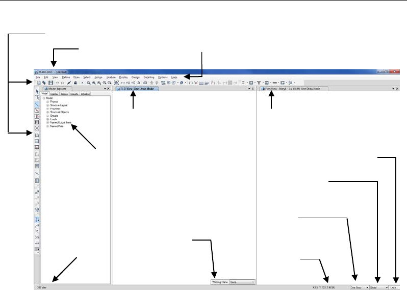
The ETABS graphical user interface shown in Figure 2-1 includes the
main window, main title bar, display title tabs, menu bar, toolbars, model
explorer, display windows, status bar, mouse pointer position coordinates
and the current units. Each of these items is described in the bulleted list
that follows.
Main Window. This window may be moved, resized, maximized,
minimized, or closed using standard Windows operations. Refer to
Windows help, available on the Start menu, for additional information
about those items.
Objective 2 - 1
User's Guide
Main Title Bar. The main title bar includes the program and model
names. The main title bar is highlighted when the program is in use.
Move the main window by left clicking in the main title bar and hold-
ing down the mouse button as you drag the window around the com-
puter screen.
Menu Bar. The menu bar contains the program's menus from which
various commands can be selected to perform specific actions.
Toolbars and Buttons. Toolbars are made up of buttons. Buttons
provide "single-click" access to commonly used commands. Holding
the mouse pointer over a toolbar button for a few seconds without
clicking or holding down any mouse buttons will display a short de-
scription of the button's function in a small text box.
Model Explorer. The model explorer allows easy access to model
definition data, including property forms, load definitions, and object
forms, as well as analysis, design, and detailing results in graphical,
Toolbars
Main Title Bar Menu Bar
Display Title Tab
(Inactive Window)
Display Title Tab
(Active Window)
Drawing & Selection
(Similar Stories Feature)
Current
Units
Coordinate
System
Mouse Pointer
Position Coordinates
Status Bar
Model Explorer
Working Plane (3D View only)
Figure 2-1: The ETABS graphical user interface
2 - 2 The ETABS Window

Chapter 2 - ETABS “Screen”
tabular, and report formats using a hierarchical tree structure. These
items are grouped in five tabs in the Model Explorer, namely Model,
Display, Tables, Reports, and Detailing. Trees may be expanded by
clicking on a node, and a right click on a "leaf" in the tree will bring
up a context-sensitive menu (items shown in bold in the menu are the
default action that will occur if the user double clicks on the leaf). Sec-
tions may be assigned to a model by simply dragging the section from
the tree onto an appropriate object in the model (i.e., a frame section
onto a frame object). This drag-&-drop technique can significantly ex-
pedite model revisions.
Display Windows. A display window shows the geometry of the
model and may also include displays of properties, loading, analysis or
design results, and detailing. There is no limit on the number of win-
dows that may be displayed.
Display Title Tab. The display title tab is located at the top of the dis-
play window. The display title tab is highlighted when the associated
display window is active. The text in the display title tab typically in-
cludes the type and location of the view in the associated display win-
dow.
Status Bar. The status bar is located at the bottom of the main win-
dow. Text describing the current status of the program is displayed on
the left side of the status bar.
Working Plane Drop-Down List. This drop-down list appears in a 3-
D View display window when a drawing command is active. Drawing
objects in a 3-D view is restricted to the story (working plane) selected
from this drop-down list, unless snaps are used.
Mouse Pointer Position Coordinates. The mouse pointer position
coordinates are displayed on the right-hand side of the status bar. A
window does not need to be active for the mouse pointer position co-
ordinates to be displayed. It is only necessary that the mouse pointer
be over the window.
Drawing & Selection Drop-Down List. This drop-down list is on the
right side of the status bar. The three options in the drop-down list are
One Story, All Stories, and Similar Stories. With One Story, an object
The ETABS Window 2 - 3

User's Guide
is created only at the story level on which it is drawn. With All Stories,
an object drawn creates objects at all story levels in the model at the
same plan location. When doing an object select with All Stories, any
object selected results in all other objects at the same plan location be-
ing selected at all story levels. With Similar Stories, an object drawn
creates objects at all similar story levels in the model at the same plan
location, and an object selected results in all other objects in the same
plan location being selected at similar story levels.
Coordinate System Drop-Down List. This drop-down list on the
right side of the status bar allows the switching of coordinate/grid sys-
tems between the Global Coordinate System and user-defined Grid
Systems. The selected system affects both the orientation of the model
as well as the mouse pointer position coordinates.
Current Units. The current units are displayed in a pop-up list located
on the far right-hand side of the status bar. These units can be changed
at any time during the model creation process.
File Operations
File operations are used to start a new model, to bring in an existing
model for display or modification, to save or export the current model for
use in ETABS or another application, and to produce output. File opera-
tions are selected from the File menu.
New models can be started from scratch or from predefined templates
supplied with the program.
Edit
Editing is used to make changes to the model. Most editing operations
work with one or more objects that were selected immediately before us-
ing the Edit command. Objects may be deleted, copied, pasted, moved,
aligned, replicated, merged, and extruded using edit commands.
2 - 4 File Operations

Chapter 2 - ETABS “Screen”
View
View options, which affect how the structure displays, may be set for
each display window and the setting may differ from window to window.
Define
Define is used to create named entities that are not part of the geometry
of the model. Those entities, accessed from the Define menu, include
items such as material properties; frame, tendon, wall, and slab sections;
and load patterns, cases and combinations. Definition of those entities
does not require prior selection of an object, and some of those entities
can be defined during the assignment operation using the Assign menu.
Draw
Drawing is used to add new objects to the model or to modify one object
at a time. Objects include beams, columns, slabs, decks, walls, links, ten-
dons, and other joint, frame and shell objects. To draw, the program must
be in Draw Mode, which is activated by clicking one of the draw buttons
on the toolbar or using a Draw menu command.
In Draw Mode, the left mouse button is used to draw and edit objects,
and the right mouse button is used to query the properties of those ob-
jects. Depending on the type of object to be drawn, a “Properties of Ob-
ject” form appears that can be used to specify various structural proper-
ties, as well as the tower to which the object belongs when multiple tow-
ers are present. As frame objects are drawn, frame properties can be as-
signed simultaneously. Shell objects may be assigned floor properties,
wall properties, or defined as openings when drawn. After an object has
been drawn, the object may be selected and loads may be assigned to it,
or existing assignments can be modified.
Draw Mode and Select Mode are mutually exclusive. No other opera-
tions can be performed when the program is in Draw Mode.
View 2 - 5

User's Guide
Select
Selection is used to identify those objects to which the next operation
will apply.
ETABS uses a “noun-verb” concept; that is, a selection is made and then
an operation is performed. Certain editing, assigning, printing and dis-
playing operations require prior selection of an object.
To select, the program must be in Select Mode, which is activated by
clicking one of the select buttons on the toolbar. Alternatively, selecting
any action from the Select menu puts the program into Select Mode.
Many different types of selection are available, including selecting indi-
vidual objects, drawing a window around objects, and selecting by prop-
erty type.
In Select Mode, the left mouse button is used to select objects, and the
right mouse button is used to query the properties of those objects.
Draw Mode and Select Mode are mutually exclusive.
Assign
Certain assignments may be made when drawing an object, such as as-
signing a structural property when drawing a frame object. However, ad-
ditional assignments, or changes to assignments, may be made to one or
more objects that were selected immediately before using the Assign
menu command. Assignment operations include properties, restraints,
loads and group names.
Analyze
After a complete structural model has been created using the preceding
commands, the model can be analyzed to determine the resulting dis-
placements, forces/stresses and reactions.
Before running an analysis, use the Set Active Degrees of Freedom
command on the Analyze menu to control the active degrees of freedom
2 - 6 Select

Chapter 2 - ETABS “Screen”
and use Check Model to ensure that objects do not overlap and that ob-
jects are connected.
The first time an analysis is to be run, chose Set Load Cases to Run from
the Analyze menu and select which cases are to be run. Once load cases
have been selected, use Run Analysis from the Analyze menu, or click
the Run Analysis button on the toolbar to run the analysis. Any cases
that have been run already do not need to be run again. If a load case that
requires results from another case is chosen, the prerequisite case will be
run first if it has not been already.
The program saves the data, then checks and analyzes the model. During
the checking and analysis phases, messages from the analysis engine ap-
pear in a monitor window. When the analysis is complete, a deformed
shape will be displayed.
No other ETABS operations may be performed while the analysis is pro-
ceeding and the monitor window is present on the screen. However, oth-
er Windows applications can be run during this time.
Display
The Display menu commands are used to view the model and the results
of the analysis. Graphical and tabular displays are available in this pro-
gram. Display items may be chosen from the Display menu or accessed
using toolbar buttons.
Graphical Displays – Different types of graphical display may be
selected for each display window. Each window may also have its
own view orientation and display options. Undeformed geometry,
loads and analysis results can all be displayed. Details of the dis-
played results can be obtained by clicking on an object with the right
mouse button.
Tabular Displays – Tabular information can be displayed for the
model by choosing the Tables tab on the Model Explorer. Choose a
table to be viewed and then right click. If objects are selected prior to
using the commands, certain tables will only be available for the se-
lected objects. If no objects are selected, the tables produced are for
Display 2 - 7

User's Guide
the entire model. Tabular data can also be printed using the Create
Report commands available on the File menu.
Design
After an analysis has been completed, frames, composite beams and col-
umns, joists, shear walls, slabs, and steel connections can be designed
with respect to design code requirements. Design may be performed for
the given design combinations by choosing the appropriate Design menu
command. Before designing, verify the selected design codes and prefer-
ences using the appropriate View/Revise Preferences command located
on the design menus.
Graphical displays of design parameters are available. Tabular design in-
formation can also be printed using commands from the File menu.
Detailing
The Detailing menu provides control over the organization and layout of
schematic construction documents. Items such as drawing size and lay-
out, section cuts, column schedules, beam framing plans, shear wall rein-
forcement, composite slab reinforcing layouts, general notes, cover
sheets and so on may be specified. This menu is typically accessed after
analysis and design are complete. The drawing sheets and views generat-
ed may be displayed by selecting the Detailing tab in the Model Explor-
er.
Tools
The Tools menu provides access to user or third-party developed plugins
that allow for customization of the program.
2 - 8 Design

Chapter 2 - ETABS “Screen”
Options
The Options menu provides various commands that affect the overall op-
eration of ETABS. Display units, colors, the graphics mode, tolerances,
and whether multiple towers are allowed can be specified here.
Help
The program Help is available from this menu. Documentation and veri-
fication manuals in PDF format are accessed through the Help menu as
well. A link to the CSI website, as well as information about the current-
ly installed version of ETABS and its associated license file, can be
found here.
Options 2 - 9

Chapter 3
Basic Modes, Drawing Tools, Mouse Pointers
Objective
This chapter briefly describes the two modes of user operation for the
program, identifies the drawing tools, and describes how the appearance
of the mouse pointer changes for various operations.
Select or Draw
The two distinct modes in this program are the select mode and the draw
mode.
The select mode allows objects to be selected and is used for ed-
iting operations, making assignments to objects, and viewing or
printing results. By default, the program is in select mode. Chap-
ter 6 describes the various methods for selecting points, lines,
and areas in a model.
The draw mode allows objects to be drawn.
Objective 3 - 1
User's Guide
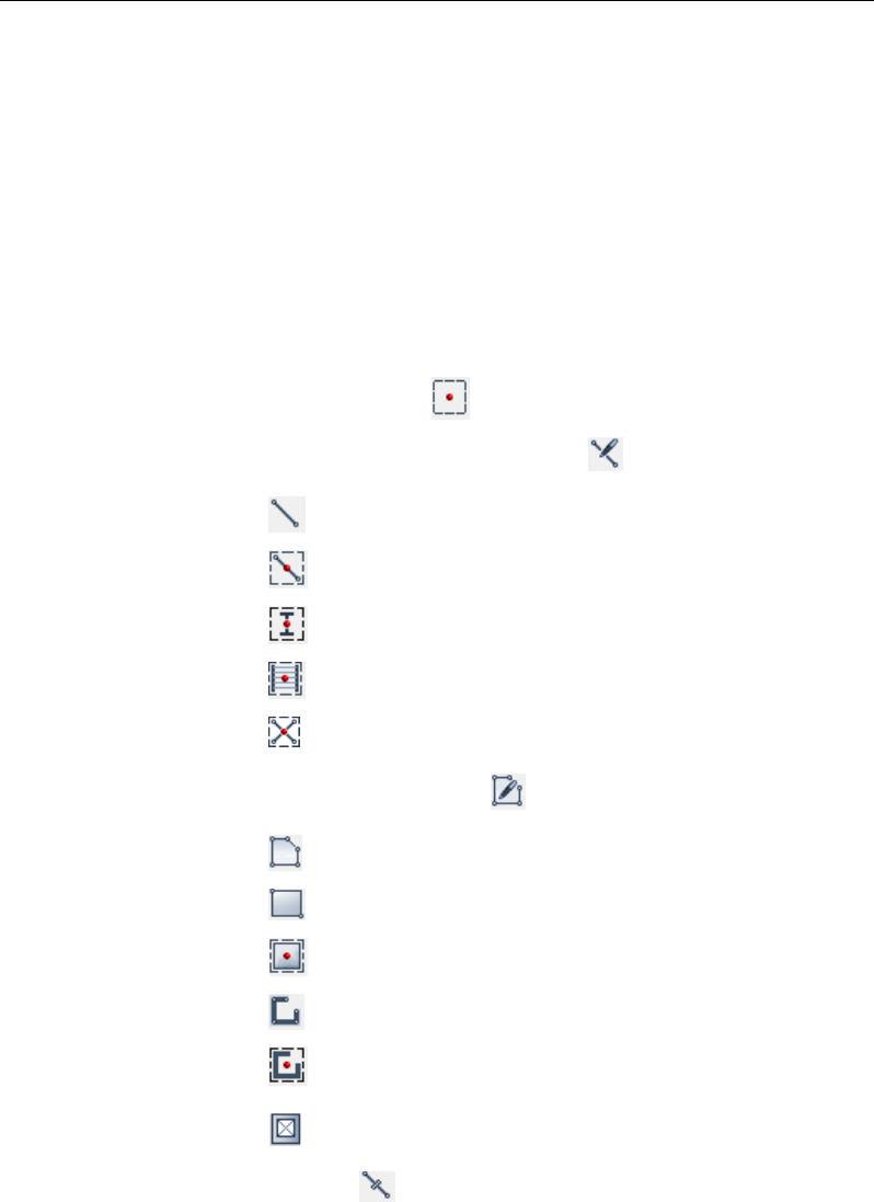
The draw mode automatically enables when one of the following sub-
menu options from the Draw menu is selected or the corresponding but-
tons on the toolbar are clicked. Note that the views in parenthesis (Plan,
Elev, 3D) after the command name indicate when the button will be ac-
tive; for example, the Draw Beam/Column/Brace command/button can
be used in the Plan, Elevation or 3D views, but the Draw Walls com-
mand/button can be used only in Plan view. The names of the commands
are assumed to explain the actions that will be accomplished. More in-
formation about the Draw tools is available by searching for “draw
menu” using the Help menu > ETABS Help command.
Draw Joint Objects
Draw Beam/Column/Brace Objects
Draw Beam/Column/Brace (Plan, Elev, 3D)
Quick Draw Beams/Columns (Plan, Elev, 3D)
Quick Draw Columns (Plan)
Quick Draw Secondary Beams (Plan)
Quick Draw Braces (Elev)
Draw Floor/Wall Objects
Draw Floor/Wall (Plan, Elev, 3D)
Draw Rectangular Floor/Wall (Plan, Elev)
Quick Draw Floor/Wall (Plan, Elev)
Draw Walls (Plan)
Quick Draw Walls (Plan)
Draw Wall Openings (Plan, Elev, 3D)
Draw Links
3 - 2 Select or Draw
Chapter 3 - Basic Modes, Drawing Tools, Mouse Pointers
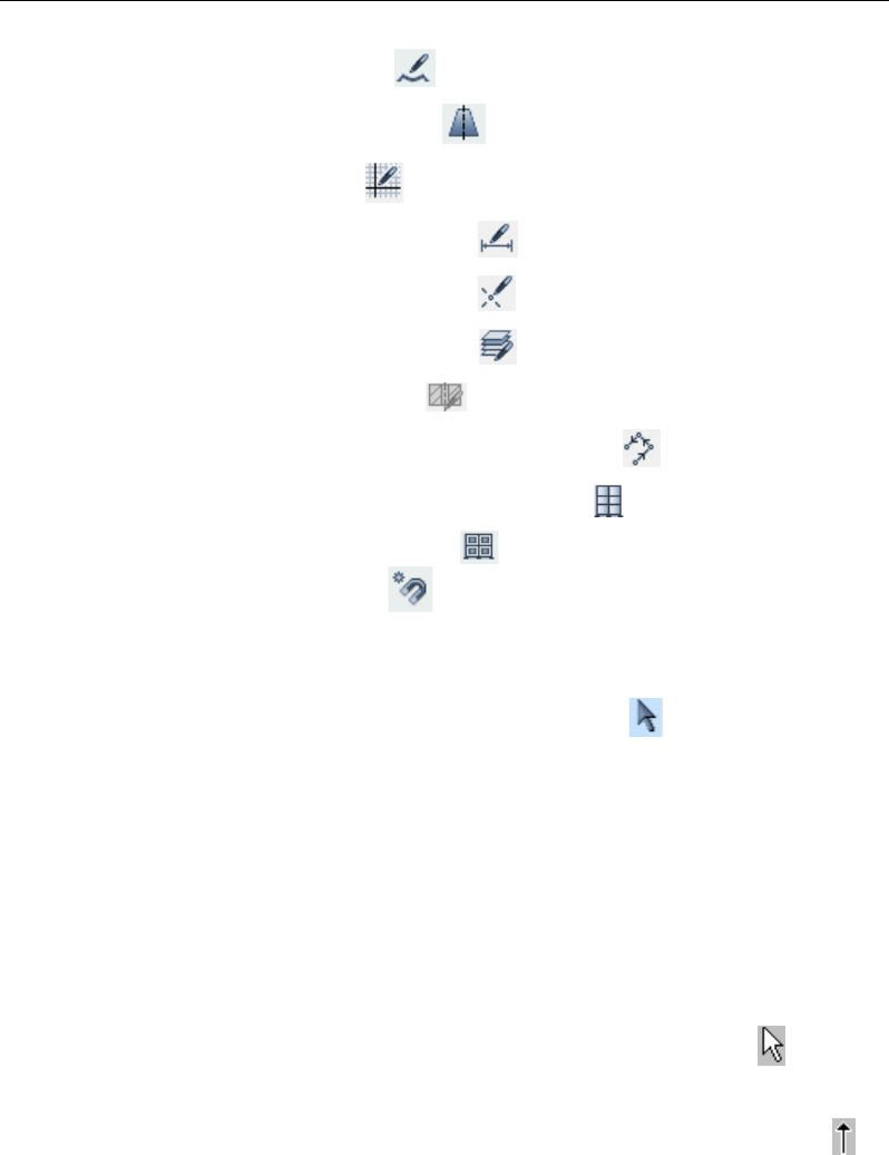
Draw Tendons
Draw Design Strips
Draw Grids
Draw Dimension Lines
Draw Reference Points
Draw Reference Planes
Draw Section Cut
Draw Developed Elevation Definition
Draw Wall Stacks (Plan, Elev, 3D)
Auto Draw Cladding
Snap Options
The draw mode remains enabled until one of the following actions is tak-
en to return to the select mode:
Click the Pointer button on the toolbar .
Press the Esc key on the keyboard.
Select a command from the Select menu.
The mouse pointer indicates which mode is enabled. The appear-
ance/properties of the mouse pointer are defined in the Windows Control
Panel. The mouse pointer properties are Normal Select Pointer and Al-
ternate Select pointer.
In select mode, the pointer is the Normal Select Pointer. If the default
settings are being used, the mouse pointer will look like this .
In draw mode, the mouse pointer is the Alternate Select pointer. If the
default settings are being used, the mouse pointer will look like this .
Note that while in draw mode, if the mouse pointer is moved over the
toolbar buttons or the menus, the pointer temporarily changes to the se-
Select or Draw 3 - 3

User's Guide
lection pointer. If during this time one of the menus or toolbar buttons is
not clicked, the mouse pointer reverts to the draw mode pointer when it
is moved back into the display window.
Other mouse properties/appearances are used for various actions in the
program, including Help Select, Busy, Text Select, Vertical Resize, Hor-
izontal Resize, and Move. The appearance of the mouse pointers for
those actions depends on the mouse pointer properties you specify.
3 - 4 Select or Draw
Chapter 4
Begin a Model
Objective
This chapter describes how to begin a model by creating the basic grid
system. Structural objects are placed relative to the grid system.
Create the Basic Grid System
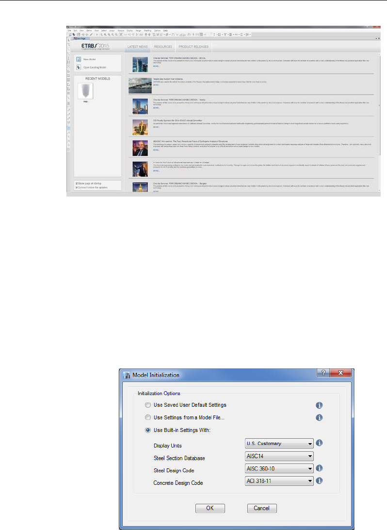
Begin creating the grid system by starting the program. The Start Page
will be displayed as shown in Figure 4-1. If the program is already run-
ning with a model displayed, you can start a new model by clicking the
File menu > New Model command or the New Model button .
Objective 4 - 1
User's Guide
The Start Page is divided into three regions: the New Model and Open
Existing Model buttons; the Recent Models area; and the Latest
News/Resources/Product Releases area. The Recent Models area con-
tains iconic buttons representing models recently created in ETABS. The
Latest News/Resources/Product Releases area displays helpful links as
well as recent news about CSI.
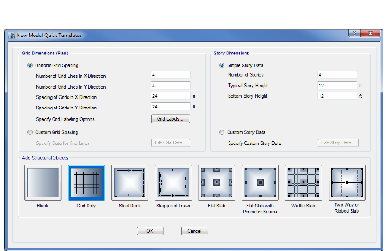
Click the New Model button on the Start Page to display the Model Ini-
tialization form shown in Figure 4-2.
Figure 4-1 Start Page
Figure 4-2 Model
Initialization form
4 - 2 Create the Basic Grid System

Chapter 4 - Begin a Model
There are three options on the Model Initialization form for setting the
initial units, preferences, properties and definitions: User Default Set-
tings, which can be saved using the Options menu > Save User Default
Settings command; Settings from a Model File; or Built-in Settings with
additional unit, section and code selections.
On the Model Initialization form select the Use Built-in Settings With
option and then choose either U.S. Customary, Metric SI or Metric MKS
from the Display Units drop-down list - this selection will set the defaults
for the input and display units. These units determine what units are as-
sociated with each piece of input data, and what units are used to display
model output. These units may be inconsistent for different items, i.e.,
moment diagrams may be displayed in kip-ft units while shear stresses
are in lb/square inch. To review the display units hold the mouse cursor
over the information icon . To change the default units, use the Op-
tions menu > Display Units command or click on the Units button lo-
cated in the lower right-hand corner of the screen.
Also on the Model Initialization form are drop-down lists for selecting
the steel section database, the steel design code, and the concrete design
code to use when creating and designing the model.
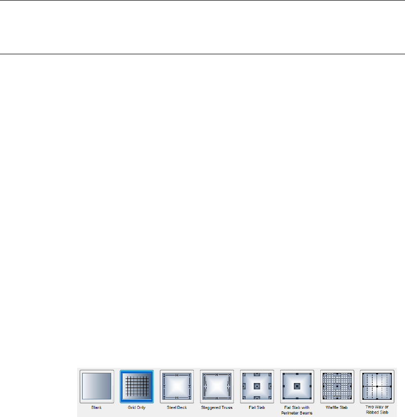
Click the OK button on the Model Initialization form to display the New
Model Quick Templates form shown in Figure 4-3. The New Model
Quick Templates form is used to specify horizontal grid line spacing, sto-
ry data, and template data. The form contains a blank button, a grid only
option, four concrete building templates (Flat Slab, Flat Slab with Perim-
eter Beams, Waffle Slab, Two Way or Ribbed Slab), and two steel build-
ing templates (Steel Deck, Staggered Truss). Template models provide a
quick, easy way of starting a model. They automatically add structural
objects with appropriate properties to the model. We highly recommend
that you start your models using templates whenever possible.
Create the Basic Grid System 4 - 3
User's Guide
Grid Dimensions (Plan) - Define a Grid System
Use the Grid Dimensions (Plan) area of the form to define a grid line sys-
tem. Select from two options for defining the grid line system:
Uniform Grid Spacing. Specify the number of grid lines in the X and
Y directions and a uniform spacing for those lines. Note that the uni-
form spacing in the X and Y directions can be different. This option
defines a grid system for the global coordinate system only. Click the
Grid Labels button to control how the grids are labeled. If subsequent-
ly necessary, edit the information using the Edit menu > Edit Stories
and Grid Systems command. For more information, search for “edit
grid data” using the Help menu > ETABS Help command. Note that
the default global coordinate/grid system is a Cartesian (rectangular)
coordinate system.
Figure 4-3 New Model Quick Templates form
4 - 4 Create the Basic Grid System

Chapter 4 - Begin a Model
Custom Grid Spacing. Define nonuniformly spaced grid lines in the
X and Y directions for the global coordinate system. After choosing
this option, click the Edit Grid Data button to edit the grid system.
For more information, search for “grid labeling” using the Help menu
> ETABS Help command.
The reasons for defining a grid system for the model include the follow-
ing:
Default elevation views in the model occur at each defined primary
grid line in a model.
Structural objects added to the model from a template are added based
on the grid line definitions in the model.
Objects snap to grid lines when drawn in the model.
Objects mesh at their intersections with grid lines.
The grid lines in the model can be defined using the same names as are
used on the building plans. This may allow for easier identification of
specific locations in the model.
Story Dimensions - Define Story Data
Use the Story Dimensions area of the form to define the number and
height of stories. Select from two options for defining the story data:
Simple Story Data: Enter values in the edit boxes to define the num-
ber of stories and a typical story height that is used for all story levels
except for the bottom story, which is specified separately. The program
provides default names for each story level (for example, Story1, Sto-
ry2 and so on) and assumptions for story level similarity.
Custom Story Data: After choosing this option, click the Edit Story
Data button to access the Story Data form. Enter values in the Story
Data form to define your own story names, story levels of non-uniform
height and customized story similarity. Story level "similarity" can be
significant, e.g., when Story2 is a Master Story, and Story1 is similar
to Story2, an object drawn on Story2 typically appears in the same
Create the Basic Grid System 4 - 5

User's Guide
plan location on Story1. The splice data identifies which stories con-
tain steel column splices and the height of the splices - splice data is
not applicable to concrete columns.
The Story Data form also appears when the Edit menu > Edit Stories
and Grid Systems command is used followed by the Modify/Show Sto-
ry Data button on the Edit Story and Grid System Data form. For more
information about the Story Data form, refer to the Editing chapter of
this manual. For more information about story level similarity, search for
“similar stories drop-down list” using the Help menu > ETABS Help
command. Story level similarity can also be significant to composite
beam and steel joist design.
4 - 6 Create the Basic Grid System
Chapter 5
Create the Structural Model
Objective
This chapter describes how to create the structural model. It is assumed
that you have read Chapter 4 Begin a Model or understand how to begin
an ETABS model by defining a grid system.
Add Structural Objects Using Templates
Use one of the six built-in templates shown on the New Model Quick
Templates form to add structural objects to your model. In many cases it
is the simplest, most convenient and quickest way to start a model. The
New Model templates are shown below:
Objective 5 - 1
User's Guide
Note that the templates consist of two for steel buildings and four for
concrete buildings, as well as a button for creating grids only and a but-
ton for starting a blank model, both of which add no structural objects to
the model. Choose any of the templates by left clicking its associated
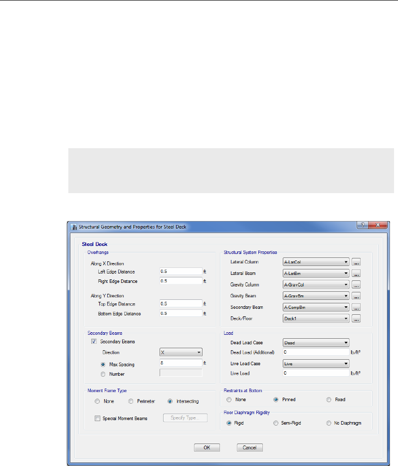
button. When one of the template buttons is chosen, the Structural Ge-
ometry and Properties form will appear for that template, as shown in
Figure 5-1. The Structural Geometry and Properties form typically con-
tains areas for specifying structure data and loads.
Once all structure and load data have been entered, click the OK button
to close the form and return to the New Model Quick Templates form.
Figure 5-1 Structural Geometry and Properties
Note: This form will not display if the Grid Only or Blank buttons are
chosen since no structural objects are defined.
5 - 2 Add Structural Objects Using Templates
Chapter 5 - Create the Structural Model
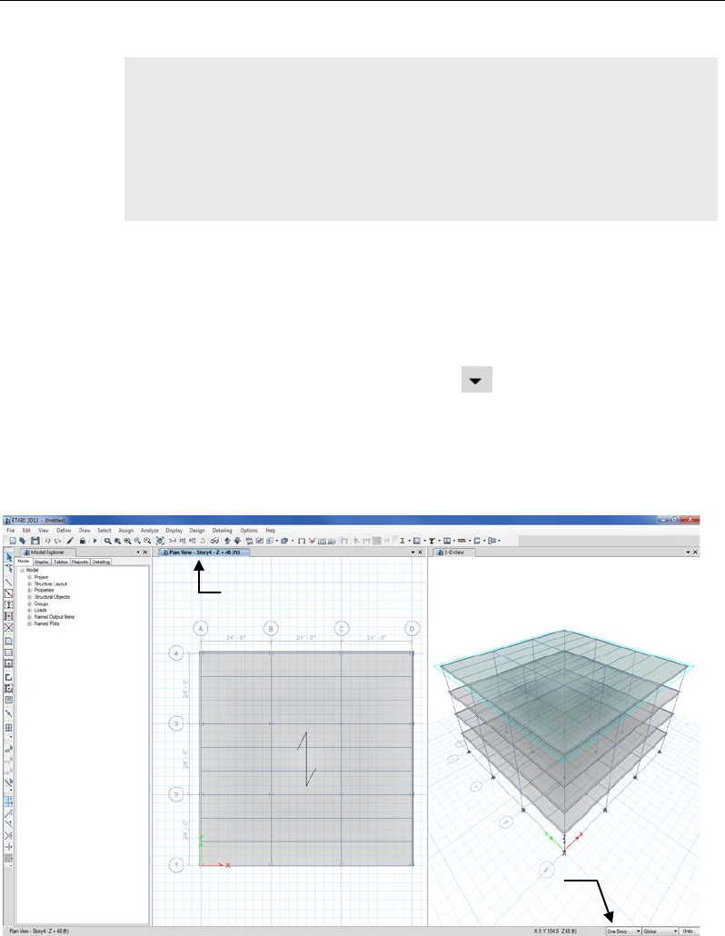
Click the OK button on the New Model Quick Templates form and the
model appears on screen in the main ETABS window with two view
windows tiled vertically, a Plan View on the left and a 3-D View on the
right, as shown in Figure 5-2. The number of view windows can be
changed using the Windows List button .
Note that the Plan View is active in Figure 5-2. When the window is ac-
tive, the display title tab is highlighted. Set a view active by clicking an-
ywhere in the view window.
Note: When using concrete building templates in this program, beams
and slab ribs (joists) are normally modeled with depths equal to the
dimension from the top of the slab (not bottom of slab) to the bottom of
the beam or slab rib. Also, beams are modeled as line elements in this
program. Thus, slabs with out-of-plane bending capability span from
center-of-beam to center-of-beam in the program model.
Display Title Tab
(Active Window)
Drawing & Selection
(Similar Stories Feature)
Figure 5-2 The ETABS main window
Add Structural Objects Using Templates 5 - 3
User's Guide
Define Properties
Template generated models typically rely on program defined material
and section properties. The following sections will show how to define
additional properties or review program defaults.
Material Properties
Click the Define menu > Material Properties command to display the
Define Materials form shown in Figure 5-3, or under the Model tab on
the Model Explorer expand the Properties branch and then the Materi-
als branch to see a list of the defined material properties (a right-click on
the Materials branch will display a context sensitive menu).
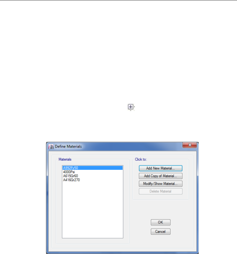
The Define Materials form allows for the both the review of existing ma-
terials, as well as the definition of new properties. To add a new material,
click the Add New Material button on the Define Materials form. When
the Add New Material Property form appears as shown in Figure 5-4, se-
lect a material from the Material Type drop-down list and then a Stand-
ard and Grade from their respective drop-down lists.
Figure 5-3 Define Materials form
5 - 4 Define Properties
Chapter 5 - Create the Structural Model
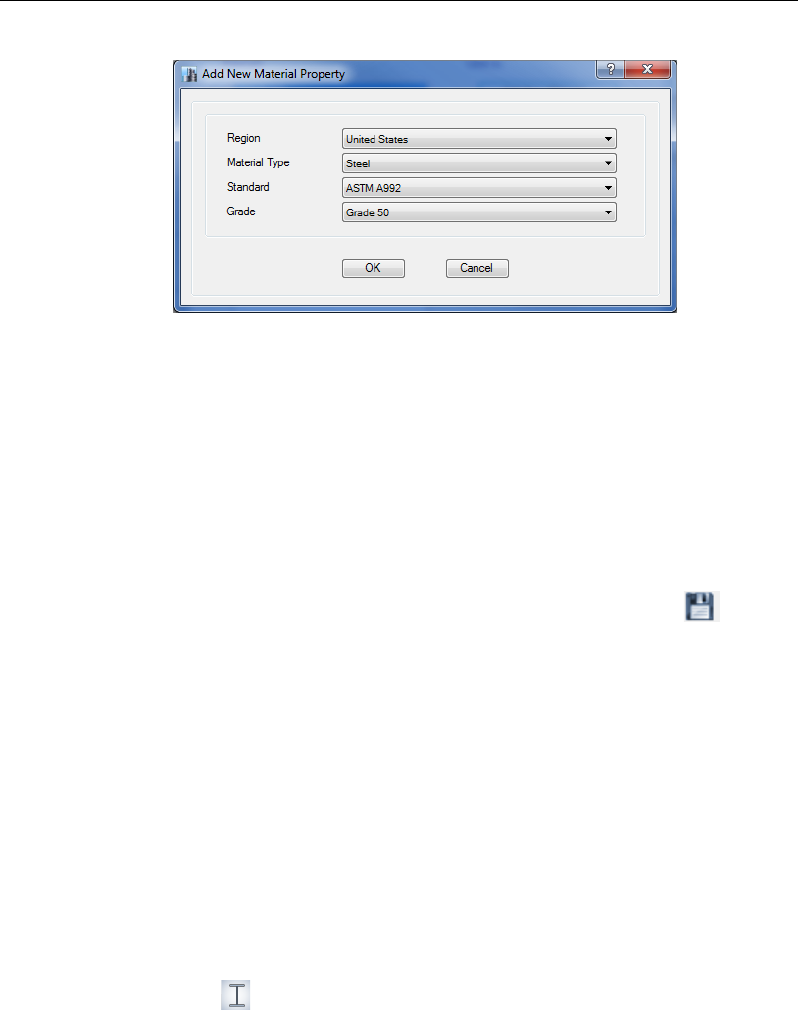
Once selections have been made on the Add New Material Property
form, click the OK button to display the Material Property Data form
where data for the new material may be reviewed and edited. Click the
OK button on the Material Property Data form to return to the Define
Materials form, where additional materials may be defined or reviewed.
Click the OK button on the Define Materials form when finished with
materials.
Click the File menu > Save command, or the Save button, , to save
the model.
Frame Sections
Click the Define menu > Section Properties > Frame Sections com-
mand, which will display the Frame Properties form. The Frame Proper-
ties form allows for the definition of new sections as well as the review
of existing sections. To make steel frame sections from property files
available click the Import New Properties button, or to add user defined
sections click the Add New Property button, both of which will display
the Frame Property Shape Type form shown in Figure 5-5.
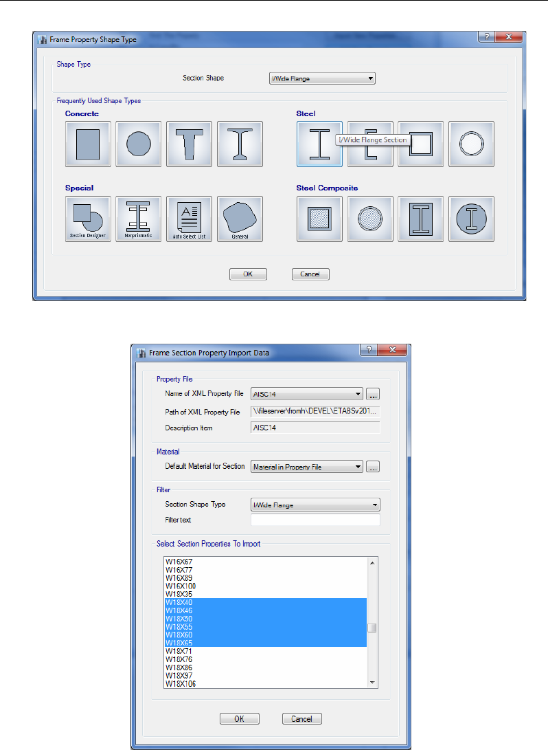
On the Frame Property Shape Type form, click on the I/Wide Flange
Section button under Steel in the Frequently Used Shape Types area,
or select I/Wide Flange from the Section Shape drop-down list in the
Shape Type area and click the OK button. The Frame Section Property
Import Data form shown in Figure 5-6 displays when importing.
Figure 5-4 Add New Material Property form
Define Properties 5 - 5
User's Guide
Figure 5-5 Frame Property Shape Type form
Figure 5-6 Frame Section Property Import Data form
5 - 6 Define Properties
Chapter 5 - Create the Structural Model
The Frame Section Property Import Data form lists the available section
properties for import into the model. Select the sections to be imported
from the list (e.g., W18X40 thru W18X65) using standard Windows se-
lect techniques, i.e., holding the Shift key while selecting. Click the OK
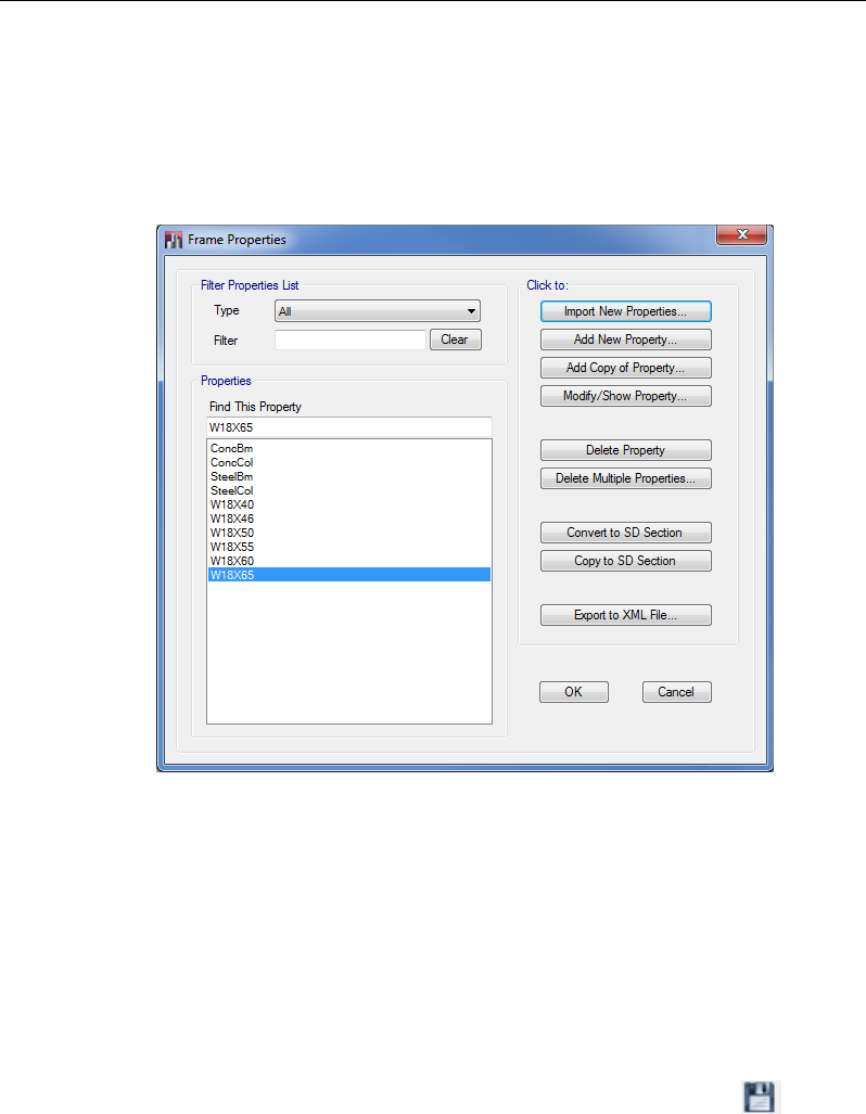
button to return to the Frame Properties form shown in Figure 5-7.
The Frame Properties form should now list the properties just selected on
the Frame Section Property Import Data form. Additional sections may
be added to the Properties list by using the Import New Properties but-
ton again, or highlighted sections may be reviewed by using the Modi-
fy/Show Property button.
Click the OK button on the Frame Properties form when finished with
section definitions.
Click the File menu > Save command, or the Save button, , to save
the model.
Figure 5-7 Frame Properties form
Define Properties 5 - 7
User's Guide
Auto Select Section List
ETABS's Auto Select Section List feature helps to reduce the time re-
quired to develop the model as well as to enhance the design process.
An auto select selection list is simply a list of sections; for example,
W18X35, W18X40, W21X44, W21X50 and W24X55. Auto select sec-
tion lists can be assigned to frame members. When an auto select selec-
tion list is assigned to a frame member, the program can automatically
select the most economical, adequate section from the auto select section
list when it is designing the member.
The program has several built-in auto select section lists. However, the
user can also develop a tailored list using the following steps:
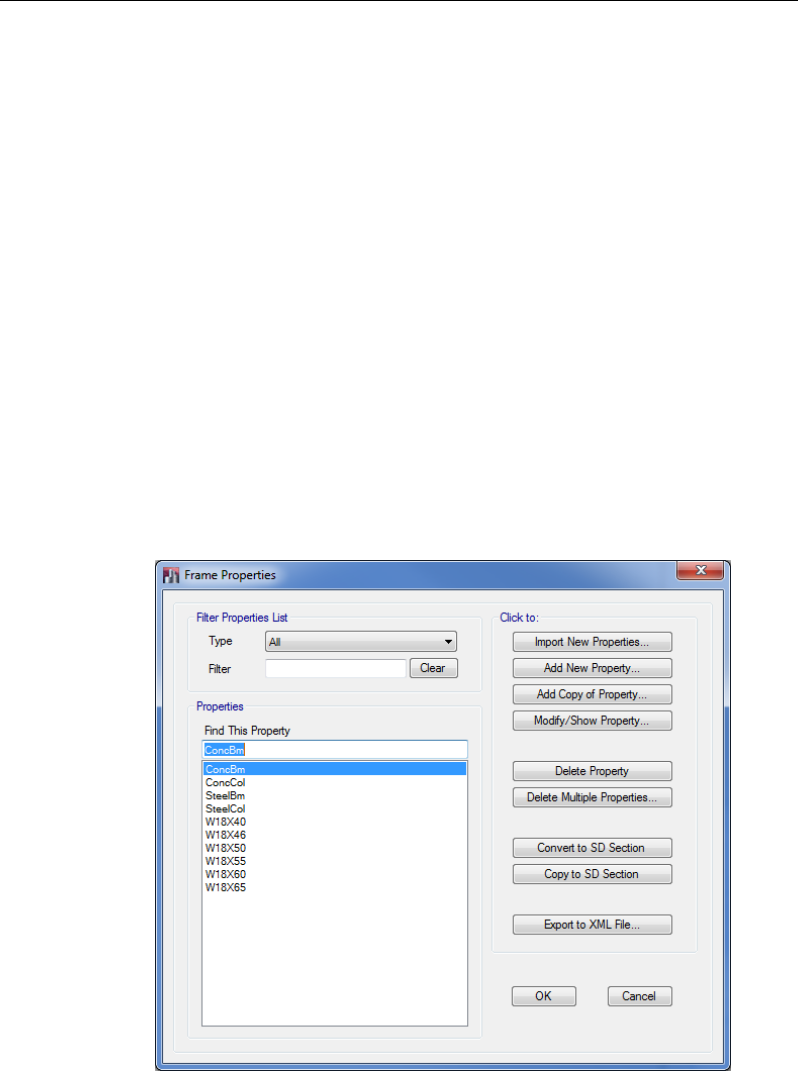
1. Click the Define menu > Section Properties > Frame Sections
command, which will display the Frame Properties form shown in
Figure 5-8. The previous section explains how to import frame prop-
erties into the Properties list.
Figure 5-8 Frame Properties form
5 - 8 Define Properties
Chapter 5 - Create the Structural Model
2. Click the Add New Property button in the Click to area of the
Frame Properties form. The Frame Property Shape Type form shown
in Figure 5-9 will appear.
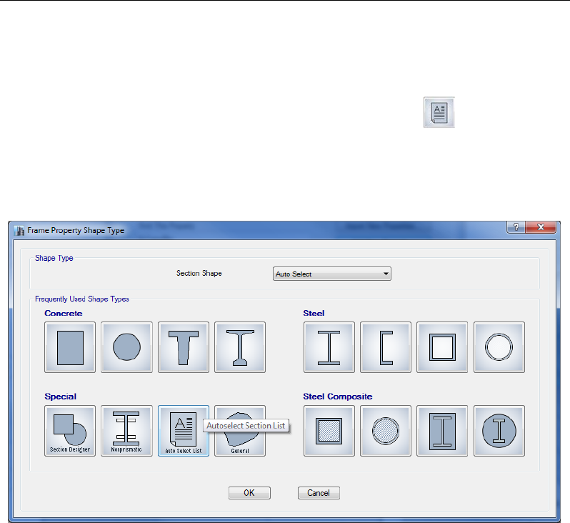
3. Click on the Autoselect Section List button under Special in
the Frequently Used Shape Types area, or select Auto Select from the
Section Shape drop-down list in the Shape Type area and then click
the OK button. The Frame Section Property Data form shown in
Figure 5-10 displays.
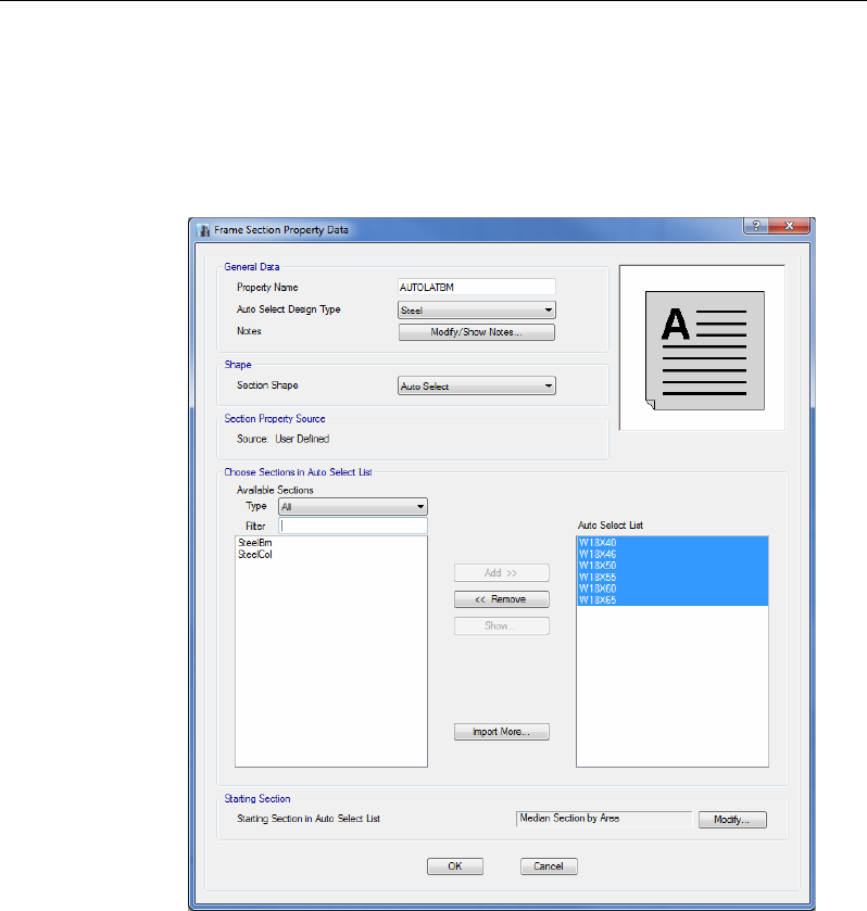
4. Type a name for the list in the Property Name edit box. Any name
can be used. For the purposes of this description, the new Auto Se-
lect Section List is AUTOLATBM.
5. Scroll down the list of sections in the Choose Sections in Auto Select
List area to find the beams to be included in the list. Click once on
them to highlight them. Note that the standard Windows methods for
selecting items in a list can be used (e.g., clicking on a section and
Figure 5-9 Frame Property Shape Type form
Define Properties 5 - 9
User's Guide
then pressing the shift key on the key board before selecting another
section will highlight all sections between the two selected items).
6. Click the Add button to add the selected beams to the Auto Select
List on the right side of the form.
7. Click the OK button and then click the OK button in the Frame
Properties form to accept the definition of a new Auto Select Section
List named AUTOLATBM.
Figure 5-10 Frame Section Property Data form
5 - 10 Define Properties
Chapter 5 - Create the Structural Model
Add Structural Objects Manually
Previously a model was generated using a template, but objects, such as
columns, beams, floors, and walls, also can be drawn manually as de-
scribed in the sections that follow.
Draw Columns
Make sure that the Plan View is active. Click the Quick Draw Columns
button, , or use the Draw menu > Draw Beam/Column/Brace Ob-
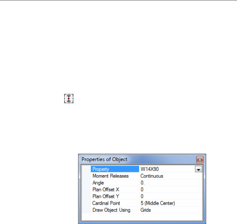
jects > Quick Draw Columns command. The Properties of Object box
for columns shown in Figure 5-11 will display docked in the lower left-
hand corner of the display. Hold the left mouse button down on the Prop-
erties of Object tab to move the box elsewhere in the display, or to dock
it using the docking arrows.
The Properties of Object box provides various definition parameters and
drawing controls. These items differ depending on the drawing command
selected. Review the parameters and controls shown in this box before
drawing the column to ensure that they are what they should be. Change
any entry in the box by clicking on it and making a new selection from
the drop-down list or entering new information into the edit box, as ap-
propriate.
After checking the parameters in the Properties of Object box, left click
once in the Plan View at the intersection of the grid lines where you want
Figure 5-11 Properties of Object Box for Columns
Add Structural Objects Manually 5 - 11
User's Guide
the column. An I-shaped column should appear at that point in the Plan
View. Continue in this manner to place other columns.
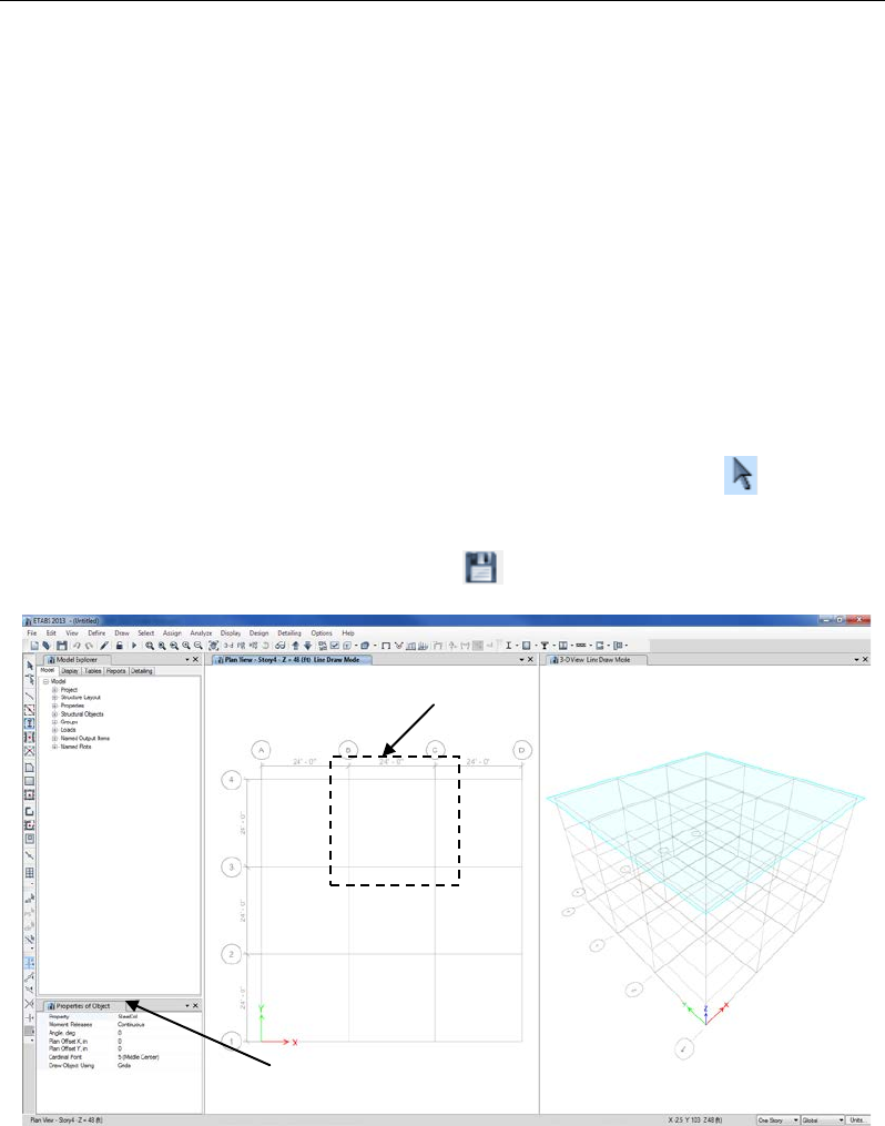
Alternatively, draw the remaining columns in one action by "windowing"
around the grid intersections. To "window," click the left mouse button
above and to the left of the first grid intersection where a column is to be
placed and then, while holding the left mouse button down, drag the
mouse until it is below and to the right of the last grid intersection where
a column is to be placed. A selection box similar to that shown in Figure
5-12 should expand around the grid line intersections as the mouse is
dragged across the model. Release the left mouse button and the program
will draw the column objects at the grid line intersections within the
boundaries of the selection box.
To leave the Draw mode, click the Select Object button, .
It is a good idea to save your models often. Click the File menu > Save
command, or the Save button, , to save the model.
Selection Box
“Docked”Properties of Object form
Figure 5-12 Drawing Column Objects in a Windowed Region
5 - 12 Add Structural Objects Manually
Chapter 5 - Create the Structural Model
Draw Beams
Make sure that the Plan View is active. Click the Quick Draw Breams
button, or the Draw menu > Draw Beam/Column/Brace Objects
> Quick Draw Beams/Columns command. The Properties of Object
box for beams shown in Figure 5-13 will display docked in the lower
left-hand corner.
As explained previously, the Properties of Object box provides various
definition parameters. Change any entry in the box by clicking on it and
making a new selection from the drop-down list or entering new infor-
mation into the edit box, as appropriate.
After checking the parameters in the Properties of Object box, left click
once in the Plan View on a grid line where a beam is to be placed. A
beam is drawn along the selected grid line. Continue in this manner to
place other beams.
Alternatively, draw the remaining beams in one action by windowing
around the grid intersections. Windowing is explained in the previous
section.
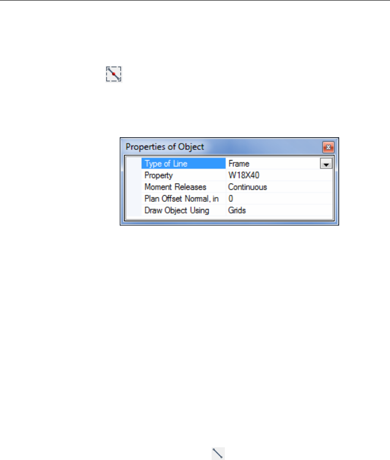
To draw beams not located on a grid line, click the Draw
Beam/Column/Brace button, or the Draw menu > Draw
Beam/Column/Brace Objects > Draw Beam/Column/Brace com-
mand. The Properties of Object box for frames shown in Figure 5-14 will
display docked in the lower left-hand corner. This form is similar to that
shown in Figure 5-13 with the addition of an option for constraining how
the frame object is to be drawn, i.e., Drawing Control Type.
Figure 5-13 Properties of Object Box for Beams
Add Structural Objects Manually 5 - 13
User's Guide
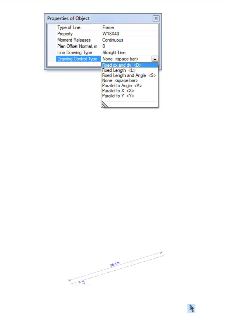
The Drawing Control Type can constrain the line to be a fixed length, or
parallel to an angle, or both, or parallel to coordinate axes.
After checking the parameters in the Properties of Object box, left click
once in the Plan View to indicate the starting location of the beam. Select
an option from the Drawing Control Type drop-down list if some type of
drawing constraint is desired, and then left click to indicate the end joint
of the beam. The program will start another frame object at the location
of the just drawn beam's end joint unless the right button of the mouse is
clicked to stop drawing.
Another aid when drawing objects is the Draw Measurement Tool shown
in Figure 5-15. This tool automatically displays when in the drawing
mode after the starting joint of the object is drawn. This tool displays the
length and angle orientation of the frame member or edge.
To leave the Draw mode, click the Select Object button, .
Figure 5-14 Properties of Object Box for Frames
Figure 5-15 Draw Measurement Tool
5 - 14 Add Structural Objects Manually
Chapter 5 - Create the Structural Model
Draw Secondary (Infill) Beams
Add secondary or "infill" beams by clicking the Quick Draw Secondary
Beams button, or the Draw menu > Draw Beam/Column/Brace
Objects > Quick Draw Secondary Beams command. Similar to the
other drawing operations, a Properties of Object box will display docked
in the lower left-hand corner that provides the opportunity to define the
parameters for the secondary beams.
To place the secondary beams, left click once in the bay bounded by grid
lines where the secondary beams are to be placed. Similar to columns
and the primary beams, secondary beams can be drawn by windowing
over the appropriate bays. Note the Approx. Orientation parameter to set
the span direction.
Click the File menu > Save command, or the Save button, , to save
the model.
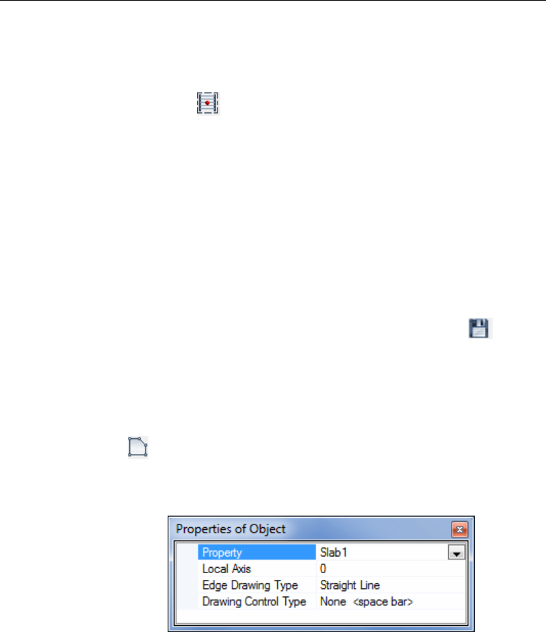
Draw the Floor
Make sure that the Plan View is active. Click the Draw Floor/Wall but-
ton, , or select the Draw menu > Draw Floor/Wall Objects > Draw
Floor/Wall command. The Properties of Object box for areas shown in
Figure 5-16 will appear docked in the lower left-hand corner.
Similar to columns and beams, this Properties of Object box provides the
opportunity to check and change the parameters for the area. Change any
entry in the box by clicking on it and making a new selection from the
Figure 5-16 Properties of Object Box for Shells
Add Structural Objects Manually 5 - 15
User's Guide
drop-down list or entering new information into the edit box, as appro-
priate.
After checking the parameters in the Properties of Object box, check that
the Snap to Grid Intersections and Points command is active. This will
assist in accurately drawing the area object. This command is active
when its associated button is depressed. Alternatively, use the Draw
menu > Snap Options command to ensure that this command is active.
By default, this command is active.
Left click once at a column to begin the floor/area object at that column.
Then, moving around the perimeter of the floor object, click once at oth-
er column intersections to draw the outline of the building. Press the En-
ter key on your keyboard to complete the floor.
If you have made a mistake while drawing this object, click the Select
Object button, , to change the program from Draw mode to Select
mode. Then click the Edit menu > Undo Shell Add command.
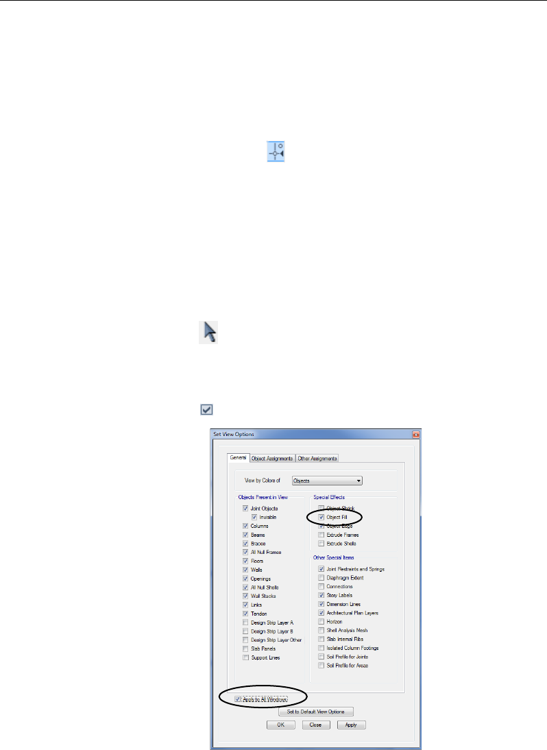
To switch the fill on or off for the floor addition, click the Set Display
Options button . Once the Set View Options form appears, check or
Figure 5-17 Set View
Options form
5 - 16 Add Structural Objects Manually
Chapter 5 - Create the Structural Model
uncheck the Object Fill check box and the Apply to All Windows check
box on the General tab, as shown in Figure 5-17. Click the OK button.
Click the File menu > Save command, or the Save button, , to save
the model.
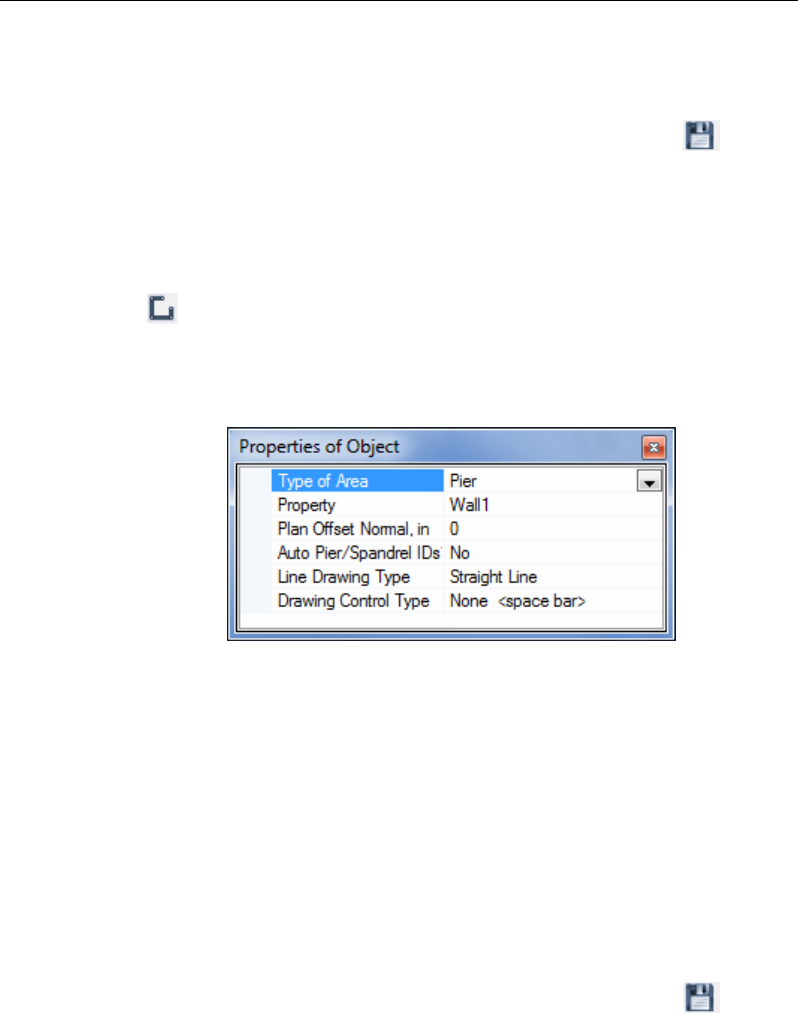
Draw Walls
Make sure that the Plan View is active. Click the Draw Walls button,
, or select the Draw menu > Draw Floor/Wall Objects > Draw
Walls command. The Properties of Object box for walls shown in Figure
5-18 will appear docked in the lower left-hand corner.
Change any entry in the Properties of Object box by clicking on it and
making a new selection from the drop-down list or entering new infor-
mation into the edit box, as appropriate.
To place walls, left click once at a point to begin the wall object at that
point. Then, move to the end of the wall segment and left click again.
Additional wall segments may be drawn by simply moving to a new
point and clicking. Press the Enter key on your keyboard to complete the
wall.
Click the File menu > Save command, or the Save button, , to save
the model.
Figure 5-18 Properties of Object Box for Walls
Add Structural Objects Manually 5 - 17
User's Guide
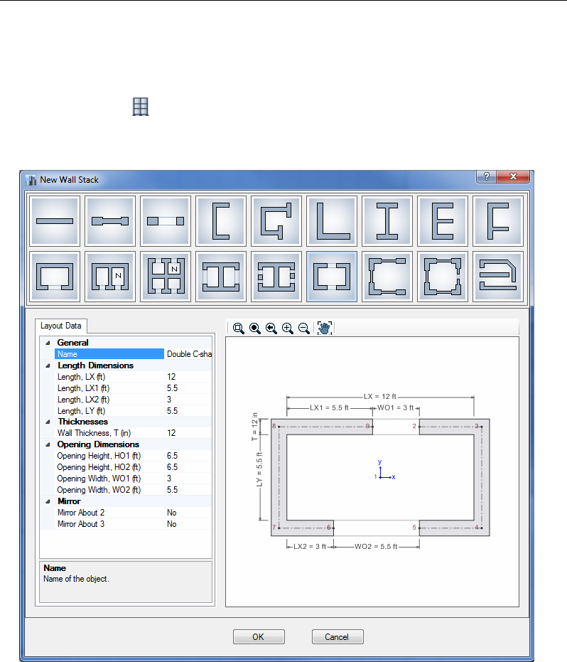
Draw Wall Stacks
Make sure that the Plan View is active. Click the Draw Wall Stacks but-
ton, , or the Draw menu > Draw Wall Stacks command. The New
Wall Stack form shown in Figure 5-19 will appear.
Select any of the predefined wall stacks by clicking on the representative
icon. The lengths and thicknesses of the wall segments may be altered by
entering changes into the edit boxes on the Layout Data tab. Once all
wall stack parameters have been reviewed on the Layout Data tab, click
Figure 5-19 New Wall Stack form
5 - 18 Add Structural Objects Manually
Chapter 5 - Create the Structural Model
the OK button. The Properties of Object box for wall stacks will appear
docked in the lower left-hand corner
Verify that the angle and range of stories for the wall stack are correct in
the Properties of Object form, and then left click once in the Plan View
where the wall stack is to be placed. A wall stack is drawn at that loca-
tion for the number of stories specified. Continue in this manner to place
other wall stacks.
To leave the Draw mode, click the Select Object button, .
Click the File menu > Save command, or the Save button, , to save
the model.
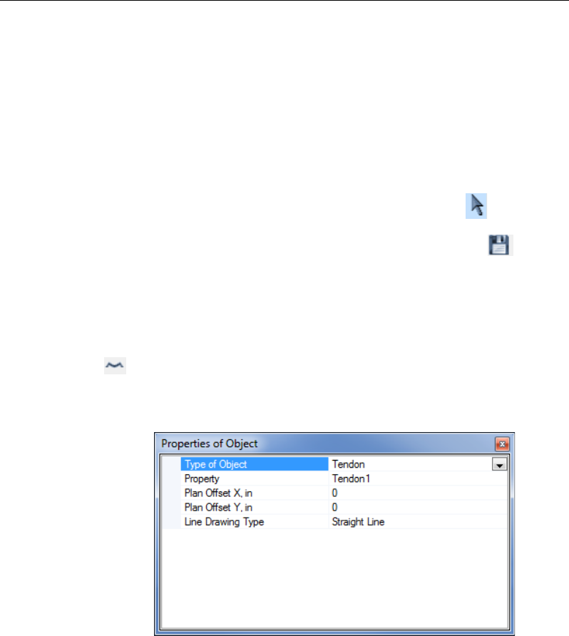
Draw Tendons
Make sure that the Plan View is active. Click the Draw Tendons button,
, or the Draw menu > Draw Tendons command. The Properties of
Object box for tendons shown in Figure 5-20 will appear docked in the
lower left-hand corner.
Change any entry in the Properties of Object box by clicking on it and
making a new selection from the drop-down list or entering new infor-
mation into the edit box, as appropriate.
To place tendons, left click once at a point to begin the tendon object at
that point. Then, move to the end of the tendon segment and left click
Figure 5-20 Properties of Object Box for Tendons
Add Structural Objects Manually 5 - 19

User's Guide
again. Additional tendon segments may be drawn by simply moving to a
new point and clicking. Press the Enter key on your keyboard to com-
plete the tendon.
To expedite the addition of banded and/or distributed tendons to a slab,
rather than draw individual tendons, it may be more efficient to use the
Edit menu > Add/Edit Design Strips > Add Design Strips command
to first layout design strips, and then use the Edit menu > Add/Edit
Tendons > Add Tendons in Strips command to rapidly place multiple
tendons within selected strips.
Click the File menu > Save command, or the Save button, , to save
the model.
5 - 20 Add Structural Objects Manually

Chapter 6
Select Structural Objects
Objective
This chapter describes how to select objects in the model.
Selecting
Selecting is used to identify existing objects to which the next operation
will apply. Operations that require prior selection include certain Editing,
Assignment, Design, Display, and Output operations.
Graphical Selection Options
The program has a number of techniques for graphically selecting ob-
jects:
Left click: Left click on an object to select it. If multiple objects are
present in the same location, one on top of the other, hold down the
Objective 6 - 1

User's Guide
Ctrl key on the keyboard and click the left mouse button on the objects.
Use the form that displays to specify which object to select.
Window or "Windowing": Drag a window from left to right to select
all objects that are fully enclosed in the window. Drag a window from
right to left to select all objects that are fully or partially enclosed in
the window. To draw a window, first position the mouse pointer be-
yond the limits of the object; for example, above and to the left of the
object(s) to be selected. Then depress and hold down the left mouse
button. While keeping the left button depressed, drag the mouse to a
position below and to the right of the object(s) to be selected. Release
the left mouse button to complete the selection. Note the following
about window selection:
As the mouse is dragged, a "rubber band window" appears. The
rubber band window is a dashed rectangle that changes shape as
the mouse is dragged. One corner of the rubber band window is at
the point where the left mouse button was first depressed. The di-
agonally opposite corner of the rubber band window is at the cur-
rent mouse pointer position. When dragging the mouse from left to
right, any visible object that is completely inside the rubber band
window is selected when the left mouse button is released. When
dragging the mouse from right to left, any visible object that the
window crosses or encloses is selected.
As long as the mouse pointer is beyond the limits of the object(s)
to be selected, the window can start at any point.
Note about Window Selections in Plan View: When selecting by win-
dow in a plan view, the objects selected will be determined by the set-
ting in the One Story drop-down list. To select only the objects at the
plan level displayed (which include the columns in the story below),
the drop-down list should be set to One Story. When set to Similar Sto-
ries or All Stories, selecting in plan view may result in objects at other
levels being selected, even though only one plan level is displayed.
Poly: Draw a polygon with any number of sides to select all objects
that are fully enclosed in the polygon. To use this selection method,
click the Select menu > Select > Poly command. Then position the
mouse pointer outside the object(s) to be selected, left click to start the
6 - 2 Selecting

Chapter 6 - Select Structural Objects
polygon and then left click at each of the polygon's vertices. Hit the
Enter key on the keyboard to complete the selection polygon. After us-
ing this method to make a selection, the program defaults to the win-
dow selection mode.
Intersecting Poly: Draw a polygon with any number of sides to select
all objects that are fully or partially enclosed in the polygon. To use
this selection method, click the Select menu > Select > Intersecting
Poly command. Then position the mouse pointer outside the object(s)
to be selected, left click to start the polygon and then left click at each
of the polygon's vertices. Hit the Enter key on the keyboard to com-
plete the selection polygon. After using this method to make a selec-
tion, the program defaults to the window selection mode.
Intersecting Line: Draw a line through one or more objects to select
them. To use this selection method, click the Select menu > Select >
Intersecting Line command or the Select using Intersecting Line
button, . Then position the mouse pointer to one side of the ob-
ject(s) to be selected and click the left mouse button. Drag the mouse
across the object(s) to be selected and click the left mouse button fol-
lowed by the Enter key on the keyboard to complete the selection. Note
the following about the intersecting line selection method:
As the mouse is dragged, a "rubber band line" appears. The rubber
band line is a dashed line that changes length and orientation as the
mouse is dragged. It extends from the point where the left mouse
button is first clicked to the current mouse pointer position. Any
visible object that is intersected (crossed) by the rubber band line is
selected when the Enter key is pressed.
After using this method to make a selection, the program defaults
to the window selection mode. Thus, the Select menu > Select >
Intersecting Line command must be selected or the Select using
Intersecting Line button must be clicked each time this selec-
tion method is used.
Selecting 6 - 3
User's Guide
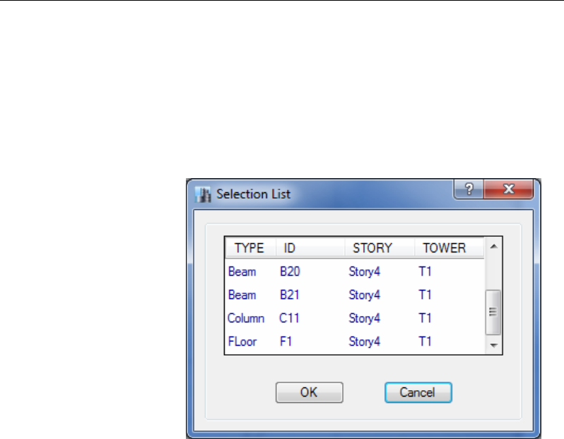
Control and Left Click: Hold down the Ctrl key on the keyboard and
left click once on a joint, frame or shell object. A Selection List form
similar to the one shown in Figure 6-1 pops up identifying the objects
that exist at that location. Select the desired object by moving the
mouse pointer over it and left clicking on it.
Selecting by Coordinates
Using the Select menu > Select > Coordinate Specification command,
select objects by clicking on a point in a XY, XZ, or YZ plane.
Selecting by Feature
Using the Select menu > Select command, select objects by their various
features, such as:
All objects of a particular type, e.g., Columns, Beams, Braces,
etc.
All objects that have a given section or property type
All objects that have a particular label or unique name
Figure 6-1 Selection
List Form
6 - 4 Selecting

Chapter 6 - Select Structural Objects
All objects that belong to the same group
All objects that belong to a particular tower or story
These selection methods operate independently of the display windows,
and affect all objects having a given feature even if those objects are not
being displayed.
Deselect Command
Deselect objects one at a time by left clicking on the selected objects. Al-
ternatively, use the Select menu > Deselect command and its subcom-
mands for quicker and more specific deselection actions. This command
provides access to subcommands similar to those described in this chap-
ter for selection, except that executing the Select menu > Deselect com-
mand and an associated subcommand deselects rather than selects an ob-
ject(s). For example, assume that you want to select all of the objects in
your model except for columns. Do this quickly and easily by first using
the Select menu > Select > All command and then using the Select
menu > Deselect > Object type command and highlighting Columns.
Invert Selection Command
The Select menu > Invert Selection command selects all objects not
currently selected, and deselects those previously selected.
Get Previous Selection Command
The Select menu > Get Previous Selection command selects the previ-
ously selected object(s). For example, assume you have selected some
frame objects by clicking on them and assigned frame section properties
to them. Use the Get Previous Selection command or the Get Previous
Selection button to select the same frame objects and assign some-
thing else to them, such as member end releases.
Selecting 6 - 5

User's Guide
Clear Selection Command
The Select menu > Clear Selection command and its associated Clear
Selection button clear all currently selected objects. It is an all or
nothing command. It cannot selectively clear a portion of a selection.
6 - 6 Selecting

Chapter 7
Assign/Change Properties
Objective
This chapter describes how to assign or change the properties of structur-
al objects in the model.
Assign
In creating the model, the user draws joint, frame, shell, link, and tendon
objects. To enable analysis and design, those objects must be assigned
properties, such as material properties, frame sections, wall/slab/deck
sections, link properties, tendon properties, and loads, among others.
Note that the assign menu lists the various properties that can be as-
signed. Also note that the assignment of loads is explained in Chapter 8
of this guide.
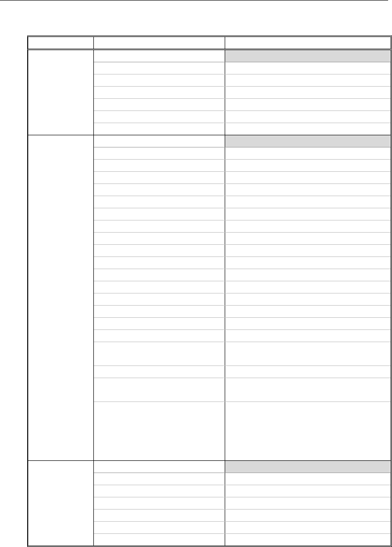
As shown in Table 7-1, the types of assignments available depend on the
type of object. Assignments also depend on the type of design (e.g., steel
versus concrete versus composite design).
Objective 7 - 1
User's Guide
TABLE 7-1 Possible Assignments to Objects by Object Type
Object
Assignment Option
Name of Input Form*
Joint
Joint Assignment -
Restraints
Restraints
Springs
Springs
Diaphragms
Diaphragms
Panel Zone
Panel Zone Property
Additional Mass
Additional Mass
Joint Floor Meshing Options
Joint Floor Meshing Option
Frame
Frame Assignment -
Section Property
Section Property
Property Modifiers
Property Modifiers
Releases/Partial Fixity
Releases/Partial Fixity
End Length Offsets
End Length Offsets
Insertion Point
Insertion Point
Local Axes
Local Axes
Output Stations
Output Stations
Tension/Compression Limits
Tension/Compression Limits
Hinges
Hinges
Hinge Overwrites
Hinge Overwrites
Line Springs
Line Springs
Additional Mass
Additional Mass
Pier Label
Pier Label
Spandrel Label
Spandrel Label
Frame Auto Mesh Options
Frame Auto Mesh Options
Frame Floor Meshing Options
Frame Floor Meshing Option
Moment Frame Beam Connec-
tion Type
Moment Frame Beam Connection Type
Column Splice Overwrite
Column Splice Overwrite
Nonprismatic Property Param-
eters
Nonprismatic Property Parameters
Material Overwrite
(not applicable to section de-
signer, nonprismatic, auto se-
lect, encased rectangle/circle,
or filled tube/pipe sections)
Material Overwrite
Shell
Shell Assignment -
Slab Section
Slab Section
Deck Section
Deck Section
Wall Section
Wall Section
Openings
Openings
Stiffness Modifiers
Stiffness Modifiers
Thickness Overwrites
Thickness Overwrites
7 - 2 Assign
Chapter 7 - Assign/Change Properties
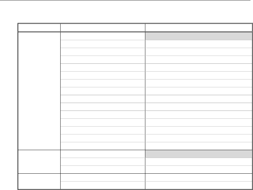
TABLE 7-1 Possible Assignments to Objects by Object Type
Object
Assignment Option
Name of Input Form*
Shell
Shell Assignment -
Insertion Point
Insertion Point
Diaphragms
Diaphragms
Edge Releases
Edge Releases
Local Axes
Local Axis
Area Springs
Area Springs
Additional Mass
Additional Mass
Pier Label
Pier Label
Spandrel Label
Spandrel Label
Wall Hinge
Hinges
Reinforcement for Wall Hinge
Wall Hinge Reinforcement Select
Floor Auto Mesh Options
Floor Auto Mesh Options
Wall Auto Mesh Options
Wall Auto Mesh Options
Auto Edge Constraint
Auto Edge Constraints
Material Overwrite
Material Overwrite
Link
Link Assignment -
Link Properties
Link Property
Local Axes
Local Axes
Tendon
Tendon Properties
Tendon Property Assign
* Note: With a form displayed on the ETABS window, click the F1 key on your
keyboard to access context-sensitive Help for the form.
View the assignments made to joint, frame, shell, link, and tendon ob-
jects by right clicking on the object. The appropriate Joint Object Infor-
mation, Frame Object Information, Shell Object Information, Link Ob-
ject Information, or Tendon Object Information form will display. Click
on the Assignments tab.
In each case, select an object before executing the desired assignment
command (e.g., select a frame object before using the Assign menu >
Frame > Section Property command). As explained in Chapter 6 of this
guide, using the Ctrl key and left clicking on a location in the model can
simplify the process of selecting objects when multiple objects may be
present at the same location or if selecting objects is new to the user and
seems challenging.
The availability of commands depends on the type of object selected.
The input forms include object/assignment-specific input fields that ena-
Assign 7 - 3
User's Guide
ble refinement of the assignment. Modifications to the assignments can
be made by accessing the input forms using the appropriate Assign menu
command.
The forms typically include OK, Apply and Close buttons that can be
used to accept or delete changes made to the forms.
Note that the combination of the type of object, name of the command
and name of the input form provides an indication of what can be
achieved by using a particular command.
Assign the AUTOLATBM Auto Select Section List
The AUTOLATBM Auto Select Section list created as described in
Chapter 5 consists of various sections that can be assigned to a frame ob-
ject. Thus, in making the assignment, the user should not select a joint or
shell object in the model, or click the Joint or Shell commands on the
Assign menu.
Rather, the user should select a frame object (e.g., a beam) and then click
the Assign menu > Frame > Section Property command. This will
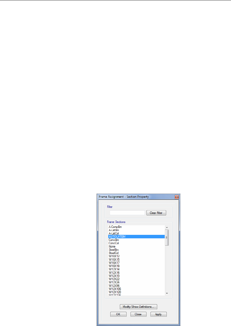
dispaly the Frame Assignment - Section Property form shown in Figure
7-1.
Figure 7-1 Frame Assignment - Section Property form
7 - 4 Assign

Chapter 7 - Assign/Change Properties
Scroll down the list of properties to locate and highlight the name of the
Auto Select Section List to be assigned; AUTOLATBM in this example.
Click the Apply button and the assignment of the Auto Select Section
List named AUTOLATBM is complete. Close the Frame Assignment -
Section Property form with the Close button.
Make an Assignment as the Object is Drawn
An Auto Select Section List can also be assigned when the frame object
is being drawn on the model. Using this method, select the desired Auto
Select Section list by name from the Property drop-down list in the Prop-
erties of Object Box that appears when a drawing tool is selected. Use of
the drawing tools is described in Chapter 5 of this guide along with fig-
ures showing the Properties of Object boxes for joint, frame, and shell
objects.
Make an Assignment using the Model Explorer
Any Frame Section or Auto Select Section List that has been defined can
be assigned from the Model Explorer using "drag & drop". On the Model
tab in the Model Explorer, click on the Properties node to expand the
tree and then on the Frame Sections node to see a list of the available
sections. Click on the desired section (or Auto Select List) and while
holding down the left-mouse button, drag the section onto a frame object
- the frame object where the section will be placed will be highlighted
with a colored line. Release the mouse button to assign the section.
Check the Sections in an Auto Select Section List
As indicated previously, several Auto Select Section Lists are built into
the program. To review the sections included in any Auto Select Section
Lists, whether built in or user-specified, complete the following steps:
1. Click the Define menu > Section Properties > Frame Sections
command. The Frame Properties form will display.
Assign 7 - 5

User's Guide
2. Highlight the name of the Auto Select Section List to be checked in
the Properties list.
3. Click the Modify/Show Property button. The Frame Section Prop-
erty Data form displays; the sections included in the selected auto se-
lect section list are listed in the Auto Select List area of the form,
available for review.
4. Click the Cancel button to close the form.
7 - 6 Assign

Chapter 8
Load the Structural Model
Objective
This chapter describes how to define structural loads for the model.
Structural Loads
The program allows the user to define a variety of structural loads, in-
cluding dead, live, earthquake and wind loads. The user then assigns the
loads to various structural objects in the model. An unlimited number of
load patterns can be defined.
Note that the steel frame, concrete frame, composite beam, composite
column, steel joist, concrete shear wall, concrete slab, and steel connec-
tion design manuals describe design combinations in accordance with
building codes.
Objective 8 - 1

User's Guide
Define the Load Patterns
To add a load pattern, click the Define menu > Load Patterns command
or expand the tree on the Model tab in the Model Explorer and right click
on Load Patterns to access the Define Load Patterns form. Complete the
following actions using that form:
1. Type the name of the load pattern in the Load edit box. The program
does not allow use of duplicate names.
2. Select a load type from the Type drop-down list.
3. Type a self-weight multiplier in the Self-Weight Multiplier edit box
(see the explanation about the self-weight multiplier that follows).
4. If the load type specified is Seismic or Wind, select an option from
the Auto Lateral Load drop-down list.
5. Click the Add New Load button.
AUTO LATERAL LOAD
Auto Lateral Loads automate the application of code defined seismic and
wind loads. Only one code based auto lateral load may be assigned for a
given load pattern. If the Type has been set to Seismic, then the Auto
Lateral Load drop-down list will show an extensive list of seismic codes
for determining earthquake loads. Once a code has been selected, click
the Modify Lateral Load button to display the Seismic Loading form
listing parameters for site coefficients, periods, and load directions.
Note: If your model has more than one tower, do not use a Seismic type
Auto Lateral Load, but perform a Response Spectrum or Time History
Note: If you select an automatic lateral load in the Auto Lateral Load
drop-down list, click the Modify Lateral Load button and review or
modify the parameters for the automatic lateral load in the resulting
form. Then click the OK button to return to the Define Load Patterns
form.
8 - 2 Structural Loads

Chapter 8 - Load the Structural Model
analysis instead. Using a seismic Auto Lateral Load with multiple towers
will likely result in an incorrect distribution of lateral loads.
If the Type has been set to Wind, then the Auto Lateral Load drop-down
list will show a list of available codes for wind loads. Once a code has
been selected, click the Modify Lateral Load button to display the Wind
Load Pattern form, where coefficients and parameters may be input and
reviewed. If the exposure is set to the Extents of Rigid Diaphragms op-
tion, the program will automatically calculate and apply the different
code defined wind load permutations to the diaphragms. With a load pat-
tern highlighted that has ASCE 7-10 as the Auto Lateral Load, clicking
the Modify Lateral Load button will display the Wind Load Pattern -
ASCE 7-10 form shown in Figure 8-1.
1. Select Create All Sets from the Case drop-down list.
2. Hold the mouse cursor over the information icon to display a ta-
ble listing the direction angles and ratios for the ASCE cases. The
ASCE 7-10 code prescribes 12 different wind load permutations.
Figure 8-1 Wind Load Pattern - ASCE 7-10 form
Structural Loads 8 - 3
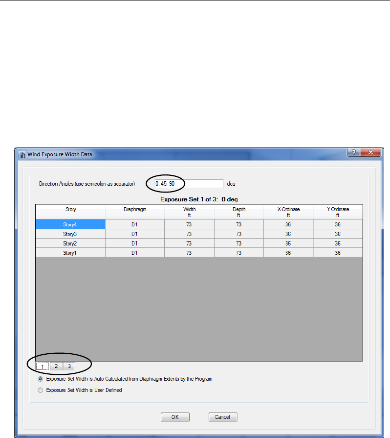
User's Guide
3. Click the OK button to close the form.
With a load pattern highlighted that has EUROCODE 1 2005 as the Auto
Lateral Load, clicking the Modify Lateral Load button will display the
Wind Load Pattern - EuroCode 1 2005 form.
On the Wind Load Pattern - EuroCode 1 2005 form, click the Modi-
fy/Show button for Wind Directions and Exposure Widths to display the
Wind Exposure Width Data form shown in Figure 8-2.
1. Type ;45 after 90 in the Direction Angles edit box (make sure to pre-
cede 45 with a semicolon ;). This adds an additional wind load at a
direction of 45 degrees to the previously defined angles of 0 and 90.
Figure 8-2 Wind Exposure Width Data form
8 - 4 Structural Loads

Chapter 8 - Load the Structural Model
2. Note that the number buttons in the lower left-hand corner of the ta-
ble expand from two to three - click on these buttons to display the
exposure set tables for each angle setting.
3. Click the OK button to close the form.
SELF-WEIGHT MULTIPLIER
The self-weight of the structure is determined by multiplying the weight-
per-unit-volume of each object that has structural properties times the
volume of the object. The weight-per-unit-volume is specified in the ma-
terial properties (search for “material properties” using the Help menu >
ETABS Help command for more information about material properties
and the Material Properties command).
A portion of the self-weight can be applied to any load pattern. The self-
weight multiplier controls what portion of the self-weight is included in a
load pattern. A self-weight multiplier of 1 includes the full self-weight of
the structure in the load pattern. A self-weight multiplier of 0.5 includes
one-half of the self-weight of the structure in the load pattern.
Normally a self-weight multiplier of 1 should only be specified in one
load pattern, usually the dead load pattern. All other load patterns
then have self-weight multipliers of zero. Note that if a self-weight mul-
tiplier of 1 is included in two different load patterns, and then those two
load patterns are combined in a load case or combination, the results are
based on an analysis where double the self-weight of the building has
been applied as a load.
Modify an Existing Load Pattern
Use the following procedure and the Define Load Patterns form to modi-
fy an existing load pattern. Recall that the Define Load Patterns form is
accessed using the Define menu > Load Patterns command:
1. Highlight the existing load pattern in the Loads area of the form.
Note that the data associated with that load pattern appears in the edit
boxes and drop-down lists at the top of the Loads area.
2. Modify any of the data in the Loads area for the load case.
Structural Loads 8 - 5

User's Guide
3. Click the Modify Load button. If necessary, click the Modify Lat-
eral Load button to modify the automatic lateral load parameters.
Delete an Existing Load Pattern
Use the following procedure to delete an existing load pattern in the De-
fine Load Patterns form. Note that when a load pattern is deleted, all of
the loads assigned in the model as a part of that load pattern are also de-
leted.
Highlight the existing load pattern in the Loads area of the form.
Note that the data associated with that load pattern appears in the edit
boxes and drop-down lists at the top of the Loads area.
Click the Delete Load button.
Define Shell Uniform Load Sets
Shell uniform load sets define loads that consist of several different load
patterns, e.g., the load set may contain loads from both dead and live pat-
terns. To add a shell uniform load set, click the Define menu > Shell
Uniform Load Sets command to access the Shell Uniform Load Sets
form. Complete the following actions using that form:
1. Click the Add New Load Set button to display the Shell Uniform
Load Set Data form.
2. On the Shell Uniform Load set Data form, type the name of the shell
load set in the Uniform Load Set Name edit box. The program does
not allow use of duplicate names.
3. Click the Add button.
4. Select a load pattern from the Load Pattern drop-down list (only load
patterns that have previously been defined may be selected).
5. Type a load value in the Load Value edit box.
6. Click the OK button to return to the Shell Uniform Load Sets form.
7. Click the OK button to close the Shell Uniform Load Sets form.
8 - 6 Structural Loads
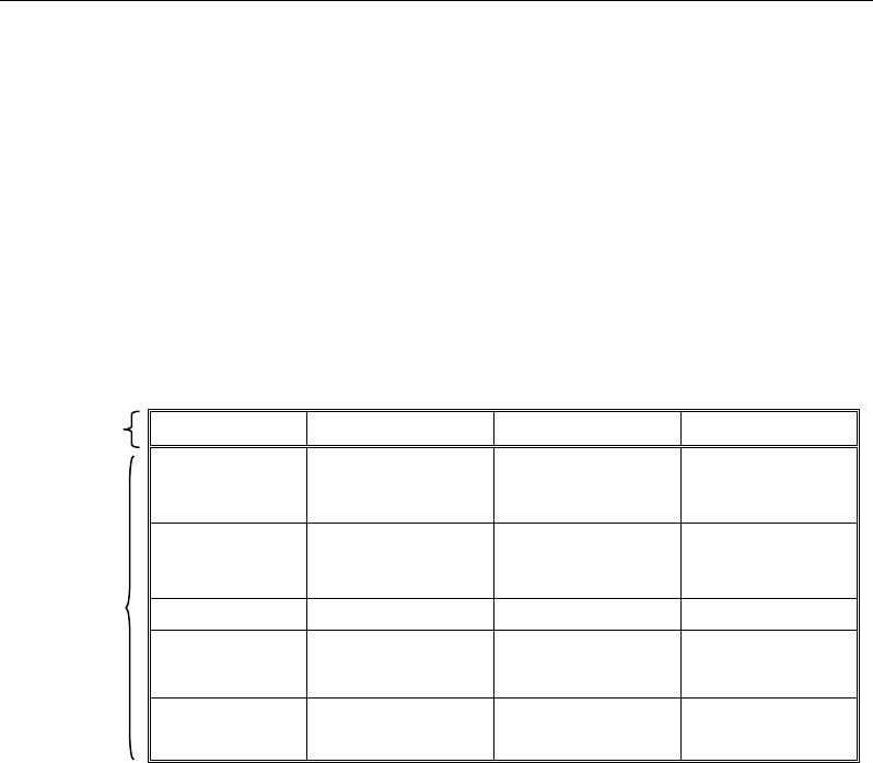
Chapter 8 - Load the Structural Model
Assign Structural Loads
The load patterns defined in the previous section are required in order to
be able to assign loads to joints, frames, and shells. The user must first
select the object before a load can be assigned to the object. Chapter 6 of
this guide describes how to select structural objects.
After the object has been selected, click the Assign menu command to
access the applicable submenu and assignment options. Table 8-1 identi-
fies the submenus and options.
TABLE 8
-
1 Load Commands on the Assign Menu
sub menus
Joint Loads
Frame Loads
Shell Loads
Tendon Loads
assignment
options
Force Point Uniform Load
Sets Tendon Loads
Ground Dis-
placement Distributed Uniform Tendon Losses
Temperature
Temperature
Non-uniform
Open Structure
Wind Parameters
Temperature
Wind Pressure
Coefficient
Note that the type of object selected determines which assignment can be
made. For example, a ground displacement assignment cannot be made
to a frame or shell object. Thus, if a frame object (e.g., a beam) or a shell
object (e.g., a wall) has been selected before clicking the Assign menu
command, attempting to assign joint loads will result in an error mes-
sage.
A form will appear after clicking the Assign menu command, the sub-
menu applicable to the type of object, and the desired assignment option.
Table 8-2 identifies the forms generated when the various commands are
used.
Assign Structural Loads 8 - 7
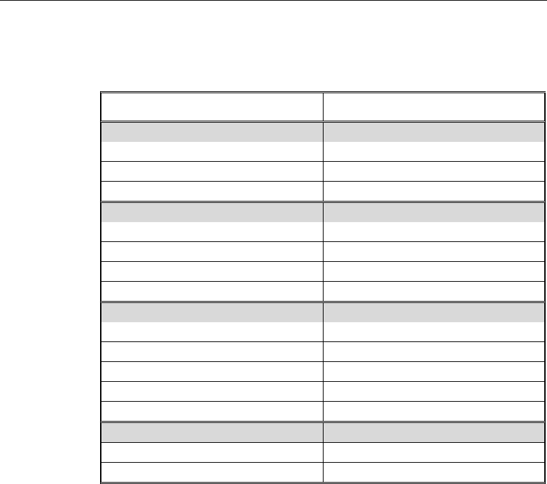
User's Guide
TABLE 8-2 Input Forms for Load Commands on the Assign Menu
Command Name of Input Form*
Joint Loads >
Joint Load Assignment -
Force
Force
Ground Displacement
Ground Displacement
Temperature
Temperature
Frame Loads >
Frame Load Assignment -
Point
Point
Distributed
Distributed
Temperature
Temperature
Open Structure Wind Parameters
Open Structure Wind Parameters
Shell Loads >
Shell Load Assignment -
Uniform Load Sets
Uniform Load Set
Uniform
Uniform
Non-uniform
Non-uniform
Temperature
Temperature
Wind Pressure Coefficient
Wind Pressure Coefficient
Tendon Loads >
Tendon Loads
Tendon Load
Tendon Losses
Tendon Loss Options
* Note: With a form displayed on the ETABS window, click the F1 key
on your keyboard to access context-sensitive Help for the form.
Although the form names vary depending on the command used, each
form has a drop-down list that allows the user to select the load pattern to
be assigned. Logically, the available load patterns vary depending on the
type of assignment. The forms also include other object/assignment-
specific input fields that enable the user to refine the load assignment.
8 - 8 Assign Structural Loads

Chapter 9
Define Load Cases
Objective
This chapter describes how to define load cases.
Review/Create Load Cases
A load case defines how loads are to be applied to the structure, and how
the structural response is to be calculated. Analyses are classified in the
broad sense as either linear or nonlinear, depending on how the model
responds to the loading. The results of linear analyses may be super-
posed, i.e., added together after analysis. The results of nonlinear anal-
yses normally should not be superposed. Instead, all loads acting together
on the structure should be combined directly within the nonlinear load
case.
After all geometry and load input has been specified for a model, review,
modify, or add load cases using the Define menu > Load Cases com-
mand. The Load Cases form shown in Figure 9-1 will appear. Highlight a
Objective 9 - 1
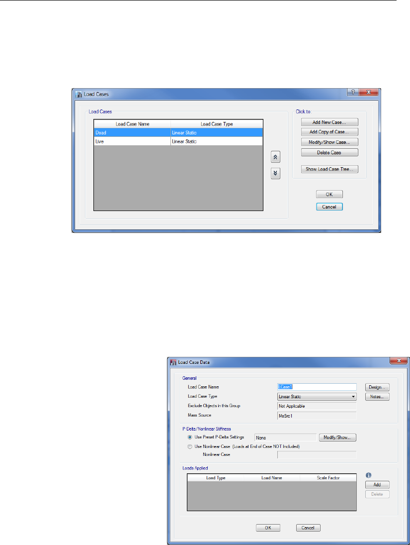
User's Guide
load case (ETABS automatically generates a load case for each load pat-
tern defined) and click the Modify/Show Case button to review or
modify the load case definition. Click the Delete Case button to delete
the highlighted load case.
To define a new load case, click the Add New Case button to display the
Load Case Data form shown in Figure 9-2.
Use that form to specify the following information:
The name of the load case. ETABS does not allow duplicate names.
Figure 9-1 Load Cases form
Figure 9-2
Load Case Data
form
9 - 2 Review/Create Load Cases
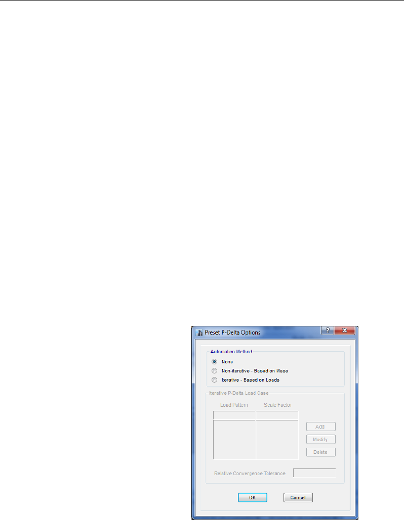
Chapter 9 - Review/Create Load Cases
A load case type, which can be selected from the Load Case Type
drop-down list. The default setting is linear static, but nonlinear stat-
ic, nonlinear staged construction, response spectrum, time history,
buckling, and hyperstatic are all available. A static case considers
loads defined in a load pattern, a response spectrum performs a sta-
tistical calculation of the response caused by acceleration loads, a
time history applies time-varying loads, buckling calculates the
buckling modes, and hyperstatic is used in slab design. Nonlinear
static may be used for pushover analysis, while nonlinear staged con-
struction allows portions of the structure to be added or removed.
The load case subtype when applicable, e.g., linear modal, nonlinear
modal (FNA), linear direct integration, or nonlinear direct integration
when the load case type is time history.
The type of P-Delta when applicable. For a load case type of linear
static, the P-Delta option may be reviewed or changed by clicking
the Modify/Show button in the P-Delta/Nonlinear Stiffness area. The
Preset P-Delta Options form shown in Figure 9-3 will display. This
form may also be accessed by using the Define menu > P-Delta Op-
tions command.
The loads to be applied. For a linear static load case type, this is typ-
ically a load pattern with a scale factor.
Figure 9-3
P-Delta Options
form
Review/Create Load Cases 9 - 3

User's Guide
Other parameters when applicable. For a load case type of response
spectrum, a modal load case will be required. A modal load case may
be defined using the Define menu > Modal Cases command. A
modal case carries out a eigen or ritz vector analysis.
Define an Auto Construction Sequence Case
A construction sequence load case automates the inclusion of stories in a
model to account for the sequential effects of construction. The sequen-
tial application of structure and load as a building is built may result in a
significantly different distribution of forces (i.e., dead load) than would
occur were the loads to be applied only after the building is complete.
The Auto Construction Sequence Case performs a multi-step analysis
that follows the sequential construction of the building.
After all geometry and load input has been specified for a model, use the
Define menu > Auto Construction Sequence Case command to specify
a construction sequence. The Auto Construction Sequence Load Case
form shown in Figure 9-4 will appear. Use that form to specify the fol-
lowing information:
Whether the case is active and the name of the case.
The number of stories to be included in each construction se-
quence - one is the default.
The loads that should be applied during this case - typically these
are dead loads.
Whether this sequential case should replace dead load cases in
design combinations.
9 - 4 Define an Auto Construction Sequence Case
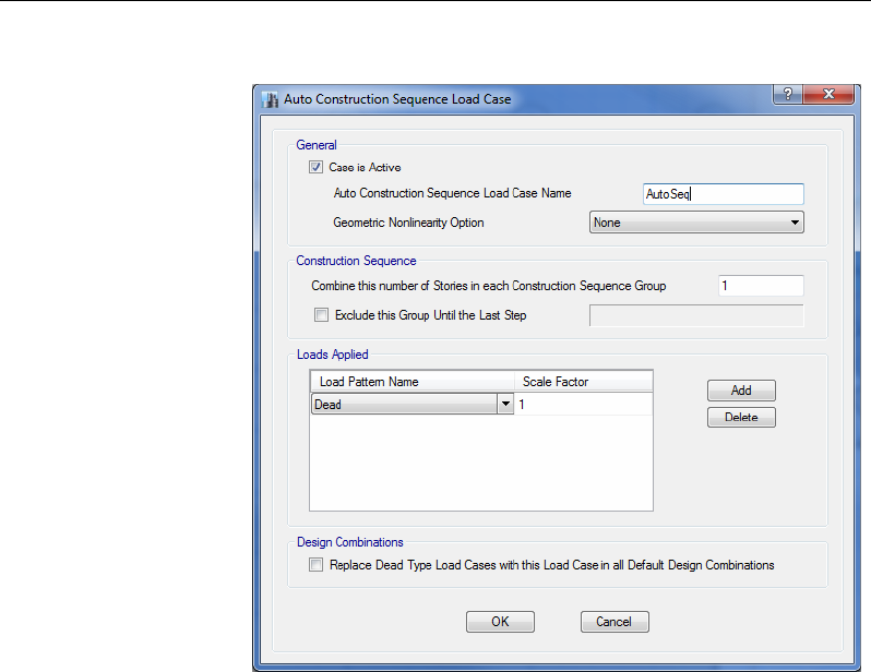
Chapter 9 - Define a Walking Vibration Case
Define a Walking Vibration Case
A walking vibration case allows for the automated application of
vertical pulse loadings across a floor to dynamically simulate the
footfall of a person walking. The output from this analysis is an
acceleration response that can be compared against specified
thresholds to determine whether the footfall impact will be percep-
tible. Use the Define menu > Walking Vibrations command to
specify walking vibration data. The Walking Vibrations form
shown in Figure 9-5 will appear. Use that form to specify the fol-
lowing information:
The name of the walking vibration case and the story level where
the path is being defined.
The walking parameters that determine the shape and size of the
pulse load.
Figure 9-4
Auto Construction
Sequence Load
Case
form
Define a Walking Vibration Case 9 - 5
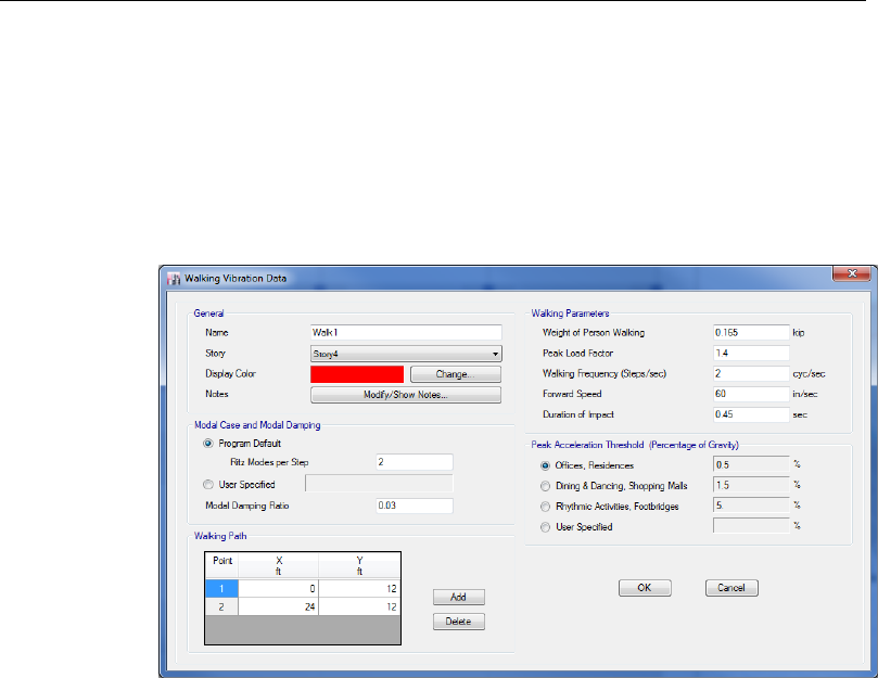
User's Guide
The modes and modal damping that should be used when calcu-
lating the dynamic excitation.
The peak acceleration threshold for comparison against the com-
puted peak acceleration.
The path of the person walking.
Figure 9-5 Walking Vibration Data form
9 - 6 Define a Walking Vibration Case

Chapter 10
Edit the Model Geometry
Objective
This chapter describes how to edit the model quickly and easily while
maintaining model integrity.
Editing Options
During the course of creating the model, the model may require editing.
Table 10-1 identifies the various edit commands available in the pro-
gram. Some are familiar Windows commands.
In most cases, first select the joint, frame, tendon, or shell object, then
click the appropriate menu or button. In some cases, the action will be
immediate (e.g., the Undo or Redo commands). In other cases, a form
will display that allows the user to specify how the object is to be edited
(e.g., the Edit menu > Align Joints/Frames/Edges command accesses
the Align Joints/Frames/Edges form, which allows the user to align joints
to the x, y, z coordinate or to the nearest frame, or to trim or extend
Objective 10 - 1
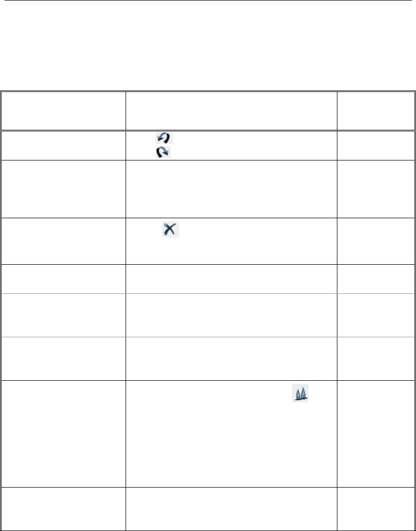
User's Guide
frames). In other cases, the command is a toggle that, when enabled, will
affect subsequent actions. Note that the type of commands and options
available depend on the type of object being edited.
TABLE 10-1 Edit Commands in ETABS
Command Action
Immediate/
Form* Used/
Toggle
Undo and Redo Undo deletes the last performed action.
Redo restores the last step that was undone.
Immediate
Cut, Copy and Paste Generally similar to the standard cut, copy and
paste Windows commands, with some ETABS
specific behaviors. Only active in plan or plan
perspective view.
Immediate
Delete Delete deletes the selected object(s) and all
of its assignments (loads, properties, supports
and the like).
Immediate
Add to Model from
Template
> Add 2D
Structure
Add objects to a model using various 2D tem-
plates.
Add to Model -
2D Structure
form
> Add 3D
Structure
Add objects to a model using various 3D tem-
plates.
Add to Model -
3D Structure
form
Edit Towers, Stories and
Grid Systems Edit Towers, Stories and Grid Systems edits
towers (if multiple towers have been allowed),
story data, and grid systems. Resulting forms
allow users to select an existing tower or define a
new one; modify/show existing story data or add
a new story; and add or modify/show existing
grid systems.
Edit Towers,
Stories and Grid
Systems form
and
Tower, Story
and Grid Sys-
tem Data form
Add Grid at Selected
Joints
Adds grid lines at selected joints. Add Grid Lines
at Selected
Joint form
10 - 2 Editing Options
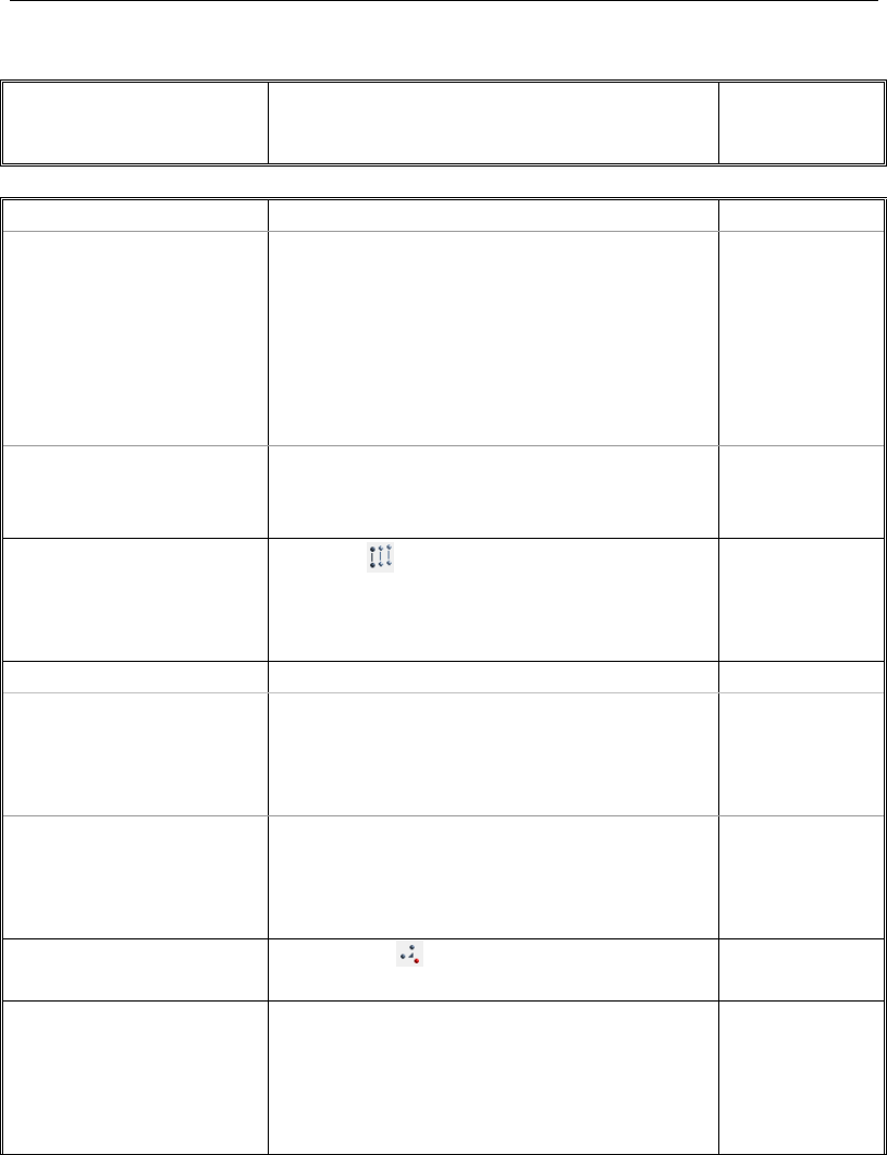
Chapter 10 - Edit the Model Geometry
TABLE 10-1 Edit Commands in ETABS
Command Action
Immediate/
Form* Used/
Toggle
Grid Options
> Glue Joints to Grids "Glues" joint objects that lie directly on grid lines
to those grid lines. When a joint object is glued to
a grid line and the grid line is moved, the joint
object moves with the grid line. Frame and shell
objects that are attached to the joint object when
it is moved remain attached to the joint object
and move or resize as appropriate.
Toggle
> Lock OnScreen Grid
System Edit
Allows users to lock out the ability to move grid
lines graphically on-screen using the Reshape
Object command.
Toggle
Replicate Replicate replicates one or more objects and
most of the object's assignments. Note that repli-
cated objects will not replace objects already
placed at a location.
Replicate form
that
accesses
options form
Extrude
> Extrude Joints to
Frames
Creates frame objects from joints. Options are
available for linear or radial extrusion. This fea-
ture is especially suited to creating
beams/columns from joints.
Extrude Joints
to Lines form
> Extrude Frames
to Shells
Extrude Frames to Shells creates shell objects
from frames. Options are available for linear or
radial extrusion. This feature is especially suited
to creating shell objects from beams.
Extrude Frames
to Shells form
Merge Joints Merge Joints merges joints within a user-
specified tolerance distance of the selected joint.
Merge Selected
Joints form
Align Joints/Frames/
Edges
Align Joints/Frames/Edges helps the user align
objects in the model. Search for “edit joints
frames edges” using the Help menu > ETABS
Help command for important notes about using
this command.
Align Selected
Frames/Edges/
Joints form
Editing Options 10 - 3

User's Guide
TABLE 10-1 Edit Commands in ETABS
Command Action
Immediate/
Form* Used/
Toggle
Move Joints/Frames/
Shells
Move Joints/Frames/Shells helps the user move
objects in the model. Search for “move joints
frames shells” using the Help menu > ETABS
Help command for more information.
Move
Joints/Frames/
Shells form
Edit Frames
> Divide Frames Divide Frames divides a frame object into multi-
ple frame objects.
Divide
Selected
Frames form
> Join Frames Join Frames joins two or more collinear frame
objects with common end joints and the same
type of property into a single frame object.
Immediate
Can use Undo
> Reverse Frame
Connectivity
Reverses the local I and J ends of a frame ob-
ject. This reversing of ends results in a change in
the orientation of the object's local axes.
Immediate
Can use Undo
> Modify/Show
Frame Type
Allows modification of the frame type to be either
straight or curved.
Frame Object
Type Options
form
Edit Shells
> Divide Shells Divide Shells divides selected shells into addi-
tional objects using user-specified options.
Edit Shell form
> Merge Shells Merge Shells merges two shell objects that have
a common edge or overlap into one larger shell
object.
Immediate
Can use Undo
> Expand/Shrink
Shells
Expand/Shrink Shells expands or shrinks a shell
object using a user-specified offset value.
Expand/Shrink
Areas form
> Split Shell Edg-
es
Adds joint objects at the mid-point of each edge
of a shell object.
Immediate
Can use Undo
> Remove Joints
from Shells
Removes joint objects from a shell object if they
are not located at corners.
Immediate
Can use Undo
> Chamfer Slab
Corners
Allows the user to add chamfers to the corners of
slabs.
Chamfer Slab
Corners form
> Reverse Wall
Local 3 Axis
Reverses the local 3 (normal) axis of wall ob-
jects.
Immediate
Can use Undo
10 - 4 Editing Options

Chapter 10 - Edit the Model Geometry
TABLE 10-1 Edit Commands in ETABS
Command Action
Immediate/
Form* Used/
Toggle
> Divide Walls for
Openings
Divides selected walls into smaller shell objects
to account for openings.
Immediate
Can use Undo
> Modify/Show
Slab Edge Type
Modify/Show Slab Edge Type allows slab edges
to be modified.
Slab Shell Ob-
ject Edge Type
Options form
> Modify/Show
Wall Curve Type
Modify/Show Wall Curve Type allows wall
shapes to be modified, i.e., changing a straight
wall into a wall with a curve.
Wall Shell Ob-
ject Curve Type
Options form
Edit Links
> Reverse Link
Connectivity
Reverses the local I and J ends of a link object.
This reversing of ends results in a change in the
orientation of the object's local axes.
Immediate
Can use Undo
Add/Edit Tendons
> Add Tendons in
Strips
Add banded or distributed tendons to selected
design strips.
Quick Tendon
Layout form
> Edit Plan Lay-
out (Horizontal)
Edit the plan geometry of selected tendons. Tendon Object
Type Options
> Edit Vertical
Profile
Edit or review the profile of the selected tendons. Tendon Vertical
Profile
> Reset Supports
and Spans to Default
Reset all support and span settings for selected
tendons to the default values.
Immediate
> Copy Vertical
Profile
Copy the vertical profile of the selected tendon
so that it may be “pasted” to another tendon.
Immediate
> Paste Vertical
Profile
Paste the previously copied vertical profile on to
the selected tendons.
Immediate
Add/Edit Design Strips
> Add Design
Strips
Add design strips to any floor using gird lines. Add Design
Strips form
> Edit Strip Widths Adjust the width of design strips automatically or
by inputting values.
Edit Strip
Widths form
Auto Relabel All Reorders all object labels based on their geomet-
ric order rather than in the sequential order
drawn.
Immediate
Cannot use
Undo
Editing Options 10 - 5

User's Guide
TABLE 10-1 Edit Commands in ETABS
Command Action
Immediate/
Form* Used/
Toggle
Nudge Works with Ctrl and arrow keys to move objects.
Allows the user to select objects and move them
a predefined distance. For more information,
search for “nudge” using the Help menu.
Immediate
* Note: With a form displayed on the ETABS window, click the F1 key on your keyboard
to access context-sensitive Help for the form.
10 - 6 Editing Options

Chapter 11
Analyze the Model
Objective
This chapter describes how to analyze the model.
Set the Mesh Options
If your model contains wall objects, or floor objects that have plate bend-
ing behavior such as cast-in-place slabs, review the meshing options
(e.g., maximum mesh size) before running the analysis by using the Ana-
lyze menu > Automatic Mesh Settings for Floors or Analyze menu >
Automatic Rectangular Mesh Settings for Walls commands. The Au-
tomatic Mesh Options (for Floors) form is shown in Figure 11-1. Default
mesh settings for floors and walls may be reviewed by using the Assign
menu > Shell > Floor Auto Mesh Options and the Assign menu >
Shell > Wall Auto Mesh Options commands, respectively.
The automatic rectangular meshing performed by ETABS for floor slabs
creates a mesh that is parallel and perpendicular to the local axes of the
Objective 11 - 1
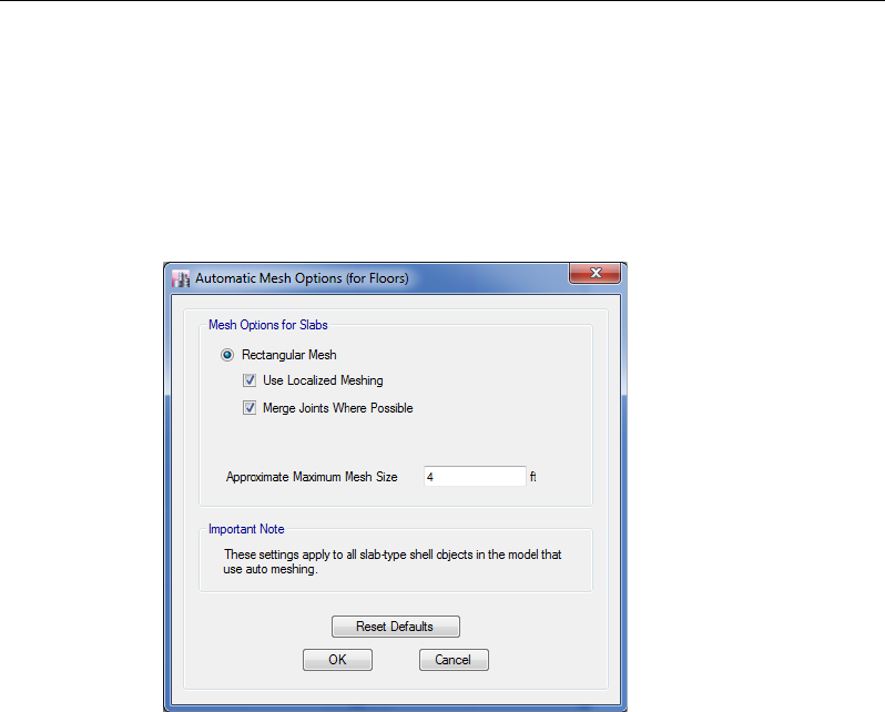
User's Guide
shell objects. Generation of the mesh is influenced by the locations of
floor and wall objects, openings, beams, columns, and joints. To preview
the element mesh before running the analysis and design, use the View
menu > Set Display Options command and check the Shell Analysis
Mesh option under the Other Special Items area of the General tab on the
Set View Options form.
Model Analysis
Prior to running the analysis, verify what load cases are set to run by
clicking on the Analyze menu > Set Load Cases To Run command.
The Set Load Cases to Run form shown in Figure 11-2 will appear.
To add or remove a load case from the analysis, highlight the load case
in the Case column and click the Run/Do Not Run Case button. Both
the status and action for each case are shown in their respective columns.
This form also allows the user to set how the Analysis Monitor should be
displayed - the default setting is that it Never Shows.
Figure 11-1 Automatic Mesh Options form
11 - 2 Model Analysis
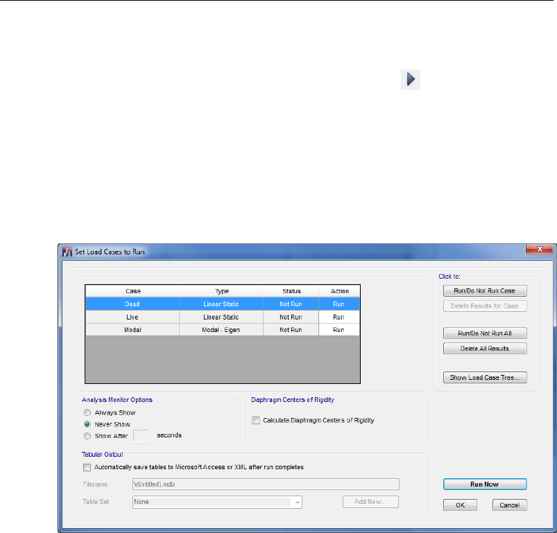
Chapter 11 - Analyze the Model
To run the analysis, click the Run Now button if the Set Load Cases to
Run form is still displayed, otherwise click the Analyze menu > Run
Analysis command or the Run Analysis button, .
The program will display an "Analyzing, Please Wait" window if the
Analysis Monitor has been set to "Always Show" or "Show After." Data
will scroll in this window as the program runs the analysis. After the
analysis has been completed, the program performs a few more
“bookkeeping actions” that are evident on the status bar in the bottom
left-hand corner of the ETABS window.
Figure 11-2 Set Load Cases to Run form
Model Analysis 11 - 3

User's Guide
Model Alive™ Feature
To run the analysis automatically, in a continuous manner, use the Ana-
lyze menu > Model Alive command. This analysis mode allows the user
to make revisions to a model and have the model analysis updated auto-
matically without first having to save the model and then execute the run
command. The Model Alive feature can be especially useful on small
models because it allows the user to instantly see the effects of any mod-
el revision. The Model Alive feature will not be as beneficial on larger
models with longer run times.
The ETABS model is not automatically saved when running the analysis
in the Model Alive mode. The File menu > Save command can be used
at any time to save the model; otherwise, the model remains unlocked
and unsaved.
Locking and Unlocking the Model
When the entire analysis process has been completed, the model auto-
matically displays a deformed shape view of the model, and the model is
locked. The model is locked when the Lock/Unlock Model button, ,
appears closed. Locking the model prevents any changes to the model
that would invalidate the analysis results.
11 - 4 Model Alive™ Feature

Chapter 12
Design
Objective
This chapter describes design using the ETABS design postprocessors.
Design the Structure
The ETABS design postprocessors include the following:
Steel Frame Design
Concrete Frame Design
Composite Beam Design
Composite Column Design
Steel Joist Design
Shear Wall Design
Objective 12 - 1

User's Guide
Concrete Slab Design
Steel Connection Design
To perform the design, first run the analysis (described in Chapter 11),
then click the Design menu and select the appropriate design from the
drop-down menu. The type of design available depends on the type of
members used in the model. That is, the user cannot complete a shear
wall design if no shear walls have been included in the model, nor could
they do a steel connection design if no steel members are present.
Similarly, the commands used to execute a design depend on the type of
design to be performed. However, each design has commands to address
the following:
Review and/or select overwrites.
Review and/or select design combinations.
Start the design or check of the structure.
Perform interactive design.
Display input and output design information on the model.
Generally, the sequence for using commands is indicated by their availa-
bility. In other words, some commands must be used before other com-
mands become available. This helps the user step through the design pro-
cess. (Search for “process” using the Help menu to access more infor-
mation about design processes and the sequence of commands.) Table
12-1 identifies the commands that are used to start design depending on
the desired design process.
TABLE 12-1 Start Design Commands
Design Process
Command that Starts Design
Steel Frame Design Start Design/Check
Concrete Frame Design Start Design/Check
Composite Beam Design Start Design/Check
12 - 2 Design the Structure
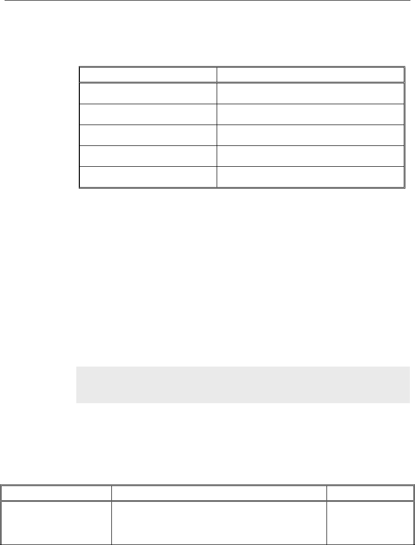
Chapter 12 - Design
TABLE 12-1 Start Design Commands
Design Process
Command that Starts Design
Composite Column Design Start Design/Check
Steel Joist Design Start Design/Check
Shear Wall Design Start Design/Check
Concrete Slab Design Start Design
Steel Connection Design Start Design/Check
It is important to understand that design in ETABS is an iterative pro-
cess. That is, the user should run the analysis and then perform the de-
sign and be prepared to run the analysis again and perform the design
again each time sections are revised. It may be necessary to repeat this
process several times before the design is complete. The objective is to
have the analysis sections match the design sections. The user should re-
peat the analysis/start design process until the analysis and design sec-
tions match and design requirements are satisfied.
Tables 12-2 through 12-9 summarize the commands used in each type of
design process.
TABLE 12-2 Steel Frame Design Commands
Command
Action
Form
View/Revise
Preferences
Designates which design code to use, as well as
defining many other design parameters. Default
values are provided for all settings.
Steel Frame De-
sign Preferences
form
Note: With a form displayed in the ETABS window, click the F1 key on
your keyboard to access context-sensitive Help for the form.
Design the Structure 12 - 3

User's Guide
TABLE 12-2 Steel Frame Design Commands
Command
Action
Form
View/Review
Overwrites
Allows review of overwrites, which are parameters
that the user specifies to change program de-
faults. Overwrites apply only to the frame objects
to which they are specifically assigned.
Overwrites form
Lateral Bracing Designates lateral bracing as either program de-
termined or user specified.
Lateral Bracing
Select Design Groups Designates that a group is to be used as a design
group. Works only when auto select sections have
been assigned to frame objects. All frame objects
in the group will be given the same design sec-
tion.
Steel Frame
form
Select Design
Combinations
Allows review of the default steel frame design
combinations defined by the program, or designa-
tion of user-specified design combinations. Facili-
tates review or modification of combinations dur-
ing design.
Design Load
Combinations
Selection form
Start Design/Check Initiates design process. If frame objects have
been selected before this command is clicked,
only the selected frame objects will be designed.
A building analysis must precede use of this
command.
Immediate, no
form used
Interactive Design Allows the user to review the design results for
any frame object and then to interactively change
the design overwrites and immediately view the
results.
No form; results
are displayed
onscreen.
Display Design Info Allows review of some of the results of the steel
frame design directly on the program model. Ex-
amples of results that can be displayed include
design sections, unbraced lengths, effective
length factors, allowable stresses, and stress ratio
information.
Display Design
Results form
12 - 4 Design the Structure

Chapter 12 - Design
TABLE 12-2 Steel Frame Design Commands
Command
Action
Form
Make Auto Select
Section Null
Removes auto select section lists from selected
frame objects. Typically used near the end of the
iterative design process so that the final design
iteration is performed using the actual frame sec-
tions assigned, not auto select sections. Only
works on a user-specified selection.
Warning message
Cannot use Undo
Change Design
Section
Allows the user to change the design section
property assigned to one or more frame objects
and then rerun the design without first rerunning
the analysis. Only works on a user-specified se-
lection.
Select Sections
form
Reset Design Section
to Last Analysis
Sets the design section for one or more frame
objects back to the last used analysis section.
Only works on a user-specified selection.
Immediate
Cannot use Undo
Verify Analysis vs
Design Section
Verifies that the last used analysis section and the
current design section are the same for all steel
frame objects in the model.
Immediate
Verify All Members
Passed
Reports if structural members have passed the
stress/capacity check. An analysis and a de-
sign/check of the structure must be completed
before this command is used.
Immediate
Reset All
Overwrites
Resets the overwrites for all frame objects with
the Steel Frame design procedure to their default
values.
Warning message
Cannot use Undo
Delete Design Results Deletes all of the steel frame design results but
not the current design section (i.e., next analysis
section).
Immediate
Cannot use Undo
Design the Structure 12 - 5

User's Guide
TABLE 12-3 Concrete Frame Design Commands
Command
Action
Form
View/Revise
Preferences
Designates the design code to use, as well as
defining other design parameters. Default values
are provided for all settings.
Concrete Frame
Design Prefer-
ences form
View/Review
Overwrites
Allows review of overwrites, which are parameters
that the user specifies to change program de-
faults. Overwrites apply only to the frame objects
to which they are specifically assigned.
Overwrites form
Select Design Groups Designates that a group is to be used as a design
group. All frame objects in the group will be given
the same design section.
Design Group
Selection
form
Select Design
Combinations
Allows review of the default concrete frame design
combinations defined by the program, or designa-
tion of user-specified design combinations. Facili-
tates review or modification of combinations dur-
ing design.
Design Load
Combinations
Selection form
Start Design/Check Initiates design process. If frame objects have
been selected before this command is used, only
the selected frame objects will be designed. A
building analysis must precede use of this com-
mand.
Immediate, no
form used
Interactive Design Allows the user to review the design results for
any frame object and then to interactively change
the design overwrites and immediately view the
results.
No form; results
are displayed
onscreen.
Display Design Info Allows review of some of the results of the con-
crete frame design directly on the program model.
Examples of results that can be displayed include
design sections, unbraced lengths and longitudi-
nal reinforcing.
Display Design
Results form
12 - 6 Design the Structure

Chapter 12 - Design
TABLE 12-3 Concrete Frame Design Commands
Command
Action
Form
Change Design
Section
Allows the user to change the design section
property assigned to one or more frame objects
and then rerun the design without first rerunning
the analysis. Only works on a user-specified se-
lection.
Select Sections
form
Reset Design Section
to Last Analysis
Sets the design section for one or more frame
objects back to the last used analysis section.
Only works on a user-specified selection.
Immediate
Cannot use Undo
Verify Analysis vs
Design Section
Verifies that the last used analysis section and the
current design section are the same for all con-
crete frame objects in the model.
Immediate
Verify All Members
Passed
Reports if structural members have passed the
capacity check. An analysis and a design/check of
the structure must be completed before this com-
mand is used.
Immediate
Reset All Overwrites Resets the overwrites for all frame objects with
the Concrete Frame design procedure to their
default values.
Warning message
Cannot use Undo
Delete Design Results Deletes all of the concrete frame design results
but not the current design section (i.e., next anal-
ysis section).
Immediate
Cannot use Undo
TABLE 12-4 Composite Beam Design Commands
Command
Action
Form
View/Revise
Preferences
Designates the design code to use, as well as
defining other design parameters, such as cam-
ber. Default values are provided for all settings.
Composite Beam
Design Prefer-
ences form
View/Review
Overwrites
Allows review of overwrites, which are parameters
that the user specifies to change program de-
faults. Overwrites apply only to the composite
beams to which they are specifically assigned.
Composite Beam
Overwrites form
Design the Structure 12 - 7

User's Guide
TABLE 12-4 Composite Beam Design Commands
Command
Action
Form
Select Design Groups Designates that a group is to be used as a design
group. Works only when auto select sections have
been assigned to frame objects. When grouped,
all beams in the group are given the same beam
size, but the shear connectors and camber may
be different.
Composite Design
Group Selection
form
Select Design
Combinations
Allows review of the default composite frame de-
sign combinations defined by the program, or des-
ignation of user-specified design combinations.
Facilitates review or modification of combinations
during design. Note that separate design combi-
nations are specified for construction loading, final
loading considering strength, and final loading
considering deflection.
Design Load
Combinations
Selection form
Start Design/Check Initiates design process. If frame objects have
been selected before this command is used, only
the selected frame objects will be designed. A
building analysis must precede use of this com-
mand.
Immediate, no
form used
Interactive Design Allows the user to review the design results for
any composite beam, select the best design from
the various acceptable designs, and interactively
change the design assumptions and immediately
view the results.
Interactive Com-
posite Beam De-
sign and Review
form
Display Design Info Allows review of some of the results of the com-
posite beam design directly on the program mod-
el. Examples of results that can be displayed in-
clude beam labels and associated design group
names; design sections together with connector
layout, camber and end reactions; and stress ratio
information.
Display Design
Results form
12 - 8 Design the Structure

Chapter 12 - Design
TABLE 12-4 Composite Beam Design Commands
Command
Action
Form
Make Auto Select
Section Null
Removes auto select section lists from selected
beams. Typically used near the end of the itera-
tive design process so that the final design itera-
tion is performed using the actual beam sections
assigned, not auto select sections. Only works on
a user-specified selection.
Warning message
Cannot use Undo
Change Design
Section
Allows the user to change the design section
property assigned to one or more beams and then
rerun the design without first rerunning the analy-
sis. Only works on a user-specified selection.
Select Sections
form
Copy Design Allows the user to select a template composite
beam and copy its design section, camber and
percentage of composite action for later use with
Paste Design.
Immediate
Paste Design Allows the user to select target composite beams
to which the previously selected design section,
camber, and percentages composite action will be
assigned. The percentage of composite action of
the template beam is applied to the target beams
as a minimum percentage of composite action.
Immediate
Reset Design Section
to Last Analysis
Sets the design section for one or more beams
back to the last used analysis section. Only works
on a user-specified selection.
Immediate
Cannot use Undo
Verify Analysis vs
Design Section
Verifies that the last used analysis section and the
current design section are the same for all com-
posite beams in the model.
Immediate
Verify All Members
Passed
Reports if structural members have passed the
stress/capacity check following a new analysis
run, or a change in project composite preferences
or composite beam overwrites.
Immediate
Reset All Overwrites
Resets the overwrites for all composite beams
with the Composite Beam design procedure to
their default values.
Warning message
Cannot use Undo
Design the Structure 12 - 9

User's Guide
TABLE 12-4 Composite Beam Design Commands
Command
Action
Form
Delete Design Results Deletes all of the composite beam design results
but not the current design section (i.e., next anal-
ysis section).
Immediate
Cannot use Undo
TABLE 12-5 Composite Column Design Commands
Command
Action
Form
View/Revise
Preferences
Designates the design code to use, as well as
defining other design parameters, such as cam-
ber. Default values are provided for all settings.
Composite Col-
umn Design Pref-
erences form
View/Review
Overwrites
Allows review of overwrites, which are parameters
that the user specifies to change program de-
faults. Overwrites apply only to the composite
columns to which they are specifically assigned.
Overwrites form
Select Design
Combinations
Allows review of the default composite frame de-
sign combinations defined by the program, or des-
ignation of user-specified design combinations.
Facilitates review or modification of combinations
during design. Note that separate design combi-
nations are specified for construction loading, final
loading considering strength, and final loading
considering deflection.
Design Load
Combinations
Selection form
Start Design/Check Initiates design process. If frame objects have
been selected before this command is used, only
the selected frame objects will be designed. A
building analysis must precede use of this com-
mand.
Immediate, no
form used
Interactive Design Allows the user to review the design results for
any composite column and then to interactively
change the design overwrites and immediately
view the results.
No form; results
are displayed
onscreen.
12 - 10 Design the Structure

Chapter 12 - Design
TABLE 12-5 Composite Column Design Commands
Command
Action
Form
Display Design Info Allows review of some of the results of the com-
posite column design directly on the program
model. Examples of results that can be displayed
include column labels and associated design
group names.
Display Design
Results form
Make Auto Select
Section Null
Removes auto select section lists from selected
columns. Typically used near the end of the itera-
tive design process so that the final design itera-
tion is performed using the actual column sections
assigned, not auto select sections. Only works on
a user-specified selection.
Warning message
Cannot use Undo
Change Design
Section
Allows the user to change the design section
property assigned to one or more columns and
then rerun the design without first rerunning the
analysis. Only works on a user-specified selec-
tion.
Select Sections
form
Reset Design Section
to Last Analysis
Sets the design section for one or more columns
back to the last used analysis section. Only works
on a user-specified selection.
Immediate
Cannot use Undo
Verify Analysis vs
Design Section
Verifies that the last used analysis section and the
current design section are the same for all com-
posite columns in the model.
Immediate
Verify All Members
Passed
Reports if structural members have passed the
stress/capacity check. An analysis and a de-
sign/check of the structure must be completed
before this command is used.
Immediate
Reset All Overwrites Resets the overwrites for all composite columns
with the Composite Column design procedure to
their default values.
Warning message
Cannot use Undo
Delete Design Results Deletes all of the composite column design results
but not the current design section (i.e., next anal-
ysis section).
Immediate
Cannot use Undo
Design the Structure 12 - 11

User's Guide
TABLE 12-6 Steel Joist Design Commands
Command
Action
Form
View/Revise Prefer-
ences
Designates the design code to use, as well as
defining other design parameters, such as cam-
ber. Default values are provided for all settings.
Steel Joist Design
Preferences form
View/Review
Overwrites
Allows review of overwrites, which are parameters
that the user specifies to change program de-
faults. Overwrites apply only to the joists to which
they are specifically assigned.
Steel Joist Design
Overwrites
Lateral Bracing Designates lateral bracing as either program de-
termined or user specified.
Lateral Bracing
Select Design Groups Designates that a group is to be used as a design
group. Works only when auto select sections have
been assigned to the joists. When grouped, all
objects in the group are given the same joist size.
Steel Joist Design
Group Selection
Form
Select Design
Combinations
Allows review of the default steel joist design
combinations defined by the program, or designa-
tion of user-specified design combinations. Facili-
tates review or modification of combinations dur-
ing design.
Design Load
Combinations
Selection Form
Start Design/Check Initiates design process. If frame objects have
been selected before this command is used, only
the selected frame objects will be designed. A
building analysis must precede use of this com-
mand.
Immediate, no
form used
Interactive Design Allows the user to review the design results for
any steel joist and then to interactively change the
design overwrites and immediately view the re-
sults.
No form; results
are displayed on-
screen.
Display Design Info Allows review of some of the results of the steel
joist design directly on the program model. Exam-
ples of results that can be displayed include joist
labels and associated design group names; de-
sign sections together with end reactions; and
design ratio information.
Display Design
Results Form
12 - 12 Design the Structure

Chapter 12 - Design
TABLE 12-6 Steel Joist Design Commands
Command
Action
Form
Make Auto Select
Section Null
Removes auto select section lists from selected
joists. Typically used near the end of the iterative
design process so that the final design iteration is
performed using the actual joist sections as-
signed, not auto select sections. Only works on a
user-specified selection.
Warning message
Cannot use Undo
Change Design
Section
Allows the user to change the design section
property assigned to one or more joists and then
rerun the design without first rerunning the analy-
sis. Only works on a user-specified selection.
Select Sections
Form
Reset Design Section
to Last Analysis
Sets the design section for one or more joists
back to the last used analysis section. Only works
on a user-specified selection.
Immediate
Cannot use Undo
Verify Analysis vs
Design Section
Verifies that the last used analysis section and the
current design section are the same for all steel
joists in the model.
Immediate
Verify All Members
Passed
Reports if all steel joists have passed the
stress/capacity check. An analysis and a de-
sign/check of the structure must be completed
before this command is used.
Immediate
Reset All Overwrites Resets the overwrites for all steel joists with the
Steel Joist design procedure to their default val-
ues.
Warning message
Cannot use Undo
Delete Design Results Deletes all of the steel joist design results but not
the current design section (i.e., next analysis sec-
tion).
Immediate
Cannot use Undo
TABLE 12-7 Shear Wall Design Commands
Command
Action
Form
View/Revise Prefer-
ences
Designates the design code to use, as well as
defining other design parameters. Default values
are provided for all settings.
Shear Wall Design
Preferences form
Design the Structure 12 - 13

User's Guide
TABLE 12-7 Shear Wall Design Commands
Command
Action
Form
Define General Pier
Sections
Allows the user to define a pier section using the
Section Designer utility.
Pier Sections form
that access other
forms
Assign Pier Sections Allows the user to assign a pier one of three sec-
tion types.
Assign Pier Sec-
tions form
View/Review Pier
Overwrites
Allows review of pier overwrites, which are pa-
rameters that the user specifies to change pro-
gram defaults. Overwrites apply only to the piers
to which they are specifically assigned.
Overwrites form
View/Review Spandrel
Overwrites
Allows review of spandrel overwrites, which are
parameters that the user specifies to change pro-
gram defaults. Overwrites apply only to the span-
drels to which they are specifically assigned.
Overwrites form
Select Design
Combinations
Allows review of the default shear wall design
combinations defined by the program, or designa-
tion of user-specified design combinations. Facili-
tates review or modification of combinations dur-
ing design.
Design Load
Combinations
Selection Form
Start Design/Check Initiates design process. If piers or spandrels have
been selected before this command is used, only
the selected piers or spandrels will be designed. A
building analysis must precede use of this com-
mand.
Immediate, no
form used
Interactive Design Allows the user to review the design results for
any piers or spandrels and then to interactively
change the design overwrites and immediately
view the results.
No form; results
are displayed
onscreen.
Display Design Info Allows review of some of the results of the shear
wall design directly on the program model. Exam-
ples of results that can be displayed include rein-
forcing requirements, capacity ratios and bounda-
ry element requirements.
Display Design
Results form
12 - 14 Design the Structure

Chapter 12 - Design
TABLE 12-7 Shear Wall Design Commands
Command
Action
Form
Make Auto Select
Section Null
Removes auto select section lists from selected
shear walls. Typically used near the end of the
iterative design process so that the final design
iteration is performed using the actual shear wall
sections assigned, not auto select sections. Only
works on a user-specified selection.
Warning message
Cannot use Undo
Verify Analysis vs
Design Section
Verifies that the last used analysis section and the
current design section are the same for all shear
walls in the model.
Immediate
Reset All Overwrites Resets the overwrites for all piers or spandrels to
their default values.
Warning message
Cannot use Undo
Delete Design Results Deletes all of the shear wall results. Immediate
Cannot use Undo
TABLE 12-8 Concrete Slab Design Commands
Command
Action
Form
View/Revise Prefer-
ences
Designates the design code to use, as well as
defining other design parameters. Default values
are provided for all settings.
Concrete Slab
Design Prefer-
ences form
View/Revise
Flexural Design Over-
writes
Allows review of flexural design overwrites, which
are parameters that the user specifies to change
program defaults. Overwrites may be applied to
selected strip based, or FEM based design.
Slab Design
Overwrites form
View/Revise Punching
Check Overwrites
Allows review of punching check overwrites,
which are parameters that the user specifies to
change program defaults. Overwrites apply only to
locations to which they are specifically assigned.
Punching Shear
Design Overwrites
form
Select Design
Combinations
Allows review of the default concrete slab design
combinations defined by the program, or designa-
tion of user-specified design combinations. Facili-
tates review or modification of combinations.
Design Load
Combinations
Selection Form
Select Stories for De-
sign
Allows selection of stories for which the concrete
slab design should be performed.
Select Stories for
Slab Design form
Design the Structure 12 - 15

User's Guide
TABLE 12-8 Concrete Slab Design Commands
Command
Action
Form
Start Design Initiates design process. Only the selected stories
will be designed. A building analysis must precede
use of this command.
Immediate, no
form used
Display Flexural De-
sign
Allows review of some of the results of the con-
crete slab design directly on the program model.
Examples of results that can be displayed include
flexural reinforcing requirements in the design
strips as rebar area or number of bars.
Slab Design form
Display Punching
Check
Allows review of the punching checks directly on
the program model.
Immediate
Reset All Flexural De-
sign Overwrites
Resets the flexural design overwrites to their de-
fault values for one of the two design methods
selected.
Warning message
Cannot use Undo
Reset All Punching
Overwrites
Resets the punching overwrites for slab design to
their default values.
Warning message
Cannot use Undo
Delete Design Results Deletes all of the concrete slab design results. Immediate
Cannot use Undo
TABLE 12-9 Steel Connection Design Commands
Command
Action
Form
View/Revise Prefer-
ences
Designates geometries and bolt patterns for three
types of beam to beam connections, four types of
beam to column connections, and a column base
plate connection. Default values are provided for
all settings.
Steel Connection
Design Prefer-
ences form
View/Revise
Overwrites
Allows review of steel connection overwrites,
which are parameters that the user specifies to
change program defaults. Overwrites apply only to
the connections to which they are specifically as-
Overwrites form
12 - 16 Design the Structure

Chapter 12 - Design
TABLE 12-9 Steel Connection Design Commands
Command
Action
Form
signed.
Select Design
Combinations
Allows review of the default steel connection de-
sign combinations defined by the program, or des-
ignation of user-specified design combinations.
Facilitates review or modification of combinations
during design.
Design Load
Combinations
Selection Form
Start Design/Check Initiates design process. If steel connections have
been selected before this command is used, only
the selected steel connections will be designed. A
building analysis must precede use of this com-
mand.
Immediate, no
form used
Interactive Design Allows the user to review the design results for
any steel connections and then to interactively
change the design overwrites and immediately
view the results.
No form; results
are displayed
onscreen.
Display Design Info Allows review of some of the results of the steel
connection design directly on the program model.
Display Design
Results form
Verify All Connections
Passed
Reports if all steel connections have passed the
design check. An analysis and a design/check of
the structure must be completed before this com-
mand is used.
Immediate
Reset All Overwrites Resets the overwrites for all steel connections to
their default values.
Warning message
Cannot use Undo
Delete Design Results Deletes all of the steel connection results. Immediate
Cannot use Undo
In addition to the commands specific to each type of design, the Design
menu contains several other more general commands described in table
12-10.
Design the Structure 12 - 17
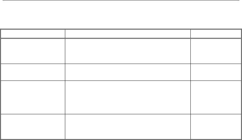
User's Guide
TABLE 12-10 Miscellaneous Design Commands
Command
Action
Form
Overwrite Frame De-
sign Procedure
Allows the user to change the default design pro-
cedure for a selected frame object, including
specifying that no design should be performed.
Overwrite Frame
Design Procedure
form
Live Load Reduction
Factors
Allows the user to adjust if and how much the live
load should be reduced.
Live Load Reduc-
tion Factor form
Set Lateral Displace-
ment Targets
Specifies displacement targets, in any direction,
for various load cases. This command is available
only for steel frames, concrete frames, and con-
crete shear walls.
Lateral Displace-
ment Targets form
Set Time Period Tar-
gets
Specifies time period targets for seismic analysis.
This command is available only for steel frames,
concrete frames, and concrete shear walls.
Time Period Tar-
gets form
12 - 18 Design the Structure

Chapter 13
Detailing
Objective
This chapter provides an overview of the detailing process available for
generating schematic construction drawings based on the analysis and
design results.
Detailing Process
ETABS detailing generates two basic types of drawing output:
Drawing sheet component views of detailed objects, such as steel beam
framing plans, steel column schedules, concrete beam elevations and
sections, concrete column schedules, shear wall reinforcing sections
and elevations, and steel connection tables
Drawing sheets containing the selected component views
Objective 13 - 1

User's Guide
Detailing generates a default set of component views and drawing sheets
that can be modified and annotated. The generated views can be edited to
improve text readability and to add additional annotations, allowing
complete control over the information contained on the drawing sheets,
including drawing size, scale, layout, title block, and component views.
Drawing can be printed directly from ETABS or exported for further
manipulation in CAD applications.
Preferences
The preferences specify various parameters such as the units for dimen-
sioning and material takeoffs, labeling rules, what is visible in plan, sec-
tion and elevation views, what to include in tables, drawing sheet size
and scale, line styles, and many other customizable parameters.
The detailing units are set using the Detailing menu > Detailing Prefer-
ences command.
Preferences for defining the drawing sheet size, scale, text size, line
thickness, margins, and title block are set using the Detailing menu >
Drawing Sheet Setup command.
The concrete slab, beam, column, and shear wall object detailing prefer-
ences can be set using the appropriate Detailing menu > Concrete
Component Preferences command. The steel beam, column, connec-
tion, and floor framing detailing preferences can be set using the appro-
priate Detailing menu > Steel Component Preferences command. Each
of those commands displays a form that allows various detailing prefer-
ences to be set, such as label prefixes, what is visible in the different
views, and other preferences dependent upon the object type.
Rebar Selection Rules
How rebar is selected for concrete beams, columns, piers and spandrels
is determined using the appropriate Detailing menu > Rebar Selection
Rules command. Each of those commands displays a form that allows
various reinforcement preferences to be set. For columns, data includes
the smallest, largest, and preferred longitudinal bar sizes, the minimum
13 - 2 Preferences

Chapter 13 - Detailing
and maximum number of longitudinal bars, the smallest, largest, and pre-
ferred sizes of bars for ties, and the minimum and maximum spacing for
ties. Similar types of reinforcement options are available for beams,
piers, and spandrels.
Start Detailing
To start detailing, use the Detailing menu > Start Detailing command.
The first time the detailing is shown for a model, a default set of draw-
ings is created. Subsequent requests to start detailing will provide the op-
tion to generate a new set of drawings or synchronize the detailing by
updating the existing set of drawings. This second option allows for re-
tention of modifications made to the drawing component views and
drawing sheets.
The Drawing Sheet Component Views and Drawing Sheets are displayed
in the detailing tab of the Model Explorer. Expand the tree and double
click one of the Drawing Sheet Component Views or Drawing Sheets to
display it in the active window. ETABS automatically places the Draw-
ing Component Views on the Drawing Sheets.
Drawing sheets may be removed using the Detailing menu > Clear De-
tailing command.
Edit Views
Modifications can be made to the drawing sheet component views to cus-
tomize the view text, modify the view properties, and add or modify sec-
tion cuts. These modifications affect the corresponding component views
as well as the view copies placed on the drawing sheets after the modifi-
cation is made. Component views already located on drawing sheets be-
fore making modifications are not updated.
The text on a drawing sheet component view can be fully customized,
including editing of the program generated text, as well as adding addi-
tional text, notes, and dimension lines. To modify the text on a specific
drawing component view, right click on the component view in the dis-
play or on the detailing tree of the Model Explorer and choose the Edit
Start Detailing 13 - 3

User's Guide
View Text command. A form is opened showing the view and contains a
wide selection of tools for zooming the view and making the necessary
modifications.
Each drawing component view also has its own properties that specify its
name, scale, and text and line sizes. These preferences can be modified
by right clicking on the component view in the display or on the detailing
tree of the Model Explorer and choosing the Edit View Properties
command.
Defined section cuts generate additional drawing component views for
the floor objects. Default section cuts are generated when the detailing is
first shown. These can be modified or deleted, or additional section cuts
can be defined, using the Detailing menu > Add/Modify Sections
commands.
Create and Manage Drawing Sheets
The drawing sheets are a collection of scaled drawing sheet component
views, ready for direct printing or export to other file formats. ETABS
automatically creates a set of default drawings with appropriate views.
Several tools are available to create new drawing sheets and to modify
and manage existing sheets.
The list of drawing sheets can be modified by right clicking on the
Drawing Sheets node on the Detailing tab of the Model Explorer win-
dow, and choosing the Edit Drawing Sheet List command. Additional
drawing sheets also may be added by right clicking on the Drawing
Sheets node and choosing the Add Blank Drawing Sheet command. In-
dividual drawings can be deleted by right clicking on them in the Model
Explorer window and choosing the Delete Drawing Sheet command.
The drawing component views can be rearranged on a drawing sheet by
simply clicking on them and dragging them to a new location. Snap fea-
tures aid in locating the component views on the drawing sheet. Alterna-
tively, right clicking on a drawing and using the Auto Arrange Views
command will automatically arrange the views on the drawing sheet, and
if necessary, generate additional sheets if all of the views do not fit on a
sheet. Drawing component views can be removed from a drawing sheet
13 - 4 Create and Manage Drawing Sheets

Chapter 13 - Detailing
by right clicking on them either on the drawing sheet on in the Model
Explorer window and choosing the Delete View command.
Drawing component views can be quickly and easily added to drawing
sheets using the Detailing menu > Add Views to Drawings command,
or by dragging a component view from the Detailing tab of the Model
Explorer window onto the drawing sheet.
Each drawing sheet component view on a drawing sheet can have its
properties and text edited using the same methods described in the previ-
ous section.
Create and Manage Drawing Sheets 13 - 5

Chapter 14
Display Results
Objective
This chapter describes how to display analysis results graphically.
Obtain Basic Graphical Displays
Analysis results can be displayed graphically after the analysis has been
run. To display results, click the Display menu and select the type of dis-
play desired. Table 14-1 identifies the display options.
Objective 14 - 1
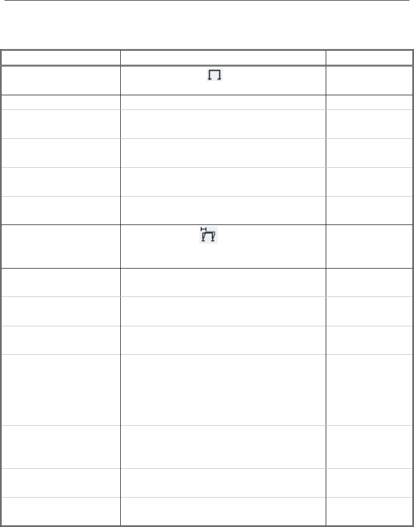
User's Guide
TABLE 14-1 Display Menu Options
Command
Action
Form
Undeformed Shape Undeformed Shape plots the undeformed
shape onscreen.
No form; results
are displayed.
Load Assigns
> Joint Displays loads assigned to Joints. Show Joint Loads
form
> Frame Displays loads assigned to Frames. Show Frame
Loads form
> Shell Displays loads assigned to Shells. Show Shell Loads
form
> Tendon Displays loads assigned to Tendons. Show Tendon
Loads form
Deformed Shape Deformed Shape plots a deformed or
mode shape onscreen based on user-specified
loads. This plot can be animated.
Deformed Shape
form
Force/
Stress Diagrams
> Support/Spring
Reactions
Displays support and spring reactions onscreen
based on user-specified loads.
Reactions form
> Soil Pressure Displays soil pressures onscreen based on us-
er-specified loads.
Soil Pressure form
> Frame/Pier/ Span-
drel/Link Forces
Displays column, beam, brace, pier, spandrel,
and link forces onscreen based on user-
specified loads.
Member Force
Diagram for
Frames/Piers/
Spandrels/Links
form
> Shell Stresses/
Forces
Displays internal shell element forces and
stresses onscreen based on user-specified
loads.
Shell Forc-
es/Stresses form
> Strip Forces Displays forces in the design strips onscreen
based on user-specified loads.
Strip Forcess form
> Diaphragm Forces Displays diaphragm forces onscreen based on
user-specified loads.
Diaphragm Forces
form
14 - 2 Obtain Basic Graphical Displays

Chapter 14 - Display Results
TABLE 14-1 Display Menu Options
Command
Action
Form
Display Performance
Check
Display Performance Check displays de-
mand/capacity (D/C) ratios for hinges after a
nonlinear time history analysis has been run if
performance checks have previously been de-
fined.
Performance
Check form
Energy/Virtual Work Di-
agram
Energy/Virtual Work Diagram displays ener-
gy/virtual work diagrams that can be used as an
aid to determine which elements should be
stiffened to most efficiently control the lateral
displacements of the structure. User defines
forces and displacements
Energy/Virtual
Work Diagram
form
Cumulative Energy
Components
Cumulative Energy Components plots all ener-
gy components in a cumulative manner after a
modal time history analysis has been run.
Immediate, no
form used
Story Response Plots Story Response Plots displays force and dis-
placement responses for specified stories as a
new tab in a display window.
Immediate, no
form used
Combined Story Re-
sponse Plots
Combined Story Response Plots displays
min/max displacements/accelerations, drifts,
shears, and overturning.
Combined Story
Response form
Response Spectrum
Curves
Response Spectrum Curves plots various re-
sponse spectra after a time history analysis
has been run.
Response
Spectrum
Generation form
Plot Functions Plot Functions plots various time history curves
based on user-specified data after a time histo-
ry analysis has been run.
Plot Function
Trace
Display
Definition form
Quick Hysteresis
> Links Plots force-deformation hysteresis loops for link
objects after a time history analysis has been
run, as a new tab in a display window.
Immediate, no
form used
Static Pushover Curve Static Pushover Curve displays various pusho-
ver curves based on user specified data after a
static nonlinear analysis has been run.
Pushover Curve
form
Obtain Basic Graphical Displays 14 - 3
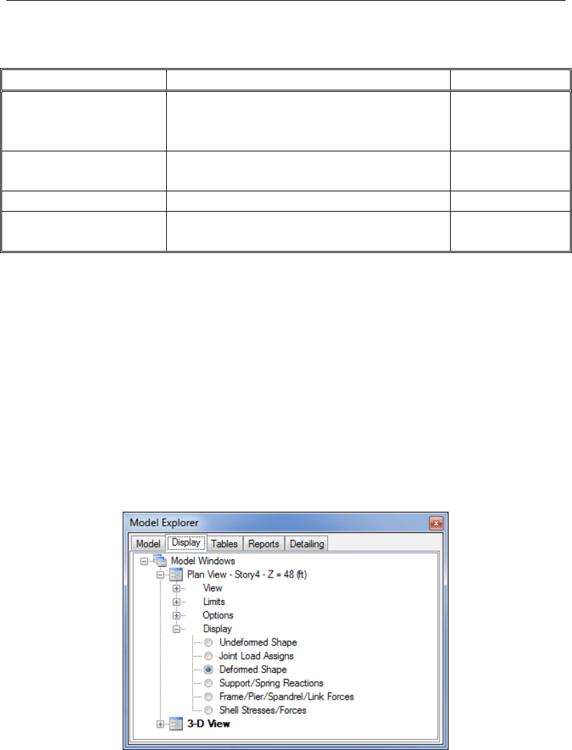
User's Guide
TABLE 14-1 Display Menu Options
Command
Action
Form
Hinge Results Hinge Results allows the user to plot rotations
and deformations vs forces for a selected hinge
after a static nonlinear analysis has been run.
Hinge Results
form
Save Named Display Save Named Display allows the user to save
the display showing in the active window.
Named Displays
form
Show Named Display
Displays a previously saved named display.
Select View form
Show Tables Show Tables allows the user to select the type
of information to display in table format.
Choose Tables
form
* Note: With a form displayed on the ETABS window, click the F1 key on your keyboard
to access context-sensitive Help for the form.
Graphical Displays using Model Explorer
A limited number of analysis results can also be shown graphically using
the Display tab in the Model Explorer. Click on the View node where re-
sults are to be displayed so that the Display branch is visible. Click on
the Display branch and then on the desired analysis result for display.
The Model Explorer should look something like that shown in Figure 14-
1. The view may be changed by clicking on the View branch and select-
ing from 3D, Plan or Elevation.
Figure 14-1 Model Explorer Display tab
14 - 4 Graphical Displays using Model Explorer

Chapter 14 - Display Results
Tabular Display of Results
Both the analysis and design results can also be displayed in tabular for-
mat in ETABS by using the Model Explorer or the Display menu >
Show Tables command. In the Model Explorer, select the Tables tab
and then expand the tree by clicking on nodes to reveal various input, re-
sults, and design data. A right click on a branch or leaf of the tree will
display an associated context sensitive menu. Click the Show Table
command on these menus to show tables along the bottom of the screen.
Tabular Display of Results 14 - 5

Chapter 15
Generate Results
Objective
This chapter describes how to output analysis and design results for fur-
ther post-processing, presentations, or project submittals.
Summary Report
A summary report is available at the click of a button using the File
menu > Create Report > Show Project Report command. This sum-
mary report is automatically created by ETABS, is compatible with Mi-
crosoft Word, and can contain the following items, depending on the
make-up of the model:
Title Page
Hyperlinked Table of Contents
Model Definition Data
Objective 15 - 1

User's Guide
Analysis Results
Summary Design Results
Print Graphics
Graphic displays also can be printed directly to a printer or captured to
various file formats.
The display in the currently active window can be printed directly to the
printer using the File menu > Print Graphics command. This will pro-
vide a print preview form that allows for adding text or graphical annota-
tions before going to the printer. Graphic displays also may be captured
to a file using the File menu > Capture Picture commands. There are
different options for defining the region to be captured and the image file
type.
Export Results
Analysis and design results also can be exported from ETABS for further
post-processing or use in other applications. The File menu > Export
command has numerous options for exporting results.
A display showing results can be exported to a DXF/DWG file compati-
ble with CAD applications. Tabular data can be exported to either Mi-
crosoft Excel (*.xls) or Microsoft Access (*.mdb). When exporting tabu-
lar data, choose the classes of data to export and the types of data within
each class; this, in turn, determines the tables that are exported. Individu-
al stories may be exported to CSI's SAFE® program for further analysis,
design, and detailing. Models containing design results can also be sent
out to Revit Structure, to a CIS/2 Step file, or to an IFC file.
15 - 2 Print Graphics
