User_Guide_B5c_V2 Users Manual 2501256
Users-Manual-2479596
Users-Manual-3133266
Users-Manual-3133276
User Manual:
Open the PDF directly: View PDF ![]() .
.
Page Count: 31

Mimosa OS
User Guide

Mimosa OS
User Interface Overview
Accessing the Interface
Logging In
The Dashboard
2
2
3
Administration
Password
Services
WiFi Console
18
18
19
w
elcome to the User Guide for the
Mimosa OS and User Interface.
Device Info
Device
Link
Remote Device
Wireless
Link
Channel
Power
Tools
Signal Meter
Site Survey
Spectrum Analyzer
Device Discovery
Ping
Traceroute
5
6
7
9
10
11
13
14
15
16
16
16
Notifications
Time and Location
Network
Update and Reset
Configure File
Diagnostics
Watchdog
Events
Syslog
Support
About Mimosa Networks
20
21
22
23
23
25
25
25
26
This User Guide is intended to help set up
the B5c as well as illustrate the benefits
and details of the numerous tools
available within the interface.
Click the sections in this menu to navigate
within the document.
Table of Contents i
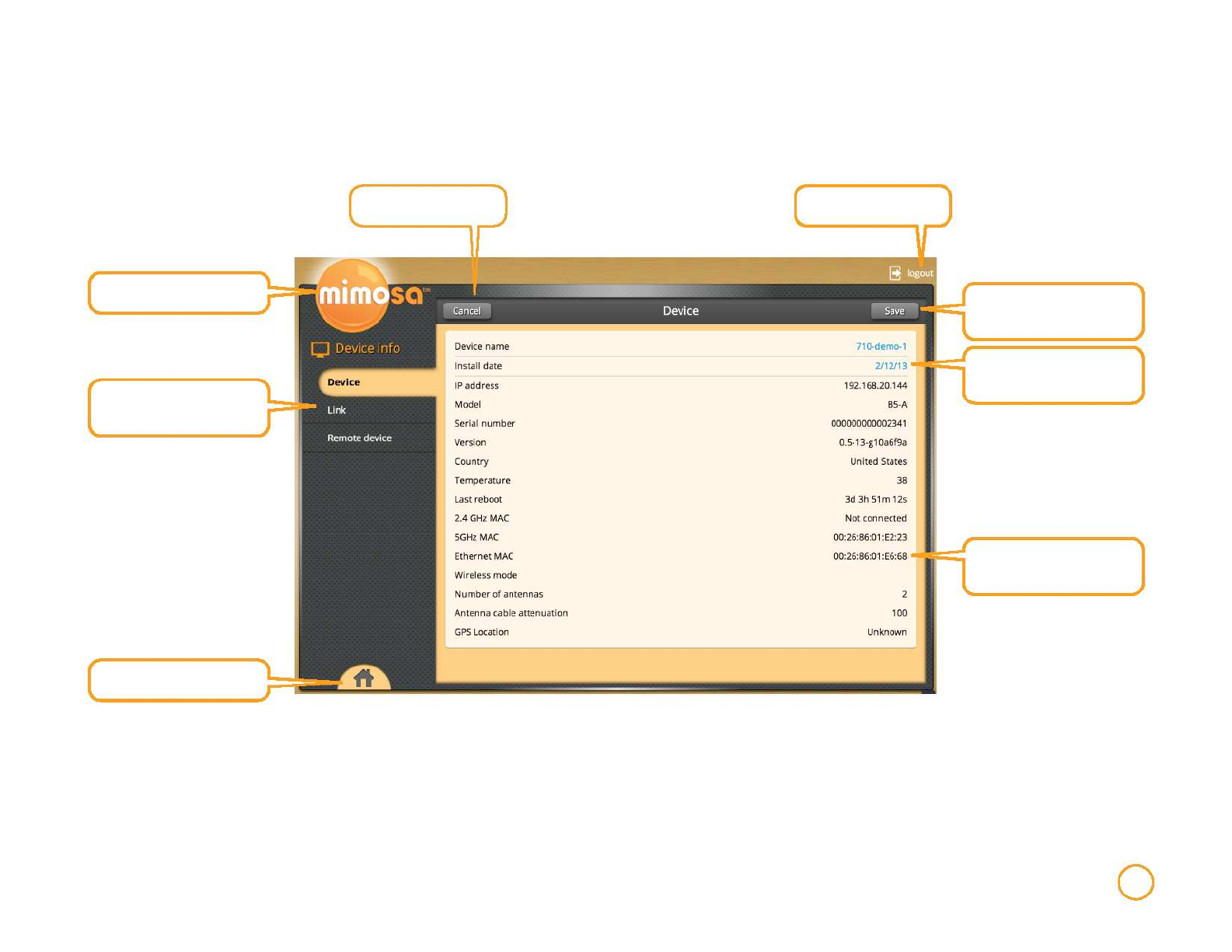
User Interface Overview
Cancel changes
Log out or change user
Return to the Home menu
Use the side navigation pane
to move between sections
Changes to configuration will
ONLY take effect after
selecting Save
Items marked in Orange can
be configured
Items in Black are fixed and
cannot be configured on
current screen by user
Return to the Home menu
User Interface Overview 1
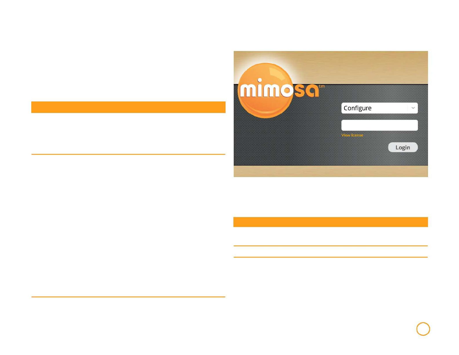
Accessing the Interface
Accessing the interface requires that the device is connected to a
power source. The device has three separate modes of access to
ensure easy set-up and management. The device can be accessed
without connection to the LAN (via 2.4 GHz mobile device
connection), through the local LAN (if the device is connected to the
LAN) or from outside of the LAN via a public IP address.
Logging In
Access Method
Via 2.4 GHz Wireless
Connection
Via Ethernet interface
or in-band over the
Wireless link
Connecting to GUI
On any device with an 802.11 2.4GHz connection, go
to the wireless network listing and connect to the
"mimosanetworks" wireless network (SSID). Once
connected, type 192.168.1.1 (OR URL TBD LATER)
into your mobile device browser.
By default, the device IP address is 192.168.1.20 and
can be accessed via the Ethernet port using this IP
address in any standard Web browser.
To access the device via a locally connected
computer initially (on the same LAN or directly to the
Ethernet port), the computer's IP address must be on
the same subnet as the above address.
After connecting via one of the above methods, the device will prompt
you to log-in with a username and password.
The default factory configured user accounts are:
Once you have modified the IP address (static or
DHCP) of the Device for remote management
purposes (in-band over wireless or over the
Ethernet interface), the new specified IP address
Username
Configure
Password
Mimosa
Access Rights
All modifiable elements can be configured
By user
must be used to access the device. This is Monitor Mimosa User cannot configure device
important to do in order to avoid IP address
conflicts with other devices on the network.
Current IP addresses of different Mimosa devices on the
network can be identified using the Mimosa Device Discovery
tool.
User Interface Overview 2
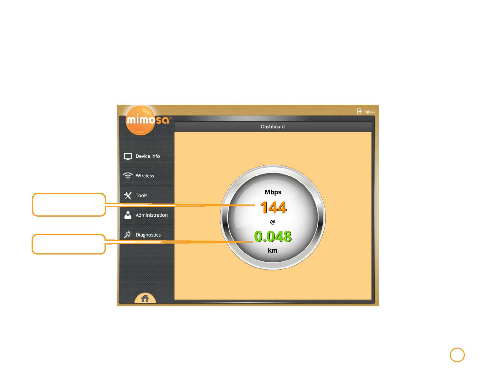
The Dashboard
After logging into the interface, if the B5c is connected to another Mimosa B5c the home page will show a dashboard that reflects the current
performance of the device and link information. You are now ready to explore the sections within the interface to setup,
manage, and monitor your B5c.
Estimated half-duplex IP
throughput in Mbps
(TCP based)
Measured link distance in
kilometers
User Interface Overview 3
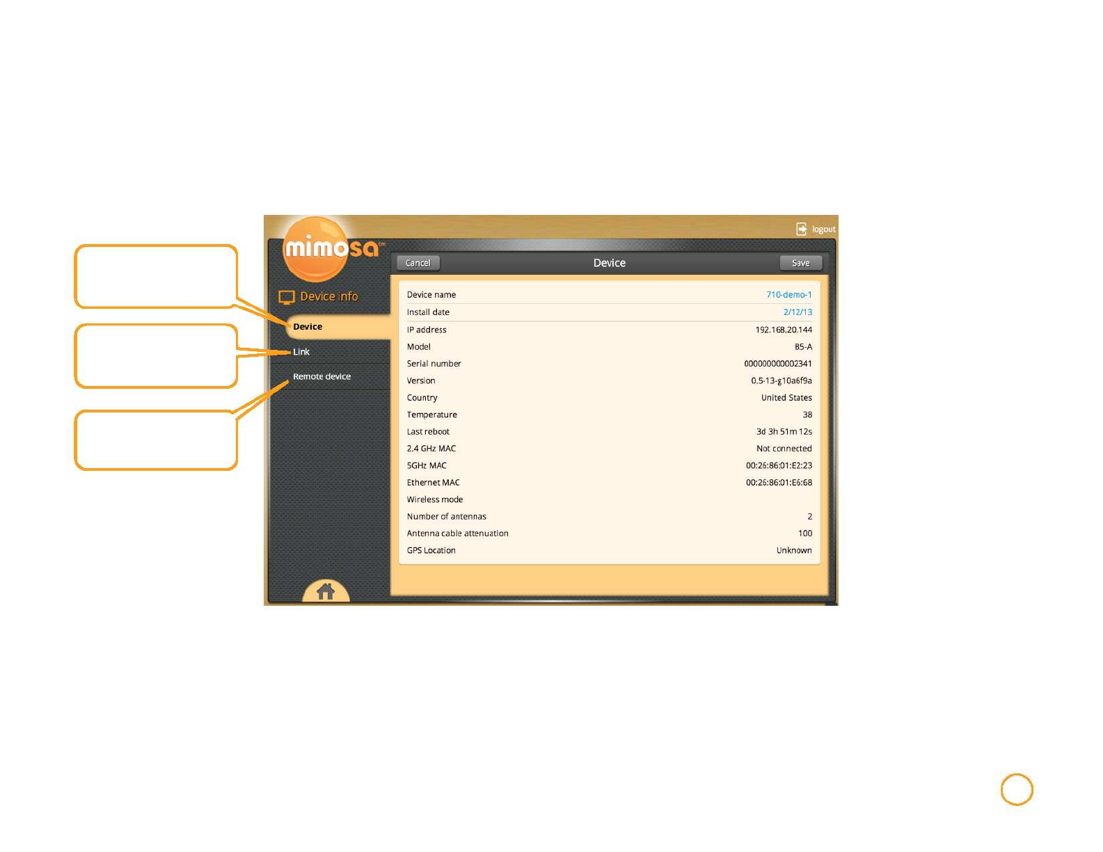
Device Info
The Device Info tab contains status and current configuration summary about your device, remote devices, and the wireless link.
Information and current
configuration of the B5c
All relevant specifications and
send/receive info for the link
between two Mimosa devices
Information and current
configuration of the remote
B5c
Device Info 4
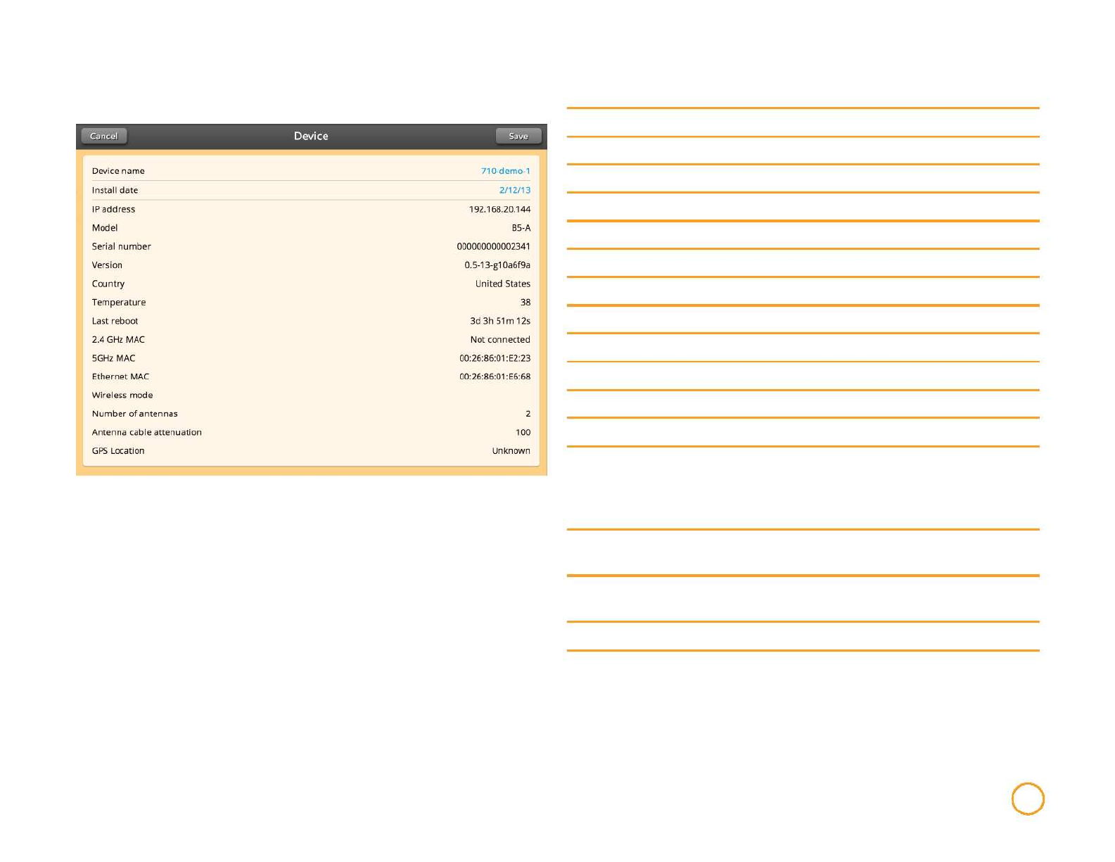
Device
Device Name
Install Date
IP Address
Model
Serial Number
Firmware
Country
Temperature
Last Reboot
2.4 GHz MAC
5 GHz MAC
Ethernet MAC
Wireless Mode
Number
antennas
Use this to differentiate between devices.
Use this to track the install dates of devices.
IP address of the device.
Mimosa device model name (e.g. B5, A5, etc.).
Mimosa device serial number.
Firmware version.
Location of device.
Temperature of device in degrees Celsius.
Time since last reboot.
MAC address for 2.4 GHz interface.
MAC address for 5 GHz interface.
MAC address for Ethernet interface.
Current role of the device as AP (Access Point) or Station. If
the device is in AP mode, it will act as the Access Point for
the network. The Stations linked to the AP will act as
children to the configuration setting of the parent AP.
of Number of antennas in the device
Antenna cable Length of cable attached to the device
attenuation
GPS Location GPS coordinates of device location.
Device Info 5
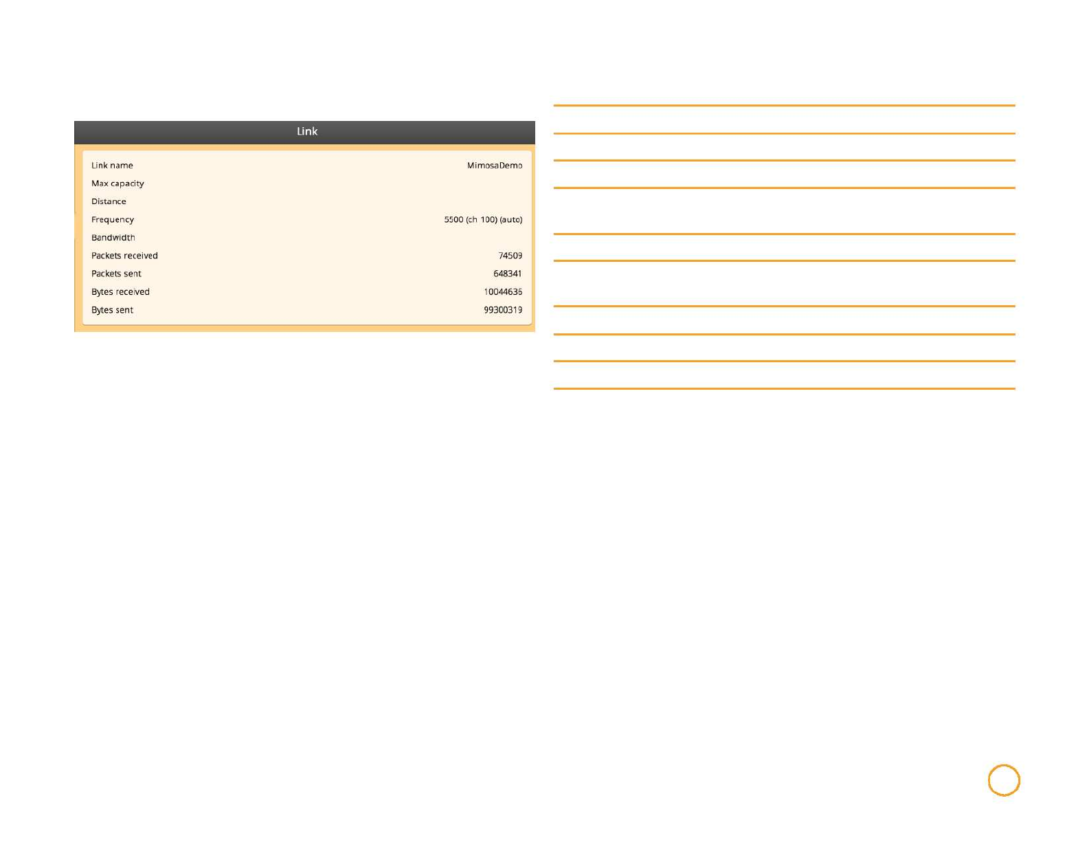
Link
Link Name
Max Capacity
Distance
Frequency
Bandwidth
Packets
Received
Packets Sent
Bytes Received
Bytes Sent
Use this to differentiate between devices.
Maximum connection rate (Mbps).
The distance between the two link endpoints.
Frequency and (Channel) or auto (if auto channel mode is
enabled).
Width of channel (MHz).
Number of packets received.
Number of packets sent.
Number of bytes received.
Number of bytes sent.
Device Info 6
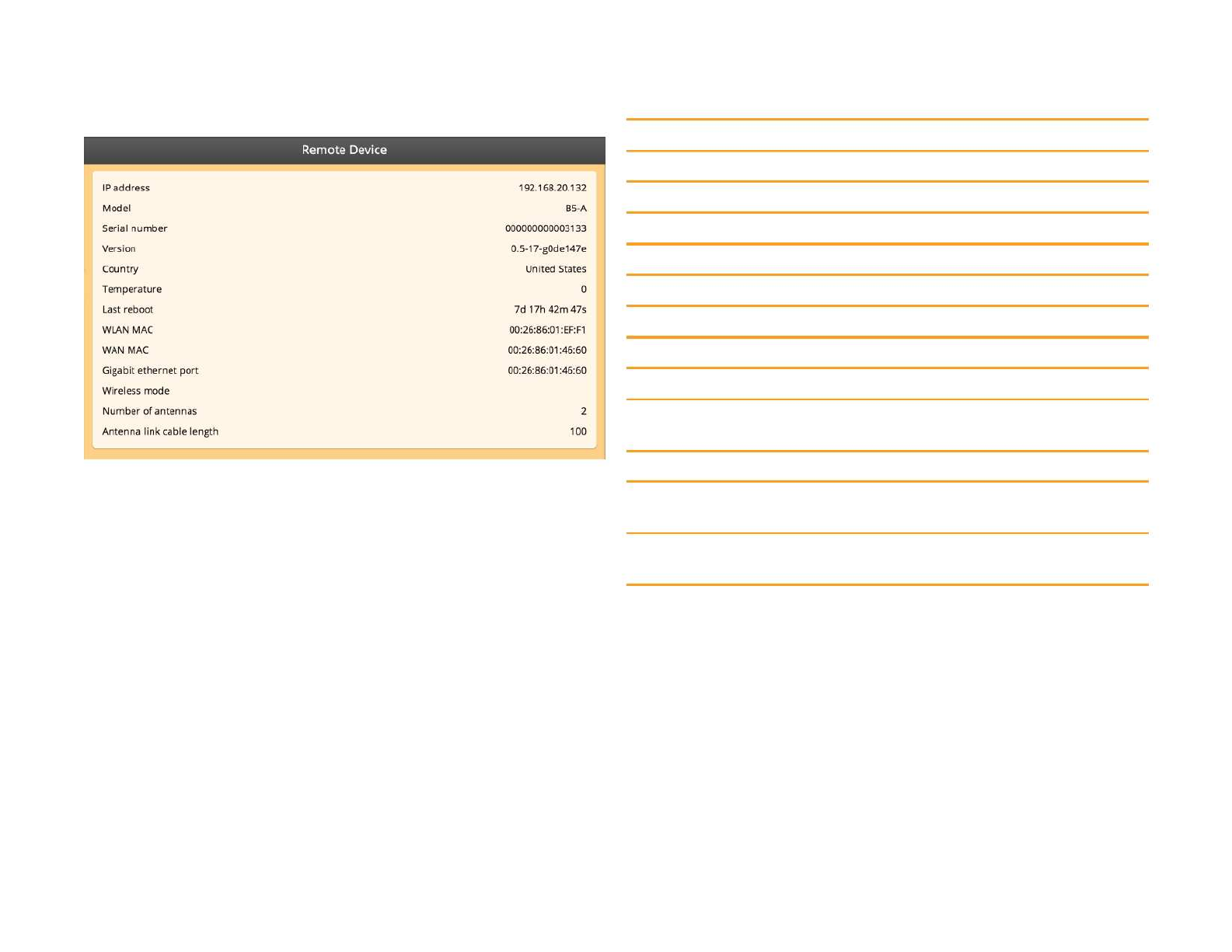
Remote Device
IP Address
Model
Serial Number
Version
Country
Temperature
Last Reboot
WLAN MAC
WAN MAC
IP address of the remote end Mimosa remote device.
Mimosa remote device model name (e.g. B5, A5, etc.).
Mimosa remote device serial number.
Firmware version.
Location of device.
Temperature of device in degrees Celsius.
Time since last reboot.
MAC address for WLAN interface.
MAC address for WAN interface.
Gigabit Ethernet MAC address for Gigabit Ethernet Port interface.
Port MAC
Wireless Mode
Number of
Antennas
Antenna link
cable length
Current role of the Mimosa remote device as AP or Station.
Number of antennas on the device
Length of cable linked to the antenna
Device Info 7
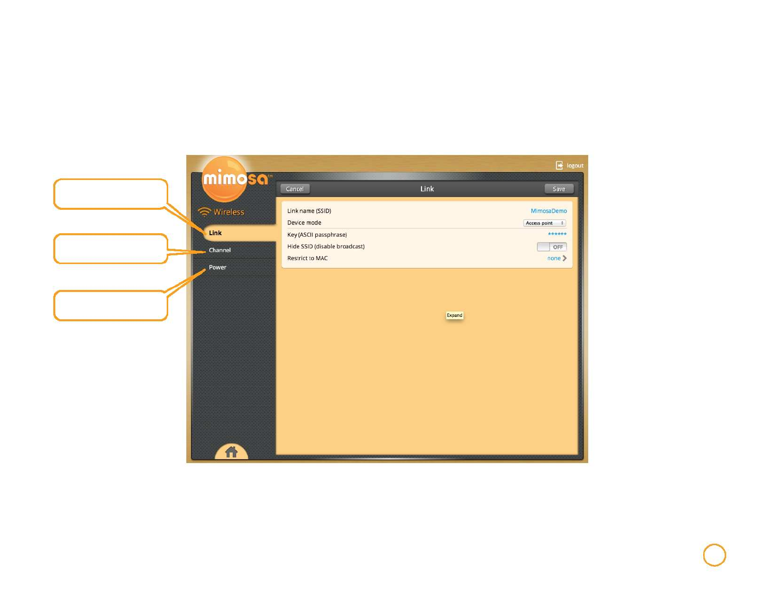
Wireless
The Wireless tab contains all necessary components for configuring the wireless link.
Link name, filter and security
settings
Manage frequency and
channel settings
Device power and
performance information
Wireless 8
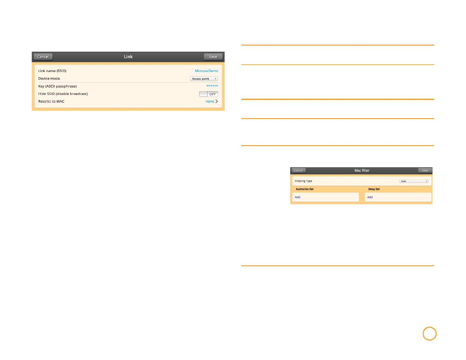
Link
Link Name
(SSID)
Device Mode
Key (ASCII
Passphrase)
Hide SSID
(disable
broadcast)
Restrict to MAC
Change/Set the name of the wireless network.
Choose whether the device will act as an Access Point or a
Station. The Access Point settings will determine the
characteristics of the network while Station devices will be
subject to changes made at the Access Point.
Change/Set the password for the wireless network.
Turn On to disable the broadcast of the wireless network
SSID beacon (the network will not be discoverable).
Allow or deny specific devices based on MAC address
with the following Filtering Type options:
None - do not filter
Authorize if not denied - allow any connection if not
denied
Deny if not authorized - block unless authorized
To add a device to either list, simply click "Add" and then
insert MAC address of device.
Wireless 9
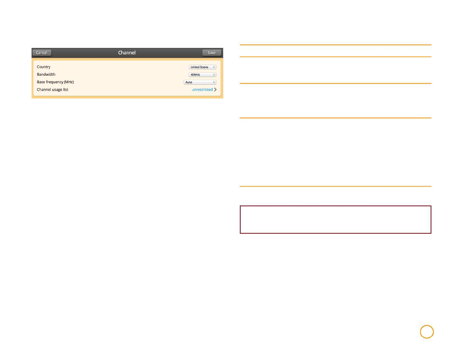
Channel
Country
Bandwidth
Base Frequency
(MHz)
Channel Usage
List
Select the country in which the device will be operating.
Select the size of the channels that will be used in the link.
Mimosa products allow for selection up to 80 MHz for
channel width.
Either choose a channel on which to operate the link or
choose Auto. If Auto is chosen, the device will
automatically choose the channel with the least
interference.
Turn Channel Usage List On to limit the channels
available for use during channel Auto selection mode. You
will be prompted to choose preferred channels (selection
list will be based on current Bandwidth selection and
available 20/40/80 MHz base frequencies). Once enabled,
the field will read specified.
If Of, all channels will be considered usable and the
Channel Usage List item will read unrestricted.
WARNING: It is important to select the right country so that your
device follows the regulations and laws of that country.
Wireless 10
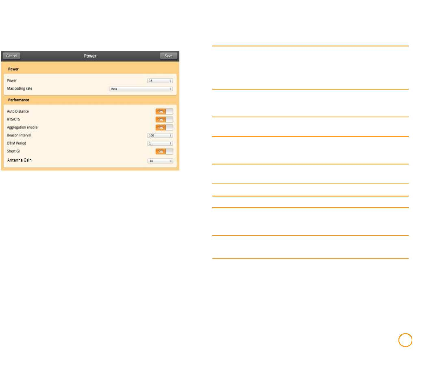
Power
Power
Max Coding Rate
Auto Distance
RTS/CTS
The maximum allowed power rate is determined by a
combination of country and chosen frequency. If a power
level is not chosen, the B5c will default to the highest power
level allowed in the chosen country/frequency combination.
Sets the maximum coding rate available for use by the link.
Selecting Auto will allow the link to use the highest coding
rate available.
Enables automatic measurement of the link distance,
allowing corresponding link parameters to be optimized.
Allows communication with legacy devices that may require
RTS/CTS. Should only be used if legacy devices are
present.
Aggregation Enables 802.11 aggregation features for performance
Enable
Beacon Interval
DTIM Period
Short GI
enhancement.
Adjusts the frequency of broadcast beacons.
Delivery traffic information map period.
Determine the length of the guard interval between
transmissions. A "Short GI" is 400 ns, while a long GI will be
800 ns.
Antenna Gain External Antenna Gain Setting. Recommended 25 dBi
Wireless 11
Tools
The Tools tab has everything you need to measure signal levels for antenna aiming, spectrum analysis optimize, and link diagnosis.
Fine grained signal meter
used for aiming the Mimosa
device
Displays all links visible in the
area and any pertinent
information on those
networks. This information
can be used in site planning
and installing new devices
Survey the location of your
radio and determine the best
frequency for your link
Analyze your network to
discover any Mimosa devices
that are active on the same
link layer network
Analyze the route of packets
on the link to a destination Ping a device in your network
and receive a readout from
the device
Tools 12
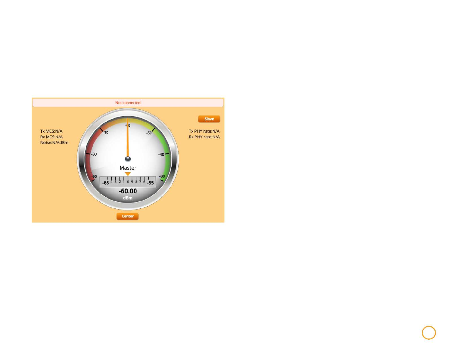
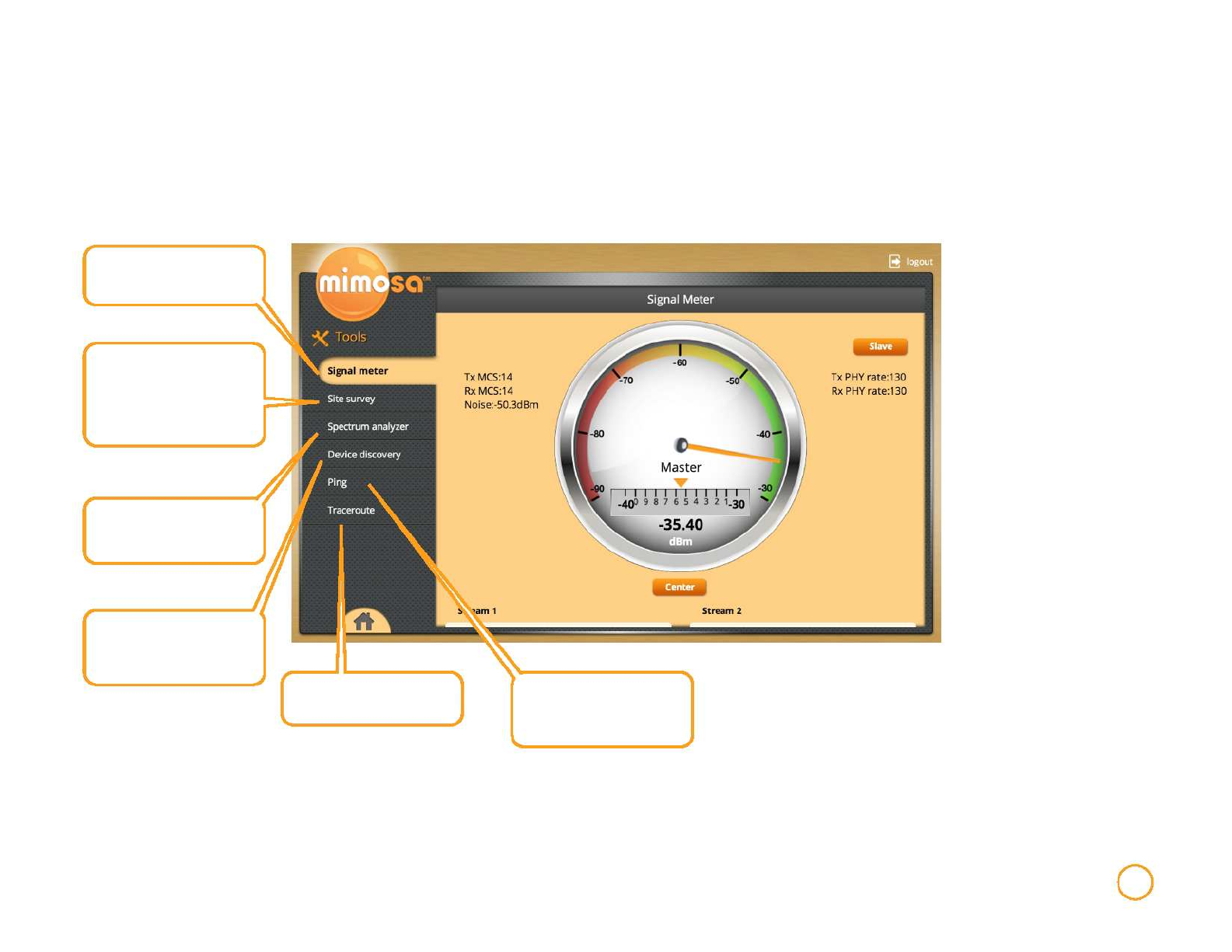
Signal Meter
The Signal Meter provides a real time signal level in dBm for an
established link. It provides fine adjustment information to
optimize the aiming of the link to achieve the highest signal level
possible. The AP device and Station device must be first
configured with the same link info (SSID and security key).
frequency and distance values are displayed at the bottom of the page.
Current Tx MCS (Modulation and Coding Scheme) and Rx MCS rate
(if associated) corresponding Tx PHY (Physical Layer
Interface) rate and Rx PHY rate are shown.
The Center button locks the fine tuning scale in place, providing
more detailed granularity with the orange arrow showing the fine
grain level to assist in orienting and aiming the link.
Scrolling to the lower portion of the page, individual stream EVM
(Error Vector Magnitude) and RSSI (Received Signal Strength
Indication) levels are displayed. Current selected bandwidth,
Tools
13
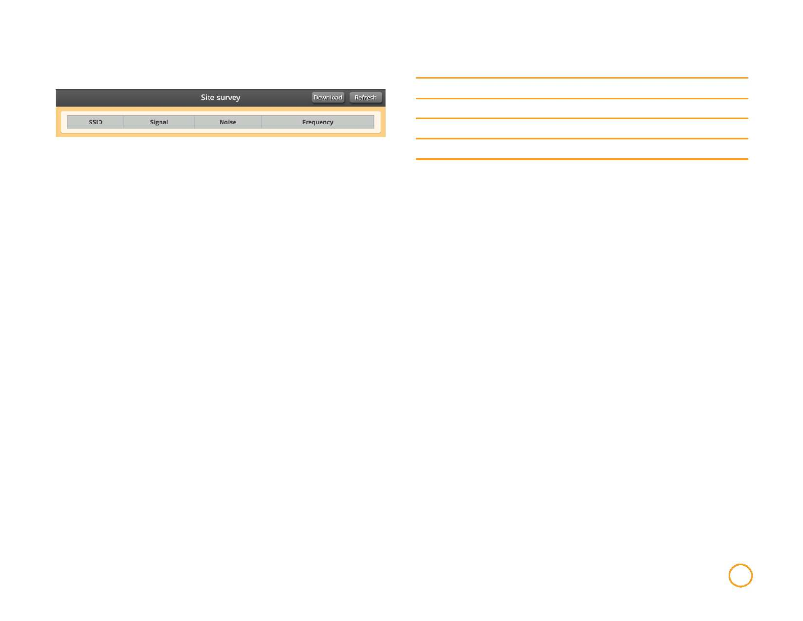
Site Survey
SSID SSID name of devices detected in the scan survey.
Signal Strength Signal strength of the specific SSID link in dBm.
Noise Amount of noise detected in the frequency/channel.
Frequency Current frequency utilized by a detected device.
The Refresh button in the upper right corner will update this
information to an up to the second view.
The Download button in the upper right corner will extract this
information into a CSV formatted file.
Tools 14
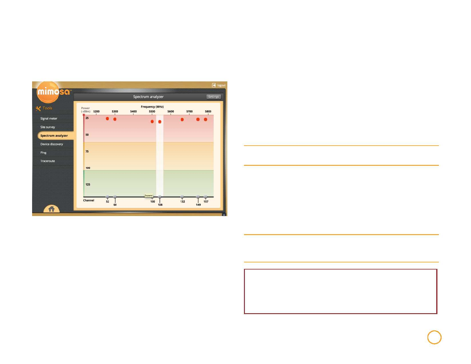
Spectrum Analyzer
The spectrum analyzer displays observed interference levels
created by other wireless devices, and is displayed by Frequency/
Channel.
immediate area, and the less likely it will be to affect the performance
of the radio.
The X-axis of the spectrum analyzer graph displays the
frequency/channel of the observed radio interference.
The colored bands represent relative impact to link performance,
red indicating highly impacting interference, yellow indicating
likely impact, and green representing negligible impact.
The graph updates automatically in real time to help you understand
radio signal levels in your location.
The Settings button in the upper right hand corner allows you to
change the way you view the graph.
Bandwidth
Channel Usage
List
Change the width of the channels that will be used on the
link.
Turn On to restrict the device to only use a specified list of
desired operation channels. Once enabled, use the
checkboxes on the analyzer page to include desired
channels eligible for use in auto-switching and when DFS/
Radar switching is required (depends on channel selected
and country regulations).
You can also click the Edit List button and go to a new
Unlike many wireless spectrum analyzers, the Mimosa device
continually captures interfering signal levels across the spectrum
without impacting ongoing link traffic.
The analyzer displays detected interference, and allows you to
select a channels or multiple channels (based on the current
selected bandwidth, and allowed channels in the country
Analyzer Signal
Decay
page to select channels.
Use this drop-down to determine how quickly an observed
signal will fade from the spectrum analyzer
graph to determine persistence of interfering signals/
selected) that you want selected to be included in the Channel
Usage List.
The Y-axis of the graph indicates the level of power of each
signal. The lower the signal, the less noise it is creating in the
Tools
WARNING: The spectrum analyzer Channel Usage List is the
same usage list as in the Channel section under Wireless.
Changing the allowed channels in the Spectrum Analyzer will also
change allowed channels in the Wireless tab.
15
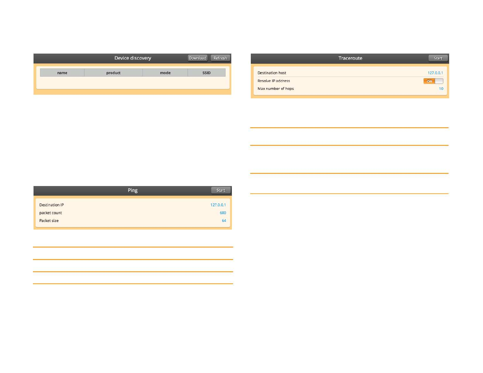
Device Discovery Traceroute
The Device Discovery displays the Name, Product, Mode and
SSID of any devices on the network that are active in the area.
The Refresh button in the upper right corner will update this
The Traceroute function assumes that the current device you are
logged into is one end of the route.
information to the most current view.
The Download button in the upper right corner will extract this
information into a Device Discovery CSV file.
Ping
Destination
host
Resolve IP
address
Max number of
hops
IP address of end Traceroute device
Determines if the report will contain device names or only
IP addresses. Turning this function Of will lead to slightly
faster results.
Set the maximum number of device hops that a packet will
encounter before ending the traceroute.
Once a traceroute is configured, select the Start button at the top to
execute. If at any point during the traceroute you wish to stop, click the
Stop button at the top right.
Destination IP IP address of the device to ping.
Packet Count Number of packets to transmit.
Packet Size Size of each packet transmit.
After configuring the ping values, press the Start button at the top to execute.
Clicking the Stop button at any point will end the ping.
Tools 16
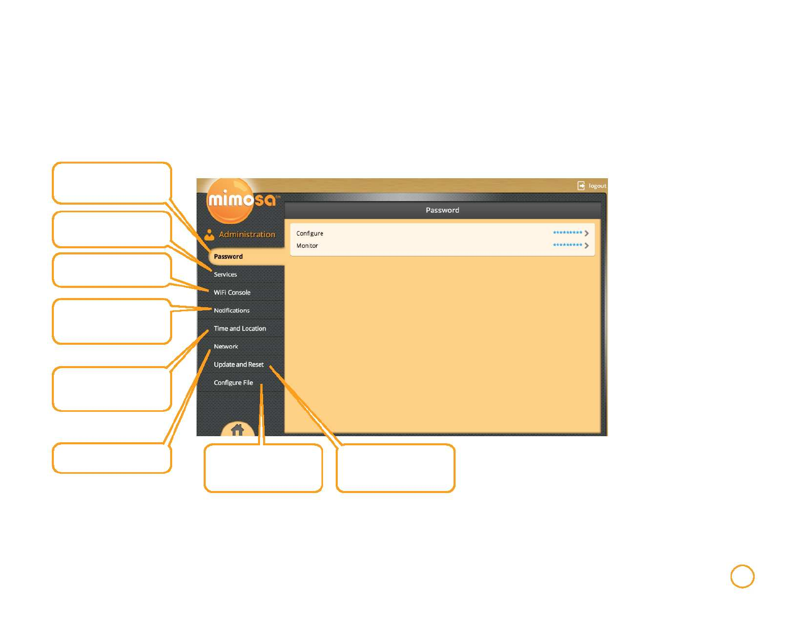
Administration
The Administration tab is used to configure device networking, remote access and other IP services, device diagnostics, and device
reboot and resetting.
Modify device passwords for
the Configure and Monitor
modes of the GUI interface
Configure remote
management and additional
IP services.
Manage the use of the 2.4
GHz management system
Configure the types of
notifications you will receive
regarding your device
Update time and location
settings based on the exact
location of your device.
Manage administrative
portions of the network
Backup device configuration
or restore configuration from
a previously saved backup.
Update device
firmware ,reset the device to
factory configuration or
reboot the device.
Administration 17
Password
To change either password, the current password will be required.
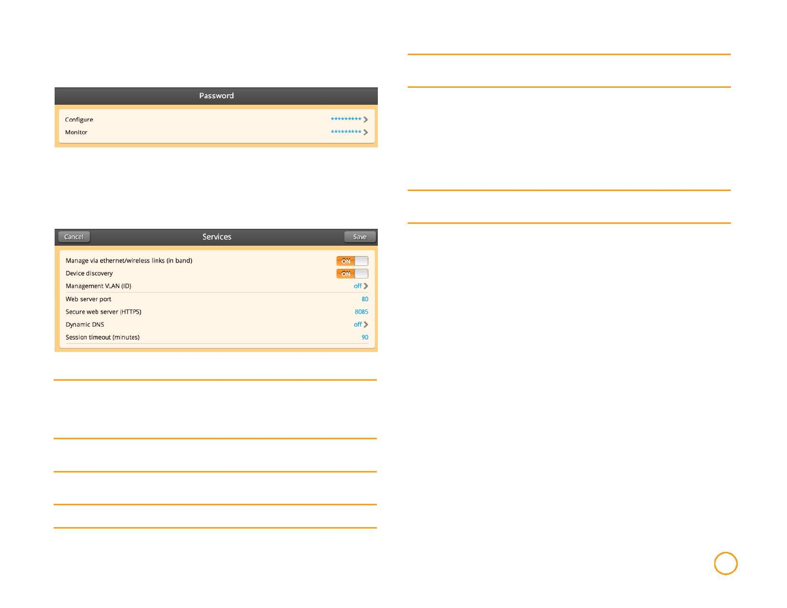
Services
Secure Web
Server (HTTPS)
Dynamic DNS
Session
Timeout
Indicate which TCP port will be used for the secure web
server.
The device provides Dynamic DNS software which
interoperates with several different DDNS services.
To use Dynamic DNS, you must already subscribe to a
DDNS provider (refer to the drop-down in the interface for a
list of compatible providers). Required parameters for
activation include the Host Name of the DDNS service,
and your Username and Password.
Number of minutes of inactivity that will be allowed on the
interface before automatic log-out.
Manage via
ethernet/
wireless inks (in
band)
Device
Discovery
Management
VLAN (ID)
Enables the device to be accessed from connections in addition to
the 2.4 GHz connection. If manage via ethernet is turned Off you
will be unable to manage the device via Ethernet (LAN or WAN side).
Determines whether the device will be discoverable on the network
by other Mimosa or LLDP devices.
Turning On and setting the VLAN ID identifies which VLAN will be
used to remotely manage the device.
Web Server Port Indicate which TCP port will be used for the web server.
Administration 18
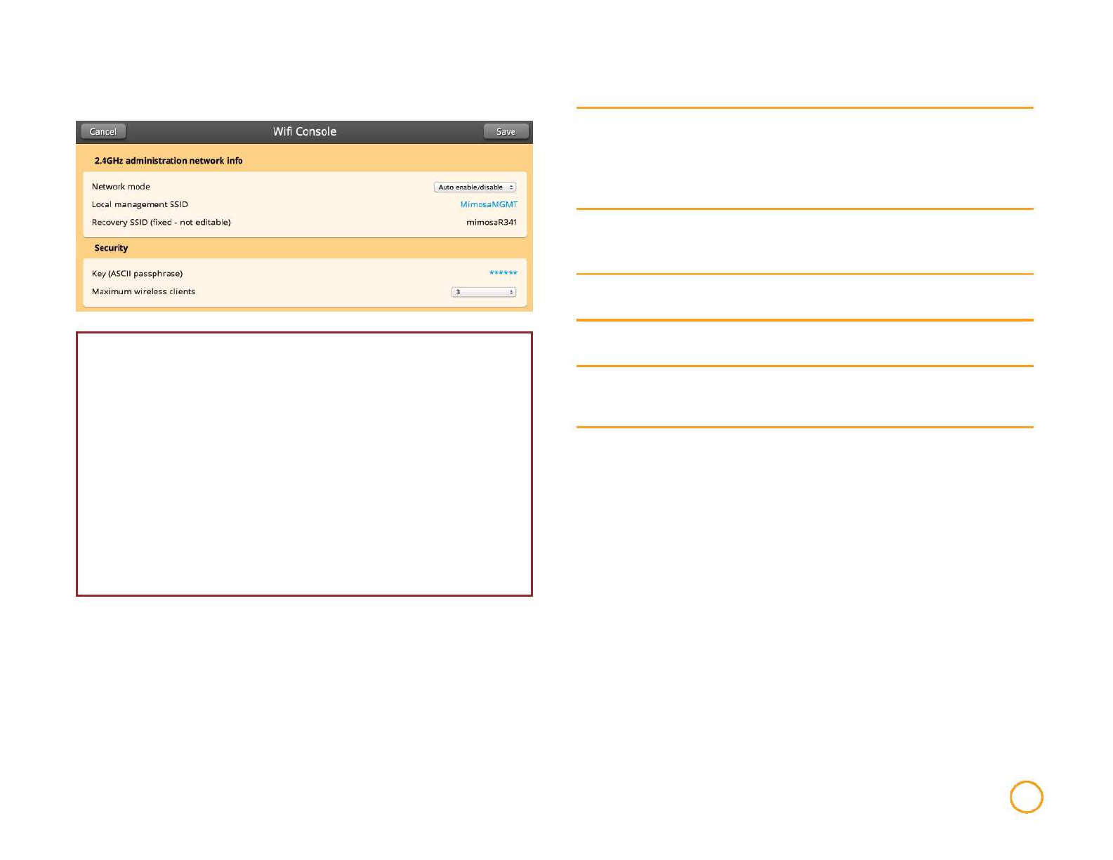
WiFi Console
WARNING: If you turn of the 2.4 GHz management, you must have an in-
band method of accessing your device. If you have turned off your 2.4 GHz
management and are now unable to access your device, you may always
access your device via your Recovery SSID.
To do this, unplug the device's ethernet cable connection. Then, unplug the
PoE (Power over Ethernet) and plug the PoE back in to cycle power. The
recovery SSID will now be broadcast and must be accessed within 2
minutes, after which the 2.4 GHz management will be disabled again.
Once you are connected to the 2.4 GHz management system, type
http://recovery.mimosa.com into your browser to reach the interface.
After you have managed the device through the Recovery mode,
reconnect the device's ethernet cable.
Network Mode
Local
Management
SSID
Recovery SSID
Key (ASCII
passphrase)
Maximum
wireless clients
Enable or Disable the 2.4 GHz management network. You
can also set the mode to auto enable/disable. This mode
turns the 2.4 GHz management system on for a limited time
(2 minutes) when the device is being booted and then turns
of.
The SSID name for the 2.4 GHz local management
interface.
This SSID is fixed as a fallback recovery of the device
management system.
Enter a passphrase to generate a WPA2-PSK key for
securing the 2.4GHz 802.11 management interface
Assign the maximum number of wireless clients that can
access the 2.4GHz 802.11 management interface
(simultaneously associated).
Administration 19
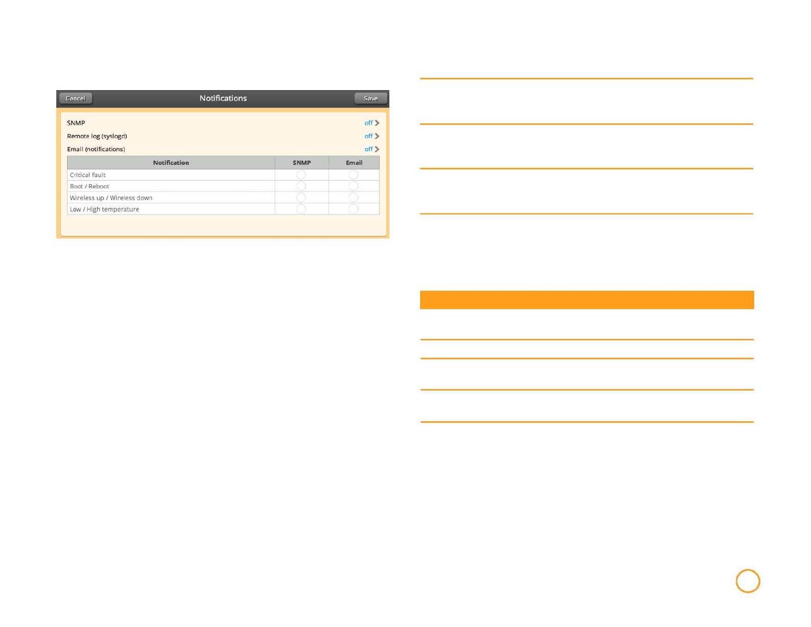
Notifications
SNMP
Remote Log
(syslogd)
Email
notifications
Enables SNMP notifications (traps) to a remote server.
Required/optional parameters include SNMP community
string, Contact, Location and Trap Server.
Enables configuration of syslogd remote logging for the
device. Required parameters include Remote log IP
address and Remote log port.
Enables SMTP mail server based email notifications for
desired device events. An external SMTP mail service is
required for this function to operate.
The notification section also contains a chart that determines which
notification types will be turned on or off, and to which notification
system they will be sent. Update these notifications
by clicking the circles in the grid to check on or off.
Notification
Critical Fault
Boot/Reboot
Wireless Up/
Wireless Down
Low/High
Temperature
Description
Notification created if the device is forced to reboot or if
GPS signal is lost.
Notification created if system boots or reboots.
Notification created if device connects to (Wireless Up)
or disconnects from (Wireless Down) another device.
Notification created if device temperature drops below
-40C or rises above +60C.
Administration 20
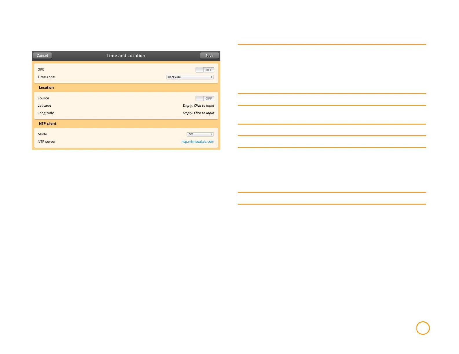
Time and Location
GPS
Time Zone
Source
Latitude
Longitude
Mode
NTP Server
Enables the integrated GPS (if provided) to allow the
device to update location details automatically. This setting
only impacts automatic location population for
Longitude/Latitude, it does not impact any synchronized
transmission features for collocating Mimosa devices
which utilize GPS based timing.
Manually update the time zone of the device.
Indicates where the location information is being derived
from.
Manually update the latitude of the device.
Manually update the longitude of the device.
Determines the method the device uses for . Change
Mode to Of, GPS (get time from GPS), GPS Fallback (get
time from NTP server.
If NTP does not have time, fallback to GPS) or GPS
override.
Identify the NTP server for the device.
Administration 21
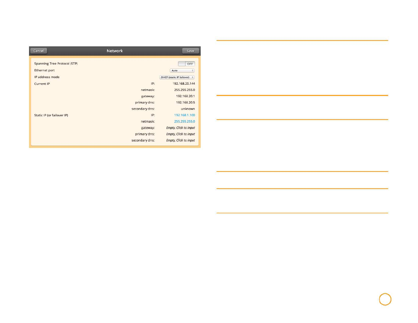
Network
Spanning Tree
Protocol (STP)
Ethernet Port
IP address
mode
Current IP
Static IP (or
failover IP)
Enables IEEE 802.1D Spanning Tree Protocol on the
device for identifying shortest network path and
eliminating network loops (in redundantly designed
networks).
Activating STP enables the device to communicate with
other STP devices on the network by sending and
receiving Bridge Data Protocol Unit (BDPU) packets.
Specify the type of Ethernet port to which the device is
connected (10BASE-T, 100BASE-T, 1000BASE-T), or use
Auto automatically detect the Ethernet link mode.
If Static is chosen, the device will always use the IP
address that you have assigned.
If DHCP (Static IP failover) is chosen, the DHCP address
assigned by your DHCP server will be used. In case of loss
of communication with the DHCP server, the static IP
(or failover IP) that you manually assigned will be used.
Displays IP information in use currently (depending on IP
address mode and status of the DHCP server).
Use this section to assign a failover or static IP
information. The IP settings must be consistent with the
address space of the device's intended network segment.
Administration 22
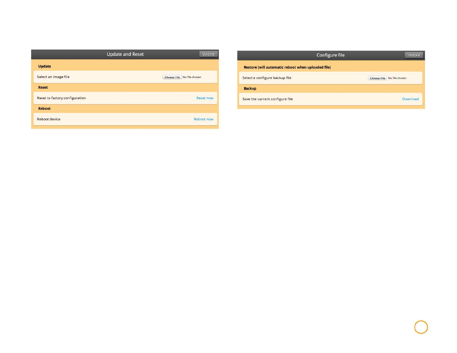
Update and Reset Configure File
To update the firmware, go to the Mimosa website and download the
latest interface firmware file. Then choose that file to upload
under Choose File. Then click Update in the upper right hand
corner.
To reset to factory configuration or to reboot your device, simply
click the Reset now.
To reboot the device, simply click Reboot now.
To restore a previous configuration, click Choose File in the restore
section and select a previously saved file. Then, click
Restore in the upper right corner to restore a previous
configuration.
To save a configuration for later restoration, click Download.
This will download the current configuration into a file.
Administration 23
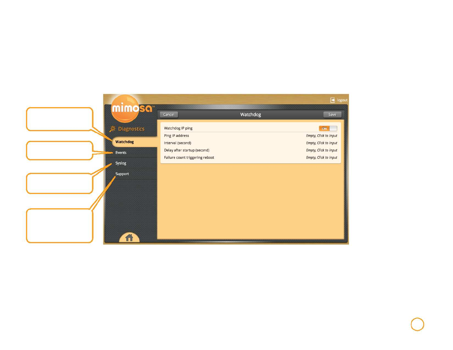
Diagnostics
The diagnostics section of the interface contains all continuously updated status and monitoring information regarding your device. All
diagnostic files can be downloaded to your computer using the upper right hand Download button.
Watchdog monitors your
network for failures
Displays significant events
experienced by the device
Comprehensive log of all
events experienced the device
Device specific support data
which may be requested by
Mimosa Support for issue
diagnosis and analysis
Diagnostics 24
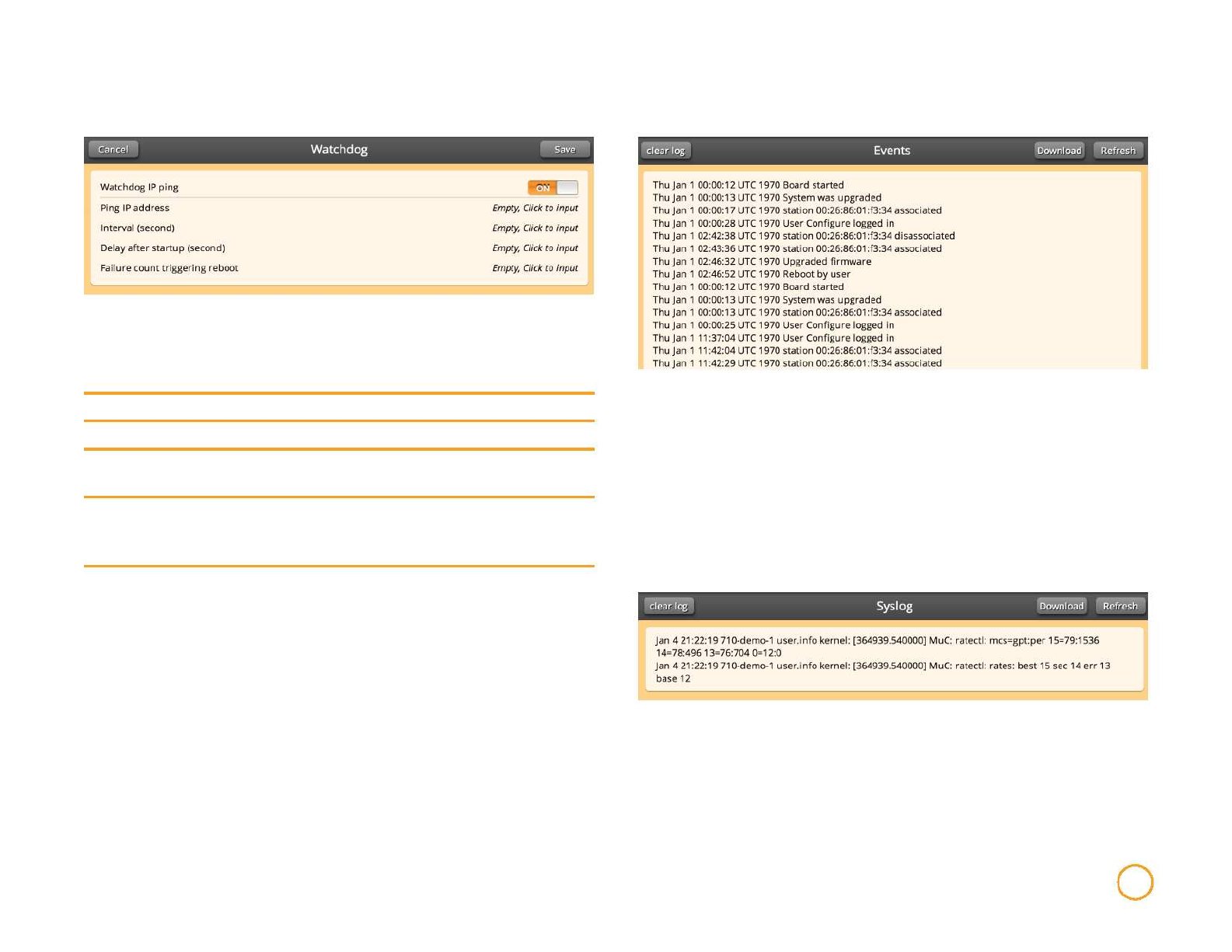
Watchdog Events
Watchdog Ping can be turned On or Off. If Watchdog IP Ping is turned to On
and it perceives failure in the network, your device
will reboot.
Ping IP address
Input IP address to ping. This is a log of all significant events that occur, not just the
events that are set to On notification. This log will be saved
Interval (second) Specify how often Watchdog should ping the IP address. regardless of reboots.
Delay after
startup (second)
Failure count
triggering
reboot
Specify the length of time prior to the first ping.
Specify how many failed pings are required to trigger a
reboot.
Syslog
This section contains a list of all status, minor and significant events
experienced by the device. This information is cleared with each device
reboot.
Diagnostics 25
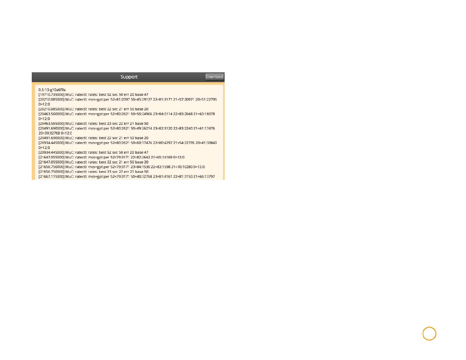
Support
This information can be downloaded and sent to Mimosa for
support.
Diagnostics 26

About Mimosa Networks
Mimosa Networks, Inc. Corporate Headquarters
300 Orchard City Dr. Ste 100
Campbell CA 95008
Support Information
Lor sum amet, commy nulputat. Duipit lum ipisl eros dolortionsed
tin hent aliquis illam volor in ea feum in ut adipsustrud elent
ulluptat. Duisl ullan ex et am vulputem augiam doloreet amet enibh eui te dipit
acillutat acilis amet, suscil.
E-mail: support@mimosa.co
Phone: +1 (408) 628-1277 in the United States or
Canada
Resources
Website: http://www.mimosa.co
© Copyright 2014 by Mimosa Networks, Inc. All rights reserved. Mimosa Networks
and the Mimosa Networks logo are trademarks of Mimosa Networks, Inc.,
registered in the U.S. and other countries. Other product and company names mentioned herein may be the trademarks of their respective owners.
About Mimosa Networks 27
FCC/IC
English
This devices complies with Industry Canada license-exempt RSS standard(s). Operation is subject to
the following two conditions:
1.This device may not cause harmful interference;
2.This device must accept any interference received, including interference that may cause undesired operation of the device.
French
Cet appareil est conforme à Industrie Canada une licence standard RSS exonérés (s). Son fonctionnement est soumis aux deux conditions suivantes:
1. Cet appareil ne doit pas provoquer d'interférences
2. Cet appareil doit accepter toute interférence reçue, y compris les interférences pouvant provoquer un fonctionnement indésirable de l'appareil.
RF EXPOSURE
The radiated output power of this device is below the FCC radio frequency exposure limits. Nevertheless, the device should be used in such a manner
that the potential for human contact during the normal operation is minimized. In order to avoid the possibility of exceeding the FCC radio frequency
exposure limit, human proximity to the antenna should be more than 1.7m.
La puissance de sortie rayonnée de cet appareil est inférieure aux limites d'exposition de radio de fréquence FCC. Néanmoins, le dispositif doit être
utilisé de telle manière que le potentiel pour le contact humain pendant l'utilisation normale soit minimisé. Afin d'éviter la possibilité de dépasser la
limite d'exposition de fréquence radio de la FCC, la proximité humaine à l'antenne devrait être plus que 1.7m.
