未命名 1 Users Manual 3024774
User Manual:
Open the PDF directly: View PDF ![]() .
.
Page Count: 9
- 47 - - 48 -
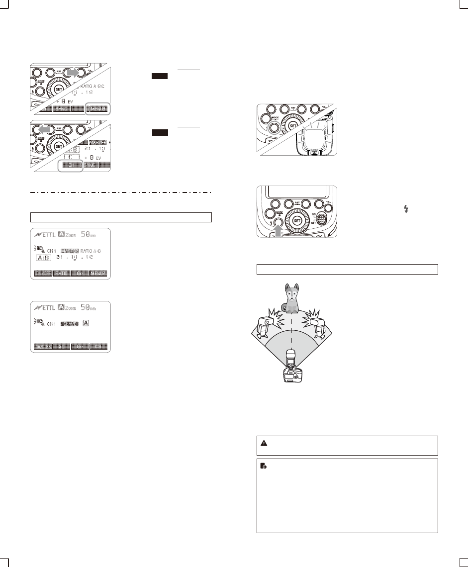
3. Setting the Communication Channel
If there are other wireless flash systems nearby, you can change the
channel IDs to prevent signal interference. The channel IDs of the
master unit and the slave unit(s) must be set to the same.
Press Function Button 4 so
1that < > is displayed
on the LCD panel.
Press Function Button 1 so
2that < > is displayed
on the LCD panel. Turn the
Select Dial to choose a
channel ID from 1 to 4.
Press the <SET> button to
3confirm.
4. ETTL:Fully Automatic Wireless Flash Shooting
Using Automatic Wireless Flash with a Single Slave Unit
Master Unit Setting
1● Attach a V860IIC camera
flash on the camera and
set it as the master unit.
●As a master unit, V860IIC
can control Canon
speedlites e.g. 580EXII,
600EX-RT via wireless.
Slave Unit Setting
2● Set the other camera flash
as the wireless slave Unit.
● As a slave unit, V860IIC
can receive wireless signals
of Canon speedlites e.g.
580EXII, 600EX-RT and
commanders of Canon
cameras e.g. 7D/60D/600D.
Check the communication
3channel.
● If the master unit and slave
unit(s) are set to a different
channel, set them to the
same channel. (Page 47)
Position the camera and
4flashes.
● Position the camera and
flashes as the picture
shows. (Page 46)
MENU3
CH
Set the master unit’s flash
5mode to <ETTL>.
● Set the master unit’s flash
mode to <ETTL>.
● For shooting, <ETTL> will
automatically be set for the
slave unit.
● Set the master unit flash
firing as ON to fire a flash.
Check that the flash is
6ready.
● Check that the master flash
ready indicator is lightened.
● When the slave flash ready
indicator is ready, the AF-
assist beam lighting area
will blinks at 1 second
intervals.
Check the flash operation.
7● Press the master unit’s
Test Button < >.
● Then, the slave unit will
fire. If not, adjust the slave
unit’s angle toward the
master unit and distance
from the master unit.
Using Automatic Wireless Flash with Multiple Slave Units
When stronger flash output or
more convenient lighting operation
is needed, increase the number of
slave units and set it as a single
slave unit.
To add slave units, use the same
steps as setting “automatic
wireless flash with a single slave
unit”. Any flash group can be set
(A/B/C).
When the number of slave units is
increased and the master unit
flash firing is ON, automatic
control is implemented to make all
groups of flashes fire the same
flash output and ensure the total
flash output up is to standard
exposure.
The slave unit might be out of order or fire an unwanted flash due to the
nearby fluorescent lamp or computer screen.
● Press the depth-of-field preview button on the camera to fire a modeling
flash.
● If the slave unit’s auto power off function is workable, press the master
unit’s test button to power it on. Please note that test firing is unavailable
during the camera’s regular metering time.
● The effective time of slave auto power off is changeable. (C.Fn-Sv APOT
Page 57)
● By making some settings, the auto AF-assist transmitter will not blink after
the slave unit’s flash ready indicator is lightened. (C.Fn-AF Page 57)
- 49 - - 50 -
Using Fully Automatic Wireless Flash
The FEC and other settings that set on the master unit will also be
appeared on the slave unit automatically. The slave unit does not
need any operation. Use the following settings to make wireless
flashes according to the same methods with normal flash shooting.
● Flash Exposure Compensation ( Page 40)
● Flash Exposure Bracketing ( Page 41)
● Flash Exposure Lock (Page 41)
● High-Speed Sync ( Page 42)
● Manual Flash (Page 43)
● Stroboscopic Flash (Page 44)
SYNC
FEB
The firing frequency of stroboscopic flash during the optic
transmission shooting can be set from 1Hz to 199Hz.
Press Function Button 4 so that < >、< >和
< > are displayed.
SYNC
FEB
About Master Unit
Use two or more master units. By preparing several cameras that
with master units flash attached, cameras can be changed in
shooting while keeping the same lighting source (slave unit).
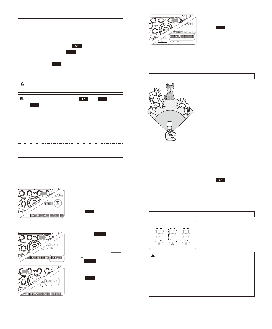
5.ETTL: Use the Wireless Shooting of Flash Ratio
Auto Flash Shooting with Two Slave Unit
Divide the slave units into A and B groups and balance their shooting
illumination (flash ratio).
Auto control exposure to make the total output of A and B flash
groups up to standard exposure.
Setting the flash groups of
1slave unit.
● Set the flash as slave unit.
● Press Function Button 3
< > and choose
<A> or <B>.
● Set one slave unit as <A>,
the other as <B>.
Gr
MENU 2
RATIO
Setting < >.
2● Step 2 to Step 4 are set on
the master unit.
● Press the Function Button
4 on the master unit so that
< > is displayed.
MENU 2
Setting <RATIO A:B>.
3● Press Function Button 2
< > so that
<RATIO A:B> is displayed.
Setting flash ratio.
4● Press Function Button 3
< >.
● Turn the Select Dial to set
the amount of flash ratio
and press<SET> button to
confirm.
Taking the picture.
5● The slave units will flash
according to the flash ratio.
Auto Flash Shooting with Three Slave Unit
Setting <RATIO A:B C>.
2● Use the same method of
step 1 and step 3 (Page
49) to set the master unit
as <RATIO A:B C>.
Setting the slave group
1<C>.
● Use the same method of
step 1 (Page 49) to set the
slave unit of flash
group<C>.
Setting flash exposure
3compensation.
● Use the same method of
step 1 (Page 49) to set the
slave unit of flash
group<C>.
● Press Function Button 2
< >. Turn the Select
Dial to set the amount of
flash exposure
compensation and
press<SET> button to
confirm.
AB
C
About Slave Group Control
If three slave units are all set to
<A> in terms of slave ID, these
slave units will be controlled as if
they were one camera flash in
slave group A.
● When setting < RATIO A:B C >, group A, B and C will fire a
flash synchronously; when setting< RATIO A:B >, group C
will not fire a flash.
● If shooting under the situation that group C is toward the
main shooting subject, over exposure might occurred.
● In some EOS film cameras that support E-TTL autoflash,
you cannot perform multiple flash wireless shooting with a
flash ratio setting.
ID=A ID=A ID=A
Slave Group A
Gr
- 51 - - 52 -
● The flash ratio of 8:1 to 1:1 to 1:8 is equivalent to 3:1 to 1:1
to 1:3 (1/2 step increment).
● The details of the flash ratio settings are as follows.
8:1 4:1 2:1 1:1 1:2 1:4 1:8
5.6:1 2.8:1 1.4:1 1:1.4 1:2.8 1:5.6
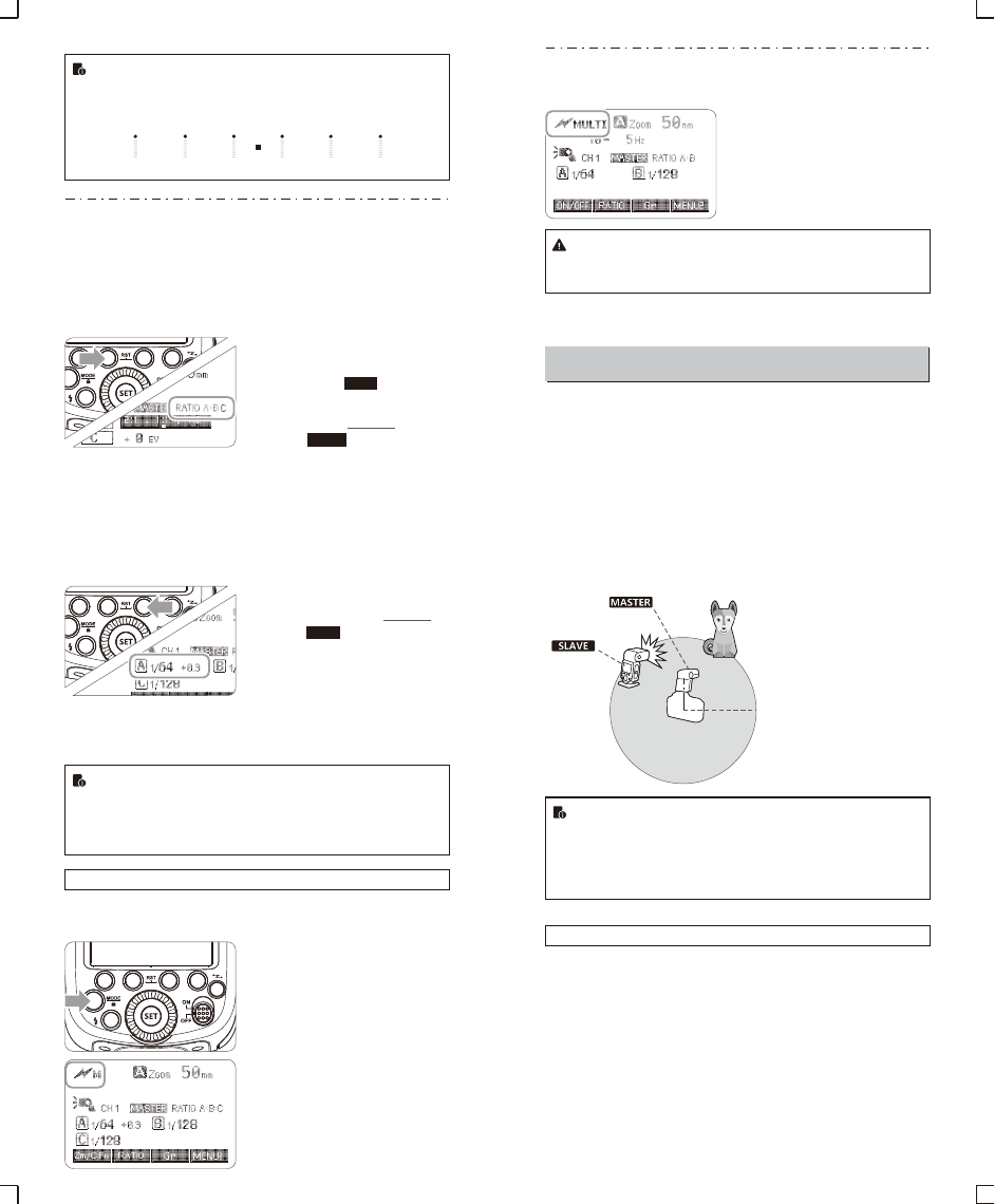
6. M: Wireless Flash Shooting with Manual Flash
This describes wireless (multiple shooting) using manual flash. You
can shoot with a different flash output setting for each slave unit
(firing group). Set all parameters on the master unit.
Setting the number of flash
2groups.
● When < > is
displayed, press the
Function Button 2
< > to set the
groups to fire.
● The setting changes as
follows each time you
press the button:
ALL(RATIO OFF)→
A/B(RATIO A:B)→
A/B/C(RATIO A:B:C)
Setting the flash mode to
1<M>.
RATIO
Setting flash output.
3● Press Function Button 3
< >. Turn the Select
Dial to set the flash output
of the groups. Press
<SET> button to confirm.
Taking the picture.
4● Each group fires at the set
flash ratio.
● When ALL < RATIO OFF > is set, set A, B or C as the firing
group for the slave units.
● To fire multiple slave units with the same flash output,
select ALL < RATIO OFF > in step 2.
Setting <M> Flash Mode
You can directly operate the slave unit to manually set the manual
flash or stroboscopic flash.
Setting the slave unit.
1(Page 46)
Setting flash mode to <M>.
2● Press <MODE> button so
that <M> is displayed.
● Set the manual flash
output. (Page 43)
MENU1
Gr
7. Multi: Wireless Flash Shooting with Manual Flash
Setting <MULTI> stroboscopic
flash.
● Press <MODE> button so that
<MULTI> is displayed.
● Setting the stroboscopic flash.
(Page 44)
The firing frequency of stroboscopic flash during the optic
transmission wireless shooting can be set from 1Hz to 199Hz
(settings from 250 Hz to 500 Hz are not available).
Wireless Flash Shooting: Radio (2.4G) Transmission
Using a flash (master/slave) with a radio transmission wireless
shooting function make it easy to shoot with advanced wireless
multiple flash lighting, in the same way as E-TTL II autoflash
shooting.
The basic relative position and operation range are as shown in the
picture. You can then perform wireless E-TTL II /ETTL autoflash
shooting just by setting the master unit to <ETTL>.
Positioning and Operation Range (Example of wireless flash
shooting)
● Autoflash Shooting with One Slave Unit
● Use the supplied mini stand to position the slave unit.
● Before shooting, perform a test flash and test shooting.
● The transmission distance might be shorter depending on
the conditions such as positioning of slave units, the
surrounding environment and whether conditions.
Transmission distance is about 100m.
You can divide the slave units into two or three groups and perform
E-TTL II/E-TTL autoflash while changing the flash ratio (factor). In
addition, you can set and shoot with a different flash mode for each
firing group, for up to 5 groups.
● Auto Shooting with Two Slave Groups
Wireless Multiple Flash Shooting
A
B
Wireless shooting using radio transmission has advantages over
wireless shooting using optic transmission, such as being less affected
by obstacles, and not having to point the slave unit’s wireless sensor
toward the master unit. The main functional differences are as follows:
Function
Distance
Channel
A/B/C Power
Radio Transmission
100m
1~32
OFF,1/128~1/1
Optic Transmission
15m
1~4
1/128~1/1
A
B
C
● Auto Shooting with Two Slave Groups
● Auto Shooting with Three Slave Groups
- 53 - - 54 -
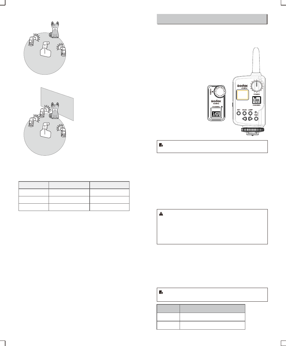
Other Applications
Wireless Control Function
The flash unit is built in with a Wireless Control Port so that you can
wirelessly adjust the power level of the flash and the flash triggering.
To control the flash wirelessly, you need a FT-16S
remote control set (on-camera and on-flash).
Insert its receive end into the Wireless Control
Port on the flash and insert the transmit end into
the camera hot shoe. Settings made on the
hotshoe-mounted transmit and receive ends
will be wirelessly communicated
to the flash. Then you can
press the camera shutter
release button to trigger
the flash. You can also hold
the transmit end at hand to
control your off-camera flash.
For full instructions on the use of FT series remote control, see its user
manual.
Sync Triggering
The Sync Cord Jack is a Φ2.5mm plug. Insert a trigger plug here
and the flash will be fired synchronously with the camera shutter.
Modeling Flash
If the camera has a depth-of-field preview button, pressing it will fire
the flash continuously for 1 second. This is called modeling flash.
It enables you to see the shadow effects on the subject and the
lighting balance. You can fire the modeling flash during wireless or
normal flash shooting.
● To avoid overheating and deteriorating the flash head, do
not fire the modeling flash for more than 10 consecutive
times. If you fire the modeling flash 10 consecutive times,
allow at least 10 minutes’ break for the camera flash.
● The modeling flash cannot be fired with the EOS 300 and
Type-B cameras.
Auto Focus Assist Beam
In poorly-lit or low-contrast shooting environments, the built-in auto
focus assist beam will automatically light on to make it easier for
autofocus. The beam will light up only when autofocus is difficult
and get out as soon as the autofocus becomes correct.
If you want to turn off the auto focus assist beam, set the “AF” to
“OFF” on the C.Fn settings.
● If you find the auto focus assist beam does not light up, this
is because the camera has got a correct autofocus.
Position
Center
Periphery
Effective Range
0.6~10m / 2.0~32.8 feet
0.6~5m / 2.0~16.4 feet
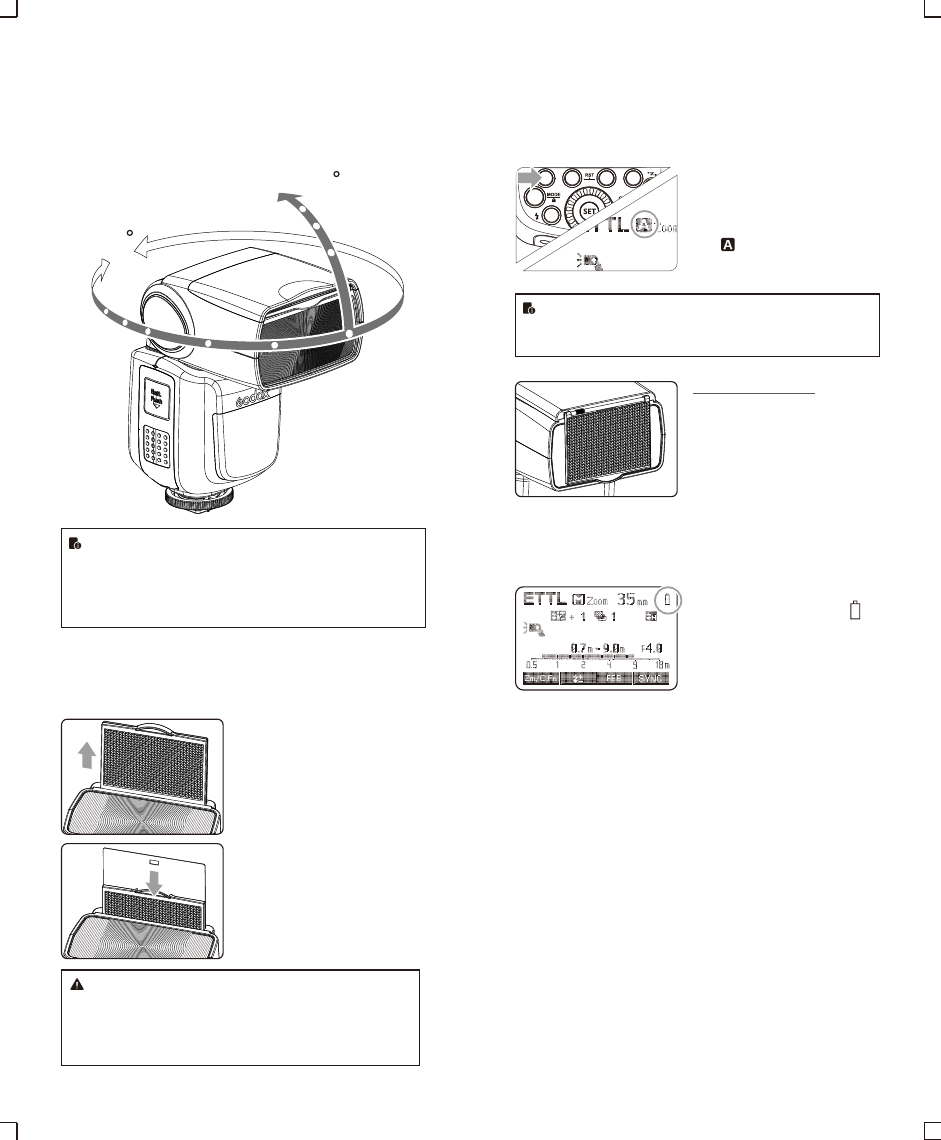
Bounce Flash
By pointing the flash head toward a wall or ceiling, the flash will
bounce off the surface before illuminating the subject. This can
soften shadows behind the subject for a more natural-looking shot.
This is called bounce flash.
To set the bounce direction, hold the flash head and turn it to a
satisfying angle.
360
-7-90
● If the wall or ceiling is too far away, the bounced flash might
be too weak and result in underexposure.
● The wall or ceiling should be a plain, white color for high
reflectance. If the bounce surface is not white, a color cast
may appear in the picture.
Creating a Catchlight
With the catchlight panel, you can create a catchlight in the subject’s
eyes to add life to the facial expression.
Point the flash head upward
1by 90°.
Pull out the wide panel. The
2catchlight panel will come out
at the same time.
Push the wide panel back in.
3
● Push in only the wide panel.
● Follow the same procedures
as for bounce flash.
● Point the flash head straight ahead and then upward by
90°. The catchlight will not appear if you swing the flash
head left or right.
● For best catchlight effect, stay 1.5m/4.9ft away from the
subject.
- 55 - - 56 -
ZOOM: Setting the Flash Coverage and Using
the Wide Panel
The flash coverage can be set automatically or manually. It can be
set to match the lens focal length from 20 mm to 200mm. Also, with
the built-in wide panel, the flash coverage can be expanded for
14mm wide-angle lenses.
In Manual Zoom mode, press the
<ZOOM/C.FN> button.
● Turn the Select Dial to change
the flash coverage.
● If < > is displayed, the flash
coverage will be set
automatically.
If you set the flash coverage manually, make sure it covers
the lens focal length so that the picture will not have a dark
periphery.
Using the Wide Panel
Pull out the wide panel and place it
over the flash head as shown. The
flash coverage will then be extended
to 14 mm.
● The catchlight panel will come out
at the same time. Push the
catchlight panel back in.
● The <ZOOM/C.FN> button will not
work.
Low Battery Warning
If the battery power is low, < >
will appear and blink on the LCD
panel. Please replace the battery
immediately.
0 →− → +
- → 0 → +
C.Fn: Setting Custom Functions
The following table lists the available and unavailable custom
functions of this flash.
m/ft
APO
FEB ACL
FEB
AF
Sv APOT
BEEP
LIGHT
LCD
m
ft
ON
OFF
ON
OFF
ON
OFF
60min
30min
ON
OFF
12sec
OFF
ON
0~9
Distance indicator
Auto power off
FEB auto cancel
FEB order
AF-assist beam
Slave auto power
off timer
Beeper
Backlighting time
LCD contrast ratio
C.Fn-00
C.Fn-01
C.Fn-03
C.Fn-04
C.Fn-08
C.Fn-10
C.Fn-20
C.Fn-22
- 57 - - 58 -
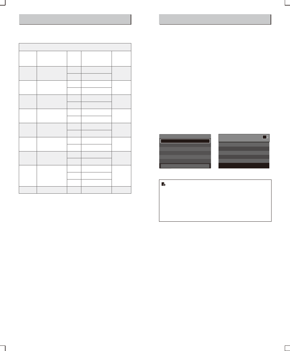
C.Fn Custom Functions
Custom
Function
Signs
Function Setting
No.
Settings &
Description
Custom
Functions
No.
m
feet
ON
OFF
ON
OFF
ON
OFF
60min
30min
ON
OFF
Off in 12 sec.
Always off
Always lighting
10 levels
1. Press <Zm/C.Fn> Backlight/Custom Setting Button for 2 seconds
or longer until C.Fn menu is displayed. The “Ver x.x” in the top-
right corner refers to the software version.
2. Select the Custom Function No.
● Turn the Select Dial to select the Custom Function No.
3. Change the Setting.
● Press<SET> button and the Setting No. blinks.
● Turn the Select Dial to set the desired number. Pressing <SET>
button will confirm the settings.
● After you set the Custom Function and press <MODE> button,
the camera will be ready to shoot.
4. In the C.Fn states, long press the “Clear”button for 2 seconds
until “OK”is displayed on the panel, which means the values in
C.Fn can be reset.
Control with the Camera’s Menu Screen
If the camera flash is attached to an EOS camera which has a
speedlite control function, the flash can be controlled using the
camera’s menu screen. For the menu operation procedure, refer to
your camera’s instruction manual.
Setting Camera Flash Functions ●
The following flash functions are settable according to different
flash modes.
1. Flash mode
2. Shutter sync (1st/2nd curtain, high speed sync)
3. FEB
4. Flash exposure compensation
5. Flash firing
6. Clear camera flash’s settings
Custom Functions of Camera Flash●
C.Fn-00, C.Fn-01, C.Fn-03, C.Fn-04, C.Fn-08, C.Fn-10, C.Fn-20,
and C.Fn-22.
Clear All Flash Custom Functions
Flash function settings screen Flash C.Fn settings screen
● If flash exposure compensation has already been set with
the camera flash, flash exposure compensation cannot be
set with the camera. To set it with the camera, the camera
flash’s flash exposure compensation must be set to zero.
● If any Flash Custom Functions and flash settings other
than flash exposure compensation have been set by both
the camera and the flash, the latest settings will take effect.
Flash C.Fn settings
Auto powe off 1
0:Enabled
1:Disabled
0 1 2 3 4 5 6 7 8 9 10 11 12 13
0 0 0 0 0 0 0 0 0 0 0 0 0 0
-
Flash function settings
Shutter syne.
FEB
Flash exp. comp
E-TTL II
Flash firing
Clear Speedlite Settings
Flash mode
E-TTL II
1st curtain
-3.2.1.0.1.2.3
-3.2.1.0.1.2.3
Evaluative
Enable
-
-
* Screens from the EOS-1D Mark III.
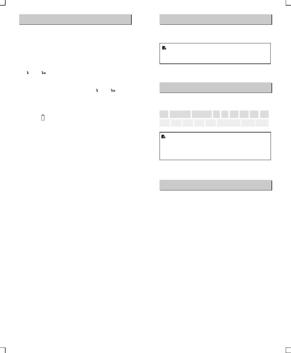
Protection Function
1. Over-Temperature Protection
● To avoid overheating and deteriorating the flash head, do not fire
more than 30 continuous flashes in fast succession at 1/1 full
power. After 30 continuous flashes, allow a rest time of at least 10
minutes.
● If you fire more than 30 continuous flashes and then fire more
flashes in short intervals, the inner over-temperature protection
function may be activated and make the recycling time over 10
seconds. If this occurs, allow a rest time of about 10 minutes, and
the flash unit will then return to normal.
● When the over-temperature protection is started, is shown on
the LCD display.
Number of flashes that will activate over-temperature
protection:
Meaning
A failure occurs on the recycling system so that the
flash cannot fire.
Please restart the flash unit. If the problem still exists,
please send this product to a maintenance center.
The system gets excessive heat. Please allow a rest
time of 10 minutes.
The voltage on two outlets of the flash tube is too high.
Please send this product to a maintenance center.
There are some errors occurred during the upgrading
process. Please using the correct firmware upgrade
method.
Prompts on LCD Panel
E1
E2
E3
E9
- 59 - - 60 -
2. Other Protections
The system provides real-time protection to secure the device and
your safety. The following lists prompts for your reference:
Number of flashes that will activate over-temperature
protection in high-speed sync triggering mode:
Power Output Level
1/1
1/2 +0.7
1/2 +0.3
1/2
1/4(+0.3,+0.7)
1/8(+0.3,+0.7)
1/16(+0.3,+0.7)
1/32(+0.3,+0.7)
1/64(+0.3,+0.7)
1/128(+0.3,+0.7)
Number of Flashes
30
40
50
60
100
200
300
500
1000
Power Output
1/1
1/2(+0.3,+0.7);
1/4(+0.3,+0.7)
1/8(+0.3,+0.7);
1/16(+0.3,+0.7)
1/32(+0.3,+0.7);
1/64(+0.3,+0.7);
1/128(+0.3,+0.7);
Times
15
20
30
40
50
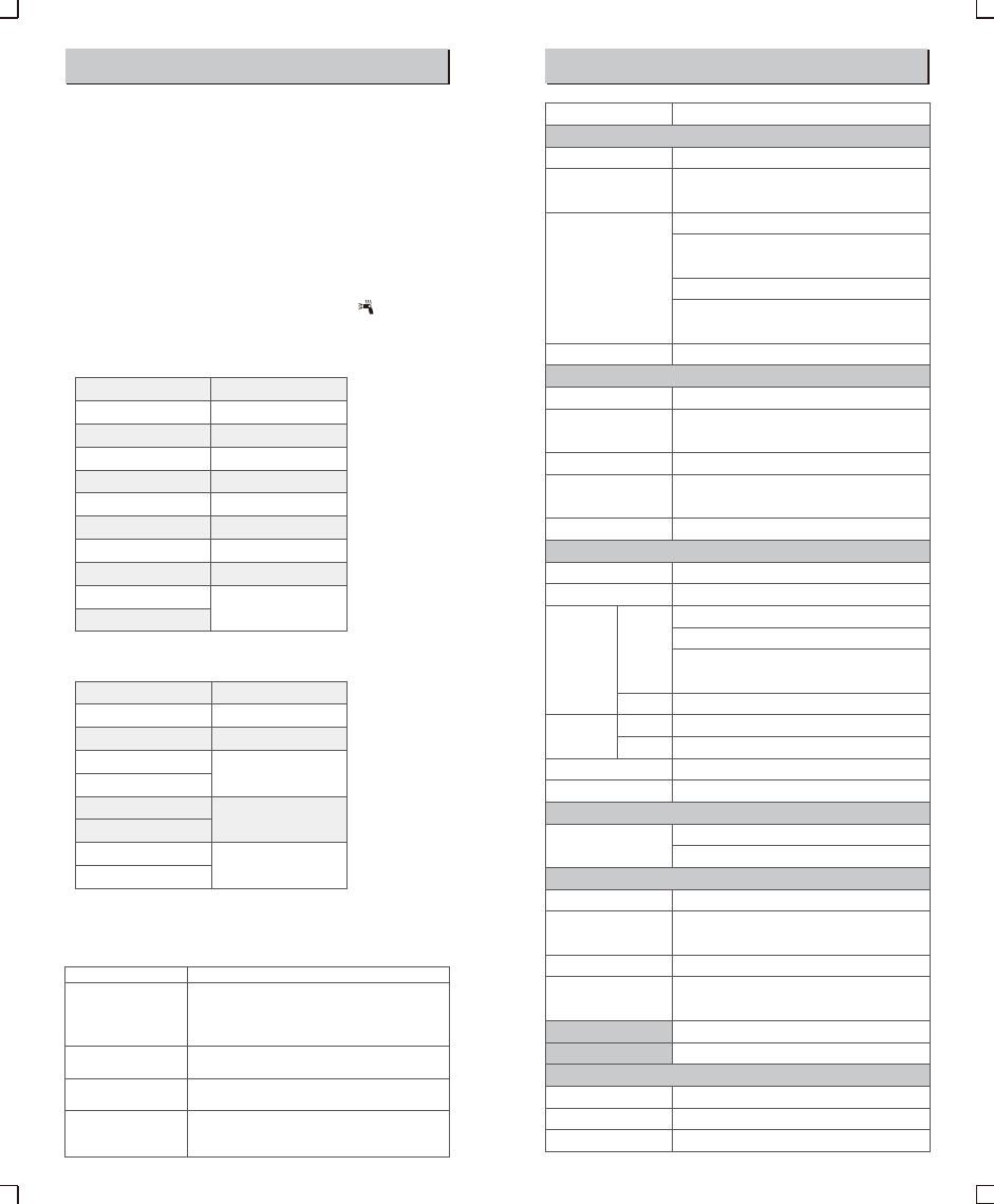
Technical Data
V860IIC
Canon EOS cameras (E-TTL II autoflash)
60 (m ISO 100)
190 (feet ISO 100)
20 to 200mm (14mm with wide panel)
• Auto zoom (Flash coverage set automatically
to match the lens focal length and image size)
• Manual zoom
• Swinging/tilting flash head (bounce flash): 0 to 360°
horizontally and -7° to 90° vertically
1/300 to 1/20000 seconds
E-TTL II autoflash and manual flash
Manual. FEB: ±3 stops in 1/3 stop increments
(Manual FEC and FEB can be combined.)
With <FEL> button or< * > button
High-speed sync (up to 1/8000 seconds),
first-curtain sync, and second-curtain sync
Provided (up to 100 times, 199Hz)
Master, Slave, Off
3 (A, B, and C)
Indoors: 12 to 15 m / 39.4 to 49.2 ft.
Outdoors: 8 to 10 m / 26.2 to 32.8 ft.
Master unit reception angle: ±40° horizontally,
±30° vertically
100m
4 (1, 2, 3, and 4)
32 (1~32)
Two red indicators blink
Fired with camera’s depth-of-field preview button
Center: 0.6~10m / 2.0~32.8 feet
Periphery: 0.6~5m / 2.0~16.4 feet
11.1V/2000mAh Li-ion polymer battery
<1.5 seconds. Red LED indicator will light up when the
flash is ready.
Approx. 650
Power off automatically after approx. 90 seconds
of idle operation. (60 minutes if set as slave)
Hotshoe, 2.5mm sync line, Wireless control port
5600±200k
64*76*190 mm
430g
540g
Model
• Type
Compatible Cameras
Guide No.
(1/1 output @ 200mm)
Flash Coverage
Flash Duration
• Exposure Control
Exposure control system
Flash exposure
compensation (FEC)
FE lock
Sync mode
Multi flash
• Wireless Flash
Wireless flash function
Controllable slave groups
Transmission Optic
range
(approx.)
2.4G
Channels Optic
2.4G
Slave-ready indicator
Modeling flash
• Auto Focus Assist Beam
Effective range (approx.)
• Power Supply
Power source
Recycle time
Full power flashes
Power saving
• Sync Triggering Mode
• Color Temperature
• Dimensions
W x H x D
Weight without battery
Weight with battery
Troubleshooting
If there is a problem, refer to this Troubleshooting Guide.
The Camera Flash does not fire.
● The camera flash is not attached securely to the camera.
→Attach the camera’s mounting foot securely to the camera.
● The electrical contacts of the Camera Flash and camera are dirty.
→Clean the contacts.
● < > or < > is not displayed in the view finder of camera.
→Wait until the flash is fully recycled and the flash ready indicator
lights up.
→If the flash ready indicator lights up, but < > or < > is not
displayed in the view finder, check whether this flash unit is
securely attached to the camera hotshoe.
→If the flash ready indicator does not light up after a long wait,
check whether the battery power is enough. If the battery power
is low, < > will appear and blink on the LCD panel. Please
replace the battery immediately.
The power turns off by itself.
● After 90 seconds of idle operation, auto power off took effect if the
flash is set as master.
→Press the shutter button halfway or press any flash button to
wake up.
● After 60 minutes (or 30 minutes) of idle operation, the flash unit
will enter sleep mode if it is set as slave.
→Press any flash button to wake up.
Auto zoom does not work.
● The camera flash is not attached securely to the camera.
→Attach the camera flash’s mounting foot to the camera.
The flash exposure is underexposed or overexposed.
● There was a highly reflective object (e.g. glass window) in the
picture.
→Use FE lock (FEL).
● You used high-speed sync.
→With high-speed sync, the effective flash range will be shorter.
Make sure the subject is within the effective flash range
displayed.
● You used Manual Flash mode.
→Set the flash mode to ETTL or modify the flash output.
Photos have dark corners or only parts of the target subject
are illuminated.
● The focal length of lens exceeds the flash coverage.
→Check the flash coverage you set. This flash unit has the flash
coverage between 20 and 200mm, which fits medium-format
cameras. Pull the wide panel out to extend the flash coverage.
- 61 - - 62 -
Firmware Upgrade
This flash supports firmware upgrade through the USB port. Update
information will be released on our official website.
USB connection line is not included in this product. The USB
port is a standard Micro USB socket. Common USB
connection line is applicable.
Compatible Camera Models
This flash unit can be used on the following
Canon EOS series camera models:
This table only lists the tested camera models, not all Canon
EOS series cameras. For the compatibility of other camera
models, a self-test is recommended.
Rights to modify this table are retained.
● Shut down the device immediately should abnormal operation be
detected.
● Avoid sudden impacts and the product should be dedusted
regularly.
● It is normal for the flash tube to be warm when in use. Avoid
continuous flashes if unnecessary.
● Maintenance of the flash must be performed by our authorized
maintenance department which can provide original accessories.
● This product, except consumables e.g. flash tube, is supported
with a one-year warranty.
● Unauthorized service will void the warranty.
● If the product had failures or was wetted, do not use it until it is
repaired by professionals.
● Changes made to the specifications or designs may not be
reflected in this manual.
Maintenance
5D Mark III 5D Mark II 6D 7D 60D 50D 40D 30D
650D 600D 550D 500D 450D 400D Digital 1100D 1000D
1DX
*RF warning:
This equipment complies with FCC radiation exposure limits set forth for an
uncontrolled environment. This equipment should be installed and operated with
minimum distance 20cm between the radiator & your body.
