VC 1 Decoder On IVAHD VC1 User Guide
User Manual:
Open the PDF directly: View PDF ![]() .
.
Page Count: 114 [warning: Documents this large are best viewed by clicking the View PDF Link!]

i
VC1 Advanced Profile Decoder on
IVAHD and M3 Based Platform
User’s Guide
Literature Number: SPRUH52
May 2018

ii
IMPORTANT NOTICE
Texas Instruments Incorporated and its subsidiaries (TI) reserve the right to make corrections, enhancements, improvements and other changes
to its semiconductor products and services per JESD46, latest issue, and to discontinue any product or service per JESD48, latest issue. Buyers
should obtain the latest relevant information before placing orders and should verify that such information is current and complete. All
semiconductor products (also referred to herein as “components”) are sold subject to TI’s terms and conditions of sale supplied at the time of
order acknowledgment.
TI warrants performance of its components to the specifications applicable at the time of sale, in accordance with the warranty in TI’s terms and
conditions of sale of semiconductor products. Testing and other quality control techniques are used to the extent TI deems necessary to support
this warranty. Except where mandated by applicable law, testing of all parameters of each component is not necessarily performed.
TI assumes no liability for applications assistance or the design of Buyers’ products. Buyers are responsible for their products and applications
using TI components. To minimize the risks associated with Buyers’ products and applications, Buyers should provide adequate design and
operating safeguards.
TI does not warrant or represent that any license, either express or implied, is granted under any patent right, copyright, mask work right, or other
intellectual property right relating to any combination, machine, or process in which TI components or services are used. Information published by
TI regarding third-party products or services does not constitute a license to use such products or services or a warranty or endorsement thereof.
Use of such information may require a license from a third party under the patents or other intellectual property of the third party, or a license
from TI under the patents or other intellectual property of TI.
Reproduction of significant portions of TI information in TI data books or data sheets is permissible only if reproduction is without alteration and is
accompanied by all associated warranties, conditions, limitations, and notices. TI is not responsible or liable for such altered documentation.
Information of third parties may be subject to additional restrictions.
Resale of TI components or services with statements different from or beyond the parameters stated by TI for that component or service voids all
express and any implied warranties for the associated TI component or service and is an unfair and deceptive business practice. TI is not
responsible or liable for any such statements.
Buyer acknowledges and agrees that it is solely responsible for compliance with all legal, regulatory and safety-related requirements concerning
its products, and any use of TI components in its applications, notwithstanding any applications-related information or support that may be
provided by TI. Buyer represents and agrees that it has all the necessary expertise to create and implement safeguards which anticipate
dangerous consequences of failures, monitor failures and their consequences, lessen the likelihood of failures that might cause harm and take
appropriate remedial actions. Buyer will fully indemnify TI and its representatives against any damages arising out of the use of any TI
components in safety-critical applications.
In some cases, TI components may be promoted specifically to facilitate safety-related applications. With such components, TI’s goal is to help
enable customers to design and create their own end-product solutions that meet applicable functional safety standards and requirements.
Nonetheless, such components are subject to these terms.
No TI components are authorized for use in FDA Class III (or similar life-critical medical equipment) unless authorized officers of the parties have
executed a special agreement specifically governing such use.
Only those TI components which TI has specifically designated as military grade or “enhanced plastic” are designed and intended for use in
military/aerospace applications or environments. Buyer acknowledges and agrees that any military or aerospace use of TI components which
have not been so designated is solely at the Buyer's risk, and that Buyer is solely responsible for compliance with all legal and regulatory
requirements in connection with such use.
TI has specifically designated certain components as meeting ISO/TS16949 requirements, mainly for automotive use. In any case of use of non-
designated products, TI will not be responsible for any failure to meet ISO/TS16949.
Products Applications
Audio www.ti.com/audio Automotive & Transportation www.ti.com/automotive
Amplifiers amplifier.ti.com Communications & Telecom www.ti.com/communications
Data Converters dataconverter.ti.com Computers & Peripherals www.ti.com/computers
DLP® Products www.dlp.com Consumer Electronics www.ti.com/consumer-apps
DSP dsp.ti.com Energy and Lighting www.ti.com/energyapps
Clocks and Timers www.ti.com/clocks Industrial www.ti.com/industrial
Interface interface.ti.com Medical www.ti.com/medical
Logic logic.ti.com Security www.ti.com/security
Power Mgmt power.ti.com Space, Avionics & Defense www.ti.com/space-avionics-defense
Microcontrollers microcontroller.ti.com Video & Imaging www.ti.com/video
RFID www.ti-rfid.com
OMAP Applications Processors www.ti.com/omap TI E2E Community e2e.ti.com
Wireless Connectivity www.ti.com/wirelessconnectivity
Mailing Address: Texas Instruments, Post Office Box 655303, Dallas, Texas 75265
Copyright© 2014, Texas Instruments Incorporated

iii
Preface
Read This First
About This Manual
This document describes how to install and work with Texas Instruments’
(TI) VC1 Advanced profile Decoder implementation on the IVAHD and M3
Based Platform platform. It also provides a detailed Application
Programming Interface (API) reference and information on the sample
application that accompanies this component.
TI’s codec implementations are based on the eXpressDSP Digital Media
(XDM) standard. XDM is an extension of the eXpressDSP Algorithm
Interface Standard (XDAIS).
Intended Audience
This document is intended for system engineers who want to integrate TI’s
codecs with other software to build a multimedia system based on the
IVAHD and M3 Based Platform platform.
This document assumes that you are fluent in the C language, have a
good working knowledge of Digital Signal Processing (DSP), digital signal
processors, and DSP applications. Good knowledge of eXpressDSP
Algorithm Interface Standard (XDAIS) and eXpressDSP Digital Media
(XDM) standard will be helpful.
How to Use This Manual
This document includes the following chapters:
Chapter 1 - Introduction, introduces the XDAIS and XDM standards.
It also provides an overview of the codec and lists its supported
features.
Chapter 2 - Installation Overview, describes how to install, build,
and run the codec.
Chapter 3 - Sample Usage, describes the sample usage of the
codec.
Chapter 4 - API Reference, describes the data structures and
interface functions used in the codec.
Chapter 5 - Frequently Asked Questions, provides answers
frequently asked questions related to using VC1 Advanced Profile
Decoder
Chapter 6 – Debug trace usage, describes how to collect debug
trace information dumped by the decoder.

Read This First
iv
Chapter 7 - Picture Format, describes the format of the output
pictures of the VC1 Decoder on IVAHD.
Chapter 8 - Error handling, describes the error reporting mechanism
of the decoder, also recommends the application behaviour for all
error scenarios.
Chapter 9 – Bit-Stream format, describes the bit-stream formats and
codec expectation and behaviour for different formats.
Chapter 10 – Meta Data Support, provides information on writing out
MB info data into application provided buffers.

Read This First
v
Related Documentation From Texas Instruments
The following documents describe TI’s DSP algorithm standards such as,
XDAIS and XDM. To obtain a copy of any of these TI documents, visit the
Texas Instruments website at www.ti.com.
TMS320 DSP Algorithm Standard Rules and Guidelines (literature
number SPRU352) defines a set of requirements for DSP algorithms
that, if followed, allow system integrators to quickly assemble
production-quality systems from one or more such algorithms.
TMS320 DSP Algorithm Standard API Reference (literature number
SPRU360) describes all the APIs that are defined by the TMS320
DSP Algorithm Inteface Standard (also known as XDAIS)
specification.
Technical Overview of eXpressDSP - Compliant Algorithms for DSP
Software Producers (literature number SPRA579) describes how to
make algorithms compliant with the TMS320 DSP Algorithm Standard
which is part of TI’s eXpressDSP technology initiative.
Using the TMS320 DSP Algorithm Standard in a Static DSP System
(literature number SPRA577) describes how an eXpressDSP-
compliant algorithm may be used effectively in a static system with
limited memory.
eXpressDSP Digital Media (XDM) Standard API Reference (literature
number SPRUEC8)
Using IRES and RMAN Framework Components for C64x+ (literature
number SPRAAI5), describes the IRES interface definition and
function calling sequence
Related Documentation
You can use the following documents to supplement this user guide:
SMPTE 421M: - Proposed SMPTE Standard for Television: VC-1
Compressed Video Bitstream Format and Decoding Process
Abbreviations
The following abbreviations are used in this document.
Table 1-1 List of Abbreviations
Abbreviation
Description

Read This First
vi
Abbreviation
Description
WMV
Windows Media Video
SMPTE
Society Of Motion Picture and Television
Engineers
BIOS
TI’s simple RTOS for DSPs
AC/DC PRED
Prediction of the first DCT co-efficient in
each row and each column of a block from
adjacent blocks
ASF
Advanced Systems Format
CPB
Coded Picture Buffer
CSL
Chip Support Library
D1
720x480 or 720x576 resolutions in
progressive scan
DCT
Discrete Cosine Transform
DMA
Direct Memory Access
DMAN
DMA Manager
DPB
Decoded Picture Buffer
EVM
Evaluation Module
IDR
Instantaneous Decoding Refresh
HDTV
High Definition Television
VC-1
SMPTE 421M approved standard for
Television.
VLC
Variable Length Coding
IRES
Interface standard to request and receive
handles to resources
ITU-T
International Telecommunication Union
IVA
Image Video Accelerator
SMPTE
Society of Motion Picture and Television
Engineers
MB
Macro Block
MV
Motion Vector
NTSC
National Television Standards Committee
RMAN
Resource Manager

Read This First
vii
Abbreviation
Description
RTOS
Real Time Operating System
VGA
Video Graphics Array (640 x 480
resolution)
VOP
Video Object Plane
XDAIS
eXpressDSP Algorithm Interface Standard
XDM
eXpressDSP Digital Media
YUV
Color space in luminance and
chrominance form
Text Conventions
The following conventions are used in this document:
Text inside back-quotes (‘‘) represents pseudo-code.
Program source code, function and macro names, parameters, and
command line commands are shown in a mono-spaced font.
Product Support
When contacting TI for support on this codec, quote the product name
(VC1 Advanced Profile Decoder on IVAHD and M3 Based Platform) and
version number. The version number of the codec is included in the title of
the Release Notes that accompanies this codec.
Trademarks
Code Composer Studio, the DAVINCI Logo, DAVINCI, DSP/BIOS,
eXpressDSP, TMS320, TMS320C64x, TMS320C6000, and
TMS320C64x+ are trademarks of Texas Instruments.
All trademarks are the property of their respective owners.

viii
Contents
PREFACE ....................................................................................................................................... III
READ THIS FIRST ......................................................................................................................... III
ABOUT THIS MANUAL ..................................................................................................................... III
INTENDED AUDIENCE ..................................................................................................................... III
HOW TO USE THIS MANUAL ........................................................................................................... III
RELATED DOCUMENTATION FROM TEXAS INSTRUMENTS .................................................................. V
RELATED DOCUMENTATION ............................................................................................................. V
ABBREVIATIONS .............................................................................................................................. V
TEXT CONVENTIONS ..................................................................................................................... VII
PRODUCT SUPPORT ..................................................................................................................... VII
TRADEMARKS ............................................................................................................................... VII
CONTENTS .................................................................................................................................. VIII
FIGURES ........................................................................................................................................ XI
TABLES ........................................................................................................................................ XII
INTRODUCTION .......................................................................................................................... 1-1
1.1 OVERVIEW OF XDAIS, XDM, AND IRES ......................................................................... 1-2
1.1.1 XDAIS Overview ..................................................................................................... 1-2
1.1.2 XDM Overview ........................................................................................................ 1-3
1.1.3 IRES Overview ........................................................................................................ 1-4
1.2 OVERVIEW OF VC1 ADVANCED PROFILE DECODER ......................................................... 1-5
1.3 SUPPORTED SERVICES AND FEATURES .......................................................................... 1-8
INSTALLATION OVERVIEW ....................................................................................................... 2-1
2.1 SYSTEM REQUIREMENTS ............................................................................................... 2-2
2.1.1 Hardware ................................................................................................................ 2-2
2.1.2 Software .................................................................................................................. 2-2
2.2 INSTALLING THE COMPONENT ......................................................................................... 2-2
2.3 BEFORE BUILDING THE SAMPLE TEST APPLICATION ........................................................ 2-4
2.3.1 Installing Framework Component (FC) ................................................................... 2-5
2.4 BUILDING AND RUNNING THE SAMPLE TEST APPLICATION ................................................ 2-6
2.4.1 Building the Sample Test Application ..................................................................... 2-6
2.4.2 Running the Sample Test Application on OMAP4 ES1.0 ....................................... 2-6
2.4.3 Running the Sample Test Application on OMAP4 IVAHD Simulator ..................... 2-7
2.5 CONFIGURATION FILES .................................................................................................. 2-8
2.5.1 Generic Configuration File ...................................................................................... 2-8
2.5.2 Decoder Configuration File ..................................................................................... 2-9
2.6 UNINSTALLING THE COMPONENT .................................................................................. 2-10
SAMPLE USAGE ......................................................................................................................... 3-1
3.1 OVERVIEW OF THE TEST APPLICATION ............................................................................ 3-2
3.1.1 Parameter Setup ..................................................................................................... 3-3
3.1.2 Algorithm Instance Creation and Initialization ........................................................ 3-3
ix
3.1.3 Process Call ............................................................................................................ 3-4
3.1.4 Algorithm Instance Deletion .................................................................................... 3-6
3.2 FRAME BUFFER MANAGEMENT BY APPLICATION .............................................................. 3-6
3.2.1 Frame Buffer Input and Output ............................................................................... 3-6
3.2.2 Frame Buffer Format ............................................................................................... 3-7
3.2.3 Frame Buffer Management by Application ............................................................. 3-7
3.3 HANDSHAKING BETWEEN APPLICATION AND ALGORITHM ................................................. 3-8
3.4 ADDRESS TRANSLATIONS ............................................................................................. 3-10
3.5 SAMPLE TEST APPLICATION ......................................................................................... 3-10
API REFERENCE......................................................................................................................... 4-1
4.1 SYMBOLIC CONSTANTS AND ENUMERATED DATA TYPES.................................................. 4-2
4.2 DATA STRUCTURES ..................................................................................................... 4-10
4.2.1 Common XDM Data Structures ............................................................................ 4-10
4.2.2 VC1 Decoder Data Structures .............................................................................. 4-23
4.3 DEFAULT AND SUPPORTED PARAMETERS ...................................................................... 4-30
4.3.1 Default and supported values of IVIDDEC3_params ........................................... 4-30
4.3.2 Default and supported values of IVIDDEC3_DynamicParams ............................. 4-31
4.3.3 Default and supported values of IVC1VDEC_Params ......................................... 4-32
4.3.4 Default and supported values of IVC1VDEC_DynamicParams ........................... 4-32
4.4 INTERFACE FUNCTIONS ................................................................................................ 4-33
4.4.1 Creation APIs ........................................................................................................ 4-34
4.4.2 Initialization API .................................................................................................... 4-36
4.4.3 Control API ............................................................................................................ 4-37
4.4.4 Data Processing API ............................................................................................. 4-38
4.4.5 Termination API .................................................................................................... 4-41
FREQUENTY ASKED QUESTIONS............................................................................................ 5-1
5.1 CODE BUILD AND EXECUTION ......................................................................................... 5-1
5.2 ISSUES WITH TOOLS VERSION ........................................................................................ 5-1
5.3 ALGORITHM RELATED .................................................................................................... 5-2
DEBUG TRACE USAGE ............................................................................................................. 6-1
6.1 DEBUG TRACE MEMORY FORMAT IN THE VC1 DECODER ................................................. 6-1
6.2 METHOD TO CONFIGURE DECODER TO COLLECT DEBUG TRACE ........................................ 6-2
6.3 METHOD FOR APPLICATION TO COLLECT DEBUG TRACE .................................................... 6-2
PICTURE FORMAT...................................................................................................................... 7-1
7.1 NV12 CHROMA FORMAT ............................................................................................... 7-1
7.2 PROGRESSIVE PICTURE FORMAT ................................................................................... 7-2
7.3 INTERLACED PICTURE FORMAT ...................................................................................... 7-4
7.4 CONSTRAINTS ON BUFFER ALLOCATION FOR DECODER ................................................... 7-6
ERROR HANDLING ..................................................................................................................... 8-1
8.1 DESCRIPTION ................................................................................................................ 8-1
8.1.1 Error Codes used to set the extendedError field in IVIDDEC3_OutArgs and
IVIDDEC3_Status ................................................................................................................ 8-2
8.1.2 Error Codes used to set the extendedErrorCode0, extendedErrorCode1,
extendedErrorCode2, extendedErrorCode3 field in IVC1VDEC_Status ............................. 8-4
BITSTREAM FORMAT ................................................................................................................ 9-1
9.1 SIMPLE AND MAIN PROFILE ............................................................................................ 9-1
9.1.1 Sequence header syntax ........................................................................................ 9-2
9.1.2 Frame header syntax .............................................................................................. 9-2
9.2 ADVANCED PROFILE ...................................................................................................... 9-3

xi
Figures
Figure 1-1. IRES Interface Definition and Function Calling Sequence. .............. 1-5
Figure 1-2. Block Diagram of VC1 Decoder ....................................................... 1-6
Figure 1-3. Working of VC1 Decoder ................................................................. 1-7
Figure 2-1. Component Directory Structure ....................................................... 2-3
Figure 3-1. Test Application Sample Implementation ......................................... 3-2
Figure 3-2. Process call with Host release ......................................................... 3-5
Figure 3-3. Interaction of Frame Buffers Between Application and Framework . 3-7
Figure 3-4. Interaction Between Application and Codec .................................... 3-9

xii
Tables
Table 1-1 List of Abbreviations ............................................................................. v
Table 2-1. Component Directories ..................................................................... 2-4
Table 3-1. Process ( ) Implementation ............................................................. 3-11
Table 4-1. List of Enumerated Data Types ........................................................ 4-2
1-1
Chapter 1
Introduction
This chapter provides a brief introduction to XDAIS and XDM. It also
provides an overview of TI’s implementation of the VC1 Advanced Profile
Decoder on the IVAHD and M3 Based Platform and its supported features.
Topic Page
1.1 Overview of XDAIS, XDM, and IRES
1-2
1.2 Overview of VC1 Advanced Profile Decoder
1-5
1.3 Supported Services and Features
1-8

Introduction
1-2
1.1 Overview of XDAIS, XDM, and IRES
TI’s multimedia codec implementations are based on the eXpressDSP
Digital Media (XDM) standard. XDM is an extension of the eXpressDSP
Algorithm Interface Standard (XDAIS). IRES is the interface for
management and utilization of special resource types such as hardware
accelerators, certain types of memory and DMA. This interface allows the
client application to query and provide the algorithm its requested resources.
1.1.1 XDAIS Overview
An eXpressDSP-compliant algorithm is a module that implements the
abstract interface IALG. The IALG API takes the memory management
function away from the algorithm and places it in the hosting framework.
Thus, an interaction occurs between the algorithm and the framework. This
interaction allows the client application to allocate memory for the algorithm
and also share memory between algorithms. It also allows the memory to be
moved around while an algorithm is operating in the system. In order to
facilitate these functionalities, the IALG interface defines the following APIs:
algAlloc()
algInit()
algActivate()
algDeactivate()
algFree()
The algAlloc() API allows the algorithm to communicate its memory
requirements to the client application. The algInit() API allows the
algorithm to initialize the memory allocated by the client application. The
algFree() API allows the algorithm to communicate the memory to be
freed when an instance is no longer required.
Once an algorithm instance object is created, it can be used to process data
in real-time. The algActivate() API provides a notification to the
algorithm instance that one or more algorithm processing methods is about
to be run zero or more times in succession. After the processing methods
have been run, the client application calls the algDeactivate() API prior
to reusing any of the instance’s scratch memory.
The IALG interface also defines three more optional APIs algControl(),
algNumAlloc(), and algMoved(). For more details on these APIs, see
TMS320 DSP Algorithm Standard API Reference (literature number
SPRU360).
Introduction
1-3
1.1.2 XDM Overview
In the multimedia application space, you have the choice of integrating any
codec into your multimedia system. For example, if you are building a video
decoder system, you can use any of the available video decoders (such as
VC1,MPEG4, H.263, or H.264) in your system. To enable easy integration
with the client application, it is important that all codecs with similar
functionality use similar APIs. XDM was primarily defined as an extension to
XDAIS to ensure uniformity across different classes of codecs (for example
audio, video, image, and speech). The XDM standard defines the following
two APIs:
control()
process()
The control() API provides a standard way to control an algorithm
instance and receive status information from the algorithm in real-time. The
control() API replaces the algControl() API defined as part of the
IALG interface. The process() API does the basic processing
(encode/decode) of data.
Apart from defining standardized APIs for multimedia codecs, XDM also
standardizes the generic parameters that the client application must pass to
these APIs. The client application can define additional implementation
specific parameters using extended data structures.
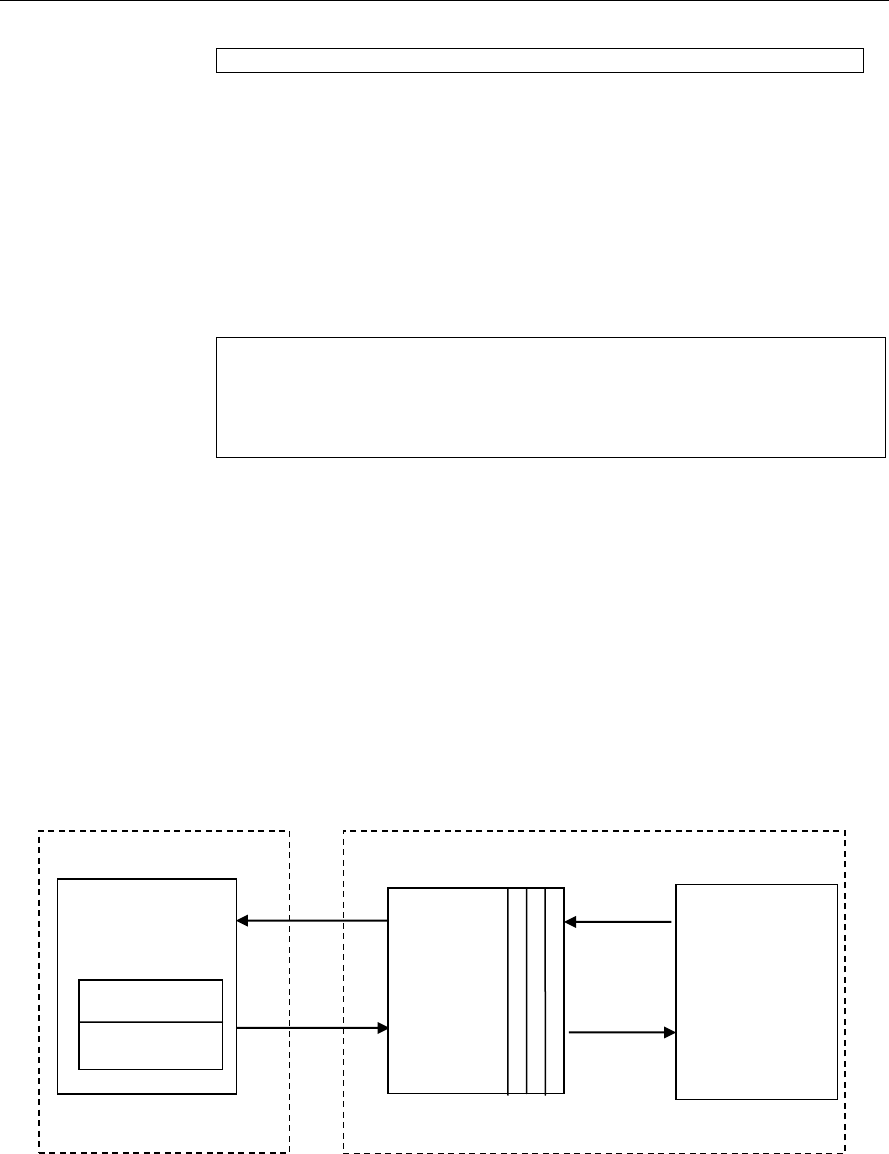
The following figure depicts the XDM interface to the client application.
As depicted in the figure, XDM is an extension to XDAIS and forms an
interface between the client application and the codec component. XDM
insulates the client application from component-level changes. Since TI’s
multimedia algorithms are XDM compliant, it provides you with the flexibility
to use any TI algorithm without changing the client application code. For
example, if you have developed a client application using an XDM-compliant
VC1 video decoder, then you can easily replace VC1 with another XDM-
compliant video decoder, say H.263, with minimal changes to the client
application.
For more details, see eXpressDSP Digital Media (XDM) Standard API
Reference (literature number SPRUEC8).
Client Application
XDAIS Interface (IALG)
TI’s Codec Algorithms
XDM Interface

Introduction
1-4
1.1.3 IRES Overview
IRES is a generic, resource-agnostic, extendible resource query,
initialization and activation interface. The application framework defines,
implements, and supports concrete resource interfaces in the form of IRES
extensions. Each algorithm implements the generic IRES interface, to
request one or more concrete IRES resources. IRES defines standard
interface functions that the framework uses to query, initialize,
activate/deactivate and reallocate concrete IRES resources. To create an
algorithm instance within an application framework, the algorithm and the
application framework agrees on the concrete IRES resource types that are
requested. The framework calls the IRES interface functions, in addition to
the IALG functions, to perform IRES resource initialization, activation, and
deactivation.
The IRES interface introduces support for a new standard protocol for
cooperative preemption, in addition to the IALG-style non-cooperative
sharing of scratch resources. Co-operative preemption allows activated
algorithms to yield to higher priority tasks sharing common scratch
resources. Framework components include the following modules and
interfaces to support algorithms requesting IRES-based resources:
IRES - Standard interface allowing the client application to query and
provide the algorithm with its requested IRES resources.
RMAN - Generic IRES-based resource manager, which manages and
grants concrete IRES resources to algorithms and applications. RMAN
uses a new standard interface, the IRESMAN, to support run-time
registration of concrete IRES resource managers.
Client applications call the algorithm’s IRES interface functions to query its
concrete IRES resource requirements. If the requested IRES resource type
matches a concrete IRES resource interface supported by the application
framework, and if the resource is available, the client grants the algorithm
logical IRES resource handles representing the allotted resources. Each
handle provides the algorithm with access to the resource as defined by the
concrete IRES resource interface.
IRES interface definition and function calling sequence is depicted in the
following figure. For more details, see Using IRES and RMAN Framework
Components for C64x+ (literature number SPRAAI5).
Introduction
1-5
Figure 1-1. IRES Interface Definition and Function Calling Sequence.
For more details, see Using IRES and RMAN Framework Components for C64x+
(literature number SPRAAI5).
1.2 Overview of VC1 Advanced Profile Decoder
VC1 is the Society of Motion Picture and Television Engineers (SMPTE)
standardized video decoder. VC1 consists of three profiles namely,
simple, main, and advanced. Simple and main profiles were developed
for use in lower-bit-rate networked computing environments. VC1
standard defines several profiles and levels that specify restrictions on
the bit stream, and hence limits the capabilities needed to decode the
bit-streams. Each profile specifies a subset of algorithmic features and
limits all decoders conforming to that profile may support. Each level
specifies a set of limits on the values that may be taken by the syntax
elements in the profile.

Introduction
1-6
Figure 1-2. Block Diagram of VC1 Decoder
From this point onwards, all references to VC1 decoder mean VC1
Advanced Profile (AP) decoder only.
Figure 1-3 depicts the working of the VC1 Decoder algorithm.
Introduction
1-7
Figure 1-3. Working of VC1 Decoder
VC1 Advanced Profile Decoder implementation on OMAP4 has two parts:
Core part of the decoding, which includes all frame and slice level
operation and core decoding algorithm. This part is implemented on
IVA-HD sub-system
Interface part of the decoder, which interacts with application and
system software. This part is implemented on M3. All the interfaces to
query algorithm resource needs belongs to this part. This part of the
video codec is exposed to system software and core part is hidden.
Interface part of the video codec communicates with core part of video
codec with private IPC defined in codec software through mailbox.
Framework Components (FC) and Codec
Engine (CE)
RMAN
Callback to make non blocking API
IRES
XDAIS and XDM
IVIDDEC3
Video Codec
(ARM Part)
CSL / IVAHD L0 API
Codec Topology and Hardware Mode Settings (L2 API)
Slice/Frame
Level Operation
Buffer
Management
Video Codec
(IVAHD Part)
Codec Software Stack
Frame Start
Frame End
IPC
IPC
Private and
Generic IPC
Inside
Codec
Software
Cortex M3
ICONT1
ICONT2
Ducati sub-system
IVA-HD sub-system
Hardware Layer

Introduction
1-8
1.3 Supported Services and Features
This user guide accompanies TI’s implementation of VC1 Decoder on the
IVAHD video accelerators.
This version of the codec has the following supported features of the
standard:
eXpressDSP Digital Media (XDM IVIDDEC3) compliant
Uses hardware accelerators of IVAHD
VC1 Advanced Profile up to Level 3 compliant
All features of Simple Profile, Main Profile and Advanced Profile are
supported
Supports Multiple slices
Minimum resolution supported is 64 x 64
Non-multiples of 16 resolutions are also supported
Progressive, Interlaced frame and Interlaced field type picture decoding
supported
Supports all block type partitions and modes
Outputs are available in YUV420 interleaved little Endian format
Tested for compliance with SMPTE reference decoder release 7
Cache aware decoder library
Independent of any OS (DSP/BIOS, Linux, Window CE, Symbian and so
on
Ability to plug in any multimedia frameworks (e.g. Codec engine,
OpenMax, GStreamer, …)
Supports multi-channel functionality.
Supports resolutions from all standard resolutions from QCIF to
1080p/1080i.
All features of Simple Profile, Main Profile and Advanced Profile are
supported
Both RCV(RCV V1, RCV V2) and Elementary stream formats are
supported
Support for error resiliency and error concealment
2-1
Chapter 2
Installation Overview
This chapter provides a brief description on the system requirements and
instructions for installing the codec component. It also provides information
on building and running the sample test application.
Topic Page
2.1 System Requirements
2-2
2.2 Installing the Component
2-2
2.3 Before Building the Sample Test Application
2-4
2.4 Building and Running the Sample Test Application
2-6
2.5 Configuration Files
2-8
2.6 Uninstalling the Component
2-10

Installation Overview
2-2
2.1 System Requirements
This section describes the hardware and software requirements for the
normal functioning of the codec component.
2.1.1 Hardware
This codec (OMAP4 release package) has been built and tested on
OMAP4ES1.
2.1.2 Software
The following are the software requirements for the normal functioning of the
codec:
Development Environment: This project is developed using
CodeComposer Studio (Code Composer Studio v4) version.
4.2.0.09000. Code Composer Studio v4 can be downloaded from the
following location.
http://software-
dl.ti.com/dsps/dsps_registered_sw/sdo_ccstudio/CCSv4/Prereleases/set
up_CCS_4.2.0.09000.zip
Code Generation Tools: This project is compiled, assembled,
archived,and linked using the code generation tools version 4.5.1.
Although CG toolsversion 4.5.1 is a part of Code Composer Studio v4, It
is recommended that you download and install the CG tools from the
following location.
https://www-a.ti.com/downloads/sds_support/CodeGenerationTools.htm
The projects are built using g-make (GNU Make version 3.78.1)
IVAHD Simulator: This codec has been tested using IVAHD simulator
version 5.0.16 (IVAHD simulation CSP 1.1.5). This release can be
obtained by software updates on Code Composer Studio v4. Make sure
that following site is listed as part of Update sites to visit.
http://software-
dl.ti.com/dsps/dsps_public_sw/sdo_ccstudio/CCSv4/Updates/IVAHD/sit
e.xml
2.2 Installing the Component
The codec component is released as a compressed archive. To install the
codec, extract the contents of the zip file onto your local hard disk. The zip
file extraction creates a top-level directory called 500.V.VC1.D.IVAHD.01.00,
under which is directory named IVAHD_001.
Installation Overview
2-3
Figure 2-1. Component Directory Structure

Installation Overview
2-4
Sub-Directory
Description
\inc
Contains XDM related header files which allow interface to the codec
library
\lib
Contains the codec library file
\docs
Contains user guide and datasheet
\client\build\TestAppOmap4
Contains the M3 cmd file.
\client\build\TestAppOmap4\make
Contains the make file for the test application project.
\client\build\TestAppOmap4\map
Contains the memory map generated on compilation of the code
\client\build\TestAppOmap4\obj
Contains the intermediate .asm and/or .obj file generated on compilation
of the code
\client\build\TestAppOmap4\out
Contains the final application executable (.out) file generated by the
sample test application
\client\test\src
Contains application C files
\client\ test\inc
Contains header files needed for the application code
\client\testvecs\config
Contains configuration parameter files
\client\test\testvecs\input
Contains input test vectors
\client\test\testvecs\output
Contains output generated by the codec
\client\test\testvecs\reference
Contains read-only reference output to be used for cross-checking
against codec output
Table 2-1. Component Directories
2.3 Before Building the Sample Test Application
This codec is accompanied by a sample test application. To run the sample
test application, you need TI Framework Components (FC).
This version of the codec has been validated with Framework Component
(FC) version 3.20.00.22 GA.
To run the Simulator version of the codec, the IVAHD simulator has to be
installed. The version of the simulator is 5.0.16. This can be done using the
“Help->Software Updates->Find and Install” option in CCSv4. Detailed
instructions to set up the configuration can be found in
ivahd_sim_user_guide.pdf present in <CCSv4 Installation
Dir>\simulation_csp_omap4\docs\pdf\ directory.

Installation Overview
2-5
This codec has also been validated on Netra Video Processing Simulator
that simulates all the three IVAHDs in DM816x. The simulator required for
this is Netra CSP (Simulation) version 0.7.1. This simulator can also be
installed using the “Help->Software Updates->Find and Install” option in
CCSv4. Detailed instructions to set up the configuration can be found in
netra_sim_user_guide.pdf present in <CCSv4 Installation Dir>\
simulation_netra\docs\user_guide directory.
Install CG Tools version 4.5.1 for ARM (TMS470) at the following location in
your system: <CCSv4_InstallFolder>\ccsv4\tools\compiler\tms470. CGTools
4.5.1 can be downloaded from
https://www-a.ti.com/downloads/sds_support/CodeGenerationTools.htm
Please note that CG Tools 4.5.1 is installed at the location mentioned above
along with the CCS v4 installation by default. But, as some problems have
been reported about this, we recommend that you install CG Tools 4.5.1 again
with the installer obtained from the above link
Set environment variable CG_TOOL_DIR to <cgtools_install_dir>.
<CG_TOOL_DIR>/bin should contain all required code generation tools
executables.
Set environment variables HDVICP2_INSTALL_DIR and
CSP_INSTALL_DIR to the locations where the HDVICP20 API library and
IVAHD CSL are present. The HDVICP20 API library and the IVAHD CSL
can be downloaded from the same place as the codec package. The
HDVICP20 API .lib files should be present at HDVICP2_INSTALL_DIR/lib
and HDVICP20 API interface header files at HDVICP2_INSTALL_DIR/inc.
The folders csl_ivahd and csl_soc of IVAHD CSL should be present at
CSP_INSTALL_DIR/.
This version of the codec has been validated with HDVICP2.0 API library
version 01.00.00.22 and HDVICP2.0 CSL Version 00.05.02.
Set the system environment variable TI_DIR to the CCSv4 installation path.
Example: TI_DIR = <CCSv4 Installation Dir>\ccsv4.
Add gmake (GNU Make version 3.78.1) utility folder path (for example,
“C:\CCStudioV4.0\ccsv4\utils\gmake”) at the beginning of the PATH
environment variable.
The version of the XDC tools required is 3.20.04.68 GA.
2.3.1 Installing Framework Component (FC)
You can download FC from the TI website:
http://software-
dl.ti.com/dsps/dsps_public_sw/sdo_sb/targetcontent/fc/3_20_00_22/index_
FDS.html

Installation Overview
2-6
Extract the FC zip file to the some location and set the system environment
variable FC_INSTALL_DIR to this path. For example: if the zip file was
extracted to C:\CCSv4\, set FC_INSTALL_DIR as C:\CCSv4\
framework_components_3_20_00_22.
The test application uses the following IRES and XDM files:
HDVICP related IRES header files, these are available in the
FC_INSTALL_DIR\packages\ti\sdo\fc\ires\hdvicp directory.
Tiled memory related Header file, these are available in the
FC_INSTALL_DIR\fctools\packages\ti\sdo\fc\ires\tiledmemory
directory.
XDM related header files, these are available in the
FC_INSTALL_DIR\fctools\packages\ti\xdais directory
2.4 Building and Running the Sample Test Application
2.4.1 Building the Sample Test Application
This library release of VC1 Decoder on HDVICP2.0 and M3-based platform
contains the following project.
Project
Make file Path
Output Files
Test
Application
\client\build\TestAppOmap4\make\
\client\build\TestAppOmap4\out
\vc1vdec_ti_host_testapp.out
Verify that the following codec object libraries exist in \lib sub-directory:
vc1vdec_ti_host_M3.lib: VC1 decoder library for Ducati
make file in the project can be built using the following commands.
o gmake –k –s deps
o gmake –k –s all
Use the following command to clean previous builds.
o gmake –k –s clean
2.4.2 Running the Sample Test Application on OMAP4 ES1.0
The sample test application that accompanies this codec component will run
in TI’s Code Composer Studio development environment. To run the sample
test application on OMAP4 ES1.0, follow these steps:
Start Code Composer Studio v4 and set up the target configuration for
OMAP4 ES1.0 Emulator.
Select the Debug perspective in the workbench. Launch OMAP4
ES1.0 Emulator in CCSv4.

Installation Overview
2-7
Select CortexA9_0 device, right click and choose “Connect Target” and
wait for emulator to connect to CortexA9 and execute the GEL file
(omap4430 startup sequence).
Select Cortex_M3_0 device, right click and choose “Connect Target”
and wait for emulator to connect to CortexM3.
Select Cortex_M3_0 device and Target > Load Program, browse to
the \client\build\TestAppOmap4\out\ sub-directory, select the codec
executable “vc1vdec_ti_host_testapp.out” and load it in preparation for
execution.
Select Target > Run to execute the application for Cortex_M3_0
device.
Test application will take input streams from \client\test\testvecs\input\
directory and generates outputs in \client\test\testvecs\output\
directory. Configuration Files
Note:
Order of connecting to the devices is important and it should be as
mentioned in above steps.
2.4.3 Running the Sample Test Application on OMAP4 IVAHD Simulator
The sample test application that accompanies this codec component will run
in TI’s Code Composer Studio development environment. To run the sample
test application on IVAHD Simulator, follow these steps:
Ensure that you have installed IVAHD Simulator version 5.0.16.
Start Code Composer Studio v4 and set up the target configuration for
OMAP4 IVAHD Simulator.
Select the Debug perspective in the workbench. Launch OMAP4
IVAHD Simulator in CCSv4.
Select CORTEX_M3_APP device and Target > Load Program, browse
to the \client\build\TestApp Omap4\out\ sub-directory, select the codec
executable “vc1vdec_ti_host_testapp.out” and load it into Code
Composer Studio in preparation for execution.
Select ICONT1 device and Target > Run to give iCont1 device a free
run.
Select ICONT2 device and Target > Run to give iCont2 device a free
run.
Select CORTEX_M3_APP device and select Target > Run to execute
the application.
Test application will take input streams from \client\test\testvecs\input\
directory and generates outputs in \client\test\testvecs\output\
directory.

Installation Overview
2-8
2.5 Configuration Files
This codec is shipped along with:
Generic configuration file (testvecs.cfg) – specifies input and reference
files for the sample test application.
Decoder configuration file (testparams.cfg) – specifies the configuration
parameters used by the test application to configure the Decoder.
2.5.1 Generic Configuration File
The sample test application shipped along with the codec uses the
configuration file, testvecs.cfg for determining the input and reference files
for running the codec and checking for compliance. The testvecs.cfg file is
available in the \client\test\testvecs\config sub-directory.
The format of the testvecs.cfg file is:
X
Config
Input
Output/Reference
where:
X may be set as:
o 1 - for CRC compliance checking, no output file is created
o 0 - for writing the output to the output file
Config is the Decoder configuration file. For details, see Section 2.5.2.
Input is the input file name (use complete path).
Output/Reference is the output file name (if X is 0) or reference file
name (if X is 1).
A sample testvecs.cfg file is as shown:
1
..\..\..\test\testvecs\config\testparams.cfg
..\..\..\test\testvecs\input\foreman_176x144.rcv
..\..\..\test\testvecs\reference\foreman_176x144.txt
0
..\..\..\test\testvecs\config\testparams.cfg
..\..\..\test\testvecs\input\foreman_176x144.rcv
..\..\..\test\testvecs\output\foreman_176x144.yuv
In compliance mode of operation, the decoder compared the reference and
the generated output and declares Passes/Failed message. If output dump
mode is selected(X set to 0), then the decoder dumps the output to the
specified file.

Installation Overview
2-9
Note:
Compliance test will not work for Interlaced test cases
2.5.2 Decoder Configuration File
The decoder configuration file, testparams.cfg contains the configuration
parameters required for the decoder. The testparams.cfg file is available in
the \client\test\testvecs\config sub-directory.
A sample testparams.cfg file is as shown:
# New Input File Format is as follows
# <ParameterName> = <ParameterValue> # Comment
#
############################################################
##############################
# Parameters
############################################################
##############################
ImageWidth = 1920 # Image width in Pels,
must be multiple of 16
ImageHeight = 1088 # Image height in Pels,
must be multiple of 16
FramesToDecode = 500 # Number of frames to be
decoded
DumpFrom = 0 # Start dumping from
this frame.
isTiler = 0 # 1-> ENable Tiler Memory
Usage for Output Buffers, 0-> Use RAW memory.
debugTraceLevel = 0 # 0,1,2,3,4 are the Valid
Trace Levels.
lastNFramesToLog = 0 # 0 to 10 are the Valid
Values.
metaDataEnable = 1 # 0 -> (Default) 1->
Parsed MetaData
metaDataType = 0 # -1 -> (Default) 0->
Parse MB Info

Installation Overview
2-10
To check the functionality of the codec for the inputs other than those
provided with the release, change the configuration file accordingly with
corresponding input test vector.
Note:
ChromaFormat supported in this codec is 420 semi-planar, that is, the
chroma planes (Cb and Cr) are interleaved.
2.6 Uninstalling the Component
To uninstall the component, delete the codec directory from your hard disk.
3-1
Chapter 3
Sample Usage
This chapter provides a detailed description of the sample test application
that accompanies this codec component.
Topic Page
3.1 Overview of the Test Application
3-2
3.2 Frame Buffer Management by Application
3-6
3.3 Handshaking Between Application and Algorithm
3-8
3.4 Address Translations
3-10
3.5 Sample Test Application
3-10

Sample Usage
3-2
3.1 Overview of the Test Application
The test application exercises the IVIDDEC3 base class of the VC1 Decoder
library. The main test application files are vc1vdec_ti_host_testapp.c and
vc1vdec_ti_ires_app.c. These files are available in the \client\test\src
directory.
Figure 3-1 depicts the sequence of APIs exercised in the sample test
application. Currently, the test application does not use RMAN resource
manager. However, all the resource allocations happens through IRES
interfaces.
Figure 3-1. Test Application Sample Implementation

Sample Usage
3-3
The test application is divided into four logical blocks:
Parameter setup
Algorithm instance creation and initialization
Process call
Algorithm instance deletion
3.1.1 Parameter Setup
Each codec component requires various codec configuration parameters to
be set at initialization. For example, a video codec requires parameters such
as video height, video width, and so on. The test application obtains the
required parameters from the Decoder configuration files.
In this logical block, the test application does the following:
Opens the generic configuration file, Testvecs.cfg and reads the
compliance checking parameter, Decoder configuration file name
(Testparams.cfg), input file name, and output/reference file name.
Opens the Decoer configuration file, (Testparams.cfg) and reads the
various configuration parameters required for the algorithm. For more
details on the configuration files, see Section 2.5.
Sets the IVIDDEC3_Params structure based on the values it reads
from the Testparams.cfg file.
Reads the input bit-stream into the application input buffer.
After successful completion of these steps, the test application does the
algorithm instance creation and initialization.
3.1.2 Algorithm Instance Creation and Initialization
In this logical block, the test application accepts the various initialization
parameters and returns an algorithm instance pointer. The following APIs
are called in sequence:
algNumAlloc() - To query the algorithm about the number of
memory records it requires.
algAlloc() - To query the algorithm about the memory requirement
to be filled in the memory records.
algInit() - To initialize the algorithm with the memory structures
provided by the application.
A sample implementation of the create function that calls algNumAlloc(),
algAlloc(), and algInit() in sequence is provided in the
ALG_create() function implemented in the alg_create.c file.

Sample Usage
3-4
Note:
Decoder requests only one memory buffer through algNumAlloc.
This buffer is for the algorithm handle.
Other memory buffer requirements are done through IRES
interfaces.
After successful creation of the algorithm instance, the test application does
HDVICP Resource and memory buffer allocation for the algorithm.
Currently, RMAN resource manager is not used. However, all the resource
allocations happen through IRES interfaces:
numResourceDescriptors() - To understand the number of
resources (HDVICP and buffers) needed by algorithm.
getResourceDescriptors() – To get the attributes of the resources.
initResources() - After resources are created, application gives the
resources to algorithm through this API.
3.1.3 Process Call
After algorithm instance creation and initialization, the test application does
the following:
Sets the dynamic parameters (if they change during run-time) by
calling the control() function with the XDM_SETPARAMS command.
Sets the input and output buffer descriptors required for the
process()function call. The input and output buffer descriptors are
obtained by calling the control() function with the XDM_GETBUFINFO
command.
Implements the process call based on the non-blocking mode of
operation explained in step 4. The behavior of the algorithm can be
controlled using various dynamic parameters (see Section 4.2.1.8).
The inputs to the process()functions are input and output buffer
descriptors, pointer to the IVIDDEC3_InArgs and IVIDDEC3_OutArgs
structures.
On the call to the process() function for encoding/decoding a single
frame of data, the software triggers the start of encode/decode. After
triggering the start of the encode/decode frame, the video task can be
put to SEM-pend state using semaphores. On receipt of interrupt signal
at the end of frame encode/decode, the application releases the
semaphore and resume the video task, which does any book-keeping
operations by the codec and updates the output parameter of
IVIDDEC3_OutArgs structure.
Sample Usage
3-5
Figure 3-2. Process call with Host release
The control() and process() functions should be called only within the
scope of the algActivate() and algDeactivate() XDAIS functions
which activate and deactivate the algorithm instance respectively. Once an
algorithm is activated, there could be any ordering of control() and
process() functions. The following APIs are called in a sequence:
algActivate() - To activate the algorithm instance.
control() (optional) - To query the algorithm on status or setting of
dynamic parameters and so on, using the six available control
commands.
process() - To call the Decoder with appropriate input/output buffer
and arguments information.
control() (optional) - To query the algorithm on status or setting of
dynamic parameters and so on, using the six available control
commands.
algDeactivate() - To deactivate the algorithm instance.
The do-while loop encapsulates picture level process() call and updates
the input buffer pointer every time before the next call. The do-while loop
breaks off either when an error condition occurs or when the input buffer
exhausts. It also protects the process() call from file operations by placing
appropriate calls for cache operations. The test application does a cache
invalidate for the valid input buffers before process() and a cache write
back invalidate for output buffers after a control() call with GET_STATUS
command.
In the sample test application, after calling algDeactivate(), the output
data is either dumped to a file or compared with a reference file.
Host
System
application
Process call frame n
HDVICP
Tasks
MB level tasks for
frame n
Host Video
Task
Transfer of
tasks at Host
MB level tasks for
frame n+1
Process call frame n+1
Host system
tasks
HDVICP Busy
Interrupt between
HDVICP and Host

Sample Usage
3-6
3.1.4 Algorithm Instance Deletion
Once decoding/encoding is complete, the test application frees the memory
resources and deletes the current algorithm instance. The following APIs
are called in sequence:
numResourceDescriptors() - To get the number of resources and
free them. If the application needs handles to the resources, it can call
getResourceDescriptors().
algNumAlloc() - To query the algorithm about the number of
memory records it used.
algFree() - To query the algorithm for memory, to free when
removing an instance.
A sample implementation of the delete function that calls algNumAlloc()
and algFree() in sequence is provided in the ALG_delete() function
implemented in the alg_create.c file.
3.2 Frame Buffer Management by Application
3.2.1 Frame Buffer Input and Output
With the new XDM IVIDDEC3 class, decoder does not ask for frame buffer
at the time of alg_create(). It uses buffer from XDM1_BufDesc *outBufs,
which it reads during each decode process call. Hence, there is no
distinction between DPB and display buffers. The framework needs to
ensure that it does not overwrite the buffers that are locked by the codec.
VC1VDEC_create();
VC1VDEC_control(XDM_GETBUFINFO); /*
Returns default PAL D1 size */
do{
VC1VDEC_decode(); //call the decode
API
VC1VDEC_control(XDM_GETBUFINFO); /*
updates the memory required as per
the size parsed in stream header */
}
while(all frames)
Note:
Application can take the information retured by the control function
with the XDM_GETBUFINFO command and change the size of the
buffer passed in the next process call.
Application can re-use the extra buffer space of the 1st frame, if
Sample Usage
3-7
the above control call returns a small size than that was provided.
The frame pointer given by the application and that returned by the
algorithm may be different. BufferID (InputID/outputID) provides the
unique ID to keep a record of the buffer given to the algorithm and released
by the algorithm.
As explained above, buffer pointer cannot be used as a unique identifier to
keep a record of frame buffers. Any buffer given to algorithm should be
considered locked by algorithm, unless the buffer is returned to the
application through IVIDDEC3_OutArgs->freeBufID[].
Note:
BufferID returned in IVIDDEC3_OutArgs ->outputID[] is only for
display purpose. Application should not consider it free unless it is a part
of IVIDDEC3_OutArgs->freeBufID[].
3.2.2 Frame Buffer Format
The frame buffer format to be used for both progressive and interlaced
pictures is as explained in the following document available in the release
package.
\IVAHD_001\docs\IVAHD_Picture_Format.pdf
3.2.3 Frame Buffer Management by Application
The application framework can efficiently manage frame buffers by keeping
a pool of free frames from which it gives the decoder empty frames on
request.
Figure 3-3. Interaction of Frame Buffers Between Application and Framework
The sample application also provides a prototype for managing frame
buffers. It implements the following functions, which are defined in file
buffermanager.c provided along with test application.
Video Decode
Thread
Free
Frame
Buffers
Post
Processing or
Display
Subsystem
Video Decoder
XDM API
GetFreeBuffer( )
ReleaseBuffer( )
Framework
Algorithm

Sample Usage
3-8
BUFFMGR_Init() - BUFFMGR_Init function is called by the test
application to initialize the global buffer element array to default and to
allocate the required number of memory data for reference and output
buffers. The maximum required DPB size is defined by the supported
profile and level.
BUFFMGR_ReInit() - BUFFMGR_ReInit function allocates global luma
and chroma buffers and allocates entire space to the first element. This
element will be used in the first frame decode. After the picture height
and width and its luma and chroma buffer requirements are obtained,
the global luma and chroma buffers are re-initialized to other elements in
the buffer array.
BUFFMGR_GetFreeBuffer() - BUFFMGR_GetFreeBuffer function
searches for a free buffer in the global buffer array and returns the
address of that element. Incase none of the elements are free, then it
returns NULL.
BUFFMGR_ReleaseBuffer() - BUFFMGR_ReleaseBuffer function
takes an array of buffer-IDs which are released by the test application. 0
is not a valid buffer ID, hence this function moves until it encounters a
buffer ID as zero or it hits the MAX_BUFF_ELEMENTS.
BUFFMGR_DeInit()- BUFFMGR_DeInit function releases all memory
allocated by buffer manager.
3.3 Handshaking Between Application and Algorithm
Application provides the algorithm with its implementation of functions for
the video task to move to SEM-pend state, when the execution happens in
the co-processor. The algorithm calls these application functions to move
the video task to SEM-pend state.

Sample Usage
3-9
Figure 3-4. Interaction Between Application and Codec
Note:
Process call architecture to share Host resource among multiple
threads.
ISR ownership is with the Host layer resource manager – outside the
codec.
The actual codec routine to be executed during ISR is provided by the
codec.
OS/System related calls (SEM_pend, SEM_post) also outside the
codec.
Codec implementation is OS independent.
The functions to be implemented by the application are:
HDVICP_configure(IALG_Handle handle, void *hdvicpHandle,
void (*ISRfunctionptr)(IALG_Handle handle))
This function is called by the algorithm to register its ISR function,
which the application needs to call when it receives interrupts
pertaining to the video task.
HDVICP_wait (void *hdvicpHandle)
This function is called by the algorithm to move the video task to SEM-
pend state.
Framework Provided
HDVICP Callback APIs
process()
Application Side
Codec
#include <…/ires_hdvicp.h>
void _MyCodecISRFunction();
MYCODEC::IVIDDEC2::process() {
:
…. set up for frame decode
HDVICP_configure(vc1d, vc1d-
>hdvicpHandle,
VC1DISRFunction);
HDVICP_wait(vc1D, vc1d-
>hdvicpHandle);
// Release of HOST
…. End of frame processing
}
void VC1DISRFunction(IALG_Handle
handle)
{ VC1VDEC_TI_Obj *vc1d = (void
*)handle;
HDVICP_done(vc1d ,
Vc1d-
>hdvicpHandle);
}
int _doneSemaphore;
HDVICP_configure(handle,
hdVicpHandle, ISRFunction){
installNonBiosISR(handle,
hdvicpHandle, ISRFunction);
}
HDVICP_wait(handle,
hdVicpHandle){
SEM_pend(_doneSemaphore);
}
HDVICP_done(handle,
hdVicpHandle) {
SEM_post(_doneSemaphore)
}

Sample Usage
3-10
HDVICP_done (void *hdvicpHandle)
This function is called by the algorithm to release the video task from
SEM-pend state. In the sample test application, these functions are
implemented in hdvicp_framework.c file. The application can
implement it in a way considering the underlying system.
3.4 Address Translations
The buffers addresses(DDR addresses) as seen by Ducati(Cortex-M3) and
IVA-HD(VDMA) will be different. Hence, address translations are needed to
convert from one address view to another. The application needs to
implement a MEMUTILS function for this address translation (which will be
later implemented by the framework components). An example of the
address translation function is as shown. The codec will make a call to this
function from the host (cortex-M3) library. Therefore, the function name and
arguments should follow the example provided below. For a given input
address, this function returns the VDMA view of the buffer (that is, address
as seen by IVAHD).
void *MEMUTILS_getPhysicalAddr(Ptr Addr)
{
return ((void *)((unsigned int)Addr & VDMAVIEW_EXTMEM));
}
}
Sample settings for the macro VDMAVIEW_EXTMEM is as shown.
#if defined(HOSTARM968_FPGA)
#define VDMAVIEW_EXTMEM (0x07FFFFFF)
#elif defined(HOSTCORTEXM3_OMAP4)
#define VDMAVIEW_EXTMEM (0xFFFFFFFF)
#elif defined(HOSTCORTEXM3_GAIA)
#define VDMAVIEW_EXTMEM (0x1FFFFFFF)
#else
#define VDMAVIEW_EXTMEM (0x07FFFFFF)
#endif
3.5 Sample Test Application
The test application exercises the IVC1VDEC extended class of the VC1
Decoder.

Sample Usage
3-11
Table 3-1. Process ( ) Implementation
/* Main Function acting as a client for Video Decode
Call */
BUFFMGR_Init();
TestApp_SetInitParams(¶ms.viddecParams);
RMAN_AssignResources(&hdvicpObj);
/*---------------- Decoder creation -----------------*/
handle = (IALG_Handle) VC1VDEC_create();
/* Get Buffer information */
VC1VDEC_control(handle, XDM_GETBUFINFO);
/* Do-While Loop for Decode Call for a given stream */
do{
/* Read the bitstream in the Application Input Buffer*/
validBytes = ReadByteStream(inFile);
/* Get free buffer from buffer pool */
buffEle = BUFFMGR_GetFreeBuffer();
/* Optional: Set Run-time parameters in the Algorithm
via control() */
VC1VDEC_control(handle, XDM_SETPARAMS);
/* Start the process : To start decoding a frame*/
/* This will always follow a VC1VDEC_decode_end call */
retVal = VC1VDEC_decode(handle,(XDM1_BufDesc
*)&inputBufDesc,(XDM_BufDesc *)&outputBufDesc,
(IVIDDEC1_InArgs *)&inArgs,(IVIDDEC1_OutArgs *)&outArgs
);
/* Get the statatus of the decoder using comtrol */
VC1VDEC_control(handle, IVC1VDEC_GETSTATUS);
/* Get Buffer information: */
VC1VDEC_control(handle, XDM_GETBUFINFO);
/* Optional: Reinit the buffer manager in case the
/* frame size is different*/
BUFFMGR_ReInit();
/* Always release buffers - which are released from
/* the algorithm side -back to the buffer manager*/

Sample Usage
3-12
BUFFMGR_ReleaseBuffer((XDAS_UInt32
*)outArgs.freeBufID);
}while(1);
/* end of Do-While loop - which decodes frames */
/* Reset the decode process. Bring the decoder to */
/* the state where decode process can start afresh */
VC1VDEC_control(handle, XDM_RESET);
ALG_delete (handle);
BUFFMGR_DeInit();
Note:
This sample test application does not depict the actual function
parameter or control code. It shows the basic flow of the code.

4-1
Chapter 4
API Reference
This chapter provides a detailed description of the data structures and
interfaces functions used in the codec component.
Topic Page
4.1 Symbolic Constants and Enumerated Data Types
4-2
4.2 Data Structures
4-10
4.3 Default and supported parameters
4-30
4.4 Interface Functions
4-33

API Reference
4-2
4.1 Symbolic Constants and Enumerated Data Types
This section describes the XDM defined data structures that are common
across codec classes. These XDM data structures can be extended to
define any implementation specific parameters for a codec component.
Table 4-1. List of Enumerated Data Types
Group or Enumeration Class
Symbolic Constant Name
Description or Evaluation
IVIDEO_FrameType
IVIDEO_NA_FRAME
Frame type not available
IVIDEO_I_FRAME
Intra coded frame
IVIDEO_P_FRAME
Forward inter coded frame
IVIDEO_B_FRAME
Bi-directional inter coded frame
IVIDEO_IDR_FRAME
Intra coded frame that can be used
for refreshing video content
IVIDEO_II_FRAME
Interlaced Frame, both fields are I
frames
IVIDEO_IP_FRAME
Interlaced Frame, first field is an I
frame, second field is a P frame
IVIDEO_IB_FRAME
Interlaced Frame, first field is an I
frame, second field is a B frame
IVIDEO_PI_FRAME
Interlaced Frame, first field is a P
frame, second field is a I frame
IVIDEO_PP_FRAME
Interlaced Frame, both fields are P
frames
IVIDEO_PB_FRAME
Interlaced Frame, first field is a P
frame, second field is a B frame
IVIDEO_BI_FRAME
Interlaced Frame, first field is a B
frame, second field is an I frame.
IVIDEO_BP_FRAME
Interlaced Frame, first field is a B
frame, second field is a P frame
IVIDEO_BB_FRAME
Interlaced Frame, both fields are B
frames
IVIDEO_MBAFF_I_FRAME
Intra coded MBAFF frame
IVIDEO_MBAFF_P_FRAME
Forward inter coded MBAFF frame
IVIDEO_MBAFF_B_FRAME
Bi-directional inter coded MBAFF
frame

API Reference
4-3
Group or Enumeration Class
Symbolic Constant Name
Description or Evaluation
IVIDEO_MBAFF_IDR_FRAME
Intra coded MBAFF frame that can
be used for refreshing video content.
IVIDEO_FRAMETYPE_DEFAUL
T
Default set to IVIDEO_I_FRAME
IVIDEO_ContentType
IVIDEO_CONTENTTYPE_NA
Content type is not applicable
IVIDEO_PROGRESSIVE
IVIDEO_PROGRESSIVE_FRAM
E
Progressive video content
IVIDEO_INTERLACED
IVIDEO_INTERLACED_FRAME
Interlaced video content
IVIDEO_INTERLACED_TOPFI
ELD
Interlaced video content, Top field
IVIDEO_INTERLACED_TOPFI
ELD
Interlaced video content, Bottom
field
IVIDEO_CONTENTTYPE_DEFA
ULT
Default set to
IVIDEO_PROGRESSIVE
IVIDEO_FrameSkip
IVIDEO_NO_SKIP
Do not skip the current frame.
Default Value
Not supported in this version of VC1
Decoder
IVIDEO_SKIP_P
Skip forward inter coded frame.
Not supported in this version of VC1
Decoder.
IVIDEO_SKIP_B
Skip bi-directional inter coded frame.
Not supported in this version of VC1
Decoder.
IVIDEO_SKIP_I
Skip intra coded frame.
Not supported in this version of VC1
Decoder.
IVIDEO_SKIP_IP
Skip I and P frame/field(s)
Not supported in this version of VC1
Decoder.
IVIDEO_SKIP_IB
Skip I and B frame/field(s).
Not supported in this version of VC1
Decoder.
IVIDEO_SKIP_PB
Skip P and B frame/field(s).
Not supported in this version of VC1
Decoder.
IVIDEO_SKIP_IPB
Skip I/P/B/BI frames
Not supported in this version of VC1
Decoder.

API Reference
4-4
Group or Enumeration Class
Symbolic Constant Name
Description or Evaluation
IVIDEO_SKIP_IDR
Skip IDR Frame
Not supported in this version of VC1
Decoder.
IVIDEO_SKIP_NONREFERENC
E
Skip non reference frame
Not supported in this version of VC1
Decoder.
IVIDEO_SKIP_DEFAULT
Default set to IVIDEO_NO_SKIP
IVIDEO_VideoLayout
IVIDEO_FIELD_INTERLEAVE
D
Buffer layout is interleaved.
IVIDEO_FIELD_SEPARATED
Buffer layout is field separated.
IVIDEO_TOP_ONLY
Buffer contains only top field.
IVIDEO_BOTTOM_ONLY
Buffer contains only bottom field
IVIDEO_OperatingMode
IVIDEO_DECODE_ONLY
Decoding Mode
IVIDEO_ENCODE_ONLY
Encoding Mode
IVIDEO_TRANSCODE_FRAME
LEVEL
Transcode Mode of operation
(encode/decode), which consumes
/generates transcode information at
the frame level.
IVIDEO_TRANSCODE_MBLEV
EL
Transcode Mode of operation
(encode/decode), which consumes
/generates transcode information at
the MB level. Not supported in this
version of VC1 Decoder
IVIDEO_TRANSRATE_FRAME
LEVEL
Transrate Mode of operation for
encoder, which consumes transrate
information at the frame level. Not
supported in this version of VC1
Decoder
IVIDEO_TRANSRATE_MBLEV
EL
Transrate Mode of operation for
encoder, which consumes transrate
information at the MB level. Not
supported in this version of VC1
Decoder
IVIDEO_OutputFrameStatus
IVIDEO_FRAME_NOERROR
Output buffer is available.
IVIDEO_FRAME_NOTAVAILAB
LE
Codec does not have any output
buffers.
IVIDEO_FRAME_ERROR
Output buffer is available and
corrupted.
IVIDEO_OUTPUTFRAMESTATU
S_DEFAULT
Default set to
IVIDEO_FRAME_NOERROR

API Reference
4-5
Group or Enumeration Class
Symbolic Constant Name
Description or Evaluation
IVIDEO_PictureType
IVIDEO_NA_PICTURE
Frame type not available
IVIDEO_I_PICTURE
Intra coded picture
IVIDEO_P_PICTURE
Forward inter coded picture
IVIDEO_B_PICTURE
Bi-directional inter coded picture
IVIDEO_DataMode
IVIDEO_FIXEDLENGTH
Input to the decoder is in multiples
of a fixed length (example, 4K)
(input side for decoder)
IVIDEO_SLICEMODE
Slice mode of operation (Input side
for decoder).
Not supported in this version of VC1
Decoder.
IVIDEO_NUMROWS
Number of rows, each row is 16
lines of video (output side for
decoder).
Not supported in this version of VC1
Decoder.
IVIDEO_ENTIREFRAME
Processing of entire frame data
IVIDEO_DataMode
IVIDEO_DECODE_ONLY
Decoding mode.
IVIDEO_ENCODE_ONLY
Encoding mode.
IVIDEO_TRANSCODE_FRAME
LEVEL
Transcode mode of operation
encode/decode) which
consumes/generates transcode
information at the frame level.
Not supported in this version of VC1
Decoder.
IVIDEO_TRANSRATE_FRAME
LEVEL
Transcode mode of operation
encode/decode) which
consumes/generates transcode
information at the MB level.
Not supported in this version of VC1
Decoder.
IVIDEO_TRANSRATE_MBLEV
EL
Transrate mode of operation
encode/decode) which
consumes/generates transcode
information at the Frame level.
Not supported in this version of VC1
Decoder.
IVIDEO_TRANSCODE_MBLEV
EL
Transrate mode of operation
encode/decode) which
consumes/generates transcode
information at the MB level.
Not supported in this version of VC1
Decoder.

API Reference
4-6
Group or Enumeration Class
Symbolic Constant Name
Description or Evaluation
IVIDDEC3_displayDelay
IVIDDEC3_DISPLAY_DELAY_
AUTO
Decoder decides the display delay
IVIDDEC3_DECODE_ORDER
Display frames are in decoded order
without delay
Other than
IVIDDEC3_DECODE_ORDER and
IVIDDEC3_DISPLAY_DELAY_AUT
O are not supported in this version
of VC1 decoder.
IVIDDEC3_DISPLAY_DELAY_
1
Display the frames with 1 frame
delay
IVIDDEC3_DISPLAY_DELAY_
2
Display the frames with 2 frame
delay
IVIDDEC3_DISPLAY_DELAY_
3
Display the frames with 3 frame
delay
IVIDDEC3_DISPLAY_DELAY_
4
Display the frames with 4 frame
delay
IVIDDEC3_DISPLAY_DELAY_
5
Display the frames with 5 frame
delay
IVIDDEC3_DISPLAY_DELAY_
6
Display the frames with 6 frame
delay
IVIDDEC3_DISPLAY_DELAY_
7
Display the frames with 7 frame
delay
IVIDDEC3_DISPLAY_DELAY_
8
Display the frames with 8 frame
delay
IVIDDEC3_DISPLAY_DELAY_
9
Display the frames with 9 frame
delay
IVIDDEC3_DISPLAY_DELAY_
10
Display the frames with 10 frame
delay
IVIDDEC3_DISPLAY_DELAY_
11
Display the frames with 11 frame
delay
IVIDDEC3_DISPLAY_DELAY_
12
Display the frames with 12 frame
delay
IVIDDEC3_DISPLAY_DELAY_
13
Display the frames with 13 frame
delay
IVIDDEC3_DISPLAY_DELAY_
14
Display the frames with 14 frame
delay
IVIDDEC3_DISPLAY_DELAY_
15
Display the frames with 15 frame
delay

API Reference
4-7
Group or Enumeration Class
Symbolic Constant Name
Description or Evaluation
IVIDDEC3_DISPLAY_DELAY_
16
Display the frames with 16 frame
delay
IVIDDEC3_DISPLAYDELAY_D
EFAULT
Same as
IVIDDEC3_DISPLAY_DELAY_AU
TO
XDM_DataFormat
XDM_BYTE
Big endian stream (default value)
XDM_LE_16
16-bit little endian stream.
Not supported in this version of VC1
Decoder.
XDM_LE_32
32-bit little endian stream.
Not supported in this version of VC1
Decoder.
XDM_LE_64
64-bit little endian stream.
Not supported in this version of VC1
Decoder.
XDM_BE_16
16-bit big endian stream.
Not supported in this version of VC1
Decoder.
XDM_BE_32
32-bit big endian stream.
Not supported in this version of VC1
Decoder.
XDM_BE_64
64-bit big endian stream.
Not supported in this version of VC1
Decoder.
XDM_ChromaFormat
XDM_YUV_420P
YUV 4:2:0 planar.
Not supported in this version of VC1
Decoder.
XDM_YUV_422P
YUV 4:2:2 planar.
Not supported in this version of VC1
Decoder.
XDM_YUV_422IBE
YUV 4:2:2 interleaved (big endian).
Not supported in this version of VC1
Decoder.
XDM_YUV_422ILE
YUV 4:2:2 interleaved (little endian)
(default value).
Not supported in this version of VC1
Decoder.
XDM_YUV_444P
YUV 4:4:4 planar.
Not supported in this version of VC1
Decoder.

API Reference
4-8
Group or Enumeration Class
Symbolic Constant Name
Description or Evaluation
XDM_YUV_411P
YUV 4:1:1 planar.
Not supported in this version of VC1
Decoder.
XDM_GRAY
Gray format.
Not supported in this version of VC1
Decoder.
XDM_RGB
RGB color format.
Not supported in this version of VC1
Decoder.
XDM_YUV_420SP
YUV 4:2:0 chroma semi-planar
XDM_ARGB8888
ARGB8888 color format.
Not supported in this version of VC1
Decoder.
XDM_RGB555
RGB555 color format.
Not supported in this version of VC1
Decoder.
XDM_RGB565
RGB565 color format.
Not supported in this version of VC1
Decoder.
XDM_YUV_444ILE
YUV 4:4:4 interleaved (little endian)
color format.
Not supported in this version of VC1
Decoder.
XDM_MemoryType
XDM_MEMTYPE_ROW
Raw Memory Type
XDM_MEMTYPE_TILED8
2D memory in 8-bit container of tiled
memory space
XDM_MEMTYPE_TILED16
2D memory in 16-bit container of
tiled memory space
XDM_MEMTYPE_TILED32
2D memory in 32-bit container of
tiled memory space
XDM_MEMTYPE_TILEDPAGE
2D memory in page container of
tiled memory space
XDM_CmdId
XDM_GETSTATUS
Query algorithm instance to fill
Status structure
XDM_SETPARAMS
Set run-time dynamic parameters
via the DynamicParams structure
XDM_RESET
Reset the algorithm.

API Reference
4-9
Group or Enumeration Class
Symbolic Constant Name
Description or Evaluation
XDM_SETDEFAULT
Initialize all fields in Params
structure to default values specified
in the library.
XDM_FLUSH
Handle end of stream conditions.
This command forces algorithm
instance to output data without
additional input.
XDM_GETBUFINFO
Query algorithm instance regarding
the properties of input and output
buffers
XDM_GETVERSION
Query the algorithm’s version. The
result will be returned in the @ data
field of the Status structure
The application should provide a
buffer of minimum size of 200 bytes
to hold the version information. The
buffer will be provided to codec
through data field as mentioned
above.
XDM_GETDYNPARAMSDEFAULT
Query algorithm instance regarding
the dynamic parameters default
values
XDM_AccessMode
XDM_ACCESSMODE_READ
The algorithm read from the buffer
using the CPU.
XDM_ACCESSMODE_WRITE
The algorithm wrote from the buffer
using the CPU
IVC1VDEC_mbErrStatus
IVC1VDEC_MB_NOERROR
This indicates that the current MB is
not erroneous.
IVC1VDEC_MB_ERROR
This indicates that the current MB is
erroneous.

API Reference
4-10
4.2 Data Structures
This section describes the XDM defined data structures, which are common
across codec classes. These XDM data structures can be extended to
define any implementation specific parameters for a codec component.
4.2.1 Common XDM Data Structures
This section includes the following common XDM data structures:
XDM2_SingleBufDesc
XDM2_BufDesc
XDM1_AlgBufInfo
IVIDEO2_BufDesc
IVIDDEC3_Fxns
IVIDDEC3_Params
IVIDDEC3_DynamicParams
IVIDDEC3_InArgs
IVIDDEC3_Status
IVIDDEC3_OutArgs
4.2.1.1 XDM2_SingleBufDesc
║ Description
This structure defines the buffer descriptor for single input and output
buffers.
║ Fields
Field
Data Type
Input/
Output
Description
*buf
XDAS_Int8
Input
Pointer to the buffer
memType
XDAS_Int32
Input
Type of memory. See XDM_MemoryType
enumeration for more details.
bufSize
XDM2_BufSize
Input
Size of the buffer(for tile memory/row memory)
accessMask
XDAS_Int32
Output
If the buffer was not accessed by the algorithm
processor (for example, it was filled by DMA or other
hardware accelerator that does not write through the
algorithm CPU), then bits in this mask should not be
set.

API Reference
4-11
4.2.1.2 XDM2_BufSize
║ Description
This defines the union describing a buffer size.
║ Fields
Field
Data Type
Input/
Output
Description
width
XDAS_Int32
Input
Width of buffer in 8-bit bytes.
Required only for tile memory.
height
XDAS_Int32
Input
Height of buffer in 8-bit bytes.
Required only for tile memory.
bytes
XDM2_BufSi
ze
Input
Size of the buffer in bytes
4.2.1.3 XDM2_BufDesc
║ Description
This structure defines the buffer descriptor for output buffers.
║ Fields
Field
Data Type
Input/
Output
Description
numBufs
XDAS_Int32
Input
Number of buffers
descs[XDM_MAX
_IO_BUFFERS]
XDM2_Singl
eBufDesc
Input
Array of buffer descriptors
4.2.1.4 XDM1_AlgBufInfo
║ Description
This structure defines the buffer information descriptor for input and output
buffers. This structure is filled when you invoke the control() function with
the XDM_GETBUFINFO command.
║ Fields
Field
Data Type
Input/
Output
Description
minNumInBufs
XDAS_Int32
Output
Number of input buffers
minNumOutBufs
XDAS_Int32
Output
Number of output buffers
minInBufSize[XDM_MAX_IO
_BUFFERS]
XDM2_BufSize
Output
Size required for each input buffer

API Reference
4-12
Field
Data Type
Input/
Output
Description
minOutBufSize[XDM_MAX_I
O_BUFFERS]
XDM2_BufSize
Output
Size required for each output buffer
inBufMemoryType[XDM_MAX
_IO_BUFFERS]
XDAS_Int32
Output
Memory type for each input buffer
outBufMemoryType[XDM_MA
X_IO_BUFFERS]
XDAS_Int32
Output
Memory type for each output buffer
minNumBufSets
XDAS_Int32
Output
Minimum number of buffer sets for
buffer management
Note:
For VC1 Advanced Profile Decoder, the buffer details are:
Number of input buffer required is 1.
Number of output buffer required is 2 for YUV420 SP.
For frame mode of operation, there is no restriction on input buffer size except that it
should contain atleast one frame of encoded data.
The output buffer sizes (in bytes) for worst case 1080p format are:
For YUV 420 SP:
Y buffer = (((1920+ 2*PAD_LUMA_X +127)>>7)<<7) * (1088 + 2*PAD_LUMA_Y)
UV buffer = (((1920+ 2*PAD_CHROMA_X +127)>>7)<<7) * (544 + 4*PAD_CHROMA_Y)
Where,
PAD_LUMA_X = 32
PAD_LUMA_Y = 40
PAD_CHROMA_X = 32
PAD_CHROMA_Y = 20
These are the maximum buffer sizes but they can be reconfigured depending on the format of the
bit-stream.
4.2.1.5 IVIDEO2_BufDesc
║ Description
This structure defines the buffer descriptor for input and output buffers.
║ Fields
Field
Data Type
Input/
Output
Description
numPlanes
XDAS_Int32
Input/O
utput
Number of buffers for video planes
numMetaPlanes
XDAS_Int32
Input/O
utput
Number of buffers for Metadata
dataLayout
XDAS_Int32
Input/O
Video buffer layout. See

API Reference
4-13
Field
Data Type
Input/
Output
Description
utput
IVIDEO_VideoLayout
enumeration for more details
planeDesc
[IVIDEO_MAX_NUM_PLANES]
XDM1_Singl
eBufDesc
Input/O
utput
Description for video planes
metadataPlaneDesc
[IVIDEO_MAX_NUM_METADATA_PLA
NES]
XDM1_Singl
eBufDesc
Input/O
utput
Description for metadata planes
secondFieldOffsetWidth[IVIDE
O_MAX_NUM_PLANES]
XDAS_Int32
Input/O
utput
Offset value for second field in
planeDesc buffer (width in pixels)
secondFieldOffsetHeight[IVID
EO_MAX_NUM_PLANES]
XDAS_Int32
Input/O
utput
Offset value for second field in
planeDesc buffer (height in lines)
imagePitch
XDAS_Int32
Input/O
utput
Image pitch, common for all planes
imageRegion
XDM_Rect
Input/O
utput
Decoded image region including
padding /encoder input image
activeFrameRegion
XDM_Rect
Input/O
utput
Actual display region/capture region
extendedError
XDAS_Int32
Input/O
utput
Provision for informing the error type
if any
frameType
XDAS_Int32
Input/O
utput
Video frame types. See enumeration
IVIDEO_FrameType.
Not applicable for encoders
topFieldFirstFlag
XDAS_Int32
Input/O
utput
Indicates when the application
(should display)/(had captured) the
top field first.
Not applicable for progressive
content.
repeatFirstFieldFlag
XDAS_Int32
Input/O
utput
Indicates when the first field should
be repeated.
Not applicable for encoders.
frameStatus
XDAS_Int32
Input/O
utput
Video in/out buffer status.
Not applicable for encoders.
repeatFrame
XDAS_Int32
Input/O
utput
Number of times to repeat the
displayed frame.
Not applicable for encoders.
contentType
XDAS_Int32
Input/O
utput
Video content type. See
IVIDEO_ContentType
chromaFormat
XDAS_Int32
Input/O
utput
Chroma format for encoder input
data/decoded output buffer. See

API Reference
4-14
Field
Data Type
Input/
Output
Description
XDM_ChromaFormat enumeration
for details.
scalingWidth
XDAS_Int32
Input/O
utput
Scaled image width for post
processing for decoder.
This field is updated when scaling
parameters are present in the bit-
stream
scalingHeight
XDAS_Int32
Input/O
utput
Scaled image height for post
processing for decoder.
This field is updated when scaling
parameters are present in the bit-
stream.
rangeMappingLuma
XDAS_Int32
Input/O
utput
The process of rescaling decoded
pixels is called range mapping. The
Luma scale factor for range mapping
is indicated by this field. This field
takes the value from 0 to 7.
rangeMappingChroma
XDAS_Int32
Input/O
utput
The process of rescaling decoded
pixels is called range mapping. The
chroma scale factor for range
mapping is indicated by this field.
This field takes the value from 0 to 7.
enableRangeReductionFlag
XDAS_Int32
Input/O
utput
This flag indicates that the decoded
pixel values are scaled by a scaling
factor indicated by
rangeMappingLuma &
rangeMappingChroma. This
information can be used by the
application for post processing. This
flag is updated only for advanced
profile streams.

API Reference
4-15
Note:
IVIDEO_MAX_NUM_PLANES:
Max YUV buffers - one each for Y, U, and V.
Metaplane data is not given out in this version of the codec.
The following parameters are not supported/updated in this version of the decoder
repeatFrame
The Range mapping for luma and chroma should be done by the application, using the
below formulae.
Y[n] = CLIP ((((Y[n] – 128) * (rangeMappingLuma + 9) + 4) >> 3) + 128);
Cb[n] = CLIP ((((Cb[n] – 128) * (rangeMappingChroma + 9) + 4) >> 3) + 128);
Cr[n] = CLIP ((((Cr[n] – 128) * (rangeMappingChroma + 9) + 4) >> 3) + 128);
Where, Y[n] corresponds to every Luma pixel, Cb[n] and Cr[n] correpond to every choma
pair.

API Reference
4-16
4.2.1.6 IVIDDEC3_Fxns
║ Description
This structure contains pointers to all the XDAIS and XDM interface
functions.
║ Fields
Field
Data Type
Input/
Output
Description
Ialg
IALG_Fxns
Input
Structure containing pointers to all the XDAIS
interface functions.
For more details, see TMS320 DSP Algorithm
Standard API Reference (literature number
SPRU360).
*process
XDAS_Int32
Input
Pointer to the process() function
*control
XDAS_Int32
Input
Pointer to the control() function
4.2.1.7 IVIDDEC3_Params
║ Description
This structure defines the creation parameters for an algorithm instance
object. Set this data structure to NULL, if you are not sure of the values to
be specified for these parameters.
║ Fields
Field
Data Type
Input/
Output
Description
Size
XDAS_Int32
Input
Size of the basic or extended (if being used)
data structure in bytes.
maxHeight
XDAS_Int32
Input
Maximum video height to be supported in pixels
maxWidth
XDAS_Int32
Input
Maximum video width to be supported in pixels
maxFrameRate
XDAS_Int32
Input
Maximum frame rate in fps * 1000 to be
supported.
maxBitRate
XDAS_Int32
Input
Maximum bit-rate to be supported in bits per
second. For example, if bit-rate is 10 Mbps, set
this field to 10485760.
dataEndianness
XDAS_Int32
Input
Endianness of input data. See

API Reference
4-17
Field
Data Type
Input/
Output
Description
XDM_DataFormat enumeration for details.
forceChromaFormat
XDAS_Int32
Input
Sets the output to the specified format. Only 420
semi-planar format supported currently.
See XDM_ChromaFormat and
eChromaFormat_t enumerations for details.
operatingMode
XDAS_Int32
Input
Video coding mode of operation
(encode/decode/transcode/transrate).
Only decode mode is supported in this version.
displayDelay
XDAS_Int32
Input
Display delay to start display.
inputDataMode
XDAS_Int32
Input
Input mode of operation.
For decoder, it is fixed length/slice mode/entire
frame.
outputDataMode
XDAS_Int32
Input
Output mode of operation.
For decoder, it is row mode/entire frame.
numInputDataUnits
XDAS_Int32
Input
Number of input slices/rows.
For decoder, it is the number of slices or
number of fixed length units.
numOutputDataUnit
s
XDAS_Int32
Input
Number of output slices/rows.
For decoder, it is the number of rows of output.
errorInfoMode
XDAS_Int32
Input
Enable/disable packet error information for
input/output
displayBufsMode
XDAS_Int32
Input
Indicates the displayBufs mode. This field
can be set either as
IVIDDEC3_DISPLAYBUFS_EMBEDDED
or IVIDDEC3_DISPLAYBUFS_PTRS.

API Reference
4-18
4.2.1.8 IVIDDEC3_DynamicParams
║ Description
This structure defines the run-time parameters for an algorithm instance
object. Set this data structure to NULL, if you are not sure of the values to be
specified for these parameters.
║ Fields
Field
Data Type
Input/
Output
Description
Size
XDAS_Int32
Input
Size of the basic or extended (if being used) data
structure in bytes.
decodeHeader
XDAS_Int32
Input
Number of access units to decode:
0 (XDM_DECODE_AU) - Decode entire frame
including all the headers
1 (XDM_PARSE_HEADER) - Decode only one
NAL unit (Not Supported)
displayWidth
XDAS_Int32
Input
If the field is set to:
0 - Uses decoded image width as pitch
If any other value greater than the decoded image
width is given, then this value in pixels is used as
pitch.
frameSkipMode
XDAS_Int32
Input
Frame skip mode. See IVIDEO_FrameSkip
enumeration for details.
newFrameFlag
XDAS_Int32
Input
Flag to indicate that the algorithm should start a new
frame.
Valid values are XDAS_TRUE and XDAS_FALSE.
This is useful for error recovery, for example, when the
end of frame cannot be detected by the codec but is
known to the application.
*putDataFxn
XDM_DataSy
ncPutFxn
Input
DataSync call back function pointer for putData
putDataHandle
XDM_DataSy
ncHandle
Input
DataSync handle for putData
*getDataFxn
XDM_DataSy
ncGetFxn
Input
DataSync call back function pointer for getData
getDataHandle
XDM_DataSy
ncHandle
Input
DataSync handle for getData
putBufferFxn
XDM_DataSy
ncPutBuffe
rFxn
Input
Function pointer provided to make a sub-frame level
callback to request buffers.

API Reference
4-19
Field
Data Type
Input/
Output
Description
putBufferHand
le
XDM_DataSy
ncHandle
Input
This is a handle which the codec must provide when
calling the app-registered
IVIDDEC3_DynamicParam.putBufferFxn().
lateAcquireAr
g
XDAS_Int32
Input
Argument used during late acquire mode of IVAHD. If
the codec supports late acquisition of resources,and
the application has supplied a lateAcquireArg value
(via #XDM_SETLATEACQUIREARG), then the codec
must also provide this lateAcquireArg value when
requesting resources (i.e. during their call to
acquire() when requesting the resource).
4.2.1.9 IVIDDEC3_InArgs
║ Description
This structure defines the run-time input arguments for an algorithm instance
object.
║ Fields
Field
Data Type
Input/
Output
Description
Size
XDAS_Int32
Input
Size of the basic or extended (if being used) data
structure in bytes.
numBytes
XDAS_Int32
Input
Size of input data (in bytes) provided to the algorithm for
decoding
inputID
XDAS_Int32
Input
Application passes this ID to algorithm and decoder will
attach this ID to the corresponding output frames. This is
useful in case of re-ordering (for example, B frames). If
there is no re-ordering, outputID field in the
IVIDDEC3_OutArgs data structure will be same as
inputID field.
Note:
VC1 Decoder copies the inputID value to the outputID value of
IVIDDEC3_OutArgs structure after factoring in the display delay.

API Reference
4-20
4.2.1.10 IVIDDEC3_Status
║ Description
This structure defines parameters that describe the status of an algorithm
instance object.
║ Fields
Field
Data Type
Input/
Output
Description
Size
XDAS_Int32
Input
Size of the basic or extended (if
being used) data structure in bytes.
extendedError
XDAS_Int32
Output
Extended error code. See
XDM_ErrorBit enumeration for
details.
data
XDM1_SingleBufDesc
Output
Buffer information structure for
information passing buffer.
maxNumDisplayBufs
XDAS_Int32
Output
Maximum number of buffers
required by the codec.
maxOutArgsDisplayB
ufs
XDAS_Int32
Output
The maximum number of display
buffers that can be returned through
IVIDDEC3_OutArgs.displayB
ufs.
outputHeight
XDAS_Int32
Output
Output height in pixels
outputWidth
XDAS_Int32
Output
Output width in pixels
frameRate
XDAS_Int32
Output
Average frame rate in fps * 1000
bitRate
XDAS_Int32
Output
Average bit-rate in bits per second
contentType
XDAS_Int32
Output
Video content. See
IVIDEO_ContentType
enumeration for details.
sampleAspectRatioH
eight
XDAS_Int32
Output
Sample aspect ratio for height
sampleAspectRatioW
idth
XDAS_Int32
Output
Sample aspect ratio for width
bitRange
XDAS_Int32
Output
Bit range. It is set to
IVIDEO_YUVRANGE_FULL.
forceChromaFormat
XDAS_Int32
Output
Output chroma format. See
XDM_ChromaFormat and
eChromaFormat_t enumeration
for details.

API Reference
4-21
Field
Data Type
Input/
Output
Description
operatingMode
XDAS_Int32
Output
Mode of operation:
Encoder/Decoder/Transcode/Transr
ate. It is set to
IVIDEO_DECODE_ONLY.
frameOrder
XDAS_Int32
Output
Indicates the output frame order.
See IVIDDEC3_displayDelay
enumeration for more details.
inputDataMode
XDAS_Int32
Output
Input mode of operation.
For decoder, it is fixed length/slice
mode/entire frame.
This version of the decoder supports
only the and entire frame mode.
outputDataMode
XDAS_Int32
Output
Output mode of operation.
For decoder, it is the row
mode/entire frame.
This version of the decoder supports
only the entire frame mode.
bufInfo
XDM_AlgBufInfo
Output
Input and output buffer information.
See XDM_AlgBufInfo data
structure for details.
decDynamicParams
IVIDDEC3_DynamicPar
ams
Output
Current values of the decoder's
dynamic parameters.
4.2.1.11 IVIDDEC3_OutArgs
║ Description
This structure defines the run-time output arguments for an algorithm
instance object.
║ Fields
Field
Data Type
Input/
Output
Description
size
XDAS_Int32
Input
Size of the basic or extended (if being used) data
structure in bytes.
extendedError
XDAS_Int32
Output
extendedError Field
bytesConsumed
XDAS_Int32
Output
Bytes consumed per decode call
outputID[IVIDEO2
_MAX_IO_BUFFERS]
XDAS_Int32
Output
Output ID corresponding to displayBufs
A value of zero (0) indicates an invalid ID. The first
zero entry in array will indicate end of valid
outputIDs within the array. Hence, the application

API Reference
4-22
Field
Data Type
Input/
Output
Description
can stop reading the array when it encounters the
first zero entry.
decodedBufs
IVIDEO2_Bu
fDesc
Output
The decoder fills this structure with buffer pointers to
the decoded frame. Related information fields for the
decoded frame are also populated.
When frame decoding is not complete, as indicated
by outBufsInUseFlag, the frame data in this
structure will be incomplete. However, the algorithm
will provide incomplete decoded frame data in case
application may choose to use it for error recovery
purposes.
freeBufID[IVIDEO
2_MAX_IO_BUFFERS
]
XDAS_Int32
Output
This is an array of inputIDs corresponding to the
frames that have been unlocked in the current
process call.
outBufsInUseFlag
XDAS_Int32
Output
Flag to indicate that the outBufs provided with the
process() call are in use. No outBufs are
required to be supplied with the next process()
call.
displayBufsMode
XDAS_Int32
Output
Indicates the mode for
#IVIDDEC3_OutArgs.displayBufs.
bufDesc [1]
IVIDEO2_Bu
fDesc
Output
Array containing display frames corresponding to
valid ID entries in the outputID array.
See IVIDEO2_BufDesc data structure for more
details.
*pBufDesc[IVIDEO
2_MAX_IO_BUFFERS
]
IVIDEO2_Bu
fDesc *
Output
Array containing pointers to display frames
corresponding to valid ID entries in the @c
outputID[]
Note:
IVIDEO2_MAX_IO_BUFFERS - Maximum number of I/O buffers set to
20.
The display buffer mode can be set as either
IVIDDEC3_DISPLAYBUFS_EMBEDDED or
IVIDDEC3_DISPLAYBUFS_PTRS.
The current implementation of the decoder will always return a
maximum of one display buffer per process call. If the mode is
IVIDDEC3_DISPLAYBUFS_EMBEDDED, then the instance of the display
buffer structure will be present in OutArgs. If the mode is
IVIDDEC3_DISPLAYBUFS_PTRS, then a pointer to the instance will be
present in OutArgs,

API Reference
4-23
4.2.2 VC1 Decoder Data Structures
This section includes the following VC1Decoder specific data structures:
IVC1VDEC_Params
IVC1VDEC_DynamicParams
IVC1VDEC_InArgs
IVC1VDEC_Status
IVC1VDEC_OutArgs
IVC1VDEC_TI_MbInfo
4.2.2.1 IVC1VDEC _Params
║ Description
This structure defines the creation parameters and any other
implementation specific parameters for an VC1 Decoder instance object.
The creation parameters are defined in the XDM data structure,
IVIDDEC3_Params.
║ Fields
Field
Data Type
Input/
Output
Description
viddec3Params
IVIDDEC3_Params
Input
See IVIDDEC3_Params data structure
for details.
errorConcealmen
tON
XDAS_Int32
Input
This parameter is used to enable (or)
disable the error concealment.
Possible values are 0 (disable) &
1 (enable)
frameLayerDataP
resentFlag
XDAS_Int32
Input
Possible values are 0 (Frame layer data
not present) & 1 (Frame layer data
present)
This flag is used by the codec only if the
bit-stream is in RCV format. Refer
Chapter 9, section 9.1.2.1 for more
details.
debugTraceLevel
XDAS_UInt32
Input
This parameter specifies the debug trace
level
Possible values are 0 to 4
lastNFramesTolo
g
XDAS_UInt32
Input
This variable specifies the number of
most recent frames to log in debug trace
Possible values are 0 to 10

API Reference
4-24
4.2.2.2 IVC1VDEC_DynamicParams
║ Description
This structure defines the run-time parameters and any other
implementation specific parameters for an VC1 instance object. The run-
time parameters are defined in the XDM data structure,
IVIDDEC3_DynamicParams.
║ Fields
Field
Data Type
Input/
Output
Description
viddec3DynamicParam
s
IVIDDEC3_DynamicPara
ms
Input
See
IVIDDEC3_DynamicParams
data structure for details.
4.2.2.3 IVC1VDEC_InArgs
║ Description
This structure defines the run-time input arguments for an VC1 instance
object.
║ Fields
Field
Data Type
Input/
Output
Description
viddec3InArgs
IVIDDEC3_InArgs
Input
See IVIDDEC3_InArgs data structure for
details.
4.2.2.4 IVC1VDEC_Status
║ Description
This structure defines parameters that describe the status of the VC1
Decoder and any other implementation specific parameters. The status
parameters are defined in the XDM data structure, IVIDDEC3_Status.
║ Fields
Field
Data Type
Input/
Output
Description
viddec3Status
IVIDDEC3_Status
Output
See IVIDDEC3_Status data structure for details
extendedError
Code0
XDAS_UInt32
Output
Bit 0 to 31 of the error status
extendedError
Code1
XDAS_UInt32
Output
Bit 32 to 63 of the error status

API Reference
4-25
Field
Data Type
Input/
Output
Description
extendedError
Code2
XDAS_UInt32
Output
Bit 64 to 95 of the error status
extendedError
Code2
XDAS_UInt32
Output
Bit 96 to 127 of the error status
debugTraceLev
el
XDAS_UInt32
Output
Specifies the debug trace level.VC-1
decoder will support till level 4.
lastNFramesTo
log
XDAS_UInt32
Output
Specifies the number of most recent
frames to log in debug trace.
extMemoryDebu
gTraceAddr
XDAS_UInt32 *
Output
Pointer to debug trace structure in
external memory.
extMemoryDebu
gTraceSize
XDAS_UInt32
Output
Size of debug trace structure.
4.2.2.5 IVC1VDEC_OutArgs
║ Description
This structure defines the run-time output arguments for the VC1 Decoder
instance object.
║ Fields
Field
Data Type
Input/
Output
Description
viddec3OutArgs
IVIDDEC3_OutArgs
Output
See IVIDDEC3_OutArgs data structure for
details.
4.2.2.6 IVC1VDEC_TI_MbInfo
║ Description
This structure defines the Mb info fields for the VC1 Decoder.
║ Fields
Field
Data Type
Input/
Output
Description
mb_addr
XDAS_UInt8
Output
It is equal to the macroblock address (counter)
in the picture.

API Reference
4-26
Field
Data Type
Input/
Output
Description
error_flag
XDAS_UInt8
Output
This indicates that an error was detected while
decoding the macroblock. . If error_flag = 1, the
contents of macroblock header data are not
ensured. This means ECD3 outputs right data
for the first 64-bit of macroblock header, but the
other parts of macroblock header data may be
corrupted.
first_mb_flag
XDAS_UInt8
Output
This indicates that the current MB is the first MB
in the slice.
pic_bound_b
XDAS_UInt8
Output
This indicates that the current MB is at the
bottom edge of the picture
pic_bound_u
XDAS_UInt8
Output
This indicates that the current MB is at the
upper edge of the picture
pic_bound_r
XDAS_UInt8
Output
This indicates that the current MB is at the right
edge of the picture
pic_bound_l
XDAS_UInt8
Output
This indicates that the current MB is at the left
boundary of the picture
mb_ur_avail
XDAS_UInt8
Output
This indicates whether the current MB has the
upper right pixels available. (in the same slice).
mb_uu_avail
XDAS_UInt8
Output
This indicates whether the current MB has the
upper pixels available. (in the same slice).
mb_ul_avail
XDAS_UInt8
Output
This indicates whether the current MB has the
upper left pixels available. (in the same slice).
mb_ll_avail
XDAS_UInt8
Output
This indicates whether the current MB has the
left pixels available. (in the same slice).
fmt_type
XDAS_UInt8
Output
This is always 0x08. which is Bi-4-MV
Macroblock Header Format
codec_type
XDAS_UInt8
Output
This indicated the codec type. This is always
0x3 for VC1 decoder.
dc_coef_q_y[4]
XDAS_UInt8
Output
These are the 4 DC co-efficient values of each
of the 8x8 Luma block
dc_coef_q_cr
XDAS_UInt8
Output
This is the DC co-efficient value for the 8x8 Cr
block
dc_coef_q_cb
XDAS_UInt8
Output
This is the DC co-efficient value for the 8x8 Cb
block

API Reference
4-27
Field
Data Type
Input/
Output
Description
block_type_cr
XDAS_UInt8
Output
This is the block type of Cr block
0: Intra,
1: Inter 8x8,
2: Inter 8x4,
3: Inter 4x8,
4: Inter 4x4
block_type_cb
XDAS_UInt8
Output
This is the block type of Cb block
0: Intra,
1: Inter 8x8,
2: Inter 8x4,
3: Inter 4x8,
4: Inter 4x4
block_type_y[4]
XDAS_UInt8
Output
These are the 4 block type values of each of the
8x8 Luma block
0: Intra,
1: Inter 8x8,
2: Inter 8x4,
3: Inter 4x8,
4: Inter 4x4
end_of_slice
XDAS_UInt8
Output
This flag is used only in AP.This indicates that
this is the last MB of this slice
cond_skip_flag
XDAS_UInt8
Output
This can be used to skip the MB if coded block
pattern is 0
skip
XDAS_UInt8
Output
0: Non Skipped MB
1: Skipped MB
overlap
XDAS_UInt8
Output
Indicates that overlap filtering is in use for the
macroblock.
0: overlap filtering is off
1: overlap filtering is on
acpred
XDAS_UInt8
Output
Indicates that AC prediction is in use for the
macroblock.
0: AC prediction is off
1: AC prediction is on
b_picture_direc
tion
XDAS_UInt8
Output
denotes inter-prediction direction for the
macroblock in B-picture
0: direct
1: forward
2: backward
3: interpolated
4: switched to backward
5: switched to forward
mv_mode
XDAS_UInt8
Output
Denotes the number of motion vectors
0: Intra (no motion vector),
1: 1-MV,
2: 2-MV,
3: 4-MV

API Reference
4-28
Field
Data Type
Input/
Output
Description
Fieldtx
XDAS_UInt8
Output
Indicates that the field transform is in use for the
macroblock.
0: Frame transform,
1: Field transform
mv_type
XDAS_UInt8
Output
Indicates that field inter-prediction is in use
(motion compensation is in field-mode). This
field is used in interlace frames only.
0: Frame prediction mode,
1: Field prediction mode
Refdist
XDAS_UInt8
Output
This equals the reference frame distance. This
field is valid for decoding interlace field only,
and used for co-located macroblock in anchor
frame
mquant_overflow
XDAS_UInt8
Output
Indicates that macroblock quantizer-scale
(MQUANT) overflows.
0: MQUANT does not overflow,
1: MQUANT overflows
quant
XDAS_UInt8
Output
Equals the quantizer-scale for the macroblock
halfqp
XDAS_UInt8
Output
1 indicates that 0.5 shall be added to PQUANT
in calculation of quantizer-scale. This field is
valid for decoding only.
0: quantizer = PQUANT,
1: quantizer = PQUANT + 1/2
dc_step_size
XDAS_UInt8
Output
Equals the DC coefficient step size which is
derived from MQUANT in the bit-stream
cbp_cr
XDAS_UInt8
Output
Denotes the coded sub-block pattern for cr
block
cbp_cb
XDAS_UInt8
Output
Denotes the coded sub-block pattern for cb
block
cbp_y[3]
XDAS_UInt8
Output
Denotes the coded sub-block pattern for luma
blocks
mv_bw_ref_y[4]
XDAS_UInt8
Output
Contains the backward reference field picture
mv_fw_ref_y[3]
XDAS_UInt8
Output
Contains the forward reference field picture
mv_fw_y[4][4]
XDAS_UInt8
Output
Unclipped forward motion vectors for luma
mv_bw_y[1][1]
XDAS_UInt8
Output
Unclipped backward motion vector for luma
mv_bw_c[2]
XDAS_UInt8
Output
Unclipped backward motion vector for chroma
mv_fw_c[2]
XDAS_UInt8
Output
Unclipped forward motion vector for chroma
cmv_fw_y[4][4]
XDAS_UInt8
Output
Clipped forward motion vector for luma

API Reference
4-29
Field
Data Type
Input/
Output
Description
cmv_bw_y[4][4]
XDAS_UInt8
Output
Clipped backward motion vector for luma
cmv_fw_c[4][4]
XDAS_UInt8
Output
Clipped forward motion vector for chroma
cmv_bw_c[4][4]
XDAS_UInt8
Output
Clipped backward motion vector for chroma

API Reference
4-30
4.3 Default and supported parameters
This section describes default and supported values for parameters of the
following structures:
IVIDDEC3_Params
IVIDDEC3_DynamicParams
IVC1VDEC_Params
IVC1VDEC_DynamicParams
4.3.1 Default and supported values of IVIDDEC3_params
Field
Default Value
Supported Values
Size
Sizeof(IVIDDEC3_Params)
Sizeof(IVIDDEC3_Par
ams)
Sizeof(IVC1VDEC_Par
ams)
maxHeight
1088
64 <= maxHeight <=
1080
[See Note below for
additional
constraint]
maxWidth
1920
64 <= maxWidth <=
1920
[See Note below for
additional
constraint]
maxFrameRate
30000
Don’t Care
maxBitRate
10000000
Don’t Care
dataEndianness
XDM_BYTE
XDM_BYTE
forceChromaFormat
XDM_YUV_420SP
XDM_YUV_420SP
operatingMode
IVIDEO_DECODE_ONLY
IVIDEO_DECODE_ONLY
IVIDEO_TRANSCODE_FR
AMELEVEL
displayDelay
IVIDDEC3_DISPLAY_DELAY_1
IVIDDEC3_DISPLAY_DE
LAY_AUTO
IVIDDEC3_DECODE_ORD
ER
IVIDDEC_DISPLAY_DEL
AY_1
inputDataMode
IVIDEO_ENTIREFRAME
IVIDEO_ENTIREFRAME
outputDataMode
IVIDEO_ENTIREFRAME
IVIDEO_ENTIREFRAME

API Reference
4-31
numInputDataUnits
0
0
numOutputDataUnits
0
0
errorInfoMode
IVIDEO_ERRORINFO_OFF
IVIDEO_ERRORINFO_OFF
displayBufsMode
IVIDDEC3_DISPLAYBUFS_EMBEDDED
IVIDDEC3_DISPLAYBUF
S_EMBEDDED
IVIDDEC3_DISPLAYBUF
S_PTRS
metadataType[0]
IVIDEO_METADATAPLANE_NONE
IVIDEO_METADATAPLAN
E_NONE
IVIDEO_METADATAPLAN
E_MBINFO
metadataType[1]
IVIDEO_METADATAPLANE_NONE
IVIDEO_METADATAPLAN
E_NONE
metadataType[2]
IVIDEO_METADATAPLANE_NONE
IVIDEO_METADATAPLAN
E_NONE
4.3.2 Default and supported values of IVIDDEC3_DynamicParams
Field
Default Value
Supported Values
size
Sizeof(IVIDDEC3_DynamicParams
)
Sizeof(IVIDDEC3_DynamicPa
rams)
Sizeof(IVC1VDEC_DynamicPa
rams)
decodeHeader
XDM_DECODE_AU
XDM_DECODE_AU
XDM_PARSE_HEADER
displayWidth
0
If YUV buffers are in
RAW/TILED_PAGE region, Any
value > = 0, which is a
multiple of 128 bytes.
If YUV buffers are in TILED
region, then this parameter
value is ignored.
frameSkipMode
IVIDEO_NO_SKIP
IVIDEO_NO_SKIP
newFrameFlag
XDAS_TRUE
XDAS_TRUE
XDAS_FALSE
putDataFxn
NULL
NULL
putDataHandle
NULL
NULL
getDataFxn
NULL
NULL
getDataHandle
NULL
NULL

API Reference
4-32
putBufferFxn
NULL
NULL
putBufferHand
le
NULL
NULL
lateAcquireAr
g
IRES_HDVICP2_UNKNOWNLATEACQUI
REARG
Any Value
4.3.3 Default and supported values of IVC1VDEC_Params
Field
Default Value
Supported Values
IVIDDEC3_Params
See Section 4.3.1
See Section 4.3.1
errorConcealmentON
0
0 - Disable
1 - Enable
frameLayerDataPresentFlag
0
0 – Frame layer data not
present.
1 – Frame layer data
present
debugTraceLevel
0
0 – Disable
1 – level 1
2 – level 2
3 – level 3
4 – level 4
lastNFramesToLog
0
0 <= lastNFramesToLog <= 10
4.3.4 Default and supported values of IVC1VDEC_DynamicParams
Field
Default Value
Supported Values
IVIDDEC3_DynamicPara
Ms
See Section 4.3.2
See Section 4.3.2
Note:
The usage of debugTraceLevel and lastNFramesToLog are explained in
detail in chapter 6.
The frameLayerDataPresentFlag is explained in detail in the section 9.1.2.1
of chapter 9.

API Reference
4-33
4.4 Interface Functions
This section describes the application programming interfaces used in the
VC1 Decoder. The VC1 Decoder APIs are logically grouped into the
following categories:
Creation – algNumAlloc(), algAlloc()
Initialization – algInit()
Control – control()
Data processing – algActivate(), process(), algDeactivate()
Termination – algFree()
You must call these APIs in the following sequence:
1) algNumAlloc()
2) algAlloc()
3) algInit()
4) algActivate()
5) process()
6) algDeactivate()
7) algFree()
control() can be called any time after calling the algInit() API.

API Reference
4-34
4.4.1 Creation APIs
Creation APIs are used to create an instance of the component. The term
creation could mean allocating system resources, typically memory.
║ Name
algNumAlloc() – determine the number of buffers that an algorithm
requires
║ Synopsis
XDAS_Int32 algNumAlloc(Void);
║ Arguments
Void
║ Return Value
XDAS_Int32; /* number of buffers required */
║ Description
algNumAlloc() returns the number of buffers that the algAlloc() method
requires. This operation allows you to allocate sufficient space to call the
algAlloc() method.
algNumAlloc() may be called at any time and can be called repeatedly
without any side effects. It always returns the same result. The
algNumAlloc() API is optional.
For more details, see TMS320 DSP Algorithm Standard API Reference.
║ See Also
algAlloc()

API Reference
4-35
║ Name
algAlloc() – determine the attributes of all buffers that an algorithm
requires
║ Synopsis
XDAS_Int32 algAlloc(const IALG_Params *params, IALG_Fxns
**parentFxns, IALG_MemRec memTab[]);
║ Arguments
IALG_Params *params; /* algorithm specific attributes */
IALG_Fxns **parentFxns;/* output parent algorithm functions
*/
IALG_MemRec memTab[]; /* output array of memory records */
║ Return Value
XDAS_Int32 /* number of buffers required */
║ Description
algAlloc() returns a table of memory records that describe the size,
alignment, type, and memory space of all buffers required by an algorithm. If
successful, this function returns a positive non-zero value indicating the
number of records initialized.
The first argument to algAlloc() is a pointer to a structure that defines the
creation parameters. This pointer may be NULL; however, in this case,
algAlloc(), must assume default creation parameters and must not fail.
The second argument to algAlloc() is an output parameter. algAlloc()
may return a pointer to its parent’s IALG functions. Since the client does not
require a parent object to be created, this pointer must be set to NULL.
The third argument is a pointer to a memory space of size
nbufs * sizeof(IALG_MemRec) where, nbufs is the number of buffers
returned by algNumAlloc() and IALG_MemRec is the buffer-descriptor
structure defined in ialg.h.
After calling this function, memTab[] is filled up with the memory
requirements of an algorithm.
For more details, see TMS320 DSP Algorithm Standard API Reference.
║ See Also
algNumAlloc(), algFree()

API Reference
4-36
4.4.2 Initialization API
Initialization API is used to initialize an instance of the VC1 Decoder. The
initialization parameters are defined in the IVIDDEC3_Params structure (see
Data Structures section for details).
║ Name
algInit() – initialize an algorithm instance
║ Synopsis
XDAS_Int32 algInit(IALG_Handle handle, IALG_MemRec
memTab[], IALG_Handle parent, IALG_Params *params);
║ Arguments
IALG_Handle handle; /* handle to the algorithm instance*/
IALG_memRec memTab[]; /* array of allocated buffers */
IALG_Handle parent; /* handle to the parent instance */
IALG_Params *params; /* algorithm initialization parameters
*/
║ Return Value
IALG_EOK; /* status indicating success */
IALG_EFAIL; /* status indicating failure */
║ Description
algInit() performs all initialization necessary to complete the run-time
creation of an algorithm instance object. After a successful return from
algInit(), the instance object is ready to be used to process data.
The first argument to algInit() is a handle to an algorithm instance. This
value is initialized to the base field of memTab[0].
The second argument is a table of memory records that describe the base
address, size, alignment, type, and memory space of all buffers allocated for
an algorithm instance. The number of initialized records is identical to the
number returned by a prior call to algAlloc().
The third argument is a handle to the parent instance object. If there is no
parent object, this parameter must be set to NULL.
The last argument is a pointer to a structure that defines the algorithm
initialization parameters. All fields in the params structure must be set as
described in IALG_Params structure (see Data Structures section for
details).
For more details, see TMS320 DSP Algorithm Standard API Reference.
║ See Also
algAlloc(), algMoved()

API Reference
4-37
4.4.3 Control API
Control API is used for controlling the functioning of VC1 Decoder during
run-time. This is done by changing the status of the controllable parameters
of the decoder during run-time. These controllable parameters are defined in
the IVIDDEC3_DynamicParams data structure (see Data Structures section
for details).
║ Name
control() – change run-time parameters of the VC1 Decoder and query
the decoder status
║ Synopsis
XDAS_Int32 (*control)(IVIDDEC3_Handle handle, IVIDDEC3_Cmd
id,IVIDDEC3_DynamicParams *params, IVIDDEC3_Status
*status);
║ Arguments
IVIDDEC3_Handle handle; /* handle to the VC1 decoder
instance */
IVIDDEC3_Cmd id; /* VC1 decoder specific control commands*/
IVIDDEC3_DynamicParams *params /* VC1 decoder run-time
parameters */
IVIDDEC3_Status *status /* VC1 decoder instance status
parameters */
║ Return Value
IALG_EOK; /* status indicating success */
IALG_EFAIL; /* status indicating failure */
║ Description
This function changes the run-time parameters of VC1 Decoder and queries
the status of decoder. control() must only be called after a successful call
to algInit() and must never be called after a call to algFree().
The first argument to control() is a handle to the VC1 Decoder instance
object.
The second argument is a command ID. See IVIDDEC3_Cmd in
enumeration table for details.
The third and fourth arguments are pointers to the
IVIDDEC3_DynamicParams and IVIDDEC3_Status data structures
respectively.
║ See Also
algInit()

API Reference
4-38
4.4.4 Data Processing API
Data processing API is used for processing the input data using the VC1
Decoder.
║ Name
algActivate()– initialize scratch memory buffers prior to processing.
║ Synopsis
Void algActivate(IALG_Handle handle);
║ Arguments
IALG_Handle handle; /* algorithm instance handle */
║ Return Value
Void
║ Description
algActivate() initializes any of the instance’s scratch buffers using the
persistent memory that is part of the algorithm’s instance object.
The first (and only) argument to algActivate() is an algorithm instance
handle. This handle is used by the algorithm to identify various buffers that
must be initialized prior to calling any of the algorithm’s processing methods.
For more details, see TMS320 DSP Algorithm Standard API Reference.
(literature number SPRU360).
║ See Also
algDeactivate()

API Reference
4-39
║ Name
process() – basic video decoding call
║ Synopsis
XDAS_Int32 (*process)(IVIDDEC3_Handle handle, XDM1_BufDesc
*inBufs, XDM_BufDesc *outBufs, IVIDDEC3_InArgs *inargs,
IVIDDEC3_OutArgs *outargs);
║ Arguments
IVIDDEC3_Handle handle; /* handle to the VC1 decoder
instance */
XDM1_BufDesc *inBufs; /* pointer to input buffer descriptor
data structure */
XDM_BufDesc *outBufs; /* pointer to output buffer descriptor
data structure */
IVIDDEC3_InArgs *inargs /* pointer to the VC1 decoder
runtime input arguments data structure */
IVIDDEC3_OutArgs *outargs /* pointer to the VC1 decoder
runtime output arguments data structure */
║ Return Value
IALG_EOK; /* status indicating success */
IALG_EFAIL; /* status indicating failure */
║ Description
This function does the basic VC1 video decoding. The first argument to
process() is a handle to the VC1 Decoder instance object.
The second and third arguments are pointers to the input and output buffer
descriptor data structures respectively (see XDM1_BufDesc and
XDM_BufDesc data structure for details).
The fourth argument is a pointer to the IVIDDEC3_InArgs data structure
that defines the run-time input arguments for the VC1 Decoder instance
object.
Note:
Prior to each decode call, ensure that all fields are set as described in
XDM1_BufDesc, XDM_BufDesc, and IVIDDEC3_InArgs structures.
The last argument is a pointer to the IVIDDEC3_OutArgs data structure that
defines the run-time output arguments for the VC1 Decoder instance object.
The algorithm may also modify the output buffer pointers. The return value
is IALG_EOK for success or IALG_EFAIL in case of failure. The
extendedError field of the IVIDDEC3_Status structure contains error
conditions flagged by the algorithm. This structure can be populated by a
calling Control API using XDM_GETSTATUS command.
║ See Also
control()

API Reference
4-40
║ Name
algDeactivate()– save all persistent data to non-scratch memory
║ Synopsis
Void algDeactivate(IALG_Handle handle);
║ Arguments
IALG_Handle handle; /* algorithm instance handle */
║ Return Value
Void
║ Description
algDeactivate() saves any persistent information to non-scratch buffers
using the persistent memory that is part of the algorithm’s instance object.
The first (and only) argument to algDeactivate() is an algorithm instance
handle. This handle is used by the algorithm to identify various buffers that
must be saved prior to next cycle of algActivate() and processing.
For more details, see TMS320 DSP Algorithm Standard API Reference.
║ See Also
algActivate()

API Reference
4-41
4.4.5 Termination API
Termination API is used to terminate the VC1 Decoder and free up the
memory space that it uses.
║ Name
algFree() – determine the addresses of all memory buffers used by the
algorithm
║ Synopsis
XDAS_Int32 algFree(IALG_Handle handle, IALG_MemRec
memTab[]);
║ Arguments
IALG_Handle handle; /* handle to the algorithm instance */
IALG_MemRec memTab[]; /* output array of memory records */
║ Return Value
XDAS_Int32; /* Number of buffers used by the algorithm */
║ Description
algFree() determines the addresses of all memory buffers used by the
algorithm. The primary aim of doing so is to free up these memory regions
after closing an instance of the algorithm.
The first argument to algFree() is a handle to the algorithm instance.
The second argument is a table of memory records that describe the base
address, size, alignment, type, and memory space of all buffers previously
allocated for the algorithm instance.
For more details, see TMS320 DSP Algorithm Standard API Reference
(literature number SPRU360).
║ See Also
algAlloc()

API Reference
4-42
This page is intentionally left blank

5-1
Chapter 5
Frequenty Asked Questions
This section answers frequently asked questions related to using VC1
Advanced Profile Decoder
5.1 Code Build and Execution
5-1
5.2 Issues with Tools Version
5-1
5.3 Algorithm Related
5-2
5.1 Code Build and Execution
Question
Answer
Build error saying that code
memory section is not
sufficient
Make sure that project settings are not changed from the released package
settings; such as making project setting as File -03 and no debug information,
which throws an error that code memory section is not sufficient.
Application returns an error
saying “Cannot open input
file “….vc1” while running
the host test app
Make sure that input bit-stream path is given correctly. If the application is
accessing input from network, ensure that the network connectivity is stable.
5.2 Issues with Tools Version
Question
Answer
Which simulator version should
I use for this release of VC1
Decoder on IVA-HD?
The IVAHD simulator version to be used is 5.0.16 and is available on the
Does this release support on
IVA-HD FPGA?
Yes
What CG tools version should I
use for code compilation?
The CG tools version used in this version of VC1 Decoder is 4.5.0

Frequenty Asked Questions
5-2
5.3 Algorithm Related
Question
Answer
What XDM interface does
codec support?
Codec supports XDM IVIDDEC3 interface
Does VC1 Decoder support
non-multiple of 16 frame height
and width?
Yes
What are the levels VC1
decoder supports?
VC1 Decoder supports up to advanced profile level 3
Does this version of VC1
decoder, support RTV format?
No this not included in this version
Does this version of VC1
decoder expose motion vectors
for a frame to the application?
No
Does this version of VC1
Decoder support additional tolls
like Intensity compensation and
Range Mapping?
Yes
Does decoder will support
Range Mapping and Resolution
scaling after frame decoding?
No. The Range Mapping and Resolution scaling parameters are informed
with IVIDDEC3 XDM parameters to the application.
Does this version of decoder
will support the display delay?
Only display delay, 1 or 0 is supported in this release. Display delay 0
means decoding order.
Does this version of VC1
decoder support, partial frame
decode and header only decode
features?
Yes
What is the Maximum bit rate
supported by this version of
VC1 Decoder?
This version of decoder supports up to 45Mbps
Does this version of decoder
support meta-data parsing and
provide the same to
application?
This version of decoder will parse the Metadata present in bitstream but
does NOT provide to application.
What is the maximum resolution
supported by this version of
VC1 Decoder?
This version of VC1 Decoder supports resolution up to 1920x1088.
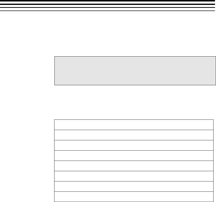
6-1
Chapter 6
Debug Trace Usage
This section describes the debug trace feature supported by codec and its
usage.
Topic Page
6.1 Debug Trace Memory format in the VC1 Decoder
6-1
6.2 Method to configure decoder to collect debug trace
6-2
6.3 Method for application to collect debug trace
6-2
6.1 Debug Trace Memory format in the VC1 Decoder
Debug trace header
Debug Trace Parameters for Process Call 1
Debug Trace Parameters for Process Call 2
Debug Trace Parameters for Process Call 3
Debug Trace Parameters for Process Call 4
Debug Trace Parameters for Process Call N
Debug Trace Parameters for Process Call N+1
Decoder collects and dumps the Debug Trace Information in DDR in above
format. At the start of the buffer, is a header. Following the header, Debug
Trace parameters for each process call is stored. There are N+1 buffers,
since logs of last N process calls need to be stored and one extra buffer for
current process call logs.
Buffers for N+1 process calls are used in a circular manner by decoder -
once data for N+1 process calls are collected, decoder wraps back in the
buffer and starts storing from first buffer location.

Debug Trace Usage
6-2
6.2 Method to configure decoder to collect debug trace
During decoder creation, application needs to set
IVC1VDEC_Params::debugTraceLevel =
IVC1VDEC_DEBUGTRACE_LEVEL1. And set
IVC1VDEC_Params::lastNFramesToLog = N, where N refers to number
of process calls for which trace needs to be collected. Note that the buffer
for debug trace collection will be requested by decoder, in DDR, during
create time and size of it will be linearly proportional to N.
6.3 Method for application to collect debug trace
Application can understand the address of the buffer by performing control
call with XDM_GETSTATUS command. Base address of the buffer will be
reported in IVC1VDEC_Status::extMemoryDebugTraceAddr. Total size of
the buffer will be reported in
IVC1VDEC_Status::extMemoryDebugTraceSize.
NOTE: Before collecting the contents from DDR, Application needs to
perform cache write back of the header portion of the buffer from M3 side.
M3_Cache_WriteBack needs to be performed at address
IVC1VDEC_Status::extMemoryDebugTraceAddr and for a size equal to
that of header (In this release, size of header is 48 Bytes) +
lastNFramesToLog * size of debug trace params (size of debug trace
params is 288 bytes)
7-1
Chapter 7
Picture Format
This Appendix explains picture format details for decoder. Decoder outputs
YUV frames in NV 12 format.
Topic Page
7.1 NV12 Chroma Format
7-1
7.2 Progressive Picture Format
7-2
7.3 Interlaced Picture Format
7.4 Constraints on Buffer Allocation for Decoder
7-4
7-6
7.1 NV12 Chroma Format
NV12 is YUV 420 semi-planar with two separate planes, one for Y, one for U
and V interleaved.
Luma Plane
Y0,0
Y0,1
Y1,0
Y1,1
Chroma Plane
U0,0
V0,0
U1,0
V1,0
WIDTH
HEIGHT
HEIGHT/2
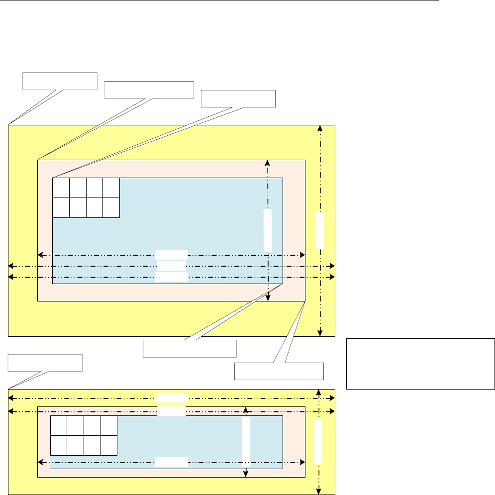
Picture Format
7-2
7.2 Progressive Picture Format
ActiveRegion and ImageRegion offsets for
chroma are derived from luma offset
ChromaXoffset = lumaX_offset & 0xfffffffe;
ChromaYoffset = (lumaY_offset>>1) & 0xfffffffe;
ACTIVE REGION (LUMA)
imagePitch
activeRegion.topLeft
activeRegion.bottomRight
frameHeight
maxHeight
maxWidth
ACTIVE REGION (CHROMA)
picChromaBufferAddr
imagePitch
frameHeight/2
maxHeight/2
maxWidth
imageRegion.topLeft
picLumaBufferAddr
imageRegion.bottomRight
U
0,0 V
0,0 U
0,1 V
0,1
U
1,0 V
1,0 U
1,1 V
1,1
frameWidth
Y
0,0 Y
0,1 Y
0,2 Y
0,3
Y
1,0 Y
1,1 Y
1,2 Y
1,3
frameWidth

Picture Format
7-3
Note that for decoder in case of progressive sequence:
Luma and chroma buffer addresses can be allocated independently
Application shall provide this through separate buffer addresses
The outermost yellow coloured region is the minimum buffer that application should
allocate for a given maxWidth and maxHeight
activeRegion
o The displayable region after cropping done by application.
o The cropping information is derived from VUI information in the bitstream
imageRegion
o Image data decoded by the decoder whose dimensions are always multiple
of 16.
o Contains the activeRegion as a proper subset.
Picture Buffer (pic(Luma/Chroma)BufferAddr)
o Contains padded regions and extra region due to alignment constraints.
o Contains the imageRegion as a proper subset.
imagePitch
o The difference in addresses of two vertically adjacent pixels
o Typically equal to width of the picture Buffer.
Padding Amounts
o In horizontal direction left and right padding amounts are 32 pixels for both
Luma and chroma buffers.
o In vertical direction top and bottom padding amounts are 40 pixels for
Luma and chroma buffers .
Picture Format
7-4
7.3 Interlaced Picture Format
ACTIVE REGION
TOP FIELD (Luma)
Y
0,0 Y
0,1 Y
0,2 Y
0,3
Y
2,0 Y
2,1 Y
2,2 Y
2,3
ACTIVE REGION
BOTTOM FIELD (Luma)
Y
1,0 Y
1,1 Y
1,2 Y
1,3
Y
3,0 Y
3,1 Y
3,2 Y
3,3
ACTIVE REGION
TOP FIELD (Chroma)
U
0,0 V
0,0 U
0,1 V
0,1
U
2,0 V
2,0 U
2,1 V
2,1
ACTIVE REGION
BOTTOM FIELD (Chroma)
U
1,0 V
1,0 U
1,1 V
1,1
U
3,0 V
3,0 U
3,1 V
3,1
maxWidth
maxHeight
maxHeight/2
maxWidth
imagePitch
frameWidth
frameWidth
frameWidth
frameHeight/2
frameHeight/4frameHeight/4 frameHeight/2
imageRegion.topLeft activeRegion.topLeft
picLumaBufferAddr =
lumaTopFieldOutput
lumaBottomFieldOutput
imagePitch
picChromaBufferAddr =
chromaTopFieldOutput
chromaTopFieldOutput
frameWidth
ActiveRegion and ImageRegion offsets for chroma are derived from luma
offset ChromaXoffset = lumaX_offset & 0xfffffffe;
ChromaYoffset = (lumaY_offset >> 1) & 0xfffffffe;
ActiveRegion and ImageRegion offsets are same for top and bottom field
For top field, offsets should be calculated from lumaTopFieldOutput
For bottom field, offsets should be calculated from lumaBottomFieldOutput
ActiveRegion and ImageRegion offsets are same for top and bottom field
For top field, offsets should be calculated from lumaTopFieldOutput
For bottom field, offsets should be calculated from lumaBottomFieldOutput
imageRegion.bottomRightactiveRegion.bottomRight
Padded region
Decoded region multiple of
16x16 macroblock
Display region of any integer
number of pixels in horizontal
and vertical direction

Picture Format
7-5
Note that for decoder in case of interlaced sequence:
Luma and chroma buffers can be allocated independently
Field buffer allocation cannot be independent
For every pair of top and bottom field, decoder shall expect a single buffer address
from the application
The outermost yellow coloured region is the minimum buffer that application should
allocate for a given maxWidth and maxHeight
activeRegion
o The displayable region after cropping done by application.
o The cropping information is derived from VUI information in the bitstream
imageRegion
o Image data decoded by the decoder.
o Contains the activeRegion as a proper subset.
Picture Buffer (pic(Luma/Chroma)BufferAddr)
o Contains padded regions and extra region due to alignment constraints.
o Contains the imageRegion as a proper subset.
imagePitch
o The difference in addresses of two vertically adjacent pixels
o Typically equal to width of the picture Buffer.
Padding Amounts
o In horizontal direction left and right padding amounts are 32 pixels for both
Luma and chroma buffers.
o In vertical direction top and bottom padding amounts are 40 pixels for
Luma and 20 pixels for chroma buffers for each interlaced fields.

Picture Format
7-6
7.4 Constraints on Buffer Allocation for Decoder
maxWidth and maxHeight are inputs given by the decoder to the applications
o Application may not know the output format of the decoder.
o Therefore, application should allocate Image Buffer based on maxWidth and
maxHeight
The extra region beyond the (maxWidth x maxHeight) requirements may
be allocated by application due to alignment, pitch or some other
constraints
Application needs to ensure following conditions regarding imagePitch
o imagePitch shall be greater or equal to the maxWidth.
o imagePitch shall be multiple of 128 bytes (if the buffer is not in TILED region).
o imagePitch shall actually be the tiler space width (i.e. depends on how many bit per
pixel, for 8bpp 16bpp and 32bpp respectively 16Kbyte, 32Kbyte and 32Kbyte). (if
the buffer is in TILED region).
o Application may set imagePitch greater than maxWidth as per display
constraints. However this value must be a multiple of 128 bytes (if the buffer is
not in TILED region).
picLumaBufferAddr and picChromaBufferAddr shall be 16-byte aligned address. (if the
buffer is not in TILED region).
ActiveRegion.topLeft and ActiveRegion.bottomRight are decoder outputs
o Application should calculate actual display width and display height based on these
parameters
o ActiveRegion.topLeft and ActiveRegion.bottomRight shall be identical for both
fields in case of interlaced format
Maximum and Minimum Resolution is defined as below
o Progressive
Minimum frameWidth = 64
Minimum frameHeight = 64
Maximum frameWidth = 1920
Maximum frameHeight = 1088
o Interlaced
Minimum frameWidth = 64
Minimum (frameHeight / 2) = 32
Maximum frameWidth = 1920
Maximum (frameHeight / 2) = 544

Picture Format
7-7
Typically picture buffer allocation requirements for decoder, after buffer addresses meet
alignment constraints (depends on decoder’s padding requirements), for both progressive
and interlaced are as given below.
o Luma buffer size = maxWidth x maxHeight and
Chroma buffer size = maxWidth x maxHeight/2 where
maxWidth = frameWidth + 4 (progressive/interlaced)
maxHeight = frameHeight

Picture Format
7-8
This page is intentionally left blank

8-1
Chapter 8
Error Handling
This chapter describes the error codes reported by codec for different
erroneous situation, and recommended action by application.
8.1 Description
8-1
8.1 Description
This version of the decoder supports handling of erroneous situations while
decoding. If decoder encounters errors in bit stream or any other erroneous
situations, decoder shall exit gracefully without any hang or crash. Also
decoder process call shall return IVIDDEC3_EFAIL and relevant error code
will be populated in extendedError field of outArgs.
Different error codes and their meanings are described below.
Definitions of bits numbered 8-15 are as per common XDM definition.
Definition of remaining bits are VC1 Decoder specific and as given in below
tabular column. Bit numbering in the 32 bit word extendedError is from
Least Significant Bit to Most Significant Bit.
Some of the erroneous situations will get reported as XDM_FATALERROR
by the decoder. In these cases, Application should perform XDM_RESET of
the decoder. After an XDM_RESET is performed, the decoder will treat the
bitstream provided freshly and it shall use no information from previously
parsed data.
Some of the erroneous situations like pointer NULL, invalid memory types for
input and output buffers are flagged as fatal errors. In such scenarios, the
application may not have initialized valid values for them. Hence the
expected behaviour from the application is to re-initialize the fields.
In certain fatal erroneous situations, the Application, might flush out the
locked buffers, if need be. See below table for more details on error
situations when flush can be performed.
In case of non-fatal errors, application need not perform XDM_RESET. It can
proceed with more decode calls, if bit stream is still not exhausted.
Meanings of various error codes and the recommended application behavior
are provided in the following tables:

8-2
8.1.1 Error Codes used to set the extendedError field in IVIDDEC3_OutArgs and
IVIDDEC3_Status
Bit
Error Code
Explanation
XDM Error
Code Mapping
Recommended
App Behavior
0
IVC1DEC_ERR_UNSUPPO
RTED_VIDDEC3PARAMS
This is
deprecated
NA
NA
1
IVC1DEC_ERR_UNSUPPO
RTED_VIDDEC3DYNAMIC
PARAMS
Unsupported
VIDDEC3
dynamic params
XDM_UNSUPPORT
EDPARAM
Call set params with
supported values of
IVIDDEC3 dynamic
params
2
IVC1DEC_ERR_UNSUPPO
RTED_VC1DECDYNAMICP
ARAMS
This is
deprecated
NA
NA
3
IVC1DEC_ERR_IMPROPE
R_DATASYNC_SETTING
This is
deprecated
NA
NA
4
IVC1DEC_ERR_NOSLICE
This is
deprecated
NA
NA
5
IVC1DEC_ERR_SLICEHD
R
Error in slice
header
XDM_CORRUPTED
HEADER
If more bytes available
in bit stream, then
pass it to decoder.
ELSE if bytes are
not available call Flush
operation.
6
IVC1DEC_ERR_MBDATA
Error in MB
data
XDM_CORRUPTED
DATA
If more bytes available
in bit stream, then
pass it to decoder.
ELSE if bytes are
not available call Flush
operation.
7
IVC1DEC_ERR_UNSUPPF
EATURE
This is
deprecated
NA
NA
8
XDM_PARAMSCHA
NGE
Sequence
Parameters
Change
XDM_PARAMSCHA
NGE
Refer codec specific
error
which causes this
9
XDM_APPLIEDCO
NCEALMENT
Applied
concealment
XDM_APPLIEDCO
NCEALMENT
Refer codec specific
error
which causes this
10
XDM_INSUFFICI
ENTDATA
Insufficient input
data
XDM_INSUFFICI
ENTDATA
Refer codec specific
error
which causes this
11
XDM_CORRUPTED
DATA
Data
problem/corruptio
n
XDM_CORRUPTED
DATA
Refer codec specific
error
which causes this
12
XDM_CORRUPTED
HEADER
Header
problem/corruptio
n
XDM_CORRUPTED
HEADER
Refer codec specific
error
which causes this
13
XDM_UNSUPPORT
EDINPUT
Unsupported
feature/paramete
XDM_UNSUPPORT
EDINPUT
Refer codec specific
error

8-3
r
which causes this
14
XDM_UNSUPPORT
EDPARAM
Unsupported
input
parameter
XDM_UNSUPPORT
EDPARAM
Refer codec specific
error
which causes this
15
XDM_FATALERRO
R
Fatal error
XDM_FATALERRO
R
Refer codec specific
error
which causes this
16
IVC1DEC_ERR_STREAM_
END
This is
deprecated
NA
NA
17
IVC1DEC_ERR_UNSUPPR
ESOLUTION
This is
deprecated
NA
NA
18
IVC1DEC_ERR_STANDBY
This is
deprecated
NA
NA
19
IVC1DEC_ERR_INVALID
_MBOX_MESSAGE
This is
deprecated
NA
NA
20
IVC1DEC_ERR_SEQHDR
Error in the
sequence header
XDM_FATALERRO
R or
XDM_CORRUPTED
HEADER
If more bytes available
in bit stream and not
fatal error, then pass it
to decoder. ELSE if
bytes are not available
call Flush operation.
21
IVC1DEC_ERR_ENTRYHD
R
Error in entry
point header
XDM_FATALERRO
R or
XDM_CORRUPTED
HEADER
If more bytes available
in bit stream and not
fatal error, then pass it
to decoder. ELSE if
bytes are not available
call Flush operation.
22
IVC1DEC_ERR_PICHDR
Error in picture
header
XDM_CORRUPTED
HEADER
If more bytes available
in bit stream, then
pass it to decoder.
ELSE if bytes are
not available call Flush
operation.
23
IVC1DEC_ERR_REF_PIC
TURE_BUFFER
Error bit for Ref
picture Buffer
NO XDM
Mapping
Pass the next frame in
the stream
24
IVC1DEC_ERR_NOSEQUE
NNCEHEADER
No sequence
header found in
the input
NO XDM
Mapping
If more bytes available
in bit stream, then
pass it to decoder.
ELSE if bytes are
not available call Flush
operation.
30
IVC1DEC_ERR_BUFDESC
Input bytes in
inargs is less
than or equal to 0
or Input ID is 0
XDM_FATALERRO
R
Invoke process call
with proper bytes in
inargs and valid input
ID
31
IVC1DEC_ERR_PICSIZE
CHANGE
Resolution of the
picture changes
NO XDM
Mapping
If more bytes available
in bit stream, then
pass it to decoder.
ELSE if bytes are
not available call Flush
operation.

8-4
8.1.2 Error Codes used to set the extendedErrorCode0, extendedErrorCode1,
extendedErrorCode2, extendedErrorCode3 field in IVC1VDEC_Status
Bit
Error Code
Explanation
XDM Error Code
Mapping
Recommended
App Behaviour
0
VC1_DYNAMIC_PARAMS_S
IZE_ERROR
Dynamic Params
size is wrong
XDM_FATALERROR
Invoke control call
again with proper
DynamicParams
structure.
1
VC1_DECODE_HEADER_ER
ROR
Decode header
param in dynamic
params is invalid
XDM_UNSUPPORTED
PARAM
Invoke control call
again with proper
DynamicParams
structure or codec will
continue with default
settings of dynamic
params
2
VC1_DISPLAY_WIDTH_ER
ROR
Display width is
invalid
XDM_UNSUPPORTED
PARAM
Invoke control call
again with proper
DynamicParams
structure or codec will
continue with default
settings of dynamic
params
3
VC1_FRAME_SKIP_MODE_
ERROR
Frame skip mode is
invalid
XDM_UNSUPPORTED
PARAM
Invoke control call
again with proper
DynamicParams
structure or codec will
continue with default
settings of dynamic
params
4
VC1_NEW_FRAME_FLAG_E
RROR
New frame falg is
invalid
XDM_UNSUPPORTED
PARAM
Invoke control call
again with proper
DynamicParams
structure or codec will
continue with default
settings of dynamic
params
5
VC1_PUT_DATA_FXN_ERR
OR
The putDataFxn is
non NULL
XDM_UNSUPPORTED
PARAM
Invoke control call
again with proper
DynamicParams
structure or codec will
continue with default
settings of dynamic
params
6
VC1_PUT_DATA_HANDLE_
ERROR
The putDataHandle
is non NULL
XDM_UNSUPPORTED
PARAM
Invoke control call
again with proper
DynamicParams
structure or codec will
continue with default
settings of dynamic
params
7
VC1_GET_DATA_FXN_ERR
OR
The GetDataFxn is
non NULL
XDM_UNSUPPORTED
PARAM
Invoke control call
again with proper
DynamicParams
structure or codec will
continue with default
settings of dynamic
params
8
VC1_GET_DATA_HANDLE_
ERROR
The
GetDataHandle is
XDM_UNSUPPORTED
PARAM
Invoke control call
again with proper

8-5
non NULL
DynamicParams
structure or codec will
continue with default
settings of dynamic
params
9
VC1_PUT_BUFFER_FXN_E
RROR
The purBufferFxn is
non NULL
XDM_UNSUPPORTED
PARAM
Invoke control call
again with proper
DynamicParams
structure or codec will
continue with default
settings of dynamic
params
10
VC1_PUT_BUFFER_HANDL
E_ERROR
The
PutBufferHandle is
non NULL
XDM_UNSUPPORTED
PARAM
Invoke control call
again with proper
DynamicParams
structure or codec will
continue with default
settings of dynamic
params
11
VC1_LATE_ACQUIRE_ARG
_ERROR
The late acquire
argument is wrong
XDM_UNSUPPORTED
PARAM
Invoke control call
again with proper
DynamicParams
structure or codec will
continue with default
settings of dynamic
params
12
VC1_NULL_INARGS_POIN
TER_ERROR
Inargs pointer is
NULL
XDM_FATALERROR
Invoke process call
again with proper
inargs pointer
13
VC1_INARGS_SIZE_ERRO
R
Inargs size is NULL
XDM_FATALERROR
Invoke process call
again with proper
inargs size
14
VC1_INVALID_INPUT_BY
TES_ERROR
Inargs input bytes
is less than or
equal to zero
XDM_FATALERROR
Invoke process call
again with proper input
bytes in the inargs
structure
15
VC1_INVALID_INPUT_BY
TES_IN_FLUSH_MODE_ER
ROR
This is deprecated
NA
NA
16
VC1_INVALID_INPUT_ID
_ERROR
Input ID is 0
XDM_FATALERROR
Invoke process call
again with proper input
ID
17
VC1_NULL_INSTANCE_HA
NDLE_ERROR
Handle provided to
process or control
call is NULL
XDM_FATALERROR
Invoke process call
again with proper
pointer to the handle
18
VC1_DECODER_NOT_INIT
IALIZED_ERROR
This is deprecated
NA
NA
19
VC1_INVALID_INPUT_BU
F_DESC_ERROR
Input buffer
descriptor pointer
given to the
process call is
NULL
XDM_FATALERROR
Invoke process call
again with proper input
buffer descriptor
20
VC1_INVALID_INPUT_BU
FFER_POINTER_ERROR
Input buffer pointer
given to process
call is NULL
XDM_FATALERROR
Invoke process call
again with proper input
buffer pointer
21
VC1_INVALID_INPUT_BU
FFER_SIZE_ERROR
Input buffer size
given to process
call is less than or
equal to zero
XDM_FATALERROR
Invoke process call
again with proper input
buffer size
22
VC1_INVALID_NUM_OF_I
NPUT_BUFFERS_ERROR
No of input buffers
is not equal to one
XDM_FATALERROR
Invoke process call
again with correct

8-6
number of buffer size
23
VC1_EXCESS_NUM_OF_IN
PUT_BUFFERS_ERROR
This is deprecated
NA
NA
24
VC1_INVALID_INPUT_BU
FFER_MEMTYPE_ERROR
The input buffer
memory type is not
RAW or
TILED_PAGE
XDM_FATALERROR
Invoke process call
with input buffer
properties as RAW or
TILED_PAGE
25
VC1_INVALID_OUTARGS_
POINTER_ERROR
The outargs pointer
is NULL
XDM_FATALERROR
Invoke process call
with proper outargs
pointer
26
VC1_INVALID_OUTARGS_
SIZE
The outargs size is
invalid
XDM_FATALERROR
Invoke process call
with proper outargs
size
27
VC1_INVALID_OUTPUT_B
UF_DESC_POINTER_ERRO
R
output buffer
descriptor pointer
given to the
process call is
NULL
XDM_FATALERROR
Invoke process call
again with proper
output buffer descriptor
28
VC1_INVALID_OUTPUT_B
UF_DESC_ERROR
This is deprecated
NA
NA
29
VC1_INVALID_NUM_OF_O
UTPUT_BUFFERS_ERROR
Number of output
buffers given to the
codec is invalid
XDM_FATALERROR
Invoke process call
again with proper
number of output
buffers
30
VC1_INVALID_OUTPUT_B
UFFER0_POINTER_ERROR
Luma pointer in the
output buffer
descriptor is NULL
XDM_FATALERROR
Invoke process call
again with valid pointer
to buffer 0
31
VC1_INVALID_OUTPUT_B
UFFER0_SIZE_ERROR
This is deprecated
NA
NA
32
VC1_INVALID_OUTPUT_B
UFFER0_MEMTYPE_ERROR
Luma buffer
memory type is
invalid
Invoke process call
again with valid pointer
memory type for buffer
0
33
VC1_INVALID_OUTPUT_B
UFFER1_POINTER_ERROR
chroma pointer in
the output buffer
descriptor is NULL
XDM_FATALERROR
Invoke process call
again with valid pointer
to buffer 1
34
VC1_INVALID_OUTPUT_B
UFFER1_SIZE_ERROR
This is deprecated
NA
NA
35
VC1_INVALID_OUTPUT_B
UFFER1_MEMTYPE_ERROR
chroma buffer
memory type is
invalid
Invoke process call
again with valid pointer
memory type for buffer
1
36
VC1_INVALID_OUTPUT_B
UFFER2_POINTER_ERROR
MB info pointer in
the output buffer
descriptor is NULL
XDM_FATALERROR
Invoke process call
again with valid pointer
to buffer 2
37
VC1_INVALID_OUTPUT_B
UFFER2_SIZE_ERROR
This is deprecated
NA
NA
38
VC1_INVALID_OUTPUT_B
UFFER2_MEMTYPE_ERROR
Mb info buffer
memory type is
invalid
Invoke process call
again with valid pointer
memory type for buffer
2
39
VC1_INVALID_BUFFER_U
SAGE_MODE
This is deprecated
NA
NA
40
VC1_INVALID_OUTPUT_B
UFFER0_TILED_WIDTH_E
RROR
This is deprecated
NA
NA
41
VC1_INVALID_OUTPUT_B
UFFER0_TILED_HEIGHT_
ERROR
This is deprecated
NA
NA

8-7
42
VC1_INVALID_OUTPUT_B
UFFER1_TILED_WIDTH_E
RROR
This is deprecated
NA
NA
43
VC1_INVALID_OUTPUT_B
UFFER1_TILED_HEIGHT_
ERROR
This is deprecated
NA
NA
44
VC1_INVALID_OUTPUT_B
UFFER2_TILED_WIDTH_E
RROR
This is deprecated
NA
NA
45
VC1_INVALID_OUTPUT_B
UFFER2_TILED_HEIGHT_
ERROR
This is deprecated
NA
NA
46
VC1_INVALID_REF_PICT
URE_BUFFER
Invalid picture
reference buffers
NA
Pass the next frame in
the stream
64
VC1_SEQ_HDR_INVALID_
PROFILE
Invalid profile found
in the bit-stream
XDM_CORRUPTEDHE
ADER &
XDM_FATALERROR
Application should exit
65
VC1_SEQ_HDR_INVALID_
LEVEL
Invalid level found
in the bit-stream
XDM_CORRUPTEDHE
ADER
If more bytes available
in bit stream, then
pass it to decoder.
ELSE if bytes are
not available call Flush
operation.
66
VC1_SEQ_HDR_INVALID_
COLORDIFF_FORMAT
Invalid color format
found in the bit-
stream
XDM_CORRUPTEDHE
ADER
If more bytes available
in bit stream, then
pass it to decoder.
ELSE if bytes are
not available call Flush
operation.
67
VC1_SEQ_HDR_INVALID_
MAX_CODED_WIDTH
Invalid max coded
width found in the
bit-stream
XDM_CORRUPTEDHE
ADER &
XDM_FATALERROR
Application should exit
68
VC1_SEQ_HDR_INVALID_
MAX_CODED_HEIGHT
Invalid max coded
height found in the
bit-stream
XDM_CORRUPTEDHE
ADER &
XDM_FATALERROR
Application should exit
69
VC1_SEQ_HDR_INVALID_
RESERVED
Reserved bits are
set in the bit-stream
XDM_CORRUPTEDHE
ADER
If more bytes available
in bit stream, then
pass it to decoder.
ELSE if bytes are
not available call Flush
operation.
70
VC1_SEQ_HDR_INVALID_
ASPECT_RATIO
Invalid aspect ratio
found in the bit-
stream
XDM_CORRUPTEDHE
ADER
If more bytes available
in bit stream, then
pass it to decoder.
ELSE if bytes are
not available call Flush
operation.
71
VC1_SEQ_HDR_INVALID_
FRAMERATENR
Invalid numerator
value decoded for
the frame rate in
the bit-stream
XDM_CORRUPTEDHE
ADER
If more bytes available
in bit stream, then
pass it to decoder.
ELSE if bytes are
not available call Flush
operation.
72
VC1_SEQ_HDR_INVALID_
FRAMERATEDR
Invalid denominator
value decoded for
the frame rate in
the bit-stream
XDM_CORRUPTEDHE
ADER
If more bytes available
in bit stream, then
pass it to decoder.
ELSE if bytes are
not available call Flush
operation.

8-8
73
VC1_SEQ_HDR_INVALID_
COLOR_PRIM
Invalid color
primary values
found in the bit-
stream
XDM_CORRUPTEDHE
ADER
If more bytes available
in bit stream, then
pass it to decoder.
ELSE if bytes are
not available call Flush
operation.
74
VC1_SEQ_HDR_INVALID_
TRANSFER_CHAR
Invalid transfer
characters found in
the bit-stream
XDM_CORRUPTEDHE
ADER
If more bytes available
in bit stream, then
pass it to decoder.
ELSE if bytes are
not available call Flush
operation.
75
VC1_SEQ_HDR_INVALID_
MATRIX_COEF
Invalid matrix co-
efficients found in
the bit-stream
XDM_CORRUPTEDHE
ADER
If more bytes available
in bit stream, then
pass it to decoder.
ELSE if bytes are
not available call Flush
operation.
76
VC1_SEQ_HDR_INVALID_
LOOPFILTER
Invalid loop filter
value found in the
bit-stream
XDM_CORRUPTEDHE
ADER
If more bytes available
in bit stream, then
pass it to decoder.
ELSE if bytes are
not available call Flush
operation.
77
VC1_SEQ_HDR_INVALID_
FASTUVMC
Invalid Fast UV
motion
compensation flag
found in the bit-
stream
XDM_CORRUPTEDHE
ADER
If more bytes available
in bit stream, then
pass it to decoder.
ELSE if bytes are
not available call Flush
operation.
78
VC1_SEQ_HDR_INVALID_
EXTENDED_MV
Invalid extended
MV found in the
bit-stream
XDM_CORRUPTEDHE
ADER
If more bytes available
in bit stream, then
pass it to decoder.
ELSE if bytes are
not available call Flush
operation.
79
VC1_SEQ_HDR_INVALID_
DQUANT
Invalid dquant
value found in the
bit-stream
XDM_CORRUPTEDHE
ADER &
XDM_FATALERROR
Application should exit
80
VC1_SEQ_HDR_INVALID_
SYNCMARKER
Invalid sync marker
found in the bit-
stream
XDM_CORRUPTEDHE
ADER
If more bytes available
in bit stream, then
pass it to decoder.
ELSE if bytes are
not available call Flush
operation.
81
VC1_SEQ_HDR_INVALID_
RANGERED
Invalid range
reduction value
found in the bit-
stream
XDM_CORRUPTEDHE
ADER
If more bytes available
in bit stream, then
pass it to decoder.
ELSE if bytes are
not available call Flush
operation.
82
VC1_SEQ_HDR_INVALID_
MAXBFRAMES
Invalid value of
maximum B frames
found in the bit-
stream
XDM_CORRUPTEDHE
ADER
If more bytes available
in bit stream, then
pass it to decoder.
ELSE if bytes are
not available call Flush
operation.
83
VC1_ENTRY_PNT_HDR_IN
VALID_DQUANT
Invalid Dquant
found in the entry
point header.
XDM_CORRUPTEDHE
ADER &
XDM_FATALERROR
Application should exit

8-9
84
VC1_ENTRY_PNT_HDR_IN
VALID_CODED_WIDTH
Invalid coded width
found in the entry
point header.
XDM_CORRUPTEDHE
ADER &
XDM_FATALERROR
Application should exit
85
VC1_ENTRY_PNT_HDR_IN
VALID_CODED_HEIGHT
Invalid coded
height found in the
entry point header.
XDM_CORRUPTEDHE
ADER
If more bytes available
in bit stream, then
pass it to decoder.
ELSE if bytes are
not available call Flush
operation.
86
VC1_PIC_HDR_INVALID_
PTYPE
Invalid picture type
in picture header
XDM_CORRUPTEDHE
ADER &
XDM_FATALERROR
Application should exit
87
VC1_PIC_HDR_INVALID_
PQINDEX
Invalid PQ index in
picture header
XDM_CORRUPTEDHE
ADER &
XDM_FATALERROR
Application should exit
88
VC1_PIC_HDR_INVALID_
MVRANGE
Invalid MV Range
in picture header
XDM_CORRUPTEDHE
ADER &
XDM_FATALERROR
Application should exit
89
VC1_PIC_HDR_INVALID_
RESPIC
Invalid Residual Pic
value in picture
header
XDM_CORRUPTEDHE
ADER
If more bytes available
in bit stream, then
pass it to decoder.
ELSE if bytes are
not available call Flush
operation.
90
VC1_PIC_HDR_INVALID_
FCM
Invalid Frame
coding mode in
picture header
XDM_CORRUPTEDHE
ADER &
XDM_FATALERROR
Application should exit
91
VC1_PIC_HDR_INVALID_
RNDCTRL
Invalid Rounding
control parameter
in picture header
XDM_CORRUPTEDHE
ADER
If more bytes available
in bit stream, then
pass it to decoder.
ELSE if bytes are
not available call Flush
operation.
92
VC1_PIC_HDR_INVALID_
MVMODE
Invalid MV mode in
picture header
XDM_CORRUPTEDHE
ADER &
XDM_FATALERROR
Application should exit
93
VC1_PIC_HDR_INVALID_
DMVRANGE
Invalid Direct MV
range in picture
header
XDM_CORRUPTEDHE
ADER &
XDM_FATALERROR
Application should exit
94
VC1_PIC_HDR_INVALID_
BFRACTION
Invalid Bfraction
syntax element
value in picture
header
XDM_CORRUPTEDHE
ADER &
XDM_FATALERROR
Application should exit
95
VC1_PIC_HDR_INVALID_
REFDIST
Invalid reference
distance in picture
header
XDM_CORRUPTEDHE
ADER &
XDM_FATALERROR
Application should exit
96
VC1_ERR_MBNUMB
Invalid number of
MBs in picture
header
XDM_CORRUPTEDHE
ADER &
XDM_FATALERROR
Application should exit
97
VC1_ERR_SCALERES
Invalid scaled
resolution in picture
header
XDM_CORRUPTEDHE
ADER
If more bytes available
in bit stream, then
pass it to decoder.
ELSE if bytes are
not available call Flush
operation.
98
VC1_ERR_ALTPQUANT
Invalid
ALTPQUANT
syntax element in
picture header
XDM_CORRUPTEDHE
ADER
If more bytes available
in bit stream, then
pass it to decoder.
ELSE if bytes are

8-10
not available call Flush
operation.
99
VC1_VOPDQUANT_INVALI
D_ABSPQ
This is deprecated
NA
NA
100
VC1_SLC_HDR_INVALID_
SLICE_ADDR
Invalid slice restart
position in slice
header
XDM_CORRUPTEDHE
ADER &
XDM_FATALERROR
Application should exit
101
VC1_IMPROPER_RESET
The reset IVAHD
function returned
error.
XDM_FATALERROR
Application should exit
102
VC1_IMPROPER_STANDBY
The standby check
on M3 failed
XDM_FATALERROR
Application should exit
103
VC1_ECD_MB_ERROR
MB level error
detected by ECD3
XDM_CORRUPTEDDA
TA
If more bytes available
in bit stream, then
pass it to decoder.
ELSE if bytes are
not available call Flush
operation.
104
VC1_NO_SEQUENCE_STAR
TCODE
This is deprecated
NA
NA
9-1
Chapter 9
Bitstream Format
This chapter explains the bitstream format of VC1 decoder for different
profiles. In addition, it explains the constraints to the application, regarding
bit-stream formats and corresponding codec behaviour.
9.1 Simple and Main Profile
9-1
9.2 Advanced Profile
9-3
9.1 Simple and Main Profile
Sequence Header occurs only once in the beginning of the stream and is in
the format specified in the figure below. The same is explained in Table 265
in Annex L of VC1 standard. The sequence header is given to the codec
during the XDM_PARSE_HEADER. During this command execution, the
codec assumes that only the sequence header is present in the input buffer
and it decodes the same.
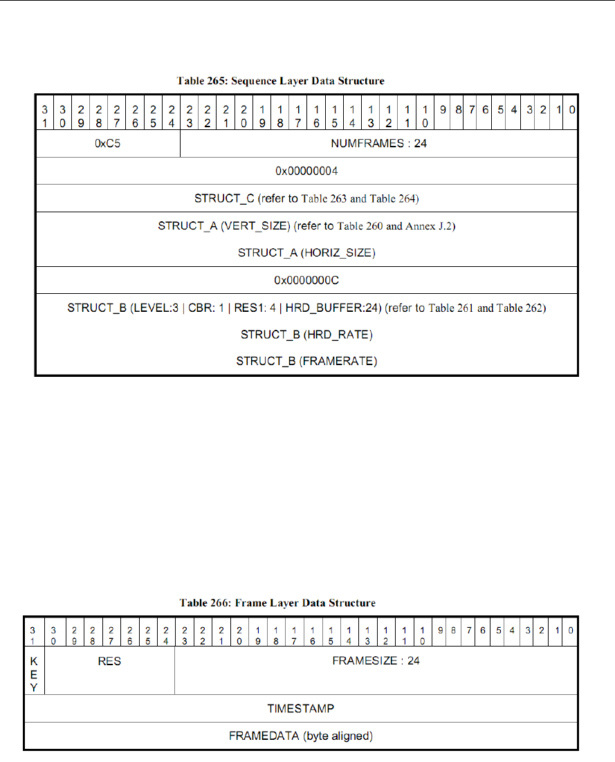
9-2
9.1.1 Sequence header syntax
Figure 9-1 Sequence Layer syntax
9.1.2 Frame header syntax
While the codec executes XDM_DECODE_AU command, the input buffer
shall only contain the compressed frame data corresponding to the
FRAMEDATA in the frame layer syntax of Table 266 in Annex L of VC1
standard. In addition, codec assumes that the buffer always contains one
full frame-data in it.
Figure 9-2 Frame layer syntax
9.1.2.1 frameLayerDataPresentFlag for RCV streams
This flag should be used to notify the decoder that frame layer payload is
provided in standard or non-standard format.

9-3
Standard Format: All fields of the frame layer are present in the
payload.(i.e KEY, RES, FRAMESIZE, TIMESTAMP, FRAMEDATA).
This is specified by enabling the frameLayerDataPresentFlag in the
IVC1VDEC_Params structure (Explained in Section 4.2.2.1) at create
time.
Non Standard Format: Only FRAMEDATA of the frame layer syntax is
present in the payload. This is specified by disabling the
frameLayerDataPresentFlag in the IVC1VDEC_Params structure
(Explained in Section 4.2.2.1) at create time.
9.2 Advanced Profile
The bit-stream format for an advanced profile stream is as shown in the
figure below.
During XDM_PARSE_HEADER, execution, the input bit-stream shall
contain SEQ_SC and SEQ_HDR only.
During XDM_DECODE_AU, execution, the input bit-stream contains
ENTRY_SC, ENTRY_HDR, FRAME_SC and FRAME_DATA. In an
advanced profile stream, multiple SEQ_SC, SEQ_HDR, ENTRY_SC and
ENTRY_HDR may occur.
Figure 9-3 Bitstream syntax for an advanced profile stream
For an interlaced stream,
During XDM_PARSE_HEADER, execution, the input bit-stream shall
contain SEQ_SC and SEQ_HDR only.
During XDM_DECODE_AU, execution:
The input bit-stream for the first field data shall contain FRAME_SC,
FRAME_HDR and FRM_DATA.
The input bit-stream for the second field data shall contain
FIELD_SC, HDR and FIELD_DATA.
The Frame-header syntax is explained in Table 18, 20 and 22 of VC1
standard. Also, frame start codes are explained in Annex G of the VC1
standard.

9-4
This page is intentionally left bank
10-1
Chapter 10
This version of the decoder supports writing out the MB Info data into
application provided buffers.
For the details on MB Info data structures, See section 4.2.2.
This feature can be enabled/disabled through create time parameters
IVIDDEC3_Params::metadataType[IVIDEO_MAX_NUM_METADATA_PLA
NES]. There can be maximum 3
(IVIDEO_MAX_NUM_METADATA_PLANES) metadata planes possible to
be supported with one instance of the decoder.
Each element of metadataType[] array can take following enumerated
values.
Enumeration
Value
IVIDEO_METADATAPLANE_NONE
-1
IVIDEO_METADATAPLANE_MBINFO
0
IVIDEO_METADATAPLANE_EINFO
1
IVIDEO_METADATAPLANE_ALPHA
2
This version of the decoder supports only following enumerated values:
IVIDEO_METADATAPLANE_NONE
IVIDEO_METADATAPLANE_MBINFO
If user wants to get the Mb info data, then
IVIDDEC3_Params::metadataType[0] should be set to
IVIDEO_METADATAPLANE_MBINFO.
If user does not want to use any meta data plane then all the entries of
IVIDDEC3_Params::metadataType[] should be set to
IVIDEO_METADATAPLANE_NONE. Note that the metadataType[] array
need to be filled contiguosly (there cannot be
IVIDEO_METADATAPLANE_NONE between 2 metadata types.
The buffer requirements for metadata can be obtained using Control call
with XDM_GETBUFINFO:
The order of the metadata buffer info supplied using status structure is
same as the order set by the user in the metadataType[] array during
Meta Data Support

10-2
create time. For example if the user has
IVIDDEC3_Params::metadataType[0] =
IVIDEO_METADATAPLANE_MBINFO and
then status->bufInfo.minOutBufSize[2] will have the Mb info buffer.
The buffer pointers for the metadata need to be supplied as below
during process Call:
When the application makes the process() call, the pointers to the
buffers where Mb info should be stored needs to be provided to the
codec in the output buffer descriptor [outputBufDesc.descs].
OutBufs->numBufs = numBuffers forYUVPlanes + number of meta
data enabled (This is = 3 if MB info is enabled)
outBufs->descs[0] -> Y plane
outBufs->descs[1] -> Cb/Cr plane outBufs.
outBufs->descs[2] -> Buffer allocated for Mb info
Codec internally writes the meta data in appropriate buffer. When
the decoder writes the MB info data, the number of metadata planes
is indicated by outArgs->decodedBufs.numMetaPlanes (this is 1 if
Mb info is enabled)
Also, the respective buffer pointer is copied back in the first meta-
plane pointer: outArgs->decodedBufs.metadataPlaneDesc[0].buf ,
again the ordering of the metadata is as per the order supplied by
IVIDDEC3_Params::metadataType[] input parameter.
Decoder parses metadata in the current process call and returns in the
same process call. This means, effectively meta data will be given out in
decode order [Not in Display Order]. If application is interested in display
order, it should have a logic to track based on input and output ID. In case of
interlaced pictures, meta data buffers provided for each field (each process
call) is assumed to be independent.
Decoder shares two types of information at MB Level:
MB Error Map: It’s an array of bytes - One byte per MB (Refer Enum
IVC1VDEC_ mbErrStatus). The byte indicates whether the MB is in error or
not.
MB Info structure: It is a structure which defines properties of a MB. Refer
structure IVC1VDEC_TI_MbInfo in ivc1vdec.h file. Size per MB = 192
bytes.
Case1: If the Application sets viddec3Params.metadataType[x] =
IVIDEO_METADATAPLANE_MBINFO and
IVIDDEC3_Params.operatingMode = IVIDEO_DECODE_ONLY, then

10-3
decoder will dump out MB Error Map at buffer location given for MB Info
meta data.
Case2: If the Application sets viddec3Params.metadataType[x] =
IVIDEO_METADATAPLANE_MBINFO and
IVIDDEC3_Params.operatingMode =
IVIDEO_TRANSCODE_FRAMELEVEL, then decoder will dump out MB
Error Map at buffer location given for MB Info meta data. Error Map will be
followed by MB Info structure for all MBs.
Note that if the Application does not set viddec3Params.metadataType[x] =
IVIDEO_METADATAPLANE_MBINFO, then no information will be dumped,
irrespective of the value of IVIDDEC3_Params.operatingMode. Also, as a
minor Interface limitation, there is no provision to dump MB Info structure
alone w/o error map and error concealment structure.
Format details for Case 1 (Dumping of Error map and Error
concealment structure):
Case 1a, Progressive Frame:
Error Map, Size in Bytes = Number of MBs in Frame
Case 1b, Interlaced Frame:
Error Map for Top Field, Size in Bytes = (Number of MBs in Frame / 2)
Error Map for Bottom Field, Size in Bytes = (Number of MBs in Frame / 2)
Format details for Case 2 (Dumping of Error map, MB Info and Error
concealment structure):
Case 2a, Progressive Frame:
Error Map, Size in Bytes = Number of MBs in Frame
MB Info structure for all MBs, Size in Bytes = 192 * Number of MBs in
Frame
Case 2b, Interlaced Frame:
Error Map for Top Field, Size in Bytes = (Number of MBs in Frame / 2)
Error Map for Bottom Field, Size in Bytes = (Number of MBs in Frame / 2)
MB Info structure for all MBs of Top Field, Size in Bytes = 192 * (Number of
MBs in Frame / 2)
MB Info structure for all MBs of Bottom Field, Size in Bytes = 192 * (Number
of MBs in Frame / 2)

10-4
IMPORTANT NOTICE
Texas Instruments Incorporated and its subsidiaries (TI) reserve the right to make corrections, enhancements, improvements and other
changes to its semiconductor products and services per JESD46, latest issue, and to discontinue any product or service per JESD48, latest
issue. Buyers should obtain the latest relevant information before placing orders and should verify that such information is current and
complete. All semiconductor products (also referred to herein as “components”) are sold subject to TI’s terms and conditions of sale supplied at
the time of order acknowledgment.
TI warrants performance of its components to the specifications applicable at the time of sale, in accordance with the warranty in TI’s terms
and conditions of sale of semiconductor products. Testing and other quality control techniques are used to the extent TI deems necessary to
support this warranty. Except where mandated by applicable law, testing of all parameters of each component is not necessarily performed.
TI assumes no liability for applications assistance or the design of Buyers’ products. Buyers are responsible for their products and applications
using TI components. To minimize the risks associated with Buyers’ products and applications, Buyers should provide adequate design and
operating safeguards.
TI does not warrant or represent that any license, either express or implied, is granted under any patent right, copyright, mask work right, or
other intellectual property right relating to any combination, machine, or process in which TI components or services are used. Information
published by TI regarding third-party products or services does not constitute a license to use such products or services or a warranty or
endorsement thereof. Use of such information may require a license from a third party under the patents or other intellectual property of the
third party, or a license from TI under the patents or other intellectual property of TI.
Reproduction of significant portions of TI information in TI data books or data sheets is permissible only if reproduction is without alteration and
is accompanied by all associated warranties, conditions, limitations, and notices. TI is not responsible or liable for such altered documentation.
Information of third parties may be subject to additional restrictions.
Resale of TI components or services with statements different from or beyond the parameters stated by TI for that component or service voids
all express and any implied warranties for the associated TI component or service and is an unfair and deceptive business practice. TI is not
responsible or liable for any such statements.
Buyer acknowledges and agrees that it is solely responsible for compliance with all legal, regulatory and safety-related requirements
concerning its products, and any use of TI components in its applications, notwithstanding any applications-related information or support that
may be provided by TI. Buyer represents and agrees that it has all the necessary expertise to create and implement safeguards which
anticipate dangerous consequences of failures, monitor failures and their consequences, lessen the likelihood of failures that might cause harm
and take appropriate remedial actions. Buyer will fully indemnify TI and its representatives against any damages arising out of the use of any TI
components in safety-critical applications.
In some cases, TI components may be promoted specifically to facilitate safety-related applications. With such components, TI’s goal is to
help enable customers to design and create their own end-product solutions that meet applicable functional safety standards and
requirements. Nonetheless, such components are subject to these terms.
No TI components are authorized for use in FDA Class III (or similar life-critical medical equipment) unless authorized officers of the parties
have executed a special agreement specifically governing such use.
Only those TI components which TI has specifically designated as military grade or “enhanced plastic” are designed and intended for use in
military/aerospace applications or environments. Buyer acknowledges and agrees that any military or aerospace use of TI components which
have not been so designated is solely at the Buyer's risk, and that Buyer is solely responsible for compliance with all legal and regulatory
requirements in connection with such use.
TI has specifically designated certain components as meeting ISO/TS16949 requirements, mainly for automotive use. In any case of use of
non-designated products, TI will not be responsible for any failure to meet ISO/TS16949.
Products Applications
Audio www.ti.com/audio Automotive & Transportation www.ti.com/automotive
Amplifiers amplifier.ti.com Communications & Telecom www.ti.com/communications
Data Converters dataconverter.ti.com Computers & Peripherals www.ti.com/computers
DLP® Products www.dlp.com Consumer Electronics www.ti.com/consumer-apps
DSP dsp.ti.com Energy and Lighting www.ti.com/energyapps
Clocks and Timers www.ti.com/clocks Industrial www.ti.com/industrial
Interface interface.ti.com Medical www.ti.com/medical
Logic logic.ti.com Security www.ti.com/security
Power Mgmt power.ti.com Space, Avionics & Defense www.ti.com/space-avionics-defense
Microcontrollers microcontroller.ti.com Video & Imaging www.ti.com/video
RFID www.ti-rfid.com
OMAP Applications Processors www.ti.com/omap TI E2E Community e2e.ti.com
Wireless Connectivity www.ti.com/wirelessconnectivity
Mailing Address: Texas Instruments, Post Office Box 655303, Dallas, Texas 75265
Copyright© 2014, Texas Instruments Incorporated
