VFC User Guide Rev A3
User Manual:
Open the PDF directly: View PDF ![]() .
.
Page Count: 28

Virtual Flow Controller Virtual Flow Controller
User Guide
For Internal Use Only
2016-10-21 Project 111111
1
Virtual Flow Controller User Guide
Revision A
2016-10-21

Virtual Flow Controller Virtual Flow Controller
User Guide
For Internal Use Only
2016-10-21
2
© 2016 Dematic Corp. All rights reserved.
No part of this document may be reproduced or transmitted in any form or by
any means, electronic or mechanical, for any purpose, without the express
written permission of Dematic Corp.
This document contains confidential information, trade secrets and/or know-how
which is the property of Dematic Corp., and may not be disclosed to any third
party without the written permission of Dematic Corp. Product and company
names herein may be the trademarks of their respective owners.
Hereinafter Dematic Corp. shall be written as Dematic and refers to any Dematic
entity within the global Dematic group of companies. Information in this
document is subject to change without notice.
Dematic Corp.
507 Plymouth Avenue
Grand Rapids, MI 49505
616-913-6200
800-530-9153
www.dematic.us

Virtual Flow Controller Virtual Flow Controller
User Guide
For Internal Use Only
2016-10-21
3
Release Dates
Release Date
Description
2016-10-21
Initial Release

Virtual Flow Controller Virtual Flow Controller
User Guide
For Internal Use Only
2016-10-21
4
Contents
1 Getting Started .............................................................................. 6
1.1 Navigating VFC ............................................................................... 7
1.2 Setting Up VFC ............................................................................. 10
1.2.1 Adding a Connection ..................................................................... 10
1.2.2 Importing a Telegram Validation File ............................................. 11
1.2.3 Adding a Controller ....................................................................... 11
1.2.4 Connecting VFC to a PLC ............................................................. 14
2 Messages ..................................................................................... 15
2.1 Message Types ............................................................................. 15
2.1.1 TUMI ............................................................................................. 15
2.1.2 TUMC ........................................................................................... 16
2.1.3 MOMI ............................................................................................ 16
2.1.4 STRQ ............................................................................................ 16
2.1.5 LORQ ........................................................................................... 16
2.1.6 SETD ............................................................................................ 16
2.1.7 SETT ............................................................................................ 16
2.1.8 MFST ............................................................................................ 17
2.1.9 FTRQ ............................................................................................ 17
2.2 Components of a Message ........................................................... 17
2.3 Sending Messages Manually ........................................................ 18
2.4 Tips and Tricks .............................................................................. 19
3 Telegram Validation .................................................................... 20
4 SRM Controllers .......................................................................... 22
4.1 Racks ............................................................................................ 22
4.1.1 Working with Rack Locations ........................................................ 23
4.2 Cranes (Unitload or Miniload) ........................................................ 24
4.2.1 Crane Properties ........................................................................... 25
4.2.2 Status Telegrams .......................................................................... 26
4.2.3 Storage Rules ............................................................................... 27
4.3 Handling Exceptions ..................................................................... 27

Virtual Flow Controller Virtual Flow Controller
User Guide
For Internal Use Only
2016-10-21
5
Figures
Figure 1 VFC .................................................................................................. 7
Figure 2 Connection Properties .................................................................... 11
Figure 3 Controller Parameters .................................................................... 13
Figure 4 Message Components .................................................................... 17
Figure 5 Controller Tab ................................................................................. 19
Figure 6 Telegram Validation Tab ................................................................. 21
Figure 7 Racks Tab ...................................................................................... 22
Figure 8 Rack Location Actions .................................................................... 24
Figure 9 Cranes (Unitload or Miniload) Tab .................................................. 25
Figure 10 Cranes Properties ........................................................................... 26
Figure 11 Handing Exceptions ........................................................................ 28

Virtual Flow Controller
User Guide
For Internal Use Only
2016-10-21
6
1 Getting Started
VFC is a Dematic desktop application that simulates Warehouse Control System
(WCS) messages being sent to Programmable Logic Controllers (PLCs) or other
controllers (either using emulation software or with real systems). VFC performs
a similar function as the WCS Simulator Tool, which you may be familiar with.
However, VFC is more robust and user-friendly. VFC is designed to assist in the
testing of emulation models and site installations prior to fully integrated testing.
VFC is a reactive tool for creating missions and messaging scenarios to
test equipment being installed on site.
VFC is designed for developers performing in-house testing (in conjunction with
Demo3D), as well as commissioning engineers on site. To begin using VFC,
download and install the latest version of the application from the Virtual Flow
Controller wiki page. If you are installing a newer version of VFC, uninstall the
old version of VFC before installing the new version.
The first time you use VFC you will need to add the proper plugins. To do this,
perform the following steps:
1. Select Edit > Add Remove Plugins from the menu bar. The Add Remove
Plugins window is displayed.
2. Click Add and navigate to C:\Program Files (x86)\Dematic\Virtual Flow
Controller.
3. Select all of the .dll files and click Open. You can ignore any error
messages that might be displayed.
Virtual Flow Controller
User Guide
For Internal Use Only
2016-10-21
7
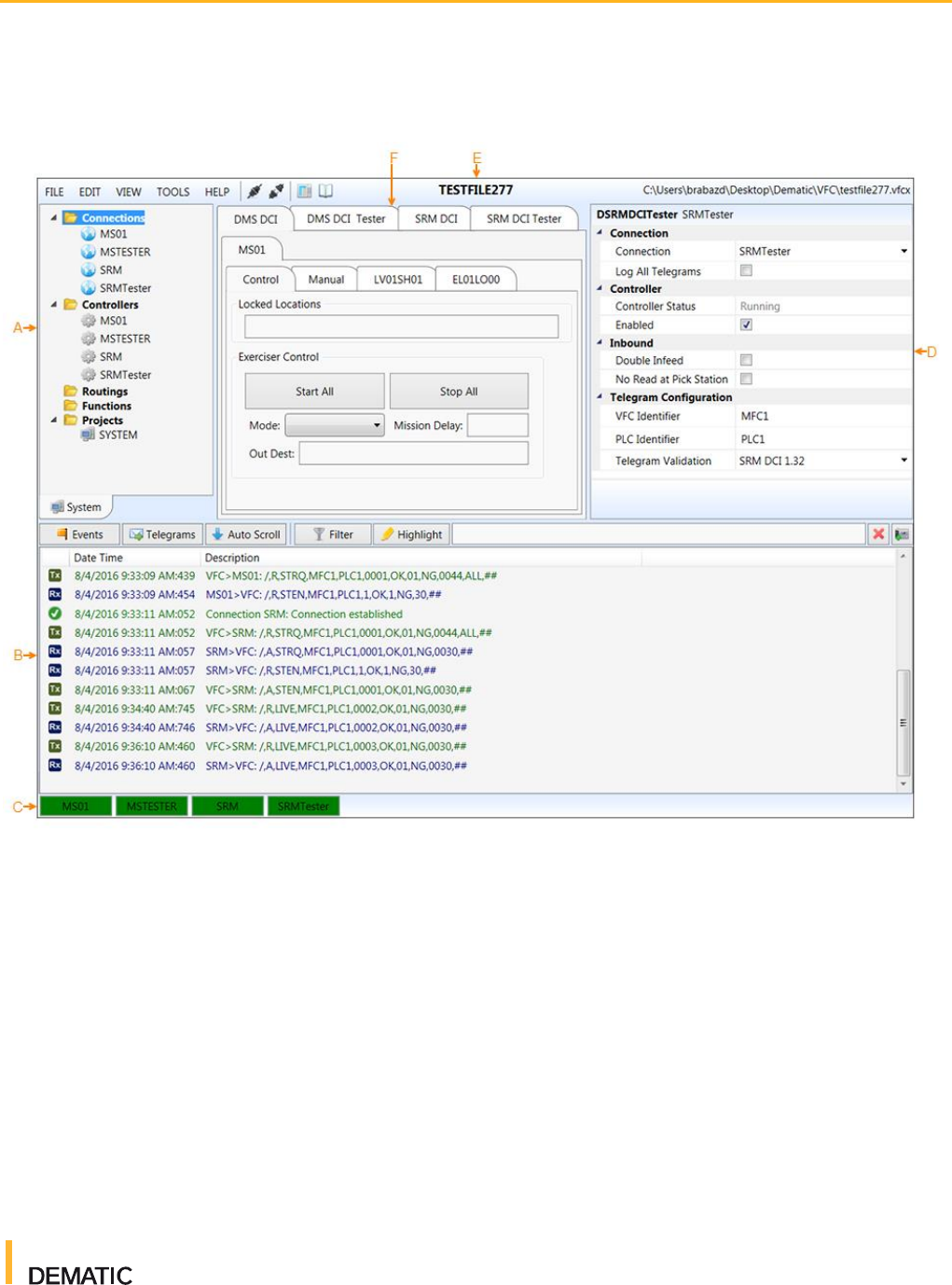
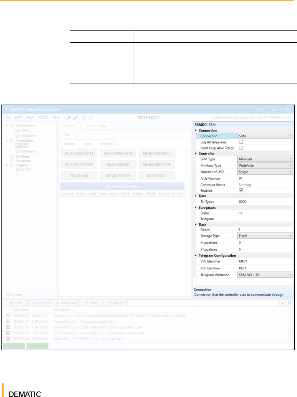
1.1 Navigating VFC
Figure 1 VFC
Virtual Flow Controller
User Guide
For Internal Use Only
2016-10-21
8
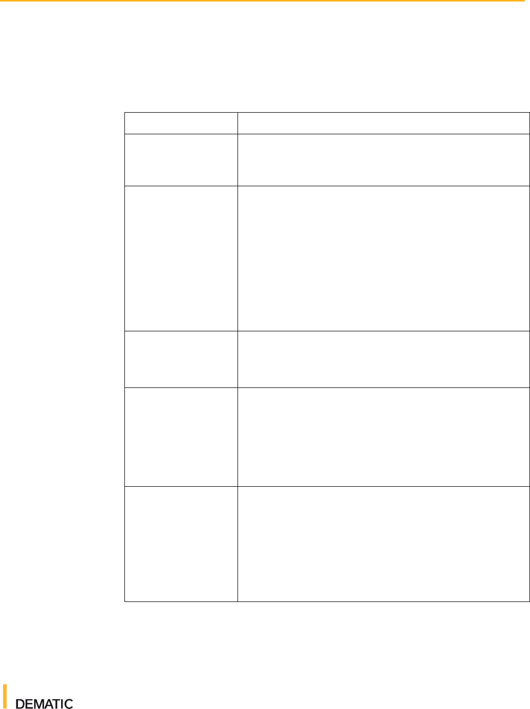
Table 1 VFC Navigation
Item
Description
A
Project Tree - The project tree displays all components within the configuration:
Connections link controllers and act as the interface to the equipment, emulation model, or
PLC.
Controllers contain the logic to control the associated equipment, or to react to a command,
using standardized message protocols (for example, Dematic Communication Interface
[DCI] TCP/IP).
Routings are typically used for routing loads throughout conveyor systems.
Functions are used to control a specific part of a controller function (for
example, RapidPick).
Projects are libraries of components, such as controllers and connections. Typically, the
only project is the base VFC application project called "SYSTEM". You can add custom
project controllers to VFC by using your own scripting. Once you have created your own
scripting, right click on Projects and select Add Extension to add the script.
Virtual Flow Controller
User Guide
For Internal Use Only
2016-10-21
9
Table 1 VFC Navigation
Item
Description
B
Message and Event Logger - The Message and Event Logger section displays a
chronological list of telegram messages and events.
Icons are displayed beside each message or event. For telegrams, a Tx icon refers to a
transmitted message and an Rx icon refers to a received message. For events, a green
check mark indicates a successful event, a yellow exclamation mark indicates a warning
related to an event, a red X indicates a failure of some sort, and a blue "i" indicates an
informative note. Check the Description column for further details about a message or
event.
Clicking on the Events or Telegrams buttons displays or hides those types of messages.
Clicking the Auto Scroll button automatically scrolls to the next message in the logging
window. If there are any error or warning messages, a blinking icon will display beside the
Auto Scroll button along with the number of errors or warnings. A red X displays for errors
and a yellow exclamation mark displays for warnings.
Clicking on a message or event displays that message or event's content in a text field at
the bottom of the screen. From here, you can copy any part of the message. If you paste
the copied text into the text field beside the Highlight button you can do several things. If
you click Filter, the messages and events will filter based on that criteria. If you click
Highlight, matching text in the messages and events will highlight yellow.
Clicking the Snap Shot of Messages button takes a snapshot of the message and event
logger, and displays it in the main window. This is a helpful tool for investigating events that
have recently occurred.
Messages and events are also stored in a log file and can be accessed by clicking the
Open Log File button on the menu bar. You can open multiple logs at once by selecting
more than one log and clicking Open.
C
Connection Status - The bottom of the screen displays all available controller connections.
The status of a connection is indicated by color: green for connected, red for disconnected,
and yellow for a connection issue.
D
Properties Window - The Properties window displays a full list of properties for the
selected component (connection, controller, and so on). Grayed out properties cannot be
modified.
E
Menu Bar - The menu bar across the top of the screen provides standard menu
functionality. The menu bar also displays the project name and the location of the open
VFC file. Hover over an icon to learn more about its function.
Click HELP for quick access to the Help content.

Virtual Flow Controller
User Guide
For Internal Use Only
2016-10-21
10
Table 1 VFC Navigation
Item
Description
F
Main Window - The main window is the main workspace of VFC. Upon opening VFC, a tab
for each controller is displayed. These tabs allow you to perform basic tasks such as
manually creating messages.
If you open other tools, such as Telegram Validation, they are displayed in the main window
as well.
1.2 Setting Up VFC
Before you can start using VFC to simulate Warehouse Control System (WCS)
messages, you must first set up the proper environment in VFC. This includes
adding a connection, importing a telegram validation file, and adding a controller.
1.2.1 Adding a Connection
Connections link controllers and act as the interface to the equipment, emulation
model, or PLC. To add a connection, perform the following steps:
Adding a Connection Complete
1. In VFC, create a new VFC file by selecting File > New, and giving your file a
name. Save the file. The file name is displayed at the top of the screen.
2. To add a connection, right click Connections in the project tree and
select Add Connection. The Add Connection dialog box is displayed.
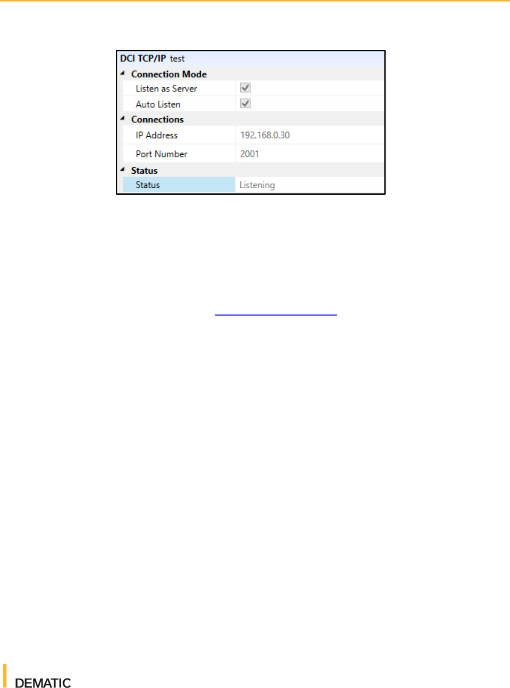
3. Enter a connection name, type, and folder name. Typically, the type
is DCI_TCPIP. Click Add. The connection is displayed in the project tree
and connection parameters are displayed in the properties window on the
right-hand side of the screen (as shown in the image to the right).
4. Enter the appropriate IP address (for your PLC or emulator) and port
number. Typically, the IP address is 192.168.0.## and the port number
is 2001.
Virtual Flow Controller
User Guide
For Internal Use Only
2016-10-21
11
Figure 2 Connection Properties
1.2.2 Importing a Telegram Validation File
The Telegram Validation tool allows you to set message parameters that ensure
sent and received telegrams contain the necessary information. To import a
telegram validation file, perform the following steps:
1. Navigate to the VFC Telegram Validation wiki page and download the
current SRM telegram validation .xml file.
2. In VFC, click the Telegram Validation icon on the menu bar. The Telegram
Validation tab is displayed.
3. Click the edit icon. Click Import Template from XML from the dropdown
menu. A file browser is displayed.
4. Select the telegram validation file you downloaded in step 1. Click Open.
1.2.3 Adding a Controller
Controllers contain the logic to control the associated equipment, or to react to a
command, using standardized message protocols. To add a controller, perform
the following steps:
1. In VFC, right click Controllers in the project tree and select Add
Controller. The Add Controller dialog box is displayed.
2. Enter a controller name, type, and folder name. Typically, the type
is SRMDCI. To help you stay organized, use the same name and folder
name as you used for your controller. Click Add. The controller is displayed
in the project tree and controller parameters are displayed in the properties
window on the right-hand side of the screen. A tab for your controller is
displayed in the main window as well; this is where you'll do most of your
work.
Virtual Flow Controller
User Guide
For Internal Use Only
2016-10-21
12
3. In the properties window, enter the appropriate parameters. Set the
Connection parameter to the connection you created earlier. Set the
telegram validation parameter to the telegram validation file you imported
earlier. The following table describes the available controller parameters:
Section
Parameters
Connection
Set Connection to the associated SRM connection. Check
the Log All Telegrams and Send Keep Alive
Telegrams check boxes to log all telegrams and send
heartbeat telegrams, respectively.
Controller
SRM Type: Select either Miniload or Unitload from the
dropdown menu.
Miniload Type: Select either Narrow Aisle or Wide
Aisle. (For ML-series SRMs only)
Number of LHD: Configure either one or two LHDs per
SRM by selecting Single or Double, respectively.
Aisle Number: Enter the two-digit aisle number.
Controller Status: Displays the current status of the
controller.
Enabled: Check this checkbox to enable the controller.
Data
TU Types: Enter the four-character TU type identifiers.
Separate multiple entries with a comma. TU types are
documented on the Controls Emulation TU Types wiki
page.
Exceptions
Status: The current exception status. If there are no
exceptions, the status will be "OK". If there is an
exception, the exception type displays (for example,
"BinOccupied").
Telegram: If there is an exception, the exception
telegram message is displayed.
Rack
Depth: The number of rack depths.
Storage Type: Select a storage type from the
dropdown menu. Fixed indicates one TU for one
location. Dynamic builds from the upright and looks at
millimeter distances from that point. Raster uses a
raster table.
X Locations: The number of locations along the X axis.
Y Locations: The number of locations along the Y axis.
Virtual Flow Controller
User Guide
For Internal Use Only
2016-10-21
13
Section
Parameters
Telegram Validation
VFC Identifier: The VFC identifier for telegrams sent to
and from the PLC.
PLC Identifier: The PLC identifier for telegrams sent to
and from VFC.
Telegram Validation: The telegram standard type.
Figure 3 Controller Parameters
4. To enable your controller, check the Enabled checkbox in the properties
window.

Virtual Flow Controller
User Guide
For Internal Use Only
2016-10-21
14
1.2.4 Connecting VFC to a PLC
Note: Before you connect VFC to your PLC you must have your PLC connected
to the Demo3D emulator. For instructions on how to do so, see
the SRM Emulation training course.
You can use VFC to simulate the WCS transport messages that are sent to and
from your PLC. You can witness these transport messages being executed in
the emulator.
To connect VFC to your PLC and to send transport missions to the PLC, perform
the following steps in VFC:
1. Select your connection from the Connections section of the project tree. In
the properties window for your connection, confirm that the IP address and
port number are correct.
2. Select your controller from the Controllers section of the project tree.
Ensure that the parameters are correct. The Connection parameter should
be set to the connection you selected in step 1.
3. Click the Connect All icon to establish a connection. The connection status
icon at the bottom of the screen turns green. VFC is now connected to your
PLC.
4. On the Manual tab for your controller, you can now enter message
parameters. Here's an example of the parameters you need to set to send a
typical TUMI telegram:
● Type: TUMI
● For Source, Current, and Destination, click Bin beside each parameter.
Enter the appropriate parameters and click Update.
● Click Send. The transport unit mission message is sent to the PLC.
The PLC tells the SRM to pick up the Transport Unit (TU) from the
source location and move it to the destination location. If there are any
errors (for example, the source bin empty or the destination bin already
full), an error message is displayed on the HMI.

Virtual Flow Controller
User Guide
For Internal Use Only
2016-10-21
15
2 Messages
It's important to understand the types and components of messages that can be
sent between WCS/VFC and controllers. This understanding will help you more
efficiently design, test, and debug software. Let's look at the various message
types, including possible responses, and then take a detailed look at exactly
what information messages contain.
2.1 Message Types
To learn more about messages and naming conventions, see the DCI
Common and DCI Transport specifications available on the VFC Telegram
Validation wiki page.
The following sections explain the types of messages that can be sent or
received by VFC.
2.1.1 TUMI
A TUMI (Transport Unit Mission) message is sent from WCS to the PLC. These
messages are used to send a new transport mission to the PLC or to update an
existing one.
The PLC will acknowledge this message with one of the following messages:
● TURP (Transport Unit Mission Report): An execution message of the
transport order indicating whether the transport unit (TU) arrived at
its destination. This message is only used for positive acknowledgment (that
is, an event code of “OK”).
● TUNO (Transport Unit Notification): A message that's used to send TU
information during travel, or a message that's sent by the PLC due to a
spontaneous event. This message is only used for positive acknowledgment
(that is, an event code of “OK”) and only if the TU has not reached its
destination. This message is optional.
● TUEX (Transport Unit Exception): A message that's used for negative
acknowledgment (that is, the event code is anything other than “OK”) of a
mission.
● TUDR (Transport Unit Destination Request): A message indicating the PLC
requests a new destination from WCS if the TU has no destination.
● TULL (Transport Unit Location Left): A message indicating the TU has left
an area.

Virtual Flow Controller
User Guide
For Internal Use Only
2016-10-21
16
2.1.2 TUMC
A TUMC (Transport Unit Mission Cancel) message indicates WCS has cancelled
the transport order.
The PLC can respond with a TUCA message (Transport Unit Cancel), which is a
positive or negative acknowledgment of the cancellation of the transport order.
2.1.3 MOMI
A MOMI (Move Mission) message is sent from WCS to move a vehicle to
a specified position.
The PLC will respond with a MORP message (Move Report), which confirms the
vehicle has executed its move mission.
2.1.4 STRQ
A STRQ (Status Request) message is sent from WCS to the PLC. These
messages are used to request status information for a specific device, group of
devices, or an entire system.
The PLC can respond with one of the following messages:
● STAT (Status): A message about availability of equipment.
● STMF (Status of Material Flow)
● STEN (End of Status): A messages indicating the end of a status sent only if
requested from WCS.
2.1.5 LORQ
A LORQ (Location Data Request) message is used by WCS to request status
information about a location from the PLC.
The PLC will respond with a TUNO (Transport Unit Notification) message, which
is used to send TU information during travel, or is sent by the PLC due to a
spontaneous event. This message is only used for positive acknowledgment
(that is, an event code of “OK”) and only if the TU has not reached its
destination. This message is optional as long as it is not sent in an abnormal
situation.
2.1.6 SETD
A SETD (Set Device) message sets a device to a given status. These messages
are typically used by WCS to put a device into a defined status or to highlight a
device within the PLC visualization.
2.1.7 SETT
A SETT (Set) message syncs the date and time between WCS and the PLC.
Virtual Flow Controller
User Guide
For Internal Use Only
2016-10-21
17
2.1.8 MFST
An MFST (Start Material Flow) message is used to start the material flow within
the entire PLC area.
2.1.9 FTRQ
A FTRQ (Fault Text Request) message is a request for the text for a fault code.
These messages can be sent manually by WCS or when a fault code is
encountered for which no fault text exists within WCS.
The PLC will respond with a FTDF (Fault Text Definition) message, which
reports the full text for the fault.
2.2 Components of a Message
Messages (also called telegrams) allow WCS and PLCs to talk to each other and
ensure both are functioning as effectively as possible. VFC mimics WCS and
can send the same types of messages to a PLC (either a simulated PLC or a
real one).
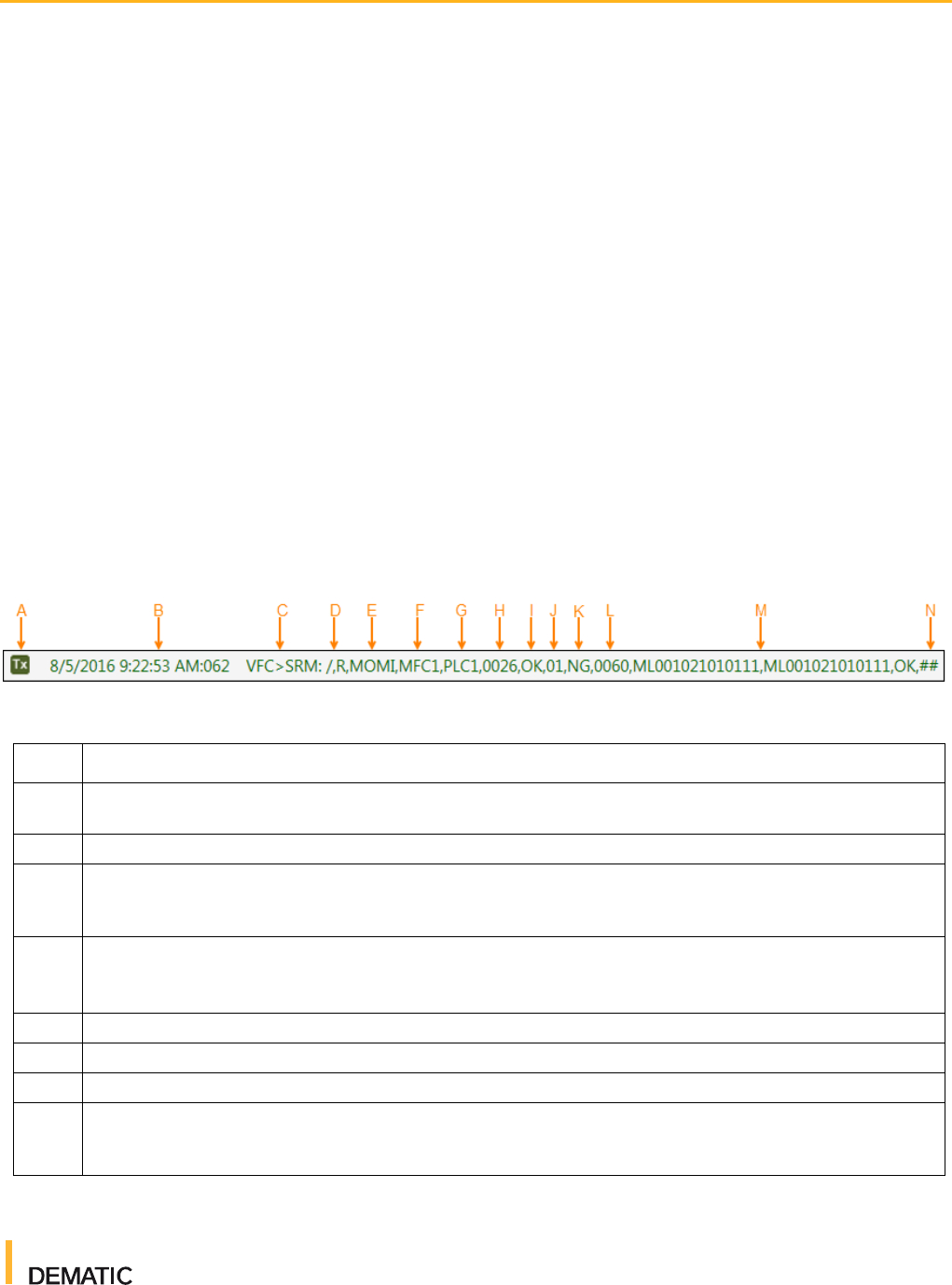
Figure 4 Message Components
Table 2 Components of a Message
Item
Description
A
The Tx icon indicates that the message is a transfer message (that is, it has been transferred from
WCS to the PLC). An Rx icon indicates the message has been received from the PLC.
B
The date and time the message was sent.
C
"VFC>SRM:" indicates the message is being sent from VFC to the controller (in this example, the
controller is called "SRM"). The sender appears before the receiver regardless of whether the sender
is the controller or VFC.
D
The "/" mark indicates the start of the message. This is byte 01.
"R" is the second byte and identifies flow control. "R" indicates that acknowledgement is required, "A"
indicates an acknowledgement flag, and "." indicates no acknowledgement is required.
E
Bytes 03 to 06 are the message type.
F
Bytes 07 to 10 are the sender (in this case, MFC1).
G
Bytes 11 to 14 are the receiver (in this case, PLC1).
H
Bytes 15 to 18 are the cycle number (in this case, 0026). This is a count of the number of messages
sent, starting from 0001. This number is incremented by the sender for every new message. If a
message is repeated, the number is not incremented.
Virtual Flow Controller
User Guide
For Internal Use Only
2016-10-21
18
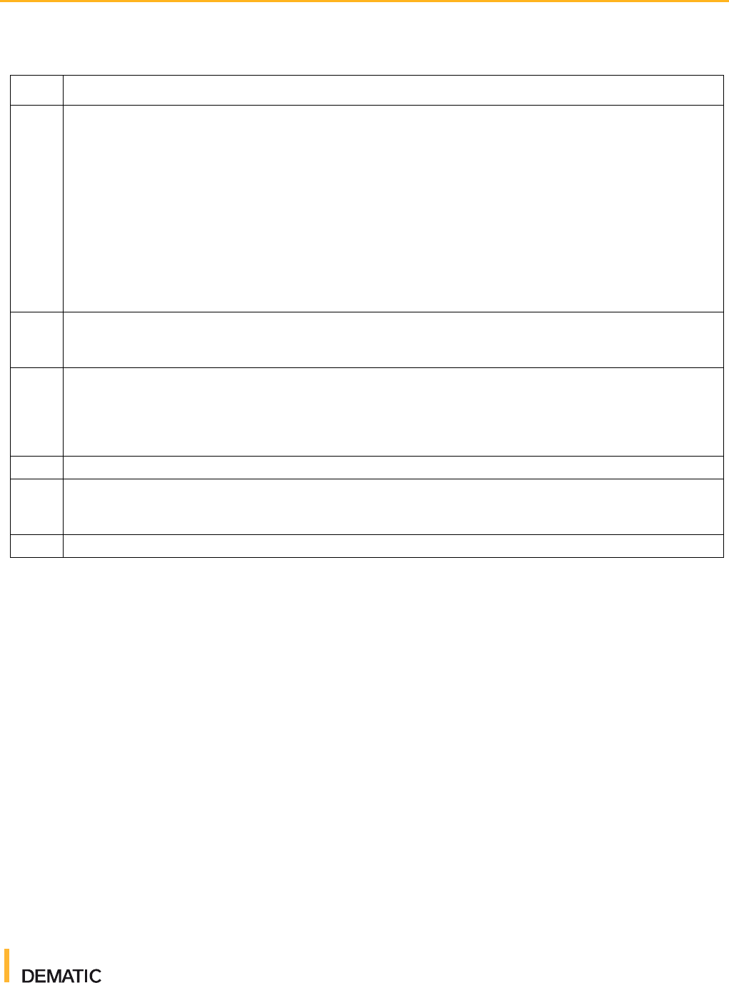
Table 2 Components of a Message
Item
Description
I
Bytes 19 and 20 are the return value (in this case, OK). The following values can be returned:
■ OK: No error occurs
■ MU: Message name is unknown. The message is not processed any further.
■ SU: Sender ID is unknown. The message is not processed any further.
■ RU: Receiver ID is unknown. The message is not processed any further.
■ LE: The message length is too long or otherwise does not fit. The message is not processed
any further.
■ BF: Receive buffer capacity exhausted. The sender must buffer the message and repeat it until
it can be accepted by the receiver. The waiting time between repetitions is 30 seconds.
■ GE: General protocol error, which means any error that's not specified above. The message is
not processed any further.
J
Bytes 21 and 22 indicate the number of blocks used in the message. You can pack multiple
messages into a single message. The example says "01", which means there is a single message
being sent.
K
Bytes 23 and 24 are the block type. "NG" indicates no logical grouping and is the default value. An
"NG" message block type means each message body is kept separate and is not logically interlinked
with the others. "LG" indicates a logical grouping of blocks and is used to process several messages
together. The PLC sends "LG" message blocks automatically if more than one TU is handled
simultaneously.
L
Bytes 25 to 28 indicate the length of the entire message in bytes (in this case, 0060).
M
This section is the actual message body. In the example, the message body includes a device
identifier, a destination location, and an event code for the MOMI message. This data was set on the
Manual tab for the controller.
N
The final two bytes are "##", which indicate the end of the message.
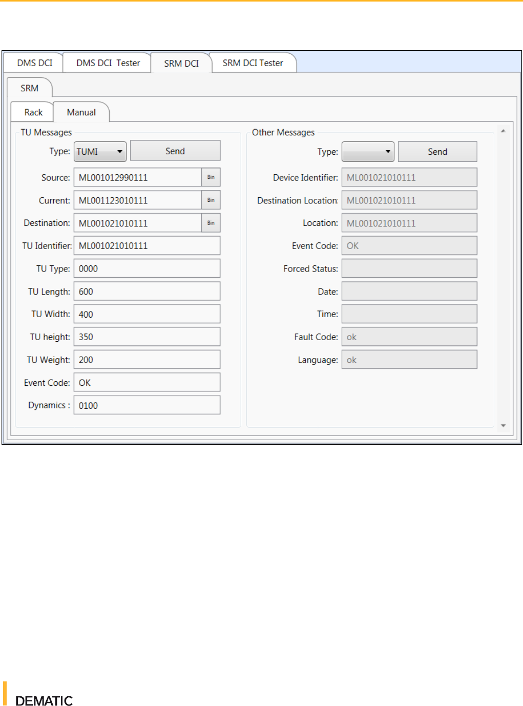
2.3 Sending Messages Manually
You can send custom messages to a destination PLC to perform specific tasks.
This can be useful for testing specific scenarios such as load tests. To send a
message manually, perform the following steps:
1. In the main window, select the appropriate controller.
2. Click the Manual tab.
3. To send a TU message, enter the necessary parameters in the TU
Messages section. To send another type of message (such as MOMI,
SETT, STRQ, and so on), enter the necessary parameters in the Other
Messages section.
4. Click Send. You can confirm your message's successful transmission by
viewing the Message and Event Logger. A Tx message should be displayed
along with an Rx message, indicating the message was both transmitted
and received as expected. If the message was not sent or received as
expected, a warning message is displayed.
Virtual Flow Controller
User Guide
For Internal Use Only
2016-10-21
19
Figure 5 Controller Tab
2.4 Tips and Tricks
Heartbeat messages (also called keep alive telegrams) are sent every 30
seconds between VFC and the PLC/controller. These messages can clog up
your message logger, which can be annoying when you're trying to review or
diagnose other messages. To turn these keep alive telegrams off, select the
controller from the project tree and then uncheck the Send Keep Alive
Telegrams check box in the Properties window.
You can resend a sent message by right clicking on the message in the
Message and Event Logger and selecting Resent Telegram. This can be
useful when performing unit level tests because it allows you to observe
duplicate message scenarios.

Virtual Flow Controller
User Guide
For Internal Use Only
2016-10-21
20
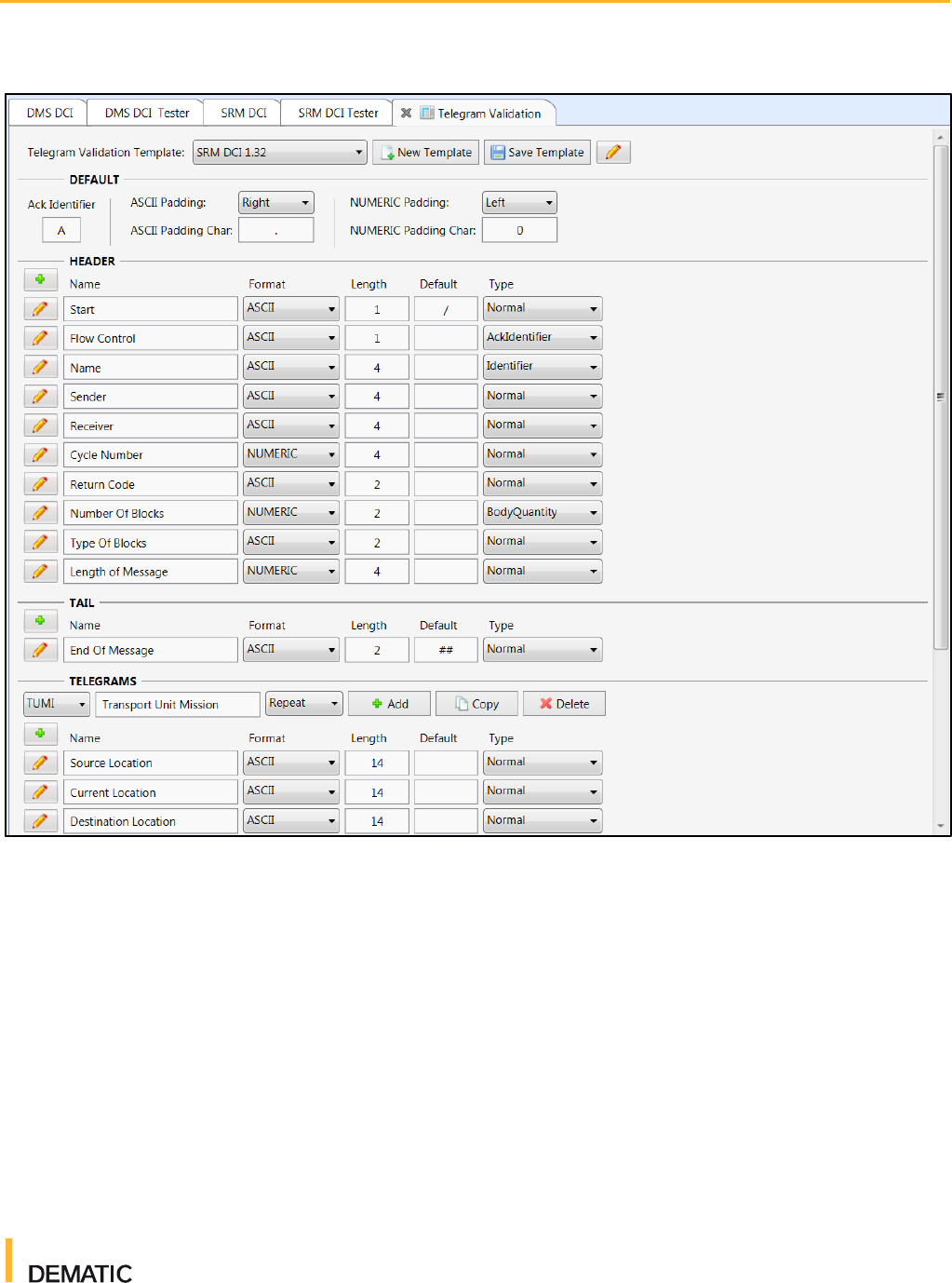
3 Telegram Validation
The Telegram Validation tool allows users to set message parameters that
ensure sent and received telegrams contain the necessary information.
Message types can include header, tail, and telegram validation properties.
These properties can be configured and linked to the applicable controllers.
Each message must pass this validation prior to being processed or sent by the
controller. This allows you to identify message errors quickly and speed up the
testing and commissioning process.
To modify or manage telegram validations, click the Telegram Validation button
on the menu bar.
Telegram validation templates can be found on the Telegram Validation wiki
page. These templates can be good starting points when beginning a VFC
project. To import or export a telegram validation template, click the pencil icon
in the top right corner of the Telegram Validation tab and then select Import
Template from XML or Export Template to XML.
If you want to create your own template, click New Template, enter a name for
the new template, and then click Add. Templates are saved as XML files and
can be modified at any time.
Note: Unlike most VFC tasks, you must save any modifications you make to
telegram validation templates. After making your changes, click the Save
Template button.
Virtual Flow Controller
User Guide
For Internal Use Only
2016-10-21
21
Figure 6 Telegram Validation Tab
Virtual Flow Controller
User Guide
For Internal Use Only
2016-10-21
22
4 SRM Controllers
VFC includes several SRM-specific features to allow you to manage TU
locations, cranes, and exceptions.
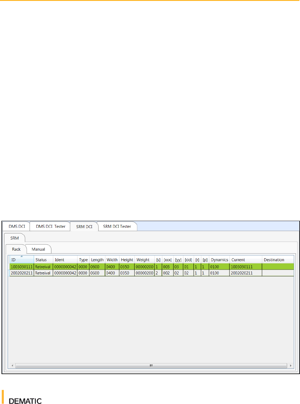
4.1 Racks
The Rack tab displays a list of all rack locations that TUs can be sent to or
retrieved from. This is a helpful screen for gaining an understanding of the
current status of your entire rack. You can modify rack locations so that they
appear occupied, reserved, and so on.
To add a rack location, perform the following steps:
1. In VFC, click the Rack tab and right click anywhere in the Rack table.
2. Click Add Location. The "Edit Rack Data" dialog box is displayed.
3. Enter the applicable rack location and TU parameters.
4. Click Update. The rack location's information is displayed in the Rack table.
Figure 7 Racks Tab

Virtual Flow Controller
User Guide
For Internal Use Only
2016-10-21
23
The following information is displayed for each rack location
● ID: The rack location identifying number. This number is determined by the
parameters set on the "Edit Rack Data" dialog box.
● Status: The current status of the rack location. The status can be Blocked,
Occupied, Reserved, Retrieval, Unknown, or Not Used.
● Ident: The TU identifying number. This is most commonly a bar code
number and can be alphanumeric.
● Type: The TU type. For more information about TU types, see the Controls
Emulation TU Types wiki page.
● Length: The TU length (in mm)
● Width: The TU width (in mm)
● Height: The TU height (in mm)
● Weight: The TU weight (in grams)
● [s]: The rack location side. That is, which side of the SRM the rack is on (01
for the left side and 02 for the right side).
● [xxx]: The rack location X-axis coordinate
● [yy]: The rack location Y-axis coordinate
● [dd]: The rack location depth
● [r]: The raster number
● [p]: The rack location position within the raster
● Dynamics: The velocity aggression
● Current: The current location of the TU. The TU could be on the rack, Pick
Station (PS), Drop Station (DS), or SRM.
● Destination: The destination location of the TU
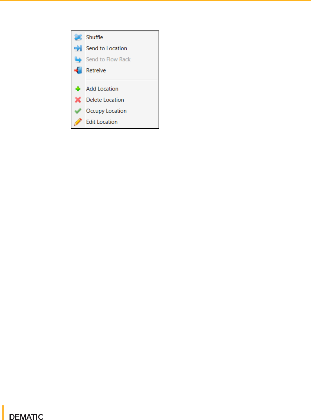
4.1.1 Working with Rack Locations
To begin working with rack locations, right click an entry in the Rack table.
Virtual Flow Controller
User Guide
For Internal Use Only
2016-10-21
24
Figure 8 Rack Location Actions
Depending on the location, the following actions might be available:
● Shuffle: Sends the TU to a random location in the same rack. Shuffling
is typically done to access TUs stored behind other TUs, or for zone
housekeeping. Additionally, when commissioning SRMs, shuffling can be
helpful for exercising machines.
● Send to Location: Sends the TU to a specified rack location. You must
enter the destination location details in the Rack Data menu that is
displayed.
● Send to Flow Rack: Sends the TU to a flow rack to be gravity fed to a
picking system.
● Retrieve: Sends the TU to a drop station.
● Add Location: Displays the "Edit Rack Data" dialog box and allows you to
configure a new rack location.
● Delete Location: Deletes the selected location as soon as you click it. Be
aware that there is no deletion confirmation.
● Occupy Location: Changes the rack location's status to Occupied.
● Edit Location: Displays the Edit Rack Data dialog box with the selected
rack location's parameters already entered.
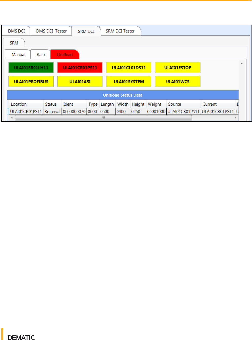
4.2 Cranes (Unitload or Miniload)
The Unitload or Miniload tab (depending on which SRM type you are working
with) provides a visual representation of the devices and components that are
running when your SRM is operational. This includes hardware such as PSs,
DSs, and load handlers. It also includes software and connections such as the
WCS, ASI, and PROFIBUS. This tab is a useful tool for quickly visualizing the
current status of your SRM. Each component's name is displayed in a box that
changes color depending on the status of that component. For more information
on status colors, see section 4.2.2.
Virtual Flow Controller
User Guide
For Internal Use Only
2016-10-21
25
Figure 9 Cranes (Unitload or Miniload) Tab
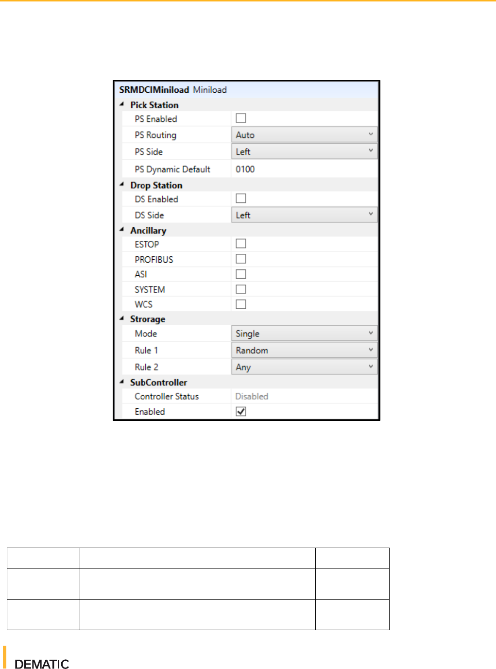
4.2.1 Crane Properties
The crane properties panel allows you to add, modify, or delete the following
components of your SRM controller configuration:
● Pick Stations: Enable pick stations by checking the PS Enabled checkbox.
Select either manual or automatic routing. Automatic automatically assign a
destination pick station, whereas Manual requires you to manually assign a
destination pick station. Select which side of the SRM the pick
stations appear on. Finally, enter a default dynamic value for the pick
stations (between 0 and 100). The PS Dynamic Default value is sent back to
the SRM if no dynamic value is set for the TU.
● Drop Stations: Enable drop stations by checking the DS
Enabled checkbox. Select which side of the SRM the drop stations appear
on.
● Ancillary: Enable additional software or communication devices or systems
that mimic common components of an SRM subsystem:
■ ESTOP: The safety emergency stop feature for the entire aisle
■ PROFIBUS: The fieldbus communication network
■ ASI: The Actuator Sensor Interface (AS-i) bit-oriented fieldbus
communication interface
■ SYSTEM: Where applicable, any inputs from fire or air pressure
warning systems for the building
■ WCS: The connection to the WCS
● Storage: Set the storage rules and mode for your SRM. For more
information, see section 4.2.3.
Virtual Flow Controller
User Guide
For Internal Use Only
2016-10-21
26
● SubController: Enable the subcontroller by checking the
Enabled checkbox.
Figure 10 Cranes Properties
4.2.2 Status Telegrams
Status telegrams send messages to change the status of a device or larger
subsystem. For example, sending an AU (automatic) telegram to a load handler
changes that load handler's status to automatic operation mode on the Unitload
or Miniload tab. The following status telegrams can be sent to VFC to alter the
status of devices, components, or subsystems:
Table 3 Status Telegrams
Status Code
Description
Status Color
AU
Automatic operation mode without any fault
Green
MA
Manual operation mode without any fault
Orange
Virtual Flow Controller
User Guide
For Internal Use Only
2016-10-21
27
Table 3 Status Telegrams
Status Code
Description
Status Color
FL
Short term fault
Red
OF
Long term not available (off or long term fault)
Yellow
..
No operation mode
White
4.2.3 Storage Rules
Storage modes and rules determine how TUs are stored and retrieved. These
parameters are set in the properties window when the Unitload or Miniload tab is
selected.
Storage Modes
● Single: Each load is stored in a different X location. This means two loads
can be arranged on the PS, DS, or LHD to be delivered both on the left side,
both on the right side, or one on each side provided that the loads do not
need to cross each other.
● Paired: (Applicable to wide aisles only) loads on the same LHD are stored in
the same X location either on the left or right side. Loads must be in the
correct order based on their destination depths.
● Mixed: (Applicable to wide aisles only) sometimes uses a single storage
mode and sometimes a paired mode.
Storage Rule 1
● Random: The location is selected at random
● Front: The free location nearest to X = 1 is selected
Storage Rule 2
● Any: Any free location is allowed
● Not Visited: A location that has not been previously visited is selected
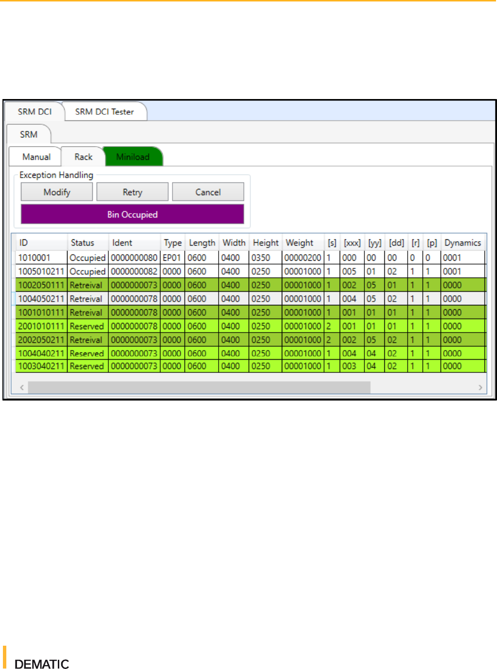
4.3 Handling Exceptions
When an exception message is sent, the exception is displayed on the Rack tab.
You can perform the following actions to handle exceptions:
● Modify: Modifies the transport mission and sends a TUMI telegram.
Virtual Flow Controller
User Guide
For Internal Use Only
2016-10-21
28
● Retry: Retries the same transport mission that caused the exception and
sends a TUMI telegram.
● Cancel: Cancels the exception. No message is sent.
Figure 11 Handing Exceptions
