1_FRONT_COVER_1 VFE2500 ELECT MANUAL.compressed
User Manual: VFE2500 ELECT MANUAL.compressed
Open the PDF directly: View PDF ![]() .
.
Page Count: 91
- 1_FRONT_COVER_1.pdf
- 2_IMPORTANT_NOTE_2.pdf
- 3_TABLE OF CONTENT_3.pdf
- 4_OVERVIEW_4.pdf
- 5_ELECTRICAL COMPONENTS_5.pdf
- 6_INITIAL_SETUP_6.pdf
- 7_PARAMETER UNIT_7.pdf
- 8_SPEED_PROFILES_8.pdf
- 9_SENSORS SETTING_9.pdf
- 10_PARAMETERS LIST_10.pdf
- 11_WIRING_DIAGRAM_11.pdf
- 12_SUPPORTIVE GRAPHS_12.pdf
- 13_FAULTS LIST_13.pdf
- 14_CLUTCH ENGAGED DISTANCE_14.pdf
- 15_STALL FORCE MEASUREMENT_15.pdf
- 16_CODE DISTANCE CLOSING TIME_16.pdf
- 17_INFRARED LIGHT CURTAIN AND VFE2500_17.pdf
- 18_HEAVY DOOR APPLICATION_18.pdf
- 19_NARROW DOOR APPLICATION_19.pdf
- 20_NUDGING APPLICATION_20.pdf
- 21_SERIAL_COMMUNICATION_21.pdf
- 22_PARTS LIST_22.pdf
- 23_LAST_PAGE_23.pdf

029)(
+$5021,&/,1($5
'22523(5$7256
(/(&75,&$/0$18$/
*$/&$1$'$
*RWWDUGR&RXUW
0LVVLVVDXJD2QWDULR
/7$&DQDGD
KWWSZZZJDOFDQDGDFRP
(
ELECTRICAL
2500-3069
I
FOREWORD
It is the intent of this manual to give the reader certain key points of information critical to the
proper installation of the door operator. It is not intended to give comprehensive installation
procedures nor does it cover the installation of door headers, track, hangers, etcetera.
It is hoped that the procedures presented in this manual will reduce the installation and
adjustment time and result in a smooth, long lasting door operation.
When properly installed, GAL door operators will give many years of trouble free service.
COMMENTS:
All *$/ door operators are factory adjusted and tested for the actual job requirements.
When installed correctly, they may require minor adjustments to suit actual job
conditions.
IMPORTANT NOTES:
All equipment must be installed, adjusted, tested and maintained to comply with all
Federal, State/Provincial, and Local codes.
Kinetic Energy and Stall Force must be adjusted to comply with ASME, A17.1,
Rule 112.4/5, and CSA/B44, Rule 2.13.4/5.
Before mounting the operator, check that the car door is plumb, free and moves
easily without bind. Check the attached standard measurement sheets.
Install the operator according to the measurements supplied.
Contact *$/ if the following label is missing from the door operator.
II
TABLE OF CONTENTS
Foreword I
Comments & Important Notes I
Table of Contents II
OVERVIEW 1
ELECTRICAL COMPONENTS OF MOVFE2500 4
1. Toggle switches 4
2. LED Indicators 5
3. Optical Sensors for Harmonic Model 6
4. Hall-effect Sensors for Linear Model 6
5. Inputs 7
6. Outputs 7
7. Additional I/O Board 8
8. Encoder module 8
9. Encoder 8
10. Learn Door Width LED 9
11. CAN bus module 9
12. Infrared Detector Edges Connection Ports 9
13. Parameter Unit 11 14. VFE2500 drive 11 15. Motors 12 16. VFE2500 Models 12
INITIAL SETUP 14
1. Turn Power ON 14
2. Motor Direction 14
3. Encoder Direction 14 4. Download an ECI default parameter set 15
5. Learn The door width 16
5.1 Door is between DOL and DCL 16
5.2 Door is fully Opened 16
5.3 Door is fully Closed 16
6. Set the operation source 17
PARAMETER UNIT 18
1. How to change parameters 18
2. How to read (copy) from a drive 18
3. How to write (download) to a drive 18
4. How to verify encoder direction 18
5. How to learn the door width 18
6. Default parameters 19 7. Conveniences keys 20 9. The View key 20
Voltage, Current, Frequency 20
III
Inputs and Outputs Monitoring 20
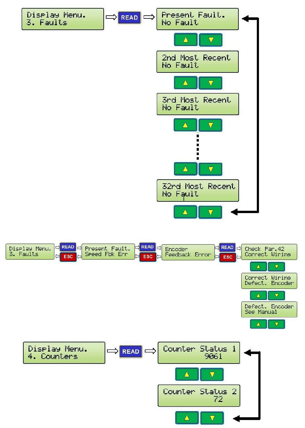
Faults 21
Counters 21
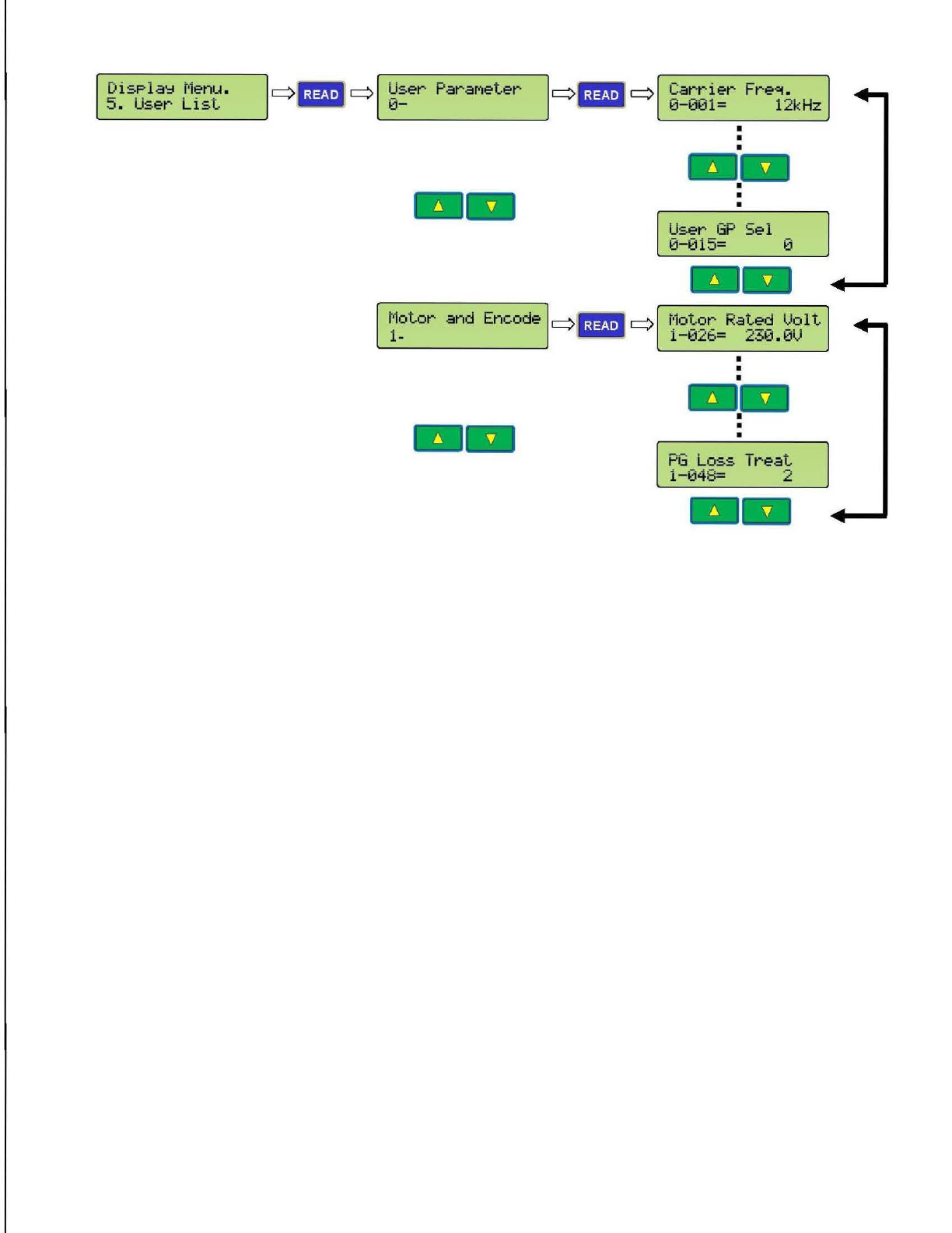
User List 22
User parameters 22
Motor and Encoder 22
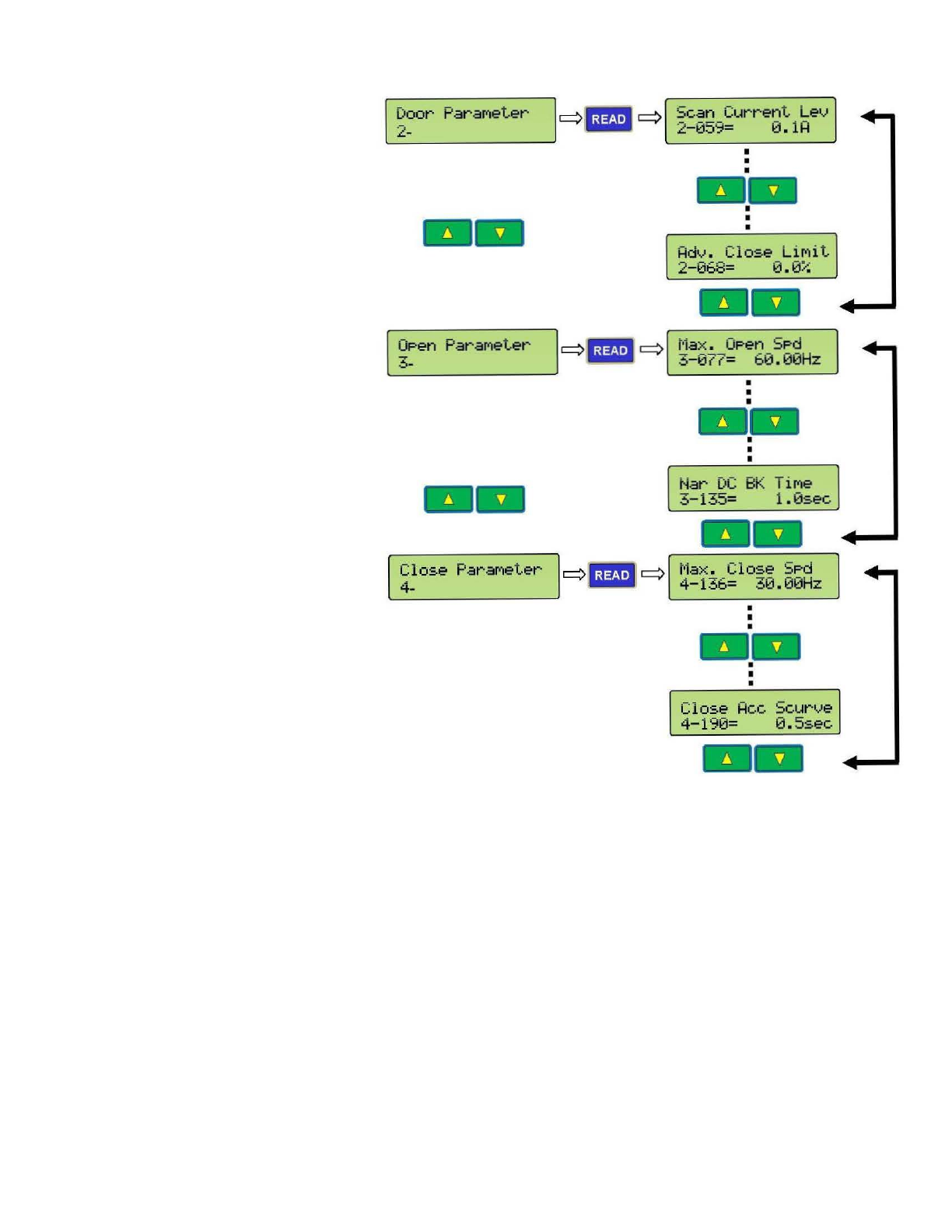
Door parameters 23
Open parameters 23
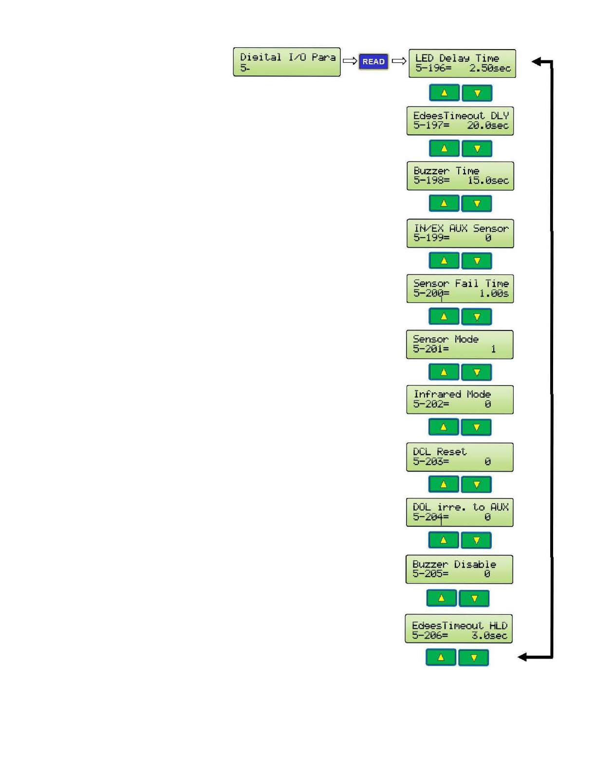
Digital I/O parameters 24
Direction 25
Communication 26
Maximum Close Speed 26
Maximum Close Force 26
ECI Defaults 27
Harmonic 27
Linear Straight 27
Linear Geared 27
Display Groups 28
Code Distance (CD) Closing Time Display 28
CD Closing Time 28
DOL Î DCL Time 28
CD Opening Time 28
DCL Î DOL Time 28
LED Indicators 28
SPEED PROFILES OF THE VFE2500 29
Normal Door 29
Heavy Door 30
Narrow Door 31
SENSORS SETTING 32
Hall-effect sensors setting for linear door operator 32
Optical sensors setting for harmonic door operator 32
PARAMETERS LIST FOR USERS 33
Group 0: User parameters 33
Group 1: Motor & Encoder parameters 33
Group 2: Door parameters 34
Group 3: Open direction parameters 35
Group 4: Close direction parameters 41
Group 5: Digital I/O parameters 46
Group 6: Protection parameters 47
Group 7: Communication parameters 48
Display Parameters 48
WIRING DIGRAMS 51
IV
SUPPORTIVE GRAPHS 52
V/F curve for Normal door 52
V/F curve for Heavy door 52
V/F curve for Narrow door 53
DC Injection 53
Stall Reverse detection 54
Frequency Failure detection 54
Infrared Detector Edges detection 54
Edges Timeout relay and Buzzer timing 55
Edges Timeout relay and Buzzer mode 55
Interaction between Re-open and Edges Timeout relay 56
FAULTS LIST 57
FAULTS RESET HANDLING FLOWCHART 61
CLUTCH ENGAGED DISTANCE SETUP 62
DOOR STALL FORCE MEASUREMENT 63
CODE DISTANCE CLOSING TIME SETUP 64
MINIMUM CLOSING TIME (ECI REFERENTIAL VALUE) 65
CHECKING PROCEDURE FOR THE CLOSING CODE TIMES 66
INTERFACING BETWEEN ECI CERTIFIED LIGHT CURTAIN AND VFE2500 67
Understanding the RE-OPEN relay 67
How to interface between the Infrared Detector Edges and VFE2500 67
Test the Infrared Detector Edges 67
If the Detector Edges function does not work 68
If the Detector Edges have intermittent problems 68
Infrared Detector Edges connection 69
INFRARED DETECTOR EDGES APPLICATION FLOWCHART 70
OPTIONAL APPLICATIONS
HEAVIER DOOR 71
NARROWER DOOR 72
NARROWER DOOR APPLICATION FLOWCHART 73
NUDGING 74
NUDGING APPLICATION FLOWCHART 75
SERIAL COMMUNICATION 76
PARTS LIST 77
NOTES & COPYRIGHT 85
1
OVERVIEW:
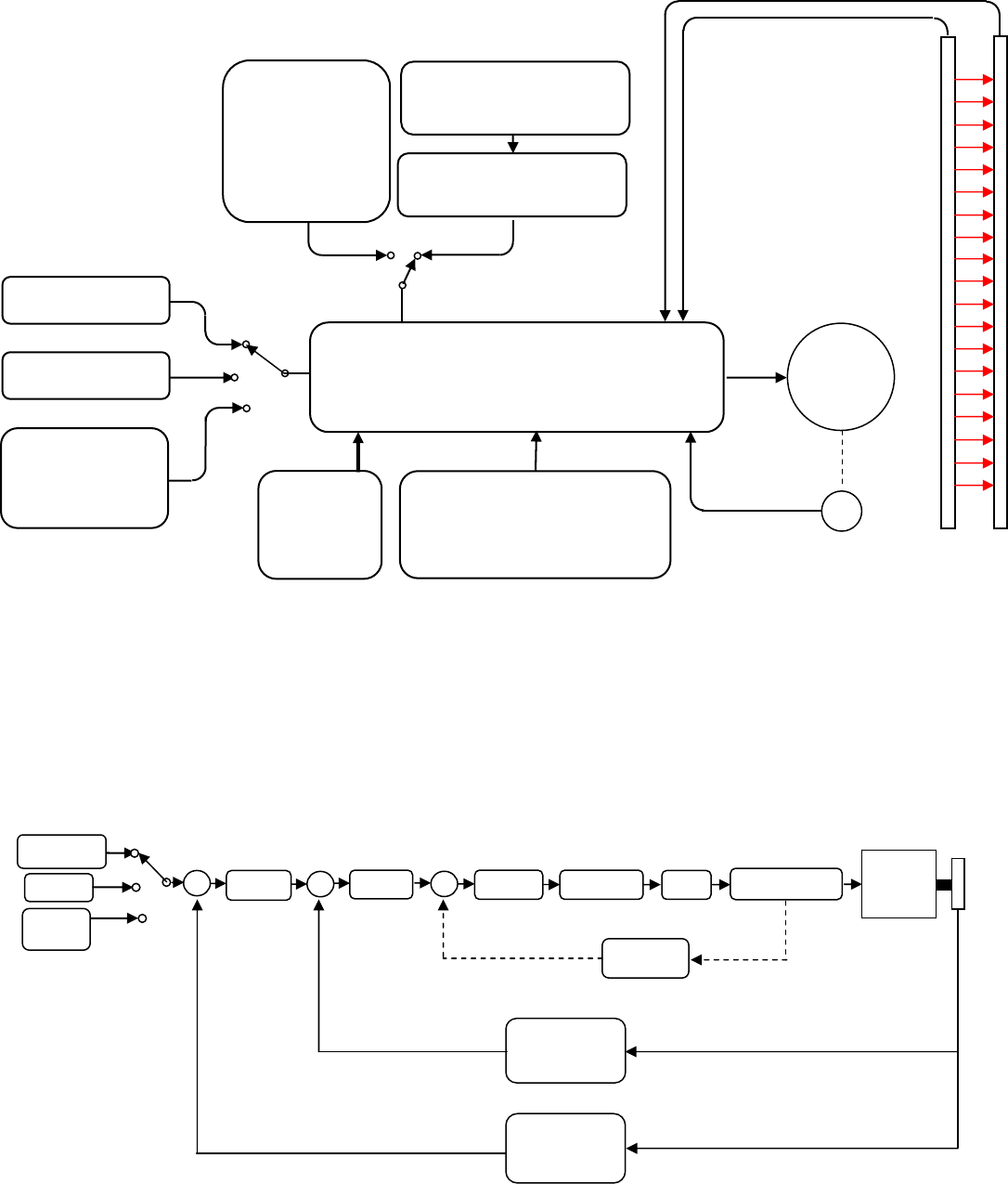
The general block diagram of the VFE2500 is in the illustration below:
The VFE2500 door operator has the following features:
DOUBLE FEEDBACK SYSTEM FOR SMOOTH PERFORMANCE:
• Distance and velocity closed-loop system
• Once the door-width is learned, VFE2500 will optimize control of the elevator door(s)
• Parameters sets are provided to maximize the performance of the system
Following is a simplified control diagram of the VFE2500.
TERMINAL INPUTS
CAN BUS
KEYPAD
OR
RS 485
VFE2500
DRIVE
QUADRATURE
ENCODER
INFRARED
DETECTOR
EDGES
(OPTIONAL)
TRANSMITTER
RECEIVER
3PH
INDUCTION
MOTOR
230VAC
POWER
SUPPLY
OPTICAL
SENSORS
FOR
HARMONIC
OPERATOR
HALL-EFFECT SENSORS
FOR LINEAR OPERATOR
SIGNALS TRANSFER
SECTION
FOR LINEAR OPERATOR
ADDITIONAL I/O
FOR HEAVY, NARROW DOORS
AND NUDGING APPLICATION
CURRENT
LIMITER
3 PHASE
AC MOTOR
CURRENT
FEEDBACK
SPEED
CONVERSION
&
FEEDBACK
POSITION
CONVERSION
&
FEEDBACK
∑
- - -
QUADRATURE
ENCODER
KEYPAD
OR
RS 485
PWM
PID
CONTROLLER
TERMINAL
INPUTS
CAN BUS ∑ ∑
POSITION
CONTROL
SPEED
CONTROL
IGBT
SWITCHING
2
SAFETY STANDARDS:
• CSA Certified. B44.1/ASME- A17.5
• Complies with the following CE and IEEE safety standards of
EN61000-4-2, EN61000-4-3 EN61000-4-4, EN61000-4-5, EN61000-4-6, EN61000-4-8,
and IEEE STD C62.45-1992
• EMC conformity report is available
A POWERFUL SYSTEM:
• 230VAC and 115VAC power supply versions are available
• Variable voltage, variable frequency (VVVF) drive
• A ½ HP AC motor is used to accommodate for most of door loads, friction, and wind pressure
HARMONIC AND LINEAR MODELS ARE AVAILABLE:
• Three models of VFE2500 are currently available:
¾ VFE2500-HH : Heavy duty Harmonic model
¾ VFE2500-GL : Light duty Linear model
¾ VFE2500-HL : Heavy duty Linear model
NON-CONTACT SENSORS:
• Optical sensors and Hall-effect sensors for final limits, door protection monitor, and narrower
door limit.
CONVENIENCE INDICATORS:
• Light Emitting Diodes (LEDs) on the main board are used to indicate status of all important
functions:
Door open, close, nudging, heavier, narrower input signals,
Door open, and close directions,
Open, and close slowdown,
Obstruction detection signal,
Stall reverse,
Frequency failure,
DOL, DCL, AUX (Narrower door), and DPM (Door Protection Monitor)* output signals,
Door-width learning completion.
UNIVERSAL INPUTS AND OUTPUTS:
• Universal inputs accept control signals in form of contacts or signal voltages;
from 24-230V AC or DC.
• Output contacts, rated at 10Amp, 230VAC, include:
Door Close Limit (DCL),
Door Open Limit (DOL),
Re-Open (RE-OPEN),
Door Protection Monitor (DPM),
Auxiliary/Narrower Door (AUX),
Edges Timeout (ET)
• All input modules, output relays, and connectors are pluggable for easy replacement.
KEYPAD (PARAMETER UNIT):
• Keypad programming with LCD display is available to adjust, monitor, copy, change
parameters, upload parameter sets, and to learn the door width distances.
• Default parameter sets are ready for all ECI operator models.
• Different parameter sets for heavier door and narrower door are available for proper
adjustments to comply with codes.
• The ability to copy (read) and download (write) parameter sets enables reduced setting time
on similar door operators.
3
TOGGLE SWITCHES FOR MANUAL TESTING:
• Toggle switches are provided for manual operation, diagnostics, and operational verification
regardless of the control wiring to the elevator controller
OVER-TORQUE AND OVER-SPEED DETECTIONS:
• Over-torque and over-speed detection and restriction are parameterized for easy adjustment
to comply with codes
PLUG-AND-PLAY INFRARED DETECTOR EDGES:
• Both NPN and PNP infrared detector edges can be connected directly to the VFE2500
simplifying electrical wiring and eliminating the need for an extra power supply
SPECIAL FEATURES ADDED:
• Combined VVVF drive and main board makes the VFE2500 drive easily interchangeable from
one model or job to another
• Additional I/O for special applications of:
Heavier door, Narrower door, Detector edges timeout for Nudging application, Buzzer output
for alarm before Nudging speed is applied
RELIABLE AND HIGH RESOLUTION FEEDBACK:
• High resolution encoder and galvanic isolation techniques are used to deliver smooth, and
reliable operation.
• Hardware and software encoder loss detections are employed to prevent run-away conditions
that could otherwise result in a closed-loop control system. This combination of hardware and
software provides an ultimate protection for human life
SERIAL COMMUNICATION TO VFE2500:
• CAN (Controlled Area Network) or other communication protocols can be used to communicate
with VFE2500 serially.
• CAN bus counter and analyzer are built in to monitor the CAN bus activities.
TROUBLESHOOTING ASSISTANCE DISPLAY:
• The Faults display will explain to users the possible causes and shows the remedies for each
fault code.
MINIMUM CODE DISTANCE CLOSING TIME TABLES:
• The minimum code distance closing time tables are available on the LCD keypad.
ACTUAL DISPLAY OF THE CLOSING TIME:
• The actual code distance of the closing time is displayed to assist users in complying with
codes.
AUTO FALLBACK TO SLOW MODE IF SENSORS OR ENCODER FAIL:
• If DOL, DCL, AUX, or DPM sensor fails, or if the encoder fails, the VFE2500 door operator will
continue to operate in slow scanning mode until repairs are completed
*: Door Protection Monitor is used in the Fault Monitor, which is a door lock and gate switch
protection device. Its purpose is to meet the ASME A17.1 RULE 210.15 and CAN/CSA-B44-M90
RULE 3.12.1.5. The Fault Monitor device can be purchased separately through ECI.

4
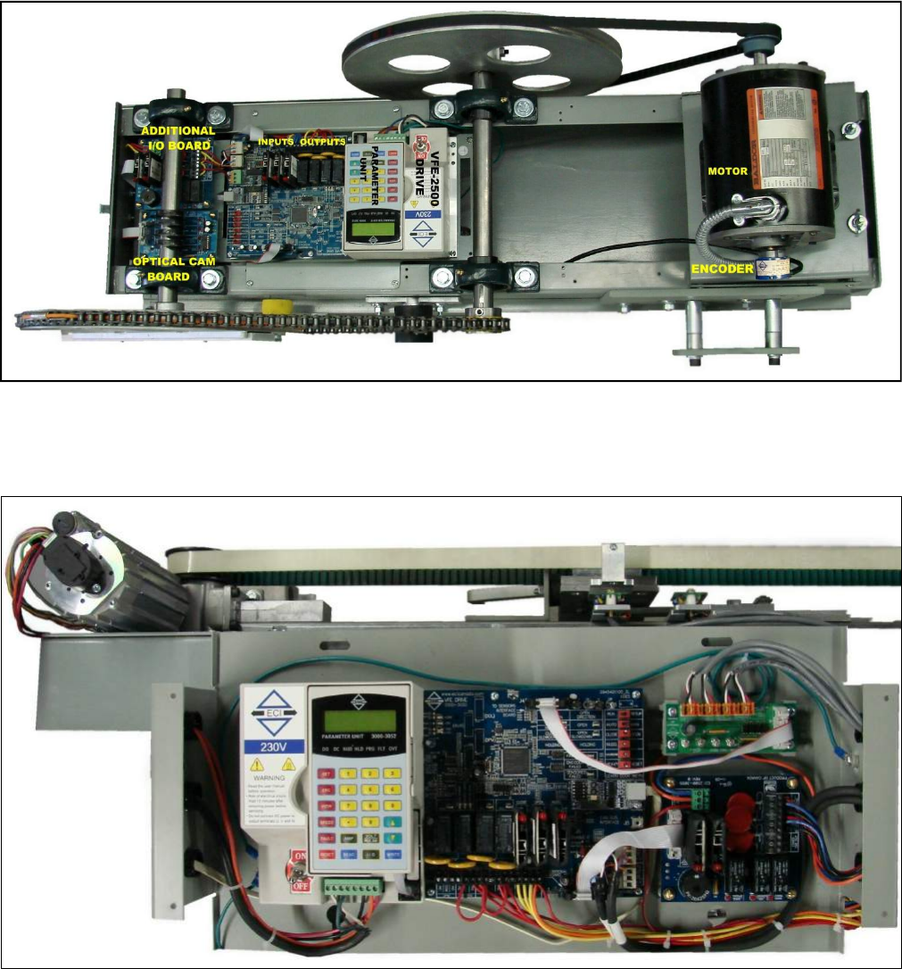
ELECTRICAL COMPONENTS OF THE VFE2500:
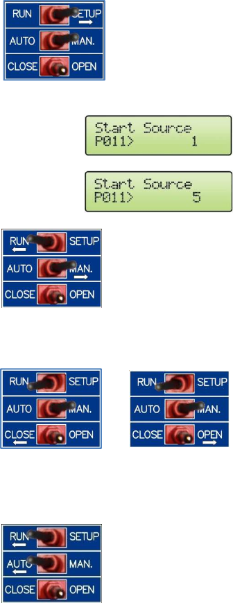
1. Toggle switches:
Order
No. Label Meaning Remarks
1 RUN/SETUP Run or Cam Setup
RUN:
The RUN position is for normal operation.
SETUP:
The SETUP position allows users to adjust the optical
cams of the Harmonic model, or the hall-effect sensors
of the Linear model. These are DOL, AUX, DPM, and
DCL sensors . Crucial parameters can only be adjusted
in STOP mode. The SETUP position will put the drive
into the STOP mode, and no power will be delivered to
the motor.
2 AUTO/MAN. Auto or Manual
AUTO:
The AUTO position is for normal operation.
MAN.:
The MAN. position allows opening and closing the door
by means of the OPEN/CLOSE switch.
3 CLOSE/OPEN Close or Open
When the AUTO/MAN. switch is in the MAN. position, if
the CLOSE/OPEN switch is pressed in the OPEN or
CLOSE positions, it will Open or Close the door
respectively.
4 NUDG. Nudging
NUDG. switch allows closing the door at a reduced
speed (Nudging speed). To test the Nudging speed in
Manual mode, the AUTO/MAN. switch must be in the
MAN. position and the CLOSE/OPEN and NUDG.
switches must be pressed to the CLOSE and NUDG.
positions.
5 NARROW Narrower Door
When the AUTO/MAN. switch is in the MAN. position, if
the NARROW switch is pressed in the NARROW position,
it will work in conjunction with the OPEN/CLOSE, and
NUDG. switches to Open, Close, or Nudge the door.
6 HEAVY/RESET
Heavier Door or
Reset
HEAVY:
When the AUTO/MAN. switch is in the MAN. position, if
the HEAVY/RESET switch is pressed in the HEAVY
position, it will work in conjunction with the
OPEN/CLOSE, NUDG. switches to Open, Close, or Nudge
RESET:
The RESET position allows manual reset of faults of the
drive, if faults have occurred. Otherwise, pressing the
RESET side has no effect.
Six toggle switches are provided to run the door operator in
manual mode. However, users can also use these switches to
troubleshoot and verify the operation.
the heavier door.
5
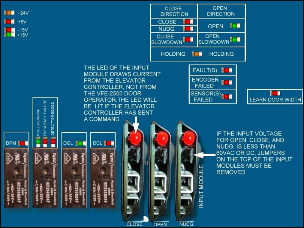
2. LED indicators:
A red LED is provided on each of the input modules (Open, Close, or Nudge). Heavy and Narrow
inputs are optional and require an additional I/O board, which will be provided on request to carry
out the Heavier and Narrower door functions.
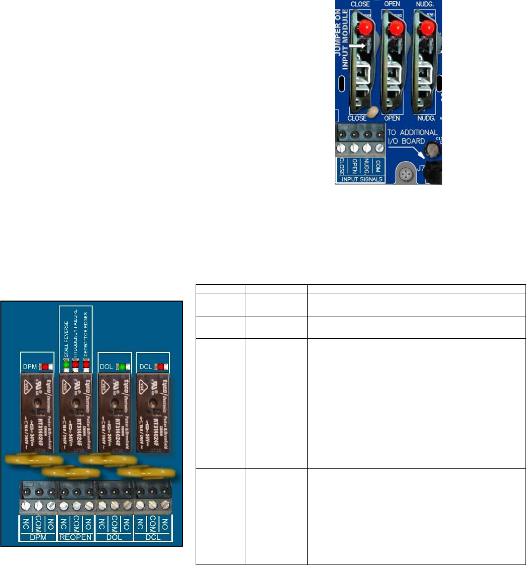
Note that if the input signals voltage is 60V or less, the jumpers on each input module must be removed.
There are 20 more LEDs, on the main board, to indicate the completion of the door width learning,
the directions, the final limit positions, nudging, holding, dynamic slowdown distances, input signals,
output signals, and voltage levels. The illustration below identifies those LEDs.

6
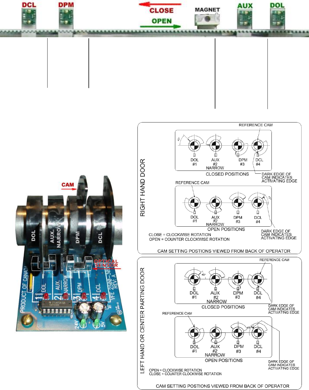
3. Optical Sensors for Harmonic Model:
For the harmonic model, there are 4 optical cams to set the final limits, door protection monitor, and
an AUX. cam for the narrower door. The Optical cam board, 2500-3056, carries the optical sensors, and
the table below describes the functions of those sensors.
4. Hall-effect Sensors for Linear Model:
For the linear model, there are 4 hall-effect sensors to set the final limits, door protection monitor,
and an AUX. sensor for the narrower door. These hall-effect sensors have the same functions as in
the harmonic operator, as shown in the table above. They are connected to the signals transfer board
and arranged as follows:
Number
on
Figure Label Remarks
1 DOL
Door Open Limit. The VFE2500 utilizes
the DOL limit signal for door width
learning. After the door width learning
process is completed, VFE2500 utilizes
the DOL limit as HOME position
whenever power is restored after an
interrupt.
2 AUX
NARROWER
Set Par. 199=0 to use the
AUX/NARROWER sensor as the DOL
input of the narrower door.
Set par. 199 = 1 to deselect the
AUX/NARROWER sensor.
3 DPM
DPM: Door Protection Monitor. The
DPM cam triggers the DPM Relay and
activates ½ inch before the Gate
switch makes.
4 DCL
Door Close Limit. The VFE2500 utilizes
the DCL limit signal for door width
learning. After the door width learning
process is completed, VFE2500 also
utilizes the DCL limit as HOME position
whenever power is restored after an
interrupt.
7
5. Inputs:
6. Outputs:
Four relays are provided to output DPM, RE-OPEN, DOL, and DCL signals to the elevator controller
in the form of contacts. The relay contacts are rated at 10Amp, 250VAC maximum and 100mA,
12VAC minimum.
Label Meaning Remarks
DCL Door Close
Limit Door Close Limit
DOL Door Open
Limit Door Open Limit
REOPEN Re-open
This output is used to flag the elevator
controller that the door(s) need to be
reopened. The reopen output DOES NOT
reopen the door directly. The signal to reopen
the door(s) must come from the elevator
controller. Re-open relay is triggered by any
one of the following detections:
- Stall Reverse; controlled by Par. 148.
- Frequency Failure; controlled by Par. 136.
- Detector Edges; controlled by Par. 202,
SW8, and Enable IC U5.
DPM
Door
Protection
Monitor
DPM is designed to work with the Fault
Monitor (FM). FM is a patented door lock and
gate switch protection device. Its purpose is
to meet the ASME A17.1 RULE 210.15 and
CAN/CSA-B44-M90 RULE 3.12.1.5. The
setting position of DPM is ½ inch before the
gate switch makes.
Three input modules are provided to receive OPEN, CLOSE,
and NUDGE commands from the elevator controller. These
universal input modules receive control signals either in
form of contacts or signal voltages; from 24-230V AC o
r
DC. Jumpers on the input modules must be removed if the
input signal voltage is 60V or less. LEDs of the input
modules draw currents from the elevator controller, not
from the VFE2500. Therefore, when these LEDs are lit, they
indicate that the elevator controller has sent commands.
In automatic mode, the VFE2500 will only accept input
signals from the elevator controller. In other words, open,
close or, (nudge + close) LEDs must be on to have the doo
r
operator open, close, and nudge respectively.
8
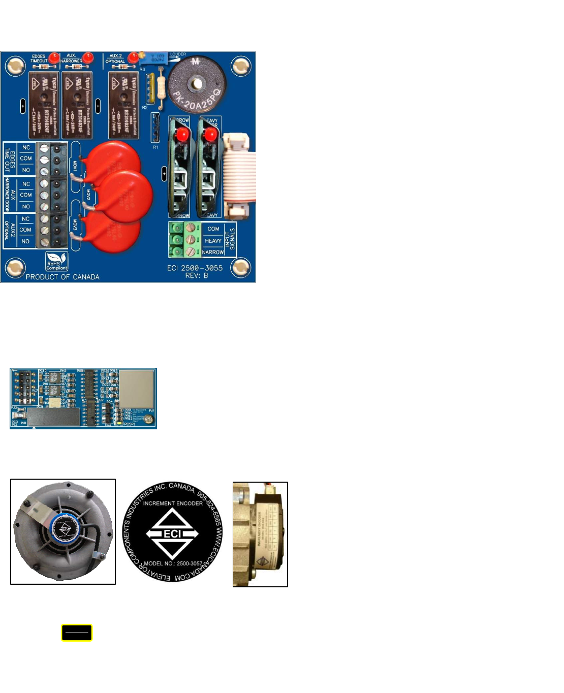
7. Additional I/O Board:
8. Encoder card:
9. Encoder:
Additional I/O board, 2500-3055, is optional. If used, this
board will be connected to the connector J7 of the main board
2500-3050. The additional features of this board are:
- Inputs for the Heavier, and Narrower doors.
Elevator controller must provide command signals
to the Heavy and Narrow inputs to use the functions of
the parameters sets of the Heavier and Narrower doors.
Set Par. 199 = 0 if Narrower door is used.
- Edges Timeout: Once the infrared detector edge is
obstructed, and after a delay set by Par. 197, the
Edges Timeout relay will be activated and held for
an interval of time set by Par. 206. Should the
edges timeout relay be used for Nudging application,
it must be subject to the elevator fire service codes.
- DOL of the narrower door is selectable between the
Regular output DOL on the main board or the
AUX/NARROWER output on the Additional I/O board.
Set Par. 204 = 1 if only the regular DOL output is used.
Set Par. 204 = 0 if both the AUX/NARROWER output
and regular DOL output are used.
- AUX2 relay is provided as a spare output and is controlled
by Par. 68. If the door position is less than the value
set in Par. 68, the AUX2 relay will be activated.
- Buzzer: once the infrared detector edge is obstructed, and
after a delay set by Par. 198, the output of the Buzzer will
be activated. Buzzer operation is controlled by Par. 205.
Par. 205 = 0 : Disable
Par. 205 = 1 : Enable in Continuous mode
Par. 205 = 2 : Enable in Pulsating mode
The Buzzer volume control is on the board. Turn the Pot. R3
clockwise for louder sound.
The optical galvanic isolation encoder card is a means to interface between the
encoder and The MCU (Micro Controller Unit). This total isolation helps enhance
the reliability and safety of the feedback system.
RJ12 mating gold-plated connectors are also used to maximize the conductivity
between the encoder and MCU.
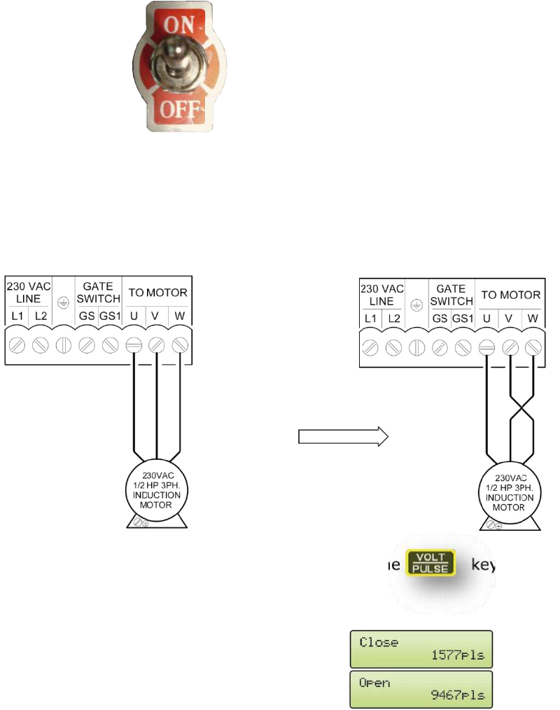
To verify encoder direction:
Press the key, run the door in manual mode or physically move the door by hand, and watch the LCD
display. If the door closes and the count decreases, or the door opens and the count increases, then the encoder
direction is correct. Otherwise, change parameter 42 from 1 to 2 or vice versa. The table below provides the default
values of par. 42.
VOLT
PULSE
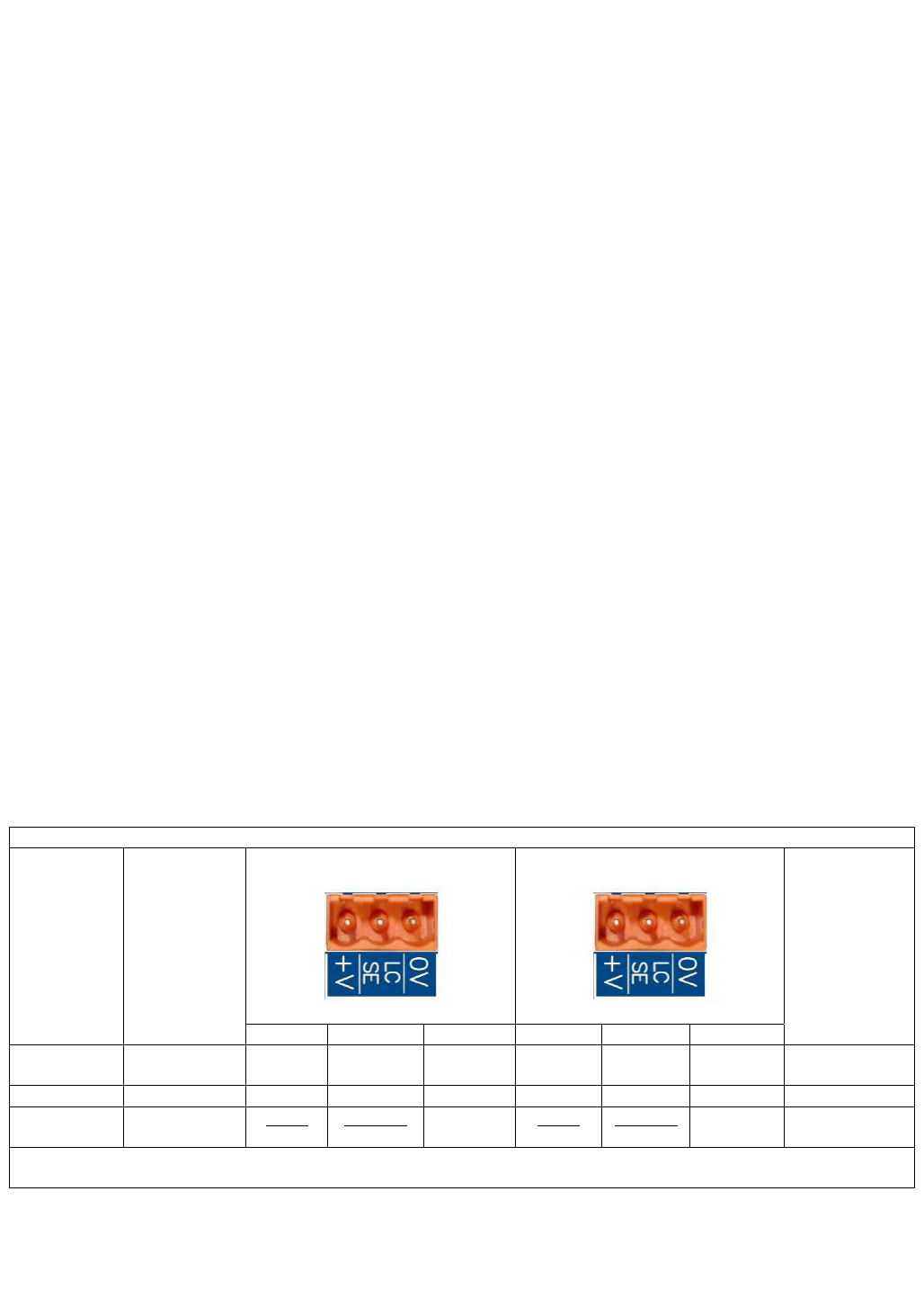
Two different types of encoder are used in
VFE2500 door operators. Model 2500-3057
encoder is used for the straight motor. Model
2500-3058 encoder is used for the geared
motor. These encoders are utilized to provide
distance and velocity feedback.
Model:2500-3057
Model:2500-3072-R/L
9
DEFAULT VALUE FOR THE ENCODER DIRECTION OF PAR. 42
HARMONIC LINEAR
STRAIGHT GEARED
LEFT RIGHT CENTER LEFT RIGHT CENTER LEFT RIGHT CENTER
2 1 2 1 2 1 1 1 2
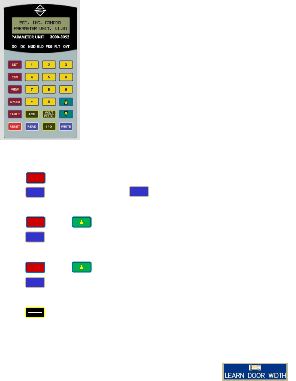
10. LEARN DOOR WIDTH LED:
11. CAN Bus card:
12. Infrared Detector Edges Connection Ports:
The “LEARN DOOR WIDTH” LED is an indicator to show the status of the door width
learning process.
To learn the Door Width:
Set Par. 63=1. Use Manual mode to run the door from DOL to DCL or vice versa.
Follow the prompts on the LCD display. The “LEARN DOOR WIDTH” LED will flash and
turn off when the learning process is completed. Par. 63 will reset itself to Zero.
See Parameter Adjustment section for more details.
The optical galvanic isolation CAN bus card is one of the methods to interface
between and the elevator controller and the VFE2500. This total isolation helps
increase the reliability of the CAN bus.
To enable CAN Bus operation:
Flip the RUN| SETUP switch to SETUP. Set Par. 11 = 5.
Flip the RUN| SETUP switch to RUN. Flip the AUTO|MAN to AUTO to run VFE2500
with the CAN Bus.
Other communication protocols are also available upon request. However, an agreement between ECI and the
requesting party must be made prior to the implementation of the communication protocols.
Contact ECI for more details in CAN or other protocols.
To simplify connections between infrared detector edges and the elevator
controller, ECI offers ECI Certified Infrared Detector Edges. These infrared
detector edges can be connected directly to the VFE2500. The procedure
below will assist users to plug and play ECI Certified Infrared Detector
Edges with the VFE2500.
NPN or PNP output:
The info of NPN or PNP output should be obtained prior to installation.
Read the label on the tube or the detector edges’ manual to know the
output type of the infrared detector edges. It is either NPN or PNP. Set the
selector switch SW8 accordingly. If the info of NPN or PNP is unavailable,
then, use a trial and error method. Assume that the edges’ output is NPN
for the 1st trial.
To set up ECI certified infrared detector edges:
Set Par. 202 = 1 for NPN type. Set Par. 202 = 2 for PNP type.
Set par. 202 = 0 to disable or should detector edges are not connected to the VFE2500.
Make sure the ENABLE CHIP is inserted into the socket U5 on the VFE2500 as shown.
Connect the ECI Certified Infrared Edges to connectors CN4 and/or CN5.
Note! Connectors CN4 and CN5 are interchangeable.
Make sure the REOPEN circuit is connected to the REOPEN output contacts as shown in section 6.
10
Test the detector edges:
- Obstruct the infrared detector edges. The DETECTOR EDGES LED, near the Re-Open relay, should be ON.
- The REOPEN relay should be activated to send the REOPEN flag to the elevator controller.
- The elevator controller will send the Door Open command signal to the VFE2500 to REOPEN the door.
The LED of the Open Input module should be ON.
If the detector edges function does not work.
- Check the manual for correct connections between edges and the VFE2500.
- Check for 24VDC between 0V and +V on either CN4 or CN5.
- Repeat testing the detector edges.
If it still does not work. Then,
-Jump 0V to LCSE on either CN4 or CN5 connector for NPN type.
-Jump +V to LCSE on either CN4 or CN5 connector for PNP type
- The DETECTOR EDGES LED should be OFF.
- The RE-OPEN Relay should be activated.
Otherwise, the problem is in the VFE2500.
If the above step works as described, turning ON the detector edges LED, then the problem is in detector edges.
If the infrared detector edges have intermittent problems:
- Check continuity of the TX and RX cables of the infrared detector edges.
- If the cables are good, but the problem still exists, then check the Earth Ground connection to the edges.
- Lower the Carrier Frequency in Par. 1 gradually until problems are resolved.
Note! The lower carrier frequency will create more audible noise.
The major advantages of connecting ECI certified infrared detector edges via VFE2500 are:
- Eliminates an extra power supply for the detector edges, resulting is less mounting, less wiring, and
fewer components to fail.
- The REOPEN relay that is used for infrared detector edges interface provides 2 more safety features
to reopen the door: Over-speed and over-torque detections.
- When the VFE2500 door operator and the interface circuit with the infrared detector edges are
provided by ECI. ECI can provide the best technical support.
- ECI provides users with an Additional I/O board to assist customers with Nudging feature. This
additional I/O board only works with ECI Certified Infrared Edges
The table below assists users to identify the colors, numbers of each wire from infrared detector edges to the
VFE -2500 door operator.
ECI CERTIFIED INFRARED DETECTOR EDGES WIRE COLORS
ECI
P/N MFG.
TX(CN5)
RX(CN4)
CONNECTION
BETWEEN
TX & RX
V+ LCSE 0V V+ LCSE 0V
906-3013 JANUS RED BLUE
ORANGE
(♦)
ORANGE
(♦)
WHITE-
WHITE
906-3020 TRITRONICS RED WHITE ORANGE NONE
906-3030 FORMULA
SYSTEMS
BLUE
1
BROWN
2
GREEN
YELLOW
BLUE
1
BROWN
2
GREEN
YELLOW NONE
(): Connect an additional wire from 0V to a true EARTH GROUND.
ECI Certified Infrared Edges and Enable IC U5 are available through ECI, Inc.
BROWN
GREEN
YELLOW
BLUE
BROWN
GREEN
YELLOW
BLUE
NONE
VERSION 2
FORMULA
SYSTEM
♦
11
13. Parameter Unit:
14. VFE2500 drive:
The Parameter Unit is a tool that plugs into the VFE2500
drive and permits changing values of relevant parameters.
Parameter unit is also needed for door width learning,
monitoring, troubleshooting, storing, copying (reading), and
downloading (writing) reference sets of parameters, to the
VFE2500 drive.
See PARAMETER UNIT section for more details.
VFE2500 drive is an integral part of the VFE2500 system.
Velocity and distance feedbacks are combined to deliver precise
and smooth stops at DOL or DCL every time
VFE2500 drive provides the connections for:
- Single phase input power supply between L1 & L2 terminals.
Note! 200-230VAC or 115VAC, 50/60Hz, and minimum 500VA
are required.
- Earth ground
Note! A True Earth Ground is required.
- Convenience Gate switch terminals: GS & GS1. Note! GS &
GS1 are only convenience terminals. They have no internal
connection to the VFE2500.
- 3-phase induction motor on U, V, W terminals.
The connector is a pluggable type to ease the connection and
swapping the drive. The RJ12 mating connector for the parameter
unit is located on the VFE2500 drive.
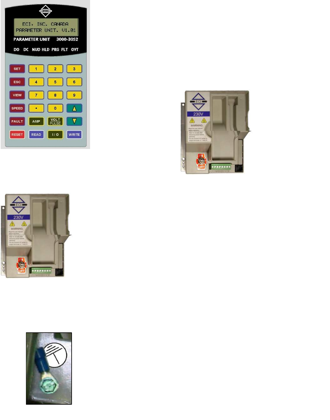
The International Ground Symbol is the True Earth Ground that is
connected to the system. A connector and a green screw, size 8/32
x 3/8, are provided by ECI as shown. Use position 22-14 of the
crimping tool to crimp the wire into the connector and use the
green screw to screw the ground connector to the chassis of the
VFE2500 door operator. The following materials are recommended:
A minimum # 14 AWG conductor size for Ground wire.
Crimping tool made by SARGENT/USA.

12
15.
Motors:
16.
VFE2500 MODELS:
Two different types of motor are used in the VFE2500 systems.
● ½ HP 3-Phase 230V induction motor is used for the Harmonic and Heavy Duty Linear models.
● 91W 3-Phase 230V induction geared motor is used for Light Duty Linear model.
Three models of VFE2500 system are available:
● VFE2500-HH: Heavy Duty Harmonic model.
● VFE2500-GL: Light Duty Linear model.
● VFE2500-HL : Heavy Duty Linear model.
Left hand, right hand, center parting versions are available for each model.
02VFE2500 Heavy Duty Linear Model
½ HP 3-Phase 230V Induction Motor 91W 3-Phase 230V Induction Motor
13
029)(+HDY\'XW\+DUPRQLF0RGHO
029)(/LJKW'XW\/LQHDU0RGHO
02VFE2500 Heavy Duty Harmonic Model
VFE2500 Light Duty Linear Model
IN
E
fo
T
1
2
3
NITIAL SET
CI has don
ollowing ini
This initial p
- The m
- The e
- The c
- The d
- The o
. Turn Po
. Motor d
direction
Note: Do the same procedure, to correct the motor direction, when is using 115VAC drive.
. Encoder
mode ag
In the cl
should d
in the op
should in
If not, c
TUP:
ne the initia
tial proced
procedure i
motor is in
encoder is
correct defa
door width
operation s
ower ON
direction:
n then go to
r direction
gain.
ose directi
decrease. O
pen directio
ncrease.
hange par.
al setup pr
dure is help
is to assure
the correc
in the corr
ault param
is learned.
source is se
Run the d
o 3. Otherw
n: On the P
on, the dis
Or,
on, the dis
. 42 from 1
rior to shipp
pful for use
e the follow
ct direction
ect directio
meter set is
.
elected.
oor in Man
wise, swap
Parameter
splay shoul
splay shoul
1 to 2 or vi
ping the VF
ers, if need
wing:
.
on.
downloade
nual mode.
p any 2 of m
unit, press
d show
d show
ce versa a
FE2500 to
ed.
ed (written
If door clo
motor wire
s the
66
nd go to 5
users. How
n) to the VF
oses and op
s as shown
key and
and
and
.
wever, the
FE2500 dri
pens in the
n, then tes
d run the d
d the pulse
d the pulse
ive.
e correct
t again.
door in Man
e count
e count
14
nual
15
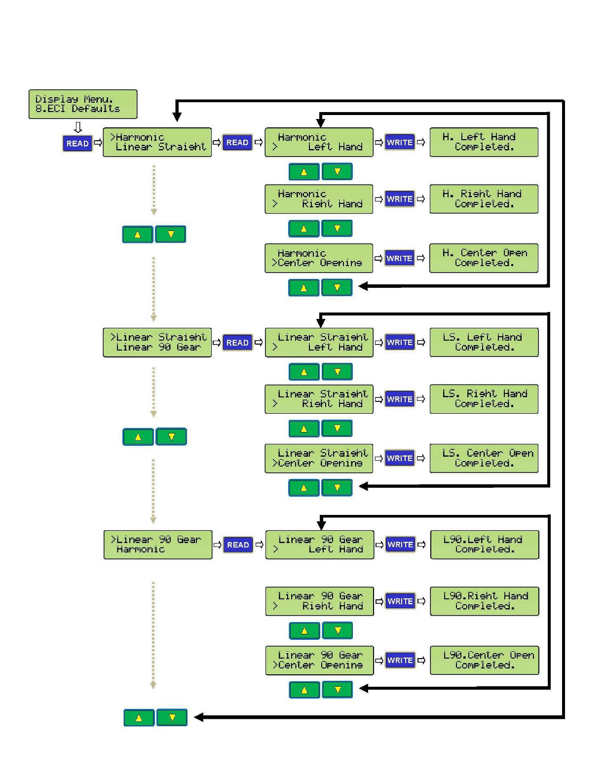
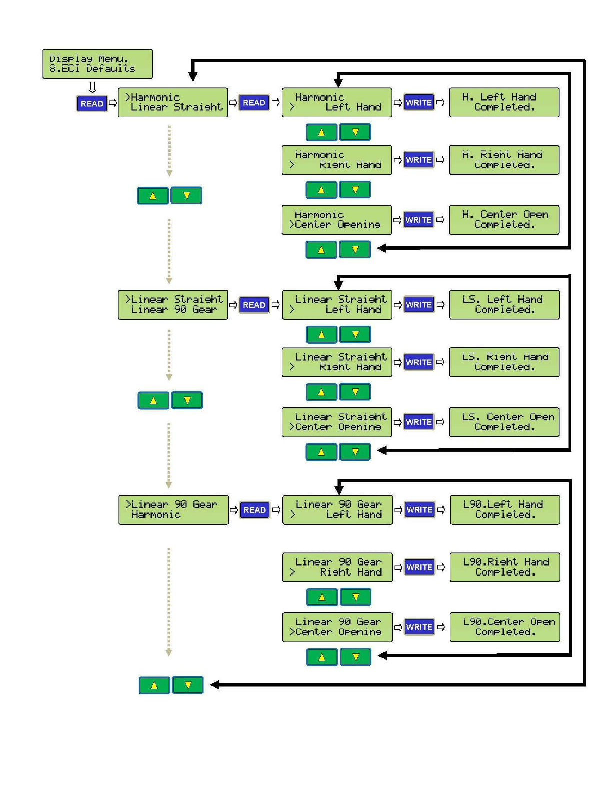
4. Download an *$/ default parameter set: Follow steps of the illustration below to
download (write) a correct default parameter set to the
02
VFE2500 drive then go to 6.
DisPla':l
t·1e
n
u.
8.
ECI
Defaults
D.
IJ#Ji
l >HarM
onic
r
~
- · • q Li
near
St
r a i9ht q
lliiiiiil
q
--
>
Lin
ear
Strai
9
ht
q
~BW!i
q
Linear
90 Gear Miilil
. . .
.
.
.
•
--
.
.
.
.
.
. .
. .
.
>Li
near
90 Gear
HarMonic
t
--
t
HarM
onic
> Lef·t
Hand
--
HarMonic
>
Ri9ht
Hand
--
HarMon
ic
>
Center
0Penin9
--
t'
Linear
S
tr
ai
9ht
> Le
ft
Hand
--
Linear
St
ra
i
9ht
> Ri9ht
Hand
--
Linear
St
r
ai
9
ht
>Ce
nter
0P
e
nin
9
--
....
Li
near
90 Gear
>
Le
ft
Hand
Linear
90
Ge
ar
>
Ri9ht
Hand
--
Linear
90 Gear
>Cent
er
0Penin9
Q
l_
h@OJ
1
q
q- q
q- q
q- q
q- q
q- q
H. L
eft
Hand
COMPleted.
H. Ri
9ht
Han
d
COMP
l
eted.
H.
Center
OPe
n
COMP
l
et
ed.
LS
. Le
ft
Ha
nd
COMPleted.
LS
. Ri
9ht
Hand
COMPleted.
. -
L::..
Center
OPen
CO
M
Plet
ed
•
L
90.
L
ef·t
Hand
COMPleted.
L90.Ri9
ht
Hand
COMP
l
eted.
L
90.Center
OP
en
COM
Pl
ete
d.
--
+-----------~
5
F
l
S
F
l
U
F
o
t
h
P
a
F
o
5
5
5
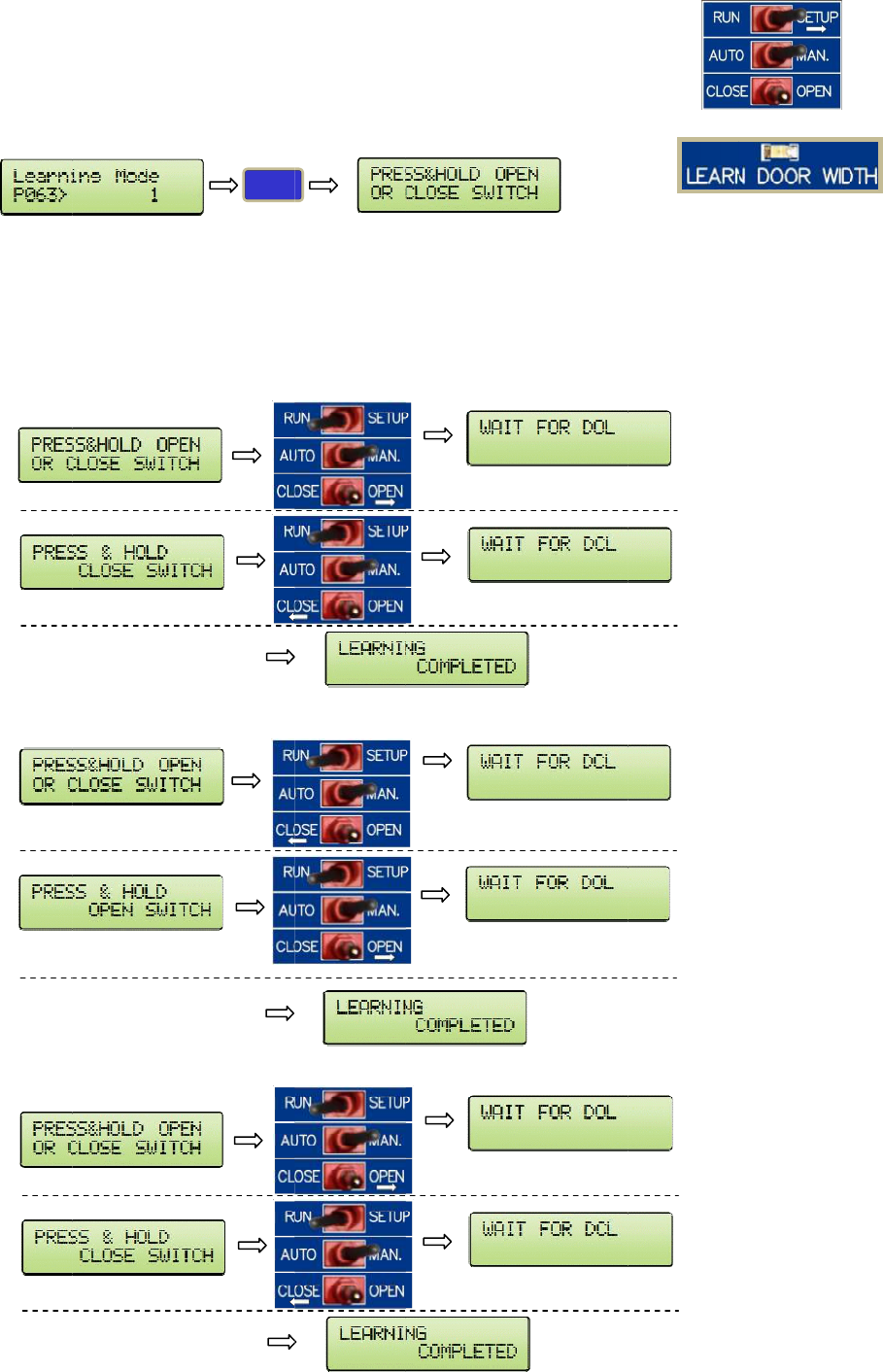
. Learn t
h
l
ip the RUN
et Par. 63
=
l
ip the RUN
se Manual
m
o
llow the p
r
h
e learning
a
r. 63 will
s
o
llowings a
r
.1 If the
.2 If the
.3 If the
h
e door
w
|SETUP swi
t
=
1.
|SETUP swi
t
m
ode to ru
n
r
ompts on t
h
process is
c
s
ets itself b
a
r
e 3 possibl
e
door is be
t
If the CL
O
door is ful
l
door is ful
l
w
idth:
t
ch to SETU
t
ch to RUN.
n
the door f
r
h
e LCD dis
p
c
ompleted.
a
ck to Zero
e
cases:
t
ween DO
L
O
SE/OPEN s
w
l
y OPENE
D
l
y CLOSED
,
WRITE
P.
r
om DOL to
p
lay. LEARN
L
and DCL
b
w
itch is pre
D
, DOL is re
a
,
DCL is rea
E
DCL, or vi
c
DOOR WI
D
b
efore learn
ssed in the
a
ched befor
e
ched befor
e
After
Afte
r
After
Afte
r
After
Afte
r
c
e versa.
D
TH LED will
ing mode,
t
OPEN side,
e
learning
m
e
learning
m
DCL is rea
c
r
DOL is rea
c
DOL is rea
c
r
DCL is rea
c
DOL is rea
c
r
DCL is rea
c
flash and
t
t
he prompt
s
the promp
t
m
ode, the p
m
ode, the p
r
c
hed
c
hed
c
hed
c
hed
c
hed
c
hed
t
urn off wh
e
s
will be:
t
s will be:
rompts will
r
ompts will
b
e
n
be:
b
e:
16
17
6. Set the operation source:
Flip the 1st toggle switch to SETUP.
Set par. 11 = 1 for Terminals operation.
Set par. 11 = 5 for CAN bus operation.
Flip the 1st toggle switch to RUN.
Flip the 2nd switch to MAN to run the door in manual mode.
Flip the 2nd switch to AUTO to run the door in automatic mode.
18
PARAMETER UNIT
The followings will describe in depth about the parameter unit:
1. HOW TO CHANGE PARAMETERS
Press . Enter a parameter number
Press . Enter a new value. Press . Wait for the Completed signal from the LCD display.
2. HOW TO READ (COPY) FROM A DRIVE
Press . Press .
Press . Wait for the Completed signal from the LCD display.
3. HOW TO WRITE (DOWNLOAD) TO A DRIVE
Press . Press .
Press . Wait for the Completed signal from the LCD display.
4. HOW TO VERIFY ENCODER DIRECTION
Press . Run the door in Manual mode using the toggle switches.
If the door Closes and the counter Decreases, or the door Opens and the counter Increases, then the
encoder Direction is Correct. Otherwise, change parameter 42.
5. HOW TO LEARN THE DOOR WIDTH
Flip the RUN|SETUP switch to SETUP. Set Par. 63 = 1.
Flip the RUN|SETUP switch to RUN. Use Manual mode to run
the door from DOL to DCL, or vice versa.
Follow the prompts on the LCD display. LEARN DOOR WIDTH
LED will flash and turn off when the learning process is completed.
Par. 63 will sets itself back to Zero.
See Parameter Adjustments section, in the Manual, for more details.
The Parameter Unit is a tool to assist users in the following tasks:
● Learning the door widths of the regular door and narrower door.
● Changing accelerations, decelerations, speeds, torques, and all
pertinent parameters of peripheral devices. See the defaults
parameters table for more details.
● Downloading (copying, reading), uploading (writing) to and
from the drive.
● Storing all default sets of parameters and a reference working
set of parameters.
● Monitoring currents, voltages, inputs, outputs, faults, encode
r
directions, closing time.
● Resetting the drive.
SET
VOLT
PULSE
WRITE
READ
SET
READ
SET
WRITE
19
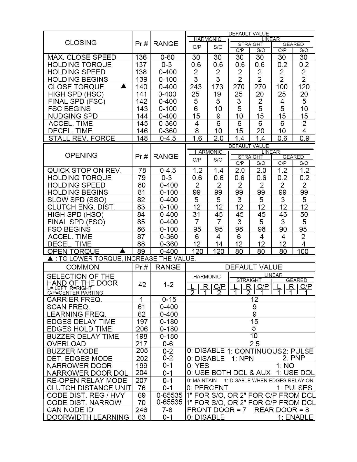
6. DEFAULT PARAMETERS
DEF
AU
LT VALUE
CLOSING HARMONIC LINEAR
Pr.# RANGE STRAIGHT GEARED
C/P
S/0
C/P S/0 C/P S/0
MAX. CLOSE SPEED 136 0-60 30 30 30 30 30 30
HOLDING TORQUE 137 0-3 0.6 0.6 0.6 0.6 0.2 0.2
HOLDING SPEED 138 0-400 2 2 2 2 2 2
HOLDING BEGINS 139 0-100 3 3 2 2 2 2
CLOSE TORQUE .& 140 0-400 243 173 270 270 100 120
HIGH SPD (HSC)
141
0-400 25 19 25 20 25 20
FINAL SPD (FSC) 142 0-400 5 5 3 2 4 5
FSC BEGINS 143 0-100 6 10 5 5 5 10
NUDGING SPD 144 0-400 15 9 10 15 15 15
ACCEL. TIME 145 0-360 4 6 6 6 6 2
DECEL. TIME 146 0-360 8 10 15
20
10 4
STALL
RE
V. FORCE 148 0-4.5 1.6 2.0 1
.4
1.4 0.6 0.9
DEF
AU
LT VALUE
OPENING HARMONIC LINE
AR
Pr.# RANGE C/P S
/0
STRAIGHT GEARED
C/P S/0 C/P S/0
QUICK STOP ON
RE
V. 78 0-4.5 1.2 1.4 2.0 2.0 1.2 1.2
HOLDING TORQUE 79 0-3 0.6 0.6 0.6 0
.6
0
.2
0.2
HOLDING SPEED 80 0-400 2 2 2 2 2 2
HOLDING BEGINS
81
0-100 99 99 99 99 99 99
SLOW SPD (SSO) 82 0-400 5 5 3 5 3 5
CLUTCH ENG. DIST. 83 0-100 12 12 12 12 12 12
HIGH SPD (HSO) 84 0-400
31
45 45 45
45
50
FINAL SPD (FSO) 85 0-400 7 7 3 5 3 5
FSO BEGINS 86 0-100 95 95 98 98 90 95
ACCEL. TIME 87 0-360 6 4 6 4 4 2
DECEL. TIME 88 0-360 12 14 12 12 12 4
OPEN TORQUE .& 89 0-400 120 120 80 80 80 100
.&
·T
O L
OW
ER TORQUE
IN
CREASE THE VALUE
COMMON Pr.# RANGE DEFAULT VALUE
SELECTION OF THE HARMONIC LINEAR
HAND OF THE DOOR STRAIG
HT
I GEARED
L= LEFT R=RI
GHT
42 1-2
+14-1~
1+1~1~
l-i-1~14E
C/P=CENTER PARTING
CARRIER FREQ. 1 0-15 12
SCAN FREQ.
61
0-400 9
LEARNING FREQ. 62 0-400 9
EDGES DELAY TIME 197 0-180 15
EDGES HOLD TIME 206 0-180 5
BUZZER DELAY TIME 198 0-180 10
OVERLOAD 217 0-6 2.5
BUZZER MODE 205 0-2
0:
DISABLE 1: CONTINUOUS2: PULSE
DET. EDGES MODE 202 0-2
0:
DISABLE
1:
NPN 2: PNP
NARROWER DOOR 199
0-1
0: Y
ES
1: NO
NARROWER DOOR DOL 204
0-1
0: USE BOTH DOL & AUX
1:
USE DOL
RE-OPEN RELAY MODE 207
0-1
0:
MA
INTAIN 1: DISABLE
WH
EN EDGES RELAY
ON
CLUTCH
DI
STANCE UNIT 76
0-1
0:
PERCENT
1:
PULSES
CODE DIST. REG I HVY 69 0-65535 1" FOR S/0 , OR 2" FOR C/P FROM
DCL
CODE DIST. NARROW 70 0-65535 1" FOR S/0 OR 2" FOR C/P FROM
DCL
CAN NODE ID 246 7-8 FRONT DOOR = 7 REAR DOOR = 8
DOORWIDTH LEARNING 63 0-1
0:
DI
SABLE 1: ENABLE
20
7. CONVENIENCE KEYS
Press to display speeds in Hz.
Press to display input and output signals.
Press to display recent faults.
Press or to view all recent faults.
Press to display currents.
Press to reset the drive.
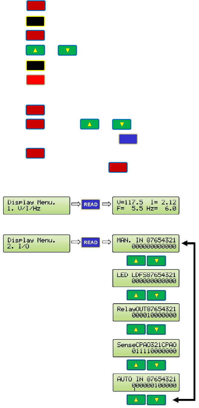
8. THE VIEW KEY
The key will help users navigate through the Parameter Unit seamlessly.
Press then press or to navigate all items under the VIEW section.
Once the desired item is found, press to view an item.
Press at any time to get back to the previous display.
The following items are under the key:
VOLTAGE, CURRENT, COMMAND FREQUENCY AND ACTUAL FREQUENCY (Hz)
INPUTS & OUTPUTS MONITORING (See Parameters List for explanation of each bit)
SPEED
I/O
FAULT
READ
AMP
RESET
VIEW
ESC
VIEW
VIEW
21
FAULTS
AN EXAMPLE OF FAULTS DISPLAY
COUNTERS
22
USER LIST
'-
_D_i_s_P_la_Y_r_·le_n_u_.
_
___JG
- ·.
q[
~s_er
ParaMeter
5.
User
List
. u [
q
IQJ•I
1 q
.__c_a_r_r_i_er_F_r_e_et_.
_
___.J
. _0-001=
12kHz
I
•
•
User
GP
Sel
0-015= 0
--
t-lotor
and
Encode Q·· . q t-lotor
Rated
lJol t
1-
1-026= 230.0l)
I
•
•
•
•
PG
Loss
Treat
1-048= 2
23
L
-~-o-
_or_P
_a_r_a_M_e_t_e_r_~l
q
1!P.J!P.1
q'
_s_c_a
_n_c_
-·u_r_r_e_n_t_L_e_v....J
.L.
.
ltiiiil
-2-059= 0.
11=1
I
~~en
ParaMeter
Close
ParaMeter
4-
I
•
•
-
I
c::::>
1!P.J!P.1
c::::>
L__t·1a_x_._o_P_e_n_s_P_d
_
__J
.
ltiiiil
3-077= 60.00Hz
•
•
I
--
•
I
I
Nar
DC
BK
TiMe
3-135=
1.0sec
t·1ax.
C 1
ose
5Pd
4-136= 30.00Hz
•
I
•
24
Di<:~ital
l/0
Para
c::::>
llll
q
5- -
Ed<:~esTiMeou
t
DLY
5-197=
20.0sec
1111
Buzzer
TiMe
5-198=
15.0sec
Sensor
t·1ode
5-201= 1
1111
Inf
·
rared
t·1ode
5-202= 0
1111
Buzzer
Disable
5-205= 0
Ed<:~esTiMeout
HLD
5-206=
3.0sec
25
L
_Pb
.
-.:_r
_o-_i...e_c_
t_l_
·
o_n
___
..JI
q II!!Bl' q
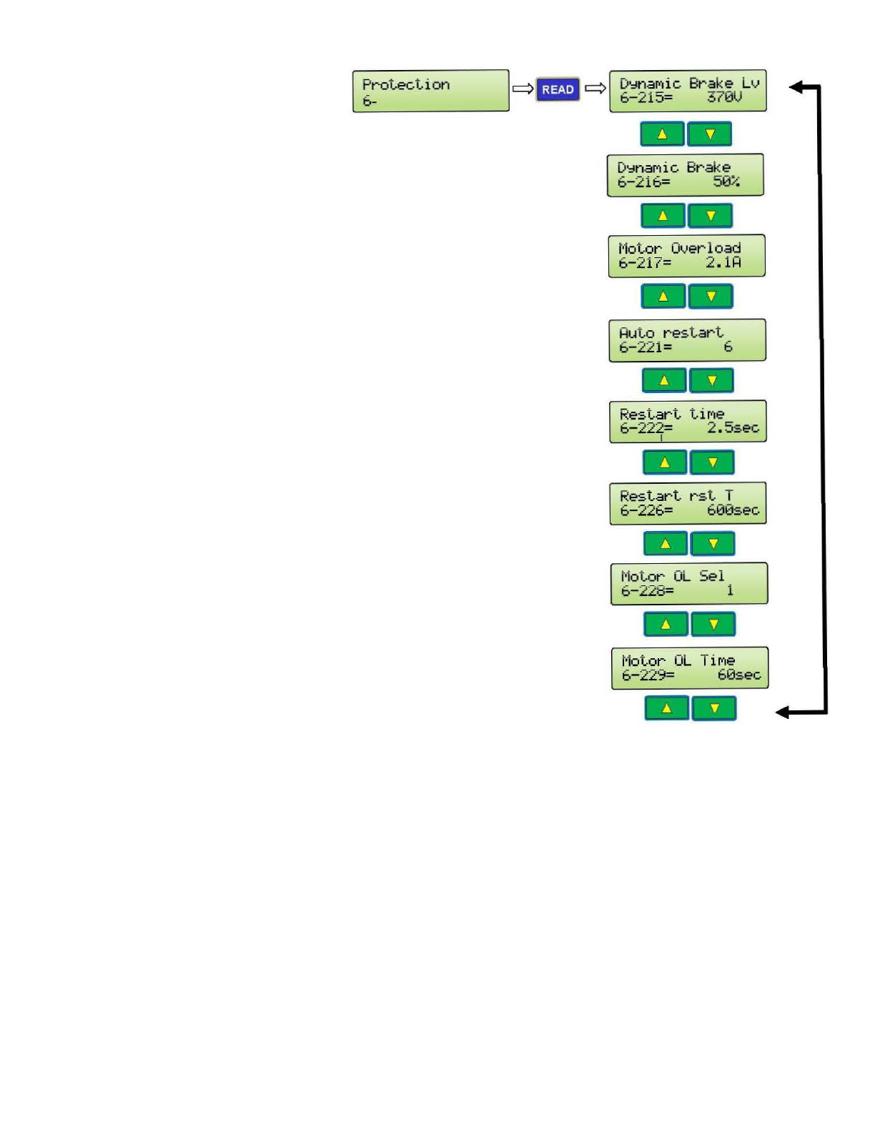
L_D_'='_n_aM-ic_B_r_a_k_e_L_v..J
.
IMiiil
6-215=
370V
--
D'::lnaMic
Brake
6-216=
50%
t·1o
tor
Overload
6-217=
2
.1H
-
Restart
tiMe
6-222=
2 .
5sec
I
--
t·lo
tor
OL
Se l
6-228=
1
--
26
MAXIMUM CLOSE SPEED AND FORCE
27
ECI DEFAULT PARAMETER SETS
Dis
P
la
~
t·1e
nu.
8.ECI D
ef
·a
ul
ts
~
>H
arMon
ic
Linear
St
rai9ht
.
.
.
•
--
.
.
.
.
.
.
.
t
rai9
ht >Linear
::.T..-
Linear
90
.
.
.
.
.
.
.
.
.
.
.
Gea
r
--
>Lin
ear
90
H
arMon
ic
t
Gear
...
~
--
q- q
q f- q
q- q
t
H
arMon
ic q- q
H.
Left
Hand
>
Le
f
·t
Hand COMPleted.
--
Har Monic q- q
H.
Ri
9ht
Han
d
>
Ri9ht
Hand
COMPl
e
ted.
--
H.
Center OP
en
HarMonic
c>
[- ]
c>
>
Center
0Penin9
COMPl
e
ted.
--
..
Lin
ea
r
St
r
ai9ht
q- q
. -L
eft
Hand
L
::..
> L
eft
Hand
COM
Pl
eted.
--
Linear
St
r
ai9ht
q- q
LS
. Ri
9ht
Hand
>
Ri9ht
Hand
CO
MP
let
ed.
--
Linear
Stra
i
9ht
q- q
L
S.
Center
OPen
>Center 0Penin9
COMP
le
ted.
--
...
~
t
Lin
ear
90 Gear q- q
L 90.
Le
f
·t
Hand
> L
ef
·t
Hand
COM
P
leted
.
Linear 90 Gear q- q
L
90
.
Ri9ht
Hand
> Ri
9ht
Hand
COM
P
leted
.
--
Line
ar
90
Ge
ar q- q
L90.Cen
te
r
OPe
n
>Center 0Pen
in
9
CO
M
Pl
et ed.
--
...
28
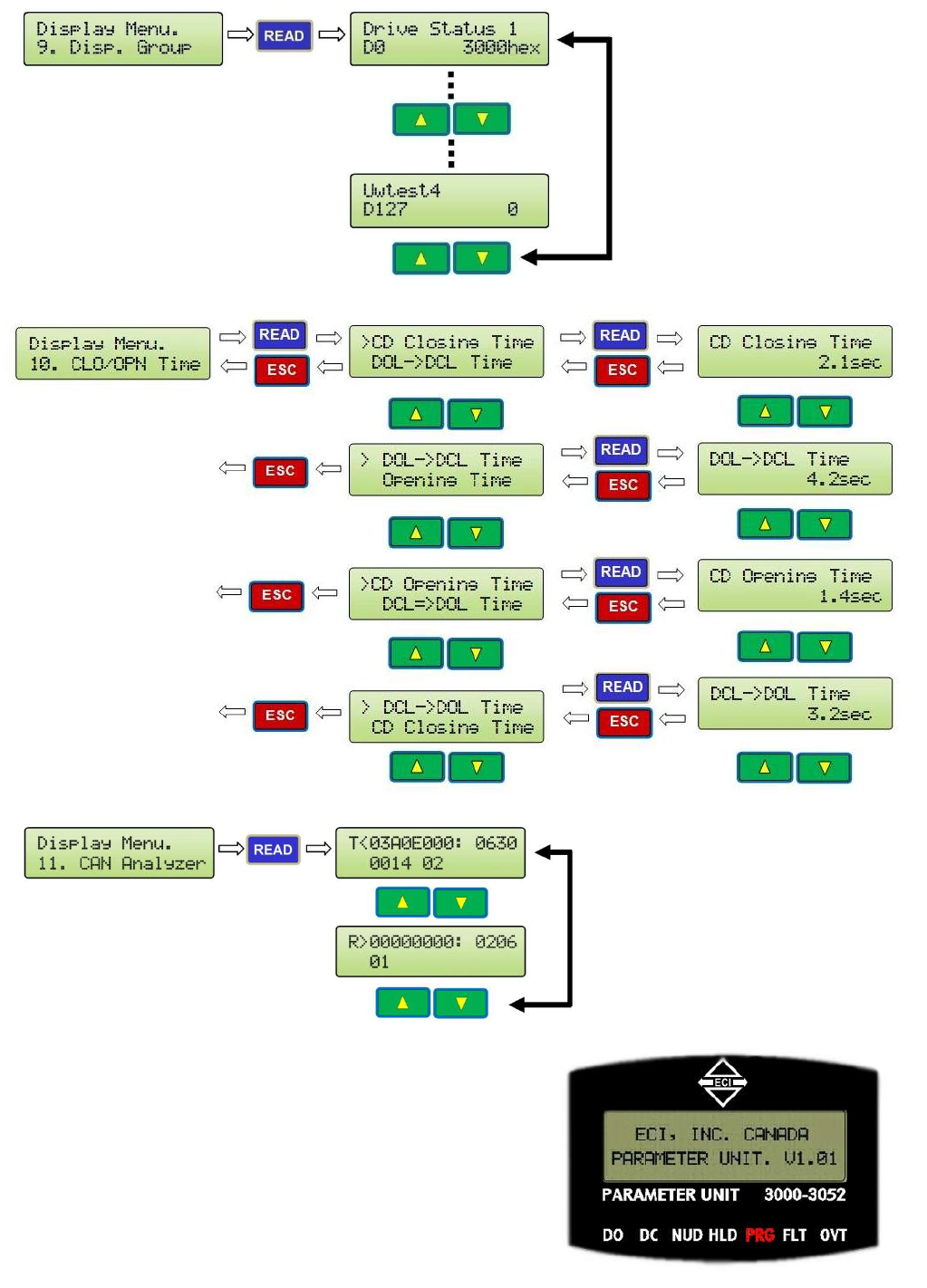
DISPLAY GROUPS FOR MONITORING AND TROUBLESHOOTING
CODE DISTANCE CLOSING TIME DISPLAY
CAN ANALYZER (AN EXAMPLE)
9. LED INDICATORS
There are 7 LEDs on the Parameter Unit. DO, DC,
NUD, HLD, PRG, FLT, and OVT. They have the
following meanings:
DO= Door Open. DC= Door Close.
NUDG.=Nudging HLD= Holding.
PRG= Programming Mode FLT= Fault
OVT= Over Torque.
29
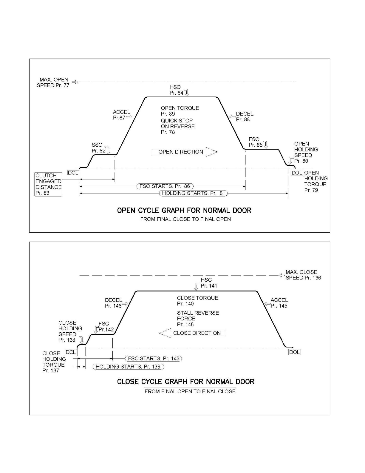
SPEED PROFILES OF THE VFE2500 FOR NORMAL DOOR
MAX.OPEN
c:>
-----------------
-
SPEED
Pr.
77
HSO
Pr.
84
OPEN TORQUE
Pr.
89
QUICK STOP
ON REVERSE
Pr.
78
OPEN
I OPEN DIRECTION > HOLDING
. I SPEED
--
L
---------
T
--
-
II;L
~~
PEN
CLUTCH
ENGAGED
DISTANCE
Pr.
83
I HOLDING
1
-·---------l
(FSOSTARTS
Pr.
86) .] TORQUE
-------~~~:{EH~O~LfD~IN~G~S~TtA~Rr!T]S~.
PEjr:=.
]8I1)
·]
Pr.
79
OPEN
CYCLE
GRAPH
FOR
NORMAL
DOOR
FROM FINAL CLOSE TO FINAL OPEN
MAX. CLOSE
----------
HSC
-----
<?
SPEEDPr.136
CLOSE
HOLDING
SPEED
Pr.
138
g'
Pr.
141
CLOSE TORQUE
Pr.
140
STALL REVERSE
FORCE
Pr.
148
< CLOSE DIRECTION
CLOSE
CYCLE
GRAPH
FOR
NORMAL
DOOR
FROM FINAL OPEN TO FINAL CLOSE
30
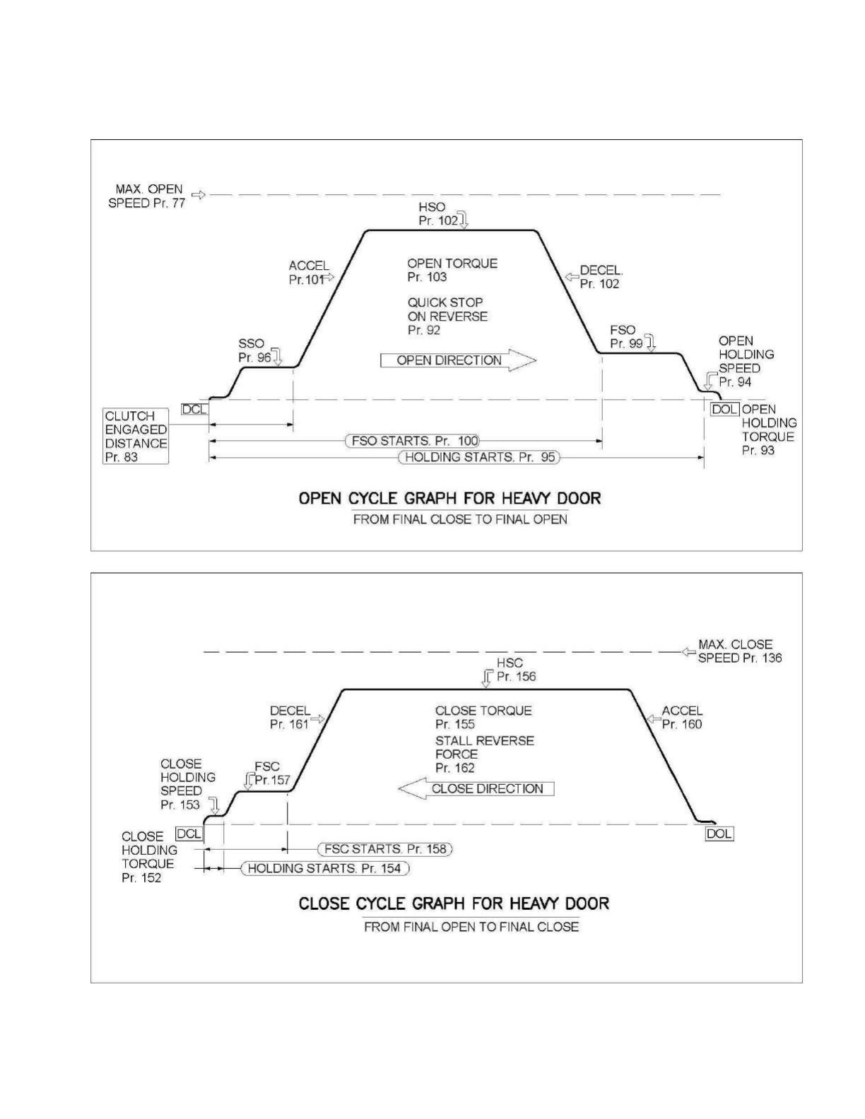
SPEED PROFILES OF THE 02VFE2500 FOR HEAVY DOOR
MAX.
OPEN
c;>-
________________
_
SPEED
Pr.
77
HSO
Pr
102
OPEN TORQUE
Pr
103
QUICK STOP
ON REVERSE
Pr.
92
SSO OPEN
Pr
96~
I OPEN DIRECTION >
~OLDING
I I SPEED
--
L--------
--
--
~
---
---tr
:~L~~PEN
CLUTCH
ENGAGED
DISTANCE
Pr.
83
I HOLDING
I
. (
FSO STARTS.
Pr
10Ql
·I TORQUE
-·
----------{
(HOLDING STARTS.
Pr
95
) ·I
Pr
93
OPEN
CYCLE
GRAPH
FOR
HEAVY
DOOR
FROM FINAL CLOSE TO FINAL OPEN
MAX.
CLOSE
-----------------
<?
HSC SPEED
Pr
136
.g'
Pr
156
CLOSE TORQUE
Pr.
155
STALL REVERSE
FORCE
Pr.
162
< CLOSE DIRECTION I
CLOSE
HOLDING
SPEED
Pr
153
-_I_-------------
CLOSE
IDCLI
I
HOLDING
-
~-·
---,---
1
--
----t•
----1
( FSC STARTS.
Pr
158)
TORQUE • • ( HOLDING STARTS.
Pr
154 )
Pr.
152
CLOSE
CYCLE
GRAPH
FOR
HEAVY
DOOR
FROM FINAL OPEN TO FINAL CLOSE
31
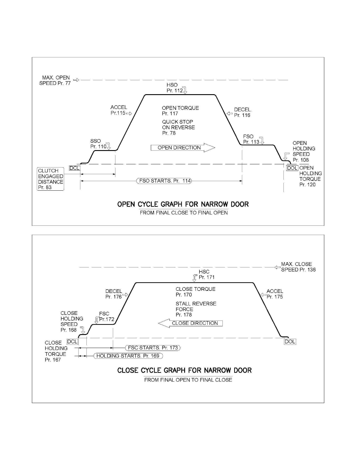
SPEED PROFILES OF THE 02VFE2500 FOR NARROW DOOR
MAX.OPEN
=(>-----------------
SPEED
Pr.
77 HSO
ACCEL
Pr.115
c¢
Pr.
112
OPEN TORQUE
Pr.
117
QUICK STOP
ON REVERSE Pr. 78
DECEL.
<?
Pr.
116
FSO
Pr.
113
~
OPEN
OPEN DIRECTION > HOLDING
' I SPEED
--
L---------
T -
-
1
1D;:
I
~~~N
CLUTCH
ENGAGED
DISTANCE
Pr.
83 I I HOLDING
1
,._.
------
---{(
FSO STARTS.
Pr.
114)
•.
TORQUE
I
Pr.
120
OPEN
CYCLE
GRAPH
FOR
NARROW
DOOR
FROM FINAL CLOSE TO FINAL OPEN
MAX. CLOSE
----------------
<?
HSC SPEED Pr. 136
CLOSE
HOLDING
SPEED
Pr.
168
Pr.
171
CLOSE TORQUE
Pr.
170
STALL REVERSE
FORCE
Pr.
178
<CLOSE DIRECTION
CLOSE
CYCLE
GRAPH
FOR
NARROW
DOOR
FROM FINAL OPEN TO FINAL CLOSE
32
HALL‐EFFECTSENSORSSETTINGFORLINEARDOOROPERATOR:
OPTICALSENSORSSETTINGFORHARMONICDOOROPERATOR:
Usethetranslationalsettingsofthehall‐effect
sensorsasreferenceforopticalsensors.
Last
¼Inch
½Inch
before
Gate
Switch
makes
Magnet
&
Magnet
Carrier
UseasDOLofthe
Narrowerdoor.
Alsocanbeused
asa2ndDOL.When
notused,setPar.
199=1toexclude
thissensor.
Last
¼Inch
NOTE! PITCHBETWEENCAMSTOBE½INCH
NOTE! PITCHBETWEENCAMSTOBE½INCH

33
PARAMETERSLISTFORUSERS
GROUP0:USERPARAMETERS
Par.
NoDescriptionRangeUnitDefaultSettingDisplayRelatedPar.
1CarrierFrequency0‐15KHz12KHzCarrierFreq.
2ParameterReset0‐9999 06:Clearallfaults
08:KeypadlockedParameterReset
12MonitorData
Selection0‐65535Hex0000TestpointSel
15UserGroup
ReadSelection 0‐9999 0UserGPSel
GROUP1:MOTOR&ENCODERPARAMETERS
Par.
NoDescriptionRangeUnitDefaultSettingDisplayRelatedPar.
26Maximumoutput
voltage255‐0.1V230MotorRatedVolt
Higherthan
Par.126&
185
27MotorRatedVolt400.00–
50.00Hz60Max.Speed
28MINOutput
Voltage
25.0–
0.0%4.0Min.Voltage
Higherthan
Par.126&
185
29MinOutputFreq.400.00–
0.10Hz0.50Min.OutputSpd
Lowerthan
Par.127&
186
31MotorRated
Current
3.60‐
0.15A0.52A:GearedMotor
2.50A:StraightMotor MotorRatedCurr
32 MotorNo‐load
Current
Par.31‐
0.00A0.38A:GearedMotor
1.40A:StraightMotor No‐loadCurrent
33Numberof
MotorPoles 2‐6Pole2:GearedMotor
6:StraightMotorPolesofmotor
41EncoderPulses4000‐0pls500Pulseperrev.
42Encoderfeedback
Setting0‐2
00:Disable
1:Forward/CCW
2:Reverse/CW
EncoderInput
49
Enter
DoorWidth
here
65535InS/O:30inches
C/P:36inchesDoorWidth(inch)
50
Enter
DoorWeight
here
65535lbsS/O:225lbs
C/P:275lbsDoorWeight

34
GROUP1:MOTOR&ENCODERPARAMETERS(CONTINUED)
Par.
NoDescriptionRangeUnitDefaultSettingDisplayRelatedPar.
51
Enter
Single‐Speed
Or
Two‐Speed
Here
0‐1
0:SingleSpeed
1:TwoSpeedDoorSpeed
52DoorType0‐5
ReadOnlyPar.
ThisPar.ischangedby
loadingECI’sdefaults.
0:Harmonic,S/O
1:Harmonic,C/P
2:LinearStraight,S/O
3:LinearStraight,C/P
4:LinearGear,S/O
5:LinearGear,C/P
DoorType
GROUP2:DOORPARAMETERS
Par.
NoDescriptionRangeUnitDefaultSettingDisplayRelatedPar.
61ScanFrequency0.00‐
400.00 Hz9HzScanSpd
62Learning
Frequency
0.00‐
400.00Hz9HzLearningSpd
63Non‐supervised
Learning 0‐1 0:Disable
1:EnableLearningMode
64RegularDoor
Width0‐65535Pulse 0‐65535RegularWidth
65NarrowDoor
Width0‐65535Pulse 0‐65535NarrowWidth

35
GROUP3:OPENDIRECTIONPARAMETERS
Par.
NoDescriptionRangeUnitDefaultSettingDisplayRelatedPar.
76ClutchEngage
Unit1‐0
0:%
1:pulsesCLUTCHUnitPar.83
77MaximumOpen
Speed
0.00‐
400.00 Hz60HzMax.OpenSpd
78QuickStopOn
Reverse0.0–4.5A
1.2A:HarmonicC/P
1.4A:HarmonicS/O
2.0A:LinearStraightC/P
2.0A:LinearStraightS/O
1.2A:LinearGearedC/P
1.2A:LinearGearedS/O
QuickStpRev.
79 Open
HoldingTorque0.0‐3.0A
0.6A:HarmonicC/P
0.6A:HarmonicS/O
0.6A:LinearStraightC/P
0.6A:LinearStraightS/O
0.2A:LinearGearedC/P
0.2A:LinearGearedS/O
OpenHLDTorque
80Open
HoldingSpeed
0.00–
400.00Hz2HzOpenHLDSpd
81Open
HoldingStart
0.0–
100%99%HoldingStart
82SlowSpeedOpen 0.00–
400.00Hz
5Hz:HarmonicC/P
5Hz:HarmonicS/O
3Hz:LinearStraightC/P
5Hz:LinearStraightS/O
3Hz:LinearGearedC/P
5Hz:LinearGearedS/O
SlowSpdSSO
83ClutchEngaged
Distance
0.0–
100%Pre‐determined%ClutchDistance
84HighSpeedOpen
HSO
0.00–
400.00Hz
31Hz:HarmonicC/P
45Hz:HarmonicS/O
45Hz:LinearStraightC/P
45Hz:LinearStraightS/O
45Hz:LinearGearedC/P
50Hz:LinearGearedS/O
HighSpdHSO
85FinalSpeedOpen
FSO
0.00–
400.00Hz
7Hz:HarmonicC/P
7Hz:HarmonicS/O
3Hz:LinearStraightC/P
5Hz:LinearStraightS/O
3Hz:LinearGearedC/P
5Hz:LinearGearedS/O
FinalSpdFSO

36
GROUP3:OPENDIRECTIONPARAMETERS(CONTINUED)
Par.
NoDescriptionRangeUnitDefaultSettingDisplayRelatedPar.
86FinalSpeedOpen
Start
0.0–
100%
95%:HarmonicC/P
95%:HarmonicS/O
98%:LinearStraightC/P
98%:LinearStraightS/O
90%:LinearGearedC/P
95%:LinearGearedS/O
FSOStart
87Open
AccelerationTime
0.1–
3600.0sec
6sec:HarmonicC/P
4sec:HarmonicS/O
6sec:LinearStraightC/P
4sec:LinearStraightS/O
4sec:LinearGearedC/P
2sec:LinearGearedS/O
OpenAcc.TM
88Open
DecelerationTime
0.1–
3600.0sec
12sec:HarmonicC/P
14sec:HarmonicS/O
12sec:LinearStraightC/P
12sec:LinearStraightS/O
12sec:LinearGearedC/P
4sec:LinearGearedS/O
OpenDec.TM
89 OpenTorque0.00–
400.00Hz
120Hz:HarmonicC/P
120z:HarmonicS/O
80Hz:LinearStraightC/P
80Hz:LinearStraightS/O
80Hz:LinearGearedC/P
100Hz:LinearGearedS/O
OpenTorque
90OpenMid.Volt0.0–
100.0%4%OPENMid.Volt
91 OpenMid.
Frequency
0.00–
400.00Hz0.5HzOPENMid.Freq.
92HeavyQuickStop
OnReverse0.0–4.5A
1.2A:HarmonicC/P
1.4A:HarmonicS/O
2.0A:LinearStraightC/P
2.0A:LinearStraightS/O
1.2A:LinearGearedC/P
1.2A:LinearGearedS/O
HvyQuickRev.
93Heavy
HoldingTorque0.0‐3.0A
0.6A:HarmonicC/P
0.6A:HarmonicS/O
0.6A:LinearStraightC/P
0.6A:LinearStraightS/O
0.2A:LinearGearedC/P
0.2A:LinearGearedS/O
HvyOpenHLDTor

37
GROUP3:OPENDIRECTIONPARAMETERS(CONTINUED)
Par.
NoDescriptionRangeUnitDefaultSettingDisplayRelatedPar.
94
Heavy
HoldingSpeed
0.00–
400.00Hz2HzHvyOpenHLDSpd
95
Heavy
HoldingStart
0.0–
100%99%HvyHLDStart
96Heavy
SlowSpeedOpen
0.00–
400.00Hz
5Hz:HarmonicC/P
5Hz:HarmonicS/O
3Hz:LinearStraightC/P
5Hz:LinearStraightS/O
3Hz:LinearGearedC/P
5Hz:LinearGearedS/O
HvySpdSSO
98Heavy
HighSpeedOpen
0.00–
400.00Hz
15Hz:HarmonicC/P
25Hz:HarmonicS/O
25Hz:LinearStraightC/P
25Hz:LinearStraightS/O
25Hz:LinearGearedC/P
20Hz:LinearGearedS/O
HvySpdHSO
99Heavy
FinalSpeedOpen
0.00–
400.00Hz
7Hz:HarmonicC/P
7Hz:HarmonicS/O
3Hz:LinearStraightC/P
5Hz:LinearStraightS/O
3Hz:LinearGearedC/P
5Hz:LinearGearedS/O
HvySpdFSO
100HeavyFinalSpeed
Start
0.0–
100%
95%:HarmonicC/P
95%:HarmonicS/O
98%:LinearStraightC/P
98%:LinearStraightS/O
90%:LinearGearedC/P
95%:LinearGearedS/O
HvyFSOStart
101
Heavy
Open
AccelerationTime
0.1–
3600.0sec
6sec:HarmonicC/P
4sec:HarmonicS/O
6sec:LinearStraightC/P
4sec:LinearStraightS/O
4sec:LinearGearedC/P
2sec:LinearGearedS/O
HvyOpenAcc.
102
Heavy
Open
DecelerationTime
0.1–
3600.0sec
10sec:HarmonicC/P
12sec:HarmonicS/O
10sec:LinearStraightC/P
10sec:LinearStraightS/O
10sec:LinearGearedC/P
2sec:LinearGearedS/O
HvyOpenDec.

38
GROUP3:OPENDIRECTIONPARAMETERS(CONTINUED)
Par.
NoDescriptionRangeUnitDefaultSettingDisplayRelatedPar.
103Heavy
OpenTorque
0.00–
400.00Hz
100Hz:HarmonicC/P
100z:HarmonicS/O
60Hz:LinearStraightC/P
60Hz:LinearStraightS/O
60Hz:LinearGearedC/P
80Hz:LinearGearedS/O
HvyOpenTorq..
104Heavy
OpenMid.Volt
0.0–
100.0%5%HvyOpenMid.V.
105
Heavy
OpenMid.
Frequency
0.00–
400.00Hz0.5HzHvyOpenMid.F
106
Narrow
QuickStopOn
Reverse
0.0–4.5A
1.2A:HarmonicC/P
1.4A:HarmonicS/O
2.0A:LinearStraightC/P
2.0A:LinearStraightS/O
1.2A:LinearGearedC/P
1.2A:LinearGearedS/O
NarQuickRev.
107Narrow
HoldingTorque0.0‐3.0A
0.6A:HarmonicC/P
0.6A:HarmonicS/O
0.6A:LinearStraightC/P
0.6A:LinearStraightS/O
0.2A:LinearGearedC/P
0.2A:LinearGearedS/O
NarOpenHLDTor
108
Narrow
HoldingSpeed
0.00–
400.00Hz2HzNarOpenHLDSpd
110Narrow
SlowSpeedOpen
0.00–
400.00Hz
5Hz:HarmonicC/P
5Hz:HarmonicS/O
3Hz:LinearStraightC/P
5Hz:LinearStraightS/O
3Hz:LinearGearedC/P
5Hz:LinearGearedS/O
NarSSO
112Narrow
HighSpeedOpen
0.00–
400.00Hz
25Hz:HarmonicC/P
35Hz:HarmonicS/O
35Hz:LinearStraightC/P
35Hz:LinearStraightS/O
35Hz:LinearGearedC/P
40Hz:LinearGearedS/O
NarHSO

39
GROUP3:OPENDIRECTIONPARAMETERS(CONTINUED)
Par.
NoDescriptionRangeUnitDefaultSettingDisplayRelatedPar.
113Narrow
FinalSpeedOpen
0.00–
400.00Hz
7Hz:HarmonicC/P
7Hz:HarmonicS/O
3Hz:LinearStraightC/P
5Hz:LinearStraightS/O
3Hz:LinearGearedC/P
5Hz:LinearGearedS/O
NarFSO
114Narrow
FinalSpeedStart
0.0–
100%
90%:HarmonicC/P
90%:HarmonicS/O
95%:LinearStraightC/P
95%:LinearStraightS/O
85%:LinearGearedC/P
90%:LinearGearedS/O
NarFSOStart
115
Narrow
Open
AccelerationTime
0.1–
3600.0sec
6sec:HarmonicC/P
4sec:HarmonicS/O
6sec:LinearStraightC/P
4sec:LinearStraightS/O
4sec:LinearGearedC/P
2sec:LinearGearedS/O
NarOpenAcc.TM
116
Narrow
Open
DecelerationTime
0.1–
3600.0sec
12sec:HarmonicC/P
14sec:HarmonicS/O
12sec:LinearStraightC/P
12sec:LinearStraightS/O
12sec:LinearGearedC/P
4sec:LinearGearedS/O
NarOpenDec.TM
117Narrow
OpenTorque
0.00–
400.00Hz
140Hz:HarmonicC/P
140z:HarmonicS/O
100Hz:LinearStraightC/P
100Hz:LinearStraightS/O
100Hz:LinearGearedC/P
120Hz:LinearGearedS/O
NarOpenTorq..
118Narrow
OpenMid.Volt
0.0–
100.0%5%NarOpenMid.V.
119
Narrow
OpenMid.
Frequency
0.00–
400.00Hz0.5HzNarOpenMid.F

40
GROUP3:OPENDIRECTIONPARAMETERS(CONTINUED)
Par.
NoDescriptionRangeUnitDefaultSettingDisplayRelatedPar.
120NarrowDOL
HoldingTorque0.0–3.0 A0.6ANar.HLDTorque
121DCBrake
Frequency
0.00–
400.00Hz60HzDCBrakeFreq
122DCBrakeTime0.0–
999.0sec1.0secDCBrakeTime
126HoldingTorque
Filter
0.01–
10.00sec0.20secHoldTorq.LPF
127OpenTimeout0.0‐
180.0sec0.0secOpenTimeout
128OpenLock
Torque.10.0–4.5A0.0AOpenLockTorq1
129OpenLock
Torque.20.0–4.5A0.0AOpenLockTorq2
130Open
HoldingTime
0.0–
999.9sec0.0secOPENHoldTime
131
Open
Acceleration
S‐curve
0.0–
10.0sec0.5secOpenAccScurve
132
Heavy
DC
BrakeFrequency
0.00–
400.00Hz60HzHvyDCBKFreq
133
Heavy
DC
BrakeTime
0.0–
999.9sec1secHvyDCBKTime
134
Narrow
DC
BrakeFrequency
0.00–
400.00Hz60HzNarDCBKFreq
135
Narrow
DC
BrakeTime
0.0–
999.9sec1secHvyDCBKTime

41
GROUP4:CLOSEDIRECTIONPARAMETERS
Par.
NoDescriptionRangeUnitDefaultSettingDisplayRelatedPar.
136Maximum
CloseSpeed
0.00–
400.00Hz30HzMax.CloseSpd
137Close
HoldingTorque0.0‐3.0A
0.6A:HarmonicC/P
0.6A:HarmonicS/O
0.6A:LinearStraightC/P
0.6A:LinearStraightS/O
0.2A:LinearGearedC/P
0.2A:LinearGearedS/O
CloseHLDTorque
138Close
HoldingSpeed
0.00–
400.00Hz2HzCloseHLDSpd
139Close
HoldingStart
0.0–
100%
3.0%:HarmonicC/P
3.0%:HarmonicS/O
2.0%:LinearStraightC/P
2.0%:LinearStraightS/O
2.0%:LinearGearedC/P
2.0%:LinearGearedS/O
HoldingStart
140CloseTorque0.00–
400.00Hz
243Hz:HarmonicC/P
173Hz:HarmonicS/O
270Hz:LinearStraightC/P
270Hz:LinearStraightS/O
100Hz:LinearGearedC/P
120Hz:LinearGearedS/O
CloseTorque
141HighSpeedClose
HSC
0.00–
400.00Hz
25Hz:HarmonicC/P
19Hz:HarmonicS/O
25Hz:LinearStraightC/P
20Hz:LinearStraightS/O
25Hz:LinearGearedC/P
20Hz:LinearGearedS/O
HighSpdHSC
142FinalSpeedClose
FSC
0.00–
400.00Hz
5Hz:HarmonicC/P
5Hz:HarmonicS/O
3Hz:LinearStraightC/P
2Hz:LinearStraightS/O
4Hz:LinearGearedC/P
5Hz:LinearGearedS/O
FinalSpdFSC
143FinalSpeedClose
Start
0.0–
100%
6%:HarmonicC/P
10%:HarmonicS/O
5%:LinearStraightC/P
5%:LinearStraightS/O
5%:LinearGearedC/P
10%:LinearGearedS/O
FSCStart

42
GROUP4:CLOSEDIRECTIONPARAMETERS(CONTINUED)
Par.
NoDescriptionRangeUnitDefaultSettingDisplayRelatedPar.
144NudgingSpeed0.00–
400.00Hz
15Hz:HarmonicC/P
9Hz:HarmonicS/O
10Hz:LinearStraightC/P
15Hz:LinearStraightS/O
15Hz:LinearGearedC/P
15Hz:LinearGearedS/O
NudgingSpd
145Close
AccelerationTime
0.1–
3600.0sec
4sec:HarmonicC/P
6sec:HarmonicS/O
6sec:LinearStraightC/P
6sec:LinearStraightS/O
6sec:LinearGearedC/P
2sec:LinearGearedS/O
CloseAcc.TM
146Close
DecelerationTime
0.1–
3600.0sec
8sec:HarmonicC/P
10sec:HarmonicS/O
15sec:LinearStraightC/P
20sec:LinearStraightS/O
10sec:LinearGearedC/P
4sec:LinearGearedS/O
CloseDec.TM
148StallReverse
Force 0.0–4.5A
1.6A:HarmonicC/P
2.0A:HarmonicS/O
1.4A:LinearStraightC/P
1.4A:LinearStraightS/O
0.6A:LinearGearedC/P
0.9A:LinearGearedS/O
StallRevNormal
150CloseMid.Volt0.0–
100.0%4%CloseMid.Volt.
151 Close
Mid.Frequency
0.00–
400.00Hz0.5HzCloseMid.Freq.
152
Heavy
Close
HoldingTorque
0.0‐4.5A
0.6A:HarmonicC/P
0.6A:HarmonicS/O
0.6A:LinearStraightC/P
0.6A:LinearStraightS/O
0.2A:LinearGearedC/P
0.2A:LinearGearedS/O
HvyCloHLDTorq
153
Heavy
Close
HoldingSpeed
0.00–
400.00Hz2HzHvyCloseHLD

43
GROUP4:CLOSEDIRECTIONPARAMETERS(CONTINUED)
Par.
NoDescriptionRangeUnitDefaultSettingDisplayRelatedPar.
154
Heavy
Close
HoldingStart
0.0–
100%
3.0%:HarmonicC/P
3.0%:HarmonicS/O
2.0%:LinearStraightC/P
2.0%:LinearStraightS/O
2.0%:LinearGearedC/P
2.0%:LinearGearedS/O
HvyHLDStart
155Heavy
CloseTorque
0.00–
400.00Hz
220Hz:HarmonicC/P
145Hz:HarmonicS/O
250Hz:LinearStraightC/P
250Hz:LinearStraightS/O
80Hz:LinearGearedC/P
100Hz:LinearGearedS/O
HvyCloseTorq.
156Heavy
HighSpeedClose
0.00–
400.00Hz
13Hz:HarmonicC/P
10Hz:HarmonicS/O
12Hz:LinearStraightC/P
12Hz:LinearStraightS/O
12Hz:LinearGearedC/P
10Hz:LinearGearedS/O
HvyHighHSC
157
Heavy
FinalSpeedClose
FSC
0.00–
400.00Hz
5Hz:HarmonicC/P
5Hz:HarmonicS/O
3Hz:LinearStraightC/P
2Hz:LinearStraightS/O
4Hz:LinearGearedC/P
5Hz:LinearGearedS/O
HvyFSC
158
Heavy
FinalSpeedClose
Start
0.0–
100%
6%:HarmonicC/P
10%:HarmonicS/O
5%:LinearStraightC/P
5%:LinearStraightS/O
5%:LinearGearedC/P
10%:LinearGearedS/O
HvyFSCStart
159Heavy
NudgingSpeed
0.00–
400.00Hz
10Hz:HarmonicC/P
10Hz:HarmonicS/O
10Hz:LinearStraightC/P
10Hz:LinearStraightS/O
10Hz:LinearGearedC/P
10Hz:LinearGearedS/O
HvyNudgSpd
160
Heavy
Close
AccelerationTime
0.1–
3600.0sec
4sec:HarmonicC/P
6sec:HarmonicS/O
6sec:LinearStraightC/P
6sec:LinearStraightS/O
6sec:LinearGearedC/P
2sec:LinearGearedS/O
HvyClo.Acc.

44
GROUP4:CLOSEDIRECTIONPARAMETERS(CONTINUED)
Par.
NoDescriptionRangeUnitDefaultSettingDisplayRelatedPar.
161
Heavy
Close
DecelerationTime
0.1–
3600.0sec
6sec:HarmonicC/P
8sec:HarmonicS/O
12sec:LinearStraightC/P
18sec:LinearStraightS/O
8sec:LinearGearedC/P
2sec:LinearGearedS/O
HvyClo.Dec.
163
Heavy
StallReverse
Force
0.0–4.5A
1.8A:HarmonicC/P
2.2A:HarmonicS/O
1.6A:LinearStraightC/P
1.6A:LinearStraightS/O
0.8A:LinearGearedC/P
1.1A:LinearGearedS/O
HvyStallNormal
165Heavy
CloseMid.Volt
0.0–
100.0%4%HvyCloseMid.V
166
Heavy
Close
Mid.Frequency
0.00–
400.00Hz0.5HzHvyCloseMid.F
167
Narrow
Close
HoldingTorque
0.0‐4.5A
0.6A:HarmonicC/P
0.6A:HarmonicS/O
0.6A:LinearStraightC/P
0.6A:LinearStraightS/O
0.2A:LinearGearedC/P
0.2A:LinearGearedS/O
NarCloHLDTorq
168
Narrow
Close
HoldingSpeed
0.00–
400.00Hz2HzNarCloseHLD
169
Narrow
Close
HoldingStart
0.0–
100%
3.0%:HarmonicC/P
3.0%:HarmonicS/O
2.0%:LinearStraightC/P
2.0%:LinearStraightS/O
2.0%:LinearGearedC/P
2.0%:LinearGearedS/O
NarHLDStart
170Narrow
CloseTorque
0.00–
400.00Hz
243Hz:HarmonicC/P
173Hz:HarmonicS/O
270Hz:LinearStraightC/P
270Hz:LinearStraightS/O
100Hz:LinearGearedC/P
120Hz:LinearGearedS/O
NarCloseTorq.

45
GROUP4:CLOSEDIRECTIONPARAMETERSCONTINUED
Par.
NoDescriptionRangeUnitDefaultSettingDisplayRelatedPar.
171Narrow
HighSpeedClose
0.00–
400.00Hz
25Hz:HarmonicC/P
19Hz:HarmonicS/O
25Hz:LinearStraightC/P
20Hz:LinearStraightS/O
25Hz:LinearGearedC/P
20Hz:LinearGearedS/O
NarHSC
172Narrow
FinalSpeedClose
0.00–
400.00Hz
5Hz:HarmonicC/P
5Hz:HarmonicS/O
3Hz:LinearStraightC/P
2Hz:LinearStraightS/O
4Hz:LinearGearedC/P
5Hz:LinearGearedS/O
NarFSC
173
Narrow
FinalSpeedClose
Start
0.0–
100%
6%:HarmonicC/P
10%:HarmonicS/O
5%:LinearStraightC/P
5%:LinearStraightS/O
5%:LinearGearedC/P
10%:LinearGearedS/O
NarFSCStart
174Narrow
NudgingSpeed
0.00–
400.00Hz
15Hz:HarmonicC/P
9Hz:HarmonicS/O
10Hz:LinearStraightC/P
15Hz:LinearStraightS/O
15Hz:LinearGearedC/P
15Hz:LinearGearedS/O
NarNudgingSpd
175
Narrow
Close
AccelerationTime
0.1–
3600.0sec
4sec:HarmonicC/P
6sec:HarmonicS/O
6sec:LinearStraightC/P
6sec:LinearStraightS/O
6sec:LinearGearedC/P
2sec:LinearGearedS/O
NarCloseAcc.TM
176
Narrow
Close
DecelerationTime
0.1–
3600.0sec
8sec:HarmonicC/P
10sec:HarmonicS/O
15sec:LinearStraightC/P
20sec:LinearStraightS/O
10sec:LinearGearedC/P
4sec:LinearGearedS/O
NarCloseDec.TM
178StallReverse
Force 0.0–4.5A
1.6A:HarmonicC/P
2.0A:HarmonicS/O
1.4A:LinearStraightC/P
1.4A:LinearStraightS/O
0.6A:LinearGearedC/P
0.9A:LinearGearedS/O
NarStallNormal

46
GROUP4:CLOSEDIRECTIONPARAMETERS(CONTINUED)
Par.
NoDescriptionRangeUnitDefaultSettingDisplayRelatedPar.
180Narrow
CloseMid.Volt
0.0–
100.0%4%NarCloseMid.V
181
Narrow
Close
Mid.Frequency
0.00–
400.00Hz0.5HzNarCloseMid.F
182FastDeceleration
Time
0.1–
3600.0sec1.0secFastestDec.TM
185HoldingTorque
Filter
0.01–
10.00sec0.20secHoldTorq.LPF
186CloseTimeout0.0‐
180.0sec0.0secCloseTimeout
187CloseLock
Torque.10.0–4.5A0.0ACloseLockTorq1
188CloseLock
Torque.20.0–4.5A0.0ACloseLockTorq2
189Close
HoldingTime
0.0–
999.9sec0.0secCLOSEHoldTime
190
Close
Acceleration
S‐curve
0.0–
10.0sec0.5secCloseAccScurve
GROUP5:DIGITALI/OPARAMETERS
Par.
NoDescriptionRangeUnitDefaultSettingDisplayRelatedPar.
196LEDDelayTime0.00–
10.00sec3.00sec(Default)LEDDelayTime
197EdgesTimeout
DelayTime
0.0–
180.0sec15sec(Default)EdgesTimeoutDLY
198BuzzerDelayTime0.0–
180.0sec10sec(Default)BuzzerTime
199Include/Exclude
AUXSensor0–1
0:IncludeAUXSensor
1:ExcludeAUXSensor(DF)IN/EXAUXSensor
200SensorFailure
DetectTime
0.0–
3600.0sec5secSensorFailTime
201SensorMode0‐2
0:Sensorisexternal,
Edgetrigger(Linear)
(Default)
1:Sensorisexternal,
Leveltrigger(Harmonic)
2:Sensorisonboard.
SensorMode

47
GROUP5:DIGITALI/OPARAMETERS
Par.
NoDescriptionRangeUnitDefaultSettingDisplayRelatedPar.
202Infrared
OutputType0–2
0:Disable
1:NPN(activeLOW)(DF)
2:PNP(activeHIGH)
InfraredType
203DCLReset0‐1
0:Enabledoorposition
resetinDCL.(Default)
1:Disabledoorposition
resetinDCL.
DCLReset
204
DOL
for
NarrowerDoor
0–1
0:UseregularasDOLof
NarrowerDoorDOL(DF)
1:UseAUXasDOLof
NarrowerDoorDOL
DOLforNarDoor
205BuzzerDisable0–1
0:BuzzerDisable(DF)
1:BuzzerEnable(Continue)
2:BuzzerEnable(ON–OFF)
BuzzerDisable
206
HoldingTime
for
EdgesTimeout
relay
0.0–
180.0sec3sec(Default)EdgesTimeoutHLD
207ReopenRelay
Mode1‐0
0:MAINTAIN
1:DISABLEWHENEDGES
RELAYON
ReopenRelayMOD
GROUP6:PROTECTIONPARAMETERS
Par.
NoDescriptionRangeUnitDefaultSettingDisplayRelatedPar.
216DCBrakeDuty0‐100% 50% DynamicBrake
217Motor
OverloadCurrent0.0–6.0A2.5A MotorOverload
221
Number
ofRetries
afterFaults
0‐106NoofRetries
222Retry
WaitingTime
0.2–
120.0sec2.5secRestarttime
226AutoResetTime
ResetafterFault9999‐0 Sec600RestartrstT
228
Motor
Overload
Selection
0‐2
00:StandardMotor
01:SpecialMotor(DF)
02:Disabled
MotorOLSel
229 Motor
OverloadTime30‐600sec60secMotorOLTime

48
OverloadTime
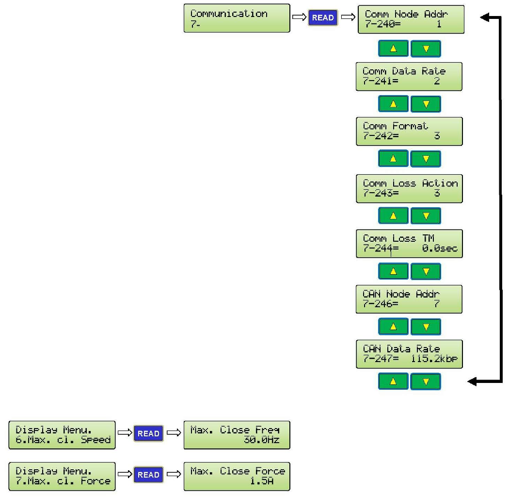
GROUP7:COMMUNICATIONPARAMETERS
Par.
NoDescriptionRangeUnitDefaultSettingDisplayRelatedPar.
240RS485
NodeNumber1‐2541CommNodeAddr
241RS485
Baudrate0‐3
0:Baudrate4800bps
1:Baudrate9600bps
2:Baudrate19200bps(DF)
3:Baudrate38400bps
CommDataRate
242
RS485
Modbus
Protocol
0–5
0:7,N,2(Modbus,ASCII)
1:7,E,1(Modbus,ASCII)
2:7,O,1(Modbus,ASCII)
3:8,N,1(Modbus,RTU)(DF)
4:8,E,1(Modbus,RTU)
5:8,O,1(Modbus,RTU)
CommFormat
243RS485
ConnectionLoss0‐3
0:Warnandkeepoperating
1:Warnandramptostop
2:Warnandcoasttostop
3:Nowarningandkeep
operating.(Default)
CommLossAction
244
RS485
ConnectionLoss
Time
0.0–
60.0sec0.0secCommLossTM
246CAN
NodeAddress0‐2557CANNodeAddr
247CAN
Baudrate
0‐
65535kbps115.2KbpsCANDataRate
DISPLAYPARAMETERS
Par.
No Function Display Unit
D0
Drive Status 1
Bit 0 Reserved
Bit 1 0: STOP,1:RUN
Bit 2 Reserved
Bit 3 0: CLOSE,1:OPEN
Bit4~5 Reserved
Bit 6 1: OVT
Bit 7 1: FLT
Bit 8~10 Reserved
Bit 11 1: Factory Set
Bit 12 Reserved
Bit 13~15 100:NUD
000:HLD
Drive Status 1 hex
D1 Output Frequency Output Freq Hz

49
DISPLAYPARAMETERS(CONTINUED)
Par.
No Function Display Unit
D2 Commanded Frequency Commanded Freq Hz
D3 Output Current Output Current A
D4 Output Voltage Output Voltage V
D5 DC Bus Voltage DC Bus Voltage V
D6 Door Close Time Door Close Time sec
D7
Switch Input Status
Bit0 0: SETUP 1:RUN
Bit1 0:MAN 1:AUTO
Bit2 OPEN
Bit3 CLOSE
Bit4 NUDG
Bit5 NARROW
Bit6 RESET
Bit7 HEAVY
SW IN 87654321
D8
Digital Input Status
Bit0 CLOSE
Bit1 OPEN
Bit2 NUDG
Bit3 NARROW
Bit4 HEAVY
Bit5 IR
Bit6 SPARE-1
Bit7 SPARE-2
MI IN 87654321
D9
Sensor Input Status
Bit0 HALL-DOL
Bit1 HALL-AUX
Bit2 HALL-DPM
Bit3 HALL-DCL
Bit4 HALL-SPARE1
Bit5 HALL-SPARE2
Bit6 HALL-SPARE3
Bit7 OPTIC-DOL
Bit8 OPTIC-AUX
Bit9 OPTIC-DPM
Bit10 OPTIC-DCL
SenseCPAO321CPAO
D10 Counter Status 1 (unit: 1) Counter Status 1
D11 Counter Status 2 (unit: 10000) Counter Status 2
D12
Relay Output Status
Bit0 EDGE Timeout
Bit1 AUX
Bit2 DPM
Bit3 REOPEN
Bit4 DOL
Bit5 DCL
Bit6 SPARE-1
Bit7 SPARE-2
RelayOUT87654321

50
DISPLAYPARAMETERS(CONTINUED)
Par.
No Function Display Unit
D13
LED Output Status
Bit0 CLOSE
Bit1 NUDG
Bit2 CLOSE SLOWDOWN
Bit3 OPEN
Bit4 OPEN SLOWDOWN
Bit5 HOLDING
Bit6 ENCODER FAILED
Bit7 SENSORS FAILED
Bit8 STALL REVERSE
Bit9 FREQUENCY FALURE
Bit10 DETECTOR EDGES
Bit11 LEARN DOOR WIDTH
LED LDFS87654321
D14 Max. Close Frequency Max. Close Freq Hz
D15 Max. Close Force Max. Close Force A
D16 Software Version Control SW Ver
D17 Drive Type Drive Type
D18 Warning Code Warn Code
D19 Memory Probe Display Testpoint Data
D20 NMI state NMI State
D21 Door Code Time Reg. Code Time sec
D22 Door Code Time for Nudging Nudg. Code Time sec
D23 Reserved
D24 Heat sink Temperature Heat Sink Temp. oC
D25 Step of Speed Step of Speed
D26 Door Position (%) Door Position %
D27 Door Position (pls) Door Position pls
D28 Feedback Freq. Feedback Freq Hz
D29 PG & CKRO pin state Encoder pin stat
D30 CAN Transmit Counter CAN TX Counter
D31 CAN Receive Counter CAN RX Counter
D32 Encoder Direction Encoder Dir.
D33 Encoder Pulse Encoder Pulses
D34 AD Value of Iv AD Value of Iv

OFF
ON
L1 L2
70
63
76
61
1
62
42
87
88
89
82
83
84
78
79
80
GS1
L
6
12
120
5
12
31
1.2
0.6
2
1.6
8
5
6
15
2
0.6
3
C/P
UV
LC/P
4
14
120
5
12
45
2
1.4
0.6
2.0
10
5
9
10
2
3
0.6
S/O
W
10
2.5
12
9
9
15
RC/P
4
12
80
5
45
12
2
S/O
2.0
0.6
1.4
20
2
5
15
2
2
0.6
S/O
L R
4
12
2
4
80
3
12
45
1.2
C/P
0.2
2
0.6
10
4
5
15
2
0.2
2
22
C/P
GEARED
NC
NO
COM
NC
NO
COM
C
O CLOSE
N
NUDG.
J4
C
N
OR
J7
OPEN
V+
LC
0V
V+
SE
0V
AUX.
BUZZER
3
1DOL
AUX
AUX
3
2 AUX
NARROW
2
BLU
4 DCL
DPM
3
GRN
YEL
ORG
()
0V
3
NC
2
BRN
NO HEAVY
GRN
YEL
ORG
()
0V
AUX2
HEAVY
51
EARTH GROUND
69
86
85
81
GATE
SWITCH
2
95
7
99
C/P
4
25
243
30
21
7
S/O
6
95
99
19
30
173
5
2 1
5
98
6
99
20
270
30
2: PNP
1
1: NO
1
90
3
99
6
GEARED
25
100
30
DOL
CLOSE
NUDG.
MAN.
SE
LC
SPARE
(
DOL 1
AUX
NARROW 2
DCL 4
COM
ORG
NARROW
COM
6-CONDUCTOR CABLE FOR ENCODER 6-CONDUCTOR CABLE FOR ENCODER REV. DESCRIPTION
200 - 230 VAC
TOGGLE SWITCHES FOR
MANUAL OPERATION.
NARROWER
DOOR
LC
SE
LC
SE
ELEVATOR CONTROLLER MUST
PROVIDE COMMAND SIGNALS TO HEAVY AND/OR NARROW INPUT(S)
TO USE HEAVIER DOOR AND/OR NARROWER DOOR FUNCTION(S).
6-CONDUCTOR CABLE FOR ENCODER DATE
Doc. No: 2500-2001-S
N.C. CONTACT OPENS WHEN DOOR REACHES THE FINAL OPEN LIMIT.
DOL RELAY IS CONTROLLED BY DOL CAM FOR HARMONIC MODEL.
OR, BY DOL HALL-EFFECT SENSOR FOR LINEAR MODEL .
6-CONDUCTOR CABLE FOR ENCODER
CAN NODE ID
BUZZER DELAY TIME
OVERLOAD
BUZZER MODE
CARRIER FREQ.
SCAN FREQ.
LEARNING FREQ.
EDGES DELAY TIME
L= LEFT R=RIGHT
SELECTION OF THE
COMMON
HAND OF THE DOOR
ACCEL. TIME
DECEL. TIME
OPEN TORQUE
SLOW SPD (SSO)
CLUTCH ENG. DIST.
HIGH SPD (HSO)
HOLDING TORQUE
HOLDING SPEED
STALL REV. FORCE
DECEL. TIME
FINAL SPD (FSC)
FSC BEGINS
NUDGING SPD
HOLDING SPEED
HOLDING TORQUE
HOLDING BEGINS
CLOSING
GS
246 7-8
0-65535
0-1
FRONT DOOR = 7
0: DISABLE
207
204
0-1
0-1
0-1
0: MAINTAIN
0: PERCENT
198
217
0-180
0-6
205 0-2 0: DISABLE
0-400
0-15
197
0-400
0-180
Pr.#
HARMONIC
1-2 R
RANGE
0-360
0-360
6
12
0-400 80
0-400
0-100
3
12
0-400 45
0-4.5 2.0
C/P
0-3
0-400
0.6
2
148
146
0-4.5
0-360
HARMONIC
1.4
15
142
143
0-400
0-100
3
5
144 0-400 10
138
137
0-400
0-3
2
0.6
139 0-100 2
HARMONIC
C/P
Pr.# RANGE
6-CONDUCTOR CABLE FOR ENCODER
ENCODER
2500-3057
COM
1: ENABLE
1: USE DOL
1: PULSES
2: PULSE
LINEAR
C/P
GEARED
100
5
12
50
1.2
S/O
0.2
2
LINEAR
0.9
4
5
10
15
0.2
LINEAR
S/O
(SEE NOTE 1)
NC
NO
COM
NC
METHOD 1
NO
COM
OPEN
CLOSE NUDG.OPEN
METHOD 2
O
INPUT SIGNALS
U5
NPN
PNP
DPPC
0001N
ENABLE IC
(SEE NOTE 2)
(OPTIONAL)
DEFAULT BAUDRATE
OF PAR. 247 = 115.2KBPS
SET PAR. 246 = 8
FOR REAR DOOR
SET PAR. 246 = 7
FOR FRONT DOOR
SET PAR. 11 = 5
TO USE CAN BUS
LINEAR GEARED MODEL:
PAR. 42 = 1 FOR RH/LH/CP
NARROW
CLOSE
RUN
6-CONDUCTOR CABLE FOR ENCODER
SPARE
14-CONDUCTOR RIBBON CABLE
906-
3030
906-
3013
ECI
P/N
INDICATOR
CANH
INDICATOR
10-CONDUCTOR RIBBON CABLE
DOL
10-CONDUCTOR RIBBON CABLE
NC
NO
HEAVY
LED
BLU
1
BLU
1
BRN
RED
V+ V+
MFG.
TX (CN5)
3 DPM
DCL
SET PAR. 199=0
TO ENABLE AUX
2500-1001
SIGNALS TRANSFER BOARD
6-CONDUCTOR CABLE FOR ENCODER
NC
NO
OPTIONAL
AUX.
COM
NONE
WHT - WHT
CONNECTION
BETWEEN TX & RX
EARTH
GROUND
EARTH GROUND
POLE ON
ENCLOSURE
CONNECTION
NARROWER DOOR
DET. EDGES MODE
EDGES HOLD TIME
C/P=CENTER PARTING
FSO BEGINS
FINAL SPD (FSO)
HOLDING BEGINS
OPENING
ACCEL. TIME
HIGH SPD (HSC)
CLOSE TORQUE
MAX. CLOSE SPEED
230VAC
1/2 HP 3PH.
INDUCTION
MOTOR
GATE
SWITCH TO MOTOR
0-65535
202
199
206
0-1
0-2
0-180
1
1: NPN0: DISABLE
0: YES
Pr.#
145
0-100
0-400
0-100
0-360
98
3
99
6
RANGE
141
140
136
0-400
0-400
0-60
25
270
30
DPM
CONNECT TO ECI
PARAMETER UNIT
2500-3051
2
95
5
99
2
20
120
30
REOPEN DCL INPUT SIGNALS
CLOSE
LED
OPEN
LED
NUDG.
LED
COM
OPEN
ENABLE IC
ONLY WORKS
WITH ECI
CERTIFIED
DETECTOR
EDGES
SW8
HEAVY
HAMONIC MODEL:
PAR. 42 = 2 FOR LH/CP
PAR. 42 = 1 FOR RH
LINEAR STRAIGHT MODEL:
PAR. 42 = 1 FOR LH/CP
PAR. 42 = 2 FOR RH
NUDG.
AUTO
EDGES
TIMEOUT
DELAY TIME FROM
TRIGGERED POINT
IS SET BY PAR. 198
PAR. 205 = 0 : DISABLE
205 = 1: CON'T
205 = 2: PULSE
BUZZER
VOLUME
CONTROL
AUX2
CN5
906-
3020
SHLD
CANL
BUS
TERMINATION SWITCH
CONNECT TO
CAN BUS
OF THE
ELEVATOR
CONTROLLER
OPTICAL CAM
BOARD
SET PAR.
201 = 1
SET PAR.
201 = 0
EDGES
TIMEOUT
NARROW
LED
RED WHT
)
DPM 3
HALL-EFFECT
SENSOR BOARD
COM
INPUT
SIGNALS
NARROW
NONE
CONNECT TO J7
ON THE MAIN BOARD
6-CONDUCTOR CABLE FOR ENCODER
500VA MIN.
CONNECT TO ANY VOLTAGE
SOURCE FROM 24 TO 230
VOLTS, AC OR DC, 30mA MIN.
REMOVE THIS JUMPER IF
INPUT SIGNAL VOLTAGE
IS 60V OR LESS
REMOVE THIS JUMPER IF
INPUT SIGNAL VOLTAGE
IS 60V OR LESS
REMOVE THIS JUMPER IF
INPUT SIGNAL VOLTAGE
IS 60V OR LESS
CN4
CONNECT TO ECI CERTIFIED
INFRARED DETECTOR EDGES
2500-3056
CONNECT
TO ENCODER
REOPEN RELAY IS ACTIVATED BY ANY ONE
OF THE FOLLOWING DETECTIONS:
1. STALL REVERSE; CONTROLLED BY PAR. 148.
2. FREQUENCY FAILURE; CONTROLLED BY PAR. 136
3. DETECTOR EDGES; CONTROLLED BY PAR. 202, SW 8, AND IC U5.
N.C. CONTACT OPENS WHEN DOOR REACHES FINAL CLOSE LIMIT.
DCL RELAY IS CONTROLLED BY DCL CAM FOR HARMONIC MODEL.
OR, BY DCL HALL-EFFECT SENSOR FOR LINEAR MODEL .
(SEE NOTE 1)
4 AMP.
SLOW BLOW
FUSES
CODE DIST. NARROW
DOORWIDTH LEARNING REAR DOOR = 8
1" FOR S/O, OR 2" FOR C/P FROM DCL
RE-OPEN RELAY MODE
NARROWER DOOR DOL 0: USE BOTH DOL & AUX
CLUTCH DISTANCE UNIT
1: DISABLE WHEN EDGES RELAY ON
1: CONTINUOUS
STRAIGHT
DEFAULT VALUE
QUICK STOP ON REV.
DEFAULT VALUE
DEFAULT VALUE
STRAIGHT
EASY SETUP PROCEDURE
WRITE (DOWNLOAD) TO THE DRIVE: Press SET, Press UP Arrow, Press WRITE.
INSTRUCTIONS FOR THE VFE2500 PARAMETER UNIT
READ (COPY) FROM THE DRIVE: Press SET, Press UP Arrow, Press READ.
6-CONDUCTOR CABLE FOR ENCODER
C = CLOSE O = OPEN N = NUDGING
EDGES TIMEOUT
RELAY
FORMULA
SYSTEMS
JANUS
RESET
LEARN DOOR WIDTH
FOR HARMONIC MODEL
SETUP
2500-1002
10-CONDUCTOR RIBBON CABLE
CONNECT TO OPTICAL CAM BOARD FOR HARMONIC MODEL.
CONNECT TO SIGNAL TRANSFER BOARD FOR LINEAR MODEL.
NARROWER DOOR
REMOVE THIS JUMPER IF
INPUT SIGNAL VOLTAGE IS
60V OR LESS
REMOVE THIS JUMPER IF
INPUT SIGNAL VOLTAGE IS
60V OR LESS
RX (CN4)
TO ELEVATOR CONTROLLER
FOR THE LIGHT DUTY LINEAR MODEL,
THE MOTOR WILL BE 230VAC 91W
3PH AND THE ENCODER IS AN
UNDETACHABLE PART OF THE
MOTOR, P/N: 2500-2016L/R
RELAY CONTACTS
ARE RATED @ 10 AMP. 250VAC
WARNING:
230 VAC
LINE
GS & GS1 ARE ONLY CONVENIENCE TERMINALS
FOR USERS. THEY HAVE NO CONNECTIONS
TO VFE-2500 CIRCUITRY.
CODE DIST. REG / HVY 1" FOR S/O, OR 2" FOR C/P FROM DCL
: TO LOWER TORQUE, INCREASE THE VALUE.
STRAIGHT
CHANGE PARMETERS: Press SET, Enter Parameter Number, Press READ, Enter
New Value, Press WRITE.
LEARNING DOORWIDTH: Set DOL and DCL properly. Flip switch to SETUP.
Set Par. 63 = 1. Flip switch back to RUN. Flip next switch to MAN.
Follow prompts on LCD Display.
CONNECTION METHODS
DELAY TIME FROM
TRIGGERED POINT
IS SET BY PAR. 197
CONTROLLER'S RELAYS MUST HAVE
THE SAME COMMON AND RELAY COIL
VOLTAGE MUST BE FROM 24V - 230V
AC OR DC.
AUX. RELAY
USE PAR. 68 TO SET
AUX2 RELAY.
SEE MANUAL FOR
DETAILS.
TRITRONICS
BUZZER IS TRIGGERED BY
INFRARED DETECTOR EDGES.
CONNECT TO
ADDITIONAL
I/O BOARD
INFRARED DETECTOR
EDGES OUTPUT TYPE
SELECTOR SWITCH.
PAR. 202 =0 TO DISABLE
PAR. 202 =1 FOR NPN
PAR. 202 =2 FOR PNP
GALVANIC
ISOLATION
CAN BUS
CARD
GALVANIC
ISOLATION
ENCODER
CARD
SET PAR. 63 =1 FOR
DOOR WIDTH LEARNING
VFE2500
CLOSED LOOP DRIVE
2500-3050
10-CONDUCTOR RIBBON CABLE
FOR LINEAR MODEL
(OPTIONAL)
SET PAR. 204=0 IF
AUX. CONTACT AND
REGULAR DOL ARE
USED AS DOL OF THE
NARROWER DOOR.
MOVFE2500 CLOSED LOOP DOOR OPERATOR
CONNECTION DIAGRAM
DPM N.O. CONTACT MAKES 1/2 INCH BEFORE
GATE SWITCH MAKES FOR FAULT MONITOR
TO MEET ANSI A17.1 AND CAN/CSA-B44.
DPM RELAY IS CONTROLLED BY DPM CAM
OR DPM HALL EFFECT SENSOR.
ADDITIONAL I/O BOARD
2500-3055
TO ELEVATOR CONTROLLER
ECI CERTIFIED INFRARED DETECTOR EDGES
NOTES: 1. HEAVY LINES REPRESENT CONNECTIONS FROM ELEVATOR CONTROLLER
TO DOOR OPERATOR PCB.
2. MAKE SURE THAT ENABLE IC IS INSERTED INTO SOCKET AS SHOWN.
EDGES TIMEOUT RELAY IS TRIGGERED BY INFRARED DETECTOR EDGES.
SET PAR. 207 = 1 TO DISABLE REOPEN RELAY WHEN EDGES TIMEOUT ACTIVATED.
DRIVE OVERLOAD FACTORY SET AT 2.5A
IF EDGES TIMEOUT OUTPUT IS USED FOR
NUDGING FEATURE, IT MUST BE SUBJECT
TO ELEVATOR FIRE SERVICE CODES.
ALL EQUIPMENT MUST BE INSTALLED AND ADJUSTED
TO MEET FEDERAL, STATE / PROVINCIAL, AND LOCAL
CODES. TO PREVENT ELECTRICAL SHOCK, METALLIC
CONDUITS, ELECTRICAL BOXES, AND MOTOR
MUST BE GROUNDED. WAIT FOR 10 MINUTES AFTER
REMOVING POWER BEFORE SERVICING.
:CONNECT 0V TO A TRUE EARTH GROUND
6-CONDUCTOR CABLE FOR ENCODER
SET PAR. 199=0 TO ENABE AUX
SUITABLE FOR USE ON A CIRCUIT
CAPABLE OF DELIVERING NOT
MORE THAN 5000 RMS SYMMETRICAL
AMPERES, 240 VOLTS MAXIMUM,
WHEN PROTECTED BY 4 AMPERES,
240V RK5 FUSES.
ECI HAS DONE THIS PROCEDURE BEFORE SHIPPING VFE2500 TO CUSTOMERS.
HOWEVER, THIS EASY SETUP PROVIDES USERS WITH HELPFUL STEPS, WHEN NEEDED.
1. TURN ON POWER AND RUN DOOR IN MANUAL MODE. IF DOOR CLOSES AND OPENS IN THE CORRECT DIRECTION,
GO TO 2. IF NOT, SWAP ANY 2 OF MOTOR WIRES, CHECK AGAIN, THEN GO TO 2.
2. ON KEYPAD, HIT VOLT/PULSE KEY. RUN DOOR IN MANUAL MODE AGAIN. IN CLOSE DIRECTION, LCD SHOULD
SHOW "CLOSE" AND PULSE COUNT SHOULD DECREASE. IF NOT, CHANGE PAR. 42. CHECK AGAIN, THEN GO TO 3.
3. USE THE PARAMETER UNIT TO UPLOAD APPROPRIATE
ECI DEFAULT FOR THE DOOR OPERATOR, THEN GO TO 4.
4. FLIP FIRST TOGGLE SWITCH TO SETUP. SET PAR. 63 = 1, FLIP TOGGLE SWITCH TO RUN, RUN THE DOOR IN MANUAL MODE.
FOLLOW INSTRUCTION ON LCD DISPLAY TO COMPLETE DOOR WIDTH LEARNING PROCESS. LEARN-DOOR-WIDTH LED WILL
FLASH AND TURN OFF WHEN PROCESS IS COMPLETED. LCD DISPLAY WILL SHOW "LEARNING COMPLETED."
PARAMETER 63 WILL RETURN TO ZERO BY ITSELF.
5. FLIP FIRST TOGGLE SWITCH TO SETUP. SET PAR. 11 = 1 FOR REGULAR OPERATION.
SET PAR. 11 = 5 FOR CAN BUS OPERATION. FLIP TOGGLE SWITCH TO RUN.
6. TEST DOOR IN MANUAL MODE, AND TEST DOOR IN AUTOMATIC MODE. DONE!
GAL CANADA
6500 GOTTARDO CRT.
MISSISSAUGA,ONTARIO
L5T 2A2 CANADA
TEL:(416)747-7967
FAX:(416)747-9035
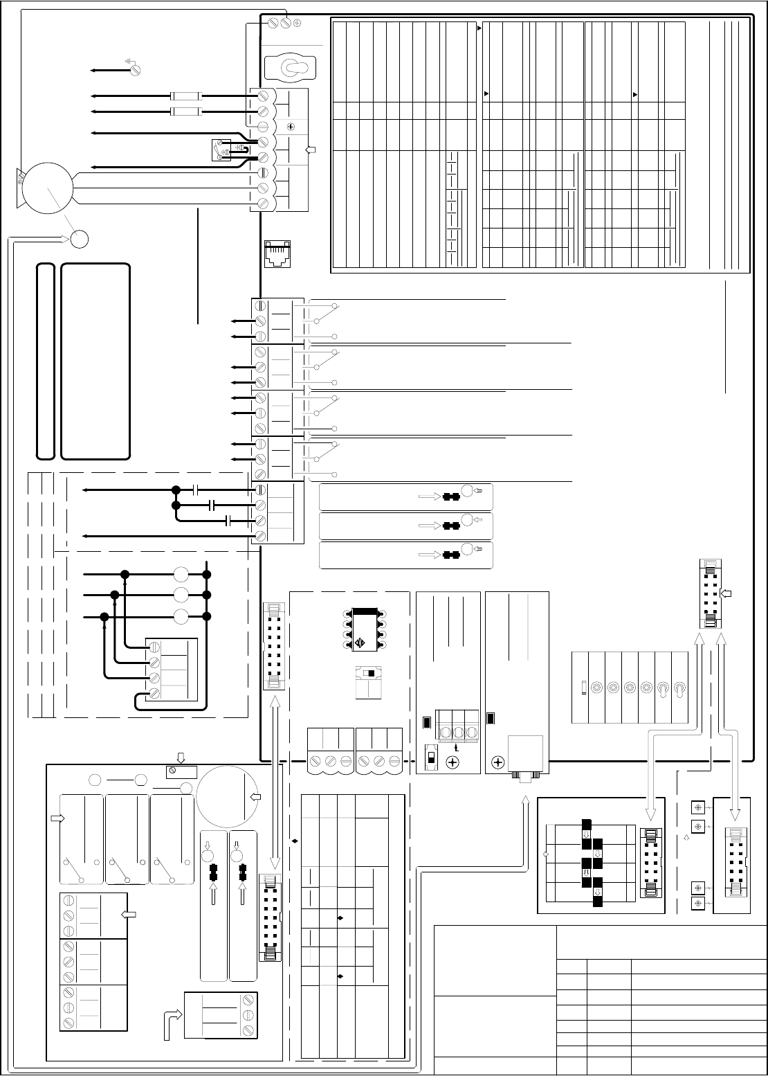
OFF
ON
L1 L2
70
63
76
61
1
62
42
87
88
89
82
83
84
78
79
80
GS1
L
6
12
120
5
12
31
1.2
0.6
2
1.6
8
5
6
15
2
0.6
3
C/P
UV
LC/P
4
14
120
5
12
45
2
1.4
0.6
2.0
10
5
9
10
2
3
0.6
S/O
W
10
2.5
12
9
9
15
RC/P
4
12
80
5
45
12
2
S/O
2.0
0.6
1.4
20
2
5
15
2
2
0.6
S/O
L R
4
12
2
4
80
3
12
45
1.2
C/P
0.2
2
0.6
10
4
5
15
2
0.2
2
22
C/P
GEARED
NC
NO
COM
NC
NO
COM
C
O CLOSE
N
NUDG.
J4
C
N
OR
J7
OPEN
V+
LC
0V
V+
SE
0V
AUX.
BUZZER
3
1DOL
AUX
AUX
3
2 AUX
NARROW
2
BLU
4 DCL
DPM
3
GRN
YEL
ORG
()
0V
3
NC
2
BRN
NO HEAVY
GRN
YEL
ORG
()
0V
AUX2
HEAVY
51
EARTH GROUND
69
86
85
81
GATE
SWITCH
2
95
7
99
C/P
4
25
243
30
21
7
S/O
6
95
99
19
30
173
5
2 1
5
98
6
99
20
270
30
2: PNP
1
1: NO
1
90
3
99
6
GEARED
25
100
30
DOL
CLOSE
NUDG.
MAN.
SE
LC
SPARE
(
DOL 1
AUX
NARROW 2
DCL 4
COM
ORG
NARROW
COM
6-CONDUCTOR CABLE FOR ENCODER 6-CONDUCTOR CABLE FOR ENCODER REV. DESCRIPTIO115
115 VAC
TOGGLE SWITCHES FOR
MANUAL OPERATION.
NARROWER
DOOR
LC
SE
LC
SE
ELEVATOR CONTROLLER MUST
PROVIDE COMMAND SIGNALS TO HEAVY AND/OR NARROW INPUT(S)
TO USE HEAVIER DOOR AND/OR NARROWER DOOR FUNCTION(S).
6-CONDUCTOR CABLE FOR ENCODER DATE
Doc. No: 2500-2001-S-1
N.C. CONTACT OPENS WHEN DOOR REACHES THE FINAL OPEN LIMIT.
DOL RELAY IS CONTROLLED BY DOL CAM FOR HARMONIC MODEL.
OR, BY DOL HALL-EFFECT SENSOR FOR LINEAR MODEL .
6-CONDUCTOR CABLE FOR ENCODER
CAN NODE ID
BUZZER DELAY TIME
OVERLOAD
BUZZER MODE
CARRIER FREQ.
SCAN FREQ.
LEARNING FREQ.
EDGES DELAY TIME
L= LEFT R=RIGHT
SELECTION OF THE
COMMON
HAND OF THE DOOR
ACCEL. TIME
DECEL. TIME
OPEN TORQUE
SLOW SPD (SSO)
CLUTCH ENG. DIST.
HIGH SPD (HSO)
HOLDING TORQUE
HOLDING SPEED
STALL REV. FORCE
DECEL. TIME
FINAL SPD (FSC)
FSC BEGINS
NUDGING SPD
HOLDING SPEED
HOLDING TORQUE
HOLDING BEGINS
CLOSING
GS
246 7-8
0-65535
0-1
FRONT DOOR = 7
0: DISABLE
207
204
0-1
0-1
0-1
0: MAINTAIN
0: PERCENT
198
217
0-180
0-6
205 0-2 0: DISABLE
0-400
0-15
197
0-400
0-180
Pr.#
HARMONIC
1-2 R
RANGE
0-360
0-360
6
12
0-400 80
0-400
0-100
3
12
0-400 45
0-4.5 2.0
C/P
0-3
0-400
0.6
2
148
146
0-4.5
0-360
HARMONIC
1.4
15
142
143
0-400
0-100
3
5
144 0-400 10
138
137
0-400
0-3
2
0.6
139 0-100 2
HARMONIC
C/P
Pr.# RANGE
6-CONDUCTOR CABLE FOR ENCODER
ENCODER
2500-3057
COM
1: ENABLE
1: USE DOL
1: PULSES
2: PULSE
LINEAR
C/P
GEARED
100
5
12
50
1.2
S/O
0.2
2
LINEAR
0.9
4
5
10
15
0.2
LINEAR
S/O
(SEE NOTE 1)
NC
NO
COM
NC
METHOD 1
NO
COM
OPEN
CLOSE NUDG.OPEN
METHOD 2
O
INPUT SIGNALS
U5
NPN
PNP
DPPC
0001N
ENABLE IC
(SEE NOTE 2)
(OPTIONAL)
DEFAULT BAUDRATE
OF PAR. 247 = 115.2KBPS
SET PAR. 246 = 8
FOR REAR DOOR
SET PAR. 246 = 7
FOR FRONT DOOR
SET PAR. 11 = 5
TO USE CAN BUS
LINEAR GEARED MODEL:
PAR. 42 = 1 FOR RH/LH/CP
NARROW
CLOSE
RUN
6-CONDUCTOR CABLE FOR ENCODER
SPARE
14-CONDUCTOR RIBBON CABLE
906-
3030
906-
3013
ECI
P/N
INDICATOR
CANH
INDICATOR
10-CONDUCTOR RIBBON CABLE
DOL
10-CONDUCTOR RIBBON CABLE
NC
NO
HEAVY
LED
BLU
1
BLU
1
BRN
RED
V+ V+
MFG.
TX (CN5)
3 DPM
DCL
SET PAR. 199=0
TO ENABLE AUX
2500-1001
SIGNALS TRANSFER BOARD
6-CONDUCTOR CABLE FOR ENCODER
NC
NO
OPTIONAL
AUX.
COM
NONE
WHT - WHT
CONNECTION
BETWEEN TX & RX
EARTH
GROUND
EARTH GROUND
POLE ON
ENCLOSURE
CONNECTION
NARROWER DOOR
DET. EDGES MODE
EDGES HOLD TIME
C/P=CENTER PARTING
FSO BEGINS
FINAL SPD (FSO)
HOLDING BEGINS
OPENING
ACCEL. TIME
HIGH SPD (HSC)
CLOSE TORQUE
MAX. CLOSE SPEED
230VAC
1/2 HP 3PH.
INDUCTION
MOTOR
GATE
SWITCH TO MOTOR
0-65535
202
199
206
0-1
0-2
0-180
1
1: NPN0: DISABLE
0: YES
Pr.#
145
0-100
0-400
0-100
0-360
98
3
99
6
RANGE
141
140
136
0-400
0-400
0-60
25
270
30
DPM
CONNECT TO ECI
PARAMETER UNIT
2500-3051
2
95
5
99
2
20
120
30
REOPEN DCL INPUT SIGNALS
CLOSE
LED
OPEN
LED
NUDG.
LED
COM
OPEN
ENABLE IC
ONLY WORKS
WITH ECI
CERTIFIED
DETECTOR
EDGES
SW8
HEAVY
HAMONIC MODEL:
PAR. 42 = 2 FOR LH/CP
PAR. 42 = 1 FOR RH
LINEAR STRAIGHT MODEL:
PAR. 42 = 1 FOR LH/CP
PAR. 42 = 2 FOR RH
NUDG.
AUTO
EDGES
TIMEOUT
DELAY TIME FROM
TRIGGERED POINT
IS SET BY PAR. 198
PAR. 205 = 0 : DISABLE
205 = 1: CON'T
205 = 2: PULSE
BUZZER
VOLUME
CONTROL
AUX2
CN5
906-
3020
SHLD
CANL
BUS
TERMINATION SWITCH
CONNECT TO
CAN BUS
OF THE
ELEVATOR
CONTROLLER
OPTICAL CAM
BOARD
SET PAR.
201 = 1
SET PAR.
201 = 0
EDGES
TIMEOUT
NARROW
LED
RED WHT
)
DPM 3
HALL-EFFECT
SENSOR BOARD
COM
INPUT
SIGNALS
NARROW
NONE
CONNECT TO J7
ON THE MAIN BOARD
6-CONDUCTOR CABLE FOR ENCODER
500VA MIN.
CONNECT TO ANY VOLTAGE
SOURCE FROM 24 TO 230
VOLTS, AC OR DC, 30mA MIN.
REMOVE THIS JUMPER IF
INPUT SIGNAL VOLTAGE
IS 60V OR LESS
REMOVE THIS JUMPER IF
INPUT SIGNAL VOLTAGE
IS 60V OR LESS
REMOVE THIS JUMPER IF
INPUT SIGNAL VOLTAGE
IS 60V OR LESS
CN4
CONNECT TO ECI CERTIFIED
INFRARED DETECTOR EDGES
2500-3056
CONNECT
TO ENCODER
REOPEN RELAY IS ACTIVATED BY ANY ONE
OF THE FOLLOWING DETECTIONS:
1. STALL REVERSE; CONTROLLED BY PAR. 148.
2. FREQUENCY FAILURE; CONTROLLED BY PAR. 136
3. DETECTOR EDGES; CONTROLLED BY PAR. 202, SW 8, AND IC U5.
N.C. CONTACT OPENS WHEN DOOR REACHES FINAL CLOSE LIMIT.
DCL RELAY IS CONTROLLED BY DCL CAM FOR HARMONIC MODEL.
OR, BY DCL HALL-EFFECT SENSOR FOR LINEAR MODEL .
(SEE NOTE 1)
8 AMP.
SLOW BLOW
FUSES
CODE DIST. NARROW
DOORWIDTH LEARNING REAR DOOR = 8
1" FOR S/O, OR 2" FOR C/P FROM DCL
RE-OPEN RELAY MODE
NARROWER DOOR DOL 0: USE BOTH DOL & AUX
CLUTCH DISTANCE UNIT
1: DISABLE WHEN EDGES RELAY ON
1: CONTINUOUS
STRAIGHT
DEFAULT VALUE
QUICK STOP ON REV.
DEFAULT VALUE
DEFAULT VALUE
STRAIGHT
EASY SETUP PROCEDURE
WRITE (DOWNLOAD) TO THE DRIVE: Press SET, Press UP Arrow, Press WRITE.
INSTRUCTIONS FOR THE VFE2500 PARAMETER UNIT
READ (COPY) FROM THE DRIVE: Press SET, Press UP Arrow, Press READ.
6-CONDUCTOR CABLE FOR ENCODER
C = CLOSE O = OPEN N = NUDGING
EDGES TIMEOUT
RELAY
FORMULA
SYSTEMS
JANUS
RESET
LEARN DOOR WIDTH
FOR HARMONIC MODEL
SETUP
2500-1002
10-CONDUCTOR RIBBON CABLE
CONNECT TO OPTICAL CAM BOARD FOR HARMONIC MODEL.
CONNECT TO SIGNAL TRANSFER BOARD FOR LINEAR MODEL.
NARROWER DOOR
REMOVE THIS JUMPER IF
INPUT SIGNAL VOLTAGE IS
60V OR LESS
REMOVE THIS JUMPER IF
INPUT SIGNAL VOLTAGE IS
60V OR LESS
RX (CN4)
TO ELEVATOR CONTROLLER
FOR THE LIGHT DUTY LINEAR MODEL,
THE MOTOR WILL BE 230VAC 91W
3PH AND THE ENCODER IS AN
UNDETACHABLE PART OF THE
MOTOR, P/N: 2500-2016-L/R
RELAY CONTACTS
ARE RATED @ 10 AMP. 250VAC
WARNING:
115 VAC
LINE
GS & GS1 ARE ONLY CONVENIENCE TERMINALS
FOR USERS. THEY HAVE NO CONNECTIONS
TO VFE-2500 CIRCUITRY.
CODE DIST. REG / HVY 1" FOR S/O, OR 2" FOR C/P FROM DCL
: TO LOWER TORQUE, INCREASE THE VALUE.
STRAIGHT
CHANGE PARMETERS: Press SET, Enter Parameter Number, Press READ, Enter
New Value, Press WRITE.
LEARNING DOORWIDTH: Set DOL and DCL properly. Flip switch to SETUP.
Set Par. 63 = 1. Flip switch back to RUN. Flip next switch to MAN.
Follow prompts on LCD Display.
CONNECTION METHODS
DELAY TIME FROM
TRIGGERED POINT
IS SET BY PAR. 197
CONTROLLER'S RELAYS MUST HAVE
THE SAME COMMON AND RELAY COIL
VOLTAGE MUST BE FROM 24V - 230V
AC OR DC.
AUX. RELAY
USE PAR. 68 TO SET
AUX2 RELAY.
SEE MANUAL FOR
DETAILS.
TRITRONICS
BUZZER IS TRIGGERED BY
INFRARED DETECTOR EDGES.
CONNECT TO
ADDITIONAL
I/O BOARD
INFRARED DETECTOR
EDGES OUTPUT TYPE
SELECTOR SWITCH.
PAR. 202 =0 TO DISABLE
PAR. 202 =1 FOR NPN
PAR. 202 =2 FOR PNP
GALVANIC
ISOLATION
CAN BUS
CARD
GALVANIC
ISOLATION
ENCODER
CARD
SET PAR. 63 =1 FOR
DOOR WIDTH LEARNING
VFE2500
CLOSED LOOP DRIVE
2500-3050-1
10-CONDUCTOR RIBBON CABLE
FOR LINEAR MODEL
(OPTIONAL)
SET PAR. 204=0 IF
AUX. CONTACT AND
REGULAR DOL ARE
USED AS DOL OF THE
NARROWER DOOR.
MOVFE2500 CLOSED LOOP DOOR OPERATOR
CONNECTION DIAGRAM
DPM N.O. CONTACT MAKES 1/2 INCH BEFORE
GATE SWITCH MAKES FOR FAULT MONITOR
TO MEET ANSI A17.1 AND CAN/CSA-B44.
DPM RELAY IS CONTROLLED BY DPM CAM
OR DPM HALL EFFECT SENSOR.
ADDITIONAL I/O BOARD
2500-3055
TO ELEVATOR CONTROLLER
ECI CERTIFIED INFRARED DETECTOR EDGES
NOTES: 1. HEAVY LINES REPRESENT CONNECTIONS FROM ELEVATOR CONTROLLER
TO DOOR OPERATOR PCB.
2. MAKE SURE THAT ENABLE IC IS INSERTED INTO SOCKET AS SHOWN.
EDGES TIMEOUT RELAY IS TRIGGERED BY INFRARED DETECTOR EDGES.
SET PAR. 207 = 1 TO DISABLE REOPEN RELAY WHEN EDGES TIMEOUT ACTIVATED.
DRIVE OVERLOAD FACTORY SET AT 2.5A
IF EDGES TIMEOUT OUTPUT IS USED FOR
NUDGING FEATURE, IT MUST BE SUBJECT
TO ELEVATOR FIRE SERVICE CODES.
ALL EQUIPMENT MUST BE INSTALLED AND ADJUSTED
TO MEET FEDERAL, STATE / PROVINCIAL, AND LOCAL
CODES. TO PREVENT ELECTRICAL SHOCK, METALLIC
CONDUITS, ELECTRICAL BOXES, AND MOTOR
MUST BE GROUNDED. WAIT FOR 10 MINUTES AFTER
REMOVING POWER BEFORE SERVICING.
:CONNECT 0V TO A TRUE EARTH GROUND
6-CONDUCTOR CABLE FOR ENCODER
SET PAR. 199=0 TO ENABE AUX
SUITABLE FOR USE ON A CIRCUIT
CAPABLE OF DELIVERING NOT
MORE THAN 5000 RMS SYMMETRICAL
AMPERES,120 VOLTS MAXIMUM,
WHEN PROTECTED BY 8 AMPERES,
120V RK5 FUSES.
ECI HAS DONE THIS PROCEDURE BEFORE SHIPPING VFE2500 TO CUSTOMERS.
HOWEVER, THIS EASY SETUP PROVIDES USERS WITH HELPFUL STEPS, WHEN NEEDED.
1. TURN ON POWER AND RUN DOOR IN MANUAL MODE. IF DOOR CLOSES AND OPENS IN THE CORRECT DIRECTION,
GO TO 2. IF NOT, SWAP ANY 2 OF MOTOR WIRES, CHECK AGAIN, THEN GO TO 2.
2. ON KEYPAD, HIT VOLT/PULSE KEY. RUN DOOR IN MANUAL MODE AGAIN. IN CLOSE DIRECTION, LCD SHOULD
SHOW "CLOSE" AND PULSE COUNT SHOULD DECREASE. IF NOT, CHANGE PAR. 42. CHECK AGAIN, THEN GO TO 3.
3. USE THE PARAMETER UNIT TO UPLOAD APPROPRIATE
ECI DEFAULT FOR THE DOOR OPERATOR, THEN GO TO 4.
4. FLIP FIRST TOGGLE SWITCH TO SETUP. SET PAR. 63 = 1, FLIP TOGGLE SWITCH TO RUN, RUN THE DOOR IN MANUAL MODE.
FOLLOW INSTRUCTION ON LCD DISPLAY TO COMPLETE DOOR WIDTH LEARNING PROCESS. LEARN-DOOR-WIDTH LED WILL
FLASH AND TURN OFF WHEN PROCESS IS COMPLETED. LCD DISPLAY WILL SHOW "LEARNING COMPLETED."
PARAMETER 63 WILL RETURN TO ZERO BY ITSELF.
5. FLIP FIRST TOGGLE SWITCH TO SETUP. SET PAR. 11 = 1 FOR REGULAR OPERATION.
SET PAR. 11 = 5 FOR CAN BUS OPERATION. FLIP TOGGLE SWITCH TO RUN.
6. TEST DOOR IN MANUAL MODE, AND TEST DOOR IN AUTOMATIC MODE. DONE!
GAL CANADA
6500 GOTTARDO CRT.
MISSISSAUGA,ONTARIO
L5T 2A2 CANADA
TEL: (416)747-7967
FAX: (416)747-9035
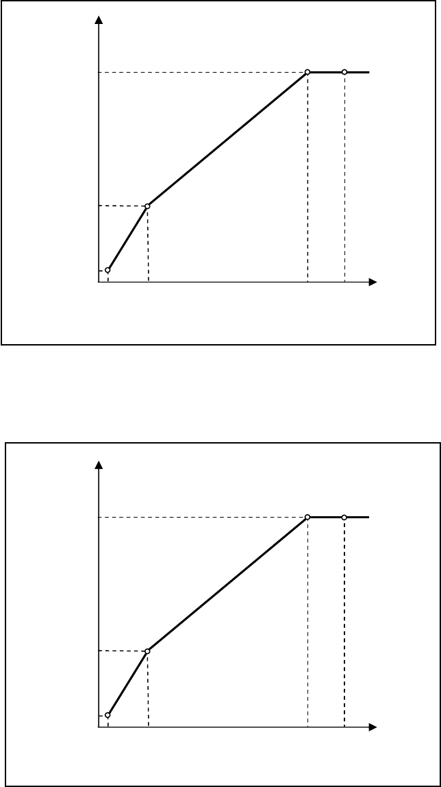
52
SUPPORTIVEGRAPHS
1. V/FCURVEFORNORMALDOOR
2. V/FCURVEFORHEAVYDOOR
OUTPUT VOLTAGE (V)
OUTPUT FREQUENCY (Hz)
V/F GRAPH FOR NORMAL DOOR
Par. 26
Vbase
Par. 90 (OPEN)
Vmid
Par. 29
Fmin
Par. 91 (OPEN)
Fmid
Par. 151 (CLOSE)
Par. 150 (CLOSE)
Par. 28
Vmin
Par. 89 (OPEN)
Par. 140 (CLOSE)
Fbase
Fmax
Par. 27
OUTPUT VOLTAGE (V)
OUTPUT FREQUENCY (Hz)
V/F GRAPH FOR HEAVY DOOR
Par. 26
Vbase
Par. 104 (OPEN)
Vmid
Par. 29
Fmin
Par. 105 (OPEN)
Fmid
Par. 166 (CLOSE)
Par. 165 (CLOSE)
Par. 28
Vmin
Par. 103 (OPEN)
Par. 155 (CLOSE)
Fbase
Fmax
Par. 27
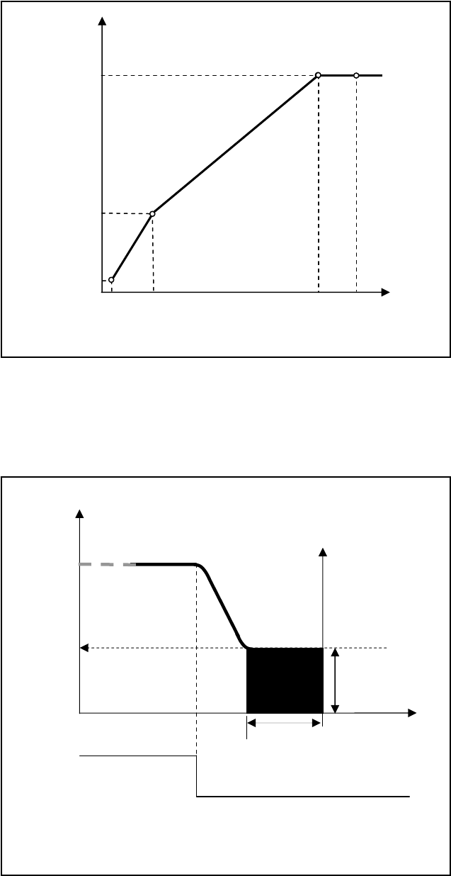
53
3. V/FCURVEFORNARROWDOOR
4. DCINJECTION
OUTPUT VOLTAGE (V)
OUTPUT FREQUENCY (Hz)
V/F GRAPH FOR NARROW DOOR
Par. 26
Vmax
Par. 118 (OPEN)
Vmid
Par. 29
Fmin
Par. 119 (OPEN)
Fmid
Par. 181 (CLOSE)
Par. 180 (CLOSE)
Par. 28
Vmin
Par. 117 (OPEN)
Par. 170 (CLOSE)
Fbase
Fmax
Par. 27
OUTPUT FREQUENCY
TIME
DC OUTPUT CURRENT
FREQUENCY DETECTION, DURATION,
AND INTENSITY OF DC INJECTION
DC BRAKE
FREQUENCY
DETECTION
Par. 121
DC BRAKE
DURATION
Par. 122
DC BRAKE
INTENSITY
Par. 78
RUN/STOP OFF
ON
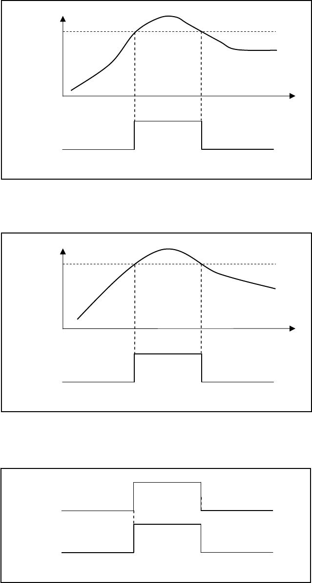
54
5. STALLREVERSEDETECTION
6. FREQUENCYFAILUREDETECTION
7. INFRAREDDETECTOREDGESDETECTION
OUTPUT
FREQUENCY
FREQUENCY FAILURE DETECTION
RE-OPEN
RELAY
OFF
OFF
ON
FREQUENCY
FAILURE
DETECTION
Par. 136
TIME
INFRARED DETECTOR EDGES DETECTION
LCSE
FROM INFRARED
DETECTOR
EDGES
DEACTIVATE
ACTIVATE DEACTIVATE
RE-OPEN
RELAY
OFF OFF
ON
OUTPUT
CURRENT
STALL REVERSE DETECTION
RE-OPEN
RELAY
OFF
OFF
ON
STALL REVERSE
DETECTION
Par. 148
TIME
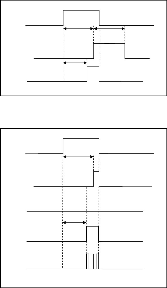
55
8. EDGESTIMEOUTRELAYANDBUZZERTIMING
9. EDGESTIMEOUTRELAYANDBUZZERMODES
EDGES TIMEOUT RELAY AND BUZZER
LCSE
FROM
INFRARED
DETECTOR
EDGES
DEACTIVATE
ACTIVATE DEACTIVATE
EDGES
TIMEOUT
RELAY
OFF
OFF
ON
EDGES DELAY
Par. 197
EDGES
HOLD TIME
Par. 206
BUZZER
OFF OFF
ON
BUZZER
DELAY
Par. 198
EDGES TIMEOUT RELAY AND BUZZER MODE
LCSE
FROM
INFRARED
DETECTOR
EDGES
DEACTIVATE
ACTIVATE DEACTIVATE
EDGES
TIMEOUT
RELAY
WITH
Par. 206 = 0
OFF
OFF
ON
EDGES DELAY
Par. 197
BUZZER
CONTINUOUS
Par 205 = 1
OFF OFF
ON
BUZZER
DELAY
Par. 198
BUZZER IS
DISABLED
Par 205 = 0
OFF
BUZZER
PULSATING
Par 205 = 2
OFF OFF
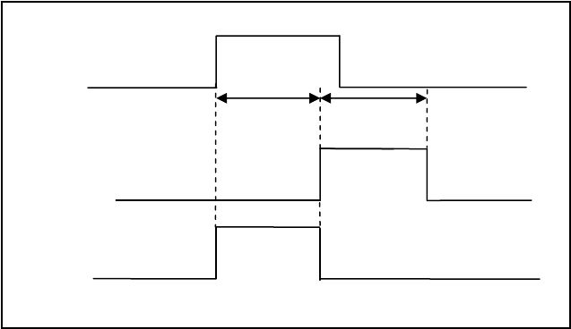
56
10. INTERACTIONBETWEENREOPENRELAYANDEDGESTIMEOUTRELAY
REOPEN RELAY & EDGES TIMEOUT RELAY
LCSE
FROM
INFRARED
DETECTOR
EDGES
DEACTIVATE
ACTIVATE DEACTIVATE
EDGES
TIMEOUT
RELAY
OFF
OFF
ON
EDGES DELAY
Par. 197
EDGES
HOLD TIME
Par. 206
REOPEN RELAY
WITH
Par. 207 = 1 OFF OFF
ON

57
FAULTSLIST
Fault
DisplayMeaningResetAuto
Reset RecordDrive
Response ResetCondition
Over‐currentOver‐currentYesYesYesCoasttoStopContinuouscurrentmustbelessthan50%of
ratedcurrentfor5seconds
Remedy
1.CheckthewiringconnectionstoU,V,Wforpossibleshortcircuits.
2.CheckthewiringconnectionsbetweentheACmotordriveandmotorforpossibleshortcircuits,
alsotoground.
3.CheckforloosecontactsbetweenACmotordriveandmotor.
4.Increasetheaccelerationtime.
5.Checkforpossibleexcessiveloadingconditionsatthemotor.
6.IftherearestillanyabnormalconditionswhenoperatingtheACmotordriveafterashort‐circuitis
removedandtheotherpointsabovearechecked,itshouldbesentbacktomanufacturer.
Fault
DisplayMeaningResetAuto
Reset RecordDrive
Response ResetCondition
Over‐voltageOver‐voltageYesYesYesCoasttoStopDC‐busmustbelessthan385Vfor230VDrive
Remedy
1.Checkiftheinputvoltageisovertheratedvoltageofthe2500‐3050driveinputvoltagerange.
2.Checkforpossiblevoltagetransients.
3.DC‐busover‐voltagemayalsobecausedbymotorregeneration.
4.Increasethedecelerationtime.
5.Checkwhethertherequiredbrakingpoweriswithinthespecifiedlimits.
6.Checkforproperearthgroundwire.
Fault
DisplayMeaningResetAuto
Reset RecordDrive
Response ResetCondition
OverheatOverheatYesYesYesCoasttoStopHeatsinktemperaturemustbelessthan
161°F(71.6°C)
Remedy1.Ensurethattheambienttemperaturefallswithinthespecifiedtemperaturerange.
2.Removeanyforeignobjectsfromtheheatsinkandcheckforpossibledirtyheatsinkfins.
Fault
DisplayMeaningResetAuto
Reset RecordDrive
Response ResetCondition
Drive
Overload
Drive
OverloadYesYesYesCoasttoStopContinuouscurrentmustbelessthan50%of
ratedcurrentfor5seconds
Remedy1.Checkwhetherthemotorisoverloaded.
2.Reducetorque
Fault
DisplayMeaningResetAuto
Reset RecordDrive
Response ResetCondition
Motor
Overload
Motor
OverloadYesYesYesCoasttoStopContinuouscurrentmustbelessthan50%of
ratedcurrentfor5seconds
Remedy
1.Reducethemotorload
2.Check,removeanyforeignobjectspreventingthemotorfrommoving.
3.Repairdefectivemechanicalsystem.

58
FAULTSLIST(CONTINUED)
Fault
DisplayMeaningResetAuto
Reset RecordDrive
Response ResetCondition
Hardware
Failure
Hardware
protection
failure
NoNoYesCoasttoStop
RemedyReturntoECI
Fault
DisplayMeaningResetAuto
Reset RecordDrive
Response ResetCondition
OC
atAccel
Overcurrent
during
Acceleration
YesYesYesCoasttoStopContinuouscurrentmustbelessthan50%of
ratedcurrentfor5seconds
Remedy
1.Short‐circuitatmotoroutput:Checkforpossiblepoorinsulationattheoutputlines.
2.Torqueboosttoohigh:DecreasethetorquecompensationsettinginPr.33.
3.AccelerationTimetooshort:IncreasetheAccelerationTime.
Fault
DisplayMeaningResetAuto
Reset RecordDrive
Response ResetCondition
OC
atDecel
Overcurrent
during
Deceleration
YesYesYesCoasttoStopContinuouscurrentmustbelessthan50%of
ratedcurrentfor5seconds
Remedy1.Short‐circuitatmotoroutput:Checkforpossiblepoorinsulationattheoutputline.
2.DecelerationTimetooshort:IncreasetheDecelerationTime.
Fault
DisplayMeaningResetAuto
Reset RecordDrive
Response ResetCondition
OC
AtSteady
Overcurrent
during
steadystate
operation
YesYesYesCoasttoStopContinuouscurrentmustbelessthan50%of
ratedcurrentfor5seconds
Remedy1.Short‐circuitatmotoroutput:Checkforpossiblepoorinsulationattheoutputline.
2.Suddenincreaseinmotorloading:Checkforpossiblemotorstall.
Fault
DisplayMeaningResetAuto
Reset RecordDrive
Response ResetCondition
Ground
Fault
Shortto
groundNoNoYesCoasttoStopContinuouscurrentmustbelessthan50%of
ratedcurrentfor5seconds
Remedy
Whenoneoftheoutputterminalsisgrounded,shortcircuitcurrentismorethan1.5A,theACmotor
drivepowermodulemaybedamaged.
1.CheckwhethertheIGBTpowermoduleisdamaged.
2.Checkforpossiblepoorinsulationattheoutputline.
NOTE!TheshortcircuitprotectionisprovidedforACmotordriveprotection,notforprotectionofthe
user.

59
FAULTSLIST(CONTINUED)
Fault
DisplayMeaningResetAuto
Reset RecordDrive
Response ResetCondition
EEPROM
ReadFail
CPURead
FailureYesNoYesCoasttoStopImmediately
RemedyReturntofactory
Fault
DisplayMeaningResetAuto
Reset RecordDrive
Response ResetCondition
Parameter
Chksum
CPUWRITE
FailureYesNoYesCoasttoStopImmediately
RemedyReturntofactory
Fault
DisplayMeaningResetAuto
Reset RecordDrive
Response ResetCondition
CommLossComm.
TimeoutYesNoYes
Disable
CoasttoStop
RamtoStop
Warning
Immediately
Remedy
1.ChecktheRS485connectionbetweentheACmotordriveandRS485masterforloosewiresand
wiringtocorrectpins.
2.Checkifthecommunicationprotocol,address,transmissionspeed,etc.areproperlyset.
3.Usethecorrectchecksumcalculation.
Fault
DisplayMeaningResetAuto
Reset RecordDrive
Response ResetCondition
Autotune
Failure
Auto‐
learning
Error
YesNoYesCoasttoStopImmediately
Remedy1.Checkthecablebetweendriveandmotor
2.Retryagain
Fault
DisplayMeaningResetAuto
Reset RecordDrive
Response ResetCondition
Encoder
Loss
Encoder
LossErrorYesYesYes
CoasttoStop
RamptoStop
Warning&
ScanSpeed
DetectthecorrectsignalsoftheEncoder
RemedyCheckthewiringoftheencoder

60
FAULTSLIST(CONTINUED)
Fault
DisplayMeaningResetAuto
Reset RecordDrive
Response ResetCondition
Encoder
FbkError
Encoder
Direction
Error
YesYesYes
CoasttoStop
RamptoStop
Warning&
ScanSpeed
Movementdirectionisinagreementwiththe
encoderdirectiondefinedbythedrive.
Remedy1.CheckvalueofPar.41.
2.CheckifthewiringoftheEncoderiscorrect.
Fault
DisplayMeaningResetAuto
Reset RecordDrive
Response ResetCondition
AUXSensor
FailAUXErrorYesYesYesWarning&
ScanSpeedRecoverifthesignalisdetectedappropriately
Remedy
1.ChecktheAUXsensor
2.CheckthewiringsoftheAUXsensor.
3.ChecktheMagnetfortheLinearmodel.
4.ChecktheCamfortheHarmonicmodel.
Fault
DisplayMeaningResetAuto
Reset RecordDrive
Response ResetCondition
DPMSensor
FailDPMErrorYesYesYesWarning&
ScanSpeedRecoverifthesignalisdetectedappropriately
Remedy
1.ChecktheDPMsensor
2.CheckthewiringsofDPMsensor.
3.ChecktheMagnetfortheLinearmodel.
4.ChecktheCamfortheHarmonicmodel.
Fault
DisplayMeaningResetAuto
Reset RecordDrive
Response ResetCondition
DOLSensor
FailDOLErrorYesYesYesWarning&
ScanSpeedRecoverifthesignalisdetectedappropriately
Remedy
1.ChecktheDOLsensor
2.CheckthewiringsoftheDOLsensor.
3.ChecktheMagnetfortheLinearmodel.
4.ChecktheCamfortheHarmonicmodel.
Fault
DisplayMeaningResetAuto
Reset RecordDrive
Response ResetCondition
DCLSensor
FailDCLErrorYesYesYesWarning&
ScanSpeedRecoverifthesignalisdetectedappropriately
Remedy
1.ChecktheDCLsensor
2.CheckthewiringsoftheDCLsensor.
3.ChecktheMagnetfortheLinearmodel.
4.ChecktheCamfortheHarmonicmodel.
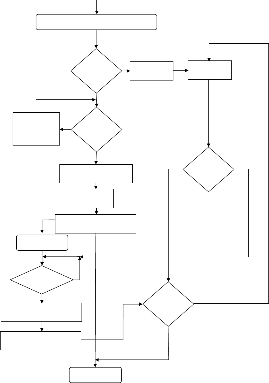
61
FAULTSRESETHANDLINGFLOWCHART
FAULT(S)OCCURED
NUMBER
OFRETRIES
FINISHED?
PAR.221=↓0
?
Yes
RECORDAFAULT
No
FAULT
CONDITION
IS
REMOVED
?
Yes
No
WAITINGFORFAULT
CONDITION
TOBEREMOVED
PAR.222(NEW)=PAR.222(OLD)‐1
FAULTRESET
NORMALOPERATION
STARTRESETTIMER
RESETTIMER>PAR.226
?
STOPTHEDRIVE
Yes
No
PAR.222(NEW)=PAR.222(ORIGINAL)
WAITINGTIMEBEFORERETRY
PAR.222
RESET
SWITCH
ON
?
IS
FAULT
CONDITION
REMOVED
?
Yes
Yes
GENERATERESETSIGNAL
No
No
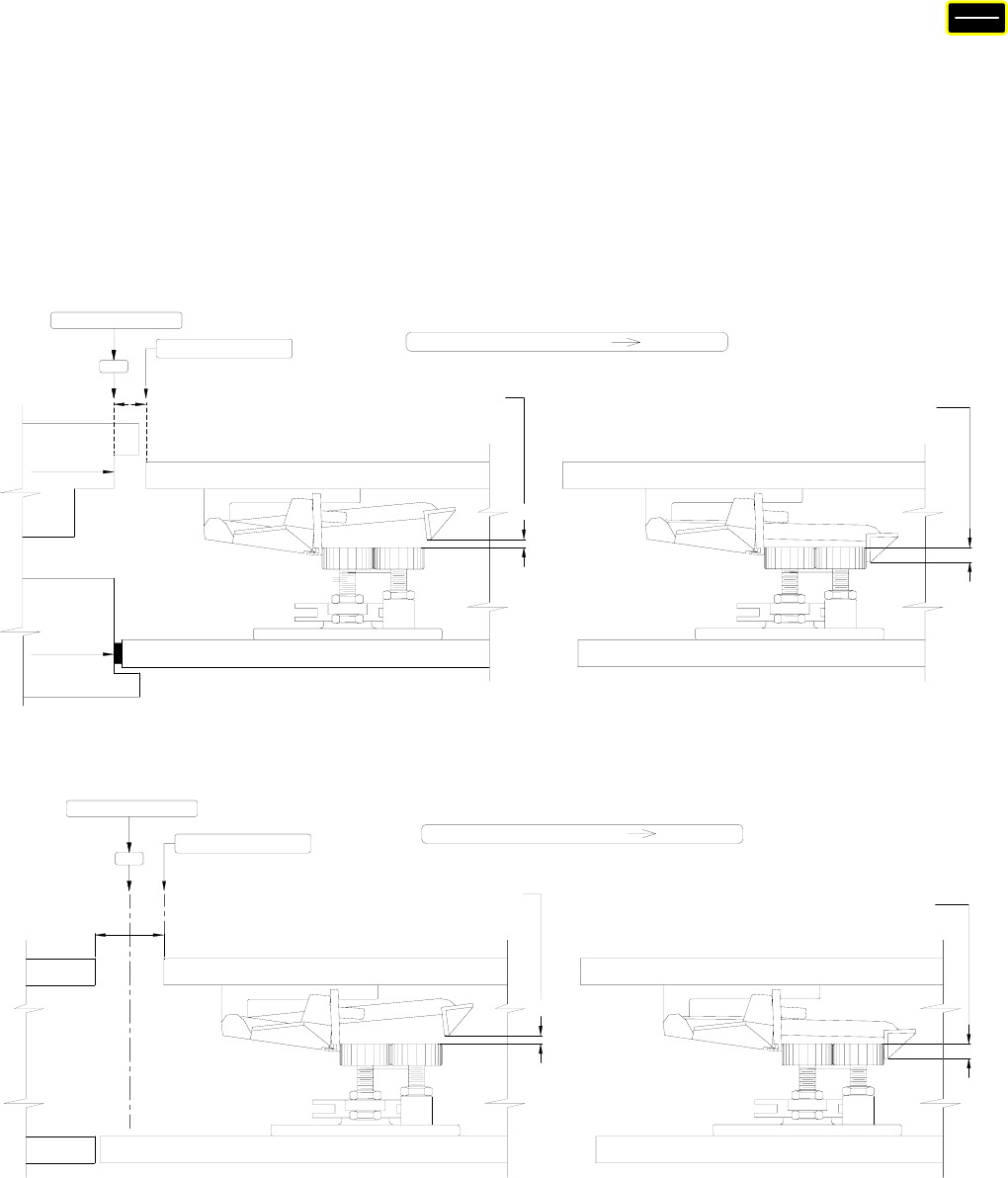
62
CLUTCHENGAGEDDISTANCESETUP
To set the Clutch Engaged Distance (CED), flip the 1st switch to SETUP. Press the
key. Physically move the door to the fully closed position. Record the count as Count1.
Move the door in the Open direction until the mechanical clutch is fully engaged and the
zone lock device is fully cleared. Record the count as Count2. Subtract Count1 from
Count2. Set Par. 76 =1. Enter the difference, Count2 minus Count1, of the Count into
Par. 83. Set Par. 76 = 0 so that Par. 83 can be displayed in percentage, instead of
pulses. The clutch engaged distance setup will help smooth the open cycle and prevent
fuses from blowing.
V
OLT
PULSE
CLUTCH REAR VANE BY 1/8" PAST
1/2" APPROX.
BUMPER
BUMPER
REMOVED
CAR DOORS 1/2" OPEN
HATCH DOOR
DOOR IS FULLY CLOSED AND CAR DOORS
THE ROLLER, AS SHOWN, WHEN HATCH
IS 1/2" FROM STRIKING POST.
1/8"
CAR DOOR
HATCH DOOR
ON THE ROLLER.
THE CLUTCH REAR VANE IS 1/2"
WITH DOORS FULLY ENGAGED
CAR DOOR
1/2"
RECORD AS COUNT 2 (COUNT 2 - COUNT 1 ) PAR. 83
DCL
RECORD AS COUNT 1
SIDE OPENING DOOR
CAR DOOR
HATCH DOOR
CAR DOORS 1" OPEN
1/8"
DOOR IS FULLY CLOSED AND CAR DOORS
THE ROLLER, AS SHOWN, WHEN HATCH
IS 1/2" FROM STRIKING POST.
CLUTCH REAR VANE BY 1/8" PAST
CAR DOOR
DOORS FULLY ENGAGED
HATCH DOOR
1/2"
THE CLUTCH REAR VANE IS 1/2"
WITH DOORS FULLY ENGAGED
ON THE ROLLER.
1" APPROX.
RECORD AS COUNT 2
CENTER PARTING DOOR
RECORD AS COUNT 1
(COUNT 2 - COUNT 1 ) PAR. 83
DCL
DOORS FULLY ENGAGED
63
DOORSTALLFORCEMEASUREMENT
The most practical way to measure the approximate magnitude of the door stall force is
to use a spring gauge as shown in the picture below. Stall force is the static force to
prevent the door from further moving.
Stop the door anywhere from one-third to two-thirds of the door travel. Press the spring
gauge against the door, remove the stop. Hold the spring gauge until the door stands
still, and take the reading. The stall force must be smaller than 30 lbs to comply with
ASME, A17.1, Rule 112.4/5, and CSA/B44, Rule 2.13.4/5.
SPRING GAUGE
SIDEOPENING
DO
STALL
FORCE
30 LBS.
MAX
CENTERPARTING
DO
STALL
FORCE
30 LBS.
MAX
DO
3
DO
6
DO
6
64
CODEDISTANCECLOSINGTIMESETUP(ACTUALVALUE)
To measure the Code Distance Closing Time, flip the 1st switch to SETUP. Press the
key . Physically move the door to the fully closed position. Record the count as
Count1. Move the door in the Open direction, away from DCL, 1 inch for Center Parting
doors, 2 inches for a Side Opening door. Record the count as Count2. Subtract Count1
from Count2. Enter the difference, Count2 minus Count1, of the Count into Par. 69. Do
the same procedure and enter the difference of the count into Par. 70 for the Narrower
door, if used. The display of the Code Distance Closing Time is in the sub-item #10
under the key as described in the Parameter Unit section of this manual.
V
OLT
PULSE
V
IEW
CENTERPARTING
CODE
DISTANCE
1
”
1
”
DCL
DOL
1
”
RECORD
AS
COUNT1
RECORD
AS
COUNT2
FOR NORMAL/HEAVY DOOR
(COUNT2 –COUNT1) Î PAR. 69
FOR NARROW DOOR
(COUNT2 –COUNT1) Î PAR. 70
SIDEOPENING
CODE
DISTANCE
2
”
2
”
DCL
DOL
RECORD
AS
COUNT1
RECORD
AS
COUNT2
FOR NORMAL/HEAVY DOOR
(COUNT2 –COUNT1) Î PAR. 69
FOR NARROW DOOR
(COUNT2 –COUNT1) Î PAR. 70
65
NOTES:
MINIMUMCLOSINGCODETIME(ECIREFERENTIALVALUE)
MinimumclosingcodetimesareobtainablefromtheLCDkeypadbyenteringthefollowings:
DOORTYPESELECTION
(HARMONIC,STRAIGHTLINEAR,ORGEAREDLINEAR)
ENTERBYECIDEFAULTS.
PAR.52(READONLY)
0:HARMONIC,S/O
1:HARMONIC,C/P
2:LINEAR‐STRAIGHT,S/O
3:LINEAR‐STRAIGHT,C/P
4:LINEAR‐GEARED,S/O
5:LINEAR‐GEARED,C/P
ENTERDOORWIDTH(INCHES)ÎPAR.49
ENTERDOOR(S)WEIGHT(LBS)ÎPAR.50
ENTERSINGLE‐SPEEDORTWO‐SPEED
SELECTION
0:SINGLESPEED
1:TWOSPEED
ÎPAR.51
ECI
MINIMUM
CLOSING
CODETIME
TABLES
REFERENTIALCLOSINGCODETIMES.
9.DISPLAYGROUP
D21:MINIMUMCLOSINGCODETIME
D22:MINIMUMCLOSINGCODETIME
FORNUDGING
66
CHECKINGPROCEDUREFORTHECLOSINGCODETIMES.
ITISSAFETOOPERATETHENORMALOR
HEAVYDOOROFTHEVFE2500DOOR
OPERATORWITHTHECURRENT
REGULARSPPED
ITISSAFETOOPERATETHENORMALOR
HEAVYDOOROFTHEVFE2500DOOR
OPERATORWITHTHECURRENT
NUDGINGSPPED
NARROWER
DOOR
(NORMAL/HEAVY)
DOOR
D22<CDNUDGINGTIME
INLCDDISPLAYITEM#10
?
NO
YES
REGULARCLOSING
OR
NUDGINGSPEED
?
REGULAR
SPEED
NUDGING
SPEED
D21<CDCLOSINGTIME
INLCDDISPLAYITEM#10
?
NO
YES
DECREASE(NARROWERHSC)PAR.171
AND
CHECKAGAIN
DECREASE(NARROWERNUDG.)PAR.174
AND
CHECKAGAIN
REGULARCLOSING
OR
NUDGINGSPEED
?
REGULAR
SPEED
NUDGING
SPEED
DECREASE(HSC)PAR.141
AND
CHECKAGAIN
DECREASE(HEAVYHSC)PAR.156
AND
CHECKAGAIN
HEAVIERDOOR
OR
NORMALDOOR
?
NORMAL
DOOR
HEAVIER
DOOR
DECREASE(NUDG.SPEED)PAR.144
AND
CHECKAGAIN
DECREASE(HEAVYNUDG.)PAR.159
AND
CHECKAGAIN
HEAVIERDOOR
OR
NORMALDOOR
?
NORMAL
DOOR
HEAVIER
DOOR
D22<CDNUDGINGTIME
INLCDDISPLAYITEM#10
?
NO
YES
D21<CDCLOSINGTIME
INLCDDISPLAYITEM#10
?
NO
YES
ITISSAFETOOPERATETHEVFE2500DOOROPERATOR
(NORMAL/HEAVY)
OR
NARROWER
DOOR
?
ITISSAFETOOPERATETHENARROWER
DOOROFTHEVFE2500DOOROPERATOR
WITHTHECURRENT
NUDGINGSPPED
ITISSAFETOOPERATETHENARROWER
DOOROFTHEVFE2500DOOROPERATOR
WITHTHECURRENT
REGULARSPPED
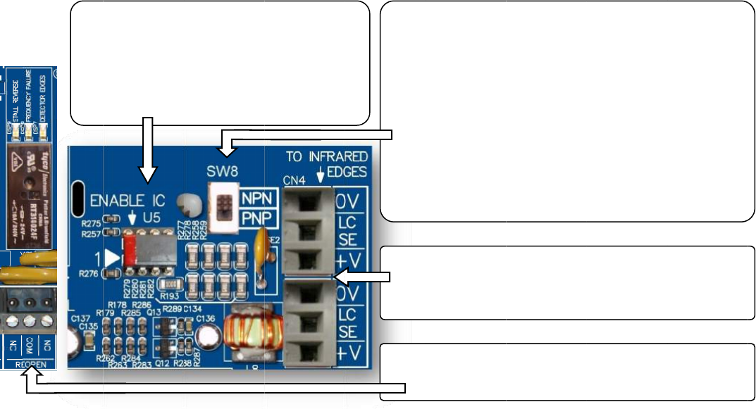
INTE
Und
e
The
R
1
st
.
O
2
nd
.
O
3
rd
.
O
Ove
r
cust
o
Edg
e
less
w
reop
ECI
C
VFE
2
Infra
user
s
relat
How
RFACINGBE
T
e
rstandingt
h
R
E‐OPENrela
O
verTorque
‐
O
verSpeed‐
O
bstruction
o
r
Torqueand
o
mersconne
c
e
stotheirow
w
iring,fewer
enthedoor
a
C
ertifiedInfra
2
500,andw
o
redDetector
s
havetoord
e
edinstructio
n
tointerface
1.In
s
The
R
ont
h
pre‐
i
Infra
T
WEENECIC
E
h
eRE‐OPENr
ycanbeacti
v
‐
Controlled
b
Controlledb
y
o
ftheInfrare
d
OverSpeed
D
c
ttheInfrare
npowersup
p
component
s
a
sasafetyre
d
redDetector
o
rkwiththe
2
EdgesviaEC
e
rtheenabl
e
n
s.
betweenth
e
s
erttheEna
b
R
EDmarkm
u
h
eleftassho
w
i
nstalledwhe
redDetecto
r
E
RTIFIEDINF
e
lay:
v
atedbyany
b
yPar.148
y
Par.136
d
DetectorE
d
D
etectionsar
e
dDetectorE
d
p
lies.Bydoin
s
tofail,and
m
d
undancy.
Edgeswillal
w
2
4VDCpower
I.Differenti
n
e
chip,match
i
e
InfraredDe
t
b
leChipinto
t
u
stbepositio
w
n.ThisEna
b
nbuyingECI
r
Edges.
RAREDLIGH
T
ofthefollo
w
d
ges‐Contro
e
thestanda
r
d
gesdirectly
gthis,custo
m
m
ostimporta
w
ayscome
w
supply.Toe
n
n
frareddetec
t
i
ngconnecto
t
ectorEdges
t
heSocketU
5
nedinthePi
n
b
leICwillbe
Certified
T
CURTAINA
N
w
ingdetectio
n
lledbyPar.2
r
dfeatureso
f
totheVFE25
m
erseliminat
ntlyincase
o
w
iththematc
n
sureaseam
t
oredgesm
a
rsCN5&CN
5
andVFE250
0
5
.
n
1
2.Re
a
detect
NPNo
thein
f
error
m
A
ssum
trial.S
e
Par.2
0
3.Con
to
c
CN
4
4.Ma
k
RE‐
O
N
DVFE2500
n
s:
02,SW8and
f
theVFE250
0
00,insteado
eanextrap
o
o
ftheEdgesf
a
hingconnect
lessinterfac
e
a
yalsobeco
n
5
,andcheck
w
0
:
a
dthelabel
o
oredgesto
rPNP.Sett
h
f
oofNPNor
P
m
ethod.
ethattheo
e
tPar.202=
1
0
2=0todisa
b
necttheECI
C
c
onnectorsC
N
4
andCN5ar
e
k
esuretheR
E
O
PENcontact
(OPTIONAL)
EnableChip
0
.Therefore,
fconnecting
o
wersupply,
r
a
ilure,theO
v
orsCN4&C
N
e
,customers
n
nectedtoth
e
w
ithECIfort
h
o
nthepacka
g
findoutth
e
h
eselectors
w
P
NPisunavai
utputofthe
1
forNPN,S
e
b
leornotus
e
C
ertifiedInfr
a
N
4and/orC
N
e
interchang
e
E
‐OPENcircu
i
s.
U5.
ECIrecomm
e
theInfrared
r
esultinginl
e
v
erTorqued
e
N
5tofitthe
needtoorde
e
VFE2500.
H
h
eavailabilit
y
g
ingorthe
m
e
outputtyp
e
w
itchSW8a
lable,then
u
edgesisN
P
e
tPar.202=
2
e
d.
a
redDetecto
r
N
5.Note!C
o
e
able.
i
tisconnect
e
6
7
e
ndsthat
Detector
e
ssmounting
,
e
tectionwill
rthe
H
owever,
y
ofthe
m
anualofth
e
e
.Itiseithe
r
ccordingly.I
f
u
seatrialan
d
P
Nforthe1
s
t
2
forPNP.Se
t
r
Edges
o
nnectors
e
dtothe
7
,
e
r
f
d
t
t
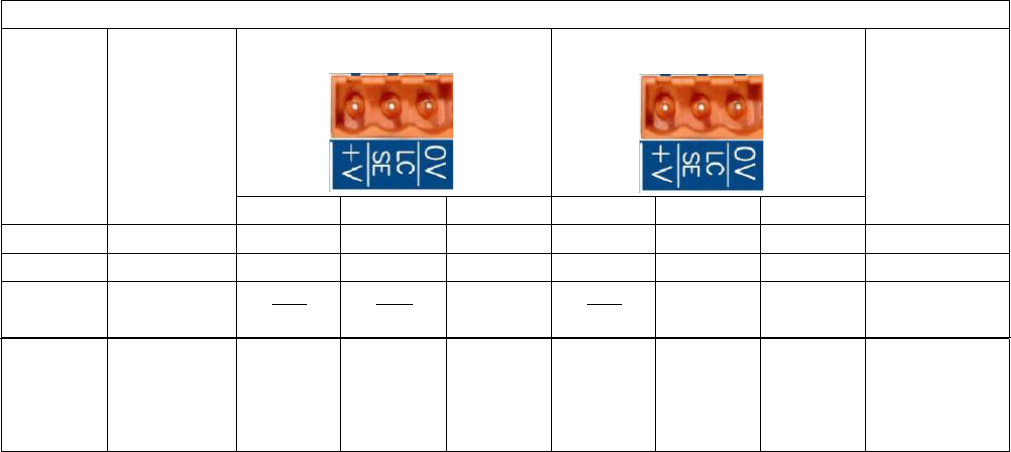
Test the Infrared Detector Edges:
‐ Obstruct the Infrared Detector Edges. The DETECTOR EDGES LED should be ON.
‐ The RE‐OPEN relay should be activated to send the RE‐OPEN signal to the elevator controller.
‐ The elevator controller will send the Door Open command signal back to the VFE‐ 2500 to OPEN the door.
The LED of the Open Input module should be ON.
If the Infrared Detector Edges function does not work:
- Check the table below for correct connections between edges and the VFE2500.
ECI CERTIFIED INFRARED DETECTOR EDGES WIRE COLORS
ECI
P/N
MFG.
TX
(CN5)
RX
(CN4)
CONNECTION
BETWEEN
TX
&
RX
V+
LCSE
0V
V+
LCSE
0V
906‐3013
JANUS
RED
BLUE
ORG
(
♦
)
ORG
(
♦
)
WHT ‐ WHT
906‐3020
TRITRONICS
RED
WHT
ORG
NONE
906‐3030
FORMULA
SYSTEMS
BLU
1
BRN
1
GRN
YEL
BLU
1
BRN
1
GRN
YEL
NONE
906‐3030
FORMULA
SYSTEMS
SECOND
VERSION
BROWN
GREEN
YELLOW
BLUE
BROWN
GREEN
YELLOW
BLUE
NONE
(
♦
)
: Connect an additional wire from 0V to a true EARTH GROUND.
‐ Check for 24VDC between 0V and +V on either CN4 & CN5.
‐ Test the Infrared Detector Edges again
If it still does not work. Then,
‐ Jump 0V to LCSE on either CN4 or CN5 connector for NPN type.
‐ Jump +V to LCSE on either CN4 or CN5 connector for PNP type
‐ The DETECTOR EDGES LED should be ON.
‐ The RE‐OPEN Relay should be activated.
If the above tests work as described, turning ON the detector edges LED, then the problem is in the Infrared Detector
Edges. Otherwise, the problem is in the VFE2500.
If the Infrared Detector Edges have intermittent problems:
‐ Check continuity of the TX and RX cables of the detector edges.
‐ If the cables are good, but the problem still exists, then check the Earth Ground connection to the edges.
‐ Lower the Carrier Frequency in Par. 1 gradually until problems are resolved.
Note! The lower carrier frequency will create more audible noise from the motor.
68
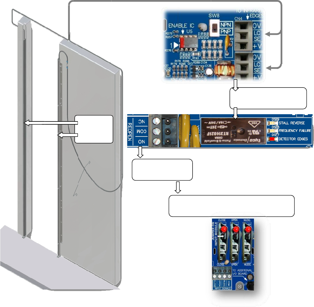
Infra
redDetecto
r
r
Edgesconn
e
e
ction
INFRARED
DETECTOR
EDGES
R
E
ToE
E
‐OPENSign
a
levatorCont
r
Ele
sig
n
a
l
r
oller
vatorContro
n
altotheVF
E
I
n
RE
O
llersendsDo
E
2500toRE‐
O
n
fraredEdges
O
PENrelayI
N
orOpenco
m
O
PENthedo
o
6
9
trigger
N
STANTLY
m
mand
o
r.
9
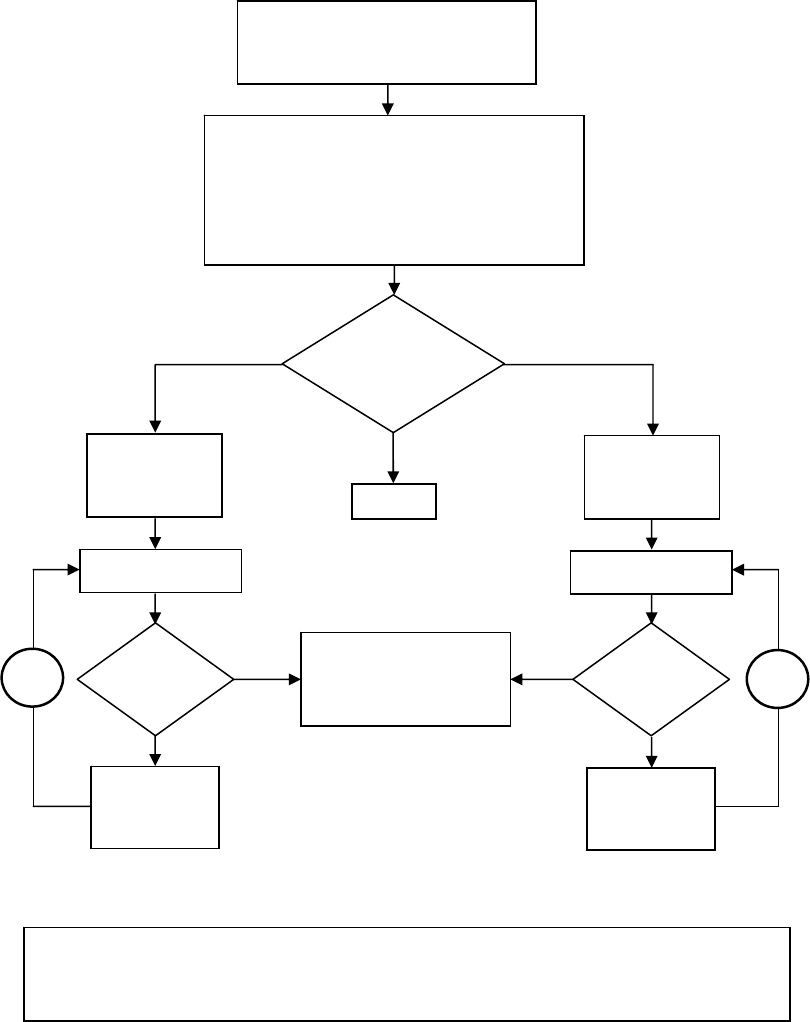
70
INFRAREDDETECTOREDGESAPPLICATIONFLOWCHART
PAR.202=0
FORNOEDGES
PAR.202=1FORNPN
NOEDGES
INFRAREDEDGES
WITH
NPNOUTPUTTYPE
INFRARED
EDGES
SOFTWARE
SELECTION
PAR.202=2FORPNP
INFRAREDEDGES
WITH
PNPOUTPUTTYPE
INFRAREDEDGESHARDWARESELECTION:
IFTHEINFOOFTHEOUTPUTTYPE,NPNORPNP,
OFTHEINFRAREDEDEGSISUNOBTAINABLE,
SETSW8TOEITHERNPNORPNP.
OTHERWISESETTHESW8APPROPRIATELY.
OBSTRUCTTHEEDGES
Yes
No
MAKINGSURETHATPAR.197&PAR.206
HAVENON‐ZEROVALUES.PAR.207=0
FORTHEFOLLOWINGPROCEDURE.
RE‐OPEN
LED
ON
?
SWITCHSW8TO
PNPPOSITION
OBSTRUCTTHEEDGES
RE‐OPEN
LED
ON
?
Yes
No
SWITCHSW8TO
NPNPOSITION
THEINFRAREDEDGES
AREWORKING
AB
NOTE!IFLOOPAORBISREPEATEDTHREETIMESBUTTHERE‐OPENLEDISNOTTURNEDON
WHENTHEEDGESAREOBSTRUCTED.
THENPROBLEMCOULDBEEITHERTHEDETECTOREDGESORTHEDRIVE.
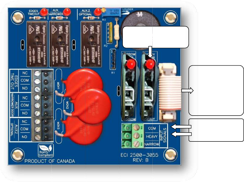
HEA
V
Inth
e
othe
itm
a
The
H
with
Inor
HEA
V
volt
a
less.
willl
i
See
t
Fort
V
YDOORAP
P
e
sameeleva
r.Asaresult
,
a
ybeacode
v
H
EAVYinput
o
adifferents
e
dertogaint
h
V
Yinputis
a
a
ges;from2
4
TheLEDoft
h
i
ghtuptoin
d
t
heparamet
e
heheavierd
o
P
LICATION(
O
tor,thedoo
r
,
thesettings
v
iolationissu
e
o
ftheVFE‐2
5
e
tofparame
t
h
eaccessto
t
a
universali
n
4
‐230VAC
o
h
einputmo
d
d
icatethatth
e
e
rslistformo
o
or,therelat
O
PTIONAL)
operatorm
a
ofTorquea
n
e
duetothe
c
5
00willresol
v
t
ersfortheh
t
heHEAVYse
n
pu
t
module
o
rDC.Theju
m
d
uledrawsc
u
e
elevatorco
redetails.
edparamete
a
yoperatet
w
n
dSpeedofo
c
onstraintof
v
ethisissue.
eavierdoor.
tofparamet
e
whichacce
p
m
perofthei
u
rrentfromt
h
ntrollerhas
s
rsare:Par.
9
w
odifferenth
nedoormay
Kineticener
g
WhentheH
E
e
rs,usersne
e
p
tsthecont
r
nputcardm
u
h
eelevatorc
o
s
enttheHEA
V
9
2‐105,andP
oist‐waydoo
notbeappli
c
g
yandtheTo
E
AVYinputis
e
dtoordera
r
olsignalei
t
u
stberemo
v
o
ntroller,no
t
V
Ycommand
.
ar.152‐163.
LEDon
t
Input
rswithone
d
c
ableforthe
o
rqueallowa
n
activated,th
nAdditional
I
t
herinthef
o
v
edifthein
p
t
fromtheV
F
.
t
heHEAVY
Module
d
oorheavier
t
o
ther.More
i
n
ce.
eVFE2500
w
I
/Oboard,2
5
o
rmofcont
a
p
utsignalvol
t
F
E2500.Ther
e
InputSig
n
HEAVIE
R
14‐cond
ribbonc
a
connecto
themai
n
2500‐
3
7
1
t
hanthe
i
mportantly,
w
illoperate
5
00‐3055.
Th
e
a
ctsorsign
a
t
ageis60Vo
e
fore,theLE
D
n
alfor
R
door
uctor
a
bleto
rJ7on
n
drive
3
050
1
e
a
l
r
D
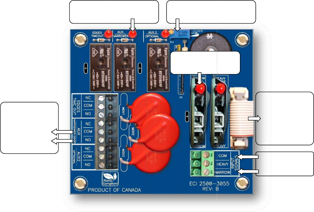
NAR
R
Inth
e
othe
appl
i
the
T
The
N
oper
Inor
The
N
volt
a
less.
LED
o
The
N
DOL
will
a
outp
regu
l
See
t
Fort
E
R
OWERDO
O
e
sameeleva
r.Asaresult
,
i
cableforthe
T
orqueallow
a
N
ARROWinp
atewithadi
f
dertogaint
h
N
ARROWin
p
a
ges;from2
4
TheLEDof
t
o
ftheNARR
O
N
ARROWdo
o
positionoft
a
lsomemori
z
utoftheDO
L
l
arDOLrelay
t
heparamet
e
henarrower
NARROWER
outputsign
E
levatorCon
t
SetPar.19
9
Ifused.
O
RAPPLICATI
tor,thedoo
r
,
thesettings
other.More
a
nce.
utoftheVFE
f
ferentsetof
h
eaccessto
t
p
utisaunive
r
4
‐230VACo
t
heinputmo
O
Winputmo
d
o
rfunctionc
a
henarrower
z
ethepositi
o
L
forthenar
r
contacts(Pa
e
rslistformo
door,therel
a
door
alto
t
roller.
9
=0
O
N(OPTION
A
operatorm
a
ofTorque,S
p
importantly,
‐2500willre
s
parameters
f
t
heNARRO
W
r
salinpu
t
m
o
rDC.Theju
m
duledraws
c
d
ulewillligh
t
a
nonlybeu
s
door.After
t
o
noftheA
U
r
owerdoorc
a
r
.204=0).
redetails.
a
tedparame
t
LEDIn
d
AUX/NAR
R
A
L)
a
yoperatet
w
p
eed,andth
e
itmaybea
c
s
olvethisiss
u
f
orthenarro
w
W
setofpara
m
o
dulewhich
a
m
perofthei
n
c
urrentfrom
t
uptoindica
t
s
edwhenPa
r
t
hecompleti
o
U
X/NARROW
E
a
nbeeither
t
t
ersare:Par
.
d
icatorfor
R
OWERRela
y
w
odifferenth
e
Mechanical
c
odeviolatio
n
u
e.Whenthe
w
erdoor.
m
eters,user
s
a
cceptsthec
o
n
putcardm
u
theelevato
r
t
ethattheel
e
r
.199=0,an
o
nofthedo
o
E
Rsensor,w
t
heAUXorr
e
.
106‐117,Pa
L
E
y
oist‐waydoo
DoorOpen
L
n
issueduet
o
NARROWin
p
s
needtoord
o
ntrolsignal
u
stberemo
v
r
controller,
n
e
vatorcontr
o
dtheAUX/N
A
o
rwidthlea
r
hichisthe
D
e
gularDOLr
e
r.167‐178,a
n
E
DontheNA
R
InputMod
u
Buzz
e
VolumeC
o
rswithone
d
L
imit(DOL)o
f
o
theconstra
i
p
utisactivat
e
eranAdditi
o
eitherinthe
v
ediftheinp
u
n
otfromthe
o
llerhassent
A
RROWERs
e
r
ningofthe
r
D
OLofthen
a
e
laycontacts
n
dPar.199.
R
ROW
u
le
e
r
o
ntrol
d
oornarrowe
f
onedoorm
a
i
ntofKinetic
e
d,theVFE‐
2
o
nalI/Oboar
d
formofcon
t
u
tsignalvol
t
VFE‐2500.T
theNARRO
W
e
nsorissetp
r
egulardoor,
a
rrowerdoo
r
(Par.204=
1
InputSig
NARROW
E
14‐cond
ribbonc
a
connecto
themai
n
2500‐
3
7
2
rthanthe
a
ynotbe
energyand
2
500will
d
,2500‐305
5
t
actsorsign
a
t
ageis60Vo
herefore,thi
W
command.
roperlyatth
e
thefirmwar
e
r
.Theactu
a
1
),oronlyth
e
nalfor
E
Rdoor
uctor
a
bleto
rJ7on
n
drive
3
050
2
5
.
a
l
r
s
e
e
a
l
e
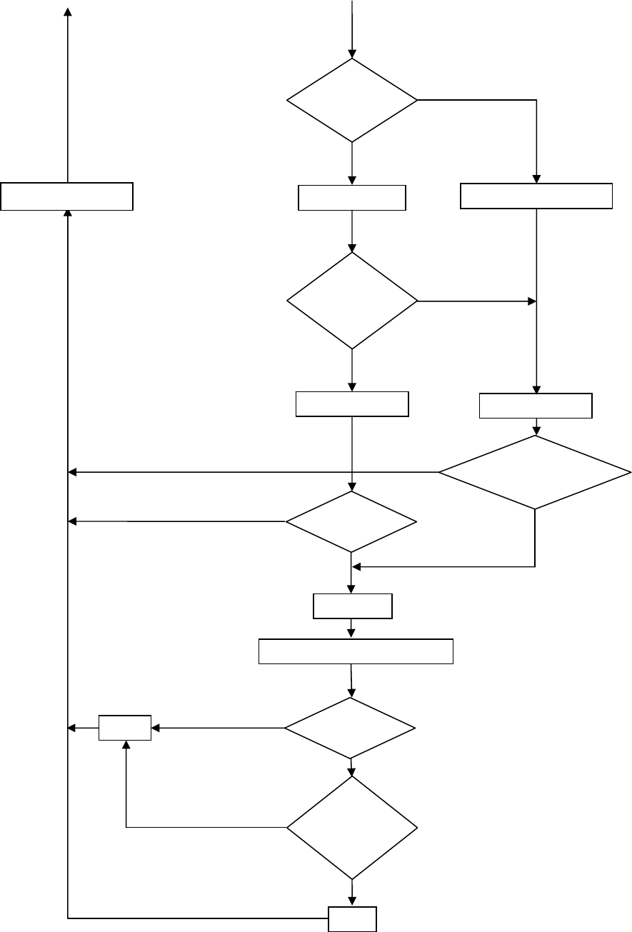
73
NARROWERDOORAPPLICATIONFLOWCHART(OPTIONAL)
Yes(PAR.199=0)
No(PAR.199=1)
DETECTAUXSENSORDONOTDETECTAUXSENSOR
DOES
AUXSENSOR
FAIL?
Yes
No
AUX(OUT)=AUX(IN) AUX(OUT)=PAR.65
AUX(IN)
?Yes
No
AUX(OUT)=1
DOORCOUNT>PAR.65?
Yes
No
Yes
PAR.204=0
?
Yes(USEBOTHAUXANDDOLRELAYS)
NARROW
DOORINPUT
?
DOL=1
Yes
DOL=0
No(USEONLYAUXRELAY)
No
RETURNTOMAIN
DOLFORNARROWERDOORSELECTION
USE
NARROWER
DOOR
?
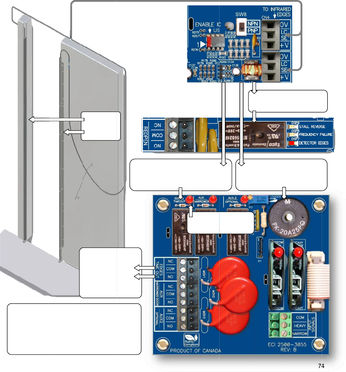
NUD
Fort
Dete
byP
a
NOT
E
E
D
fo
o
f
D
e
S
e
GINGAPPLI
C
heNUDGIN
G
ctorEdges
w
a
r.198.Thei
l
E
:NUDGING
D
GESTIMEO
U
raninterval
f
theobstru
e
tectorEdge
s
e
tPar.206=
C
ATION(OPT
I
G
application,
w
illtriggerth
e
l
lustrationb
e
featureissu
U
Trelayonce
oftimeset
b
ctioncondi
t
s
.
0toDisable
t
I
ONAL)
usersneedt
o
e
EDGESTIM
E
e
lowshowst
h
bjecttothe
F
activatedwi
b
yPar.206r
e
t
ionofthe
t
heHolding
T
EDGESTI
M
outputsig
ElevatorCo
n
forNUD
G
Applica
t
INFRARED
DETECTOR
EDGES
o
orderanA
d
E
OUTrelaya
h
emechanis
m
F
ireService
C
llremain
e
gardless
Infrared
T
ime
EDGES
T
M
EOUT
nalto
n
troller
G
ING
t
ion
d
ditionalboa
r
fteraDELAY
m
oftheEDG
E
C
odes.
InfraredEdg
e
T
IMEOUTrel
a
setbyPa
r
d,2500‐305
5
setbyPar.1
9
E
STIMEOUT
e
strigger
a
yafteraDE
L
r.197
LEDind
EDGESTI
M
5
.Theobstru
9
7,andtheB
relayandth
e
I
B
L
AY
icatorof
M
EOUTrelay
ctionoftheI
UZZERafter
a
e
BUZZER.
InfraredE
d
REOPENrela
I
nfraredEdg
e
B
UZZERafter
setbyPa
r
7
4
nfrared
a
DELAYset
d
gestrigger
yINSTANTLY
e
strigger
aDELAY
r
.198
4
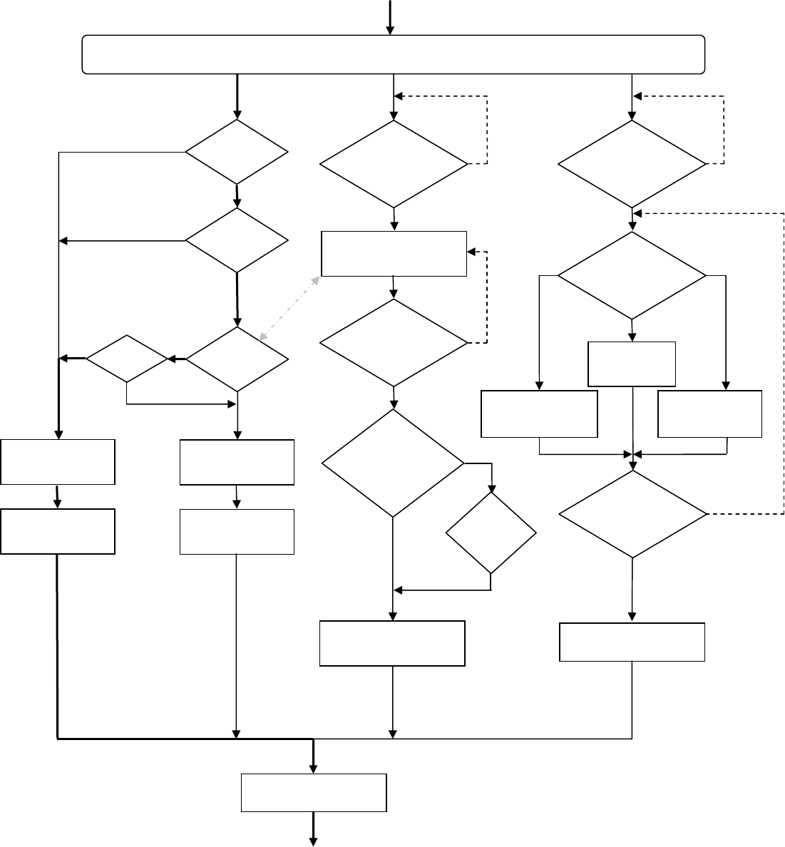
75
NUDGINGAPPLICATIONFLOWCHART
Note!NudgingapplicationissubjecttotheFireServiceCodes,ifapplicable.
INFRAREDDETECTOREDGESAREOBSTRUCTED
DCL
ISREACHED
?
DOOROPEN
INPUT
?
No
Yes
Yes
No
YesEDGES
TIMEOUTOUTPUT
ON?
No
TURNONDETECTOR
EDGESLED
TURNONRE‐OPEN
OUTPUT(RELAY)
PAR.207=1
?
No
Yes
TURNOFFDETECTOR
EDGESLED
TURNOFFRE‐OPEN
OUTPUT(RELAY)
EDGESTIMEOUT
DELAYTIMER(PAR.197)
EXPIRED?
Yes
TURNONEDGESTIMEOUT
OUTPUT(RELAY)&LED
INFRARED
DETECTOREDGESARE
UNOBSTRUCTED
?
Yes
No
SETTINGOF
EDGESTIMEOUT
HOLDTIMER
PAR.206=0
?
Yes
TURNOFFEDGESTIMEOUT
OUTPUT(RELAY)&LED
No
TIMER
(PAR.206)
EXPIRED
?
Yes
BUZZER
DELAYTIMER(PAR.198)
EXPIRED?
Yes
DISABLEBUZZER
NOSOUND
BUZZER
SOUNDSTYLE
SELECTION
PAR.205
PAR.205=2
PAR.205=1
PAR.205=0
TURNONBUZZER
WITH
CONTINUOUSSOUND
TURNONBUZZER
WITH
PULSATINGSOUND
INFRARED
DETECTOREDGESARE
UNOBSTRUCTED
?
No
TURNOFFBUZZER
Yes
NoNo
RETURNTOMAIN
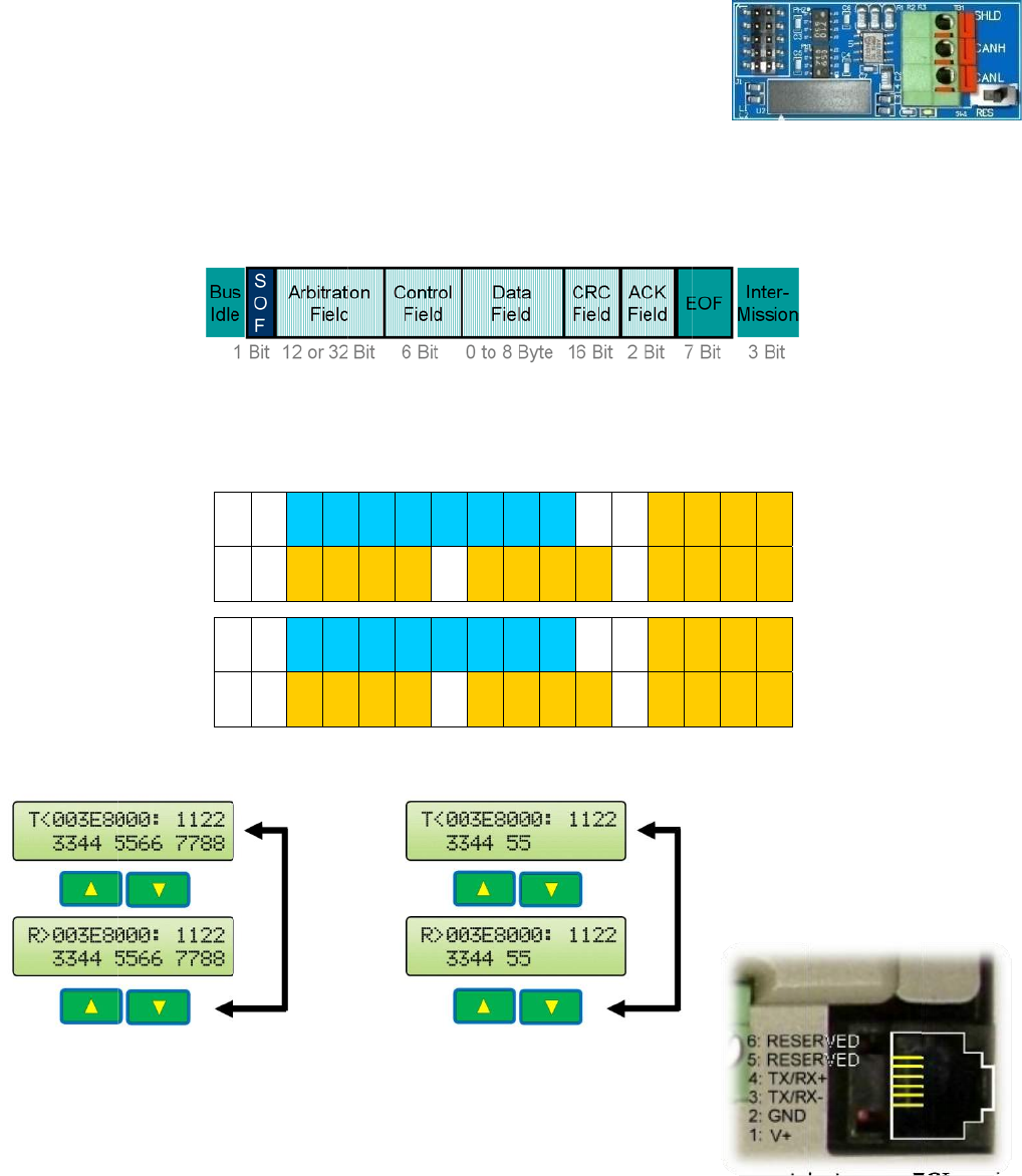
SERI
A
CA
N
con
t
To
s
Flip
Set
Set
Ret
u
To
A
Par.
Foll
o
The
Arbi
the
Exa
m
The
RS-
4
for
t
Oth
e
req
u
mo
r
A
LCOMMU
N
N
Bus is cu
r
t
roller and
s
etup CAN
the 1
st
sw
i
Par. 11 =
Par. 246
=
u
rn to Aut
o
A
UTO. The
247. The
o
wing is th
mapping
tration Fi
e
Control Fi
e
m
ples:
DLC
RJ-11 jac
k
4
85 serial
t
his port.
e
r commu
n
u
esting pa
r
r
e details
o
N
ICATION
r
rently us
e
the VFE2
5
bus comm
i
tch to SE
T
5 to use t
h
=
7 for Fro
n
o
matic Op
e
Baudrate,
default va
l
e CAN fra
m
below sh
o
e
ld and “D
”
e
ld.
= 8
k
for the p
a
interfacin
g
n
ication p
r
r
ty must b
o
n CAN an
d
R
T
e
d to com
m
5
00.
unication,
T
UP.
h
e CAN bu
s
n
t Door. S
e
e
ration by
f
max. 1Mb
l
ue for Par
m
e:
o
ws CAN
f
”
represen
t
a
rameter
u
g
. Modbus
p
r
otocols ar
e
e made p
r
d
other pro
》I
31‐28
I
27‐
2
D
3H
D
3
L
《I
31‐28
I
27‐
2
D
3H
D
3
L
m
unicate b
e
s
. Otherwi
s
e
t Par. 24
6
f
lipping th
e
it, for CAN
. 247 is 11
f
rame on
t
t
s for Dat
a
u
nit can al
s
p
rotocol is
e
availabl
e
r
ior to the
tocols.
2
4
I
23‐20
I
19‐16
I
15‐12
L
D
4H
D
4L
2
4
I
23‐20
I
19‐16
I
15‐12
L
D
4H
D
4L
e
tween th
e
s
e, set Par
6
= 8 for R
e
e
AUTO/M
A
bus can
b
5.2kbps.
t
he Keypa
a
Field.
T
h
DLC=5
s
o be used
currently
a
e
upon req
u
implemen
t
I
11‐8
I
7‐4
I
3‐0
D
5H
D
5L
D
6H
I
11‐8
I
7‐4
I
3‐0
D
5H
D
5L
D
6H
e
elevator
. 11 = 1.
e
ar Door.
A
N switch
b
e set by
d LCD di
s
e DLC , D
a
for
a
vailable
u
est. An a
t
ation of c
o
:D
1H
D
D
6L
D
7H
D
:D
1H
D
D
6L
D
7H
D
s
play whe
r
a
ta Lengt
h
greement
o
mmunica
t
D
1L
D
2H
D
2L
D
7L
D
8H
D
8L
D
1L
D
2H
D
2L
D
7L
D
8H
D
8L
r
e, “I” rep
h
Code, is
between
E
t
ion. Con
t
7
6
resents fo
decided b
y
E
CI and th
e
t
act ECI fo
6
r
y
e
r
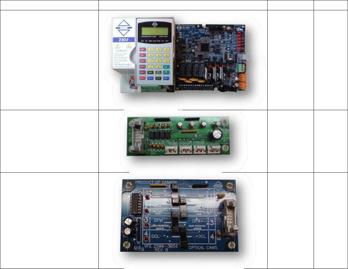
PAR
T
The
f
Not
e
Descr
i
PCB,
V
drive- 230VAC
PCB,
S
linear
PCB,
O
T
SLIST
f
ollowingpar
t
e
:ECIreserve
s
i
ption
V
FE2500clos
e
S
ignaltransfe
model
O
pticalcamb
t
scanbepur
s
therightto
e
‐looped
rboardfor
oard
chasedfrom
replaceany
i
Picture
ECI.
i
temsinthislistatanyti
m
m
ewithoutn
o
o
tice.
ECIPartNo.
2500‐3050
2500‐1002
2500‐3056
7
7
Remarks
7
PCB,
V
drive- 115VAC
V
FE2500clos
e
e
‐looped2500‐3050-1
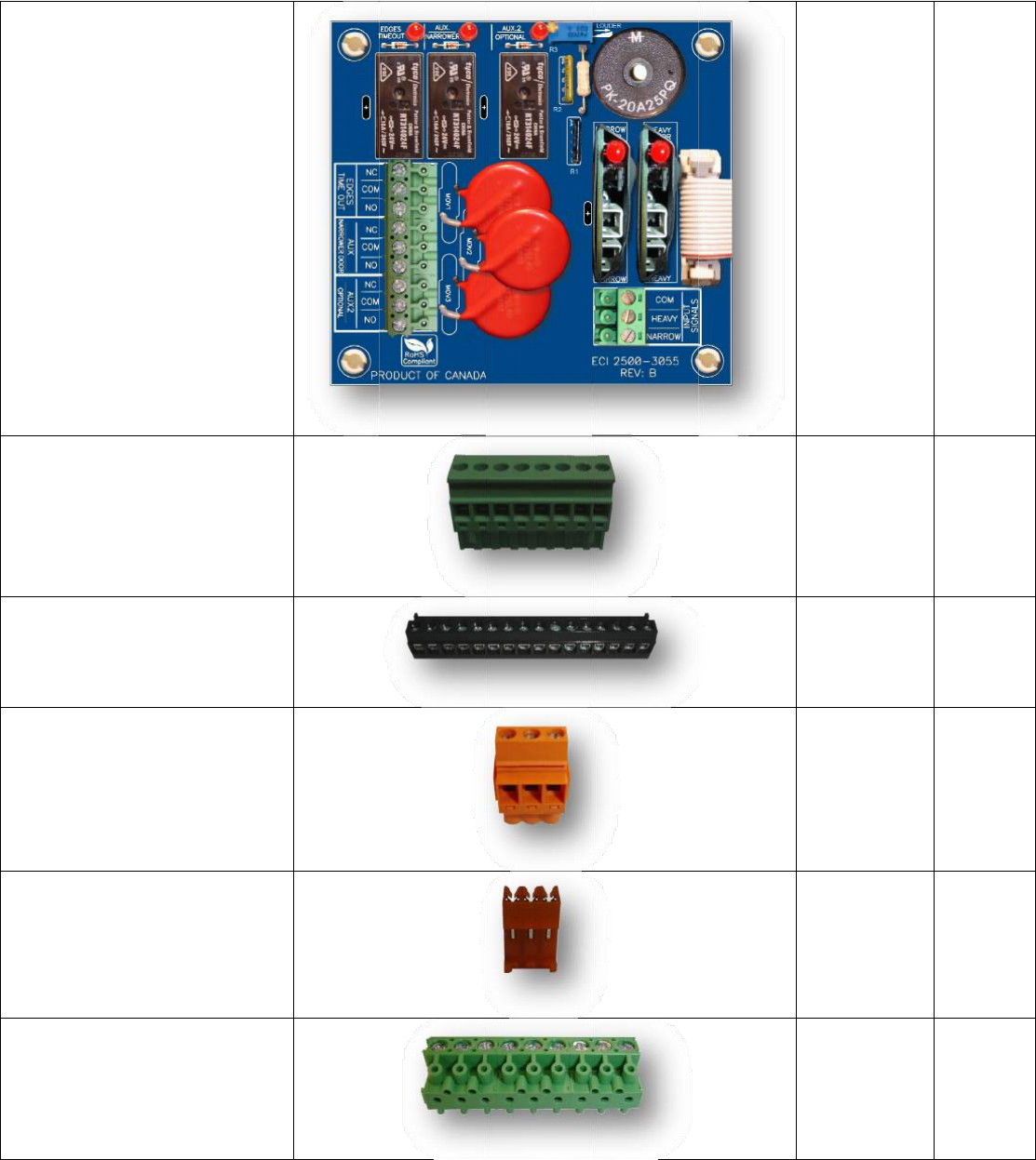
PCB,
A
Conn
e
(Gree
n
Conn
e
ando
u
Con
n
d
e
Conn
e
for
t
Conn
e
f
o
A
dditionalI/
O
e
ctor,Power
c
n
color)
e
ctor,16‐pos
i
u
tputsconne
n
ector,3‐pos
i
e
tectoredges
e
ctor,3‐posit
t
hehall‐effec
t
e
ctor,9‐posit
o
routputsig
n
additionalI
/
O
board
c
onnector
i
tioninputs
ctor
i
tioninfrared
connector
ionconnect
o
t
sensorPCB
ionconnect
o
n
alsofthe
/
OPCB
o
r
o
r
2500‐3055
2500‐3082
2500‐3081
2500‐3080
2500‐3079
2500‐3078
7
8
CN1
CN4,
CN5
8
Conn
hea
v
IC,En
a
Relay,
10Am
Modu
enco
d
Modu
busm
Modu
Enco
d
ector,3‐pos
c
v
yandnarro
w
a
bleIC
24VDCcoil
v
p,250VACr
e
le,Galvanici
s
d
ermodule
le,GalvanicI
s
odule
le,Universal
d
erfor½HP
A
c
onnectorfo
r
w
doorinput
v
oltage,
e
lay
s
olation
s
olationcan
inputmodul
e
A
Cmotor
r
e
2500‐3077
2500‐3076
2500‐2011
2500‐1003
2500‐1005
2500‐3061
2500‐2020
7
9
U5
9
Edges
,
edges
Edges
,
detec
t
Edges
,
Janusinfrar
e
,
Tritronicsin
t
oredges
,FormulaSy
s
detector
e
e
ddetector
frared
s
temsinfrare
e
dges
d
906‐3013
906‐3020
906‐3030
8
0
0
Cable
,
thea
d
Cabl
t
h
Cabl
e
C
Fuse,
4
Moto
r
Induc
t
,
14‐pinribb
o
d
ditionalI/O
b
e,10‐pinrib
b
h
esignaltran
s
e
,7ftCablef
o
Unit
C
able,7½in
Paramete
r
4
‐AmpSlow
B
r
,3‐Phase23
0
t
ionMotor
o
ncablefor
b
oard
b
oncablefor
s
ferboard
o
rParamete
r
Cablefor
r
Unit
B
lowfuse
0
VAC1/3HP
r
2500‐3073-1
2500‐3073-1
2500‐2026
2500‐2026‐
1
2500‐3070
2500‐2014
8
1
1
1
Moto
r
Gear
e
Moto
r
Gear
e
Trans
f
Cam,
P
Para
m
StallF
forst
a
r
,91W3‐pha
s
e
dMotor–L
e
r
,91W3‐pha
s
e
dMotor–Ri
g
f
ormer,500
V
P
lasticCam
m
eterUnit
orceGauge,
S
a
llforcemea
s
s
e230VAC
e
fthand
s
e230VAC
g
hthand
V
A110/220
S
pringgauge
s
urement
2500‐2016‐
L
2500‐2016‐
R
2500‐2017
2500‐1010
2500‐3051
2500‐3068
8
2
L
R
2
Manu
VFE2
5
Quick
Brack
e
al,Hardcop
y
5
00electrical
setupbroch
u
e
t,Hall‐effec
t
y
ofthe
manual
u
re
t
sensor
2500‐3069
2500‐3066
2500‐5019
8
3
3
Cover
,
VFE2
5
,
Plasticcove
5
00drive
rforthe
2500‐3052
8
4
4
Cover
,
VFE2
5
,
Plasticcove
5
00drive
rforthe
2500‐3052-1

85
NOTES:
Copyright © 2012 ECI Inc.
All rights reserved.
No part of this document may be reproduced in any form, machine or natural without the
express written consent of ECI Inc.
