VH6020 4 R3 Manual
VH6020-4_r3_Manual
User Manual:
Open the PDF directly: View PDF ![]() .
.
Page Count: 11
VH-6020-4
Table of Contents
1 Proper Care Guidelines ...................................................... 3
1.1 High Vacuum .............................................................. 3
1.2 Evacuating ................................................................ 3
2 Loading the Vacuum Chamber ............................................... 4
2.1 Disassembly ............................................................... 4
2.2 Loading the cavity .......................................................... 6
2.3 Reassembly ................................................................ 7
3 Connecting to a Temperature Controller ...................................... 8
3.1 Integrated heaters .......................................................... 8
3.2 DB-9 Pinout ............................................................... 8
4 Appendix 1 - GE MC65F103B Thermistor .................................... 9
4946 63rd St, Suite B 1Oce: (303) 542 0427
Boulder, Colorado 80301 stablelasers.com Fax: (303) 542 0428

VH-6020-4
List of Figures
1 Removing the front thermal shell endcap ......................................... 4
2 Removing the thermal insulation ................................................ 4
3 Removing the front vacuum ange............................................... 5
4 Cavity mounting block assembly................................................. 6
5 Loading the cavity and mounting block ........................................... 6
4946 63rd St, Suite B 2Oce: (303) 542 0427
Boulder, Colorado 80301 stablelasers.com Fax: (303) 542 0428

VH-6020-4
1 Proper Care Guidelines
1.1 High Vacuum
To ensure optimal performance, Latex or Nitrile gloves should always be worn when working
with materials that will be placed inside the vacuum can, or when touching internal surfaces.
Be very careful with the vacuum surfaces. Aluminum is soft, and radial scratches in the area of the O-
ring are detrimental to the sealing surface of the can. Please work on a soft surface covered in lint-free
cleanroom wipes, and keep all tools and other hard materials well clear of the aluminum surfaces.
1.2 Evacuating
Pumping air out of the vacuum can, or re-admitting gas to the vacuum housing, should be done ex-
tremely slowly. Please plan to pump very slowly from atmospheric pressure to a pressure of a few Torr.
This reduces the chance that particulates will be stirred up and deposited on the cavity mirrors. An
in-line filter is recommended to slow the pumping speed. Stable Laser Systems recommends pumping
out the vacuum chamber for a period of a few days to ensure optimal performance.
The vacuum chamber can be vented with very clean (oil-free) air or gas, such as nitrogen, and a small
positive pressure can be maintained while the cavity is being loaded.
4946 63rd St, Suite B 3Oce: (303) 542 0427
Boulder, Colorado 80301 stablelasers.com Fax: (303) 542 0428
VH-6020-4
2 Loading the Vacuum Chamber
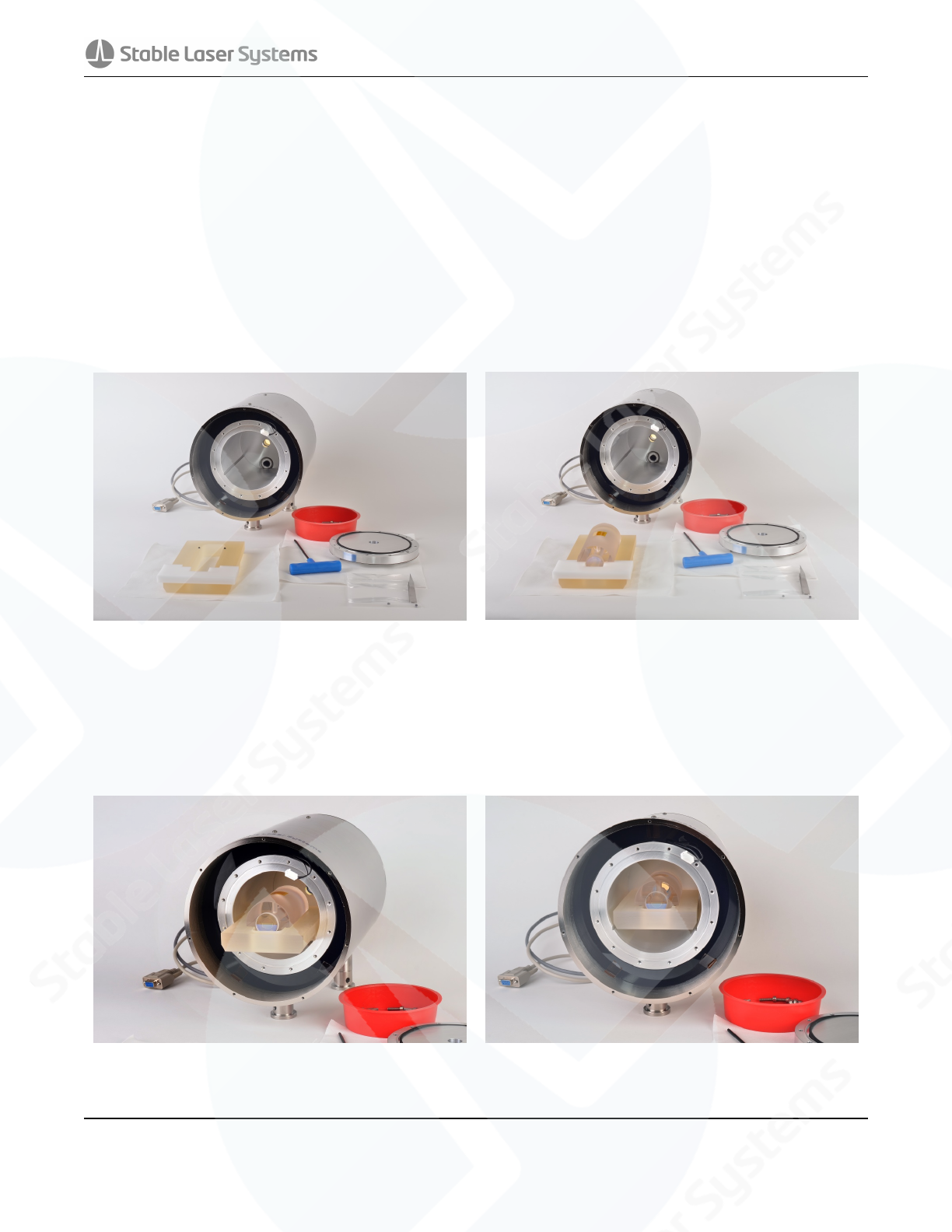
2.1 Disassembly
Place the vacuum housing in the location where it will permanently reside to avoid having to move the
assembly with the cavity installed. It is recommended that the clamping forks provided are used to secure
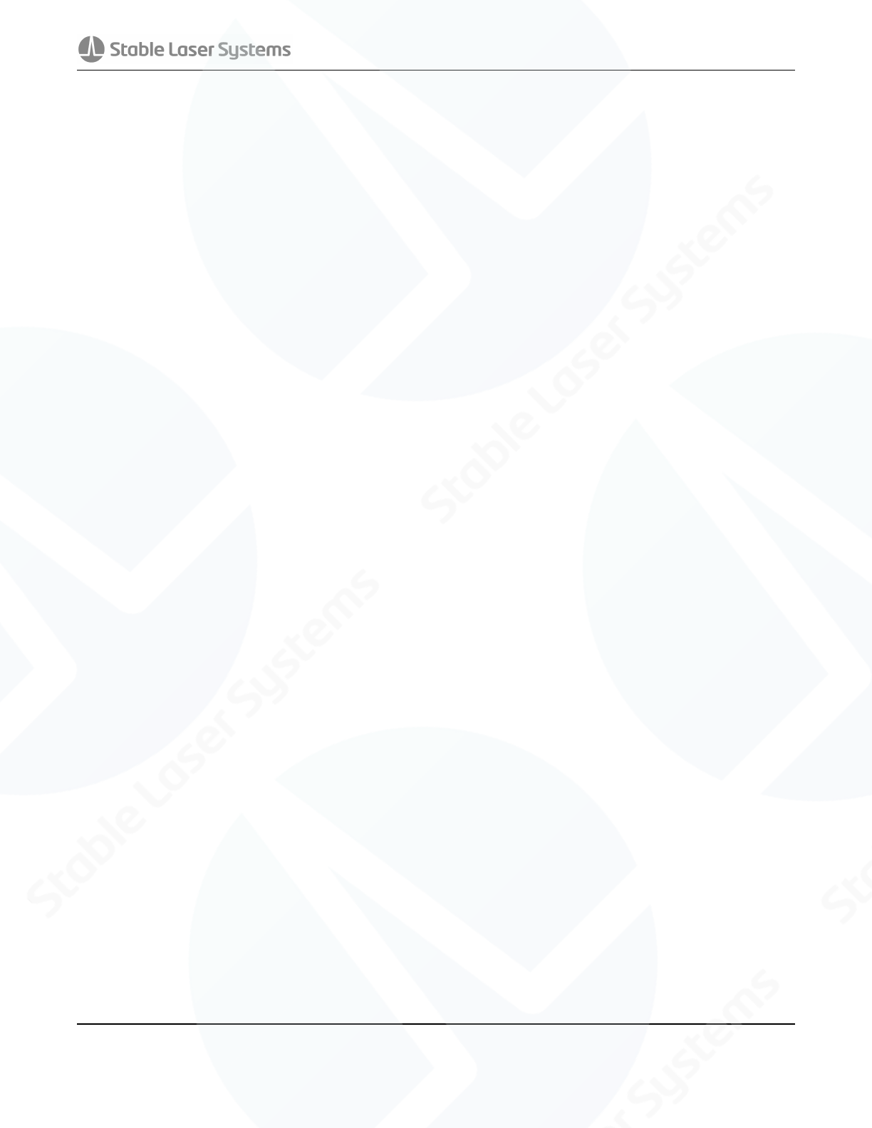
down the vacuum housing before loading the cavity. Unscrew the M3 x 6 button head screws and remove
the front thermal shell endcap (the one nearest the Stable Laser Systems logo).
(a) Fully assembled VH-6010-4 (b) Remving M3 x 6 screws
Figure 1: Removing the front thermal shell endcap
Remove the loose thermal insulation. Be sure to also remove the annular ring of thermal insulation
around the can. Leave the black plastic insulation stop in place to keep the insulation around the tube
from falling into the can while loading the cavity.
(a) Remove the circular insulation (b) Leave the insulation stop in place
Figure 2: Removing the thermal insulation
4946 63rd St, Suite B 4Oce: (303) 542 0427
Boulder, Colorado 80301 stablelasers.com Fax: (303) 542 0428
VH-6020-4
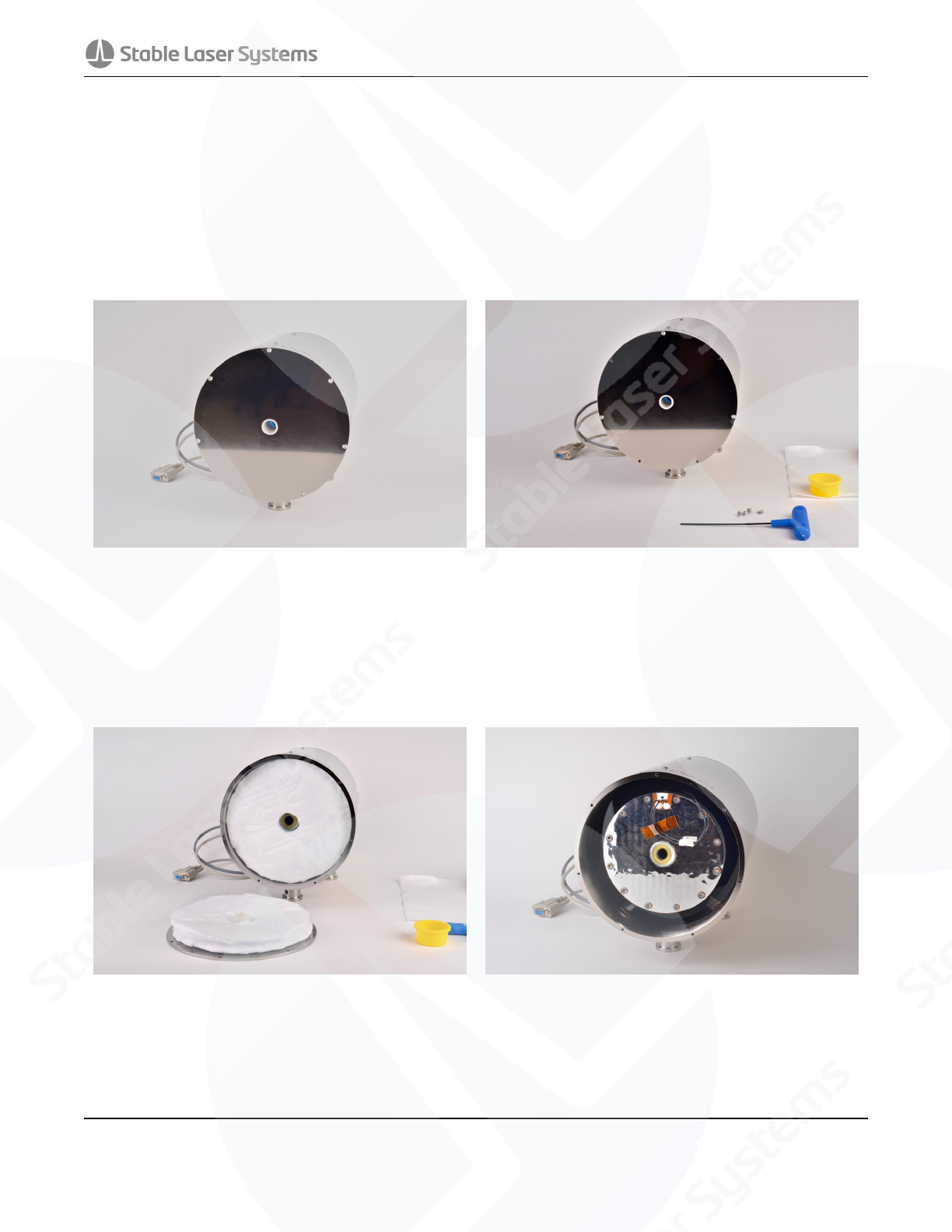
Disconnect the front heater by unplugging the white connector that attaches the ange heater to the
body. Unscrew and remove the vacuum chamber ange, taking particular care to hold the ange while
the last screw is removed so it doesn’t scratch the sealing surface while moving against the can. Place
the ange O-ring side up on a clean cleanroom wipe, taking care not to damage the window.
(a) Disconnect the heater (b) Place the window side down on a clean surface
Figure 3: Removing the front vacuum ange
4946 63rd St, Suite B 5Oce: (303) 542 0427
Boulder, Colorado 80301 stablelasers.com Fax: (303) 542 0428
VH-6020-4
2.2 Loading the cavity
Generally, the mirrors should have an engraving on the edge to indicate the radius of curvature. If no
radius is indicated, the mirror with the larger coating will be the concave mirror, and the smaller coating
will be the plano mirror. Take note of the cavity orientation before loading it into the housing.
Load the cavity onto the Zerodur mounting block, using the Viton balls provided. Place the four 1/4”
Viton balls in the machined holes in the mounting block. A white delrin alignment fixture has been
provided with the mounting block. Place the alignment fixture over one end of the cavity support.
Center the cavity in the cutout and lower it into the support while firmly holding the alignment fixture.
Remove the alignment fixture and the Kapton tape covering the vent hole prior to loading the cavity.
(a) Insert the Viton balls into the machined holes (b) Gently place the cavity in the mounting block, using the align-
ment xture to ensure proper positioning
Figure 4: Cavity mounting block assembly
Load the Zerodur mounting block into the can by sliding the block into the grooves in the chamber. Try
to align the block so that there is an equal gap on each side with respect to the vacuum chamber.
(a) Place the mounting block on the grooves (b) Slide the mounting block into position
Figure 5: Loading the cavity and mounting block
4946 63rd St, Suite B 6Oce: (303) 542 0427
Boulder, Colorado 80301 stablelasers.com Fax: (303) 542 0428

VH-6020-4
2.3 Reassembly
Replace the vacuum end ange, and fasten the screws in a diametric pattern. Following the points of
a clock, first insert a screw at 12 o’clock, then 6 o’clock, 3 o’clock, then 9 o’clock, and repeat this
diametric pattern for the two other sets of four screws. Repeat the pattern, graduating in torque each
pass from finger-tight the first pass, 10 in·lbs (1.13 Nm) on the second pass, 20 in·lbs (2.25 Nm) on
the third pass, and then 2-3 additional passes at 30 in·lbs (3.39 Nm). Do not exceed 36 in·lbs (4 Nm)
or damage may occur to the ange.
Reconnect the heater and replace the thermal insulation. Then reattach the thermal shell end cap.
4946 63rd St, Suite B 7Oce: (303) 542 0427
Boulder, Colorado 80301 stablelasers.com Fax: (303) 542 0428
VH-6020-4
3 Connecting to a Temperature Controller
3.1 Integrated heaters
The integrated heater resistance is close to 5.5 Ohms at room temperature.
The thermistors are General Electric MC65F103B, and a data sheet may be found in Appendix 1. Please
consider the self-heating of the thermistor when measuring absolute temperature.
3.2 DB-9 Pinout
The pinout for the vacuum housing 9 pin D-sub cable is as follows. The additional cable is connected
to a test thermistor which may be monitored on a multimeter.
Pin Number Description
1 Heater
2 Heater
4 Thermistor
5 Thermistor
Others N/C
4946 63rd St, Suite B 8Oce: (303) 542 0427
Boulder, Colorado 80301 stablelasers.com Fax: (303) 542 0428
VH-6020-4
4 Appendix 1 - GE MC65F103B Thermistor
Crown Industrial Estate, Priorswood Road 808 US Highway 1 967 Windfall Road
Taunton, Somerset TA2 8QY UK Edison, New Jersey 08817-4695 USA St. Marys, Pennsylvania 15857-3397 USA
Tel +44 (0) 1823 335200 Tel +1 (732) 287 2870 Tel +1 (814) 834 9140
Fax +44 (0) 1823 332637 Fax +1 (732) 287 8847 Fax +1 (814) 781 7969
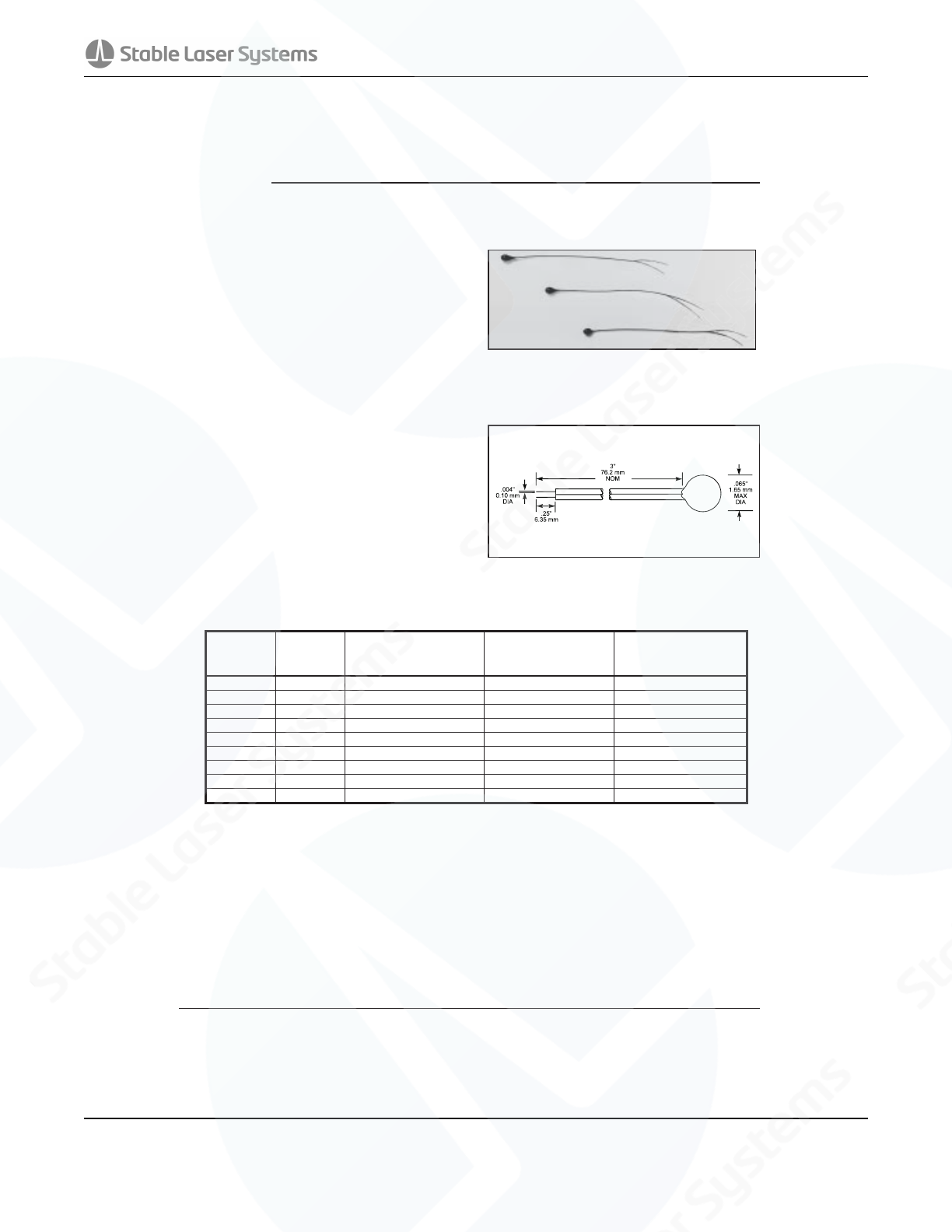
NTC THERMISTORS: TYPE MC65
INSULATED LEAD INTERCHANGEABLE CHIP THERMISTOR
DESCRIPTION:
Epoxy Coated interchangeable chip thermistors
with heavy isomid insulated Nickel lead-wires.
FEATURES:
•Precision, solid state temperature sensor
•Interchangeability down to ±0.05 °C
•Suitable for use over the range of
–40°C to +105°C
•High sensitivity greater than –4%/ °C at 25°C
•Suitable for temperature measurement,
control and compensation
•High reliability and stability over
interchangeable range
•Special tight tolerances in the clinical range
for Medical applications
•Most popular R-vs-T curves are available
•Fully insulated
•Resin coated for good mechanical strength and
resistance to solvents
•.004" (.1 mm) dia. heavy isomid insulated
Bifilar Nickel lead-wires
OPTIONS:
Consult factory for availability of options:
•Other resistance values in the range of
100Ω- 100kΩ
•Other tolerances or ranges
•Other lead wires or lengths
•Non standard R-vs-T curves
•Controlled dimensions
DATA:
THERMAL AND ELECTRICAL PROPERTIES:
Dissipation constant:........(still air) .5 mW/°C
(stirred oil) 4 mW/°C
Thermal time constant:.....(still air) 8 sec.
(stirred oil) .5 sec.
Maximum power at 25°C .........................25mW
(derated from 100% at 25°C to 0% at 100°C)
DIMENSIONS:
Select appropriate part number below for resistance and temperature tolerance desired
R25°C MATERIAL
SYSTEM
± .05°C; 35°C to 39°C
± .075°C; 39°C to 42°C
± .10°C; 20°C to 45°C
± .15°C; 0°C to 50°C
± .1°C; 35°C to 39°C
± .15°C; 20°C to 45°C
± .2°C; 0°C to 50°C
± .15°C; 35°C to 39°C
± .2°C; 20°C to 45°C
± .25°C; 0°C to 50°C
2252 F MC65F232A MC65F232B MC65F232C
3000 F MC65F302A MC65F302B MC65F302C
5000 F MC65F502A MC65F502B MC65F502C
10000 F MC65F103A MC65F103B MC65F103C
10000 Y MC65Y103A MC65Y103B MC65Y103C
30000 H MC65H303A MC65H303B MC65H303C
50000 G MC65G503A MC65G503B MC65G503C
100000 Y MC65Y104A MC65Y104B MC65Y104C
100000 G MC65G104A MC65G104B MC65G104C
g
4946 63rd St, Suite B 9Oce: (303) 542 0427
Boulder, Colorado 80301 stablelasers.com Fax: (303) 542 0428
VH-6020-4
Crown Industrial Estate, Priorswood Road 808 US Highway 1 967 Windfall Road
Taunton, Somerset TA2 8QY UK Edison, New Jersey 08817-4695 USA St. Marys, Pennsylvania 15857-3397 USA
Tel +44 (0) 1823 335200 Tel +1 (732) 287 2870 Tel +1 (814) 834 9140
Fax +44 (0) 1823 332637 Fax +1 (732) 287 8847 Fax +1 (814) 781 7969
MATERIAL TYPE
: F
AVAILABLE PRODUCTS:
HM, C100, EC95, DC95, MC65, MF65, SC30, SC50
Temp Range
(°C)
Ratio
Beta
0 to 50
0 to 70
25 to 50
25 to 85
25 to 100
25 to 125
37.8 to 104.4
9.08
18.64
2.78
9.30
14.64
29.05
9.67
3895
3917
3933
3969
3981
3999
4000
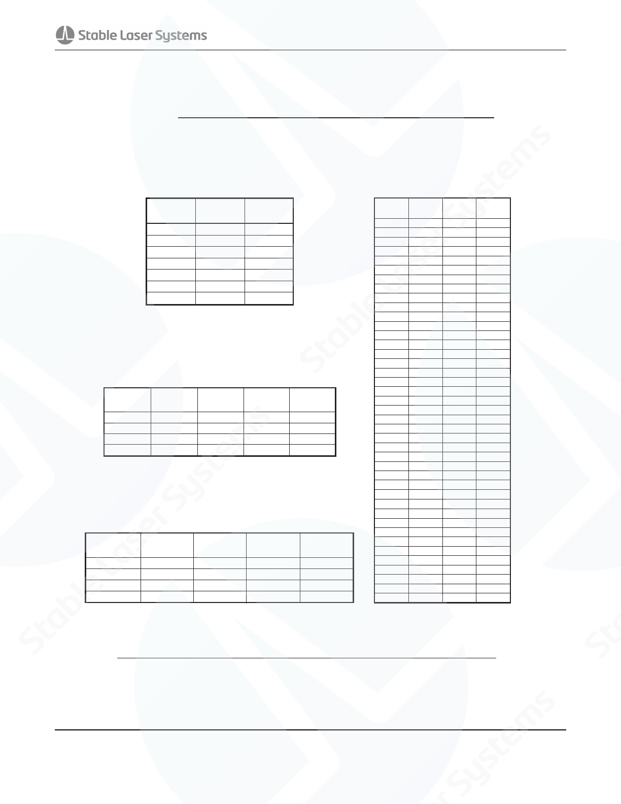
Data for material type : F
Temp Range
(°C)
A
BCD
-50 to 0
0 to 50
50 to 100
100 to 150
-1.4122478E+01
-1.4141963E+01
-1.4202172E+01
-1.6154078E+01
4.4136033E+03
4.4307830E+03
4.4975256E+03
6.8483992E+03
-2.9034189E+04
-3.4078983E+04
-5.8421357E+04
-1.0004049E+06
-9.3875035E+06
-8.8941929E+06
-5.9658796E+06
1.1961431E+08
Rt/R25 range
a
bcd
68.600 to 3.274
3.274 to 0.36036
0.36036 to 0.06831
0.06831 to 0.01872
1.0969244E-07
7.3003206E-08
4.6045930E-08
-4.0719355E-07
1.9243889E-06
2.0829210E-06
1.9621987E-06
-2.6687093E-06
2.5654090E-04
2.5627725E-04
2.5609446E-04
2.4057263E-04
3.3538646E-03
3.3540154E-03
3.3539264E-03
3.3368620E-03
Temperature
(°C)
Rt/R25
nominal
Temp Coef
∝
( %/°C)
β
Deviation
†
(±%)
-50
-45
-40
-35
-30
-25
-20
-15
-10
-5
0
5
10
15
20
25
30
35
40
45
50
55
60
65
70
75
80
85
90
95
68.60
48.16
34.23
24.62
17.91
13.17
9.782
7.339
5.558
4.247
3.274
2.544
1.992
1.572
1.250
1.000
0.8056
0.6530
0.5326
0.4369
0.3604
0.2989
0.2491
0.2087
0.1756
0.1485
0.1261
0.1075
0.09209
0.07916
7.21%
6.96%
6.71%
6.48%
6.26%
6.05%
5.85%
5.66%
5.47%
5.30%
5.13%
4.97%
4.81%
4.67%
4.53%
4.39%
4.26%
4.14%
4.02%
3.91%
3.80%
3.69%
3.59%
3.49%
3.40%
3.31%
3.23%
3.14%
3.06%
2.99%
2.30%
2.68%
2.87%
2.92%
2.86%
2.71%
2.50%
2.25%
1.97%
1.68%
1.37%
1.07%
0.78%
0.50%
0.24%
0.00%
0.21%
0.40%
0.56%
0.69%
0.80%
0.87%
0.92%
0.93%
0.92%
0.88%
0.81%
0.72%
0.59%
0.45%
100
105
110
115
120
125
130
135
140
145
150
0.06831
0.05916
0.05141
0.04483
0.03922
0.03442
0.03030
0.02675
0.02369
0.02103
0.01872
2.91%
2.85%
2.77%
2.70%
2.64%
2.57%
2.51%
2.47%
2.41%
2.35%
2.35%
0.28%
0.08%
0.12%
0.36%
0.61%
0.87%
1.16%
1.46%
1.82%
2.14%
2.46%
To calculate Rt/R25 at temperatures other than those listed in the
table, use the following equation:
Rt/R25 = exp{A + B/
T
+ C/
T2
+ D
/T3
}
where T = temperature in K
where K = ºC + 273.15
To calculate the actual thermistor temperature as a function of the
thermistor resistance, use the following equation:
I/T=a+b(Ln Rt/R25)+c(Ln Rt/R25)
2
+d(Ln Rt/R25)
3
†The deviation resulting from the tolerance on the material constant,
Beta. The deviation must be added to the resistance tolerance of the
part as specified at 25ºC.
g
4946 63rd St, Suite B 10 Oce: (303) 542 0427
Boulder, Colorado 80301 stablelasers.com Fax: (303) 542 0428
