VID6606 Manual 060809 Stepper Motor Driver
User Manual:
Open the PDF directly: View PDF ![]() .
.
Page Count: 6
Stepper Motor Driver
(For four motors)
Type:VID6606
Revision: 1
Page:1/6
A Company of Wellgain Group
© 2005 Data Instrumentation Technology
E-mail: vid.info@wellgain.com Website:http://www.vid.wellgain.com/
STEPPER MOTOR DRIVER VID66-06
G
GE
EN
NE
ER
RA
AL
L
D
DE
ES
SC
CR
RI
IP
PT
TI
IO
ON
N
The quad stepping motor driver VID66-06 is a monolithic CMOS device intended to be
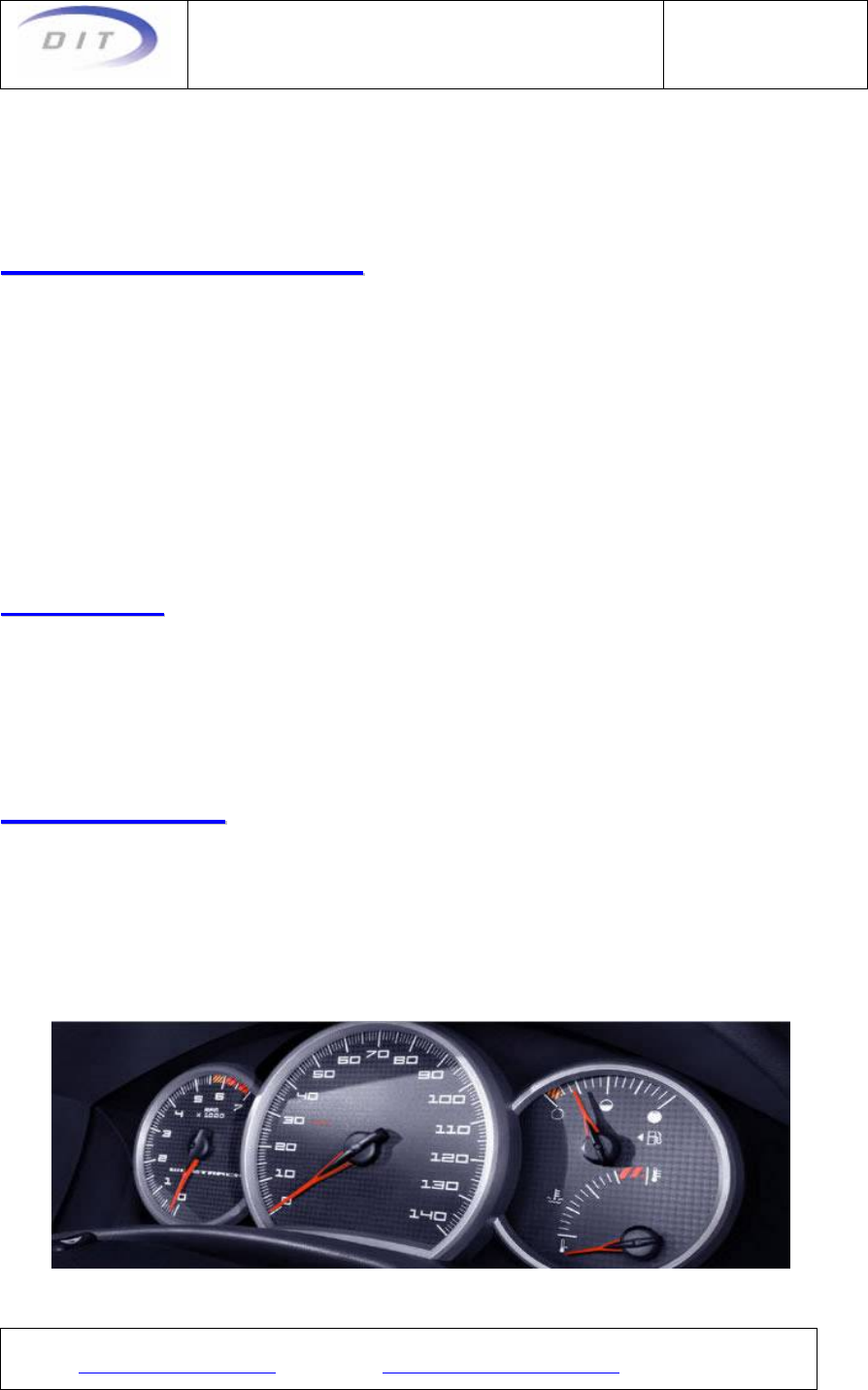
used as an interface circuit to ease the use of the stepper motor VID29-XX. It is
specifically designed for applications in the car dashboard. The chip allows the user to
drive four motors as it contains four identical drivers on the same chip.
The driver circuit converts a pulse train f(scx) into a current level sequence sent to the
motor coils. This sequence is used to produce the micro stepping movement of the
motor. Each inner driver in the chip generates 2 sequent logic pulse signals and
provides shaft stepping angle resolution 1/12°.
F
FE
EA
AT
TU
UR
RE
ES
S
¾ Generates micro steps
¾ Glitch filters on all inputs
¾ V
DD = 4.5 to 5.5V
¾ Low EMI emission
A
AP
PP
PL
LI
IC
CA
AT
TI
IO
ON
NS
S
¾ Car dashboard Nautical instrumentation
¾ Nautical instrumentation
¾ Aeronautical instrumentation
¾ Appliance controls
¾ Devices for medical analysis

Stepper Motor Driver
(For four motors)
Type:VID6606
Revision: 1
Page:2/6
A Company of Wellgain Group
© 2005 Data Instrumentation Technology
E-mail: vid.info@wellgain.com Website:http://www.vid.wellgain.com/
T
TY
YP
PI
IC
CA
AL
L
O
OP
PE
ER
RA
AT
TI
IN
NG
G
C
CO
ON
NF
FI
IG
GU
UR
RA
AT
TI
IO
ON
N
P
PI
IN
N
C
CO
ON
NF
FI
IG
GU
UR
RA
AT
TI
IO
ON
N
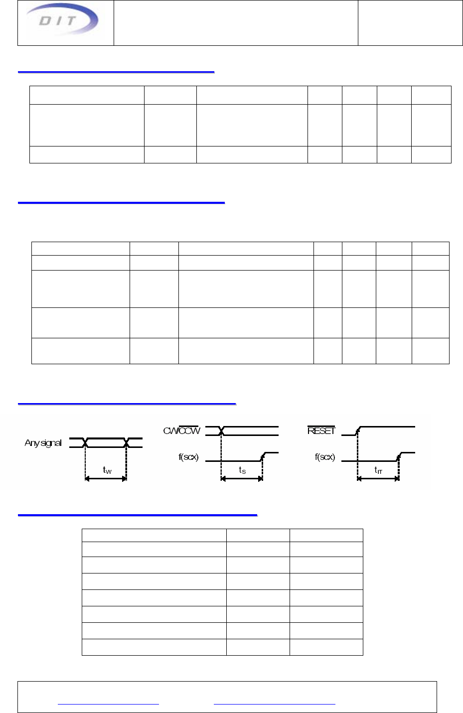
MCU
RESET
f
(
scx
)
A
CW/CCW
A
f
(
scx
)
B
CW/CCWB
f
(
scx
)
C
CW/CCWC
f
(
scx
)
D
CW/CCWD
VID6606
OUT
A
OUT
B
OUT
C
OUT
D
Stepper Motor Driver
(For four motors)
Type:VID6606
Revision: 1
Page:3/6
A Company of Wellgain Group
© 2005 Data Instrumentation Technology
E-mail: vid.info@wellgain.com Website:http://www.vid.wellgain.com/
P
PI
IN
N
D
DE
ES
SC
CR
RI
IP
PT
TI
IO
ON
N
Unused inputs must always be tied to a defined logic voltage level .
Pin Number
SOP - 28 Name I/O Function
1/15 VDD V Positive supply voltage
12 VSS V Negative supply voltage
28/3/14/17 f(scx) A/B/C/D I Stepping frequency; Driver A / B / C / D
27/2/13/16 CW/CCW A/B/C/D I Direction of rotation; Driver A / B / C / D
26 RESET I Reset for the four drivers
4/5/6/7 OUT 3A/4A/2A/1A O Output driver A
8/9/10/11 OUT 1D/2D/4D/3D O Output driver D
18/19/20/21 OUT 3C/4C/2C/1C O Output driver C
22/23/24/25 OUT 1B/2B/4B/3B O Output driver B
O
OP
PE
ER
RA
AT
TI
IN
NG
G
C
CO
ON
ND
DI
IT
TI
IO
ON
NS
S
Parameter Symbol Test
Conditions Min Typ Max Units
Operating temperature TA -40 +105
℃
Thermal impedance Rti SOP 80
℃/W
Supply voltage VDD 4.5 5 5.5 V
Input voltage at any pin VIN V
SS V
DD V
E
EL
LE
EC
CT
TR
RI
IC
CA
AL
L
C
CH
HA
AR
RA
AC
CT
TE
ER
RI
IS
ST
TI
IC
CS
S
VDD = 4.5~5.5V, TA = -40~105°C, unless otherwise specified
Parameter Symbol Test Conditions Min Typ Max Units
Typical supply
current IC VDD=5V,ω=200°/S,
TA=25℃,RB25=280Ω 76 mA
Worst case supply
current ICMAX VDD=5.5V,RESET=VSS,
TA=-40℃,RB-40=190Ω 200 mA
Quiescent supply
current ICC All inputs at VDD or VSS,
no load 300
μA
Low level input
voltage
VIL V
DD=4.5~5.5V VSS 1.35 V
High level input
voltage
VIH V
DD=4.5~5.5V 3.15 VDD V
Input leakage IIN V
IN=VSS or VDD -10 10
μA
Stepper Motor Driver
(For four motors)
Type:VID6606
Revision: 1
Page:4/6
A Company of Wellgain Group
© 2005 Data Instrumentation Technology
E-mail: vid.info@wellgain.com Website:http://www.vid.wellgain.com/
L
LO
OA
AD
D
C
CH
HA
AR
RA
AC
CT
TE
ER
RI
IS
ST
TI
IC
CS
S
Parameter Symbol Test Conditions Min Typ Max Units
Coil resistance
RB25
RB-40
RB105
VID29-XX,TA=25℃
VID29-XX,TA=-40℃
VID29-XX,TA=105℃
260
190
350
280 300
Ω
Ω
Ω
Phase inductance L25 VID29-XX,TA=25℃ 0.4 H
T
TI
IM
MI
IN
NG
G
C
CH
HA
AR
RA
AC
CT
TE
ER
RI
IS
ST
TI
IC
CS
S
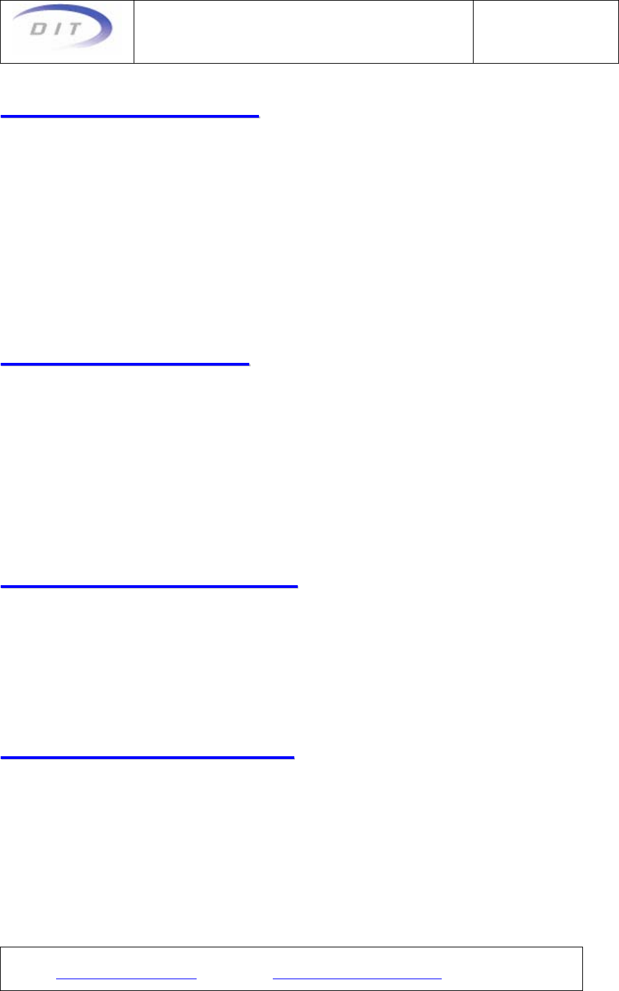
VDD = 4.5~5.5V, TA = -40~105°C, trise and tfall ≤ 20ns, input signal swing VSS to VDD
Parameter Symbol Test Conditions Min Typ Max Units
Signal pulse width tw high or low 450 ns
Input frequency f(scx)
Driver input limit 1.1 MHz
Motor speed limit
(=600°/s)
1.1
7.2
MHz
KHz
Setup time to
f(scx) ts high or low 100 ns
RESET release
time to f(scx) trr 100 ns
D
DE
EL
LA
AY
Y
T
TI
IM
MI
IN
NG
G
W
WA
AV
VE
EF
FO
OR
RM
MS
S
A
AB
BS
SO
OL
LU
UT
TE
E
M
MA
AX
XI
IM
MU
UM
M
R
RA
AT
TI
IN
NG
GS
S
Parameter Symbol Conditions
Voltage VDD to VSS V
DD -0.3~+6V
Voltage at any pin to VDD V
MAX +0.3V
Voltage at any pin to VSS V
MIN -0.3V
Current at OUTs 1-4 IOUTMAX ±35mA
Max. junction temperature Tj 150℃
Operating temp. range TA -40~+105℃
Storage temp. range TSTO -65~+125℃
Stepper Motor Driver
(For four motors)
Type:VID6606
Revision: 1
Page:5/6
A Company of Wellgain Group
© 2005 Data Instrumentation Technology
E-mail: vid.info@wellgain.com Website:http://www.vid.wellgain.com/
H
HA
AN
ND
DI
IN
NG
G
P
PR
RO
OC
CE
ED
DU
UR
RE
ES
S
Stresses beyond these listed maximum ratings may cause permanent damage to the
device. Exposure to conditions beyond specified operating conditions may affect
device reliability or cause malfunction.
The device has built-in protection against high static voltages or electric fields; however,
anti-static precautions must be taken as for any other CMOS component. Unless
otherwise specified, proper operation can only occur when all terminal voltages are
kept within the supply voltage range. Unused inputs must always be tied to a defined
logic voltage level unless otherwise specified.
C
CI
IR
RC
CU
UI
IT
T
P
PR
RO
OT
TE
EC
CT
TI
IO
ON
NS
S
To filter fast voltage transients, it is highly recommended to connect two 100nF ceramic
capacitors to the power supply pins, one on either side and as close as possible to the
chip.
Moreover, to protect the chip against latch-up, a 5uF capacitor per motor connected
should be added. Thus, for 4 motors, typically a 22uF capacitor must be used, either
electrolytic or tantalum. Note this capacitor can be placed close to the voltage
regulator.
R
RE
EC
CO
OM
MM
ME
EN
ND
DE
ED
D
P
PO
OW
WE
ER
R
U
UP
P
In order to power up the circuit in a defined manner, it is recommended to keep the
RESET input low while the VDD voltage is raising. After a delay of about 1ms, the
RESET can be released (i.e. set high). Depending on the micro controller used, an
external pull-down resistor might be required to properly set the RESET state at low
during the start-up.
F
FU
UN
NC
CT
TI
IO
ON
NA
AL
L
D
DE
ES
SC
CR
RI
IP
PT
TI
IO
ON
N
The rising edge of the f(scx) input signal moves the rotor by one micro step.
The input signal "CW/CCW" (clockwise / counterclockwise) controls the direction of
rotation of the motor.
Stepper Motor Driver
(For four motors)
Type:VID6606
Revision: 1
Page:6/6
A Company of Wellgain Group
© 2005 Data Instrumentation Technology
E-mail: vid.info@wellgain.com Website:http://www.vid.wellgain.com/
I
IN
NP
PU
UT
T
G
GL
LI
IT
TC
CH
H
F
FI
IL
LT
TE
ER
R
&
&
L
LE
EV
VE
EL
L
S
SH
HI
IF
FT
TE
ER
R
All logic inputs of this driver are armed with a glitch filter to avoid erroneous information
due to spikes and glitches on the input signal lines. All negative or positive pulses of
less than 20 ns width are ignored.
A minimum signal pulse width (positive or negative) of 450 ns guarantees correct
function over the full temperature range.
All logic inputs also feature a level shifter, which allows for operation of the circuit at a
higher supply voltage (VDD) than the circuits driving the inputs. This is in order to drive
the VID motors at a higher torque level.
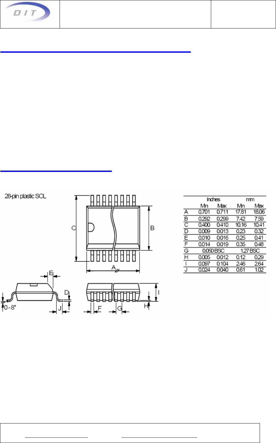
P
PA
AC
CK
KA
AG
GE
E
D
DI
IM
ME
EN
NS
SI
IO
ON
NS
S
