VK4K Installation Manual
User Manual: VK4K installation manual
Open the PDF directly: View PDF ![]() .
.
Page Count: 32
66250457-EN
V 3.4
31/08/16
VIDEOKIT
VK4K/6256 SERIES
“6 Wire” bus one way, two way videokit
Installation handbook
VK4K
VK4KC
6256
We recommend
This equipment is installed by a
Competent Electrician, Security or
Communications Engineer
.
English

66250457-EN - V 3.4 - 31/08/16
2
VK4K/6256 Series “6 wire Bus” videokit
VK4K/6256 Series - Installation handbook
Index
Introduction
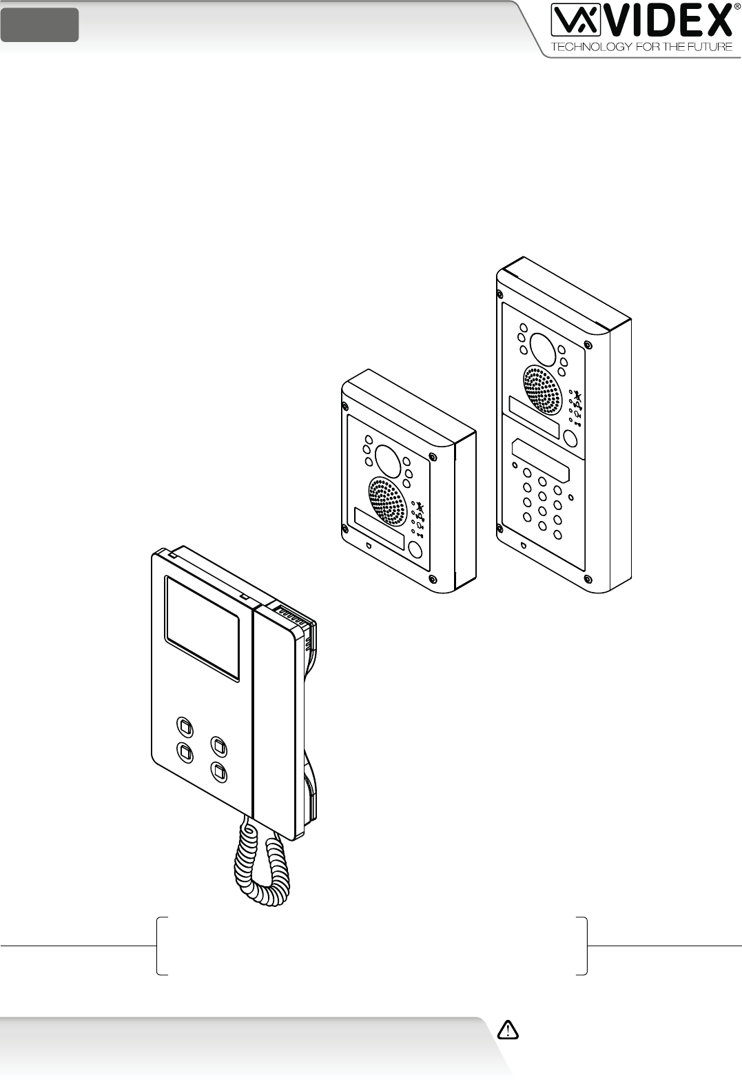
The VK4K Series is a new range of videokits that use the 4000 Series external door station and the Art.6256 Series videophone.
The camera / audio unit is the size of a single 4000 Series module and is available in either ush (VK4K) or surface (VK4K-S) mounting
versions.
As a result of using microprocessor technology in the door panel and videophone, a number of additional features have been add-
ed to enhance the operation of the videokits and give greater feedback to the visitor and user.
• Disability friendly, visual and acoustic signals from the door panel to inform the visitor of call status (call made, ringing, speak,
door open).
• Programmable door open and conversation time.
• Expandable to 4 entrance panels (requires an additional relay Art.506N for each entrance panel).
• Connections for a push to exit button.
• Two methods of operating the electric lock:- 1) Dry contact relay, 2) capacitor discharge 12Vdc output.
• Facility for the connection of a codelock Art.4800M, display module Art.4820, stand-alone proximity reader Art.4850 or stand-
alone biometric reader Art.4821 etc.
• Programmable number of call tone rings from 2 to a maximum of 8.
• Input for local door bell push button.
• Programmable timed privacy function from 15 minutes to a maximum of 8 hours.
• Door open status LED (additional wire required from the door to the videophone)
• Up to 4 videophones can be connected in parallel, all with intercommunication facility.
• Videophones can have a maximum of two additional audio telephone handsets connected in parallel.
• Camera recall on all systems, with selective recall on systems with multiple entrances.
• Door panel camera can be adjusted horizontally and vertically (10 degrees).
Introduction .................................................................................................................................................................................... 2
System components and available versions ................................................................................................................................ 3
General directions for installation ................................................................................................................................................ 5
Troubleshooting guide .................................................................................................................................................................. 6
Art.4833 Speaker unit ................................................................................................................................................................... 7
Art.4800 - 4800M Digital codelock module ............................................................................................................................... 10
4000 Series surface and ush mounting door station installation .......................................................................................... 13
Art.6256 3.5" colour videophone .............................................................................................................................................. 15
6200 Series Videophone wall mounting instructions ............................................................................................................... 18
Installation diagrams ................................................................................................................................................................... 19
66250457-EN - V 3.4 - 31/08/16
3
VK4K/6256 Series “6 wire Bus” videokit
VK4K/6256 Series - Installation handbook
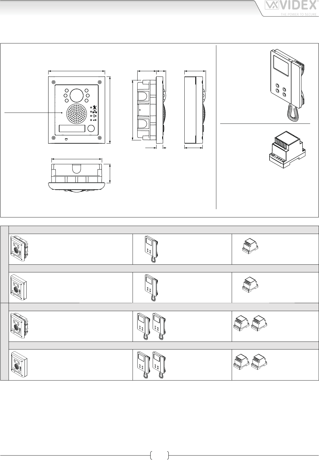
System components and available versions
VK4K/6256
Colour videokit.
49,8
43,8
135,0
160,0
45,0 22,5
15,7
143,0
120,0
45,0
INDOOR
STATION
Videophone
Art.6256
pag. 15
ACCESSORIES
Power supply
Art.850K
pag. 5
OUTDOOR
STATION
Camera unit
Art.4833
pag. 7
Flush
Mounting
Surface
Mounting
Fig. 1 - VK4K/6256 components (measures in mm)
ONE WAY VERSIONS
VK4K-1/6256 - ush mounting
1 Outdoor station composed of:
1 Art.4833-1/C: 1 button camera unit
1 Art.4851: Flush mounting box
1 Colour videophone
Art.6256
1 Power supply
Art.850K
VK4K-1S/6256 - surface mounting
1 Outdoor station composed of:
1 Art.4833-1/C: 1 button camera unit
1 Art.4881: Surface mounting box
1 Colour videophone
Art.6256
1 Power supply
Art.850K
TWO WAY VERSIONS
VK4K-2/6256 - ush mounting
1 Outdoor station composed of:
1 Art.4833-2/C: 2 buttons camera unit
1 Art.4851: Flush mounting box
2 Colour videophones
Art.6256
2 Power supplies
Art.850K
VK4K-2S/6256 - surface mounting
1 Outdoor station composed of:
1 Art.4833-2/C: 2 buttons camera unit
1 Art.4881: Surface mounting box
2 Colour videophones
Art.6256
2 Power supplies
Art.850K
66250457-EN - V 3.4 - 31/08/16
4
VK4K/6256 Series “6 wire Bus” videokit
VK4K/6256 Series - Installation handbook
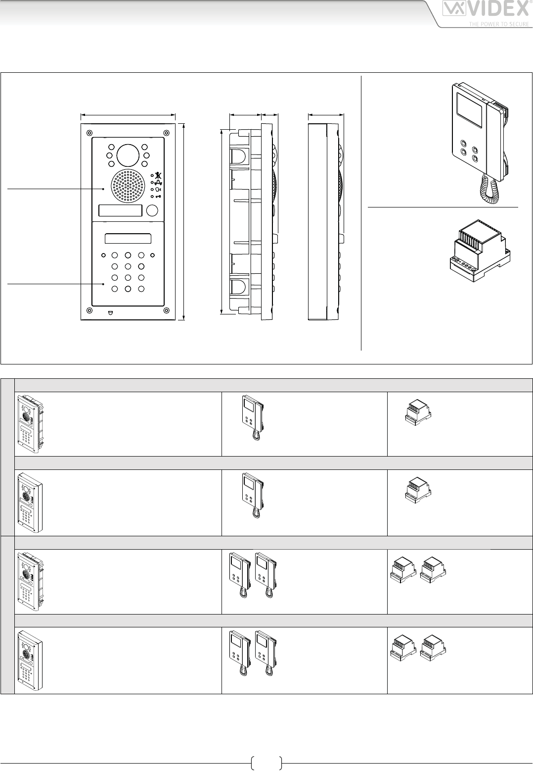
VK4KC/6256 Colour videokit plus a codelock module.
51,0135,0
280,0
45,0 24,0
263,0
INDOOR
STATION
Videophone
Art.6256
pag. 17
ACCESSORIES
Power supply
Art.850K
pag. 5
OUTDOOR
STATION
Flush
Mounting
Surface
Mounting
Camera unit
Art.4833
pag. 7
Codelock
module
Art.4800M
pag. 10
Fig. 2 - VK4KC/6256 components (measures in mm)
ONE WAY VERSIONS
VK4KC-1/6256 - ush mounting
1 Outdoor station composed of:
1 Art.4833-1/C: 1 button camera unit
1 Art.4800M: Codelock module
1 Art.4852: Flush mounting box
1 Colour videophone
Art.6256
1 Power supply
Art.850K
VK4KC-1S/6256 - surface mounting
1 Outdoor station composed of:
1 Art.4833-1/C: 1 button camera unit
1 Art.4800M: Codelock module
1 Art.4882: Surface mounting box
1 Colour videophone
Art.6256
1 Power supply
Art.850K
TWO WAY VERSIONS
VK4KC-2/6256 - ush mounting
1 Outdoor station composed of:
1 Art.4833-2/C: 2 buttons camera unit
1 Art.4800M: Codelock module
1 Art.4852: Flush mounting box
2 Colour videophones
Art.6256
2 Power supplies
Art.850K
VK4KC-2S/6256 - surface mounting
1 Outdoor station composed of:
1 Art.4833-2/C: 2 buttons camera unit
1 Art.4800M: Codelock module
1 Art.4882: Surface mounting box
2 Colour videophones
Art.6256
2 Power supplies
Art.850K
System components and available versions

66250457-EN - V 3.4 - 31/08/16
5
VK4K/6256 Series “6 wire Bus” videokit
VK4K/6256 Series - Installation handbook
General directions for installation
CONNECTION TO MAINS
The system must be installed according to national rules in force, in particular we recommend to:
• Connect the system to the mains through an all-pole circuit breaker which shall have contact separation of at least 3mm in each
pole and shall disconnect all poles simultaneously;
• The all-pole circuit breaker shall be placed for easy access and the switch shall remain readily operable.
POWER SUPPLY INSTALLATION
• Remove the terminal side covers by unscrewing the retaining screws;
• Fix the power supply to a DIN bar or directly to the wall using two expansion type screws;
• Switch o the mains using the circuit breaker mentioned above and then make the connections as shown on the installation diagrams;
• Check the connections and secure the wires into the terminals;
• Replace the terminal covers and x them using the relevant screws;
• When all connections are made, restore the mains.
CABLE SIZE
Video connections and Audio connections must be wired in twisted pair: pair the video lines (terminals/signals “V1” and “V2”),
pair the audio lines (terminals /signals “1” and “2”).
+V *
*
1
V1
V2
2
Power
supply Videophone
Up to 40mt
2 wires
Ø 1mm
20mt max
Outdoor
station
BROWN
ORANGE
BLUE
GREEN
WHITE/BROWN
WHITE/ORANGE
WHITE/BLUE
WHITE/GREEN
Distance Suggested cables type
Up to
40mt
CAT5/CAT6 FTP/UTP
AWG24
* Couple the two wires to
double the section.
1
V1
V2
+V
2
1
V1
V2
+V
2
1
V1
V2
+V
2
Power
supply Videophone
Up to 50mt
Outdoor
station
Outdoor
station
Outdoor
station
"+V" and "–"
Ø 0.35mm
"V1" and "V2"
Ø 0.35mm Twisted pair
"1" and "2"
Ø 0.35mm Twisted pair
20mt max
2 wires
Ø 1mm
from 50 to 100mt
"+V" and "–"
Ø 0.75mm
"1" and "2"
Ø 0.5mm Twisted pair
"V1" and "V2"
Ø 0.5mm Twisted pair
from 100 to 200mt
"+V" and "–"
Ø 1.5mm
"V1" and "V2"
Ø 0.75mm Twisted pair
"1" and "2"
Ø 0.75mm Twisted pair
Distance Suggested cables type
Up to
50mt
Belden 9746 or equivalnet
4 pair (8 cores) 0.35mm
AWG22 - 48/Km
From
50 to
100mt
Belden 9690 or equivalnet
3 pair (6 cores) 0.8mm
AWG18 - 19.2/Km
From
100 to
200mt
Belden 9157 or equivalnet
4 pair (8 cores) 0.8mm
AWG18 - 19.2/Km
66250457-EN - V 3.4 - 31/08/16
6
VK4K/6256 Series “6 wire Bus” videokit
VK4K/6256 Series - Installation handbook
In case of system failure, try the following preliminary checks:
• Check that the cables are connected as shown in the installation diagram and that the cables are rmly xed into the relevant terminals;
• Check that the mains voltage is available on terminals 230Vac (or 127Vac) and 0 of the power transformer Art.850K;
• Check the 24Vac voltage output of the power transformer Art.850K. If this voltage is not available it could be the 1,6A fuse, in this case
remove the mains voltage, remove possible short-circuits or overload sources then replace the fuse with an equal or equivalent one.
• Check that the voltage between the terminals “+” and “-” of the speaker unit is between 16 and 20Vdc.
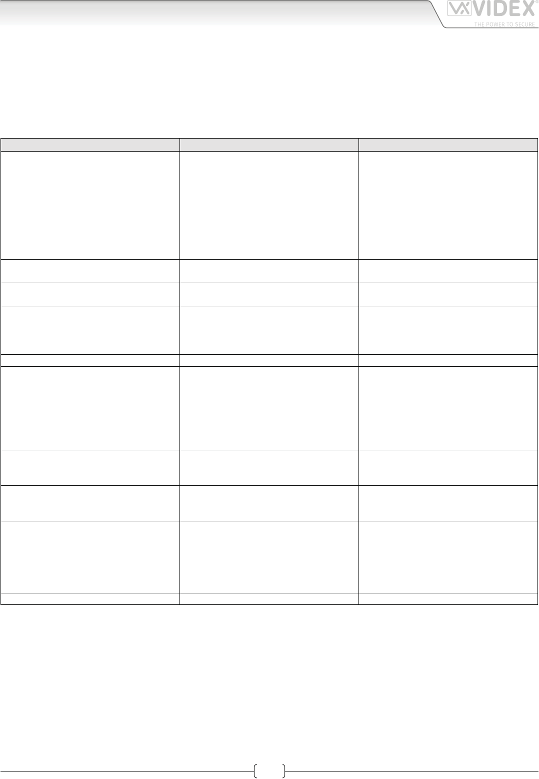
If the problem persists try the tests in the following table or contact technical support.
SYMPTOM CAUSE SOLUTION
The door station is not able to call the ex-
tension (the bell LED is switched on for 2
seconds):
• Wrong connection between door sta-
tion and the videophone
• Cable size too small.
• Programmed videophone address in-
correct.
• You have changed the videophone ad-
dress without power down the system.
• Check the 6 common wire connections
especially wire “1” (speech line/data).
• Increase cable size or double up using
two wires for each connection.
• Check videophone address on dip-swi-
tches.
• Power down the system then power up
again to detect the new videophone ad-
dress.
External call works but when answered
the communication fails:
• Cable size too small. • Increase cable size or double up using
two wires for each signal.
During the conversation it is not possible
to open the door:
• Cable size too small. • Increase cable size or double up using
two wires for each signal.
During the conversation it is not possible
to open the door but the key LED on the
door station switches on for the program-
med time:
• Incorrect position of J2 jumper.
• Electric lock wires unconnected or in short.
• Wrong electric lock type.
• Check J2 position on the door station.
• Check connection.
• Check that the electric lock type (ac or dc)
is suitable for the J2 position chosen.
Speech only from outside to inside: • Wire “2” broken or in short. • Check connection of wire “2”.
Low volume of speech: • Volume trimmers of door station require
adjustment.
• Adjust the trimmers until the required
volume is reached.
Noise over the speech line during the con-
versation:
• The 6 common wires are cabled to-
gether with 230 or 380Vac power lines.
• The 6 common wires are cabled to-
gether with 24Vac videophone power
supply wires.
• Separate the 6 common wires from the
high voltages cables.
• Separate the 6 common wires from the
two 24Vac wires or cable them together
only for a short distance.
Camera recall service does not work: • Camera recall button pressed for a num-
ber of times dierent from the ID of the
door station to be switched on.
• Check the ID (1..4) of the door station to be
recalled and press the camera recall but-
ton as many time as the ID value.
Intercommunicating call does not work: • ”Key” button pressed for a number of
times dierent from the videophone ad-
dress value.
• Check the address of the videophone
you are calling and try again.
The video shown on the monitor is of a bad
quality and the image is distorted or double
• V1,V2 signals unconnected, reversed or
shorted.
• The switches of the two way dip-switch
are not both in ON position.
• V1,V2 of the last Art. 316N (if present)
not closed with 75 Ohm resistor.
• Check that the wires are not broken or
shorted.
• Set both switches to the ON position.
• Use 2x 75 Ohm resistors to connect V1
& V2 to 0V.
Local call does not work: • Wrong connection or call button broken. • Check connection or replace the button.
Troubleshooting guide
66250457-EN - V 3.4 - 31/08/16
7
VK4K/6256 Series “6 wire Bus” videokit
VK4K/6256 Series - Installation handbook
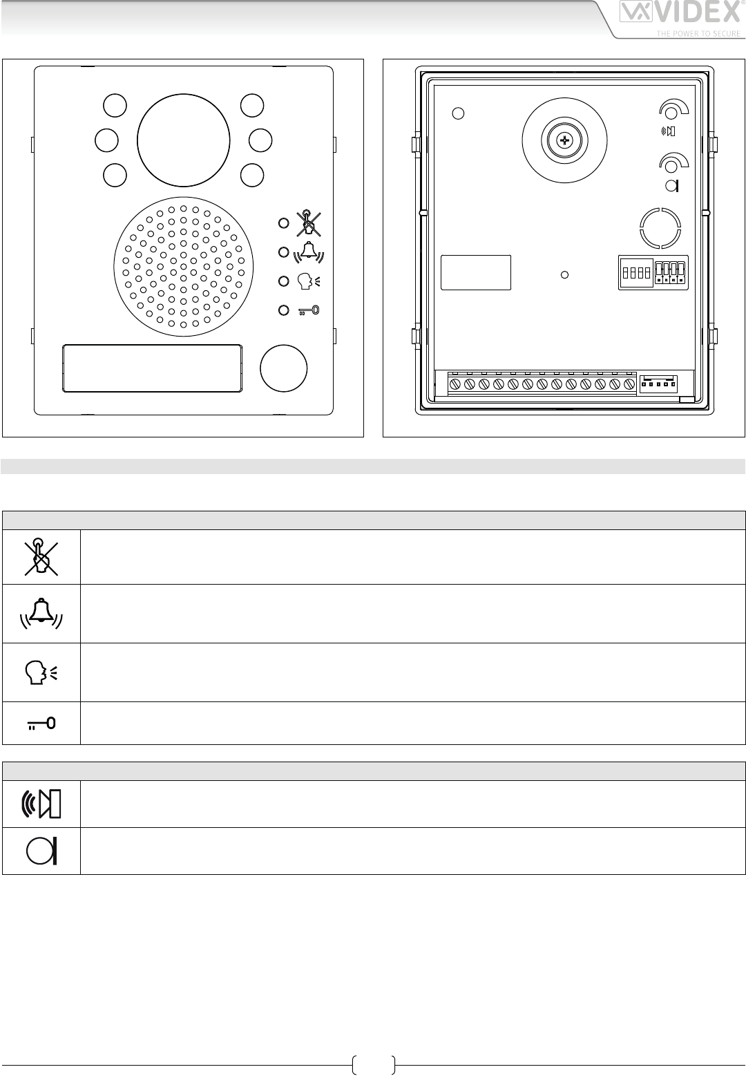
Art.4833 Speaker unit
Fig. 1
sw
NONCCPTESLBSV1V221
12Vout
-
+V
J1 J2 J3 J4
1234
ON
DATA
H
L
R02A
Fig. 2
DESCRIPTION
Speaker unit module Art.4833 comprising of high quality auto iris lens CCD Day/Night colour camera with infrared illumination LEDs.
LEDS
When illuminated, indicates that it is not possible to make a call because a call or a conversation is in progress (from
the outdoor station from which you are calling or from another outdoor station on systems with multiple entrances).
The LED will be o when the system is in stand-by.
If illuminated, indicates that the call from the outdoor station is in progress. The LED will switch OFF when the call is
answered or after the programmed number of rings.
If illuminated, indicates that it is possible to speak because the call has been answered. The LED will switch OFF at
the end of a conversation (or at the end of the conversation time).
If illuminated, indicates that the door lock has been operated. It will switch OFF at the end of the programmed “door
opening” time.
CONTROLS SPEAKER & MICROPHONE VOLUME
Trimmer to adjust the speaker volume. Rotate clockwise to increase or anticlockwise to decrease.
Trimmer to adjust the microphone volume. Rotate clockwise to increase or anticlockwise to decrease.
66250457-EN - V 3.4 - 31/08/16
8
VK4K/6256 Series “6 wire Bus” videokit
VK4K/6256 Series - Installation handbook
Art.4833 Speaker unit
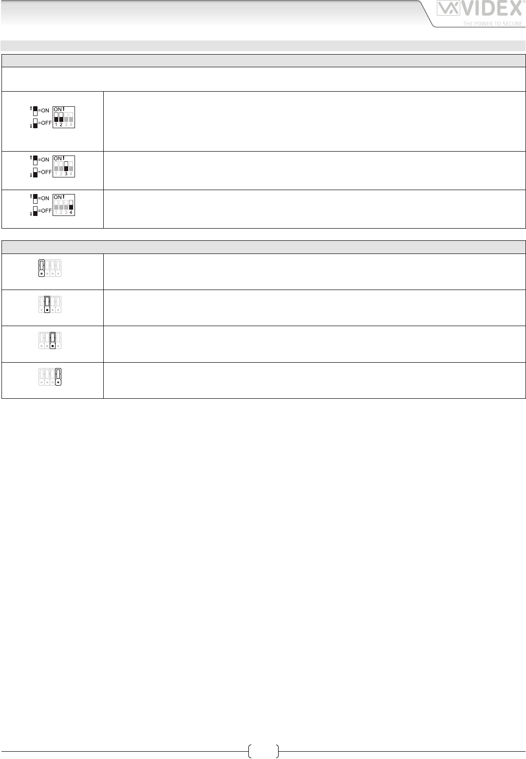
SETTINGS DIPSWITCH & JUMPERS
4 WAY DIPSWITCH
First two switches are used to set the speaker unit address: the speaker unit address is required for camera recall operation on 2
or more entrance systems.
SW
Switches 1,2 Unit Address
OFF OFF 1
ON OFF 2
OFF ON 3
ON ON 4
SW
Switches 3 Conversation Time
OFF 60 seconds
ON 120 seconds
SW
Switch 4 Door opening time (J2 = “L” position)
OFF 2 seconds
ON 6 seconds
JUMPERS J1, J2, J3, J4
H
L
J2 J3 J4J1
J1 Position Call reassurance tone volume
H High
L Low
H
L
J1 J2 J3 J4
J2 Position Door open relay operating mode
H Capacitor discharge
L Dry contacts
H
L
J1 J2 J3 J4
J3 Position Call buttons operating mode (only for Art.4833)
H Each button calls a dierent videophone
L Both buttons call the same videophone (Address 1)
H
L
J1 J2 J3 J4
J4 Position Built-in relays – back EMF protection (MOV)
H NC contact
L NO contact
When the door open relay operating mode is set to “capacitor discharge”*, one terminal of the electric lock must be connected to
ground while the second must be connected to “NO” terminal. The “NO” terminal will supply a temporary voltage when the speaker
unit receives the door open command.
* When “capacitor discharge” operating mode is set, one terminal of the electric lock must be connected to the ground while the
second one must be connected to “NO” terminal. The “NO” terminal will supply a temporary voltage when the speaker unit receives
the door open command (we suggest to use a 12Vac/dc 1A max electric lock). Setting “dry contacts” operating mode, when the
speaker unit receives the door open command, the “NO” terminal will be internally linked to the “C” terminal for the programmed
time (switch 4 of the 4 way dip-switch bank).
66250457-EN - V 3.4 - 31/08/16
9
VK4K/6256 Series “6 wire Bus” videokit
VK4K/6256 Series - Installation handbook
Art.4833 Speaker unit
BUILTIN RELAYS BACK EMF PROTECTION
The Art.4833 includes selectable back EMF protection on the relays. The jumpers marked J4 (One jumper for each relay) are used to
select the protection type. When using a fail secure lock with connections C & NO the jumper should be in the NO position. When using
a fail open lock with connections C & NC the jumper should be in the NC position and when using the codelock to trigger a gate con-
troller or another third party controller the jumper should be removed completely (This disables the protection on the relay).
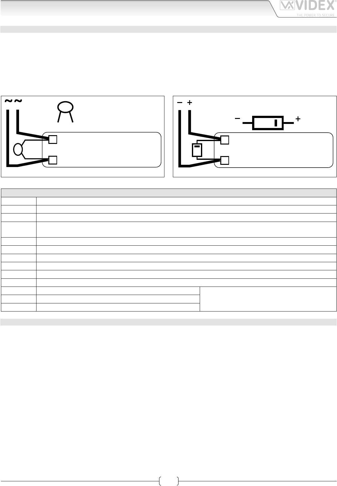
LOCK RELEASE BACK EMF PROTECTION
A varistor must be tted across the terminals on AC lock release (Fig.1A) and a diode must be tted across the terminals on a DC
lock release (Fig.1B) to suppress back EMF voltages. Connect the components to the lock releases as shown in gures.
VARISTOR (MOV)
12V AC
LOCK RELEASE
Fig.1A
DIODE
1N4002
12V DC
LOCK RELEASE
Fig.1B
SIGNALS
+V Power input 16÷20Vdc
Power input ground
12Vout 12Vdc. 0,3A max. output to supply accessiories
1Speech line input toward the loudspeaker and data signal (about 12V in stand-by, about 5V with a conversation in
progress)
2Speech line output from the microphone (about 12V in stand-by, about 3V with a conversation in progress)
V1 Balanced video signal sync.–
V2 Balanced video signal sync.+
BS Input/Output busy signal (about 12V in stand-by, about 0V with a call in progress)
SL Active low output to enable the enslavement relay for video signal exchange (active with a call in progress)
PTE Active low input to control directly the door open relay
CDoor open relay common contact
Max 24Vdc, 3A when used as dry contacts relayNC Door open relay normally closed contact
NO Door open relay normally open contact
TECHNICAL SPECIFICATION
Power Supply: Supplied by the BUS line, 20Vdc
Power consumption: Stand-by: 70mA
Operating: 250mA
Working Temperature: -10 +50° C
66250457-EN - V 3.4 - 31/08/16
10
VK4K/6256 Series “6 wire Bus” videokit
VK4K/6256 Series - Installation handbook
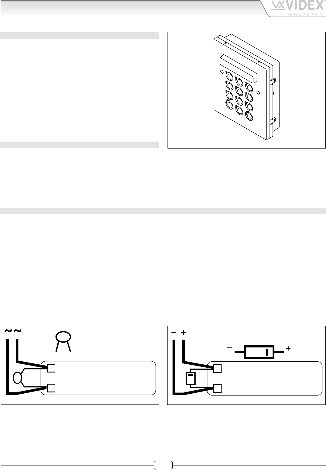
Art.4800M Digital codelock module
CODELOCK UNIT MODULES ART.4800M
The module features 12 stainless steel buttons (Keys 0 - 9,
ENTER and CLEAR), 2 LED’s for progress information during
use and programming and a mirror nish stainless steel front
plate (Standard version). With three integral relays each with
common, normally open and normally closed connections and
two inputs to enable the external triggering of relays one and
two (For example, push to exit button). Key presses are signalled
both acoustically and visually while each button press has a tac-
tile feel. Entering the correct code followed by ENTER will ac-
tivate the relevant relay. Programming is carried out through
the same keypad following a simple programming menu. The
module can be combined with other 4000 Series modules in an
audio or video intercom system.
‘
MAIN FEATURES
• 3 C, NC, NO relay outputs (24Vac/dc – 5A max);
• 3 Programmable secret codes (one for each relay);
• Each relay can be set to be activated for a specic time (01 to 99 seconds) or to work as latch;
• Two active low inputs to command directly the relay 1 and 2;
• Programming menu guarded by a 4-8 digit programmable engineer’s code;
• Visual and Acoustic signal during operating and programming;
• Keypad illumination LEDs;
GENERAL DIRECTIONS FOR INSTALLATION
In order to achieve the best results from the schematics described it is necessary to install only original VIDEX equipment, strictly
keeping to the items indicated on each schematic and follow these General Directions for Installation:
• The system must be installed according to national rules in force, in any case the running of cables of any intercom unit must be
carried out separately from the mains;
• All multipair cables should be compliant to CW1308 specication (0.5mm twisted pair telephone cable).
• Cables for speech line and service should have a max resistance of 10 Ohm
• Lock release wires should be doubled up (Lock release wires and power supply wires should have a max resistance of 3 Ohm);
• The cable sizes above can be used for distances up to 50m. On distances above 50m the cable sizes should be increased to keep
the overall resistance of the cable below the RESISTANCES indicated above;
• Double check the connections before power up;
• Power up the system then check all functions.
LOCK RELEASE BACK EMF PROTECTION
A varistor must be tted across the terminals on AC lock release (Fig.1A) and a diode must be tted across the terminals on a DC
lock release (Fig.1B) to suppress back EMF voltages. Connect the components to the lock releases as shown in gures.
VARISTOR (MOV)
12V AC
LOCK RELEASE
Fig.1A
DIODE
1N4002
12V DC
LOCK RELEASE
Fig.1B
Fig. 1 - Art.4800M
66250457-EN - V 3.4 - 31/08/16
11
VK4K/6256 Series “6 wire Bus” videokit
VK4K/6256 Series - Installation handbook
BUZZER BACK EMF
When using intercoms with buzzer call (Art.924/926, SMART1/2, 3101/2, 3001/2 and 3021/2) add one 0.1uF (100nF) capacitor be-
tween terminals 3 and 6 on the telephone.
BUILTIN RELAYS BACK EMF PROTECTION
The Art.4800M includes selectable back EMF protection on the relays. The jumpers marked MOV (One jumper for each relay) are
used to select the protection type. When using a fail secure lock with connections C & NO the jumper should be in the NO position.
When using a fail open lock with connections C & NC the jumper should be in the NC position and when using the codelock to
trigger a gate controller or another third party controller the jumper should be removed completely (This disables the protection
on the relay).
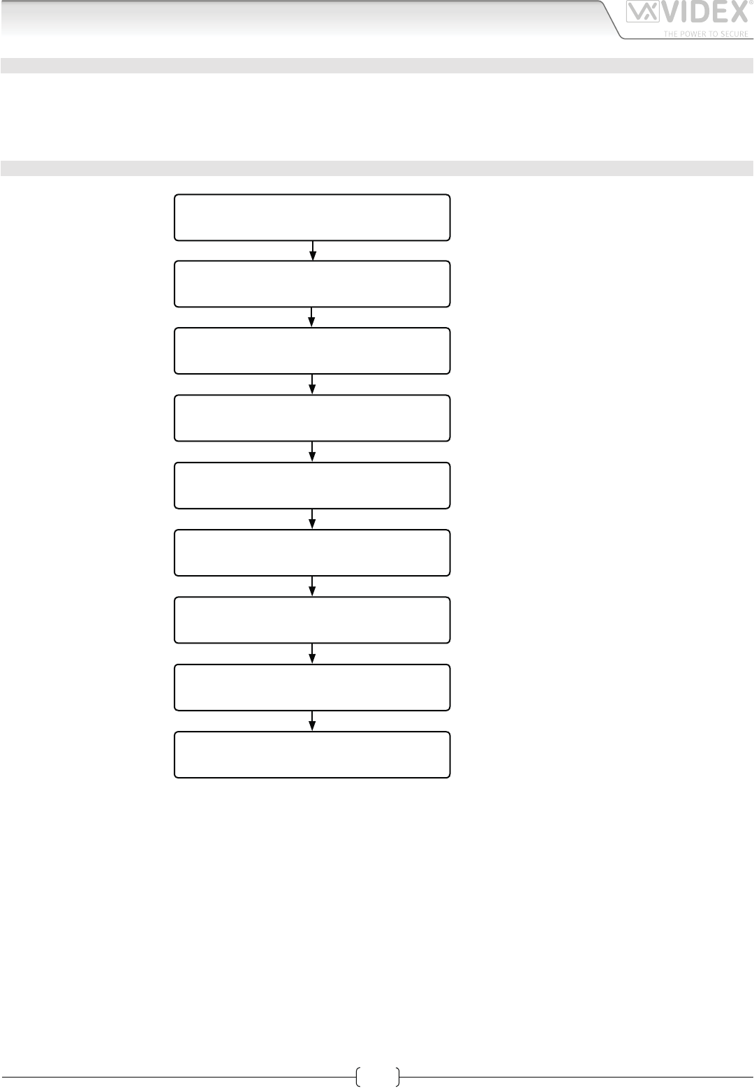
PROGRAMMING SEE ALSO THE RELEVANT FLOW CHART
• Enter the “ENGINEER’S CODE”: rst time type six times “1” (111111 factory preset) and press “ENTER” (The red LED will illuminate);
• Conrm “ENGINEER’S CODE” (typing again the same) or type the new code (4 to 8 digits) then press “ENTER” (Melody). Pressing
twice the “ENTER” button without changing the “ENGINEER’S CODE”, will exit from the programming;
• Enter the code (4 to 8 digits) to enable “RELAY 1” or re-enter the existing code then press “ENTER” (Melody);
• Enter the “RELAY 1” operation time (2 digits 01 to 99 I.E. 05=5 seconds, 00= remain open time) or re-enter the existing time then
press “ENTER” (Melody);
• Enter the code (4 to 8 digits) to enable “RELAY 2” or re-enter the existing code then press “ENTER” (Melody);
• Enter the “RELAY 2” operation time (2 digits 01 to 99 I.E. 05=5 seconds, 00= remain open time) or re-enter the existing time then
press “ENTER” (Melody);
• Enter the code (4 to 8 digits) to enable “RELAY 3” or re-enter the existing code then press “ENTER” (Melody);
• Enter the “RELAY 3” operation time (2 digits 01 to 99 I.E. 05=5 seconds, 00= remain open time) or re-enter the existing time then
press “ENTER” (Melody);
• The system is ready to use (the red LED will be o).
PROGRAMMING NOTES
• After pressing enter following a command, press “ENTER” a further twice to exit the programming menu.
RETURN SYSTEM TO PRESET ENGINEER’S FACTORY CODE
• Turn o power to code lock;
• Keep “ENTER” button pressed while turning the power back on;
• Release “ENTER” button;
• The engineer’s code is now set to “111111” (six times one).
OPERATION
• Type in the programmed code and press “ENTER”;
• If the code is correct, the green LED will illuminate for ap-
prox. 2 seconds and the relay relevant to the code will oper-
ate for the programmed time;
• If a wrong code is entered, a continuous melody will sound
for 4 or more seconds, according to the number of mistakes;
• To switch o any relay while operating, type in the relevant
code then press the “CLEAR” button;
OPERATION NOTES
• To operate relays together, set the same code for each relay;
• If a wrong code is entered, the system will lock out for 5 sec-
onds which will increase each time a wrong code is entered.
The system will operate only when the correct code is entered.
TERMINALS:
SW2 Relay 2 command signal (active low)
SW1 Relay 1 command signal (active low)
NC3 Relay 3 normally closed contact
Max
24Vac/dc
3A
NO3 Relay 3 normally open contact
C3 Relay 3 common contact
NC2 Relay 2 normally closed contact
NO2 Relay 2 normally open contact
C2 Relay 2 common contact
NC1 Relay 1 normally closed contact
NO1 Relay 1 normally open contact
C1 Relay 1 common contact
12/24Vac/dc power input
+
Art.4800M Digital codelock module
66250457-EN - V 3.4 - 31/08/16
12
VK4K/6256 Series “6 wire Bus” videokit
VK4K/6256 Series - Installation handbook
TECHNICAL SPECIFICATION
Power Supply: 12/24 Vac/dc – 2VA
Power Consumption: Stand-by: 20mA
Operating: 70mA
Working Temperature: -10 +50° C
PROGRAMMING FLOWCHART
ENTER “ENGINEER’S CODE“
AND PRESS “ENTER“
CONFIRM OR CHANGE “ENGINEER’S CODE“
AND PRESS “ENTER“
ENTER “ACCESS 1 CODE“
AND PRESS “ENTER“
ENTER “ACCESS 1 TIME“
AND PRESS “ENTER“
ENTER “ACCESS 2 CODE“
AND PRESS “ENTER“
ENTER “ACCESS 2 TIME“
AND PRESS “ENTER“
ENTER “ACCESS 3 CODE“
AND PRESS “ENTER“
ENTER “ACCESS 3 TIME“
AND PRESS “ENTER“
SYSTEM READY TO USE
First time 6 times 1 "111111"
factory preset
Type again six times “1”
or the new enginner’s code 4 to 8 digits
Code to enable
relay 1
4 to 8 digits
Code to enable
relay 2
4 to 8 digits
2 digits (01 to 99)
I.E. 05 = 5 seconds
00 = remain open time
2 digits (01 to 99)
I.E. 05 = 5 seconds
00 = remain open time
Code to enable
relay 3
4 to 8 digits
2 digits (01 to 99)
I.E. 05 = 5 seconds
00 = remain open time
Red LED will be ON
Red LED will be OFF
Melody
Melody
Melody
Melody
Melody
Melody
Melody
Art.4800M Digital codelock module
66250457-EN - V 3.4 - 31/08/16
13
VK4K/6256 Series “6 wire Bus” videokit
VK4K/6256 Series - Installation handbook
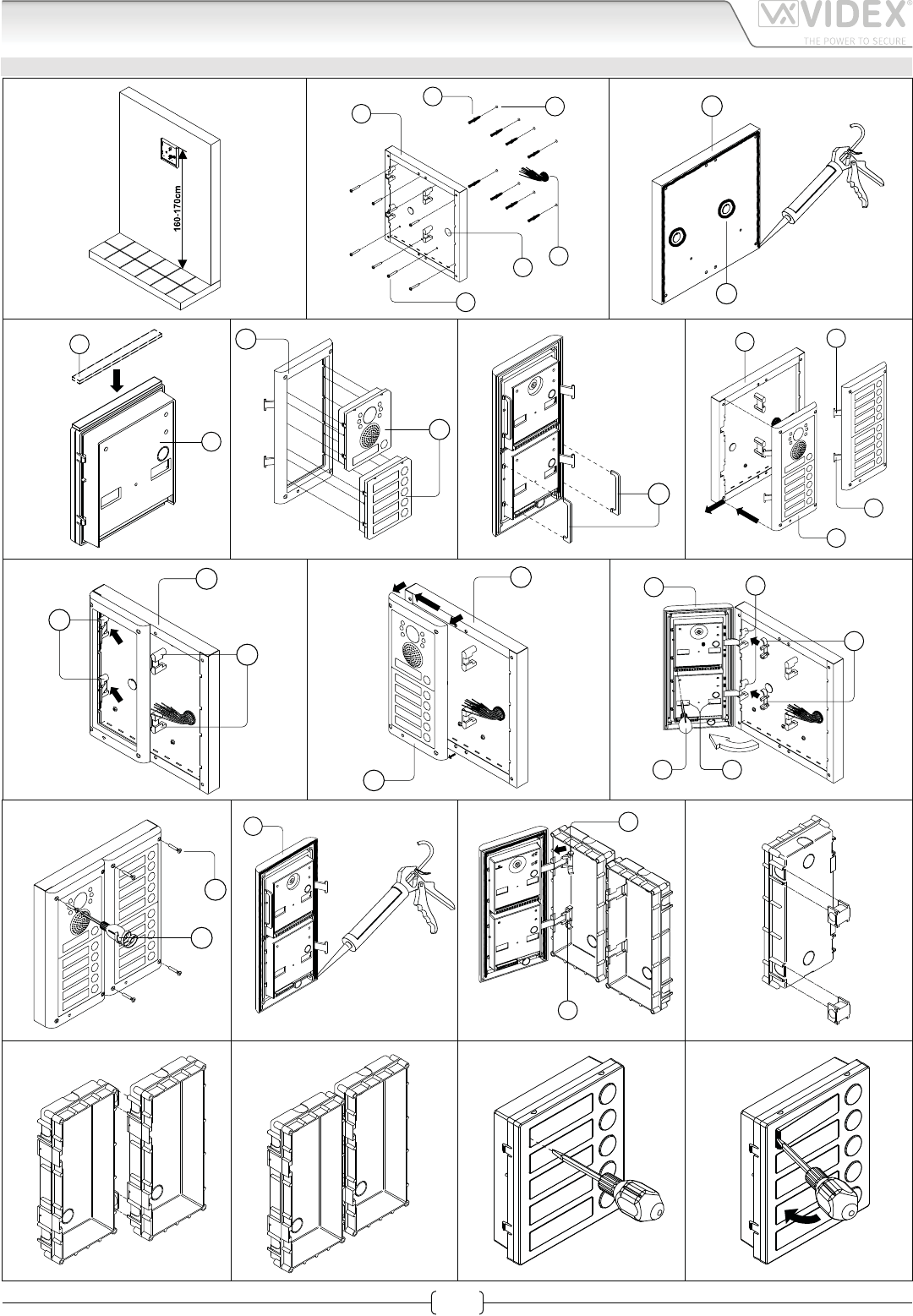
4000 Series Surface and ush mounting door station installation
H
G
H
Y
G
C
F
E
D
BA
CL
H
L
P O
N
M
H
M
M
C
Q
P
C
D
W
N
N
C
H
g. 1
g. 8
g. 4 g. 5 g. 6 g. 7
g. 3
g. 10
g. 11
g. 15
g. 12
g. 16
g. 13
g. 17
g. 14
g. 18
g. 2
g. 9
EXAMPLE: INSTALLING A FOUR MODULE OUTDOOR STATION
66250457-EN - V 3.4 - 31/08/16
14
VK4K/6256 Series “6 wire Bus” videokit
VK4K/6256 Series - Installation handbook
4000 Series Surface and ush mounting door station installation
INSTALLING A SURFACE MOUNT DOOR STATION
1. Place the surface box against the wall (165-170cm between the top of the box and the oor level as shown in Fig.1) and mark the
xing holes for the wall plugs and the hole for the cables E (g.2). Observe the orientation of the box with the hinge on the left;
In order to prevent water ingress we highly recommend using a silicon sealant between the wall and the back box C
(Fig.3) and around all holes D (Fig.3);
2. As shown on Fig.2, drill the xing holes A, insert the wall plugs B and feed the cables E through the surface box opening D, x
surface box C to the wall using the screws F;
3. Apply the Y silicon sealant on top of each module as shown in Fig.4;
4. Before installation of the module support frame, hook the modules G to the support frame H as shown in Fig.5 then, as shown
in Fig. 6, t the two anti-tampering locks W for each module (do the same for the second module support frame);
5. When you have more than one support frame, hook the support frame to the surface box starting from the left. For convenience we
will described how to attach the left frame but the same must be carried out for the right frame. As shown in Fig. 7, hook the module
support frame H (complete with modules) to the surface box C moving the frame as suggested from pointers. Ensure that the pivots
L (Fig. 7) go inside the relevant housing M as shown in Fig. 8;
6. As shown on Fig. 9, pull back the module support frame H while moving it slightly to the left as suggested by the pointers;
7. As shown in Fig. 10, open the module support frame H as suggested by the pointer, hook the hinge locks N to the hinges M,
make the required connections using the screwdriver provided P (at blade end) and make the required adjustment by adjust-
ing the settings (through openings O) and adjust trimmers;
8. Repeat the same operations described above for the second module support frame (or for the third if available);
9. When the system has been tested and is working correctly, move back the module support frames carefully, x them to the surface
box using the screwdriver provided P (torx end) and the pin machine torx screws Q (Fig. 11). Note: do not over tighten the screws
more than is necessary.
INSTALLING A FLUSH MOUNTING DOOR STATION
When ush mounting and the number of modules is greater than 3, the required back boxes need to be linked together (before
embedding them in the wall) as shown on Fig. 14, 15 and 16:
• Arrange the back boxes and remove knockouts to allow cables to be fed from one back box to the other;
• Hook the spacers to rst back box then hook the second back box to obtain the result shown on Fig. 16;
1. Protect the module support frame xing holes from dust then embed the back box into the wall (165-170cm between the top
of the box and the oor level as shown on the Fig. 1) feeding the cables E (Fig. 2) through a previously opened hole in the box.
Observe the direction of the box ensuring the hinge is on the left and take care that the box prole is in line with the nished
wall prole;
In order to prevent water ingress we highly recommend using a silicon sealant between the wall and the back box H
(Fig.12);
2. Continue from step 4 of surface mounting instructions , but at step 7 hook the hinge locks N as shown on Fig. 13.
Note: if additional holes are made in the surface box, oxidation problems may appear unless the unprotected metal is
coated with a protective paint.
NOTES
• The screwdriver’s blade has two sides, one at and one torx, to select one of them unplug the blade from the screwdriver body
and plug it into the required side.
• The example shows the use of only one back box bottom hole for wires, this is done to keep le drawings clear. Naturally the
installer can use the left hole or the right or both if required.
HOW TO REMOVE THE CARD NAME HOLDER
• To avoid damage to the module front plate, tape the side that will be in contact with the screwdriver blade;
• lnsert the screwdriver (at side) into the card-holder hole as shown in Fig. 17;
• Move the screwdriver to the left as shown in Fig. 18 to extract the card name holder;
• Edit the card name then replace it inside the holder and ret: insert the holder inside its housing from the left or right side then
push the other side until it clips into place.
66250457-EN - V 3.4 - 31/08/16
15
VK4K/6256 Series “6 wire Bus” videokit
VK4K/6256 Series - Installation handbook
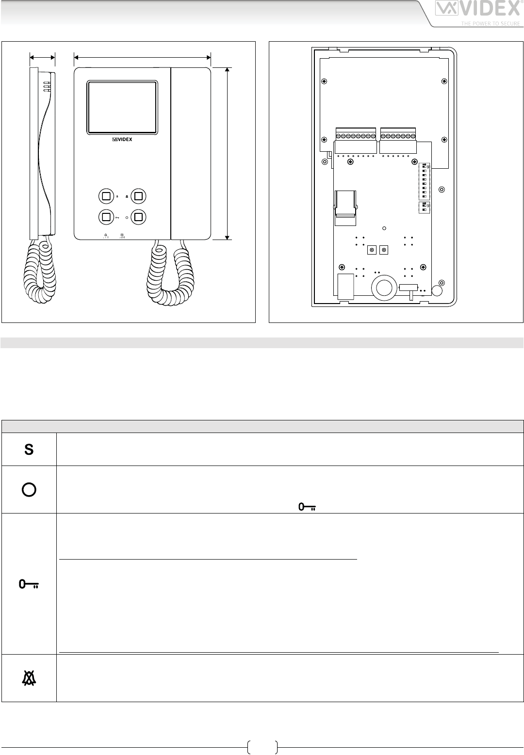
Art.6256 3.5" colour videophone
27 mm 144 mm
182 mm
Fig. 1
+V
-
1
2
V1
V2
24Vac
0Vac
SW1 SW2
PT3 PT2
PT1
SW1
LB
SB
LD
2A
3A
4A
5A
Fig. 2
DESCRIPTION
Surface mount videophone incorporating a 3.5” Hi-Res full colour active matrix LCD monitor specic for “6 wire” videokit (VK4K,
VRVK and VK8K range). It includes 4 buttons: “camera recall”, “open door” , “service” and “privacy”.
2 LED’s* indicate the privacy activated and open door. Programmable privacy duration and number of rings. Intercommunicating
call and door call. Adjustments: call tone volume switch (3 levels), picture hue, contrast and brightness.
* The operation of some LED’s and the functions described may require additional cabling
PUSH BUTTONS
Service push button.
Shorts the “SB” terminal to GROUND (open collector 24Vdc 100mA max) while the button remain pressed.
Camera recall button.
Pick up the handset then press the button (Press once for door/gate 1, twice for 2 and so on up to a maximum of 4
entrances): the relevant LED switches ON and the monitor switches on showing the video from the door panel. The
speech is also live and the door can be opened by pressing .
Door-open / intercommunicating call button.
With the handset lifted and speech lines open to the entrance panel, press this button to open the door. If the termi-
nal “LD” is properly connected the relevant LED remains switched ON until the door is closed.
Intercommunication only works when the system is in stand-by condition.
Switch 4 of the SW1 dip-switch selects the type of intercommunication:
OFF Intercommunication between two apartments - pick up the handset and press the key button to call the video-
phone(s) in the other apartment. A busy tone will signal that the other videophone is in conversation with the
door station and so cannot be called.
ON Intercommunication between videophones in the same apartment
- pick up the handset and press the key button one, two, three or four times to call videophone with extension ad-
dress 1, 2, 3 or 4 (Set on dip-switch 2&3 of SW1).
Any intercommunicating conversation is always interrupted by an external call (i.e. External calls take priority).
Privacy ON-OFF button.
When the system is in stand-by, the pressing of this button activates (LED switched on) or disables (LED switched
o) the “privacy” service. The service is automatically disabled when the programmed privacy time expires. When
the service is enabled the videophone does not receive calls.
66250457-EN - V 3.4 - 31/08/16
16
VK4K/6256 Series “6 wire Bus” videokit
VK4K/6256 Series - Installation handbook
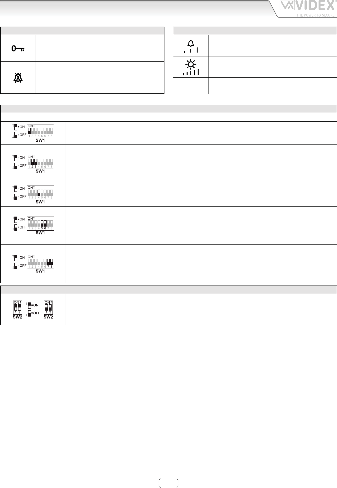
LEDS
Door open LED.
Can be used to indicate the status of a door or gate. It
requires a switched 12Vdc connection to terminal “LD”.
Privacy ON/OFF LED.
When the videophone is in stand-by, this LED
signals the privacy service status
(ON = service enabled, OFF = service disabled).
CONTROLS
SW1 Call tone volume controll (3 levels).
PT1 Brightness control.
PT2 PT2 Hue control.
PT3 PT3 Contrast control.
SETTINGS DIPSWITCH
The videophone setup is carried out by the 2 dip-switch banks.
Switches 1 Apartment Address
OFF 1
ON 2
Switches 2,3 Extension Address
OFF OFF 1
ON OFF 2
OFF ON 3
ON ON 4
Switch 4 Intercommunication
OFF Between videophones of the two apartment
ON Between videophones in the same apartment
Switches 5,6 Number of rings
OFF OFF 2
ON OFF 4
OFF ON 6
ON ON 8
Switches 7,8 Privacy duration time
OFF OFF 15 minutes
ON OFF 1 hours
OFF ON 4 hours
ON ON 8 hours
2 WAY DIPSWITCH SW2
The two way dip-switch adjusts the impedance of the video signal. The default setting is “ON” for both
switches (75 Ohm): when there are more videophones in parallel connection (without video distributor)
both switches must be “ON” only on the last videophone (looking at the connection order) while for all
other videophones both switches must be set to “OFF”.
Art.6256 3.5" colour videophone
66250457-EN - V 3.4 - 31/08/16
17
VK4K/6256 Series “6 wire Bus” videokit
VK4K/6256 Series - Installation handbook
Art.6256 3.5" colour videophone
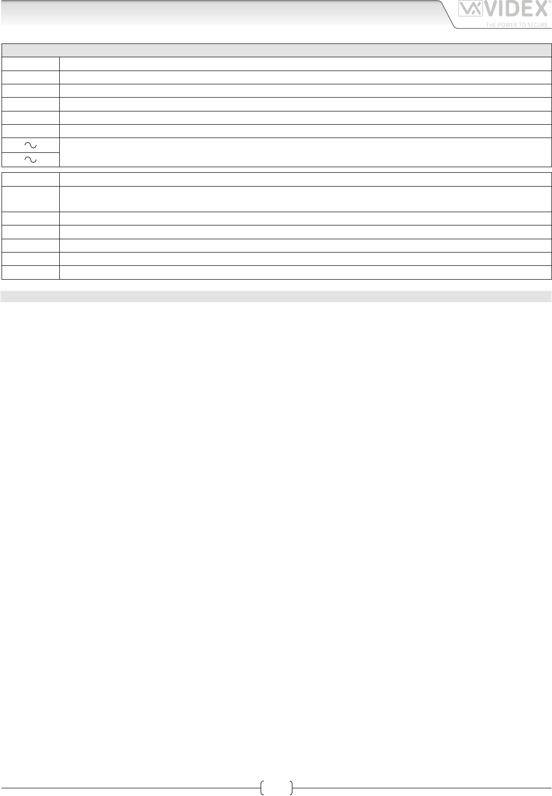
SIGNALS ON CONNECTION BOARD
+V 20Vdc Input/Output (As input 16÷20Vdc 0,5A – as output 20Vdc 0,5A max)
Ground reference for +V terminal.
1Speech line output from handset’s microphone and data signal (Approx. 12V in stand-by, 5V during a conversation)
2Speech line input toward the handset’s loudspeaker (Approx. 12V in stand- by, approx. 3V during a conversation)
V1 Balanced video signal 1 sync.-
V2 Balanced video signal 2 sync.+
24Vac 1A max power input
LB Local call input (5V in standby, 0V to trigger)
SB Service button (open collector) active low output. The button goes active when the button is pressed (Open Collec-
tor 24Vdc 100mA max)
LD 12Vdc input for door-open LED
2A Speech line input toward the loudspeaker of the parallel telephone (Approx. 12V in stand-by, 3V during a conversation)
3A Output switched ground for parallel telephone
4A Output call tone for parallel telephone
5A Input for door-open command from parallel telephone
TECHNICAL SPECIFICATION
Power Supply: Supplied by the BUS line, 20Vdc
Power consumption: Stand-by: 50mA Max
Operating: 200mA Max
Working Temperature: -10 +50 °C
66250457-EN - V 3.4 - 31/08/16
18
VK4K/6256 Series “6 wire Bus” videokit
VK4K/6256 Series - Installation handbook
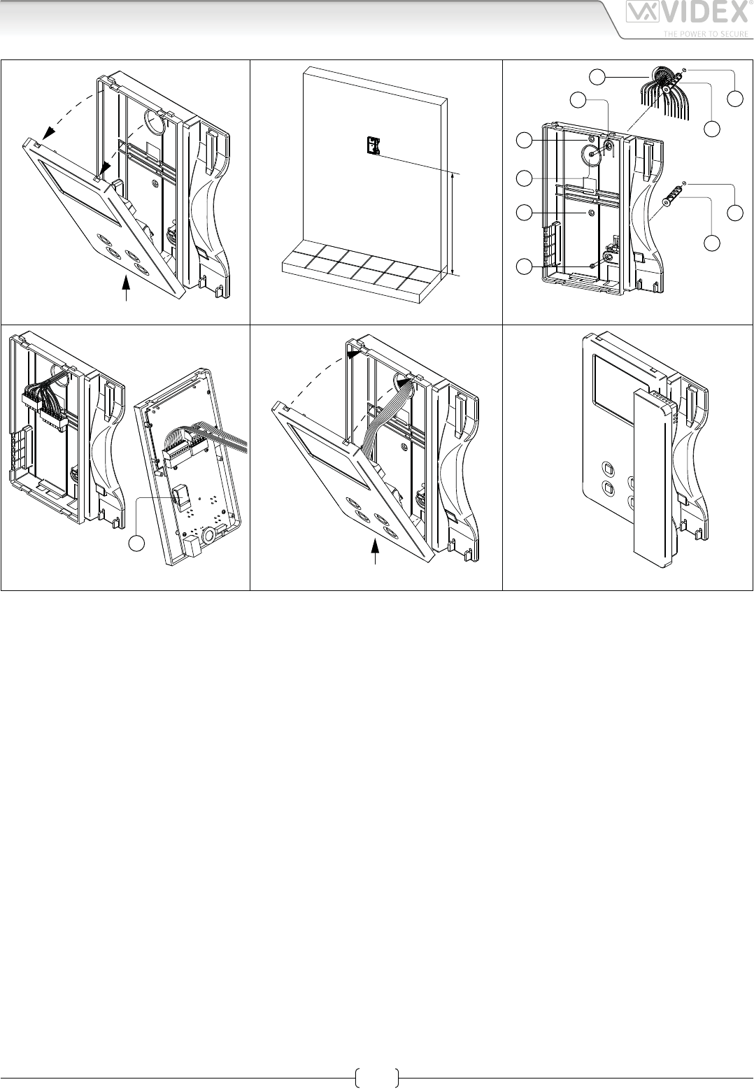
6200 Series Videophone wall mounting instructions
1. In order to install the videophone, it is necessary to remove the cover, which contains all the electronics, from the base: rstly
disconnect the handset from the videophone (by removing its plug from the videophone), then press lightly the bottom part of
the videophone and simultaneously pulling outwards the upper part as shown in Fig. 1.
2. Put the base of the unit on the wall at approx 135cm from the nished oor to mark the points for the xing holes “A” (Fig. 2)
remembering that the wires “D” (Fig. 3) must be fed through the hole “E” (Fig. 3). If you use the ush mounting box 503, embed
it into the wall vertically at approx. 140cm from the nished oor and the base.
3. Following Fig. 3, make the holes “A”, insert the wall plugs “B” and x the base with the screws “C” feeding the wires “D” into
the hole “E”. If you have used the box 503, x the base to the wall through the holes “F” using the screws “C”.
4. As shown in Fig. 4A, connect the wires to the removable terminals following the provided installation diagram. Connect the ter-
minal blocks to the electronics contained in the cover as shown in Fig. 4B. Reinsert the handset and test system before closing.
Note: Contrast and hue trimmers can be adjusted only if the videophone is open. Note while testing the system, it is
advisable to hold the cover with your hand closing manually the hook switch of the handset (see Fig. 4B reference “G”).
5. Once testing is complete and all the necessary adjustments are made, disconnect the handset from the cover and close the unit
as shown in Fig. 5: rst hook it on the bottom then push in the top until you hear the clip.
6. Reconnect the handset and hang it as shown in Fig. 6.
1
2
Fig. 1
A
B
G
Fig. 4
135cm
Fig. 2
1
2
Fig. 5
A
B
A
B
D
F
E
F
C
C
Fig. 3
Fig. 6
66250457-EN - V 3.4 - 31/08/16
19
VK4K/6256 Series “6 wire Bus” videokit
VK4K/6256 Series - Installation handbook
Installation diagrams
NOTES AND SUGGESTIONS
• All diagrams refer to all kits versions: ush or surface, colour or black & white.
• Dashed connections refer to optional connections (“Local bell”, “Push to exit” & “Door monitor”).
• Some diagrams show how to connect a 12Vdc electric lock: these directions are suitable for all diagrams in this manual.
• Each time a setting is changed on a videophone (address, extension, number of rings etc.), the videophone must be disconnected
from the relevant connection board then after a few seconds reconnected again to allow the recognizing of the new setting.
• All diagrams shown are valid for B&W or colour systems with surface or ush mount door station.
DECLETION OF RESPONSIBILITY
This manual has been written and revised carefully. The instructions and the descriptions which are included in it are referred to
VIDEX parts and are correct at the time of print. However, subsequent VIDEX parts and manuals, can be subject to changes without
notice. VIDEX Electronics S.p.A. cannot be held responsible for damages caused directly or indirectly by errors, omissions or discrep-
ancies between the VIDEX parts and the Manual.
WE RECOMMEND
This equipment is installed by a Competent Electrician, Security on Communications Engineer
66250457-EN - V 3.4 - 31/08/16
20
VK4K/6256 Series “6 wire Bus” videokit
VK4K/6256 Series - Installation handbook
Installation diagrams
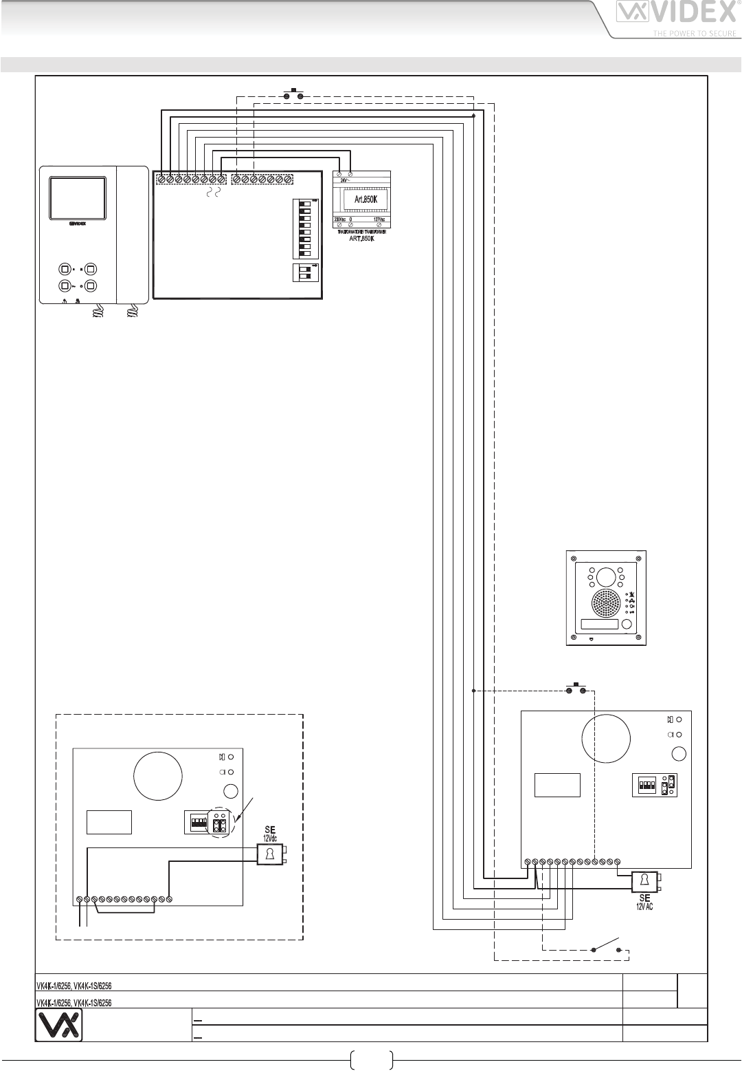
VIDEOKIT VK4K1/6256, VK4K1S/6256
Push to
Exit
Local Bell
Door
Monitor
NC
V2
BS
PTE
SL
V1
2
-
1
12Vout
+V
C
NO
4321
ON
1
Art.4833-1
Using Electric Lock 12Vdc 0.3A Max
Con serratura elettrica 12Vdc 0.3A Max
NC
V2
BS
PTE
SL
V1
2
-
1
12Vout
+V
C
NO
4
3
21
ON
1
Art.4833-1
Affinche qualsiasi modifica alle impostazioni dei dip switch del
videocitofono o del posto esterno venga riconosciuta dal sistema,
è necessario togliere l'alimentazione di rete all'impianto e
restituirla.
In order to make the system recognize any modification of the
videophone's and outdoor station's dip-switch setting temporarily
disconnect the system from the mains and reconnect
Videx Electronics S.p.A.
Via del Lavoro 1, 63020 Monte Giberto (AP)
Phone: +39 0734 631669 - Fax +39 0734 631669
www.videx.it - info@videx.it
Autore:
Data modifica:
Data creazione:Title:
Notes:
Titolo:
Note: Cod.File:
Foglio
/11
Marco Rongoni
vk4k62h-002.dw
g
23/10/2015
18/11/2015
12345678 12
ON
Address N.
ON
+V
_
1
2
V1
SB
LD
2A
3A
4A
SW2
SW1
LB
V2
5A
1 Ext.1
Art.6256
66250457-EN - V 3.4 - 31/08/16
21
VK4K/6256 Series “6 wire Bus” videokit
VK4K/6256 Series - Installation handbook
Installation diagrams
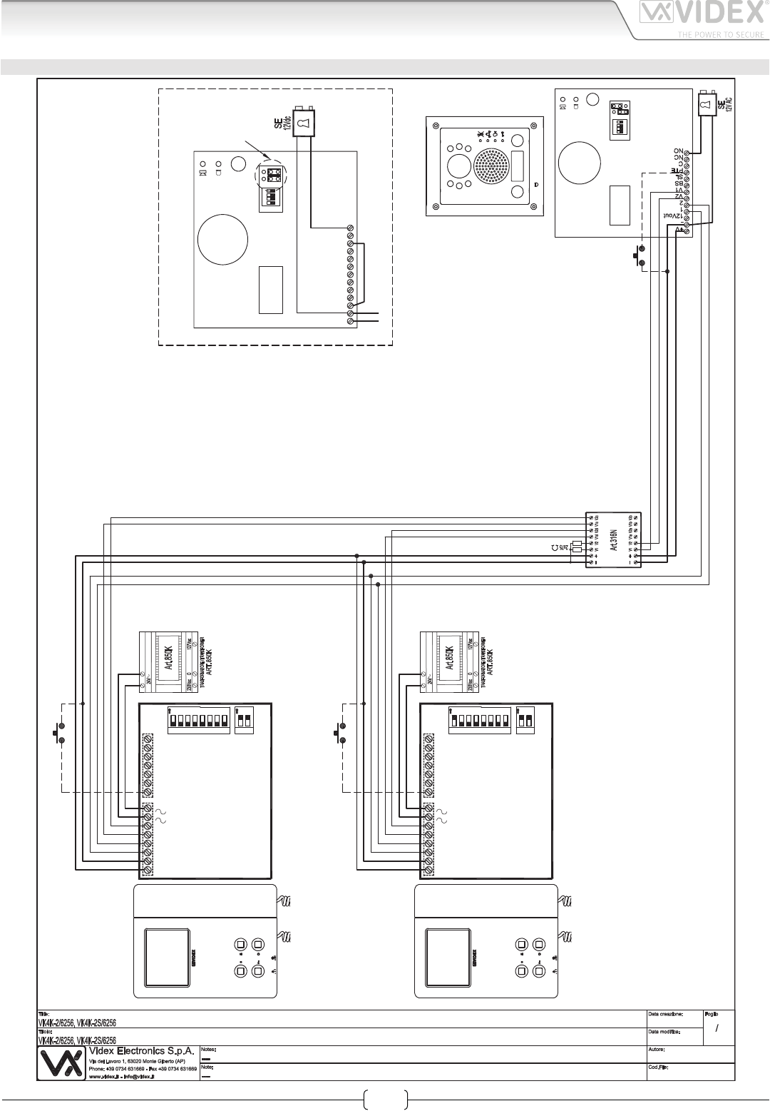
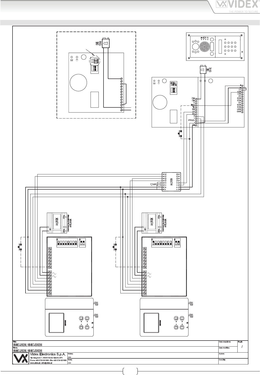
VIDEOKIT VK4K2/6256, VK4K2S/6256
11
Marco Rongoni
vk4k62h-003.dw
g
17/11/2015
18/11/2015
432
1
ON
1
Art.4833-1D
Using Electric Lock 12Vdc 0.3A Max
Con serratura elettrica 12Vdc 0.3A Max
NC
V2
BS
PTE
SL
V1
2
-
1
12Vout
+V
C
NO
4321
ON
1
Art.4833-1D
Push
to
Exit
12
Affinche qualsiasi modifica alle impostazioni dei dip switch del
videocitofono o del posto esterno venga riconosciuta dal sistema,
è necessario togliere l'alimentazione di rete all'impianto e
restituirla.
In order to make the system recognize any modification of the
videophone's and outdoor station's dip-switch setting temporarily
disconnect the system from the mains and reconnect
Local Bell
Local Bell
12345678 12
ON
Address N.
ON
+V
_
1
2
V1
SB
LD
2A
3A
4A
SW2
SW1
LB
V2
5A
1 Ext.1
Art.6256
12345678 12
ON
Address N.
ON
+V
_
1
2
V1
SB
LD
2A
3A
4A
SW2
SW1
LB
V2
5A
2 Ext.1
Art.6256
66250457-EN - V 3.4 - 31/08/16
22
VK4K/6256 Series “6 wire Bus” videokit
VK4K/6256 Series - Installation handbook
Installation diagrams
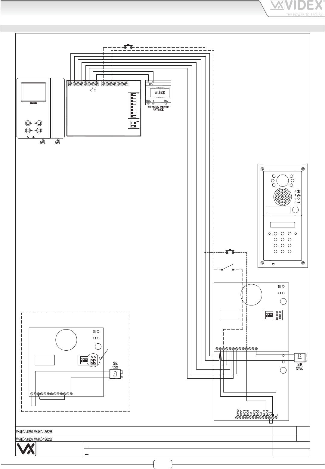
VIDEOKIT VK4KC1/6256, VK4KC1S/6256
Videx Electronics S.p.A.
Via del Lavoro 1, 63020 Monte Giberto (AP)
Phone: +39 0734 631669 - Fax +39 0734 631669
www.videx.it - info@videx.it
Autore:
Data modifica:
Data creazione:Title:
Notes:
Titolo:
Note: Cod.File:
Foglio
/11
Marco Rongoni
vk4k62h-004.dw
g
17/11/2015
17/11/2015
Push to
Exit
Door
Monitor
NC
V2
BS
PTE
SL
V1
2
-
1
12Vout
+V
C
NO
4321
ON
1
Art.4833-1
Using Electric Lock 12Vdc 0.3A Max
Con serratura elettrica 12Vdc 0.3A Max
NC
V2
BS
PTE
SL
V1
2
-
1
12Vout
+V
C
NO
4
3
21
ON
1
Art.4833-1
Art.4800
Affinche qualsiasi modifica alle impostazioni dei dip switch del
videocitofono o del posto esterno venga riconosciuta dal sistema,
è necessario togliere l'alimentazione di rete all'impianto e
restituirla.
In order to make the system recognize any modification of the
videophone's and outdoor station's dip-switch setting temporarily
disconnect the system from the mains and reconnect
Local Bell
12345678 12
ON
Address N.
ON
+V
_
1
2
V1
SB
LD
2A
3A
4A
SW2
SW1
LB
V2
5A
1 Ext.1
Art.6256
66250457-EN - V 3.4 - 31/08/16
23
VK4K/6256 Series “6 wire Bus” videokit
VK4K/6256 Series - Installation handbook
Installation diagrams
VIDEOKIT VK4KC2/6256, VK4KC2S/6256
12
11
Marco Rongoni
vk4k62h-005.dw
g
17/11/2015
17/11/2015
4321
ON
1
Art.4833-1D
Using Electric Lock 12Vdc 0.3A Max
Con serratura elettrica 12Vdc 0.3A Max
NC
V2
BS
PTE
SL
V1
2
-
1
12Vout
+V
C
NO
4321
ON
1
Art.4833-1D
Push
to
Exit
Affinche qualsiasi modifica alle impostazioni dei dip switch del
videocitofono o del posto esterno venga riconosciuta dal sistema,
è necessario togliere l'alimentazione di rete all'impianto e
restituirla.
In order to make the system recognize any modification of the
videophone's and outdoor station's dip-switch setting temporarily
disconnect the system from the mains and reconnect
Local Bell
Local Bell
Art.4800
12345678 12
ON
Address N.
ON
+V
_
1
2
V1
SB
LD
2A
3A
4A
SW2
SW1
LB
V2
5A
1 Ext.1
Art.6256
12345678 12
ON
Address N.
ON
+V
_
1
2
V1
SB
LD
2A
3A
4A
SW2
SW1
LB
V2
5A
2 Ext.1
Art.6256
66250457-EN - V 3.4 - 31/08/16
24
VK4K/6256 Series “6 wire Bus” videokit
VK4K/6256 Series - Installation handbook
Installation diagrams
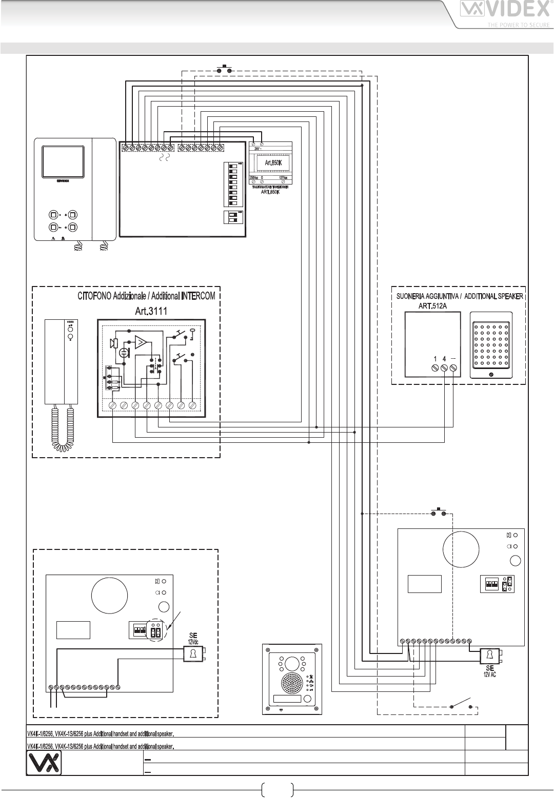
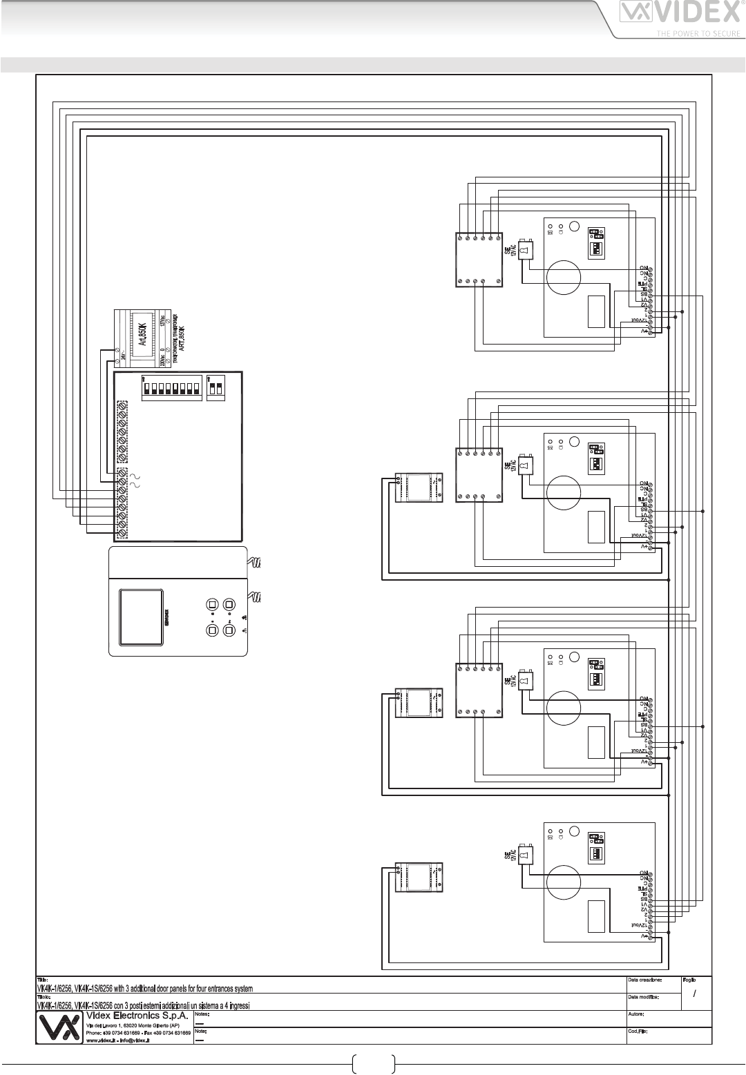
VIDEOKIT VK4K1/6256, VK4K1S/6256 WITH ADDITIONAL INTERCOM AND EXTENSION SOUNDER
Videx Electronics S.p.A.
Via del Lavoro 1, 63020 Monte Giberto (AP)
Phone: +39 0734 631669 - Fax +39 0734 631669
www.videx.it - info@videx.it
Autore:
Data modifica:
Data creazione:Title:
Notes:
Titolo:
Note: Cod.File:
Foglio
/11
Marco Rongoni
vk4k62h-008.dw
g
17/11/2015
17/11/2015
Push to
Exit
Local Bell
Door
Monitor
NC
V2
BS
PTE
SL
V1
2
-
1
12Vout
+V
C
NO
4321
ON
1
Art.4833-1
Using Electric Lock 12Vdc 0.3A Max
Con serratura elettrica 12Vdc 0.3A Max
NC
V2
BS
PTE
SL
V1
2
-
1
12Vout
+V
C
NO
432
1
ON
1
Art.4833-1
Affinche qualsiasi modifica alle impostazioni dei dip switch del
videocitofono o del posto esterno venga riconosciuta dal sistema,
è necessario togliere l'alimentazione di rete all'impianto e
restituirla.
In order to make the system recognize any modification of the
videophone's and outdoor station's dip-switch setting temporarily
disconnect the system from the mains and reconnect
YELLOW
6
BLACK
VOL.REG.
4
RED
93
GREEN
2 1 5 8
12345678 12
ON
Address N.
ON
+V
_
1
2
V1
SB
LD
2A
3A
4A
SW2
SW1
LB
V2
5A
1 Ext. 1
Art.6256
66250457-EN - V 3.4 - 31/08/16
25
VK4K/6256 Series “6 wire Bus” videokit
VK4K/6256 Series - Installation handbook
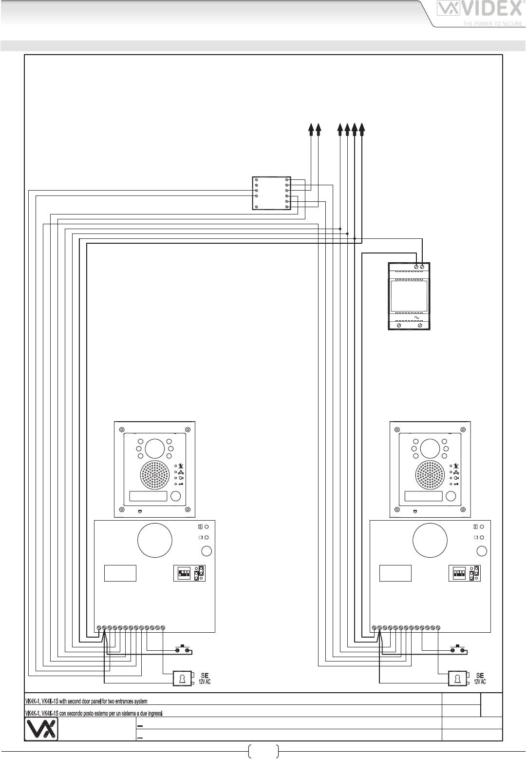
Installation diagrams
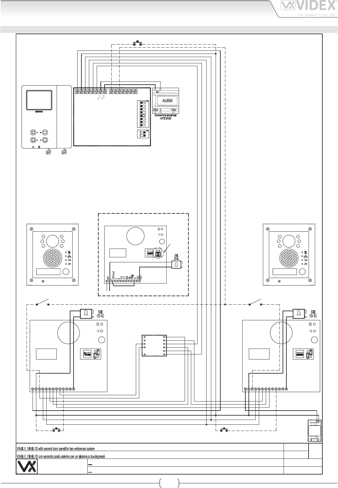
VIDEOKIT VK4K1/6256, VK4K1S/6256 WITH ADDITIONAL DOOR PANEL FOR 2 ENTRANCES SYSTEM
Videx Electronics S.p.A.
Via del Lavoro 1, 63020 Monte Giberto (AP)
Phone: +39 0734 631669 - Fax +39 0734 631669
www.videx.it - info@videx.it
Autore:
Data modifica:
Data creazione:Title:
Notes:
Titolo:
Note: Cod.File:
Foglio
/11
Marco Rongoni
vk4k62h-009.dw
g
17/11/2015
17/11/2015
Push to
Exit
Door
Monitor
Door
Monitor
Push to
Exit
Art.506N
1
4
2
3
5
NC1
C01
NC2
NO1
CO2
NO2
NC
V2
BS
PTE
SL
V1
2
-
1
12Vout
+V
C
NO
4
3
21
ON
2
Art.4833-1
NC
V2
BS
PTE
SL
V1
2
-
1
12Vout
+V
C
NO
4
3
21
ON
1
Art.4833-1
43
21
ON
1
Art.4833-1
Using Electric Lock 12Vdc 0.3A Max
Con serratura elettrica 12Vdc 0.3A Max
Local Bell
Affinche qualsiasi modifica alle impostazioni dei dip switch del
videocitofono o del posto esterno venga riconosciuta dal sistema,
è necessario togliere l'alimentazione di rete all'impianto e
restituirla.
In order to make the system recognize any modification of the
videophone's and outdoor station's dip-switch setting temporarily
disconnect the system from the mains and reconnect
12345678 12
ON
Address N.
ON
+V
_
1
2
V1
SB
LD
2A
3A
4A
SW2
SW1
LB
V2
5A
1 Ext. 1
Art.6256
18Vdc
230V
+-
ART.
323/18
66250457-EN - V 3.4 - 31/08/16
26
VK4K/6256 Series “6 wire Bus” videokit
VK4K/6256 Series - Installation handbook
Installation diagrams
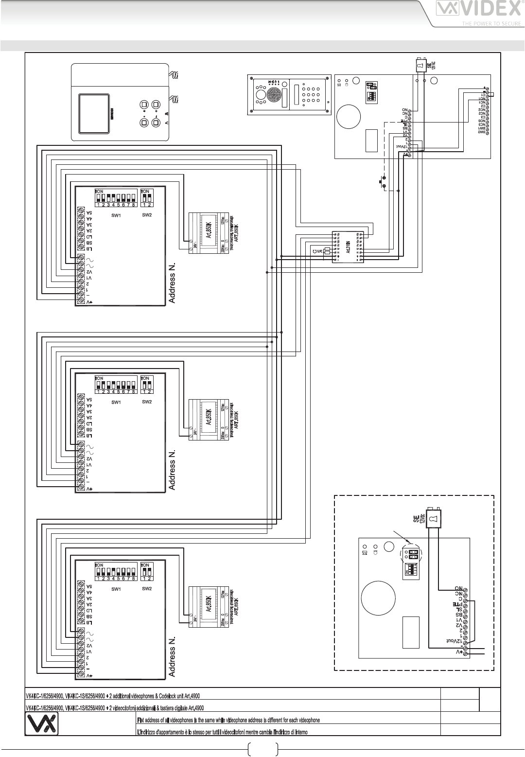
VIDEOKIT VK4KC1/4900/6256 VK4KC1S/4900/6256 WITH 3 ADDITIONAL VIDEOPHONES
Videx Electronics S.p.A.
Via del Lavoro 1, 63020 Monte Giberto (AP)
Phone: +39 0734 631669 - Fax +39 0734 631669
www.videx.it - info@videx.it
Autore:
Data modifica:
Data creazione:Title:
Notes:
Titolo:
Note: Cod.File:
Foglio
/11
Marco Rongoni
vk4k62h-010.dw
g
17/11/2015
17/11/2015
1
Art.4833-1Art.4900
Using Electric Lock 12Vdc 0.3A Max
Con serratura elettrica 12Vdc 0.3A Max
1
Art.4833-1D
Push
to
Exit
Affinche qualsiasi modifica alle impostazioni dei dip switch del
videocitofono o del posto esterno venga riconosciuta dal sistema,
è necessario togliere l'alimentazione di rete all'impianto e
restituirla.
In order to make the system recognize any modification of the
videophone's and outdoor station's dip-switch setting temporarily
disconnect the system from the mains and reconnect
1 Ext. 1
Art.6256
1 Ext. 2
Art.6256
1 Ext. 3
Art.6256
66250457-EN - V 3.4 - 31/08/16
27
VK4K/6256 Series “6 wire Bus” videokit
VK4K/6256 Series - Installation handbook
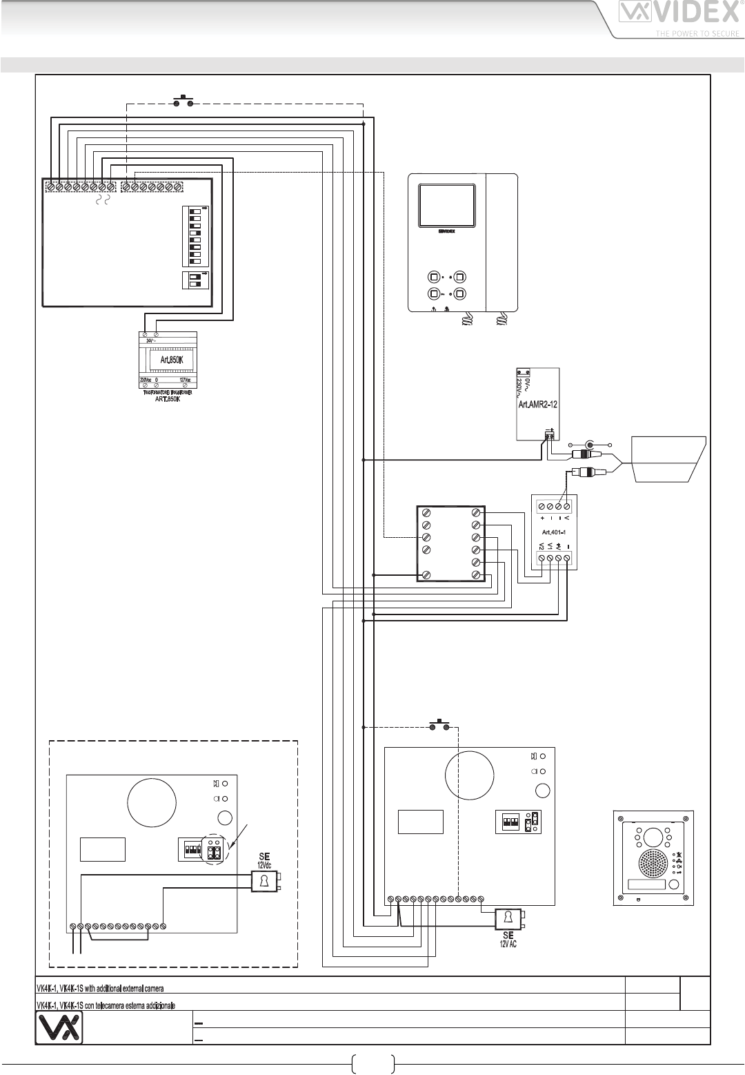
Installation diagrams
VIDEOKIT VK4K1/6256 VK4K1S/6256 WITH EXTERNAL CAMERA CONTROLLED BY SERVICE PUSH BUTTON
Videx Electronics S.p.A.
Via del Lavoro 1, 63020 Monte Giberto (AP)
Phone: +39 0734 631669 - Fax +39 0734 631669
www.videx.it - info@videx.it
Autore:
Data modifica:
Data creazione:Title:
Notes:
Titolo:
Note: Cod.File:
Foglio
/11
Marco Rongoni
vk4k62h-011.dw
g
17/11/2015
17/11/2015
Push to
Exit
NC
V2
BS
PTE
SL
V1
2
-
1
12Vout
+V
C
NO
432
1
ON
1
Art.4833-1
Using Electric Lock 12Vdc 0.3A Max
Con serratura elettrica 12Vdc 0.3A Max
NC
V2
BS
PTE
SL
V1
2
-
1
12Vout
+V
C
NO
4
3
21
ON
1
Art.4833-1
Affinche qualsiasi modifica alle impostazioni dei dip switch
del videocitofono o del posto esterno venga riconosciuta
dal sistema, è necessario togliere l'alimentazione di rete
all'impianto e restituirla.
In order to make the system recognize any modification of
the videophone's and outdoor station's dip-switch setting
temporarily disconnect the system from the mains and
reconnect
NC2
4
C01
NC1
NO1
CO2
1
2
3
Art.506T
NO2
5
+
12Vdc
Coax to
Balanced
video
converter
Power
Supply
Ext Camera
989
Relay
Local Bell
12345678 12
ON
Address N.
ON
+V
_
1
2
V1
SB
LD
2A
3A
4A
SW2
SW1
LB
V2
5A
1 Ext. 1
Art.6256
66250457-EN - V 3.4 - 31/08/16
28
VK4K/6256 Series “6 wire Bus” videokit
VK4K/6256 Series - Installation handbook
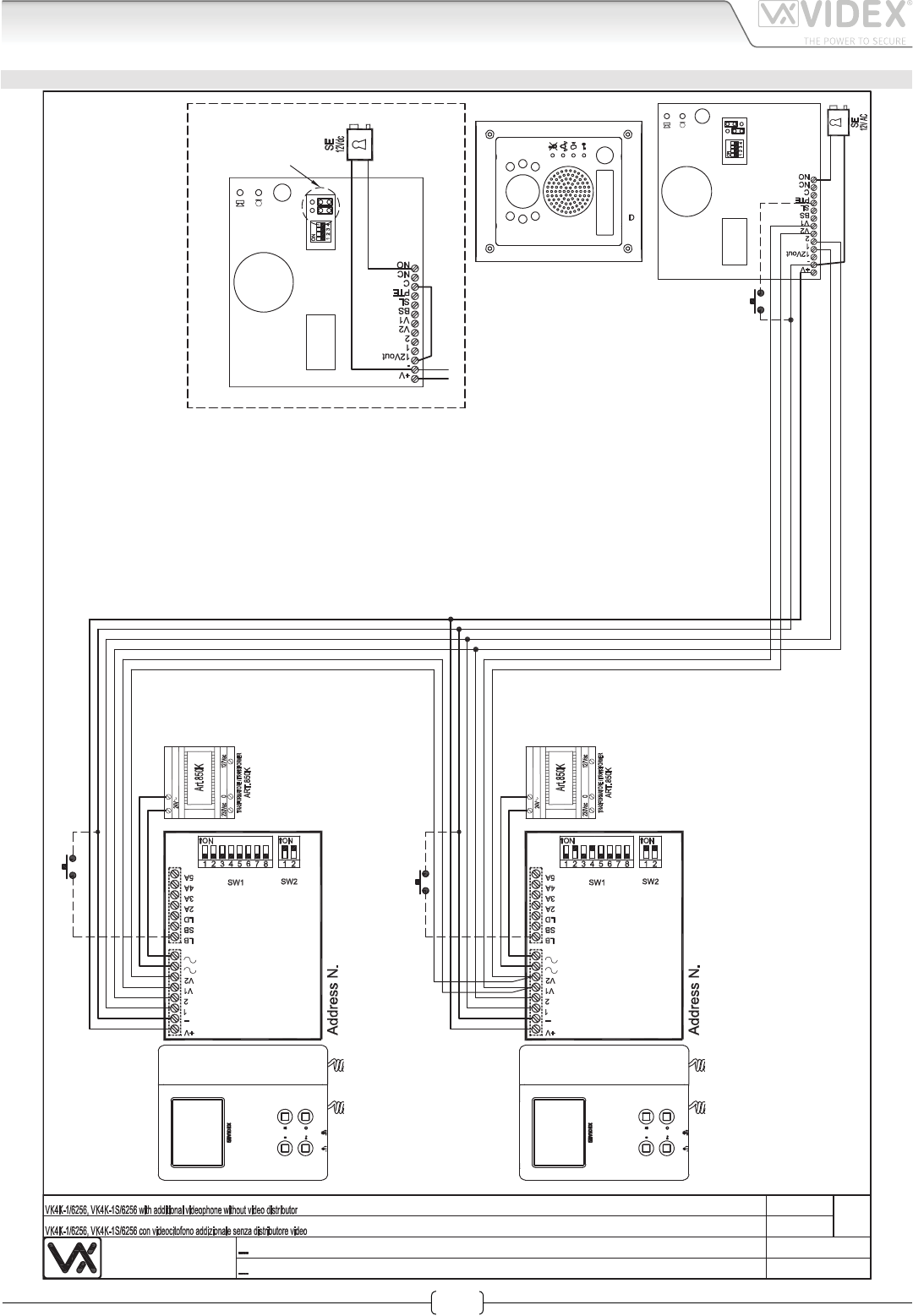
Installation diagrams
VIDEOKIT VK4KC1/6256 VK4KC1S/6256 WITH ADDITIONAL VIDEOPHONE
Videx Electronics S.p.A.
Via del Lavoro 1, 63020 Monte Giberto (AP)
Phone: +39 0734 631669 - Fax +39 0734 631669
www.videx.it - info@videx.it
Autore:
Data modifica:
Data creazione:Title:
Notes:
Titolo:
Note: Cod.File:
Foglio
/11
Marco Rongoni
vk4k62h-012.dw
g
17/11/2015
18/11/2015
1
Art.4833-1
Using Electric Lock 12Vdc 0.3A Max
Con serratura elettrica 12Vdc 0.3A Max
1
Art.4833-1D
Push
to
Exit
1
Affinche qualsiasi modifica alle impostazioni dei dip switch del
videocitofono o del posto esterno venga riconosciuta dal sistema,
è necessario togliere l'alimentazione di rete all'impianto e
restituirla.
In order to make the system recognize any modification of the
videophone's and outdoor station's dip-switch setting temporarily
disconnect the system from the mains and reconnect
Local Bell
Local Bell
1 Ext. 2
Art.6256
1 Ext. 1
Art.6256
66250457-EN - V 3.4 - 31/08/16
29
VK4K/6256 Series “6 wire Bus” videokit
VK4K/6256 Series - Installation handbook
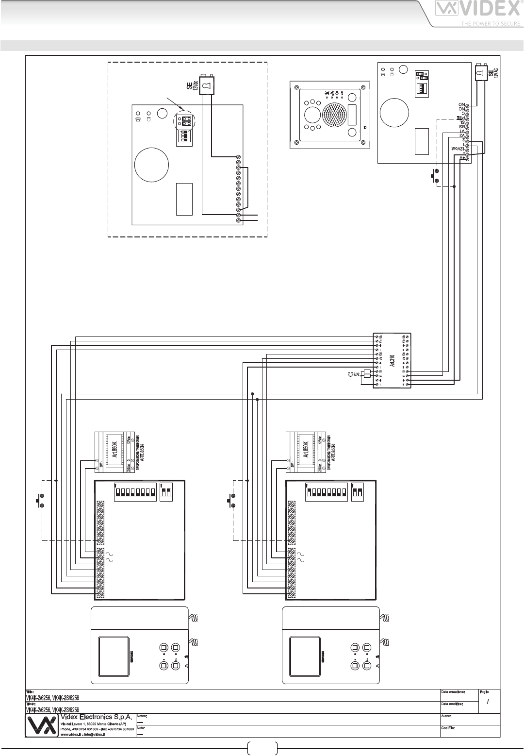
Installation diagrams
VIDEOKIT VK4K2/6256 VK4K2S/6256 WITH ART.316
11
Marco Rongoni
vk4k62h-001.dw
g
21/10/2015
17/11/2015
432
1
ON
1
Art.4833-1D
Using Electric Lock 12Vdc 0.3A Max
Con serratura elettrica 12Vdc 0.3A Max
NC
V2
BS
PTE
SL
V1
2
-
1
12Vout
+V
C
NO
4321
ON
1
Art.4833-1D
Push
to
Exit
12
Affinche qualsiasi modifica alle impostazioni dei dip switch del
videocitofono o del posto esterno venga riconosciuta dal sistema,
è necessario togliere l'alimentazione di rete all'impianto e
restituirla.
In order to make the system recognize any modification of the
videophone's and outdoor station's dip-switch setting temporarily
disconnect the system from the mains and reconnect
Local Bell
Local Bell
12345678 12
ON
Address N.
ON
+V
_
1
2
V1
SB
LD
2A
3A
4A
SW2
SW1
LB
V2
5A
1 Ext.1
Art.6256
12345678 12
ON
Address N.
ON
+V
_
1
2
V1
SB
LD
2A
3A
4A
SW2
SW1
LB
V2
5A
2 Ext.1
Art.6256
66250457-EN - V 3.4 - 31/08/16
30
VK4K/6256 Series “6 wire Bus” videokit
VK4K/6256 Series - Installation handbook
TWO ENTRANCES SYSTEM INSTALLATION
NC
V2
BS
PTE
SL
V1
2
-
1
12Vout
+V
C
NO
4
3
21
ON
2
Art.4833-1
NC
V2
BS
PTE
SL
V1
2
-
1
12Vout
+V
C
NO
4
3
21
ON
1
Art.4833-1
Art.506N
1
4
2
3
5
NC1
C01
NC2
NO1
CO2
NO2
Push to exitPush to exit
+20V
GND
1
2
V1
V2
18Vdc
230V
+-
ART.
323/18
Videx Electronics S.p.A.
Via del Lavoro 1, 63846 Monte Giberto (FM)
Phone: +39 0734 631669 - Fax +39 0734 631669
www.videx.it - info@videx.it
Autore:
Data modifica:
Data creazione:Title:
Notes:
Titolo:
Note: Cod.File:
Foglio
/11
Marco Rongoni
vk4k-1-001-2e.dw
g
29/10/2015
29/10/2015
Installation diagrams
66250457-EN - V 3.4 - 31/08/16
31
VK4K/6256 Series “6 wire Bus” videokit
VK4K/6256 Series - Installation handbook
FOUR ENTRANCES SYSTEM INSTALLATION
11
Marco Rongoni
vk4k62h-013.dw
g
25/11/2015
25/11/2015
4321
ON
1
Art.4833-1
4321
ON
2
Art.4833-1
Art.506N
1
4
2
3
5
NC1
C01
NC2
NO1
CO2
NO2
4321
ON
3
Art.4833-1
Art.506N
1
4
2
3
5
NC1
C01
NC2
NO1
CO2
NO2
4321
ON
4
Art.4833-1
Art.506N
1
4
2
3
5
NC1
C01
NC2
NO1
CO2
NO2
12345678 12
ON
Address N.
ON
+V
_
1
2
V1
SB
LD
2A
3A
4A
SW2
SW1
LB
V2
5A
1 Ext. 1
Art.6256
18Vdc
230V
+-
ART.
323/18
18Vdc
230V
+-
ART.
323/18
18Vdc
230V
+-
ART.
323/18
Installation diagrams

MANUFACTURER
VIDEX ELECTRONICS S.P.A.
Via del Lavoro, 1 - 63846 Monte Giberto (FM) Italy
Tel (+39) 0734 631669 - Fax (+39) 0734 632475
www.videx.it - info@videx.it
CUSTOMER SUPPORT
All Countries:
VIDEX ELECTRONICS S.P.A.
www.videx.it - technical@videx.it
Tel: +39 0734-631669 - Fax: +39 0734-632475
UK Customers:
VIDEX SECURITY LTD
www.videx-security.com
Tech Line: 0191 224 3174 - Fax: 0191 224 1559
The product is CE marked demonstrating its conformity and is for distribution
within all member states of the EU with no restrictions. This product follows
the provisions of the European Directives 2014/30/EU (EMC); 2014/35/EU
(LVD); 2011/65/EU (RoHS): CE marking 93/68/EEC.
Main UK oce:
VIDEX SECURITY LTD
1 Osprey Trinity Park
Trinity Way
LONDON E4 8TD
Phone: (+44) 0870 300 1240
Fax: (+44) 020 8523 5825
www.videx-security.com
marketing@videx-security.com
Northern UK oce:
VIDEX SECURITY LTD
Unit 4-7
Chillingham Industrial Estate
Chapman Street
NEWCASTLE UPON TYNE - NE6 2XX
Tech Line: (+44) 0191 224 3174
Phone: (+44) 0870 300 1240
Fax: (+44) 0191 224 1559
Greece oce:
VIDEX HELLAS Electronics
48 Filolaou Str.
11633 ATHENS
Phone: (+30) 210 7521028
(+30) 210 7521998
Fax: (+30) 210 7560712
www.videx.gr
videx@videx.gr
Danish oce:
VIDEX DANMARK
Hammershusgade 15
DK-2100 COPENHAGEN
Phone: (+45) 39 29 80 00
Fax: (+45) 39 27 77 75
www.videx.dk
videx@videx.dk
Benelux oce:
NESTOR COMPANY NV
E3 laan, 93
B-9800 Deinze
Phone: (+32) 9 380 40 20
Fax: (+32) 9 380 40 25
www.videx.be
info@videx.be
Dutch oce:
NESTOR COMPANY BV
Business Center Twente (BCT)
Grotestraat, 64
NL-7622 GM Borne
www.videxintercom.nl
info@videxintercom.nl
