VORON Assembly And Setup Guide
VORON%20Assembly%20and%20Setup%20Guide
VORON%20Assembly%20and%20Setup%20Guide
User Manual:
Open the PDF directly: View PDF ![]() .
.
Page Count: 43

UNOFFICIAL
Rev 1.1 | December 23, 2016
VORON
Assembly/Setup Guide

2 | P a g e
Table of Contents
Table of Contents ..........................................................................................................................2
Introduction....................................................................................................................................4
List of Changes .............................................................................................................................5
Conventions Used in This Guide...................................................................................................6
Bill of Materials (BOM) ..................................................................................................................7
Frame ........................................................................................................................................7
Linear Motion .............................................................................................................................8
Electronics .................................................................................................................................8
Electronics (Optional) ..............................................................................................................10
Extrusion..................................................................................................................................10
Build Plate................................................................................................................................10
Hardware (KIT4) ......................................................................................................................10
Tools ........................................................................................................................................12
Tools (Optional) .......................................................................................................................12
Printed Components....................................................................................................................13
Component Breakdown ...........................................................................................................13
Component Sources ................................................................................................................15
Electronics Preparation ...............................................................................................................16
Download the Arduino IDE ......................................................................................................16
Download Pronterface .............................................................................................................16
Download and Configure Cura ................................................................................................16
RAMPS Board Setup...................................................................................................................19
Unpack your kit ........................................................................................................................19
Inspect your kit.........................................................................................................................20
Install the jumpers....................................................................................................................22
Trim some pins ........................................................................................................................24
Assemble the RAMPS/MEGA2560..........................................................................................25
Stepper drivers ........................................................................................................................26
Mixing stepper drivers..............................................................................................................28
Power supply inputs and final wrap-up ....................................................................................32
Arduino Setup and Marlin Configuration .....................................................................................34
VORON Build Preparation...........................................................................................................35
Executing the Build......................................................................................................................36
Glossary ......................................................................................................................................37

3 | P a g e
References ..................................................................................................................................38
Resources ...................................................................................................................................39
Acknowledgements .....................................................................................................................40

4 | P a g e
Introduction
Thank you for downloading the unofficial VORON CoreXY 3D printer assembly and setup guide!
This guide was developed with the 3D printing newcomer in mind to ensure better
understanding of the concepts of the printer, regardless of your level of experience.
This guide will walk you through every stage of the VORON setup process, explaining concepts
as they become necessary to understand. It is important that you read each page in its entirety
to ensure that you configure everything exactly as described, especially once you get to the
electronics layout. Failure to follow instructions with electronic components can lead to
catastrophic failure of your equipment, with shorted equipment at best, and electrical
shock/fires at worst.
Take note that the VORON CoreXY 3D printer is an open source platform, under the lead of
Maksim Zolin, and this guide may be outdated by the time you read it. To ensure that you have
the most up to date set of instructions, please visit one of the official VORON sites:
MZBot Website
http://mzbot.us/
VORON Reddit Community
https://www.reddit.com/r/voroncorexy/
VORON GitHub Repository
https://github.com/mzbotreprap/VORON
In addition to these pages, a VORON Facebook group has been started to ensure better
coverage across the community.
This manual will cover VORON up through 1.5. The primary differences between
VORON 1.0 and VORON 1.5 are within the gantry and X-carriage components.
Screenshots used in this manual will be from both macOS and Windows systems. If
the software used on one operating system is laid out substantially different from its
counterpart on another operating system, these differences will be accounted for.

5 | P a g e
List of Changes
Because this is a living document, changes will continue to be made as the VORON evolves
and the community submits improvements/advice.
Date
Change Description
Author
12/23/16
Completed RAMPS Board Setup
Terrance S.
11/26/16
Guide created
Terrance S.

6 | P a g e
Conventions Used in This Guide
Throughout this guide, there will be various icons to indicate helpful tips, as well as cautionary
or warnings to be followed to the fullest extent possible. Where applicable, here are the
meanings behind these indicators:
This is an informational block (e.g., a note), and provides insight to the surrounding
text that you may find useful.
⚠
This is a warning block, and will mention any particular hazards that could be
fatal to your equipment (or yourself), and should be heeded absolutely.

7 | P a g e
Bill of Materials (BOM)
The parts shown here within the bill of materials (BOM) have been copied from those on the
official VORON CoreXY GitHub page. The primary difference here is that these components
have links provided to vendors that will reduce shipping costs and overall wait for the VORON
components. That being said, Amazon is extensively used due to the fact that they have the
vast majority of parts required for the built at relatively competitive prices.
Where possible, links have been provided to the vendor pages for easier ordering. Please
ensure you read the notes, as this BOM has been modified from the official VORON BOM
due to Amazon components being substituted, among other changes/notes.
For the quantities of each of these components, bear in mind that these exact quantities are
required to complete the build. As such, you may want to procure spares of certain items—
screws, DuPont, and MicroFit3 connectors, for example—to ensure that you have more on hand
in the event you make a mistake and damage them.
To reiterate one final time: This BOM encompasses all the parts listed from the official BOM, but
with a heavier lean on Amazon for the procurement of the parts. Bear in mind that some of
these parts may be inferior to those specified in the official BOM; where applicable, user ratings
have been taken into consideration when selecting these components.
Frame
Description
MZBot Part #
Supplier
Supplier Part #
Qty
2020 Extrusion – Black –
370mm
VB-FR-01-
EXT1
Misumi
HFSB5-2020-
370
12
Cube Corner Bracket
VB-FR-01-CB1
*OpenBuilds
Link
8
Cube Corner Bracket
*Misumi
HBLCR5-B
8
As of November 25, 2016, Misumi is offering 30% off all orders within 30 days of
creating your account.
*For the corner brackets, you can opt to use either OpenBuilds or Misumi for the
source. OpenBuilds’ product is roughly $2.00 cheaper in comparison, but their
shipping can also be arguably slower.
You can also opt to have Misumi tap the ends of the extrusions for you. Note that
this option will add a pretty substantial fee on to the extrusions (price of extrusions
without tapping as of this writing: $3.25/ea; price of extrusions with tapping
(selecting Both Ends Tapped (TPW)): $6.85.
Linear Motion
Description
MZBot Part #
Supplier
Supplier Part #
Qty
8 | P a g e
Linear Shaft – 8mm –
Hardened – 320mm
VB-LM-01-LS1
Misumi
PSFJ8-320
8
Linear Bearing (Single)
VB-LM-01-LB1
Misumi
LM8UU
2
Linear Bearing (Double)
VB-LM-01-LB2
Misumi
LMUW8
6
GT2 belt – 6mm x 2mm pitch
1.5M
VB-LM-01-
GTB1
Amazon
Link
2
GT2 pulley – 20 tooth – 2mm
pitch
VB-LM-01-
GTP1
Amazon
Link
2
NEMA 17 Linear Stepper
TR8x8 300mm (with nut)
GB-EL-01-
LSM1
Amazon
Link
2
F695ZZ – Flanged Ball
Bearing
VB-LM-01-
BBF1
Amazon
Link
16
Electronics
Description
MZBot Part #
Supplier
Supplier Part #
Qty
NEMA 17 Stepper
VB-EL-01-SM1
Amazon
Link
2
Arduino MEGA2560 R3
VB-EL-01-AM3
Amazon
1
RAMPS 1.4 SP
VB-EL-01-RSP
Amazon
1
LCD Controller Full Graphics
VB-EL-01-LCD
Amazon
Link
(RAMPS Kit)
1
DRV8825 Drivers (set of 5)
VB-EL-01-DRV
Amazon
Link
1
Endstop Microswitch (KW10
series, hole distance 6.5mm)
VB-EL-01-
ESS1
Amazon
Link
2
12V PSU 16.7A
VB-EL-01-
PSU1
OMC
StepperOnline
S-201-12
1
250V 10A 3pin IEC320 C14
Inlet w/ fuse and switch
VB-EL-01-
ISW1
Amazon
C14
1
Bed Thermistor – M3 Hex
Stud – EPCOS
VB-EL-01-TB1
eBay
Link
1
Bed Harness Connector –
Molex
VB-EL-01-
BHC1
Mouser
538-76650-
0065 (2-pack)
1
Silicone Heater 110V 250W
VB-EL-01-BH1
Omega
SRFG-505/10-P
1
110V SSR – Omron
VB-EL-01-
SSR1
Mouser
653-G3A-210B-
DC5
1
2-pin DuPont jumper wire
(12V supply for Fan
Expansion Board)
VB-EL-01-
FXW1
eBay
Link
1
RAMPS Fan Expansion
Board
VB-EL-01-
RFX1
eBay
Link
1
DuPont Connector Kit
N/A
Amazon
Link
1
Molex MicroFit3 3-pin plug
housing
VB-EL-01-
MLX-H3
Mouser
538-43640-
0301
1
9 | P a g e
Molex MicroFit3 3-pin
receptacle
VB-EL-01-
MLX-R3
Mouser
538-43645-
0300
1
Molex MicroFit3 2-pin plug
housing
VB-EL-01-
MLX-H2
Mouser
538-43640-
0201
7
Molex MicroFit3 2-pin
receptacle
VB-EL-01-
MLX-R2
Mouser
538-43645-
0200
7
Molex MicroFit3 female pin
(20-24AWG)
VB-EL-01-
MLX-FP1
Mouser
538-43030-
0007
4
Molex MicroFit3 female pin
(26-30AWG)
VB-EL-01-
MLX-FP2
Mouser
538-43030-
0010
13
Molex MicroFit3 male pin
(20-24AWG)
VB-EL-01-
MLX-MP1
Mouser
538-43031-
0007
4
Molex MicroFit3 male pin
(26-30AWG)
VB-EL-01-
MLX-MP2
Mouser
538-43031-
0010
13
Spade connector (female)
VB-EL-01-
SPC-F
Amazon
Link
8
Spade connector (male)
VB-EL-01-
SPC-M
Amazon
Link
1
20AWG wire (black) 9’
VB-EL-01-
W20-B
Amazon
1
20AWG wire (red) 9’
VB-EL-01-
W20-R
Amazon
Link
1
20AWG wire (white) 9’
N/A
Amazon
Link
1
20AWG wire (green) 3’
VB-EL-01-
W20-G
Amazon
Link
1
CAT5e stranded patch cable
wire (6’)
VB-EL-01-
CAT5
Amazon
Link
1
80x80x10 case fan 12V
VB-EL-01-
F802
Amazon
Link
1
40x40x20 blower fan 12V
VB-EL-01-
F302
Amazon
Link
1
Inductive Proximity Sensor
VB-EL-01-
IPS1
Amazon
LJ12A3-4-Z/BX
1
2M Ohm resistor (for
inductive sensor)
VB-EL-01-R2M
Amazon
Link
1
USB Cable
VB-EL-01-USB
Amazon
Link
1
C14 Power Cable (US)
VB-EL-01-PC-
US
Amazon
Link
1
⚠
The bed heater in this instance must be suitable to the task. You can use an
alternate supplier for this component, but you must ensure you meet the 110V
250W requirement at a minimum.
Electronics (Optional)
Description
MZBot Part #
Supplier
Supplier Part #
Qty
10 | P a g e
LED strip
VB-EL-01-
LED1
Amazon
Link
1
Thermal protection fuse
(120°C)
VB-EL-01-
TPF1
Amazon
Link
1
Extrusion
Description
MZBot Part #
Supplier
Supplier Part #
Qty
E3D Chimera and/or E3Dv6
Kit
VB-EX-01-
DHK1
Filastruder
Link
1
NEMA 17 Stepper
VB-EL-01-
LSM1
Amazon
Link
2
VORON Belted Extruder –
Bowden
VB-BX-HW-
KIT2
MZBot
(see separate
BOM for parts)
2
Build Plate
Description
MZBot Part #
Supplier
Supplier Part #
Qty
Aluminum tooling plate MIC-
6 9”x9”x0.25”
VE-B-AL-9
Midwest Metal
Warehouse
Link
1
PEI sheet 9”x9”x0.04”
VE-B-PEI-9
Amazon
Link
1
3M 468MP 12”x12”
VE-B-3-M468-
12
Amazon
Link
1
Hardware (KIT4)
Description
MZBot Part #
Supplier
Supplier Part #
Qty
10mm M5 cap socket screw
VB-HW-CSS-
M5-10
McMaster Carr
91239A224
36
30mm M5 cap socket screw
VB-HW-CSS-
M5-30
McMaster Carr
91239A236
6
20mm M3 hex socket screw
VB-HW-HSS-
M3-20
McMaster Carr
91290A123
9
30mm M3 hex socket screw
VB-HW-HSS-
M3-30
McMaster Carr
91290A130
5
40mm M3 hex socket screw
VB-HW-HSS-
M3-40
McMaster Carr
91290A136
2
16mm M3 hex socket screw
VB-HW-HSS-
M3-16
McMaster Carr
91290A120
19
8mm hex socket screw
VB-HW-HSS-
M3-8
McMaster Carr
91290A113
25
12mm hex socket screw
VB-HW-HSS-
M3-12
McMaster Carr
91290A117
2
11 | P a g e
6mm M4 cap socket screw
VB-HW-HSS-
M4-6
McMaster Carr
91239A138
4
M3 hex nut
VB-HW-HN-
M3
McMaster Carr
90591A250
14
M3 hex lock nut
VB-HW-HLN-
M3
McMaster Carr
90576A102
4
M5 hex nut
VB-HW-HN-
M5
McMaster Carr
98676A300
2
M5 steel washer
VB-HW-WST-
M5
McMaster Carr
98269A440
2
No. 6 neoprene washer
VB-HW-WNP-
M3
McMaster Carr
90133A005
16
M3 steel washer
VB-HW-WST-
M3
McMaster Carr
98269A420
4
Plastics screw No. 1 7/16”
VB-HW-PS-1
McMaster Carr
92470A056
4
1” L spring 0.408” OD
VB-HW-SPB-1
McMaster Carr
9657K311
4
M3 pressfit threaded insert
VB-HW-PFTI-
M3
McMaster Carr
94510A030
3
M5 drop-in T-slot nuts
VB-FR-01-
TSN2
Amazon
Link
36
Phillips #10-24 5/8” thread-
rolling screws
VB-FR-01-
PTS1
Fastenal
145017
24
For the thread-rolling screws (VB-FR-01-PTS1): These are for actually connecting
your extrusions together. Note: This is an incredibly time-intensive process and
will require patience and care to avoid damaging the aluminum extrusions.
You can also bypass this requirement by opting to have Misumi tap the ends of the
extrusions for you. Note that this option will add a pretty substantial fee on to the
extrusions (price of extrusions without tapping as of this writing: $3.25/ea; price of
extrusions with with tapping (selecting Both Ends Tapped (TPW)): $6.85.
Yet another option would be to purchase a 10-24 thread tapping drill bit if you own a
drill; this will substantially reduce the amount of effort it requires to complete this
phase of assembly.
Tools
Description
MZBot Part #
Supplier
Supplier Part #
Qty
Ball-end Allen wrenches
Brondhus
1
SuperLube 21030 synthetic
lube with PTFE
Amazon
Link
1


13 | P a g e
Printed Components
In addition to the components outlined in the BOM, you must also obtain the printed
components. MZBot has provided the STL files required for this within the VORON GitHub
repository, and each filename specifies the quantity of parts you will need. Additionally, they are
listed here for completeness.
Within the GitHub repository, you can find these files located within STLs > VORON and STLs
> VORON Belted Extruder. In the event that you want to choose an alternate form of extruder
(for example, a flexible filament extruder, check out the corresponding folder).
Component Breakdown
Part
Part Name
Qty
□
a_idler_lower
1
□
a_idler_upper
1
□
a_motor_mount
1
□
b_idler_lower
1
□
b_idler_upper
1
□
b_motor_mount
1
□
bed_support_carriage_a_x2
2
□
bed_support_carriage_b_x2
2
□
bed_support_carriage_midsection_x2
2
□
belt_clip_x2
2
□
blower_fan_duct
1
□
carriage_end_a
1
14 | P a g e
□
carriage_end_b
1
□
hotend_mount_chimera_bottom
1
□
hotend_mount_chimera_top
1
□
hotend_mount_e3d_v6_x2
2
□
lcd_case-back_cover
1
□
lcd_case-jog
1
□
lcd_case-main
1
□
lcd_case-stop_button
1
□
power_box
1
□
psu_upper_brace
1
□
ramps_case-body
1
□
ramps_case-door
1
□
ramps_case-fan_guard
1
□
spool_holder
1*
□
xy_bearing_retainer_a_x2
2
□
xy_bearing_retainer_b_x2
2
□
xy_idler_block_x2
2
15 | P a g e
□
y_rod_retainer_x2
2
□
z_motor_mount_x2
2
□
z_sensor_mount
1
□
z_shaft_support_lower_x4
4
□
z_shaft_support_upper_x4
4
Component Sources
If you do not already have a 3D printer with which to print these components, you can either go
to a 3D printing service such as 3D Hubs or even check out the RepRapPIF community on
reddit. This community is made up of people that are willing to provide their printer’s time to
forward the 3D printing hobby in exchange for various things, with a roll of filament and cost of
shipping being a recurring theme.
Alternatively, you can touch bases with someone from the VORON community, of course, and
they may be willing to provide their time and printer to help you with this.

16 | P a g e
Initial Preparation
Before beginning assembly, it may be a good idea to test your electronic components to ensure
that the RAMPS assembly and the stepper motors are in good working order. To that end, you
will begin with some initial preparation to ensure that your computer system is in working order
to move forward as you progress through the guide.
Download the Arduino IDE
Arduino is an open-source system that allows you to control physical components through a
computer interface. Before you can do this with your own Arduino MEGA2560 board (a
component of the overall RAMPS assembly), you will need to download and install the Arduino
IDE (Integrated Development Environment).
1. Go to the Arduino IDE download page at https://www.arduino.cc/en/Main/Software.
2. Download the Arduino software for your platform (Windows/Mac/Linux).
3. Once downloaded, install the software; install drivers if prompted to do so.
Download Pronterface
Pronterface is one of many programs that can be used to interface with the control boards in 3D
printers. Though it is not as full-featured as many of the higher end programs, its strengths are
in its expandability, as well as that it is free for use.
1. Go to the Printrun GitHub repository at https://github.com/kliment/Printrun.
2. Scroll down the page until you see “GETTING PRINTRUN”. You will see links to a page
that has the Windows and Mac binaries (executables and their dependencies), as well
as steps for Linux users. Download the binaries and extract them if necessary. You are
done here for now, but remember the location of your Pronterface executable.
Download and Configure Cura
Cura is software developed by the Ultimaker company, creators of a high-end desktop 3D
printer. Cura’s function in the 3D printing space is that of the slicer: a program that takes a 3D
model and “slices” it into the many, many layers that a 3D printer can understand. The output
from a slicer is either sent directly to the printer via wifi or USB connection, or saved as GCode.
1. Go to the Cura download website at https://ultimaker.com/en/products/cura-software/list.
2. Scroll down if necessary and select the most recent version 15 release. As of the time of
this writing, that is version 15.04.6 (released on 06/07/16). Version 2 of Cura brings with
it a lot of extra bells and whistles, but may not work correctly with the provided VORON
Cura profile.
17 | P a g e
3. A window will pop up asking for your usage of the software. You can choose to answer
the question (and its follow-on questions) or you can select “I don’t want to share any
information”. Either way, download the software.
4. Once downloaded, install Cura. During the setup of Cura, one of the options provided is
to install Arduino drivers. Unless you skipped installation of those drivers when you
installed the Arduino IDE, you can skip it (uncheck the option) now.
5. Once installation is completed, go ahead and run Cura to get the basic VORON profile
set up.
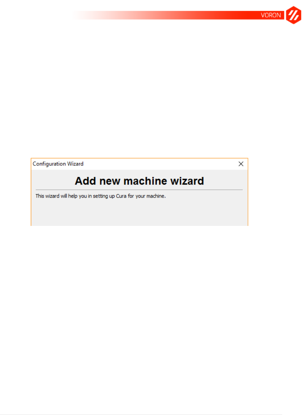
a. One of the first things you should see when you run Cura for the first time is the
Configuration Wizard. If you don’t, cancel out of any window you’re in to access
the main Cura Interface, and select Machine > Add new machine.... You should
see a window that looks similar to the following.
The Cura Configuration Wizard.
b. Click Next.
c. On the Select your machine screen, select Other (Ex:
RepRap/Makerbot/Witbox), and then click Next.
d. On the Other machine information screen, leave Custom... selected and click
Next.
e. Use the following settings in the Custom RepRap Information screen:
Machine Name: VORON
Machine Width X (mm): 230
Machine Depth Y (mm): 230
Machine Height Z (mm): 230
Nozzle size (mm): 0.4
Check Heated Bed

18 | P a g e
Leave Bed center is 0, 0, 0 (RoStock) unchecked (this is used for delta-style 3D
printers; on the VORON printer, the bed center is at 115, 115, 10)
f. Click Finish.
g. This will return you to the main Cura interface. All that remains now is to load the
VORON Cura profile.
i. Download the VORON Cura profile here, or using the following link:
https://syrinathos.com/files/cura_profile.ini.
ii. Back in Cura, click File > Open Profile....
iii. Select the profile you downloaded in step i, and click Open. The VORON
configuration settings are now loaded into Cura for use later.
h. Cura configuration is now complete. You can quit Cura until later.

19 | P a g e
RAMPS Board Setup
Getting your RAMPS (RepRap Arduino MEGA Polulu Shield) board set up is straightforward,
but can seem daunting to first-time 3D printer users. Depending on the route you chose for
sourcing the parts, you may end up needing to perform soldering to get your board up and
running; this is why a RAMPS kit has been recommended for the modified BOM within this
guide.
The photos shown here may reference the A4988 drivers, whereas the VORON
utilizes DRV8825s. So long as you read this portion carefully, you will be able to
follow these instructions for either stepper driver.
⚠
Ensure that you follow the instructions provided here with zero deviation.
Failing to do so could lead to electrical shock, fire, or bodily harm; as well as
(most definite) damage to your electronic components.
Unpack your kit
The first thing that you’ll want to do is unpack your kit (cannot recall how many times I’ve
advocated this route at this point, but it’s the easiest way to get into this path). You should have
the following items:
Specifically, your kit should come with the following items at a minimum:
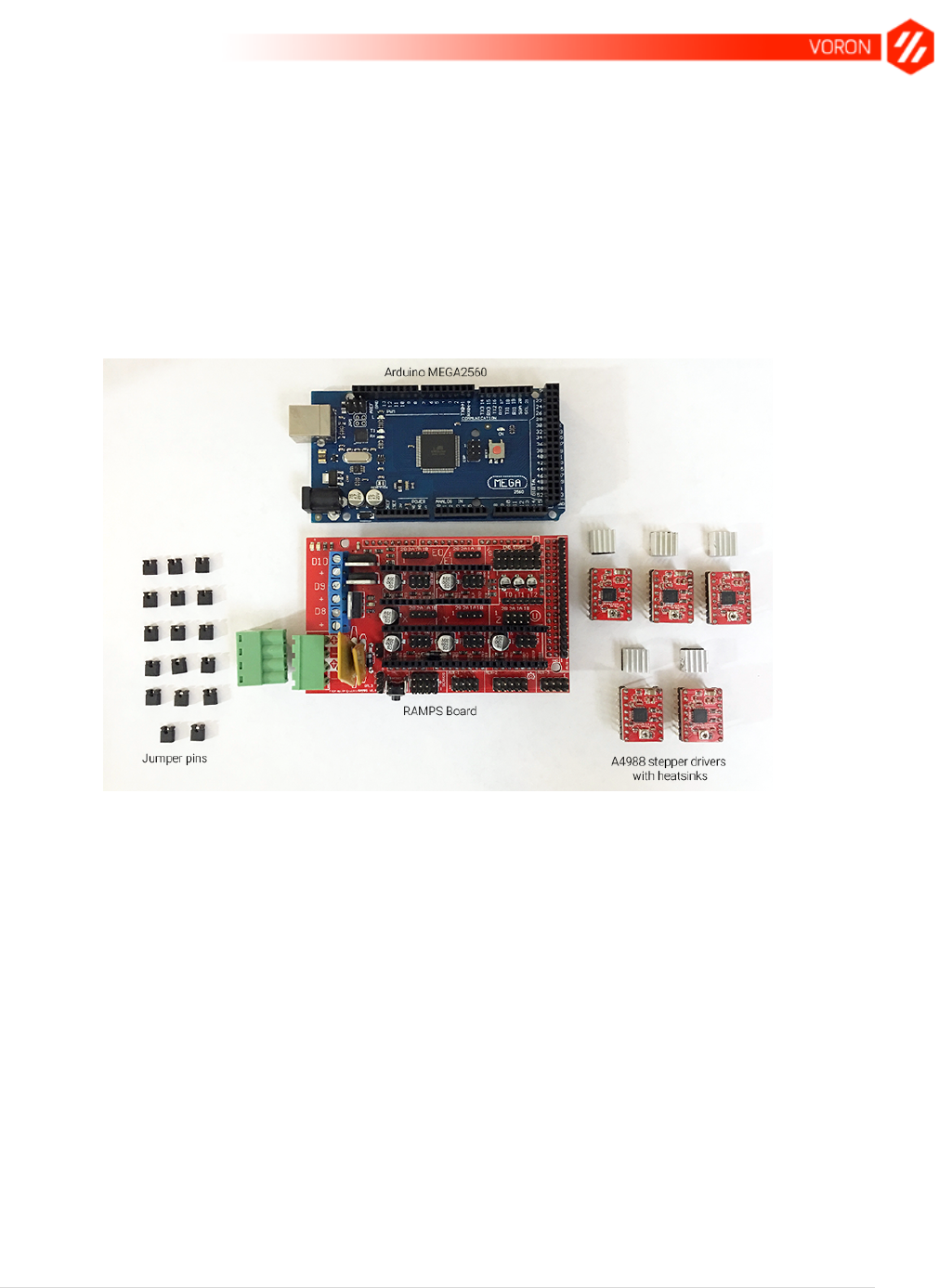
20 | P a g e
RAMPS board (current version in most kits these days is 1.4)
Arduino MEGA2560 board (most kits will sell clones of the authentic Arduino board)
A4988 stepper drivers with heatsinks (5)
Jumper pins (15 is the minimum, you may receive spares)
LCD smart controller with the smart controller adapter and cables
USB A cable (all kits I have purchased have included insanely short cables; I’d
recommend getting your own with at least a 6’ length, but your mileage may vary)
A breakdown of the critical components (minus the LCD controller) are shown below. Make sure
that you familiarize yourself with the terminology, as it’s not going anywhere.
Inspect your kit
The MEGA2560 board will factor very little into the overall assembly process as far as we’re
concerned, but inspect the board and make sure that there are no bent pins/connectors to
ensure you won’t have any issues going forward.
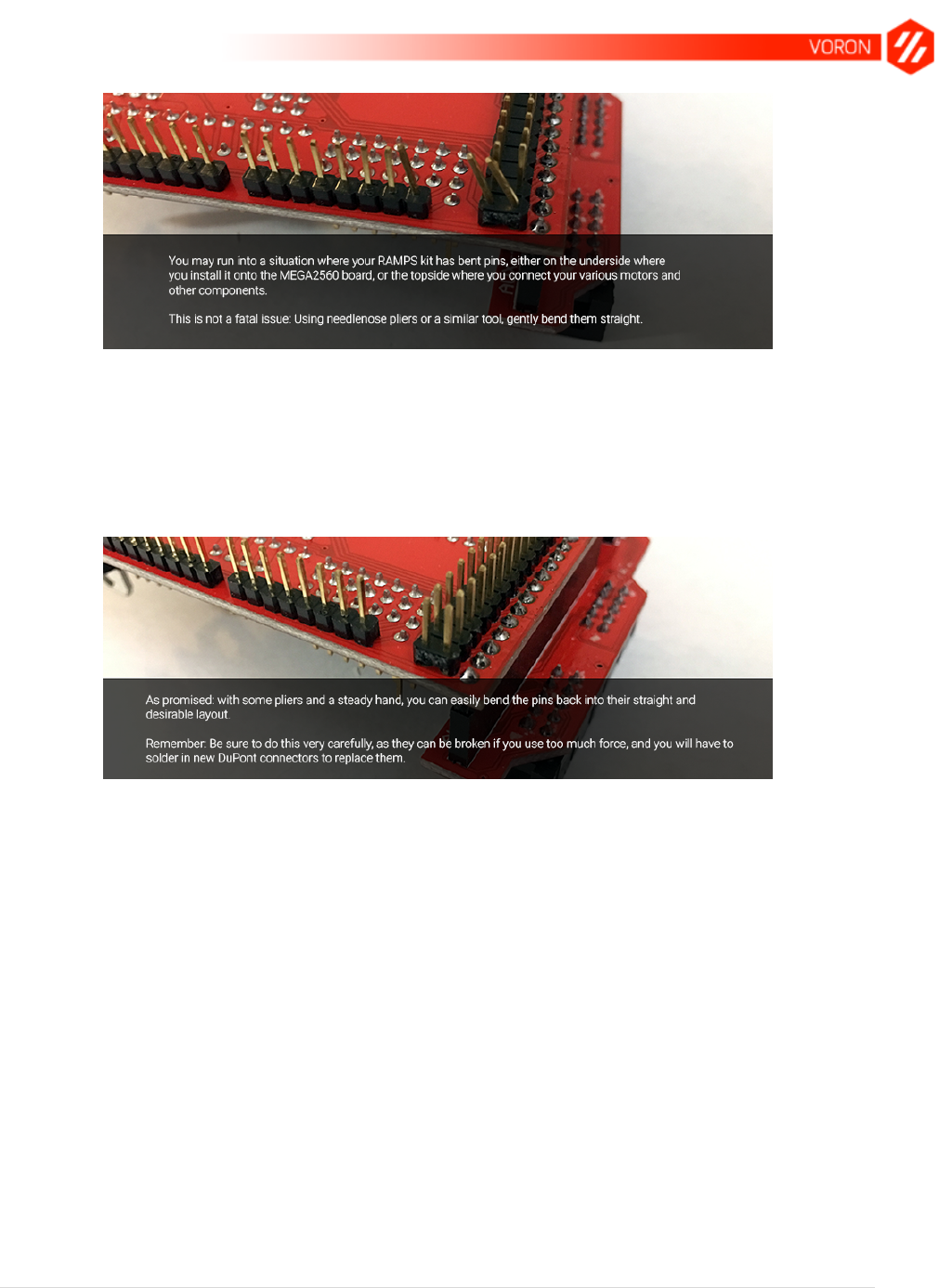
And on the note of inspection, you’ll most definitely want to inspect your RAMPS board itself for
any and all bent pins. It can and does happen, and there’s no real say as to whether that
happens in transit from the vendor to you, or from the manufacturer to the vendor.
21 | P a g e
The positive note here is that the problem is easily remedied with some pliers (I’d recommend
needlenose pliers because… well, they’ve got finer tips and are less likely to bend surrounding
pins as you fix the issue.
Before you proceed any further, look at the actual board itself and familiarize yourself with the
pin assignments. This will become crucial later on when you start installing your stepper motor
drivers.

22 | P a g e
Shown in the photo above, you can see the RAMPS board from the Kuman kit with each
individual section of pins labeled in a pretty minimalist way. Without having to think about it too
hard, though, you can see areas marked off as E0, E1, X, Y, and Z. These are where we will be
installing the stepper motor drivers later on, but for now pay attention to the areas marked 1
through 5.
1. Jumpers for Extruder 0
2. Jumpers for Extruder 1
3. Jumpers for X axis
4. Jumpers for Y axis
5. Jumpers for Z axis
In addition to the jumpers, look at the pin assignments inscribed on the board surrounding each
block. You’ll see words like GND, DIR, and so on. When you go to install your steppers, these
will need to be taken into account to ensure you don’t short your equipment, or hurt
yourself/others. This point will be re-stated throughout this portion of the manual as you
can easily hurt yourself, others, or your damage your electronics.
Install the jumpers
The jumpers you received will need to be installed to set the appropriate step settings for the
stepper drivers that will be installed immediately after. It is important to note that RAMPS boards
are very specifically labeled with regards to what goes where, and this will help immensely for
this and subsequent tasks. For jumper installation, you will want to inspect the RAMPS board
and look at the pins labeled MS1, MS2, and MS3.
23 | P a g e
Depending on the drivers you end up using (either the VORON-recommended DRV8825 or the
kit-included A4988), you will be using a 1/16 microstep setting for your VORON system. The
table below illustrates the jumper settings to use dependent on your driver selection:
Driver
MS1
MS2
MS3
A4988
Yes
Yes
Yes
DRV8825
No
No
Yes
TMC2100
No
No
No
As each jumper can cover a maximum of two pins, a Yes shows that you will install a jumper
covering both pins for either MS1, MS2, or MS3, whereas a No indicates that you will not install
a driver in that slot.
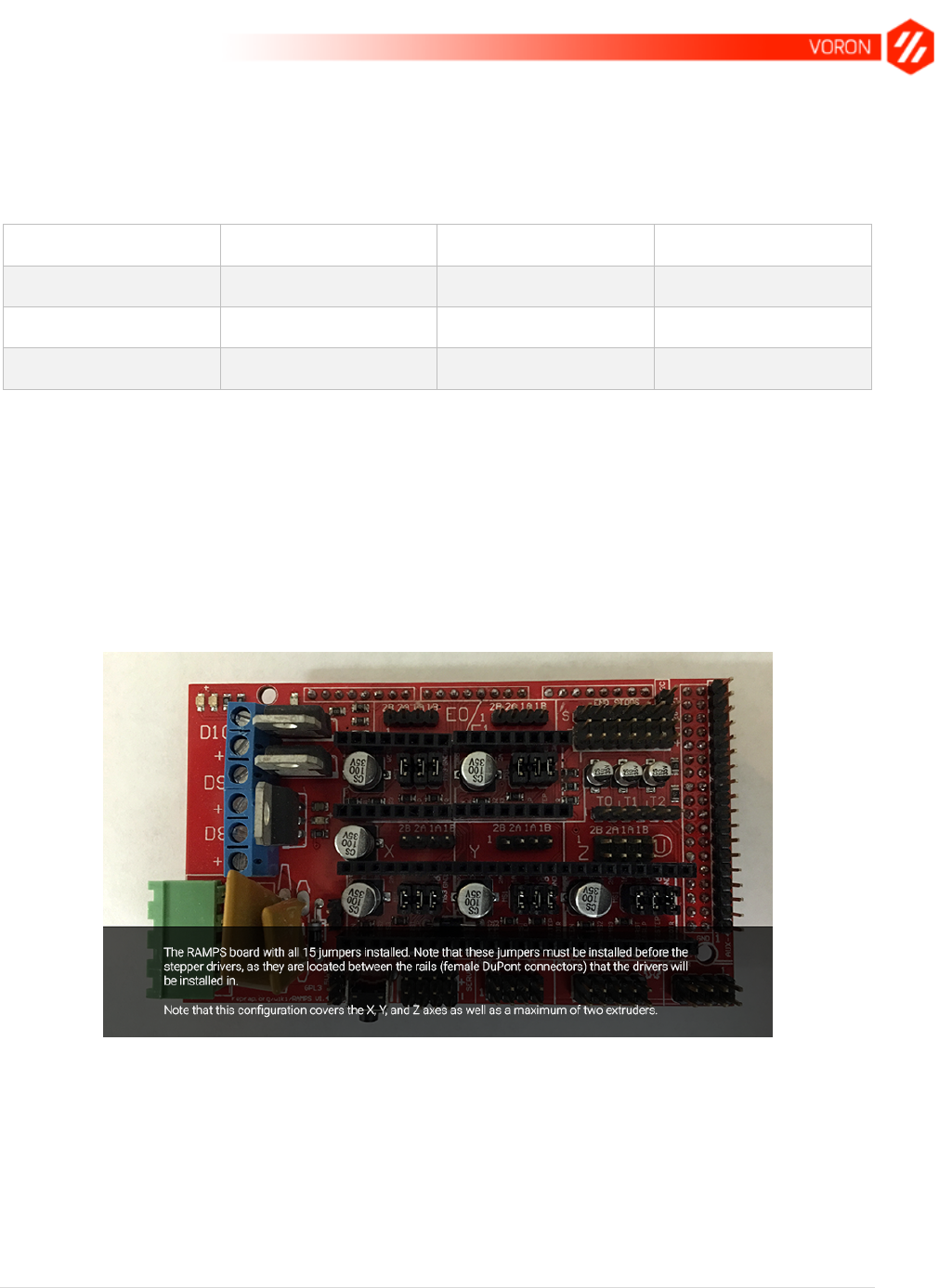
That aside, let’s go ahead and take those jumpers and install them in place. Remember, you’ll
be using 5 of them in total across the five areas shown in the last photo (1 jumper per area).
When it’s all said and done, you should have something resembling the following:
This illustration depicts the jumper settings when using a DRV8825 stepper driver in
slot E0. Refer to the preceding chart for the jumper settings for the stepper drivers
you selected to use for your build.
Using the depicted jumper settings when using a DRV8825 driver will
configure that driver for 1/32 microstepping, which will require you to double
the step values within Marlin’s Configuration.h file later on.
24 | P a g e
Trim some pins
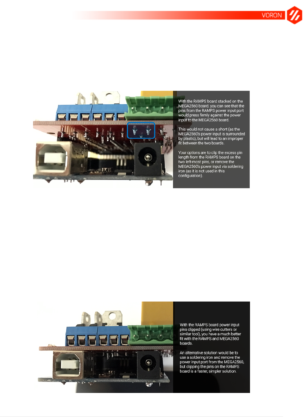
Next up is installing the RAMPS board onto the MEGA2560. Before you can do this, though,
there is a concern worth note: the power supply pins from the RAMPS board run a bit long on
one side and end up causing issues with proper seating between the two boards:
As stated in the above illustration, you have two options that you can pursue and both are
completely viable:
You can clip the longer pins so they don’t prevent proper seating of the boards.
You can remove the MEGA2560 power input connector since you won’t be using it.
Of the two options, it is recommended to clip the connectors: This way you can reuse the
MEGA2560 board for other purposes down the road without having to re-solder the power
connector should that become a requirement. What’s more: most people will have something
they can use to clip the pin excess (e.g., nail clippers, wire cutters, etc.) than are likely to have a
soldering iron.
Once your pins have been clipped, you will have something resembling the following:
Clipped pins on the RAMPS board leads to a substantially better fit.
25 | P a g e
That photo was a bit out of order with the flow of things, but I wanted to show what the boards
should look like from that end before proceeding.
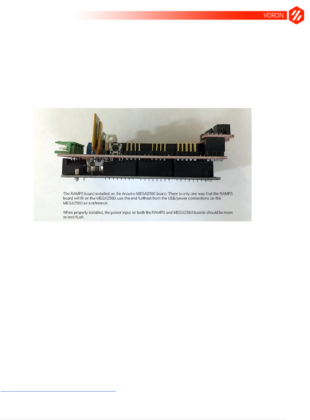
Assemble the RAMPS/MEGA2560
With your pin issue resolved (regardless of which route you chose), you can now sandwich the
boards together and have the following setup:
The stacked RAMPS/MEGA 2560 assembly.
As you can see in the photo, both boards are installed correctly with the closest fit possible
between the male DuPont connectors of the RAMPS board and the female DuPont receptacles
of the MEGA2560. As stated earlier, there’s only one way for these two boards to fit together
(correctly, that is); as long as you use the end opposite the power supply end as a guide, you’ll
be good to go.
Also remember that single button that you see next to the DuPont connectors: that’s your
emergency reset button, and in the event that your print goes horribly awry or your carriage
decides to crash through the build plate on what should be a routine maneuver, you’ll be able to
stop the evolution immediately.
With the RAMPS/MEGA2560 assembly complete, we can move on to the final parts of the
puzzle: the stepper drivers. Before we actually install them on the board, though, we’re going to
look at the differences between the top two drivers in use these days: the A4988 and the
DRV8825 drivers (used in the VORON).
Stepper drivers
Stepper drivers are the components that actually drive the stepper motors. Specifically,
RepRap.org has this to say about them:
26 | P a g e
“These chips keep the power that drives the motors separate from the power that is on the
arduino. The arduino can't provide enough juice to power the stepper motors directly. This is
why you have to use separate chips to sort of act as valves that control how the motor spins.”
As mentioned before, there are two drivers that are predominantly used in 3D printing with
RAMPS: the A4988 and DRV8825 drivers.
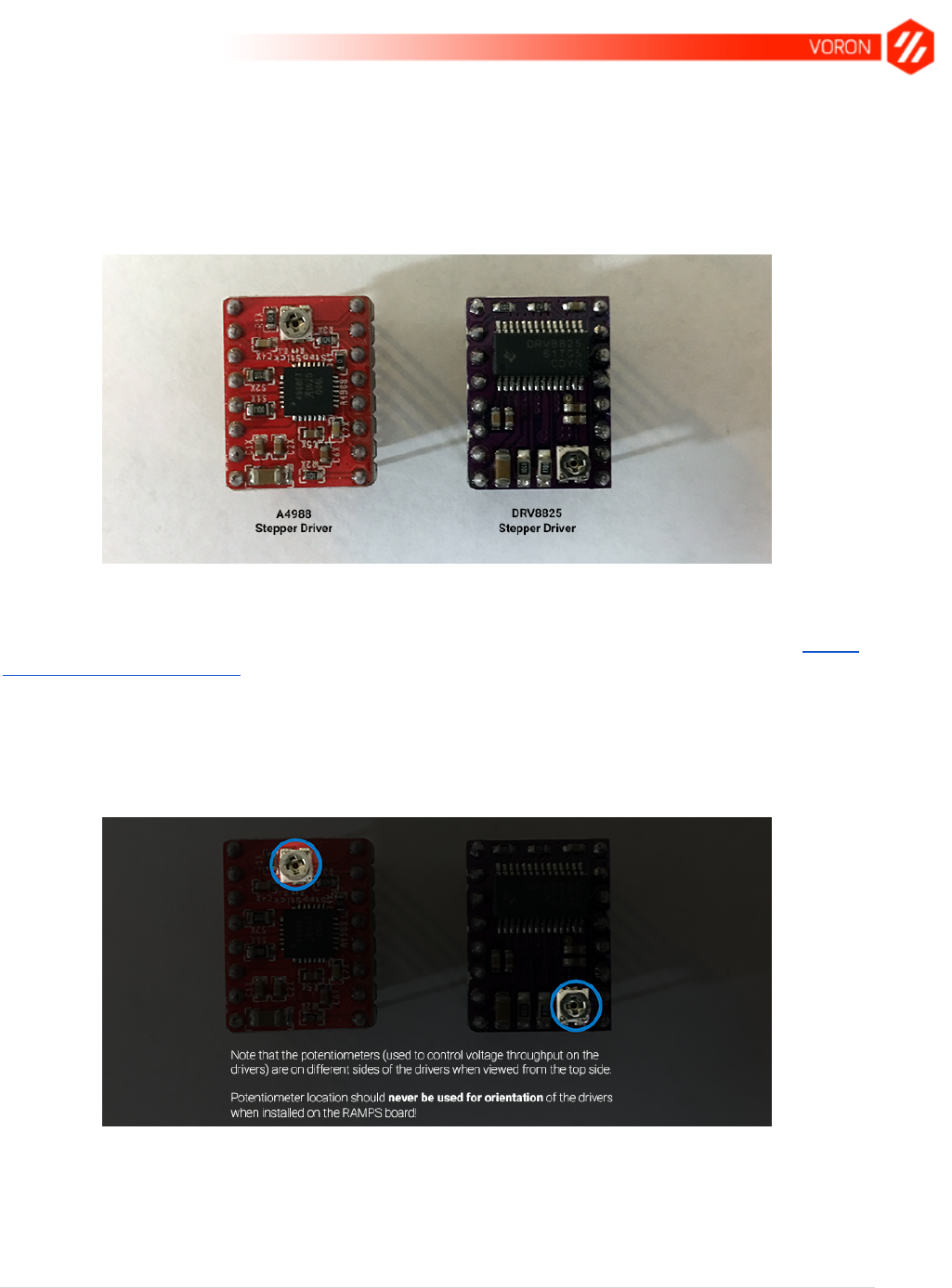
The A4988 and DRV8825 stepper drivers.
The primary difference between these two driver options is in how precisely they can control
your stepper motors, as well as how quietly they operate. You can find more information on the
RepRap comparison page, but in summary: the DRV8825 will give you much finer control over
the microsteps that your motors can make.
The important takeaway from the above illustration is that the orientation of the drivers is
intentional. The potentiometer (the metal disc with a Phillips indentation) is actually flipped on
these two drivers, as highlighted here:
Potentiometer location on the A4988 (left) vs the DRV8825 (right).
The reason that this distinction is made (here and many times throughout this section of the
guide) is because there are instructions available online that use the potentiometer as a means
of orienting the stepper drivers on the RAMPS board. And though this (usually) works for the
27 | P a g e
A4988 driver, using this point of reference with the DRV8825 driver instead will lead to
disastrous consequences.
Though the writing is tiny, you can easily make out on the RAMPS board which pins go where,
and with the DRV8825, you actually flip the orientation of the potentiometer. Bear in mind that
this is also a sweeping generalization, and you are highly recommended to read the pin
assignments inscribed on the drivers and RAMPS board you have on hand.
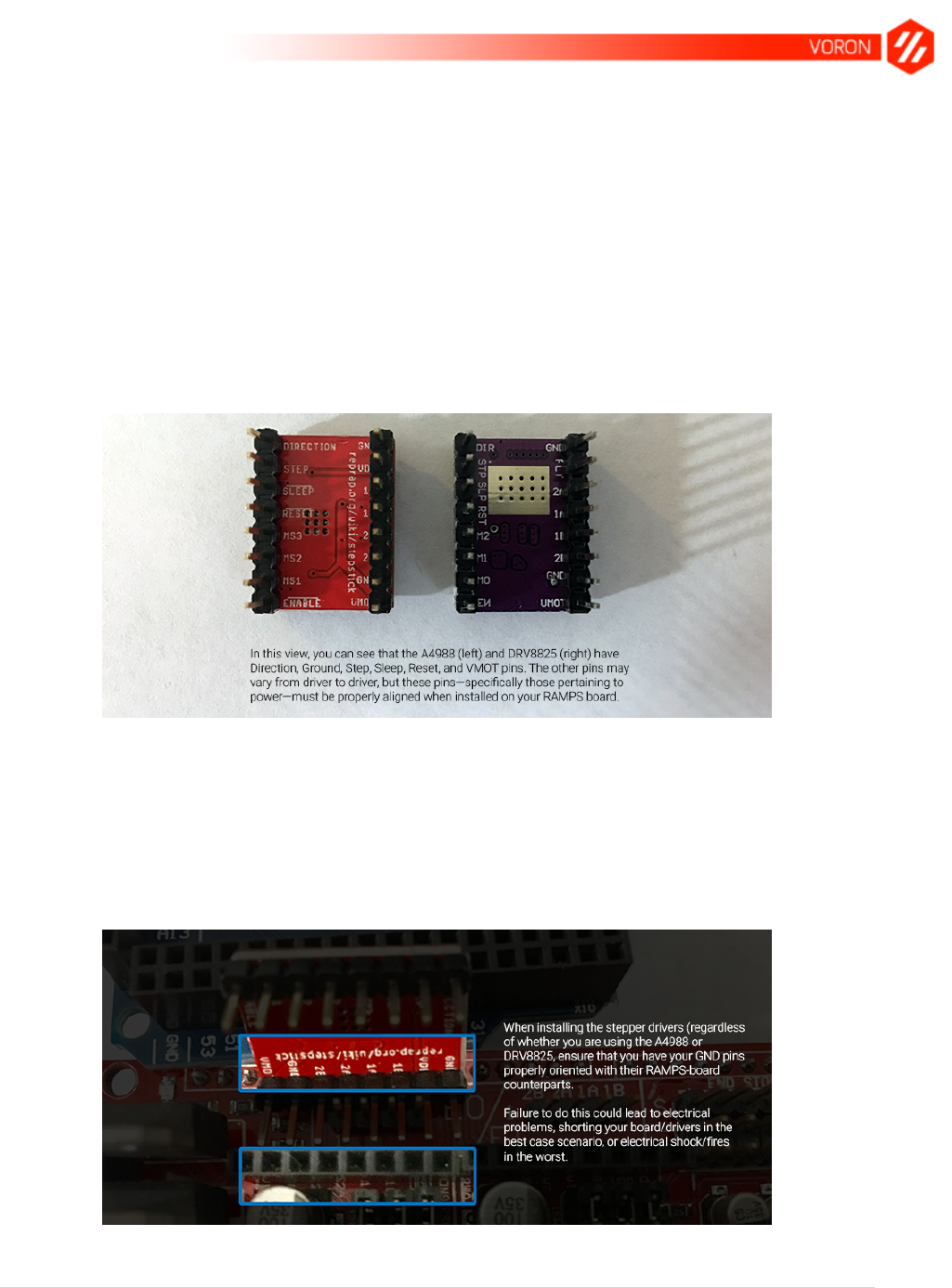
This may not seem like such a big deal at first, but if you flip those same drivers over, you’ll see
that even with the potentiometers on different sides, we have nearly the same pin assignments
underneath:
A4988 (left) vs DRV8825 pin assignments when flipped over (potentiometers on opposite ends).
Though there are some slight differences between the inscribed pin assignments, they are the
same where it counts. The DIR and GND pins along the top edge are identical, as well as the
STEP, SLP, and RESET pins on the left edge, and ENABLE and VMOT pins along the bottom
edge; as well as the other GND pin just above the VMOT pin.
If you opt for the standard A4988 setup, you can install it on the board like so:
The A4988 (above) and RAMPS board (below) showing proper alignment.

28 | P a g e
Or if using the recommended DRV8825 stepper drivers:
The DRV8825 driver (above) properly lined up with the RAMPS board (below).
Whichever stepper driver you choose, make sure that you find a point of reference on the driver
and line it up with the correct pins on the board. Double, triple, and quadruple check that
these match before supplying power to the board. If it seems like I’m overkilling this
particular warning, well… deal with it. Or skip past it; it’s really your call, but after spending more
money than I needed to because I wasn’t paying attention, I’m trying to do you a solid here.
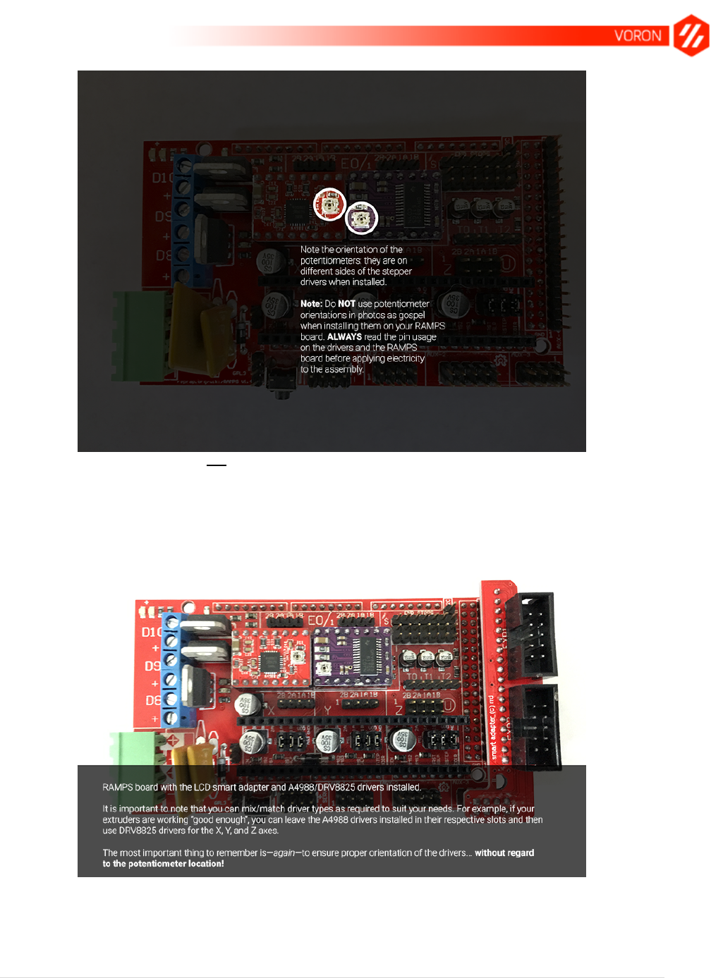
Mixing stepper drivers
Also worth mentioning is that you can, in fact, mix different stepper drivers on the same board.
Just make sure that you don’t let the potentiometers trick you into installing one or more of them
on backwards:
29 | P a g e
Do not use potentiometers as an orientation aid.
Go ahead and grab your LCD controller smart adapter and install it on the board (again, it can
only fit one correct way), and you should see something somewhat similar to this:
LCD controller smart adapter and A4988/DRV8825 drivers installed.
Once again, notice that the potentiometers are on opposite ends of the drivers. A closeup of the
LCD controller smart adapter installed:
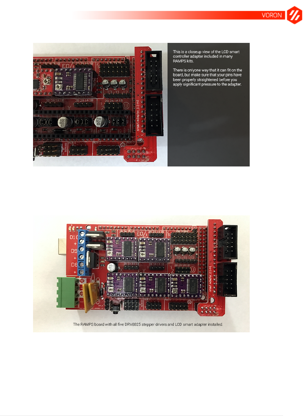
30 | P a g e
Closeup view of the LCD controller smart adapter installed on the RAMPS board.
Back to the actual drivers, you should end up with something similar if you went with DRV8825
drivers:
All five DRV8825 drivers installed on the RAMPS board.
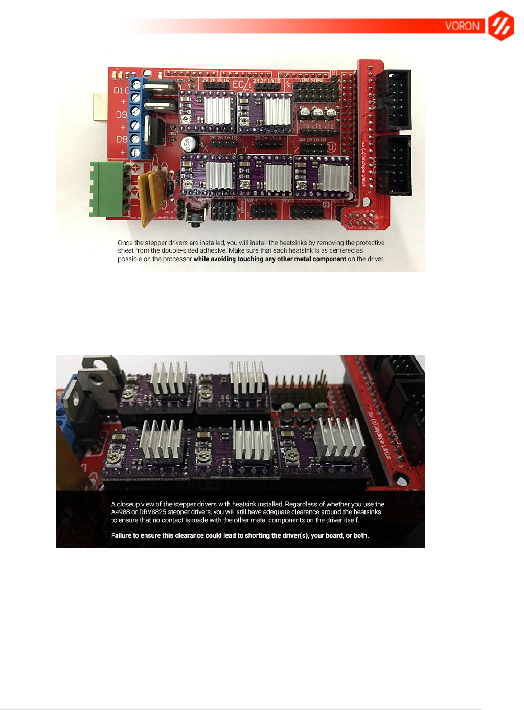
We’re almost done with the drivers; all that remains now are the heatsinks. These are the small
pieces of aluminum with the 3M double-sided adhesive, and you’ll mount them to the chips on
the driver boards as shown:
31 | P a g e
DRV8825 drivers with heatsinks installed.
As mentioned in the photo above, it’s important to ensure that the heatsinks do not make
contact with any other metal components of the driver:
They are somewhat large pieces compared with the chips on the drivers, but in my experience,
you will always have sufficient clearance on all edges without contacting any other part of the
driver. This becomes a bit more difficult if the heatsink(s) you received had double-sided foam
adhesive as opposed to just a typical “sticker-type” adhesive, but do your best to work with what
you have.
32 | P a g e
Power supply inputs and final wrap-up
That’s actually it for the RAMPS assembly. Everything else is relatively plug-and-play with
regards to your connections to your motors and other components, but before we move on to
the software, let’s take a closing look at the power inputs/outputs.
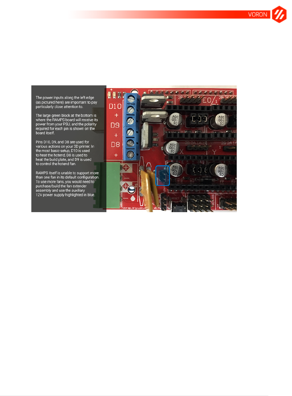
A quick and dirty breakdown of the power supply situation on your RAMPS board.
On the left edge of your RAMPS board (as shown above), you have all the power inputs that
you’ll need to concern yourself with for a RAMPS-enabled 3D printer.
The large green block is the power input from your Power Supply Unit (PSU), and will not be
covered in this section of the guide.
Pins D10, D9, and D8 are actually assigned within Marlin (and can be reassigned as needed),
and provide the actual power output to the different components of your 3D printer. Specifically,
however, these are what the different pins/receptacles provide on your standard RAMPS
configuration:
D10 is used to provide power to the hotend (that is, the part that melts the plastic
filament)
D9 is used to power your hotend’s cooling fan to help reduce the chance of a
nozzle/hotend clog
D8 is used to provide power to the build plate (that is, the platform onto which plastic is
extruded)
Though the assignments above are for RAMPS configurations for many other
printers, VORON utilizes pins D10 and D9 for each individual hotend (when using
the Chimera for dual extrusion) and D8 for the RAMPS case fan. The build plate for
the VORON will receive its power from the SSR, external to the RAMPS board.

33 | P a g e
In addition to the pins discussed here, the illustration also shows the pins used for the auxiliary
12V power source that will be used by the RAMPS fan extender board during the later build
section of the guide.

34 | P a g e
Arduino Setup and Marlin Configuration
Introduction
This section of the guide will walk you through the setup and configuration of Arduino and
Marlin. If you are new to 3D printing, it is recommended that you read through this section in its
entirety before committing to the steps given.
For those that are new to 3D printing: Arduino is an open-source framework that allows for the
control of physical devices. When paired with your RAMPS board, it is the primary driving force
behind everything that your 3D printer actually does.
To go along with your Arduino and RAMPS board is the software: Marlin is the firmware being
used (default recommendation) for the VORON due to its robust feature set and ease of use.
Currently, the version that is supported by the VORON community as of December 23, 2016 is:
Marlin v1.1.0 RC8
This can be downloaded on its GitHub repository.
Getting it Done
1. Go to the Marlin GitHub repository and download the latest VORON-supported version
of Marlin (from the link provided, click Clone or download > Download ZIP). Extract the
files and navigate to the Marlin folder (you should see around 76 files or so, including
Configuration.h and Configuration_adv.h).
2. From the VORON repository’s Marlin-VORON folder, copy and paste the files below into
the folder you’re in from step 1:
a. Configuration.h
b. _Bootscreen.h
c. pins.h
d. pins_RAMPS_VORON.h
e. ultralcd.cpp
3. Using the USB cable provided in your RAMPS kit, connect your RAMPS board to your
computer (you don’t need to have power supplied to the board via the PSU; your
computer will provide all you need for this step) and launch the Arduino IDE you installed
earlier by double-clicking the Marlin.ino file within the Marlin firmware directory you
unzipped the firmware to earlier (step 1).
35 | P a g e
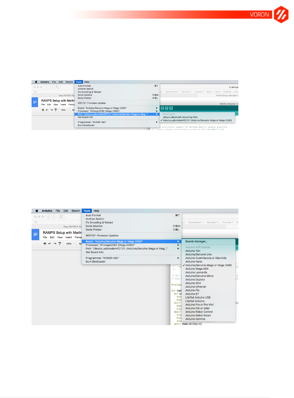
4. Before doing anything else, you’ll need to configure the Arduino IDE to know which port
and board you’re working on. For the RAMPS setup I recommended, these are the
options you’ll choose for the port: Select Tools > Port > Port, where Port is the port
being used by your operating system to detect your printer. When selecting your port,
Arduino may automatically show you the specific type of board it has picked up on any
given port.
You’ll want to choose the port that specifically lists your Arduino board; in this case, the MEGA 2560.
a. Take note that Windows doesn’t necessarily tell you what’s running on a port, and
will be represented by COMX, where X is any given port number available to
Arduino.
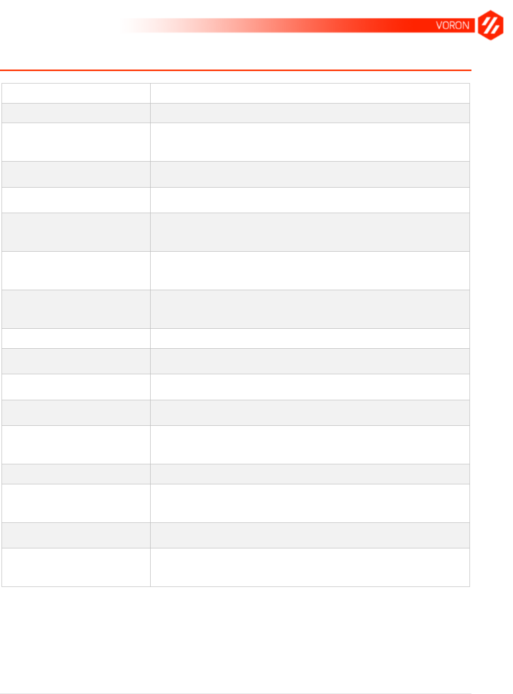
5. And then the board. Select Tools > Board > Board, where Board is the particular board
you will be using for your setup. For this manual’s purposes, Arduino/Genuino Mega or
Mega 2560 is the board type to select.
Select the Arduino/Genuino Mega or Mega 2560 option.
6. From here on out, you’ll only need to worry about two parts in the Arduino interface:
Verify and Upload. Verify is shown in the following screenshot as a checkmark, and
Upload as the right-facing arrow.

36 | P a g e
The Arduino IDE interface.
7. The other part of note for Arduino is the multitude of tabs at the top. Arduino source code
is collectively saved as a “sketch file”, with the .ino file extension. When uploading the
Marlin firmware, you may get an error at one point or another where it says that the file
must be located within a directory named Marlin. If you get this, cancel the upload and
rename the root directory (that is, the directory with Marlin.ino, Configuration.h,
Configuration_adv.h, etc.) to Marlin and try again.
8. Back to the tabs: Each tab represents a specific file within the Arduino sketch. You can
see in this screenshot that the tabs spill off the edge of the window, but you’ll also see
that there’s a downward-facing arrow on the very right. Clicking this will give you a
scrollable menu of all the tabs/files in your sketch:
There are many files in your sketch, but they’re all within reach.
9. Click the Upload button in Arduino to upload your settings to your board. If everything is
configured properly, you should be good to go with a decent baseline.
Again, please note: This guide and the provided files assumes you’re running an Anet A8 3D
printer. Though the A8 is just one of many Prusa i3 clones on the market today, there are
differences in builds (mostly the build sizes and offsets which must be taken into account within

37 | P a g e
your Configuration.h file), and if they’re not properly addressed can lead to some horrendous
noises at best, and damaged hardware at worst.

38 | P a g e
VORON Build Preparation
Before commencing with the build, take the time to go through and verify that all of your
components have been sorted out. As mentioned in the BOM section, the BOM itself as it
stands with regards to quantity is very exact, and as such, is very unforgiving.

39 | P a g e
Executing the Build
This portion of the manual is currently under construction. Please refer to the official VORON
Manual within the GitHub repository for assembly instructions.
40 | P a g e
Glossary
Term
Definition
Build plate
See also Heatbed
Cartesian (Printer)
A Cartesian printer is one in which the X, Y, and Z axes are all
mapped out in a logical means and are moved via stepper
motors to build the 3D model
Control board
The “motherboard” of a 3D printer that accepts and performs
commands send to it via control/slicing software
Control software
Software used to send commands to the 3D printer for
execution (e.g., Pronterface)
CoreXY
A unique take on the typical Cartesian 3D printer platform
where the Z axis moves vertically as opposed to horizontally.
The VORON is a CoreXY system
FDM
Fused Deposition Modeling is a trademarked term for the
process used by most consumer-grade 3D printers that create
prints via melting filaments.
FFF
Fused Filament Fabrication is an alternative term for the
process used by most consumer-grade 3D printers that create
prints via melting filaments.
GCode
The instruction code send to 3D printers for execution
Heatbed
The headed area where the melted filament is extruded, layer
by layer, to build the model
Hotend
This is the part of a 3D printer that melts the plastic filament for
extrusion
Slicer
Software used to “slice” a provided 3D model into various
layers that can be used by the 3D printer
Stepper driver
An electronics board used to control the flow of current to the
stepper motors to accurately position the printing components
of the printer
Stepper motor
The actual motors used to move about the X, Y, and Z axes
STL (File type)
STL files are the common de facto standard used for 3D
models available from model repositories such as Youmagine,
Pinshape, and Thingiverse
STL (Process)
Stereolithography is a 3D printing process which involves the
curing of resin in various layers for creating 3D prints.
RAMPS
RepRap Arduino MEGA Polulu Shield is the collective term
used to describe the control board for many community-
sourced 3D printers


42 | P a g e
Resources

43 | P a g e
Acknowledgements
Primary thanks, of course, goes to Maksim Zolin for his incredible work on the VORON CoreXY
printer system. As well, all the contributors of the RepRap community as a whole are to thank
for their dedication and hard work.
