VS1SDManual
User Manual: VS1SDManual
Open the PDF directly: View PDF ![]() .
.
Page Count: 192 [warning: Documents this large are best viewed by clicking the View PDF Link!]
- Table of Contents
- Chapter 1 - Introduction
- Chapter 2 - General Information
- Chapter 3 - Installing the Drive
- Chapter 4 - Power Wiring
- 4.1 Grounding the Drive
- 4.2 Line Impedance
- 4.3 Line Disconnect
- 4.4 Protective Devices
- 4.5 Reduced Input Voltage Considerations
- 4.6 Electrical Installation
- 4.7 Optional Filter/Reactor
- 4.8 Incoming Power and Motor Connections
- 4.9 Operating a 3-Phase Control on Single Phase Input Power
- 4.10 3-Phase Motor Connections
- 4.11 Strain Relief (Mounted at Terminal Box)
- 4.12 Brushless Servo Motor Identification
- 4.13 External Trip Input
- 4.14 Resolver Installation
- 4.15 Optional Dynamic Brake Hardware
- 4.16 Home (Orient) Switch Input
- Chapter 5 - Control Wiring
- 5.1 Control Board Connections
- 5.2 Analog Inputs
- 5.3 Analog Outputs
- 5.4 Opto-Isolated Inputs
- 5.5 Operating Modes
- 5.5.1 Keypad
- 5.5.2 Standard Run 2-Wire
- 5.5.3 Standard Run 3-Wire
- 5.5.4 15 Preset Speeds
- 5.5.5 Fan Pump 2-Wire
- 5.5.6 Fan Pump 3-Wire
- 5.5.7 Process Control
- 5.5.8 3 Speed Analog 2-Wire
- 5.5.9 3 Speed Analog 3-Wire
- 5.5.10 E-POT 2-Wire
- 5.5.11 E-POT 3-Wire
- 5.5.12 Network
- 5.5.13 Profile Run
- 5.5.14 Bipolar
- 5.5.15 Pulse Follower
- 5.5.16 PLC
- 5.6 Digital Outputs
- 5.7 Relay Outputs
- 5.8 USB Port
- 5.9 Communication Expansion Boards
- 5.10 Opto-Isolated Inputs
- 5.11 Opto-Isolated Outputs
- 5.12 Pre-Operation Checklist (Check of Electrical Items)
- 5.13 Powerup Procedure
- 5.14 Mint WorkBench
- Chapter 6 - Using the Keypad
- Chapter 7 - Parameter Descriptions
- Chapter 8 - Customizing Your Application
- Chapter 9 - Troubleshooting
- Chapter 10 - PLC Mode Description
- Chapter 11 - Composite Reference Description
- Chapter 12 - Monitor and RTC Description
- Appendix A - Technical Specifications
- Appendix B - Parameter Tables
- Appendix C - CE Guidelines
- Appendix D - Options and Kits
- Appendix E - Remote Keypad Mounting Template
- Baldor Sales Offices

10/12 Installation & Operating Manual MN766
VS1SD
AC Servo Control

Any trademarks used in this manual are the property of their respective owners.
Important:
Be sure to check www.baldor.com for the latest software, rmware and drivers for your VS1SD product. Also you can
download the latest version of this manual in Adobe Acrobat PDF format.

iMN766
Chapter 1
Introduction
1.1 Getting Assistance from Baldor .................................................... 1-1
1.2 Safety Notices .................................................................. 1-1
1.3 Quick Start ..................................................................... 1-3
Chapter 2
General Information
2.1 Limited Warranty ................................................................ 2-1
2.2 Standards ...................................................................... 2-1
2.2.1 Design and Test Standards .................................................. 2-1
2.2.2 Environmental Test Standards ................................................ 2-1
2.2.3 Marks ................................................................... 2-1
Chapter 3
Installing the Drive
3.1 Receiving & Inspection ........................................................... 3-1
3.2 General Requirements for the Installation Site ......................................... 3-1
3.2.1 Location Instructions ....................................................... 3-1
3.2.2 Minimum Mounting Clearances ............................................... 3-1
3.3 Mounting the Drive ............................................................... 3-1
3.3.1 Protecting the Drive from Debris .............................................. 3-1
3.3.2 Watts Loss Data ........................................................... 3-2
3.4 Cover Removal Procedure (NEMA 1 Drives) ........................................... 3-2
3.5 Cover Removal Procedure (NEMA 4X Frames AA and B) ................................ 3-2
3.6 Cover Replacement Procedure (NEMA 4X Frames AA and B) ............................. 3-3
Chapter 4
Power Wiring
4.1 Grounding the Drive .............................................................. 4-1
4.1.1 Ungrounded Distribution System .............................................. 4-1
4.1.2 Input Power Conditioning ................................................... 4-1
4.2 Line Impedence ................................................................. 4-2
4.2.1 Line Reactors ............................................................. 4-2
4.2.2 Load Reactors ............................................................ 4-2
4.3 Line Disconnect ................................................................. 4-2
4.4 Protective Devices .............................................................. 4-3
4.5 Reduced Input Voltage Considerations ............................................... 4-3
4.6 Electrical Installation ............................................................. 4-3
4.7 Optional Filter/Reactor ............................................................ 4-3
4.8 Incoming Power and Motor Connections ............................................. 4-5
4.9 Operating a 3-Phase Control on Single Phase Input Power ............................... 4-6
4.9.1 Single Phase Power Derating ................................................ 4-6
4.9.2 Single Phase Power and Motor Connections VS1SD6XX-XX ........................ 4-8
4.10 3-Phase Motor Connections ....................................................... 4-9
4.10.1 Motor Lead Termination ..................................................... 4-9
4.11 Strain Relief (Mounted at Terminal Box) ............................................... 4-10
4.12 Brushless Servo Motor Identication ................................................. 4-11
4.13 External Trip Input ............................................................... 4-11
4.14 Resolver Installation .............................................................. 4-12
4.14.1 Feedback Termination ...................................................... 4-12
Table of Contents

ii MN766
4.15 Optional Dynamic Brake Hardware .................................................. 4-12
4.16 Home (Orient) Switch Input ........................................................ 4-13
4.16.1 External Index Jumper Position ............................................... 4-13
4.16.2 Connections for External Index Signal .......................................... 4-13
Chapter 5
Control Wiring
5.1 Control Board Connections ........................................................ 5-1
5.2 Analog Inputs ................................................................... 5-3
5.2.1 Analog Input 1 (Single Ended) ................................................ 5-3
5.2.2 Analog Input 2 (Differential) .................................................. 5-3
5.3 Analog Outputs ................................................................. 5-4
5.4 Opto-Isolated Inputs ............................................................. 5-4
5.5 Operating Modes ............................................................... 5-5
5.5.1 Keypad .................................................................. 5-5
5.5.2 Standard Run 2-Wire ....................................................... 5-6
5.5.3 Standard Run 3-Wire ....................................................... 5-7
5.5.4 15 Preset Speeds .......................................................... 5-8
5.5.5 Fan Pump 2-Wire .......................................................... 5-9
5.5.6 Fan Pump 3-Wire .......................................................... 5-10
5.5.7 Process Control ........................................................... 5-11
5.5.8 3 Speed Analog 2-Wire ..................................................... 5-12
5.5.9 3 Speed Analog 3-Wire ..................................................... 5-13
5.5.10 E-POT 2-Wire ............................................................. 5-14
5.5.11 E-POT 3-Wire ............................................................. 5-15
5.5.12 Network ................................................................. 5-16
5.5.13 Prole Run ............................................................... 5-17
5.5.14 Bipolar .................................................................. 5-18
5.5.16 Pulse Follower ............................................................ 5-20
5.5.17 PLC .................................................................... 5-20
5.6 Digital Outputs .................................................................. 5-20
5.7 Relay Outputs .................................................................. 5-21
5.8 USB Port ...................................................................... 5-21
5.9 Communication Expansion Boards ................................................. 5-22
5.9.1 RS485 Modbus ............................................................ 5-22
5.10 Opto-Isolated Inputs ............................................................. 5-23
5.11 Opto-Isolated Outputs ............................................................ 5-23
5.12 Pre-Operation Checklist .......................................................... 5-24
5.13 Powerup Procedure ............................................................. 5-24
5.14 Mint WorkBench. . . . . . . . . . . . . . . . . . . . . . . . . . . . . . . . . . . . . . . . . . . . . . . . . . . . . . . . . . . . . . . . . 5-25
5.14.1 Install USB Driver .......................................................... 5-25
5.14.2 Install Mint WorkBench ..................................................... 5-26
5.14.3 Update Firmware .......................................................... 5-28

iiiMN766
Chapter 6
Using the Keypad
6.1 Keypad Components ............................................................. 6-1
6.1.1 Display Description ......................................................... 6-1
6.1.2 Display Features ........................................................... 6-2
6.2 Status Mode .................................................................... 6-3
6.3 Menu Display ................................................................... 6-4
6.4 Basic Params ................................................................... 6-5
6.5 Save Parameter Values ............................................................ 6-8
6.6 Restore Parameter Values .......................................................... 6-9
6.7 Advanced Prog .................................................................. 6-10
6.7.1 Modied Parameters ........................................................ 6-11
6.7.2 Linear List ................................................................ 6-11
6.8 Event Log ...................................................................... 6-12
6.9 Diagnostics .................................................................... 6-13
6.10 Display Options ................................................................. 6-15
6.11 Operating the Control from the Keypad ............................................... 6-16
6.11.1 Accessing the Keypad JOG Command ......................................... 6-16
6.11.2 Speed Adjustment using Local Speed Reference ................................. 6-16
Chapter 7
Parameter Descriptions
7.1 Level 1 Parameters (Advanced Prog, Level 1 Blocks) ..................................... 7-1
7.2 Level 2 Parameters (Advanced Prog, Level 2 Blocks) .................................... 7-15
7.3 Level 3 Parameters (Advanced Prog, Level 3 Blocks) ..................................... 7-25
Chapter 8
Customizing Your Application
8.1 Manually Tuning the Control ........................................................ 8-1
Chapter 9
Troubleshooting
9.1 Event Log ...................................................................... 9-1
9.2 Diagnostic Information ............................................................ 9-6
9.3 Fault Messages .................................................................. 9-8
9.4 Electrical Noise Considerations ..................................................... 9-13
Chapter 10
PLC Mode Description
10.1 Overview ...................................................................... 10-1
10.2 Conguring Parameters ........................................................... 10-1
10.3 Comparator Function ............................................................. 10-1
10.4 Timers ........................................................................ 10-2
10.5 PLC Mode as Standard Run 2-Wire Mode ............................................ 10-8
10.6 PLC Mode as 15 Preset Speed Mode ................................................ 10-9
10.7 PLC Mode as Process PID Mode ................................................... 10-10
10.8 PLC Mode as a Modied Process PID Mode .......................................... 10-11

iv MN766
Chapter 11
Composite Reference Description
11.1 Overview ...................................................................... 11-1
11.2 Composite Reference Examples .................................................... 11-2
Chapter 12
Monitor and RTC Description
12.1 Monitor Parameters (P0001 to P0202) ................................................ 12-1
12.2 Real Time Clock (RTC) Overview .................................................... 12-7
Appendix A
Technical Specifications
A.1 VS1SD Specications ............................................................. A-1
A.2 Specications for Power Terminal Block Wiring ......................................... A-4
A.3 Identifying the Drive by Model Number ................................................ A-5
A.4 Storage Guidelines ............................................................... A-5
A.5 VS1SD Drive Ratings, Model Numbers and Frame Sizes .................................. A-6
A.6 VS1SD Terminal Wire Gauge Specications ............................................ A-7
A.7 VS1SD Dimensions and Weights ..................................................... A-8
Appendix B
Parameter Tables
B.1 Level 1 Parameters (Advanced Prog, Level 1 Blocks) ..................................... B-1
B.2 Level 2 Parameters (Advanced Prog, Level 2 Blocks) ..................................... B-8
B.3 Level 3 Parameters (Advanced Prog, Level 3 Blocks) ..................................... B-12
Appendix C
CE Guidelines
C.1 Outline ........................................................................ C-1
C.2 EMC - Conformity and CE Marking ................................................... C-1
C.3 EMC Installation Options ........................................................... C-2
C.4 Grounding the Wall Mounting (Class A) ............................................... C-2
C.5 Grounding the Enclosure Mounting (Class B) ........................................... C-2
C.6 Use of CE Compliant Components ................................................... C-2
C.7 EMC Wiring Technique ............................................................ C-3
C.8 EMC Installation Instructions. . . . . . . . . . . . . . . . . . . . . . . . . . . . . . . . . . . . . . . . . . . . . . . . . . . . . . . . C-4
Appendix D
Options and Kits
D.1 Dynamic Braking (DB) Hardware ..................................................... D-1
D.2 Expansion Boards ................................................................ D-2
D.3 Keypad Extension Cable ........................................................... D-3
D.4 Keypad Connector ............................................................... D-3
D.5 Optional Remote Keypad Installation ................................................. D-4
Appendix E
Remote Keypad Mounting Template
E.1 Remote Keypad Mounting Template .................................................. E-1

Introduction 1-1MN766
Chapter 1
Introduction
The information in this manual supports rmware versions up through 1.22. This manual is intended for qualied electrical
personnel familiar with installing, programming, and maintaining AC Drives. This manual contains information on:
• Installing and wiring the VS1SD drive
• Programming the drive
• Troubleshooting the drive
1.1 Getting Assistance from Baldor
For technical assistance, contact your Baldor District Ofce. Before calling, please review the troubleshooting section of this
manual. You will be asked for the drive model number or catalog number that is located on the nameplate along with the
drive serial number.
1.2 Safety Notices
This equipment contains voltages that may be as high as 1000 volts! Electrical shock can cause serious or fatal injury. Only
qualied personnel should attempt the start-up procedure or troubleshoot this equipment.
This equipment may be connected to other machines that have rotating parts or parts that are driven by this equipment.
Improper use can cause serious or fatal injury. Only qualied personnel should attempt the start-up procedure or
troubleshoot this equipment.
CLASSIFICATIONS OF CAUTIONARY STATEMENTS
WARNING: Indicates a potentially hazardous situation which, if not avoided, could result in injury or death.
CAUTION: Indicates a potentially hazardous situation which, if not avoided, could result in damage to
property.
PRECAUTIONS
WARNING: Do not touch any circuit board, power device or electrical connection before you first ensure
that power has been disconnected and there is no high voltage present from this equipment or
other equipment to which it is connected. Electrical shock can cause serious or fatal injury. Only
qualified personnel should attempt the start-up procedure or troubleshoot this equipment.
WARNING: Be sure that you are completely familiar with the safe operation of this equipment. This equipment
may be connected to other machines that have rotating parts or parts that are controlled by this
equipment. Improper use can cause serious or fatal injury. Only qualified personnel should
attempt the start-up procedure or troubleshoot this equipment.
WARNING: Do not use motor overload relays with an automatic reset feature. These are dangerous since the
process may injure someone if a sudden or unexpected automatic restart occurs. If manual reset
relays are not available, disable the automatic restart feature using external control wiring.
WARNING: This unit has an automatic restart feature that will start the motor whenever input power is
applied and a RUN (FWD or REV) command is issued. If an automatic restart of the motor could
cause injury to personnel, the automatic restart feature should be disabled.
WARNING: Be sure the system is properly grounded before applying power. Do not apply AC power before
you ensure that all grounding instructions have been followed. Electrical shock can cause serious
or fatal injury.
WARNING: Do not remove cover or open door for at least five (5) minutes after AC power is disconnected to
allow capacitors to discharge. Dangerous voltages are present inside the equipment. Electrical
shock can cause serious or fatal injury.
WARNING: Improper operation of control may cause violent motion of the motor shaft and driven equipment.
Be certain that unexpected motor shaft movement will not cause injury to personnel or damage
to equipment. Certain failure modes of the control can produce peak torque of several times the
rated motor torque.
WARNING: Motor circuit may have high voltage present whenever AC power is applied, even when motor is
not rotating. Electrical shock can cause serious or fatal injury.
WARNING: Dynamic brake resistors may generate enough heat to ignite combustible materials. Keep all
combustible materials and flammable vapors away from brake resistors.

1-2 Introduction MN766
WARNING: The motor shaft will rotate during the autotune procedure. Be certain that unexpected motor shaft
movement will not cause injury to personnel or damage to equipment.
WARNING: MEDICAL DEVICE/PACEMAKER DANGER - Magnetic and electromagnetic fields in the vicinity
of current carrying conductors and industrial motors can result in a serious health hazard to
persons with cardiac pacemakers, internal cardiac defibrillators, neurostimulators, metal
implants, cochlear implants, hearing aids, and other medical devices. To avoid risk, stay away
from the area surrounding a motor and its current carrying conductors.
CAUTION: Disconnect motor leads (T1, T2 and T3) from control before you perform a dielectric withstand
(insulation) test on the motor. Failure to disconnect motor from the control will result in extensive
damage to the control. The control is tested at the factory for high voltage/leakage resistance as
part of the Underwriters Laboratory requirements.
CAUTION: Suitable for use on a circuit capable of delivering not more than the RMS symmetrical short circuit
amperes listed here at rated voltage.
Horsepower RMS Symmetrical Amperes
1-50 5,000
51-200 10,000
201-400 18,000
401-600 30,000
601-900 42,000
CAUTION: Do not connect AC power to the Motor terminals T1, T2 and T3. Connecting AC power to these
terminals may result in damage to the control.
CAUTION: Baldor does not recommend using “Grounded Leg Delta” transformer supplies that may create
ground loops. Instead, we recommend using a four wire Wye.
CAUTION: Do not supply any power to the External Trip (motor thermostat) leads at TH1 and TH2. Power on
these leads can damage the control. Use a dry contact type that requires no external power to
operate.
CAUTION: If a customer installed Dynamic Brake (DB) hardware mounting is in any position other than
vertical, the DB hardware must be derated by 35% of its rated capacity.
CAUTION: Before external Dynamic Brake Hardware is added, the internal resistor must be disconnected
(frames AA, B, C and D only). Remove the resistor from the B+/R1 and R2 terminals and insulate
the leads to avoid accidental connection to drive circuity. The external resistor can be connected
across these terminals. Failure to remove the internal resistor will decrease the total resistance
(parallel connection) and cause damage.
CAUTION: Do not set Level 2, Drive Configure, Power Input parameter to Common Bus if AC power
is connected to L1, L2 or L3. Common Bus requires numerous changes. Contact Baldor for
information.
CAUTION: Only Baldor cables should be used to connect the keypad and control. These are special twisted
pair cables to protect the control and keypad. Damage associated with other cable types are not
covered by the Baldor warranty.
CAUTION: If an M-Contactor is installed, the control must be disabled for at least 200msec before the
M-Contactor is opened. If the M-Contactor is opened while the control is supplying voltage and
current to the motor, the control may be damaged. Before the control is enabled, the M-Contactor
must be closed for at least 200msec.
CAUTION: Use of power correction capacitors on the output of the drive can result in erratic operation
of the motor, nuisance tripping, and/or permanent damage to the drive. Remove power
correction capacitors before proceeding. Failure to observe this precaution could result in
damage to, or destruction of, the equipment.
CAUTION: Motor thermostat leads must be routed in a separate conduit than the motor power leads. Failure
to isolate these connections may cause nuisance trips, misoperation or component failure.

Introduction 1-3MN766
1.3 Quick Start
Quick Start Guide MS766 is also available separately from www.baldor.com.
If you are an experienced user of Baldor controls, you are probably already familiar with the keypad programming and
keypad operation methods. If so, this quick start guide has been prepared for you. This procedure will help get your system
up and running in the keypad mode quickly and allows motor and control operation to be veried. This procedure assumes
that the Control, Motor and Dynamic Brake hardware are correctly installed (see Chapters 3, 4, and 5 for procedures)
and that you have an understanding of the keypad programming and operation procedures. Figure 1-1 shows minimum
connection requirements. It is not necessary to wire the terminal strip to operate in Keypad mode (Chapter 5 describes
terminal strip wiring procedures).
The quick start procedure is as follows:
1. Read the Safety Notice and Precautions in this Chapter.
2. Mount the control. Refer to Chapters 3, 4, and 5 “Physical Location” procedure.
3. Connect AC power ensuring source voltage matches drive voltage (Figure 1-1). See wire and fuse size guidelines in
Chapter 4. Torque connections per Table A-2.
4. Connect the motor ensuring motor is wired for same voltage as drive (Figure 1-1). Torque connections per Table A-2. Do
not couple the motor shaft to the load until auto tune is complete.
5. Install Dynamic brake hardware, if required. Refer to Chapter 4 “Optional Dynamic Brake Hardware.”
6. Connect motor thermostat leads to TH1 and TH2 after removing factory supplied jumper. Be sure to route these leads in
a separate conduit from the motor power leads.
CAUTION: After completing the installation but before you apply power, be sure to check the following
electrical items:
1. Verify AC line voltage at source matches control rating.
2. Inspect all power connections for accuracy, workmanship and torques as well as compliance to codes.
3. Verify control and motor are grounded to each other and the control is connected to earth ground.
4. Check all signal wiring for accuracy.
5. Be certain all brake coils, contactors and relay coils have noise suppression. This should be an R-C lter for AC coils and
reverse polarity diodes for DC coils. MOV type transient suppression is not adequate.
CAUTION: Make sure that unexpected operation of the motor shaft during start up will not cause injury to
personnel or damage to equipment.
Procedure - Initial Conditions
Be sure the Control, Motor and Dynamic Brake hardware are wired according to the procedures described in Chapters 4
and 5 of this manual. Become familiar with the keypad programming and keypad operation of the control as described in
Chapter 6 of this manual.
1. Remove all power from the control.
2. Verify that any enable inputs to J2-8 are open (remove factory jumper from J2-8 to J3-24).
3. Uncouple the motor from the load (including coupling or inertia wheels).
4. Turn power on. Be sure there are no faults displayed. If a fault is indicated, refer to Chapter 9 “Troubleshooting”.
5. Select “Advanced Prog”, “Level 2 Blocks”, “Drive Cong” and set the parameter “Factory Settings” to “Yes”. This will
change all parameters to Factory Default.
6. Set the Level 2 Drive Limits block, “OPERATING ZONE” parameter as desired.
(STD CONST TQ, STD VAR TQ, QUIET CONST TQ or QUIET VAR TQ).
7. If external dynamic brake hardware is used, set the Level 2 Brake Adjust block “Resistor Ohms” and “Resistor Watts”
parameters (see parameter description in Chapter 7 for more information).
8. Enable the control (J2-8 connect to J3-24).
CAUTION: The motor shaft will rotate during this procedure. Be certain that unexpected motor shaft
movement will not cause injury to personnel or damage to equipment.
9. Select Basic Params from the main keypad menu. Perform each step including motor data and “Calc Motor Model”.
10. For applications with resolver feedback, select “Advanced Prog”, “Level 2 Blocks”, “Auto Tune” and execute “Feedback
Test”. This will cause motor rotation to verify proper resolver feedback connections. For more advanced tuning of the
uncoupled motor to the drive, see the Autotune parameters in Level 2 programming.
11. Remove all power from the control.
12. Couple the motor to its load.
13. Verify freedom of motion of motor shaft.
14. Verify the motor coupling is tight without backlash.
15. Verify the holding brakes, if any, are properly adjusted to fully release and set to the desired torque value.
16. Turn power on. Be sure no errors or faults are displayed.
17. Run the drive from the keypad using one of the following: the arrow keys for direct speed control, a keypad entered
speed or the JOG mode.
18. Select and program additional parameters to suit your application.
1-4 Introduction MN766
The control is now ready for use in the keypad mode. If a different operating mode is desired, refer to Chapter 5 Operating
Modes and Chapter 6 and 7 for Programming and Operation.
For more advanced tuning of the drive speed loop once coupled to the load, see “Speed Loop Tune” in “Autotune Block” in
Chapter 7.
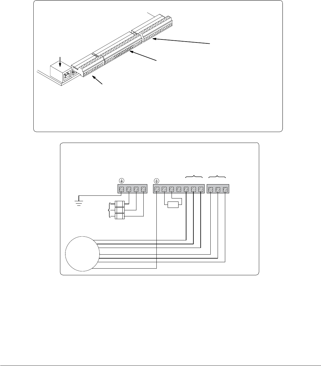
Figure 1-1 Minimum Connection Diagram
Example of Terminal Strip Layout**
Input AC
Power
Earth Ground
DB Resistor
(Internal)
GND
TH2TH1T3T2T1B-R2
R1/B+
L3L2L1
G
T3
T2
T1
TH2
TH1
Motor
Motor Leads Motor Thermal Leads*
Fuses
AC Power & Motor Connections
Minimum Signal Connections
Terminals 1 to 7 (J1)
1User Analog Return
2Analog Input #1
3Analog Ref. Power
4Analog Input #2 +
5Analog Input #2 -
6Analog Output #1
7Analog Output #2
Terminals 8 to 20 (J2)
8Enable Input
9Digital Input #1
10 Digital Input #2
11 Digital Input #3
12 Digital Input #4
13 Digital Input #5
14 Digital Input #6
15 Digital Input #7
16 Digital Input #8
17 Digital Out #1+ (Collector)
18 Digital Out #1- (Emitter)
19 Digital Out #2+ (Collector)
20 Digital Out #2- (Emitter)
For keypad operation, only Enable (J2-8) is required.
J1
J2
J3
USB Port
1
8
21 Terminals 21 to 30 (J3)
21 External User +24V Return
22 External User +24V
23 Internal +24V
24 Internal +24V Return
25 Relay Out 1 NC
26 Relay Out 1 COM
27 Relay Out 1 NO
28 Relay Out 2 NC
29 Relay Out 2 COM
30 Relay Out 2 NO
GND
Note: The control enable input must be active to allow operation. Therefore, J2-8 Enable is connected by a factory installed
jumper to J3-24. This uses the internal supply and provides an active low at J2-8.
Remove TH1 and TH2 jumper if Motor Thermal Leads are connected.
Note: Motor thermal leads must be run in a separate conduit from motor power leads.
Note: An open circuit on these terminals will generate a motor overtemperature fault. Refer to the fault / troubleshooting
information provided in Chapter 9.
See Figure 4-3 for terminal arrangement for the various frame sizes.

General Information 2-1MN766
Chapter 2
General Information
The VS1SD provides control of 3-phase AC servomotors in an industrial package and design. These controls offer Baldor’s
easy to use Smart Keypad for easy setup and exibility. The H2 keypad follows the same easy to use menu structure as that
of its companions, the H2 Inverter and H2 Vector drives.
The control’s rated output power is designed for use with Baldor’s PM motors.
The control’s rated output power is based on the use of a NEMA design B four pole motor and 60Hz operation at nominal
rated input voltage. If any other type of motor is used, the control should be sized to the motor using the rated current of
the motor. The control may be used in various applications. It may be programmed by the user to operate in four different
operating zones: standard or quiet and constant torque or variable torque. It can also be congured to operate in a number
of modes depending upon the application requirements and user preference. It is the responsibility of the user to determine
the optimum operating zone and mode to interface the control to the application. These choices are made with the keypad
as explained in Chapter 6 of this manual.
2.1 Limited Warranty
For a period of two (2) years from the date of original purchase, BALDOR will repair or replace without charge controls
and accessories which our examination proves to be defective in material or workmanship. This warranty is valid if the
unit has not been tampered with by unauthorized persons, misused, abused, or improperly installed and has been used
in accordance with the instructions and/or ratings supplied. This warranty is in lieu of any other warranty or guarantee
expressed or implied. BALDOR shall not be held responsible for any expense (including installation and removal),
inconvenience, or consequential damage, including injury to any person or property caused by items of our manufacture
or sale. (Some states do not allow exclusion or limitation of incidental or consequential damages, so the above exclusion
may not apply.) In any event, BALDOR’s total liability, under all circumstances, shall not exceed the full purchase price of the
control. Claims for purchase price refunds, repairs, or replacements must be referred to BALDOR with all pertinent data as to
the defect, the date purchased, the task performed by the control, and the problem encountered. No liability is assumed for
expendable items such as fuses.
Goods may be returned only with written notication including a BALDOR Return Authorization Number and any return
shipments must be prepaid.
2.2 Standards
The VS1SD drives have been designed and tested to comply with the following standards.
2.2.1 Design and Test Standards
• UL508C: Power Conversion Equipment.
• UL840: Insulation coordination including clearance and creepage distances for electrical equipment.
• CSA C22.2 No. 14: Industrial Control Equipment.
• EN61800-5-1: Adjustable speed electrical power drive systems. Safety requirements.
Electrical, thermal and energy.
• EN50178: Electronic equipment for use in power installations.
• EN60529: Degrees of protection provided by enclosures.
• EN61800-3: When installed as directed in this manual, VS1SD drives conform to the category C3 emission limits and the
‘second environment’ immunity requirements dened by this standard.
2.2.2 Environmental Test Standards
• EN60068-1: Environmental testing, general and guidance.
• EN60068-2-2: Environmental testing, Test B. Dry heat.
• EN60068-2-78: Environmental testing, Test cab. Damp heat, steady state.
• EN60068-2-6: Vibration testing.
2.2.3 Marks
See also Appendix C for general recommendations for CE compliance.

2-2 General Information MN766

Installing the Drive 3-1MN766
Chapter 3
Installing the Drive
This chapter provides information that must be considered when planning a VS1SD drive installation and provides drive
mounting information and installation site requirements.
3.1 Receiving & Inspection
When you receive your control, there are several things you should do immediately.
1. Observe the condition of the shipping container and report any damage immediately to the commercial carrier that
delivered your control.
2. Remove the control from the shipping container and remove all packing materials from the control. The container and
packing materials may be retained for future shipment.
3. Verify that the catalog number of the control you received is the same as the catalog number listed on your purchase
order.
4. Inspect the control for external physical damage that may have been sustained during shipment and report any damage
immediately to the commercial carrier that delivered your control.
5. If the control is to be stored for several weeks before use, make sure that it is stored in a location that conforms to
published storage humidity and temperature specications stated in this manual.
3.2 General Requirements for the Installation Site
It is important to ensure that the drive’s environment and operating conditions are satisfactory. The area behind the drive
must be kept clear of all control and power wiring. Power connections may create electromagnetic elds that may interfere
with control wiring or components when run in close proximity to the drive.
Read the recommendations in the following sections before continuing with the drive installation.
3.2.1 Location Instructions
Before deciding on an installation site, consider the following guidelines:
• Protect the cooling fan by avoiding dust or metallic particles.
• Do not expose the drive to a corrosive atmosphere.
• Protect the drive from moisture and direct sunlight.
• Verify that the drive location will meet the environmental conditions specied in Table 3-1.
Table 3-1 Ambient Temperatures and Mounting Clearances
Frame
Size
Ambient Temperature
Enclosure Rating
Minimum Mounting Clearances
Minimum Maximum Top & Bottom Left & Right Sides
AA
-10°C (14°F)
45°C NEMA 1
2 inches (50mm)
2 inches (50mm)
NEMA 4X 0 inches (0mm)
B45°C NEMA 1 2 inches (50mm)
40°C NEMA 4X 0 inches (0mm)
C45°C NEMA 1 2 inches (50mm)
D
3.2.2 Minimum Mounting Clearances
Be sure to provide proper top, bottom and side clearance (2” minimum on each side).
3.3 Mounting the Drive
Mount the drive upright on a at, vertical surface. Avoid mounting the drive in locations that would subject the drive to
vibration in excess of the 0.5G RMS rating (e.g. adjacent to a large punch press).
3.3.1 Protecting the Drive from Debris
Drives suppled in NEMA 1 enclosures must be protected from debris falling through the drive vents during installation
and operation. The drive is designed to operate in NEMA 1 Type installations. The atmosphere must not contain airborne
particles that can collect on the internal circuitry of the drive, especially conductive particles. Drives supplied in NEMA 4X
enclosures are designed for harsh environments including dust and water. NEMA 1 and NEMA 4X drives are for indoor use
only.
3-2 Installing the Drive MN766
3.3.2 Watts Loss Data
Table 3-2 Watts Loss Data
Frame Size 240VAC 480VAC
2.5kHz PWM 8.0kHz PWM 2.5kHz PWM 8.0kHz PWM
AA, B, C and D 50Watts +
(14 W/Amp) 50Watts +
(17 W/Amp) 50Watts +
(17 W/Amp) 50Watts +
(26 W/Amp)
Example: At 2.5kHz, a 3HP, 240VAC control draws 10Amps. Watts loss = 50W + (10x14) = 190Watts
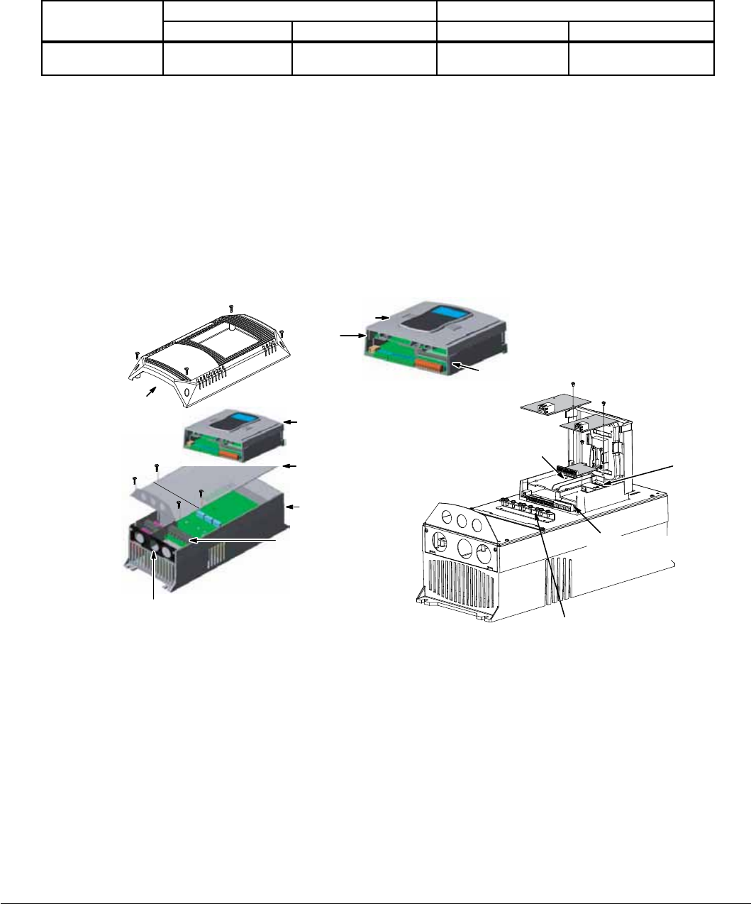
3.4 Cover Removal Procedure (NEMA 1 Drives):
To connect power and signal wires, the cover must be removed (AA, B, C and D frame drives). This procedure describes
how to access all terminal connections inside the control.
1. Remove the four cover screws shown in Figure 3-1.
2. Lift and remove the cover.
3. Press in the two Cover Releases (Control) and rotate the control cover open as shown.
Figure 3-1 Cover Removal
Lift and
remove cover
Cover
Screws
(4)
Cover
Release
Cover
Release
Cover
Control
Cover
Cable Entrance
I/O Module
Slot 1
Analog/Digital
I/O Terminals
I/O Module
Slot 2
Control
Shield
Plate
Power
Base
Shield
Screws
(4)
Power & Motor
Connections
Cable Clamp and
Shield Termination
3.5 Cover Removal Procedure (NEMA 4X Frames AA and B):
CAUTION: Failure to follow this procedure may result in damage to the controller cover gasket which will
cause improper sealing and inability to maintain specified NEMA 4X ratings.
1. While supporting cover, remove all cover screws reserving for usage when replacing cover.
2. Do not use any kind of tool to pry the cover away from the drive to avoid damaging the gasket or surrounding plastic.
3. Separate cover from base a short distance by pulling it away from the drive while being careful to not pull on the keypad
cable which is attached to both the cover and the control board.
4. Disconnect the keypad cable from the keypad board connector on the inside of the cover by pressing in on the retention
clip and gently pulling the cable out of the connector.
Installing the Drive 3-3MN766
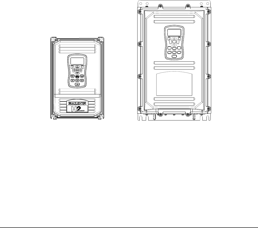
3.6 Cover Replacement Procedure (NEMA 4X Frames AA and B):
CAUTION: Failure to follow this procedure may result in damage to the controller cover gasket which will
cause improper sealing and inability to maintain specified NEMA 4X ratings.
1. While holding the cover close to the controller, plug the keypad cable (disconnected in step 4 above) into the connector
on the keypad board making sure that the retention clip snaps into place.
2. Check that keypad cable is not overlapping any of the cover edges while placing cover on drive. Ensure that gasket is
seated in cover groove around the complete perimeter of the cover without any folds.
3. While holding the cover against the base, insert, start and tighten all cover screws and tighten only to the point of contact
with the cover while following the numerical sequence outlined in the diagram below.
4. Using the numerical sequence on the following gure, tighten each screw to 15 in-lbs. of torque.
5. Do not over-tighten ensuring that the cover is seated ush around complete perimeter of base.
Figure 3-2 Cover Replacement (NEMA 4X)
3
10
4
9
2
11
5
8
1
12
7
6
B - FRAME NEMA 4XAA - FRAME NEMA 4X
1
2
4
3
Maximum cover screw torque:
15 in-lbs. (see above procedure)
Maximum cover screw torque:
15 in-lbs. (see above procedure)

3-4 Installing the Drive MN766
Power Wiring 4-1MN766
Chapter 4
Power Wiring
4.1 Grounding the Drive
Baldor does not recommend using “Grounded Leg Delta” transformer power leads that may create ground loops. Instead
we recommend using a four wire Wye. Baldor drives are designed to be powered from standard three phase lines that are
electrically symmetrical with respect to ground. System grounding is an important step in the overall installation to prevent
problems. The recommended grounding method is shown in Figure 4-1.
Figure 4-1 Recommended System Grounding
L1
AC Main
Supply
Safety
Ground
Driven Earth
Ground Rod
(Plant Ground)
Four Wire
Wye
L1
L2
L3
Earth
L2 L3 T1 T2 T3
Optional
Line
Reactor
Optional
Load
Reactor
Route all 4 wires L1, L2, L3 and Earth (Ground)
together in conduit or shielded cable.
Route all 4 wires T1, T2, T3 and Motor Ground together
in conduit or shielded cable.
Connect all wires (including motor ground)
inside the motor terminal box.
Ground per NEC and
Local codes.
Note:
Motor thermal leads must be run
in separate conduit from motor
power leads.
Note: An optional separately
purchased load reactor
is recommended.
Note: A line reactor is recommended
and must be purchased separately.
Drive
See recommended tightening torques in Table A-2. TH1
TH2
GND Wiring shown for clarity of
grounding method only. Not
representative of actual
terminal block arrangement.
Note:
4.1.1 Ungrounded Distribution System
With an ungrounded power distribution system it is possible to have a continuous current path to ground through the MOV
devices internal to the VS1SD. To avoid equipment damage, an isolation transformer with a WYE grounded secondary is
recommended. This provides three phase AC power that is symmetrical with respect to ground.
4.1.2 Input Power Conditioning
Baldor drives are designed for direct connection to standard three phase lines that are electrically symmetrical with respect
to ground. An AC line reactor or an isolation transformer may be required for some power conditions.
• If the feeder or branch circuit that provides power to the drive has permanently connected power factor correction
capacitors, an input AC line reactor or an isolation transformer must be connected between the power factor correction
capacitors and the drive.
• If the feeder or branch circuit that provides power to the drive has power factor correction capacitors that are switched on
line and off line, the capacitors must not be switched while the drive is connected to the AC power line. If the capacitors
must be switched while the drive is connected to the AC power line, additional protection is required. TVSS (Transient
Voltage Surge Suppressor) of the proper rating must be installed on the drive input between the drive and any type of
input impedance such as an input reactor or drive isolation transformer.

4-2 Power Wiring MN766
4.2 Line Impedance
Baldor VS1SD drives require 1% line impedance minimum (3% for AA frame size drives and B Frame NEMA 4X drives). If the
impedance of the incoming power does not meet this requirement, a 3 phase line reactor can be used to provide the needed
impedance in most cases. The input impedance of the power lines can be determined as follows:
Measure the line to line voltage at no load and at full rated load.
Use these measured values to calculate impedance as follows:
% Impedance = No Load Full Load
Volts Volts
x 100
No Load
Volts
4.2.1 Line Reactors
Three phase line reactors are available from Baldor. The line reactor to order is based on the full load current of the motor
(FLA). If providing your own line reactor, use the following formula to calculate the minimum inductance required.
Where:
L =
X
(I X
√
3377)
0.01)
L- L
(V X
L Minimum inductance in Henries.
L- L
V Input volts measured line to line.
0.01 Desired percentage of input impedance 1%. (Note: Change this value to
0.03 for AA Frame Size drives.)
I Input current rating of drive.
377 Constant used with 60 Hz power.
Use 314 if input power is 50 Hz.
4.2.2 Load Reactors
Line reactors may be used at the drive output to the motor. When used this way, they are called Load Reactors. Load
reactors serve several functions that include:
• Protect the drive from a short circuit at the motor.
• Limit the rate of rise of motor surge currents.
• Slowing the rate of change of power the drive delivers to the motor.
Note: The wire leads that connect the motor to the control are critical in terms of sizing, shielding and the cable
characteristics. Short cable runs are usually trouble free but fault-monitoring circuitry can produce numerous faults
when long cables (over 200 feet) are used.
• 200+ft (60m): Baldor recommends adding an optional load reactor to the output of the control.
• 300+ft (90m): Baldor recommends adding an optional load reactor and common mode choke to the control.
The load reactor and/or common mode choke should be placed in close physical proximity to the control.
Unexpected faults may occur due to excessive charging current required for motor cable capacitance. If you use
long motor leads and experience unexpected trips due to overcurrent conditions and are not sure how to correctly
size and connect the optional load reactors, contact your local Baldor District Ofce.
Load reactors should be installed as close to the drive as possible. Selection should be based on the motor nameplate FLA
value.
4.3 Line Disconnect
A power disconnect should be installed between the input power service and the drive for a fail safe method to disconnect
power. This drive will remain in a powered-up condition until all input power is removed from the drive and the internal bus
voltage is depleted.
Power Wiring 4-3MN766
4.4 Protective Devices
Note: Integral solid state short circuit protection does not provide branch circuit protection. Branch circuit protection must
be provided in accordance with the National Electrical Code and any additional local codes.
Recommended fuse sizes are based on the following:
115% of maximum continuous drive input current for time delay.
150% of maximum continuous drive input current for Fast or Very Fast action.
Note: These recommendations do not consider harmonic currents or ambient temperatures greater than 45°C. Be sure a
suitable input power protection device is installed. Use the recommended fuses and wire sizes shown in Tables
4-1 through 4-6. Wire size is based on the use of copper conductor wire rated at 75°C. The table is specied for
NEMA B motors.
Fast Action Fuses: 240VAC, Buss® KTN
480VAC, Buss® KTS to 600A (KTU for 601 to 1200A)
600VAC, Buss® KTS to 600A (KTU for 601 to 1200A)
Very Fast Action: 240VAC, Buss® JJN
480VAC, Buss® JJS
600VAC, Buss® JJS
Time Delay: 240VAC, BUSS FRN
480VAC, BUSS FRS (KLU for 601 to 1200A)
600VAC, BUSS FRS (KLU for 601 to 1200A)
Semiconductor 240VAC, Ferraz Shawmut A50QS
Fuses: 480VAC, Ferraz Shawmut A70QS (22.8mm) M20, PG16
600VAC, Ferraz Shawmut A70QS
UL Listed Breakers: Frame Size D - 250A maximum (all ratings)
Buss® is a trademark of Cooper Industries, Inc.
4.5 Reduced Input Voltage Considerations
Power ratings are for nominal AC input voltages (240 or 480VAC). The power rating of the drive must be reduced when
operating at a reduced input voltage. The amount of reduction is the ratio of the voltage change.
Examples:
A 5HP, 240VAC drive operating at 208VAC has an effective power rating of 4.33HP.
5Hp x = 4.33Hp
208VAC
240VAC
Likewise, a 3HP, 480VAC drive operating at 380VAC has an effective power rating of 2.37HP.
3Hp x = 2.37Hp
380VAC
480VAC
4.6 Electrical Installation
All interconnection wires between the drive, AC power source, motor, host control and any other operator interface stations
should be in metal conduits or shielded cable must be used. If the connection being made is on a connection stud or
grounding screw, then use listed closed loop connectors that are of appropriate size for wire gauge being used. Connectors
are to be installed using crimp tool specied by the manufacturer of the connector. Only Class 1 wiring should be used. See
Figure A-2 in Appendix A for conduit hole size for each frame size.
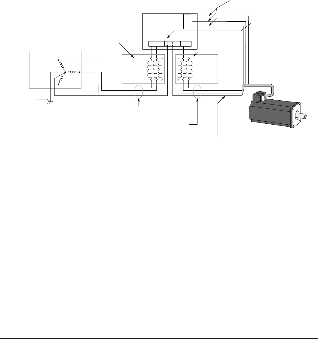
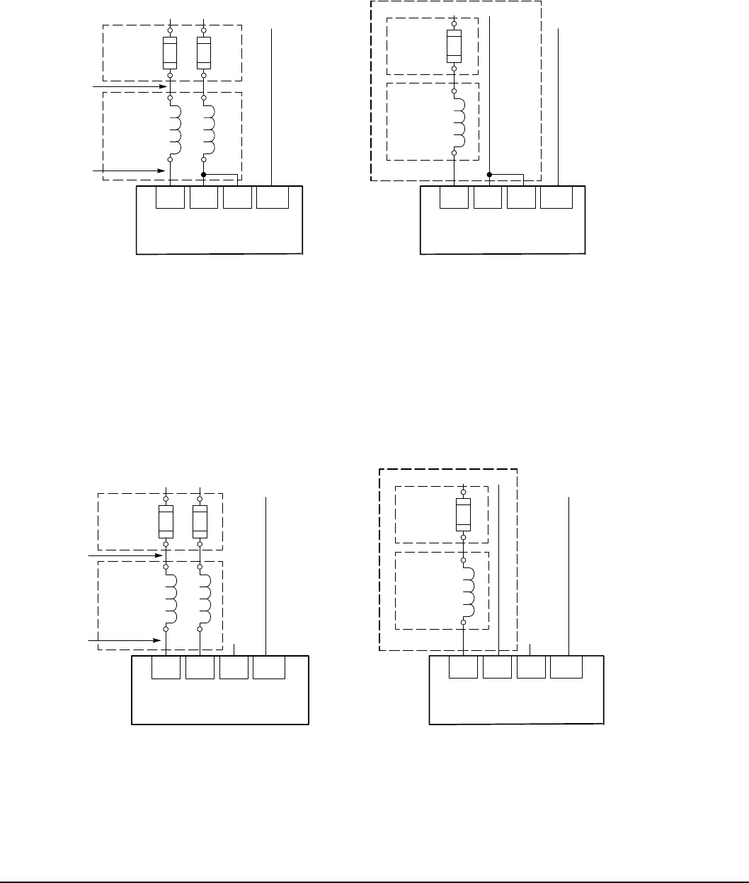
4.7 Optional Filter/Reactor
Figure 4-2 shows the connections for installing an optional Line Filter and AC Line Reactor.
Figure 4-2 Filter and Reactor Connections
Control
L1
L2
L3
PE
Reactor
FilterL1
L2
L3
PE
L1
L2
L3
PE
Line Load
AC
Line
4-4 Power Wiring MN766
Table 4-1 240VAC Three Phase Wire Size and Protective Devices
Catalog
No.
VS1SD
Control Rating Input Fuse (Amps) Wire Gauge
HP Input Amps Fast Acting (UL) Fast Acting (CUL) Time
Delay Semiconductor (CUL) AWG mm2
2A3 1 3.2 9 9 6 14 2.5
2A4 2 4.2 12 12 9 14 2.5
2A7 3 6.8 15 15 12 14 2.5
2A10 5 9.6 25 25 20 14 2.5
2A15 7.5 15.2 35 35 30 12 4
2A22 10 22 40 40 35 10 6
2A28 15 28 70 70 60 8 10
2A42 20 42 80 80 70 6 16
2A54 25 54 100 *100 A50QS100-4 4 25
2A68 30 68 125 *125 A50QS125-4 4 25
2A80 40 80 150 *150 A50QS150-4 4 25
2A104 50 104 175 175 150 2 50
2A130 60 130 200 200 175 2/0 70
* Requires custom drive for CUL application using fast fuses.
Note: Wire sizes based on 750C copper wire. Fuses based on 400C ambient, max continuous output and no harmonic current.
Table 4-2 480VAC Three Phase Wire Size and Protective Devices
Catalog
No.
VS1SD
Control Rating Input Fuse (Amps) Wire Gauge
HP Input Amps Fast Acting (UL) Fast Acting (CUL) Time
Delay Semiconductor (CUL) AWG mm2
4A2 1 2.1 3 3 3 14 2.5
4A3 2 3.4 6 6 4.5 14 2.5
4A5 3 4.8 8 8 6.3 14 2.5
4A8 5 7.6 12 12 10 14 2.5
4A11 7.5 11 17.5 17.5 15 14 2.5
4A14 10 14 25 25 17.5 12 4
4A21 15 21 35 35 30 10 6
4A27 20 27 40 40 35 8 10
4A34 25 34 50 *50 A70QS70-4 8 10
4A40 30 40 60 *60 A70QS80-4 8 10
4A52 40 52 80 *80 A70QS100-4 6 16
4A65 50 65 100 100 80 4 25
4A77 60 77 125 125 100 3 35
4A96 75 96 150 150 125 1 50
4A124 100 124 200 200 175 2/0 70
* Requires custom drive for CUL application using fast fuses.
Note: Wire sizes based on 750C copper wire. Fuses based on 400C ambient, max continuous output and no harmonic current.
Power Wiring 4-5MN766
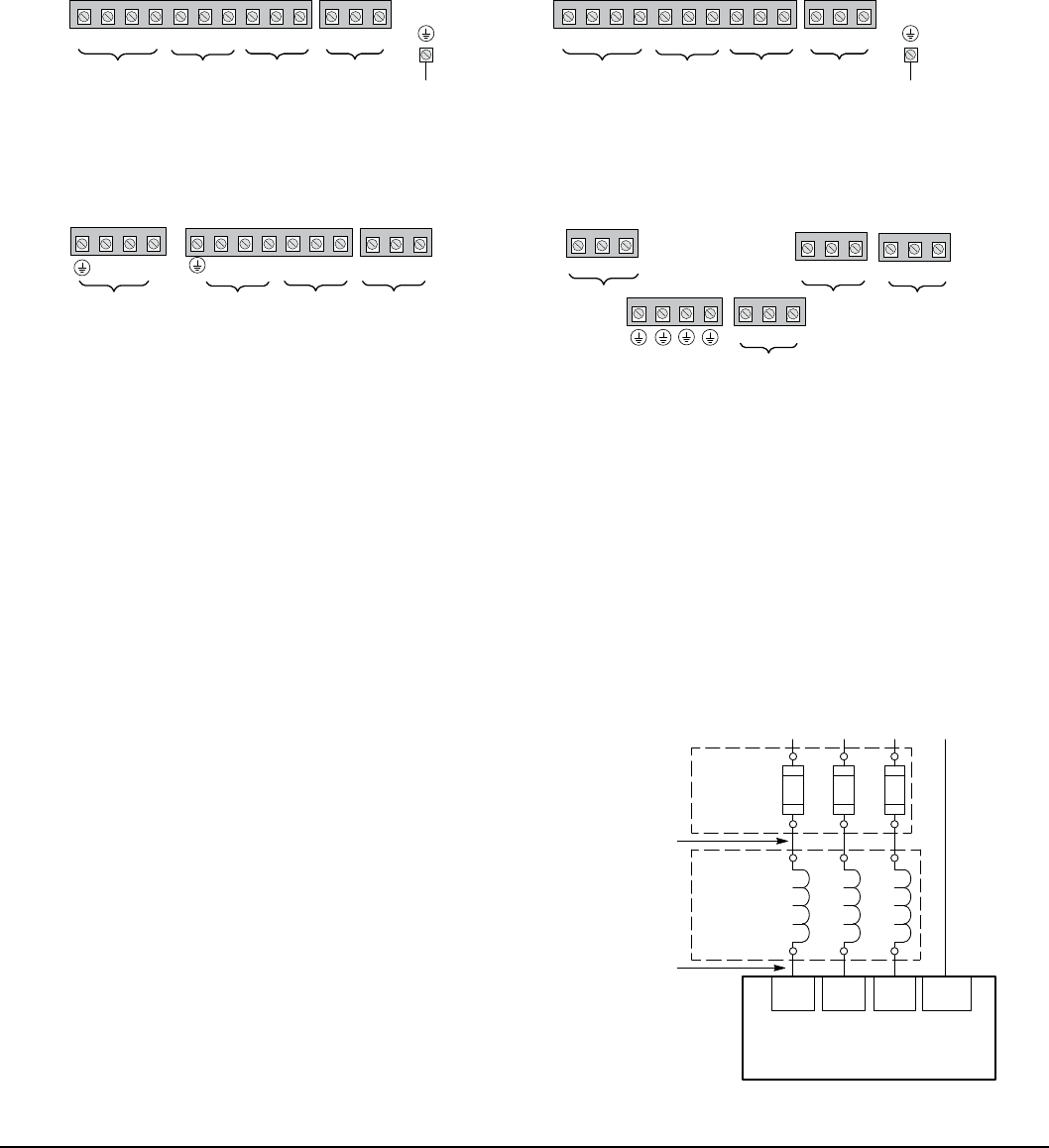
4.8 Incoming Power and Motor Connections
Figure 4-3 shows the layout of the terminals on the power connectors for each size drive. All cables must be in conduits
or shielded and the conduits or shields must be grounded at the cable entrance. The brake resistor and cable must be in a
conduit or shielded if installed outside the enclosure.
Figure 4-3 Power Connections
Frame Size AA 1-Phase Input Drives
Frame Size B and C Drives
GNDTH2TH1T3T2T1B-R2
B+/R1
L3L2L1
GND
TH2TH1T3T2T1B-R2
R1/B+
GNDNL2L1
Input AC Power
Motor Thermal
Leads *
Input AC Power
Motor Thermal
Leads
Motor GND
Motor
Chassis
Ground
*
Dynamic Brake
Motor Leads
See Recommended Tightening Torques in Table A-2.
*Remove TH1 to TH2 jumper if Motor Thermal Leads are connected.
Motor Leads
Dynamic Brake
Frame Size AA 3-Phase Input Drives
GND
TH2TH1T3T2T1B-R2
R1/B+
GNDL3L2L1
Input AC Power
Motor Thermal
Leads
Motor
Chassis
Ground
*
Dynamic Brake
Motor Leads
L3L2
L1
Ground
GND
TH2TH1
Motor Thermal
Leads
*
Frame Size D Drives
Dynamic Brake
B-R2
B+/R1
Motor Leads
T3T2
T1
Input AC Power
Note: An open circuit between TH1 and TH2 will cause an overtemperature fault.
Refer to fault/troubleshooting information in Chapter 9.
Motor GND
1. Access the Power and Motor Terminals (see Cover Removal procedure).
2. Feed the power supply and motor cables into the drive through the cable entrance.
3. Connect the line L1, L2, L3 and GND to the power terminal connectors, Figure 4-4.
4. Connect motor leads to T1, T2, T3 and GND motor terminal connectors.
Figure 4-4 3 Phase Input Power Connections
*Optional components not provided with control.
Notes:
1. See “Protective Devices” described previously in this section.
L1 L2 L3
L1 L2 L3
Earth
Note 3
Baldor
Control
*Optional
Line
Reactor
Note 1
Note 3
A1 B1 C1
A2 B2 C2
Note 4
GND
Note 2
*Fuses
2. Use same gauge wire for Earth ground as is used for L1, L2
and L3 for AA, B, C frame drives. For D frame drives, size the
grounding conductor per the local electrical codes.
3. Metal conduit should be used. Connect conduits so the
use of a Reactor or RC Device does not interrupt EMI/RFI
shielding.
4. See Line/Load Reactors described previously in this section.
4-6 Power Wiring MN766
4.9 Operating a 3-Phase Control on Single Phase Input Power
Single phase AC input power can be used to power the control instead of three phase for control sizes AA, B and C. The
specications and control sizes are listed in Appendix A of this manual. If single phase power is to be used, the rated
control output current may have to be reduced (derated). In addition, power wiring and jumper changes are required. Both
connection types are shown in Figures 4-5 and 4-6.
Single phase rating wire size and protection devices are listed in Table 4-5.
4.9.1 Single Phase Power Derating:
Single phase power derating requires that the continuous and peak current ratings of the control be reduced by the
following:
1. 3.2 to 15.2 Continuous Amp, 240 and 480VAC controls:
Derate output to next lower model rating. (I.E. 2A15 becomes 2A10.)
2. 22 to 80 Continuous Amp, 240 and 480VAC controls:
Derate output by 50% of the nameplate rating.
Table 4-3 Single Phase Wire Size and Protection Devices - 240VAC Controls
Catalog
No.
VS1SD
Control
Rating
Input
Amps
Control Rating
Output Amps
(QCT Continuous)
Input Fuse (Amps) Input
Wire Gauge
Output
Wire Gauge
Fast Acting
(UL)
Fast Acting
(CUL)
Time
Delay
Semiconductor
(CUL) AWG mm2AWG mm2
2A3 3.8 2.2 6 6 5 14 2.5 14 2.5
2A4 5.5 3.2 10 10 8 14 2.5 14 2.5
2A7 7.3 4.2 15 15 12 14 2.5 14 2.5
2A10 11.8 6.8 20 20 15 14 2.5 14 2.5
2A15 16.6 9.6 25 25 20 10 6 14 2.5
2A22 19 11 30 30 25 10 6 14 2.5
2A28 24 14 40 40 35 10 6 12 4
2A42 36 21 60 60 50 8 10 10 6
2A54 47 27 70 *70 A50QS80-4 6 16 8 10
2A68 59 34 90 *90 A50QS100-4 4 25 8 10
2A80 69 40 110 *110 A50QS125-4 3 35 8 10
* Requires custom drive for CUL application using fast fuses.
Note: Wire sizes based on 750C copper wire. Fuses based on 400C ambient, max continuous output and no harmonic current.
Table 4-4 Single Phase Wire Size and Protection Devices - 480VAC Controls
Catalog
No.
VS1SD
Control
Rating
Input
Amps
Control Rating
Output Amps
(QCT Continuous)
Input Fuse (Amps) Input
Wire Gauge
Output
Wire Gauge
Fast Acting
(UL)
Fast Acting
(CUL)
Time
Delay
Semiconductor
(CUL) AWG mm2AWG mm2
4A3 5.2 3.0 8 8 6 14 2.5 14 2.5
4A5 5.9 3.4 10 10 8 14 2.5 14 2.5
4A8 8.3 4.8 15 15 12 14 2.5 14 2.5
4A11 13.2 7.6 20 20 15 12 4 14 2.5
4A14 12.1 7.0 20 20 15 12 4 14 2.5
4A21 18.2 10.5 30 30 25 10 6 14 2.5
4A27 23.4 13.5 40 40 30 10 6 12 4
4A34 29 17 50 *50 A70QS60-4 8 10 10 6
4A40 35 20 60 *60 A70QS70-4 8 10 10 6
4A52 45 26 70 *70 A70QS80-4 6 16 10 6
* Requires custom drive for CUL application using fast fuses.
Note: Wire sizes based on 750C copper wire. Fuses based on 400C ambient, max continuous output and no harmonic current.
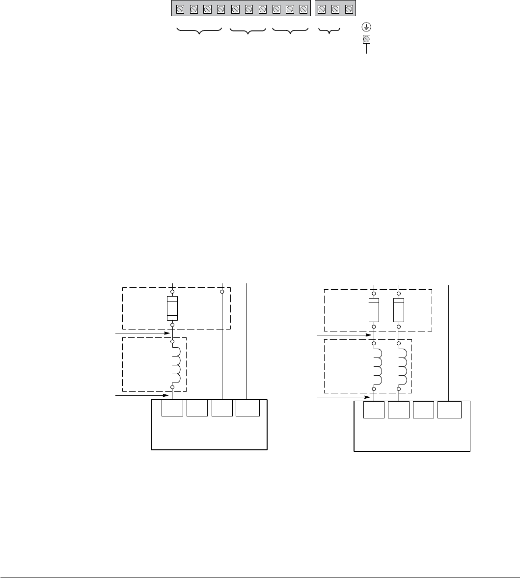
Power Wiring 4-7MN766
Figure 4-5 Size AA Single Phase Power Connections to a 3 Phase Control
L1 L2
L1 L2 L3
Earth
*Optional components are not provided with control.
Note 3
Baldor
Control
* Optional
Line
Reactor
Note 1
Note 3
A1 B1
A2 B2
Note 4
GND
Note 2
* Fuses
Single Phase 2 Wire Connections
Single Phase 3 Wire Connections
L1
*Optional
Line
Reactor
A1
A2
*Fuse
Neutral
L1 L2 L3
Earth
Baldor
Control
GND
Notes:
1. See Protective Devices described previously in this section.
2. Use same gauge wire for Earth ground as is used for L1 and L2.
3. Metal conduit should be used. Connect conduits so the use of a
Reactor or RC Device does not interrupt EMI/RFI shielding.
4. See Line/Load Reactors described previously in this section.
Line Reactors are built-in for size B and larger controls.
In order to protect the drive,
Level 2, Drive Congure, Power
Input P#2110 should be set to
“Single Phase”.
See recommended tightening torques in Table A-2.
Figure 4-6 Size B and C Single Phase Power Connections to a 3 Phase Control
L1 L2
L1 L2 L3
Earth
*Optional components not provided with control.
Note 3
Baldor
Control
*Optional
Line
Reactor
Note 1
Note 3
A1 B1
A2 B2
Note 4
GND
Note 2
* Fuses
Single Phase 2 Wire Connections
Single Phase 3 Wire Connections
L1
* Optional
Line
Reactor
A1
A2
* Fuse
Neutral
L1 L2 L3
Earth
Baldor
Control
GND
Notes:
1. See Protective Devices described previously in this section.
2. Use same gauge wire for Earth ground as is used for L1 and L2.
3. Metal conduit should be used. Connect conduits so the use of a
Reactor or RC Device does not interrupt EMI/RFI shielding.
4. See Line/Load Reactors described previously in this section.
Line Reactors are built-in for size B and larger controls.
IMPORTANT:
Do not connect L3.
IMPORTANT:
Do not connect L3.
In order to protect the drive,
Level 2, Drive Congure, Power
Input P#2110 should be set to
“Single Phase”.
See recommended tightening torques in Table A-2.
4-8 Power Wiring MN766
4.9.2 Single Phase Power and Motor Connections VS1SD6XX-XX
Figure 4-7 shows the minimum connections required at the power connector. All cables must be in conduits or shielded
and the conduits or shields must be grounded at the cable entrance. The brake resistor and cable must be in a conduit or
shielded if installed outside the enclosure.
Figure 4-7 Single Phase Control Power Terminals
See recommended tightening torques in Table A-2.
Frame Size AA
GND
TH2TH1T3T2T1 B-R2
R1/B+
GNDNL2L1
Input AC
Power
Motor Thermal
Leads
*
Motor GND
Motor
Chassis
Ground
*Remove TH1 to TH2 jumper if Motor Thermal Leads are connected.
Dynamic
Brake
Motor
Leads
Note: An open circuit between TH1 and TH2 will be used by the drive to generate a motor overtemperature fault. Refer to
the fault/troubleshooting information provided in Chapter 9.
1. Access the Power and Motor Terminals (see Cover Removal procedure).
2. Feed the power supply and motor cables into the drive through the cable entrance.
3. Connect the line L1, L2, N and GND to the power terminal connections, Figure 4-7.
4. Connect motor leads to T1, T2, T3 and GND motor terminal connectors.
Figure 4-8 Single Phase Control Power Connections
L1 L2
L1 L2 N
Earth
Note 3
Baldor
Control
*Optional
Line
Reactor
Note 1
Note 3
A1 B1
A2 B2
Note 4
GND
Note 2
*Fuses
240VAC Single Phase
L1 N
L1 L2 N
Earth
Note 3
Baldor
Control
*Optional
Line
Reactor
Note 1
Note 3
A1
A2
Note 4
GND
Note 2
*Fuses
120VAC Single Phase
*Optional components not provided with control.
Notes:
1. See Protective Devices described previously in this section.
2. Use same gauge wire for Earth ground as is used for L1, L2 and N.
3. Metal conduit should be used. Connect conduits so the use of a
Reactor or RC Device does not interrupt EMI/RFI shielding.
4. See Line/Load Reactors described previously in this section.
Line Reactors are built-in for size B and larger controls.
See recommended tightening torques in Table A-2.
Power Wiring 4-9MN766
Table 4-5 Single Phase Rating Wire Size and Protection Devices - 120VAC/240VAC Control
120VAC Single Phase Input 240VAC Single Phase Input
Catalog
No.
VS1SD
Input
Amps
Input Fuse (Amps)
Fast Acting AWG mm2
Catalog
No.
VS1SD
Input
Amps
Input Fuse (Amps)
Fast Acting AWG mm2
6A3 7.6 12 14 2.5 6A3 3.8 6 14 2.5
6A4 11 20 14 2.5 6A4 5.5 10 14 2.5
6A7 15 25 12 4 6A7 7.3 12 14 2.5
Note: All wire sizes are based on 750C copper wire. Recommended fuses are based on 400C ambient, maximum
continuous control output and no harmonic current.
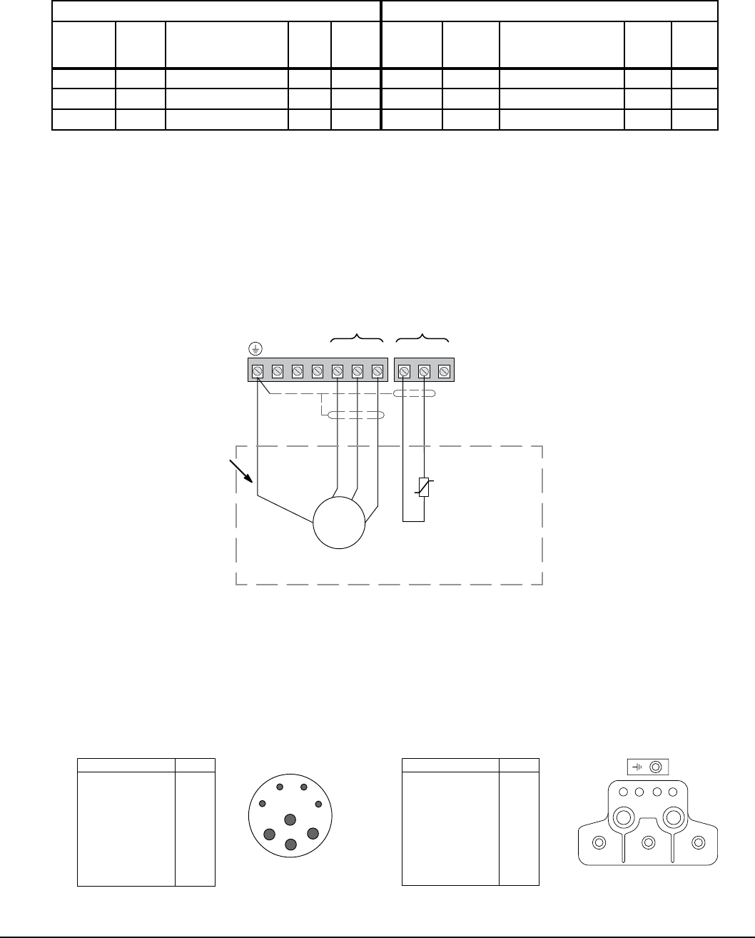
4.10 3-Phase Motor Connections
Figure 4-9 shows typical connections to a control. Note all wiring should be 600 volts.
Figure 4-9 Typical Connections to Motor Control
4-10 Power Wiring
G
N
D
TH1 TH2
Motor
GND
Motor
Leads
Motor Thermal
Leads
AC Servo Motor
G
U V
W
Motor
Temperature
Switch
Shielded Twisted
Pair Wire
Motor Ground
Wire
R2 B- T1 T2 T3
R1/B+
4.10.1 Motor Lead Termination
Motor leads are normally terminated using a Connector or Terminal Box (see Figure 4-10) or Flying Leads. When no
termination is provided and the motor leads just exit the motor housing, this is called “Flying Leads”. For ying leads, refer
to the motor packing list to determine the lead conguration.
Figure 4-10 Motor Termination
Terminal Box Termination
8 Pin
Function
Thermal Switch
Thermal Switch
Brake
Brake
U
Ground
W
VConnector Termination
1
D
2
3
4
CBA
Function
Thermal Switch
Thermal Switch
Brake
Brake
U
V
W
Ground (P.E.)
U
A
B
W
Pin
V
2
4
Pin
3
Screw
U
W
V
22
1
431
D
C
1
3
4
4-10 Power Wiring MN766
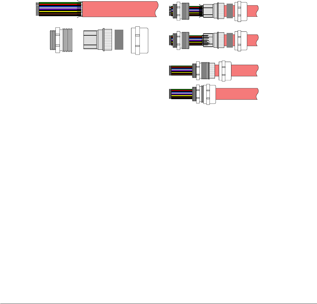
4.11 Strain Relief (Mounted at Terminal Box)
The motor cable is terminated at the Terminal Box using a Shielded Strain Relief Connector. Figure 4-11 shows the
components.
1. Strip the outer shield from the cable to expose the conductors and shield.
2. Slip the Strain Relief components onto the cable in the order shown.
3. Fold the Shield wires over the end of the Contact Carrier.
4. Slide the Threaded Adapter onto the Contact Carrier until the Carrier is completely inserted into the Adapter.
5. Slide the Gasket into the Contact Carrier.
6. Slide the Adapter Cover onto the Threaded Adapter and Tighten. As it is tightened, it compresses the Gasket against the
Cable to form the strain relief and securely hold the cable.
7. The assembly can be inserted into the Terminal Box and secured.
Figure 4-11 Motor Cable Strain Relief Assembly
Threaded
Adapter Gasket
Cover
Contact
Carrier
Shielded Cable Assemble Parts onto Cable
Assembled
Fold Shield wires over Contact Carrier
Adapter
Power Wiring 4-11MN766
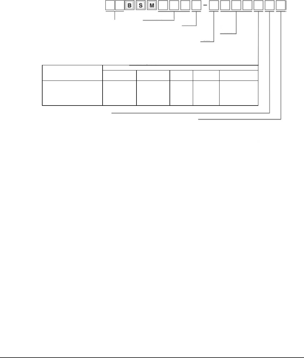
4.12 Brushless Servo Motor Identification
Figure 4-12
A = Resolver
D = Absolute Encoder
E = Encoder w/Commutation (1000ppr)
F = Encoder w/Commutation (2500ppr)
H = Hall effect only
T = Tach/Hall effect
Y = Resolver mounting only
Blank = No Option
M = No Keyway
N = DIN 42955-R
O = DIN 42955-R & No Keyway
P = Optional Motor Connector on BSM 90/100
(Note: This option available only if current is 20 amps or less).
Z1 = Blower 115 VAC (not available on all motors)
Z2 = Blower 230 VAC (not available on all motors)
Z3 = Blower 24VDC
Accessory Options
Feedback Options
IEC NEMA
50 5N
63 6N
80 8N
90 9N
100
C
N
1
2
3
4
50
75
etc.
SS = Stainless
Steel
Motor (no shaft seal)
Motor & Brake
Motor with shaft oil seal
Motor with brake & shaft oil seal
A
B
C
D
Description Standard (Metric)
Threaded Style
I
J
K
L
Optional (inch)
Quick Connect
E
F
G
H
Cables (5)
Connections
M
N
O
P
Flying
Leads (5)
R
S
T
U
Rotatable
Metric Threaded (9)
Notes: 1)
2) Standard BSM90/100 Series includes feedback device, one threaded connector (metric style) for feedback, termination of motor lead
wires on terminal block, IEC square mounting ange.
3) Standard BSM motors do not have shaft seal. Motors will meet IP65 if shaft oil seal is added.
4) Standard BSM50 Series has as standard no-keyway.
5) Standard cables and ying leads are 1 meter long.
6) SSBSM motors available with IEC mounting and include a shaft oil seal as standard.
7) BSM motors are IP60. Motors that meet IP65 include shaft oil seal.
8) SSBSM motors are IP67.
9) Rotatable connectors are not available for BSM50 series.
10)Contact Baldor for special option availabliity.
Motor Options
Frame
Motor
Size
Winding
Code
Series
Standard BSM50/63/80 Series includes feedback device, two threaded connectors (metric style) for feedback and motor terminations,
IEC square mounting ange.
4.13 External Trip Input
Terminal J2-16 is available for connection to a normally closed contact. The contact should be a dry contact type with no
power available from the contact. When the contact opens (activated), the control will automatically shut down and give an
External Trip fault.
4-12 Power Wiring MN766
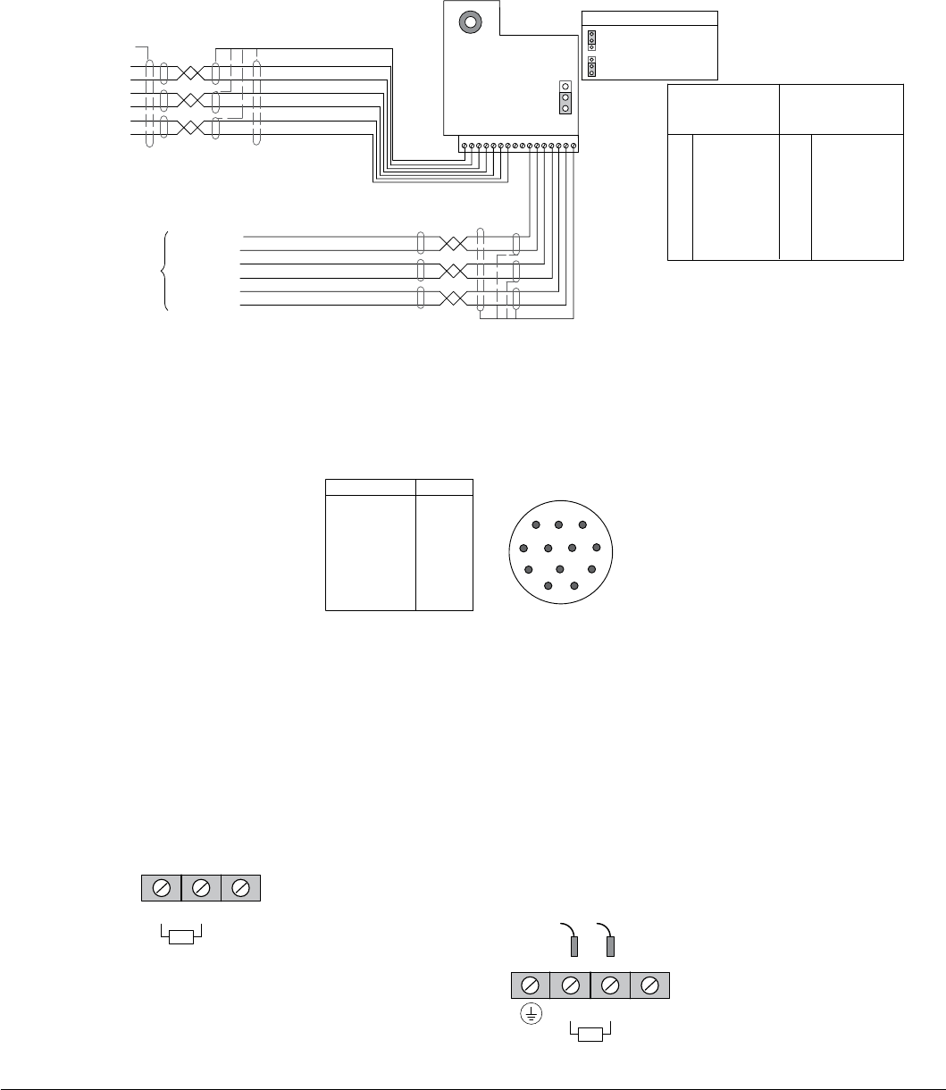
4.14 Resolver Installation
The Resolver Board is installed in the Feedback Module Slot 3. Connect resolver wiring to the resolver board as shown in
Figure 4-13. Use 16AWG (1.31mm2) maximum.
Figure 4-13 Resolver Connections
Sine+
Sine-
Cosine+
Cosine-
Excitation+
Excitation-
Encoder Output
16-22A WG Twisted Pair
1
Chassis
GND
Channel A+
Channel A-
Channel B+
Channel B-
Channel C+
Channel C-
16 = Outer
Shield
Resolver
Board
16-22A WG
Twisted Pair
1
2 Sine +
3 Sine -
4 Cosine +
5 Cosine -
6 Excitation +
7 Excitation -
8 Ext Index +
9 Ext Index -
10
11
12
13
14
15
16 ∆
Resolver Input
Signal Terminals
Motor Frame
J3
1
J3 Index Source Select
Internal Index (sync)
External Index (sync)
Blue
Red
Yellow
Green
Gray
Pink
Shield
See recommended tightening torques in Table A-2.
Emulated Encoder
Output Signal
Terminals
CH A+
CH A-
CH B+
CH B-
CH C+
CH C-
Outer Shield
(Chassis GND)
Chassis GND
∆
∆Terminals 1 and 16 are connected internally.
4.14.1 Feedback Termination
Connections for Feedback cables are different for each type of feedback device. Standard devices are: Resolver, Halls
(Hall Effect). Custom feedback devices are also available. Request a wiring diagram of your feedback device from the
manufacturer to determine the pin-out and/or wire color codes.
Figure 4-14 Typical Connections to Feedback Termination
Resolver
Function
R1 REF HI
R2 REF LO
S1 COS+
S3 COS-
S2 SINE+
S4 SINE-
Open
8
9
1
712
10
2
6
11
3
5
4
12 Pin
1
2
3
4
5
6
7-12
Pin
4.15 Optional Dynamic Brake Hardware
Refer to Figure 4-15 for DB resistor connections. Dynamic Brake (DB) Hardware must be installed on a at, non-ammable,
vertical surface for effective cooling and operation.
CAUTION: Before external Dynamic Brake Hardware is added, the internal resistor must be disconnected
(frames AA, B, C, and D). Remove the resistor from the B+/R1 and R2 terminals. The external
resistor can be connected across these terminals. Failure to remove the internal resistor will
decrease the total resistance (parallel connection) and cause damage.
Figure 4-15 DB Terminal Identification
“E” or “W” sufx
B+ / R1 R2
Frame C Size Only - Disconnect Internal DB resistor
wires from DBR1 and DBR2 terminals before
connecting external DB Resistor to prevent damage.
B+ / R1 R2 B -
DBR2
DBR1
TB101
External
External
See recommended tightening torques in Table A-2.
Frame AA, B and D Sizes
B -
Wires from the Internal Dynamic Brake resistor
for size AA, B and D controls must be removed
before external resistor hardware is installed.
Note: Although not shown, metal conduit should be
used to shield all power wires and motor leads.
Power Wiring 4-13MN766
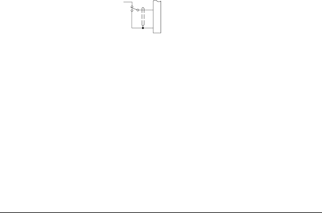
4.16 Home (Orient) Switch Input
The Home or Orient function causes the motor shaft to rotate to a predened home position. The homing function allows
shaft rotation in the drive forward direction only. The home position is located when a machine mounted switch or “Index”
pulse is activated (closed). Home is dened by a rising signal edge at Resolver expansion board terminal 8. The shaft will
continue to rotate only in a “Drive Forward” direction for a user dened offset value. The offset is programmed in Level 2
Miscellaneous Homing Offset P2308. The speed at which the motor will “Home” or orient is set in Level 2 Miscellaneous
Homing Speed P2307.
To use the internally generated index pulse for homing, no external connections are required. However, to use an external
index input jumper J3 on the resolver expansion board must be moved to External Index (sync) and a switch must be
connected to Index+ and Index-, shown in Figure 4-16.
4.16.1 External Index Jumper Position
Use the following procedure.
1. Remove all power from the control. Wait 5 minutes for bus capacitors to discharge. Open cover.
2. Place resolver expansion board jumper J3 in the desired position, see Figure 4-13.
3. Close cover. Turn power on. Be sure no errors are displayed.
4.16.2 Connections for External Index Signal
A machine mounted switch may be used to dene the Home position or “index” channel. A differential line driver output
from a solid state switch is preferred for best noise immunity. Connect this differential output to resolver expansion board
terminals 8 and 9.
A single ended solid-state switch or limit switch should be wired as shown in Figure 4-16. Regardless of the type of switch
used, clean rising and falling edges at pin 8 are required for accurate positioning.
Note: Control requires dynamic brake hardware for Orient (Homing) function to work. Control will trip without dynamic brake
hardware installed. Size AA and B controls (“-E” sufx) are shipped with factory installed dynamic brake hardware.
Figure 4-16 Typical Home or Orient Switch Connections
8
9INDEX -
INDEX +
Resolver Board
Limit Switch (Closed at HOME)
Customer
Provided
+5VDC to
+12VDC
See recommended tightening torques in Table A-2.

4-14 Power Wiring MN766
Control Wiring 5-1MN766
Chapter 5
Control Wiring
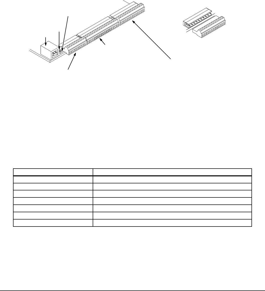
5.1 Control Board Connections
The analog and digital input and output terminals are shown in Figure 5-1. The signals are described in Tables 5-1, 5-2 and
5-3. Connections will depend upon which operating mode is selected (P1401). Each mode is described and a connection
diagram is provided later in this section.
Figure 5-1 Control I/O Connections
J1
J2
J3
Terminals 1 to 7 (J1)
1User Analog Return
2Analog Input 1
3Analog Ref. Power
4Analog Input 2 +
5Analog Input 2 -
6Analog Output 1
7Analog Output 2
Terminals 8 to 20 (J2)
8Enable Input
9Digital Input 1
10 Digital Input 2
11 Digital Input 3
12 Digital Input 4
13 Digital Input 5
14 Digital Input 6
15 Digital Input 7
16 Digital Input 8
17 Digital Out 1 + (Collector)
18 Digital Out 1 - (Emitter)
19 Digital Out 2 + (Collector)
20 Digital Out 2 - (Emitter)
Terminals 21 to 30 (J3)
21 External User +24V Return
22 External User +24V
23 Internal +24V
24 Internal +24V Return
25 Relay Out 1 NC
26 Relay Out 1 COM
27 Relay Out 1 NO
28 Relay Out 2 NC
29 Relay Out 2 COM
30 Relay Out 2 NO
USB Port Board Plug
Connector
Heartbeat/
Fault LED
USB Activity LED
1
1
21
8
See recommended tightening torques in Table A-2.
Table 5-1 J1 Connector Definition
Connector Terminal Signal Description
J1-1 0VDC - Common reference for Analog Inputs and Outputs
J1-2 AIN1 – Analog Input 1
J1-3 AREF - Analog reference power (+10V for Analog Input 1)
J1-4 AIN2+ - Analog Input 2+
J1-5 AIN2- - Analog Input 2-
J1-6 AOUT1 - Analog Output 1
J1-7 AOUT2 - Analog Output 2

5-2 Control Wiring MN766
Table 5-2 J2 Connector Definition
Connector Terminal Signal Description
J2-8 Enable Input
J2-9 DIN1 – Digital Input 1
J2-10 DIN2 – Digital Input 2
J2-11 DIN3 – Digital Input 3
J2-12 DIN4 – Digital Input 4
J2-13 DIN5 – Digital Input 5
J2-14 DIN6 – Digital Input 6
J2-15 DIN7 – Digital Input 7
J2-16 DIN8 – Digital Input 8
J2-17 Digital Output #1+ (Collector)
J2-18 Digital Output #1- (Emitter)
J2-19 Digital Output #2+ (Collector)
J2-20 Digital Output #2- (Emitter)
Table 5-3 J3 Connector Definition
Connector Terminal Signal Description
J3-21 External User +24V Return
J3-22 External User +24V
J3-23 Internal +24VDC
J3-24 Internal +24VDC Return
J3-25 Relay Output #1 N.C.
J3-26 Relay Output #1 COMMON
J3-27 Relay Output #1 N.O.
J3-28 Relay Output #2 N.C.
J3-29 Relay Output #2 COMMON
J3-30 Relay Output #2 N.O.
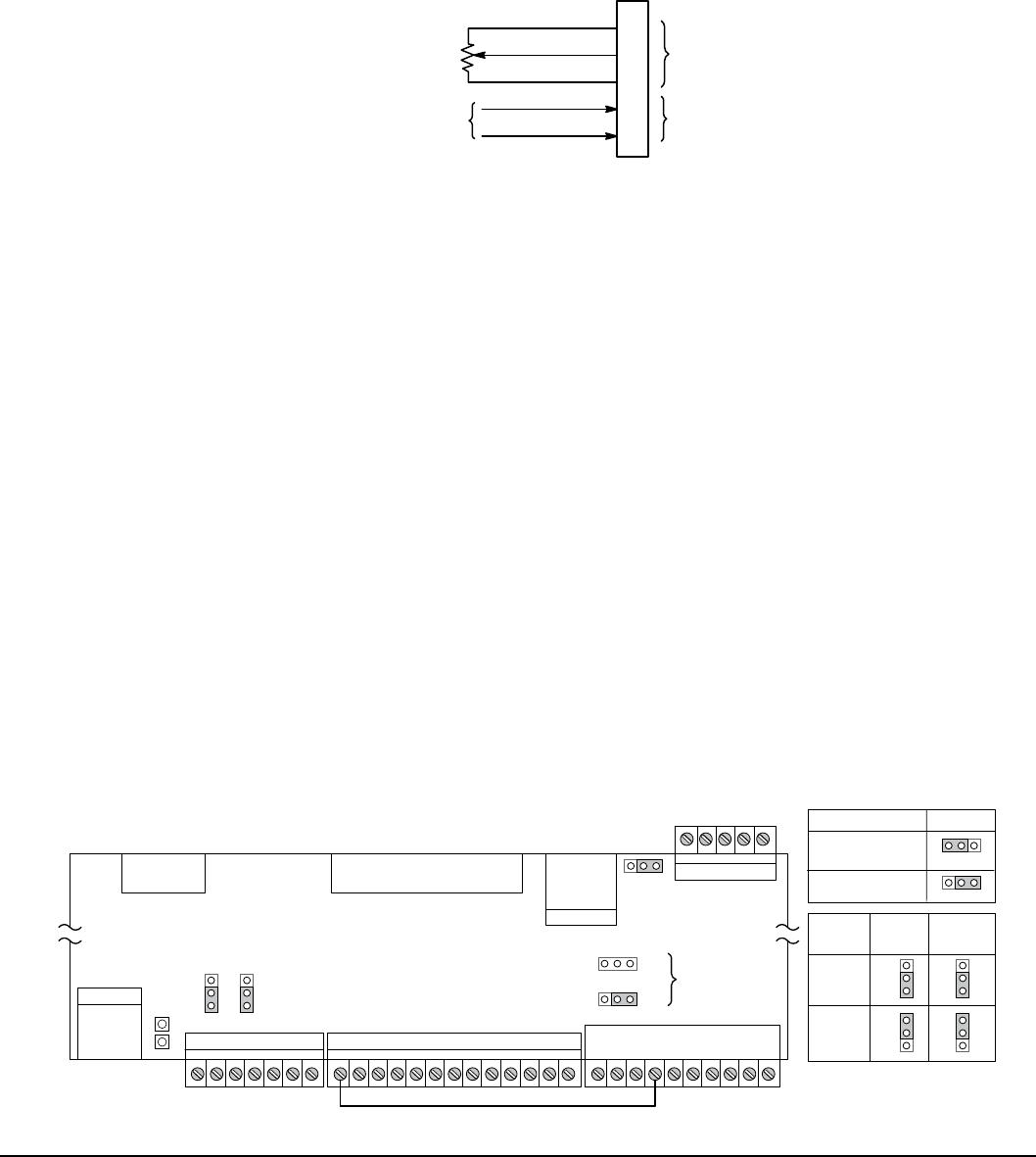
Control Wiring 5-3MN766
5.2 Analog Inputs
Two analog inputs are available: Analog Input 1 (J1-1 and J1-2) and Analog Input 2 (J1-4 and J1-5) as shown in Figure 5-2.
Either analog input may be selected in the Level 1 Input block, Command Source Parameter, (P1402)..
Figure 5-2 Analog Inputs
J1
Analog GND
Analog Input 1
Pot Reference
Analog Input +2
Analog Input -2
1
2
3
4
5
Analog Input 1
Analog Input 2
Command Pot or
0 - 10VDC
±5VDC, ±10VDC,
0-20mA or 4-20mA Input
See recommended terminal tightening torques in Table A-2.
5.2.1 Analog Input 1 (Single Ended)
When using a potentiometer as the speed command, process feedback or setpoint source, the potentiometer should be
connected at Analog Input 1. When using Analog Input 1, the respective parameter must be set to “Analog Input 1”.
Note: A potentiometer value of 5kΩ to 10kΩ, 0.5 watt may be used.
Parameter Selection
The single ended Analog Input 1 is typically used in one of three ways:
1. Speed or Torque command (Level 1 Input block, Command Source=Analog Input 1).
2. Process Feedback (Level 2 Process Control block, Process Feedback=Analog Input 1).
3. Setpoint Source (Level 2 Process Control block, Setpoint Source=Analog Input 1).
5.2.2 Analog Input 2 (Differential)
Analog Input 2 accepts a differential command ±5VDC, ±10VDC, 0-20mA or 4-20mA.
If pin J1-4 is positive with respect to pin J1-5 and P1408=±5V or ±10V, the motor will rotate in the forward direction.
If pin J1-4 is negative with respect to pin J1-5 and P1408=±5V or ±10V, the motor will rotate in the reverse direction. If
forward direction is not correct, change Level 2, Motor Data Reverse Rotation parameter P2415.
Analog Input 2 can be connected for single ended operation by connecting either of the differential terminals to common,
provided the common mode voltage range is not exceeded. See Note.
Analog Input 2 can be set for voltage or current mode operation. With JP1 as shown in Figure 5-3 , Voltage mode is
selected. If JP1 is connected to pins 2 and 3, current mode is selected.
The Level 1 Input Setup Parameter P1408 can be set to the full scale voltage or current range desired.
Note: The common mode voltage can be measured with a voltmeter. Apply the maximum command voltage to Analog Input
2 (J1-4,5). Measure the AC and DC voltage across J1-1 to J1-4. Add the AC and DC values. Measure the AC and DC
voltage from J1-1 to J1-5. Add these AC and DC values. If either of these measurement totals exceeds a total of ±15
volts, then the common mode voltage range has been exceeded. To correct this condition, isolate the command
signal with a signal isolator, such as Baldor catalog number BC145.
Figure 5-3 Jumper Locations
Fault
USB
USB Port
J1 J2 J3
JP1 JP2
JP3
11
1
RS485
Keypad
Connector
Ribbon
Cable
Regen
Connector
Control
Circuit Board JP6
JP5
P1
J7 J8
P2
P3
SGA B S
ENP
EPN
INP
DFT
Factory Settings
as shown
Note: Factory connection of
J2-8 (Enable) to J3-24.
248
See recommended tightening Torques in Table A-2.
JP1 JP2
ANAIN2 ANAOUT1
Voltage
Current
1 1
1 1
Type
1
JP3
1
No Termination
120 ohm
Termination
RS485
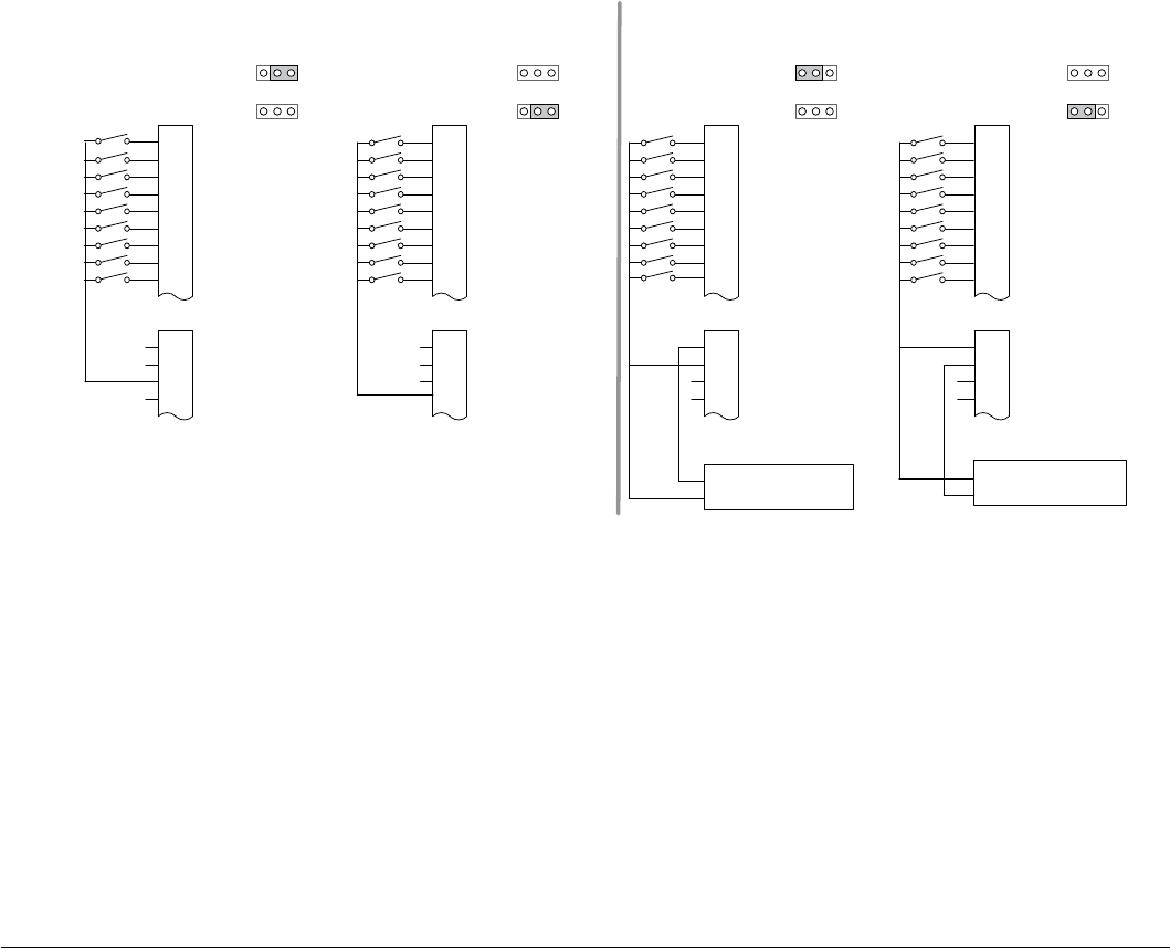
5-4 Control Wiring MN766
5.3 Analog Outputs
Two programmable analog outputs are provided on J1-6 and J1-7. These outputs are scaled and can be used to provide
status of various control conditions. The return for these outputs is J1-1 analog return. Each output function is programmed
in the Level 1 Output Setup block, Analog Out1 Signal, (P1511), or Analog Out2 Signal (P1514) parameter values.
Analog Output 1 can be set for voltage or current mode operation. With JP2 as shown in Figure 5-3, Voltage mode is
selected. If JP2 is connected to pins 2 and 3, current mode is selected.
The Level 1 Output Setup Parameter (P1510) can be set to the full scale voltage or current range desired.
5.4 Opto-Isolated Inputs
Logic input connections are made at terminal strip J2 pins 8 to 16. J2 inputs can be wired as Active High or Active Low as
shown in Figure 5-4. Internal or external power source is selected by jumpers JP5 and JP6 shown in Figure 5-4.
Notes for Figure 5-4:
1. See operating modes dened later in this chapter for input usage.
2. Factory connection of J2-8 (Enable) is made to J3-24 for Internal, Active Low connection. For other congurations, the
wire at J3-24 must be moved to J3-23, J3-21 or J3-22 as needed.
Figure 5-4 Active HIGH (Sourcing)/LOW (Sinking) Relationship
Enable
J2
Digital Input 2
Digital Input 3
Digital Input 4
Digital Input 5
Digital Input 6
Digital Input 7
Digital Input 8
21
J3
22
23
24
Active High Connections
User Provided
+24V Power Source
Active Low Connections
(Factory Default Settings)
Enable
J2
Digital Input 1
Digital Input 2
Digital Input 3
Digital Input 4
Digital Input 5
Digital Input 6
Digital Input 7
Digital Input 8
External User Return
21
J3
External User +24V
Internal +24V
22
23
Internal 24V Return
24
Internally Supplied 24VDC Externally Supplied 24VDC
8
9
10
11
12
13
14
15
16
8
9
10
11
12
13
14
15
16
Source Sink
Enable
J2
Digital Input 2
Digital Input 3
Digital Input 4
Digital Input 5
Digital Input 6
Digital Input 7
Digital Input 8
21
J3
22
23
24
Active High Connections Active Low Connections
Enable
J2
Digital Input 2
Digital Input 3
Digital Input 4
Digital Input 5
Digital Input 6
Digital Input 7
Digital Input 8
21
J3
22
23
24
8
9
10
11
12
13
14
15
16
8
9
10
11
12
13
14
15
16
Source Sink
User Provided
+24V Power Source
JP6
JP5
ENP
EPN
INP
DFT
JP6
JP5
*ENP
*EPN
INP
DFT
JP6
JP5
ENP
EPN
INP
DFT
JP6
JP5
ENP
EPN
INP
DFT
External User +24V
Internal +24V
Internal 24V Return
External User Return
External User +24V
Internal +24V
Internal 24V Return
External User Return
External User +24V
Internal +24V
Internal 24V Return
See recommended tightening torques in Table A-2.
Digital Input 1 Digital Input 1 Digital Input 1
External User Return
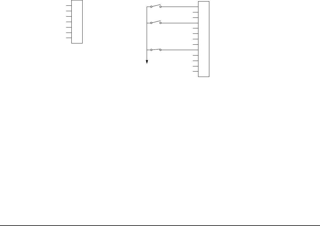
Control Wiring 5-5MN766
5.5 Operating Modes
The operating modes dene the basic motor control setup and the operation of the input and output terminals. After the
circuit connections are completed, the operating mode is selected by programming the Operating Mode parameter in the
Level 1 Input Setup Programming Block (P1401).
Operating modes include:
• Keypad • Standard Run 2Wire • Standard Run 3Wire • 15 Preset Speeds
• Fan Pump 2Wire • Fan Pump 3Wire • Process Control* • 3 Spd Ana 2Wire
• 3 Spd Ana 3Wire • Electronic Pot 2Wire • Electronic Pot 3Wire • Network
• Prole Run* • 15 Preset Position* • Bipolar • Pulse Follower*
• PLC*
* To view and change parameters associated with these modes, Operating Mode (P1401) must be set to the respective
mode. For example, this means Process Control parameters will not appear on the keypad for selection unless Level 1, Input
Setup, Operating Mode (P1401) is set to “Process Control”.
Each mode requires connections to the J1, J2 and J3 terminal strips. The terminal strips are shown in Figure 5-1. The
connection of each input or output signal is described in the following pages.
5.5.1 Keypad
The Keypad mode allows the control to be operated from the keypad. In this mode only the Enable input is required.
However, the Stop and External Trip inputs may optionally be used. All other Digital Inputs remain inactive. The Analog
Outputs and Digital Outputs remain active at all times.
Figure 5-5 Keypad Connection Diagram
User Analog Return
Analog Input 1
Analog Ref. Power +
1
2
3
4
5
6
7
J1
Analog Input 2+
Analog Input 2-
Analog Output 1
Analog Output 2
Enable
8
J2
17 Digital Output 1 + (Collector)
9
10
11
12
13
14
15
16
Digital Output 1 - (Emitter)
Digital Output 2 + (Collector)
Digital Output 2 - (Emitter)
18
19
20
Enable
External Trip
See Figure 5-4 for
connection information.
(Optional Stop)
Digital Input 1
Digital Input 2
Digital Input 3
Digital Input 4
Digital Input 5
Digital Input 6
Digital Input 7
Digital Input 8
For keypad operation, only Enable (J2-8) is required.
See recommended tightening torques in Table A-2.
*
*Note: Remove factory jumper from J2-8 and J3-24 before connecting switch at J2-8.
J2-8 CLOSED allows normal control operation.
OPEN disables the control and motor coasts to stop.
J2-11 Optional STOP input (not required).
CLOSED allows normal control operation.
OPEN motor coasts or brakes to stop if Level 1 Keypad Setup block, Local Hot Start parameter is set to “ON”.
J2-16 Optional External Trip input (not required). If used, you must set Level 2 Drive Protect block, External Trip to “ON”.
CLOSED allows normal operation.
OPEN causes an External Trip to be received by the control (when programmed to “ON”).
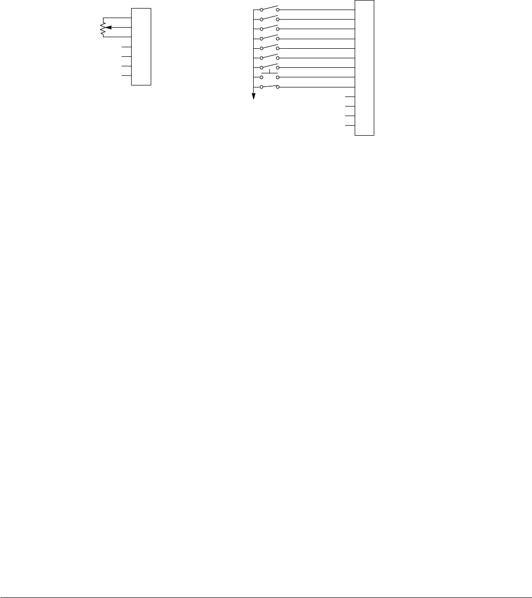
5-6 Control Wiring MN766
5.5.2 Standard Run 2-Wire
In Standard Run 2Wire mode, the control is operated by the digital inputs and the command source. Also, Preset Speed 1
can be selected. The opto inputs can be switches as shown in Figure 5-6 or logic signals from another device.
Figure 5-6 Standard Run 2-Wire Connection Diagram
User Analog Return
Analog Input 1
Analog Ref. Power +
1
2
3
4
5
6
7
J1
Analog Input 2+
Analog Input 2-
Analog Output 1
Analog Output 2
Enable
J2
Digital Output 1 + (Collector)
Digital Output 1 - (Emitter)
Digital Output 2 + (Collector)
Digital Output 2 - (Emitter)
See Figure 5-4 for
connection information.
Enable
Forward Run
Reverse Run
Jog Forward
Jog Reverse
Accel/Decel Select
Preset Speed 1
External Trip
10KΩ Pot or
0 - 10VDC
Fault Reset
Digital Input 1
Digital Input 2
Digital Input 3
Digital Input 4
Digital Input 5
Digital Input 6
Digital Input 7
Digital Input 8
8
17
9
10
11
12
13
14
15
16
18
19
20
See recommended tightening torques in Table A-2.
*
*Note: Remove factory jumper from J2-8 and J3-24 before connecting switch at J2-8.
J2-8 CLOSED allows normal operation.
OPEN disables the control and motor coasts to a stop.
J2-9 CLOSED starts motor operation in the Forward direction.
OPEN motor decels to stop. If Level 1, Keypad Setup, Stop Mode is set to “coast”, motor coasts to stop.
J2-10 CLOSED starts motor operation in the Reverse direction.
OPEN motor decels to stop. If Level 1, Keypad Setup, Stop Mode is set to “coast”, motor coasts to stop.
J2-11 CLOSED starts motor JOG operation in the Forward direction.
OPEN motor decels to stop. If Level 1, Keypad Setup, Stop Mode is set to “coast”, motor coasts to stop.
J2-12 CLOSED starts motor JOG operation in the Reverse direction.
OPEN motor decels to stop. If Level 1, Keypad Setup, Stop Mode is set to “coast”, motor coasts to stop.
J2-13 CLOSED selects ACC / DEC / S-ACC / S-DEC group 2.
OPEN selects ACC / DEC / S-ACC / S-DEC group 1.
J2-14 CLOSED selects Preset Speed 1 (J2-11 or 12, will override this Preset Speed).
OPEN allows speed command from the Command Source (P1402).
J2-15 CLOSED to reset fault.
OPEN to run.
J2-16 Optional External Trip input (not required). If used, you must set Level 2 Drive Protect block, External Trip to “ON”.
CLOSED allows normal operation.
OPEN causes an External Trip to be received by the control.
Note: When Command Source is a unipolar signal (0-10V, 0-5V, 4-20mA etc.) and Forward Run or Reverse Run is closed,
motion will occur (unless both are closed at the same time).
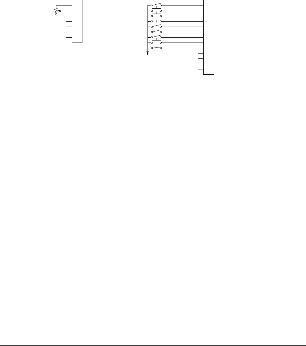
Control Wiring 5-7MN766
5.5.3 Standard Run 3-Wire
In Standard Run 3Wire mode, the control is operated by the digital inputs and the command source. Also, Preset Speed 1
can be selected. The opto inputs can be switches as shown in Figure 5-7 or logic signals from another device.
Figure 5-7 Standard Run 3-Wire Connection Diagram
User Analog Return
Analog Input 1
Analog Ref. Power +
1
2
3
4
5
6
7
J1
Analog Input 2+
Analog Input 2-
Analog Output 1
Analog Output 2
Enable
J2
Digital Output 1 + (Collector) Digital Output 1 - (Emitter)
Digital Output 2 + (Collector)
Digital Output 2 - (Emitter)
See Figure 5-4 for connection
Information.
Enable
Forward Start
Reverse Start
Stop
Jog
Accel/Decel
Preset Speed 1
External Trip
10K Ω Pot or
0 - 10VDC
Fault Reset
Digital Input 1
Digital Input 2
Digital Input 3
Digital Input 4
Digital Input 5
Digital Input 6
Digital Input 7
Digital Input 8
8
17
9
10
11
12
13
14
15
16
18
19
20
See recommended tightening torques in Table A-2.
*
*Note: Remove factory jumper from J2-8 and J3-24 before connecting switch at J2-8.
J2-8 CLOSED allows normal operation.
OPEN disables the control and motor coasts to a stop.
J2-9 MOMENTARY CLOSED starts motor operation in the Forward direction.
In JOG mode (J2-12 CLOSED), motor jogs in the Forward direction as long as closed.
J2-10 MOMENTARY CLOSED starts motor operation in the Reverse direction.
In JOG mode (J2-12 CLOSED), motor jogs in the Reverse direction as long as closed.
J2-11 MOMENTARY OPEN motor decels to stop.
J2-12 CLOSED places control in JOG mode, Forward and Reverse run are used to jog the motor.
J2-13 CLOSED selects ACC / DEC / S-ACC / S-DEC group 2.
OPEN selects ACC / DEC / S-ACC / S-DEC group 1.
J2-14 CLOSED selects Preset Speed 1 (J2-12,will override this Preset Speed).
OPEN allows speed command from the Command Source (P1402).
J2-15 CLOSED to reset fault.
OPEN to run.
J2-16 Optional External Trip input (not required). If used, you must set Level 2 Drive Protect block, External Trip to “ON”.
CLOSED allows normal operation.
OPEN causes an External Trip to be received by the control.
Note: When Command Source is a unipolar signal (0-10V, 0-5V, 4-20mA etc.) and Forward Run or Reverse Run is closed,
motion will occur (unless both are closed at the same time).
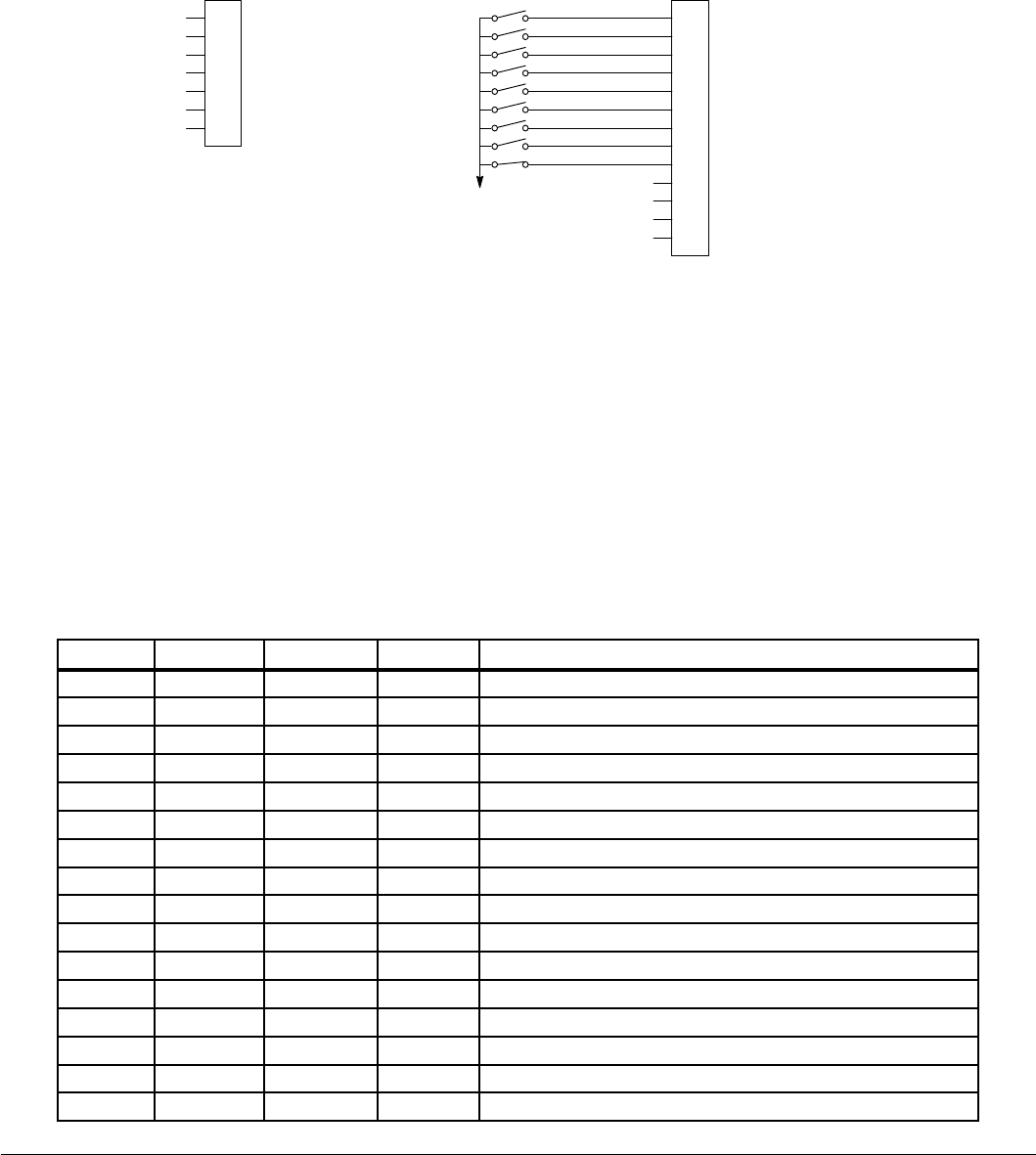
5-8 Control Wiring MN766
5.5.4 15 Preset Speeds
Operation in 15 Preset Speeds 2-Wire mode is controlled by the opto isolated inputs at J2. The values of the Preset Speeds
are set in the Level 1 Preset Speeds block, Preset Speed 1 to Preset Speed 15. J2-11 through J2-14 inputs allow selection
of 15 Preset Speeds. The opto inputs can be switches as shown in Figure 5-8 or logic signals from another device.
Figure 5-8 15 Preset Speeds
User Analog Return
Analog Input 1
Analog Ref. Power +
1
2
3
4
5
6
7
J1
Analog Input 2+
Analog Input 2-
Analog Output 1
Analog Output 2
Enable
J2
Digital Output 1 + (Collector)
Digital Output 1 - (Emitter)
Digital Output 2 + (Collector)
Digital Output 2 - (Emitter)
See Figure 5-4 for
connection information.
Enable
Forward Run
Reverse Run
Switch 1
Switch 2
Switch 3
Switch 4
External Trip
Accel/Decel
Digital Input 1
Digital Input 2
Digital Input 3
Digital Input 4
Digital Input 5
Digital Input 6
Digital Input 7
Digital Input 8
8
17
9
10
11
12
13
14
15
16
18
19
20
See recommended tightening torques in Table A-2.
*
*Note: Remove factory jumper from J2-8 and J3-24 before connecting switch at J2-8.
J2-8 CLOSED allows normal operation.
OPEN disables the control and motor coasts to a stop.
J2-9 CLOSED operates the motor in the Forward direction (with J2-10 open).
OPEN motor decels to stop.
J2-10 CLOSED operates motor in the Reverse direction (with J2-9 open).
OPEN motor decels to stop.
J2-11 to J2-14 Selects programmed Preset Speeds as dened in Table 5-4 .
J2-15 CLOSED selects ACC / DEC / S-ACC / S-DEC group 2.
OPEN selects ACC / DEC / S-ACC / S-DEC group 1.
J2-16 Optional External Trip input (not required). If used, you must set Level 2 Drive Protect block, External Trip
to “ON”.
CLOSED allows normal operation.
OPEN causes an External Trip to be received by the control.
Table 5-4 Speed Select Table for 15 Speed, 2-Wire Control Mode
J2-11 J2-12 J2-13 J2-14 Function
OPEN OPEN OPEN OPEN Selects Level 1:Preset Speed:Preset Speed 1 (P1001)
CLOSED OPEN OPEN OPEN Selects Level 1:Preset Speed:Preset Speed 2 (P1002)
OPEN CLOSED OPEN OPEN Selects Level 1:Preset Speed:Preset Speed 3 (P1003)
CLOSED CLOSED OPEN OPEN Selects Level 1:Preset Speed:Preset Speed 4 (P1004)
OPEN OPEN CLOSED OPEN Selects Level 1:Preset Speed:Preset Speed 5 (P1005)
CLOSED OPEN CLOSED OPEN Selects Level 1:Preset Speed:Preset Speed 6 (P1006)
OPEN CLOSED CLOSED OPEN Selects Level 1:Preset Speed:Preset Speed 7 (P1007)
CLOSED CLOSED CLOSED OPEN Selects Level 1:Preset Speed:Preset Speed 8 (P1008)
OPEN OPEN OPEN CLOSED Selects Level 1:Preset Speed:Preset Speed 9 (P1009)
CLOSED OPEN OPEN CLOSED Selects Level 1:Preset Speed:Preset Speed 10 (P1010)
OPEN CLOSED OPEN CLOSED Selects Level 1:Preset Speed:Preset Speed 11 (P1011)
CLOSED CLOSED OPEN CLOSED Selects Level 1:Preset Speed:Preset Speed 12 (P1012)
OPEN OPEN CLOSED CLOSED Selects Level 1:Preset Speed:Preset Speed 13 (P1013)
CLOSED OPEN CLOSED CLOSED Selects Level 1:Preset Speed:Preset Speed 14 (P1014)
OPEN CLOSED CLOSED CLOSED Selects Level 1:Preset Speed:Preset Speed 15 (P1015)
CLOSED CLOSED CLOSED CLOSED Fault Reset
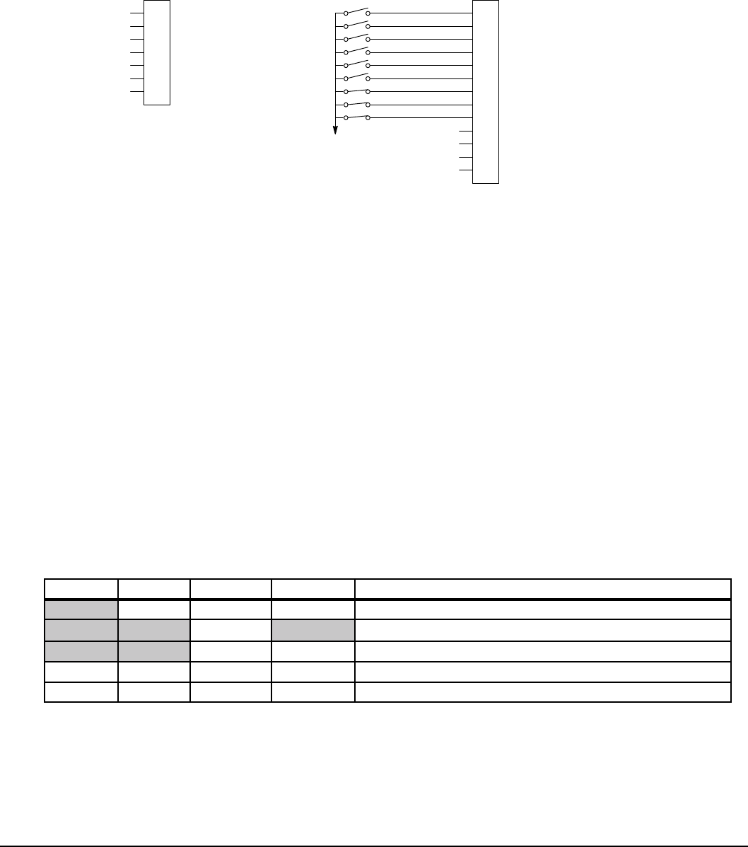
Control Wiring 5-9MN766
5.5.5 Fan Pump 2-Wire
Operation in the Fan Pump 2-Wire mode is controlled by the opto isolated inputs at J2-8 through J2-16. The opto inputs can
be switches as shown in Figure 5-9 or logic signals from another device.
Figure 5-9 Fan Pump 2-Wire Connection Diagram
User Analog Return
Analog Input 1
Analog Ref. Power +
1
2
3
4
5
6
7
J1
Analog Input 2+
Analog Input 2-
Analog Output 1
Analog Output 2
Enable
J2
Digital Output 1 + (Collector)
Digital Output 1 - (Emitter)
Digital Output 2 + (Collector)
Digital Output 2 - (Emitter)
Enable
Forward Run
Reverse Run
Analog Input Select
Run Command
Speed Command
Firestat
External Trip
See Figure 5-4 for
connection information.
Freezestat
Digital Input 1
Digital Input 2
Digital Input 3
Digital Input 4
Digital Input 5
Digital Input 6
Digital Input 7
Digital Input 8
8
17
9
10
11
12
13
14
15
16
18
19
20
See recommended tightening torques in Table A-2.
*
*Note: Remove factory jumper from J2-8 and J3-24 before connecting switch at J2-8.
J2-8 CLOSED allows normal control operation.
OPEN disables the control and the motor coasts to a stop.
J2-9 CLOSED operates the motor in the Forward direction (with J2-10 open).
OPEN motor decels to stop. Note: J2-9 and J2-10 are both closed = Fault Reset.
J2-10 CLOSED operates the motor in the Reverse direction (with J2-9 open).
OPEN motor decels to stop. Note: J2-9 and J2-10 are both closed = Fault Reset.
J2-11 CLOSED selects Analog Input 1 (if J2-13, J2-14 and J2-15 are closed).
OPEN selects Command Source (Level 1, Input, Command Source) if J2-13, J2-14 and J2-15 are closed.
J2-12 CLOSED selects STOP/START and Reset commands from terminal strip.
OPEN selects STOP/START and Reset commands from Keypad.
J2-13 CLOSED allows other selections, see Speed Select Table 5-5 .
OPEN selects speed commanded from Keypad (if J2-14 and J2-15 are closed).
Note: When changing from Terminal Strip to Keypad (J2-12 or J2-13) the motor speed and direction will remain
the same after the change.
J2-14 Firestat. Selects Level 1, Preset Speeds, Preset Speed 1.
J2-15 Freezestat. Level 1, Preset Speeds, Preset Speed 2 (if J2-14 is closed).
J2-16 Optional External Trip input (not required). If used, you must set Level 2 Drive Protect block, External Trip to “ON”.
CLOSED allows normal operation.
OPEN causes an External Trip to be received by the control (when programmed to “ON”).
Table 5-5 Speed Select Table – Fan Pump 2-Wire
J2-11 J2-13 J2-14 J2-15 Command
OPEN CLOSED CLOSED Keypad Speed Command
OPEN Level 1, Preset Speeds, Preset Speed 1
CLOSED OPEN Level 1, Preset Speeds, Preset Speed 2
OPEN CLOSED CLOSED CLOSED Level 1, Input Setup, Command Source (parameter P1402)
CLOSED CLOSED CLOSED CLOSED Analog Input 1
Note: When Command Source is a unipolar signal (0-10V, 0-5V, 4-20mA etc.) and Forward Run or Reverse Run is closed,
motion will occur (unless both are closed at the same time).
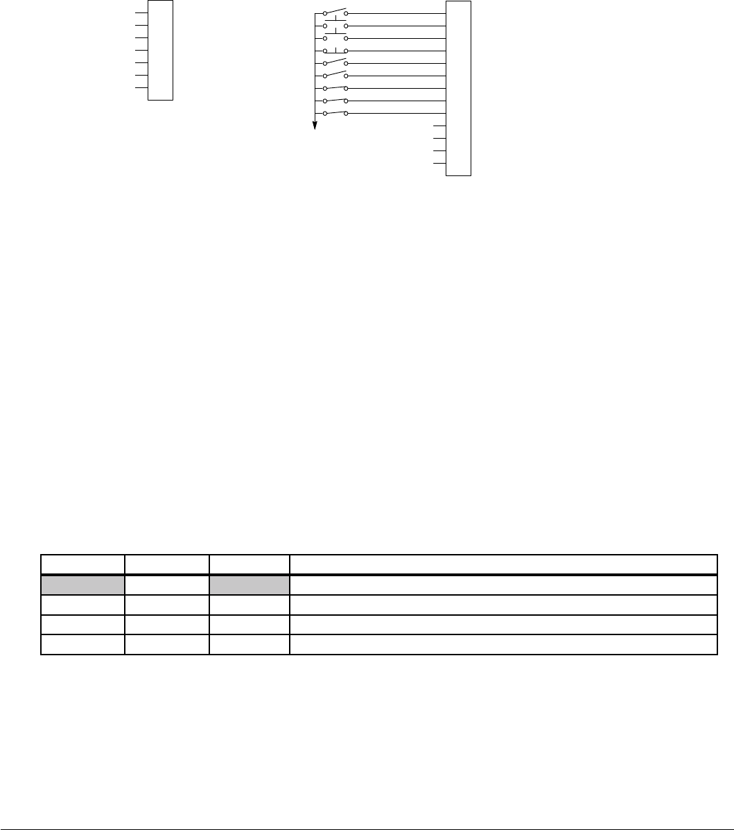
5-10 Control Wiring MN766
5.5.6 Fan Pump 3-Wire
Operation in the Fan Pump 3-Wire mode is controlled by the opto isolated inputs at J2-8 through J2-16. The opto inputs can
be switches as shown in Figure 5-10 or logic signals from another device.
Figure 5-10 Fan Pump 3-Wire Connection Diagram
User Analog Return
Analog Input 1
Analog Ref. Power +
1
2
3
4
5
6
7
J1
Analog Input 2+
Analog Input 2-
Analog Output 1
Analog Output 2
Enable
J2
Digital Output 1 + (Collector)
Digital Output 1 - (Emitter)
Digital Output 2 + (Collector)
Digital Output 2 - (Emitter)
See Figure 5-4 for
connection information.
Enable
Forward Start
Reverse Start
Stop
Run Command
Speed Command
Firestat
External Trip
Freezestat
Digital Input 1
Digital Input 2
Digital Input 3
Digital Input 4
Digital Input 5
Digital Input 6
Digital Input 7
Digital Input 8
8
17
9
10
11
12
13
14
15
16
18
19
20
See recommended tightening torques in Table A-2.
*
*Note: Remove factory jumper from J2-8 and J3-24 before connecting switch at J2-8.
J2-8 CLOSED allows normal control operation.
OPEN disables the control and the motor coasts to a stop.
J2-9 MOMENTARY CLOSED starts motor operation in the Forward direction.
Note: Closing both J2-9 and J2-10 at the same time will reset a fault.
J2-10 MOMENTARY CLOSED starts motor operation in the Reverse direction.
Note: Closing both J2-9 and J2-10 at the same time will reset a fault.
J2-11 MOMENTARY OPEN motor decels to stop.
J2-12 CLOSED selects STOP/START and Reset commands from terminal strip.
OPEN selects STOP/START and Reset commands from Keypad.
J2-13 CLOSED allows other selections, see Speed Select Table 5-6.
OPEN selects speed commanded from Keypad (if J2-14 and J2-15 are closed).
Note: When changing from Terminal Strip to Keypad (J2-12 or J2-13) the motor speed and direction will remain
the same after the change.
J2-14 Firestat. Selects Level 1, Preset Speeds, Preset Speed 1.
J2-15 Freezestat. Selects Level 1, Preset Speeds, Preset Speed 2 (if J2-14 is closed).
J2-16 Optional External Trip input (not required). If used, you must set Level 2 Drive Protect block, External Trip to “ON”.
CLOSED allows normal operation.
OPEN causes an External Trip to be received by the control (when programmed to “ON”).
Table 5-6 Speed Select Table – Fan Pump 3-Wire
J2-13 J2-14 J2-15 Command
OPEN Level 1, Preset Speeds, Preset Speed 1
CLOSED CLOSED OPEN Level 1, Preset Speeds, Preset Speed 2
OPEN CLOSED CLOSED Keypad Speed Command
CLOSED CLOSED CLOSED Level 1, Input Setup, Command Source (parameter P1402)
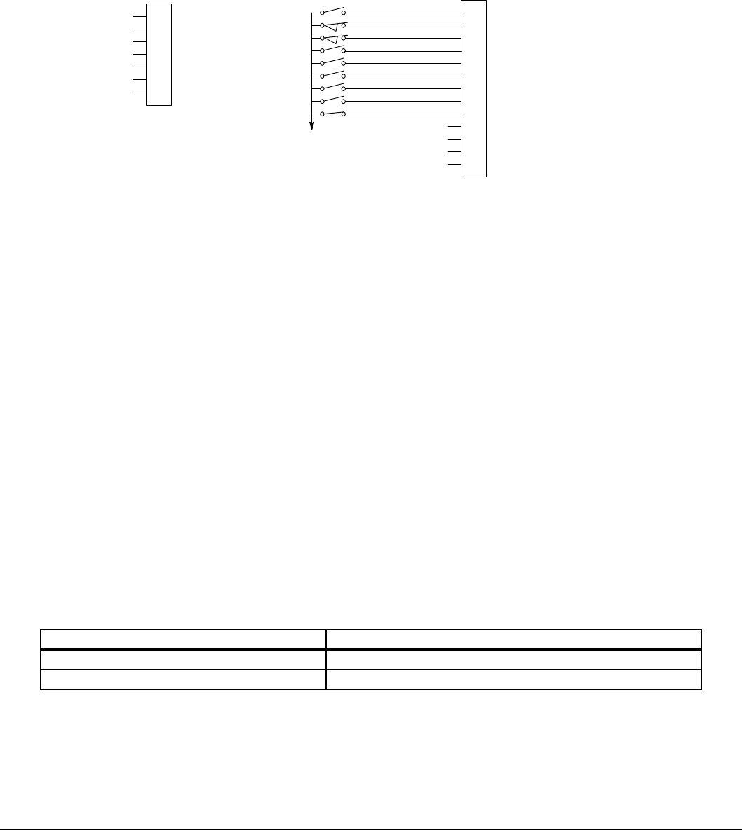
Control Wiring 5-11MN766
5.5.7 Process Control
The process control mode provides an auxiliary closed loop general purpose PID set point control. The process control loop
may be congured in various ways and detailed descriptions of the Process Control are given in MN707 “Introduction to
Process Control”. The opto inputs can be switches as shown in Figure 5-11 or logic signals from another device.
Figure 5-11 Process Control Connections
See Figure 5-4 for
connection information.
Enable
Forward Enable
Reverse Enable
Table Select
Speed/Torque
Process Mode Enable
Jog
External Trip
Fault Reset
Enable
J2
Digital Output 1 + (Collector)
Digital Output 1 - (Emitter)
Digital Output 2 + (Collector)
Digital Output 2 - (Emitter)
Digital Input 1
Digital Input 2
Digital Input 3
Digital Input 4
Digital Input 5
Digital Input 6
Digital Input 7
Digital Input 8
8
17
9
10
11
12
13
14
15
16
18
19
20
User Analog Return
Analog Input 1
Analog Ref. Power +
1
2
3
4
5
6
7
J1
Analog Input 2+
Analog Input 2-
Analog Output 1
Analog Output 2
See recommended tightening torques in Table A-2.
*
*Note: Remove factory jumper from J2-8 and J3-24 before connecting switch at J2-8.
J2-8 CLOSED allows normal control operation.
OPEN disables the control and the motor coasts to a stop.
J2-9 CLOSED to enable operation in the Forward direction.
OPEN to disable Forward operation (drive will decel to a stop if a Forward speed command is still present).
Reverse operation is still possible if J2-10 is closed.
J2-10 CLOSED to enable operation in the Reverse direction.
OPEN to disable Reverse operation (drive will decel to a stop if a Reverse speed command is still present).
Forward operation is still possible if J2-9 is closed.
Note: If J2-9 and J2-10 are both opened, the drive will decel to a stop.
J2-11 CLOSED = TABLE 2,
OPEN = TABLE 1. Refer to Table 5-7.
Note: The Operating Mode (P1401) must be set to a mode that allows table switching in both tables T1 and T2.
J2-12 CLOSED Selects ACC/DEC group 2 (V/F) or selects torque mode (Vector).
OPEN Selects ACC/DEC group 1 (V/F) or selects speed mode (Vector).
Note: If a stop command is issued while in the torque (current) mode, the control will stop but will not maintain
position (zero current). This is different than zero speed operation for the velocity mode.
J2-13 CLOSED to enable PID and FF. Feedforward (FF) is from Command Source (P1402).
OPEN to enable FF only. PID is disabled with its integrator reset to zero.
J2-14 CLOSED to enable JOG mode. Jog in either direction is allowed if enabled by J2-9 or J2-10.
J2-15 CLOSED to reset a fault.
OPEN to run.
J2-16 Optional External Trip input (not required). If used, you must set Level 2 Drive Protect block, External Trip to “ON”.
CLOSED allows normal operation.
OPEN causes an External Trip to be received by the control (when programmed to “ON”).
Table 5-7 Process Control Select Table
J2-11 Command
OPEN Selects Parameter Table 1
CLOSED Selects Parameter Table 2
Note: See multiple parameter sets in this section.
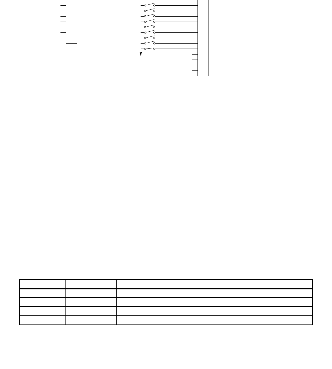
5-12 Control Wiring MN766
5.5.8 3 Speed Analog 2-Wire
Provides 2 wire input control and allows selection of 3 Preset Speeds. The values of the Preset Speeds are set in the Level
1 Preset Speeds block, Preset Speed 1, Preset Speed 2 and Preset Speed 3. The opto inputs can be switches as shown in
Figure 5-12 or logic signals from another device.
Figure 5-12 3 Speed Analog 2-Wire Connection Diagram
User Analog Return
Analog Input 1
Analog Ref. Power +
1
2
3
4
5
6
7
J1
Analog Input 2+
Analog Input 2-
Analog Output 1
Analog Output 2
Enable
J2
Digital Output 1 + (Collector)
Digital Output 1 - (Emitter)
Digital Output 2 + (Collector)
Digital Output 2 - (Emitter)
See Figure 5-4 for
connection information.
Enable
Forward Run
Reverse Run
Analog Input Select
Run Command
Speed Command
Switch 1
External Trip
Switch 2
Digital Input 1
Digital Input 2
Digital Input 3
Digital Input 4
Digital Input 5
Digital Input 6
Digital Input 7
Digital Input 8
8
17
9
10
11
12
13
14
15
16
18
19
20
See recommended tightening torques in Table A-2.
*
*Note: Remove factory jumper from J2-8 and J3-24 before connecting switch at J2-8.
J2-8 CLOSED allows normal control operation.
OPEN disables the control and the motor coasts to a stop.
J2-9 CLOSED operates the motor in the Forward direction (with J2-10 open).
OPEN motor decels to stop.
J2-10 CLOSED operates the motor in the Reverse direction (with J2-9 open).
OPEN motor decels to stop.
Note: Closing both J2-9 and J2-10 at the same time will reset a fault.
J2-11 CLOSED selects Analog Input 1.
OPEN selects Level 1 Input block, Command Source parameter.
Note: If Command Source (Level 1 Input block) is set to Analog Input 1, then Analog Input 1 is always selected
regardless of this switch position.
J2-12 CLOSED selects STOP/START and Reset Commands from the terminal strip.
OPEN selects STOP/START and Reset Commands from the keypad.
J2-13 CLOSED selects Level 1 Input block, Command Source parameter.
OPEN selects speed commanded from Keypad.
Note: When changing from Terminal Strip to Keypad (J2-12 or J2-13) the motor speed and direction will remain
the same after the change.
J2-14 Selects Preset Speeds as dened in the Speed Select Table (Table 5-8).
J2-15 Selects Preset Speeds as dened in the Speed Select Table (Table 5-8).
J2-16 Optional External Trip input (not required). If used, you must set Level 2 Drive Protect block, External Trip to “ON”.
CLOSED allows normal operation.
OPEN causes an External Trip to be received by the control (when programmed to “ON”).
Table 5-8 Speed Select Table
J2-14 J2-15 Command
OPEN OPEN Level 1, Input Setup, Command Source (parameter P1402)
CLOSED OPEN Preset 1
OPEN CLOSED Preset 2
CLOSED CLOSED Preset 3
Note: When Command Source is a unipolar signal (0-10V, 0-5V, 4-20mA, etc.) and forward run or reverse run is closed,
motion will occur (unless both forward run and reverse run are closed at the same time).
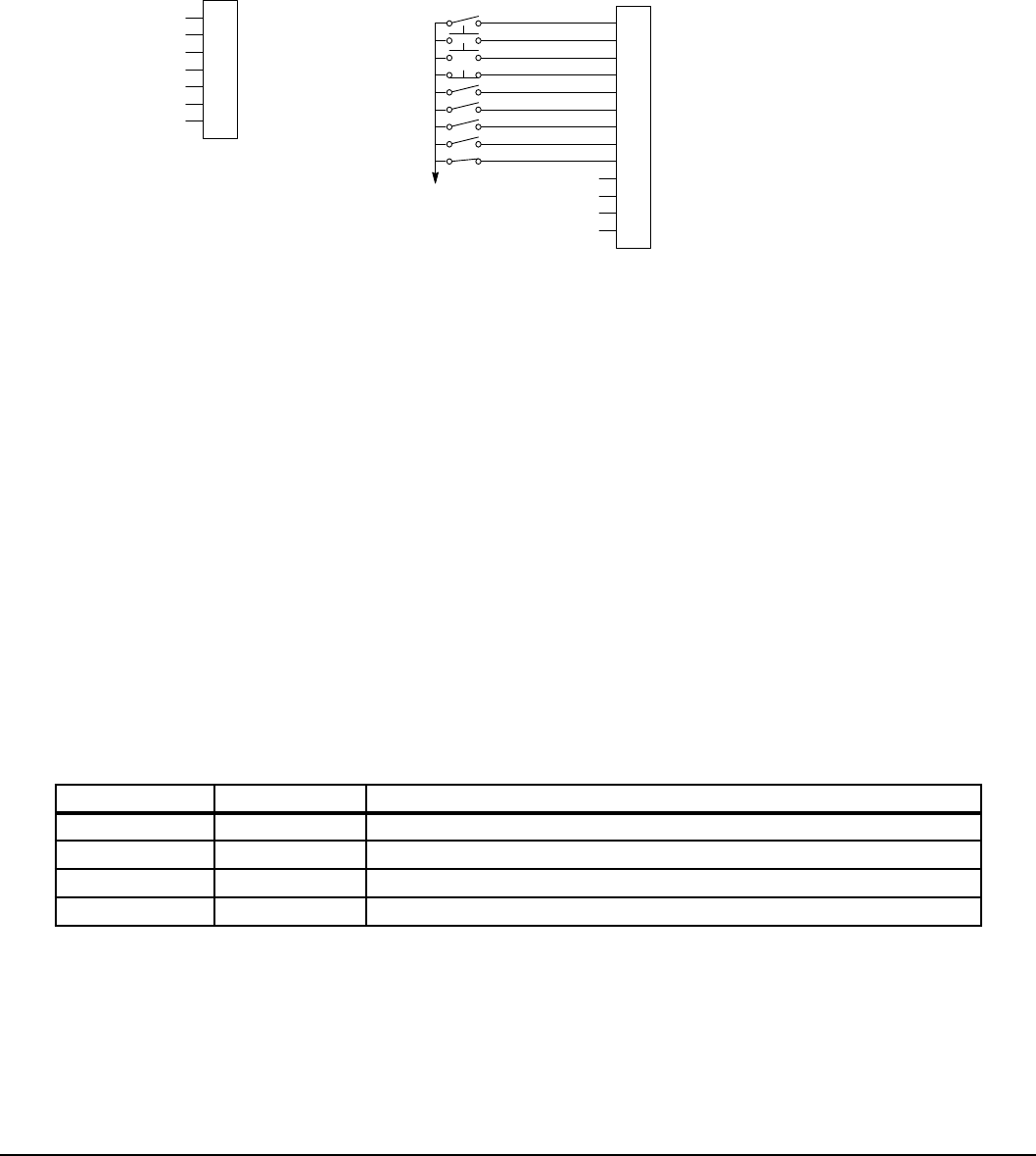
Control Wiring 5-13MN766
5.5.9 3 Speed Analog 3-Wire
Provides 3 wire input control and allows selection of 3 Preset Speeds. The values of the Preset Speeds are set in the Level
1 Preset Speeds block, Preset Speed 1, Preset Speed 2 and Preset Speed 3. The opto inputs can be switches as shown in
Figure 5-13 or logic signals from another device.
Figure 5-13 3 Speed Analog 3-Wire Connection Diagram
User Analog Return
Analog Input 1
Analog Ref. Power +
1
2
3
4
5
6
7
J1
Analog Input 2+
Analog Input 2-
Analog Output 1
Analog Output 2
Enable
J2
Digital Output 1 + (Collector)
Digital Output 1 - (Emitter)
Digital Output 2 + (Collector)
Digital Output 2 - (Emitter)
See Figure 5-4 for
connection information.
Enable
Forward Start
Reverse Start
Stop
Run Command
Speed Command
Switch 1
External Trip
Switch 2
Digital Input 1
Digital Input 2
Digital Input 3
Digital Input 4
Digital Input 5
Digital Input 6
Digital Input 7
Digital Input 8
8
17
9
10
11
12
13
14
15
16
18
19
20
See recommended tightening torques in Table A-2.
*
*Note: Remove factory jumper from J2-8 and J3-24 before connecting switch at J2-8.
J2-8 CLOSED allows normal control operation.
OPEN disables the control and the motor coasts to a stop.
J2-9 MOMENTARY CLOSED starts motor operation in the Forward direction.
J2-10 MOMENTARY CLOSED starts motor operation in the Reverse direction.
Note: Closing both J2-9 and J2-10 at the same time will reset a fault.
J2-11 MOMENTARY OPEN motor decels to stop.
J2-12 CLOSED selects STOP/START and Reset Commands from the terminal strip.
OPEN selects STOP/START and Reset Commands from the keypad.
J2-13 CLOSED selects Level 1 Input block, Command Source parameter.
OPEN selects speed commanded from Keypad.
Note: When changing from Terminal Strip to Keypad (J2-12 or J2-13) the motor speed and direction will remain
the same after the change.
J2-14 Selects Preset Speeds as dened in the Speed Select Table (Table 5-9).
J2-15 Selects Preset Speeds as dened in the Speed Select Table (Table 5-9).
J2-16 Optional External Trip input (not required). If used, you must set Level 2 Drive Protect block, External Trip to “ON”.
CLOSED allows normal operation.
OPEN causes an External Trip to be received by the control (when programmed to “ON”).
Table 5-9 Speed Select Table
J2-14 J2-15 Command
OPEN OPEN Level 1, Input Setup, Command Source (parameter P1402)
CLOSED OPEN Preset 1
OPEN CLOSED Preset 2
CLOSED CLOSED Preset 3
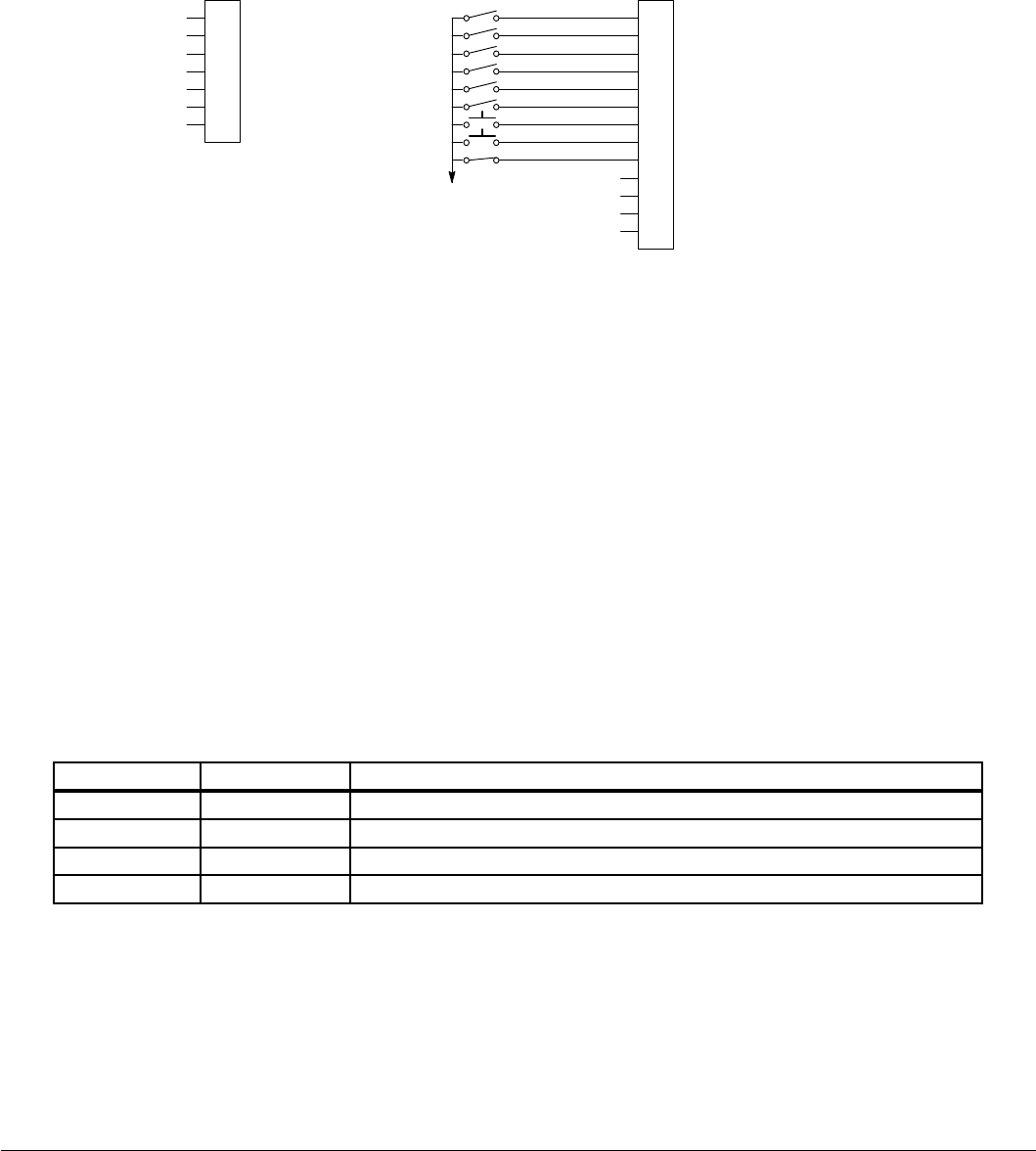
5-14 Control Wiring MN766
5.5.10 E-POT 2-Wire
Provides speed Increase and Decrease inputs to allow E-POT (Electronic Potentiometer) operation with 2 wire inputs. The
values of the Preset Speeds are set in the Level 1 Preset Speeds block, Preset Speed 1 or Preset Speed 2. The opto inputs
can be switches as shown in Figure 5-14 or logic signals from another device.
Figure 5-14 E-POT 2-Wire Connection Diagram
User Analog Return
Analog Input 1
Analog Ref. Power +
1
2
3
4
5
6
7
J1
Analog Input 2+
Analog Input 2-
Analog Output 1
Analog Output 2
Enable
J2
Digital Output 1 + (Collector) Digital Output 1 - (Emitter)
Digital Output 2 + (Collector)
Digital Output 2 - (Emitter)
See Figure 5-4 for
connection information.
Enable
Forward Run
Reverse Run
Switch 1
Switch 2
Accel/Decel
Increase
External Trip
Decrease
Digital Input 1
Digital Input 2
Digital Input 3
Digital Input 4
Digital Input 5
Digital Input 6
Digital Input 7
Digital Input 8
8
17
9
10
11
12
13
14
15
16
18
19
20
See recommended tightening torques in Table A-2.
*
*Note: Remove factory jumper from J2-8 and J3-24 before connecting switch at J2-8.
J2-8 CLOSED allows normal control operation.
OPEN disables the control and the motor coasts to a stop.
J2-9 CLOSED starts motor operation in the Forward direction.
OPEN motor decels to stop.
J2-10 CLOSED starts motor operation in the Reverse direction.
OPEN motor decels to stop.
Note: Closing both J2-9 and J2-10 at the same time will reset a fault.
J2-11 Selects Preset Speeds as dened in the Speed Select Table (Table 5-10).
J2-12 Selects Preset Speeds as dened in the Speed Select Table (Table 5-10).
J2-13 CLOSED selects ACC / DEC / S-ACC /S-DEC group 2.
OPEN selects ACC / DEC / S-ACC /S-DEC group 1.
J2-14 MOMENTARY CLOSED increases motor speed while contact is closed.
J2-15 MOMENTARY CLOSED decreases motor speed while contact is closed.
J2-16 Optional External Trip input (not required). If used, you must set Level 2 Drive Protect block, External Trip to “ON”.
CLOSED allows normal operation.
OPEN causes an External Trip to be received by the control (when programmed to “ON”).
Table 5-10 Speed Select Table
J2-11 J2-12 Command
OPEN OPEN Electronic Pot
CLOSED OPEN Level 1, Input Setup, Command Source (parameter P1402)
OPEN CLOSED Preset 1
CLOSED CLOSED Preset 2
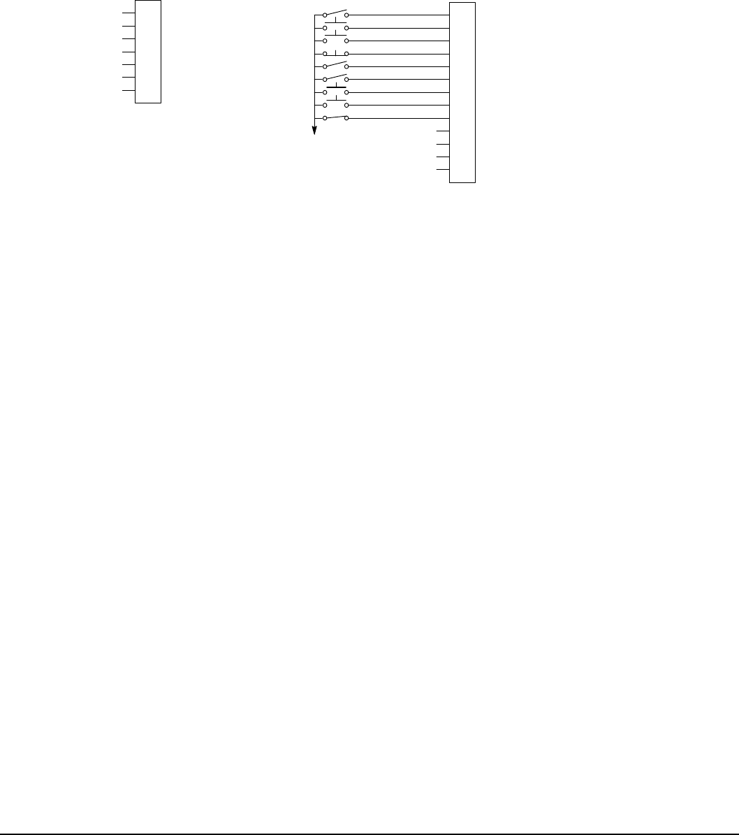
Control Wiring 5-15MN766
5.5.11 E-POT 3-Wire
Provides speed Increase and Decrease inputs to allow E-POT operation with 3 wire inputs. The opto inputs can be switches
as shown in Figure 5-15 or logic signals from another device.
Figure 5-15 E-POT 3-Wire Connection Diagram
User Analog Return
Analog Input 1
Analog Ref. Power +
1
2
3
4
5
6
7
J1
Analog Input 2+
Analog Input 2-
Analog Output 1
Analog Output 2
Enable
J2
Digital Output 1 + (Collector)
Digital Output 1 - (Emitter)
Digital Output 2 + (Collector)
Digital Output 2 - (Emitter)
See Figure 5-4 for
connection information.
Enable
Forward Start
Reverse Start
Stop
E-POT CMD Select
Accel/Decel
Increase
External Trip
Decrease
Digital Input 1
Digital Input 2
Digital Input 3
Digital Input 4
Digital Input 5
Digital Input 6
Digital Input 7
Digital Input 8
8
17
9
10
11
12
13
14
15
16
18
19
20
See recommended tightening torques in Table A-2.
*
*Note: Remove factory jumper from J2-8 and J3-24 before connecting switch at J2-8.
J2-8 CLOSED allows normal control operation.
OPEN disables the control and the motor coasts to a stop.
J2-9 MOMENTARY CLOSED starts motor operation in the Forward direction.
J2-10 MOMENTARY CLOSED starts motor operation in the Reverse direction.
Note: Closing both J2-9 and J2-10 at the same time will reset a fault.
J2-11 MOMENTARY OPEN motor decels to stop.
J2-12 CLOSED selects Level 1 Command Source parameter value.
OPEN selects E-POT.
J2-13 CLOSED selects ACC / DEC / S-ACC /S-DEC group 2.
OPEN selects ACC / DEC / S-ACC /S-DEC group 1.
J2-14 MOMENTARY CLOSED increases motor speed while contact is closed.
J2-15 MOMENTARY CLOSED decreases motor speed while contact is closed.
J2-16 Optional External Trip input (not required). If used, you must set Level 2 Drive Protect block, External Trip to “ON”.
CLOSED allows normal operation.
OPEN causes an External Trip to be received by the control (when programmed to “ON”).
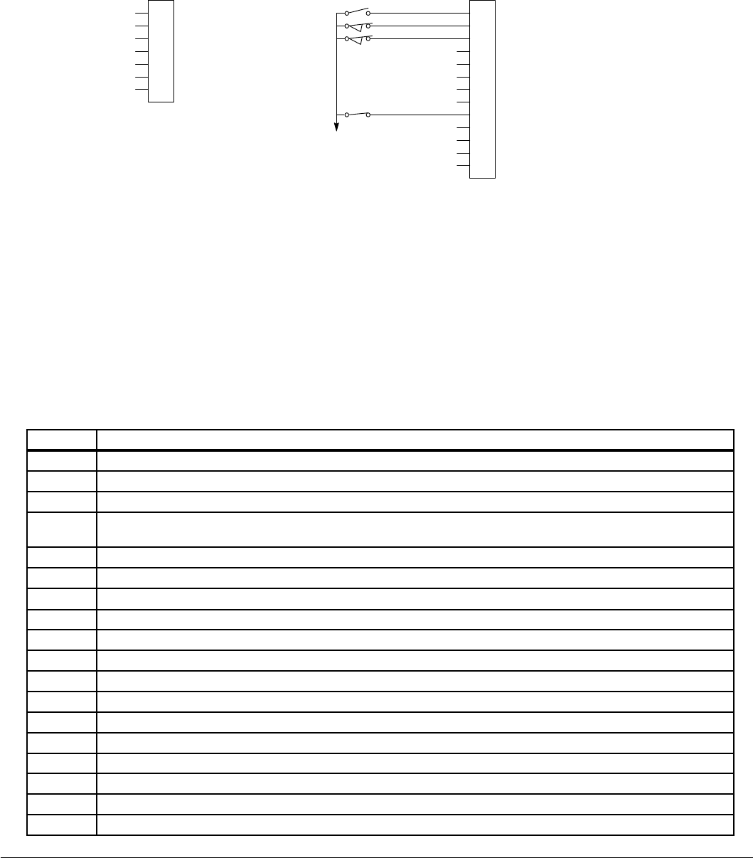
5-16 Control Wiring MN766
5.5.12 Network
Provides bipolar speed or torque control. Preset speeds are set in software. The opto inputs can be switches as shown in
Figure 5-16 or logic signals from another device. See Table 5-11 for Modbus coils that may be used in this mode.
Figure 5-16 Network Connection Diagram
User Analog Return
Analog Input 1
Analog Ref. Power +
1
2
3
4
5
6
7
J1
Analog Input 2+
Analog Input 2-
Analog Output 1
Analog Output 2
Enable
J2
Digital Output 1 + (Collector) Digital Output 1 - (Emitter)
Digital Output 2 + (Collector)
Digital Output 2 - (Emitter)
See Figure 5-4 for
connection information.
External Trip
Digital Input 1
Digital Input 2
Digital Input 3
Digital Input 4
Digital Input 5
Digital Input 6
Digital Input 7
Digital Input 8
8
17
9
10
11
12
13
14
15
16
18
19
20
Forward Enable
Reverse Enable
Enable
See recommended tightening torques in Table A-2.
*
*Note: Remove factory jumper from J2-8 and J3-24 before connecting switch at J2-8.
J2-8 CLOSED allows normal control operation.
OPEN disables the control and the motor coasts to a stop.
J2-9 CLOSED to enable operation in the Forward direction.
OPEN to disable Forward operation (drive will decel to a stop if a Network Forward command is still present).
Reverse operation is still possible if J2-10 is closed.
J2-10 CLOSED to enable operation in the Reverse direction.
OPEN to disable Reverse operation (drive will decel to a stop if a Network Reverse command is still present).
Forward operation is still possible if J2-9 is closed.
J2-16 Optional External Trip input (not required). If used, you must set Level 2 Drive Protect block, External Trip to “ON”.
CLOSED allows normal operation.
OPEN causes an External Trip to be received by the control (when programmed to “ON”).
Table 5-11 Modbus Coils that Affect this Mode
Coil
2 Torque Mode (Vector Only)
3 Speed Mode
4 Orientation, absolute position orientation (Closed Vector or AC Servo only)
9Homing
(available in Closed Vector or AC Servo Only)
10 Process Torque (Vector Only)
11 Process Velocity
13 Network Current Limiting
15 Jog Mode
33 Keypad Reference Source (local)
34 Terminal Block Reference Source (remote)
35 Network Reference Source
42 Select Acc/Dec Group 1
43 Select Acc/Dec Group 2
78 Stop, stops the motor
79 Forward Run (terminal J2-9 must also be true)
80 Reverse Run ( terminal J2-10 must also be true)
81 Bipolar Mode (terminals J2-9 and J2-10 must also be true)
82 Network Drive enable and drive hardware enable (terminal J2-8) must both be set else drive is disabled
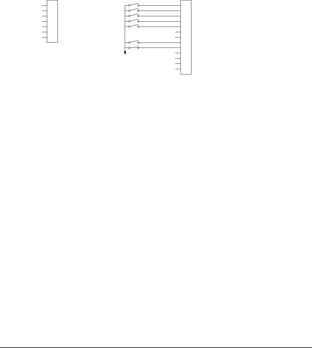
Control Wiring 5-17MN766
5.5.13 Profile Run
Provides a speed prole consisting of seven segments to setup a cyclic operation or test cycle. The opto inputs can be
switches as shown in Figure 5-17 or logic signals from another device. Speed settings for Speed Curve 1 to Speed Curve 7
are Preset Speed 1 to Preset Speed 7. See level 3, Prole Run block for more information.
Figure 5-17 Profile Run Connection Diagram
User Analog Return
Analog Input 1
Analog Ref. Power +
1
2
3
4
5
6
7
J1
Analog Input 2+
Analog Input 2-
Analog Output 1
Analog Output 2
Enable
J2
Digital Output 1 + (Collector) Digital Output 1 - (Emitter)
Digital Output 2 + (Collector)
Digital Output 2 - (Emitter)
See Figure 5-4 for
connection information.
Enable
External Trip
Digital Input 1
Digital Input 2
Digital Input 3
Digital Input 4
Digital Input 5
Digital Input 6
Digital Input 7
Digital Input 8
8
17
9
10
11
12
13
14
15
16
18
19
20
Reset
Forward Enable
Reverse Enable
Run
Cycle
See recommended tightening torques in Table A-2.
*
*Note: Remove factory jumper from J2-8 and J3-24 before connecting switch at J2-8.
J2-8 CLOSED allows normal operation.
OPEN disables the control and motor coasts to a stop.
J2-9 CLOSED to enable operation in the Forward direction.
OPEN to disable Forward operation (drive will decel to a stop if a Forward prole run command is still present).
Reverse operation is still possible if J2-10 is closed.
J2-10 CLOSED to enable operation in the Reverse direction.
OPEN to disable Reverse operation (drive will decel to a stop if a Reverse prole run command is still present).
Forward operation is still possible if J2-9 is closed.
J2-11 CLOSED runs the prole for an indenite number of cycles. When the Level 3, Prole Run, Number of Cycles
(P3001) cycle count is reached, the counter is reset and the mode restarts (continuous cycling).
Example: If P3001 = 5 the prole runs 5 times, the counter is reset to zero, and will begin running 5 more cycles
immediately. As long as pin 11 is closed it will keep resetting the count to zero every time the number of cycles is
reached.
OPEN cycle mode is terminated when cycle count is reached.
J2-12 CLOSED uses Run Command and Cycle Command from J2-9, J2-10 and J2-11.
OPEN uses Commands from Keypad.
J2-13 Not used.
J2-14 Not used.
J2-15 CLOSED resets an alarm or fault.
OPEN normal operation.
J2-16 Optional External Trip input (not required). If used, you must set Level 2 Drive Protect block, External Trip to “ON”.
CLOSED allows normal operation.
OPEN causes an External Trip to be received by the control (when programmed to “ON”).
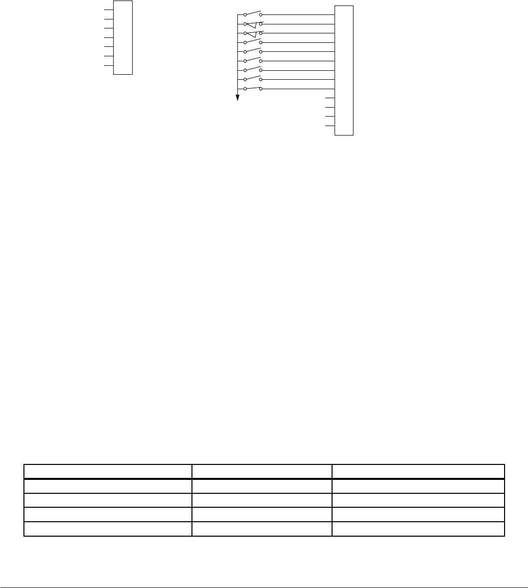
5-18 Control Wiring MN766
5.5.14 Bipolar
Provides bipolar speed or torque control. The control is operated by the digital inputs and the command source. The opto
inputs can be switches as shown in Figure 5-19 or logic signals from another device.
Figure 5-18 Bipolar Connection Diagram
User Analog Return
Analog Input 1
Analog Ref. Power +
1
2
3
4
5
6
7
J1
Analog Input 2+
Analog Input 2-
Analog Output 1
Analog Output 2
Enable
J2
Digital Output 1 +
Digital Output 1 -
Digital Output 1 +
Digital Output 2 -
Enable
Forward Run
Reverse Run
Homing
Speed/Torque
Switch 1
Switch 2
External Trip
Fault Reset
Digital Input 1
Digital Input 2
Digital Input 3
Digital Input 4
Digital Input 5
Digital Input 6
Digital Input 7
Digital Input 8
8
17
9
10
11
12
13
14
15
16
18
19
20
Servo Mode
See Figure 5-4 for
connection information.
See recommended tightening torques in Table A-2.
*
*Note: Remove factory jumper from J2-8 and J3-24 before connecting switch at J2-8.
J2-8 CLOSED allows normal control operation.
OPEN disables the control and the motor coasts to a stop.
J2-9 CLOSED to enable operation in Forward direction.
OPEN to disable Forward operation (drive will decel to a stop if a Forward reference command is still
present). Reverse operation is still possible if J2-10 is closed.
J2-10 CLOSED to enable operation in the Reverse direction.
OPEN to disable Reverse operation (drive will decel to a stop if a Reverse reference command is still
present). Forward operation is still possible if J2-9 is closed.
Note: If J2-9 and J2-10 are both opened, the drive will decel to a stop.
J2-11 CLOSED causes the motor to rotate in the forward direction until the load reaches a marker or external
switch location.
OPEN allows normal operation.
Note: Parameter P2308 sets the homing offset. The motor rotates at the speed set in P2307 until the
index pulse is detected and then at the speed set in P1001 until the offset is reached.
J2-12 CLOSED puts the control in torque command mode, Vector modes only.
OPEN puts the control in speed (velocity) command mode. Note: If a stop command is issued while in
the torque (current) mode, the control will stop but will not maintain position (zero current). This is
different than zero speed operation for the velocity mode.
J2-13 & J2-14 Select from four parameter tables as dened in Table 5-13.
J2-15 Momentary CLOSED to reset fault condition.
OPEN allows normal operation.
J2-16 Optional External Trip input (not required). If used, you must set Level 2 Drive Protect block, External Trip
to “ON”.
CLOSED allows normal operation.
OPEN causes an External Trip to be received by the control (when programmed to “ON”).
Table 5-12 Bipolar Mode Select Table
J2-13 J2-14 Function
OPEN OPEN Parameter Table 1 (T1)
CLOSED OPEN Parameter Table 2 (T2)
OPEN CLOSED Parameter Table 3 (T3)
CLOSED CLOSED Parameter Table 4 (T4)
Note: See multiple parameter sets in this section.

Control Wiring 5-19MN766
Bipolar - Multiple Parameter Sets
The following procedure allows you to program up to four complete sets of parameter values and to use these multiple
parameter sets. Each parameter table must be properly initialized before use. Each table must have an operating mode
that supports table switching (Process Control, Bipolar or Network) and all motor data and related parameters must be the
same in each table if switching tables with the drive enabled. When programming each parameter set, use the ENTER key to
accept and automatically save parameter values.
Note: The control can be programmed in the REMOTE mode with the drive enabled. The control must be disabled to
change the operating mode parameter. The operating mode is not stored with the other parameters in a parameter
table.
1. If this is a new installation, perform this procedure after the Pre-Operation Checklist and Power-Up Procedures at the end
of this section.
2. Set the Level 1 INPUT block, Operating Mode parameter, (P1401) value to BIPOLAR in each of the parameter sets.
3. Set switches J2-13 and J2-14 to Parameter Table 1 (both switches open). Be sure switches J2-8, J2-9 and J2-10 are
OPEN. Select Basic Parameters from the main Keypad menu. Perform each step including Calc Motor Model. This
creates and saves the rst parameter set which is numbered Table 1.
4. Set switches J2-13 and J2-14 to Parameter Table 2. Be sure switches J2-8, J2-9 and J2-10 are OPEN. Select Basic
Parameters from the main Keypad menu. Perform each step including Calc Motor Model. This creates and saves the
second parameter set which is numbered Table 2.
5. Set switches J2-13 and J2-14 to Parameter Table 3. Be sure switches J2-8, J2-9 and J2-10 are OPEN. Select Basic
Parameters from the main Keypad menu. Perform each step including Calc Motor Model. This creates and saves the
6. third parameter set which is numbered Table 3.
7. Set switches J2-13 and J2-14 to Parameter Table 4. Be sure switches J2-8, J2-9 and J2-10 are OPEN. Select Basic
Parameters from the main Keypad menu. Perform each step including Calc Motor Model. This creates and saves the nal
parameter set which is numbered Table 4.
8. Remember that to change the value of a parameter in one of the parameter tables, you must rst select the table using
the switches. You cannot change a value in a table until you have rst selected that table.
Note: The active parameter table is selected by Level 2:Drive Congure:Active Parameter Table, (P0052).
Example:
Before attempting to switch parameter tables during operation “on the y” using the digital inputs J2-13 & 14, the operating
mode for each parameter table to be used must be initialized. Specically, to switch from Table 1 to Table 2 then back to
Table 1 both parameter Table 1 and parameter Table 2 must have operating modes that support table switching. Otherwise,
once the switch occurs, switching back will not be possible.
To illustrate this, prior to running Bipolar Mode perform the following steps:
1. Use the keypad, set Level 2:Drive Congure:Active Parameter Table to 0 “Table 1”.
2. Go to Level One and set Level 1: Input Setup:Operating Mode to Bipolar.
Repeat the above steps but this time for Table 2.
3. Use the keypad, set Level 2:Drive Congure:Active Parameter Table to 1 “Table 2”.
4. Go to Level One and set Level 1:Input Setup:Operating Mode to Bipolar.
The drive is now properly congured to switch between parameter Table 1 and Table 2.
Home Adjustment
(Do not power up the control at this time. Perform this procedure after the Powerup Procedure at the end of this section).
Perform this procedure as part of the Powerup Procedure described at the end of this section. To set the electrical home
position perform the following procedure:
1. Disable drive (J2-8 open).
2. Set P2308 Homing Offset and P2307 Homing Speed as required.
3. Place control in remote mode.
4. Enable drive (J2-8 closed).
5. Close J2-9 and J2-10, forward and reverse enables.
6. Close J2-11 to start the move.
7. The motor runs forward in speed mode at homing speed until the index pulse is triggered. The homing function allows
shaft rotation in the drive forward direction only. The home position is located when a machine mounted switch or
“Index” pulse is activated (closed). Home is dened by a rising signal edge at Resolver expansion board terminal 8. The
shaft will continue to rotate only in a “Drive Forward” direction for a user dened offset value. The offset is programmed
in Level 2 Miscellaneous Homing Offset P2308. The Speed at which the motor will “Home” or orient is set in Level 2
Miscellaneous Homing Speed P2307.
To use the internally generated index pulse for homing, no external connections are required. However, to use an external
index input, jumper J3 on the resolver expansion board must be moved to External Index (sync) and a switch must be
connected to Index+ and Index-, shown in Figure 4-17.
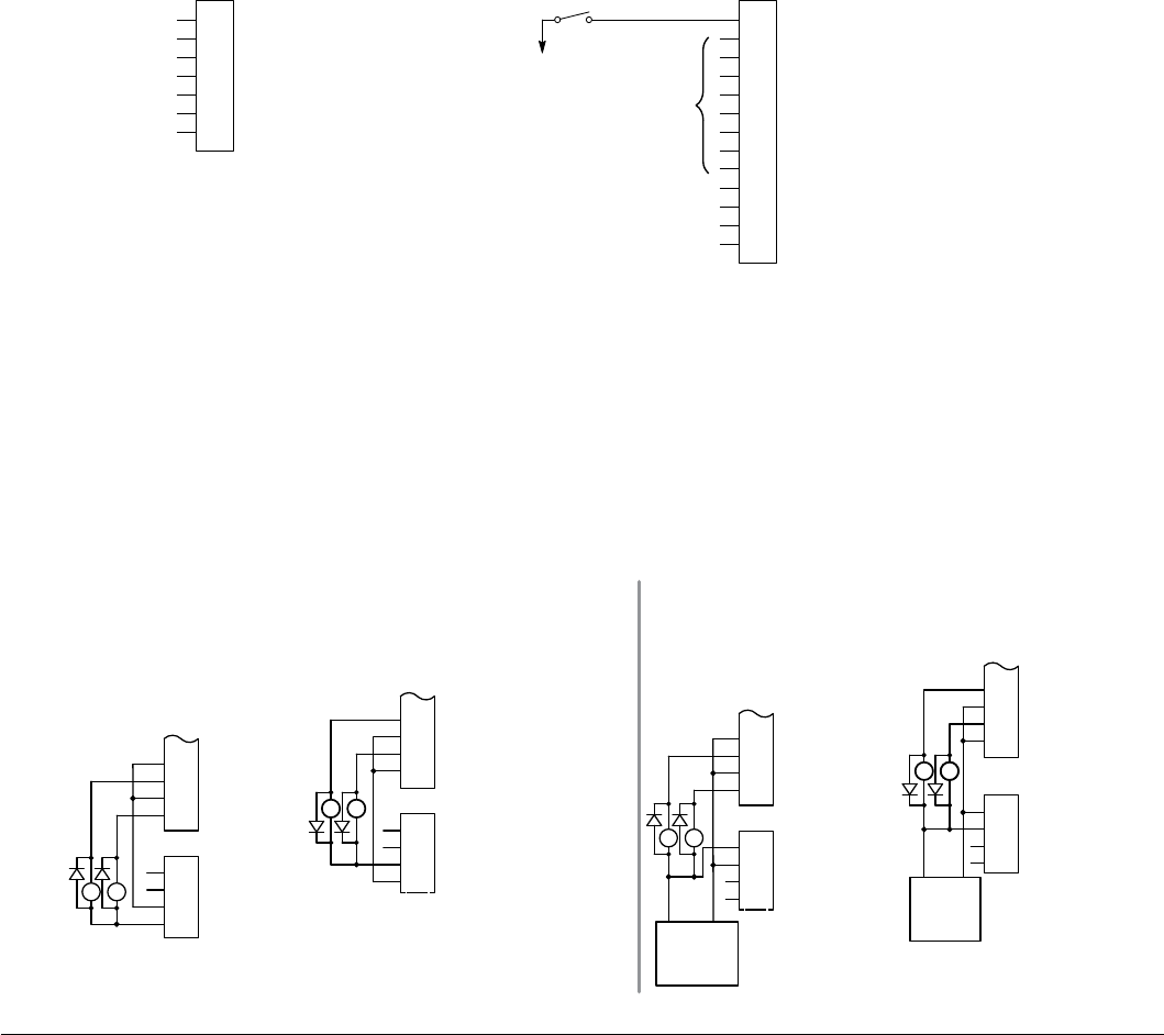
5-20 Control Wiring MN766
a. If the homing speed is increased, the homing offset may also need to be increased to avoid the motor reversing
direction to reach the home position. The Home Offset is actually the counts the motor travels to stop after the home
switch is found.
b. During the offset positioning portion of the homing move, Preset Speed 1 and ACC/DEC Group 1 are used.
c. If homing is triggered during a move, the drive enters speed mode, attains homing speed using ACC/DEC Group 1,
then completes the homing normally.
8. Another home sequence can be performed while at the home position by opening and closing J2-11.
5.5.15 Pulse Follower
Provides electronic gearing of two or more controls from an upstream pulse reference. This mode requires expansion board
EXBHH007 and its operation is described in MN755.
5.5.16 PLC
Provides control from a PLC device (Programmable Logic Control) as described in Chapter 10 of this manual. Preset speeds
are set in software. The opto inputs can be switches as shown in Figure 5-20 or logic signals from another device.
Figure 5-19 PLC Connection Diagram
1
2
3
4
5
6
7
Enable
J2
Digital Output 1 + (Collector)
Digital Output 1 - (Emitter)
Digital Output 2 + (Collector)
Digital Output 2 - (Emitter)
Digital Input 1
Digital Input 2
Digital Input 3
Digital Input 4
Digital Input 5
Digital Input 6
Digital Input 7
Digital Input 8
8
17
9
10
11
12
13
14
15
16
18
19
20
Enable
See recommended tightening torques in Table A-2.
*
Optional
Inputs
J1
User Analog Return
Analog Input 1
Analog Ref. Power +
Analog Input 2 +
Analog Input 2 -
Analog Output 1
Analog Output 2
See Figure 5-4 for
connection information.
*Note: Remove factory jumper from J2-8 and J3-24 before connecting switch at J2-8.
One input must be a direction
input (FWD or REV).
5.6 Digital Outputs
Digital Outputs 1 and 2 are opto-isolated. Internal supply or a customer provided external power source may be used as
shown in Figure 5-21. The maximum voltage from Digital Output to common when active is 1.0 VDC.
If the Digital Outputs are used to directly drive a relay, a yback diode rated at 1A, 100V (IN4002 or equivalent) minimum
should be connected across the relay coil. See Figure 5-21. Each opto output is programmed in the Output programming
block.
Figure 5-20 Digital Output Power Connections
Note: Digital Outputs are rated to 24VDC @ 60mA resistive (non-inductive).
Sinking Current Connections
Sourcing Current Connections
Internally Supplied 24VDC Externally Supplied 24VDC
Sinking Current Connections
Sourcing Current Connections
See recommended tightening torques in Table A-2.
J2
Digital Output 1 +
Digital Output 1 -
Digital Output 2 +
Digital Output 2 -
21
J3
Internal 24V Return
22
23
24
17
18
19
20
Out1
Out2
External User Return
External User +24V
Internal +24V
User
24VDC
+
21
22
23
24
19
23
External User Return
External User +24V
Internal +24V
Internal 24V Return
J2
17 Digital Output 1 + (Collector)
Digital Output 1 - (Emitter)
Digital Output 2 + (Collector)
Digital Output 2 - (Emitter)
18
19
20
21
J3
22
Out1
Out2
24
J2
Digital Output 1 +
Digital Output 1 -
Digital Output 2 +
Digital Output 2 -
21
J3
22
23
24
17
18
19
20
Out1
Out2
External User Return
External User +24V
Internal +24V
Internal 24V Return User
24VDC
+
J2
Digital Output 1 +
Digital Output 1 -
Digital Output 2 +
Digital Output 2 -
J3
Internal 24V Return
17
18
20
Out1
Out2
External User Return
External User +24V
Internal +24V
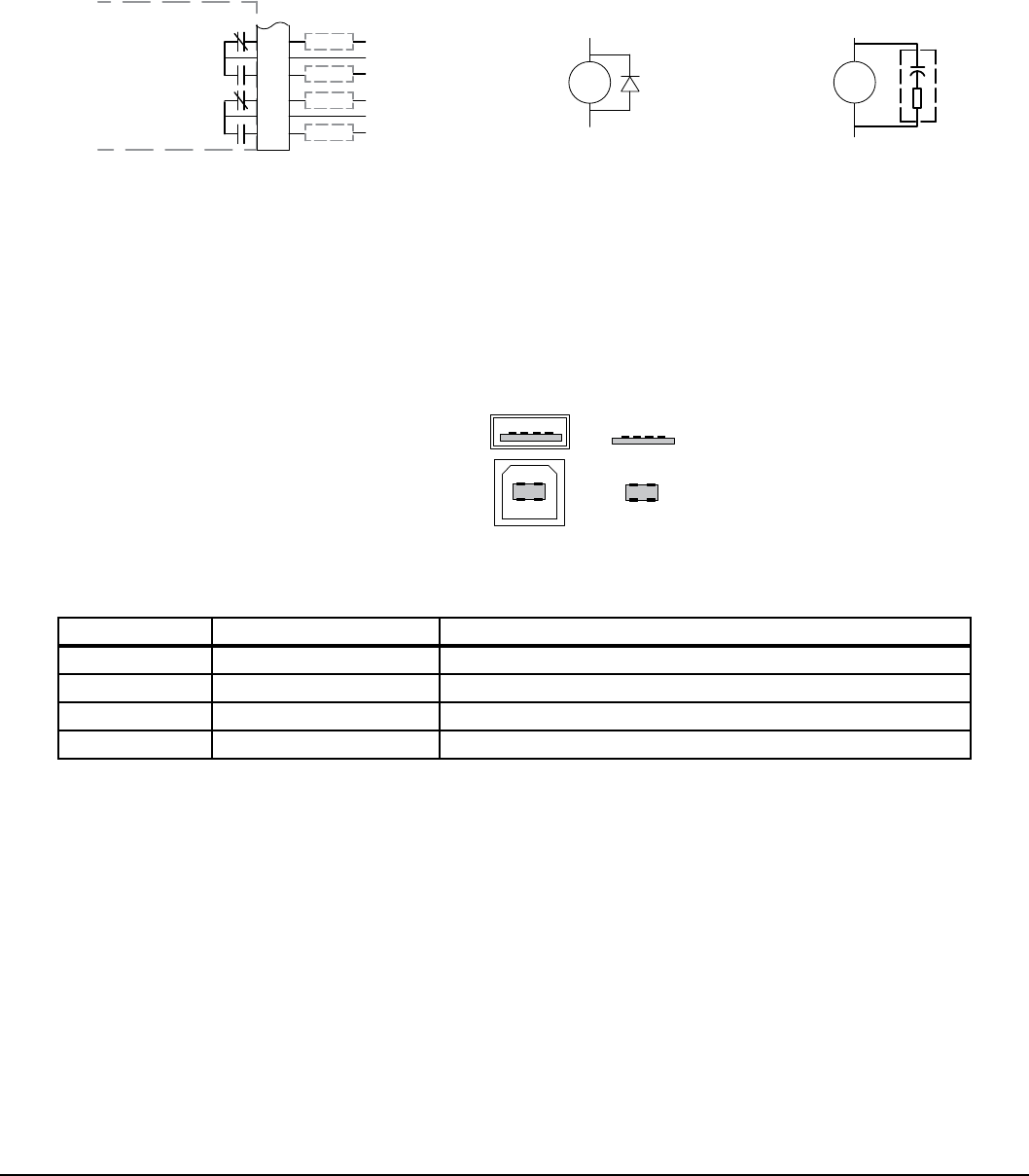
Control Wiring 5-21MN766
5.7 Relay Outputs
Relay Outputs 1 and 2 provide N.O. and N.C. voltage-free contacts. The internal relay function is shown in Figure 5-22.
Figure 5-21 Relay Contacts
J3
30
Relay Out 2 N.O.
25
26
27
Relay Out 1 N.C.
Relay Out 1 COM
Relay Out 1 N.O.
28
29
Relay Out 2 N.C.
Relay Out 2 COM
Load
Load
Load
Load
RE
+
-
If the load is a DC relay
coil, install a yback
diode across the coil to
reduce noise
transmission. RE
If the load is an AC
relay coil, install an RC
Snubber across the coil
to reduce noise
transmission.
RC Snubber
0.47 μf
33 Ω
See recommended tightening torques in Table A-2.
Control Board
Note: Relay Outputs are rated to 10-30VDC or 240VAC @ 5A resistive (non-inductive).
5.8 USB Port
The USB port shown in Figure 5-23 is a full 12Mbps USB 2.0 compliant port for serial communications. The connections are
described in Figure 5-23 and Table 5-14.
Figure 5-22 USB Receptacle Pin Identification
Peripheral End (USB-B)
Host End (USB-A) 14
1
4
2
3
Table 5-13 USB Port Connections
Pin Signal Name Description
1 Vbus USBus power from the host for monitoring
2 D- Data Return
3 D+ Data In
4 GND Power Supply Return
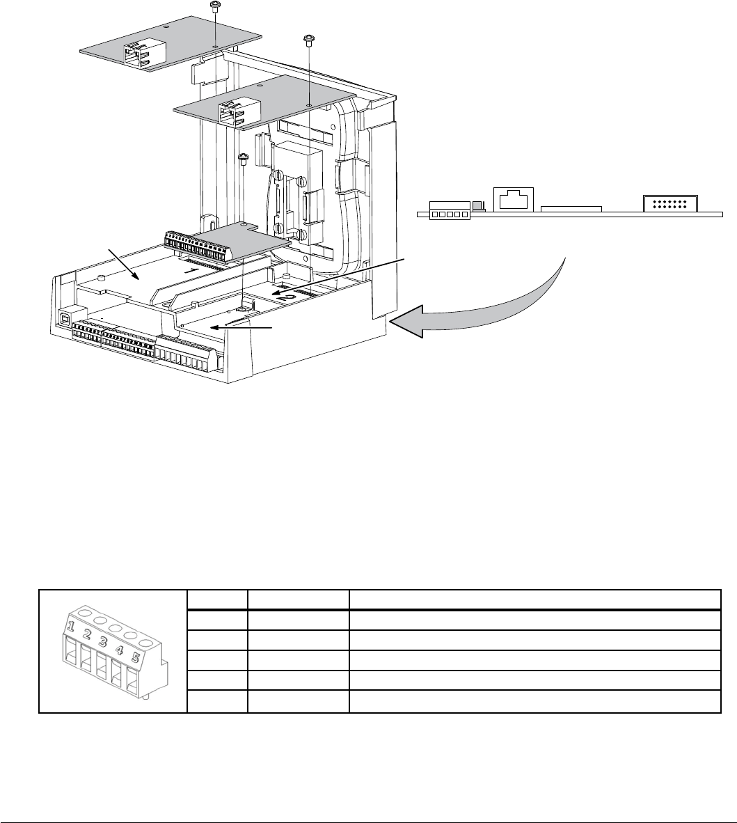
5-22 Control Wiring MN766
5.9 Communication Expansion Boards
The communication and feedback module slots are shown in Figure 5-24. All option boards are designed as plug-in
modules.
Figure 5-23 Expansion Board Location
Feedback
Module Slot 3
I/O Module Slot 1 I/O Module
Slot 2
Control
Board
RS485
JP3
View From Rear (Opposite J1 Connector)
Keypad
Connector
Ribbon Cable
Regen
Board
Connector
J1 J2
J3
See recommended tightening torques in Table A-2.
5.9.1 RS485 Modbus
The serial communications port on the control board supports RS485 communications, Figure 5-24. The baud rate and node
addresses are selectable from the Keypad. Jumper JP3 (Figure 5-24) on the control board sets termination. As shown (pins 2
and 3 jumpered) no terminating resistor is used. Setting the jumper to pins 1 and 2 selects the 120 ohm terminating resistor
for the RS485 cable. The RS485 connections are described in Table 5-15. Refer to Baldor manual MN744 for connection
and software information. Note that the hardware specications for this port follow the RS485 standard.
Table 5-14 RS485 Multi-Drop Port Connections
SBA
S
G
Pin Signal Name Description
1 SCR Screen termination, connected to chassis on the control board
2 B Data Return
3 A Data In
4 GND Power Supply Return
5 SCR Screen termination, connected to chassis on the control board
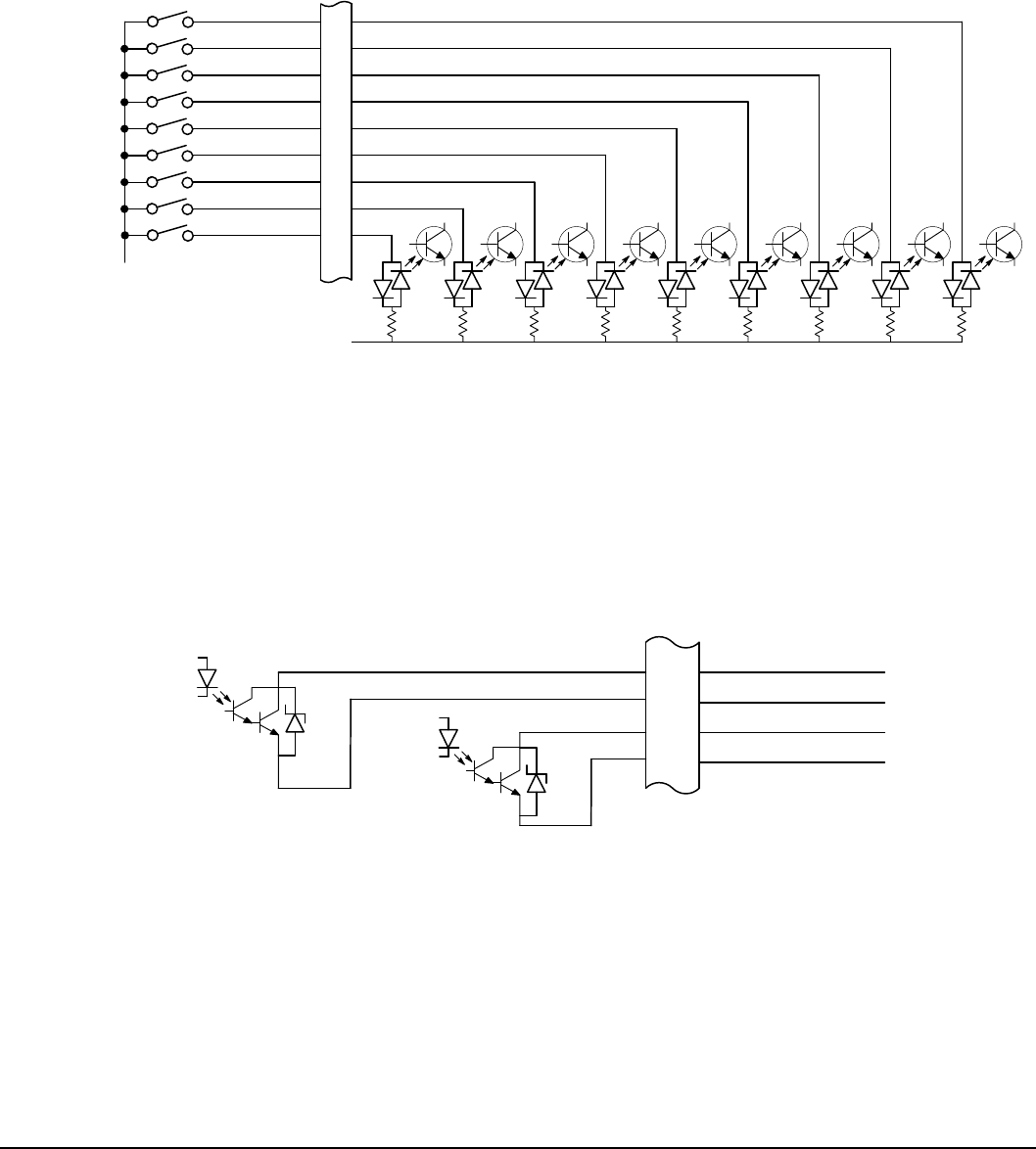
Control Wiring 5-23MN766
5.10 Opto-Isolated Inputs
The equivalent circuit of the nine opto inputs is shown in Figure 5-25. The function of each input depends on the operating
mode selected and each is described previously in this section. This Figure also shows the connections using the internal
opto input Supply.
Figure 5-24 Opto-Input Connections
See recommended terminal tightening torques in Table A-2.
4.8K 4.8K 4.8K 4.8K 4.8K 4.8K 4.8K 4.8K 4.8K
15
16
Digital Input 7
Digital Input 8
8
9
10
11
12
13
14
J2
Enable
Digital Input 1
Digital Input 2
Digital Input 3
Digital Input 4
Digital Input 5
Digital Input 6
See Figure 5-4 for
connection information.
Opto In Common
5.11 Opto-Isolated Outputs
The outputs are opto-isolated and may be congured for sinking or sourcing. However, all must be congured the same. The
maximum voltage from opto output to common when active is 1.0 VDC (TTL compatible). The equivalent circuit for the opto-
isolated outputs is shown in Figure 5-26.
Figure 5-25 Opto-Output Equivalent Circuit
17
18
19
20
Digital Output 1 + (Collector)
Digital Output 1 (Emitter)
Digital Output 2 + (Collector)
Digital Output 2 (Emitter)
J2
PC865
50mA max
PC865
50mA max
See recommended terminal tightening torques in Table A-2.

5-24 Control Wiring MN766
5.12 Pre-Operation Checklist (Check of Electrical Items)
1. Verify AC line voltage at source matches control rating.
2. Inspect all power connections for accuracy, workmanship and tightness and compliance to codes.
3. Verify control and motor are grounded to each other and the control is connected to earth ground.
4. Check all signal wiring for accuracy.
5. Be certain all brake coils, contactors and relay coils have noise suppression. This should be an R-C lter for AC coils and
reverse polarity diodes for DC coils. MOV type transient suppression is not adequate.
5.13 Powerup Procedure
1. Remove all power from the control.
2. Verify that any enable inputs to J2-8 are open.
3. Disconnect the motor from the load (including coupling or inertia wheels).
4. Turn power on. Be sure there are no faults.
5. Set the Level 2 Drive Limits block, “OPERATING ZONE” (P2001) parameter as desired
(STD CONST TQ, STD VAR TQ, QUIET CONST TQ or QUIET VAR TQ).
6. If external dynamic brake hardware is used, set the Level 2 Brake Adjust block “Resistor Ohms” and “Resistor Watts”
parameters.
7. Enable the control (J2-8 connect to J3-24).
WARNING: The motor shaft will rotate during this procedure. Be certain that unexpected motor shaft
movement will not cause injury to personnel or damage to equipment.
8. Select Basic Parameters from the main Keypad menu. Enter values for each parameter:
• MOTOR RATED AMPS (P2402)
• MOTOR POLE PAIRS (P2413)
• MOTOR RATED SPEED (P2403)
• FEEDBACK SOURCE (P2409)
• ENCODER COUNTS (P2408) (Use default setting only)
• CALC MOTOR MODEL - YES - (P2414)
9. Select “Advanced Prog”, Level 2 Blocks, Auto Tune, “One-Step Tuning” and run all tests.
10. Remove all power from the control.
11. Couple the motor to its load.
12. Verify freedom of motion of motor shaft.
13. Verify the motor coupling is tight without backlash.
14. Verify the holding brakes if any, are properly adjusted to fully release and set to the desired torque value.
15. Turn power on. Be sure no errors are displayed.
16. Run the drive from the keypad using one of the following: the arrow keys for direct speed control, a keypad entered
speed or the JOG mode.
17. Select and program additional parameters to suit the application.
The control is now ready for use in the keypad mode. If a different operating mode is desired, refer to Chapter 5 Operating
Modes and Chapter 6 Using the Keypad.
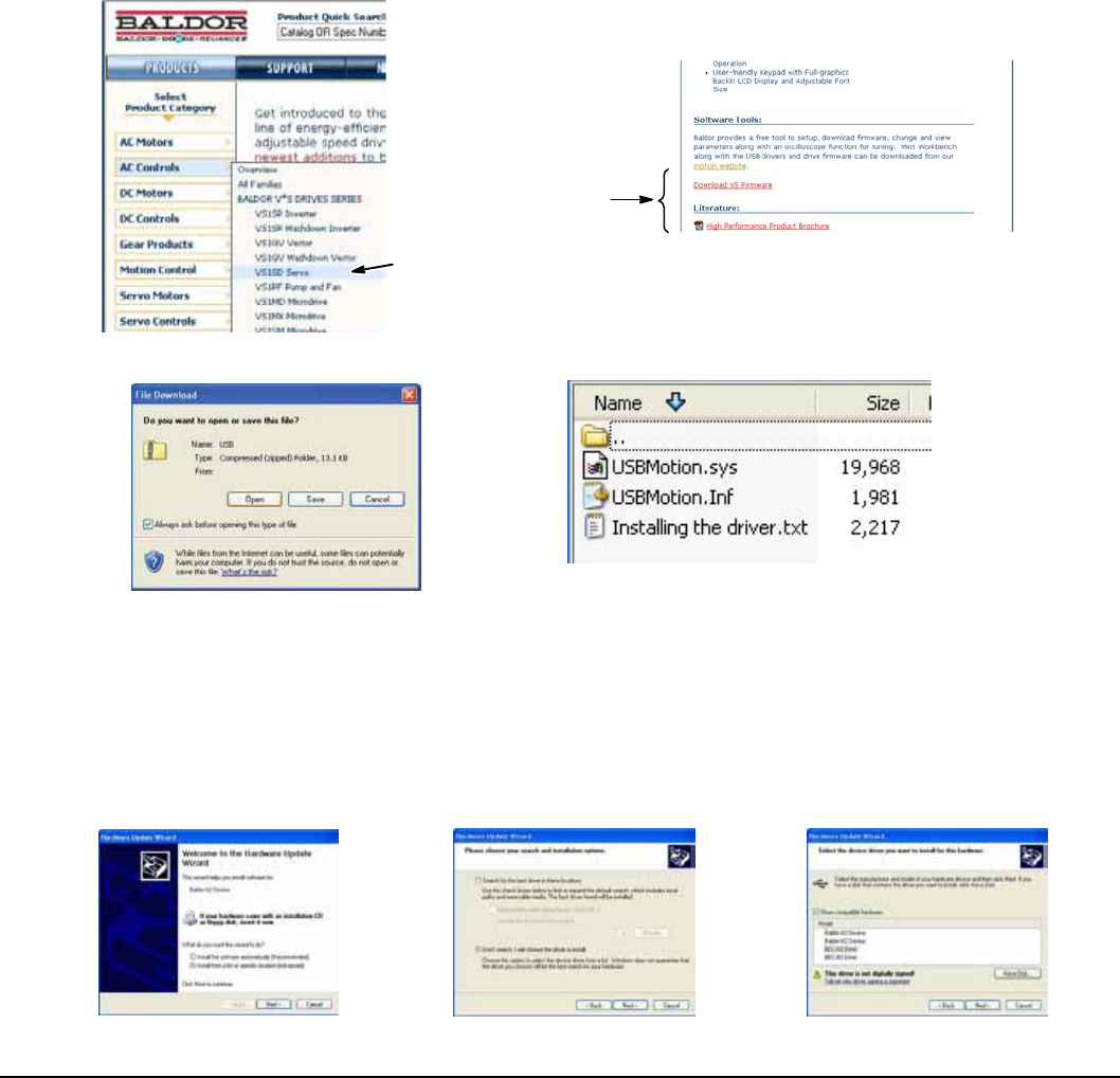
Control Wiring 5-25MN766
5.14 Mint WorkBench
As an alternative to using the keypad for programming and setup, Baldor’s Mint WorkBench software version 5.5 or greater
can be used. When the software is installed and congured, the help topics provide information on how to use the software.
The following procedure will help you install and congure the software.
Before you can use Mint WorkBench software, it must be installed on your PC’s hard drive.
Be sure that the USB port of the control is connected to a USB port on your PC.
This must be connected to establish communication after the software is installed.
5.14.1 Install USB Driver
The control connects to a PC by using USB cable connection. This procedure installs the USB driver that is required by
Windows.
1. The software must be downloaded from the Baldor site: http://www.baldor.com Simply log into that web site and select
Products then select AC Controls then select VS1 Series AC Servo to locate the Software tools.
2. USB Device Driver
Figure 5-26 USB Driver
Select Control Type
Select Software Tool
3. Click on USB Device Drive and select Open to view the uncompressed les.
4. Select the inf and sys les and copy them to a folder on your hard drive. These will be installed next.
5. Be sure the control is powered up.
6. Connect the USB cable to the control. Windows should nd a new USB device.
7. Install the USB drivers.
a. Choose “install from a list or specic location” and click Next.
b. Choose “Don’t search I will choose the driver to install”.
c. Click “Have Disk”. Then enter the location that you stored the inf and sys le (in step 3) and click Next to install the
driver les.
5-32 Control Wiring
8. Proceed to the Mint WorkBench installation procedure.
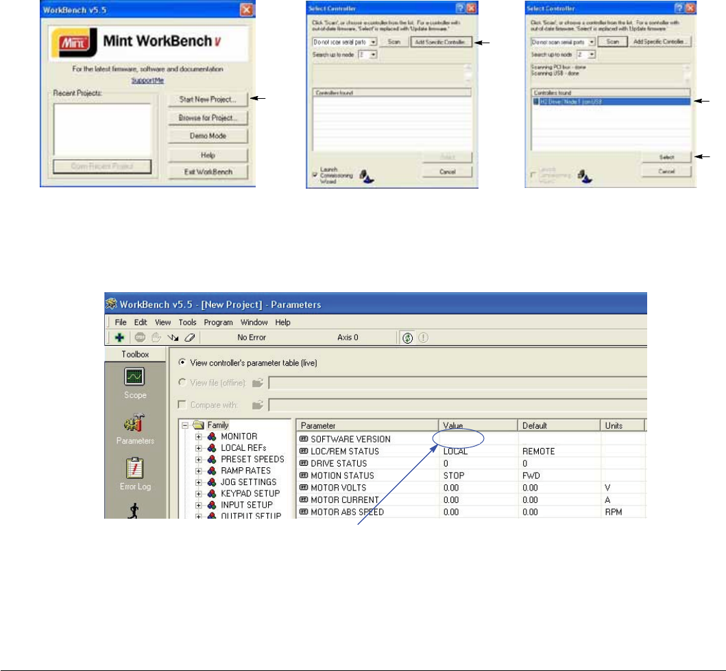
5-26 Control Wiring MN766
5.14.2 Install Mint WorkBench
1. Use the Add/Remove Software feature of the Windows control panel and remove previous versions of Mint WorkBench
software.
2. The software must be downloaded from the Baldor site: http://www.baldor.com
Simply log into that web site, Figure 5-27, and locate
1. Mint WorkBench v X.x
3. Click on Download the software, and run the installation program.
4. When installation is complete, the Mint WorkBench program will start, see Figure 5-28.
a. Click “Start New Project”.
b. Click “Scan”.
c. Select “VS1” from the list.
d. Click Select and the Mint WorkBench main menu is displayed, see Figure 5-29.
Figure 5-27 Mint WorkBench Software Set-up
X.x
a
b
c
d
Figure 5-28 Communication Established
Software version is Servo (SHH) version 1 release 20.
SHH-1.20 SHH-1.20
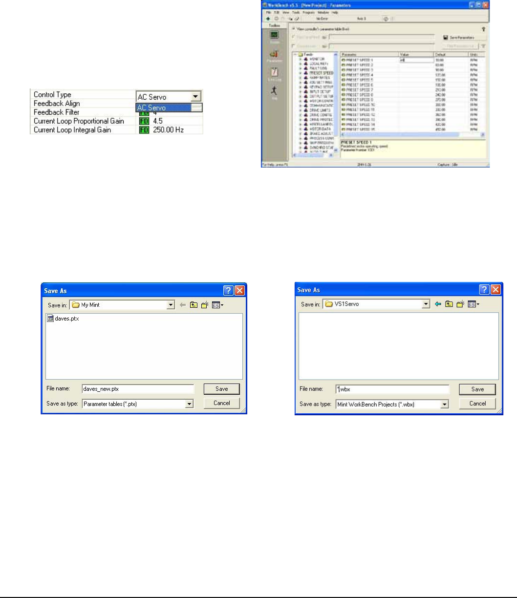
Control Wiring 5-27MN766
5. Parameter values can be modied as desired.
Figure 5-29 Mint WorkBench Main Menu
Change a Parameter Value Example:
Change Preset Speed 1 to 48RPM.
Click on Preset Speeds Block.
Click in the Value Column for Preset Speed 1.
Type in the new value “48” press enter.
Note that the keypad will instantly display the new value.
If the parameter value is a selection, a
list will appear for you to make the selection.
6. When all parameter values are as desired, they can be saved to a le. Click File, see Figure 5-31. The PTX le is saved in
My Documents\My Mint directory.
7. When complete, the entire project can be saved to your PCs hard disk for future use. Click File, Save File, see Figure
5-31. The WBX le is saved in C:\Program Files\Mint Machine Center\Firmware\ you can choose the directory.
Figure 5-30 Save Parameters & Project
Note: For Parameter Tables, a .ptx extension is Note: For Mint WorkBench Projects, a .wbx extension is
automatically added when you enter a le name. automatically added when you enter a le name.
The help menus provided with the software can be used to explore other features and descriptions of menu choices.
As previously stated, either the Mint WorkBench program or the Keypad can be used to adjust parameter values for the
application.
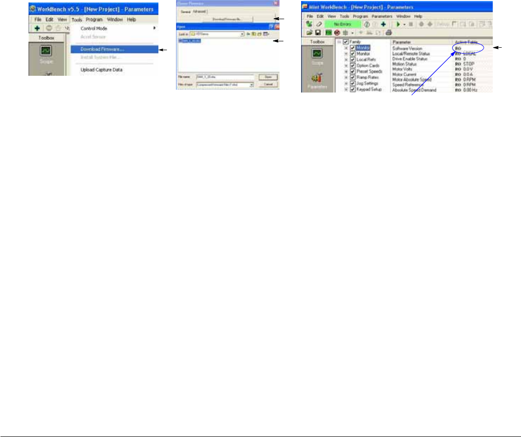
5-28 Control Wiring MN766
5.14.3 Update Firmware
Installing chx Files
(If you are installing msx les skip this procedure and go to “Installing msx Files”).
This procedure erases memory and restores factory settings. All user data will be lost. After the rmware download, all user
data values must be reprogrammed.
1. The software must be downloaded from the Baldor site: http://www.baldor.com
Simply log into that web site, Figure 5-27. Locate and click on Drive Firmware.
2. Save the rmware le to a location on your hard disk.
(for example: C:\Program Files\Mint Machine Center\Firmware\VS1 Servo\SHH_1_20.chx).
This procedure erases memory and restores factory settings. All user data will be lost. After the rmware download, all user
data values must be reprogrammed.
3. Start the Workbench program as before, see Figure 5-32.
a. Select “Download Firmware” from the Tools menu.
b. Select “Advanced” then “Download Firmware File”, click “Yes” at the warning to download.
c. Select the rmware le to download (for example: SHH_1_20.chx).
d. When complete, the new rmware version is displayed and the control is ready for use.
Note: All user settings and motor parameter values have been over written by factory settings.
Figure 5-31 Mint WorkBench Firmware Update
a
Software version is Servo (SHH) version 1 release 20.
b
d
c
SHH-1.20

Using the Keypad 6-1MN766
Chapter 6
Using the Keypad
6.1 Keypad Components
The keypad is used to program the control parameters, to operate the motor and to monitor the status and outputs of the
control by accessing the display options, the diagnostic menus and the fault log. Additionally drive parameters can be
stored in the keypad for future retrieval.
6.1.1 Display Description
Keypad Display – Displays status
Information during Local or Remote
operation. It also displays information
during parameter setup and fault or
Diagnostic information. STATUS FWD LOCAL
DIAG 600r MAIN
159.5 V 600 RPM
6.2 A 20.0 HZ
Display Diagnostics –
I/O Status
I/O Function conguration
Modied Parameters
Control Operation Data
Custom Units
Fault Display – 10 Faults with Time
Stamp
F1 – Alternates or “toggles” between
The last two menu choices or function
Indicated by text displayed directly
Above key.
F2 – Clears faults or undo parameter
edit changes or function indicated by
text displayed directly above key.
Up Arrow
Down Arrow
Left Arrow
Right Arrow
Moves cursor to select menu choices.
ENTER – Press ENTER to save
parameter value changes. In the
display mode the ENTER key is used to
directly set the local speed reference. It
is also used to select other operations
when prompted by the keypad display.
LOCAL/REMOTE – Switches between
local and remote modes.
MENU/ESC – Selects the menu
display when viewing status. The
following menu items are shown:
Status, Basic Params, Advanced Prog,
Event Log, Diagnostics and Display
Options. Backs up one level for other
screens.
HELP – Provides help at each display
screen, setup parameter and fault.
Press to view/close help information.
REV – When pressed, initiates a
reverse direction run command.
JOG – Initiates Jog mode. Press FWD
or REV for motion. Only active in local
mode.
STOP – Initiates a stop command.
Note: Pressing the stop key twice in
succession will immediately disable the
drive placing the motor in a coast stop
condition.
FWD – When pressed, initiates a
forward direction run command.
Indicator Lights – (on indicated key)
STOP key with red light indicator.
FWD key with green light indicator.
REV key with green light indicator.
JOG key with green light indicator.

6-2 Using the Keypad MN766
6.1.2 Display Features
Present Menu Selection
STOP=Stop; FWD=Forward; REV=Reverse
Local / Remote Mode
Previous Menu Selection
(Press F1 to return to previous menu)
Speed Reference
Press F2 to go back one menu level
STATUS FWD LOCAL
DIAG 600r MAIN
159.5V 600RPM
6.2A 20.0HZ
Prog Mode Display Features:
The rst character of the parameter number PROG
STATUS BACK
PRESET SPEED 1
30RPM
F1001T1
PRESET SPEEDS
Parameter Table used:
T1, T2, T3, T4
has the following meaning:
F = Factory Setting (parameter value has not been changed).
C = Custom value set by user (not factory value).
V = Parameter value may be Viewed but not changed.
L = Parameter value is locked, security code required.
Using the Keypad 6-3MN766
6.2 Status Mode
When AC power is applied to the control, the keypad will display the status.
Action Description Display Comments
Apply Power Logo is displayed for a short time.
The Status screen is then
displayed.
Normal screen at start up.
Displays Motor Voltage,
Factory default value.
MOTOR DATA
STATUS F2401T`1 BACK
MOTOR RATED VOLT
230.0V
Press key Next screen format is displayed.
0.0A
STOP
LOCAL
DIAG 0.00r MAIN
Press key Next screen format is displayed.
STOP
LOCAL
DIAG 0.00r MAIN
Press key Next screen format is displayed.
STOP
LOCAL
DIAG 0.00r MAIN
Press key Next screen format is displayed.
STOP
LOCAL
DIAG 0.00r MAIN
Press key Next screen format is displayed.
STOP
LOCAL
DIAG 0.00r MAIN
0RPM
0RPM
0.0HZ
0.0A
0.0V
0RPM
0.0A
0.0V
0RPM
0.0NM
0.0A
STATUS
STATUS
STATUS
STATUS
STATUS
PROG
STOP LOCAL
DIAG 0.00r MAIN
0.0V
0.0A
0RPM
0.0HZ
STATUS
Status screen is displayed
Press F1 - Status

6-4 Using the Keypad MN766
Status Mode Continued
Press key The rst screen format is
displayed. STOP LOCAL
DIAG 0.00r MAIN
0.0V
0.0A
Press FWD key Motor begins to rotate in the
forward direction at the preset
speed.
STATUS FWD LOCAL
DIAG 600r MAIN
159.5V
0.2A
0RPM
0.0HZ
600RPM
20.0HZ
STATUS
Action Description Display Comments
6.3 Menu Display
After power-up the display shows the Status screen. Press the Menu key to display menu options.
Action Description Display Comments
Status Display STATUS STOP LOCAL
DIAG 0.00r MAIN
0.0V 0RPM
0.0A 0.0HZ
Press Menu/Esc Displays top level menu options.
DIAG BACK
STATUS
BASIC PARAMS
ADVANCED PROG
EVENT LOG
DIAGNOSTICS
Press or to move cursor over
the desired selection and press
“Enter” to select and display the
selection.

Using the Keypad 6-5MN766
6.4 Basic Params
From the Menu display screen, select Basic Params and press Enter.
Parameter Status
All programmable parameters are displayed with an “F” at the bottom center of the display. “F” means it is the factory
setting value. “C” means it is a custom value set by the user. “V” means the parameter value may be viewed but not
changed while the motor is operating. If the parameter is displayed with an “L”, the value is locked and may not be changed
until the security code is entered.
Action Description Display Comments
Basic Params Display Control type display. The
parameter number “1601” is given
at the bottom center of the
display.“F”1601 indicates it is at
the factory setting and has not
been changed.
BASIC
STATUS F1601T1 BACK
CONTROL TYPE
AC Servo
MOTOR CONTROL No other control selections are
available.
Press to go to the
next Basic Params
screen.
BASIC
F2413T1 BACK
MOTOR POLE PAIRS
2
MOTOR DATA
Press to go to the
next Basic Params
screen.
BASIC
F2403T1 BACK
MOTOR RATED SPD
2500 RPM
MOTOR DATA
Press to go to the
next Basic Params
screen.
BASIC
F2409T1 BACK
FEEDBACK SOURCE
Daughter FDBK
Press to go to the
next Basic Params
screen.
BASIC
F2408T1 BACK
ENCODER COUNTS
1024 PPR
MOTOR DATA
MOTOR DATA
Press to go to the
next Basic Params
screen.
BASIC
F2402T1 BACK
MOTOR RATED AMPS
4.2 A
MOTOR DATA
STATUS
STATUS
STATUS
STATUS
STATUS

6-6 Using the Keypad MN766
Basic Params Continued
Action Description Display Comments
Press to go to the
next Basic Params
screen.
BASIC
F1101T1 BACK
ACCEL TIME 1
3.0 SEC
RAMP RATES
Press to go to the
next Basic Params
screen.
BASIC
Press to go to the
next Basic Params
screen.
BASIC
Press to go to the
next Basic Params
screen.
BASIC
Press to go to the
next Basic Params
screen.
BASIC
BACK
END OF
BASIC PARAMS
F2003T1 BACK
MAX OUTPUT SPEED
2500 RPM
DRIVE LIMITS
DRIVE LIMITS
RAMP RATES
F2202 T1 BACK
F1104T1 BACK
DECEL TIME 1
3.0 SEC
MIN OUTPUT SPEED
0 RPM
Press to go to the
next Basic Params
screen.
BASIC
STATUS F2401T1 BACK
OPERATING MODE
Keypad
INPUT SETUP
STATUS
STATUS
STATUS
STATUS
STATUS
Press to go to the
next Basic Params
screen.
BASIC
STATUS F2414 BACK
CALC MOTOR MODEL
No
MOTOR DATA
Using the Keypad 6-7MN766
How to Change a Value
These are the BASIC screens. To change a value, simply display the desired parameter and press Enter and change the
value. For example:
Action Description Display Comments
Press to go to the
next Basic Params
screen.
1401 indicates the parameter
number and F indicates it is the
factory value.
BASIC
STATUS F1401T1 BACK
OPERATING MODE
Keypad
INPUT SETUP
Press Enter to choose
parameter value and
edit.
STATUS F1401T1 BACK
Press “F2” to exit EDIT mode
without saving changes.
Press the or keys
to change parameter
value.
END F1401T1 BACK
Press Enter to save the
parameter value and
exit.
BASIC
STATUS C1401T1 BACK
OPERATING MODE
Process Control
BASIC
BASIC
INPUT SETUP
INPUT SETUP
INPUT SETUP
Process Control
OPERATING MODE
OPERATING MODE
Keypad
When editing a parameter value, the function of the “F1” key (previous parameter block) shown in the lower left of the
display changes to one of the following to help select the parameter value: TOP Press “F1” to display and select the rst
value in the list of parameter values.
When the rst parameter value is displayed, press Enter or scroll to select a different value. END Press “F1” to display and
select the last value in the list of parameter values.
When the last parameter value is displayed, press Enter or scroll to select a different value. DEF Press “F1” to display and
select the Factory Setting value.
PREV Press “F1” to display and select previous value.
MIN Press “F1” to display and select minimum parameter value.
MAX Press “F1” to display and select maximum parameter value.
Note: When END is displayed, Pressing “F1” will display the last value in the list but then TOP or DEF is displayed. The “F1”
key allows you to quickly move through large lists of parameter choices. The value is not selected until you press
“Enter”.

6-8 Using the Keypad MN766
6.5 Save Parameter Values
The keypad keys and display work with the memory of the control. When a parameter value is displayed, the displayed value
is the value stored in control memory. The changes are written to non-volatile memory and are stored even when power is
removed. Normal control operation can resume when power is restored.
Keypad memory is only used to backup the four parameter tables stored in control memory. This means that after the
parameters are congured for the application and the control operation is as desired, a copy of the parameters can be
saved to keypad memory as a backup copy. This backup copy can be restored at any time. This is useful to restore program
operation after a rmware update or to make several controls operate the same. It prevents having to make the changes to
each control individually.
Action Description Display Comments
Press Menu. Go to the Advanced Prog
Level 1 Keypad Setup block. PRESET SPEEDS
RAMP RATES
JOG SETTINGS
KEYPAD SETUP
INPUT SETUP
Press “Enter” to select.
Press Enter to edit
Keypad Setup
parameters.
Scroll to PARAMS TO KEYPAD. PROG
F1310
PARAMS TO KEYPAD
No
STATUS BACK
Press “Enter” to change
parameter value.
Note that T1 is missing from the
parameter number. It is not part
of the stored parameter table
values T1, T2, T3 and T4.
Press Enter to edit
parameter. EDIT
F1310
PARAMS TO KEYPAD
BACK
Press to change value to YES.
Press Enter to load the
parameter table values
from control memory to
keypad memory.
PROG
F1310
PARAMS TO KEYPAD
No
KEYPAD SETUP
BACK
Press “F2” to return to Keypad
Setup menu.
STATUS BACK
Yes
STATUS
STATUS
KEYPAD SETUP
KEYPAD SETUP
A copy of all four parameter tables have now been saved to non-volatile keypad memory.

Using the Keypad 6-9MN766
6.6 Restore Parameter Values
The keypad keys and display work with the memory of the control. When a parameter value is displayed, the displayed value
is the value stored in control memory. The changes are written to non-volatile memory and are stored even when power is
removed. Normal control operation can resume when power is restored.
Keypad memory is only used to backup the four parameter tables stored in control memory. This means that after the
parameters are congured for the application and the control operation is as desired, a copy of the parameters can be
saved to keypad memory as a backup copy. This backup copy can be restored at any time. This is useful to restore program
operation after a rmware update or to make several controls operate the same. It prevents having to make the changes to
each control individually.
Action Description Display Comments
Press Menu. Go to the Level 1 Keypad Setup
block. PRESET SPEEDS
RAMP RATES
JOG SETTINGS
KEYPAD SETUP
INPUT SETUP
Press “Enter” to select.
Press Enter to edit
Keypad Setup
parameters.
Scroll to DOWNLOAD SELECT
and change as desired. PROG
F1311T1
DOWNLOAD SELECT
ALL
KEYPAD SETUP
STATUS BACK
ALL = Download all parameters.
Motor = Download only motor
parameters.
Other = All parameters other than
motor parameters.
Scroll to KEYPAD TO PARAMS. PROG
F1312T1
KEYPAD TO PARAMS
No
KEYPAD SETUP
BACK
Press “Enter” to change
parameter value.
Press Enter to edit
parameter. EDIT
F1312T1
KEYPAD TO PARAMS
KEYPAD SETUP
BACK
Press to change value to YES.
Press Enter to load the
parameter table values
from keypad memory to
control memory.
PROG
F1312T1
KEYPAD TO PARAMS
No
KEYPAD SETUP
BACK
Press “F2” to return to Keypad
Setup menu.
STATUS
STATUS
STATUS
Yes
A copy of all four parameter tables have now been restored to non-volatile memory control.
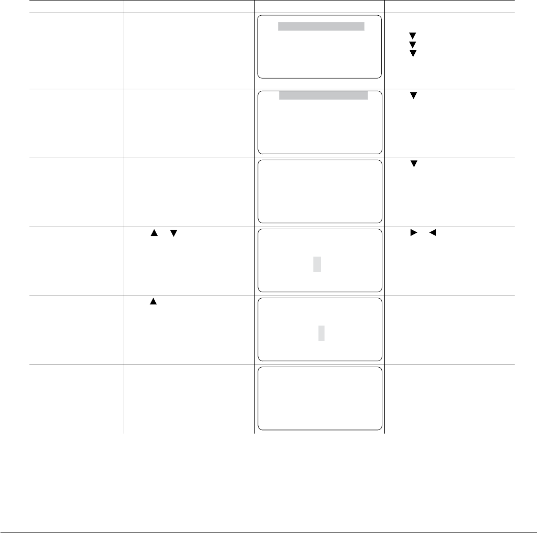
6-10 Using the Keypad MN766
6.7 Advanced Prog
At the Menu display screen, select ADVANCED PROG and press Enter. This menu provides access to all drive parameters
which are organized in blocks that are grouped into one of 3 levels. Examples of tasks accomplished via this menu are:
1. Adjustment of motor data not available in the basic parameters menu.
2. Auto Tune the motor.
3. Customize the drive parameters to your application.
Parameter Status
All programmable parameters are displayed with its parameter number shown at the bottom center of the display. “F” means
it is the factory setting value. “C” means it is a custom value set by the user. “V” means the parameter value may be viewed
but not changed while the motor is operating. If the parameter is displayed with an “L”, the value is locked and may not be
changed until the security code is entered.
Action Description Display Comments
Advanced Prog Display Top Level Advanced Prog menu. LEVEL 1 BLOCKS
LEVEL 2 BLOCKS
LEVEL 3 BLOCKS
MODIFIED PARAMS
LINEAR LIST
block parameters.
Press to view Level 2 blocks.
Press to view Level 3 blocks.
Press to view list of parameters
that have been changed from their
factory settings or to view a list of
parameters organized by number.
Press Enter to edit
Level 1 parameters.
Top of Level 1 Advanced Prog
Block 1 menu. PRESET SPEEDS
RAMP RATES
JOG SETTINGS
KEYPAD SETUP
INPUT SETUP
Press to scroll to next level 1
.
Press Enter to select
Preset Speeds.
Preset speed 1 value display. PROG
PRESET SPEED 1
30 RPM
F1001T1
Press to go to next Preset
Speed parameter.
Press Enter to edit
Preset Speed 1.
Press or to increase or
decrease the value highlighted by
the cursor.
EDIT
F1001T1
PRESET SPEED 1
00030 RPM
MAX RESET
PRESET SPEEDS
Press
or to move cursor.
Press “F1” to select the maximum
allowable speed.
Press to increase the value. EDIT
F1001T1
PRESET SPEED 1
000040 RPM
MAX RESET
PRESET SPEEDS Press F2 to exit editing the value
without saving or press Enter to
exit and save the new value.
Press Enter to save the
new value and stop
editing.
PROG
C1001T1
PRESET SPEED 1
000040 RPM
STATUS BACK
PRESET SPEEDS Press F2 to return to previous
screen.
Press F1 to go to Status screen.
STATUS BACK
STATUS BACK
STATUS BACK
PRESET SPEEDS
block
Press enter to program level 1
Parameter values in other Level 1, 2 and 3 blocks can be selected and edited in the same way.
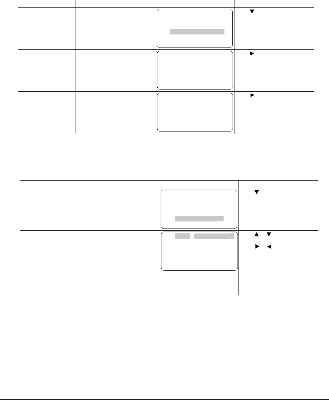
Using the Keypad 6-11MN766
6.7.1 Modified Parameters
Allows viewing of all parameters that have been changed from factory set values.
Action Description Display Comments
Advanced Prog Display. Top Level Advanced Prog menu. LEVEL 1 BLOCKS
LEVEL 2 BLOCKS
LEVEL 3 BLOCKS
MODIFIED PARAMS
LINEAR LIST
Press to scroll to Modied Params.
Press enter to view list of
parameters that have been changed
from their factory settings.
Press Enter to select
Modied Parameters.
View parameter values that have
been changed from factory
settings by user selection,
autotune, etc.
PROG
PRESET SPEED 1
38 RPM
C1001T1
STATUS BACK
PRESET SPEEDS Press to go to next modied
Press F2 to return to Advanced
Prog menu.
PROG
C1401T1
OPERATING MODE
PLC
STATUS BACK
INPUT SETUP Press to go to next modied
parameter.
Press F2 to return to Advanced
Prog menu.
parameter.
6.7.2 Linear List
Action Description Display Comments
Advanced Prog Display. Top Level Advanced Prog menu. LEVEL 1 BLOCKS
LEVEL 2 BLOCKS
LEVEL 3 BLOCKS
MODIFIED PARAMS
LINEAR LIST
Press to scroll to Linear List.
Press enter to view list of
parameters beginning with 1001.
Press Enter to select
sequential view of
parameters by
parameter number
“Linear List”.
The number and name of each
parameter is displayed in listing
format.
The rst character of the parameter
number has the following meaning:
F = Factory Setting
C = Custom value set by user
V = Parameter value may be Viewed
but
not changed.
L = Parameter value is locked,
security code required.
PNUM BACK
C1001 PRESET SPEED 1
F1002 PRESET SPEED 2
F1003 PRESET SPEED 3
F1004 PRESET SPEED 4
F1005 PRESET SPEED 5
Press or keys to scroll to
through the parameter list.
Press or keys to jump to
next page.
Press F2 to return to previous
menu.
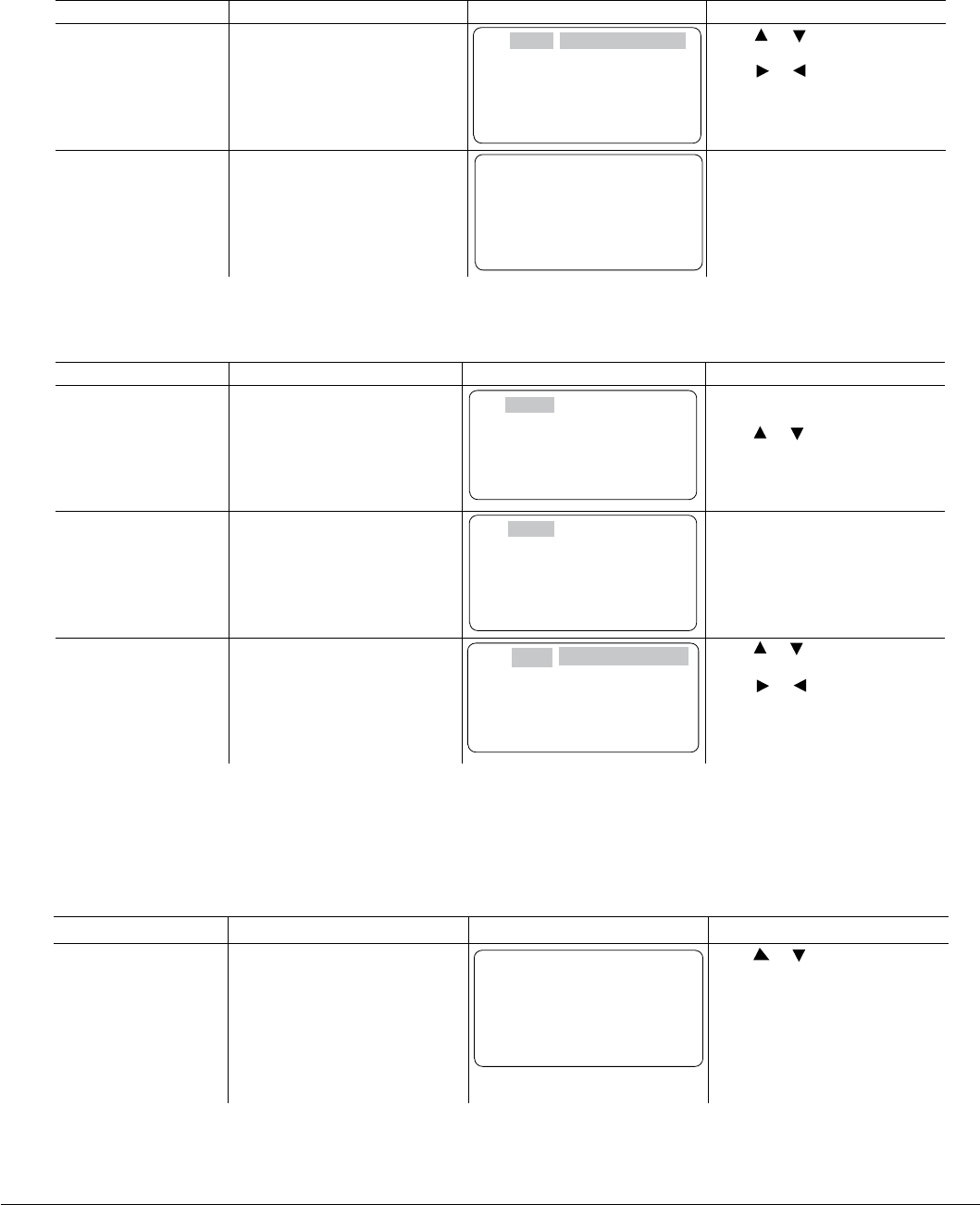
6-12 Using the Keypad MN766
Change a parameter value within the linear list as follows:
Action Description Display Comments
Press Enter to select
the parameter value to
be viewed or modied.
The number and name of each
parameter is displayed in listing
format.
PNUM BACK
C1001 PRESET SPEED 1
F1002 PRESET SPEED 2
F1003 PRESET SPEED 3
F1004 PRESET SPEED 4
F1005 PRESET SPEED 5
Press or keys to scroll to
through the parameter list.
Press or keys to jump to
next page.
Press F2 to return to previous
menu.
Press Enter to change
the parameter value.
The parameter value can be
changed as previously described
in Advanced Programming.
PROG
PRESET SPEED 1
38 RPM
C1001T1
STATUS BACK
PRESET SPEEDS Press Enter then use cursor keys
to position cursor and increase or
decrease each character under
the cursor as desired.
Press F2 to return to previous
menu.
Jump to display a different range of parameters as follows:
Press F1 key (PNUM)
to highlight Parameter
Number.
The parameter number is
highlighted.
PNUM BACK
Press F1 key (PNUM) to highlight
Parameter Number
.
Press or keys to scroll.
Press F2 (BACK) to return to
previous menu.
Press Enter key to edit
the highlight Parameter
Number.
The parameter number is
highlighted.
PNUM BACK
C2001 PRESET SPEED 1
F1002 PRESET SPEED 2
F1003 PRESET SPEED 3
F1004 PRESET SPEED 4
F1005 PRESET SPEED 5
Use cursor keys to position cursor
and increase or decrease each
character under the cursor as
desired. Press Enter when
nished.
Press F2 to return to previous
menu.
The newly selected parameter
number range is displayed.
These values may be viewed and
changed or jump to a different
parameter range may be
performed. PNUM BACK
F2001
F2002 MIN OUTPUT SPEED
F2003 MAX OUTPUT SPEED
F2004 PWM FREQUENCY
F2006 CURR RATE LIMIT
Press or keys to scroll to
through the parameter list.
Press or keys to jump to
next page. Press F2 (BACK) to
return to previous menu.
C1001 PRESET SPEED 1
F1002 PRESET SPEED 2
F1003 PRESET SPEED 3
F1004 PRESET SPEED 4
F1005 PRESET SPEED 5
OPERATING ZONE
Action Description Display Comments
6.8 Event Log
From the Menu display screen, select Event Log and press enter. Trace is used to display control conditions present at the
time the fault occurred. A separate trace log is recorded for each event.
Action Description Display Comments
Event Log Display
LOW INITIAL BUS
0 Date Time
Entry #
0-9
HH:MM:SS
Displays error name,
Entry # and time the
error occurred.
DD/MM/YY
EV. LOG
STATUS TRACE
LOW INITIAL BUS
0 4-Jul-06 09:35:00
LOCAL
STOP Press or to view next entry.
Press F2 to view Trace Log
Press F1 to return to Status
Menu.
Note: Trace is described in
Chapter 9 of this manual.
Input states, Output states, various voltage and current values etc. can be viewed to help understand the cause of the fault
condition. See Chapter 9 of this manual for more information.

Using the Keypad 6-13MN766
6.9 Diagnostics
From the Menu display screen, select Diagnostics and press enter. These are read only values with the exception of the real
time clock settings.
See Chapter 9 for a more detailed description.
Action Description Display Comments
Press Menu. Displays top level menu options. STATUS
BASIC PARAMS
ADVANCED PROG
EVENT LOG
DIAGNOSTICS
STATUS BACK
Press or to move cursor over
the “DIAGNOSTICS” selection.
Press to display next
group. Displays active operating mode
settings.
STATUS 0.00r MAIN
OPERATING MODE
Keypad
Speed
AC Servo
DIAG STOP LOCAL
Press to display next
group.
Bit display of digital inputs,
outputs and the voltage present at
the internal 24V supply terminals.
STATUS 0.00r MAIN
DIGITAL I/O
INPUTS 100000000
OUTPUTS 0001
USER 24V 24.9V
DIAG STOP LOCAL Press or to go to the next or
previous Diagnostic screen.
Press F2 to return to main menu.
Press to display next
group.
Output Frequency, % Feedforward
% Setpoint, % Feedback
STATUS 0.00r MAIN
PROC CONTROL PID
0.00HZ 0.0FF
0.0SP 0.0FB
DIAG STOP LOCAL Press or to go to the next or
previous Diagnostic screen.
Press F2 to return to main menu.
Note: This screen does not appear
unless P1401 is set to
Displays software version, hp,
volts and Amp/Volt ratings.
STATUS 0.00r MAIN
SHH-1.21
RATED HP 3HP
RATED VOLTS 240.0V
RATED A/V 4.0A/V
DIAG STOP LOCAL Press to go to the next or
previous Diagnostic screen.
Press F2 to return to main menu.
Press to display next
group.
STATUS 0.00r MAIN
RATED CURRE 9.6A
RATED PK CU 16.8A
DIAG STOP LOCAL Press to go to the next or
previous Diagnostic screen.
Press F2 to return to main menu.
Press to display next
group. Displays:
Power Base ID number
EE Firmware version
FPGA Firmware version
STATUS 0.00r MAIN
POWER BASE VERSION
ID 0x000A2003
EE VER 0x00000001
FPGA VER 0x00000A02
DIAG STOP LOCAL Press to go to the next or
previous Diagnostic screen.
Press F2 to return to main menu.
0x=Hexadecimal
0b=Binary
Press to display next
group. Displays real time clock values
(date and time) and total run time
since installation.
Press ENTER to set date and
time. STATUS 0.00r MAIN
REAL TIME CLOCK
Jul 4, 2006
22:07:35
RUN TIMER 474.1HR
DIAG STOP LOCAL Press to go to the next or
previous Diagnostic screen.
Press F2 to return to main menu.
or
or
or
or
Note: Example display shows that
the drive enable terminal
(J2-8) is on and that
Relay Out 2 is on.
SHH-1.21
Press Enter to view diagnostic
information.
Press to display next
group.
Process Control.
Press F1 to go to STATUS screen.
Press F1 to go to STATUS screen.
Press F1 to go to STATUS screen.
Press F1 to go to STATUS screen.
Press F1 to go to STATUS screen.
Press F1 to go to STATUS screen.

6-14 Using the Keypad MN766
Diagnostics Continued
Action Description Display Comments
Press to display next
group. Displays energy cost (based on
parameter P2305 value).
STATUS 0.00r MAIN
ENERGY
EST POWER 0.00KW
EST ENERGY 0.0KWH
EST COST 0.0$
DIAG STOP LOCAL Press to go to the next or
previous Diagnostic screen.
Press F2 to return to main menu.
Press F1 to go to Status screen.
Press to display next
group.
Diagnostic Analog Input values
display
.
STATUS 0.00r MAIN
ANALOG INPUTS
ANA IN1 1.3v
ANA IN2 0.0v
DIAG STOP LOCAL Press to go to the next or
previous Diagnostic screen.
Press F2 to return to main menu.
Press to display next
group.
Diagnostic Analog Output values
display
.
STATUS 0.00r MAIN
ANALOG OUTPUTS
ANA OUT1 0.0V
ANA OUT2 0.0V
DIAG STOP LOCAL Press to go to the next or
previous Diagnostic screen.
Press F2 to return to main menu.
or
or
or
Press to display next
group.
Displays keypad software version.
STATUS 0.00r MAIN
KEYPAD VERSION
KEYPAD SOF 1.1X
DIAG STOP LOCAL
Press to display next
group.
Diagnostic installed Option Card
identication display.
.
STATUS 0.00r MAIN
OPTION BOARDS
OPTION 1 ETHERNET
OPTION 2 NONE
FEEDBACK RESOLVER
DIAG STOP LOCAL Press to go to the next or
previous Diagnostic screen.
Press F2 to return to main menu.
Press F1 to go to Status screen.
Press to display next
group.
Displays Composite Reference
values.
STATUS 0.00r
COMPOSITE REF
COMPONENT A 0.00%
COMPONENT B 0.00%
REFERENCE 0.00%
DIAG STOP LOCAL
Press to display next
group.
DC Bus Voltage
Drive Heatsink Temperature
% Drive Overload (remaining)
DRIVE
BUS VOLTAGE 333.9V
DRIVE TEMP 26.1C
DRIVE O/L L 100.0%
DIAG STOP LOCAL
STATUS 0.00r
Press to go to the next or
previous Diagnostic screen.
Press F2 to return to main menu.
Press to display next
group.
Motor Voltage
Motor Current
% Motor Overload (remaining)
MOTOR
MOTOR VOLTAGE 333.9V
MOTOR CURRE 4.8A
MOTOR O/L L 100.0%
DIAG STOP LOCAL
STATUS 0.00r
Press to go to the next or
previous Diagnostic screen.
Press F2 to return to main menu.
or
or
or
Press to display next
group.
Full revolutions are displayed.
STATUS 0.00r MAIN
POSITION COUNTER
REVOLUTIONS 0
COUNTS 0
SPEED MEAS 0
DIAG STOP LOCAL Press to go to the next or
previous Diagnostic screen.
Press F2 to return to main menu.
or
(Note that this is not the same
as the drive control rmware.)
Alarm
MAIN
MAIN
Press F1 to go to Status screen.
Press F1 to go to Status screen.
Press F1 to go to Status screen.
Press F1 to go to Status screen.
Press F1 to go to Status screen.
Press to go to the next or
previous Diagnostic screen.
Press F2 to return to main menu.
Press F1 to go to Status screen.
or
Press to go to the next or
previous Diagnostic screen.
Press F2 to return to main menu.
Press F1 to go to Status screen.
or
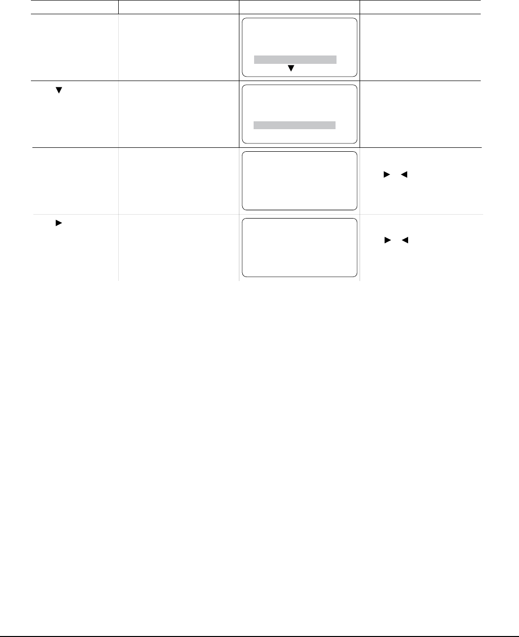
Using the Keypad 6-15MN766
6.10 Display Options
Action Description Display Comments
STATUS
DIAG BACK
BASIC PARAMS
ADVANCED PROG
Press “F1” or “F2” to return to
DIAGNOSTICS.
BASIC PARAMS
DIAG BACK
ADVANCED PROG
EVENT LOG
Displays the KEYPAD CONTRAST
adjustment screen.
Press to DISPLAY
OPTIONS. Press ENTER.
PROG KEYPAD SETUP
STATUS F1313T1 BACK
KEYPAD CONTRAST
50%
Press “Enter” to change parameter
value.
Press to display next screen.
Press “F2” to return to previous menu.
or
PROG KEYPAD SETUP
DIAG F1314T1 BACK
BACKLIGHT
On
Press “Enter” to change parameter
value.
Press to display next screen.
Press “F2” to return to previous menu.
Displays the BACKLIGHT On/Off
select screen.
Press to display next
parameter.
Press “F2” to return to
MAIN MENU.
Press “F1” to return to STATUS screen.
Press “F1” to return to STATUS screen.
or
Displays top level menu options.
EVENT LOG
DIAGNOSTICS
DIAGNOSTICS
DISPLAY OPTIONS

6-16 Using the Keypad MN766
6.11 Operating the Control from the Keypad
To activate the LOCAL Mode, rst press the “STOP” key (if enabled).
Note: Pressing the keypad STOP key (if enabled) will automatically issue a motor stop command and change to LOCAL
mode. Selection of LOCAL Mode overrides any remote or serial control inputs except the External Trip input, Local
Enable Input or STOP input.
The control can operate the motor from the keypad in two ways.
1. JOG Command.
2. Speed adjustment with Keypad entered values and/or Keypad Up/Down arrow keys.
Note: If the level 1, input block operating mode parameter is set to Keypad, then no other means of operation is permitted
other than from the keypad.
6.11.1 Accessing the Keypad JOG Command
Action Description Display Comments
Status Display STATUS STOP LOCAL
DIAG 0.00r MAIN
0.0V 0RPM
0.0A 0.0HZ
Press JOG key
Next, press and hold
the FWD or REV key
The JOG LED will light indicating
the JOG mode is active. Holding
the FWD or REV key starts JOG
operation.
Releasing FWD or REV key will
terminate motor rotation.
STATUS FWD LOCAL
DIAG 210r MAIN
10.1V 210RPM
1.3A 7.0HZ
To change Jog Speed, Edit
Level 1 parameter P1201 (Jog
Speed).
Press STOP key twice to
terminate JOG mode.
6.11.2 Speed Adjustment using Local Speed Reference
Action Description Display Comments
At the Status Display,
press ENTER key to
access Local Speed
Reference.
EDIT LOCAL REFs
MAX F0201 RESET
LOC SPEED REF
000000 RPM
EDIT
DIAG F0201 BACK
LOC SPEED REF
000000 RPM
Press to move cursor.
Press to increase or
decrease value at cursor.
Press ENTER when nished and
save the new value.
EDIT
DIAG C0201 BACK
LOC SPEED REF
000300 RPM
Press to move cursor.
Press to increase or
decrease value at cursor.
Press ENTER when nished and
save the new value.
Press FWD or REV key. The control will turn the motor
shaft at the local speed ref speed. STATUS FWD LOCAL
DIAG 300r BACK
12.7V 300RPM
1.3A 10.0HZ
Press STOP key to terminate
local speed mode.
Press to increase or
decrease motor speed during
rotation.
or
or
or
or
or
LOCAL REFs
LOCAL REFs

Parameter Descriptions 7-1MN766
Chapter 7
Parameter Descriptions
7.1 Level 1 Parameters (Advanced Prog, Level 1 Blocks)
Table 7-1 Level 1 Parameter Block Definitions
Block Title Parameter (Number)
Selection (Value) Parameter Name and Description
PRESET
SPEEDS
PRESET SPEED 1 (1001)
PRESET SPEED 2 (1002)
PRESET SPEED 3 (1003)
PRESET SPEED 4 (1004)
PRESET SPEED 5 (1005)
PRESET SPEED 6 (1006)
PRESET SPEED 7 (1007)
PRESET SPEED 8 (1008)
PRESET SPEED 9 (1009)
PRESET SPEED 10 (1010)
PRESET SPEED 11 (1011)
PRESET SPEED 12 (1012)
PRESET SPEED 13 (1013)
PRESET SPEED 14 (1014)
PRESET SPEED 15 (1015)
Preset Value: 30
Preset Value: 60
Preset Value: 90
Preset Value: 120
Preset Value: 150
Preset Value: 180
Preset Value: 210
Preset Value: 240
Preset Value: 270
Preset Value: 300
Preset Value: 330
Preset Value: 360
Preset Value: 390
Preset Value: 420
Preset Value: 450
Range: 0 - Max Speed RPM
Allows selection of 15 predened motor operating speeds. Each speed may
be selected using external switches connected to terminals at J2. For motor
operation, a motor direction command must be given along with a preset
speed command.
RAMP
RATES
ACCEL TIME 1 (1101)
ACCEL TIME 2 (1107) Preset Value: 3.0
Range: 0.0 to 3600.0 Seconds
Accel time is the number of seconds required for the motor to increase at a
linear rate from 0 to “Max Output Speed” parameter (P2003) in the Level 2
Output Limits block.
DECEL TIME 1 (1104)
DECEL TIME 2 (1110) Preset Value: 3.0
Range: 0.0 to 3600.0 Seconds
Decel time is the number of seconds required for the motor to decrease at
a linear rate from the speed specied in the “Max Output Speed” parameter
(P2003) to 0.
START S-ACC 1 (1102)
START S-ACC 2 (1108 ) Preset Value: 0.0
Range: 0.0 to 100.0%
Start S-Curve Acceleration as a percentage of accel time (% 1 and 2).
END S-ACC 1 (1103)
END S-ACC 2 (1109) Preset Value: 0.0
Range: 0.0 to 100.0%
End S-Curve Acceleration as a percentage of accel time (% 1 and 2).
START S-DEC 1 (1105)
START S-DEC 2 (1111) Preset Value: 0.0
Range: 0.0 to 100.0%
Start S-Curve Deceleration as a percentage of decel time (% 1 and 2).
END S-DEC 1 (1106)
END S-DEC 2 (1112) Preset Value: 0.0
Range: 0.0 to 100.0%
End S-Curve Deceleration as a percentage of decel time (% 1 and 2).
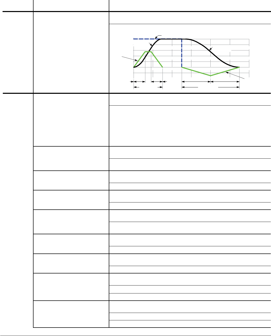
7-2 Parameter Descriptions MN766
Block Title Parameter (Number)
Selection (Value) Parameter Name and Description
RAMP
RATES
(Continued)
PL DEC TIME (1113) Preset Value: 1.0
Range: 0.0 to 3600.0 Seconds
Time to stop the motor from maximum drive speed during a power loss.
% Maximum Speed
100
80
60
40
20
-20
-40
0
Accel Time
Start
S-Accel 1
End
S-Accel 1 Decel Time
Start
S-Decel 1
End
S-Decel 1
Speed Curve
(Accel) Speed Curve
(Decel)
Seconds24 6 8 10
Commanded Speed
12
Decel Rate
Accel Rate
JOG
SETTINGS
JOG SPEED (1201) Preset Value: 210
Range: 0 - MAX Speed RPM
Jog Speed is the programmed speed used during jog. Jog can be initiated
from the keypad or terminal strip. At the Keypad, press and release the
JOG key then press and hold the direction (FWD or REV). For Standard Run
3Wire mode, close the JOG input (J2-12) at the terminal strip then close and
maintain the direction input (J2-9 or J2-10). Process Control mode operation
is different. If the terminal strip Process Control Enable input (J2-13) is
closed, pressing the Keypad JOG key (or closing J2-14) will cause the drive
to move in the direction of the error (without pressing FWD or REV).
JOG ACCEL TIME (1202) Preset Value: 10.0
Range: 0.0 to 3600.0 Seconds
The accel rate or time to reach max Speed.
Time to reach Jog Speed=(Jog Speed/Max Speed) x (Jog Accel Time).
JOG START S-ACC (1203) Preset Value: 0.0
Range: 0.0 to 100.0%
Start S-Curve Acceleration as a percentage of jog accel time.
JOG END S-ACC (1204 ) Preset Value: 0.0
Range: 0.0 to 100.0%
End S-Curve Acceleration as a percentage of jog accel time.
JOG DECEL TIME (1205) Preset Value: 10.0
Range: 0.0 to 3600.0 Seconds
The decel rate or time to decel from max Speed.
Time to reach zero speed=(Jog Speed/Max Speed) x (Jog Decel Time).
JOG START S-DEC (1206) Preset Value: 0.0
Range: 0.0 to 100.0%
Start S-Curve Deceleration as a percentage of jog decel time.
JOG END S-DEC (1207) Preset Value: 0.0
Range: 0.0 to 100.0%
End S-Curve Deceleration as a percentage of jog decel time.
JOG FORWARD (1209) Preset Value: 1
Range: 0 - 1
Off (0) Mode Disabled.
On (1) Enables Jog in the drive forward direction at Jog speed for keypad mode.
JOG REVERSE (1210) Preset Value: 1
Range: 0 - 1
Off (0) Mode Disabled.
On (1) Enables Jog in the drive reverse direction at Jog speed for keypad mode.
Table 7-1 Level 1 Parameter Block Definitions Continued

Parameter Descriptions 7-3MN766
Block Title Parameter (Number)
Selection (Value) Parameter Name and Description
KEYPAD
SETUP
STOP KEY (1301) Preset Value: 1
Range: 0 - 1
Off (0) Keypad STOP key is not active.
On (1)
Allows keypad STOP key to initiate motor stop during remote or serial
operation. If active, pressing STOP selects Local mode and initiates the
stop command. Note: Pressing STOP key twice in rapid succession will
immediately terminate PWM to motor and disable the drive.
STOP MODE (1302) Preset Value: 0
Range: 0 - 1
Regen (0) The voltage and frequency to the motor is reduced at a rate set by Decel
Time.
Coast (1) Motor is turned off and allowed to coast to a stop.
Selects if the Stop command causes the motor to COAST to a stop or
REGEN to a stop.
RUN FORWARD (1303) Preset Value: 1
Range: 0 - 1
Off (0) Disables FWD key in Local mode.
On (1) Makes the keypad FWD key active in Local mode.
RUN REVERSE (1304) Preset Value: 1
Range: 0 - 1
Off (0) Disables REV key in Local mode.
On (1) Makes the keypad REV key active in Local mode.
SWITCH ON FLY (1305)
(LOCAL/REMOTE KEY) Preset Value: 0
Range: 0 - 1
Off (0) Disables Switch on Fly.
On (1) Allows switching between Local and Remote while Control is on.
LOCAL HOT START (1306) Preset Value: 0
Range: 0 - 1
Off (0) Disables the Stop input at J2-11 in the keypad operating mode.
On (1) Enables the Stop input at J2-11 in the keypad operating mode.
SPEED INCREMENT (1307) Preset Value: 30
Range: 1 to 2500 RPM or 0.01 to 60 Hz
Sets the increment of speed change for each key press. (1-3600 RPM or
0-60 Hz)
INIT LOCAL SPEED (1308) Preset Value: 0
Range: 0 - 2
Zero Speed (0) Initializes local speed to 0 RPM on Power Up.
Last Speed (1) Initializes local speed to last speed on Power Up.
Set Speed (2) Initializes local speed to “Set Speed” (P1309) on Power Up.
SET SPEED (1309) Preset Value: 30
Range: 0 - MAX Speed RPM
At power up, initializes the local speed to this preset value if “Init Local
Speed” = Set Speed.
PARAMS TO KEYPAD (1310) Preset Value: 0
Range: 0 - 1
No (0) No action.
Yes (1) Transfers the parameter settings stored in the control memory (ash) to
keypad memory.
Table 7-1 Level 1 Parameter Block Definitions Continued

7-4 Parameter Descriptions MN766
Block Title Parameter (Number)
Selection (Value) Parameter Name and Description
KEYPAD
SETUP
(Continued)
DOWNLOAD SELECT (1311) Preset Value: 0
Range: 0 - 2
All (0) All parameters.
Motor (1) Motor parameters only.
Other (2) All parameters except Motor parameters.
Selects parameters to download (All, Motor or Other) with “Keypad to
Params” (P1312). See Appendix B for notation of which parameters are
motor related.
KEYPAD TO PARAMS (1312) Preset Value: 0
Range: 0 - 1
No (0) No action.
Yes (1) Transfers the parameter settings stored in keypad memory to the control
memory (ash).
KEYPAD CONTRAST (1313) Preset Value: 50
Range: 20 - 80%
Sets LCD contrast: 0=dimmest, 100=brightest.
BACKLIGHT (1314) Preset Value: 1
Range: 0 - 1
Off (0) Sets the Keypad Display backlight OFF.
On (1) Sets the Keypad Display backlight ON.
LOC TORQUE MODE (1315) Preset Value: 0
Range: 0 - 1
Off (0) Disables local torque mode.
On (1) Enables local torque mode operation.
LOC TORQUE REF (1316) Preset Value: 0.00
Range: -100.00 to 100.00%
Local torque mode reference value.
INPUT
SETUP
OPERATING MODE (1401) Preset Value: 0
Range: 0 - 16
Keypad (0) Drive operates from keypad only.
Standard Run 2Wire (1) Drive operates from digital inputs and command source. Preset Speed 1
may also be selected.
Standard Run 3Wire (2) Drive operates from digital inputs and command source. Preset Speed 1
may also be selected.
15 Preset Speeds (3) Operation in 15 Preset Speeds 2 Wire Mode is controlled by digital inputs at
J2. Speeds set in parameters P1001 to P1015.
Fan & Pump 2Wire (4) Operation in Fan & Pump 2 Wire controlled by digital inputs at J2.
Fan & Pump 3Wire (5) Operation in Fan & Pump 3 Wire controlled by digital inputs at J2.
Process Control (6) The Process Control provides an auxiliary closed loop general purpose PID
set point control.
3Spd Ana 2Wire (7) Provides 2 Wire control and allows selection of 3 Preset Speeds.
3Spd Ana 3Wire (8) Provides 3 Wire control and allows selection of 3 Preset Speeds.
E-Pot 2Wire (9) Electronic Potentiometer provides digital inputs for Speed Increase and
Speed Decrease. Also provides 2 digital inputs for selection of E-Pot or
"Command Source" (1402), Preset Speed 1, and Preset Speed 2.
E-Pot 3Wire (10) Electronic Potentiometer provides digital inputs for Speed Increase and
Speed Decrease. Also provides a digital input for selection of E-Pot or
“Command Source” (1402).
Network (11 Provides Bipolar speed or torque control.
Table 7-1 Level 1 Parameter Block Definitions Continued

Parameter Descriptions 7-5MN766
Block Title Parameter (Number)
Selection (Value) Parameter Name and Description
INPUT
SETUP
(Continued)
OPERATING MODE (1401)
(Continued) Preset Value: 0
Range: 0 - 16
Prole Run (12) Provides a seven segment speed prole for cyclic operation or test cycle.
See Level 3, Prole Run Block.
15 Preset Positions (13) (Closed loop vector only). Provides for 15 preset Point-to-Point moves.
Bipolar (14) Provides bipolar speed or torque control. Torque control only available in
vector modes.
Pulse Follower (15) Provides electronic gearing of two or more controls from upstream
reference. (Requires Expansion Board EXBHH007).
PLC (16) Provides for control from custom designed internal logic.
CTD 2Wire (17 Cooling Tower Drive, (CTD) 2 Wire provides for 2 wire control with Trickle
Current Enable digital input.
CTD 3Wire (18) Cooling Tower Drive (CTD) 2 Wire provides for 2 wire control with reversing
and Trickle Current Enable digital input.
CTD 2Wire Rev (19) Cooling Tower Drive (CTD) 2 Wire provides for 2 wire control with reversing
and Trickle Current Enable ditial input.
CTD 3Wire Rev (20) Cooling Tower Drive (CTD) 2 Wire provides for 3 wire control with reversing
and Trickle Current Enable digital input.
External connections to the control are made at the control terminal strip
(wiring diagrams are shown in Chapter 5 “Operating Modes”).
COMMAND SOURCE (1402) Preset Value: 1
Range: 0 - 10
None (0) Command Source is not used.
Analog In1 (1) Connect a 10Kohm pot at J1 or connect a 0-10VDC signal to J1-2 and J1-1.
Analog In2 (2) Connect a 0-5V, 0-10V, ±5V, ±10V, 0-20mA or 4-20mA source to J1-4 and
5. 4-20mA should be considered when a long distance (greater than 50 ft)
between the external device and J1-4 and 5 of the control is necessary.
Keypad (3) Command is from Keypad.
Network (4) Signal source is from a device on the network.
Composite Ref (5) The result of the Level 3 Composite Reference set by the user.
Opt1 Ana In1 (6) Scaled value of option board 1 analog input 1 signal value.
Opt1 Ana ln2 (7) Scaled value of option board 1 analog input 2 signal value.
Opt2 Ana ln1 (8) Scaled value of option board 2 analog input 1 signal value.
Opt2 Ana ln2 (9) Scaled value of option board 2 analog input 2 signal value.
EXB Pulse Fol (10) Signal source is from the EXB Pulse Follower expansion board.
ANA IN1 TYPE (1403) Preset Value: 1
Range: 0 - 1
None (0) Input not used.
Potentiometer (1) 0 - 10V signal used.
Table 7-1 Level 1 Parameter Block Definitions Continued

7-6 Parameter Descriptions MN766
Block Title Parameter (Number)
Selection (Value) Parameter Name and Description
INPUT
SETUP
(Continued)
ANA IN2 TYPE (1408) Preset Value: 1
Range: 0 - 6
None (0) Input not used.
-10V to +10V (1) Bipolar 10V signal used.
-5V to +5V (2) Bipolar 5V signal used.
4 to 20mA (3) 4-20mA current signal used.
0 to 20mA (4) 0-20mA current signal used.
0 to 10V (5) Unipolar 10V signal used.
0 - 5V (6) Unipolar 5V signal used.
Denes signal being used.
ANA IN1 INVERT (1404)
ANA IN2 INVERT (1409) Preset Value: 0
Range: 0 - 1
Off (0) Will cause a low input voltage (e.g. 0VDC) to be a low motor speed
command and a maximum input voltage (e.g. 10VDC) to be a maximum
motor speed command.
On (1) Will cause a low input voltage (e.g. 0VDC) to be a maximum motor speed
command and a maximum input voltage (e.g. 10VDC) to be a low motor
speed command.
ANA IN1 GAIN (1405)
ANA IN2 GAIN (1410) Preset Value: 100.0%
Range: 0.0% to 300.0%
Allows 0 to 300% gain to be applied ((as in Y=Gain*(X-Offset)).
ANA IN1 OFFSET (1406)
ANA IN2 OFFSET (1411) Preset Value: 0.0
Range: -100.0% to 100.0%
Provides an offset to the Analog Input to minimize signal error. For example,
if the minimum speed signal is 1VDC (instead of 0VDC) the Ana In1 Offset
can be set to -10% so the minimum voltage input is seen by the control as
0VDC. This parameter is automatically adjusted during the auto tune Analog
Offset Trim test.
ANA IN1 FILTER (1407)
ANA IN2 FILTER (1413) Preset Value: 0
Range: 0 - 6
No Filter (0) No Filtering.
Max Filter (6) Max Filtering.
Amount of low pass signal ltering to use.
ANA IN2 D.BAND (1412) Preset Value: 0.0
Range: 0.0% to 75.0%
Allows a dened range of voltage to be a deadband. A command signal
within this range will not affect the control output. The deadband value is the
voltage above and below the zero command signal level.
EXT. CUR LIMIT (1414) Preset Value: 0
Range: 0 - 1
Off (0) Ramp output to speed loop is held at its present value as long as regen
current limit is active.
On (1) Ramp output to speed loop is always ramped to the value of its input.
Table 7-1 Level 1 Parameter Block Definitions Continued

Parameter Descriptions 7-7MN766
Block Title Parameter (Number)
Selection (Value) Parameter Name and Description
INPUT
SETUP
(Continued)
CURR LMT SOURCE (1415) Preset Value: 0
Range: 0 - 9
None (0) Turns off external current limit.
Analog In1 (1) Connect a 10Kohm pot at J1 or connect a 0-10VDC signal to J1-2 and J1-1.
Analog In2 (2) Connect a 0-5V, 0-10V, ±5V, ±10V, 0-20mA or 4-20mA source to J1-4 and 5.
4-20mA should be considered when a long distance (up to 50 ft) between
the external device and J1-4 and 5 of the control is necessary.
Keypad (3) Turns off Current Limit Source from Keypad.
Composite Ref (4) See Chapter 11 for more information.
Opt1 Ana In1 (5) Selects analog input from high resolution analog input/output Expansion
Board (EXBHH005) mounted in expansion slot 1.
Opt1 Ana In2 (6) Selects analog input from high resolution analog input/output Expansion
Board (EXBHH005) mounted in expansion slot 1.
Opt2 Ana In1 (7) Selects analog input/output Expansion Board (EXBHH005) mounted in
expansion slot 2.
Opt2 Ana In2 (8) Selects analog input/output Expansion Board (EXBHH005) mounted in
expansion slot 2.
Network (9) Selects the network current limit word as the current limit source.
Selects the external current limit reference to be used, converts it internally
to a percentage and then sets the torque limit of the drive as a percentage of
the drive’s Peak Current Level (P2006).
SLEEP MODE (1416) Preset Value: 0
Range: 0 - 1
Off (0) No action.
On (1) Disables control when Command Source is less than CMD Sleep Band
(P1417). Active in all speed modes.
CMD SLEEP BAND (1417) Preset Value: 0.00
Range: 0.00 to 100.00%
Disables the control when Command Source is less than CMD Sleep
Band (P1417). Active in all speed modes and is also applied to the torque
reference when in torque mode.
Table 7-1 Level 1 Parameter Block Definitions Continued

7-8 Parameter Descriptions MN766
Block Title Parameter (Number)
Selection (Value) Parameter Name and Description
INPUT
SETUP
(Continued)
TORQUE FF SRC (1418) Preset Value: 0
Range: 0 - 8
None (0) Turns off external torque feedforward reference.
Analog In1 (1) Connect a 10Kohm pot at J1 or connect a 0-10VDC signal to J1-2 and J1-1.
Analog In2 (2) Connect a 0-5V, 0-10V, ±5V, ±10V, 0-20mA or 4-20mA source to J1-4 and
5. 4-20mA should be considered when a long distance (greater than 50 ft)
between the external device and J1-4 and 5 of the control is necessary.
Keypad (3) Turns off external torque feedforward reference. (Keypad uses Local Keypad
Torque Reference as feedforward.)
Composite Ref (4) See Chapter 11 for more information.
Opt1 Ana In1 (5) Selects analog input from high resolution analog input/output expansion
Board(EXBHH005) mounted in expansion slot 1.
Opt1 Ana In2 (6) Selects analog input from high resolution analog input/output expansion
Board(EXBHH005) mounted in expansion slot 1.
Opt2 Ana In1 (7) Selects analog input/output Expansion Board (EXBHH005) mounted in
expansion slot 2.
Opt2 Ana In2 (8) Selects analog input/output Expansion Board (EXBHH005) mounted in
expansion slot 2.
Selects the external torque feedforward reference to be used which is added
to the torque demand from the speed loop. The result then becomes the
torque reference for the current loop.
1451-1474 Parameters 1451-1474 are used to congure the High Resolution Analog I/O
Expansion Board. See manual MN754 for Conguration details.
Table 7-1 Level 1 Parameter Block Definitions Continued

Parameter Descriptions 7-9MN766
Block Title Parameter (Number)
Selection (Value) Parameter Name and Description
OUTPUT
SETUP
DIGITAL OUTPUT 1 (1501)
DIGITAL OUTPUT 2 (1502)
RELAY OUTPUT 1 (1503)
RELAY OUTPUT 2 (1504)
Preset Value: 1
Preset Value: 8
Preset Value: 9
Preset Value: 17
Range: 0 - 31
Drive Run (0) Active when drive is “On” and a FWD/REV direction command is present.
Drive Ready (1) Active after soft start, when drive is enabled and no faults are present.
Drive On (2) (V/F) Active when drive is “Ready” and producing PWM to motor. (Vector)
Active when drive is “Ready” and motor ux is present.
Drive Stopped (3) Active when stop command is present and motor is stopped (or coasting to
stop).
Jog (4) Active during Jog mode.
Accelerate (5) Active when control is accelerating.
Constant Speed (6) Active when control speed is constant.
Decelerate (7) Active when control is decelerating.
At Zero Speed (8) Active when motor speed is less than the Level 1 Output Setup “Zero SPD
Set Pt (P1505)”.
At Speed (9) Active when motor speed is within band set by the Level 1 Output Setup “At
Speed Band (P1506)”.
At Set Speed (10) Active when output speed is at or greater than the Level 1 Output Setup
“Set Speed Point (P1507)”.
Curr Overload (11) Active when motor current is greater than “Overload Set Point (P1508)”.
Curr Underload (12) Active when motor current is less than “Underload Set Point (P1509)”.
I2T Overload (13) Active when overload left is less than 100%.
Keypad Control (14) Active when control is in Local keypad control.
Dynamic Brake (15) Active when Dynamic Brake transistor is turned ON.
Foldback (16) Active when current foldback is active (V/Hz Mode only).
Fault (17) Active when a fault condition is present (will cause trip).
Alarm (18) Active when an Alarm condition is present (but doesn’t cause trip).
Command Forward (19) Active during forward run command.
Command Reverse (20) Active during reverse run command.
Motor Forward (21) Active when motor is moving in Drive forward direction.
Motor Reverse (22) Active when motor is moving in Drive reverse direction.
Process Error (23) Active when absolute process error is greater than P2606 (Process Error
Tolerance).
Network (24) Active when commanded by network. Network device controls this output.
At Position (25) Active when load is at position (|Position error|≤P1517) AND
(|Motor Speed|≤P1505).
In Motion (26) Active when load is moving (|Position error|>P1517) OR
(|Motor Speed|>P1505).
PLC (27) Output is controlled by PLC mode.
RTC (28) Output is controlled by RTC module.
Powered Up (29) Active when Bus is “UP” and no faults are present.
Heater (30) Output turns on when trickel current heating is active
Contactor Ctl (31) Provides control of a contactor between the Control and the motor so that
the contactor is sequenced with the required time delays.
See also 1505, 1506, 1507, 1508,1509, 1517, Chapter 10, Chapter 11,
Chapter 12.
Table 7-1 Level 1 Parameter Block Definitions Continued

7-10 Parameter Descriptions MN766
Block Title Parameter (Number)
Selection (Value) Parameter Name and Description
OUTPUT
SETUP
(Continued)
ZERO SPD SET PT (1505) Preset Value: 180
Range: 0 - MAX Speed RPM
A digital output programmed to “At Zero Speed” becomes active when
motor speed becomes less than this setting. This is useful when a motor
brake is to interlock operation with a motor.
AT SPD BAND (1506) Preset Value: 60
Range: 0 - 100 RPM
At Speed opto output is active when the magnitude of (Speed Ref)-(Speed
Demand) is less than the set value of P1506.
SET SPEED POINT (1507) Preset Value: 1800
Range: 0 - MAX Speed RPM
A digital output programmed to “At Set Speed” becomes active when the
motor speed is greater than the value programmed in this parameter. This is
useful when another machine must not start or stop until the motor exceeds
a predetermined speed.
OVERLOAD SET PT (1508) Preset Value: 150.0
Range: 0.0 - 200.0%
Sets the motor current value as a percent of drive rated current at which the
Overload digital output is active.
UNDERLOAD SET PT (1509) Preset Value: 50.0
Range: 0.0 - 200.0%
Sets the motor current value as a percent of drive rated current at which the
Underload digital output is active.
ANA OUT1 TYPE (1510) Preset Value: 0
Range: 0 - 3
0 to +10V (0) Sets the Analog Output Signal to 0 - 10V.
0 to 5V (1) Sets the Analog Output Signal to 0 - 5V.
4mA to 20mA (2) Sets the Analog Output Signal to 4 - 20mA.
0mA to 20mA (3) Sets the Analog Output Signal to 0 - 20mA.
ANA OUT2 TYPE (1513) Preset Value: 1
Range: 0 -1
+5/-5V (0) Sets the Output Signal ±5V.
+10/-10V (1) Sets the Output Signal ±10V.
ANA OUT1 SIGNAL (1511)
ANA OUT2 SIGNAL (1514) Preset Value: 29
Preset Value: 3
Range: 0 - 34
Speed Ref (0) Scaled value of speed reference (input to velocity proler) (ACC/DEC ramp).
Speed Demand (1) Scaled value of speed reference (output of velocity proler) (ACC/DEC
ramp).
ACC/DEC (2) Scaled value of ACC/DEC rate. Range is from 0 to max ACC/DEC rate.
Motor Current (3) Scaled value of Motor Current. Range is based on 2 times drive FLA.
(Includes both MAG and Load currents).
Mag Current (4) Scaled value of magnetizing current, range is based on 2 times drive FLA.
Mag Curr Cmd (5) The commanded D-axis PI vector magnetizing current to the current
controller, range is based on 2 times drive FLA.
Load Current (6) Scaled value of the load amps, range is based on 2 times drive FLA.
Load Curr Cmd (7) The commanded Q-axis PI vector load current to the current controller,
range is based on 2 times drive FLA.
Table 7-1 Level 1 Parameter Block Definitions Continued

Parameter Descriptions 7-11MN766
Block Title Parameter (Number)
Selection (Value) Parameter Name and Description
OUTPUT
SETUP
(Continued)
ANA OUT1 SIGNAL (1511)
ANA OUT2 SIGNAL (1514)
(Continued)
Preset Value: 29
Preset Value: 3
Range: 0 - 34
Power Factor (8) Scaled value of power factor, range is from 0 to 1.0.
Ph1 Current (9) Scaled value of the phase 1 motor current, range is based on 2 times drive
FLA.
Ph2 Current (10) Scaled value of the phase 2 motor current, range is based on 2 times drive
FLA.
Ph3 Current (11) Scaled value of the phase 3 motor current, range is based on 2 times drive
FLA.
Motor Voltage (12) Scaled value of the motor voltage, range is based on drive rated output
voltage.
VD Demand (13) Flux controller output. Used to diagnose control problems.
VQ Demand (14) Load controller output. Used to diagnose control problems.
Bus Voltage (15) Scaled value of the Bus voltage. (Range is based on 123% of drive rated
output voltage).
Abs Torque (16) Scaled value of the absolute torque, range is based on peak torque (2 x
rated torque).
Torque (17) Scaled value of the motor torque (signed), range is based on rated torque
(2 x rated torque).
Control Temp (18) Scaled value of the control heatsink temperature, range is -50°C to 150ºC.
Analog In1 (19) Scaled value of the analog input 1 signal value.
Analog In2 (20) Scaled value of the analog input 2 signal value, range depends on input type
P1408.
Opt1 Ana In1 (21) Scaled value of option board 1 analog input 1 signal value, range depends
on input type selected.
Opt1 Ana In2 (22) Scaled value of option board 1 analog input 2 signal value, range depends
on input type selected.
Opt2 Ana In1 (23) Scaled value of option board 2 analog input 1 signal value, range depends
on input type selected.
Opt2 Ana In2 (24) Scaled value of option board 2 analog input 2 signal value, range depends
on input type selected.
Proc Feedforward (25) Scaled value of the process feedforward signal, range is -100% to 100% of
Process Feedforward signal.
Proc Feedback (26) Scaled value of the process feedback signal, range is -100% to 100% of
Process Feedback signal.
Proc Setpoint (27) Scaled value of the process setpoint source, range is -100% to 100% of
Process Setpoint signal.
Electric Angle (28) Scaled value of the electrical angle of shaft, range is from 0-359 degrees.
Abs Speed (29) Scaled value (absolute) of actual motor speed, range is 0-Max Motor Speed
P2003.
Velocity (30) Scaled value (signed) of actual motor speed, range is - Max Motor Speed to
+Max Motor Speed P2003.
Network (31) Represents the network speed reference, see MN744. Analog 1 holding
register is 40014:40013, Analog 2 holding register is 40016:40015.
Composite Ref (32) Scaled value of the Composite Reference output, range is -100% to 100%
of composite reference calculation.
Power (kW) (33) Scaling power calculated using nominal output amps and RMS output volts.
Calibrate (34) Produces maximum value of selected analog output type.
Table 7-1 Level 1 Parameter Block Definitions Continued

7-12 Parameter Descriptions MN766
Block Title Parameter (Number)
Selection (Value) Parameter Name and Description
OUTPUT
SETUP
(Continued)
ANA OUT1 GAIN (1512)
ANA OUT2 GAIN (1515) Preset Value: 100.0
Preset Value: 100.0
Range: 0.0 - 500.0%
Scale factor for analog output (as in Y=Gain*X)
CAL ANA OUT (1516) Preset Value: 0.0
Range: -100.0% to 100.0%
Scalable output signal used to calibrate output device (-100% to 100% of
Analog Out 1 Type).
AT POS BAND (1517)
for Feedback Only Preset Value: 10
Range: 1 to 4095 Counts
Load is at target position (|Position-Feedback|) < Band.
1551-1562 Parameters 1551-1562 are used to congure the High Resolution Analog I/O
Expansion Board. See manual MN754 for Conguration details.
MOTOR
CONTROL
CNTL BASE SPEED (1602) Preset Value: 2500
Range: 30 - 15000 RPM
Speed at which eld weakening begins
CUR LOOP FF GAIN (1603) Preset value: 100.0
Range: 0.0% - 200.0%
Motor model voltage FEEDFORWARD GAIN.
FEEDBACK ALIGN (1631) Preset Value: 0
Range: 0 - 1
Forward (0) Sets the feedback’s electrical direction in forward rotation.
Reverse (1) Sets the feedback’s electrical direction in reverse rotation.
Sets the feedback’s electrical direction of rotation to match that of the
motor.
FEEDBACK FILTER (1632)
Preset Value: 4
Range: 0 - 7
A larger value provides a more ltered signal but at the cost of reduced
bandwidth.
CURR PROP GAIN (1633) Preset Value: CALC
Range: 0.00 - 150.00
Sets the current loop proportional gain.
CURR INT GAIN (1634) Preset Value: 150.00
Range: 0.00 - 3000.00Hz
Sets the current loop integral gain.
SPEED PROP GAIN (1635) Preset Value: CALC
Range: 0.000 - 1000.000
Sets the speed (velocity) loop proportional gain. Excessive speed prop gain
will cause ringing around the set point. Decreasing the speed prop gain will
result in slower response and decrease the ringing, but will increase the
overshoot.
SPEED INT GAIN (1636) Preset Value: 10.000
Range: 0.000 - 1000.000Hz
Sets the speed (velocity) loop integral gain.
SPEED DIFF GAIN (1637) Preset Value: 0.00
Range: 0.00000 - 1.00000
Sets the speed (velocity) loop differential gain.
POSITION GAIN (1638) Preset Value: 8.0
Range: 0.0 - 1000.0
Sets the position loop proportional gain. Used with Master Pulse Ref/
Follower expansion board (EXBHH007). Not used in 15 preset position
mode.
Table 7-1 Level 1 Parameter Block Definitions Continued

Parameter Descriptions 7-13MN766
Block Title Parameter (Number)
Selection (Value) Parameter Name and Description
MOTOR
CONTROL
(Continued)
A.S. PROP GAIN (1639) Preset Value: 10.0
Range: 0.0 - 255.0
Sets the anti-saturation proportional gain.
A.S. INT GAIN (1640) Preset Value: 50.00
Range: 0.00 - 150.00Hz
Sets the anti-saturation integral gain.
FEEDBACK OFFSET (1671)
For Resolver Feedback Only Preset Value: 46.60°
Range: 0.00 to 360.00°
Feedback offset angle for brushless DC motors.
STATOR L (1672) Preset Value: CALC
Range: 0.0 to 1000.0 mH
Stator inductance. Value is measured and set during auto tune and used to
tune the current loop gain.
STATOR R (1673) Preset Value: CALC
Range: CALC
Stator resistance. Value is measured and set during auto tune and used to
tune the current loop gain.
VOLTAGE CONSTANT (1674) Preset Value: CALC
Range: 0.0 to 6000.0 V/kRPM
Voltage constant of motor. Voltage constant as RMS line to line emf at 1000
RPM.
TRICKLE HEAT AMPS (1678) Preset Value: 0.0
Range: 0.0 - 50.0% of Motor Rated Amps
Used to provide heating amps in the motor windings while the motor is
stopped to help eliminate condensation within the motor. A value of 0.0
amps in this parameter disables the function. A non-zero value will cause
the amount of amps programmed in this parameter to ow through the
motor windings after the motor is stopped and a 300 second delay. Both the
REV and FWD LEDs on th ekeypad will ash while the timer is counting and
then both LEDs are on solid when trickle current is owing.
COMMUNI-
CATION
BAUD RATE (1701) Preset Value: 1
Range: 0 - 4
9600 (0) Baud Rate = 9600
19200 (1) Baud Rate = 19200
38400 (2) Baud Rate = 38400
56000 (3) Baud Rate = 56000
115200 (4) Baud Rate = 115200
Sets the Modbus-RTU communication baud rate.
PARITY (1702) Preset Value: 0
Range: 0 - 2
None (0) No parity used.
Odd (1) Odd parity used.
Even (2) Even parity used.
Sets Modbus-RTU communication parity.
STOP BITS (1703) Preset Value: 0
Range: 0 - 1
One (0) One stop bit used.
Two (1) Two stop bits used.
Sets the number of stop bits to use for Modbus-RTU.
Table 7-1 Level 1 Parameter Block Definitions Continued

7-14 Parameter Descriptions MN766
Block Title Parameter (Number)
Selection (Value) Parameter Name and Description
COMMUNI-
CATION
(Continued)
DRIVE ADDRESS (1704) Preset Value: 1
Range: 1 - 247
Sets the drive address for communication via USB or Modbus-RTU.
OPT CARD RESET (1705) Preset Value: 0
Range: 0 - 3
Off (0) No Action.
Slot 1 (1) Reset Expansion Board in slot 1.
Slot 2 (2) Reset Expansion Board in slot 2.
Slots 1 & 2 (3) Resets both Expansion boards 1 & 2.
Sends a power up reset command to all expansion boards, slot 1 only, or
slot 2 only.
SECURITY DEFAULT (1706) Preset Value: 0
Range: 0 - 1
No (0) No Action.
Yes (1) Reset settings.
Restores factory settings to Browser User ID and Password.
BROWSER USER ID (1707)(1708) Preset Value: baldor
ASCII user ID for the Ethernet Web Browser Option Board if installed.
BROWSER PASSWORD (1709)
(1710) Preset Value: baldor
Password for the Ethernet Web Browser Option Board if installed.
1740-1791 See documentation provided with communications expansion board.
CUSTOM
MOTOR
ALIGNMENT CURRENT (1821) Preset Value: 50.0%
Range: 2.0 to 100.0%
Sets the amount of d-axis current, as a percent of Motor Rated Amps,
during alignment of PM motors.
ALIGNMENT TIME (1822) Preset Value: 5.0
Range: 1.0 to 60.0 seconds
Sets the amount of time used for alignment at motor startup.
Table 7-1 Level 1 Parameter Block Definitions Continued

Parameter Descriptions 7-15MN766
Block Title Parameter (Number)
Selection (Value) Parameter Name and Description
DRIVE
LIMITS
OPERATING ZONE (2001) Preset Value: 2
Range: 0 - 3
Std Const Trq (0) Sets the PWM operating zone to Standard 2.5kHz output carrier frequency
Constant Torque. Constant Torque allows 175% for 3 seconds and 150% for
60 seconds of peak overload capacity.
Std Var Trq (1) Sets the PWM operating zone to Standard 2.5kHz output carrier frequency
Variable Torque. Variable Torque allows 125% for 1 second and 115% for 60
seconds of peak overload capacity.
Quiet Const Trq (2) Sets the PWM operating zone to Quiet 8.0kHz output carrier frequency
Constant Torque. Constant Torque allows 175% for 3 seconds and 150% for
60 seconds of peak overload capacity.
Quiet Var Trq (3) Sets the PWM operating zone to Quiet 8.0kHz output carrier frequency
Variable Torque. Variable Torque allows 125% for 1 second and 115% for 60
seconds of peak overload capacity.
MIN OUTPUT SPEED (2002) Preset Value: 0
Range: 0 - MAX Speed RPM
Sets the minimum motor speed in RPM. During operation, the motor speed
will not decrease below this value except for motor starts or during dynamic
braking to a stop.
MAX OUTPUT SPEED (2003) Preset Value: 2500
Range: 30.0 - 15,000 RPM
Sets the maximum motor speed in RPM.
PWM FREQUENCY (2004) Preset Value: 8000
Range: 5000 - 16000Hz
The frequency that the output transistors are switched. PWM (pulse width
modulation) frequency is also referred to as “Carrier” frequency. PWM
should be as low as possible to minimize stress on the output transistors
and motor windings. It is recommended that the PWM frequency be set
to approximately 15 times the maximum output frequency of the control.
Ratios less than 15 will result in non-Sinusoidal current waveforms.
CURR RATE LIMIT (2005)
Preset Value: 0.004
Range: 0.000 - 10.000 seconds
Limits the rate of torque change in response to a torque command. This
parameter sets the time in seconds to change the output torque by 1 times
motor rated torque.
PEAK CURR LEVEL (2006) Preset Value: CALC
Range: 0 - Peak Rated Current
Sets maximum motor current level for operation.
REGEN TORQ LIMIT (2007) Preset Value: CALC
Range: 0.0 - CALC (motor amps)
Sets the maximum motor current (not including MAG current allowed during
regen.
DRIVE
CONFIG
SPEED UNITS (2101) Preset Value: 1
Range: 0 - 1
Hz (0) Sets units to Frequency, Hz.
RPM (1) Sets units to RPM.
7.2 Level 2 Parameters (Advanced Prog, Level 2 Blocks)
Table 7-2 Level 2 Parameter Block Definitions

7-16 Parameter Descriptions MN766
Block Title Parameter (Number)
Selection (Value) Parameter Name and Description
DRIVE
CONFIG
(Continued)
LANGUAGE SELECT (2102) Preset Value: 0
Range: 0 - 1
English (0) Sets English as displayed text.
Other (1)
Sets "OTHER", (Spanish, German, Italian, French, or Portuguese) English
and one language can be stored (Spanish, German, Italian, French and
Portuguese). Standard rmware allows English and Spanish. For other
languages, language tables must be loaded into the drive’s language ash
area.
FACTORY SETTINGS (2103) Preset Value: 0
Range: 0 - 1
No (0) No Action.
Yes (1) Restores factory settings for all parameters. (Overwrites all stored values for
all four parameter tables).
SECURITY (2105) Preset Value: 0
Range: 0 - 3
Off (0) Security not enabled.
Local (1) Security enabled for keypad only.
Network (2) Security enabled for Network only.
Total (3) Security enabled for both Keypad and Network.
Enables Security.
ACCESS TIMEOUT (2106) Preset Value: 5.0
Range: 1.0 - 600.0 seconds
If security is enabled and program mode is entered, the access code must
be correctly entered. After parameters are changed and program mode
exited this timer begins to timeout. If program mode is accessed after
timeout, the security code must be entered a second time.
ACCESS CODE (2107) Preset Value: 9999
Range: 0 - 9999
Sets security code for login required to access locked parameters.
ACTIVE PARAM TBL (0052) Preset Value: 0
Range: 0 - 3
T1 (0) Table 1 is used as active parameter set.
T2 (1) Table 2 is used as active parameter set.
T3 (2) Table 3 is used as active parameter set.
T4 (3) Table 4 is used as active parameter set.
Note: This parameter is not actually in the Level 2 Blocks. It is Parameter
0052 in the MONITOR block if using Workbench.
CLEAR FAULT LOG (2108) Preset Value: 0
Range: 0 - 1
No (0) No Action.
Yes (1) Deletes all fault log entries and trace values.
Table 7-2 Level 2 Parameter Block Definitions Continued

Parameter Descriptions 7-17MN766
Block Title Parameter (Number)
Selection (Value) Parameter Name and Description
DRIVE
CONFIG
(Continued)
POWER INPUT (2110) Preset Value: 0
Range: 0 - 3
Single Phase (0)
The output values are derated for single phase operation.
Note: For three phase power input, if a phase is lost this parameter will
automatically be changed to single phase and the control will automatically
be derated for single phase operation.
Common Bus Slave (1) Selected when only DC input power (master) is available. Do not choose if
AC power is connected. Common bus setting disables precharge and soft
start features of the control.
Three Phase (2) Standard operation.
Common Bus Master (3) Selected for special installations, three phase with common bus slave
support.
The Power base senses the control power base (single or three phase). If
connecting a three phase control to a single phase power source, change
value from 2 to 0 to avoid “Loss of Phase” trips.
EXECUTE MACRO (2112) Preset Value: 0
Range: 0 - 5
No (0) Do not execute macro.
M1 (1) Execute Macro M1.
M2 (2) Execute Macro M2.
M3 (3) Execute Macro M3.
M4 (4) Execute Macro M4.
M5 (5) Execute Macro M5.
Executes the selected macro one time. A macro is a list of parameter
numbers and values that when executed set the respective parameters in
the list to the predened values.
UNDO MACRO (2113) Preset Value: 0
Range: 0 - 1
No (0) Don’t undo macro.
Yes (1) Value in the parameter Macro Status (P116) is read and that macro is
undone
(factory settings are restored for values modied by that macro).
TORQ ENABLE SEQ (2114) Preset Value: 0
Range: 0 - 1
Torque On Enable (0) Regulates motor torque any time the drive is enabled.
Torque On Command (1) Regulates motor torque only after the drive has received a Run Forward or
Run Reverse command.
This parameter determines whether the drive starts regulating motor torque
immediately upon closure of the drive enable input (J2-8) or only after the
drive receives a forward/reverse command input.
Table 7-2 Level 2 Parameter Block Definitions Continued

7-18 Parameter Descriptions MN766
Block Title Parameter (Number)
Selection (Value) Parameter Name and Description
DRIVE
PROTECT
EXTERNAL TRIP (2201) Preset Value: 0
Range: 0 - 1
Off (0) External Trip is Disabled.
On (1) External Trip is enabled. If a normally closed contact at J2-16 is opened, an
External Trip fault will occur and cause the drive to shut down.
FOLLOWING ERROR (2202) Preset Value: 0
Range: 0 - 1
Off (0) Control ignores “At Speed Error” from the process.
On (1) Control monitors the following error from the process. If the process
speed is outside the range set in the Level 1 Output block, At Speed Band
parameter, the drive will fault and will disable.
TORQUE PROVING (2203) Preset Value: 0
Range: 0 - 1
Off (0) Torque Proving disabled.
On (1) Provides Torque Proving at start up to establish motor connections.
FEEDBACK LOSS (2204) Preset Value: 0
Range: 0 - 1
Off (0) Loss of feedback signal is ignored.
On (1) Loss of feedback signal produces a trip condition to disable the drive.
OVERLOAD (2206) Preset Value: 0
Range: 0 - 2
Fault (0) Drive will fault and disable PWM to motor if overload capability is exceeded.
Foldback (1) Drive attempts to reduce current to 80% of Drive rated current so that time
remaining can count back up.
Hold (2) Drive attempts to reduce current to 100% of drive rated current so that time
remaining can hold at present value.
Sets how the control handles I2T power overloads. When an overload occurs
it will either Fault, Foldback, or Hold based on the control output AMPS.
OVER TEMPERATURE (2210) Preset Value: 1
Range: 0 - 1
Derate (0)
When control temperature reaches 80°C (standard or 90°C quiet mode),
output is derated by 30% (current limiting) and operation is allowed at the
reduced value. Operation at full current is allowed when control temperature
decreases to 70°C. If control temperature reaches 85°C, control trips on
fault.
Fault (1) When control temperature reaches 85°C, control trips on fault.
PWR DOWN OPTIONS (2211) Preset Value: 0
Range: 0 - 1
Fault (0) If Control is enabled, it will trip on a fault; (disable) while powering down.
Ride Through (1) Control will decelerate attempting to maintain DC Bus voltage and continue
operation.
CNTL STP BUS LVL (2212) Preset Value: CALC
Range: 200 to 800V
Active during a power loss ride-through. Sets the DC bus level at which a
controlled stop may be triggered.
CNTL STOP DELAY (2213) Preset Value: 1.0
Range: 0.0 to 3600.0 seconds
Delay time required after a controlled stop before drive enabled.
Kp RIDE THROUGH (2214) Preset Value: 10.0000
Range: 0 to 1000.0000
Proportional gain of PI controller for pwer loss ride through.
Table 7-2 Level 2 Parameter Block Definitions Continued

Parameter Descriptions 7-19MN766
Block Title Parameter (Number)
Selection (Value) Parameter Name and Description
DRIVE
PROTECT
(Continued)
Ki RIDE THROUGH (2215) Preset Value: 0
Range: 0 to 1000.0000
Integral gain of PI controller for pwer loss ride through.
MISCELLA-
NEOUS
AUTO RESTART (2301) Preset Value: 1
Range: 0 - 3
Manual (0)
If set to Manual and a run command (enable signal & FWD or REV
command) is present at power up, the motor will not run. The run command
must be removed then reapplied to start operation. The run command
refers to the enable plus direction (FWD or REV) signals. Restart after
Fault - If a fault occurs during operation, the control must be reset and the
run command must be removed then reapplied to start operation. Note: If
Restarts/Hr (P2302) is zero, the control must be manually reset. If Restarts/
Hr (P2302) is non-zero, the control will automatically attempt to reset the
fault but will not restart until the run command is removed then reapplied to
start operation.
At Powerup (1) If a run command (enable signal & FWD or REV command) is present at
power up, the control will automatically start. Auto restarts enabled at power
up but disabled after a fault.
After Fault (2)
If a fault occurs during operation, the control will automatically reset (after
the restart delay time) to resume operation if the Restarts/Hr (P2302) is set
to a non zero value. Auto restarts disabled at power up but enabled after a
fault.
Both (3)
Auto restarts active at power up and after faults. 3 Wire modes, AUTO start
after a fault or loss of power will not occur because the momentary contacts
are open and the run command must again be applied. The run command
refers to the enable plus direction (FWD or REV) lines.
RESTARTS/HOUR (2302) Preset Value: 3
Range: 0 - 10
The maximum number of automatic restart attempts before requiring a
manual restart. After one hour without reaching the maximum number of
faults or if power is turned off and on again, the fault count is reset to zero.
RESTART DELAY (2303) Preset Value: 3
Range: 0 - 3600 seconds
Sets the time delay after a fault occurs before a fault reset and automatic
restart are attemped. If the fault reset is successful, the restart will occur. If
not successful, a new delay occurs. Useful to allow sufcient time to clear a
fault condition before restart is attempted.
PWM TECHNIQUE (2304) Preset Value: 1
Range: 0 - 1
Space Vector (0) Utilizes Vector Orientation to determine pulse ring.
Sine Triangle (1) Utilizes Sine/Triangle Waveform Intersect technique to determine pulse
widths.
Sets the method used to generate the motor voltage PWM signal.
COST OF ENERGY (2305) Preset Value: 0.10
Range: 0.00 - 99999.00$/KWH
Sets the billing cost per KWH charged by the local power utility.
RESET ENERGY (2306) Preset Value: 0
Range: 0 - 1
No (0) No Action.
Yes (1) Resets the energy counter (in power base of the control).
Table 7-2 Level 2 Parameter Block Definitions Continued

7-20 Parameter Descriptions MN766
Block Title Parameter (Number)
Selection (Value) Parameter Name and Description
MISCELLA-
NEOUS
(Continued)
HOMING SPEED (2307) Preset Value: 90
Range: 0 - MAX Speed RPM
This parameter sets the speed that the motor shaft will rotate in the forward
direction to “Home” position when the home input switch is closed.
Available only in modes that have a homing (orient) input. For Bipolar and
Network Modes, the speed and ramp rates during this nal positioning are
set by Preset Speed 1 and ACC/DEC Group 2 respectively.
HOMING OFFSET (2308) Preset Value: 1024
Range: -9999 to 20000 counts (Range shown is limited by keypad display.
Value in MINT is -20000 to 20000).
This parameter sets the number of feedback counts past home at which the
motor will stop. Feedback pulses are 4 times the number of feedback lines
per revolution. The recommended minimum number is 100 feedback counts
to allow for deceleration distance to allow the motor to stop smoothly.
Example: The motor must stop one complete revolution past the home
marker position. Note: Homing direction always begins in the drive forward
direction. The shaft will continue to rotate in either direction to the user
dened ±offset value (P2308).
FILTER TYPE (2309) Preset Value: 0
Range: 0 - 3
None (0) Sets the auxiliary lter to None.
Low Pass (1) Sets the auxiliary lter to Low Pass.
High Pass (2) Sets the auxiliary lter to High Pass.
Notch (3) Sets the auxiliary lter to Notch.
FILTER SOURCE (2310) Preset Value: 0
Range: 0 - 9
None (0) Sets the auxiliary lter to None.
Raw Speed (1) Sets the auxiliary lter to Raw Speed.
Torque (2) Sets the auxiliary lter to Torque Loop.
Analog In1 (3) Sets the auxiliary lter to Analog In1.
Analog In2 (4) Sets the auxiliary lter to Analog In2.
Composite Ref (5) Sets the auxiliary lter to Composite Reference.
Opt1 Ana In1 (6) Sets the auxiliary lter to Opt1 Ana In1.
Opt1 Ana In2 (7) Sets the auxiliary lter to Opt1 Ana In2.
Opt2 Ana In1 (8) Sets the auxiliary lter to Opt2 Ana In1.
Opt2 Ana In2 (9) Sets the auxiliary lter to Opt2 Ana In2.
FILTER DEST (2311) Preset Value: 0
Range: 0 - 6
None (0) Sets the Filter Destination, (Output), to None.
Speed Loop (1) Sets the Filter Destination, (Output), to Speed Loop.
Torque Loop (2) Sets the Filter Destination, (Output), to Torque Loop.
Speed FFWD (3) Sets the Filter Destination, (Output), to Speed Forward.
Process FBK (4) Sets the Filter Destination, (Output), to Process Feedback.
Process FFWD (5) Sets the Filter Destination, (Output), to Process Feedforward.
Process SP (6) Sets the Filter Destination, (Output), to Process Setpoint.
FILTER CUTOFF (2312) Preset Value: 0.00
Range: 0.00 - 1000.00Hz
Sets the cutoff frequency of the auxiliary lter (a low value = slower
response).
Table 7-2 Level 2 Parameter Block Definitions Continued

Parameter Descriptions 7-21MN766
Block Title Parameter (Number)
Selection (Value) Parameter Name and Description
MISCELLA-
NEOUS
(Continued)
NOTCH CNTR FREQ (2313) Preset Value: 0.00
Range: 0.00 - 500.00Hz
Sets the center frequency for the notch lter (if Filter Type=Notch).
NOTCH BAND (2314) Preset Value: 0.00
Range: 0.00 - 200.00Hz
Sets the frequency band of the notch lter (if Filter Type=Notch).
MOTOR
DATA
MOTOR RATED VOLT (2401) Preset Value: CALC
Range: Determined by drive voltage rating and DC BUS value
Nameplate value for Motor Rated Voltage.
MOTOR RATED AMPS (2402) Preset Value: CALC
Range: 0 - MAX AMPS
The rated current of the motor (listed on the motor nameplate).
MOTOR RATED SPD (2403) Preset Value: 1800
Range: 10 - 30000 RPM
The rated speed of the motor (listed on the motor nameplate).
ENCODER COUNTS (2408)
Only available in Closed Vector
mode with encoder feedback.
Ignore for Open Vector and V/F
modes. USE DEFAULT SETTINGS
ONLY.
Preset Value: LEAVE AT DEFAULT SETTING
Range: 50 - 20000 PPR
The number of encoder feedback counts in lines per revolution.
FEEDBACK SOURCE (2409) Preset Value: LEAVE AT DEFAULT SETTING
Range: 0 - 3
None (0) No encoder option board.
Option Slot1 (1) Feedback option board location is Option Slot1.
Option Slot2 (2) Feedback option board location is Option Slot2.
Daughter FDBK (3) Feedback option board location is Daughter FDBK.
ENCODER TYPE (2410) USE
DEFAULT SETTINGS ONLY Preset Value: LEAVE AT DEFAULT SETTING
Range: 0 - 1
Single (0) Sets the encoder type to single ended encoder selection
Differential (1) Sets the encoder type to differeential encoder selection
RESOLVER SPEED (2411) Preset Value: 1
Range: 0 - 10
The speed of the resolver, if a resolver is used for feedback. (Parameter is
displayed when resolver expansion board is installed).
MOTOR POLE PAIRS (2413) Preset Value: 2
Range: 1 - 100
The number of motor poles/2. Factory setting is 2 pole pairs. The values
shown here are for standard Baldor BSM motors.
NUMBER OF
MOTOR POLE PAIRS
BSM63, BSM80 2
BSM90, BSM100 4
BSM4F, BSM6F, BSM8F 4
CALC MOTOR MODEL (2414) Preset Value: 0
Range: 0 - 1
No (0) No presets are calculated.
Yes (1) Loads preset values into memory that are required to perform auto tune.
Table 7-2 Level 2 Parameter Block Definitions Continued

7-22 Parameter Descriptions MN766
Block Title Parameter (Number)
Selection (Value) Parameter Name and Description
MOTOR
DATA
(continued)
REVERSE ROTATION (2415) Preset Value: 0
Range: 0 - 1
Off (0) Standard rotation not changed.
On (1) Control output phase change to reverse rotation direction without motor
wiring change.
Reverse direction of motor rotation without rewiring the motor or feedback
wires.
If the drive is being operated with “Control Type” (P1601), set to “Closed
Vector”, then the feedback align procedure must be executed after changing
this parameter.
Note: In position mode, if the feedback alignment parameter is changed,
the motor will continue to rotate in the same direction for a given position
reference. However, if the feedback wires are swapped, motor rotation will
reverse.
BRAKE
ADJUST
RESISTOR OHMS (2501) Preset Value: CALC
Range: 30.0 - 255.0Ω
The dynamic braking resistor value in ohms. Refer to dynamic braking
manual for additional information.
RESISTOR WATTS (2502) Preset Value: CALC
Range: 0 - 999999W
The dynamic braking resistor watts rating.
RESISTOR TTC (2503) Preset Value: CALC
Range: 20 – 3600 seconds
Sets the time for heat dissipation for the dynamic braking resistor. If 2X
watts is dissipated continuously “Regen R Fault” will occur in the time set
by this parameter. If 3x watts is dissipated continuously, “Regen R Fault” will
occur in half the time set by this parameter.
PROCESS
CONTROL
PROCESS TYPE (2601) Preset Value: 0
Range: 0 - 2
None (0) PID is disabled, however feedforward is always available.
Forward Acting (1) The process error computed as: PE = (Set Point) - (Feedback). Useful when
feedback increases as motor speed increases.
Reverse Acting (2) The process error computed as: PE =(Feedback) - (Set Point). Useful when
feedback decreases as motor speed increases.
Sets the type of PID control. “End Of Param Block” is displayed if P1401 is
not set to Process Control mode.
SETPOINT ADJ LIM (2602) Preset Value: 100.0
Range: 0.0 - 100.0%
Set as a percent of motor speed. It limits speed corrections due to process
error.
Table 7-2 Level 2 Parameter Block Definitions Continued

Parameter Descriptions 7-23MN766
Block Title Parameter (Number)
Selection (Value) Parameter Name and Description
PROCESS
CONTROL
(Continued)
PROC FEEDBACK (2603) Preset Value: 0
Range: 0 - 10
None (0) No feedback assigned.
Setpoint Cmd (1) Setpoint command value used for feedback.
Loc Speed Ref (2) Local speed reference used for feedback.
Analog In1 (3) Analog Input 1 signal used for feedback.
Analog In2 (4) Analog Input 2 signal used for feedback.
Network (5) Network value used for feedback.
Composite Ref (6) Output of Composite Ref signal used for feedback.
Opt1 Ana In1 (7) Option 1, Analog Input 1 used for feedback.
Opt1 Ana In2 (8) Option 1, Analog Input 2 used for feedback.
Opt2 Ana In1 (9) Option 2, Analog Input 1 used for feedback.
Opt2 Ana In2 (10) Option 2, Analog Input 2 used for feedback.
Sets the type of signal used for the process feedback signal.
SETPOINT SOURCE (2604) Preset Value: 0
Range: 0 - 10
None (0) Source of Process Loop Setpoint is not dened.
Setpoint Cmd (1) Setpoint command value used for Setpoint.
Loc Speed Ref (2) Local speed reference used for Setpoint.
Analog In1 (3) Analog Input 1 signal used for Setpoint.
Analog In2 (4) Analog Input 2 signal used for Setpoint.
Network (5) Network value used for Setpoint.
Composite Ref (6) Output of Composite Ref signal used for Setpoint.
Opt1 Ana In1 (7) Option 1, Analog Input 1 used for Setpoint.
Opt1 Ana In2 (8) Option 1, Analog Input 2 used for Setpoint.
Opt2 Ana In1 (9) Option 2, Analog Input 1 used for Setpoint.
Opt2 Ana In2 (10) Option 2, Analog Input 2 used for Setpoint.
Sets the source input signal type to which the process feedback will be
compared. If “Setpoint CMD” is selected, the xed value of the set point is
entered in the Setpoint Command parameter value.
SETPOINT COMMAND (2605) Preset Value: 0.0
Range: -100.0% to +100.0%
Sets the value as a percentage of the process feedback signal; the control
will try to maintain by adjusting motor speed. This is only used when the
Setpoint Source is a xed value “Setpoint CMD” under Setpoint Source.
PROC ERR TOL (2606) Preset Value: 10.0
Range: 0.0 - 100.0%
The band within which the Opto or Relay Output is active (turned ON)
indicating the process is within the desired range.
PROC PROP GAIN (2607) Preset Value: 1.0000
Range: 0.0000 - 1000.0000
Sets the PID loop proportional gain. Determines how much adjustment to
motor speed is due to process error.
PROC INTG GAIN (2608) Preset Value: 0.0000
Range: 0.0000 - 1000.0000
Sets the PID loop Integral gain. Determines how quickly the motor speed is
adjusted to correct long term error.
Table 7-2 Level 2 Parameter Block Definitions Continued

7-24 Parameter Descriptions MN766
Block Title Parameter (Number)
Selection (Value) Parameter Name and Description
PROCESS
CONTROL
(Continued)
PROC INTG CLAMP (2609) Preset Value: 100.0
Range: 0.0 - 100.0%
Sets the level of the Integrator clamp as a percentage of maximum motor
speed.
PROC DIFF GAIN (2610) Preset Value: 0.0000
Range: 0.0000 - 1000.0000
Sets the PID loop differential gain. This determines how much adjustment to
motor speed is made for transient error.
PROFILE ADJUST (2611) Preset Value: 0
Range: 0 - 1
Off (0) No adjustment is made.
On (1) ACC/DEC group is selected based upon comparing process error to Prole
Adjust Band (P2612).
PROFILE ADJ BAND (2612) Preset Value: 50.0
Range: 0 - 200.0%
Active when Prole Adjust (P2611) is ON. If process error is within this band,
ACC/DEC Group 1 is used. If process error is outside this band, ACC/DEC 2
is used. Useful when the PID’s response needs to differ when process error
is small as compared to when it is large.
PROC SLEEP BAND (2613) Preset Value: 0.0
Range: 0 - 100.0%
Non-zero - Enables process PID sleep mode. When Process error remains
within this band for 5 seconds, sleep mode is active (control is disabled,
motor coasts). If at any time the process error moves out of this band, sleep
mode is terminated and normal PID operation is resumed.
Zero - Disables sleep mode.
PROC OUT FILTER (2614) Preset Value: 0.00
Range: 0.0 - 100.0 seconds
Sets the amount of ltering for the PID process output.
PROC OUT OFFSET (2615) Preset Value: 0.0
Range: -100.0 - 100.0%
Sets the amount of offset for the PID process output.
PROC OUT GAIN (2616) Preset Value: 100.0
Range: 0.0 - 200.0%
Sets the amount of gain for the PID process output.
SKIP
FREQU-
ENCY
SKIP FREQ 1 (2701)
SKIP FREQ 2 (2703)
SKIP FREQ 3 (2705)
Preset Value: 0 RPM
Range: 0 - 2500
Sets the center frequency on the band to skip or treat as a deadband. Three
bands can be dened independently or the three values can be seleted to
skip one wide band.
SKIP BAND 1 (2702)
SKIP BAND 2 (2704)
SKIP BAND 3 (2706)
Preset Value: 0 RPM
Range: 0 - 2500
Sets the span of the band centered on the Skip Frequency. Example: If “Skip
Freq 1” (P2701) is set to 20 RPM and the “Skip Band 1” (P2702) is set to 5
RPM, continuous operation is not in the deadband of 15 to 20 RPM.
AUTO TUNE ANA OFFSET TRIM (2901) Preset Value: 0
Range: 0 - 1
No (0) No action.
Yes (1) Measures analog offset for all analog inputs. Set analog inputs to zero
before executing.
Table 7-2 Level 2 Parameter Block Definitions Continued

Parameter Descriptions 7-25MN766
Block Title Parameter (Number)
Selection (Value) Parameter Name and Description
AUTO TUNE
(Continued)
ONE-STEP TUNING (2902) Preset Value: 0
Range: 0 - 1
No (0) No action.
Yes (1) Performs one step auto tune. (Prompts for “Press Enter” before a rotational
test is performed).
STATOR R1 TUNE (2903) Preset Value: 0
Range: 0-1
No (0) No action
Yes (1) Measures Stator Resistance. Stationery test will not cause motor shaft
rotation.
CUR. LOOP TUNE (2906) Preset Value: 0
Range: 0 - 1
No (0) No action.
Yes (1) Tunes the current controller loop.
FLUX CUR. TUNE (2907)
Preset Value: 0
Range: 0 - 1
No (0) No action.
Yes (1) Tunes the ux controller loop. This is a rotational test.
FEEDBACK TEST (2908) Preset Value: 0
Range: 0 - 1
No (0) No action.
Yes (1) Checks and adjusts for feedback alignment. This is a rotational test.
SPEED LOOP TUNE (2910) Preset Value: 0
Range: 0 - 1
No (0) No action.
Yes (1) Tunes the speed controller loop. This is a rotational test.
Table 7-2 Level 2 Parameter Block Definitions Continued

7-26 Parameter Descriptions MN766
Block Title Parameter (Number)
Selection (Value) Parameter Name and Description
PROFILE
RUN
NUMBER OF CYCLES (3001) Preset Value: 0
Range: 0 - 255
Sets the number of cycles that the prole will automatically run before
stopping. “End Of Param Block” is displayed if P1401 is not set to Prole
Run mode.
PR RESTART MODE (3002) Preset Value: 0
Range: 0 - 1
Restart (0) If interrupted, prole will start from the rst step.
Continue (1) If interrupted, prole will start from current step.
Sets the restart mode if Prole Run is interrupted.
SPEED CURVE 1 (3003)
SPEED CURVE 2 (3005)
SPEED CURVE 3 (3007)
SPEED CURVE 4 (3009)
SPEED CURVE 5 (3011)
SPEED CURVE 6 (3013)
SPEED CURVE 7 (3015)
Preset Value: 0
Range: 0 - 3
FWD-Group1 (0) FWD-ACC/DEC Group1
REV-Group1 (1) REV-ACC/DEC Group1
FWD-Group2 (2) FWD-ACC/DEC Group2
REV-Group2 (3) REV-ACC/DEC Group2
Speed for curve is set by the value of the correlating Preset Speed.
PROFILE TIME 1 (3004)
PROFILE TIME 2 (3006)
PROFILE TIME 3 (3008)
PROFILE TIME 4 (3010)
PROFILE TIME 5 (3012)
PROFILE TIME 6 (3014)
PROFILE TIME 7 (3016)
Preset Value: 0.00
Range: 0 -99999.00 seconds
Sets the amount of time Prole Run stays at a preset speed. Time starts
when speed is within the At Speed Band P1506. ACC/DEC times are not
included. A setting of zero causes an immediate transition to the next speed
segment after the current segment is within the speed band. (See also
1506.)
PULSE
FOLLOWER
MASTER PPR (3101) Preset Value: 1024
Range: 50 - 20000 counts
The number of encoder pulses per revolution of the master encoder. (See
also MN755.) “End Of Param Block” is displayed if #1401 is not set to Pulse
Follower mode or if EXBHH007 is not installed.
INPUT VOLTS (3102) Preset Value: 0
Range: 0 - 1
5V (0) Encoder operating voltage is 5V.
12V (1) Encoder operating voltage is 12V.
INPUT TYPE (3103) Preset Value: 1
Range: 0 - 2
None (0) No encoder input signal to the EXBHH007 expansion board.
Quadrature (1) Quadrature encoder input signal to the EXBHH007 expansion board.
Speed (2) Speed encoder input signal to the EXBHH007 expansion board.
7.3 Level 3 Parameters (Advanced Prog, Level 3 Blocks)
Table 7-3 Level 3 Parameter Block Definitions
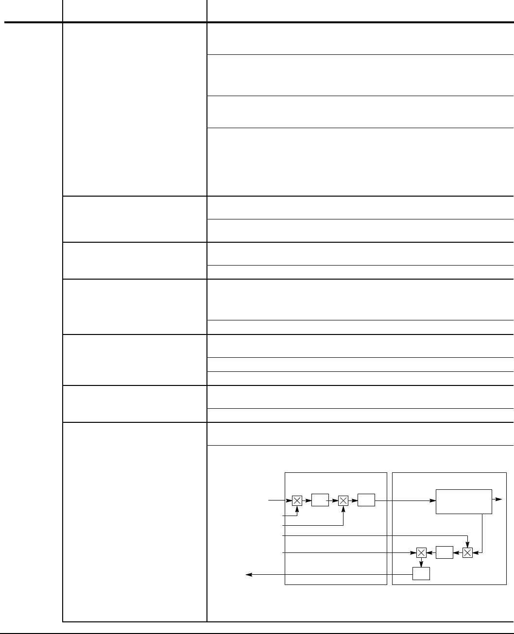
Parameter Descriptions 7-27MN766
Block Title Parameter (Number)
Selection (Value) Parameter Name and Description
PULSE
FOLLOWER
(Continued)
TRACK MODE (3104) Preset Value: 0
Range: 0 - 2
Velocity Following (0)
Increment/Decrement changes the Rx Ratio Output by the value of the
increment step parameter on the y, and follows the velocity of the master
(no position loop). The present position gain parameter disabled (internally
set to 0).
Position Following (1) Increment/Decrement changes the Rx Ratio Output on the y, and follows
the position of the master (position loop enabled internally). The position
gain parameter active at present value.
Position Sync (2)
Increment/Decrement adds or takes away counts and position loop is
enabled internally. In other words this adds/subtracts counts to the position
register when it is closed and then returns to normal following when it
is opened. This is used to take the slack out of the web should it slip. It
doesn’t change the ratio so when the slip of the material is corrected, the
normal following ratio is resumed. The position gain parameter active at
present value.
INCREMENT STEP (3105) Preset Value: 1
Range: 1 - 1024
Output portion of the selected I:O ratio or absolute position is changed by
this.
RX RATIO INPUT (3106) Preset Value: 1024
Range: 1 - 1048576
Receive Input Ratio or the received counts input divisor.
RX RATIO OUT 1 (3107)
RX RATIO OUT 2 (3108)
RX RATIO OUT 3 (3109)
RX RATIO OUT 4 (3110)
Preset Value: 1024
Range: 1 - 1048576
Received counts output multiplier.
OUTPUT TYPE (3111) Preset Value: 0
Range: 0 - 1
Quadrature (0) Quadrature encoder output signal from the EXBHH007 expansion board.
Speed (1) Speed encoder output signal from the EXBHH007 expansion board.
TX RATIO INPUT (3112) Preset Value: 1024
Range: 1 - 1048576
Retransmitted input count ratio or retransmitted input counts divisor.
TX RATIO OUTPUT (3113) Preset Value: 1024
Range: 1 - 1048576
Retransmitted output count ratio or retransmitted output counts output
multiplier.
VS1 ControlMPR/F Expansion Board
Rx
From Master
Encoder Scale
Buffered Encoder
Output
Rx Ratio Input
Rx Ratio Output
Rx
Scale Rx Out Position
Processor
Tx Ratio Input
Tx Ratio Output Tx
Scale
Tx
Scale
Example: Master Encoder=1024, Buffered Encoder Output = 1024 (Desired)
Rx Ratio In = 1024, Rx Ratio Out = 2048 Rx Out to H2 Control = 2048 Tx
Ratio In = 2048, Tx Ratio Out = 1024 Buffered Encoder Output = 1024
Table 7-3 Level 3 Parameter Block Definitions Continued

7-28 Parameter Descriptions MN766
Block Title Parameter (Number)
Selection (Value) Parameter Name and Description
PULSE
FOLLOWER
(Continued)
SAVE RX OUT RATI (3114) Preset Value: 0
Range: 0 - 1
No (0) Does not save values to non-volatile memory.
Yes (1) Saves values to non-volatile memory.
Determines whether or not receive output ratios are saved to non-volatile
memory so that they are retained upon loss of drive power.
CUSTOM
UNITS
MAX DEC PLACES (3201) Preset Value: 1
Range: 0 - 5
0 Zero decimal places for the Custom Units display.
1 One decimal place for the Custom Units display.
2 Two decimal places for the Custom Units display.
3 Three decimal places for the Custom Units display.
4 Four decimal places for the Custom Units display.
5 Five decimal places for the Custom Units display.
The number of decimal places for the Custom Units display.
VALUE AT SPEED (3202) Preset Value: 0.0: 0RPM
Range: 0.0 - 9999999.0 (X.X: YRPM)
Sets the desired output rate per RPM of motor speed for the Custom Units
display. This parameter provides scaling. Normal status display used until
“y” is set to a non-zero value. The value “X.X” is displayed at “Y” RPM.
Note that “Y” RPM is programmed in parameter P3204, AT SPEED VALUE,
when using Mint WorkBench.
UNITS OF MEASURE (3203) Preset Value: Cust
Range: ASCII & Graphic Characters
Allows user specied units of measure to be displayed for the Custom
Units display. Characters are selected from display using and keys.
More characters are available (press MORE “F1” on keypad) for additional
characters.
PRESET
POSITIONS
PRESET REVs 2 (3301)
PRESET REVs 3 (3302)
PRESET REVs 4 (3303)
PRESET REVs 5 (3304)
PRESET REVs 6 (3305)
PRESET REVs 7 (3306)
Preset Value: 1:0000
Preset Value: 2:0000
Preset Value: 3:0000
Preset Value: 4:0000
Preset Value: 5:0000
Preset Value: 6:0000
Range: (-49999 to 49999) : (-4095 to 4095)
Sets integral number of revolutions for preset number position ((2 (3301)
through 7 (3306)). Preset position number ((2 (3301) through 7 (3306)) is
an absolute move relative to the home position. Only available or active if
the Master Pulse Reference/Isolated Pulse Follower EXB (EXBHH007) is
installed.
Only displayed when Level 1, Input Setup, Operating Mode parameter
P1401 is set to “Preset Position”.
Table 7-3 Level 3 Parameter Block Definitions Continued

Parameter Descriptions 7-29MN766
Block Title Parameter (Number)
Selection (Value) Parameter Name and Description
PRESET
POSITIONS
(Continued)
PRESET REVs 8 (3307)
PRESET REVs 9 (3308)
PRESET REVs 10 (3309)
PRESET REVs 11 (3310)
PRESET REVs 12 (3311)
PRESET REVs 13 (3312)
PRESET REVs 14 (3313)
PRESET REVs 15 (3314)
Preset Value: 7:0000
Preset Value: 8:0000
Preset Value: 9:0000
Preset Value: 10:0000
Preset Value: 11:0000
Preset Value: 12:0000
Preset Value: 13:0000
Preset Value: 14:0000
Range: (-49999 to 49999) : (-4095 to 4095)
Sets integral number of revolutions for preset position number ((8 (3307)
through 15 (3314)). Preset position number ((8 (3307) through 15 (3314)) is
an incremental move relative to the present position. Only available or active
if the Master Pulse Reference/Isolated Pulse Follower EXB (EXBHH007) is
installed.
Only displayed when Level 1, Input Setup, Operating Mode parameter
P1401 is set to “Preset Position”.
POS PROP GAIN (3329) Preset Value: 000.1000
Range 000.0000 to 100.0000
Proportional gain of the PID control loop used during preset position
moves. Only available or active if the Master Pulse Reference/Isolated Pulse
Follower EXB (EXBHH007) is installed.
Only displayed when Level 1, Input Setup, Operating Mode parameter
P1401 is set to “Preset Position”.
POS INTG GAIN (3330) Preset Value: 000.0000
Range 000.0000 to 100.0000
Integral gain of the PID control loop used during preset position moves. Only
available or active if the Master Pulse Reference/Isolated Pulse Follower
EXB (EXBHH007) is installed.
Only displayed when Level 1, Input Setup, Operating Mode parameter
P1401 is set to “Preset Position”.
POS INTG CLAMP (3331) Preset Value: 10%
Range 000.0 to 100.0%
Clamp used to prohibit windup by limiting the integral value of the PID
position control loop. Only available or active if the Master Pulse Reference/
Isolated Pulse Follower EXB (EXBHH007) is installed.
Only displayed when Level 1, Input Setup, Operating Mode parameter
P1401 is set to “Preset Position”.
POS DIFF GAIN (3332) Preset Value: 0.0000
Range 000.0000 to 100.0000
Differential gain of the PID control loop used during preset position moves.
Only available or active if the Master Pulse Reference/Isolated Pulse
Follower EXB (EXBHH007) is installed.
Only displayed when Level 1, Input Setup, Operating Mode parameter
P1401 is set to “Preset Position”.
POS MAX ADJUST (3333) Preset Value: 10%
Range 000.0 to 100.0%
Maximum percentage that the position loop can adjust the speed due
to following error. Only available or active if the Master Pulse Reference/
Isolated Pulse Follower EXB (EXBHH007) is installed.
Only displayed when Level 1, Input Setup, Operating Mode parameter
P1401 is set to “Preset Position”.
POS FILTER (3334) Preset Value: 10.0 Hz
Range 0.1 to 500.0 Hz
Low pass lter on the output of the position loop. Only available or active
if the Master Pulse Reference/Isolated Pulse Follower EXB (EXBHH007) is
installed.
Only displayed when Level 1, Input Setup, Operating Mode parameter
P1401 is set to “Preset Position”.
Table 7-3 Level 3 Parameter Block Definitions Continued

7-30 Parameter Descriptions MN766
Block Title Parameter (Number)
Selection (Value) Parameter Name and Description
PLC MODE PLC CONFIG 1 through
PLC CONFIG 30 (3401 - 3430) Preset Value: 000.128.000.000
Range: 0 to 255.255.255.255
30 PLC statements that dene the 32 bit word format and structure as:
Where:
DDD = bits 31-24 Byte 3
CCC = bits 23-16 Byte 2
BBB = bits 15-8 Byte 1
AAA = bits 7-0 Byte 0
Parameter No. Hex Byte 3 Hex Byte 2 Hex Byte 1 Hex Byte 0
PS3401 - 3430 Condition ID Logical Operator ID Condition ID Action ID
MSD LSD
(see Chapter 10) (see Chapter 10) (see Chapter 10) (see Chapter 10)
051 = Digital Input 1 (see Chapter 10)
000 = OR (see Chapter 10)
000 = False (see Chapter 10)
020 = Forward (see Chapter 10)
Parameter Number Format = DDD.CCC.BBB.AAA Example: P3401 = 051.000.000.020
See also Chapter 10.
COMPARE A PARAM (3431)
COMPARE B PARAM (3433) Preset Value: 0
Range: 00000 to 10000
Comparator parameters provide a way to monitor real-time signals
within the drive and apply them to the PLC Mode’s logic. The setting of
these parameters is the number of the parameter to be monitored by the
comparator. They may be used on the condition denition side of the PLC
Mode’s logic. (See Chapter 10).
COMPARE A CNST1 (3432)
COMPARE B CNST1 (3434) Preset Value: 0.00%
Range: 0.00 to 200.00%
See Chapter 10.
COMPARE A CNST2 (3435)
COMPARE B CNST2 (3436) Preset Value: 0.00%
Range: -100.00 to 100.00%
See Chapter 10.
TIMER A DURATION (3440)
TIMER B DURATION (3441)
TIMER C DURATION (3442)
TIMER D DURATION (3443)
Preset Value: 0.00
Range: 0.00 to 999999.00 seconds
See Chapter 10.
COMP REF PARAM A NUMBER (3501)
PARAM B NUMBER (3503) Preset Value: 0
Range: 00000 to 10000
Holds number to the second parameter used in the reference. See Chapter
11.
PARAM A FUNCTION (3502)
PARAM B FUNCTION (3504) Preset Value: 0
Range: 0 - 9
Zero (0)
Identity (1)
Absolute Value (2)
Invert (3)
Square (4)
Square Root (5)
Sine (6)
Cosine (7)
Ramp Generator (8)
Freq Generator (9)
Mathematical function applied to the rst (A) and second (B) parameter. See
Chapter 11.
Table 7-3 Level 3 Parameter Block Definitions Continued

Parameter Descriptions 7-31MN766
Block Title Parameter (Number)
Selection (Value) Parameter Name and Description
COMP REF
(Continued)
OPERATOR (3505) Preset Value: 0
Range: 0 - 5
Sum (0)
Difference (1)
Multiply (2)
Divide (3)
Maximum (4)
Minimum (5)
The mathematical operator applied to the rst and second parameters. See
Chapter 11.
FUNCTION (3506) Preset Value: 1
Range: 0 - 9
Zero (0)
Identity (1)
Absolute Value (2)
Invert (3)
Square (4)
Square Root (5)
Sine (6)
Cosine (7)
Ramp Generator (8)
Freq Generator (9)
Mathematical function applied after the operator. See Chapter 11.
PARAM A GAIN (3507)
PARAM B GAIN (3508) Preset Value: 1.000
Preset Value: 1.000
Range: -1000.000 to 1000.000
Provides numerical scaling for parameter A and B. See Chapter 11.
Table 7-3 Level 3 Parameter Block Definitions Continued

7-32 Parameter Descriptions MN766
Block Title Parameter (Number)
Selection (Value) Parameter Name and Description
RTC
FEATURES
RTC ACTION 1 (3601)
RTC ACTION 2 (3602) Preset Value: 0
Range: 0 - 23
None (0)
D.Out1 On (1)
D.Out1 Off (2)
D.Out2 On (3)
D.Out2 Off (4)
R.Out1 On (5)
R.Out1 Off (6)
R.Out2 On (7)
R.Out2Off (8)
Increment (9)
Decrement (10)
Reset (11)
D.Out1 On/IncP107 (12)
D.Out1 Off/IncP107 (13)
D.Out1 On/DecP107 (14)
D.Out1 Off/DecP107 (15)
D.Out1 On/Reset (16)
D.Out1 Off/Reset (17)
R.Out1 On/IncP107 (18)
R.Out1 Off/IncP107 (19)
R.Out1 On/DecP107 (20)
R.Out1 Off/DecP107 (21)
R.Out1 On/Reset (22)
R.Out1 Off/Reset (23)
First action taken as a result of an edge from the RTC. See Chapter 12.
Second action taken as a result of an edge from the RTC. See Chapter 12.
RTC MESSAGE 1 (3603)
RTC MESSAGE 2 (3604) Preset Value: 0
Range: 0 - 8
None (0)
Clean Filter (1)
Change Filter (2)
Apply Oil/Lube (3)
Lube Mtr. Brngs (4)
Service Drive (5)
Service Coolant (6)
Service Heating (7)
RTC Alarm (8)
First message sent as a result of an edge from the RTC. See Chapter 12.
Second message sent as a result of an edge from the RTC. See Chapter 12.
Table 7-3 Level 3 Parameter Block Definitions Continued

Parameter Descriptions 7-33MN766
Block Title Parameter (Number)
Selection (Value) Parameter Name and Description
RTC
FEATURES
(Continued)
ACT1 QUALIFIER (3605)
ACT2 QUALIFIER (3606) Preset Value: 0
Range: 0 - 6
Once (0)
Second (1)
Minute (2)
Hourly (3)
Daily (4)
Monthly (5)
Yearly (6)
Schedule qualier for the RTC action 1. See Chapter 12.
Schedule qualier for the RTC action 2. See Chapter 12.
MSG1 QUALIFIER (3607)
MSG2 QUALIFIER (3608) Preset Value: 0
Range: 0 - 6
Once (0)
Second (1)
Minute (2)
Hourly (3)
Daily (4)
Monthly (5)
Yearly (6)
Schedule qualier for the RTC message 1. See Chapter 12.
Schedule qualier for the RTC message 2. See Chapter 12.
ACT1 DATE/TIME (3609)
ACT2 DATE/TIME (3610) Preset Value: 01 January 2000, 00:00:00
Range: 01 January 2000, 00:00:00 - 31 December 2063, 23:59:59
Schedule qualier for the RTC message 1. See Chapter 12.
Schedule qualier for the RTC message 2. See Chapter 12.
MSG1 DATE/TIME (3611)
MSG2 DATE/TIME (3612) Preset Value: 01 January 2000, 00:00:00
Range: 01 January 2000, 00:00:00 - 31 December 2063, 23:59:59
Date and Time for RTC message 1. See Chapter 12.
Date and Time for RTC message 2. See Chapter 12.
RTC COUNTER MAX (3630) Preset Value: 60
Range: 00000 - 99999
See Chapter 12.
DST SELECT (3631) Preset Value: 0
Range: 0 - 2
Off (0) Daylight Saving Time select. DST not used.
U.S.A. (1) Daylight Saving Time select. DST for U.S.A.
E.U. (2) Daylight Saving Time select. DST for E.U.
See Chapter 12.
Table 7-3 Level 3 Parameter Block Definitions Continued

7-34 Parameter Descriptions MN766
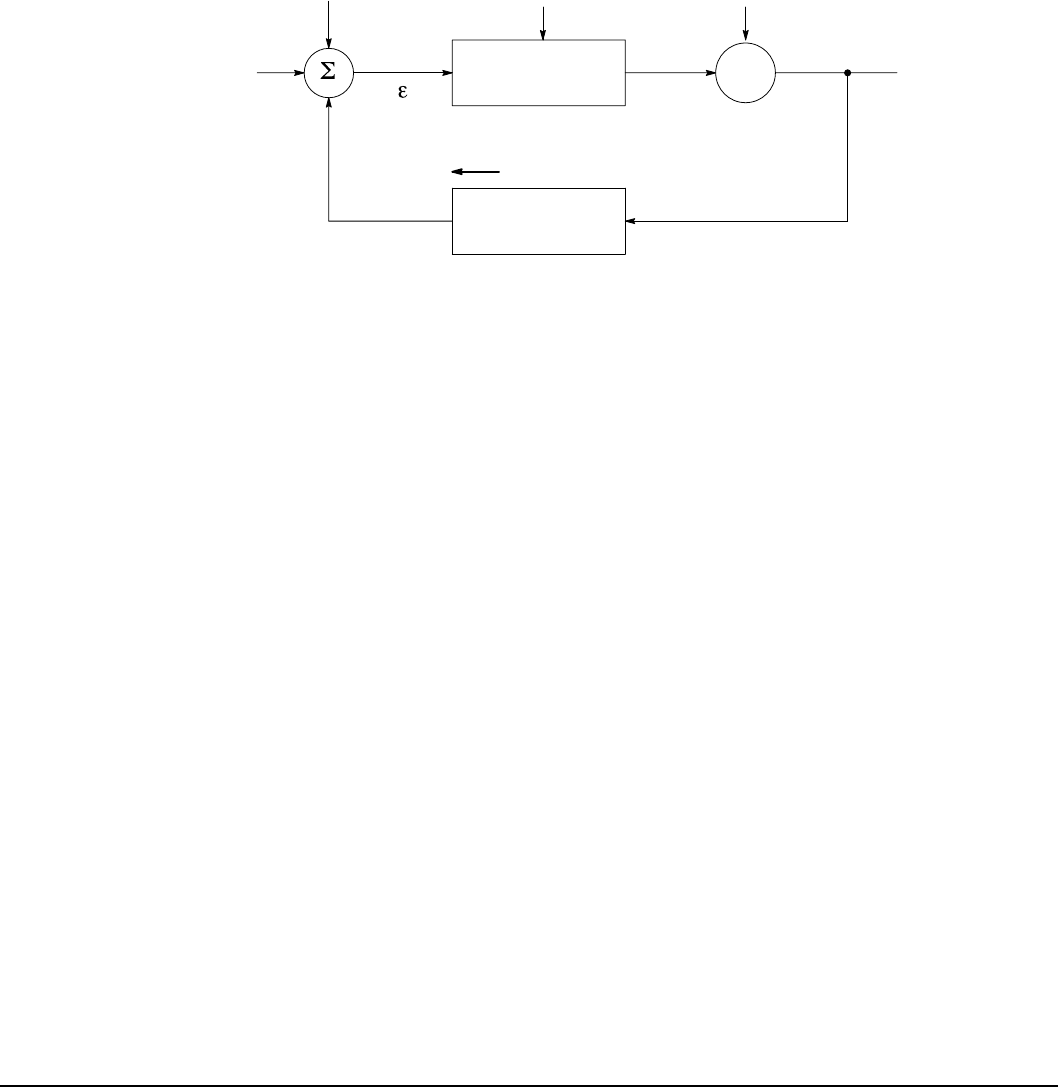
Customizing Your Application 8-1MN766
Chapter 8
Customizing Your Application
8.1 Manually Tuning the Control
Explanation of Closed Loop Block Diagrams
Control systems are usually represented by a series of interconnected blocks. The blocks represent the individual functions
of the system. The blocks are interconnected by a series of lines, which represent the variable or quantity involved with
directional arrows showing the direction of information ow. See Figure 8-1.
Figure 8-1 Block Diagram of a Closed Loop System
Summing Junction
(error detector)
Input Command
(Desired Value)
Error
Signal
Output
2
1
3
4
Power Input
Control
Measuring
Means
Load Disturbance
Controlled
Variable
Controlled Variable
Feedback
Motor
Any closed loop system can be divided into four basic operations:
1. Measurement of the controlled variable. The controlled variable can be velocity, torque, etc. This measuring means is
accomplished using a sensor that converts the variable to an electrical signal that is compatible with the control inputs,
usually voltage or current. This signal now represents the controlled variable (Feedback).
2. Determination of the error. The summing junction compares the measured value of the controlled variable (Feedback
Input) with the Input Command (desired value) and generates an error signal. The operation is a simple mathematical
subtraction operation as follows:
Error Signal ( ε ) = Input Command - Feedback
3. The error signal is then used by the control to change the motor speed or torque.
4. The motor speed or torque is then used to reduce the error signal by driving the control, and the nal controlled variable,
so that the actual value of the controlled variable approaches the Input Command value or desired value. It should be
noted that closed loop control systems are error actuated. In other words, an error must be present before the system
will try to correct for it.
Definition of Input Command (Desired Value)
The Input Command is the input signal set by the operator. This can represent speed or torque level.
Definition of Feedback
Feedback is the signal which represents the actual measured value from the controlled variable. This can represent a
pressure, ow, speed, torque, level or temperature sensor. This input is usually a sensor voltage or current representing the
measured value.
Definition of Error
Error is the result of subtracting the Input Command and Feedback signals.
Error is mathematically dened as:
Error Signal ( ε ) = Input Command - Feedback
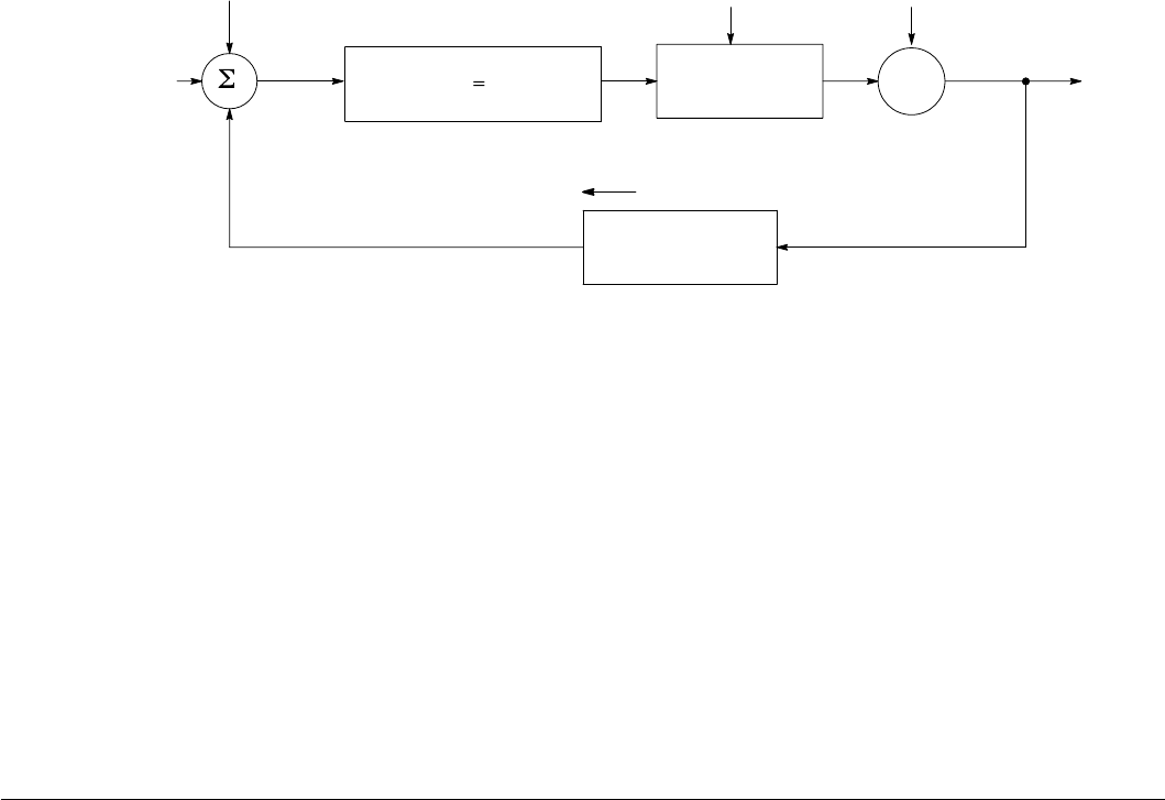
8-2 Customizing Your Application MN766
Definition of “P” (Proportional Gain)
Proportional Gain is the amplication that is applied to the process error signal, which will result in a particular control
output.
Proportional Gain is mathematically dened as;
Aout = Kp
Where:
Aout
= Control output
Kp = Proportional gain
= Error signal = (Input Command - feedback)
In Figure 8-2 we see that the amplitude of the output of the control is dependent on the error,
multiplied by the proportional gain.
For a given amount of error, the greater the proportional gain, the greater the output.
It is also true that, for a given amount of proportional gain, the greater the error, the greater the
output.
ε
ε
Figure 8-2 Block Diagram of the P Element
Summing Junction
(error detector)
Input
Command
Error
Signal
Output
Power Input
Control
Measuring
Means
Load Disturbance
Controlled
Variable
Controlled Variable
Feedback
Motor
Feedback
Input
AoutKpε
ε
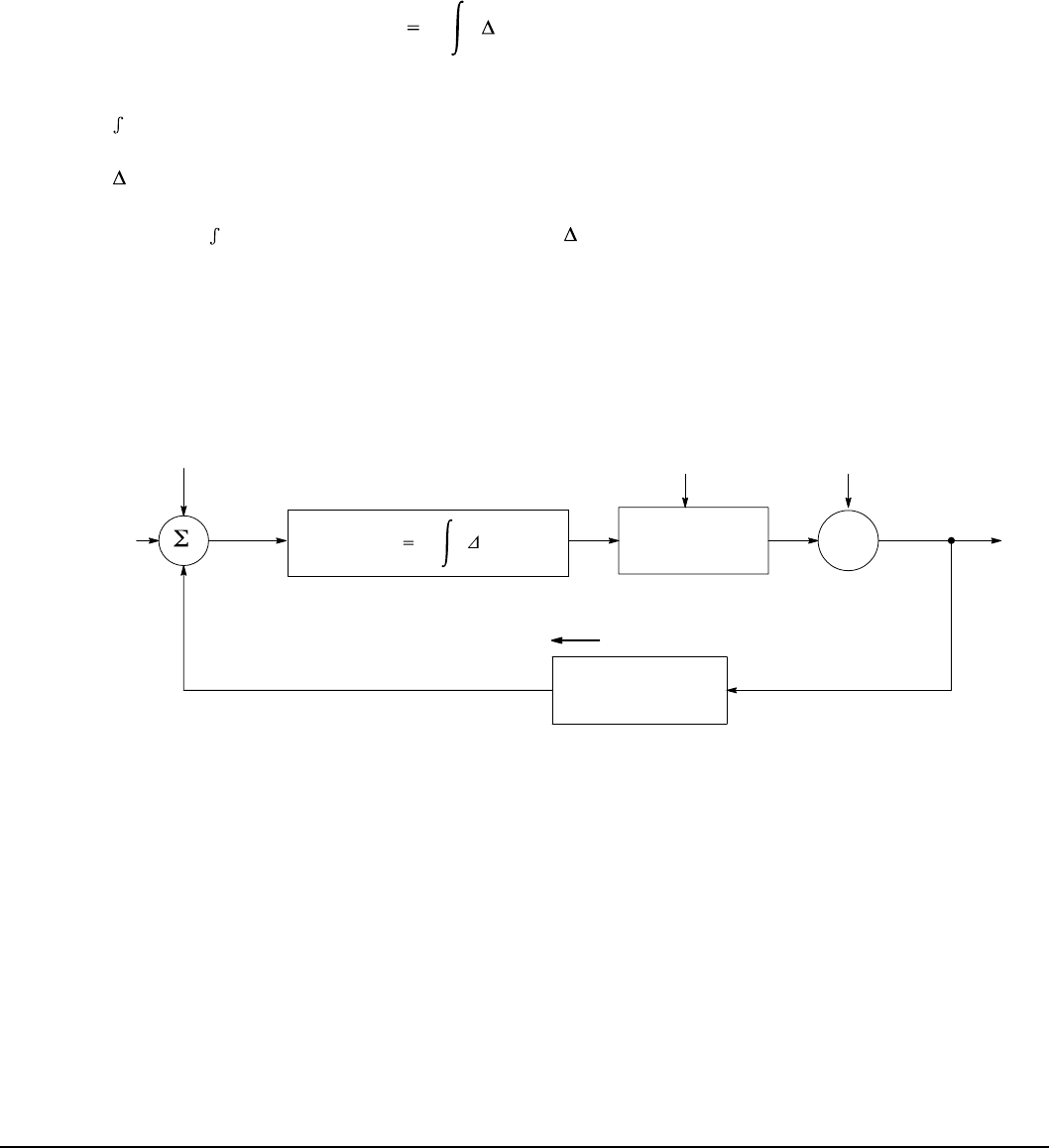
Customizing Your Application 8-3MN766
Definition of “I” (Integral Gain)
Integral Gain (like Proportional Gain) is amplication of the process error signal, but is time dependent. If a steady state
error exists for long periods of time, it is known as an offset. Integral gain compensates for this long term error or offset.
Generally speaking, if you were to use only proportional control in a process, the control output would never get the
controlled variable exactly equal to the input command. You would always have some small amount of error. This is often
called offset. The Integral term senses this long term offset, and corrects the control output to reduce the effect of offset.
Integral Gain is mathematically dened as:
AoutKit
Where:
Aout = Controller output
Ki = Integral gain
= Integrator symbol
= Process error signal = (setpoint - feedback)
= Change in time
This formula states that a given control output (A out) is equal to integral gain ( Ki ), multiplied by
the integral ( ) of the error ( ), multiplied by the change ( ) in time ( t ). Simply, an Integrator loop
is used and error is accumulated over time (or integrated), and integral gain is used to reduce
long term error. Figure 8-3 shows this process.
t
ε
ε
ε
Figure 8-3 Block Diagram of the I Element
Summing Junction
(error detector)
Input
Command
Error
Signal
Output
Power Input
Control
Measuring
Means
Load Disturbance
Controlled
Variable
Controlled Variable
Feedback
Motor
Feedback
Input
AoutKit
ε
ε
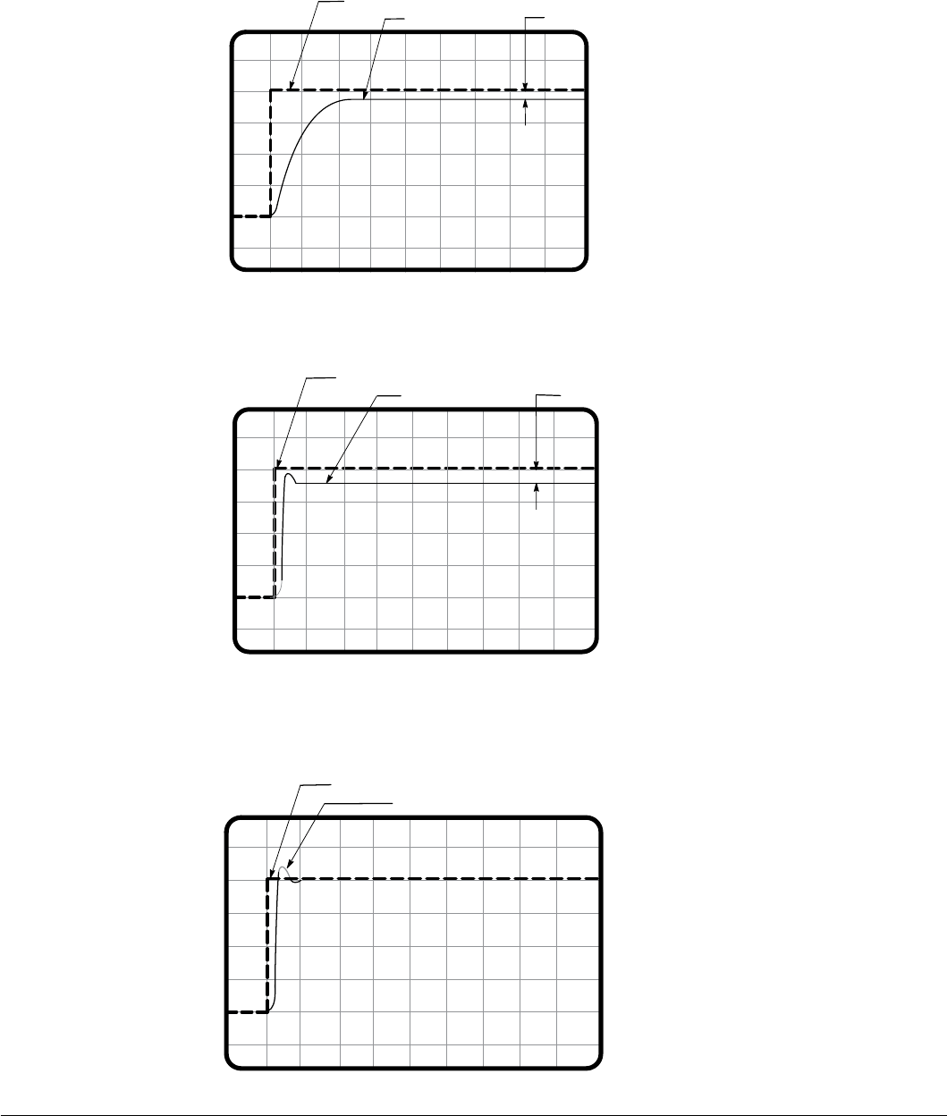
8-4 Customizing Your Application MN766
To illustrate the concept of offset, refer to the following waveform. When the feedback has stabilized, it is not equal to input
command. In this case, the difference between the input command and the feedback is the offset. Note that the integral gain
is set to zero.
Feedback
Input Command
(Oscilloscope set to:
vertical = 1 V/division
horizontal = 1.0 sec/division)
Gain Settings:
Proportional gain = 25
Integral gain = 0.00
Offset
The next waveform illustrates what happens when the proportional gain is increased from 25 to 100. An increase in the
proportional gain causes the controlled variable to respond more quickly as indicated by the feedback signal.
Feedback
Input Command
(Oscilloscope set to:
vertical = 1 V/division
horizontal = 1.0 sec/division
Process Gain Settings:
Proportional gain = 100
Integral gain = 0.00
Offset
The next waveform illustrates what happens to the system offset when we apply integral gain. With the addition of integral
gain (2.00 Hz), the system offset is reduced to zero.
Process Feedback
Setpoint Command
(Oscilloscope set to:
vertical = 1 V/division
horizontal = 1.0 sec/division)
Process Gain Settings:
Proportional gain = 100
Integral gain = 2.00

Customizing Your Application 8-5MN766
Manually Tuning the Control
In some applications the drive cannot be accurately auto-tuned. In these cases it is necessary to calculate the values
needed to tune the drive and manually enter these calculated parameter values.
Current Prop Gain Parameter
This parameter (P1633) is located in the Level 1, Motor Control Block. The Current Prop Gain parameter is normally
autotuned when motor inductance is not known. Where autotuning can’t be used, the proper manual setting for the
proportional gain can be calculated by:
VAC
Where:
L = Line to neutral inductance of the motor in mH
VAC = Nominal line Volts
A/V = The Amps/Volt scaling of the current feedback
Motor line to neutral inductance can be obtained either from the motor manufacturer or by
measuring the line-to-line inductance and dividing by two.
The A/V scaling for the control can be found in the diagnostic information located in the DISPLAY
MODE.
For most applications setting the Current Prop Gain parameter to a value of 60 will yield adequate
performance.
Current PROP Gain [740 x L x (A/V)]
Current Int Gain Parameter
The Current Int Gain parameter (P1634) located in the Level 1 Motor Control Block is factory preset at 250 Hz. This setting is
suitable for essentially all systems. DO NOT CHANGE WITHOUT FACTORY APPROVAL.
Speed Prop Gain Parameter
The Level 1 Motor Control Block Speed Prop Gain parameter (P1635) factory setting is 1.00. This gain may be increased
or decreased to suit the application. Increasing the Speed Prop Gain parameter will result in faster response, excessive
proportional gain will cause overshoot and ringing. Decreasing the Speed Prop Gain parameter will cause slower response
and decrease overshoot and ringing caused by excessive proportional gain.
Speed Int Gain Parameter
The Level 1 Motor Control Block Speed Int Gain parameter (P1636) is set to 1.00 Hz and may be set at any value from zero
to 50.00 Hz. Setting the Speed Int Gain parameter to 0 Hz removes integral compensation. This results in a proportional loop
only. This selection is ideal for systems where overshoot must be avoided and substantial stiffness (ability of the control to
maintain commanded speed despite varying torque loads) is not required.
Increasing values of the Speed Int Gain parameter increases the low frequency gain and stiffness of the control. An
excessive integral gain setting will cause overshoot for transient speed commands and may lead to oscillation. If the Speed
Prop Gain parameter and the Speed Int Gain parameter are set too high, an overshoot condition can also occur.
To manually tune the control, the following procedure is used:
1. Set the speed Int Gain parameter = 0 (remove integral gain).
2. Increase the Speed Prop Gain parameter setting until adequate response to step speed commands is attained.
3. Increase the Speed Int Gain parameter setting to increase the stiffness of the drive, or ability to maintain speed with
dynamic load changes.
Note: It is convenient to monitor speed step response with a strip chart recorder or storage oscilloscope connected to
J1-6 or J1-7 with Level 1, Output Block Analog Out1 Signal (P1511) or Analog Out2 Signal (P1514) set to ABS
SPEED, 0 VDC = zero speed. See Chapter 5 for analog outputs.

8-6 Customizing Your Application MN766
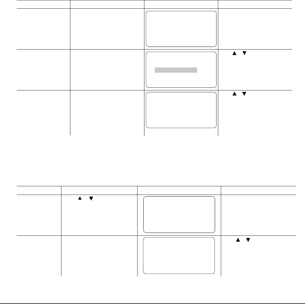
Troubleshooting 9-1MN766
Chapter 9
Troubleshooting
The VS1SD continuously monitors its status and operation. When a fault occurs, the event and drive status is captured to
help you troubleshoot problems. The following are designed to help in troubleshooting:
• LEDs on the keypad indicate status (Stop, FWD, REV, Jog)
• Fault Codes displayed on the keypad display as they occur
• A log of these faults and the time each occurred is kept in the Event Log
• A trace log for each event stored in the Event log
9.1 Event Log
From the Menu display screen, select Event Log and press enter. If an error is displayed during operation, press the “Help”
key to learn more about the error. If more than one error was logged, access the Event Log and examine each error Entry at
the time of the event to learn more about the error.
Action Description Display Comments
Status Display After power up the display shows
the Status screen. STATUS FWD LOCAL
DIAG 600r MAIN
159.5V 600RPM
6.2A 20.00HZ
Press Menu Displays top level menu options. STATUS
BASIC PARAMS
ADVANCED PROG
EVENT LOG
DIAGNOSTICS
DIAG BACK
Press to move cursor over
the “EVENT LOG” selection.
Press Enter to view the event log.
Event Log Display
LOW INITIAL BUS
0 Date Time
Entry #
0-9
HH:MM:SS
Displays error name,
Entry # and time the
error occurred.
DD/MM/YY
EV. LOG
STATUS TRACE
LOW INITIAL BUS
0 4-Jul-06 09:35:00
LOCALSTOP Press to view next entry
.
Press F2 to display Trace menu.
Press F1 to return to Status menu.
or
or
Trace
Input states, Output states, various voltage and current values etc. can be viewed to help understand the cause of the fault
condition. Each event in the Event log has its own Fault Trace displays that were captured when that event occurred. Scroll
through the event log to the event you wish to investigate.
Trace Displays
Action Description Display Comments
Event Log Display Press to scroll to the
event you want to investigate. EV. LOG
STATUS TRACE
LOW INITIAL BUS
3 4-Jul-06 09:42:00
LOCAL
STOP Press F2 (or press Enter) to show
the fault Trace for the event.
Fault Trace Display The Fault Latch word is displayed.
0x=Hexadecimal
0b=Binary
STATUS T0003 BACK
FAULT LATCH
0x0000
EV. LOG FAULT TRACE Press to view next entry.
This is a hex value.
The T0003 indicates the Fault
Trace for event 3 of the event log
is displayed.
or
or
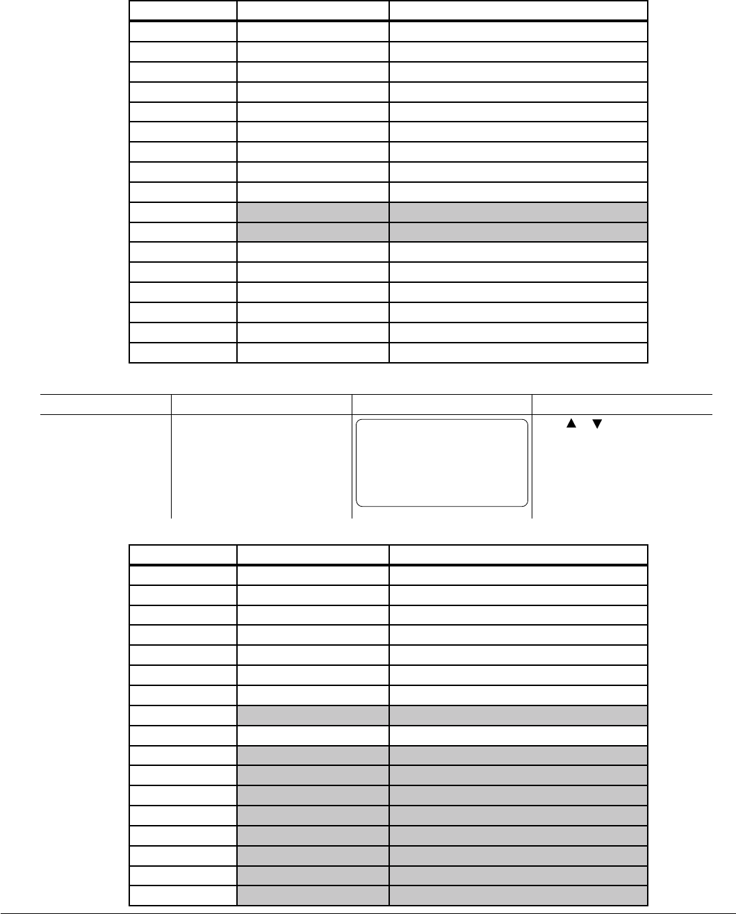
9-2 Troubleshooting MN766
FAULT LATCH Word Interpretation
Hexadecimal Binary Description
0000 0000 0000 0000 0000 No Fault
0001 0000 0000 0000 0001 Motor Phase U upper Transistor
0002 0000 0000 0000 0010 Motor Phase U lower Transistor
0004 0000 0000 0000 0100 Motor Phase V lower Transistor
0008 0000 0000 0000 1000 Motor Phase V upper Transistor
0010 0000 0000 0001 0000 Motor Phase W lower Transistor
0020 0000 0000 0010 0000 Motor Phase W upper Transistor
0040 0000 0000 0100 0000 Brake Desaturation Fault
0080 0000 0000 1000 0000 Brake IGBT Fault
0100 0000 0001 0000 0000 Not Used
0200 0000 0010 0000 0000 Not Used
0400 0000 0100 0000 0000 Ground Fault
0800 0000 1000 0000 0000 Over Current Fault (Active Low)
1000 0001 0000 0000 0000 Pulse by Pulse fault on Motor Phase 1
2000 0010 0000 0000 0000 Pulse by Pulse fault on Motor Phase 2
4000 0100 0000 0000 0000 Pulse by Pulse fault on Motor Phase 3
8000 1000 0000 0000 0000 Inverter Desaturation Fault
Trace Displays Continued
Action Description Display Comments
Fault Trace Display The Alarm Latch word is also
displayed. The T0003 indicates
the Fault Trace for event 3 of the
event log is displayed.
STATUS T0003 BACK
ALARM LATCH
0x0000
EV. LOG FAULT TRACE Press to view next entry.
This is a hex value.
or
ALARM LATCH Word Interpretation
Hexadecimal Binary Description
0000 0000 0000 0000 0000 No Alarm
0001 0000 0000 0000 0001 Fan Alarm
0002 0000 0000 0000 0010 Motor Over Temperature
0004 0000 0000 0000 0100 Phase Loss
0008 0000 0000 0000 1000 Line Loss
0010 0000 0000 0001 0000 Line Sag
0020 0000 0000 0010 0000 Power Supply Alarm
0040 0000 0000 0100 0000 Not Used
0080 0000 0000 1000 0000 Powerbase in pulse-by-pulse limiting
0100 0000 0001 0000 0000 Not Used
0200 0000 0010 0000 0000 Not Used
0400 0000 0100 0000 0000 Not Used
0800 0000 1000 0000 0000 Not Used
1000 0001 0000 0000 0000 Not Used
2000 0010 0000 0000 0000 Not Used
4000 0100 0000 0000 0000 Not Used
8000 1000 0000 0000 0000 Not Used
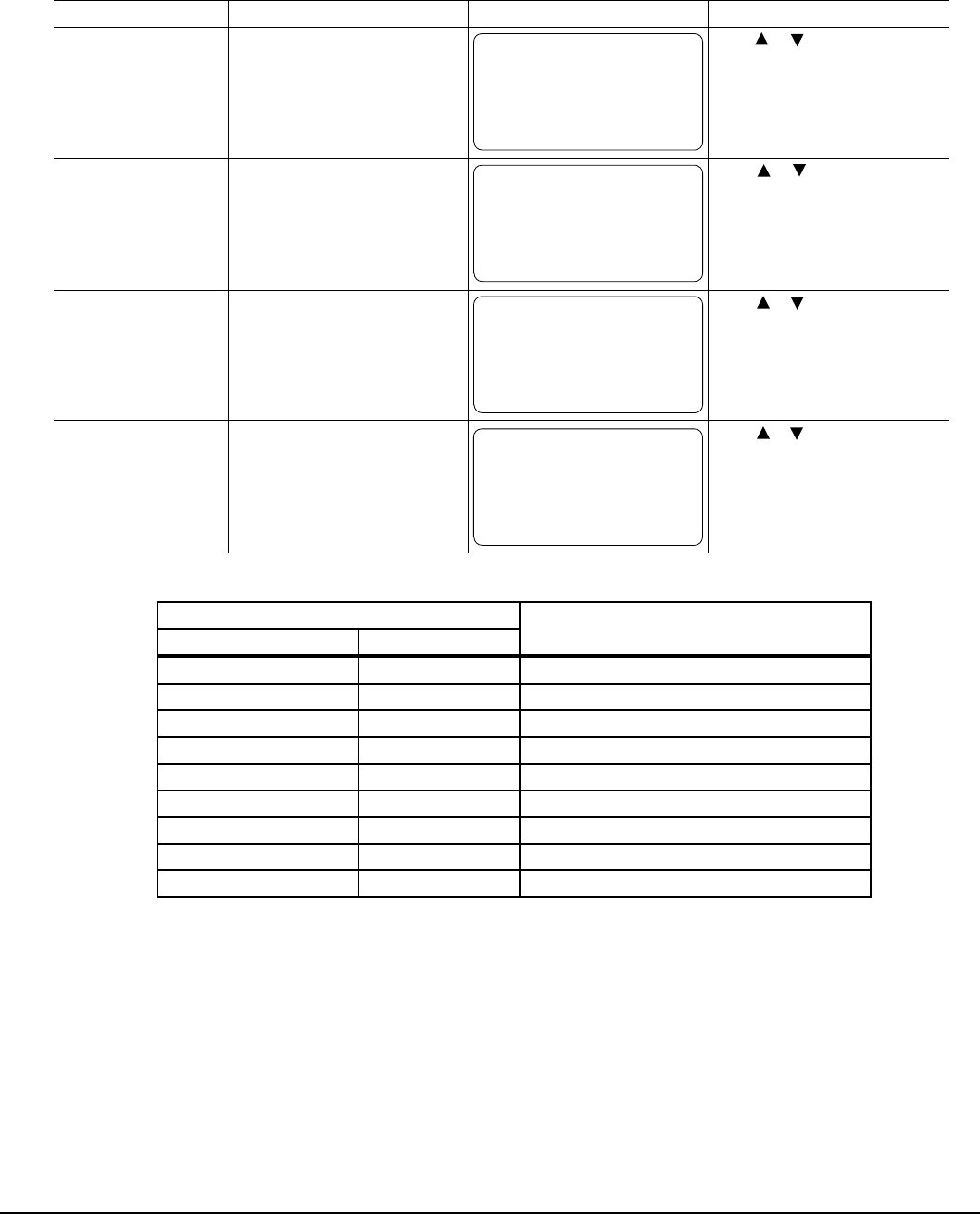
Troubleshooting 9-3MN766
Trace Displays Continued
Action Description Display Comments
Fault Trace Display Third word in the event trace is
the Voltage reference for the
Analog to Digital Converter.
STATUS T0003 BACK
ADC CURRENT REF
0.000 V
EV. LOG FAULT TRACE Press to view next entry.
Fault Trace Display Next is the Voltage measurement
of the Internal 24V power supply
for the Opto Inputs and Outputs.
STATUS T0003 BACK
24 V REF
0.0 V
EV. LOG Press to view next entry.
Fault Trace Display Next is the status of the nine
Digital Input signals.
J2-8 (Enable) left most digit=1.
J2-16 (DIN#8) right most digit=0.
STATUS T0003 BACK
USER INPUTS
100000000
EV. LOG Press to view next entry.
This is a bit display not a hex
value.
or
or
or
Fault Trace Display Next is the status of the Digital
Output signals. The below table
indicates the function of each of
the 8 bits.
STATUS T0003 BACK
DIGITAL OUTPUTS
00000000
EV. LOG Press to view next entry
.
This is a bit display not a hex
value.
or
FAULT TRACE
FAULT TRACE
FAULT TRACE
Digital Output Display Description
Hexadecimal Binary
00 0000 0000 No Fault
01 0000 0001 Actual Speed is less than Zero Speed Band
02 0000 0010 Main SCR enable (active low)
04 0000 0100 Dynamic Brake active
08 0000 1000 Soft start (pre-charge) relay active
10 0001 0000 Relay Output 2 (J3-28, 29, 30) active
20 0010 0000 Relay Output 1 (J3-25, 26, 27) active
40 0100 0000 Digital Output 2 (J2-19, 20) active
80 1000 0000 Digital Output 1 (J2-17, 18) active

9-4 Troubleshooting MN766
Trace Displays Continued
Action Description Display Comments
Next is the voltage present at
Analog Input 1.
STATUS T0003 BACK
ANA INPUT 1
0.0 V
EV. LOG FAULT TRACE Press to view next entry.
Next is the voltage present at
Analog Input 2.
STATUS T0003 BACK
ANA INPUT 2
0.0 V
EV. LOG FAULT TRACE Press to view next entry.
Next is the Speed Reference
Setting.
STATUS T0003 BACK
SPEED REF
0 RPM
EV. LOG FAULT TRACE Press to view next entry.
Next is the AC output current on
phase 1.
STATUS T0003 BACK
PH1 CURRENT
0.0 A
EV. LOG FAULT TRACE Press to view next entry.
or
or
or
or
Next is the AC output current on
phase 2.
STATUS T0003 BACK
PH2 CURRENT
0.0 A
EV. LOG FAULT TRACE Press to view next entry.
Next is the AC output current on
phase 3.
STATUS T0003 BACK
PH3 CURRENT
0.0 A
EV. LOG FAULT TRACE Press to view next entry.
Next is the Motor Current.
STATUS T0003 BACK
MOTOR CURRENT
0.0A
EV. LOG FAULT TRACE Press to view next entry.
Next is the Motor Torque.
STATUS T0003 BACK
MOTOR TORQUE
0.0 NM
EV. LOG FAULT TRACE Press to view next entry.
or
or
or
or
Fault Trace Display
Fault Trace Display
Fault Trace Display
Fault Trace Display
Fault Trace Display
Fault Trace Display
Fault Trace Display
Fault Trace Display

Troubleshooting 9-5MN766
Trace Displays Continued
Display
The control heatsink temperature.
T0003 BACK
DRIVE TEMP
0.0 °C
EV. LOG Press to view next entry.
The fault code for the event.
T0003 BACK
FAULT LATCH
0x0000
EV. LOG Press to view next entry.
The alarm code for the event.
T0003 BACK
ALARM LATCH
0x0000
EV. LOG Press to view next entry.
BACK
END OF
FAULT TRACE
EV. LOG Press Enter or F2 to return to the
event log.
or
or
or
Next is the Motor Voltage.
STATUS T0003 BACK
MOTOR VOLTS
0.0V
EV. LOG FAULT TRACE Press to view next entry.
Next is the Motor Speed.
T0003 BACK
MOTOR SPEED
0 RPM
EV. LOG Press to view next entry.
Next is Bus Voltage.
BUS VOLTAGE
0.0 V
EV. LOG Press
to view next entry.
or
or
or
Action Description Display Comments
Fault Trace Display
Fault Trace Display
Fault Trace Display
Fault Trace Display
Fault Trace Display
Fault Trace Display
Fault Trace Display
STATUS
STATUS
STATUS
STATUS
STATUS
FAULT TRACE
FAULT TRACE
FAULT TRACE
FAULT TRACE
FAULT TRACE

9-6 Troubleshooting MN766
9.2 Diagnostic Information
After power up, select the Diagnostic Menu to see information from the diagnostic displays.
Action Description Display Comments
Press Menu Displays top level menu options. STATUS
BASIC PARAMS
ADVANCED PROG
EVENT LOG
DIAGNOSTICS
STATUS BACK
Press or to move cursor over
the “DIAGNOSTICS” selection.
Press to display next
group.
Displays active operating mode
settings.
STATUS 0r MAIN
OPERATING MODE
Keypad
Speed
AC Servo
DIAG LOCAL
Press to display next
group.
Bit display of digital inputs,
outputs and the voltage present at
the internal 24V supply terminals.
STATUS 0r MAIN
DIGITAL I/O
INPUTS 100000000
OUTPUTS 0001
USER 24V 24.9V
DIAG LOCAL Press or to go to the next or
previous Diagnostic screen.
Press F2 to return to main menu.
Press to display next
group.
Output Frequency,% Feedforward
% Setpoint, % Feedback
STATUS 0r MAIN
PROC CONTROL PID
0.00HZ 0.0FF
0.0SP 0.0FB
DIAG LOCAL Press or to go to the next or
previous Diagnostic screen.
Press F2 to return to main menu.
Note: This screen does not appear
unless P1401 is set to
Diagnostic Display Displays software version, hp,
volts and Amp/Volt ratings.
STATUS 0r MAIN
SHH-1.21
RATED HP 3HP
RATED VOLTS 240.0V
RATED A/V 4.0A/V
DIAG STOP LOCAL Press to go to the next or
previous Diagnostic screen.
Press F2 to return to main menu.
or
Note: Example display shows that
the drive enable terminal
(J2-8) is on and that
Relay Out 2 is on.
STOP
STOP
STOP
Press to display next
group.
STATUS 0r MAIN
SHH-1.21
RATED CURRENT 9.6A
RATED PK CU 16.8A
DIAG STOP LOCAL Press to go to the next or
previous Diagnostic screen.
Press F2 to return to main menu.
Press to display next
group. Displays:
Power Base ID number
EE Firmware version
FPGA rmware version
STATUS 0r MAIN
POWER BASE VERSION
ID 0x000A2003
EE VER 0x00000001
FPGA VER 0x00000A02
DIAG LOCAL Press to go to the next or
previous Diagnostic screen.
Press F2 to return to main menu.
0x=Hexadecimal
0b=Binary
Press to display next
group.
Displays real time clock values
(date and time) and total run time
since installation.
Press ENTER to set date and
time.
STATUS 0r MAIN
REAL TIME CLOCK
Jan 1, 2009
22:07:35
RUN TIMER 474.1HR
DIAG LOCAL Press to go to the next or
previous Diagnostic screen.
Press F2 to return to main menu.
or
or
or
STOP
STOP
Press Enter to view diagnostic
information.
Process Control.
Press F2 to return to main menu.
Press F1 to return to STATUS screen.
Press F1 to return to STATUS screen.
Press F1 to return to STATUS screen.
Press F1 to return to STATUS screen.
Press F1 to return to STATUS screen.
Press F1 to return to STATUS screen.
Press F1 to return to STATUS screen.

Troubleshooting 9-7MN766
Diagnostics Information Continued
Action Description Display Comments
Press to display next
group.
STATUS 0r MAIN
DIAG STOP LOCAL Press to go to the next or
previous Diagnostic screen.
Press F2 to return to main menu.
Press to display next
group.
STATUS 0r MAIN
DIAG LOCAL Press to go to the next or
previous Diagnostic screen.
Press F2 to return to main menu.
Press to display next
group.
STATUS 0r MAIN
DIAG LOCAL Press to go to the next or
previous Diagnostic screen.
Press F2 to return to main menu.
Press to display next
group.
STATUS 0r MAIN
DIAG LOCAL Press to go to the next or
previous Diagnostic screen.
Press F2 to return to main menu.
Press to display next
group.
STATUS 0r MAIN
DIAG LOCAL Press to go to the next or
previous Diagnostic screen.
Press F2 to return to main menu.
Press to display next
group.
STATUS 0r MAIN
DIAG LOCAL
or
or
or
or
or
STOP
STOP
STOP
STOP
STOP
Displays energy cost (based on
parameter P2305 value). ENERGY
EST POWER
EST ENERGY
EST COST
0.00KW
0.0KWH
0.0$ Press F1 to go to Status screen.
Diagnostic Analog Input values
display.
ANALOG INPUTS
ANA IN1 1.3v
ANA IN2 0.0v
Diagnostic Analog Output values
display.
ANALOG OUTPUTS
ANA OUT1 0.0V
ANA OUT2 0.0V
Diagnostic installed Option Card
identication display.
POSITION COUNTER
REVOLUTION
COUNTS 0
0CNT
Full revolutions and feedback
counts are displayed.
OPTION BOARDS
OPTION 1 ETHERNET
OPTION 2 MASTER PF
FEEDBACK RESOLVER Press F1 to go to Status screen.
Displays keypad software version.
(Note that this is not the same
as the drive control rmware.) KEYPAD VERSION
KEYPAD SOF 1.1X
Press to display next
group.
Displays Composite Reference
values.
STATUS MAIN
COMPOSITE REF
COMPONENT A 0.00%
COMPONENT B 0.00%
REFERENCE 0.00%
DIAG STOP LOCAL
Press to display next
group.
DC Bus Voltage
Drive Heatsink Temperature
% Drive Overload (remaining)
STATUS MAIN
DRIVE
BUS VOLTAGE 333.9V
DRIVE TEMP 26.1C
DRIVE O/L L 100.0%
DIAG STOP LOCAL Press to go to the next or
previous Diagnostic screen.
Press F2 to return to main menu.
Press to display next
group.
Motor Voltage
Motor Current
% Motor Overload (remaining)
STATUS MAIN
MOTOR
MOTOR VOLTAGE 333.9V
MOTOR CURRENT 4.8A
MOTOR O/L L 100.0%
DIAG STOP LOCAL Press to go to the next or
previous Diagnostic screen.
Press F2 to return to main menu.
or
0r
0r
0r
or
Press F1 to go to Status screen.
Press F1 to go to Status screen.
Press F1 to go to Status screen.
Press F1 to go to Status screen.
Press F1 to go to Status screen.
Press to go to the next or
previous Diagnostic screen.
Press F2 to return to main menu.
Press F1 to go to Status screen.
Press to go to the next or
previous Diagnostic screen.
Press F2 to return to main menu.
Press F1 to go to Status screen.
or
or
SPEED MEAS 0

9-8 Troubleshooting MN766
9.3 Fault Messages
Table 9-1 Fault Messages (Alphabetical by Keypad Text)
Keypad Text Type Fault
Number Description
AC Input High Fault 69 Check AC Input Line Voltage.
ADC Calibr Fault Fault 57 ADC Calibration Voltages Out of Range. Check analog input wiring for noise. If
problem persists, contact factory for further assistance.
Alignment Error Fault 121 Drive fault to protect from starts without the control being Feedback Tested.
Apply Oil/Lub Alarm 84 Triggered from RTC Module.
Aux Filter Setup Alarm 51 Incorrect setup. Filter Source should be set to "Raw Speed" when destination is
set to SpeedLoop.
Brake Over Temp Alarm 97 Dynamic brake has overheated, check sizing or increase ohms setting for
brake.
Brk Desat Fault 65 Dynamic brake de-saturation has occurred. Check that dynamic brake resistor
is properly connected to R1 and R2.
Bus Transient Fault 95 Transient causing unbalanced bus capacitor voltage; cycle power to reset fault.
A line surge or bus capacitor failure has resulted in an unbalanced voltage
condition as determined by a bus voltage monitoring circuit.
Change Filter(s) Alarm 83 Triggered from RTC Module.
Clean Filter(s) Alarm 82 Triggered from RTC Module.
Conguration Fault 2 Some drive feature or option has failed initial startup tests; parameter(s) out of
range after download of improper parameter le settings.
Control EE Fault 27 Problem reading EEPROM on the control board, contact Baldor for service.
Control EE Fault 29 Problem writing fault log to control board EEPROM, contact Baldor for service.
Control EE Fault 31 Problem writing the header record to the control board EEPROM, contact
Baldor for service.
Control EE Fault 32 Problem writing a parameter to the control board EEPROM, contact Baldor for
service.
Conv Over Temp Alarm 98 Converter has overheated, decrease loading; check for proper air ow; check
for elevated ambient temperature.
Current Ref Fault 15 Reference volt for current readings out of tolerance. Contact Baldor for service.
Current Sense Fault 12 Motor current sensor(s) out of tolerance; cycle power to drive; if problem
persists contact factory.
DC Bus High Fault 19 DC Bus V over 405/810/1000V for 230V/460V/575V units. Check for high input
line voltage; increase decel rates; check for correct brake resistor on R1/R2.
DC Bus Low Alarm 20 DC Bus V below 220/440/550V for 230V/460V/575V units. Check for low input
line voltage; increase accel rate; verify B+ to B- voltage; verify proper brake
resistor.
DC Pk Overvolt Fault 63 Bus peak voltage rating exceeded. Check AC input lines; sizing of dynamic
brake; insure that input does not have power factor correction capacitors or
other source of transients.
Desaturation Fault 7 Output current exceeds desaturation limit. Check motor and connections for
short circuit; verify proper motor load; increase acc/dec; check for conductive
debris inside drive.
Download Fault 54 Parameter download from keypad or network has failed. Verify parameter set
compatibility.
Drive Disabled Alarm 66 Motion command given with drive disabled. Check drive enable input.
Drive Enabled Alarm 67 Drive enabled during parameter download. Drive must remain disabled until
completion of parameter download.
Drive Low Temp Fault 76 Heat sink Temperature is lower than allowed. Space heater may be required in
cabinet.
Drive Over Tmp Alarm 21 Heatsink temp exceeded 85/950 C. Verify ambient does not exceed 45°C.
Clean fans and heatsink. Add cabinet cooling if ambient is too high.

Troubleshooting 9-9MN766
Keypad Text Type Fault
Number Description
Dyn Brake Desat Fault 36 Dynamic braking current limit exceeded. Check for shorted braking resistor
circuit or for brake resistor with an ohmic value below the allowed limit for the
drive. Check for a short between R1 or R2 and B-.
Encoder Loss Fault 58 Feedback device detected but has poor or no signal. Check feedback wiring;
verify shielding, grounding and bonding practices.
Excess Faults/Hr Alarm 79 The allowed number of faults/hour has been exceeded.
External Trip Fault 22 J1-16 is open. Check remote connection on J1-16. Occurs only when external
fault parameter is turned ON.
Fan Loss Alarm 62 Fan circuit is seeing low current or over current. Verify that fan is not blocked
and is connected properly.
Flt Log Mem Fail Fault 28 Problem reading fault log from control board EEPROM, contact Baldor for
service.
Following Error Fault 18 Speed error beyond Set Speed Band parameter. Verify motor is not overloaded;
increase Set Speed Band.
Ground Fault Fault 8
Ground currents in output of control. Due to shorts to ground or excessive
leakage current to ground. Disconnect motor, meg motor for insulation leakage
to ground; check motor leads for shorts to ground; replace motor leads with
lower capacitance cable or shorten leads if possible; consider the usage of load
reactor.
High Line Alarm 102 Power grid voltage too high, check power base rating, check input lines.
IGBT Thermal Fault 94 IGBT thermal overload. Check motor loading. Allow time to cool.
Initial Pos Alarm 70 The initial position reading could not be read or is out of expected range. Check
motor feedback wiring. Verify proper wiring, grounding and bonding.
Internal Cong Fault 35 An internal rmware conguration occurred, contact Baldor for service.
Invalid FB Sel Alarm 56 Feedback board not installed in selected slot. Select an Encoder/Resolver
board as feedback source. Verify selection of correct slot for motor feedback.
Invalid Res Sel Alarm 71 The feedback source selected is not a resolver board. If resolver feedback
utilized, ensure installed feedback board is for resolver feedback. Verify
selection of correct slot for motor feedback.
Line Loss Alarm 37 All 3 input phases lost. Check input circuit breaker, fuses or input contacts
Line Regen Fault 34 This fault code is not used. If it occurs, contact Baldor for service
Line Sag Alarm 64 All 3 phase input lines have sagged below 70% of nominal. Check input line
quality; check line impedance; check for excessive loading on power system.
Logic Supply Fault 9 Internal logic power supply has dropped below 24V threshold. Replace Power
Supply.
Low Initial Bus Fault 11 Bus volt below 200/400/500V on 230/460/575V units at power up. Check input
line voltage; check for proper resistor on R1/R2; check for open circuit on TH1-
TH2 Terminals.
Low Line Alarm 101 Power grid voltage too low. Check power base rating; check input connections;
ensure input voltage is within drive specication.
Lower U Gate Fault 40 Transistor #1 failed to re or misred. Verify IGBT is not shorted. Verify no
debris has fallen into drive. Check wiring between drive and motor. Verify motor
windings are not shorted.
Lower V Gate Fault 42 Transistor #2 failed to re or misred. Verify IGBT is not shorted. Verify no
debris has fallen into drive. Check wiring between drive and motor. Verify motor
windings are not shorted.
Lower W Gate Fault 44 Transistor #3 failed to re or misred. Verify IGBT is not shorted. Verify no
debris has fallen into drive. Check wiring between drive and motor. Verify motor
windings are not shorted.
Macro Cmd Failed Fault 93 Macro command execution failure. Verify that macro le is correct.
Macro Cmd Inval Fault 92 Macro command found is invalid. Verify that macro le is correct.
Macro Read Fault 90 Macro record read failed. Recompile le and download to drive again.
Table 9-1 Fault Messages Continued

9-10 Troubleshooting MN766
Keypad Text Type Fault
Number Description
Macro Rec Length Fault 91 Macro record length is invalid. Recompile le and download to drive again.
Memory Fault 49 Option card problem, memory failure, contact Baldor for service.
Motor Overload Fault 23 Motor thermal connection at TH1-TH2 open circuit. Motor overheated due to
excess load; Ohm connections at TH1-TH2.
Motor Overload Fault 80 Motor overloaded. Check motor load. Verify motor rated amps parameter.
Motor Ovrtmp Alarm 61 Motor has overheated. Check motor cooling system or blocked air ow; check
thermal switch on TH1-TH2 circuit; reduce load on motor.
Network Timeout Fault 48 Forced network fault. Loss of network communications; watchdog timer
expired; user program timing problems.
New Base ID Fault 5 Control board detected new or a different power base. Press RESET to
clear. Factory settings will be restored. Verify all settings and setup custom
parameters.
No Fault Fault 0 No Fault Exists.
NV memory Fail Fault 30 Problem writing a parameter to the control board EEPROM, contact Baldor for
service.
Opt1 Protocol Alarm 77 Invalid protocol selected for optional communication card 1. Select a protocol
supported by the expansion board that is installed or replace board with a
board that supports the desired protocol.
Opt2 Protocol Alarm 78 Invalid protocol selected for optional communication card 2. Select a protocol
supported by the expansion board that is installed or replace board with a
board that supports the desired protocol.
Option Board Fault 50 Option board not recognized or is not supported. Verify proper rmware version
is being used. Download latest rmware from www.baldor.com and install in
drive.
Option Not Found Alarm 74 Option Board for the feature requested is not installed. Verify slot location for
expansion board to support desired feature; install appropriate option board for
requested feature.
Over Current Fault 6 Motor current exceeded peak limit. Check motor connections and motor load;
increase acc/dec times; verify correct motor data settings; verify proper tuning.
Over Speed Fault 59 Rotor speed over 110% maximum speed limit. Verify proper drive tuning;
ensure drive is not being overhauled by excessive high-speed regenerative
load.
Overload - 1 Min Fault 16 Motor current exceeded 150% for 1 minute. Check motor load. Extend acc/dec
times. Verify proper motor data and drive tuning.
Overload - 3 Sec Fault 17
Motor current exceeded 175% for 3 seconds. Check motor load and resize
motor and drive as needed. Extend acc/dec times. Verify proper motor data and
drive tuning. Change setting of "Overload" parameter (P2206) to "Foldback" to
allow current to automatically limit to a lower level prior to the 3 second time
limit.
Param Checksum Fault 4 Cycle power. If no change, load Factory Settings.
Parameter Fault 55 Parameters momentarily locked. Wait 30 seconds, try again.
PB Power Supply Alarm 68 Power Base Logic Power Supply below acceptable operating levels.
PCB Over Temp Alarm 96 Powerbase signal interface PCB board is over heating, reduce loading or
contact Baldor for service.
PF Setup Alarm 73 Pulse Follower Option Board Setup. Check Master PPR, Receive, Transmit
Ratio and Input Type.
Ph1 (L1) Loss Alarm 109 Loss of phase 1 (L1), check power grid or wiring connections.
Ph1 Pulse Fault 45 Phase 1 current limiting via pulse by pulse method; check motor spiking loads,
chattering contacts, loose connections.
Ph2 (L2) Loss Alarm 110 Loss of phase 2 (L2), check power grid or wiring connections.
Ph2 Pulse Fault 46 Phase 2 current limiting via pulse by pulse method; check motor spiking loads,
chattering contacts, loose connections.
Table 9-1 Fault Messages Continued

Troubleshooting 9-11MN766
Keypad Text Type Fault
Number Description
Ph3 (L3) Loss Alarm 111 Loss of phase 3 (L3), check power grid or wiring connections.
Ph3 Pulse Fault 47 Phase 3 current limiting via pulse by pulse method; check motor spiking loads,
chattering contacts, loose connections.
Phase Loss Alarm 38 Single input phase lost. Check input circuit breaker, fuses or input contacts.
Excessive line notching occurring.
PLC Mode Trip Fault 81 PLC Mode Trip. PLC action has generated this trip. Check input dened in PLC
mode for fault trip. Check PLC program logic.
Pos Cnt Overow Fault 75 Position counter has exceeded max or min range. Verify wiring, grounding and
bonding of position feedback; verify range of acceptable values.
Power Base Fault 10 Should occur in conjunction with other faults to indicate that fault was
generated by the power base circuitry. This is useful in trouble-shooting to
understand that the fault was detected by the power base electronics.
Powerbase EE Fault 26 Communication error between control board and power base memory. Cycle
power. If problem persists, contact factory for assistance.
Powerbase FPGA Fault 52 Power base communication loss or incompatible rmware. Cycle power. If
problem persists, contact factory.
Pre-charge Fault Fault 60 Dynamic Brake miswired; AC Input too low; input impedance too high (soft
line); Bus Caps shorted or Input Single Phasing. Check motor thermal lead
connections to TH1-TH2.
Reac Over Temp Alarm 99 Reactor has overheated, decrease loading; decrease wire length; verify drive
ambient temperature is less than 45°C; verify proper air ow and system
cooling capability.
Regen R or PWR Fault 25 Brake resistor power rating exceeded. Check resistor ratings; extend decel
times; increase size of braking kit.
Resolver Loss Fault 72 Resolver signal poor or missing. Verify wiring, grounding, and bonding of
resolver feedback.
RTC Alarm Alarm 89 Triggered from RTC Module.
SCR1 No Fire Alarm 103 Phase loss due to SCR1 (L1 upper) not ring. Verify SCR gate leads properly
connected.
SCR2 No Fire Alarm 104 Phase loss due to SCR2 (L1 lower) not ring. Verify SCR gate leads properly
connected.
SCR3 No Fire Alarm 105 Phase loss due to SCR3 (L2 upper) not ring. Verify SCR gate leads properly
connected.
SCR4 No Fire Alarm 106 Phase loss due to SCR4 (L2 lower) not ring. Verify SCR gate leads properly
connected.
SCR5 No Fire Alarm 107 Phase loss due to SCR5 (L3 upper) not ring. Verify SCR gate leads properly
connected.
SCR6 No Fire Alarm 108 Phase loss due to SCR6 (L3 lower) not ring. Verify SCR gate leads properly
connected.
Sel FB Source Alarm 53
Feedback Source Not Selected/Feedback Board is absent. Choose card
for resolver; verify selection of appropriate feedback source; verify wiring to
feedback device. Operate in V/Hz or Open Vector mode if feedback device or
board not present.
Sense 1 TA Alarm 100
Temperature of converter bridge detected by power interface board is too
low or too high. Verify drive ambient temperature is between -10°C and 45°C.
Verify proper air ow and system cooling capability. Verify proper termination of
temperature sensors within drive.
Ser Coolant Sys Alarm 87 Triggered from RTC Module.
Ser Heating Sys Alarm 88 Triggered from RTC Module.
Service Drive Alarm 86 Triggered from RTC Module.
Service Motor Alarm 85 Triggered from RTC Module.
Soft Version Fault 33 This fault code is not used, if it occurs contact Baldor for service.
Table 9-1 Fault Messages Continued

9-12 Troubleshooting MN766
Keypad Text Type Fault
Number Description
SPI Timeout Fault 3 Comms Error between control board and power board. Remove power from
drive, verify proper grounding and bonding techniques. Re-apply power. If
persists, contact Baldor.
Torque Proving Fault 24 Failed to read current in all 3 motor phases. Check motor connections or open
motor contacts.
U Fiber COM Fault 113 Detects a broken or unplugged ber (F or F1) between the signal interface
board and the master gate drive board for the U-Phase. If the signal is off for
more than 5 mS, the fault will occur.
Unknown Fault 1 This fault should not occur. Contact Baldor for service.
Upper U Gate Fault 39 Transistor #1 failed to re or misred. Verify IGBT is not shorted. Verify no
debris has fallen into drive. Check wiring between drive and motor. Verify motor
windings are not shorted.
Upper V Gate Fault 41 Transistor #2 failed to re or misred. Verify IGBT is not shorted. Verify no
debris has fallen into drive. Check wiring between drive and motor. Verify motor
windings are not shorted.
Upper W Gate Fault 43 Transistor #3 failed to re or misred. Verify IGBT is not shorted. Verify no
debris has fallen into drive. Check wiring between drive and motor. Verify motor
windings are not shorted.
User 24V Fault 14
User 24V supply out of tolerance. Measure 24V supply using a digital multi-
meter at terminals J1-23 and J1-24. If voltage is not correct, remove all external
control connections and repeat measurement to determine if problem is with
external connections or with the power supply.
User Ref Fault 13 User analog input reference out of tolerance. Check connections for proper
shielding and grounding; check for excessive noise on analog signals. If
problem persists, contact Baldor for service.
V Fiber COM Fault 115 Detects a broken or uplugged ber (F or F1) between the signal interface board
and the master gate drive board for the V-Phase. If the signal is off for more
than 5 mS, the fault will occur.
W Fiber COM Fault 117 Detects a broken or uplugged ber (F or F1) between the signal interface board
and the master gate drive board for the W-Phase. If the signal is off for more
than 5 mS, the fault will occur.
Table 9-1 Fault Messages Continued
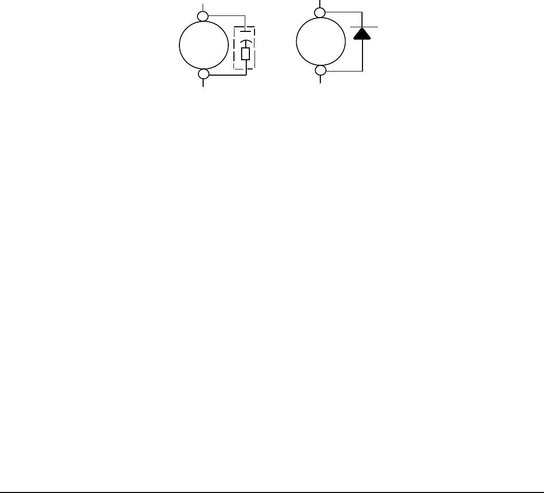
Troubleshooting 9-13MN766
9.4 Electrical Noise Considerations
All electronic devices are vulnerable to signicant electronic interference signals (commonly called “Electrical Noise”). At the
lowest level, noise can cause intermittent operating errors or faults. From a circuit standpoint, 5 or 10 millivolts of noise may
cause detrimental operation. For example, analog speed and torque inputs are often scaled at 5 to 10VDC maximum with a
typical resolution of one part in 1,000. Thus, noise of only 5 mV represents a substantial error.
At the extreme level, signicant noise can cause damage to the drive. Therefore, it is advisable to prevent noise generation
and to follow wiring practices that prevent noise generated by other devices from reaching sensitive circuits. In a control,
such circuits include inputs for speed, torque, control logic, and speed and position feedback, plus outputs to some
indicators and computers.
Relay and Contactor Coils
Among the most common sources of noise are the coils of contactors and relays. When these highly inductive coil circuits
are opened, transient conditions often generate spikes of several hundred volts in the control circuit. These spikes can
induce several volts of noise in an adjacent wire that runs parallel to a control-circuit wire. Figure 9-1 illustrates noise
suppression for AC and DC relay coils.
Figure 9-1 AC and DC Coil Noise Suppression
μ
0.47 f
Ω
33
AC Coil DC Coil Diode
RC Snubber
Wires between Controls and Motors
Output leads from a typical 460VAC drive controller contain rapid voltage rises created by power semiconductors switching
650V in less than a microsecond, 1,000 to 16,000 times a second. These noise signals can couple into sensitive drive
circuits. If shielded pair cable is used, the coupling is reduced by nearly 90%, compared to unshielded cable. Even input AC
power lines contain noise and can induce noise in adjacent wires. In some cases, line reactors may be required. To prevent
induced transient noise in signal wires, all motor leads and AC power lines should be contained in rigid metal conduit, or
exible conduit. Do not place line conductors and load conductors in same conduit. Use one conduit for 3 phase input wires
and another conduit for the motor leads. The conduits should be grounded to form a shield to contain the electrical noise
within the conduit path. Signal wires, even ones in shielded cable, should never be placed in the conduit with motor power
wires.
Special Drive Situations
For severe noise situations, it may be necessary to reduce transient voltages in the wires to the motor by adding load
reactors. Load reactors are installed between the control and motor. Line and Load Reactors are typically 3% reactance and
are designed for the frequencies encountered in PWM drives. For maximum benet, the reactors should be mounted in the
drive enclosure with short leads between the control and the reactors.
Control Enclosures
Motor controls mounted in a grounded enclosure should also be connected to earth ground with a separate conductor to
ensure best ground connection. Often grounding the control to the grounded metallic enclosure is not sufcient. Usually
painted surfaces and seals prevent solid metallic contact between the control and the panel enclosure. Likewise, conduit
should never be used as a ground conductor for motor power wires or signal conductors.
Special Motor Considerations
Motor frames must also be grounded. As with control enclosures, motors must be grounded directly to the control and
plant ground with as short a ground wire as possible. Capacitive coupling within the motor windings produces transient
voltages between the motor frame and ground. The severity of these voltages increases with the length of the ground wire.
Installations with the motor and control mounted on a common frame, and with heavy ground wires less than 10 ft. (3m)
long, rarely have a problem caused by these motor-generated transient voltages.
Analog Signal Wires
Analog signals generally originate from speed and torque controls, plus DC tachometers and process controllers. Reliability
is often improved by the following noise reduction techniques:
• Use twisted-pair shielded wires with the shield grounded at the drive end only.
• Route analog signal wires away from power or control wires (all other wiring types).
• Cross power and control wires at right angles (90°) to minimize inductive noise coupling

9-14 Troubleshooting MN766

PLC Mode Description 10-1MN766
Chapter 10
PLC Mode Description
10.1 Overview
PLC functionality is selected by setting Level 1, Input Setup block, Operating Mode parameter P1401 to PLC. PLC mode
allows 2-Wire and 3-Wire operating modes to be created using a selection of conditions, logical operators and desired
actions. PLC Mode parameters are located in Level 3, PLC block parameters P3401 through P3443.
Simply stated, for each logical statement choose two input conditions from Table 10-1, one logical operation from Table
10-2 and one action from Table 10-3. These 30 logical statements are evaluated every 10 milliseconds, in order from P3401
to 3430. For each statement Condition 1 and Condition 2 are evaluated to True or False, the Logical Operator is applied and
the nal outcome is either True or False. If True the Action is taken; if False the Alternate Action is taken.
Conditions, operators and actions are pre-dened and so cannot be changed.
10.2 Configuration Parameters
The PLC program is contained within 30 statements, PLC CONFIG 1 (P3401) through PLC CONFIG 30 (P3430). Each
statement has the same 32 bit word format and structure as the example given in Figure 10-1. If P3401-P3430 are not
programmed, the PLC Mode will do nothing. It is also possible to program them so that the motor will not move. This can
happen, for instance, if no Forward/Reverse Enables are programmed.
Figure 10-1 Example PLC Configuration Parameters
Where:
DDD = bits 31-24 Byte 3 051 = Digital Input 2 (from Table 10-1)
CCC = bits 23-16 Byte 2 000 = OR (from Table 10-2)
BBB = bits 15-8 Byte 1 000 = False (from Table 10-1)
AAA = bits 7-0 Byte 0 020 = Forward (from Table 10-3)
Parameter No. Hex Byte 3 Hex Byte 2 Hex Byte 1 Hex Byte 0
P3401 - 3430 Condition ID Logical Operator ID Condition ID Action ID
MSD LSD
(Table 10-1) (Table 10-2) (Table 10-1) (Table 10-3)
Parameter Number Format = DDD.CCC.BBB.AAA Example: P3401 = 051.000.000.020
A conguration parameter may be disabled (turned off) by setting bit 23 in its conguration word. This is the same as
setting the most signicant bit of byte 2 (the logical operator ID eld). If any eld within any of these parameters is invalid,
it is ignored at run time. Only one runtime version exists at a time. The runtime version in effect is the one dened by the
parameter table active at the time the drive was placed in Remote Mode.
To switch runtime PLC versions perform the following operations:
1. Disable the drive.
2. At the keypad, select “Local” mode.
3. Select the desired parameter table.
4. Enable the drive.
5. At the keypad, select “Remote” mode.
If a parameter table is switched while the drive is enabled the run time PLC version is not affected.
10.3 Comparator Function
Comparator parameters provide a way to monitor real-time signals within the drive and apply them to the PLC Mode’s logic.
They may be used on the condition denition side of the PLC Mode’s logic. Parameters P3431 and P3433 hold parameter
numbers (i.e. they point to other parameters, see Monitor and RTC chapter in this manual for these values). P3432 and
P3434 hold percents that are applied against P3431 and P3433 maximums, together they provide all that is needed for the
following comparison equations:
If |Value of P3431| ≤ (P3432/100)*(Max of P3431) then True or
If |Value of P3433| ≤ (P3434/100)*(Max of P3433) then True
In a sense P3431 and P3433 may be viewed as holding addresses for other parameters.
For example: If P3431 = 5 (selects parameter 5 which is Motor Volts = 230V) and P3432=20% then Comparator A is true if
|P5| = (20/100)*230 ≤ 46V. But if the voltage exceeds 46V, Comparator A is false.
If P3433 = 6 (selects parameter 6 Motor Current = 10 Amps) then Comparator B is true if |P6| ≤ 1 Amp. Any parameter (see
Monitor and RTC chapter in this manual for these values) can be used in a comparator.
Note: Don’t use P3431 and P3433 since this would create a circular reference and the comparator would fail.

10-2 PLC Mode Description MN766
A and B are defined as follows:
A = (Value of Parameter P3431) / (Max of Parameter P3431)
B = (Value of Parameter P3433) / (Max of Parameter P3433)
Then, A & B are signals with the following properties: -1≤ A ≤1 and -1≤ B ≤1.
A and B are normalized signals derived from parameters pointed to by P3431 and P3433.
Comparator A
Comparator A is used in Condition 76 and checks the following relationship for true or false:
If | A - P3435/100 | ≤ P3432/100
Alternatively, another way of writing the same relation is as follows:
If (P3435 - P3432)/100 ≤ A ≤ (P3432 + P3435)/100
Thus, Comparator A provides a way to determine if a parameter is within a specic range. For example, if P3431=5 (Motor
Volts with Max=230V) and P3432=20% and P3435=0% then Comparator A would be true so long as |P5| ≤ 46V or |A| ≤ 0.20.
That is, motor voltage is monitored and so long as it remains below 46 Volts, the outcome of Comparator A would be True,
but if it were to go above 46 Volts, the output of Comparator A would be False.
Comparator B
Comparator B is used in Condition 77 and checks the following relationship for true or false:
If | B - P3436/100 | ≤ P3434/100
Alternatively, another way of writing the same relation is as follows:
If (P3436 - P3434)/100 ≤ B ≤ (P3436 + P3434)/100
Thus, Comparator B provides a way to determine if a parameter is within a specic range. For example, if P3433=6 (Motor
Current with Max=10Amps) and P3434=10% and P3436=50% then Comparator B would be true so long as:
4 Amps ≤ P6 ≤ 6 Amps
OR
0.4 ≤ B ≤ 0.60.
That is, motor current is monitored and so long as it remains within 1 Amp of 5 Amps the outcome of Comparator B would
be True, but if it were to go above 6 Amps or below 4 Amps the output of Comparator B would be False.
Less than
Less than, Condition 88, uses the following equation: If A<B then True else False For example, if P3431=103 (Analog Input 1
Reference with Max=100%) and P3433=104 (Analog Input 2 Reference with Max=100%) then Condition 88 would be true so
long as P103<P104 or so long as Analog Input 1 Reference is less than Analog Input 2 Reference.
Equal
Equal, Condition 89, uses the following equation: If A=B then True else False For example, if P3431=103 (Analog Input 1
Reference with Max=100%) and P3433=104 (Analog Input 2 Reference with Max=100%) then Condition 89 would be true so
long as P103=P104 or so long as Analog Input 1 Reference is equal to Analog Input 2 Reference.
Greater than
Greater than, Condition 90, uses the following equation: If A>B then True else False For example, if P3431=103 (Analog
Input 1 Reference with Max=100%) and P3433=104 (Analog Input 2 Reference with Max=100%) then
Condition 90 would be true so long as P103>P104 or so long as Analog Input 1 Reference is greater than Analog Input 2
Reference.
10.4 Timers
The PLC Mode uses four general purpose timers: Timer A (P3440), B (P3441), C (P3442) and D (P3443) with units of
seconds and resolution of 10ms or 100 counts/sec. They may be used in PLC control and logic statements as dened in
the Conditions and Actions Tables. In general there are actions to start and stop the timers as well as conditions to test their
contents.
P113, P114, P117 and P118 are read/write monitor parameters that reect the current state of timers A through D. Since
they may be written, they can be used to start a timer by writing zero to it or to stop a timer by writing max counts.
For example, set P3440 to 1.5 sec then upon Timer A timeout,
P113 = 150 counts = (1.5 sec) x (100 counts/sec)
Starting timer A also starts P113 ramping from 0 to 150 in 1.5 seconds.
Set P3441 to 10 seconds and start Timer B, P114 then ramps from 0 to 1000 in 10 sec.
These monitor parameters may also be inputs to the Composite Reference block to generate timed ramps or other complex
reference signals.

PLC Mode Description 10-3MN766
Table 10-1 PLC Conditions
ID Description
0 False - This condition is always False
1 True - This condition is always True
2 Reserved (Workbench - Digital Input)
3 Reserved (Workbench - Hard Forward Limit)
4 Reserved (Workbench - Hard Reverse Limit)
5 Reserved (Workbench - Soft Forward Limit)
6 Reserved (Workbench - Soft Reverse Limit)
7 Reserved (Workbench - Move Statue)
8 Reserved (Workbench - Idle)
9 Reserved (Workbench - Position achieved)
10 Reserved (Workbench - At target position)
11 Reserved (Workbench - In Idle Position Window)
12 Reserved (Workbench - Following Error Fatal)
13 Reserved (Workbench - Following Error Warning)
14 At Speed - If the measured speed of the rotor is within the At Speed Band (P1506) of the reference then this
condition is True.
15 Reserved - (Workbench - Velocity Error)
16 Velocity Setpoint Minimum - If the measured absolute speed is below the Minimum Output Speed (P2002) then this
condition is True.
17 Velocity Setpoint Maximum- If the measured absolute speed is above the Maximum Output Speed (P2003) then this
is True.
18 Reserved
19 Motor Overload - If the motor's I2T algorithm has exceeded its integral limit this condition is True.
20 Drive Overload - If the drive's I2T algorithm has exceeded its integral limit this condition is True.
21 Motor Direction - If rotor speed is positive this condition is True
22 Command Direction - If speed demand is positive this condition is True
23 Ready - If soft start is complete, drive hardware enable is on and there are no errors this condition is True.
24 Drive On - If the drive is ready and producing PWM to the motor this condition is True.
25 Fault - If the drive is faulted for any reason this condition is True.
26 Motor Over Temp Trip - If the motor's over temperature trip input has occurred then this condition is True.
27 Drive Over Temp Trip - If the drive's over temperature trip input has occurred then this condition is True.
28 Drive Over Temp Warning - If the drive's temperature has exceeded that dened for the drive then this condition is
True.
29 Reserved (Workbench - home status)
50 Digital Input 1 (J2-9) - If digital input 1 is high this condition is true. (Level sensitive)
51 Digital Input 2 (J2-10) - If digital input 2 is high this condition is true. (Level sensitive)
52 Digital Input 3 (J2-11) - If digital input 3 is high this condition is true. (Level sensitive)
53 Digital Input 4 (J2-12) - If digital input 4 is high this condition is true. (Level sensitive)
54 Digital Input 5 (J2-13) - If digital input 5 is high this condition is true. (Level sensitive)
55 Digital Input 6 (J2-14) - If digital input 6 is high this condition is true. (Level sensitive)
56 Digital Input 7 (J2-15) - If digital input 7 is high this condition is true. (Level sensitive)
57 Digital Input 8 (J2-16) - If digital input 8 is high this condition is true. (Level sensitive). When J2-16 is used in PLC
Program, Set P2201=OFF to avoid an external trip condition.
58 Drive Run - If the drive is on and has a forward or reverse command this condition is True.
59 Stop - If motion status is stopped this condition is True.
60 Jog - If jog mode is active this condition is True.

10-4 PLC Mode Description MN766
ID Description
61 Accelerating - If absolute speed demand is accelerating this condition is True.
62 Constant Speed - If absolute speed demand is constant this condition is True.
63 Decelerating - If absolute speed demand is decelerating this condition is True.
64 At Zero Speed - If absolute speed demand is below the Zero Speed Set Point (P1505) this condition is True.
65 At Set Speed - If absolute speed demand is above Set Speed Point (P1507) this condition is True.
66 Motor Over Current - If motor RMS current is above the Overload Set Point (P1508) this condition is True.
67 Motor Under Current - If motor RMS current is below the Underload Set Point (P1509) this condition is True.
68 Keypad Control - If the drive is under keypad control this condition is True.
69 Dynamic Brake - If the drive's dynamic brake is on this condition is True.
70 Frequency Foldback - If the drive is in frequency foldback this condition is True.
71 Alarm - If an alarm is active this condition is True.
72 Forward - If the drive has a forward command this condition is True.
73 Reverse - If the drive has a reverse command this condition is True.
74 Process PID Error - If the absolute value of Process PID Error is less than the Process PID Error Tolerance (P2606)
this condition is True.
75 Sleep Mode - If the drive's sleep algorithm has put the drive to sleep this condition is True.
76 Comparator A - Monitors a parameter and returns True if the parameter is less than a predened setpoint.
NOTE: See chapter on PLC Comparator Parameters.
77 Comparator B - Monitors a parameter and returns True if the parameter is below a predened setpoint.
NOTE: See chapter on PLC Comparator Parameters .
78 Parameter Table 1 - If parameter table 1 is active then this condition is True.
79 Parameter Table 2 - If parameter table 2 is active then this condition is True.
80 Parameter Table 3 - If parameter table 3 is active then this condition is True.
81 Parameter Table 4 - If parameter table 4 is active then this condition is True.
82 Digital Output 1- If digital output 1 is On this condition is True.
83 Digital Output 2- If digital output 2 is On this condition is True.
84 Relay Output 1 - If relay output 1 is On this condition is True.
85 Relay Output 2 - If relay output 2 is On this condition is True.
86 Timer A - True if Timer A has expired.
87 Timer B - True if Timer B has expired.
88 Less Than (<) - Monitors two parameters (A & B) and returns True if A<B else False is returned.
89 Equal (=) - Monitors two parameters (A & B) and returns True if A=B else False is returned.
90 Greater Than (>) - Monitors two parameters (A & B) and returns True if A>B else False is returned.
91 Timer C - True if Timer C has expired else it is False.
92 Timer D - True if Timer D has expired else it is False.
100 Logical Variable A - Logical variable A is tested for True/False
101 Logical Variable B - Logical variable B is tested for True/False
102 Logical Variable C - Logical variable C is tested for True/False
103 Logical Variable D - Logical variable D is tested for True/False
104 Logical Variable E - Logical variable E is tested for True/False
105 Logical Variable F - Logical variable F is tested for True/False
106 Logical Variable G - Logical variable G is tested for True/False
107 Logical Variable H - Logical variable H is tested for True/False
108 Logical Variable I – Logical variable I is tested for True/False
109 Logical Variable J - Logical variable J is tested for True/False
150 Heater - If the trickle current heater is running then this condition is True else it is False.
Table 10-1 PLC Conditions Continued

PLC Mode Description 10-5MN766
Table 10-2 PLC Logical Operators
ID Description
0 OR - Performs logical OR operation on input conditions
1 AND - Performs logical AND operation on input conditions
2 XOR - Performs logical XOR operation on input conditions
3 NOR - Performs logical NOR operation on input conditions
4 NAND - Performs logical NAND operation on input conditions
Table 10-3 PLC Actions
ID Description
0 Digital Output 1 - If the input condition is True then Digital Output 1 (J2-17,18) will be active otherwise it is inactive
NOTE: Digital output 1 must have been set to “PLC” using P1501
1 Digital Output 2 - If the input condition is True then Digital Output 2 (J2-19,20) will be active otherwise it is inactive
NOTE: Digital output 2 must have been set to “PLC” using P1502
2 Relay Output 1 - If the input condition is True then Relay Output 1 (J3-25,26,27) will be active otherwise it is inactive
NOTE: Relay output 1 must have been set to “PLC” using P1503
3 Reserved (Workbench - Fault)
4 Drive Enable/Disable - If the condition is True then the drive is capable of producing power. If the condition is False
the drive is disabled. NOTE: If not programmed, J2-8 alone enables the drive NOTE: The drive's hardware enable
input (J2-8) must be is active for this action.
5 Jog Reverse - If the condition is True then the motor will jog in the reverse direction at the speed set by P1201 if
jogging is enabled. NOTE: If both jog forward and reverse are active the motor stops
6 Jog Forward - If the condition is True then the motor will jog in the forward direction at the speed set by P1201 if
jogging is enabled. NOTE: If both jog forward and reverse are active the motor stops
7 Reserved (Workbench - Hold)
8 Stop Enable/Disable - If the input condition is True the motor is stopped.
9 Reserved (Workbench - Error Deceleration)
10 Reserved (Workbench - Cancel)
11 Reserved (Workbench - Disable)
12 Reserved (Workbench - Forced Abort)
13 Reserved (Workbench - Fast Gear)
18 Jog Enable - Allows jogging if True else jogging is disabled
19 Fault - If the input condition is True a “PLC Fault” is triggered. If using J2-16 to generate a PLC Fault Condition,
P2201 must be set to “OFF” to avoid a conict with external trip.
20 Forward Enable/Disable - If the input condition is True forward motion is enabled otherwise it is disabled.
21 Reverse Enable/Disable - If the input condition is True reverse motion is enabled otherwise it is disabled.
22 Acc/Dec Group Select - If the input condition is True then Acc/Dec group 2 is selected otherwise group 1 is selected.
NOTE: If this action is not programmed Group 1 is active by default.
23 Reset - If the input condition is True a reset request is issued. NOTE: This action is edge triggered on a False to True
transition. NOTE: Pre-existing faults/alarms may or may not be cleared.
24
Preset Speed/Analog - If the input condition is True then the Preset Speed Select Table Index sets the speed
reference from the Preset Speeds (P1001-P1015) else the Command Source (P1402) selects the speed reference.
NOTE: If this action is not programmed P1402 is always active. NOTE: If the Preset Speed Select Table Index is not
programmed then P1001 is used.
25 Preset Speed Select Table Index Bit 0 - If the input condition is True then bit 0 of the Preset Speed Select Table
Index is set else it is reset. NOTE: If this action is not programmed then bit 0 is reset.
26 Preset Speed Select Table Index Bit 1 - If the input condition is True then bit 1 of the Preset Speed Select Table Index
is set else it is reset. NOTE: If this action is not programmed then bit 1 is reset.
27 Preset Speed Select Table Index Bit 2 - If the input condition is True then bit 2 of the Preset Speed Select Table Index
is set else it is reset. NOTE: If this action is not programmed then bit 2 is reset.

10-6 PLC Mode Description MN766
ID Description
28 Preset Speed Select Table Index Bit 3 - If the input condition is True then bit 3 of the Preset Speed Select Table Index
is set else it is reset. NOTE: If this action is not programmed then bit 3 is reset.
29 Process PID Enable/Disable - If the input condition is True then the Process PID is active otherwise it is inactive.
NOTE: The Process PID is automatically set to inactive during keypad control or while jogging.
30 Keypad - If the input condition is True then forward/reverse and stop commands along with the keypad's local speed
reference control the drive. The keypad is disabled by default.
31 Electronic Pot - If the input condition is True the Electronic Pot sets the speed reference otherwise it is not active. The
pot is disabled by default.
32 Decrease Electronic Pot Speed Reference- If the input condition is True the Electronic Pot speed reference is
increased else has no affect. NOTE: E-Pot is non-volatile. NOTE: E-Pot is unipolar so direction is determined by
forward/reverse commands.
33 Increase Electronic Pot Speed Reference- If the input condition is True the Electronic Pot speed reference is
decreased else has no affect. NOTE: E-Pot is non-volatile. NOTE: E-Pot is unipolar so direction is determined by
forward/reverse commands.
34 Parameter Table Select Enable - If the input condition is True enables parameter table selection through the
parameter table select index, else parameter table selection is disabled.
35 Parameter Table Select Index Bit 0 - If the input condition is True then bit 0 of the Parameter Table Select Index
is set else it is reset. NOTE: If this action is not programmed then bit 0 is reset. NOTE: This index sets the active
parameter table
36 Parameter Table Select Index Bit 1 - If the input condition is True then bit 1 of the Parameter Table Select Index
is set else it is reset. NOTE: If this action is not programmed then bit 1 is reset. NOTE: This index sets the active
parameter table
37 Relay Output 2 - If the input condition is True then Relay Output 2 (J3-28,29,30) will be active otherwise it is inactive
NOTE: Relay Output 2 must have been set to “PLC” using P1504
38 Torque/Speed Mode - If the input condition is True then the drive controls torque else it controls speed. Default is
speed control. NOTE: For V/F, torque control is not supported and is ignored.
39 Seed E-Pot - If the condition is true, the current speed reference is seeded into the E-Pot speed reference.
Otherwise, it is not seeded. NOTE: E-Pot must not be the active speed reference for seeding to occur.
40 Logical Variable A - If the input condition is True then logical variable A is set else reset
41 Logical Variable B - If the input condition is True then logical variable B is set else reset
42 Logical Variable C - If the input condition is True then logical variable C is set else reset
43 Logical Variable D - If the input condition is True then logical variable D is set else reset
44 Logical Variable E - If the input condition is True then logical variable E is set else reset
45 Logical Variable F - If the input condition is True then logical variable F is set else reset
46 Logical Variable G - If the input condition is True then logical variable G is set else reset
47 Logical Variable H - If the input condition is True then logical variable H is set else reset
48 Logical Variable I - If the input condition is True then logical variable I is set else reset
49 Logical Variable J - If the input condition is True then logical variable J is set else reset.
50 Start Timer A - If the input condition is True zero Timer A else count up to a timeout.
51 Stop Timer A - If the input condition is True, set Timer A= P3440 counts else do nothing.
52 Start Timer B - If the input condition is True, set Timer B= 0 else count up to a timeout.
53 Stop Timer B - If the input condition is True, set Timer B= P3441 counts else do nothing.
54 Start Timer C - If the input condition is True, set Timer C= 0 else count up to a timeout.
55 Stop Timer C - If the input condition is True, set Timer C= P3442 counts else do nothing.
56 Start Timer D - If the input condition is True, set Timer D= 0 else count up to a timeout.
57 Stop Timer C - If the input condition is True, set Timer D= P3443 counts else do nothing.
58 Pulse Start Timer A –If the input condition is True and timer A has expired then restarts timer A
59 Pulse Start Timer B –If the input condition is True and timer B has expired then restarts timer B
60 Pulse Start Timer C –If the input condition is True and timer C has expired then restarts timer C
Table 10-3 PLC Actions Continued

PLC Mode Description 10-7MN766
ID Description
61 Pulse Start Timer D –If the input condition is True and timer D has expired then restarts timer D
69 Reset PLC – If the input condition is True then a PLC reset is performed. All timers are expired and all logical
variables are set to FALSE. Comparators are not affected.
70- 99 Jump 0-29 – If the input condition is True then a jump from the current rung number to the specied rung number
is performed. Skipped rungs are not executed. Only forward jumps are allowed. Jumps from high to lower rungs or
jumps to the same rung number result in an error.
150 Heater - If the input condition is true then trickle current heating is enabled else it is disabled.
Table 10-4 Preset Speed Select Index
ID of PLC Actions Description
28 27 26 25
0 0 0 0 Preset Speed 1 (P1001) Selected
0 0 0 1 Preset Speed 2 (P1002) Selected
0 0 1 0 Preset Speed 3 (P1003) Selected
0 0 1 1 Preset Speed 4 (P1004) Selected
0 1 0 0 Preset Speed 5 (P1005) Selected
0 1 0 1 Preset Speed 6 (P1006) Selected
0 1 1 0 Preset Speed 7 (P1007) Selected
0 1 1 1 Preset Speed 8 (P1008) Selected
1 0 0 0 Preset Speed 9 (P1009) Selected
1 0 0 1 Preset Speed 10 (P1010) Selected
1 0 1 0 Preset Speed 11 (P1011) Selected
1 0 1 1 Preset Speed 12 (P1012) Selected
1 1 0 0 Preset Speed 13 (P1013) Selected
1 1 0 1 Preset Speed 14 (P1014) Selected
1 1 1 0 Preset Speed 15 (P1015) Selected
1 1 1 1 Zero Speed (Not Dened) Selected
Table 10-5 Parameter Table Select Index
ID of PLC Actions Description
36 35
0 0 Parameter Table 1 (P52 set to T1) Selected
0 1 Parameter Table 2 (P52 set to T2) Selected
1 0 Parameter Table 3 (P52 set to T3) Selected
1 1 Parameter Table 4 (P52 set to T4) Selected
Table 10-3 PLC Actions Continued
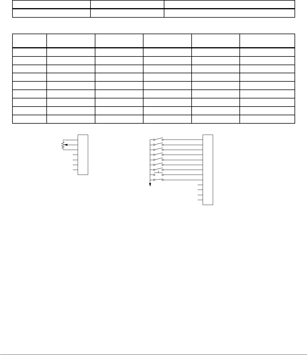
10-8 PLC Mode Description MN766
10.5 PLC Mode as Standard Run 2-Wire Mode
This example shows how the PLC Mode may operate as the Standard Run 2-Wire Mode.
These parameter values are entered from the keypad.
Initialization:
Parameter Value Comment
P1401 PLC PLC operating mode selected
PLC Mode configuration parameters:
Parameter
Number
Parameter Dec
Value Byte 3 Condition Byte 2 Logic Byte 1 Condition Byte 0 Action
P3401 050.000.000.020 Input 1 (50) OR (0) False (0) Forward (20)
P3402 051.000.000.021 Input 2 (51) OR (0) False (0) Reverse (21)
P3403 052.000.053.018 Input 3 (52) OR (0) Input 4 (53) Jog Enable (18)
P3404 052.000.000.006 Input 3 (52) OR (0) False (0) Jog Forward (6)
P3405 053.000.000.005 Input 4 (53) OR (0) False (0) Jog Reverse (5)
P3406 054.000.000.022 Input 5 (54) OR (0) False (0) Acc/Dec Group (22)
P3407 055.000.000.024 Input 6 (55) OR (0) False (0) Presets/Analog (24)
P3408 056.000.000.023 Input 7 (56) OR (0) False (0) Reset (23)
P3409 057.003.000.019 Input 8 (57) NOR (3) False (0) Fault (19)
User Analog Return
Analog Input 1
Analog Ref. Power +
1
2
3
4
5
6
7
J1
Analog Input 2+
Analog Input 2-
Analog Output 1
Analog Output 2
Enable
J2
Digital Output 1 + (Collector)
Digital Output 1 - (Emitter)
Digital Output 2 + (Collector)
Digital Output 2 - (Emitter)
Enable
Forward Run
Reverse Run
Jog Forward
Jog Reverse
Accel/Decel Select
Preset Speed 1
Fault
Fault Reset
Digital Input 1
Digital Input 2
Digital Input 3
Digital Input 4
Digital Input 5
Digital Input 6
Digital Input 7
Digital Input 8
8
17
9
10
11
12
13
14
15
16
18
19
20
*
*Note: Remove factory jumper from J2-8 and J3-24 before connecting switch at J2-8.
10K Pot or
0 - 10 VDC
See Figure 5-4 for
connection information.
See recommended tightening torques in Table A-2.
The Parameter Dec Value column can be used when entering the PLC conguration parameters at the keypad (parameters
are shown as decimal long values - byte3.byte2.byte1.byte0).
For this mode Enable is active.
Note that Preset Speed 1 is active so the Preset Speed Select Table Index need not be programmed since it automatically
follows action 24 (Presets/Analog)
Jog is enabled anytime input 3 or 4 is on while these same inputs set the direction for jog.
The Fault action is programmed to trigger whenever digital input 8 goes low.
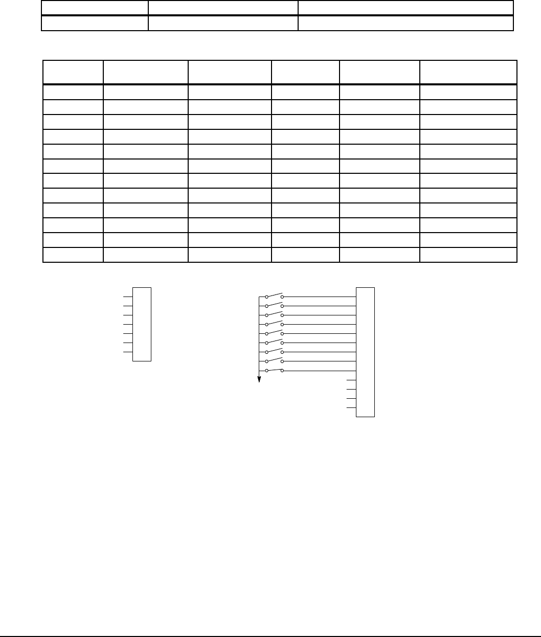
PLC Mode Description 10-9MN766
10.6 PLC Mode as 15 Preset Speed Mode
This example shows how the PLC Mode creates the 15 Preset Speed Mode.
Initialization:
Parameter Value Comment
P1401 PLC PLC operating mode selected
PLC Mode configuration parameters:
Parameter
Number
Parameter Dec
Value Byte 3 Condition Byte 2 Logic Byte 1 Condition Byte 0 Action
P3401 050.000.000.020 Input 1 (50) OR (0) False (0) Forward (20)
P3402 051.000.000.024 Input 2 (51) OR (0) False (0) Reverse (21)
P3403 001.000.000.035 True (1) OR (0) False (0) Presets/Analog (24)
P3404 052.000.000.025 Input 3 (52) OR (0) False (0) Preset Tbl Bit 0 (25)
P3405 053.000.000.026 Input 4 (53) OR (0) False (0) Preset Tbl Bit 1 (26)
P3406 054.000.000.027 Input 5 (54) OR (0) False (0) Preset Tbl Bit 2 (27)
P3407 055.000.000.028 Input 6 (55) OR (0) False (0) Preset Tbl Bit 3(28)
P3408 052.001.053.040 Input 3 (52) AND (1) Input 4 (53) Variable A (40)
P3409 054.001.055.041 Input 5 (54) AND (1) Input 6 (55) Variable B (41)
P3410 100.001.101.023 A (100) AND (1) B (101) Reset (23)
P3411 056.000.000.022 Input 7 (56) OR (0) False (0) Acc/Dec Group (22)
P3412 057.003.000.019 Input 8 (57) NOR (3) False (0) Fault (19)
User Analog Return
Analog Input 1
Analog Ref. Power +
1
2
3
4
5
6
7
J1
Analog Input 2+
Analog Input 2-
Analog Output 1
Analog Output 2
Enable
J2
Digital Output 1 + (Collector)
Digital Output 1 - (Emitter)
Digital Output 2 + (Collector)
Digital Output 2 - (Emitter)
Enable
Forward Run
Reverse Run
Switch 1
Switch 2
Switch 3
Switch 4
External Trip
Accel/Decel
Digital Input 1
Digital Input 2
Digital Input 3
Digital Input 4
Digital Input 5
Digital Input 6
Digital Input 7
Digital Input 8
8
17
9
10
11
12
13
14
15
16
18
19
20
*
See Figure 5-4 for
connection information.
*Note: Remove factory jumper from J2-8 and J3-24 before connecting switch at J2-8.
See recommended tightening torques in Table A-2.
The Parameter Dec Value column can be used when entering the PLC conguration parameters at the keypad (parameters
are shown as decimal long values - byte3.byte2.byte1.byte0).
For this mode Enable is active.
Note that Preset Speed 1 is active so the Preset Speed Select Table Index need not be programmed since it automatically
follows action 24 (Presets/Analog).
Jog is enabled anytime input 3 or 4 is on while these same inputs set the direction for jog.
The Fault action is programmed to trigger whenever digital input 8 goes low.
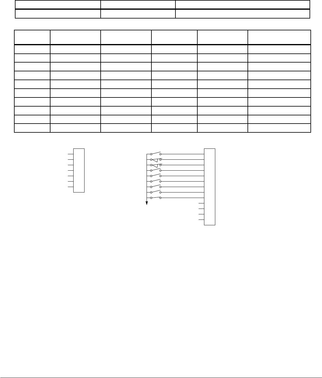
10-10 PLC Mode Description MN766
10.7 PLC Mode as Process PID Mode
This example shows how the PLC Mode rendered as the Process PID Mode.
Initialization:
Parameter Value Comment
P1401 PLC PLC operating mode selected
PLC Mode configuration parameters:
Parameter
Number
Parameter Dec
Value Byte 3 Condition Byte 2 Logic Byte 1 Condition Byte 0 Action
P3401 050.000.000.020 Input 1 (50) OR (0) False (0) Forward (20)
P3402 051.000.000.021 Input 2 (51) OR (0) False (0) Reverse (21)
P3403 001.000.000.034 True (1) OR (0) False (0) Param Table Select (34)
P3404 052.000.000.035 Input 3 (52) OR (0) False (0) Table Select Bit 0 (35)
P3405 053.000.000.038 Input 4 (53) OR (0) False (0) Torque/Speed (38)
P3406 054.000.000.029 Input 5 (54) OR (0) False (0) PID (29)
P3407 055.000.000.018 Input 6 (55) OR (0) False (0) Jog Enable (18)
P3408 055.000.000.006 Input 6 (55) OR (0) False (0) Jog Forward (6)
P3409 056.000.000.023 Input 7 (56) OR (0) False (0) Reset (23)
P3410 057.003.000.019 Input 8 (57) NOR (3) False (0) Fault (19)
User Analog Return
Analog Input 1
Analog Ref. Power +
1
2
3
4
5
6
7
J1
Analog Input 2+
Analog Input 2-
Analog Output 1
Analog Output 2
Enable
J2
Digital Output 1 + (Collector)
Digital Output 1 - (Emitter)
Digital Output 2 + (Collector)
Digital Output 2 - (Emitter)
Enable
Forward Enable
Reverse Enable
Table Select
Speed/Torque
Process Mode Enable
Jog
External Trip
Fault Reset
Digital Input 1
Digital Input 2
Digital Input 3
Digital Input 4
Digital Input 5
Digital Input 6
Digital Input 7
Digital Input 8
8
17
9
10
11
12
13
14
15
16
18
19
20
*
*Note: Remove factory jumper from J2-8 and J3-24 before connecting switch at J2-8.
See recommended tightening torques in Table A-2.
See Figure 5-4 for
connection information.
The Parameter Dec Value column can be used when entering the PLC conguration parameters at the keypad (parameters
are shown as decimal long values - byte3.byte2.byte1.byte0).
For this mode Enable is active.
The unconditional True statement P3403 enables parameter table select (Table 10-5 ) at all times.
The Fault action is programmed to trigger whenever digital input 8 goes low.
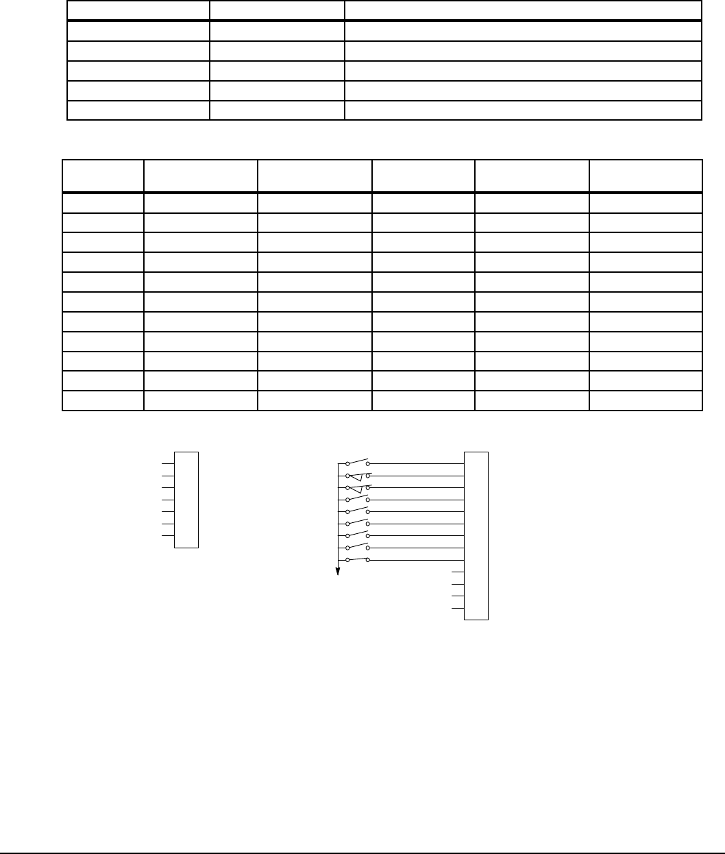
PLC Mode Description 10-11MN766
10.8 PLC Mode as a Modified Process PID Mode
This example shows how the PLC Mode as a modied Process PID Mode.
Initialization:
Parameter Value Comment
P1401 PLC PLC operating mode selected
P1501 PLC Digital Output 1 Set by PLC Mode Logic
P3431 10 Comparator A monitors absolute speed demand (P10)
P3432 20% Comparator A’s constant (12 Hz for 60 Hz max)
P3440 3.00 sec Timer A set for 3 seconds
PLC Mode configuration parameters:
Parameter
Number
Parameter Dec
Value Byte 3 Condition Byte 2 Logic Byte 1 Condition Byte 0 Action
P3401 076.000.000.040 Comp A (76) OR (0) False (0) A (40)
P3402 050.000.000.020 Input 1 (50) OR (0) False (0) Forward (20)
P3403 051.000.000.021 Input 2 (51) OR (0) False (0) Reverse (21)
P3404 100.000.000.038 A (100) OR (0) False (0) Torque/Speed (38)
P3405 053.002.100.029 Input 4 (53) XOR (2) A (100) PID (29)
P3406 054.000.055.018 Input 5 (54) OR (0) Input 6 (55) Jog Enable (18)
P3407 054.000.000.006 Input 5 (54) OR (0) False (0) Jog Forward (6)
P3408 055.000.000.005 Input 6 (55) OR (0) False (0) Jog Reverse (5)
P3409 056.000.000.023 Input 7 (56) OR (0) False (0) Reset (23)
P3410 057.000.000.050 Input 8 (57) OR (0) False (0) Start Timer (50)
P3411 086.000.000.019 Timer A (86) OR (0) False (0) Fault (19)
User Analog Return
Analog Input 1
Analog Ref. Power +
1
2
3
4
5
6
7
J1
Analog Input 2+
Analog Input 2-
Analog Output 1
Analog Output 2
Enable
J2
Digital Output 1 + (Collector)
Digital Output 1 - (Emitter)
Digital Output 2 + (Collector)
Digital Output 2 - (Emitter)
Enable
Forward Enable
Reverse Enable
PID
Jog Enable
Jog Forward
Jog Reverse
Fault
Fault Reset
Digital Input 1
Digital Input 2
Digital Input 3
Digital Input 4
Digital Input 5
Digital Input 6
Digital Input 7
Digital Input 8
8
17
9
10
11
12
13
14
15
16
18
19
20
*
*Note: Remove factory jumper from J2-8 and J3-24 before connecting switch at J2-8.
See recommended tightening torques in Table A-2.
See Figure 5-4 for
connection information.
The Parameter Dec Value column can be used when entering the PLC conguration parameters at the keypad (parameters
are shown as decimal long values - byte3.byte2.byte1.byte0).
For this mode Enable is active.
Use of logical variables A, B, C or D allows for complex PLC logic.
Variable “A” is set based on the outcome of a comparator and then used as an input condition for the torque/speed select
and PID actions.

10-12 PLC Mode Description MN766
Note that P3401 is programmed to set logical variable “A” before it is used since statements are executed in order from
P3401 through P3410.
Either input 5 or 6 enable jog and they also set jog direction as in P3407 and P3408.
Speed mode is active above 12 Hz but torque mode is active when less than 12Hz.
The PID becomes active above 12 Hz if input 4 is ON.
The PID becomes active at less than 12 Hz when input 4 is OFF.
The Fault action is programmed to trigger after a three second delay following digital input 8 going low.
Timer A is used to implement this action.
Normally P3410 continuously resets Timer A when digital input 8 is high.
If digital input 8 goes low then high in less than three seconds no fault action occurs since Timer A is reset before it has a
chance to timeout.
If digital input 8 goes low and stays low for at least 3 seconds then Timer A does timeout and a fault occurs.
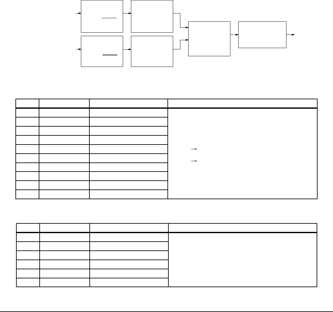
Composite Reference Description 11-1MN766
Chapter 11
Composite Reference Description
11.1 Overview
This reference is mathematically computed from any two valid drive parameters. Once congured, it can provide a signal to
drive the speed loop, torque loop or process PID. In addition, this reference can drive all existing operating modes including
the PLC Mode. Composite Ref can be referenced to any valid input:
P1402 - Command Source P2310 - Auxiliary Filter Source P1415 - Current Limit Source
P2603 - Process PID Feedback Source P1418 -Torque Feedforward Source P2604 - Process PID Setpoint Source
Mathematical operations are performed at each stage in its development providing the ability to add, subtract, multiply or
divide any two parameters to form a complex internal reference source. This reference source can inuence the operation of
all existing operating modes including PLC Mode. The Composite Reference Parameter Block is programmed in the Level 3,
Composite REF parameters.
Figure 11-1 Composite Reference Generator Block Diagram
Stage 1 (P#3501 & 3507)
Scale Factor
P
y=P
x
Max Px
Py
Px
Variable A
Stage 1 (P#3503 & 3508)
Scale Factor
P
b=P
a
Max P
a
Pb
Variable B P
a
Output is = ± 100%
Output is = ± 100%
Stage 2 (P#3502)
Math Function
P
z=F(P
y)
Pz
Py
Stage 2 (P#3504)
Math Function
P
cF(P
b)
P
c
Pb
Stage 3 (P#3505)
Binary Operator
Rx=(P
c)O(P
z)
Rx
Pz
P
c
Stage 4 (P#3506)
Math Function
with Limit Setting
RyF(Rx)
Ry
Rx
Ry
* K1
* K2=
=
Table 11-1 Math Functions (P3506)
ID Function Description Notes
0 0 Zero1 1. Zero Function, F(x) = 0
2. Identity Function, F(x) = x
3. Where, |x| is the absolute value function:
|x|= x for x ≥ 0
|x|=-x for x < 0
4. The ramp generator is computed as follows:
0.0 1.0 for x > 0
Constant output for x = 0
0.0 -1.0 for x < 0
Withtimeperiodequalto1.0/(|x|•100)Sec
5. The frequency generator is computed
as follows: y = Ramp(x) Freq(x) = Sin(2πy) With
outputfrequencyequalto|x|•100Hz
1 X Identity2
2 | X | Absolute Value3
3 1/X Inversion
4 X2 Square
5 √(|X|) Square Root3
6 Sin(x) Sine
7 Cos(x) Cosine
8 Ramp(x) Ramp Generator4
9 Freq(x) Frequency Generator5
Table 11-2 Binary Operator Selection Parameter (P3505)
ID Function Description Notes
0 + Sum 1. Y = Max(x, y) provides the maximum
2. Y = Min(x, y) provides the minimum
1 - Difference
2•Multiply
3 / Divide
4 Max Maximum1
5 Min Minimum2

11-2 Composite Reference Description MN766
Table 11-3 Composite Reference Parameters
Stage P# Description
1 3501 &
3503 Scale Factor - Monitor a parameter number (Variable A or B) and scales the value into percentage of
maximum value for use by the next stage. As an example, P3501=5 Motor Voltage (assume its maximum
is 230V) is monitored and internally 20% is computed for P5= 46 V or 10% for P5=23 V. Likewise, with
P3503=11 then Speed Demand (assume its maximum is 60 Hz) is monitored and 50% is output when
P11=30 Hz or –50% when P11= -30 Hz.
P3501 or P3503 can be can be set to any valid drive parameter number. If either is set to an invalid
parameter number Py=0% or Pb=0%.
P3501 or P3503 only point to a valid parameter number in the active parameter table, never a parameter
outside the active table. Switching parameter tables with the drive enabled causes the Composite
Reference to be redened by the parameter values in the new active parameter table.
2 & 4 3502,
3504 &
3506
Math Function - These parameters select the mathematical functions to be applied at the second and
fourth stage of the Composite Reference's derivation. Refer to Table 11-1.
3 3505 Operator - This parameter provides the mathematical operation to be performed at the third stage of the
Composite Reference derivation. Refer to Table 11-2 .
1 3507 &
3508 These parameters provide a way to scale up or down the percentage calculation of the rst stage. They
range from -1000.00 to 1000.00 with default 1.00. Normally, the defaults work so these parameters need
not be changed.
A simple example of their use is: A 5A motor is connected to a 15A (peak) drive. When the motor is at
rated amps only 5/15 or 33.3% is passed on to stage 2, but by setting P3507=3.00, 100% is passed on
allowing full use of the motor’s current.
11.2 Composite Reference Examples
The following table gives examples of the kinds of Composite References that may be developed.
Table 11-4 Examples
Composite Reference Parameters Description
P3501 P3502 P3503 P3504 P3505 P3506 P3507 P3508
P103 Identity P104 Identity Sum Identity 0.5 0.5 Average of Analog Inputs 1&2:
Ry = (A1+A2)/2
P103 Identity P104 Freq Multiply Identity 1.0 1.0 Signal Generator with Magnitude set by
A1 and Frequency by A2:
Ry = A1 x Freq(A2)
P103 Identity P104 Identity Divide Identity 1.0 1.0 Ratio of Analog Inputs 1&2: Ry = A1/A2
P102 Square P104 Square Difference Square
Root 1.0 1.0 Square Root of Difference of Squares of
Process Error and Analog2:
Ry = √(|Pe
2 – A2
2|)

Monitor and RTC Description 12-1MN766
Chapter 12
Monitor and RTC Description
12.1 Monitor Parameters (P0001 to P0818)
Monitor parameters can be viewed using the WorkBench software. Most are read only (P0001) but some (P0052) can be
written as well.
Table 12-1 Monitor Parameters Descriptions
P# Type Name Unit Help
1 SOFTWARE VERSION Software Version. - Drive rmware version number
2 LOC/REM STATUS Local/Remote Status. - Source of run/stop commands. Local for keypad
or Remote for terminal block
3 DRIVE STATUS Drive Enable Status. - 0 for disabled, 1 for enabled
4 MOTION STATUS Motion Status. - Status: stopped, forward, reverse, bipolar, sleep,
homing, etc.
5 MOTOR VOLTS V Motor Volts. - Estimated line-to-line drive output RMS voltage
6 MOTOR CURRENT A Motor Current. - Measured motor RMS current
7 MOTOR ABS SPEED RPM Motor Absolute Speed. - Estimated or measured absolute rotor speed
8 POSITION COUNTER CNT Position Counter. - Accumulated count in revolutions and counts for
feedback device.
9 SPEED REF Hz Speed Reference. - Setpoint speed for motor. Command source
parameter determines the source
10 ABS SPEED DEMAND Hz Absolute Speed Demand. - Absolute speed output from Speed Proler.
11 SPEED DEMAND Hz Speed Demand. - Signed speed output from Speed Proler
12 ABS MOTOR FREQ Hz Absolute Motor Frequency. - Estimated motor electrical frequency
13 MOTOR FREQ Hz Motor Frequency. - Signed motor frequency
14 DRIVE TEMP °C Drive Temperature. - Measured temperature of drive heat sink
15 BUS VOLTAGE V Bus Voltage. - Measured bus voltage. DC bus high fault occurs above
400/820V DC
16 OVERLOAD LEFT % Overload Remaining. - Current overload count remaining until overload
fault/foldback occurs
17 INPUTS Digital Inputs. - State of terminal block digital inputs. Off/On indicated
by 0/1
18 OUTPUTS Digital Outputs. - State of the terminal block digital/relay outputs. Off/On
indicated by 0/1
19 R/W RATED HP HP Rated Horsepower. - Drive rated horsepower
20 R/W RATED CURRENT A Rated Current. - Nominal/derated drive continuous RMS current rating
21 R/W RATED PK CURRENT A Rated Peak Current. - Nominal/de-rated drive peak, short term, current
rating
22 R/W RATED VOLTS V Rated Voltage. - Nominal voltage rating of drive
23 ACTIVE FAULTS Active Faults. - Number of active / simultaneous drive faults
24 ACTIVE FLT CODE Active Fault Code. - Currently active drive fault code number
25 PROC FEEDFORWARD % FF Process Feedforward. - Process PID feed forward signal
26 PROC SETPOINT % SP Process Setpoint. - Process PID set point signal

12-2 Monitor and RTC Description MN766
P# Type Name Unit Help
27 PROC FEEDBACK % FB Process Feedback. - Process PID feedback signal
28 ADC USER REF V ADC User Reference. - Hardware ADC reference voltage for analog
inputs
29 ADC CURR REF V ADC Current Reference. - Hardware ADC reference voltage for currents
30 USER 24V V User 24V. - Measured, internally supplied 24V for I/O
31 MOTOR TORQUE NM Motor Torque. - Estimated motor torque from measured currents and
motor model
32 AUTO-TUNE PROG % Auto-Tune Progress. - Estimated progress of auto-tune test
33 LINE VOLTAGE V Line Voltage. - Estimated drive input line-to-line RMS voltage
34 RATED A/V A/V Rated Amps/Volt. - Nominal drive current scaling set at the factory
35 MOTOR POLES Motor Poles. - Calculated /entered number of motor poles
36 RUN TIMER HR Run Timer. - Accumulated drive run (non-idle) time in hours
37 ACTIVE ALARMS Active Alarms. - Number of currently active /simultaneous alarms
38 ACT ALARM CODE Active Alarm Code. - Currently active alarm code
39 ANA IN1 V Analog Input 1. - Measured value of analog input #1 on terminal input
J1-2 and J1-1
40 ANA IN2 V Analog Input 2. - Measured value of analog input #2 on terminal input
J1-4 and J1-5
41 ANA OUT1 V Analog Output 1. - Estimated value of analog output #1 on terminal J1-6
42 ANA OUT2 V Analog Output 2. - Estimated value of analog output #2 on terminal J1-7
43 OPTION1 Option 1. - Option board detected in option slot #1 (left slot)
44 OPTION2 Option 2. - Option board detected in option slot #2 (right slot)
45 FEEDBACK Feedback. - Feedback board detected in motor feedback board slot
46 R/W DATE AND TIME Current Date and Time. - Real time clock current reading
47 DST STATUS DST Status. - Daylight Saving Time status: 0=Not Active 1=Active
48 MOTOR OVERLOAD
REMAINING %Current overload count remaining until a motor overload fault/overload
occurs
49 LAST MOTOR
OVERLOAD
REMAINING % Last reading of motor overload left before power down
50 LAST DRIVE
OVERLOAD
REMAINING % Last reading of drive overload left before power down
51 SPEED MEASURED RPM Displays measured speed from resolver even if control type is V/F or
open vector
52 R/W ACTIVE PARAM TBL Active Parameter Table. – Parameter table currently in use on the drive
53 EE VER Power Base EEPROM Rev. - Power base EEPROM parameter revision
number. Set by factory
54 FPGA VER Power Base FPGA Rev. - Power base FPGA revision control number. Set
by factory
Table 12-1 Monitor Parameters Descriptions Continued

Monitor and RTC Description 12-3MN766
P# Type Name Unit Help
55 ACC/DEC DEMAND Hz/SEC Accel/Decel Demand. - Current ramp rate used by the velocity proler
56 ID CURRENT A ID Current. - D axis measured current proportional to motor ux
57 ID DEMAND A ID Demand. - D axis demand current proportional to motor ux
58 IQ CURRENT A IQ Current. - Q axis measured current proportional to motor torque
59 IQ DEMAND A IQ Demand. - Q demand current proportional to motor torque
60 POWER FACTOR Power Factor. - Ratio of (real power)/(apparent power)
61 PHASE 1 CURRENT A Phase 1(U) Current. - Phase U current
62 PHASE 2 CURRENT A Phase 2(V) Current. - Phase V current
63 PHASE 3 CURRENT A Phase 3(W) Current. - Phase W current
64 VD DEMAND V VD Demand. - D axis voltage demand for setting up motor ux
65 VQ DEMAND V VQ Demand. - Q axis voltage demand for setting up motor torque
66 ELECTRICAL ANGLE ° Electrical Angle. - Electrical angle used to develop phased voltages to
the motor
67 MOTOR SPEED RPM Motor Speed. - Current speed of the motor
68 AT TEST DESC Autotune Test Description. - Description of current autotuning state
69 R/W APP LAYER ERROR Application Layer Error. Application layer error code number. The last
error that occurred
70 USB TRANSACTIONS USB Transactions. Total number of USB transactions since start up
71 USB ERRORS USB Errors. Total number of USB errors since start up
72 TSK STATUS Task Status. Runtime task overrun status. Bits correspond to tasks that
have overrun their time limit
73 TSK ID Task ID. First task that overran its time slot
74 TSK COUNT Task Count. Total number of overruns for the rst task to overrun its time
slot
75 Kp PACKETS Keypad Packets. Total number of processed keypad packets
76 Kp T-GAPS Keypad Gaps. Total number of keypad inter-packet time gap errors
77 Kp NAKs Keypad NAKs. Total number of NAKs sent. High word are received
NAKs low word is transmitted NAKs
78 EST POWER kW Estimated Power. - Drive power output estimated from measured current
and voltages. Units: KW
79 EST ENERGY kWH Estimated Energy. - Delivered by drive. Estimated from measured
current and voltages. Units: kHW
80 EST COST $ Estimated Cost. - Cost of output energy delivered. Estimated from cost
of kWH unit parameter
81 R/W ACCESS KEY Access Key. - Parameter security access key. Contact Baldor to decode
the key code
82 R/W KEYPAD SOFT VER Keypad Software Version. - Keypad software version string
Table 12-1 Monitor Parameters Descriptions Continued

12-4 Monitor and RTC Description MN766
P# Type Name Unit Help
83 AUTOTUNE TEST RE Autotune test result. Use keypad back/forward keys to review results on
the keypad
84 AUTOTUNE TEST RE Autotune test result. Use keypad back/forward keys to review results on
the keypad
85 CMD TYPE Command Type. Operating mode input signal command type
86 FPGA READ ERRORS FPGA Read Errors. Number of errors when reading FPGA since start up
87 FPGA WRITE ERROR FPGA Write Errors. Number of errors when writing to FPGA since start
up
88 FPGA ALARM REG FPGA Alarm Register. Alarm Latch|Alarm Status of Powerbase FPGA
89 R/W REFRESH REQUEST Refresh Request. - Refresh parameter list request from drive to host
90 PHASE 1 VOLTAGE V Phase 1(U) Voltage. - Phase U RMS voltage
91 PHASE 2 VOLTAGE V Phase 2(V) Voltage. - Phase V RMS voltage
92 PHASE 3 VOLTAGE V Phase 3(W) Voltage. - Phase W RMS voltage
93 CUSTOM UNITS CUSTOM Custom Units. - Shows production rates according to custom units.
94 POS REFERENCE CNT Position Reference. - Position Proler's Current Target Position.
95 POS DEMAND CNT Position Demand. - Position Proler's Current Position Demand.
96 POS ERROR CNT Position Following Error. - Difference Between Position Demand and
Rotor Position.
97 POS COUNTER CNT Position Counter. - In accordance with feedback device.
98 LV TEST FEEDBACK LV test feedback. - Gives feedback on state of test
99 LV TEST FE STATE Front End State. -Gives feedback on state of front end
100 ID Power Base ID. - Power Base ID Number. Set by factory
102 PROC ERROR % ER Process Error. - Process PID error signal
103 ANA1 REF % Analog Input 1 Reference. - Reference generated from analog input 1
104 ANA2 REF % Analog Input 2 Reference. - Reference generated from analog input 2
105 COMPOSITE REF % Composite Reference. - Reference generated composite reference
parameter block.
106 POS MOVE STATUS Position Move Status. - 15 Preset Position Mode status. 0x0=inactive,
0x1-0xF=active, 0x101-0x10F=complete
107 R/W RTC EDGE COUNTER RTC Edge Counter. - General purpose date/time edge counter used in
Real Time Clock Features.
108 R/W RTC OUTPUTS RTC Virtual Outputs. - Outputs set by the RTC and mapped to real
outputs if enabled.
109 R/W RTC MSG STATUS RTC Message Status. - Individual bits are mapped to RTC message
when set
110 R/W LAST POWERDOWN Last Drive Power Down Date. - The date and time the drive was last
turned off.
111 COMPONENT A % Component A of Composite Reference. - First part of the composite
reference signal.
Table 12-1 Monitor Parameters Descriptions Continued

Monitor and RTC Description 12-5MN766
P# Type Name Unit Help
112 COMPONENT B % Component B of Composite Reference. - First part of the composite
reference signal.
113 R/W PLC TIMER A PLC Mode Timer A Counter. - General purpose timer/counter in 10ms
clock ticks.
114 R/W PLC TIMER B PLC Mode Timer B Counter. - General purpose timer/counter in 10ms
clock ticks.
115 ENC POS FB SPEED % Speed reference set by Pulse Follower EXB.
116 R/W MACRO STATUS ID number of last executed macro (none if no macros have been
executed).
117 R/W PLC Timer C PLC Mode Timer C Counter- General purpose timer/counter in 10ms
clock ticks.
118 R/W PLC Timer D PLC Mode Timer D Counter - General purpose timer/counter in 10ms
clock ticks.
201 LOC SPEED REF Hz Local Speed Reference. - Local speed reference from keypad.
Reference can be entered in Hz or RPM
202 E-POT SPEED REF Hz E-Pot Speed Ref. - Electronic pot speed reference
301 FAULT LOG TIME Fault Log Time. Time stamp for fault log entries
302 FAULT LOG MSG Fault Log Message.
501 COUNTS CNT Counts. Accumulated position from feedback device.
502 REVOLUTIONS REV Revolutions. Accumulated revolutions since power up. Encoder PPR
parameter sets the revolution count.
503 OPT1 ANA IN1 V/mA Option 1 Analog Input 1. Option board 1 analog input 1
504 OPT1 ANA IN2 V/mA Option 1 Analog Input 2. Option board 1 analog input 2
505 OPT2 ANA IN1 V/mA Option 2 Analog Input 1. Option board 2 analog input 1
506 OPT2 ANA IN2 V/mA Option 2 Analog Input 2. Option board 2 analog input 2
507 OPT1 ANA OUT1 V/mA Option 1 Analog Output 1. Option board 1 analog output 1
508 OPT1 ANA OUT2 V/mA Option Board 1 Analog Output 2. Option 1 analog output 2
509 OPT2 ANA OUT1 V/mA Option 2 Analog Output 1. Option board 2 analog output 1
510 OPT2 ANA OUT2 V/mA Option 2 Analog Output 2. Option board 2 analog output 2
511 TX CNTS CNT PF Tx Counts. PF transmitted accumulated position from feedback
device.
512 TX REVS REVS PF Tx Revolutions. PF transmitted accumulated revolutions since power
up.
513 RX CNTS CNT PF Rx Counts. PF received accumulated position from feedback device.
514 RX REVS REVS PF Rx Revolutions. PF received accumulated revolutions since power
up.
515 OPT1 CONFIG1 Option Card 1 Conguration Word 1. Slot 1 option card's general
purpose cong data from its EE
516 OPT1 CONFIG2 Option Card 1 Conguration Word 2. Slot 1 option card's general
purpose cong data from its EE
Table 12-1 Monitor Parameters Descriptions Continued

12-6 Monitor and RTC Description MN766
P# Type Name Unit Help
517 OPT1 CONFIG3 Option Card 1 Conguration Word 3. Slot 1 option card's general
purpose cong data from its EE
518 OPT1 CONFIG4 Option Card 1 Conguration Word 4. Slot 1 option card's general
purpose cong data from its EE
519 OPT2 CONFIG1 Option Card 2 Conguration Word 1. Slot 2 option card's general
purpose cong data from its EE
520 OPT2 CONFIG2 Option Card 2 Conguration Word 2. Slot 2 option card's general
purpose cong data from its EE
521 OPT2 CONFIG3 Option Card 2 Conguration Word 3. Slot 2 option card's general
purpose cong data from its EE
522 OPT2 CONFIG4 Option Card 2 Conguration Word 4. Slot 2 option card's general
purpose cong data from its EE
530 OPT1 FIRMWARE Option Card 1 Firmware Version. Option card 1 rmware version string
531 OPT2 FIRMWARE Option Card 2 Firmware Version. Option card 2 rmware version string
532 R/W OPT1 CONFIG Option Card 1 Conguration Status. Slot 1 option card's conguration
status
533 R/W OPT2 CONFIG Option Card 2 Conguration Status. Slot 2 option card's conguration
status
534 OPT1 RUN STATUS Option Card 1 Runtime Status. Slot 1 option card's run time status
535 OPT2 RUN STATUS Option Card 2 Runtime Status. Slot 2 option card's run time status
536 OPT1 ANA1 REF % Option Card 1 Analog Input 1 Reference. Reference generated from
analog input 1 on option card 1
537 OPT1 ANA2 REF % Option Card 1 Analog Input 2 Reference. Reference generated from
analog input 2 on option card 1
538 OPT2 ANA1 REF % Option Card 2 Analog Input 1 Reference. Reference generated from
analog input 1 on option card 2
539 OPT2 ANA2 REF % Option Card 2 Analog Input 2 Reference. Reference generated from
analog input 2 on option card 2
801 FAULT LATCH Fault Latch. Fault trace signal: powerbase fault active high latch
802 ALARM LATCH Alarm Latch. Fault trace signal: powerbase alarm active high latch
803 ADC CURRENT REF V ADC Current Reference. Fault trace signal: ADC 1.5V current reference
804 24V REF V 24V Reference. Fault trace signal: 24v reference
807 USER INPUTS User Digital Inputs. Fault trace signal: user digital inputs
806 DIGITAL OUTPUTS Digital Outputs. Fault trace signal: all digital outputs
807 ANA INPUT 1 V Analog Input 1. Fault trace signal: analog input 1
808 ANA INPUT 2 V Analog Input 2. Fault trace signal: analog input 2
809 SPEED REF Hz Speed Reference. Fault trace signal: speed reference
810 PH1 CURRENT A Phase 1(U) Current. Fault trace signal: motor phase 1 current
811 PH2 CURRENT A Phase 2(V) Current. Fault trace signal: motor phase 2 current
812 PH3 CURRENT A Phase 3(W) Current. Fault trace signal: motor phase 3 current
Table 12-1 Monitor Parameters Descriptions Continued
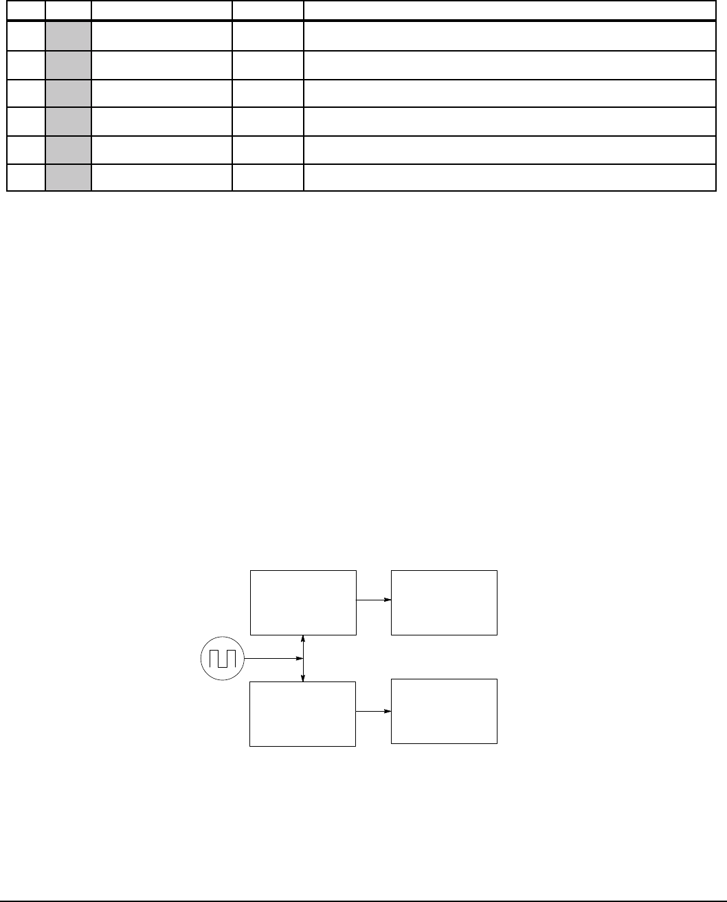
Monitor and RTC Description 12-7MN766
P# Type Name Unit Help
813 MOTOR CURRENT A Motor Current. Fault trace signal: motor instantaneous RMS current
814 MOTOR TORQUE NM Motor Torque. Fault trace signal: motor instantaneous torque
815 MOTOR VOLTS V Motor Voltage. Fault trace signal: instantaneous voltage to motor
816 MOTOR SPEED RPM Motor Speed. Fault trace signal: motor instantaneous rotor speed
817 BUS VOLTAGE V Bus Voltage. Fault trace signal: instantaneous bus voltage
818 DRIVE TEMP °C Drive Temperature. Fault trace signal: drive temperature
12.2 Real Time Clock (RTC) Overview
Action Module
Action Module parameters P3601 - 3602 set the actions to be scheduled. Action 2 takes priority over action 1 should
both be scheduled to trigger within the same second. So, if action 1 turns on output 1 and action 2 turns off output 1
and they both trigger on the same seconds tick, then output 1 will appear as though to never turn on.
As a rule, once an action is taken it is latched until it is reset by another action.
Action Module selections are shown in Table 12-2.
Figure 12-1 RTC Features
Action Module
P3601-3602
P3605-3606
P3609-3610
Message Module
P3603-3604
P3607-3608
P3611-3612
RTC
Operating Modes
Alarm System
Table 12-1 Monitor Parameters Descriptions Continued

12-8 Monitor and RTC Description MN766
Table 12-2 Actions (P3601 & 3602)
ID ACTION DESCRIPTION
0 None No action assigned. Default setting.
1 Digital Output 1 On Digital output 1 is turned on. P1501 set to RTC.
2 Digital Output 1 Off Digital output 1 is turned off. P1501set to RTC
3 Digital Output 2 On Digital output 2 is turned on. P1502 set to RTC
4 Digital Output 2 Off Digital output 2 is turned off. P1502 set to RTC
5 Relay Output 1 On Relay output 1 is turned on. P1503 set to RTC
6 Relay Output 1 Off Relay output 1 is turned off. P1503 set to RTC
7 Relay Output 2 On Relay output 2 is turned on. P1504 set to RTC
8 Relay Output 2 Off Relay output 2 is turned off. P1504 set to RTC
9 Increment P107 Increments the RTC counter parameter
10 Decrement P107 Decrements the RTC counter parameter
11 Reset P107 Resets the RTC counter parameter
12 Digital Output 1 On with Inc Performs digital I/O with P107 increment
13 Digital Output 1 Off with Inc Performs digital I/O with P107 increment
14 Digital Output 1 On with Dec Performs digital I/O with P107 decrement
15 Digital Output 1 Off with Dec Performs digital I/O with P107 decrement
16 Digital Output 1 On with Reset Performs digital I/O with P107 reset
17 Digital Output 1 Off with Reset Performs digital I/O with P107 reset
18 Relay Output 1 On with Inc Performs digital I/O with P107 increment
19 Relay Output 1 Off with Inc Performs digital IO with P107 increment
20 Relay Output 1 On with Dec Performs digital IO with P107 decrement
21 Relay Output 1 Off with Dec Performs digital IO with P107 decrement
22 Relay Output 1 On with Reset Performs digital IO with P107 reset
23 Relay Output 1 Off with Reset Performs digital IO with P107 reset
Level 1, Output Setup Block parameters P1501-P1504 select the digital/relay output functions. P107 is the RTC counter
parameter.
Message Module (P3603 - 3604)
Message Module parameters P3603 - 3604 set the messages to be scheduled. Message selections are shown in Table 12-3.
Table 12-3 RTC Message 1&2 Parameters (P3603 & P3604)
ID ACTION DESCRIPTION
0 None (default) No message active
1 Clean Filter(s) Time to do periodic cleaning of lter(s)
2 Change Filter(s) Time to change out the lter(s)
3 Apply Oil/Lubricate Apply oil and/or lubricant necessary areas of the system
4 Service Motor Check motor cables, resolver, clean motor etc.
5 Service Drive Check drive cables, clean panels and keypad display etc.
6 Service Coolant System Check coolant pressures/levels, check for leaks, top off as needed
7 Service Heating System Check for gas leaks, clean lters, blowers and connections
8 RTC Alarm Generic real-time clock alarm

Monitor and RTC Description 12-9MN766
RTC Action/Message Qualifier Parameters (P3605-P3608)
Qualier parameters shown in Table 12-4 set the interval of time of the actions and messages selected.
Table 12-4 Action/Message Qualifier Parameters (P3605 – P3608)
ID QUALIFIERS DESCRIPTION
0 Once Action/Message is scheduled once to occur on the date and time entered.
1 Second Action/Message is scheduled every second. Starting on the date and time entered and
repeated every second thereafter.
2 Minute Action/Message is scheduled every minute. Starting on the date and time entered and
repeated every minute thereafter at the same seconds into the minute specied in the start
date and time.
3 Hourly Action/Message is scheduled hourly. Starting on the date and time entered and repeated
every hour thereafter at the same minutes and seconds into the hour as specied in the start
date and time.
4 Daily Action/Message is scheduled Daily. Starting on the date and time entered and repeated every
day thereafter at the same hour, minutes and seconds specied in the start date and time. If
the day specied does not exist for that month the action/message is skipped.
5 Monthly Action/Message is scheduled monthly. Starting on the date and time entered and repeated
every month thereafter on the same day, hour, minutes and seconds specied in the start
date and time.
6 Yearly Action/Message is scheduled yearly. Starting on the date and time entered and repeated
every year thereafter on the same month, day, hour, minutes and seconds in the start date
and time.
RTC Schedule Date Parameters (P3609-P3612)
To each action and message there is an associated start date and time. For Action 1 (P3609) is used; for Action 2 (P3610)
and for Messages 1 & 2 (P3611 and P3612) are used respectively.
The internal date and time parameter format is shown in Table 12-5 .
Table 12-5 Date and Time Format (P0046)
Bits 31-26 25-22 21-17 16 15-12 11-6 5-0
Fields Year
(00-63)
Month
(1-12)
Day
(1-31)
Hour
Bit 5
Hour Bits 4-0
(0-23)
Minutes
(0-59)
Seconds
(0-59)
RTC Counter and Maximum Count Parameters (P107 and P3630)
Monitor parameter P107 is a general purpose RTC Counter that can be assigned as the target of a RTC action. This
parameter may be incremented, decremented or reset by RTC actions.
Parameter number P3630 sets the maximum for P107, so that: -P3630 ≤ P107 ≤ P3630.
The comparators A&B of the PLC Operating Mode along with the Composite Reference make use of the maximum setting of
a parameter for internal scaling of their operations.
RTC Daylight Saving Time Parameter (P3631)
P3631 has three settings: OFF, U.S.A. (United States of America) and E.U. (European Union).
Setting it to OFF disables the DST Feature. Setting it to USA enable Daylight Saving Time for US customers. Setting it to EU
enables Daylight Saving Time for Europe based countries.
Power Cycles and RTC Edit Changes
The RTC acts like an alarm clock during power cycles, edit changes and DST (Daylight Saving Time) updates. After power
up, even though an action/message would have occurred during the power down period no action/message is issued, that
action/message is lost. The next regularly scheduled action/message will trigger on the next regularly occurring clock edge
after power up.
Likewise if the RTC is advanced by some time-offset due to editing or DST action/messages may be lost. For example,
digital output 1 is scheduled to turn on at 1:00 PM daily. At 12:15:00 PM the clock is changed to 1:15:00 PM advancing it an
hour.
The output will not turn on that day since its triggering edge never occurs.
On the other hand, if the clock is receded by one hour, that is, changed at 1:30:00 PM to 12:30:00 PM then two triggers for
digital output 1 on will have been generated that day since the RTC will have passed through 1:00 PM twice. Furthermore,
if an active RTC message is not acknowledged by an operator and power is cycled that message persists after the cycle.
The operator must acknowledge an RTC message even if power is cycled. The same is NOT true for outputs. RTC controlled
digital outputs and relays are reset at power up.

12-10 Monitor and RTC Description MN766
RTC Scheduling Examples
The following table gives examples of the kinds scheduled events that may be programmed.
Table 12-6 Scheduled Events Examples
Action 1 Action 2 Message 1 Message 2
P3601 Digital Out 1 ON
P3602 Digital Out 1 OFF
P3603 Change Filters
P3604 Service Heating System
P3605 Daily
P3606 Daily
P3607 Monthly
P3608 Yearly
P3609 3-Feb-07 01:00:00
P3610 3-Feb-07 02:00:00
P3611 10-Jan-06 13:30:00
P3612 10-Jul-06 13:30:00
For this example assume the drive is in Standard Run Two Wire operating mode with digital output 1 wired to FWD. The
drive would then run daily for one hour from 1:00 AM to 2:00 AM starting February 3, 2007. The same drive is scheduled for
monthly and yearly service. Filters are to be changed on the tenth of every month after lunch starting January 10, 2006. In
addition, once a year on the 10 of July the heating system is serviced after lunch as well.
RTC messages 1&2 are not logged but must be acknowledged before they are cleared.
RTC Keypad Screens
The following templates shows how these parameters are displayed on the keypad.
Keypad Screen
Line 1 Program Parameter Block Name
Line 2 Parameter Name
Line 3 Parameter List Text1Qualier1
Line 4 Month1Day1, Year1Hour1: Minutes1: Seconds1
Line 5 A Parameter Number B
Note 1: Field is editable.
Line 1 holds the screen’s name and parameter block name. Line 2 holds a parameter name. Line 3 holds list parameter text
and the scheduling qualier. Line 4 holds the date and time. And line 5 holds the A-Function Key name, a parameter number
and the B-Function Key name.
Example one:
Keypad Screen
Line 1 Prog RTC
Line 2 ACTION 1
Line 3 Digital Output 1 ON Daily
Line 4 July 04 2006 01 : 00 : 00
Line 5 Diag C3601T1 Back
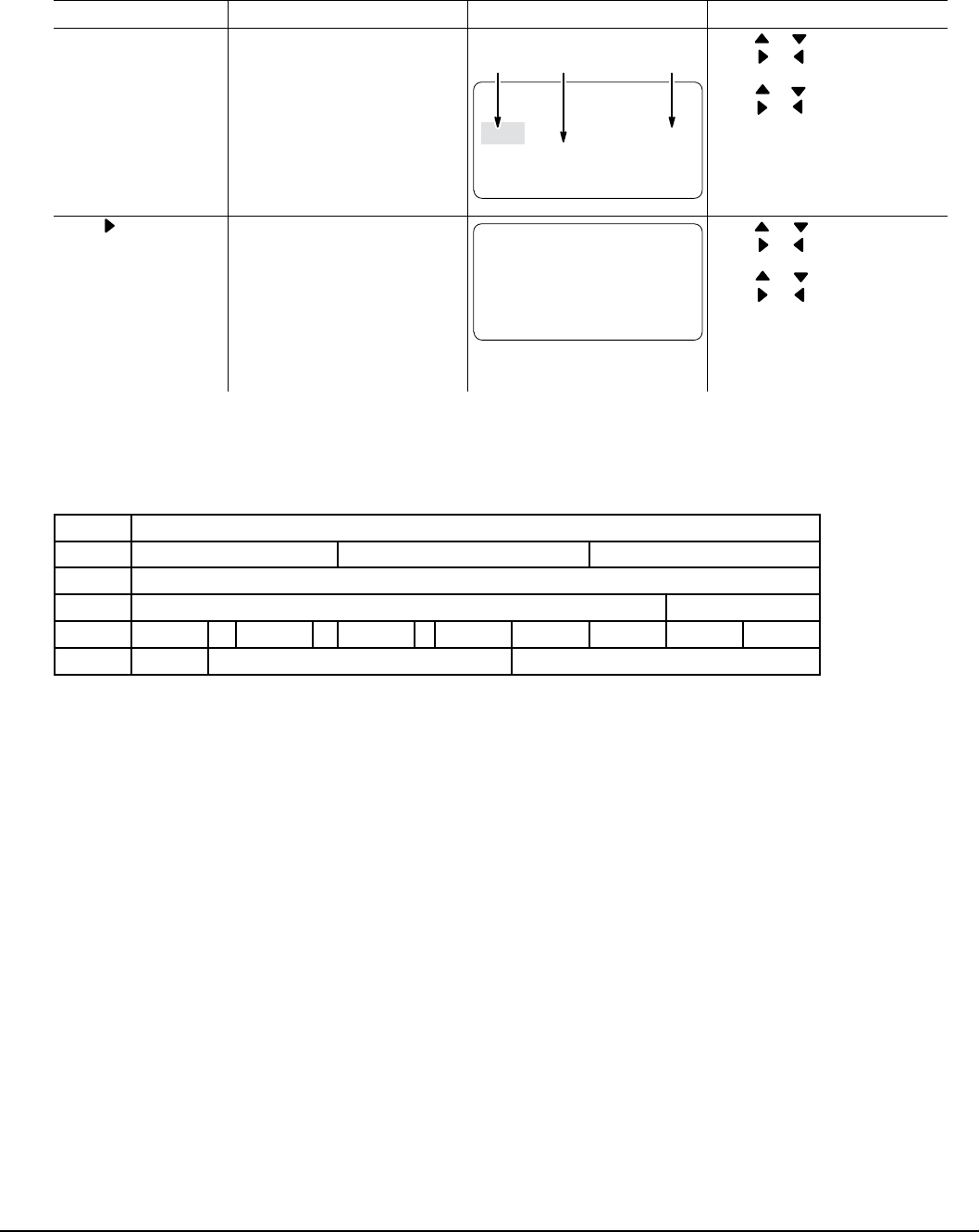
Monitor and RTC Description 12-11MN766
Action Description Display Comments
At the Level 3
Programming Menu
select RTC FEATURES
At the rst menu
“RTC ACTION 1” press ENTER.
EDIT RTC FEATURES
MAX F0201 RESET
RTC ACTION 1
None Once
Jul 04, 2006 01:00:00
RTC
Action
Action
Qualier
Action
Date & Time
Press or to change value.
Press or to move cursor to
Action Qualier.
Press or to change value.
Press or to move cursor to
Date & Time.
Press ENTER when nished and
save the new value.
See RTC chapter of this manual
for additional details.
Press to go to the
next RTC screen.
Each RTC parameter can be
changed by using the procedure
described for RTC ACTION 1.
EDIT RTC FEATURES
MAX F0201 RESET
RTC ACTION 2
None Once
Jul 04, 2006 01:00:00
Press or to change value.
Press or to move cursor to
Action Qualier.
Press or to change value.
Press or to move cursor to
Date & Time.
Press ENTER when nished and
save the new value.
See RTC chapter of this manual
for additional details.
Example two:
Keypad Screen
Line 1 Prog RTC
Line 2 MESSAGE 1
Line 3 Change Filter(s) Monthly
Line 4 Jul 17 2010 13 : 30 : 00
Line 5 Diag C3603T1 Back

12-12 Monitor and RTC Description MN766

Technical Specications A-1MN766
Appendix A
Technical Specifications
A.1 VS1SD Specifications
Table A-1 VS1SD Specifications
Input Ratings
Voltage 120 240 240 480
Voltage Range 95-130 180-264 180-264 340-528
Phase Single Phase Three Phase (single phase with derating)
Frequency 50/60Hz ±5%
Impedance 1% minimum from mains connection (3% minimum for AA frame drives)
Output Ratings
Current 3-7A @ 120/240VAC, 1PH
3-130A @ 240VAC, 3PH
2-124A @ 480VAC, 3PH
Overload Capacity Constant Torque (Heavy Duty) = 150% for 60 seconds, 175% for 3 seconds
Frequency 0-500Hz
Voltage 0 to maximum input voltage (RMS)
Resolver
Feedback
Feedback Type Resolver coupled to motor shaft
Sine/Cosine Inputs 3.02 VRMS ± 7% (maximum coupled)
Excitation (VReference) 8.85 VRMS @ 10 kHz
Transformation Ratio Dependent on excitation frequency
Positioning Output for position loop controller, simulated resolver 1024 ppr quadrature with index
Protective
Features
Servo Trip Missing control power, over current, over voltage, under voltage, motor over speed,
resolver loss, over temperature (motor or control), output shorted or grounded, motor
overload
Stall Prevention Over voltage suppression, over current suppression
External Output LED trip condition indicators, 4 assignable logic outputs, 2 assignable analog outputs
Short Circuit Phase to phase, phase to ground
Electronic Motor
Overload Meets UL508C (I2T)
Environmental
Conditions
Temperature -10°C to 45°C
Derate 3% per degree C above 45°C to 55°C maximum ambient temperature
Cooling Forced air
Enclosure NEMA 1, IP20 (-1B), NEMA 4X, IP66 (-4B) Indoor mounting only.
Altitude Sea level to 3300 Feet (1000 Meters) Derate 2% per 1000 Feet (303 Meters) above 3300
Feet
Humidity 10 to 90% RH Non-Condensing (NEMA 1); to 100% (NEMA 4X)
Shock 1G
Vibration 0.5G at 10Hz to 60Hz
Transportation
and Storage
Temperature -30°C to +65°C
Duty Cycle 1.0

A-2 Technical Specications MN766
Keypad Display
Display LCD Graphical 128x64 Pixel
Keys 14 key membrane with tactile feedback
Functions
Output status monitoring
Digital speed control
Parameter setting and display
Diagnostic and Fault log display
Motor run and jog
Local/Remote toggle
LED Indicators
Forward run command
Reverse run command
Stop command
Jog active
Remote Mount 200 feet (60.6m) maximum from control. (NEMA 4X requires purchase of separate
keypad.)
Trip Separate message and trace log for each trip, last 10 trips retained in memory
Control
Specications
Control Method Microprocessor controlled PWM output, brushless PM commutation control
Speed Setting ±5VDC, 0-5VDC ±10VDC, 0-10VDC, 4-20mA, 0-20mA; digital (keypad), Serial
Comms/USB 2.0, and Modbus RTU standard
Accel/Decel 0-3600 seconds
Motor Matching Automatic tuning to motor with manual override
PC Setup Software Mint WorkBench software available using USB2.0 port for commissioning
wizard, rmware download, parameter viewer, scope capture and cloning
Velocity Loop Bandwidth Adjustable to 180Hz (Control only)
Current Loop Bandwidth Adjustable to 1200Hz (Control only)
Maximum Output
Frequency 500Hz
Quiet PWM Frequency
Version
Full rating 5-8kHz PWM frequency
Adjustable to 16kHz with linear derating (between 8 - 16kHz) of 50% at 16kHz
(Size AA and B only)
Selectable Operating
Modes
Keypad
Standard Run 2Wire
Standard Run 3Wire
15 Preset Speeds
Fan Pump 2Wire
Fan Pump 3Wire
Process Control
3 Spd Ana 2Wire
3 Spd Ana 3Wire
Electronic Pot 2Wire
Electronic Pot 3Wire
Network
Prole Run
15 Preset Positions
Bipolar
Pulse Follower
PLC
Differential
Analog Input
Common Mode Rejection 40DB
Full Scale Range ±5VDC, ±10VDC, 4-20mA and 0-20mA
Resolution 11 bits + sign
Input Impedance 80 kOhms (Volt mode); 500 Ohms (Current mode)
Table A-1 VS1SD Specifications Continued

Technical Specications A-3MN766
Single Ended
Analog Input
Full Scale Range 0 - 10VDC
Resolution 11 bits
Input Impedance 80 kOhms
Analog Outputs
Analog Outputs 2 Assignable
Full Scale Range AOUT1 (0-5V, 0-10V, 0-20mA or 4-20mA), AOUT2 (±5V, ±10V)
Source Current 1 mA maximum (volt mode), 20mA (current mode)
Resolution 9 bits + sign
Digital Inputs
Opto-isolated Inputs 8 Assignable, 1 dedicated input (Drive Enable)
Rated Voltage 10 - 30VDC (closed contacts std)
Input Impedance 4.71kOhms
Leakage Current 10 µA maximum
Update Rate 16msec
Digital Outputs
(2 Opto Outputs)
Rated Voltage 5 to 30VDC
Maximum Current 60mA Maximum
ON Voltage Drop 2VDC Maximum
OFF Leakage Current 0.1A Maximum
Output Conditions 31 Conditions (see Output Setup Block parameter table, Chapter 7)
Digital Outputs
(2 Relay Outputs)
Rated Voltage 5 to 30VDC or 240VAC
Maximum Current 5A Maximum non-inductive
Output Conditions 31 Conditions (see Output Setup Block parameter table, Chapter 7)
Diagnostic Indications:
Current Sense Fault Regeneration (DB) Overload Following Error
Ground Fault Soft Start Fault PWR Base Fault
Instantaneous Over Current Under Voltage Logic Power Fault
Overload Ready Resolver Loss
Line Power Loss Parameter Loss
Microprocessor Failure Overload
Over temperature (Motor or Control) Overvoltage
Over speed Torque Proving
Note: All specications are subject to change without notice.
Table A-1 VS1SD Specifications Continued

Technical Specications A-4MN766
A.2 Specifications for Power Terminal Block Wiring
Table A-2 Terminal Tightening Torque Specifications
240 VAC
Catalog No.
Tightening Torque
Power TB1 B+/R1; B+;
B-; or R2 Ground
TH1 and TH2 Control J1,
J2, P3 Control J3
In-lbs N-M In-lbs N-M In-lbs N-M In-lbs N-M In-lbs N-M In-lbs N-M
VS1SD6A3-1B, 4B 12 1.36 12 1.36 12 1.36 4 0.45 2 0.23 5 0.56
VS1SD6A4-1B, 4B 12 1.36 12 1.36 12 1.36 4 0.45 2 0.23 5 0.56
VS1SD6A7-1B, 4B 12 1.36 12 1.36 12 1.36 4 0.45 2 0.23 5 0.56
VS1SD2A3-1B, 4B 12 1.36 12 1.36 12 1.36 4 0.45 2 0.23 5 0.56
VS1SD2A4-1B, 4B 12 1.36 12 1.36 12 1.36 4 0.45 2 0.23 5 0.56
VS1SD2A7-1B, 4B 12 1.36 12 1.36 12 1.36 4 0.45 2 0.23 5 0.56
VS1SD2A10-1B, 4B 12 1.36 12 1.36 12 1.36 4 0.45 2 0.23 5 0.56
VS1SD2A15-1B, 4B 12 1.36 12 1.36 12 1.36 4 0.45 2 0.23 5 0.56
VS1SD2A22-1B 35 4 35 4 35 4 4 0.45 2 0.23 5 0.56
VS1SD2A28-1B 35 4 35 4 35 4 4 0.45 2 0.23 5 0.56
VS1SD2A42-1B 35 4 35 4 35 4 4 0.45 2 0.23 5 0.56
VS1SD2A54-1B 35 4 35 4 35 4 4 0.45 2 0.23 5 0.56
VS1SD2A68-1B 35 4 35 4 35 4 4 0.45 2 0.23 5 0.56
VS1SD2A80-1B 35 4 35 4 35 4 4 0.45 2 0.23 5 0.56
VS1SD2A104-1B 180 20.3 80 9.1 50 5.6 6 0.68 2 0.23 5 0.56
VS1SD2A130-1B 180 20.3 80 9.1 50 5.6 6 0.68 2 0.23 5 0.56
VS1SD4A2-1B, 4B 12 1.36 12 1.36 12 1.36 4 0.45 2 0.23 5 0.56
VS1SD4A3-1B, 4B 12 1.36 12 1.36 12 1.36 4 0.45 2 0.23 5 0.56
VS1SD4A5-1B, 4B 12 1.36 12 1.36 12 1.36 4 0.45 2 0.23 5 0.56
VS1SD4A8-1B, 4B 12 1.36 12 1.36 12 1.36 4 0.45 2 0.23 5 0.56
VS1SD4A11-1B, 4B 12 1.36 12 1.36 12 1.36 4 0.45 2 0.23 5 0.56
VS1SD4A14-1B 12 1.36 12 1.36 12 1.36 4 0.45 2 0.23 5 0.56
VS1SD4A21-1B 12 1.36 12 1.36 12 1.36 4 0.45 2 0.23 5 0.56
VS1SD4A27-1B 12 1.36 12 1.36 12 1.36 4 0.45 2 0.23 5 0.56
VS1SD4A34-1B 35 4 35 4 35 4 4 0.45 2 0.23 5 0.56
VS1SD4A40-1B 35 4 35 4 35 4 4 0.45 2 0.23 5 0.56
VS1SD4A52-1B 35 4 35 4 35 4 4 0.45 2 0.23 5 0.56
VS1SD4A65-1B 180 20.3 80 9.1 50 5.6 4 0.45 2 0.23 5 0.56
VS1SD4A77-1B 180 20.3 80 9.1 50 5.6 6 0.68 2 0.23 50.56
VS1SD4A96-1B 180 20.3 80 9.1 50 5.6 6 0.68 2 0.23 5 0.56
VS1SD4A124-1B 180 20.3 80 9.1 50 5.6 6 0.68 2 0.23 5 0.56

Technical Specications A-5MN766
A.3 Identifying the Drive by Model Number
Each drive can be identied by its model number, as shown in Figure A-1. The model number is on the shipping label and
the drive nameplate. The model number includes the drive and any options. Drive model numbers for the VS1SD drive
are provided in Table A-3. Goods may be returned only with written notication including a BALDOR Return Authorization
Number and any return shipments must be prepaid.
Figure A-1 Drive Identification
VS1SD 4 A15 - 1 B
Voltage Code
2 = 240VAC, 3PH
4 = 480VAC, 3PH
6 = 120/240VAC, 1PH Current Rating
VS1SD Servo Control
A15 = 15 AMP
1 = NEMA1
4 = NEMA4X (indoor use only)
T = Transistor
B = Both Resistor/Transistor
A.4 Storage Guidelines
If you need to store the drive, follow these recommendations to prolong drive life and performance:
• Store the drive within an ambient temperature range of -40°C to +70°C.
• Store the drive within a relative humidity range of 0% to 90%, non-condensing.
• Do not expose the drive to a corrosive atmosphere.

A-6 Technical Specications MN766
A.5 VS1SD Drive Ratings, Model Numbers and Frame Sizes
Similar VS1SD drive sizes are grouped into frame sizes to simplify re-ordering and dimensioning. Refer to Table A-5 for the
dimensions of each frame size.
Table A-3 provides VS1SD drive ratings, model numbers and frame sizes.
Table A-3 Drive Ratings, Model Numbers and Frame Sizes
Catalog No.
Input Volt Size
Quiet 8.0kHz PWM Standard 2.5kHz PWM
Constant Torque Constant Torque
Input Amp Output Input Amp Output
IC IP IC IP
VS1SD6A3-1B, 4B 120 AA 10 3.2 6.4 12 4.2 7.4
240 AA 4.8 3.2 6.4 6.3 4.2 7.4
VS1SD6A4-1B, 4B 120 AA 12 4.2 8.4 20 6.8 11.9
240 AA 6.3 4.2 8.4 10.2 6.8 11.9
VS1SD6A7-1B, 4B 120 AA 20 6.8 13.6 30 9.6 16.8
240 AA 10.2 6.8 13.6 14.4 9.6 16.8
VS1SD2A3-1B, 4B 240 AA 3.2 3.2 6.4 4.2 4.2 7.4
VS1SD2A4-1B, 4B 240 AA 4.2 4.2 8.4 6.8 6.8 11.9
VS1SD2A7-1B, 4B 240 AA 6.8 6.8 13.6 9.6 9.6 16.8
VS1SD2A10-1B, 4B 240 AA 9.6 9.6 19.2 15.2 15.2 26.6
VS1SD2A15-1B, 4B 240 AA 15.2 15.2 30.4 22 22 38.5
VS1SD2A22-1B 240 B 22 22 44 28 28 49
VS1SD2A28-1B 240 B 28 28 56 42 42 74
VS1SD2A42-1B 240 B 42 42 84 54 55 94.5
VS1SD2A54-1B 240 C 54 54 94.5 68 68 119
VS1SD2A68-1B 240 C 68 68 119 80 80 140
VS1SD2A80-1B 240 C 80 80 140 104 104 182
VS1SD2A104-1B 240 D 104 104 182 130 130 228
VS1SD2A130-1B 240 D 130 130 228 154 154 270
VS1SD4A2-1B, 4B 480 AA 2.1 2.1 4.2 3.4 3.4 6.0
VS1SD4A3-1B, 4B 480 AA 3.4 3.4 6.8 4.8 4.8 8.4
VS1SD4A5-1B, 4B 480 AA 4.8 4.8 9.6 7.6 7.6 13.3
VS1SD4A8-1B, 4B 480 AA 7.6 7.6 15.2 11.0 11.0 19.3
VS1SD4A11-1B, 4B 480 AA 11 11 22 14 14 24.5
VS1SD4A14-1B 480 B 14 14 28 21 21 36.8
VS1SD4A21-1B 480 B 21 21 42 27 27 47.3
VS1SD4A27-1B 480 B 27 27 54 34 34 59.5
VS1SD4A34-1B 480 C 34 34 60 40 40 70
VS1SD4A40-1B 480 C 40 40 70 52 52 91
VS1SD4A52-1B 480 C 52 52 91 65 65 114
VS1SD4A65-1B 480 D 65 65 114 77 77 135
VS1SD4A77-1B 480 D 77 77 135 96 96 168
VS1SD4A96-1B 480 D 96 96 168 124 124 217
VS1SD4A124-1B 480 D 124 124 217 156 156 273

Technical Specications A-7MN766
A.6 VS1SD Terminal Wire Gauge Specification
Table A-4 species the wire gauge allowed for each terminal in the drives.
Table A-4 Terminal Wire Gauge Specification
Catalog Number
Power
AWG
Min-Max
B+/R1, R2 & B-
AWG
Min-Max
Ground
AWG
Min-Max
TH1/TH2
AWG
Min-Max
Control J1, J2 & P3
AWG
Min-Max
Control J3
AWG
Min-Max
VS1SD6A3-1B, 4B 18-6 18-6 18-6 24-14 30-14 28-12
VS1SD6A4-1B, 4B 18-6 18-6 18-6 24-14 30-14 28-12
VS1SD6A7-1B, 4B 18-6 18-6 18-6 24-14 30-14 28-12
VS1SD2A3-1B, 4B 18-6 18-6 18-6 24-14 30-14 28-12
VS1SD2A4-1B, 4B 18-6 18-6 18-6 24-14 30-14 28-12
VS1SD2A7-1B, 4B 18-6 18-6 18-6 24-14 30-14 28-12
VS1SD2A10-1B, 4B 18-6 18-6 18-6 24-14 30-14 28-12
VS1SD2A15-1B, 4B 18-6 18-6 18-6 24-14 30-14 28-12
VS1SD2A22-1B 18-6 18-6 18-6 24-14 30-14 28-12
VS1SD2A28-1B 18-6 18-6 18-6 24-14 30-14 28-12
VS1SD2A42-1B 18-6 18-6 18-6 24-14 30-14 28-12
VS1SD2A54-1B 8-1 8-1 8-1 24-14 30-14 28-12
VS1SD2A68-1B 8-1 8-1 8-1 24-14 30-14 28-12
VS1SD2A80-1B 8-1 8-1 8-1 24-14 30-14 28-12
VS1SD2A104-1B 14-3/0 14-2/0 (4) 14-2/0 26-10 30-14 28-12
VS1SD2A130-1B 14-3/0 14-2/0 (4) 14-2/0 26-10 30-14 28-12
VS1SD4A2-1B, 4B 18-6 18-6 18-6 24-14 30-14 28-12
VS1SD4A3-1B, 4B 18-6 18-6 18-6 24-14 30-14 28-12
VS1SD4A5-1B, 4B 18-6 18-6 18-6 24-14 30-14 28-12
VS1SD4A8-1B, 4B 18-6 18-6 18-6 24-14 30-14 28-12
VS1SD4A11-1B, 4B 18-6 18-6 18-6 24-14 30-14 28-12
VS1SD4A14-1B 18-6 18-6 18-6 24-14 30-14 28-12
VS1SD4A21-1B 18-6 18-6 18-6 24-14 30-14 28-12
VS1SD4A27-1B 18-6 18-6 18-6 24-14 30-14 28-12
VS1SD4A34-1B 8-1 8-1 8-1 24-14 30-14 28-12
VS1SD4A40-1B 8-1 8-1 8-1 24-14 30-14 28-12
VS1SD4A52-1B 8-1 8-1 8-1 24-14 30-14 28-12
VS1SD4A65-1B 14-3/0 14-2/0 (4) 14-2/0 26-10 30-14 28-12
VS1SD4A77-1B 14-3/0 14-2/0 (4) 14-2/0 26-10 30-14 28-12
VS1SD4A96-1B 14-3/0 14-2/0 (4) 14-2/0 26-10 30-14 28-12
VS1SD4A124-1B 14-3/0 14-2/0 (4) 14-2/0 26-10 30-14 28-12
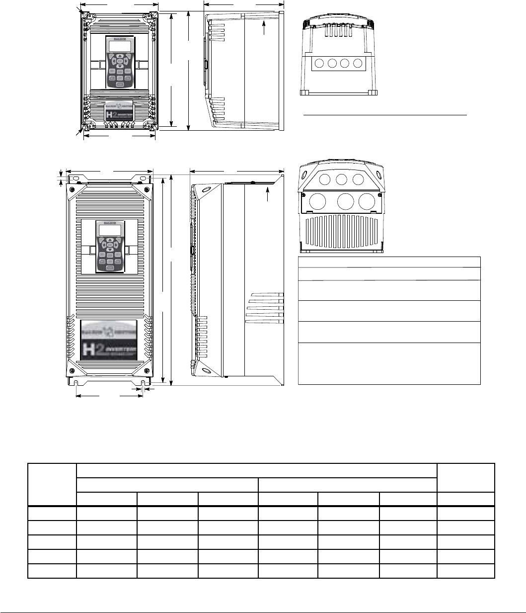
A-8 Technical Specications MN766
A.7 Mounting Dimensions for the VS1SD Drive
Figure A-2 Drive Dimensions
Size # Holes Diameter inches (mm)
AA 4 0.87 (22)
OM2000A01
Size # Holes Diameter inches (mm)
3 1.115 (28.3)
3 1.362 (34.6)
3 1.115 (28.3)
3 1.68 (42)
2 2.47 (62.7)
1 1.362 (34.6)
1 0.5 (12.7)
B
C
D
Size B, C, and D OM2000A00, 02
Size AA
Exhaust
A
A1
BC
0.25
(6.35)
dia.
0.25
(6.35)
dia.
B1
0.35
(8.9)
BC
Exhaust
A
A1
B1
0.35 (8.9)
CONDUIT INFORMATION
3 1.109 (28.2)
2 1.375 (34.9)
B-N4X
3 1.115 (28.3)
Table A-5 Mounting Dimensions
Size
Dimensions inches (mm) Weight
Outside Mounting
Height (A) Width (B) Depth (C) Height (A1) Width (B1) Width (B2) lb (kg)
AA 12.27 (311) 7.97 (202) 8.21 (208) 11.75 (298) 7.38 (187) - 20 (9.1)
B 18.00 (457) 9.10 (231) 9.75 (248) 17.25 (438) 7.00 (178) - 30 (13.6)
B-N4X 17.50 (444) 10.73 (273) 10.47 (266) 16.50 (419) 7.88 (200) 9.76 (248) 32 (14.5)
C 22.00 (559) 9.10 (231) 9.75 (248) 21.25 (540) 7.00 (178) - 60 (27.2)
D 28.00 (711) 11.50 (292) 13.00 (330) 27.25 (692) 9.50 (241) - 120 (54.4)

Parameter Tables B-1MN766
Appendix B
Parameter Tables
B.1 Level 1 Parameters (Advanced Prog, Level 1 Blocks)
All parameters displayed in this appendix are Parameter Table 1 (T1) factory set values. Setting parameter P2103 to yes will
load these values into all four parameter tables. Level 1 & 2 parameters are secured by security access code (P2107).
Table B-1 Parameter Block Values Level 1
Block Title Parameter P# Adjustable Range Factory User Setting
PRESET
SPEEDS PRESET SPEED 1 1001 0 - MAX Speed 30
PRESET SPEED 2 1002 0 - MAX Speed 60
PRESET SPEED 3 1003 0 - MAX Speed 90
PRESET SPEED 4 1004 0 - MAX Speed 120
PRESET SPEED 5 1005 0 - MAX Speed 150
PRESET SPEED 6 1006 0 - MAX Speed 180
PRESET SPEED 7 1007 0 - MAX Speed 210
PRESET SPEED 8 1008 0 - MAX Speed 240
PRESET SPEED 9 1009 0 - MAX Speed 270
PRESET SPEED 10 1010 0 - MAX Speed 300
PRESET SPEED 11 1011 0 - MAX Speed 330
PRESET SPEED 12 1012 0 - MAX Speed 360
PRESET SPEED 13 1013 0 - MAX Speed 390
PRESET SPEED 14 1014 0 - MAX Speed 420
PRESET SPEED 15 1015 0 - MAX Speed 450
RAMP RATES ACCEL TIME 1 1101 0.0 to 3600.0 Seconds 3.0
START S-ACC 1 1102 0.0 - 100.0% 0.0
END S-ACC 1 1103 0.0 - 100.0% 0.0
DECEL TIME 1 1104 0.0 to 3600.0 Seconds 3.0
START S-DEC 1 1105 0.0 - 100.0% 0.0
END S-DEC 1 1106 0.0 - 100.0% 0.0
ACCEL TIME 2 1107 0.0 to 3600.0 Seconds 3.0
START S-ACC 2 1108 0.0 - 100.0% 0.0
END S-ACC 2 1109 0.0 - 100.0% 0.0
DECEL TIME 2 1110 0.0 to 3600.0 Seconds 3.0
START S-DEC 2 1111 0.0 - 100.0% 0.0
END S-DEC 2 1112 0.0 - 100.0% 0.0
PL DEC TIME 1113 0.0 to 3600.0 Seconds 1.0
JOG
SETTINGS JOG SPEED 1201 0 - MAX Speed 210
JOG ACCEL TIME 1202 0.0 to 3600.0 Seconds 10.0
JOG START S-ACC 1203 0.0 - 100.0% 0.0
JOG END S-ACC 1204 0.0 - 100.0% 0.0
JOG DECEL TIME 1205 0.0 to 3600.0 Seconds 10.0
JOG START S-DEC 1206 0.0 - 100.0% 0.0
JOG END S-DEC 1207 0.0 - 100.0% 0.0
JOG FORWARD 1209 0-Off
1-On 1
JOG REVERSE 1210 0-Off
1-On 1

B-2 Parameter Tables MN766
Block Title Parameter P# Adjustable Range Factory User Setting
KEYPAD
SETUP STOP KEY 1301 0-Off (Keypad Stop inactive in remote)
1-On (Keypad Stop active in remote) 1
STOP MODE 1302 0-Regen
1-Coast 0
RUN FORWARD 1303 0-Off
1-On 1
RUN REVERSE 1304 0-Off
1-On 1
SWITCH ON FLY 1305 0-Off
1-On 0
LOCAL HOT START 1306 0-Off
1-On 0
SPEED INCREMENT 1307 0 - 2500RPM or 0.01 to 60Hz 30
INIT LOCAL SPEED 1308 0-Zero
1-Last Speed
2-Set Speed
0
SET SPEED 1309 0 - MAX Speed RPM 30
PARAMS TO KEYPAD 1310 0-No
1-Yes 0
DOWNLOAD SELECT 1311 0-All
1-Motor
2-Other
0
KEYPAD TO PARAMS 1312 0-No
1-Yes 0
KEYPAD CONTRAST 1313 0 - 100% (0=dimmest, 100=brightest) 50
BACKLIGHT 1314 0-Off
1-On 1
LOC TORQUE MODE 1315 0-Off
1-On 0
LOC TORQUE REF 1316 -100.00 to 100.00% 0.00
INPUT SETUP OPERATING MODE 1401 0-Keypad
1-Standard Run 2Wire
2-Standard Run 3Wire
3-15 Preset Speeds
4- Fan & Pump 2Wire
5- Fan & Pump 3Wire
6-Process Control
7-3Spd Ana 2Wire
8-3Spd Ana 3Wire
9-E-Pot 2Wire
10-E-Pot 3Wire
11-Network
12-Prole Run
13-15 Preset Positions
14-Bipolar
15-Pulse Follower
16-PLC
0
COMMAND SOURCE 1402 0-None
1-Analog In1
2-Analog In2
3-Keypad
4-Network
5-Composite Ref
6-Opt1 Ana In1
7-Opt1 Ana In2
8-Opt2 Ana In1
9-Opt2 Ana In2
10-EXB Pulse Fol
1
Table B-1 Parameter Block Values Level 1 (Cont.)

Parameter Tables B-3MN766
Block Title Parameter P# Adjustable Range Factory User Setting
INPUT SETUP
(Continued) ANA IN1 TYPE 1403 0-None
1-Potentiometer 1
ANA IN1 INVERT 1404 0-Off
1-On 0
ANA IN1 GAIN 1405 0.0% to 300.0% 100.0
ANA IN1 OFFSET 1406 -100.0% to 100.0% 0.0
ANA IN1 FILTER 1407 0 (No Filter) to 6 (Max Filter) 0
ANA IN2 TYPE 1408 0-None
1-(-10V to +10V)
2-(-5V to +5V)
3-(4 to 20mA)
4-(0 to 20mA)
5-(0 to 10V)
6-(0 to 5V)
1
ANA IN2 INVERT 1409 0-Off
1-On 0
ANA IN2 GAIN 1410 0.0% to 300.0% 100.0
ANA IN2 OFFSET 1411 -100.0% to 100.0% 0.0
ANA IN2 D.BAND 1412 0.0% to 75.0% 0.0
ANA IN2 FILTER 1413 0 (No Filter) to 6 (Max Filter) 0
EXT. CUR LIMIT 1414 0-Off
1-On 0
CURR LMT SOURCE 1415 0-None
1-Analog In1
2-Analog In2
3-Keypad
4-Composite Ref
5-Opt1 Ana In1
6-Opt1 Ana In2
7-Opt2 Ana In1
8-Opt2 Ana In2
9-Network
0
SLEEP MODE 1416 0-Off
1-On 0
CMD SLEEP BAND 1417 0.00 to 100.00% 0.00
TORQUE FF SRC 1418 0-None
1-Analog In1
2-Analog In2
3-Keypad
4-Composite Ref
5-Opt1 Ana In1
6-Opt1 Ana In2
7-Opt2 Ana In1
8-Opt2 Ana In2
0
Table B-1 Parameter Block Values Level 1 (Cont.)

B-4 Parameter Tables MN766
Block Title Parameter P# Adjustable Range Factory User Setting
OUTPUT
SETUP DIGITAL OUTPUT 1 1501 0-Drive Run
1-Drive Ready
2-Drive On
3-Drive Stopped
4-Jog
5-Accelerate
6-Constant Speed
7-Decelerate
8-At Zero Speed
9-At Speed
10-At Set Speed
11-Current Overload
12-Current Underload
13-I2T Overload
14-Keypad Control
15-Dynamic Brake
16-Foldback
17-Fault
18-Alarm
19-Command Forward
20-Command Reverse
21-Motor Forward
22-Motor Reverse
23-Process Error
24-Network
25-At Position
26-In Motion
27-PLC
28-RTC
29-Powered Up
1
DIGITAL OUTPUT 2 1502 8
RELAY OUTPUT 1 1503 9
RELAY OUTPUT 2 1504 17
ZERO SPD SET PT 1505 0 - MAX Speed 180
AT SPD BAND 1506 0 - 100 RPM 60
SET SPEED POINT 1507 0 - MAX Speed RPM 1800
OVERLOAD SET PT 1508 0.0 - 200.0% 150.0
UNDERLOAD SET PT 1509 0.0 - 200.0% 50.0
ANA OUT1 TYPE 1510 0-(0 to +10V)
1-(0 to 5V)
2-(4mA to 20mA)
3-(0mA to 20mA)
0
Table B-1 Parameter Block Values Level 1 (Cont.)

Parameter Tables B-5MN766
Block Title Parameter P# Adjustable Range Factory User Setting
OUTPUT
SETUP
(Continued)
ANA OUT1 SIGNAL 1511 0-Speed Ref
1-Speed Demand
2-ACC/DEC
3-Motor Current
4-Mag Current
5-Mag Curr Cmd
6-Load Current
7-Load Curr Cmd
8-Power Factor
9-Ph1 Current
10-Ph2 Current
11-Ph3 Current
12-Motor Voltage
13-VD Demand
14-VQ Demand
15-Bus Voltage
16-Abs Torque
17-Torque
18-Control Temp
19-Analog In1
20-Analog In2
21-Opt1 Ana In1
22-Opt1 Ana In2
23-Opt2 Ana In1
24-Opt2 Ana In2
25-Proc Feedforward
26-Proc Feedback
27-Proc Setpoint
28-Electric Angle
29-Abs Speed
30-Velocity
31-Network
32-Composite Ref
33-Power (kW)
34-Calibrate
29
ANA OUT1 GAIN 1512 0.0 - 200.0% 100.0
ANA OUT2 TYPE 1513 0-(+/-5V)
1-(+/-10V) 1
Table B-1 Parameter Block Values Level 1 (Cont.)

B-6 Parameter Tables MN766
Block Title Parameter P# Adjustable Range Factory User Setting
OUTPUT
SETUP
(Continued)
ANA OUT2 SIGNAL 1514 0-Speed Ref
1-Speed Demand
2-ACC/DEC
3-Motor Current
4-Mag Current
5-Mag Curr Cmd
6-Load Current
7-Load Curr Cmd
8-Power Factor
9-Ph1 Current
10-Ph2 Current
11-Ph3 Current
12-Motor Voltage
13-VD Demand
14-VQ Demand
15-Bus Voltage
16-Abs Torque
17-Torque
18-Control Temp
19-Analog In1
20-Analog In2
21-Opt1 Ana In1
22-Opt1 Ana In2
23-Opt2 Ana In1
24-Opt2 Ana In2
25-Proc Feedforward
26-Proc Feedback
27-Proc Setpoint
28-Electric Angle
29-Abs Speed
30-Velocity
31-Network
32-Composite Ref
33-Power (kW)
34-Calibrate
3
ANA OUT2 GAIN 1515 0.0 - 200.0% 100.0
CAL ANA OUT 1516 -100.0% to 100.0% 0.0
AT POS BAND (for Feedback
Device Only) 1517 1 to 4095 Counts 10
MOTOR
CONTROL CONTROL TYPE 1601 3-AC Servo (only value selection) 3
FEEDBACK ALIGN 1631 0-Forward
1-Reverse 0
FEEDBACK FILTER 1632 0 - 7 4
CURR PROP GAIN 1633 0 - 150 20
CURR INT GAIN 1634 0.0 - 3000.00Hz 150.00
SPEED PROP GAIN 1635 0.0 - 1000.00 1.000
SPEED INT GAIN 1636 0.00 - 1000.00Hz 1.000
SPEED DIFF GAIN 1637 0.00 - 1.00000 0.00000
POSITION GAIN 1638 0.0 - 1000.0 8.0
A.S. PROP GAIN 1639 0.0 - 255.0 10.0
A.S. INT GAIN 1640 0.00 - 150.00Hz 50.0
FEEDBACK OFFSET
(for Resolver Feedback Only) 1671 0.00 to 360.00° 46.60°
STATOR L 1672 0.0 to 1000.0mH CALC
STATOR R 1673 0.0 to 1000.0Ω CALC
VOLTAGE CONSTANT 1674 0.0 to 1500.0V/kRPM CALC
Table B-1 Parameter Block Values Level 1 (Cont.)

Parameter Tables B-7MN766
Block Title Parameter P# Adjustable Range Factory User Setting
COMMUNI-
CATION BAUD RATE 1701 0-9600
1-19200
2-38400
3-56000
4-115200
1
PARITY 1702 0-None
1-Odd
2-Even
0
STOP BITS 1703 0-One
1-Two 0
DRIVE ADDRESS 1704 1 - 247 1
OPT CARD RESET 1705 0-Off
1-Slot 1
2-Slot 2
3-Slots 1 & 2
0
SECURITY DEFAULT 1706 0-No
1-Yes 0
BROWSER USER ID 1707 ASCII user ID for the Ethernet Web
Browser Option Board if installed. baldor
BROWSER PASSWORD 1709 Password for the Ethernet Web Browser
Option Board if installed. baldor
CUSTOM
MOTOR ALIGNMENT CURRENT 1821 10.0 to 100.0% 50.00%
ALIGNMENT TIME 1822 0.0 to 60.0 seconds 5.0
Table B-1 Parameter Block Values Level 1 (Cont.)

B-8 Parameter Tables MN766
B.2 Level 2 Parameters (Advanced Prog, Level 2 Blocks)
Table B-2 Parameter Block Values Level 2
Block Title Parameter P# Adjustable Range Factory User Setting
DRIVE LIMITS OPERATING ZONE 2001 0-Std Const Torq
1-Std Var Torq
2-Quiet Const Torq
3-Quiet Var Torq
2
MIN OUTPUT SPEED 2002 0 - MAX Speed RPM 0
MAX OUTPUT SPEED 2003 500 - 15,000RPM 2500
PWM FREQUENCY 2004 1000 - 16000Hz 8000
CURR RATE LIMIT 2005 0.000 - 10.000 seconds 0.004
PEAK CURR LEVEL 2006 0.000 – Peak Rated Current CALC
REGEN TORQ LIMIT 2007 0.0 - 200% CALC
DRIVE
CONFIGURE SPEED UNITS 2101 0-Hz
1-RPM 1
LANGUAGE SELECT 2102 0-English
1-Other (Spanish, German, Italian,
French, or Portuguese)
0
FACTORY SETTINGS 2103 0-No
1-Yes 0
SECURITY 2105 0-Off
1-Local
2-Network
3-Total
0
ACCESS TIMEOUT 2106 1.0 - 600.0 seconds 5.0
ACCESS CODE 2107 0 - 9999 9999
ACTIVE PARAM TBL 0052 0-T1
1-T2
2-T3
3-T4
0
CLEAR FAULT LOG 2108 0-No
1-Yes 0
POWER INPUT 2110 0-Single Phase
1-Common Bus Slave
2-Three Phase
3-Common Bus Master
2
EXECUTE MACRO 2112 0-No
1-M1
2-M2
3-M3
4-M4
5-M5
0
UNDO MACRO 2113 0-No
1-Yes 0
TORQ ENABLE SEQ 2114 0-Torque On Enable
1-Torque On Command 0
DRIVE
PROTECT EXTERNAL TRIP 2201 0-Off
1-On 0
FOLLOWING ERROR 2202 0-Off
1-On 0
FEEDBACK LOSS 2204 0-Off
1-On 0
OVERLOAD 2206 0-Fault
1-Foldback
2-Hold
0

Parameter Tables B-9MN766
Block Title Parameter P# Adjustable Range Factory User Setting
DRIVE
PROTECT
(Continued)
OVER TEMPERATURE 2210 0-Derate
1-Fault 1
POWER DOWN OPTIONS 2211 0-Fault
1-Ride Through 0
CNTRL STP BUS LBL 2212 200 to 800V CACL
CNTL STOP DELAY 2213 0-3600.0 Seconds 1
Kp RIDE THROUGH 2214 0-1000.0000 10
Ki RIDE THROUGH 2215 0-1000.0000 0
MISCELLA-
NEOUS AUTO RESTART 2301 0-Manual
1-At Powerup
2-After Fault
3-Both
1
RESTARTS/HOUR 2302 0 - 10 3
RESTART DELAY 2303 0 - 3600 seconds 3
PWM TECHNIQUE 2304 0-Space Vector
1-Sine Triangle 1
COST OF ENERGY 2305 0.00 - 99999.00$/KWH 0.10
RESET ENERGY 2306 0-No
1-Yes 0
HOMING SPEED 2307 0 - MAX Speed RPM 90
HOMING OFFSET 2308 -9999 to 20000 counts 1024
FILTER TYPE 2309 0-None
1-Low Pass
2-High Pass
3-Notch
0
FILTER SOURCE 2310 0-None
1-Raw Speed
2-Torque
3-Analog In1
4-Analog In2
5-Composite Ref
6-Opt1 Ana In1
7-Opt1 Ana In2
8-Opt2 Ana In1
9-Opt2 Ana In2
0
FILTER DEST 2311 0-None
1-Speed Loop
2-Torque Loop
3-Speed FFWD
4-Process FBK
5-Process FFWD
6-Process SP
0
FILTER CUTOFF 2312 0.00 - 1000.00Hz 0.00
NOTCH CNTR FREQ 2313 0.00 - 500.00Hz 0.00
NOTCH BAND 2314 0.00 - 200.00Hz 0.00
MOTOR DATA MOTOR RATED AMPS 2402 0 - MAX AMPS CALC
MOTOR RATED SPD 2403 10 - 30000RPM 2500
ENCODER COUNTS 2408 50 - 20000 Use default
setting
only
FEEDBACK SOURCE 2409 0-None
1-Option Slot1
2-Option Slot2
3-Daughter FDBK
Use default
setting
only
Table B-2 Parameter Block Values Level 2 (Cont.)

B-10 Parameter Tables MN766
Block Title Parameter P# Adjustable Range Factory User Setting
MOTOR DATA
(Continued) ENCODER TYPE 2410 0-Single
1-Differential Use default
setting
only
RESOLVER SPEED 2411 0 - 10 1
MOTOR POLE PAIRS 2413 1 - 100 2
CALC MOTOR MODEL 2414 0-No
1-Yes 0
REVERSE ROTATION 2415 0-Off
1-On 0
BRAKE ADJUST RESISTOR OHMS 2501 0 - 255.0Ohms CALC
RESISTOR WATTS 2502 0 - 999999Watts CALC
RESISTOR TTC 2503 20 - 3600 seconds CALC
PROCESS
CONTROL PROCESS TYPE 2601 0-None
1-Forward Acting
2-Reverse Acting
0
SETPOINT ADJ LIM 2602 0.0 - 100.0% 100.0%
PROC FEEDBACK 2603 0-None
1-Setpoint Cmd
2-Local Speed Ref
3-Analog In1
4-Analog In2
5-Network
6-Composite Ref
7-Opt1 Ana In1
8-Opt1 Ana In2
9-Opt2 Ana In1
10-Opt2 Ana In2
0
SETPOINT SOURCE 2604 0-None
1-Setpoint Cmd
2-Local Speed Ref
3-Analog In1
4-Analog In2
5-Network
6-Composite Ref
7-Opt1 Ana In1
8-Opt1 Ana In2
9-Opt2 Ana In1
10-Opt2 Ana In2
0
SETPOINT COMMAND 2605 -100.0% to +100.0% 0.0
PROC ERR TOL 2606 0.0 - 100.0% 10.0
PROC PROP GAIN 2607 0.0000 - 1000.0000 1.0000
PROC INTG GAIN 2608 0.0000 - 1000.0000 0.0000
PROC INTG CLAMP 2609 0.0 - 100.0% 100.0
PROC DIFF GAIN 2610 0.0000 - 1000.0000 0.0000
PROFILE ADJUST 2611 0-Off
1-On 0
PROFILE ADJ BAND 2612 0.0 - 200.0% 50.0
PROC SLEEP BAND 2613 0.0 - 100.0% 0.0
PROC OUT FILTER 2614 0.0 - 100.0 seconds 0.00
PROC OUT OFFSET 2615 -100.0 - 100.0% 0.0
PROC OUT GAIN 2616 0.0 - 200.0% 100.0
Table B-2 Parameter Block Values Level 2 (Cont.)

Parameter Tables B-11MN766
Block Title Parameter P# Adjustable Range Factory User Setting
AUTO TUNE ANA OFFSET TRIM 2901 0-No
1-Yes 0
ONE-STEP TUNING 2902 0-No
1-Yes 0
CUR. LOOP TUNE 2906 0-No
1-Yes 0
FLUX CUR. TUNE 2907 0-No
1-Yes 0
FEEDBACK TEST 2908 0-No
1-Yes 0
SPEED LOOP TUNE 2910 0-No
1-Yes 0
Table B-2 Parameter Block Values Level 2 (Cont.)

B-12 Parameter Tables MN766
B.3 Level 3 Parameters (Advanced Prog, Level 3 Blocks)
Table B-3 Parameter Block Values Level 3
Block Title Parameter P# Adjustable Range Factory User Setting
PROFILE RUN NUMBER OF CYCLES 3001 0 - 255 0
PR RESTART MODE 3002 0-Restart
1-Continue 0
SPEED CURVE 1 3003 0-FWD-Group1
1-REV-Group1
2-FWD-Group2
3-REV-Group2
0
PROFILE TIME 1 3004 0 - 99999.00 seconds 0.00
SPEED CURVE 2 3005 0-FWD-Group1
1-REV-Group1
2-FWD-Group2
3-REV-Group2
0
PROFILE TIME 2 3006 0 - 99999.00 seconds 0.00
SPEED CURVE 3 3007 0-FWD-Group1
1-REV-Group1
2-FWD-Group2
3-REV-Group2
0
PROFILE TIME 3 3008 0 - 99999.00 seconds 0.00
SPEED CURVE 4 3009 0-FWD-Group1
1-REV-Group1
2-FWD-Group2
3-REV-Group2
0
PROFILE TIME 4 3010 0 - 99999.00 seconds 0.00
SPEED CURVE 5 3011 0-FWD-Group1
1-REV-Group1
2-FWD-Group2
3-REV-Group2
0
PROFILE TIME 5 3012 0 - 99999.00 seconds 0.00
SPEED CURVE 6 3013 0-FWD-Group1
1-REV-Group1
2-FWD-Group2
3-REV-Group2
0
PROFILE TIME 6 3014 0 - 99999.00 seconds 0.00
SPEED CURVE 7 3015 0-FWD-Group1
1-REV-Group1
2-FWD-Group2
3-REV-Group2
0
PROFILE TIME 7 3016 0 - 99999.00 seconds 0.00
PULSE
FOLLOWER ASTER PPR 3101 50 - 20000 counts 1024
INPUT VOLTS 3102 0-5V
1-12V 0
INPUT TYPE 3103 0-None
1-Quadrature
2-Speed
1
TRACK MODE 3104 0-Velocity Following
1-Position Following
2-Position Sync
0
INCREMENT STEP 3105 1 - 1024 1
RX RATIO INPUT 3106 1 - 1048576 1024
RX RATIO OUT 1 3107 1 - 1048576 1024

Parameter Tables B-13MN766
Block Title Parameter P# Adjustable Range Factory User Setting
PULSE
FOLLOWER
(Continued)
RX RATIO OUT 2 3108 1 - 1048576 1024
RX RATIO OUT 3 3109 1 - 1048576 1024
RX RATIO OUT 4 3110 1 - 1048576 1024
OUTPUT TYPE 3111 0-Quadrature
1-Speed 0
TX RATIO INPUT 3112 1 - 1048576 1024
TX RATIO OUTPUT 3113 1 - 1048576 1024
SAVE RX OUT RATIO 3114 0 - 1 0
CUSTOM
UNITS MAX DEC PLACES 3201 0 - 5 1
VALUE AT SPEED 3202 0.0 - 9999999.0 (X.X: YRPM) 0.0: 0RPM
UNITS OF MEASURE 3203 ASCII & Graphic Characters Cust
PRESET
POSITIONS [2] PRESET REVs 2 3301 (-49999 to 49999) : (-4095 to 4095) 1:0000
PRESET REVs 3 3302 (-49999 to 49999) : (-4095 to 4095) 2:0000
PRESET REVs 4 3303 (-49999 to 49999) : (-4095 to 4095) 3:0000
PRESET REVs 5 3304 (-49999 to 49999) : (-4095 to 4095) 4:0000
PRESET REVs 6 3305 (-49999 to 49999) : (-4095 to 4095) 5:0000
PRESET REVs 7 3306 (-49999 to 49999) : (-4095 to 4095) 6:0000
PRESET REVs 8 3307 (-49999 to 49999) : (-4095 to 4095) 7:0000
PRESET REVs 9 3308 (-49999 to 49999) : (-4095 to 4095) 8:0000
PRESET REVs 10 3309 (-49999 to 49999) : (-4095 to 4095) 9:0000
PRESET REVs 11 3310 (-49999 to 49999) : (-4095 to 4095) 10:0000
PRESET REVs 12 3311 (-49999 to 49999) : (-4095 to 4095) 11:0000
PRESET REVs 13 3312 (-49999 to 49999) : (-4095 to 4095) 12:0000
PRESET REVs 14 3313 (-49999 to 49999) : (-4095 to 4095) 13:0000
PRESET REVs 15 3314 (-49999 to 49999) : (-4095 to 4095) 14:0000
POS PROP GAIN 3329 000.0000 to 100.0000 000.1000
POS INTG GAIN 3330 000.0000 to 100.0000 000.0000
POS INTG CLAMP 3331 000.0 to 100.0% 10.0
POS DIFF GAIN 3332 000.0000 to 100.0000 0.0000
POS MAX ADJUST 3333 000.0 to 100.0% 10.0
POS FILTER 3334 0.1 to 500.0Hz 10.0
[2] The adjustable range of each Preset Position parameter is x:y where:
x= -49999 to 49999 REV
y= -4095 to 4095 counts
Note: In Mint WorkBench, each position is displayed as individual parameters.
For example, Preset POS 2 is 3301 (X) and 3315 (y). Parameters 3315 through 3328 are viewable only in Mint
WorkBench.
PLC MODE PLC CONFIG 1 3401 0 to 255.255.255.255 000.128.000.000
PLC CONFIG 2 3402 0 to 255.255.255.255 000.128.000.000
PLC CONFIG 3 3403 0 to 255.255.255.255 000.128.000.000
PLC CONFIG 4 3404 0 to 255.255.255.255 000.128.000.000
PLC CONFIG 5 3405 0 to 255.255.255.255 000.128.000.000
PLC CONFIG 6 3406 0 to 255.255.255.255 000.128.000.000
PLC CONFIG 7 3407 0 to 255.255.255.255 000.128.000.000
PLC CONFIG 8 3408 0 to 255.255.255.255 000.128.000.000
Table B-3 Parameter Block Values Level 3 (Cont.)

B-14 Parameter Tables MN766
Block Title Parameter P# Adjustable Range Factory User Setting
PLC MODE
(Continued) PLC CONFIG 9 3409 0 to 255.255.255.255 000.128.000.000
PLC CONFIG 10 3410 0 to 255.255.255.255 000.128.000.000
PLC CONFIG 11 3411 0 to 255.255.255.255 000.128.000.000
PLC CONFIG 12 3412 0 to 255.255.255.255 000.128.000.000
PLC CONFIG 13 3413 0 to 255.255.255.255 000.128.000.000
PLC CONFIG 14 3414 0 to 255.255.255.255 000.128.000.000
PLC CONFIG 15 3415 0 to 255.255.255.255 000.128.000.000
PLC CONFIG 16 3416 0 to 255.255.255.255 000.128.000.000
PLC CONFIG 17 3417 0 to 255.255.255.255 000.128.000.000
PLC CONFIG 18 3418 0 to 255.255.255.255 000.128.000.000
PLC CONFIG 19 3419 0 to 255.255.255.255 000.128.000.000
PLC CONFIG 20 3420 0 to 255.255.255.255 000.128.000.000
PLC CONFIG 21 3421 0 to 255.255.255.255 000.128.000.000
PLC CONFIG 22 3422 0 to 255.255.255.255 000.128.000.000
PLC CONFIG 23 3423 0 to 255.255.255.255 000.128.000.000
PLC CONFIG 24 3424 0 to 255.255.255.255 000.128.000.000
PLC CONFIG 25 3425 0 to 255.255.255.255 000.128.000.000
PLC CONFIG 26 3426 0 to 255.255.255.255 000.128.000.000
PLC CONFIG 27 3427 0 to 255.255.255.255 000.128.000.000
PLC CONFIG 28 3428 0 to 255.255.255.255 000.128.000.000
PLC CONFIG 29 3429 0 to 255.255.255.255 000.128.000.000
PLC CONFIG 30 3430 0 to 255.255.255.255 000.128.000.000
COMPARE A PARAM 3431 00000 to 10000 0
COMPARE A CNST1 3432 0.00 to 100.00% 0.00
COMPARE A CNST2 3433 0.00 to 100.00% 0.00
COMPARE B PARAM 3434 00000 to 10000 0
COMPARE B CNST1 3435 0.00 to 100.00% 0.00
COMPARE B CNST2 3436 0.00 to 100.00% 0.00
TIMER A DURATION 3440 0.00 to 999999.00 seconds 0.00
TIMER B DURATION 3441 0.00 to 999999.00 seconds 0.00
TIMER C DURATION 3442 0.00 to 999999.00 seconds 0.00
TIMER D DURATION 3443 0.00 to 999999.00 seconds 0.00
COMPOSITE
REF PARAM A NUMBER 3501 00000 to 10000 0
PARAM A FUNCTION 3502 0-Zero
1-Identity
2-Absolute Value
3-Invert
4-Square
5-Square Root
6-Sine
7-Cosine
8-Ramp Generator
9-Freq Generator
0
PARAM B NUMBER 3503 00000 to 10000 0
Table B-3 Parameter Block Values Level 3 (Cont.)

Parameter Tables B-15MN766
Block Title Parameter P# Adjustable Range Factory User Setting
COMPOSITE
REF
(Continued)
PARAM B FUNCTION 3504 0-Zero
1-Identity
2-Absolute Value
3-Invert
4-Square
5-Square Root
6-Sine
7-Cosine
8-Ramp Generator
9-Freq Generator
0
OPERATOR 3505 0-Sum
1-Difference
2-Multiply
3-Divide
4-Mazimum
5-Minimum
0
FUNCTION 3506 0-Zero
1-Identity
2-Absolute Value
3-Invert
4-Square
5-Square Root
6-Sine
7-Cosine
8-Ramp Generator
9-Freq Generator
1
PARAM A GAIN 3507 -1000.000 to 1000.000 1.000
PARAM B GAIN 3508 -1000.000 to 1000.000 1.000
RTC
FEATURES
(Real Time
Clock)
RTC ACTION 1 3601 0-None
1-D.Out1 On
2-D.Out1 Off
3-D.Out2 On
4-D.Out2 Off
5-R.Out1 On
6-R.Out1 Off
7-R.Out2 On
8-R.Out2 Off
9-Increment
10-Decrement
11-Reset
12-D.Out1 On/IncP107
13-D.Out1 Off/IncP107
14-D.Out1 On/DecP107
15-D.Out1 Off/DecP107
16-D.Out1 On/Reset
17-D.Out1 Off/Reset
18-R.Out1 On/IncP107
19-R.Out1 Off/IncP107
20-R.Out1 On/DecP107
21-R.Out1 Off/DecP107
22-R.Out1 On/Reset
23-R.Out1 Off/Reset
0
RTC ACTION 2 3602 0
RTC MESSAGE 1 3603 0-None
1-Clean Filter
2-Change Filter
3-Apply Oil/Lube
4-Service Motor
5-Service Drive
6-Service Coolant
7-Service Heating
8-RTC Alarm
0
RTC MESSAGE 2 3604 0
Table B-3 Parameter Block Values Level 3 (Cont.)

B-16 Parameter Tables MN766
Block Title Parameter P# Adjustable Range Factory User Setting
RTC
FEATURES
(Real Time
Clock)
(Continued)
ACT1 QUALIFIER 3605 0-Once
1-Second
2-Minute
3-Hourly
4-Daily
5-Monthly
6-Yearly
0
ACT2 QUALIFIER 3606 0
MSG1 QUALIFIER 3607 0
MSG2 QUALIFIER 3608 0
ACT1 DATE/TIME 3609 01 January 2000, 00:00:00 -
31 December 2063, 23:59:59 Jan 01,2000
00:00:00
ACT2 DATE/TIME 3610 01 January 2000, 00:00:00 -
31 December 2063, 23:59:59 Jan 01,2000
00:00:00
MSG1 DATE/TIME 3611 01 January 2000, 00:00:00 -
31 December 2063, 23:59:59 Jan 01,2000
00:00:00
MSG2 DATE/TIME 3612 01 January 2000, 00:00:00 -
31 December 2063, 23:59:59 Jan 01,2000
00:00:00
RTC COUNTER MAX 3630 00000 - 99999 60
DST SELECT 3631 0-Off
1-U.S.A.
2-E.U.
0
Table B-3 Parameter Block Values Level 3 (Cont.)
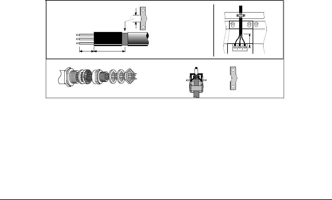
CE Guidelines C-1MN766
Appendix C
CE Guidelines
C.1 Outline
This section provides general information regarding recommended methods of installation for CE compliance. It is not
intended as an exhaustive guide to good practice and wiring techniques. It is assumed that the installer of the VS1SD is
sufciently qualied to perform the task, and is aware of local regulations and requirements. Baldor products that meet the
EMC directive requirements are indicated with a “CE” mark. A duly signed CE declaration of conformity is available from
Baldor.
C.2 EMC - Conformity and CE Marking
The information contained herein is for your guidance only and does not guarantee that the installation will meet the
requirements of the Electromagnetic Compatibility Directive 2004/108/EC or the Low Voltage Directive 2006/95/EC.
The purpose of the EEC directives is to state a minimum technical requirement common to all the member states within the
European Union. In turn, these minimum technical requirements are intended to enhance the levels of safety both directly
and indirectly.
Council directive 2004/108/EC relating to Electro Magnetic Compliance (EMC) indicates that it is the responsibility of the
system integrator to ensure that the entire system complies with all relative directives at the time of installing into service.
Motors and controls are used as components of a system, per the EMC directive. Hence all components, installation of
the components, interconnection between components, and shielding and grounding of the system as a whole determines
EMC compliance.
The CE mark informs the purchaser that the equipment has been tested and complies with the appropriate standards.
It rests upon the manufacturer or his authorized representative to ensure the item in question complies fully with all
the relative directives in force at the time of installing into service, in the same way as the system integrator previously
mentioned. Remember that it is the instructions of installation and the product that should comply with the directive.
Note that this drive is commercial in design. It is not intended to be used on a low-voltage public network which
supplies domestic premises. In a domestic environment, this product may cause radio interference in which case
supplementary mitigation may be required.
Wiring of Shielded (Screened) Cables
Figure C-1
Remove the outer insulation to
expose the overall screen.
Conductive
Clamp
Shielded Couplings
360 Degree Coupling 360 Degree
Coupling
Conductive
360 Degree Clamp
AB
C
d
A = 30mm max.
B = 500mm max.
C = 30mm max.

C-2 CE Guidelines MN766
C.3 EMC Installation Options
When installed for Class A or Class B operation, the control is compliant with EN55011 (1991)/ EN55022 (1994) for radiated
emissions as described.
C.4 Grounding for Wall Mounting (Class A) also see Chapter 4
Top cover must be installed.
• A single-star point (earth) is required.
• The protective earth connection (PE) to the motor must be run inside the screened cable or conduit between the motor
and control and be connected to the protective earth terminal at the control.
• The internal/external AC supply lter must be permanently earthed.
• The signal/control cables must be screened.
C.5 Grounding for Enclosure Mounting (Class B) also see Chapter 4
• The unit is installed for Class B operation when mounted inside an enclosure that has 10dB attenuation from 30
to 100MHz (typically the attenuation provided by a metal cabinet with no opening greater than 0.15m), using the
recommended AC supply lter and having met all cable requirements.
Note: Radiated magnetic and electric elds inside the cubicle will be high and components installed inside must be
sufciently immune.
• The control, external lter and associated equipment are mounted onto a conducting, metal panel. Do not use enclosures
that use insulating mounting panels or undened mounting structures. Cables between the control and motor must be
screened or in conduit and terminated at the control.
C.6 Use of CE Compliant Components
The following points should be considered:
• Using CE approved components will not guarantee a CE compliant system!
• The components used in the drive, installation methods used, materials selected for interconnection of components are
important.
• The installation methods, interconnection materials, shielding, ltering and earthing / grounding of the system as a whole
will determine CE compliance.
• The responsibility of CE mark compliance rests entirely with the party who offers the end system for sale (such as an OEM
or system integrator).

CE Guidelines C-3MN766
C.7 EMC Wiring Technique
Figure C-2
1 CABINET
The drawing shows an electroplated zinc coated enclosure, which is
connected to ground. This enclosure has the following advantages:
- All parts mounted on the back plane are connected to ground.
- All shield (screen) connections are connected to ground.
Within the cabinet there should be a spatial separation between power
wiring (motor and AC power cables) and control wiring.
2 SCREEN CONNECTIONS
All connections between components must use shielded cables. The cable
shields must be connected to the enclosure. Use conductive clamps to
ensure good ground connection. With this technique, a good ground shield
can be achieved.
3 EMC - FILTER
The EMI or main filter should be mounted next to the power supply (here
BPS). For the connection to and from the main filter, screened cables should
be used. The cable screens should be connected to screen clamps on both
sides. (Exception: Analog Command Signal).
Note: EMC compliance testing was conducted on representative drives
of each frame size using Schaffner FN3258 and FN351 series filters.
4 GROUNDING (EARTH)
For safety reasons (VDE0160), all Baldor components must be connected
to ground with a separate wire. The diameter of the wire must be at minimum
AWG#6 (10mm2). Ground connections (dashed lines) must be made from the
central ground to the regen resistor enclosure and from the central ground to
the Shared Power Supply.
5 Y-CAPACITOR
The connection of the regeneration resistor can cause RFI (radio frequency
interference) to be very high. To minimize RFI, a Y-capacitor is used. The
capacitor should only be connected between the dynamic brake resistor
housing and terminal pin R1.
CONTROLLER
FILTER
Y-Capacitor
Minimum size of the protective earthing conductor shall comply with the local
safety regulation for high protective earthing conductor current equipment.
Attention: Line drawing shows only principle of an EMC wiring. The shown installation can be different to
any national standard (e.g. VDE)
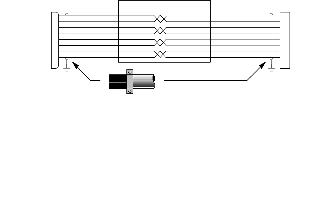
C-4 CE Guidelines MN766
C.8 EMC Installation Instructions
To ensure electromagnetic compatibility (EMC), the following installation instructions should be completed. These steps help
to reduce interference.
Consider the following:
• Grounding of all system elements to a central ground point
• Shielding of all cables and signal wires
• Filtering of power lines
A proper enclosure should have the following characteristics:
A) All metal conducting parts of the enclosure must be electrically connected to the back plane. These connections should
be made with a grounding strap from each element to a central grounding point. [1]
B) Keep the power wiring (motor and power cable) and control wiring separated. If these wires must cross, be sure they
cross at 90 degrees to minimize noise due to induction.
C) The shield connections of the signal and power cables should be connected to the screen rails or clamps. The screen
rails or clamps should be conductive clamps fastened to the cabinet. [2]
D) The cable to the regeneration resistor must be shielded. The shield must be connected to ground at both ends.
E) The location of the AC mains lter has to be situated close to the drive so the AC power wires are as short as possible.
F) Wires inside the enclosure should be placed as close as possible to conducting metal, cabinet walls and plates. It is
advised to terminate unused wires to chassis ground. [1]
G) To reduce ground current, use at least a 10mm2 (6 AWG) solid wire for ground connections.
[1] Grounding in general describes all metal parts which can be connected to a protective conductor, e.g. housing of
cabinet, motor housing, etc. to a central ground point. This central ground point is then connected to the main plant (or
building) ground.
[2] Or run as twisted pair at minimum.
Example Cable Screens Grounding
Figure C-3
Cable (Twisted Pair Conductors)
Conductive Clamp - Must contact bare cable shield
and be secured to metal backplane.

Options and Kits D-1MN766
Appendix D
Options and Kits
D.1 Dynamic Braking (DB) Hardware
Whenever a motor is abruptly stopped or forced to slow down quicker than if allowed to coast to a stop, the motor becomes
a generator. This energy appears on the DC Bus of the control and must be dissipated using dynamic braking hardware.
Dynamic braking resistors are completely assembled and mounted in a NEMA 1 enclosure. A listing of available RGA
assemblies is provided in Table D-1. Select the braking resistor that has correct ohm value for the control and adequate
continuous watts capacity to meet load requirements.
Table D-1 Dynamic Braking Resistor Assemblies (RGA)
Input
Volts HP Total *
Ohms
Continuous Rated Watts
600 1200 2400 4800 6400 9600 14200
230
1-7.5 20 RGA620 RGA1220 RGA2420
10-20 6 RGA1206 RGA2406 RGA4806
25-40 4 RGA1204 RGA2404 RGA4804
50-60 2 RGA4802 RGA6402 RGA9602 RGA14202
1-3 120 RGA6120 RGA12120 RGA24120
460
5-10 60 RGA660 RGA1260 RGA2460 RGA4860
15-25 20 RGA620 RGA1220 RGA2420 RGA4820
30-50 10 RGA1210 RGA2410 RGA4810
60-125 4 RGA1204 RGA2404 RGA4804 RGA6404 RGA9604 RGA14204
* Note: Total Ohms column indicates the minimum resistance that the output transistors can drive. For example, if the Total
Ohms column indicates 6 ohms and a 6 ohm resistor is unavailable, an 8 ohm can be used but not a 4 ohm resistor.

D-2 Options and Kits MN766
D.2 Expansion Boards
Baldor offers a wide variety of plug-in expansion boards for their Controls. Expansion boards allow a control to be
compatible with various inputs and outputs. Each control can accept up to two expansion boards. Chapter 3 of this manual
describes the locations of the connectors for these expansion boards.
Table D-2 Expansion Board Descriptions
Catalog Number Description
EXBHH001A01 Ethernet Server Expansion Board
Uses standard RJ-45 female terminal for Ethernet connection. Provides easy connection to any
PC based Web Browser that has an Ethernet connection. Allows you to quickly access all drive
parameters for setup and review. Download parameter values, operating conditions, and fault log
data for review and archive.
EXBHH002A01 Mint® Expansion Board
Provides stand alone single axis Position Control and is programmable in Mint® language.
Position capabilities include Master Axis Follower, Electronic Gearbox, Flying Shears, Registration,
VirtualMaster, and CAM functions. Uses MINT Workbench V5 for setup and diagnostics. Master
encoder input supports differential inputs for A, B and C (Index pulse). Uses DB9 for connection. One
CANopen channel is available for connection to additional I/O breakout box or CAN HMI terminal.
Connection to PC is by USB1.1 connector. Includes CD Rom and 2m USB cable.
EXBHH003A01
Isolated Input Expansion Board
Contains 9 isolated inputs, jumper congurable for 90-130 VAC. All inputs must be the same voltage.
One side of all inputs is common. This board replaces all the opto inputs on the main control board.
Uses screw terminals for connection.
EXBHH005A01
High resolution analog input/output board
Allows two inputs with up to 16 bits resolution. DC inputs: ±10V, 0-10V, ±5V, 0-5V, with 300 microvolt
resolution. Current inputs: 4-20mA, with 0.6 microamps resolution.
Input Resolution
±10V 16 bit
0 - 10V 15 bit
±5V 15 bit
0 - 5V 14 bit
0 - 20mA 15 bit
4 - 20mA 15 bit
Both the 0-10V and 4-20mA inputs may be inverted to 10-0V and 20-4mA. Two outputs, each with
±10VDC, 0-10VDC or 4-20mA with inverting capability. These are in addition to the two analog
outputs on the main control board (4 total). Uses screw terminals for connection.
EXBHH007A01
Master Pulse Reference / Isolated Pulse Follower
Jumper selection of the following modes:
1. Accepts a 5VDC or 12VDC quadrature pulse train input or pulse and direction input to
use as a master reference.
2. Re-transmits the input pulse train at 5VDC for ratios from 1:20 up to 65535:1. (Scaled
output).
3. Can be used as a auxiliary encoder input to the control
4. A CANopen port with an RJ-45 female connector for adding an additional I/O breakout
box or CAN HMI terminal.
EXBHH013A02
DeviceNet / EtherNet/IP / Modbus-TCP Communications Expansion Board
Allows connection to DeviceNet Communications Bus. Allows connection to EtherNet/IP
Communications Bus. Allows connection to Modbus-TCP Communications Bus. Uses screw
terminals for DeviceNet connection.
EXBHH014A02
PROFIBUS-DP Expansion Board
Allows connection to PROFIBUS-DP Communications Bus. Uses 9-pin D-shell for connection.
EXBHH016A01 LonWorks Communications Expansion Board
Allows connection to LonWorks Communications Bus. Uses plug-in terminals for connection.
EXBHH017A01 Metasys N2 Communications Expansion Board
Allows connection to or N2 communications network.
Uses screw terminals for connection.
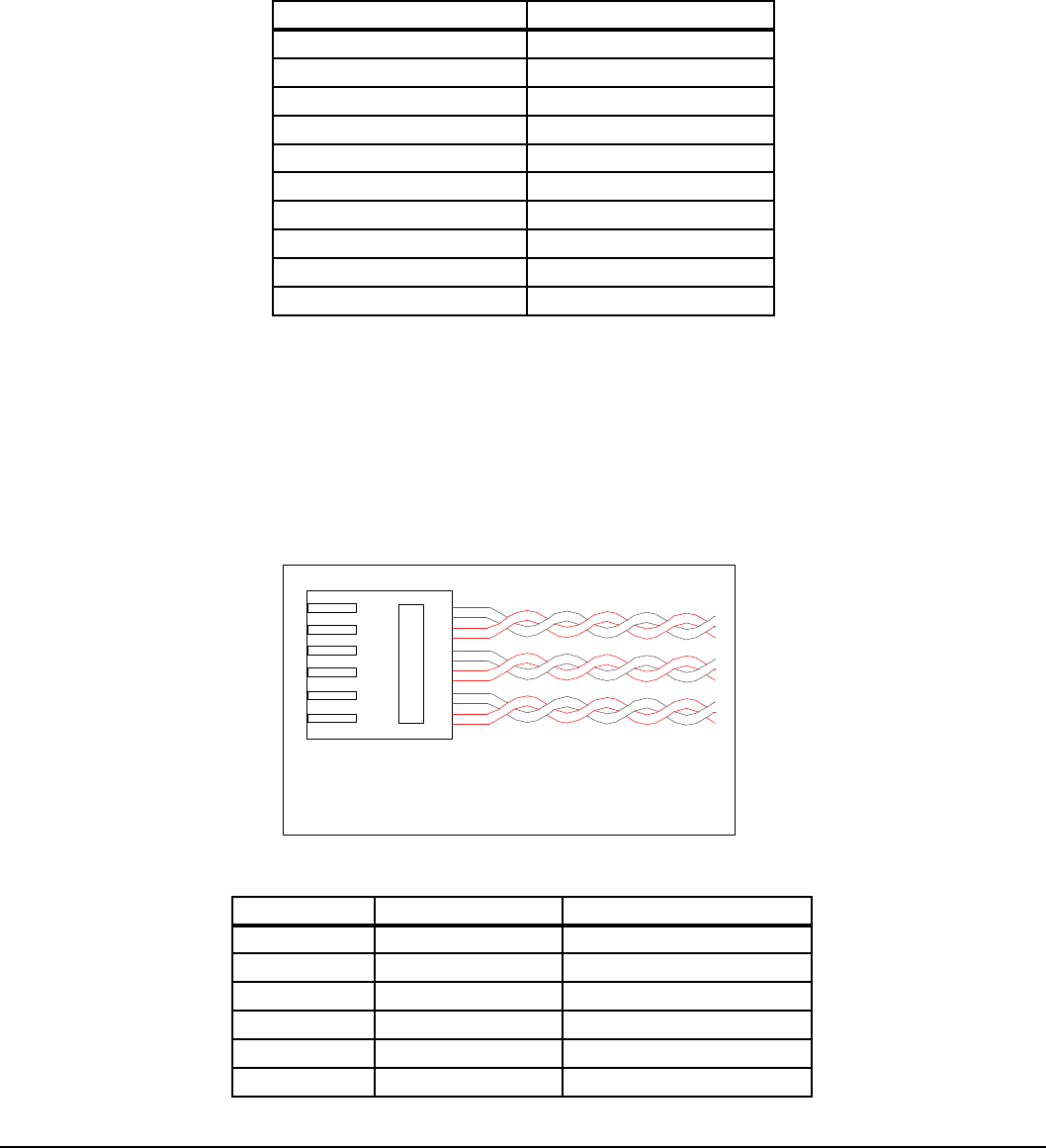
Options and Kits D-3MN766
D.3 Keypad Extension Cable
For the convenience of our customers, we offer a connector plug/cable assembly. This assembly provides the connectors
from the keypad to the control for remote keypad operation.
CAUTION: Only use cables manufactured by Baldor. Cables purchased from other sources may not be
properly wired and may damage the control or keypad and void the warranty.
Table D-3 Keypad Extension Cable Selection
Catalog Number Length
CBLHH015KP 5 ft (1.5m)
CBLHH030KP 10 ft (3.0m)
CBLHH046KP 15 ft (4.6m)
CBLHH061KP 20 ft (6.1m)
CBLHH091KP 30 ft (9.1m)
CBLHH152KP 50 ft (15.2m)
CBLHH229KP 75 ft (22.9m)
CBLHH305KP 100 ft (30.5m)
CBLHH457KP 150 ft (45.7m)
CBLHH610KP 200 ft (61.0m)
D.4 Keypad Connector
The keypad connector referenced in Figure D-1 and Table D-4 is an RJ-11 type wired as half duplex RS485. Twisted pair
wire must be used to connect the keypad and control for remote mounting of the keypad.
CAUTION: Only Baldor cables should be used to connect the keypad and control. These are special twisted
pair cables to protect the control and keypad. Damage associated with other cable types are not
covered by the Baldor warranty.
Figure D-1 Keypad Connector RJ-11
6
5
3
4
1
2
Connection, either end with clip on bottom
RJ11
Table D-4 Cable Connections
Pin Signal Name Description
1 A RS485 Line A
2 B RS485 Line B
3 KP_PS_GND Power Supply Return
4 +8V Power Supply +
5 KP_PS_GND Power Supply Return
6 +8V Power Supply +
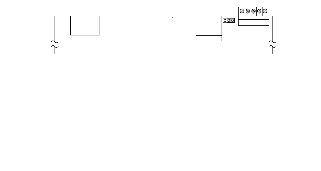
D-4 Options and Kits MN766
D.5 Optional Remote Keypad Installation
The keypad may be remotely mounted using optional Baldor keypad extension cable (refer to Table D-3). When the keypad
is properly mounted to a NEMA Type 4X enclosure, it retains the Type 4X rating. The mounting/drill template is located in
Appendix E of this manual.
CAUTION: Only use cables manufactured by Baldor. Cables purchased from other sources may not be
properly wired and may damage the control or keypad and void the warranty.
Tools Required:
•Centerpunch,taphandle,screwdrivers(Phillipsandstraight)
•#27drillbit
•1-3/8”standardknockoutpunch
•RTVSealant
•(3)6-32x3/8”screws
•(3)#6FlatWashers
Mounting Instructions: For clearance mounting holes
1. Locate a at 4” wide x 5.5” minimum high mounting surface. Material should be sufcient thickness (14 gauge minimum).
2. Place the template on the mounting surface or mark the holes as shown on the template (ensure template is not distorted
due to reproduction).
3. Accurately center punch the 3 mounting holes and the large knockout.
4. Drill three #27 clearance holes.
5. Locate the 1-3/8” knockout center and punch using the manufacturers instructions.
6. Debur knockout and mounting holes making sure the panel stays clean and at.
7. Apply RTV to the three #27 clearance holes.
8. Assemble the keypad to the panel. Use 6-32 screws and at washers.
9. From the inside of the panel, apply RTV over each of the three mounting screws. Cover a 3/4” area around each screw
making sure to completely encapsulate the screw head and washer.
10. Route the keypad cable into the control and connect to P2 of the control board, Figure D-2.
Figure D-2 Connector Locations
Keypad
Connector
Ribbon Cable
Control
Circuit Board
J8
P2
Regen
Connector
J7
See recommended tightening torques in Table A-2. RS485
P3
JP3
1S G A B S
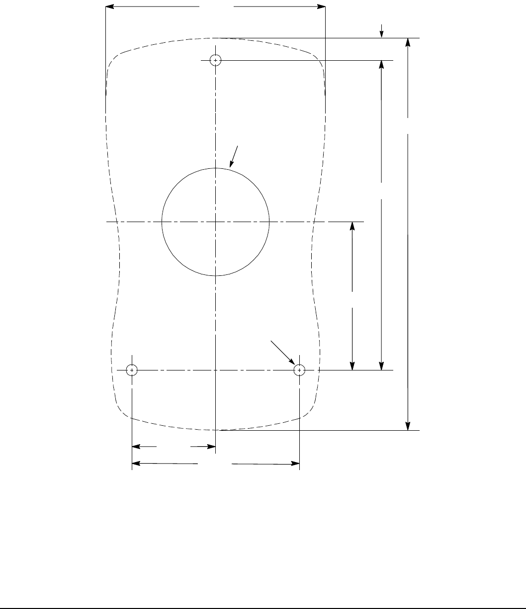
Remote Keypad Mounting Template E-1MN766
Appendix E
Remote Keypad Mounting Template
E.1 Remote Keypad Mounting Template
Figure E-1
Note: Template may be distorted duetoreproduction.
2.81
1.38Knockout
Drill#27 Hole
3 Places
1.89
3.95
4.99
2.14
1.07
0.28
KP0030A00

E-2 Remote Keypad Mounting Template MN766
NOTES
_________________________________________________________________________
_________________________________________________________________________
_________________________________________________________________________
_________________________________________________________________________
_________________________________________________________________________
_________________________________________________________________________
_________________________________________________________________________
_________________________________________________________________________
_________________________________________________________________________
_________________________________________________________________________
_________________________________________________________________________
_________________________________________________________________________
_________________________________________________________________________
_________________________________________________________________________
_________________________________________________________________________
_________________________________________________________________________
_________________________________________________________________________
_________________________________________________________________________
_________________________________________________________________________
_________________________________________________________________________
_________________________________________________________________________
Baldor Sales Offices
OHIO (Continued)
CLEVELAND
8929 FREEWAY DRIVE
MACEDONIA, OH 44056
PHONE: 330-468-4777
FAX: 330-468-4778
OKLAHOMA
TULSA
5555 E. 71st st., suItE 9100
tulsA, OK 74136
PHONE: 918-366-9320
FAX: 918-366-9338
OREGON
PORTLAND
12651 sE CAPPs ROAD
ClACKAMAs, OR 97015
PHONE: 503-691-9010
FAX: 503-691-9012
PENNSYLVANIA
PHILADELPHIA
1035 tHOMAs BusCH
MEMORIAl HIGHWAY
PENNsAuKEN, NJ 08110
PHONE: 856-661-1442
FAX: 856-663-6363
PITTSBURGH
159 PROMINENCE DRIVE
NEW KENsINGtON, PA 15068
PHONE: 724-889-0092
FAX: 724-889-0094
TENNESSEE
MEMPHIS
4000 WINCHEstER ROAD
MEMPHIs, tN 38118
PHONE: 901-365-2020
FAX: 901-365-3914
TEXAS
DALLAS
2920 114tH stREEt suItE 100
GRAND PRAIRIE, tX 75050
PHONE: 214-634-7271
FAX: 214-634-8874
HOUSTON
10355 W. lIttlE YORK ROAD
suItE 300
HOustON, tX 77041
PHONE: 281-977-6500
FAX: 281-977-6510
UTAH
SALT LAKE CITY
2230 sOutH MAIN stREEt
sAlt lAKE CItY, ut 84115
PHONE: 801-832-0127
FAX: 801-832-8911
WISCONSIN
MILWAUKEE
1960 sOutH CAlHOuN ROAD
NEW BERlIN, WI 53151
PHONE: 262-784-5940
FA X: 262-784-1215
IOWA
DES MOINES
1943 Hull AVENuE
DEs MOINEs, IA 50313
PHONE: 515-263-6929
FAX: 515-263-6515
MARYLAND
BALTIMORE
6660 sANtA BARBARA RD.
suItEs 22-24
ElKRIDGE, MD 21075
PHONE: 410-579-2135
FAX: 410-579-2677
MASSACHUSETTS
BOSTON
6 PullMAN stREEt
WORCEstER, MA 01606
PHONE: 508-854-0708
FAX: 508-854-0291
MICHIGAN
DETROIT
5993 PROGREss DRIVE
stERlING HEIGHts, MI 48312
PHONE: 586-978-9800
FAX: 586-978-9969
MINNESOTA
MINNEAPOLIS
13098 GEORGE WEBER DR, suItE 400
ROGERs, MN 55374
PHONE: 763-428-3633
FAX: 763-428-4551
MISSOURI
ST LOUIS
13678 lAKEFRONt DRIVE
EARtH CItY, MO 63045
PHONE: 314-373-3032
FAX: 314-373-3038
KANSAS CITY
1501 BEDFORD AVENuE
NORtH KANsAs CItY, MO 64116
PHONE: 816-587-0272
FAX: 816-587-3735
NEW YORK
AUBURN
ONE EllIs DRIVE
AuBuRN, NY 13021
PHONE: 315-255-3403
FAX: 315-253-9923
NORTH CAROLINA
GREENSBORO
1220 ROtHERWOOD ROAD
GREENsBORO, NC 27406
PHONE: 336-272-6104
FAX: 336-273-6628
OHIO
CINCINNATI
2929 CREsCENtVIllE ROAD
WEst CHEstER, OH 45069
PHONE: 513-771-2600
FAX: 513-772-2219
INTERNATIONAL SALES
FORT SMITH, AR
P.O. BOX 2400
FORt sMItH, AR 72902
PHONE: 479-646-4711
FAX: 479-648-5895
CANADA
EDMONTON, ALBERTA
4053-92 stREEt
EDMONtON, AlBERtA t6E 6R8
PHONE: 780-434-4900
FAX: 780-438-2600
TORONTO
OAKVILLE, ONTARIO
2750 COVENtRY ROAD
OAKVIllE, ONtARIO l6H 6R1
PHONE: 905-829-3301
FAX: 905-829-3302
MONTREAL, QUEBEC
5155 J-ARMAND BOMBARDIER
sAINt-HuBERt, QuéBEC
CANADA J3Z 1G4
PHONE: 514-933-2711
FAX: 514-933-8639
VANCOUVER,
BRITISH COLUMBIA
1538 KEBEt WAY
PORt COQuItlAM,
BRItIsH COluMBIA V3C 5M5
PHONE 604-421-2822
FAX: 604-421-3113
WINNIPEG, MANITOBA
54 PRINCEss stREEt
WINNIPEG, MANItOBA R3B 1K2
PHONE: 204-942-5205
FAX: 204-956-4251
MEXICO
LEON, GUANAjUATO
KM. 2.0 BlVD. AEROPuERtO
lEON, GuANAJuAtO, CP37545
MEXICO
FAX: +52 477 761 2010
UNITED STATES
ARIZONA
PHOENIX
4211 s 43RD PlACE
PHOENIX, AZ 85040
PHONE: 602-470-0407
FAX: 602-470-0464
ARKANSAS
CLARKSVILLE
706 WEst MAIN stREEt
ClARKsVIllE, AR 72830
PHONE: 479-754-9108
FAX: 479-754-9205
CALIFORNIA
LOS ANGELES
6480 FlOtIllA stREEt
COMMERCE, CA 90040
PHONE: 323-724-6771
FAX: 323-721-5859
HAYWARD
21056 FORBEs stREEt
HAYWARD, CA 94545
PHONE: 510-785-9900
FAX: 510-785-9910
COLORADO
DENVER
3855 FOREst stREEt
DENVER, CO 80207
PHONE: 303-623-0127
FAX: 303-595-3772
CONNECTICUT
WALLINGFORD
65 sOutH tuRNPIKE ROAD
WAllINGFORD, Ct 06492
PHONE: 203-269-1354
FAX: 203-269-5485
FLORIDA
TAMPA/PUERTO RICO/
VIRGIN ISLANDS
3906 EAst 11tH AVENuE
tAMPA, Fl 33605
PHONE: 813-248-5078
FAX: 813-241-9514
GEORGIA
ATLANTA
62 tECHNOlOGY DRIVE
AlPHAREttA, GA 30005
PHONE: 770-772-7000
FAX: 770-772-7200
ILLINOIS
CHICAGO
340 REMINGtON BlVD.
BOlINGBROOK, Il 60440
PHONE: 630-296-1400
FAX: 630-226-9420
INDIANA
INDIANAPOLIS
5525 W. MINNEsOtA stREEt
INDIANAPOlIs, IN 46241
PHONE: 317-246-5100
FAX: 317-246-5110

© Baldor Electric Company
MN766
All Rights Reserved. Printed in USA.
10/12
!766-1012*
P.O. Box 2400, Fort Smith, AR 72902-2400 U.S.A., Ph: (1) 479.646.4711, Fax (1) 479.648.5792, International Fax (1) 479.648.5895
Baldor - Dodge
6040 Ponders Court, Greenville, SC 29615-4617 U.S.A., Ph: (1) 864.297.4800, Fax: (1) 864.281.2433
www.baldor.com
