VSA 51 Digital AV Room Control System Extron Electronics Speaker SM 3
User Manual: Extron Electronics Speaker SM 3
Open the PDF directly: View PDF ![]() .
.
Page Count: 47
- Table of Contents
- 1 Introduction
- 1.1 System Components
- VSA-51-R - System Receiver
- VSA-UI-DP - User Interface Panel
- VSA-UI-8 - 8 Button User Interface Expansion
- VSA-H-DP - HDMI and Audio Sender Plate
- VSA-V-DP - VGA/YPbPr and Audio Sender Plate
- VSA-C-DP - Composite Video and Audio Sender Plate
- VSA-MNT - Ceiling Projector Mount w/Receiver Bay
- VSA-PGSNS - Non-Invasive Priority Page Sensor
- 1.2 System Diagram
- 1.1 System Components
- 2 Hardware
- 3 Software
- 4 Troubleshooting & FAQs
- 5 Specifications
VSA-51
Digital AV Room Control System
User Manual
&
Installation Guide
Order toll-free in the U.S. 800-959-6439
FREE technical support, Call 714-641-6607 or fax 714-641-6698
Mail order: Hall Research, 1163 Warner Ave. Tustin, CA 92780
Web site: www.hallresearch.com E-mail: info@hallresearch.com
CUSTOMER SUPPORT
INFORMATION
UMA1182 Rev. 1.41
Digital AV Room Control System
1
TRADEMARKS USED IN THIS MANUAL
Hall Research and the Hall Research Logo ( ) are trademarks of Hall Research.
HDMI™ is a registered trademark of HDMI Licensing LLC. Any other trademarks
mentioned in this manual are acknowledged to be the property of the trademark owners.
FEDERAL COMMUNICATIONS COMMISSION
RADIO FREQUENCY INTERFERENCE STATEMENT
This equipment generates, uses, and can radiate radio frequency energy and if not installed and used properly, that is, in
strict accordance with the manufacturer’s instructions, may cause interference to radio communication. It has been
designed to comply with the limits for a Class A computing device in accordance with the specifications in Subpart B of
Part 15 of FCC rules, which are intended to provide reasonable protection against such interference when the equipment
is operated in a commercial environment. Operation of this equipment in a residential area is likely to cause interference,
in which case the user at their own expense will be required to take whatever measures may be necessary to correct the
interference.
Changes or modifications not expressly approved by the party responsible for compliance could void the user’s authority
to operate the equipment.
This digital apparatus does not exceed the Class A limits for radio noise emission from digital apparatus set out in the
Radio Interference Regulation of the Canadian Department of Communications.

2
VSA-51
Table of Contents
1 Introduction ........................................................................................................ 3
1.1 System Components .................................................................................................................. 3
1.2 System Diagram ......................................................................................................................... 4
2 Hardware ............................................................................................................ 5
2.1 VSA-51-R ................................................................................................................................... 5
2.2 VSA-UI-DP ................................................................................................................................. 8
2.3 VSA-UI-8 .................................................................................................................................. 11
2.4 VSA-C-DP ................................................................................................................................ 12
2.5 VSA-H-DP ................................................................................................................................ 13
2.6 VSA-V-DP ................................................................................................................................ 14
2.7 VSA-MNT ................................................................................................................................. 15
2.8 VSA-PGSNS ............................................................................................................................ 23
3 Software ........................................................................................................... 24
3.1 IP Settings ................................................................................................................................ 25
3.2 VSA IP Manager ....................................................................................................................... 28
4 Troubleshooting & FAQs ................................................................................ 42
4.1 Video Issues ............................................................................................................................. 42
4.2 Audio Issues ............................................................................................................................. 42
4.3 Electrical Issues ....................................................................................................................... 42
4.4 Web page / Network Issues ...................................................................................................... 43
5 Specifications .................................................................................................. 44

Digital AV Room Control System
3
1 Introduction
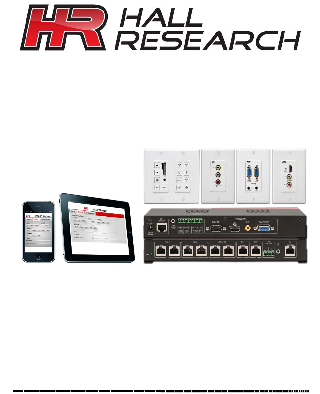
The VSA-51 is the latest addition to Hall Research’s Sw it ch -Ca t ™ room control product line. It offers true flexibility in
access and control making it ideal for K-12 classrooms, conference rooms and more.
All configuration and control software is embedded in the receiver and served over HTTP to a browser which means you
can access and control the device from a PC, Mac, smart phone, or tablet. Custom programmable commands offer
advanced control of the device and 3rd party equipment. Software features include embedded device control, task
scheduling and automation, theft detection, and more. The VSA-51 allows for up to 5 modular input sources (2x VGA, 2x
composite, 1x HDMI) to be switched to a single projector or display along with audio. In addition, auxiliary RS232 and
contact closures can provide advanced control options.
1.1 System Components
The VSA-51 system consists of multiple components. Other than the receiver, all components are optional which offers
flexibility to use only the components necessary. Available components are:
VSA-51-R - System Receiver
The receiver is the central component of the VSA-51. It handles all switching and hosts the web-based software that runs
the system. Input plates and User Interface panels connect directly to and receive power from the receiver.
VSA-UI-DP - User Interface Panel
The VSA-UI-DP is a dual-gang Decora® plate user interface panel. It has dedicated volume and power controls as well as
8 customizable buttons that can be configured to perform any System Action. The clear button caps are removable,
allowing custom labels to be inserted. The VSA-UI-DP includes an auxiliary serial port (RS-232) for controlling a
secondary serial device. It also includes an IR receiver with pass through terminals for IR signal routing. It can also
generate IR commands for the most popular IR standards (customer should know the format of IR standard and IR code).
VSA-UI-8 - 8 Button User Interface Expansion
The VSA-UI-8 is an optional 8 port expansion module for the User Interface Panel. Generally it is used to control other
devices such as DVR or External Switchers. The buttons can be programmed to issue RS-232 to either of the 2 ports, IR,
command, control discrete (contact closure/open collector) output states, and more.
VSA-H-DP - HDMI and Audio Sender Plate
The VSA-H-DP is a modular input plate that sends HDMI and audio to the receiver via 2x UTP cables. Note that since the
Receiver has a built in amplifier, all input Decora® plates need to have their own audio source. Since HDMI has digital
audio embedded in the PC, you may have to setup your source to output separate R/L audio.
VSA-V-DP - VGA/YPbPr and Audio Sender Plate
The VSA-V-DP is a modular input plate that sends VGA or YPbPr and audio to the receiver via 2x UTP cables. It also
features a local output for directing video and audio back to a local console. The VSA-51 System can accommodate up to
2x VSA-V-DP inputs.
VSA-C-DP - Composite Video and Audio Sender Plate
The VSA-C-DP is a modular input plate that sends composite video and audio to the receiver via a single UTP cable. The
VSA-51 System can accommodate up to 2x VSA-C-DP inputs.
VSA-MNT - Ceiling Projector Mount w/Receiver Bay
The VSA-MNT is a ceiling projector drop mount with locking cage. The projector mount is universally compatible with most
projectors. The VSA-51-R mounts inside the cage keeping connections securely fastened and all electronics below the
ceiling.
VSA-PGSNS - Non-Invasive Priority Page Sensor
The VSA-PGSNS is an optional kit to enable non-invasive Page Sense Mute feature.
4
VSA-51
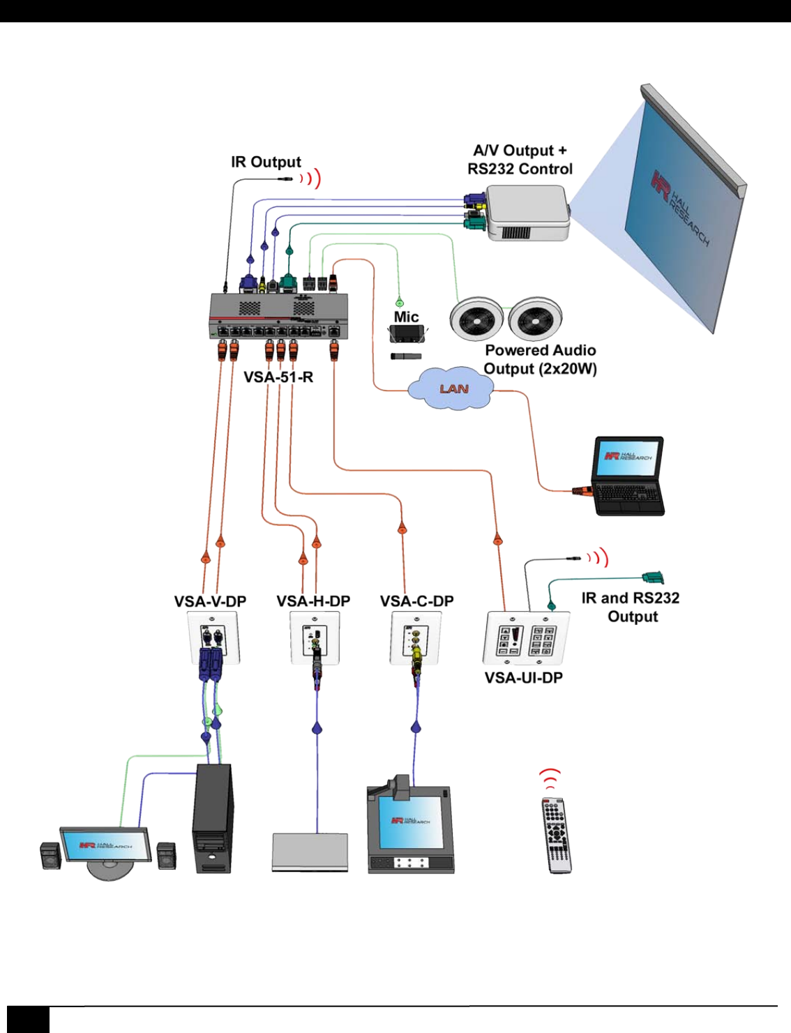
1.2 System Diagram
VSA-51 System Diagram
Digital AV Room Control System
5
2 Hardware
2.1 VSA-51-R
The VSA-51-R is the central component of the VSA-51 hardware installation. The User Interface panel and input
plates connect to the receiver via UTP cable. The receiver also connects directly to the display, audio, and relay
devices.
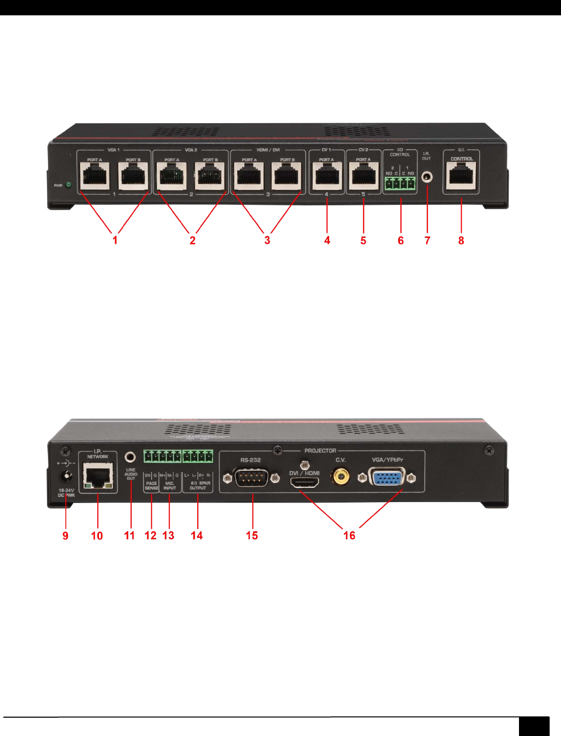
VSA-51-R Front
1. VGA input #1. Connect to a VSA-V-DP via 2x UTP cables.
2. VGA input #2. Connect to a VSA-V-DP via 2x UTP cables.
3. HDMI input. Connect to a VSA-H-DP via 2x UTP cables.
4. Composite input #1. Connect to a VSA-C-DP via 1x UTP cable.
5. Composite input #2. Connect to a VSA-C-DP via 1x UTP cable.
6. Discrete outputs via Phoenix connector.
7. IR output via 3.5mm jack (use with Optional IR Emitter Cable Model CIR-EMT).
8. User Interface input. Connect to VSA-UI-DP via 1x UTP cable.
VSA-51-R Rear
9. Power input. Accepts 18-24VDC.
10. IP/LAN for network based configuration and control.
11. Preamp Audio output. Line level via 3.5mm jack.
12. Page Sensor input for optional page sensor kit (VSA-PGSNS See Section 2.8).
6
VSA-51
13. Microphone input via Phoenix connector is designed as a differential input to help eliminate noise.
14. Speaker terminals for use with 8 or 16 Ohm speakers.
15. Receiver serial. Connects to the primary display.
16. Video Output to display via HDMI, composite video or VGA/YPbPr.
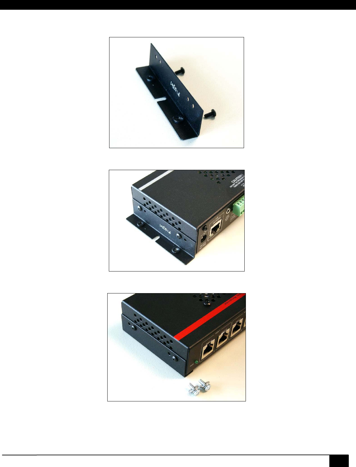
2.1.1 Mounting the VSA-51-R
The VSA-51-R ships with 2 “L” brackets attached to its sides (see photo below). This bracket is reversible and the flange
can wrap around under the product, or stick-out.
When you install the VSA-51-R in the VSA-MNT ceiling projector drop mount cage (see section 2.7), the brackets point
inward and you use the supplied #6 screws and washers to attach the receiver to the cage.
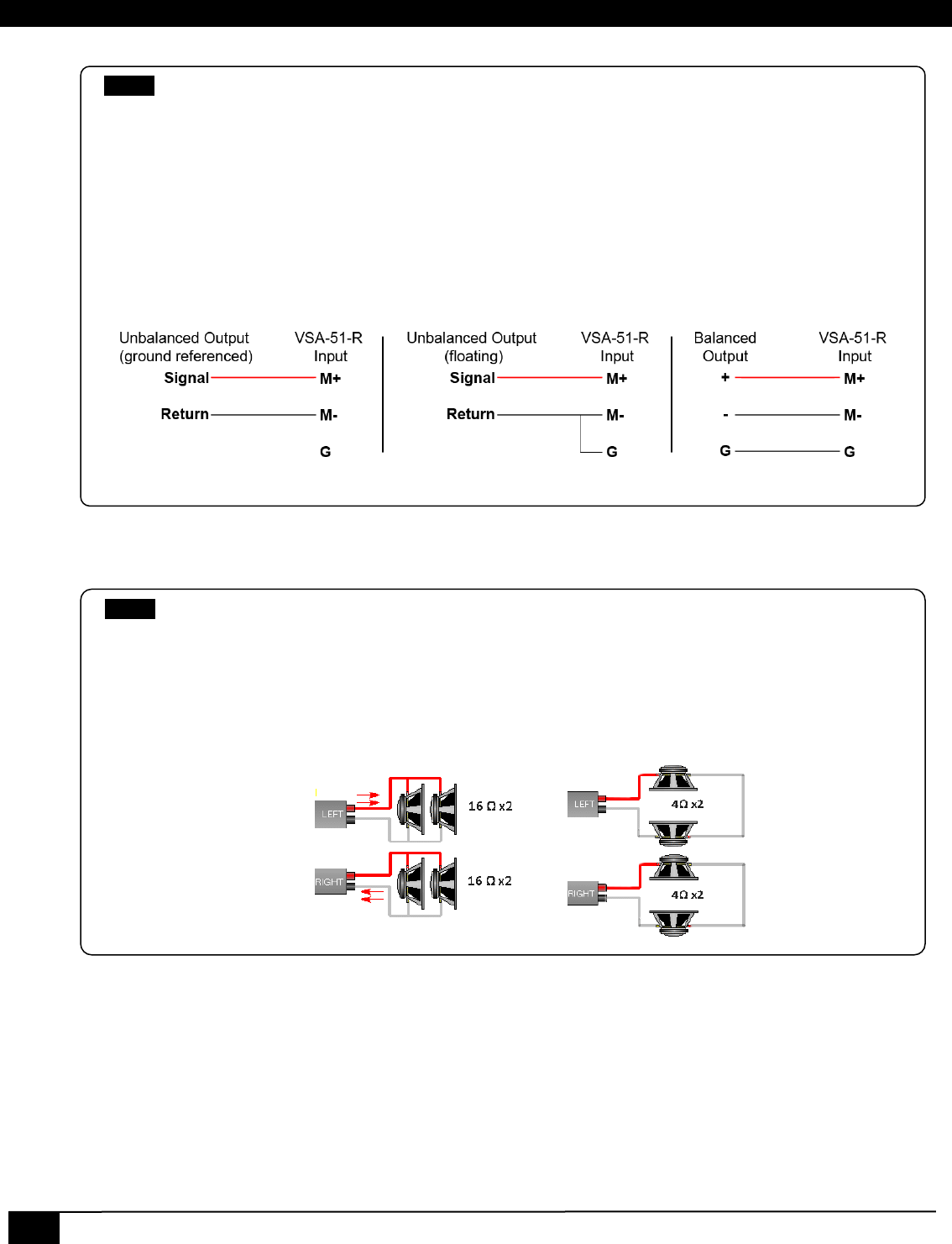
NOTE
The Mic input expects a line level signal, so you may need external preamp for low level dynamic
microphones. There is no phantom power provided at the mic input. In most K-12 installations wireless
(RF or IR based) mics are used that have line-level output. We have found that most condenser and some
dynamic mics may work without external preamps if you turn up the mic volume on the system.
Use the following diagram for connection of external preamp (such as wireless mic receiver) to the
system. Ground referenced means that the external preamp has a connection to ground (the AC cord has a
ground prong), in that case if the preamp does not provide a balanced (differential) output, you should
not tie the return of your source to the ground of the VSA-51 lest you create a ground loop. But if you are
sure that your external preamp is floating (its AC cord has no ground prong), then it may be advisable to
connect the negative input signal to ground at the VSA-51 receiver.
Mic Wiring Diagram
NOTE
The Audio Amp is designed to drive loads equal to or greater than 8 Ω. Using lower loads may cause over-
current shutdown of the Audio amp, which would require an All-Mute procedure to reset the amp. It is
recommended that when using a single speaker for each side to use 8 or 16 Ω speakers. The amp can drive
around 42 watts total when using 8 Ω speakers, which may be loud for a small room. Using 16 Ω speakers
will cut the power delivered by half.
To drive 2 speakers from each side(total of 4 speakers in the room), connect two 16 Ω speakers in parallel
or two 4Ω or 8 Ω speakers in series as shown below. Never connect two 8 Ω speakers in parallel!
Digital AV Room Control System
7
When you install VSA-51-R on any other surface (such as drywall) you have the option to flip the brackets and have the
flange outside for easy access to mounting holes.
The “L” Brackets of VSA-51-R
Bracket installation for surface mounting
Bracket installation for vault mounting
(Use the included #6 screws and washers from outside of bottom of vault to attach the receiver)
8
VSA-51
2.2 VSA-UI-DP
The VSA-UI-DP is a dual-gang User Interface panel for controlling the VSA-51. It can be mounted in any dual-
gang Decora® standard mounting plate. The VSA-UI-DP receives power directly from the VSA-51-R receiver
via the single Cat5 cable so no extra wiring is necessary.
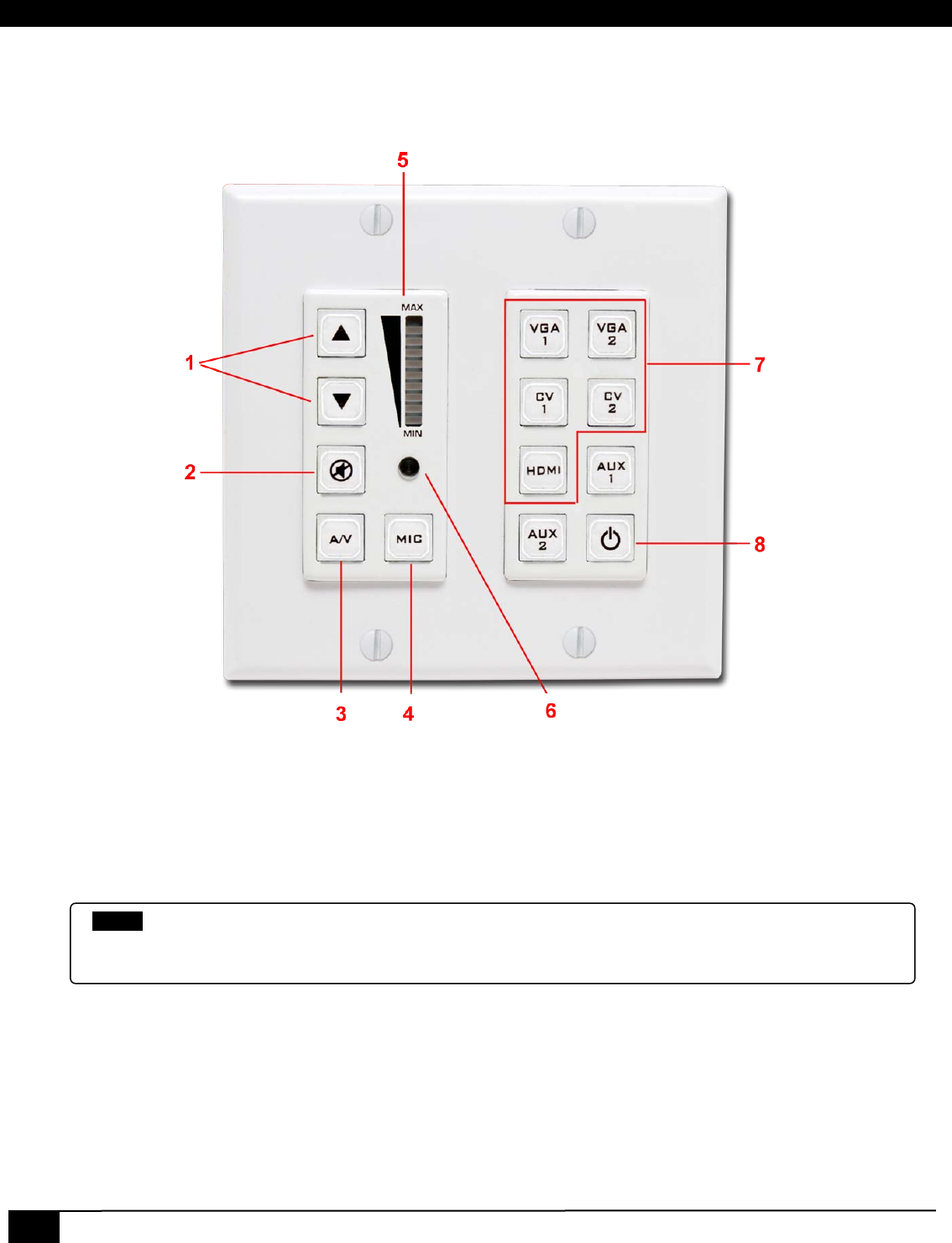
VSA-UI-DP Front
1. Volume Up and Down. Adjusts the volume for the active source (A/V or mic) input.
2. Mute. Toggles mute for the active audio (A/V or Mic).
3. A/V Audio Selector. If this is active the audio controls will adjust audio for the currently selected AV source input.
4. Mic Audio Selector. If this is active the audio controls will adjust audio for the mic input.
5. Volume Level Indicator. Indicates volume level of the active audio (A/V or Mic).
6. IR Receiver. Receives IR signal and passes through to the receiver and outputs on 2 wire captive screw terminal
on the rear of the unit.
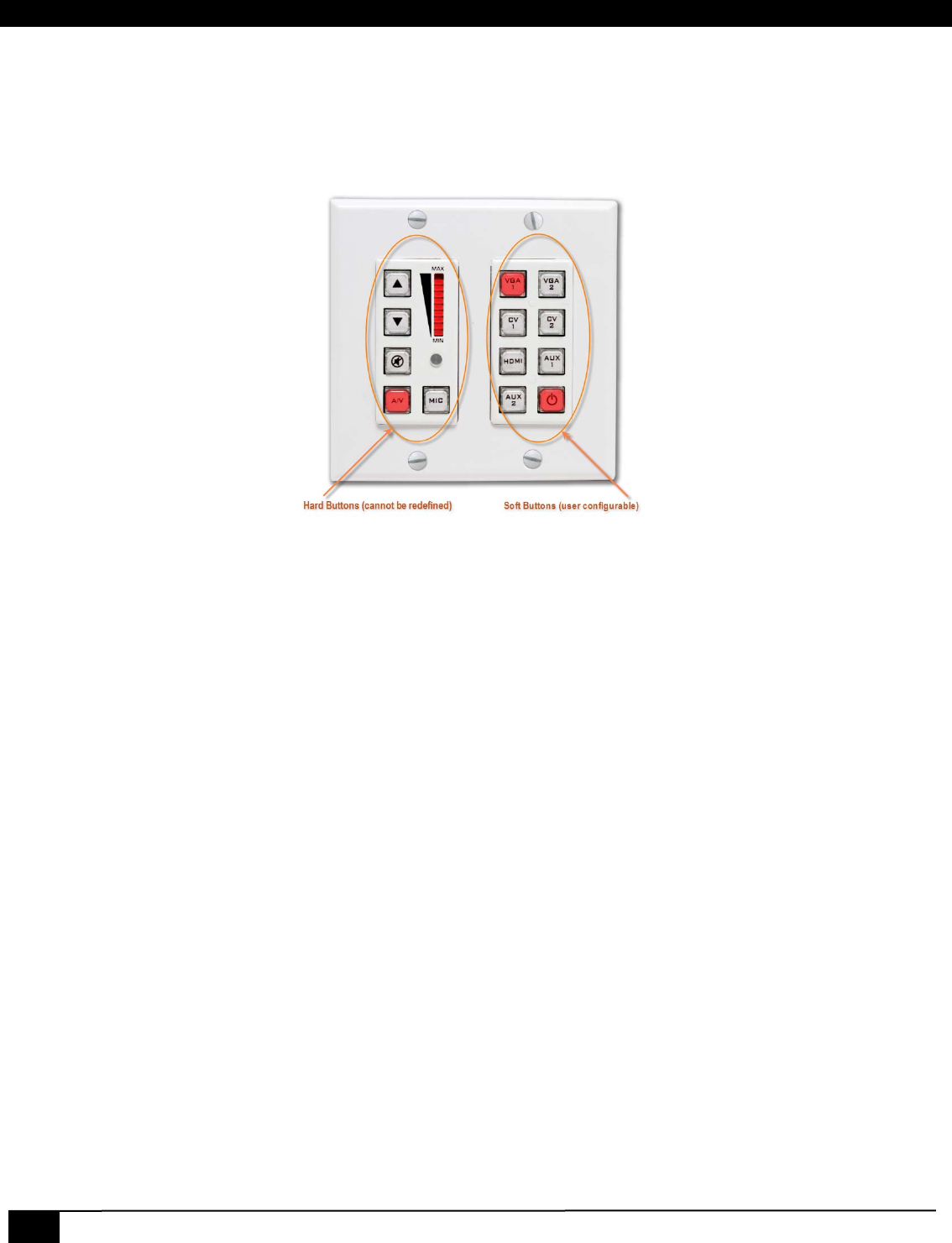
7. AV Source Selection. These are the default source selection buttons. Each of these buttons can be programmed
for other actions and relabeled accordingly.
8. Misc buttons. If all AV inputs are utilized then there will be 3 available buttons for misc operation. These could be
programmed for example to turn projector on/off or move a motorized projection screen. All configuration of the
buttons is done through the Web Manager.
NOTE
If you find that a particular input gets very loud quickly with volume indicator is still near bottom, then
you can specify a Max Volume for that input in terms of % of absolute maximum. In that way each
increment of the volume control will be smaller and the display will be normalized to the new max.
Digital AV Room Control System
9
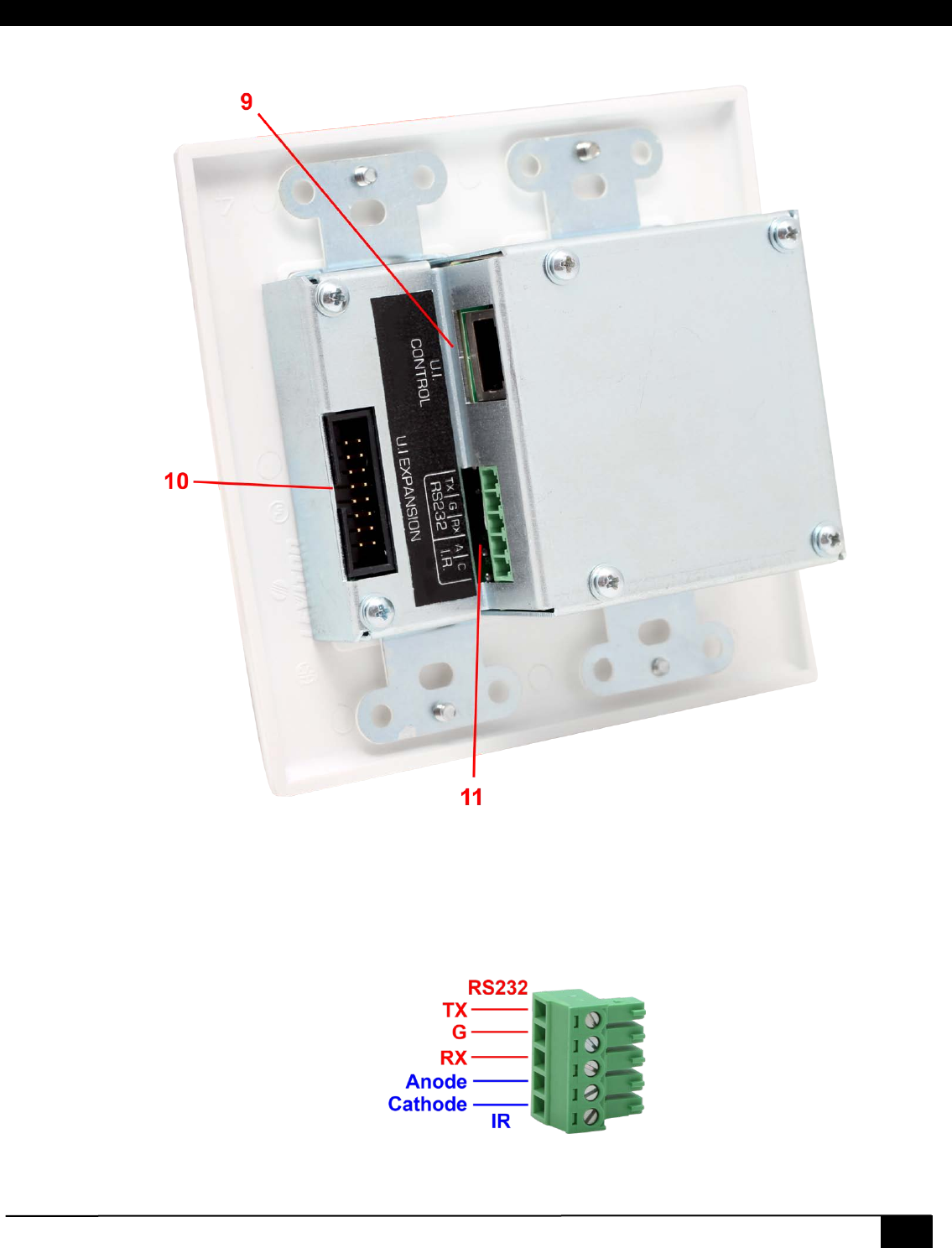
VSA-UI-DP Rear
9. Receiver RJ45 port. Connects directly to “UI Control” port on VSA-51-R receiver via Cat5 cable. This link
handles communication and sends power to the UI panel from the receiver.
10. Expansion Header for optional extended control panel (VSA-UI-8).
11. IR/Serial Port. Provides captive screw terminals for IR and secondary RS232 output. The diagram below shows
the pin out for the Phoenix connector.
10
VSA-51
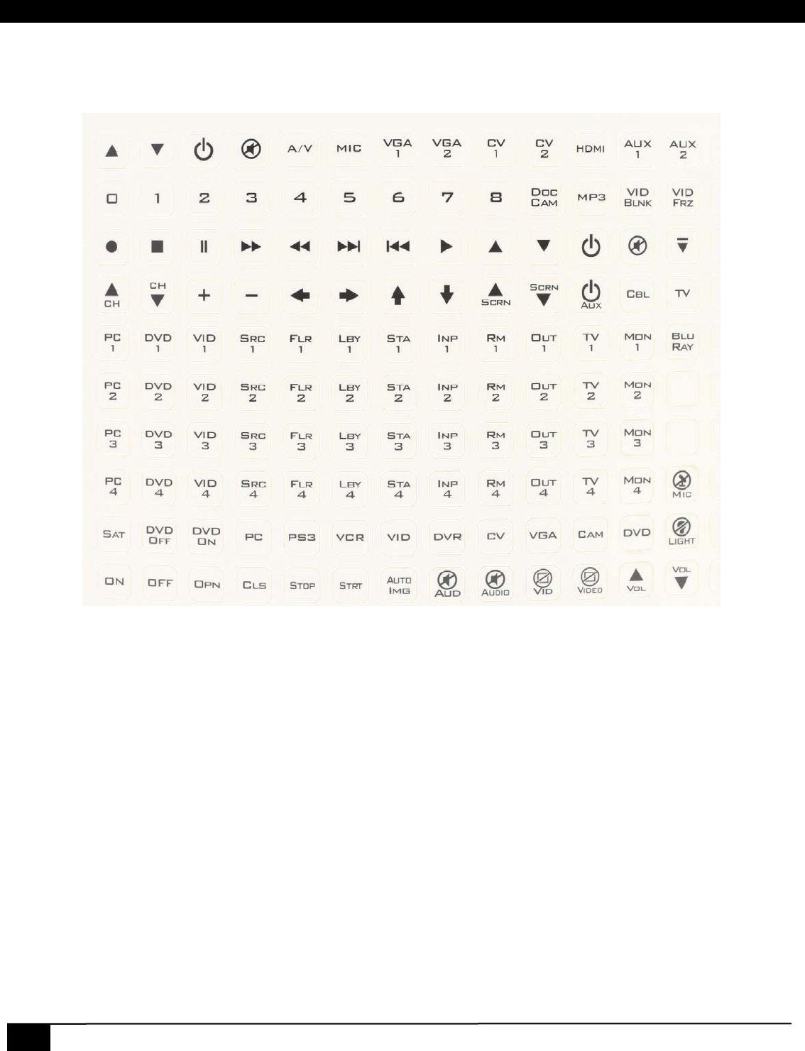
2.2.1 Changing Button Labels
The VSA-UI-DP comes with a printed sheet of common button labels. These labels are pre-scored to the size of the
buttons on the VSA-UI-DP or VSA-UI-8. See the example below.
Button Label Sheet
Note that some of these buttons may be missing from the sheet as they are already applied to the panels from the factory.
If you need a label that is not already on the sheet then you can print to the appropriate size, cut to shape and apply it to
the button face. Adhesive backing will keep the label firmly applied to the button face but is not entirely necessary as the
clear cap will hold the label in place.
To change the button labels follow these steps:
1. Remove the UI panel from the wall plate.
2. Remove the 6 Phillips head screws securing the metal back plate to the rear of the unit.
3. Remove the 2 exposed Phillips head screws securing the 8 button faceplate. Remove the faceplate to expose
the buttons.
4. Remove the clear plastic button cap. The cap can be easily popped off with a flat head screwdriver.
5. Peel off the existing label and apply a new one. Set it gently in place and try not to press it too firmly or it will
wrinkle. Make sure to keep it properly aligned.
6. Re-apply the button cap by snapping it into place.
7. Re-attach the metal faceplate.
8. Re-attach the metal back plate.
9. Re-attach the UI panel to the wall plate (if necessary).
Digital AV Room Control System
11
2.2.2 Recovering from Audio Amp Shutdown
In rare instances it is possible for the audio amp in the Receiver to shut down due to an instantaneous over current
condition. The amp requires 8 Ω or higher load on each side. If the load has lower resistance and if you have a large
impulse on the audio input that exceeds several volts, the audio amp will shut-down to protect against damage. You can
recover from this condition using a “Double Mute” procedure whereby both the mic and the AV source volume are muted
at the same time. This will reset the audio amp and bring it out of shutdown.
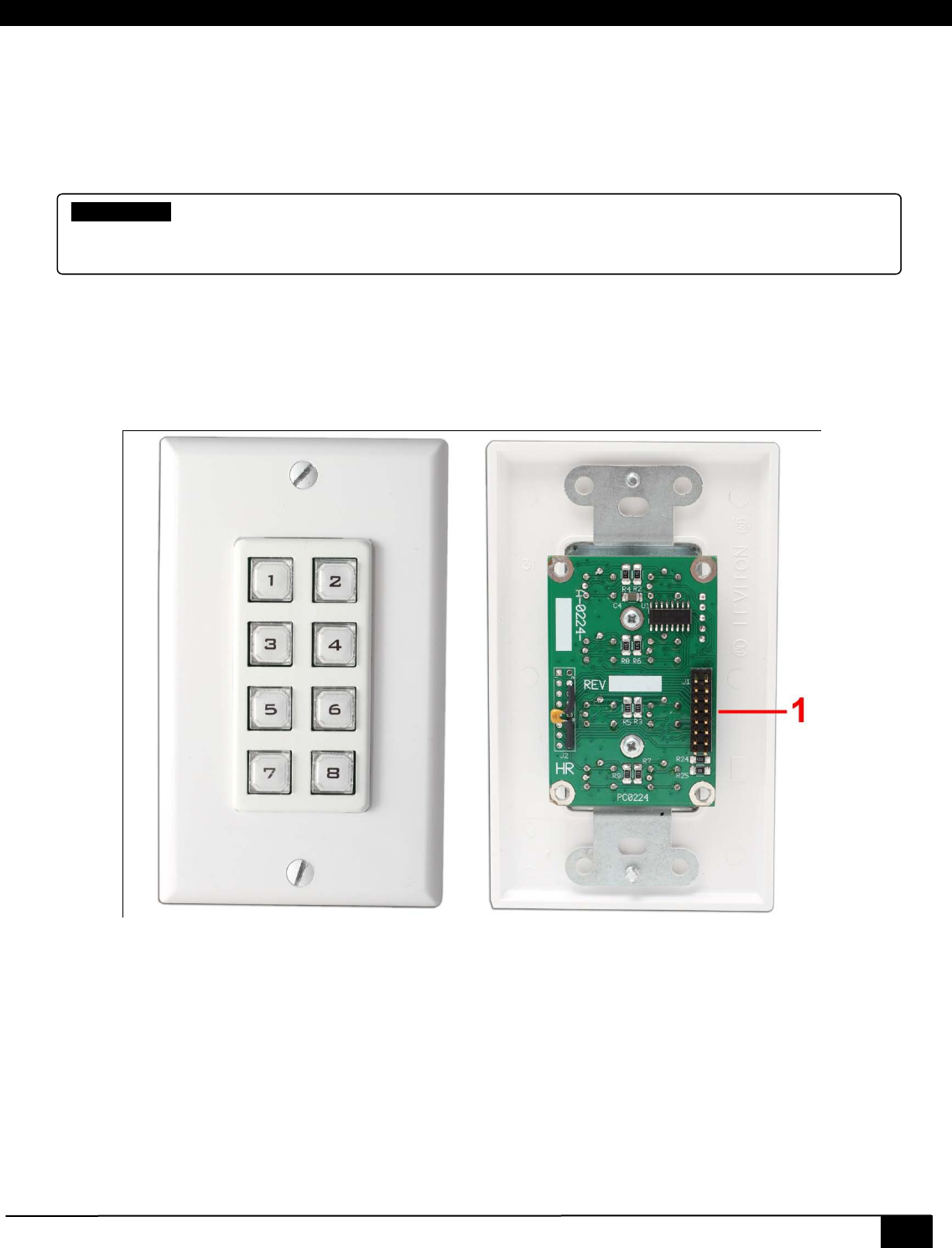
2.3 VSA-UI-8
The VSA-UI-8 expands the UI panel capability by adding 8 additional buttons. Each button is programmable via the Web
Manager software. The VSA-UI-8 connects directly to the VSA-UI-DP via a 16 pin ribbon cable. The header also provides
power to the unit.
VSA-UI-8 Front and Rear
1. Header port connects to the expansion port on the VSA-UI-DP.
Changing Button Labels
The procedure for changing the VSA-UI-8 button labels is the same as for the VSA-UI-DP except there is no metal back-
plate to remove. Follow steps 3-7 from section 2.2.1 above.
Double-Mute
If the system has no amplified audio output whatsoever, it could be that the audio amp is shut-
down due to over current. To recover from this condition, mute the microphone and the A/V source
simultaneously. This will reset the amp. Upon un-muting either source, the Amp should be working
12
VSA-51
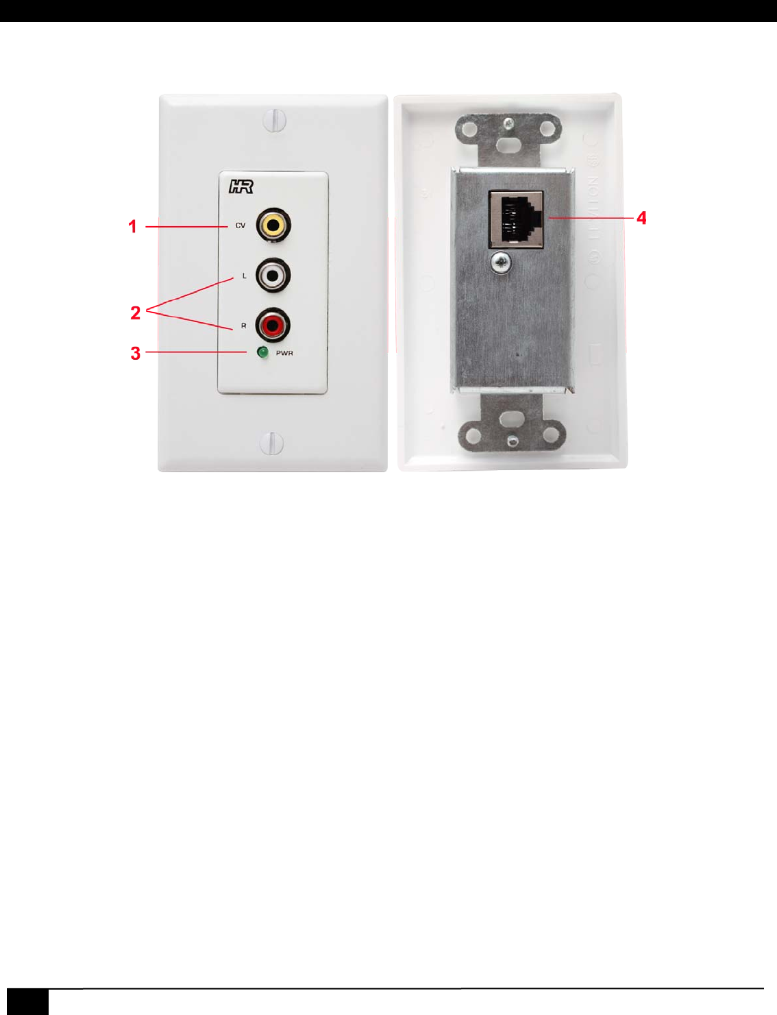
2.4 VSA-C-DP
The VSA-C-DP is a modular input plate that sends composite video and audio to the receiver via a single UTP cable.
VSA-C-DP Front and Rear
1. Composite Video input.
2. Left and Right audio input on RCA connectors.
3. Power LED indicates power received from VSA-51-R. This should be active as long as the connection is good
and the VSA-51-R has power.
4. RJ45 Port A connects to Port A of CV1 or CV2 on the VSA-51-R via Cat5 cable.
Digital AV Room Control System
13
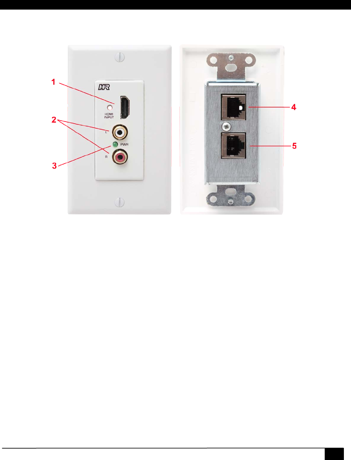
2.5 VSA-H-DP
The VSA-H-DP is a modular input plate that sends HDMI and audio to the receiver via 2x UTP cables.
VSA-H-DP Front and Rear
1. HDMI input with threaded insert for compatible locking HDMI cables.
2. Left and Right audio input on RCA connectors.
3. Power LED indicates power received from VSA-51-R. This should be active as long as the connection is good
and the VSA-51-R has power.
4. RJ45 Port A connects to Port A of HDMI/DVI on the VSA-51-R via Cat5e/6 cable.
5. RJ45 Port B connects to Port B of HDMI/DVI on the VSA-51-R via Cat5e/6 cable.
The HDMI/DVI connection from VSA-H-DP input wall plate to the VSA-51-R receiver consists of two twisted pair (UTP or
STP) cables. The receiver labels the pair of RJ45s as input 3 and each RJ45 is designated as Port A and Port B.
Port A carries high-speed digital video data, while port b carries low bandwidth audio, and handshake data. Therefore the
type of cables used can affect the distances that can be achieved.
For best results (particularly for distances over 50 ft / 15 meters), it is recommended that 23 gauge Cat6 (or higher) cable
be used for connection of Port B of the HDMI/DVI. All other UTP connections on the VSA-51 can be either Cat5e or Cat6
regardless of the distance.
14
VSA-51
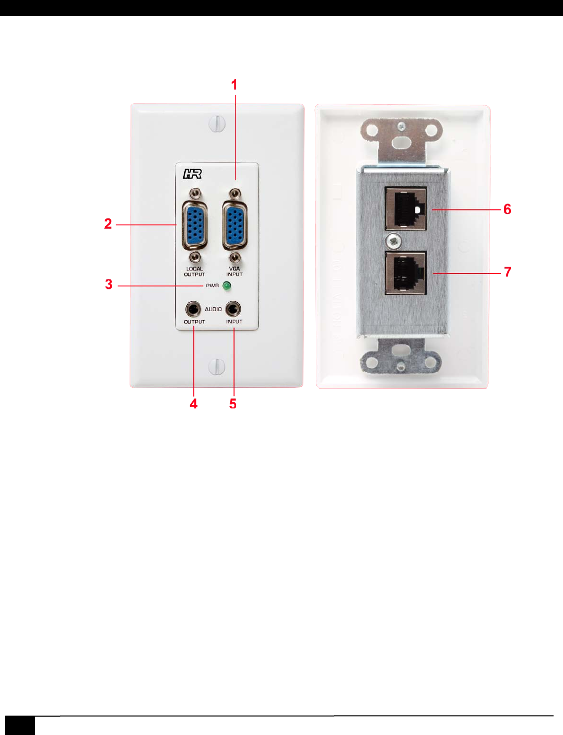
2.6 VSA-V-DP
The VSA-V-DP is a modular input plate that sends VGA or YPbPr and audio to the receiver via 2x UTP cables. It also
features a local output for directing video and audio back to a local console.
VSA-V-DP Front and Rear
1. VGA input accepts both RGBHV and YPbPr signals on an HD15 connector.
2. Local VGA Output loops the VGA input signal out for use at a local display.
3. Power LED indicates power received from VSA-51-R. This should be active as long as the connection is good
and the VSA-51-R has power.
4. Audio Output loops the Audio input out for use at a local audio monitor.
5. Audio input accepts stereo audio on a 3.5mm jack.
6. RJ45 Port A connects to Port A of VGA1 or VGA2 on the VSA-51-R via Cat5 cable.
7. RJ45 Port B connects to Port B of VGA1 or VGA2 on the VSA-51-R via Cat5 cable.
Digital AV Room Control System
15
2.7 VSA-MNT
The VSA-MNT is an optional projector ceiling drop mount system that comes in two variations: VSA-MNT-01 and VSA-
MNT-02. The VSA-MNT-01 consists of just a projector cage mount. The VSA-MNT-02 consists of a projector cage mount,
ceiling plate and pole.
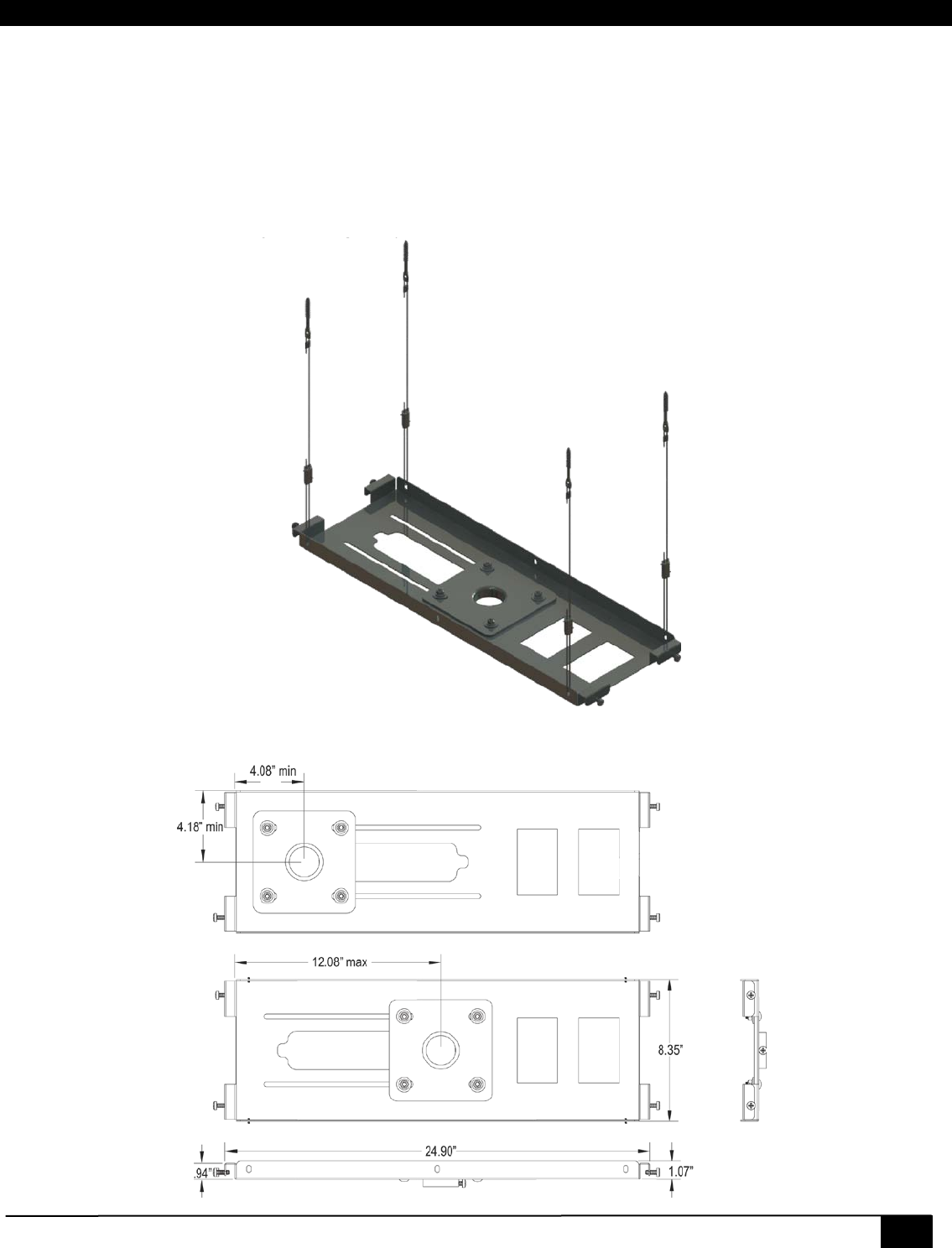
2.7.1 VSA-MNT Ceiling Plate
The Ceiling Plate provides mounting support up to 50lbs for suspended ceilings. The plate fits within any standard 2’x2’ to
2’x4’ ceiling tiles and includes cutouts for Carlon B114R electrical boxes.
VSA-MNT Ceiling Plate
16
VSA-51
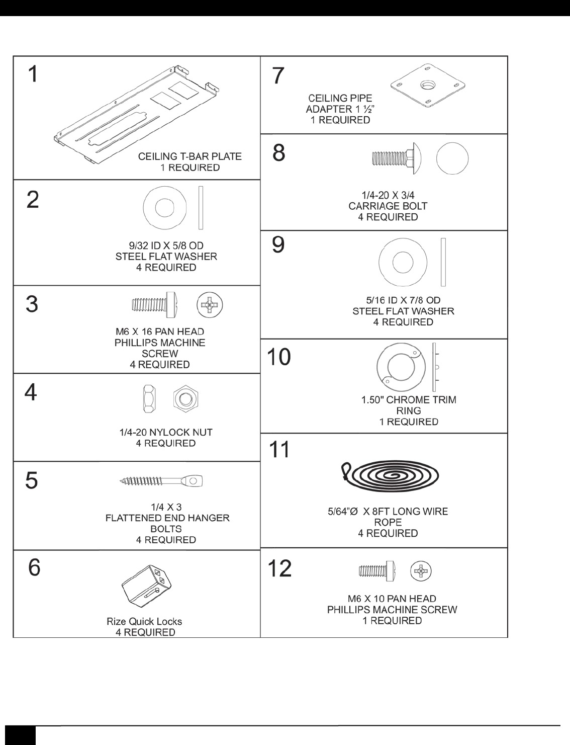
2.7.1.1 Hardware
Digital AV Room Control System
17
WARNING
• The ceiling structure must be capable of supporting at least 5 times the weight of the projector and the CEILING
PLATE kit. Incorrect installation can cause the projector to fall and cause injury.
• Always install so that the load is carried by the ceiling support structure through the guide wires and quick locks
supplied.
• Use the specified bolts and screws in the specified places and tighten them firmly. Failure to do this could cause
injury if the projector falls.
CAUTION
• Do not attempt to perform this work by yourself.
• Manufacturer assumes absolutely no responsibility for injuries and damages that may occur due to improper
installation and handling.
• Avoid installing in locations where the temperature and humidity are excessively high, and where contact with any
water is possible. These can result in fire or electric shock.
• Do not install close to an air conditioner intake or outlet. Do not install in locations where there are excessive
amounts of dust, oily smoke or tobacco smoke. Fire could result.
• Do not block the ventilation holes. Leave sufficient clearance in regard to the surroundings to avoid blocking the
ventilation. The internal temperature could elevate and possibly result in fire.
• Do not install in locations where there is excessive vibration or impact. Injury and damage could result from the
projector mount falling.
2.7.1.2 Installation
18
VSA-51
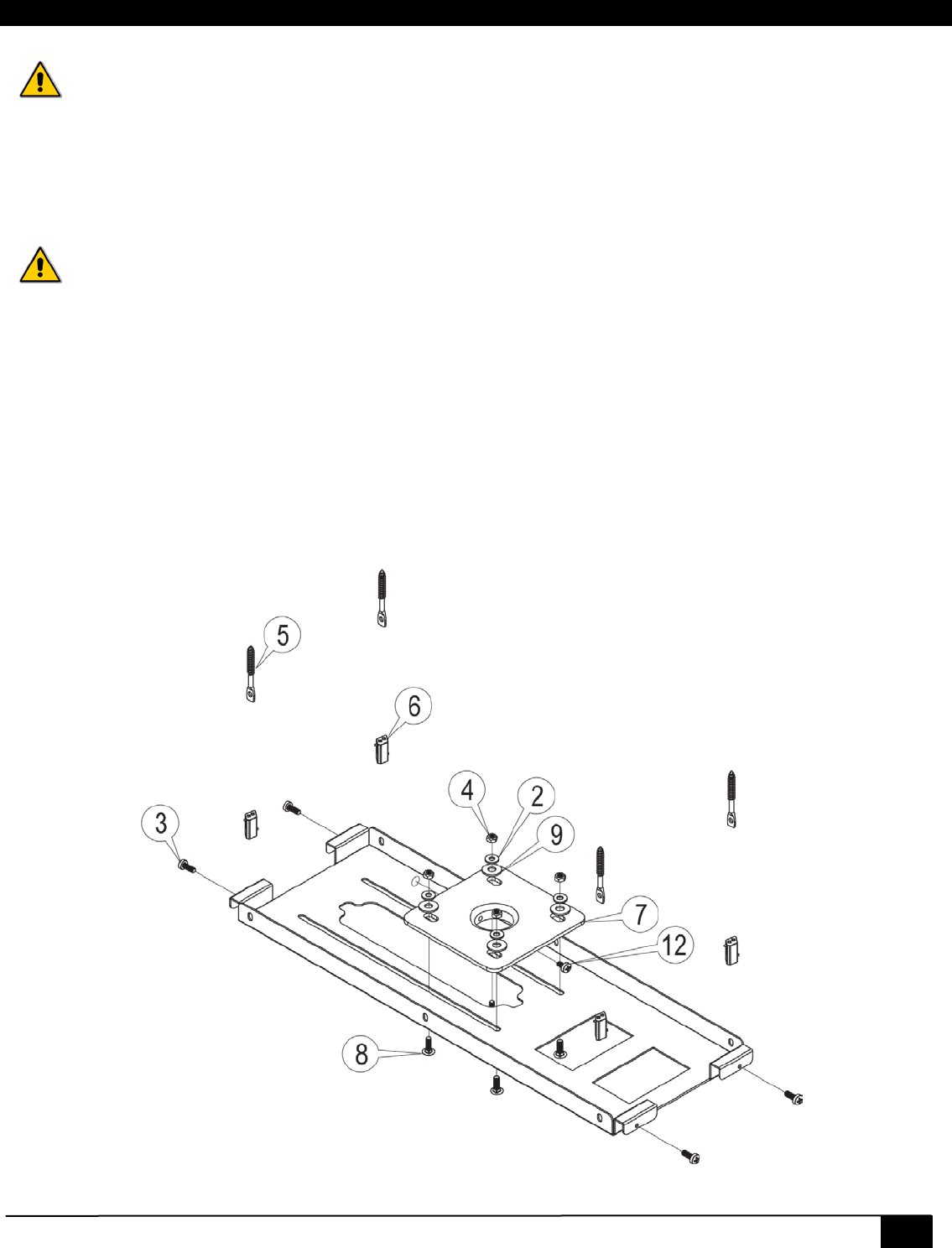
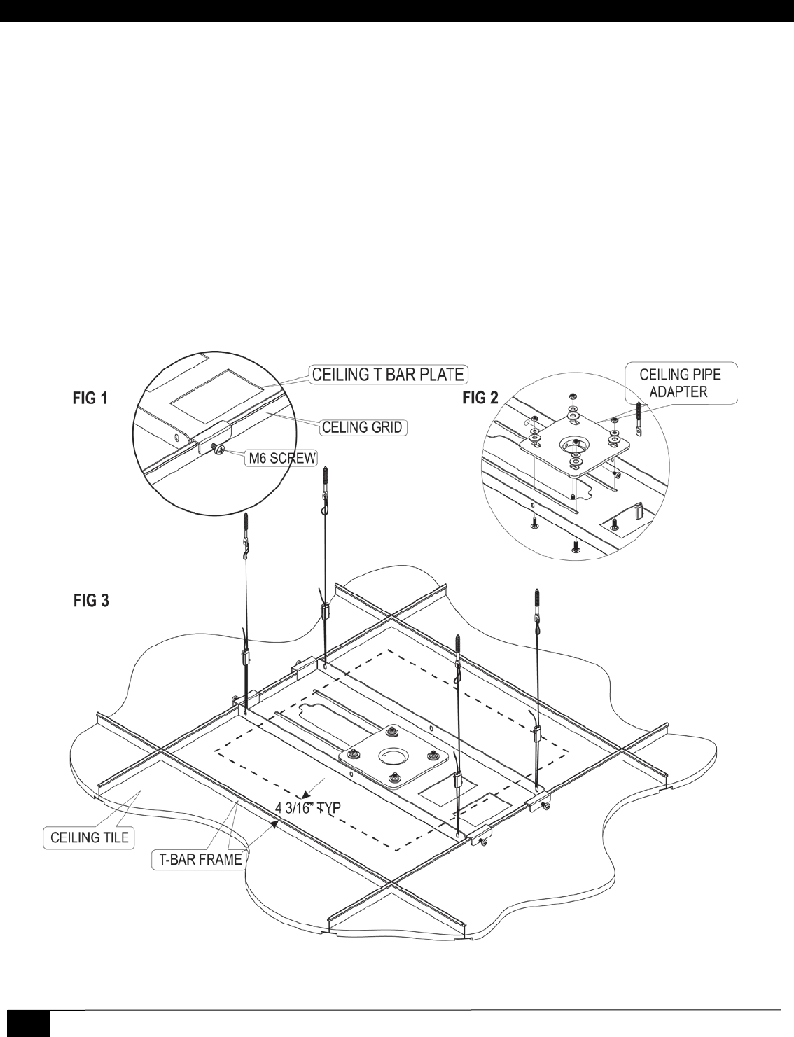
Ceiling Plate Assembly
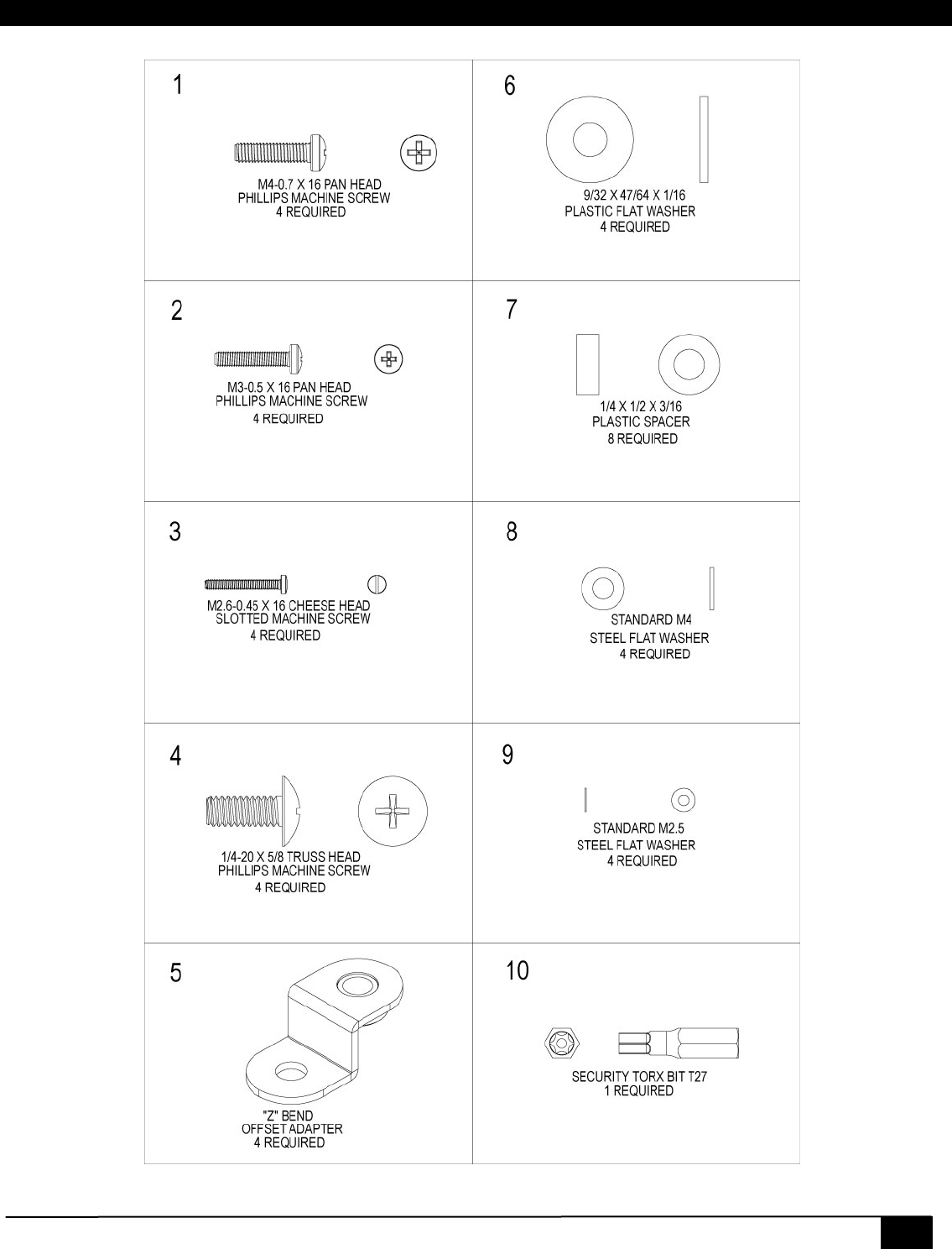
1. Install the (#3) M6 screws into the ends of the (#1) ceiling t-bar plate. Leave enough room to slide over the ceiling
grid bars. See fig 1.
2. Install the (#7) ceiling pipe adapter onto the (#1) plate using the hardware (#2, 4, 8, 9). Do not tighten at this time.
See fig 2.
3. Determine where the 1 ½”pipe will be located in the ceiling. The ceiling plate center point can be located
anywhere within 4 3/16” from any outer edge of the tile See fig 3. Place a mark on the location and drill a small
hole through the ceiling tile.
4. Remove the tile adjacent to the tile where the pipe mount will be installed (for easy access).
5. Place the ceiling plate kit into the grid and adjust the mount to the center of the pilot hole drilled into the tile. See
fig 3.
6. Using a pencil trace the inside of the Ceiling pipe adapter onto the ceiling tile.
7. Remove the ceiling plate and the ceiling tile.
8. Using a knife, saw blade or hole saw, cutout the area marked by a pencil. Include enough clearance for the pipe
and lock screw (#12).
9. Replace the ceiling tile and the ceiling plate mount into the ceiling grid. Check the alignment of the clearance hole
for the pipe and the hardware on the (#7) ceiling pipe adapter. Leave the M6 screws on the ends to the t-bar
loose at this time.
Digital AV Room Control System
19
Ceiling Plate Installation
These instructions are intended for use in a wooden sub structure. Alternate substructure such as concrete or steel
capable of supporting 4 x the weight of the mount and display system can also be used (fasteners not supplied for other
than wood sub structure)
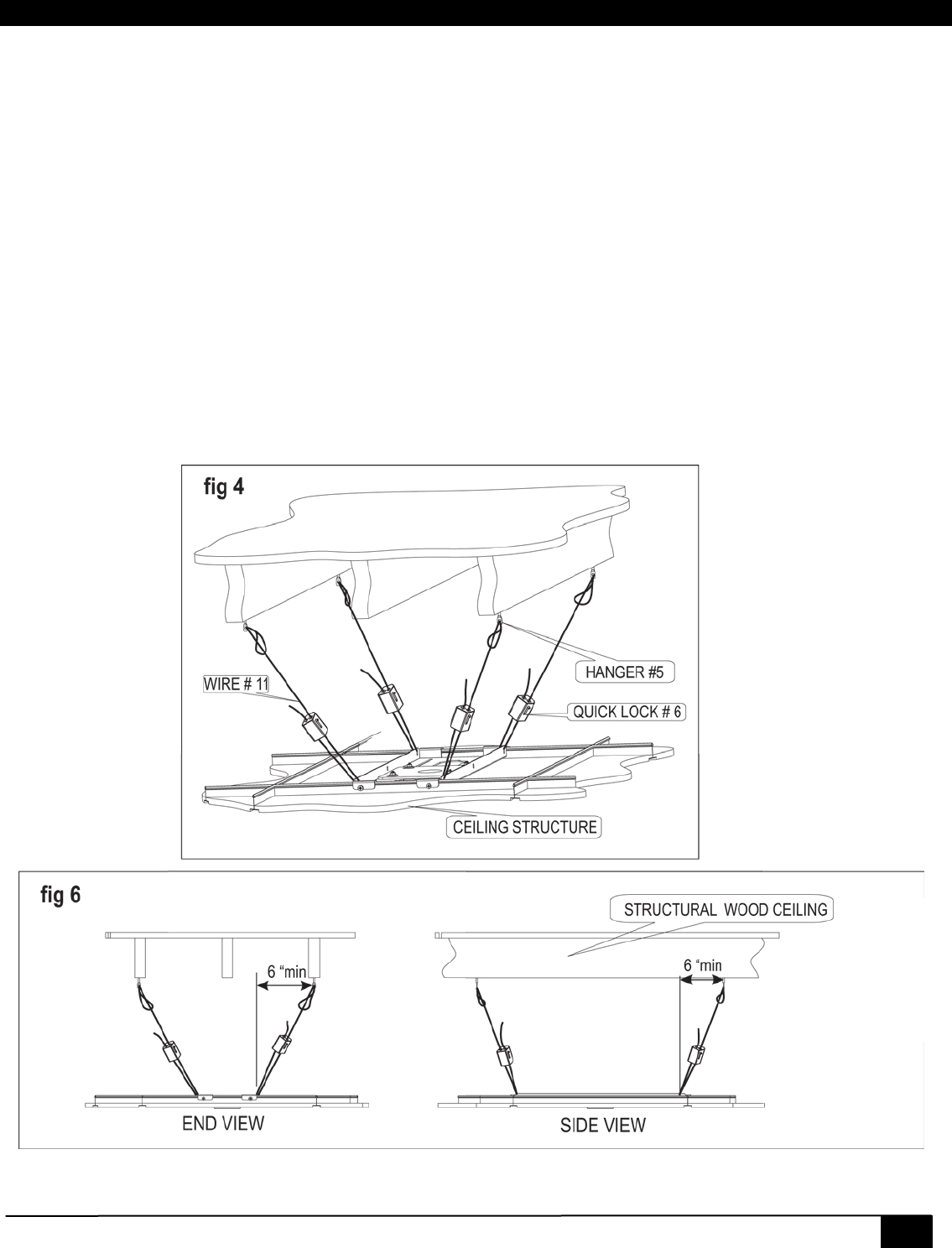
1. Locate the hardware to secure the ceiling plate kit. (#5,6,11).
2. Locate and mark the anchor points for the end hanger bolts (#5). Space the bolts centered above the mount at
least 6” wider on all sides than the ceiling plate mount See fig 4 & 6.
3. Drill a 3/16” pilot hole into the wood substructure and screw the hanger bolts until no threads are exposed about 1
½” deep.
4. Pass the wire (#11) thru the (#5) hanger bolts. Loop the cut end through hanger bolt and then through the looped
end of the wire. Pull snug to take up the slack in the wire.
5. Pass the wire through the (#11) Quick lock and through the (#1) ceiling plate and back again through the quick
lock.
6. Apply a small hand pressure on the ceiling plate downward and pull the wire through the quick lock until the slack
is removed.
7. A final adjustment will be needed with the 1 ½” pipe and projector installed.
NOTE: The Ceiling Plate is supported by the wire rope and (#6) “Quick Locks” not the false ceiling
structure or t-bars.
20
VSA-51
2.7.2 VSA-MNT Cage Mount
The projector cage mount is universally compatible with most projectors. The VSA-51-R mounts inside the cage keeping
connections securely fastened and all electronics below the ceiling. The projector inversely mounts to the bottom of the
cage and can be adjusted on 3-axis using the adjustment knobs as shown below.
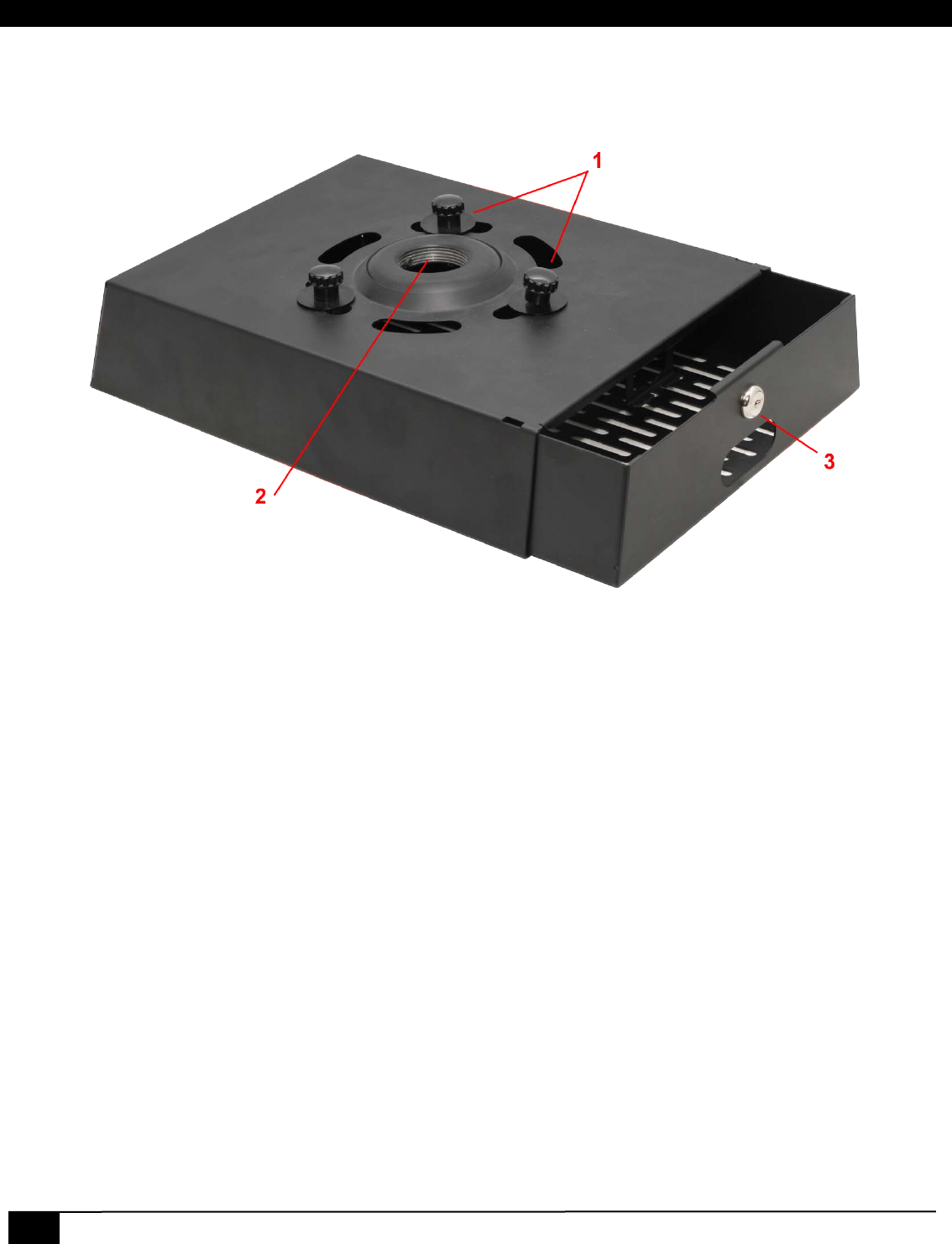
VSA-MNT cage mount
1. Adjustment knobs for adjusting pitch and roll.
2. 1.5” NPT Threaded Pipe Insert. Use with any custom length pipe.
3. Security Lock to keep cage contents secure.
Digital AV Room Control System
21
2.7.2.1 Hardware
22
VSA-51
2.7.2.2 Installation
CAUTION
• Do not attempt to perform this work by yourself.
• Request an installation specialist to install this unit.
• Manufacturer assumes absolutely no responsibility for injuries and damages that may occur due to improper
installation and handling.
• Please remember that if you remove the mount from the wall/ceiling later, you will find the screw holes and anchor
bolts for the mounting unit left on the wall.
• Avoid installing in locations where the temperature and humidity are excessively high, and where contact with any
water is possible. These can result in fire or electric shock.
• Do not install close to an air conditioner intake or outlet. Do not install in locations where there are excessive
amounts of dust, oily smoke or tobacco smoke. Fire could result.
• Do not block the ventilation holes. Leave sufficient clearance in regard to the surroundings to avoid blocking the
ventilation. The internal temperature could elevate and possibly result in fire.
• Do not install in locations where there is excessive vibration or impact. Injury and damage could result from the
projector mount falling.
• Do not install where there is direct sunlight or other strong light. Strong light could result in eye fatigue during
usage.
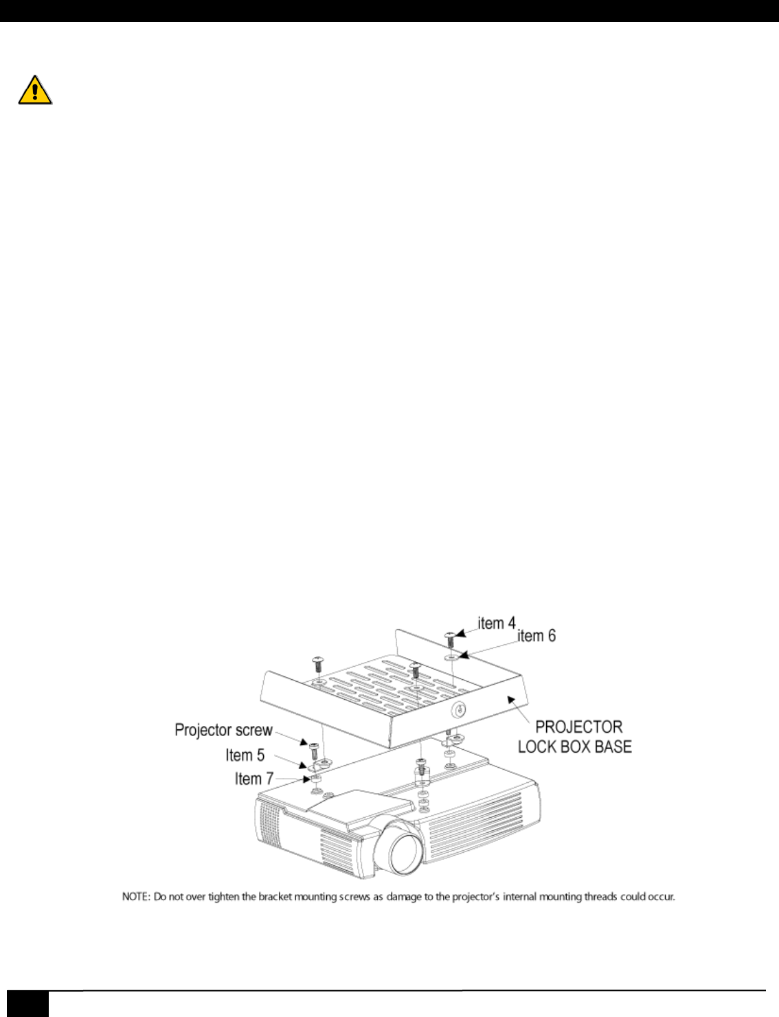
1. Place the projector on a padded surface.
2. Locate the proper screws and washers supplied to fit your projector.
3. Using the brackets (item 5), screws and spacers (item 7), fasten the brackets to the projector. (Only snug screws
at this time)
4. Place the lock box base on top of the projector and rotate the brackets (item 5) to align with the slots in the base.
5. Make sure projector is centered below lock box base, to evenly distribute weight. Fully tighten screws to projector.
6. Fasten the projector to the mount using the screw (item4) and washer (item6) through the base and into the
threaded bracket. (See Projector Installation)
7. Attach projector lock box cover to 1.5” NPT. Be sure to engage security screw into the pipe.
8. Route the wires thru the pipe, down and out the back of the cover to the projector. Slide the base into cover and
secure with the lock.
9. Adjust the 3 knobs for a squared picture.
Projector Installation
Digital AV Room Control System
23
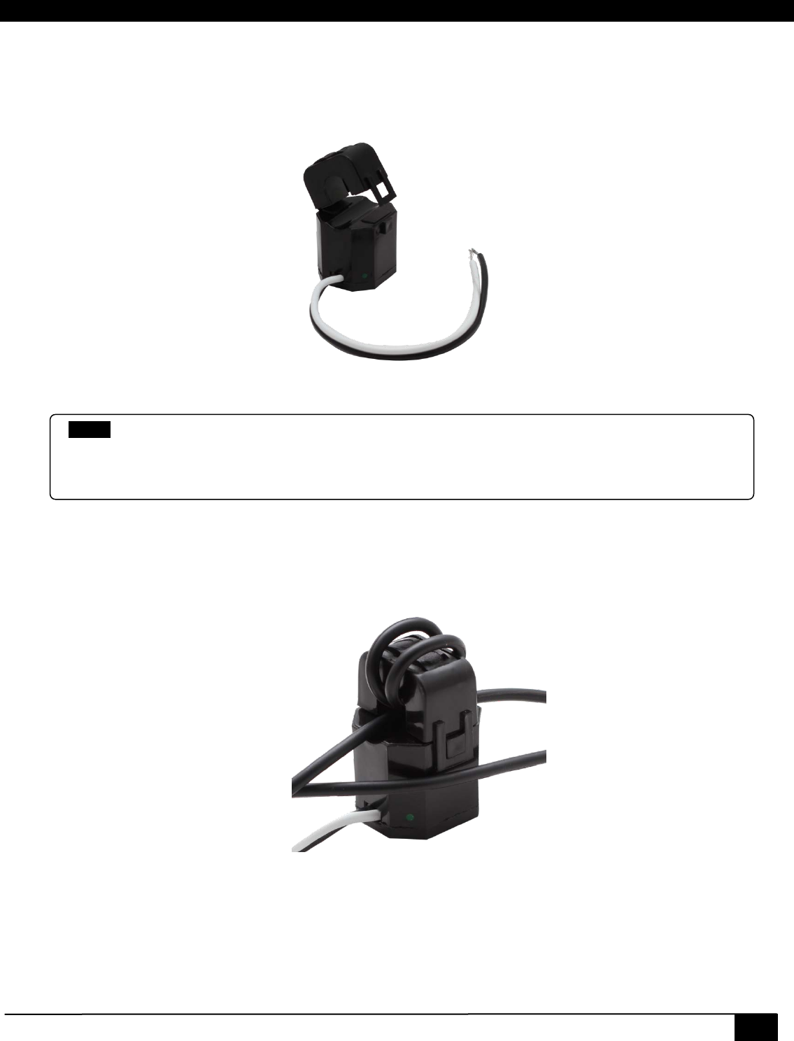
2.8 VSA-PGSNS
The VSA-PGSNS is an optional kit to enable the Priority Page Sense Mute feature. It uses a non-invasive sensor that
monitors existing PA lines without having to splice into the wires. The sensor detects when the PA system is activated and
sends a signal to the VSA-51 to mute the audio. Once the PA line goes quiet the VSA-51 resumes audio.
VSA-PGSNS
2.8.1 Installation
1. To install the VSA-PGSNS, first locate the PA line.
2. You will need to isolate one of the wires from the pair to run through the sensor. Carefully separate the wire pair
taking caution not to sever the line or expose the wire inside the insulation.
3. Wrap one of wires around the sensor lid 2-3 times as shown below.
4. Connect the leads on the sensor to the VSA-51-R port labeled “page sense”. Connect white to SN (+) and black
to G (-).
5. Now that the sensor is installed it still needs to be calibrated for sensitivity. Refer to the software documentation
on how to adjust the VSA-PGSNS sensitivity.
NOTE
The optional Page Sensor works with 25 V or 70 V and even 4/8 ohm PA systems. It is not designed for,
two-way intercoms or IP-based paging systems. The sensor measures AC audio current going to the PA
speaker and compares it against a “set point” to ignore background PA system noise. The mute trigger
sensitivity is easily set using the web-based software from any PC, tablet, or smart phone.
24
VSA-51
3 Software
The VSA-51 offers true flexibility in access and control. All configuration and control software is embedded in the receiver
and served over HTTP to a browser which means you can access and control the device from a PC, Mac, smart phone, or
tablet. Custom programmable serial strings allow advanced control of virtually any display plus an additional serially
controlled device and 2 discrete outputs. Software features include embedded device control, task scheduling and
automation, theft detection, and more.
One of the major features of the VSA-51 is the embedded IP Manager software. The IP Manager allows you to configure
and control a VSA-51 from almost any PC, Tablet or Smart Phone. This gives users the flexibility to remotely control a
VSA-51 without being tied to any specific computer or having to preinstall any software.
NOTE All of the configuration of the VSA-51 is handled through the IP Manager so in order to setup your system you
will need to login from a compatible browser. The VSA-51 software uses websockets for bi-directional
communication between the receiver and your browser so you must use a browser that supports websockets.
Compatible browsers as of April 2011 are:
• Google Chrome (10.0 and later)
• Firefox 4 (with websockets enabled)
• Safari 5
• Mobile Safari (iOS 4.2 and later)
Apple iPad, iPhone, iPod Touch (basically iOS devices with version4.2 or above ) are currently supported
NOTE Websockets transmits on TCP port 9987. This port needs to be open on the network to be able to access the
embedded software for configuration or control. If port 9987 is blocked the configuration page will partially load
but will display “Not connected” status. This indicates that http (port 80) is working but websockets (port 9987)
is not.
Digital AV Room Control System
25
3.1 IP Settings
This section covers all the steps necessary to setup your system
3.1.1 IP Address
The VSA-51 comes preconfigured for DHCP which means it will automatically obtain an IP address when it is connected
to the LAN. It is recommended that you set a static IP on each system in order to guarantee it maintains the same
address. In order to set a static IP you must first discover what DHCP address was issued and then login to reconfigure
the settings.
3.1.1.1 Assigning Static IP address using the web interface
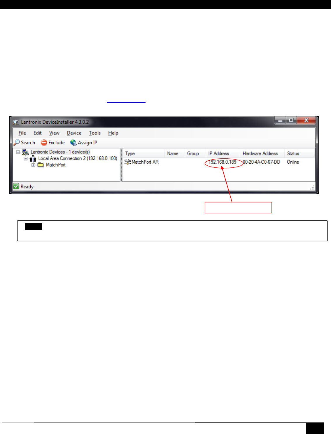
Before you can access the device on your browser, you need to know what temporary IP address has been assigned to it
by your LAN. Download and install the DeviceInstaller utility available on Hall Research Website. Once installed, run the
program. It will scan your LAN and locate any devices that are connected.
DeviceInstaller
Follow these steps to configure the VSA-51 IP address.
1. Open your browser and enter the IP address indicated by DeviceInstaller.
2. Login with the default username “admin” and password “pass”.
3. Click on Configuration -> System -> Communications. Here you can set the unit for DHCP or static IP. It’s
best to assign a static IP so the address will always remain the same.
4. Set the IP address to a known reserved IP.
5. Set subnet mask to 255.255.255.0.
6. Set the gateway. This is usually XXX.XXX.XXX.1 where the first three octets match the subnet.
(i.e.: 192.168.0.1)
7. Set DNS servers. If you don’t know this information you can usually specify the gateway address for the
primary DNS. Secondary DNS is optional.
8. Click reboot. It should take approximately 15 seconds for the unit to reboot and come back online.
9. Change the IP address in the browser address bar to match the new VSA-51 IP address and hit enter. If you
are prompted to login again then the VSA-51 is properly configured with a new IP.
Your Device’s IP Address
NOTE
Don’t try to change the IP address of your appliance here. The IP address can be changed from Web interface or
from Serial interface

26
VSA-51
3.1.1.2 Assigning IP address using the RS232 Port on the Receiver
The serial port on the receiver is normally used to control a projector, but you can use it to set an IP address.
Since the baud rate the port operates when communicating with the projector is unknown, the following procedure
assumes that you have just powered up the receiver and have not pressed any buttons on the user interface keypad to
send commands to the projector.
Upon power up the receiver assumes a baud rate of 19200 bps, and you can communicate with it at this rate
Connect a DB9 Female-to-Female cross over cable from your PC (use a USB to Serial adapter such as Hall Research
model USB-RS232-1) to the receiver. Use a terminal emulator on your PC (such as HyperTerminal) and set it up to
operate at 19200 baud with no handshake.
First put the system into administration mode:
Command: SUDO<cr>
Response: SUDO<cr>
Once in administration mode you can issue the following commands:
Set IP address:
Command: IP<space><ip_address_value><cr>
Error Response: ERR3
Success Response: IP=<ip_address_value>
Example command: IP 192.168.1.100
Example response: IP=192.168.1.100
Set Subnet address:
Command: SN<space><sn_address_value><cr>
Error Response: ERR3
Success Response: SN=<sn_address_value>
Example command: SN 255.255.255.0
Example response: SN=255.255.255.0
Set Gateway address:
Command: GW<space><gw_address_value><cr>
Error Response: ERR3
Success Response: GW=<gw_address_value>
Example command: GW 192.168.1.1
Example response: GW=192.168.1.1
Restore Factory Defaults: All system configurations (including button functions and actions) will be erased and replaced.
Command: FDT<cr>
Error Response: ERR3
Success Response: FDT
Exit administration mode:
Command: EXIT<cr>
Error Response: ERR3
Success Response: EXIT
NOTE
You must reboot the device for the network changes to take effect.
Digital AV Room Control System
27
3.1.2 Configuration File
Configuring multiple VSA-51 systems can be time consuming. Fortunately, we’ve made it easier by allowing you to save a
configuration and upload it to other systems, requiring only minimal changes. All configuration including settings, users,
actions, groups, buttons, events and state information are stored in a file called ‘config.js’. This file can be downloaded or
uploaded through the IP Manager interface.
3.1.2.1 Save Configuration
Follow these simple steps to save the configuration settings:
1. FTP into the device. You can use a free FTP utility like Filezilla.
2. Login with username: admin password: PASS
3. Download the “config.js” file. This contains all the system configuration information.
You can now keep this file as a backup or use it to configure other systems
3.1.2.2 Upload Configuration
Follow these simple steps to upload a configuration file:
1. FTP into the device.
2. Login with username: admin password: PASS
3. Upload “config.js” file and overwrite the existing one.
4. Reboot the device for the changes to take effect.
If you have uploaded a configuration from another system with a static IP then you should power down or disconnect the
original system before rebooting the new one with the same configuration because once the new system reboots it will try
to obtain the same IP address which will cause conflicts on the network. Once the new system reboots you can login and
change the IP and system information.
3.1.3 Firmware Upgrade
Occasionally we may release firmware upgrades to address bugs or add new features. You can safely upgrade your
firmware with the following procedure:
1. If you have made changes to the system then you should save the configuration file.
2. Download the latest firmware file from our website at http://www.hallresearch.com/page/Products/VSA-51 and
extract the contents. There should be a file called Matchport_ar.romz and a folder called http. Matchport_ar.romz
is the actual firmware file. The http folder contains the VSA IP Manager Web code.
3. Open an FTP connection to the VSA-51 using an FTP client like Filezilla. Login with the username: admin and the
password: PASS.
4. Once connected, upload the HTTP folder into the root directory, overwriting the existing one. You may be
prompted to confirm overwriting existing files. Say yes to all as we want to replace the existing HTTP directory
with the new one. During the upload process you may see the system pause briefly on some files. This is
because the system needs to compact itself for adequate space. It shouldn’t time out during this process but if it
does and fails to upload any files then you reconnect and reinitiate the transfer for the missed files.
5. Once the HTTP folder is finished uploading, upload the file Matchport_ar.romz to the root directory. Once the file
has finished uploading the device should restart automatically but if not you can simply reset the power to force a
reboot.
6. Once the system is rebooted it will have the latest firmware running. You can verify this by logging in and
checking the firmware version on the status page. Note that the system is set by default for DHCP so once it
reboots with the new firmware it may not have the same IP address as before. You may need to redetect the
device on the LAN before you are able to reconnect. Also note that if the system was previously configured then
the config file will need to be uploaded.
NOTE
The config.js file is JSON format. JSON is very particular about syntax and spacing. It is not recommended to
manually edit the config file unless you are absolutely sure what you are doing. Any mistakes in the file could
cause the system to be unstable.
28
VSA-51
3.2 VSA IP Manager
The Web Manager is divided into 3 main top level sections: Status, Control and Configuration. The Status tab displays a
summary of unique information about the system configuration and its state. The Control tab displays a dynamic user
interface to control the system, similar to the User Interface panel (VSA-UI-DP) and expansion (VSA-UI-8). The
Configuration tab is where all configuration takes place including system settings, users, actions, buttons, grouping, and
scheduling.
The Web Manager Navigation tree is structured as follows:
• Status
• Control
• Configuration
• System
o Basic
o Communications
o Advanced
• Users
• Actions
• Buttons
• Groups
• Scheduling
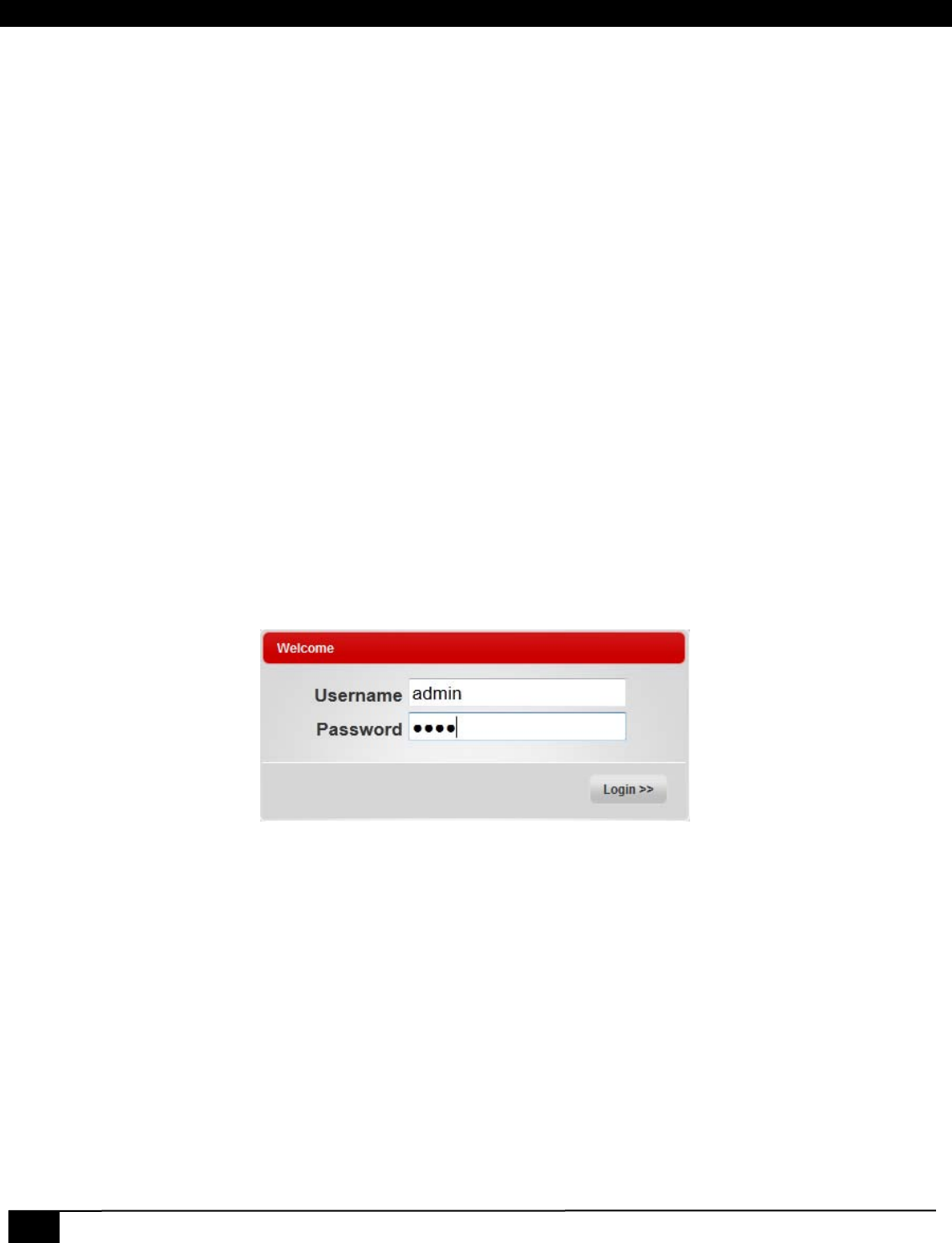
3.2.1 Connect & Login
To connect to the VSA-51 IP Manager you must first know the IP address. See section 3.2.1 for how to locate the IP
address.
Enter the address of the device in the URL bar of your browser. For example, http://192.168.0.100. You will be prompted
with a login box. The default username and password are: username admin password pass
Digital AV Room Control System
29
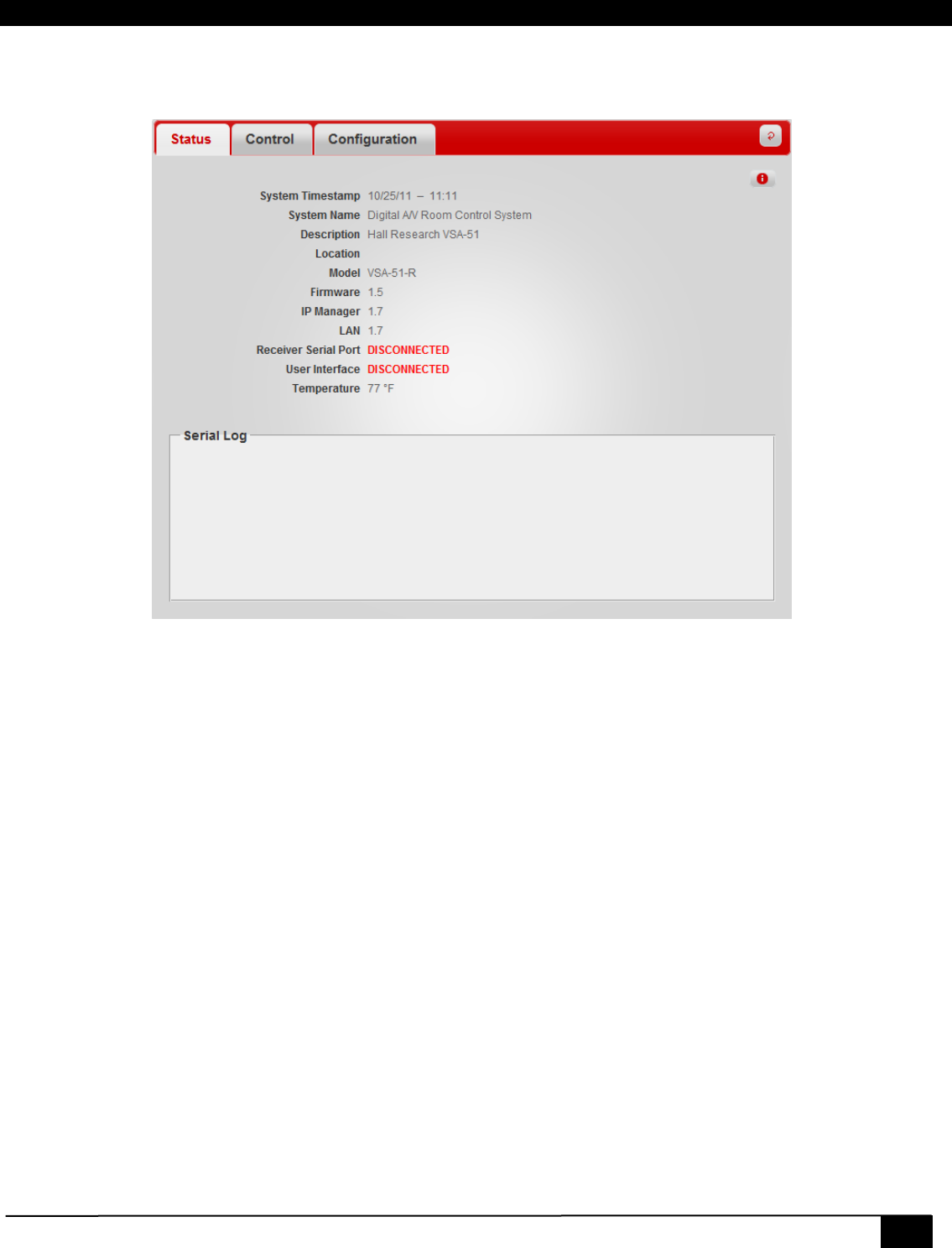
3.2.2 Status
The Status tab displays a summary of information about the system such as the system time, installation profile, and
connection status.
Status Tab
System Timestamp
The current system time. This is refreshed approximately once every minute.
System Name
This is the System Name specified under Configuration - Basic settings.
Description
This is the Description specified under Configuration - Basic settings.
Location
This is the Location specified under Configuration - Basic settings.
Model
This is the product model name.
Firmware
Current firmware version(s)
Receiver Serial Port
This indicates if a display’s RS-232 port is physically connected to the VSM-51 receiver. The system uses a proprietary
method to detect the presence of a projector. A disconnected status means either the projector is unplugged from the
receiver or it is disconnected from AC power. This can be used a theft detection scheme.
User Interface
This indicates if the User Interface panel (VSA-UI-DP) is connected to the receiver. If the UI panel is installed and this
reads DISCONNECTED then there may be a problem with the connection. Note that the VSA-UI-DP is not required and
some installations may not utilize it so in that case a DISCONNECTED notification may not be a problem.
30
VSA-51
Temperature
This is the current temperature reading of a chip’s core on the receiver printed circuit board. There are many components
on the board that generate heat, so don’t be alarmed if the reading is high
as it typically reads around 30 °F above ambient.
An internal fan will automatically come on if the temperature reading exceeds 120 °F.
The Audio amplifier is a class D and very efficient, but if it is pumping 42 watts of continuous power it will create additional
heat (plus the fact that the receiver is in a vault above a projector that creates more hot air. So it is possible for the fan to
turn on and off during use.
The audio amp has hardware shutdown for over temperature condition to prevent damage. The job of the fan is to prevent
loss of audio due to over temperature of the amplifier.
Serial Log Window
This window shows responses from the serial device (in most cases the video projector connected to the Receiver), in
response to user defined queries.
Say you want to know the total lamp hours of the projector connected to the unit so you can schedule maintenance
sometime before the end of lamp’s life.
You can create an action to send a serial query command to the projector and schedule the action to automatically take
place once a day or week, or whatever. The responses of the projector to these queries will be displayed in the Serial Log
window. In this way every time you click on the Status tab, you will see what the lamp hours were the last time the query
executed. As part of your action definition you can also clear this screen if you only want to see the latest reading and not
have the entire long history displayed.
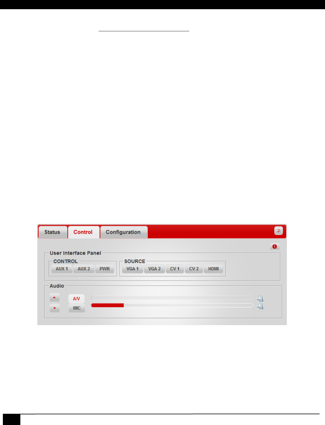
3.2.3 Control
The Control Page is used to control the VSA-51. It can be used with or instead of the UI panel (VSA-UI-DP). The control
panel is updated in real-time even if changes are made at the UI panel or from another connected web client.
The Control page is dynamically created based on Button and Group configuration.
Control Tab
The Control Tab example shows the default button groups and labels. All groups and buttons on the Control page (accept
Audio) are customizable and can be renamed, removed, or modified. For example if you wanted to control another device
like a DVD player via IR or RS232 then you would first create actions for each command and then assign those actions to
buttons (ie: play, stop, pause) and group them under a heading like DVD PLAYER. Section 3.2.3.3 - Actions and 3.2.3.4 –
Buttons explains these steps in more detail.
Digital AV Room Control System
31
3.2.4 Configuration
The Configuration tab is where all the system settings are configured. It is broken down into 6 sub-sections: System,
Users, Actions, Buttons, Groups, and Scheduling.
3.2.4.1 System
The System tab contains 3 sub levels for system configuration: Basic, Communications, and Advanced.
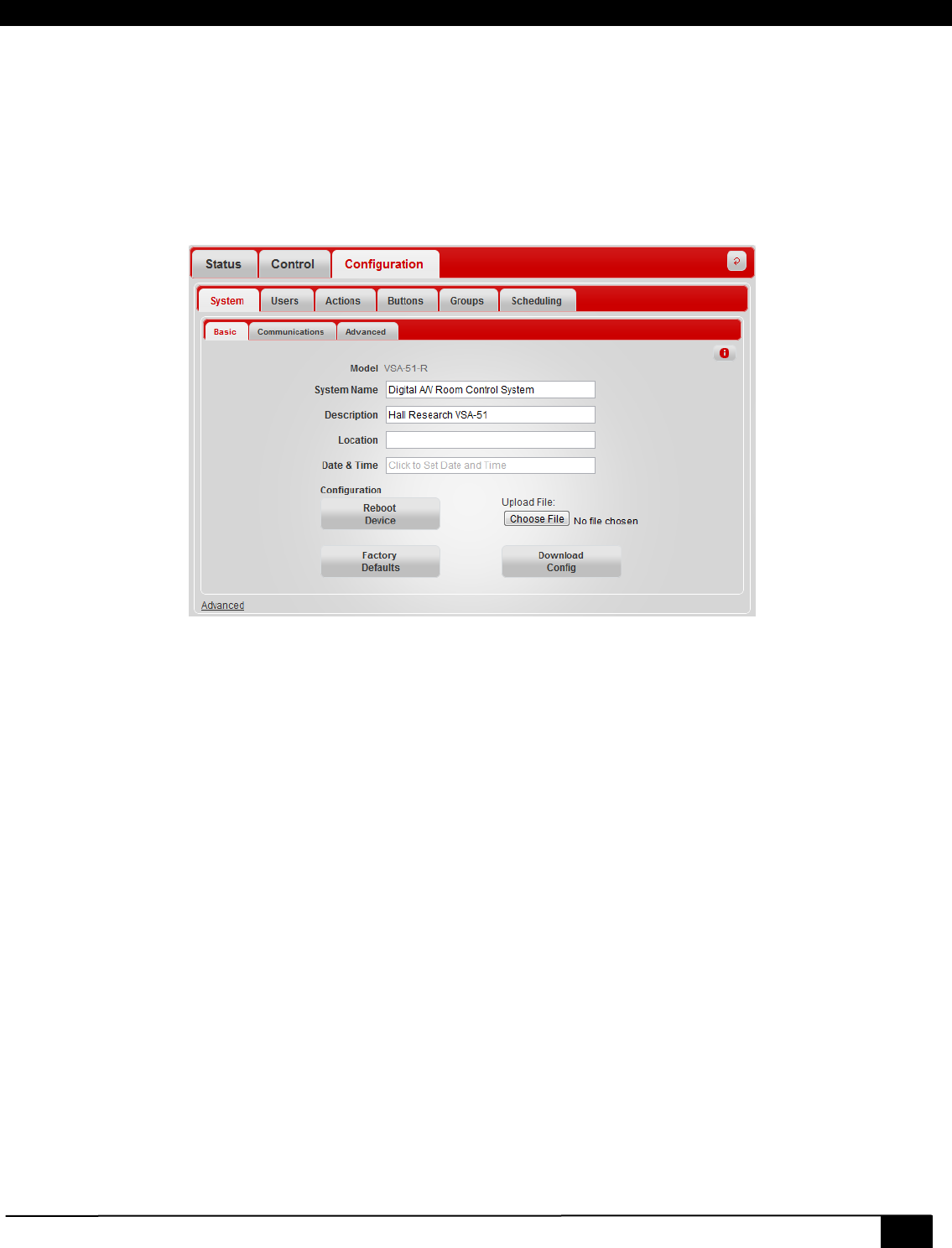
3.2.4.1.1 Basic
The Basic tab is for general system settings and installation profile.
Basic Configuration Tab
Model
The Model is specified in the firmware configuration file.
System Name
System Name is used to identify the device. This would usually be a location descriptor, for example “Main Lecture Hall”.
Description
The Description can provide additional information about the device or the installation.
Location
The Location is used to provide specific location information such as a Room number.
Date & Time
Used to set system Date & Time. The automatic scheduling system is based off this date and time.
Reboot Device
This will force the system to reboot.
Factory Defaults
Restores system back to default configuration. This will erase all custom configuration.
Configuration Upload
Uploads a new configuration file. The configuration file stores all settings and configuration information about a VSA-51
system.
Download Config
Downloads the current system configuration settings.
32
VSA-51
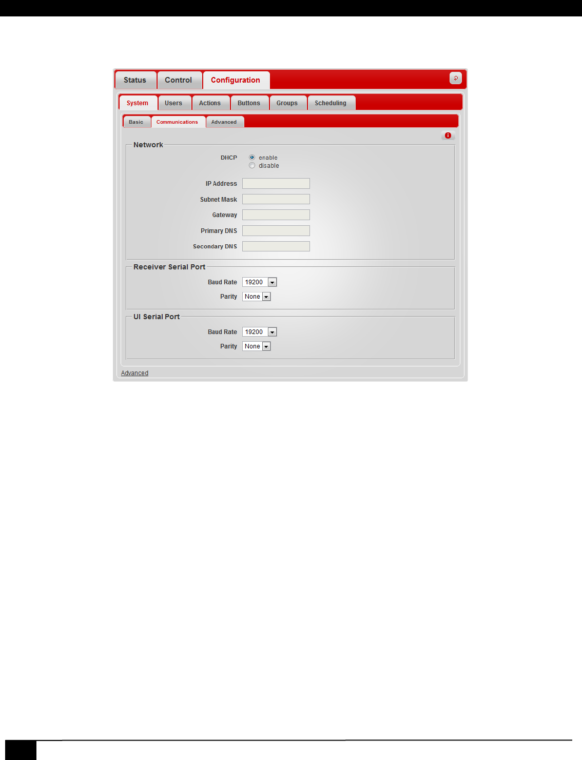
3.2.4.1.2 Communications
The communications configuration page is used for IP and serial communications settings.
Communications Tab
DHCP
Enables or Disables DHCP
IP Address
Specifies a static IP address
Subnet Mask
Subnet mask for static IP configuration
Gateway
Gateway address for static IP configuration
Primary DNS
Optional primary DNS server address for static IP configuration
Secondary DNS
Optional secondary DNS server address for static IP configuration
Receiver Serial Port Settings
Port settings for the serial port on the receiver. This connects to this display.
UI Serial Port Settings
Port settings for the serial port on the VSA-UI-DP. This connects to auxiliary devices.
Digital AV Room Control System
33
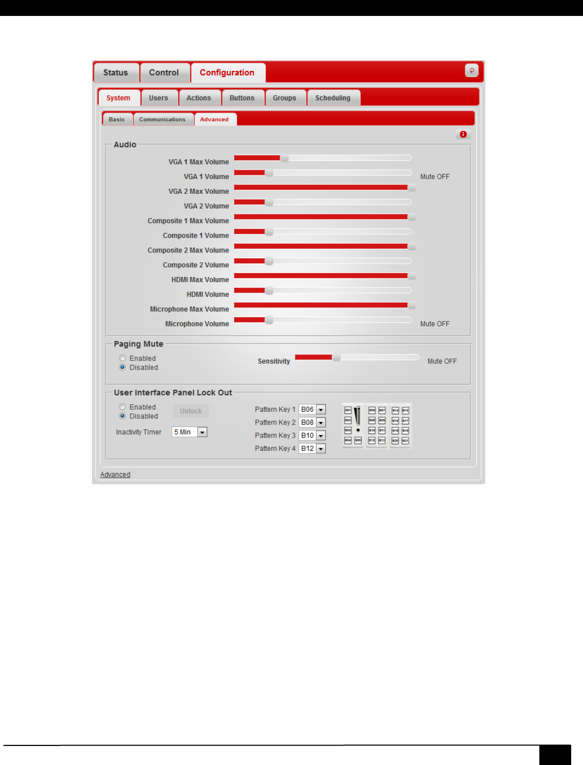
3.2.4.1.3 Advanced
The Advanced configuration tab is used for advanced and optional system settings.
Advanced Configuration Tab
Volume and Max Volume
The Max Vol setting limits the maximum volume level for each source. The volume setting indicates the current volume
level for each source. The volume level is scaled to whatever the max volume is set for so, for example, if max volume is
set to 50% then setting the volume to the highest level would only go as loud as the 50% max volume setting allows.
Paging Mute
The Page mute feature requires the optional Page Sensor Kit (VSA-PGSNS). This feature will automatically mute the
system audio when it detects a signal on the paging line. If enabling this feature then it should be calibrated first by
activating the paging system and adjusting the sensitivity until the mute turns on. It should turn off a few seconds after the
paging signal drops.
User Interface Panel Lock Out
This feature will automatically lock the UI Panel (VSA-UI-DP) after a specified time of inactivity (default is 5 minutes).
Unlocking the panel requires a 4 key unlock code. Program the unlock code by selecting the 4 keys in order from the
dropdown.
34
VSA-51
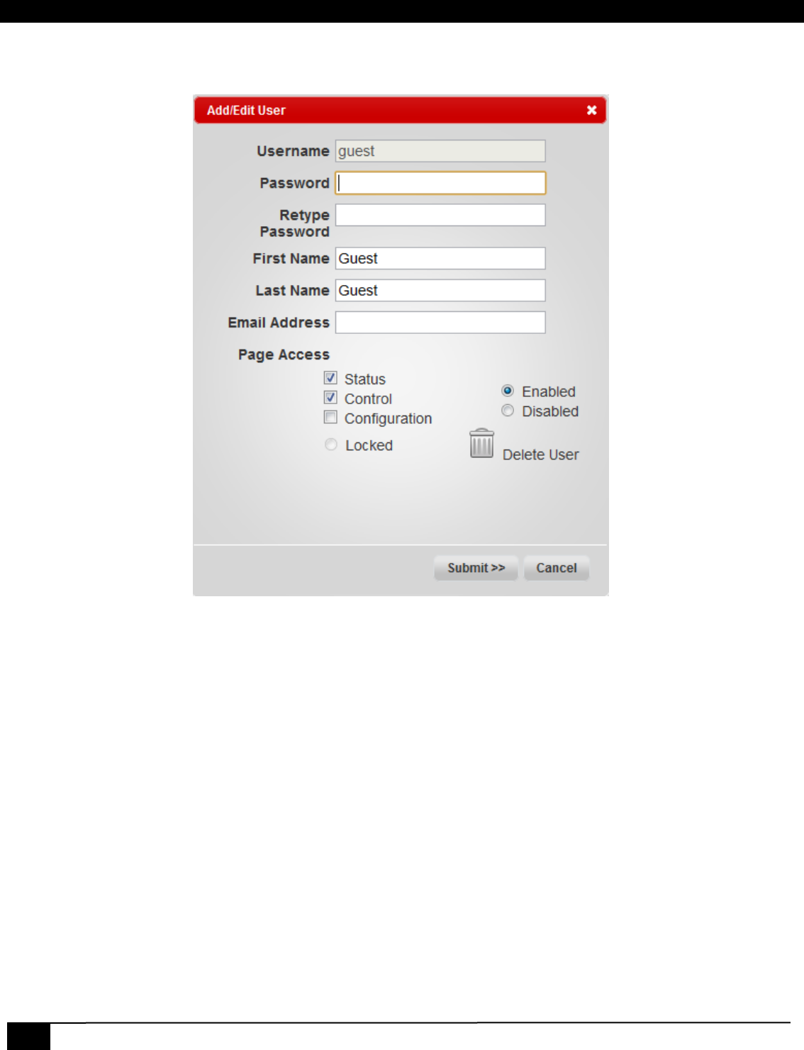
3.2.4.2 Users
The Users Page lists all the users of the system. Click on the username to configure settings for that user or click ‘Add
User’ to create a new one.
Add/Edit User
Username
The username is how a user logs in to the system. Once a user is created the username cannot be changed without
deleting and recreating the user.
Password
This is the password for the account
First Name/Last Name
This is the user’s real name
Email Address
Optional email address.
Page Access
Grants user access to top level pages or tabs. Note that giving access to the Configuration tab grants access to all system
settings. This should be reserved for administers only.
Enabled/Disabled
Enables or disables a user. A disabled user cannot login.
Delete User
Permanently deletes a user. This feature is disabled for Admin user.

Digital AV Room Control System
35
3.2.4.3 Actions
The Actions Page lists all the defined actions of the system. Actions are typically serial, IR, or I/O functions that can be
assigned to buttons or scheduled events. The system comes with default actions, some of which cannot be deleted or
changed.
Click on the name of an Action to edit it or click ‘Add Action’ to create a new one.
Add/Edit Action
Action Name
The action name is used to refer to the action throughout the rest of the system once it is created. This cannot be
changed without deleting and recreating the action.
Description
Provides a brief description of what the action does.
Enabled/Disabled
Enables or disables an action
Delete Action
Permanently deletes an action
Other Actions
Allows you to insert other actions already defined. This gives advanced capability to create chained actions but be careful
when doing so because if one of the actions is improperly setup or has a mistake it could affect other actions down the
chain.
Built-In
Inserts a pre-defined built-in command. For example, switching audio and video source input on the receiver.

36
VSA-51
Time Delay
Inserts a delay to wait before executing the next command in the action sequence
Serial Port
Selects which serial port to assign to the string when it is inserted into the command list. Strings assigned to the Receiver
will go to the connected display. Strings assigned to User Interface will be sent through the VSA-UI-DP serial port.
Serial String
Used for inserting one ASCII Serial command at a time. Hexadecimal codes may be inserted beginning with an &h
followed by a hexadecimal code. For example, a carriage return can be inserted by appending the command with &h0d
IR Protocol
Specifies the IR protocol to use. Choose from the list of compatible protocols.
IR Address
Enter the IR Address in decimal format
IR Command
Enter the IR command in decimal format
Button LED
Selects which button LED to control.
Behavior
Choose to turn LED on, off, or blink.
Action Command List
This box shows the individual commands that make up the entire action sequence. Commands are inserted into the list in
the order they are added, top to bottom. Commands can be reordered by clicking and dragging them to a new position.
Commands can be deleted by clicking the trash can symbol. Click the “Clear” button to delete all the contents of the
action.
Actions are very flexible in that they can be configured in a variety of ways and even linked together to form compound
actions. This flexibility makes them versatile but also makes them a bit tricky to understand at first. For example, if you
wanted to turn down lights, lower a projection screen, and turn on a projector from a single button press then you would
create a compound action consisting of individual actions. First, you would create an action to turn down the lights, either
with IR, RS232, or using a discrete output to open or close a relay. Do the same for the screen and projector. Finally,
create an action that executes all three actions. You can also include a delay in between each action. This is just a basic
example of how to use actions.
3.2.4.3.1 Action Sequence
Notice in the action window for SRCVGA1 the action sequence is:
BL6,1
BL7,0
BL8,0
BL9,0
BL10,0
(VGA1)
Let’s break this action sequence down and explain what is going on.
The first 5 commands are actually turning Button LEDs on/off while the last command tells the VSA-51-R to switch to
VGA1 input. There may be some latency when processing an action sequence so the first thing we want to do is set the
proper button lighting on the keypad to minimize the user perception of any latency.
Digital AV Room Control System
37
The SRCVGA1 action is assigned to Button 6 (labeled “VGA 1”) so the first command is turning the Button 6 LED on
(BL6,1). Button 6 is part of a group with Button 7 (VGA 2), Button 8 (CV 1), Button 9 (CV 2), and Button 10 (HDMI). This is
a radio group which means only one button should be lit at a time (because only one source can be active at a time).
Therefore, we must also turn off the other buttons. Notice we do the same thing for the actions for the other buttons. It
may be tricky at first to understand the concept of turning the LEDs on/off on every action sequence. The important thing
to note is that you must know what button the action is going to be assigned to before you create the action. Also, if the
button is part of a group then you must know what other buttons will be part of the group and what the LED behavior
should be.
The final command switches to VGA input 1. This command is specific to the VSA-51-R and can be inserted from the
“built-in” command dropdown.
3.2.4.3.2 Adding custom strings
The default actions do not contain the serial strings needed to control the display. Once the display type is know, these
actions should be appended with the proper serial command. Continuing with the example above for SRCVGA1, we need
to add the command to switch to the VGA input on our display. To program the system we need a list of the commands to
control our particular display. This can usually be found in the users manual or somewhere from the display
manufacturers website.
Suppose for this example, the command to switch to VGA input on our display is “VGA1<CR>” (without quotes). The
<CR> indicates a carriage return, which is typical. We can input the ASCII characters as given but the <CR> must be
given in hexadecimal format. We can insert hexadecimal strings by first specifying &h followed by the hex code. The hex
code for a carriage return is 0d so to insert a carriage return in the action sequence we need to enter “&h0d” (without
quotes. The exact syntax would be:
VGA1&h0d
Some serial commands are entirely in hexadecimal format. For example, “BEEF” codes typically begin with hex codes of
“BE EF…” (followed by some other bytes). In this case we would enter each byte with &h so it would be: “&hBE &hEF…”
(without quotes).
NOTE
When hex codes are inserted into the action sequence they will show up in the action window preceded by
“\u00”. These are just escape characters used by the system to store and process the codes properly.
38
VSA-51
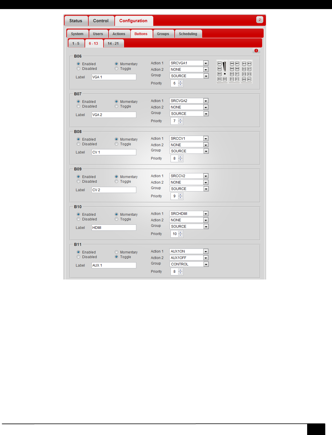
3.2.4.4 Buttons
The buttons page is used to assign actions to buttons and to assign buttons to groups. All buttons are mapped to the
VSA-UI-DP and VSA-UI-8 expansion module. Note that the first 5 buttons cannot be modified because they are
configured for fixed functions such as volume and mute.
Remember the VSA-UI-DP has 8 user configurable buttons.
Digital AV Room Control System
39
Buttons Tab
Enabled/Disabled
This enables or disables a button. A disabled button will not display on the control page and will not perform any action
when pressed on the UI panel.
Label
The label is the name that refers to the button. The label appears on the button on the control page.
Momentary/Toggle
If a button is set for momentary then it will perform the same action every time it is pressed. If set for toggle, it will
alternate between Action 1 and Action 2 each time it is pressed. Note that if a button is set for momentary it will perform
both Action 1 and Action 2 if both are defined.
Action 1
This is the primary action that is performed when a button is pressed.
Action 2
This is the secondary action that is performed when a button is pressed. Typically this is only used for toggle mode.
40
VSA-51
Group
This assigns a button to a group.
Priority
This is an integer value that affects how buttons are ordered within the group. A lower value gives higher priority and
displays first. Buttons with the same priority value will be displayed alphabetically based on the label.
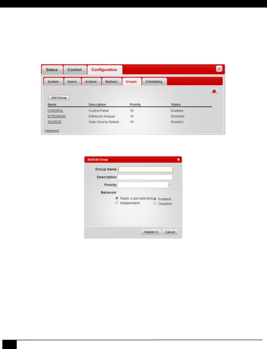
3.2.4.5 Groups
Groups determine how buttons are arranged on the control page. Some predefined groups are created by default.
Default Groups
Click on an existing group to modify it or click “Add Group” button to create a new group.
Add/Edit Group
Group Name
This assigns a name to the group. Note the group name cannot be changed once a group is created.
Description
Provides a brief description of what the group is for (optional).
Behavior
Groups can be configured as either Radio or Independent. Radio groups allow only one button to be active at a time.
Independent behavior allows buttons to behave independently of each other.
Enabled/Disabled
Enables or disables a group. If a group is disabled it will not display on the control page.
Delete Group
Permanently deletes a group.
Digital AV Room Control System
41
3.2.4.6 Scheduling
Events can be created and scheduled to perform once or recurring. This is useful for automating tasks such as
automatically turning a projector off at the end of the day or turning it on in the morning.
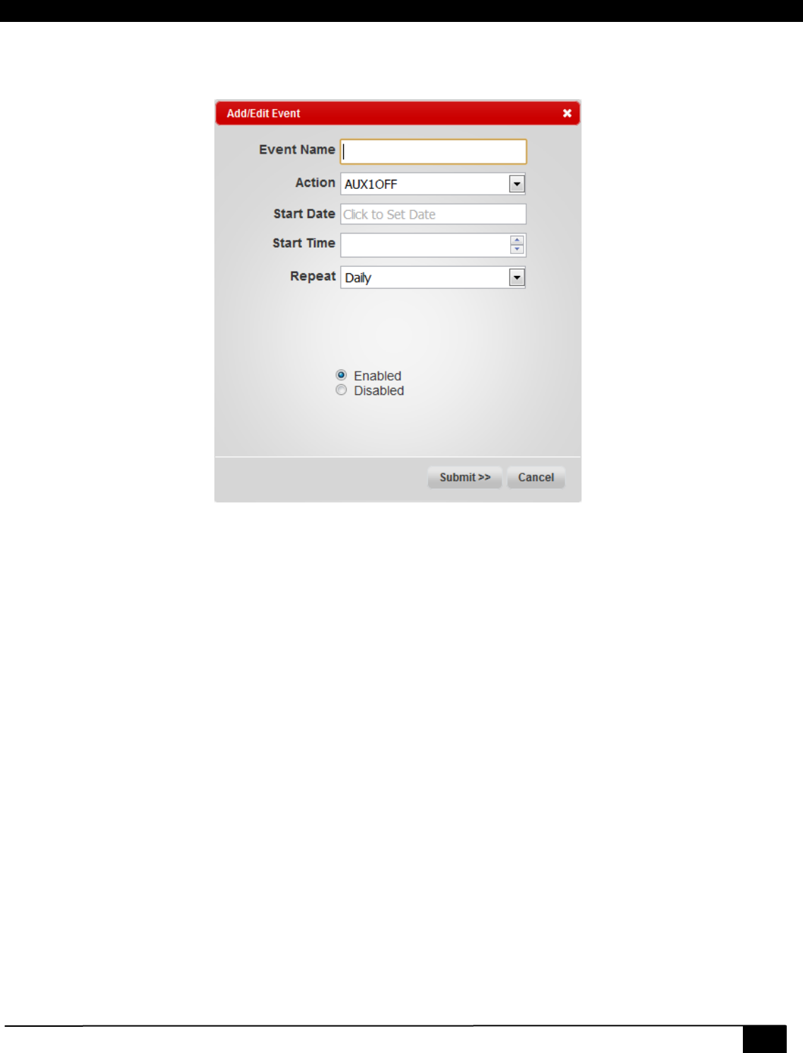
Add/Edit Event
Event Name
Name of the event. Once created, the name cannot be changed.
Action
The action to perform when the event occurs.
Start Date
The date when the event happens for the first time.
Start Time
The time of day when the event occurs. This is in 24 hr format.
Repeat
Specify when to repeat the event.
Enabled/Disabled
Enables or disables an event. A disabled event will not occur.
Delete Event
Permanently delete an event.
42
VSA-51
4 Troubleshooting & FAQs
These FAQs address some of the more common issues and questions. Please review these thoroughly before contacting
support.
4.1 Video Issues
This addresses some common issues that may affect video.
Screen is blank or there is no video displaying
• Ensure all video cables are securely connected and that all sources and display have power.
• Make sure the correct video source is selected.
• Verify input plates have power by noting the Power LED status. If the LED is not on then the input is not
transmitting to the receiver.
• Verify cat5 cables connecting the input plates to the receiver are within their specified max length.
HDMI video not displaying
• HDMI input plate should be about 150 ft from the receiver. This distance may vary depending on the display
in use so if you are approaching this length then you may want to test with a shorter cable length.
• Make sure ports A and B are properly connected and not reversed.
Analog video has red skew
• Try using skew free cat5 cable or reduce the length of the cable.
4.2 Audio Issues
No audio
• Verify speakers or audio system is properly connected. If necessary, bypass any extra audio equipment to
make sure audio is coming from the receiver.
• Make sure the audio is not muted and that the volume is set to a reasonable level.
• Check the max volume settings in the configuration. The max volume setting should not be set too low that it
is not audible.
• In some cases, over-current may have caused the audio amp to shut-down which will cause no amplified
audio from the system whatsoever. To correct this, mute both the source and mic audio. This will force the
audio processor to reset. Once you un-mute either of the audio sources the amp should be active again.
Volume is too low
• Check the max volume settings in the configuration. If the max volume is set too low then it would cause the
volume to be weak even with the volume level all the way up.
• If the audio is being routed through any other equipment then first bypass the equipment to verify audio is
coming from the receiver.
4.3 Electrical Issues
Input Plates are not powering up
• Check to make sure the cat5 cables are connected to the proper ports on the input plate and the receiver.
• Verify the wiring is correct on the cat5 cables. It should be a typical straight through wiring.
Double-Mute
If the system has no amplified audio output whatsoever, it could be that the audio amp is shut-
down due to over current. To recover from this condition, mute the microphone and the A/V source
simultaneously. This will reset the amp. Upon un-muting either source, the Amp should be working

Digital AV Room Control System
43
4.4 Web page / Network Issues
Web page says status disconnected.
• The system only works with browsers that support Websockets. Websockets is currently only supported by
the latest versions of Chrome, Safari, and Firefox. As of July 2011 Internet Explorer does not support
websockets.
• If you are using Firefox 4 you may need to enable websockets as it comes disabled by default. In the address
bar Type about:config and set the network.websocket.enabled preference to true (usually is already true) and
set the network.websocket.override security block preference to true (which is usually false by default).
• Websockets communicated on TCP port 9877. Make sure your network is configured to allow connections on
this port. You may need to contact your network administrator.
44
VSA-51
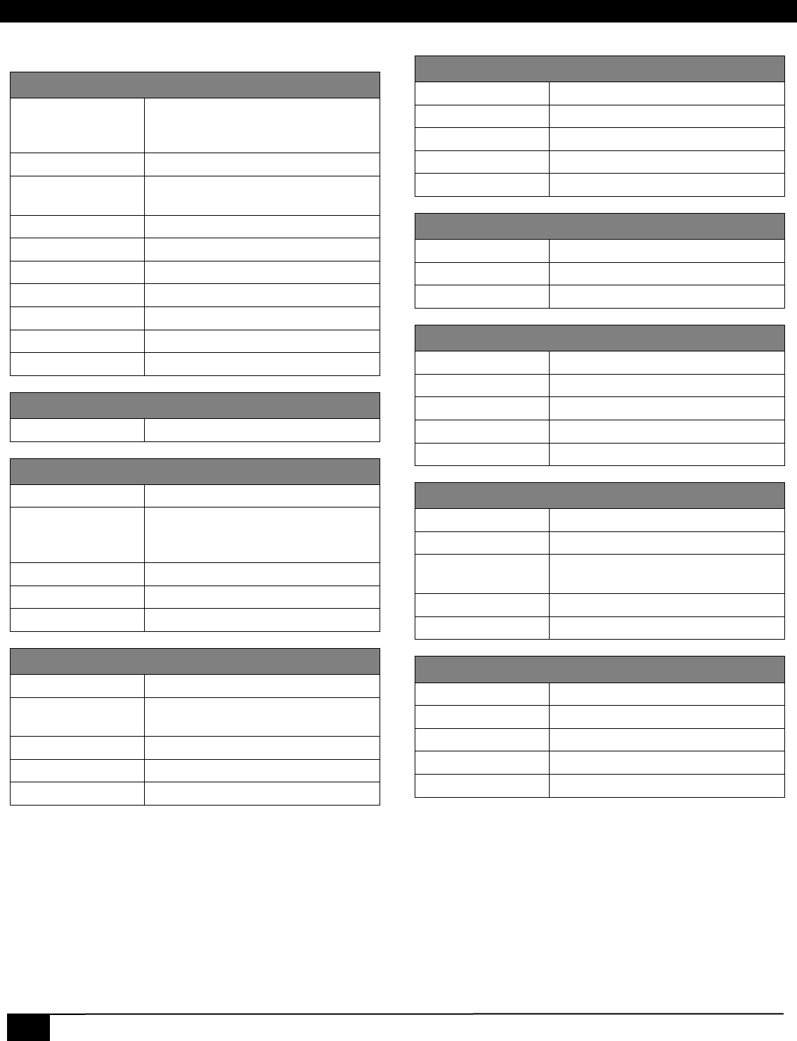
5 Specifications
VSA-51-R
Video Outputs
1 Composite
1 VGA
1 HDMI
Mic Input
screw terminals
Audio Outputs
1 Line level stereo
21Wx2 @ 8Ω
Serial Port
1 DB9 male
IR
3.5mm jack
IP/LAN
10/100 Ethernet
Discrete Outputs
2 Isolated Contacts
Current Draw
2.5A
Enclosure
Steel
Dimensions
24.3cm(w) x 3.4cm(h) x 8.5cm(d)
VSA-PGSNS
Dimensions
2.5cm(w) x 3.7cm(h) x 2.5cm(l)
VSA-MNT Cage Mount
Max Load
80 lbs (36kg)
3-axis adjustments 14º pitch
±5º roll
360º yaw
Threaded Pole
1.5” NPT
Shipping Weight
7 lbs (3.2kg)
Dimensions
24.7cm(w) x 6.3cm(h) x 29.2cm(l)
VSA-MNT Ceiling Plate
Max Load
50 lbs (22.7kg)
Electrical
Knockout Compatible with Carlon B114R
Threaded Pole
1.5” NPT
Shipping Weight
12 lbs (5.25kg)
Dimensions
63.3cm(w) x 2.7cm(h) x 21.2cm(l)
VSA-UI-DP
Max Distance
300 ft
Serial Port
1 screw terminal
IR
1 screw terminal
Form Factor
Dual-gang Decora®
Dimensions
8.9cm(w) x 10.2cm(h) x 4.5cm(d)
VSA-UI-8
Max Distance
3 ft (from VSA-UI-DP)
Form Factor
Single-gang Decora®
Dimensions
8.9cm(w) x 10.2cm(h) x 2cm(d)
VSA-C-DP
Max Distance
1200 ft
Video Format
Composite
Audio Input
Stereo line level on RCA
Form Factor
Single-gang Decora®
Dimensions
3.5cm(w) x 10.2cm(h) x 4.5cm(d)
VSA-H-DP
Max Distance
150 ft
Video Format
HDMI 1.3, DVI, HDCP compliant
Audio Input
Stereo line level on RCA or
embedded in HDMI
Form Factor
Single-gang Decora®
Dimensions
3.5cm(w) x 10.2cm(h) x 4.5cm(d)
VSA-V-DP
Max Distance
750 ft
Video Format
RGBHV, RGB
Audio Input
Stereo line level on RCA
Form Factor
Single-gang Decora®
Dimensions
3.5cm(w) x 10.2cm(h) x 4.5cm(d)

© Copyright 2012. Hall Research, Inc.
All rights reserved.
Order toll-free in the U.S. 800-959-6439
FREE technical support, Call 714-641-6607 or fax 714-641-6698
Mail order: Hall Research, 1163 Warner Ave. Tustin, CA 92780
Web site: www.hallresearch.com E-mail: info@hallresearch.com
CUSTOMER SUPPORT
INFORMATION
