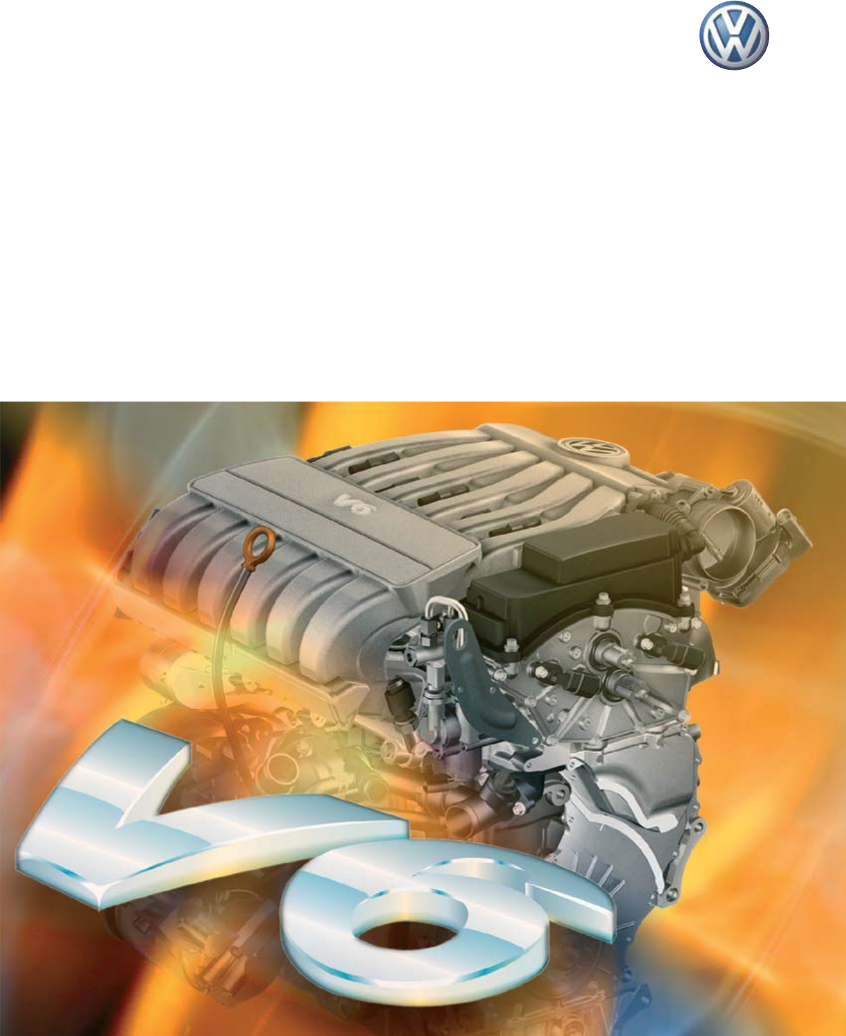
VELOCITY VR 6000 VWUSA.COM SSP 823603 3.2L 3.6L VR6 FSI Engine
User Manual: VELOCITY VR 6000
Open the PDF directly: View PDF ![]() .
.
Page Count: 72
Service Training
Self Study Program 823603
VW 3.2 and 3.6 liter FSI Engine
Volkswagen of America, Inc.
Volkswagen Academy
Printed in U.S.A.
Printed 10/2006
Course Number 823603
©2006 Volkswagen of America, Inc.
All rights reserved. All information contained in this manual is
based on the latest information available at the time of printing
and is subject to the copyright and other intellectual property
rights of Volkswagen of America, Inc., its affiliated companies
and its licensors. All rights are reserved to make changes at
any time without notice. No part of this document may be
reproduced, stored in a retrieval system, or transmitted in any
form or by any means, electronic, mechanical, photocopying,
recording or otherwise, nor may these materials be modified
or reposted to other sites without the prior expressed written
permission of the publisher.
All requests for permission to copy and redistribute
information should be referred to Volkswagen of America,
Inc.
Always check Technical Bulletins and the latest electronic
repair information for information that may supersede any
information included in this booklet.
Trademarks: All brand names and product names used in
this manual are trade names, service marks, trademarks,
or registered trademarks; and are the property of their
respective owners.

Overview ..................................................1
Basics .....................................................4
Engine Mechanics ..........................................15
Engine Management ........................................40
Operating Diagrams ........................................59
Service ...................................................65
Knowledge Assessment .....................................67
iii
Contents
This Self-Study Program provides information
regarding the design and function of new
models.
This Self-Study Program is not a Repair Manual.
This information will not be updated.
For maintenance and repair procedures,
always refer to the latest electronic
service information.
Note Important!

Page intentionally left blank
1
Overview
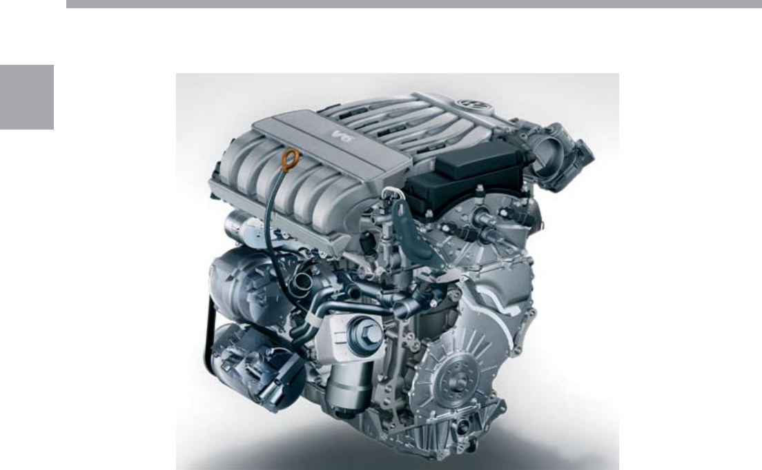
The 3.2L and the 3.6L V6 FSI engines belong to
the VR family of engines. Their reduced V-angle,
compared with a traditional V-engine, gives them an
extremely compact and space-saving design.
The VR engines have a long history at Volkswagen.
The VR success began in 1992 with the start of
production of the 2.8L VR6 engine. In 2002, the
VR6 was converted to four-valve technology. In 2003
the capacity of the VR6 was increased to 3.2 liters,
resulting in a power increase of up to 250 hp. Then,
in 2006, the capacity was increased to 3.6 liters,
resulting in a power increase of up to 280 hp.
The VR engines are highly suitable for a broad range
of applications due to their compact design.
This self-study program is designed for use in the
Volkswagen Group, and therefore does not address
the application of the engine in a specific vehicle.
If reference is made to a particular vehicle, this is
intended only as an example, to describe design,
operation or to help better understand this manual.
Overview
S360_371
2
Overview
The new 3.2L and 3.6L V6 FSI engines are the
newest representatives of the VR engine series.
The displacement was increased to 3.2 liters or
3.6 liters, combined with the switch to the FSI
technology. This yields a noticeable increase in power
and torque compared with the previous engines.
The 3.6L engine has a maximum rated power of
280 hp (206 kW) and produces a maximum torque of
265 lb.fts (360 Nm).
Special Features of both Engines:
Compact size
FSI direct gasoline injection
Four-valve technology with roller rocker arms
Internal exhaust gas recirculation
Single-piece variable-length intake manifold made
of plastic
Cast iron crankcase
Chain drive located on the transmission side with
integral drive for the high-pressure fuel pump
Continuously variable intake and exhaust
camshafts
The use of FSI direct fuel injection technology makes
it possible to meet current Low Emission Vehicle
(LEV2) emission standards.
•
•
•
•
•
•
•
•
S360_203
3
Overview
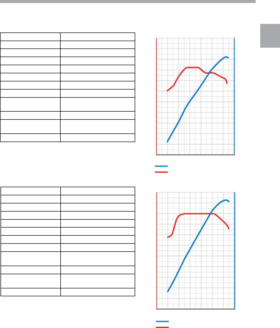
Technical Data for the 3.2L V6 Engine
Construction 6 cylinders VR Engine
Displacement 193.3 cu.in (3168 cm3)
Bore 3.4 in (86 mm)
Stroke 3.58 in (90.9 mm)
V Angle 10.6°
Valves per cylinder 4
Compression ratio 12:1
Max Output 250 hp (184 kW) @ 6250 rpm
Max Torque 243 lbs.ft (330 Nm) @ 2750-
3750 rpm
Engine management Motronic MED 9.1
Exhaust emission
control
Three-way catalytic converters
with O2 sensor
Emission standard LEV2
Torque-power Curve
Power in hp
Torque in lb.ft S360_116
2000 4000 6000
50
250
200
150
100
250
125
200
150
175
225
Technical Data for the 3.6L V6 FSI Engine
Construction 6 cylinders VR Engine
Displacement 219.5 cu.in (3597 cm3)
Bore 3.5 in (89 mm)
Stroke 3.8 in (96.4 mm)
V Angle 10.6°
Valves per cylinder 4
Compression ratio 12:1
Max Output 280 hp (206 kW) @ 6200 rpm
Max Torque 265 lbs.ft (360 Nm) @ 2500-
5000 rpm
Engine management Motronic MED 9.1
Exhaust emission
control
Three-way catalytic converters
with O2 sensor
Emission standard LEV2
Torque-power Curve
Power in hp
Torque in lb.ft S360_115
2000 4000 6000
50
250
200
150
100
250
125
200
150
175
225
The Variable Intake Manifold
The variable intake manifold design increases low
rpm torque and high rpm power by taking advantage
of the self-charging or “ram effect” that exists at
some engine speeds.
By “tuning” the intake manifold air duct length,
engineers can produce this ram effect for a given rpm
range. A manifold that has two different lengths of air
ducts can produce the ram effect over a broader rpm
range.
The 3.2 and 3.6-liter V6 engines use two lengths of
air ducts but not in the same way as the dual path
manifolds used on other engines.
Instead of using high velocity air flow in a long
narrow manifold duct to ram more air into an engine
at low rpm and then opening a short, large diameter
duct for high rpm, the 3.2 and 3.6-liter V6 engines
take advantage of the pressure wave created by
the pressure differential that exists between the
combustion chamber and the intake manifold.
All air enters the intake manifold plenum and torque
port, then is drawn down the long intake ducts to
the cylinders.
4
Basics
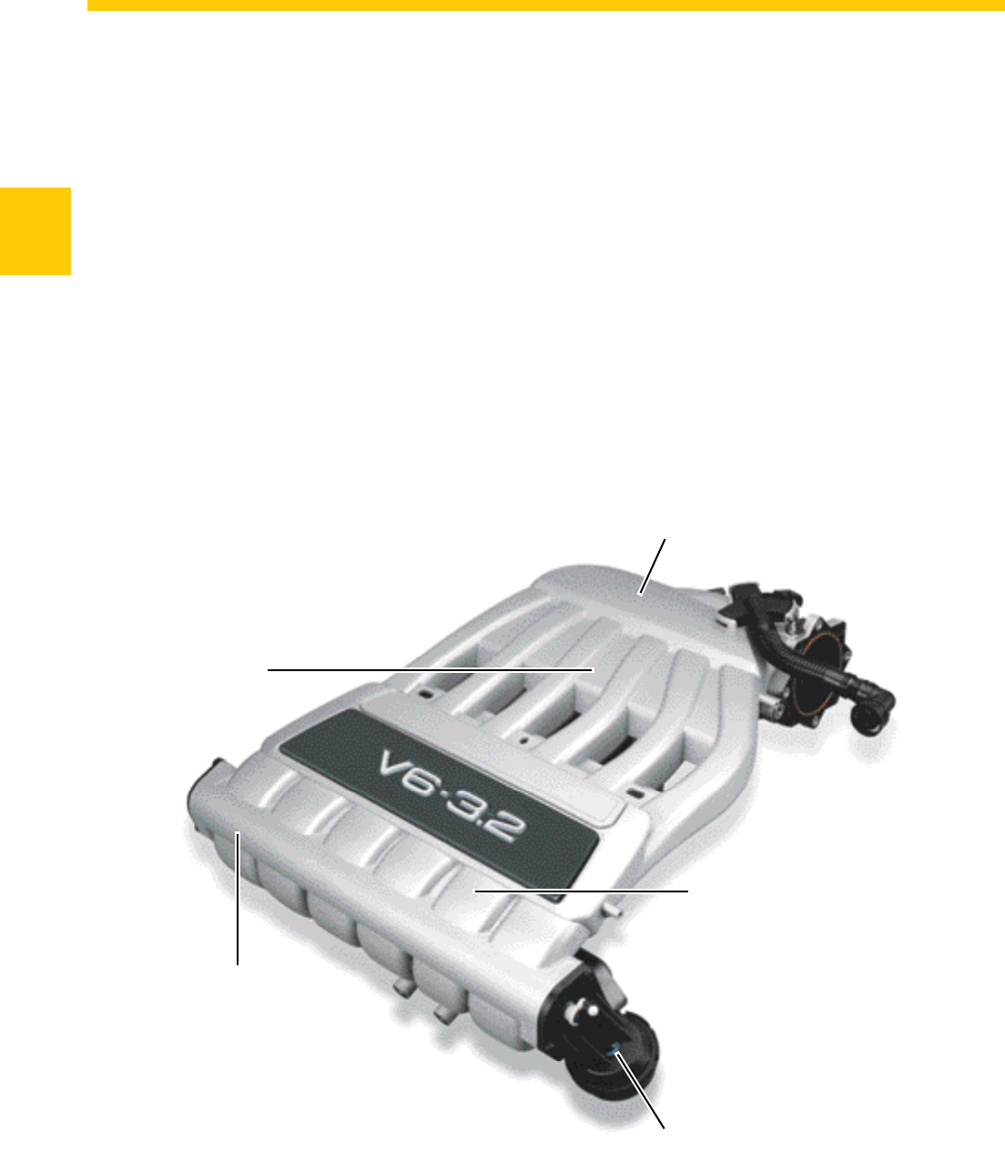
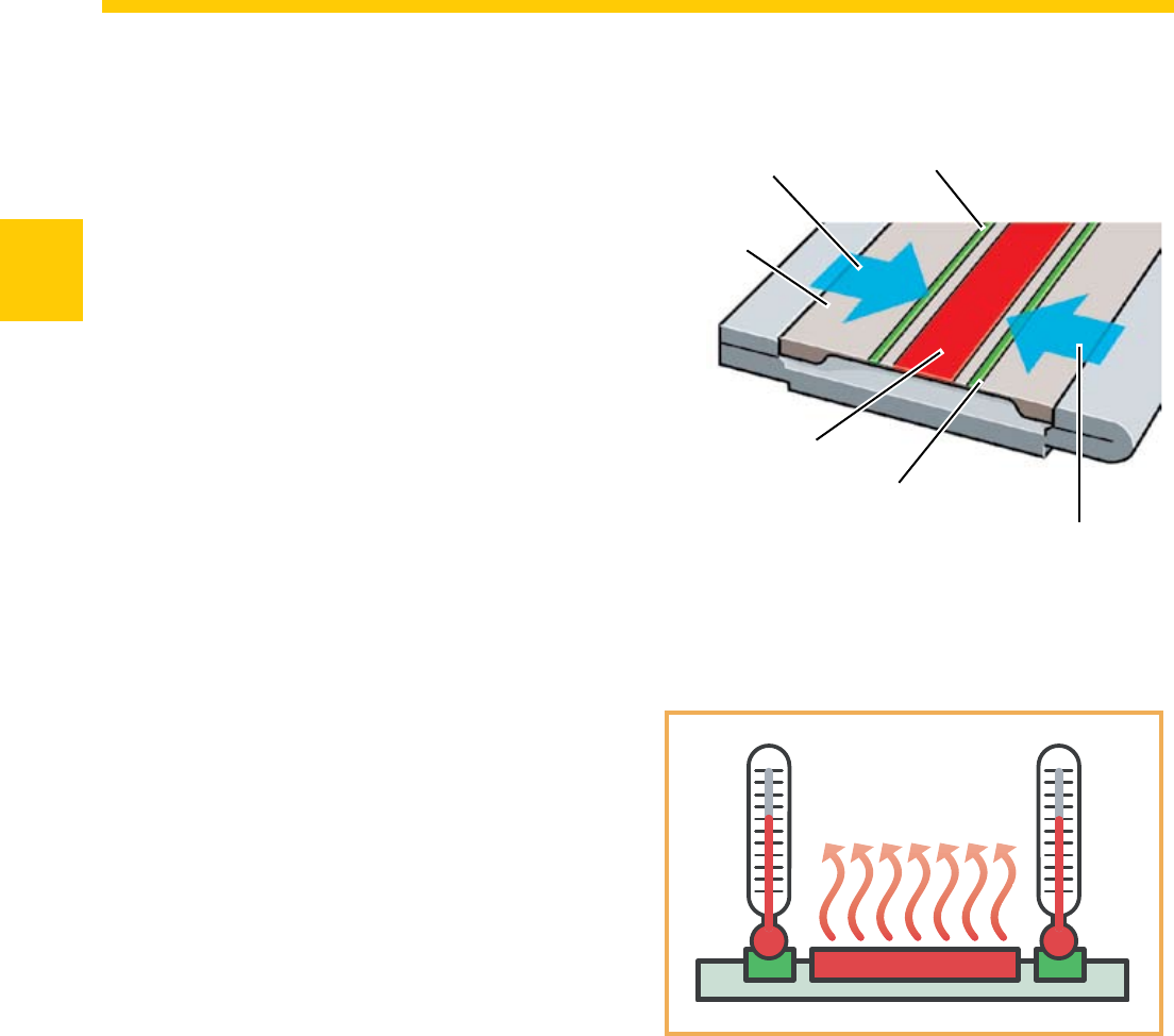
Intake Manifold Plenum
Change-Over Barrel
Vacuum Motor
Performance Port
Torque Port
S360_370
Basics
5
Basics
A second plenum called the performance port,
which is attached to a set of short manifold ducts,
joins the long intake ducts near the cylinder head. A
performance port valve, similar in design to a throttle
valve, separates the performance port from the short
ducts.
Note that the performance port does not have any
passage to the intake manifold other than through
the performance port valve. It does not have access
to the torque port and does not admit any more air
into the cylinders than what is already drawn down
the long intake ducts.
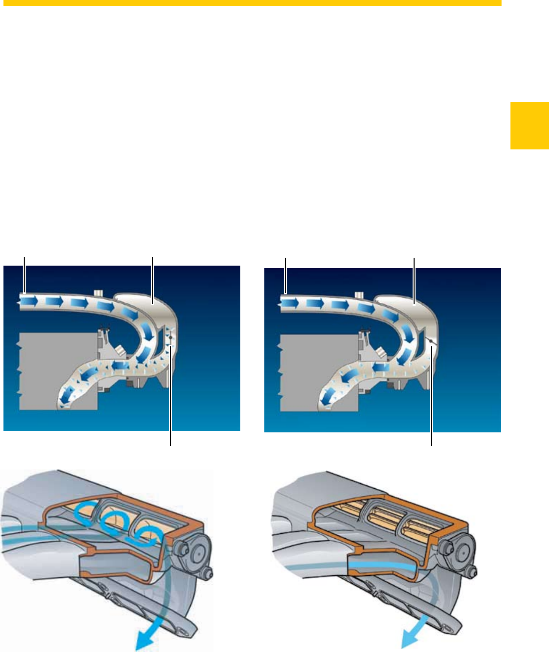
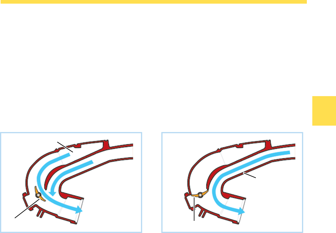
At engine speeds below 900 rpm the performance
port is open for idling. The performance port valve is
actuated. At engine speeds between 900 rpm and
4100 rpm, the performance port is closed and the
engine produces its maximum low end torque (the
performance port valve is not actuated).
At engine speeds above 4100 rpm the performance
port is open (the performance port valve is actuated).
Torque Port Performance Port
Performance Port Valve Open
Performance Port Valve Open
Torque Port Performance Port
Performance Port Valve Closed
Performance Port Valve Close
S360_352 S360_351
S360_353 S360_354
6
Basics
Performance Port Valve Actuation
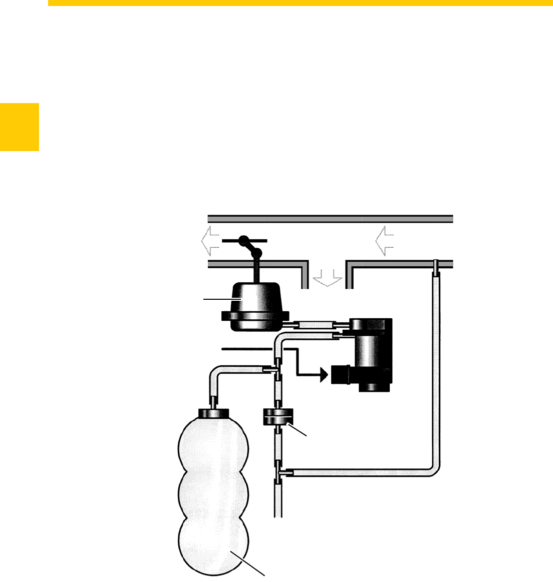
Intake manifold change-over is engine speed
dependent. The Motronic Engine Control Module
J220 activates the Intake Manifold Change-Over
Valve N156, which supplies vacuum to the vacuum
solenoid that operates the performance port valve.
A vacuum reservoir with non-return valve is used
to store a vacuum supply for the performance valve
operation. This is necessary as manifold vacuum
may be insufficient to actuate the vacuum solenoid
at high engine speeds.
Performance Port Valve (Open)
From Torque Port
To Intake Valve
To Performance Port
Vacuum Solenoid
Signal from Motronic
Engine Control
Module J220
Intake Manifold
Change-Over Valve
N156
Non-Return Valve
To Fuel Pressure Regulator
Vacuum Reservoir
S360_355
7
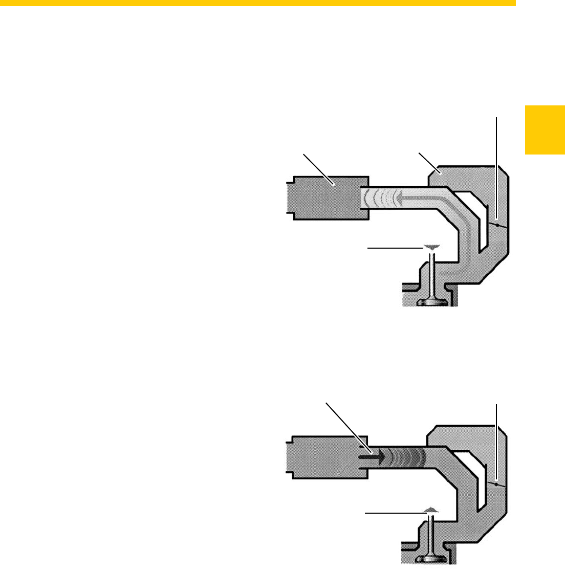
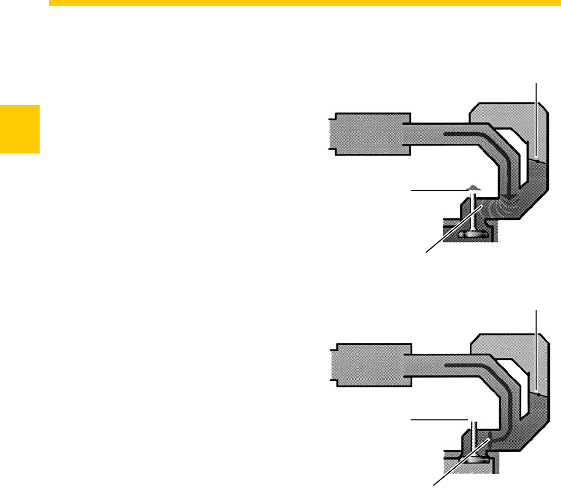
Basics
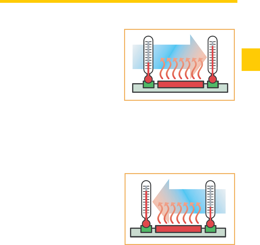
Principles of Variable Resonance
Intake Manifold Operation
After combustion has taken place in a cylinder,
there is a pressure differential between the cylinder
combustion chamber and the intake manifold. When
the intake valves open, an intake wave forms in the
intake manifold. This low pressure wave moves from
the intake valve ports toward the torque port at the
speed of sound.
Torque Port Performance Port
Performance Port Valve Closed
Performance Port Valve ClosedReflection Point
Intake Valve Closing
Intake Valve Closing
The open end of the intake duct at the torque port
has the same effect on the intake wave as a solid
wall has on a ball. The wave is reflected back toward
the intake valve ports in the form of a high pressure
wave.
S360_356
S360_357
8
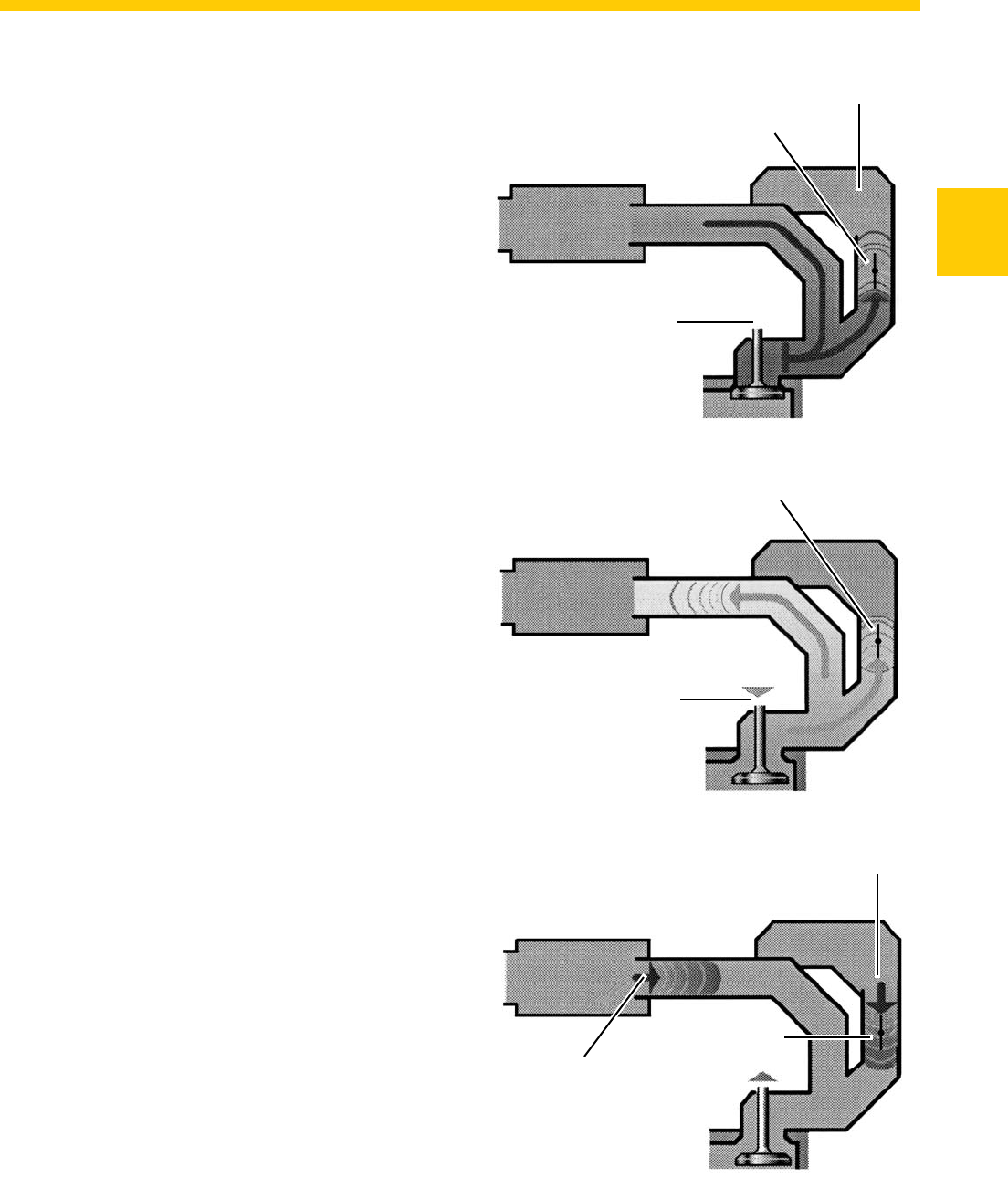
Basics
At an optimal intake manifold length, the maximum
pressure reaches the intake valve ports shortly
before the valves close. By this time the piston
has started back up the cylinder, compressing the
air/fuel mixture.
The pressure wave forces more air into the cylinder
against this rising compression pressure, filling the
cylinder with more air/ fuel mixture than would be
possible from just the piston moving downward on
the intake stroke alone. This adds to what is called
self-charging or “ram effect.”
As engine speed increases, the high pressure wave
will have less time to reach the inlet port. Because
the pressure wave is only able to move at the
speed of sound, it will reach the intake valve ports
too late. The valves will already be closed, and the
“ram effect” cannot take place. This problem can be
solved by shortening the intake manifold.
Performance Port Valve Closed
Intake Valve Closing
Performance Port Valve Closed
Intake Valve Closed
Pressure Wave
Pressure Wave Closed
S360_358
S360_359
9
Basics
In the 3.2 and 3.6-liter V6 engines, the performance
port valve turns to the performance position at
engine speeds below 900 rpm and above 4100 rpm.
This opens up the path to the performance port. The
performance port is designed so that the intake and
pressure waves will have a shorter path back to the
intake valve ports.
The performance port is filled with air when the
intake valve ports are closed.
When the intake valves open, the intake wave
moves up both manifold intake ducts toward the
torque port and the performance port at the same
speed.
Because the distance it must travel is shorter, the
intake wave reaches the open end of the intake duct
at the performance port before it reaches the open
end of the intake duct at the torque port.
Performance Port Valve Open
Intake Valve Closed
Performance Port Valve Open
Intake Valve Open
Reflection Point for Performance Port
Reflection Point
for Torque Port
Performance Port Filled with Air
Performance Port
Valve Open
S360_360
S360_361
S360_362
10
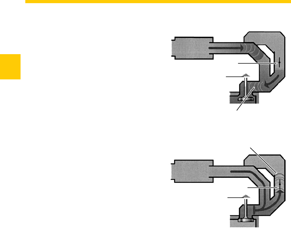
Basics
The performance port pressure wave is reflected
back toward the intake valve ports, and that air is
forced into the combustion chamber before the
intake valves close.
The pressure wave arriving too late from the torque
port is reflected by the closed intake valves and
pushes its air charge up the intake duct, filling the
performance port in preparation for the next cycle.
Performance Port Valve Open
Input Valve Closing
but Still Open
Pressure Wave for Performance
Port Charges the Cylinder with Air
Pressure Wave Fills Performance Port
Performance Port Valve Open
Intake Valve Closed
S360_363
S360_364
11
Basics
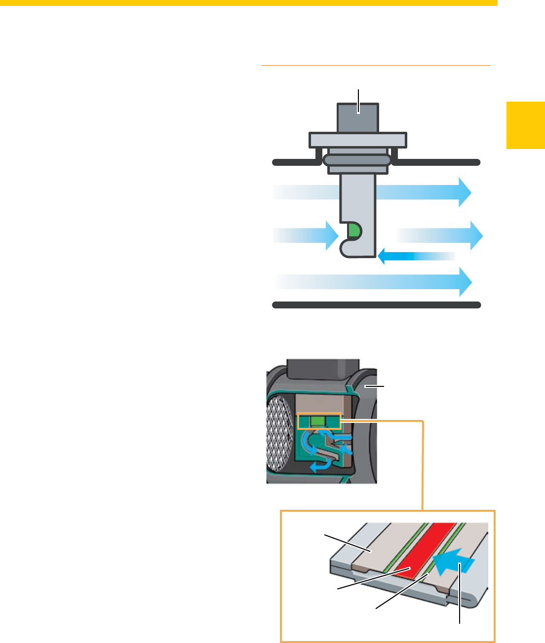
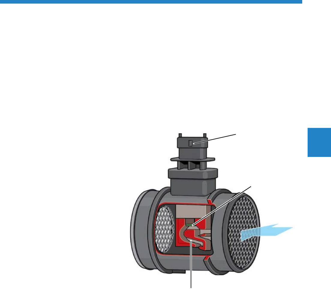
195_0 94
The Air Mass Meter with
Reverse Flow Recognition
To guarantee optimal mixture composition and
lower fuel consumption, the engine management
system needs to know exactly how much air the
engine intakes. The air mass meter supplies this
information.
The opening and closing actions of the valves cause
the air mass inside the intake manifold to flow in
reverse. The hot-film air mass meter with reverse
flow recognition detects reverse flow of the air mass
and makes allowance for this in the signal it sends
to the engine control unit. Thus, the air mass is
metered very accurately.
Design
The electronic circuit and the sensor element of the
air mass meter are accommodated in a compact
plastic housing.
Located at the lower end of the housing is a
metering duct into which the sensor element
projects. The metering duct extracts a partial flow
from the air stream inside the intake manifold and
guides this partial flow past the sensor element. The
sensor element measures the intake and reverse air
mass flows in the partial air flow. The resulting signal
for the air mass measurement is processed in the
electronic circuit and sent to the engine control unit.
Measurement of the
Intake Air
Cut-out Mass Airflow Sensor
Sensor
Element
Intake Air Flow
Temperature Sensor
Heating Resistor
S360_179
S360_178
Air Mass Meter
Reverse Flow
Intake Manifold S360_365
12
Basics
Functional Principle
Two temperature sensors (T1 and T2) and a heating
element are mounted on the sensor.
The sensors and heating element are attached to a
glass membrane. Glass is used because of its poor
thermal conductivity. This prevents heat which the
heating element radiates from reaching the sensors
through the glass membrane. This can result in
measurement errors.
The heating element warms up the air above the
glass membrane. The two sensors register the same
air temperature, since the heat radiates uniformly
without air flow and the sensors are equidistant from
the heating element.
Sensor
Element
Intake Air Flow
Temperature Sensor 1
Heating Resistor
S360_179b
Temperature Sensor 2Returning Air
Temperature Sensor
T1 T2
T1 T2
195_0 42
S360_366
13
Basics
T1 T2
T1 T2
Induced Air Mass Recognition
In the intake cycle, an air stream is ducted from T1
to T2 via the sensor element. The air cools sensor
T1 down and warms up when it passes over the
heating element, with the result that sensor T2 does
not cool down as much as T1.
The temperature of T1 is then lower than that of T2.
This temperature difference sends a signal to the
electronic circuit that air induction has occurred.
Reverse Air Mass Flow
Recognition
If the air flows over the sensor element in the
opposite direction, T2 will be cooled down more
than T1. From this, the electric circuit recognizes
reverse flow of the air mass. It subtracts the reverse
air mass flow from the intake air mass and signals
the result to the engine control unit.
The engine control unit then obtains an electrical
signal: it indicates the actual induced air mass and
is able to meter the injected fuel quantity more
accurately.
T1 T2
195_0 43
S360_367
S360_368
T1 T2
195_0 44

14
Notes
15
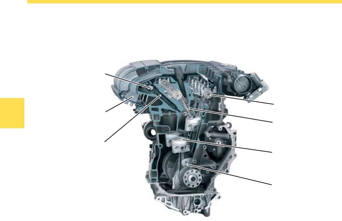
Engine Mechanics
The cylinder block has been significantly redesigned
compared with the 3.2L manifold injection engine.
The goal was to obtain a displacement of 3.6 liters
without changing the exterior dimensions of the
engine. This was achieved by changing the V-angle
and the offset.
Both FSI engines, the 3.2L and the 3.6L, have the
new cylinder block. It is made of cast iron with
lamellar graphite.
Further innovations compared with the 3.2L manifold
injection engine include:
Oil pump integral with the cylinder block
Better oil return from the cylinder block to the oil
pan
Improved cylinder block rigidity, while reducing
weight at the same time
Volume of coolant in the cylinder block reduced by
0.7 liter, allowing the coolant to heat up faster.
•
•
•
•
The Cylinder Block
S360_004
Engine Mechanics
16
Engine Mechanics
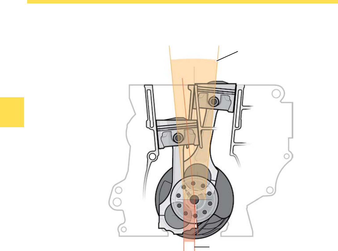
The V-angle
The V-angle of the cylinder block is 10.6°.
By changing the V-angle from 15° to 10.6°, it was
possible to provide the necessary cylinder wall
thickness without changing the dimensions of the
engine.
Offset
By reducing the V-angle, the cylinder longitudinal
axis moves outward relative to the bottom of the
crankshaft.
The distance between the cylinder longitudinal axis
and the crankshaft center axis is the Offset.
The Offset is increased from 12.5 mm to 22 mm
compared with the manifold injection engine.
V angle
10.6°
Cylinder Longitudinal Axis
Crankshaft Center Axis
Offset
22 mm
S360_003
17
Engine Mechanics
The Crankshaft
It is made of cast iron and has 7 bearings, as in the
3.2L manifold injection engine.
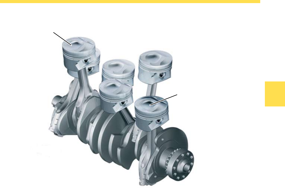
The Pistons
The pistons are recessed and are made of aluminum
alloy. In order to improve their break-in properties,
they have a graphite coating.
The pistons are different for the cylinder bank 1 and
the cylinder bank 2. They differ in the arrangement
of the valve pockets and the combustion chamber
recess.
The location and design of the piston recess
generates a swirling motion of the injected fuel and
mixes it with the intake air.
The Connecting Rods
The connecting rods are not cast but milled. The
connecting rod eye is of a trapezoidal design. The
connecting rod bearings are molybdenum coated.
This provides good running-in properties and high
load capacity
Piston Recess
Running-in Coating
S360_001
18
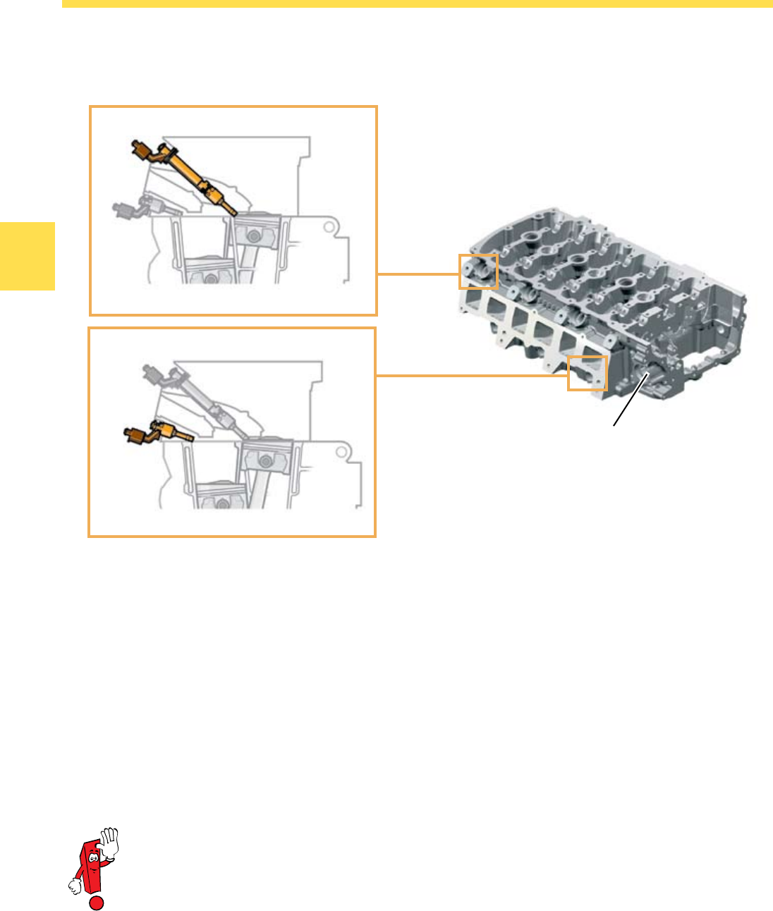
Engine Mechanics
The cylinder head is made of an aluminum-silicon-
copper alloy and is identical for both engines. It is a
new design as a result of the direct fuel injection.
The cylinder head has been lengthened to
accommodate the chain drive and to strengthen the
high-pressure fuel pump mounting location.
The fuel injectors for both cylinder banks are located
on the intake side of the cylinder head.
The fuel injector bores for cylinders 1, 3 and 5 are
located above the intake manifold flange. The fuel
injectors for cylinders 2, 4 and 6 are installed below
the intake manifold flange.
As a result of this layout, the fuel injectors for
cylinders 1, 3 and 5 pass through the cylinder head
intake manifold.
In order to compensate for the effect of the fuel
injectors on the airflow characteristics in the intake
manifold, the valve spacing for all cylinders has been
increased from 34.5 mm to 36.5 mm. This reduces
the change in airflow direction resulting from the fuel
injectors when filling the cylinders.
High-Pressure Fuel Pump Location
The Cylinder Head
Injectors 1, 3, 5
Injectors 2, 4, 6
S360_006
S360_007
S360_011
Fuel injectors of two different lengths
are required because of the two different
positions for the fuel injectors.
19
Engine Mechanics
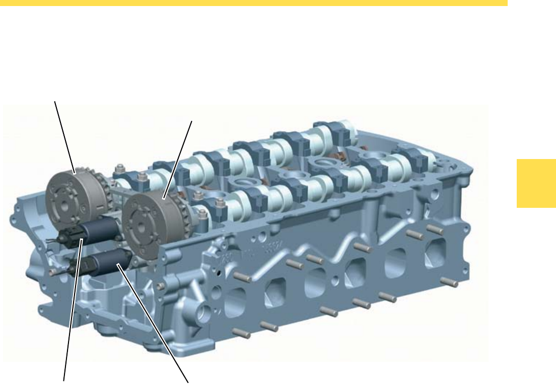
By adjusting the camshafts, power and torque can
be increased, fuel consumption can be improved
and emissions reduced, depending on the load
characteristics of the engine.
The camshafts are adjusted by two vane type
adjusters. Both camshafts can be adjusted
continuously in the direction of early valve opening
and late valve opening.
To adjust the camshafts, the Engine Control Module
(ECM) actuates the solenoids:
N205 Camshaft Adjustment Valve 1 and
N318 Camshaft Adjustment Valve 1 (exhaust).
•
•
Maximum adjustment of the camshafts:
Intake camshaft 52° from the crankshaft angle and
Exhaust camshaft 42° from the crankshaft angle.
Both camshaft adjusters are adjusted by two valves
with the assistance of the engine oil pressure.
Adjusting both camshafts enables a maximum valve
overlap of 42° crankshaft angle. The valve overlap
allows for internal exhaust gas recirculation.
•
•
Camshaft Adjustment
Vane Type Adjuster for Intake Camshaft
N318 Camshaft Adjustment Valve 1 (Exhaust)N205 Camshaft Adjustment Valve 1
Vane Type Adjuster for Exhaust Camshaft
S360_012
20
Engine Mechanics
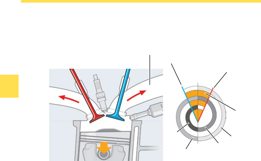
Internal exhaust gas recirculation counteracts the
formation of nitrous oxides (NOx).
Just as with external exhaust gas recirculation, the
reduced formation of NOx is based on lowering
combustion temperature by introducing combustion
gases.
The presence of combustion gases in the fresh
fuel-air mixture produces a slight oxygen deficit.
Combustion is not as hot as with an excess of
oxygen.
Nitrous oxides are formed in greater concentrations
under relatively high combustion temperatures.
By reducing combustion temperature in the engine
and with the lack of oxygen, the formation of NOx is
reduced.
Internal Exhaust Gas
Recirculation
Operation
During the exhaust stroke, the intake and the exhaust
valves are both open simultaneously. As a result
of the high intake manifold vacuum, some of the
combustion gases are drawn out of the combustion
chamber back into the intake manifold and swirled
into the combustion chamber with the next induction
stroke for the next combustion cycle.
Benefits of the internal exhaust gas recirculation:
Improved fuel consumption due to reduced gas
exchange
Partial load range expanded with exhaust gas
recirculation
Smoother idle
Exhaust gas recirculation possible even with a cold
engine
•
•
•
•
Intake Valve opens
Valve Overlap
Cycle 3
Inlet Manifold Vacuum
Cycle 1
Cycle 2
Cycle 4
Exhaust Valve closes
Intake ValveExhaust Valve
S360_124
21
Engine Mechanics
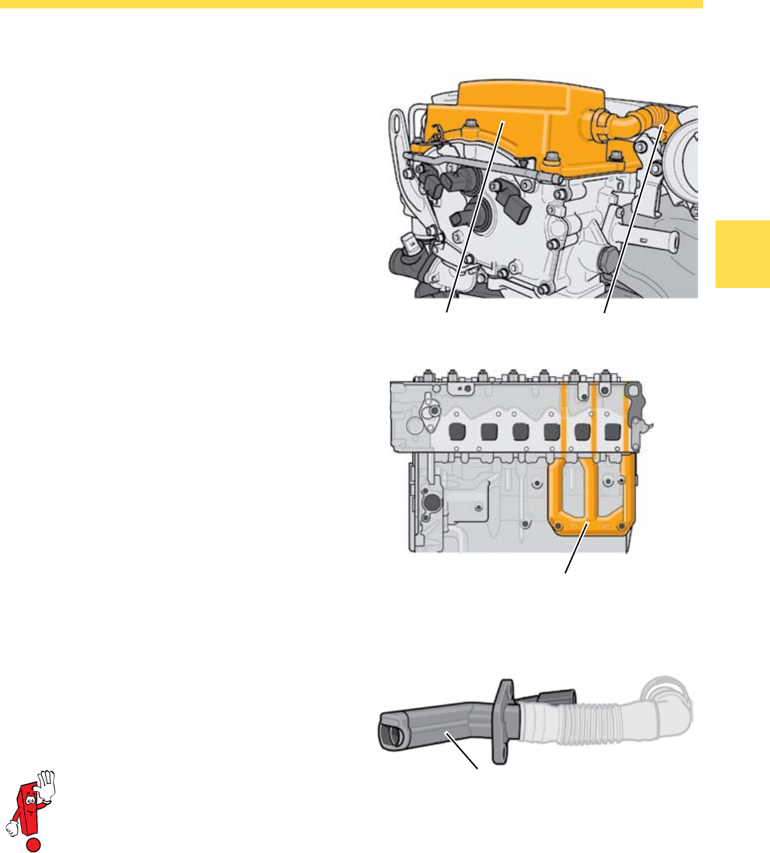
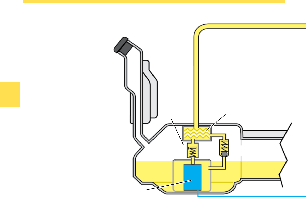
Crankcase Ventilation
It prevents hydrocarbon-enriched vapors (blow-by
gases) from escaping from the crankcase into the
atmosphere. Crankcase ventilation consists of vent
passages in the cylinder block and cylinder head, the
cyclone oil separator and the crankcase ventilation
heater.
Operation
The blow-by gases in the crankcase are drawn out by
intake manifold vacuum through:
the vent ports in the cylinder block,
the vent ports in the cylinder head,
the cyclone oil separator and
the crankcase ventilation heater
The blow-by gases are then rerouted into the intake
manifold.
•
•
•
•
Ventilation Ports in the Cylinder
Block and Cylinder Head
Crankcase
Ventilation Heater
Cyclone Oil Separator
S360_064
S360_253
Crankcase Ventilation Heating
The heating element is installed in the flexible tube
from the cyclone oil separator to the intake manifold,
and prevents icing of the blow-by gases when the
intake air is extremely cold.
Heating Element S360_026
In the event of a defective pressure
regulator valve, the full intake manifold
vacuum and internal crankcase pressure
are constantly applied to the crankcase
ventilation. This causes a large amount
of oil to be drawn out of the crankcase,
possibly resulting in engine damage.
22
Engine Mechanics
Intake Manifold
Oil Vent Opening
into the Crankcase
Oil Droplets
Gas Particles
Gas Exit to the
intake Manifold
Inlet
Oil Vent Opening
Vacuum Valve
Cyclone Oil
Separator
S360_025
S360_059
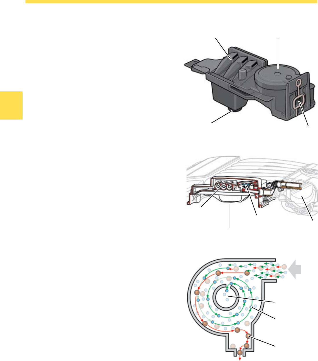
The Cyclone Oil Separator
The cyclone oil separator is located in the cylinder
head cover. Its function is to separate oil from the
blow-by gases from the crankcase and to return it to
the primary oil circuit.
A pressure regulator valve limits the intake manifold
vacuum from about 700 mbar to about 40 mbar.
It prevents the entire intake manifold vacuum and
the internal crankcase vacuum from affecting the
crankcase ventilation and drawing in engine oil or
damaging seals.
Operation
The cyclone oil separator separates the oil from
the oil vapor drawn in. It works on the principle of
centrifugal separation.
Due to the cyclone design of the oil separator, the oil
vapors drawn in are set into a rotating motion. The
resulting centrifugal force throws the oil against the
separating wall where it combines into larger drops.
While the separated oil drips into the cylinder head,
the gas particles are routed into the intake manifold
through a flexible tube.
Cyclone Oil Separator Pressure Regulation Valve
Oil Vent to the Intake Manifold
S360_058
23
Engine Mechanics
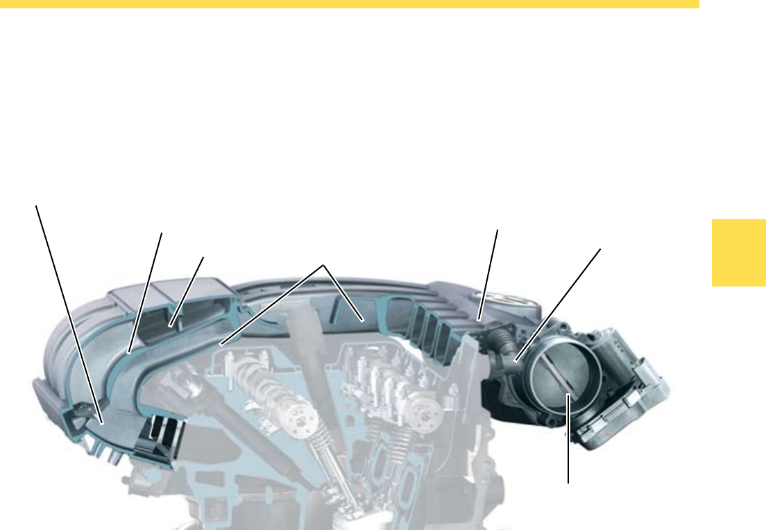
The Intake Manifold
Both engines have a single-piece overhead intake
manifold made of plastic.
Design
The variable length intake manifold consists of:
the main manifold
two resonance pipes of different length per
cylinder
the control shaft
the power manifold
the vacuum tank
the intake manifold valve
•
•
•
•
•
•
The two resonance pipes differ in length because
a long pipe is needed to achieve high torque and a
short pipe is needed to achieve high power.
The control shaft opens and closes the connection to
the power manifold.
Control Shaft with Flaps
Throttle Valve
Control Unit
Crankcase Ventilation
Main Manifold
Long Resonance Pipe
Power Manifold
Short Resonance Pipe
S360_021
24
Engine Mechanics
Control Flaps
The Control Flaps
Switching between the power and torque positions
is accomplished by control flaps.
The control flaps are vacuum operated by the Engine
Control Module (ECM) J623 through the Intake
Manifold Runner Control (IMRC) Valve N316. When
current is not applied to the valve, the control flaps
are open and are in the power setting.
The Vacuum Tank
A vacuum tank is located within the intake manifold.
A vacuum supply is maintained in this vacuum tank
and will allow to actuate the control flaps.
The air from the vacuum tank is drawn through a
check valve into the primary manifold, so that vacuum
can build up in the vacuum tank.
If the check valve is defective, the control flaps
cannot be activated.
Main Manifold
Vacuum Tank
Check Valve
N316
J623
S360_022
S360_061
S360_060
N316
25
Engine Mechanics
Function of the Variable Length
Intake Manifold
The variable length intake manifold is designed so
that a resonance is created between the timing of
the valves, the intake pulses and the vibration of the
air which produces an increase in pressure in the
cylinder and subsequently good charging efficiency in
the cylinder.
Engine Speed between about 1200 and 4000 rpm
Current is applied from the ECM to the intake
manifold flap control valve. The control flaps are closed
and close the power manifold. The cylinders draw air
through the torque manifold directly from the main
manifold.
Engine Speed above 4000 rpm
No current is applied to the intake manifold flap
control valve. As a result, the intake manifold claps
switch back to the power position.
Engine Speed between 0 and about 1200 rpm
The variable length intake manifold is in the power
position. Current is not applied to the intake manifold
flap control valve. The vacuum wave generated at
the beginning of the intake stroke is reflected at the
end of the power collector in the power manifold
and returns after a brief time to the intake valve as a
pressure wave.
Power Manifold
Control Shaft
Torque Setting of the Variable Intake Manifold
Control Shaft
Air Supply from the
Power Manifold
Variable Intake
Manifold Housing
Air Supply from the
Intake Manifold
Power Setting of the Variable Intake Manifold
S360_063 S360_062
26
Engine Mechanics
Please refer to the current Repair
Manuals to adjust the valve timing. There
is a new special tool T10332 for locking
the high pressure-pump pinion wheel.
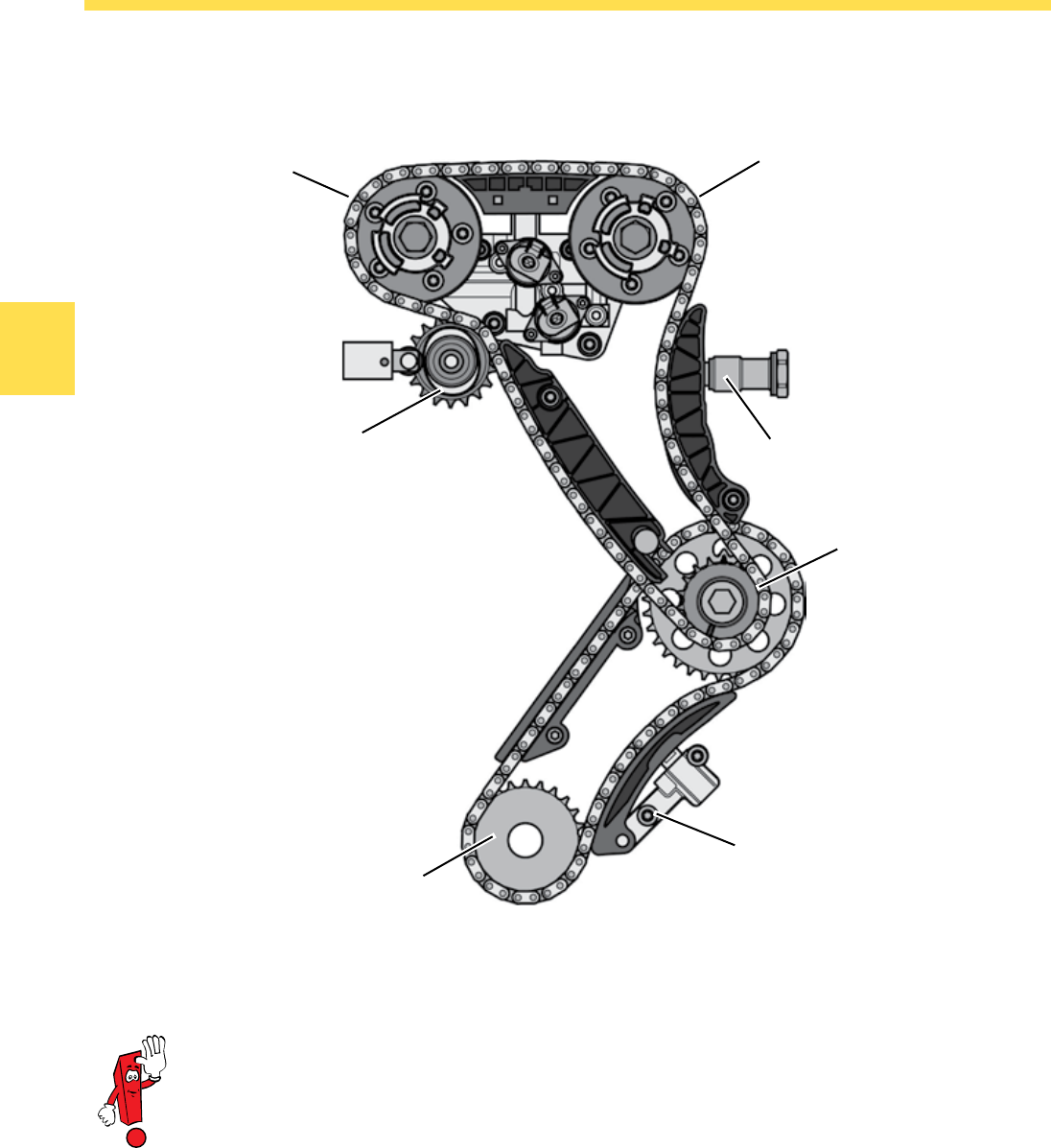
The Chain Drive
Intake Camshaft Drive
The chain drive is located on the transmission side
of the engine. It consists of the primary chain and
the camshaft chain.
The primary chain is driven by the crankshaft. It
drives the camshaft chain and the oil pump via a
sprocket wheel.
The two camshafts and the high-pressure fuel pump
are driven by the camshaft chain.
Both chains are kept at the precise tension by
hydraulic tensioners.
High-pressure Fuel Pump Drive
Crankshaft Pinion
Oil Pump Drive
Hydraulic Chain Tensioner
Exhaust Camshaft Drive
Hydraulic Chain Tensioner
S360_016
27
Engine Mechanics
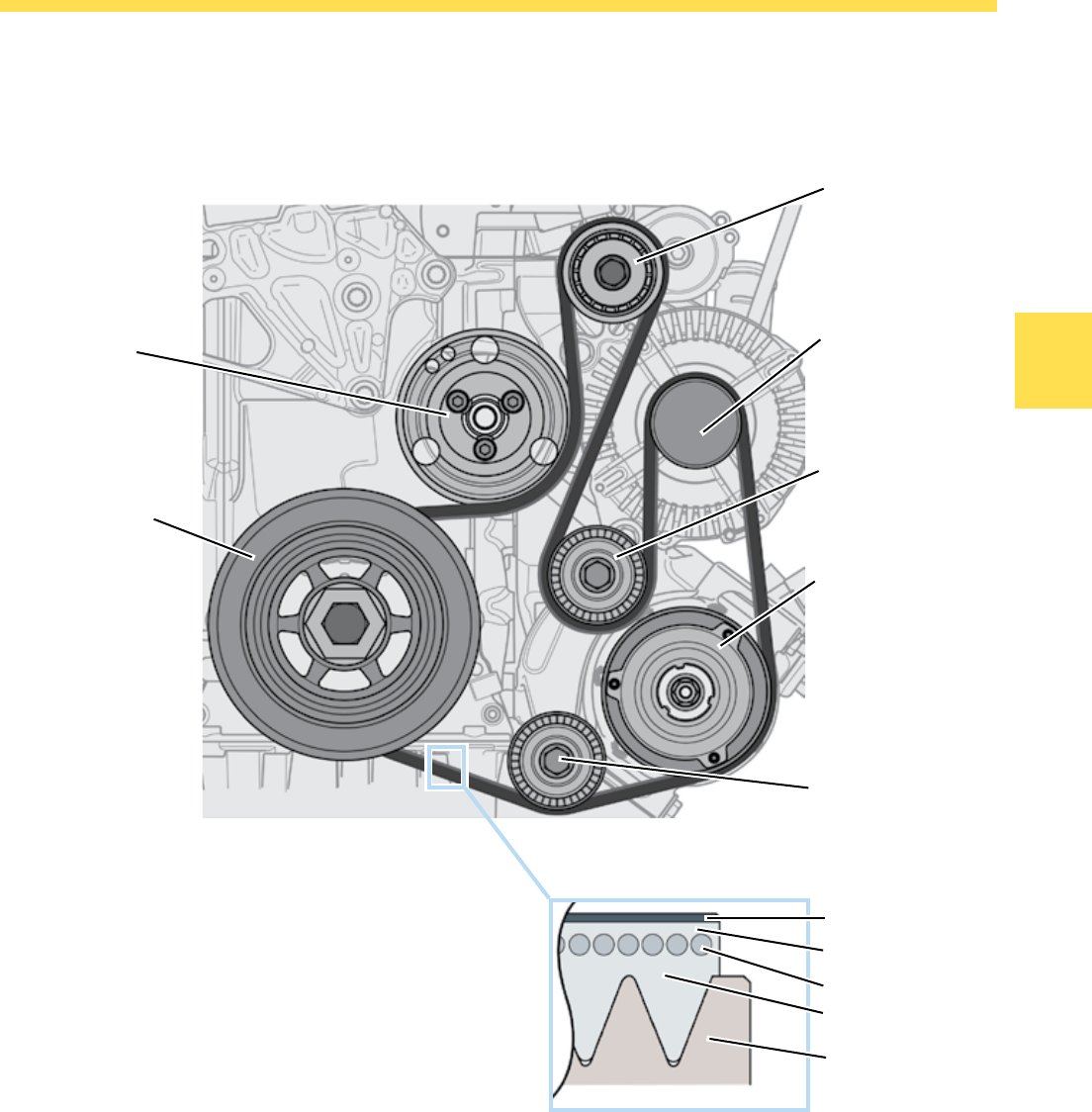
The Ribbed V-belt Drive
The belt drives the air-conditioning compressor, the
alternator and the coolant pump.
The V-belt is always kept at the correct tension by a
belt tensioner.
Construction of
the Poly-V Drive
Belt
Crankshaft V-belt
Drive Pulley
The ribbed V-belt is a single-sided poly-V belt. Even at
high speed, it runs quietly and vibration-free. The belt
is driven by the crankshaft through the V-belt pulley
with vibration damper.
Drive Belt Pulley
Substructure
Polyester Drive-ply
Cover Layer
Cover Fabric
Air-Conditioning
Compressor Drive
Idler Pulley
Alternator Drive
Tensioning Pulley
Coolant
Pump Drive
S360_015
Idler Pulley
S360_170
28
Engine Mechanics
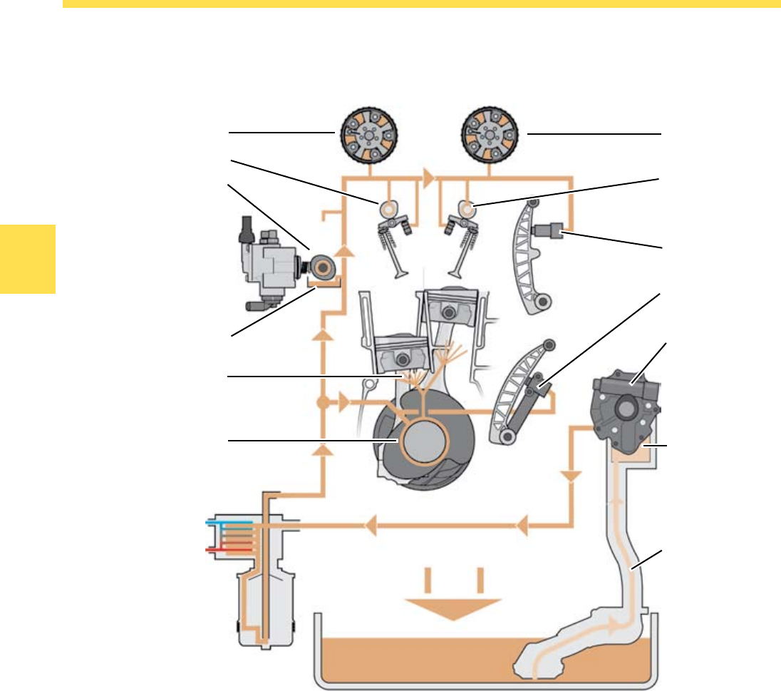
Oil Circulation
Oil pressure is generated by a self-priming duocentric
oil pump. It is installed in the cylinder block and is
chain driven.
The installation of the oil pump results in a longer
path for the oil. This can be a disadvantage when
starting the lubrication of engine components. For
this reason, oil is drawn from an oil tank located
behind the oil pump to ensure the initial supply of oil.
The oil pump draws oil from the oil pan and then
pumps it to the oil filter-cooler module. In that
module, the oil is cleaned and cooled before it is
transferred to the lubrication points in the engine.
Camshaft Adjuster
Oil Return
Oil Pan
Intake Duct
Chain Tensioner
Camshaft Bearing
Oil filter Cooler Module
Crankshaft Bearing
Spray Jets for
Piston Lubrication
Oil Tank
High-pressure Fuel
Pump Drive
Hydraulic Valve Lifter
Camshaft Adjuster
Oil Pump
Chain Tensioner
Oil Tank
S360_122
29
Engine Mechanics
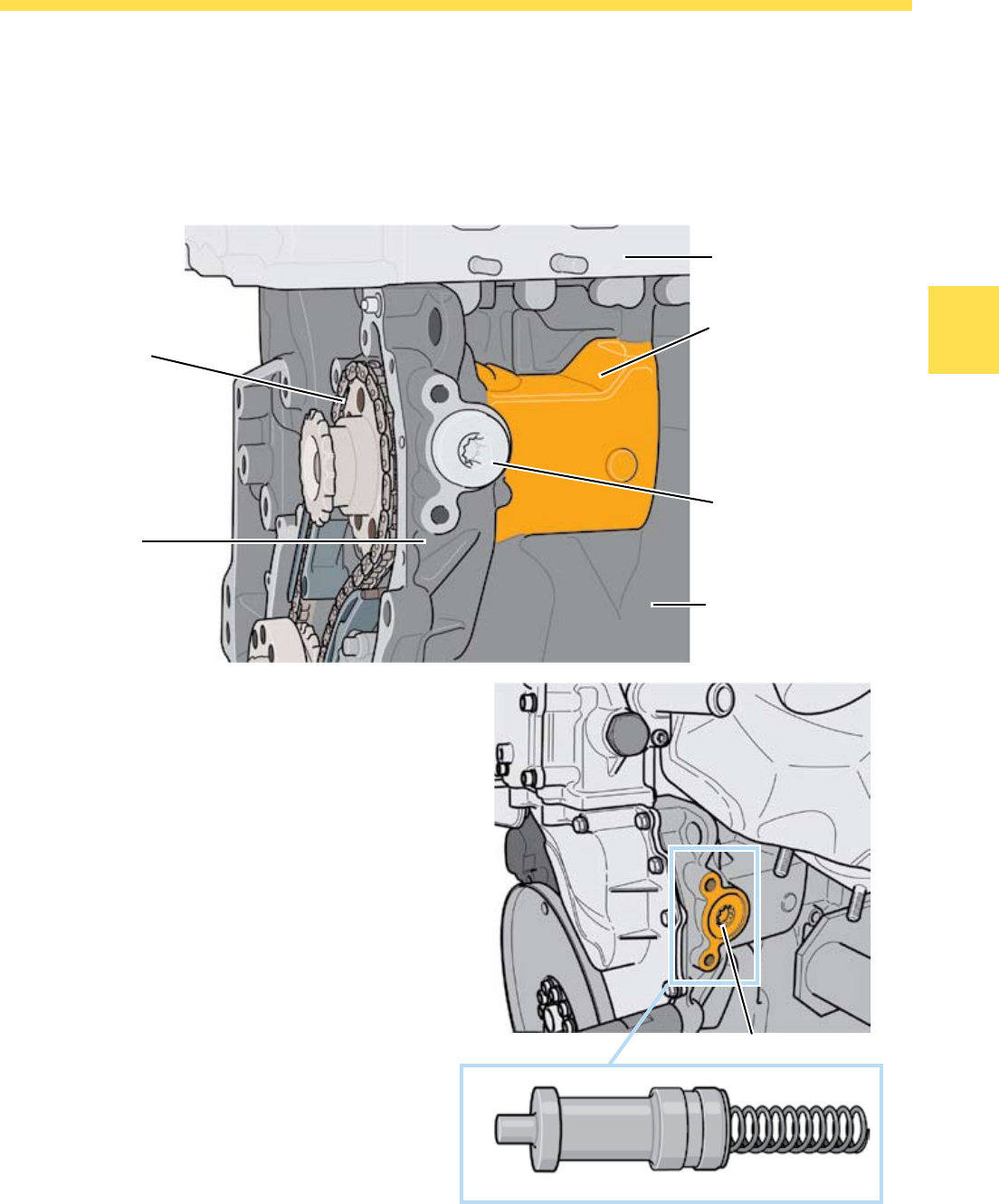
The Oil Pump with Oil Tank
The oil tank is formed in the cylinder block by a cavity
behind the oil pump. Its volume is approximately
280 ml and does not drain even after the engine is
switched off.
Drive Pinion
The Service Opening for the Oil Pump
The service opening provides access to the oil pump
excess-pressure piston. After removing the cover
bolt and a second internal bolt, the oil pump pressure
piston can be removed and its condition can be
inspected without having to remove the drive chain.
Pressure Piston
Cover Screw
Cylinder Block
Service Opening
Cylinder Head
Oil Pump
Oil Tank
S360_174
S360_052
S360_056
30
Engine Mechanics
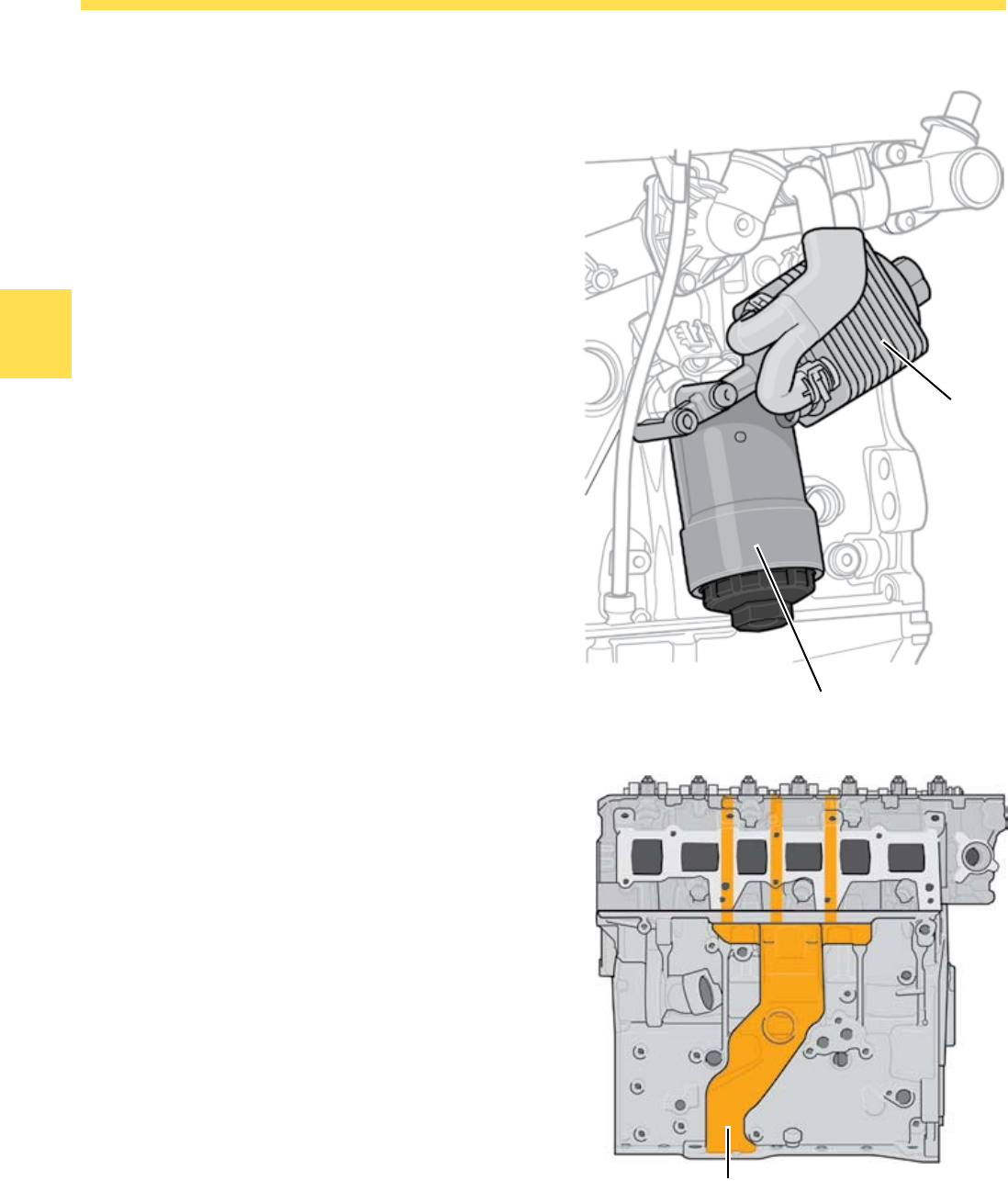
The Oil Filter Cooler Module
The oil filter cooler module is an assembly made of
the oil filter, oil cooler, check valve and filter bypass
valve.
The Oil Return
The returning oil is directed through three return
ducts in the cylinder head into a central oil return
duct in the cylinder block.
The oil then flows into the oil pan to the bottom of
the sump. In addition to the central oil return, oil is
returned to the oil pan from the front of the engine
through the timing chain housing.
Oil Cooler
Oil Filter
Oil Return
S360_019
S360_219
31
Engine Mechanics
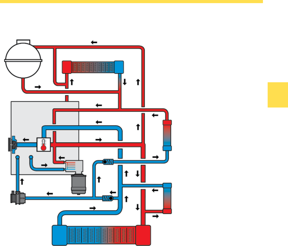
Coolant Circulation
The coolant is circulated by the mechanical coolant
pump. The pump is driven by the V-belt.
There are 9 liters (2.4 gallons) of coolant in the
cooling system. The total amount of coolant has
been reduced by 2 liters in comparison to the
3.2L manifold injection engine. The reduced coolant
allows the engine to reach operating temperature
faster.
Coolant circulation is controlled by the expansion
thermostat.
Depending on the vehicle, there may be an auxiliary
cooler in the coolant circuit (10).
The check valves are included in the coolant circuit
in order to prevent any coolant return flow.
Legend
Coolant Tank
Heater Exchanger for Heating
Coolant Pump
Transmission Fluid Cooler
Thermostat
Oil Cooler
Check Valve
Recirculation Pump V55
Check Valve
Auxiliary Cooler
Radiator
1.
2.
3.
4.
5.
6.
7.
8.
9.
10.
11.
S360_213
12
34
5
6
7
89
10
11
32
Engine Mechanics
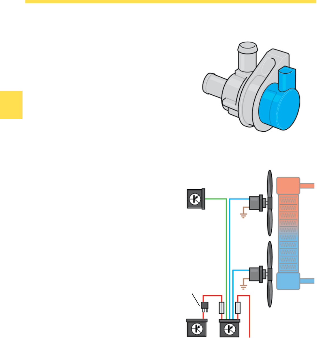
The Recirculation Pump V55
The Recirculation Pump is an electrical pump. It
is integrated into the engine coolant circuit and is
actuated by the ECM based on a characteristic map.
After the engine has been turned off, and with no
driving airflow, the Recirculation Pump is switched
on depending on coolant temperature.
The Coolant Fan
The V6 FSI engine has two electric Coolant Fans.
The Coolant Fans are activated as needed by the
ECM.
The Engine Control Module (ECM) J623 signals the
need for radiator cooling to the Coolant Fan Control
(FC) Module J293.
Depending on the need, the Coolant Fan Control
(FC) Module J293 then supplies current to one or
both of the fans. Current is supplied to the Cooling
Fan Control (FC) Module J293 by the Motronic
Engine Control Module (ECM) Power Supply Relay
J271 and by the Vehicle Electrical System Control
Module J519.
The fans can also be switched on by the Coolant
Fan Control (FC) Module after the engine has been
turned off.
In order to turn on the fans when the engine has
been turned off, the Coolant Fan Control (FC)
Module has a connection to terminal 30.
Engine Control Module
(ECM) J623 Coolant Fan
V7
Coolant Fan
2 V177
Motronic Engine
Control Module
(ECM) Power
Supply Relay
J271
Terminal 30
Coolant
Fan Control
(FC) Control
Module J293
Vehicle
Electrical
System
Control
Module J519
S360_169
S360_171
33
Engine Mechanics
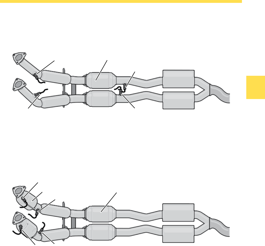
The Exhaust System
3.2-liter V6 FSI Engine
The exhaust system for the 3.2L engine has a
primary ceramic catalytic converter for each cylinder
bank.
The exhaust system for the 3.6L FSI engine is
equipped with two pre-catalytic converters and two
main catalytic converters.
Exhaust gas quality is monitored by two oxygen
sensors upstream of the pre-catalytic converters and
two oxygen sensors downstream of the pre-catalytic
converters.
Primary Catalytic Converter
Pre-Catalytic Converter Primary Catalytic Converter
G39
G130
G108 G131
G39
G130
G108 G131
S360_117
S360_118
3.6-liter V6 FSI Engine
Exhaust gas quality is monitored by two oxygen
sensors upstream and downstream of the catalytic
converters.
The exhaust system complies with the Low
Emission Vehicle (LEV) 2 emission standards.
The exhaust system complies with the LEV 2
emission standards.
34
Engine Mechanics
FSI Technology
Contributing Factors
Direct gasoline injection requires precise timing of
the combustion process.
The factors affecting the combustion process are:
Cylinder bore and stroke
Shape of the recess in the piston surface
Valve diameter and lift
Valve timing
Geometry on the intake ports
Volumetric efficiency of the fresh air supplied
Fuel injector characteristics (spray cone, spray
angle, flow amount, system pressure and timing)
Engine rpm
An essential part in the optimization of the
combustion performance is the study of airflow
characteristics in the combustion chamber. The
mixture formation is substantially affected by the flow
characteristics of the intake air and the injected fuel.
•
•
•
•
•
•
•
•
In order to determine the optimal airflow
characteristics and as a result define the optimal
piston shape for both banks of cylinders, Doppler
Global Velocimetry was used. This procedure makes
it possible to study airflow characteristics and mixture
formation while the engine is running.
With the help of this procedure and by modifying the
characteristics of the fuel injectors it was possible
to equalize and match airflow velocities and mixture
formation in the combustion chambers for both
cylinder banks.
The engine operation is entirely homogenous.
The homogenous split catalytic converter heating
process for heating the catalytic converter is new.
System Pressure
Start of Actuation
End of Actuation
Intake Manifold Shape
Air Flow
Fuel Flow
Spray Cone
Spray Angle
Stroke
Bore
Engine rpm
Recess Shape
Valve Lift
Valve Diameter
Valve Timing
S360_035

35
Notes
36
Engine Mechanics
The Low-Pressure Fuel System
The low-pressure system transfers fuel from the
fuel tank. The transfer fuel pump is activated by the
ECM through the Fuel Pump (FP) Control Module
depending on the requirements at a working pressure
between 2 and 5 bar.
Operation
The signal from the Low Fuel Pressure Sensor G410
constantly informs the ECM of the current fuel
pressure.
The ECM compares the current pressure to the
required fuel pressure. If the current fuel pressure
is not adequate to meet the fuel needs, the ECM
activates the Fuel Pump (FP) Control Module J538.
This control module then activates the transfer
fuel pump, which increases the working pressure.
When the fuel requirement drops again, the working
pressure at the pump drops accordingly.
The pressure retention valve maintains the fuel
pressure when the engine is switched off. If the fuel
line is ruptured in an accident, the pressure retention
valve helps to prevent fuel from escaping.
The pressure relief valve opens at a pressure of
93 psi (6.4 bar) and thus prevents excessive fuel
pressure in the low-pressure line.
Excess fuel can flow back into the fuel tank.
Pressure Retention Valve
The Fuel System
Low-Pressure Line
Pressure
Relief Valve
Fuel Filter
G6 Transfer Fuel Pump (FP)
G247 Fuel Pressure Sensor
G410 Low Fuel Pressure
Sensor
J538 Fuel Pump (FP) Control
Module
J623 Engine Control Module
(ECM)
N276 Fuel Pressure Regulator
Valve
G6
37
Engine Mechanics
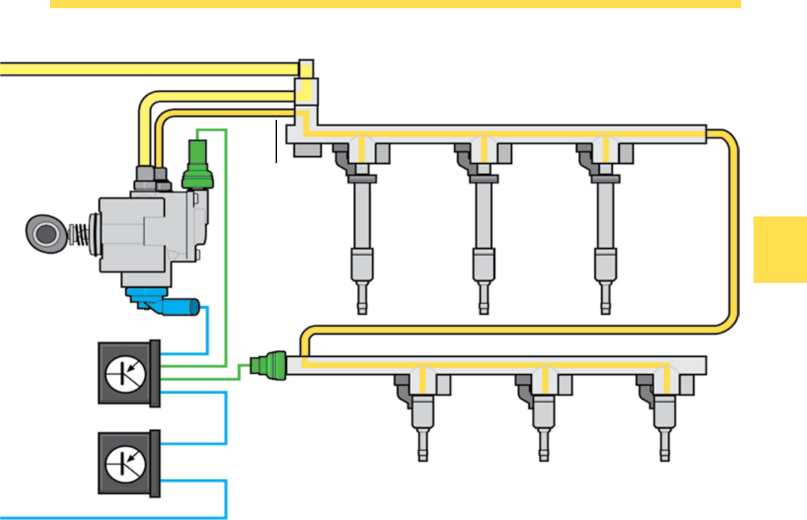
The High-Pressure Fuel System
The Pressure Relief Valve
The Pressure Relief Valve is located on the fuel
distributor of the cylinder bank 1.
The valve opens a connection to the low-pressure
fuel system when the fuel pressure in the high-
pressure fuel system is over 1,740 psi (120 bar).
Distributor Rail Cylinder Bank 1
High-Pressure
Fuel Pump Fuel Injector
Cylinder 1
High-Pressure
Line
The Fuel Pressure Sensor G247
The Fuel Pressure Sensor G247 is installed in the
fuel distributor of the cylinder bank 2 and informs the
ECM of current pressure in the high-pressure fuel
system.
The Fuel Pressure Regulator Valve N276
The Fuel Pressure Regulator Valve N276 is threaded
into the high-pressure fuel pump and regulates the
pressure in the high-pressure fuel system according
to the signal from the ECM.
Distributor Rail Cylinder Bank 2
Fuel Injector
Cylinder 3
Fuel Injector
Cylinder 5
Fuel Injector
Cylinder 2
Fuel Injector
Cylinder 4
Fuel Injector
Cylinder 6
G410
N276
J623
J538
G247
S360_321
38
Engine Mechanics
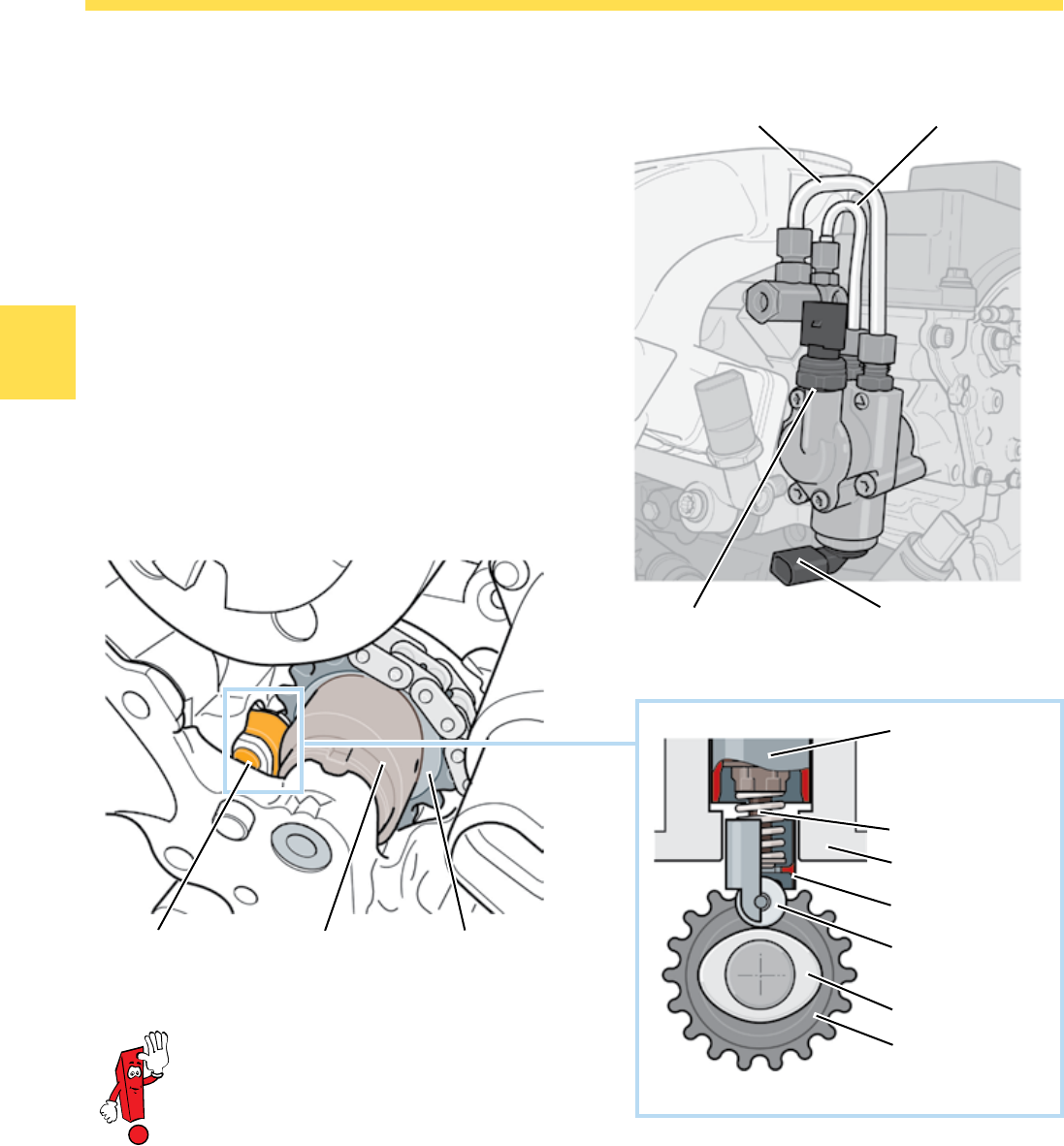
In order to install the camshaft roller
chain, the High-Pressure Fuel Pump
pinion must be locked with special tool
T10332.
Please refer to the Volkswagen Self-
Study Program 821503 “The 2.0L
FSI Turbocharged Engine Design and
Function” for more information about
the High-Pressure Fuel Pump.
The High-Pressure Fuel Pump
The High-Pressure Fuel Pump is located on the
cylinder head and is a piston pump. It is driven by the
camshaft and generates a fuel pressure of 1,595 psi
(110 bar).
Low-Pressure Fuel Line
Dual Cam
Roller
Cam Follower
Cylinder Head
Pump Piston
High-Pressure
Fuel Pump
Pinion Gear
Dual Cam
Fuel Pump Drive
The High-Pressure Fuel Pump Drive
The High-Pressure Fuel Pump is driven by a pinion
gear with dual cam.
The dual cam actuates the pump piston through a
roller. The pump piston generates the high pressure
in the pump.
Pinion Gear
High-Pressure Fuel Line
Low Fuel Pressure
Sensor G410
Fuel Pressure Regulator
Valve N276
S360_123
S360_173
S360_038
39
Engine Mechanics
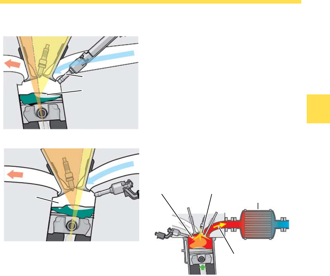
The Homogenous Split Catalytic
Converter Heating Process
The Homogenous Split Catalytic Converter Heating
Process brings the catalytic converters to operating
temperature quickly after a cold start.
To achieve this, the fuel is injected twice during one
combustion cycle. The first injection takes place in
the intake stroke. This achieves an even distribution
of the fuel-air mixture.
Fuel Injector Characteristics
Since the fuel injectors are inserted from the same
side for both banks of cylinders, the piston recess
must be shaped differently. This is necessary
because the fuel injectors and the intake valves
for both cylinder banks are positioned at different
angles.
The shape and orientation of the fuel injection play
an important role along with the quantity of fuel
injected and the length of injection.
Hotter Combustion
Gases heat up the
Catalytic Converter
Catalytic Converter
Late Ignition Timing
Late Pre-Injection
Valve
Pocket
Valve Angle Cylinder 1, 3, 5
Piston Recess
Fuel Injector
Valve Angle Cylinder 2, 4, 6
Exhaust Valve Intake Valve
S360_252
S360_251 S360_159
In the second injection, a small amount of fuel is
additionally injected shortly before ignition Top Dead
Center (TDC). The late injection increases exhaust
gas temperature. The hot exhaust gas heats up
the catalytic converter so that it reaches operating
temperature more quickly.
40
Engine Management
System Overview
Sensors Engine Speed (RPM) Sensor G28
Mass Air Flow (MAF) Sensor G70
Throttle Position (TP) Sensor G79
Accelerator Pedal Position Sensor 2 G185
Clutch Position Sensor G476
Throttle Valve Control Module J338 with
Throttle Drive Angle Sensor 1 (for Electronic
Power Control (EPC)) G187
Throttle Drive Angle Sensor 2 (for Electronic
Power Control (EPC)) G188
Camshaft Position (CMP) Sensor G40
Camshaft Position (CMP) Sensor 2 G163
Engine Coolant Temperature (ECT) Sensor G62
Engine Coolant Temperature (ECT) Sensor (on
Radiator) G83
Knock Sensor (KS) 1 G61
Knock Sensor (KS) 2 G66
Brake Light Switch F
Fuel Pressure Sensor G247
Low Fuel Pressure Sensor G410
Oil Level Thermal Sensor G266
Heated Oxygen Sensor (HO2S) G39
Heated Oxygen Sensor (HO2S) 2 G108
Oxygen Sensor (O2S) Behind Three Way
Catalytic Converter (TWC) G130
Oxygen Sensor (O2S) 2 Behind Three Way
Catalytic Converter (TWC) G131
Engine Control
Module (ECM)
J623
CAN Data-bus
S360_154
Engine Management
41
Engine Management
Actuators
Instrument Cluster
Control Module J285
Fuel Pump (FP) Control Module J538
Transfer Fuel Pump (FP) G6
Cylinder 1-6 Fuel Injector
N30, N31, N32, N33, N83, N84
Ignition Coil 1-6 with Power Output Stage
N70, N127, N291, N292, N323, N324
Throttle Valve Control Module J338 with
Throttle Drive (for Electronic Power Control (EPC))
G186
Fuel Pressure Regulator Valve N276
Evaporative Emission (EVAP) Canister Purge
Regulator Valve N80
Intake Manifold Runner Control (IMRC) Valve N316
Camshaft Adjustment Valve 1 N205
Camshaft Adjustment Valve 1 (exhaust) N318
Oxygen Sensor (O2S) Heater Z19
Oxygen Sensor (O2S) 2 Heater Z28
Oxygen Sensor (O2S) 1 (behind Three Way Catalytic
Converter (TWC)) Heater Z29
Oxygen Sensor (O2S) 2 (behind Three Way Catalytic
Converter (TWC)) Heater Z30
Coolant Fan Control (FC) Control Module J293
Coolant Fan V7
Coolant Fan 2 V177
Recirculation Pump Relay J160
Recirculation Pump V55
S360_155
CAN Data-bus
42
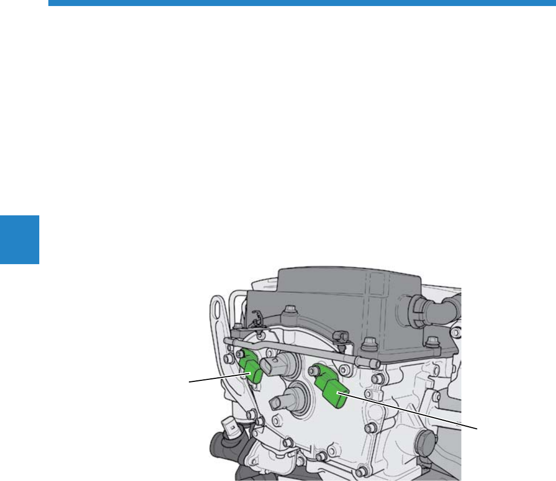
Engine Management
Sensors
Engine Speed (RPM) Sensor G28
The Engine Speed Sensor is threaded into the side of
the cylinder block. It scans the sensor wheel on the
crankshaft.
Signal Utilization
The engine speed and the exact position of the
crankshaft relative to the camshaft are determined
by the engine speed sensor. Using this information,
the injection quantity and the start of injection are
calculated.
Effects of Signal Failure
In case of signal failure, the engine is switched off
and cannot be restarted.
S360_111
43
Engine Management
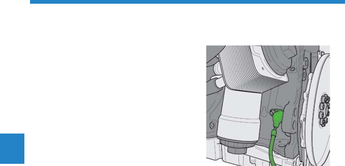
Mass Airflow Sensor G70
The 6th generation hot film mass airflow sensor
(HFM6) is used in the 3.2L and the 3.6L FSI engine.
It is located in the intake manifold and operates
based on a thermal measurement principle, as did its
predecessor.
Characteristics
Micromechanical sensor element with reverse
current detection
Signal processing with temperature compensation
High measurement accuracy
High sensor stability
•
•
•
•
Connector
Sensor Electronics
Bypass Channel
Drawn-in Air
S360_183
Signal Utilization
The signal from the mass airflow sensor is used
in the ECM to calculate the volumetric efficiency.
Based on the volumetric efficiency, and taking into
consideration the lambda value and ignition timing,
the control module calculates the engine torque.
Effects of Signal Failure
If the mass airflow sensor fails, the engine
management system calculates a substitute value.
44
Engine Management
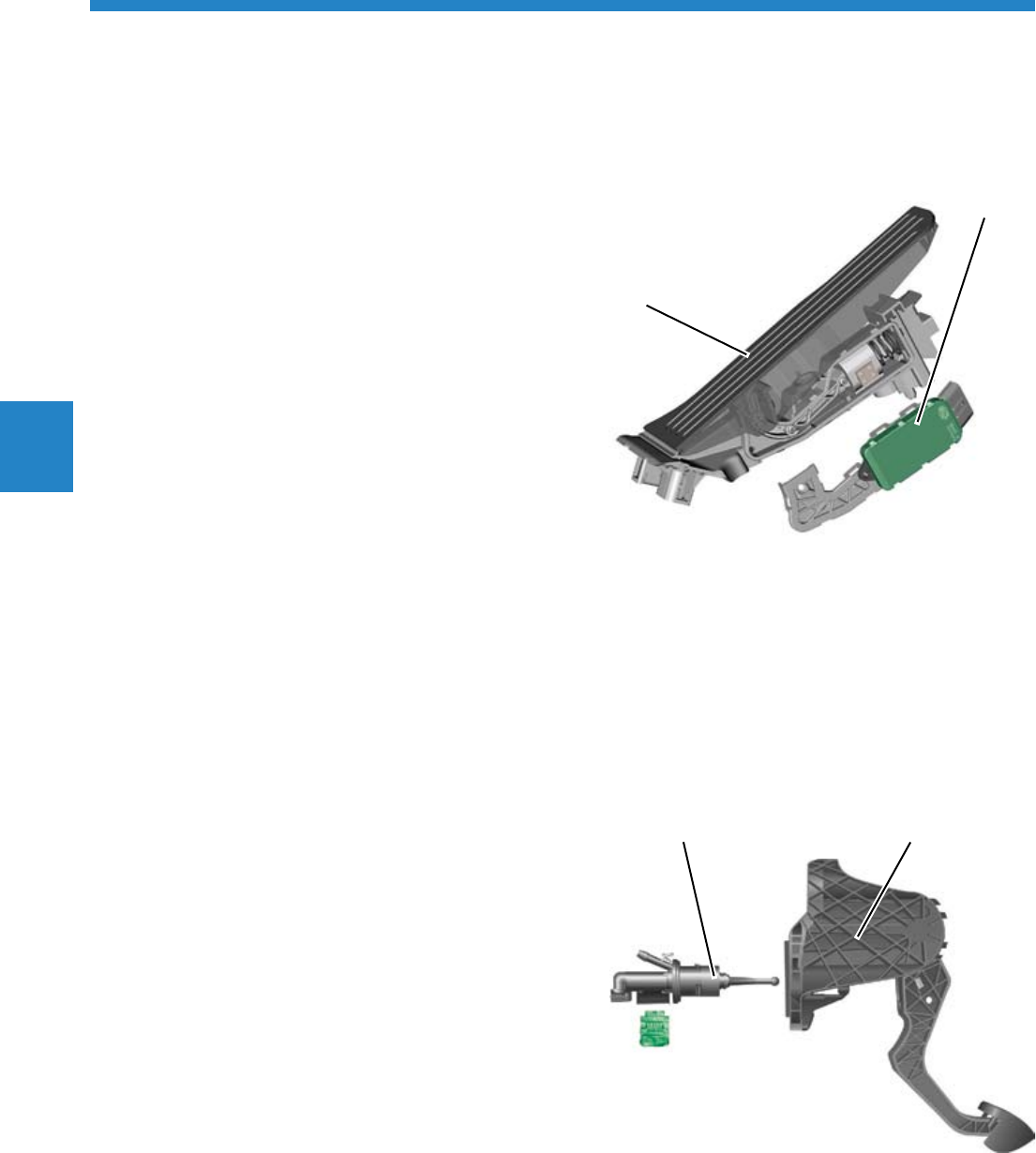
The Throttle Position (TP) Sensor
G79 and the Accelerator Pedal
Position Sensor 2 G185
The two throttle position sensors are part of the
accelerator pedal module and are contact-free
sensors.
The ECM detects the driver’s request from these
sensor signals.
Signal Utilization
The ECM uses the signals from the Throttle Position
Sensor to calculate the fuel injection volume.
Effects of a Signal Failure
If one or both sensors fails, an entry is made in
the DTC memory and the error light for electronic
power control is switched on. Comfort functions
such as cruise control or engine drag torque control
are switched off.
Clutch Position Sensor G476
The Clutch Position Sensor is a mechanically
actuated switch located on the clutch pedal. It is
only required on vehicles with manual transmission.
Signal Utilization
The signal is used to control the cruise control and
to control the ignition timing and quantity of fuel
when shifting.
Effects of a Signal Failure
The cruise control cannot be turned on. It also
results in driveability problems, such as engine
jerking and increased RPM when shifting.
Sensor Cylinder Clutch Pedal Module
G476
S360_150
S360_163
Accelerator Pedal
G79 and G185
45
Engine Management
The Throttle Drive Angle Sensor 1
G187 and Throttle Drive Angle
Sensor 2 G188 in the Throttle Valve
Control Unit
These sensors determine the current position of the
throttle valve and send this information to the ECM.
Signal Utilization
The ECM recognizes the position of the throttle valve
from the angle sensors signals. The signals from
the two sensors are redundant, meaning that both
sensors provide the same signal.
Effects of a Signal Failure
Example 1
The ECM receives an implausible signal or no signal
at all from an angle sensor:
An entry is made in the DTC memory and the error
light for electric throttle operation is switched on
Systems which affect torque, (e.g. cruise control
system or engine drag torque control), are
switched off
The load signal is used to monitor the remaining
angle sensor
The accelerator pedal responds normally
•
•
•
•
Example 2
The ECM receives an implausible signal or no
signal from both angle sensors:
An entry is made for both sensors in the DTC
memory and the error light for electric throttle
operation is switched on
The throttle valve drive is switched off
The engine runs only at an increased idle speed
of 1,500 RPM and no longer reacts to the
accelerator pedal
•
•
•
Throttle Valve Housing Throttle Valve Drive
Throttle Valve
G187 and G188
S360_238
46
Engine Management
The Camshaft Position Sensors
(CMP) G40 and G163
Both Hall sensors are located in the engine timing
chain cover. Their task is to communicate the
position of the intake and exhaust camshafts to the
ECM.
To do this, they scan a quick-start sensor wheel
which is located on the individual camshaft.
The ECM recognizes the position of the intake
camshaft from the Camshaft Position (CMP) Sensor
G40, and recognizes the position of the exhaust
camshaft from Camshaft Position (CMP) Sensor 2
G163.
Signal Utilization
Using the signal from the Camshaft Position Sensors,
the precise position of the camshaft relative to the
crankshaft is determined very quickly when the
engine is started. Used in combination with the
signal from the Engine Speed (RPM) Sensor G28, the
signals from the Camshaft Position Sensors allow to
detect which cylinder is at TDC.
The fuel can be injected into the corresponding
cylinder and ignited.
Effects of a Signal Failure
In case of signal failure, the signal from the Engine
Speed (RPM) Sensor G28 is used instead. Because
the camshaft position and the cylinder position
cannot be recognized as quickly, it may take longer
to start the engine.
G163
S360_108
G40
47
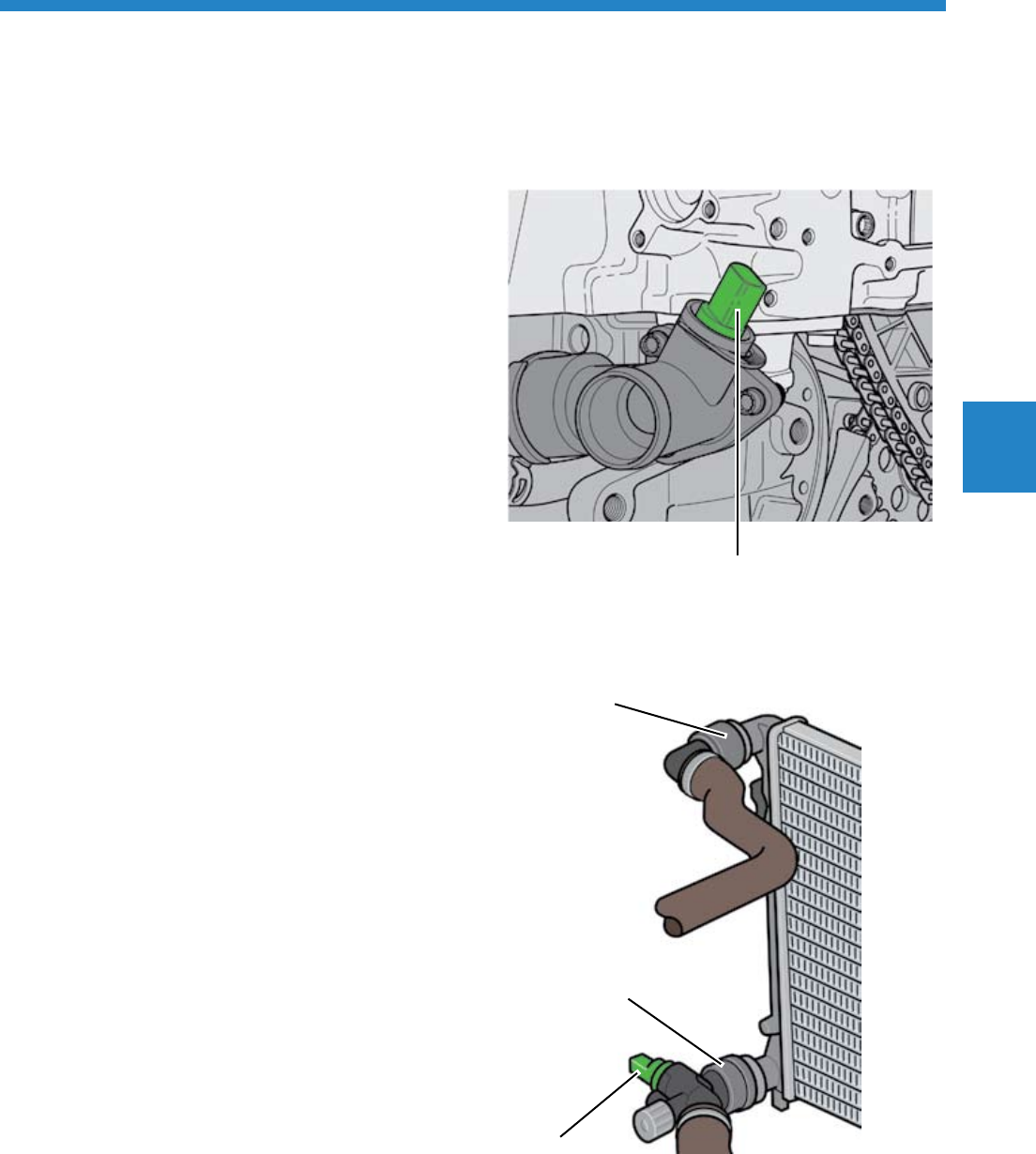
Engine Management
The Engine Coolant Temperature
(ECT) Sensor G62
This sensor is located at the coolant distributor above
the oil filter on the engine and it informs the ECM of
the coolant temperature.
Signal Utilization
The coolant temperature is used by the ECM
for different engine functions. For example, the
computation for the injection amount, compressor
pressure, start of fuel delivery and the amount of
exhaust gas recirculation.
Effects of a Signal Failure
If the signal fails, the ECM uses the signal from the
Engine Coolant Temperature (ECT) Sensor G83.
The Engine Coolant Temperature
(ECT) Sensor (on the Radiator) G83
The Engine Coolant Temperature Sensor (on the
Radiator) G83 is located in the radiator output line
and measures the coolant exit temperature.
Signal Utilization
The radiator fan is activated by comparing both
signals from the Engine Coolant Temperature Sensors
G62 and G83.
Effects of a Signal Failure
If the signal from the Engine Coolant Temperature
Sensor G83 is lost, the first speed engine coolant fan
is activated permanently.
Radiator Inlet
G62
G83
Radiator Outlet
S360_164
S360_182
48
Engine Management
Knock Sensor (KS) 1 G61 and
Knock Sensor (KS) 2 G66
The Knock Sensors are threaded into the crankcase.
They detect combustion knocks in individual
cylinders. To prevent combustion knock, a cylinder-
selective knock control overrides the electronic
control of the ignition timing.
Effects of a Signal Failure
In the event of a knock sensor failure, the ignition
timing for the affected cylinder group is retarded.
This means that a safety timing angle is set in the
“late“ direction. This can lead to an increase in fuel
consumption. Knock control for the cylinder group of
the remaining knock sensor remains in effect.
If both knock sensors fail, the engine management
system goes into emergency knock control in which
the ignition angle is retarded across the board so
that full engine power is no longer available.
Signal Utilization
Based on the knock sensor signals, the ECM
initiates ignition timing adjustment in the knocking
cylinder until knocking stops.
G61 G66
S360_157 S360_158
49
Engine Management
The Brake Light Switch F
The Brake Light Switch is located on the tandem
master cylinder. It scans a magnetic ring on the
tandem master cylinder piston using a contactless
Hall Element.
This switch provides the ECM with the signal “Brake
actuated“ via the CAN data bus drive.
Signal Utilization
When the brake is operated, the cruise control
system is deactivated. If the signal “accelerator
pedal actuated“ is detected first and “brake
actuated“ is detected next, the idle speed is
increased.
Effects of a Signal Failure
If the sensor signal is lost, the amount of fuel
injected is reduced and the engine has less power.
The cruise control system is also deactivated.
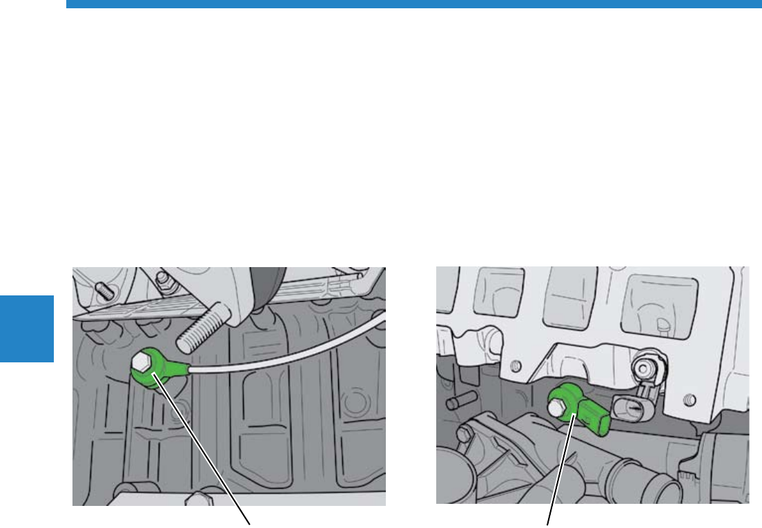
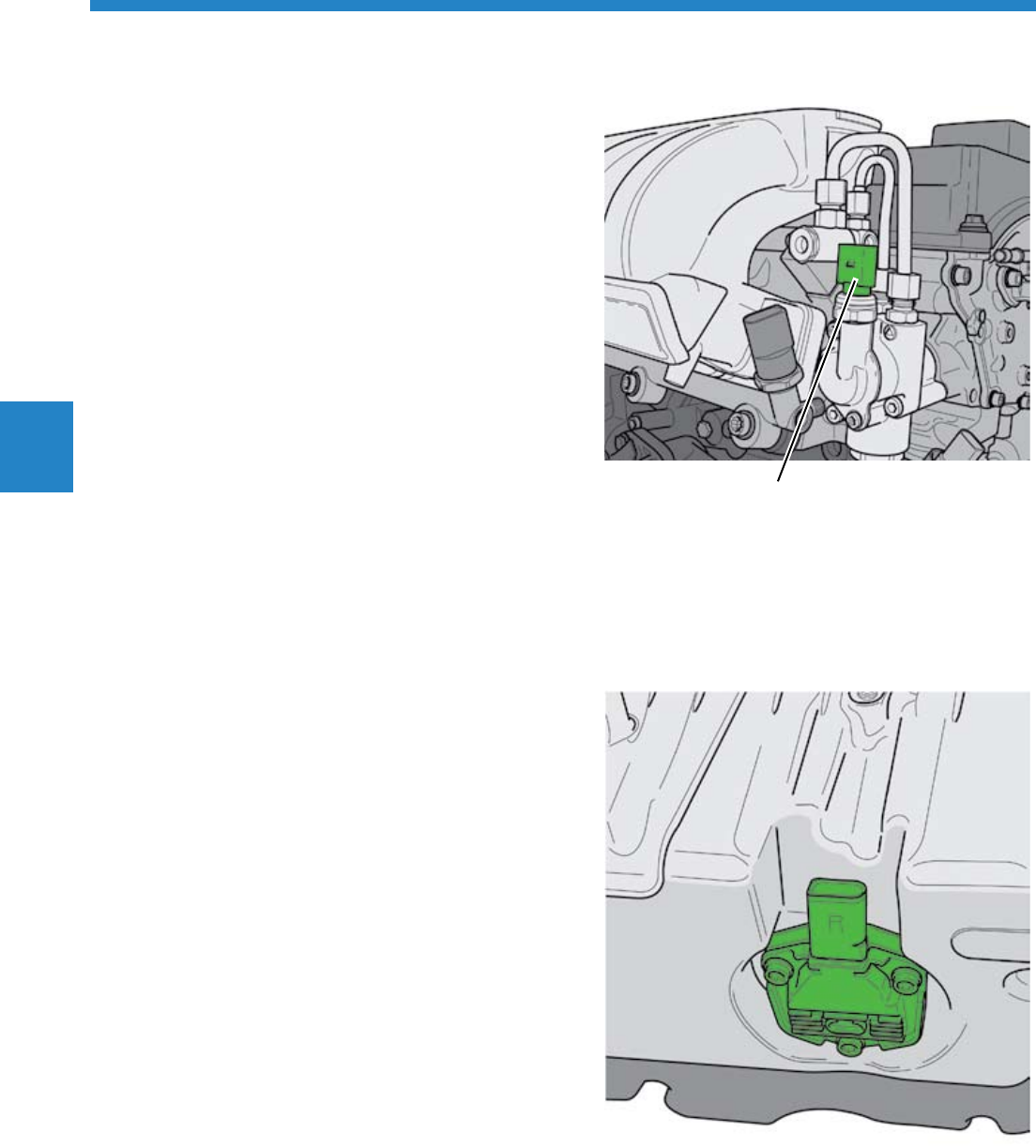
The Fuel Pressure Sensor G247
The Fuel Pressure Sensor is located on the lower
fuel distributor pipe. It measures the fuel pressure in
the high-pressure fuel system.
Signal Utilization
The Engine Control Module (ECM) analyzes the
signal and regulates the fuel high pressure through
the Fuel Pressure Regulator Valve N276 in the high-
pressure pump.
Effects of a Signal Failure
If the Fuel Pressure Sensor fails, the fuel pressure
regulator valve is activated at a fixed value by the
ECM.
G247
S360_177
S360_110
50
Engine Management
The Low Fuel Pressure Sensor G410
The Low Fuel Pressure Sensor is located on the high-
pressure fuel pump. It measures the fuel pressure in
the low-pressure fuel system.
Signal Utilization
The signal is used by the ECM to regulate the low-
pressure fuel system. Based on the signal from the
sensor, a signal is sent by the ECM to the Fuel Pump
Control Module J538, which then regulates the fuel
pump as needed.
Effects of a Signal Failure
If the Low Fuel Pressure Sensor fails, the fuel
pressure is not regulated as needed. Fuel pressure is
maintained at a constant 72 psi (5 bar).
The Oil Level Thermal Sensor G266
The Oil Level Thermal Sensor is threaded into the
oil pan from below. Its signal is used by several
control modules. The Instrument Cluster Control
Module J285 uses this signal to display the engine oil
temperature.
Signal Utilization
The ECM receives the signal over the CAN data bus
and uses the oil temperature signal to control the
retarded setting of the exhaust camshaft at high oil
temperatures.
Effects of a Signal Failure
The control module uses the signal from the Coolant
Temperature Sensor instead of the oil temperature
signal.
G410
S360_109
S360_156
51
Engine Management
The Oxygen Sensor (O2S) Behind
Three Way Catalytic Converter
(TWC) G130 and the Oxygen
Sensor (O2S) 2 Behind Three Way
Catalytic Converter (TWC) G131
The planar oxygen sensors are located downstream
of the pre-catalytic converter. They measure the
remaining oxygen content in the exhaust gas. Based
on the amount of oxygen remaining in the exhaust
gas, the ECM can draw conclusions about the
catalytic converter operation.
Signal Utilization
The Engine Control Module uses the signals from
the post-catalytic converter oxygen sensors to check
the catalytic converter operation and the closed-loop
oxygen control system.
Broadband Oxygen Sensor
Planar Oxygen Sensor
S360_224
S360_222
Effects of a Signal Failure
If the post-catalytic converter oxygen sensor fails,
the closed loop operation continues. The operation
of the catalytic converter can no longer be checked.
The Heated Oxygen Sensors
(HO2S) G39 and the Heated
Oxygen Sensors (HO2S) 2 G108
A broadband oxygen sensor is assigned to each pre-
catalytic converter as a pre-catalytic oxygen sensor.
Using the broadband oxygen sensors, a wide range
of oxygen concentration in the exhaust gas can be
calculated. Both oxygen sensors are heated to reach
operating temperature more quickly.
Signal Utilization
The signals from the Heated Oxygen Sensors are
one of the variables used in calculating the injection
timing.
Effects of a Signal Failure
If the pre-catalytic converter oxygen sensor fails,
there is no closed loop control. The fuel injection
adaptation is not available. An emergency running
mode is enabled using an engine characteristics map.
52
Engine Management
The Actuators
Camshaft Adjustment Valve 1
N205, Camshaft Adjustment Valve
1 (exhaust) N318
The solenoid valves are integrated in the camshaft
adjustment housing. They distribute the oil pressure
based on the ECM signals for the adjustment
direction and adjustment travel at the camshaft
adjusters.
Both camshafts are continuously adjustable:
Intake camshaft at 52° of the crankshaft angle
Exhaust camshaft at 42° of the crankshaft angle
Maximum valve overlap angle 47°
The exhaust camshaft is mechanically locked when
no oil pressure is available (engine not running).
•
•
•
Effects of a Signal Failure
If an electrical connection to the camshaft adjusters
is defective or if a camshaft adjuster fails because it
is mechanically seized or as a result of inadequate oil
pressure, there is no camshaft adjustment.
S360_161
N205 N318
53
Engine Management
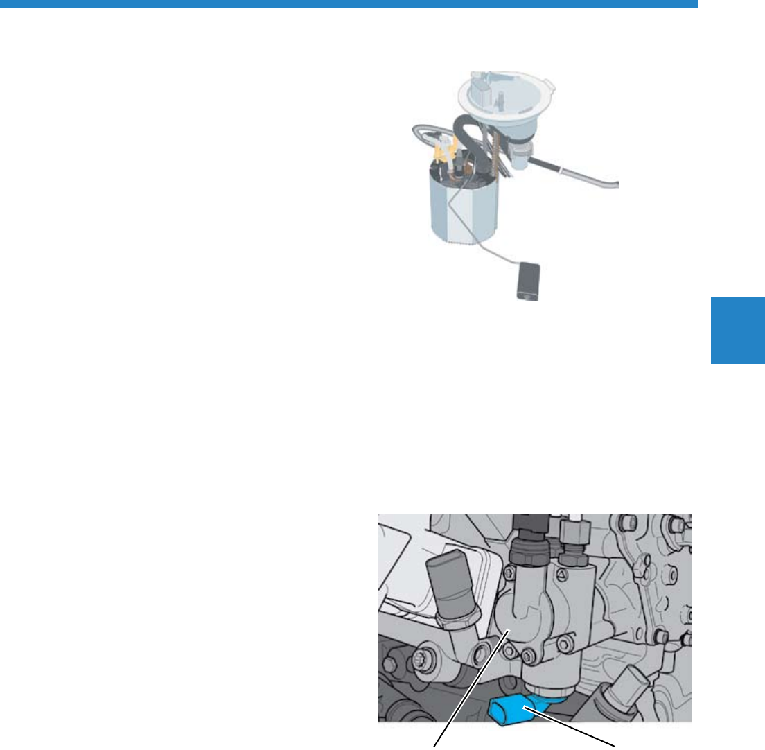
The Transfer Fuel Pump (FP) G6 and
the Fuel Level Sensor G
The Transfer Fuel Pump and the Fuel Filter are
combined in the Fuel Transfer Unit. The Fuel Transfer
Unit is located in the fuel tank.
Operation
The Transfer Fuel Pump transfers the fuel in the low-
pressure fuel system to the high-pressure fuel pump.
It is activated by a Pulse Width Modulation (PWM)
signal from the Fuel Pump Control Module.
The Transfer Fuel Pump transfers as much fuel as the
engine requires at any point in time.
Effects of a Failure
If the Transfer Fuel Pump fails, engine operation is
not possible.
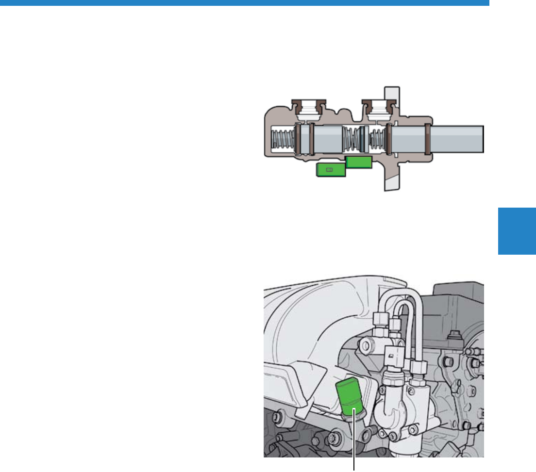
The Fuel Pressure Regulator Valve
N276
The Fuel Pressure Regulator Valve is located on the
underside of the High-Pressure Fuel Pump.
The ECM regulates the fuel high-pressure through
the Fuel Pressure Regulator Valve at a level between
507 and 1,450 psi (35 and 100 bar).
Effects of a Failure
The ECM goes into emergency running mode.
High-Pressure Fuel
Pump
N276
S360_162
S360_190
54
Engine Management
The Ignition Coils 1-6 with Power
Output Stage N70, N127, N291,
N292, N323, N324
The ignition coil and power output stage are
one component. The ignition timing is controlled
individually for each cylinder.
Effects of a Failure
If an ignition coil fails, fuel injection for the affected
cylinder is switched off. This is possible for a
maximum of two cylinders.
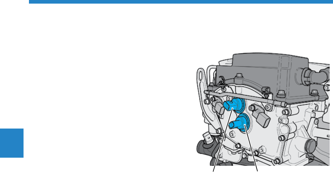
The Evaporative Emission (EVAP)
Canister Purge Regulator Valve N80
The Evaporative Emission Canister Purge Regulator
Valve is located on the front (belt drive side) of the
engine and is triggered by the ECM. The fuel vapors
collected in the evaporative emission canister
are sent for combustion and thus the evaporative
emission canister is emptied.
Effects of a Signal Failure
If the current is interrupted, the valve remains closed.
The fuel tank is not vented to the engine.
N80
S360_192
S360_191
Ignition Coils
55
Engine Management
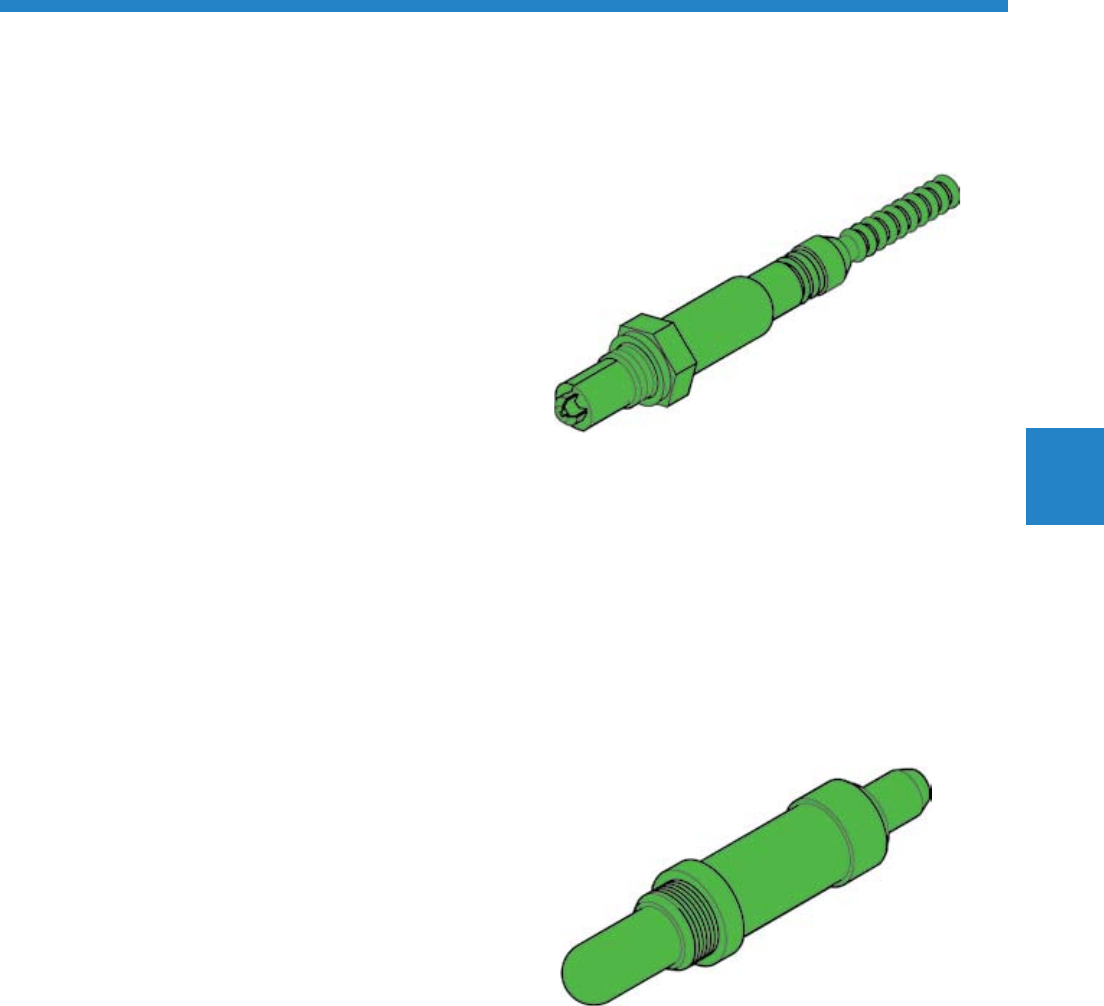
The Cylinders 1-6 Fuel Injectors
N30, N31, N32, N33, N83, N84
The High-Pressure Fuel Injectors are inserted into
the cylinder head. They are triggered by the ECM in
accordance with the firing orders. When triggered,
they spray fuel directly into the cylinder.
Due to the design of the engine, injection takes
place from one side. For this reason, the fuel
injectors for cylinder bank 1, 3 and 5 are longer than
the fuel injectors for cylinder bank 2, 4 and 6.
Effects of a Failure
A defective fuel injector is recognized by misfire
detection and is no longer triggered.
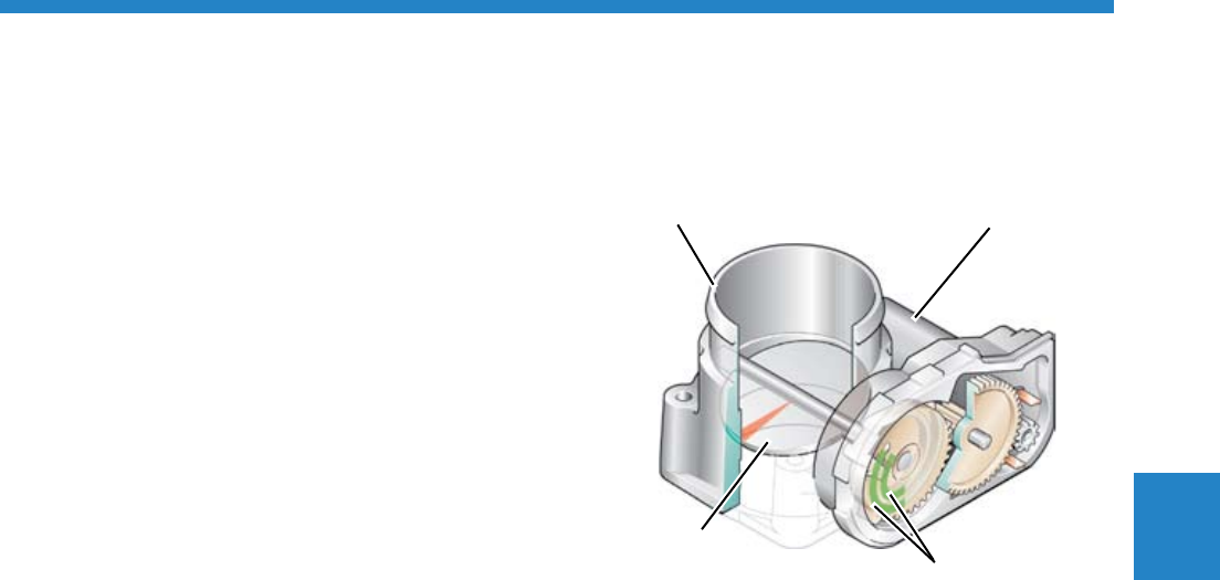
Throttle Drive for Electronic Power
Control (EPC) G186
The Throttle Drive for Electronic Power Control is an
electrical motor which operates the throttle valve
through a gear mechanism.
The range of adjustment is stepless from idle to the
wide-open throttle position.
Effects of a Failure
If the throttle drive fails, the throttle valve is
automatically pulled to the emergency running
position. An entry is made in the DTC memory
and the error lamp for electronic power control is
switched on.
Throttle Valve Housing
Throttle Valve
G186
S360_137
S360_195
56
Engine Management
Intake Manifold Runner Control
(IMRC) Valve N316
The Intake Manifold Runner Control Valve is
located on the variable intake manifold and is an
electropneumatic valve.
When it is activated, it operates the intake manifold
flap to change the length of the intake manifold.
Effects of a Failure
If the valve fails, the intake manifold flaps are pulled
by a mechanical spring to an emergency running
position. This position corresponds to the power
setting of the intake manifold.
The Recirculation Pump V55
The Recirculation Pump is activated by the ECM.
It assists the mechanical coolant pump when the
engine is running. After the engine is turned off and
with a lack of moving air resulting from the vehicle
motion, the Recirculation Pump may be switched on
depending on the coolant temperature, to prevent
heat buildup in the engine.
Effects of a Failure
If the Recirculation Pump fails, the engine may
overheat.
V55
S360_051
S360_045
N316

57
Engine Management
Oxygen Sensor (O2S) Heaters Z19,
Z28, Z29 and Z30
The job of the Oxygen Sensor Heater is to bring
the ceramic of the oxygen sensor rapidly up to its
operating temperature of approx. 1652°F (900°C)
when the engine is started and the temperature is
low. The oxygen sensor heater is controlled by the
ECM.
Effects of a Failure
The engine can no longer be regulated with respect
to the emissions.
Oxygen Sensor Heater
S360_193

58
Notes
59
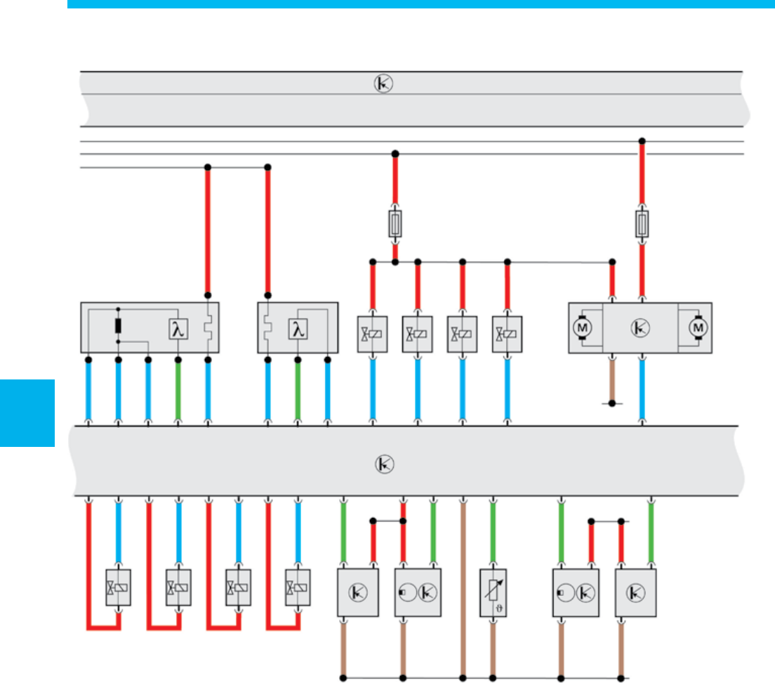
Operating Diagrams
The Control Modules in the
CAN Data Bus
The schematic below shows the Engine Control
Module J623 integrated into the CAN data bus
structure of the vehicle. Information is exchanged
between the control modules over the CAN data
bus.
J743
J217
J104
J623
J533
J285
J234
J519
J257
Legend
J623 Engine Control Module (ECM)
J104 ABS Control Module
J217 Transmission Control Module (TCM)*
J234 Airbag Control Module
J285 Instrument Cluster Control Module
J519 Vehicle Electrical System Control Module
J527 Steering Column Electronic Systems Control
Module
J533 Data Bus On Board Diagnostic Interface
J743 Direct Shift Gearbox (DSG) Mechatronic*
* Either J217 or J743 will be used.
Color coding
Powertrain CAN-bus
Comfort system CAN-bus
Infotainment CAN-bus
S360_175
60
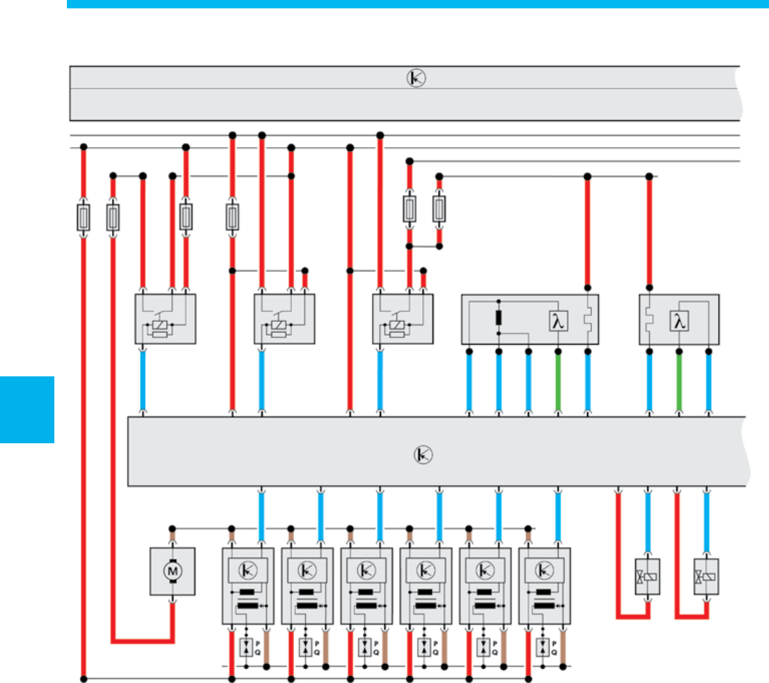
Operating Diagrams
G39 Heated Oxygen Sensor (HO2S)
G130 Oxygen Sensor (O2S) Behind Three Way
Catalytic Converter (TWC)
J160 Recirculation Pump Relay
J271 Motronic Engine Control Module (ECM)
Power Supply Relay
J519 Vehicle Electrical System Control Module
J623 Engine Control Module (ECM)
J670 Motronic Engine Control Module (ECM)
Power Supply Relay 2
N30 Cylinder 1 Fuel Injector
N31 Cylinder 2 Fuel Injector
N70 Ignition Coil 1 with Power Output Stage
N127 Ignition Coil 2 with Power Output Stage
N291 Ignition Coil 3 with Power Output Stage
N292 Ignition Coil 4 with Power Output Stage
N323 Ignition Coil 5 with Power Output Stage
N324 Ignition Coil 6 with Power Output Stage
Z19 Oxygen Sensor (O2S) Heater
Z29 Oxygen Sensor (O2S) 1 (behind Three Way
Catalytic Converter (TWC)) Heater
J519
K30
K15
G39
J160 J271 Z19 Z29
J623
J257
N70 N127 N291 N292 N323 N324
N30 N31
G130
J670
S360_165
Operating Diagrams
61
Operating Diagrams
F Brake Light Switch
F1 Oil Pressure Switch
G Fuel Level Sensor
G1 Fuel Gauge
G5 Tachometer
G6 Transfer Fuel Pump (FP)
G21 Speedometer
G28 Engine Speed (RPM) Sensor
G61 Knock Sensor (KS) 1
G66 Knock Sensor (KS) 2
G79 Throttle Position (TP) Sensor
G185 Accelerator Pedal Position Sensor 2
G186 Throttle Drive (for Electronic Power Control
(EPC))
G187 Throttle Drive Angle Sensor 1 (for Electronic
Power Control (EPC))
G188 Throttle Drive Angle Sensor 2 (for Electronic
Power Control (EPC))
G266 Oil Level Thermal Sensor
J285 Instrument Cluster Control Module
J338 Throttle Valve Control Module
J538 Fuel Pump (FP) Control Module
J623 Engine Control Module (ECM)
N276 Fuel Pressure Regulator Valve
J519
G G6 F1 G266
CAN
J285
J538
G1 G5 G21
F N276
J623
G28 G61 G66 G79 G185
G186 G187 G188
J338
S360_166
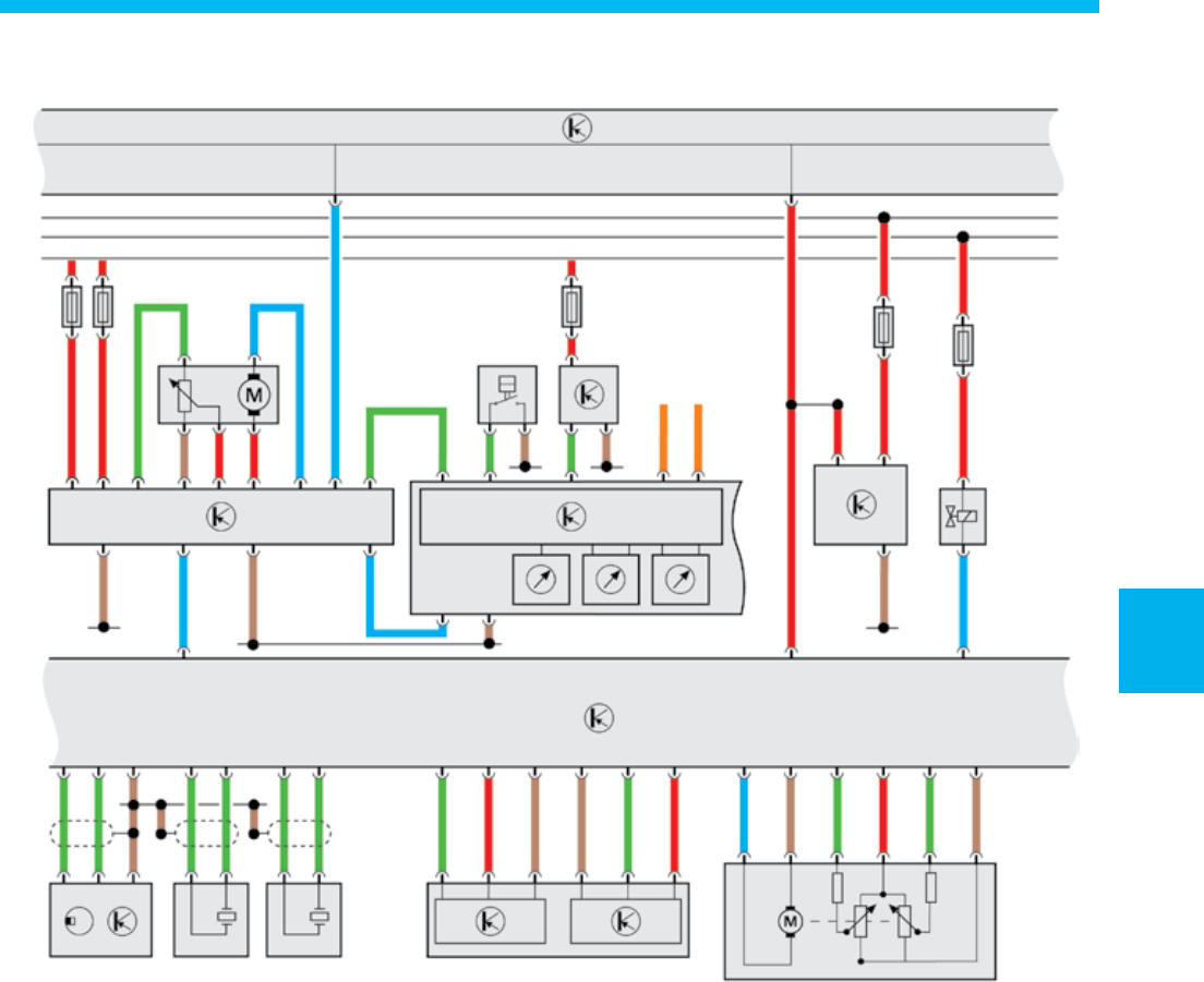
62
Operating Diagrams
G40 Camshaft Position (CMP) Sensor
G83 Engine Coolant Temperature (ECT) Sensor
(on Radiator)
G108 Heated Oxygen Sensor (HO2S) 2
G131 Oxygen Sensor (O2S) 2 Behind Three Way
Catalytic Converter (TWC)
G163 Camshaft Position (CMP) Sensor 2
G247 Fuel Pressure Sensor
G410 Low Fuel Pressure Sensor
J293 Coolant Fan Control (FC) Control Module
J519 Vehicle Electrical System Control Module
J623 Engine Control Module (ECM)
N32 Cylinder 3 Fuel Injector
N33 Cylinder 4 Fuel Injector
N80 Evaporative Emission (EVAP) Canister Purge
Regulator Valve
N83 Cylinder 5 Fuel Injector
N84 Cylinder 6 Fuel Injector
N205 Camshaft Adjustment Valve 1
N316 Intake Manifold Runner Control (IMRC) Valve
N318 Camshaft Adjustment Valve 1 (exhaust)
V7 Coolant Fan
V177 Coolant Fan 2
J519
G108 G131
Z28 Z30 N205 N80 N316 N318 V7 J293 V177
J623
N32 N33 N83 N84
G410 G163 G83 G40 G247
S360_167
63
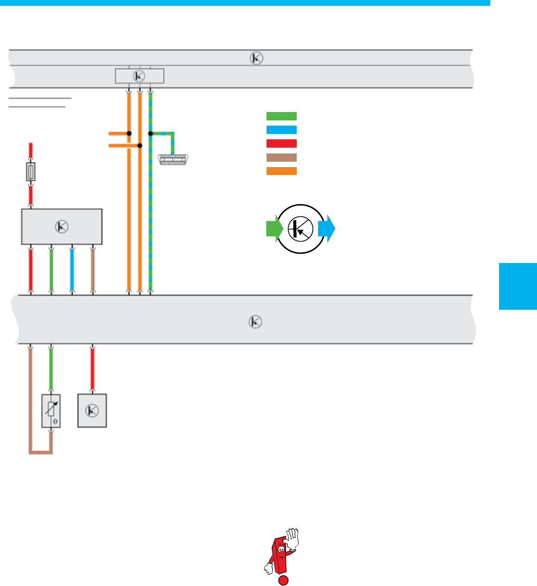
Operating Diagrams
The operating diagram shows the
3.6-liter FSI engine in the Passat as
an example.
G62 Engine Coolant Temperature (ECT) Sensor
G42 Intake Air Temperature (IAT) Sensor
G70 Mass Air Flow (MAF) Sensor
J519 Vehicle Electrical System Control Module
J527 Steering Column Electronic Systems Control
Module
J533 Data Bus On Board Diagnostic Interface
J623 Engine Control Module (ECM)
Z28 Oxygen Sensor (O2S) 2 Heater
Z30 Oxygen Sensor (O2S) 2 (behind Three Way
Catalytic Converter (TWC)) Heater
Input signal
Output signal
Plus
Ground
CAN Databus
IN OUT
J519
J533
K30
K15
CAN
G42 G70
G62 J527
J623
S360_168

64
Notes
65
Service
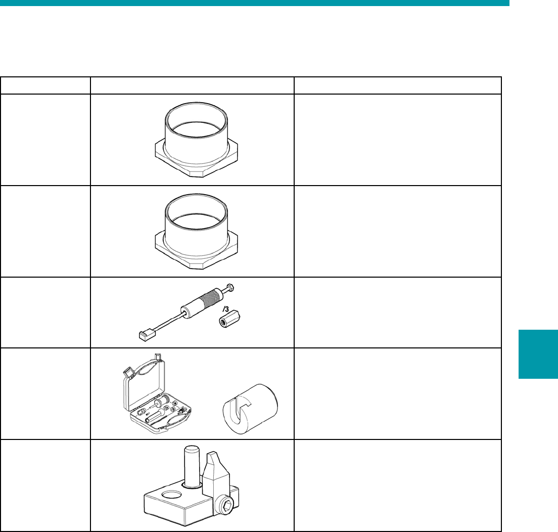
Special Tools
Description Tool Use
Funnel T 10333 The Funnel T 10333 is used for installing the
pistons on the 3.6 V6 FSI engine.
Funnel T 10343 The Funnel T 10343 is used for installing the
pistons on the 3.2 V6 FSI Engine.
Puller T10055
Adapter T
10055/3
The Puller T10055 with Adapter T 10055/3
is used to remove the oil pump.
Tool Set T 10133
Puller T 10133/10
The Tool Set T 10133 with Puller
T 10133/10 is needed to remove the fuel
injectors.
Adjusting tool
T 10332
The Adjusting Tool T 10332 must be used
to lock the pinion on the high-pressure fuel
pump drive.
Service

66
Notes

An on-line Knowledge Assessment (exam) is available for this
Self-Study Program
You can find this Knowledge Assessment on your
Certification Resource Center
at:
www.vwwebsource.com
From the vwwebsource.com homepage, do the following:
1. Click on the Certification tab
2. Click on “My Certification” tab
3. Click the Fulfill link next to this SSP
4. Click “Launch Assessment”
For assistance, please call:
Volkswagen Academy Concierge
1 – 877 – 791 – 4838
(8:00 a.m. to 8:00 p.m. EST)
Or, E-Mail:
concierge@volkswagenacademy.com
Volkswagen of America, Inc.
3800 Hamlin Road
Auburn Hill, MI 48326
Printed in the U.S.A.
October 2006
