VX2202 Digital Door Panel PC Interface Software VX2200 Prog Guide
User Manual: VX2200 Prog Guide
Open the PDF directly: View PDF ![]() .
.
Page Count: 10
Page 1 of 10 2x02PCVer5 USER INSTRUCTIONS
VX2202 & VX2300 Digital door panel PC interface software
IMPORTANT NOTE: THIS SOFTWARE CAN BE USED WITH ANY OF THE VX2300
DIGITAL DOOR PANELS BUT ONLY VX2200 DIGITAL DOOR PANELS WITH
SOFTWARE VERSION 5.0 OR LATER. USE THE VX2200 PC PROGRAMMER
SOFTWARE (2202PC.EXE) FOR OLDER VERSIONS.
INTRODUCTION
The software enables an engineer to program the VX2200/VX2300 digital door panel and
concierge using a PC. The PC will attach to the door panel using the cable supplied (Either
the serial cable on its own if the PC has a serial port or the serial cable with the USB
adapter fitted if the PC only has USB ports). The PC end of the cable is the 9 pin D type
connector for connecting to a spare serial port (or USB adapter) and the other end is a
male jack plug which can be inserted into the jack socket in the door panel or on the rear
of the concierge unit.
IMPORTANT NOTE: If the USB adapter is to be used it must first be installed
correctly using the drivers supplied. Please follow the instructions to install the
adapter in appendix A.
The information that can be programmed has been listed below:-
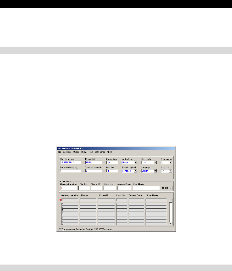
A screen shot of the main screen is shown above. The items in blue are the common
information, the line in red is the apartment information line currently being edited and
below that is a list of all the apartments currently in the database.
COMMON INFORMATION
• Main display logo – This logo will be displayed on the top line of the door panel
LCD display. The bottom line will say [<- OR SEARCH ->], or [NUMBER] for
systems without the search facility. It can be up to 16 characters long (e.g. ENTER
FLAT, ENTER OFFICE etc)
• Switch display logo – The display will switch between logo1 and this logo while
the system is in standby. This logo could be used to show the building name etc.
(Max. 16 characters). The bottom line will be blank when this logo is on show.
(Leaving switched logo blank will result in the main logo being shown at all times
without switching.)
Page 2 of 10 2x02PCVer5 USER INSTRUCTIONS
• Master code – The master code is needed to access the information in the door
panel. This can be up to six digits long. NOTE: If the master code is changed on the
computer, to upload you must enter the old master code. After the upload, the new
code will have replaced the old code.
• Trade access code – This code can be used to gain access only when the time
clock input is shorted (TRD – 0V). If no code is required enter a 0.
• Speech time – The speech time can be set from 1 – 255 seconds
• Door time – The door open time can be set from 1 – 255 seconds
• Master/Slave – On a single level VX2200 system there should be only one master
panel. All other panels should be set as slaves. This option is not required on the
VX2300 system and so can be ignored.
• Speech playback - An internal speech board can be activated/deactivated. This
speech board will give voice feedback when buttons are pressed. The voice can be
set as combined, individual or none. When set to combined the door panel will
speak the number as a combination of the numbers entered. For example, entering
100 and pressing enter would speak [Calling number one hundred]. When set to
individual the door panel would speak [Calling number one zero zero]. Setting as
none will disable speech playback facility. (Only available in English at present).
• Door mode – The door panel can be used in one of two modes of operation. The
mode selected depends on the installation type and the location of the door panel
on the system. The options are as follows:-
1. The system does not include any 2206N or 2306 block
exchange devices – Set as door mode = local.
2. The system includes 2206N or 2306 block exchange devices
and this door panel to be programmed is connected as a block
panel as oppose to a main panel – Set as door mode = local.
3. The system includes 2206N or 2306 block exchange devices
and this door panel to be programmed is connected as a main
panel which can call all blocks – Set as door mode = main.
• Language – The language on the display can be set to one of the following :-
o English
o Italian
o Spanish
o Portuguese
o French
o German
• Door number – The door number can be set from 1 to 10 and will indicate to a
concierge which door the call was initiated from. It will also allow the concierge to
call back the door and open the door without first being called. It is important to give
each door a unique number, especially when using video or a concierge.
• Ring time – The ring time is only programmable on the 2202 door panel when used
with the 3161 or 3162 telephone types. Ring time can be between 1 – 60 seconds.
Page 3 of 10 2x02PCVer5 USER INSTRUCTIONS
USER INFORMATION (Up to 998 users can be programmed into the door panel when in main mode or
180 users (100 users on 2303) when the door panel is in local mode).
• Memory location – The memory location is not editable and only indicates the
position in the door panel’s memory where the information will be stored.
• USER NAME – A name of up to 16 characters can be programmed for each user
location. This could be a tenants name or a company name etc and will be available
to scroll on scroll facility door panels.
• Flat number – The flat number can be up to six digits long and is the number that
the caller will type into the panel to make the call.
• Phone ID – The binary dip-switch setting on the telephone. The dip-switch setting
should be set prior to powering up the system.
• Block No. – The block number is only used on 2 level systems which include either
the 2206N or the 2306 bus exchange device. On a system with these devices, each
block will have a bus exchange device and each bus exchange device will have a
unique ID set by dip switches. The block no. is the unique ID of the 2206N/2306 for
the block in which the apartment is located.
• Personal access code – Each tenant can have a personal access code to gain
entry into the building. The code can be up to six digits long. If no code is required,
this can be left blank.
INSTRUCTIONS
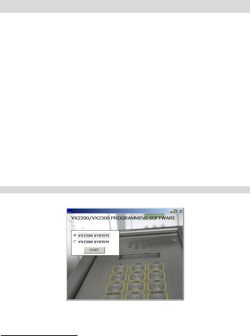
After starting the program the following screen will appear:-
Select either the VX2200 System or the VX2300 system and then press start to go to the
main screen.
To Starting a new data file
To start a new file simply choose New from the File drop down menu. You will be
prompted for a file name to save the data in. A file will be created with default setting.
Page 4 of 10 2x02PCVer5 USER INSTRUCTIONS
To Opening an existing file
To open an existing file simply choose Open from the File drop down menu and select the
file name you want to open.
Save as
Every time you press update, the information is saved to the file. If you want to save the
file under a different name simply select Save as from the File drop down menu and enter
the new name. The old file name will not be deleted.
Convert an older file to the new format
If you have an old file from a door panel which has software older than version 5 then in is
possible to convert this file to the new format. Simply select File > Convert from the drop
down menus. An open dialogue box will appear requesting the name of the old file, select
it and click open. You will then be asked to create a name for the new file. Create the
name and then press Save. The new file will be created with the data from the old file and
then displayed in the on-screen boxes.
Obtain a hard copy
If a hard copy of the programming information is required then select Print from the File
menu. The hard copy will contain all the programming information. Additionally it will also
show the dip-switch settings for all flats in diagram format.
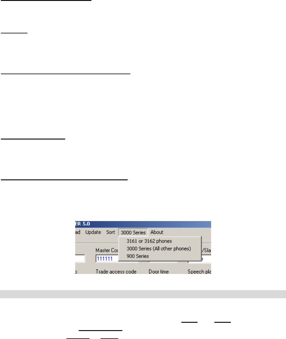
Telephone type (VX2200 system only)
There are three types of telephone available for the VX2200 system and it is important to
choose the correct ones. In most cases this will be the 3000 Series but for older systems it
may be 900 series. 3161 or 3162 phones are special low cost low facility phones. Choose
the correct phone type from the drop down menu as shown below.
UPLOADING AND DOWNLOADING THE INFORMATION BETWEEN THE PC & PANEL
IMPORTANT SETTINGS WHICH NEED TO BE CHANGED FOR EACH UPLOAD:-
9 Select if the door panel uploading to is a local or a main panel
9 Select the door number
9 Select master or slave (2202 only)
Page 5 of 10 2x02PCVer5 USER INSTRUCTIONS
If you are not sure of the communication port number that you are connected too;
press the search button. All available communication ports in the range of 1 - 16 will
be checked and the correct port will automatically be shown.
If for any reason your PC has assigned a port higher than 16 to your USB adapter
then you will need to manually reconfigure it to a lower number. Follow the steps in
Appendix B to do this.
Download information from the door panel
To download information from the door panel simply press the download button on the
main screen. You will be prompted for a file name to save the downloaded data too. After
which a new window will appear (as shown above) where you will be asked to select the
communication port you are connected to and then enter the master code. When OK is
pressed, the master code entered will be checked against the master code in the door
panel. If they are the same the download will commence.
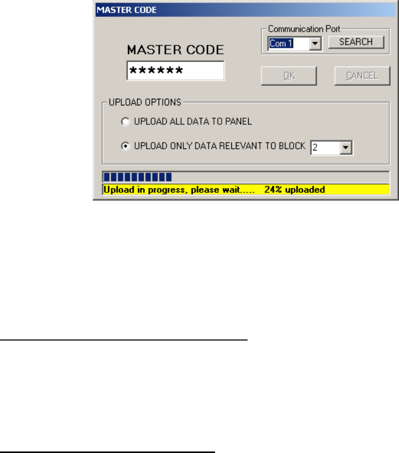
Upload information to the door panel
After creating or opening a data file, it can then be uploaded to the door panel. To upload
simply press the upload button. A new window will appear which will require the master
code in the door panel and the communication port to upload to. There will also be
additional options depending on if the door panel is a local door panel (On systems without
2206N/2306 units or door panels connected to the local connection of a 2206N/2306 and
only requiring certain apartments from the database to be uploaded) or a main panel
(Connected to the main connection of 2206N/2306’s and requiring all the information to be
uploaded to it).
NOTE: It is very important to select if the door panel is MAIN or LOCAL as MAIN
panels will only work when connected to the main bus side of 2206N/2306’s
If the door panel is a local panel and requires only certain information to be uploaded
follow these steps (Ensure the Block ID fields have been completed correctly in the
database):-
1. Select Local from the Door Mode menu on the main page.
2. Select Master or Slave on the main page depending on if the door panel to be
programmed should be a master or a slave.
3. Select the unique door number for the door panel to be programmed.
4. Press Upload

Page 6 of 10 2x02PCVer5 USER INSTRUCTIONS
5. In the upload options box, select if you want to upload the complete database of
apartments or only apartments which are connected to a particular 2206N. If you
choose the latter, select the 2206N/2306 number from the drop down box.
6. Select the communication port, enter the master code and then press OK.
If the door panel is a main panel connected to the main bus side of 2206N/2306’s:-
1. Select Main from the Door Mode menu on the main page.
2. Select Master or Slave on the main page depending on if the door panel to be
programmed should be a master or a slave. (There should only be one master on
the main bus, all other panels on the main bus should be slaves).
3. Select the unique door number for the door panel to be programmed.
4. Press Upload
5. Select the communication port, enter the master code and then press OK.
After pressing OK. If the master code is correct the information will begin uploading to the
door panel.
Sort
Using the sort facility it is possible to arrange the user data into either alphabetical order
using the user name or numerical order using the flat number. To use this facility select
Sort from the menu bar and click on either Sort by user name or Sort by flat number.
Update
It is very important to press Update after changes to any of the user lines or the common
information. If update is not pressed the information will not be saved to file and will be
lost. To make changes simply click on the line to be changed or use the scroll bar to move
it to the edit window. Make the changes to the line and then press Update.
Close
To close the program, select Close from the File menu.
Page 7 of 10 2x02PCVer5 USER INSTRUCTIONS
APPENDIX A
Installing the driver for the USB – Serial converter.
There are three routes to installing the driver on your PC. The first is for Windows 98, 2000
& XP. The second option is for Windows Vista and the third option is a manual installation
of the driver and should only be used if the other options have failed.
WINDOWS 98, 2000 & XP
Step 1: Before inserting the USB – Serial adapter, run the .exe file found on the
VX2200PC installation CD at the following address (Where d is your CD drive letter):-
D:\USBDriver\Windows\XP\
Step 2: After the installation process above is complete. Plug the USB – Serial adapter into
a spare USB port. If you are asked the locate the drive, choose the ‘Locate and install the
drive (Recommended)’ Option. The device should now be ready to use.
WINDOWS Vista
Step 1: Before inserting the USB – Serial adapter, run the .exe file found on the
VX2200PC installation CD at the following address (Where d is your CD drive letter):-
D:\USBDriver\Windows\Vista\
Step 2: After the installation process above is complete. Plug the USB – Serial adapter into
a spare USB port. The device should now be ready to use. If you are asked the locate the
drive, choose the ‘Locate and install the drive (Recommended)’ Option. The device should
now be ready to use.
Manually install the driver
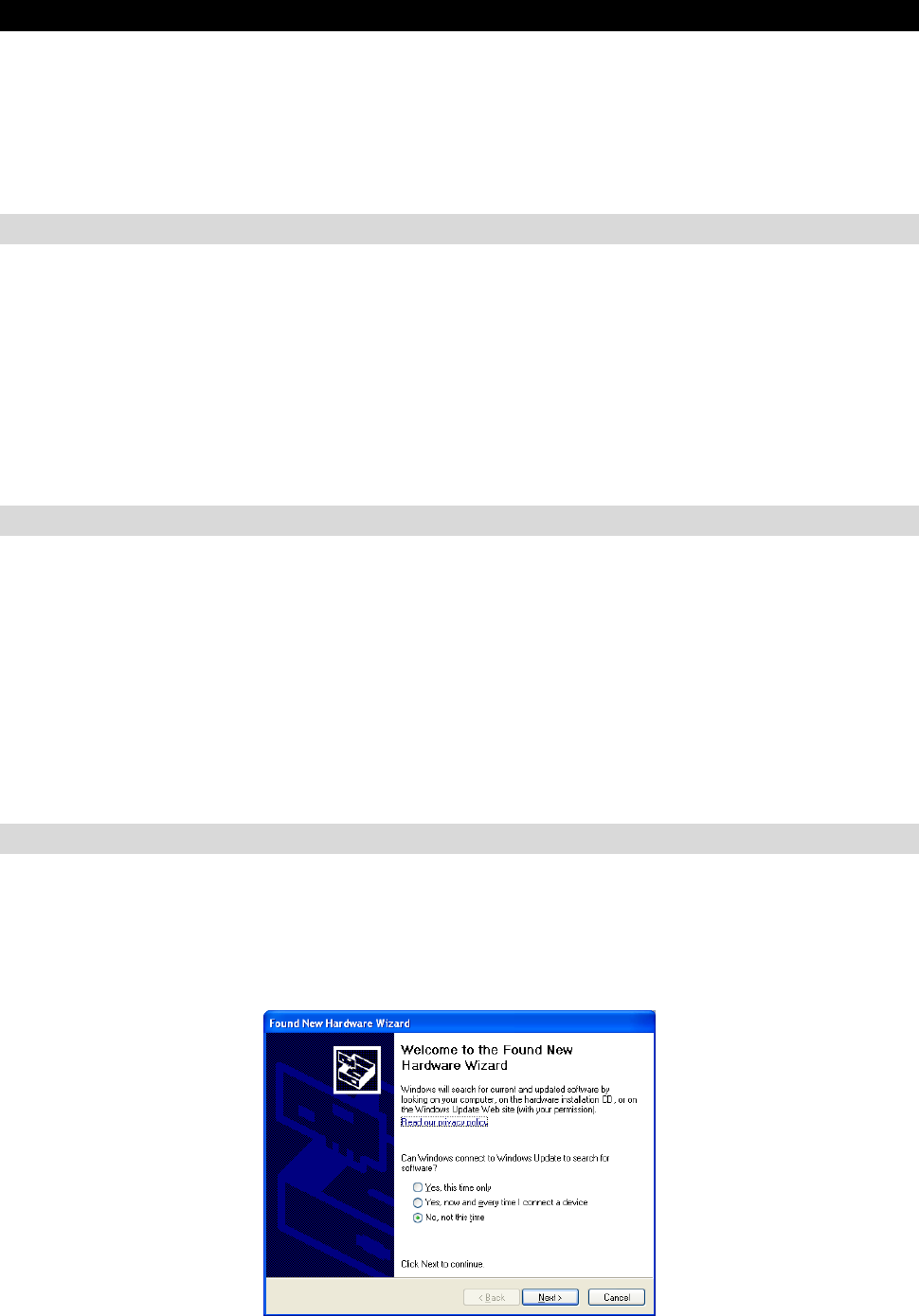
Step 1: Power up and log on to the PC.
Step 2: Plug the USB – Serial converter into a spare USB port on the PC. The following
screen will appear:-
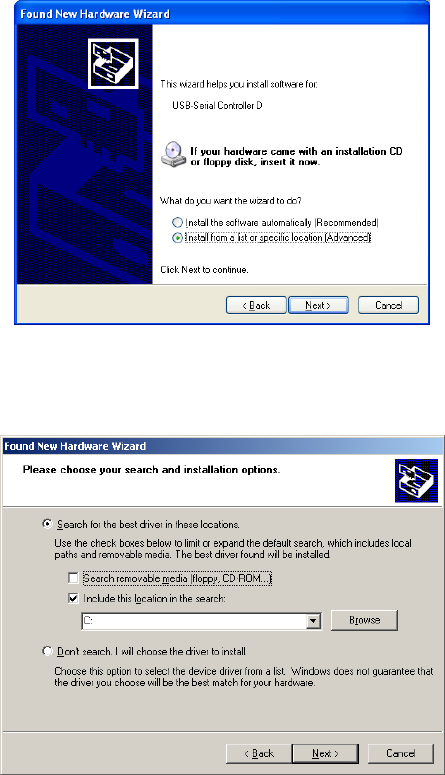
Step 3: Select ‘No, not this time’ and then press Next. The following screen will appear:
Page 8 of 10 2x02PCVer5 USER INSTRUCTIONS
Step 4: Select ‘Install from a list or specific location [Advanced]’ and then press next. The
following screen will appear:
Step 5: Un-tick the ‘Search removable media’ and tick the ‘Include this location on the
search’
Step 6: Press the ‘Browse’ button and navigate to the following location on the VX2202PC
CD:
D:\USBDriver\Windows\manual
Step 7: Follow the onscreen instructions to complete the installation.
Page 9 of 10 2x02PCVer5 USER INSTRUCTIONS
APPENDIX B
Checking and if necessary, changing the assigned port number of your USB adapter
If you want to check if the adapter has installed correctly to a port in the range of 1 –
16 (If it has been assigned a higher number then it must be changed using the steps
below). Follow the following steps:-
1. From the start menu choose Control Panel (or Settings>Control panel).
2. From the new Window double click ‘System’. For Windows XP and Windows Vista
first click on ‘Classic View’
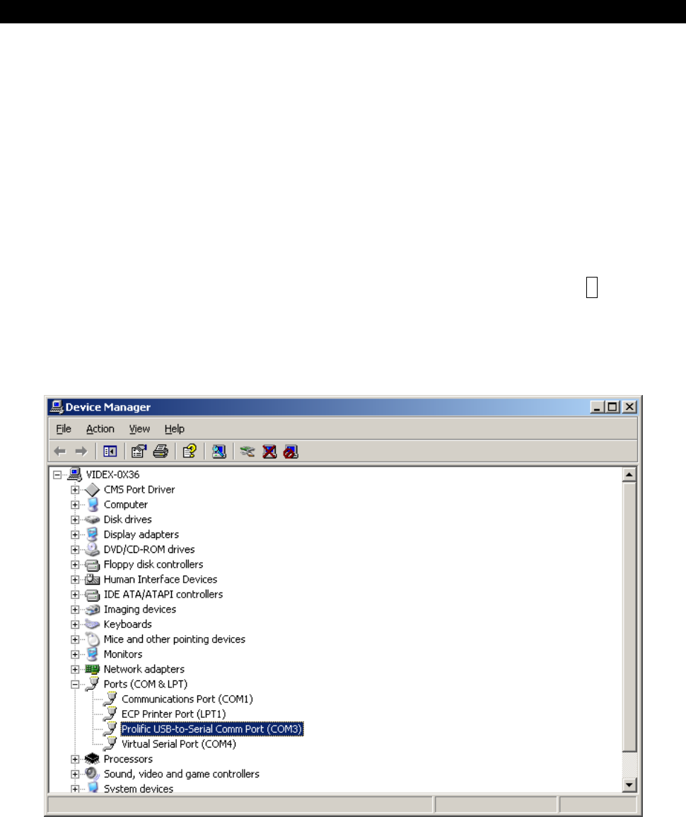
3. Select the ‘Hardware’ tab and click on ‘Device Manager’ or choose Device manager
directly from the page, then expand the ‘Ports’ menu by clicking on the +
4. The USB-Serial converter will be shown in the list as ‘Prolific USB-to-Serial Comm
Port (COMx)’ Where x is the communication port number.
If the communication port number requires changing, follow these steps:-
(Port must be in the range of 1 – 16)
1. Click on the ‘Prolific USB – Serial Comm Port’ Line, then right click and select
‘Properties’ (Ensure the USB adapter is plugged in).
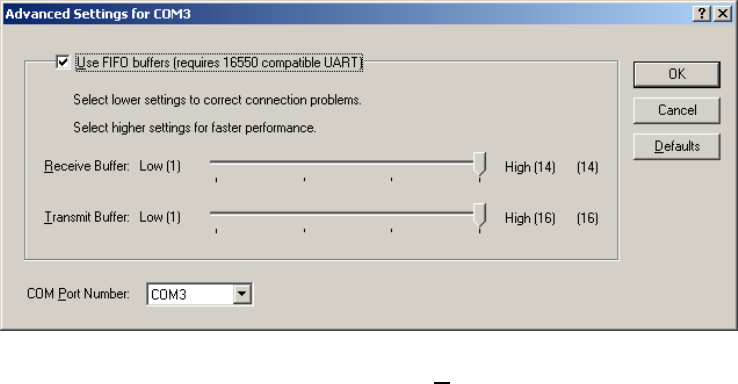
2. Select the ‘Port Settings’ tab on the new window and then click on ‘Advanced’. The
following screen will be displayed:-
Page 10 of 10 2x02PCVer5 USER INSTRUCTIONS
3. Click on the drop down menu labelled ‘COM Port Number’ to display the list of
available communication ports.
4. Select the lowest number available (i.e. Available means it does not have ‘In use’
on that line). Click OK to accept. You must use a port number in the range of 1-16.
Remember, If the USB adapted is plugged into a different USB port or other USB
devises are plugged into the PC before this one then it may become a different COM
port number.
