Vacuum Forming Guide
User Manual:
Open the PDF directly: View PDF ![]() .
.
Page Count: 53

Contents
Section 1..............................................................................3
Introduction .........................................................................3
Section 2..............................................................................4
Applications.........................................................................4
Section 3..............................................................................6
The Vacuum Forming Process ...........................................6
Clamping .............................................................................7
Heating.................................................................................7
Sheet Level...........................................................................8
Pre-stretch ( Bubble) ...........................................................8
Vacuum ...............................................................................8
Plug Assist .............................................................................8
Cooling and Release..........................................................8
Section 4............................................................................10
Plastic Materials and Their Characteristics.....................10
Acrylonitrile Butadiene Styrene– (ABS) ...........................13
Acrylic - PMMA – (Perspex, Oroglas, Plexiglas).............14
Co-Polyester – (PETG / VIVAK) .........................................15
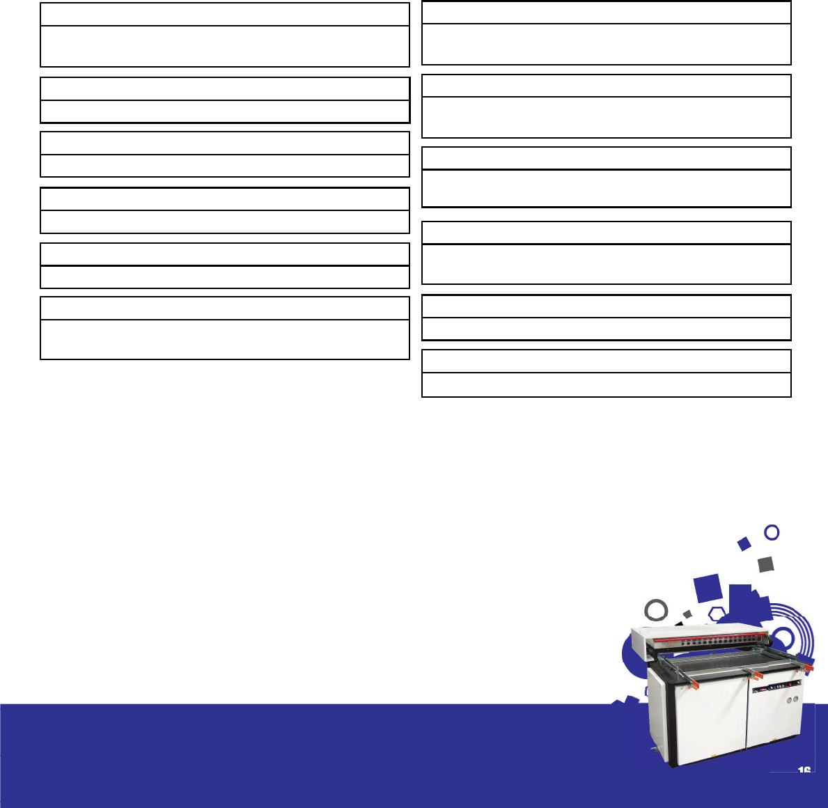
Polystyrene– Polyphenylethene (H.I.P.S / BEXTRENE) ...16
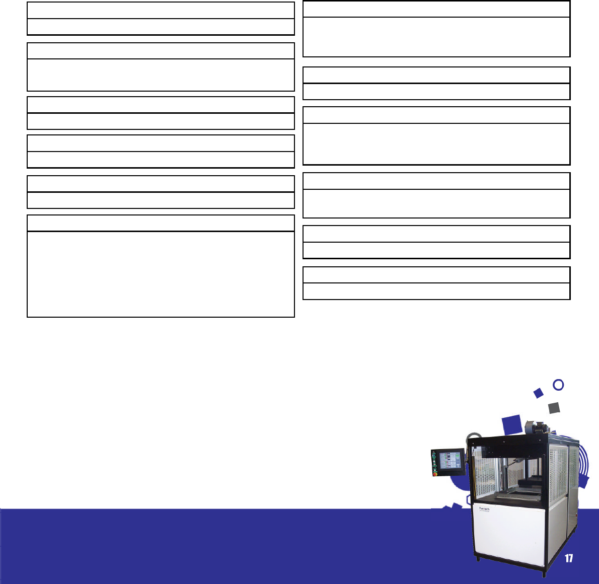
Polycarbonate – (P.C. / LEXAN/ MAKROLON)...............17
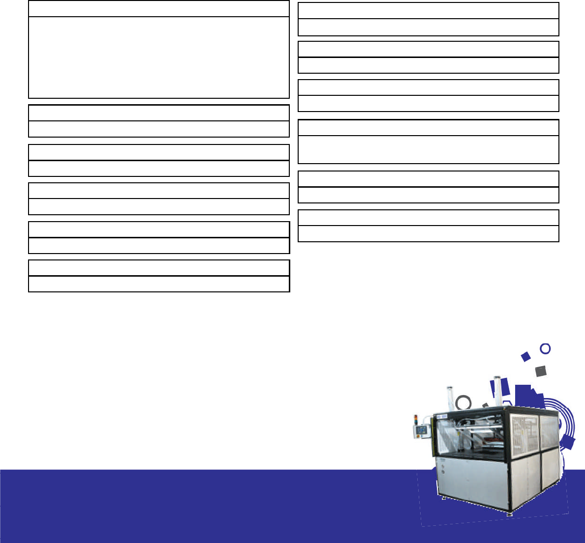
Polypropylene – (PP).........................................................18
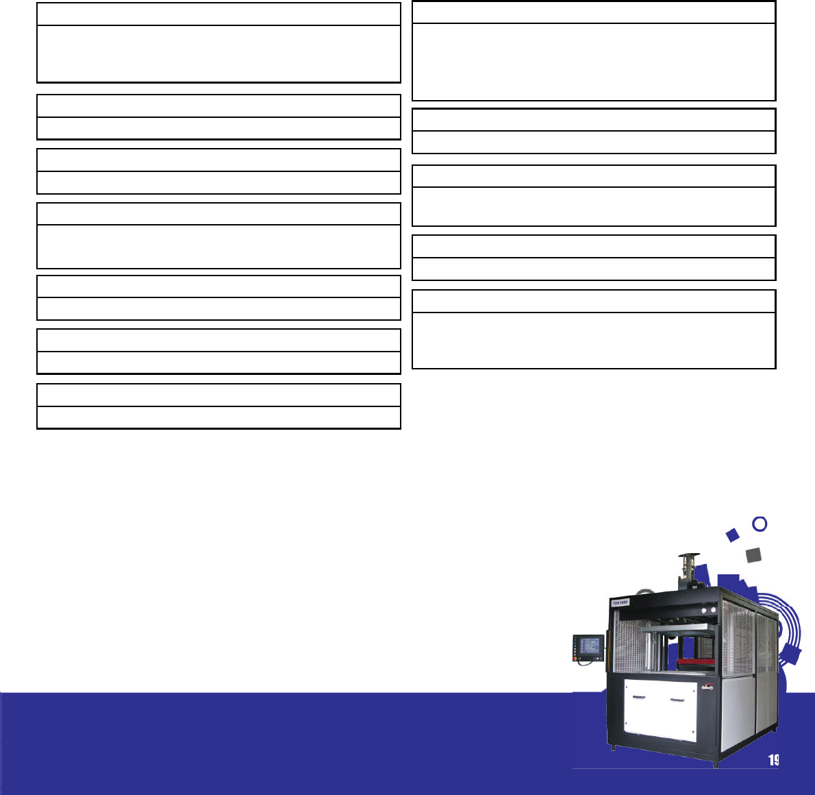
Polyethelene – (PE, HDPE, LDPE, PE FOAM) ...................19
Polyvinylchloride – (PVC) .................................................20
Section 5............................................................................21
Mould and Mould Design ................................................21
Mould Materials.................................................................22
Male and Female Moulds ................................................28
Baseboards and Mounting ..............................................29
Draught Angles / Tapers...................................................30
Venting...............................................................................30
Shrinkage and Mould Release ........................................31
Undercuts, Split and Multi Impression Moulds ................32
Mould Cooling...................................................................33
Plug Assist Design ..............................................................33
Webbing/ Chill Marks/ Thinning.......................................35
Webbing ............................................................................35
Chill Marks ..........................................................................36
Thinning ..............................................................................36
Section 6............................................................................37
Finishing and Trimming......................................................37
Considerations...................................................................38
Heated knife/ Scalpel.......................................................39
Vertical Bandsaw ..............................................................40
Horizontal Bandsaw (Fig 6.4)............................................40
Rollerpress/ Steel Rule Dies ( g 6.5).................................41
Guillotine ............................................................................42
Clicker / Punch Press.........................................................42
Hand Held Air Powered Router .......................................42
CNC Routers - 3, 4 and 5 axis...........................................43
Circular spindle saw..........................................................43
Circular Cutter mounted from under table. ..................44
Section 7............................................................................45
Trouble Shooting Guide....................................................45
Section 8............................................................................50
Supplier Guide...................................................................50
Section 9............................................................................53
Further Information............................................................53

Introduction
Thermoforming is one of the oldest and most
common methods of processing plastic materials.
Thermoformed plastic products are all around us
and play a major part in our daily lives. It is a very
versatile process used to manufacture a wide
range of products from simple packaging trays to
high impact aircraft cockpit covers. It is also used
extensively to make design prototypes of prod-
ucts to be produced by other processes.
The process, however, is basically the same in
each case. In its simplest form thermoforming
is the heating of a plastic sheet which is then
draped over a mould whilst a vacuum is applied.
The moulding is then allowed to cool before it is
ejected from the mould using a reverse pressure
facility.
Thermoforming covers all processes which involve
heat to shape polymers. However, in this manual
we will concentrate speci cally on the ‘vacuum
forming process’ which applies to the range of
machines Formech supply. Vacuum forming has
generally been promoted as a ‘dark art’ and best
left to companies with sophisticated processing
equipment who are able to supply the facility
and service. However with their range of com-
pact, easy to use machines Formech have, over
the years, endeavoured to introduce vacuum
forming to the ‘masses’ and it is some testament
that there are now over six thousand machines
worldwide, many supplied to those looking to
start vacuum forming for the rst time. In this man-
ual we hope to provide an insight into this adapt-
able process. However, it is only a guide and can-
not impart the practical experience and skill that
any user will eventually attain. We hope it assists
in taking the ‘guess work’ out of the process and
proves useful as a means of technical and engi-
neering support.
In the following sections we have provided a list
of the various examples of applications for ther-
moformed parts along with an insight into the
forming process and techniques. A plastics sec-
tion follows in which we examine materials and
their characteristics. Information on tooling, trim-
ming and nishing, a trouble shooting guide and
recommended suppliers list concludes the manu-
al with a glossary of key words to aid navigation
through the manual.
If you are new to the process and have just pur-
chased a Formech machine we trust you nd this
manual a bene cial aid in getting started and
wish you success in your future business.
3
Section 1

Applications
Below we have allocated sub-headings to a wide
range of industries using vacuum forming for a mul-
titude of applications. The list is fairly comprehen-
sive and although there are many other potential
applications we have attempted to highlight the
most popular. You can nd photographic exam-
ples of a selection of vacuum formed products in
the galleries contained in the ‘support’ section of
our web page.
Aeronautical Manufacturers
Interior Trim Panels, Covers and Cowlings
Internal sections for NASA Space Shuttle
Agricultural Suppliers
Seed Trays, Flower Tubs, Animal Containers, Clear
Growing Domes
Calf Milking Receptacles, Machines Parts,
Lawnmower Enclosures and Covers
Architectural Model Makers
Production of Miniature Parts for Architectural
Models
Prototypes.
Automotive and Vehicular Industry
Wheel Hub Covers, Ski-Boxes and Storage Racks
Wind Tunnel Models, Parts for All Terrain Vehicles
Truck Cab Door Interiors, Wind and Rain De ec-
tors
Scooter Shrouds, Mudguards, Bumpers and Pro-
tective Panels
Battery and Electronic Housings, Prototype and
Development work
Utility Shelves, Liners, Seat Backs, Door Innerliners
and Dash Surrounds
Windshields, Motorcycle Windshields, Golf Cart
Shrouds, Seats and Trays
Tractor Shrouds & Door Fascia, Camper Hardtops
and Interior Components
Building and Construction Industry
Drainpipe Anti Drip ttings
Roof Lights, Internal Door Liners, PVC Door Panels
Producing Moulds for Concrete Paving Stones
and Special Bricks
Moulded Features for Ceilings, Fireplaces, Porch-
es and other items.
Boat Building industry
Boat Hulls, Covers and Hatches
Electrical Enclosures, Dashboards
Chocolate industry
Manufacture of Chocolate Moulds for Special-
ised Chocolates and
Easter Eggs etc. and Packaging
Computer Industry
Manufacture of Screen Surrounds
Soft Transparent Keyboard Covers
Enclosures and Ancillary Equipment
Design Industry
Production of prototypes and Pre - Production
Runs
Prototype Cocepts for other Plastic Processes
4
Section 2

Education
Training Aids for Students Studying Polymers and
Plastic Processing.
Electronics Industry
Manufacturing Enclosures for Specialist Electronic
Equipment
Anti Static Component Trays.
Film and Media Industry
Manufacture of Costumes and Sets
Animation Models and Mock Ups for Computer
Simulation
Furniture Manufacturing Industry
Chair and Seat Backs
Cutlery tray inserts
Kitchen Unit Panels and Storage Modules
Hospitals and Medical Applications
Radiotherapy Masks for Treatment of Cancer Pa-
tients
Pressure Masks for Burn Victims
Prosthesis Parts
Dental Castings
Parts for Wheelchairs and Medical Devices for the
Disabled
Machinery Manufacturers
Fabricating machine guards and electrical en-
closures.
Model Car and Aircraft Industry
Production of bodies fuselages and other parts for
models.
Museums
Variety of applications within Science and Natu-
ral History Museums
Packaging and related Industries
Point of Purchase
Trays and Plates
Cosmetic Cases and Packages
Electronics and Cassette Holders
Blister Pack Products, Skin Pack Products
Food Trays, Cups and Fast Food Containers
Plastic Sheet Extrusion
Testing and Sampling of Extruded Sheet
Sanitary Industry
Bathroom Fittings
Bathtubs, Jacuzzis and WhirlpoolsBath
Shower Surrounds, Shower Trays and Retro t
Shower Components
Signmaking Industry
Vacuum Formed Exterior Signs
Point of Sale Displays
Souvenir Industry
Making parts for and moulds to cast craft souve-
nir’s.
Theatre
Manufacture of Props, Sets and Costumes
5
Section 2/Applications

The Vacuum
Forming
Process
In its simplest form the process consists essentially
of inserting a thermoplastic sheet in a cold state
into the forming clamp area, heating it to the de-
sired temperature either with just a surface heater
or with twin heaters and then raising a mould from
below. The trapped air is evacuated with the as-
sistance of a vacuum system and once cooled a
reverse air supply is activated to release the plas-
tic part from the mould. The process is shown in
diagram form on g. 3.1 page 13. In its advanced
stage pneumatic and hydraulic systems com-
plimented with sophisticated heat and process
controllers allow high speed and accurate vac-
uum forming for those heavy duty and high end
volume applications.
The thermoforming industry has developed de-
spite two fundamental shortcomings. Many other
thermoforming processes use a resin base in pow-
der or pellet form. Vacuum forming begins fur-
ther down the line with an extruded plastic sheet
which incurs an additional process and therefore
an extra cost to reach this stage. In addition,
there is generally an area of material which is cut
away from the formed part which unless reground
and recycled has to be considered as waste and
accounted for in any costings made. However
these problems have been invariably resolved by
strict control of sheet quality and by clever mould
design to minimise the amount of waste material.
Throughout this manual you will nd useful hints
and techniques to assist in maximising the poten-
tial from this process.
Despite the above disadvantages vacuum form-
ing offers several processing advantages over
such others as blow, rotational and injection
moulding. Fairly low forming pressures are needed
therefore enabling comparatively low cost tool-
ing to be utilised and relatively large size mould-
ings to be economically fabricated which would
be otherwise cost prohibitive with other process-
es. Since the moulds witness relatively low forces,
moulds can be made of relatively inexpensive
materials and mould fabrication time reasonably
short. This results in comparatively short lead times.
It provides the perfect solution for prototype and
low quantity requirements of large parts as well as
medium size runs utilising multiple moulds. (Moulds
are discussed in greater detail in section 5).
The typical process steps can be identi ed as fol-
lows: clamping, heating with sheet level activat-
ed , pre-stretch, forming with plug assist, cooling
with air and spray mist, release and trimming They
are examined more closely under the following
sub headings.
6
Section 3
Clamping
The clamp frame needs to be suf ciently power-
ful enough to handle the thickest material likely to
be formed on the machine – up to 6mm with our
single heater models and up to 10mm with the
twin heater machines. If an automated process
is used the operation of the moving parts must
be guarded and interlocked to avoid acciden-
tal damage. In addition a safety guard ( in the
form of a fabricated guard or light curtain) must
be provided to protect the machine operator at
all times.
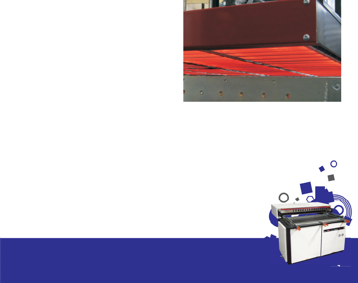
Heating
Heaters are generally infra-red elements mount-
ed within an aluminium re ector plate. In order to
obtain the best vacuum forming results, using any
material, it is essential that the sheet is heated uni-
formly over its entire surface area and throughout
its thickness. In order to achieve this it is necessary
to have a series of zones which are controlled by
energy regulators. Ceramics do have some dis-
advantage in that their high thermal mass makes
them slow to warm up (approx 15 minutes) and
slow in their response time when adjustments are
made.
More sophisticated quartz heaters are available
which have less thermal mass enabling more rap-
id response time. Pyrometers enable accurate
heat temperature control by sensing the melting
temperature of the sheet and interacting with
the operating process control. A cooling jacket is
required for the pyrometer. Precise temperature
readout is also available with a computer control-
led system working in unison with the pyrometer(s).
The megapoint system was devised by Formech
for the accurate heating of large areas, using a
standard PC and a minimum of exterior electron-
ics. The heating control system is an extension of
the process controller, allowing rapid visual inter-
pretation of the heater zoning. Temperatures are
controlled precisely using thyristor modules. Full
feedback is available to allow zones to be banked
up or down by percentage amounts. Twin heat-
ers are also recommended when forming thicker
materials as they assist in providing more uniform
heat penetration and faster cycle times.
Twin quartz heaters as used in the Formech FDH
model are advisable when forming high temper-
ature materials with critical forming temperatures.
By close control of areas of heat intensity, heat
losses around the edges caused by convection
air currents and absorption from clamp areas can
be fully compensated for and consistent results
achieved on a continuous basis. Cost savings can
also be considerable if quartz heaters are speci-
ed as there is an adjustable percentage power
drop when the heaters are in the rear position
during the forming process.
7
Section 3/The Vacuum Forming
Process

Sheet Level
A photo-electric beam is incorporated in the ma-
chine to scan between the bottom heater and
the sheet of plastic. If the sheet of plastic sags
down and breaks the beam then a small amount
of air is injected into the bottom chamber, thus
lifting the sheet to stop it from sagging.
Pre-stretch ( Bubble)
Once the plastic has reached it’s forming tem-
perature or ‘plastic’ state it can be pre- stretched
to ensure even wall thickness when the vacuum is
applied. Pre-stretch is an invaluable feature when
forming deep draw parts with minimum draft an-
gles and high mould surface detail. The method
of controlling the bubble height should be such
that consistent results are obtainable. Vacuum,
air pressure and optional aids such as a plug assist
are then used to assist in moulding the heated,
stretched plastic.
Vacuum
Once the material is suitably pre-stretched a vac-
uum can be applied to assist in forming the sheet.
A dry vane vacuum pump is used to draw the air
trapped between the sheet and the mould. The
vacuum pump should be capable of maintain-
ing a differential pressure of approx 27” mercury.
With larger machines a vacuum reservoir is used
in conjunction with a high volume capacity vacu-
um pump. This enables a two stage vacuum to be
applied ensuring rapid moulding of the heated
sheet ( before the sheet temperature drops be-
low its ideal forming temperature).
Plug Assist
Plug-assist forming is the term used to describe the
use of a male plug tool, mounted on a pneumat-
ic or hydraulic cylinder situated over the forming
area of the machine, to force the material into a
female cavity within the moulding area. It ena-
bles complicated and deep-draw moulds to be
produced without webbing and with even thick-
ness distribution. The idea behind the process is to
feed as much material into the cavity prior to the
vacuum being applied in order to avoid thinning
in that area. Plug moulds are generally made from
wood or metal and a smooth surface allows the
sheet to slide whilst stretching into the mould. A
felt or leather lining ensures that the risk of prema-
ture chilling on contact is greatly reduced. Resin
plugs provide a good alternative as being good
insulators they do not affect the temperature of
the sheet.
Plug assist is also an essential feature when form-
ing multiple impression male moulds as they can
be placed very close together without the fear of
the material webbing between the formed parts.
Cooling and Release
Once formed the plastic must be allowed to
cool before being released. If released too soon
then deformation of the moulding will result in a
reject part. To speed up the cooling cycle high
speed fans are tted and activated once the
part is formed. A spray mist option is also avail-
able whereby nozzles are attached to the fans
and a ne mist of chilled water is directed onto
the sheet. This, in conjunction with the fans can
speed up the cooling cycle by up to 30%.
Mould temperature control units are also avail-
able which regulate the temperature within the
mould ensuring accurate and consistent cooling
times when cooling crystalline and crystallising
polymers such as PP, HDPE and PET.
8
Section 3/The Vacuum Forming
Process
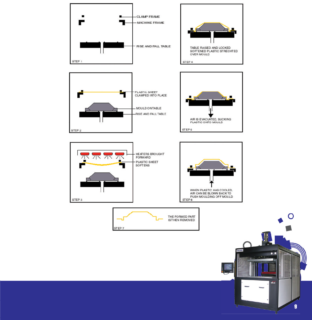
Once cooled suf ciently the sheet can be released by a reverse pressure activated through the
vacuum system. The part is then stripped from the mould and transferred to the trimming station. See
the relevant section for further details on trimming and nishing.
The following diagrams display the basic principles of vacuum forming.
Fig. 3.1
9
Section 3/The Vacuum Forming
Process

Plastics comprise a of a wide range of materials
but fundamentally fall into two groups – thermo-
set and thermoplastic, the latter being a mate-
rial which, due to the molecular structure, has the
property of softening repeatedly when heated
and hardening once cooled. Thermoplastics also
have what is known as a ‘memory’ enabling a
formed part to revert to its original state when re-
heated.
It is the thermoplastic type that is used speci cally
for thermoforming and therefore we will concen-
trate on this category in this section. Further infor-
mation on the complete range of polymers can
be obtained from the contacts listed at the end
of this manual.
Polymers are made up of molecules which in turn
are made up of atoms. These atoms have many
different combinations which all have different
properties and contain a wide range of addi-
tives to give each material its own characteristics.
There is constant research being carried out to
develop new materials suited to an ever increas-
ing range of applications. Later in this section we
have provided a breakdown of the more com-
mon materials used for thermoforming, their char-
acteristics and the applications to which they are
most suited.
Thermoplastics are split into two different groups
– amorphous and crystaline. Crystalline thermo-
plastics contain an ordered manner of molecules
and amorphous contain a random arrangement.
Generally speaking amorphous materials, e.g.
Polystyrene and ABS are easier to vacuum form as
they do not have such a critical forming tempera-
ture. When heat is applied amorphous materials
becomes soft and pliable – when it reaches this
state it is known as its Glass Transition Temperature
(Tg). If heated to a higher temperature it reaches
a Viscous state (Tv). The changes occur over a
range of temperatures and enable the operator
to have a fairly wide forming range.
Semi-crystaline and crystaline materials, e.g. Poly-
ethylene and Polypropylene have a far more criti-
cal forming temperature as they go rapidly from
the Tg state to Tv a change known as the Melt
Transition Temperature (Tm). When using crystal-
line materials is imperative that accurate tem-
perature control is used to monitor the heating
process.
In summary, the forming temperature bands for
amorphous materials is much wider and as a re-
sult are easier to process in comparison to their
semi-crystalline counterparts. In other words they
have a much better melt strength and will not
sag as much as the melt transition temperature is
reached.
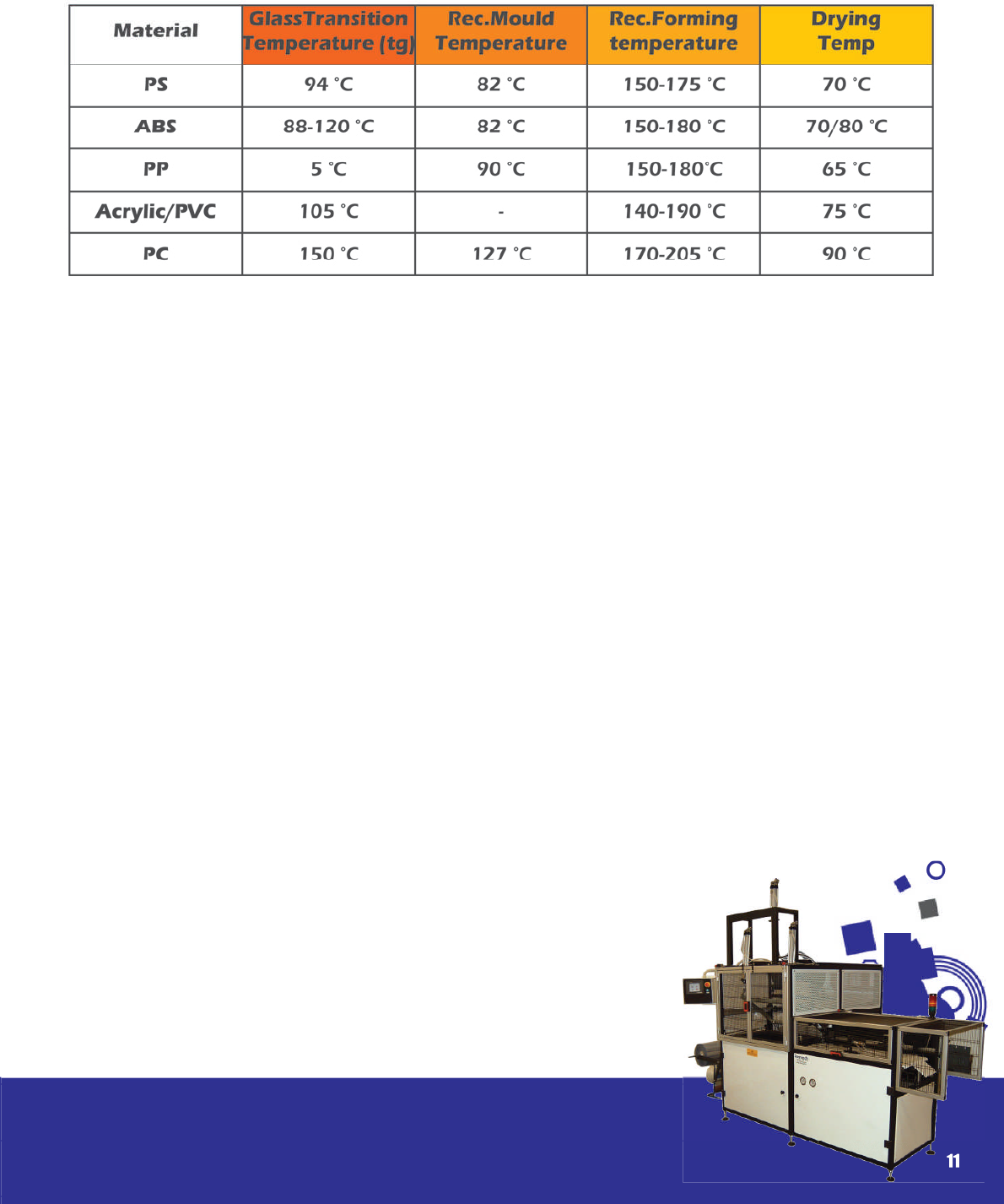
The accompanying table 4.1 lists some more
commonly used amorphous and semi crystalline
materials and provides a guideline as to their tem-
perature characteristics.
10
Section 4
Plastic materials
and their
characteristics
Different thermoplastics have different charac-
teristics and are better suited to speci c appli-
cations. Ideally the material should be easy to
form with a low forming temperature, good ow
characteristics and thermal strength, high impact
strength and low shrinkage on cooling.
To improve thermal stability in certain materials
like, for example, PVC, stabilisers are added to
help prevent degradation when heated.
Certain materials are known as Hygroscopic –
namely that they absorb moisture which if not pre-
dried prior to forming will result in moisture blisters
which will pit the surface of the sheet resulting in
a reject part. It is a common misconception that
the blisters are as a result of too much heat. This
in turn can lead to incorrect heating cycles being
entered which in turn cause problems with de ni-
tion on the nished part. ( To avoid the pitting the
operator is forced into forming the part before the
plastic has reached its forming temperature).
To overcome this problem it is therefore necessary
for hygroscopic materials to be pre – dried in an
oven before forming. The drying temperature and
length of drying time depends on the material
and the thickness. It is advisable to contact the
suppliers who will advise exactly what drying tem-
perature and time is required for their materials.
E.g.: Polycarbonate with a thickness of 3mm
would require 4 hours at a drying temperature of
80-120°.
In the following pages we will look at the more
commonly used plastics and list their properties,
features and some of the more popular applica-
tions for which they are used. ( a full schedule of
applications for thermoformed products is listed
in section 2) For more detailed information and
speci cation we recommend you contact the
various suppliers who would be happy to assist
with any enquiries.
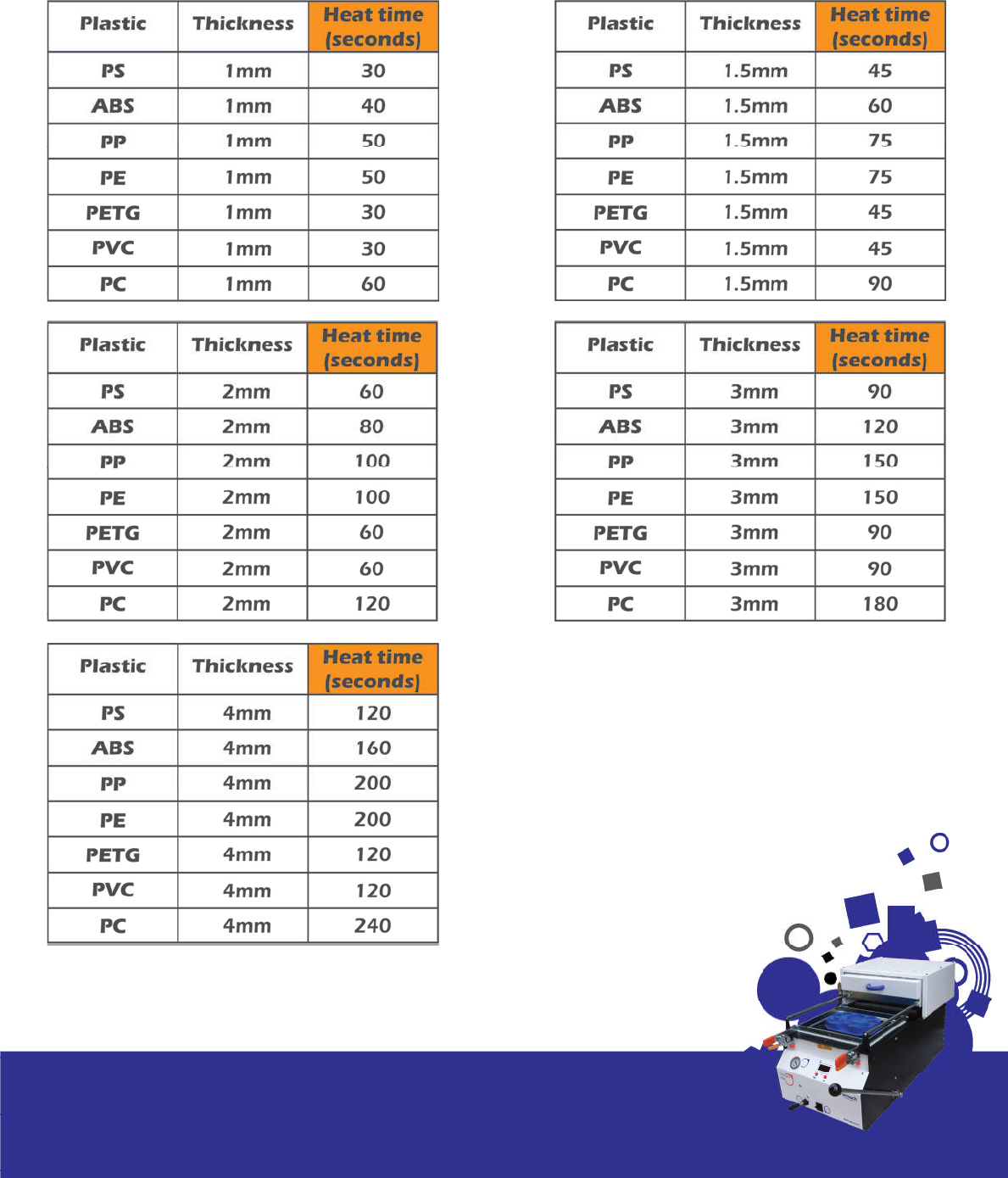
In table 4.2 you will nd a selection of more com-
monly used materials and the heating times re-
quired using a single heater Formech machine
equipped with Infra-red ceramics ( if twin heaters
are used then the heat cycle can be reduced by
up to 30%). These are given as a guideline only
as many different grades of materials exist and
other factors which affect timescales. We would
recommend you contact the plastic manufactur-
er to obtain more accurate gures prior to com-
mencing production.
11
Section 4/Plastic materials and their
characteristics
Table 4.1
12
Section 4/Plastic materials and their
characteristics
Table 4.2
Acrylonitrile Butadiene Styrene– (ABS)
Properties
Hard, rigid amorphous thermoplastic with good impact strength and weather resistance. It contains
a rubber content which gives it an improved impact resistance. Available with different textures and
nishes in a range of thickness. Needs drying. Available in Fire Retardant and UV stabilised grades.
Formability
Good – forms to a high de nition.
Hygroscopic
Yes – pre drying required at approx 80° (1 hour
per mm)
Strength
Good – High Impact
Shrinkage Rates
0.3 – 0.8%
Availability
From stock
Solvent/ Filler
Methyl Ethyl Ketene (MEK), Toluene and Dichlo-
romethane Solvent will make ller paste.
Finishing/ Machining
Machines well with Circular Saws, Routers and
Band saws– takes all sprays.
Can be Guillotined and Roller cut.
Clear
Not Available
Colours
Black / White / Grey and limited colours.
Applications
Luggage, Caravan Parts, Vehicular Parts, Sanitary
Parts, Electrical Enclosures.
Price
Medium
Stockist
Stephen Webster, Amari Plastics, Larger quantities
– Doe ex
13
Section 4/Plastic materials and their
characteristics
Acrylic - PMMA – (Perspex, Oroglas, Plexiglas)
Properties
A high quality hard amorphous plastic with good clarity that can be worked after forming. NOTE:
Only extruded sheet is suitable for vacuum forming effectively. Cast Acrylic will not respond well as
it displays a very small usable plastic zone. As a result it will only produce general contours with large
drape radii. Needs drying. Often replaced by PETG – see separate heading.
Formability
Tends to be brittle and is temperature sensitive.
Hygroscopic
Yes – Consult supplier for drying times.
Strength
Medium to High strength
Shrinkage Rate
0.3 – 0.8%
Availability
Ex stock – 2 weeks
Solvent/ Filler
Tensol, Solvent and gap ller.
Finishing/ Machining
Prone to Shatter. Takes cellulose and enamel
spray. Good for hand working.
Clear
Yes.
Colours
Solid colours
Applications
Signs, Roof Lights and Domes, Baths and Sanitary
Ware, Light Diffusers
Price
Expensive
Stockist
Amari, Visijar Tuckers, Multiplastics
14
Section 4/Plastic materials and their
characteristics
Co-Polyester – (PETG / VIVAK)
Properties
An easy forming amorphous thermoplastic. FDA approved for food applications. Optically very good
with excellent fabricating performance. Thermoforms with ease utilising low temperatures and fast
cycle times. Can be sterilised and is resilient to a wide range of acid oils and alcohols. Not recom-
mended for use with highly alkaline solutions.
Formability
Very Good – forms to a high de nition. Forming
range 80 - 120°C
Hygroscopic
Not normally required. If sheet is exposed to high
humidity conditions for an extended time then
pre-drying is required – 8 hours at 60° C.
Strength
Good – High Impact
Availability
From stock
Solvent/ Filler
Cementing can be done using solvents or com-
mercial glues. Can be Ultrasonically Welded.
15
Section 4/Plastic materials and their
characteristics
Finishing/ Machining
Can be Guillotined, Saw Cut or Routered. Die
Cutting and Punching also possible up to 3mm.
Paints and Inks for Polyester can be used for print-
ing on PETG.
Clear
Yes
Colours
Limited – Contact Supplier
Applications
Point of Sale and Displays, Medical Applications
Price
Expensive – ( competitive with other clear materi-
als e.g. PC/ PMMA
Stockist
ABG, Axxis ViVak
Finishing/ Machining
Needs special etch primer before spraying. Good
machining with all methods.
Clear
Yes – Styrolux ( Clarity not to quality of PETG/ PC/
PMMA
Colours
All colours and also available in a Flocked nish
ideal for presentation trays and inserts.
Applications
Low cost and disposable items, toys and models,
packaging and presentation, displays.
Price
Low - Medium
Stockist
Stephen Webster, Larger quantities – Doe ex.
Polystyrene– Polyphenylethene (H.I.P.S / BEXTRENE)
Properties
One of the most widely used materials An easy forming amorphous thermoplastic. Thermoforms with
ease utilising low temperatures and fast cycle times. Available with different textures and patterns. No
pre drying required. Poor UV resistance –not suitable for outdoor applications.
Formability
Very Good – forms to a high de nition. Forming
range circa 150°C
Hygroscopic
No
Strength
Medium to Good impact strength
Shrinkage Rate
0.3 – 0.5%
Availability
From stock
Solvent/ Filler
Dichoromethane, Toluene. Filler can be made
from dissolved plastic in solvent.
16
Section 4/Plastic materials and their
characteristics
Finishing/ Machining
Good for screen printing. Good machine quali-
ties. Can be ultrasonically welded, drilled and
tapped. Takes spray.
Clear
Yes
Colours
Translucent and solid colours. Opal and diffuser
patterns. Available in a variety of embossed tex-
tures.
Applications
Light diffusers, Signs, Machine Guards, Aircraft
trim, Skylights, Riot Shields, Guards and Visors
Price
Expensive
Stockist
Amari , Comco
Polycarbonate – (P.C. / LEXAN/ MAKROLON)
Properties
Hard, rigid clear amorphous material with high impact resistance and good re rating. Self extinguish-
ing. Requires high forming temperatures. Needs drying. Excellent clarity. Similar properties to Acrylic.
Formability
Good
Hygroscopic
Yes – Drying temperature 90° C. 1mm – 1 hr. 3mm
– 4hrs. 4mm – 10hrs.
Strength
Very good impact strength
Shrinkage Rate
0.6 – 0.8%
Availability
From stock
Solvent/ Filler
Between PC components Dichloromethane or
MEK solvent. Care must be taken with solvents
as PC is a stress sensitive material and can be
adversely affected by the solvents at its weak
points. Most proprietary adhesives can be used
to join PC with metal, glass and wood.
17
Section 4/Plastic materials and their
characteristics
SEE PETG AS AN EXCELLENT ALTERNATIVE TO PC
Finishing/ Machining
Does not take spray
Clear
Translucent –
Colours
Black / white and colours available
Applications
Luggage, Food Containers, Toys, Enclosures,
Medical Applications, Chemical Tanks.
Price
Inexpensive
Stockist
Doe ex
Polypropylene – (PP)
Properties
PP is a semi-crystalline thermoplastic which has dif cult form characteristics with sheet sag inevitable.
Chemically inert and very exible with minimum moisture absorption make it suitable for a wide range
of applications. High forming temperature but no drying required. Many grades of PP are available
containing llers and additives. Co polymer as opposed to homo-polymer PP is recommended for
vacuum forming, as the copolymerisation process helps reduce stiffness and broaden the melt and
glass transition temperatures increasing thermoforming ability.
Formability
Dif cult – Translucent material goes clear when in
its plastic state – occurs within temperature band
of approx 10°C and provides excellent indicator
to forming temperature. Good temperature con-
trol required in conjunction with a sheet level fa-
cility.
Hygroscopic
No
Strength
Very good impact strength
Shrinkage Rate
1.5 – 2.2%
Availability
From stock
Solvent/ Filler
No solvent
18
Section 4/Plastic materials and their
characteristics
Clear
Translucent – Goes clear when in its plastic state
– occurs within temperature band of approx 10°C
and provides excellent indicator to forming tem-
perature.
Colours
Black / white and colours available
Applications
Caravan Parts, Vehicular Parts, Enclosures and
Housings.
Price
Inexpensive
Stockist
PE - Amari, Simona
PE FOAM – Polyformes
CONDUCTIVE PE – Dentec
Polyethelene – (PE, HDPE, LDPE, PE FOAM)
Properties
PE is a semi-crystalline thermoplastic with similar forming properties to PP. Good heat control with
sheet level required for successful forming. High shrinkage rates but good chemical resistance and
strength. Available also as a cross linked closed cell foam (PLASTAZOTE) - ideal for packaging and
liners.
Formability
PE – Dif cult
PE FOAM – Good but form at lower temperatures
to prevent surface scorching.
Hygroscopic
No
Strength
Very good impact strength
Shrinkage Rate
LDPE - 1.6 – 3.0%
HDPE - 3.0 – 3.5%
Availability
From stock
Solvent/ Filler
No solvents
Finishing/ Machining
Does not take spray. Takes some specialist inks.
19
Section 4/Plastic materials and their
characteristics
Finishing/ Machining
Does not take spray. Takes some specialist inks.
Clear
Yes – Different web widths available with thick-
ness from 150 microns – 750microns.
Colours
Black / white and colours available
Applications
Packaging, Machine Guards and Car Trim.
Price
Inexpensive
Stockist
Smaller quantities – Stephen Webster
Polyvinylchloride – (PVC)
Properties
Strong, tough thermoplastic with good transparency in thinner gauges. Good chemical and re re-
tardant properties. Highly resistant to solvents. Thicker materials are rigid with good impact strength
ideally suited to outdoor industrial applications.
Formability
Forms well but with a tendency to web.
Hygroscopic
No
Strength
Good
Shrinkage Rate
N / A - Contact Supplier
Availability
From stock – Sheet or Reel
Solvent/ Filler
Toluene may be used – no others solvents suit-
able. Hot air weld or glue.
20
Section 4/Plastic materials and their
characteristics

Mould and
Mould Design
The thermoforming mould can be as simple as a
wooden block or as sophisticated as an injection
mould with all the ancillary elements to enable
in mould trimming. They are one of the most im-
portant parts of the thermoforming cycle. One of
the main advantages of vacuum forming is that
the pressures used are signi cantly less compared
to, for example, the injection moulding process.
The result is that vacuum formed tools can be
produced economically and in a wide range of
materials to suit different prototype and produc-
tion requirements. In this manual we concentrate
on moulds ideally suited to the vacuum forming
process. The prime function of a mould is to en-
able the machine operator to produce the nec-
essary quantity of duplicate parts before degra-
dation.
A wide range of materials can be used but it is
important to determine the correct mould mate-
rial and type most suitable for a particular appli-
cation. In this section we look rstly at the different
types of mould material available. We then look
more closely at different types of moulds, mould
design and techniques and provide some useful
tips and hints to assist the ‘in house’ production of
moulds.
Mould Materials
Selection of the best suited mould material de-
pends largely on the severity and length of serv-
ice required. If only a few parts are required us-
ing fairly low temperature plastics then wood or
plaster could be used. However, if the quantity
requirements run into the thousands and mate-
rial temperatures are higher then ideally an alu-
minium based resin or aluminium mould would be
recommended.
Once a prototype mould has been fabricated
then it is a simple process to cast a resin mould
into a forming taken from the original tool.
See the heading Resin moulds for further details.
21
Section 5

1) Modelling Clay, Plaster
Modelling clay is widely used for educational
and model making purposes. It enables the user
to quickly shape a low cost prototype which can
then be cured in an oven overnight. Suitable only
for a few formings as the heat and pressures ap-
plied cause it to deteriorate rapidly.
Plaster is a good material for making inexpensive
prototype moulds. However it is essential that the
plaster is allowed to dry in a warm environment
for up to three days. The reasons are twofold;
1) Moisture can be drawn into the vacuum
system causing internal damage to the machine
and pump.
2) The time is required for the plaster to de-
velop nal properties and stabilise the water con-
tent.
When using plaster moulds it is also essential to
have a lter tted to ensure no powder or parti-
cles are drawn into the vacuum system.
The surface of a plaster mould is sensitive to heat
build up and therefore tend to crack and break
up after about 50 cycles. It is not normally neces-
sary to vent plaster moulds as the surface is po-
rous.
2) Wood
Wooden moulds are cheap and easy to fabricate,
and have a longer life than plaster moulds – in
many cases being used on a production basis for
in excess of 500 formings. Hardwoods are recom-
mended, notably ‘jelutong’ and ‘obeche’ which
both have a close and even grain which makes
them easier to work and less prone to cracking
and splitting during the forming process.
Conventional woodworking techniques are used
to fabricate the moulds. It is important to ensure
the wood is kiln dried before working to ensure
there is no warping or cracking during fabrication.
As with any wood due to expansion and contrac-
tion during the forming process deterioration is
inevitable but can be reduced by sealing with
an enamel or varnish. This will enable countless
mouldings to be produced with minimum re nish-
ing required.
Because of the cost implications there are many
cases where for particularly large applications
such as signs, displays and whirlpools which re-
quire thicker materials wooden moulds are used
on a production basis.
Grease, paraf n and vaseline and silicone release
sprays can all used as a release agent.
22
Section 5/Mould and Mould Design

3) Cast Epoxy Resins
There are numerous resins available which are
relatively cheap and easy to work. Moulds made
from this material are durable and produce a
forming with good surface nish. Some synthetic
resins are sensitive to surface heat build up but
this can be alleviated by incorporating aluminium
powders to increase the heat stability and also
the longevity. They are normally supplied as a two
part mix; the resin itself and a hardener.
Once an original pattern has been produced ei-
ther in wood or other material it is possible to use
a forming taken off this as a mould in which to
cast the resin.
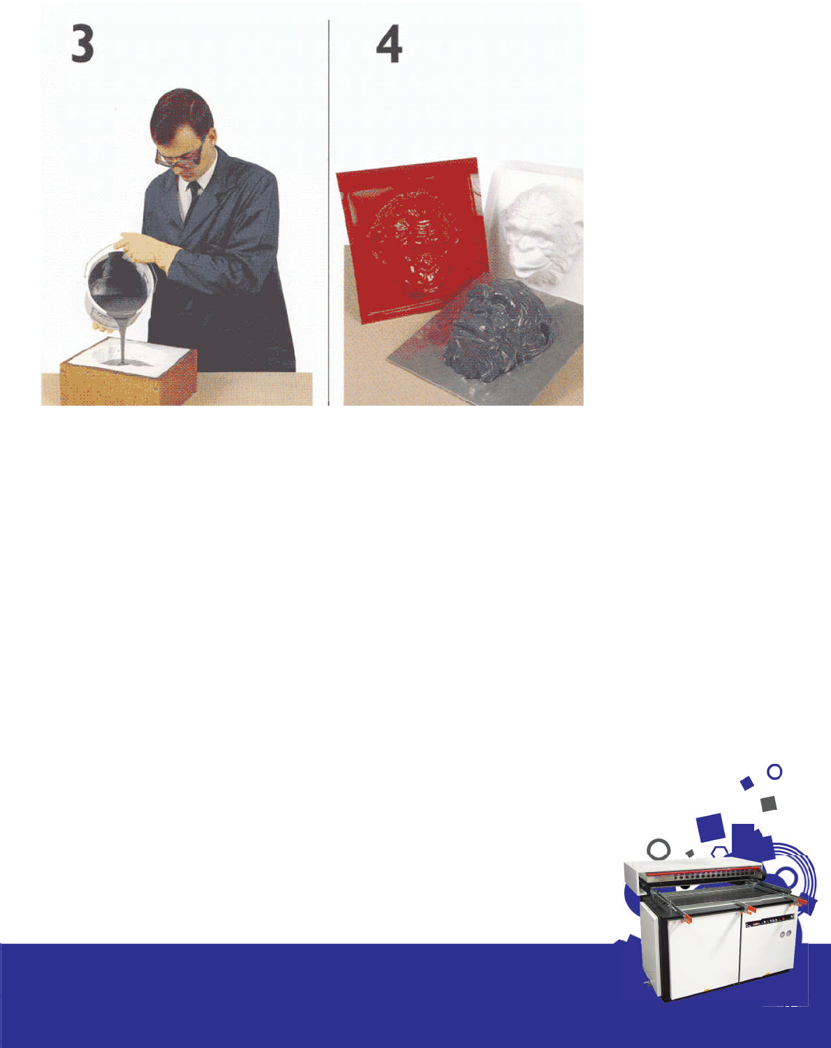
You can see from the accompanying pictures
the process in its different stages. The pictures are
supplied courtesy of Ciba Geigy who produce
a compatible resin XD4500 for vacuum forming
applications. Alchemie also supply a range of
resin tooling systems suitable for vacuum forming
moulds.
(see the suppliers section for company details.)
The plastic moulding should be at least 2mm in
thickness, mounted into a wooden frame lled
with sand for support to avoid distortion. It is then
necessary to mix the resin and hardener accord-
ing to instructions and then allow time for curing.
With larger moulds and to save on resin costs and
reduce mould weight it is normally advisable to ll
the mould with wooden blocks or foam around
which the resin is poured.
23
Section 5/Mould and Mould Design

Select the pack size which is
appropriate to the casting
being made. The pack vol-
umes are given below as a
guide :
5kg pack - 3lt
2kg pack - 1.2lt
Pour all of the hardener into the resin container and add accelera-
tor according to the thickness of the cross section to be cast. Mixing
instructions are enclosed with each pack and these de ne accel-
erator additions. Stir thoroughly taking care to mix in resin from the
sides and bottom of the container.
After stirring allow the mix to stand for 3-5 minutes to enable air bub-
bles to rise and break. Alternatively, if the equipment is available
de-aerate in a vacuum chamber.
The mix should be cast well within its pot-life which is 40 min at 21 °C.
As with all resin systems the mix is exothermic in bulk and this effect
is increased by higher temperatures and by the use of XD 4500 ac-
celerator.
24
Section 5/Mould and Mould Design
Models may be made from a va-
riety of patternmaking materials,
e.g. wood, plastics, and metal etc.
Porous materials should be sealed
before use, for instance with a poly-
urethane varnish. Care taken at the
model making stage will be re ect-
ed in the quality of the nished tool.
The next stage depends on whether
a male or female production tool is
required.
To produce a female tool, apply a
wax release agent or a suitable al-
ternative to the model in prepara-
tion for the casting operation.
A male tool can be made by taking
a vacuum forming from the model.
The forming should be backed with
a material such as plaster of paris
for rigidity and then be released as
above for casting.
Fig. 5.1
MODEL
MIX
CURING. Allow the resin
casting to harden at room
temperature and then post-
cure as follows:
16 hours at room tempera-
ture - to demould
4 hours at 40 °C
3 hours at 60 °C
2 hours at 80 °C
The above times are minimums.
In the case of tools with a cross section thickness of less than 1 in
(25mm) the room temperature stage must employ a temperature
of at least 15 °C to provide an adequate initial cure for demoulding
and further processing, e.g. machining etc.
When time is at a premium tools may be post-cured by putting them
into service. Care is essential to avoid overheating during the early
stages of tool life.
DRILLING AND MACHINING. Evacuation holes may be drilled by any
one of the engineering techniques available.
Araldite Vacuum Forming Tooling System XD 4500 is formulated to be
easy and clean to machine. It contains no hard llers and produces
swarf rather than dust.
25
Section 5/Mould and Mould Design
Pour the mixed resin system slowly
and in a steady stream into the low-
est point of the mould until the re-
quired tool thickness is reached.
For mould surfaces with ne detail,
rst carefully brush a thin coat of mix
over the surface and then proceed
as above.
Castings of greater thickness than
the normal maximum of 3 in (75mm)
can be made by pouring subse-
quent layers of mix onto the back
of the preceding one, once it has
gelled but not fully hardened.
Wood or polystyrene blocks can be
suspended in the mould cavity to
reduce cross sectional thickness. This
serves to reduce the risk of excessive
exotherm and to economise on resin
usage.
Fig. 5.2
CAST
FINISHING

26
Section 5/Mould and Mould Design
Araldite Vacuum Forming Tooling System XD 4500 is designed
to meet a particular need of the toolmaker for small to medium
size cast resin tooling.
The Araldite Tooling resin range also includes resin systems suit-
able for the production of larger vacuum forming tools. These
are produced by employing gel coats, laminating systems in
combination with fabrics, and sometimes aluminium pellets, to
provide a variety of materials and techniques for many appli-
cations
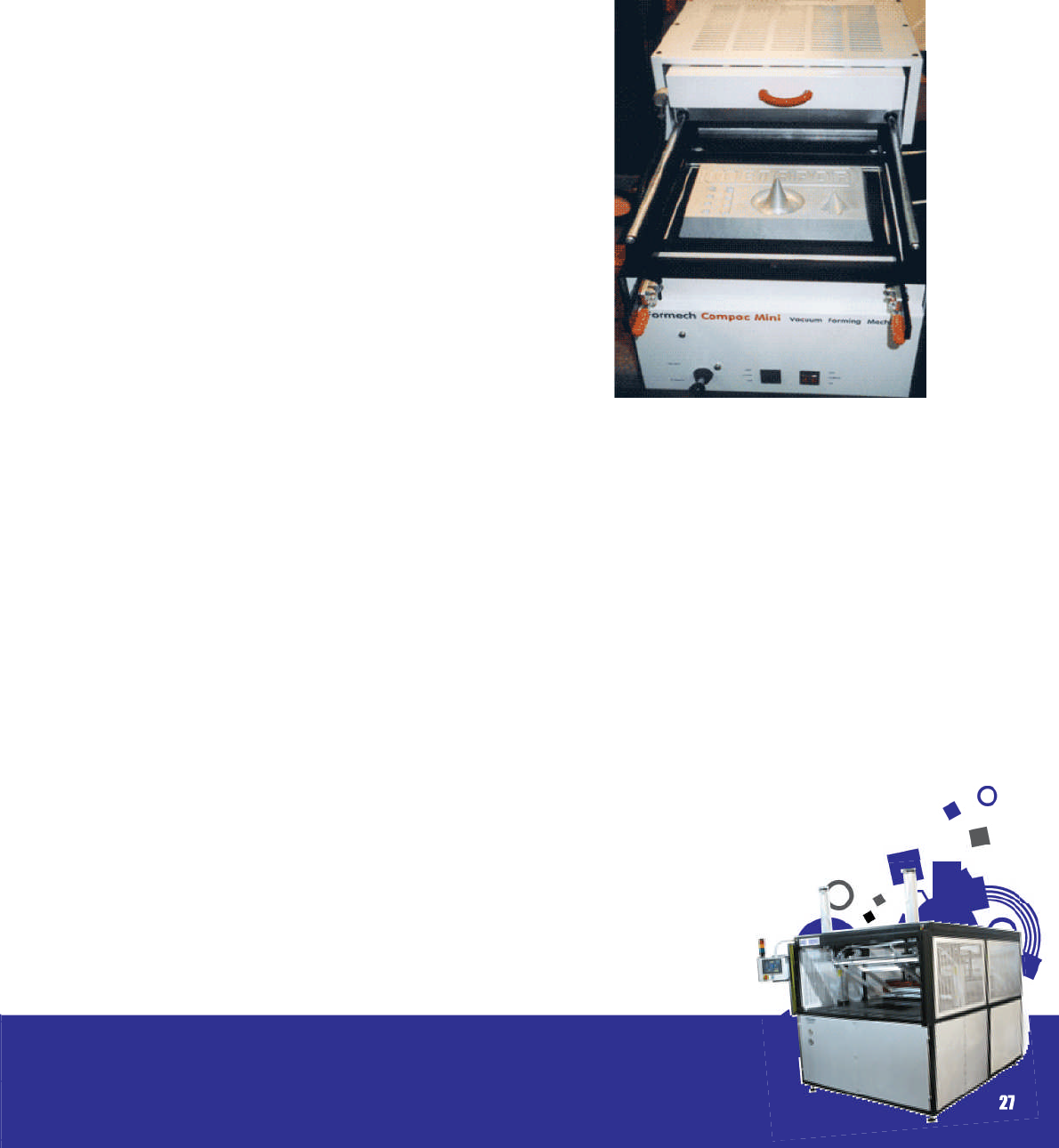
Fig. 5.3
XD 4500 in use on a
small scale vacuum
former
4) Aluminium
Aluminium is frequently the material chosen for
production tooling due to its good surface hard-
ness, heat conductive properties and low wear.
It is lightweight and has an excellent strength to
weight ratio. It can be machined from blocks or
cast from patterns and due to its thermal proper-
ties heat from the formed plastic sheet is quickly
and ef ciently dissipated.
A wide range of surface nishes are possible but
generally speaking a sand blasted surface is ideal
in that it prevents air being trapped between the
mould and heated sheet.
Aluminium moulds have a virtually unlimited
lifespan.
5) Metaphor – Porous Aluminium
Metaphor – F100 Al is a micro porous air permea-
ble aluminium. It is an exciting new breakthrough
in material science, where a material has been
custom designed speci cally to enhance the per-
formance of tools for vacuum forming. Although
expensive it has the following advantages over
aluminium;
• It permits more accurately nished thermofor-
mings because the micro vents are micro close
together, allowing the material to be rmly held in
place over the entire tool during tooling.
• It machines faster than aluminium and does not
require venting as it is naturally porous.
• More intricate moulds with steeper draughts are
possible.
It is available in slab form and can be obtained
through the UK supplier, Alchemie. See the suppli-
ers section for company details.
Fig. 5.4 A metaphor mould demonstrated on
one of the Formech range of vacuum forming
machines
27
Section 5/Mould and Mould Design
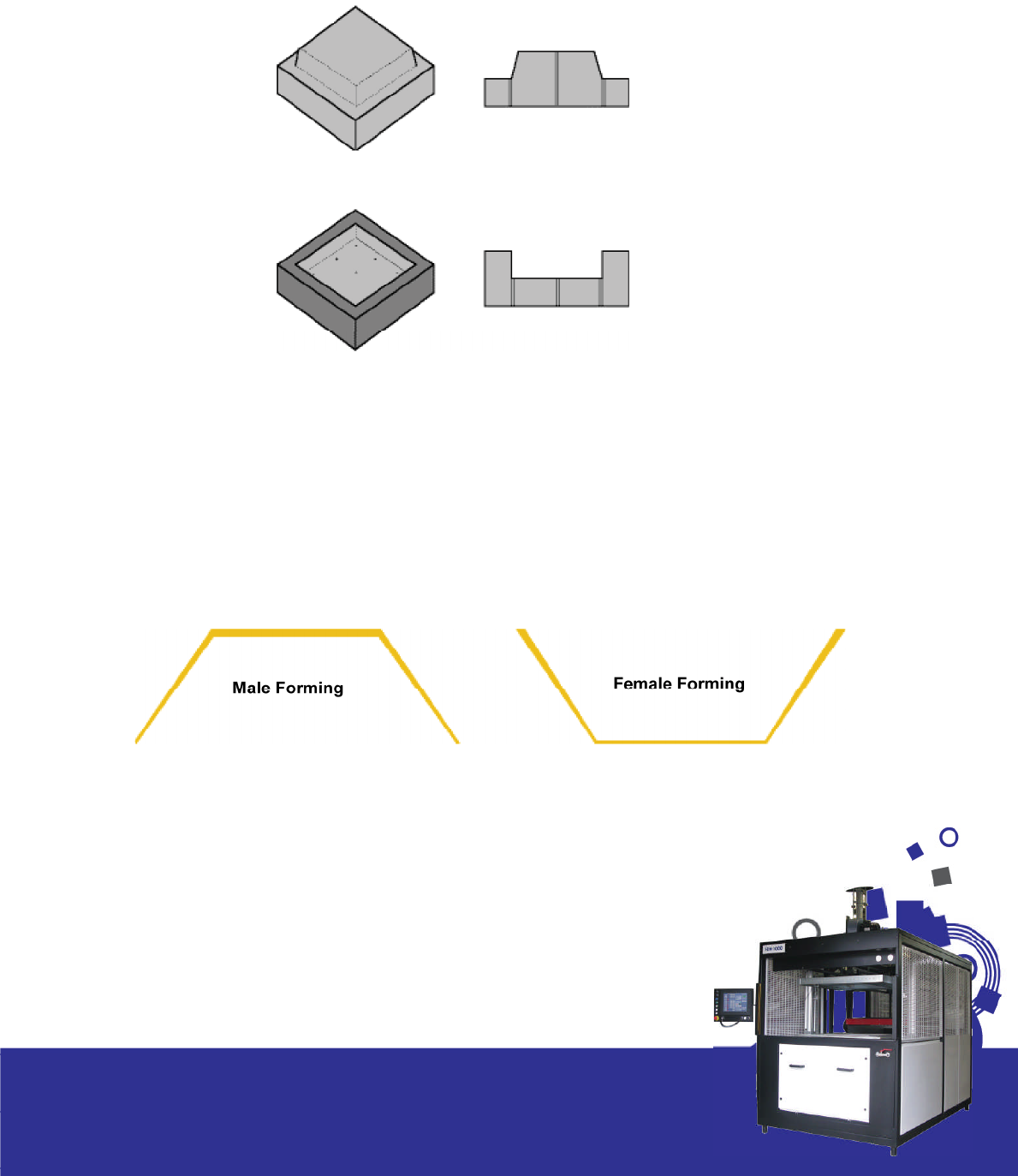
Male and Female Moulds
There are basically two kinds of moulds: male (positive) and female (negative).
See g 5.5 below.
Male Mould
Female Mould
Several factors will affect the decision as to which is more suited and below we provide a few useful
pointers.
The top surface of a moulding (the part not in contact with the mould) is invariably the better n-
ished surface, since it cannot pick up any marks such as dust particles from the tool itself. This factor
alone may dictate whether a male or female mould is required. Often a male tool is much easier
to make and more suitable for a single deep-draw object. On the other hand, a compartment tray
with divisions, would typically be of female construction.
Fig 5.6 shows a male and female forming and the effects of thinning to the plastic sheet.
A greater degree of de nition is achieved on the side of the plastic in contact with the
mould. The choice of a male or female should be considered so that the side requiring the
highest de nition is the one in contact with the mould especially thicker plastics.
28
Section 5/Mould and Mould Design
Fig. 5.5
Fig. 5.6

In general, a mould cavity which is deeper than its
diameter will give unacceptable thinning at the
bottom corners. Negative moulds will produce a
forming progressively thinner towards the bottom,
because, directly vacuum is applied, the material
will cling to the sides of the mould and will tend to
stretch like a piece of elastic. To produce a more
uniform thickness a plug should be used to stretch
the material mechanically before vacuum is ap-
plied. On a positive mould and especially if the
Pre-Stretch (bubble) option is used this mechani-
cal stretching is done automatically. It may be
worth discussing your mould requirements with
the material manufacturer if in any doubt.
Baseboards and Mounting
Generally speaking moulds should be mounted
onto baseboards prior to forming to assist release.
However, from time to time and often when a
quick prototype is required moulds are placed
directly onto the mould table and formed over.
The main setback with this method is that when
it comes to releasing the cooled part from the
mould it often, due to shrinkage, sticks to the
mould. It is then necessary to remove the part
with the mould inside and physically split the two
or trim the part whilst attached to the mould.
e.g. In the case of radiotherapy mask moulds
which have many undercuts and are placed di-
rectly on the table, the part and mould are re-
moved together and trimmed out with an air
powered hand operated slitting saw.
In most cases it is recommended to use a base-
board. The baseboard can be made from hard-
board or steel plate. It’s primary purpose is to lo-
cate and hold down the mould when using the
reverse blow facility. We recommend that a thick-
ness of between 3 – 5mm is used to ensure it sits
ush with the top of the forming area seal on the
machine.
Depending on which machine you have will de-
termine which size the baseboard should be. We
advise that if, for example, you are utilising the full
forming area (620mm x 620mm) with the mod-
el 660 machine then the baseboard should be
made to t tightly into this aperture.
To improve further the release the baseboard can
be mounted directly to the table. In order to do
this the table needs rst to be drilled and tapped
in the four corners which act as the location points
for the baseboard.
When mounting moulds to the baseboard it is
necessary to ensure there is some clearance for
air ow between the mould base and the board.
This can be done by either using a thin gauze or
by incorporating channels.
29
Section 5/Mould and Mould Design
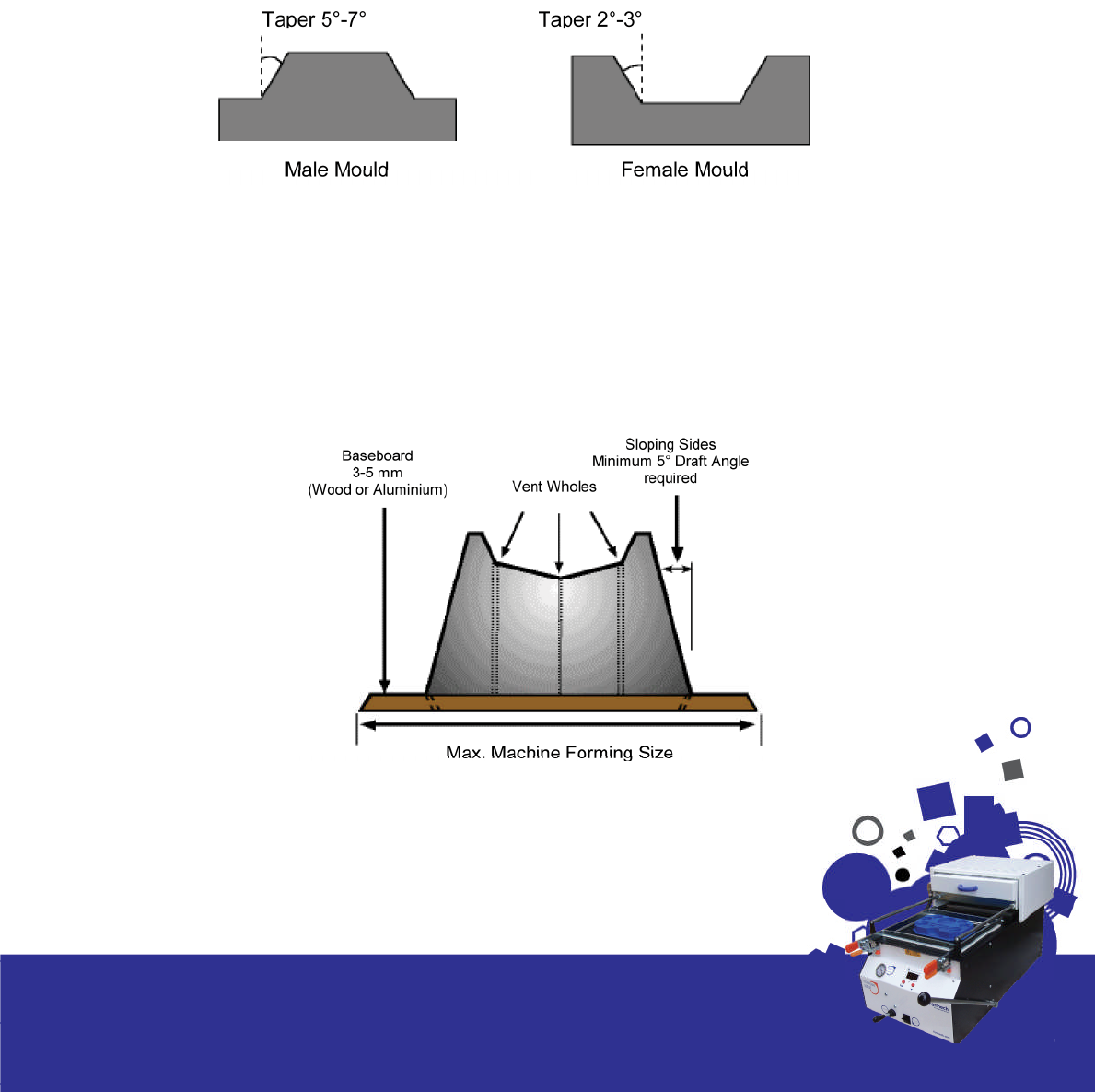
Draught Angles / Tapers
Most moulds are made with a base to sit at on the forming table and must be provided with a draught
or taper to facilitate removal, ( g 5.7.) The degree of taper will depend on various factors, such as the
surface quality of the tool, the depth of near vertical faces, type of material used and if the option of
pre-stretch is being utilised. In some instances, an internal recess may be made with zero draft angle,
since the shrinkage will actually pull the sheet away from the mould. However the minimum typical
taper we would recommend to ensure good quality forming and moulding release would be circa 5°.
It therefore goes without saying that the greater the taper, the more even the thickness of sheet and
the easier it will be to release. In summary, if using female moulds we recommend a minimum taper
of 3° and 5° for male moulds.
Venting
An important feature of mould design is the requirement for suitably positioned vent holes to facili-
tate the evacuation of air trapped between the plastic sheet and the mould. Ideally located in parts
where the sheet last makes contact - notably edges, cavities and internal corners. All these areas
need to be vented to ensure good de nition and rapid air evacuation. ( g 5.8 and 5.9)
30
Section 5/Mould and Mould Design
Fig. 5.7
Fig. 5.8

Depending on plastic used and mould design de-
termines the number of vent holes required. Ide-
ally they should be as few as possible and small
enough to prevent them witnesses on the nished
parts outer surface. However if too few vent holes
are provided or if the vent area is too small, the
rate of draw-down will be controlled by the rate
of air owing from the bubble. If this is too slow
then the plastic may cool before the required
de nition has been achieved.
The diameter of vents at the surface should be
less than half the material thickness at the mould
surface or between ½ and 1mm. They can be far
larger below the surface and one solution is to
drill the smaller hole from the surface using a high
speed hand powered drill or pillar drill. The mould
can then be inverted and a larger hole drilled
from the underneath.
As an alternative to a drill it is possible to use spring
steel otherwise known as piano wire. This material
when attened and sharpened is ideal for vent-
ing dif cult angles and for creating evacuation
holes in deeper moulds when drill lengths restrict
the venting depth.
Shrinkage and Mould Release
On cooling and hardening, a molding will tend to
shrink on to a male mould. Different thermoplastics
have differing shrinkage rates depending on the
grade and thickness. Crystalline and semi crystal-
line materials tend to shrink more than amorphous
normally due to the higher forming temperatures
required. The shrinkage rates of some of the more
widely used plastics are listed in the plastics sec-
tion under the speci ed materials, however, we
do recommend you contact the supplier for more
accurate gures as different grades of material
may have different shrinkage rates.
The shrinkage rate of the materials will also affect
the mould design in that these differences need
to be taken into consideration during the design
phase especially if tolerances are critical.
Dif culties in stripping the molding from the tool
will depend to a large extent on mould design.
If generous tapers, no undercuts, good surface
nish exist then removal should be fairly straight
forward.
In order to assist removal there are a number of
oil and silicone based release sprays which when
applied to the mould prior to forming facilitate
easy release.
31
Section 5/Mould and Mould Design
Fig. 5.9
Typical Vent Whole Position
It is also possible to use a compressed air line to
blow air between the molding and the tool.
The most effective way to ensure that the mold-
ings are released on a repeated basis is to ensure
that the moulds are mounted on baseboards
which in turn can be attached to the mould rise
and fall table on the machine. This ensures that
only the plastic part is ejected when release is ac-
tivated.
(please cross reference with the sub heading
Baseboards and Mounting)
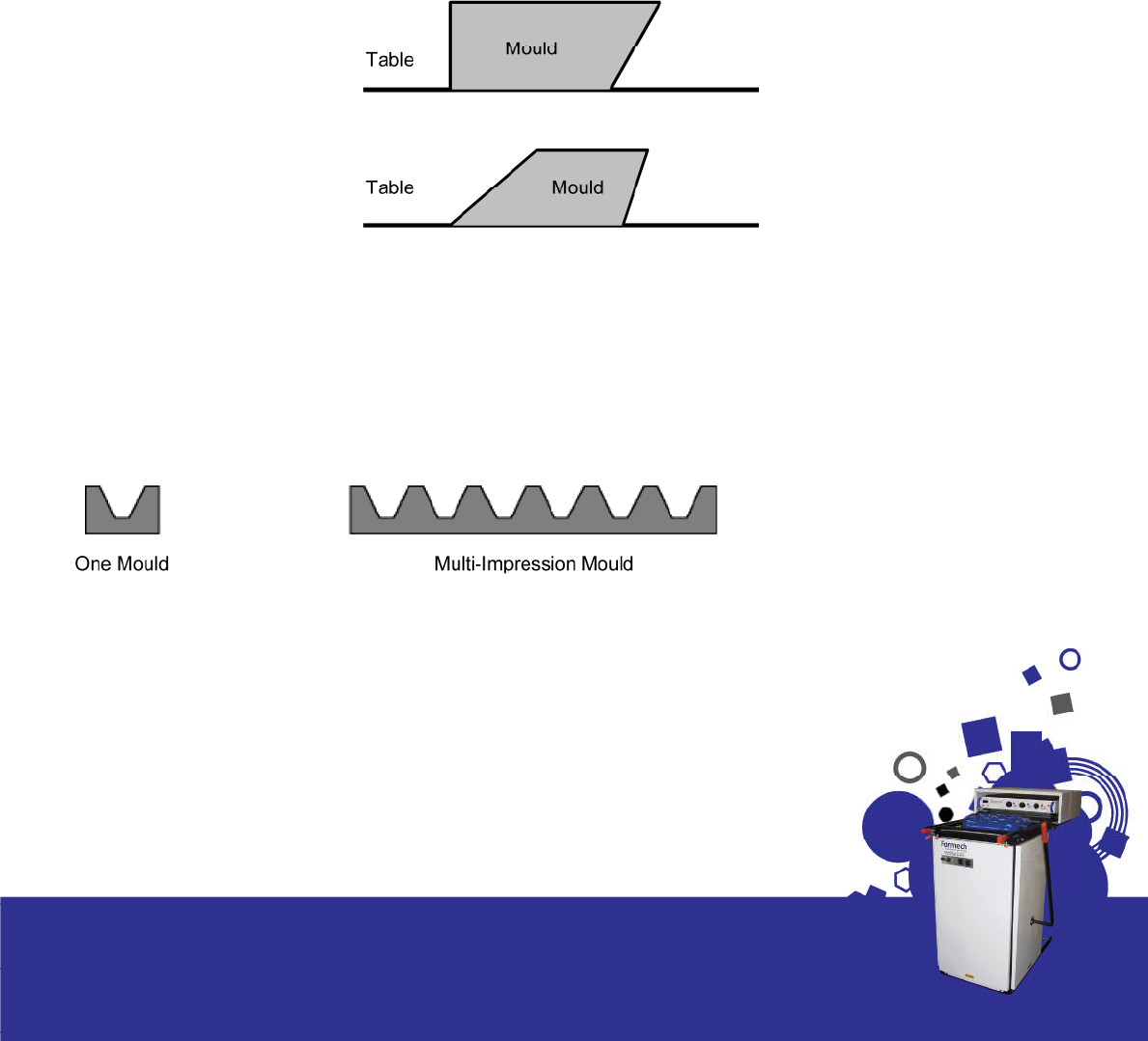
Undercuts, Split and Multi Impression Moulds
A number of other features can be incorporated
into mould design. Although technically not pos-
sible as once formed it is impossible to release, un-
dercuts can be incorporated into a mould design
with the use of split tooling. With the use of a re-
movable side entrant tool it is possible to achieve
undercuts in forming. Tooling costs are higher in
most cases.
If the mould has an undercut at one end but an
equal angle at the other end then the nished
part can also be released. ( g 5.10)
32
Section 5/Mould and Mould Design
Fig. 5.10
Not possible
Possible -
As direction of remov-
al has a greater angle
than the undercut
Fig. 5.11
Multi impression moulds are used when production requirements justify the added expense. It is nor-
mally the case that with higher levels of production the maximum forming area of the machine is
utilized by making multi impression moulds.
Mould Cooling
For large production runs we recommend a water
cooled mould. The temperature can be control-
led by a chiller unit which is connected directly
to the mould. Channels are incorporated in the
moulds during manufacture to accommodate
this facility. This helps maintain a constant mould
temperature ensure consistent results combined
with optimum cycle times. It is also possible to
mount the mould onto a cooling bolster which
contains channels for circulating cooling uid.
Costs for these moulds are considerably higher
than conventional moulds, however it is normally
a justi able expense due to the production levels
required.
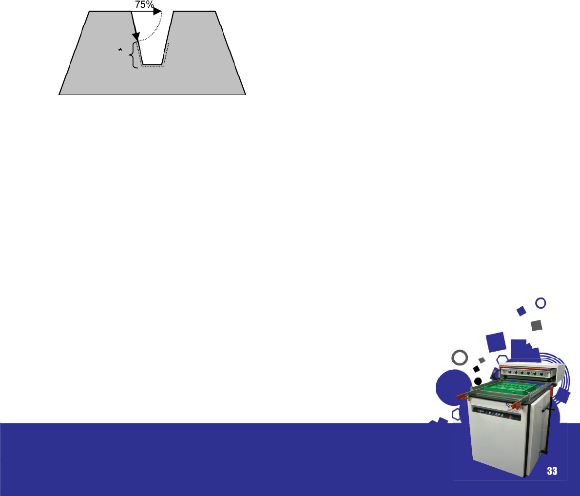
Plug Assist Design
The purpose of a plug feature is two fold. It is
used to prevent webbing in the forming of mul-
tiple male moulds which are close together and
to help achieve good wall thickness when form-
ing into deep cavities. Under normal conditions
plastic will start to thin radically once it exceeds
in depth more than 75% of the cross section ( g
5.12).
Fig. 5.12
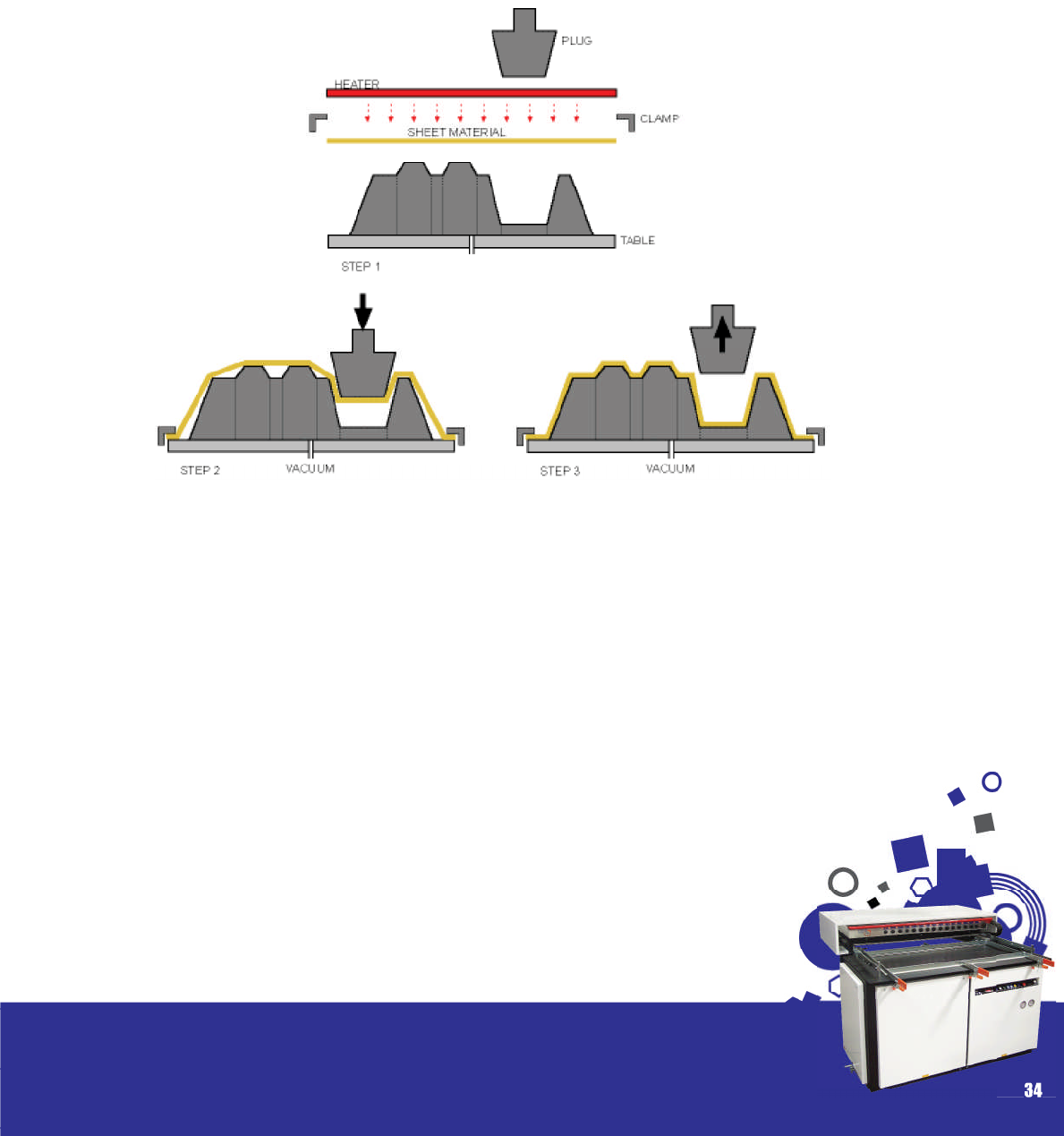
The plug is used to push the heated material into
a female mould prior or in conjunction with the
vacuum being applied. It is used whenever large
draw ratios are required.
Draw Ratio = depth of the aperture divided by the
length of the shortest cross section. For example a
refrigerator liner has a large draw ratio in that it is
a deep molding with small cross section.
In most cases the plug assist facility is a feature
suspended above the forming area and activat-
ed by pneumatic or hydraulic systems. ( g 5.13)
However on smaller machines with manual op-
eration the plug is often operator handled on a
manual basis. The majority of plug moulds are sim-
ple in design and made from hardwood. A felt or
ocked surface is often added to ensure the plug
glides into the aperture without tearing or mark-
ing the plastic too much.
33
Section 5/Mould and Mould Design
Fig. 5.12
* Depth of cavity can be 75% of the width of the
opening on the surface. Excess thinning will occur
beyond this depth.
34
Section 5/Mould and Mould Design
Fig. 5.13
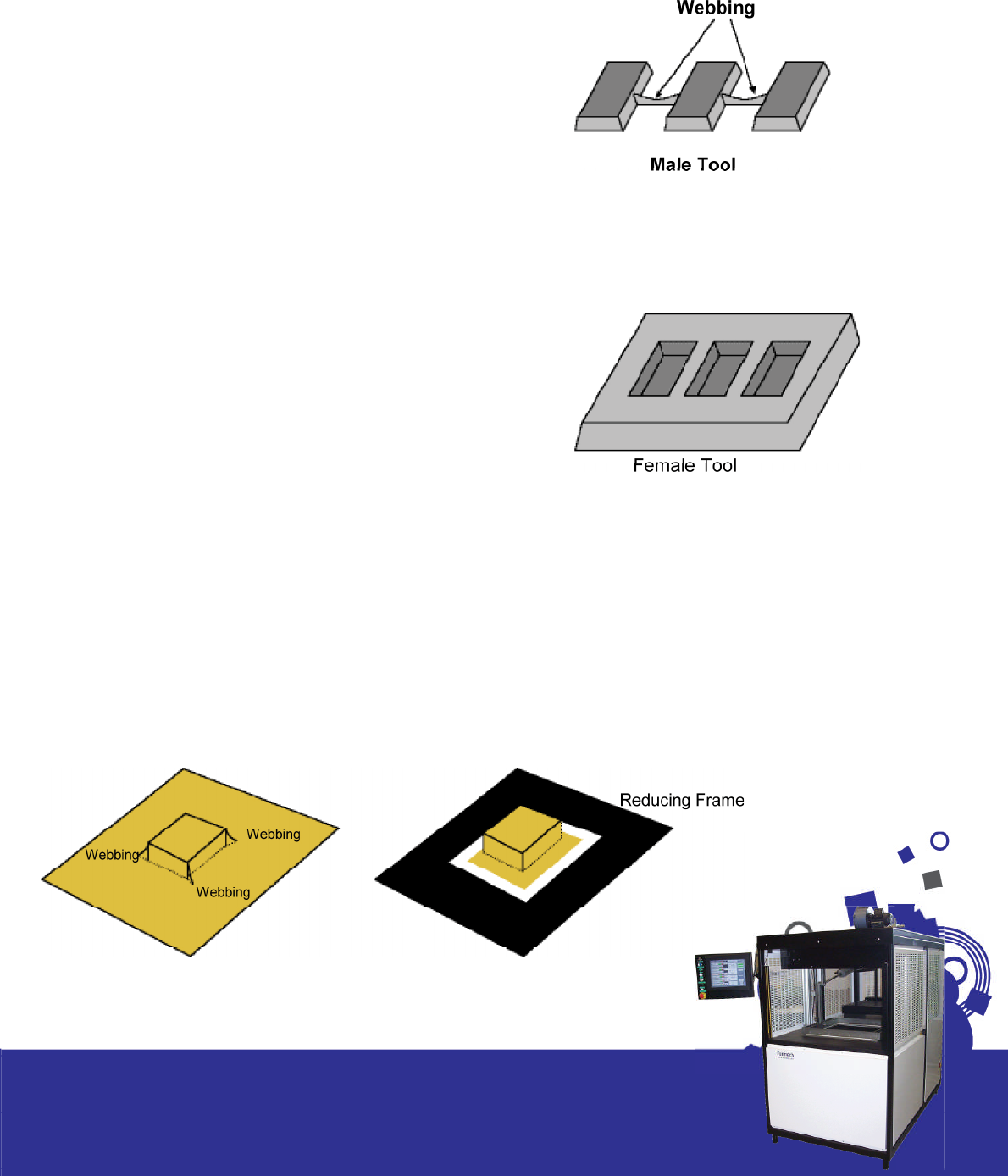
Webbing/ Chill Marks/ Thinning
Webbing
Another factor which affects mould design is
webbing. This occurs when the material shrinks
back on itself. The cause of this can be any of the
following;
• When the mould is too high in relation to its base
area.
• By sharp vertical corners with minimum draught
angles
• By deep multiple male moulds in close proximity
to each other.(Fig 5.14)
• Excess of sheet material when using small
moulds.
A female mould Fig 5.15 can often overcome the
webbing caused by multiple male moulds.
Webbing can be voided by restricting the amount
of sheet around the mould. This can be in the form
of reducing windows ( g 5.16) or with the use of a
plug. It can be minimized by a slower application
of vacuum or by using thicker sheet. It may be
necessary to modify the mould design if all else
fails to solve the problem.
35
Section 5/Mould and Mould Design
Fig. 5.14
Fig. 5.15
Fig. 5.16

Chill Marks
When raising a deep draw mould into a heated
sheet, the point which rst makes contact cools,
reducing its ow characteristics and producing
a uneven ow of material at the top which thins
down the sidewalls as the vacuum is applied.
( g 5.17) This can be eliminated by increasing the
draught angles and ensuring the mould is not too
cool. The pre-stretch facility (bubble) is also a
useful feature in overcoming this problem.
Thinning
This is one of the most common problems with
mould design and is the result of deep draw ra-
tios and minimum draught angles. See g 5.18
shows thinning caused as a result of deep draw
male mould with minimum draft angles. There are
numerous solutions which include pre-stretch
( bubble), plug assist , strengthening ribs incorpo-
rated into the mould design and increased inter-
nal draught angles.
The above three problems are examined further in the trouble shooting section of this manual.
Formech offer a pattern making facility with moulds from wood, resin and aluminium.
For all your mould requirements please contact us at : sales@formech.com
36
Section 5/Mould and Mould Design
Fig. 5.17
Fig. 5.18

Finishing and
Trimming
Finishing and Trimming
With vacuum forming there are secondary proc-
esses and operations required before a nished
part will be ready for the customer. Once the
formed part has cooled and been removed from
the machine the excess material is removed,
holes, slots and cut-outs are drilled into the part.
Other post forming processes include decoration,
printing, strengthening, reinforcing and assembly.
A variety of different trimming methods are used
to trim the product from the sheet. The type of
equipment best suited depends largely on the
type of cut, size of the part, draw ratio, thickness
of material and the production quantity required.
They are also factors to consider when determin-
ing the investment cost of such equipment. Be-
low are listed some of the more popular methods
adopted. Thin gauge parts are normally trimmed
on a mechanical trim press – otherwise known as a
Rollerpress. Heavy gauge parts can be removed,
placed into trim “jigs” or xtures and trimmed with
most of the methods listed below.
37
Section 6

38
Section 6/Finishing and Trimming
Considerations
Over time you will usually be able to build up a
gut feel for which particular plastic processing
method is best suited to your particular product.
In order to do a comparison to the other process-
es that are available, you will need to take note
of the following factors:
Quantity: The amount of parts you wish to pro-
duce are critical in determining not only if vacuum
forming is the right process for this particular job,
but also the number of tools you need to make
and the total forming area. If time is limited, then
you may decide to invest in a greater numbers of
tools in order to complete the job in less time.
Price: Very few customers adopt the approach
of “money’s no object”. There is always a good
reason why a product has been produced in a
particular manner and this is usually cost related.
As a general rule once the quality and delivery
issues have been established then price usually
becomes the deciding factor in which process
will be used, although occasionally there are ex-
ceptions.
Finish: What sort of nish do you require? What
market is the part going in to? Is the part going
to be seen? Is it for indoor or outdoor applica-
tion? How many post forming operations will be
required in order to turn the vacuum forming into
the nished part?
Accuracy: The more accurate the part the more
expensive it becomes to produce. Vacuum form-
ing will not have the consistency of injection
moulding, because you are only forming over one
face, whereas injection moulding is a totally en-
closed die, with toleranced surfaces on all sides.
Strength: What’s the application? Will the vacu-
um forming require additional fabrication in order
to give it the rigidity it requires? Will the extra parts
be glued , welded or fastened in place?
Time: Most processes require CAD these days, ei-
ther at the design stage or to create the nished
tool for production. This all takes time and needs
to be added to the total delivery time (including
the actual production of the parts) to work out
when the parts will be on your doorstep.
Example
Let’s assume that you intend to produce a vacu-
um formed machine cover based on the follow-
ing:
Speci cation:
Material: 2mm red high impact polystyrene.
Size: 330mm x 180mm x 50mm high.
Quantity: 500 off per annum. To be produced in
batches of ten at a time.
Machine cover showing the top side and the un-
derside.
This part would t comfortably on our 300XQ ma-
chine and because of the small quantities and
the size of the part we would form the part one
up. In this particular case you could only t one
tool on the table of the 300XQ. If you wanted
Section 6/Finishing and Trimming
to produce 500 parts in one go then usually this
kind of part would be produced two up on one
of our larger machines. The bene ts of increasing
the number of tools used to form the parts is that
the job is completed in a shorter time and so you
have reduced labour and machine costs and in
addition when multiples of tools are used, it usu-
ally means that less material is wasted.
Post forming operations
With most vacuum forming projects using the
slightly heavier gauge materials there is always
a certain amount of post forming operations to
be carried out and in most cases people usually
multitask during the machine operation. If you are
using an automatic machine you will have all the
time between clamping one sheet and the next
sheet. A typical automatic cycle will be as follows:
1. Place sheet in machine and clamp the mate-
rial.
2. Heat the material.
3. Pre-stretch the material.
4. Raise the tool up into the material.
5. Apply the vacuum.
6. Start the cooling cycle.
7. Release the formed part from the tool and low-
er the tool.
8. Open the clamping frame and remove the
formed sheet.
Repeat action 1 to start the next cycle.
If you are forming 2mm material with cooling fans,
then you will typically have a 3 minute cycle in
which to carry out additional tasks. It would be
very wasteful just to let the vacuum formings stack
up beside the machine and then do all the trim-
ming at a later date. Try if possible to complete
or carry out as many other operations relating to
the job as possible during the cycle. The longer
parts stand around untrimmed the more dust they
collect and the possibility of damage increases.
There is another factor that is often overlooked –
boredom. Just spending your life waiting for ma-
chines to complete their cycles is tedious. When
the operator is active and focussed on the job
when multitasking there is a tremendous sense of
achievement and the time just ies by.
Exactly what is required to complete this machine
depends on the equipment you have available.
Let’s assume that you do not have access to a
ve axis CNC router and that you are going to
trim the part with more conventional equipment.
(Incidentally a ve axis CNC router would easily
trim the part in under three minutes.
Heated knife/ Scalpel
Educational user / Model maker/ R & D work – thin
plastics only.
39
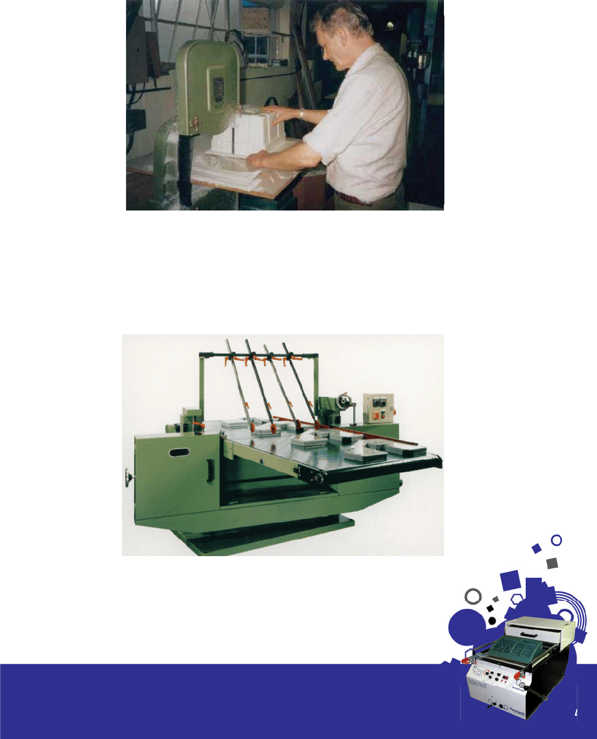
Horizontal Bandsaw (Fig 6.4)
This method can be used for both thick and thin thermoplastics formings. The technique has a very
wide application, the essential features being a sliding table whose height relative to the saw blade
can be adjusted ( or vice versa).
40
Section 6/Finishing and Trimming
Fig. 6.3
Vertical Bandsaw
Fig. 6.4

Rollerpress/ Steel Rule Dies ( g 6.5)
The machine consists of a pair of adjustable, electrically driven rollers, placed one above the other.
The rollers rotate in opposite directions to draw the cutting tool and the material to be cut between
them.
High quality shape and hole cutting can be achieved with low cost cutting dies. Simple and easy
to operate they will form cut virtually all types of exible and semi rigid materials up to a thickness of
about 4mm. Cutting widths from 700mm upwards can be accommodated.
Please refer to the products section for more information on the range available.
41
Section 6/Finishing and Trimming
Fig. 6.5
Guillotine
The industrial guillotine is similar to those used to
cut paper. Used to cut non brittle and thinner ma-
terials. Available in manual and powered versions
probably the most well known supplier in the U.K
is the company Edwards who have a good range
of industrial guillotines.
Clicker / Punch Press
A moving head which is moved over the trim jig
containing the formed part and then activated
to press down and cut the part.
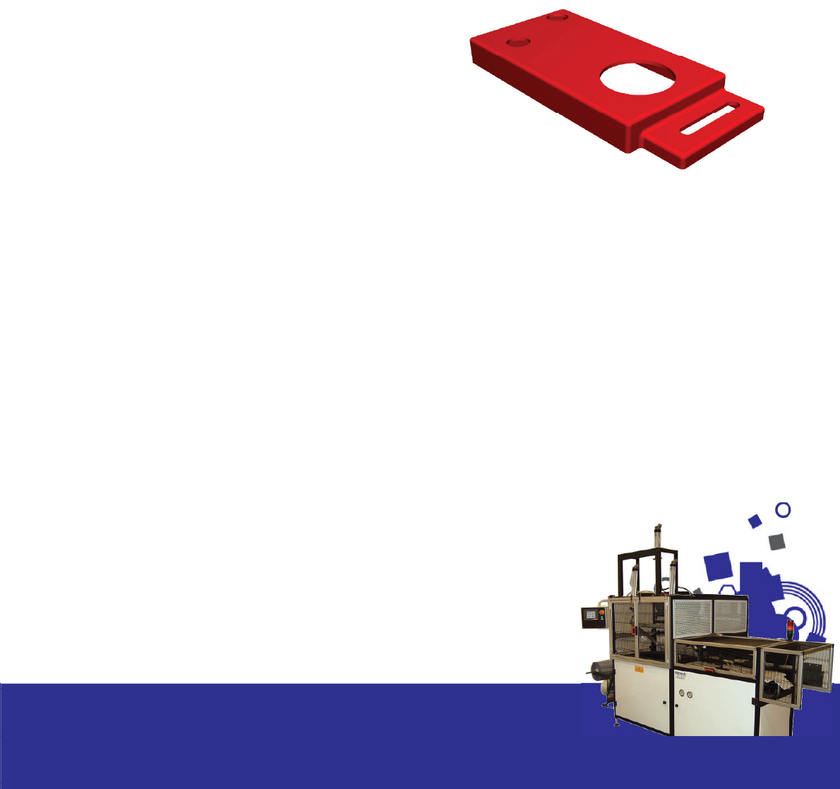
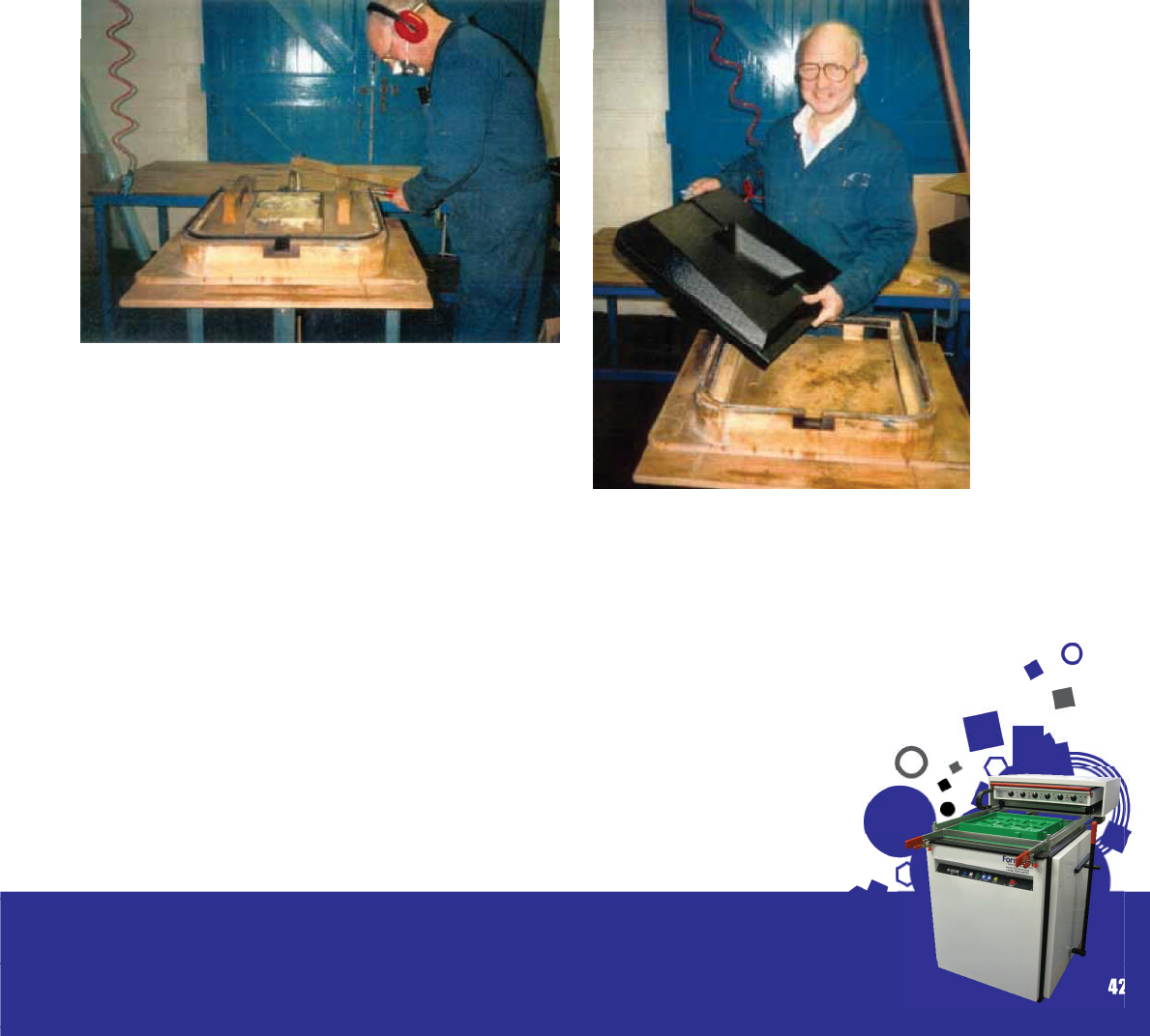
Hand Held Air Powered Router
This is a versatile and accurate manual method
of trimming awkward shapes. The moulded part
is located in a ‘trim jig’ with guidelines along
which the operator can run the router. A bearing
is attached to the router cutter to ensure smooth
movement when trimming parts. See g. 6.6-6.9
for examples of products trimmed using this meth-
od.
42
Section 6/Finishing and Trimming
Fig. 6.6
Fig. 6.7

De Soutter provide very reliable air tools and
have branches nationwide. Bearings and cutters
are added to suit.
Circular spindle saw
As the name suggests this is a circular cutter mounted on a spindle and xed in a pillar
drill. The cutting disc is reversed to ensure safety when trimming parts. Cuts vertically from
above.
43
Section 6/Finishing and Trimming
Fig. 6.8
Fig. 6.9
Circular Cutter mounted from under table.
Larger industrial version of the Formech Gerbil
and powered by a router motor mounted under
a table. Ideal for cutting on a vertical edge.
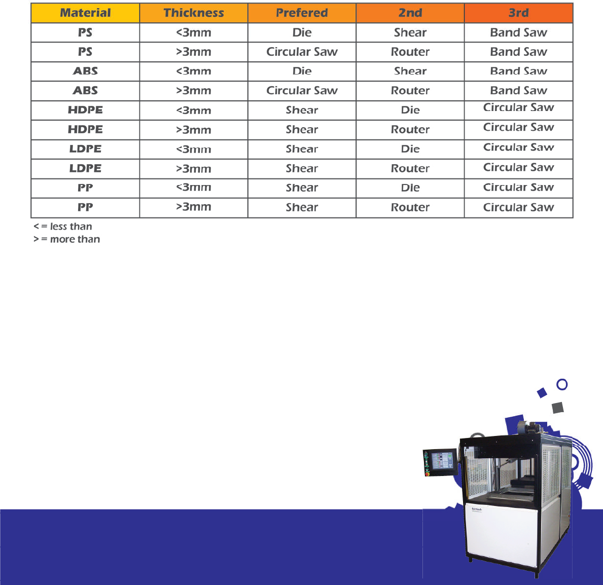
Below we have provided a guideline to the pre-
ferred trimming methods for a
range of the more commonly used thermoplas-
tics.
Formech are able to assist with any questions you
may have and also provide further details of suit-
able trimming machines and suppliers. Please also
refer to the products section of the web page.
44
Section 5/Mould and Mould Design
Table 6.1

Trouble
Shooting
Guide
The purpose of the following section is to help the
user in overcoming some problems frequently
encountered in thermoforming. Most of the ma-
jor problems identi ed in thermoforming can be
traced back inadequate process control. Im-
proper sheet temperature at the time of forming is
a primary source of problems. Poor vacuum con-
trol and insuf cient cooling are also typical caus-
es. The table below lists the majority of recurring
problems in thermoforming along with the sug-
gested courses of action to correct or eliminate
the processing problem.
45
Section 7
Table. 7.1
Problem Cause Remedy
Blisters or Bubbles Overheating/Sheet heated too
rapidly
- Lower the heater temperatures or
reduce the top heater if using twin
heating.
Excessive moisture - Pre-dry sheet
- Pre-heat sheet
- Heat from both sides
- Keep material wrapped until
ready to use
Uneven Heating - Check consumption.
- Increase zone control.
Poor Mould Release Mould or part too hot - Increase cooling cycle.
- Decrease mould temperature.
Mould undercuts - Increase release time and pressure
Insufficient draft angles - Increase draft.
- Convert mould to female.
Poor mould surface - Use mould release. Improve
mould surface.
Sheet Scorching Top/Bottom surface too hot - Decrease heating cycle time.
- Decrease heater temperature.
- Check for faulty heat zones if
problem in isolated area. Pre-heat
material.

46
Section 7/Trouble Shooting Guide
Problem Cause Remedy
Lack of Definition Material too cold - Increase heating time.
- Increase heater temperature.
- Increase heater density and/or
wattage.
- If localized problem check heater
zone and elements.
Mould too cold - Ensure mould is at optimum temp.
for forming
Insufficient vacuum - Adjust vacuum timings.
- Check vent holes on mould.
- Increase number and or diameter of
vacuum holes.
- Check mould is not restricting
vacuum flow - are vacuum tracks in
mould adequate?
- Check for leakage in vacuum system
- Increase vacuum capacity
Webbing Material too hot - Shorten cycle time.
- Lower heater temperature.
Insufficient vacuum - Check system for leaks
- Increase size of vacuum holes
- Check for blocked holes
Incorrect Pre-Stretch height - Adjust pre-stretch flow and time
Excess material - Reduce material size and use reduc-
ing windows
Poor mould design - Increase radii improve draw ratios
- Use plug/ring assist.
- Use assist blocks to pull out web-
bing.
- Increase spacing between moulds.
- Switch to female mould.
Vacuum speed too fast - Regulate to suit.
- Use smaller vacuum holes.

47
Section 7/Trouble Shooting Guide
Problem Cause Remedy
Whitening Part removed too early - Part must be below set temp. before
removing
- Increase cooling cycle.
- Add extra cooling fans
- Utilise a spray mist facility
- Use water cooled moulds.
Uneven part cooling - Increase mould temp. and/or temp.
uniformity.
Poor mould design - Redesign. Incorporate ribs/tapers
Poor sheet distribution - Check for uneven heating
- Use plug assist or pre-stretch for
deep draw.
Excessive mould release pres-
sure or timing
- Adjust to suit.
Chill Marks Stretching stops when sheet
makes contact with cold
mould/plug
- Increase mould temp.
- Increase plug temp.
Mould design - Use plug to assist mould flow.
Insufficient pre-stretch - Increase pressure, flow or time
Plug tool too cold - Wrap tool with felt or similar.
Thinning at corners on deep
draw parts
Uncontrolled sheet heat - Improve zone control.
Sheet formed too slow - Use more vacuum
- Increase number and size of vent
holes
Too much pre-stretch - Decrease flow or timing.
Cold spots - Check elements
- Check for draughts.
Too thin gauge - Increase
Uncontrolled material distri-
bution
- Use plug assist and/or pre-stretch

48
Section 7/Trouble Shooting Guide
Problem Cause Remedy
Tearing of sheet whilst forming Sheet too hot - Decrease heating cycle time.
- Decrease temp. settings.
- Pre-heat sheet.
Sheet too cold - Increase heating cycle time
- Increase temp. settings.
Pre-stretch too large - Reduce time and flow.
Mould design - Increase corner radii and draw
ratio.
Improper material selection - Consult supplier
Parts stick in mould Part temp. too high - Increase cooling cycle.
- Lower mould temp.
- Reduce heating cycle time.
Mould not fixed on base-
board
- Mount mould to baseboard ensure
it is then fixed to table.
Insufficient draft - Increase taper.
Mould undercuts - Increase air eject.
- Remove part earlier and use cooling
jigs.
- Use retractable undercut segments
in mould.
Poor mould quality - Polish mould.
- Use release agent.
- Remove rough edges from wooden
moulds.
Nipples on formed parts Sheet too hot - Reduce heating cycle
- Reduce heat temp.
Vacuum holes too large Plug holes/re-drill.
Excessive sag Sheet too hot - Decrease heat cycle time.
- Decrease heater temp.
Sheet area too large - Improve zone control
- Ensure auto level feature activated.

49
Section 7/Trouble Shooting Guide
Problem Cause Remedy
Marks on finished moulding Dirty mould - Clean mould with air gun after each
cycle.
Water droplets - Decrease spray mist.
- Check all hoses, gaskets for leaks.
Poor mould surface - Smooth/Polish surface.
Scratched sheet - Inspect handling procedure
- Ensure protective film removed im-
mediatly prior to forming.
Plastic pulls from clamp frame Insufficient clamp pressure - Check clamp pressure.
- Adjust alignment.
- Heat frame prior to inserting sheet.
Material too cold - Increase heat cycle.
Wrong material selection - Consult supplier.

Supplier guide The following list of suppliers has been divided into
four sub sections;
1. Formech Int Ltd – Machines & Spares, An-
cillary Equipment.
2. Plastic Stockists,
3. Plastic Extruders (minimum order 500 - 1000
kilos)
4. Resin/ mould material suppliers.
50
Section 8
Formech International Ltd
Sales and Administration
Unit 4, Thrales End Business Park
Thrales End Lane
Harpenden
Hertfordshire
AL5 3NS
England
Tel: + 44 (0)1582 469 797
Fax: + 44 (0)1582 469 646
Email: sales@formech.com
www.formech.com
Spare Parts and Service
Unit 4, Thrales End Business Park
Thrales End Lane
Harpenden
Hertfordshire
AL5 3NS
England
Tel: + 44 (0)1582 469 797
Fax: + 44 (0)1582 469 646
Email: service@formech.com
www.formech.com
Suppliers of:
• Vacuum Forming Machines.
• Reducing Windows, Spare Parts and Spare Parts Kit.
• Rollerpresses, Horizontal Bandsaws and Gerbils
• Drying Ovens, Line Bending Equipment.
• Tooling – Prototype and Production
• Tradeforming facility

51
Section 8/Supplier guide
Plastic Sheet Stockists
ABG Ltd
Galowhill Road
Brackmills
Northampton
NN4 7EE
England
Tel: + 44 (0)1604 70 08 80
Fax: + 44 (0)1604 76 61 13
Email: cs@abgrp.co.uk
www.abgrp.co.uk
Suppliers of:
PETG. Axxis Vivak. Clear polyester
sheet.
Amari Plastic Ltd
Branches nationwide.
Head Of ce:
Holmes House
24 – 30 Baker Street
Weybridge
Surrey
KT13 8AU
England
Tel: + 44 (0)1932 83 50 00
Fax: + 44 (0)1932 83 50 01
Email: ho@amariplastics.com
www.amariplastics.com
Suppliers of:
ABS, PC, PP, PMMA
Multiplastics Ltd
Paycocke Road
Basildon
Essex
SS14 3EU
England
Tel: + 44 (0)1268 28 91 81
Fax: + 44 (0)1268 53 04 76
Email: cturner@multiplastics.co.uk
Suppliers of:
Acrylic, PC.
Simona Ltd
Telford Drive
Brookmead Ind. Park
Stafford
ST16 3ST
England
Tel: + 44 (0)1785 22 24 44
Fax: + 44 (0)1785 22 20 80
Suppliers of:
PE, PP, PETG
Stephen Webster Plastics Ltd
Brick Knoll Park
Ashley Road
St Albans
Herts
AL1 5PL
England
Tel: + 44 (0)1727 86 31 38
Fax: + 44 (0)1727 84 42 91
Email: sales@stephen-webster.
co.uk
www.stephen-webster.co.uk
Suppliers of:
• Holds in stock a large range of
Sheet Polystyrene in black, white,
colours and textures.
• Also supplies ABS, PETG, PVC,
Acrylic Capped ABS.
• Excellent delivery times and no
minimum.
• Discounts for quantity. Free deliv-
ery over £ 50.00
UKAP
Sterling House
21-25 Station Lane
Hornchurch
Essex
RM12 6JL
England
Tel: + 44 (0)1708 44 77 88
Fax: + 44 (0)1708 44 11 11
Email: sales@ukap.co.uk
www.ukap.co.uk
Suppliers of:
Flocked P.S and PVC (reel form
only)
Polyformes Ltd
Cherry court Way
Stanbridge Road
Leighton Buzzard
Beds
LU7 8HU
England
Tel: + 44 (0)1525 85 24 44
Fax: + 44 (0)1525 85 04 84
Email: sales@polyformes.co.uk
www.polyformes.co.uk
Suppliers of:
Closed cell PE foams.

52
Section 8/Supplier guide
Plastic Extruders
Athlone Extrusions Ltd
Grace Road
Athlone
Co. Westmeath
Ireland
Tel: + 353 (0)902 92 67 9
Fax: + 353 (0)902 94 08 6
Email: info@athloneextrusions.ie
Extruders of:
P.S. ABS (Fire retardant) Acrylic
Capped ABS
Doe ex PLC
Holmethorpe Avenue
Redhill
Surrey
RH1 2NR
England
Tel: + 44 (0)1737 77 12 21
Fax: + 44 (0)1737 77 24 61
Email: sales.doe ex@dial-pipex.
com
Suppliers of:
Polystyrene / Conductive PE and
PP
Wardle Storeys
Brantham Works
Brantham
Manningtree
Essex
CO11 1NJ
England
Tel: + 44 (0)1206 39 24 01
Fax: + 44 (0)1206 39 52 88
Email: sales@wardlestoreys.com
Extuders of:
HDPE, PP.(Minimum order- 500
Kilos)
Resin Suppliers
Alchemie Limited
Warwick Road
Kineton
Warwick
CV35 0HU
England
Tel: + 44 (0)1926 64 16 00
Fax: + 44 (0)1926 64 16 98
Email: sales@alchemie.com
www.alchemie.com
Suppliers of:
• Epoxy Resin Tooling Systems for
vacuum forming.
• Metaphor – Porous Aluminium

Further
Information
We hope this manual has provided a useful insight
into vacuum forming. Whilst we have tried to cov-
er all aspects of the process the following industry
bodies and associations are able to provide fur-
ther assistance and information on the thermofor-
ming process in general. Please see our contacts
section for links to the following companies or you
can link directly below.
53
Section 9
British Plastic Federation (BPF)
5-6 Bath Place
Rivington Street
London
EC2A 3JE
England
Tel: + 44 (0)20 74 57 50 00
Fax: + 44 (0)20 74 57 50 45
www.bpf.co.uk
British Polymer Training
Association(BPTA)
Hales eld 7
Telford
Shropshire
TF7 4NA
England
Tel: + 44 (0)1952 58 70 20
Fax: + 44 (0)1952 58 20 65
Email: samr@bptaserv.co.uk
www.bpta.co.uk
Institute of Materials
1 Carlton House Terrace
London
SW1Y 5DB
England
Tel: + 44 (0)20 74 51 73 00
Fax: + 44 (0)20 83 91 70 2
www.materials.org.uk
Rubber & Plastics Research Association
of G.B. ( RAPRA)
Shawbury
Shrewsbury
Shropshire
England
Tel: + 44 (0)1939 25 03 83
Fax: + 44 (0)1939 25 11 18
Email: info@rapra.net
www.rapra.net
