ISSUE 0 Valcom VIP 204 Page Pro SIP Based Paging Gateway Installation Manual
User Manual: Valcom VIP-204 PagePro SIP Based Paging Gateway Installation Manual Valcom IP Solutions - Telecomuserguides.com
Open the PDF directly: View PDF ![]() .
.
Page Count: 4
1 947694
ISSUE 4
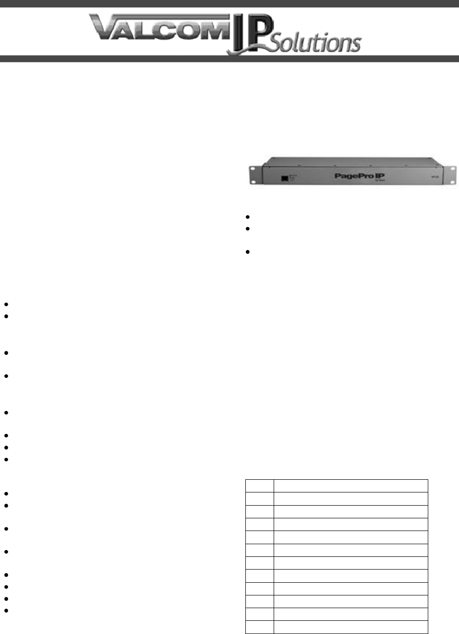
PagePro VIP-204
SIP Based Paging Gateway
INTRODUCTION
The VIP-204 SIP Based Paging Gateway is
designed for use with virtually all IP based
telephone systems. The unit provides 8 SIP
addressable groups and 4 analog outputs that
may be included as part of the SIP addressable
groups. The VIP-204 can control thousands of IP
speakers and/or analog speakers or provide
interface to legacy paging systems.
SPECIFICATIONS
Access Methods
SIP
Valcom Multicast Page Group
Power Options
802.3af, Class 3 Compliant Power over
Ethernet
Optional External Power Supply (VIP-324)
Features
4 Analog Audio Outputs (for inclusion in
groups only)
4 Programmable Form A Relay Closures
RJ-45 for Network Connection
Provides Audio for Valcom Analog One-Way
Self Amplified Speaker Assemblies or 25/70
Volt central amplifiers
AUX Audio Input via RCA Jack
Optional Background Music, Music Mutes
During a Page
Output Control Relay Closure Provided
During Paging Output
2.5mm Jack for optional DC Power (non-
POE)
LED Status Indicator
Network Activity LEDs
Optional Feedback Elimination/Page Repeat
Programmable Night Ring
Dimensions/Weight
1 Standard 19” Rack Unit
1.75” H x 16.6" W x 9.5" D
(4.57 cm x 42.16 cm x 24.13 cm)
Weight: 7.25 lbs. (3.28 kg)
Nominal Specifications
AUX Input Impedance:
8 to 600 Ohms
AUX Input Level:
-10dBm nominal
Output Impedance:
50 Ohms
Output Level:
- 10dBm nominal
Relay Current Rating:
1 Amp @ 24VDC
Nominal Power Requirements
Via rear panel barrel connector
Voltage:
24VDC
Current:
325mA
Via 802.3af PoE Ethernet Switch:
Class 3
Environment
Temperature:
0 to +40° C
Humidity:
0 to 85% Non-Precipitating
Packing List
Qty
Item
1
VIP-204
5
RJ-45 Patch Cables
4
RJ-45 Terminal Blocks
4
Rubber Pads
2
Mounting Brackets
8
Mounting Bracket Screws
4
Rack Mount Screws
4
Wall Mount Screws
1
Quick Start Guide
1
VSP Document
1
Set Up CD
2 947694
CAUTION: To reduce the risk of electric shock,
Do not remove cover.
No user serviceable parts inside.
Refer servicing to qualified service personnel.
CAUTION
RISK OF ELECTRIC SHOCK
DO NOT OPEN
This symbol indicates that dangerous
voltage constituting a risk of electric
shock is present within this unit.
This symbol indicates that there are
important operating and maintenance
instructions in the literature accompanying
this unit.
INSTALLATION
FCC Information
This equipment has been tested and found to
comply with the limits for a Class A digital
device, pursuant to Part 15 of the FCC Rules.
These limits are designed to provide
reasonable protection against harmful
interference when the equipment is operated
in a commercial environment. This
equipment generates, uses and can radiate
radio frequency energy and if not installed
and used in accordance with the instruction
manual, may cause harmful interference to
radio communications. Operation of this
equipment in a residential area may cause
harmful interference in which case the user
will be required to correct the interference at
their own expense.
Precautionary Designations
Mounting
The VIP-204 SIP Based Paging Gateway is
designed for rack, shelf, or wall mounting.
Rack: Attach the brackets to the four holes
closest to the front on each side, and then mount
the unit to a 19” rack.
Shelf: Provided with the VIP-204 SIP Based
Paging Server are four rubber stick-on pads.
Peel the pads from their carrier backing and
place at the four corners of the bottom of the unit.
Wall: Using the brackets and wood screws
provided, secure the VIP-204 SIP Based Paging
Server to the wall.
Power Connections
The preferred method of powering a VIP-204 is
via a power over Ethernet switch meeting the
802.3af specification.
If the rear panel barrel connector is used for
power, the preferred power supply is a Valcom
VIP-324.
Make all required signal connections before
applying power to the unit.
Network Connection
The VIP-204 has one Category 5 RJ-45 network
connector on the front panel.
Use one of the supplied Category 5 patch cables
to connect the VIP-204 to an Ethernet switch. If
the Ethernet switch is 802.3af compliant the VIP-
204 will draw power from it.
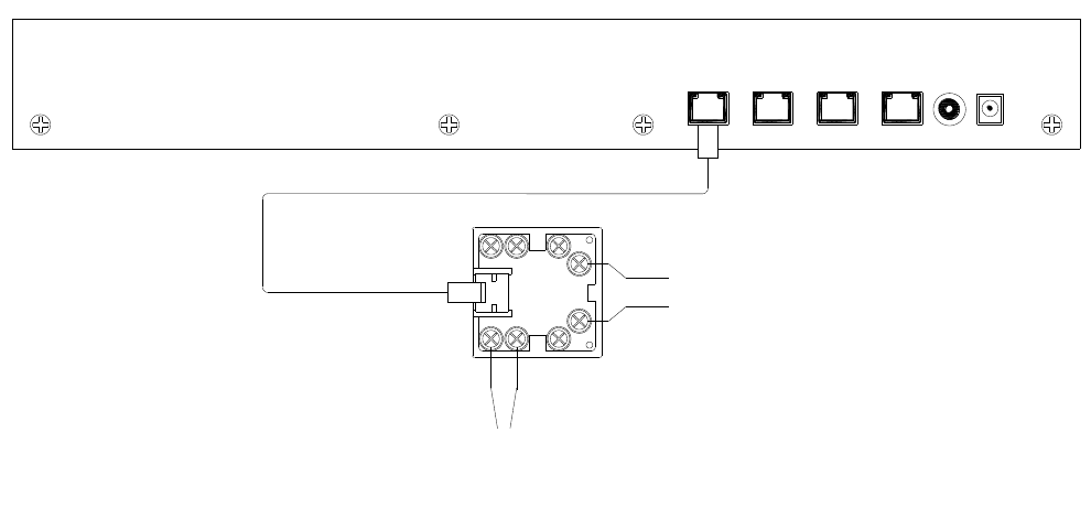
Signal Connections
The VIP-204 has 5 signal connectors on the rear
panel:
• 1 RCA jack for AUX audio input
• 4 RJ-45 connectors for audio and relay
connections for each networked channel.
AUX Input: Local audio may be input via the
rear panel RCA jack. Nominal input impedance
is 600 Ohms. Connect any compatible audio
source using an RCA patch cable. Audio
supplied through the rear panel RCA jack
broadcasts to all Audio Outs whenever they are
idle. This is typically used for background music.
Input / Output Connections: Access to the
audio output and relay output for each of the four
channels is provided through the four RJ-45 jacks
on the rear panel of the VIP-204. Four patch
cables and four Telco-style terminal block
connectors are included for ease of installation.
The following chart shows the pin assignments
for the four input/output connections.
N.O. Relay Closure Output: The Normally
Open Relay Closure Output connection can be
programmed on the VIP-204 to close the contacts
in response to paging events. The relay will
return to the open state when the event ends.
Audio Output: Typically connects to Self
Amplified Speakers or into an amplifier. Audio
feeds connected to the AUX Input mute on any
active Audio Output.
Pins
Telco Connector
Wire Color
Signal
4,5
Red & Green
N.O. Relay
Closure Output
7,8
Brown & Grey
Audio Output
3 947694
AUX
IN
+24VDC
PORT4PORT 3PORT 2PORT 1
N.O. RELAY OUTPUT
RJ-45 PATCH CABLE BL OR
GY BR YL
BK
GN
RD
VIP-204 (REAR VIEW)
LINE-LEVEL
AUDIO OUTPUT
(TO SPEAKERS)
VIP-204 Audio/Relay Connections (one per channel)
Status Indicator Lights
The VIP-204 Network Interface has 3 status
indication lights:
STATUS: Flashes during normal operation and
solid during system startup.
LINK: Indicates a 100 Mbit Ethernet connection
when illuminated. A non-illuminated LINK LED
indicates a 10 Mbit connection or no network
connection.
ACT: Indicator flashes to indicate network activity
Operation
Provides paging from SIP connection or from
another Valcom VIP unit. Interface to customer
telephone system can be via SIP registration,
FXO port (with VIP-811), or FXS port (with
VIP-821). Unit can also be accessed from a
VIP-801 connected to a page port or a Valcom
page control.
Setup
Information specific to your application will need
to be programmed into the VIP-204. The PC
used for programming should be connected to
the same subnet as the VIP-204.
Setup will be done using the IP Solutions Setup
Tool. The IP Solutions Setup Tool is included on
the CD ROM enclosed with the VIP-204.
TECHNICAL ASSISTANCE
Assistance in troubleshooting is available from
the factory. Call (540) 563-2000 and press 1 for
Technical Support or via email at
support@valcom.com.
Valcom equipment is not field repairable.
Valcom, Inc. maintains service facilities in
Roanoke, VA. Should repairs be necessary,
attach a tag to the unit clearly stating your
company name, address, phone number, contact
person and the nature of the problem. Send the
unit to:
Valcom, Inc.
Repair & Return Dept.
5614 Hollins Road
Roanoke, Va. 24019-5056
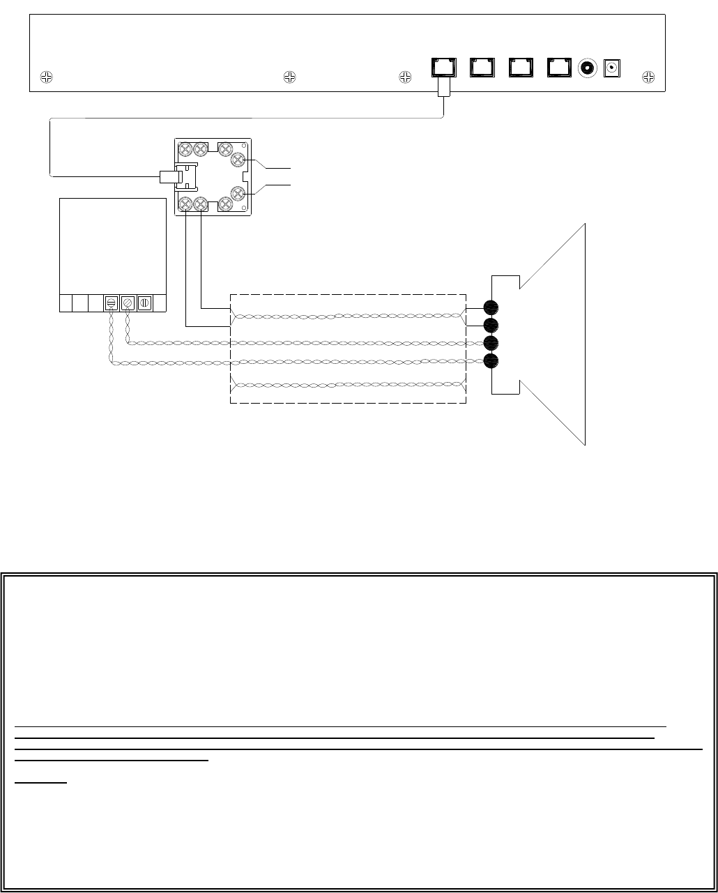
4 947694
AUX
IN
+24VDC
PORT4PORT 3PORT 2PORT 1
N.O. RELAY OUTPUT
RJ-45 PATCH CABLE BL OR
GY BR YL
BK
GN
RD
24VDC
- + AC
Ground
POWER SUPPLY
VALCOM
-24Vdc
TIP
RING
GND
-24Vdc
WHITE-BLUE / BLUE PAIR
WHITE-ORANGE / ORANGE PAIR
WHITE-BROWN / BROWN PAIR
CAT 3/5/5e/6 CABLE
WHITE-GREEN / GREEN PAIR (UNUSED)
VIP-204 (REAR VIEW)
VALCOM
SELF-AMPLIFIED
SPEAKER
Typical Connection to Valcom Self-amplified Speakers
VALCOM LIMITED WARRANTY
Valcom, Inc. warrants its products only to the original purchaser, for its own use, to be free from defects in materials and workmanship under conditions of
normal use and service for a period of one year from the date of shipment. This Limited Warranty obligation shall be limited to the replacement, repair or
refund of any such defective device within the warranty period, provided that:
1. inspection by Valcom, Inc. indicates the validity of the claim;
2. the defect is not the result of damage, misuse or negligence after the original shipment;
3. the product has not been altered in any way or repaired by others and that factory sealed units are unopened (a service charge plus parts
and labor will be applied to units defaced or physically damaged);
4. freight charges for the return of products to Valcom are prepaid;
5. all units 'out of warranty' are subject to a service charge. The service charge will cover minor repairs (major repairs will be subject to
additional charges for parts and labor).
This Limited Warranty is in lieu of and excludes all other warranties, expressed or implied and in no event shall Valcom, Inc. be liable for any
anticipated profits, consequential damages, loss of time or other losses incurred by the buyer in connection with the purchase, operation,
maintenance, installation, removal or use of the product. The maximum liability of Valcom under this warranty is limited to the purchase price of the
specific Product covered by the warranty.
Disclaimer. Except for the Limited Warranty provided herein, the product is provided “as-is” without any warranty of any kind whatsoever including, without
limitation, any WARRANTY OF MERCHANTABILITY, FITNESS FOR A PARTICULAR PURPOSE OR NON-INFRINGEMENT.
This warranty specifically excludes damage incurred in shipment. In the event a product is received in damaged condition, the carrier should be notified
immediately. Claims for such damage should be filed with the carrier involved in accordance with the F.O.B. point.
Headquarters:
Valcom, Inc.
5614 Hollins Road Roanoke, VA 24019-5056
Phone: (540) 563-2000 FAX: (540) 362-9800
