Vectrino II Profiler User Guide
Vectrino%20Profiler%20User%20Guide
User Manual:
Open the PDF directly: View PDF ![]() .
.
Page Count: 36
USER GUIDE
2012
ECTRINO
PROFILER
P R O F I L I N G
V E L O C I M E T E R
V

ECTRINO
PROFILER
P R O F I L I N G
V E L O C I M E T E R
Copyright © Nortek Scientific Acoustic Development Group Inc. All rights reserved. This document
may not – in whole or in part – be copied, photocopied, translated, converted or reduced to any
electronic medium or machine-readable form without prior consent in writing from Nortek Scientific.
Every effort has been made to ensure the accuracy of this manual. However, Nortek Scientific makes
no warranties with respect to this documentation and disclaims any implied warranties of
merchantability and fitness for a particular purpose. Nortek Scientific shall not be liable for any errors
or for incidental or consequential damages in connection with the furnishing, performance or use of
this manual or the examples herein. Nortek Scientific reserves the right to amend any of the
information given in this manual in order to take new developments into account.
Microsoft, ActiveX, Windows, Windows 2000, Vista, Windows 7 and Win32 are either registered
trademarks or trademarks of Microsoft Corporation in the United States and/or other countries. Other
product names, logos, designs, titles, words or phrases mentioned within this publication may be
trademarks, service marks, or trade names of Nortek AS or other entities and may be registered in
certain jurisdictions including internationally.
Nortek Scientific Acoustic Development Group Inc, 27 Drydock Avenue
Boston, MA 02210 USA
Tel: (617) 206-7570 Fax: (617) 275-8955
V

Vectrino Profiler
3
TABLE OF CONTENTS
Introduction 5
Getting Started .......................................................................................................... 5
Contents of Your Shipment ....................................................................................... 6
Product Specification 7
Mechanical................................................................................................................. 7
Sampling Volume ...................................................................................................... 7
Echo Intensity ............................................................................................................ 7
Sensors ...................................................................................................................... 8
Data Communication ................................................................................................. 8
Multi Unit Operation ................................................................................................... 8
Software ..................................................................................................................... 8
Power ......................................................................................................................... 9
Connectors ................................................................................................................ 9
Materials .................................................................................................................... 9
Environmental ............................................................................................................ 9
Options ...................................................................................................................... 9
Technical Description 10
System Components ............................................................................................... 10
Probe ....................................................................................................................... 10
Transducers ............................................................................................................. 10
Electronics Modules ................................................................................................ 10
Temperature sensor ................................................................................................ 10
Power and Communication Cable ........................................................................... 11
Functional Description 12
Doppler Theory ........................................................................................................ 12
Data Handling .......................................................................................................... 15

4
Content
Software 16
Installation ................................................................................................................ 16
Mounting Guidelines 18
What to consider ...................................................................................................... 18
Test and Verification 19
Communication ........................................................................................................ 19
Transducers ............................................................................................................. 19
Probe Check ............................................................................................................ 20
Synchronizing Multiple Instruments 22
Synchronizing Multiple Vectrino Profilers ................................................................ 22
Synchronizing From a TTL Source .......................................................................... 23
How Synchronization Works .................................................................................... 23
Maintenance 24
Preventive Maintenance .......................................................................................... 24
Corrective Maintenance ........................................................................................... 24
Upgrading 25
Upgrading Software ................................................................................................. 25
Upgrading Firmware ................................................................................................ 25
Firmware upgrade procedure .................................................................................. 26
Further Information and Help 27
Visit www.nortek-as.com ......................................................................................... 27
Nortek’s Forum ........................................................................................................ 27
Returning Your Vectrino Profiler for Repair ...................................................................................... 28
Returning your Vectrino Profiler .............................................................................. 28
Insurance ................................................................................................................. 28
Customs regulations ................................................................................................ 29
Drawings and Dimensions 31

Vectrino Profiler
5
Chapter 1
Introduction
Thank you for purchasing Nortek’s Vectrino Profiler velocimeter! Your
Vectrino Profiler has been designed to provide you with many years of
safe, reliable service.
The Vectrino Profiler is a high-resolution acoustic Doppler velocimeter
used to measure turbulence and 3D water velocity in a wide variety of
applications from the laboratory to the ocean. The basic measurement
technology is coherent Doppler processing, which is characterized by
accurate data and no appreciable zero offset.
Getting Started
This guide, in combination with the Quick Start guide which is part of
the Help function, will help you getting started with your Vectrino
Profiler. As initial preparation for using your new velocimeter, we
recommend the following steps:
1 Verify that you have received all parts (see next page).
2 Install the Vectrino Profiler software on a computer (see chapter 5,
Software).
3 Perform a functional test of your new Vectrino Profiler (see chapter
7, Test and Verification).
4 Mount the Vectrino Profiler in accordance with the guidelines (see
chapter 6, Mounting Guidelines).
6
Chapter 1
Introduction
.
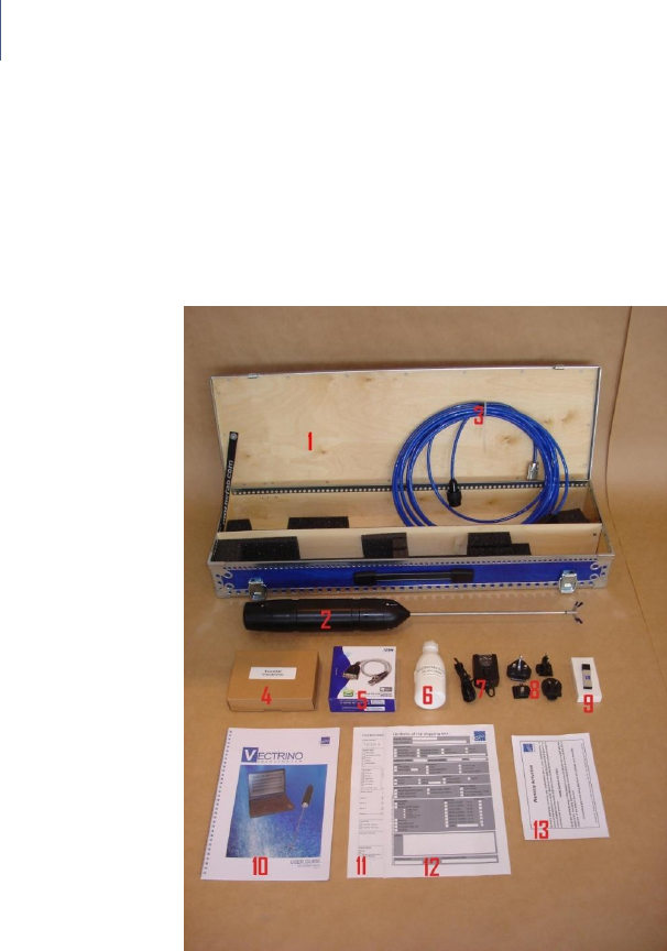
Contents of Your Shipment
When you receive your Vectrino Profiler, the shipping box should
contain the following components:
Note: If any part of the delivery
should be missing, please
contact Nortek immediately
1 Transportation and storage case
2 Vectrino Profiler velocimeter
3 External power/signal cable
4 Tool kit, Nortek
5 RS-422 to USB high speed adaptor (model not as shown)
6 Seeding material (bottle of 250 ml)
7 AC/DC voltage transformer, 24 V DC
8 Universal plugs for AC/DC voltage transformer
9 USB memory stick with Vectrino Profiler software
10 This guide
11 Final test check list
12 Packing list
13 Warranty card

Vectrino Profiler
7
Chapter 2
Product Specification
Mechanical
Vectrino Profiler cylinder: 70 mm
Vectrino Profiler height: 388 mm
Transport weight: 8 kg
Dimensions
Transport box: 88 x 27 x 12 cm
Transport and storage box: 88 x 34 x 12 cm
Weight in air: 1.2 kg
Sampling Volume
Distance from probe: 40 – 70 mm (full profiler)
45-55 mm (point measurement)
Diameter: 6 mm
Height (user selectable): 1– 4 mm
Echo Intensity
Acoustic frequency: 10 MHz
Dynamic range: 50 dB

8
Chapter 5
Software
Sensors
Temperature: Thermistor embedded in probe
Range: –4 °C to +40 °C
Accuracy/Resolution: 1 °C / 0.1 °C
Time response: 5 min.
Data Communication
I/O: RS-422
Baud rate: 300–1250000 (user setting)
Max. cable length: 100 m
User control: Vectrino Profiler Software
Synchronization: Multiple Vectrino Profilers can be
synchronized. Each can operate as
either master or slave.
Multi Unit Operation
Software: Vectrino Profiler Software
I/O: RS 422–USB support for devices with 1,
2 and 4 serial ports.
Software
Operating system: Windows 2000®, or newer
Features : Instrument configuration
Profile data collection
Profile data display
Data storage

Vectrino Profiler
9
Power
DC Input: 12–48 VDC
Peak current: 2.5A at 12 VDC (user selectable)
Max. consumption at 100 Hz: 7W
Connectors
Bulkhead: Splash-proof connector or MCBH-12-FS
waterproof connector
Cable: Splash-proof or PMCIL-12-MP
waterproof
Materials
Standard model Delrin® housing. Stainless steel (316) probe and
screws.
Environmental
Operating temperature: –4 °C to +40 °C
Storage temperature: –15 °C to 60 °C
Shock and vibration: IEC 721–3–2
Options
Your Vectrino Profiler can be shipped with the following components
to suit your requirements. For further information, contact Nortek.
4-beam down-looking probe or side-looking probe. Fixed
stem or flexible cable
12-pin splash-proof connector or Impulse 12-pin underwater
connector
10, 20, 30, 50 or 100 m cable with your choice of splash-proof
or Impulse underwater connector
Combined transportation and storage cage

10
Chapter 5
Software
Chapter 3
Technical Description
System Components
Probe
The probe is made of titanium and consists of four receive
transducers and a transmit transducer. It is mounted either on a fixed
stem connected to the main housing through the probe end bell, or
on a cable connected to the main housing through the same probe
end bell.
Transducers
Each of the four receive transducers is mounted inside a
receiver arm
.
The transmit transducer is in the centre of the probe. The transducers
are covered with hard epoxy.
Electronics Modules
The electronics module is located inside the pressure case and
consists of a single board with the power transmitter, analog and
digital signal processing, power conditioning, and interface circuits.
Temperature sensor
The temperature sensor (thermistor) is located inside the probe head.
Vectrino Profiler
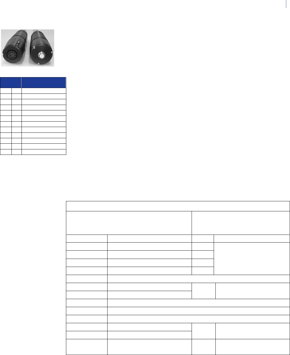
11
The two available connectors
Pin
No.
Function
1
A
Serial In +
2
B
Serial In -
3
C
Serial Out -
4
D
Serial Out +
5
E
N/C
6
F
Sync -
7
G
Sync+
8
H
N/C
9
J
N/C
10
K
N/C
11
L
Gnd (power –)
12
M
Power + (12–48V)
The pin-outs for the connectors.
Power and Communication Cable
The power and communication cable is connected to the end bell con-
nector. The cable supplies external DC power (15–48 V) and provides
two-way serial communication with an external computer.
The cable also provides synchronization options when the Vectrino
Profiler is used as master or slave to synchronize measurements with
other Vectrino Profiler’s and/or other instruments.
Cable Wiring. By default, the Vectrino Profiler is shipped with a 12-pin
connector and cable. The connector type is either a splash-proof
connector or an MCBH-12-FS waterproof connector. The Vectrino
Profiler power lines are diode protected, hence, you do not have to
worry about wiring the Vectrino Profiler power backwards. If you do, it
will not damage your instrument. The pin-out is shown in the side
bar.
Wiring of Vectrino II cable for RS422 communications
Underwater connector
Teledyne MCIL-12-MP
Termination
Pin No.
Purpose
Pin
Description
1
RS422 Rx +
3
DB-9 connector, pins 1 and
5 are grounded
2
RS422 Rx -
8
3
RS422 Tx -
2
4
RS422 Tx +
7
5
Not Used
6
Sync-
Terminal block
7
Sync+
8
Not Used
9
Not Used
10
Not Used
11
Power Ground
Power Supply Connector
12
Power +
Shield
Power Ground
Connected internally to
Power Ground

12
Chapter 5
Software
Chapter 4
Functional Description
This section briefly describes some of the underlying principles that
control the operation and application of the Vectrino Profiler
velocimeter.
The Vectrino Profiler has two modes of operation:
• Command mode. In command mode the Vectrino Profiler is ready
to accept your instructions.
• Data Acquisition Mode. The Vectrino Profiler enters data acquisition
mode when you click any of the Start commands (e.g. Start Data
Collection) in the Vectrino Profiler software. The Vectrino Profiler
collects data without interruption.
Doppler Theory
Sound does not reflect from
water, but from particles
suspended in the water. These
particles are typically
suspended sediment or seeding
particles, and move with the
same average speed as the
water. The velocity that is
measured is consequently the
velocity of the water.
The Vectrino Profiler uses the Doppler effect to measure current
velocity. The Doppler effect is the change in pitch that is heard when
either the source of a sound or the listener is in motion. When you
hear a vehicle with a siren, the pitch is higher when the vehicle is
heading towards you, and lower when it is going away. The change in
pitch tells you how fast the vehicle is moving.
The Vectrino Profiler transmits short pairs of sound pulses, listens to
their echoes, and, ultimately, measures the change in pitch or
frequency of the returned sound.
Vectrino Profiler
13
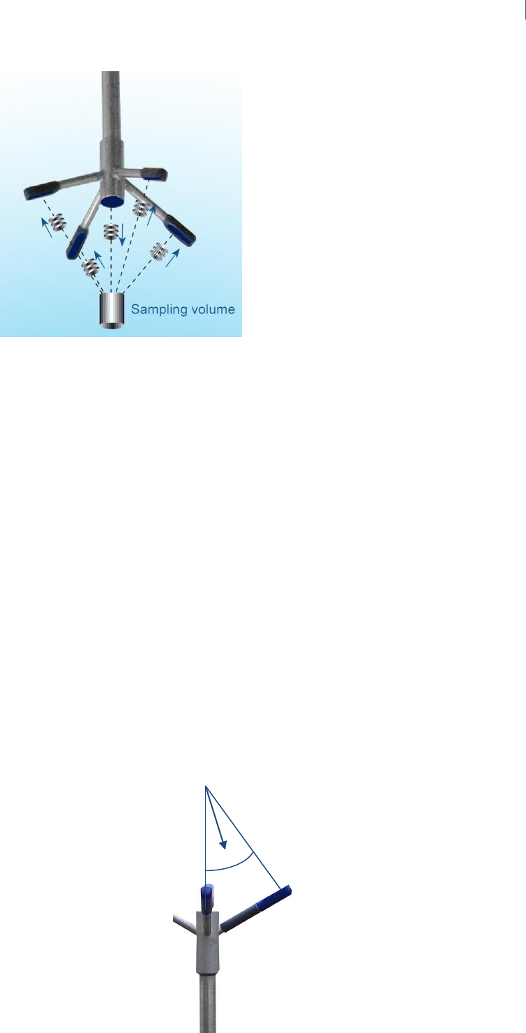
The Vectrino Profiler
velocimeter operating
principle: A pulse is
transmitted from the centre
transducer, and the Doppler
shift introduced by the
reflections from particles
suspended in the water, is
picked up by the four
receivers.
SNR Sweet Spot: The
profiling range of the
Vectrino II is ultimately
controlled by SNR. The SNR
is highest at the sweet spot,
located 5 cm from the
transmitter. The best profiling
range is a region centered on
this sweet spot location.
The transmit/receive beam
pair is sensitive to velocity in
the direction of the angular
bisector between the beams.
The arrow indicates a
positive velocity. Since the
receive beams are slanted
at 30°, all three beam pairs
measure velocity that is 15°
away from the transmit
beam.
Vectrino Sonar Principles
In contrast to standard Doppler profilers and current meters, the
Vectrino is a bistatic sonar. This means that it uses separate transmit
and receive beams. It transmits through a central beam and receives
through four beams displaced off to the side. The figure below shows
how the beams intersect each other 50 mm from the transmitter. The
measurement profile is defined by this intersection and by range
gating in time. The transmit transducer sends a short pulse that
transits the profiling region of approximately 30-80 mm and the
receivers listen to echoes returned from this pulse gated in time. The
Vectrino uses four receivers, all focused on the same volume, to
obtain the three velocity components from that very volume.
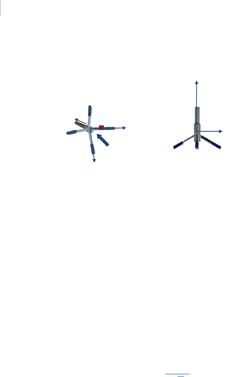
The figure below shows that a transmit/receive beam pair is sensitive
to velocity in the direction of the angular bisector between the beams.
The arrow indicates a positive velocity.
14
Chapter 5
Software
The arm with the marking
defines the X-direction. The
Z-direction is towards the
electronics of the Vectrino.
Coordinate System
The Vectrino measures velocity components parallel to its three
beams, or in beam components. It reports data in Beam or XYZ
coordinate systems.
The XYZ coordinates are relative to the probe and independent of
whether the Vectrino points up or down.
In XYZ coordinates, a positive velocity in the X-direction goes in the
direction of the X-axis arrow.
Velocity Uncertainty
The Vectrino velocity is an average of many velocity estimates (called
pings). The uncertainty of each ping is dominated by the short term
error. We reduce the measurement uncertainty by averaging together
many pings. There is a limit to how much you can reduce your
uncertainty. We call this limit the long-term bias. The long-term bias
depends on internal signal processing, especially filters, and on the
beam geometry. The long-term bias in the Vectrino is typically a
fraction of 1 cm/s. The short-term error of a single ping depends on
the size of the transmit pulse, the measurement volume, and the
beam geometry. Averaging multiple pings reduces errors according to
the formula:
where σ is the standard deviation and N is the number pings
averaged together.
Note: The Vectrino software minimizes the instrumental error only. In
30o
View direction
Z
X
Z
X
Y

Vectrino Profiler
15
many situations, the environmental turbulence or surface waves will
dominate the short term velocity fluctuations.
Data Handling
The Vectrino Profiler software saves data in binary files, which are
easily converted to Matlab structured arrays or ASCII format files,
using the conversion module in the software.
Matlab:
• The *.mat file contains Data and Config structured arrays. Each
array contains a “Comments” and “Units” field that describe the
contents of each structure.
ASCII:
• The *.hdr file is a self-documented table.
• The *.dat file contains velocity data at the full sample rate.
ASCII files are easily imported into most spreadsheets and data
analysis programs.

16
Chapter 5
Software
Chapter 5
Software
This chapter provides you with basic information about the software,
installation of the software and its configuration. For further
information, about the software, its configuration and use, please see
the Help function in the Vectrino Profiler software.
Please see the Software Users Guide for more information on how to
use the software.
Installation
The Vectrino Profiler acquisition software on the included memory stick
requires a Java virtual machine (JVM) to operate. The software has been
tested with the Sun JVM available from http://www.java.com/ but is also
known to be fully functional with other JVMs. To install the software,
double click on Vectrino Profiler_setup.exe . This will copy the
appropriate files to the installation directory and create a shortcut to
the application on the desktop.
PDF versions of both manuals will be copied into the install directory
when the software is first executed. More information on installation is
available in the software user guide.
Licensing
The firmware supports several functionally different variants based
upon a license key which is provided when the instrument is purchased.
The currently supported variants are:

Vectrino Profiler
17
Variant
Name
Number
of
Velocity
Cells
Velocity
Sampling
rate (Hz)
Maximum
Velocity
Range
(m/s)
Adaptive
Config
Bottom
Check
Profiler
Full
profile
range
100
3.0
Yes
Yes with
amplitude
profile
Vectrino-
ProfilerB+
1
200
5.0
Yes
Yes
Vectrino-
Profiler+
1
200
5.0
No
No
Vectrino-
Profiler
1
25
1.0
No
No

18
Chapter 5
Software
Chapter 6
Mounting Guidelines
Follow these guidelines when you mount your Vectrino Profiler.
What to consider
• Make sure that there are no obstructions between the sensor and the
focal point (sampling volume) located about 5 cm from the
transducers.
Note: When mounting your
Vectrino Profiler, use the
recessions to strap it to the
structure. Never use the probe
stem as mounting point.
• Consider the effects of large objects on the flow itself. A rough rule
of thumb is that objects disturb the flow as far as 10 diameters away
from the object. Flow disturbance is greatest directly downstream in
the wake behind the object.
• All acoustic transducers must be submerged during data collection.
Operating your Vectrino Profiler when the transducers are out of
water will not cause any damage, but your data will be meaningless.
For side-looking probes, it is possible to collect 2D-data with only
the lower receiver arms submerged.
• The best quality is achieved if the main flow direction is
perpendicular to the transmit axis. Flow directly into the transmit
axis should be avoided.
• Make sure your mounting structure is stable. Small vibrations in the
mount can generate large accelerations in the data.

Vectrino
19
Chapter 7
Test and Verification
Verify that your equipment is working as expected.
Communication
Check that you have installed the software correctly according to the
procedure in chapter 5, Software, and then follow this procedure to test the
communication:
1 Using the enclosed cables, plug in the AC adapter, and connect the
Vectrino Profiler cable and USB converter to the USB port on your
computer
2 Start the Vectrino Profiler software
3 Click on Connect: Vectrino Profiler
4 Select the appropriate serial port and communication speed
5 Click on Apply to initiate communications with the instrument
Transducers
1 Fill a bucket with water and a little dirt (as sound-scattering material).
2 Click the Start Collecting Data button. While the transducers are in the air,
the velocity measurement will look like random noise.
3 Immerse the transducers in the water, and observe the velocity, the
standard deviation, and the amplitude. Note the change in the graphical
view of the velocity when the probe is lowered into the water. In the air the

20
Chapter 5
Software
graphs are noisy; in water they should be smooth.
Measurement in air
(left part of the
graph) and in water
(right part of the
graph).
Noisy velocity
graphs: If the
velocity graphs
remain noisy when
the probe is
immersed in water,
try varying the
position of the
probe, or add some
seeding like dirt or
small particles to the
water.
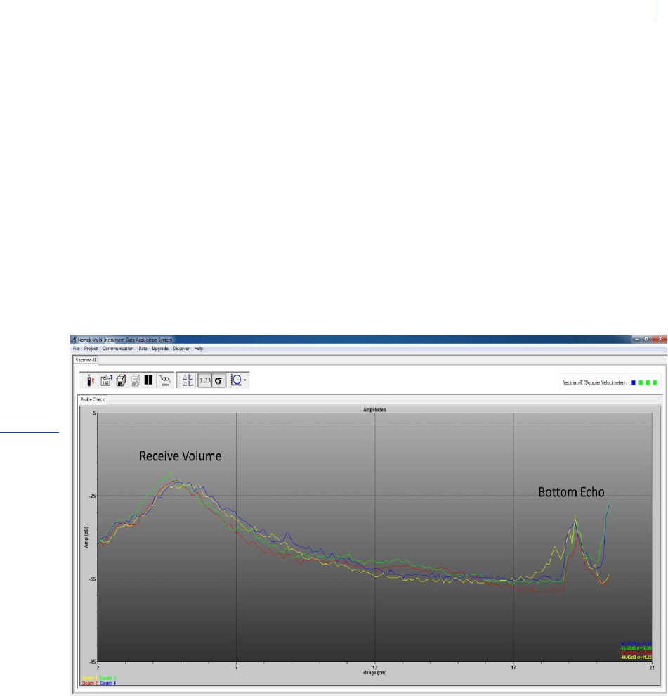
Probe Check
Previous generations of the Vectrino velocimeter used a separate Probe Check
mode to verify the integrity of the instrument. When licensed for profiling, the
Vectrino Profiler collects amplitude profiles from the beams (showing how the
signal varies with range) as part of its normal operation. For single
measurement licensed instruments, a “beam check” mode is provided which
produces an equivalent amplitude profile for a range up to 30cm. Amplitude
profiles can be used to diagnose and correct problems and to optimize data
collection.
Vectrino
21
Signal-to-noise
ratio:
The signal-to-noise
ratio (SNR) is
defined as follows:
)
Strictly speaking,
some noise will
always be present,
so Amplitudesignal
should read
Amplitudesignal + noise.
However, for SNR
values in the
magnitude
applicable to typical
Vectrino Profiler
situations, the
difference is
negligible.
To check probe operation:
1 Make sure the probe is submerged in water with the transducers within 20
cm of the bottom.
2 Enable the Probe Check option in the configuration.
3 Click the Start Data Collection button.
The four colored graphs in the profile display window on the left correspond to
each of the four receive beams.
There are two peaks visible in the amplitude data. The broad peak centered at
~5cm is the valid profiling volume. The sharper secondary peak (located at
~19 cm in this data set) is the bottom return.

22
Chapter 5
Software
Chapter 8
Synchronizing Multiple
Instruments
Your Vectrino Profiler can serve as master for other Vectrino Profiler’s,
or its sampling can be controlled by other sensors. This comes in
handy when you need to use several Vectrino Profilers for a single set
of measurements.
If you connect a controller to the Vectrino Profiler, you can set up a
fairly sophisticated system in which the controller can power the
Vectrino Profiler and provide it with sync pulses to control the
sampling accurately. The controller can serve as a storage device.
Note: On some older
instruments the sync lines are
labeled Sync in and Sync out.
These should be treated as
Sync– (Sync In) and Sync+
(Sync Out).
Your Vectrino Profiler can be synchronized with other instruments via
a pair of sync lines. To avoid noise problems and to make cabling
easier, the two sync lines use an RS-485 chip which is balanced and
bi-directional.
The sync lines are labeled Sync– (n) and Sync+ (p).
Synchronizing Multiple Vectrino Profilers
1 Connect all the Sync+ lines together and all the Sync– lines
together. All instruments should share a common ground.
2 Select one instrument as the master and the rest as slaves (Input
sync) in the software.
3 Start data collection in all slaves (click the Start Collecting Data
icon) before starting the master. The slaves will then wait for the

Vectrino
23
first sync pulse from the master before sampling commences.
If you use Sample on sync, all instruments should be configured with
the same sampling rate.
Synchronizing From a TTL Source
TTL signal levels can be mixed with the RS-485 levels of the Vectrino
Profiler.
Connect your sync pulse (0 – V volts) to Sync- and connect Sync+ to a
constant voltage V/2 (where V is the ON voltage of the sync pulse).
This provides a defined transition when the TTL signal changes, which
is not the case if you ground Sync+. The SYNC inputs are diode
limited to 5V through a 4.7 ohm resistor. Input voltages above 5V are
not recommended for use.
RS485 levels: These differential
levels define the signal the
Vectrino Profiler reads for Input
Sync:
High level: Sync- > Sync+ by
200 mV
Low level: Sync- < Sync+ by
200 mV
Noise problems: If you
encounter noise problems, try
terminating the Sync- line at the
TTL input by connecting a 120
ohm resistor in series with a 1nF
capacitor between the Sync-
line and ground. The best
solution for external sync is
using RS485 as the input /
output device.
Note: This implies that a
Vectrino Profiler can operate as
a master for a Vector, but the
opposite is not possible.
When the Vectrino Profiler functions as master, the Sync- line can be
connected to the TTL input and the two systems must be connected
so they share common ground.
How Synchronization Works
Output Sync
(operating as the master) transmits a pulse with a
duration of 50 µs. The Vectrino Profiler transmits a pulse at the end of
the sampling interval and a single pulse at the beginning of the first
sampling interval to start everything when in “Master (Vectrino)”
mode. When in “Master (Other)” mode, a pulse is transmitted in the
middle of each sampling interval.
Input Sync
triggers on the falling edge of the Sync+ / Sync- signal.
After each trigger the input is discarded for the next 100 µs.

24
Chapter 5
Software
Chapter 9
Maintenance
Before you assemble a system that involves custom cables, power
supplies or the like, first assemble and test the Vectrino Profiler using
just the cables and power supply that came with the system. This is
the easiest way to get the system up and working. If you encounter
problems, you can always return to this setup to confirm that they are
not caused by a faulty instrument.
Preventive Maintenance
Preventive maintenance is your primary tool to keep your Vectrino
Profiler in shape and ready for action and deployment.
Clean your Vectrino Profiler Velocimeter regularly. Use a mild
detergent, and pay special attention to the transducers.
Corrective Maintenance
Only qualified personnel are allowed to perform corrective mainte-
nance activities. Please refer to the separate service manual or contact
Nortek for further assistance.

Vectrino
25
Chapter 10
Upgrading
Note: If you enter the download
section without logging in, you
will be prompted to log in when
you attempt to download a file.
If you are not a registered user,
simply follow the link to the
registration form.
Upgrading Software
You will find the latest release of the software for your Vectrino
Profiler at: http://www.nortekusa.com/usa/support/ . To upgrade the
software, follow the procedure for software installation (see
Chapter 5).
Upgrading Firmware
Firmware refers to the internal software of the instrument, as opposed
to the instrument software running on a computer and described in
this manual.
When you purchase a brand new instrument from the factory, it
contains the latest firmware version, and there is no need to upgrade
the firmware.
However, new functionality (and in rare cases bug fixes) will likely be
offered in the future, requiring an upgrade of the firmware. New
firmware is posted on our web site at:
http://www.nortekusa.com/usa/support/ . When you upgrade your
firmware, make sure you also have the latest version of the software
as new versions are often released at the same time.
26
Chapter 5
Software
Note: If you have not registered
with us already, you will need to
do this first. Click the link New
User on the right, and fill in the
registration form to register.
Firmware upgrade procedure
1 Download the most recent firmware to your computer from:
http://www.nortekusa.com/usa/support /
2 Click on Upgrade in the Vectrino Profiler software, select the
relevant instrument and then browse to the downloaded firmware
file and select it.
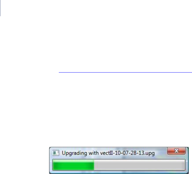
3 If you have the standard Vectrino Profiler, simply click OK to start
downloading the file to the instrument. This will produce the
following box:
The License Key dialogue box
will appear when you attempt to
upgrade the firmware.
To ensure that the Vectrino Profiler firmware is not corrupted if the
download transmission fails during the download process, the
Vectrino Profiler runs a check on the received file before it is allowed
to replace the existing firmware. After the file is received by the
instrument (indicated by completion of the progress bar), there can be
up to a 30 second wait as the new firmware is validated and
programmed into place.
If the firmware file is not accepted, repeat the upgrade process until
the firmware file is successfully downloaded.

Vectrino
27
Chapter 11
Further Information and Help
Visit www.nortek-as.com
At our website, www.nortek-as.com, you will find technical support,
user manuals, and the latest soft- and firmware updates for the
Vectrino Profiler and our other products, as well as more general
information, technical notes and user experience regarding data
analyses and related matters.
Our aim is that our users should be able to find any information they
may need regarding our instruments and the use of them online. If
you are unable to find the information you are looking for, we
encourage you to use our forum.
Nortek’s Forum
Nortek’s forum on the web is where users from all over the world
meet to discuss and share their experience with Nortek’s instruments.
If you have comments, questions, application tips, suggestions for
improvements, or simply want to learn from others or share your own
experience with other users all over the world, we encourage you to
register and post to our forum.

28
Chapter 5
Software
Chapter 12
Returning Your Vectrino
Profiler for Repair
Returning your Vectrino Profiler
Before you return a product for repair you must have obtained a
Return Merchandise Authorization (RMA) in writing from Nortek AS.
You can send your RMA request by e-mail to inquiry@nortek.no
Your shipment must be accompanied by a proforma invoice. You can
either copy the proforma invoice on the next page, or make your own,
but make sure you include the same information.
Remember to include a copy of all shipping and export documents in
the freight box.
Insurance
We recommend that you fully insure your return shipment in case it is
lost or damaged, as Nortek AS does not cover freight insurance on
repairs.
Nortek AS is not responsible for instruments damaged or lost in
transit. Nor shall we be held responsible for consequential damage as
a result of instruments being damaged or lost in transit.
Nortek AS will insure the instrument upon returning the goods to you.
We will bill you for the insurance along with the costs for repair and

Vectrino
29
freight.
For warranty repairs, the transport and freight insurance from Nortek
AS to you will be covered by Nortek AS.
Customs regulations
The regulations and requirements covering the export and re-import
of items sent for repair varies from country to country. In the past,
some of our customers have experienced problems because they have
failed to provide the proper documentation. If these matters are not
managed correctly, you may be charged import duties and taxes for a
second time when your instrument is returned to you.
At Nortek we must meet our own country’s regulations when
instruments are repaired and subsequently returned. This, however,
may not be sufficient for your country.
To avoid problems, we strongly recommend that you, as part of your
own procedures for handling returns, always check with your customs
authorities as to what information, documents etc. they need from
you and from us. Then let us know what you need from us by e-mail,
fax or mail. We will do our very best to help you.
30
Chapter 5
Software
PROFORMA INVOICE
SENDER (Exporter)
RECEIVER
Name:
Name: NORTEK AS
Address:
Address: Vangkroken 2
City:
City: NO-1351 RUD
Country:
Country: NORWAY
Tel.:
Tel.: +47 67 17 45 00
E-mail:
Fax: +47 67 13 67 70
Fax:
E-mail:
inquiry@nortek.no
Contact:
Contact: Jonas Røstad
ABOUT THE GOODS
Date:
No. of Units:
Tracking no.:
Weight:
Value:
NORTEK RMA No.:
Reason for Export:
Exporter’s signature
NOT A SALE – TEMPORARY EXPORT TO
NORWAY FOR REPAIR ONLY

Vectrino
31
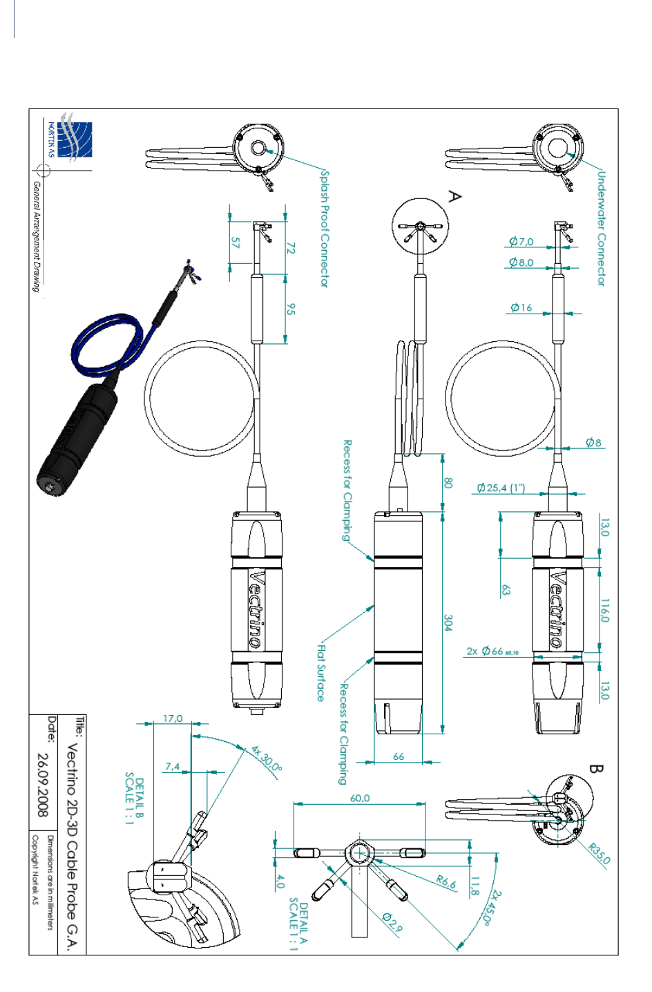
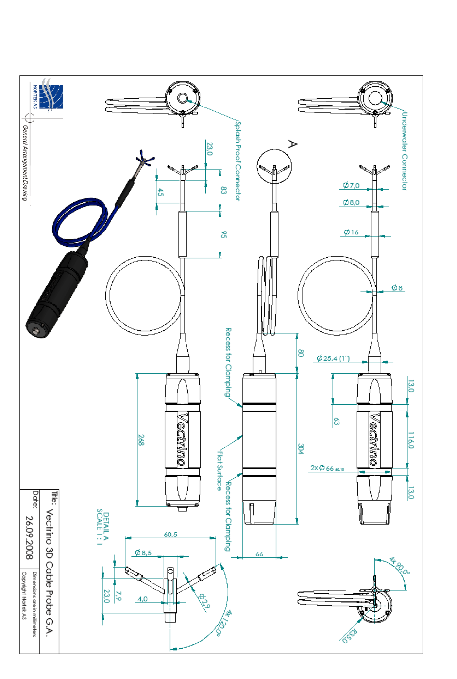
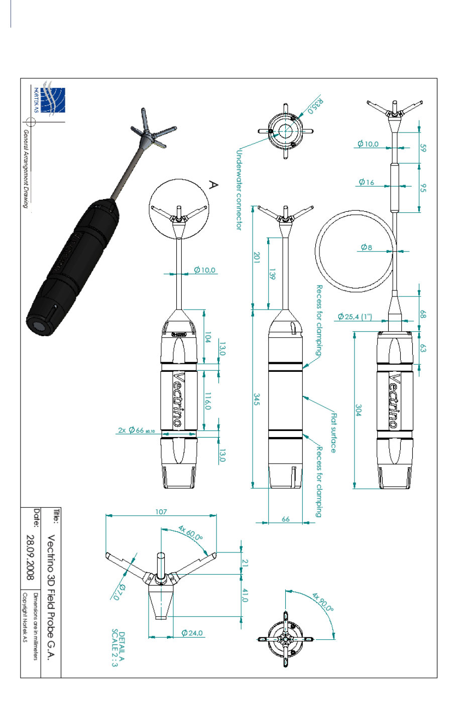
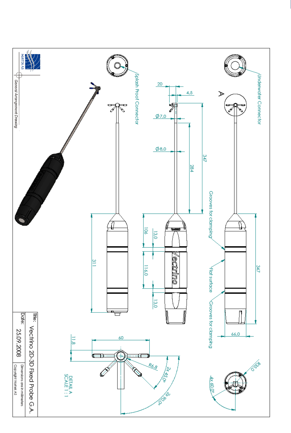
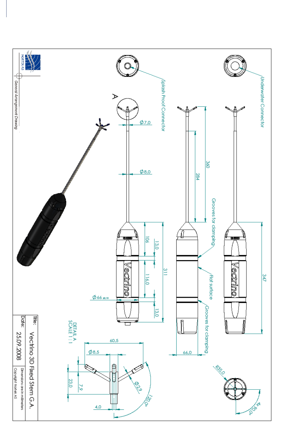
APPENDIX
Drawings and Dimensions
On the following pages you will find drawings with dimensions for
your Vectrino Profiler.
32
Chapter 5
Software
Vectrino
33
34
Chapter 5
Software
Vectrino
35
36
Chapter 5
Software
