_623MAN.BK Veeder Root TLS3 Series System Set Up Manual
User Manual: manual pdf -FilePursuit
Open the PDF directly: View PDF ![]() .
.
Page Count: 222 [warning: Documents this large are best viewed by clicking the View PDF Link!]
- Table of Contents
- Figures
- Tables
- Introduction
- Front Panel Keypads
- Setup Mode Organization
- Prior to Applying AC Power to the Console
- System Setup
- Programming Guidelines
- Automatic Return to Operating Mode
- Setup Data Warning
- Printing a Setup Data Report
- Selecting the System Setup Function
- System Language
- System Units
- Setting the Date and Time Format
- Current Date
- Current Time
- Report Headers
- Shift Start Times
- Shift BIR Printouts
- Daily BIR Printouts
- Ticketed Delivery
- TC Ticketed Delivery
- Close Day of Week
- Variance Reports
- Tank Periodic Test Needed Warnings
- Tank Annual Test Needed Warnings
- Line Re-Enable Method
- Line Periodic Test Needed Warnings
- Line Annual Test Needed Warnings
- Remote Printer Page Eject
- Print TC Volumes
- Temperature Compensation Value
- Tanker Load Report - International Option
- Stick Height Offset - International Option
- Ullage
- H-Protocol Data Format - International Option
- Precision Test Duration (PLLD/WPLLD Only)
- Precision Line Test Auto-Confirm
- Daylight Savings Time
- Re-direct Local Printout
- QPLD Monthly Printout - International Option
- Euro Protocol Prefix
- BDIM Trans Alarm Delay
- System Security Code
- Maintenance History
- Tank Chart Security
- Custom Alarm Labels
- Service Notice (TLS-350 Consoles Only)
- System Beeper
- Mass/Density
- Fiscal Height Security
- Communications Setup
- Selecting the Communications Setup Function
- Port Settings
- Note: Port Settings - International Installations With SiteLink modems
- Baud Rate
- Parity
- Stop Bit
- Data Length
- Dial Type
- Answer On
- Security Code
- Setting the Modem Type (international Installations)
- Modem Setup String
- Dial Tone Interval
- DTR Normal State
- Specifying Port Settings for Additional Communication Modules
- Continue Communications Setup
- Auto-Transmit Setup (RS-232 or RS-232/RS-485 Modules Only)
- Phone Directory Setup
- Auto-Dial Setup
- Receiver Report List
- Auto Dial Method: All Phones/Single Phone
- Auto-Dial Frequency: Specific Date
- Auto-Dial Frequency: Annually
- Auto-Dial Frequency: Monthly
- Auto-Dial Frequency: Weekly
- Auto-Dial Frequency: Daily
- Auto-Dial Frequency: BIR End
- Setting Up the Frequency for Additional Receivers (Single Phone Only)
- Continue Communications Setup
- Auto-Dial Alarm Setup
- In-Tank Alarms
- Remaining Alarm Groups
- Liquid Sensor Alarms
- Vapor Sensor Alarms
- External Inputs Alarms
- Line Leak Alarms (VLLD)
- Groundwater Sensor Alarms
- 2 Wire C.L. Sensor Alarms
- 3 Wire C.L. Sensor Alarms
- Receiver Alarms
- Power Side DIM Alarms
- Reconciliation Alarms
- Pressure Line Leak Detector (PLLD) Alarms
- Wireless Pressure Line Leak Detector (WPLLD) Alarms
- Communication Side DIM Alarms
- Smart Sensor Alarms
- Pump Relay Monitor Alarm
- VMCI Dispenser Interface Alarms
- VMC Alarms
- Setting Up Auto-Dial Alarms for Additional Destinations
- RS-232 End of Message
- In-Tank Setup
- Selecting the In-Tank Setup Function
- Tank Configuration
- Product Labels
- Product Code
- Coefficient of Thermal Expansion
- Tank Density
- Tank Diameter
- Tank Profile
- Full Volume
- Meter Data Present
- Vapor Loss Factor - International Option
- End Factor
- Calibration Update
- Float Size
- Water Warning
- High Water Limit
- Max or Label Vol
- Overfill Limit
- High Product
- Delivery Limit
- Low Product
- Leak Alarm Limit
- Sudden Loss Limit
- Tank Tilt
- Probe Offset
- Siphon Manifolded Tank Status
- Line Manifolded Tank Status
- Leak Minimum Periodic
- Leak Minimum Annual
- Periodic Test Type
- Annual Test Fail
- Periodic Test Fail
- Gross Test Fail
- Annual Test Averaging
- Periodic Test Averaging
- Tank Test Notify
- Tank Test Siphon Break
- Stick Offset (International Option)
- HRM Reconciliation Warning Limit (International Option)
- HRM Reconciliation Alarm Limit (international Option)
- Delivery Report Delay Time
- Pump Threshold
- Setting Up Additional Tanks
- In-Tank Leak Tests
- Fuel Management
- Pressurized Line Leak Detection
- Line Manifolding Implications for AccuChart
- PLLD Setup
- Activating PLLDs
- Labeling PLLDs
- Piping Type
- Piping Length
- User Defined Pipe Type - Setup Parameters
- Thermal Coefficient
- 0.2 gph (0.76 lph) Line Leak Test Scheduling
- 0.1 gph (0.38 lph) Line Leak Test Scheduling
- Passive 0.1 gph Line Leak Testing
- Shutdown Rate
- Low Pressure Alarm Shutoff
- Tank Selection
- Selecting a Dispense Mode
- Pressure Transducer Type
- Pressure Offset
- Setting Up Additional PLLDs
- Wireless Pressurized Line Leak Detection
- Line Manifolding Implications for AccuChart
- WPLLD Setup
- Activating WPLLDs
- Labeling WPLLDs
- Piping Type
- Piping Length
- 0.2 gph (0.76 lph) Line Leak Test Scheduling - Option
- 0.1 gph (0.38 lph) Line Leak Test Scheduling - Option
- Shutdown Rate
- Pressure Offset
- Tank Selection
- Selecting a Dispense Mode
- Setting Up Additional WPLLDs
- Volumetric Line Leak Detection
- Volumetric Line Leak Tests
- Line Leak Test Lockout
- Pump Sense Setup
- Pump Relay Monitor Setup
- Reconciliation Setup
- Liquid Sensor Setup
- Vapor Sensor Setup
- Groundwater Sensor Setup
- 2-Wire C.L. Sensor Setup
- 3-Wire C.L. Sensor Setup
- External Input Setup
- Output Relay Setup
- Selecting the Output Relay Setup Function
- Relay Configuration
- Relay Designation
- Selecting Relay Type
- Assignment Method
- In-Tank Alarms
- Remaining Alarm Groups
- Liquid Sensor Alarms
- Vapor Sensor Alarms
- External Inputs Alarms
- Line Leak Alarms (VLLD)
- Groundwater Sensor Alarms
- 2 Wire C.L. Sensor Alarms
- 3 Wire C.L. Sensor Alarms
- Power Side DIM Alarms
- Reconciliation Alarms
- Pressure Line Leak Detector (PLLD) Alarms
- Wireless Pressure Line Leak Detector (WPLLD) Alarms
- Communication Side DIM Alarms
- Smart Sensor Alarms
- Pump Relay Monitor Alarm
- VMCI Dispenser Interface Alarms
- VMC Alarms
- Setting Up Additional Relays
- Line Disable Setup
- Selecting the PLLD, WPLLD, or VLLD Line Disable Setup Function
- In-Tank Alarms
- Remaining Alarm Groups
- Liquid Sensor Alarms
- Vapor Sensor Alarms
- External Input Alarms
- Line Leak Alarms
- Groundwater Sensor Alarms
- 2 Wire C.L. Sensor Alarms
- 3 Wire C.L. Sensor Alarms
- Power Side DIM Alarms
- Reconciliation Alarms
- Pressure Line Leak Detector (PLLD) Alarms
- Wireless Pressure Line Leak Detector (WPLLD) Alarms
- Communication Side DIM Alarms
- Smart Sensor Alarms
- Pump Relay Monitor Alarm
- VMCI Dispenser Interface Alarms
- VMC Alarms
- Setting Up Additional Disables
- Smart Sensor Setup
- VMC Setup
- Archive Utility
- Appendix A: Calculating Tank Tilt - International
- Appendix B: Setup Parameters for TLS-300 System - International
- Appendix C: Setup Parameters for TLS-350 System - International
- Tech Docs Index

Manual No: 576013-623 • Revision: AE
System Setup Manual
TLS-3XX Series Consoles
Software Version X32

Notice
Veeder-Root makes no warranty of any kind with regard to this publication, including, but not limited to, the implied warranties of
merchantability and fitness for a particular purpose.
Veeder-Root shall not be liable for errors contained herein or for incidental or consequential damages in connection with the
furnishing, performance, or use of this publication.
Veeder-Root reserves the right to change system options or features, or the information contained in this publication.
This publication contains proprietary information which is protected by copyright. All rights reserved. No part of this publication
may be modified or translated to another language without the prior written consent of Veeder-Root.
Contact TLS Systems Technical Support for additional troubleshooting information at 800-323-1799.
DAMAGE CLAIMS / LOST EQUIPMENT
Thoroughly examine all components and units as soon as they are received. If any cartons are damaged or missing, write a
complete and detailed description of the damage or shortage on the face of the freight bill. The carrier's agent must verify the
inspection and sign the description. Refuse only the damaged product, not the entire shipment.
Veeder-Root must be notified of any damages and/or shortages within 30 days of receipt of the shipment, as stated in our Terms
and Conditions.
VEEDER-ROOT’S PREFERRED CARRIER
1. Contact Veeder-Root Customer Service at 800-873-3313 with the specific part numbers and quantities that were missing
or received damaged.
2. Fax signed Bill of Lading (BOL) to Veeder-Root Customer Service at 800-234-5350.
3. Veeder-Root will file the claim with the carrier and replace the damaged/missing product at no charge to the customer.
Customer Service will work with production facility to have the replacement product shipped as soon as possible.
CUSTOMER’S PREFERRED CARRIER
1. It is the customer’s responsibility to file a claim with their carrier.
2. Customer may submit a replacement purchase order. Customer is responsible for all charges and freight associated with
replacement order. Customer Service will work with production facility to have the replacement product shipped as soon as
possible.
3. If “lost” equipment is delivered at a later date and is not needed, Veeder-Root will allow a Return to Stock without a restocking
fee.
4. Veeder-Root will NOT be responsible for any compensation when a customer chooses their own carrier.
RETURN SHIPPING
For the parts return procedure, please follow the appropriate instructions in the "General Returned Goods Policy” pages in the
"Policies and Literature" section of the Veeder-Root North American Environmental Products price list. Veeder-Root will not
accept any return product without a Return Goods Authorization (RGA) number clearly printed on the outside of the package.
©Veeder-Root 2011. All rights reserved.

Table of Contents
iii
1 Tables
1 Introduction
Contractor Certification Requirements ...........................................................................1-1
Related Manuals ............................................................................................................1-1
Safety Precautions .........................................................................................................1-2
Safety Warnings ............................................................................................................1-2
2 Front Panel Keypads
Arrangement of Keys .....................................................................................................2-1
Operating Keys......................................................................................................2-1
Alphanumeric Keys................................................................................................2-1
Blue Key (Maintenance Tracker - TLS-350 Only)..................................................2-2
White Key (Maintenance Report - TLS-350 Only) .................................................2-2
Using the Operating Keys ..............................................................................................2-2
Using the Alphanumeric Keys ........................................................................................2-3
Entering Alphanumeric Data..................................................................................2-4
Special Characters and Cursor Movement............................................................2-4
3 Setup Mode Organization
Functions .......................................................................................................................3-1
Steps ..............................................................................................................................3-1
Setup Mode Programming Table ...................................................................................3-1
4 Prior to Applying AC Power to the Console
Security Code Enable/Disable .......................................................................................4-1
TLS-300 Consoles.................................................................................................4-1
TLS-350 Consoles.................................................................................................4-1
Battery Backup ..............................................................................................................4-6
Applying AC Power to the Console ................................................................................4-6
5 System Setup
Programming Guidelines ...............................................................................................5-1
Automatic Return to Operating Mode ............................................................................5-1
Setup Data Warning ......................................................................................................5-1
Printing a Setup Data Report .........................................................................................5-1
Selecting the System Setup Function ............................................................................5-2
System Language ..........................................................................................................5-2
System Units ..................................................................................................................5-2
Setting the Date and Time Format .................................................................................5-3
Current Date ..................................................................................................................5-3
Current Time ..................................................................................................................5-4
Report Headers .............................................................................................................5-4
Shift Start Times ............................................................................................................5-4
Shift BIR Printouts .........................................................................................................5-5
Daily BIR Printouts .........................................................................................................5-5
Ticketed Delivery ...........................................................................................................5-5
TC Ticketed Delivery .....................................................................................................5-6
Close Day of Week ........................................................................................................5-6
Variance Reports ...........................................................................................................5-6
Daily Delivery Variance Reports............................................................................5-6
Weekly Delivery Variance Reports ........................................................................5-6
Periodic Delivery Variance Reports.......................................................................5-7

Table of Contents
iv
Daily Book Variance Reports.................................................................................5-7
Weekly Book Variance Reports.............................................................................5-7
Periodic Book Variance Reports............................................................................5-7
Daily Variance Analysis Reports ...........................................................................5-7
Weekly Variance Analysis Reports........................................................................5-7
Periodic Variance Analysis Reports ......................................................................5-8
Tank Periodic Test Needed Warnings ...........................................................................5-8
Enable Tank Periodic Test Needed Warnings and Alarms ...................................5-8
Disable Tank Periodic Test Needed Warnings......................................................5-9
Tank Annual Test Needed Warnings .............................................................................5-9
Enable Tank Annual Test Needed Warnings and Alarms .....................................5-9
Disable Tank Annual Test Needed Warnings and Alarms ..................................5-10
Line Re-Enable Method ...............................................................................................5-10
Line Periodic Test Needed Warnings ..........................................................................5-10
Enable Line Periodic Test Needed Warnings and Alarms...................................5-11
Disable Line Periodic Test Needed Warnings.....................................................5-11
Line Annual Test Needed Warnings ............................................................................5-11
Enable Line Annual Test Needed Warnings and Alarms ....................................5-12
Disable Line Annual Test Needed Warnings and Alarms....................................5-12
Remote Printer Page Eject ..........................................................................................5-13
Print TC Volumes .........................................................................................................5-13
Temperature Compensation Value ..............................................................................5-13
Tanker Load Report - International Option ..................................................................5-14
Stick Height Offset - International Option ....................................................................5-14
Ullage ...........................................................................................................................5-14
H-Protocol Data Format - International Option ............................................................5-14
Precision Test Duration (PLLD/WPLLD Only) .............................................................5-15
Precision Line Test Auto-Confirm ................................................................................5-15
Daylight Savings Time .................................................................................................5-16
Re-direct Local Printout ...............................................................................................5-16
QPLD Monthly Printout - International Option ..............................................................5-17
Euro Protocol Prefix .....................................................................................................5-17
BDIM Trans Alarm Delay .............................................................................................5-17
System Security Code .................................................................................................5-17
Maintenance History ....................................................................................................5-18
Tank Chart Security .....................................................................................................5-18
Custom Alarm Labels ..................................................................................................5-19
Service Notice (TLS-350 Consoles Only) ....................................................................5-27
System Beeper ............................................................................................................5-28
Mass/Density ...............................................................................................................5-29
Fiscal Height Security ..................................................................................................5-30
6 Communications Setup
Selecting the Communications Setup Function .............................................................6-1
Port Settings ..................................................................................................................6-1
Note: Port Settings - International Installations With SiteLink modems.................6-1
Baud Rate..............................................................................................................6-1
Parity .....................................................................................................................6-2
Stop Bit..................................................................................................................6-2
Data Length ...........................................................................................................6-2
Dial Type ...............................................................................................................6-3
Answer On.............................................................................................................6-3
Security Code........................................................................................................6-3
Setting the Modem Type (international Installations) ............................................6-4

Table of Contents
v
Modem Setup String..............................................................................................6-4
Dial Tone Interval ..................................................................................................6-4
DTR Normal State .................................................................................................6-4
Specifying Port Settings for Additional Communication Modules..........................6-5
Continue Communications Setup ..........................................................................6-5
Auto-Transmit Setup (RS-232 or RS-232/RS-485 Modules Only) .................................6-5
Auto-Transmit Method ...........................................................................................6-5
Auto Delay Time ....................................................................................................6-6
Auto Repeat Time..................................................................................................6-6
Continue Communications Setup ..........................................................................6-6
Phone Directory Setup ...................................................................................................6-7
Receiver Configuration..........................................................................................6-7
Receiver Location..................................................................................................6-7
Receiver Telephone Number.................................................................................6-7
Select Modem........................................................................................................6-8
Receiver Type .......................................................................................................6-8
Retry Number ........................................................................................................6-8
Retry Delay Time...................................................................................................6-9
Confirmation Report ..............................................................................................6-9
Setting Up Additional Phone Numbers..................................................................6-9
Continue Communications Setup ..........................................................................6-9
Auto-Dial Setup ............................................................................................................6-10
Receiver Report List............................................................................................6-10
Auto Dial Method: All Phones/Single Phone .......................................................6-11
Auto-Dial Frequency: Specific Date.....................................................................6-11
Auto-Dial Frequency: Annually ............................................................................6-12
Auto-Dial Frequency: Monthly .............................................................................6-13
Auto-Dial Frequency: Weekly ..............................................................................6-13
Auto-Dial Frequency: Daily..................................................................................6-14
Auto-Dial Frequency: BIR End ............................................................................6-14
Setting Up the Frequency for Additional Receivers
(Single Phone Only) ............................................................................................6-15
Continue Communications Setup ........................................................................6-15
Auto-Dial Alarm Setup .................................................................................................6-15
In-Tank Alarms ....................................................................................................6-16
Remaining Alarm Groups ....................................................................................6-17
Liquid Sensor Alarms ..........................................................................................6-17
Vapor Sensor Alarms ..........................................................................................6-17
External Inputs Alarms ........................................................................................6-17
Line Leak Alarms (VLLD) ....................................................................................6-17
Groundwater Sensor Alarms ...............................................................................6-17
2 Wire C.L. Sensor Alarms ..................................................................................6-18
3 Wire C.L. Sensor Alarms ..................................................................................6-18
Receiver Alarms ..................................................................................................6-18
Power Side DIM Alarms ......................................................................................6-18
Reconciliation Alarms..........................................................................................6-18
Pressure Line Leak Detector (PLLD) Alarms ......................................................6-18
Wireless Pressure Line Leak Detector (WPLLD) Alarms ....................................6-19
Communication Side DIM Alarms........................................................................6-19
Smart Sensor Alarms ..........................................................................................6-19
Pump Relay Monitor Alarm..................................................................................6-19
VMCI Dispenser Interface Alarms .......................................................................6-19
VMC Alarms ........................................................................................................6-19
Setting Up Auto-Dial Alarms for Additional Destinations .....................................6-20
RS-232 End of Message ..............................................................................................6-20

Table of Contents
vi
7 In-Tank Setup
Selecting the In-Tank Setup Function ............................................................................7-1
Tank Configuration ........................................................................................................7-1
How the System Configures In-Tank Probes ........................................................7-1
Specifying In-Tank Probe Positions.......................................................................7-1
Product Labels ...............................................................................................................7-2
Product Code .................................................................................................................7-2
Coefficient of Thermal Expansion ..................................................................................7-3
Tank Density ..................................................................................................................7-4
Tank Diameter ...............................................................................................................7-5
Tank Profile ....................................................................................................................7-5
Tank Profile Selections..........................................................................................7-5
Procedure ..............................................................................................................7-6
Full Volume ....................................................................................................................7-6
4 or 20 Point Tank Profiles Height/Volume Entries ...............................................7-7
50 Point Tank Profile Height/Volume Entries (Tank Chart Security Disabled) ......7-7
50 Point Tank Profile Entries With Tank Chart Security Enabled..........................7-9
Meter Data Present ......................................................................................................7-11
Vapor Loss Factor - International Option .....................................................................7-11
End Factor ...................................................................................................................7-12
Calibration Update .......................................................................................................7-12
Float Size .....................................................................................................................7-13
Water Warning .............................................................................................................7-14
High Water Limit ..........................................................................................................7-15
Water Alarm Filter ........................................................................................................7-15
Max or Label Vol ..........................................................................................................7-15
Overfill Limit .................................................................................................................7-16
High Product ................................................................................................................7-16
Delivery Limit ...............................................................................................................7-17
Low Product .................................................................................................................7-17
Leak Alarm Limit ..........................................................................................................7-17
Sudden Loss Limit .......................................................................................................7-18
Tank Tilt .......................................................................................................................7-18
Calculating Tank Tilt (H2)....................................................................................7-18
Entering the Tank Tilt Value ................................................................................7-19
Probe Offset .................................................................................................................7-19
Siphon Manifolded Tank Status ...................................................................................7-20
Line Manifolded Tank Status .......................................................................................7-20
Leak Minimum Periodic ...............................................................................................7-21
Leak Minimum Annual .................................................................................................7-22
Periodic Test Type .......................................................................................................7-22
Annual Test Fail ...........................................................................................................7-22
Periodic Test Fail .........................................................................................................7-23
Gross Test Fail ............................................................................................................7-23
Annual Test Averaging ................................................................................................7-23
Periodic Test Averaging ...............................................................................................7-24
Tank Test Notify ...........................................................................................................7-24
Tank Test Siphon Break ..............................................................................................7-24
Stick Offset (International Option) ................................................................................7-24
HRM Reconciliation Warning Limit (International Option) ............................................7-25
HRM Reconciliation Alarm Limit (international Option) ................................................7-25
Delivery Report Delay Time .........................................................................................7-26

Table of Contents
vii
Pump Threshold ..........................................................................................................7-26
Setting Up Additional Tanks ........................................................................................7-26
8 In-Tank Leak Tests
Selecting the In-Tank Leak Test Setup Function ...........................................................8-1
Leak Test Method: All Tank/Single Tank .......................................................................8-1
Leak Test Frequency .....................................................................................................8-2
Test On Date .........................................................................................................8-2
Annual Test ...........................................................................................................8-3
Monthly Test ..........................................................................................................8-3
Weekly Test...........................................................................................................8-4
Daily Test...............................................................................................................8-4
Automatic Test.......................................................................................................8-4
CSLD - Option .......................................................................................................8-5
Gross Test Auto-Confirm ...............................................................................................8-7
Leak Test Start Time .....................................................................................................8-7
Leak Test Rate ..............................................................................................................8-7
Leak Test Duration ........................................................................................................8-8
Leak Test Early Stop .....................................................................................................8-8
CSLD Report Only .........................................................................................................8-9
Leak Test Report Format ...............................................................................................8-9
Setting Up Additional Tanks ..........................................................................................8-9
9 Fuel Management
Selecting the Fuel Management Function .....................................................................9-1
Delivery Warning Days ..................................................................................................9-1
Daily Time to Print Fuel Management Report ................................................................9-1
Average Daily Sales ......................................................................................................9-2
10 Pressurized Line Leak Detection
Line Manifolding Implications for AccuChart ................................................................10-1
PLLD Setup .................................................................................................................10-1
Activating PLLDs .........................................................................................................10-1
Labeling PLLDs ...........................................................................................................10-1
Piping Type ..................................................................................................................10-2
Piping Length ...............................................................................................................10-2
Entering Line Length for Dual Size Flexible Pipe Types .....................................10-3
Entering Line Length for 2.0/3.0 In. Fiberglass Pipe Type ..................................10-3
User Defined Pipe Type - Setup Parameters ...............................................................10-3
Thermal Coefficient ......................................................................................................10-4
0.2 gph (0.76 lph) Line Leak Test Scheduling .............................................................10-4
0.1 gph (0.38 lph) Line Leak Test Scheduling .............................................................10-5
Passive 0.1 gph Line Leak Testing ..............................................................................10-5
Shutdown Rate ............................................................................................................10-6
Low Pressure Alarm Shutoff ........................................................................................10-6
Tank Selection .............................................................................................................10-7
Selecting a Dispense Mode .........................................................................................10-7
Pressure Transducer Type ..........................................................................................10-7
Pressure Offset ............................................................................................................10-8
Venting The Line .................................................................................................10-8
Determining a Pressure Offset Value for each Transducer.................................10-9
Entering the Pressure Offset Value for each Transducer....................................10-9
Mechanical Blenders .................................................................................................10-10

Table of Contents
viii
Setting Up Additional PLLDs .....................................................................................10-10
11 Wireless Pressurized Line Leak Detection
Line Manifolding Implications for AccuChart ................................................................11-1
WPLLD Setup ..............................................................................................................11-1
Activating WPLLDs ......................................................................................................11-1
Labeling WPLLDs ........................................................................................................11-2
Piping Type ..................................................................................................................11-2
Piping Length ...............................................................................................................11-2
0.2 gph (0.76 lph) Line Leak Test Scheduling - Option ...............................................11-3
0.1 gph (0.38 lph) Line Leak Test Scheduling - Option ...............................................11-4
Shutdown Rate ............................................................................................................11-4
Pressure Offset ............................................................................................................11-4
Venting The Line .................................................................................................11-5
Determining a Pressure Offset Value for each Transducer.................................11-5
Entering the Pressure Offset Value for each Transducer....................................11-6
Tank Selection .............................................................................................................11-6
Selecting a Dispense Mode .........................................................................................11-6
Setting Up Additional WPLLDs ....................................................................................11-7
12 Volumetric Line Leak Detection
VLLD Setup .................................................................................................................12-1
Activating VLLDs .........................................................................................................12-1
Pipe Label and Tank Identification ...............................................................................12-1
Enter Dispense Mode ..................................................................................................12-2
Fuel Type .....................................................................................................................12-3
Piping Length and Type ...............................................................................................12-3
Pump Pressure ............................................................................................................12-4
Shutdown Rate ............................................................................................................12-5
Pumpside Test .............................................................................................................12-5
Wait Mode ....................................................................................................................12-6
New Blender Protocol (NBP) Partner ...........................................................................12-6
Last Annual Test Passed .............................................................................................12-7
Setting Up Additional Line Leak Detectors ..................................................................12-7
13 Volumetric Line Leak Tests
Selecting the Line Leak Test Setup Function ..............................................................13-1
Leak Test Setup Method: All Lines/Single Lines .........................................................13-1
Leak Test Frequency ...................................................................................................13-2
On Date ...............................................................................................................13-2
Annual Test .........................................................................................................13-2
Monthly Test ........................................................................................................13-3
Weekly Test.........................................................................................................13-3
Daily Test.............................................................................................................13-4
Leak Test Start Time ...................................................................................................13-4
Leak Test Rate ............................................................................................................13-4
Setting Up Additional Lines ..........................................................................................13-5
14 Line Leak Test Lockout
Selecting the Line Leak Test Lockout Function ...........................................................14-1
Lockout Schedule ........................................................................................................14-1
Daily Schedule .............................................................................................................14-1
Individual Schedules ....................................................................................................14-2

Table of Contents
ix
Entering Additional Test Lockout Schedules ...............................................................14-3
15 Pump Sense Setup
Selecting the Pump Sense Function ............................................................................15-1
Pump Sense Configuration ..........................................................................................15-1
How the System Configures Pump Sense Modules............................................15-1
Specifying Pump Sense Positions.......................................................................15-1
Pump Sense Tank Number .........................................................................................15-2
Pump Sense Dispense Mode ......................................................................................15-2
16 Pump Relay Monitor Setup
Selecting the Pump Relay Monitor Function ................................................................16-1
Pump Relay Monitor Configuration ..............................................................................16-1
How the System Configures Pump Relay Monitor Modules................................16-1
Specifying Pump Relay Monitor Positions...........................................................16-1
Labeling Pump Relay Monitors ....................................................................................16-2
Pump Relay Monitor Relay Input .................................................................................16-2
Pump Relay Monitor Delay Input .................................................................................16-2
17 Reconciliation Setup
Dispenser Module Data String .....................................................................................17-1
Automatic Daily Closing ...............................................................................................17-1
Automatic Shift Closing ................................................................................................17-2
Periodic Reconciliation Mode ......................................................................................17-2
Periodic Reconciliation Alarm ......................................................................................17-3
Remote Report Format ................................................................................................17-4
Temp Compensation ...................................................................................................17-4
Meter Calibration Offset ...............................................................................................17-5
Modify Tank/Meter Map ...............................................................................................17-5
18 Liquid Sensor Setup
Selecting the Liquid Sensor Setup Function ................................................................18-1
Liquid Sensor Configuration ........................................................................................18-1
How the System Configures Liquid Sensors .......................................................18-1
Specifying Liquid Sensor Positions .....................................................................18-1
Liquid Sensor Location ................................................................................................18-2
Liquid Sensor Type ......................................................................................................18-2
Liquid Sensor Category (RS-232 and Remote Display) ..............................................18-3
Setting Up Additional Liquid Sensors ..........................................................................18-3
19 Vapor Sensor Setup
Selecting the Vapor Sensor Setup Function ................................................................19-1
Vapor Sensor Configuration ........................................................................................19-1
How the System Configures Vapor Sensors .......................................................19-1
Specifying Vapor Sensor Positions .....................................................................19-1
Vapor Sensor Location ................................................................................................19-2
Vapor Threshold ..........................................................................................................19-2
Before You Begin ................................................................................................19-2
Specifying Vapor Threshold Levels .....................................................................19-3
Vapor Sensor Category ...............................................................................................19-3
Setting Up Additional Vapor Sensors ..........................................................................19-3
20 Groundwater Sensor Setup

Table of Contents
x
Selecting the Groundwater Sensor Setup Function .....................................................20-1
Groundwater Sensor Configuration .............................................................................20-1
How the System Configures Groundwater Sensors............................................20-1
Specifying Groundwater Sensor Positions ..........................................................20-1
Groundwater Sensor Location .....................................................................................20-2
Groundwater Sensor Category ....................................................................................20-2
Setting Up Additional Groundwater Sensors ...............................................................20-2
21 2-Wire C.L. Sensor Setup
Selecting the 2-Wire C.L. Sensor Setup Function .......................................................21-1
2-Wire C.L. Sensor Configuration ................................................................................21-1
How the System Configures 2-Wire C.L. Sensors...............................................21-1
Specifying 2-wire C.L. Sensor Positions..............................................................21-1
2-Wire C.L. Sensor Location ........................................................................................21-2
2-Wire C.L. Sensor Type .............................................................................................21-2
2-Wire C.L. Sensor Category .......................................................................................21-2
Setting Up Additional 2-Wire C.L. Sensors ..................................................................21-3
22 3-Wire C.L. Sensor Setup
Selecting the 3-Wire C.L. Sensor Setup Function .......................................................22-1
3-Wire C.L. Sensor Configuration ................................................................................22-1
How the System Configures 3-Wire C.L. Sensors...............................................22-1
Specifying 3-Wire C.L. Sensor Positions.............................................................22-1
3-Wire C.L. Sensor Location ........................................................................................22-2
3-Wire C.L. Sensor Mode ............................................................................................22-2
3-Wire C.L. Sensor Category .......................................................................................22-2
Setting Up Additional 3-Wire C.L. Sensors ..................................................................22-3
23 External Input Setup
Selecting the External Input Setup Function ................................................................23-1
External Input Configuration ........................................................................................23-1
How the System Configures Input Devices .........................................................23-1
Specifying Input Positions ...................................................................................23-1
External Input Name ....................................................................................................23-2
External Input Type ......................................................................................................23-2
Switch Orientation ........................................................................................................23-3
External Input Emergency Generator Data ..................................................................23-3
Pump Sense Setup Data .............................................................................................23-3
Selecting a Dispense Mode.................................................................................23-4
Setting Up Additional Inputs ........................................................................................23-4
24 Output Relay Setup
Selecting the Output Relay Setup Function .................................................................24-1
Relay Configuration .....................................................................................................24-1
How the System Configures Output Relays ........................................................24-1
Specifying Output Relay Positions ......................................................................24-1
Relay Designation ........................................................................................................24-2
Selecting Relay Type ...................................................................................................24-2
Assignment Method .....................................................................................................24-3
In-Tank Alarms ....................................................................................................24-3
Remaining Alarm Groups ....................................................................................24-5
Liquid Sensor Alarms ..........................................................................................24-5
Vapor Sensor Alarms ..........................................................................................24-5
External Inputs Alarms ........................................................................................24-5

Table of Contents
xi
Line Leak Alarms (VLLD) ....................................................................................24-5
Groundwater Sensor Alarms ...............................................................................24-5
2 Wire C.L. Sensor Alarms ..................................................................................24-6
3 Wire C.L. Sensor Alarms ..................................................................................24-6
Power Side DIM Alarms ......................................................................................24-6
Reconciliation Alarms..........................................................................................24-6
Pressure Line Leak Detector (PLLD) Alarms ......................................................24-6
Wireless Pressure Line Leak Detector (WPLLD) Alarms ....................................24-6
Communication Side DIM Alarms........................................................................24-7
Smart Sensor Alarms ..........................................................................................24-7
Pump Relay Monitor Alarm..................................................................................24-7
VMCI Dispenser Interface Alarms .......................................................................24-7
VMC Alarms ........................................................................................................24-7
Setting Up Additional Relays .......................................................................................24-8
25 Line Disable Setup
Selecting the PLLD, WPLLD, or VLLD Line Disable Setup Function ...........................25-1
Alarm Assignment Notes.....................................................................................25-1
In-Tank Alarms ............................................................................................................25-1
Remaining Alarm Groups ....................................................................................25-2
Liquid Sensor Alarms ..........................................................................................25-3
Vapor Sensor Alarms ..........................................................................................25-3
External Input Alarms ..........................................................................................25-3
Line Leak Alarms.................................................................................................25-3
Groundwater Sensor Alarms ...............................................................................25-3
2 Wire C.L. Sensor Alarms ..................................................................................25-3
3 Wire C.L. Sensor Alarms ..................................................................................25-4
Power Side DIM Alarms ......................................................................................25-4
Reconciliation Alarms..........................................................................................25-4
Pressure Line Leak Detector (PLLD) Alarms ......................................................25-4
Wireless Pressure Line Leak Detector (WPLLD) Alarms ....................................25-4
Communication Side DIM Alarms........................................................................25-5
Smart Sensor Alarms ..........................................................................................25-5
Pump Relay Monitor Alarm..................................................................................25-5
VMCI Dispenser Interface Alarms .......................................................................25-5
VMC Alarms ........................................................................................................25-5
Setting Up Additional Disables ....................................................................................25-6
26 Smart Sensor Setup
Selecting the Smart Sensor Setup Function ................................................................26-1
Sensor Configuration ...................................................................................................26-1
Smart Sensor Label .....................................................................................................26-2
Selecting Sensor Category ..........................................................................................26-2
Mag Sensor Setup .......................................................................................................26-3
Vac Sensor Setup ........................................................................................................26-4
27 VMC Setup
Selecting the VMC Setup Function ..............................................................................27-1
Add a VMC Serial Number ..........................................................................................27-1
Edit a VMC Serial Number ...........................................................................................27-1
Remove a VMC Serial Number ....................................................................................27-2
28 Archive Utility
Accessing the Archive Utility Function .........................................................................28-1
Archiving Setup Data ...................................................................................................28-1

Table of Contents
xii
Restoring Archived Setup Data ...................................................................................28-2
Clearing Archived Setup Data .....................................................................................28-3
A Appendix A: Calculating Tank Tilt - International
Entering the Tank Tilt Value ................................................................................. A-3
B Appendix B: Setup Parameters for TLS-300 System - International
System Setup ............................................................................................................... B-1
Comm Board (1, 2, etc.) Setup ..................................................................................... B-2
In-Tank Setup ............................................................................................................... B-2
Leak Test Method Setup ............................................................................................... B-3
C Appendix C: Setup Parameters for TLS-350 System - International
Figures
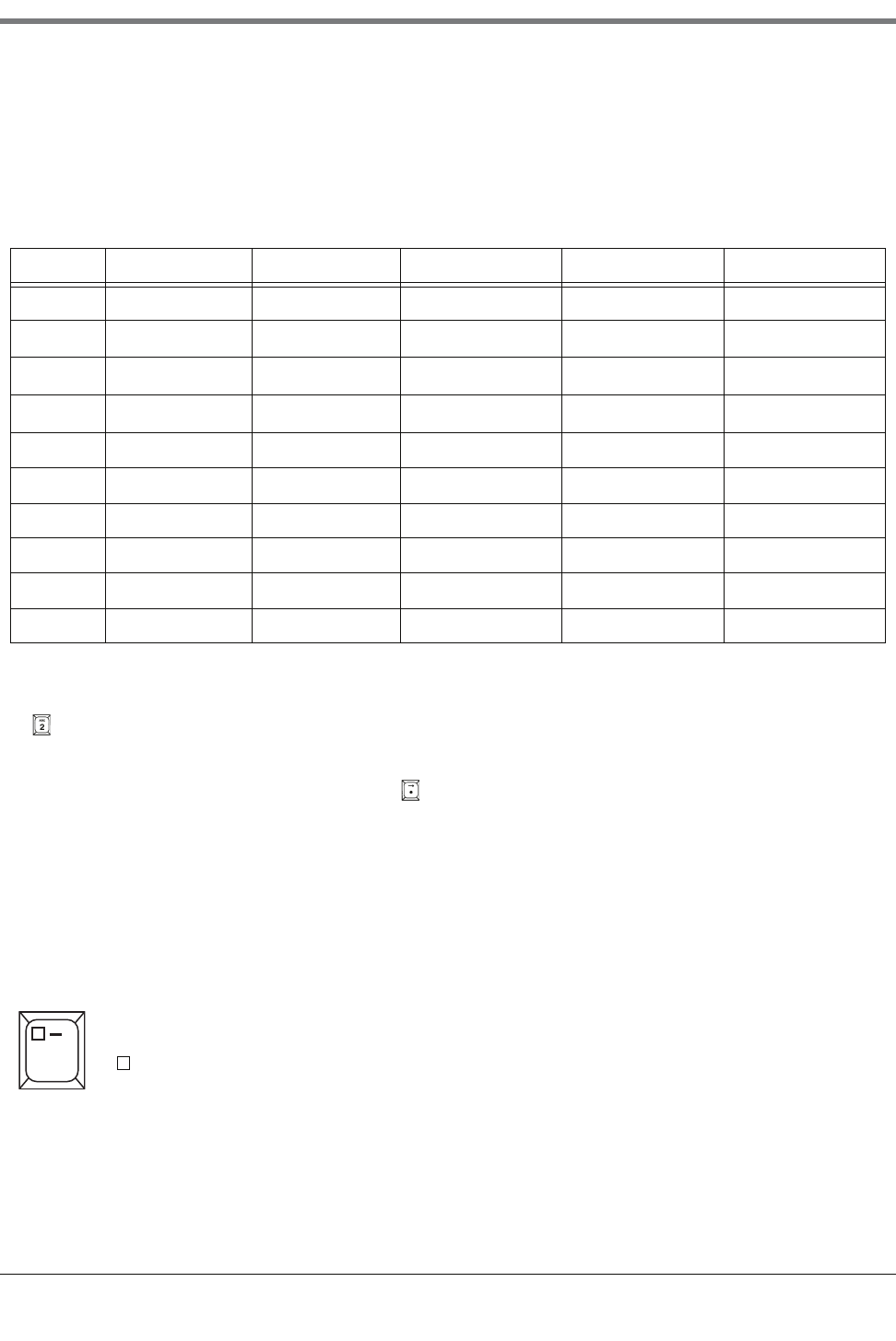
Figure 4-1. Battery Backup Switch and DIP Switch Location -
TLS-300 Console .................................................................................4-3
Figure 4-2. Battery Backup Switch and DIP Switch Location -
TLS-350 Consoles with CPU Board ....................................................4-4
Figure 4-3. Battery Backup Switch and DIP Switch Location -
TLS-350 Consoles with ECPU Board ..................................................4-5
Figure 7-1. Relative Positions of Tank Alarm Limits ............................................7-14
Figure 7-2. Siphon Manifolded Tanks ..................................................................7-20
Figure 7-3. Line Manifolding A Siphon Manifolded Set To A Single Tank...............7-21
Tables
Table 2-1.- Character Assignments for Numeric Keys .............................................2-4
Table 5-1.- Alarm Labels ........................................................................................5-21
Table 6-1.- SiteLink Modem Default Port Settings ....................................................6-1
Table 6-2. Alarm List .............................................................................................6-21
Table 7-1.- Typical Thermal Coefficients ..................................................................7-3
Table 7-2.- Tank Tilt Calculation Worksheet ...........................................................7-19
Table 10-1.- Reference of Absolute Pressure Offsets at Various Altitudes ..............10-8
Table 12-1.- Submersible Pump Nominal Pressures ................................................12-4
Table A-1.- Typical Tank Offset Values ................................................................... A-1
Table B-1. System Setup ........................................................................................ B-1
Table B-2. Comm Board Setup ............................................................................... B-2
Table B-3. In-tank Setup ......................................................................................... B-2
Table B-4. Leak Test Method Setup ....................................................................... B-3
Table C-1. System Setup ........................................................................................C-1
Table C-2. Comm Board (1, 2, Etc.) Setup .............................................................C-2
Table C-3. In-tank Setup .........................................................................................C-3
Table C-4. Leak Test Method Setup .......................................................................C-4
Table C-5. Reconciliation Setup ..............................................................................C-5

1-1
1 Introduction
This manual lists programming instructions for every available TLS-3XX Console Setup Function. The manual is
divided into sections for each Setup Function beginning with Section 5, System Setup. Depending on your
console type and its installed features, you may only see (and be able to program) some of the Functions and/or
Steps. Skip over the material in this manual that does not apply to your particular installation. You cannot perform
these setup procedures until the console, probes, and sensors have been installed and connected.
Contractor Certification Requirements
Veeder-Root requires the following minimum training certifications for contractors who will install and setup the
equipment discussed in this manual:
Installer (Level 1) Certification: Contractors holding valid Installer Certification are approved to perform wiring
and conduit routing; equipment mounting; probe, sensor and carbon canister vapor polisher installation; wireless
equipment installation; tank and line preparation; and line leak detector installation.
ATG Technician (Level 2/3 or 4) Certification: Contractors holding valid ATG Technician Certifications are
approved to perform installation checkout, startup, programming and operations training, system tests,
troubleshooting and servicing for all Veeder-Root Series Tank Monitoring Systems, including Line Leak Detection.
In addition, Contractors with the following sub-certification designations are approved to perform installation
checkout, startup, programming, system tests, troubleshooting, service techniques and operations training on the
designated system.
• Wireless 2
•Tall Tank
VR Vapor Products Certification: Contractors holding a certification with the following designations are
approved to perform installation checkout, startup, programming, system tests, troubleshooting, service techniques
and operations training on the designated system.
• ISD – In Station Diagnostics
• PMC – Pressure Management Control
• CCVP - Veeder-Root Vapor Polisher
• Wireless – ISD/PMC Wireless
• A current Veeder-Root Technician Certification is a prerequisite for the VR Vapor Products course.
Warranty Registrations may only be submitted by selected Distributors.
Related Manuals
576013-610 TLS-3XX Series Consoles Operator’s Manual
576013-879 TLS-3XX Series Consoles Site Prep Manual
577013-874 Maintenance Service Code Quick Help
1 Introduction
Safety Precautions
1-2
Safety Precautions
The following safety symbols may be used in this manual to alert you to important safety hazards and precautions.
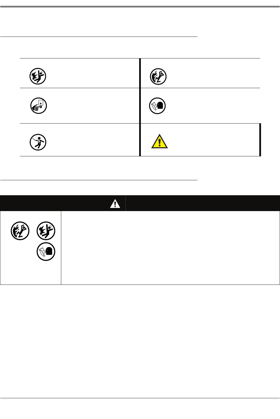
Safety Warnings
EXPLOSIVE
Fuels and their vapors are extremely
explosive if ignited.
FLAMMABLE
Fuels and their vapors are extremely
flammable.
TURN POWER OFF
Live power to a device creates a
potential shock hazard. Turn Off power
to the device and associated accesso-
ries when servicing the unit.
READ ALL RELATED MANUALS
Knowledge of all related procedures
before you begin work is important.
Read and understand all manuals thor-
oughly. If you do not understand a pro-
cedure, ask someone who does.
ELECTRICITY
High voltage exists in, and is supplied
to, the device. A potential shock hazard
exists.
WARNI NG
Heed the adjacent instructions to avoid
damage to equipment, property, envi-
ronment or personal injury.
WARNING
This system operates near highly combustible fuel storage tanks.
FAILURE TO COMPLY WITH THE FOLLOWING WARNINGS AND SAFETY
PRECAUTIONS COULD CAUSE DAMAGE TO PROPERTY, ENVIRONMENT,
RESULTING IN SERIOUS INJURY OR DEATH.
Leaking tanks can create serious environmental and health hazards. Improper
programming and operation may also result in equipment self-test failures and
submersible pump shutdowns. It is the owner’s responsibility to:
1. Ensure that this equipment is properly programmed.
2. Promptly investigate any alarm conditions.
3. Operate this equipment in accordance with the instructions in this manual.
OFF
2-1
2 Front Panel Keypads
You use the front panel keypads to enter information into the system.
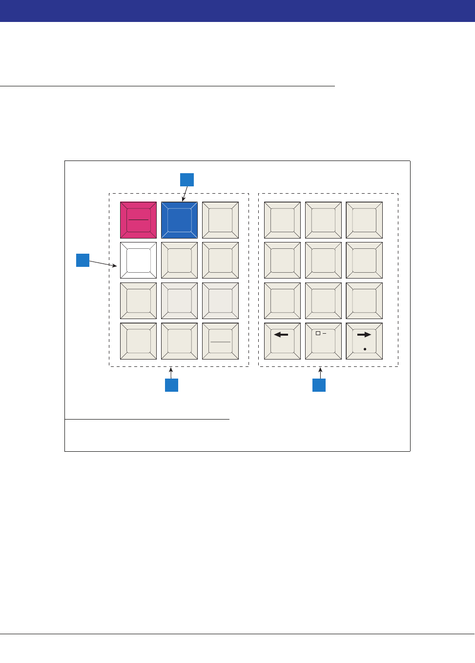
Arrangement of Keys
The keypads (see Figure 2-1) consist of two groups of 12 keys. The functions for each key have been established
to make movement within the setup mode, entry of setup data, and selection of setup choices as simple as
possible
.
Figure 2-1. Console Keypads
OPERATING KEYS
The 12 left-hand keys are operating keys. They allow you to access and print data, start and stop in-tank leak test
procedures, program the system, test system operation and review diagnostic information. (See “Using the
Operating Keys” on page 2-2.)
ALPHANUMERIC KEYS
The 12 right-hand keys have alphanumeric and cursor movement functions for entering setup information.
Legend for numbered boxes:
1. Maintenance Report (white) key 3. Alphanumeric keypad
2. Maintenance Tracker (blue) key 4. Operating keypad
consoles\keypad.eps
MODE
BACKUP FUNCT-
TION
PRINT CHANGE STEP
PAPER
FEED ENTER
QZ. ABC DEF
GHI JKL MNO
PRS TUV WXY
ALARM
TEST
TANK
SENSOR
,
+/-
0
789
123
456
1
4 3
2
2 Front Panel Keypads
Using the Operating Keys
2-2
If a numeric value is required for entry of a particular setup parameter, the keys provide only numeric functions. If
either alphabetic or numeric characters may be entered, the keys provide both alphabetic and numeric functions.
(See “Using the Alphanumeric Keys” on page 2-3).
BLUE KEY (MAINTENANCE TRACKER - TLS-350 ONLY)
Contractor plugs a valid ID Key into the TLS and presses the blue key to log in for a work session. Note: This key
is available in consoles with Version 27 and higher software. In addition to certain hardware requirements, the
Maintenance Tracker feature must be enabled for this key to function.
WHITE KEY (MAINTENANCE REPORT - TLS-350 ONLY)
Press the white key to printout up to the last 75 maintenance history records. Additional records going back up to
3 years are also selectable. Note: This key is available in consoles with Version 27 and higher software and is
functional only if the Maintenance History or Maintenance Tracker feature enabled.
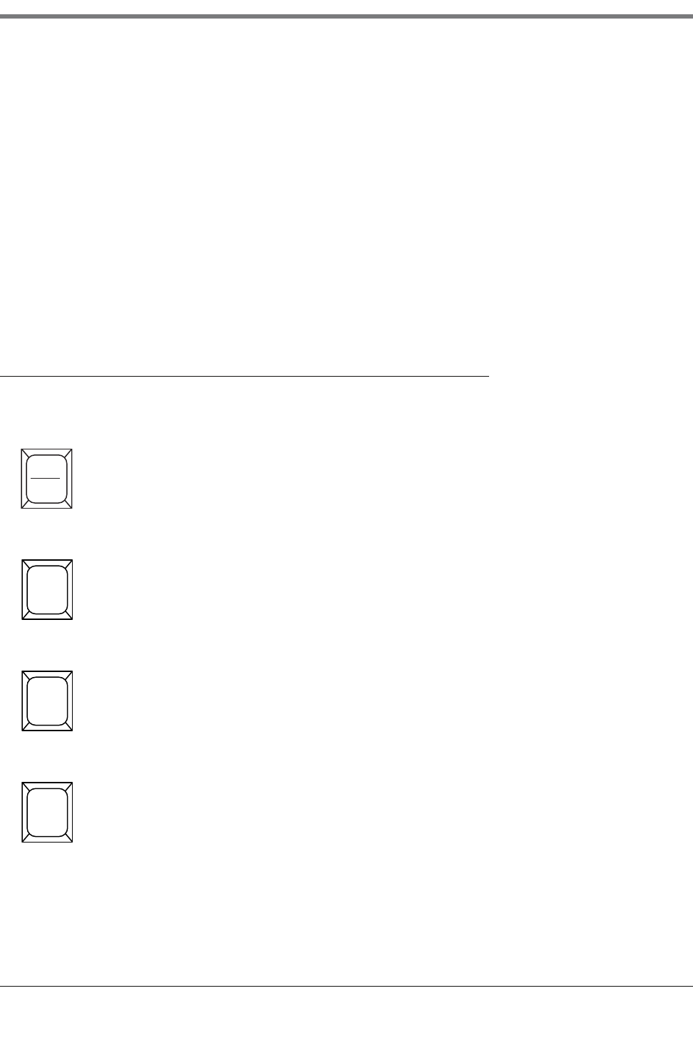
Using the Operating Keys
Operating key functions are summarized below.
ALARM/TEST
Shuts off audible alarm and clears alarms that have returned to normal condition. Will not shut off
display indicators or disable alarm function. If your system has a printer, it will print an alarm or
warning report when this button is pressed.
Used to activate and de-activate output relays when OUTPUT RELAY TEST function is used.
MODE
Select operating modes: Normal Mode, Setup Mode, Diagnostic Mode.
If MODE is pressed while in a Function or Step, the system will advance to the next MODE.
FUNCTION
The FUNCTION key is used to scroll through and access functions within a MODE.
If FUNCTION is pressed while in a STEP, the system will advance to the next FUNCTION.
STEP
Use the STEP key to move from one procedure to the next within a FUNCTION.
ALARM
TEST
MODE
FUNC-
TION
STEP
2-3
2 Front Panel Keypads
Using the Alphanumeric Keys
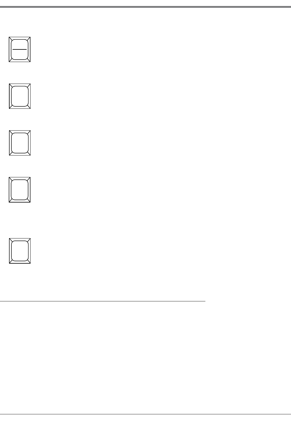
Using the Alphanumeric Keys
You use alphanumeric keys to enter data during the setup process. When a numeric value is required (i.e.gallons,
time, etc.), the keys provide only a numeric function. When you can enter either alphabetic or numeric characters
(i.e. station headers, sensor locations, etc.), the keys provide both functions.
TA N K / S E N S O R
The TANK/SENSOR key is used to advance by tank or sensor through setup procedures or dis-
played data.
CHANGE
CHANGE is used in Normal and Setup modes to enter data, revise existing data or change an
entry.
ENTER
ENTER completes a selection or enters data into a function. It is also used to start certain func-
tions such as leak tests.
BACKUP
BACKUP lets you move back through STEPS, FUNCTIONS and MODES to access data or
entries you have already passed in the normal progression. It eliminates the need to move com-
pletely through a function or mode to access a step recently passed.
BACKUP will move through the hierarchy of commands as follows: through STEPS within a
FUNCTION to that FUNCTION; then back through FUNCTIONS to MODE; then back through
MODES.
PRINT
Press PRINT to generate inventory, delivery, leak test, status, setup, diagnostic and alarm history
reports.
TANK
SENSOR
CHANGE
ENTER
BACKUP
PRINT
2 Front Panel Keypads
Using the Alphanumeric Keys
2-4
ENTERING ALPHANUMERIC DATA
Keys 0 through 9 provide both alphabetic and numeric capability by activating each character shown on the key
with successive pushes of the key. Table 2-1 shows characters assigned to each of the numeric keys for all
languages except Japanese, Russian, Turkish, and Greek.
For example, to enter an “A” in a station header, which accepts either alphabetic or numeric characters, you press
the key once. Push the key again to change the character to a “B”, again to enter a “C”, and again to enter a “2”.
The period (.) is on key “1”.
When the correct selection is displayed, press the key to move the cursor to the next position and enter the
required character as described. When all the characters have been entered, press ENTER.
If you enter an incorrect character, you may use the arrow keys to move the cursor to the character, press
CHANGE, and enter the correct character.
SPECIAL CHARACTERS AND CURSOR MOVEMENT
Several keys let you enter special characters and move the cursor as follows:
Table 2-1.- Character Assignments for Numeric Keys
Key 1st Key Press 2nd Key Press 3rd Key Press 4th Key Press 5th Key Press
Key 0 ‘space’ ‘-’ ‘,’ ‘0’ ‘*’
Key 1 ‘Q’ ‘Z’ ‘.’ ‘1’ ‘&’1
Key 2 ‘A’ ‘B’ ‘C’ ‘2’ ‘=’1
Key 3 ‘D’ ‘E’ ‘F’ ‘3’ ‘%’1
Key 4 ‘G’ ‘H’ ‘I’ ‘4’
Key 5 ‘J’ ‘K’ ‘L’ ‘5’
Key 6 ‘M’ ‘N’ ‘O’ ‘6’
Key 7 ‘P’ ‘R’ ‘S’ ‘7’
Key 8 ‘T’ ‘U’ ‘V’ ‘8’
Key 9 ‘W’ ‘X’ ‘Y’ ‘9’
1Character only available when entering the Modem Setup String.
The Zero key has a comma (,) plus two special characters that can be used in making alphanumeric
entries. They are:
= Space (no character)
— = Dash (a “*” character is generated by pressing this key 5 times).
,
0

2-5
2 Front Panel Keypads
Using the Alphanumeric Keys
The Right-Arrow key lets you advance the cursor to the right when making alphanumeric entries
such as station headers and when selecting certain parameters such as module configurations.
The step-by-step setup instructions will identify when this function should be used. The . (decimal)
is used in numeric entries as required. It is not used as a period for text entries.
The Left-Arrow key lets you move the cursor to the left.
The +/- is used to identify a positive or negative value.
+/-

3-1
3 Setup Mode Organization
The Setup Mode is used to enter information and operating parameters that govern the way your system monitors
your installation. Setup data is entered via the front panel keypads. The previous section describes in detail the
functions of each key.
Functions
Functions are the major groups in the Setup Mode of the console.
IMPORTANT! The list below contains all of the available Setup Mode functions. However, only the functions
relevant to your console and its installed options and connected detection systems will be accessible in setup.
•System Setup
•Communications Setup
•In-Tank Setup
•Fuel Management Setup
•In-Tank Leak Test Setup
•Pressure Line Leak Setup
•WPLLD Line Leak Setup
•Line Leak Detector Setup [VLLD]
•Line Leak Test Setup
•Line Leak Lockout Setup
•Pump Sensor Setup
•Pump Relay Monitor Setup
•Reconciliation Setup
•Liquid Sensor Setup
•Vapor Sensor Setup
•Groundwater Sensor Setup
•2-Wire C.L. Sensor Setup
•3-Wire C.L. Sensor Setup
•External Input Setup
•Output Relay Setup
•PLLD Line Disable Setup
•WPLLD Line Disable Setup
•Line Disable Setup [VLLD]
•Smart Sensor Setup
•VMC Setup
•Archive Utility
Steps
Within each FUNCTION are STEPS at which you enter setup data.
Setup Mode Programming Table
The table below takes you through the complete setup mode as it appears in the console display with all features
installed (all choices may not appear on your TLS). Always press the ENTER key after entering data. If you press
the STEP, FUNCTION, or MODE key without pressing ENTER, the data will not be saved. It is a good idea to print

3 Setup Mode Organization
Setup Mode Programming Table
3-2
a setup report for record keeping purposes after completing your system’s setup. In the System Setup Table
below, ↓FUNCTION or ↓STEP refers to pressing that key on the front panel.
Setup Mode Table
↓FUNCTION SYSTEM SETUP
↓STEP System Language - English/ and second language as ordered
↓STEP System Units (U.S./Metric/Imperial Gallons)
↓STEP Date/Time Format
↓STEP Set Month Day Year
↓STEP Set Time
↓STEP Station Header Line 1 (Line 2/Line 3/Line 4)
↓STEP Shift #1 Start Time (Shift 2/Shift 3/Shift 4)
↓STEP Shift BIR Printouts (Enable/Disable)
↓STEP Daily BIR Printouts (Enable/Disable)
↓STEP Ticketed Delivery (Enable/Disable)
↓STEP TC Ticketed Delivery (Enable/Disable)
↓STEP Close Day Of Week
↓STEP Daily Dlvy Var Rpts (Disable/Enable)
↓STEP Weekly Dlvy Var Rpts (Disable/Enable)
↓STEP Periodic Dlvy Var Rpts (Disable/Enable)
↓STEP Daily Book Dlvy Var Rpts (Disable/Enable)
↓STEP Weekly Book Dlvy Var Rpts (Disable/Enable)
↓STEP Periodic Book Dlvy Var Rpts (Disable/Enable)
↓STEP Daily Var Analy Rpts (Disable/Enable)
↓STEP Weekly Var Analy Rpts (Disable/Enable)
↓STEP Periodic Var Analy Rpts (Disable/Enable)
↓STEP Tank Per Tst Needed Wrn (Disable/Enable)
↓STEP Tank Per Tst Needed Wrn Days
↓STEP Tank Per Tst Needed Alm Days
↓STEP Tank Ann Tst Needed Wrn Days
↓STEP Tank Ann Tst Needed Alm Days
↓STEP Line Reenable Method (Pass Line Test/Alarm Acknowledge)
↓STEP Line Per Tst Needed Wrn (Disable/Enable)
↓STEP Line Per Tst Needed Wrn Days
↓STEP Line Per Tst Needed Alm Days
↓STEP Line Ann Tst Needed Wrn (Disable/Enable)
↓STEP Line Ann Tst Needed Wrn Days
↓STEP Line Ann TsT Needed ALM Days
↓STEP Remote Printer Page Eject
↓STEP Print Tc Volume
↓STEP Temp Compensation
↓STEP Tanker Load Report
↓STEP Stick Height Offset (Disable/Enable)
↓STEP Ullage (90%/95%)
↓STEP H-Protocol Data Format
↓STEP Precision Test Duration (12 - 744 hrs [w/o CSLD]/12 - 744 hrs [w/CSLD])

3-3
3 Setup Mode Organization
Setup Mode Programming Table
↓STEP 0.2 gph (0.76 lph) Line Test Auto-Confirm (Enable/Disable)
↓STEP 0.1 gph (0.38 lph) Line Test Auto-Confirm (Enable/Disable)
↓STEP Daylight Savings Time (Disable/Enable)
↓STEP HRM-QPLD Printouts (Enable/Disable)
↓STEP Re-direct Local PrintouT (Enable/Disable)
↓STEP Euro Protocol Prefix
↓STEP Bdim Trans Alarm Delay
↓STEP System Security Code
↓STEP Maintenance History (Enable/Disable)
↓STEP Tank Chart Security
↓STEP Custom Alarms
↓STEP Service Notice
↓STEP System Beeper
↓STEP Mass/Density
↓STEP Fiscal Height Security
↓FUNCTION COMMUNICATION SETUP
↓STEP Comm Board Port Settings - Repeat for each board (Baud Rate/Parity/Stop Bit/Data Length/
Dial Type/Answer On/Code/Modem Setup String/Dial Tone Interval/DTR Normal State
↓STEP Auto Transmit Setup (Transmit Message Setup/Auto-Transmit Delay Time/Auto-Transmit Repeat
Time)
↓STEP Phone Directory Setup
↓STEP Auto Dial Setup
↓STEP Auto Dial Alarm
↓STEP RS-232 End Of Message
↓FUNCTION IN-TANK SETUP
↓STEP Tank Config Module 1 (Up To 3)
↓STEP Product Label
↓STEP Product Code
↓STEP Thermal Coeff.
↓STEP Tank Density
↓STEP Tank Diameter
↓STEP Tank Profile (1 Pt/4 Pts/20 Pts/linear/50 Pts)
↓STEP Full Volume
↓STEP Meter Data Present
↓STEP Vapor Loss Factor
↓STEP End Factor (None/Flat/Hemispherical/Other)
↓STEP End Value
↓STEP Calibration Update
↓STEP Float Size
↓STEP Water Warning Limit (Not Active For Tanks With High Alcohol Probes)
↓STEP High Water Limit (Not Active For Tanks With High Alcohol Probes)
↓STEP Water Alarm Filter (Not Active For Tanks With High Alcohol Probes)
↓STEP Max Or Label Volume
↓STEP Overfill Limit
↓STEP High Product
↓STEP Delivery Limit

3 Setup Mode Organization
Setup Mode Programming Table
3-4
↓STEP Low Product
↓STEP Leak Alarm Unit
↓STEP Sudden Loss Limit
↓STEP Tank Tilt
↓STEP Probe Offset
↓STEP Siphon Manifolded
↓STEP Line Manifolded
↓STEP Leak Minimum Periodic
↓STEP Leak Minimum Annual
↓STEP Periodi c Te st Typ e
↓STEP Annual Test Fail Alarm
↓STEP Periodic Test Fail Alarm
↓STEP Gross Test Fail Alarm
↓STEP Annual Test Averaging
↓STEP Periodic Test Averaging
↓STEP Tank Test Noti fy
↓STEP Tank Test Siphon B reak
↓STEP Stick Offset
↓STEP Delivery Delay
↓STEP Pump Threshold
↓FUNCTION FUEL MANAGEMENT SETUP
↓STEP Delivery Warn Days XX.X
↓STEP Fuel Management Auto Print
↓STEP Average Daily Sales
↓FUNCTION IN-TANK LEAK TEST SETUP
↓STEP Test Method (Single Tank/All Tanks)
↓STEP Test Frequency (On Date/Annually [Month/Week, Day]/Monthly [Week, Day]/Weekly [Day]/
Daily/ Auto [If line leak or pump sense]/CSLD - if enabled [Prob. Detect.(9%/99%)]/Climate
Factor [Moderate/Extreme])
↓STEP Gross Test Auto-Confirm (If CSLD select with Pump Sense)
↓STEP Test S tart Tim e
↓STEP Leak Test Rate (0.2gph [0.76 lph]/0.1 gph [0.38 lph])
↓STEP Test Duratio n
↓STEP Leak Test Early Stop
↓STEP Report Only - if CSLD selected (Disabled/End of Month/Day 15 and End of Month/Day 25 and
End of Month)
↓STEP Leak Test Report Format (Normal/Enhanced)
↓FUNCTION PRESSURE LINE LEAK SETUP
↓STEP Line Config. - Module 1 ( up to 3)
↓STEP Pressure Line Label
↓STEP Piping Type
↓STEP Line Length
↓STEP User Defined Pipe Type - If selected in Piping Type (1st Line Length/2nd Line Length - if neces-
sary/1st Bulk Modulus/2nd Bulk Modulus- if necessary/Thermal Coeff.)
↓STEP Thermal Coefficient - If certain piping types selected
↓STEP 0.2 gph (0.76 lph) Line Leak Test Scheduling (Disabled/Repetitive/Monthly/Manual)

3-5
3 Setup Mode Organization
Setup Mode Programming Table
↓STEP 0.1 gph (0.38 lph) Line Leak Test SchedulingTest (Disabled/Repetitive/Auto/Manual)
↓STEP Passive 0.1 gph (0.38 lph) Line Leak Testing (if certain pipe type selections made and 0.1 gph
line leak test shedule selection is auto)
↓STEP Shutdown Rate (3.0 gph [11.3 lph]/0.2 gph [0.76lph]/0.1 gph [0.38 lph]/None)
↓STEP Low Pressure Alarm Shutoff (No/Select Value)
↓STEP Select Tank - in which PLLD controlled pump is installed (None/Select Number)
↓STEP Dispense Mode (Standard/Manifold:Alternate/Manifold:Sequential/Manifold:All Pumps)
↓STEP Pressure Transducer (Non-Vented/Vented/High Pressure)
↓STEP Pressure Offset Value
↓STEP Mechanical Blender
↓STEP Blend Partners
↓FUNCTION WPLLD LINE LEAK SETUP
↓STEP Line Config. Module 1 ( up to 3)
↓STEP WPLLD Line Label
↓STEP Piping Type
↓STEP Line Length
↓STEP 0.2 gph (0.76 lph) Test (Disabled/Repetitive/Monthly/Manual)
↓STEP 0.1 gph (0.38 lph) Test (Disabled/Auto/Manual)
↓STEP Shutdown Rate (3.0 gph [11.3 lph]/0.2 gph [0.76lph]/0.1 gph [0.38 lph]/None)
↓STEP Dispense Mode (Standard/Manifold:Alternate/Manifold:Sequential/Manifold:All Pumps)
↓STEP Pressure Offset Value
↓FUNCTION LINE LEAK DETECTOR SETUP (Volumetric)
↓STEP Line Config. Module 1 ( up to 8)
↓STEP Enter Pipe Label
↓STEP Tank #
↓STEP Dispense Mode (Standard/Manifold:Alternate/Manifold:Sequential/Manifold:All Pumps)
↓STEP Fuel Type (Gasoline/Diesel)
↓STEP 2-inch (50mm) Piping Length
↓STEP 3-inch (76mm) Piping Length
↓STEP Pipe Type (Steel/Fiberglass/2-wall Fiberglass/Flexible)
↓STEP Pump Pressure
↓STEP Shutdown Rate (3.0 gph [11.3 lph]/0.2 gph [0.76lph]/0.1 gph [0.38 lph])
↓STEP Pumpside Test
↓STEP Wait Mode (Temp. Meas./Vol. Chg. Meas.)
↓STEP NPB Partner
↓FUNCTION LINE LEAK TEST SETUP
↓STEP Leak Test Method (All Lines/Single Line)
↓STEP Test Frequency (On Date/Annually [Month/ Week, Day]/Monthly [Week, Day]/ Weekly [Day]/
Daily)
↓STEP Leak Test Start Time
↓STEP Test Rate (0.2 gph [0.76 lph]/0.1 gph [0.38 lph])
↓FUNCTION LINE LEAK LOCKOUT SETUP
↓STEP Lockout Schedule (Daily [Start Time/Stop Time]/ Individual [Start Day/Time/Stop Day/Time])

3 Setup Mode Organization
Setup Mode Programming Table
3-6
↓FUNCTION PUMP SENSOR SETUP
↓STEP Pump Sense Config. Module 1 ( up to 8)
↓STEP Select Tank
↓STEP Dispense Mode (Standard/Manifold:Alternate/Manifold:Sequential/Manifold:All Pumps)
↓FUNCTION PUMP RELAY MONITOR SETUP
↓STEP Pump Relay Config. Module 1 ( up to 8)
↓STEP Enter Pump Monitor Label
↓STEP Select Pump Relay (None/PumpSense/PLLD/WPLLD/VLLD/Relay [Pump Control Output
only])
↓STEP Stuck Delay - 5 - 600 sec (Visible only if Relay assigned)
↓STEP Select Max Run Time - 1 - 24 hr (Visible If None was selected for Pump Relay)
↓FUNCTION RECONCILIATION SETUP
↓STEP Dispenser Module Data String
↓STEP Automatic Daily Closing Time
↓STEP Auto Shift #1 Closing Time
↓STEP Auto Shift #2 Closing Time
↓STEP Auto Shift #3 Closing Time
↓STEP Auto Shift #4 Closing Time
↓STEP Periodic Reconciliation Mode (Monthly/Rolling [Length])
↓STEP Periodic Reconciliation Alarm (Disabled/Enabled)
↓STEP Periodic Reconciliation Alarm Threshold
↓STEP Periodic Reconciliation Offset
↓STEP Remote Report Format (Line/Column)
↓STEP Temp Compensation (Standard/TC Vol)
↓STEP Meter Calibration Offset
↓STEP Modify Tank/Meter Map
↓FUNCTION LIQUID SENSOR SETUP
↓STEP Sensor Config. - Module 1 (up to 8)
↓STEP Sensor Location
↓STEP Sensor Types (Tri-State/NC/Dual Float Hydrostatic/Dual Float Discriminating/Dual Float High
Vapor/Interceptor)
↓STEP Category (Annular Space/Dispenser Pan/Monitor Well/STP Sump/Piping Sump/Other)
↓FUNCTION VAPOR SENSOR SETUP
↓STEP Sensor Config. - Module 1 (up to 8)
↓STEP Sensor Location
↓STEP Sensor Threshold
↓STEP Category (Annular Space/Dispenser Pan/Monitor Well/STP Sump/Piping Sump/Other)
↓FUNCTION GROUNDWATER SENSOR SETUP
↓STEP Sensor Config. - Module 1 (up to 8)
↓STEP Sensor Location
↓STEP Category (Annular Space/Dispenser Pan/Monitor Well/STP Sump/Piping Sump/Other)

3-7
3 Setup Mode Organization
Setup Mode Programming Table
↓FUNCTION 2-WIRE CL SENSOR SETUP
↓STEP Sensor Config. - Module 1 (up to 8)
↓STEP Sensor Location
↓STEP Sensor Types (Discrim. Interstitial/Ultra 2)
↓STEP Category (Annular Space/Dispenser Pan/Monitor Well/STP Sump/Piping Sump/Other)
↓FUNCTION 3-WIRE CL SENSOR SETUP
↓STEP Sensor Config. - Module 1 (up to 8)
↓STEP Sensor Location
↓STEP Sensor Mode (Standard/High Vapor)
↓STEP Category (Annular Space/Dispenser Pan/Monitor Well/STP Sump/Piping Sump/Other)
↓FUNCTION EXTERNAL INPUT SETUP
↓STEP Input Config. - Module 1 (up to 8)
↓STEP Input Name
↓STEP External Input Type (Standard [NO/NC]/Generator [Select Orientation (NO/NC)/Generator
Tank [All Tanks/By Tank]/Pump Sense [Select Orientation (NO/NC)/Select Tank (Tank #/
None)/Dispense Mode [Standard/Manifold:Alternate/Manifold:Sequential/Manifold:All
Pumps])
↓STEP Standard ACK (NO/NC)
↓FUNCTION OUTPUT RELAY SETUP
↓STEP Relay Config. - Module 1 (up to 8)
↓STEP Enter Relay Designation
↓STEP Select Relay Type (Standard [NO/NC]/Pump Control Output [Select Tank (None/Tank #)]/
Momentary [NO/NC]/Pump Comm Control [Select Tank (None/Tank #)])
↓STEP Relay Assignments - for each relay except Pump Comm Control types (In-Tank Alarms [None/
All /Single]/ Liquid Sensor Alarms [None/All /Single]/ Vapor Sensor Alarms [None/All /Single]]/
External Inputs [None/All /Single]]/ Line Leak Alarms - VLLD [None/All /Single]/ Groundwater
Alarms [None/All /Single]/ 2-Wire CL (Type A) Alarms [None/All /Single]/ 3-Wire CL (Type B)
Alarms [None/All /Single]/ Power Side DIM Alarms [None/All /Single]/ Reconciliation Alarms
[None/All /Single]/ PLLD Alarms [None/All /Single]/ WPLLD Alarms [None/All /Single]/ Comm
Side DIM Alarms [None/All /Single]/ Pump Relay Monitor Alarms [None/All /Single]
↓FUNCTION PLLD LINE DISABLE SETUP
↓STEP Relay Assignments - for each relay except Pump Comm Control types (In-Tank Alarms [None/
All /Single]/ Liquid Sensor Alarms [None/All /Single]/ Vapor Sensor Alarms [None/All /Single]]/
External Inputs [None/All /Single]]/ Line Leak Alarms - VLLD [None/All /Single]/ Groundwater
Alarms [None/All /Single]/ 2-Wire CL (Type A) Alarms [None/All /Single]/ 3-Wire CL (Type B)
Alarms [None/All /Single]/ Power Side DIM Alarms [None/All /Single]/ Reconciliation Alarms
[None/All /Single]/ PLLD Alarms [None/All /Single]/ WPLLD Alarms [None/All /Single]/ Comm
Side DIM Alarms [None/All /Single]/ Pump Relay Monitor Alarms [None/All /Single]
↓FUNCTION WPLLD LINE DISABLE SETUP
↓STEP Relay Assignments - for each relay except Pump Comm Control types (In-Tank Alarms [None/
All /Single]/ Liquid Sensor Alarms [None/All /Single]/ Vapor Sensor Alarms [None/All /Single]]/
External Inputs [None/All /Single]]/ Line Leak Alarms - VLLD [None/All /Single]/ Groundwater
Alarms [None/All /Single]/ 2-Wire CL (Type A) Alarms [None/All /Single]/ 3-Wire CL (Type B)
Alarms [None/All /Single]/ Power Side DIM Alarms [None/All /Single]/ Reconciliation Alarms
[None/All /Single]/ PLLD Alarms [None/All /Single]/ WPLLD Alarms [None/All /Single]/ Comm
Side DIM Alarms [None/All /Single]/ Pump Relay Monitor Alarms [None/All /Single]

3 Setup Mode Organization
Setup Mode Programming Table
3-8
↓FUNCTION LINE DISABLE SETUP (VLLD)
↓STEP Relay Assignments - for each relay except Pump Comm Control types (In-Tank Alarms [None/
All /Single]/ Liquid Sensor Alarms [None/All /Single]/ Vapor Sensor Alarms [None/All /Single]]/
External Inputs [None/All /Single]]/ Groundwater Alarms [None/All /Single]/ 2-Wire CL (Type
A) Alarms [None/All /Single]/ 3-Wire CL (Type B) Alarms [None/All /Single]/ Power Side DIM
Alarms [None/All /Single]/ Reconciliation Alarms [None/All /Single]/ PLLD Alarms [None/All /
Single]/ WPLLD Alarms [None/All /Single]/ Comm Side DIM Alarms [None/All /Single]/ Pump
Relay Monitor Alarms [None/All /Single]
↓FUNCTION SMART SENSOR SETUP
↓STEP SS Config. - Module 1 (up to 8)
↓STEP Enter SmartSensor Label
↓STEP Select SS Category (Air Flow Meter[ISD System Device - ref. manual 577013-800]/ Vapor
Pressure [ISD System Device - ref. manual 577013-800]/ Mag Sensor/ Vac Sensor/ ATMP
Sensor/ Uknown)
↓FUNCTION VMC SETUP
↓STEP Add/Edit/Remove VMC Serial Number
↓FUNCTION ARCHIVE UTILITY
↓STEP Save Setup Data
↓STEP Restore Setup Data
↓STEP Clear Setup Data

4-1
4 Prior to Applying AC Power to the Console
Please read this section before applying AC power to the console.
Security Code Enable/Disable
Access to all setup functions through either the front panel and/or the RS-232 interface can be restricted by the
use of security codes. Once this feature has been activated, only persons knowing the user-designated codes may
enter or change any setup values.
This feature will prevent unauthorized persons from intentionally or accidentally entering or changing setup values.
Two separate Security Codes may be entered—one to restrict access to the Setup Mode from the front-panel
keyboard and another to restrict remote access through the RS-232 interface.
Open the left front panel door and locate the slide switch for the battery and the DIP switch. See appropriate
figure for your console (Figure 4-1 - Figure 4-3).
TLS-300 CONSOLES
IMPORTANT! DIP switch #2 controls the power to the front-panel display and must be in the OPEN position!
If you want to enable the security code feature and require entering of the security code(s) for front-panel and/or
RS-232 system setup access, make sure that switches #3 and/or #4 on DIP switch S2 are in the Closed position.
If you want to disable the security code feature and allow front panel and RS-232 system setup access, make sure
that switches #3 and #4 on DIP switch S2 are both in the OPEN position.
TLS-350 CONSOLES
If you want to disable the security code feature and allow front panel and RS-232 system setup access, make sure
that switches #1 and #2 on DIP switch SW2 are both in the OPEN position.
If you want to enable the security code feature and require entering of the security code(s) for front-panel and/or
RS-232 system setup access, make sure that switches #1 and/or #2 on DIP switch SW2 are in the Closed
position.
IMPORTANT! DIP switch #3 controls the power to the front-panel display and must be in the OPEN position!
When switch #3 is closed, the console display remains blank. For international operation only! - set DIP switch 3
to the Closed position to enable HRM.
DIP switch #4 is not used at this time and may be in either position. DIP switch #1 is not used at this time and
may be in either position.

4 Prior to Applying AC Power to the Console
Security Code Enable/Disable
4-2
Legend for numbered boxes:
1. Maintenance Report (white) key 3. Alphanumeric keypad
2. Maintenance Tracker (blue) key 4. Operating keypad
consoles\keypad.eps
MODE
BACKUP FUNCT-
TION
PRINT CHANGE STEP
PAPER
FEED ENTER
QZ. ABC DEF
GHI JKL MNO
PRS TUV WXY
ALARM
TEST
TANK
SENSOR
,
+/-
0
789
123
456
1
4 3
2
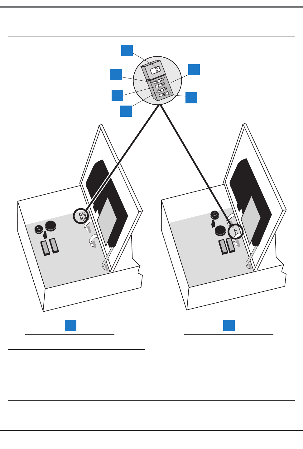
4-3
4 Prior to Applying AC Power to the Console
Security Code Enable/Disable
Figure 4-1. Battery Backup Switch and DIP Switch Location - TLS-300 Console
Legend for numbered boxes:
1. Battery Backup Switch (S1) shown in OFF position 5. DIP switch 1 can be in either position - It is shown in closed
position (open side up, number side down)
2. Front Panel Security Code (DIP Switch 4) 6. Switch (S2)
3. RS-232 Security Code (DIP Switch 3) 7. S1 and S2 Locations in Consoles with Through-Hole Mount
CPU Board
4. Front Panel Display (DIP Switch 2) 8. S1 and S2 Locations in Consoles with Surface Mount CPU
Board
S2
S1
1234
OPEN
1
consoles\300dp1.eps
1
2
3
4
5
6
8 7
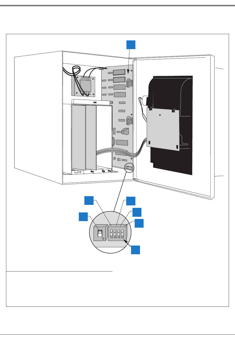
4 Prior to Applying AC Power to the Console
Security Code Enable/Disable
4-4
Figure 4-2. Battery Backup Switch and DIP Switch Location TLS-350 Consoles with CPU Board
Legend for numbered boxes:
1. CPU Board 5. DIP Switch 4 (not used)
2. Front Panel Security Code (DIP Switch 1) 6. Front Panel Display (DIP Switch 3)
3. Battery Backup Switch (S1) - Shown in ON position
(up)
7. RS-232 Security Code (DIP Switch 2)
4. DIP switches: 1 - 4 shown in the OPEN position
(open end down, number end up)
consoles\cpubbsw1.eps
BATT
1234
S1
S2
OPEN
OPEN
1
2
3
7
6
5
4
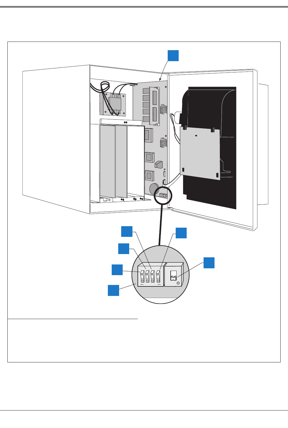
4-5
4 Prior to Applying AC Power to the Console
Security Code Enable/Disable
Figure 4-3. Battery Backup Switch and DIP Switch Location TLS-350 Consoles with ECPU Board
Legend for numbered boxes:
1. ECPU board 5. DIP switches: 1 - 4 shown in the OPEN position (open end
down)
2. View Front Panel Display (DIP Switch 3) 6. Battery Backup Switch (SW1)- Shown in OFF position
(down)
3. RS-232 Security Code (DIP Switch 2) 7. DIP Switch 4 (not used)
4. Front Panel Security Code (DIP Switch 1)
SW2
SW1
consoles\ecp350sw1.eps
1234
OPEN
1
2
3
4
5
6
7
4 Prior to Applying AC Power to the Console
Battery Backup
4-6
Battery Backup
The system is equipped with an internal backup battery to protect all setup and operating data in the event of an
AC-power interruption.
The system is shipped from the factory with the Battery Backup slide switch in the OFF position. Make sure this
switch is in the OFF position before applying AC power to the console.
Applying AC Power to the Console
1. Open the left front door of the console. With the Battery Backup switch in the OFF position, turn On AC power
to the console.
2. The console front panel display will cycle through the following screens: (NOTE: if you enabled the HRM
feature, the system date/time format will default to DD-MM-YY HH:MM:SS).
The display below appears only if you have one of the modem modules or WPLLD installed:
The message below appears in consoles with Archive Utility feature only. For more information about saving and
restoring system setup data, refer to “Archive Utility” on page 28-1.
At this point the ALARM audible beeper and front panel light will begin turning on and off, and the printer will
printout:
**** SYSTEM RESET ****
MMM DD, YYYY HH:MM XM
CLEARING ALL RAM
SYSTEM COLD START
SYSTEM SELF TEST
WORKING
********************
SYSTEM STARTUP COMPLETE
MMM DD, YYYY HH:MM:SS XM
RESTORE SETUP DATA?

4-7
4 Prior to Applying AC Power to the Console
Applying AC Power to the Console
and the front panel display will read:
3. Press the ALARM/TEST key to silence the audible alarm. Slide the Battery Backup switch (S1 or SW1) to the
ON position. After a few seconds, the alarm light will go out and the front panel display will read:
4. You can now begin the System Setup procedure.
MMM DD, YYYY HH:MM:SS XM
BATTERY IS OFF
MMM DD, YYYY HH:MM:SS XM
ALL FUNCTIONS NORMAL
5-1
5 System Setup
Programming Guidelines
This manual details setup procedures for every available console Function within the Setup Mode. The manual is
divided into sections for each Function as they appear on the display, beginning with Section 5, System Setup
through Section 26, Archive Utility. Depending on your console type and its installed features, you may only see
(and be able to program) some of the Functions and/or Steps. Just skip over the material in this manual that
doesn’t apply to your installation. The screen examples shown in this manual, are in U.S. units. However, Metric or
Imperial units would appear if either of those choices were selected in the System Units step.
•Programming Instructions. All the programming instructions in this manual assume that this is a first-time
(cold-start) setup.
•Sample Screens. The screens that are shown in these setup procedures display factory-set values or choices.
If you change these settings as you set up the system for your application, your setup values or choices will
appear in the display when the Setup Mode is re-entered.
•Key Functions. The keys used to revise any setting are the same as used during initial programming, although
the key sequences may change.
•Multiple Choice Entries. The setup procedure mentioned in this manual instructs you to press the STEP key
to accept a default value and move to the next setup parameter. When you are offered multiple choices, press
the CHANGE key to display these alternate choices, and the ENTER key to confirm the choice you decide
upon.
Automatic Return to Operating Mode
The system will automatically return to the Operating Mode status display in 15 minutes if no activity takes place
while the system is in the Setup Mode. Mark where you are in the setup sequence if you are going to be away for
longer than this.
Setup Data Warning
When you exit the Setup Mode, a Setup Data Warning will appear in the Status Display and the yellow warning
light will flash if insufficient or invalid setup data has been entered. In systems equipped with a printer, a Setup
Data Warning report will also be printed.
The display and report will identify the source of the warning (i.e. Tank 1, Sensor 4, etc.), and the warning
indicators will remain active until the cause has been corrected.
Printing a Setup Data Report
You should print and save a setup data report once all setup procedures are complete. This report will be a record
of all setup values entered into this system and save valuable time if system memory is lost due to a simultaneous
interruption of AC and battery power, or due to a problem within the system.
5 System Setup
Selecting the System Setup Function
5-2
To print a Setup Data Report, press the MODE key to display the Setup Mode main screen (see below), then
press the PRINT key.
Selecting the System Setup Function
Press MODE to select the Setup Mode, then press FUNCTION until you see the message:
Press STEP to continue.
System Language
If necessary, press STEP until you see the message:
Once you choose a language, the system displays and prints all information in that language. Available language
choices depend on the language set specified when the system was ordered. The available language sets are:
•English/Dutch •English/French • English/Finnish
•English/German •English/Greek • English/Italian
•English/Japanese •English/Polish • English/Portuguese
•English/Russian •English/Spanish • English/Swedish
•English/Turkish
To choose English, press STEP. (The system displays the SYSTEM UNITS message.) NOTE: When using the
English/Japanese language set with a remote printer, you must set the printer’s data bit-per-character switch to 8
bits.
To choose an alternate language, press CHANGE, in response to the SYSTEM LANGUAGE message, and press
ENTER. The system displays the message:
Press STEP to continue.
System Units
If necessary, press STEP until you see the message:
SETUP MODE
PRESS <FUNCTION> TO CONT
SYSTEM SETUP
PRESS <STEP> TO CONTINUE
SYSTEM LANGUAGE
ENGLISH
[Selected Language]
PRESS <STEP> TO CONTINUE
SYSTEM UNITS
U.S.
5-3
5 System Setup
Setting the Date and Time Format
You can set the system units to U.S. units (gallons, gal/hour, inches, °F), metric units (litres, litres/hour, millimeters,
°C), or imperial gallons (imperial gallons, imp. gal/hour, inches, °F). If the HRM feature was enabled, the default
units will be metric.
NOTE: If you change the System Units after entering other quantitative setup values, the system converts values to
the new units. The Date format also changes according to your selection of System Units.
To choose U.S. units, press STEP. (The system displays the SET DATE message.)
To choose metric, press CHANGE in response to the SYSTEM UNITS message and press ENTER. To choose
imperial gallons, press CHANGE twice in response to the SYSTEM UNITS message and press ENTER. The
system confirms your choice with the message:
Press STEP to continue.
Setting the Date and Time Format
If necessary, press STEP until you see the message:
To accept the format shown, press STEP. (The system displays the SET TIME message).
Available date/time formats are:
•MON DD YYYY HH:MM:SS (APR 01 2002 10:02:30)
•MM-DD-YY HH:MM:SS xM (04-01-02 10:02:30 AM); xM is AM or PM
•MM-DD-YY HH:MM:SS (04-01-02 10:02:30)
•DD-MM-YY HH:MM:SS (01-04-027 10:02:30)
•YY-MM-DD HH:MM:SS (02-04-01 10:02:30)
Press CHANGE until the desired format is shown, then press ENTER. Press STEP to continue.
Current Date
If necessary, press STEP until you see the message:
To accept the date shown, press STEP. (The system displays the SET TIME message).
To change the date shown, press CHANGE, enter the correct date by first entering the month then the day then
the year following the format shown on the display, then press ENTER. The system confirms your entry with the
message:
Press STEP to continue.
[Selected Units]
PRESS <STEP> TO CONTINUE
SYSTEM DATE/TIME FORMAT
MON DD, YYYY HH:MM:SS xM
SET: MONTH DAY YEAR
DATE: XX/XX/XXXX
DATE: XX/XX/XXXX
PRESS <STEP> TO CONTINUE
5 System Setup
Current Time
5-4
Current Time
If necessary, press STEP until you see the message:
To accept the time shown, press STEP. (The system displays the ENTER STATION HEADER message.)
To set a different time, press CHANGE and enter the correct time from 12:00 to 11:59 then am or pm. (Press the
Left or Right Arrow to select AM or PM). Press ENTER. The system confirms your entry with the message:
Press STEP to continue.
Report Headers
If necessary, press STEP until you see the message:
NOTE: The header can be up to four lines with 20 characters per line. Use the header to identify site location,
telephone number, etc. (See “Using the Alphanumeric Keys” on page 2-3 for instructions on how to enter
alphanumeric data.)
If you do not want a header for reports, press STEP. The system displays the SHIFT START TIME message.)
To create a header, press CHANGE in response to the ENTER STATION HEADER message. Enter up to 20
characters for the first line. Press ENTER. The system confirms your entry with the message:
To enter additional header lines, press STEP and repeat the above procedure up to three more times for lines 2, 3,
and 4. When you finish entering the header, press STEP to continue.
Shift Start Times
If necessary, press STEP until you see the message:
Setting shift start times can ease shift changes and improve fuel inventory management. At each programmed
time, the system automatically prints a complete inventory report and stores it in memory.
NOTE: At least one Shift Start Time must be entered to activate the “Last Shift Inventory” feature. If you have fewer
than three shifts and wish to receive a day-end inventory report at the end of the final shift, use the next shift start
time as the day-end time. The system automatically prints a final inventory.
SET TIME
TIME: XX:XX AM PM
TIME: XX:XX XM
PRESS <STEP> TO CONTINUE
ENTER STATION HEADER
#1:
#1: [1st Line Of Header]
PRESS <STEP> TO CONTINUE
SHIFT #1 START TIME
TIME: DISABLED

5-5
5 System Setup
Shift BIR Printouts
To leave a shift start time disabled, press STEP. (The system displays the SHIFT START TIME message for the
next shift.)
To set a start time for shift 1, press CHANGE, and enter the shift 1 start time. Press the Left or Right Arrow to
select AM or PM. Then press ENTER. The system confirms your entry with the message:
Press STEP. The system displays the SHIFT START TIME message for the next shift:
Repeat the above procedures to enter or disable start times for shifts 2, 3, and 4.
Shift BIR Printouts
If necessary, press STEP until you see the message:
Shift BIR Printouts enabled causes a BIR report to print at the end of every shift. If you want a BIR printout at the
conclusion of each shift, press STEP to continue. To disable Shift BIR Printouts, press CHANGE, ENTER, then
STEP.
Daily BIR Printouts
If necessary, press STEP until you see the message:
Daily BIR Printouts enabled causes a BIR report to print at the end of the day’s last shift. If you want a BIR
printout at the conclusion of the last shift, press STEP to continue. To disable Daily BIR Printouts, press
CHANGE, ENTER, then STEP.
Ticketed Delivery
If necessary, press STEP until you see the message:
When you enable ticketed delivery, you can manually enter ticketed volumes using the receipts from tank delivery
trucks. To enter this data, use the Delivery Maintenance function in the Operating Mode. This feature generates
reports showing delivery variances between ticketed volume and gauged volume, book variance, and variance
analysis. To enable Ticketed Delivery, press CHANGE, ENTER, then STEP.
TIME: XX:XX:XM
PRESS <STEP> TO CONTINUE
SHIFT #2 START TIME
TIME: DISABLED
SHIFT BIR PRINTOUTS
ENABLED
DAILY BIR PRINTOUTS
ENABLED
TICKETED DELIVERY
DISABLED
5 System Setup
TC Ticketed Delivery
5-6
TC Ticketed Delivery
If necessary, press STEP until you see the message:
If you enabled ticketed delivery, you can choose whether the values you enter are standard (gross) volumes or
temperature-compensated (TC) volumes (see page 5-13 for a description of “Temperature Compensation Value”).
For standard volumes, press STEP to leave TC Ticketed Delivery disabled. For TC volumes, press CHANGE,
ENTER, then STEP.
Close Day of Week
If necessary, press STEP until you see the message:
If you enabled ticketed delivery, you can choose the last day of the weekly cycle for Variance Reports. (Close Day
of Week is similar to “Automatic Daily Closing” on page 17-1.) Press CHANGE until the appropriate day appears,
then press ENTER and STEP.
Variance Reports
If you enabled ticketed delivery, you can print several different types of variance reports on demand from the
Reconciliation Mode (Operating Mode). Variance reports are similar to the reconciliation reports generated for BIR,
except they also show ticketed (book) delivery volume. Delivery Variance Reports show the difference between
ticketed delivery and gauged delivery volumes. Book Variance Reports show the difference between book
inventory and closing gauged volume. Variance Analysis Reports have the most detail because they summarize the
Delivery and Book Variance Reports and show tank test results, line leak test results, and corrective actions.
You must enable variance reports before you can view or print them. They are available as daily, weekly, or periodic.
The default for the period length is monthly; you can change it in “Periodic Reconciliation Mode” on page 17-2.
DAILY DELIVERY VARIANCE REPORTS
If necessary, press STEP until you see the message:
To enable Daily Delivery Variance Reports, press CHANGE, ENTER, then STEP.
WEEKLY DELIVERY VARIANCE REPORTS
If necessary, press STEP until you see the message:
TC TICKETED DELIVERY
DISABLED
CLOSE DAY OF WEEK
SUN
DAILY DLVY VAR RPTS
DISABLED
WEEKLY DLVY VAR RPTS
DISABLED
5-7
5 System Setup
Variance Reports
To enable Weekly Delivery Variance Reports, press CHANGE, ENTER, then STEP.
PERIODIC DELIVERY VARIANCE REPORTS
If necessary, press STEP until you see the message:
To enable Periodic Delivery Variance Reports, press CHANGE, ENTER, then STEP.
DAILY BOOK VARIANCE REPORTS
If necessary, press STEP until you see the message:
To enable Daily Book Variance Reports, press CHANGE, ENTER, then STEP.
WEEKLY BOOK VARIANCE REPORTS
If necessary, press STEP until you see the message:
To enable Weekly Book Variance Reports, press CHANGE, ENTER, then STEP.
PERIODIC BOOK VARIANCE REPORTS
If necessary, press STEP until you see the message:
To enable Periodic Book Variance Reports, press CHANGE, ENTER, then STEP.
DAILY VARIANCE ANALYSIS REPORTS
If necessary, press STEP until you see the message:
To enable Daily Variance Analysis Reports, press CHANGE, ENTER, then STEP.
WEEKLY VARIANCE ANALYSIS REPORTS
If necessary, press STEP until you see the message:
PERIODIC DLVY VAR RPTS
DISABLED
DAILY BOOK VAR RPTS
DISABLED
WEEKLY BOOK VAR RPTS
DISABLED
PERIODIC BOOK VAR RPTS
DISABLED
DAILY VAR ANALY RPTS
DISABLED
WEEKLY VAR ANALY RPTS
DISABLED
5 System Setup
Tank Periodic Test Needed Warnings
5-8
To enable Weekly Variance Analysis Reports, press CHANGE, ENTER, then STEP.
PERIODIC VARIANCE ANALYSIS REPORTS
If necessary, press STEP until you see the message:
To enable Periodic Variance Analysis Reports, press CHANGE, ENTER, then STEP.
Tank Periodic Test Needed Warnings
If necessary, press STEP until you see the message:
The system monitors the amount of time since the last passed 0.2 gph (0.76 lph) tank test. By enabling the Tank
Periodic Test Needed Warnings, you can have the system provide a warning when a tank test has not been
passed, or conducted in a specified number of days (0 to 30), and activate an alarm if a test has not been passed
after a warning, or a specified number of days.
ENABLE TANK PERIODIC TEST NEEDED WARNINGS AND ALARMS
To enable Tank Test Needed Periodic Warnings, press STEP. The system displays the message:
Press CHANGE, and enter the number of days (0 to 30 days) after which you want the system to warn that a tank
test has not been passed. Press ENTER. The system displays the message:
Press STEP. The system displays the message:
Press CHANGE, and enter the number of days (0 to 30) after which you want an alarm if a test has not been
passed. This number should be higher than the number you set for the periodic warning. Press ENTER. The
system displays the message:
Press STEP. (The system displays the Tank Annual Test Needed Warnings message.)
PERIODIC VAR ANALY RPTS
DISABLED
TANK PER TST NEEDED WRN
DISABLED
TANK PER TST NEEDED WRN
DAYS = XX
DAYS = XX
PRESS <STEP> TO CONTINUE
TANK PER TST NEEDED ALM
DAYS = XX
DAYS = XX
PRESS <STEP> TO CONTINUE
5-9
5 System Setup
Tank Annual Test Needed Warnings
DISABLE TANK PERIODIC TEST NEEDED WARNINGS
To disable Tank Periodic Test Needed Warnings, press CHANGE in response to the Tank Annual Test Needed
Warnings Enabled message. The system now displays:
Press ENTER. The system confirms your choice with the message:
Press STEP to continue. (The system displays the Tank Annual Test Needed Warnings message.)
Tank Annual Test Needed Warnings
If necessary, press STEP until you see the message:
The system monitors the amount of time since the last passed 0.1 gph (0.38 lph) tank test. By enabling Tank
Annual Test Needed Warnings, you can have the system provide a warning when a 0.1 gph (0.38 lph) tank test
has not been passed or conducted in a specified number of days (0 to 365) and activate an alarm if a test has not
been passed after a warning, or a specified number of days.
To keep Tank Annual Test Needed Warnings disabled, press STEP. (The system displays the Line Re-Enable
Method message.)
ENABLE TANK ANNUAL TEST NEEDED WARNINGS AND ALARMS
To enable Tank Annual Test Needed Warnings, press CHANGE. The system now displays:
Press ENTER. The system confirms your choice with the message:
Press STEP. The system now displays:
Press CHANGE and enter the number of days after which you want the system to warn that a 0.1 gph (0.38 lph)
tank test has not been passed (0 to 365). Press ENTER. The system displays the message:
TANK PER TST NEEDED WRN
DISABLED
DISABLED
PRESS <STEP> TO CONTINUE
TANK ANN TST NEEDED WRN
DISABLED
TANK ANN TST NEEDED WRN
ENABLED
ENABLED
PRESS <STEP> TO CONTINUE
TANK ANN TST NEEDED WRN
DAYS = XXX
DAYS = XXX
PRESS <STEP> TO CONTINUE
5 System Setup
Line Re-Enable Method
5-10
Press STEP. The system displays the message:
The default value is 355 days. If you do not want to accept the default, press CHANGE. Enter the number of days
after which you want the system to alarm if a test has not been passed (0 to 365). This number should be higher
than the number you set for periodic warning. Press ENTER. The system displays the message:
Press STEP. (The system displays the Line Re-Enable Method message.)
DISABLE TANK ANNUAL TEST NEEDED WARNINGS AND ALARMS
To disable Tank Annual Test Needed Warnings that are already enabled, press CHANGE in response to the Tank
Annual Test Needed Warnings Enabled message and press ENTER. The system confirms your choice with the
message:
Press STEP continue. (The system displays the Line Re-Enable Method message.)
Line Re-Enable Method
If necessary, press STEP until you see the message:
This feature lets you choose how to re-enable a line shut down by a failing line leak test. To re-enable a shutdown
line only by a passed line test, press STEP. (The system displays the Line Periodic Test Needed Warning.)
To re-enable a shutdown line by acknowledging the alarm that caused the shutdown, press CHANGE and the
system displays the message:
Press ENTER to confirm the choice and STEP to continue.
Line Periodic Test Needed Warnings
If necessary, press STEP until you see the message:
The system monitors the amount of time since the last passed 0.2 gph (0.76 lph) line test. By enabling Line
Periodic Test Needed Warnings, you can have the system provide a warning when a line test has not been passed,
TANK ANN TST NEEDED ALM
DAYS = XXX
DAYS = XXX
PRESS <STEP> TO CONTINUE
DISABLED
PRESS <STEP> TO CONTINUE
LINE RE-ENABLE METHOD
PASS LINE TEST
LINE RE-ENABLE METHOD
ACKNOWLEDGE ALARM
LINE PER TST NEEDED WRN
DISABLED
5-11
5 System Setup
Line Annual Test Needed Warnings
or conducted in a specified number of days (0 to 30), and activate an alarm if a test has not been passed after a
warning, or a specified number of days.
ENABLE LINE PERIODIC TEST NEEDED WARNINGS AND ALARMS
To enable Line Periodic Test Needed Warnings, press CHANGE, ENTER, then STEP. The system displays the
message:
Press CHANGE, and enter the number of days (0 to 30 days) after which you want the system to warn that a
periodic line test has not been passed. Press ENTER. The system displays the message:
Press STEP. The system displays the message:
Press CHANGE, and enter the number of days (0 to 30) after which you want the system to alarm if a test has not
been passed. This number should be higher than the number you set for the warning. Press ENTER. The system
displays the message:
Press STEP. (The system displays the Line Annual Warnings message.)
DISABLE LINE PERIODIC TEST NEEDED WARNINGS
To disable the line periodic warnings, press CHANGE in response to the Line Periodic Test Needed Warnings
Enabled message. The system now displays:
Press ENTER. The system confirms your choice with the message:
Press STEP to continue. (The system displays the Line Annual Test Needed Warnings message.)
Line Annual Test Needed Warnings
If necessary, press STEP until you see the message:
LINE PER TST NEEDED WRN
DAYS = XXX
DAYS = XXX
PRESS <STEP> TO CONTINUE
LINE PER TST NEEDED ALM
DAYS = XXX
DAYS = XX
PRESS <STEP> TO CONTINUE
LINE PER TST NEEDED WRN
DISABLED
DISABLED
PRESS <STEP> TO CONTINUE
LINE ANN TST NEEDED WRN
DISABLED
5 System Setup
Line Annual Test Needed Warnings
5-12
The system monitors the amount of time since the last passed 0.1 gph (0.38 lph) line test. By enabling Line Annual
Test Needed Warnings, you can have the system provide a warning when a 0.1 gph line test has not been passed,
or conducted in a specified number of days (0 to 365), and activate an alarm if a test has not been passed after a
warning, or a specified number of days.
To keep Line Annual Test Needed Warnings disabled, press STEP. (The system displays the Remote Printer Page
Eject or Print TC Volumes message.)
ENABLE LINE ANNUAL TEST NEEDED WARNINGS AND ALARMS
To enable line annual warnings, press CHANGE. The system now displays:
Press ENTER. The system confirms your choice with the message:
Press STEP. The system now displays:
Press CHANGE and enter the number of days after which you want the system to warn that a 0.1 gph (0.38 lph)
line test has not been passed (0 to 365). Press ENTER. The system displays the message:
Press STEP. The system displays the message:
The default value is 355 days. If you do not want to accept the default, press CHANGE. Enter the number of days
after which you want the system to alarm if a test has not been passed (0 to 365). This number should be higher
than the number you set for periodic warning. Press ENTER. The system displays the message:
Press STEP. (The system displays the Remote Printer Page Eject or Print TC Volumes message.)
DISABLE LINE ANNUAL TEST NEEDED WARNINGS AND ALARMS
To disable Line Annual Test Needed Warnings that are already enabled, press CHANGE in response to the Line
Annual Test Needed Warnings Enabled message and press ENTER. The system confirms your choice with the
message:
Press STEP continue. (The system displays the Remote Printer Page Eject or Print TC Volumes message.)
LINE ANN TST NEEDED WRN
ENABLED
ENABLED
PRESS <STEP> TO CONTINUE
LINE ANN TST NEEDED WRN
DAYS = XXX
DAYS = XXX
PRESS <STEP> TO CONTINUE
LINE ANN TST NEEDED ALM
DAYS = XXX
DAYS = XXX
PRESS <STEP> TO CONTINUE
DISABLED
PRESS <STEP> TO CONTINUE
5-13
5 System Setup
Remote Printer Page Eject
Remote Printer Page Eject
If necessary, press STEP until you see the message:
NOTE: This system feature is for systems equipped with a Remote Printer Interface Module and Remote Printer
only.
Enabling this feature forces the printer to start each new report on a new page. If you disable this feature, new
reports will print continuously on the same page as the previous report.
To have each new report begin on a new page, press CHANGE in response to the REMOTE PRINTER PAGE
EJECT message. Then press ENTER. The system confirms your choice with the message:
Print TC Volumes
If necessary, press STEP until you see the message:
Use this display to enable or disable the display and printout of TC volumes. Press STEP to accept or CHANGE
and ENTER to disable this feature. The system confirms your choice with the message:
Temperature Compensation Value
The system allows you to enter the temperature compensation (TC) reference temperature for all volume
calculations. This temperature is determined by your location. In the U.S., the reference temperature used to
calculate TC volume is normally 60°F. In other countries, this value may differ. Canada, for example, uses 15°C.
Press STEP to display the message:
TLS-350R only—If BIR is being used and the meters reporting the sales are temperature compensated, the value
you enter must match the meters’ reference temperature value. Also, in BIR setup, Temp Compensation must be
set to TC VOLUME (see “Temp Compensation” on page 17-4).
LEAK CALCULATIONS NOTE: All leak calculations are based on the reference temperature you enter.
DENSITY CALCULATIONS NOTE: If you are using the Density/Mass feature, the reference temperature entered
here is used in Density reporting.
To accept the default value of 60°F (15.6°C), press STEP.
REMOTE PRINTER
PAG E EJ ECT
PAGE EJECT ENABLED
PRESS <STEP> TO CONTINUE
PRINT TC VOLUMES
ENABLED
DISABLED
PRESS <STEP> TO CONTINUE
TEMP COMPENSATION
VALUE (DEG F): +060.0

5 System Setup
Tanker Load Report - International Option
5-14
To enter a different TC reference temperature, press CHANGE. Enter a value between 0 and 120°F (-17 to
+49°C). Press ENTER to confirm your entry. The system displays:
Tanker Load Report - International Option
The Tanker Load Report is an optional feature. In the ENABLE position, a report is printed after every tanker load is
dispensed.
Press STEP to display the message:
Press CHANGE to select DISABLE, then ENTER to not automatically print this report. See the Operating Mode
charts in the Operator’s Manual to print out a report when you want it.
Stick Height Offset - International Option
The Stick Height Offset is a “reference only” height reading that allows a user- programmable offset to be entered
that makes the probe height reading “appear” to be the same as the stick height reading. Stick height offset will
not be used for volume calculation. If this feature is enabled, you must enter the stick height offset for each tank in
the In-Tank Setup section of this manual (“Stick Offset (International Option)” on page 7-24).
Press STEP to display the message:
Press CHANGE, ENTER, then STEP to enable this feature, or Press STEP to leave it disabled and continue.
Ullage
Tank Ullage can be changed from the default value of 90 percent to 95 percent as required.
Press STEP to display the message:
Press CHANGE, ENTER, then STEP to select 95%, or Press STEP to leave it at 90% and continue.
H-Protocol Data Format - International Option
This feature is available only if there is an RS-232 or modem module installed in the console and H-protocol is
used.
VALUE (DEG F): +(TC Value)
PRESS <STEP> TO CONTINUE
TANKER LOAD REPORT
ENABLE
STICK HEIGHT OFFSET
DISABLED
ULLAGE
90 PERCENT
5-15
5 System Setup
Precision Test Duration (PLLD/WPLLD Only)
Press STEP to display the message:
This option allows either Tank Height or Tank Volume data for H-protocol. On power up, this feature will default to
HEIGHT for backward compatibility. Press CHANGE, then ENTER to change the default. Accept the default if you
are not using H-protocol.
Precision Test Duration (PLLD/WPLLD Only)
When optional 0.2 gph (0.76 lph) [PLLD and WPLLD] and 0.1 gph (0.38 lph) [PLLD only] line leak tests are
enabled, this feature lets you extend the time between a passed test and running the next test from 12 hours (60
hours with CSLD option), up to a maximum of 744 hours (31 days).
Press STEP to display the message:
Press CHANGE, then enter the desired duration (from 12 up to 744 hours without the CSLD option, or from 60
up to 744 hours with the CSLD option), then press ENTER.
Precision Line Test Auto-Confirm
These Auto-Confirm selections reduce the risks of false 0.2 and 0.1 gph (0.76 and 0.38 lph) line test results.
However, enabling these options extends the time it takes to post line test results.
Press STEP to display the message:
This feature evaluates several individual 0.2 gph line tests before a result is posted. To leave Auto-Confirm
enabled, press STEP: To disable Auto-Confirm, press CHANGE, ENTER.
Press STEP to display the message:
This feature evaluates several individual 0.1 gph line tests before a result is posted. To leave Auto-Confirm
enabled, press STEP: To disable Auto-Confirm, press CHANGE, ENTER.
Press STEP to display the message:
To leave the printing of 0.2 and 0.1 gph test results disabled, press STEP: To enable these printouts, press
CHANGE, ENTER.
H-PROTOCOL DATA FORMAT
HEIGHT
PRECISION TEST DURATION
HOURS: XXX
0.2 GPH LINE TEST
AUTO-CONFIRM: ENABLED
0.1 GPH LINE TEST
AUTO-CONFIRM: ENABLED
PRINT PRECISION LINE
TEST RESULTS: DISABLED
5 System Setup
Daylight Savings Time
5-16
Daylight Savings Time
This feature allows you to enter Daylight Savings Start and End Dates/Times. Once enabled, the console will
automatically adjust for daylight savings time on the dates and times you enter here.
Press STEP to display the message:
To leave Daylight Savings Time disabled, press STEP. To enable Daylight Savings Time, press CHANGE, ENTER,
then STEP to display the Start Date message:
Press CHANGE then ENTER to select another start date. Press ENTER to accept your selected Start Date. The
Start Time message appears:
Press CHANGE then ENTER to select another Start Time. Press ENTER to accept your selected Start Time. The
End Date message appears:
Press CHANGE then ENTER to select another End Date. Press ENTER to accept your selected End Date. The
End Time message appears:
Press CHANGE then ENTER to select another End Time. Press ENTER to accept your selected End Time.
Re-direct Local Printout
This feature is available only if there is an RS-232 or DIM card installed in the console and Gilbarco protocol is
used.
Press STEP to display the message:
This option allows you to send a printout to Gilbarco’s printer instead of to the console’s printer. The default for
this feature is DISABLED. Press CHANGE, then ENTER to change the default to ENABLED. Accept the default if
you are not using Gilbarco protocol.
DAYLIGHT SAVINGS TIME
DISABLED
START DATE
APR WEEK 1 SUN
START TIME
TIME: 02:00 AM
END DATE
OCT WEEK 6 SUN
END TIME
TIME: 02:00 AM
RE-DIRECT LOCAL PRINTOUT
DISABLED
5-17
5 System Setup
QPLD Monthly Printout - International Option
QPLD Monthly Printout - International Option
When the HRM feature is enabled, QPLD is automatically enabled and it will print out a report once a month. If this
report is not required it may be disabled as follows.
Press STEP to display the message:
Press CHANGE to disable the report, then press ENTER.
Euro Protocol Prefix
This feature is for European applications only. If necessary, press STEP until you see the message:
Accept the default S for the standard Euro Protocol command response prefix. Press CHANGE, then ENTER, to
select d which is a special Euro Protocol command prefix.
BDIM Trans Alarm Delay
If necessary, press STEP until you see the message:
BDIM Transaction Alarm Delay is available only if there is a Block DIM card installed in the console. This feature
lets you enter a delay (of from 5 to 999 hours) before posting a Block DIM Transaction Alarm. Press CHANGE,
enter the desired delay, then press ENTER to confirm your choice. Enter 000 to disable this feature.
System Security Code
If necessary, press STEP until you see the message:
The System Security Code is a 6-digit numeric code which should be known only to personnel responsible for the
setup, management, and service of the system. If you enable the System Security Code, you will be required to
enter this code before you can access any setup or diagnostic function.
If you do not want to enable the Security Code, the system setup is complete. Press FUNCTION to exit the
System Setup function or press STEP to return to the SYSTEM LANGUAGE message.
To enable the System Security Code:
1. Follow the Security Code Enable/Disable procedure in the previous section to make the required DIP switch
enable settings,
QPLD MONTHLY PRINTOUT
ENABLED
EURO PROTOCOL PREFIX
S
BDIM TRANS ALARM DELAY
HOURS: 024
SYSTEM SECURITY
CODE: 000000
5 System Setup
Maintenance History
5-18
2. Press CHANGE in response to the first SYSTEM SECURITY CODE message. Enter any six digits for your
code and press ENTER. The system confirms your entry with the message:
Maintenance History
The Maintenance Report feature is available in the TLS-350 with version 27 software and a NVMEM 203 card
installed.
Press STEP to display the message:
This feature maintains a rolling 3 year history of the following maintenance records:
•Active Alarm (alarm post) – alarm type and number, device number, active date/time. This includes protected
maintenance alarms.
•Inactive Alarm (alarm clear) – alarm type and number, device number, inactive date/time. This includes protected
maintenance alarms.
•Maintenance History enable - date/time of enable
•Maintenance History disable –date/time of disable
•Service codes – service code, date/time entered (Note: Service codes can be found in the Maintenance
Service Code Quick Help (P/N 577013-874)
•Last Monthly Fullest Periodic Tank Test Passed – tank number, start date/time
•Last Monthly PLLD 0.2 GPH Test Passed – tank number, date/time entered (record added at 1st of month)
•Last Monthly WLLD 0.2 GPH Test Passed – tank number, date/time entered (record added at 1st of month)
•Last Monthly VLLD 0.2 GPH Test Passed – tank number, date/time entered (record added at 1st of month)
The default for this feature is DISABLED. Press CHANGE, then ENTER to change the default to ENABLED.
Tank Ch art Security
If necessary, press STEP until you see the message:
CODE: XXXXXX
PRESS <STEP> TO CONT
MAINTENANCE HISTORY
DISABLED
TANK CHART SECURITY
PRESS <ENTER>
5-19
5 System Setup
Custom Alarm Labels
Press ENTER to continue:
If you have not entered a passcode, press CHANGE and enter a 6-digit numeric passcode, then press ENTER to
accept your entry:
Press STEP to continue.
If necessary, press CHANGE and enter the TLS Console serial number from the label on the bottom of the
console. Press ENTER to accept your entry. Press STEP to continue:
If necessary, press CHANGE and enter the Weights and Measures office number. Press ENTER to accept your
entry. Press STEP to continue.
Custom Alarm Labels
If necessary, press STEP until you see the message:
This step allows you to enter up to 16 custom labels and indications per alarm (one per device with a maximum of
16 devices), for up to 10 alarms, for a maximum of 160 labels, each up to 19 characters in length, and each with
its own indication set. Only alarms that applicable to your site’s equipment configuration and features can be
customized.
Your custom labels replace the system generated display/print alarm labels that are used in display messages,
printouts, and RS-232 reports only. Alarm labels used in Autodial, Output Relay, WPLLD, PLLD, and VLLD line
disable setups, shown in the Autodial Alarm Label column of Table 5-1, will not change.
After you have made a custom label change, you also select a custom indicator set for that alarm which determines
what console indicator(s) are activated when the alarm is posted:
•LCD: Display in the front panel screen - yes / no
•Print: yes / no
•Beep: Turn on the console beeper - yes / no
TANK CHART SECURITY
ENTER PASSCODE->______<
TANK CHART SECURITY
CODE : 000000 This display appears if a passcode has not been entered (default). All zeros
This display appears if Tank Chart Security is enabled - a passcode other than all zeros
disables Tank Chart Security.
has been entered. Enter the 6-digit numeric passcode and press ENTER.
CODE: ******
PRESS <STEP> TO CONTINUE
CONSOLE SERIAL NUMBER:
S/N : (serial number)
WEIGHTS AND MEASURES:
W&M: (weights and measures)
CUSTOM ALARM LABELS
PRESS <ENTER>
5 System Setup
Custom Alarm Labels
5-20
•LED: Turn on the front panel Warning or write in your new label in the Custom Alarm Label column of Table 5-1.
When you have completed your custom alarm label entries, press the PRINT key while in System Setup, to print
out a copy of your changes.
To continue, press ENTER:
Press CHANGE:
Press ENTER:
Press STEP to continue:
Press CHANGE and ENTER to access available System Alarms, or STEP to move through the alarm sets: In-Tank
alarms, Liquid Sensor alarms, etc. When making changes, standard setup entry procedures apply - you can
designate a single device or all devices for the label change. After each custom label entry, you then select enable
or disable for each of the four console alarm indicators assigned to that custom alarm: LCD, Print, Beep, and LED.
CUSTOM ALARM LABELS
DISABLED
CUSTOM ALARM LABELS
ENABLED
ENABLED
PRESS <STEP> TO CONTINUE
CUSTOM ALARM LABELS
SYSTEM ALARMS : NO

5-21
5 System Setup
Custom Alarm Labels
Note: The ID Code column of Table 5-1 contains codes that enable service technicians to recognize your custom labels.
Table 5-1.- Alarm Labels
Alarm Category Display/print Alarm Label Custom Alarm Label
ID Code
Type/Num Autodial Alarm Label
System Alarm PAPER OUT 01/01 N/A
PRINTER ERROR 01/02
WRONG SOFTWARE WARNING 01/03
BATTERY IS OFF 01/04
TOO MANY TANKS 01/05
SYS SECURITY WARNING 01/06
ROM REVISION WARNING 01/07
REMOTE DISPLAY ERROR 01/08
SOFTWARE MODULE WARN 01/10
TANK TEST SHUTDOWN 01/11
CLOSE SHIFT PENDING 01/13
CLOSE DAILY PENDING 01/14
PC (H8) REVISION WARN 01/15
SYSTEM SELF TEST ALM 01/16
CLOCK IS INCORRECT 01/17

5 System Setup
Custom Alarm Labels
5-22
Tank Alarm SETUP DATA WARNING 02/01 N/A
LEAK ALARM 02/02 LEAK
HIGH WATER ALARM 02/03 HIGH WATER
OVERFILL ALARM 02/04 OVERFILL
LOW PRODUCT ALARM 02/05 LOW PRODUCT
SUDDEN LOSS ALARM 02/06 SUDDEN LOSS
HIGH PRODUCT ALARM 02/07 HI PRODUCT
INVALID FUEL LEVEL 02/08 INVALID HGT
PROBE OUT 02/09 PROBE OUT
HIGH WATER WARNING 02/10 WATER WARN
DELIVERY NEEDED 02/11 DLVY NEEDED
MAX PRODUCT ALARM 02/12 MAX PRODUCT
GROSS TEST FAIL 02/13 GROSS FAIL
PERIODIC TEST FAIL 02/14 PERIOD FAIL
ANNUAL TEST FAIL 02/15 ANNUAL FAIL
PER TST NEEDED WRN 02/16 PER NEED WRN
ANN TST NEEDED WRN 02/17 ANN NEED WRN
PER TST NEEDED ALM 02/18 PER NEED AL
ANN TST NEEDED ALM 02/19 ANN NEED AL
TANK TEST ACTIVE 02/20 TEST NOTIFY
NO CSLD IDLE TIME 02/21 No IDLE TIME
TANK SIPHON BREAK 02/22 SIPHON BRK
CSLD INCR RATE WARN 02/23 CSLD INCR
ACCUCHART CAL WARN 02/24 ACCU WARN
RECON WARN 02/25 RECON WARN
RECON ALARM 02/26 RECON ALARM
LOW TEMP WARNING 02/27 LOW TEMP
MISSING TICKET WARN 02/28 TICKET WARN
GROSS FAIL LINE TNK 02/29 GROSS LN TK
DELIVY DENSITY WARN 02/30 DLVY DEN WRN
FUEL QUALITY ALARM 02/32 FUEL QUAL
Table 5-1.- Alarm Labels
Alarm Category Display/print Alarm Label Custom Alarm Label
ID Code
Type/Num Autodial Alarm Label

5-23
5 System Setup
Custom Alarm Labels
Liquid Sensor
(03), Vapor Sen-
sor (04), Ground-
water Sensor
(07), Type A Sen-
sor (08), Type B
Sensor (12), or
Universal Sensor
(13) Alarm
SETUP DATA WARNING (for type,
see alarm
category)/
02
N/A
FUEL ALARM ditto/03 FUEL
SENSOR OUT ALARM ditto/04 OPEN
SHORT ALARM ditto/05 SHORT
WATER ALARM ditto/06 WATER
WATER OUT ALARM ditto/07 WATER OUT
HIGH LIQUID ALARM ditto/08 HIGH LIQUID
LOW LIQUID ALARM ditto/09 LOW LIQUID
LIQUID WARNING ditto/10 LIQ WARNING
SENSOR NORMAL N/A
Input Alarm SETUP DATA WARNING 05/01 N/A
EXTERN INPUT NORMAL 05/02 N/A
EXTERN INPUT ALARM 05/03 CLOSED
VLLD Alarm SETUP DATA WARNING 06/01 N/A
LLD SELF TEST FAIL 06/02 N/A
LINE LEAK SHUTDOWN 06/03 SHUTDOWN
LINE LEAK TEST FAIL 06/04 N/A
SELF TEST INVALID 06/05 SELF WARN
CONT HANDLE WARN 06/06 HANDLE WARN
GRS-LINE TEST FAIL 06/07 GROSS LINE
GRS-LINE SELF FAIL 06/08 GROSS LSELF
GRS-PUMP TEST FAIL 06/09 GROSS PUMP
GRS-PUMP SELF FAIL 06/10 GROSS PSELF
PER TST NEEDED WRN 06/11 PER NEED WN
ANN TST NEEDED WRN 06/12 ANN NEED WN
PER TST NEEDED ALM 06/13 PER NEED AL
ANN TST NEEDED ALM 06/14 ANN NEED AL
PER-LINE TEST FAIL 06/15 PER LINE
PER-LINE SELF FAIL 06/16 PER LSELF
Table 5-1.- Alarm Labels
Alarm Category Display/print Alarm Label Custom Alarm Label
ID Code
Type/Num Autodial Alarm Label

5 System Setup
Custom Alarm Labels
5-24
VLLD Alarm PER-PUMP TEST FAIL 06/17 PER PUMP
PER-PUMP SELF FAIL 06/18 PER PSELF
ANN-LINE TEST FAIL 06/19 ANN LINE
ANN-LINE SELF FAIL 06/20 ANN LSELF
ANN-PUMP TEST FAIL 06/21 ANN PUMP
ANN-PUMP SELF FAIL 06/22 ANNLSELF
LLD PRESSURE WARN 06/23 PRESS WARN
LLD PRESSURE ALARM 06/24 PRESS ALM
LLD TEST FAULT-GRS 06/25 TST FLT GRS
LLD TEST FAULT-PER 06/26 TST FLT PER
LLD TEST FAULT-ANN 06/27 TST FLT ANN
FUEL OUT 06/28 FUEL OUT
Receiver Alarm SETUP DATA WARNING 14/01 N/A
AUTODIAL FAILURE 14/02 N/A
SERVICE REPORT WARN 14/03 SERVICE REPORT WARN
ALARM CLEAR WARNING 14/04 ALARM CLEAR WARNING
DELIVERY REPORT WRN 14/05 DELIVERY REPORT WRN
Power Side DIM
(MDIM) (18) or
Communication
Side DIM (EDIM/
BDIM) (19)
DISABLED DIM ALARM (for type,
see alarm
category)/
02
DISABLED
COMMUNICATION ALARM ditto/03 COMM ERROR
BDIM only TRANSACTION ALARM 19/04 TRANS ALARM
Product (BIR)
Alarm
RECON SETUP WARNING 20/01 N/A
PROD THRESHOLD ALM 20/02 REC THRHOLD
CLOSE SHIFT WARNING 20/03 CLOSE SHIFT
CLOSE DAILY WARNING 20/04 CLOSE DAILY
PLLD Alarm SETUP DATA WARNING 21/01 N/A
GROSS LINE FAIL 21/02 GROSS FAIL
ANNUAL LINE FAIL 21/03 ANN LN FAIL
PER TST NEEDED WRN 21/04 PER NEED WRN
PER TST NEEDED ALM 21/05 PER NEED AL
Table 5-1.- Alarm Labels
Alarm Category Display/print Alarm Label Custom Alarm Label
ID Code
Type/Num Autodial Alarm Label

5-25
5 System Setup
Custom Alarm Labels
PLLD Alarm PLLD OPEN ALARM 21/06 OPEN ALARM
PLLD SHUTDOWN ALARM 21/08 SHUTDOWN
PERIOD LINE FAIL 21/11 PERIOD FAIL
ANN TST NEEDED WRN 21/12 ANN NEED WN
ANN TST NEEDED ALM 21/13 ANN NEED AL
LOW PRESSURE ALARM 21/14 LO PRES ALM
CONT HANDLE ALRM 21/16 HANDLE ALRM
FUEL OUT 21/17 FUEL OUT
LN EQUIP FAULT ALM 21/18 LN EQ FAULT
WPLLD Alarm SETUP DATA WARNING 26/01 N/A
GROSS LINE FAIL 26/02 GROSS FAIL
PERIOD LINE FAIL 26/03 PERIOD FAIL
PER TST NEEDED WRN 26/04 PER NEED WN
PER TST NEEDED ALM 26/05 PER NEED AL
WPLLD OPEN WARN 26/06 OPEN ALARM
WPLLD COMM ALARM 26/07 COMM ALARM
WPLLD SHUTDOWN ALARM 26/08 SHUTDOWN
ANNUAL LINE FAIL 26/10 ANN LN FAIL
ANN TST NEEDED WRN 26/11 ANN NEED WN
ANN TST NEEDED ALM 26/12 ANN NEED AL
CONT HANDLE ALRM 26/16 HANDLE ALRM
FUEL OUT 26/17 FUEL OUT
LN EQUIP FAULT ALM 26/18 LN EQ FAULT
Table 5-1.- Alarm Labels
Alarm Category Display/print Alarm Label Custom Alarm Label
ID Code
Type/Num Autodial Alarm Label

5 System Setup
Custom Alarm Labels
5-26
Smart Sensor
Alarm
SETUP DATA WARNING 28/01 SETUP WARN
COMMUNICATION ALARM 28/01 COMM ALARM
SENSOR FAULT ALARM 28/03 SENSR FAULT
FUEL WARNING 28/04 FUEL WARN
FUEL ALARM 28/05 FUEL ALARM
WATER WARNING 28/06 WATER WARN
WATER ALARM 28/07 WATER ALARM
HIGH LIQUID WARNING 28/08 HI LIQ WRN
HIGH LIQUID ALARM 28/09 HI LIQ ALM
LOW LIQUID WARNING 28/10 LOW LIQ WRN
LOW LIQUID ALARM 28/11 LOW LIQ ALM
TEMPERATURE WARNING 28/12 TEMP WARN
RELAY ACTIVE 28/13 RELAY ACTIV
INSTALL ALARM 28/14 INSTALL ALM
SENSOR FAULT WARN 28/15 SNSR FLT WN
VACUUM WARNING 28/16 VACUUM WARN
NO VACUUM ALARM 28/17 NO VAC ALM
Pump Relay Mon-
itor Alarm
SETUP DATA WARNING 34/01 SETUP WARN
PUMP RELAY MON ALM 34/02 PUMP ALARM
VMCI Interface
Dispenser Alarms
SETUP DATA WARNING 35/01 SETUP WARN
COMMUNICATION ALARM 35/02 COMM ALARM
VMC Alarms VMC COM TIMEOUT ALARM 36/01 COM TIMEOUT
METER NOT CONNECTED 36/02 METR NC ALM
FP SHUTDOWN WARNING 36/03 SHUTDWN WRN
FP SHUTDOWN ALARM 36/04 SHUTDWN ALM
Table 5-1.- Alarm Labels
Alarm Category Display/print Alarm Label Custom Alarm Label
ID Code
Type/Num Autodial Alarm Label
5-27
5 System Setup
Service Notice (TLS-350 Consoles Only)
Service Notice (TLS-350 Consoles Only)
When service is preformed at a site, “false” alarms and “false” deliveries can be generated. “False” alarms can
trigger unneeded service dispatches to the site and “false” deliveries can cause reconciliation problems.
When a ‘Service Notice’ session is enabled the following will happen:
1. A Service Notice warning is posted:
a. Front panel display will show the warning
b. Front panel yellow LED will blink
c. Console beeper is silent
d. The warning will printout
e. The warning will appear in the active alarm report
f. The warning will post in both the priority and non-priority alarm histories
2. A ‘Service Notice’ duration timer starts (1 to 8 hours as selected in Diagnostic Mode, default 2 hours).
3. A ‘Service Notice’session start record is entered in the Service Notice history (contains the last 10 records).
4. If ‘Delivery Override’ is enabled then any deliveries that occur when the TLS is in a ‘Service Notice’ session will
not go into the standard delivery history or BIR delivery history.
5. If ‘Delivery Override’ is disabled then any deliveries that occur when the TLS is in a ‘Service Notice’ session will
go into the standard delivery history or BIR delivery history.
6. All tank alarms will work as normal
7. All alarms will work as normal
When a ‘Service Notice’ feature is disabled in Diagnostic Mode, OR the ‘Service Notice’ session is
ended, OR the ‘Service Notice’ session times out, the following will happen:
1. The ‘Service Notice’ warning clears
2. Front panel yellow LED turns off
3. The ‘Service Notice’ warning will clear in both the priority and non-priority alarm histories
4. The ‘Service Notice’ wiring is removed from the active alarm report
5. The ‘Service Notice’ end record is entered in the Service Notice history
6. The ‘Service Notice’ duration timer clears
7. Any deliveries that occur will be recorded in the standard delivery and BIR delivery histories as normal.
If necessary, press STEP until you see the message:
Press ENTER:
SERVICE NOTICE
PRESS <ENTER>
SERVICE NOTICE
DISABLE
5 System Setup
System Beeper
5-28
Press CHANGE:
Press ENTER:
Press STEP:
If Delivery Override is desired, press CHANGE, otherwise, press STEP.
Press ENTER:
Press STEP:
If necessary, press STEP until you see the message:
Press ENTER, CHANGE and then enter the three alpha-character country code. Default is blank.
System Beeper
If necessary, press STEP until you see the message:
If you want to disable the console beeper, press CHANGE:
SERVICE NOTICE
ENABLED
ENABLED
PRESS <STEP> TO CONTINUE
DELIVERY OVERRIDE
DISABLED
Menu will only appear if Service Notice is enabled and there is
a probe module
DELIVERY OVERRIDE
ENABLED
ENABLED
PRESS <STEP> TO CONTINUE
SERVICE NOTICE
ENABLE
ISO 3166 COUNTRY
PRESS <ENTER> This feature is an international option.
BEEPER
ENABLED
BEEPER
DISABLED
5-29
5 System Setup
Mass/Density
Press ENTER:
Press STEP:
Press CHANGE:
Press ENTER:
Mass/Density
If necessary, press STEP until you see the message:
When mass is required in addition to volume as an alternative measure of fuel, this feature must be enabled. Press
ENTER:
Press CHANGE to enable this feature:
Press ENTER to accept:
NOTE: A Setup Data Warning is posted from the time the Mass/Density feature is enabled until a product density
value is entered for that tank, clearing the alarm (ref.“Tank Density” on page 7-4).
DISABLED
PRESS <STEP> TO CONTINUE
DISABLED
ARE YOU SURE? : NO
DISABLED
ARE YOU SURE? : YES
ARE YOU SURE? : YES
PRESS <STEP> TO CONTINUE
MASS/DENSITY
PRESS <ENTER>
MASS/DENSITY
DISABLED
MASS/DENSITY
ENABLED
ENABLED
PRESS <STEP> TO CONTINUE
5 System Setup
Fiscal Height Security
5-30
Press STEP:
The system setup is complete. Press STEP to continue or FUNCTION to exit Setup Mode.
Fiscal Height Security
If necessary, press STEP until you see the message:
NOTE: When Fiscal Height Security is enabled and DIP switch position 4 is in the ON position, then the Fiscal
Height Security parameter AND the following tank height modifying parameters Probe Offset, Tank Tilt and Float
Size cannot be modified!
Press ENTER:
Press CHANGE to enable this feature:
Press ENTER to accept:
NOTE: If the TLS-350 is physically sealed then the Fiscal Height Security menu is displayed but cannot be
changed.
MASS/DENSITY
PRESS <ENTER
FISCAL HEIGHT SECURITY
PRESS <ENTER>
FISCAL HEIGHT SECURITY
DISABLED
FISCAL HEIGHT SECURITY
ENABLED
ENABLED
PRESS <STEP> TO CONTINUE
6-1
6 Communications Setup
The Communications Setup function allows you to: enter communication port settings for each Comm Module;
enter dates/times for each of the Comm Modules to automatically dial out and connect to a selected remote
device; and select the alarm notifications and status reports (modem modules only) for transmission to the remote
device once the connection has been made.
Selecting the Communications Setup Function
To select Communications Setup, press FUNCTION until you see the message:
Press STEP to continue.
Port Settings
In response to the COMMUNICATIONS SETUP message, press STEP until you see the message:
This display allows you to access the communications settings—Baud Rate, Parity, Stop Bit, etc.—for any board
installed in the console’s Comm Bay.
NOTE: PORT SETTINGS - INTERNATIONAL INSTALLATIONS WITH SITELINK MODEMS
SiteLink modems are auto detected by system software. This auto-detect feature will set, automatically, the Baud
Rate, Parity, Data Length, and Stop bit values required for the detected modem type (see Table 6-1). If necessary
you can manually enter another value for any of these default port settings.
BAUD RATE
Press ENTER in response to the PORT SETTINGS message. The system displays the message:
Table 6-1.- SiteLink Modem Default Port Settings
Modem Baud Rate Parity Data Length Stop Bit
Netcomm Smart M7F (Australia) 2400 Odd 7 1
US Robotics (UK)
9600 None 8 1VR TLS Analog Mod (UK)
VR TLS GSM Modem (UK)
COMMUNICATIONS SETUP
PRESS <STEP> TO CONTINUE
PORT SETTINGS
PRESS <ENTER>
COMM BOARD: 1 (Type)
BAUD RATE: 1200
6 Communications Setup
Port Settings
6-2
The system labels the communications module in the leftmost slot as “COMM BOARD: 1”. To access port settings
for the remaining communications modules, press TANK/SENSOR.
Choose the baud rate that matches the external device connected to the module. For the RS-232 and Dual-Port
RS-232/RS-485 Modules, the choices are; 300, 1200, 2400, 4800, and 9600. For modem modules, scroll
through the choices and select the one that matches the external device.
To accept the rate shown on the display, press STEP. (The PARITY message appears.) To choose another Baud
Rate, press CHANGE until you see the correct baud rate. Then press ENTER to confirm your choice. The system
displays the message:
Press STEP to continue.
PARITY
Choose the parity that matches the external device connected to the module. The choices are NONE, ODD, and
EVEN.
To accept the parity shown on the message, press STEP. To choose another parity setting, press CHANGE until
you see the correct parity. Press ENTER to confirm your choice. The system displays the message:
Press STEP to continue.
STOP BIT
Choose the stop bit (1 or 2) that matches the external device connected to the module.
To accept 1, press STEP. To choose 2, press CHANGE and press ENTER. The system confirms your choice with
the message:
Press STEP to continue.
DATA LENGTH
Choose the data length that matches the external device connected to the module.
BAUD RATE: XXXX
PRESS <STEP> TO CONTINUE
COMM BOARD: 1 (Type)
PARITY: ODD
PARITY: XXX
PRESS <STEP> TO CONTINUE
COMM BOARD: 1 (Type)
STOP BIT: 1 STOP
STOP BIT: X STOP
PRESS <STEP> TO CONTINUE
COMM BOARD: 1 (Type)
DATA LENGTH: 7 DATA
6-3
6 Communications Setup
Port Settings
The choices are 7 or 8. To accept 7, press STEP. To choose 8, press CHANGE and press ENTER. The system
confirms your choice with the message:
Press STEP to continue.
DIAL TYPE
Choose the Dial Type (Tone or Pulse) that matches the receiving device.
NOTE: The above message appears only for systems equipped with a modem module.
To accept Tone, press STEP. To choose Pulse, press CHANGE and press ENTER. The system displays the
message:
Press STEP to continue.
ANSWER ON
Use this display to set the number of rings on which the system answers an incoming communication. You may
enter 0 through 9 rings.
NOTE: The above message appears only for systems equipped with a modem module.
To accept the system default of 1 ring, press STEP. To choose another value you can toggle the CHANGE key (for
2 through 8 rings) or enter the desired value using the numeric keys. Press ENTER to confirm your entry. The
system displays:
Press STEP to continue.
SECURITY CODE
If desired, you can enter a 6-digit security code for this board. To accept no code press STEP to continue. To enter
a code press CHANGE.
Enter the 6-digit code (e.g., 000016) and press ENTER. The system confirms your choice with the message:
DATA LENGTH: X DATA
PRESS <STEP> TO CONTINUE
COMM BOARD: 1 (Type)
DIAL TYPE: TONE
DIAL TYPE: PULSE
PRESS <STEP> TO CONTINUE
COMM BOARD: 1 (Type)
ANSWER ON: 1
ANSWER ON: (Number)
PRESS <STEP> TO CONTINUE
COMM BOARD: 1 (Type)
CODE: DISABLED
COMM BOARD: 1 (Type)
CODE: 000016
6 Communications Setup
Port Settings
6-4
Press STEP to continue.
SETTING THE MODEM TYPE (INTERNATIONAL INSTALLATIONS)
This feature lets you select the modem used with a SiteLink Module.
Press ENTER to accept the modem option or press CHANGE and then ENTER to choose US ROBOTICS (UK),
VR TLS ANALOG MOD, or VR TLS GSM MODEM. Press STEP to continue.
MODEM SETUP STRING
If you have a modem installed, the system displays the message:
This string will contain modem commands. The default for the string will be a blank string (no additional
commands). Press CHANGE and enter up to 20 characters, e.g., AT&B1.
Note: the’&’, ‘=’, and ‘%’ characters are available only when entering the Modem Setup String in all languages
except Japanese, Russian, Turkish, and Greek. See Table 2-1 on page 2-4 for instructions on entering these
characters.
Press ENTER to select string and confirm selection, e.g.:
Press STEP to continue.
DIAL TONE INTERVAL
If you have a modem installed, the system displays the message:
This feature allows the user to program the console to check the phone lines every selected number of hours. If
after three sequential checks in which the line is not operative, a NO DIAL TONE is posted. The default interval is
32 hours and can be set from 1 to 9999. Press CHANGE and enter the desired interval, e.g., 48. Press ENTER to
select your entry and the system displays the message:
Press STEP to continue.
DTR NORMAL STATE
If you have a S-Sat Module installed, the system displays the message:
COMM BOARD: 1 (S-Link)
MODEM: NETCOMM SMART M7F
MODEM SETUP STRING
c 1:
MODEM SETUP STRING
c 1: AT&B1
COMM BOARD: 1 (Type)
DIAL TONE INTERVAL: 32
COMM BOARD: 1 (FXMOD)
DIAL TONE INTERVAL: 48
COMM BOARD: 1 (S-SAT)
DTR NORMAL STATE: HIGH
6-5
6 Communications Setup
Auto-Transmit Setup (RS-232 or RS-232/RS-485 Modules Only)
This feature allows the user to program the S-Sat Module’s Data Transmit Ready (DTR) normal state to either High
or Low. The default state is High. Press CHANGE and ENTER to select the Low state, or press STEP to accept
the default state and continue.
SPECIFYING PORT SETTINGS FOR ADDITIONAL COMMUNICATION MODULES
After you set the last port setting, the system returns to the PORT SETTINGS message. If you have additional
communication modules to set up, press ENTER to display the BAUD RATE message, press TANK/SENSOR to
choose another communication module and then repeat the procedure described above to enter port settings for
the selected module.
CONTINUE COMMUNICATIONS SETUP
When you have specified port settings for all the communication modules, press STEP in response to the PORT
SETTINGS message to advance to the next communications setup function.
Auto-Transmit Setup (RS-232 or RS-232/RS-485 Modules Only)
If necessary, press STEP until you see the message:
The Auto-Transmit Setup feature allows you to set an Automatic Transmit or Transmit/Repeat of any of the
following signals – in-tank alarm, sensor alarm, delivery start/stop, and input on/off – to an external device via the
RS-232 or RS-485 port.
If you enable this feature, the system provides three choices for each type of alarm, delivery, or input feature
configured in the system. These choices are: Disable, Transmit, Transmit/Repeat. If you choose Transmit or
Transmit/Repeat for any alarm, delivery, or input message, you must enter an Auto-Transmit Delay Time. In addition,
if you choose Transmit/Repeat for any item, you must enter an Auto-Transmit Repeat Time.
NOTE: The entered Delay and Repeat times apply to all transmit and repeat choices.
AUTO-TRANSMIT METHOD
Press ENTER in response to the AUTO TRANSMIT SETUP message. The system displays the message:
Press ENTER to continue. The system displays:
Use this display to choose Auto Transmit for the Auto Leak Alarm Limit. To choose DISABLED, press STEP. To
choose Transmit, press CHANGE once in response to the AUTO LEAK ALARM LIMIT message. To choose
TRANSMIT/REPEAT, press CHANGE twice. Press ENTER to confirm your choice. The system displays:
Repeat the above steps to continue selecting Auto Transmit for the remaining alarm, delivery, or input signals:
AUTO TRANSMIT SETUP
PRESS <ENTER>
TRANSMIT MESSAGE SETUP
PRESS <ENTER>
AUTO LEAK ALARM LIMIT
DISABLED
(Selected Setting)
PRESS <STEP> TO CONTINUE
6 Communications Setup
Auto-Transmit Setup (RS-232 or RS-232/RS-485 Modules Only)
6-6
•AUTO HIGH WATER LIMIT • AUTO OVERFILL LIMIT
•AUTO LOW PRODUCT • AUTO THEFT LIMIT
•AUTO DELIVERY START • AUTO DELIVERY END
•AUTO EXTERNAL INPUT ON • AUTO EXTERNAL INPUT OFF
•AUTO SENSOR FUEL ALARM • AUTO SENSOR WATER ALARM
•AUTO SENSOR OUT ALARM
When you have finished selecting Auto Transmit for the above items, press STEP until you see TRANSMIT
MESSAGE SETUP message.
AUTO DELAY TIME
Press STEP in response to the TRANSMIT MESSAGE SETUP message. The system displays the message:
NOTE: The above message appears only if you chose Transmit for at least one of the items in the step described
above.
Use this display to specify the time interval between any alarm, delivery, or input indication in the system and the
time the system sends an Auto-Transmit message. To set the Auto Delay Time, press CHANGE and enter the
delay time, in seconds, up to a maximum of 254 seconds. Press ENTER to confirm your entry. The system
displays:
Press STEP to continue.
AUTO REPEAT TIME
After you set the Auto Delay Time, the system displays the message:
NOTE: The above message appears only if you chose Transmit/Repeat for at least one of the items in the steps
described above.
Use this display to specify the length of time the system waits before retransmitting a message. To set the Auto
Repeat Time, press CHANGE and enter the repeat time, in seconds, up to a maximum of 240 seconds. Press
ENTER to confirm your entry. The system displays:
CONTINUE COMMUNICATIONS SETUP
Press STEP to return to the AUTO TRANSMIT SETUP message. Press STEP again to continue to the next
communications setup function.
AUTO TRANSMIT MESSAGE
AUTO DELAY TIME: 005
AUTO DELAY TIME: XXX
PRESS <STEP> TO CONTINUE
AUTO TRANSMIT MESSAGE
AUTO REPEAT TIME: 060
AUTO REPEAT TIME: XXX
PRESS <STEP> TO CONTINUE

6-7
6 Communications Setup
Phone Directory Setup
Phone Directory Setup
If necessary, press STEP until you see the message:
NOTE: This message appears only for systems equipped with a modem module.
Through the Phone Directory feature, you can program up to 8 telephone numbers for automatic dialing to
teletype, facsimile, or computer modems. The system sends specific reports to the programmed telephone
numbers.
RECEIVER CONFIGURATION
Press ENTER in response to the PHONE DIRECTORY SETUP message. The system displays the message:
Use this display to tell the system how many phone numbers are to be entered. Press CHANGE twice to configure
one receiver. To configure additional receivers, press the Right-Arrow key, then press CHANGE for up to seven
more receivers.Press ENTER to confirm your entry. The system displays:
Press STEP to continue.
RECEIVER LOCATION
After you set the receiver configuration, the system displays the message:
Enter the location (e.g., MAIN OFFICE FAX) of the selected receiver. To enter the location, press CHANGE. Enter
up to 20 alphanumeric characters for the location and press ENTER. The system confirms your entry:
Press STEP to continue.
RECEIVER TELEPHONE NUMBER
After you enter the receiver location, the system displays the message:
You can enter up to 20 numbers for each telephone number. Be sure to include the direct-dial long distance code
and any numbers required to access outside lines. Use a comma (,) if the telephone system requires a pause
during dialing. When entering receiver telephone numbers, the keypad defaults to numeric mode (e.g., you only
press the keys once to enter a digit instead of the 3 or 4 times required in alphanumeric mode). To enter the phone
PHONE DIRECTORY SETUP
PRESS <ENTER>
RCVR CONFIG
X X X X XX X X X X X X X
X X X X X X X X X X X X
PRESS <STEP> TO CONTINUE
ENTER RCVR LOCATION
D1:
D1: (Destination)
PRESS <STEP> TO CONTINUE
ENTER RCVR PHONE NO.
D1:
6 Communications Setup
Phone Directory Setup
6-8
number for the selected receiver, press CHANGE. Enter the number and press ENTER to confirm your entry. The
system displays:
Press STEP to continue.
SELECT MODEM
After you set the receiver phone number, the system displays the message:
Your system may have up to three a modem modules in slots 1, 2, and/or 3 of the Comm Bay. Enter the slot
number in which the a modem module that you are using as the modem for the specified telephone number is
installed. To accept the slot number shown, press STEP, or press CHANGE until the correct slot number appears,
then ENTER to confirm your choice. The system displays:
Press STEP to continue.
RECEIVER TYPE
After you select the modem module’s Comm Bay slot number, the system displays the message:
The system provides three choices for the type of receiver: Teletype, Facsimile, or Computer. A description of each
follows:
Teletype: the system calls the receiver telephone number and then transmits the programmed RS-232 reports.
Facsimile: the system calls the receiver telephone number then transmits the report in facsimile format.
Computer: the system calls the receiver telephone number and then waits 1-minute for a command from the
computer (receiver).
To choose Teletype, press STEP. (The system displays the Retry Number message.) To choose Facsimile, press
CHANGE once. To choose Computer, press CHANGE twice. Press ENTER to confirm your choice:
Press STEP to continue.
RETRY NUMBER
After you select the receiver type, the system displays the message:
D1: (Phone #)
PRESS <STEP> TO CONTINUE
D1:
SELECT MODEM: 3
SELECT MODEM: [Selection]
PRESS <STEP> TO CONTINUE
D1:
RCVR TYPE: TELETYPE
RCVR TYPE: (Selected Setting)
PRESS <STEP> TO CONTINUE
D1:
RETRY NUMBER: XX
6-9
6 Communications Setup
Phone Directory Setup
You can specify the number of times the system attempts to redial a telephone number if there is a busy signal, no
answer, or incomplete connection. To enter the number, press CHANGE and enter a number between 3 and 99.
Press ENTER to confirm your entry. The system displays:
Press STEP to continue.
RETRY DELAY TIME
After you set the retry dial number, the system displays the message:
You can specify the time interval the system waits to redial a telephone number if there is a busy signal, no answer,
or incomplete connection. To enter the interval, press CHANGE and enter the number of minutes between 1 and
60. Press ENTER to confirm your entry. The system displays:
Press STEP to continue.
CONFIRMATION REPORT
After you set the dial retry delay, the system displays the message:
This message selects whether or not the system confirms when specified reports have been transmitted
successfully. The default condition is Off. If you do not wish to receive confirmations, press STEP. (The system
returns to the PHONE DIRECTORY SETUP message.) To enable the feature, press CHANGE and press ENTER.
The system confirms your choice with the message:
Press STEP to continue.
SETTING UP ADDITIONAL PHONE NUMBERS
After you specify the confirmation report option and press STEP, the system returns to the PHONE DIRECTORY
SETUP message. If you have additional receivers to set up, press ENTER until the system displays the RCVR
CONFIG message. Press STEP, then press TANK/SENSOR to choose another receiver. Enter the setup data for
this receiver by repeating the procedures described above, beginning with the section entitled “Receiver Location”
on page 6-7.
CONTINUE COMMUNICATIONS SETUP
When you have set up all the phone numbers/receivers, press STEP in response to the PHONE DIRECTORY
SETUP message. (The system displays the AUTO DIAL SETUP message.)
DIAL RETRY NUMBER: XX
PRESS <STEP> TO CONTINUE
D1:
DIAL RETRY DELAY: 00
DIAL RETRY DELAY: XX
PRESS <STEP> TO CONTINUE
D1:
CONFIRMATION REPORT: OFF
CONFIRMATION REPORT: ON
PRESS <STEP> TO CONTINUE
6 Communications Setup
Auto-Dial Setup
6-10
Auto-Dial Setup
If necessary, press STEP until you see the message:
NOTE: This message appears only if you have a modem module installed and after you complete the Phone
Directory Setup.
Using Auto-Dial Setup, you can tell the system what reports to transmit, to whom to transmit, and when to transmit.
You can also specify the intervals at which the system transmits this information.
RECEIVER REPORT LIST
Press ENTER in response to the AUTO DIAL SETUP message. The system displays the message:
Use this display to choose the types of status reports that you want to transmit to all programmed telephone
numbers or to single telephone numbers. Press ENTER to display the message:
To exclude System Status reports from transmission to the receiver specified in the first line of the message (D1,
D2, etc.), press STEP. (The system displays the next type of report.) To include System Status reports for
transmission to the selected receiver, press CHANGE and press ENTER. The system confirms you choice with the
message:
Repeat the steps described in the previous paragraph for each type of report. The list of reports may include:
•SYSTEM STATUS • PERIODIC BOOK VAR
•NONPRIORITY HISTORY • IN-TANK STATUS
•INVENTORY • DELIVERY
•LEAK DETECT • SHIFT INVENTORY
•PRESSURE LLD RESULT • DAILY VAR ANALY
•PERIODIC DLVY VAR • PERIODIC ROW REPORT
•FUEL MANAGEMENT • CSLD REPORT
•LAST DELIVERY • LINE LEAK STATUS*
•PRIORITY HISTORY* • WPLLD LLD RESULT
* Volumetric Line Leak Detection
When you have specified the reports you want to transmit, press STEP to return to the RCVR REPORT LIST
message. If you want to transmit reports to additional receivers, press ENTER to redisplay the message:
AUTO DIAL SETUP
PRESS <ENTER>
D1: RCVR REPORT LIST
PRESS <ENTER>
D1: RECEIVER NAME
SYSTEM STATUS: NO
SYSTEM STATUS: YES
PRESS <STEP> TO CONTINUE
D1: RECEIVER NAME
SYSTEM STATUS: NO
6-11
6 Communications Setup
Auto-Dial Setup
Press TANK/SENSOR to select a second receiver and repeat the steps described above to select the types of
reports to be transmitted to that receiver. Press TANK/SENSOR to select a third receiver, and so forth. When you
have selected reports to transmit to all the receivers that you want, press STEP in response to the RCVR
REPORT LIST message.
AUTO DIAL METHOD: ALL PHONES/SINGLE PHONE
When you press STEP in response to the RCVR REPORT LIST message, the system displays the message:
You can send the selected reports at the same time (frequency) for all phone numbers (receivers) or different times
for each phone number. To choose All Phones, press STEP. The system displays the ON DATE message for All
Receivers:
To transmit reports using different frequencies, press CHANGE in response to the AUTO DIAL METHOD
message and press ENTER. The system confirms your choice with the message:
Press STEP. The system displays the message:
NOTES: If you choose Single Phone, you must enter report transmission frequency information for each receiver
individually. The screen examples shown in this procedure assume that you have selected All Phones. If you
choose Single Phone, the phrase “ALL RCVR” is replaced on each screen by the selected receiver number (RCVR
1, RCVR 2, etc.).
AUTO-DIAL FREQUENCY: SPECIFIC DATE
When you press STEP in response to the AUTO DIAL METHOD message, the system displays the message:
Use this display to select the Auto-Dial Frequency. You may choose among the following frequency options:
•ON DATE: Lets you enter a specific date and time to transmit the reports.
•ANNUALLY: Lets you select the month, week (1, 2, 3, or 4), and day you wish to transmit reports.
•MONTHLY: Lets you select the week (1, 2, 3, or 4) and day you wish to transmit reports.
•WEEKLY: Lets you select the day you wish to transmit weekly reports.
•DAILY: Lets you select the time of day you wish to transmit daily reports.
•BIR END: Lets you select having reports transmit at the actual closing time of the period. For rolling, this would
be the end of the rolling period; for monthly this would be the first of the month.
AUTO DIAL METHOD
ALL PHONES
ALL RCVRS
ON DATE
SINGLE PHONE
PRESS <STEP> TO CONTINUE
SINGLE RCVR: D1
ON DATE
ALL RCVRS
ON DATE

6 Communications Setup
Auto-Dial Setup
6-12
To set the Auto-Dial Frequency to On Date, press STEP. (To set the frequency to Annually, Monthly, Weekly, Daily,
or BIR End follow the procedures described in the corresponding section below.) The system displays the
message:
Press CHANGE, and enter the date on which you want the reports to be transmitted. Enter the date in the format
MM/DD/YYYY. Press ENTER to confirm the date:
Press STEP to enter the time you want the reports to transmit. The system displays the message:
Press CHANGE, and enter the time. Press the Right Arrow key to choose AM or PM. Press ENTER to confirm
your entry:
Press STEP to continue. If you are using the All Phones method or have set up all the receivers for Single Phone,
refer to the section entitled “Continue Communications Setup” on page 6-15. If you are using the Single Phone
method and have additional receivers to set up, refer to the section entitled “Setting Up the Frequency for
Additional Receivers (Single Phone Only)” on page 6-15.
AUTO-DIAL FREQUENCY: ANNUALLY
If necessary, press STEP until you see the message:
To transmit the reports annually, press CHANGE and press ENTER. The system displays the message:
Press STEP to continue setting the annual transmission. The system displays the message:
To set the date of the annual transmission, press CHANGE until the month during which you want to transmit the
reports appears. Press the Right Arrow key. Press CHANGE until the week during which you want to transmit the
reports appears, and press the Right Arrow key. Press CHANGE until the day on which you want to transmit the
reports appears. Press ENTER to confirm the date:
DIAL ON DATE: ALL RCVRS
DATE: XX/XX/XXXX
DATE: XX/XX/XXXX
PRESS <STEP> TO CONTINUE
DIAL TIME: ALL RCVRS
TIME: XX:XX AM PM
TIME: XX:XX AM PM
PRESS <STEP> TO CONTINUE
ALL RCVRS
ON DATE
ANNUALLY
PRESS <STEP> TO CONTINUE
ANNUALLY: ALL RCVRS
JAN WEEK1 MON
MONTH WEEK DAY
PRESS <STEP> TO CONTINUE
6-13
6 Communications Setup
Auto-Dial Setup
For example, if you chose to transmit the reports on the Friday of the first week of June, the system would display
the message:
Press STEP to continue. If you are using the All Phones method or have set up all the receivers for Single Phone,
refer to the section entitled “Continue Communications Setup” on page 6-15. If you are using the Single Phone
method and have additional receivers to set up, refer to the section entitled“Setting Up the Frequency for
Additional Receivers (Single Phone Only)” on page 6-15.
AUTO-DIAL FREQUENCY: MONTHLY
If necessary, press STEP until you see the message:
Press CHANGE twice and press ENTER. The system displays the following message:
Press STEP to display the message:
To set the date of the monthly transmission, press CHANGE until the week during which you want to transmit the
reports appears and press the Right Arrow key. Press CHANGE until the day on which you want to transmit the
reports appears. Press ENTER to confirm the date:
Press STEP to continue. If you are using the All Phones method or have set up all the receivers for Single Phone,
refer to the section entitled “Continue Communications Setup” on page 6-15. If you are using the Single Phone
method and have additional receivers to set up, refer to the section entitled “Setting Up the Frequency for
Additional Receivers (Single Phone Only)” on page 6-15.
AUTO-DIAL FREQUENCY: WEEKLY
If necessary, press STEP until you see the message:
Press CHANGE three times and press ENTER. The system displays the message:
Press STEP to display the message:
JUNE WEEK 1 FRI
PRESS <STEP> TO CONTINUE
ALL RCVRS
ON DATE
MONTHLY
PRESS <STEP> TO CONTINUE
MONTHLY: ALL RCVRS
WEEK1 MON
WEEK DAY
PRESS <STEP> TO CONTINUE
ALL RCVRS
ON DATE
WEEKLY
PRESS <STEP> TO CONTINUE
WEEKLY: ALL RCVRS
MON
6 Communications Setup
Auto-Dial Setup
6-14
To set the date of the weekly transmission, press CHANGE until the day on which you want to transmit the reports
appears. Press ENTER to confirm the date:
Press STEP to continue. If you are using the All Phones method or have set up all the receivers for Single Phone,
refer to the section entitled “Continue Communications Setup” on page 6-15. If you are using the Single Phone
method and have additional receivers to set up, refer to the section entitled “Setting Up the Frequency for
Additional Receivers (Single Phone Only)” on page 6-15.
AUTO-DIAL FREQUENCY: DAILY
If necessary, press STEP until you see the message:
Press CHANGE four times and press ENTER. The system displays the message:
Press STEP to display the message:
Press CHANGE and enter the time at which you want to transmit the reports. Press the Right Arrow key to choose
AM or PM. Press ENTER to confirm your entry:
Press STEP to continue. If you are using the All Phones method or have set up all the receivers for Single Phone,
refer to the section entitled “Continue Communications Setup” on page 6-15. If you are using the Single Phone
method and have additional receivers to set up, refer to the section entitled “Setting Up the Frequency for
Additional Receivers (Single Phone Only)” below.
AUTO-DIAL FREQUENCY: BIR END
If necessary, press STEP until you see the message:
Press CHANGE five times and press ENTER. The system displays the message:
Press STEP to continue. The system displays the message:
DAY
PRESS <STEP> TO CONTINUE
ALL RCVRS
ON DATE
DAILY
PRESS <STEP> TO CONTINUE
DAILY: ALL RCVRS
TIME: DISABLED
TIME: (Time)
PRESS <STEP> TO CONTINUE
ALL RCVRS
ON DATE
BIR END
PRESS <STEP> TO CONTINUE
DIAL BIR END: ALL RCVRS
TIME DISABLED
6-15
6 Communications Setup
Auto-Dial Alarm Setup
To enable this feature, press CHANGE:
Press ENTER and the system confirms your choice with the message:
Press STEP to continue.
If you are using the All Phones method or have set up all the receivers for Single Phone, refer to the section
entitled “Continue Communications Setup” on page 6-15. If you are using the Single Phone method and have
additional receivers to set up, refer to the section entitled “Setting Up the Frequency for Additional Receivers
(Single Phone Only)” on page 6-15.
SETTING UP THE FREQUENCY FOR ADDITIONAL RECEIVERS
(SINGLE PHONE ONLY)
If necessary, press STEP until you see the message:
Press STEP until you see the message:
Press TANK/SENSOR to choose the destination (D1, D2, etc.) you want to set up. Choose the frequency you
want for this destination by following the appropriate Auto-Dial Frequency instructions, beginning on page 6-11.
NOTE: Do not press ENTER after changing the destination. You must choose the Auto-Dial Frequency, as
described in the previous sections, before pressing ENTER.
CONTINUE COMMUNICATIONS SETUP
If you are finished setting up the Auto-Dial Frequency, press STEP, if necessary, until you see the message:
This screen displays for modem modules only. Press STEP to continue.
Auto-Dial Alarm Setup
IMPORTANT! Before you set up this feature, you must enter information for the In-Tank Setup function and set up
all the sensors in your system. If an alarm occurs while you are setting up this feature and you have not set up in-
tank and sensor information yet, the system will try to send a report. This action may cause a system lockout.
If necessary, press STEP until you see the message:
DIAL BIR END: ALL RCVRS
TIME: AUTO DAILY CLOSING
TIME: AUTO DAILY CLOSING
PRESS <STEP> TO CONTINUE
D1: RCVR REPORT LIST
PRESS <ENTER>
SINGLE RCVR: D1
ON DATE
AUTO DIAL SETUP
PRESS <ENTER>
AUTO DIAL ALARM SETUP
PRESS <ENTER>
6 Communications Setup
Auto-Dial Alarm Setup
6-16
Through the Auto Dial Alarm Setup, you can tell the system to send reports of alarm conditions to the programmed
destinations. Choose No, if you do not wish to send a report for a particular alarm condition, or Yes if you do want
the alarm reported.
IN-TANK ALARMS
Press ENTER in response to the AUTO DIAL ALARM SETUP message.The system displays the message:
To accept no transmission of In-Tank Alarm reports to the selected destination (D1, D2, etc.), press STEP.
For transmission of In-Tank Alarm reports to the selected destination, press CHANGE and press ENTER. The
system confirms your choice with the message:
Press STEP to display the message:
This message shows the first kind of alarm condition for In-Tank Alarms: Leak. You must tell the system whether to
send reports about the displayed alarm condition for No Tanks, All Tanks, or Single Tanks. To choose No Tanks,
press STEP.
To choose All Tanks, press CHANGE once. To choose Single Tanks, press CHANGE twice. Press ENTER to
confirm your choice. If ALL TANKS is selected, the system displays:
Press STEP to specify the tanks for the next In-Tank Alarm condition (HIGH WATER). Repeat the steps described
above for each of the In-Tank Alarms (ref. Alarm List in Table 6-2).
To choose Single Tanks, press CHANGE twice in response to the LEAK: NO TANKS message. Then press
ENTER. The system displays the message:
Press STEP. The system displays:
Press TANK/SENSOR to select the desired tank, then press CHANGE and press ENTER. The system displays
the message:
Press TANK/SENSOR to select additional tanks for the In-Tank Leak alarm. When you have specified all tanks for
the first In-Tank alarm, press STEP to advance to the next alarm. Repeat the steps described above to assign tanks
for each In-Tank alarm. After you have specified tanks for each In-Tank alarm condition, press STEP to advance to
the next alarm group.
D1: (Destination)
IN-TANK ALARMS: NO
IN-TANK ALARMS: YES
PRESS <STEP> TO CONTINUE
D1: IN-TANK ALARMS
LEAK: NO TANKS
LEAK: ALL TANKS
PRESS <STEP> TO CONTINUE
LEAK: SINGLE TANKS
PRESS <STEP> TO CONTINUE
D1: (Destination)
T1: LEAK: NO
R1: T1 LEAK: YES
PRESS <TANK> TO CONTINUE
6-17
6 Communications Setup
Auto-Dial Alarm Setup
REMAINING ALARM GROUPS
Continue to step through all of the available alarm groups, selecting the various alarms from the groups that you
want to send to the selected destination (D1, D2, etc.). The procedure for bypassing or selecting alarms from each
group and then assigning them to a device in that group is the same as discussed for In-Tank alarms above.
Only installed components will display, so some of the alarm groups shown below may not appear.
LIQUID SENSOR ALARMS
If necessary, press STEP until you see the message:
Select the Liquid Sensor Alarms to send (ref. Alarm List in Table 6-2).
VAPOR SENSOR ALARMS
If necessary, press STEP until you see the message:
Select the Vapor Sensor Alarms to send (ref. Alarm List in Table 6-2).
EXTERNAL INPUTS ALARMS
If necessary, press STEP until you see the message:
Select the External Inputs Alarm to send (ref. Alarm List in Table 6-2).
LINE LEAK ALARMS (VLLD)
If necessary, press STEP until you see the message:
Select the Line Leak (Volumetric) Alarms to send (ref. Alarm List in Table 6-2).
GROUNDWATER SENSOR ALARMS
If necessary, press STEP until you see the message:
Select the Groundwater Sensor Alarms to send (ref. Alarm List in Table 6-2).
D1: (Destination)
LIQUID SENSOR ALMS: NO
D1: (Destination)
VAPOR SENSOR ALMS: NO
D1: (Destination)
EXTERNAL INPUTS: NO
D1: (Destination)
LINE LEAK ALARMS: NO
D1: (Destination)
GROUNDWATER ALMS: NO

6 Communications Setup
Auto-Dial Alarm Setup
6-18
2 WIRE C.L. SENSOR ALARMS
If necessary, press STEP until you see the message:
Select the 2 Wire C.L. Sensor Alarms to send (ref. Alarm List in Table 6-2).
3 WIRE C.L. SENSOR ALARMS
If necessary, press STEP until you see the message:
Select the 3 Wire C.L. Sensor Alarms to send (ref. Alarm List in Table 6-2).
RECEIVER ALARMS
If necessary, press STEP until you see the message:
Select the Receiver Alarms to send (ref. Alarm List in Table 6-2).
POWER SIDE DIM ALARMS
If necessary, press STEP until you see the message:
Select the Power Side DIM Alarms to send (ref. Alarm List in Table 6-2).
RECONCILIATION ALARMS
If necessary, press STEP until you see the message:
Select the Reconciliation Alarms to send (ref. Alarm List in Table 6-2).
PRESSURE LINE LEAK DETECTOR (PLLD) ALARMS
If necessary, press STEP until you see the message:
Select the Pressure Line Leak Detector Alarms to send (ref. Alarm List in Table 6-2).
D1: (Destination)
2 WIRE CL ALARMS: NO
D1: (Destination)
3 WIRE CL ALARMS: NO
D1: (Destination)
RECEIVER ALARMS: NO
D1: (Destination)
POWER SIDE DIM ALM: NO
D1: (Destination)
RECONCILIATION ALM: NO
D1: (Destination)
PRESSURE LINE LEAK: NO
6-19
6 Communications Setup
Auto-Dial Alarm Setup
WIRELESS PRESSURE LINE LEAK DETECTOR (WPLLD) ALARMS
If necessary, press STEP until you see the message:
Select the WPLLD Line Leak Alarms to send (ref. Alarm List in Table 6-2).
COMMUNICATION SIDE DIM ALARMS
If necessary, press STEP until you see the message:
Select the Communication Side DIM Alarms to send (ref. Alarm List in Table 6-2).
SMART SENSOR ALARMS
If necessary, press STEP until you see the message:
Select the Smart Sensor Alarms to send (ref. Alarm List in Table 6-2).
PUMP RELAY MONITOR ALARM
If necessary, press STEP until you see the message:
Select Pump Relay Monitor Alarm (ref. Alarm List in Section 6, Table 6-2).
VMCI DISPENSER INTERFACE ALARMS
If necessary, press STEP until you see the message:
Select the VMCI Alarms to send (ref. Alarm List in Table 6-2).
VMC ALARMS
If necessary, press STEP until you see the message:
Select the VMC Alarms to send (ref. Alarm List in Table 6-2).
D1: (Destination)
WPLLD LINE LEAK: NO
D1: (Destination)
COMM SIDE DIM ALM: NO
D1: (Destination)
SMART SENSOR ALM: NO
D1: (Name)
PUMP ALARM: NO
D1: (Destination)
VMCI ALARM: NO
D1: (Destination)
VMC ALARM: NO
6 Communications Setup
RS-232 End of Message
6-20
SETTING UP AUTO-DIAL ALARMS FOR ADDITIONAL DESTINATIONS
If necessary, press STEP until you see the message:
If you have additional destinations to which to send alarms, press ENTER. The system displays the message:
Press TANK/SENSOR to select another destination (D1, D2, etc.). Repeat the procedures described above
beginning with the section entitled “In-Tank Alarms” on page 6-16.
RS-232 End of Message
If necessary, press STEP until you see the message:
This feature notifies the receiver that the message is complete. The default value is disabled. To enable the feature
so that an end of message character is sent by the RS-232 command, press CHANGE and press ENTER. The
system confirms your choice with the message:
Press FUNCTION to exit.
AUTO DIAL ALARM SETUP
PRESS <ENTER>
D1: (Destination)
IN-TANK ALARMS: NO
RS-232 END OF MESSAGE
DISABLED
ENABLED
PRESS <FUNCTION> TO CONTINUE
6-21
6 Communications Setup
RS-232 End of Message
.
Table 6-2. Alarm List
In-Tank Alarms LEAK
HIGH WATER
OVERFILL
LOW PRODUCT
SUDDEN LOSS
HI PRODUCT
INVALID HGT
PROBE OUT
WATER WARN
DLVY NEEDED
MAX PRODUCT
GROSS FAIL
PERIOD FAIL
ANNUAL FAIL
PER NEED WN
ANN NEED WN
PER NEED AL
ANN NEED AL
TEST NOTIFY
NoIDLE TIME
SIPHON BRK
CSLD INCR
ACCU WARN
RECON WARN
RECON ALARM
LOW TEMP
TICKET WARN
GROSS LN TK
DLVY DEN WRN
FUEL QUAL
NOTE: A strikethrough an
alarm condition means that
you will see the condition in
the sequence.
6 Communications Setup
RS-232 End of Message
6-22
Liquid Sensor Alarms FUEL
OPEN1
SHORT
WATER
WATER OUT
HIGH LIQUID
LOW LIQUID
LIQ WARNING
Vapor Sensor Alarms FUEL
OPEN1
SHORT
WATER
WATER OUT
HIGH LIQUID
LOW LIQUID
LIQ WARNING
External Inputs Alarm CLOSED
Table 6-2. Alarm List
1Sensor Out alarm
6-23
6 Communications Setup
RS-232 End of Message
VLLD Alarms SHUTDOWN
SELF WARN
HANDLE WARN
GROSS LINE
GROSS LSELF
GROSS PUMP
GROSS PSELF
PER NEED WN
ANN NEED WN
PER NEED AL
ANN NEED AL
PER LINE
PER LSELF
PER PUMP
PER PSELF
ANN LINE
ANN LSELF
ANN PUMP
ANN PSELF
PRESS WARN
PRESS ALM
TST FLT GRS
TST FLT PER
TST FLT ANN
FUEL OUT
Groundwater Sensor Alarms FUEL
OPEN1
SHORT
WATER
WATER OUT
HIGH LIQUID
LOW LIQUID
LIQ WARNING
Table 6-2. Alarm List
1Sensor Out alarm
6 Communications Setup
RS-232 End of Message
6-24
2-Wire C.L. Sensor Alarms FUEL
OPEN1
SHORT
WATER
WATER OUT
HIGH LIQUID
LOW LIQUID
LIQ WARNING
3-Wire C.L. Sensor Alarms FUEL
OPEN1
SHORT
WATER
WATER OUT
HIGH LIQUID
LOW LIQUID
LIQ WARNING
Receiver Alarms SERVICE REPORT WARN
ALARM CLEAR WARNING
DELIVERY REPORT WRN
NO DIAL TONE ALARM
DEL NOTIFICATION
Power Side DIM Alarms DISABLED
COMM ERROR
Reconciliation Alarms REC THRHOLD
CLOSE SHIFT
CLOSE DAILY
Table 6-2. Alarm List
1Sensor Out alarm

6-25
6 Communications Setup
RS-232 End of Message
PLLD Alarms GROSS FAIL
ANN LN FAIL
PER NEED WN
PER NEED AL
OPEN ALARM
SHUTDOWN
PERIOD FAIL
ANN NEED WN
ANN NEED AL
LO PRES ALM
HANDLE ALRM
FUEL OUT
LN EQ FAULT
WPLLD Alarms GROSS FAIL
PERIOD FAIL
PER NEED WN
PER NEED AL
OPEN ALARM
COMM ALARM
SHUTDOWN
ANN LN FAIL
ANN NEED WN
ANN NEED AL
HANDLE ALRM
FUEL OUT
LN EQ FAULT
Comm Side DIM Alarms DISABLED
COMM ERROR
TRANS ALARM
Smart Sensor Alarms SETUP WARN
COMM ALARM
SENSR FAULT
FUEL WARN
FUEL ALARM
WATER WARN
Table 6-2. Alarm List

6 Communications Setup
RS-232 End of Message
6-26
Smart Sensor Alarms WATER ALARM
HI LIQ WRN
HI LIQ ALM
LOW LIQ WRN
LOW LIQ ALM
TEMP WARN
RELAY ACTIVE
INSTALL ALM
SNSR FLT WRN
VACUUM WARN
NO VAC ALM
Pump Relay Monitor
Alarm
PUMP ALARM
VMCI Dispenser Inter-
face Alarms
DISABLED
VMC Alarms COM TIMEOUT
METR NC ALM
SHUTDWN WRN
SHUTDWN ALM
Table 6-2. Alarm List
7-1
7 In-Tank Setup
The In-Tank Setup function allows you to enter information about your tanks and the products they contain. Also,
through this function you set up the monitoring, reporting, and alarm features for each tank.
You must enter data individually for each connected tank.
Selecting the In-Tank Setup Function
To select In-Tank Setup, press FUNCTION until you see the message:
Press STEP to continue.
Tank Configuration
If necessary, press STEP until you see the message:
Use the message shown above to tell the system which of the four probe positions on a module are connected to
probes.
HOW THE SYSTEM CONFIGURES IN-TANK PROBES
If in-tank probes are installed, the system recognizes the presence and module slot location(s) of Probe Interface
Module(s). It also establishes a module number based on slot location. For example, if modules are installed in
slots #3 and #4, the module in slot #3 automatically becomes module #1 and the module in slot #4 becomes
module #2.
As you specify which positions on a module are connected to probes, the system establishes a number for each
probe that corresponds to the probe’s position on the module. For example, if there is a probe connected to
positions 2 and 3 of module 1, the probe for position 2 becomes T2 and the probe for position 3 becomes T3.
To indicate that a probe position on the module is connected to a probe, choose the number corresponding to that
position. For example, if the position is 3, choose 3 for the position. To indicate that a position is not connected to
a probe, choose X for that position.
SPECIFYING IN-TANK PROBE POSITIONS
To specify whether position 1 is connected, press CHANGE until the correct choice appears (1 if the position is
connected, X if it is not). Press the Right Arrow key to move to position 2 and press CHANGE again until the
correct choice appears. Repeat these steps until you have correctly specified all four probe positions. When you
have entered a choice for all positions, press ENTER to confirm your entry. The system displays the following
message:
IN-TANK SETUP
PRESS <STEP> TO CONTINUE
TANK CONFIG - MODULE 1
SLOT #: X X X X
SLOT # - 1 2 3 4
PRESS <STEP> TO CONTINUE
7 In-Tank Setup
Product Labels
7-2
Press STEP. If more than one module is installed, the system automatically advances to the TANK CONFIG
message for the next module. Up to 2 modules may be installed. Repeat the steps described above for each
module until you have entered the configuration information (probe positions) for all modules and the system
displays the ENTER PRODUCT LABEL message.
Product Labels
If necessary, press STEP until you see the message:
Enter the type of fuel (e.g., Diesel, Unleaded, etc.) in the selected tank, identified in the second line of the
message. In international installations, the first two characters of the product label will be sent to third party
equipment as a GRADE label, i.e., UL UNLEADED will send “UL.”
To enter the type of fuel in the tank, press CHANGE. Enter an alphanumeric label for any system-compatible fluid
fuel. Press ENTER to confirm your entry. The system displays:
Press STEP to continue.
Product Code
If necessary, press STEP until you see the message:
Enter the alphanumeric code used by a point-of-sale terminal or other external device to identify product for
inventory control purposes.
NOTE: Many point of sale and pump control devices within the United Kingdom use 4* to indicate “Four Star”
premium grade petrol. The asterisk * is entered by pressing the zero key 5 times.
To enter the product code for the selected tank, press CHANGE. Enter the alphanumeric code. Press ENTER to
confirm your entry. The system displays:
Press STEP to continue.
ENTER PRODUCT LABEL
T1:
T1: (Product Label)
PRESS <STEP> TO CONTINUE
T1: (Product Label)
PRODUCT CODE: 1
PRODUCT CODE: X
PRESS <STEP> TO CONTINUE

7-3
7 In-Tank Setup Coefficient of Thermal Expansion
Coefficient of Thermal Expansion
If necessary, press STEP until you see the message:
To ensure proper leak test performance, you must enter the Coefficient of Thermal Expansion for the fuel in each
tank. The system requires these values to establish proper temperature compensation factors during a leak test
and for use in calculating temperature compensated volume and density.
If you know your product’s thermal coefficient enter that value. Otherwise refer to Table 7-1 for list of typical
thermal coefficients for various fuels and liquids:
Table 7-1.- Typical Thermal Coefficients
Product
Thermal
Coefficient
(U.S. Units)
Thermal
Coefficient
(Metric Units)
AdBlue or DEF 0.00040 0.00022
Alcohol 0.00063 0.00114
Aviation Gas 0.00075 0.00135
Diesel (fuel oil #2) [DERV] 0.00045 0.00081
<Derv> Biodiesel (B20) 0.00045 0.00081
<Derv> Biodiesel (B100) 0.00044 0.00079
Ethylene Glycol 0.00037 0.00067
Fuel Oil #4 0.00047 0.00085
Gasohol 0.00069 0.00125
Gear Oil, 90W 0.00047 0.00085
Hydraulic Oil 0.00047 0.00085
Jet Fuel 0.00047 0.00085
Kerosene (fuel oil #1) [Paraffin] 0.00050 0.00090
Liquefied Petroleum Gas (LPG) 0.00160 0.00288
Leaded 0.00070 0.00126
Motor Oil 0.00047 0.00085
Premium [4 Star] 0.00070 0.00126
Regular Unleaded 0.00070 0.00126
Super Unleaded 0.00070 0.00126
Low benzene unleaded petrol 0.00070 0.00126
Transmission Fluid 0.00047 0.00085
Turbine Oil 0.00047 0.00085
T1: (Product Label)
THERMAL COEFF: 0.00000 If this is a siphon manifolded secondary tank, this window will not appear.
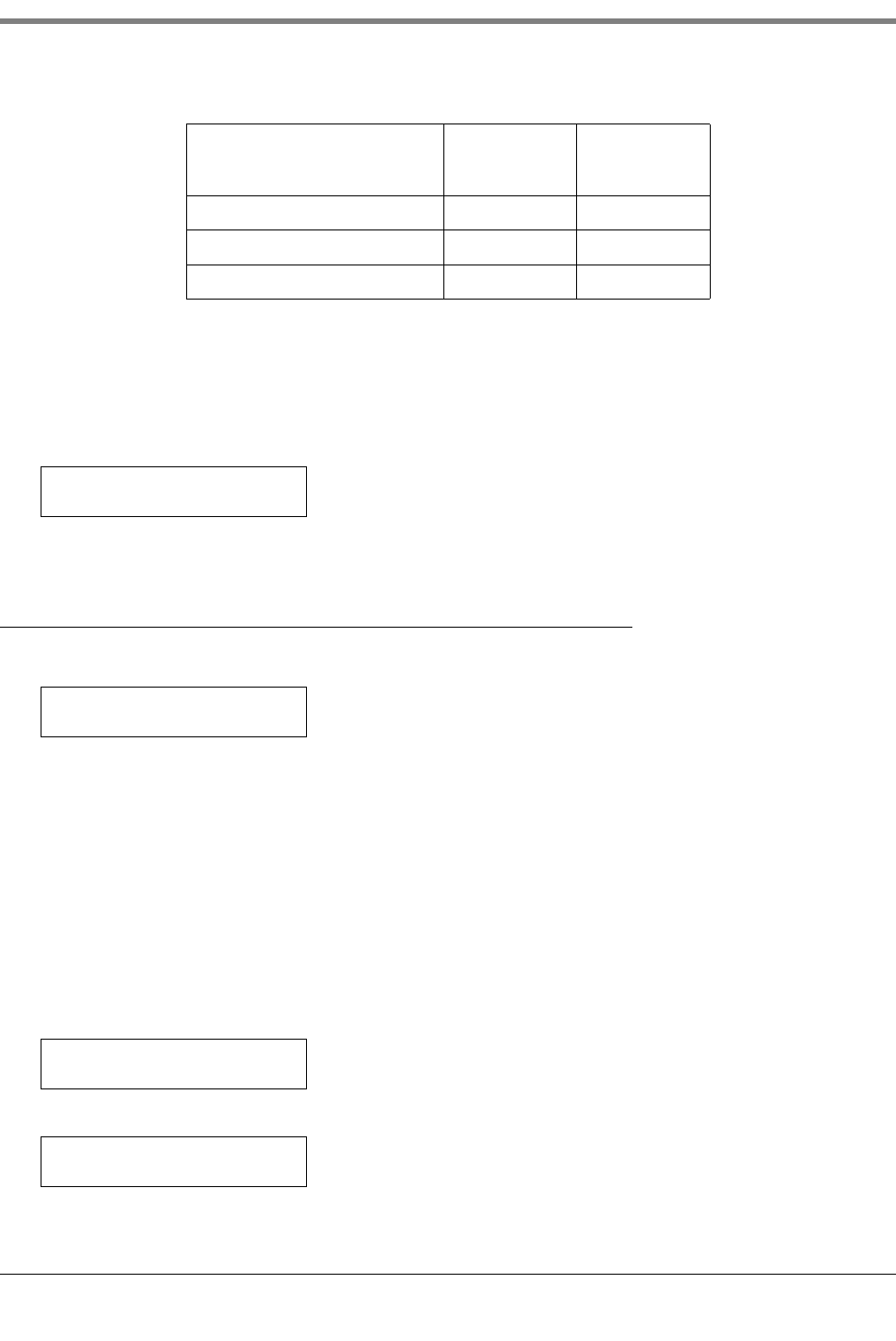
7 In-Tank Setup
Tank Density
7-4
To enter the Thermal Coefficient, press CHANGE and enter the coefficient in U.S. or Metric units, depending on
the units specified in System Setup (Be careful to add the correct number of zeros to the right of the
decimal point. An incorrect entry can cause test failures and other problems).
Contact your authorized Veeder-Root Service Representative for thermal coefficients for British Imperial units.
Press ENTER to confirm your entry. The system displays:
Press STEP to continue.
Tank De ns i ty
If necessary, press STEP until you see the message:
A value of 0 indicates that the density for the product in this tank has not been entered, or a delivery has ocurred,
or the thermal coefficient changed. For Tank Density enter any one of the product’s values below (units are not
entered):
•Mass per unit volume at reference temperature (density),
•Specific Gravity,
•API number
•A fourth way to enter Density is by entering the known Thermal Coefficient of the product in the tank (in the
setup step above) and letting the console automatically calculate Tank Density using the Thermal Coefficient
value (density value is not displayed).
If necessary, press CHANGE and enter the density of the product in this tank as shown in the example below:
Press ENTER:
If this value is accepted, it will be converted to actual density (but the user entered value is displayed).
Water 0.00012 0.00022
Washer Fluid 0.00047 0.00085
Used Oil 0.00044 0.00079
Table 7-1.- Typical Thermal Coefficients
Product
Thermal
Coefficient
(U.S. Units)
Thermal
Coefficient
(Metric Units)
THERMAL COEFF: 0.000XX
PRESS <STEP> TO CONTINUE
T1: (Product Label)
DENSITY :0.0000
If Mass/Density is disabled
this window will not appear!
T1: (Product Label)
DENSITY :5.9987
DENSITY
PRESS <STEP> TO CONTINUE
:5.9987
7-5
7 In-Tank Setup
Tank Diameter
NOTE: A Setup Data Warning is posted from the time the Mass/Density feature is enabled until a density or
thermal coefficient value is entered for that tank, clearing the alarm.
Press STEP to continue.
Tank Diameter
If necessary, press STEP until you see the message:
Enter the inside diameter of the selected tank (for a linear tank, enter the inside tank height in place of the tank’s
inside diameter). You can find this dimension on the Tank Chart. To enter the diameter, press CHANGE, enter the
diameter, then press ENTER to confirm your entry. The system displays:
Press STEP to continue.
Tank Profile
If necessary, press STEP until you see the message:
Use this display to select the number of height/volume values you wish to enter for the tank. The system will use
these values, along with the Tank’s inside diameter (or height), to interpolate volume readings along the entire
length of the probe.
TANK PROFILE SELECTIONS
1 point
This method requires only the 100% (full) volume to profile the tank. This selection is used for horizontally installed,
flat-ended cylindrical tanks, and should be selected when AccuChart is available for this type tank.
4 Points
This method requires 4 volumes to profile the tank. The requested volumes are at percentages of height (e.g., the
75% volume of a 96” diameter tank = the volume at a height which is 75% of 96” or 72”). This selection can be
used for all rounded- and dished-end tanks, and should be selected when AccuChart is available for these type
tanks.
20 points
This method requires 20 volumes to profile the tank. The requested volumes are at percentages of height (e.g., the
5% volume of a 96” diameter tank = the volume at a height which is 5% of 96” or 4.8”). This selection can be
used for all rounded- and dished-end tanks.
50 Points
This method requires entry of height/volumes pairs for up to 50 points to profile the tank (tank diameter/full volume
is counted as one of the 50 points). It is recommended that these pairs be derived by strapping the tank. This
selection can be used for all tanks.
T1: (Product Label)
TANK DIAMETER: 000.00
TANK DIAMETER: XXX.XX
PRESS <STEP> TO CONTINUE
T1: (Product Label)
TANK PROFILE 1PT
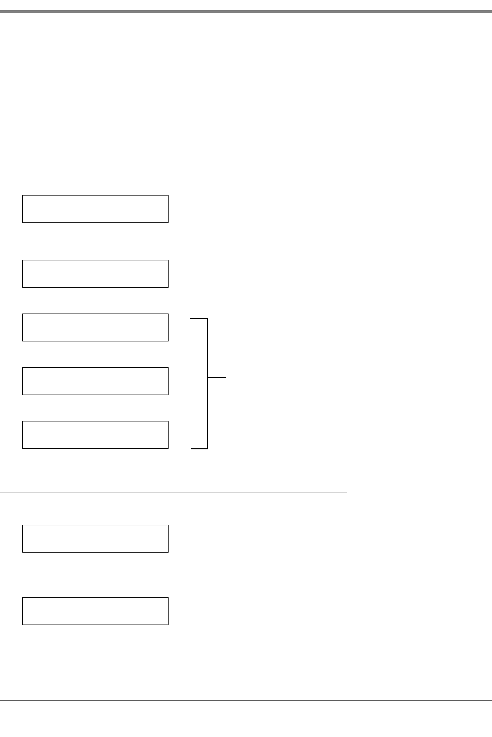
7 In-Tank Setup
Full Volume
7-6
Linear
This method requires only the 100% (full) volume to profile the tank. When using the linear tank profile you must
enter the inside height of the tank in place of the inside diameter of the tank in Tank Diameter setup (see above).
This profile can be used for flat-ended cylindrical tanks standing on end and for rectangular tanks.
PROCEDURE
To accept the Tank Profile shown on the TANK PROFILE message, press STEP. (The system displays the FULL
VOL message.)
To change the Tank Profile, press CHANGE until the desired profile appears. Press ENTER to confirm your choice.
The system displays:
To accept the displayed tank profile, press STEP to continue. To select another tank profile, 4 pt, 20 pt, Linear, or
50 pt, press CHANGE until the desired profile is displayed:
Press ENTER:
If sure, press CHANGE:
Press ENTER to confirm:
Full Volume
If necessary, press STEP until you see the message:
To enter the full volume of the tank (100% height) press CHANGE. Enter the volume in gallons or litres, depending
on the units established in System Setup. Press ENTER to confirm your entry. The system displays:
T1: (Product Label)
TANK PROFILE 1PT
TANK PROFILE: XXXXXX
T1: (Product Label)
These messages appear when 50 pt profile is selected.
Changing profile selection will erase the previously
entered 50 point profile!
ARE YOU SURE? : NO
CLEAR EXISTING PROFILE
ARE YOU SURE? : YES
CLEAR EXISTING PROFILE
PRESS <STEP> TO CONTINUE
ARE YOU SURE? : YES
T1: (Product Label)
FULL VOL: 000000
FULL VOL: XXXXXX
PRESS <STEP> TO CONTINUE
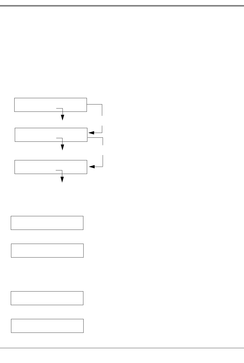
7-7
7 In-Tank Setup
Full Volume
4 OR 20 POINT TANK PROFILES HEIGHT/VOLUME ENTRIES
If you selected 4 or 20 points for Tank Profile press STEP and the system prompts you for additional volumes at
specified heights in the tank. Calculate these values from the Tank Chart. Note: for both profiles (4 or 20 pt), these
volumes are requested as a percentage (e.g., 75% volume means the volume at a point 75% of the height. For a
96” diameter tank with a full volume of 10000 gallons, 75% volume would be the volume at 72”, not 75% of
10,000 gallons). Repeat the procedure described above to enter each prompted volume. When all volumes are
entered, press STEP.
50 POINT TANK PROFILE HEIGHT/VOLUME ENTRIES (TANK CHART SECURITY DISABLED)
If you selected 50 points for Tank Profile and Tank Chart Security is disabled, press STEP and the system displays:
A - Viewing Height/Volume Points
At the display below:
Press ENTER to view the 50 points (top down) and the display appears:
Continue to press STEP to view remaining height/volume points in descending order by height.
B - Adding Height/Volume Points
At the display below:
Press ENTER to add a height/volume point and the display appears:
T1: VIEW HEIGHT/VOL PTS
PRESS <ENTER>
T1: ADD HEIGHT/VOL PTS
PRESS <ENTER>
T1: REMOVE HEIGHT/VOL PT
PRESS <ENTER>
Press STEP
Press STEP
See Paragraph A below
See Paragraph B below
See Paragraph C below
T1: VIEW HEIGHT/VOL PTS
PRESS <ENTER>
T1: (Product Label)
92.16 INCH VOL: 009800
This example shows the first height/volume point in a
96” diameter, 10,000 gallon tank
T1: ADD HEIGHT/VOL PTS
PRESS <ENTER>
T1: (Product Label)
HEIGHT : 000000
7 In-Tank Setup
Full Volume
7-8
Press CHANGE, enter the height:
Press ENTER:
Press STEP:
Press CHANGE, enter the volume at this height:
Press ENTER to accept the entry:
Press STEP and follow the above procedure to continue adding height/volume points until you are finished.
C - Removing Height/Volume Points
At the display below:
Press ENTER and if necessary, press STEP until you display the height/volume point you want to remove:
Press CHANGE:
Press ENTER to confirm:
Press STEP and follow the above procedure to continue removing height/volume points until you are finished.
T1: (Product Label)
HEIGHT : 88.32
HEIGHT : 88.32
PRESS <STEP> TO CONTINUE
T1: (Product Label)
88.32 INCH VOL : 000000
T1: (Product Label)
88.32 INCH VOL : 9200
88.32 INCH VOL : 9200
PRESS <STEP> TO CONTINUE
T1: REMOVE HEIGHT/VOL PT
PRESS <ENTER>
88.32 INCH VOL : 9200
T1 : REMOVE: NO
88.32 INCH VOL : 9200
T1 : REMOVE: YES
T1 : REMOVE: YES
PRESS <STEP> TO CONTINUE
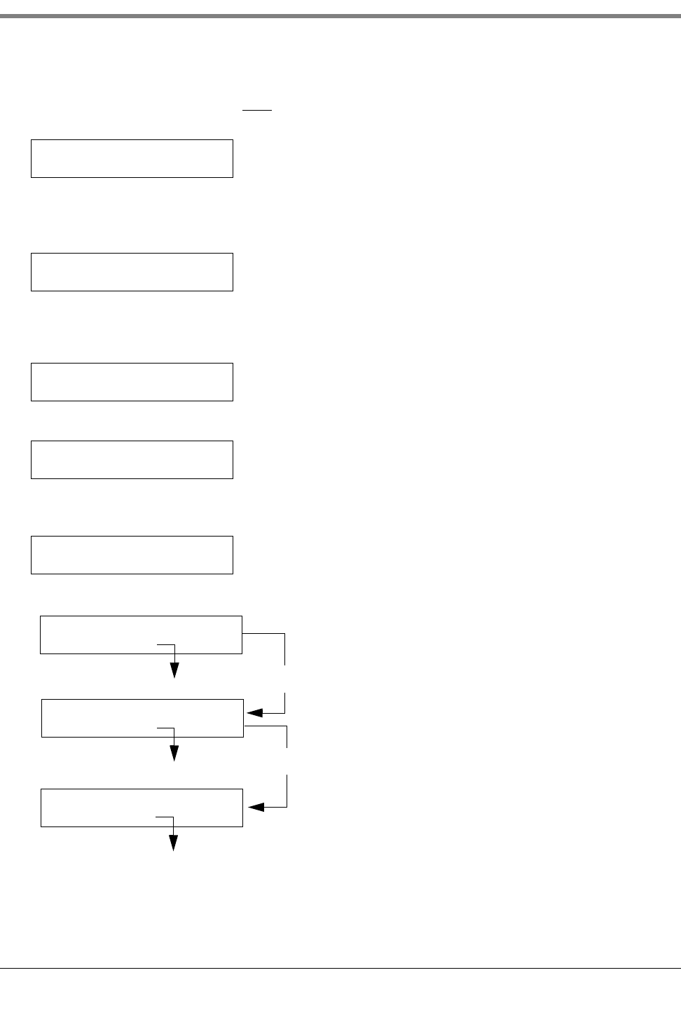
7-9
7 In-Tank Setup
Full Volume
50 POINT TANK PROFILE ENTRIES WITH TANK CHART SECURITY ENABLED
If you selected 50 points for Tank Profile AND Tank Chart Security has been enabled, press STEP and the system
displays:
Enter the 6-digit numeric passcode and press ENTER:
To enter the full volume of the tank (100% height) press CHANGE. Enter the volume in gallons or litres, depending
on the units established in System Setup (NOTE: Full Volume cannot be a volume less than the largest tank chart
volume). Press ENTER to confirm your entry. The system displays:
Press STEP to continue:
The Weights and Measures Officer presses CHANGE and enters the tank capacity. Press ENTER to accept the
value and press STEP to continue:
Press STEP to continue:
TANK PROFILE
ENTER PASSCODE->_______<
: 50 PTS
T1: (Product Label)
FULL VOL: 000000
FULL VOL: XXXXXX
PRESS <STEP> TO CONTINUE
T1: (Product Label)
TANK CAPACITY : 000000
T1: (Product Label)
PROBE S/N : XXXXXX
This display is view-only display and shows the serial number of the probe installed in the tank.
T1: VIEW HEIGHT/VOL PTS
PRESS <ENTER>
T1: ADD HEIGHT/VOL PTS
PRESS <ENTER>
T1: REMOVE HEIGHT/VOL PT
PRESS <ENTER>
Press STEP
Press STEP
See Paragraph D below
See Paragraph E below
See Paragraph F below
7 In-Tank Setup
Full Volume
7-10
D - Viewing Height/Volume Points
At the display below:
Press ENTER to view the 50 points (top down) and the display appears:
Continue to press STEP to view remaining height/volume points in descending order by height.
E - Adding Height/Volume Points
At the display below:
Press ENTER to add a height/volume point and the display appears:
Press CHANGE, enter the height:
Press ENTER:
Press STEP:
Press CHANGE, enter the volume at this height:
Press ENTER to accept the entry:
Press STEP and follow the above procedure to continue adding height/volume points until you are finished.
T1: VIEW HEIGHT/VOL PTS
PRESS <ENTER>
T1: (Product Label)
92.16 INCH VOL: 009800
This example shows the first height/volume point in a
96” diameter, 10,000 gallon tank
T1: ADD HEIGHT/VOL PTS
PRESS <ENTER>
T1: (Product Label)
HEIGHT : 000000
T1: (Product Label)
HEIGHT : 88.32
HEIGHT : 88.32
PRESS <STEP> TO CONTINUE
T1: (Product Label)
88.32 INCH VOL : 000000
T1: (Product Label)
88.32 INCH VOL : 9200
88.32 INCH VOL : 9200
PRESS <STEP> TO CONTINUE
7-11
7 In-Tank Setup
Meter Data Present
F - Removing Height/Volume Points
At the display below:
Press ENTER and if necessary, press STEP until you display the height/volume point you want to remove:
Press CHANGE:
Press ENTER to confirm:
Press STEP and follow the above procedure to continue removing height/volume points until you are finished.
Meter Data Present
If necessary, press STEP until you see the message:
When this feature is enabled, all meter data collected from the dispensers will be reported to the system. If
dispenser data for this tank is being reported to the DIM (i.e., meter data present), then this parameter MUST be
set to YES.
To enable the feature, press CHANGE then ENTER to confirm your choice. The system displays:
Press STEP to continue.
Vapor Loss Factor - International Option
If necessary, press STEP until you see the message:
Press CHANGE and enter the vapor loss factor. Allowable range 0.00 (default) to 0.20%. Press ENTER to
confirm your choice.
Press STEP to continue.
T1: REMOVE HEIGHT/VOL PT
PRESS <ENTER>
88.32 INCH VOL : 9200
T1 : REMOVE: NO
88.32 INCH VOL : 9200
T1 : REMOVE: YES
T1 : REMOVE: YES
PRESS <STEP> TO CONTINUE
T1: (Product Label)
METER DATA PRESENT: NO
METER DATA PRESENT: YES
PRESS <STEP> TO CONTINUE
T1: (Product Label)
VAPOR LOSS FACTOR: 0.00%
Ticketed Delivery must be enabled for this menu
to appear.
7 In-Tank Setup
End Factor
7-12
End Factor
If necessary, press STEP until you see the message:
NOTE: This message appears only if you select METER DATA PRESENT: YES.
The End Factor allows you to select an end shape type (if known) to improve the AccuChart height-to-volume
calculations. Press CHANGE to view your choices. The default setting of NONE automatically bypasses the End
Factor entry and determines tank profile based upon your selection in the “Tank Profile” entry on page 7-5.
Selecting FLAT = an End Factor of 0. Selecting HEMISPHER = an End Factor of 1. Selecting OTHER displays
the message:
If you select NONE, FLAT, or HEMISPHER(E), press ENTER when that choice is visible, then STEP.
If you select OTHER, press ENTER and the End Value message appears. Press CHANGE, enter an End Value of
from 0 to 1.0 in 0.1 increments (0.3 is the recommended end value for dished-end tanks), press ENTER, then
STEP.
Calibration Update
If necessary, press STEP until you see the message:
Note: This message appears only if you select METER DATA PRESENT: YES. Note for international installations,
CAL UPDATE will be PERIODIC if HRM is enabled.
IMPORTANT! For proper setup and operation of this feature, you should:
1. Pressure-test all lines for tightness prior to startup.
2. Calibrate all dispensing meters “on strike” or within one cubic inch per five gallons (8.65 centilitres per 10 litres
[0.865%]).
3. Run all tanks over as wide a range of fuel levels as possible for the first 56 days of operation to improve
calibration accuracy.
When this feature is enabled, you can control when AccuChart updates the calibration chart. The product volume
of your tank may be recalculated when AccuChart updates the calibration chart. If you are performing manual
reconciliation, you will probably want to control when AccuChart changes the product volume of your tank.
AccuChart Features
AccuChart is permitted in line, siphon, or a combination of line and siphon manifolded tanks with the following
restrictions:
•A siphon manifolded set can have no more than 2 tanks.
•There can be no more than 4 sets of siphon manifolded tanks per system.
•AccuChart does not work on manifolded tanks with a BDIM.
T1: (Product Label)
END FACTOR: NONE
T1: (Product Label)
END VALUE: X.X
T1: (Product Label)
CAL UPDATE: IMMEDIATE

7-13
7 In-Tank Setup
Float Size
•Entering a Tank Tilt value is not recommended if the system is performing automatic Business Inventory
Reconciliation and AccuChart.
Calibration Update Selections
To change the method for calibration updates, press CHANGE until the desired method appears. Descriptions of
the available update methods are listed below.
•Immediate--This method provides the most accurate reconciliation results. It is designed for customers using
BIR reports for reconciliation. All calibrations and any resulting changes in product volume go into effect
immediately, as they occur. Changes to the product volume will not generate BIR variance errors.
•Periodic--This method is designed for customers performing manual reconciliation. It allows a maximum of two
changes to product volume, as a result of AccuChart’s calibration. The first calibration update occurs 28 days
from the startup of AccuChart and the second calibration update occurs 56 days from the startup of AccuChart.
•Complete--This method is also designed for customers performing manual reconciliation. It is similar to the
Periodic method, except that it allows only one change to product volume, as a result of AccuChart’s calibration.
The only calibration update occurs 56 days from the startup of AccuChart.
•Never--This setting is used by customers who want to disable AccuChart (two reasons are discussed below).
Height to volume calculations are performed by using the values entered by the customer for diameter, tilt, and
capacity. If the customer changes the method from Never to one of the other methods, the other method goes
into effect immediately.
1. For PLLD installations with line manifolded tanks, the master tank’s check valve’s relief pressure must be
below the pump’s operating pressure. AccuChart will run when there is line manifolding with PLLD line leak
detection; however, you should disable AccuChart if the results are poor.
2. AccuChart also cannot support ISTs if they are communicating to each other. The same is true of Red
Jacket’s CPT and any other configuration where all pumps are On (e.g., Dispensing mode = All [see page 10-7,
page 11-6, or page 15-2 as appropriate]). Disconnecting the ISTs/CPTs links and/or selecting Sequential or
Alternate dispense modes during the calibration period would overcome this limitation.
Press ENTER to confirm your choice. Press STEP to continue.
Float Size
This display requires that you enter the installed Mag probe float size.
Enter the float size installed on the tank’s probe: 4-, 3-, 2-, or 1-inch (101 mm, 76 mm, 50 mm, or 25 mm), 4.0 IN.
PS or Custom. The system automatically recognizes which Mag probe type you have installed and will display only
the applicable float size options. Only select "Custom" if the literature that was shipped with the float specifically
states that you must choose this float size selection, i.e., Chem-ISO and LPG-ISO probes. The installation
literature accompanying Chem-ISO and LPG-ISO probes will list the required values to enter.
Press CHANGE to display the float size you installed (for Custom, see literature accompanying float), then press
ENTER to confirm your choice. Press STEP to continue.
T1: (Product Label)
FLOAT SIZE: 3.0 IN.
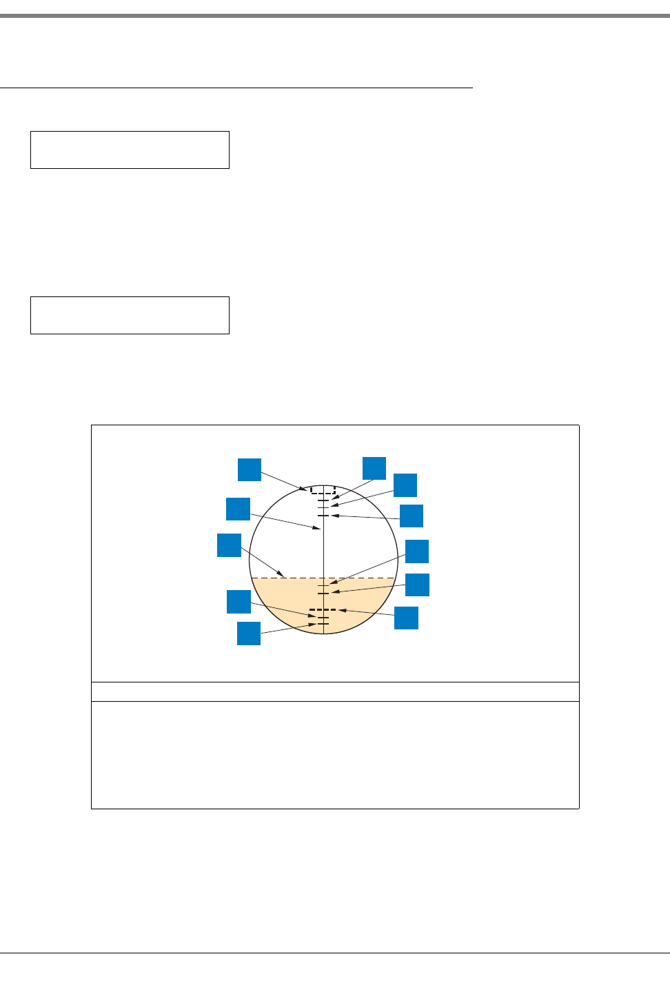
7 In-Tank Setup
Water Warning
7-14
Water Warning
If necessary, press STEP until you see the message:
NOTE: This message does not appear for tanks in which high alcohol probes are installed.
Water Warning identifies a high water level in the bottom of the tank [see Figure 7-1]. It acts as a pre-warning to
the High Water Limit. Set this value at a lower level than High Water Limit.
To enter the Water Warning value for the selected tank, press CHANGE. Enter the limit in inches (5.0 maximum) or
millimeters (199 maximum), depending on the units established in System Setup. Press ENTER to confirm your
entry. The system displays:
Press STEP to continue.
Figure 7-1. Relative Positions of Tank Alarm Limits
Legend for numbered boxes:
1. Probe Canister (Reference) 7. Low Product
2. Probe 8. Delivery Limit
3. Product 9. Overfill Limit
4. High Water Limit 10. High Product
5. Water Warning 11. Max or Label Vol
6. Pump Pickup (Reference)
T1: (Product Label)
WATER WARNING: 00:0
WATER WARNING: XX.X
PRESS <STEP> TO CONTINUE
consoles\tnkalm1.eps
1
2
3
4
5
6
7
8
9
10
11
7-15
7 In-Tank Setup
High Water Limit
High Water Limit
If necessary, press STEP until you see the message:
Note: This message does not appear for tanks in which high alcohol probes are installed.
When water in the tank rises to this High Water Limit value, the system triggers an alarm. Set this value at a level
lower than the pickup for the submersible pump or suction line [see Figure 7-1].
To enter the High Water Limit value for the selected tank, press CHANGE. Enter the limit in inches (5.0 maximum)
or millimeters (199 maximum), depending on the units established in System Setup. Press ENTER to confirm your
entry. The system displays:
Press STEP to continue.
Water Alarm Filter
If necessary, press STEP until you see the message:
Note: This message does not appear for tanks in which high alcohol probes are installed.
The water alarm filter allows the user to determine the response time of the water alarm during a delivery. The
default filter setting of Low will provide the quickest response time but may be susceptible to false alarms if the
turbulence caused by a delivery disturbs the water float. In most applications the water filter setting of Low will not
produce false water alarms. Adjustments to the delivery fill tube may eliminate false water alarms caused by
delivery turbulence. If deliveries are causing an unacceptable number of false water alarms, raise the water filter
level to Medium. If the false water alarms continue, raise the filter level to High.
Press CHANGE to select a different filter, press ENTER to confirm the change, then STEP; otherwise press STEP
to continue.
Max or Label Vol
If necessary, press STEP until you see the message:
Maximum or Label Volume (in international installations this is considered safe working capacity) alarm warns when
the level of fluid in the tank exceeds the volume you enter here. Set this value at a level higher than the High Level
Limit [see Figure 7-1].
T1: (Product Label)
HIGH WATER LIMIT: 0:0
HIGH WATER LIMIT: X.X
PRESS STEP TO CONTINUE
T1: (Product Label)
WATER ALARM FILTER: LOW
T1: (Product Label)
MAX OR LABEL VOL: 000000
7 In-Tank Setup
Overfill Limit
7-16
Press CHANGE and enter the value. Press ENTER to confirm your entry. The system displays:
Overfill Limit
If necessary, press STEP until you see the message:
Overfill Limit warns of a potential overfill only during a bulk delivery. When the volume reaches this limit, the system
can activate an on-site overfill alarm and trigger a printout showing the tank #, date, time, and product. Set this
percentage no greater than 90% of the tank’s capacity (in international installations set this percentage no greater
than 99% of label volume) see Figure 7-1.
Press CHANGE. Enter the percent limit and press ENTER to confirm your entry:
High Product
If necessary, press STEP until you see the message:
High Product warns when the volume of fluid in the tank exceeds the value you enter here. The High Product alarm
occurs whenever this value is exceeded, whether or not a delivery is in progress.
In U.S. installations this is especially useful in applications such as used oil holding tanks, where the rate of fill can
be too gradual for the system to recognize the increase as a delivery and activate the Overfill Limit. It can trigger
the same alarm indications as Overfill Limit. Set this limit at a percentage that is between the Overfill Limit
percentage and 95% (of the tank’s capacity) [see Figure 7-1].
In international installations, this is especially useful to warn of an impending overfill. It can trigger the same alarm
indications as Overfill Limit. Set this limit to 98% if the label volume is greater than 25,000 litres and to 96% if the
label volume is less than 25,000 litres.
Press CHANGE. Enter the percent limit. Press ENTER to confirm your entry. The system displays:
MAX OR LABEL VOL: XXXXXX
PRESS <STEP> TO CONTINUE
T1: (Product Label)
OVERFILL LIMIT: 000%
OVERFILL LIMIT: XX%
PRESS <STEP> TO CONTINUE
T1: (Product Label)
HIGH PRODUCT: 000%
HIGH PRODUCT: XX%
PRESS <STEP> TO CONTINUE
7-17
7 In-Tank Setup
Delivery Limit
Delivery Limit
If necessary, press STEP until you see the message:
Delivery Limit warns when the level of fluid in the tank drops to a level at which the operator calls for a delivery. Set
this percentage at a volume higher than that of the Low Product alarm [see Figure 7-1].
Press CHANGE. Enter the percent limit. Press ENTER to confirm your entry. The system displays:
Low Product
If necessary, press STEP until you see the message:
Low Product warns when volume in a tank recedes to the level you enter here [see Figure 7-1].
In international installations, assuming no water in the tank, this limit should be set no lower than: the tank volume
at 250 mm for Mag probe types 8473, or the tank volume at 125 mm for Mag probe types 8493 (these are the
minimum volumes that can be measured by each probe type).
Press CHANGE. Enter the volume. Press ENTER to confirm your entry. The system displays:
Leak Alarm Limit
If necessary, press STEP until you see the message:
During a leak test, Leak Alarm Limit warns when the cumulative temperature compensated product loss from a
tank reaches the limit value. The system automatically interprets the limit you enter as a negative. It is not
necessary to enter the minus (-) sign.
The Leak Alarm Limit is intended to identify and warn of large losses of product during a leak test. Small changes
in fuel conditions can cause temporary variations in fuel level reading that balance out over the duration of a test in
a tight tank.
To prevent false reports and alarms from being triggered, do not set the limit value to identify losses of 0.2 gph
(0.76 lph) or less during the test period. The Leak Limit should be set to identify losses of 1 gph (4 lph) or greater.
T1: (Product Label)
DELIVERY LIMIT: 000%
DELIVERY LIMIT: XX%
PRESS <STEP> TO CONTINUE
T1: (Product Label)
LOW PRODUCT: 000000
LOW PRODUCT: XXXXXX
PRESS <STEP> TO CONTINUE
T1: (Product Label)
LEAK ALARM LIMIT: 00
7 In-Tank Setup
Sudden Loss Limit
7-18
Consider the leak rate you wish to identify and the length of the test when determining a limit value. A limit value of
8 gallons (32 litres) will warn of a 1 gph (4 lph) leak in 8 hours or a 2 gph (8 lph) leak in 4 hours.
To enter the Leak Alarm Limit, press CHANGE. Enter the limit in gallons (from 1 to 99) or litres (from 4 to 399),
depending on the units set up in System Units. Press ENTER to confirm your entry. The system displays:
Sudden Loss Limit
If necessary, press STEP until you see the message:
Sudden Loss Limit immediately warns of a sudden loss of fuel during a leak test. It is not based on temperature-
compensated volume and is intended to identify losses larger than the Leak Alarm Limit. Typically, you should set
this limit at 25 gallons or 100 litres, or higher.
To enter the Sudden Loss Limit for the selected tank, press CHANGE. Enter the limit in gallons or litres,
depending on the units specified in System Setup. Press ENTER to confirm your entry. The system displays:
Tank Tilt
The following Tank Tilt procedure is for U.S. installations. For international installations, see Appendix A.
Consoles w/ BIR only--Entering a Tank Tilt value is not recommended if the system is performing automatic
Business Inventory Reconciliation and AccuChart.
If the probe is installed in the center of the tank, the value is 000.00 U.S.; 0000.0 Metric.
CALCULATING TANK TILT (H2)
Use the worksheet below to record measurements and perform Tank Tilt calculations for each of the tanks.
1. Stick the tank at the fill riser opening at least three times. Record the average reading in column A of the chart.
2. Before beginning this step, make sure the Tank Tilt in the display above = 0. Record the probe’s Fuel Height (In-Tank
Inventory Function) reading in column B of the chart.
3. Subtract the value entered in column B from the value entered in column A. Record the result in column C.
4. Measure the distance in inches (or millimeters if you use Metric Units) between the probe and fill risers. Record the
measurement in column D.
5. Divide the value in column C by column D to determine the pitch. Record the results in column E.
6. Measure the distance in inches or millimetres from the probe riser to the center of the tank. Record the distance in column
F.
7. Multiply column E by column F to determine Tank Tilt (E X F = Tank Tilt Value). Record the value in column G.
LEAK ALARM LIMIT: XX
PRESS <STEP> TO CONTINUE
T1: (Product Label)
SUDDEN LOSS LIMIT: 000000
SUDDEN LOSS LIMIT: XXXXXX
PRESS <STEP> TO CONTINUE

7-19
7 In-Tank Setup
Probe Offset
ENTERING THE TANK TILT VALUE
To enter the Tank Tilt value for the selected tank, press CHANGE. If the value is negative, press the +/- key so that
a minus (-) sign appears on the display. Enter the value as calculated according to the above procedures. Press
ENTER to confirm your entry. The system displays:
Probe Offset
If necessary, press STEP until you see the message:
This offset is intended for installations in which the probe is not resting on the bottom of the tank. The value you
enter (the distance off bottom) is continually added to the product height, but only to the water height when the
water float exceeds a minimum level. The allowable range is -144.0 to +144.0 inches (-3657.6 to +3657.6 mm);
the default value is 0 inches.
Table 7-2.- Tank Tilt Calculation Worksheet
Tank
No.
A
Stick
Gauge
Avg. Height
@ Fill Riser
B
Probe’s Fuel
Height
Reading
(Probe Riser)
C
(A - B = C)
D
Distance
Fill to Probe
Risers
E
Pitch
(C / D = E)
F
Distance from
Probe Riser to
Center of Tank
G
Tank Tilt*
(E x F = G)
1
2
3
4
5
6
7
8
9
10
11
12
*Tank Tilt may be a positive (+) or negative (-) value. If it is a negative value, BE SURE to change the value symbol to minus (-)
when entering a negative Tank Tilt value.
TANK TILT: ±XXX.XX
PRESS <STEP> TO CONTINUE
T1: (Product Label)
PROBE OFFSET: +0000.00
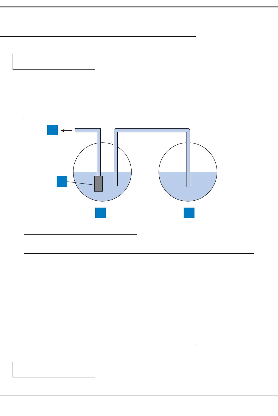
7 In-Tank Setup
Siphon Manifolded Tank Status
7-20
Siphon Manifolded Tank Status
If necessary, press STEP until you see the message:
This entry tells the system which tanks are siphon manifolded together (see Figure 7-2), allowing the system to
provide cumulative volume information on product stored in a siphon manifolded tank set. You only need to enter
this information for one of the tanks in the set. The system automatically enters the information for the other tank(s)
in the set.
Figure 7-2. Siphon Manifolded Tanks
For example, if you are entering setup information for Tank #1 as in the figure, and it is manifolded with Tank #2,
you would press CHANGE until 02 appears (you would press the Right-Arrow key to move to the next field if
another tank were in the group, then press CHANGE until that tank’s number appeared). Press ENTER when you
are done making these changes. (Since you are connecting tanks 1 and 2 in this example, you would just STEP
past this procedure when you are entering the setup for tank 2 (and any additional tank in the set).
Press STEP to continue.
Line Manifolded Tank Status
If necessary, press STEP until you see the message:
Legend for numbered boxes:
1. To dispenser 3. T1
2. Pump 4. T2
T1: SIPHON MANIFOLDED
T#: 00,00,00,00,00,00,00
consoles\siphon1.eps
1
3 4
2
T3: LINE MANIFOLDED
T#: 00,00,00,00,00,00,00
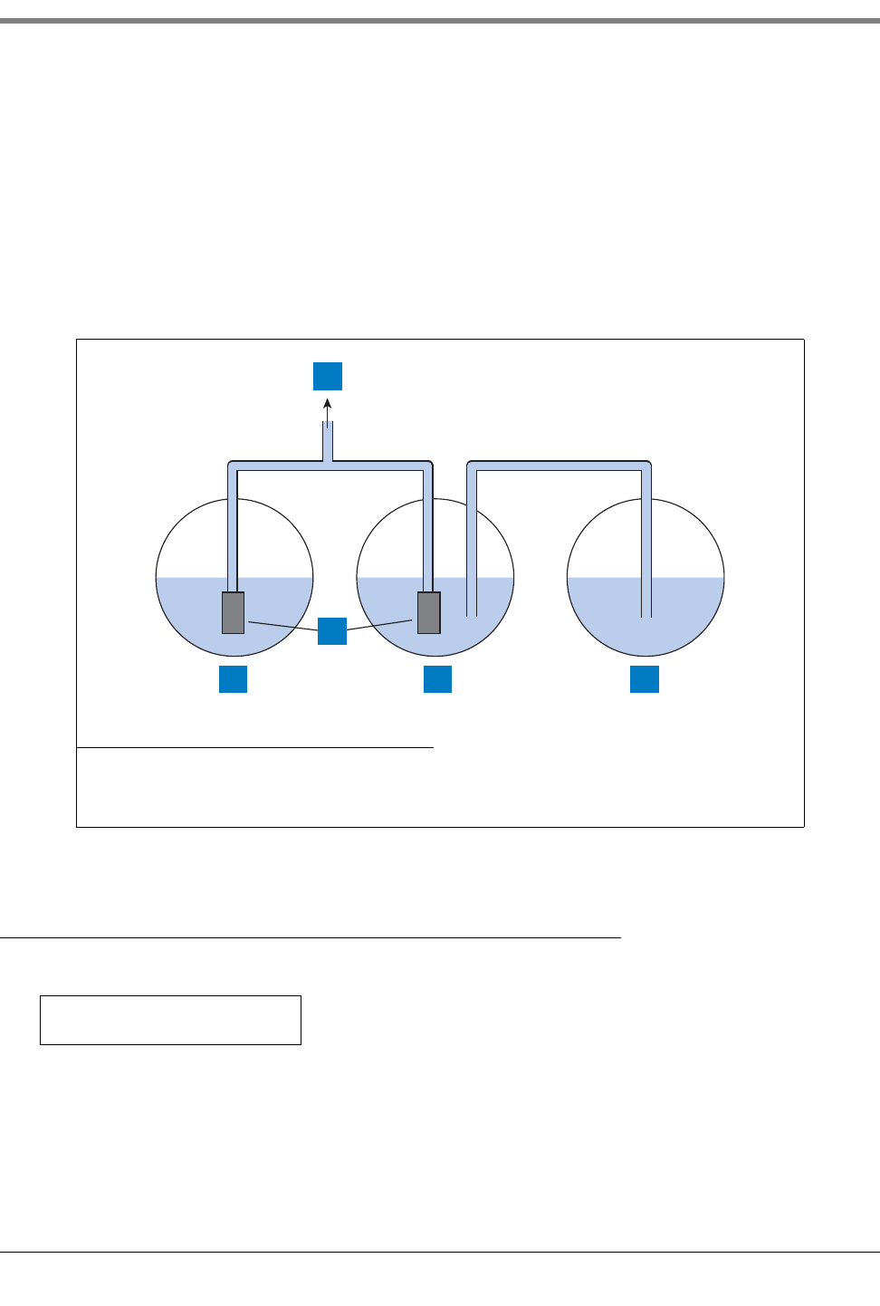
7-21
7 In-Tank Setup
Leak Minimum Periodic
This entry tells the system which tanks are line manifolded together (see Figure 7-3), allowing the system to
provide cumulative volume information on product stored in a line manifolded tank set. You only need to enter this
information for one of the tanks in the line manifolded set. The system automatically enters the information for the
other tank (s) in the set. For example, if you are entering setup information for Tank #3 as shown in the figure, and
it is line manifolded with Tank #1 (itself in a siphon manifolded set), you would press CHANGE until 01 appears
(you would press the Right-Arrow key to move to the next field if another tank were in the line manifolded set, then
press CHANGE until that tank’s number appeared). Press ENTER when you are done making these changes.
Press STEP to continue.
in the set.
Figure 7-3. Line Manifolding A Siphon Manifolded Set To A Single Tank
Leak Minimum Periodic
If necessary, press STEP until you see the message:
This value tells the system the minimum tank volume required to record a passed periodic test. The value reflects
federal, state, and local requirements.
Legend for numbered boxes:
1. To dispenser 4. T2
2. T1 5. T3
3. Pumps
consoles\l&s.eps
1
3
2 4 5
T1: (Product Label)
LEAK MIN PERIODIC: 000%

7 In-Tank Setup
Leak Minimum Annual
7-22
To enter a Leak Minimum Periodic value for the selected tank, press CHANGE. Enter the percent value and press
ENTER to confirm your entry. The system displays:
Leak Minimum Annual
If necessary, press STEP until you see the message:
This value tells the system the minimum tank volume required to record a passed annual test. The value reflects
federal, state, and local requirements.
To enter a Leak Minimum Annual value for the selected tank, press CHANGE. Enter the percent value and press
ENTER to confirm your entry. The system displays:
Periodic Test Type
If necessary, press STEP until you see the message:
You can choose between Standard and Quick. Choose Standard to run a 2-hour periodic leak test. Choose Quick
to perform a 0.2 gph (0.76 lph) test in one hour.
To choose Standard, press STEP. (The system displays the ANNUAL TEST FAIL message.) To choose Quick,
press CHANGE, then press ENTER. The system displays the message:
Annual Test Fail
If necessary, press STEP until you see the message:
LEAK MIN PERIODIC: XXX%
PRESS <STEP> TO CONTINUE
T1: (Product Label)
LEAK MIN ANNUAL: 000%
LEAK MIN ANNUAL: XXX%
PRESS <STEP> TO CONTINUE
T1: PERIODIC TEST TYPE
STANDARD
QUICK
PRESS <STEP> TO CONTINUE
T1: ANNUAL TEST FAIL
ALARM DISABLED
7-23
7 In-Tank Setup
Periodic Test Fail
Annual Test Fail alarms when an annual leak test has not passed. You can enable or disable this alarm. To disable
the alarm, press STEP. (The system displays the PERIODIC TEST FAIL message.) To enable the alarm for the
selected tank, press CHANGE and press ENTER. The system displays the message:
Periodic Test Fail
If necessary, press STEP until you see the message:
The Periodic Test Fail feature allows you to disable or enable an alarm that triggers if a 0.2 gph (0.76 lph) leak test
fails. To disable the alarm, press STEP. (The system displays the GROSS TEST FAIL message.) To enable the
alarm for the selected tank, press CHANGE and press ENTER. The system displays the message:
Gross Test Fail
If necessary, press STEP until you see the message:
The Gross Test Fail feature allows you to disable or enable an alarm that triggers when a 3.0 gph (11.3 lph) leak
test fails. To disable the alarm, press STEP. (The system displays the ANN TEST AVERAGING message.) To
enable the alarm for the selected tank, press CHANGE and press ENTER. The system displays the message:
Annual Test Averaging
If necessary, press STEP until you see the message:
When on, Annual Test Averaging averages the last ten 0.1 gph (0.38 lph) in-tank leak tests. To leave the feature
off, press STEP. (The system displays the PER TEST AVERAGING message.) To turn on the feature, press
CHANGE and press ENTER. The system displays the message:
ALARM ENABLED
PRESS <STEP> TO CONTINUE
T1: PERIODIC TEST FAIL
ALARM DISABLED
ALARM ENABLED
PRESS <STEP> TO CONTINUE
T1: GROSS TEST FAIL
ALARM DISABLED
ALARM ENABLED
PRESS <STEP> TO CONTINUE
T1: (product Label)
ANN TEST AVERAGING: OFF
ANN TEST AVERAGING: ON
PRESS <STEP> TO CONTINUE

7 In-Tank Setup
Periodic Test Averaging
7-24
Periodic Test Averaging
If necessary, press STEP until you see the message:
When on, Periodic Test Averaging activates averaging for the last five 0.2 gph (0.76 lph) in-tank leak tests. To leave
the feature off, press STEP. (The system displays the TANK TEST NOTIFY message.) To turn on the feature, press
CHANGE and press ENTER. The system displays the message:
Tank Test Notify
If necessary, press STEP until you see the message:
When on, the Tank Test Notify feature triggers a warning, allowing the operator to set a relay to shut down the
submersible. To leave the feature off, press STEP. (The system displays the TNK TST SIPHON BREAK message.)
To turn on the feature, press CHANGE and press ENTER. The system displays the message:
Tank Test Siph on B reak
If necessary, press STEP until you see the message:
NOTE: This option requires that the siphon break valve be installed.
When on, Tank Test Siphon Break allows the operator to perform in-tank leak tests on siphon manifolded tanks. To
leave the feature off, press STEP. (The system displays the DELIVERY DELAY message.) To turn on the feature,
press CHANGE and press ENTER. The system displays the message:
Stick Offset (International Option)
The Stick Offset display appears only if Stick Height Offset was enabled in System Setup (“Stick Height Offset -
International Option” on page 5-14). A Stick Offset can be entered for each tank so that the probe (product)
T1: (Product label)
PER TEST AVERAGING: OFF
PER TEST AVERAGING: ON
PRESS <STEP> TO CONTINUE
T1: (Product Label)
TANK TEST NOTIFY: OFF
TANK TEST NOTIFY: ON
PRESS <STEP> TO CONTINUE
T1: (Product Label)
TNK TST SIPHON BREAK: OFF
TNK TST SIPHON BREAK: ON
PRESS <STEP> TO CONTINUE

7-25
7 In-Tank Setup
HRM Reconciliation Warning Limit (International Option)
height “appears” to be equal to a stick gauge reading of the product height - This entry is for operator
convenience only, and as such it has no bearing on product volume calculations.
Press STEP to display the message:
To determine the value to enter for Stick Offset, refer to the Tank's Tilt Worksheet (if completed), or record the
probe height reading and record a stick height reading from the tank. If the probe's fuel height reading is lower
than the stick reading, enter the positive difference between the two. If the probe's reading is higher than the stick
reading, enter the negative difference between the two. For example, if stick height = 52 and probe height = 48,
you enter +4; if stick height = 52 and probe height = 54, you enter -2.
Stick offsets can range from +144 to -144 inches. Press CHANGE, enter the desired offset, then press ENTER.
HRM Reconciliation Warning Limit (International Option)
The warning threshold for the Hourly Reconciliation Monitoring (HRM) feature can be set [to verify that HRM is
enabled, see Figure 4-2 on page 4-4]. This is the average reconciliation variance over a 24-hour period.
If necessary, press STEP until you see the message:
Press STEP to accept the default warning limit of 3 litres. Min. value is 1 litre and max. value is 400 litres.
To change the warning threshold press CHANGE and enter the desired threshold. Press ENTER to confirm the
entry.
The display will confirm your entry with the message:
HRM Reconciliation Alarm Limit (international Option)
The alarm threshold for the Hourly Reconciliation Monitoring feature can be set. This is the average reconciliation
variance over a 24-hour period.
If necessary, press STEP until you see the message:
Press STEP to accept the default alarm limit of 4 litres. Min. value is 1 litre and max. value is 400 litres.
To change the alarm threshold press CHANGE and enter the desired threshold. Press ENTER to confirm the
entry.
The display will confirm your entry with the message:
T1: (Product Label)
STICK OFFSET: XXXX.XX
T1:(Product Label)
RECON WARN LIMIT:000003
T1: RECON WARN LIMIT:00000n
PRESS <STEP> TO CONTINUE
T1:(Product Label)
RECON ALM LIMIT:000004
T1:RECON ALM LIMIT:00000n
PRESS <STEP> TO CONTINUE
7 In-Tank Setup
Delivery Report Delay Time
7-26
Delivery Report Delay Time
If necessary, press STEP until you see the message:
Use this display to set a delay time between the completion of a bulk delivery and the Delivery Increase Report.
This feature prevents generation of false reports during the intervals between multi-compartment drops to one
tank. The feature also allows fuel to “settle out” after a delivery, which is especially important in manifolded tank
groups.
To enter a delay time for the selected tank, press CHANGE. Enter the delay time in minutes (up to 99). Press
ENTER to confirm your entry. The system displays:
Pump Threshold
This feature is for line manifolded tanks and is only enabled when you have the Dispense Mode set to Manifolded:
Sequential.
If necessary, press STEP until you see the message:
When the tank’s volume drops below the entered Pump Threshold percentage, pumping will switch over
immediately to the next available tank in the line manifolded set. Pumping will continue from the current tank for
another 10 seconds to avoid a disruption in dispensing during the switch over. The allowable threshold can be
from 0 to 50 percent of the tank’s full volume (see “Full Volume” on page 7-6). The default value is 10 percent.
Setting Up Additional Tanks
If you have additional tanks to set up, press STEP to return to the ENTER PRODUCT LABEL message. Then
Press TANK/SENSOR to select another tank. Repeat the setup procedures for the new tank beginning with the
section above entitled “Product Labels” on page 7-2.
If you have entered setup information for all tanks, press FUNCTION to exit.
T1: (Product Label)
DELIVERY DELAY: 01
DELIVERY DELAY: XX
PRESS <STEP> TO CONTINUE
T1: (Product Label)
PUMP THRESHOLD : 10.00
8-1
8 In-Tank Leak Tests
The In-Tank Leak Test Setup function allows you to establish and enter the method, timing, and duration of
automatic leak tests.
If you are using the In-Tank Leak Test feature for underground storage tank regulatory compliance, be sure the leak
test limits you establish and enter comply with the test type, accuracy, and frequency requirements as defined by
the regulatory authorities governing your site. In addition, set the in-tank leak test time for a period when no fueling
from or bulk delivery to the tank will occur. Such activity during an in-tank leak test will result in inaccurate test
results.
NOTE: In-Tank Leak tests may also be conducted, as needed, from the Operating mode.
Selecting the In-Tank Leak Test Setup Function
To select In-Tank Leak Test Setup, press FUNCTION until you see the message:
Press STEP to continue.
Leak Test Method: All Tank/Single Tank
If necessary, press STEP until you see the message:
You can choose to run In-Tank Leak Tests for all tanks simultaneously, using the same setup information, or you can
choose to set up and run leak tests for single tanks. If you choose Single Tank, you may run overlapping tests
simultaneously, even though you enter separate setup information for each tank.
NOTE: If you choose ALL TANK and plan to choose CSLD as the test frequency, then all tanks in the system must
be equipped with 0.1 gph (0.38 lph) magnetostrictive probes, and you must have the CSLD software module key
installed in this system. If you choose Single Tank, you must enter test setup information for each tank individually.
To run tests with the same setup information for all tanks, press STEP. The system displays the message:
To run tests with different setup information for each tank, press CHANGE in response to the LEAK TEST
METHOD message, so the system displays SINGLE TANK. Press ENTER and press STEP. The system now
displays:
Whether you choose ALL TANK or SINGLE TANK, the procedure for specifying setup information is almost
identical. The only difference is that the SINGLE TANK method requires you to specify multiple test setups, one for
each tank.
IN-TANK LEAK TEST SETUP
PRESS <STEP> TO CONTINUE
LEAK TEST METHOD
ALL TANK
TEST ALL TANK:
ON DATE
TEST SINGLE TANK: TANK 1
ON DATE
8 In-Tank Leak Tests
Leak Test Frequency
8-2
NOTE: The screen examples shown in this procedure assume that you have selected the ALL TANK method. If you
choose SINGLE TANK, the tank number (for example “TANK 1”) replaces the phrase “ALL TANK” on each screen.
Leak Test Frequency
As mentioned, when you select a leak test method—ALL TANK in this example—the system displays the message:
NOTE: If you are entering setup information using the SINGLE TANK method and have already set up the test for
Tank 1, press TANK to choose the tank number you want to set up.
Do not press ENTER after changing the tank number. You must choose the Test Frequency, as described below,
before pressing ENTER.
You may choose from among the following leak test frequency options:
•ON DATE
•ANNUALLY
•MONTHLY
•WEEKLY
•DAILY (QPLD will be selected if the Leak Test Frequency is set to daily, and the Leak Start Time is disabled.
This feature is only available if HRM has been enabled [see Figure 4-2 on page 4-4]).
•AUTOMATIC (requires that the tank be assigned to a Line Leak Detector [see “Tank Selection” on page 10-7 for
PLLD, “Tank Selection” on page 11-6 for WPLLD, or “Pipe Label and Tank Identification” on page 12-1 for
VLLD], or a Pump Sense input - see Chapter 15)
•CSLD (runs leak tests automatically during idle tank times and stores data for leak test reports)
NOTE: The CSLD option appears only when the tank is equipped with a 0.1 gph (0.38 lph) Mag probe, and the
system has the CSLD software module key installed.
TEST ON DATE
To run the test on a specific date, press STEP in response to the ON DATE message. (To run the test using other
frequency options, follow the procedures described in the appropriate section below.) The system displays the
message:
Press CHANGE, and enter the date on which you want the tests to run. Enter the date in the format MM/DD/
YYYY. Press ENTER to confirm the date:
Press STEP to continue. The system displays the START TIME message. Follow the procedure under “Leak Test
Start Time” on page 8-7.
TEST ALL TANK:
ON DATE
TEST ON DATES: ALL TANKS
DATE: XX/XX/XXXX
DATE: XX/XX/XXXX
PRESS <STEP> TO CONTINUE
8-3
8 In-Tank Leak Tests
Leak Test Frequency
ANNUAL TEST
To run the tests annually, press CHANGE and press ENTER in response to the ON DATE message:
The system displays the message:
Press STEP to continue setting the annual test. The system displays the message:
To set the date of the annual test, press CHANGE until the month during which you want to perform the test
appears, and press the Right Arrow key. Press CHANGE until the week during which you want to perform the test
appears and press the Right Arrow key. Press CHANGE until the day on which you want to perform the test
appears. Press ENTER to confirm the date:
For example, if you chose to run the tests on the Friday of the first week of June, the system would display the
message:
Press STEP to continue. The system displays the START TIME message. Follow the procedure under “Leak Test
Start Time” on page 8-7.
MONTHLY TEST
To run the tests monthly, press CHANGE twice, then press ENTER in response to the ON DATE message:
The system displays the message:
Press STEP to display the message:
To set the date of the monthly test, press CHANGE until the week during which you want to perform the test
appears and press the Right Arrow key. Press CHANGE until the day on which you want to perform the test
appears. Press ENTER to confirm the date:
TEST ALL TANK:
ON DATE
ANNUALLY
PRESS <STEP> TO CONTINUE
TEST ANNUALLY: ALL TANKS
JAN WEEK 1 MON
MONTH WEEK DAY
PRESS <STEP> TO CONTINUE
JUNE WEEK 1 FRI
PRESS <STEP> TO CONTINUE
TEST ALL TANK:
ON DATE
MONTHLY
PRESS <STEP> TO CONTINUE
TEST MONTHLY: ALL TANKS
WEEK 1 MON
WEEK DAY
PRESS <STEP> TO CONTINUE
8 In-Tank Leak Tests
Leak Test Frequency
8-4
Press STEP to continue. The system displays the START TIME message. Follow the procedure under “Leak Test
Start Time” on page 8-7.
WEEKLY TEST
To run the tests weekly, press CHANGE three times, then press ENTER in response to the ON DATE message:
The system displays the message:
Press STEP to display the message:
To set the date of the weekly test, press CHANGE until the day on which you want to perform the test appears.
Press ENTER to confirm the date:
Press STEP to continue. The system displays the START TIME message. Follow the procedure under “Leak Test
Start Time” on page 8-7.
DAILY TEST
To run the tests daily, press CHANGE four times, then press ENTER in response to the ON DATE message:
The system displays the message:
Press STEP to continue. The system displays the START TIME message. Follow the procedure under “Leak Test
Start Time” on page 8-7.
AUTOMATIC TEST
NOTE: This option is available only if Line Leak Detector or Pump Sense is installed, configured and assigned to
the tank, or if External Input Type is configured as Pump Sense and assigned to the tank. (See section entitled
“External Input Type” on page 23-2.)
To run the tests automatically when Line Leak Detector or Pump Sense is installed, press CHANGE five times in
response to the ON DATE message:
TEST ALL TANK:
ON DATE
WEEKLY
PRESS <STEP> TO CONTINUE
TEST WEEKLY: ALL TANKS
MON
DAY
PRESS <STEP> TO CONTINUE
TEST ALL TANKS:
ON DATE
DAILY
PRESS <STEP> TO CONTINUE
TEST ALL TANK:
ON DATE
8-5
8 In-Tank Leak Tests
Leak Test Frequency
Press ENTER to confirm your choice:
If you are setting up the test for All Tanks, the setup is complete. Press FUNCTION to exit.
If you are setting up the test for Single Tanks, the setup is complete for the tank you are setting up. Press STEP
and press TANK to choose the next tank. Return to the beginning of the section “Leak Test Frequency” on page 8-
2 and repeat the procedure for the next tank.
CSLD - OPTION
NOTE: The CSLD option appears only when the tank is equipped with a 0.1 gph (0.38 lph) Mag probe, and the
system has the CSLD software module key installed.
If necessary, press STEP until you see the message:
To run the test using the CSLD frequency option, press CHANGE repeatedly until you see CSLD on the display.
Press ENTER to confirm your choice:
Press STEP to display the message:
You can set the Pd (Probability of Detection) to 95% or 99%. To accept the 95% value, press STEP. (The system
displays the CLIMATE FACTOR message.) If “Custom” appears in this field, a special value has been entered
remotely. Do not change the selection from Custom. This selection is used primarily for European operations.
To change the value to 99%, press CHANGE, then press ENTER to confirm your choice:
Press STEP to display the message:
The default is Moderate and the other choice is Extreme.
Climate Factor - set to Moderate
Press STEP to display the message:
If you are setting up the CSLD test frequency for All Tanks, the setup is complete. Press FUNCTION to exit.
AUTOMATIC
PRESS <STEP> TO CONTINUE
TEST ALL TANK:
ON DATE
CSLD
PRESS <STEP> TO CONTINUE
CSLD Pd: ALL TANKS
Pd = 95%
Pd = 99%
PRESS <STEP> TO CONTINUE
CLIMATE FACTOR: ALL TANKS
MODERATE
TEST ALL TANKS
CSLD
8 In-Tank Leak Tests
Leak Test Frequency
8-6
If you are setting up the CSLD test frequency for a Single Tank, the setup is complete for the tank you are setting
up. Press TANK to choose the next tank. Return to the beginning of the “CSLD - Option” on page 8-5 and repeat
the procedure for the next tank.
Climate Factor - set to Extreme
To choose Extreme, press CHANGE, then press ENTER to confirm your choice:
The following message displays:
If you are setting up the CSLD test frequency for All Tanks, the setup is complete. Press FUNCTION to exit. If you
are setting up the CSLD test frequency for a Single Tank, the setup is complete for the tank you are setting up.
Press TANK to choose the next tank. Return to the beginning of the “CSLD - Option” on page 8-5 and repeat the
procedure for the next tank.
Changing Evaporation Compensation to YES should only be used on individual tanks which have exhibited
evidence of consistent, extreme vapor loss due to fuel evaporation, and which interferes with normal CSLD leak
detection monitoring causing false leak alarms.
If you want to activate CSLD evaporation compensation for a single tank, press CHANGE. Press ENTER to
confirm your choice. The following message displays:
The default for Stage II Vapor is YES. To select No, press CHANGE and ENTER.
Next you must enter CSLD Evaporation Constants for the months of the year. Press FUNCTION until you see the
message:
Press STEP to display the message:
Press ENTER and the Reid Vapor Pressure entry for January displays:
You will need to enter a Reid Vapor Pressure (RVP) value for at least 1 month of the year. The RVP monthly values
for your geographical area can be obtained from your local Petroleum Distributor. The range of valid RVP entries is
0 to 15. The default value is 00.0.
Press CHANGE, enter the Reid Vapor Pressure for January, then press ENTER. If you are entering RVPs for
selected months, Press STEP to display the month(s) for which you want to enter RVP values. For each month,
Press CHANGE, enter the value, then press ENTER to confirm your choice. When you have finished entering the
RVP values, press FUNCTION until you return to In-Tank Leak Test Setup.
EXTREME
PRESS <STEP> TO CONTINUE
EVAP COMP: ALL TANK
EVAP COMP: NO
STAGE II VAPOR: TANK X
STAGE II VAPOR: YES
SYSTEM SETUP
PRESS <STEP> TO CONTINUE
CSLD EVAP CONSTANTS
PRESS <ENTER>
REID VAPOR PRESSURE
JAN: 00.0
8-7
8 In-Tank Leak Tests
Gross Test Auto-Confirm
Gross Test Auto-Confirm
If necessary, press STEP until you see the message:
Note: this message only displays if you have selected CSLD as the test frequency and the tank is assigned to a
pump sensing device (any LLD, pump sense, I/O).
If you are experiencing tank gross test alarms that are proven to be false, enabling this feature may reduce these
false alarms. When enabled, two test fails in a row will be required before a Fail is posted. However, when enabled
this feature will also increase the time needed to detect a gross leak by one 30-45 minute idle period.
To leave this feature disabled, press STEP to continue, or press CHANGE, then ENTER and the message
displays:
Press STEP to continue.
Leak Test Start Time
If necessary, press STEP until you see the message:
You can enable the test by entering a start time or leave the test disabled.
To leave the test disabled, press STEP. (The system displays the TEST RATE message.)
To enter a start time, press CHANGE in response to the START TIME message. Enter the start time and press the
Right Arrow key to select AM or PM. Press ENTER to confirm your entry:
Press STEP to continue.
Leak Test Rate
If necessary, press STEP until you see the message:
You can set the leak test rate at 0.2 gph or 0.1 gph (0.76 lph or 0.38 lph). The default test rate is 0.2 gph. The
system prints a leak report at the completion of the test.
NOTE: The 0.1 gph option appears only when a 0.1 gph Mag probe is installed.
To accept the default rate of 0.2 gph, press STEP. (The system displays the TEST DURATION message.)
GROSS TEST: ALL TANK
AUTO-CONFIRM: DISABLED
GROSS TEST: ALL TANK
AUTO-CONFIRM: ENABLED
START TIME: ALL TANK
TIME: DISABLED
TIME: XX:XX XM
PRESS <STEP> TO CONTINUE
TEST RATE: ALL TANK
0.10 GAL/HR
8 In-Tank Leak Tests
Leak Test Duration
8-8
To set the test rate to 0.1 gph (0.38 lph), press CHANGE, then press ENTER to confirm your choice. The system
displays the following message:
Press STEP to continue.
Leak Test Duration
If necessary, press STEP until you see the following message:
To accept the displayed duration, press STEP. To set another test duration, press CHANGE. The maximum
duration is 6 hours. We recommend a minimum duration of two hours for 0.2 gph (0.76 lph) tests and three hours
for 0.1 gph tests.
Note: If you have Leak Test Early Stop enabled and the console determines that an in-tank leak test has passed
after the first two hours of the test, the test is completed, even though you had entered a Leak Test Duration of
more than 2 hours.
Enter the test duration in hours and press ENTER to confirm your choice:
Press STEP to continue.
Leak Test Early Stop
If necessary, press STEP until you see the following message:
Disabled is the default setting. When enabled this feature will prevent an In-Tank Leak Test from starting under the
following conditions:
1. Fuel level is less than Leak Min Periodic (0.2 gph test rate) or Leak Min Annual (0.1 gph test rate).
2. It is less than 8 hours from a delivery.
3. The product temperature is less than 0°F (-17.6°C) or more than +100°F (+37.4°C).
4. The fuel level is too low.
To accept the disabled condition, press STEP. To enable Leak Test Early Stop, press CHANGE and then ENTER
and the system displays:
Press STEP to continue.
TEST RATE: 0.10 GAL/HR
PRESS <STEP> TO CONTINUE
TEST DURATION: ALL TANK
DURATION: 02
DURATION: XX
PRESS <STEP> TO CONTINUE
TST EARLY STOP: ALL TANKS
DISABLED
TST EARLY STOP: ALL TANKS
ENABLED
8-9
8 In-Tank Leak Tests
CSLD Report Only
CSLD Report Only
If necessary, press STEP until you see the message:
Note: this message only displays if you have selected CSLD as the test frequency.
When enabled this feature inhibits the ‘No CSLD Idle Time’ and ‘CSLD Incr Rate’ alarms, and only prints CSLD
status reports at one of the times selected below:
•End of Month (at 8:00 a.m.),
•Day 15 and End of Month (both at 8:00 a.m.), or
•Day 25 and End of Month (both at 8:00 a.m.)
Press STEP to leave this feature disabled. Press CHANGE until the desired report print time(s) is displayed and
then press ENTER. Press STEP to continue.
Leak Test Report Format
The leak test report format can be set to Normal or Enhanced (select Enhanced to comply with the California Code
of Regulations). The enhanced report will have height, water, temperature, percent volume, rate and threshold
values in addition to the normal report format.
If necessary press STEP until you see the following message:
To accept the displayed format, press STEP. To select the enhanced test format press CHANGE to toggle to
enhanced, then press ENTER to confirm. Press STEP to continue.
Setting Up Additional Tanks
If you are setting up the test for Single Tanks, the setup is complete for the selected tank. To set up additional
tanks, press STEP to return to the TEST SINGLE TANK message:
Then press TANK to choose the next tank. Repeat the setup procedures described above, beginning with the
section titled “Leak Test Frequency” on page 8-2. If you are setting up the test for All Tanks, or have completed
setting up all individual tanks, the setup is complete. Press FUNCTION to exit.
REPORT ONLY: ALL TANK
DISABLED
LEAK TEST REPORT FORMAT
NORMAL
TEST SINGLE TANK: TANK 1
ON DATE
9-1
9 Fuel Management
The Fuel Management Setup function lets you estimate the number of days remaining before the tank reaches the
programmed low product level. The Low Product alarm activates when the amount of fuel falls below the Low
Product Limit set during In-Tank Setup (see “Low Product” on page 7-16 for information on how to set this value.)
This function also keeps track of each product’s average daily sales, which you can display or print. The starting
inventory minus ending inventory, plus deliveries determine the sales for each day of the week. Using this data, the
system calculates the estimated number of days of product remaining.
NOTE: The system assumes tanks with the same product code contain the same product. All information
displayed is for products, not tanks. The product name is the product label of the lowest tank number containing
the product (see “Product Labels” on page 7-2 and “Product Code” on page 7-2).
Selecting the Fuel Management Function
To select Fuel Management Setup, press FUNCTION until you see the message:
Press STEP until you see the setup screen that you want.
Delivery Warning Days
If necessary, press STEP until you see the message:
You can set a threshold number of days of fuel remaining. When any product falls below this threshold, the system
posts a Delivery Needed warning for the product.
To set the threshold number of days of fuel remaining, press CHANGE in response to the DELIVERY WARN
DAYS message. Enter the threshold number of days of fuel remaining. This number can be up to 99.9 days. Enter
0 if you want to disable the warning. Press ENTER to confirm your entry:
Press STEP to continue.
Daily Time to Print Fuel Management Report
If necessary, press STEP until you see the message:
This display lets you set a daily time when the system will automatically print a fuel management report. The report
printed is a “Short Report” (see the system Operator’s Manual).
FUEL MANAGEMENT SETUP
PRESS <STEP> TO CONTINUE
FUEL MANAGEMENT SETUP
DELIVERY WARN DAYS: ##.#
DELIVERY WARN DAYS: XX.X
PRESS <STEP> TO CONTINUE
FUEL MGT AUTO PRINT
TIME: 12:00 AM PM
9 Fuel Management
Average Daily Sales
9-2
To set a daily time to print the report, press CHANGE in response to the FUEL MGT AUTO PRINT message.
Enter the time that you want the report to print each day or press CHANGE to disable. Press the Right or Left
Arrow keys to choose AM or PM. Press ENTER to confirm your entry:
Press STEP to continue.
Average Daily Sales
If necessary, press STEP until you see the message:
Use this display to enter the average daily sales for the selected product. If needed, press TANK to display and
select another product for which to set the average daily sales.
To set the average sales for Sundays, press CHANGE. Enter the average Sunday sales for the product selected.
Press ENTER to confirm your entry:
Press STEP to display the AVG SALES message for Mondays:
Press CHANGE, enter the average daily sales for the selected day and product, and press ENTER. Press STEP.
Repeat the procedures just described until you have entered an average daily sales for each day of the week.
When you are finished entering the average sales for that product, press TANK to choose another product and
enter the average daily sales for it. Repeat the procedure until you have entered the average daily sales for each
product.
NOTE: Whenever the AVG SALES message appears, you may press TANK to select a different product or press
STEP to select a different day of the week.
When you have entered the average daily sales for each product, press FUNCTION to exit.
TIME: XX:XX AM
PRESS <STEP> TO CONTINUE
REGULAR UNLEADED
AVG SALES SUN: 983
AVG SALES-SUN
PRESS <STEP> TO CONTINUE
REGULAR UNLEADED
AVG SALES MON: 983
10-1
10 Pressurized Line Leak Detection
This function allows you to enter information about Pressurized Line Leak Detectors (PLLD) installed on product
pipelines in the system. You must enter data individually for each PLLD.
Line Manifolding Implications for AccuChart
For PLLD installations with line manifolded tanks, the master tank’s check valve’s relief pressure must be below the
pump’s operating pressure. AccuChart will run when there is line manifolding with PLLD line leak detection;
however, you should disable AccuChart if the results are poor. Also leaky valves will degrade AccuChart
performance. To disable AccuChart, select ‘Never’ at the Calibration Update step (In-Tank Setup, page 7-12).
PLLD Setup
Press FUNCTION until you see the message:
Press STEP to continue.
Activating PLLDs
This display allows you to activate up to six PLLDs. In the active state, PLLD attempts to conduct line leak tests
whenever the dispensers are off.
To activate a PLLD, you replace the X with a number by pressing the CHANGE key. To leave a PLLD inactive,
leave an X in its position. You move between PLLDs 1 through 6 by pressing the right or left arrow key.
Press ENTER to confirm your choices (in this example you activate all six). The system displays:
Press STEP to continue.
Labeling PLLDs
This display allows you to label the line being monitored by a particular PLLD (location, fuel type, etc.).
If necessary, press TANK/ SENSOR to select the desired PLLD in the system.
PRESSURE LINE LEAK SETUP
PRESS <STEP> TO CONTINUE
LINE CONFIG - MODULE 1
SLOT # - X X X X X X
SLOT #: 1 2 3 4 5 6
PRESS <STEP> TO CONTINUE
PRESSURE LINE LABEL
Q1:
10 Pressurized Line Leak Detection
Piping Type
10-2
When the appropriate PLLD appears in the display, press CHANGE. (To erase a label press CHANGE again.)
Enter up to 20 alphanumeric characters for the line label and press ENTER. The system confirms your entry with
the message:
Press STEP to continue.
Piping Type
This display allows you to select the type of line being used:
• 2.0 IN. (50 mm) STEEL • 2.0/3.0 IN. (50/76 mm) FIBERGLASS • 1.5 (38 mm) IN. ENVIRN GFLEXII
• ENVIROFLEX PP1501 • ENVIROFLEX PP1500 • WFG COFLX2000 RIBBED
• OMNIFLEX CP1501 • 1.5/2 IN. ENVIRON GFLXD • ENVROFLX PP1503/2503
• ENVROFLX PP1502/2502 • OPW PISCES SP15 • OMNIFLEX CP1503
• OPW PISCES CP15 • APT P175SC • OPW PISCES CP15DW
• OPW PISCES CP20 • USER DEFINED* • PETROTECHNIK UPP EXTRA 63 MM
•OPW PISCES SP20
* To select ‘User Defined’, you must know the Bulk Modulus of the pipe type.
IMPORTANT! To ensure accurate line monitoring, you must enter the piping type that is installed for this line. The
default is Enviroflex PP1501.
Press CHANGE, enter the correct pipe type, press ENTER to confirm your choice and continue.
Piping Length
This display allows you to enter the total length of piping run between the tank and the dispensers. For manifolded
tanks, include the length of piping between the manifolded tank’s check valve and where it connects into the
product line.
NOTE: Refer to the Veeder-Root Line Leak Application Guide (Part No. 577013-465) for approved minimum and
maximum piping lengths.
IMPORTANT! The default line length must be changed to reflect the actual line length or a Setup Data Warning
will occur.
Press STEP until you see the message:
Press CHANGE, enter the actual line length (rounded up to the next foot or meter). Press ENTER to confirm your
choice and press STEP to continue.
Q1: (Pressure Line Label)
PRESS <STEP> TO CONTINUE
Q1: (Pressure Line Label)
TYP: ENVIROFLEX PP1501
Q1: (Pressure Line Label)
LINE LENGTH: XXX
10-3
10 Pressurized Line Leak Detection
User Defined Pipe Type - Setup Parameters
ENTERING LINE LENGTH FOR DUAL SIZE FLEXIBLE PIPE TYPES
If you are using Enviroflex PP1502/2502, Enviroflex PP1502/2503, or 1.5/2 IN Envirn Gflxd, your line length setup
will first display the 1.5 inch size:
Press CHANGE and enter the actual line length (rounded up to the next foot). Press ENTER to confirm your
choice and the line length setup for the 2.5 inch size appears:
Press CHANGE and enter the actual line length (rounded up to the next foot). Press ENTER to confirm your
choice and press STEP to continue.
ENTERING LINE LENGTH FOR 2.0/3.0 IN. FIBERGLASS PIPE TYPE
If you are using fiberglass, your line length setup will first display the 2.0 inch (50 mm) size:
Enter the actual line length (rounded up to the next foot) and press ENTER. If you are not using 2-inch fiberglass,
enter 0 and press ENTER. The display shows the 3-inch (76 mm) size:
If you are not using 3-inch line, enter 0 and press ENTER. If you are using 3-inch line, enter the length and press
ENTER.
IMPORTANT! When using the Fiberglass pipe type, the unused size’s length must be set to zero.
Press STEP to continue.
User Defined Pipe Type - Setup Parameters
If you selected User Defined as the pipe type, your 1st line length setup will display (If the line consists of one pipe
type, one diameter, ignore the second line length entry. If the line is constructed of two connected lengths of the
same pipe type but with different diameters, or of two connected lengths of different pipe types with the same or
different diameters, then enter the required second line’s data.):
Press CHANGE, enter the first line length (rounded up to the next foot) then press ENTER to confirm your choice.
Press STEP to continue.
Q1: (Pressure Line Label)
1.5 IN DIAM. LEN: 501
Q1: (Pressure Line Label)
LINE LENGTH: 301
Q1: (Pressure Line Label)
2.0 IN DIAM. LEN: 501
Q1: (Pressure Line Label)
3.0 IN DIAM. LEN: 351
Q1: (Pressure Line Label)
1ST LINE LENGTH: 501
Q1: (Pressure Line Label)
2ND LINE LENGTH: 0
10 Pressurized Line Leak Detection
Thermal Coefficient
10-4
Press CHANGE, enter the second line length, if necessary, (rounded up to the next foot) then press ENTER to
confirm your choice. Press STEP to continue.
Press CHANGE, enter the first line’s diameter then press ENTER to confirm your choice. Press STEP to continue.
Press CHANGE, enter the second line’s diameter (displays only if second line’s length >0) then press ENTER to
confirm your choice. Press STEP to continue.
Press CHANGE, enter the bulk modulus of the first line then press ENTER to confirm your choice. Press STEP to
continue.
Press CHANGE, enter the second line’s bulk modulus (displays only if second line’s length >0) then press ENTER
to confirm your choice. Press STEP to continue.
Press CHANGE, enter the thermal coefficient for the product in the line then press ENTER to confirm your choice
(see “Coefficient of Thermal Expansion” on page 7-3). Press STEP to continue.
Thermal Coefficient
If you selected APT P175SC, PETROTECHNIK UPP EXTRA 63 MM, or OPW PISCES SP20 as the pipe type, you
must enter the product’s thermal coefficient after entering the pipe’s length.
Press STEP to continue.
Press CHANGE, enter the thermal coefficient for the product in the line then press ENTER to confirm your choice
(see “Coefficient of Thermal Expansion” on page 7-3). Press STEP to continue.
0.2 gph (0.76 lph) Line Leak Test Scheduling
NOTE: The 0.2 gph (0.76 lph) Line Leak Test is an optional feature. This message will not appear unless the 0.20
Repetitive PLLD software module key is installed in your system:
This feature allows the user to choose the frequency of the 0.2 gph (0.76 lph) tests1:
Q1: (Pressure Line Label)
1ST LINE DIAMETER: 0.00
Q1: (Pressure Line Label)
2ND LINE DIAMETER: 0.00
Q1: (Pressure Line Label)
1ST BULK MODULUS: 0
Q1: (Pressure Line Label)
2ND BULK MODULUS: 0
Q1: (Pressure Line Label)
THERMAL COEFF: 0.00070
Q1: (Pressure Line Label)
THERMAL COEFF: 0.00070
Q1: (Pressure Line Label)
0.20 GPH TEST: DISABLED
10-5
10 Pressurized Line Leak Detection
0.1 gph (0.38 lph) Line Leak Test Scheduling
•Disabled - No manual or automatic 0.2 gph testing is allowed.
•Repetitive - After a dispense, a 3.0 gph (11.3 lph) test is run, followed by a 0.2 gph test. The test blockout
period (selected in Precision Test Duration setup) is then observed. Following the test blockout period, the test
sequence repeats after the next dispense. This selection also enables manual 0.2 gph testing.
•Monthly - At the beginning of every month until a test has passed. This selection also enables manual 0.2 gph
testing.
•Manual - 0.2 gph tests run only when manually started.
Disabled is the default setting. Press STEP for Disabled, or press CHANGE to select other choices, then press
ENTER. Press STEP to continue.
0.1 gph (0.38 lph) Line Leak Test Scheduling
NOTE: The 0.1 gph Line Leak Test is an optional feature. This message will not appear unless the 0.10 Repetitive
PLLD or 0.10 On Demand PLLD software module key is installed in your system.
This feature allows the user to choose the scheduling frequency of the 0.1 gph tests1:
•Disabled (default) - No manual or automatic 0.1 gph testing is allowed.
•Repetitive -After a dispense, a 3.0 gph test is run, a 0.2 gph test is run, followed by the 0.1 gph test. The test
blockout period (selected in Precision Test Duration setup) is then observed. Following the test blockout period,
the test sequence repeats after the next dispense. This selection also enables manual 0.1 gph testing. (Note:
The Repetitive option is not available when the 0.1 On Demand PLLD software module key is installed.)
•Auto - 6 months after the last passed 0.1 gph test. Also enables manual 0.1 gph testing.
•Manual - 0.1 gph tests run only when manually started.
Press STEP for Disabled, or press CHANGE to select other choices, then press ENTER. Press STEP to continue.
Passive 0.1 gph Line Leak Testing
If pipe type selection was either User-Defined or APT P175SC, and the 0.1 gph line leak test scheduling selection
was Auto, the following message will appear:
Use this option if the user desires the most current passing results for 0.1 testing without increasing exposure to
false alarms.
This option does not interfere with the 6-month automatically scheduled 0.1 gph test.
1. When CSLD is available, all 0.2 gph and 0.1 gph line leak testing is subject to test blockout periods. These blockouts are imposed to allow
CSLD ‘pump off’ time to collect tank leak test data. Precision tests are run on an every other day basis. In addition, if the last precision test
result is a pass, there will be a minimum of 60 hours before the next test will be attempted. If necessary, the 60-hour blockout period can be
extended in the Precision Test Duration setup [page 5-15].
Q1: (Pressure Line Label)
0.10 GPH TEST: DISABLED
Q1: (Pressure Line Label)
PASSIVE 0.10 GPH: NO
10 Pressurized Line Leak Detection
Shutdown Rate
10-6
If the Passive 0.1 testing option is selected the system will continue monitoring the line pressure after it has
completed a passing 0.2 test. The test is labeled passive because it will not turn on the pump. If the line pressure
remains stable it will satisfy the requirements for a passing 0.1 test. The passed test will be recorded.This method
cannot identify a leaking line because the line has to be repressurized several times to distinguish a leak from
thermals.
No is the default setting. Press STEP for No, or press CHANGE to select Yes, then press ENTER.
Press STEP to continue.
Shutdown Rate
This feature lets you shut down the line following a failed line leak test. The choices are 3.0 gph, 0.2 gph, 0.1 gph,
or none.
Note: you must have the Precision PLLD software module key installed in your system to select shutdown rates
of 0.2 gph or 0.1 gph.
Press STEP to accept the 3.0 gph (11.3 lph) shutdown rate, or press CHANGE until the desired shutdown rate
appears, then ENTER to confirm your choice. NOTE: If you select a 0.1 gph (0.38 lph) shutdown rate, a failed 0.1
gph, 0.2 gph (0.76 lph), or 3.0 gph leak test will disable dispensing. If you select a shutdown rate of 3.0 gph, then
only a failed 3.0 gph leak test will disable dispensing, while a failed 0.2 gph or 0.1 gph leak test will just trigger an
alarm. If you select None, no failed test will shut down the line.
Press STEP to continue.
Low Pressure Alarm Shutoff
The Low Pressure Alarm Shutoff detects low pressure during a dispense. The Default value is 0 psi (0 kPa), with
programmable values from 0 - 25 psi (0 - 7 kPa). When the pressure drops below the entered shutoff value, the
pump shuts off. The next handle up will restart the pump. A value of 0 will disable this alarm.
For no low pressure shutoff, press STEP. To enter a different Low Pressure Shutoff value, press CHANGE, then
ENTER. Press STEP and enter the desired pressure. Press ENTER, the system confirms your choice with the
message:
Q1: (Pressure Line Label)
SHUTDOWN RATE: 3.0 GPH
Q1: (Pressure Line Label)
LOW PRESSURE SHUTOFF: NO
Q1: (Pressure Line Label)
LOW PRESSURE: 5

10-7
10 Pressurized Line Leak Detection
Tank Selection
Tank Selection
This message appears only if tanks have been configured in the In-Tank Setup procedure.
For no selection press STEP to continue. To enter the number of the tank in which the pump the plld is controlling
is installed, press CHANGE, select the tank number, then press ENTER. The system confirms your choice with the
message:
Press STEP to continue.
Selecting a Dispense Mode
NOTE: This option will only appear if a tank has been selected for the PLLD.
If necessary, press STEP until you see the message:
This entry asks you to select the dispense mode. You can select between:
•STANDARD - Only one pump feeds the line.
•MANIFOLDED: ALTERNATE1 - The pump will run in the tank with the greatest inventory volume.
•MANIFOLDED: SEQUENTIAL1 - The tanks are pumped low one at a time. When the tank’s volume drops
below the entered Pump Threshold percentage, pumping will switch over immediately to the next available tank
in the line manifolded set. Pumping will continue from the current tank for another 10 seconds to avoid a
disruption in dispensing during the switch over. (see “Pump Threshold” on page 7-26).
•MANIFOLDED: ALL PUMPS - All pumps on the line are run.
Press CHANGE until your choice appears, then press ENTER to continue.
Pressure Transducer Type
There are 3 different PLLD transducer types. Each type can be identified as follows: Non-Vented (transducer has
an aluminum top); Vented (transducer has an aluminum top with a slotted vent screw); and High Pressure
(transducer has a plastic top with a metal nameplate [this type is currently being shipped]).
1. To prevent backfilling, the level of all tanks connected to the line will be monitored. If the level of any tank exceeds 95% of the Max
or Label Volume limit (see “Max or Label Vol” on page 7-15), the pump for that tank will also be turned on during dispensing. The
state of the pump that was already ON will not be changed.
Q1: (Pressure Line Label)
NONE
T#: (Pressure Line Label)
PRESS <STEP> TO CONTINUE
Q1: ENTER DISPENSE MODE
XXXXXXXXX
10 Pressurized Line Leak Detection
Pressure Offset
10-8
If you have any one of the three PLLD transducer types, and the line does not have a high pressure pump, you may
use the Non-vented (default) selection for this step. If you have a high pressure pump in the line, you must use a
high pressure transducer and select High Pressure in this step.
Press CHANGE until your choice appears, then press ENTER to continue.
Pressure Offset
New transducers are now factory sealed and their internal chamber cannot be equalized to atmospheric pressure
by opening a vent screw as in the past. The Pressure Offset test procedure described in this section must be
performed when using new PLLD transducers with serial numbers of 100,000 or above, in sites located at
altitudes above 2,000 feet (609 m). Note: this procedure can also be used with transducers having serial numbers
below 100,000 instead of using the vent screw to equalize pressure.
Table 10-1 illustrates approximate absolute pressures that are for reference only. The transducer’s actual reading
may vary slightly due to its construction, A/D conversion, head pressure in the lines, etc.
Before this procedure is performed, the pressure in the line MUST be vented to zero. It is recommended that this
procedure be performed immediately after installing the transducer, before energizing the STP.
The first step is to vent the line(s). The second step is to go to the Diagnostic Mode and run a Pressure Offset Test
for each transducer to determine its Pressure Offset value. The third step is to return to the Setup Mode and enter
the Pressure Offset determined in the tests, for each transducer.
VENTING THE LINE
1. Turn Off, lock out, tag power to the STP.
Table 10-1.- Reference of Absolute Pressure Offsets at Various Altitudes
Altitude
ft (m)
Atmospheric Pressure Offset
psi (kPa)
Sea level - 2000 (609) No Change
2000 - 3000 (609 - 914) +1 (+6.9)
3000 - 4000 (914 - 1219) +1.5 (+10.3)
4000 - 5000 (1219 - 1524) +2.0 (+13.8)
5000 - 6000 (1524 - 1829) +2.5 (+17.2)
6000 - 7000 (1829 - 2134) +3.0 (+20.7)
7000 - 8000 (2134 - 2438) +3.4 (+23.4)
8000 - 9000 (2438 - 2743) +3.8 (+26.2)
9000 - 10,000 (2743 - 3048) +4.2 (+28.9)
10,000 - 12,000 (3048 - 3658) +4.6 (+31.7)
12,000 - 14,000 (3658 - 4267) +5.4 (+37.2)
14,000 (4267) - above +5.7 (+39.3)
Q1:
SENSOR: NON-VENTED
OFF
10-9
10 Pressurized Line Leak Detection
Pressure Offset
2. Vent the line to zero.
3. Reseal the line.
4. Turn On power to the STP. Follow the procedure below.
DETERMINING A PRESSURE OFFSET VALUE FOR EACH TRANSDUCER
Press MODE to display DIAGNOSTIC MODE, then FUNCTION until you see the message:
From the PLLD Diag message, press STEP until you see the display below
Press ENTER and the results of the last test displays (‘No Test Data Available’ message appears if this is the first
test):
Press STEP:
To start the test, press ENTER. During the test this message appears:
The Pressure Offset test results message appears when the test ends:
You can print out the test result if you have an optional printer. If you do not have a printer, record the offset value
for the transducer. Press Tank/Sensor and repeat the above procedure for all installed transducers.
The maximum offset pressure range is ±5 psi (±34.5 kPa). If a Pressure Offset is greater than ±5 psi (±34.5 kPa),
repeat the test. If the Pressure Offset is again out of range, either the line pressure is not completely vented or
there is a hardware problem. Refer to PLLD troubleshooting procedures for further instructions.
ENTERING THE PRESSURE OFFSET VALUE FOR EACH TRANSDUCER
Press MODE to return to the SETUP MODE, then FUNCTION until you see the message:
PRESSURE LINE LEAK DIAG
PRESS <STEP> TO CONTINUE
Q 1: PLLD NUMBER 1
P OFFSET TEST <ENTER>
Q 1: PRESS OFFSET TST PSI
9-30-99 03:10AM +3.2
Q 1: START P OFFSET TEST
PRESS <ENTER>
Q 1: PRESSURE OFFSET TEST
MEASURING
Q 1: PRESSURE OFFSET TEST
DONE - OFFSET: +XX.X PSI
PRESSURE LINE LEAK SETUP
PRESS <STEP> TO CONTINUE
10 Pressurized Line Leak Detection
Mechanical Blenders
10-10
Press STEP until you see the message:
Press CHANGE and enter the Pressure Offset value for transducer Q1. If necessary, press the left arrow key to
change the sign (+ or -). Note: enter the Offset value exactly as displayed in the Offset test result message
(including + or - sign). Press TANK/SENSOR, to display another transducer. Press CHANGE to enter its Pressure
Offset value, then ENTER to confirm the change. Repeat this procedure until you have entered Offsets for all
transducers.
Mechanical Blenders
When a site has mechanical blenders, the lines can be assigned to a blend set. This change affects the scheduling
of precision line testing, 0.2 and 0.1.
Press STEP until you see the message:
Press CHANGE:
Press ENTER.
Before proceeding to Blend Partners, enable Mechanical Blender for all lines:
Press CHANGE:
Press ENTER.
Setting Up Additional PLLDs
If you have additional PLLDs to set up, press STEP to return to the PRESSURE LINE LABEL message:
Press TANK to access another PLLD. Repeat the steps described above, beginning with “Labeling PLLDs” on
page 10-1. After you have entered setup information for all PLLDs in the system, press FUNCTION to exit.
Q 1: PLLD NUMBER 1
PRESSURE OFFSET: +XX.X
Q 1: PLLD NUMBER 1
MECHANICAL BLENDER: NO
Q 1: PLLD NUMBER 1
MECHANICAL BLENDER: YES
Q 1: BLEND PARTNERS
Q#: 00, 00
Q 1: BLEND PARTNERS
Q#: 02, 03
PRESSURE LINE LABEL
Q1:

11-1
11 Wireless Pressurized Line Leak Detection
This function allows you to enter information about Wireless Pressurized Line Leak Detectors (WPLLD) installed
on product pipelines in the system. You must enter data individually for each WPLLD.
Line Manifolding Implications for AccuChart
For WPLLD installations with line manifolded tanks, the master tank’s check valve’s relief pressure must be below
the pump’s operating pressure. AccuChart will run when there is line manifolding with WPLLD line leak detection;
however, you should disable AccuChart if the results are poor. Also leaky valves will degrade AccuChart
performance. To disable AccuChart, select ‘Never’ at the Calibration Update step (In-Tank Setup, page 7-12).
WPLLD Setup
Press FUNCTION until you see the message:
Press STEP to continue.
Activating WPLLDs
This display allows you to activate up to a maximum of 9 WPLLDs. In the active state, a WPLLD attempts to
conduct line leak tests whenever the dispensers are off:
To activate a WPLLD, you replace the X with a number by pressing the CHANGE key. To leave a WPLLD inactive,
leave an X in its position. You move between WPLLDs 1 through 3 by pressing the right or left arrow key.
Press ENTER to confirm your choices (in this example you activate the first three). The system displays:
If more than three WPLLDs are installed, pressing STEP will display the second module. Make any required
activations as described above, press ENTER then STEP (repeat if necessary).:
Press STEP to continue.
WPLLD LINE LEAK SETUP
PRESS <STEP> TO CONTINUE
LINE CONFIG - MODULE 1
SLOT # - X X X
SLOT #: 1 2 3
PRESS <STEP> TO CONTINUE
LINE CONFIG - MODULE 2
SLOT # - X X X
11 Wireless Pressurized Line Leak Detection
Labeling WPLLDs
11-2
Labeling WPLLDs
This display allows you to identify the line being monitored by a particular WPLLD (location, fuel type, etc.).
If necessary, press TANK/ SENSOR to select the desired WPLLD in the system.
When the appropriate WPLLD appears in the display, press CHANGE. (To erase a label press CHANGE again.)
Enter up to 20 alphanumeric characters for the line label and press ENTER. The system confirms your entry with
the message:
Press STEP to continue.
Piping Type
This display allows you to select the type of line being used:
• 2.0-IN. (50 mm) STEEL • 2.0/3.0 IN. (50/76 mm) FIBERGLASS
• ENVIROFLEX PP15011•ENVIROFLEX PP1500
1
• OMNIFLEX CP15011• 1.5 IN. (38 mm) ENVIRON GEOFLX D1
13.0 gph (11.3 lph) leak tests only on these piping types.
NOTE: to ensure correct line monitoring, you must enter the piping type that is installed for this line. The default is
Enviroflex PP1501.
Press CHANGE, enter the correct pipe type, press ENTER to confirm your choice and continue.
Piping Length
This display allows you to enter the total length of piping run between the tank and the dispensers. For manifolded
tanks, include the length of piping between the manifolded tank’s check valve and where it connects into the
product line. The allowable length in feet for each of the line types are: steel 30 to 500 ft (10 to 151 m), all others
10 to 500 (3 to 151 m)- except 3 inch (76 mm) fiberglass which is 10 to 220 (3 to 67 m).
IMPORTANT! The default length must be changed to reflect the actual line length or a Setup Data Warning will
occur.
NOTE: Refer to the Veeder-Root Line Leak Application Guide (Part No. 577013-465) for approved minimum and
maximum piping lengths.
Press STEP until you see the message:
WPLLD LINE LABEL
W1:
W1: (WPLLD Line Label)
PRESS <STEP> TO CONTINUE
W1: (WPLLD Line Label)
TYP: ENVIROFLEX PP1501
W1: (WPLLD Line Label)
LINE LENGTH: XXX

11-3
11 Wireless Pressurized Line Leak Detection
0.2 gph (0.76 lph) Line Leak Test Scheduling - Option
Press CHANGE and enter the actual line length (rounded up to the next foot). Press ENTER to confirm your
choice, and continue.
If you are using fiberglass, your line length setup will first display the 2.0 inch (50 mm) size:
Enter the actual line length (rounded up to the next foot) and press ENTER. If you are not using 2.0 inch fiberglass
enter 0 and press ENTER. The display shows the 3.0 (76 mm) size:
If you are not using 3.0 inch line, enter 0 and press ENTER. If you are using 3.0 inch line, enter the length and
press ENTER.
NOTE: When using the Fiberglass pipe type, the unused size’s length must be set to zero.
Press STEP to continue.
0.2 gph (0.76 lph) Line Leak Test Scheduling - Option
NOTE: The 0.2 gph Line Leak Test is an optional feature for steel and fiberglass piping types only. This message
will not appear unless the 0.20 Repetitive WPLLD software module key is installed in your system.
This feature allows the user to choose the scheduling frequency of the 0.2 gph tests1:
•Disabled - No manual or automatic 0.2 gph testing is allowed.
•Repetitive - After a dispense, a 3.0 gph (11.3 lph) test is run, followed by a 0.2 gph test. The test blockout
period (selected in Precision Test Duration setup) is then observed. After the test blockout period, the test
sequence repeats after the next dispense. This selection also enables manual 0.2 gph testing.
•Monthly - At the beginning of every month until a test has passed. This selection also enables manual 0.2 gph
testing.
•Manual - 0.2 gph tests run only when manually started.
Disabled is the default setting. Press STEP for Disabled, or press CHANGE to select other choices, then press
ENTER. Press STEP to continue.
1. When CSLD is available, all 0.2 gph and 0.1 gph line leak testing is subject to test blockout periods. These
blockouts are imposed to allow CSLD ‘pump off’ time to collect tank leak test data. Precision tests are run on an
every other day basis. In addition, if the last precision test result is a pass, there will be a minimum of 60 hours
before the next test will be attempted. If necessary, the 60 hour blockout period can be extended in the Precision
Test Duration setup [page 5-15].
W1: (WPLLD Line Label)
2.0 iN DIAM. LEN: 501
W1: (WPLLD Line Label)
3.0 iN DIAM. LEN: 351
W1: (WPLLD Line Label)
0.20 GPH TEST: DISABLED
11 Wireless Pressurized Line Leak Detection
0.1 gph (0.38 lph) Line Leak Test Scheduling - Option
11-4
0.1 gph (0.38 lph) Line Leak Test Scheduling - Option
NOTE: The 0.1 gph Line Leak Test is an optional feature for steel and fiberglass piping types only. This message
will not appear unless the 0.10 On Demand WPLLD software module key is installed in your system.
This feature allows the user to choose the scheduling frequency of the 0.1 gph tests (See footnote 1 preceding
page):
•Disabled - No manual or automatic 0.1 gph testing is allowed.
•Auto - 6 months after the last passed 0.1 gph test. Also enables manual 0.1 gph testing.
•Manual - 0.1 gph tests run only when manually started.
Disabled is the default setting. Press STEP for Disabled, or press CHANGE to select other choices, then press
ENTER. Press STEP to continue.
Shutdown Rate
This feature lets you shut down the line following a failed line leak test. The choices are 3.0 gph (11.3 lph), 0.2 gph
(0.76 lph), 0.1 gph (0.38 lph), or none.
Note: you must have steel or fiberglass line types, and the Precision WPLLD software module key installed in your
system to select shutdown rates of 0.2 gph or 0.1 gph.
Press STEP to accept the 3.0 gph shutdown rate, or press CHANGE until the desired shutdown rate appears,
then ENTER to confirm your choice. NOTE: if you select a 0.1 gph shutdown rate, a failed 0.1 gph, 0.2 gph, or 3.0
gph leak test will disable dispensing. If you select a shutdown rate of 3.0 gph, then only a failed 3.0 gph leak test
will disable dispensing, while a failed 0.2 gph or 0.1 gph leak test will just trigger an alarm. If you select None, no
failed test will shut down the line.
Press STEP to continue.
Pressure Offset
New transducers are now factory sealed and their internal chamber cannot be equalized to atmospheric pressure
by opening a vent screw as in the past. The Pressure Offset test procedure described in this addendum must be
performed when using new WPLLD transducers with serial numbers of 100,000 or above, in sites located at
altitudes above 2,000 feet (609 m). Note: this procedure can also be used with transducers having serial numbers
below 100,000 instead of using the vent screw to equalize pressure.
See Table 10-1 on page 10-8 for approximate absolute pressures that are for reference only. The transducer’s
actual reading may vary slightly due to its construction, A/D conversion, head pressure in the lines, etc.
Before this procedure is performed, the pressure in the line MUST be vented to zero. It is recommended that this
procedure be performed immediately after installing the transducer, before energizing the STP.
W1: (WPLLD Line Label)
0.10 GPH TEST: DISABLED
W1: (WPLLD Line Label)
SHUTDOWN RATE: 3.0 GPH
11-5
11 Wireless Pressurized Line Leak Detection
Pressure Offset
The first step is to vent the line(s). The second step is to go to the Diagnostic Mode and run a Pressure Offset Test
for each transducer to determine its Pressure Offset value. The third step is to return to the Setup Mode and enter
the Pressure Offset determined in the tests, for each transducer.
VENTING THE LINE
1. Turn Off, lock out, tag power to the STP.
2. Vent the line to zero. IMPORTANT - The STP is actually turned On for the WPLLD test, so be sure to reseal the
lines after venting.
3. Reseal the line.
4. Turn On power to the STP. Follow the procedure below.
DETERMINING A PRESSURE OFFSET VALUE FOR EACH TRANSDUCER
Press MODE to display DIAGNOSTIC MODE, then FUNCTION until you see the message:
From the WPLLD Diag message, press STEP until you see the display below
Press ENTER and the results of the last test displays (‘No Test Data Available’ message appears if this is the first
test):
Press STEP:
To start the test, press ENTER. During the test this message appears:
The Pressure Offset test results message appears when the test ends:
You can print out the test result if you have an optional printer. If you do not have a printer, record the offset value
for the transducer. Press Tank/Sensor and repeat the above procedure for all installed transducers.
The maximum offset pressure range is ±5 psi (±34.5 kPa). If a Pressure Offset is greater than ±5 psi (±34.5 kPa),
repeat the test. If the Pressure Offset is again out of range, either the line pressure is not completely vented or
there is a hardware problem. Refer to WPLLD troubleshooting procedures for further instructions.
OFF
WPLLD LINE LEAK DIAG
PRESS <STEP> TO CONTINUE
W 1: WPLLD NUMBER 1
P OFFSET TEST <ENTER>
W 1: PRESS OFFSET TST PSI
9-30-99 03:10AM +3.2
W 1: START P OFFSET TEST
PRESS <ENTER>
W 1: PRESSURE OFFSET TEST
MEASURING
W 1: PRESSURE OFFSET TEST
DONE - OFFSET: +XX.X PSI
11 Wireless Pressurized Line Leak Detection
Tank Selection
11-6
ENTERING THE PRESSURE OFFSET VALUE FOR EACH TRANSDUCER
Press MODE to return to the SETUP MODE, then FUNCTION until you see the message:
Press STEP until you see the message:
Press CHANGE and enter the Pressure Offset value for transducer W1. If necessary, press the left arrow key to
change the sign (+ or -). Note: enter the Offset value exactly as displayed in the Offset test result message
(including + or - sign). Press TANK/SENSOR, to display another transducer. Press CHANGE to enter its Pressure
Offset value, then ENTER to confirm the change. Repeat this procedure until you have entered Offsets for all
transducers.
Tank Selection
This entry allows a tank’s WPLLD to act as a pump sense input for automatic in-tank leak detection, CSLD,
catastrophic leak testing and other features. This step can only be used for tanks that are not already connected to
a line leak detector. This message appears only if tanks have been configured in the In-Tank Setup procedure.
For no selection press STEP to continue. If yes, press CHANGE until the tank number to which the particular
WPLLD is connected appears, then press ENTER. The system confirms your choice with the message:
Press STEP to continue.
Selecting a Dispense Mode
NOTE: This option will only appear if a tank has been selected for the WPLLD.
If necessary, press STEP until you see the message:
This entry asks you to select the dispense mode. You can select between:
•STANDARD - Only one pump feeds the line.
WPLLD LINE LEAK SETUP
PRESS <STEP> TO CONTINUE
W 1: WPLLD NUMBER 1
PRESSURE OFFSET: +XX.X
W1: SELECT TANK
NONE
T#: (Product Label)
PRESS <STEP> TO CONTINUE
W1: ENTER DISPENSE MODE
XXXXXXXXX
11-7
11 Wireless Pressurized Line Leak Detection
Setting Up Additional WPLLDs
•MANIFOLDED: ALTERNATE1 - The pump will run in the tank with the greatest inventory volume.
•MANIFOLDED: SEQUENTIAL1 - The tanks are pumped low one at a time. When the tank’s volume drops
below the entered Pump Threshold percentage, pumping will switch over immediately to the next available tank
in the line manifolded set. Pumping will continue from the current tank for another 10 seconds to avoid a
disruption in dispensing during the switch over. (see “Pump Threshold” on page 7-26).
•MANIFOLDED: ALL PUMPS - All pumps on the line are run.
Press CHANGE until your choice appears then press ENTER to continue.
Setting Up Additional WPLLDs
If you have additional WPLLDs to set up, press STEP to return to the WPLLD LINE LABEL message:
Press TANK to access another WPLLD. Repeat the steps described above, beginning with “Labeling WPLLDs”
on page 11-2. After you have entered setup information for all WPLLDs in the system, press FUNCTION to exit.
1. To prevent backfilling, the level of all tanks connected to the line will be monitored. If the level of any tank
exceeds 95% of the Max or Label Volume limit (see “Max or Label Vol” on page 7-15), the pump for that
tank will also be turned on during dispensing. The state of the pump that was already ON will not be
changed.
WPLLD LINE LABEL
W1:
12-1
12 Volumetric Line Leak Detection
This function allows you to enter information about Volumetric Line Leak Detectors (VLLDs) installed on product
pipelines in the system. You must enter data individually for each line leak detector.
VLLD Setup
To select Volumetric Line Leak Detector Setup, press FUNCTION until you see the message:
Press STEP to continue.
Activating VLLDs
If necessary, press STEP until you see the following message:
This display allows you to activate the Line Leak Detectors in a module. In the active state, the detector attempts to
conduct line leak tests whenever the dispensers are off. To activate a detector, you must replace the X with a 1. To
leave a detector inactive, choose an X for the position.
To set up the detector, press CHANGE in response to the LINE CONFIG message until the correct choice
appears (1 to activate, X to deactivate). Press ENTER to confirm your choices. The system displays:
NOTE: Slot 1 is the slot at the bottom (not the top) of the compartment as shown on the circuit directory inside the
console door.
Press STEP to continue. The system automatically displays a LINE CONFIG message for each Line Leak Detector
Module installed in the system. When you have configured all the modules, press STEP to display the ENTER
PIPE LABEL message.
Pipe Label and Tank Identification
If necessary, press STEP until you see the following message:
This display allows you to enter a label that will identify the pipe being monitored (location, fuel type, etc.).
If needed, press TANK to access any other Line Leak Detector in the system.
LINE LEAK DETECTOR SETUP
PRESS <STEP> TO CONTINUE
LINE CONFIG - MODULE 1
SLOT# - X
SLOT# - 1
PRESS <STEP> TO CONTINUE
ENTER PIPE LABEL
P#:
12 Volumetric Line Leak Detection
Enter Dispense Mode
12-2
When the appropriate detector appears on the screen, press CHANGE. Enter up to 20 alphanumeric characters
for the pipe label and press ENTER. The system confirms your entry with the message:
Press STEP to display the message:
Enter the number of the tank on which the Line Leak Detector has been installed. This number must be the same
number assigned to the tank by the system during the in-tank setup. (Refer to In-Tank Setup, Section 7.)
NOTE: If you are uncertain of the tank number, print an inventory report and review the tank number assignments.
The system automatically picks up important tank data and includes this information in alarm and status reports.
NOTE: Except for the LINE CONFIG message, you may use the TANK button at any time during the Setup
procedure to access another Line Leak Detector.
To enter the number of the tank on which the Line Leak Detector has been installed, press CHANGE and enter a
number between 1 and 8. Press ENTER. The system confirms your entry with the message:
Press STEP to continue.
Enter Dispense Mode
If necessary, press STEP until you see the message:
This step lets you choose the dispense mode of the tank(s) on which the Line Leak Detector has been installed.
The choices are:
•STANDARD - Only one pump feeds the line.
•MANIFOLDED: ALTERNATE1 - The pump will run in the tank with the greatest inventory volume.
•MANIFOLDED: SEQUENTIAL1 -The tanks are pumped low one at a time. When the tank’s volume drops below
the entered Pump Threshold percentage, pumping will switch over immediately to the next available tank in the
line manifolded set. Pumping will continue from the current tank for another 10 seconds to avoid a disruption in
dispensing during the switch over. (see “Pump Threshold” on page 7-26).
•MANIFOLDED: ALL PUMPS - All pumps on the line are run.
To select Standard (the system default), press STEP. To choose one of the Manifolded options, press CHANGE
until the option you want appears. Then press ENTER. The system confirms your choice with the message:
1. To prevent backfilling, the level of all tanks connected to the line will be monitored. If the level of any tank
exceeds 95% of the Max or Label Volume limit (see “Max or Label Vol” on page 7-15), the pump for that tank
will also be turned on during dispensing. The state of the pump that was already ON will not be changed.
P#: (Pipe Label)
PRESS <STEP> TO CONTINUE
P1: SELECT TANK
TANK#:
TANK #: X
PRESS <STEP> TO CONTINUE
P#: ENTER DISPENSE MODE
STANDARD
12-3
12 Volumetric Line Leak Detection
Fuel Type
Press STEP to continue.
Fuel Type
If necessary, press STEP until you see the message:
Use this display to specify the type of fuel running through the assigned product line. To accept Gasoline for the
Fuel Type, press STEP. (The system proceeds to the 2” PIPING LENGTH message.) To choose Diesel, press
CHANGE in response to the FUEL TYPE message and press ENTER. The system confirms your choice with the
message:
NOTE: If a fuel other than diesel or gasoline is used, select the type that is closest in viscosity to the fuel that is
being dispensed.
Press STEP to continue.
Piping Length and Type
If necessary, press STEP until you see the message:
To enter the length of 2-inch (50 mm) piping in the line, press CHANGE. Enter the length. Press ENTER. The
system confirms your entry:
Press STEP to display the message that allows you to enter the total length of 3-inch (76 mm) piping in the
system:
To enter the 3-inch piping length, press CHANGE. Enter the length. Press ENTER. The system confirms your entry
with the message:
P#: (Dispense Mode)
PRESS <STEP> TO CONTINUE
P#: (Pipe Label)
FUEL TYPE: GASOLINE
FUEL TYPE: DIESEL
PRESS <STEP> TO CONTINUE
P#: (Pipe Label)
2” PIPING LENGTH: 000
2” PIPING LENGTH: XXX
PRESS <STEP> TO CONTINUE
P#: (Pipe Label)
3” PIPING LENGTH: 000
3” PIPING LENGTH: XXX
PRESS <STEP> TO CONTINUE
12 Volumetric Line Leak Detection
Pump Pressure
12-4
Press STEP to display the message:
Use this display to enter the type of piping material of fiberglass, steel, 2-wall fiber (fiberglass), or flexible.
If the piping is made of steel, press STEP to continue, or press CHANGE until the correct piping material appears,
then press ENTER. The system confirms your choice with the message:
Press STEP to continue.
Pump Pressure
If necessary, press STEP until you see the message:
Use this display to enter the pump pressure in the pipeline.
To enter the pump pressure, press CHANGE. Enter the pump pressure to the nearest whole number. Refer to
Table 12-1 for nominal pressures:
Table 12-1.- Submersible Pump Nominal Pressures
Pump Brand Model HP PSI KPA
Red Jacket P33R1 1/3 25 172
P75S1 3/4 27 186
P150S1 1-1/2 29 200
P200U1 2 45 310
X315OU1 1-1/2 43 297
Red Jacket
Big-Flo
P200H3-2MB 2 (2-stage) 44 304
P300H3-2HB 3 (2-stage) 34 237
P500H3-2K 5 (2-stage) 40 279
Tokheim 585-13 1/3 23 159
585-34 3/4 25 172
585-150 1-1/2 27 186
FE Petro STP33 1/3 27 186
STP75 3/4 30 207
STP150 1-1/2 33 228
FE Petro
Hi Capacity
STP3HP 3 33 229
STP5HP 5 39 272
P#: (Pipe Label)
PIPE TYPE: STEEL
PIPING TYPE: (Choice)
PRESS <STEP> TO CONTINUE
P#: (Pipe Label)
PUMP PSI:
12-5
12 Volumetric Line Leak Detection
Shutdown Rate
Press ENTER. The system confirms your entry with the message:
Press STEP to continue.
Shutdown Rate
If necessary, press STEP until you see the message:
Line leak detectors are required by law to shut down the submersible if the system detects a 3.0 gph (11.3 lph)
leak. Using this feature, you may program the system to shut down the submersible when it detects leaks of 3.0
gph, 0.2 gph (0.76 lph), or 0.1 gph (0.38 lph).
To accept a shutdown leak rate of 3.0 gph, press STEP, or press CHANGE until the desired shutdown rate
appears, then press ENTER. The system confirms your choice with the message:
Press STEP to continue.
Pumpside Test
If necessary, press STEP until you see the message:
After the system conducts a line leak test, the line leak detector also runs a pump side test for a pressure loss in
the piping and connections between the in-line check valve and the submersible pump.
Leak detection for components prior to the check valve must be provided. This can be done through use of VLLD
programmed pump side testing, installation of containment sumps and sensors, or other suitable means. Failure to
provide leak detection capability for components prior to the VLLD check valve could allow undetected product
leakage with possible contamination of the environment.
To accept ENABLED press STEP. Press CHANGE, then ENTER to disable the test. The system confirms your
choice with the message:
Press STEP to continue.
PUMP PSI: XXX
PRESS <STEP> TO CONTINUE
P#: (Pipe Label
SHUTDOWN: 3.0 GPH
SHUTDOWN: (X.X) GPH
PRESS <STEP> TO CONTINUE
P#: (Pipe Label)
PUMPSIDE TEST: ENABLED
PUMPSIDE TEST DISABLED
PRESS <STEP> TO CONTINUE
12 Volumetric Line Leak Detection
Wait Mode
12-6
Wait Mode
If necessary, press STEP until you see the message:
Wait Mode selects which method the system uses to determine thermal stability before performing a line leak test,
TEMP. MEAS. (temperature measurement) or VOL. CHG. MEAS. (volume change measurement).
Select TEMP. MEAS. if your system has both an in-tank probe and a ground thermistor installed, and has lines less
than 500 feet (151 m) in length.
Select VOL. CHG. MEAS. if your system does not have both in-tank probe and ground thermistor installed, or your
system has lines over 500 feet in length.
NOTE: If you are using flexible piping, you cannot use the VOL. CHG. MEAS. option.
Press STEP to accept TEMP. MEAS., or CHANGE then ENTER to select VOL. CHG. MEAS. The system
confirms your choice with the message:
Press STEP to continue.
New Blender Protocol (NBP) Partner
If necessary, press STEP until you see the message:
The NBP (New Blender Protocol) Partner feature allows LLDs attached to lines, where products are blended at
the pump using a blend valve, to continue operating if the blend valve leaks. The recommended setting is NONE.
However, if line leak failures repeatedly occur because of blend valve anomalies, choose the corresponding
blended line number (determined by the number of volumetric LLDs).
NOTE: NBP is normally used for mechanical blenders only.
To accept None for the NBP Partner, press STEP. (The system displays the LAST ANNUAL TEST PASSED
message).
To choose a pipeline for the NBP Partner, press CHANGE in response to the NBP PARTNER message. Select
the desired line and press ENTER. The system displays the message:
Press STEP to continue.
P#: (Pipe Label)
WAIT MODE: TEMP. MEAS.
WAIT MODE: VOL. CHG. MEAS.
PRESS <STEP> TO CONTINUE
P#: SELECT NBP PARTNER
NONE
(Blend Partner)
PRESS <STEP> TO CONTINUE
12-7
12 Volumetric Line Leak Detection
Last Annual Test Passed
Last Annual Test Passed
If necessary, press STEP until you see the message:
Use this display to enter the date of the last annual test passed.
NOTE: This message only appears if “Annual Warning” was enabled in System Setup.
To enter the date of the last annual test passed, press CHANGE and enter the date. Press ENTER to confirm your
entry:
Setting Up Additional Line Leak Detectors
If you have additional Line Leak Detectors to set up, press STEP to return to the ENTER PIPE LABEL message:
Press TANK to access a new Line Leak Detector. Repeat the steps described above beginning with “Pipe Label
and Tank Identification” on page 12-1.
If you have entered setup information for all Volumetric Line Leak Detectors in the system, press FUNCTION to
exit.
LAST ANNUAL TEST PASSED
DATE: XX/XX/XXXX
DATE: XX/XX/XXXX
PRESS <STEP> TO CONTINUE
ENTER PIPE LABEL
P#:
13-1
13 Volumetric Line Leak Tests
The Volumetric Line Leak Detection (VLLD) system performs fully automatic test routines after each dispense
cycle. In addition, Volumetric Line Leak Detectors may be programmed for testing at a specified time or date.
The Line Leak Test Setup function lets you set the test method, schedule, and test rate for programmed automatic
line leak tests. Programmed tests continue to run according to the schedule you enter until you change the
parameters or disable the test.
NOTE: Line leak tests also may be started at any time from Operating Mode.
Selecting the Line Leak Test Setup Function
To select Line Leak Test Setup, press FUNCTION until you see the message:
Press STEP to continue.
Leak Test Setup Method: All Lines/Single Lines
If necessary, press STEP until you see the following message:
You can run line leak tests using the same test conditions (frequency, start time, and test rate) for all lines, or you
can establish different test conditions for each line.
To specify the same test conditions for all lines, press STEP. The system displays the following message:
To specify different test conditions for each line, press CHANGE in response to the LEAK TEST METHOD
message, so the system displays SINGLE LINE. Press ENTER and press STEP. The system now displays the
message:
Whether you choose ALL LINES or SINGLE LINE, the procedure for specifying a set of test conditions is
identical. The only difference is that the SINGLE LINE method requires you to specify multiple test conditions, one
for each line.
NOTE: The screen examples shown in this procedure assume that you have selected the ALL LINES method. If
you choose SINGLE LINE, the line number (e.g., LINE 1) appears in place of “ALL LINES” in each message.
LINE LEAK TEST SETUP
PRESS <STEP> TO CONTINUE
LEAK TEST METHOD
ALL LINES
ALL LINES:
ON DATE
SINGLE LINE: LINE 1
ON DATE
13 Volumetric Line Leak Tests
Leak Test Frequency
13-2
Leak Test Frequency
As mentioned, when you select a leak test method—ALL LINES in this example—the system displays the message:
You can now choose to run the line leak tests on a specific date, or you can run the tests on an annual, monthly,
weekly, or daily basis.
ON DATE
To run the test on a specific date, press STEP in response to the ON DATE message. (To run the test annually,
monthly, weekly, or daily, follow the procedures described in the appropriate section below.) The system displays
the message:
Press CHANGE, and enter the date on which you want the tests to run. Enter the date in the format MM/DD/
YYYY. Press ENTER to confirm the date:
Press STEP to continue. The system displays the START TIME message. Follow the procedure under “Leak Test
Start Time” on page 13-4.
ANNUAL TEST
To run the tests annually, press CHANGE and press ENTER in response to the ON DATE message:
The system displays the message:
Press STEP to continue setting the annual test. The system displays the message:
To set the date of the annual test, press CHANGE until the month during which you want to perform the test
appears, and press the Right Arrow key. Press CHANGE until the week during which you want to perform the test
appears and press the Right Arrow key. Press CHANGE until the day on which you want to perform the test
appears. Press ENTER to confirm the date:
ALL LINES:
ON DATE
TEST ON DATE: ALL LINES
DATE: XX/XX/XXXX
DATE: XX/XX/XXXX
PRESS <STEP> TO CONTINUE
ALL LINES:
ON DATE
ANNUALLY
PRESS <STEP> TO CONTINUE
TEST ANNUALLY: ALL LINES
JAN WEEK 1 MON
MONTH WEEK DAY
PRESS <STEP> TO CONTINUE
13-3
13 Volumetric Line Leak Tests
Leak Test Frequency
For example, if you chose to run the tests on the Friday of the first week of June, the system would display the
message:
Press STEP to continue. The system displays the START TIME message. Follow the procedure under “Leak Test
Start Time” on page 13-4.
MONTHLY TEST
To run the tests monthly, press CHANGE twice, then press ENTER in response to the ON DATE message:
The system displays the message:
Press STEP to display the message:
To set the date of the monthly test, press CHANGE until the week during which you want to perform the test
appears, and press the Right Arrow key. Press CHANGE until the day on which you want to perform the test
appears. Press ENTER to confirm the date:
Press STEP to continue. The system displays the START TIME message. Follow the procedure under “Leak Test
Start Time” on page 13-4.
WEEKLY TEST
To run the tests weekly, press CHANGE three times, then press ENTER in response to the ON DATE message:
The system displays the message:
Press STEP to display the message:
JUNE WEEK 1 FRI
PRESS <STEP> TO CONTINUE
ALL LINES:
ON DATE
MONTHLY
PRESS <STEP> TO CONTINUE
TEST MONTHLY: ALL LINES
WEEK 1 MON
WEEK DAY
PRESS <STEP> TO CONTINUE
ALL LINES:
ON DATE
WEEKLY
PRESS <STEP> TO CONTINUE
TEST WEEKLY: ALL LINES
MON

13 Volumetric Line Leak Tests
Leak Test Start Time
13-4
To set the date of the weekly test, press CHANGE until the day on which you want to perform the test appears.
Press ENTER to confirm the date:
Press STEP to continue. The system displays the START TIME message. Follow the procedure under “Leak Test
Start Time” on page 13-4.
DAILY TEST
To run the tests daily, press CHANGE four times, then press ENTER in response to the ON DATE message:
The system displays the message:
Press STEP to continue. The system displays the START TIME message. Follow the procedure under below.
Leak Test Start Time
If necessary, press STEP until you see the message:
You can enable the test by entering a start time or leave the test disabled.
To leave the test disabled, press STEP. (The system displays the TEST RATE message.)
To enter a test start time, press CHANGE in response to the START TIME message. Enter the start time and press
the Right Arrow key to select AM or PM. Press ENTER to confirm your entry:
NOTE: The system automatically establishes the correct test length.
Press STEP to continue.
Leak Test Rate
If necessary, press STEP until you see the message:
DAY
PRESS <STEP> TO CONTINUE
ALL LINES:
ON DATE
TEST DAILY: ALL LINES
PRESS <STEP> TO CONTINUE
START TIME: ALL LINES
TIME: DISABLED
TIME: XX:XX XM
PRESS <STEP> TO CONTINUE
TEST RATE: ALL LINES
0.20 GAL/HR

13-5
13 Volumetric Line Leak Tests
Setting Up Additional Lines
You can set the test leak rate to 0.2 or 0.1 gph (0.76 or 0.38 lph). The default test rate is 0.2 gph. To accept the
default test rate, press STEP. To set the test rate to 0.1 gph, press CHANGE and press ENTER to confirm your
choice. The system displays the following message:
Setting Up Additional Lines
To set up line leak tests for additional lines, press STEP to return to the TEST SINGLE LINE message:
Press TANK to select the next line. Repeat the steps described above beginning with “Leak Test Frequency” on
page 13-2.
If you are setting up the test for All Lines, or have completed setting up all individual lines, the setup is complete.
Press FUNCTION to exit.
X.X GAL/HR
PRESS <STEP> TO CONTINUE
TEST SINGLE LINE: LINE 1
ON DATE
14-1
14 Line Leak Test Lockout
The line leak detection system cannot test a line when AC power to the submersible pump is shut off. Since the
line leak system automatically attempts to conduct a test whenever it receives a signal that the dispenser is off, it is
necessary to lock out line tests when the station or fueling site is shut down and submersible pump power is off. In
some areas, regulations prohibit leaving power to submersibles switched On during hours when the site is
unattended.
The Line Leak Test Lockout function provides a flexible means of locking out line leak tests in accordance with
business hours. This feature sets lockout times for VLLD, WPLLD, and PLLD leak detection systems.
Selecting the Line Leak Test Lockout Function
To select Line Leak Test Lockout Setup, press FUNCTION until you see the message:
Press STEP to continue.
Lockout Schedule
The Lockout schedule identifies the hours not to run line leak tests for the station. There are two types of
schedules for test lockouts: Daily and Individual.
A Daily schedule allows you to enter a Lockout Start Time and Lockout Stop Time. The lockout period will begin
and end at these times every day of the week. Note: By using a Daily schedule and entering the same Start and
Stop Times, you can lock out the line leak test function 24 hours per day. This accommodates vacation shutdowns.
An Individual schedule allows you to enter seven separate lockout periods to provide varying lockout schedules.
You may program each lockout period with a Start Day and Time, and a Stop Day and Time. For example, lockouts
1 through 5 could be programmed to lock out the line leak test each day from Monday through Friday to
accommodate hours when the fueling site is not operating at night. Lockout 6 could be programmed to lock out
the test from Friday night to Monday morning if the site is closed for the weekend.
IMPORTANT! If lockout schedules are programmed incorrectly, the line leak tests may not run. Make sure you have
programmed the settings correctly.
Daily Schedule
Once you have selected the Line Leak Test Lockout Setup function, press STEP to display the message:
To accept the daily schedule, press STEP. The system displays the message:
LINE LEAK LOCKOUT SETUP
PRESS <STEP> TO CONTINUE
LOCKOUT SCHEDULE
DAILY
DAILY LOCKOUT
START TIME: DISABLED
14 Line Leak Test Lockout
Individual Schedules
14-2
Press CHANGE and enter the daily lockout start time. Press the Right Arrow key to select AM or PM. Press
ENTER. The system confirms your entry with the message:
Press STEP to display the message:
Press CHANGE and enter the daily lockout stop time. Press the Right Arrow key to select AM or PM. Press
ENTER. The system confirms your entry with the message:
Press FUNCTION to exit or press STEP to return to the LOCKOUT SCHEDULE message.
Individual Schedules
Once you have selected the Line Leak Test Lockout Setup function, press STEP to display the message:
Press CHANGE and press ENTER. The system confirms your choice with the message:
Press STEP to display the message:
If you want to change the lockout schedule number (you can have up to seven individual lockout schedules), press
TAN K.
NOTE: Do not press ENTER after changing the lockout schedule number. You must enter the Start Day
(described below) before pressing ENTER.
To set the start day for the lockout schedule number displayed, press CHANGE until the day that you want
appears. Press ENTER. The system confirms your choice with the message:
Press STEP to display the message:
TIME: XX:XX XM
PRESS <STEP> TO CONTINUE
DAILY LOCKOUT
STOP TIME: DISABLED
TIME: XX:XX XM
PRESS <STEP> TO CONTINUE
LOCKOUT SCHEDULE
DAILY
INDIVIDUAL
PRESS <STEP> TO CONTINUE
LOCKOUT #: 1
START DAY: MON
START DAY: (Day)
PRESS <STEP> TO CONTINUE
LOCKOUT #1: (Day) (START)
TIME: DISABLED
14-3
14 Line Leak Test Lockout
Entering Additional Test Lockout Schedules
To set the lockout start time for the lockout number displayed, press CHANGE and enter the time. Press the Right
Arrow key to select AM or PM. Press ENTER. The system confirms your entry with the message:
Press STEP to display the message:
To set the stop day for the lockout number displayed, press CHANGE until the day that you want appears. Press
ENTER. The system confirms your choice with the message:
Press STEP to display the message:
Press CHANGE and enter the lockout stop time. Press the Right Arrow key to select AM or PM. Press ENTER.
The system displays the message:
Entering Additional Test Lockout Schedules
To enter additional line leak test lockout schedules, press STEP to return to the LOCKOUT #: START DAY
message, or press FUNCTION to exit.
START TIME: XX:XX XM
PRESS <STEP> TO CONTINUE
LOCKOUT #1:
STOP DAY: MON
STOP DAY: (Day)
PRESS <STEP> TO CONTINUE
LOCKOUT #: (Day) (STOP)
TIME: DISABLED
STOP TIME: XX:XX XM
PRESS <STEP> TO CONTINUE

15-1
15 Pump Sense Setup
The Pump Sense function monitors pump on/off status to ensure that in-tank leak tests are not scheduled when
the pumps are operating.
Selecting the Pump Sense Function
To select Pump Sense Setup, press FUNCTION until you see the message:
Press STEP to continue.
Pump Sense Configuration
If necessary, press STEP until you see the message:
Use this display to tell the system which Pump Sense module inputs are connected to pump controllers.
NOTE: If Pump Sense modules are not installed, this function is not available.
HOW THE SYSTEM CONFIGURES PUMP SENSE MODULES
If Pump Sense modules are installed, the system recognizes their presence and slot locations. The system also
establishes a module number based on the slot location. For example, if Pump Sense modules are installed in slots
#10 and #13, the module in slot #10 automatically becomes module #1 and the module in slot #13 becomes
module #2.
As you specify which positions on a module are connected to which pumps, the system assigns a number, for
each pump, that corresponds to its position on the module. For example, if there is a pump connected to inputs 3
and 4 of module 1, the pump connected to position 3 becomes S3 and the pump connected to position 4
becomes S4.
SPECIFYING PUMP SENSE POSITIONS
If position 1 is connected to a pump controller, press CHANGE and 1 appears (leave the X selection if no pump
input is connected to position 1). Press the Right Arrow key to move to position 2. If a pump is connected to this
input, press CHANGE and a 2 appears (leave X if there is no connection). Repeat these steps until you have all 4
positions for the module selected. Press ENTER to confirm your selections. The system displays the following
message (in this example the first 3 positions are connected to pump controllers:
Press STEP. If more than one module is installed, the system automatically advances to the PUMPSENS CONFIG
message for the next module. Up to 8 modules may be installed. Repeat the steps described above for each
module until you have entered the configured all modules, and the system displays the SELECT TANK message.
PUMP SENSOR SETUP
PRESS <STEP> TO CONTINUE
PUMPSENS CONFIG: MODULE1
SLOT # - X X X X
SLOT # - 1 2 3 X
PRESS <STEP> TO CONTINUE
15 Pump Sense Setup
Pump Sense Tank Number
15-2
Pump Sense Tank Number
If necessary, press STEP until you see the message:
In this step you assign each connected pump controller (selected above) to the tank in which it is installed (only
configured Pump Sense module inputs will appear). The default value is for this display is NONE. Press CHANGE
until the correct tank number for the first pump controller is visible. Press the TANK/SENSOR key to view the next
pump controller. Press CHANGE to select its correct tank number. Press ENTER to confirm your choice. The
system displays the following message:
Press STEP to display the Enter Dispense Mode screen.
Pump Sense Dispense Mode
If necessary, press STEP until you see the message:
In this step you select the dispense mode of the tank. The choices are:
•STANDARD - Only one pump feeds the line.
•MANIFOLDED: ALTERNATE 1- The pump will run in the tank with the greatest inventory volume.
•MANIFOLDED: SEQUENTIAL1 - The tanks are pumped low one at a time. When the tank’s volume drops
below the entered Pump Threshold percentage, pumping will switch over immediately to the next available tank
in the line manifolded set. Pumping will continue from the current tank for another 10 seconds to avoid a
disruption in dispensing during the switch over. (see “Pump Threshold” on page 7-26).
•MANIFOLDED: ALL PUMPS - All pumps on the line are run.
To select Standard (the system default) press STEP, or press CHANGE until the option you want appears. Then
press ENTER. The system confirms your choice with the message:
Press TANK/SENSOR to enter a dispense mode for the next pump controller’s tank. When you have entered
setup information for all pump controller’s tanks, press FUNCTION to exit.
1. To prevent backfilling, the level of all tanks connected to the line will be monitored. If the level of any tank
exceeds 95% of the Max or Label Volume limit (see “Max or Label Vol” on page 7-15), the pump for that
tank will also be turned on during dispensing. The state of the pump that was already ON will not be
changed.
SX: SELECT TANK
NONE
T#: [Product Label)
PRESS <STEP> TO CONTINUE
S1: ENTER DISPENSE MODE
STANDARD
S1: (Dispense Mode)
PRESS <STEP> TO CONTINUE
16-1
16 Pump Relay Monitor Setup
The Pump Relay Monitor function allows you to monitor a pump’s On/Off state to determine if the pump is not
turning off when instructed to do so (TLS controlled pump), or if its relay is stuck (non-TLS controlled pump).
Selecting the Pump Relay Monitor Function
To select Pump Relay Monitor Setup, press FUNCTION until you see the message:
Press STEP to continue.
Pump Relay Monitor Configuration
If necessary, press STEP until you see the message:
Use this display to tell the system which Pump Relay Monitor module inputs are connected to which pumps.
NOTE: If Pump Relay Monitor modules are not installed, this function is not available.
HOW THE SYSTEM CONFIGURES PUMP RELAY MONITOR MODULES
If Pump Relay Monitor modules are installed, the system recognizes their presence and slot locations. The system
also establishes a module number based on the slot location. For example, if Pump Relay Monitor modules are
installed in slots #10 and #13, the module in slot #10 automatically becomes module #1 and the module in slot
#13 becomes module #2.
As you specify which positions on a module are connected to which pumps, the system assigns a number, for
each pump, that corresponds to its position on the module. For example, if there is a pump connected to inputs 3
and 4 of module 1, the pump connected to position 3 becomes r3 and the pump connected to position 4
becomes r4.
SPECIFYING PUMP RELAY MONITOR POSITIONS
If position 1 is connected to a pump controller, press CHANGE and 1 appears (leave the X selection if no pump
input is connected to position 1). Press the Right Arrow key to move to position 2. If a pump is connected to this
input, press CHANGE and a 2 appears (leave X if there is no connection). Repeat these steps until you have all 4
positions for the module selected. Press ENTER to confirm your selections. The system displays the following
message (in this example the first 3 positions are connected to pump controllers:
Press STEP. If more than one module is installed, the system automatically advances to the PUMP MON CONFIG
message for the next module. Up to 8 modules may be installed. Repeat the steps described above for each
module until you have entered the configured all modules, and the system displays the SELECT TANK message.
PUMP RELAY MONITOR SETUP
PRESS <STEP> TO CONTINUE
PUMP MON CONFIG: MODULE1
SLOT # - X X X X
SLOT # - 1 2 3 X
PRESS <STEP> TO CONTINUE
16 Pump Relay Monitor Setup
Labeling Pump Relay Monitors
16-2
Labeling Pump Relay Monitors
This display allows you to identify the pump being monitored by a particular Pump Relay Monitor relay (tank, fuel
type, etc.).
If necessary, press TANK/SENSOR to select the desired Pump Relay Monitor relay in the system.
When the appropriate relay appears in the display, press CHANGE. (To erase a label press CHANGE again.)
Enter up to 20 alphanumeric characters for the line label and press ENTER. The system confirms your entry with
the message:
Press STEP to continue.
Pump Relay Monitor Relay Input
If necessary, press STEP until you see the message:
In this step you assign each connected pump to its relay control type:
•NONE - TLS does not control the pump (default selection)
Choose this selection to monitor the pump each time it switches on, and if it is still running after a 1 - 24 hour
delay (Max Run Time delay), to post an alarm.
•Enter the device code, number, and label of the controlling relay (e.g., Pump Sense, PLLD, WPLLD, VLLD,
Pump Control Output - I/O Combo or 4-Relay). For any of these entries, if the pump continues to run after it is
instructed to turn off, for longer than a 5 - 600 second selectable delay (Stuck Delay), an alarm is posted.
The default value for this display is NONE. Press CHANGE until the correct relay for the first pump is visible.
Press the TANK/SENSOR key to view the next pump controller. Press CHANGE to select its correct relay control
type. Press ENTER to confirm your choice.
Pump Relay Monitor Delay Input
If necessary, press STEP until you see one of the messages below.
If Stuck Delay, select from 5 to 600 seconds (60 is default). If Max Run Time, select from 1 to 24 hours (8 is
default). Press CHANGE to enter another selection and press ENTER to confirm your change.
ENTER PUMP MONITOR LABEL
rX: (pump monitor label)
r1: (pump monitor label)
PRESS <STEP> TO CONTINUE
rX: SELECT PUMP RELAY
NONE
r#: [pump monitor label)
MAX RUN TIME (HR): 8
r#: [pump monitor label)
STUCK DELAY (SEC): 60
If NONE was selected for Pump Relay: If a controlling relay was selected for Pump Relay:
OR

17-1
17 Reconciliation Setup
To select Reconciliation Setup, press FUNCTION until you see the message:
Press STEP to continue.
International installations - for consoles without BIR, the HRM Features DIP switch [see Figure 8 on page 5-3]
must be enabled to enter Reconciliation Setup.
Dispenser Module Data String
If necessary, press STEP until you see the message:
Device codes for the two types of DIM modules are a “M” for Mechanical Dispenser Interface Modules (MDIM),
and an “E” for Electronic Dispenser Interface Modules (EDIM). All EDIM modules install in the Comm Bay of the
console and include; Current Loop, Block, RS-232, IFSF, and RS-485 dispenser interface modules. All MDIM
modules install in the Power Bay of the console and include; Low Voltage Mechanical, and High Voltage
Mechanical Dispenser Interface Modules.
When a BDIM, EDIM, or CDIM is installed, the system will recognize its presence and position in the Comm Bay
of the console. When a MDIM is installed, the system will recognize its presence and position in the Power Bay.
To enter a dispenser module data string, press CHANGE, enter a valid DIM description selected from the
appropriate DIM Installation Manual. The system accepts up to twelve alphanumeric characters; however, it reads
only the first eight. If no data are entered, the DIM defaults are used.
After entering your description, press ENTER. The system confirms your entry with the following message:
If more than one DIM is installed, the system will automatically advance to the next module when setup for one is
complete. You can also press TANK to select a specific module. When all DIM modules have been set up, press
STEP to advance to the next feature. (The system displays the AUTOMATIC DAILY CLOSING message.)
Automatic Daily Closing
If necessary, press STEP until you see the message:
Enter the time you wish to designate as the daily closing time. At the programmed time, the system stores the
current day’s data, and prints a report if “Daily BIR Reports” was set to enabled in System Setup (page 5-5). The
default time is set to 2:00 a.m. This feature cannot be disabled.
RECONCILIATION SETUP
PRESS <STEP> TO CONTINUE
DISP. MODULE DATA STRING
EDIM #X: XXXXXXXX
XDIM#X: [Description]
PRESS <STEP> TO CONTINUE
AUTOMATIC DAILY CLOSING
TIME: 2:00 AM

17 Reconciliation Setup
Automatic Shift Closing
17-2
To accept the default time, press STEP. (The system displays the AUTO SHIFT #1 CLOSING message.) To enter
a different closing time, press CHANGE and enter the desired time. Press the Left or Right Arrow to select AM or
PM. Press ENTER. The system confirms your entry with the message:
Press STEP to continue.
Automatic Shift Closing
If necessary, press STEP until you see the message:
Refer to your Shift Start Times in the System Setup Function (see “Shift Start Times” on page 5-4) to determine
the Automatic Shift Closing Times:
•Shift Closing Time #1 should match Shift Start Time #2
•Shift Closing Time #2 should match Shift Start Time #3
•Shift Closing Time #3 should match Shift Start Time #4
•Shift Closing Time #4 should match Shift Start Time #1
At each programmed time, a new shift close report will automatically be printed [if Shift BIR Reports was enabled
in System Setup (page 5-5)], and stored in memory.
To leave a shift closing time disabled, press STEP. (The system displays the AUTO SHIFT CLOSING TIME
message for the next shift.)
To set a closing time for shift #1, press CHANGE and enter the appropriate time. Press the Left or Right Arrow to
select AM or PM. Then press ENTER. The system confirms your entry with the message:
Press STEP. The system displays the next AUTO SHIFT CLOSING TIME message:
Repeat the above procedures to enter or disable closing times for shifts 2, 3, and 4.When you have entered or
disabled a closing time for shift 4, the system displays the PERIODIC RECONCILIATION MODE message.
Periodic Reconciliation Mode
If necessary, press STEP until you see the message:
Periodic Reconciliation Mode allows you to print a summary report of the activity during the last month or period,
up to the last scheduled daily closing. If you choose MONTHLY, a report will automatically print on the first day of
TIME: XX:XX XM
PRESS <STEP> TO CONTINUE
AUTO SHIFT #1 CLOSING
TIME: DISABLED
TIME: XX:XX XM
PRESS <STEP> TO CONTINUE
AUTO SHIFT #2 CLOSING
TIME: DISABLED
PERIODIC RECONCILIATION
MODE: MONTHLY

17-3
17 Reconciliation Setup
Periodic Reconciliation Alarm
each month. If you choose ROLLING, a report will automatically be printed at the end of the interval you choose (1
- 31 days).
To accept MONTHLY, press STEP. (The system displays the PERIODIC RECONCILIATION ALARM message.)
To switch to ROLLING, press CHANGE and press ENTER. They system displays:
Press STEP. The system displays the following message:
Press CHANGE. Enter the number of days (1–31) between the printing of each periodic reconciliation report.
Then press ENTER. The system confirms your entry with the message:
Press STEP to continue.
Periodic Reconciliation Alarm
If necessary, press STEP until you see the message:
If enabled, the Periodic Reconciliation Alarm will be activated when the programmed threshold for discrepancies
between fuel delivery amount and dispensed fuel amount is exceeded. The system default is 1.00% of throughput
plus 130 gallons (492 litres) offset. In the U.S. the EPA has set this default as a criteria not to be exceeded. The
Periodic Reconciliation Alarm is triggered when the alarm threshold plus offset exceeds the allowed variance.
To leave the Periodic Reconciliation Alarm disabled, press STEP until you see the REMOTE REPORT FORMAT
message. (The system displays the PERIODIC RECONCILIATION ALARM THRESHOLD message.)
To enable the Periodic Reconciliation Alarm, press CHANGE, then press ENTER. The system confirms your entry
with the message:
Press STEP. The system displays the message:
Press CHANGE. Enter the percent of total meter sales (throughput). Note - the Alarm Threshold must be
between 0.00 and 5.00 percent.
Press ENTER. The system confirms you entry with the message:
MODE: ROLLING
PRESS <STEP> TO CONTINUE
PERIODIC RECONCILIATION
LENGTH: XX DAYS
LENGTH: XX DAYS
PRESS <STEP> TO CONTINUE
PERIODIC RECONCILIATION
ALARM: DISABLED
ALARM: ENABLED
PRESS <STEP> TO CONTINUE
PERIODIC RECONCILIATION
ALARM THRESHOLD: 1.00
ALARM THRESHOLD: X.XX
PRESS <STEP> TO CONTINUE

17 Reconciliation Setup
Remote Report Format
17-4
Press STEP. The system displays the message:
Press CHANGE. Enter the number of gallons (litres) of allowable variance. Press ENTER. The system confirms
your entry with the message:
Press STEP to continue.
Remote Report Format
If necessary, press STEP until you see the message:
NOTE: This feature appears only when a remote printer is installed.
You can choose between ROW and COLUMN printer formats. To maintain the default or current setting, press
STEP. (The system displays the MODIFY TANK/METER MAP message.)
To change the default or current setting, e.g., from ROW to COLUMN, press CHANGE, then press ENTER. The
system confirms your entry with the message:
Press STEP to continue.
Temp Compensation
If necessary, press STEP until you see the message:
This feature allows you to choose whether or not to calculate Business Inventory Reconciliation (BIR) volumes
using the Programmable Temperature Compensation (TC) value. For information on entering this value, (See
“Temperature Compensation Value” on page 13.). Select STANDARD (the default) if the meters are not
temperature compensated. Select TC VOLUME if the meters are temperature compensated (the calculation of all
BIR volumes will be based on the TC value).
Press STEP to accept STANDARD. Press CHANGE, then ENTER to select TC VOLUME. The system confirms
your choice with the message:
PERIODIC RECONCILIATION
ALARM OFFSET: 000130
ALARM OFFSET: XXXXXX
PRESS <STEP> TO CONTINUE
REMOTE REPORT FORMAT
SELECT: ROW
SELECT: COLUMN
PRESS <STEP> TO CONTINUE
TEMP COMPENSATION
STANDARD
TC VOLUME
PRESS <STEP> TO CONTINUE
17-5
17 Reconciliation Setup
Meter Calibration Offset
Meter Calibration Offset
If necessary, press STEP until you see the message:
This feature only appears if BIR is installed. The Meter Calibration offset is added to the dispensed amount
received. The default value is 0.000%. You can enter an offset from -1.000 to +1.000%. Press CHANGE and
enter the desired value (e.g., 0.250%). Press ENTER and the system confirms your choice with the message:
Press STEP to continue.
Modify Tank/Meter Map
If necessary, press STEP until you see the message:
Meter data sent from a POS terminal to a TLS 350R console may be collected from a tank that does not have a
probe. Probes collect height data needed for Business Inventory Reconciliation (BIR). This feature allows you to
assign a meter to a tank that does not have a probe so that BIR can still function.
Note: the system must be configured before you can modify the tank/meter map.
Press ENTER to change the tank/meter map and the system displays:
Press or to move to the field you want to change. Then press CHANGE until the correct choice appears.
Press ENTER to confirm your change. Press PRINT to output a report of the current meter map for reference
before proceeding.
The values you may enter are:
Bus--Power or Communications Bay of the console in which the Dispenser Interface Module (DIM) card is placed.
•2: Power Bay (MDIMs)
•3: Communication Bay (BDIMs, EDIMs, or CDIMs)
Slot--Slot in which the DIM card is placed.
•9 - 16 (where 9 is the bottom slot): Slots on Type 2 bus
•1 - 3 (where 1 is the left-most slot): Slots on Type 3 bus
Fuel--Fueling position number reported by the POS terminal. This number can range from 0 - 99. There is a
maximum of 36 unique fueling position numbers.
Meter--Meter number reported by POS terminal. This number can range from 0 - 99. There is a maximum of 6
unique meter numbers per fueling position.
Tank--One of the following:
METER CALIBRATION
OFFSET: +0.000
METER CALIBRATION
OFFSET: +0.250
MODIFY TANK/METER MAP
PRESS <ENTER>
BUS SLOT FUEL METER TANK
X XX XX XX XX
+/-
17 Reconciliation Setup
Modify Tank/Meter Map
17-6
•99: Tank with no probe
•00: Remove meter from tank/meter map
•xx: Any tank number set up for BIR. (Note: only the primary tank needs to be entered for a manifolded set of
tanks. The primary tank is the tank with the lowest number in the set. If a tank number is entered that is part of a
manifolded set, but it is not the primary tank, the selection will be rejected.)
Press STEP until you see the message:
Press STEP to return to the Disp. Module Data String menu if DIM is installed or to Automatic Daily Closing menu
if DIM is not installed; or press ENTER to change the meter offset for the selected fuel position/meter. The system
displays:
Then press CHANGE. The Offset value flashes ‘0’. Enter the desired offset in increments of ±0.01% with a
mximum range of ±9.99% and Press ENTER to confirm your change. Press STEP to continue to the next meter.
Press FUNCTION to exit the Reconciliation Setup function.
INDIVIDUAL METER OFFSET
PRESS <ENTER> Ticketed Delivery must be enabled to view this menu.
FUEL
XX XX XX +X.XX
METER TANK OFFSET
18-1
18 Liquid Sensor Setup
The Liquid Sensor Setup function allows you to enter information about liquid sensors installed in the interstitial
space of double-wall tanks and the sumps of double-wall piping systems, or the oil/water separator sensor. You
must enter data individually for each sensor. The information you enter tells the system the number, location, and
types of sensors installed.
Selecting the Liquid Sensor Setup Function
To select Liquid Sensor Setup, press FUNCTION until you see the message:
Press STEP to continue.
Liquid Sensor Configuration
If necessary, press STEP until you see the message:
Use this display to tell the system which liquid sense wire positions on a module are connected to liquid sensors.
NOTE: If liquid sensors are not installed, this function is not available.
HOW THE SYSTEM CONFIGURES LIQUID SENSORS
If liquid sensors are installed, the system will recognize the presence and module slot locations of Interstitial
Sensor Interface Modules. The system also establishes a module number based on the slot location. For example,
if modules are installed in slots #3 and #6, the module in slot #3 automatically becomes module #1 and the
module in slot #6 becomes module #2.
As you specify which liquid sense wire positions on a module are connected to liquid sensors, the system
establishes a number for each liquid sensor. For example, if there is a liquid sensor in positions 3 and 5 of module
1, the sensor in position 3 becomes L3 and the sensor in position 5 becomes L5.
To indicate that a liquid sensor position is connected, choose the number corresponding to that position. For
example, if the position is 3, choose 3 for the position. To indicate that a position is not connected, choose X for
that position.
SPECIFYING LIQUID SENSOR POSITIONS
To specify whether the first position is connected, press CHANGE until the correct choice appears (1 if the
position is connected, X if it is not). Press the Right Arrow key to move to position 2 and press CHANGE again
until the correct choice appears. Repeat these steps until you have correctly specified all sensor positions. When
you have entered a choice for all positions, press ENTER to confirm your entry. The system displays the following
message:
LIQUID SENSOR SETUP
PRESS <STEP> TO CONTINUE
SENSOR CONFIG - MODULE 1
SLOT # - X X X X X X X X
SLOT # - X X X X X X X X
PRESS <STEP> TO CONTINUE
18 Liquid Sensor Setup
Liquid Sensor Location
18-2
Press STEP. If more than one module is installed, the system automatically advances to the SENSOR CONFIG
message for the next module. Up to 8 modules may be installed. Repeat the steps described above for each
module until you have entered the configuration information (sensor positions) for all modules and the system
displays the ENTER SENSOR LOCATION message.
Liquid Sensor Location
If necessary, press STEP until you see the message:
To enter the location of a liquid sensor, press TANK repeatedly until the sensor you want appears on the second
line of the message (L1, L2, L3, etc.). Press CHANGE and enter the location (up to 20 alphanumeric characters)
of the selected sensor. Typical entries would be: INTERSTITIAL TANK 1; SUMP TANK 1, etc. (This information will
appear on sensor status and sensor alarm reports to make it easier to identify the location of alarms.) Press
ENTER to confirm your entry:
Press STEP to continue.
Liquid Sensor Type
If necessary, press STEP until you see the message:
If necessary press CHANGE to display additional liquid sensor types (see table below):
Sensor Type Entry Applicable V-R Sensor V-R Part Number
Tri-State (Single Float) Sump sensor 794380-208
Steel Tank sensor 794380-420, -460
Fiberglass Interstitial Float sensor 794390-401, -404, -407, -409
Position-Sensitive sensor 794380-323
Media-Isolated Float sensor 794380-430
Normally Closed None None
Dual Float Hydrostatic Dual Point Hydrostatic sensor 794380-302 (soon to superseded by 794380-303)
Dual Float Discriminating* Discriminating Pan sensor 794380-322
Discriminating Sump sensor 794380-352
Dual Float High Vapor Discriminating Pan sensor 794380-322
Discriminating Sump sensor 794380-352
Interceptor (European - limited to
certain specific Interceptor types)
Interceptor sensor 720-000-1000
*For Oil/Water Separator sensors (P/N 794690-XXX) use Dual Float Discriminating for sensor type.
ENTER SENSOR LOCATION
L1:
L1: (Sensor Location)
PRESS <STEP> TO CONTINUE
L1: ENTER SENSOR TYPE
TRI-STATE (SINGLE FLOAT)

18-3
18 Liquid Sensor Setup
Liquid Sensor Category (RS-232 and Remote Display)
Press ENTER to confirm your choice:
Press STEP to continue.
Liquid Sensor Category (RS-232 and Remote Display)
If necessary, press STEP until you see the message:
If necessary, press CHANGE until you see the correct category. Additional category options are:
•ANNULAR SPACE1
•DISPENSER PAN
•MONITOR WELL
•STP SUMP
•PIPING SUMP
When you display the correct category, press ENTER.
1International installations - Interstitial sensors to be configured under ANNULAR SPACE in the liquid sensor
category. Then upon alarm this sensor can only be cleared through the CONFIRM CLEAR function in the
Diagnostic Mode. This is feature is only available if HRM is enabled (ref. Figure 4-2 on page 4-4).
Setting Up Additional Liquid Sensors
If you have additional liquid sensors to configure, press STEP, if necessary, until you see the ENTER SENSOR
LOCATION message. Press TANK to select another sensor and follow the procedures described above beginning
with the section “Liquid Sensor Location” on page 18-2.
If you have entered setup information for all sensors, press FUNCTION to exit.
(Sensor Type)
PRESS <STEP> TO CONTINUE
L1:(Sensor Location)
CATEGORY : OTHER SENSORS
19-1
19 Vapor Sensor Setup
The Vapor Sensor Setup function allows you to enter information about vapor sensors installed in vapor monitoring
wells at the site. You must enter data individually for each sensor. The information you enter tells the system the
number, location, and vapor thresholds of installed sensors.
Selecting the Vapor Sensor Setup Function
To select Vapor Sensor Setup, press FUNCTION until you see the message:
Press STEP to continue.
Vapor Sensor Configuration
If necessary, press STEP until you see the message:
Use this display to tell the system which sensor positions on a module are connected to vapor sensors.
NOTE: If vapor sensors are not installed, this function is not available.
HOW THE SYSTEM CONFIGURES VAPOR SENSORS
If vapor sensors are installed, the system recognizes the presence and module slot locations of Vapor Sensor
Interface Modules. The system also establishes a module number based on the slot location. For example, if
modules are installed in slots #3 and #6, the module in slot #3 automatically becomes module #1 and the module
in slot #6 becomes module #2.
As you specify which sensor positions on a module are connected to vapor sensors, the system establishes a
number for each sensor. For example, if there is a vapor sensor in positions 3 and 5 of module 1, the sensor in
position 3 becomes V3 and the sensor in position 5 becomes V5.
To indicate that a vapor sensor position is connected, choose the number corresponding to that position. For
example, if the position is 3, choose 3 for the position. To indicate that a position is not connected, choose X for
that position.
SPECIFYING VAPOR SENSOR POSITIONS
To specify whether the first position is connected, press CHANGE until the correct choice appears (1 if the
position is connected, X if it is not). Press the Right Arrow key to move to position 2 and press CHANGE again
until the correct choice appears. Repeat these steps until you have correctly specified all sensor positions. When
you have entered a choice for all positions, press ENTER to confirm your entry. The system displays the following
message:
VAPOR SENSOR SETUP
PRESS <STEP> TO CONTINUE
SENSOR CONFIG - MODULE 1
SLOT # - X X X X X
SLOT # - X X X X X
PRESS <STEP> TO CONTINUE
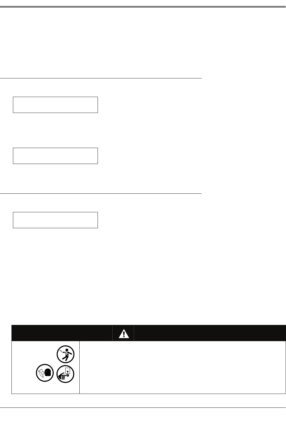
19 Vapor Sensor Setup
Vapor Sensor Location
19-2
Press STEP. If more than one module is installed, the system automatically advances to the SENSOR CONFIG
message for the next module. Up to 8 modules may be installed. Repeat the steps described above for each
module until you have entered the configuration information (sensor positions) for all modules and the system
displays the ENTER SENSOR LOCATION message.
Vapor Sensor Location
If necessary, press STEP until you see the message:
To enter the sensor location, press TANK repeatedly until the sensor you want appears on the second line of the
message (V1, V2, etc.). Press CHANGE and enter the location (up to 20 alphanumeric characters) of the selected
sensor. Typical entries would be: WELL #1, NEW CORNER, etc. (This information appears on sensor status and
sensor alarm reports to make it easier to identify the location of the alarm.) Press ENTER to confirm your entry:
Press STEP to continue.
Vapor Threshold
If necessary, press STEP until you see the message:
The SENSOR THRESHOLD message lets you enter vapor levels to identify a leak or serious spillover and to
trigger the vapor alarm. Thresholds are in ohms (Ω) and must be calculated for each vapor sensor according to the
formula described below. Thresholds may be set to account for existing vapor levels as long as these vapors do
not exceed the limits explained below.
BEFORE YOU BEGIN
IMPORTANT! A vapor sensor must be operated only in wells where preliminary testing has determined that the soil
is not already contaminated beyond acceptable limits (as defined by applicable regulations) or that contaminated
soil has been remediated and is now clean. A vapor sensor should not be operated in wells where preliminary
testing indicates that the initial vapor sensor resistance exceeds 25k ohms. Vapor sensors must have been
installed in their wells at least 24 hours prior to calculating and entering vapor alarm thresholds.
WARNING
This system contains electrical voltages that can be lethal.
Electrical shock resulting in serious injury or death could result if incorrect
service procedures are used.
When you perform the following procedure:
1. Read all instructions carefully.
2. Turn Off power to the console.
ENTER SENSOR LOCATION
V1:
V1: (Sensor Location)
PRESS <STEP> TO CONTINUE
V1: (Sensor Location)
SENSOR THRESHOLD: 000000
OFF
19-3
19 Vapor Sensor Setup
Vapor Sensor Category
1. Be sure that the Battery-Backup switch is in the On position before proceeding. If the battery is Off when AC
power to the system is turned Off, all previously entered setup data WILL BE LOST!
2. Turn Off all AC power to the system.
3. In the intrinsically safe area of the monitor, locate the Vapor Sensor Interface Module(s).
4. Measure the resistance across the “V” (vapor) and “G” (ground) terminals for each sensor using an ohmmeter.
5. For each sensor, multiply the measured resistance by 4 to determine the vapor threshold value that you should
enter.
IMPORTANT! Vapor alarm threshold values cannot exceed l00k ohm or be less than 1k ohm. The system will not
accept values outside these limits.
SPECIFYING VAPOR THRESHOLD LEVELS
To enter the vapor threshold for the selected sensor, press CHANGE in response to the SENSOR THRESHOLD
message. Enter the vapor threshold value that you calculated based on the formula described above (between 1k
and 100k ohms). Press ENTER to confirm your entry:
Press STEP to continue.
Vapor Sensor Category
If necessary, press STEP until you see the message:
If necessary, press CHANGE until you see the correct category then press ENTER. The category options are:
•ANNULAR SPACE
•DISPENSER PAN
•MONITOR WELL
•STP SUMP
•PIPING SUMP
When the correct category displays, press ENTER.
Setting Up Additional Vapor Sensors
If you have additional vapor sensors to configure, press STEP, if necessary, to return to the ENTER SENSOR
LOCATION message. Press TANK to select another sensor and follow the procedures described above, beginning
with the section “Vapor Sensor Location” on page 19-2.
If you have entered setup information for all vapor sensors, press FUNCTION to exit.
OFF
VAPOR THRESHOLD: XXXXXX
PRESS <STEP> TO CONTINUE
V1: (Sensor Location)
CATEGORY:OTHER SENSORS

20-1
20 Groundwater Sensor Setup
The Groundwater Sensor Setup function allows you to enter information about groundwater sensors installed in
groundwater monitoring wells at the site. You must enter data individually for each sensor. The information you
enter tells the system the number and location of installed sensors.
Selecting the Groundwater Sensor Setup Function
To select Groundwater Sensor Setup, press FUNCTION until you see the message:
Press STEP to continue.
Groundwater Sensor Configuration
If necessary, press STEP until you see the message:
Use this display to tell the system which sensor positions on a module are connected to groundwater sensors.
NOTE: If groundwater sensors are not installed, this function is not available.
HOW THE SYSTEM CONFIGURES GROUNDWATER SENSORS
If groundwater sensors are installed, the system recognizes the presence and module slot locations of
Groundwater Sensor Interface Modules. The system also establishes a module number based on the slot location.
For example, if modules are installed in slots #3 and #6, the module in slot #3 automatically becomes module #1
and the module in slot #6 becomes module #2.
As you specify which sensor positions on a module are connected to groundwater sensors, the system establishes
a number for each sensor. For example, if there is a groundwater sensor in positions 3 and 5 of module 1, the
sensor in position 3 becomes G3 and the sensor in position 5 becomes G5.
To indicate that a groundwater sensor position is connected, choose the number corresponding to that position.
For example, if the position is 3, choose 3 for the position. To indicate that a position is not connected, choose X
for that position.
SPECIFYING GROUNDWATER SENSOR POSITIONS
To specify whether the first position is connected, press CHANGE until the correct choice appears (1 if the
position is connected, X if it is not). Press the Right Arrow key to move to position 2 and press CHANGE again
until the correct choice appears. Repeat these steps until you have correctly specified all sensor positions. When
you have entered a choice for all positions, press ENTER to confirm your entry. The system displays the following
message:
GROUNDWATER SENSOR SETUP
PRESS <STEP> TO CONTINUE
SENSOR CONFIG - MODULE 1
SLOT # - X X X X X
SLOT # - X X X X X
PRESS <STEP> TO CONTINUE
20 Groundwater Sensor Setup
Groundwater Sensor Location
20-2
Press STEP. If more than one module is installed, the system automatically advances to the SENSOR CONFIG
message for the next module. Up to 8 modules may be installed. Repeat the steps described above for each
module until you have entered configuration information (sensor positions) for all modules and the system displays
the ENTER SENSOR LOCATION message.
Groundwater Sensor Location
If necessary, press STEP until you see the message:
To enter the sensor location, press TANK repeatedly until the sensor you want appears on the second line of the
message (G1, G2, G3, etc.). Press CHANGE and enter the location (up to 20 alphanumeric characters) of the
selected sensor. Typical entries are: WELL #1, NEW CORNER, etc. (This information appears on sensor status
and sensor alarm reports to make it easier to identify the location of the alarm.) Press ENTER to confirm your entry:
Press STEP to continue.
Groundwater Sensor Category
If necessary, press STEP until you see the message:
If necessary, press CHANGE until you see the correct category. The category options are:
•ANNULAR SPACE • DISPENSER PAN
•MONITOR WELL • STP SUMP
•PIPING SUMP
When the correct category displays, press ENTER.
Setting Up Additional Groundwater Sensors
If you have additional sensors to configure, press STEP, if necessary, until you see the ENTER SENSOR
LOCATION message. Press TANK to select another sensor and follow the procedures described above, beginning
with “Groundwater Sensor Location” on page 20-2.
If you have entered setup information for all sensors, press FUNCTION to exit.
ENTER SENSOR LOCATION
G1:
G1: (Sensor Location)
PRESS <STEP> TO CONTINUE
G1: (Sensor Location)
CATEGORY:OTHER SENSORS
21-1
21 2-Wire C.L. Sensor Setup
The 2-Wire C.L. (Current Loop) (Type A) Sensor Setup function allows you to enter information about 2-Wire C.L.
(Type A) Sensors installed at your site. You must enter data individually for each sensor.
Selecting the 2-Wire C.L. Sensor Setup Function
To select 2-Wire C.L. Sensor Setup, press FUNCTION until you see the message:
Press STEP to continue.
2-Wire C.L. Sensor Configuration
If necessary, press STEP until you see the message:
Use this display to tell the system which sensor positions on a module are connected to 2-Wire C.L. sensors.
NOTE: If 2-Wire C.L. sensors are not installed, this function is not available.
HOW THE SYSTEM CONFIGURES 2-WIRE C.L. SENSORS
If 2-Wire C. L. sensors are installed, the system recognizes the presence and module slot locations of Type A
Interface Modules. The system also establishes a module number based on the slot location. For example, if
modules are installed in slots #3 and #6, the module in slot #3 automatically becomes module #1 and the module
in slot #6 becomes module #2.
As you specify which sensor positions on a module are connected to 2-Wire C.L. sensors, the system establishes
a number for each sensor. For example, if there is a 2-Wire C.L. sensor in positions 3 and 5 of module 1, the
sensor in position 3 becomes C3 and the sensor in position 5 becomes C5.
To indicate that a 2-Wire C.L. sensor position is connected, choose the number corresponding to that position. For
example, if the position is 3, choose 3 for the position. To indicate that a position is not connected, choose X for
that position.
SPECIFYING 2-WIRE C.L. SENSOR POSITIONS
To specify whether the first position is connected, press CHANGE until the correct choice appears (1 if the
position is connected, X if it is not). Press the Right Arrow key to move to position 2 and press CHANGE again
until the correct choice appears. Repeat these steps until you have correctly specified all sensor positions. When
you have entered a choice for all positions, press ENTER to confirm your entry. The system displays the following
message:
2 WIRE C.L. SENSOR SETUP
PRESS <STEP> TO CONTINUE
SENSOR CONFIG - MODULE 1
SLOT # - X X X X X X X X
SLOT # - X X X X X X X X
PRESS <STEP> TO CONTINUE
21 2-Wire C.L. Sensor Setup
2-Wire C.L. Sensor Location
21-2
Press STEP. If more than one module is installed, the system automatically advances to the SENSOR CONFIG
message for the next module. Up to 8 modules may be installed. Repeat the steps described above for each
module until you have entered configuration information (sensor positions) for all modules and the system displays
the ENTER SENSOR LOCATION message.
2-Wire C.L. Sensor Location
If necessary, press STEP until you see the message:
To enter the sensor location, press TANK repeatedly until the sensor you want appears on the second line of the
message (C1, C2, etc.). Press CHANGE and enter the location (up to 20 alphanumeric characters) of the
selected sensor. Typical entries are: INTERSTITIAL-TANK 1; etc. (This information appears on sensor status and
sensor alarm reports to make it easier to identify the location of the alarm.) Press ENTER to confirm your entry:
Press STEP to continue.
2-Wire C.L. Sensor Type
If necessary, press STEP until you see the message:
Use this display to identify the selected sensor’s type, so the system can properly interpret and report sensor
information. You can choose DISCRIM INTERSTITIAL or ULTRA 2 for the Sensor Type. DISCRIM INTERSTITIAL
sensors have three sensing states: normal condition, water detection, and fuel detection. ULTRA-2 sensors may
have two sensing states: normal condition and liquid condition.
NOTE: The interstitial sensor for high alcohol applications (Form No. 794380-345) must be set up as
ULTRA 2.
Press STEP to accept DISCRIM INTERSTITIAL. Press CHANGE, then ENTER to accept ULTRA 2, press
CHANGE in response to the ENTER SENSOR TYPE message. Press ENTER to confirm your choice:
Press STEP to continue.
2-Wire C.L. Sensor Category
If necessary, press STEP until you see the message:
ENTER SENSOR LOCATION
C1:
C1: (Sensor Location)
PRESS <STEP> TO CONTINUE
C1: ENTER SENSOR TYPE
DISCRIM INTERSTITIAL
ULTRA 2
PRESS <STEP> TO CONTINUE
C1: (Sensor Location)
CATEGORY: OTHER SENSORS

21-3
21 2-Wire C.L. Sensor Setup
Setting Up Additional 2-Wire C.L. Sensors
If necessary, press CHANGE until you see the correct category. The category options are:
•ANNULAR SPACE •DISPENSER PAN
•MONITOR WELL •STP SUMP
•PIPING SUMP
When you display the correct category, press ENTER.
Setting Up Additional 2-Wire C.L. Sensors
If you have additional sensors to configure, press STEP until you see the ENTER SENSOR LOCATION message.
Press TANK to select another sensor and follow the procedures described above, beginning with“2-Wire C.L.
Sensor Location” on page 21-2.
If you have entered setup information for all sensors, press FUNCTION to exit.

22-1
22 3-Wire C.L. Sensor Setup
The 3-Wire C.L. (Current Loop) (Type B) Sensor Setup function allows you to enter information about dispenser
pan and containment sump sensors installed at the site. You must enter data individually for each sensor. The
information you enter tells the system the number and location of installed sensors.
Selecting the 3-Wire C.L. Sensor Setup Function
To select 3-Wire C.L. Sensor Setup, press FUNCTION until you see the message:
Press STEP to continue.
3-Wire C.L. Sensor Configuration
If necessary, press STEP until you see the message:
Use this display to tell the system which sensor positions on a module are connected to 3-Wire C.L. sensors.
NOTE: If dispenser pan and containment sump sensors are not installed, this function is not available.
HOW THE SYSTEM CONFIGURES 3-WIRE C.L. SENSORS
If dispenser pan and containment sump sensors are installed, the system will recognize the presence and module
slot locations of Type B Interface Modules. The system also establishes a module number based on the slot
location. For example, if modules are installed in slots #3 and #6, the module in slot #3 automatically becomes
module #1 and the module in slot #6 becomes module #2.
As you specify which positions on a module are connected to 3-Wire C.L. sensors, the system establishes a
number for each sensor. For example, if there is a sensor in positions 3 and 5 of module 1, the sensor in position 3
becomes H3 and the sensor in position 5 becomes H5.
To indicate that a sensor position is connected, choose the number corresponding to that position. For example, if
the position is 3, choose 3 for the position. To indicate that a position is not connected, choose X for that position.
SPECIFYING 3-WIRE C.L. SENSOR POSITIONS
To indicate whether position 1 is connected, press CHANGE until the correct choice appears (1 if the position is
connected, X if it is not). Press the Right Arrow key to move to position 2 and press CHANGE again until the
correct choice appears. Repeat these steps until you have correctly specified all sensor positions. When you have
entered a choice for all positions, press ENTER to confirm your entry. The system displays the following message:
Press STEP. If more than one module is installed, the system automatically advances to the SENSOR CONFIG
message for the next module. Up to 8 modules may be installed. Repeat the steps described above for each
3 WIRE C.L. SENSOR SETUP
PRESS <STEP> TO CONTINUE
SENSOR CONFIG - MODULE 1
SLOT # - X X X X X
SLOT # - X X X X X
PRESS <STEP> TO CONTINUE

22 3-Wire C.L. Sensor Setup
3-Wire C.L. Sensor Location
22-2
module until you have entered the configuration information (sensor positions) for all modules and the system
displays the ENTER SENSOR LOCATION message.
3-Wire C.L. Sensor Location
If necessary, press STEP until you see the message:
To enter the sensor location, press TANK repeatedly until the sensor you want appears on the second line of the
message (H1, H2, etc.). Press CHANGE and enter the sensor location (up to 20 alphanumeric characters) of the
selected sensor. A typical entry is: DISPENSER PAN PUMP, etc. (This information appears on sensor status and
sensor alarm reports to make it easier to identify the location of the alarm.) Press ENTER to confirm your entry:
Press STEP to continue.
3-Wire C.L. Sensor Mode
If necessary, press STEP until you see the message:
Use this display to identify the selected sensor’s mode, so the system can properly interpret and report sensor
information. You can choose Standard mode or High Vapor mode. In Standard mode, the sensor alarms when it
senses any hydrocarbon, liquid, or vapor along the length of the sensor. In High Vapor mode the sensor alarms
only if it detects both liquid hydrocarbon and an extremely high hydrocarbon vapor. This mode is recommended
ONLY if the sensor has recently detected a leak and hydrocarbon residue may still be on the sensing element.
To choose Standard mode, press STEP. (The system displays the CATEGORY message.)
To choose High Vapor, press CHANGE in response to the ENTER SENSOR MODE message. Press ENTER to
confirm your choice:
Press STEP to continue.
3-Wire C.L. Sensor Category
If necessary, press STEP until you see the message:
If necessary, press CHANGE until you see the correct category. The category options are:
ENTER SENSOR LOCATION
H1:
H1: (Sensor Location)
PRESS <STEP> TO CONTINUE
H1: ENTER SENSOR MODE
STANDARD
H1: (Sensor Mode)
PRESS <STEP> TO CONTINUE
H1: (Sensor Location)
CATEGORY:OTHER SENSORS

22-3
22 3-Wire C.L. Sensor Setup
Setting Up Additional 3-Wire C.L. Sensors
•ANNULAR SPACE •DISPENSER PAN
•MONITOR WELL •STP SUMP
•PIPING SUMP
When the correct category displays, press ENTER.
Setting Up Additional 3-Wire C.L. Sensors
If you have additional sensors to configure, press STEP, if necessary until you see the ENTER SENSOR
LOCATION message. Press TANK to select another sensor and follow the procedures described in the preceding
sections, beginning with “3-Wire C.L. Sensor Location” on page 22-2.
If you have entered setup information for all sensors, press FUNCTION to exit.
23-1
23 External Input Setup
Input devices can be connected to the system monitor via Input/Output (I/O) Combination Interface Modules. You
must enter data individually for each input device. The information you enter tells the system the number, location,
type, and name of installed input devices.
Selecting the External Input Setup Function
To select External Input Setup, press FUNCTION until you see the message:
Press STEP to continue.
External Input Configuration
If necessary, press STEP until you see the message:
Use this display to tell the system which input positions on a module are connected to external devices.
NOTE: If external devices are not installed, this function is not available.
HOW THE SYSTEM CONFIGURES INPUT DEVICES
If input devices are installed, the system recognizes the presence and module slot locations of I/O Combination
Interface Modules. It also establishes a module number based on the slot location. For example, if modules are
installed in slots #3 and #6, the module in slot #3 automatically becomes module #1 and the module in slot #6
becomes module #2.
As you specify which input positions on a module are connected to external devices, the system establishes a
number for each input position. For example, if an external device is connected to positions 1 and 2 of module 1,
input position 1 becomes I1 and input position 2 becomes I2.
To indicate that an input position on the module is connected, choose the number corresponding to that position.
For example, if the position is 3, choose 3 for the position. To indicate that a position is not connected, choose X
for that position.
SPECIFYING INPUT POSITIONS
To indicate whether position 1 is connected, press CHANGE until the correct choice appears (1 if the position is
connected, X if it is not). Press the Right Arrow key to move to position 2 and press CHANGE again until the
correct choice appears. When you have entered a choice for both positions, press ENTER to confirm your entry:
Press STEP. If more than one module is installed, the system automatically advances to the INPUT CONFIG
message for the next module.Up to 8 modules may be installed. Repeat the steps described above for each
EXTERNAL INPUT SETUP
PRESS <STEP> TO CONTINUE
INPUT CONFIG - MODULE 1
SLOT # - X X
SLOT # - X X
PRESS <STEP> TO CONTINUE

23 External Input Setup
External Input Name
23-2
module until you have entered configuration information (input positions) for all modules and the system displays
the ENTER INPUT NAME message.
External Input Name
If necessary, press STEP until you see the message:
To enter the name of an external device, press TANK repeatedly until the input position that is connected to the
external device you want appears on the second line of the message (I1, I2, etc.). Press CHANGE and enter the
name (up to 20 alphanumeric characters) of the selected device. Typical entries are: GENERATOR 1, BURGLAR
ALM, DCD input, etc. (This information appears on reports to make it easier to identify the input. The name
appears in the message when selecting Output Relay Assignments.) Press ENTER to confirm your entry:
Press STEP to continue.
External Input Type
If necessary, press STEP until you see the message:
Use this display to define the type of input—Standard, Generator, Pump Sense, or Standard ACK—that is
connected to the selected input location:
•Choose Standard for any input device connected for the purpose of using the system’s reporting, alarm, and
data communications features
•Choose Generator for applications where you monitor fuel tank(s) supplying an emergency generator and you
receive GENERATOR ON and OFF signals from the generator. The system runs a continuous leak test in the
generator’s tank(s) until the generator turns On. When the generator shuts Off, the system returns to its Leak
Test mode. GENERATOR ON and GENERATOR OFF messages are printed whenever the generator turns on
and off.
•Choose Pump Sense when the input is used to indicate the On/Off state of the pump.
•Choose Standard ACK when using an eternal input (e.g., remote pushbutton) as an ALARM/TEST key.
Press CHANGE until the correct choice appears then press ENTER to confirm your choice:
Press STEP to continue.
ENTER INPUT NAME
I1:
I1: (Input Name)
PRESS <STEP> TO CONTINUE
I1: EXTERNAL INPUT TYPE
STANDARD
I1: (Input Type)
PRESS <STEP> TO CONTINUE
23-3
23 External Input Setup
Switch Orientation
Switch Orientation
If necessary, press STEP until you see the message:
You must identify the input switch type as either normally open or normally closed so the system properly
recognizes an ON or OFF condition. To choose Normally Open, press STEP. To choose Normally Closed, press
CHANGE and press ENTER to confirm your choice:
If you chose Standard or Standard ACK for the External Input Type, you are finished entering setup data for the
selected input position. To enter setup information for additional input positions, press STEP to return to the
ENTER INPUT NAME message. Press TANK to choose another input. To exit the function, press FUNCTION.
If you chose Generator or Pump Sense for the External Input Type, press STEP to continue. Refer to the section
below that corresponds to the input type you chose. (The system displays the SELECT TANK message for the
Input Type you selected.)
External Input Emergency Generator Data
If necessary, press STEP until you see the message:
NOTE: This message appears only if you chose GENERATOR for the External Input Type.
You must identify which tanks supply fuel to the generator, so that the system will conduct a continuous leak test in
these tanks while the generator is off. If all tanks connected to the system supply fuel to the generator wired to this
input, select All Tanks. If only one or some of the tanks connected to the system supply fuel to this generator, enter
the individual tank numbers.
If you want to choose All Tanks, do nothing. If you want to enter tank numbers, press CHANGE. Enter the tank
numbers and press ENTER to confirm your entry:
If you have additional input positions to configure, refer to the section below entitled “Setting Up Additional Inputs”
on page 23-4.
If you have entered setup information for all input positions, press FUNCTION to exit.
Pump Sense Setup Data
If necessary, press STEP until you see the message:
I1: SELECT ORIENTATION
NORMALLY OPEN
NORMALLY CLOSED
PRESS <STEP> TO CONTINUE
I1: SELECT TANK
TANK #: ALL TANK
TANK #: X, X
PRESS <STEP> TO CONTINUE
I1: SELECT TANK
NONE

23 External Input Setup
Setting Up Additional Inputs
23-4
NOTE: This message appears only if you chose Pump Sense for the External Input Type.
You must identify the tank to which this Pump Sense input is assigned.
To enter the tank number, press CHANGE until the desired Tank number is displayed. Press ENTER to confirm
your entry:
SELECTING A DISPENSE MODE
If necessary, press STEP until you see the message:
This entry asks you to select the dispense mode. You can select between:
•STANDARD - Only one pump feeds the line.
•MANIFOLDED: ALTERNATE1 - The pump will run in the tank with the greatest inventory volume.
•MANIFOLDED: SEQUENTIAL1 - The tanks are pumped low one at a time. When the tank’s volume drops
below the entered Pump Threshold percentage, pumping will switch over immediately to the next available tank
in the line manifolded set. Pumping will continue from the current tank for another 10 seconds to avoid a
disruption in dispensing during the switch over. (see “Pump Threshold” on page 7-26).
•MANIFOLDED: ALL PUMPS - All pumps on the line are run.
Press CHANGE until your choice appears then press ENTER to continue.
Setting Up Additional Inputs
If you have additional input positions to configure, press STEP. The system returns to the ENTER INPUT NAME
message. Press TANK to select another input position and follow the procedures described in the preceding
sections, beginning with “External Input Name” on page 23-2.
If you have entered setup information for all input positions, press FUNCTION to exit.
1. To prevent backfilling, the level of all tanks connected to the line will be monitored. If the level of any tank
exceeds 95% of the Max or Label Volume limit (see “Max or Label Vol” on page 7-15), the pump for that
tank will also be turned on during dispensing. The state of the pump that was already ON will not be
changed.
TANK #: (Product Label)
PRESS <STEP> TO CONTINUE
Q1: ENTER DISPENSE MODE
XXXXXXXXX
24-1
24 Output Relay Setup
Output Relays allow you to assign alarm limits, line leak alarms, sensor alarms, and inputs from external devices to
specific relays. Signals from an alarm limit or device triggers the Output Relay assigned to it. You must enter data
individually for each Output Relay. The data you enter tells the system the number, location, and name of Output
Relays installed.
NOTE: If output relay modules are not installed, this function is not available.
Selecting the Output Relay Setup Function
To select Output Relay Setup, press FUNCTION until you see the message:
Press STEP to continue.
Relay Configuration
If necessary, press STEP until you see the message:
Use this display to tell the system which relay positions on a module are connected to external devices.
HOW THE SYSTEM CONFIGURES OUTPUT RELAYS
If output relay modules are installed, the system recognizes the presence and module slot locations of each one.
The system also establishes a module number based on the slot location. For example, if modules are installed in
slots #9 and #13, the module in slot #9 automatically becomes module #1 and the module in slot #13 becomes
module #2.
As you tell the system which relay positions on a module are connected to external devices, the system establishes
a number for each relay. For example, if there are relays in positions 2 and 4 of module 1, the relay in position 2
becomes R2 and the relay in position 4 become R4.
To indicate that one of the relay positions on the module is connected to an external device, choose the number
corresponding to that position. There can be up to four relay positions for 4-Relay Modules and up to two positions
for I/O Combo Modules. For example, if the position is two, choose “2” for the position. To indicate that a position
is not connected to an external device, choose X for that position.
SPECIFYING OUTPUT RELAY POSITIONS
To specify whether position 1 is connected, press CHANGE until the correct choice appears (1 if the position is
connected, X if it is not). Press the Right Arrow key to move to position 2 and press CHANGE again until the
correct choice appears. Repeat these steps until you have correctly specified all positions. When you have entered
a choice for all positions, press ENTER to confirm your entry:
OUTPUT RELAY SETUP
PRESS <STEP> TO CONTINUE
RELAY CONFIG - MODULE 1
SLOT #: X X X X
SLOT #: X X X X
PRESS <STEP> TO CONTINUE
24 Output Relay Setup
Relay Designation
24-2
Press STEP. If more than one module is installed, the system automatically advances to the RELAY CONFIG
message for the next module. Up to 8 modules may be installed. Repeat the steps described above for each
module until you have entered the configuration information (relay positions) for all modules and the system
displays the ENTER RELAY DESIGNATION message.
Relay Designation
If necessary, press STEP until you see the message:
Enter the name of the device connected to the selected output relay. Typical names are: OVERFILL ALARM;
AUTO DIALER; etc. (This name appears on reports to make it easier to identify the external device. The name also
appears on the display when in-tank or sensor alarms and external inputs are assigned to the relay).
To enter a designation for the selected relay, press CHANGE and enter up to 20 alphanumeric characters. Press
ENTER to confirm your entry. The system displays:
Press STEP to continue.
Selecting Relay Type
If necessary, press STEP until you see the message:
From this display, press CHANGE to display one of four output relay types:
•STANDARD - The On/Off state is determined by assigned alarms/warnings.
•PUMP CONTROL OUTPUT - Responds to a pump request received from an assigned Pump Sense module or
Line Leak module.
•MOMENTARY - The On/Off state is determined by assigned alarms/warnings. However, relay returns to the
inactive state after the ALARM/TEST key is pressed to acknowledge the alarm.
•PUMP COMM CONTROL - Select this relay type only when a set of line manifolded tanks are using Red Jacket
IQ Controllers, and you want to run PLLD/WPLLD precision line leak tests. After selecting this relay type, when
one IQ controlled pump of a manifolded set is turned On for line leak testing, the relay will activate, blocking
communication with the second IQ controlled pump (giving the console total control of the pumps) until the
precision test is complete.
When the desired relay type appears on the display, press ENTER to confirm your choice.
If you select STANDARD or MOMENTARY, the display reads:
To accept normally open (relay de-energized when alarm is inactive), press STEP. Press CHANGE to display
normally closed (relay energized when alarm is inactive), then ENTER to accept.
ENTER RELAY DESIGNATION
R1:
R1: (Name)
PRESS <STEP> TO CONTINUE
R1: SELECT RELAY TYPE
STANDARD
R X:SELECT ORIENTATION
NORMALLY OPEN
24-3
24 Output Relay Setup
Assignment Method
If you select PUMP CONTROL OUTPUT or PUMP COMM CONTROL relay types, you will prompted to specify a
tank number.
Press ENTER to confirm your choice. The system displays:
Press STEP to display the message:
For Pump Control Output relay selection, press CHANGE and enter the tank number of the assigned Pump Sense
module or Line Leak module.
For Pump Comm Control relay selection, press CHANGE and enter the number of the tank in the manifolded set
which is assigned to the PLLD or WPLLD module.
In either case, press ENTER to confirm your entry. The system displays:
Press STEP to continue.
Assignment Method
This function allows you to assign alarms and external inputs for each relay (except Pump Comm Control relay). For
the selected relay, you will first specify whether you want to assign an available alarm type (e.g., In-Tank, Liquid
Sensor, etc.) or external input to that relay by choosing Yes or No for that type of alarm or input. For all alarms
except System, if you choose Yes, you must then specify the method of assignment (none, all, or single) for each
alarm condition.
NOTE: You may assign more than one in-tank alarm, sensor alarm, and external input to a relay, and you may assign
any in-tank alarm, sensor alarm, and external input to more than one relay.
As you step through possible relay assignments, the system automatically displays all in-tank alarms, sensor
alarms, line leak alarms and external inputs that have been configured in the system. If no other sensors or inputs
are configured, the system returns to the RELAY DESIGNATION message. Refer to the section entitled “Setting
Up Additional Relays” on page 24-8.)
IN-TANK ALARMS
If necessary, press STEP until you see the message:
If you do not want to assign In-Tank Alarms to the relay displayed in the first line of the IN- TANK ALARMS
message, press STEP. (The system displays the next available alarm or input assignment group.
To assign In-Tank Alarms to the selected relay, press CHANGE in response to the IN-TANK ALARMS: NO
message. Press ENTER to confirm your choice. The system displays:
PUMP CONTROL OUTPUT
PRESS <STEP> TO CONTINUE
PUMP COMM CONTROL
PRESS <STEP> TO CONTINUE
or
R1: SELECT TANK
NONE
TANK #: X
PRESS <STEP> TO CONTINUE
R1:(Name)
IN-TANK ALARMS: NO
IN-TANK ALARMS: YES
PRESS <STEP> TO CONTINUE
24 Output Relay Setup
Assignment Method
24-4
Press STEP to display the message:
This message shows the first kind of alarm condition for In-Tank Alarms: LEAK. You must tell the system whether to
assign the displayed alarm condition (in this case In-Tank Leak Alarms) to the selected relay for No Tanks, All
Tanks, or Single Tanks. To choose No Tanks, press STEP. (The system displays the next In-Tank Alarm condition:
HIGH WATER.)
To choose All Tanks, press CHANGE once. Press ENTER to confirm your choice. The system displays:
Press STEP to specify the assignment method for the next In-Tank Alarm condition (HIGH WATER).
To choose Single Tanks, press CHANGE twice in response to the LEAK: NO TANKS message. Press ENTER to
confirm your choice. The system displays:
Press STEP to display the message: The system displays:
Use the above message to specify the tank number(s) that you want to assign to the relay. If you do not want to
assign the tank number shown (T1, T2, etc.), press TANK until you see the tank number that you want to assign to
the relay. When the correct tank number appears, press CHANGE and press ENTER. The system confirms your
entry (for T1) with the message:
Continue to press TANK to select additional tanks. For example, pressing TANK once would display the following
message:
Repeat the steps described above to assign additional tanks to the relay. When you have assigned all the tanks
you want to the relay, press STEP. The system displays the assignment method message for the next In-Tank Alarm
condition:
Repeat the procedures described for the LEAK alarm condition until you have specified an assignment method for
the all remaining In-Tank Alarm conditions (ref. Alarm List in Section 6, Table 6-2).
Press TANK/SENSOR to select additional tanks for the In-Tank Leak alarm. When you have specified all tanks for
the first In-Tank alarm, press STEP to advance to the next alarm group. Repeat the steps described above to
assign tanks for each In-Tank alarm. After you have specified tanks for each In-Tank alarm condition, press STEP to
advance to the next alarm group.
R1: IN-TANK ALARMS
LEAK: NO TANKS
LEAK: ALL TANKS
PRESS <STEP> TO CONTINUE
LEAK: SINGLE TANK
PRESS <STEP> TO CONTINUE
R1: (Name)
T1 LEAK: NO
R1: T1 LEAK: YES
PRESS <TANK> TO CONTINUE
R1: (Name)
T2 LEAK: NO
R1: IN-TANK ALARMS
HIGH WATER: NO TANKS
24-5
24 Output Relay Setup
Assignment Method
REMAINING ALARM GROUPS
Continue to step through all of the available alarm groups, selecting the various alarms from the groups that you
want to assign to the selected relay (R1, R2, etc.). The procedure for bypassing or selecting alarms from each
group and then assigning them to a device in that group is the same as discussed for In-Tank alarms above.
The remaining alarm groups/alarms are shown below. Only installed components will display, so some of the alarm
groups may not appear.
LIQUID SENSOR ALARMS
If necessary, press STEP until you see the message:
Select the Liquid Sensor Alarms (ref. Alarm List in Section 6, Table 6-2).
VAPOR SENSOR ALARMS
If necessary, press STEP until you see the message:
Select the Vapor Sensor Alarms (ref. Alarm List in Section 6, Table 6-2).
EXTERNAL INPUTS ALARMS
If necessary, press STEP until you see the message:
Select the External Inputs Alarm (ref. Alarm List in Section 6, Table 6-2).
LINE LEAK ALARMS (VLLD)
If necessary, press STEP until you see the message:
Select Volumetric Line Leak Alarms (ref. Alarm List in Section 6, Table 6-2).
GROUNDWATER SENSOR ALARMS
If necessary, press STEP until you see the message:
Select Groundwater Sensor Alarms (ref. Alarm List in Section 6, Table 6-2).
R1: (Name)
LIQUID SENSOR ALMS: NO
R1: (Name)
VAPOR SENSOR ALMS: NO
R1: (Name)
EXTERNAL INPUTS: NO
R1: (Name)
LINE LEAK ALARMS: NO
R1: (Name)
GROUNDWATER ALMS: NO

24 Output Relay Setup
Assignment Method
24-6
2 WIRE C.L. SENSOR ALARMS
If necessary, press STEP until you see the message:
Select 2 Wire C.L. Sensor Alarms (ref. Alarm List in Section 6, Table 6-2).
3 WIRE C.L. SENSOR ALARMS
If necessary, press STEP until you see the message:
Select 3 Wire C.L. Sensor Alarms (ref. Alarm List in Section 6, Table 6-2).
POWER SIDE DIM ALARMS
If necessary, press STEP until you see the message:
Select Power Side DIM Alarms (ref. Alarm List in Section 6, Table 6-2).
RECONCILIATION ALARMS
If necessary, press STEP until you see the message:
Select Reconciliation Alarms (ref. Alarm List in Section 6, Table 6-2).
PRESSURE LINE LEAK DETECTOR (PLLD) ALARMS
If necessary, press STEP until you see the message:
Select Pressure Line Leak Detector Alarms (ref. Alarm List in Section 6, Table 6-2).
WIRELESS PRESSURE LINE LEAK DETECTOR (WPLLD) ALARMS
If necessary, press STEP until you see the message:
Select WPLLD Line Leak Alarms (ref. Alarm List in Section 6, Table 6-2).
R1: (Name)
2 WIRE CL ALARMS: NO
R1: (Name)
3 WIRE CL ALARMS: NO
R1: (Name)
POWER SIDE DIM ALM: NO
R1: (Name)
RECONCILIATION ALM: NO
R1: (Name)
PRESSURE LINE LEAK: NO
R1: (Name)
WPLLD LINE LEAK: NO
24-7
24 Output Relay Setup
Assignment Method
COMMUNICATION SIDE DIM ALARMS
If necessary, press STEP until you see the message:
Select Communication Bay DIM Alarms (ref. Alarm List in Section 6, Table 6-2).
SMART SENSOR ALARMS
If necessary, press STEP until you see the message:
Select Smart Sensor Alarms (ref. Alarm List in Section 6, Table 6-2).
PUMP RELAY MONITOR ALARM
If necessary, press STEP until you see the message:
Select Pump Relay Monitor Alarm (ref. Alarm List in Section 6, Table 6-2).
When you have specified the assignment method for each Pump Relay Monitor Alarm condition, press STEP. If no
other sensor or inputs are configured, the system returns to the IN-TANK ALARMS message.
VMCI DISPENSER INTERFACE ALARMS
If necessary, press STEP until you see the message:
Select the VMCI Alarms to send (ref. Alarm List in Section 6, Table 6-2).
VMC ALARMS
If necessary, press STEP until you see the message:
Select the VMC Alarms to send (ref. Alarm List in Section 6, Table 6-2).
R1: (Name)
COMM SIDE DIM ALM: NO
R1: (Name)
PUMP RLY MON ALMS: NO
R1: (Name)
PUMP ALARM: NO
R1: (Destination)
VMCI ALARM: NO
R1: (Destination)
VMC ALARM: NO

24 Output Relay Setup
Setting Up Additional Relays
24-8
Setting Up Additional Relays
After setting up the data for the selected relay (R1, R2, etc.), press STEP, if necessary, until the system returns to
the message:
Press TANK/SENSOR to choose another relay. Set up the relay by repeating the procedures you followed for the
previous relay. Refer to the previous sections beginning with “Relay Designation” on page 24-2. If you have
entered setup data for all relays, press FUNCTION to exit.
ENTER RELAY DESIGNATION
R1:
25-1
25 Line Disable Setup
The Line Disable Setup Function allows you designate alarm limits, line leak alarms, sensor alarms, and inputs from
external devices to shut down any line.
Line Disable works with any of the three line leak detection systems; Pressurized Line Leak (PLLD), Wireless
Pressurized Line Leak (WPLLD), or Volumetric Line Leak (VLLD).
Selecting the PLLD, WPLLD, or VLLD Line Disable Setup Function
Select the Line Disable Setup for the type(s) of leak detection system at your site (PLLD, WPLLD or VLLD).
Press FUNCTION until you see the message:
Press STEP to continue.
ALARM ASSIGNMENT NOTES
As you step through the Line Disable Setup’s steps, the system automatically displays the in-tank alarms, sensor
alarms, and external inputs from which you can choose to shut down a line. If a type of alarm is listed in these
instructions, but does not appear on your screen, that alarm is not available on your system. Refer to the sections
listed below that correspond to the alarm types displayed on your screen.
You may assign more than one in-tank alarm, sensor alarm, and external input to a line, and you may assign any in-
tank alarm, sensor alarm, and external input to more than one line.
Whenever the prefix “Q” appears in the display, it stands for the selected line in the PLLD system, “W” stands for
the selected line in the WPLLD system and “P” stands for the selected line in the VLLD system.
In-Tank Alarms
If necessary, press STEP until you see the message:
If you do not want to assign In-Tank Alarms to the line displayed in the IN- TANK ALARMS message, press STEP.
(The system displays the next available alarm or input assignment group. Refer to the section below corresponding
to the next available alarm or input group. If no other sensor or inputs are configured, the system returns to the IN-
TANK ALARMS message. Refer to the section entitled “Setting Up Additional Disables” on page 25-6.)
To assign In-Tank Alarms to the selected line, press CHANGE, then ENTER to confirm your choice:
Press STEP to display the message:
XXXXX LINE DISABLE SETUP
PRESS <STEP> TO CONTINUE
Q1: (Name)
IN-TANK ALARMS: NO
IN-TANK ALARMS: YES
PRESS <STEP> TO CONTINUE
Q1: IN-TANK ALARMS
LEAK: NO TANKS

25 Line Disable Setup
In-Tank Alarms
25-2
This message shows the first kind of alarm condition for In-Tank Alarms: LEAK. You must tell the system whether to
assign the displayed alarm condition (in this case In-Tank Leak Alarms) to the selected line for No Tanks, All Tanks,
or Single Tanks. To choose No Tanks, press STEP. (The system displays the next In-Tank Alarm condition: HIGH
WATER.)
To choose All Tanks, press CHANGE once. Press ENTER to confirm your choice. The system displays:
Press STEP to specify the assignment method for the next In-Tank Alarm condition (HIGH WATER).
To choose Single Tanks, press CHANGE twice in response to the LEAK: NO TANKS message. Press ENTER to
confirm your choice. The system displays:
Press STEP to display the message:
Use this display to specify the tank number(s) that you want to assign to the line. If you do not want to assign the
tank number shown (T1, T2, etc.), press TANK until you see the tank number that you want to assign to the line.
When the correct tank number appears, press CHANGE and press ENTER. The system confirms your entry (for
T1) with the message:
Continue to press TANK to select additional tanks. For example, pressing TANK once would display the following
message:
Repeat the steps described above to assign additional tanks to the line. When you have assigned all the tanks you
want to the line, press STEP. The system displays the assignment method message for the next In-Tank Alarm
condition:
Repeat the procedures described for the LEAK alarm condition until you have specified an assignment method for
all remaining In-Tank Alarm conditions (ref. Alarm List in Section 6, Table 6-2).
When you have specified the assignment method for each In-Tank Alarm condition, press STEP. The system
displays the next available alarm or input assignment group.
REMAINING ALARM GROUPS
Continue to step through all of the available alarm groups, selecting the various alarms from the groups that you
want to have disable the selected line (Q1, Q2, etc.). The procedure for bypassing or selecting alarms from each
group and then assigning them to a device in that group is the same as discussed for In-Tank alarms above.
The remaining alarm groups/alarms are shown below. Only installed components will display, so some of the alarm
groups may not appear.
LEAK: ALL TANKS
PRESS <STEP> TO CONTINUE
LEAKS: SINGLE TANKS
PRESS <STEP> TO CONTINUE
Q1: (Name)
T1 LEAK: NO
Q1: T1 LEAK: YES
PRESS <TANK> TO CONTINUE
Q1: (Name)
T2 LEAK: NO
Q1: IN TANK ALARMS
HIGH WATER: NO TANKS
25-3
25 Line Disable Setup
In-Tank Alarms
LIQUID SENSOR ALARMS
If necessary, press STEP until you see the message:
Select the Liquid Sensor Alarms (ref. Alarm List in Section 6, Table 6-2).
VAPOR SENSOR ALARMS
If necessary, press STEP until you see the message:
Select the Vapor Sensor Alarms (ref. Alarm List in Section 6, Table 6-2).
EXTERNAL INPUT ALARMS
If necessary, press STEP until you see the message:
Select the External Inputs Alarm (ref. Alarm List in Section 6, Table 6-2).
LINE LEAK ALARMS
If necessary, press STEP until you see the message:
Select Line Leak (Volumetric) Alarms (ref. Alarm List in Section 6, Table 6-2).
GROUNDWATER SENSOR ALARMS
If necessary, press STEP until you see the message:
Select Groundwater Sensor Alarms (ref. Alarm List in Section 6, Table 6-2).
2 WIRE C.L. SENSOR ALARMS
If necessary, press STEP until you see the message:
Select 2 Wire C.L. Sensor Alarms (ref. Alarm List in Section 6, Table 6-2).
Q1: (Name)
LIQUID SENSOR ALMS: NO
Q1: (Name)
VAPOR SENSOR ALMS: NO
Q1: (Name)
EXTERNAL INPUTS: NO
Q1: (Name)
LINE LEAK ALARMS: NO
Q1: (Name)
GROUNDWATER ALMS: NO
Q1: (Name)
2 WIRE CL ALARMS: NO

25 Line Disable Setup
In-Tank Alarms
25-4
3 WIRE C.L. SENSOR ALARMS
If necessary, press STEP until you see the message:
Select 3 Wire C.L. Sensor Alarms (ref. Alarm List in Section 6, Table 6-2).
POWER SIDE DIM ALARMS
If necessary, press STEP until you see the message:
Select Power Side DIM Alarms (ref. Alarm List in Section 6, Table 6-2).
RECONCILIATION ALARMS
If necessary, press STEP until you see the message:
Select Reconciliation Alarms (ref. Alarm List in Section 6, Table 6-2).
PRESSURE LINE LEAK DETECTOR (PLLD) ALARMS
If necessary, press STEP until you see the message:
Select Pressure Line Leak Detector Alarms (ref. Alarm List in Section 6, Table 6-2).
•OPEN ALARM*
•HANDLE ALRM*
•LN EQ FAULT*
*These are the only PLLD alarms that can disable a PLLD line.
WIRELESS PRESSURE LINE LEAK DETECTOR (WPLLD) ALARMS
If necessary, press STEP until you see the message:
Select WPLLD Line Leak Alarms (ref. Alarm List in Section 6, Table 6-2).
•COMM ALARM* • HANDLE ALRM*
•LN EQ FAULT*
*These are the only WPLLD alarms that can disable a WPLLD line.
Q1: (Name)
3 WIRE CL ALARMS: NO
Q1: (Name)
POWER SIDE DIM ALM: NO
Q1: (Name)
RECONCILIATION ALM: NO
Q1: (Name)
PRESSURE LINE LEAK: NO
Q1: (Name)
WPLLD LINE LEAK: NO
25-5
25 Line Disable Setup
In-Tank Alarms
COMMUNICATION SIDE DIM ALARMS
If necessary, press STEP until you see the message:
Select Communication Bay DIM Alarms (ref. Alarm List in Section 6, Table 6-2).
SMART SENSOR ALARMS
If necessary, press STEP until you see the message:
Select Smart Sensor Alarms (ref. Alarm List in Section 6, Table 6-2).
PUMP RELAY MONITOR ALARM
If necessary, press STEP until you see the message:
Select Pump Relay Monitor Alarm (ref. Alarm List in Section 6, Table 6-2).
When you have specified the assignment method for each Pump Relay Monitor Alarm condition, press STEP. If no
other sensor or inputs are configured, the system returns to the IN-TANK ALARMS message.
VMCI DISPENSER INTERFACE ALARMS
If necessary, press STEP until you see the message:
Select the VMCI Alarms to send (ref. Alarm List in Section 6, Table 6-2).
VMC ALARMS
If necessary, press STEP until you see the message:
Select the VMC Alarms to send (ref. Alarm List in Section 6, Table 6-2).
Q1: (Name)
COMM SIDE DIM ALM: NO
Q1: (Name)
SMART SENSOR ALM: NO
Q1: (Name)
PUMP RLY MON ALMS: NO
Q1: (Destination)
VMCI ALARM: NO
Q1: (Destination)
VMC ALARM: NO

25 Line Disable Setup
Setting Up Additional Disables
25-6
Setting Up Additional Disables
After setting up the data for the selected line (e.g., Q1), press STEP, if necessary, until the system returns to the
message:
Press TANK to choose another line. Set up the line by repeating the procedures you followed for the previous line.
Refer to the previous sections beginning with “Alarm Assignment Notes” on page 25-1 for instructions.
If you have entered setup data for all lines, press FUNCTION to exit.
Q1: (Name)
IN-TANK ALARMS: NO
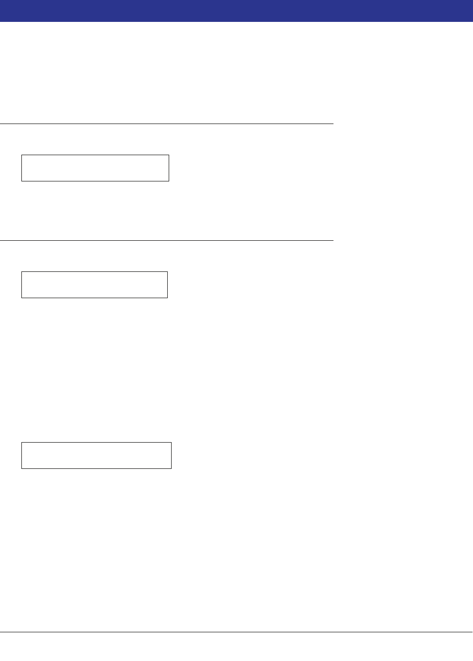
26-1
26 Smart Sensor Setup
Your console may have Smart Sensors installed. Once a Smart Sensor is configured, the system reads the
sensor’s feature set and programming options. After configuring each Smart Sensor, you should printout the Smart
Sensor Setup before attempting to program the sensor.
NOTE: If Smart Sensor modules are not installed, this function is not available.
Selecting the Smart Sensor Setup Function
To select Smart Sensor Setup, press FUNCTION until you see the message:
Press STEP to continue.
Sensor Configuration
If necessary, press STEP until you see the message:
When Smart Sensor Interface Modules (8 inputs) or Smart Sensor / Press Modules (7 inputs) are installed, the
system recognizes the presence and module slot locations of each one. The system also designates the module
number (n) based on the slot location. In this display you tell the system which positions on the module have been
connected to sensors.
As you tell the system which sensor positions on a module are connected, the system establishes a number for
each sensor. For example, if there are sensors connected to positions 2 and 4 of module 1, the sensor in position
2 becomes s2 and the sensor in position 4 becomes s4.
To specify whether position 1 is connected, press CHANGE until the correct choice appears (1 if the position is
connected, X if it is not). Press the Right Arrow key to move to position 2 and press CHANGE again until the
correct choice appears (2). Repeat these steps until you have correctly specified all sensors connected to this
Smart Sensor module. Press ENTER to confirm your entry:
Press STEP. If more than one module is installed, the system automatically advances to the SS CONFIG message
for the next module. Up to 40 smart sensors can be monitored by the console.
NOTE: At least one Smart Sensor / Press module is required with Vac Sensors. You can use either additional
Smart Sensor / Press Modules or 8-input Smart Sensor Interface Modules if more than 7 Vac Sensors are
installed.
Repeat the steps described above for each module until you have entered the configuration information (sensor
positions) for all modules and the system displays the ENTER SMARTSENSOR LABEL message.
When you have finished configuring all Smart Sensors, press the PRINT key to printout a copy of each sensors
feature set and programming options (see example printout below).
SMART SENSOR SETUP
PRESS <STEP> TO CONTINUE
SS CONFIG - MODULE n
SLOT #: X X X X X X X X
SLOT #: X X X X X X X X
PRESS <STEP> TO CONTINUE
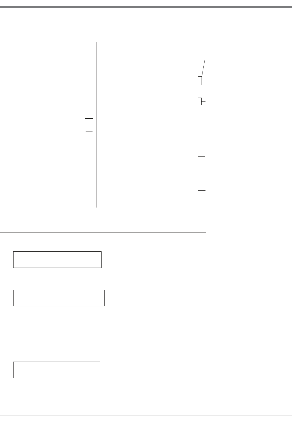
26 Smart Sensor Setup
Smart Sensor Label
26-2
Smart Sensor Label
If necessary, press STEP until you see the message:
Enter a name for the sensor connected to the selected Smart Sensor connector. Press CHANGE and enter up to
20 alphanumeric characters. Press ENTER to confirm your entry. The system displays:
Press STEP to continue.
Selecting Sensor Category
If necessary, press STEP until you see the message:
If necessary, press CHANGE until the desired category appears then press ENTER to confirm your choice.
•Air Flow Meter
SMARTSENSOR SETUP
----------------------
s 1:(label)
CATEGORY MAG SENSOR
ALM UPGRADE DELAY: 72
PROGRAMMABLE YES
MIN THRESHOLD 0.0
MAX THRESHOLD 24.0
FUEL ALARM
FUEL HT > 2.0
PROGRAMMABLE NO
UPGRADE NO
WATER WARNING
WATER HT > 2.0
PROGRAMMABLE YES
UPGRADE YES
TEMPERATURE WARNING
FLUID TEMP < -12.5
PROGRAMMABLE YES
UPGRADE NO
Alarm Name
Alarm Parameter
Alarm is programmable (yes/no)
Alarm is upgradeable (yes/no)
Alarm Setup Format
< symbol, i.e., temp warning posted
when temp is less than -12.5 degrees.
Default fluid temp in °F. range is -40 to 120°F
Alarm threshold - default water warn height limit
in inches.
> symbol, i.e., fuel warn posted when height is
greater than 2 inches
device limits - non programmable
For all warnings that are upgradeable, this is the time
(in hours) all uncleared warnings will delay upgrading
to alarms. Range 0 - 9999 hours maximum. Can be
programmed only if the device is factory coded
programmable (in this example yes). If set to 0, the
upgrade option is disabled.
ENTER SMARTSENSOR LABEL
s 1:
s 1: (Name)
PRESS <STEP> TO CONTINUE
s 1: SELECT SS CATEGORY
MAG SENSOR
26-3
26 Smart Sensor Setup
Mag Sensor Setup
•Vapor Pressure
•Mag Sensor
•Vac Sensor
•ATMP Sensor (NOTE: The atmospheric pressure [ATMP] sensor is resident in the Smart Sensor / Press
Module. One ATMP sensor is required with Vac Sensor systems per site. You only need to configure the ATMP
sensor, there is no setup [other than assigning a label]. A Setup Data Warning will be posted for all Vac Sensors
if an ATMP sensor is not present and configured)
•Unknown
Mag Sensor Setup
If the Mag Sump Sensor you installed has NO programmable features (i.e., alarm upgrade delay, water warning
height, or water alarm height), you will not be able to enter Mag Sensor Setup after entering Smart Sensor label
and Sensor Category.
If necessary, press STEP until you see the message:
Press ENTER:
This display appears if the alarm upgrade delay has been factory set to programmable. This is the time in hours
that all uncleared warnings will delay before upgrading to alarms. Also, this upgrade only applies to Smart Sensor
warnings that have been factory set to upgrade.
If necessary, press CHANGE and enter the number of hours (up to 9999) to delay upgrades. Entering 0 disables
the Alarm Upgrade Delay feature. Press ENTER to confirm your entry.
Press STEP to continue.:
This display appears only if the Water Warning has been factory set to programmable. This is the height in inches
(or mm if metric units selected) at which the Water Warning will activate. Refer to your Smart Sensor setup
printout’s Min/Max Thresholds for the permissible range within which to select this value.
If necessary, press CHANGE and enter the Water Warning height. Press ENTER to confirm your entry.
Press STEP to continue.:
This display appears only if the Water Alarm has been factory set to programmable. This is the height in inches (or
mm if metric units selected) at which the Water Alarm will activate. Refer to your Smart Sensor Setup printout’s
Min/Max Thresholds for the permissible range within which to select this value.
If necessary, press CHANGE and enter the Water Alarm height. Press ENTER to confirm your entry.
s 1: MAG SENSOR SETUP
PRESS <ENTER>
s 1: (Name)
ALM UPGRADE DELAY: XXXX
s 1: WATER WARNING
WATER HT > 0002.0
s 1: WATER ALARM
WATER HT > 0005.0
26 Smart Sensor Setup
Vac Sensor Setup
26-4
Vac Sensor Setup
If necessary, press STEP until you see the message:
Press ENTER:
You must select the pump that will provide the source of vacuum for this Vac Sensor or a Setup Data Warning will
be posted for this Vac Sensor. If necessary, press CHANGE until the correct pump’s control device displays [QX
(PLLD), WX (WPLLD), or RX (Output Relay)]. NOTE: an Output Relay must be set to Pump Control Output to be
assigned as a pump. If the selected pump output relay is not assigned to a pump sense device, a Setup Data
Warning for this Vac Sensor will be posted.
Press ENTER to confirm your entry.
Press STEP to continue.:
Enter the volume in gallons of the interstitial space being monitored by the Vac Sensor. The permitted range is 1 to
500 gallons. Default is 501. A Setup Data Warning alarm will activate if a volume between 1 and 500 is not
entered.
Press CHANGE and enter the interstitial space volume. Press ENTER to confirm your entry.
Press STEP to continue.:
Steel Tank
If this Vac Sensor is monitoring a steel tank’s interstitial space, a relief valve is usually not needed. Press STEP
to accept the default NO. Press Tank/Sensor to setup another Vac Sensor.
Fiberglass Tank
If this Vac Sensor is monitoring a fiberglass tank’s interstitial space, a relief valve is required to prevent excess
vacuum from damaging the tank. Press CHANGE and select YES. Press ENTER to confirm your entry.
Press STEP to continue.:
Enter the pressure at which the installed Relief Valve is rated to open (the vent pressure is stamped on the
body of the V-R Relief Valve). The permitted range is -5 to -9 psi. Default vent pressure is -9. Press ENTER to
confirm your entry. Press Tank/Sensor to setup another Vac Sensor.
s 1: VAC SENSOR SETUP
PRESS <ENTER>
s 1: SELECT PUMP #
NONE
s 1: (Vacuum Label)
VOLUME: 501
s 1: (Vacuum Label)
RELIEF VALVE: NO
s 1: (Vacuum Label)
RELIEF VALVE PRESSURE: -9.0
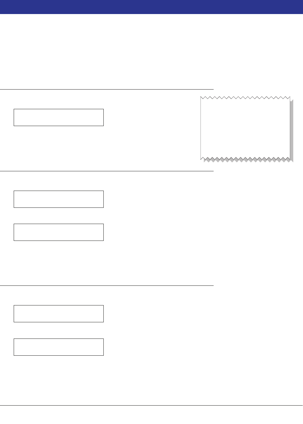
27-1
27 VMC Setup
The Vapor Monitoring Controller (VMC) Setup function allows you to monitor a series of up to 18 dispenser
mounted, Gilbarco Vapor Monitor Controllers via an installed VMCI comm board.The VMCI board will poll each
VMC on the bus, and periodically upload the VMC information back to the TLS. The TLS supports the installation
of only 1 VMCI comm board. Additional VMCI boards will cause Setup Data Warnings. A VMCI board must be
installed in the TLS for the VMC Setup function to appear. NOTE: VMC setup will not be saved in E2. On cold
boot, the VMC serial numbers entered during setup will have to be reentered following the setup procedure below.
Selecting the VMC Setup Function
To enter VMC Setup, press FUNCTION until you see the message:
Press STEP to continue. Press PRINT to printout current VMC setup
(see example at right).
Add a VMC Serial Number
If necessary, press STEP until you see the message:
Press ENTER.
Enter the serial number of the displayed VMC or press TANK repeatedly until the desired VMC displays. Press
CHANGE and enter the VMC’s serial number. Press ENTER to confirm your entry. Press STEP to continue.
Edit a VMC Serial Number
If necessary, press STEP until you see the message:
Press ENTER. If necessary, press TANK repeatedly until the desired VMC displays.
Press CHANGE and enter the revised serial number of the displayed VMC. Press ENTER to confirm your entry.
Press STEP to continue.
VMC SETUP
PRESS <STEP> TO CONTINUE
VMC SETUP
- - - - - - - - - - -
VMC S/N
1 005830
2 005813
3 002209
consoles\vmcsetup.eps
ADD VMC SERIAL NUMBER
PRESS <ENTER>
ADD VMC SERIAL NUMBER
x 1:
EDIT VMC SERIAL NUMBER
PRESS <ENTER>
EDIT VMC SERIAL NUMBER
x 1: 111111
27 VMC Setup
Remove a VMC Serial Number
27-2
Remove a VMC Serial Number
If necessary, press STEP until you see the message:
Press ENTER. If necessary, press TANK repeatedly until the desired VMC displays.
Press CHANGE.
Press ENTER to confirm..
Press STEP:
Press CHANGE.
Press STEP:
REMOVE VMC SERIAL NUMBER
PRESS <ENTER>
x 1: 111111
REMOVE VMC: NO
x 1: 111111
REMOVE VMC: YES
REMOVE VMC: YES
PRESS <STEP> TO CONTINUE
REMOVE VMC: 111111
ARE YOU SURE? NO
REMOVE VMC: 111111
ARE YOU SURE? YES
REMOVE VMC SERIAL NUMBER
PRESS <ENTER>
28-1
28 Archive Utility
The Archive Utility allows you to save system setup data to the EEPROM (E2) chip and later restore this saved
setup data should a power interruption occur while the battery backup is OFF. Because system setup data is not
automatically saved, you have more flexibility when using different setup conditions. Another feature the Archive
Utility provides you is the ability to clear current system setup data and replace it with system setup data you
stored previously in the E2 chip.
AccuChart users should note that you archive system setup data only in the E2 chip. If AccuChart is complete, the
final calibration values are automatically stored in the E2 chip and there will be no need to recalibrate the tank.
Incomplete CSLD data, AccuChart data, BIR historical data, etc., are all stored in various RAM locations within the
console, not in the E2 chip. When turned ON, the Battery Backup feature will protect these data in the event of a
power loss to the console. But should you lose AC power to the console while the Battery Backup switch is OFF,
all of this important historical data will be lost (e.g., AccuChart calibration will have to restart and won’t be
complete for 56 days).
Therefore, if you plan to replace the ECPU board or the battery, you should consider downloading all data (setup
and historical) to a computer using Veeder-Root’s Inform software (Part No. 848900-X0X).
NOTE: Setup data archived in the E2 chip is not an option to turning the Backup Battery ON. The Backup Battery
switch should always be set to the ON position.
Accessing the Archive Utility Function
To select the Archive Utility, press FUNCTION until you see the message:
Press STEP to continue.
The system also provides interactive access to Archive Utility functions by prompting you to restore previously
saved setup data upon power up, if the battery switch is set to OFF.
For example, if you power up the system while the battery switch is set to OFF, and setup data was previously
saved, the system displays a message such as the following:
To restore setup data in response to this message, press CHANGE, then press ENTER.
Archiving Setup Data
Once you have selected the Archive Utility, press STEP, if necessary, until you see the message:
If you do not wish to save setup data, press STEP. (The system displays the RESTORE SETUP DATA message.)
ARCHIVE UTILITY
PRESS <STEP> TO CONTINUE
MMM DD, YYYY HH:MM:SS XM
RESTORE SETUP DATA: NO
ARCHIVE UTILITY
SAVE SETUP DATA: NO
28 Archive Utility
Restoring Archived Setup Data
28-2
To save setup data, press CHANGE, then press ENTER. The system confirms your choice with the message:
The system asks you to reconfirm your choice with the following message:
To abandon the save process, press STEP. (The system displays the RESTORE SETUP DATA message.) To
continue saving setup data, press CHANGE, then press ENTER. The system displays the message:
When you press STEP in response to this message, the system starts saving your setup data to the EEPROM.
This process may take a minute or so. When the save is completed, the system returns the original message:
Press STEP to use another archive feature or press either FUNCTION or MODE to exit the Archive Utility.
Restoring Archived Setup Data
NOTE: If you are restoring after a reboot (switching the console Off and then back On), the system will wait 5
minutes before processing your request to restore archived setup data. This delay is to allow all hardware to
initialize.
If necessary, press STEP until you see the message:
If you do not wish to restore setup data, press STEP. (The system displays the CLEAR SETUP DATA menu.)
To restore setup data, press CHANGE, then press ENTER. The system confirms your choice with the message:
The system asks you to reconfirm your choice with the following message:
To abandon the restore process, press STEP. (The system displays the CLEAR SETUP DATA menu.) To continue
restoring setup data, press CHANGE, then press ENTER. The system displays the message:
SAVE SETUP DATA: YES
PRESS <STEP> TO CONTINUE
SAVE SETUP DATA: YES
ARE YOU SURE?: NO
ARE YOU SURE?: YES
PRESS <STEP> TO CONTINUE
ARCHIVE UTILITY
PRESS <STEP> TO CONTINUE
ARCHIVE UTILITY
RESTORE SETUP DATA: NO
RESTORE SETUP DATA: YES
PRESS <STEP> TO CONTINUE
RESTORE SETUP DATA: YES
ARE YOU SURE?: NO
ARE YOU SURE?: YES
PRESS <STEP> TO CONTINUE
28-3
28 Archive Utility
Clearing Archived Setup Data
When you press STEP in response to this message, the system starts restoring previously saved setup data from
the EEPROM. This process may take a minute or so. When the restore is completed, the system returns the
original message:
The system also prints a complete listing of all restored setup data.
Press STEP to use another archive feature or press either FUNCTION or MODE to exit the Archive Utility.
Clearing Archived Setup Data
If necessary, press STEP until you see the message:
If you do not wish to clear setup data in EEPROM, press STEP. (The system returns to the SAVE SETUP DATA
message.)
To clear all current setup data in the EEPROM, press CHANGE, then press ENTER. The system confirms your
choice with the message:
The system asks you to reconfirm your choice with the following message:
To abandon the clear process, press STEP. (The system returns to the SAVE SETUP DATA message.) To continue
clearing setup data, press CHANGE, then press ENTER. The system displays the message:
When you press STEP in response to this message, the system starts clearing all current setup information in the
EEPROM. When the clear process is completed, the system returns the original message:
Press STEP to use another archive feature or press either FUNCTION or MODE to exit the Archive Utility.
ARCHIVE UTILITY
PRESS <STEP> TO CONTINUE
ARCHIVE UTILITY
CLEAR SETUP DATA: NO
CLEAR SETUP DATA: YES
PRESS <STEP> TO CONTINUE
CLEAR SETUP DATA: YES
ARE YOU SURE?: NO
ARE YOU SURE?: YES
PRESS <STEP> TO CONTINUE
ARCHIVE UTILITY
PRESS <STEP> TO CONTINUE

A-1
Appendix A: Calculating Tank Tilt - International
TLS-350R only--Entering a Tank Tilt value is not recommended if the system is performing automatic Business
Inventory Reconciliation and AccuChart.
If the probe is installed in the center of the tank, the value is 000.00 Metric.
Within Setup Mode, Press FUNCTION until you In-Tank Setup, then press STEP until you see the message:
Tank Tilt allows you to compensate for a difference between fuel height at the ideal probe location (on the centreline
of the tank with no striker plate underneath) and at the actual probe position (offset from the tank centreline and/or
over a striker plate).
TLS-350R only--Entering a Tank Tilt value is not recommended if the system is performing automatic Business
Inventory Reconciliation and AccuChart.
Table A-1 lists offset values for various tank diametres/probe offset combinations (used in determining Tank Tilt).
Vertical offset values given in Table A-1 were derived from the formula:
Where, Oh = vertical offset height
R = tank radius
Od = offset distance from centreline (C/L).
Figure A-1 illustrates the four possible Tank Tilt computational scenarios.
Table A-1.- Typical Tank Offset Values
Imp. Diam.
ft-in
Metric
Diam.
mm
Probe
offset
from C/L
50 mm
Probe
offset
from C/L
100 mm
Probe
offset
from C/L
150 mm
Probe
offset
from C/L
200 mm
Probe
offset
from C/L
250 mm
6-01829 1 5 122235
7-02134 1 5 111930
8-0 2438 1 4 9 17 26
9-0 2743 1 4 8 15 23
9-10 2997 1 3 8 13 21
T1: (Product Label)
TANK TILT: +000.00
Oh R R Od––=
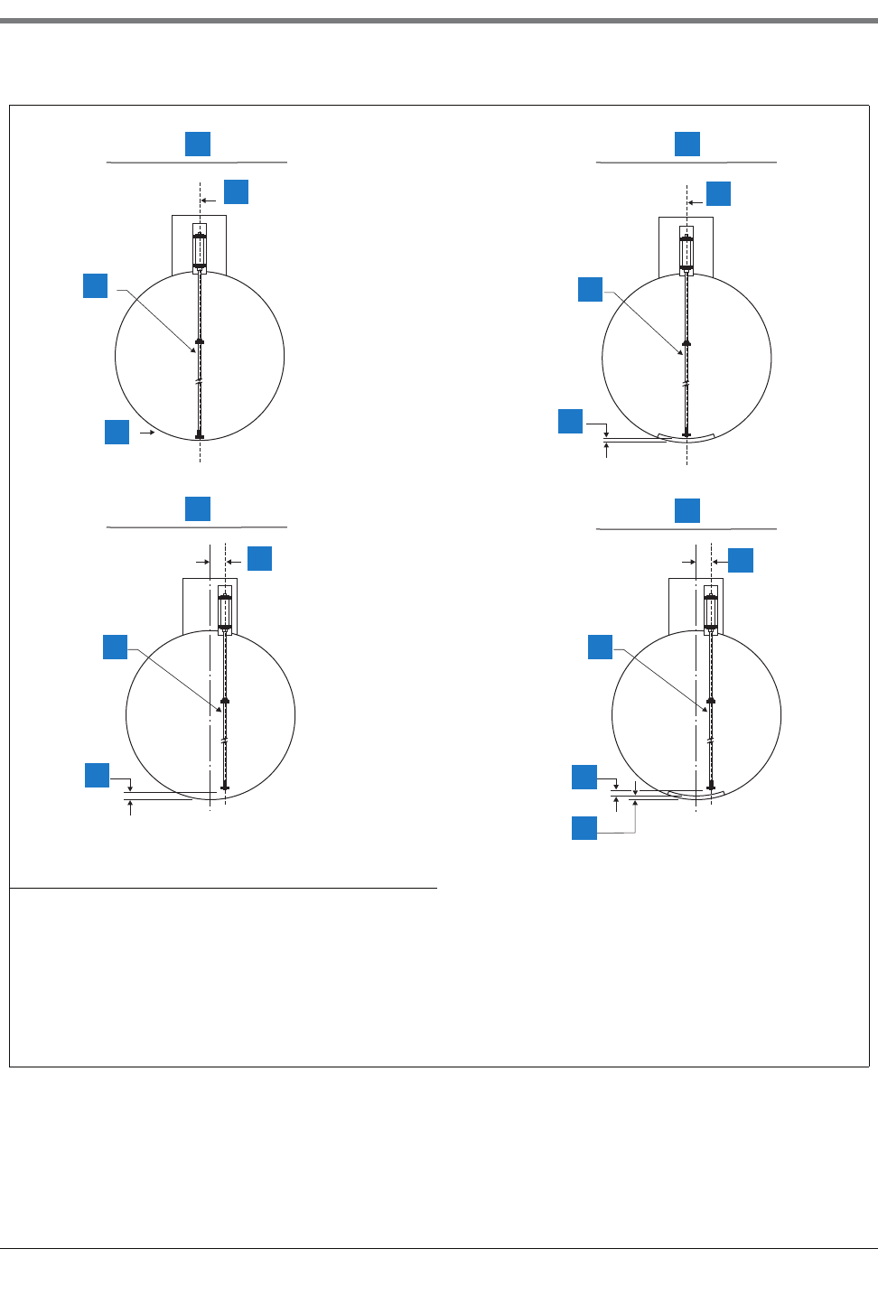
Appendix A: Calculating Tank Tilt - International
A-2
.
Figure A-1. Methods for Determining the Tank Tilt Entry
Legend for numbered boxes:
1. Tank Tilt = +000.00 9. Tank Tilt = Striker Plate Thickness
2. No offset 10. No offset
3. Probe 11. Probe
4. No striker plate 12. Thickness of striker plate
5. Tank Tilt = Offset Value (No Striker Plate) 13. Tank Tilt = Offset Value + Striker Plate Thickness
6. No offset 14. No offset
7. Probe 15. Probe
8. Tank Tilt (mm) (read from table) 16. Offset value (read from table)
consoles\uktktlt1.eps
1 9
10
13
14
15
15
15
5
7
8
6
2
3
4
11
12

Appendix A: Calculating Tank Tilt - International
A-3
ENTERING THE TANK TILT VALUE
To enter the Tank Tilt value for the selected tank, press CHANGE. If the value is negative, press the +/- key so that
a minus (-) sign appears on the display. Enter the value as calculated according to the above procedures (inches
or millimetres depending on the units specified in System Setup). Press ENTER to confirm your entry. The system
displays:
Press STEP to continue.
TANK TILT: ±XXX.XX
PRESS <STEP> TO CONTINUE
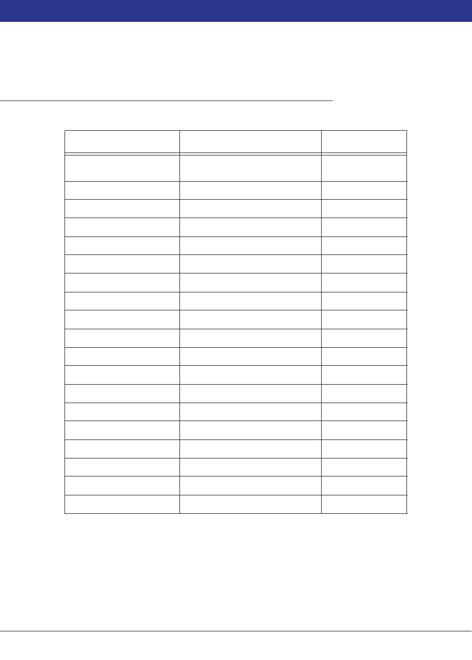
B-1
Appendix B: Setup Parameters for TLS-300 System - International
The following list of setup parameters is intended for use as a programming guide for the commissioning engineer.
System Setup
Table B-1. System Setup
Parameter Default Set As
Time & Date 08:00 01:01:94 Current Time &
Date
System Units Metric Default
System Language English As Required
Header Message 1 None Site Name
Header Message 2 None Site Address
Header Message 3 None Site Address
Header Message 4 None Site Address
Shift Time 1 Disabled Default
Shift Time 2 Disabled Default
Shift Time 3 Disabled Default
Shift Time 4 Disabled Default
Tank Per Tst Needed Wrn Disabled Default
Tank Ann Tst Needed Wrn Disabled Default
Print TC Vol. Enabled Disable
Temp. Comp. °C 15.6 Default
Stick Height Offset Disabled Disabled
Daylight Savings Time Enabled Default
H Protocol Format Height Default
Security Code 000000 xxxxxx

Appendix B: Typical Setup Parameters - TLS-300
Comm Board (1, 2, etc.) Setup
B-2
Comm Board (1, 2, etc.) Setup
In-Tank Setup
Table B-2. Comm Board Setup
Parameter Default Set As
Baud Rate 1200 Comm Rate for
Third Party Equip.
Parity Odd Parity for Third
Party Equip.
Stop Bit 1 Stop Default
Data Length 7 Data Default
Table B-3. In-tank Setup
Parameter Default Set As
Product Label None As Tank Product
(e.g. UL UNLEADED)
Product Code 1 to 8 Default
Thermal Coeff. 000000 0.00126 Spirit, 0.00300 LPG
0.00081 DV
Tank Diameter 00000 As Tank Diameter
Tank Profile 1 Point 1 Point Flat Ends
4 Point Shallow-dished Ends.
20 Point Hemispherical Ends.
Linear for Vertical Cylindrical & Rectangular Tanks
Full Volume 00000 100% Tank Volume
Label Vol. As 100% Vol. As Tank Label
Float Size Depends on probe type Enter as used
Water Warning 00.00 25.0 mm
Water Limit 00.0 32.0 mm
Overfill Vol. 000% 99%
High Product 000% 98% if Label Volume >25,000 litres, or 96% if Label Vol-
ume <25,000 litres
Delivery Limit 001% Default
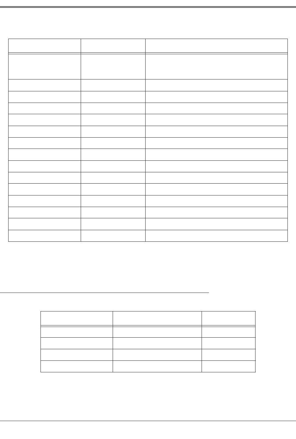
Appendix B: Typical Setup Parameters - TLS-300
Leak Test Method Setup
B-3
The product code for all partners should be the same, e.g., tank 1 product code 1 manifold partner tank 4 product
code 1.
Leak Test Method Setup
Low Product:
Mag Type 8473
Mag Type 8493
00000
0000
Vol at 250 mm
Vol at 125 mm
Leak Alarm Limit 374 10 litres
Sudden Loss Limit 374 200 litres
Tank Tilt 0 10 mm
Manifold Tanks None Default*
Leak Min. Annual 0 60%
Periodic Test Type Standard Default
Annual Test fail Al. Disabled Default
Periodic Test Fail Al. Disabled Default
Gross Test Fail Disabled Default
Ann. Test Averaging OFF Default
Per. Test Averaging OFF Default
Tank Test Notify OFF ON
Tank Test Siphon B OFF Default
Delivery Delay 1 Minute 15 Minutes
Table B-4. Leak Test Method Setup
Parameter Default Set As
Test on Date Current T & D All Tanks Default
Start Time Disabled Default
Test Rate 0.76 LPH 0.38 LPH
Duration 2 Hours 4 Hours
Table B-3. In-tank Setup
Parameter Default Set As

C-1
Appendix C: Setup Parameters for TLS-350 System - International
The following list of setup parameters is intended for use as a programming guide for the commissioning engineer.
Table C-1. System Setup
Parameter Default Set As
Time & Date 08:00 01:01:94 Current Time & Date
System Units Metric Default
System Language English Default
Time/Date Format DD-MM-YY HH-MM-SS MON-DD-YY HH:MM:SS
Header Message 1 None Site Name
Header Message 2 None Site Address
Header Message 3 None Site Address
Header Message 4 None Site Address
Shift Time 1 Disabled Default
Shift Time 2 Disabled Default
Shift Time 3 Disabled Default
Shift Time 4 Disabled Default
Shift BIR Prn Disable Default
Daily BIR Prn Enabled Default*
Ticketed Delivery Disabled Default
TC Ticketed Delivery Disabled Default
Close Day of Week Sun Default
Tank Per Tst Needed Wrn Disabled Default
Tank Per Tst Needed Wrn Days Disabled Default
Tank Per Tst Needed Alm Days Disabled Default
Tank Ann Tst Needed Wrn Disabled Default
Tank Ann Tst Needed Wrn Days Disabled Default
Tank Ann Tst Needed Alm Days 355 days Default
Line Per Tst Needed Wrn Disabled Default
Line Per Tst Needed Wrn Days Disabled Default
Line Per Tst Needed Alm Days Disabled Default

Appendix C: Typical Setup Parameters - TLS-350
C-2
*IMPORTANT: If Gilbarco T24 (BDIM) Site Controllers are to be interfaced to the gauge on a Non-24-Hour site,
this parameter should be set to DISABLED.
Line Ann Tst Needed Wrn Disabled Default
Line Ann Tst Needed Wrn Days Disabled Default
Line Ann Tst Needed Alm Days Disabled Default
Remote Printer Page Eject Disabled Default
Print TC Vol. Enabled Disable
Temp. Comp. 15.6°C Enabled Default
Stick Height Offset Disabled Disabled
H Protocol Format Height Default
Precision Test Duration
Precision Line Test Auto-Confirm Enabled
Daylight Savings Time Enabled
MAR WK6 SUN 03:00AM
OCT WK6 SUN 04:00AM
Re-Direct Local Printout Disabled Default
QPLD Monthly Printout Enabled Default*
BDIM Transaction Delay 24 Default
Euro Protocol Prefix S Default
Security Code 000000 XXXXXX
Table C-2. Comm Board (1, 2, Etc.) Setup
Parameter Default Set As
Baud Rate 1200 Comm Rate for Third Party Equip.
Parity Odd Parity for Third Party Equip.
Stop Bit 1 Stop Default
Data Length 7 Data Default
Table C-1. System Setup
Parameter Default Set As

Appendix C: Typical Setup Parameters - TLS-350
C-3
Table C-3. In-tank Setup
Parameter Default Set As
Product Label None
As Tank Product
(e.g. UL unleaded)
Product Code 1 to 8 Default
Thermal Coeff. 000000
0.00126 Spirit, 0.00300 LPG
0.00081 DV
Tank Diameter 00000 As Tank Diameter
Tank Profile 1 Point
1 Point Flat Ends
4 Point Shallow-dished Ends.
20 Point Hemispherical Ends.
Linear for Vertical Cylindrical & Rectangular Tanks
Full Volume 00000 100% Tank Volume
Point 2 00000 75% Tank Diameter
Point 3 00000 50% Tank Diameter
Point 4 00000 25% Tank Diameter
Meter Data No Yes
End Factor Other
Cal. Update Periodic Default (except select NEVER for Linear Tanks)
Float Size
101 mm (8496 and 8499
types) 50 or 76 mm (according to size fitted)
Water Warning 00.00 25.0 mm
Water Limit 00.0 32.0 mm
Label Vol. as 100% Vol. As Tank Label
Overfill Vol. 000% 99%
High Product 000%
98% if Label Volume >25,000 litres, or 96% if Label
Volume <25,000 litres
Delivery Limit 001% Default
Low Product:
Mag Type 8473
Mag Type 8493
00000
0000
Vol at 250 mm
Vol at 125 mm
Leak Alarm Limit 374 10 litres
Sudden Loss Limit 374 200 litres
Tan k Ti lt 0 1 0 m m
Manifold Tanks None Default*
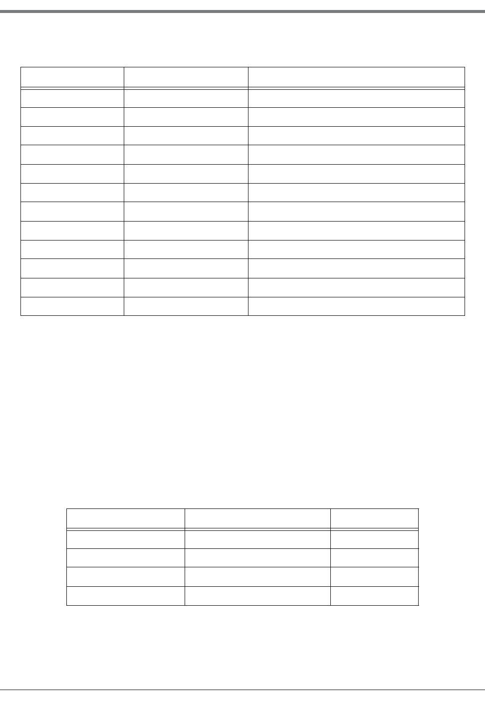
Appendix C: Typical Setup Parameters - TLS-350
C-4
*When manifolded tanks are to be configured in order that the system does not give false RECONCILIATION
WARNINGS AND ALARMS, the parameters for reconciliation should be set to 7 LITRES for RECON
WARNINGS and 8 LITRES for RECON ALARMS.
The product code for all partners should be the same, e.g., tank 1 product code 1 manifold partner tank 4 product
code 1.
The calibration update setup parameter must be set to NEVER as systems using a BDIM are theoretically unable
to carry out good calibration. "NEVER" will allow the system to run using only the 1, 4, or 20 point user data input
at time of commissioning.
All of the above setup parameters are required whenever manifolds are to be set if a BDIM is in use.
NOTE: METER DATA should be set to YES – this will allow BIR to run for the manifolded tanks on site.
Leak Min. Annual 0 60%
Periodic Test Type Standard Default
Annual Test fail Al. Disabled Default
Periodic Test Fail Al. Disabled Default
Gross Test Fail Disabled Default
Ann. Test Averaging OFF Default
Per. Test Averaging OFF Default
Tan k Tes t N ot if y OFF ON
Tank Test Siphon B OFF Default
Recon Warning Limit 3 litres 4 litres*
Recon Alarm Limit 4 litres 5 litres*
Delivery Delay 1 Minute 15 Minutes
Table C-4. Leak Test Method Setup
Parameter Default Set As
Test on Date Current T & D All Tanks Default
Start Time Disabled Default
Test Rate 0.76 LPH Default
Duration 2 Hours 4 Hours
Table C-3. In-tank Setup
Parameter Default Set As

Appendix C: Typical Setup Parameters - TLS-350
C-5
**Setting Periodic Recon Mode to Rolling will ensure 31 days of data may be viewed at any time (after the first 31
days of operation).
Table C-5. Reconciliation Setup
Parameter Default Set As
DIM 1 Default String As Site Controller
Auto Daily Closing 02:00 AM Default
To Shift 1 Closing Time Disabled Default
To Shift 2 Closing Time Disabled Default
To Shift 3 Closing Time Disabled Default
To Shift 4 Closing Time Disabled Default
Periodic Recon. Mode Monthly Rolling**

For technical support, sales or
other assistance, please visit:
www.veeder.com
