Vicon Nexus Reference Guide
User Manual:
Open the PDF directly: View PDF ![]() .
.
Page Count: 356 [warning: Documents this large are best viewed by clicking the View PDF Link!]
- Contents
- About this guide
- About Vicon Nexus documentation
- Data management with Nexus
- Labeling skeleton calibration in detail
- Using monitors
- Modeling with Vicon Nexus
- Biomechanics workflow
- Using the Advanced Gait Workflow
- Using a custom biomechanics workflow
- Overview of the biomechanics workflow
- View real-time subject calibration feedback with monitors
- About functional calibration in the biomechanics workflow
- Create a biomechanics workflow
- About SCoRE and SARA in Vicon Nexus
- Prepare data for use with SCoRE and SARA
- Capture and process a trial with SCoRE and SARA
- Process multiple joints with SCoRE and SARA
- OCST, SCoRE and SARA research references
- Improve manual labeling
- Eye tracking with Vicon Nexus
- Vicon Nexus user interface

Vicon Nexus Reference Guide
© Copyright 2016–2019 Vicon Motion Systems Limited. All rights reserved.
Vicon Motion Systems Limited reserves the right to make changes to information in this document without notice.
Companies, names, and data used in examples are fictitious unless otherwise noted. No part of this publication may be
reproduced, stored in a retrieval system, or transmitted in any form or by any means, electronic or mechanical, by
photocopying or recording, or otherwise without the prior written permission of Vicon Motion Systems Ltd.
Vicon® is a registered trademark of Oxford Metrics plc. Vicon Bonita™, Vicon Lock™, Vicon Lock+™, Vicon Lock Lab™,
Vicon Lock Studio™, Vicon Nexus™, Vicon MX™, Vicon Shōgun™, Vicon Tracker™, T-Series™, Vicon Vantage™,
Vicon Vero™, Vicon Vertex™, and Vicon Vue™ are trademarks of Oxford Metrics plc.
VESA® is a registered trademark owned by VESA (www.vesa.org/about-vesa/). Other product and company names
herein may be the trademarks of their respective owners. For full and up-to-date copyright and trademark
acknowledgements, visit https://www.vicon.com/vicon/copyright-information.
Vicon Motion Systems is an Oxford Metrics plc company.
Email: support@vicon.com Web: http://www.vicon.com
Contents
About this guide..................................................................................................3
About Vicon Nexus documentation................................................................ 4
Regulatory information.................................................................................. 5
Data management with Nexus ........................................................................ 6
Navigate in Data Management.....................................................................8
Work with database hierarchy nodes ........................................................ 10
Customize the Data Management display................................................ 16
Advanced data searching .............................................................................17
Load large trials............................................................................................. 19
Batch process trials ......................................................................................20
Labeling skeleton calibration in detail ......................................................... 23
Comparison of skeleton calibration operations .......................................24
Choose the appropriate subject calibration workflow ...........................33
Using monitors ................................................................................................. 39
Create a monitor .......................................................................................... 40
Configure a monitor......................................................................................42
Configure an AND or OR Monitor............................................................... 51

Nexus
Reference
Guide
Vicon Motion Systems Ltd. 13-Nov-2018 Page 2 of 356
Activate and deactivate a monitor.............................................................53
Reload a monitor...........................................................................................54
Monitor configuration examples................................................................55
Modeling with ViconNexus ........................................................................... 59
Modeling with MATLAB ............................................................................... 61
Modeling with Python .................................................................................. 75
Biomechanics workflow.................................................................................. 79
Using the Advanced Gait Workflow ........................................................... 81
Using a custom biomechanics workflow ................................................102
OCST, SCoRE and SARA research references.........................................130
Improve manual labeling................................................................................ 131
Eliminate overlapping trajectories ........................................................... 132
Prevent ghost markers ............................................................................... 133
Eye tracking with Vicon Nexus.....................................................................135
Set up eye tracking hardware...................................................................136
Add a Dikablis Eye Tracker device in ViconNexus................................139
Calibrate eye tracking in ViconNexus ....................................................140
Export eye vector data ............................................................................... 147
ViconNexus user interface.......................................................................... 150
About the ViconNexus user interface.....................................................151
Resources pane ........................................................................................... 152
System tab ...................................................................................................156
System Resources nodes ...........................................................................163
Subjects tab .................................................................................................247
View pane.....................................................................................................257
Tools pane ...................................................................................................280
Communications pane ...............................................................................325
Menu bar ..................................................................................................... 336
Toolbar .......................................................................................................... 351

Nexus
Reference
Guide
About this guide
Vicon Motion Systems Ltd. 13-Nov-2018 Page 3 of356
About this guide
This guide contains information about Nexus functionality that is likely to
be of interest if you are already familiar with the basic procedures
described in the
Vicon Nexus User Guide
.
For instructions on configuring your Vicon system within Nexus and on the
basic tasks that are part of the everyday Nexus workflow, see the Vicon
Nexus User Guide.

Nexus
Reference
Guide
About Vicon Nexus documentation
Vicon Motion Systems Ltd. 13-Nov-2018 Page 4 of356
1 http://docs.vicon.com
About Vicon Nexus documentation
The following documentation is available with Nexus, available online and
as PDFs that you can download from docs.vicon.com1:
Document Description
What’s New in Vicon Nexus
Information about the main features that
are new in the current version of Nexus.
Installing and licensing
Vicon Nexus
Step-by-step instructions installing and
licensing Nexus.
Vicon Nexus User Guide
Information about how to use Nexus.
Vicon Nexus Reference
Guide
(this guide)
Descriptions of less frequently used or
more complex procedures, background
information, and further details about the
Nexus user interface.
Creating labeling skeleton
templates (VSTs)
Instructions on how to create your own
custom labeling skeleton templates for
use with Nexus.
Plug-in Gait Reference
Guide
Detailed information on the Plug-in Gait
model.


Nexus
Reference
Guide
Data management with Nexus
Vicon Motion Systems Ltd. 13-Nov-2018 Page 6 of356
3 https://www.youtube.com/watch?v=rZh-R7eHwcg&feature=youtu.be
Data management with Nexus
The Data Management tab of the Communications window provides
functionality for storing and managing all data associated with your motion
capture files. Data is organized in a hierarchical structure, with data and
information stored in relevant nodes.
For a video guide to database management, see the Vicon video,
proEclipse: Preparing and managing your database3, which is available on
YouTube.
The default location of Data Management is on a tab at the bottom of the
Communications window. If you prefer, you can click the buttons at the top
right of the Communications window to un-dock it and display it full-
screen. To toggle the display of the Data Management tab, press F2.
Tip
You can also choose to hide the entire Communications pane, in
which the Data Management tab appears, when you load a trial. To
do this, on the Window menu, select the Close Communications
Pane on Trial Load option. Alternatively, to temporarily hide/reveal
the Communications pane, double-click any of its tabs.
By default, the last opened database is loaded when you restart Nexus.

Nexus
Reference
Guide
Data management with Nexus
Vicon Motion Systems Ltd. 13-Nov-2018 Page 7 of356
The following topics provide an introduction to data management with
Nexus:
•Navigate in Data Management, page 8
•Work with database hierarchy nodes, page 10
•Customize the Data Management display, page 16
•Advanced data searching, page 17
•Load large trials, page 19
•Batch process trials, page 20
The Data Management tab also enables you to perform file transfers and
transcoding of reference video files, as well as providing access to batch
processing functionality. For information on these topics, see Work with
digital video files in the
Vicon Nexus User Guide
and Batch process trials,
page 20.
Nexus
Reference
Guide
Data management with Nexus
Vicon Motion Systems Ltd. 13-Nov-2018 Page 8 of356
Navigate in Data Management
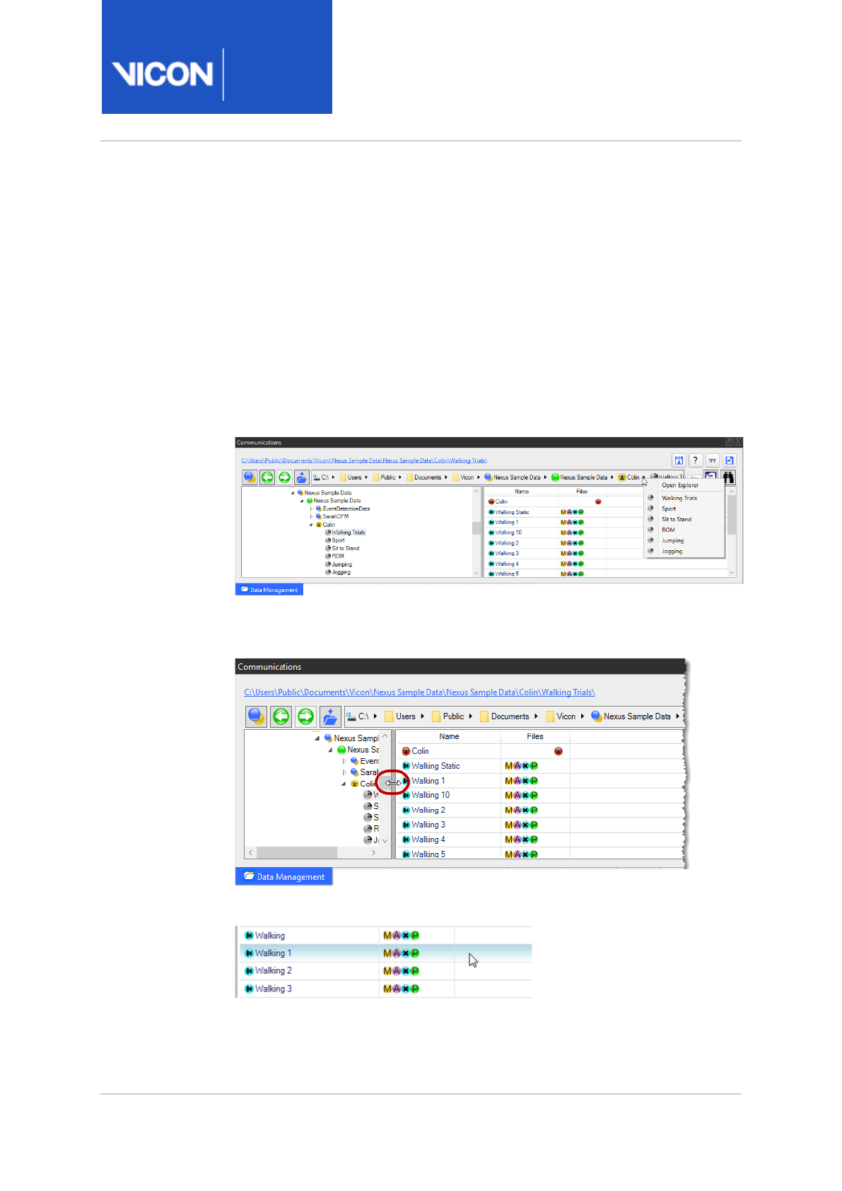
Navigation in Data Management (located in the Communications pane) is
similar to that of the web or in Microsoft Windows. Forward, back and up
controls are displayed and path navigation, similar to that in Windows
Explorer is available.
The live path link at the top of the pane contains icons and arrows which,
when clicked, give access to other folders at the selected level, and enable
you to open Windows Explorer.
For faster navigation within a database or across a hard drive, you can also
hide the tree view to expand panes.
When you hover the mouse pointer over a trial row, it is highlighted in blue.
Nexus
Reference
Guide
Data management with Nexus
Vicon Motion Systems Ltd. 13-Nov-2018 Page 9 of356
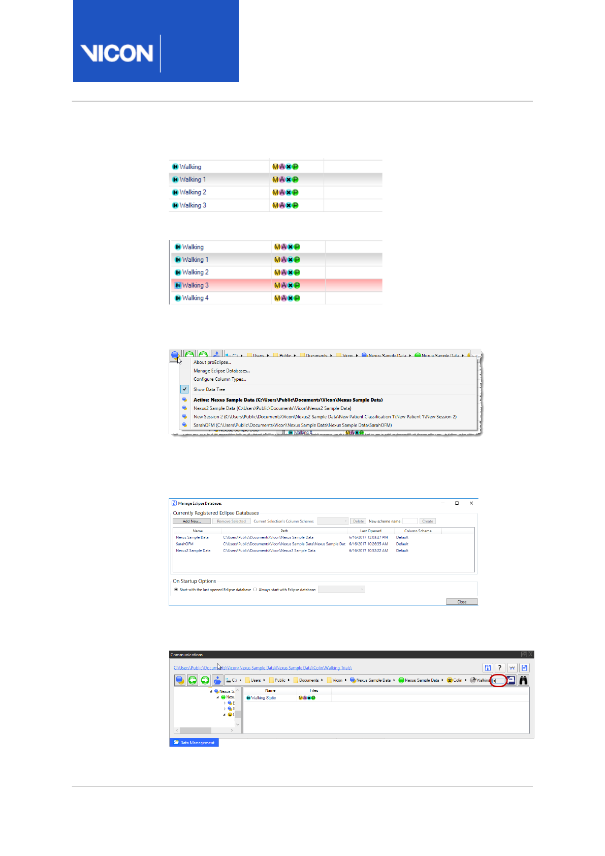
The currently selected node is highlighted in gray:
When you mark a node, it is highlighted in red:
The Show main proEclipse menu button gives you instant access to the
most recently used databases.
It also gives you access to the Manage Eclipse Databases dialog box,
enabling you to create, browse and register databases, as well as access
other options for managing them.
The quick search facility enables you to filter all the files that are visible in
the current view by typing any letter into the Filter box.

Nexus
Reference
Guide
Data management with Nexus
Vicon Motion Systems Ltd. 13-Nov-2018 Page 10 of356
Work with database hierarchy nodes
You view and manage the nodes created for the database hierarchy on the
Data Management tab of the Communications window.
The data management function keeps all files associated with a Vicon
motion capture trial together in a strict hierarchical order. The database
hierarchy can contain up to four levels (Database, Patient Classification,
Patient, and Session) to define the appropriate hierarchical structure for
your motion capture trial as defined in the database template (.eni ) file on
which the database is based.
Each level (node) in the hierarchy has its own properties and can contain
only certain types of data. The top-level node for the hierarchy has the
same name as the database, with sub folders for each node. Sub-sessions
and trials do not have their own folders but are sets of files within the
session folder.
You can expand and contract the nodes in an database hierarchy as you
would with standard file explorers. Additionally, you can identify a node for
which you want to perform an action in the following ways:
•Marked node A marked node will be acted on by buttons selected from
the Data Management toolbar.
A marked node is highlighted with a red check mark across the node
icon. Its row has a red background, unless it is also selected, when it is
gray.
•Selected node A selected node will be acted on by commands selected
from the context menu displayed when you right-click on the node.
A selected node is highlighted with a gray background for its row.
Caution
The hierarchy shown on the Data Management tab is mirrored in
the folder system on your hard drive. Under no circumstances
should you manually change these folders on your hard drive as this
will prevent your database system from functioning correctly. Make
any changes from within the Data Management tab in Nexus.

Nexus
Reference
Guide
Data management with Nexus
Vicon Motion Systems Ltd. 13-Nov-2018 Page 11 of356
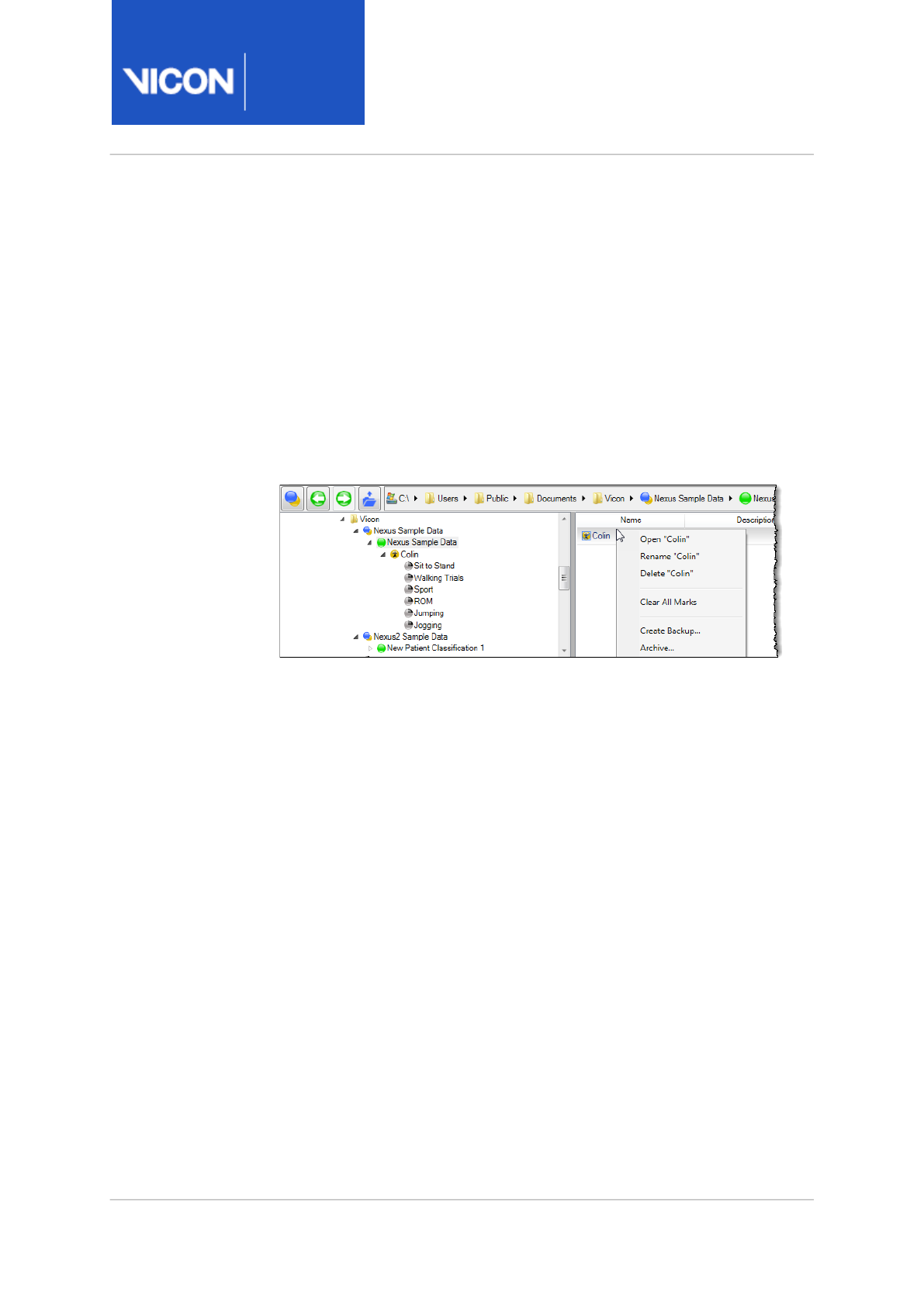
After you have selected or marked a node, you can carry out the operations
described below.
Manage database nodes
After you have created one or more nodes in a trial database, on the Data
Management tab you can create, delete, rename, and move folders and files
to meet your requirements.
You can manage database nodes using the mouse and/or the following
commands from the context (right-click) menu :
• Open Patient/Session/Trial/Subject
• Rename
• Delete
• Create copy of Master with tag
This can be one of Labeled, Modeled, Filtered, or Backup.
• Mark
When you mark one or more nodes, the Show/hide marked nodes button
is displayed in the Data Management toolbar, enabling you to display
only marked nodes on the Data Management tab.
• Clear All Marks
• Create Backup (Session node and below)
• Archive (Session node and above)
• Restore
For information about archiving, backup and restoring, see Archive and
backup data, page 13.
Nexus
Reference
Guide
Data management with Nexus
Vicon Motion Systems Ltd. 13-Nov-2018 Page 12 of356
About Data type icons
View and open the different data types saved for a motion capture trial
using the Data Type icons on the Data Management tab.
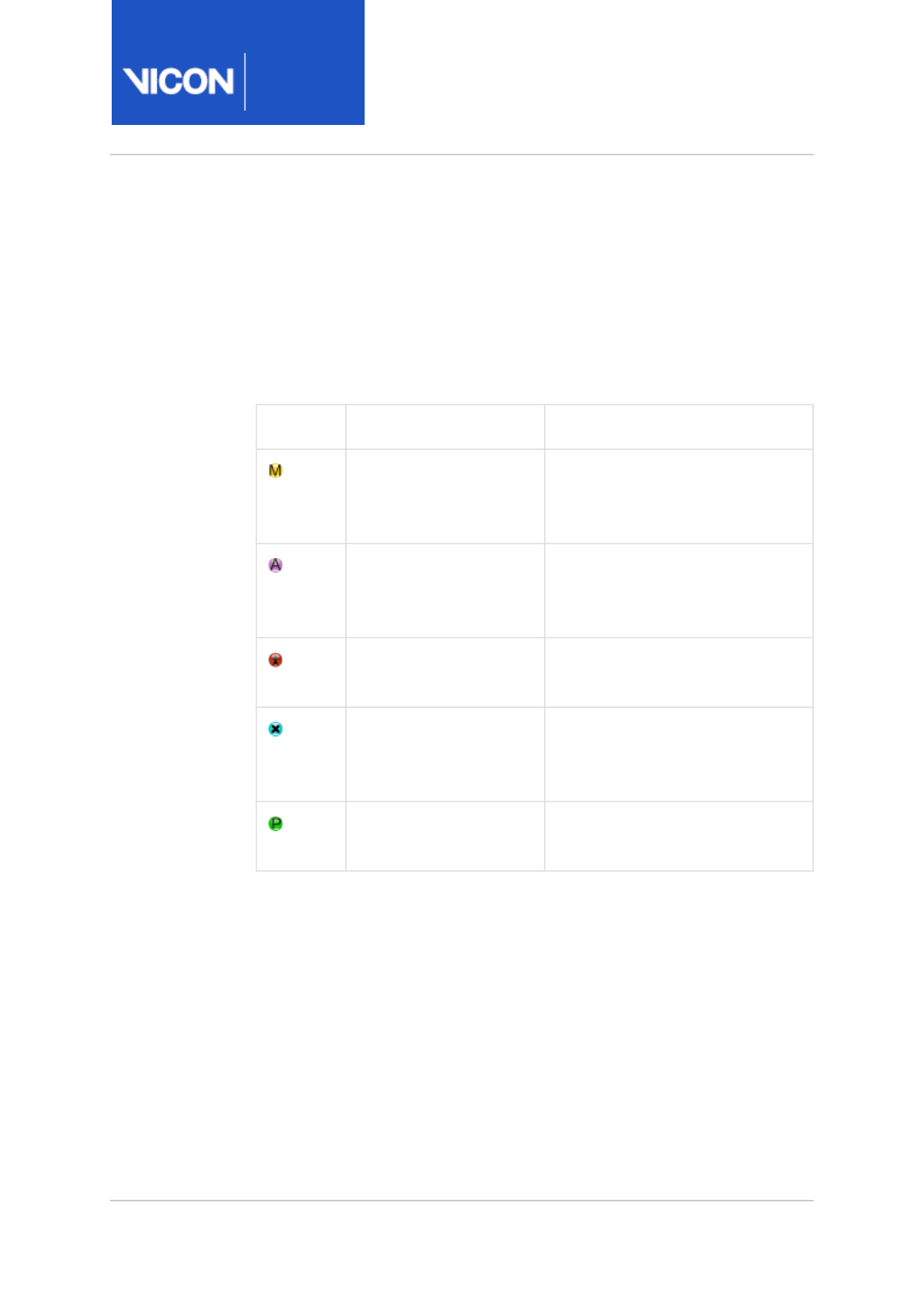
The icons for the standard data types that can be associated with Vicon
motion capture trials are shown here in the default order in which they
appear from left to right in the Files column:
Icon Data type Description
Movie File Multimedia sound and moving
picture data in .mpg or .avi
format files
Raw Analog Data Unprocessed analog data (e.g.,
from force plates) in .x1d format
files
Model Parameter File The model's parameters for Plug-
in Gait or BodyLanguage models
Centroid/Grayscale File Unprocessed Vicon video data
from Vicon cameras in .x2d
format files
Processed Capture Data Processed Vicon 3D motion data
in .c3d format files
Archived nodes are displayed with a red cross over them, to indicate that
they cannot be used until restored.
You may also see additional icons for file types of motion data created in
earlier Vicon motion capture application software or exported for use in
third-party applications (such as animation software or Excel
spreadsheets).

Nexus
Reference
Guide
Data management with Nexus
Vicon Motion Systems Ltd. 13-Nov-2018 Page 13 of356
Manage data files
View and manage the motion capture data saved to a trial database on the
Data Management tab. The data files associated with a motion capture
trial are indicated by data type icons in the Files column to the right of a
node name in the database hierarchy.
To open a trial:
In the database hierarchy, double-click the node name.
Nexus opens the trial, and the reconstructed data (and the associated
movie file if present) is displayed in the view pane.
To open a data file:
In the database hierarchy, click a node icon and in the context menu, click
the required file name.
Nexus opens the specified data file, displays system and subject data in the
appropriate Resources pane and displays the visual data in the current view
pane.
To delete a data file:
In the database hierarchy, right-click the desired node name and on the
context menu click Delete "
Filename
" .
The specified data file is deleted from the current database hierarchy, and
the associated folders and files are deleted from your hard disk.
Archive and backup data
Archiving and backup enables you to save your data (optionally in
compressed format), so that it can be restored when required.
Archiving (moving files to a specified location (optionally a .zip file) so that
they can be restored when required) can be applied to the Session node
and all nodes above it in the hierarchy. When you archive a node, data from
the node and all nodes below it in the hierarchy are moved to the archive
and can be restored to the same location when required. The archived node
is indicated by a red cross over its icon. This is useful if you need to save
space.
Nexus
Reference
Guide
Data management with Nexus
Vicon Motion Systems Ltd. 13-Nov-2018 Page 14 of356
Creating a backup (creating a zipped copy of a node, but leaving the
original node(s) in place) can be applied to all nodes in the hierarchy. When
you back up a node, data from the node and all nodes below it in the
hierarchy are copied to the backup (a .zip file) and can be restored to the
same location when required. This is useful if you want to share files with
Vicon Support or with your colleagues.
Archive a node:
1. On the Data Management tab, in the pane on the right, right-click the
required node.
2. On the context menu, click Archive and in the Create Archive dialog box:
a. Enter or browse to the required location.
b. Ensure that theOptions line is as required.
c. Click Start/Stop.
The bar displays the progress of the archiving.
3. When all the files have been processed, click Close.
The node is saved to the specified location, as a zip file if this option
was selected in step 2.
On the Data Management tab, the archived node is shown with a red
cross over it and cannot be used until it is restored.

Nexus
Reference
Guide
Data management with Nexus
Vicon Motion Systems Ltd. 13-Nov-2018 Page 15 of356
Restore an archived or backed up node:
1. In the Data Management hierarchy, locate the node that you want to
restore and in the pane on the right, right-click the required node.
2. On the context menu, point to Restore Backup and then click the
required file name.
3. In the Restore Backup dialog box:
a. Ensure the path is as required, or enter or browse to the required
location.
b. Ensure that the Archive Name field displays the name of the required
archive.
c. Click Start/Stop.
The bar displays the progress of the restoration.
4. When all the files have been processed, click Close.
Back up a node:
1. In the Data Management hierarchy, right-click the required node.
2. On the context menu, click Create Backup.
3. In the Create Backup dialog box:
a. Ensure the path is as required, or enter or browse to the required
location.
b. Ensure that theOptions line is as required.
c. Click Start/Stop.
The bar displays the progress of the backup.
4. When all the files have been processed, click Close.
A .zip file containing the backup is saved to the specified location. This
can be sent to Vicon Support or shared within your organization as
required. The original node is unaffected.
To restore a backup, follow the procedure in Restore an archived or
backed up node, page 15.

Nexus
Reference
Guide
Data management with Nexus
Vicon Motion Systems Ltd. 13-Nov-2018 Page 16 of356
Customize the Data Management display
You can customize databases from within ViconNexus to hide the tree
view, and to display the required columns, to show specific, searchable
metadata.
Drag to customize the display
To hide some or all of the tree view and expand the data pane, drag the
splitter:
Add custom data fields
To add custom data fields to Data Management:
1. In the Data Management window, click the Show main proEclipse menu
button.
2. Click Configure Column Types and under the Defined Column Types list,
click Add Column Type.
3. Click on ENTER LABEL and in the Edit Selected Column Type section,
change the text in the Column Identifier, Header Text and Metadata Key
fields as required (to display a tooltip, hover the mouse pointer over the
relevant field).
4. Ensure that the correct option is chosen in the Column's base type field.
5. Click OK at the bottom right of the dialog box to save the new column
type(s).
Tip
In addition to adding custom data fields, you can change the
available options for the existing field types. To do this, in the
Defined Column Types list, click a field type to select it and in
the Edit Fixed Values for Selected Column Type section, change
the values as required.

Nexus
Reference
Guide
Data management with Nexus
Vicon Motion Systems Ltd. 13-Nov-2018 Page 17 of356
Advanced data searching
The advanced search in Data Management enables you to create custom
search fields that will return trials (or other data levels) based on your
chosen set of search criteria that exist in either the metadata (columns) or
within the C3D files (variables). This is particularly useful if you are trying
to find an individual trial or sets of trials for comparison purposes. You can:
• Search a single database or across multiple databases
• Search databases that exist on the local PC or across a network drive
• Use the wizard-based search building system
• Build complex search criteria for metadata or C3D information
For example, searches you might set up could be:
• Find all trials where the subject BodyMass is greater than 75Kg, the
Pathology is Osteoarthritis, the Affected Side is Left and the Maximum
Knee Moment is greater than 715Nm; or
• Find all Subject Names where the Activity is Baseball Pitching, the
Maximum Shoulder Angle Velocity is higher than 80 degrees per second
and Trial Date is between Jan 1, 2013 and Today.
To use the search query wizard:
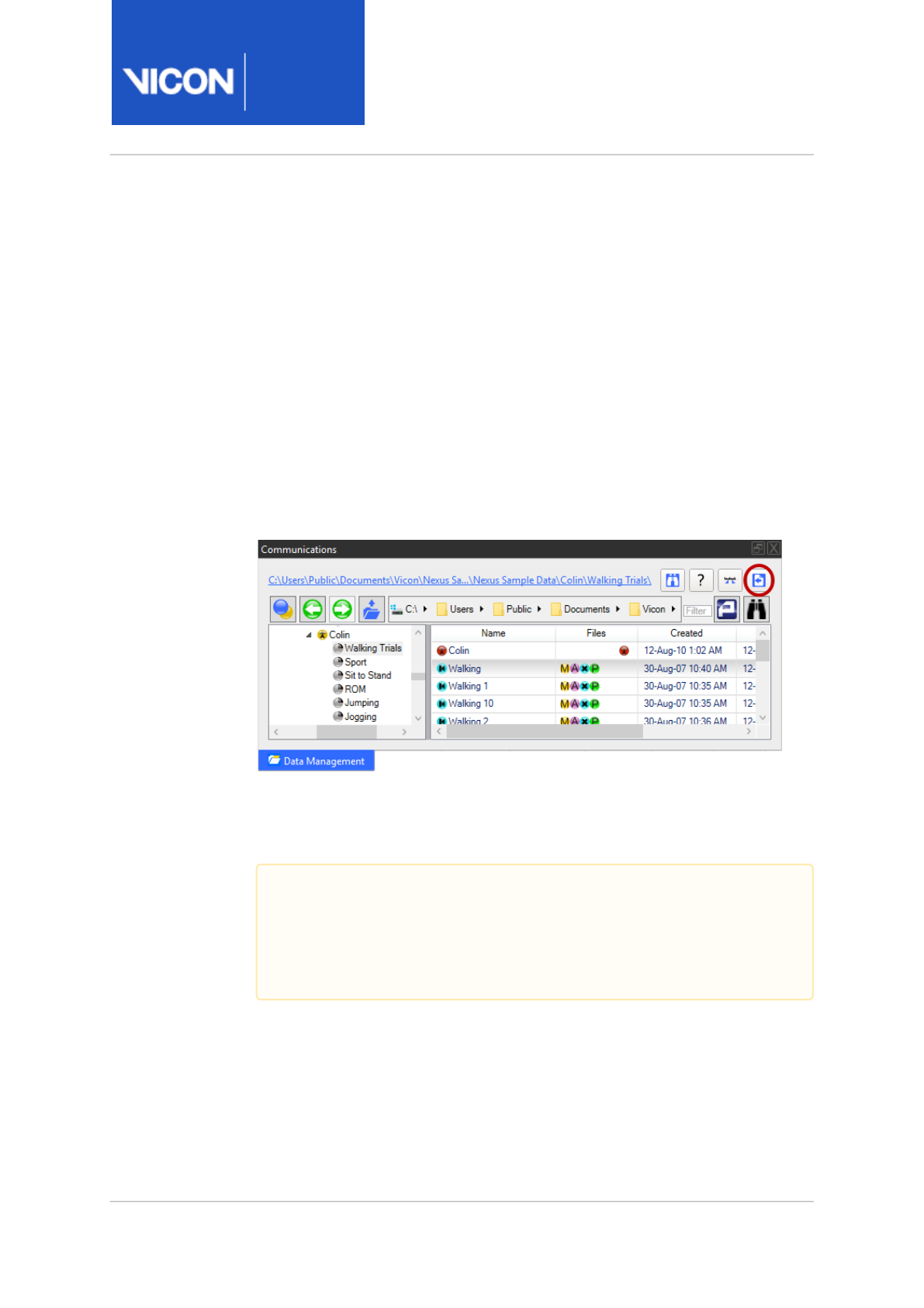
1. On the Data Management tab, make sure the required location is
selected.
2. Click the Search button (or click the Toggle search interface
button .)
Nexus
Reference
Guide
Data management with Nexus
Vicon Motion Systems Ltd. 13-Nov-2018 Page 18 of356
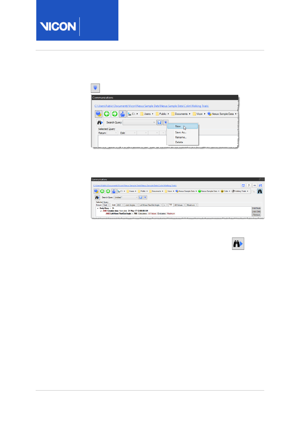
3. In the Search Query line, either select an existing search from the drop-
down list, or to start a new search, click the Configuration menu button
and then click New.
4. To specify a new search, in the Selected Query area, select the required
options, working from left to right. To add further criteria to your search,
click the Add Node button or Add Child button to the right of the pane.
Note that the criteria available for selection change depending on the
currently selected line.
5. To run the current search, click the Execute Search button at the
left of the pane.
The results of your search are displayed.
6. To save the search, click either the Save button or from the
Configuration menu list, click Save As.
7. To close the search controls, in the toolbar at the top of the pane, click
the Search button again (see Step 2).
You can now:
• Sort based on any of the returned data columns
• Open any level of data by double-clicking on it
• Export the data as ASCII to either Notepad or Excel
• Export the data as a list of paths to either Notepad or Excel (for
external processing)

Nexus
Reference
Guide
Data management with Nexus
Vicon Motion Systems Ltd. 13-Nov-2018 Page 19 of356
Load large trials
To facilitate working with very large unprocessed data files, you can choose
which files will be loaded (.x2d camera data and/or .x1d analog data), and
how many frames of the trial are loaded.
To work with large trial data:
1. In the Communications window, at the top right of the Data
Management tab, click Show Trial Loading Options.
2. To select only required frames, in the Raw Data Loading Options area,
select Load Frames From and type the frame to start from in the first
box and the end frame in the second box.
3. If required, choose whether to load both centroid/grayscale data (X2D)
and raw analog data (X1D) files, or only one of these options.
4. Process the file(s) as normal.
Only the selected range and files are processed.
Nexus
Reference
Guide
Data management with Nexus
Vicon Motion Systems Ltd. 13-Nov-2018 Page 20 of356
Batch process trials
If necessary, for example, if you are working with large numbers of files, you
can set up and run automated operations as batch processes, using the
controls in the Batch Processing interface on the Data Management tab.
Batch process multiple trials
You can automatically process any number of trials from the current motion
capture database using the Show File Transfer/Batch Processing interface
button on the Data Management toolbar at the top of the Data
Management tab.
Batch processing is optional. It is useful for processing large numbers of
files simultaneously or for automating frequently used processing
operations.
Important
Before batch processing trial data, ensure that you have already:
• Captured trial data
• Created any pipelines you intend to run
Nexus
Reference
Guide
Data management with Nexus
Vicon Motion Systems Ltd. 13-Nov-2018 Page 21 of356
To batch process trial data:
1. On the Data Management tab, mark the nodes (select nodes, right-click
and click Mark) containing the files you wish to batch process.
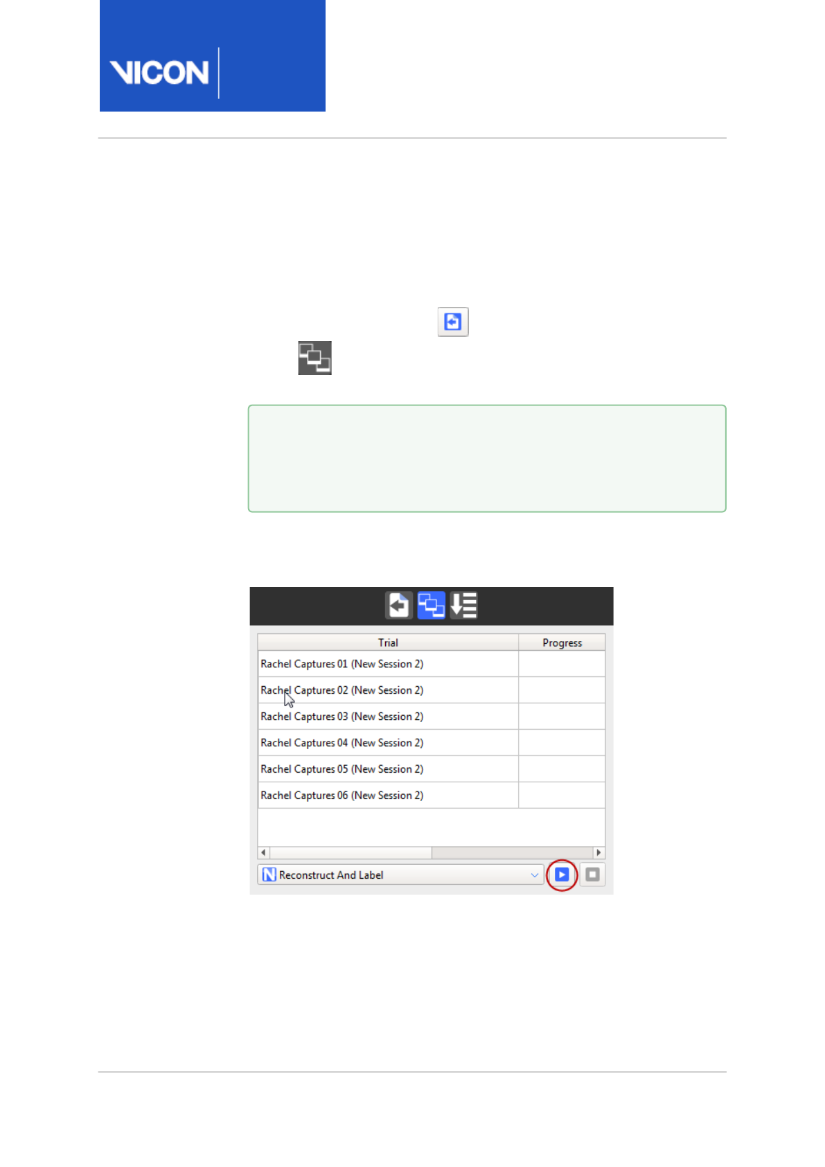
2. If the File Transfer/Batch Processing interface is not already displayed,
on the Data Management toolbar, click the Show File Transfer/Batch
Processing interface button , and then click the Batch Processing
button . The marked nodes are displayed in the list on the Batch
Processing tab.
3. From the drop-down menu at the bottom right of the Batch Processing
interface, select the pipeline to be run on the listed trial files and click
the Start Processing button to start the batch process.
When batch processing begins, an information window is displayed
when a file is being imported for processing. It indicates the import
status and contains buttons to Pause, Stop, or Cancel the import
operation.
Tip
To remove nodes from batch processing, on the Data
Management tab, unmark the nodes (right-click marked nodes
and click Clear Marks).
Nexus
Reference
Guide
Data management with Nexus
Vicon Motion Systems Ltd. 13-Nov-2018 Page 22 of356
During the batch processing, the Progress column in the trials list
indicates the overall status of the processing:
• Blank: Batch processing idle.
• Yellow moving bar: Batch processing in progress.
• Green static bar: Batch processing successfully completed.
• Red static bar: Batch processing failed or canceled.
Tip
Hover the mouse pointer over a progress bar to view details of
the batch processing operations.

Nexus
Reference
Guide
Labeling skeleton calibration in detail
Vicon Motion Systems Ltd. 13-Nov-2018 Page 23 of356
Labeling skeleton calibration in detail
The following topics will help you to choose the most appropriate type of
labeling skeleton calibration for your particular trials.
•Comparison of skeleton calibration operations, page 24
•Choose the appropriate subject calibration workflow, page 33

Nexus
Reference
Guide
Labeling skeleton calibration in detail
Vicon Motion Systems Ltd. 13-Nov-2018 Page 24 of356
Comparison of skeleton calibration operations
Subject-specific information is what enables a skeleton labeling template
(VST) to be converted to a subject-specific labeling skeleton (VSK). All of
the skeleton calibration operations make changes to the labeling skeleton,
as can be seen inside the VSK file. For VST version 3 files, the attributes
that are modified by at least one of the existing skeleton calibration
operations are:
•Parameters. These control the pose of joints and the position of markers
in the parent segment coordinate frame. A single parameter can be
applied to both a segment and a marker or any combination of markers
and segments. The calibration operations can change the value stored in
the parameter.
•Segments. Bone lengths can be changed due to the parameters
changing. The VST format doesn't have a concept of bone length. Bone
lengths are inferred from the pose transformation between a pair of
joints. This is made up of a pre- and a post-transformation. It is quite
common for this transformation to have only one parameter that can be
changed: this parameter is often named SomeBoneLength. The
calibrated values are written to the VSK but are not reloaded on VSK
import.
•Joints. Various attributes on the joint can be changed by the calibration
operations. The mean, covariance, range-center and range can all be
calculated from data.
•Targets. Target (marker) mean and covariance can be calculated from
data.
Deciding which of the different skeleton calibration operations is best in
your situation depends on a number of considerations including trial type,
processing time, and desired labeling quality.

Nexus
Reference
Guide
Labeling skeleton calibration in detail
Vicon Motion Systems Ltd. 13-Nov-2018 Page 25 of356
The following descriptions cover the various operations that use the same
underlying skeleton calibration algorithm.
•Functional Skeleton Calibration operation, page 27
•Functional Skeleton Calibration - Markers Only operation, page 28
•Static Skeleton Calibration operation, page 29
•Static Skeleton Calibration - Markers Only operation, page 30
•Calculate Skeleton Joint & Marker Statistics operation, page 31

Nexus
Reference
Guide
Labeling skeleton calibration in detail
Vicon Motion Systems Ltd. 13-Nov-2018 Page 26 of356
The operations change the following pieces of information in the skeleton:
Operation Parameters Segments Joints
statistics
Marker
positions
Marker
statistics
Functional Skeleton
Calibration operation,
page 27
Yes Yes Yes Yes Yes
Functional Skeleton
Calibration - Markers
Only operation, page 28
Yes No Yes Yes Yes
Static Skeleton
Calibration operation,
page 29
Yes Yes No Yes No
Static Skeleton
Calibration - Markers
Only operation, page 30
Yes No No Yes No
Calculate Skeleton Joint
& Marker Statistics
operation, page 31
No No Yes No Yes
For information on how to use the operations in common Nexus workflows,
see Choose the appropriate subject calibration workflow, page 33.

Nexus
Reference
Guide
Labeling skeleton calibration in detail
Vicon Motion Systems Ltd. 13-Nov-2018 Page 27 of356
Functional Skeleton Calibration operation
This operation is the most general of the skeleton calibration operations. It
is used to fully calibrate a labeling skeleton from a trial in which the subject
is moving. This is normally a ROM trial but can sometimes be a movement
trial.
Functional Skeleton Calibration optimizes both joint and marker positions.
It also calculates joint and marker statistics.
Ensure the trial covers the full range of motion that is expected in the
movement trials.
Algorithm description
The Functional Skeleton Calibration operation runs two algorithms:
• The first optimizes the skeleton segment and marker parameters. This is
done using a subset of the frames in the trial. These are chosen to get
the subject in a variety of poses. The more frames that are considered,
the better the skeleton will be, however, using more frames makes the
calibration take longer.
The calibration algorithm simultaneously tries to get the skeleton marker
positions to be as close as possible to the corresponding labeled
reconstructions. It does this by changing the joint angles, segment poses
and marker positions. It considers only the selected frames, so selecting
more frames gives the algorithm more poses to try to match. The
algorithm minimizes a statistical distance measuring how close the
skeleton markers are to the reconstructions. This distance accounts for
the fact that some skeleton markers (with a larger covariance) are
expected to be found a larger physical distance away from their
reconstructions. The default parameters reset this covariance to the
template covariance (in the VST). The motion that is allowed between
segments is constrained by the joint type. Any joint type mis-modeling is
not absorbed into the joint, but by either the segment or marker
positions, where the effect has less impact. In sparse marker sets this is
sometimes a necessary trade-off.
• The second algorithm calculates the joint and marker statistics (see
Calculate Skeleton Joint & Marker Statistics operation, page 31).

Nexus
Reference
Guide
Labeling skeleton calibration in detail
Vicon Motion Systems Ltd. 13-Nov-2018 Page 28 of356
Examples of using Functional Skeleton Calibration
• Generating a skeleton with the best quality labeling results. This is
because the method provides a large amount of data for markers and
joint movement.
• Creating a custom labeling skeleton template defined using the Labeling
Template Builder.
For information on how to use this operation in common Nexus workflows,
see Calibrate a labeling skeleton using a ROM trial in the
Vicon Nexus User
Guide
.
Functional Skeleton Calibration - Markers Only operation
This operation calculates the skeleton's marker positions from a ROM trial.
This operation is useful if the skeleton has already been scaled
appropriately for the subject and more accurate marker position
information is required. Any parameters that are shared between bones and
markers are not altered. The operation finishes by calculating joint and
marker statistics (see Calculate Skeleton Joint & Marker Statistics
operation, page 31).
Algorithm description
The Functional Skeleton Calibration - Markers Only operation is very similar
to the full Functional Skeleton Calibration algorithm (see Functional
Skeleton Calibration operation, page 27). The only difference is that the
parameters that refer to segments positions are kept constant. For this
algorithm to provide good labeling results, the skeleton must already be the
correct size. You can achieve this in the following ways:
• Scale the template skeleton to a reconstruction point cloud.
• Recalibrate a subject after adjusting its markers.
Compared with the full Functional Skeleton Calibration operation, the
Markers Only version has an extra step at the beginning. In this step, the
parameters that influence segment properties (bone lengths) are identified.
These parameters are held constant during the operation. If a parameter
refers to both a segment and a marker, it is also held constant. This

Nexus
Reference
Guide
Labeling skeleton calibration in detail
Vicon Motion Systems Ltd. 13-Nov-2018 Page 29 of356
reduction in parameters to estimate means that a Markers Only calibration
tends to be faster than a full calibration.
The algorithm uses the same criteria as the full skeleton calibration to
decide how to move the marker parameters and joint angles for each
selected frame. It also runs the algorithm to calculate the joint and marker
statistics.
Examples of using Functional Skeleton Calibration - Markers Only
Recalibration of an existing skeleton when the markers have moved, for
example, when an orthosis has been applied. If the orthosis is expected to
move significantly with respect to the underlying segment, this operation is
more suitable than Static Skeleton Calibration - Markers Only because this
operation updates the marker covariances as well as the marker positions.
Static Skeleton Calibration operation
Static Skeleton Calibration attempts to calibrate a skeleton from a single
frame. It tries to optimize both joint and marker positions. The subject is
usually in a T-pose for the entire trial.
Algorithm description
This operation calibrates the joint and marker positions from a single frame.
It also tries to fit the skeleton joint angles. To do this, it runs the same
algorithm as Functional Skeleton Calibration with only one frame selected.
It is not normally advisable to run this operation on a general skeleton
template because it is not possible to determine the joint centers without
any motion. For this operation to succeed, every joint center must be
defined by a linear combination of marker positions. As it is not possible to
estimate the joint and marker statistics from a single frame, the subject
statistics are left unchanged.

Nexus
Reference
Guide
Labeling skeleton calibration in detail
Vicon Motion Systems Ltd. 13-Nov-2018 Page 30 of356
Static Skeleton Calibration - Markers Only operation
This operation calculates the skeleton's marker positions from a single
frame. This operation is only useful if the skeleton has already been scaled
appropriately for the subject.
Algorithm description
The Static Skeleton Calibration - Markers Only operation provides a quick
way to update a skeleton's marker positions. It usually operates on a static
trial in which the subject is in the T-pose. Sometimes it is run on a single
frame from a full ROM as part of the Auto Initialize Labeling pipeline. Static
Skeleton Calibration - Markers Only estimates both the joint angles and the
marker positions for the selected frame. Before running this operation, the
subject skeleton must be correctly scaled. This is usually done by scaling
the subject, as is done by the Auto Initialize Labeling pipeline. You could
also use a previously calibrated skeleton for the same subject.
As happens in Functional Skeleton Calibration - Markers Only, the
parameters that refer to segments are identified and held constant by the
operation. The calibration then optimizes the joint angles and marker
positions for the frame selected. Optimizing the joint angles allows the
subject to be in a pose that is different from the T-pose. This protects
against the calibration from introducing marker position errors due to the
subject being in a slightly incorrect base pose.
As with Static Skeleton Calibration, the joint and marker statistics are left
unchanged.
Examples of using Static Skeleton Calibration - Markers Only
This operation is used for recalibration of an existing correctly scaled
skeleton. It is part of the Auto Initialize Labeling pipeline and runs after the
Scale subject operation. It can also be used to recalibrate markers if they
have fallen off and been replaced.

Nexus
Reference
Guide
Labeling skeleton calibration in detail
Vicon Motion Systems Ltd. 13-Nov-2018 Page 31 of356
Calculate Skeleton Joint & Marker Statistics operation
This operation calculates joint and marker statistics from either a
movement trial or a ROM trial. Both the Functional Skeleton Calibration
and the Functional Skeleton Calibration - Markers Only operations run this
operation after calculating the skeleton parameters.
Algorithm description
This operation calculates joint and marker statistics for the subject. Joint
and particularly marker statistics are used in the labeling algorithms. Joint
statistics tell the labelers how much a particular joint is expected to move.
Marker statistics give information about how much soft tissue motion is
expected for the markers. Good marker statistics can improve labeling
significantly.
This operation assumes that the skeleton has already been calibrated. It
does not change any joint or marker positions. If it is run on an uncalibrated
skeleton, the covariances and ranges calculated will be large.
For joints, this operation calculates values for: mean, covariance, range
center, and range matrix. For markers, it calculates mean and covariance.
The statistics are calculated from all of the frames in the trial.
The values stored in the mean and covariance are not calculated directly
from the data. During a ROM trial the subject has only a few joints moving
at a time, the rest are not moving much. If you plot the joint position
samples over a trial you tend to see a large peak of samples and a few
spread across the joint range.
In some cases, such as the knee, a mean and covariance calculated from
the samples does a very bad job of representing the distribution. In the
case of the knee, the majority of the samples are collected with the knee
straight. This leads to a mean that is nearly straight and a covariance that
suggests the knee can bend forward and backward equally well.
Instead of calculating the mean and covariance directly, a range and range
center is calculated. This applies to both joints and markers. It is then
assumed that the samples that really represent the distribution are

Nexus
Reference
Guide
Labeling skeleton calibration in detail
Vicon Motion Systems Ltd. 13-Nov-2018 Page 32 of356
uniformly distributed across the range. If you look in the VSK, you can see
that joint means and joint range centers are the same.
Examples of using Calculate Skeleton Joint & Marker Statistics
Calculate Skeleton Joint & Marker Statistics can be used when a skeleton
has been calibrated using a single frame but doesn't label well. This
operation can be used on a movement trial to calculate better joint and
marker statistics which will improve the labeling performance.
For information on how to use this operation in common Nexus workflows,
see Choose the appropriate subject calibration workflow, page 33.

Nexus
Reference
Guide
Labeling skeleton calibration in detail
Vicon Motion Systems Ltd. 13-Nov-2018 Page 33 of356
Choose the appropriate subject calibration workflow
Your choice of workflow depends upon the raw data you are able to collect
and your desired outcome.
To use any of the operations, observe the following preconditions:
• A fully labeled trial (ROM, static, or movement) must exist.
• The trial must contain only raw reconstructions; leave any gaps unfilled.
(Unlabeled reconstructions have no influence on the operations.)
The following table summarizes the workflow to follow for common labeling
skeleton calibration scenarios:
In this scenario Use this trial type And this pipeline/operation
Simple movement (eg basic
gait).
Subject is unable to complete
full ROM.
Speed of subject setup takes
precedence over labeling
accuracy.
Single static frame
(base pose used
when VST was
created)
Reconstruct pipeline
Auto Initialize Labeling pipeline
For step-by-step instructions, see
Calibrate a labeling skeleton using
a static trial in the
Vicon Nexus
User Guide
.
Automatic labeling (eg Auto
Initialize Labeling) or the
Labeling operation alone does
not produce satisfactory
labeling.
The movement during capture
is not sufficiently similar to
the static/ROM trial.
Movement (ie, same
motion as that being
studied) that
includes static
motorbike/base pose
as the first frame.
Reconstruct pipeline
Auto Initialize Labeling pipeline
and manual labeling
Calculate Skeleton Joint & Marker
Statistics operation, page 31

Nexus
Reference
Guide
Labeling skeleton calibration in detail
Vicon Motion Systems Ltd. 13-Nov-2018 Page 34 of356
In this scenario Use this trial type And this pipeline/operation
Complex movement (sports
movements, or multi-segment,
high velocity movement,
where segments or markers
interact).
Labeling accuracy is more
important than speed of
subject setup.
ROM, beginning in
static auto-label
pose
Note: Because of its
labeling quality,
Vicon recommends
that this method is
used whenever
possible.
Reconstruct pipeline
Auto Initialize Labeling pipeline on
static frame, then use it to label
whole trial.
Use manual labeling to correct any
labeling errors for the whole trial.
Functional Skeleton Calibration
operation, page 27 on whole trial.
For step-by-step instructions, see
Calibrate a labeling skeleton using
a ROM trial in the
Vicon Nexus
User Guide
.
A marker has fallen off and
been re-applied.
Single static frame
(base pose used
when VST was
created)
Reconstruct pipeline
Label pipeline (or use previously
calibrated skeleton) with
Static Skeleton Calibration -
Markers Only operation, page 30 to
recalibrate the marker that fell off.
For further details, see the recommended ways of working in the following
workflow descriptions.
•Subject set up workflows, page 35
•Re-calibrate workflows, page 38

Nexus
Reference
Guide
Labeling skeleton calibration in detail
Vicon Motion Systems Ltd. 13-Nov-2018 Page 35 of356
Subject set up workflows
The following workflows are the recommended ways of working when you
are setting up a subject for labeling.
Auto Initialize Labeling pipeline
This is a recommended workflow for setting up a subject for labeling when
you want to produce a labeling skeleton that can be used for trials that
capture
simple
data, such as basic gait, non-ballistic/sports movements, or
other movements that are not multi-segment, high velocity, or complex,
where segments or markers tend to interact. This method uses less data
(single static frame) than Functional Skeleton Calibration, and can be
processed very quickly.
• Put markers on the subject and get them to perform a static trial.
• Reconstruct the trial and run the Auto Initialize Labeling pipeline.
The Auto Initialize Labeling pipeline consists of three operations:
• A T-pose label operation (Autolabel Static). This operation labels the trial
for the following two operations to use.
• Subject scale (Scale Subject VSK). This operation takes the labeled
reconstruction cloud and scales the template skeleton to be the same
size. This enables you to use the same template skeleton for both
children and adults.
•Static Skeleton Calibration - Markers Only. This operation finishes off the
set up by moving the skeleton markers to the correct locations in the
segment coordinate frames. This is to allow for the variable placement of
the markers.
This workflow calibrates both the bone lengths and marker positions from a
single frame. However, the calibration is split over two operations. Scaling
the subject changes all of the bone lengths by the same factor. The marker-
only calibration can then use the scaled skeleton to optimize the marker
positions.

Nexus
Reference
Guide
Labeling skeleton calibration in detail
Vicon Motion Systems Ltd. 13-Nov-2018 Page 36 of356
Auto Initialize Labeling pipeline with Calculate Statistics
The standard Auto Initialize Labeling workflow is useful in cases where the
subject's ability to perform a full ROM trial might be limited or where total
time of capture/calibration is paramount. In these types of capture
scenarios, the Auto Initialize Labeling pipeline will often produce
completely acceptable labeling. If less than ideal labeling performance is
found, the addition of the Calculate Skeleton Joint & Marker Statistics
operation can improve labeling.
To do this, you (semi-)manually label one of the movement trials and run a
Calculate Skeleton Joint & Marker Statistics operation on it. This calculates
the joint and marker statistics that represent the subject in that particular
activity.
Important
Ensure that the trial contains no labeling errors, as any errors have
the potential to significantly increase the estimated covariance of
affected markers.

Nexus
Reference
Guide
Labeling skeleton calibration in detail
Vicon Motion Systems Ltd. 13-Nov-2018 Page 37 of356
ROM trial subject set up
This workflow for setting up a subject provides more information (multi-
frame, multi-joint range movements) to the Nexus subject calibrator and
gives the best labeling performance in most scenarios. However, the
increased amount of calibration data results in higher processing times
than the simpler Static method (see Auto Initialize Labeling pipeline, page 35
above).
This workflow consists of the following steps:
1. The subject performs a range of motion trial in which they fully exercise
all of their joints. It is recommended that the subject starts the ROM
trial in the static autolabel pose, so that the Auto Initialize Labeling
pipeline can be run on the first frame to generate a skeleton that can be
used to help label the rest of the ROM trial.
2. After the trial has been captured you must reconstruct and label it. The
recommended way of doing this is to run the Auto Initialize Labeling
pipeline on a T-pose frame and use the skeleton generated by that
operation to label the rest of the trial.
3. After you have labeled the trial, you run the Functional Skeleton
Calibration operation. This calculates bone lengths, marker positions,
and skeleton statistics.
Tip
If the trial is being labeled semi-automatically, scrub through the
trial to make sure that all of the labels are correct. Incorrect
labels degrade the quality of the calibration.

Nexus
Reference
Guide
Labeling skeleton calibration in detail
Vicon Motion Systems Ltd. 13-Nov-2018 Page 38 of356
Re-calibrate workflows
You may find yourself in a situation where a quick recalibration is
preferable to performing a new full calibration. The following are two
examples where a recalibration operation may be preferable to a full
calibration.
Recalibrate for orthosis
Some capture sessions involve trials in which the subject is wearing an
orthosis and others without. If the othosis is large or moving significantly
with respect to the segment(s), the trials with the orthosis might not label
well. In this case you might want a quicker calibration procedure than a full
Functional Skeleton Calibration.
One way of achieving this is to capture a second ROM trial with the
orthosis. Instead of running a full Functional Skeleton Calibration, you
could run a Functional Skeleton Calibration - Markers Only operation to
update the marker positions and the subject statistics for the trials using
the orthosis.
Recalibrate after replacing a marker
Markers sometimes get knocked off the subject and need to be re-applied.
In this case you can use a frame in which the marker has been re-applied to
run a Static Skeleton Calibration - Markers Only operation to recalibrate the
marker that had fallen off.
In this situation it is highly likely that the marker covariance will not need
to be updated so you do not need to run a Functional Skeleton Calibration -
Markers Only operation.

Nexus
Reference
Guide
Using monitors
Vicon Motion Systems Ltd. 13-Nov-2018 Page 39 of356
Using monitors
Monitors enable you to evaluate subject and device outputs, so that when
a specified condition or event happens (eg, a leg is raised to a specified
height or a knee exceeds a specified angle), one or more actions is
triggered (eg, a sound is played). If required, you can configure multiple
actions and multiple monitors.
You can use monitors in both Live and Offline modes. In Live mode, you can
compare the current value against the thresholds. In Offline mode, you can
tune a series of monitors against captured data before applying them to
live data.
For more information, see:
•Create a monitor, page 40
•Configure a monitor, page 42
•Configure an AND or OR Monitor, page 51
•Activate and deactivate a monitor, page 53
•Reload a monitor, page 54
•Monitor configuration examples, page 55
For an example of creating monitor, see Create a joint range overlay
monitor, page 106 (part of a biomechanics workflow).
Nexus
Reference
Guide
Using monitors
Vicon Motion Systems Ltd. 13-Nov-2018 Page 40 of356
Create a monitor
Monitors enable you to specify conditions or events during motion capture
sessions, and to interact with them. For example, you can create a monitor
for a graphed model output (such as the subject raising an arm to a certain
height, or the subject's left knee angle exceeding 180 degrees), and then
configure it on the Monitors tab of the Communications window to trigger
one or more actions (such as an event on the time bar or a tone sounding)
when the model output matches a condition you specify.
You create monitors in the Graph view. You can then configure the
monitors in the Monitors tab of the Communications pane.
To create a monitor:
1. Decide on the elements you wish to monitor (trajectories, model
outputs, devices, or joints).
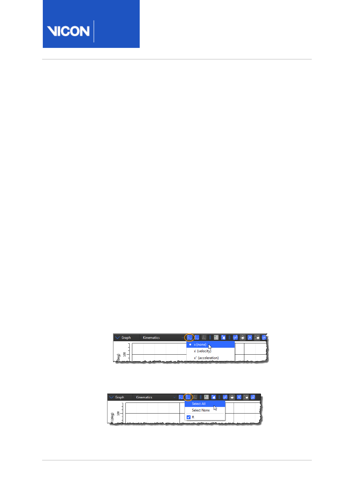
2. In a Graph view, click the Differentiate the graph button and from the
dropdown list, select either:
• The current variable ( x ); or
• Its first derivative, that is, its velocity or angular velocity (x'), or
• Its second derivative, that is, its acceleration or angular acceleration
(x")
For example, a graph of a trajectory will have X, Y, and Z axes, but
when differentiated to x' (velocity), the axes will change to X', Y', and
Z' axes.
3. Click the Choose the components button and select the graph
components that you want to plot in the Graph view (the options
depend on your choice in the previous step).
Nexus
Reference
Guide
Using monitors
Vicon Motion Systems Ltd. 13-Nov-2018 Page 41 of356
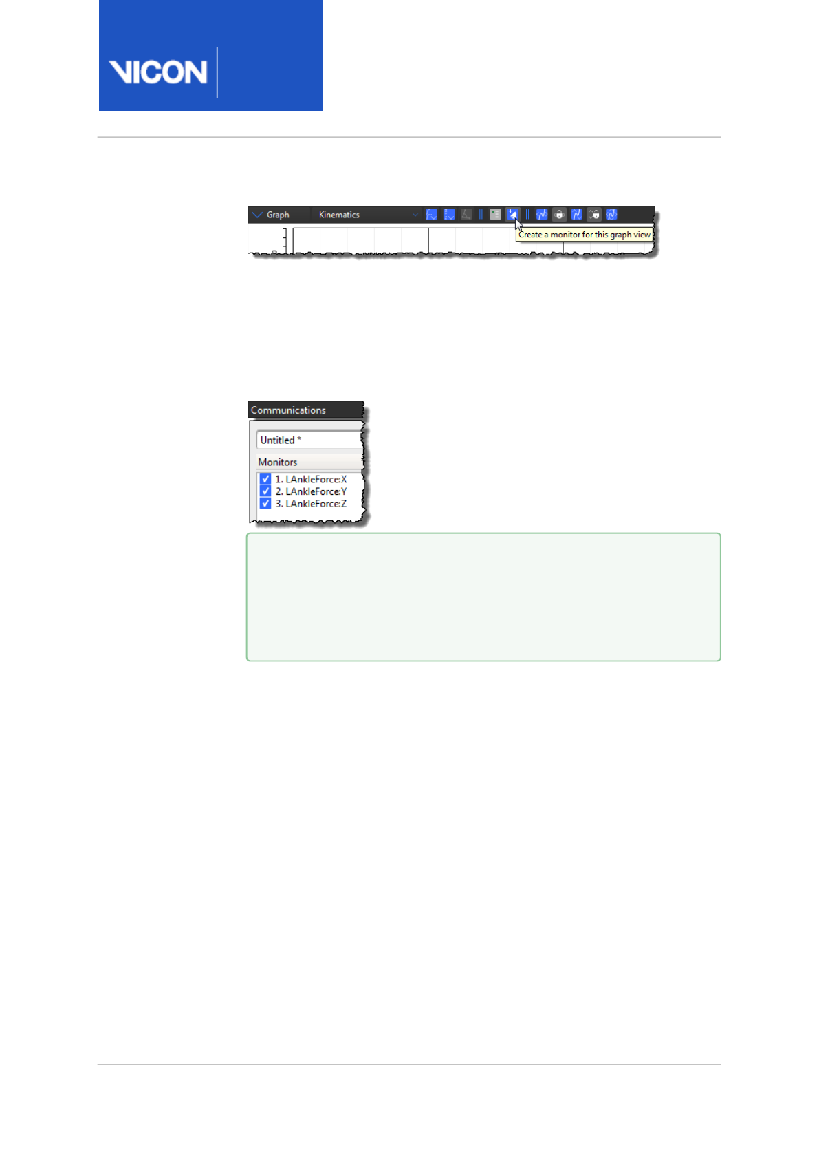
4. On the Graph view toolbar, click the Create a Monitor button.
The monitor is added to the Monitors list in the Monitors
communications pane.
The monitor takes the name of the component you selected. For
example, if the Graph view you've selected shows X, Y, and Z for the
LeftAnkleForce, three monitors are created: LAnkleForce:X,
LAnkleForce:Y, and LAnkleForce:Z.
You can now configure the monitor, for example to specify a monitor
threshold and trigger conditions that will trigger an action.
Tip
If you select multiple components for your Graph view, a monitor
is created for each component (e.g., x, y, z). You can select and
remove one or more monitors that you don't need from the
Monitors list, or click Clear to remove all of them.

Nexus
Reference
Guide
Using monitors
Vicon Motion Systems Ltd. 13-Nov-2018 Page 42 of356
Configure a monitor
After you have created a monitor for a motion capture event in the Graph
view pane, you can configure the monitor in the Monitors tab of the
Communications pane. You can change the monitor's default name, and
configure it to be triggered upon a specified event or action.
To rename a monitor:
• In the Monitors list on the Monitors tab, double-click the name of the
required monitor and type a new name.
To configure a monitor:
1. In the Monitors list on the Monitors tab, click the name of the required
monitor to select it.
2. In the Threshold section on the right, specify the value and condition
that will trigger the action:
Property Description
Threshold
Mode
Select the type of threshold:
Above
Upper
Tracks a graph value above a specified
range. You must also set the Upper
Threshold value.
Below
Lower
Tracks a graph value below a specified
range. You must also set the Lower
Threshold value.
Between Tracks a graph value within a specified
range (default). You must also enter the
Upper Threshold and Lower Threshold
values.

Nexus
Reference
Guide
Using monitors
Vicon Motion Systems Ltd. 13-Nov-2018 Page 43 of356
Property Description
Outside Tracks a graph value outside a specified
range. You must also enter the Upper
Threshold and Lower Threshold values.
Tip: The threshold range you specify is displayed as a
shaded area with a dashed line in the Graph view.
Condition In the Trigger section, select the condition under which
the threshold should activate:
On Enter Monitor triggers upon entering the
threshold range.
On Exit Monitor triggers upon exiting the threshold
range.
Within Monitor triggers on every frame within the
threshold range.
Max
Value on
Exit
Monitor triggers upon exiting the threshold
range, but the event is registered at the
point of maximum value within the range.
For example, if you set a Timebar Event
with Max Value on Exit, the time bar event
registers at the point of maximum value
within the specified threshold range.
Min Value
on Exit
Monitor triggers upon exiting the threshold
range, but the event is registered at the
point of minimum value within the
specified range.
Always

Nexus
Reference
Guide
Using monitors
Vicon Motion Systems Ltd. 13-Nov-2018 Page 44 of356
3. To specify the action that will execute when the monitor threshold and
trigger conditions are met, ensure the required monitor is selected and
in the Actions area on the right of the Monitors tab, click Add and select
the required action.
Action Description/Properties
Capture
Start Starts a capture.
Stop Stops a capture.
Toggle Switches to the opposite capture state, e.g.,
stops a capture that is in progress, or starts a
capture if the previous state was stopped.
Capture actions can only be performed in Live
mode. If you want to create and test a capture
action based on a representative trial, you can
add a complementary Timebar Event to
indicate that the condition was met. Then for
the live test or real trial capture, turn off the
monitor time bar action.
Tip: In the Auto Capture settings of the
Capture Tools pane, ensure the Arm button is
enabled (pressed down) before triggering
capture.
You can also use other Auto Capture settings
in conjunction with monitor events. For
example, in addition to setting up a monitor
event to trigger a capture, you can also set a
pre-trigger capture time. To do this, set up the
monitor to trigger the capture and also set a
pre-trigger capture time so that the first frame
captured is prior to the condition which
triggers the capture.

Nexus
Reference
Guide
Using monitors
Vicon Motion Systems Ltd. 13-Nov-2018 Page 45 of356
Action Description/Properties
External
Trigger
Sends a trigger pulse to external equipment or software
from the Sync Output ports on the back of the
connectivity device.
Sync
Port
Select which port you want to use to send the
pulse (sends a trigger pulse from the Sync
Output port of a Vicon Lock+ or Giganet to an
external piece of equipment or software).
Affects all connected devices.
Action Choose from:
• Toggle (between Low and High)
• Go High (+4.3V)
• Go Low (0V)
Timebar
Event
Places an event on the time bar, which can be configured
to include:
Subject
Name
Enter the subject name.
Context Select where to place a time bar event:
• General: Places a marker on the General
rule of the time bar ruler.
• Left: Places a marker on the Left (e.g.,
left side of the body) rule of the time bar
ruler.
• Right: Places a marker on the Right (e.g.,
right side of the body) rule of the time
bar ruler.|

Nexus
Reference
Guide
Using monitors
Vicon Motion Systems Ltd. 13-Nov-2018 Page 46 of356
Action Description/Properties
Event
Type
Select the type of user-defined event that will
be specified on the time bar:
• General: Indicates the point on the time
bar at which the trial subject performs a
user-defined event.
• Foot Strike: Indicates the point on the
time bar at which the trial subject's foot
contacts the ground.
• Foot Off: Indicates the point on the time
bar at which the trial subject's foot
leaves the ground.
Clip Select the clip:
• Active: Sets the action to whichever
state Nexus is in. Tip: Active has the
same functionality as Offline if you are
analyzing or processing an offline trial,
and Live if you are currently in Live
mode. This eliminates having to change
this property when you switch between
Live and Offline.
• Live: Sets the action to occur on a live
clip.
• Offline: Sets the action to occur on a
captured trial that has been loaded or a
trial that is currently being captured.

Nexus
Reference
Guide
Using monitors
Vicon Motion Systems Ltd. 13-Nov-2018 Page 47 of356
Action Description/Properties
Frame Select the frame:
• Current: Sets the action for the currently
selected frame in the clip.
• First: Sets the action to the first frame in
the time interval. For an offline clip, this
would be frame 1. For a live clip, this
would be the first frame of a 100-frame
moving time window.
• Last: Sets the action to the last frame in
the current interval. For an offline clip,
this would be the very last frame.
The Frame settings detect real time events
that are written to the offline clip. During
capture, the current Live frame is equivalent to
the last Offline frame. If you set Clip to Offline
and Frame to Last, you will have real time
event detection during capture. If you
configure this option, you will need to run a
post-capture pipeline.
Frame
Offset
Type a number in the field to indicate the
number of frames of offset before adding the
event.

Nexus
Reference
Guide
Using monitors
Vicon Motion Systems Ltd. 13-Nov-2018 Page 48 of356
Action Description/Properties
Progress
Bar
Displays a progress bar. The progress bar reflects a
normalized value within the boundaries of the threshold;
that is, Vicon Nexus computes the upper and lower
threshold values so that a given value within the range is
represented as a progress bar percentage.
This action works best when the Monitor Threshold is set
to Between, and is intended for a Trigger condition of
Within. The Progress Bar will function when used On
Enter, On Exit, etc., but will not provide meaningful
results. For example, if you set the trigger condition to On
Enter and the parameter enters the threshold region from
below, then the progress bar value will remain near 0%.
If the parameter enters the threshold region from above,
the progress bar value will remain around 100%.
Tip: The Progress Bar is divided into thirds, each
designated by a color: Red for the lower third, yellow for
the middle third, and green for the upper third.
Range
Overlay
Displays an overlay in the 3D Perspective view that
provides an easy, visual way to verify whether a ROM trial
has captured enough of the required movement to be
likely to provide a good calibration of the subject. For
more information, see Create a joint range overlay
monitor, page 106.
Name The title of the overlay
Zero
(deg)
Type a value or move the slider to specify
where zero appears on the dial

Nexus
Reference
Guide
Using monitors
Vicon Motion Systems Ltd. 13-Nov-2018 Page 49 of356
Action Description/Properties
Sound
Tone
Sounds a system tone based on the threshold range and
trigger condition.
Sound Tone is recommended with the trigger conditions
of Between and Within. The Sound Tone provides an audio
alert in a similar fashion to the Progress Bar: If set to
Between or Within, the sound pitch varies in proportion to
the parameter's value within the threshold range.
Play Sound File (see below) is recommended with the
trigger actions of On Enter or On Exit.
Toggle
Monitor
Changes the enabled state of the selected monitor to On,
Off, or Toggle.
Important: Vicon Nexus adjusts the Monitor Index field if
changing the number of Monitors in a configuration
affects the Monitor Index. That is, if you configure
multiple monitors and set Toggle Monitor events, deleting
a monitor can change the Monitor Index field number.
Example (1):
You configure Monitor 1, Monitor 2, and Monitor 3.
You add a Toggle Monitor event to Monitor 2, with the
Monitor Index set to 3 (meaning that Monitor 3 will
toggle).
If you remove Monitor 1, Monitor 2's Monitor Index will
change from 3 to 2 (Monitor 3 is now Monitor 2).
Example (2):
You configure Monitor 1, Monitor 2, and Monitor 3.
You add a Toggle Monitor to Monitor 2, with the Monitor
Index set to 3.
If you delete Monitor 3, Monitor 2's Monitor Index will be
blank (there is no longer any Monitor 3 to toggle).

Nexus
Reference
Guide
Using monitors
Vicon Motion Systems Ltd. 13-Nov-2018 Page 50 of356
Action Description/Properties
Monitor
Index
Type the number corresponding to the monitor
in the Monitors List
Action Sets the toggle state to On, Off, or Toggle.
Play
Sound
File
Plays the sound file you specify.
Sound
File
Click the Browse button to navigate to the
relevant directory on your computer, then
select a .wav file from the drop-down list.
4. If you want to configure multiple actions for the monitor, repeat steps 2
and 3.
5. In the Configuration Management area of the Communications pane,
click Save to save the configured monitor, enter a name for the monitor
configuration and select Shared or Private.
6. In the Configuration Management area of the View pane, click Save to
save the Graph view that corresponds to the monitor you have
configured, type a name for the Graph view configuration, and select
Shared or Private.
7. Test the monitor to ensure that the action occurs when the specified
condition is met.
To configure multiple monitors, repeat steps 1–7 for each monitor.
Tip
Whenever you want to view the graph related to the monitor,
select it from the View pane list.
Important
Monitor actions function only in a forward time sequence. In other
words, monitors will not activate when you manipulate the time bar
ruler back and forth.

Nexus
Reference
Guide
Using monitors
Vicon Motion Systems Ltd. 13-Nov-2018 Page 51 of356
Configure an AND or OR Monitor
In the Communications pane, on the Monitors tab, you can configure two
special monitor types that execute actions based on the conditions of a
group of monitors. They are called AND or OR monitors, or Boolean
monitors.
The monitors that make up a Boolean monitor are called children. The
Boolean monitor bases its action on the status of the child monitors; that
is, based on whether the child's thresholds and triggers are present. You
can trigger an action based upon a Boolean monitor's condition just like
you can for an individual monitor, but Boolean monitors operate in specific
ways:
•Boolean AND monitor, page 52
•Boolean OR monitor, page 52
To configure an AND or OR monitor:
1. On the Monitors tab, in the Monitors list, select two or more monitors
that will make up the AND or OR monitor.
2. Click the AND or OR button below the Monitors list.
A new Boolean monitor appears in the list (Boolean AND or Boolean OR).
3. Highlight the monitor name and a list of the child monitors within the
monitor appears.
4. Configure the monitor (see Configure a monitor, page 42).
Important
This procedure assumes that you have already configured multiple
monitors. For information on creating and configuring monitors,
see Create a monitor, page 40 and Configure a monitor, page 42.
Tip
To change the child monitors included in the Boolean monitor,
click in the Children field and type the monitor numbers,
separated by commas.

Nexus
Reference
Guide
Using monitors
Vicon Motion Systems Ltd. 13-Nov-2018 Page 52 of356
Boolean AND monitor
If all the child monitors within a Boolean AND monitor meet the monitor
configuration condition at the same time, then the Boolean AND monitor
executes its configured action. In other words, if the condition of all the
children is TRUE then the Boolean AND monitor condition is TRUE, and the
Boolean AND monitor executes.
• Example: If in Child monitor1 the Left Knee Angle > 180 AND in Child
monitor 2 the Right Knee Angle > 180, the Boolean AND monitor is true
and the monitor action executes.
All the Boolean AND monitor children must meet the specified condition at
the same time or the Boolean AND monitor condition is FALSE, and the
Boolean AND monitor will not execute the action.
Boolean OR monitor
If at least one of the child monitors within a Boolean OR monitor meets the
specified monitor configuration (threshold, trigger, and condition), then the
Boolean OR monitor executes the specified action. In other words, the
condition of at least one of children is TRUE, therefore the Boolean OR
monitor condition is TRUE.
• Example: If in Child monitor 1 the Left Knee Angle > 180 OR in Child
monitor 2 the Right Knee Angle > 180, the Boolean OR monitor is true
and the monitor action executes.
When none of the Children meets the specified condition, the Boolean OR
monitor's condition is FALSE and the Boolean OR monitor does not
execute.

Nexus
Reference
Guide
Using monitors
Vicon Motion Systems Ltd. 13-Nov-2018 Page 53 of356
Activate and deactivate a monitor
After you configure a monitor (see Configure a monitor, page 42), you can
activate or deactivate it.
To activate or deactivate a monitor:
• On the Monitors tab in the Communications pane, select or clear the
check box for the required monitor.
Nexus
Reference
Guide
Using monitors
Vicon Motion Systems Ltd. 13-Nov-2018 Page 54 of356
Reload a monitor
You will need to reload your monitor if you do any of the following:
• Make changes to the monitor configuration; or
• Configure or use other monitors; or
• Switch between Live and Offline mode.
To reload a monitor:
For a monitor to take effect in Live mode:
• Reload the trial file on the Data Management tab.
For a monitor to take effect in Offline mode:
• Select Refresh List from the Configuration menu on the Monitors tab.
Tip
Because monitors can be set to toggle on and off, you may need to
reload the monitor before processing a new trial.

Nexus
Reference
Guide
Using monitors
Vicon Motion Systems Ltd. 13-Nov-2018 Page 55 of356
Monitor configuration examples
You can configure monitors in a variety of ways.
For examples of configuring monitors, see the following:
•Configure multiple actions on one monitor, page 55
•Configure multiple monitors, page 55
•Configure multiple actions on multiple monitors, page 56
•Configure Boolean monitors, page 57
Configure multiple actions on one monitor
A single monitor can perform multiple actions, such as to write a time bar
event, display a progress bar, and sound a tone.
To configure a monitor with multiple actions that detects only the first
occurrence of an event:
1. Configure a monitor to detect an event.
2. Add a Timebar Event action.
3. Add a Toggle Monitor action to toggle the monitor Off so that the
Timebar Event is identified only the first time.
Configure multiple monitors
You can use multiple monitors to identify multiple events. Each event type,
such as Foot Strike and Foot Off, would have its own monitor.
For example, you may want one monitor to look for the start of a particular
body motion, which starts another monitor that evaluates whether the
pelvic alignment is within the threshold range. If the pelvic alignment
exceeds the threshold range, the second monitor could sound a tone to
notify the operator, and activate a third monitor to evaluate the range of
yet another element.

Nexus
Reference
Guide
Using monitors
Vicon Motion Systems Ltd. 13-Nov-2018 Page 56 of356
To configure multiple monitors:
1. Configure monitor 1 to detect the counter-motion of a jump (e.g., when
the angular velocity of the knee exceeds a threshold).
2. Add a Capture action to the monitor to start a capture when this
condition is met.
3. Add a Toggle Monitor action to toggle the monitor off so that the
capture is initiated only once.
4. Configure monitor 2 to detect the maximum height of the sacrum for
both the initial jump and the jump after landing on the force plate
(Maximum Value on Exit).
Add a Timebar Event action to the monitor.
5. Configure monitor 3 to detect landing on the force plate.
Set the Threshold Mode to monitor the vertical force value (Fz) at the
appropriate threshold (On Enter).
6. Add a Timebar Event action.
7. Configure monitor 4 to detect takeoff from the force plate.
Set the Threshold Mode to detect when the vertical force value (Fz)
drops below a threshold (you can use the same trigger value as for
Monitor 3, but you would set the condition to On Exit).
Configure multiple actions on multiple monitors
To configure multiple monitors, each with multiple actions:
1. Configure a master monitor to trigger the detection of trial events (e.g.,
subject jumps onto a force plate and then jumps off).
2. Configure a series of monitors with Timebar Event actions (e.g., Foot
Strike and Foot Off).
3. Clear each monitor's check box so that its initial state is Off.
Tip
Force plate monitor properties will depend on which force plate
device is being used. Some force plates used with ViconNexus
register a positive vertical force on contact (such as the AMTI),
while others register a negative force on contact (such as
Kistler).

Nexus
Reference
Guide
Using monitors
Vicon Motion Systems Ltd. 13-Nov-2018 Page 57 of356
4. Add a Toggle Monitor action to the master monitor for each event
monitor.
5. Set each Toggle Monitor to On. Once the master monitor is triggered,
the event monitors will turn On. The events are detected and written to
the time bar.
Tip
The trial conditions could be such that a master monitor isn't
necessary to control the event detection monitors in Step 2. The
value of the master monitor is to make sure that the monitored
parameters are in the proper state for appropriate event
detections. This is a safeguard against identifying false events.
Configure Boolean monitors
You should carefully consider how you configure Boolean monitor
thresholds and triggers to execute event actions.
If you use an AND monitor, it will mark an event only if the conditions of the
child monitors occur at the same frame (an AND monitor event requires all
child monitor parameters to be true). This seems obvious, but let's say you
want to mark an event when parameter 1 is above one threshold and
parameter 2 falls below another threshold. You'd be inclined to set:
• AND Child monitor 1:
• Threshold Mode: Above Upper
• Condition: On Enter
• AND Child monitor 2:
• Threshold Mode: Below Lower
• Condition: On Enter
However, configured this way, the AND monitor will mark the event only if
the two parameters enter the respective threshold regions on the same
frame, which is unlikely.

Nexus
Reference
Guide
Using monitors
Vicon Motion Systems Ltd. 13-Nov-2018 Page 58 of356
Unless you want this specific occurrence tracked, instead you would set:
• AND Child monitor 1:
• Threshold Mode: Between
• Condition: Within
• AND Child monitor 2:
• Threshold Mode: Below Lower
• Condition: On Enter
Configured in this way, when the parameter for Child monitor 1 is within its
threshold, the action will execute the instant the parameter for Child
monitor 2 falls below its threshold.
If you use an OR monitor, because the child monitor trigger conditions do
not need to coincide (an OR monitor requires only one of the monitor
parameters to be true), you can set:
• OR Child Monitor 1
• Threshold: Above Upper
• Trigger: On Enter
• OR Child Monitor 2
• Threshold: Below Lower
• Trigger: On Enter

Nexus
Reference
Guide
Modeling with ViconNexus
Vicon Motion Systems Ltd. 13-Nov-2018 Page 59 of356
4 mailto:support@vicon.com
Modeling with ViconNexus
Nexus 2 offers the following options for modeling:
• Plug-in Gait (and the Oxford Foot Model). If you are new to modeling
with Nexus, this provides a good introduction: the Plug-in Gait model is
supplied with Nexus and all the operations necessary to run the model
are easily accessible and ready to use. For more information, see
Modeling with Plug-in Gait in the
Vicon Nexus User Guide
.
• MATLAB. If you are familiar with MATLAB, you can use the supplied
examples to create your own custom model. See Modeling with MATLAB,
page 61.
• Python. If you are familiar with Python, you can use the supplied
examples to create your own custom models. See Modeling with Python,
page 75.
Note
For research and experimental purposes, a version of Plug-in Gait
in open MATLAB script is available. For further details, contact
Vicon Support4.

Nexus
Reference
Guide
Modeling with ViconNexus
Vicon Motion Systems Ltd. 13-Nov-2018 Page 60 of356
About modeling terminology
For a clear understanding of the way modeling is represented in Nexus,
bear in mind the following definitions:
•Labeling Any process, operation or algorithm that is used in Vicon Nexus
to assign a label to a reconstruction
•Modeling Takes labeled reconstructions and uses these to perform
calculations whose results are new variables.
•Models Files or operations that produce new calculations after labeling.
Plug-in Gait and the Oxford Foot Model are models, as are MOD files built
in BodyBuilder.
•Subject The representation in Nexus of a physical entity (eg a patient)
•Labeling skeleton template (VST): Contains information and definitions
related to labeling.
•Labeling skeleton (VSK) A subject that has a labeling skeleton template
attached to it and subject-specific properties that are required for
modeling (after labeling)
The following examples show the distinction between labeling and
modeling:
•Labeling VSTs/VSKs, labeling skeleton calibration (labeling calibration)
•Modeling PlugInGait.MOD, scripts in Bodybuilder, PECS, MATLAB
calculations

Nexus
Reference
Guide
Modeling with ViconNexus
Vicon Motion Systems Ltd. 13-Nov-2018 Page 61 of356
5 https://www.microsoft.com/en-gb/download/details.aspx?id=30653
Modeling with MATLAB
The MATLAB interface provides immediate feedback of scripting changes
in the 3D Perspective view.
For more information, see:
•Example of modeling with MATLAB, page 62
•Advanced MATLAB modeling, page 66
•MATLAB commands for use with Nexus, page 68
•MATLAB troubleshooting, page 70
Important
ViconNexus 2is supported with MATLAB 2013b and later. Nexus
may function with other versions of MATLAB, but other versions
have not been extensively tested by Vicon. To use MATLAB with
ViconNexus 2, ensure that, in addition to installing MATLAB, you
install.NET Framework version 4.55.

Nexus
Reference
Guide
Modeling with ViconNexus
Vicon Motion Systems Ltd. 13-Nov-2018 Page 62 of356
Example of modeling with MATLAB
The following example uses a supplied MATLAB script (
SimpleMidpoint.m
),
which is installed with Nexus 2 in the following default folder:
C:\Program Files (x86)\Vicon\Nexus2.#\SDK\Matlab\Examples
This example script creates a marker mid way between two existing
markers in a loaded trial, so you must specify the subject, the two markers
between which to create the midpoint, and the name of the midpoint
marker that is to be created.
To execute a MATLAB script from within ViconNexus:
1. In Nexus, open the trial on which the script is to run.
2. In the Communications window, click on the Matlab tab.
3. In the Matlab script field, enter or browse to the folder that contains the
required MATLAB script (
*.m
).
4. In the Input arguments field, if your script requires arguments, provide a
comma-separated list of arguments to be used by the script,
surrounding each argument with single quotes. In this example:
'Colin','LWRA','LWRB','LWRM'
The supplied examples show the required input and its format.
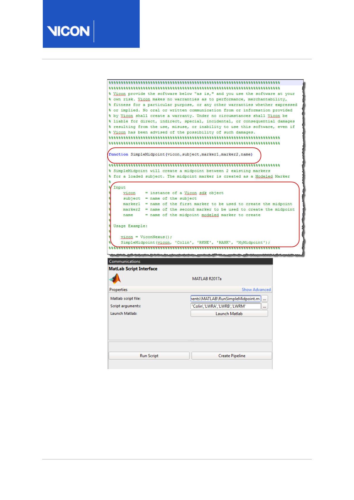
Nexus
Reference
Guide
Modeling with ViconNexus
Vicon Motion Systems Ltd. 13-Nov-2018 Page 63 of356
If your script does not require any arguments, leave the Script
arguments field blank.
5. If you want to launch MATLAB and display your script, click the Launch
Matlab button.

Nexus
Reference
Guide
Modeling with ViconNexus
Vicon Motion Systems Ltd. 13-Nov-2018 Page 64 of356
6. Click Run Script.
Information, such as a time stamp and text describing the processing,
together with any error messages, is displayed on the Matlab tab.
Relevant information is also displayed in the Log pane.
The modeled marker (in this case, the midpoint marker, LWRM) is
created, and can be seen in the 3D Perspective view.
On the Subjects Resources pane, additional outputs are displayed under
a newly created Modeled Markers node of the resources tree. In the
following example, the new marker is called MyMidpoint.
7. Display a Graph view of the new marker to see that a trajectory for the
new marker has been created for the whole trial.
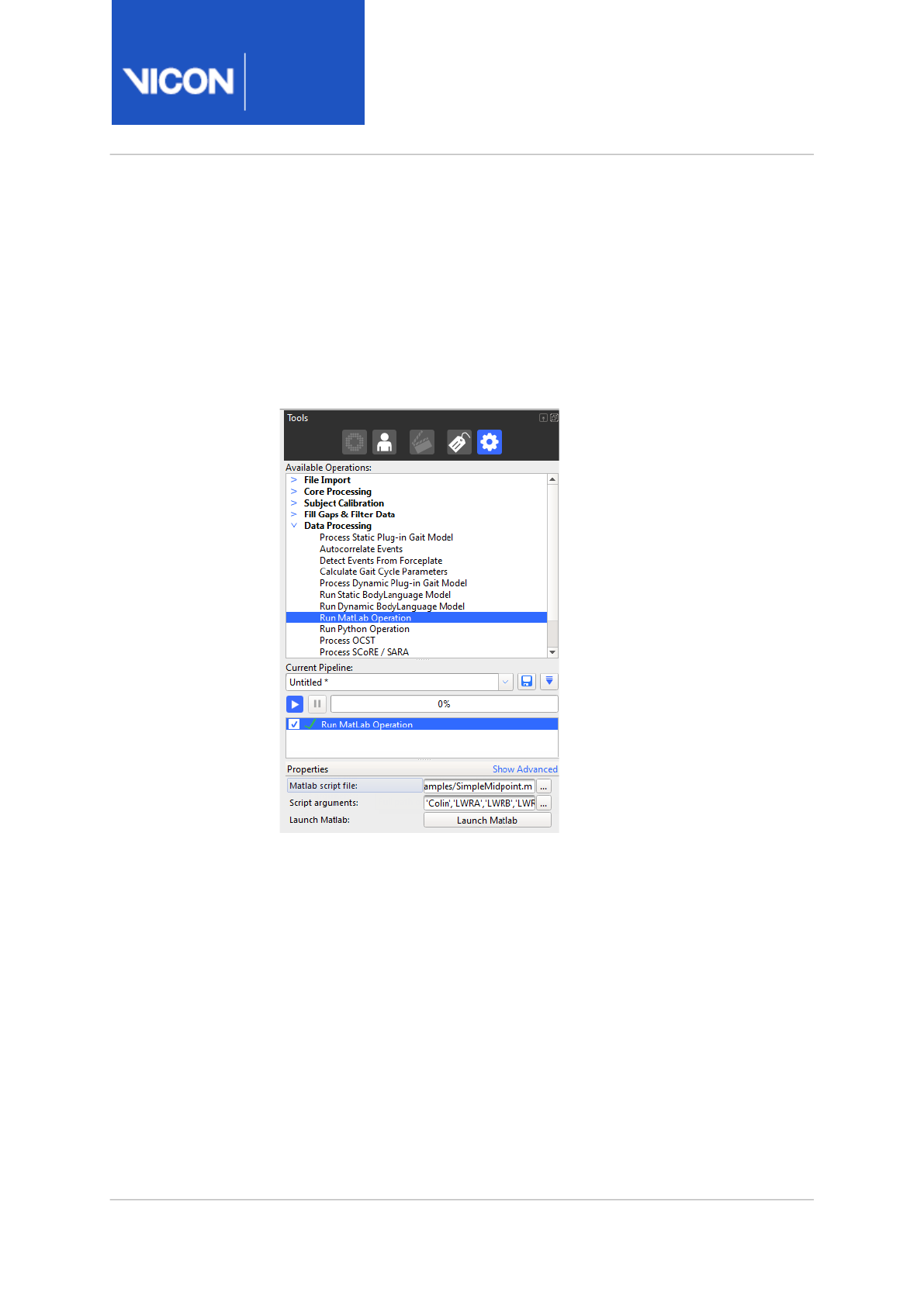
Nexus
Reference
Guide
Modeling with ViconNexus
Vicon Motion Systems Ltd. 13-Nov-2018 Page 65 of356
8. If necessary, you can change your script in MATLAB and, to check that it
has the desired result, run it again from either MATLAB or by clicking
Run Script again.
9. When you have finished refining your script, to include it in a pipeline,
click Create Pipeline, which copies the information you have supplied to
a Data Processing pipeline operation, Run Matlab Operation in the
Pipeline tools pane. The required inputs are displayed in the Properties
pane.

Nexus
Reference
Guide
Modeling with ViconNexus
Vicon Motion Systems Ltd. 13-Nov-2018 Page 66 of356
Advanced MATLAB modeling
From Nexus 2.2 and later releases, to simplify biomechanical modeling,
additional MATLAB scripts are available in the Nexus SDK.
Classes that represent trajectories (read from Nexus or created as modeled
markers), body segments, and angle outputs have been included to ease
modeling of biomechanics based on Nexus data.
Sample functions include:
• Calculating the angles between two segments (as fixed, Euler or helical
angles)
% Calculate the angle between two segments.
% Can choose euler, fixed or helical angle.
% Specify order of output angles for fixed and euler.
LKneeAnglesEulerML = AngleBetween( LThigh, LShank, 'euler',
'yxz' );
LKneeAnglesEulerML.Create( vicon );
LKneeAnglesEulerML.Write( vicon );
LKneeAnglesFixedML = AngleBetween( LThigh, LShank, 'fixed' );
LKneeAnglesFixedML.Create( vicon );
LKneeAnglesFixedML.Write( vicon );
LKneeAnglesHelicalML = AngleBetween( LThigh, LShank,
'helical' );
LKneeAnglesHelicalML.Create( vicon );
LKneeAnglesHelicalML.Write( vicon );
• Creating modeled markers based on existing trajectory data
% Create a trajectory from the segment origin
LThighPosML = NexusTrajectory( 'Colin' );
LThighPosML.SetPosition( LThigh.Position() );
LThighPosML.Create( vicon );
LThighPosML.Write( vicon );

Nexus
Reference
Guide
Modeling with ViconNexus
Vicon Motion Systems Ltd. 13-Nov-2018 Page 67 of356
• Translating points in the coordinate system of existing segments
% Create a global trajectory that is offset by (100,0,0) in the
% segment coordinate system
Offset = NexusTrajectory('Colin');
Offset.SetPosition( [100;0;0] );
TestTranslateML = LKNE + Offset*LThigh - LThigh.Position();
TestTranslateML = LThigh.TranslatePointInSegment( LKNE, [100;
0; 0 ] );
TestTranslateML.Create( vicon );
TestTranslateML.Write( vicon );
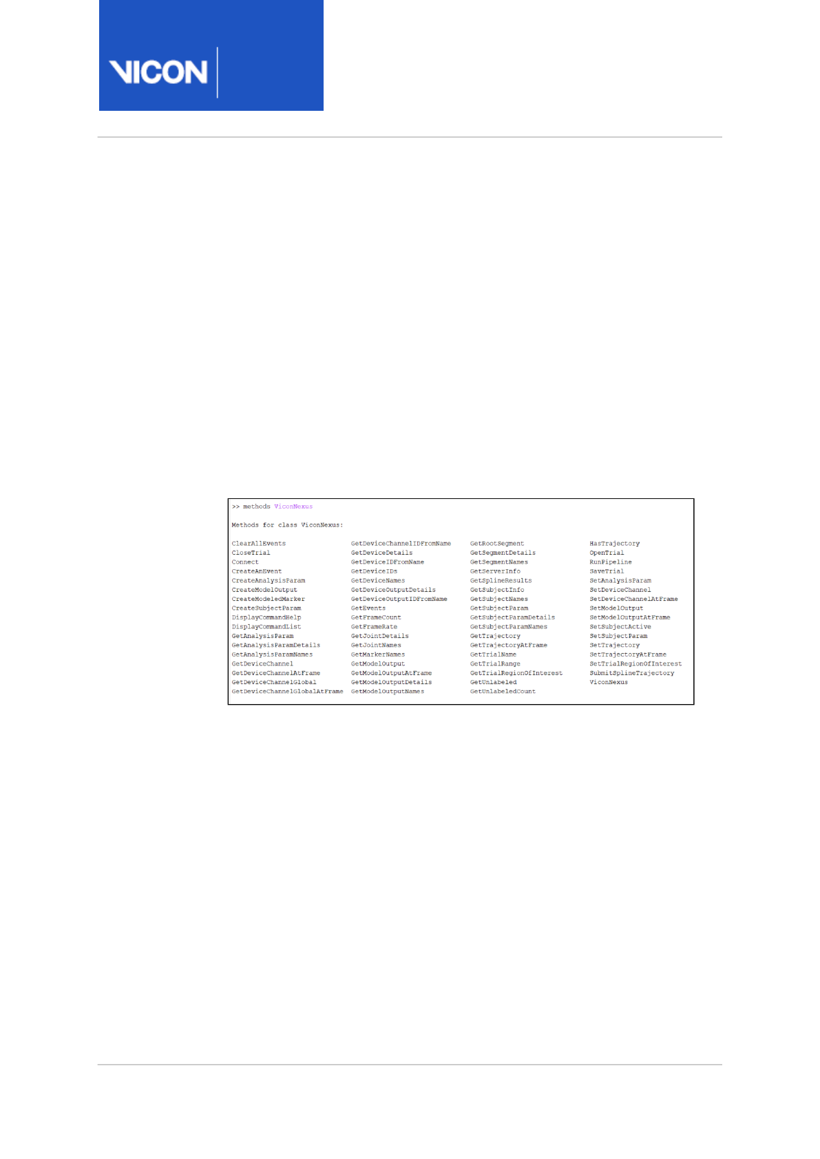
Nexus
Reference
Guide
Modeling with ViconNexus
Vicon Motion Systems Ltd.
27-Feb-2019
Page 68 of356
MATLAB commands for use with Nexus
The following information is provided to help you to get started using
MATLAB for modeling with Vicon Nexus 2.
•Display all Nexus MATLAB SDK commands, page 68
•Display help on a Nexus MATLAB SDK command, page 69
Display all Nexus MATLAB SDK commands
At the MATLAB command prompt, enter:
methods ViconNexus
A list of all Nexus MATLAB SDK commands is displayed:

Nexus
Reference
Guide
Modeling with ViconNexus
Vicon Motion Systems Ltd.
27-Feb-2019
Page 69 of356
Display help on a Nexus MATLAB SDK command
To display help on one of the commands listed above:
At the command prompt, enter:
help ViconNexus/
commandName
Where
commandName
is the command for which you want to display help.
For example, to display help about GetTrajectory, enter:
help ViconNexus/GetTrajectory

Nexus
Reference
Guide
Modeling with ViconNexus
Vicon Motion Systems Ltd. 13-Nov-2018 Page 70 of356
6 http://blogs.msdn.com/b/ukvsts/archive/2009/02/27/adding-the-ms-loopback-adapter-on-
windows-7.aspx
MATLAB troubleshooting
The following table lists possible issues you may encounter when modeling
with MATLAB, helps you to understand why the issue may have occurred,
and suggests the remedial actions to take, in the order to try them.
Issue Reason Action
Nexus error:
When you click the Run
Script button, Nexus
becomes unresponsive for
some time, and finally, the
Matlab tab displays the
following error:
Default Run Matlab
Operation Host
Application is not
connected, unable to
retrieve command list
MATLAB error:
Default Run Matlab
Operation Host
Application is not
connected, unable to
retrieve command list
MATLAB connects to
Nexus over TCP/IP. If you
disconnect your Ethernet
cable and disable wifi (ie,
if you are working
entirely offline), MATLAB
and Nexus cannot
connect.
Install the Microsoft Loopback
Adapter. For instructions on how
to do this, see
Adding the MS
Loopback Adapter on Windows 7
,
on blogs.msdn.com6.

Nexus
Reference
Guide
Modeling with ViconNexus
Vicon Motion Systems Ltd. 13-Nov-2018 Page 71 of356
Issue Reason Action
MATLAB error when
constructing an instance
of the ViconNexus object
vicon = ViconNexus();
Undefined function or
variable 'ViconNexus'
When you try to create
an instance of the class
object ViconNexus,
MATLAB is unable to
locate the definition for
the class.
This is generally an
indication that the
Search path in MATLAB
has not been set to
include a path to the
NexusSDK or that the
NexusSDK has not been
installed
Ensure that the NexusSDK has
been installed. The 32-bit version
of the SDK should be installed for a
32bit installation of MATLAB; the
64-bit version of the SDK should
be installed for a 64-bit installation
of MATLAB.
In MATLAB, ensure that the path
to the NexusSDK has been added:
64-bit MATLAB NexusSDK path is:
NexusInstallFolder
SDK\Win64\Mat
lab
32-bit Matlab NexusSDK path is
NexusInstallFolder
SDK\Win32\Matl
ab
Use the shortcut provided on the
Start menu to set the MATLAB
path.
MATLAB error when
constructing an instance
of the ViconNexus object
vicon = ViconNexus();
Could not load file or
assembly
'NexusSDKClientDotNET.d
ll' or one of its
dependencies. The
specified module could
not be found.
This can happen if the
VC++ 64-bit runtimes did
not get installed from the
Nexus bootstrap installer
setup.exe
Install the runtimes manually.
Navigate to the folder where the
installation files were unzipped
run
vcredist_x64.exe

Nexus
Reference
Guide
Modeling with ViconNexus
Vicon Motion Systems Ltd. 13-Nov-2018 Page 72 of356
Issue Reason Action
Generic type error
message received in
MATLAB after calling a
function
result =
vicon.function();
Error using
ViconNexus/function
(line 123)
Error: Invalid
Parameter Value
Look at the log in the Nexus
Matlab tab as it may contain more
detailed information on the error
that has been generated.

Nexus
Reference
Guide
Modeling with ViconNexus
Vicon Motion Systems Ltd. 13-Nov-2018 Page 73 of356
Issue Reason Action
MATLAB error
Host application failed
to respond to the
information request.
After MATLAB sends a
command to Nexus, it
waits for a specific
amount of time for the
reply to be received. If
the reply is not received
in that timeframe, this
error is generated.
Delays in processing can
occur when Nexus is
waiting for input from
the user to proceed or it
has become
unresponsive.
Look at the log in the Nexus
Matlab tab to see if an error has
been generated. Often, commands
will return a reply, but some
commands, such as OpenTrial and
RunPipeline, require that Nexus
generates a notification of task
completion. An error in these
commands can cause the reply to
be delayed or not be generated.
Look at the log in the Nexus
Matlab tab to see if the command
was received by Nexus. If the log
does not have an entry showing
that the command was received
then it is possible that something
has happened to the connection
between the applications.
Restart Nexus.
Make sure that Nexus is not
displaying a user prompt, if it is,
answer the prompt and retry the
command.
Restart Nexus.
MATLAB error
Unable to Communicate
with the host
application.
The function called
failed to execute
because the connection
to Nexus has either been
dropped or never
established.
Make sure that Nexus is running
and is responsive.
If running from within MATLAB,
remove the ViconNexus object
from the workspace using the
MATLAB clear command and re-
create the object.
Restart Nexus.
Restart MATLAB.

Nexus
Reference
Guide
Modeling with ViconNexus
Vicon Motion Systems Ltd. 13-Nov-2018 Page 74 of356
Issue Reason Action
Nexus error
MATLAB version is shown
in the Matlab tab but a
message states that
MATLAB is not accessible.
This can happen if Nexus
is able to determine that
MATLAB is installed but
it is unable to access the
MATLAB automation
server.
Run matlab.exe with the /register
option to have MATLAB re-register
its automation server components.
When there are multiple
versions of MATLAB
installed, Nexus is running
the wrong version of
MATLAB
MATLAB registers COM
components to provide
access to its automation
server, Nexus will use the
currently registered
components so the order
of installation/uninstall/
upgrade of different
MATLAB versions can
make a difference.
Run matlab.exe from the MATLAB
version you wish to use with the /
register option to have MATLAB re-
register its automation server
components.

Nexus
Reference
Guide
Modeling with ViconNexus
Vicon Motion Systems Ltd. 13-Nov-2018 Page 75 of356
7 https://www.youtube.com/watch?
v=rrYlNsGdNgs&index=6&list=PLxtdgDam3USUSIeuO6UloG3ogPsFNtEJS
8 https://www.youtube.com/watch?v=s5pU_ZDHWsg
Modeling with Python
Python is a powerful, widely used programming language that can be a
useful tool for mathematical modeling with ViconNexus.
To ensure that custom modeling is available whether or not you have
access to MATLAB, Python is automatically installed with Nexus.
For more information, see:
•Set up Python for use with Nexus, page 76
•Python commands for use with Nexus, page 77
In addition, the following Vicon Nexus 2 videos are available on YouTube:
•Python Plug-in Gait to Excel7
•Python demonstration with custom Gait Kinematics script8
Note
As the videos were recorded using an earlier version of Nexus 2,
you may notice small differences in the user interface.
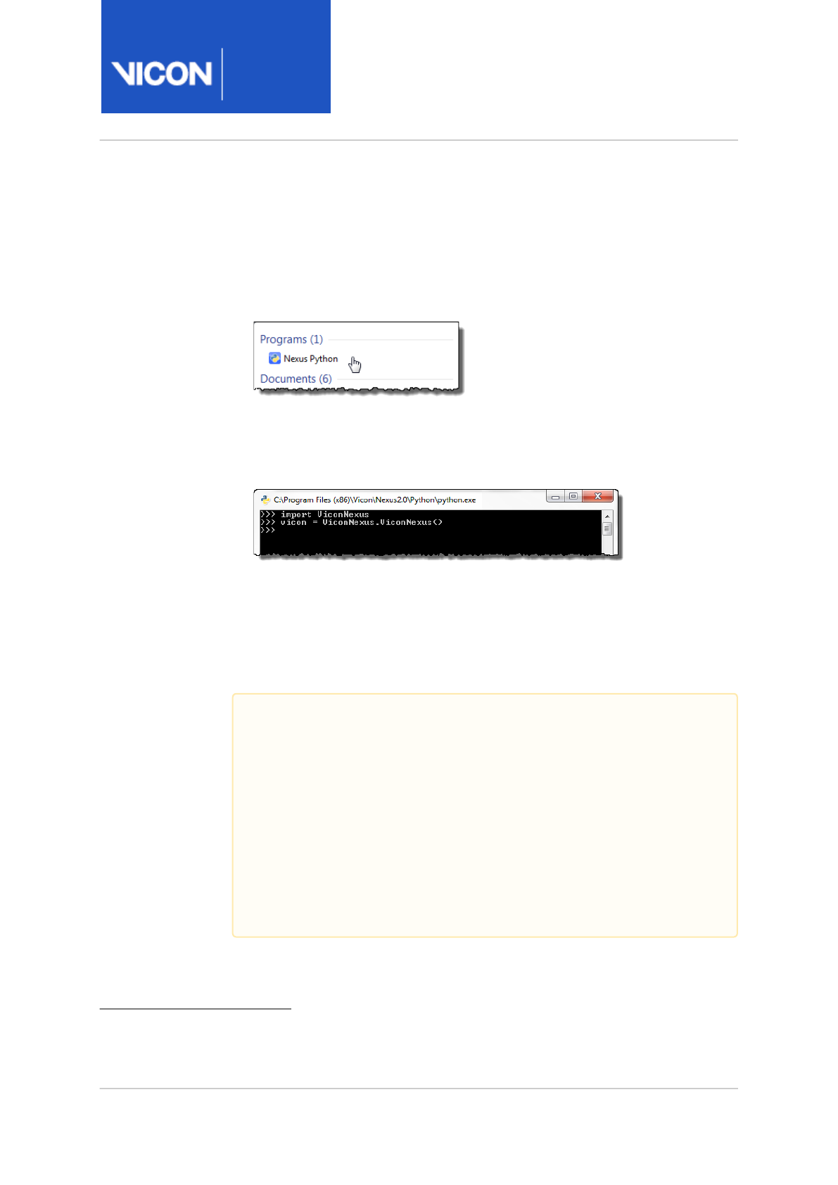
Nexus
Reference
Guide
Modeling with ViconNexus
Vicon Motion Systems Ltd. 13-Nov-2018 Page 76 of356
9 http://blogs.msdn.com/b/ukvsts/archive/2009/02/27/adding-the-ms-loopback-adapter-on-
windows-7.aspx
Set up Python for use with Nexus
To set up Python to work with Nexus:
1. Click Start, point to All Programs and then start to type Python.
2. Click the Python symbol.
3. To automatically configure Python for scripting with Nexus, at the
command prompt, enter the following:
import ViconNexus
vicon = ViconNexus.ViconNexus()
For information on how to access the help provided on the relevant Python
commands, see Python commands for use with Nexus, page 77. For more
information about how to use Python, see https://www.python.org/about/
gettingstarted/.
Important
If you disconnect your Ethernet cable and disable wifi, when you
enter a Python command, the following error may be displayed:
Host Application is not connected, unable to retrieve
command list
This is because Python connects to Nexus over TCP/IP and if you
are working entirely offline, Python and Nexus cannot connect.
To solve this issue, install the Microsoft Loopback Adapter. For
instructions on how to do this, see
Adding the MS Loopback
Adapter on Windows 7
, on blogs.msdn.com9.
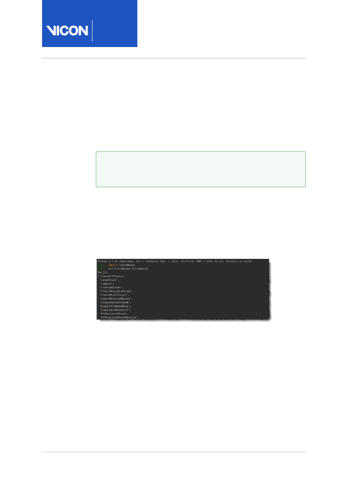
Nexus
Reference
Guide
Modeling with ViconNexus
Vicon Motion Systems Ltd.
27-Feb-2019
Page 77 of356
Python commands for use with Nexus
The following commands are provided to help you to get started using
Python for modeling with Nexus.
•Display all Nexus Python SDK commands, page 77
•Display help on a Nexus Python SDK command, page 78
Display all Nexus Python SDK commands
At the Python command prompt, assuming you have completed the above
preparatory step, enter:
dir(ViconNexus.ViconNexus)
A list of all Nexus Python SDK commands is displayed:
Tip
Remember to import the module first:
import ViconNexus
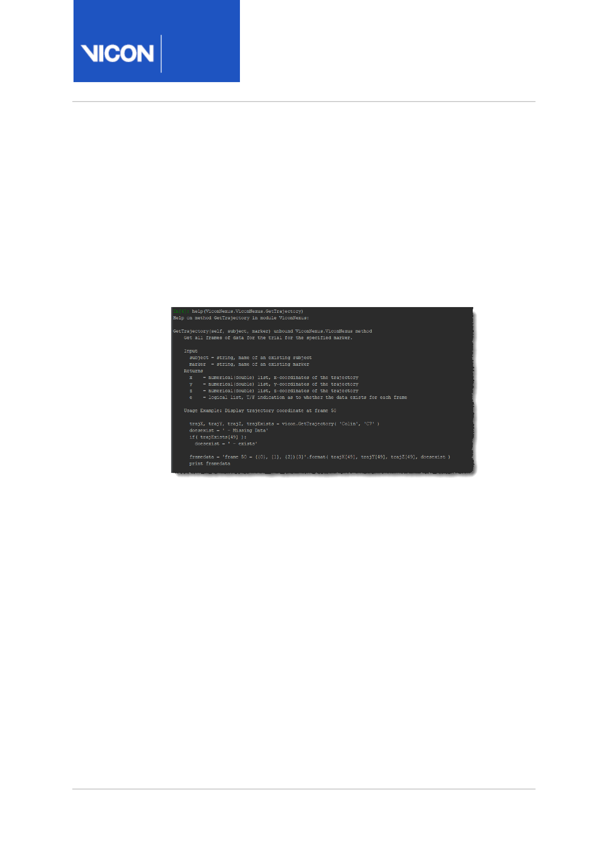
Nexus
Reference
Guide
Modeling with ViconNexus
Vicon Motion Systems Ltd.
27-Feb-2019
Page 78 of356
Display help on a Nexus Python SDK command
To display help on one of the commands listed above:
At the Python command prompt, enter:
help(
commandName
)
Where
commandName
is the command for which you want to display help.
For example, to display help about GetTrajectory, enter:
help(ViconNexus.ViconNexus.GetTrajectory)

Nexus
Reference
Guide
Biomechanics workflow
Vicon Motion Systems Ltd. 13-Nov-2018 Page 79 of356
10 http://www.gaitposture.com/article/S0966-6362%2810%2900129-3/abstract
11 http://www.jbiomech.com/article/S0021-9290%2806%2900415-5/abstract
12 http://www.jbiomech.com/article/S0021-9290%2805%2900446-X/abstract
Biomechanics workflow
ViconNexus 2 includes a Biomechanics Workflow area that enables you to
associate specified data capture and processing steps with particular trial
types, add joint range monitors for instant feedback, and quickly accept or
reject the results of each step.
Important
The Optimum Common Shape Technique (OCST)110, Symmetrical
Center of Rotation Estimation (SCoRE)211 and Symmetrical Axis of
Rotation Analysis (SARA)312 methods are based on research
publications that can be obtained from Vicon on request. As the
research and validation of the values produced by these methods is
a continuing effort, it is recommended that OCST, SCoRE and SARA
are used for investigative and research purposes. It is the
responsibility of the user to review the scientific references and
understand the methods. Any use of the methods as part of a
clinical assessment is strictly at the discretion of the user.

Nexus
Reference
Guide
Biomechanics workflow
Vicon Motion Systems Ltd. 13-Nov-2018 Page 80 of356
13 https://www.youtube.com/watch?
v=zGzd3cJkmiI&index=5&list=PLxtdgDam3USUSIeuO6UloG3ogPsFNtEJS
In the Biomechanics Workflow area, you can run (or modify and then run)
the supplied Advanced Gait Workflow, or set up your own workflows:
• To help you to calculate a repeatable Hip Joint Center location using the
SCoRE method, and an optimized Knee Joint Flexion Axis using the SARA
method, Nexus includes an Advanced Gait Workflow. TheAdvanced Gait
Workflow also incorporates a mathematical approach (known as OCST)
that finds the average or common shape for selected sets of markers.
The OSCT method allows non-rigid arrangements of skin-based markers
to be used in SCoRE and SARA calculations where rigidity is assumed.
TheAdvanced Gait Workflow steps each have an associated step
description in the Biomechanics Workflow area that guides you through
the process from marker placement to capture and processing. For more
information, seeUsing the Advanced Gait Workflow, page 81.
• To set up your own workflow, see Using a custom biomechanics
workflow, page 102, which explains how to set up and use custom
workflows, and includes further information on using functional
calibration and SCoRE and SARA.
In addition, a Vicon Nexus 2 video: SCoRE and SARA13, is available on
YouTube.
Note
As the videos were recorded using an earlier version of Nexus 2,
you may notice small differences in the user interface.

Nexus
Reference
Guide
Biomechanics workflow
Vicon Motion Systems Ltd. 13-Nov-2018 Page 81 of356
14 http://www.gaitposture.com/article/S0966-6362%2810%2900129-3/abstract
15 http://www.jbiomech.com/article/S0021-9290%2806%2900415-5/abstract
16 http://www.jbiomech.com/article/S0021-9290%2805%2900446-X/abstract
Using the Advanced Gait Workflow
Nexus 2 includes a feature called the Biomechanics Workflow. This area on
the Data Management tab enables you to create a custom series of
sequential steps that constitutes a collection protocol. These steps can
automatically select aspects of Nexus for data collection and processing,
including trial types, trial names, and processing pipelines.
The Advanced Gait Workflow (AGW) helps you to calculate a repeatable Hip
Joint Center location using the SCoRE method, and an optimized Knee
Joint Flexion Axis using the SARA method. TheAdvanced Gait Workflow
also incorporates a mathematical approach (known as OCST) that finds the
average or common shape for selected sets of markers. The OSCT method
allows non-rigid arrangements of skin-based markers to be used in SCoRE
and SARA calculations where rigidity is assumed. TheAdvanced Gait
Workflow steps each have an associated step description in the
Biomechanics Workflow area that guides you through the process from
marker placement to capture and processing.
Important
The Optimum Common Shape Technique (OCST)114, Symmetrical
Center of Rotation Estimation (SCoRE)215 and Symmetrical Axis of
Rotation Analysis (SARA)316 methods are based on research
publications that can be obtained from Vicon on request. As the
research and validation of the values produced by these methods is
a continuing effort, it is recommended that OCST, SCoRE and SARA
are used for investigative and research purposes. It is the
responsibility of the user to review the scientific references and
understand the methods. Any use of the methods as part of a
clinical assessment is strictly at the discretion of the user.

Nexus
Reference
Guide
Biomechanics workflow
Vicon Motion Systems Ltd. 13-Nov-2018 Page 82 of356
The Advanced Gait Workflow steps you through a series of trial captures
and automated processes to:
• Calibrate the subject's labeling skeleton
• Calibrate the OCST pelvis, femur, and tibia segments
• Monitor the range of motion (ROM) of the hip and knee joints for SCoRE
and SARA calibration
• Calibrate the SCoRE hip joint centers
• Calibrate the SARA knee flexion axes
• Capture a dynamic trial and use the calibrated OCST, SCoRE and SARA
data to compute the hip joint centers and knee flexion axes for further
analysis
The workflow enables you to accept the outcome of the current step and
proceed to the next automatically or to reject it to repeat the step until the
outcome is satisfactory. It illustrates how to use the Biomechanics
Workflow and its corresponding features with the suppliedAdvanced Gait
Workflow VSTs, but if required, you can modify it and the associated trial
types, monitors and pipelines to suit your needs.
The following topics describe each step in the Advanced Gait Workflow
along with its outcome. The final topic describes how to use the MATLAB
Plug-in Gait scripts with the SCoRE and SARA data for further analysis.
•Advanced Gait Workflow files, page 83
•Prepare a subject for SCoRE and SARA and the Advanced Gait Workflow,
page 87
•Run the Advanced Gait Workflow, page 88
•Troubleshoot AGW reconstruction and labeling, page 95
•Process a kinematic model with SCoRE and SARA, page 96

Nexus
Reference
Guide
Biomechanics workflow
Vicon Motion Systems Ltd. 13-Nov-2018 Page 83 of356
Advanced Gait Workflow files
By default, the Advanced Gait Workflow files are located in the following
installation folder:
C:\Program Files (x86)\Vicon\Nexus2.#\
You are given the option to change this location during the Nexus
installation.
The Advanced Gait Workflow (AGW) files are:
•AGW labeling skeleton template and marker files, page 84
•AGW pipelines, page 84
•AGW trial types, page 84
•AGW monitors, page 85
•AGW capture workflow, page 85
•AGW MATLAB folder and files, page 85
•PlugInGait FullBody Ai Functional VST, page 85

Nexus
Reference
Guide
Biomechanics workflow
Vicon Motion Systems Ltd. 13-Nov-2018 Page 84 of356
AGW labeling skeleton template and marker files
The following labeling skeleton template and marker files are installed in:
<installation folder>
\ModelTemplates
• PlugInGait FullBody Ai Functional.vst
• PlugInGait FullBody Ai Functional.mkr
• PlugInGait LowerBody Ai Functional.vst
• PlugInGait LowerBody Ai Functional.mkr
AGW pipelines
The following pipelines are installed in:
<installation folder>
\Configurations\Pipelines
• AGW Static.Pipeline
• AGW LHip.Pipeline
• AGW LKnee.Pipeline
• AGW RHip.Pipeline
• AGW RKnee.Pipeline
• AGW Process.Pipeline
AGW trial types
The following trial types are installed in:
<installation folder>
\Configurations\TrialTypes
• AGW Static.TrialTypes
• AGW LHip.TrialTypes
• AGW LKnee.TrialTypes
• AGW RHip.TrialTypes
• AGW RKnee.TrialTypes
• AGW Process.TrialTypes

Nexus
Reference
Guide
Biomechanics workflow
Vicon Motion Systems Ltd. 13-Nov-2018 Page 85 of356
AGW monitors
The following monitors are installed in:
<installation folder>
\Configurations\Monitors
• AGW LHip.Monitors
• AGW LKnee.Monitors
• AGW RHip.Monitors
• AGW RKnee.Monitors
AGW capture workflow
The following capture workflow is installed in:
<installation folder>
\Configurations\CaptureWorkflows
• AGW Lower Body.CaptureWorkflow
AGW MATLAB folder and files
The following MATLAB folder and files are installed in:
<installation folder>
\SDK\Matlab
• +Vicon (folder containing the Plug-in Gait MATLAB model)
• DynamicPiG.m
• StaticPiG.m
PlugInGait FullBody Ai Functional VST
The
PlugInGait FullBody Ai.vst
uses the same marker set and marker
locations as the legacy
PlugInGait FullBody
(UPA and FRM).vst but it has
been rewritten into the VST/VSK format to take advantage of the skeleton
calibration and labeling algorithms of Nexus 2.
The
PlugInGait FullBody Ai Functional.vst
has four additional markers that
are used to define independent thigh and tibia segments for SCoRE and
SARA processing. (Note that this VST is just one example of the possible
marker sets that can be used with SCoRE and SARA.) The additional
markers include the L and R THIA, typically placed on the anterior aspect of
the thigh, which combine with the THI and KNE markers to define the left
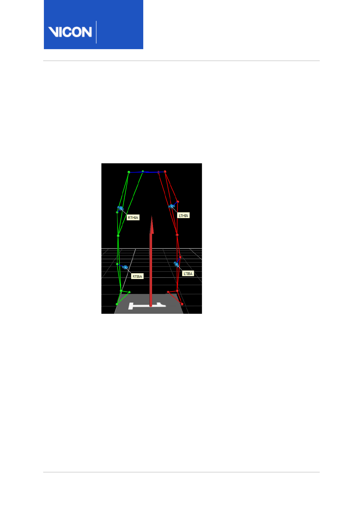
Nexus
Reference
Guide
Biomechanics workflow
Vicon Motion Systems Ltd. 13-Nov-2018 Page 86 of356
and right femur OCST segments. Also the L and R TIBA markers, typically
placed on the anterior aspect of the tibia, combine with the TIB and ANK
markers to define the left and right tibia OCST segments. Although the
exact placement of these additional markers does not necessarily
correspond with anatomical landmarks, it's important that the markers form
a solid geometrical relationship with the other markers on the segment to
provide well-defined and stable OCST segments, as shown in the following
illustration.

Nexus
Reference
Guide
Biomechanics workflow
Vicon Motion Systems Ltd. 13-Nov-2018 Page 87 of356
Prepare a subject for SCoRE and SARA and the Advanced Gait
Workflow
1. Take the standard Plug-in Gait Full Body anthropometric measurements.
2. Attach the markers to the subject.
3. On the Subjects tab, click Create a new subject from a Labeling Skeleton
and select PlugInGait FullBody Ai Functional.
4. Enter the subject's anthropometric measurements into the subject
Properties fields.
Note
These anthropometric measurements aren't used to calculate
OCST/SCoRE/SARA values, however they are required for Plug-in
Gait processing (standard and/or MATLAB).
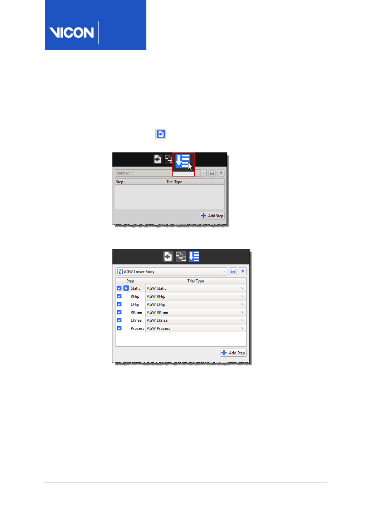
Nexus
Reference
Guide
Biomechanics workflow
Vicon Motion Systems Ltd. 13-Nov-2018 Page 88 of356
Run the Advanced Gait Workflow
1. After attaching markers, have the subject enter the volume.
2. On the Data Management tab, click the File Transfer/Batch Processing
Interface icon.
3. Click the Biomechanics Workflow icon.
4. From the dropdown list, select AGW Lower Body.
The steps are displayed in the Biomechanics Workflow area:
Complete the steps as described in the following sections.
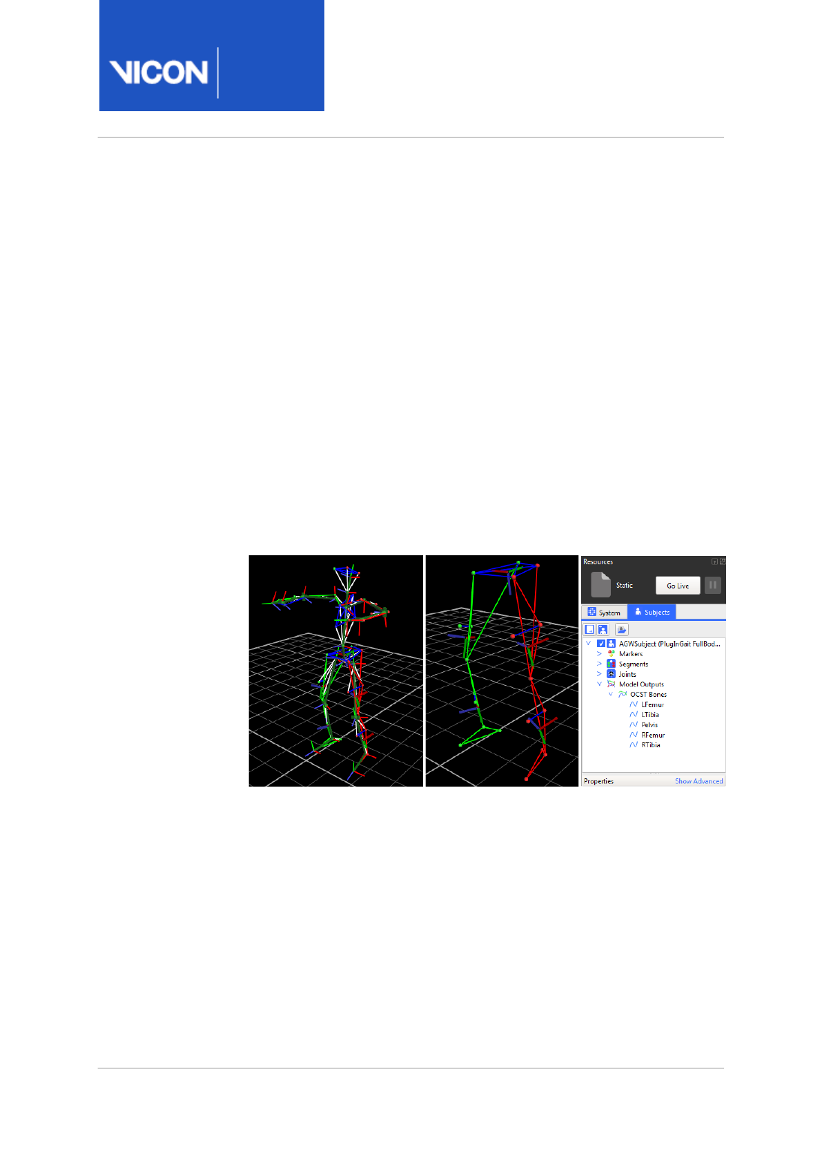
Nexus
Reference
Guide
Biomechanics workflow
Vicon Motion Systems Ltd. 13-Nov-2018 Page 89 of356
Step 1: AGW Static
This step calibrates the subject's labeling skeleton and OCST segments
from a static trial.
1. Have the subject stand in the motorbike pose and click on the first step,
which is labeled Static. When selected, the play icon is positioned at
that step, as shown in the previous illustration.
2. To initiate the capture, click Start.
The AGW Static trial type is loaded automatically. It is set to capture a 1-
second trial and run the AGW Static pipeline after the capture is
complete. The outcome is a calibrated labeling skeleton and calibrated
OCST Pelvis, RFemur, LFemur, RTibia, and LTibia segments.
3. Review the subject in the 3D Perspective view to make sure the results
are acceptable.
The OCST local segment axes are displayed on the subject as well as
written to the subject's OCST Bones node, in the Model Outputs node.
If the results look incorrect, check the Log tab for any error messages.
4. If the results are acceptable, click Accept to move on to the next step or
to repeat the current step, click Reject.
When you click Accept, the current offline trial is automatically saved,
which updates the subject's .
mp
file with the calibrated data.
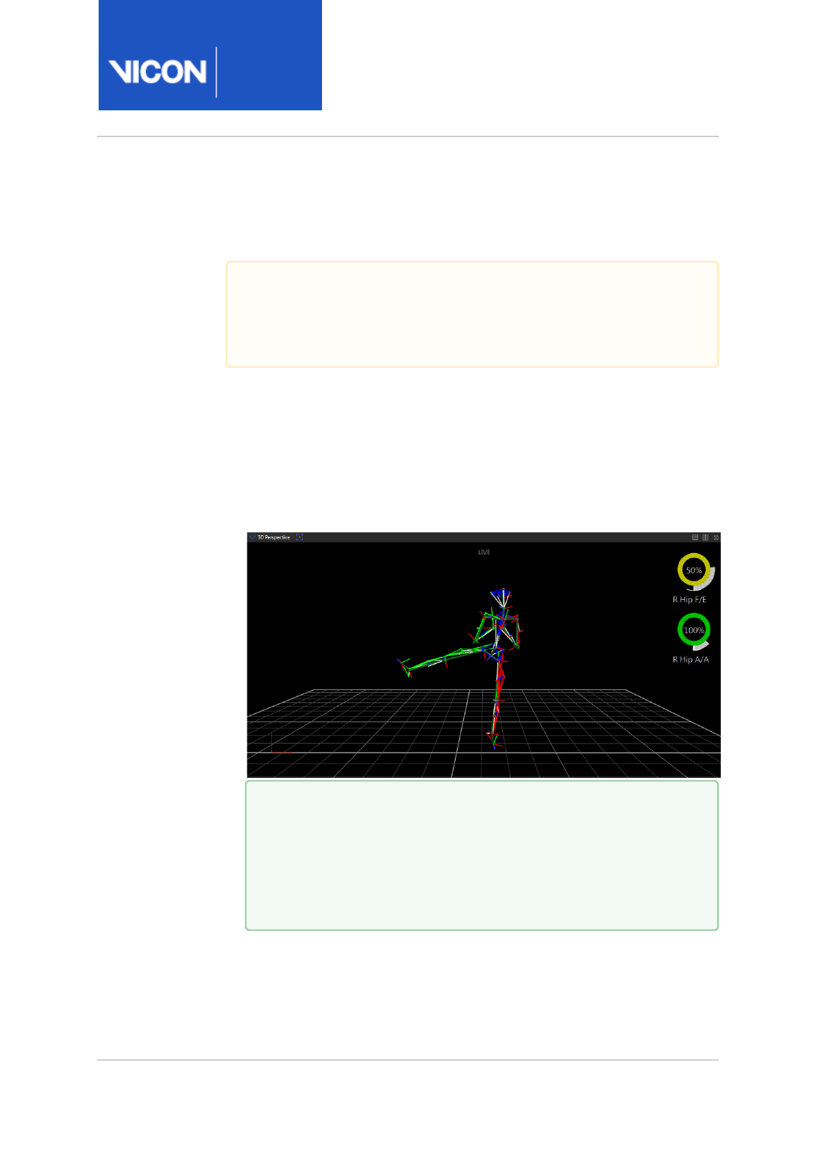
Nexus
Reference
Guide
Biomechanics workflow
Vicon Motion Systems Ltd. 13-Nov-2018 Page 90 of356
Step 2: AGW RHip
This step calibrates the right SCoRE hip joint center.
1. Prepare the subject to perform a star-arc movement pattern for the right
hip.
2. To initiate the capture, click Start.
The AGW RHip trial type and the AGW RHip range monitor are loaded
automatically. The trial type starts the capture automatically, but you
must stop the capture after the hip joint has moved about all three axes
through the acceptable ranges.
3. When the joint ranges have been satisfied, stop the capture manually.
The AGW RHip pipeline runs automatically and the outcome is a
calibrated right SCoRE hip joint center. The hip joint center appears in
Important
To make the subject's skeleton joint data available to the range
monitors, set the Processing Output Level property of Local Vicon
System to Kinematic Fit.
Tip
The axes correspond to the labeling skeleton's segment
definitions, where RHip X is flexion/extension, RHip Y is internal/
external rotation, and RHip Z is abduction/adduction. The range
values defined within the monitors serve as examples, but can
be modified to suit your application needs.
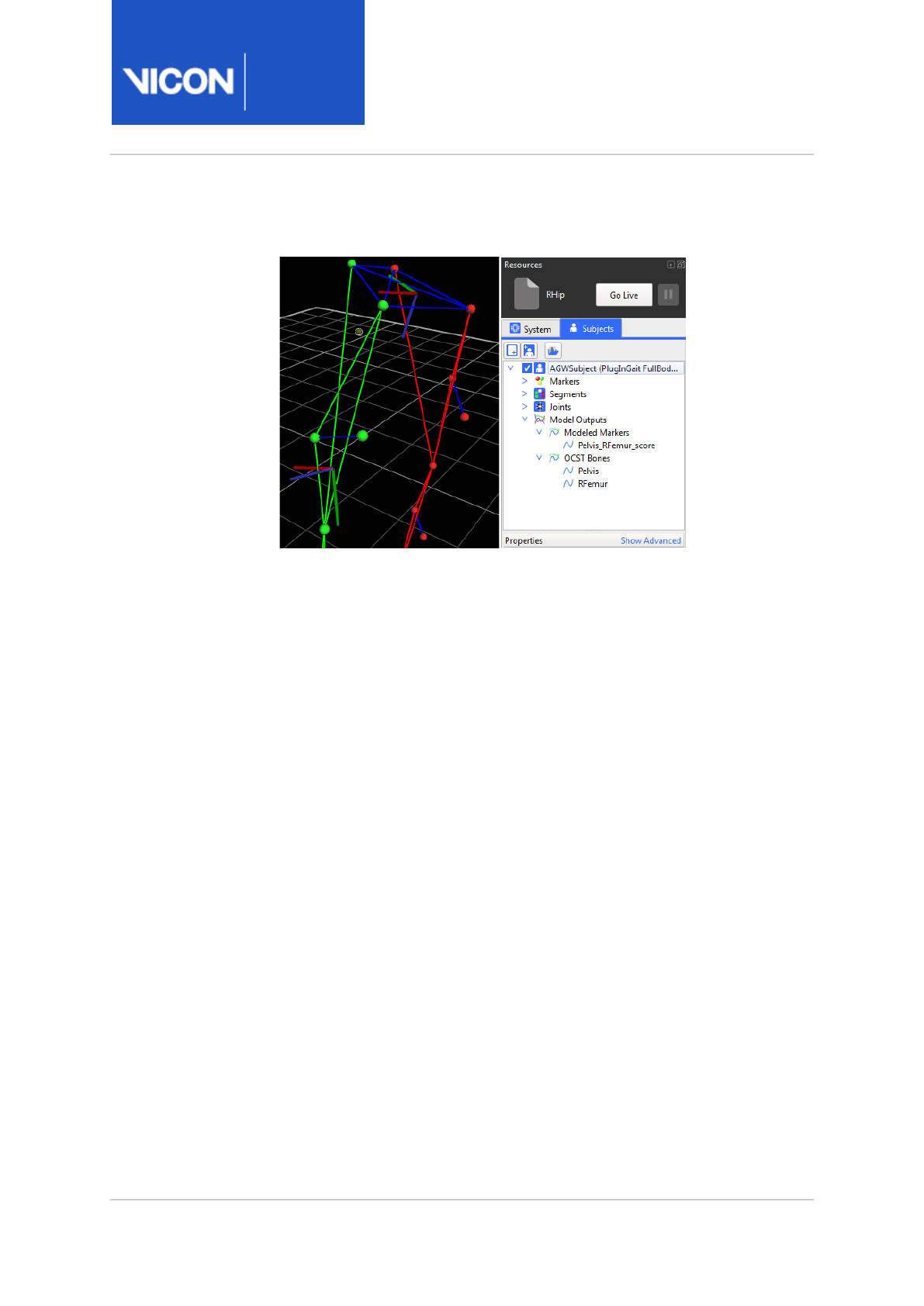
Nexus
Reference
Guide
Biomechanics workflow
Vicon Motion Systems Ltd. 13-Nov-2018 Page 91 of356
the 3D Perspective view as a virtual point and is added to the subject's
Modeled Markers node in the Model Outputs node.
4. Review the virtual point location and the Log tab for errors.
5. If the results are acceptable, click Accept to move on to the next step or
to repeat the current step, click Reject.
When you click Accept the current offline trial is automatically saved,
which updates the subject's .
mp
file with the calibrated data.
Step 3: AGW LHip
This step calibrates the left SCoRE hip joint center.
1. Prepare the subject to perform a star-arc movement pattern for the left
hip.
2. Follow the same procedure as that of the right hip, but note that the
AGW LHip trial type and the AGW LHip range monitor are automatically
loaded.
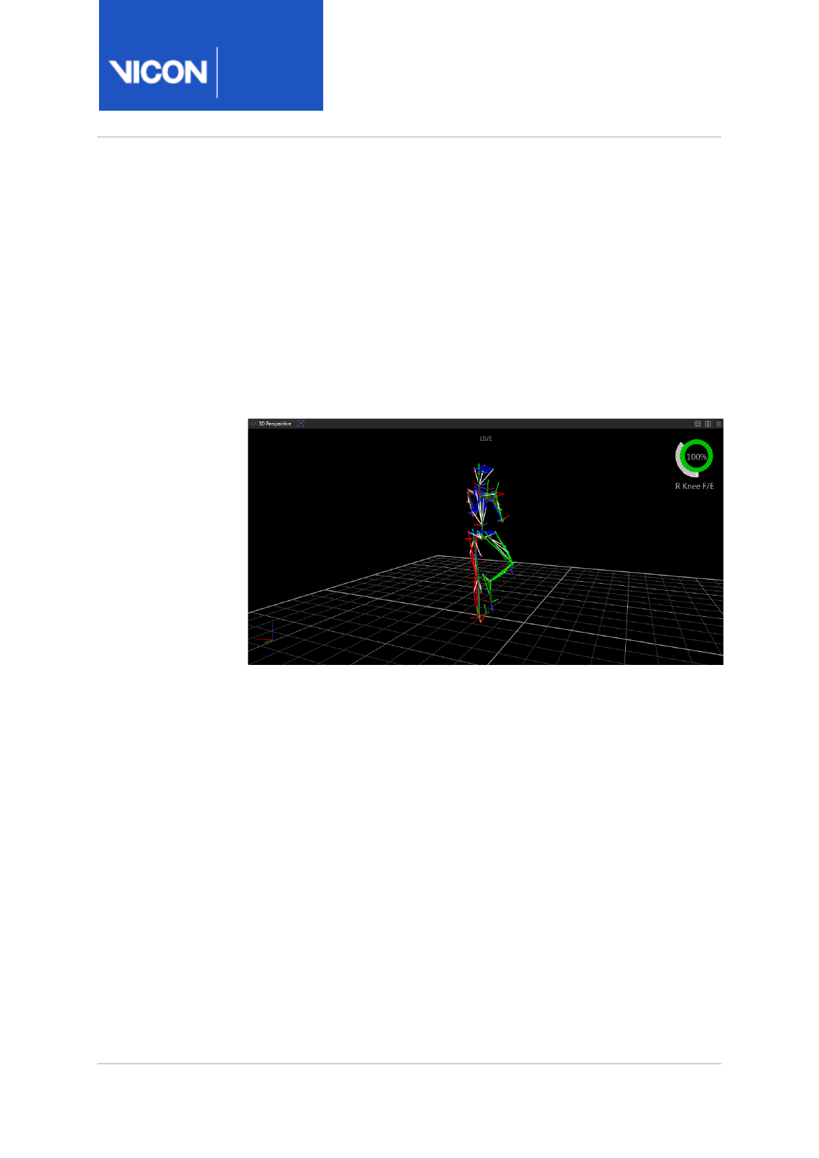
Nexus
Reference
Guide
Biomechanics workflow
Vicon Motion Systems Ltd. 13-Nov-2018 Page 92 of356
Step 4: AGW RKnee
This step calibrates the right knee SARA flexion axis.
1. Prepare the subject to perform a knee flexion movement pattern for the
right knee.
2. To begin capturing, click Start.
The AGW RKnee trial type and the AGW RKnee range monitor are loaded
automatically. The trial type starts the capture automatically, but you
must stop the capture after the knee joint has moved about its flexion
axis through the acceptable range.
3. When the joint range has been satisfied, stop the capture manually.
The AGW RKnee pipeline runs automatically and the outcome is a
calibrated right SARA knee flexion axis. The SCoRE knee joint center
appears in the 3D Perspective view as a virtual point and is added to the
subject's Modeled Markers node in the Model Output node. Because the
knee joint range of motion is primarily about its flexion axis, the SCoRE
joint center location is not as accurate as that of the hip. In this case,
the knee joint center serves more appropriately as an endpoint of the
knee flexion axis vector.
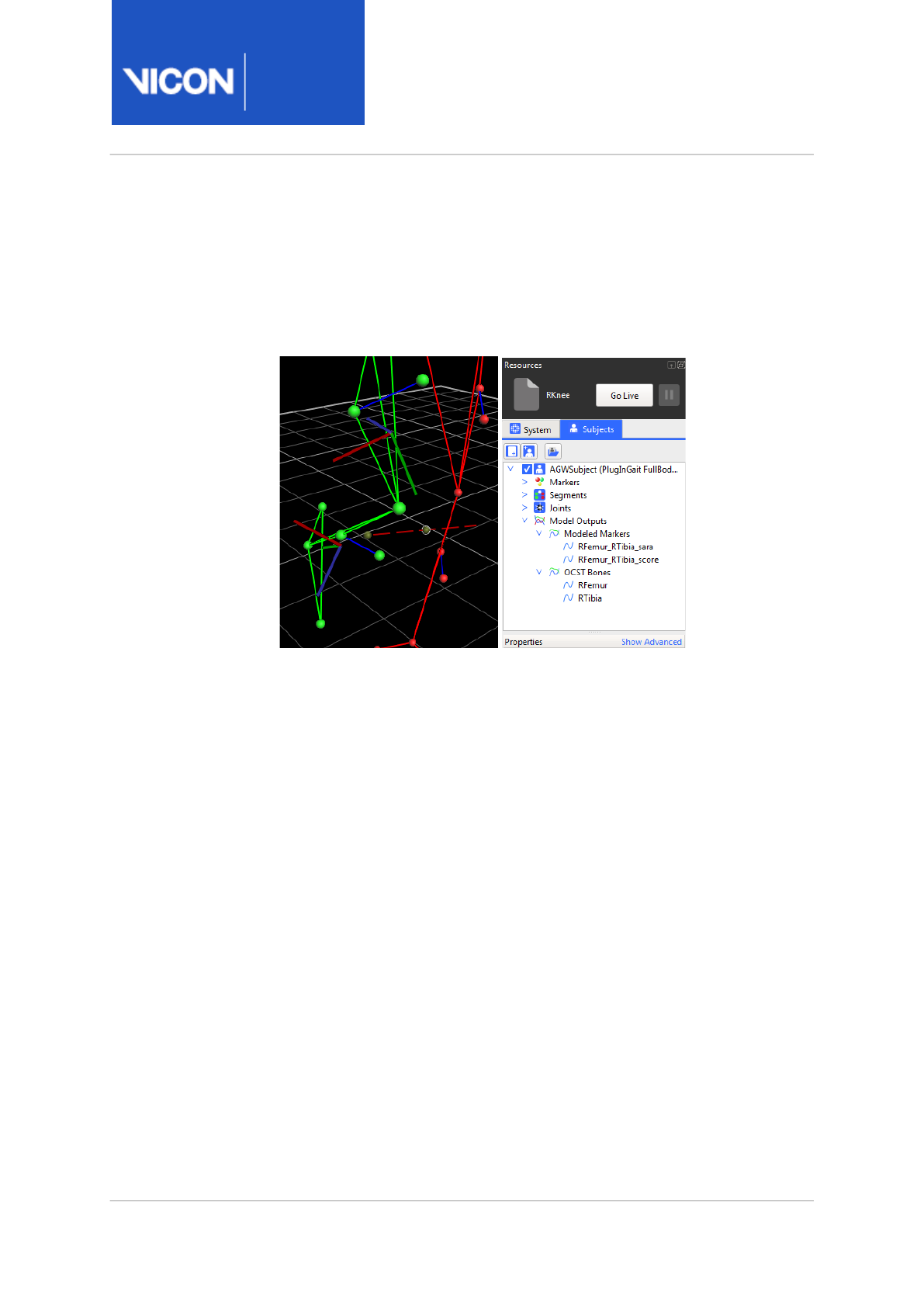
Nexus
Reference
Guide
Biomechanics workflow
Vicon Motion Systems Ltd. 13-Nov-2018 Page 93 of356
The SARA knee flexion axis appears in the 3D Perspective view as the
opposite endpoint of a vector formed along with the SCoRE knee joint
center. The joint axis line appears in the 3D Perspective view. The
anatomical knee joint center estimation is expected to be defined by
more conventional means, such as Plug-in Gait.
4. Review the virtual point location and check the Log tab for any errors.
5. If the results are acceptable, click Accept to move on to the next step, or
to repeat the current step, click Reject. When you click Accept, the
current offline trial is automatically saved, which updates the
subject's
.mp
file with the calibrated data.
Step 5: AGW LKnee
This step calibrates the left knee SARA flexion axis.
1. Prepare the subject to perform a knee flexion movement pattern for the
left knee.
2. Follow the same procedure as that for the right hip, but note that the
AGW LKnee trial type and the AGW LKnee range monitor are
automatically loaded.
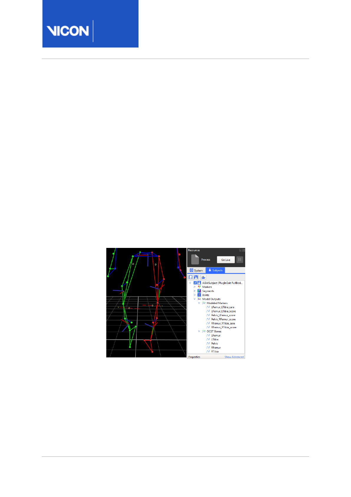
Nexus
Reference
Guide
Biomechanics workflow
Vicon Motion Systems Ltd. 13-Nov-2018 Page 94 of356
Step 6: AGW Process
This step captures and processes a dynamic trial.
1. Prepare the subject to perform the dynamic activity.
2. Because the SCoRE and SARA calibrations are complete and there is not
a range monitor associated with the dynamic capture step, at this stage,
if desired, you can switch the Processing Output Level of Local Vicon
System back to Labels.
3. To begin the capture, click Start.
The AGW Process trial type is loaded and the capture starts
automatically.
4. When the trial activity is complete, stop the capture.
The AGW Process pipeline is run automatically and the outcome is a
reconstructed and labeled trial that includes the processed SCoRE hip
joint centers and the SARA knee flexion axes.
As in the calibration steps, these calculations are represented in the 3D
Perspective view as well as in the subject's Modeled Markers node.

Nexus
Reference
Guide
Biomechanics workflow
Vicon Motion Systems Ltd. 13-Nov-2018 Page 95 of356
Troubleshoot AGW reconstruction and labeling
If the captured data contains gaps or incorrect labels, you can adjust the
settings of the Combined Processing operation, which is found in each of
the relevant pipelines (see Advanced Gait Workflow files, page 83) to improve
the reconstruction and labeling of the data.

Nexus
Reference
Guide
Biomechanics workflow
Vicon Motion Systems Ltd. 13-Nov-2018 Page 96 of356
Process a kinematic model with SCoRE and SARA
The SCoRE and SARA operations are solely joint calibrations and are not a
full kinematic model. If you want to produce kinematic outputs (for
example, Joint Angles), the Hip Joint locations and Knee flexion axes must
be input into a secondary full kinematic model such as Plug-in Gait.
When Nexus is installed, a version of Plug-in Gait written in MATLAB is also
installed. The following steps describes how to use this model to calculate
Plug-in Gait variables that use SCoRE hip joint centers and SARA optimized
knee axes as their foundation. You are assumed to have run through the
Advanced Gait Workflow (see Run the Advanced Gait Workflow, page 88).
Using Plug-in Gait Matlab with SCoRE and SARA
Plug-in Gait Matlab has been created for research purposes and to allow
the incorporation of SCoRE and SARA within the modeling process.
To use Plug-in Gait Matlab with SCoRE and SARA, you run a static script
followed by the dynamic script:
• Process static Plug-in Gait, page 97
•Process dynamic Plug-in Gait, page 100
Important
To run PlugInGait Matlab, you need a valid MATLAB license.
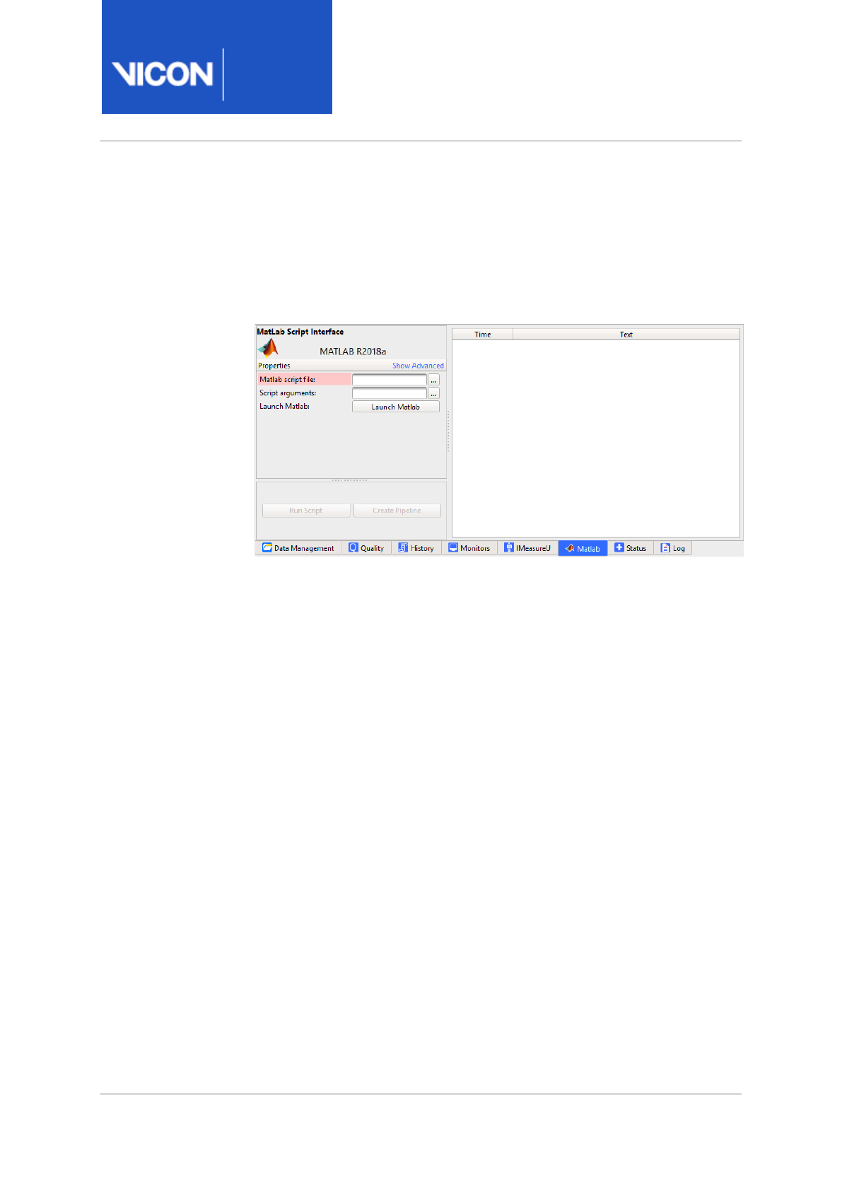
Nexus
Reference
Guide
Biomechanics workflow
Vicon Motion Systems Ltd. 13-Nov-2018 Page 97 of356
Process static Plug-in Gait
1. Load your static trial (created during Step 1: Static, page 89).
2. Run the AGW Process pipeline to calculate the SCoRE hip joint centers
and SARA knee flexion axes outputs for the static trial.
3. Click on the Matlab tab.
4. In the Matlab script file field, browse to
C:\Program Files
(x86)\Vicon\Nexus2.#\SDK\Matlab
and select
StaticPiG.m.
5. In the Script arguments field enter the following values as a comma-
separated string:
• FirstFrame (a number)
• LastFrame (a number)
• MarkerSize (marker size in mm)
• bAntTiltPos (true or false)
• bLFootFlat (true or false)
• bRFootFlat (true or false)
• bHeadLevel (true or false)

Nexus
Reference
Guide
Biomechanics workflow
Vicon Motion Systems Ltd. 13-Nov-2018 Page 98 of356
Static example:
1, 337, 14, true, true, true, true
6. After you have entered all the required information, click Run Script.
The log file displays the relevant feedback.
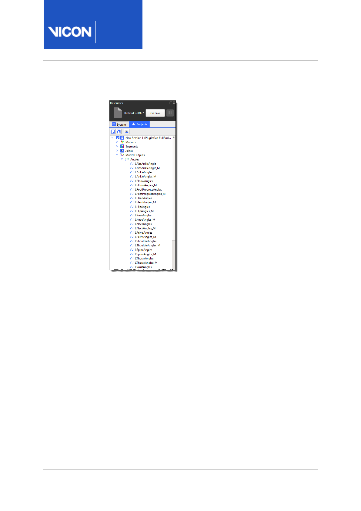
Nexus
Reference
Guide
Biomechanics workflow
Vicon Motion Systems Ltd. 13-Nov-2018 Page 99 of356
An extra set of Model Outputs are created - <AngleName>_M:
7. Save the trial.
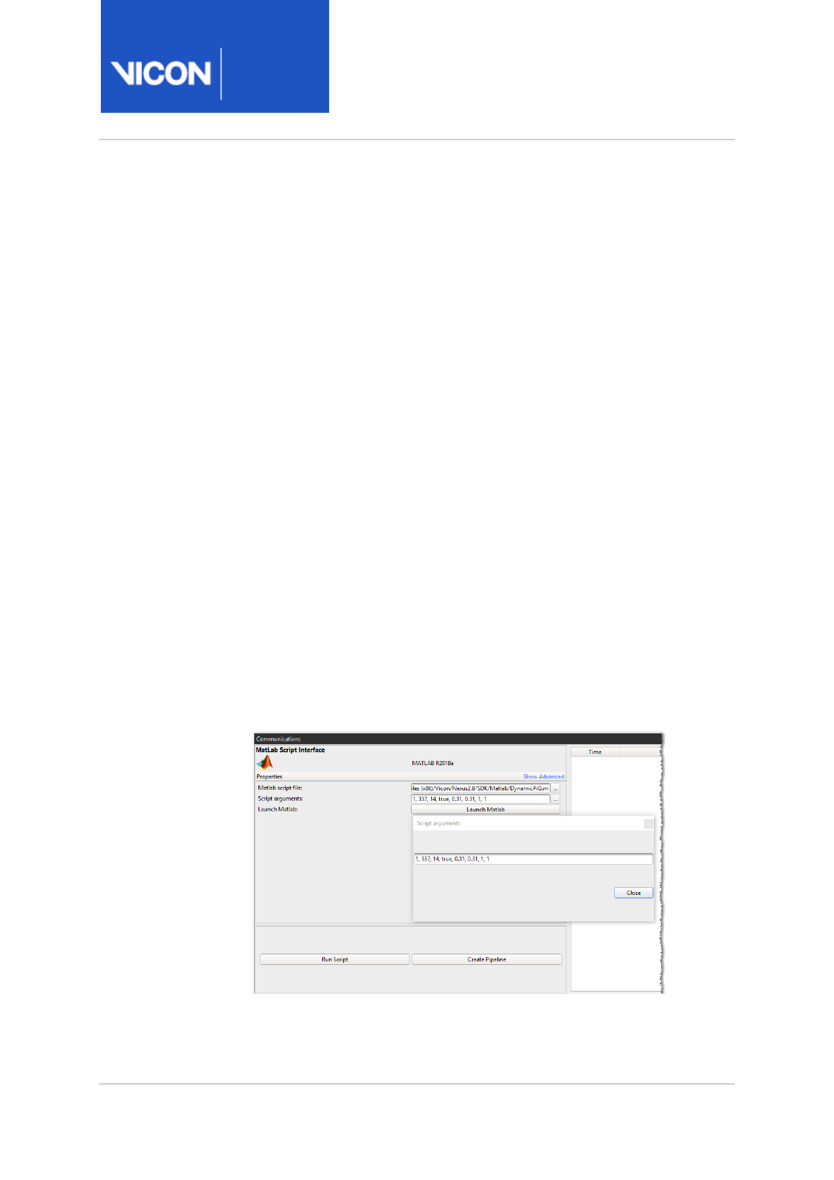
Nexus
Reference
Guide
Biomechanics workflow
Vicon Motion Systems Ltd. 13-Nov-2018 Page 100 of356
Process dynamic Plug-in Gait
1. Load your dynamic trial (created in Step 6: Process, page 94).
2. Click on the Matlab tab.
3. In the Matlab script file field, browse to
C:\Program Files
(x86)\Vicon\Nexus2.#\SDK\Matlab
and select
DynamicPiG.m
.
4. In the Script arguments field, enter the following values as a comma-
separated string:
• FirstFrame (a number)
• LastFrame (a number)
• MarkerSize (marker size in mm)
• bAntTiltPos (true or false)
• PelvisROG (0.31)
• ThoraxROG (0.31)
• ReactionFrame (a number: 0=proximal segment, 1=distal segment,
2=global frame)
• PowerOutput (a number: 1=single value power, 3=3-component power)
• bAllowCrossPlateStrikes (true or false, optional, default false). When
this variable is set to true, Plug-in Gait combines the dynamics of foot
strikes that straddle two adjacent plates.
Dynamic example:
1, 337, 14, true, 0.31, 0.31, 1, 1
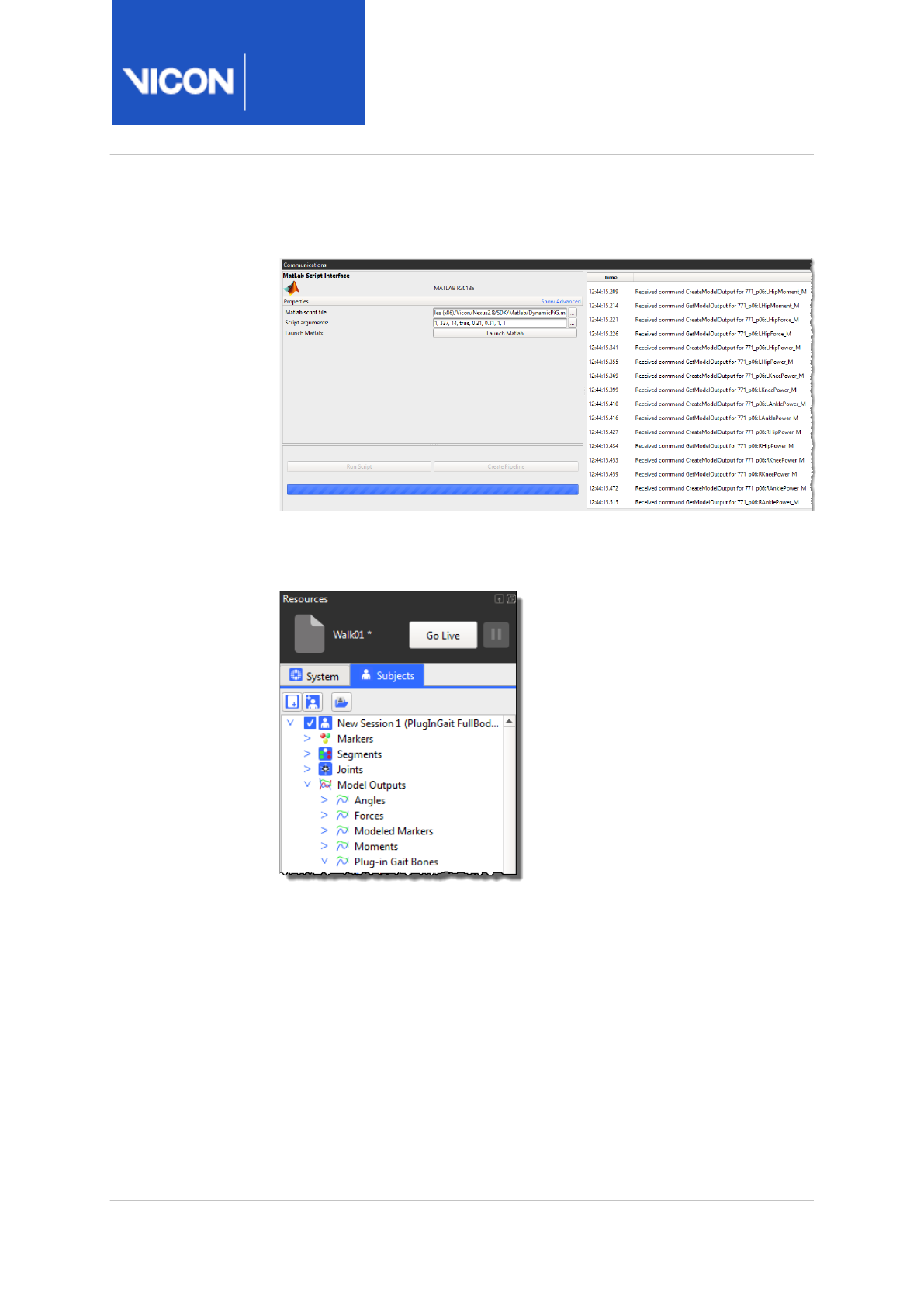
Nexus
Reference
Guide
Biomechanics workflow
Vicon Motion Systems Ltd. 13-Nov-2018 Page 101 of356
5. After you have entered all the required information, click Run Script.
The Log file displays all the relevant feedback.
An extra set of Model Outputs is created: <AnglesName>_M,
<ForcesName>_M, <ModeledMarkers>_M, <MomentsName>_M, <Plug-
InGaitBonesName>_M, <PowerName>_M
6. Save the trial.

Nexus
Reference
Guide
Biomechanics workflow
Vicon Motion Systems Ltd. 13-Nov-2018 Page 102 of356
17 http://www.gaitposture.com/article/S0966-6362%2810%2900129-3/abstract
18 http://www.jbiomech.com/article/S0021-9290%2806%2900415-5/abstract
19 http://www.jbiomech.com/article/S0021-9290%2805%2900446-X/abstract
Using a custom biomechanics workflow
To help you use a biomechanics workflow, Nexus includes the Advanced
Gait Workflow, which steps you through a series of trial captures and
automated processes to enable you to use the calibrated OCST, SCoRE and
SARA data to compute the hip joint centers and knee flexion axes for
further analysis. You can use the workflow as supplied, or if required, you
can modify it and the associated trial types, monitors and pipelines to suit
your needs. For information, see Using the Advanced Gait Workflow, page 81.
If you need to set up your own biomechanics workflow from scratch, see
the following topics.
•Overview of the biomechanics workflow, page 103
•View real-time subject calibration feedback with monitors, page 105
•About functional calibration in the biomechanics workflow, page 110
•Create a biomechanics workflow, page 112
•About SCoRE and SARA in ViconNexus, page 118
•Prepare data for use with SCoRE and SARA, page 120
•Capture and process a trial with SCoRE and SARA, page 122
•Process multiple joints with SCoRE and SARA, page 125
Important
The Optimum Common Shape Technique (OCST)117, Symmetrical
Center of Rotation Estimation (SCoRE)218 and Symmetrical Axis of
Rotation Analysis (SARA)319 methods are based on research
publications that can be obtained from Vicon on request. As the
research and validation of the values produced by these methods is
a continuing effort, it is recommended that OCST, SCoRE and SARA
are used for investigative and research purposes. It is the
responsibility of the user to review the scientific references and
understand the methods. Any use of the methods as part of a
clinical assessment is strictly at the discretion of the user.
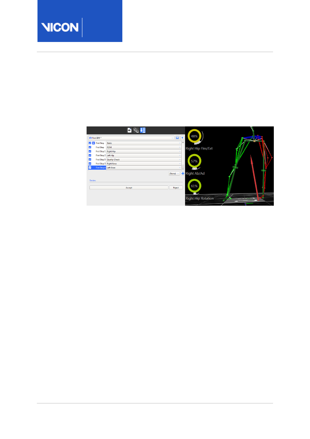
Nexus
Reference
Guide
Biomechanics workflow
Vicon Motion Systems Ltd. 13-Nov-2018 Page 103 of356
Overview of the biomechanics workflow
The Biomechanics Workflow area is a powerful tool for simplifying and
speeding up multi-step procedures, such as those involving SCoRE and
SARA, the processing algorithms that can be used for hip and knee joint
estimation.
The biomechanics workflow enables you to:
• Create a series of collection and processing steps for any set workflow.
• Specify capture settings for any step (a trial type, for example static,
ROM, etc).
• Specify post-capture processing steps (post capture pipelines, for
example, Reconstruct and Label).
• Associate real-time monitors (for example, joint range monitors) with a
step.
• Accept or reject the results of each step with a single mouse click.
When you have set up all the steps in your biomechanics workflow, you can
save it for future re-use. You can then apply the whole workflow or selected
steps to your future work with ViconNexus, from capture right through to
data export.
To use a biomechanics workflow that includes functional calibration, which
is the recommended way of working, it is a good idea to begin by setting up
joint range monitors to provide real-time subject calibration feedback. This
is necessary, because, for functional calibration to work, you need to be
sure that the ROM trial has included enough of the required movement to
result in a successful subject calibration.
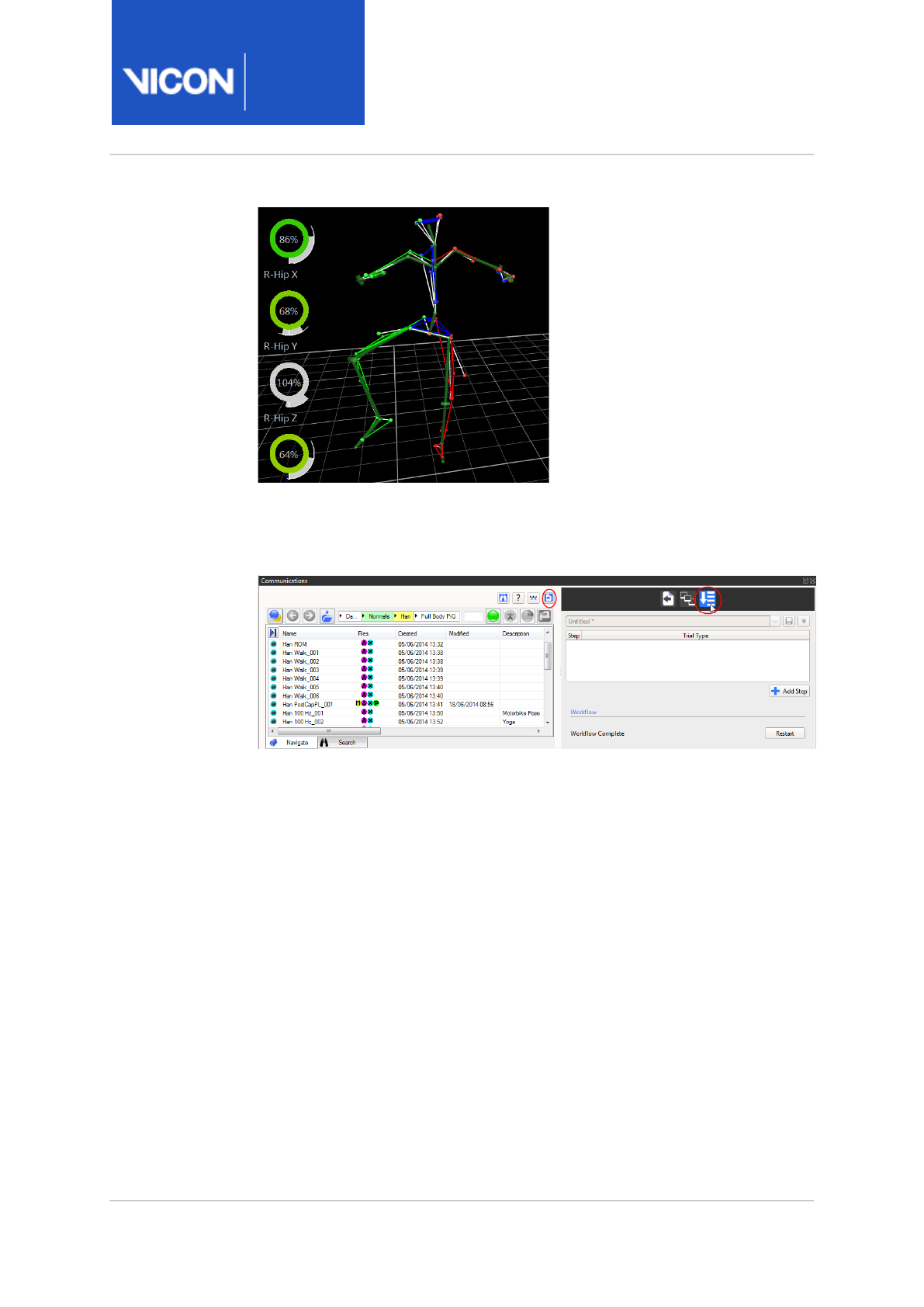
Nexus
Reference
Guide
Biomechanics workflow
Vicon Motion Systems Ltd. 13-Nov-2018 Page 104 of356
You can then include joint range monitors and define the steps required in
your workflow, using the Biomechanics Workflow area on the Data
Management tab in the Communications pane.

Nexus
Reference
Guide
Biomechanics workflow
Vicon Motion Systems Ltd. 13-Nov-2018 Page 105 of356
View real-time subject calibration feedback with monitors
Before you set up a biomechanics workflow that includes functional
calibration, you can set up a joint range overlay monitor to provide instant
visual feedback on how much joint movement the subject has performed
during a ROM trial.
This is important because a minimum amount of angular movement (per
joint) is needed to obtain the best possible calibration. Setting up a monitor
enables you to decide immediately whether the ROM trial has captured
enough range of joint movement to provide an accurate calibration.
Important
Although collecting the recommended/desired range does not
guarantee
a good calibration, obtaining positive feedback from a
joint range monitor indicates that the ROM trial has the potential
to provide a good calibration.

Nexus
Reference
Guide
Biomechanics workflow
Vicon Motion Systems Ltd. 13-Nov-2018 Page 106 of356
Create a joint range overlay monitor
To create a joint range overlay monitor, you use a Range Overlay monitor,
which is available from the Actions menu in the Monitors area.
Because you will be monitoring joint movement, you need to first ensure a
Kinematic Fit operation has been run on the subject. You can then create
the monitor for a joint movement range.
To create a joint range overlay monitor:
1. Load a ROM trial.
2. Reconstruct and Label the ROM trial.
3. Run a Functional Skeleton Calibration pipeline operation.
4. Kinematic fit the subject using a Pipeline operation under the Core
Processing category. Choose one of:
•Kinematic Fit (if the subject is already labeled); or
•Combined Processing with the Output level set to Kinematic Fit.
The following image shows a subject after kinematic fitting.
The subject now shows the internal labeling skeleton, displaying joints,
as well as the labeled markers and segments.
5. In the Communications pane, click on the Monitors tab to give it focus
and ensure a Graph pane is displayed.
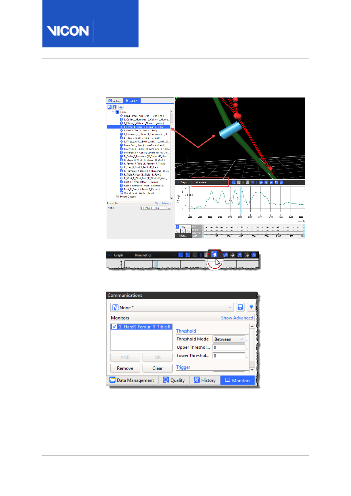
Nexus
Reference
Guide
Biomechanics workflow
Vicon Motion Systems Ltd. 13-Nov-2018 Page 107 of356
6. In either the 3D Perspective view or in the Subjects Resources tree, click
on a joint whose range you want to monitor.
7. In the Graph pane, click the Create a Monitor button.
The new monitor is added to the Monitors list on the Monitors tab in the
Communications pane.
8. On the Monitors tab:
a. Click on the new monitor to select it, and in the Threshold area, set
the desired Range of Motion for the selected joint by specifying the
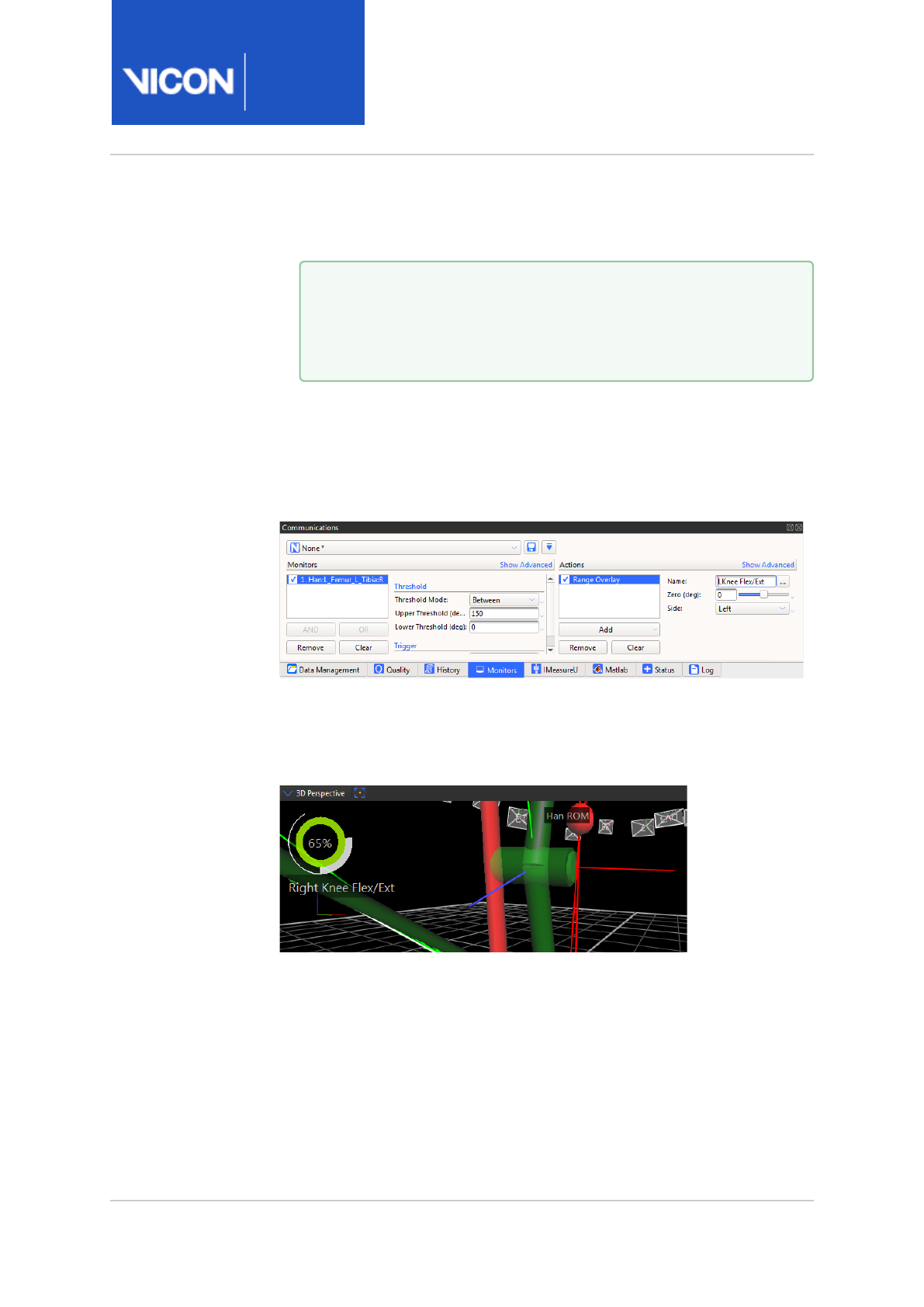
Nexus
Reference
Guide
Biomechanics workflow
Vicon Motion Systems Ltd. 13-Nov-2018 Page 108 of356
Threshold Mode, and the upper and/or lower limits of the range to be
monitored.
b. In the Actions area, click Add and select Range Overlay from the list
of monitor types
c. Ensure the new action is selected (blue) and in the Name field,
provide a descriptive name for your new monitor.
The named monitor appears as an overlay in the Graph view.
9. Play through the trial to see the monitor working.
As the trial progresses, the monitor reflects the collected range of
motion for the selected joint.
The nearer to 100% that is displayed by the monitor, the more of the
required movement has been captured.
10. Save the configuration under a suitable name.
You can use your new monitor for both Live and Offline trials and
include it in a biomechanics workflow.
Note that you can use a monitor that was based on a particular subject,
such as monitors for labeled trajectories, model outputs, joints, or
Tip
To select the required range, look at the values in the Graph
view and choose the highest and lowest values shown over
the whole trial.

Nexus
Reference
Guide
Biomechanics workflow
Vicon Motion Systems Ltd. 13-Nov-2018 Page 109 of356
segments, for other subjects that contain the same marker/segment/joint
name. However, note the following restrictions:
• If multiple subjects are present, the monitor will only work with the
original subject.
• The new subject must have the same marker/segment/joint name as was
used to configure the monitor.
• The new subject must be the only active subject (that is, selected in the
System tree) that contains that marker/segment/joint name.

Nexus
Reference
Guide
Biomechanics workflow
Vicon Motion Systems Ltd. 13-Nov-2018 Page 110 of356
About functional calibration in the biomechanics workflow
For calibration, the subject variables of interest: Kinematics (Joint Angles)
and Kinetic (Forces, Moments and Powers), must be calculated from a joint
center point and have a joint axis line to be accurate.
Nexus 2 provides functional joint calibration, which estimates the center
and axis of a joint using joint movement collected in a Range of Motion
(ROM) trial.
Because functional calibration requires you to be able to decide whether,
for a particular ROM trial, you have collected the minimum amount of
angular movement (per joint) needed to obtain a good calibration, it is a
good idea to set up a joint range monitor to give you the instant visual
feedback that enables you to make this decision quickly (for information on
setting up a joint range monitor, see View real-time subject calibration
feedback with monitors, page 105).
The biomechanics workflow enables you to include functional calibration
and joint range monitors in your workflow steps, so that you can set up the
required procedures once and then reuse them as required. For information
on setting up a biomechanics workflow, see Create a biomechanics
workflow, page 112.
For more information about the distinction between static and functional
joint calibration, see the following definitions:
•What is static joint calibration?, page 111
•What is functional joint calibration?, page 111
•What is local optimization?, page 111

Nexus
Reference
Guide
Biomechanics workflow
Vicon Motion Systems Ltd. 13-Nov-2018 Page 111 of356
What is static joint calibration?
Static calibration uses a single frame of data. The subject is captured in a
single pose (body position). Regression equations are used to estimate /
calibrate:
• The location of a Virtual Joint Center point (relative to a segment)
• A line defining the axis of rotation for the Joint
Vicon's Plug-In Gait model uses static joint calibration.
What is functional joint calibration?
Functional joint calibration uses multiple frames of data where the joint of
interest is moving (dynamic).
Using Range Of Motion (ROM) data from a joint enables functional joint
calibration to better estimate the true center and axis of a joint.
What is local optimization?
The process of eliminating errors and finding the best solution for joint
centers and axes is sometimes referred to as optimization.
Local optimization takes information from one joint at a time and tries to
find the best solution only for that joint.
SCoRE and SARA are local optimization techniques. They are a set of
algorithms produced by researchers at the University of Berlin – Julius
Wollf Institute for Biomechanics and Musculoskeletal Regeneration.
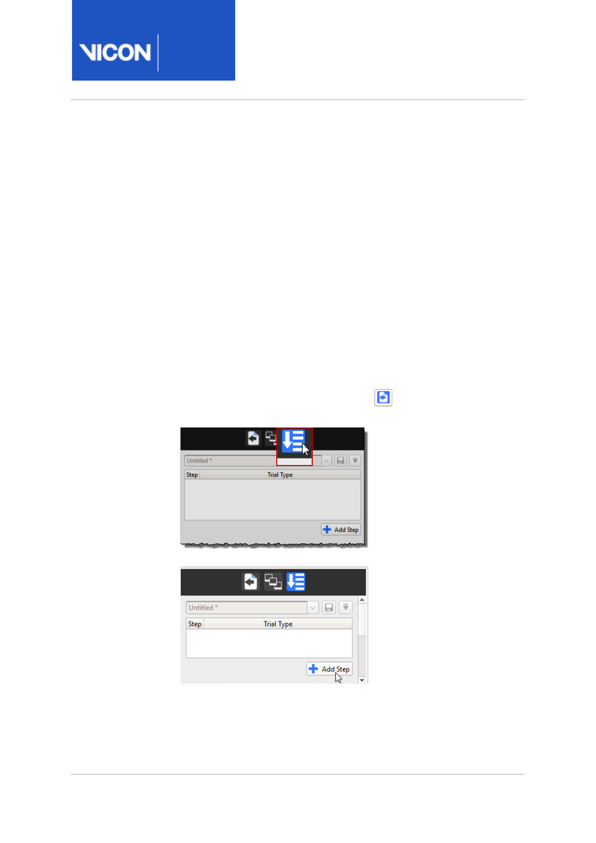
Nexus
Reference
Guide
Biomechanics workflow
Vicon Motion Systems Ltd. 13-Nov-2018 Page 112 of356
Create a biomechanics workflow
To create a biomechanics workflow, you use the Biomechanics Workflow
area of the Data Management tab in the Communications window to
associate specified data capture and processing steps with particular trial
types, and monitors.
Before you begin adding the steps that will comprise your new workflow,
make sure you have set up any required range monitors (see View real-time
subject calibration feedback with monitors, page 105).
The following example shows you how to set up a biomechanics workflow
that includes steps for a static capture, followed by a ROM capture coupled
with a joint range monitor.
To create a new workflow:
1. On the Data Management tab in the Communications pane, open the
File Transfer/Batch Processing interface.
2. Click the Biomechanics Workflow button.
3. Click the Add Step button to add your first step.

Nexus
Reference
Guide
Biomechanics workflow
Vicon Motion Systems Ltd. 13-Nov-2018 Page 113 of356
4. Double-click on the new step and add a name for it, in this case, Static
Calibration.
5. From the list of trial types to the right of the step name, select the
required trial type for the step.
If the trial type doesn't exist yet, switch to Live mode and on the Capture
tools pane, specify the required settings for the trial type, for example,
for a static trial:
•Name: Static
•Duration of the capture: 2 secs
•Run pipeline after capture: Reconstruct and Label
Tip
For each step, this name will be the name of the trial that is
saved as a result of running the step.

Nexus
Reference
Guide
Biomechanics workflow
Vicon Motion Systems Ltd. 13-Nov-2018 Page 114 of356
6. Save the new trial type and in the Trial Type list, select the new trial
type (in this case Static).
Now, every time you go to Live mode and run the new workflow, the first
step will automatically capture a 2-second, static trial, and run the
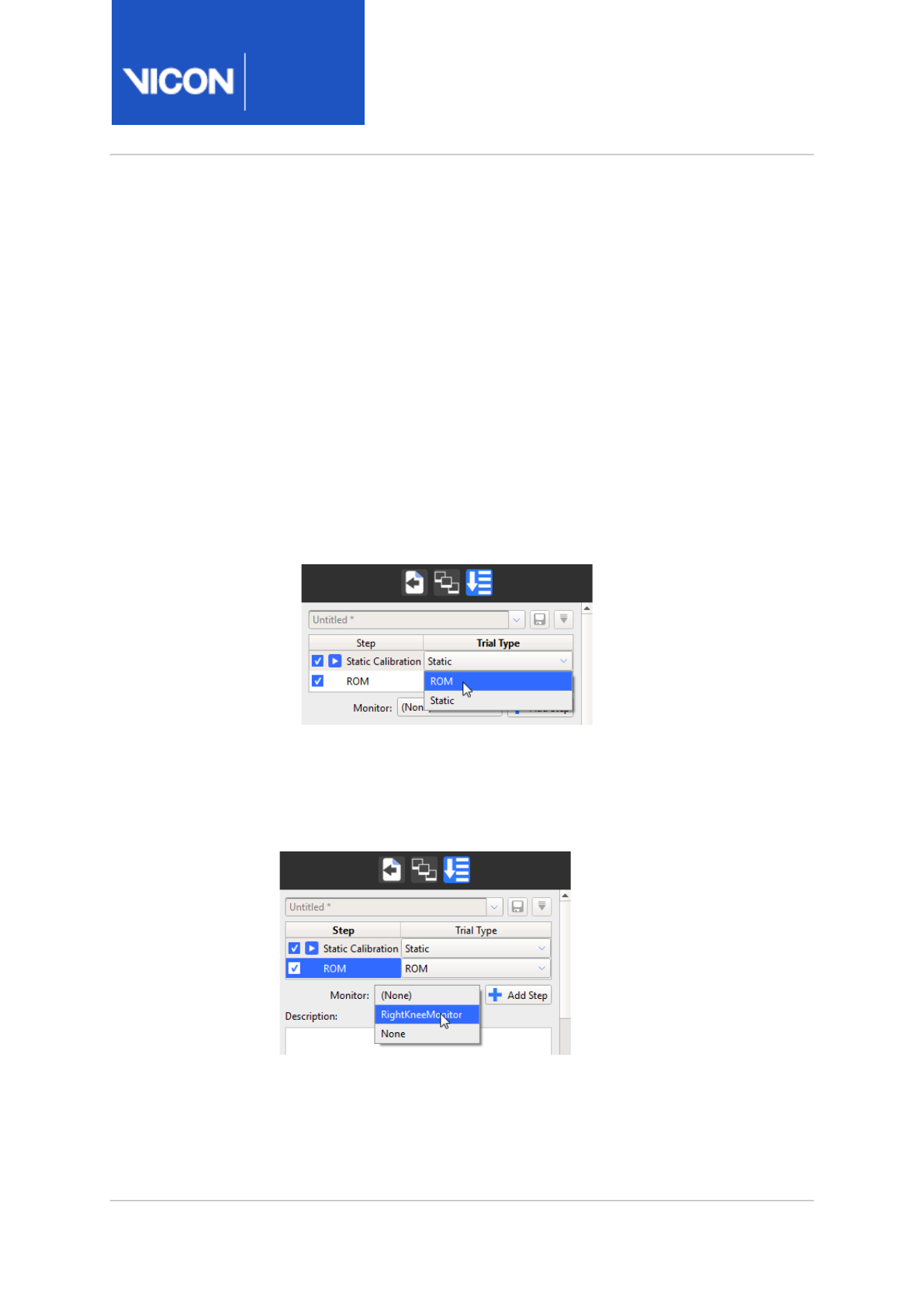
Nexus
Reference
Guide
Biomechanics workflow
Vicon Motion Systems Ltd. 13-Nov-2018 Page 115 of356
Reconstruct and Label pipeline afterwards. It will then automatically go
to Offline mode and display buttons to enable you to accept or reject
the result of the first step (the reconstructed and labeled trial).
7. To set up step 2, in the Biomechanics Workflow area:
a. Click Add Step again.
b. In the Step column, type a name for the second step, in this case
ROM.
c. In the Trial Type list, select the required trial type, for example, ROM.
If the ROM trial type doesn't exist yet, you will need to create it, using
the same procedure as you used for creating a static trial type in the
previous step. For a ROM trial, you may want to specify a different
duration, or clear the Auto Capture Setup options so that you can
start and stop the capture manually, when sufficient data has been
collected.
8. To add a range monitor to your ROM step so that you can quickly assess
whether to accept it, click the Monitor button, and from the list of
available monitors, select the required monitor, for example, the one you
created previously (see View real-time subject calibration feedback with
monitors, page 105).
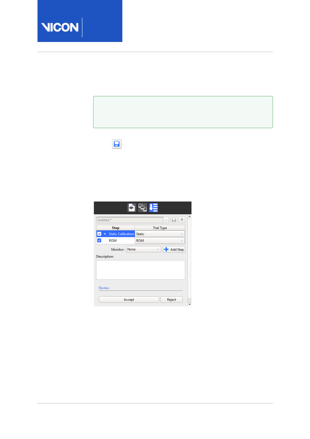
Nexus
Reference
Guide
Biomechanics workflow
Vicon Motion Systems Ltd. 13-Nov-2018 Page 116 of356
9. Continue adding steps, creating appropriate trial types as necessary, and
adding monitors to help you make the Accept or Reject decision for
each step, until you have completed your workflow.
10. To save the completed workflow, click the Save current configuration
button at the top of the Biomechanics Workflow area, and enter a
suitable name for your new workflow.
11. To run your new workflow, change to Live mode and in the Biomechanics
Workflow area, click Start.
When the step has run, Nexus automatically goes to Offline mode and
the Biomechanics Workflow area displays buttons to enable you to
accept or reject the result of the step.
If you click Accept, the next step, is run. If you click Reject, Nexus
returns to Live mode, so that you can perform another capture.
Tip
To reorder the steps, click on a step and drag it to the required
position in the list.
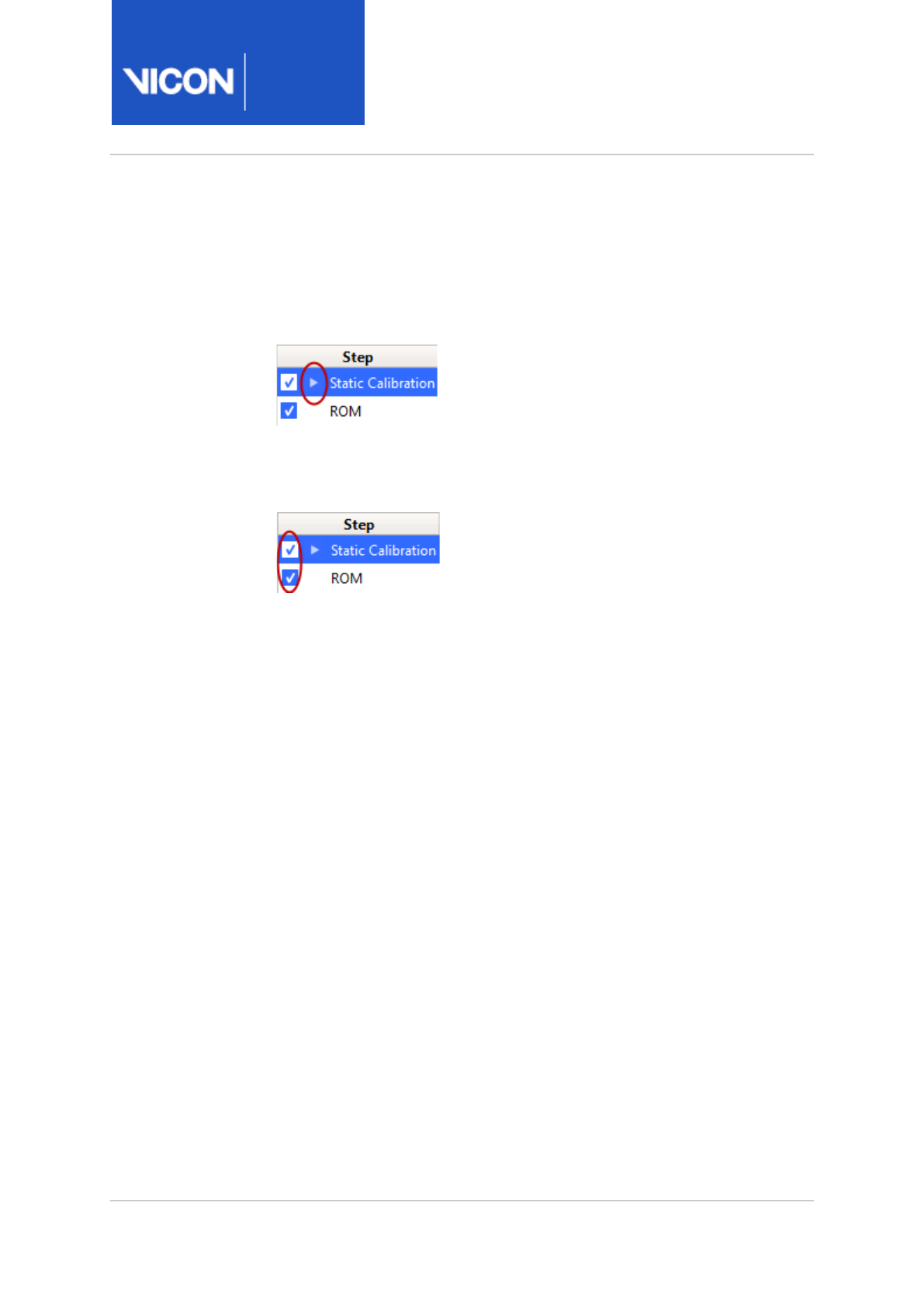
Nexus
Reference
Guide
Biomechanics workflow
Vicon Motion Systems Ltd. 13-Nov-2018 Page 117 of356
Tips for creating biomechanics workflow steps
• When you run through the biomechanics workflow, the Play icon is
displayed next to the current step, so that you can instantly see where
you are in the workflow.
• In a similar way to running pipeline operations in the Pipeline tools pane,
you can select or clear the check boxes next to each step to run only the
required steps.
• If necessary, you can reorder the steps by dragging steps up or down in
the Biomechanics Workflow area.

Nexus
Reference
Guide
Biomechanics workflow
Vicon Motion Systems Ltd. 13-Nov-2018 Page 118 of356
20 mailto:support@vicon.com
About SCoRE and SARA in ViconNexus
The SCoRe and SARA operations are provided with ViconNexus 2 for
research purposes and to enable clinical researchers to assess their use,
compared with other methods. You can download the literature for these
methods from the Vicon website or obtain it from the group at the
University of Berlin. Before using these methods, you are strongly advised
to review the published material to understand the methods and best
practices for gaining meaningful results.
A review of this literature suggests that for the joints of the lower limbs,
SCoRE can produce a meaningful estimation of hip joint center locations.
The axes produced by the SARA optimization may not be useful. This is due
to ball and socket nature of the joint.
The opposite is suggested for the hinge-link knee joint. The SARA-
optimized axis (primary flex/ext axis) may be useful; however the joint
center location may not be strictly defined along this axis.
To allow further development and validation of these methods, Nexus does
not restrict where they can be run. The operations allow the calculation of
SCoRE and SARA for any combination of parent and child segments.
By combining SCoRE and SARA with an existing Plug-in Gait model, you can
obtain full kinematic and kinetic outputs with reduced errors.
Important
You are responsible for reviewing the published articles before
using these operations. Research is continuing the area of
functional joint calibration and it is solely your responsibility as the
user to determine whether the results from these methods are
appropriate for your research outcomes or clinical use.
Note
To apply SCoRE and SARA to Plug-in Gait, you need to obtain the
Plug-in Gait MATLAB script. For more information, contact Vicon
Support20.

Nexus
Reference
Guide
Biomechanics workflow
Vicon Motion Systems Ltd. 13-Nov-2018 Page 119 of356
About SCoRE
SCoRE is an acronym for Symmetrical Center of Rotation Estimation.
It is an optimization algorithm that uses functional calibration frames
between a parent and child segment to estimate the center point of
rotation. It is particularly valuable in providing repeatable and -accurate hip
joint center locations.
SCoRE locates the joint center only. Kinematics and kinetics must still be
calculated by a full biomechanical model (such as Plug-in Gait).
About SARA
SARA is an acronym for Symmetrical Axis of Rotation Analysis.
It is an optimization algorithm that uses functional calibration frames
between a parent and child segment to estimate the axis of rotation. It is
particularly valuable in providing repeatable and accurate knee joint axes.
SARA locates the joint axis only. Kinematics and kinetics must still be
calculated by a full biomechanical model (such as Plug-in Gait).
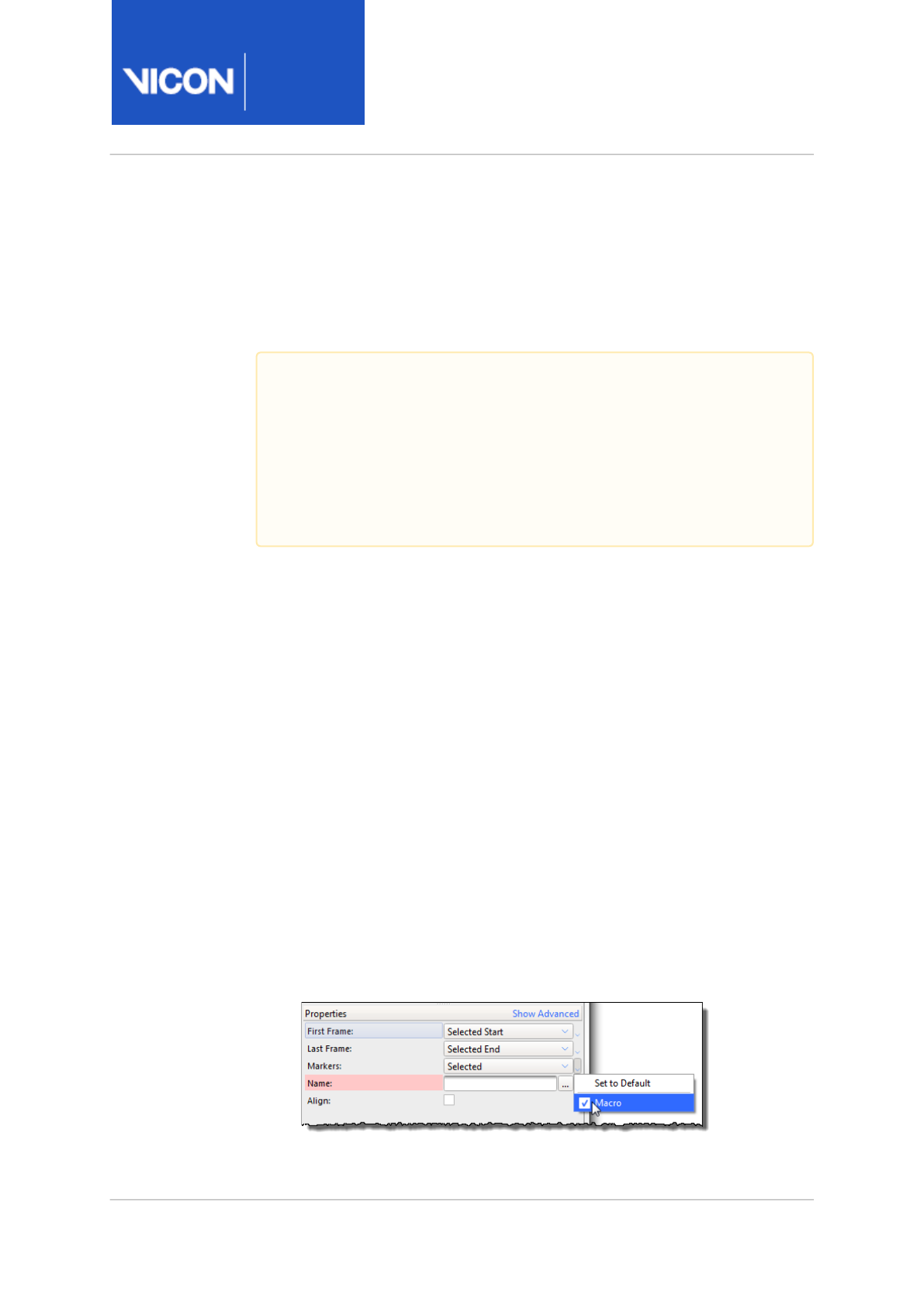
Nexus
Reference
Guide
Biomechanics workflow
Vicon Motion Systems Ltd. 13-Nov-2018 Page 120 of356
Prepare data for use with SCoRE and SARA
OCST is a mathematical approach that finds the average or common shape
for selected sets of marker (3 or more). It enables a non rigid cluster (skin-
based) to be described as if it were truly rigid.
For related research, see OCST, SCoRE and SARA research references, page
130.
To create a segment using OSCT:
1. Load the trial containing the markers whose positions are to be
calculated using OCST. These markers will form the segments that will
be used in SCoRE and SARA pipeline operations.
2. In the Pipeline tools pane, from the Subject Calibration pipeline
operations, double-click the Calibrate OCST operation to add it to the
current pipeline.
3. Click on Calibrate OCST and in the Properties pane ensure the required
start and end frames, together with the required markers (at least three)
are specified. To select the required markers, in the 3D Perspective view,
CTRL+click or ALT+drag the markers (at least three per segment).
If you have Markers set to Selected in the Properties pane, to check that
you have selected the required markers:
a. In the Properties pane for Calibrate OCST, click the small arrow to the
right of the Markers field and clear the Macro check box.
Important
Although marker clusters that are attached to a truly rigid base do
not necessarily require OSCT processing to provide rigidity, if you
want to include the supplied SCoRE and SARA pipeline operations
as part of your workflow, use of the Calibrate OCST and Process
OCST operations is recommended to provide the best possible
results.
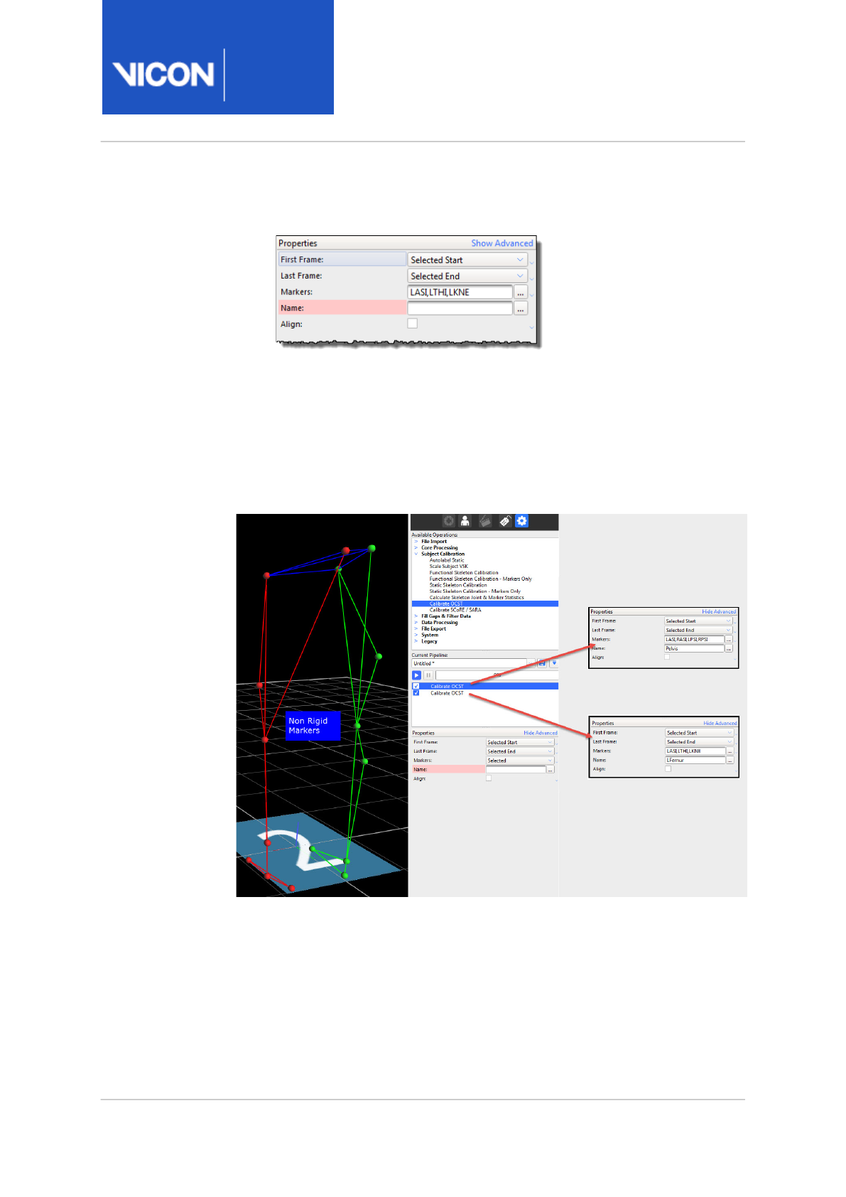
Nexus
Reference
Guide
Biomechanics workflow
Vicon Motion Systems Ltd. 13-Nov-2018 Page 121 of356
You can now see the selected marker names in the Markers field.
b. When you have made sure you have selected the required markers, re-
select Macro again.
4. In the Name field, enter a name for the segment to be created by OCST.
5. To create the new segment, run the pipeline.
In the following example, OCST segments called Pelvis and LFemur are
created.
The new OCST segment names (Pelvis and LFemur in the above example)
can now be passed into SCoRE and SARA pipeline operations.

Nexus
Reference
Guide
Biomechanics workflow
Vicon Motion Systems Ltd. 13-Nov-2018 Page 122 of356
21 mailto:support@vicon.com
Capture and process a trial with SCoRE and SARA
You can use the biomechanics workflow to simplify and speed up the
capturing and processing of data that requires a number of repeated steps,
and can include trial types, range monitors and post-processing pipelines.
This makes it a particularly useful tool if you want to use the new SCoRE
and SARA pipeline operations that are included in ViconNexus 2, as you
can save any required ROM trial types, including joint range monitors, OCST
pipeline operations, and any other processing needed, in a single workflow.
Advice was sought from research labs in the biomechanics community who
use the SCoRE and SARA methodologies in their clinical assessments. The
recommended ViconNexus 2 workflow for using these functional joint
calibrations is derived from this advice.
To apply SCoRE and SARA to Plug-in Gait, you need to obtain the Plug-in
Gait MATLAB script. For more information, contact Vicon Support21.
For more information, see:
•Collecting data for use with SCoRE and SARA, page 122
•Capturing hip and knee ROMs, page 123
•Using SCoRE and SARA, page 123
Collecting data for use with SCoRE and SARA
You can capture trials in the following ways:
• One joint per trial, that is separate trials for each hip and knee (Left Hip,
Right Hip, Left Knee, Right Knee); or
• A single ROM trial that includes joint movement for all four joints
Collecting a single ROM trial can save time in both capture and processing.
However, some pathological subjects may require assistance in completing
a joint ROM, so this is not always an option and multiple ROMs may be
needed. The biomechanics workflow provides a way of performing the
ROMs in one or multiple trials and saving the workflow so that it can be
easily repeated and results obtained with the minimum of effort.
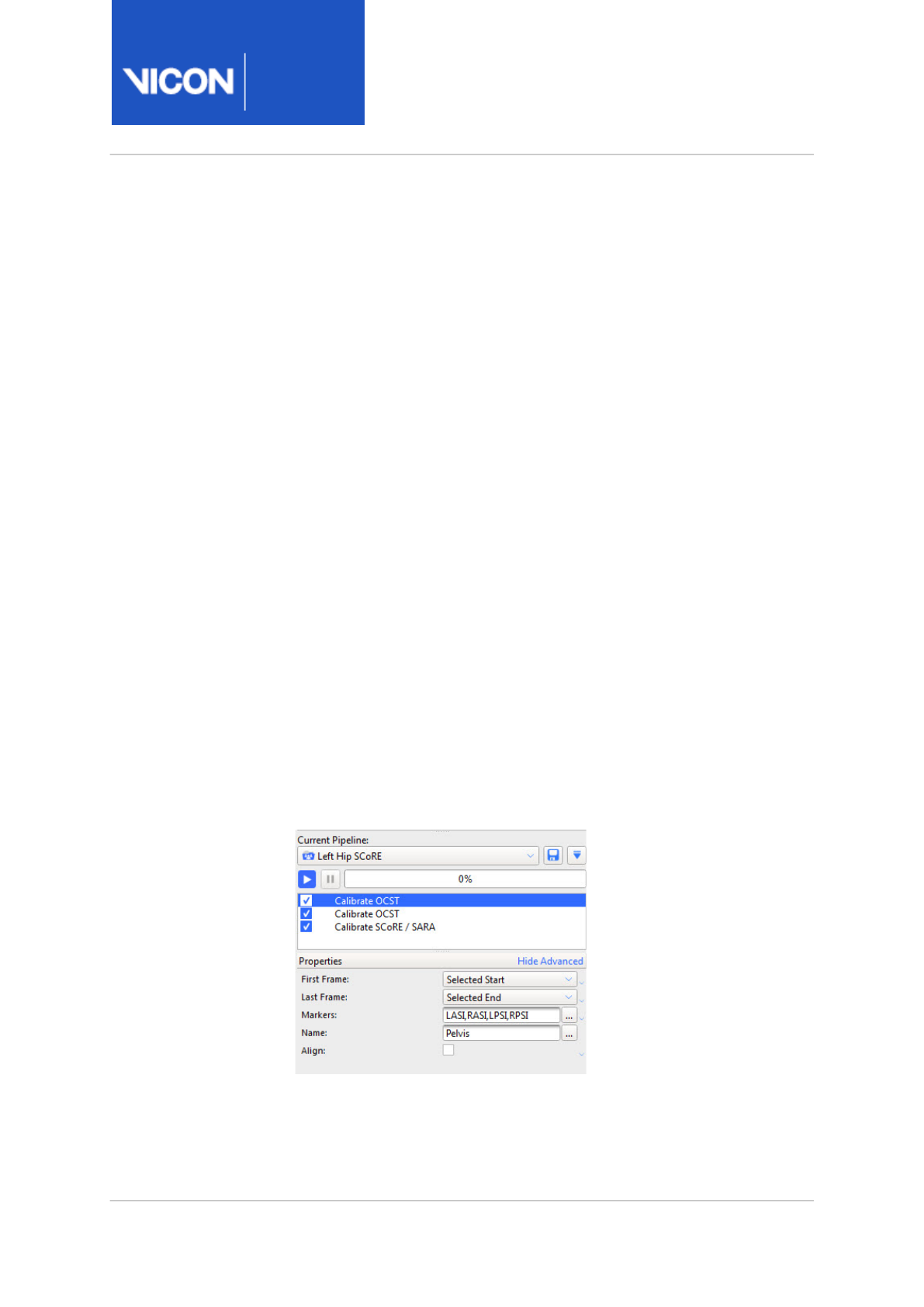
Nexus
Reference
Guide
Biomechanics workflow
Vicon Motion Systems Ltd. 13-Nov-2018 Page 123 of356
Capturing hip and knee ROMs
The goal with either hip or knee joints is to move the joint through as much
of its entire range as possible.
•Knees are basically hinge joints with flexion and extension. Flexing and
extending the knee through its full range is all that is required to capture
the required motion.
•Hips are ball joints. When capturing a ROM for hip joints, the
recommended approach is to have the subject (on their own or with
assistance) perform a 'star arc'. This involves swinging the leg directly
forward, then back to the static position, then to the side at a forty-five
degree angle to the first swing, and back, and so on, round in a circle.
Using SCoRE and SARA
Before you run a Calibrate SCoRE/SARA pipeline operation, specify and run
a Calibrate OCST pipeline operation on the relevant data, as described in
the following steps.
To use SCoRE and SARA:
1. Create a pipeline that includes all the necessary operations:
• A Calibrate OCST operation that specifies the parent segment (for
example, Pelvis), by selecting at least three markers (for example,
LASI, RASI, LPSI, RPSI). For information on how to do this, see (see
Prepare data for use with SCoRE and SARA, page 120).
• A Calibrate OCST operation that specifies the child segment (for
example, LFemur), by selecting at least three markers (for example,

Nexus
Reference
Guide
Biomechanics workflow
Vicon Motion Systems Ltd. 13-Nov-2018 Page 124 of356
LASI, LTHI, LKNE).
• A Calibrate SCoRE /SARA operation that creates a joint center
between the specified parent (Pelvis) and child (LFemur).
2. Run the pipeline.
In the 3D Perspective view, you can see an additional SCoRE (or SARA)
marker.
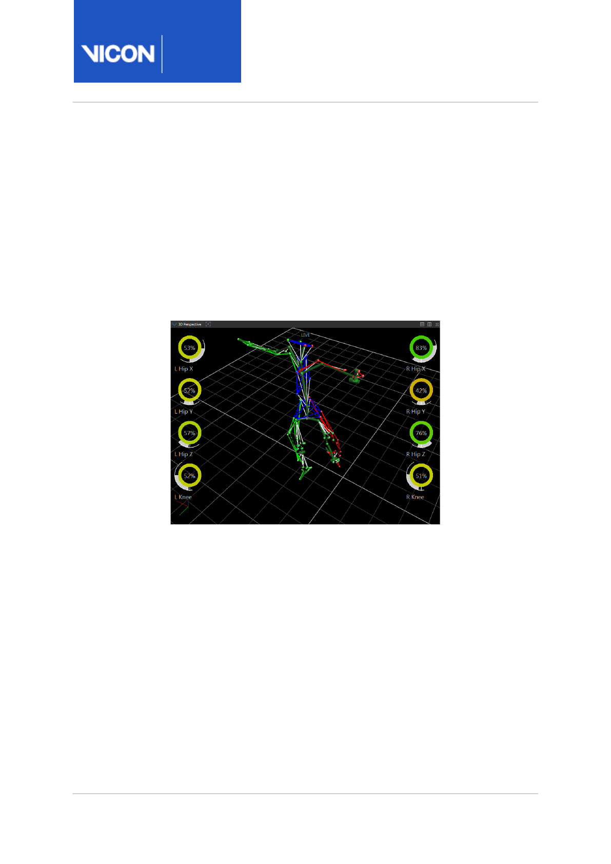
Nexus
Reference
Guide
Biomechanics workflow
Vicon Motion Systems Ltd. 13-Nov-2018 Page 125 of356
Process multiple joints with SCoRE and SARA
The following steps show how to calculate SCoRe joint centers and SARA
knee axes in the same workflow. Including both hips and knees in the same
workflow saves time, but relies on having a subject who can perform the
required ROMs reasonably easily and without much assistance.
Before you begin, make sure you have set up monitors to display all the
required range of motion for both hips and knees. (For information on
setting up joint range monitors, see View real-time subject calibration
feedback with monitors, page 105.)
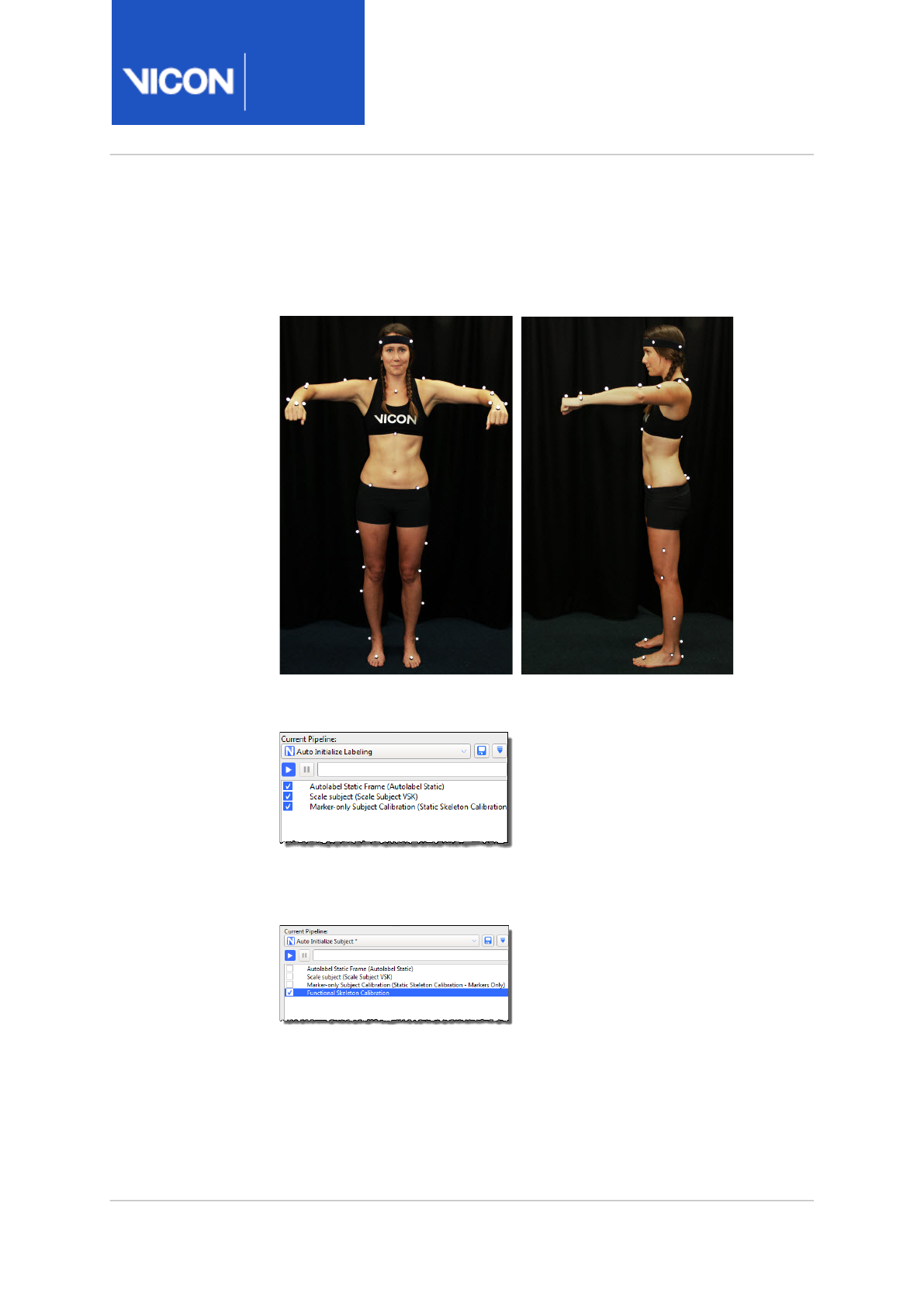
Nexus
Reference
Guide
Biomechanics workflow
Vicon Motion Systems Ltd. 13-Nov-2018 Page 126 of356
To calculate SCoRE joint centers and SARA knee axes:
1. Capture a subject ROM. Ensure that, for the first few frames and last
few frames, the subject is in the motorbike pose, as shown in the
following images.
2. Reconstruct the trial and then run the Auto Initialize Labeling pipeline
on the first frame of data (motorbike pose) to initialize the labeling.
3. Run the Functional Skeleton Calibration pipeline operation (found in the
Subject Calibration pipeline operations) to calibrate the labeling
skeleton.
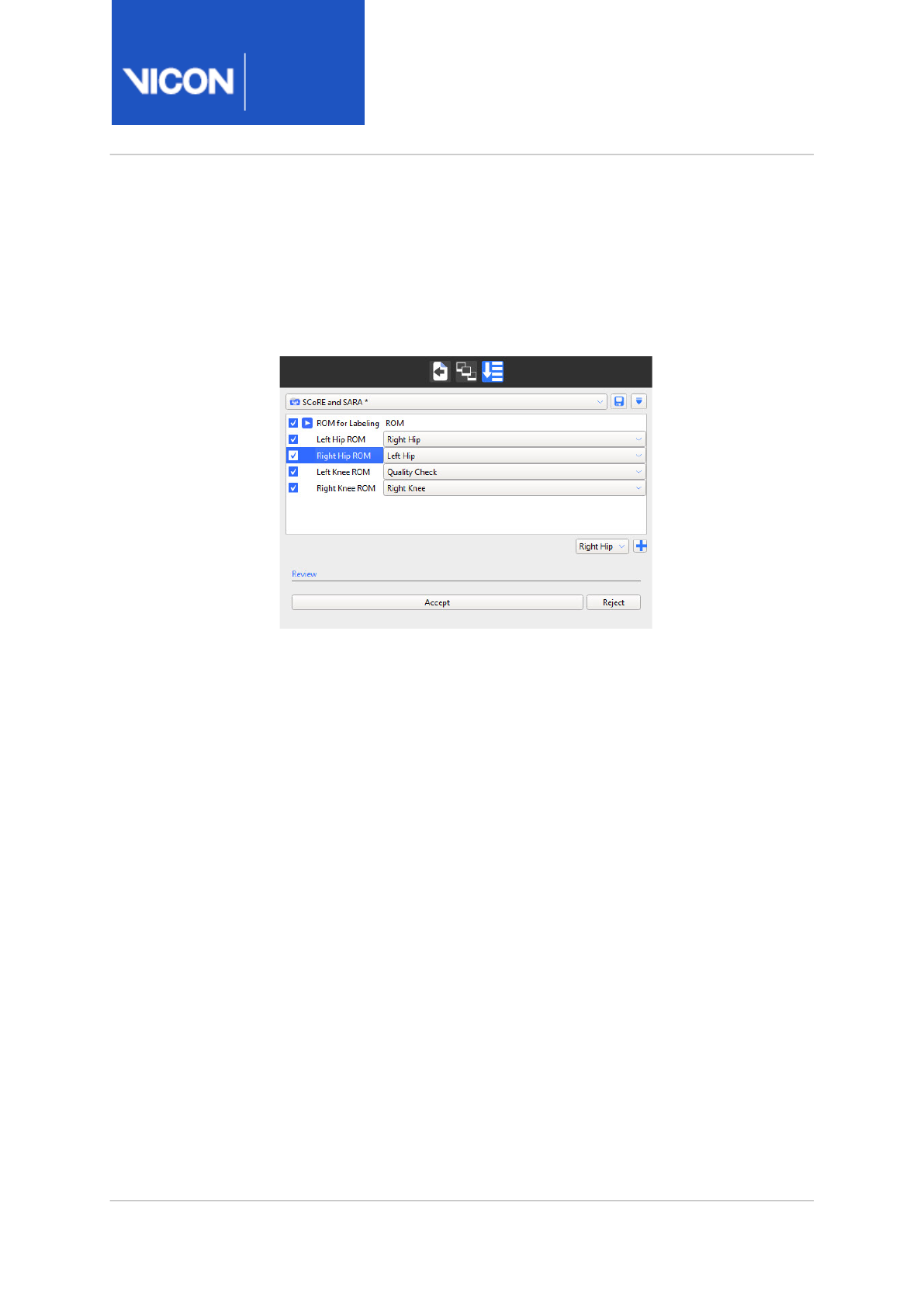
Nexus
Reference
Guide
Biomechanics workflow
Vicon Motion Systems Ltd. 13-Nov-2018 Page 127 of356
4. Capture ROM trials that move the hip joint and knee joints through a
ROM, as described in Capture and process a trial with SCoRE and SARA,
page 122.
To enable you to quickly assess the ROMs for multiple SCoRE and SARA
trials, you can set up a biomechanics workflow, including joint range
monitors, similar to the following:
For information on setting up a biomechanics workflow, see Create a
biomechanics workflow, page 112.
5. Run the Reconstruct and Label pipeline.
6. Create a new pipeline to contain the SCoRE/SARA calibrations you will
need, plus any required OCST calibrations. For example, you could call
the pipeline Calibrate SCoRE & SARA.
7. Add the required Calibrate OCST pipeline operations to the new pipeline
(see Prepare data for use with SCoRE and SARA, page 120).
8. Specify OCST segments for all the required joints, for example:
• Pelvis (LASI, RASI, LPSI, RPSI)
• LFemur (LASI, LTHI, LKNE)
• LTibia (LKNE, LTIB, LANK)
• RFemur (RASI, RTHI, RKNE)
• RTibia (RKNE, RTIB, RANK)
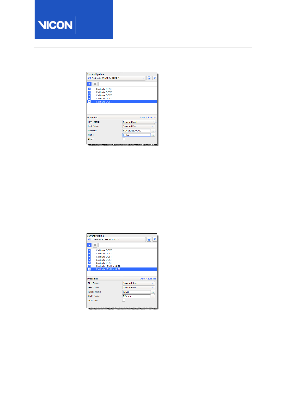
Nexus
Reference
Guide
Biomechanics workflow
Vicon Motion Systems Ltd. 13-Nov-2018 Page 128 of356
Your new pipeline will now look similar to this:
9. For each joint, add a Calibrate SCoRE/SARA operation (found in the
Subject Calibration pipeline operations), and specify each parent and
child segment, for example:
• For left hip:
Parent Name: Pelvis;
Child Name: LFemur
• For right hip:
Parent Name: Pelvis
Child Name: RFemur
For these two joints, leave the SARA Axis check box cleared, as it is
normally more applicable to the knee joints.
10. Add two more Calibrate SCoRE/SARA operations for the knee joints:
• For the left knee:
Parent Name: LFemur
Child Name: LTibia

Nexus
Reference
Guide
Biomechanics workflow
Vicon Motion Systems Ltd. 13-Nov-2018 Page 129 of356
• For the right knee:
Parent Name: RFemur
Child Name: RTibia
For these two joints, select the SARA Axis check box, as it is applicable
to the knee joints.
11. Save the pipeline and calibrate the joints by running the Calibrate OCST
and Calibrate SCoRE/SARA pipeline operations.
New hip and knee joint markers are displayed in the 3D Perspective
view.
12. Collect dynamic trials with the subject performing the required
movement (walking, etc).
13. Create a new Process SCoRE & SARA pipeline to contain the processing
operations.
14. For each SCoRE/SARA joint that you created previously, add a Process
SCoRE/SARA operation (found in Data Processing pipeline operations).
Specify the same Parent and Child segments as those you created in the
Calibrate SCoRE & SARA pipeline.
15. Run the processing pipeline.

Nexus
Reference
Guide
Biomechanics workflow
Vicon Motion Systems Ltd. 13-Nov-2018 Page 130 of356
22 http://www.gaitposture.com/article/S0966-6362(10)00129-3/abstract
23 http://www.jbiomech.com/article/S0021-9290(06)00415-5/abstract
24 http://www.jbiomech.com/article/S0021-9290(05)00446-X/abstract
OCST, SCoRE and SARA research references
1. Repeatability and reproducibility of OSSCA, a functional approach for
assessing the kinematics of the lower limb22. W.R. Taylor, E.I.
Kornaropoulos, G.N. Duda, S. Kratzenstein, R.M. Ehrig, A. Arampatzis,
M.O. Heller. publ. Gait & Posture 32 (2010) 231–236
2. A survey of formal methods for determining functional joint axes23.
Rainald M. Ehrig, William R. Taylor, Georg N. Duda, Markus O. Heller.
Journal of Biomechanics 40 (2007) 2150–2157
3. A survey of formal methods for determining the centre of rotation of ball
joints24. Rainald M. Ehrig, William R. Taylor, Georg N. Duda, Markus O.
Heller. Journal of Biomechanics 39 (2006) 2798–2809

Nexus
Reference
Guide
Improve manual labeling
Vicon Motion Systems Ltd. 13-Nov-2018 Page 131 of356
Improve manual labeling
In addition to the procedures described in Review trials and fill gaps in the
Vicon Nexus User Guide
, if your data contains overlapping trajectories and/
or ghost markers, you may need to do some further work.
For more information, see:
•Eliminate overlapping trajectories, page 132
•Prevent ghost markers, page 133

Nexus
Reference
Guide
Improve manual labeling
Vicon Motion Systems Ltd. 13-Nov-2018 Page 132 of356
Eliminate overlapping trajectories
Nexus recognizes a marker's trajectory continuously throughout a captured
trial. There can be gaps in the data, but Nexus can still recognize the same
marker trajectory on either side of a gap, as long as the gap is small enough
or the marker's movement doesn't vary significantly within the gap.
Occasionally, instead of a gap or a continuous marker trajectory, Nexus
creates two separate sub-trajectory sections that belong to the same
marker. This is called an overlapping trajectory, because the two sections
overlap; that is, they are both present in the same frame(s).
During the labeling process, because both trajectories are present in the
same frame(s), Nexus assumes that they must belong to separate markers.
Therefore, when Nexus auto-labels these trajectory sections, it labels one
and leaves the other unlabeled.
Overlapping trajectories can cause difficulties during manual labeling. One
common difficulty occurs when two markers are correctly labeled at the
start of the trial but then become confused or "swapped" later in the trial.
If you attempt to correct this label swap with Whole selected in the Manual
Labeling section of the Label/Edit Tools (the default setting), you may lose
correct labels early in the trial. The easiest way around this issue is by
clicking the Backward or Forward button before labeling, so that labeling is
only continued in the frames before or after the current frame.
When this labeling method is used, Nexus "snips" the trajectory at the
current frame and only labels in the direction chosen (forward in time or
backward in time from the current frame). The process of snipping a
trajectory causes a single continuous trajectory to be split into two
separate unique trajectories at the current time frame.

Nexus
Reference
Guide
Improve manual labeling
Vicon Motion Systems Ltd. 13-Nov-2018 Page 133 of356
Prevent ghost markers
The typical cause of overlapping trajectories is spurious, or ghost, markers
that are present during marker reconstruction. A ghost marker is a false
marker reconstruction that appears as an additional trajectory very close to
a legitimate marker trajectory. Ghost markers can be reconstructed if:
• The Nexus Core Processor settings are not optimized for the type of
capture you are performing. For example, if a Reconstruction Minimum
Separation is set too low, Nexus may reconstruct all detected marker
positions rather than selecting only the best candidates.
Depending on whether you want to adjust the Core Processor settings
for offlline data or live capture:
• If you do not want to recapture the trial you are processing, you can
adjust the Offline processing parameters and reprocess the existing
trial to see if Nexus can resolve the overlapping trajectory. You set
offline processing parameters in the Core Processing operations in the
Pipeline Tools pane.
• However, you may also need to evaluate whether future captures will
be similar enough to the current trial conditions (such as subject
movements, marker placement and movement, number of cameras,
etc.), that also adjusting the Live Core Processor settings will eliminate
this situation in the future. You set live processing parameters by
clicking on Local Vicon System in the System Resources pane and then
in the Properties pane going to the General section and selecting the
required Processing Output Level.
• One or more cameras need to be recalibrated. For example, if one or
more cameras has been accidentally knocked since it was calibrated. For
more information, see Understand camera calibration refinement, page
289.
• Camera masking is inadequate or has not been performed. For more
information on masking, see Mask unwanted reflections in the
Vicon
Nexus User Guide
.
After you have addressed the above issues, you will then need to reprocess
the trial before proceeding.

Nexus
Reference
Guide
Improve manual labeling
Vicon Motion Systems Ltd. 13-Nov-2018 Page 134 of356
If adjusting the reconstruction parameters and reprocessing do not
produce a properly labeled trajectory, you may need to manipulate the
trajectory sections manually.

Nexus
Reference
Guide
Eye tracking with Vicon Nexus
Vicon Motion Systems Ltd. 13-Nov-2018 Page 135 of356
Eye tracking with Vicon Nexus
The Dikablis Eye Tracking system, when combined with a Vicon motion
capture system, enables you to calculate the head position and 3D gaze
vector of a test subject. It is compatible with current Vicon cameras. A
minimum of two cameras are required for use with the system.
The Dikablis Eye Tracking unit is available in either wired or wireless
options. The wireless unit provides unlimited mobility and allows the test
subject to move within a perimeter of up to 800 meters.
For more information, see:
•Set up eye tracking hardware, page 136
•Add a Dikablis Eye Tracker device in ViconNexus, page 139
•Calibrate eye tracking in ViconNexus, page 140
•Export eye vector data, page 147
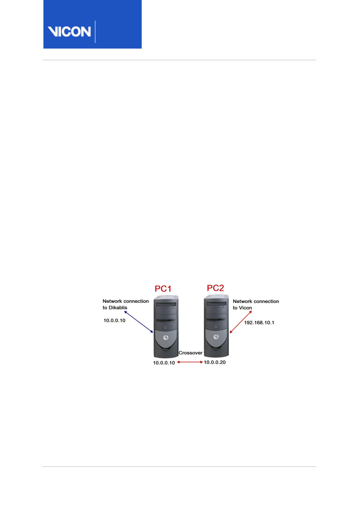
Nexus
Reference
Guide
Eye tracking with Vicon Nexus
Vicon Motion Systems Ltd. 13-Nov-2018 Page 136 of356
Set up eye tracking hardware
Before setting up your Dikablis Eye Tracking system with ViconNexus,
ensure the following system components are ready for use:
• Head unit
• Dikablis laptop
• Ethernet cable or crossover cable
• Battery pack and wireless transmitter (for wireless option), with battery
fully charged
• Dikablis wireless receiver (for wireless option)
Although you can capture both Vicon data and Dikablis gaze data on a
single PC, a dual-computer setup is recommended, where:
• The Dikablis laptop connects to the head unit and runs the Dikablis
software.
• The desktop computer is connected to the Vicon system and runs Nexus.
• The Dikablis laptop is directly connected to the Nexus PC via a cable
that runs between two Ethernet ports.

Nexus
Reference
Guide
Eye tracking with Vicon Nexus
Vicon Motion Systems Ltd. 13-Nov-2018 Page 137 of356
Note
Before proceeding, ensure the battery is fully charged. When fitting
the battery into its holder, make sure the battery is correctly
oriented by first inserting the end with the contact points and then
clicking the other end into place in the holder. For further
instructions on setting up the hardware, see the
Dikablis Eye
Tracker User Manual
.

Nexus
Reference
Guide
Eye tracking with Vicon Nexus
Vicon Motion Systems Ltd. 13-Nov-2018 Page 138 of356
Ensure the Dikablis Eye Tracking system is calibrated
Before you add a Dikablis Eye Tracker device to ViconNexus, set up the
Dikablis laptop and ensure that eye tracking is calibrated, so that the pupil
is tracked accurately by Dikablis Recorder.
To ensure the Dikablis Eye Tracking system is calibrated:
1. Turn on the Dikablis laptop.
2. Double-click the Dikablis Recorder icon on the desktop to start the
software.
3. Attach the head unit to the subject's head (for instructions, see the
Dikablis Eye Tracker User Manual
).
4. In Dikablis Recorder, ensure that a cross hair appears on subject's pupil
and that the pupil is accurately tracked (for instructions, see the
Dikablis Eye Tracker User Manual
).
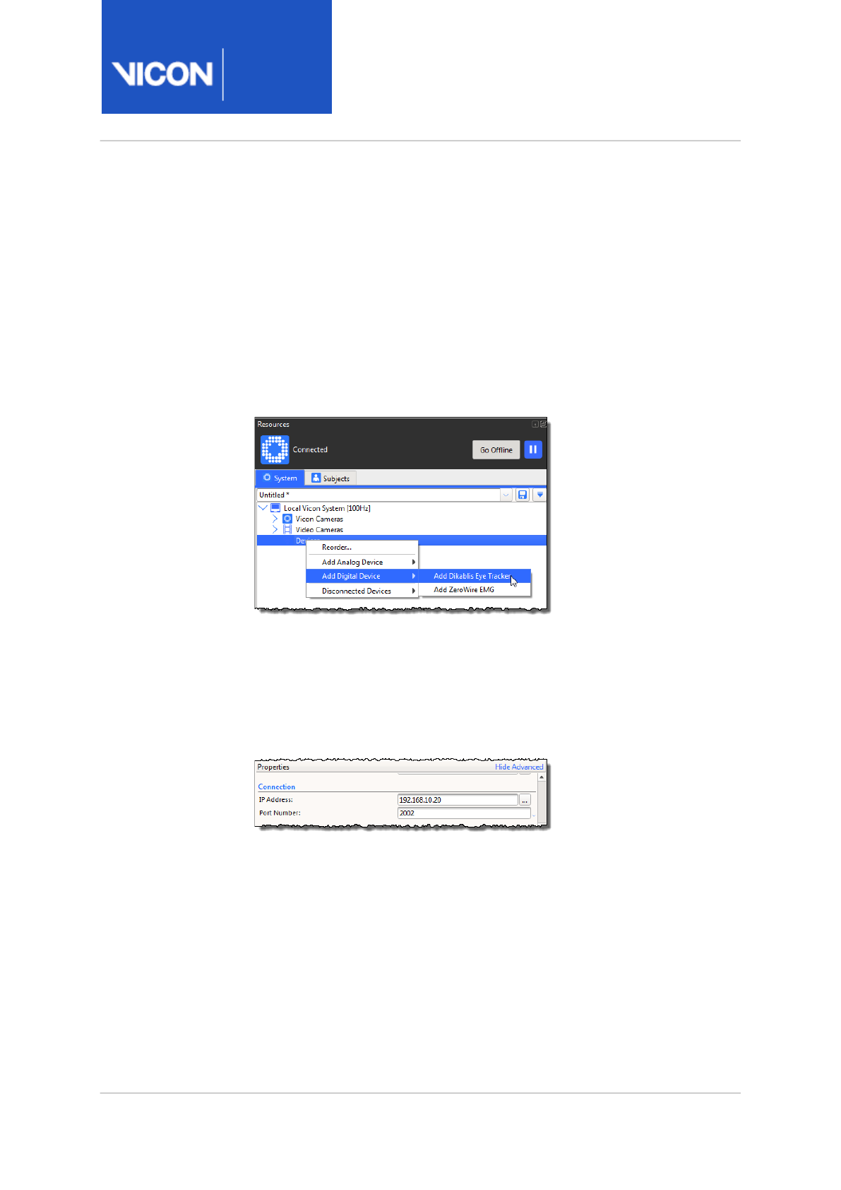
Nexus
Reference
Guide
Eye tracking with Vicon Nexus
Vicon Motion Systems Ltd. 13-Nov-2018 Page 139 of356
Add a Dikablis Eye Tracker device in ViconNexus
After you have verified that the Dikablis Eye Tracking system is calibrated,
add the Dikablis Eye Tracker in Nexus as a device.
To add eye tracking in Nexus:
1. In the System resources pane, click the Go Live button.
2. Right-click Devices, point to Add Digital Device, and select Add Dikablis
Eye Tracker. A Dikablis Eye Tracker node appears under Devices.
3. Click the Dikablis Eye Tracker node that you just added to select it and
in the Properties pane, set the following communication parameters in
the Connection section:
•IP Address: Use the same IP address that has been set in the Dikablis
eye tracking software.
•Port Number: Leave as default (2002).
4. If the connection and IP address are correct, the Dikablis Eye Tracker
icon in the System resources tree turns green. This indicates that Nexus
is able to communicate with and receive the data stream from the
Dikablis laptop.
5. With the head unit attached to the subject, display a Graph view in
Nexus and ensure that a line is displayed charting the pupil coordinates.
Data begins streaming from the Dikablis software when it is in Record
mode.

Nexus
Reference
Guide
Eye tracking with Vicon Nexus
Vicon Motion Systems Ltd. 13-Nov-2018 Page 140 of356
Calibrate eye tracking in ViconNexus
Before capturing an eye tracking trial, you must calibrate eye tracking
within Nexus. To do this, complete the following procedures in the order
shown:
•Set up a calibration trial for eye-tracking, page 140
•Create objects for eye tracking in ViconNexus, page 141
•Specify Dikablis Eye Tracker device properties, page 144
•Calibrate eye tracking in ViconNexus, page 145
Set up a calibration trial for eye-tracking
To set up a ViconNexus calibration trial for eye-tracking:
1. Before you begin a calibration trial for eye-tracking, ensure you have
calibrated your Vicon cameras, set the volume origin, and added the
Dikablis device to Nexus.
2. Get your subject to enter the volume wearing the head unit with
markers, and holding the calibration wand in front of them.
3. In the Capture tools pane, in the Next Trial Setup section, enter a Trial
Name (for example, Calibration), and in the Capture section, click Start
to capture a short trial (a couple of seconds).
4. Load the trial you just created (on the Data Management tab (F2),
double-click on the trial) and on the Nexus toolbar, click the Reconstruct
button .
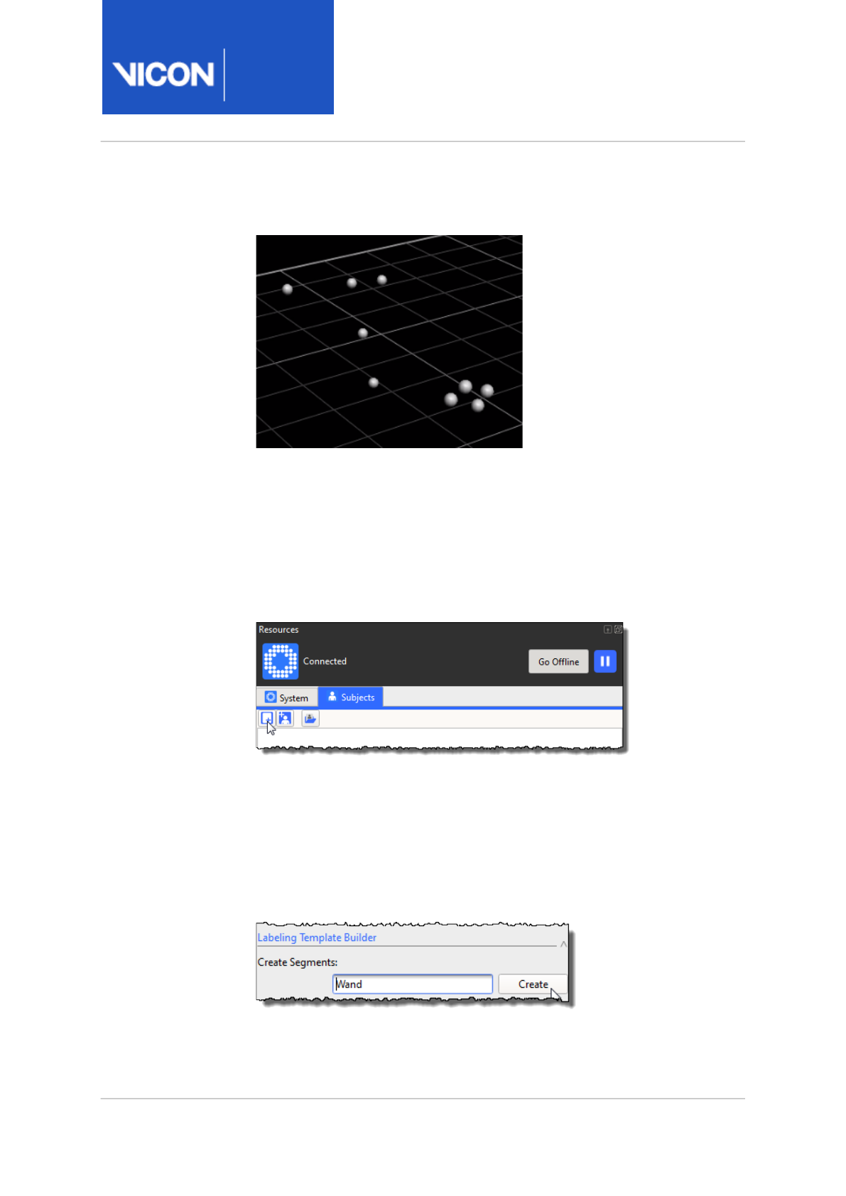
Nexus
Reference
Guide
Eye tracking with Vicon Nexus
Vicon Motion Systems Ltd. 13-Nov-2018 Page 141 of356
5. In a 3D Perspective view, zoom in so you can see the two objects
(subject and wand).
Create objects for eye tracking in ViconNexus
To set up a calibration trial for eye tracking, you need to create wand and
head objects.
To create the objects in Nexus:
1. On the Subjects resources pane, click the Create a blank subject button.
2. In the Enter Subject Name dialog box, enter the subject name: Wand.
3. On the Subjects tab, click the Wand object you just created to select it
and at the top of the Subject Preparation tools pane on the right of the
screen, in the Subject dropdown menu, ensure Wand is selected.
4. In the Subject Preparation tools pane, in the Labeling Template Builder
section, enter a segment name (Wand) in the Create Segments box and
click Create.

Nexus
Reference
Guide
Eye tracking with Vicon Nexus
Vicon Motion Systems Ltd. 13-Nov-2018 Page 142 of356
5. In a 3D Perspective view, select the wand markers, beginning with the
origin (middle) marker.
6. Ensure all the wand markers are selected.
7. In the Labeling Template Builder section, click Create again.
8. In the 3D Perspective view, check the axes and origin are shown for the
wand.
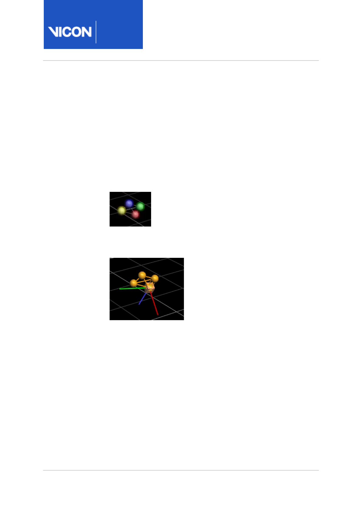
Nexus
Reference
Guide
Eye tracking with Vicon Nexus
Vicon Motion Systems Ltd. 13-Nov-2018 Page 143 of356
9. To create a head object, in the Subjects Resources pane, click the Create
a blank subject button and in the Enter Subject Name dialog box, enter
Head.
10. On the Subjects resources pane, click the Head object you just created
and at the top of the Subject Preparation tools pane, ensure Head is
selected.
11. In the Labeling Template Builder section, in the Create Segments box,
type Head and click Create.
12. In the 3D Perspective view, select the head markers, beginning with the
origin marker. For the head's origin marker, select the marker closest to
the eyeball, then select the others.
13. In the Labeling Template Builder section, click Create again.
14. In the 3D Perspective view, check the axes and origin are shown for the
new object.
15. Before proceeding, it is a good idea to save both subjects (Wand and
Head). To do this, on the Subjects Resources pane, right-click on the
node for each subject in turn and then click Save Subject.
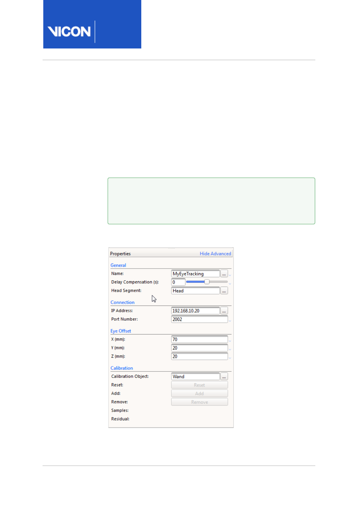
Nexus
Reference
Guide
Eye tracking with Vicon Nexus
Vicon Motion Systems Ltd. 13-Nov-2018 Page 144 of356
Specify Dikablis Eye Tracker device properties
After you have created both the Wand and the Head in Nexus, specify their
properties on the System Resources tab.
1. On the System resources tab, click on the Dikablis Eye Tracker node, and
in the General section of the Properties pane, in the Head Segment field,
enter Head.
2. In the Eye Offset section, enter the relevant values (that is, the distance
between the origin marker and the eye).
3. In the Calibration Object field in the Calibration section, enter the name
of the calibration object (Wand).
You have now set up the eye tracker properties.
Tip
To find the relevant eye offset values, if your Vicon system
includes video cameras, you can use overlay video. If not, you
can measure the distance from the origin marker.
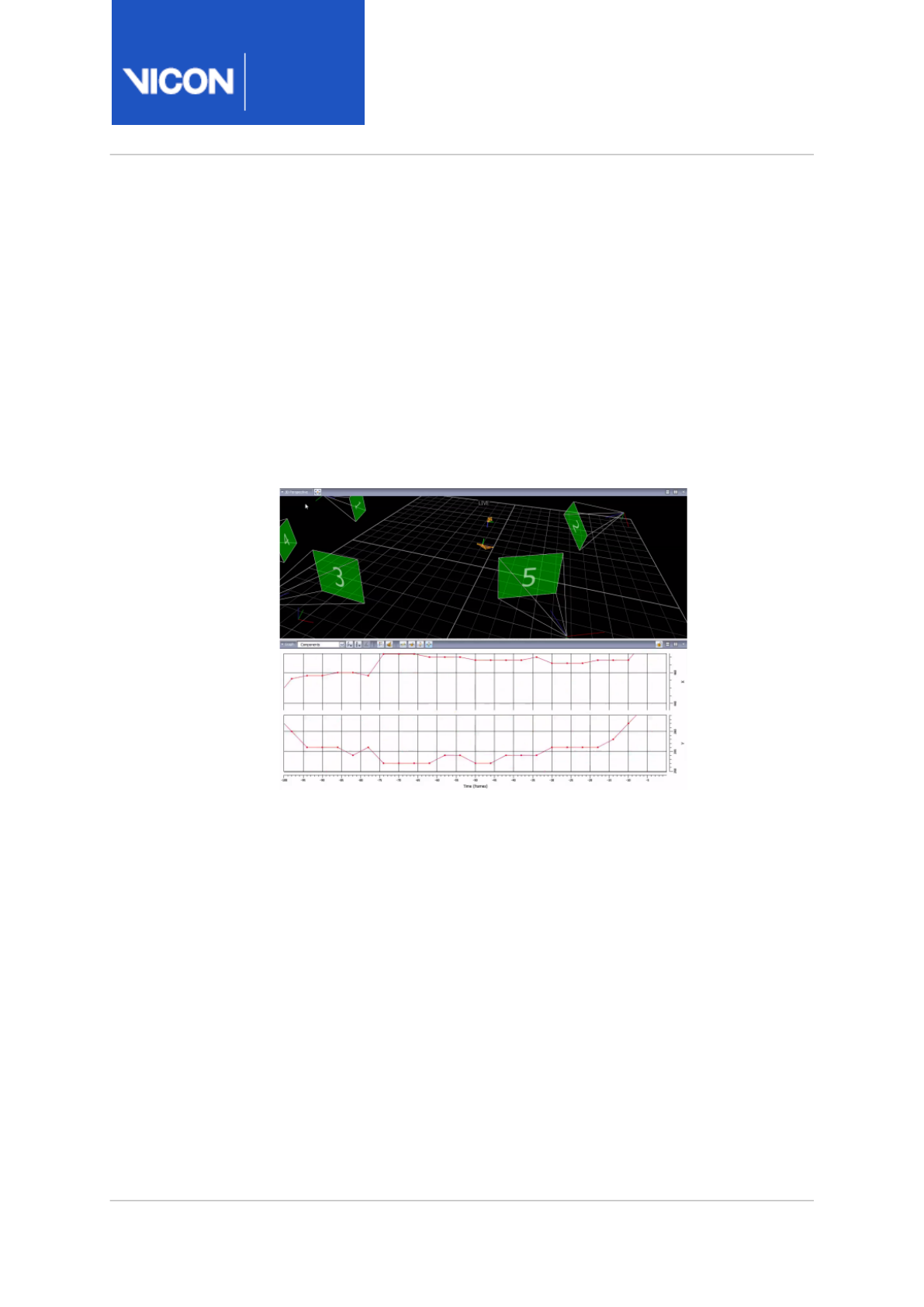
Nexus
Reference
Guide
Eye tracking with Vicon Nexus
Vicon Motion Systems Ltd. 13-Nov-2018 Page 145 of356
Calibrate eye tracking in ViconNexus
After you have added eye tracking to Nexus, created Head and Wand
objects, and set the eye tracking properties, you can complete the final
steps.
To calibrate the eye tracker in Nexus:
1. On the SystemResources pane, under the expanded Dikablis Eye Tracker
node, click the Eye node to select it.
2. Display a Data Correction view, to show both a 3D Perspective and
Graph view.
You should see the x and y values for the selected eye.
3. In the capture volume, place the wand 2–2.5 meters from the subject
and get the subject to look at the origin marker (the middle marker at
the top of the T).
4. On the SystemResources tab, click the Dikablis Eye Tracker node and in
the Properties pane, go to the Calibration section and click Add.
5. Move the wand to another part of the volume and click Add again.
In the Samples box, 2 is displayed.
6. Repeat the previous step.
After you have collected three samples, an eye vector and an eyeball are
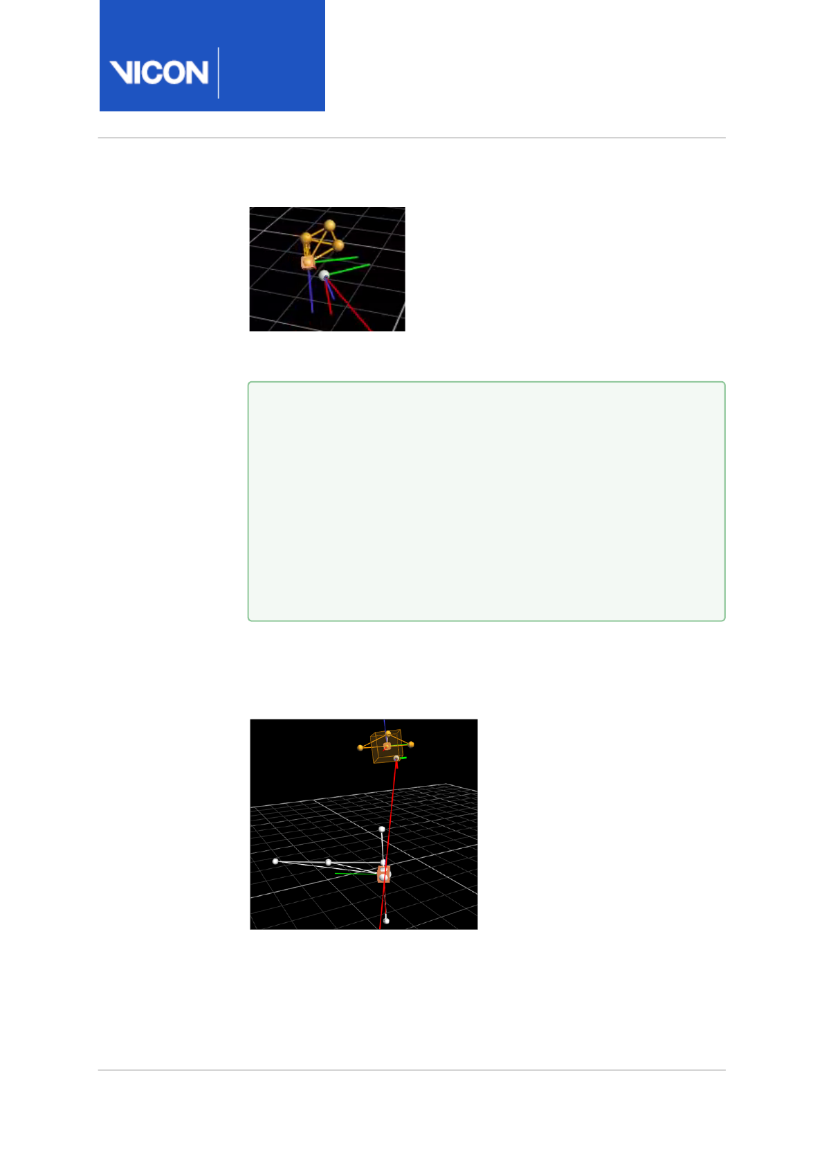
Nexus
Reference
Guide
Eye tracking with Vicon Nexus
Vicon Motion Systems Ltd. 13-Nov-2018 Page 146 of356
displayed in the 3D Perspective view.
7. Collect more samples (aim for at least five samples in total) to refine
your results.
8. When the eye tracker system has been calibrated (and if the subject is
looking at the origin marker), in 3D Perspective view, the eye gaze vector
will pass through (or point to) the origin marker of the calibration wand,
depending on how far the subject's head is from the wand.
9. View the results in a 3D Perspective view.
10. To check that the eye tracks the wand correctly, record a short trial.
Tip
When collecting samples, place the wand in the bottom left of
volume and have the subject look at the origin marker. Pause for
about a second and then in the Calibration section, and click
Add. Then place the wand in the top left of the volume, and have
the subject look at the origin marker. Again, pause, and click
Add. Repeat with the wand at the top right of the volume, and
then at the bottom right of the volume. Continue to move the
wand and click Add until the eye gaze vector accurately tracks
the origin marker.
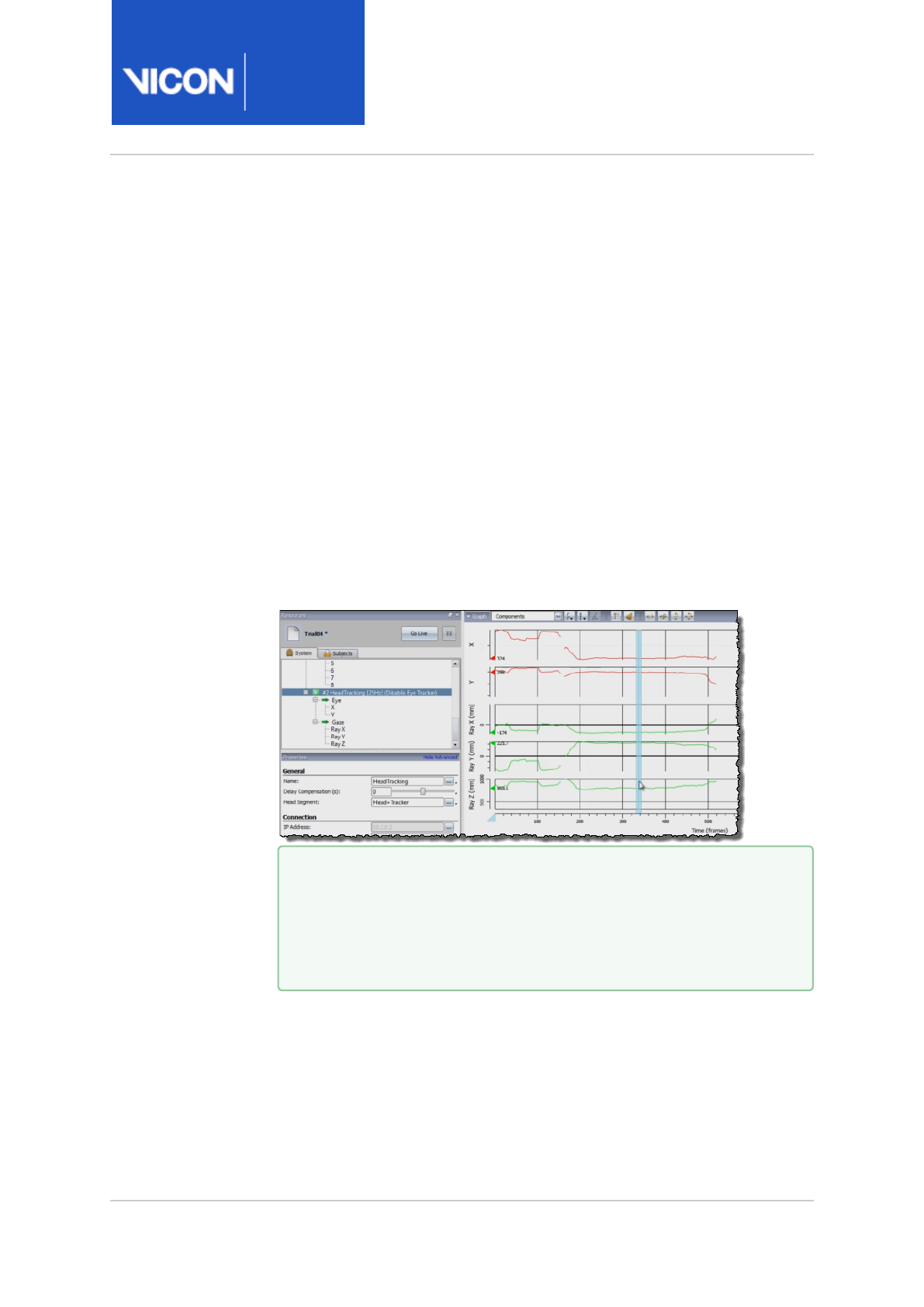
Nexus
Reference
Guide
Eye tracking with Vicon Nexus
Vicon Motion Systems Ltd. 13-Nov-2018 Page 147 of356
Export eye vector data
To use eye vector data, you will normally want to export both the eye vector
data itself and the Head and Tracker data (the segment data) that relates
the eye vector to its position within the global coordinate system. To export
all the information relating to the eye vector, you must reconstruct and
label the trial and kinematically fit the data before exporting it.
To export eye vector data and segment data:
1. Load into ViconNexus the trial from which you want to export eye
tracking data.
2. On the System tab of the Resources pane, click the Dikablis Eye Tracker
node to select it.
3. To check that the eye vector data is included, open a Graph view pane
and observe the eye vector x and y values.
4. Run Reconstruct and Label, either by clicking the Reconstruct and Label
button on the Nexus toolbar or by running the Reconstruct and Label
pipeline in the Pipeline Tools pane.
In the 3D Perspective view, as processing proceeds, you can see first the
addition of the object markers and then the labeling.
Tip
You can export the eye vector data at this point, but the
exported file will not include the segment data, which is
necessary to position the eye vector within the global
coordinate system.
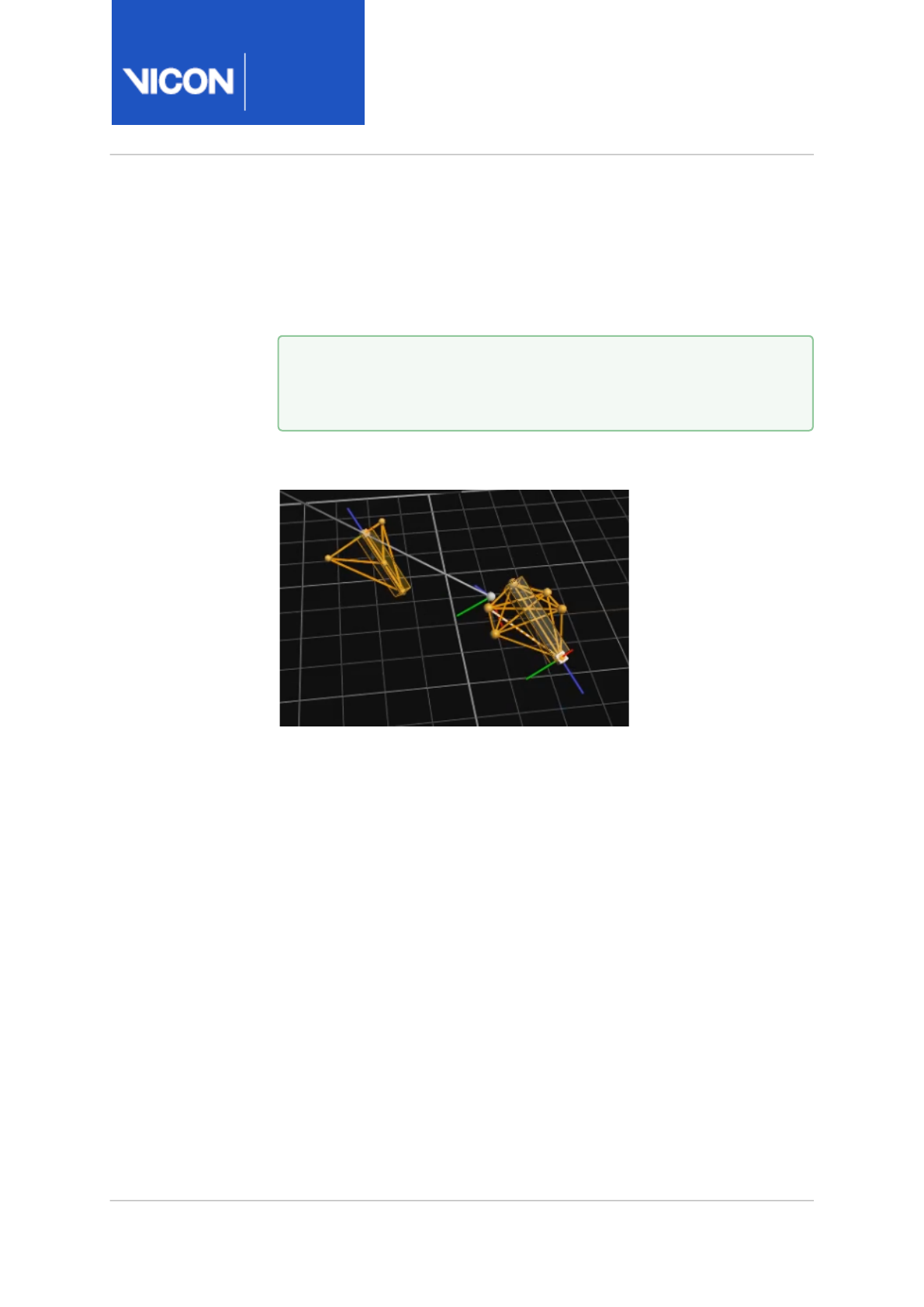
Nexus
Reference
Guide
Eye tracking with Vicon Nexus
Vicon Motion Systems Ltd. 13-Nov-2018 Page 148 of356
5. After labeling is complete, to see and use the eye vector, you need to
kinematically fit the data. To do this, run Kinematic Fit, either by clicking
the KinFit button on the Nexus toolbar or by running the Kinematic Fit
pipeline in the Pipeline Tools pane, making any changes necessary in the
Properties pane.
6. Run the Kinematic Fit operation.
The eye vector is displayed in the 3D Perspective view.
7. In the Pipeline Tools pane, expand File Export, then double-click Export
ASCII.
8. In the Properties pane, in the Segments section, change the Global
Angle setting to All.
9. Run the Export ASCII pipeline operation.
10. To see the exported data, on the Data Management tab, with the
relevant trial selected, click on the hyperlink at the bottom and double-
click the relevant
.csv
file to open it.
The eye vector data is displayed as a unit vector in the columns headed
RayX, RayY, and RayZ.
Tip
To produce the required result, you may need to reduce the Prior
Importance to zero.

Nexus
Reference
Guide
Eye tracking with Vicon Nexus
Vicon Motion Systems Ltd. 13-Nov-2018 Page 149 of356
The units are between 1000 and -1000mm. Note that the eye vector
data is local to the segment to which the eye tracker is connected (ie,
the Head). Both the eye vector data and the Head and Tracker (and
Wand) data are exported.
11. To position the eye vector in global coordinate space, you need to use
the Head and Tracker data. To ensure accuracy, you also need to apply
the offset from the Head segment. To find the offset, in the System
Resources pane, click on the Dikablis Eye Tracker node and in the
Properties pane, go to the Eye Offset coordinates.
12. When you save, kinematic data is not saved, so to preserve kinematics,
rerun Kinematic Fit.

Nexus
Reference
Guide
ViconNexus user interface
Vicon Motion Systems Ltd. 13-Nov-2018 Page 150 of356
ViconNexus user interface
This chapter provides detailed descriptions of the main components of the
ViconNexus user interface:
•About the ViconNexus user interface, page 151
•Resources pane, page 152
•System tab, page 156
•System Resources nodes, page 163
•Subjects tab, page 247
•View pane, page 257
•Tools pane, page 280
•Communications pane, page 325
•Menu bar, page 336
•Toolbar, page 351
For basic instructions on how to use these components, see the
Vicon
Nexus User Guide.

Nexus
Reference
Guide
ViconNexus user interface
Vicon Motion Systems Ltd. 13-Nov-2018 Page 151 of356
About the ViconNexus user interface
The ViconNexus user interface includes the following components:
•Resources pane, page 152: Enables you to manage the components of your
Vicon system and the subjects whose motion is to be captured.
•View pane, page 257: Enables you to set up the way you want to view the
capture data from one or more cameras (or supported third-party
devices), either live in real time or from file for post-processing.
•Tools pane, page 280: Enables you to manage each step of the motion
capture workflow through preparation, acquisition, and review.
•Communications pane, page 325: Enables you to run customized
workflows, monitor trials, work with data from Vicon IMUs, work with
MATLAB, check system status and view log information.
•Menu bar, page 336: Enables you to access common commands from the
current workflow stage.
•Toolbar, page 351: Enables you to access frequently used commands from
the current workflow stage.
For introductory information about the Nexus user interface, see
Introducing ViconNexus in the
Vicon Nexus User Guide
.

Nexus
Reference
Guide
ViconNexus user interface
Vicon Motion Systems Ltd. 13-Nov-2018 Page 152 of356
Resources pane
The Resources pane contains the following elements:
•System connection buttons, page 153
•Resources tabs, page 154
•System and Subjects trees, page 154
•Properties pane, page 155
You can hide, pin, and unpin the Resources pane to ensure you use the
available screen space as efficiently as possible (see Customize the Vicon
Nexus user interface in the
Vicon Nexus User Guide
).
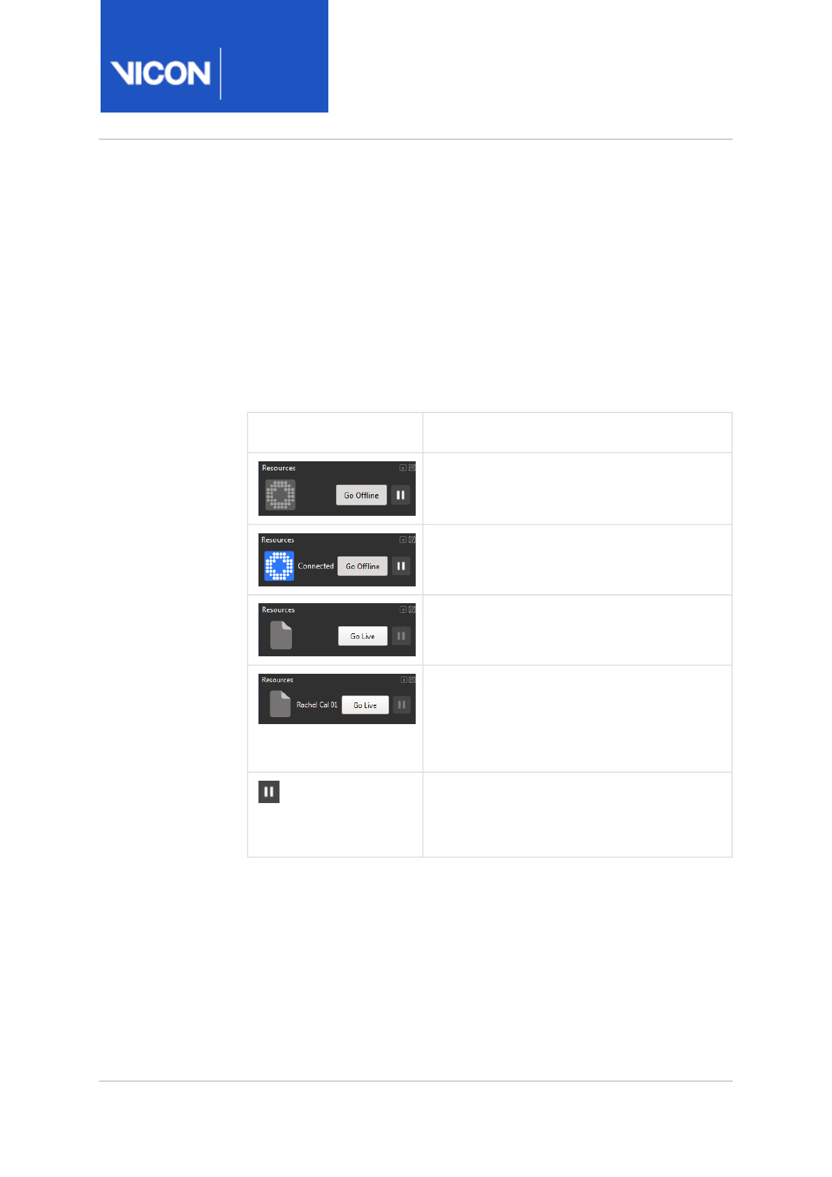
Nexus
Reference
Guide
ViconNexus user interface
Vicon Motion Systems Ltd. 13-Nov-2018 Page 153 of356
System connection buttons
Nexus has two operating modes: Live Mode and Offline Mode. The system
status indicators at the top of the Resources pane make it easy for you to
immediately identify the current operating mode and the hardware
connection status.
• Live mode connects the system and starts real-time streaming.
• Offline mode disconnects the system and stops real-time data streaming.
Previously captured and saved data can be played back offline.
Appearance System status
System in Live Mode - No connection
established with Vicon hardware
System in Live Mode - Connection
established with Vicon hardware
System in Offline Mode - No trial loaded in
memory
System in Offline Mode - Trial is loaded in
memory
The trial name is displayed to the left. The
tool tip shows the file location.
Pause button Pauses real-time data streaming. This
button is available and is a brighter color
when the system is in its Live mode.
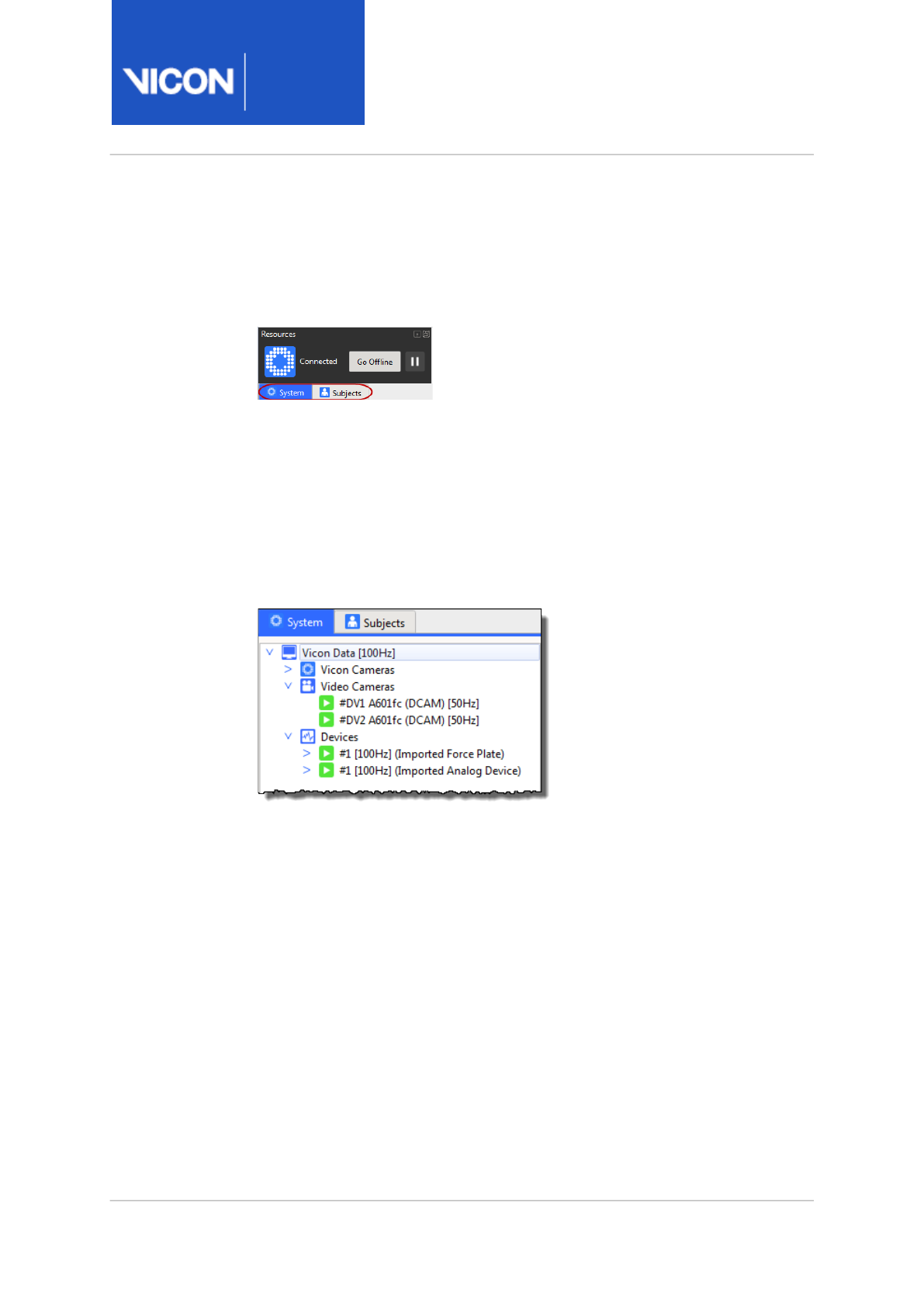
Nexus
Reference
Guide
ViconNexus user interface
Vicon Motion Systems Ltd. 13-Nov-2018 Page 154 of356
Resources tabs
You select the type of resources to be displayed by clicking the appropriate
Resources tab:
•System tab Lets you configure the components of your Vicon system. For
more information, see System tab, page 156.
•Subjects tab Lets you load and manage files for the subjects whose
motion data you want to capture and analyze in ViconNexus. For more
information, see Subjects tab, page 247.
System and Subjects trees
You select the items and any sub items to be configured with the System
tree or Subjects tree in the middle of the Resources pane. The nodes
displayed in the tree depend on whether you are viewing the System tab or
the Subjects tab in the Resources pane.
For more information, see System Resources nodes, page 163 andSubjects
tab, page 247.
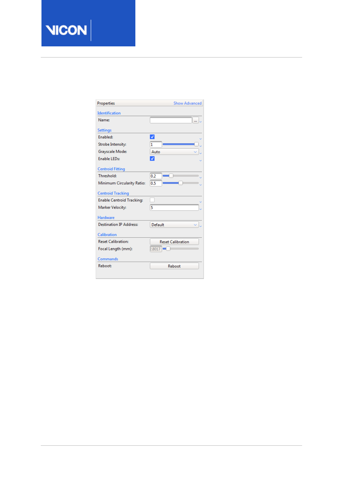
Nexus
Reference
Guide
ViconNexus user interface
Vicon Motion Systems Ltd. 13-Nov-2018 Page 155 of356
Properties pane
You view and change settings for the item selected in the resources tree in
the Properties pane at the bottom of the Resources pane. The contents of
this section depend on the node selected in the Resources tree.
For information about the available properties, see the
Properties
section
for the required node in System Resources nodes, page 163.
To see additional settings for the selected node, click Show Advanced at
the top right of the Properties pane. To show basic settings only, click Hide
Advanced.
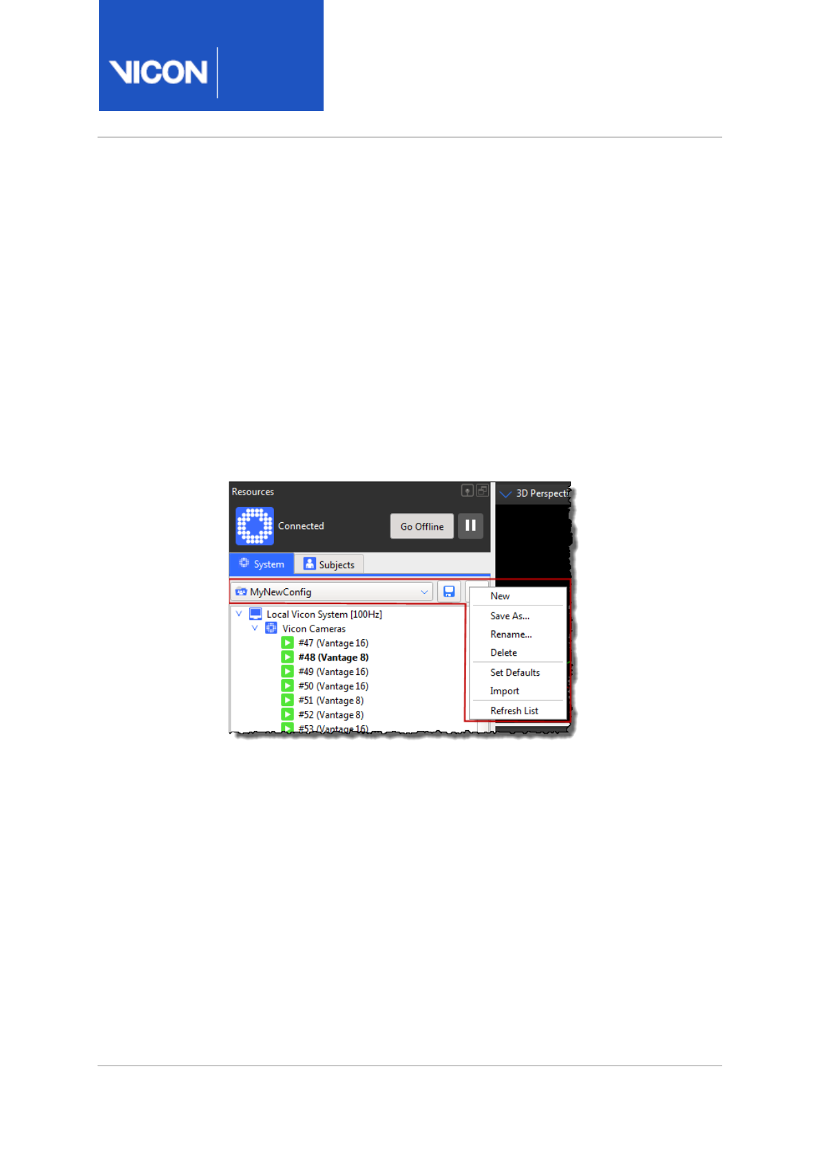
Nexus
Reference
Guide
ViconNexus user interface
Vicon Motion Systems Ltd. 13-Nov-2018 Page 156 of356
System tab
The System tab in the Resources pane enables you to manage the
components of your Vicon system.
The System tab contains the following sections:
•System configuration management, page 156
•System Resources tree, page 157
•System Properties pane, page 162
System configuration management
You create or manage configurations for the settings on the System tab
using the configuration management section at the top of the pane. This
section is displayed when Nexus is in Live or Pause mode (click the Go Live
button or the Pause button).
This enables you to save any changes you make to the settings on the
System tab to a configuration file, with the extension .System. You can
then re-use your saved configuration file as required, for example, you
could save different system settings for each type of motion capture
application that you use.
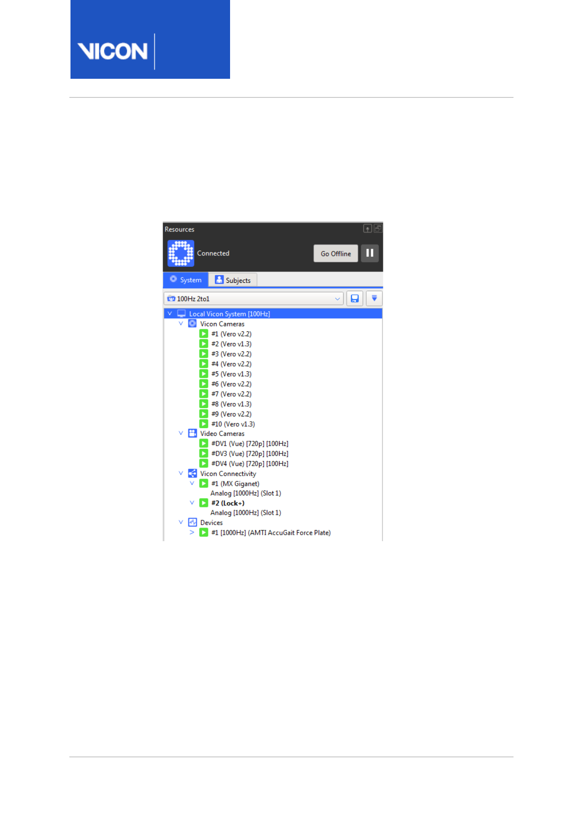
Nexus
Reference
Guide
ViconNexus user interface
Vicon Motion Systems Ltd. 13-Nov-2018 Page 157 of356
In addition to creating customized Systems configurations, the
Configuration menu button enables you to rename, import, reload and
delete configurations and refresh the list.
System Resources tree
You select the node for the system component you want to configure in the
Resources tree on the System tab (the nodes displayed depend on the
current system connection mode and connected system components):

Nexus
Reference
Guide
ViconNexus user interface
Vicon Motion Systems Ltd. 13-Nov-2018 Page 158 of356
Node Description
Local Vicon
System
Displayed in Live mode only. Enables you to view and/or control the Vicon
system capture rate and the Nexus memory buffer size; real-time
processing settings; and the identification and connection settings for
the Nexus host PC.
The Local Vicon System node contains sub nodes for each device
connected to your Vicon system under the following nodes:
• Vicon Cameras
• Vicon Connectivity
• Video Cameras
• Devices (including force plates, accelerometers, EMG, Dikablis eye
tracker, etc)
The node for the device designated as the Vicon system synchronization
master is highlighted in bold in the System Resources tree. For more
information, see
Change the synchronization master
in the
Vicon Nexus
User Guide
.
For more information on this node, see Local Vicon System node, page 164.
Vicon Data Displayed in Offline mode only. The details for cameras and capture
devices in your Vicon system that were used for a previously saved
motion capture trial. For more information, see Vicon Data node, page 181.
Vicon Cameras The identification and configuration settings for each Vicon camera
connected to your Vicon system. For more information, see Vicon
Cameras node, page 182.
Vicon
Connectivity
The identification and configuration settings for each Vicon connectivity
device included in your Vicon system architecture. For more information,
see Vicon Connectivity nodes, page 206.
Devices The connection and configuration settings for Vicon and supported third-
party devices included in your Vicon system architecture. For more
information, see Devices node, page 216.

Nexus
Reference
Guide
ViconNexus user interface
Vicon Motion Systems Ltd. 13-Nov-2018 Page 159 of356
You can perform commands specific to a type of system component node
or sub node by right-clicking on a node in the System Resources tree and
selecting the desired command from the displayed context menu.
Device status
Some nodes have sub-nodes for individual components of that type:
• Green play button: Component OK (active or connected); if an analog
device is connected to the Vicon component, the analog source is
selected and all channels are configured.
• Yellow pause button: Component not fully set up
• Gray play button: Component connected but not contributing any
data.
• Red stop button: Component down (unavailable or disconnected)
• Green arrow: Analog channel connected to source device.
• Yellow arrow: Analog channel not connected to source device, or
device is disabled (Enabled check box is not selected in the Status
section of the Properties pane.)
For more information on the status of system components, see Status tab,
page 334.
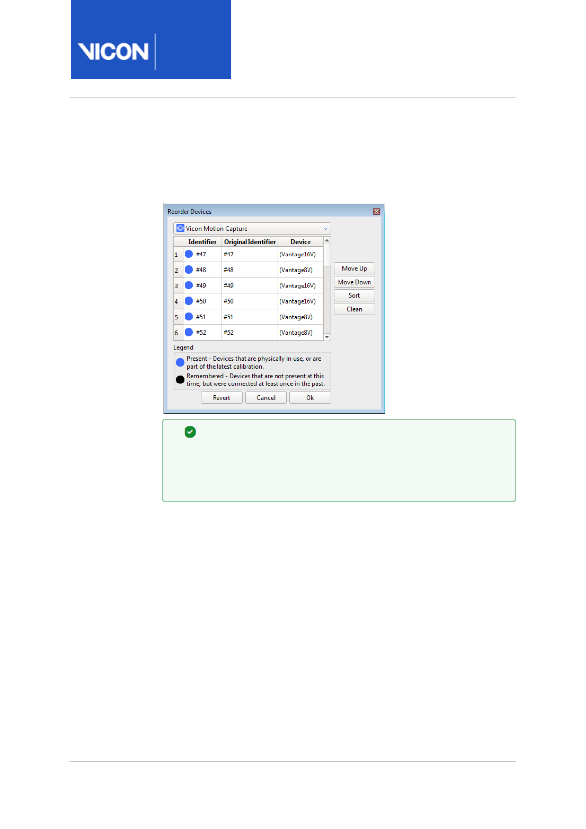
Nexus
Reference
Guide
ViconNexus user interface
Vicon Motion Systems Ltd. 13-Nov-2018 Page 160 of356
Reorder Devices dialog box
You change the order in which devices are displayed in the System
Resources tree in the Reorder Devices dialog box.
Tip
You can automatically number cameras according to their position
in the volume by using the Auto number cameras feature. For
more information, see System Preparation tools, page 283.
You access the Reorder Devices dialog box by right-clicking Vicon Cameras,
Video Cameras, Vicon Connectivity nodes, or Devices in the System
Resources tree and selecting Reorder from the context menu. This menu is
available only when the system is in Live mode (click the Go Live button);
devices listed in an offline processing file cannot be reordered.
Each Vicon camera and connectivity device is assigned a unique ID at
manufacture, which remains the same, regardless of its position in the list
of other devices of the same type. Once integrated in a Vicon system, each
device is assigned a sequential ID, which is used to identify it (for example,
in user interface lists and camera calibration parameters (.xcp) files). This
sequential ID is not dependent on which socket the device is plugged into
(for example, a Vicon camera plugged into socket 2 in an MXGiganet is not
necessarily assigned a device ID of 2). Reordering the device changes its

Nexus
Reference
Guide
ViconNexus user interface
Vicon Motion Systems Ltd. 13-Nov-2018 Page 161 of356
sequential ID. You may find this useful if you want to order your device
numbers to match their physical sequence in your capture volume.
To change the order of devices in the Reorder Devices dialog box:
1. In the System Resources tree, right-click Vicon Cameras, Video Cameras,
Vicon Connectivity or Devices and from the displayed context menu
select Reorder.
2. In the Reorder Devices dialog box, click on the device whose position
you want to change.
In the Identifier column, the color of the circle to the left of the ID
number indicates the current status of that device:
• Blue (Present) - Devices that are physically in use, or are part of the
latest calibration
• Black (Remembered) - Devices that are not present at this time, but
were connected at least once in the past
The Original Identifier column shows the sequence ID previously
assigned to the device.
3. Change the order of the device using the buttons:
•Move Up Move the selected entry up one position in the list.
•Move Down Move the selected entry down one position in the list.
•Sort Sorts the list of devices according to name and type.
Remembered devices are at the bottom of the list.
•Clean Removes the entries for devices that are not present in the
current session.
4. Repeat steps 1–3 for each device whose position you wish to change.
5. Click OK to save the changes and close the Reorder Devices dialog box.

Nexus
Reference
Guide
ViconNexus user interface
Vicon Motion Systems Ltd. 13-Nov-2018 Page 162 of356
System Properties pane
You can view or modify system components in the Properties pane, which is
at the bottom of the of the System tab.
The properties displayed depend upon the component node selected in the
System Resources tree. Properties can be presented in categories such as
General, Settings, etc.
To see all the properties for a selected component node, ensure you have
clicked Show Advanced at the top of the Properties pane.

Nexus
Reference
Guide
ViconNexus user interface
Vicon Motion Systems Ltd. 13-Nov-2018 Page 163 of356
System Resources nodes
The following topics describe nodes that are displayed in the tree on the
System tab of the Resources pane:
•Local Vicon System node, page 164
•Vicon Data node, page 181
•Vicon Cameras node, page 182
•Video Cameras node, page 198
•Vicon Connectivity nodes, page 206
•Devices node, page 216
•Force plate nodes, page 218
•Analog accelerometer, EMG, & other analog device nodes, page 231
•Digital device nodes, page 234
•Dikablis Eye Tracker node, page 235
•IMeasureU Sensor node, page 239
•Zerowire EMG node, page 241

Nexus
Reference
Guide
ViconNexus user interface
Vicon Motion Systems Ltd. 13-Nov-2018 Page 164 of356
Local Vicon System node
The Local Vicon System node is the top-level node that is displayed for the
Nexus host PC when Nexus is in Live mode. It contains sub-nodes for each
device connected to your Vicon system:
• Vicon Cameras
• Vicon Connectivity (Vicon Lock+, Vicon MX Giganet)
• Video Cameras
• Devices (including force plates, accelerometers, EMG, Dikablis eye
tracker, etc)
The node for the device designated as the synchronization master is
highlighted in bold in the System Resources tree. (For more information,
see
Change the synchronization master
in the
Vicon Nexus User Guide
.)

Nexus
Reference
Guide
ViconNexus user interface
Vicon Motion Systems Ltd. 13-Nov-2018 Page 165 of356
For more information on the Local Vicon System node, see:
•Local Vicon System node context menu, page 165
•Local Vicon System properties, page 166
Local Vicon System node context menu
You can select from the following commands on the context menu
displayed when you right-click on the Local Vicon System node:
Command Description
Reboot Vicon
Hardware
Resets all of the Vicon hardware devices in the Vicon
system.
Use this command if a camera has failed to boot, or if
you need to reset the whole system for other reasons.
Alternatively, use the Reboot All button in the System
section of the Properties pane.
Reboot Core
Processor
Restarts the Core Processor and resets the labeler.
Alternatively, press CTRL + R.
Resynchronize Forces the synchronization master to resynchronize
the frame rate for all connected cameras and third-
party devices.
Reprogram
Vicon
Firmware
Display the Reprogram Firmware dialog box in which
you can view and update firmware for Vicon devices in
your Vicon system.

Nexus
Reference
Guide
ViconNexus user interface
Vicon Motion Systems Ltd. 13-Nov-2018 Page 166 of356
Local Vicon System properties
You can configure the following settings in the Properties pane for the
Local Vicon System node.
Tip
If you can't see some of the listed properties, click Show Advanced
at the top of the Properties pane.
These settings affect the local Vicon system in Live mode. The equivalent
settings for offline processing can be found under Core Processing
operations, page 303 on the Pipeline tab.
Local Vicon System properties are divided into the following sections:
• System section, page 167
•Genlock and Timecode section, page 169
•General section, page 172
•Grayscale Circle Fitting section, page 173
•Reconstruction section, page 173
•Trajectory Tracking section, page 176
•Labeling section, page 177

Nexus
Reference
Guide
ViconNexus user interface
Vicon Motion Systems Ltd. 13-Nov-2018 Page 167 of356
System section
Contains system-wide parameters that affect all the connected cameras
and devices.
Property Description
Requested
Frame Rate
(Hz)
The rate (in Hertz) at which to synchronize the Vicon
cameras. If using external video signal, select from
displayed values (multiples of the base frame rate of the
PAL, NTSC, or Film video standard specified in Standard)
up to a maximum of 2,000. You can choose any number
you want if you do not have any Genlock Standard set.
The configured Vicon system capture rate is displayed in
square brackets beside the node. For example, if the
Vicon system frame rate is set to 100 Hz, the node title is
displayed as Local Vicon System [100Hz]. If the
Requested Frame Rate cannot be met due to the camera
frame rate, Vicon Nexus displays the nearest adjusted
frame rate in square brackets. To meet the Requested
Frame Rate, you can change the Sub Sample Ratio of the
relevant camera(s).
Default: 100
Actual
Frame Rate
(Hz)
The frame rate used by the Vicon system, which is
constrained by the camera frame rate limits.
Preferred
Master
A list from which you can choose the synchronization
master. If you are using multiple devices such as Vicon
Lock+ or MX Giganets, to connect and control your
cameras, a synchronization master is automatically
chosen by Vicon Nexus. If the automatically selected
synchronization master is not the required choice, you
can select the appropriate device from the Preferred
Master list. (For more information, see
Change the
synchronization master
in the
Vicon Nexus User Guide
).
Default: Automatic

Nexus
Reference
Guide
ViconNexus user interface
Vicon Motion Systems Ltd. 13-Nov-2018 Page 168 of356
Property Description
Buffer Size
(MB)
The size (in MB) of the memory buffer on the host PC
when Nexus is receiving data from Vicon hardware.
Specify a value between 0-1024 MB. This buffer is used if
data comes in faster than Nexus can process it;
therefore, the larger the buffer, the longer it takes before
capture fails. Increasing this value enables a greater
Capture Before Start duration to be set. The optimum
size of the Buffer Size parameter depends on the amount
of memory on your PC. The proportion of the total
memory buffer that is reserved for Vicon devices is
determined by the Buffer Reserve (see below).
Tip: If you experience failure of a combined video and
optical camera calibration , particularly if you are
capturing a long wand wave, close and restart Nexus.
Reduce the Buffer Size to 0 MB before calibrating. Do
not increase the buffer size to its usual level until you
have completed a successful calibration.
Default: 250
Buffer
Reserve
The proportion of the total buffer size (see Buffer Size
above) that is reserved for Vicon video devices. The
default of 0.5 results in half of the total buffer size being
reserved for Vicon video devices (Vicon Vue and Bonita
Video cameras). The remaining buffer space is used by
third-party video cameras. If you want to maximize the
buffer space reserved for Vue or Bonita Video cameras,
set this value to 1.0. If you are using only Basler cameras
or third-party DV cameras, set this value to 0.
Default: 0.5
Reboot All Resets all of the Vicon hardware devices in the Vicon
system. Use this button if a camera has failed to boot, or
if you need to reset the whole system for other reasons.
Alternatively, use the Reboot Vicon Hardware command
from the context menu.

Nexus
Reference
Guide
ViconNexus user interface
Vicon Motion Systems Ltd. 13-Nov-2018 Page 169 of356
Property Description
Minimize
Latency
Minimizes the level of latency, or lag time, the RealTime
Engine introduces during data streaming when data rates
approach or exceed system processing capacity.
If selected, the RealTime Engine introduces no lag time
when processing data frames. This decreases data
throughput, but increases the possibility of frames being
dropped.
If cleared, the RealTime Engine introduces 20 frames of
lag time when processing data frames. As this increases
data throughput, it can produce better labeling results.
Default: Cleared
Genlock and Timecode section
Settings for genlock and timecode.
Property Description
Genlock
Standard
The type of video standard supported by the connected
video source: None, PAL, NTSC, Film (24 fps), Film
(24/1.001 fps, 30Hz, VESA (100Hz) or VESA (120Hz). For
information about the symbols in this list, see Icons in
Genlock and Timecode lists, page 171.
Default: None
Important: To use the 30Hz option, the Vicon firmware
must be Bundle 500 or above.
Enable
Genlock
Enables genlock based on the signals that are currently
detected.
Auto
Genlock
Automatically selects a genlock standard and enables
genlock based on the signals that are currently detected.

Nexus
Reference
Guide
ViconNexus user interface
Vicon Motion Systems Ltd. 13-Nov-2018 Page 170 of356
Property Description
Genlock
Offset
Enables you to specify a system offset relative to the
genlock signal, as a fraction of the genlock frame period.
Values are in the range 0–1. For VESA modes, specify a
value using the VESA Offset control.
VESA Offset Applies only if you have selected one of the VESA
standards from the Genlock Standard list (see above). It
enables a system offset relative to VESA signal (as a
fraction of the VESA frame period). It changes when the
Vicon cameras take a frame (and hence when the camera
strobes are on) relative to the incoming VESA frames. The
camera timing can be offset by up to one VESA frame.
The main purpose of this feature is to prevent camera
strobes from interfering with the IR-synchronized 3D
glasses used in some virtual reality systems.
Timecode
Source
The genlock timecode source. Can be VITC, LTC, Internal
or Internal Drop (uses drop frame when applicable).
Default is Internal.
For information about the symbols in this list, see Icons in
Genlock and Timecode lists, page 171.
Note: VITC and LTC always display a flat line if the system
is not genlocked. This is because these signal types can
only be detected by a master device that is genlocked.
Enable
Timecode
When selected, timecode is enabled.
Detected
Timecode
Given as the number of timecode frames per second for
example, 24 fps, 25 fps, 30 fps, 30 fps DropFrame

Nexus
Reference
Guide
ViconNexus user interface
Vicon Motion Systems Ltd. 13-Nov-2018 Page 171 of356
Icons in Genlock and Timecode lists
The icon to the left of each option provides additional information about
the availability of that standard:
Icon Meaning
Cross The standard is not supported by the hardware (that is,
no connected device supports locking to a signal of that
type). If you select an unsupported standard, it restricts
the available frame rates as it does in the previous
version of Nexus.
Flat line No device in the system is detecting that standard.
Blue
square
wave
The master device is detecting that signal and can
genlock to it.
Green
square
wave
If you select a mode with the blue wave icon and then
select the Enable Genlock check box, the icon turns
green.
Red
square
wave
A device in the system is detecting the mode but a
problem prevents it from being used, for example, if the
signal is being detected by a device that is not the
master device in the system.
In all cases, you can display a tooltip by holding the mouse over the Genlock
Standard list.

Nexus
Reference
Guide
ViconNexus user interface
Vicon Motion Systems Ltd. 13-Nov-2018 Page 172 of356
General section
Settings for the Core Processor component, which receives data from the
Vicon cameras and transforms the data to the trajectories or segments that
your Vicon system is tracking.
Property Description
Processing
Output
Level
The amount of real-time processing the Core Processor is
to perform on source data:
•Circles: Have the Nexus Core Processor attempt to
circle fit grayscale blobs that the Vicon cameras
could not resolve. Data will not be reconstructed to
3D trajectories, so you will only see data in the 2D
Camera view pane.
•Reconstructions: Create 3D reconstructions of
marker images. 3D trajectories are created, but
they are not labeled.
•Labels: Assign labels to markers, based on the
Vicon Skeleton (.vsk file). Labels are applied to the
reconstructed trajectories if a .
vsk
file is present.
•Kinematic Fit: Fit joint angles defining the
relationship between segments. The segments
defined in the .
vsk
file are fitted and displayed.
Default: Labels
Important: These settings are applied cumulatively. For
example, selecting Labels applies that setting as well as
the Reconstructions and Circles settings.

Nexus
Reference
Guide
ViconNexus user interface
Vicon Motion Systems Ltd. 13-Nov-2018 Page 173 of356
Grayscale Circle Fitting section
Property Description
Enable Select this check box to enable circle fitting of grayscale
blobs. If selected, processing speed may be slightly
slowed, but more data may be collected.
Default: Selected.
Reconstruction section
Controlling the number of cameras that are required to start or continue a
trajectory can be beneficial in producing higher quality data. The ability to
define how trajectories are created can help you to produce higher quality
data that requires less manual editing.
Property Description
Environmental
Drift Tolerance
Increase this parameter to reduce the sensitivity (in
mm) of the camera calibration to environmental
factors, particularly temperature change.
Use this setting to compensate for environmental
changes when you do not have time or other
resources to recalibrate the whole system. For the
most accurate results, recalibration remains the
preferred solution.
Default: 1.5
Minimum
Cameras to
Start Trajectory
This parameter controls how many cameras (rays)
must see the same marker (centroid) in order to
create a new reconstruction and potentially form a
new trajectory. The minimum value that can possibly
create a reconstruction is two cameras. The
maximum value of this parameter is 30 cameras or
the total number of cameras in your system. This
value can be increased if there are a large number of
unlikely reconstructions being created.
Default: 3 cameras

Nexus
Reference
Guide
ViconNexus user interface
Vicon Motion Systems Ltd. 13-Nov-2018 Page 174 of356
Property Description
Minimum
Cameras to
Continue
Trajectory
This parameter controls how many cameras (rays)
must see the same marker (centroid) in order to
create a reconstruction to continue a recognized
trajectory. The minimum value that can possibly
create reconstructions is two cameras. The maximum
value of this parameter is 30 cameras or the total
number of cameras in your system. The value can be
decreased if there are gaps in trajectories where
reconstruction should be possible when viewed by
fewer cameras.
Default: 2 cameras
Reconstruction
Minimum
Separation
The minimum distance, specified as a value in the
range 0–1000000 millimeters, allowed between 3D
marker positions in order for them to be considered
for reconstruction. If two candidate reconstructions
are closer than this minimum separation, only the
most likely reconstruction (in terms of the number of
cameras contributing) will be reported. The other will
be discarded. A higher value decreases the likelihood
of creating spurious reconstructions, but increases
the possibility that some genuine markers will not be
reconstructed.
Generally, this parameter should be slightly above the
size of the markers you are using. For examples, if you
are using 14mm markers, try setting it to 16mm. Then,
for example, if during reconstruction two markers
(one a ghost marker) are found within 17mm, one
would be discarded.
Default: 14
Minimum
Centroid Radius
The minimum radius (in pixels) of a 2D centroid that
is allowed for a reconstruction. Any reconstruction
with a radius less than this value is ignored.
Default: 0

Nexus
Reference
Guide
ViconNexus user interface
Vicon Motion Systems Ltd. 13-Nov-2018 Page 175 of356
Property Description
Maximum
Centroid Radius
The maximum radius (in pixels) of a 2D centroid that
is allowed for a reconstruction. Any reconstruction
with a radius greater than this value is ignored.
Default: 50
Minimum
Reconstruction
Radius
The minimum 3D radius (in mm) that is allowed for a
reconstruction. Any reconstruction with a radius less
than this value is discarded.
Default: 0
Maximum
Reconstruction
Radius
The maximum 3D radius (in mm) that is allowed for a
reconstruction. Any reconstruction with a radius
greater than this value is discarded.
Default: 1000
Volume min X X value of lower corner of reconstruction volume.
Default -100000.
Volume min Y Y value of lower corner of reconstruction volume.
Default -100000
Volume min Z Z value of lower corner of reconstruction volume.
Default -100000
Volume max X X value of upper corner of reconstruction volume.
Default 100000.
Volume max Y Y value of upper corner of reconstruction volume.
Default 100000.
Volume max Z Z value of upper corner of reconstruction volume.
Default 100000.
Use Target
Volume
Sets the reconstruction volume to the dimensions of
the target volume (Set the target volume dimensions
in the Options dialog box (press F7)

Nexus
Reference
Guide
ViconNexus user interface
Vicon Motion Systems Ltd. 13-Nov-2018 Page 176 of356
Trajectory Tracking section
Property Description
Trajectory
Startup
Error
The deviation allowed (in mm/sec) in a marker's position
at the start of a trajectory. This value is related to the
radius within which the current trajectory is matched to
a reconstruction in the following frame. To help start
trajectories on faster moving markers, increase the value.
To help with dense marker sets, decrease the value.
Default: 150
Trajectory
Prediction
Error
The deviation allowed (in mm/sec) in a marker's position
on a trajectory. This value is related to the radius within
which the current trajectory is matched to a
reconstruction in the following frame. To help continue
trajectories on faster moving markers, increase the value.
To help with dense marker sets, decrease the value.
Default: 150

Nexus
Reference
Guide
ViconNexus user interface
Vicon Motion Systems Ltd. 13-Nov-2018 Page 177 of356
Labeling section
Property Description
Label
Completeness
Entrance
Threshold
Specifies the proportion of markers that have to be
present when a subject enters the capture volume or
when the trial starts. If it is less than this value, the
subject is not labeled. Higher values help to prevent
mis-labeling when the subject first enters the volume.
For example, if labeling starts only a significant
number of frames after the subject has entered the
volume, then a reduction of this value may encourage
labeling to start earlier, when a smaller percentage of
total subject markers are first seen.
Conversely, if when the subject enters the volume, the
initial labeling result is poor, increasing the value
encourages the labeler to wait until a larger
proportion of subject markers are seen and should
produce a more reliable labeling result.
Default: 0.85
Label
Completeness
Exit Threshold
Specifies the proportion of a subject's markers below
which the subject is considered by Nexus to have left
the capture volume. Labeling will not recommence
unless the proportion reaches the Entrance Threshold.
Higher values help to prevent mis-labeling when the
subject leaves the volume.
For example, a value of 1 requires all markers to be
recognized for labels to continue to be produced.
Tip: Do not set this value higher than Label
completeness entrance threshold.
Default: 0.6

Nexus
Reference
Guide
ViconNexus user interface
Vicon Motion Systems Ltd. 13-Nov-2018 Page 178 of356
Property Description
Booting quality Affects when the system will start labeling based on
how well the labeling skeleton matches the
reconstructed data. For greater tolerance, reduce this
value; to reduce the risk of mis-labeling, increase this
value.
Lower values are more tolerant, but may result in more
mis-labels, whereas higher values require a closer
match between the labeling skeleton and the
reconstructed data, and therefore reduce the risk of
mis-labeling.
If fewer than expected labels are achieved, reducing
this value may decrease the number of labeled
reconstructions.
Conversely, if the labeling results produce an
unacceptably high number of mis-labels (due to poor
skeleton-to-reconstruction matching), an increase in
this number may result in fewer mis-labels.
Default: 0
Booting versus
tracking
Booting is a process in which Nexus attempts to work
out the labeling for the active subjects with marker
statistics calculated from the VSK. This is done
without requiring any information from earlier frames,
such as previous labels.
Tracking is a process in which Nexus uses the pose of
the labeling skeleton from the previous frame's labels.
This is used to predict the labeling in the current
frame.
Values less than 0 favor rebooting; values greater than
0 favor tracking.
Default: 0

Nexus
Reference
Guide
ViconNexus user interface
Vicon Motion Systems Ltd. 13-Nov-2018 Page 179 of356
Property Description
Tracking
quality
Compares the match between reconstructions and
skeleton data with the previous frame to determine
whether labeling continues. Adjusting this parameter
affects how close this match must be.
Higher values require a closer match between frames.
This reduces the risk of incorrect labeling, but may
leave more constructions unlabeled.
Lower values do not require as close a match between
frames. This can increase the total number of labeled
reconstructions but may produce more mis-labels.
For greater tolerance, reduce this value; to reduce the
risk of incorrect labeling, increase this value.
Default: 0
Smoothing
factor
Specifies how much the subject markers can move
between frames before labeling stops. This value can
be increased for slow-moving subjects and decreased
for faster motion (at the cost of a greater likelihood of
mis-labels).
Default is 200.

Nexus
Reference
Guide
ViconNexus user interface
Vicon Motion Systems Ltd. 13-Nov-2018 Page 180 of356
Property Description
Joint Ranges
Slack
A calibrated skeleton contains joint range information.
This informs the labeler about the expected Range of
Motion for any joint and the markers associated with
that joint, helping the labeler make decisions.
If a subject's joints move beyond the estimated range,
the result may be unlabeled reconstructions.
Increasing this value may increase the number of
labels and is useful when the subject does not go
through their entire Range of Motion during
calibration.
Values greater than 1 extend the joint ranges allowed
in the subject calibration. Higher values can be set to
reduce the chances of mis-labels. Values less than 1
tighten the ranges.
Default: 1
Enforce Joint
Ranges
If selected, Nexus considers only a marker labeling
solution that adheres strictly to the joint range values
defined in the labeling skeleton (VSK).
Default is cleared.

Nexus
Reference
Guide
ViconNexus user interface
Vicon Motion Systems Ltd. 13-Nov-2018 Page 181 of356
Vicon Data node
The Vicon Data node is the top-level node that is displayed on the System
tab in the Resources pane when Nexus is in Offline mode. It represents the
Nexus host PC.
in this mode, you can view but not manage the device details displayed on
the System tab.
It enables you to view details of the cameras and capture devices in your
Vicon system that were used for a previously saved motion capture trial.
The Vicon Data node contains sub-nodes for each capture device that was
connected to your Vicon system during the trial capture under the
following nodes:
• Vicon Cameras node
• Video Cameras node
• Devices node (including force plates, accelerometers, etc)
The top-level Vicon Data node does not have any displayed properties. Not
all properties that are configurable for a device in Live mode are visible in
Offline mode. For further details, see Local Vicon System node, page 164.

Nexus
Reference
Guide
ViconNexus user interface
Vicon Motion Systems Ltd. 13-Nov-2018 Page 182 of356
Vicon Cameras node
The Vicon Cameras node on the System tab of the Resources pane enables
you to manage the identification and configuration settings for each Vicon
camera connected to your Vicon system.
For more information, see:
•Vicon Cameras node context menu, page 182
•Vicon Camera properties, page 184
Vicon Cameras node context menu
You can select the following commands from the context menu displayed
when you right-click on the Vicon Cameras node:
Command Description
Reorder Display the Reorder Devices dialog box, page 160 in which
you can change the order in which Vicon cameras are
displayed in the System Resources tree.
Reboot
Vicon
Cameras
Stop and restart all of the Vicon optical cameras in the
Vicon system.
Remove
Vicon
Cameras
Displays a choice of Disconnected or Missing:
•Disconnected - removes from the Resources tree
cameras that are currently unplugged.
•Missing - removes from the Resources tree
cameras that are unplugged, but were previously
used in a calibration.

Nexus
Reference
Guide
ViconNexus user interface
Vicon Motion Systems Ltd. 13-Nov-2018 Page 183 of356
Command Description
Enable
Preview
Mode
Enables Preview mode for Vicon cameras. In this mode
Vicon Nexus displays a 'video' image from the optical
sensor of a Vicon camera, which enables you to aim
cameras more quickly and easily during setup.
Note that this preview feature is for system setup
purposes only. You cannot capture camera data in
Preview mode.
You can select the following commands from the context menu displayed
when you right-click on a node for a specific Vicon camera:
Command Description
Reset
Calibration
Remove the selected camera from the current
calibration.
Reboot Start and restart the selected Vicon camera.

Nexus
Reference
Guide
ViconNexus user interface
Vicon Motion Systems Ltd. 13-Nov-2018 Page 184 of356
Vicon Camera properties
You can configure settings in the following sections of the Properties pane
for Vicon cameras:
• Identification section, page 184
•Settings section, page 185
•Centroid Fitting section, page 191
•Centroid Tracking section, page 193
•Status section, page 194
•Hardware section, page 195
•Firmware section, page 196
•Calibration section, page 197
•Commands section, page 197
Identification section
Property Description
Name A user-defined display name for the entire set of Vicon
cameras or for each individual camera. For example, if a
camera is placed over a door, you could name it "Over
Door."
Default: Blank
Device ID The unique identification number Vicon assigns to each
camera during manufacture. The top-level entry for all
Vicon cameras takes no value.
Default: Identified on connection

Nexus
Reference
Guide
ViconNexus user interface
Vicon Motion Systems Ltd. 13-Nov-2018 Page 185 of356
Settings section
Property Description
Enabled Whether or not the Vicon camera is currently enabled for use.
Default: Selected
Strobe Intensity The amount of light emitted by Vicon camera strobe units. This value can
be set between 0-1 to minimize reflections and obtain clear marker
images. The higher the setting, the larger the markers appear, but this
may cause blobs to be produced from unwanted reflection sources.
Lower settings reduce unwanted reflection sources but make the
markers themselves less visible to the Vicon cameras.
In almost all circumstances, you will want to keep the intensity at its
maximum level because the system works by recording light from the
strobes that is reflected from the markers, thus the more light the
strobes send out the more light the markers reflect. However, there are
two significant cases where you may want to lower the intensities:
• If you see a lot of reflections in the volume, either from other
cameras or from other objects in the room, such as shiny
equipment, floors, or from the subject.
• If you are capturing a very fast moving subject. The strobe
intensity affects the time the strobe is on for each camera frame.
The full strobe intensity corresponds to 1ms for normal frame rates.
Lower strobe intensities mean that the markers are captured with
the strobes on for less time and, therefore, have less time to move
during the frame.
Tip: In normal circumstances, it is advisable to use full strobe intensity
and deal with reflection problems by closing the camera lens aperture.
However, especially when the capture volume is very small, this may be
uncomfortable to the patient, so less than the full intensity may be the
best setting.
Adjust this setting in conjunction with the Threshold setting until
reflections are minimized or gone.

Nexus
Reference
Guide
ViconNexus user interface
Vicon Motion Systems Ltd. 13-Nov-2018 Page 186 of356
Property Description
Note: If you are using a mixed system (ie your Vicon system consists of a
mix of MX T-Series cameras and other current Vicon cameras), and if it is
crucial to your work that the shutter periods for all cameras are precisely
aligned, ensure that your firmware is upgraded to version 700 or later,
and set the Strobe Intensity for the T-Series camera(s) to its maximum.
Default: 1
Gain The digital amplification of the pixel value. Select a displayed value to
determine the intensity of the grayscale from the Vicon cameras: x1, x2,
x4, or x8.
This setting is applied to the camera to change the dynamic range of the
recorded image. Increasing the gain means that the marker has less
variation in grayscale intensity between its center and its edge, but in
certain circumstances, using a higher gain yields markers that are easier
for the camera to distinguish. Vicon does not recommend using a gain
setting higher than x2.
Adjust this setting if the markers appear too faint or if the cameras have
trouble distinguishing them; otherwise, leave the this property at the
default x1 setting.
Default: x1

Nexus
Reference
Guide
ViconNexus user interface
Vicon Motion Systems Ltd. 13-Nov-2018 Page 187 of356
Property Description
Grayscale Mode The type of data for processed grayscale blobs that the Vicon cameras
send to Vicon Nexus. The Vicon cameras perform data processing to
create 2D data for Vicon markers. They generate grayscale blobs for
reflections from objects in the capture volume and then use centroid-
fitting algorithms to determine which of these are likely to be markers by
comparing the shape of the grayscale blobs to the Minimum Circularity
Ratio and Max Blob Height settings. During this processing, Vicon
cameras can produce the following types of data for grayscale blobs:
centroids data (x, y coordinates and the radius of the centroid
calculated), grayscale data (pixel and line information), or coordinates
data (line information, i.e. grayscale data without pixel values).
You can specify which type of processed data Vicon cameras send to
Nexus:
•Auto: Send grayscale data only of the grayscale blobs for which
centroids were not generated, that is, those below the threshold
specified for Minimum Circularity Ratio.Send coordinates data of
grayscale blobs for which one or more line segments, or the total
number of lines in the blob, exceeds the value set for Max Blob
Height. If a marker can be centroid fitted by the Vicon camera, the
centroid is passed to the capture PC. If it cannot, the full grayscale
of the image is sent, allowing the data to be post-processed on the
PC. This is the default and recommended mode.
•None: Send no grayscale or coordinates data; send only centroid
data. Any grayscale image that cannot be centroid fitted by the
camera will be discarded. Select this mode if you are capturing a
large number of markers and have redundancy in your capture
setup.

Nexus
Reference
Guide
ViconNexus user interface
Vicon Motion Systems Ltd. 13-Nov-2018 Page 188 of356
Property Description
•All: Send grayscale data both of grayscale blobs for which
centroids were generated and of those for which centroids were
not generated, that is those below the threshold specified for
Minimum Circularity Ratio. Send coordinates data of grayscale
blobs for which one or more line segments, or the total number of
lines in the blob, exceeds the value set for Max blob height. Select
this setting if you need to see exactly where the camera calculates
the centroid with respect to the grayscale marker image, for
example when adjusting parameters. This setting results in much
larger data rates and files; it may be useful for diagnostic purposes,
but do not use it in normal capture situations.
•Only: Send all grayscale and coordinates data; send no centroid
data.This setting is useful when focusing or making other
adjustments to the cameras themselves as you see exactly the
image recorded on the sensor.
•Edges: Send only edge coordinates data; send no centroid or
grayscale data.If data rates are very high, for example when there
are too many reflections, the camera automatically enters this
mode. Use this setting to manually force the camera into this
mode.
• No Edges: Send grayscale data both of grayscale blobs for which
centroids were generated and of those for which centroids were
not generated; send no coordinates data.Use this setting to
prevent the Vicon camera from sending edge coordinates.
Default: Auto
Caution Even if you have not specified a Grayscale mode setting that
would have coordinates data sent to Nexus, a Vicon camera
automatically sends coordinates data– either temporarily or
permanently– if it is overloaded with data (e.g., too many markers, too
many reflections, hand or reflective objects immediately in front of the
camera, too low a threshold or too high a gain). If a camera automatically
starts to present coordinates data, you should identify the source of the
overload and attempt to remedy it.

Nexus
Reference
Guide
ViconNexus user interface
Vicon Motion Systems Ltd. 13-Nov-2018 Page 189 of356
Property Description
Allow
Windowing
Windowing enables Vicon cameras that support windowing to run at a
faster frame rate by using letterboxing to reduce the dimensions of the
camera sensor area. The configured frame rate affects the field of view.
When you select Allow Windowing, if you specify a frame rate greater
than the maximum frame rate for the camera at full resolution, image
size is automatically reduced in comparison with that for a lower camera
frame rate by windowing. This keeps the pixel rate the same by
transmitting a greater number of smaller images per second. Cannot be
used in calibration mode.
Default: Selected
Enable LEDs Enables you to select whether or not to use the status lights on the
Vicon camera strobe unit that provide feedback on the status of the
camera (such as its enabled, connection, or selection state and any
processing feedback). This is useful for motion capture applications in
very dark environments (such as Virtual Reality) where the brightness of
these LED status lights can cause problems.
Default: Selected
Enable Display Toggles on or off the OLED display on the front of the strobe (of
supported Vicon cameras) , which gives feedback about the current
camera status, eg, when the camera has finished booting, its calibration
status, and whether it has been moved since calibration. If Enable
Accelerometry is selected (see below), the image on the display rotates
based on the orientation of the camera. For more information, see the
Vicon Vantage Reference Guide
.
Enable Tap to
Select
For supported Vicon cameras, enables you to lightly tap the camera in
the volume to select it (and deselect the other cameras). This is useful,
for example, when you are setting up cameras, before they are calibrated.
Default: Selected

Nexus
Reference
Guide
ViconNexus user interface
Vicon Motion Systems Ltd. 13-Nov-2018 Page 190 of356
Property Description
Enable
Accelerometry
Applies to supported Vicon cameras only. Accelerometers in the Vicon
cameras enable bump detection to operate in calibrated cameras to alert
you when they have moved from their calibrated positions. If a calibrated
camera is knocked, the camera's status LEDs flash red and in Nexus, the
camera's Bumped check box (in its Status properties) displays a check
mark. See also Bumped and Bump Detection Sensitivity, page 194 in the
Status section.
Default: Selected

Nexus
Reference
Guide
ViconNexus user interface
Vicon Motion Systems Ltd. 13-Nov-2018 Page 191 of356
Centroid Fitting section
Property Description
Threshold The threshold for the minimum brightness (intensity) for
marker pixels (the setting does nothing to an overall
marker, just the individual pixels); pixels of an intensity
lower than this threshold are ignored. This value can be
set between 0-1 to determine the pixels to be considered
for centroid fitting onboard the Vicon cameras. Lower
settings enable the camera to detect lower light levels,
thus making the markers appear larger, but introduce
more noise from unwanted reflections and other light
sources. Higher settings reduce the noise, but make the
markers themselves less visible.
This setting differentiates between markers and ambient
light. Vicon cameras record 10-bit grayscale data, which
for each sensor pixel is a measure of how much light fell
on that pixel during a given amount of time. However, the
cameras will almost always pick up some ambient light in
the volume. To enable the cameras to distinguish
between light that comes from markers and light that
does not, a threshold is applied. Anything above this
threshold is deemed to be a marker, anything below is
deemed to be ambient light. A value in the region of 0.2
to 0.5 is usually appropriate, but Vicon strongly
recommends that you use static markers in the volume in
order to establish an appropriate setting. If cameras are
evenly spaced around the volume, the same Threshold
value is usually sufficient for all cameras.
Adjust this setting, the Strobe Intensity, and the camera's
aperture until reflections are minimized or gone.
Default: 0.2

Nexus
Reference
Guide
ViconNexus user interface
Vicon Motion Systems Ltd. 13-Nov-2018 Page 192 of356
Property Description
Minimum
Circularity
Ratio
The circularity threshold used by the centroid-fitting
algorithms in a Vicon camera. This value can be set
between 0-1 to determine how similar a grayscale blob
must be to the internal model of a marker– that is a
radially symmetric object that has smooth, sharp edges
and whose pixel intensity is brightest at the center and
gradually fades towards the edges. The Vicon cameras
consider grayscale blobs with circularity equal to or
greater than this threshold to be well-formed, circular
marker images. The higher the value, the more stringent
the centroid fitter is; the lower the value, the less
stringent the centroid fitter is. You may wish to apply
higher settings for camera calibration to ensure that the
Vicon system selects the best markers and thus provides
the best possible calibration. A lower value may be
appropriate for data capture.
Default: 0.5
Maximum
Blob Height
The maximum height in pixels of a grayscale blob for a
camera to attempt to circle fit it. If the number of pixels
exceeds this value, the Vicon camera determines that the
grayscale blob is not a marker, stops processing it, and
discards the pixel values (it preserves just the
coordinates data, which can be sent to Vicon Nexus,
depending on the Grayscale mode setting).
Set this value between 0-500 to determine how large a
grayscale blob can be for a Vicon camera to consider it a
candidate marker. The Vicon cameras consider grayscale
blobs with horizontal lines containing this number or
fewer pixels to be good-sized, circular marker images. The
higher the value, the larger a grayscale blob can be; the
lower the value, the smaller a grayscale blob must be.
Default: 50

Nexus
Reference
Guide
ViconNexus user interface
Vicon Motion Systems Ltd. 13-Nov-2018 Page 193 of356
Centroid Tracking section
Property Description
Enable
Centroid
Tracking
When Nexus recognizes the presence of Vicon cameras,
the Enable Centroid Tracking parameter becomes
available. Tracking and identifying 2D centroids on an
individual camera allows the production of 2D tracks.
Tracking and identifying 2D camera centroids provides
extra information that maintains marker labels in real
time when only one camera can see a marker. When
enabled, the 2D track calculations are performed by the
cameras' onboard sensors. When disabled, the 2D track
calculation is performed by the PC (in Nexus).
Click on a Vicon camera to turn on 2D switchable tracks.
Disable this option to turn off.
Note: Applies only to Vicon cameras that have the ability
to process this information on board the camera.
Default: Off
Marker
Velocity
Maximum velocity at which a marker will be tracked,
expressed as the percentage of image width per second.
Default: 5

Nexus
Reference
Guide
ViconNexus user interface
Vicon Motion Systems Ltd. 13-Nov-2018 Page 194 of356
Status section
Property Description
Connected Whether or not the Vicon camera is currently
connected to the Vicon system.
Default: Identified on connection
Sync Master Whether or not the Vicon camera is designated as the
synchronization master for the Vicon system. (Not
relevant for MX T-Series cameras.) For more
information, see
Change the synchronization master
in
the
Vicon Nexus User Guide
.
Default: Identified on connection
Contributing
Centroids
Whether or not the Vicon camera is contributing
centroid data during the current motion capture.
Default: Identified during capture
Contributing
Grayscale
Whether or not there is a socket open to the Vicon
camera that is capable of receiving grayscale. This
socket may be dropped when the system is under heavy
load, therefore this property is useful as a system status
monitor. It is not related to Grayscale property under
Settings.
Default: Selected
Contributing
Tracks
Whether or not the camera is contributing tracks.
Default: Cleared
Bumped If selected, indicates that a calibrated camera has
moved (usually because it has been accidentally
knocked) since it was calibrated. To remove selected
camera's bumped status, clear this check box. To clear
all cameras' Bumped status, press CTRL+SHIFT+B.
Applies only to Vicon cameras that support indicating
Bumped status.
Default: Cleared

Nexus
Reference
Guide
ViconNexus user interface
Vicon Motion Systems Ltd. 13-Nov-2018 Page 195 of356
Property Description
Bump
Detection
Sensitivity
Enables you to change the sensitivity of the camera to
knocks and bumps. Applies only to Vicon cameras that
support bump detection.
Default: Medium
Hardware section
Property Description
Type The type of Vicon camera. The top-level entry for all
Vicon optical cameras takes no value.
Default: Identified on connection
Strobe Type The type of strobe unit (if any) attached to the front of
the Vicon camera: Visible Red (VR), Near Infrared (NIR),
or Infrared (IR).
Default: Identified on connection
Camera Body
Temp 1
Camera Body
Temp 2
or
Strobe
Temperature
(Vicon
Vantage only)
Current operating temperature given in degrees Celsius.
A colored temperature indicator on the right changes to
reflect a change in temperature: yellow (warming up to
the temperature specified by the lower bounds), green
(between the specified upper and lower bounds) or red
(overheated above the upper bounds). To change the
upper and lower bounds, click Camera Temperature
Range in list on the left of the Options dialog box (F7).
Applies only to Vicon cameras that support temperature
sensor display.
Default: Identified during connection
Sensor Width The width (in pixels) of the Vicon camera sensor.
Default: Identified on connection
Sensor
Height
The height (in pixels) of the Vicon camera sensor.
Default: Identified on connection

Nexus
Reference
Guide
ViconNexus user interface
Vicon Motion Systems Ltd. 13-Nov-2018 Page 196 of356
Property Description
Revision Camera revision number.
MAC Address The Media Access Control (MAC) address assigned to
the Vicon camera during manufacture. This is a
hexadecimal value in the format ##.##.##.##.##.##.
The top-level entry for all Vicon cameras takes no value.
Default: Identified on connection
IP Address The Internet Protocol (IP) address assigned to the Vicon
camera on the Vicon MX Ethernet network. The top-
level entry for all Vicon cameras takes no value.
Default: Identified on connection
Destination
IP Address
The IP address of the network adapter to which data
from this camera will be sent.
Default: Default
Firmware section
Property Description
Firmware
Version
The version number of the firmware currently installed on
the Vicon camera.
Default: Identified on connection
Firmware
Complete
Whether or not the currently installed firmware is
complete. If not, you can reprogram the firmware. See
Update firmware, in the Vicon Nexus User Guide.
Default: Identified on connection

Nexus
Reference
Guide
ViconNexus user interface
Vicon Motion Systems Ltd. 13-Nov-2018 Page 197 of356
Calibration section
Property Description
Reset
Calibration
Removes the selected camera from the current
calibration.
Focal
Length
(mm)
The focal length (in millimeters) of the Vicon camera lens.
The focal length of the lens is automatically calculated by
the calibration algorithm. You only need to enter this
value manually if you use the Aim Cameras function. Can
be set to a value between 2-100.
Default: 8
Commands section
Property Description
Reboot Stop and restart the selected Vicon camera.

Nexus
Reference
Guide
ViconNexus user interface
Vicon Motion Systems Ltd. 13-Nov-2018 Page 198 of356
25 https://docs.vicon.com/
Video Cameras node
The Video Cameras node on the System tab of the Resources pane enables
you to manage the identification and configuration settings for each digital
video camera connected to your Vicon system. You can also remove or
reorder video cameras.
See also:
•Video Cameras node context menu, page 198
•Video Camera properties, page 199
• PC setup for Vicon systems
(PDF available from the Vicon documentation website25).
Video Cameras node context menu
You can select the following commands from the context menu displayed
when you right-click on the Video Cameras node:
Command Description
Reorder Display the Reorder Devices dialog box, page 160 in
which you can change the order in which digital video
cameras are displayed in the System resources tree.
Reboot Video
Cameras
Stop and restart all of the Vicon Video cameras in the
Vicon system.
Remove Video
Cameras
(Disconnected
or Missing)
Removes disconnected video cameras
Align Shutters
(Basler)
Aligns the shutters with the rest of the Vicon system.
Use after any change to the camera settings that
affects shutter alignment.

Nexus
Reference
Guide
ViconNexus user interface
Vicon Motion Systems Ltd. 13-Nov-2018 Page 199 of356
Video Camera properties
You can configure settings in the following sections of the Properties pane
for video cameras. The available properties depend on the type of video
camera included in your Vicon system, so you may not see all of the
properties described.
• Identification section, page 199
•Settings section, page 200
•Frame Rate section, page 203
•Centroid Fitting section, page 204
•Hardware section, page 204
•Calibration section, page 205
•Commands section, page 205
The settings for some properties may differ depending on whether you are
using video calibration setup mode or live capture mode. For these
properties, changes you make in video calibration setup mode do not affect
the settings in live capture mode and vice versa. In the following lists, these
properties are indicated by an asterisk (*).
Identification section
Property Description
Name A name that you supply, which enables you to identify the
camera in Vicon Nexus.
Default: Blank
Device ID The unique identification number Vicon assigns to the
digital video camera. The top-level entry for all cameras
takes no value.
Default: Identified on connection

Nexus
Reference
Guide
ViconNexus user interface
Vicon Motion Systems Ltd. 13-Nov-2018 Page 200 of356
Settings section
Property Description
Enabled Whether or not the digital video camera is currently
enabled for use.
Default: Selected
Color* Whether the video camera captures in color.
Default: Selected
Shutter
Duration*
The length of time that the camera shutter is open during
an image capture. The maximum shutter speed cannot
exceed the value specified in Requested Frame Rate. For
example, if the frame rate is set to 50 fps, an image is
taken every 20 milliseconds, the shutter speed cannot
exceed 19 ms.
Default: 9
Video
Saturation
This value controls the amount of color in the image.
Decreasing the value towards 0 results in a grayscale
image with no color; increasing the value over 1 results in
supersaturated colors.
Default: 1

Nexus
Reference
Guide
ViconNexus user interface
Vicon Motion Systems Ltd. 13-Nov-2018 Page 201 of356
Property Description
Video
Gain*(all)
The digital amplification of the pixel value.
Select a displayed value to determine the intensity of the
grayscale from the video cameras: x1, x2, x4 or x8.
This setting is applied to the camera to change the
dynamic range of the recorded image. Increasing the gain
means that the marker has less variation in grayscale
intensity between its center and its edge, but in certain
circumstances, using a higher gain yields markers that
are easier for the camera to distinguish.
Vicon does not recommend using a gain setting higher
than x2.
Adjust this setting if the markers appear too faint or if
the cameras have trouble distinguishing them; otherwise,
leave the this property at the default setting.
Default: x1
Camera
Gain*
The digital amplification of the pixel value.
The value can be set between 0-100. Gain on a video
camera is similar to the contrast control on a television.
Higher values mean a greater camera response to a
change in light level and, therefore, a greater visible
difference between pixels of different intensity.
Adjust this setting until you are satisfied with the image
quality– the optimum settings depends on factors such
as the ambient light conditions and the Camera
Brightness setting.
Default: 10

Nexus
Reference
Guide
ViconNexus user interface
Vicon Motion Systems Ltd. 13-Nov-2018 Page 202 of356
Property Description
Camera
Brightness*
The brightness of pixels.
The value can be set between 0-100. Brightness on a
video camera is similar to the brightness control on a
television; it represents an offset of the entire image
signal. Higher values mean a greater apparent brightness
of the image.
Adjust this setting until you are satisfied with the image
quality– the optimum settings depends on factors such
as the ambient light conditions and the Camera Gain
setting.
Default: 50
Camera
Gamma*
The gamma setting of the camera.
The value can be set between 0.1-10. A setting of 1 is
linear.
Default: 1
Brightness
Offset*(all)
A linear intensity offset that is applied to each
component of the video image. Where Video Gain is a
multiplication, Brightness Offset adds a value to the
component.
Default: 0
Capture
Path
The drive letter (e.g., C:\ or H:) of the computer from
which video data from the digital video camera is to be
captured. Because the data rates can be very high, you
are advised to capture digital video data to a different
drive than the Vicon optical data.
For optimum performance, specify a different capture
drive for each camera. Do not use a mapped drive.
Default: Blank

Nexus
Reference
Guide
ViconNexus user interface
Vicon Motion Systems Ltd. 13-Nov-2018 Page 203 of356
Property Description
Pixel Aspect
Ratio
The height vs. width ratio of pixels. The default varies
according to camera type: Vicon Nexus detects whether
the camera is likely to produce non-square pixels and
adjusts the ratio accordingly.
Default: Depends on camera type
Frame Rate section
Property Description
Trigger
Source
The source of the synchronization signal. Select the
Vicon connectivity unit to which the video camera is
connected from this drop-down list. If None is selected,
no synchronization occurs.
When specifying a requested frame rate for Basler
cameras, set the Requested Frame Rate and ensure the
Incoming Frame Rate and the rate reported in the System
tree are as required, before selecting the trigger source.
Default: Blank
Trigger
Offset (ms)*
The sync pulse delay, in millisecond (ms). Default: 0
Requested
Frame Rate*
The rate, in frames per second (fps), for the video camera
to control the camera shutter speed, data rate, and area
of interest to achieve the desired frequency.
Default: Depends on the connected camera
Incoming
Frame Rate
The actual system frame rate at which the camera is
sending video frames to Nexus. The Incoming Frame Rate
may differ from the Requested Frame Rate and the rate
reported next to the camera node in the System tree due
to system limits and fluctuations.

Nexus
Reference
Guide
ViconNexus user interface
Vicon Motion Systems Ltd. 13-Nov-2018 Page 204 of356
Centroid Fitting section
Property Description
Threshold This setting differentiates between markers and ambient
light. To enable the cameras to distinguish between light
that comes from markers and light that does not, a
threshold is applied. Anything above this threshold is
deemed to be a marker, anything below is deemed to be
ambient light. A value in the region of 0.2 to 0.5 is
usually appropriate.
Default: 0.5
Hardware section
Property Description
Destination
IP Address
The IP address of the network adapter to which data is to
be sent. For video cameras, the Destination IP address
must not be shared with another camera.
Always choose the shortest possible path between the
camera and the computer and ensure that the network
adapter with the destination IP address is plugged into
the same Vicon connectivity device or switch as the
camera.
Default: Default
For more information, see the
PC Setup for Vicon
Systems
PDF.
Sub Sample
Ratio*
Ratio of sub-sampled frames to requested frame rate, for
example, for a Requested Frame Rate of 240Hz, a sub
sample ratio of 2:1 gives a sub-sampled frame rate of
120Hz.
Default: 1:1

Nexus
Reference
Guide
ViconNexus user interface
Vicon Motion Systems Ltd. 13-Nov-2018 Page 205 of356
Calibration section
Property Description
Reset
Calibration
Removes the selected camera from the current
calibration.
Focal
Length
(mm)
The focal length (in millimeters) of the camera lens.
Set this to a value between 2-100. Set this value if you
use the Aim Cameras function or Static Video Calibration.
On some cameras with variable zoom, the focal length
may be difficult to determine; to obtain the lens
properties, see the documentation supplied with the
camera.
Default: Basler 20, Bonita: 8
Commands section
Property Description
Reboot
button
When clicked, reboots the selected video camera
You can also remove or reorder video cameras (see Video Cameras node
context menu, page 198).

Nexus
Reference
Guide
ViconNexus user interface
Vicon Motion Systems Ltd. 13-Nov-2018 Page 206 of356
Vicon Connectivity nodes
You use the Vicon Connectivity node on the System tab of the Resources
pane to configure Vicon connectivity units (eg Vicon Lock units or MX
Giganets), which are smart boxes that can be combined to create a
distributed architecture.
See also:
•Vicon Connectivity node context menu, page 206
•Vicon Lock node and MX Giganet node, page 207
Vicon Connectivity node context menu
You can select the following commands from the context menu displayed
when you right-click on the Vicon Connectivity node:
Command Description
Reorder Display the Reorder Devices dialog box, page 160 in
which you can change the order in which Vicon
connectivity units are displayed in the System
Resources tree.
Reboot All
Vicon
Connectivity
Units
Stop and restart all of the Vicon connectivity units in
the Vicon system.
Note
Except where noted, references to Vicon Lock, Lock units, and Lock
apply to all current models of the Vicon Lock unit (at the time of
publication, this includes Vicon Lock+, Vicon Lock Studio and Vicon
Lock Lab).

Nexus
Reference
Guide
ViconNexus user interface
Vicon Motion Systems Ltd. 13-Nov-2018 Page 207 of356
Vicon Lock node and MX Giganet node
The Vicon Lock and MX Giganet nodes are displayed under the Vicon
Connectivity node on the System tab of the Resources pane when Vicon
Nexus is connected to a Vicon system with at least one Lock unit or MX
Giganet unit and is in Live mode.
These connectivity unit nodes enable you to manage the identification and
configuration settings for each Vicon Lock unit and MX Giganet unit
included in your Vicon system architecture.
For each connectivity unit the node name includes:
• The device position number
• Any display name specified in the Identification property
• The device type listed in parentheses
For example #1 Name (Lock+).
If either or both analog option cards are installed in the MX Giganet and
in all cases for Vicon Lock+ and Lock Lab, the sample rates are displayed
in brackets, for example, #1 Name [1000Hz/1000Hz] (MX Giganet), and
an Analog Card (Slot 1) sub node is displayed as appropriate. If no analog
source is selected, [No Source] is displayed after the device name.
See also:
• Vicon Lock and MX Giganet node context menu, page 207
•Vicon Lock and MX Giganet node properties, page 208
•Analog card properties, page 215
Vicon Lock and MX Giganet node context menu
You can select the following commands from the context menu displayed
when you right-click on a node for a specific Lock unit or MX Giganet:
Command Description
Reboot Stop and restart the selected device.
Reset
Timecode
Reset the Timecode to 00:00:00:00.

Nexus
Reference
Guide
ViconNexus user interface
Vicon Motion Systems Ltd. 13-Nov-2018 Page 208 of356
Vicon Lock and MX Giganet node properties
You can configure settings in the following sections of the Properties pane
for the Vicon Connectivity node and nodes for any current Vicon
connectivity units:
•Identification section, page 208
•Status section, page 209
•Genlock section, page 210
•Timecode section, page 211
•Sync Out section, page 212
•Hardware section, page 213
•Firmware section, page 214
•Commands section, page 214
If you are using an analog card (this applies to all Lock+ and Lock Lab units,
and MX Giganet units that are fitted with analog cards), see also:
•Analog card properties, page 215
Identification section
Property Description
Name A user-defined display name for the entire set of Vicon
connectivity units or for each individual connectivity
unit.
Default: Blank
Type The device type
Default: Identified on connection.
Device ID The unique identification number Vicon assigns to each
connectivity unit during manufacture. The Vicon
Connectivity node takes no value.
Default: Identified on connection

Nexus
Reference
Guide
ViconNexus user interface
Vicon Motion Systems Ltd. 13-Nov-2018 Page 209 of356
Status section
Property Description
Connected Whether or not the connectivity unit is currently
connected to the Vicon system.
Default: Identified on connection
Enabled Whether or not the connectivity unit is currently enabled
for use.
Default: Selected
Sync
Locked
Whether or not the connectivity unit is receiving and
locked to the master synchronization signal for the Vicon
system.
Default: Identified on connection
Sync Master Whether or not the connectivity unit is designated as the
synchronization master for the Vicon system. For more
information,
see
Change the synchronization master
in the
Vicon
Nexus User Guide
.
Default: Identified on connection

Nexus
Reference
Guide
ViconNexus user interface
Vicon Motion Systems Ltd. 13-Nov-2018 Page 210 of356
Genlock section
Property Description
Enabled Whether or not Genlock functionality supported by the
connectivity unit is currently enabled. If so, the scan rate
of the incoming video signal from a PAL or NTSC video
source is synchronized with Vicon cameras.
Default: Identified on connection
Source The genlock device source.
Default: Internal
Standard The video standard of the external video source with
whose incoming video signal scan rate the connectivity
device is to synchronize the Vicon cameras. If one is not
identified, None is displayed.
Default: Identified on connection
Status The status of the Genlock functionality: None, In Use,
Ready To Use, Requires Other Frame Rate, Requires
Device To Be Master, or Requires Genlock.
Default: Identified on connection

Nexus
Reference
Guide
ViconNexus user interface
Vicon Motion Systems Ltd. 13-Nov-2018 Page 211 of356
Timecode section
Property Description
Enabled Whether or not Timecode functionality supported by an
connectivity unit nis currently enabled. If so, the
connectivity unit can be configured to trigger from or be
time-stamped from a connected VITC (video) or LTC
(audio) Timecode source.
Default: Identified on connection
Source The source designated as the master Timecode signal
generator: VITC (external video device), LTC (external
audio device), or Internal (Vicon connectivity unit).
Default: Internal
Dropped
Frames
Whether or not the connectivity unit is to adjust its
internal counter to drop frames for the NTSC video
standard. This option is available only if Internal is
specified in Source. If selected, the separator character
in the Timecode display in the Capture tools pane
changes between a colon ( : ) for non-drop frames and
semicolon ( ; ) for drop frames.
Default: Cleared
Standard The video standard of the Timecode source from which
the connectivity unit will trigger data capture or be time-
stamped. If one is not identified, None is displayed.
Default: Identified on connection
Status The status of the Timecode functionality: None, In Use,
Ready To Use, Requires Other Frame Rate, Requires
Device To Be Master, or Requires Genlock.
Default: Identified on connection

Nexus
Reference
Guide
ViconNexus user interface
Vicon Motion Systems Ltd. 13-Nov-2018 Page 212 of356
Sync Out section
The characteristics of a synchronization pulse that the connectivity unit is
to generate to synchronize third-party hardware with the Vicon system (for
technical details, see the
Vicon Vantage Reference Guide
or
Go Further
with Vicon MX T-Series
). The general purpose output driver (*.
gpo
file) you
specify here determines the output frequency of the synchronization pulse.
You can select a driver for each of the sync outputs.
For each sync output, use the Browse for a folder button to navigate to the
folder containing the .
gpo
files (by default,
C:\Program
Files(x86)\Vicon\Nexus2.# \GPO
) and then used the drop-down list button
to select the desired file (None, Duration, DV_Double, DV_Half, DV_Normal,
or DV_Quarter):
Property Description
Socket 1 The .gpo configuration file to use to specify the
synchronization signal for Powered Sync Output 1 in the
rear panel of the connectivity unit.
Default: Blank
Socket 2 The .gpo configuration file to use to specify the
synchronization signal for Powered Sync Output 2 in the
rear panel of the connectivity unit.
Default: Blank
Socket 3 The .gpo configuration file to use to specify the
synchronization signal for Powered Sync Output 3 in the
rear panel of the connectivity unit.
Default: Blank
Socket 4 The .gpo configuration file to use to specify the
synchronization signal for Powered Sync Output 4 in the
rear panel of the connectivity unit.
Default: Blank

Nexus
Reference
Guide
ViconNexus user interface
Vicon Motion Systems Ltd. 13-Nov-2018 Page 213 of356
Property Description
Socket 5 The .gpo configuration file to use to specify the
synchronization signal for Sync Output 5 in the rear panel
of the connectivity unit.
Default: Blank
Socket 6 The .gpo configuration file to use to specify the
synchronization signal for Sync Output 6 in the rear
panel of the connectivity unit.
Default: Blank
Socket 7 The .gpo configuration file to use to specify the
synchronization signal for Sync Output 7 in the rear panel
of the connectivity unit.
Default: Blank
Socket 8 The .gpo configuration file to use to specify the
synchronization signal for Sync Output 8 in the rear
panel of the connectivity unit.
Default: Blank
Hardware section
Property Description
MAC
Address
The Media Access Control (MAC) address assigned to the
connectivity unit during manufacture. This is a
hexadecimal value in the format ##.##.##.##.##.##. The
top-level entry for all connectivity units takes no value.
Default: Identified on connection
IP Address The Internet Protocol (IP) address assigned to the
connectivity unit on the Vicon system Ethernet network.
The top-level entry for all connectivity units takes no
value.
Default: Identified on connection

Nexus
Reference
Guide
ViconNexus user interface
Vicon Motion Systems Ltd. 13-Nov-2018 Page 214 of356
Firmware section
Property Description
Firmware
Version
The version number of the firmware currently installed on
the connectivity unit.
Default: Identified on connection
Firmware
Complete
Whether or not the currently installed firmware is
complete. If not, you can reprogram the firmware. See
Update firmware
, in the Vicon Nexus User Guide.
Default: Identified on connection
Commands section
Property Description
Reboot Stop and restart the connectivity unit.

Nexus
Reference
Guide
ViconNexus user interface
Vicon Motion Systems Ltd. 13-Nov-2018 Page 215 of356
Analog card properties
Configuration section
You can configure the following settings in the Properties pane for an
analog card connected to a connectivity unit:
Property Description
Sampling
Frequency
(HZ)
The sample rate for the analog card. The default analog
sampling frequency is 1000 Hz and the corresponding
default Vicon system frame rate is 100 Hz. The analog
frequency must be an integer multiple of the frame rate
and both must divide evenly into 135 MHz (the master
clock frequency). If you change the frame rate, the
analog frequency may change automatically to meet
these criteria. Similarly, if you enter an invalid analog
sampling rate, its value is automatically adjusted to meet
the criteria.
Default: Identified on connection
Channel
Count
The number of channels provided by the analog card
Default: 64

Nexus
Reference
Guide
ViconNexus user interface
Vicon Motion Systems Ltd. 13-Nov-2018 Page 216 of356
Devices node
Use the Devices node to manage the connection and configuration
settings for supported analog and digital devices of all types, including
force plates, accelerometers, EMG devices, IMeasureU sensors, and the
Dikablis eye tracker.
See also:
•Devices node context menu, page 217
•Force plate nodes, page 218
•Analog accelerometer, EMG, & other analog device nodes, page 231
•Dikablis Eye Tracker node, page 235
•IMeasureU Sensor node, page 239

Nexus
Reference
Guide
ViconNexus user interface
Vicon Motion Systems Ltd. 13-Nov-2018 Page 217 of356
Devices node context menu
You can select the following commands from the context menu displayed
when you right-click on the Devices node:
Command Description
Reorder Selecting this command displays the Reorder Devices
dialog box, page 160. Reordering the force plates changes
their position in the Devices tree.
Add Analog
Device
Enables you to select from the following options to add
supported analog devices:
• Add AMTI AccuGait Force Plate
• Add AMTI OR6 Series Force Plate
• Add analog accelerometer
• Add analog EMG
• Add Bertec Force Plate
• Add generic analog
• Add Kistler Force Plate (External Amplifier)
• Add Kistler Force Plate (Internal Amplifier)
• Add Motekforce Link treadmill
Add Digital
Device
Enables you to select from the following options to add
supported digital devices:
• Add Dikablis Eye Tracker
• Add IMeasureU Sensor
• Add ZeroWire/Wave EMG
Disconnected
Devices
Enables you to select whether to show or hide devices
that are not currently connected to the system.

Nexus
Reference
Guide
ViconNexus user interface
Vicon Motion Systems Ltd. 13-Nov-2018 Page 218 of356
Force plate nodes
You manage the connection and configuration settings for supported force
plates included in your Vicon system architecture with the appropriate
force plate node. You select the required force plate node under the
Devices node in the System Resources tree. If no analog source is selected,
[No Source] is displayed after the device type. Force plate data can be
acquired through the analog capture functionality of a Vicon Lock Lab,
Lock+ or an MX Giganet with an analog card.
See also:
•Force plate node context menu, page 219
•Force plate properties, page 221
For information about configuring force place display options, which affect
the way force plates are displayed in the 3D Perspective view, see
Configure force plates
in the
Vicon Nexus User Guide
.
For information on how to handle cross-plate foot strikes when modeling
with Plug-in Gait, see
Cross-plate foot strikes
in the
Vicon Nexus User
Guide
.

Nexus
Reference
Guide
ViconNexus user interface
Vicon Motion Systems Ltd. 13-Nov-2018 Page 219 of356
Force plate node context menu
You can select the following commands from the context menu displayed
when you right-click on a force plate node:
Command Description
Foot
Contact
Attributes the force plate to:
• Auto-detect, in which Nexus attributes the force plate
contact based upon foot segment kinematics
• Left foot contact
• Right foot contact
• Invalid if no valid left or right foot contact can be
associated with the force plate.
You can also adjust these settings by right-clicking a
displayed force plate in the 3D Perspective view pane.
Show Raw Adds each raw voltage signal for the device.
For example, Kistler force plates contain 8 input channels
that are processed to yield a resultant force and moment
(3 components each, 6 total).
Using the Show Raw command, you can select one or
more inputs and graph their raw data in a Graph view
pane, allowing you to view, troubleshoot, or configure a
monitor for the raw signals.
If you use Show Raw and collect a trial, the raw voltages
will be stored in the .x1d file, so you can view them in the
offline trial as well as the force channels. If you save the
trial, or export a .c3d file, when you load the trial the raw
channels will be grouped together and designated within
an Imported Analog Device.
To remove the raw inputs from the System Resources
tree, right-click on the force plate node and click Hide
Raw.

Nexus
Reference
Guide
ViconNexus user interface
Vicon Motion Systems Ltd. 13-Nov-2018 Page 220 of356
Command Description
Zero Level Calibrates the force plate. This process eliminates any
significant offset between the force plate's nominal
output levels at rest and its theoretical zero level. Select
this option if, after setting the force plates to the
electrical zero level, small differences remain between
the theoretical zero level and the observed output level.
This option is also available in the General section of the
Properties pane.
Remove
Device
Removes the force plate entry from the System
Resources tree.

Nexus
Reference
Guide
ViconNexus user interface
Vicon Motion Systems Ltd. 13-Nov-2018 Page 221 of356
Force plate properties
You can configure settings for force places in the following sections in the
Properties pane for force plates:
• General section, page 221
•Calibration matrix values, page 225
•Source section, page 227
•Dimensions section, page 228
•Position section, page 228
•Orientation section, page 229
•Origin section, page 230
General section
For all force plates:
Property Description
Name A user-defined display name for the force plate.
Default: Blank
Delay
Compensation
The delay compensation value (in seconds). All
devices have a delay compensation value which
adjusts the synchronization offset between the
device and the Vicon data. Analog data collected
with a Vicon connectivity device should already be
synchronized, so this value should be set at 0. Values
can be set between -10 and 10.
Default: 0

Nexus
Reference
Guide
ViconNexus user interface
Vicon Motion Systems Ltd. 13-Nov-2018 Page 222 of356
For all but Kistler force plates:
Property Description
Calibration
File
The force plate calibration file Nexus is to use. This file
describes the forces plate's properties, such as its
physical dimensions, output voltages, and crosstalk
coefficients between each analog output. Nexus
automatically displays some of these values as the
default settings in the relevant properties for the force
plates (for example, X Length, Y Length and Calibration
Matrix). Use the Browse for a folder button to navigate to
the folder containing the calibration file supplied by the
force plates manufacturer. Then use the drop-down list
button to select the desired file. Default: Blank
Calibration
Matrix
Displays the size of the calibration matrix (e.g., 6x6
Matrix). Click the Edit Text button to display the
Calibration Matrix dialog box, which shows the values
supplied by the force plate manufacturer. If you do not
have a calibration file for your force plate, contact the
manufacturer for a replacement file or refer to the
calibration information supplied in your force plate
documentation. You can manually edit the values for
each channel scale. If you manually enter the values,
ensure that you use the correct input values to transform
the voltages captured by the MX Giganet or MX Ultranet
analog card to forces and moments. The sensitivity
values you must specify depend upon the type of force
plate as shown in Calibration matrix values, page 225.
Default: Identified from calibration file specified in the
Calibration File property

Nexus
Reference
Guide
ViconNexus user interface
Vicon Motion Systems Ltd. 13-Nov-2018 Page 223 of356
Property Description
Zero Level Resets the force plate voltage zero level. This process
eliminates any significant offset between the force
plate's nominal output levels at rest and its theoretical
zero level. Use this function if after setting the force
plates to the electrical zero level, small differences
remain between the theoretical zero level and the
observed output level.
Click the Edit Text button to display the Zero Level matrix
in which you can enter the required value to calibrate the
force plate. Then click Apply, then click Close.
Correction
Factor
The factor by which Nexus is to convert the values
supplied from a force plate into the values it requires.
Correction factor corresponds to a force plate's amplifier
setting and is used along with the calibration matrix to
convert raw Volts to Newtons.
For an AMTI OR6 Series force plate:
• Forces: from Newtons per microvolt (N/µV) to
Newtons (N).
• Moments: from Newton meters per microvolt (Nm/
µV) to Newton millimeters (Nmm).
The formula for calculating the coefficient ( K) is:
K = 1000000/(Gain x Excitation Voltage)
where both Gain and Excitation Voltage are
established in the AMTI amplifier. Check the
settings for your AMTI amplifier.
Default: 25 (for an AMTI amplifier with a default
setting of 4,000 Gain and 10V Excitation Voltage).

Nexus
Reference
Guide
ViconNexus user interface
Vicon Motion Systems Ltd. 13-Nov-2018 Page 224 of356
Property Description
Force
Threshold
(N)
The threshold (in Newtons) identifying the noise floor
value for calculated forces. Forces that do not exceed
this magnitude are assumed to be too noisy and are
clamped to zero. Values can be set between 0-50. This
value is not affected by the value for Force Threshold
that is set in the Options dialog box (see Visualize and
record Force Threshold)
in the Vicon Nexus User Guide.Default: 25
For Kistler (Internal amplifier) force plates only:
Property Description
Sensitivities
(mV/N)
Force plate sensitivity vector. Click the Edit Text
button to display the Sensitivities (mV/N) matrix in
which you can enter the required values in millivolts
per Newton.
Default: Identified on connection

Nexus
Reference
Guide
ViconNexus user interface
Vicon Motion Systems Ltd. 13-Nov-2018 Page 225 of356
Calibration matrix values
Supported Force
Plate
Manufacturer Supplied
Units
Nexus Required
Units
Force
Channels
Moment
Channels
AMTI Hall Effect Plate
(AccuGait Series)
United States
Customary (USC) units
Supplied in
manufacturer's .acl file.
lb/V lb/V
AMTI Strain Gage
Plate (BP Series and
OR6 Series)
(See following Note)
United States
Customary (USC) unit
matrix
Supplied in
manufacturer's .plt file
and Sensitivity Matrix.
uV/Vex/
lb
uV/Vex/
in lb
Bertec International System
(SI) units
Supplied in
manufacturer's
documentation.
N/V Nm/V
Kistler (External
Amplifier)
International System
(SI) units
Supplied in
manufacturer's
documentation.
pC/N pC/N
Kistler (Internal
Amplifier)
International System
(SI) units
Supplied in
manufacturer's
documentation.
mV/N mV/N

Nexus
Reference
Guide
ViconNexus user interface
Vicon Motion Systems Ltd. 13-Nov-2018 Page 226 of356
Note
If you are connecting to AMTI OR6 Series force plates, Nexus
expects the force plate calibration values from the USC matrix in
pounds (lb) and Inch-Pounds (in-lb) as supplied by AMTI with recent
plates. Some older AMTI OR6 Series plates, however, have their
USC calibration matrix presented in units of Pounds and Foot-
Pounds (ft-lb).
If the calibration matrix for your force plate is presented in units of
ft-lb, you must convert the values to the required in-lb units.
To do this, create a copy of the calibration .
plt
file and in this copy,
divide the values of the last three columns of the matrix by 12.
Save this modified calibration file and apply it to your force plate by
specifying it in the Calibration File field.
If you enter the matrix values manually, first divide the terms in the
Sensitivity Matrix by 12.
The force plate moments will then scale correctly.

Nexus
Reference
Guide
ViconNexus user interface
Vicon Motion Systems Ltd. 13-Nov-2018 Page 227 of356
Source section
Property Description
Source The Vicon connectivity device to which the physical
force plates device is connected. From the drop-down
list, select the correct one from the available analog
option cards detected in your Vicon system architecture.
Default: None
Gain (V) The programmable gain (+/- volts) for the channel: 1.25
Volts, 2.5 Volts, 5 Volts, or 10 Volts. The gain voltages
correspond to 8, 4, 2 and 1 gain values, respectively (e.g.,
a gain of 2.5 Volts means that the input signal will be
multiplied by 4.
Default: 10.00
Fill Fills all input connections in the expected sequence,
starting with the lowest unassigned pin, for the device
selected in Source.
Clear Clears the input connection setting from all pins.
Channel The input connections from the device. After selecting
the Source, select the source input from the drop-down
list, or use the Fill button to automatically fill all the
positions.
• AMTI AccuGait: FzA, FzB, FzC, FzD, FyAC, FxDC,
FxAB, FyBD
• AMTI OR6 and Bertec: Fx, Fy, Fz, Mx, My, Mz
• Kistler: Fx (1+2), Fx (3+4), Fy (1+4), Fy (2+3), Fz1,
Fz2, Fz3, Fz4
Default: None

Nexus
Reference
Guide
ViconNexus user interface
Vicon Motion Systems Ltd. 13-Nov-2018 Page 228 of356
Dimensions section
Property Description
X Length
(mm)
The length (in millimeters) of the x axis of the force plate.
Default: Identified from calibration file specified in the
Calibration property, if one.
Y Length
(mm)
The length (in millimeters) of the y axis of the force plate.
Default: Identified from calibration file specified in the
Calibration property, if one.
Position section
Property Description
X Position
(mm)
The origin coordinate (in millimeters) for the X axis of the
force plate in relation to the origin of the capture volume,
as specified by the L-Frame when you perform the
System calibration.
Default: 0
Y Position
(mm)
The origin coordinate (in millimeters) for the Y axis of the
force plate in relation to the origin of the capture volume,
as specified by the L-Frame when you perform the
System calibration.
Default: 0
Z Position
(mm)
The origin coordinate (in millimeters) for the Z axis of the
force plate in relation to the origin of the capture volume,
as specified by the L-Frame when you perform the
System calibration.
Default: 0
Normally, the force plate origin is chosen by placing the calibration device
on the desired corner of the force plate. In this case, the position offset is
half the width and half the length of the plate. However, for other plates
that did not have the calibration device placed on them during calibration,

Nexus
Reference
Guide
ViconNexus user interface
Vicon Motion Systems Ltd. 13-Nov-2018 Page 229 of356
you must fully specify the coordinates of the center of the plate in relation
to the capture volume origin.
Orientation section
Property Description
X Angle Axis
(deg)
Maps the x axis (in degrees) of the local force plate
coordinate system to the global coordinate system
specified for Nexus in the System Preparation tools pane.
Default: 0
Y Angle Axis
(deg)
Maps the y axis (in degrees) of the local force plate
coordinate system to the global coordinate system
specified for Nexus in the System Preparation tools pane.
Default: 0
Z Angle Axis
(deg)
Maps the z axis (in degrees) of the local force plate
coordinate system to the global coordinate system
specified for Nexus in the System Preparation tools pane.
Default: 0

Nexus
Reference
Guide
ViconNexus user interface
Vicon Motion Systems Ltd. 13-Nov-2018 Page 230 of356
Origin section
For all but Kistler force plates:
Property Description
X Origin
(mm)
The displacement (in millimeters) from the sensor X
origin to the force plate X origin.
Default: 0
Y Origin
(mm)
The displacement (in millimeters) from the sensor Y
origin to the force plate Y origin.
Default: 0
Z Origin
(mm)
The displacement (in millimeters) from the sensor Z origin
to the force plate Z origin.
Default: 0
For Kistler force plates:
Property Description
a (mm) The displacement (in millimeters) from the sensor X
origin to the force plate X origin.
Default: 120
b (mm) The displacement (in millimeters) from the sensor Y
origin to the force plate Y origin.
Default: 200
az0 (mm) The negative displacement (in millimeters) from the
sensor Z origin to the force plate surface.
Default: 48

Nexus
Reference
Guide
ViconNexus user interface
Vicon Motion Systems Ltd. 13-Nov-2018 Page 231 of356
Analog accelerometer, EMG, & other analog device nodes
You manage the connection and configuration settings for supported
analog devices included in your Vicon system architecture with the
appropriate Devices sub-node on the System tab of the Resources pane.
See also:
•Analog device node context menu, page 231
•Analog EMG device node properties, page 232
For information on force plates, see Force plate nodes, page 218.
Analog device node context menu
You can select the following options from the context menu displayed
when you right-click on a sub-node for an analog accelerometer or EMG:
Option Description
Zero Level Calibrates the force plate. This process eliminates any
significant offset between the force plate's nominal
output levels at rest and its theoretical zero level. Select
this option if, after setting the force plates to the
electrical zero level, small differences remain between
the theoretical zero level and the observed output level.
This option is also available in the General Properties
pane.
Remove
Device
Remove the device entry from the System resource tree.
You can select from a list of available outputs from the context menu that
is displayed when you right-click on a Generic Analog sub-node. Nodes
representing the outputs you select are added below the Generic Analog
sub-node in the System Resources tree.

Nexus
Reference
Guide
ViconNexus user interface
Vicon Motion Systems Ltd. 13-Nov-2018 Page 232 of356
Analog EMG device node properties
You can configuresettings in the following sections in the Properties pane
for analog EMG devices:
• General section, page 232
•Source section, page 233
General section
Property Description
Name A user-defined display name for the device. Default:
Blank
Delay
Compensation
(s)
The delay compensation value (in seconds).
Many EMG systems, particularly new wireless
systems, may introduce a small delay in transmission
of data. This delay may cause a misalignment
between Vicon frames of data and EMG frames of
data. The Delayed Compensation slider bar enables
you to correct this difference and properly align Vicon
data with EMG data. To find the amount of delay for
an EMG system. refer to the operating manual of the
EMG system. If you can't find the value in the EMG
manual, contact the EMG manufacturer.
All devices have a delay compensation value which
adjusts the synchronization offset between the
device and the Vicon data. Analog data collected
with the MX Giganet should already be synchronized,
so this value should be set at 0. Values can be set
between -10 and 10.
Default: 0
Amplifier Gain
(V)
The voltage gain scale factor. Can be set between 1 -
1000. Default: Depends on device

Nexus
Reference
Guide
ViconNexus user interface
Vicon Motion Systems Ltd. 13-Nov-2018 Page 233 of356
Source section
Property Description
Source The Vicon connectivity device to which the physical
force plates device is connected.
From the drop-down list, select the correct one from the
available analog option cards detected in your Vicon
system architecture.
Default: None

Nexus
Reference
Guide
ViconNexus user interface
Vicon Motion Systems Ltd. 13-Nov-2018 Page 234 of356
Digital device nodes
You manage the connection and configuration settings for supported
digital devices included in your Vicon system architecture with the
appropriate Devices sub-node in the System Resources tree.
A sub-node is displayed under the Devices node of the Local Vicon System
node when Vicon Nexus is connected to a Vicon system with at least one
analog or digital device and is in Live mode. The sub-node is displayed
under the Devices node of the Vicon Data node when Nexus is in Offline
mode.
Currently supported digital devices include:
•Dikablis Eye Tracker node, page 235
•IMeasureU Sensor node, page 239
•ZeroWire EMG node, page 241
Nexus also supports other digital devices via *.vdd files created by the
following third-party suppliers:
• Delsys
• AMTI
• Noraxon
• Kistler by Prophysics
• NIDAQ by Prophysics

Nexus
Reference
Guide
ViconNexus user interface
Vicon Motion Systems Ltd. 13-Nov-2018 Page 235 of356
Dikablis Eye Tracker node
The Dikablis Eye Tracker enables you to track movement of the eye's pupil
to calculate the gaze vector. Its node is displayed under the Devices node
when Vicon Nexus is connected to a Vicon system that includes at least
one Dikablis Eye Tracker.
The Dikablis Eye Tracking system is compatible with current Vicon cameras.
A minimum of two cameras are required for use with the system.
For information on setting up a Vicon system that includes Dikablis Eye
Tracker, see Eye tracking with Vicon Nexus, page 135.
Dikablis Eye Tracker node context menu
The following command is available from the context menu that is
displayed when you right-click on a Dikablis Eye Tracker node in the
Resources tree on the System tab:
Command Description
Remove
Device
Removes the Dikablis Eye Tracker node from the System
Resources tree.
Dikablis Eye Tracker node properties
You can configure the following settings in the Properties pane for a
Dikablis Eye Tracker. For instructions on setting up the hardware, see the
Dikablis Eye Tracker User Manual
.
• General section, page 236
•Connection section, page 237
•Eye Offset section, page 237
•Calibration section, page 238

Nexus
Reference
Guide
ViconNexus user interface
Vicon Motion Systems Ltd. 13-Nov-2018 Page 236 of356
General section
Property Description
Name A user-defined display name for the device.
Default: Blank
Delay
Compensation
(s)
The delay compensation value (in seconds).
Many eye tracking systems, particularly new wireless
systems, may introduce a small delay in transmission
of data. This delay may cause a misalignment
between Vicon frames of data and eye tracking
frames of data. The Delayed Compensation slider bar
enables you to correct this difference and properly
align Vicon data with eye tracking data. To find the
amount of delay for an eye tracking system, refer to
the operating manual of the eye tracking system.
All devices have a delay compensation value which
adjusts the synchronization offset between the
device and the Vicon data. Analog data collected
with the Vicon connectivity devices should already be
synchronized, so this value should be set at 0. Values
can be set between -10 and 10.
Default: 0
Head Segment Enter or navigate to the name of the segment that
contains the eye.

Nexus
Reference
Guide
ViconNexus user interface
Vicon Motion Systems Ltd. 13-Nov-2018 Page 237 of356
Connection section
Property Description
IP Address Enter the same IP address that has been set in the
Dikablis Recorder software.
Port
Number
The port number for connecting the Dikablis Recorder on
the Dikablis laptop. Normally, leave this number at its
default value (2002).
Eye Offset section
To find the relevant eye offset values, if your Vicon system includes video
cameras, you can use overlay video. If not, you can measure the distance
from the origin marker.
Property Description
x Enter the X-coordinate of the eye in the head segment
coordinate frame (the distance between the origin
marker and the eye (in mm)
y Enter the Y-coordinate of the eye in the head segment
coordinate frame (the distance between the origin
marker and the eye (in mm)
z Enter the Z-coordinate of the eye in the head segment
coordinate frame (the distance between the origin
marker and the eye (in mm)

Nexus
Reference
Guide
ViconNexus user interface
Vicon Motion Systems Ltd. 13-Nov-2018 Page 238 of356
Calibration section
Property Description
Calibration
Object
Enter the name of the calibration device (normally Wand)
Reset Clears the current calibration
Add Add a point to the current calibration.
Remove Undoes the last Add operation
Samples The number of points used in the current calibration
Residual Estimated residual accuracy value. Calculated as the
average reprojection error in eye tracker pixels.

Nexus
Reference
Guide
ViconNexus user interface
Vicon Motion Systems Ltd. 13-Nov-2018 Page 239 of356
26 https://docs.vicon.com/display/IMU/IMeasureU+Sensor+Safety+and+Regulatory+Information
IMeasureU Sensor node
You can configure the following settings in the Properties pane for an
IMeasureU sensor.
For information on setting up and using IMUs with Nexus, see Configure
IMUs and Work with IMUs in the
Vicon Nexus User Guide
.
General section
Property Description
Name A name that you supply for the sensor.
Delay
Compensation
(s)
Default: 0
Enabled When selected, data capture is enabled for this
sensor.
Default: Selected
Mode Streaming mode for the sensor.
Default: 100Hz (9-Axis)
Sensor Number Unique identifier for the sensor, which is found on
the tag on the side of the sensor. Although you enter
only the digits on the tag, this is an eight-digit
number that is padded with four zeros when
displayed in the Log.
Important
Vicon IMUs are supported for use with Nexus for research purposes
only. For full sensor safety and regulatory details, see the
IMeasureU Sensor Safety and Regulatory Information26.

Nexus
Reference
Guide
ViconNexus user interface
Vicon Motion Systems Ltd. 13-Nov-2018 Page 240 of356
Property Description
Sensor
Reconnect
If the connection to a sensor is lost (the device is
displayed as gray in the System Resources pane),
click this button to reconnect. (This button is not
available while you are capturing a trial.)
Sensor
Disconnect
Disconnect the sensor.
Calibrate
Sensor
Calibrate the sensor. Calibration is only available
when running at 100Hz.
Firmware
Version
Firmware version of the connected sensor.
Status section
Property Description
Connected Indicates whether the sensor is connected.
Sample
Rate (Hz)
Displays the number of samples collected per component
per second.
Battery (%) Displays the percentage of battery life remaining.
Free Space The amount of free space remaining on the sensor.

Nexus
Reference
Guide
ViconNexus user interface
Vicon Motion Systems Ltd. 13-Nov-2018 Page 241 of356
Zerowire EMG node
You can configure these settings in the Properties pane for a digital
ZeroWire EMG device:
Property Description
Auto
Populate
Enables or disables automatic detection of ZeroWire EMG
modules that are in use. When enabled, Nexus
automatically adds and removes EMG components when
they are connected, and the Add and Remove EMG menu
items are unavailable.
Default: Selected
Sync Rate Sets the device frame rate, and affects the number of
samples per frame. In free-running mode this parameter
may be left at its default. In hardware sync mode this
parameter should be set to the appropriate sync frame
rate, which would usually be the same as the MX frame
rate. Values which do not divide into 2000 can not be
used. See the Sync Pulse parameter.
Default: 50
Sync Pulse Enables or disables the use of a TTL compatible hardware
sync pulse to control drift between the ZeroWire device
and a Vicon system. If you wish to use this feature,
connect the ZeroWire unit to a GPO pin via the included
ZeroWire sync cable.
Advanced users wishing to synchronize ZeroWire to a
Vicon system running at a frame rate which does not
divide into 2000Hz (for example, 120Hz) should
construct a GPO program which provides a sync pulse at
a rate which does divide. The GPO program entitled
ZeroWire 100Hz Sync.gpo
is provided as an example (see
Example ZeroWire100Hz Sync.gpo program, page 246).
Default: Unchecked

Nexus
Reference
Guide
ViconNexus user interface
Vicon Motion Systems Ltd. 13-Nov-2018 Page 242 of356
Property Description
Trigger
Pulse
Enables or disables the use of a TTL compatible hardware
trigger pulse to synchronize the start and stop of
ZeroWire data acquisition with a Vicon system. Users
wishing to synchronize ZeroWire to a Vicon system
should connect the ZeroWire unit to a GPO pin via the
included ZeroWire sync cable, and run the included GPO
program entitled
ZeroWire Trigger.gpo
(see below).
For best results, use this feature with the Sync Pulse
feature. Consult the ZeroWire technical manual for a
description of the ZeroWire sync cable.
Default: Unchecked

Nexus
Reference
Guide
ViconNexus user interface
Vicon Motion Systems Ltd. 13-Nov-2018 Page 243 of356
General section
Property Description
Name A user-defined display name for the device.
Default: Blank
Delay
Compensation
(s)
The delay compensation value (in seconds).
All devices have a delay compensation value which
adjusts the synchronization offset between the
device and the Vicon data. Analog data collected
with the Vicon connectivity devices should already be
synchronized, so this value should be set at 0. Values
can be set between -10 and 10.
Default: 0
Errors An advanced parameter which stores any diagnostic
errors received from the ZeroWire device. Use this
parameter for troubleshooting. For further
information, see the documentation supplied by the
manufacturer.
Default: Determined by device state

Nexus
Reference
Guide
ViconNexus user interface
Vicon Motion Systems Ltd. 13-Nov-2018 Page 244 of356
Sync section
Property Description
Sync Rate Sets the device frame rate, and affects the number of
samples per frame. In free-running mode this parameter
may be left at its default. In hardware sync mode this
parameter should be set to the appropriate sync frame
rate, which would usually be the same as the MX frame
rate. Values which do not divide into 2000 can not be
used. See the Sync Pulse parameter.
Default: 50
Sync Pulse Enables or disables the use of a TTL compatible hardware
sync pulse to control drift between the ZeroWire device
and a Vicon system. If you wish to use this feature,
connect the ZeroWire unit to a GPO pin via the included
ZeroWire sync cable.
Advanced users wishing to synchronize ZeroWire to a
Vicon system running at a frame rate which does not
divide into 2000Hz (for example, 120Hz) should
construct a GPO program which provides a sync pulse at
a rate which does divide. The GPO program entitled
ZeroWire 100Hz Sync.gpo
is provided as an example (see
Example ZeroWire100Hz Sync.gpo program, page 246).
Default: Unchecked

Nexus
Reference
Guide
ViconNexus user interface
Vicon Motion Systems Ltd. 13-Nov-2018 Page 245 of356
Property Description
Trigger
Pulse
Enables or disables the use of a TTL compatible hardware
trigger pulse to synchronize the start and stop of
ZeroWire data acquisition with a Vicon system. Users
wishing to synchronize ZeroWire to a Vicon system
should connect the ZeroWire unit to a GPO pin via the
included ZeroWire sync cable, and run the included GPO
program entitled
ZeroWire Trigger.gpo
(see Example
ZeroWire Trigger.gpo program).
For best results, use this feature with the Sync Pulse
feature. Consult the ZeroWire technical manual for a
description of the ZeroWire sync cable.
Default: Unchecked

Nexus
Reference
Guide
ViconNexus user interface
Vicon Motion Systems Ltd. 13-Nov-2018 Page 246 of356
Example ZeroWire100Hz Sync.gpo program
The
ZeroWire 100Hz Sync.gpo
file is defined as follows:
<?xml version="1.0" standalone="yes"?>
<AllPrograms>
<Program Name="ZeroWire 100Hz Sync">
<Type>Repeating</Type>
<Polarity>High</Polarity>
<StartEvent>MXDVStart</StartEvent>
<StopEvent>MXDVStop</StopEvent>
<StartOffset MicroSeconds="0"/>
<StopOffset MicroSeconds="0"/>
<PulseWidth MicroSeconds="5000"/>
<PulsePeriod MicroSeconds="10000"/>
</Program>
</AllPrograms>
Example ZeroWire Trigger.gpo program
The
ZeroWire Trigger.gpo
file is defined as follows:
<?xml version="1.0" standalone="yes"?>
<AllPrograms>
<Program Name="Duration">
<Type>Duration</Type>
<Polarity>High</Polarity>
<StartEvent>MXDVStart</StartEvent>
<StopEvent>MXDVStop</StopEvent>
<StartOffset Frames="0"/>
<StopOffset Frames="0"/>
<PulseWidth Frames="0"/>
<PulsePeriod Frames="0"/>
</Program>
</AllPrograms>

Nexus
Reference
Guide
ViconNexus user interface
Vicon Motion Systems Ltd. 13-Nov-2018 Page 247 of356
Subjects tab
The Subjects tab of the Resources pane enables you to prepare and
manage the subjects whose motion data you want to capture and analyze
in Vicon Nexus.
The Subjects tab contains the following sections:
•Subjects toolbar, page 247
•Subjects Resources tree, page 248
•Subjects properties, page 249
Subjects toolbar
Create or manage subject nodes for Vicon labeling skeleton templates (.vst
files) or Vicon labeling skeletons (.vsk files) using the following buttons in
the toolbar at the top of the Subjects Resources pane:
• Create a blank subject Create a new subject node in the Resources
tree. You can subsequently create, attach, or import .vst or .vsk files for
the blank node. The node automatically includes the minimum sub nodes
for the elements required for a .vst file.
•Create a new subject from a labeling skeleton Create a new
subject node in the Resources tree based on an existing .vst file. The
node automatically includes any sub nodes and data for the elements
defined in the selected .vst file.
•Load an existing subject Load an existing labeling skeleton (.vsk
file) into a subject node in the Resources tree. The node automatically
contains sub nodes and data for all elements defined in the selected .vsk
file.

Nexus
Reference
Guide
ViconNexus user interface
Vicon Motion Systems Ltd. 13-Nov-2018 Page 248 of356
Subjects Resources tree
Enable a subject for motion capture and data recording in the tree in the
Subjects Resources pane.
Expand ( > ) or collapse ( V ) the following sub-nodes to display or hide a list
of subject elements that you can use for selecting, editing, or showing in
graph traces:
•Markers Model markers defined in the .vst or .vsk file as well as
trajectories for markers visible in the capture volume or from a
loaded .c3d file. The marker text is gray if the marker is not physically
present in the capture volume.
•Segments Segments defined in the .vst or .vsk file.
•Joints Joints defined in the .vst or .vsk file. The names of the segments
that the joint connects are shown in parentheses after the joint name.
•Model Outputs Components of variables calculated for a kinematic
model (such as Angles, Forces, Moments, Powers, or Bones) created by
Vicon Plug-in Gait and available in Nexus from a loaded .c3d file.
You can perform commands to manage specific nodes by right-clicking on
the node in the Subjects Resources tree and selecting the desired
command from the displayed menu.
The color-coded symbols displayed for entries in the Markers and Segments
lists correspond to the colors defined for each model marker and joint in
the .vst or .vsk file. This provides a helpful visual aid when you are manually
labeling a subject. The symbols for entries in the Joints list and the Traces
list are not color coded: the same joint symbol is displayed for all joints, and
the same model outputs symbol is displayed for all model outputs.
If no markers, segments, or joints have yet been defined for a new subject,
the lists may not contain any entries.

Nexus
Reference
Guide
ViconNexus user interface
Vicon Motion Systems Ltd. 13-Nov-2018 Page 249 of356
Subjects properties
The Properties section at the bottom of the Subjects Resources pane
enables you to view or edit properties of the node selected in the Subjects
tree. The properties displayed depend upon the subject node, sub node, or
element selected in the System Resources tree (marker, segment, joint, or
trace). For details on how to specify settings for properties, see
Set
properties in Vicon Nexus
in the
Vicon Nexus User Guide
.
For more information, see:
• Subject node context menu, page 250
•Subject node Properties pane, page 251
•Markers context menus, page 252
•Markers properties, page 253
•Segments context menu, page 254
•Segments properties, page 254
•Joints context menu, page 254
•Joints properties, page 255
•Model Output properties, page 255
•Model Outputs context menu, page 255
•Element color properties, page 256

Nexus
Reference
Guide
ViconNexus user interface
Vicon Motion Systems Ltd. 13-Nov-2018 Page 250 of356
Subject node context menu
You can select the following commands from the context menu displayed
when you right-click on a subject node:
•Attach Labeling Skeleton Template In the Choose a Subject file dialog
box, navigate to and select the .vst or .vsk file to be attached to this
subject node and then click Open. Nexus attaches the specified .vst
or .vsk file, closes the dialog box, and updates the subject node with sub
nodes and data contained in the specified file.
•Save Subject Nexus saves the contents of the subject node in a .vsk file
in the currently active session of the motion capture database.
•Save Labeling Skeleton as Template In the Choose a Subject file dialog
box, navigate to the folder in which you want to save the Vicon labeling
skeleton template, enter the name for the .vst file, and then click Save.
Nexus saves the contents of the subject node in the specified .vst file. It
also generates a corresponding marker file with the same base name and
a .mkr extension in the same folder. If you subsequently run a BodyBuilder
model that requires a marker file, this .mkr file is automatically copied to
the relevant session folder.
Save your .vst file in the default Nexus model templates folder (C:\Program
Files(x86)\Vicon\Nexus2.#\ModelTemplates) to make it available from the
list of available .vst files displayed when you create a new subject node
from a template.
•Revert to Uncalibrated Nexus discards any calibration data in the .vsk file
and reverts to the generic information from the Vicon labeling skeleton
template on which the.vsk file was based.
•Delete Subject and VSK In the Warning confirmation message, click Yes
to proceed.
• Nexus deletes the subject node from the Subjects Resources pane,
unloads the .vsk file from the current session, and unlabels the
trajectories associated with that subject

Nexus
Reference
Guide
ViconNexus user interface
Vicon Motion Systems Ltd. 13-Nov-2018 Page 251 of356
Subject node Properties pane
The Properties section of the Subjects Resources pane enables you to edit
the properties of a Vicon labeling skeleton template (.vst file).
You can configure the following settings for a Subject node:
•Name The name of the selected subject node. This name is used when
the Vicon labeling skeleton template is saved in a .vst file or the Vicon
labeling skeleton is saved in a .vsk file. You can change this either by
overtyping the current name or by clicking the ellipsis (...) to display the
Name dialog box in which you can overtype the existing node name with
a text string.
•Color Not currently applicable.
•Add Parameter Enables you to add a custom parameter (measurement)
to the model. In the Add Subject Parameter dialog box, supply a name,
specify whether the measurement is required to run the model, specify
the units, value and default for your new measurement.
•Set All to Default Sets all the selected subject's parameters to their
default values.
In the remaining sections, properties vary depending on the labeling
skeleton used for the subject selected in the Subjects tree (the following
example properties are from a subject based on Plug-in Gait):
General section
•Bodymass The subject's body mass (in kg).
Default: As defined in the .vsk or .vst file, or user-specified.
•Height The subject's height (in mm).
Default: As defined in the .vsk or .vst file or user-specified
•InterAsisDistance The distance (in mm) between the subject's left and
right anterior superior iliac spine (ASIS).
Default: As defined in the .vsk or .vst file or user-specified
•HeadOffset Patient's head offset (in degrees).

Nexus
Reference
Guide
ViconNexus user interface
Vicon Motion Systems Ltd. 13-Nov-2018 Page 252 of356
Left section and Right section
•LegLength The length (in mm) of the subject's leg.
Default: As defined in the .vsk or .vst file or user-specified
•AsisTrocanterDistance The distance (in mm) between the subject's ASIS
and greater trochanter.
Default: As defined in the .vsk or .vst file or user-specified
•KneeWidth The width (in mm) of the subject's knee.
Default: As defined in the .vsk or .vst file or user-specified
•AnkleWidth The width (in mm) of the subject's ankle.
Default: As defined in the .vsk or .vst file or user-specified
•TibialTorsion The torsion (in deg) of the subject's tibia.
Default: As defined in the .vsk or .vst file or user-specified
•SoleDelta The distance in millimeters between the thickness of the sole
at the toe and at the heel.
•ShoulderOffset The vertical distance (in millimeters) from the base of the
acromion marker to the shoulder joint center.
•ElbowWidth The width (in millimeters) of the elbow along flexion axis.
•WristWidth The anterior/posterior width (in millimeters) of the wrist.
•HandThickness The anterior/posterior width (in millimeters) of the hand.
For more details on these measurements, see
Take subject measurements
for Plug-in Gait
in the
Vicon Nexus User Guide
.
Markers context menus
You can select the following command from the context menu displayed
when you right-click on the Markers node:
•Reorder Displays the Reorder Markers dialog box, where you can change
the order in which the markers are displayed.
You can select the following command from the context menu displayed
when you right-click on a sub node for a specific marker:
•Detach Marker The marker is detached from the subject and is no longer
displayed in the list of markers on the Subjects tab (and is removed from
the VSK) or the Manual Labeling list in the Label/Edit Tools pane.

Nexus
Reference
Guide
ViconNexus user interface
Vicon Motion Systems Ltd. 13-Nov-2018 Page 253 of356
Markers properties
You can configure the following settings in the Properties section for the
markers:
•Name The name of the Vicon marker. You can rename a marker by
overtyping it.
Default: As defined in .vsk or .vst file or as specified in the Labeling
Template Builder.
•Color The color in which to display the Vicon marker in a 3D Perspective
view pane. You can assign either a specific color or the associated
context color.
Default: As defined in .vsk or .vst file or as specified in the Labeling
Template Builder.
•Radius The size of the Vicon marker attached to subject during trial
capture. This setting also dictates the size of the marker displayed in the
3D Perspective view pane. You can change the radius by either
overtyping the current value or dragging the slider bar left to decrease
the value or right to increase it.
Default: As defined in .vsk or .vst file or as specified in the Labeling
Template Builder
•Status The requirement for the marker's inclusion in a .vst file for static
trials (used for calibration) and/or the .vsk file calibrated from the .vst file
for dynamic trials (used for analysis):
•Required: Marker must be present for both static and dynamic trials.
•Optional: Marker can optionally be left off. If the marker is not present
for the calibration, the autolabeler will not look for it in the dynamic
trials. If the marker is present in the static trial, it will also form part of
the dynamic marker set and will be used to aid tracking and to provide
redundancy.
•Calibration Only: Marker must be present for static trials to align
coordinate systems, but it must be removed for dynamic trials.
Default: Required

Nexus
Reference
Guide
ViconNexus user interface
Vicon Motion Systems Ltd. 13-Nov-2018 Page 254 of356
Segments context menu
You can select the following commands from the context menu displayed
when you right-click on a sub node for a specific segment:
•Pick as Kinematic Fill Source Enables you to copy the kinematics from
the selected segment to fill a gap.
The suggested fill is displayed in purple in the 3D Perspective window.
You can also view the suggested fill options as colored dotted lines in
the Graph view.
•Delete Segment Deletes the selected segment.
Segments properties
You can configure the following settings in the Properties section for the
segments:
•Name The name of the skeleton segment.
Default: As defined in .vsk or .vst file or as specified in the Labeling
Template Builder
•Color The color in which to display the skeleton segment in a 3D
Perspective view pane. You can assign either a specific color or the
associated context color.
Default: As defined in .vsk or .vst file or as specified in the Labeling
Template Builder
Joints context menu
You can select the following command from the context menu displayed
when you right-click on a sub node for a specific Joint:
•Unlink Joint Unlinks the selected segments.

Nexus
Reference
Guide
ViconNexus user interface
Vicon Motion Systems Ltd. 13-Nov-2018 Page 255 of356
Joints properties
•Name The names of the segments connected by the joint.Default: As
defined in .vsk or .vst file or as specified in the Labeling Template Builder.
•Output Format The joint angle output format (if appropriate):
•XYZ Euler Angles
•ZYX Euler Angles
•XZY Euler Angles
•ZX Euler Angles
•YXZ Euler Angles
•ZXY Euler Angles
•Helical Axis
Default: Helical Axis
Model Output properties
•Name The names of the model outputs in a loaded .c3d file.
Default: As defined in the .c3d file
Model Outputs context menu
Model outputs depend upon the modeling that is performed, but can
include some or all of the following:
• Angles
• Forces
• Moments
• Powers
• Scalars
• Bones
You can delete a single model output, groups of model outputs or all the
outputs under a single output sub-node by right-clicking on the relevant
node(s) in the Subjects Resources tree and then clicking Delete. (You can
also delete model outputs using the Delete Model Outputs pipeline
operation, available in the Data Processing operations on the Pipeline Tools
pane.)

Nexus
Reference
Guide
ViconNexus user interface
Vicon Motion Systems Ltd. 13-Nov-2018 Page 256 of356
Element color properties
In the Color property for Markers and Segments, you can specify the
default color for these subject elements using one of the following
methods:
• Assign a specific color using the color map.
• Click the current color in the entry field to display the Select Color dialog
box.
• In the Basic colors area, click the square for the desired color, or in the
Custom colors areas define a new color.
• Specify the default color of its associated context (if any) using the
Context Color macro.
• Click the Color property context menu button and select Macro. Context
Color is displayed in the entry field. A marker inherits its context from
the segment to which it is attached. A segment's context is derived from
its name, for example "LeftFemur" has a left context. To turn off the
context color macro, clear Macro in the Color property context menu.
Context Default Color
General Orange
Left Red
Right Green
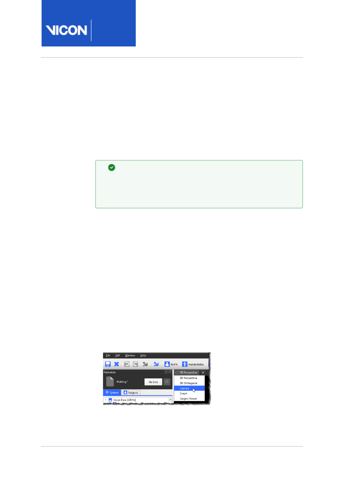
Nexus
Reference
Guide
ViconNexus user interface
Vicon Motion Systems Ltd. 13-Nov-2018 Page 257 of356
View pane
The View pane enables you to visualize data from one or more cameras in
real time or from a saved file.
You can visualize the system components or subjects selected in the
Resources pane, or the results of processing performed in the Tools pane
during any stage of the Nexus motion capture workflow.
Tip
By default, the View pane is in the center of the Nexus window.
You cannot detach or change the position of this pane, but you
can open a separate floating view workspace.
You view and manipulate the type of data you specified for display in the
view pane below the toolbar. By default, a single view pane is displayed.
You can display multiple view panes, and specify the same or different view
in each. You can manually resize each view pane.
You can control the way data is visualized in the view panes, for example,
by changing the display options for force plate, in the Options dialog box
(press F7).
View panes contain the following controls:
•View pane toolbar Select the view to use, manage any display options for
the selected view, and specify the number and arrangement of views
displayed in the toolbar at the top of the view pane. The lists and
buttons on the View pane toolbar that are available from all types of
view panes are described below.
•View list
Nexus
Reference
Guide
ViconNexus user interface
Vicon Motion Systems Ltd. 13-Nov-2018 Page 258 of356
• Select the views to be displayed from the View list:
•3D Perspective view, page 259 Reconstructed motion capture data from
all active Vicon cameras in 3D (three-dimensional) perspective, that is
length, width, and depth.
•3D Orthogonal view, page 261 Motion capture data in 3D perspective
viewed from a specified point of sight, or direction, of the capture
volume.
•Camera view, page 263 Raw 2D motion capture data from an individual
Vicon camera or a supported digital video camera.
•Graph view, page 267 Various values of one or more selected items (such
as the x, y, and z components of a marker trajectory) plotted against
each other or against time.
•Subject viewer, page 275 The base pose for the labeling skeleton
template (VST) of the currently selected subject. Also facilitates
manual labeling.
•Standard buttons
Specify the number and arrangement of view panes displayed in the
workspace using the following buttons:
•Horizontal Split the current view horizontally into two view panes.
•Vertical Split the current view vertically into two view panes.
•Close Close the current view pane. (You cannot close the default View
pane in the center of the Nexus window.)
Depending upon the view selected, there may be additional lists and
buttons available.
•Time bar, page 276 You manipulate offline trial data using the time bar.

Nexus
Reference
Guide
ViconNexus user interface
Vicon Motion Systems Ltd. 13-Nov-2018 Page 259 of356
3D Perspective view
The 3D Perspective view enables you to visualize reconstructed motion
capture data from all active Vicon cameras, or Vicon Skeleton Templates
(.vst), or Vicon Skeleton (.vsk) files, in 3D (three dimensional) perspective,
that is length, width, and depth.
You can view 3D data live in real time or from a previously saved trial.
In addition to the standard buttons (see View pane, page 257), the 3D
Perspective view contains the following sections:
•3D Perspective view pane toolbar You manage the display of 3D data in
the active workspace by selecting these buttons at the top of the view
pane:
•Center camera on selection Position the currently selected data in the
center of the view pane. This option does not automatically zoom in on
the selected data.
•Export Workspace to AVI Enables you to create video files of a selected
3D workspace (including any labeled subject). For details, see
Export
3D Workspace as AVI
in the
Vicon Nexus User Guide
.
•3D Perspective view You view and manipulate 3D data in the view pane
below the toolbar. For example, you can dolly, orbit, pan, tilt, truck, and
zoom to control the portion of the capture volume that is displayed.
3D Perspective view usage tips
When you display a 3D Perspective view pane:
• If you have additional 3D Perspective or other view panes (3D
Orthogonal, Camera, Graph view or Subject Viewer panes) open, you can
change the number and arrangement of view panes displayed in the
workspace to suit your preferences using the view pane toolbar buttons
at the top right of the view pane.
• You can highlight the representations of specific cameras in the 3D
Perspective view pane workspace by selecting one or more cameras
under the Vicon Cameras node in the System Resources pane.
• You can configure display options in the Options dialog box (F7), such as
force plate display options.

Nexus
Reference
Guide
ViconNexus user interface
Vicon Motion Systems Ltd. 13-Nov-2018 Page 260 of356
To visualize data in the view pane:
1. Either stream live camera data (click Go Live), or double-click the name
of a processed data file on the Data Management tab.
2. From the View pane toolbar, select 3D Perspective. The reconstructed
3D data from all cameras is displayed in a single 3D Perspective view
pane.
Information about the current trial appears at the top of the view pane:
• NO TRIAL if no trial is loaded
• LIVE if Nexus is in Live mode
• The trial file name if you are viewing a trial in Offline mode.
3. If you want to change the way this text is displayed, open the Options
dialog box (F7), and configure the Workspace Title option.

Nexus
Reference
Guide
ViconNexus user interface
Vicon Motion Systems Ltd. 13-Nov-2018 Page 261 of356
3D Orthogonal views
The 3D Orthogonal view pane enables you to visualize motion capture data
in 3D perspective viewed from a specified point of sight, or direction, of the
capture volume.
You can view 3D data from an orthogonal perspective live in real time or
from a previously saved trial.
In addition to the standard buttons (see View pane, page 257), the 3D
Orthogonal view pane contains the following sections:
•3D Orthogonal view pane toolbar Manage the display of data in the
active workspace with the following list and button at the top of the
view pane:
•Orthogonal view list Set the point of sight by selecting one of the
following orthogonal projections (also called orthographic projections): -
Z (default), +Z, +X, -X, +Y, -Y
•Center camera on selection Position the currently selected data in the
center of the view pane. This option does not automatically zoom in on
the selected data.
•3D Orthogonal view View and manipulate 3D data in the view pane
below the view pane toolbar. For example, you can dolly, tilt, truck, and
zoom (but not pan or orbit) to control the portion of the capture volume
that is displayed.

Nexus
Reference
Guide
ViconNexus user interface
Vicon Motion Systems Ltd. 13-Nov-2018 Page 262 of356
3D Orthogonal view usage tips
When you display a 3D Orthogonal view pane:
• To visualize data in the view pane, either stream live camera data (click
Go Live), or double-click a processed data file on the Data
Management tab.
• Reconstructed 3D data from all cameras is displayed in a single 3D
Orthogonal view pane, initially from the -Z (top) view.
• The current trial name appears at the top of the view pane:
• – NO TRIAL if no trial is loaded
• – LIVE if Nexus is in Live mode
• – The trial file name if you are viewing a trial in Offline mode.
• If you want to change the way this text is displayed, open the Options
dialog box (F7), and configure the Workspace Title option.

Nexus
Reference
Guide
ViconNexus user interface
Vicon Motion Systems Ltd. 13-Nov-2018 Page 263 of356
Camera view
The Camera view pane enables you to view raw 2D motion capture data
from an individual Vicon camera or a supported digital video camera either
live in real time or from a previously saved raw capture file (.x2d).
In addition to the standard buttons (see View pane, page 257), the Camera
view pane contains the following sections:
•Camera view pane toolbar Manage the display of camera data in the
workspace with the following controls and buttons in the Camera view
pane toolbar at the top of the view pane:
•View list Manage the way camera data is visualized in the active
Camera view pane by selecting the following options from the View
drop-down list:
•3D Overlay Overlay multiple Camera view panes on top of each other,
so all camera views are displayed in a single view pane. Each camera is
rendered in a unique color.
Default: Off
•Rotated Rotate the Camera view, so it is corrected to the vertical axis
defined in the system calibration (which corresponds to the earth's
vertical axis). It also enables you to manually rotate the view by
dragging the view left or right. Information from the camera
calibration is required to present the rotated view.
Default: Off
•Combined Correctly model lens distortions and display a corrected
camera view with the 3D view rendered underneath the 2D camera
view. This is particularly useful for viewing Vicon optical data overlaid
onto images from video cameras. You can burn this overlay information
onto the .avi file to view in other applications using the Export 3D
Overlay Video pipeline operation.
Default: Off
•Zoom to Fit Zoom the selected Camera view pane to fit the full
workspace.
Default: On
•Zoom to Window See Display camera sensor window, below.

Nexus
Reference
Guide
ViconNexus user interface
Vicon Motion Systems Ltd. 13-Nov-2018 Page 264 of356
•Export Workspace to AVI button Enables you to create video files,
including labeled subject, of a selected 3D workspace. For more
information, see
Export workspace as AVI
in the
Vicon Nexus User Guide
.
•Paint a mask onto the camera button Paint over any cells in the camera
grid (displayed when the button is clicked) that contain unwanted
reflections. When a cell is painted, its background color changes from
black to blue. The camera mask consists of blue cells obscuring
unwanted reflections. For more information, see
Mask unwanted
reflections
in the
Vicon Nexus User Guide
.
•Erase a mask from the camera button Erase a previously painted cell
from a mask. When an individual cell is erased, its background color
changes from blue to black, and any reflection that had previously been
obscured is visible again.
•Clear the mask from the camera button Automatically remove a
previously painted mask. When the mask is cleared, the background
color of any previously painted cells changes from blue to black, and any
reflections that had previously been obscured are visible again.
•Display grayscale blobs button When selected, grayscale blobs are
displayed in the Camera view.
•Display centroid circles button When selected, centroids are displayed in
the Camera view.
•Display camera sensor window button Displays a visual representation of
the windowing that occurs at higher frame rates. The windowed area is
indicated by a rectangle within the Camera view, showing the size and
position of the active window on the camera sensor. (Windowing is also
displayed in the 3D Overlay view and in Rotated view). For instant
feedback on the area that is captured and to save room on the screen,
you can zoom in to the sensor window. To do this, in a Camera view, from
the View menu, select Zoom to window, or to turn on Zoom to window
for all windows, press the hot keys: Ctrl+Shift+Z.
To toggle the display of windowing, in the Options dialog box (F7), click
the Camera Limits option and in the Properties pane, select the Sensor
Window property.
•Lock / Unlock button (displayed with standard buttons on the right) Lock
the current Camera view pane, so that it is effectively detached from the
selection set and is not affected by any subsequent selections in other
open view panes. This is useful for displaying views from different

Nexus
Reference
Guide
ViconNexus user interface
Vicon Motion Systems Ltd. 13-Nov-2018 Page 265 of356
cameras in multiple Camera views.
When the active clip changes, or when you switch from Live to Offline
mode, the selection is automatically unlocked.
•Camera view pane View and manipulate 2D data in the view below the
view pane toolbar. For example, you can orbit, truck, dolly, and zoom the
displayed data.

Nexus
Reference
Guide
ViconNexus user interface
Vicon Motion Systems Ltd. 13-Nov-2018 Page 266 of356
Camera view usage tips
To visualize optical data in a Camera view:
1. Either stream live camera data (click Go Live), or double-click a raw data
file (.x2d file) on the Data Management tab.
2. In the System Resources tree, select one or more cameras whose data
you want to visualize. To do this, expand the Vicon Cameras node and
then click on the sub node for one or more cameras.
The 2D data from each selected camera is displayed in a separate
Camera view pane.
To visualize video data in a Camera view:
Note that a video camera is listed under the Video Cameras node for
each .avi file you have loaded.
1. Do one of the following:
• Double-click on the desired movie file on the Data Management
tab; or
• From Windows Explorer, drag the required .avi file onto a Camera view
pane. (If you drag an .avi file onto a Camera view pane, the current
trial closes, and no file name is displayed in the View pane, because
the .avi file is not associated with any particular trial.); or
• Import an .avi file into the current trial by running the Import AVI
pipeline operation. This operation is located in the File Import
operations list in the Pipeline Tools pane.
2. If you make a change to the video file camera settings, an asterisk (*)
appears next to the configuration name at the top of the System
Resources tree, reminding you that there are unsaved changes to your
system configuration.
3. In the System Resources pane, expand the Video Cameras node and
select one or more digital video cameras.
4. To play offline video, click Play in the tool bar. The video from each
camera selected is displayed in a separate Camera view pane.
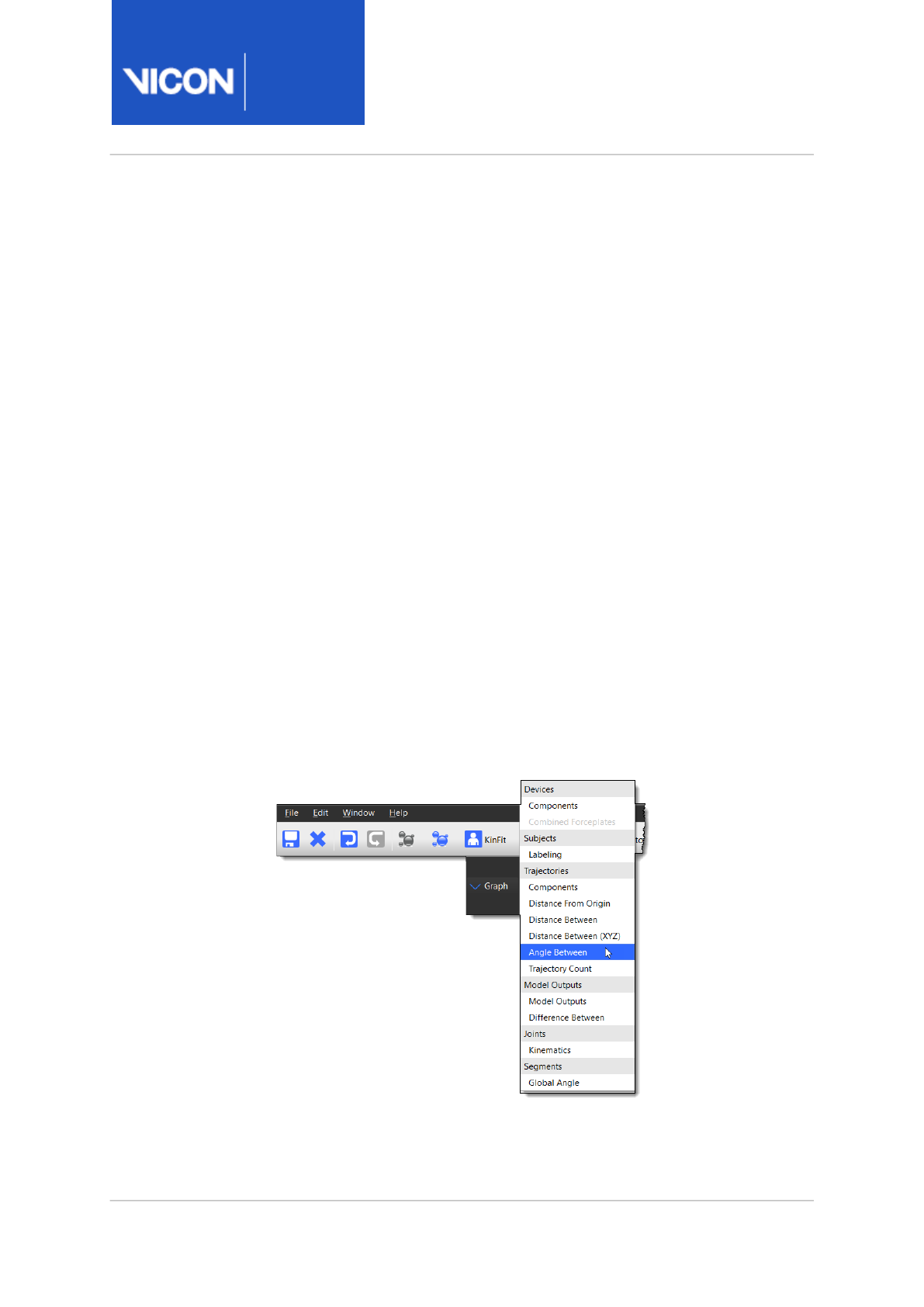
Nexus
Reference
Guide
ViconNexus user interface
Vicon Motion Systems Ltd. 13-Nov-2018 Page 267 of356
Graph view
The Graph view enables you to view various values of one or more selected
items (such as the x, y, and z components of a marker trajectory) against
each other or against time, or analog data from any supported force plates
or EMG devices.
You can view graphs of motion data live in real time or from a previously
saved reconstructed and labeled trial.
In addition to the standard buttons (see View pane, page 257), the Graph
view contains the following controls.
Graph view pane toolbar
Manage the display of graph data in the view pane with the following
controls at the top of the view pane. The Graph view pane toolbar leads you
left to right through the normal flow of operations required to plot a graph
for the selected elements
•Graph type drop-down list
Select the type of graph to be displayed from the categories in this drop-
down list. (Graph types that are not available for the data currently
selected in the System Resources pane are dimmed.) See Graph type
options, page 270.)
Nexus
Reference
Guide
ViconNexus user interface
Vicon Motion Systems Ltd. 13-Nov-2018 Page 268 of356
•Differentiate the graph button Specify, for the currently displayed
graph, the current variable, its first derivative (velocity or angular
velocity), or its second derivative (acceleration or angular acceleration)
by selecting the desired options from this drop-down list:
• x (none)
• x' (velocity)
• x" (acceleration)
A graph of a trajectory will have X, Y, and Z axes, but when differentiated
to x' (velocity), the axes will change to X', Y', and Z' axes.
•Choose the components of the graph button Specify the
components of the selected graph type to be plotted in the active Graph
view by selecting the desired options from this drop-down list (only
components that you have selected forGraph view are available).
This option enables you to focus on a component of particular interest,
which occupies more of the workspace. When multiple components are
plotted, each is always shown on a separate axis, and the components
shown are applied to all channels visible in the workspace. The number
of vertically stacked graphs displayed in the workspace depends on the
number of options selected for graph view, and from those, the number
selected from this list.
•Legend button Display a legend for the current graph listing the
color for each trace plotted, the subject (if multiple subjects are loaded),
and the name of each element being plotted in that trace. To display a
temporary tooltip with this information, hovering the mouse pointer over
the button. To open a separate splitter pane to permanently display the
legend to the right of the graph view, click the button.
•Choose the rotation order button If you select a segment in the
Subjects Resources pane, you can select Global Angle from the Graph
type drop-down list. This enables the Choose the rotation order button.
Clicking on the Rotation Order button lists the angle convention choices
of Helical (default), XYZ, XZY, etc. This enables you to choose either a
Tip
You can then use the Add Monitor button to provide real-time
bio-feedback on differentiated as well as positional data. For
more information, see Using monitors, page 39.
Nexus
Reference
Guide
ViconNexus user interface
Vicon Motion Systems Ltd. 13-Nov-2018 Page 269 of356
Helical or an Euler angle convention. The Euler angle convention has
multiple rotation order conventions represented by XYZ, XZY, etc.
•Create a monitor button Add the selected graph component as a
monitor entry in the Monitors communications pane.
•Scale the graph to fit (horizontal) button Zoom out the x-axis to
show the complete range of the trace for the selected time period. This
is useful if you have zoomed in a long way and now want to quickly see
the entire graph again.
•Lock the horizontal graph axis button Lock the horizontal axis to
prevent further rescaling of the axis once it is at a desired length of
frames. This is useful if you want the horizontal axis range to stay the
same.
•Scale the graph to fit (vertical) button Scale the y-axis so that all the
data in selected traces for the currently visible x-axis is visible. If there
are multiple components in the selected traces, they are all set to the
same range, that is, the range required to show all the data in the
component with the largest range.
If Nexus is in Live mode, this button acts as a toggle, enabling you to
leave this mode switched on or off. If on, when plotting live data, the y-
axis is automatically scaled as the data changes so all traces are visible.
Manually zooming switches the automatic mode off.
•Lock the vertical graph axis button Lock the vertical axis to prevent
further rescaling of the axis once it is at a desired range. This is useful if
you want the vertical axis range to stay the same.
•Scale the graph to fit (horizontal and vertical) button Scale the x
and y axes simultaneously to fit the horizontal and vertical ranges of
data.
•Lock / Unlock button (displayed with standard buttons on the right)
Lock the current Graph view pane, so that it is effectively detached from
the selection set and is not affected by any subsequent selections in
other open view panes. This is useful for displaying elements in multiple
Graph views.
When the active clip changes, or when you switch from Live to Offline
mode, the selection is automatically unlocked.

Nexus
Reference
Guide
ViconNexus user interface
Vicon Motion Systems Ltd. 13-Nov-2018 Page 270 of356
Graph view pane
View and manipulate graph data in the view pane below the view pane
toolbar. For example, you can slide the displayed data along the axes or
zoom in and out.
Graph type options
Devices
Displays graphs for the components of the analog signals from force plates
or EMG devices. This is useful for examining analog device activity such as
force plate strikes or EMG voltage output. You can also display graphs
displaying units of mm/s2 of analog signals from an accelerometer device,
which allows you to examine voltage output from an accelerometer device.
•Components: View force plate data such as Forces, Moments, and Center
of Pressure, or to view Other Devices, such as EMG and Accelerometer
data.
•Combined Forceplates: Enables you to view combined selected outputs
from multiple force plates. For more information, see View combined
output from multiple force plates in the
Vicon Nexus User Guide
.
Subjects
•Labeling: View labeling data for the current subject
Trajectories
Displays graphs for one or more marker trajectories selected, such as the
global XYZ components of a marker, a marker's distance from the global
origin, distance between two markers, angle between three markers, or a
count of how many reconstructed markers are in any current frame of data.
•Components: View the X, Y, and Z coordinates of a marker selected in
either the Subjects Resources pane or the 3D Perspective view.
•Distance From Origin: View the straight-line distance between the
chosen point and the global origin. Plots the distance from the capture
volume origin to each selected marker. This is useful for plotting velocity
or acceleration of markers.

Nexus
Reference
Guide
ViconNexus user interface
Vicon Motion Systems Ltd. 13-Nov-2018 Page 271 of356
•Distance Between: View the straight-line distance between two markers
selected in either the Subjects Resources pane or the 3D Perspective
view.
•Distance Between (XYZ): View the global X, Y, and Z components of the
distance between two markers selected in either the Subjects Resources
pane or the 3D Perspective view. Plots the absolute distance (as a
vector) between two selected markers. This is useful, for example, to see
how the distance between two markers that are assumed to have a rigid
relationship changes over time. This graph type calculates a separate
component (X,Y,Z) distance between the two markers. It is only available
when two markers are selected in the 3D Perspective view.
•Angle Between: Plots the angle between the two vectors formed by any
three markers selected in either the Subjects Resources pane or from
the 3D Perspective view pane. This is useful for seeing how the group of
markers moves over time.
•Trajectory Count: View the number of markers (both labeled and
unlabeled) currently reconstructed in the 3D Perspective view. Plots the
total number of trajectories over time visible to the Vicon cameras (if
streaming Live data in real time) or processed in trial (if viewing
previously captured data in a file).
Model Outputs
Displays three graphs of the components of any output variables (such as
Angles, Forces, Moments, Powers, or Bones) that have been calculated by
Vicon Plug-in Gait for your model. This is useful for visually validating data
produced by post-capture processing models without having to load the
data into Polygon for full biomechanical analysis or reporting.
•Model Outputs: Select to view outputs from calculations run in post-
capture pipeline.
•Difference Between: The difference between first and second selected
model output in X, Y and Z (example: New Patient 1:LAnkleAngles - New
Patient 1:RAnkleAngles)

Nexus
Reference
Guide
ViconNexus user interface
Vicon Motion Systems Ltd. 13-Nov-2018 Page 272 of356
Joints
Displays graphs of the components of selected joint kinematics, either
three graphs for Euler angles or six graphs for a helical vector (as
appropriate for the joint type). This is useful for displaying approximate
joint angles between linked segments of the labeling template worn by
your subject in real time. This type of graph can only be plotted for a
subject that has been kinematically fitted (for example, one that has had
the Kinematic Fit operation, found under Core Processing on the Pipeline
Tools pane, run on it).
•Kinematics: Select to view kinematic angles between linked segments of
the subject. (To see these angles, you must have performed kinematic
fitting on labeled trajectories.)
Segments
•Global Angle The angle between the selected segment and the global
origin in rotation (RX, RY, RZ) and translation (TX, TY, TZ).
Graph view usage tips
• When zooming into or out of graph data, the display of grid lines can be
set to guide the eye toward the selected area of focus. Major grid lines
remain at their normal weight, while any minor grid lines gradually fade.
To obtain this behavior, in the Options dialog box (F7), select Graph and
then ensure the Show Minor Grid Lines property is selected.
• The Graph view contains rulers and axes along the left and bottom edges
and graph traces for the item being plotted. The contents of the axes of
the Graph view depend on whether the system is in Live or Offline mode:
•Live The y-axis vertical ruler is on the right side of the graph and the x-
axis horizontal ruler is below the graph. The y-axis represents the live
frame, so is constantly updated in real time. The x-axis represents the
time (in frames). It starts on the right side, which is labeled 0 (zero) and
is labeled from right to left with decreasing negative values to reflect the
number of frames away from the live frame. Because the current time is
always zero, the Time Bar is not displayed at the bottom of the
workspace.
•Offline The y-axis vertical ruler is on the left side of the graph and the x-
axis horizontal ruler is below the graph. The rulers indicate the scale and

Nexus
Reference
Guide
ViconNexus user interface
Vicon Motion Systems Ltd. 13-Nov-2018 Page 273 of356
the variable names that are being plotted and the horizontal and vertical
axes are labeled to indicate the units of measurement used. The graph
traces represent the actual data and are scaled to the current rulers. You
can select elements to graph in the Resources pane or the 3D
Perspective view.
If the elements selected have more than one component, these
components are shown on separate, vertically stacked axes sharing a
common x-axis. You can select the components to be displayed from the
Component Options list in the Graph view pane toolbar.
• You navigate in Graph view in the usual way, using the mouse. For
example, to pan and zoom, click and hold the right mouse button and
then drag the mouse up/down to zoom along the Y axis or drag left/right
to zoom along the X axis. To pan the graph in any direction, hold the left
and right mouse buttons down at the same time as you drag the mouse.
• When you select a data type in the System Resources pane (Trajectories,
Model Outputs, Devices, or Joints), Nexus will attempt to intelligently
update the Graph view type to match the data type you've selected.
To visualize data in a graph:
1. Either click the Go Live button or on the Data Management tab, double-
click a processed data file (.c3d) file.
2. Select the elements to be graphed (eg markers, model outputs, force
plates, etc) in any of the following ways:
• In the Subjects Resources pane, expand the desired Subject node,
expand the relevevant sub-node (eg Markers, Model Outputs, etc), and
then select (CTRL+click to select multiple elements) one or more
elements; or
• In a 3D Perspective view pane, select one or more elements displayed
in the view pane.
The number of elements you select depends on the type of graph you
wish to view.
3. From the view pane toolbar select Graph.
If required, you can select additional elements to add to the Graph view
pane. If you are viewing trajectories, each one is displayed in a different
color trace. You can use the Legend button in the Graph view pane
toolbar to identify the color trace used for each trajectory. If the trace
Nexus
Reference
Guide
ViconNexus user interface
Vicon Motion Systems Ltd. 13-Nov-2018 Page 274 of356
for any additional elements is not visible, use the Fit Horizontally, Fit
Vertically, or Fit Both Horizontally and Vertically buttons.
4. If you want to save a particular graph view (for example, specific
trajectories that you have selected), save your configuration using the
Configuration menu button next to the View Type list on the Nexus
toolbar.
You can visualize raw analog signals in a Graph view by selecting Show Raw
from the device node context menu in the System Resources pane.
Graphing joint kinematics
1. Select the joints that are of interest.
2. From the Graph Type list in the Graph view pane toolbar, select the
Kinematics option under the Joints section to plot the joint angles for
the selected joints.
Kinematic components for root segments include Tx, Ty, and Tz,
accompanied by Rx, Ry, and Rz. These components can be further
differentiated to also include Rx', Ry', Rz', Rx'', Ry'', Rz'', Tx', Ty', Tz', Tx'',
Ty'', and Tz''. Designate the T's as translations and the R's as rotations
between the two segments that the joint connects.
Note: The ' and " designations are used to indicate velocity and
acceleration, respectively.
Tip
You can plot the Mean and Standard Deviation values for a
component in a Graph view pane.
To do this, in the Options dialog box, select Graph from the list on
the left.
Click Show Advanced and then select the Show Mean and SD
check box.
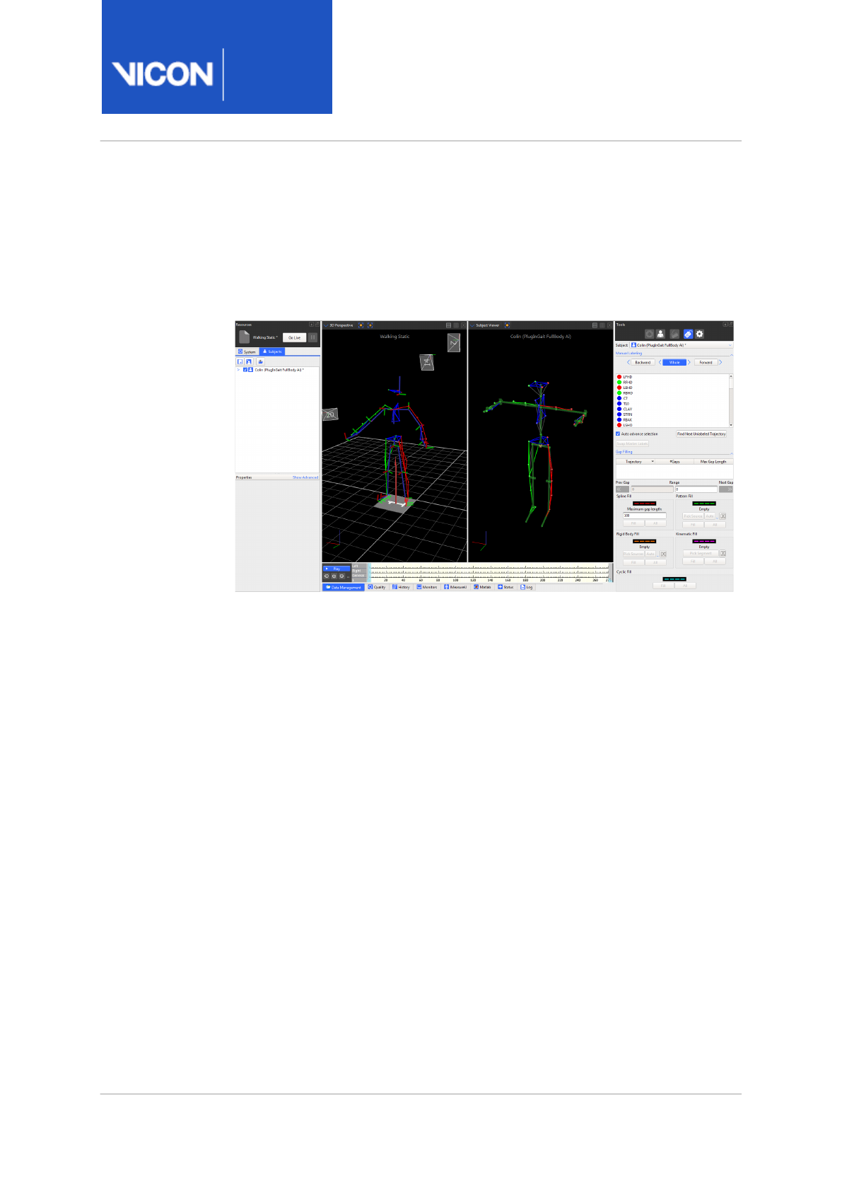
Nexus
Reference
Guide
ViconNexus user interface
Vicon Motion Systems Ltd. 13-Nov-2018 Page 275 of356
Subject viewer
The Subject Viewer pane enables you to display the base pose for the
labeling skeleton template (VST) of the currently selected subject. This
helps you ensure that your subjects adopt the correct base (neutral) pose.
You can also use the Subject Viewer to assist with manual labeling by
making it easy to correlate reconstructions with the appropriate marker. To
do this:
1. Ensure the Label/Edit Tools pane is displayed and that the view pane
displays both a 3D view of the subject whose markers you are labeling
and the Subject Viewer.
2. Select a marker in the Subject Viewer.
Nexus switches to labeling mode. The mouse pointer changes to display
the name of the currently selected marker and the marker is highlighted
in the Manual Labeling list.
This works both ways: selecting a marker in the Manual Labeling list
highlights the marker in the Subject Viewer.
3. In the 3D view, click on the marker that is the equivalent of that
highlighted in the Subject Viewer and the Manual Labeling list.
The next marker is automatically highlighted, ready for you to continue
labeling.
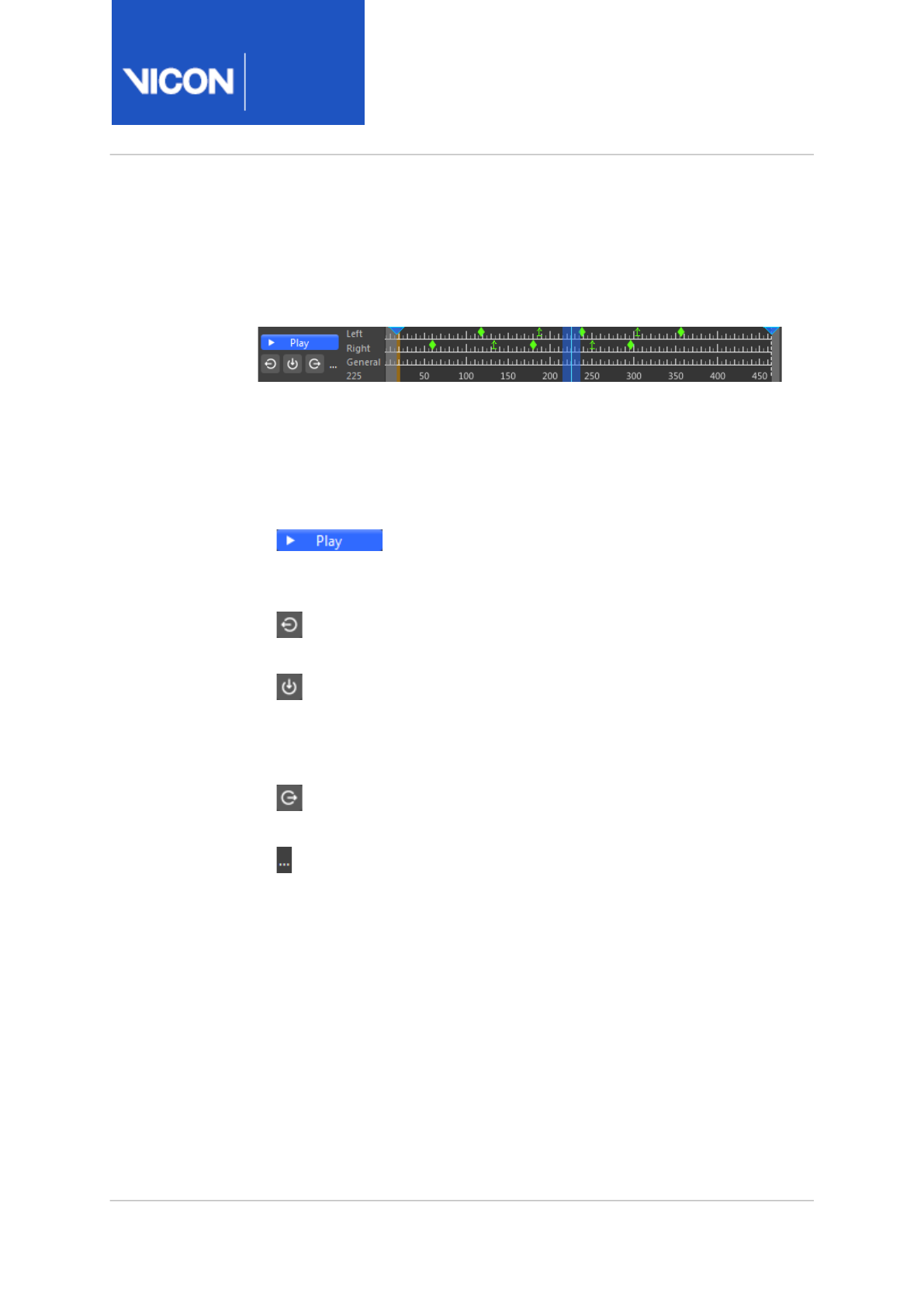
Nexus
Reference
Guide
ViconNexus user interface
Vicon Motion Systems Ltd. 13-Nov-2018 Page 276 of356
Time bar
You manipulate offline trial data with time and synchronization
characteristics in the time bar.
The time bar is available at the bottom of all types of view pane when you
play back data from a saved trial. It is displayed only when the system is in
Offline mode (click the Go Offline button), and contains the following
controls:
•Play/Stop button
Play forward continuously through trial. When clicked,
the button switches to its Stop setting.
•Jump to Previous Event button
Play backward one event (when in Event Identification Mode).
•Enter Event identification mode button
Switch between modes in which you can manipulate data based on
time (button off) or events (button on). For details on manipulating data,
see
Add events to trials
in the
Vicon Nexus User Guide
.
•Jump to the next event button
Play forward one event (when in Event Identification Mode).
•Ellipsis
Display a context menu from which you can select the following
options to manipulate trial data (you also can display the context menu
by right-clicking anywhere on the time bar):
•Zoom to Trial Reset the ruler to the full trial timescale after zooming in
or out.
•Zoom to Region-of-Interest Reset the ruler to the range of frames
identified by the Start Range Frame indicator and the End Range
Frame indicator (for details on these indicators, see below).
•Set Current Frame Opens the Go to Frame dialog box, in which you can
specify the required frame. When you click OK, the current time
indicator moves to the specified frame.

Nexus
Reference
Guide
ViconNexus user interface
Vicon Motion Systems Ltd. 13-Nov-2018 Page 277 of356
•Set Region-of-Interest Opens the Set Region of Interest dialog box, in
which you can specify the start and end frames for the region of
interest.
•Play Every Frame When selected, the datastream ships all frames.
(Rendering is unaffected.) Select this option only if you want to
perform calculations on the datastream data.
•Replay Speed Specify the playback speed relative to real time by
selecting one of the following sub options: 1/10, 1/4, 1/2, 1, 2, or Other.
The Other option displays a dialog box in which you can set a specific
value.
Default: 1
•Trajectory Tails Specify the length of tails for selected trajectories, as a
value in frames before and after every gap by selecting one of the
following from the displayed context menu: 0 frames, 25 frames, 50
frames, 100 frames, 200 frames, or Other. The Other option displays
the Trajectory Tails dialog box in which you can set a specific value.
Default: 100 frames
•Clear All Events Clear all marked events from the ruler. Note that you
can also use the Delete Timebar Events pipeline operation to delete
events from a specified range of frames.
• You can also manage data playback using the keyboard. For example, you
can use keys and mouse actions to manage the timescale displayed in
the timeline, the time bar data displayed in the workspace, and event
identification mode. For more information see
Hot keys and shortcuts
in
the
Vicon Nexus User Guide
.
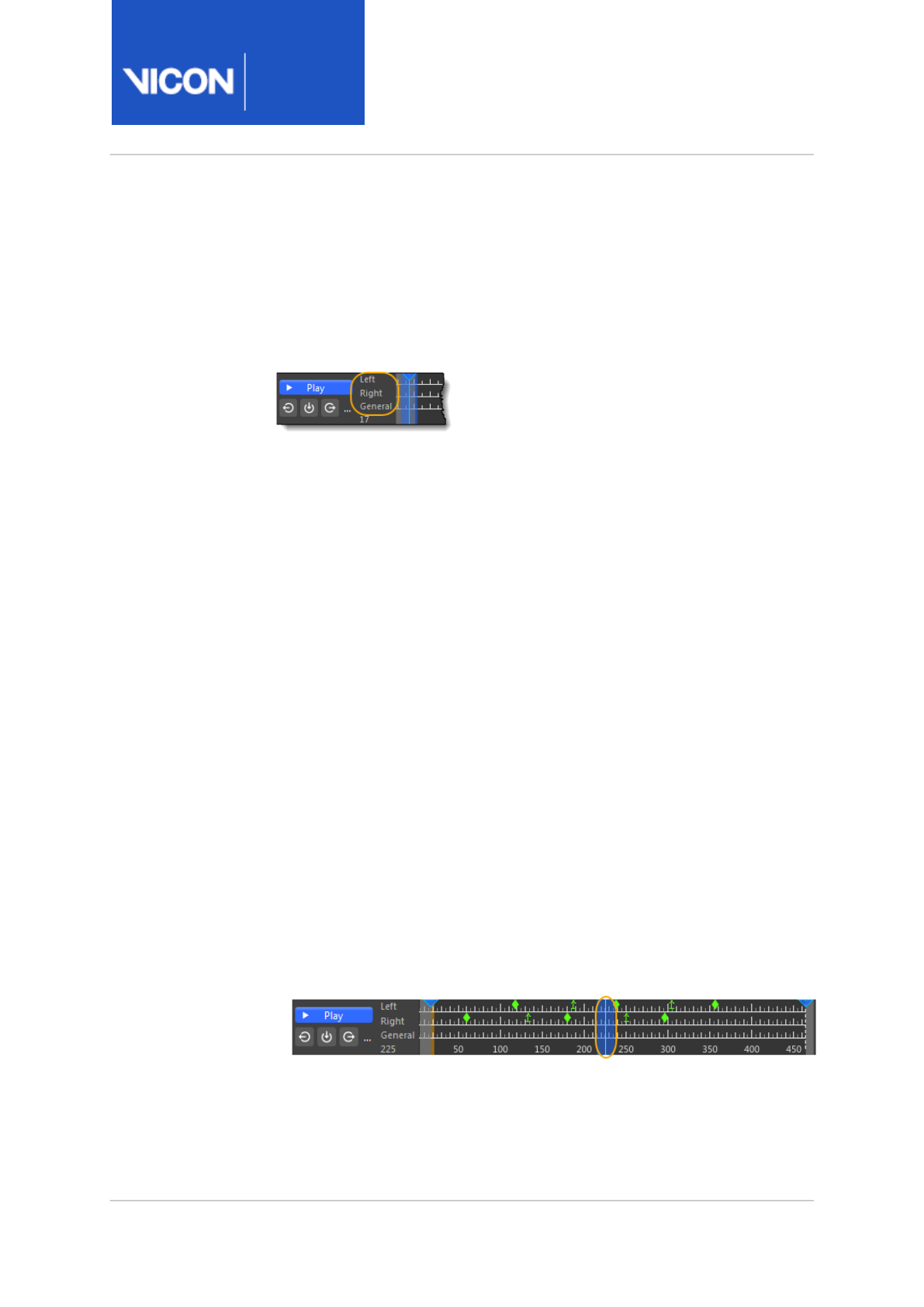
Nexus
Reference
Guide
ViconNexus user interface
Vicon Motion Systems Ltd. 13-Nov-2018 Page 278 of356
You identify or manipulate trial data based either on time or event,
depending on the whether the Enter Event Identification Mode button is on
or off with the following areas of the time bar.
•Timeline
The overall time span and the range of frames currently viewable in the
workspace. The timeline is split into default contexts:
•Left The top rule on the timeline contains markers for any events
specified for the left context.
•Right The middle rule on the timeline contains markers for any events
specified for the right context.
•General The bottom rule on the timeline contains markers for any
events specified for the general context.
•Selected frame The number of the currently selected frame is
displayed at the bottom of the timeline.
•Timescale
Displays the overall span of time for the range of frames that can
currently be selected. The current frame of trial data is displayed in the
label on the left side of the scale at the bottom of the timeline. You can
move the visible portion of the timescale or zoom in or out of it (for
details, see
Shortcuts for working with the time bar
in the
Vicon Nexus
User Guide
).
•Indicators
Indicate a selected characteristic of the trial data for playback. You can
move the indicators along the timeline to manually move the data
playback forward or backward and display the desired frame in the view
pane. Indicators are displayed when appropriate for the playback
operation:
•Current time indicator
Indicates the current time of the data playback along the timeline. This
vertical bar spans the entire height of the timeline. In Event
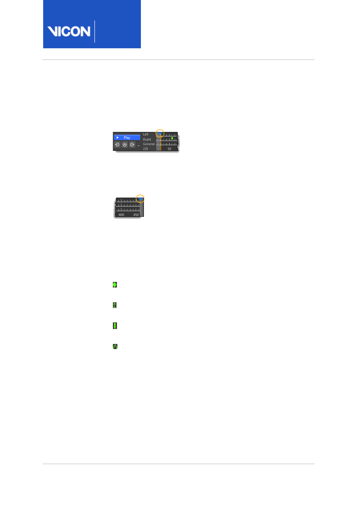
Nexus
Reference
Guide
ViconNexus user interface
Vicon Motion Systems Ltd. 13-Nov-2018 Page 279 of356
Identification Mode, the current time indicator follows the mouse
cursor. You can click and drag the mouse for slow-motion playback.
When you release the mouse button, the event context menu is
displayed.
•Start of range indicator
Indicates the frame specified as the start of the range of trial data to
play back or process. This blue triangle is initially positioned on the
first frame at the top of the timeline.
• End of range indicator
Indicates the frame specified as the end of the range of trial data to
play back. This blue triangle is initially positioned on the last frame at
the top of the timeline.
•Event markers
Indicate a specific event to be applied or displayed in the currently
selected frame of the trial data:
• Foot Strike The point at which the trial subject's foot contacts the
ground.
• Foot Off The point at which the trial subject's foot leaves the
ground.
• General A point at which the trial subject performs a user-defined
event.
• Custom A point at which the trial subject performs a user-defined
event that can be named.
•Delete Event <Type> Deletes the selected event.
•Delete All Events at Frame x Deletes all events previously set for the
current frame.
•Clear All Events Deletes all events previously set for the entire trial.
To work with an event, you must be in Event Identification Mode (see
Enter Event identification mode button, page 276).

Nexus
Reference
Guide
ViconNexus user interface
Vicon Motion Systems Ltd. 13-Nov-2018 Page 280 of356
Tools pane
Configure settings, run tools, and view data processing results in the
sections below the toolbar in the Tools pane. The contents of this section
depend on the button you select in the Tools pane toolbar.
The Tools pane contains the following tabs:
•System Preparation tools, page 281
•Subject Preparation tools, page 291
•Capture tools, page 292
•Label/Edit tools, page 298
•Pipeline tools, page 299

Nexus
Reference
Guide
ViconNexus user interface
Vicon Motion Systems Ltd. 13-Nov-2018 Page 281 of356
System Preparation tools
System calibration is a process by which Vicon Nexus calibrates the system
based on specialized calibration objects (whose dimensions and relative
marker positions are known). It consists of several procedures:
•Camera calibration The camera calibration process calculates the
physical position and orientation of each Vicon camera in the capture
volume based on the movement of the calibration object. Nexus uses
this information to determine each camera's physical position and
orientation in the capture volume, to correct for any lens distortion, and
to set internal camera parameters.
•Set volume origin During this process, Nexus measures the position of
the calibration object and uses this information to identify the origin of
the world (center of the capture volume) and its horizontal and vertical
axes. These volume origin and axes are referred to as the global
coordinate system. The global origin coordinates are always (0,0,0). The
global axes coordinates are given in the form (x, y, z), where x is a
horizontal axis, y is the horizontal axis perpendicular to x, and z is the
vertical axis. If the floor of your volume is uneven, you can also use the
Set Floor Plane option as part of this process.
For basic step-by-step instructions on how to complete these procedures,
see
Calibrate a Vicon system
in the
Vicon Nexus User Guide
.
To enable you to perform these procedures, the System Preparation Tools
pane contains the following sections (to show additional options, click
Show Advanced in the relevant section).
•Video Calibration Setup section, page 282
•Mask Cameras section, page 282
•Aim Cameras section, page 282
•Calibrate Cameras section, page 282
•Set Volume Origin section, page 283
•Static Video Calibration section, page 284
•Manage Camera Calibration section, page 284
•Camera Calibration Feedback section, page 285

Nexus
Reference
Guide
ViconNexus user interface
Vicon Motion Systems Ltd. 13-Nov-2018 Page 282 of356
Video Calibration Setup section
Enables you to activate video calibration mode by clicking the Activate
button. Note that if you haven't saved the current configuration, you will be
prompted to do so before you can proceed.
You automatically activate calibration mode when you click Start in the
Mask Cameras section, the Aim Cameras section or the Calibrate Cameras
section.
To exit calibration mode, click the Deactivate button in the Video
Calibration Setup section.
Mask Cameras section
Enables you to automatically create cameras masks to obscure all
reflections visible to the Vicon cameras. By enabling the Advanced
properties, you can choose to mask all cameras or just selected cameras.
For more information on how to mask cameras, see
Mask unwanted
reflections
in the
Vicon Nexus User Guide
.
Aim Cameras section
Enables you to check the positioning of Vicon cameras around the capture
volume with real-time feedback. You normally perform this step before you
begin calibration check.
For more information on how to aim cameras, see
Aim Vicon cameras
in the
the
Vicon Nexus User Guide
.
Calibrate Cameras section
Enables you to calibrate the Vicon cameras to determine their positions,
orientations, and lens properties, which enables Nexus to produce accurate
3D and 2D (video) data from motion data captured throughout the capture
volume. The Advanced properties contain the following options:
•Wand The calibration object to be used during the dynamic stage of the
camera calibration process.
Default: Active Wand v2 (both optical cameras and digital video cameras
are calibrated with an Active Wand)

Nexus
Reference
Guide
ViconNexus user interface
Vicon Motion Systems Ltd. 13-Nov-2018 Page 283 of356
•Calibration Type Specify whether to use a Full Calibration or a quicker
Calibration Refinement. (If you have not already calibrated or aimed all
cameras, you cannot perform a calibration with the Calibration
Refinement option.) For more information on calibration options, see
Understand camera calibration refinement, page 289.
•Cameras to Calibrate Can be All Cameras or Selected Cameras (that is,
the cameras selected in the System Resources tree). The selection is
applied when the Stop button in the Calibrate Cameras section is
clicked.
Default: All Cameras
•Refinement frames The minimum coverage (in number of frames)
required per camera in the final phase of the refine camera calibration
process.
Default: 1000. For more information, see Understand camera calibration
refinement, page 289.
•Wand Ratio Tolerance (Advanced setting) Tolerance of the distance
between the markers on the wand (expressed as a ratio), to enable it to
be labeled in 2D.
Default 0.2.
•Wand Straightness Tolerance Tolerance in alignment of wand markers
(relating to the maximum angle allowable between the markers), to
enable it to be labeled in 2D.
•DV Calibration frames The minimum coverage (in number of frames)
required per DV camera for the calibration to autostop (if Auto Stop is
selected).
Default: 500
•Auto Stop Whether or not Nexus is to automatically stop the camera
calibration process when sufficient data has been collected.
For more information on how to calibrate cameras (both optical and video),
see
Calibrate Vicon cameras
in the
Vicon Nexus User Guide
.
Set Volume Origin section
Enables you to define the global origin and the axes of the world (in the
context of the capture volume).
The Advanced options are:

Nexus
Reference
Guide
ViconNexus user interface
Vicon Motion Systems Ltd. 13-Nov-2018 Page 284 of356
•L-Frame The calibration object to be used for setting the volume origin.
Default: 5 Marker Wand & L-Frame
•Start/Set Origin and Cancel buttons Enable you to start, set the origin
and cancel setting the origin.
•One Marker Enables you to set the origin to the selected marker.
•Three Markers Enables you to set the origin to the selected three
markers.
•Set Floor Plane Enables you to set the position of the floor plane in
Nexus by using markers in the volume to automatically define it. For
more information, see Calibrate the floor plane in the
Vicon Nexus User
Guide
.
Static Video Calibration section
If you are not using an Active Wand, you use this section to calibrate digital
video cameras included in your Nexus system. This enables 3D overlay from
Vicon cameras to be displayed with the 2D video from the digital video
cameras.
Manage Camera Calibration section
Contains the following controls:
•Auto number cameras Ensure you have aimed the cameras (seeAim
Vicon cameras) before clicking this button. Automatically numbers the
currently connected Vicon cameras in ascending order, according to
their position in the capture volume. Automatic numbering starts with
the camera furthest from the volume origin. The cameras are then
numbered in a clockwise direction around the volume. If your cameras
are positioned at different levels, the cameras in the level that contains
the most cameras are numbered first.
•Reset Removes all non-existing cameras, clears the calibrated position
for existing cameras, and reverts all calibration parameters to their
default settings. This enables you to recalibrate the system from a clean
starting point.
•Load Navigate to and select a previously saved camera calibration (.xcp
file) defining settings for the Vicon cameras and any supported digital
video cameras in your Nexus system.

Nexus
Reference
Guide
ViconNexus user interface
Vicon Motion Systems Ltd. 13-Nov-2018 Page 285 of356
Camera Calibration Feedback section
Enables you to view system calibration processing progress and status
information. This section contains the following controls:
•Progress bar This bar displays a percentage indicating the progress of
the overall camera calibration process.
•Camera This column contains the device ID for each Vicon camera being
calibrated.
•Wand Count For each Vicon camera, this value identifies the number of
frames it has captured containing the calibration object. Initially, the
entry for the number of wand frames is displayed in red; the entry turns
green when Nexus has acquired enough wand data to calibrate that
camera, typically 1000 frames.
By default, the calibration process stops when the camera with the
lowest frame count reaches the number of frames specified in the
Refinement frames parameter in the Calibrate Cameras section.
•World Error Displays the calibration error in millimeters. World error is
calculated per camera from the Image Error in pixels and the distance of
the camera to the center of the volume. Cameras further away, with the
same image error, display a larger world error.
•Image ErrorThis value (RMS distance in camera pixels) indicates the
accuracy of the 3D reconstruction of the markers. This value represents
the difference between the 2D image of each marker on the camera
sensor and the 3D reconstructions of those markers projected back to
the camera's sensor. Acceptable values depend on factors such as the
size of the capture volume and the camera lens type.
Additional features in this section enable you to export your calibration, to
identify calibration issues or to ensure that the current calibration
conforms to an established standard.
• Export a calibration as a CSV file, page 286
•Compare calibrations, page 286
•Set calibration error threshold, page 287
•Sort columns, page 288
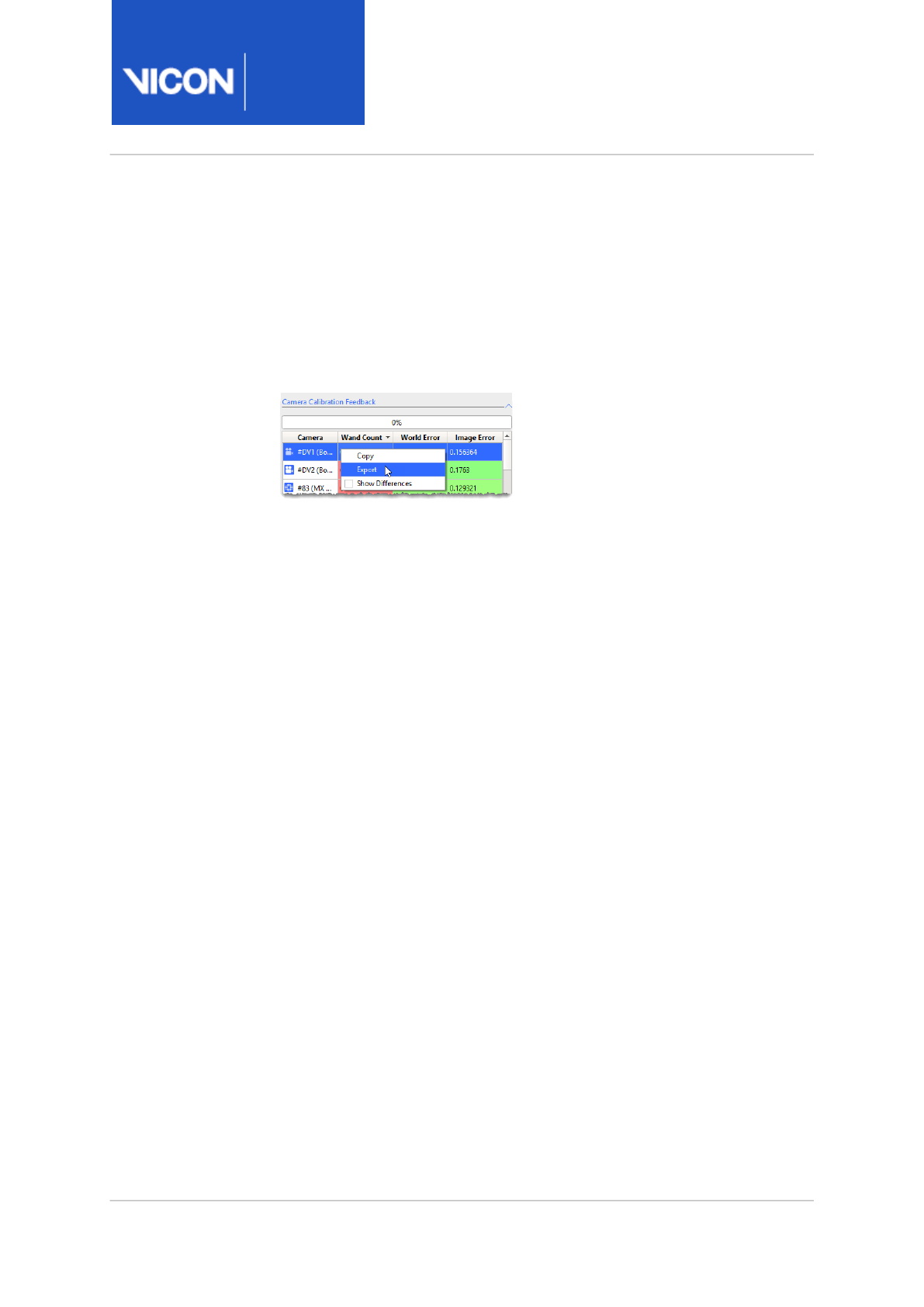
Nexus
Reference
Guide
ViconNexus user interface
Vicon Motion Systems Ltd. 13-Nov-2018 Page 286 of356
Export a calibration as a CSV file
You can export the current calibration as a .
csv
file. This helps you to
monitor your calibration standards over time.
To export a calibration as a CSV file:
1. In the Camera Calibration Feedback section, right-click and then click
Export.
2. Enter a file name, ensure the file extension is .csv and click Save.
Compare calibrations
You can compare the current calibration results with the results from the
previous calibration.
To compare the current and last calibrations:
• In the Camera Calibration Feedback section, right-click and then select
Show Differences.
The World Error and Image Error columns display the differences
between the two calibrations.
If the results from the latest calibration are better (ie produce smaller
errors) than the previous one, the columns are displayed in green to
yelllow.
If the results from the latest calibration are worse (ie produce larger
errors) than the previous one, the columns are displayed in red to orange.
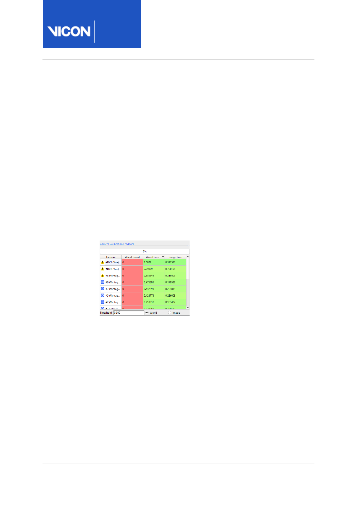
Nexus
Reference
Guide
ViconNexus user interface
Vicon Motion Systems Ltd. 13-Nov-2018 Page 287 of356
Set calibration error threshold
You can specify a maximum calibration error, above which cameras are
flagged as having an error that is higher than the threshold that you have
set.
To set a calibration error threshold:
• At the bottom of the the Camera Calibration Feedback section, set the
error threshold (World or Image).
After calibration, in the Camera Calibration Feedback section, cameras with
an error greater than this value are displayed with a yellow warning icon
instead of the normal blue camera icon. The default setting (0.000)
disables any warnings.
In the following example, the error threshold is set to 0.5mm, so that the
three cameras with a calibration error greater than this are displayed with a
warning icon:
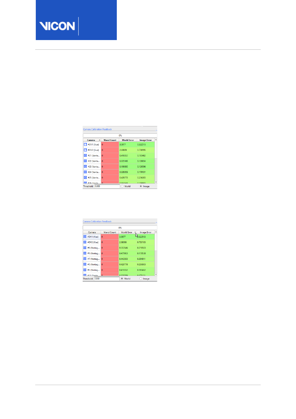
Nexus
Reference
Guide
ViconNexus user interface
Vicon Motion Systems Ltd. 13-Nov-2018 Page 288 of356
Sort columns
If you are working with a large number of cameras, it is useful to be able to
sort the results to enable you to quickly identify problematic cameras. You
can now sort the columns in the Camera Calibration Feedback section by
clicking on the required column heading.
The default sorting is on the camera number (low to high):
To make it easy to find cameras with the highest errors, you can sort on
World Error or Image Error, displaying the cameras with the highest errors
at the top of the column:
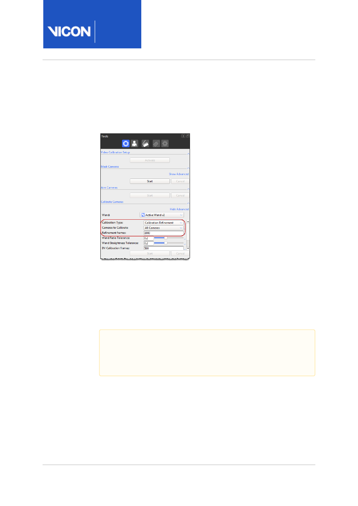
Nexus
Reference
Guide
ViconNexus user interface
Vicon Motion Systems Ltd. 13-Nov-2018 Page 289 of356
Understand camera calibration refinement
Calibration refinement provides a fast, reliable way to fine-tune an existing
camera calibration, for example, as part of your daily calibration workflow
before beginning the day's captures.
Full Calibration consists of an initialization phase, followed by a multi-pass
process to optimize the camera positions.
Calibration Refinement uses exactly the same process as full calibration,
but without the initialization phase. It provides a reliable way to refine
existing calibration data to produce a calibration that is as good as a full
calibration of the same system, but is much faster.
To save time while maintaining accuracy, you can perform both full and
refinement calibration on any selected camera(s), as well as on all cameras.
Under most circumstances, the default value for Refinement frames
produces good results. If you need to improve the results, particularly if you
are using larger numbers of cameras, try increasing this value.
Important
As Calibration Refinement operates on existing data, you must have
loaded a full calibration into Nexus before running the refinement
calibration.

Nexus
Reference
Guide
ViconNexus user interface
Vicon Motion Systems Ltd. 13-Nov-2018 Page 290 of356
Note that the value specified for Refinement frames applies to the number
of frames used:
• By Auto Stop
• In the refinement phase of a Full Calibration
• When running a Calibration Refinement
When to use a refinement calibration
The following table gives guidance on when to use each type of calibration:
Scenario Type of calibration
A full calibration of all cameras has
recently been performed, but since
then, several cameras have been
repositioned to another part of the
volume.
Full Calibration on just the
moved cameras, with a short
wand wave that concentrates
on the moved cameras.
A full calibration of all cameras has
recently been performed, but during
the trial, one camera was accidentally
slightly bumped.
Full Calibration on the bumped
camera, with a short wand
wave that concentrates on the
bumped camera.
Since yesterday's full calibration,
environmental factors may have
caused small changes in the camera
positions and it is necessary to re-
calibrate them accurately and quickly.
Calibration Refinement of all
cameras, with a normal length
wand wave that includes all
cameras.

Nexus
Reference
Guide
ViconNexus user interface
Vicon Motion Systems Ltd. 13-Nov-2018 Page 291 of356
Subject Preparation tools
You must create a Vicon labeling skeleton template (.vst file), or import an
existing one, for each type of subject whose motion is to be captured and
analyzed in Nexus. You only need to do this once for each type of subject.
Sample .vst file are provided under the Nexus model templates folder (by
default, C:\Program Files (x86)\Vicon\Nexus2.#\ModelTemplates).
You must then calibrate the .vst file to create a Vicon labeling skeleton (.vsk
file) that is scaled for each specific subject of that type. You must do this
the first time you intend to capture a new subject and each time you want
to use a different marker arrangement on the same subject.
For detailed information about creating and using custom Vicon labeling
skeleton templates, see
Creating Labeling Skeleton Templates (VSTs)
.
To enable you to produce .vst and .vsk files, the Subject Preparation Tools
pane contains the following sections:
•Subject Select a specific Vicon labeling skeleton template (.vst file) or
Vicon labeleling skeleton (.vsk file). The contents of this list depends on
the subject nodes enabled for capture (ie displayed with a check mark
next to them) in the Subjects Resources pane.
•Subject Capture Enables you to capture a brief trial to obtain subject
data. You can use the subject data to build or calibrate a Vicon labeling
skeleton template and to manually label a subject.
•Subject Calibration Enables you to manage the subject calibration
process to create a Vicon labeling skeleton (.vsk file) for a specific
subject.
•Labeling Template Builder Enables you to build a generic Vicon labeling
skeleton template (.vst file) for a type of subject (for example, humans,
wearing a particular marker set). You subsequently use this .vst file to
calibrate a Vicon labeling skeleton (.vsk file) for a specific subject of that
type (for example, Jane, wearing the same particular marker set).

Nexus
Reference
Guide
ViconNexus user interface
Vicon Motion Systems Ltd. 13-Nov-2018 Page 292 of356
Capture tools
The Capture Tools pane enables you to collect motion data.
Collecting motion data involves identifying where in a motion capture trial
database to store the data, specifying the type of source data that is to be
captured, optionally configuring any remote triggering, optionally
determining any automated processing to be performed, and managing the
capture process. You can capture trials manually or configure Nexus to
capture trials automatically.
For basic instructions on collecting data, see
Capture movement trials
in
the
Vicon Nexus User Guide
.

Nexus
Reference
Guide
ViconNexus user interface
Vicon Motion Systems Ltd. 13-Nov-2018 Page 293 of356
The Capture Tools pane contains the following sections:
•Trial Type list Create or manage configurations for the motion capture
trial types specified in the Capture Tools using the configuration
management section at the top of the pane. (For information on
managing configurations, see
Manage configurations
in the
Vicon Nexus
User Guide
.)
•Next Trial Setup Specify identification and information details for the
way Nexus is to store data for this trial in a motion capture database:
•Session A link to the active subject\session node in the currently
loaded trial database. Click the link to open the Communications
window, displaying the Data Management tab, or bring it to the front if
it is already open, with the active node highlighted. If you make a
different session the active node, the Session link is updated.
Default: Identified by system
•Trial Name The name under which to save the trial data in the motion
capture database.
Default: Blank if you are creating a new trial in a new session, or if the
trial is the latest of several in a session and Auto increment is selected
(see below), the system automatically names it after the preceding
trial and increments numbering by 1.
Do not use the following special characters in a trial name:
\ backslash
. period
/ slash
, comma
< left angle bracket
? question mark
> right angle bracket
*asterisk
: colon
" double quotation mark
| vertical bar
% percent
$ dollar sign

Nexus
Reference
Guide
ViconNexus user interface
Vicon Motion Systems Ltd. 13-Nov-2018 Page 294 of356
•Description Enter any description you want to specify for the trial. This
description is displayed on the Data Management tab in the row
associated with the captured trial.
Default: Blank
•Notes Enter any notes you want to specify for the trial. These notes
are displayed on the Data Management tab in the row associated with
the captured trial.
Default: Blank
•Auto increment trial number Choose whether or not to have Nexus
automatically add a numerical suffix to the trial name for each
subsequent trial, for example, Trial001, Tria002, Trial003, etc.
Default: Selected
•Permit overwrite of existing files Choose whether or not to have Nexus
overwrite an existing data file without prompting you with a warning
that it has the same name as that specified in the Trial Name field with
this trial data.
Note that if Auto increment trial number is selected and the file name
that would be created using the next sequential numerical suffix is the
same as that for an existing file, that previous file is overwritten.
Default: Cleared
•Data Source Setup Specify the type of motion data to be captured by
your Nexus system in the Data Source Setup section of the Capture
Tools pane:
•Device Data Analog signals captured by any third-party devices such
as force plates or EMG devices.
Default: Selected
•Optical Camera Data Marker images visible to the Vicon optical
cameras
Default: Selected
•Video Camera Data Digital video captured by any connected digital
video cameras.
Default: Selected
•Auto Capture Setup You can configure Vicon Nexus to automatically
capture trials using the following controls:
•Range Use an external remote control device to trigger data capture in
your Vicon system. The remote control device must be connected to

Nexus
Reference
Guide
ViconNexus user interface
Vicon Motion Systems Ltd. 13-Nov-2018 Page 295 of356
an MX Giganet or Vicon Lock+ unit in your Vicon system (for details,
see
Go Further with Vicon MX T-Series
or
Vicon Vantage Reference
Guide
), and the sync outputs (GPO pins) for the remote functionality
must be configured under the relevant Vicon Connectivity node in the
System Resources pane.
•Capture before Start Specify the number of seconds of data to
record prior to capture being triggered either manually (with the
Start button) or automatically (based on timecode or a remote
control device).
•Stop after duration Specify the number of seconds of data to
record after which capturing will automatically stop.
•Triggers Use a labeling percentage value that you specify or an
external timecode source to trigger data capture in your Vicon system.
The timecode source must be connected to an an MX Giganet or Vicon
Lock+ unit (for details, see
Go Further with Vicon MX T-Series
or
Vicon
Vantage Reference Guide
), and the corresponding timecode options
must be configured under the relevant Vicon Connectivity node in the
System Resources pane.
•Start on Labeling (%) Captures automatically start when a
subject first fully enters the volume. Set the labeling percentage
(ie, the percentage of markers expected from the total number
of markers in your subject's labeling skeleton) that needs to be
recognized by Nexus within the capture volume for the subject
to be considered as fully in the volume and therefore to trigger
capture start.
•Stop on Labeling (%) Captures automatically stop when the
subject leaves the volume. Set the labeling percentage (ie, the
percentage of markers expected from the total number of
markers in your subject's labeling skeleton) that needs to be
recognized by Nexus within the capture volume for the subject
to be considered to have left the volume and therefore to trigger
capture stop.
•Start/Stop on remote trigger Start and/or stop capture on the
activation of a remote trigger. This option is disabled if no
remote trigger devices are recognized.
Trigger the start of the capture from your remote control device.

Nexus
Reference
Guide
ViconNexus user interface
Vicon Motion Systems Ltd. 13-Nov-2018 Page 296 of356
After you have acquired the data you need, trigger the stop of
the capture from your remote control device.
•Start on Timecode Select this check box and specify the
timecode at which capture should automatically start.
•Stop on Timecode Select this check box and specify the
timecode at which capture should automatically stop.
For further details on the use of timecode functionality in Vicon
systems, see the
Vicon Vantage Reference Guide
or
Go Further
with Vicon MX T-Series.
•Start/Stop over network Broadcast a UDP message over an intranet or
direct network cable connection to or from another application (or
instance of Nexus) to trigger capture start and stop.
•Address Enables you to select the network interface (first field) and
UDP port (second field) on which to broadcast.
•Arm button To set the system to a state where it is ready to accept a
trigger signal for automatic capture based on a remote control device,
click the Arm button.
•Lock button If you want to enable the system to remain ready to
receive subsequent remote capture signals after the capture is
stopped, click the Lock button to the right of the Arm button.
•Post-Capture Pipeline Setup Enables you to specify any automatic post-
processing that you want Nexus to perform on the captured data:
•Run pipeline after capture Whether or not to run a previously defined
pipeline immediately after the trial is captured. Select the pipeline that
you want from the drop-down list.Default: Cleared
•Capture section Enables you to manage the motion capture process and
view the number of frames captured and the current duration in seconds
during processing:
•Start/Stop Click this button to start a capture. When clicked, the
button switches to the Stop setting.If you have set the Stop after
Duration or Stop on Timecode settings in the Auto Capture Setup
section, or if there is data in the buffer that has still to be written to
disk, the button switches to Stopping until the capture has completed.
If you click the button while it displays Stopping, the capture stops,
and you will lose any data that was due to be captured, or that is
currently in the buffer but not yet written to disk.

Nexus
Reference
Guide
ViconNexus user interface
Vicon Motion Systems Ltd. 13-Nov-2018 Page 297 of356
•Cancel Click this button to cancel an active capture.
•Frames Captured Displays the number of frames captured in the
current trial. This number increments until the motion capture process
is stopped.
•Trial time The amount of time elapsed during the current capture is
displayed in hh:mm: ss(ff) format, where hh is hours, mm is minutes, ss
is seconds and ff is frames. For example, a 2.5 second capture at 50 Hz
(125 frames) is displayed as 00:00:02(125).

Nexus
Reference
Guide
ViconNexus user interface
Vicon Motion Systems Ltd. 13-Nov-2018 Page 298 of356
27 http://www.vicon.com/faqs
Label/Edit tools
The Label/Edit Tools pane enables you to manually label trial data and fill
any gaps in trial data. It contains the following sections:
•Subject You select the subject to manually label or edit in the Subject
list at the top of the Label/Edit Tools pane. To appear in this list, the
subject's node must be selected (ie, its check box must be selected in
the Subjects tree in the Resources pane).
•Manual Labeling You manually label reconstructed trial data for the
selected subject using the controls in this section. For instructions, see
Manually label a trial
in the
Vicon Nexus User Guide
.
•Backward, Whole, and Forward buttons. Label the currently selected
trajectory either for the whole trial, or backward or forward from the
current frame. Use Whole if you are confident that the trial data contains
very few mislabels or swaps. Use Backward or Forward to label the trial
data backwards or forwards from the current frame, without affecting
other frames.
•Auto advance selection When selected, Nexus automatically advances to
the next marker in the Manual Labeling list. Default: Selected
•Find Next Unlabeled Trajectory When you click this button, Nexus
advances to the next frame that contains an unlabeled marker trajectory.
•Swap Marker Labels To correct swapped marker labels, select the
relevant two marker trajectories and then click this button.
•Gap Filling Enables you to identify and fill gaps in reconstructed marker
trajectories. See also the FAQ
What gap-filling algorithms are used in
Nexus 2?
on the Vicon website27.
Tip
When you are manually labeling a subject, to help you place the
selected label onto the correct 3D reconstruction, in the 3D
Perspective view pane the pointer changes to include a tooltip
that identifies the label. You can also use the Subject Viewer to
help you identify the markers (see Subject Viewer, page 275).

Nexus
Reference
Guide
ViconNexus user interface
Vicon Motion Systems Ltd. 13-Nov-2018 Page 299 of356
Pipeline tools
The Pipeline Tools pane enables you to create and manage a customized
sequence of operations to automate the processing of a trial.
Pipeline processing is optional, but is useful for automating the data
processing operations that you use frequently or on a large number of
trials.
The Pipeline Tools pane contains the following sections:
•Available Operations section
The Available Operations section enables you to select the type of
pipeline you want to create and the operations to run. Operations are
grouped under the following types:
•File Import operations, page 303 For automating the import of trial files
into Vicon Nexus from third-party software packages.
•Core Processing operations, page 303 For automating reconstruction,
labeling, and kinematic fitting to produce 3D trajectories from raw
marker data.
•Subject Calibration operations, page 305 For automating the processing
of system and subject calibration.
•Events & Timebar operations, page 308 For automating operations
involving events and/or normally performed using the time bar.
•Fill Gap & Filter Data operations, page 310 For automating the post-
processing of data, such as gap-filling.
•Data Processing operations, page 317 For automating the production of
model outputs (forces and moments, joint angles, etc).
•File Export operations, page 320 For automating the export of trial files
from Nexus to third-party software packages.
•System operations, page 323 For automating offline camera calibration
and applying a codec to video.
•Legacy operations, page 324 For automating the processing of legacy
trial data.
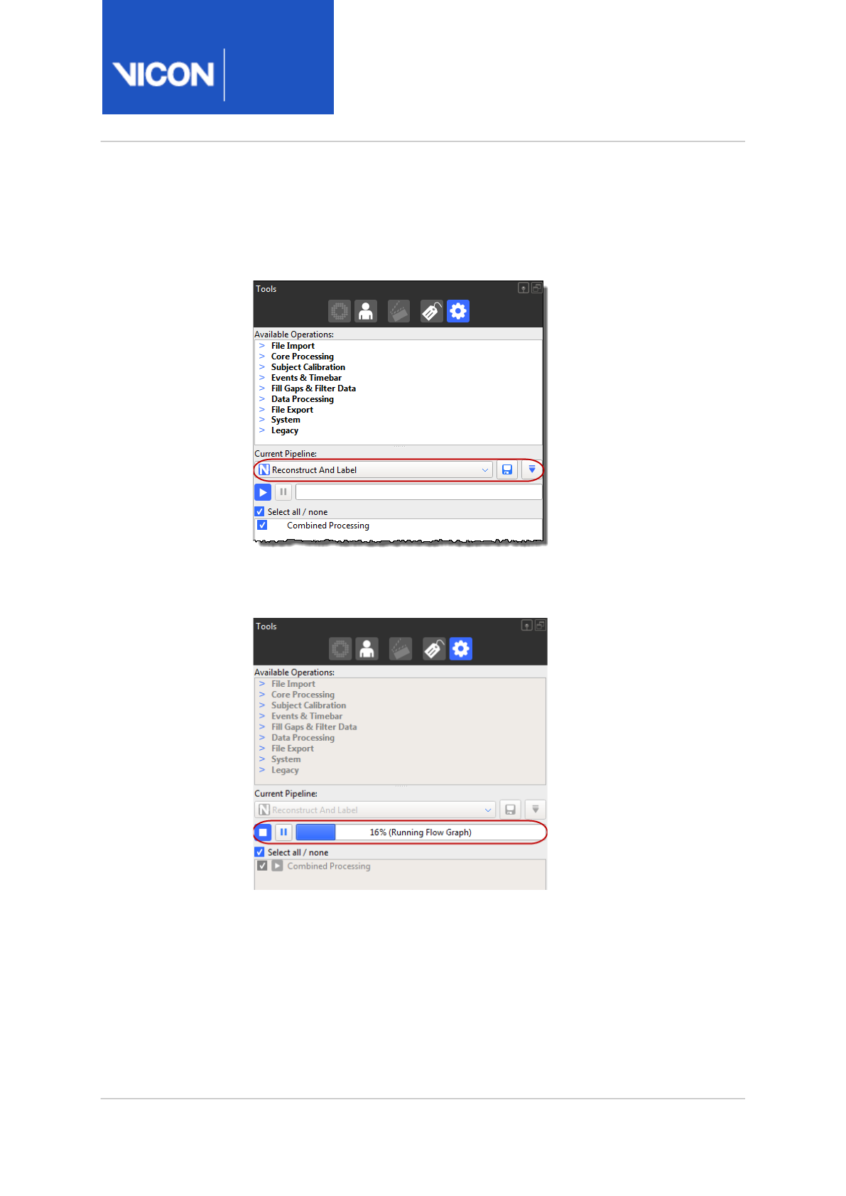
Nexus
Reference
Guide
ViconNexus user interface
Vicon Motion Systems Ltd. 13-Nov-2018 Page 300 of356
•Current Pipeline section
At the top of the Current Pipeline section, the configuration
management controls enable you to create or manage configurations for
the settings specified in the Pipeline Tools pane.
The middle of the Current Pipeline section enables you to manage the
pipeline operations and view their status with the playback controls and
progress bar.

Nexus
Reference
Guide
ViconNexus user interface
Vicon Motion Systems Ltd. 13-Nov-2018 Page 301 of356
In the list at the bottom of the Current Pipeline section, you can view the
operations included in the currently loaded pipeline.
For information on using pipelines, see
Work with pipelines
in the
Vicon
Nexus User Guide
.
Tip
Pipeline operations are run in the order they appear in this list.
You can drag operations into the desired position in the list.
Alternatively, you can run an individual operation by right-
clicking on it and clicking Run selected Op.
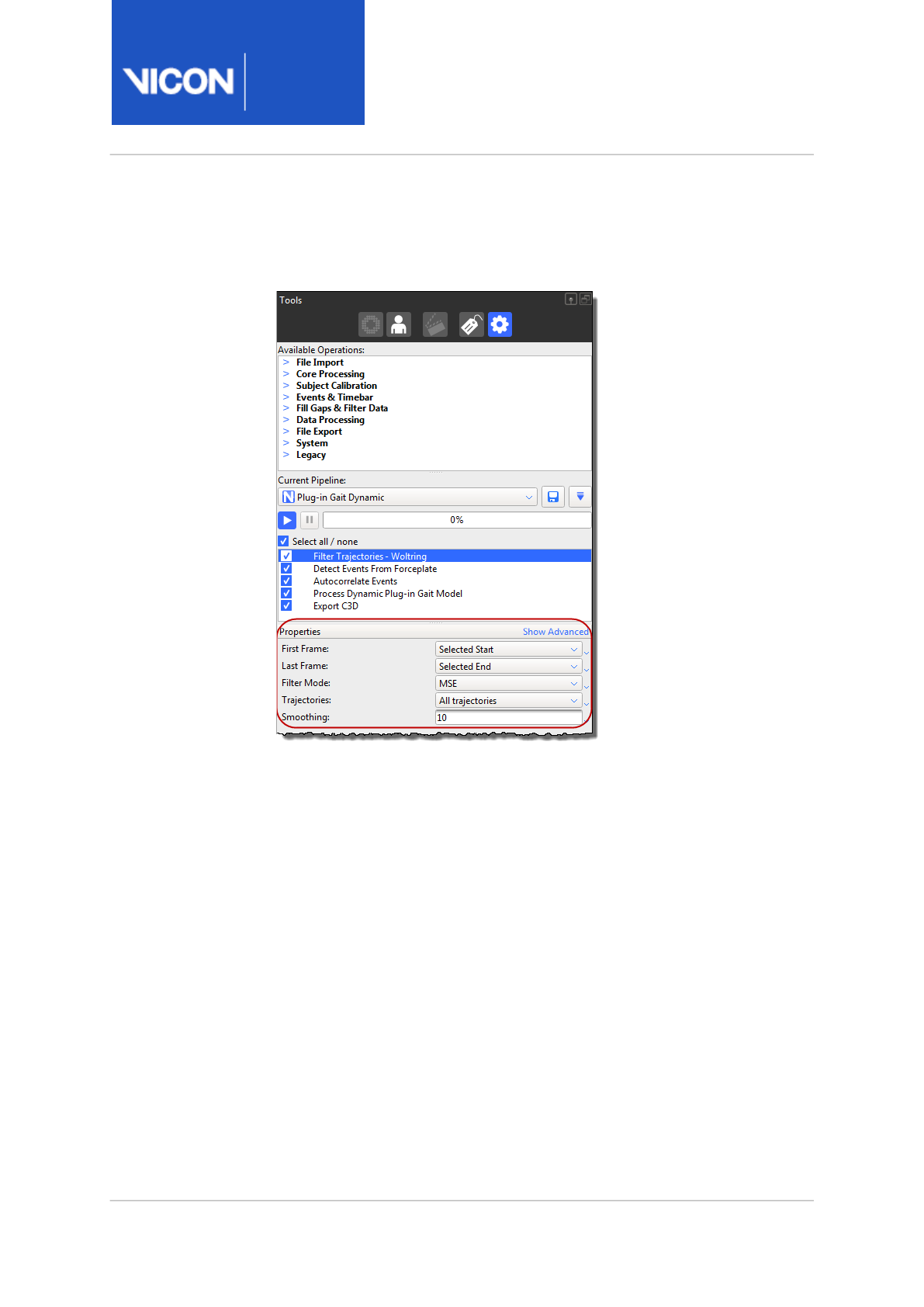
Nexus
Reference
Guide
ViconNexus user interface
Vicon Motion Systems Ltd. 13-Nov-2018 Page 302 of356
•Properties pane
You can view or change settings for the selected pipeline operation in
the Properties pane at the bottom of the Pipeline Tools pane.
Pipeline operations
Pipeline operations are found in the Pipeline Tools pane, in the Available
Operations section.
• File Import operations, page 303
•Core Processing operations, page 303
•Subject Calibration operations, page 305
•Events & Timebar operations, page 308
•Fill Gap & Filter Data operations, page 310
•Data Processing operations, page 317
•File Export operations, page 320
•System operations, page 323
•Legacy operations, page 324

Nexus
Reference
Guide
ViconNexus user interface
Vicon Motion Systems Ltd. 13-Nov-2018 Page 303 of356
File Import operations
Use File Import operations to automate the import of trial files to Vicon
Nexus from third-party software packages.
Operation Description
Import AVI Import a video .avi file to be saved and associated with
the current trial.
Import MP Import subject parameters specified in a .mp file into the
active subject.
Import VSK Import a labeling skeleton (.
vsk)
file.
Import XCP Import a calibration file (
.xcp
) into the current trial to
replace the current calibration.
Core Processing operations
Use Core Processing operations to automate the processing of offline
reconstruction, labeling, and kinematic fitting to produce 3D trajectories
from raw marker data.
Operation Description
Combined
Processing
Performs one or more of: reconstruction, labeling, and
subject motions. Running this operation is faster than
running each process individually.
Reconstruct 3D trajectories are reconstructed from the raw 2D marker
data.
Label Controls how 3D trajectories are labeled with subject
data

Nexus
Reference
Guide
ViconNexus user interface
Vicon Motion Systems Ltd. 13-Nov-2018 Page 304 of356
Operation Description
Kinematic
Fit
Controls how the labeling skeleton contained in the .vsk
is kinematic-fitted to the marker data. In addition to
specifying the frames on which to operate, you can
adjust settings for:
•Prior importance: Weighting given to the
uncalibrated values from the VST. Range is 0-100,
default is 25.
•Mean pose ratio: Ratio of tracking pose as prior
(where 0 = mean pose only; 1 (default) = external
(or tracking) prior only.)
Tip
The equivalent settings for Live processing can be found in the
Local Vicon System properties, page 166, found in the System
Resources pane.

Nexus
Reference
Guide
ViconNexus user interface
Vicon Motion Systems Ltd. 13-Nov-2018 Page 305 of356
Subject Calibration operations
Use Subject Calibration operations to automate the processing of labeling
skeleton calibration.
Operation Description
Set Autolabel
Pose
Sets the pose for Autolabel Static to be the pose at
the selected frame.
Autolabel Static Run on a reconstructed static trial to automatically
label the labeling skeleton in a single frame, using
information from the .
vst
file. It matches the shape of
the reconstruction to the shape of the subject
template for that pose.
The labels are applied to the whole trajectory, not just
the chosen frame. It works best when all the markers
have been reconstructed and there are no additional
markers or clutter in the scene.
This operation does not require a .
vsk
file.
Scale Subject
VSK
Scales the labeling skeleton to be the same size as a
labeled set of reconstructions on a particular frame.
The scale factor is calculated assuming that the
subject is in the same pose as was used for Autolabel
Static (see above).
(Note that this scaling respects any constraints that
you may have specified in the template. For example
if your template specifies (ie a StaticParameter) that
a segment is 100mm long, the segment will not be
scaled. Only parameters are considered for scaling.)
Functional
Skeleton
Calibration
Calibrate the subject's bone lengths, joint locations,
and marker locations from a whole trial. Use to
calibrate a whole ROM trial.

Nexus
Reference
Guide
ViconNexus user interface
Vicon Motion Systems Ltd. 13-Nov-2018 Page 306 of356
Operation Description
Functional
Skeleton
Calibration -
Markers-only
Calibrate the subject's marker locations from a whole
trial. This is useful, for example if a marker becomes
detached from the subject and you need to re-run the
calibration with the replaced marker.
Static Skeleton
Calibration
Calibrate the subject's bone lengths, joint locations,
and marker locations from a single frame. Use to
calibration a static calibration, as in versions of Vicon
Nexus earlier than 2.0.
Static Skeleton
Calibration -
Markers-only
Uses a single frame to update the marker locations
for the labeling skeleton. This operation both fits the
subject pose (that is, the pose that was defined when
the labeling skeleton was created) to the labeled
reconstructions and calibrates the marker locations.
Fitting the subject pose allows for the likely situation
of your subject standing close to the template pose.
Again, this operation respects any constraints
specified in the labeling skeleton template and
changes only parameters.
This operation is useful, for example if a marker
becomes detached from the subject and you need to
re-run the calibration with the replaced marker.

Nexus
Reference
Guide
ViconNexus user interface
Vicon Motion Systems Ltd. 13-Nov-2018 Page 307 of356
Operation Description
Update
Skeleton
Parameters
Initial label booting can be improved by providing
more representative data from a movement or ROM
trial. This operation enables you to do this by
updating the default values of a selected skeleton
with movement or ROM trial data contained in the
current calibrated labeling skeleton (VSK). The
options for this operation are:
•Update Marker Covariances Marker covariance
is used by the labeler to account for skin
motion, so the default for this option is
Selected.
•Update Parameters If you have calibrated a
skeleton from the Labeling Template Builder,
select this check box.
•Update Joint Mean & Covariance Joint
covariance is used in booting the labeling. If
you have a very flexible subject, a larger
covariance will help, so select this check box.
•Update Joint Ranges Joint ranges can be
enforced to detect infeasible joint angles. If
you have a very flexible subject, larger joint
ranges are needed, so select this check box.
Calculate
Skeleton Joint
& Marker
Statistics
Measure the subject's labeling statistics from a whole
trial.
Calibrate OCST Finds the Optimum Common Shape
Calibrate
SCoRE/SARA
Calibrate joint positions using the Symmetrical
Center of Rotation Estimation and Symmetrical Axis
of Rotation Analysis.
See also Labeling skeleton calibration in detail, page 23.

Nexus
Reference
Guide
ViconNexus user interface
Vicon Motion Systems Ltd. 13-Nov-2018 Page 308 of356
Events & Timebar operations
Use Events & Timebar operations to automate processes relating to events
and the timebar.
Operation Description
Auto Crop Trial For trials where the subject starts outside the volume,
moves into the volume and then exits, Nexus can
automatically determine the first and last frame
where the subject is fully in the volume.
•First Frame and Last Frame Set these options
to the frames during which the subject enters
and leaves the volume.
•Start % and End % Set these options to the
required minimum percentage of markers (ie,
the percentage expected from the total
number of markers in your subject's labeling
skeleton) that must be labeled in each case.
•Frames Required If necessary, adjust this
option to set a minimum number of frames
where the Start % criterion must be met. This is
helpful if early single frames of data meet the
percentage, but the point at which the trial is
intended to start (ie, the point at which the
percentage is maintained over a number of
frames) is later in the trial.
Autocorrelate
Events
Based on user-defined parameters, this operation
detects the pattern of the tracked marker at the set
events and defines these events for the rest of the
trial. The available parameters are: marker being
tracked; the X, Y, or Z component of the marker; and
the position, velocity, or acceleration of the marker.
Normally used after the Detect Events from
Forceplate operation.

Nexus
Reference
Guide
ViconNexus user interface
Vicon Motion Systems Ltd. 13-Nov-2018 Page 309 of356
Operation Description
Detect Events
from ForcePlate
Automatically detects gait cycle events and adds
them to the time bar throughout the trial using
vertical GRFs measured by a force plate connected to
the Vicon system. Includes the option to set the force
threshold and the label of the markers attached to
the front and back of the foot for both sides.
Delete Timebar
Events
Delete events from the specified range for the
subject(s). An advanced option lets you choose
whether to delete events that are inside or outside
the specified range of frames.

Nexus
Reference
Guide
ViconNexus user interface
Vicon Motion Systems Ltd. 13-Nov-2018 Page 310 of356
Fill Gap & Filter Data operations
Use Fill Gap & Filter Data operations to automate gap-filling and other post-
processing.
Operation Description
Fill Gaps -
Cyclic
For trials that contain captured data that is cyclic in
nature (for example, when a motion on a treadmill or
other repetitive motion is captured), fills gaps using
patterns from earlier or later gait cycles. You can
specify the Gap Length, Units, First and Last Frame,
and select the trajectories to fill.
Fill Gaps -
Kinematic
Fills all gaps in trajectories that pass through a
selected segment, based on calculated kinematics. To
run this operation, you must have already obtained
the kinematic data on which to base gap-filling, for
example, by running the Nexus Legacy Fit Motion
pipeline.
Fill Gaps -
Pattern
Fills the selected gap using the shape of another
trajectory without a gap. Use this tool only if there is
a suitable marker with a trajectory similar to the one
whose gap you wish to fill.
Fill Gaps - Rigid
Body
Fills gaps in a trajectory based on other trajectories in
a rigid body. This option is the Nexus equivalent of
the Replace 4 option, which is available in
BodyBuilder. Use this option when a rigid or semi-
rigid relationship exists between markers.

Nexus
Reference
Guide
ViconNexus user interface
Vicon Motion Systems Ltd. 13-Nov-2018 Page 311 of356
Operation Description
Fill Gaps -
Woltring
Run on labeled dynamic trials to fill in gaps using
Woltring quintic spline interpolation. Includes the
option to choose maximum gap frame length to fill.
You can configure the following settings in the
Properties section:
•Max Gap Length The maximum length of any
gap in a marker trajectory that will be filled
with this operation.
Default: 5
•First Frame The first of the range of frames in
the region of interest of the trial that you wish
to analyze. For example, if the capture includes
the subject entering the capture volume, you
are strongly advised to set the range of frames
to exclude this portion of the capture. That will
simplify the job of cleaning up your data. You
can specify the following settings:
•First Frame: The first frame of the trial.
•Selected Start: The frame indicated by the
Start Range Frame indicator on the time bar
ruler.
•Current Frame: The frame indicated by the
Current Time indicator on the time bar ruler.
•First Full Frame: First full frame of range to
process
Default: Selected Start

Nexus
Reference
Guide
ViconNexus user interface
Vicon Motion Systems Ltd. 13-Nov-2018 Page 312 of356
Operation Description
•Last Frame The last of the range of frames in
the region of interest of the trial that you wish
to analyze. For example, if the capture includes
the subject leaving the capture volume, you are
strongly advised to set the range of frames to
exclude this portion of the capture. That will
simplify the job of cleaning up your data. You
can specify the following settings:
•End Frame: The last frame of the trial.
•Selected End: The frame indicated by the End
Range Frame indicator on the time bar ruler.
•Current Frame: The frame indicated by the
Current Time indicator on the time bar ruler.
•Last Full Frame: Last full frame of range
Default: Selected End

Nexus
Reference
Guide
ViconNexus user interface
Vicon Motion Systems Ltd. 13-Nov-2018 Page 313 of356
Operation Description
Filter Analog
Data -
Butterworth
Filter analog device data using a low-pass digital
Butterworth filter. The filter is by default setup as
recommended in Winter, D.A. Biomechanics of Motor
Control and Human Movement to filter out signal
noise above 300 Hz using a fourth order filter with
zero lag (see descriptions below for an explanation of
these parameters).
Note: For force plates, only the calculated Force and
Moment signals can be filtered. Raw and Center of
Pressure signals cannot be filtered.
You can configure the following settings in the
Properties section:
•Cut-Off Frequency The filter cut-off frequency,
separating the low-frequency signal from high
frequency noise. Data at frequencies above the
cut-off frequency are attenuated increasingly
as the frequency increases. The attenuation
exactly at the cut-off frequency is designed to
be "half power," or -3 dB. Note Cut-off
frequencies greater than half of the analog
device sampling frequency (often called the
Nyquist frequency) cannot be used and will
result in an error message and no filtering of
the data.

Nexus
Reference
Guide
ViconNexus user interface
Vicon Motion Systems Ltd. 13-Nov-2018 Page 314 of356
Operation Description
•Filter Order The Second Order filter performs a
single pass of the filter in the forwards
(increasing time) direction, resulting in a "lag,"
or "phase shift" in the analog data. The Fourth
Order filter performs two passes of the filter, in
first the forward, then the reverse direction,
resulting in any lag being cancelled out (hence
"zero lag"). The parameters of the Fourth Order
filter are adjusted, such that the attenuation
exactly at the cut-off frequency is maintained
at "half power," or -3 dB.
•Filter Type Can be Low Pass (the default) or
High Pass. Select High Pass to filter low-
frequency noise from your data.
•Devices A comma separated list of Devices,
Outputs and Components can be typed, or the
Macros All or Selected can be used. All will
always filter the data from every device
currently connected and Selected will filter the
data from the devices, device outputs, and
output components with names matching
those currently selected in the System
resource pane and in the 3D Perspective view.

Nexus
Reference
Guide
ViconNexus user interface
Vicon Motion Systems Ltd. 13-Nov-2018 Page 315 of356
Operation Description
Filter Model
Outputs -
Butterworth
Filter subject model outputs using a low-pass digital
Butterworth filter. The filter is by default setup as
recommended in Winter, D.A. Biomechanics of Motor
Control and Human Movement to filter out signal
noise above 6 Hz using a Fourth Order filter with zero
lag.
You can configure the following settings in the
Properties section:
•Cut-Off Frequency Same as Analog Data above.
•Filter Order Same as Analog Data above.
•Model Outputs A comma separated list of
Model Outputs can be typed, or the Macros All
or Selected can be used. All will always filter all
Model Outputs calculated for a subject and
Selected will filter Model Outputs with names
matching those currently selected on the
Subjects tab of the Resources pane and in the
3D Perspective view. You can use the * wildcard
for all model outputs.

Nexus
Reference
Guide
ViconNexus user interface
Vicon Motion Systems Ltd. 13-Nov-2018 Page 316 of356
Operation Description
Filter
Trajectories -
Butterworth
Filter trajectories using a low-pass digital
Butterworth filter. The filter is by default set up as
recommended in Winter, D.A. Biomechanics of Motor
Control and Human Movement to filter out signal
noise above 6 Hz using a Fourth Order filter with zero
lag.
You can configure the following settings in the
Properties section:
•Cut-Off Frequency Same as Analog Data above.
•Filter Order Same as Analog Data above.
•Trajectories A comma separated list of
trajectories can be typed, or the Macros All, All
Labeled, or Selected can be used. All will
always filter every trajectory, including
unlabeled ones, All Selected will filter every
currently labelled trajectory, and Selected will
filter trajectories with names matching those
labelled trajectories currently selected on the
Subjects tab of the Resources pane and in the
3D Perspective view.
Filter
Trajectories -
VCM Spline
Vicon Gait Model event VCM Spline Filter
Filter
Trajectories -
Woltring
Filters the data using the Woltring filter to ensure
smooth trajectories for calculating kinetics.
Delete Optional
Subject Marker
Run on a any trial to delete a specified group of
subject markers from the marker list that will not be
used during the dynamic captures.

Nexus
Reference
Guide
ViconNexus user interface
Vicon Motion Systems Ltd. 13-Nov-2018 Page 317 of356
Operation Description
Delete
Unlabeled
Trajectories
Run on a fully labeled trial to delete any remaining
unlabeled trajectories. Includes the option to choose
maximum length of unlabeled trajectory to delete.
Data Processing operations
Use Processing operations to automate real-time and offline motion
capture data processing.
Operation Description
Process Static
Plug-in Gait
Model
Runs the static Plug-In Gait model on the active
subject of the current trial.
For more information, see
Modeling with Plug-in Gait
in the
Vicon Nexus User Guide
and the
Plug-in Gait
Reference Guide
.
Calculate Gait
Cycle
Parameters
Calculate Vicon Gait Model temporal parameters.
Includes the option to set the output units.
Process
Dynamic Plug-
in Gait Model
Runs the dynamic Plug-In Gait model on the active
subject of the current trial.
For more information, see
Modeling with Plug-in Gait
in the
Vicon Nexus User Guide
and the
Plug-in Gait
Reference Guide
.
Run Static
BodyLanguage
Model
Runs the static BodyLanguage model
Run Static
Oxford Foot
Model
Runs the static Oxford Foot Model pipeline operation
(installed as part of Nexus) that was previously
available as a separate legacy VPI.

Nexus
Reference
Guide
ViconNexus user interface
Vicon Motion Systems Ltd. 13-Nov-2018 Page 318 of356
Operation Description
Run Dynamic
BodyLanguage
Model
Runs the dynamic BodyLanguage model
Run Dynamic
Oxford Foot
Model
Runs the dynamic Oxford Foot Model pipeline
operation (installed as part of Nexus) that was
previously available as a separate legacy VPI.
Run MatLab
Operation
Execute MATLAB script.
For information on using MATLAB with Nexus, see
Modeling with MATLAB, page 61.
Run ProCalc
Operation
Run ProCalc scripts/models directly from Nexus.
For information on Procalc, see the Vicon Procalc
documentation .
Run Python
Operation
Execute Python script.
For information on using Python with Nexus, see
Modeling with Python, page 75.
Process OCST Finds the coordinate system trace using the Optimum
Common Shape Technique.
For more information, see Biomechanics workflow,
page 79.
Process
SCoRE / SARA
Generates joint position model outputs using
Symmetrical Center of Rotation Estimation and
Symmetrical Axis of Rotation Analysis.
For more information, see Biomechanics workflow,
page 79.
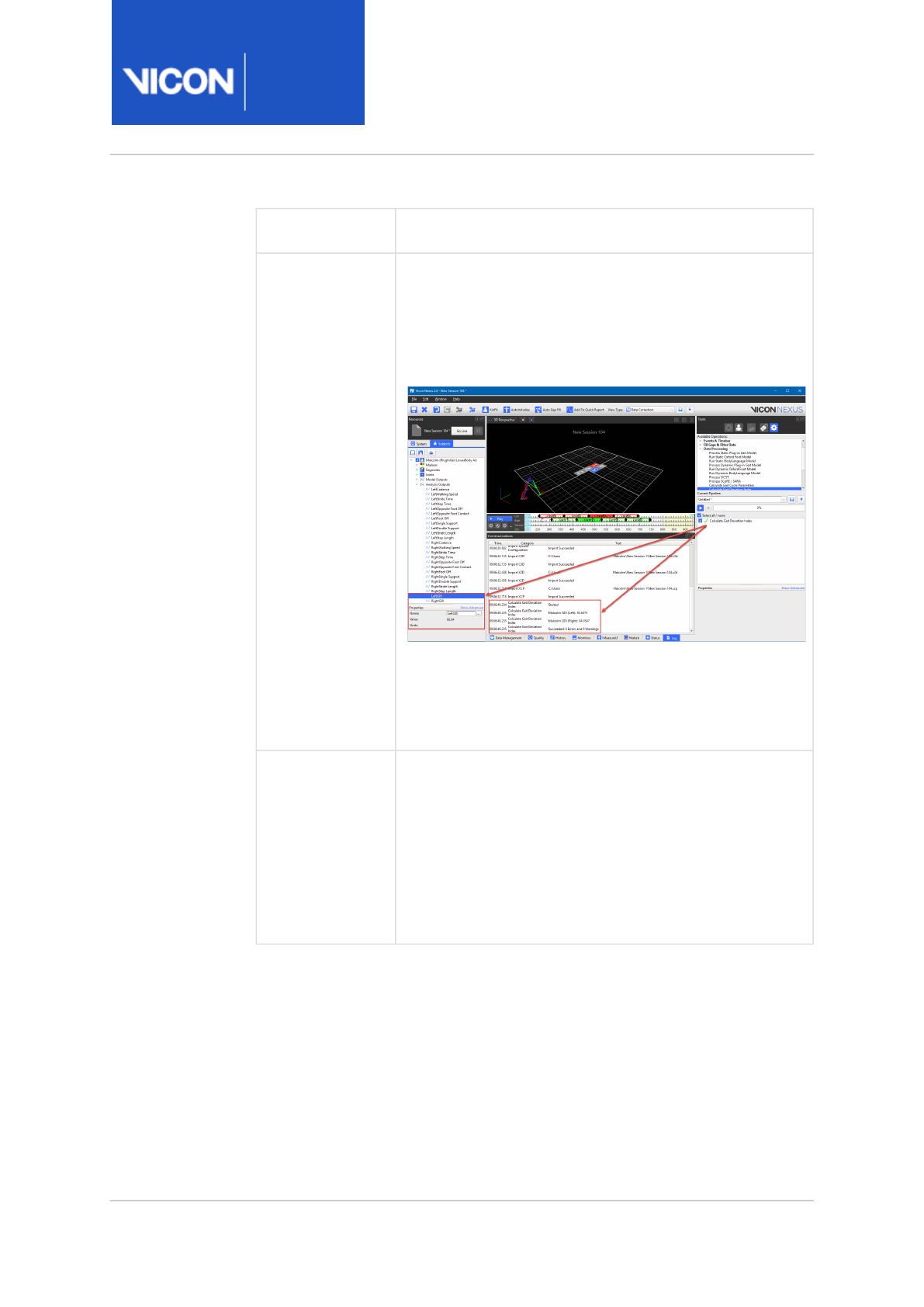
Nexus
Reference
Guide
ViconNexus user interface
Vicon Motion Systems Ltd. 13-Nov-2018 Page 319 of356
Operation Description
Calculate Gait
Deviation Index
Generates a GDI (Gait Deviation Index) score for the
subject of the current trial. 1
When you run this operation on a trial, two GDI values
(left and right), are output to the log and saved as
subject parameters.
To output these values when you run the Export ASCII
pipeline operation, select the Export Gait Cycle
Parameters option.
Delete Model
Outputs
Enables you to delete from the current trial the
selected model output(s), all model outputs, or to
specify a comma-separated list of model output
names.
Tip: You can also access the same options by right-
clicking the relevant node in the Subjects Resources
tree.
1. The following research publication provides supporting information on
the scientific basis and validation of Vicon's implementation of the
calculation of the GDI score:
SCHWARTZ, M. H., and ROZUMALSKI, A.,
The gait deviation index: A new
comprehensive index of gait pathology
, Gait & Posture 28 (2008), p351–
357.

Nexus
Reference
Guide
ViconNexus user interface
Vicon Motion Systems Ltd. 13-Nov-2018 Page 320 of356
File Export operations
Use File Export operations to export of data from Vicon Nexus for use with
third-party software packages.
Operation Description
Export 3D
Overlay
Video
Export a copy of the reference video .
avi
file(s) with the
3D Perspective data overlaid onto the video image. You
can choose which 3D view option to display and select
the codec used to compress the new .
avi
file.
You can configure the following settings in the
Properties section:
•View Options Set The .
options
configuration files that
have been saved in the Options dialog box (F7). You
can select settings for the 3D data to be exported
with the .
avi
file. Select a configuration file from the
drop-down list. If you do not specify a file, the current
view options are used.
Default: blank
•Video Codec The video compression method to use
when exporting the .avi file. Select a codec
appropriate for the digital camera used to capture
the .
avi
file.
Default: (None)
•First Frame and Last Frame Enables you to specify the
range of frames to export.
Tip: If you want to export labeled subjects in the Nexus
3D workspace, use instead the Export Workspace to AVI
button (available on the View pane toolbar) . For more
information, see
Export 3D Workspace as AVI
in the
Vicon
Nexus User Guide
.

Nexus
Reference
Guide
ViconNexus user interface
Vicon Motion Systems Ltd. 13-Nov-2018 Page 321 of356
Operation Description
Export
ASCII
Export delimited ASCII format to a .
csv
or .
txt
file, or
another format that you specify by clearing the Macro
check box (click the downward arrow at the right of the
extension list) and entering the required extension. You
can select commas, tabs, or line feeds as the delimiter.
Export C3D Export the current state of the processed data to a .
c3d
file. You can then import the data into other software for
further processing or report generation. For example, in
Vicon Polygon you can visualize the trajectories,
kinematic model elements, and kinetics data.
If you manually import the corresponding .vst file into
Polygon, it also visualizes the bones.
Export MKR Export an .
mkr
file. You can choose whether the exported
file name is based on the active subject name(s) or active
labeling skeleton template name(s). If you choose Active
Labeling Skeleton Names, the name of any labeling
skeleton template attached to the subject (for example,
PlugInGait FullBody Ai) is used as the name of the MKR
file. If more than one subject is present with the same
model attached, a log message indicates that only one
MKR file will be exported.
Export MOX Export Nexus data files in .mox format for MoXie
( http://moxie.smalll.eu/).
Export MP Export the current subject parameters to an .
mp
file
(subject parameter file compatible with legacy software).
Export TRC Export a .
trc
file.
Export VSK Export a labeling skeleton (
.vsk
) file
Export XCP Export the current calibration file to an .
xcp
file in a
specified location.

Nexus
Reference
Guide
ViconNexus user interface
Vicon Motion Systems Ltd. 13-Nov-2018 Page 322 of356
Operation Description
Export MOT Export files in .mot format for use in OpenSim.
Save Trial -
C3D + VSK
Save the files associated with the currently open trial.
For more information on how to use the export operations, see
Export trial
data
in the
Vicon Nexus User Guide
.

Nexus
Reference
Guide
ViconNexus user interface
Vicon Motion Systems Ltd. 13-Nov-2018 Page 323 of356
System operations
Use System operations to automate oflline camera calibration and applying
codecs to video files.
Operation Description
Process
Offline
Camera
Calibration
Run on a captured trial of a calibration wand wave to
calibrate a system (instead of calibrating the system live).
Transcode
Video for
Trial
Automates transcoding the raw video files associated
with the current trial. Enables you to choose the required
codec.
Apply Codec
to Video
Applies a codec to all AVIs associated with the current
trial. You can select which codec to use, whether to keep
the original movie file, and whether to remove interlacing.
Important: Reverting to the backup file to re-do the de-
interlacing is not supported in Nexus. For more
information, see
De-interlace AVI files
in the
Vicon Nexus
User Guide
.
Reset force
plate
offsets
Resets the force plate offsets. Enables you to specify the
range of frames on which to operate, the affected
device(s), and the range of frames to use for zeroing the
force plate.
Set Camera
Calibration
Origin
Sets the camera calibration origin using a calibration
object.

Nexus
Reference
Guide
ViconNexus user interface
Vicon Motion Systems Ltd. 13-Nov-2018 Page 324 of356
Legacy operations
Use Legacy operations to automate the processing of legacy trial data:
Operation Description
Nexus
Legacy
Labeler
Run on fully reconstructed trials to label the subject as a
whole instead of frame-by-frame as in the Core
Processor. This operation requires a .
vsk
file.
Nexus
Legacy Fit
Motion
Run on fully labeled trials to Kinematic Fit the trial as a
whole instead of frame-by-frame as in the Core
Processor.
Nexus
Reference
Guide
ViconNexus user interface
Vicon Motion Systems Ltd. 13-Nov-2018 Page 325 of356
Communications pane
The Communications pane enables you to view and manage the state of
your Vicon system, and streamline your motion capture workflow.
The tabs at the bottom of the Communications pane enable you to switch
between the available monitoring tools.
Tip
To avoid the pane taking up too much onscreen space, you can
choose to hide the Communications pane when you load a trial. To
do this, on the Window menu, select the Close Communications
Pane on Trial Load option. Alternatively, to temporarily hide/reveal
the Communications pane, so that the tabs are minimized to the
bottom of the screen without completely closing, double-click any
of its tabs.
For information, see:
•Data Management tab, page 326
•Quality tab, page 327
•History tab, page 328
•Monitors tab, page 328
•IMeasureU tab, page 331
•MATLAB tab, page 333
•Status tab, page 334
•Log tab, page 335
Nexus
Reference
Guide
ViconNexus user interface
Vicon Motion Systems Ltd. 13-Nov-2018 Page 326 of356
Data Management tab
The Data Management tab contains the following controls:
•Database location You can view the full path of the active node in the
trial database at the top of the Data Management tab. To access the
files in Windows Explorer, click the hyperlink.
•Navigation buttons You open the Manage Databases dialog
box, go forward a node, go back a node and move up a level using the
navigation buttons at the top left of the Data Management tab.
•Search button Displays or hides the Search window. For more
information, see Advanced data searching, page 17.
•Show Trial Loading Options button Displays or hides the Raw Data
Loading Options area, in which you can specify your requirements for
loading large trials.
For more information, see Load large trials, page 19.
•Show File Transfer/Batch Processing Interface button Displays or
hides the Remote File Transfer/Batch Processing pane on the right side
of the Data Management tab.
For more information, see Work with digital video files in the
Vicon
Nexus User Guide
and Batch process trials, page 20.
•Data Management toolbar You create and manage nodes in the database
hierarchy using the buttons in the toolbar at the top right of the Data
Management tab. From left to right, the buttons are:
• New Patient Classification button
• New Patient button
• New Session
• New Polygon Report
•Database hierarchy nodes You view a visual representation of the
structure and contents of a trial database, and select individual data
types for loading in Nexus, in the nodes on the Data Management tab.
•Data type icons You can view and select individual motion
capture files using the icons that represent the data saved for the trial.

Nexus
Reference
Guide
ViconNexus user interface
Vicon Motion Systems Ltd. 13-Nov-2018 Page 327 of356
•Data fields You can view or enter descriptive text or numerical data
associated with a specific node in the trial database in the fields in the
columns to the right of a node name.
For information on using Data Management in Vicon Nexus, see Data
management with Nexus, page 6.
Quality tab
The data Quality pane, a tab in the Communications window, provides an
overview of data quality for a subject across a whole trial and enables you
to examine the health of individual trajectories. It also provides a way to
navigate to the highlighted issues.
The display options in the Options column enable you to configure the
display options for this tab. Alternatively, you can open the Options dialog
box (F7), click Data Quality Panel Options on the left, and change the
properties as required.
The Trajectory Sort Value list contains the following options:
•Percentage Labeled Orders blobs with the highest labeling percentage
first (from top left).
•Max Gap Orders blobs with the trajectories containing the longest gaps
first (see the Max Gap Length column of the Gap Filling section in the
Label/Edit Tools).
•Model Order Displays blobs in the same order as the markers are listed
under the Markers node in the Subjects Resources tree.
•Number Of Gaps Orders blobs with the trajectories with the highest
number of gaps first (see the #Gaps column of the Gap Filling section in
the Label/Edit Tools).
•Trajectory Length Orders blobs with the longest trajectories first.
You can also select other options in the Options column to tailor the
display to your requirements.
To save any changes to these settings, click the Save current configuration
button in the Options dialog box.
For information on using the Quality tab, see Assess trial health with the
data Quality pane in the
Vicon Nexus User Guide
.

Nexus
Reference
Guide
ViconNexus user interface
Vicon Motion Systems Ltd. 13-Nov-2018 Page 328 of356
History tab
The History tab in the Communications pane enables you to review all
processing that has been performed on a loaded trial file.
This ensures that, even if you have not worked with the data before, you
can continue to work on the trial without missing or duplicating processing
steps performed by another Nexus user.
To display information about a particular event, click on the event on the
History tab. Details about the settings used to run the event are displayed
in the Property and Value columns on the right.
In the Notes field, you can add notes that will be useful to you or anyone
else working with the same trial. Your notes are saved with the trial.
Monitors tab
The Monitors tab enables you to configure monitors that you create in the
Graph view pane to detect motion capture events.
For information on creating and using monitors and detailed descriptions
of the options, see Using monitors, page 39.
The Monitors tab contains the following areas:
Monitors configuration management area
You manage monitor configurations in the Monitors tab using the
configuration management section at the top of the pane.
Note
A processing history is available only for files processed in Nexus
2.3 and above.

Nexus
Reference
Guide
ViconNexus user interface
Vicon Motion Systems Ltd. 13-Nov-2018 Page 329 of356
Monitors area
The Monitors area enables you to define the monitor behavior. It contains
the following components:
Component Description
Monitors
list
Lists the currently defined monitors. Select the check
box next to a monitor name to enable the monitor, or
clear the check box to disable the monitor. Select a
monitor in the list to view or configure its properties.
AND button When multiple monitors are selected from the list, this
button adds a Boolean AND monitor that triggers an
action when all of the monitor trigger conditions are
present.
OR button When multiple monitors are selected from the list, this
button adds a Boolean OR monitor that triggers an action
when at least one of the monitor conditions is present.
Remove
button
Removes the selected monitor from the list.
Clear
button
Removes all monitors from the list.

Nexus
Reference
Guide
ViconNexus user interface
Vicon Motion Systems Ltd. 13-Nov-2018 Page 330 of356
Actions area
The Actions section of the Monitors tab enables you to view or modify
monitor action settings. It contains the following components:
Component Description
Actions list Actions that you add will execute when the monitor
threshold and trigger conditions are met.
Add button Click to add the selected action to the Actions list.
You can select from: Capture, External trigger, Timebar
Event, Progress Bar, Range Overlay, Sound Tone, Toggle
Monitor and Play Sound File.
Remove
button
Click to remove the selected action from the Actions list.
Clear
button
Clears all actions from the Actions list.

Nexus
Reference
Guide
ViconNexus user interface
Vicon Motion Systems Ltd. 13-Nov-2018 Page 331 of356
IMeasureU tab
The IMeasureU tab enables you to work with data recorded from Vicon
IMUs (Inertial Measurement Units).
After you have finished capturing data and have plugged the IMUs into the
PC, you use the IMeasureU tab to work with and transfer the data from the
IMUs to the Nexus Session folder.
For information on working with IMUs and Nexus, see Work with IMUs in
the
Vicon Nexus User Guide
.
The IMeasureU tab contains the following areas:
Transfer pane
The Transfer pane of the IMeasureU tab enables you to transfer data
captured with Vicon IMUs to the current Session folder in Nexus. It
contains the following components:
Component Description
Transfer list:
Trial column and
Progress column
The Trial column lists the trials currently
stored on connected IMUs.
The Progress column displays the current
transfer status of each captured trial.
Select All button Selects all trials.
Select Transferred button Selects transferred trials.
Select None button Clears all selections.
Select Untransferred
button
Selects all trials that have not been
transferred.
Remove Selected Trials
button
Removes selected trials from the Transfer
list.

Nexus
Reference
Guide
ViconNexus user interface
Vicon Motion Systems Ltd. 13-Nov-2018 Page 332 of356
Component Description
Remove Selected Devices
button
Removes from Nexus all references to
selected IMUs and their related trials.
Erase Selected Devices
button
Removes from one or more IMUs all
collected trials, and removes the IMU and
its trials from the Transfer list.
Transfer Files button Transfers selected trials from connected
IMUs to the current Session folder in
Nexus.
Cancel Transfer button Cancels the current transfer operation.

Nexus
Reference
Guide
ViconNexus user interface
Vicon Motion Systems Ltd. 13-Nov-2018 Page 333 of356
Import pane
Component Description
Source Files (CSV) field Enables you to browse to or enter the full
path to the CSV file that you want to
import.
Create files from sub-
folders check box
When selected, files are created from sub-
folders of the selected path.
Trial name field Enables you to enter the name of the next
file to be imported.
Auto increment trial
number check box
When selected, the number of the
imported trial is automatically
incremented.
Permit overwrite of
existing files check box
When selected, existing files with the
same name are overwritten.
Create trial button Creates a trial from the file(s) in the
specified source folder.
Cancel button Cancels the current import process.
Progress bar Displays the progress of the current
import process as a percentage.
MATLAB tab
Enables you to execute a MATLAB script from within Vicon Nexus. For more
information, see Modeling with MATLAB, page 61.

Nexus
Reference
Guide
ViconNexus user interface
Vicon Motion Systems Ltd. 13-Nov-2018 Page 334 of356
Status tab
Enables you to monitor the state of your Vicon system during any stage of
the Nexus motion capture workflow. This is useful for identifying problems
and determining the Nexus system component that needs to be examined.
The Status tab contains the following sections:
•Status Summary
View a visual summary of the status of system components in the Status
Summary section of the Status communications pane:
•Vicon Cameras
View the status of Vicon cameras.
•Video Cameras
View the status of digital video cameras.
•Connectivity
View the status of Vicon connectivity units.
•Capture
View the status of capture sessions in Nexus.
•Status Details
View details of the status of a system component in the Status Details
section of the Status tab. The contents of this section depend on the
component you click on in the Status Summary section.
The background in each summary corresponds to the icon
displayed for the devices in the System Resources pane. The
color of a summary border reflects the status for the set of
components:
• Green: All components OK
• Yellow: One or more components are on standby
• Red: One or more components are down
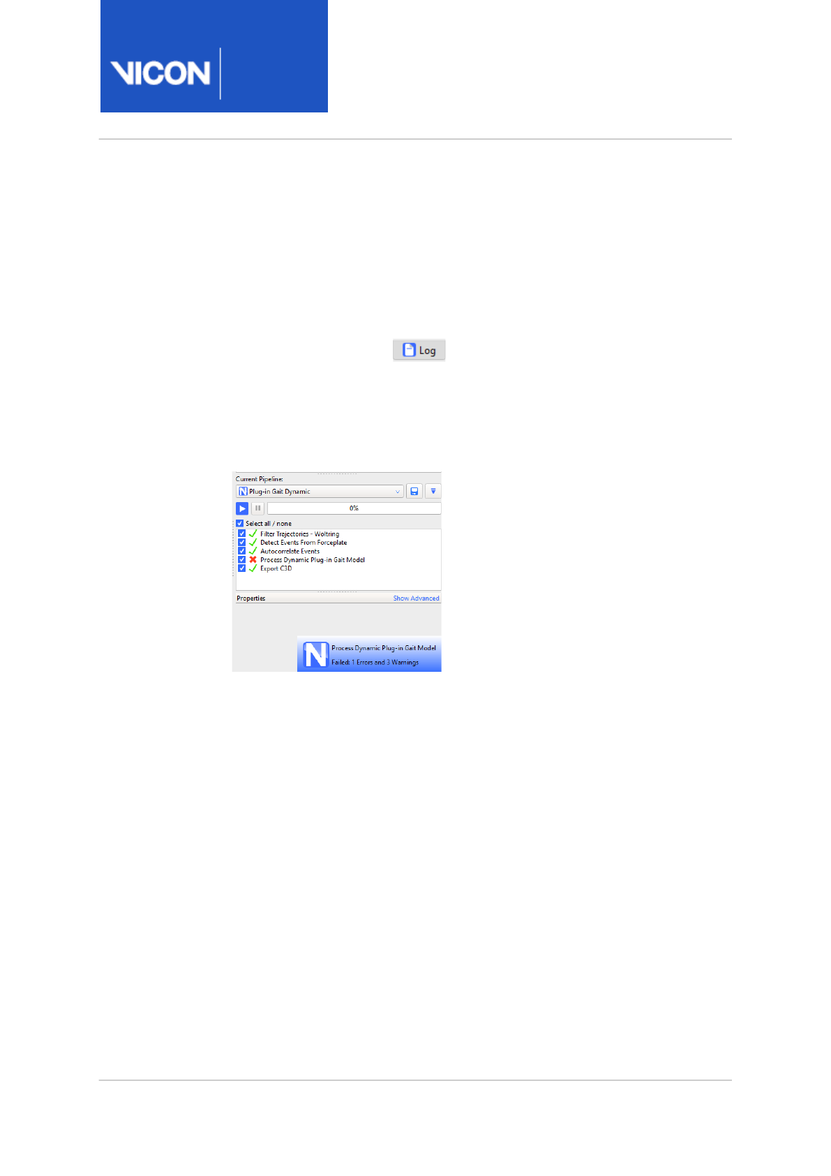
Nexus
Reference
Guide
ViconNexus user interface
Vicon Motion Systems Ltd. 13-Nov-2018 Page 335 of356
Log tab
Enables you to monitor Nexus system activity and troubleshoot any errors.
For example, if a pipeline operation fails (indicated by a red X next to the
operation in the Pipeline Tools pane), you can find information as to why
the failure occurred on the Log tab.
The icon on the Log tab automatically appears to scroll to indicate
that a warning is displayed (for example, a new log entry indicating that an
operation has failed).
You are alerted to important errors by popup notifications that are briefly
displayed at the bottom right of the Nexus window.
If you are using the default sounds supplied with Nexus and have audio
enabled, a relevant sound clip is also played.
To view further details about the error in the Log, click the notification.
The notification disappears after four seconds.

Nexus
Reference
Guide
ViconNexus user interface
Vicon Motion Systems Ltd. 13-Nov-2018 Page 336 of356
Menu bar
The Nexus menu bar contains the following controls:
•File menu, page 336
•Edit menu, page 337
•Window menu, page 338
•Help menu, page 350
File menu
The File menu contains the following options:
•Save (shortcut CTRL+S) Saves the current data for subjects enabled in
the Subjects Resources pane to the .c3d file for the current trial.
•Copy As Displays the Choose a c3d file dialog box in which you can enter
or select the name of the file to copy to. Makes a copy of the current
trial .c3d, .vsk, and .mp files. Using this feature, you can archive copies of
a .c3d file to document its processing progression.
•Import XCP Displays the Choose an XCP file dialog box in which you can
select the desired Vicon camera calibration parameters (.xcp) file to load
in Nexus. Use this command to import .xcp files created in Vicon Nexus.
•Export XCP Displays the Choose an XCP file dialog box in which you can
specify a calibration parameters (.xcp) file into which to export the
current Vicon camera settings. Use this command to export .xcp files
created in Vicon Nexus.
•Exit Closes the Vicon Nexus application window. If you have not saved
any changes made to trial data, Nexus displays a prompt to enable you to
save changes to trial data, subjects, or both, before it closes.
Tip
You are prompted to save the copy in the same location in the
Data Management hierarchy as the original file, and after saving
it will be available in the Data Management pane.

Nexus
Reference
Guide
ViconNexus user interface
Vicon Motion Systems Ltd. 13-Nov-2018 Page 337 of356
Edit menu
The Edit menu contains the following options, which take effect only when
the system is in Pause or Offline mode:
•Undo (shortcut CTRL+Z) Undoes the last action. This command is
available only after a relevant action has been performed. The name of
the Undo command changes to reflect the latest action, for example,
Undo Import XCP. You also can hover the mouse pointer over the Undo
button to display a tooltip that identifies the action to be undone. Some
actions, such as reconstructing data, cannot be undone.
•Redo (shortcut CTRL+Y) Reinstates the previously undone action. This
command is available only after an Undo command has been performed.
The name of the Redo command changes to reflect the latest action, for
example, Redo Import XCP. Hover the mouse pointer over the Redo
button to display a tooltip that identifies the action to be redone. Any
action that was undone can be redone.

Nexus
Reference
Guide
ViconNexus user interface
Vicon Motion Systems Ltd. 13-Nov-2018 Page 338 of356
Window menu
The Window menu contains the following options:
•Simple Capture Mode (shortcut CTRL+H). Displays a window containing
only the minimum of controls necessary for capture, facilitating the
capture of multiple trials. See Use Simple Capture Mode in the
Vicon
Nexus User Guide
.
•New floating workspace. Opens a separate floating view pane. See View
pane, page 257.
•Reset to default layout Resets the Nexus panes to their layout when
Nexus was installed.
•Toolbar Opens the Customize Toolbar dialog box, in which you can add,
remove, and customize buttons on the Nexus toolbar. See Customize
Toolbar dialog box, page 353.
•Quick Reports (shortcut F4) Opens a Quick Reports window, in which you
can display multiple graphs of model outputs. See Quick Reports, page
339.
•Sounds (shortcut F6) Opens the Sounds dialog box, in which you can
view or change the sounds that are used to alert you to Nexus events.
You can also disable the sounds individually or disable all sounds. See
Sounds dialog box, page 346.
•Options (shortcut F7) Opens the Options dialog box, in which you control
how data is displayed. See Options dialog box, page 347.
•Plug-ins Displays the Plugins dialog box in which you can view and
manage plug-in modules that have been loaded in Vicon Nexus.
•Manage Control Authorizations Opens the Vicon Control dialog box,
where you can authorize or revoke authorizations for instances of Vicon
Control that are connected to the Vicon system. See Vicon Control
dialog box, page 349.
•Footstrike Monitor Settings Lets you set options for foot strike
monitoring. See Automatically assess foot strikes in the
Vicon Nexus
User Guide
.
•Close Communications Pane on Trial Load Enables you to show or hide
the Communications pane when you load a trial. If selected, the
Communications pane is minimized at the bottom of the Nexus window
the next time you load a trial. The Communications pane stays hidden
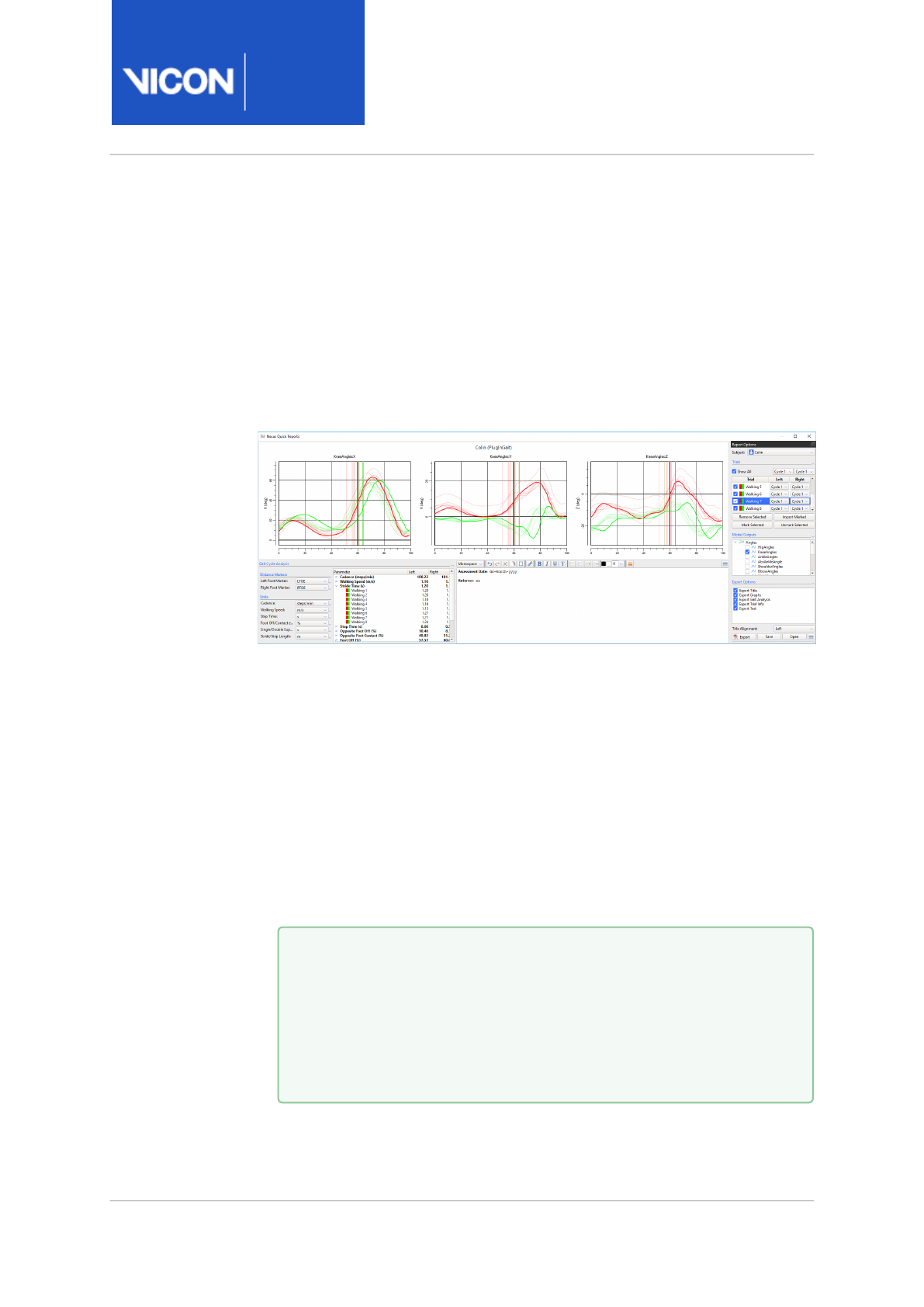
Nexus
Reference
Guide
ViconNexus user interface
Vicon Motion Systems Ltd. 13-Nov-2018 Page 339 of356
until you double-click one of the tabs at the bottom of the
Communications pane. Your choice for this option is retained when you
exit and restart Nexus. It can be set as required by each Nexus user.
Quick reports
The Nexus Quick Reports window enables you to display multiple graphs of
model outputs normalized over the gait cycle (like a simplified Vicon
Polygon graph view).
To display model outputs in Nexus Quick Reports:
1. On the Window menu, click Quick Reports, or press F4 to open the
Nexus Quick Reports window.
2. In the main Nexus window, ensure that the trial (*.C3D file) that you
want add to Quick Reports is the current trial.
3. From the Pipeline Tools pane, expand Data Processing and double-click
Add Trial to Quick Report to add it to the current pipeline.
4. In the Current Pipeline list, right-click the Add Trial to Quick Report
operation and click Run select Op.
5. For each trial that you want to add, repeat step 2–4.
Tip
To add trials to Quick Reports, you can also:
• Drag and drop one or more trials (*.C3D files) from Windows
Explorer into the Quick Reports window; or
• Click the Add To Quick Report button on the Nexus toolbar
(adds the current trial).
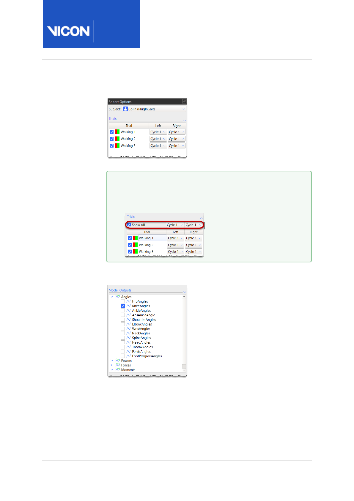
Nexus
Reference
Guide
ViconNexus user interface
Vicon Motion Systems Ltd. 13-Nov-2018 Page 340 of356
6. In the Nexus Quick Reports window, the added trials are displayed in the
Trials list, by default on the right of the window.
7. Ensure the required cycle is selected in the Left and Right columns.
8. To display model outputs in the graphs, in the Model Outputs list,
expand the relevant node and then select the required check box(es).
Tip
To change the options for all the trials, click the downward
arrow to expand the Trials section and click the appropriate
option at the top of the columns.
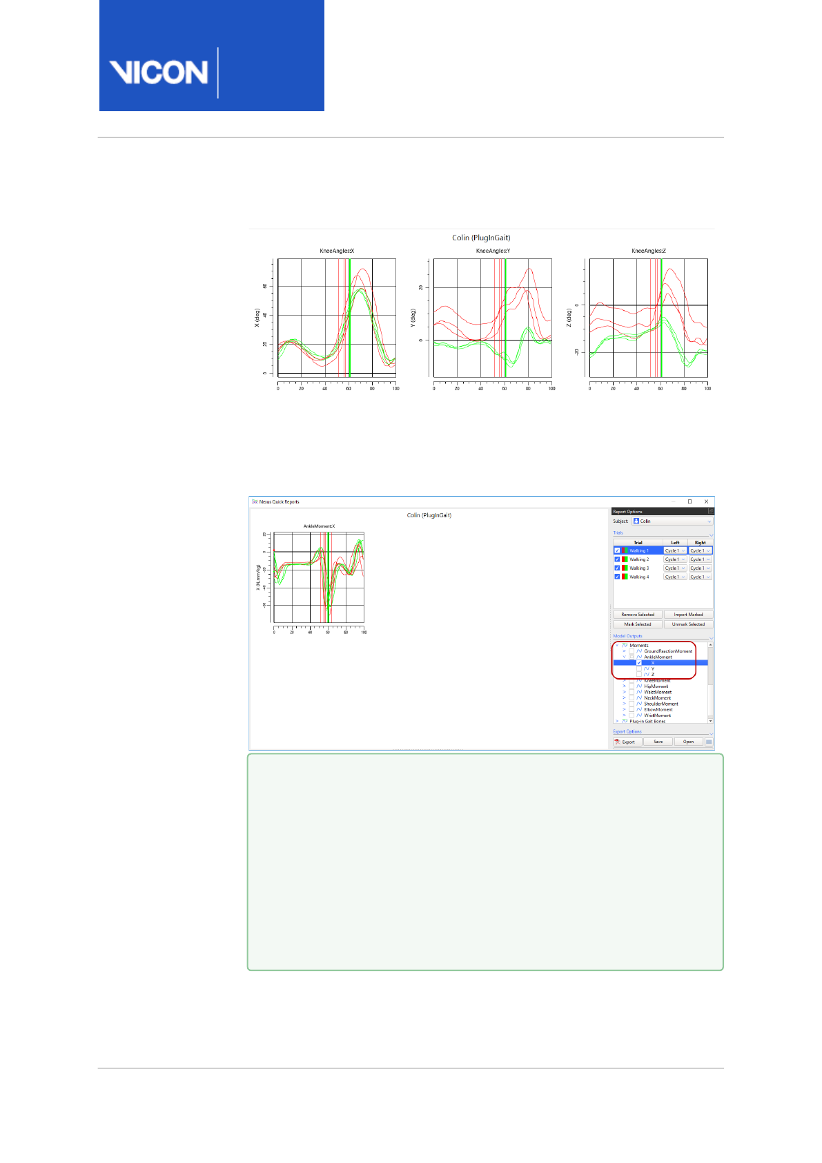
Nexus
Reference
Guide
ViconNexus user interface
Vicon Motion Systems Ltd. 13-Nov-2018 Page 341 of356
The selected outputs are displayed as graphs in the Nexus Quick
Reports window.
To display only the required components, in the Model Outputs tree,
clear the check boxes for the unwanted components.
For example, if you are interested in Ankle Moment X only, you can
select this only.
Tip
By default a red line represents data from the left side and a
green line represents data from the right. The trial currently
selected in the Report Options list is represented by a heavier
line on the graphs. To change green and red to solid and dashed
lines, in the Options dialog box (press F7), on the left, click Quick
Reports and then clear Use Context Colors. To change the colors
displayed for each trace on the graph, click the color(s) that you
want to change.

Nexus
Reference
Guide
ViconNexus user interface
Vicon Motion Systems Ltd. 13-Nov-2018 Page 342 of356
9. Expand the Gait Cycle Analysis section at the bottom left of the window
and ensure the Distance Markers and Units are as required.
10. To export a PDF of the data in the Nexus Quick Reports window:
a. Expand the Export Options section and clear or select the required
options.
b. From the Title Alignment list, select the required option.
c. Click Export and in the Export to PDF dialog box, enter or browse to
the required location.
d. Click Save.
11. To save your work, click the Save button at the bottom of the Report
Options pane and select the appropriate option:
• *.
qrd
(Quick Reports Document): Saves the current Quick Report.
Select this option if you have to suspend work on the report and want
to carry on where you left off later.
• *.
qrt
(Quick Reports Template): Saves the layout of the Nexus Quick
Reports window (ie the options currently selected in the Quick
Reports window).Select this option if you want to produce reports of
the same type of information for later trials. Quick Reports templates
that are saved to the default location (
C:
\Users\Public\Documents\Vicon\Nexus2.x\Configurations\QuickReport
s
) are listed when you click the Apply Report Template button .
Tip
By default, the Parameter column displays average values across
all selected trials. To view the average value for each trial,
expand the relevant parameter.

Nexus
Reference
Guide
ViconNexus user interface
Vicon Motion Systems Ltd. 13-Nov-2018 Page 343 of356
About the Nexus Quick Reports window
The Nexus Quick Reports window comprises two sections:
• Controls are contained in a dockable Report Options pane, which by
default is displayed to the right of the window. Expand the Trials, Model
Outputs and Export Options sections by clicking the downward arrow to
the right of each section divider. To move the controls pane, drag the
Report Options title. The pane can be floated or docked to the left or
right.
• Graphs of the data selected in the Report Options pane are shown in the
main workspace. The current subject’s name and model template are
shown as a title at the top.
To the bottom left of the main workspace, Gait Cycle Analysis parameters
for the loaded trials are displayed.
In the large text box on the right, you can enter a description or notes, etc,
which can be formatted using the buttons on the toolbar above the text
box.

Nexus
Reference
Guide
ViconNexus user interface
Vicon Motion Systems Ltd. 13-Nov-2018 Page 344 of356
Report Options controls
In the Report Options pane, the following controls are available:
Control Description
Subject
field
Enables you to select the subject whose data you want to
view.
Trials list Lists the trials that you have added to the report. In this
list, you can select or clear the relevant check boxes to
display the required trial(s). To show/hide all trials,
expand the Trials section and select or clear the check
box at the top. The outputs for selected trials are
displayed in each graph.
The Cycle dropdown lists at the top and in the Left and
Right columns of the Trials list enable you to select which
gait cycles to show for the left and right contexts for
each trial.
To select trials, click (or Shift+click/Ctrl+click) in the Trial
column of the required row(s) in the list. The selected
row(s) in the list are highlighted with a blue background
and by thicker lines in the graph.
To remove selected trials from the report or to mark
selected trials in Data Management (eg, for use in Vicon
Polygon), click Remove Selected or Mark Selected at the
bottom of the list.
Model
Outputs list
Displays available model outputs from the trials that have
been added to the report.
Export
button
Opens the Export to PDF dialog box, which enables you to
save the contents of the current Nexus Quick Reports
window to a *.PDF file, with a name and location that you
specify.
Save button Enables you to save the current Quick Report either as a
document (*.
qrd
) or a template (*.
qrt
).

Nexus
Reference
Guide
ViconNexus user interface
Vicon Motion Systems Ltd. 13-Nov-2018 Page 345 of356
Control Description
Open
button
Enables you to enter or browse to aQuick Report
document (*.
qrd
) or a template (*.
qrt
).
Apply
Report
Template
button
Enables you to apply a report template that was saved to
the default location (
C:
\Users\Public\Documents\Vicon\Nexus2.x\Configurations
\QuickReports
).

Nexus
Reference
Guide
ViconNexus user interface
Vicon Motion Systems Ltd. 13-Nov-2018 Page 346 of356
Sounds dialog box
Nexus can play sounds through your PC's speakers to alert you when a
Nexus event has taken place (for example, operation completion, system
status, and issues). This keeps you informed of system status while you're
still in the volume, so that you don't have to spend time returning to the PC
to look at the screen.
You can access this dialog box from the Window menu or by pressing F6.
By default, Nexus uses speech sounds to alert you to the following events:
• Calibration start
• Wand Wave complete
• Calibration complete
• Calibration failed
• Origin set
• Capture started
• Capture ended
• Capture failed
• Camera bumped
• Pipeline ended
• Pipeline failed
Nexus is supplied with a set of default sound files (.wavs). You can modify
the sounds that are used for each event and you can disable sounds
individually or disable all sounds.
To disable all sounds, in the Sounds section, clear the Enabled check box.
To disable one or more sounds, click the relevant drop-down arrow and
select (None) from the list.
To choose one of the other sounds supplied with Nexus, click the drop-
down arrow and select the required sound from the list.
To substitute your own sounds for those supplied with Nexus, click the
relevant ellipsis (...) and enter or browse to the location of the required .wav
files.
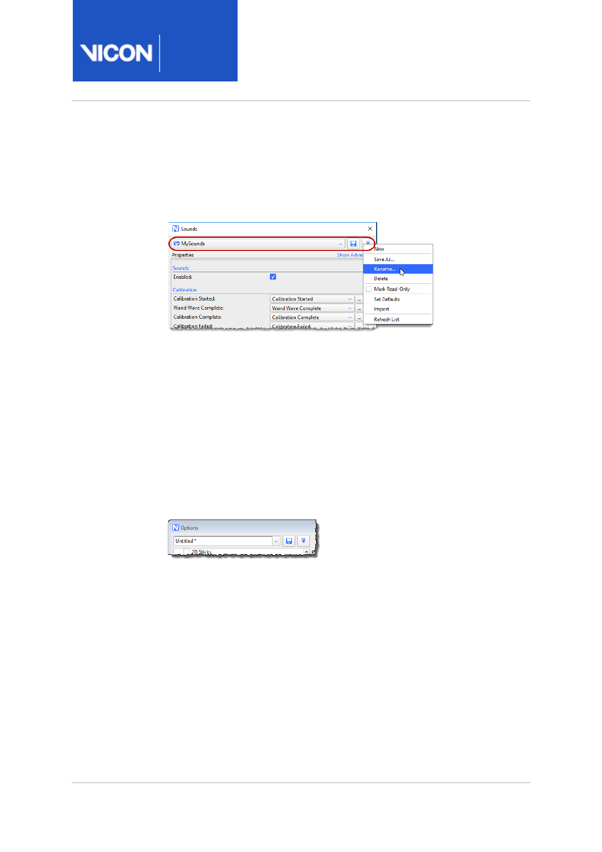
Nexus
Reference
Guide
ViconNexus user interface
Vicon Motion Systems Ltd. 13-Nov-2018 Page 347 of356
Use the configuration management area at the top of the Sounds dialog
box to name, to save, delete and if necessary protect the sounds that you
have allocated to Nexus events. After you have saved sounds configuration
files, you can select them from the menu at the top of the dialog box and
can use the Configuration menu to manage them.
The sounds configuration file (*.
AudioScheme
) is saved into an
AudioSchemes
folder, in the same location as other Nexus configuration
files (see Managing configurations in Vicon Nexus in the
Vicon Nexus User
Guide
).
Options dialog box
The Options dialog box enables you to control the way data is visualized in
the view panes. You can access this dialog box from the Window menu or
by pressing F7.
The Options dialog box includes a configuration area:
This enables you to save any changes you make in the Options dialog box to
a configuration file, with the extension .Options. You can then re-use your
saved configuration file as required, for example, you could save a different
set of options for each type of motion capture application that you use.
In addition to creating customized Options configurations, the
Configuration menu button enables you to rename, import, reload and
delete configurations, and refresh the list.

Nexus
Reference
Guide
ViconNexus user interface
Vicon Motion Systems Ltd. 13-Nov-2018 Page 348 of356
To configure settings in the Options dialog box:
1. Open the Options dialog box in either of these ways:
• Click the Window menu and then click Options; or
• Press F7.
2. In the list of options on the left side of the dialog box, click an option
whose properties you wish to view or change. You can now:
• Select the check box to switch on the functionality or clear the check
box to switch off the functionality for the option.
• In the Properties section on the right side of the dialog box, view or
change settings as desired for any available properties. (To see
additional settings that may be available for an option, click Show
Advanced.)
3. Repeat step 2 for each property whose settings you wish to configure.
4. To save your settings, do one of the following:
• To save your settings as the current configuration and close the
Options dialog box, click Close; or
• To give your configuration a name, so that you can easily find it for re-
use later, click the Configuration menu button, then click Save As,
enter a name in the dialog box, click OK, and then choose whether to
save your configuration as Shared or Private.

Nexus
Reference
Guide
ViconNexus user interface
Vicon Motion Systems Ltd. 13-Nov-2018 Page 349 of356
Vicon Control dialog box
The Vicon Control dialog box enables you to carry out the following
operations:
• To grant unprompted access in future, ensure the relevant device's check
box is selected in the Known Devices list.
In future, the device will be able to connect without having to be re-
authorized.
• To permanently revoke access, clear the device's check box in the Known
Devices list.
The device is disconnected and in future, it will not be able to connect.
This is useful if you accidentally authorized a device, or if you need to
remove an authorized device from the system, for example, if it is lost or
sold.
• To remove a connected device from the Known Devices list and force re-
authorization on the next attempt to connect, select the device and
then click Forget Device.
To reconnect, the device will have to send an authorization request and
be re-authorized.
• To remove all connected devices from the Known Devices list and force
re-authorization on the next attempt to connect by any of the listed
devices, click Forget All.

Nexus
Reference
Guide
ViconNexus user interface
Vicon Motion Systems Ltd. 13-Nov-2018 Page 350 of356
Help menu
The Help menu contains the following commands:
•View latest help from vicon.com Displays the most recent version of the
live online help.
•View installed help Displays the help file (PDF) that was installed with
Vicon Nexus.
•Check for updates Detects whether any Nexus updates are available.
•Check for firmware updates The Checking Firmware Version dialog box
displays information about the latest released firmware version. See also
Update firmware in the
Vicon Nexus User Guide
.
•About Vicon Nexus Displays the Vicon Nexus startup screen, in which
you can view version and license server information about the installed
release of Nexus.
•Hotkeys Displays a list of Nexus shortcuts and hot keys.
•Vicon Product Licensing Displays the Vicon Automated Unified Licensing
Tool (VAULT), which enables you to manage your Vicon product licensing.
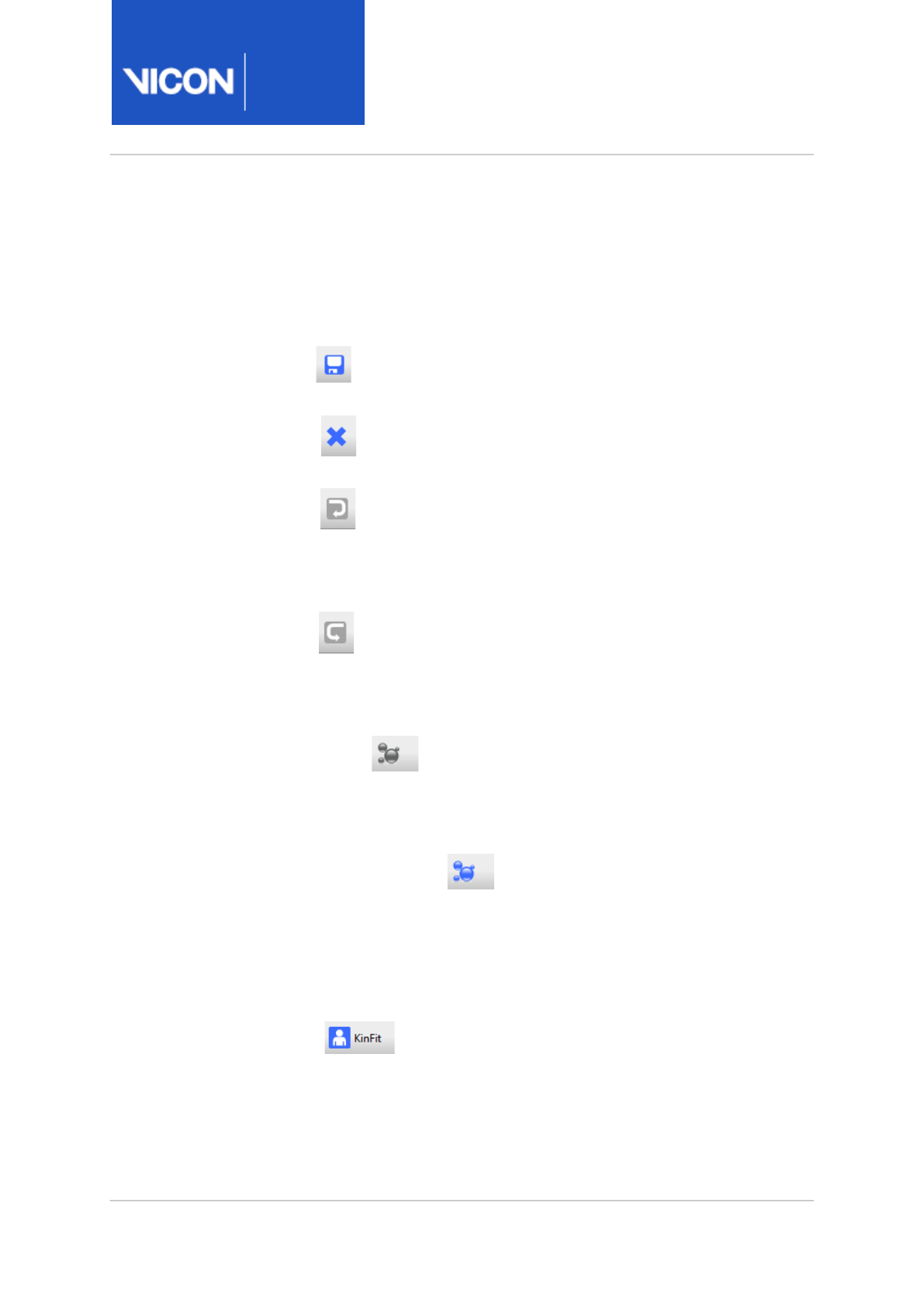
Nexus
Reference
Guide
ViconNexus user interface
Vicon Motion Systems Ltd. 13-Nov-2018 Page 351 of356
Toolbar
The Nexus toolbar contains the following controls. For information on how
to change the standard toolbar, see Customize Toolbar dialog box, page 353:
•Save Saves the current data for subjects enabled in the Subjects
Resources pane to the .c3d file for the current trial.
•Close Closes the current trial and clears data. You are prompted to
save any unsaved changed before closing the current trial.
•Undo Undoes the last action. This command is available only after
a relevant action has been performed. Hover the mouse pointer over the
Undo button to display a tooltip identifying the action to be undone.
Some actions, such as reconstructing data, cannot be undone.
•Redo Reinstates the previously undone action. This command is
available only after an Undo command has been performed. Hover the
mouse pointer over the Redo button to display a tooltip identifying the
action to be redone. Any action that was undone can be redone.
•Reconstruct Runs the Reconstruct pipeline defined in the
Pipeline Tools pane. For information on Reconstruct settings, see the
equivalent Local Vicon System settings (Reconstruction section, page 173),
which control the same functionality for realtime.
•Reconstruct and Label Runs the Reconstruct and Label pipeline
defined in the Pipeline Tools pane. For information on Reconstruct
settings, see the equivalent Local Vicon System settings (Reconstruction
section, page 173). For information on Label settings, see the equivalent
Local Vicon System settings (Labeling section, page 177), which control the
same functionality for realtime.
•KinFit Runs the Kinematic Fit pipeline defined in the Pipeline
Tools pane.
Nexus
Reference
Guide
ViconNexus user interface
Vicon Motion Systems Ltd. 13-Nov-2018 Page 352 of356
•AutoInitialize Runs the Auto Initialize Labeling pipeline,
which consists of the Autolabel Static, Scale Subject VSK, and Static
Skeleton Calibration - Markers-only pipeline operations.. For more
information, see Subject calibration operations, page 305.
•Auto Gap Fill Runs the Auto Intelligent Gap Fill pipeline,
which consists of Nexus gap-filling operations (see Fill Gap & Filter Data
operations, page 310). This enables you to quickly fill all gaps in your trial,
without having to choose which fill method is best for each gap.
•Add To Quick Report Adds the current trial to a
Quick Report. For more information, see Quick Reports, page 339.
•View Type list Create or manage the
layouts specified in the View pane using the View Type list at the top of
the pane.
The view type includes the layout of view panes as well as any cameras,
hardware devices, and subject elements that were selected in the
System Resources pane or the Subjects Resources pane when the view
type was saved.
For example, if you save a view type with all cameras selected and a
Camera view specified for each, the next time you select that view type,
all of the cameras are automatically selected and displayed in separate
Camera views.
If you save a view type with a Graph view showing the EMG channels,
when you next select this view type, the correct EMG device is selected.
If you save a view type with a Graph view showing the distance between
two specific markers, when you next select this view type, these two
markers are selected.

Nexus
Reference
Guide
ViconNexus user interface
Vicon Motion Systems Ltd. 13-Nov-2018 Page 353 of356
Customize Toolbar dialog box
You can add, remove, and customize buttons on the Nexus toolbar using
the Customize Toolbar dialog box.
To access this dialog box:
• On the Window menu, click Toolbar.
The toolbar settings are saved in the appropriate configuration file: the
default Nexus toolbar is stored in the Shared configuration folder; if
customized, the toolbar is saved in a Private configuration folder and
loaded the next time you start Vicon Nexus.
The Save, Undo, and Redo buttons always appear on the Nexus toolbar in
their default positions on the left of the toolbar; you cannot customize
these buttons.
You can add new buttons to run a specified pipeline, load a previously
created View Option configuration, or display a View Type configuration.
For each button, you can define a tooltip, associate an icon, and associate a
text string. You can group related buttons together on the toolbar with
separators or reposition buttons along the toolbar.
You can customize your toolbar in the following ways:
• Add or change toolbar buttons, page 354
•Change a button's position on the toolbar, page 355
•Group related buttons with separators, page 356
•Remove a button or separator from the toolbar, page 356

Nexus
Reference
Guide
ViconNexus user interface
Vicon Motion Systems Ltd. 13-Nov-2018 Page 354 of356
Add or change toolbar buttons
To add or change a toolbar button in the Customize Toolbar dialog box:
1. Click Add Button. A new button entry is added to the bottom of the
Toolbar Buttons list and is highlighted and selected. Alternatively, select
an existing toolbar button.
2. In the Button Properties area, configure the following information for
the selected button:
•Caption: The label to be displayed on the button.
•Icon: The icon to be displayed for the button. Select an available icon
from the drop-down list.
•Tooltip: The text to be displayed to indicate the operation to be
executed when the button is pressed.
3. Select the check box for one of the following actions to be taken when
the button is pressed:
•Load View Options: Apply the specified view options settings. Select a
previously created View Option configuration from the drop-down list.
If you have not created any configurations, this check box is not
selectable and this list is empty.
•Load View Type: Apply the specified view type. Select a previously
created View Type configuration from the drop-down list. If you have
not created any configurations, this check box is not selectable and
this list is empty.
•Run Pipeline: Run the specified pipeline. Select a pipeline file supplied
with Nexus or a previously created custom pipeline from the drop-
down list.
4. Click Apply to preview the button on the Nexus toolbar. If you are not
happy with the result, change the button details in the Customize
Toolbar dialog box and preview the changes again.
5. Repeat steps 1-4 for each button you want to add to the Nexus toolbar.
6. Click OK to save the customized toolbar and close the dialog box.

Nexus
Reference
Guide
ViconNexus user interface
Vicon Motion Systems Ltd. 13-Nov-2018 Page 355 of356
Change a button's position on the toolbar
To change the position of a toolbar button in the Customize Toolbar dialog
box:
1. In the Toolbar Buttons list, select the entry for the button whose
position you want to change.
Button entries in this list from top to bottom correspond to the button
positions on the toolbar from left to right.
2. Change the button's position on the toolbar using the buttons:
•Move Up: Move the selected button up one position in the list, that is,
left one position on the toolbar.
•Move Down: Move the selected button down one position in the list,
that is, right one position on the toolbar.
3. Click Apply to preview the changed button location on the Nexus
toolbar. If you are not happy with the result, change the position again
in the Customize Toolbar dialog box and preview the position again.
4. Click OK to save the customized toolbar and close the dialog box.
Important
Nexus executes any customized buttons in the following order:
1) View Option
2) View Type
3) Pipeline
Vicon recommends that you lay out your custom toolbar buttons in
this order to avoid the potential for losing unsaved changes if you
press multiple buttons before saving a configuration.

Nexus
Reference
Guide
ViconNexus user interface
Vicon Motion Systems Ltd. 13-Nov-2018 Page 356 of356
Group related buttons with separators
To group related buttons together on the toolbar in the Customize Toolbar
dialog box:
1. Click Add Separator. A new separator entry is added to the bottom of
the Toolbar Buttons list and is highlighted and selected.
2. Change the separator's position on the toolbar using the buttons:
•Move Up: Move the selected separator up one position in the list, that
is, left one position on the toolbar.
•Move Down: Move the selected separator down one position in the
list, that is, right one position on the toolbar.
3. Repeat steps 1–2 for each separator you want to add between buttons
on the Nexus toolbar.
4. Click OK to save the customized toolbar and close the dialog box.
Remove a button or separator from the toolbar
To remove a toolbar button or separator in the Customize Toolbar dialog
box:
1. In the Toolbar Buttons list, select the entry for the button or separator
you want to remove from the toolbar.
2. Click Remove.
3. In the displayed confirmation dialog box, click Remove Item. The entry is
removed from the list and button or separator is removed from the
toolbar.
4. Click OK to save the customized toolbar and close the dialog box.
If you want to discard any changes you have made in the Customize Toolbar
dialog box, click Cancel.
Nexus displays a warning message for you to confirm that you want to lose
any changes you have made.
If you want to reload the default Nexus toolbar, click Reset.
Nexus displays a warning message asking you to confirm that you want to
discard any customizations you have previously saved.
