Vicon Nexus User Guide
User Manual:
Open the PDF directly: View PDF ![]() .
.
Page Count: 240 [warning: Documents this large are best viewed by clicking the View PDF Link!]
- Contents
- About this guide
- Introducing Vicon Nexus
- Get to know Vicon Nexus
- Basic keyboard shortcuts and mouse actions
- Manage motion capture data with the Data Management tab
- Manage system and subjects in the Resources pane
- Display data in the View pane
- Manage the motion capture workflow in the Tools pane
- Play back data with the time bar
- Access menu options from the Nexus menu bar
- Access common commands from the Nexus toolbar
- Manage configurations in Vicon Nexus
- Customize the Vicon Nexus user interface
- Vicon Nexus motion capture workflow
- Hot keys and shortcuts
- Common hot keys and shortcuts
- Shortcuts for navigating in Vicon Nexus
- Shortcuts for managing real-time data
- Shortcuts for selecting items
- Shortcuts for moving the camera view
- Shortcuts for viewing data in 3D views
- Shortcuts for viewing data in the Graph view
- Shortcuts for visualizing graph data
- Shortcuts for working with the time bar
- Shortcuts for gap-filling
- Shortcuts for using the Quality tab
- Get to know Vicon Nexus
- Prepare a Vicon system
- Configure Vicon hardware in Nexus
- Change the synchronization master
- Update firmware
- Connect devices running the Vicon Control app
- Configure system settings
- Configure Vicon optical cameras for data capture
- Configure video cameras for digital video capture
- Aim Vicon cameras
- Mask unwanted reflections
- Configure Vicon connectivity units
- Configure supported devices
- Prepare a data storage location
- Configure Vicon hardware in Nexus
- Calibrate a Vicon system
- Prepare a subject
- Capture movement trials
- Review trials and fill gaps
- Review processing history
- Review data quality
- Crop trials
- Fill gaps in trial data
- Add events to trials
- Modeling with Plug-in Gait
- About the Plug-in Gait model
- Plug-in Gait files installed with Vicon Nexus
- How Plug-in Gait works
- Take subject measurements for Plug-in Gait
- Attach Plug-in Gait markers to a patient
- Plug-in Gait Static pipeline
- Plug-in Gait Dynamic pipeline
- Run the Dynamic Plug-in Gait pipeline
- Delete Unlabeled Trajectories pipeline operation
- Filter Trajectories - Woltring pipeline operation
- Detect Events From Forceplate pipeline operation
- Autocorrelate Events pipeline operation
- Process Dynamic Plug-in Gait Model pipeline operation
- Cross-plate foot strikes
- Export C3D
- Work with digital video files
- Work with IMUs
- Export trial data
- Further resources

© Copyright 2016–2018 Vicon Motion Systems Limited. All rights reserved.
Vicon Motion Systems Limited reserves the right to make changes to information in this document without notice.
Companies, names, and data used in examples are fictitious unless otherwise noted. No part of this publication may be
reproduced, stored in a retrieval system, or transmitted in any form or by any means, electronic or mechanical, by
photocopying or recording, or otherwise without the prior written permission of Vicon Motion Systems Ltd.
Vicon® is a registered trademark of Oxford Metrics plc. Vicon Blade™, Vicon Control™, Vicon Lock™, Vicon Lock+™, Vicon
Nexus™, Vicon MX™, Vicon Pegasus™, Vicon ProCalc™, Vicon Shogun™, Vicon Studio™, T-Series™, Vicon Tracker™,
Vicon Vantage™, Vicon Vero™, Vicon Vertex™, and Vicon Vue™ are trademarks of Oxford Metrics plc.
VESA® is a registered trademark owned by VESA ( ). Other product and company names herein may www.vesa.org/about-vesa/
be the trademarks of their respective owners.
Vicon Motion Systems is an Oxford Metrics plc company. Email: Web: support@vicon.com http://www.vicon.com
Vicon Nexus User Guide
Contents
About this guide . . . . . . . . . . . . . . . . . . . . . . . . . . . . . . . . . . . 4
About Vicon Nexus documentation . . . . . . . . . . . . . . . . . . . . . 5
Introducing ViconNexus . . . . . . . . . . . . . . . . . . . . . . . . . . . . 7
Get to know Vicon Nexus . . . . . . . . . . . . . . . . . . . . . . . . . . . . . . 8
Vicon Nexus motion capture workflow . . . . . . . . . . . . . . . . . 29
Hot keys and shortcuts . . . . . . . . . . . . . . . . . . . . . . . . . . . . . . 30
Prepare a Vicon system . . . . . . . . . . . . . . . . . . . . . . . . . . . . 43
Configure Vicon hardware in Nexus . . . . . . . . . . . . . . . . . . . 44
Prepare a data storage location . . . . . . . . . . . . . . . . . . . . . . . 94
Calibrate a Vicon system . . . . . . . . . . . . . . . . . . . . . . . . . . . 96
Calibrate Vicon cameras . . . . . . . . . . . . . . . . . . . . . . . . . . . . . . 97
Set the volume origin . . . . . . . . . . . . . . . . . . . . . . . . . . . . . . . 101
Calibrate the floor plane . . . . . . . . . . . . . . . . . . . . . . . . . . . . . 103
Manage camera calibrations . . . . . . . . . . . . . . . . . . . . . . . . . 105
Prepare a subject . . . . . . . . . . . . . . . . . . . . . . . . . . . . . . . . 108
Create a new subject from a template . . . . . . . . . . . . . . . . . 110

© Copyright 2016–2018 Vicon Motion Systems Limited. All rights reserved.
Vicon Motion Systems Limited reserves the right to make changes to information in this document without notice.
Companies, names, and data used in examples are fictitious unless otherwise noted. No part of this publication may be
reproduced, stored in a retrieval system, or transmitted in any form or by any means, electronic or mechanical, by
photocopying or recording, or otherwise without the prior written permission of Vicon Motion Systems Ltd.
Vicon® is a registered trademark of Oxford Metrics plc. Vicon Blade™, Vicon Control™, Vicon Lock™, Vicon Lock+™, Vicon
Nexus™, Vicon MX™, Vicon Pegasus™, Vicon ProCalc™, Vicon Shogun™, Vicon Studio™, T-Series™, Vicon Tracker™,
Vicon Vantage™, Vicon Vero™, Vicon Vertex™, and Vicon Vue™ are trademarks of Oxford Metrics plc.
VESA® is a registered trademark owned by VESA ( ). Other product and company names herein may www.vesa.org/about-vesa/
be the trademarks of their respective owners.
Vicon Motion Systems is an Oxford Metrics plc company. Email: Web: support@vicon.com http://www.vicon.com
Calibrate a labeling skeleton . . . . . . . . . . . . . . . . . . . . . . . . . 113
Correcting swapped labels . . . . . . . . . . . . . . . . . . . . . . . . . . . 127
Manually label a trial . . . . . . . . . . . . . . . . . . . . . . . . . . . . . . . . 128
Work with pipelines . . . . . . . . . . . . . . . . . . . . . . . . . . . . . . . . . 131
Capture movement trials . . . . . . . . . . . . . . . . . . . . . . . . . . 136
Capture the required movement . . . . . . . . . . . . . . . . . . . . . . 137
Reconstruct and label movement trials . . . . . . . . . . . . . . . . 150
Review trials and fill gaps . . . . . . . . . . . . . . . . . . . . . . . . . 152
Review processing history . . . . . . . . . . . . . . . . . . . . . . . . . . . 153
Review data quality . . . . . . . . . . . . . . . . . . . . . . . . . . . . . . . . . 154
Crop trials . . . . . . . . . . . . . . . . . . . . . . . . . . . . . . . . . . . . . . . . . 165
Fill gaps in trial data . . . . . . . . . . . . . . . . . . . . . . . . . . . . . . . . 169
Add events to trials . . . . . . . . . . . . . . . . . . . . . . . . . . . . . . . . . 180
Modeling with Plug-in Gait . . . . . . . . . . . . . . . . . . . . . . . . 185
About the Plug-in Gait model . . . . . . . . . . . . . . . . . . . . . . . . 187
Plug-in Gait files installed with ViconNexus . . . . . . . . . . . 189
How Plug-in Gait works . . . . . . . . . . . . . . . . . . . . . . . . . . . . . 190
Take subject measurements for Plug-in Gait . . . . . . . . . . . 191
Attach Plug-in Gait markers to a patient . . . . . . . . . . . . . . 199
Plug-in Gait Static pipeline . . . . . . . . . . . . . . . . . . . . . . . . . . 201
Plug-in Gait Dynamic pipeline . . . . . . . . . . . . . . . . . . . . . . . . 203
Work with digital video files . . . . . . . . . . . . . . . . . . . . . . . 214
About transferring and transcoding . . . . . . . . . . . . . . . . . . . 215
Transfer and transcode digital video files . . . . . . . . . . . . . . 217

© Copyright 2016–2018 Vicon Motion Systems Limited. All rights reserved.
Vicon Motion Systems Limited reserves the right to make changes to information in this document without notice.
Companies, names, and data used in examples are fictitious unless otherwise noted. No part of this publication may be
reproduced, stored in a retrieval system, or transmitted in any form or by any means, electronic or mechanical, by
photocopying or recording, or otherwise without the prior written permission of Vicon Motion Systems Ltd.
Vicon® is a registered trademark of Oxford Metrics plc. Vicon Blade™, Vicon Control™, Vicon Lock™, Vicon Lock+™, Vicon
Nexus™, Vicon MX™, Vicon Pegasus™, Vicon ProCalc™, Vicon Shogun™, Vicon Studio™, T-Series™, Vicon Tracker™,
Vicon Vantage™, Vicon Vero™, Vicon Vertex™, and Vicon Vue™ are trademarks of Oxford Metrics plc.
VESA® is a registered trademark owned by VESA ( ). Other product and company names herein may www.vesa.org/about-vesa/
be the trademarks of their respective owners.
Vicon Motion Systems is an Oxford Metrics plc company. Email: Web: support@vicon.com http://www.vicon.com
De-interlace AVI files . . . . . . . . . . . . . . . . . . . . . . . . . . . . . . . 220
Work with IMUs . . . . . . . . . . . . . . . . . . . . . . . . . . . . . . . . . . 222
Capture IMU data . . . . . . . . . . . . . . . . . . . . . . . . . . . . . . . . . . 223
Manage your captured IMU data . . . . . . . . . . . . . . . . . . . . . 225
Transfer data from IMUs . . . . . . . . . . . . . . . . . . . . . . . . . . . . . 227
Export IMU data . . . . . . . . . . . . . . . . . . . . . . . . . . . . . . . . . . . 228
Import data from the IMeasureU Research app . . . . . . . . 229
Calibrate IMUs . . . . . . . . . . . . . . . . . . . . . . . . . . . . . . . . . . . . . 231
Pair an IMU to a different device . . . . . . . . . . . . . . . . . . . . . 232
Export trial data . . . . . . . . . . . . . . . . . . . . . . . . . . . . . . . . . 233
Configure file export pipeline operations . . . . . . . . . . . . . . 234
Export 3D workspace as AVI . . . . . . . . . . . . . . . . . . . . . . . . . 239
Further resources . . . . . . . . . . . . . . . . . . . . . . . . . . . . . . . . 240

Nexus
User
Guide
Vicon Motion Systems Ltd. 26-Oct-2018 Page of 4 240
About this guide
This guide contains instructions for using Vicon Nexus. It explains configuring your
Vicon system within Nexus and the basic tasks that make up the everyday Nexus
workflow. It assumes you have already installed and licensed Nexus and set up your
Vicon system hardware. If you need information about these procedures, see
Installing
and/or the Vicon documentation that was supplied with
and licensing Vicon Nexus
your hardware, or for help with how to connect up your Vicon system, see Vicon system
. You can also contact .setup information Vicon Support
Videos of many of the procedures described in this guide, including many additional
tips and examples, are available from the on YouTube, Vicon Nexus 2 Tutorials playlist
beginning with system calibration.
Note
As the videos were recorded using an earlier version of Nexus 2, you may
notice small differences in the user interface.

Nexus
User
Guide
Vicon Motion Systems Ltd. 26-Oct-2018 Page of 5 240
About Vicon Nexus documentation
The following documentation is available with Nexus, both as help pages available
online and as PDFs that you can download from :docs.vicon.com
Document Description
What’s New
in Vicon
Nexus
Information about the main features that are new in the current
version of Nexus.
Installing
and
licensing
Vicon Nexus
Step-by-step instructions installing and licensing Nexus.
Vicon Nexus
User Guide
(this guide)
Information about how to use Nexus.
Vicon Nexus
Reference
Guide
Reference information about less frequently used or more complex
procedures, background information to provide you with a better
understanding of Nexus, and further details about the Nexus user
interface.
Creating
labeling
skeleton
templates
(VSTs)
Instructions on how to create your own custom labeling skeleton
templates for use with Nexus.
Plug-in Gait
Reference
Guide
Detailed information on the Plug-in Gait model.
For additional documentation related to Nexus and other Vicon documents, visit docs.
.vicon.com


Nexus
User
Guide
Vicon Motion Systems Ltd. 26-Oct-2018 Page of 8 240
Get to know Vicon Nexus
The Nexus user interface enables you to access the tools you need quickly and easily.
Within the primary panes ( , , , and ), you use the Resources View Tools Communications
tabs and buttons to open secondary panes containing tools and options for specific
parts of the motion capture workflow.
Resources pane: Manage the different components of your Vicon system, and
the subjects whose motion is to be captured, on the tab and the System
tab. See Subjects Manage system and subjects in the Resources pane on page
.12
View pane: Set up the way you want to visualize the capture data from one or
more cameras (or supported third-party devices) either live in real time or
offline, from a saved file. See .Display data in the View pane on page 16
Nexus
User
Guide
Vicon Motion Systems Ltd. 26-Oct-2018 Page of 9 240
Tools pane: Work through the main stages of the motion capture workflow,
using the tabs in the Tools pane from left to right: System Preparation, Subject
Preparation, Capture, Label/Edit and Pipeline (this last tab enables you to
group and run operations that you use throughout the workflow). See Manage
.the motion capture workflow in the Tools pane on page 18
Communications pane: Store and manage all data associated with your motion
capture trials ( tab: see Data Management Manage motion capture data with
), assess trial health with the tools (the Data Management tab on page 11
tab: see ), view stored processing Quality Review data quality on page 154
history (History tab: see ), set up and Review processing history on page 153
control monitors for your trials ( tab), (Monitor work with IMUs on page 222
tab), interact with MATLAB, view system status information ( IMeasureU Status
tab), and view a log of Nexus system activity since start up ( tab). Log
Menu bar: Access menu options. See Access menu options from the Nexus
.menu bar on page 20
Toolbar: Access frequently used commands and create and select view types.
See . Access common commands from the Nexus toolbar on page 20
Basic keyboard shortcuts and mouse actions
You can use the mouse to manipulate items and manage the way data is visualized in
Nexus, and you can combine standard mouse actions with keyboard keys. The following
mouse and keyboard combinations are used most frequently in Nexus.
Navigate in the 3D Perspective view:
Zoom: Right-click + drag forward or backward
Orbit: Click + drag
Translate/Move: Click wheel button (or left-and-right-click) + drag
Nexus
User
Guide
Vicon Motion Systems Ltd. 26-Oct-2018 Page of 10 240
Tip
To open files in Nexus, in addition to loading files as described in Play back
, you can drag and drop Nexus files onto a data with the time bar on page 19
view (or any other view). File types that you can load in this 3D Perspective
way include: C3D, ENF, VSK/VST, X1D, X2D, and XCP.
Select objects in the view pane:
Select a single item: Click
Select multiple consecutive items: SHIFT + click
Select multiple non-consecutive items: CTRL + click
Select items within a bounding outline: ALT + click and drag
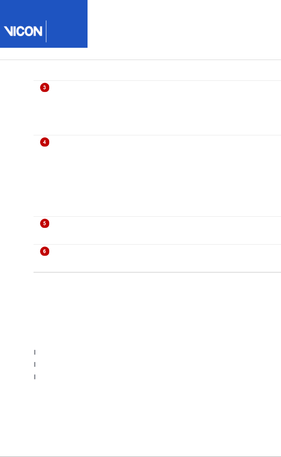
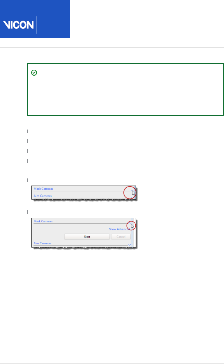
Display/hide a section within a pane:
Click the Display Section arrow on the right
Click the Hide Section arrow on the right
For lists summarizing more Nexus shortcuts and mouse actions, see Hot keys and
.shortcuts on page 30

Nexus
User
Guide
Vicon Motion Systems Ltd. 26-Oct-2018 Page of 11 240
Manage motion capture data with the Data Management tab
The tab of the window enables you to create a Data Management Communications
hierarchical structure in which to store and manage all the data associated with your
motion capture trials. For information on how to do this, see Prepare a data storage
.location on page 94
Tip
To toggle the display of the tab, press F2.Data Management
It also enables you to:
Assess trial health with the tools on the tab. For more information, see Quality
.Review data quality on page 154
View processing history on the tab. For more information, see History Review
.processing history on page 153
Set up and control monitors for your trials with the tab.Monitor
Interact with MATLAB.
View system status information on the tab.Status
View a log of Nexus system activity since start up on the tab.Log
Nexus
User
Guide
Vicon Motion Systems Ltd. 26-Oct-2018 Page of 12 240
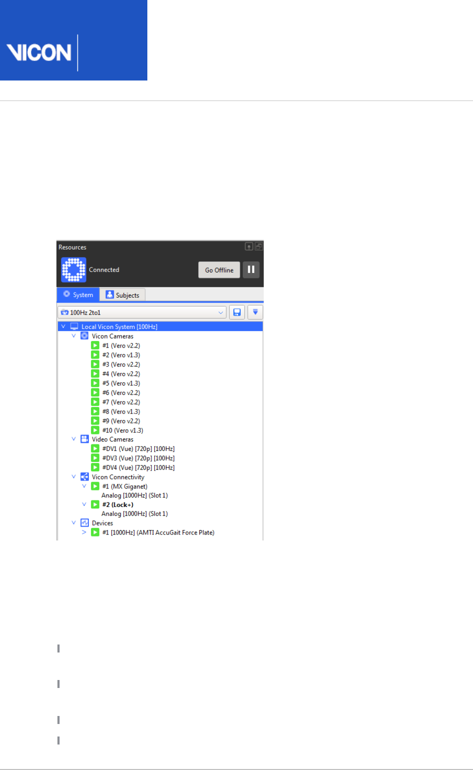
Manage system and subjects in the Resources pane
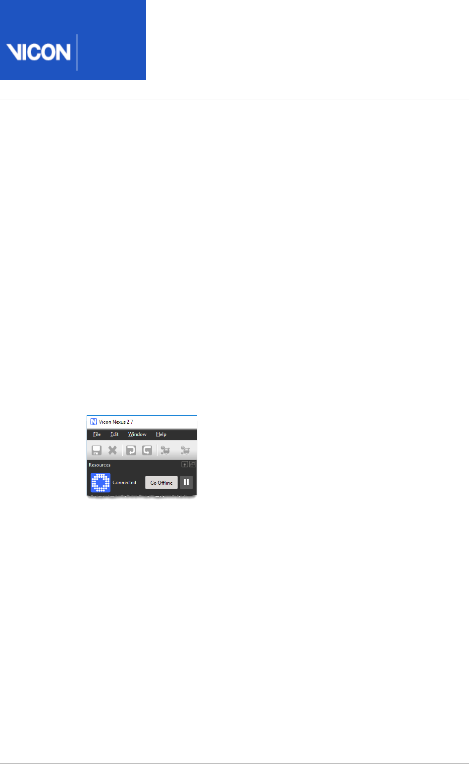
To manage Nexus system connection and real-time data-streaming, click the system
connection buttons at the top of the pane:Resources
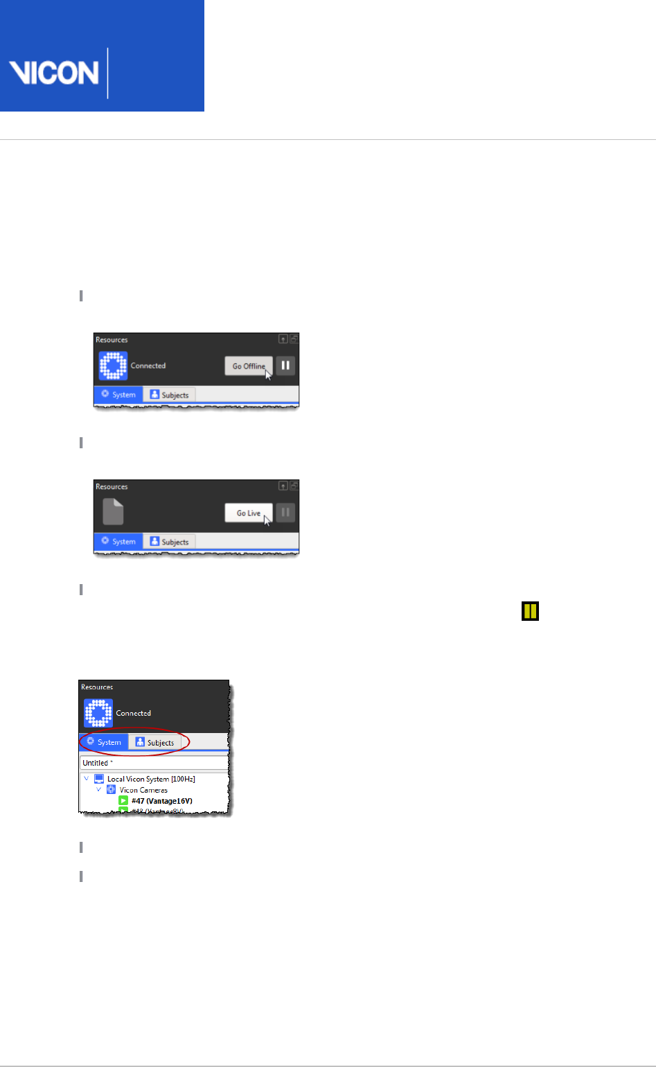
Go Live: Connect the system and start real-time data streaming. The button's label
changes to .Go Offline
Go Offline: Disconnect the system and stop real-time data streaming. The button's
label changes to .Go Live
Pause: Pause real-time data streaming. When you click the Pause button while the
system is in Live mode, the button turns blue and a pause symbol is displayed in
the view pane. When the system is in Offline mode, the button is unavailable.
At the top of the pane, click the tab for the resources you want to manage:Resources
System: View and configure Vicon system components
Subjects: Load and manage files for mocap subjects
Nexus
User
Guide
Vicon Motion Systems Ltd. 26-Oct-2018 Page of 13 240
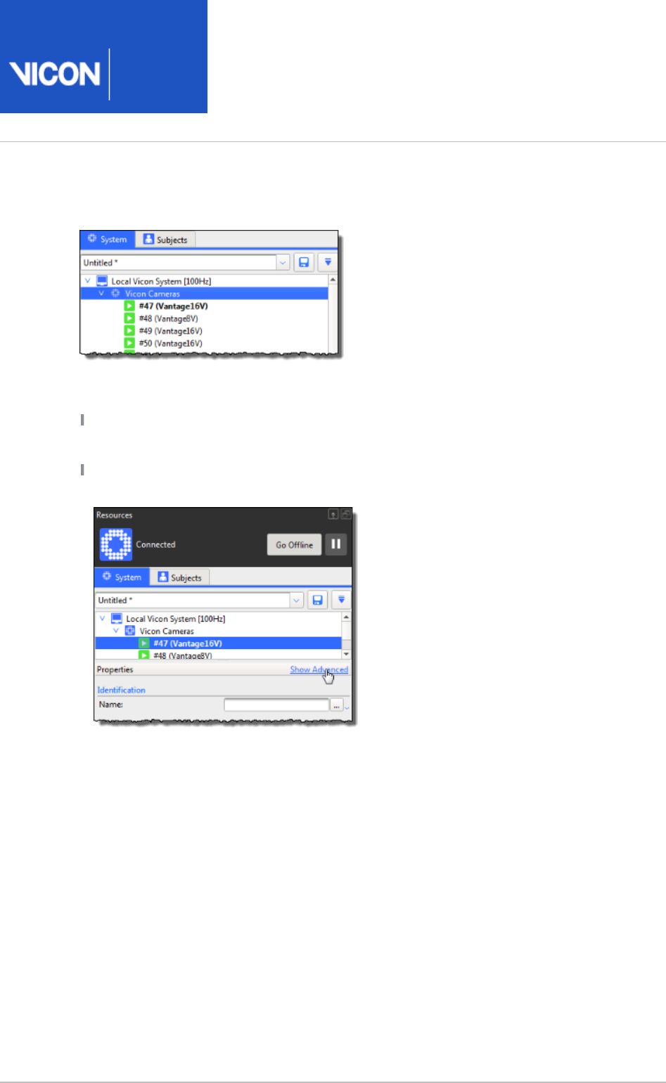
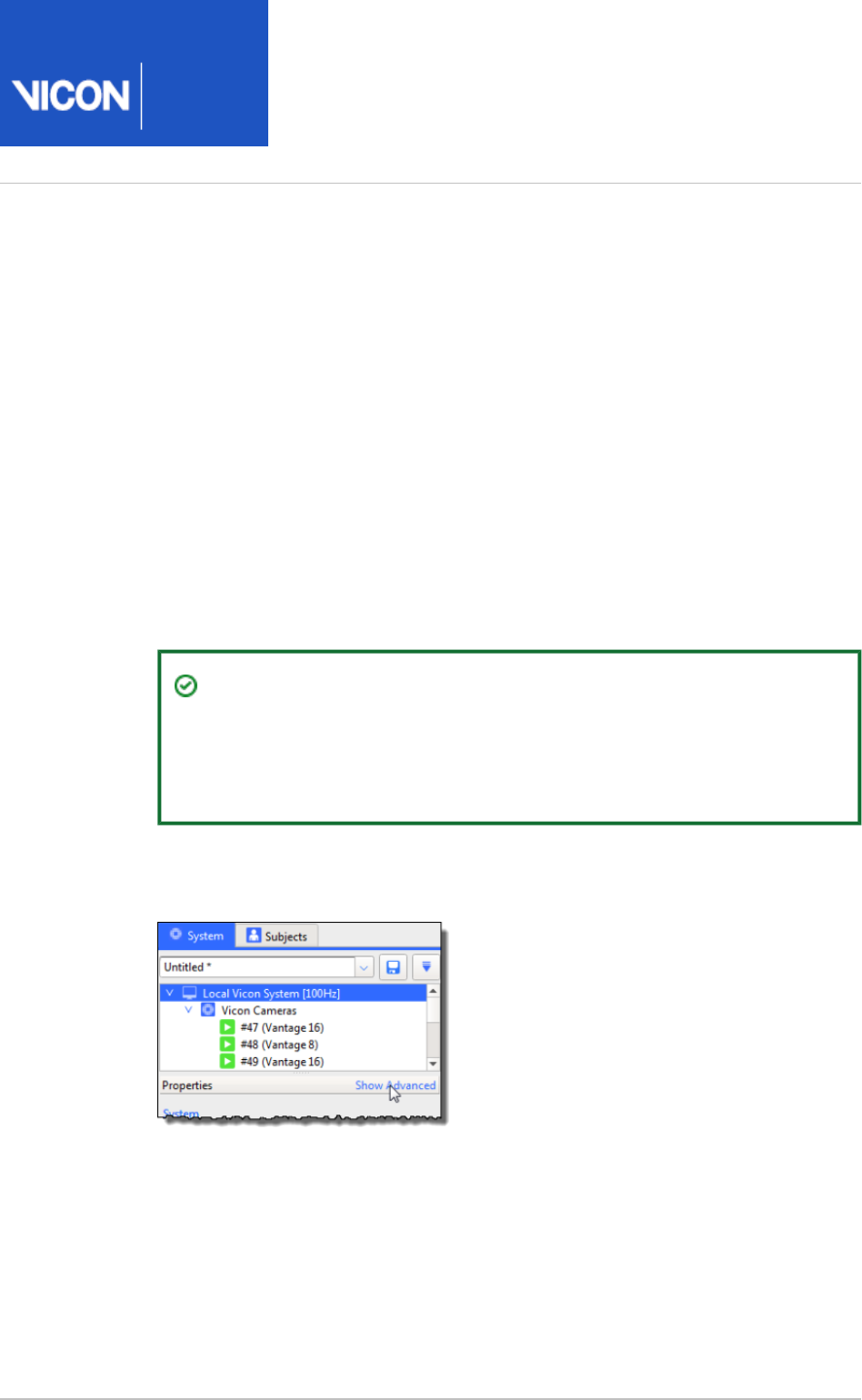
In the tree or tree, select the item(s) you want System Resources Subjects Resources
to configure.
Depending on whether you are in Live mode, you can then:
Right-click a node to display a context (shortcut) menu of commands that can be
applied to that item, if one exists.
In the pane below the tree, view the settings for the item(s) Properties Resources
selected in the tree. To view all of the available properties, click .Show Advanced
For more information, see .Set properties in Vicon Nexus on page 14

Nexus
User
Guide
Vicon Motion Systems Ltd. 26-Oct-2018 Page of 14 240
1.
2.
3.
4.
Set properties in Vicon Nexus
You can configure certain aspects of the Nexus system, such as system components
and motion capture subjects, by configuring settings in the corresponding Properties
section of the user interface.
Required properties for which you must specify a value are indicated in the Nexus user
interface with a shaded background.
Some properties settings automatically persist, so Nexus remembers them in
subsequent sessions. You must explicitly save other settings using the relevant
configuration management controls for that area of the Nexus window.
To set properties in Nexus:
In the Nexus window, open the pane or dialog box containing the properties
whose settings you wish to configure. For example:
System components - paneSystem Resources
Motion-capture subjects - paneSubjects Resources
Camera calibration process - paneSystem Preparation Tools
Subject calibration process - paneSubject Preparation Tools
Data processing operations - panePipelineTools
Monitor and event actions - tab in the paneMonitors Communications
Data visualization - dialog boxOptions
To view all of the available properties, click the link. To show Show Advanced
only the basic properties, click the link.Hide Advanced
View or change the setting for the desired properties using its entry field or
control.
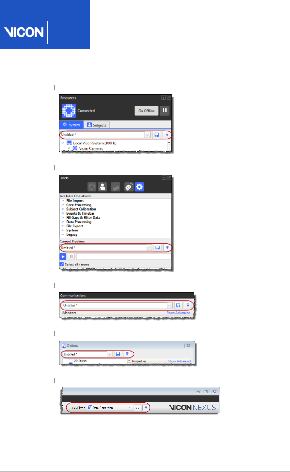
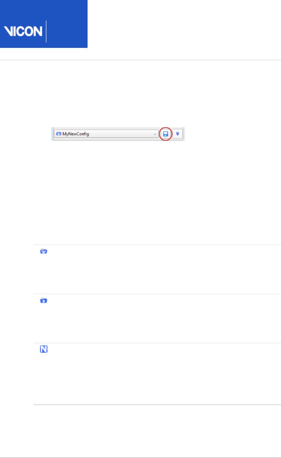
When you are working in the following areas of the Nexus window, you can save
any changes you have made to the settings, using the configuration
management controls (indicated in the following images). Your settings are
saved to a configuration file, so that you can re-use them later.
Nexus
User
Guide
Vicon Motion Systems Ltd. 26-Oct-2018 Page of 15 240
4.
System Resources pane
Pipeline Tools pane
Monitors tab in the paneCommunications
Options dialog box (press F7 to display)
Nexus toolbar (working with the layout of the view panes)
For more information on configuration files, see Manage configurations in Vicon Nexus
.on page 21
Nexus
User
Guide
Vicon Motion Systems Ltd. 26-Oct-2018 Page of 16 240
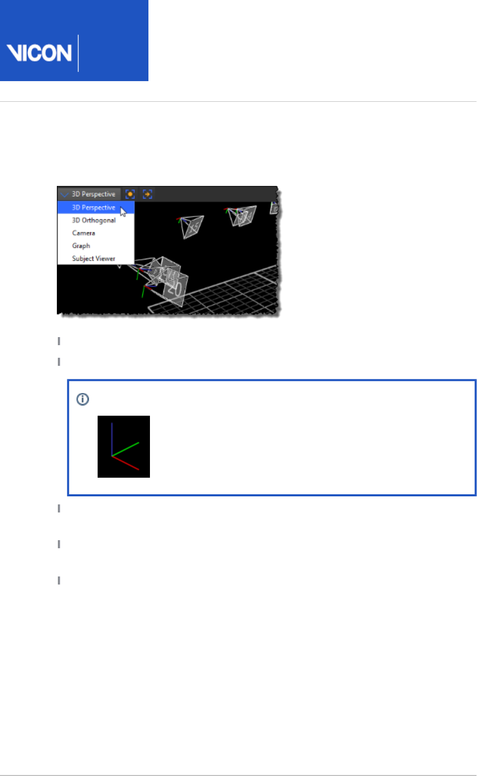
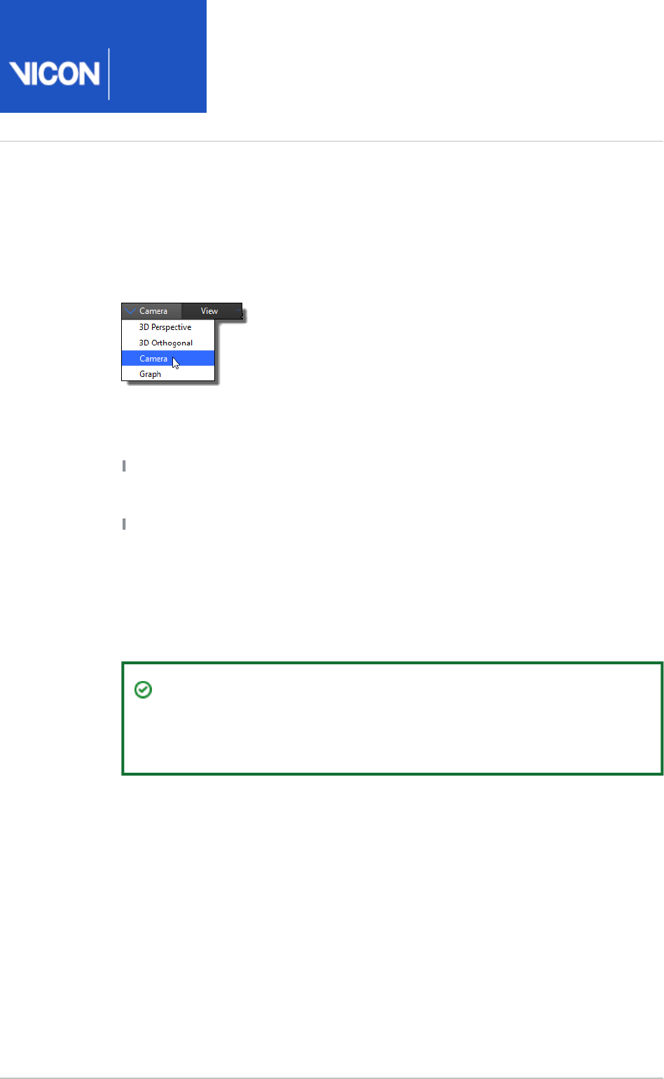
Display data in the View pane
At the left of the View pane toolbar, click the drop-down list and select one of the
available views:
3D Perspective: Display 3D reconstructions of Vicon camera data.
3D Orthogonal: Orthogonal views of 3D data: -Z, +Z, +X, -X, +Y, or -Y
Note
RGB = XYZ
Camera: Display 2D optical data from Vicon cameras or video streams from
connected video cameras.
Graph: Display variables (model outputs), or system components such as force plate
or EMG activity.
Subject Viewer: Display the base (default) pose for the labeling skeleton template
(VST) of the currently selected subject. This is useful when you are calibrating and
manually labeling a labeling skeleton, which are explained in Prepare a subject on
.page 108
Nexus
User
Guide
Vicon Motion Systems Ltd. 26-Oct-2018 Page of 17 240
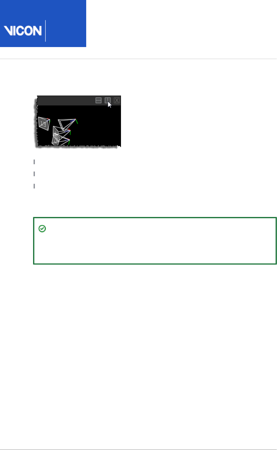
At the right of the View pane toolbar, click the buttons to specify the number and
arrangement of views displayed:
Horizontal
Vertical
Close
Depending on the view selected, additional lists and buttons are available to manage
the display options.
Tip
To display multiple views, in the tree, SHIFT+click Camera System Resources
to select multiple cameras and in the View workspace, select view.Camera
Nexus
User
Guide
Vicon Motion Systems Ltd. 26-Oct-2018 Page of 18 240
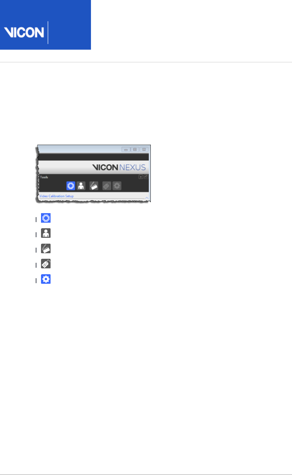
Manage the motion capture workflow in the Tools pane
At the top of the pane, click the buttons for tools relating to the stage in the Tools
workflow that you want to display. The buttons are displayed in the order of a typical
Nexus workflow (from left to right) and are enabled appropriately, depending on
whether you are in Live or Offline mode (the following image is in Live mode).
: Prepare your Vicon system for motion capture.System Preparation
: Prepare subjects whose motion is to be captured.Subject Preparation
: Collect motion data.Capture
: Label and fill any gaps in trial data.Label/Edit
: Create and manage sequences of operations to process trials.Pipeline
To find out more about the motion capture workflow, see ViconNexus motion capture
.workflow on page 29
Nexus
User
Guide
Vicon Motion Systems Ltd. 26-Oct-2018 Page of 19 240
1.
2.
3.
4.
5.
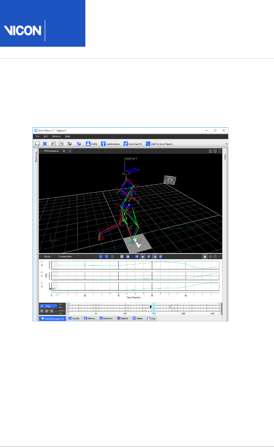
Play back data with the time bar
To explore the time bar:
Ensure a view is displayed (see 3D Perspective Display data in the View pane on
).page 16
On the tab at the bottom of the Nexus window, navigate to Data Management
an existing database. You can do this by expanding the displayed hierarchy and
using the , , and Go forward to the next node Go back to the last node Move up
buttons .one folder level
In the column, double-click the trial that you want to load.Name
The window is minimized and Nexus opens the trial.Data Management
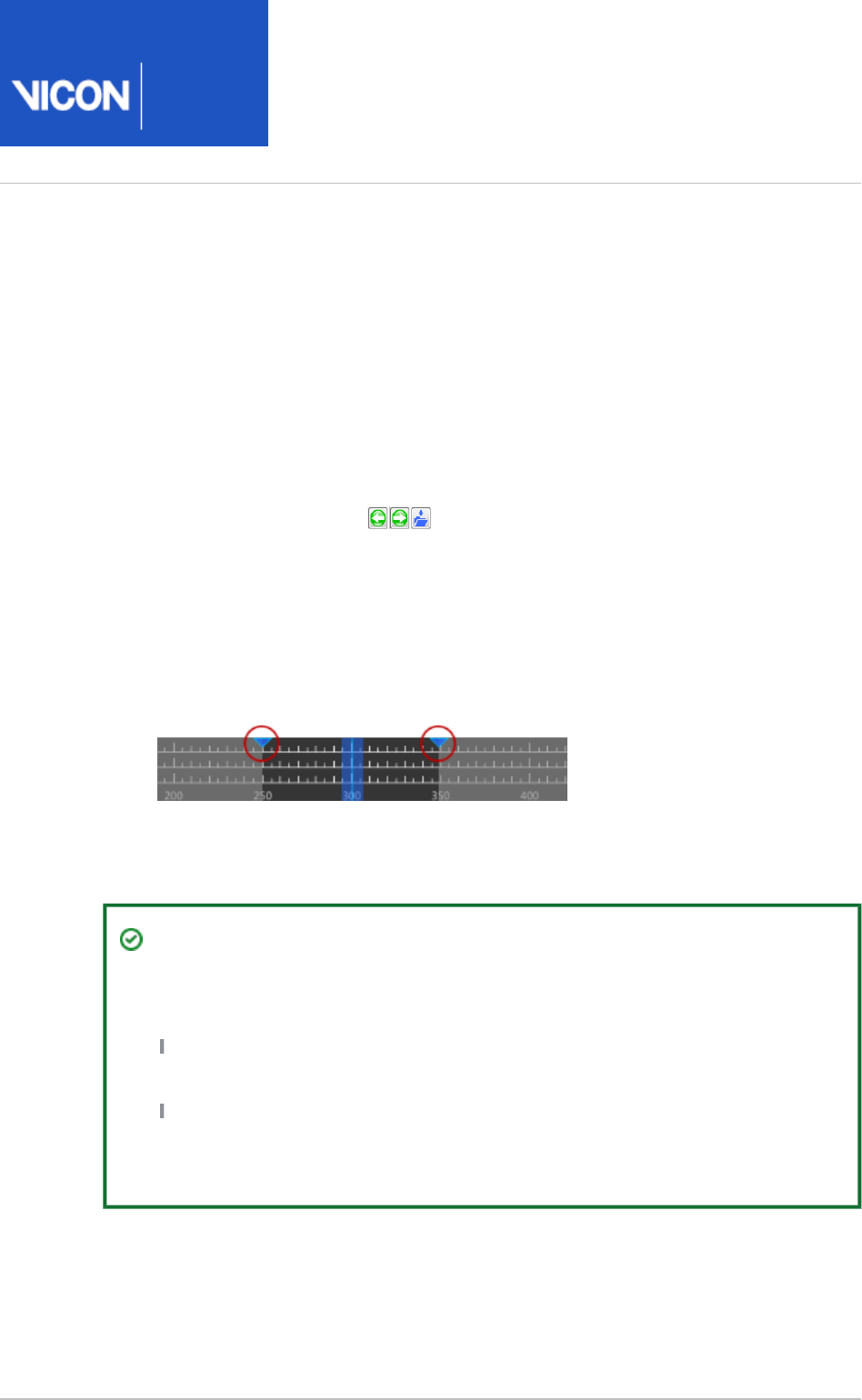
On the time bar, click the button or drag the current time indicator (blue Play
vertical line) to play back offline capture data. To crop a trial (restrict playback to
a range of frames), you can drag the Start and End Range indicators (the blue
triangles at the top of the timeline) along the time bar.
To re-display the window, double-click the Data Management Data Management
tab at the bottom of the Nexus window.
Tip
In addition to using the time bar to view and navigate trials, you can also use it
to:
View data quality as a heat map. For more information, see Review trial data
.using the time bar on page 154
Create and manage events (for example, a foot striking a force plate, or a
joint attaining a specified angle, etc). For more information, see Add events
.to trials on page 180
Nexus
User
Guide
Vicon Motion Systems Ltd. 26-Oct-2018 Page of 20 240
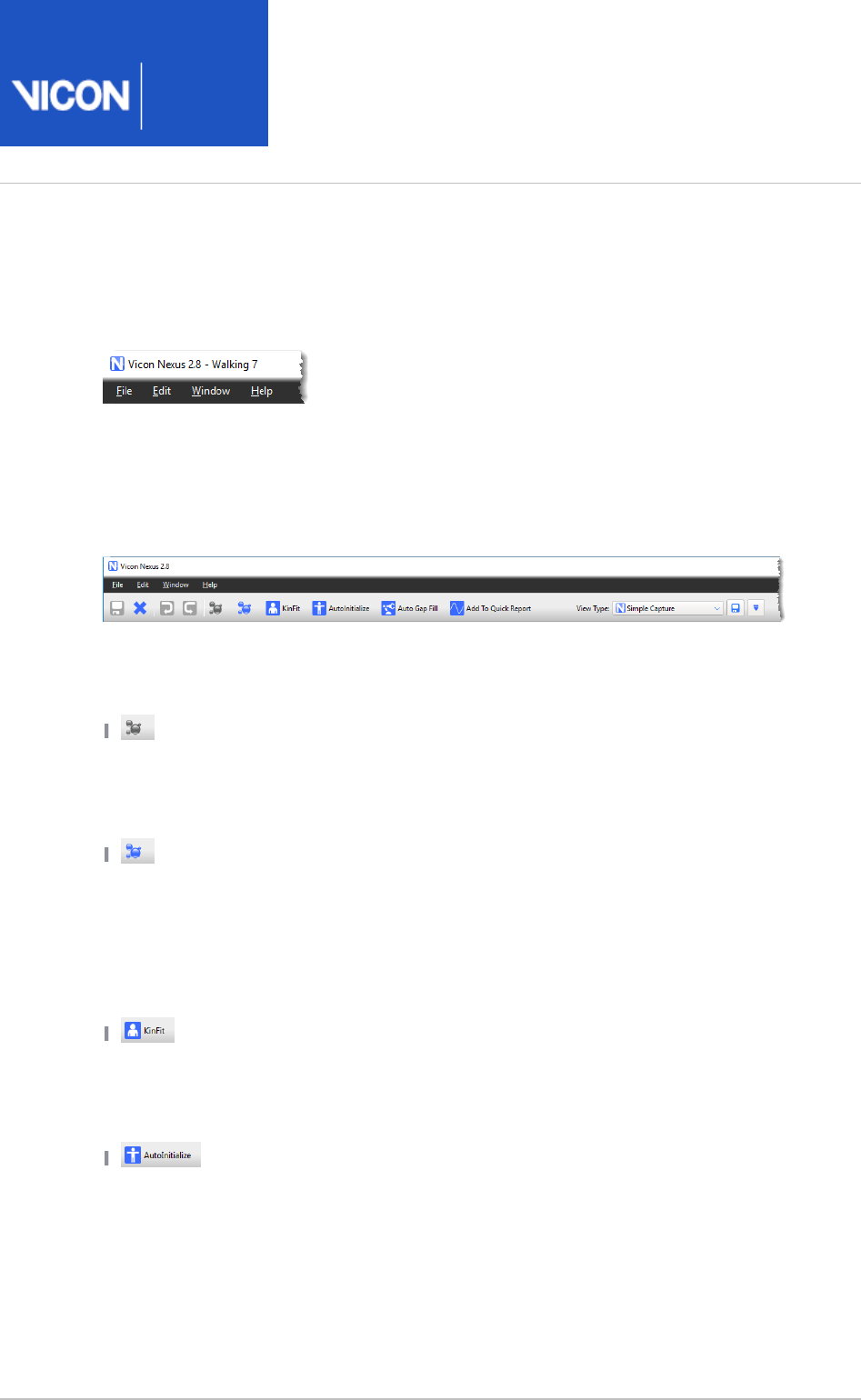
Access menu options from the Nexus menu bar
The Nexus menu bar enables you to access common commands.
Access common commands from the Nexus toolbar
Access frequently used commands from the Nexus motion capture workflow from the
Nexus toolbar.
The Nexus toolbar contains buttons that enable you to save the current trial, close the
current trial, and undo and redo actions. In addition it contains the following controls:
Reconstruct Runs the pipeline defined in the pane. Reconstruct Pipeline Tools
(Reconstruction is the process by which Nexus calculates the position of markers in
three-dimensional space and links these points frame-by-frame into a trajectory.) For
examples of using this pipeline, see .Calibrate a labeling skeleton on page 113
Runs the pipeline defined in the Reconstruct and Label Reconstruct and Label
pane. (The Label process is where labels defined in the labeling Pipeline Tools
skeleton template for the subject are applied, either manually or automatically, to a
point in the trajectory of a marker.) Normally used when processing trials. For an
example of using this pipeline, see Reconstruct and label movement trials on page
. 150
Runs the pipeline defined in the pane. This KinFit Kinematic Fit Pipeline Tools
pipeline is often used before running a operation for filling gaps Fill Gaps - Kinematic
in trajectories, and for visualizing or graphing segment- or joint-based data in
realtime.
Runs the pipeline defined in the AutoInitialize Auto Initialize Labeling
pane. Often used as part of calibrating a labeling skeleton For an Pipeline Tools
example of using this pipeline, see .Calibrate a labeling skeleton on page 113
Nexus
User
Guide
Vicon Motion Systems Ltd. 26-Oct-2018 Page of 21 240
Runs the pipeline defined in the Auto Gap Fill Auto Intelligent Gap Fill
pane. This enables you to quickly fill gaps in your trial, without having Pipeline Tools
to choose which fill method is best for each gap. For good results, you must
configure the relevant pipeline operations for your particular trials. For information
on using this command, see .Automatically fill gaps in trial data on page 177
Adds the current trial to a Quick Report. For more Add To Quick Report
information, see in the .Quick Reports
Vicon Nexus Reference Guide
Any user-customized buttons If required, you can create your own additional buttons
and configure them to run a specified pipeline or load a previously created view
configuration. You can create or change toolbar buttons in the Customize Toolbar
dialog box.
list Lists any saved view types. The adjacent View Type
configuration buttons enable you to create and save custom view types.
Clicking a button on the toolbar executes the defined action for the button. A button is
dimmed if it is not available, for example, if it cannot be run at that stage of the
workflow or if a customized button has been deleted or renamed.
Tip
To display a tooltip that explains why a button is unavailable, hover the mouse
pointer over the button.
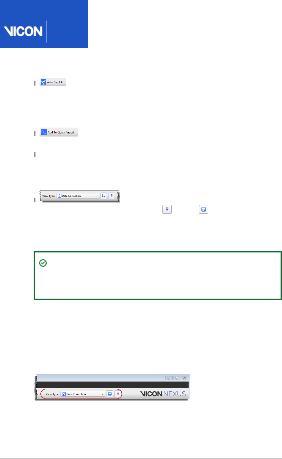
Manage configurations in Vicon Nexus
You can determine how Nexus looks and behaves by creating and editing
configurations in the configuration management controls in the Nexus window. To
view and select any default configurations that were installed with Nexus, click the
dropdown list in the relevant configuration management controls, for example, for View
Types:
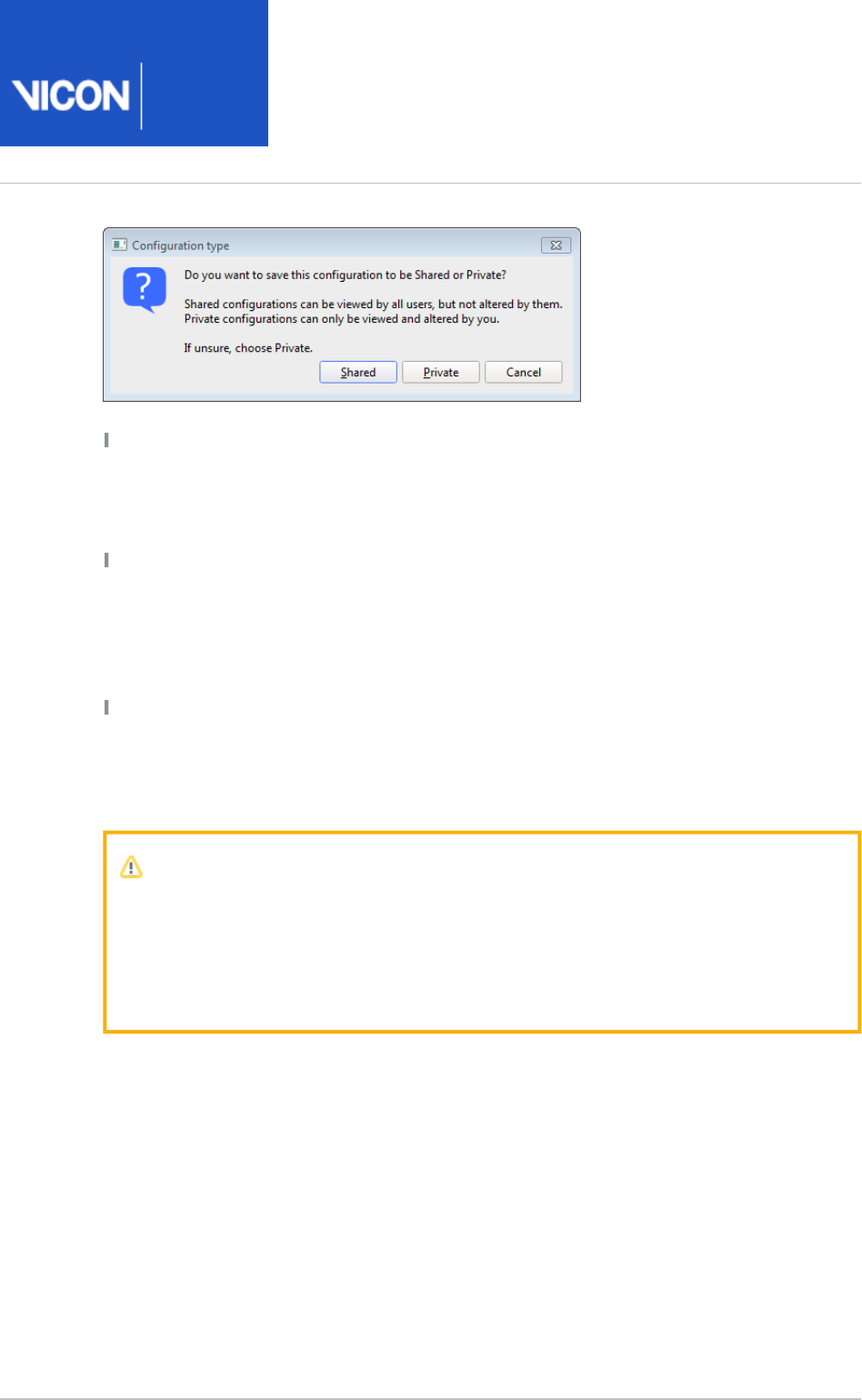
You can create different configurations to suit different types of motion capture
applications and then select the appropriate configuration when required. You can also
save configurations for use by multiple users (Shared) or for a specific user (Private), to
suit the way your organization works:
Nexus
User
Guide
Vicon Motion Systems Ltd. 26-Oct-2018 Page of 22 240
Shared These configurations can be viewed by all users; they can be changed only by
the user who was logged on when the file was first created and saved. Shared
configuration files are stored in the appropriate folder, by default under:
C:\Users\Public\Documents\Vicon\Nexus2.x\Configurations
Private These configurations can be viewed and changed only by the user who was
logged on when the file was first created and saved. Private files are stored in the
appropriate folder under the logged-in user's Application Data files folder, by default
under:
C:\Users\<UserName>\AppData\Roaming\Vicon\Nexus2.x\Configurations\
System These configurations are the default configurations that are installed with
Nexus and are stored in the Nexus configurations folder, by default:
C:\Program Files (x86)\Vicon\Nexus2.#\Configurations
For more information, see .Recognize Shared, Private, and System files on page 25
Important
The default Nexus toolbar is stored in the configuration file
Standard.toolbar
in the Nexus configuration folder . If you add, delete, or Shared
Toolbars
reposition buttons on the Nexus toolbar using the dialog Customize Toolbar
box, these customizations are stored in your configuration folder. Private

Nexus
User
Guide
Vicon Motion Systems Ltd. 26-Oct-2018 Page of 23 240
1.
To manage configurations in Nexus:
In the Nexus window, open the pane or dialog box containing the type of Nexus
configuration file you want to manage:
Nexus UI area Configuration type Configurations
folder\file
Capture Tools pane Motion capture
settings
TrialTypes\*.
TrialTypes
Biomechanics Workflow area of
paneCommunications
Biomechanics
workflow
CaptureWorkflows\*.
CaptureWorkflow
Sounds dialog box Sounds settings AudioSchemes\*.
AudioScheme
Monitors tab in Communications
pane
Event monitors
and actions
Monitors\*.Monitors
Options dialog box Data view options Options\*.Options
Pipeline Tools pane Automated
processing
operations
Pipelines\*.Pipeline
System Resources pane System settings Systems\*.System
Toolbar Toolbar buttons Toolbars\*.Toolbar
(see note above)
View pane View options and
layouts
ViewTypes\*.
ViewType

Nexus
User
Guide
Vicon Motion Systems Ltd. 26-Oct-2018 Page of 24 240
2.
3.
4.
Depending on whether you want to create a new configuration from scratch or
change the current configuration or either:
Leave the currently loaded configuration file. (If no configuration file has been
created yet, * is displayed and no other options are available.)Untitled
or
Select another configuration file from the dropdown list. If you have made
changes to the current configuration file, Nexus prompts you to save these
before changing the configuration file.
In other areas of the Nexus pane or dialog box, make any desired changes to
settings, such as those in a section.Properties
Click the configuration menu button and select the required command from
the displayed list:
New: Create a new configuration in which to save the current settings. The
name * is displayed in the list.Untitled Choose configuration
Save As: In the dialog box, enter a name to overwrite the default new Save As
configuration file name * or to create a new system configuration file Untitled
in which to save a copy of the current configuration file and click OK.
Additional options include:
Rename: In the dialog box, enter a new name for the currently loaded Rename
configuration file and click OK.
Delete: At the prompt, click Yes to delete the current file displayed in Delete
the configuration dropdown list.
Mark Read-Only: Select to protect the current configuration file from further
changes.
Set Defaults: Returns values to their default settings.
Import: Enables you to select and import a configuration file. This is useful
when you want to copy a configuration file from another machine.
Reload: Reload or delete an automatically saved configuration file. You can
select from the list of timestamped files or, if required, delete all the saved
configurations.
Refresh List: Re-display the contents of the configuration dropdown list. This
is useful if you copy a file into one of the sub-folders, enabling Configurations
you to update the options displayed in the relevant list, without having to re-
start Nexus.
Nexus
User
Guide
Vicon Motion Systems Ltd. 26-Oct-2018 Page of 25 240
5.
6.
In the dialog box, select the user permissions for the Configuration type
configuration: or .Shared Private
The new file name is displayed in the configuration dropdown list.
Click the Save button to store the settings in the configuration displayed in the
configuration dropdown list.
For more information, see .Set properties in Vicon Nexus on page 14
Recognize Shared, Private, and System files
When pipelines, view types, monitors, labeling skeleton templates, and configurations
are displayed in Nexus (ie, listed in menus, etc), you can immediately recognize whether
they are Private, Shared, or System files:
Icon File
type
Description
Shared Can be viewed by multiple users; can be changed only by the user
who was logged on when the file was first created and saved.
Shared files are stored in subfolders in:
C:\Users\Public\Documents\Vicon\Nexus2.x
Private Can be viewed and changed only by the user who was logged on
when the file was first created and saved. Private files are stored
in subfolders in:
C:\Users\ \AppData\Roaming\Vicon\Nexus2.x
<username>
System Cannot be changed (Read-Only) and are upgraded when the next
version of Nexus is installed. Stored in subfolders in the Nexus
installation folder, whose default location is:
C:\Program Files (x86)\Vicon)\Nexus2.# or
C:\Program Files\Vicon\Nexus2.#
Nexus
User
Guide
Vicon Motion Systems Ltd. 26-Oct-2018 Page of 26 240
Customize the Vicon Nexus user interface
In addition to the usual resize and close window options, you can slide the Resources
and panes to either side of the Vicon Nexus window and or minimize the Tools
pane, to give you a larger workspace area.Communications
Nexus
User
Guide
Vicon Motion Systems Ltd. 26-Oct-2018 Page of 27 240
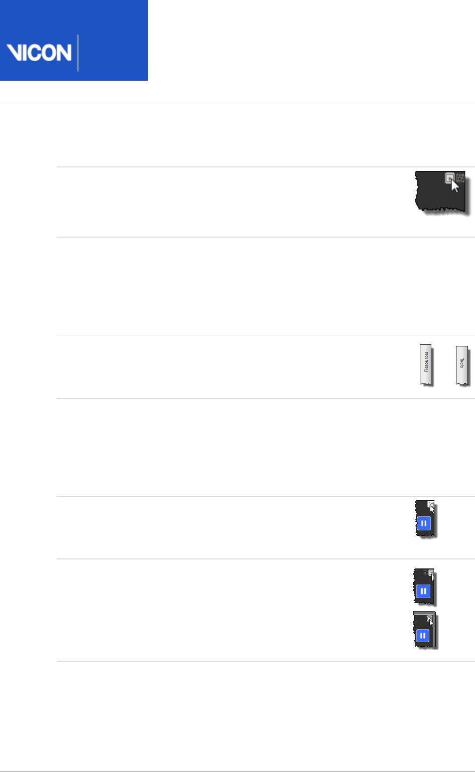
Requirement Action
To hide the
andResources
/or panesTools
At the top of the or pane, click Resources Tools
the button.UnPin
To hide the
Communications
pane
Double-click a tab within the Communications
pane; or
To hide the pane whenever you load a trial, on
the menu, select the Window Close
option.Communications Pane on Trial Load
To reveal the
andResources
/or panesTools
Click the tab at the side of the Nexus window
or
To reveal the
Communications
pane
Double-click a tab within the Communications
pane; or
To make the pane visible whenever you load a
trial, on the menu, clear the Window Close
option.Communications Pane on Trial Load
To return a pane
to being locked
into place
At the top of the pane, click the button.Pin
To undock (float)
and dock a pane
At the top of the (pinned) pane, click the Undock
or button.Dock
or

Nexus
User
Guide
Vicon Motion Systems Ltd. 26-Oct-2018 Page of 28 240
Customize a View pane
The View pane cannot be undocked, repositioned, or resized in the Nexus window.
However, you can open a separate floating view pane by selecting the New floating
command from the menu. This floating workspace can be workspace Window
repositioned and resized.
The width of the View pane is affected by resizing panes to the left and/or right of it.
The height of the View pane is affected by resizing the panes below it.

Nexus
User
Guide
Vicon Motion Systems Ltd. 26-Oct-2018 Page of 29 240
Vicon Nexus motion capture workflow
In Vicon Nexus, you can capture and analyze the movement of live subjects (such as
human beings or animals) and of inanimate objects (such as sports equipment or other
rigid objects) for a variety of motion capture applications. You can either stream motion
data in real time or capture it for offline processing, depending on your requirements.
The stages involved in the typical workflow for the operation of Nexus for motion
capture production and control are outlined below.
Prepare a Vicon system on page 43 when you first set up or significantly change
your motion capture system.
Calibrate a Vicon system on page 96 when you first set up your system and
regularly afterwards (eg, at the start of every day, before you begin motion capture),
to ensure any changes (eg, slight movement of cameras or other equipment) is
accounted for. You also do this if you make changes to the system.
Prepare a subject on page 108 when you have a new subject, or want to make
changes to an existing subject. This stage includes calibrating a labeling skeleton for
your new subject or re-calibrating when you have made changes to an existing
subject.
Capture movement trials on page 136 after you have calibrated the labeling skeleton,
to collect the data needed for your trials.
Review trials and fill gaps on page 152 after you have captured, reconstructed and
labeled your movement trials, to fill any gaps in the data.
After you have filled any gaps and cropped the data as necessary, you can perform
any required modeling (for example, you can run the dynamic Plug-in Gait model, or
perform custom modeling) to generate the required model outputs (such as angles,
forces, moments, powers, or bones). For information, see Modeling with Plug-in Gait
.on page 185
Export trial data on page 233, which is normally the final stage in motion capture,
and enables you to use the captured data in third-party applications.
To speed up some of the above processes, you can use the supplied pipelines,
consisting of one or more operations that are supplied with Nexus, or you can create
your own custom pipelines. To use pipelines on a large number of trials, you can run
them as batch processes. For more information, see .Work with pipelines on page 131

Nexus
User
Guide
Vicon Motion Systems Ltd. 26-Oct-2018 Page of 30 240
Hot keys and shortcuts
To help you use Vicon Nexus efficiently, this section provides lists of shortcuts:
Common hot keys and shortcuts on page 30
Shortcuts for navigating in Vicon Nexus on page 32
Shortcuts for managing real-time data on page 33
Shortcuts for selecting items on page 34
Shortcuts for moving the camera view on page 35
Shortcuts for viewing data in 3D views on page 35
Shortcuts for viewing data in the Graph view on page 36
Shortcuts for visualizing graph data on page 37
Shortcuts for working with the time bar on page 38
Shortcuts for gap-filling on page 41
Shortcuts for using the Quality tab on page 42
Common hot keys and shortcuts
You can use the mouse to manipulate items and manage the way data is displayed in
the Vicon Nexus window. Standard mouse actions can also be combined with keyboard
keys. The following mouse actions and hot keys are available throughout Nexus, where
applicable/available:
Task Keys and mouse
Start/stop capture CTRL+Enter
Select individual items Click
Select items within a bounding outline ALT+click and drag
Select multiple non-consecutive items CTRL+click
Rotate/orbit Click and drag
Nexus
User
Guide
Vicon Motion Systems Ltd. 26-Oct-2018 Page of 31 240
Task Keys and mouse
Zoom Right-click and drag
Translate/Move Click wheel button (or
left-and-right-click) and
drag
Scroll forward or backward through a list Rotate mouse wheel
Undo CTRL+Z
Redo CTRL+Y
Save currently enabled subject data to the current trial's
. file (equivalent of clicking on the menu)
c3d
Save File
CTRL+S
Reset Core Processor CTRL+R
Esc Exit current mode
(labeling, etc)
Unset all cameras' Bumped status CTRL+SHIFT+B
Note
The behavior of the ALT GR key depends upon the regional settings specified
for your keyboard in the Windows operating system. In some regions, the
behavior of this key is identical to that of the ALT key, while in other regions
the ALT GR key functions as if the ALT+CTRL keys were pressed together.
Nexus assumes the latter behavior.
If you wish to use the ALT GR key as if it was the ALT key, you must change
the regional settings for your keyboard to use the US layout, which assumes
identical behavior for these two keys. You change your keyboard language
settings in the dialog box, accessed from Text Services and Input Languages
the tab in the dialog box in Languages Regional and Language Options
Windows . For more information, see the Microsoft Windows Control Panel
help.

Nexus
User
Guide
Vicon Motion Systems Ltd. 26-Oct-2018 Page of 32 240
Shortcuts for navigating in Vicon Nexus
Use the following hot keys to navigate to the different areas of the Vicon Nexus user
interface.
Task Keys
Display the Vicon Nexus online help F1
Display/Close tabData Management F2
Display/Close the windowQuick Reports F4
Enter/Exit full screen mode F5
Display/Close dialog boxSounds F6
Display/Close dialog boxOptions F7
Go to paneSystem Preparation Tools F8
Go to paneSubject Preparation Tools F9
Go to paneCapture Tools F10
Go to paneLabel/Edit Tools F11
Go to panePipeline Tools F12
The behavior of function keys is dependent upon the area of the Nexus window that
has focus when the key is pressed. Click anywhere in the window to set the focus
before using the function keys to navigate to a different part of the user interface.

Nexus
User
Guide
Vicon Motion Systems Ltd. 26-Oct-2018 Page of 33 240
Shortcuts for managing real-time data
Use the following hot keys to manage real-time data streaming and offline data
processing in Vicon Nexus.
Task Keys
Start/stop capture CTRL+Enter
Switch between Live and Offline mode CTRL+TAB
Pause/Restart real-time data streaming (Live
mode)
SPACE (or middle mouse
button)
Play/Stop offline data (Offline mode) SPACE (or middle mouse
button)
Toggle Simple Capture mode (Live mode) CTRL+H

Nexus
User
Guide
Vicon Motion Systems Ltd. 26-Oct-2018 Page of 34 240
Shortcuts for selecting items
Use these hot keys and mouse actions to select items in the Vicon Nexus window. To
cancel a selection, left-click again in the view pane.
Task Keys and mouse
Select single item Click
Select multiple non-consecutive items CTRL+click
Select multiple non-consecutive items maintaining
the order of selection
SHIFT+CTRL+click
Select multiple consecutive items SHIFT+click, SHIFT and
drag, or drag
Select next optical camera ]
Select previous optical camera [
Select next video camera CTRL+]
Select previous video camera CTRL+[
In a Camera view, sweep select for manual masking ALT+drag

Nexus
User
Guide
Vicon Motion Systems Ltd. 26-Oct-2018 Page of 35 240
Shortcuts for moving the camera view
Use the following mouse actions to move the camera view in the , 3D Perspective 3D
, and views.Orthogonal Camera
Task Keys and mouse
Zoom: Move the camera viewpoint closer to or
further away from the focal point
Right-click + drag forward or
backward
Orbit: Move the 3D viewpoint around the focal
point
Left-click + drag left, right,
forward, or backward
Translate: Move the 3D viewpoint along a
horizontal or vertical axis
Click wheel button + drag left,
right, forward, or backward
Zoom to window (for all windows). Applies in
Camera, 3D Overlay and Rotated views.
CTRL+SHIFT+Z
Zoom camera view to fit CTRL+SHIFT+F
Shortcuts for viewing data in 3D views
Use the following hot keys to view data in the 3D Perspective and 3D Orthogonal views:
Task Keys
Toggle display of labels CTRL+space
bar
Reset footstrike counters (see Automatically assess foot strikes on
). page 146
CTRL+SHIFT+R

Nexus
User
Guide
Vicon Motion Systems Ltd. 26-Oct-2018 Page of 36 240
Shortcuts for viewing data in the Graph view
Use the following hot keys and mouse actions to view data in the Graph view. For more
information, see .Shortcuts for visualizing graph data on page 37
Task Keys and mouse
Select range of frames to zoom ALT and right-click + drag across frames
Slide x-axis left Click wheel button + drag left
Slide x-axis right Click wheel button + drag right
Slide y-axis up Click wheel button + drag forward
Slide y-axis down Click wheel button + drag backward
Zoom x-axis in Right-click + drag left
Zoom x-axis out Right-click + drag right
Zoom y-axis in Right-click + drag backward
Zoom y-axis out Right-click + drag forward

Nexus
User
Guide
Vicon Motion Systems Ltd. 26-Oct-2018 Page of 37 240
Shortcuts for visualizing graph data
The way the graph that is displayed in a view depends on whether the system Graph
connection is live or offline and whether an individual point or a range has been
selected for plotting.
When zooming into or out of graph data, the display of grid lines in the view pane can
be set to guide the eye toward the selected area of focus. Major grid lines remain at
their normal weight, while any minor grid lines gradually fade. To obtain this behavior,
open the dialog box (F7) and under , select . In the Options General View Options Graph
pane on the right, ensure is selected.Properties Show Minor Grid Lines
Zoom an axis (x or y)
All component graphs in a single workspace maintain the same scale for both the x-
and y-axes. The x-axis is shared across all components, but each component has its
own y-axis. The y-axes may show different ranges, but represent the same number of
values.
Offline: The portion of the specific component trace displayed in the view pane is
centered around the point where the mouse was clicked. All other component views
are scaled by the same amount, with the vertical range centered on the median value
of the visible portion of all the selected traces.
Live: The x-axis, the workspace is centered around zero, keeping zero on the right
edge of the workspace and changing the values displayed on the left.
Zoom selected range of frames
Offline: The y-axis displays only the selected area of the specific trace and the x-axis
displays only the selected frames.
Live: This type of zooming in the x-axis is disabled to ensure that the live frame is
always on the right of the graph.
Pan across an axis (x or y)
Offline: Each component in the y-axis can be panned independently.
Live: Panning in the x-axis is disabled to ensure that the live frame is always on the
right of the graph.

Nexus
User
Guide
Vicon Motion Systems Ltd. 26-Oct-2018 Page of 38 240
Open a Quick Reports window
In addition to displaying a Graph view, you can also open a window Quick Reports
(press F4), which enables you to display multiple graphs of model outputs normalized
over the gait cycle. For more information, see in the Quick Reports
Vicon Nexus
.
Reference Guide
Shortcuts for working with the time bar
Use the following hot keys and mouse actions to work with the time bar at the bottom
of a view pane:
Timescale displayed in timeline
Task Keys and mouse
Slide timeline left Middle-click + drag left
Slide timeline right Middle-click + drag right
Select range of frames to zoom ALT and right-click + drag across frames
Zoom scale in Right-click and drag right or up
Zoom scale out Right-click and drag left or down

Nexus
User
Guide
Vicon Motion Systems Ltd. 26-Oct-2018 Page of 39 240
Time bar data displayed in view pane
Task Keys and mouse
Start/Stop data playback Middle-click
Jog forward/backward through data playback Rotate mouse wheel forward
/backward
Move Current Time Cursor to specific frame Click frame in the timeline
Move Start Range Frame Cursor back to zero
frame of trial
Click cursor
Move End Range Frame Cursor back to last frame
of trial
Click cursor
Go to the previous frame LEFT ARROW
Go to the next frame RIGHT ARROW
Go to the first frame HOME
Go to the last frame END
Go forward 10 frames PAGE UP
Go backward 10 frames PAGE DOWN
Go to frame
<number>
CTRL+G
Set Region of Interest CTRL+D

Nexus
User
Guide
Vicon Motion Systems Ltd. 26-Oct-2018 Page of 40 240
Event identification mode in timeline
Task Keys
Enter/exit event identification mode
(where the time cursor follows the
mouse)
CTRL+E
Go to the previous event CTRL+LEFT ARROW
Go to the next event CTRL+RIGHT ARROW
Lock/unlock event context (In event
identification mode, select desired Left,
Right, or General event context on
timeline; subsequently moving the
mouse forward or backward does not
change context.)
UP ARROW or DOWN ARROW
Display context menu (after event
context locked)
ENTER
Highlight command from context menu UP ARROW or DOWN ARROW
Select highlighted command from
context menu
ENTER
Move event to next frame ALT+RIGHT ARROW
Move event to previous frame ALT+LEFT ARROW

Nexus
User
Guide
Vicon Motion Systems Ltd. 26-Oct-2018 Page of 41 240
Shortcuts for gap-filling
Use the following hot keys to speed up gap-filling and correcting swapped marker
labels:
Task Keys
Select next gap CTRL+8
Select previous gap CTRL+7
Spline fill CTRL+U
Spline fill all CTRL+I
Pick source for pattern filling CTRL+9
Pattern fill CTRL+O
Pattern fill all CTRL+P
Pick source for rigid body fill CTRL+J
Rigid body fill CTRL+M
Rigid body fill all CTRL+,
Pick segment for kinematic fill CTRL+K
Kinematic fill CTRL+L
Kinematic fill all CTRL+.
Cyclic fill CTRL+;
Cyclic fill all CTRL+'
Swap marker labels CTRL+T

Nexus
User
Guide
Vicon Motion Systems Ltd. 26-Oct-2018 Page of 42 240
Shortcuts for using the Quality tab
Use the following hot keys to speed up working on the tab, when using the Quality
view type:Data Correction
Task Keys
Show/hide unlabeled trajectories CTRL+F3
Show/hide trajectory names CTRL+F4
Move to next gap for selected trajectory CTRL+8
Move to previous gap for selected trajectory CTRL+7
Move to previous trajectory CTRL+PgUp
Move to next trajectory CTRL+PgDown

Nexus
User
Guide
Vicon Motion Systems Ltd. 26-Oct-2018 Page of 43 240
Prepare a Vicon system
Before you can use your Vicon Nexus system, you need to configure the system for
motion capture.
When you have done this, the next step is to prepare a hierarchy of folders in which to
store all the files associated with your motion capture trials.
These procedures are explained in the following topics:
Configure Vicon hardware in Nexus on page 44
Prepare a data storage location on page 94
Before you begin to configure your Vicon system, ensure that the following
prerequisites have been met:
It is assumed that your Vicon system hardware (including the Vicon cameras, Vicon
connectivity units, and any supported third-party devices) has been set up and
connected and that Nexus has been installed and licensed. Your Vicon system may
have been professionally installed by a Vicon Support engineer. If you are installing
the system yourself, for full details on installing system hardware, see the Vicon
documentation that was supplied with your hardware, and for installing and licensing
the software, see .
Installing and licensing Vicon Nexus
Vicon Nexus software is licensed using Safenet licensing and the VAULT licensing
system. The licensing drivers must have been installed on the host PC, and the
dongle must be plugged into an appropriate port (parallel or USB) on the computer
while you are running the application software.
The IP address for the Ethernet card on the host PC must be set to 192.168.10.1 using
the default IP address range (for details, see the Vicon PDF
PC Setup for Vicon
, which can be downloaded from the ).
Systems
Vicon documentation website

Nexus
User
Guide
Vicon Motion Systems Ltd. 26-Oct-2018 Page of 44 240
Configure Vicon hardware in Nexus
The first time you use your Vicon Nexus system, you must configure the Vicon cameras,
connectivity units, and any supported third-party devices such as digital video cameras,
force plates, or EMG devices. After this, you only need to change the system setup in
Nexus if you change your hardware configuration or if you need different system
settings, for example, a different camera frequency.
You can save your system settings in a configuration file so that you can re-use or
modify them later. You can create any number of system configuration files. You can
then load the appropriate file for a particular type of motion capture application. For
more information, see .Manage configurations in Vicon Nexus on page 21
When you start Nexus, it automatically detects all the hardware currently connected to
your Vicon system, and groups them into several different categories. You configure
the Vicon system hardware and system-wide parameter and data processing settings
on the tab in the pane (referred to as the pane).System Resources System Resources
Basic setup information for each type of hardware that is likely to be present in a Vicon
Nexus system is included in the following topics:
Connect devices running the Vicon Control app on page 49
Configure system settings on page 52
Configure Vicon optical cameras for data capture on page 55
Configure video cameras for digital video capture on page 61
Aim Vicon cameras on page 64
Mask unwanted reflections on page 66
Configure Vicon connectivity units on page 70
Configure supported devices on page 74
If your system contains more than one Vicon Lock+ or MX Giganet, or if you want to
change the automatically assigned synchronization master, also see Change the
.synchronization master on page 45
If you are not sure whether your firmware is up-to-date or if you have received an email
from Vicon Support about updating your firmware, see the instructions on how to
.Update firmware on page 46

Nexus
User
Guide
Vicon Motion Systems Ltd. 26-Oct-2018 Page of 45 240
1.
2.
3.
Change the synchronization master
The node for the device designated as the Vicon system synchronization master, which
is responsible for providing the master synchronization signal to the system, is
highlighted in bold in the tree. Depending on the age of your Vicon System Resources
system and the connectivity devices it includes, Vicon Nexus automatically designates
the synchronization master:
If a Vicon Lock+ or an MX Giganet is included in the system, it is automatically
designated as the synchronization master.
If the system does not contain a Lock+ or an MX Giganet, then a Vicon camera is
automatically designated as the synchronization master.
If the system contains more than one Lock+ or MX Giganet, you must ensure that the
connectivity unit that is connected to the PC (known as the primary unit) is the
synchronization master. However, because Vicon software cannot detect which
connectivity unit is connected to the PC, you may need to change the automatically
selected master.
To change the synchronization master:
At the top of the tab, click to select it.System Local Vicon System
At the top of the pane, click .Properties Show Advanced
In the section of the pane, click the list and System Properties Preferred Master
then choose the required synchronization master from the list.
Nexus
User
Guide
Vicon Motion Systems Ltd. 26-Oct-2018 Page of 46 240
1.
2.
3.
Update firmware
Each Vicon camera and connectivity unit is programmed with firmware to control its
operation. Periodically, Vicon supplies firmware updates to correct or improve device
functionality. You apply these firmware updates to your Vicon devices via the Vicon
Ethernet network using the Vicon Firmware Update Utility, as described below.
For versions of Nexus 2.8 and later, you are automatically notified when any
component of your Vicon system is running out-of-date firmware, and given the
opportunity to update to the latest version. (For information about updating firmware
for earlier versions of Nexus, see the earlier Nexus documentation.)
Important
To ensure optimum performance and access to all the latest functionality,
Vicon recommends that you upgrade to the latest firmware whenever it
becomes available.
To monitor and/or upgrade system firmware:
When you start Nexus or connect any Vicon devices into your system, Nexus
checks to see whether the firmware for all your devices is up-to-date.
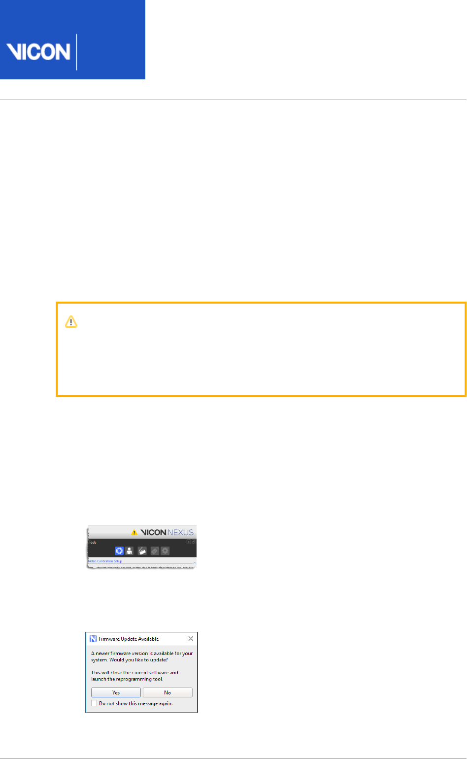
If your devices aren’t using the latest firmware, Nexus displays an icon in the
toolbar to let you know that a more up-to-date version of the firmware is
available:
Click on the icon to display more information.
Nexus displays a prompt that enables you to open the Vicon Firmware Update
Utility (reprogramming tool).
Nexus
User
Guide
Vicon Motion Systems Ltd. 26-Oct-2018 Page of 47 240
3.
4.
5.
6.
Click Yes to open the Vicon Firmware Update Utility. Note that you can also open
the Vicon Firmware Update Utility from the menu (select > Start Vicon Vicon
).Firmware Update Utility
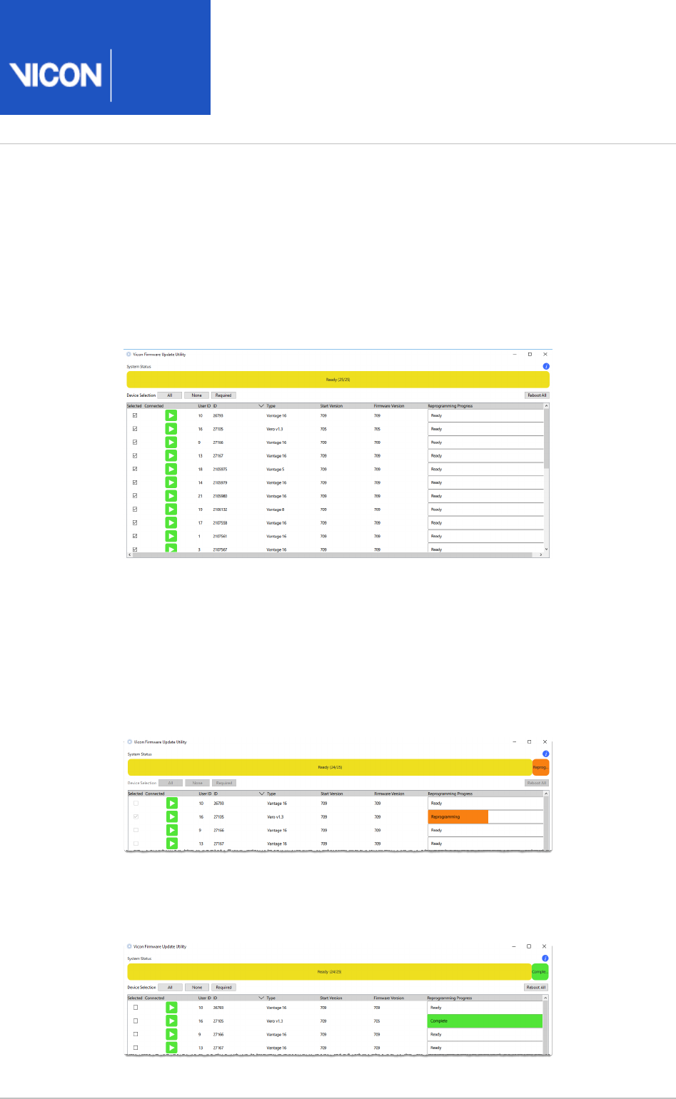
Nexus closes and the Vicon Firmware Update Utility is displayed, showing all the
connected devices and their current firmware version.
By default, all devices are selected.
If you don’t want to update any of the devices, clear the relevant check box(es).
Note that if required, you can select devices to be updated that are already using
the latest version.
At the bottom of the Vicon Firmware Update Utility window, in the Choose
list, select or browse to the required firmware version.Firmware version
Click to update the firmware for the selected device(s).Reprogram
When updating is complete, the column displays the updated Firmware Version
firmware version and the line and the System Status Reprogramming Status
column display on a green background.Complete

Nexus
User
Guide
Vicon Motion Systems Ltd. 26-Oct-2018 Page of 48 240
Note
If you do not have continual internet access, Nexus is unable to notify you
when a new version of the system firmware is available. In this case, install the
Vicon Firmware Update Utility on an internet-connected machine to detect
and download the latest version of the firmware. You can then transfer this
download to the local machine and use the Vicon Firmware Update Utility to
update to the latest version of the firmware.
To downgrade to an earlier firmware version
To downgrade to a firmware version that was previously downloaded, open the Vicon
Firmware Update Utility (from the menu click > Start Vicon Vicon Firmware Update
) and select the required firmware version.Utility
Nexus
User
Guide
Vicon Motion Systems Ltd. 26-Oct-2018 Page of 49 240
1.
2.
3.
Connect devices running the Vicon Control app
To make it easy for a single operator to set up Vicon cameras, you can use the Vicon
Control app, which runs on compatible iOS and Android devices. For more information,
see the on the Vicon website. If you are using the Vicon Control app, Vicon Control app
connect it to your Vicon Nexus system so that you can use it to configure Vicon
cameras.
The following procedure describes how to connect Vicon Control to your Vicon Nexus
system.
Before you can use your phone or tablet with Nexus, you must pair it with the PC that is
running Nexus (the Vicon host PC).
To connect a device running the Vicon Control app to Nexus on a Vicon host PC:
Ensure that your device is connected to a Wifi access point that is on the same
subnet as the Vicon host PC.
On the Vicon host PC, ensure that the required connection is used, that Nexus is
running, and the system is connected.
On the device, open the Vicon Control app.

Nexus
User
Guide
Vicon Motion Systems Ltd. 26-Oct-2018 Page of 50 240
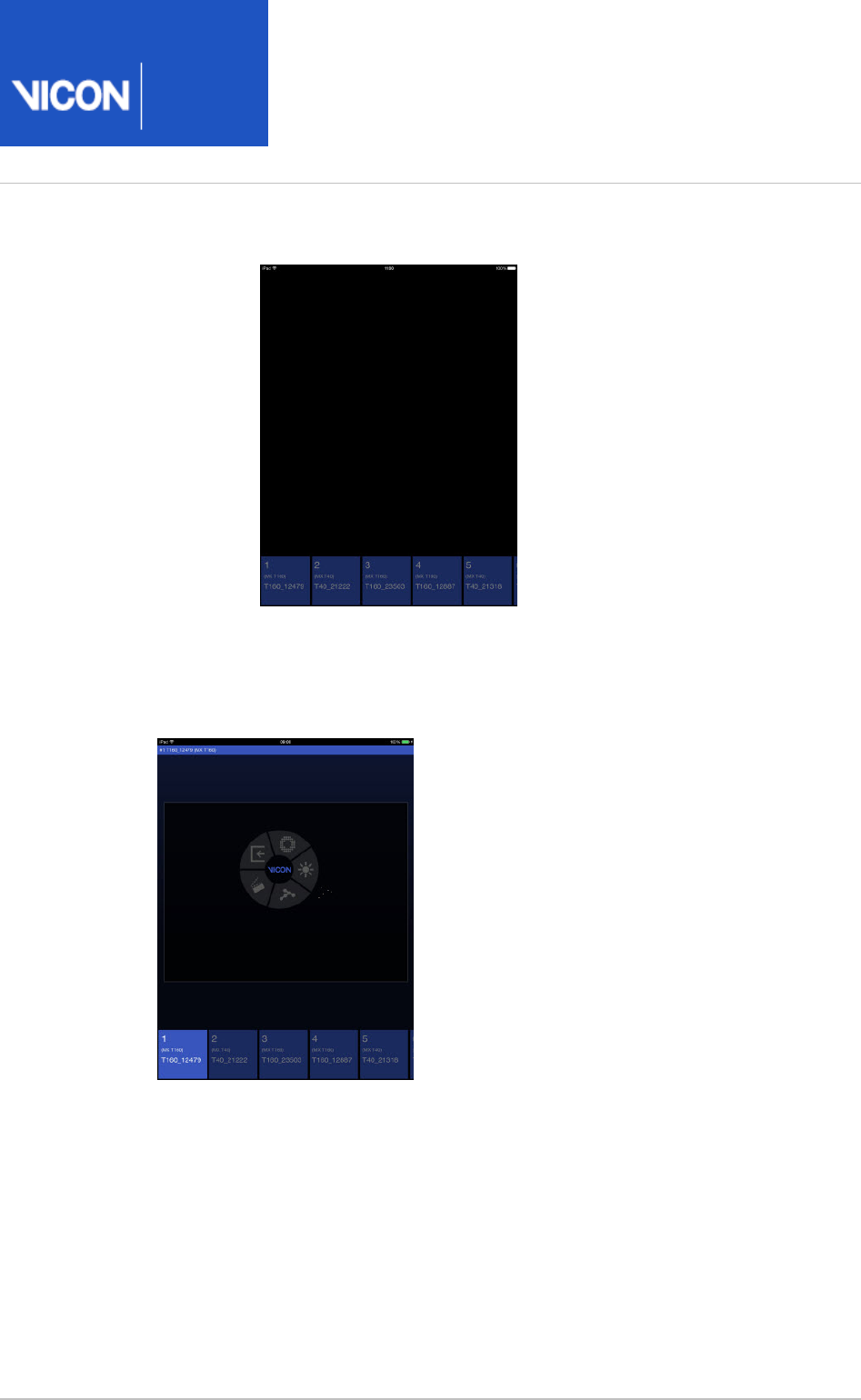
3.
4.
5.
The connection to Nexus is displayed on the initial Control screen:
Tap the Nexus icon.
You are alerted that you must authorize the connection on the Vicon host PC
before you can continue.
In Nexus on the Vicon host PC, an authorization request is displayed:
To use the same connection in future, select Remember this choice for future
. To permit Control to access Nexus, click .connection attempts Allow
Tip
If later you need to revoke authorizations for Vicon Control, either right-
click the node for the device in the tree and then System Resources
click , or on the menu in Nexus, click Revoke Authorization Window
and click (for a single Manage Control Authorizations Forget Device
device) or (for all connected devices).Forget All
Nexus
User
Guide
Vicon Motion Systems Ltd. 26-Oct-2018 Page of 51 240
5.
6.
7.
On the device, a screen similar to the following is displayed:
To select a camera and display a camera view, tap at the bottom of the screen.
You can swipe the camera view right or left to change to the next or previous
camera and use stretch and pinch as normal to zoom in and out.
To access the dial control, tap and hold in a selected camera view.
Use the dial to view and change settings, calibrate and capture.
Nexus
User
Guide
Vicon Motion Systems Ltd. 26-Oct-2018 Page of 52 240
Configure system settings
You specify system-wide settings in the pane, by clicking on the top-System Resources
level node called . This node is displayed when Nexus is in Live Local Vicon System
mode (if necessary, click the button to see this node). It contains sub-nodes for Go Live
each device connected to your Vicon system.
If you have saved any system configurations (.system files), before changing Local
settings, ensure the required configuration is selected at the top of the Vicon System
pane (see ).System Resources Manage configurations in Vicon Nexus on page 21
The node provides access to system-wide properties, enabling you Local Vicon System
to:
Configure the Vicon system capture rate and the amount of memory allocated to
Nexus for motion capture.
Manage the way Nexus produces real-time 3D representations of the subjects whose
motion is being captured.
Specify the identification and connection settings for the Nexus host PC.
Specify video standards and timecode options.
Nexus
User
Guide
Vicon Motion Systems Ltd. 26-Oct-2018 Page of 53 240
1.
2.
3.
To change Vicon system settings:
If Nexus is currently offline, in the pane, click .Resources Go Live
On the tab, click the node.System Local Vicon System
In the pane at the bottom of the tab, view or change settings Properties System
for the required properties to suit the needs of your motion capture application.
When you set up your Vicon system, ensure that the Requested Frame Rate
property in the section of the pane is suitable for your System Properties
application.
The is the rate (in Hz) at which to synchronize the Vicon Requested Frame Rate
cameras. If you are using an external video signal, select from displayed values
(multiples of the base frame rate of the PAL, NTSC, or Film video standard
specified in Standard) up to a maximum of 2,000. You can choose any number
you want if you do not have any Genlock Standard set.
Tip
The default setting of 100 (Hz) is suitable for a range of common
applications, so unless you have a specific requirement for a different
value, you do not need to adjust this setting.
You can configure additional properties as required to suit your motion capture
application. To view all the available properties for , at the top Local Vicon System
right of the pane, click .Properties Show Advanced
For detailed information about each of the properties, see
Local Vicon System
in the .
properties Vicon Nexus Reference Guide

Nexus
User
Guide
Vicon Motion Systems Ltd. 26-Oct-2018 Page of 54 240
3.
When you have finished specifying the properties, at the top of the tab, System
click the button to save your system configuration settings to a file Save
.system
in the Systems configurations folder (see Manage configurations in Vicon Nexus
).on page 21
Tip
The node for the device designated as the Vicon system synchronization
master is highlighted in bold in the tree. For information on System Resources
changing the synchronization master, see Change the synchronization master
.on page 45

Nexus
User
Guide
Vicon Motion Systems Ltd. 26-Oct-2018 Page of 55 240
Configure Vicon optical cameras for data capture
As part of setting up your Vicon system, you must specify the required settings for
Vicon optical cameras. To do this, you use the node in the Vicon Cameras System
pane. You can configure the settings for an individual camera, several Resources
cameras, or all cameras at once.
The node is displayed under the node when Vicon Vicon Cameras Local Vicon System
Nexus is connected to a Vicon system and is in Live mode. It is displayed under the
node when Nexus is in Offline mode. It lists each Vicon optical camera Vicon Data
connected to your Vicon system. For each camera, the node name includes the device
position number, any display name specified in the property, and the Identification
camera type in parentheses, for example, .#1 Over Door (Vantage 16)
Important
Before making changes to your Vicon camera settings, ensure that:
You have set your cameras' focus and aperture. ( To see
how to set up Vicon Vero cameras with Vicon Tracker software, which is
similar to Nexus setup, see the on Tracker Installation and Training Guide
YouTube.)
The required system configuration has been selected in the System
(see ).Resources pane Manage configurations in Vicon Nexus on page 21
Your calibration device (wand) is available.
You have some markers with which to outline the capture volume. This will
also assist with camera setup.
If you are setting up a mixed camera system (that is, a system that includes both Vicon
MX T-Series cameras as well as other current Vicon cameras), see also Set up mixed
.Vicon camera systems on page 59
Nexus
User
Guide
Vicon Motion Systems Ltd. 26-Oct-2018 Page of 56 240
1.
2.
3.
4.
To configure Vicon optical cameras for data capture:
Ensure Vicon Nexus is in Live mode. If it is not, in the pane, click Resources Go
.Live
To visualize your capture volume, from the view pane menu, select .Camera
In the tree, select the node(s) for the camera(s) whose System Resources
properties you wish to configure, either:
Vicon Cameras node for all Vicon cameras
or
A sub node for a specific Vicon camera. The camera sub-nodes on the System
tab correspond to the you set in the pane (see below).Names Properties
Note that If no Lock+ or MX Giganet is present in the Vicon system, the sub-
node for the Vicon camera acting as the synchronization master is displayed in
bold.
When a camera is selected, a blue status light on its strobe unit lights up.
Tip
In many cases, it is best to start by selecting all of the cameras, to find a
common baseline. You can then adjust individual cameras as required.
In the capture volume, have someone wave the calibration wand and ensure that
you can see marker images moving in the view.Camera

Nexus
User
Guide
Vicon Motion Systems Ltd. 26-Oct-2018 Page of 57 240
5. In the pane at the bottom of the tab, click to Properties System Show Advanced
show additional properties.
When you first set up your Vicon system, configure the following camera
properties in the order shown. (If you are not sure what a particular setting
means, you can display a tooltip by hovering the mouse over the relevant field or
control ):
section:Identification
Name (If you wish to distinguish it from the other cameras)
Settings section:
Strobe Intensity In most cases, keep its default setting (1). However, if your
Vicon system consists of a mix of MX T-Series cameras and other current Vicon
cameras, and if it is crucial to your work that the shutter periods for all are
precisely aligned, ensure that your firmware is upgraded to version 700 or later,
and set the for the T-Series camera(s) to the maximum. For Strobe Intensity
more information, see .Set up mixed Vicon camera systems on page 59
Gain Only adjust this setting if the markers appear too faint or the cameras
have trouble distinguishing them; otherwise, leave at its default setting (x1).
Vicon does not recommend using a setting higher than x2.
Grayscale Mode This setting determines what data is sent from the camera to
the computer. Ensure this is set to the default setting ( ) for capturing Auto
data. If the camera recognizes a blob as a circle, only centroid data is sent. If
the camera cannot distinguish the blob as a circle, full grayscale data is sent so
that Nexus can attempt to circle-fit the blobs. Circle fitted markers are
displayed as crosshairs in the view. Camera
Centroid Fitting section:
Threshold This setting differentiates between markers and ambient light. A
value in the region of 0.2 (the default) to 0.5 is usually appropriate, but Vicon
strongly recommends that you view static markers in the volume to establish
an appropriate setting. If cameras are evenly spaced around the volume, the
same value is usually sufficient for all cameras.Threshold
Minimum Circularity Ratio The circularity threshold used by the centroid-fitting
algorithms in a Vicon camera to fit centroids to grayscale blobs. The higher the
value, the more stringent the centroid fitter is. For camera calibration, you may
wish to apply higher settings to ensure that the Vicon system selects the best
markers and thus provides the best possible calibration. For data capture, a
lower value may be appropriate. When a blob is fitted with a centroid, it is
represented by crosshairs. The default setting is 0.5.

Nexus
User
Guide
Vicon Motion Systems Ltd. 26-Oct-2018 Page of 58 240
5.
6.
7.
Tip
If adjusting these settings does not easily enable you to eliminate
reflections, create camera masks to eliminate reflections and other
unwanted light sources that occur in parts of the capture volume. For
information on masking, see .Mask unwanted reflections on page 66
Centroid Tracking section:
Enable Centroid Tracking Tracking 2D camera centroids provides extra
information that maintains marker labels in real time when only one camera
can see a marker. When enabled, the 2D track calculations are performed by a
camera's onboard sensors. When disabled, the 2D track calculation is
performed by the PC (in Nexus). The default is off.
Marker Velocity Maximum velocity at which a marker will be tracked,
expressed as the percentage of image width per second. The default is 5.
Important
These properties affect the quality of the motion capture data. You
cannot adjust them after data capture, so it is important to optimize
these before you collect data intended for analysis. In subsequent
sessions, you may wish to configure additional properties to suit the
needs of your motion capture application.
For further details about each of the properties, see Vicon Camera
Vicon Camera
in the .
properties VIcon Nexus Reference Guide
When you have finished adjusting the settings, in the Vicon Cameras Settings
section, ensure that is set to .Grayscale Mode Auto
At the top of the tab, click the Save button to save your system System
configuration settings to a .system file in the Systems Configurations folder (see
).Manage configurations in Vicon Nexus on page 21
Nexus
User
Guide
Vicon Motion Systems Ltd. 26-Oct-2018 Page of 59 240
Set up mixed Vicon camera systems
Vicon Nexus (version 2.4 and later) enables you to run mixed Vicon camera systems
consisting of Vicon Vero cameras (v1.3 and v2.2), Vicon Vantage cameras (V5, V8, V16)
and/or MX T-Series cameras (T10, T20, T40, T160, or S Edition) and Bonita Optical
cameras (B3, B10). You can also use Vicon Vue and Bonita Video cameras in the same
mixed system.
Caution
The use of mixed systems that include Vicon cameras older than T-Series and
Bonitas is not supported and full functionality cannot be guaranteed.
For systems involving only Vero, Vantage and Bonita cameras, the shutter period
characteristics for all cameras match exactly. Irrespective of individual cameras' strobe
(shutter) settings, the center alignment of these periods in any Vero/Vantage/Bonita
camera in the same system align exactly. You do not need to make any adjustments to
ensure that this alignment occurs.
However, for systems involving Vicon MX T-Series cameras, depending on your
requirements (see ), When are differences in strobe timings important? on page 60
you may need to make some manual adjustment (see the following steps).
Important
Support for mixed systems' center strobe alignment requires Vicon firmware
700 or later. Vicon recommends that you always update to the latest
firmware.
Due to the differences in strobe timings between the current Vicon cameras (Vero,
Vantage and Bonita cameras) and the MX T-Series cameras, in situations where very
small timing differences are considered to be relevant and greater than other accepted
limitations (such as skin movement artifacts), ensure that the camera strobe periods
match by setting the for the MX T-Series camera(s) to maximum as Strobe Intensity
described below.

Nexus
User
Guide
Vicon Motion Systems Ltd. 26-Oct-2018 Page of 60 240
1.
2.
To obtain consistent strobe timing and sensor exposure in mixed camera systems that
include T-series:
In the tree, select the MX T-Series camera(s).System Resources
In the selected camera's pane, in the section, ensure the Properties Settings
is set to its maximum.Strobe Intensity
This ensures that the center of the strobe pulse and shutter period for the Vero/Vue
/Bonita cameras matches that of the MX T-Series cameras.
When are differences in strobe timings important?
In situations where very small timing differences are considered to be relevant and
greater than other accepted limitations (such as skin movement artifacts), ensure that
all the camera strobe periods match by setting an appropriate value in the Strobe
for the cameras you are using. If all cameras are of the same type, this value is Intensity
the same for all cameras, but for systems that include both T-series and other current
Vicon cameras, set the TSeries' to its maximum, as described above. Strobe Intensity
Situations that may warrant this consideration include studies where very fast ballistic
movements are expected and/or where very small markers are likely to be in close
proximity.
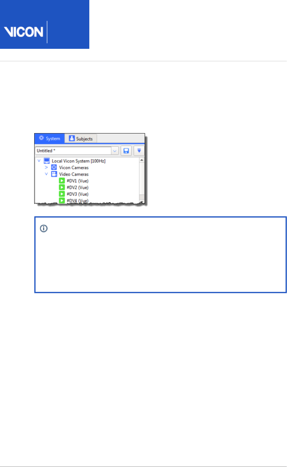
Nexus
User
Guide
Vicon Motion Systems Ltd. 26-Oct-2018 Page of 61 240
Configure video cameras for digital video capture
You manage the identification and configuration settings for each digital video camera
connected to your Vicon system with the node in the Video Cameras System Resources
pane. Using this node, you can also remove or reorder video cameras.
Note
References to "Vicon video camera" apply to the use of Vicon video cameras
(Vicon Bonita and Vicon Vue). The following instructions also apply to Basler
cameras that are supported by Vicon Nexus. For details of how to set up a
Vicon system that includes video cameras, see the PDF PC Setup for Vicon
.systems
The node is displayed under the node when one or Video Cameras Local Vicon System
more video cameras is connected to the Nexus host PC and Vicon Nexus is in Live
mode, or when a previously saved file containing video cameras is loaded. It lists each
video camera connected to your Vicon system. For each camera, the node name
includes the camera number, the camera type in parentheses and the frame rate in
brackets, for example, .#DV2 Over Door (Bonita 720c) [50Hz]

Nexus
User
Guide
Vicon Motion Systems Ltd. 26-Oct-2018 Page of 62 240
1.
2.
3.
Important
For this node to be displayed, Nexus must be in Live mode (click the Go Live
button) or a previously saved trial must be loaded. Before managing video
cameras in your Vicon system, ensure that the desired system configuration
has been selected in the pane (see System Resources Manage configurations
). This topic assumes that the digital video camera in Vicon Nexus on page 21
is connected and feeding data through the FireWire or GigE port. For
information on setting up this port, see the documentation provided with your
FireWire card or GigE port.
You can connect a digital video camera to the Nexus host PC. You can connect
supported Basler video cameras to the FireWire or GigE port on the PC and then
capture reference video for use with your optical motion capture data. You can overlay
the Vicon optical motion data onto the digital video images from the video cameras in
the view using the option, from the menu. If required, you can Camera 3D Overlay View
burn this information into the digital video image and export the .avi file for viewing in
another application using the operation.Configure the Export 3D Overlay Video
To configure video cameras for digital video capture:
Ensure Nexus is in Live mode (in the pane, click ).Resources Go Live
In the tree, select the node whose properties you wish to System Resources
configure:
Video Cameras node, for all digital video cameras
A sub-node, for a specific video camera
Note that if you are configuring a Vicon video camera, the node will not become
green until you specify the .Destination IP Address
Also note that cameras with gray icons are connected to the network but are not
contributing data. For example, if you have connected Vicon Bonita video
cameras, but your Vicon connectivity device does not support jumbo packets, the
icons for the Vicon video cameras will remain gray. For more information and
help with upgrading your system, contact Vicon Support.
In the pane at the bottom of the pane, view or Properties System Resources
change settings for the required properties.
When you first set up your Vicon system, you must configure at least the
following properties in the order shown. In subsequent sessions, you may want to
configure additional properties to suit the needs of your motion capture
application.

Nexus
User
Guide
Vicon Motion Systems Ltd. 26-Oct-2018 Page of 63 240
3.
4.
5.
Section Property name
Hardware Destination IP Address (Vicon video cameras)
Settings Capture Path (enter a separate HDD or an SSD drive for each
camera)
Video Gain and (Vicon video)Brightness Offset
Camera Gain and (Basler)Camera Brightness
Frame
Rate:
Requested Frame Rate
Settings Shutter Duration and (Basler),Camera AOI
Frame
Rate
Packet Size (Baslers using Firewire)
Hardware Trigger Source (Basler)
Calibration Focal Length (millimeters) (if you will be using )Aim Cameras
For further details about each of the properties, see Video Camera
Video Camera
in the .
properties Vicon Nexus Reference Guide
If you are using Basler cameras, to align the shutters with the rest of the Vicon
system, in the tree, right-click the node and System Resources Video Cameras
then click .Align Shutters (Basler)
At the top of the tab, click the Save button to save your system System
configuration settings to a . file in the configurations folder (see
system
Systems
).Manage configurations in Vicon Nexus on page 21
Tip
When you plug a video camera into the Vicon system, the system
automatically assigns it a number. To reorder video cameras, select the
camera in the dialog box and click or . Reorder Devices Move Up Move Down
Then click OK.
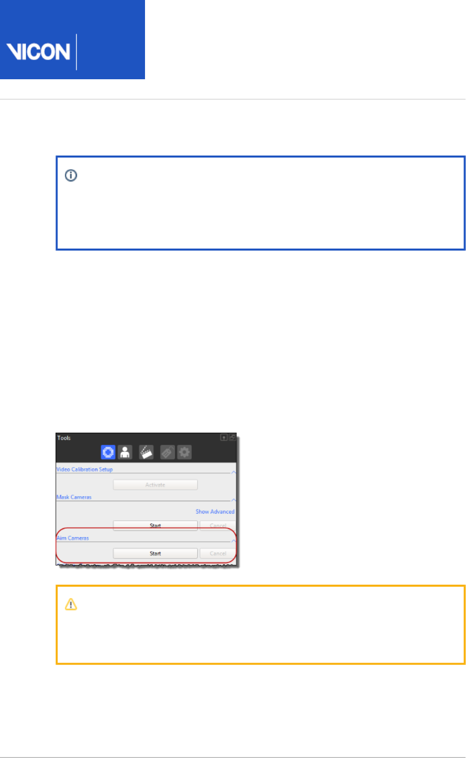
Nexus
User
Guide
Vicon Motion Systems Ltd. 26-Oct-2018 Page of 64 240
Aim Vicon cameras
Note
Aiming cameras is useful for providing an initial, approximate calibration,
before you fully calibrate the cameras as described in Calibrate Vicon cameras
.on page 97
Before you aim your Vicon cameras, ensure that they are displayed in the 3D
view.Perspective
Vicon camera positioning changes in real time. When you physically move a camera in
the capture volume, you should be able to see that its representation moves
correspondingly in the view. If you can't see the cameras in the 3D Perspective 3D
view, or if you want to change the way the cameras are displayed, press F7 Perspective
to open the dialog box, and on the left, ensure is selected. If Options Camera Positions
required, change the on the right.Properties
When you have roughly positioned the cameras in the volume, you can use the Aim
section of the pane to optimize their positions, Cameras System Preparation Tools
before running a full camera calibration.
Important
To aim Vicon cameras, you must use the calibration device supplied with your
Vicon system. To aim digital video cameras, you must use an Active Wand.
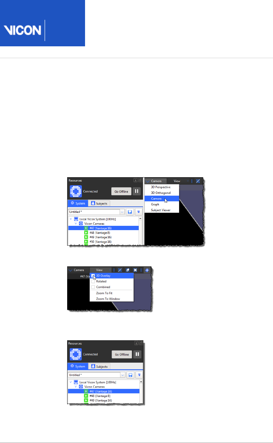
Nexus
User
Guide
Vicon Motion Systems Ltd. 26-Oct-2018 Page of 65 240
1.
2.
3.
4.
a.
b.
c.
To optimize the position of Vicon cameras:
In the pane, ensure Nexus is in Live mode.Resources
In the dialog box (press F7), under the section, Options General View Options
select the option.Target Volume
On the right side of the dialog box, update the properties of the target volume to
reflect the dimensions of your capture volume.
View the Vicon camera feedback by doing the following:
In the view pane, select the view.Camera
In the view toolbar, on the drop-down list, select .Camera View 3D Overlay
In the tree, click the cameras that you want to aim to System Resources
select them.
A virtual representation of your target volume is overlaid on the 2D data
from the camera image.

Nexus
User
Guide
Vicon Motion Systems Ltd. 26-Oct-2018 Page of 66 240
4.
c.
5.
6.
7.
8.
9.
In the pane, expand the section and System Preparation Tools Set Volume Origin
from the drop-down list select the or L-Frame Active Wand 5 Marker Wand & L-
calibration object. Frame
In the capture volume, place the calibration object flat on the floor in the center
of the capture volume at the desired origin position.
In the section, click to begin the camera-aiming process.Aim Cameras Start
Nexus starts attempting to identify the calibration object in each camera view,
and the button switches to its setting.Start Stop
In the tree, select the camera you want to position and ensure System Resources
that you can see the calibration object in the view.Camera
Physically move a Vicon camera in the capture volume and check its coverage
against the target volume.
Repeat steps 7–8 for each Vicon camera, until they are all correctly aimed at the
calibration object.
Mask unwanted reflections
Masking enables grayscale blobs that are generated from reflections of objects other
than markers (eg, reflections from floor or furniture, or opposing camera strobe rings) to
be ignored by the Vicon cameras. In capture volumes where this spurious data is
present, camera masking improves calibration robustness and reconstruction quality.
In Nexus, masking is shown as a grid of small blue tiles superimposed over the camera
image in a view, each cell of which can be set to obscure unwanted reflections Camera
that are seen by a camera.
Vicon Nexus offers both automatic masking and tools for manual masking. If you have a
large number of reflections in your capture volume, it is a good idea to create camera
masks automatically first. You can then eliminate any remaining reflections by creating
masks manually.
For more information, see:
Automatically create Vicon camera masks on page 67
Manually create Vicon camera masks on page 68
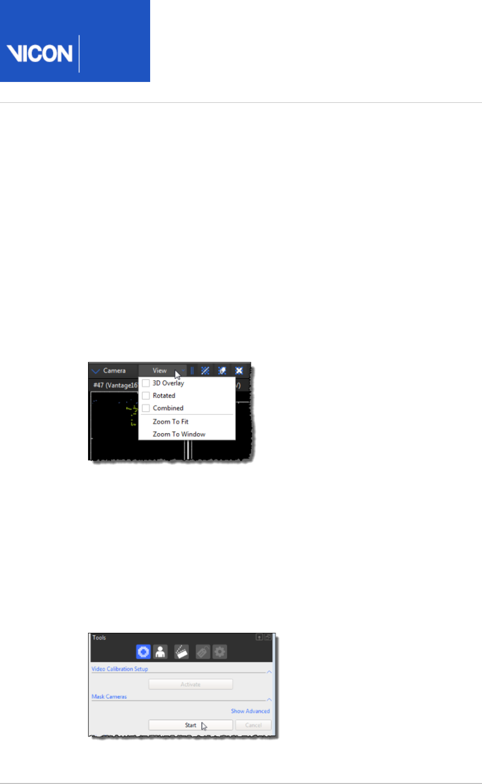
Nexus
User
Guide
Vicon Motion Systems Ltd. 26-Oct-2018 Page of 67 240
1.
2.
3.
4.
5.
6.
7.
8.
9.
Automatically create Vicon camera masks
To automatically create camera masks:
Remove from the capture volume any unnecessary objects, such as calibration
objects. For best results, the capture volume should be entirely free from objects
likely to cause background interference.
In the pane, ensure Nexus is in Live mode.Resources
From the tree, select all Vicon cameras.System Resources
From the view pane toolbar, select to display the 2D data being captured Camera
by each selected camera in a separate view.Camera
From the drop-down list at the top of the view pane, ensure that the View 3D
and options are cleared.Overlay Combined
In the dialog box (F7), under the section ensure Options General View Options
that the option is selected.Threshold Map
Ensure you have adjusted camera settings as described in Configure Vicon
. Any reflections are clearly visible optical cameras for data capture on page 55
in the view, typically as non-circular areas of grayscale or edge data. Camera
Note that as reflections can severely affect the camera data rates, you may find
that the camera overloads. In this case, the camera automatically sends edge
data instead of full grayscale.
In the pane, in the section, click .System Preparation Tools Mask Cameras Start

Nexus
User
Guide
Vicon Motion Systems Ltd. 26-Oct-2018 Page of 68 240
9.
10.
1.
2.
3.
4.
5.
6.
The button switches to its setting. Nexus starts recording the data Start Stop
visible to each of the cameras connected. Any camera masks created are
displayed as blue cells in the views for affected cameras. If there is no Camera
data visible to a particular camera, Nexus does not create any masks for it. About
30 seconds of recording is generally sufficient to enable Nexus to collect the
data visible to the cameras.
After about 30 seconds, click . If you still see unwanted reflections, you can Stop
start and stop the option again until you have hidden the Mask Cameras
reflections, or mask any remaining reflections manually.
Manually create Vicon camera masks
You can manually create masks to eliminate any reflections in the capture volume that
are visible to the cameras. If you have a large number of reflections in your capture
volume, it is a good idea to create camera masks automatically first (see above).
To manually create camera masks:
From the capture volume, remove any unnecessary objects, such as calibration
objects. For best results, ensure the capture volume is entirely free from objects
likely to cause unwanted reflections.
From the tree, select all Vicon cameras.System Resources
From the view pane toolbar, select to display the 2D data being captured Camera
by each selected camera in a separate view.Camera
From the drop-down list at the top of the view pane toolbar, ensure that View
the and options are cleared.3D Overlay Combined
In the dialog box (F7), under , ensure that Options General View Options
is selected.Threshold Map
Tip
The default color is blue, but you can change the color Threshold Map
in the dialog box. In the following descriptions, the masking Options
tiles are described as blue.
Nexus
User
Guide
Vicon Motion Systems Ltd. 26-Oct-2018 Page of 69 240
6.
7.
Ensure you have adjusted camera settings as described in Configure Vicon
. If reflections are present, they optical cameras for data capture on page 55
should be clearly visible in the view, typically as non-circular areas of Camera
grayscale or edge data. Note that as reflections can severely affect the camera
data rates, you may find that the camera overloads. In this case, the camera
automatically sends edge data instead of full grayscale.
From the view pane toolbar, use the following buttons to obscure any unwanted
reflections visible to the selected Vicon cameras. (When you click any of these
buttons, a grid of small blue tiles is superimposed over the camera image in each
view.)Camera
Paint a mask onto the camera
Click an individual tile, click and drag across multiple tiles, or hold down ALT
and click while dragging the mouse across an entire area of unwanted
reflections visible in the camera grid. You can drag the mouse horizontally,
vertically, or diagonally.
When a cell is painted, its background color changes from black to blue. The
camera mask consists of blue cells obscuring unwanted reflections.
Erase a mask from the camera
Click an individual tile, click and drag across multiple tiles, or hold down ALT
and click while dragging the mouse across an entire area of blue cells in the
camera grid. You can drag the mouse horizontally, vertically, or diagonally.
When an individual cell is erased, its background color changes from blue to
black, and any reflection that had previously been obscured is visible again.
Clear the mask from the camera
Click the button to automatically remove the entire mask from the camera.
When the mask is cleared, the background color of any previously painted cells
changes from blue to black, and any reflections that had previously been
obscured are visible again.
Tip
To zoom in on the images, right-click and drag the mouse forward (to
zoom in) or backward (to zoom out). To pan the image, click both mouse
buttons and drag
The camera masks are applied in real time and are saved along with your camera
calibration.

Nexus
User
Guide
Vicon Motion Systems Ltd. 26-Oct-2018 Page of 70 240
Configure Vicon connectivity units
Vicon connectivity units are smart boxes that can be combined to create a distributed
architecture, enabling you to customize the number of Vicon cameras and supported
third-party devices in your Vicon system.
As part of setting up your Vicon system, you configure your Vicon connectivity unit(s)
for system communications and any GPO or remote triggering.
The node is displayed under the Local Vicon System node when Vicon Connectivity
Vicon Nexus is connected to the Vicon system and is in Live mode. It is displayed under
the Vicon Data node when Nexus is in Offline mode. It lists each connectivity unit
connected to your Vicon system.
Depending on the type of Vicon system you are running, your Vicon system
architecture will contain one or more of the following Vicon connectivity units:
Vicon Lock unit: Facilitates the integration of synchronous third-party equipment
with Vicon Vantage, Vicon Vero, and Vicon Bonita cameras, by providing or receiving
synchronization and/or timecode. Also provides connectivity for third-party analog
capture sources, such as force plates and EMG equipment. Connects to a PoE+
switch to which Vicon cameras and the host PC are connected.
If your Vicon system includes PoE or PoE+ switches, note that although they do not
appear as connectivity nodes in the tree, the cameras that are System Resources
connected to them are displayed.
Note
Except where noted, references to Vicon Lock, Lock units, and Lock apply to
all current models of the Vicon Lock unit (at the time of publication, this
includes Vicon Lock+, Vicon Lock Studio and Vicon Lock Lab).
MX Giganet: The primary connectivity unit in an MX T-Series system. To connect and
synchronize force plates and EMG devices, MX Giganets can be configured with a 64-
channel analog card. (This functionality is integral to Vicon Lock+ and Lock Lab
units.) You can incorporate units and components from an MX T-Series system into a
Vicon Vantage system. See the or contact Vicon
Vicon Vantage Reference Guide
Support for details on configuring a combined architecture.
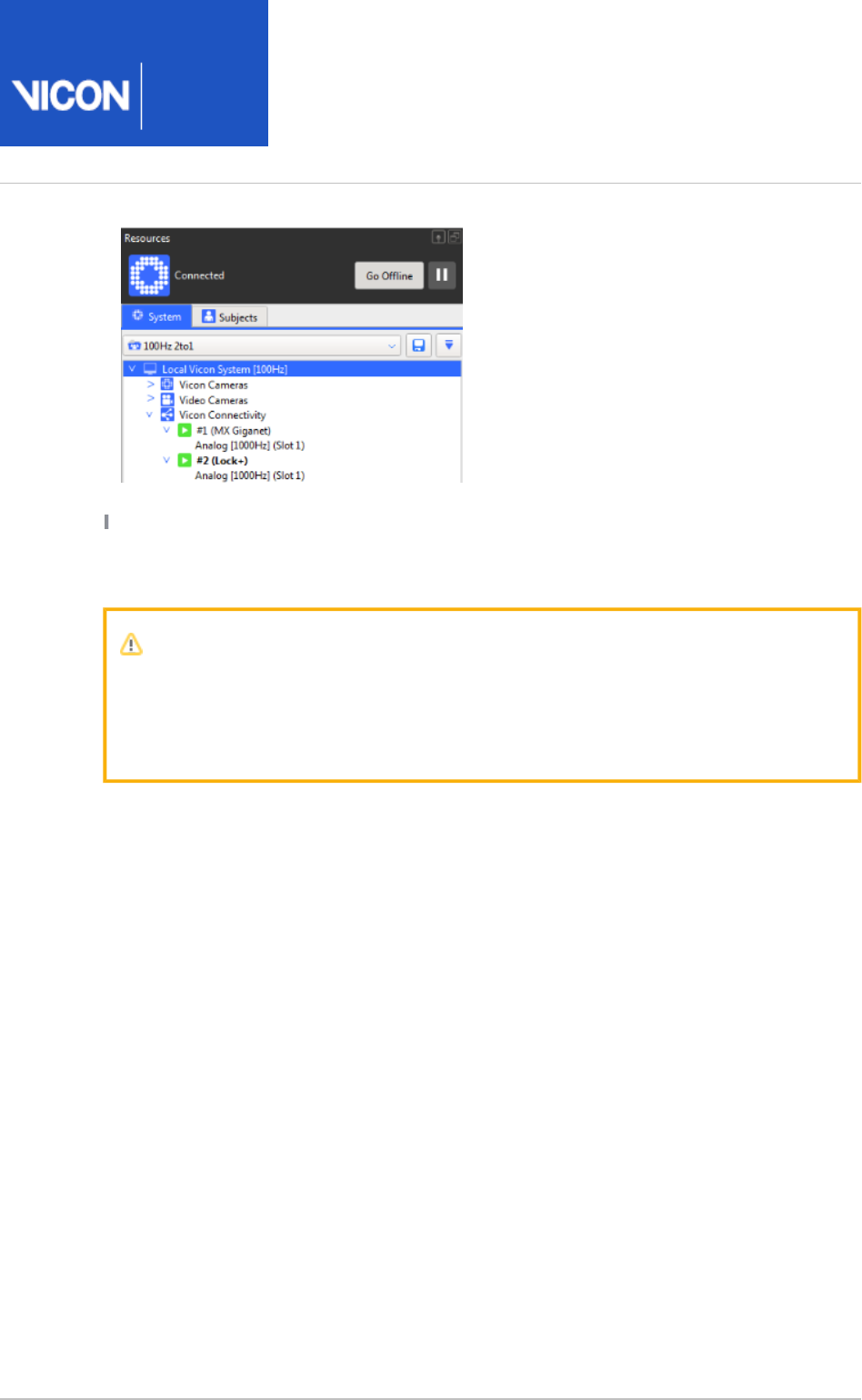
Nexus
User
Guide
Vicon Motion Systems Ltd. 26-Oct-2018 Page of 71 240
If your Vicon system includes PoE or PoE+ switches, note that although they do not
appear as connectivity nodes in the System Resources tree, the cameras that are
connected to them are displayed.
Important
Before managing Vicon connectivity units, ensure that the desired system
configuration has been selected in the pane (see System Resources Manage
).configurations in Vicon Nexus on page 21

Nexus
User
Guide
Vicon Motion Systems Ltd. 26-Oct-2018 Page of 72 240
1.
2.
Set up Vicon connectivity units
The node lists each MX Giganet or Vicon Lock unit connected to Vicon Connectivity
your Vicon system. For each unit, the node name includes the device position number,
any display name specified in the Identification property, and the device type listed in
parentheses, for example . For Lock Lab and Lock+, and for MX #1 Name (Lock+)
Giganet if either or both analog option cards are installed, the sample rates are
displayed in brackets, and an Analog Card (Slot 1) sub node is displayed as appropriate.
If no analog source is selected, [No Source] is displayed after the device name.
The Lock or MX Giganet node enables you to manage the identification and
configuration settings for each connectivity unit included in your Vicon system
architecture. The node is displayed under the node in the Vicon Connectivity System
pane when Vicon Nexus is connected to a Vicon system with at least one Resources
Lock unit or MX Giganet unit and is in Live mode (click the button).Go Live
To configure connectivity units for analog data acquisition:
In the pane, click the button.System Resources Go Live
In the tree, select the node whose properties you want to System Resources
configure:
Vicon Connectivity node for all Vicon connectivity units
A sub node for a specific connectivity unit – the sub nodes in the System
tree correspond to the IDs assigned by Nexus. If a connectivity unit Resources
has automatically been designated as the synchronization master for the Vicon
system, its node name is displayed in bold.
The colored icon beside a connectivity node identifies the status of the device:
Green play button: Component OK (active). If an analog device is
connected, this status does not reflect the analog device's status.
Yellow pause button: Component is not fully set up or device has been
disabled in Status section of Properties.
Gray play button: Component connected but not contributing any data.
Red stop button: Component down (unavailable or disconnected).
In the section at the bottom of the pane, view or Properties System Resources
change settings for the desired properties.

Nexus
User
Guide
Vicon Motion Systems Ltd. 26-Oct-2018 Page of 73 240
2.
3.
When you first set up your Vicon system, you must configure at least:
Name A name you supply, to enable you to identify this unit easily
Sync Out (if you are using synchronization functionality) The general purpose
output driver (* file) you specify here determines the output frequency of
.gpo
the synchronization pulse. You can select a driver for each of the sync outputs.
For further details, see or
Go Further with Vicon MX T-Series Vicon Vantage
.)
Reference Guide
In subsequent sessions, you may wish to configure additional properties to suit
the needs of your motion capture application. For details about all the properties
for Vicon connectivity units, see in the Vicon Lock and MX Giganet properties
.
Vicon Nexus Reference Guide
In the pane, click the button to save your system System Resources Save
configuration settings to a . file in the Systems configurations folder (see
system
).Manage configurations in Vicon Nexus on page 21

Nexus
User
Guide
Vicon Motion Systems Ltd. 26-Oct-2018 Page of 74 240
1.
2.
3.
4.
5.
Configure supported devices
As part of setting up your Vicon system, you configure supported devices using the
node in the pane.Devices System Resources
The node is displayed under the node when Vicon Nexus is Devices Local Vicon System
connected to a Vicon system with at least one Vicon or supported third-party analog or
EMG device and is in Live mode. It is displayed under the node when Nexus Vicon Data
is in Offline mode. The node lists each supported device connected to your Devices
Vicon system.
For each device, the node name includes any display name specified in the Name
property, its approximate sample rate in brackets, and the device type in parenthesis,
for example, . The default name property displayed is Name [2000Hz] (Analog EMG)
.Name [1000Hz] (Analog EMG)
For analog devices, if no analog source is selected, is displayed after the [No Source]
device type. sub nodes are displayed for any analog channels. Predefined Channel
configurations for some devices are supplied with Vicon Nexus.
Tip
To add new device entries to this node, Vicon Nexus must be in Live mode
(click the button). Before managing other devices, ensure that the Go Live
desired system configuration has been selected in the pane System Resources
(see ).Manage configurations in Vicon Nexus on page 21
To view a graph of one or more device output or component signals:
In the tree, expand the node to show the devices System Resources Devices
connected to your Nexus system
Select one or more devices, outputs or components.
From the view pane toolbar, select .Graph
If necessary, in the view toolbar, from the drop-down list, Graph Graph Type
select .Components
The view displays a graph of the selected components.Graph
For more information on configuring supported devices, see:
Configure force plates on page 75
Configure EMG devices on page 87
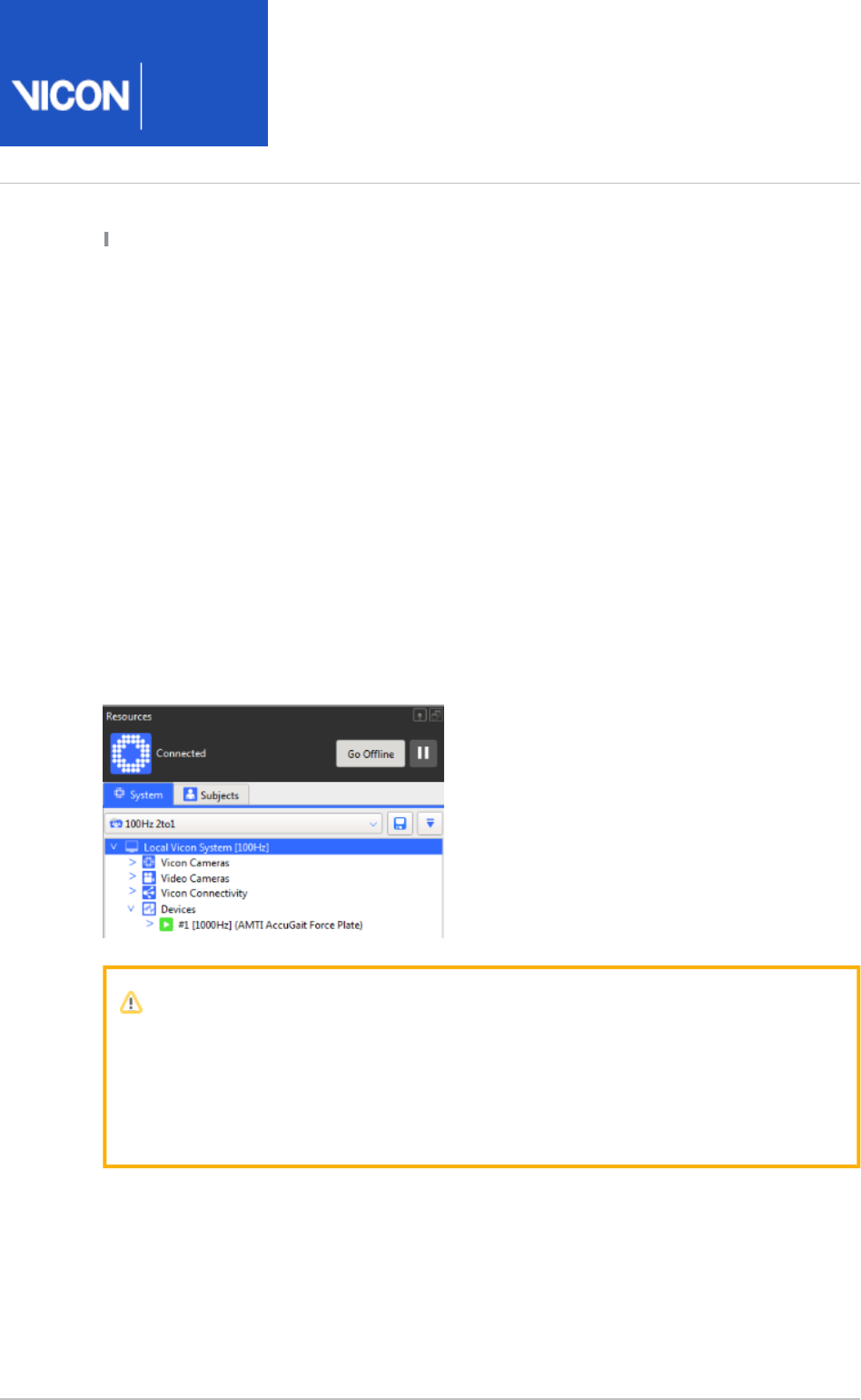
Nexus
User
Guide
Vicon Motion Systems Ltd. 26-Oct-2018 Page of 75 240
Configure IMUs on page 89
Configure force plates
As part of setting up your Vicon system, you manage the connection and configuration
settings for supported force plates in your Vicon system with the appropriate force
plate node. You can select the required force plate node under the Devices node in the
pane when Vicon Nexus is connected to a Vicon system with at System Resources
least one force plate unit and is in Live mode. When Nexus is in Offline mode, the force
plate node is displayed under the node of the node.Devices Vicon Data
The node lists each force plate connected to your Vicon system. For each Devices
device, the node name includes any display name specified in the Name property, its
sample rate in brackets, and the force plate type in parentheses, for example, Name
. If no analog source is selected, is [1000Hz] (AMTI AccuGait Force Plate) [No Source]
displayed after the device type. sub nodes are displayed for each channel. Channel - #
Predefined configurations for some supported force plates are supplied with Vicon
Nexus.
Important
To add new force plate entries to the node, Nexus must be in Live Devices
mode (click the Go Live button). Before managing force plates, ensure that the
desired system configuration has been selected in the pane System Resources
(see ).Manage configurations in Vicon Nexus on page 21
Force plates data can be acquired through the analog capture functionality of a Vicon
connectivity device (Vicon Lock+ or MX Giganet ). This topic describes the analog
connection only. If your force plate has a digital output, it is possible that this data
stream can also be captured, but this depends on the data stream's format and the
equipment's manufacturer. For information on the digital data streams that can be
used with Vicon systems, contact Vicon Support.

Nexus
User
Guide
Vicon Motion Systems Ltd. 26-Oct-2018 Page of 76 240
1.
2.
3.
a.
b.
To configure force plates for analog data capture:
In the pane, click the button.System Resources Go Live
The first time you use Nexus, the node is empty. You must add and Devices
configure a new force plate device before it will be displayed in the System
tree.Resources
In the tree, right-click the node, point to System Resources Devices Add Analog
and from the context menu select the type of force plate that is Device
integrated in your Vicon system.
The selected force plate node automatically expands to display the newly
created device. (For Motekforce Link treadmills, two new device nodes are
displayed, one for each plate.) If the appropriate type is not displayed, contact
Vicon Support.
The colored icon beside a force plate node identifies the status of the device and
of any connected analog source:
Green play button: Component OK (active or connected); if an analog
device is connected, the analog source is selected and all channels are
configured.
Yellow pause button: Component is not fully set up (e.g., not all channels
have been assigned a pin or the calibration matrix has not been configured).
Gray play button: Component connected but not contributing any data.
Red stop button: Component down (unavailable or disconnected).
These colored icons correspond to those used for the device summary in the
pane.Status Communications
In the section at the bottom of the pane, view or Properties System Resources
change settings for the following properties:
In the section, enter a Name.General
In the section, go to the field, and load the General Calibration File
manufacturer's calibration file:
If the calibration file is not listed in the drop-down list, click the ellipsis
(...) next to the field to browse to the relevant location, Calibration File
and select it. The file becomes available in the drop-down list.
Select the calibration file. (For Motekforce Link treadmills, note that a
single calibration file is used for both plates.)
If not supplied by the manufacturer's calibration file, you can set the
device , , , and in those Dimensions Position Orientation Origin Properties
sections.

Nexus
User
Guide
Vicon Motion Systems Ltd. 26-Oct-2018 Page of 77 240
3.
c.
d.
e.
f.
4.
5.
6.
7.
If there is no calibration file, click at the top right of the Show Advanced
section and enter the values Properties Calibration Matrix 6x6 Matrix
manually.
Important
The values must be entered, either via a calibration file or Matrix
by manual entry, in order for the force plate to become active.
In the section, select a (the Vicon connectivity device to Source Source
which the device is attached) from the drop-down list.
The drop-down list contains all connected Vicon connectivity Source
devices; a USB force plate will have its drop-down list populated Source
with connected USB devices of the required type.
In the section, use the button to populate the input Source Fill
connections sequentially (if these are consecutive on the Vicon
connectivity device).
In the section, select the for the Source from the choice of Source Gain
gains available for the Vicon connectivity device.
In the tree, if necessary, expand the force plate node to System Resources
expose the and (Center of Pressure) channels.Force, Moment CoP
The colored icon beside the output node identifies the analog channel status:
Green arrow: Analog channel connected to source device.
Yellow arrow: Analog channel has not been assigned a pin.
To tare the force plate at zero load, in the section, click the General Zero Level
browse button and enter the matrix properties.
Tip
You can also tare the force plate by right-clicking on the force plate
name in the tree and selecting .System Resources Zero Level
In a view, ensure that a gray or colored rectangle with the 3D Perspective
number 1 on it, representing the force plate, is displayed in the capture volume
where you have positioned it.
If you have multiple force plates configured, they will be numbered in the order
they appear in the tree.System Resources

Nexus
User
Guide
Vicon Motion Systems Ltd. 26-Oct-2018 Page of 78 240
7.
8.
9.
10.
11.
12.
In the capture volume, have someone step onto the force plate. You should see
the force vector being displayed in real time.
At the top of the pane, click the Save button to save your System Resources
system configuration settings to a . file in the configurations
system
Systems
folder (see ).Manage configurations in Vicon Nexus on page 21
From the tree, expand the force plate node and select the System Resources
output.Force
Switch to a view.Graph
If necessary, select from the drop-down list. A real-time Components Graph Type
graph of the output is displayed.Force
Verify that the vertical (Fz) force component is equal to [known mass * 9.81].
For more information, see:
Force plate minimum setup requirements on page 79
Change force plate display options on page 80
Visualize and record Force Threshold on page 83
View combined output from multiple force plates on page 84
Usage recommendations for Motekforce Link treadmill on page 86
See also in the .Force plate properties
Vicon Nexus Reference Guide

Nexus
User
Guide
Vicon Motion Systems Ltd. 26-Oct-2018 Page of 79 240
Force plate minimum setup requirements
For a force plate to appear in a view, you must configure at least the 3D Perspective
following properties:
Source
Calibration Matrix
Position (X, Y, Z)
Name: Assigning a force plate name is recommended, especially if you are setting up
more than one force plate.
For a force plate to appear in Live mode in the view, you must fully 3D Perspective
configure:
Source
Calibration Matrix
Dimensions (X, Y)
Origin
The and are necessary for the (Center of Pressure) and Position Orientation CoP Force
vector to be represented correctly, but they can be changed according to the setup. In
subsequent sessions, you may wish to configure additional properties to suit the needs
of your motion capture application.
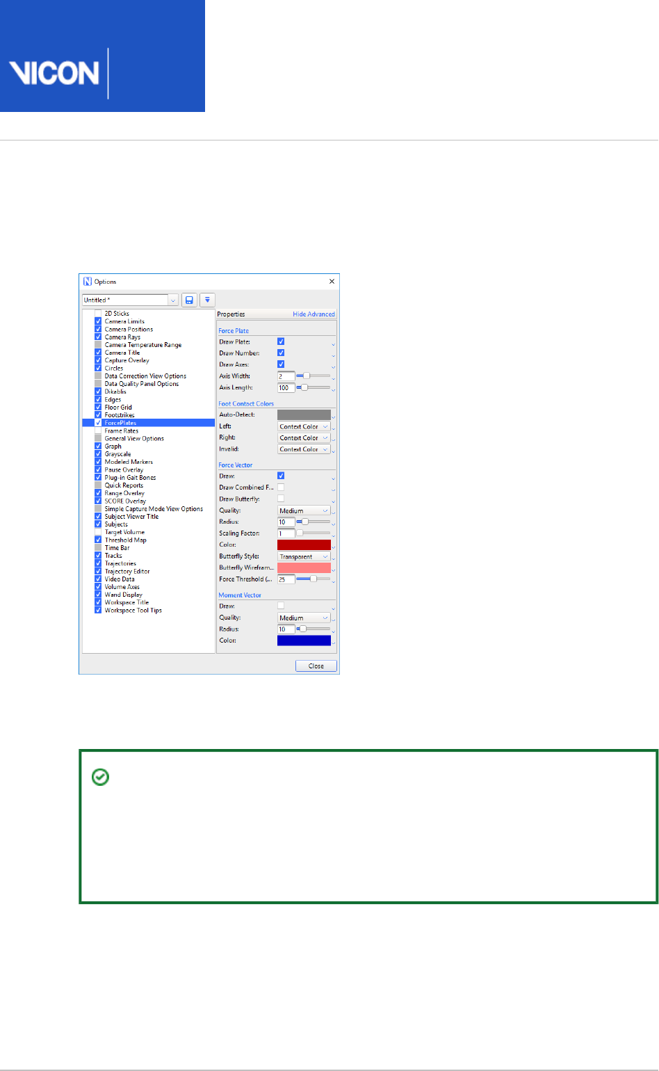
Nexus
User
Guide
Vicon Motion Systems Ltd. 26-Oct-2018 Page of 80 240
Change force plate display options
You can configure colors and other force plate display options in the dialog Options
box (F7).
You turn a display option on or off by selecting or clearing the corresponding check
box.
Tip
You can set colors for some of the display options. If a default color is listed as
Context Color (this indicates the color is set to the system default) and you
want to change it, click the down arrow to the right of the drop-down list, and
clear the Macro check box. You can then activate the color picker.

Nexus
User
Guide
Vicon Motion Systems Ltd. 26-Oct-2018 Page of 81 240
To view force plates in a view, ensure the check box on 3D Perspective Force Plates
the left side of the dialog box is selected. You can change the following Options
options:
Force Plate section
Property Description
Draw
Plate
When selected, the force plate appears in the View pane.
Draw
Number
By default, each force plate displays a number (e.g., 1, 2, 3). The number
corresponds to the order in which the force plates appear in the System
tree. You can turn off the number display by clearing the Resources
check box.
Draw
Axes
You can configure how the force plate axes appear in the 3D Perspective
view by selecting the check box. The axes appear below the Draw Axes
floor plane of the volume.
Axis
Width
Width of the axis. Set the axis width by typing a value or by moving the
slider.
Axis
Length
Length of the axis. Set the axis length by typing a value or by moving the
slider.
Foot Contact Colors section
If you have designated a force plate to be a left or right foot contact, by default Nexus
displays a left-foot contact force plate in red in the view, a right-foot 3D Perspective
contact force plate in green. An auto-detect force plate is displayed in light gray, and
an invalid force plate (neither left, right nor auto-detect) is displayed in dark gray.
To change the default colors for the force plate display, in the dialog box, Options
select the option, and in the pane on the right, click on a color Force Plates Properties
in the section to activate the color picker.Foot Contact Colors

Nexus
User
Guide
Vicon Motion Systems Ltd. 26-Oct-2018 Page of 82 240
Force Vector section
You can visualize the force vector by selecting the and check Draw Draw Butterfly
boxes. Then you can set the quality of the vector display, as well as the radius and
scaling factor (length), the butterfly style (whether the butterfly is represented as
transparent, as a wireframe or both), and color.
Setting a value causes the vector to be displayed as an arrow originating Scaling Factor
from the force plate in the direction of the force.
Values below the are not visualized as force vectors on the plate. Force Threshold (N)
This setting does not affect the value for that is written into a Force Threshold
recorded trial (see ).Visualize and record Force Threshold on page 83
Moment Vector section
You can select whether the moment vector is visually represented in the 3D Perspective
view, as well as the quality, radius and color of the moment vector display.
You can see the results of your settings in the view as you configure an 3D Perspective
option.

Nexus
User
Guide
Vicon Motion Systems Ltd. 26-Oct-2018 Page of 83 240
1.
2.
3.
4.
1.
2.
3.
Visualize and record Force Threshold
The of a force plate specifies the noise floor value in Newtons. Forces Force Threshold
below this value are assumed to be noise and are clamped to zero.
An setting for force plates enables you to specify a different value for the Options
depending on whether you are recording data or displaying a trial.Force Threshold
The value for the that is set in the pane for the Force Threshold System Resources
force plate affects the values that are written into a recorded trial. For example, if the
is set to 25 N, all values below this are considered noise and values Force Threshold
of zero are recorded.
The value for the that is set in the dialog box ensures that Force Threshold Options
values below this threshold are not visualized as force vectors on the plate. This
prevents very small values, which are simply noise, from creating a distracting
‘flickering’ force vector on the plate. If you are distracted by flickering while viewing a
trial, raise this value to remove the flickering. This does not affect the value for Force
that is written into a recorded trial.Threshold
To specify the Force Threshold that is recorded for a force plate:
Ensure the system is in Live mode.
In the tree, select the force plate.System Resources
In the pane, ensure the properties are displayed.Properties Advanced
In the section, change from the default (25 N) to the General Force Threshold (N)
required value.
Values below this magnitude are ignored and are recorded as zero.
To specify a value for visualizing the force vector:
Press F7 to open the dialog box.Options
On the left click .ForcePlates
In the pane on the right, in the section, change the Properties Force Vector
to the required value (the default is 25 N).Force Threshold (N)
Regardless of the setting of the in the pane, Force Threshold System Resources
the force vector that is displayed in the view pane is below the threshold that is
set in the dialog box. For example, if you set the value to 10 in the Options
pane, but left it at 25 in in the dialog box, a value of System Resources Options
15 would be prevented from causing flickering, but would be recorded in saved
trials.

Nexus
User
Guide
Vicon Motion Systems Ltd. 26-Oct-2018 Page of 84 240
1.
2.
View combined output from multiple force plates
You can combine selected outputs from multiple force plates, both in Live mode and
when reviewing captured trials in Offline mode. For example, in trials where the
subject's feet land on separate force plates, you can examine the combined landing
force or overall CoP from both feet.
To view combined output from multiple force plates:
In the dialog box (press F7), on the left, click and in the Options ForcePlates
pane on the right, in the section, ensure Properties Force Vector Draw Combined
is selected.Force Vector
In the tree, CTRL+click to select the required outputs from System Resources
each force plate.
Ensure you select identical outputs from each force plate.
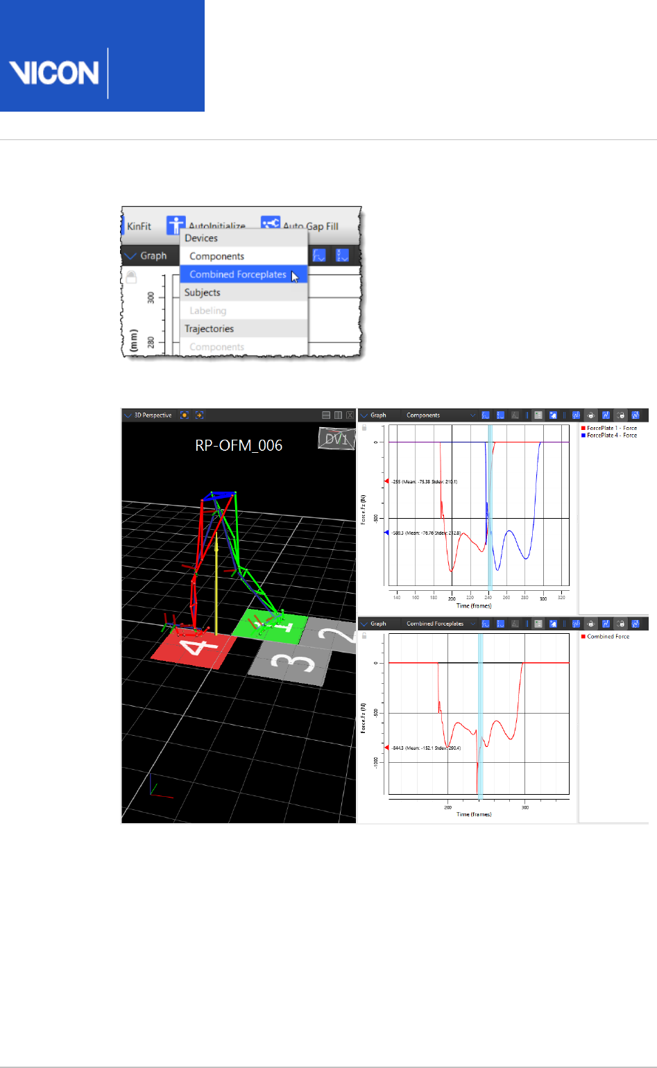
Nexus
User
Guide
Vicon Motion Systems Ltd. 26-Oct-2018 Page of 85 240
3.
4.
In a view, in the list, select .Graph Graph type Combined Forceplates
In the view, the combined output you selected is displayed.Graph

Nexus
User
Guide
Vicon Motion Systems Ltd. 26-Oct-2018 Page of 86 240
Usage recommendations for Motekforce Link treadmill
Note the following recommendations for setting up and using a Motekforce Link
treadmill with Nexus:
For ease of use, align the Vicon world Y-axis with the direction of walking on the
treadmill. To achieve this, you can either move the treadmill in the laboratory to align
with the Vicon world axes in Nexus, or change the Vicon world axes to align with the
position of the treadmill. You can then set the incline of both plates of the treadmill
by adjusting the property of the force plate.XOrientation
Assuming you follow this advice so that the direction of walking on the force plates
aligns with the Vicon Y-axis, and the left-right (medial-lateral) direction aligns with
the Vicon X-axis, inclination of the force plate will correspond to a rotation of the
plate about its X-axis. For example, to set a 10 degree inclination of the treadmill, you
would set a 10 degree rotation in the plate's properties.X (deg) Orientation
Each capture must use only one inclination of the treadmill. If you need to capture
multiple inclinations, to enable you to switch easily between different inclinations,
create a number of separate system files: one for each required inclination.

Nexus
User
Guide
Vicon Motion Systems Ltd. 26-Oct-2018 Page of 87 240
1.
2.
3.
4.
a.
Configure EMG devices
EMG data can be acquired through the analog capture functionality of a Vicon
connectivity device. If your EMG device has a digital output, it is possible that this data
stream can also be captured, but this depends on the data stream's format and the
equipment's manufacturer. For more information on the digital data streams that can
be used with your Vicon system, contact Vicon Support.
To configure EMG devices for data capture:
If Vicon Nexus is not in Live mode, in the pane, click the System Resources Go
button.Live
The first time you use Nexus, the node is empty. You must add and Devices
configure a new EMG device before it will be displayed in the System Resources
pane.
In the tree, right-click , point to or System Resources Devices Add Analog Device
and from the context menu select the type of EMG device Add Digital Device
that is integrated in your Vicon system.
The node automatically expands to display the newly created EMG Devices
device with its attendant output:
An analog Accelerometer will have an outputAcceleration
An analog EMG will have a outputVoltage
A ZeroWire EMG will have a and a outputVoltage Foot Switch
In the tree, select the node whose properties you wish to edit:System Resources
Generic Analog Device sub node for all devices
A sub node for a specific device
The colored icon beside a device node identifies the status of the device and of
any connected source:
Green play button: Component OK (active or connected); if an analog
device is connected, the source is selected and all channels are configured.
Yellow pause button: Component is not fully set up (e.g., not all channels
have been assigned a pin or the calibration matrix has not been configured).
Gray play button: Component connected but not contributing any data.
Red stop button: Component down (unavailable or disconnected).
In the section at the bottom of the pane, view or Properties System Resources
change settings for the following properties:

Nexus
User
Guide
Vicon Motion Systems Ltd. 26-Oct-2018 Page of 88 240
4.
a.
b.
5.
6.
In the section:General
Enter a to enable you to identify the device.Name
Set the (in frames). All devices have a delay Delay Compensation
compensation value which adjusts the synchronization offset between
the device and the Vicon data. The slider bar Delay Compensation
enables you to correct this difference. Values can be set between -10
and 10 (the default is 0). Note that analog data collected with a Vicon
Lock+ or an MX Giganet should already be synchronized, so in this case,
this value should be set at 0.
Set the . The voltage gain scale factor. Can be set Amplifier Gain
between 1-1000. The default setting depends on the device.
In the section, select a (the Vicon connectivity device to Source Source
which the accelerometer or EMG is attached) from the drop-down list.
When you first set up your Vicon system, you must configure at least the Name
and properties, add channels and designate the for each channel. Source Source
In subsequent sessions, you may wish to configure additional properties to suit
the needs of your motion capture application.
In the tree, expand the device node you added and select a System Resources
device output sub node which corresponds to an output from the device (such
as for an accelerometer, or for an EMG device).Acceleration Voltage
Right-click the device output and add an output component or components:
For an accelerometer or analog EMG, choices are:
Add Component (or , , or )2 4 8 Components
For a ZeroWire EMG, choices are:
Under :Voltage
Add EMG (numbered 1 - 16)
Remove Channels (if you have added channels)
Enable Auto Populate (or if the Disable Auto Populate AutoPopulate Properties
box is selected)
Under :Foot Switch
Add FSW (designated A1-A4 and B1-B4)
A new component node (or nodes) is added to the tree.
The colored icon beside the device output node identifies the analog channel
status:
Green arrow: Analog channel connected to source device.

Nexus
User
Guide
Vicon Motion Systems Ltd. 26-Oct-2018 Page of 89 240
6.
7.
8.
a.
b.
c.
9.
Yellow arrow: Analog channel not fully set up (e.g., not all channels have been
assigned a pin or the calibration matrix has not be configured).
In the pane under the section, specify a for the node or Properties General Name
nodes you have added.
For the ZeroWire EMG, is the only property setting necessary.Name
In the section:Properties Source
Assign the to one of the available pins on device. After you Pin Source
have assigned a pin, the status icons will turn green.
Specify the (V).Gain
Set the .Zero Level
At the top of the pane, click the Save button to save your System Resources
system configuration settings to a .system file in the Systems Configurations
folder (see ).Manage configurations in Vicon Nexus on page 21
For more information on the properties for EMG and other devices, see
System
in the .
Resources nodes Vicon Nexus Reference Guide
Configure IMUs
To enable you to capture data from Vicon IMUs (Inertial Measurement Units) and
optical markers simultaneously, you can use IMUs as digital devices in Nexus to stream
and capture data. You can use IMUs to preview data in real time and to capture data
onto the IMU's internal memory. You can then plug the IMUs into your PC via USB and
use Nexus to download the captured data.
Important
Vicon IMUs are supported for use with Nexus for research purposes only. For
full sensor safety and regulatory details, see the IMeasureU Sensor Safety and
, available from the Vicon website.Regulatory Information
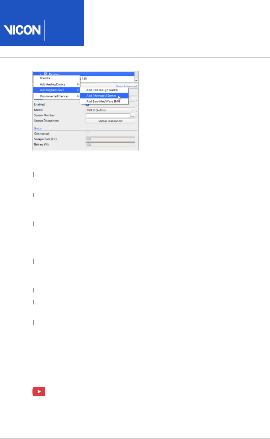
Nexus
User
Guide
Vicon Motion Systems Ltd. 26-Oct-2018 Page of 90 240
1.
Before you begin using IMUs with Nexus, note the following points:
Windows 10 and above only is supported. Ensure the latest Windows 10 updates are
installed.
To use Vicon IMUs in Nexus, first plug the supplied Bluetooth® (BLE) dongle into the
relevant Windows PC. Ensure that its drivers have been updated: you can do this
using the Windows Device Manager.
To enable further setup and control of your IMUs after they are paired and
recognized by Windows 10, you can download IMU Lightning desktop software. IMU
Lightning enables you to see the status of IMUs outside of Nexus and is useful in
certain troubleshooting situations.
IMUs have five collection modes: 100 Hz (9-axis), 250 Hz (6-axis), 500 Hz (6-axis),
500 Hz (9-axis), or 1000 Hz (3-axis). To accommodate the IMUs, ensure that your
Vicon system is running at a compatible frame rate.
Nexus supports the use of up to four current Vicon IMUs.
You can transfer the data that is collected and stored on your IMUs onto your PC
using the pane in Nexus (see ).IMU Transfer Transfer data from IMUs on page 227
To enable transfers to work, ensure you have downloaded and installed the CP210x
.USB to UART Bridge VCP Drivers
Set up IMUs for capture
The following are brief notes on working with IMUs with Nexus. For more information
on setting up and using IMUs to stream and capture data, see the IMeasureU
documentation.
For more detail on working with IMUs and Nexus, watch the Vicon videos, IMU
, , and Unboxing Introduction to using Vicon IMU with Nexus Nexus and the IMU
, available on YouTube.Research app

Nexus
User
Guide
Vicon Motion Systems Ltd. 26-Oct-2018 Page of 91 240
1.
2.
3.
4.
a.
b.
c.
If necessary (see ), download and install IMU previous points on page 90
Lightning.
Ensure that the Bluetooth® dongle is plugged into the PC and that its drivers are
up-to-date.
Turn on the IMUs and pair them to the relevant Windows computer, via
Bluetooth settings in Windows 10.
In Nexus, add the IMUs as digital devices and in the pane, specify the Properties
required settings:
In the pane, expand the node, then System Resources Local Vicon System
right-click the node, point to and click Devices Add Digital Device Add
.IMeasureU Sensor
In the pane below, specify a and :Properties Name Sensor Number
Property Description
Name The identifier that you want to give to the IMU.
Sensor
Number
The unique serial number of the device, which is found on
the tag on the side of the IMU. Although you enter only the
digits on the tag, this is an eight-digit number that is
padded with four zeros when displayed in the Log.
For more information on the available properties, see IMeasureU Sensor
in the .node
Vicon Nexus Reference Guide
Note that if the connection to the IMU is lost (the device is displayed as
gray in the pane), you can click the System Resources Sensor Reconnect
button to reconnect. This button is not available while you are capturing a
trial.
When you have specified a name and number, in the Resources list, the Play icon
next to the IMU name turns green.
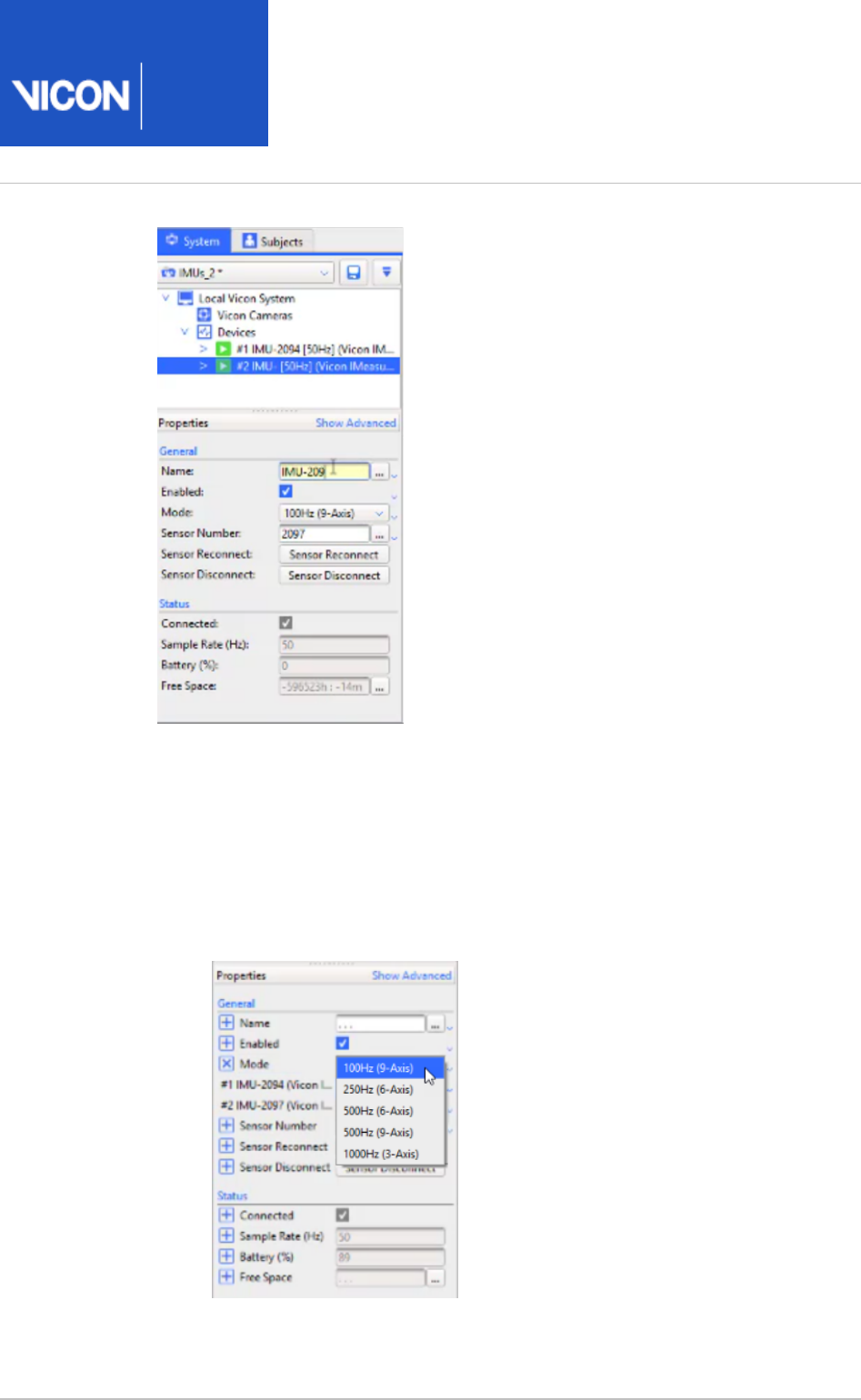
Nexus
User
Guide
Vicon Motion Systems Ltd. 26-Oct-2018 Page of 92 240
4.
5.
a.
b.
c.
d.
If necessary, change the collection mode (frequency) at which the IMUs are to
run.
To do this:
In the Resources list, ensure the IMUs are selected.
To display the axes for the IMUs, in the view pane, select Graph view.
In the Properties pane, from the list, select the required frequency.Mode
In the Graph view, the graphs change to reflect the selection.

Nexus
User
Guide
Vicon Motion Systems Ltd. 26-Oct-2018 Page of 93 240
5.
6.
7.
Note
If you need to calibrate the IMUs (normally only necessary when you
update the camera firmware or if an offset occurs), see Calibrate IMUs
. Note that, for calibration, you must set the collection on page 231
mode to 100 Hz.
Attach the IMUs to the subject.
Set up and start capture in the usual way (see Capture the required movement
in the ).on page 137
Vicon Nexus User Guide
For more information, see .Work with IMUs on page 222
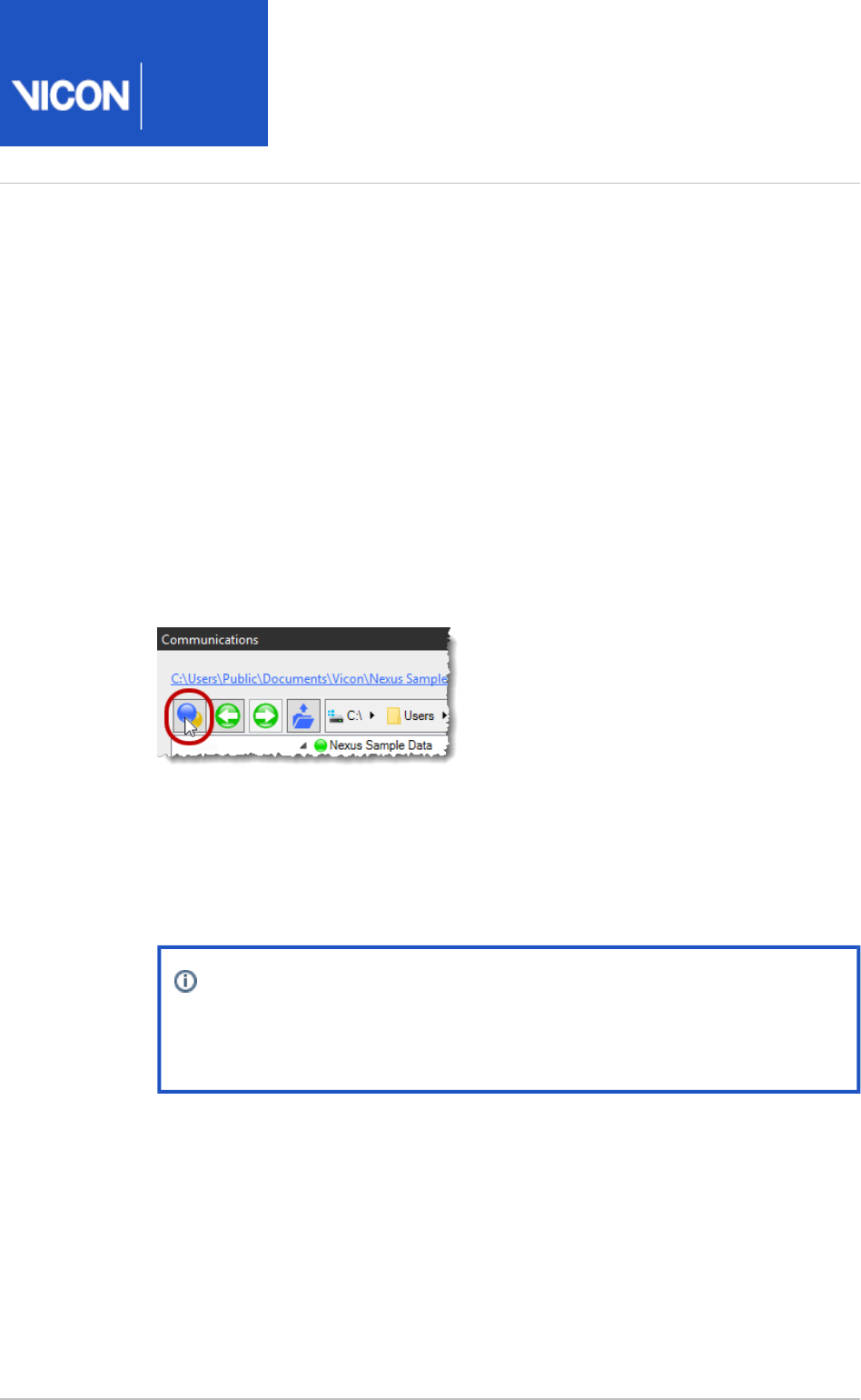
Nexus
User
Guide
Vicon Motion Systems Ltd. 26-Oct-2018 Page of 94 240
1.
2.
3.
4.
5.
Prepare a data storage location
Before you capture and process a trial, you must create a hierarchical structure for
storing and managing all the data associated with the motion capture trial. You do this
in the pane, on the tab.Communications Data Management
For a video guide to database management, see the Vicon video, proEclipse: Preparing
, which is available on YouTube.and managing your database
To prepare a location for your trial data:
In the pane, click the tab.Communications Data Management
On the toolbar, click the button.Show main proEclipse menu
Click , and in the dialog Manage Eclipse Databases Manage Eclipse Databases
box, click the button to enable you to locate and register a database Add New
folder. (Registering a folder enables you to select it in the Currently Registered
list and from the recently used files that are displayed when Eclipse Databases
you click the button.)Show main proEclipse menu
Note
A database is just a folder structure where your Nexus files will be
saved. Generally, you can create a database in any unrestricted location.
Select a location on your local hard disk for the database folder, or if required,
click and enter a name for your folder. Click OK.Make New Folder
In the dialog box, the folder that you just selected or Manage Eclipse Databases
created appears in the list. Click .Currently Registered Eclipse Databases Close
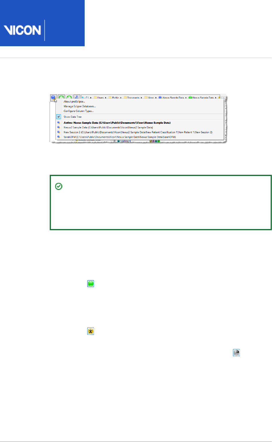
Nexus
User
Guide
Vicon Motion Systems Ltd. 26-Oct-2018 Page of 95 240
5.
6.
7.
a.
b.
c.
8.
All registered databases are also available when you click the Show main
button.proEclipse menu
On the tab, click on name of the folder you just created, Data Management
ensuring its name appears in the live link at the top left of the tab.
Tip
To check that your hierarchy of folders appears as expected, click the
live link to open an instance of Windows Explorer, where you can see
the folder you created.
Ensure the folder name is still selected in the hierarchy displayed on the left of
the tab, and create a hierarchy of data folders in which to Data Management
store your data. A good practice is to make sure all your data goes into a session
folder. To do this:
Add a top-level folder by clicking the green New Patient Classification
button . You can change its name as required. Generally, this classifies
a group of subjects such as Men/Women, Old/Young, or Target Population
/Controls.
In the left hand panel, click the new patient classification that you just
added and then add a patient folder by clicking the yellow New Patient
button . Again, you can rename it as required.
In the left-hand panel, click the patient folder that you just added and then
add a session folder by clicking the gray button . Rename New Session
it as required.
Select the new session folder by clicking it on the tab.Data Management
You now have an active session, ready to store your preliminary capture.
For more detailed information on data management, see
Data management with Nexus
in the Vicon Nexus Reference Guide.

Nexus
User
Guide
Vicon Motion Systems Ltd. 26-Oct-2018 Page of 96 240
Calibrate a Vicon system
The following topics cover calibrating the Vicon system, including the Vicon cameras
and any video cameras, for motion capture.
After you have configured your system (see ), the Prepare a Vicon system on page 43
next setup step is to calibrate the Vicon cameras and define the origin of the capture
volume. Calibration enables Nexus to determine the positions, orientations, and lens
properties of all the Vicon cameras and to produce accurate 3D data.
Important
Vicon recommends that you calibrate your Vicon cameras after any changes
to your system and each day, before you capture any data. This ensures that
any accidental changes in your setup (such as a camera being knocked while
the system was unsupervised) does not influence the quality of your data. You
can perform the level of camera calibration that suits your requirements: a full
camera calibration or a calibration refinement.
For more information see:
Calibrate Vicon cameras on page 97
Set the volume origin on page 101
Calibrate the floor plane on page 103
Manage camera calibrations on page 105
A showing these procedures is available on YouTube.Vicon Nexus 2 Calibration video
Note
As the videos were recorded using an earlier version of Nexus 2, you may
notice small differences in the user interface.
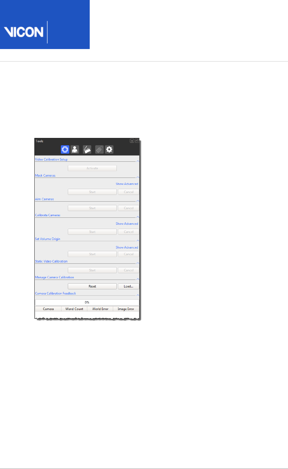
Nexus
User
Guide
Vicon Motion Systems Ltd. 26-Oct-2018 Page of 97 240
Calibrate Vicon cameras
To calibrate Vicon cameras, you use the relevant sections of the System Preparation
pane.Tools
To perform a camera calibration, you need a Vicon calibration device, which is supplied
with your Vicon system. Note that, to use the following process to calibrate supported
digital video cameras, as well as optical cameras, you must use an Active Wand, which
must be set to Strobe mode. (If you are not using an Active Wand, you can calibrate any
supported video cameras using the legacy section of the Static Video Calibration
pane. For more information, contact Vicon Support.)System Preparation Tools
Camera calibration describes the capture volume to the system, enabling Nexus to
produce accurate 3D data. During camera calibration, Vicon Nexus creates a calibration
parameters (. ) file. This file contains the calibration settings and threshold data
xcp
specified for the Vicon cameras (as well as any supported video cameras) in your Nexus
system and is used when data from these cameras is processed.
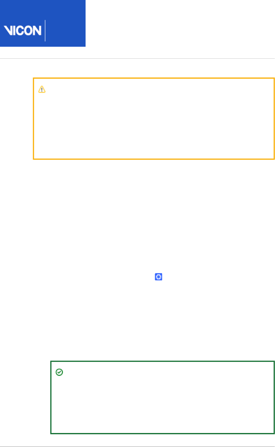
Nexus
User
Guide
Vicon Motion Systems Ltd. 26-Oct-2018 Page of 98 240
1.
2.
3.
4.
5.
6.
7.
8.
Important
Vicon recommends that you calibrate your Vicon cameras each day before you
capture any data. This ensures that any unexpected changes in your setup
that may have occurred when the system was unsupervised (such as someone
accidentally knocking a camera slightly out of position) will not influence the
quality of your data. You can perform the level of camera calibration that suits
your requirements: a full camera calibration or a calibration refinement.
To calibrate Vicon cameras in Nexus:
Ensure you have aimed and masked the cameras (see Aim Vicon cameras on
and ).page 64 Mask unwanted reflections on page 66
Remove from the capture volume all markers and the sources of any unwanted
reflections that have not been accounted for by camera masks previously
created in a view.Camera
In the pane, ensure Nexus is in Live mode.Resources
Display a view.Camera
In the tree, expand the node and select all System Resources Vicon Cameras
Vicon cameras.
In the pane , expand and from System Preparation Tools Calibrate Cameras
the list, select the calibration device that you are using.Wand
If your Vicon system includes video cameras, in the Video Calibration Setup
section, click to start video calibration mode. If your system does not Activate
include video cameras, go straight to the next step.
If you have not already saved the current configuration, you will be prompted to
save it. Ensure its name is recognizable as a calibration and then choose whether
it will be or Private (see Shared Manage configurations in Vicon Nexus on page
).21
Tip
The settings for some video camera properties may differ in video
calibration setup mode from those in live capture mode. For these
properties, any changes made after you click only apply during Activate
video calibration setup mode. The properties revert to their live capture
settings after you click .Deactivate
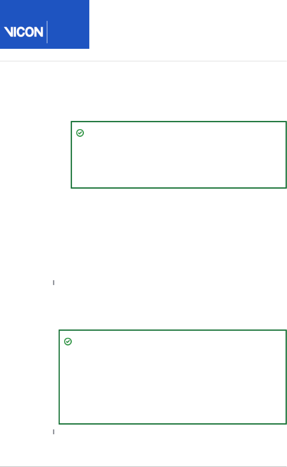
Nexus
User
Guide
Vicon Motion Systems Ltd. 26-Oct-2018 Page of 99 240
8.
a.
b.
9.
10.
11.
In the section, view or change settings for the required Calibrate Cameras
parameters:
Select the appropriate or Calibration Type: Full Calibration Calibration
.Refinement
Tip
If you have not already calibrated all cameras, you cannot perform
a calibration with the option. For more Calibration Refinement
information on calibration refinement, see Understand camera
in the .calibration refinement
Vicon Nexus Reference Guide
To automatically stop calibration when sufficient information has been
acquired, ensure is selected.Auto Stop
In the section, click The camera calibration process Calibrate Cameras Start.
starts, and the button switches to its setting.Start Stop
In the capture volume, wave the calibration wand throughout the area where you
intend to capture 3D data, ensuring that the markers on the calibration object
are visible to the cameras. Vicon Nexus begins to capture wand wave data.
Monitor the calibration progress and status:
In each view, ensuring that the colored lines that identify wand frames Camera
indicate that sufficient wand frames are spread across the intended 3D
capture volume. Also check the colored triangle in the lower right of each view
pane. The triangles change from red to green as the collection of calibration
information progresses, and then vanish when the cameras are calibrated.
Tip
If no cameras are visible in the view, ensure that the Camera Show
option is selected in the Uncalibrated Cameras Camera Positions
section of the dialog box (press F7). Also, if you are not using Options
the Vicon Control app, you may find it helpful to display the Nexus
window on a large screen where the person in the capture volume
can see the feedback in the view while they are waving the Camera
calibration wand, so they can see the area that they have covered.
In the pane, under the System Preparation Tools Camera Calibration Feedback
section check values returned for each camera.Wand Count

Nexus
User
Guide
Vicon Motion Systems Ltd. 26-Oct-2018 Page of 100 240
11.
12.
13.
14.
On the strobe unit on the front of each camera, the status light flashes while
the camera registers valid frames where the whole wand is visible. When the
status light turns a solid green, the camera has collected enough data to be
calibrated successfully, usually 1,000 frames of valid wand data.
If was not selected, in the section, click . Auto Stop Calibrate Cameras Stop
Nexus starts processing the calibration information.
If you selected the option, Nexus automatically stops collecting Auto Stop
calibration information and starts processing it when sufficient calibration
information has been acquired.
Note that, for a system that includes video cameras, calibration is done in two
passes, so the bar progresses from 0% to 100% Camera Calibration Feedback
twice.
In the section, monitor the progress bar until the Camera Calibration Feedback
camera calibration process is complete and review the and Wand Count Image
data. As a general guideline, Nexus typically takes 15–60 seconds to Error
complete its calculations for a typical Vicon system setup, but this can take
longer for a very large system or low-specification PC. When the camera
calibration has successfully completed, it is automatically saved to an . file.
xcp
For more information on the controls in this section, see Camera Calibration
in the .Feedback section
Vicon Nexus Reference Guide
Tip
Because calibration feedback values are based on factors such as the
size of the capture volume and the camera lens type, it is not possible to
provide general guidelines on typical or acceptable ranges. Therefore, to
determine the optimal values for your Vicon system, shortly after the
system is installed, establish a baseline against which you can compare
future daily calibration values.
If you have calibrated video cameras, to exit video calibration mode and return to
your settings for live captures, click in the Deactivate Video Calibration Setup
section.
When you have finished calibrating the Vicon cameras, you are ready to Set the volume
.origin on page 101

Nexus
User
Guide
Vicon Motion Systems Ltd. 26-Oct-2018 Page of 101 240
1.
2.
3.
4.
5.
Set the volume origin
Setting the volume origin (global coordinate system) tells the Vicon system where the
center of your capture volume is and what its orientation is (x, y, and z axes), so that
subjects are displayed the right way up in the Nexus view pane and so that you can
change the way data is visualized. You normally set the volume origin immediately after
the previous step .Calibrate Vicon cameras on page 97
To set the volume origin, you need a calibration device, normally an Active Wand, which
is supplied with your Vicon system.
To set the global coordinate system:
Remove from the capture volume all markers and the sources of any unwanted
reflections that have not been accounted for by camera masks previously
created in a view (see ).Camera Mask unwanted reflections on page 66
In the pane, ensure Nexus is in Live mode.Resources
Display a view.3D Perspective
In the tools pane, expand the section and System Preparation Set Volume Origin
from the drop-down list, select the type of calibration device you are L-Frame
using to set the volume origin. (This will normally be the calibration device that
was supplied with your Vicon system.)
If it is impractical to place the wand in the required position, you can instead use
the or options to set the origin. (The One Marker Three Markers Three Markers
option creates two vectors that determine the orientation of the volume.) To use
these options, position the marker(s) in the volume and then click next to the Set
chosen option. You can then select the required marker(s) in the 3D Perspective
view. If you selected , you are prompted to select an origin marker, Three Markers
a primary (X-axis) marker, and secondary (Z-axis) marker.

Nexus
User
Guide
Vicon Motion Systems Ltd. 26-Oct-2018 Page of 102 240
5.
6.
7.
8.
9.
In the capture volume, place the calibration object flat on the floor in the
position and orientation that you would like to be the origin of the global
coordinates system (often a force plate corner or another clearly marked area of
the volume).
In the section, click .Set Volume Origin Start
The calibration object tracking process starts, Nexus identifies the calibration
object in the capture volume, displays a 3D representation of it in the 3D
view, and switches the button to its setting.Perspective Start Set Origin
Click to complete the calibration object tracking process. Nexus sets Set Origin
the global origin and axes to correspond to the position and orientation of the
calibration object in the capture volume. In the view, the floor 3D Perspective
grid is displayed aligned with the capture volume floor and the representations
of the cameras are distributed in the position and orientation in which the
physical cameras are located around the capture volume. When the global
coordinate system has been successfully set, it is automatically saved to an .xcp
file. The latest calibration (.xcp) file is saved to the default location. This
calibration file is automatically copied to every subsequent trial captured.
Verify that the global coordinate system was successfully set by checking that
the system tracks the calibration object.
If it does not, check that you selected the correct calibration object from the L-
drop-down list at the top of the tools pane. If not, repeat this procedure Frame
from step 4, ensuring that you select the correct entry for the calibration device
you are using. After you have set the global coordinate system, you can display
the volume axes marker in the bottom corner of the view.3D Perspective
Turn the display of the volume axes on or off in the dialog box (F7) by Options
selecting or deselecting under .Volume Axes General View Options

Nexus
User
Guide
Vicon Motion Systems Ltd. 26-Oct-2018 Page of 103 240
1.
2.
3.
4.
5.
Calibrate the floor plane
To ensure that your coordinate system is accurately aligned with the floor of the
capture volume, which is particularly useful if the floor is uneven, you can adjust the
position of the floor plane using markers in the volume to automatically define it.
To calibrate the floor plane:
Complete the camera calibration procedure (see Calibrate Vicon cameras on
) and set the origin (see ).page 97 Set the volume origin on page 101
Turn off the calibration object or remove it from the volume.
Scatter a quantity of the same size Vicon markers across the floor of your
capture volume. If you want Vicon Nexus to automatically recognize these
markers as floor plane markers, ensure that they outnumber any other groups of
markers (e.g, markers on a wand or markers that were used to focus cameras,
etc).
In the pane, expand the section, System Preparation Tools Set Volume Origin
click , and ensure that the options relating to are Show Advanced Set Floor Plane
as required:
Auto detect: Markers are automatically detected, based on the marker group
that defines the plane with the most markers. (If, when you click , Auto detect
the wrong markers are selected in the view, you can add or 3D Perspective
remove markers in the volume until selection is as required.) To ensure that the
tolerance setting (in mm), which specifies the height of the group of markers
that define the floor plane, is as required, click the drop-down arrow next to
, and set the tolerance to a value that prevents a large variance in Auto Detect
height (2mm is often enough).
Start: Enables you to manually select the markers that will determine the floor
plane by clicking the required markers in the view.3D Perspective
Offset: Select the check box and set the amount (in mm) by which to adjust
the floor plane (default is zero) in X Y and Z planes. Because Nexus finds the
centers of the markers, set a Z-offset that accounts for the size of the markers
plus their bases (for example, for 14mm markers on 2mm bases, the Z-offset is
-9mm).
If you clicked , when you have selected the required markers, click the Start Stop
button.
In the view the cameras shift as a group slightly along one or 3D Perspective

Nexus
User
Guide
Vicon Motion Systems Ltd. 26-Oct-2018 Page of 104 240
5.
more rotation axes to better reflect an average of the markers scattered across
the floor, taking into account any offsets that you specified. The latest
calibration (.xcp) file is updated. This calibration file is automatically copied to
every subsequent trial captured.
Your Vicon cameras are now calibrated and ready to capture data.

Nexus
User
Guide
Vicon Motion Systems Ltd. 26-Oct-2018 Page of 105 240
Manage camera calibrations
In the section of the pane, you Manage Camera Calibration System Preparation Tools
can click to automatically number the cameras number in Auto number cameras
ascending order, according to their position in the capture volume.
The section also enables you to reset or load camera Manage Camera Calibration
calibrations that define settings for Vicon cameras.
Automatically number cameras on page 105
Reset and load camera calibrations on page 107
Automatically number cameras
The button enables you to quickly number the currently Auto number cameras
connected Vicon cameras in ascending order, according to their position in the capture
volume. To obtain useful autonumbering, you normally auto-number the cameras at
some point after you have aimed (and calibrated) the cameras.
Tip
You can auto-number the cameras at any point after you have performed the
operation (see ): you do not Aim Cameras Aim Vicon cameras on page 64
need to perform a complete camera calibration to auto-number the cameras.
Automatic numbering starts with the camera that is furthest from the volume origin.
The cameras are then numbered in a clockwise direction around the volume. If your
cameras are positioned at different levels, the cameras in the level that contains the
most cameras are numbered first.
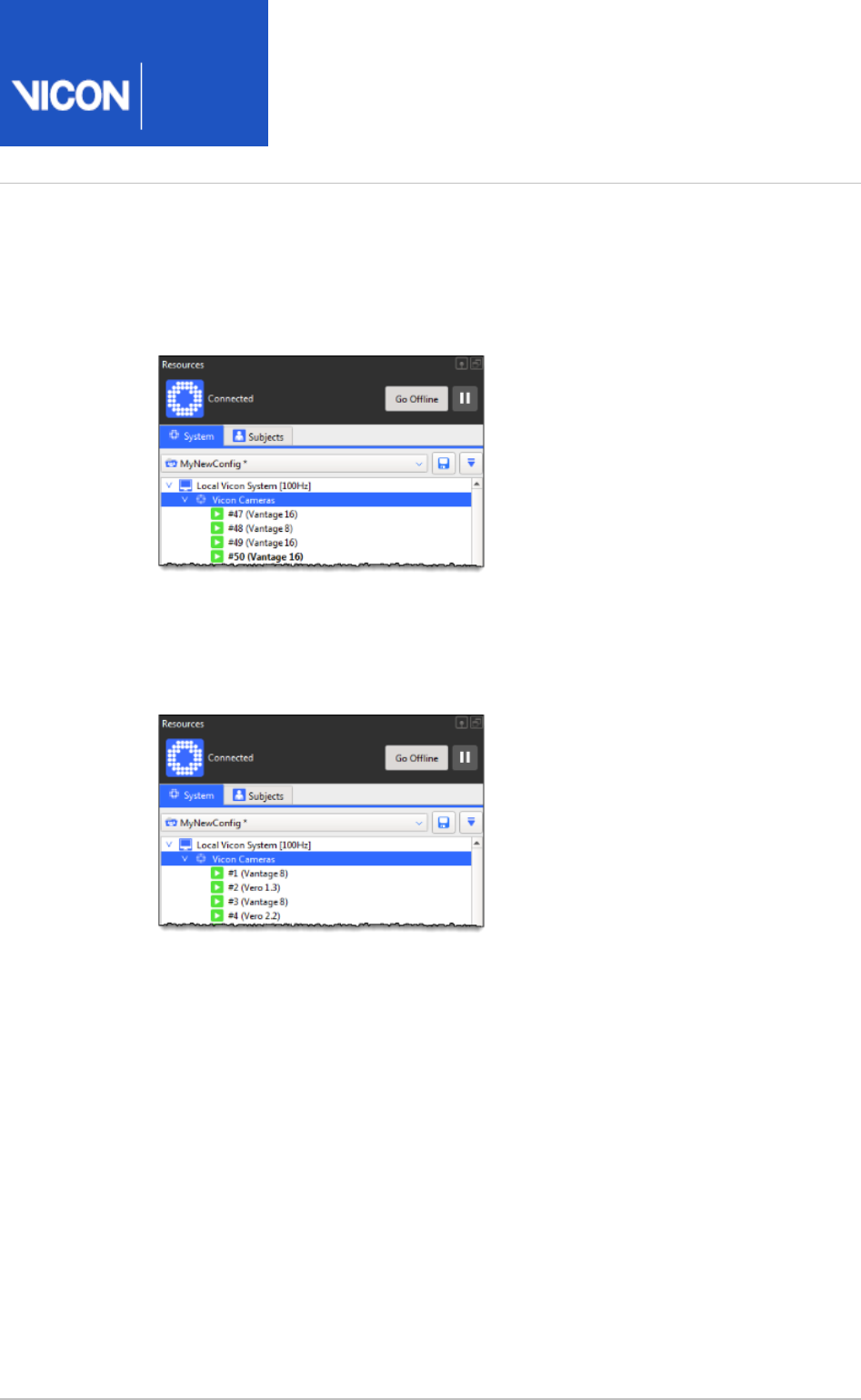
Nexus
User
Guide
Vicon Motion Systems Ltd. 26-Oct-2018 Page of 106 240
1.
2.
3.
4.
To automatically number Vicon cameras:
Ensure Nexus is in Live mode and that you have aimed the cameras.
On the tab, ensure you can see a list of Vicon cameras.System Resources
On the pane, in the System Preparation Tools Manage Camera Calibration
section, click .Auto number cameras
The cameras are automatically numbered in ascending order, according to their
position in the volume.
In the volume, check that the cameras are now numbered as required.

Nexus
User
Guide
Vicon Motion Systems Ltd. 26-Oct-2018 Page of 107 240
Reset and load camera calibrations
During camera calibration, Vicon Nexus creates a calibration parameters (.xcp) file.
When you change the currently loaded .xcp file, either by calibrating cameras or by
setting the global coordinate system, Nexus stores the calibration state before the
changes. This enables you to revert to the previous calibration or load a different
calibration at any time while using Nexus (for example, you would normally want to
load a different calibration when you connect your Nexus PC to a different system).
Changing a camera calibration can be useful in the following circumstances:
To undo a poor calibration
To compare calibration changes
To manage camera calibration files in Nexus:
In the pane, under the section, System Preparation Tools Manage Camera Calibration
click the desired button:
Reset Removes all non-existing cameras, clears the calibrated position for existing
cameras, and reverts all calibration parameters to their default settings. This enables
you to recalibrate the system from a clean starting point.
Load Enables you to load a previously saved calibration file. In the Choose a file
dialog box, navigate to and select the desired camera calibration (.xcp or .cp file) and
click .Open
If a camera is not calibrating well or has been bumped after calibration, you can remove
it from the current calibration prior to data capture.
To remove a camera from an existing system calibration:
Use any of the following methods:
In the pane, right-click on the node for the camera you want to System Resources
remove and select ; orReset Calibration
In the pane, select the node for the camera you want to remove System Resources
and in the pane, scroll down to the section and click Properties Calibration Reset
; orCalibration
In a view, right-click the camera that you want to remove and then 3D Perspective
click .Reset Calibration

Nexus
User
Guide
Vicon Motion Systems Ltd. 26-Oct-2018 Page of 108 240
Prepare a subject
After you have configured and calibrated your Vicon system, and prepared a data
management hierarchy in which to store your data, you can prepare the subject whose
motion is to be captured.
To start with, you may find it easiest to use the standard Plug-in Gait marker set and in
Vicon Nexus, create a subject that is based on one of the Vicon-supplied labeling
skeleton templates (VSTs), as described in the following topics. If you are planning on
processing your captured data with Plug-in Gait, then you must use one of the supplied
Plug-in Gait VST files. For more information, see Modeling with Plug-in Gait on page 185
.
Later, if required, you may want to create your own custom labeling skeleton template.
The labeling skeleton template that you use is determined by your particular
application and your marker set. For information on how to create a custom labeling
skeleton template, see .
Creating labeling skeleton templates (VSTs)
Having chosen your marker set, you can prepare the subject data in Nexus. To do this,
you use the pane and the pane to create Subjects Resources Subject Preparation Tools
a new subject from a template and to calibrate the labeling skeleton. These and other
procedures that you may find useful while creating and calibrating your labeling
skeleton are described in the following topics:
Create a new subject from a template on page 110
Calibrate a labeling skeleton on page 113
Correcting swapped labels on page 127
Manually label a trial on page 128
Work with pipelines on page 131

Nexus
User
Guide
Vicon Motion Systems Ltd. 26-Oct-2018 Page of 109 240
If you have problems calibrating your labeling skeleton, also see Troubleshooting
in .labeling skeleton templates
Creating labeling skeleton templates (VSTs)
Important
A Nexus .vst file is used only to define the marker set and to enable Nexus to
perform automatic labeling. It is not a biomechanical model that will output
valid joint angles or other kinematic/kinetic variables. To derive valid
kinematics or kinetics, use either a predefined model (such as Vicon Plug-in
Gait, as described in this documentation) or create your own model with Vicon
BodyBuilder, MATLAB or Python.
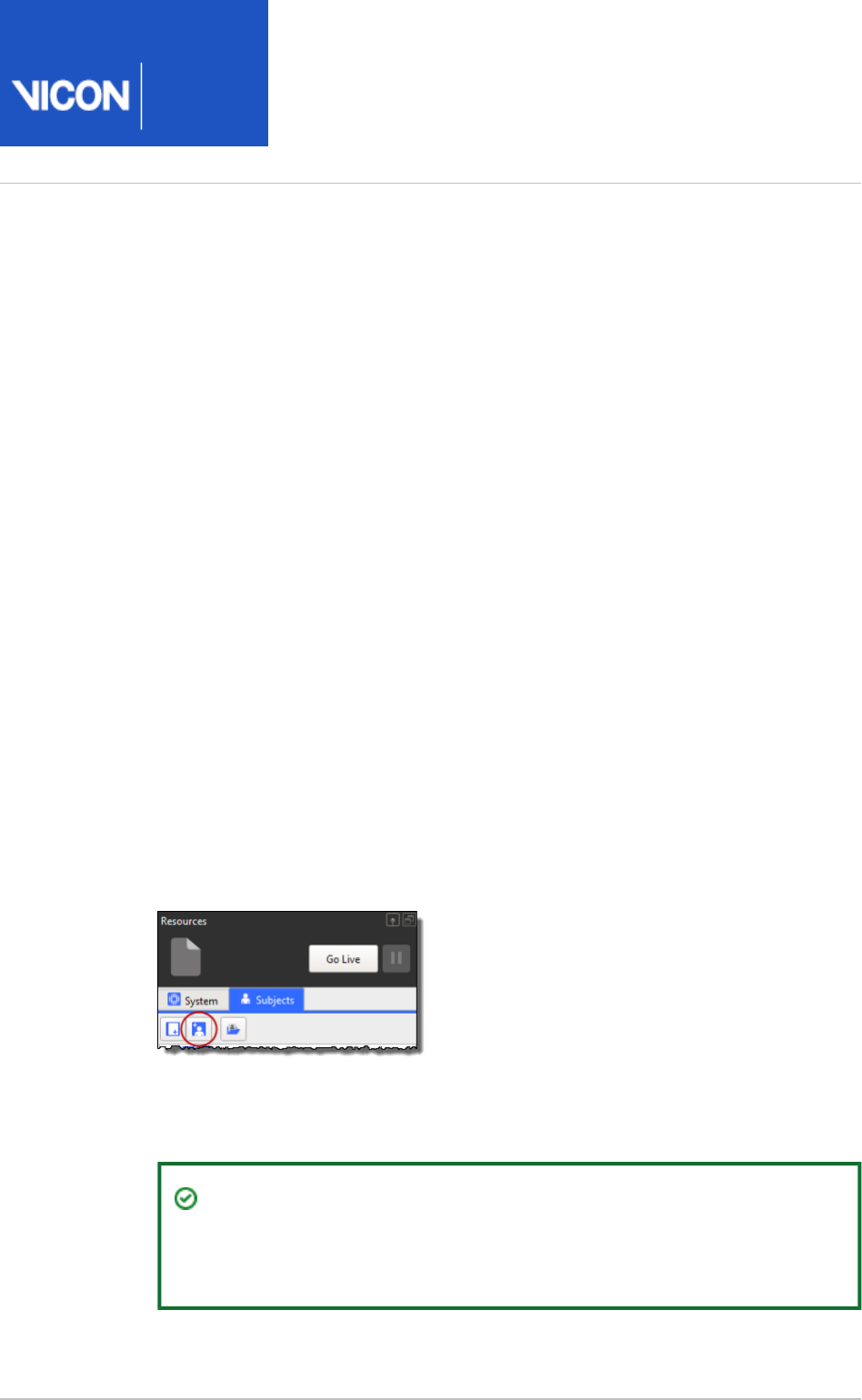
Nexus
User
Guide
Vicon Motion Systems Ltd. 26-Oct-2018 Page of 110 240
1.
2.
3.
Create a new subject from a template
Before you calibrate a labeling skeleton, you must create a new subject node for your
subject. The following instructions explain how to create a new subject node in the
tree, and base it on an existing Vicon labeling skeleton template (.Subjects Resources
file) in the pane.
vst
Subjects Resources
Sample . files, including those for Plug-in Gait, are provided in the Nexus model
vst
templates folder (by default, ).
C:\Program Files (x86)\Vicon\Nexus2.#\ModelTemplates
If you are using a standard Vicon marker set, you can base a new node on one Subject
of these templates. You subsequently scale the template to fit your particular subject
when you calibrate the labeling skeleton (.vsk file).
If you are not using a standard marker set, or need to modify a standard set, you will
need to create a custom labeling skeleton template. For more information, see
Creating
or contact Vicon Support.
labeling skeleton templates (VSTs)
To create a new subject based on a Vicon labeling skeleton template:
Ensure that you have created or opened a session in a database in which you
want to store the trial data, and that it is the active session (see Prepare a data
).storage location on page 94
In the pane toolbar, click the Subjects Resources Create a new Subject from a
button.Labeling Skeleton
A list of all Vicon labeling skeleton templates (.vst files) currently contained in
the Nexus ModelTemplates folder as well as a link are displayed.Browse
Tip
The supplied templates, whose names end in Ai, enable you to autolabel
static frames.
Select or browse to the desired . file. (For details of Plug-in Gait templates, see
vst
in the .
Plug-in Gait models and templates Plug-in Gait Reference Guide
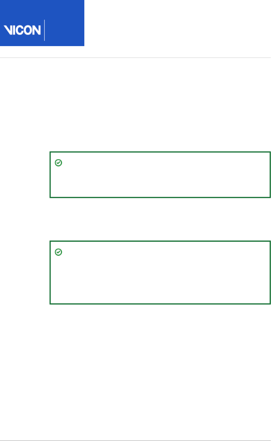
Nexus
User
Guide
Vicon Motion Systems Ltd. 26-Oct-2018 Page of 111 240
4.
5.
6.
In the dialog box, specify the name for your new subject (of Enter Subject Name
no more than 32 characters) and click OK.
If you used the link rather than selecting a . file from the list, the Browse
vst
file dialog box is then displayed. Navigate to and select the . Choose a Subject
vst
file on which the Vicon labeling skeleton (.vsk file) is to be based.
The new subject node is added in alphabetical order to the Subjects Resources
tree. The node automatically includes any sub nodes and data for the elements
defined in the selected .vst file: , , , and .Markers Segments Joints Model Outputs
Tip
Marker names are displayed in gray if they are defined in the template
but the markers are not yet labeled.
In the pane for the newly created subject, enter values for all the Properties
measurements that are required for this template. For information on the
measurements required to run the supplied Plug-in Gait model, see Take subject
. measurements for Plug-in Gait on page 191
Tip
Required measurements are highlighted in pink until you supply a value
for them; optional measurements are not highlighted. Note that these
measurements are required to run the relevant model; they do not
affect labeling.

Nexus
User
Guide
Vicon Motion Systems Ltd. 26-Oct-2018 Page of 112 240
7. In the pane, right-click the subject name and click Subjects Resources Save
.Subject
Note
When you save a labeling skeleton (VSK), Vicon Nexus automatically
creates an accompanying . file, which is saved into the same folder
mp
as the VSK. If required, you can import this data by running an Import MP
pipeline operation. This is only necessary in particular circumstances
(for example, if you are using Vicon BodyBuilder or Vicon Polygon), and
is not part of the normal Nexus workflow.
You can now place the appropriate marker set on your subject, (for information on
attaching the Plug-in Gait marker set, see Attach Plug-in Gait markers to a patient on
) and calibrate its labeling skeleton (.vsk file). page 199

Nexus
User
Guide
Vicon Motion Systems Ltd. 26-Oct-2018 Page of 113 240
Calibrate a labeling skeleton
Calibrating a Vicon labeling skeleton (VSK) enables Nexus to recognize the subject and
automatically determine which labels belong to its reconstructions.
Having chosen a labeling skeleton template (VST) for your subject (see Create a new
), you then capture a short subject calibration trial subject from a template on page 110
(see below), run the required calibration operations on it and save the trial and the
labeling skeleton (VSK). The calibration process applies the general information
contained in the VST to your particular subject, who is wearing the marker set
described in the VST. When you save the calibration, a labeling skeleton (VSK),
containing information that is specific to your particular subject is saved.
You can then use that VSK to automatically label all the trials in an entire capture
session. You only need to recalibrate if the subject changes, for example, if a different
subject wears the same marker set, or if the markers are moved. For more detailed
information about VSKs and labeling skeleton templates (VSTs) see
Creating labeling
.
skeleton templates (VSTs)
Nexus provides a number of processes and multiple calibration options for calibrating a
labeling skeleton. The factors that affect which process and which options are best for
your situation, include:
Whether your subject is able to perform a full ROM (Range of Motion) trial
The type of movement you are studying
Whether obtaining results quickly or labeling accuracy is more important
The following types of trial can be used to calibrate a labeling skeleton:
ROM trial In a ROM trial, the subject completes a series of movements that exercises
all of their joints. To produce the best calibration (and auto-labeling), the subject
moves all of their joints through as full a joint range as possible. For the best results,
ensure that each joint moves through a range that represents what the subject is
likely to do during capture of trial data (ie, movement trials). Full ROM calibrations
provide the most information of any of the calibration methods and therefore often
provide the best labeling. For this reason Vicon recommends using a full ROM
calibration whenever possible.
For step-by-step instructions on using this type of trial to calibrate a labeling
skeleton, see .Calibrate a labeling skeleton using a ROM trial on page 115
Static trial This is a short trial where the subject stands in a base pose. A base pose is
a static pose that is used when the VST (labeling skeleton template) file is first
created. For Plug-in Gait, this is a T-pose or 'motorbike' pose. (To view images of the

Nexus
User
Guide
Vicon Motion Systems Ltd. 26-Oct-2018 Page of 114 240
motorbike pose, see .) Calibrate a labeling skeleton using a ROM trial on page 115
This operation requires the least processing time, but provides less information than
functional calibration (which is often used as part of ROM calibration, described
above), as it operates on only a single frame of data. Consider using this type of
calibration if:
A subject's ability to perform a ROM trial is limited; and/or
You want to obtain results as quickly as possible.
For step-by-step instructions on using this type of trial to calibrate a labeling
skeleton, see .Calibrate a labeling skeleton using a static trial on page 125
Movement trial This trial type is similar to a ROM trial, but focuses on only joint
movements that are expected and specific to the activity being studied. For example,
a gait laboratory might use a walking trial for this type of calibration. Movement trials
are not normally used for an initial or full subject setup, but can be used in
combination with some pipeline operations to improve labeling. They may be of
benefit if the motion of the subject during movement trials is not similar enough to
what is captured when using a static or ROM trial. For more information on this type
of labeling skeleton calibration, see in the
Labeling skeleton calibration in detail
.
Vicon Nexus Reference Guide
Whichever type of calibration you choose, note the following requirements for your
calibration trial:
Aim to produce a trial (ROM, static, or movement) that is as fully labeled as possible.
The trial must contain only raw reconstructions; leave any gaps unfilled. (Unlabeled
reconstructions have no influence on subsequent operations.) However, if necessary,
you can manually label any missing markers (see ) Manually label a trial on page 128
or correct any swapped markers (see ).Correcting swapped labels on page 127
For information on creating custom labeling skeleton templates (VSTs), see
Creating
.
labeling skeleton templates (VSTs)
Note
This topic assumes that you are using a Vicon-supplied PlugInGait Ai VST,
although you could instead use a custom VST, providing it conforms to the
requirements listed in in Requirements for custom labeling skeleton templates
.
Creating labeling skeleton templates (VSTs)

Nexus
User
Guide
Vicon Motion Systems Ltd. 26-Oct-2018 Page of 115 240
1.
2.
3.
4.
Calibrate a labeling skeleton using a ROM trial
The recommended workflow for Nexus 2, which is described below, is to use a ROM
trial and dynamic calibration to calibrate a labeling skeleton, as this is likely to produce
more accurate automated labeling. However, if you need to use a static frame to
calibrate your labeling skeleton (for example, if your subject cannot perform a full ROM,
or you are capturing simple movement and/or want to obtain some results quickly), see
.Calibrate a labeling skeleton using a static trial on page 125
After you have prepared a subject for capture (see ), to Prepare a subject on page 108
enable Nexus to provide correct automatic labeling for your subject, you capture a
ROM (Range of Motion) trial that starts with a few frames where the subject is static,
as described in the following steps.
Vicon Nexus then uses the information from the ROM trial to automatically label the
subject in subsequent movement trials.
The following workflow is just one approach that you can adapt to suit your particular
circumstances. For a detailed explanation of all the methods of subject calibration, see
in the .Labeling skeleton calibration in detail
Vicon Nexus Reference Guide
The workflow for calibrating a labeling skeleton based on a ROM trial can be divided
into the following stages:
Perform an initial calibration of a labeling skeleton using a ROM trial
Ensure you have obtained any subject measurements required to run the model
(required measurements are highlighted in pink in the Subjects Resources pane):
for Plug-in Gait Lower Body, these are the body weight and height as well as
measurements of both left and right leg lengths, knee widths, and ankle widths.
These are used to calculate joint center positions, and must be measured and
entered into Nexus before any modeling can take place can begin. Optionally,
you can also measure tibial torsion, the inter-ASIS distance, the ASIS-to-greater
trochanter distance, and the sole delta if the subject is wearing shoes. For more
information on the measurements needed to run the Plug-in Gait model, see
.Take subject measurements for Plug-in Gait on page 191
In the pane, on the tab, ensure that you Communications Data Management
have created or opened the required database in which to store the data you will
be capturing and that the required session is active. (For a reminder of how to do
this, see .)Prepare a data storage location on page 94
In the pane, ensure Nexus is in Live mode.Resources
Nexus
User
Guide
Vicon Motion Systems Ltd. 26-Oct-2018 Page of 116 240
4.
5.
6.
7.
8.
In the tree, select the node and then in System Resources Local Vicon System
the section under , check that the , which Properties General Processing Level
sets the amount of real-time processing that is performed on the source data, is
set appropriately. If you are not sure, set it to at least the level.Labels
Display a view.3D Perspective
In the tree, ensure the required PlugInGait Ai (Auto Initialize) Subjects Resources
labeling skeleton template (VST) file is specified for the subject (see Create a
) and that the subject node you new subject from a template on page 110
created from the template is the only entry enabled for capture. (When enabled,
the check box contains a check mark.)
If required by your model, in the section at the bottom of the Properties Subjects
pane, enter any subject measurements you obtained in step 1.Resources
In the pane, ensure that the subject you created is Subject Preparation Tools
selected in the list.Subject
Tip
If you want to capture video or if you want to avoid automatically
switching to mode as soon as you have captured a trial, instead Offline
of clicking the button, click the button and Subject Preparation Capture
on the tab, ensure the settings are as required (for example, to Capture
capture video, ensure that in the section, Data Source Setup Video
is selected).Camera Data

Nexus
User
Guide
Vicon Motion Systems Ltd. 26-Oct-2018 Page of 117 240
9.
10.
11.
12.
To enable Nexus to automatically label the key trajectories, in the capture
volume, have the subject stand in the stationary neutral pose that was selected
when the labeling skeleton template was created. If you are using a Vicon-
supplied PiG template, ensure the pose is as described in step 12.
Tip
To help you to ensure that the subject adopts the correct base pose, on
the view pane toolbar, click the button and in the second Split vertically
pane, open a . This displays the base pose for the current Subject Viewer
labeling skeleton template (VST).
To make sure all the markers are visible, count the number of markers under the
node in the tree, and make sure the same number of Markers Subjects Resources
markers is visible in the view.3D Perspective
On the pane, in the section, click .Capture Tools Capture Start
The button switches to its setting.Start Stop
Capture a ROM trial where the first 1–3 seconds are of the subject in the
'motorbike' pose, as shown in the following image, in which:
Arms are outstretched, held level or slightly lowered, with elbows bent and
further forward than the shoulders (so that they don't hide any of the body
markers).
Rest of body is straight.
Feet point forward

Nexus
User
Guide
Vicon Motion Systems Ltd. 26-Oct-2018 Page of 118 240
12.
13.
14.
For the rest of the ROM trial, have the subject go through the required range of
motion.
Tip
If the subject is not able to attain the base pose, they can use any pose
where all of the markers are visible to the cameras. This ensures that
the markers can be reconstructed, but is unlikely to produce good
autolabeling when (part of the Autolabel Static Frame Auto Initialize
pipeline) is run. If this is the case, you will need to manually Labeling
label the trial (see ) and then run the Manually label a trial on page 128
two remaining operations from the pipeline. (For Auto Initialize Labeling
information on running pipelines, see .)Run a pipeline on page 132
If the chosen base pose proves unattainable by many subjects, consider
substituting a different, attainable pose by specifying a different frame.
To do this, on the pane, expand the Pipeline Tools Subject Calibration
section and double-click the pipeline operation to Set Autolabel Pose
add it to the current pipeline. In the pane, ensure the frame Properties
with the required pose is selected and then run the Set Autolabel Pose
pipeline.
When enough data has been captured, click to end the trial. For a ROM trial, Stop
this is typically 1–3 seconds of static data capture, followed by the required ROM.
If you are using the tab, Nexus automatically switches to Subject Preparation
mode.Offline

Nexus
User
Guide
Vicon Motion Systems Ltd. 26-Oct-2018 Page of 119 240
14.
15.
16.
17.
18.
Reconstruct the trial either by clicking on the Nexus toolbar or, Reconstruct
if you need to change the reconstruction settings, by clicking the button Pipeline
in the pane and configuring and running the pipeline to Tools Reconstruct
create a 3D image of the captured markers. (For information on how to run a
pipeline, see .)Run a pipeline on page 132
View the subject data in a view and ensure that all the markers 3D Perspective
are clearly visible to the Vicon cameras. (If they are not, check your camera
settings, system setup steps, system calibration, etc. Also check that clothing
isn't causing markers to move, and the condition (age, etc) of the markers
themselves.)
From the pane, run the supplied pipeline Pipeline Tools Auto Initialize Labeling
(or if preferred, you can manually label the trial):
Nexus labels the trajectories based on the marker set defined in the . file.
vst
Save the trial and the labeling skeleton (VSK) by pressing CTRL+S or by clicking
the Save button on the Nexus toolbar. If an asterisk is displayed to the right
of the the subject name in the pane, this means that you Subjects Resources
have also made changes that affect the labeling skeleton template (VST).To save
the VST, right-click on the subject name and click .Save Subject

Nexus
User
Guide
Vicon Motion Systems Ltd. 26-Oct-2018 Page of 120 240
1.
2.
Review and finalize a calibration of a labeling skeleton using a ROM trial
After you have saved your initial calibration (see above), assess the results by
looking at the labeling of the frame that contains the static base pose in the 3D
Perspective view. Ensure that all markers are connected by sticks and that the
sticks on the left side of the subject are red and those on the right side are
green. For a more detailed check, look at the information on the data tab.Quality
Tip
To see all the assigned marker labels in the view, press 3D Perspective
CTRL+space bar. This enables you to check that all the required markers
are present and correctly labeled.
Depending on the results of the labeling, take the appropriate action:
If the static frame is correctly labeled and the labeling skeleton fits well, any
further processing of your first movement trial (see Capture movement trials
) will give you an indication of the level of labeling that this on page 136
subject calibration will provide for your specific trial type. Based on these

Nexus
User
Guide
Vicon Motion Systems Ltd. 26-Oct-2018 Page of 121 240
2.
3.
a.
b.
c.
results, you can decide whether they meet your requirements. For example, for
walking trials, the quick calibration produced by the Auto Initialize Labeling
pipeline is likely to produce good labeling of movement trials.
When the subject has been calibrated, segments of the labeling skeleton are
fitted to the labeled markers in the view, and your subject is 3D Perspective
automatically labeled. To verify that the subject has been calibrated
successfully, switch Nexus to and ask your subject to move around in the Live
capture volume. You should see that the markers are labeled and the subject is
tracked.
If the results are satisfactory, go straight to step 4(set a range).
If the results are not satisfactory, this may be because your movement trials
include more challenging or complex movement and therefore require a
further level of labeling reliability. To provide this enhanced reliability you will
need to run a functional calibration, which calibrates the subject's bone
lengths and joint and marker locations from the whole ROM trial, as described
in step 3. To ensure the best results, first consider the following factors:
If any markers are labeled incorrectly, fix them (see Correcting swapped
and ) and from the labels on page 127 Manually label a trial on page 128
pipeline, re-run the and Auto Initialize Labeling Scale subject Marker-only
operations; orSubject Calibration
If all the labels are correct but there is a large distance between a marker
and the corresponding reconstruction, the labeling skeleton cannot
accurately represent the configuration of labeled reconstructions. This is an
indication that you may get poor labeling results and may need to improve
your labeling skeleton template (see Requirements for custom labeling
in ).skeleton templates
Creating labeling skeleton templates (VSTs)
Note that takes more processing time to Functional Skeleton Calibration
complete than the pipeline.Auto Initialize Labeling
(Optional step) Run a by completing the Functional Skeleton Calibration
following steps:
Verify that the trial is correctly labeled for every frame.
Note that only labels the trajectories that are Autolabel Static Frame
present on the static frame(s).
Visually check for any markers that get occluded and manually re-label
them (see ) when they re-appear.Manually label a trial on page 128
On the pane, expand the operations Pipeline Tools Subject Calibration
section, add the operation to the current Functional Skeleton Calibration
pipeline and run it.
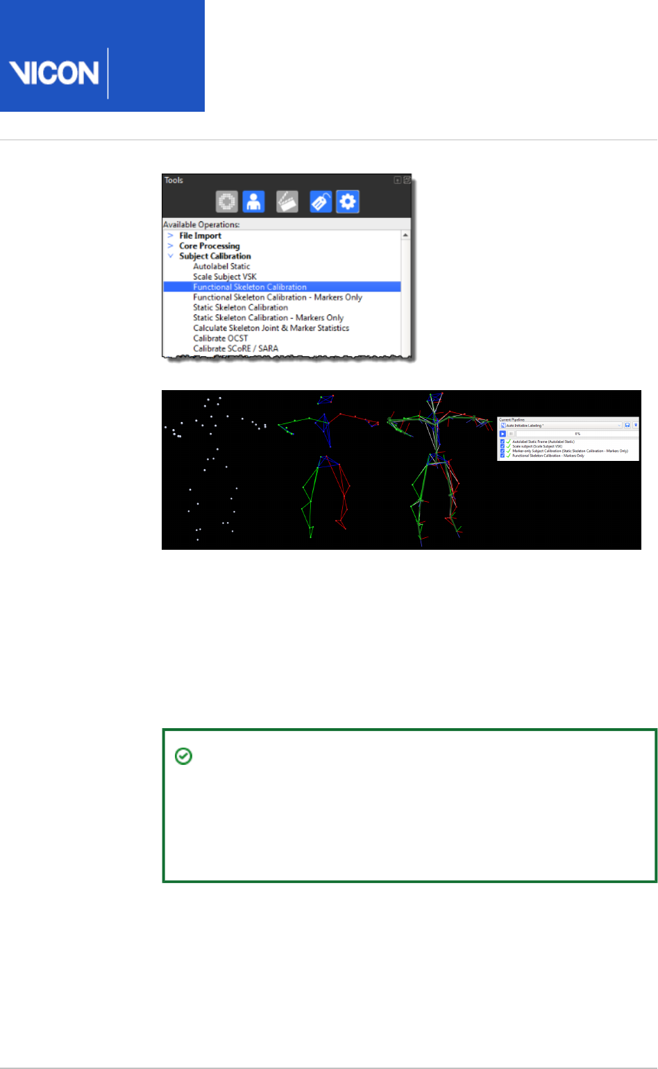
Nexus
User
Guide
Vicon Motion Systems Ltd. 26-Oct-2018 Page of 122 240
3.
c.
d.
4.
5.
a.
When the has completed, in the Functional Skeleton Calibration Options
dialog box (F7), click (on the left) and in the pane, go Subjects Properties
to the section, and select Covariance.Markers Draw
If you can see any large covariance ellipsoids around a marker, check for
mis-labeling of a small number of frames for that marker and fix any
mislabels. Note that some markers, such as the ASIS markers, will naturally
have a larger covariance, due to skin motion.
Tip
The size of covariance ellipsoids vary, depending upon the way a
marker is defined in a skeleton, the amount of marker movement
possible, and the quality of the subject calibration. Particularly
large covariance ellipsoids may indicate a poor calibration.
On the Time Bar, move the and (the Start Range indicator End Range indicator
blue triangles) along the timeline to set a range of frames to select only the first
few seconds of the static pose at the beginning of the trial.
Run any further processing needed to achieve the required modeling. For
example, if you are using Plug-in Gait, to make the necessary calculations and
calibrate the static subject, run the pipeline:Plug-in Gait Static
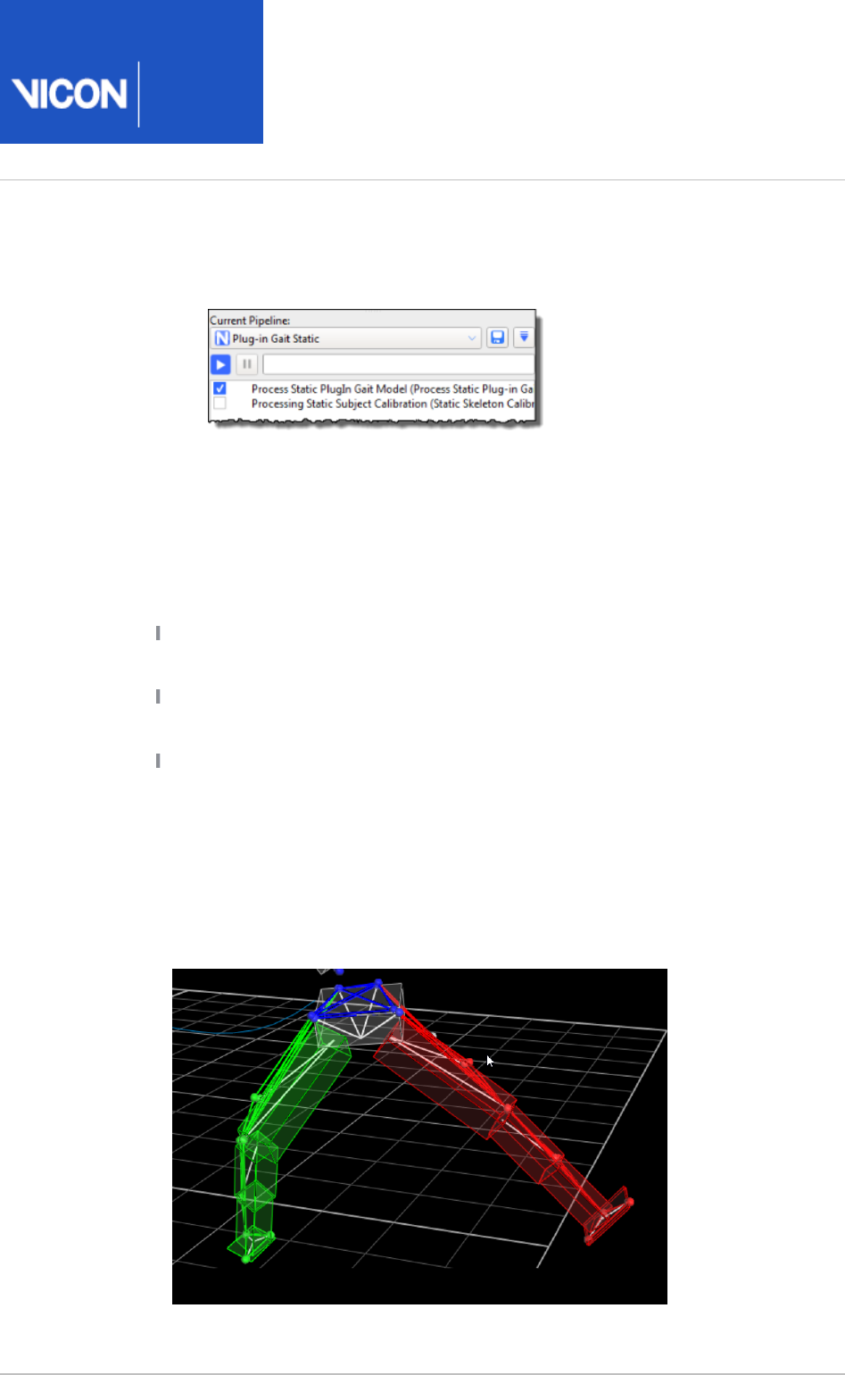
Nexus
User
Guide
Vicon Motion Systems Ltd. 26-Oct-2018 Page of 123 240
5.
a.
b.
c.
6.
7.
In the list, select the pipeline, and Current Pipeline Plug-in Gait Static
ensure that you leave the check box for Processing Static Subject
cleared (its default setting).Calibration
Click on the operation and ensure that in Process Static Plugin Gait Model
the pane, the is set to and Properties First Frame Selected Start Last
is set to (the default settings).Frame Selected End
Run the pipeline. Plug-in Gait Static
To check that your model has been processed correctly:
Ensure that in the pane, a green check mark is displayed to the Pipeline Tools
left of the operation in the list.Current Pipeline
Ensure that Plug-in Gait bones are visible in the view. If they 3D Perspective
are not, press F7 to open the dialog box and select .Options Plug-in Gait Bones
In the pane, ensure that you can expand to Subjects Resources Model Outputs
see all the calculated components of variables for a kinematic model (such as
Angles, Forces, Moments, etc).
To verify that Nexus has successfully created a labeling skeleton and that it is
automatically labeling, ensure that, as shown in the following image, the
bounding boxes for Plug-in Gait model segments are displayed in the 3D
view. (The bounding boxes that Nexus draws around each Perspective
segment that is defined in the template are for visualization purposes only.)
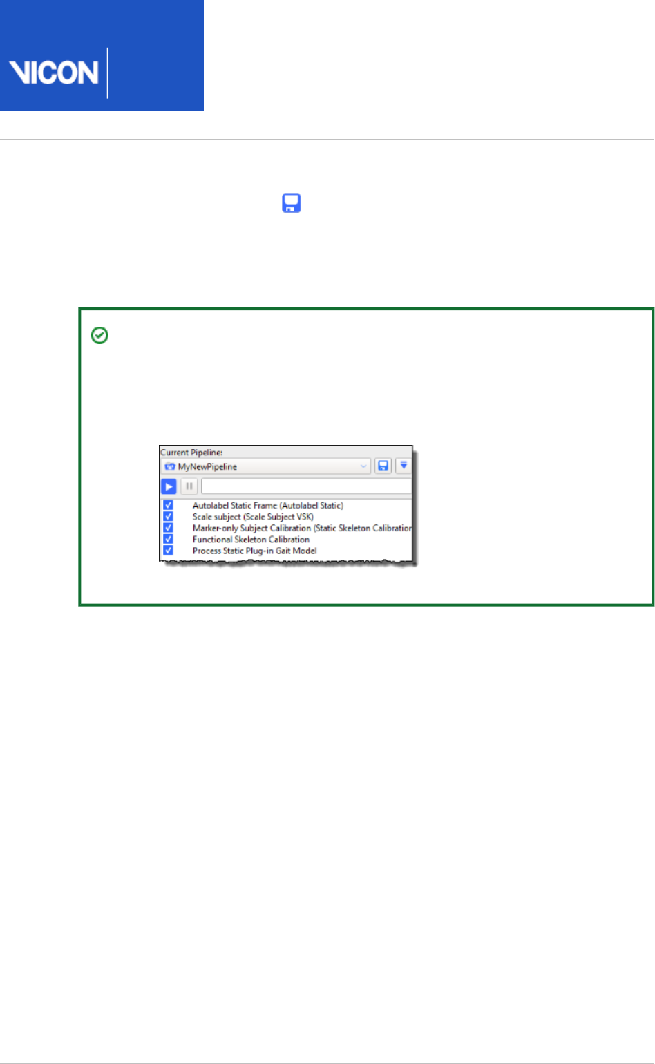
Nexus
User
Guide
Vicon Motion Systems Ltd. 26-Oct-2018 Page of 124 240
7. Save the ROM trial and the labeling skeleton (VSK) by pressing CTRL+S or
clicking the Save button on the Nexus toolbar.
When you have a fully labeled and processed trial (containing only raw reconstructions
and no gap-filling), you can proceed to capture and process your movement trials (see
).Capture movement trials on page 136
Tip
To save time in future, you may want to save all the relevant pipeline
operations to one customized pipeline. To do this, add the relevant operations
to the end of the pipeline and save the pipeline under Auto Initialize Labeling
a new name.

Nexus
User
Guide
Vicon Motion Systems Ltd. 26-Oct-2018 Page of 125 240
1.
2.
3.
4.
5.
6.
Calibrate a labeling skeleton using a static trial
The recommended workflow for Nexus 2 is to use a ROM trial and dynamic calibration
as this offers the benefits of the more efficient, automated labeler (for more
information on this workflow, see Calibrate a labeling skeleton using a ROM trial on
). However, if you need to use a static frame to calibrate your labeling page 115
skeleton (for example, if you are capturing simple movement, or your subject cannot
perform a full ROM, and/or you want to obtain some results quickly), you can instead
use the following workflow.
To perform a static calibration:
Ensure you have obtained and entered any subject measurements required to
run the model (required measurements are highlighted in red in the Subjects
pane): for Plug-in Gait, these are the body weight and height as well Resources
as measurements of both left and right leg lengths, knee widths, and ankle
widths. These are used to calculate joint center positions, and must be measured
and entered into Nexus before any processing can begin. Optionally, you can also
measure tibial torsion, the inter-ASIS distance, the ASIS-to-greater trochanter
distance, and the sole delta if the subject is wearing shoes.
In the pane, on the tab, ensure that you Communications Data Management
have created or opened the required database in which to store the data you will
be capturing and that the required session is active. (For a reminder of how to do
this, see .)Prepare a data storage location on page 94
In the pane, ensure Nexus is in Live mode.Resources
Display a view.3D Perspective
Capture a static trial. For more details, see Perform an initial calibration of a
.labeling skeleton using a ROM trial on page 115
Reconstruct the trial either by clicking on the Nexus toolbar or, if Reconstruct
you need to configure the reconstruction settings, by clicking the Pipeline
button in the pane and changing and running the pipeline Tools Reconstruct
to create a 3D image of the captured markers. (For information on how to run a
pipeline, see .)Run a pipeline on page 132

Nexus
User
Guide
Vicon Motion Systems Ltd. 26-Oct-2018 Page of 126 240
6.
7.
8.
9.
10.
11.
In the tree, right-click on the subject node and attach the Subjects Resources
required PlugInGait Ai (Auto Initialize) labeling skeleton template (VST) file (see
) to the subject.Create a new subject from a template on page 110
Tip
To use a workflow prior to Nexus 2.x, ensure you use the required old
labeling skeleton template, (PlugInGait.vst, PlugInGait Fullbody.vst, etc).
If you chose to import old settings files when you first installed Nexus 2.
x, you can select it from the list of available templates. If you didn't
import the old settings files when you installed Nexus 2, copy the old
VST files from ...\Vicon\Nexus\ModelTemplates to ...\Vicon\Nexus2.
#\ModelTemplates.
Ensure that the subject node is the only entry enabled for capture. (When
enabled, there is a check mark in the check box.)
In the tools pane, select and run the pipeline or if Pipeline Auto Initialize Labeling
necessary, manually label the trial (see ).Manually label a trial on page 128
Nexus labels the trajectories based on the marker set defined in the . file.
vst
Assess the results by looking at the labeling in the view. Ensure 3D Perspective
that all markers are connected by sticks and that the sticks on the left side of the
subject are red and those on the right side are green.
Save the trial and the labeling skeleton (VSK) by pressing CTRL+S or clicking the
Save button on the Nexus toolbar.
You can now run any further processing needed to achieve the required
modeling and finalize the calibration (see steps 5–7 of Review and finalize a
).calibration of a labeling skeleton using a ROM trial on page 120
When you have saved a fully labeled trial (containing only raw reconstructions and no
gap-filling), you can proceed to capture and process your movement trials (see Capture
).movement trials on page 136

Nexus
User
Guide
Vicon Motion Systems Ltd. 26-Oct-2018 Page of 127 240
1.
2.
Correcting swapped labels
To obtain error-free auto-labeling, it is very important to ensure that the labels are
present and correct in your .vst file and that you have labeled your ROM or static trial
before running any calibration operation. If the markers in your ROM or static trial are
not labeled, the calibration operation will fail. If your markers are erroneously labeled
(for example, if left and right markers have been mistakenly swapped) the operation will
succeed, but when the Vicon Skeleton (.vsk file) is used for automatic marker labeling
of your movement trials, it will continue to produce the erroneous labels.
To address this, check your labeling carefully. If you identify any swapped markers, you
can correct this using the button in the pane.Swap Marker Labels Label/Edit Tools
Tip
To see all the assigned marker labels in the view, press 3D Perspective
CTRL+space bar.
To correct swapped markers:
Select the two swapped markers in either the view or in the 3D Perspective
pane.Subjects Resources
In the pane, in the section, click the Label/Edit Tools Manual Labeling Swap
button.Marker Labels

Nexus
User
Guide
Vicon Motion Systems Ltd. 26-Oct-2018 Page of 128 240
Manually label a trial
The recommended workflow for Nexus 2 is to use a ROM trial and dynamic calibration
as this enables the use of automated labeling (for more information on this workflow,
see ). However, on Calibrate a labeling skeleton using a ROM trial on page 115
occasions, you may need to supplement automated labeling with manual labeling, or to
use manual labeling where automated labeling gives insufficiently accurate results.
You manually label reconstructed trial data using the tools in the pane.Label/Edit Tools
Manual labeling involves associating the markers defined in a Vicon labeling skeleton
template (.vst file) with reconstructed markers displayed in the view. 3D Perspective
The manual labeling is then used when the .vst file is scaled to fit the subject wearing
the marker set described in the .vst file, during subject calibration. In subsequent
movement trials, Nexus uses the resulting subject-specific Vicon labeling skeleton (.vsk
file) to automatically label the subject wearing the same marker set.
Important
Before manually labeling markers, ensure that you have already:
Created or opened a session in the database on page 94 in which you
want to store the trial data, and ensured that it is the active session.
Obtained an existing .vst on page 108 file corresponding to the type of
subject whose motion is to be captured, or created a custom Vicon labeling
.skeleton template
Created a new subject node on page 110 from the template in which the
manual labeling is to be stored.
Attached the Vicon markers to the subject in accordance with the marker
set defined in the associated template. For information on how to do this for
Plug-in Gait markers, see Attach Plug-in Gait markers to a patient on page
.199
Captured a brief ROM trial including static frames on page 115, or a static
, or obtained a single frame of live data with reconstructed trial on page 125
markers corresponding to the marker set specified in the associated .vst file.

Nexus
User
Guide
Vicon Motion Systems Ltd. 26-Oct-2018 Page of 129 240
1.
2.
3.
4.
5.
6.
7.
8.
To manually label 3D marker reconstructions:
In the pane, on the tab, open the trial file Communications Data Management
that contains reconstructed markers.
On the time bar, move the current time indicator (vertical blue line) to the first
frame of the trial in which the subject is standing in a stationary neutral pose.
This is typically a T-pose or 'motorbike' pose, in which the subject stands in the
basic neutral pose and raises the arms out straight to the sides with palms facing
down in a position in the shape of a T. If the subject is not able to attain the T-
pose, they can use any neutral pose where all of the markers are visible to the
cameras so that they will be able to be reconstructed.
In the tree, ensure that the subject node you created from Subjects Resources
the template is the only entry enabled for capture. (When enabled, there is a
check mark in the check box.)
At the top of the pane, from the list select the subject Label/Edit Tools Subject
to be manually labeled.
Labels for the markers defined in the .vst file are displayed in the list in the
section.Manual Labeling
By default, the button is selected, so trajectories are labeled in both Whole
directions. This ensures that, when you label a marker at the current frame, the
same marker is labeled throughout the trial. However, if you want the marker to
be labeled from this point forward (or backward) only, for example, if you are
resolving an overlapping trajectory, click the or button before Backward Forward
proceeding.
In the section, ensure is selected to Manual Labeling Auto advance selection
have Nexus automatically select the next label in the list after you have assigned
a label to a marker.
In the list in the section, click on the label you want to use.Manual Labeling
The shape of the pointer changes to include a tooltip that identifies the selected
label to guide you in assigning labels to markers in the view.3D Perspective
Tip
To help you apply labels to the correct markers, on the view pane
toolbar, click the button and in the second pane, open a Split vertically
. Any marker you select in the pane is Subject Viewer Label/Edit Tools
highlighted in the , so that you can see where to place it Subject Viewer
on the figure in the 3D view.
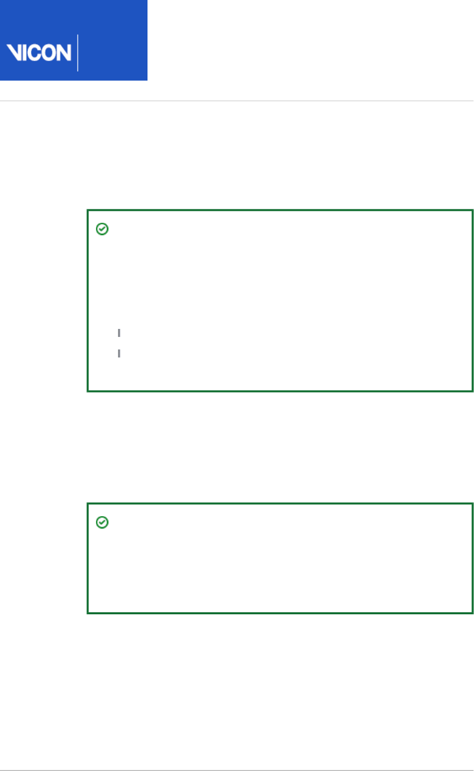
Nexus
User
Guide
Vicon Motion Systems Ltd. 26-Oct-2018 Page of 130 240
8.
9.
10.
11.
In the view click on the marker to which you want to assign the 3D Perspective
label.
The next label in the list is selected and the tooltip changes to indicate that
label. As you label more markers, a colored line is drawn between each marker
until a stick figure appears.
Tip
If you move the mouse to another area of the Nexus workspace while a
marker is selected in the section, the cursor retains the Manual Labeling
tooltip, indicating that Nexus is still in labeling mode. If you need to do
something else in Nexus before marker labeling is complete, you can
turn off labeling mode in one of these ways:
Press the ESC key.
Click on the icon, or any of the other icons in the Label/Edit Tools
pane toolbar.
Repeat steps 7-8 until you have assigned all of the labels to markers.
The stick figure in the view should resemble a skeleton of the 3D Perspective
subject type defined in the .vst file.
To verify that the manual labeling was successful, check that all the markers are
connected by sticks and that the sticks on the left side of the subject are red and
those on the right side are green.
Tip
To find the next unlabeled marker in the clip, you can also use the Find
button. Nexus searches from the current Next Unlabeled Trajectory
frame forward until it finds an unlabeled marker. When found, the
marker is selected and centered in the view pane.
To save the labeling information with the trial, on the Nexus toolbar, click the
button.Save
Nexus
User
Guide
Vicon Motion Systems Ltd. 26-Oct-2018 Page of 131 240
Work with pipelines
Pipelines enable you run one or more operations that you use frequently or on a large
number of trials, from import, through reconstruction and labeling and various other
types of processing, to export.
You can set up pipelines to run automatically immediately after capture or as required
on one or more saved trials.
You can use any of the pipelines supplied with Vicon Nexus or create your own by
grouping a particular sequence of operations to suit your particular needs. Each
operation within a pipeline can have a unique set of options and parameters.
Tip
If you are working with large numbers of files, to further speed up your work,
you can set up and run pipelines as batch processes, using Show File Transfer
and then the button /Batch Processing interface Batch Processing
on the .Data Management tab
The following topics describe how to:
Run a pipeline on page 132
Create a pipeline on page 134
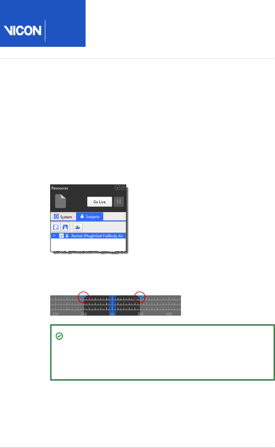
Nexus
User
Guide
Vicon Motion Systems Ltd. 26-Oct-2018 Page of 132 240
1.
2.
3.
Run a pipeline
This topic describes how to run a pipeline. For information on creating your own
pipelines, see .Create a pipeline on page 134
The procedure for running a pipeline is the same, whether you want to run a pipeline
supplied with Vicon Nexus or your own custom pipeline.
To run a pipeline:
In the pane, ensure that the subject whose trial data you Subjects Resources
want the pipeline to operate on is enabled. (When a subject is enabled, there is a
check mark in the check box next to it.)
If you want the pipeline to operate only on a part of the trial rather than the
whole trial, on the time bar, move the blue triangles that represent the start and
end of a range of frames along the time line to set the required range.
Tip
To change the view of the timeline so that it shows only the selected
range, right-click on the timebar and then click Zoom to Region-of-
.Interest
In the pane, from the list, select a pipeline.Pipeline Tools Current Pipeline

Nexus
User
Guide
Vicon Motion Systems Ltd. 26-Oct-2018 Page of 133 240
3.
4.
5.
In the operations list, ensure that the operation(s) to be run is Current Pipeline
selected.
Click the Run button to start the pipeline process. Each operation is run in the
order it appears in the list from top to bottom.
The progress bar displays the results of the pipeline processing, and gives an
indication of the percentage of processing completed for each operation.

Nexus
User
Guide
Vicon Motion Systems Ltd. 26-Oct-2018 Page of 134 240
5.
1.
2.
The operations list may contain the following information for Current Pipeline
each operation (to the right of the check box):
The operation is being processed.Processing
The operation was completed successfully.Processed
The operation was not completed successfully.Failed
The operation processing was stopped.Stopped
Create a pipeline
To save time, you can save and run sequences of frequently used processing operations
using tools in the pane. Some pipelines can also be selected and run in Pipeline Tools
the pane and the pane.Subject Preparation Tools Capture Tools
The following instructions describe how to create your own pipeline. For information
on how to run an existing pipeline, see .Run a pipeline on page 132
To create a pipeline:
If you want to modify an existing pipeline, in the pane, in the Pipeline Tools
area, select an existing pipeline. If you want to create a new Current Pipeline
pipeline, go straight to the next step.
In the list, expand or collapse the pipeline type to display or Available Operations
hide the operations you can use for that type of automatic processing of trial
data:
File Import Operations for automating the import of trial files into Vicon Nexus
from third-party software packages.
Core Processing Operations for automating reconstruction, labeling, and
kinematic fitting to produce 3D trajectories from raw marker data.
Subject Calibration Operations for automating the processing of system and
labeling skeleton calibration.
Events & Timebar Operations for automating events and operations that can
be carried out using the timebar.
Fill Gaps & Filter Data Operations for automating the post-processing of data,
such as gap-filling and data-filtering.
Data Processing Operations for automating the production of model outputs
(forces and moments, joint angles, etc).
File Export Operations for automating the export of trial files from Vicon Nexus
to third-party software packages.

Nexus
User
Guide
Vicon Motion Systems Ltd. 26-Oct-2018 Page of 135 240
2.
3.
4.
5.
6.
System Operations for automating offline camera calibration, applying a codec
to video, resetting force plate offsets and setting the camera calibration origin.
Legacy Operations for automating access to legacy labeling and fit motion.
For further details of each of the pipeline operations, see in the Pipeline tools
.
VIcon Nexus Reference Guide
To view a tooltip describing an operation's function, hover the pointer over its
name in the list.
Double-click each operation that you want to include in your pipeline.
The operation is displayed in the list in the section. The Current Pipeline
operations are run in the order they appear in the pipeline; to rearrange the
order, drag operations into the required position in the list.
Tip
To automatically save the trial you are processing, add the Save Trial -
operation (located in the pipeline operations) to C3D + VSK File Export
your pipeline. As a general rule, you will want to save the trial as a last
step after the other pipeline operations have been run, so position the
operation at the required point in the Save Trial - C3D + VSK Current
operation list.Pipeline
In the list of operations, click on the operation you added in the Current Pipeline
previous step, then in the pane at the bottom of the Properties Pipeline Tools
pane, view or change the settings as required.
To save your pipeline settings to a . file in the folder (see
pipelines
Pipelines
), click the Save button to the right Manage system configurations on page 21
of the list.Current Pipeline
In the dialog box, supply a name for your new pipeline.Save As
An asterisk * is displayed next to the pipeline name if there are unsaved changes.

Nexus
User
Guide
Vicon Motion Systems Ltd. 26-Oct-2018 Page of 136 240
Capture movement trials
Before you collect your trial data, you must first have calibrated the labeling skeleton
(see ) and ensured your subject is wearing the Calibrate a labeling skeleton on page 113
appropriate marker set.
When you have calibrated the labeling skeleton, you are ready to capture movement
trials for the specified subject, during which the patient performs the motion that is to
be analyzed. You then reconstruct and label the trial data, and run any further
processing required.
For detailed instructions on these steps, see:
Capture the required movement on page 137
Reconstruct and label movement trials on page 150
You capture motion data using the tools in the pane, and process trial Capture Tools
data using tools on the Nexus menu bar or in the pane.Pipeline Tools
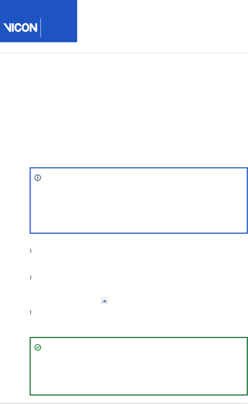
Nexus
User
Guide
Vicon Motion Systems Ltd. 26-Oct-2018 Page of 137 240
Capture the required movement
After you have calibrated the labeling skeleton for your subject (see Calibrate a labeling
), you can capture the required trials.skeleton on page 113
You can stream motion data in real time and/or capture raw camera data for offline
processing. You can capture a trial manually (see below), or configure Nexus to start
/stop capture automatically (see ).Automatically start and stop capture on page 140
To quickly capture sequences of trials using the same setup information for each trial,
see .Use Simple Capture Mode on page 148
Note
For clarity, reconstruction and labeling are described as separate steps.
However, if you want to run reconstruction and labeling as soon as each trial
has been captured, you can add these operations (and any others that you
want to run automatically) to a post-capture pipeline that runs as soon as
capture finishes. For more information see step 7 below.
Before capturing a movement trial, ensure that you have already:
Created or opened a session in the database in which you want to store the trial data,
and ensured that it is the active session. For more information, see Prepare a data
.management hierarchy to store your files on page 94
Loaded an existing .vsk file for the subject whose motion is to be captured. If you
have just created your VSK (see ), the Calibrate a labeling skeleton on page 113
correct VSK is already loaded. If not, in the pane, click the Subjects Resources Load
button and open the required .vsk file.an existing subject
Attached the Vicon markers to the subject in accordance with the marker
arrangement used in the labeling skeleton (.vsk) file (if you are using Plug-in Gait, see
).Attach Plug-in Gait markers to a patient on page 199
Tip
If you are using Plug-in Gait, Vicon recommends that you do not remove the
heel markers for the movement trials. Their presence does not affect the
calculated output from Plug-in Gait, but it does improve the reliability of the
automatic labeling in Nexus.

Nexus
User
Guide
Vicon Motion Systems Ltd. 26-Oct-2018 Page of 138 240
1.
2.
3.
4.
5.
6.
7.
8.
9.
To capture movement trials:
In the pane, ensure Nexus is in mode.Resources Live
Display a view.3D Perspective
In the pane, select an existing capture configuration for the trial Capture Tools
from the list or save as a new one.Trial Type
In the section, complete the details for storing your trial data in Next Trial Setup
the active session.
In the section, ensure Data Source Setup Optical Camera Data,Video Camera
, and are selected as required.Data Device Data
If you want capture to start and/or stop automatically, specify the required
settings in the section. (For more information, see Auto Capture Setup
.)Automatically start and stop capture on page 140
If you are conducting clinical gait trials for kinetic analysis involving one or more
force plates and want Nexus to automatically assess whether the foot is
correctly positioned and is producing valid data for your live trials, ensure that in
the dialog box (F7), is selected. For more information, see Options Footstrikes
.Automatically assess foot strikes on page 146
In the section, specify any pipelines containing Post-Capture Pipeline Setup
operations to be run automatically on the trial data when the capture is
complete. (For example, if you are using Plug-in Gait, you could select Run
and then select the and pipeline after capture Reconstruct And Label Plug-in
pipelines. This automatically reconstructs and labels the data and Gait Dynamic
then runs filtering, event detection, modeling and export operations.) However,
to start with, you will probably prefer to leave this option cleared, so that you can
run each operation separately and observe their effects.
In the tree, select and then in theSystem Resources Local Vicon System
pane, in the section, set to .Properties General Processing Output Level Labels
In the capture volume, have the subject perform the movement that is to be
captured.
Nexus
User
Guide
Vicon Motion Systems Ltd. 26-Oct-2018 Page of 139 240
9.
10.
11.
12.
Nexus automatically reconstructs, labels, and fits the Vicon labeling skeleton
created in the previous stage (see ) to the subject Prepare a subject on page 108
in real time.
Tip
If a labeling error is obvious or persistent, restart the labeler by right-
clicking node and then clicking Local Vicon System Reboot Core
(CTRL+R).Processor
If the subject steps on the force plates, the force vector is also shown in real
time.
On the tab, unless you have specified a time or trigger on which to Capture Tools
start capturing (see step 5), in the section, click to begin capturing Capture Start
and in the capture volume, have your subject wearing the appropriate marker set
for your VST perform the required motion.
Unless you have specified a time or trigger on which to stop capturing in the
section, when the subject has completed the required Auto Capture Setup
motion, click .Stop
If you specified a post-capture pipeline (see step 7), Nexus automatically
switches to mode, displays the subject data in the view, Offline 3D Perspective
and automatically performs any operations contained in any pipelines selected in
the section. Otherwise the system remains Live, Post-Capture Pipeline Setup
ready to capture the next trial.
Tip
If events are not automatically detected, or are only partially detected,
you will need to add them manually (see Add events to trials on page
). You will probably need to do this in situations such as: trials 180
without force plates; movements that are not on a flat surface, such as
stepping up/down/over, climbing, etc; pathological or non-cyclical gait
movement.
Repeat steps 9–11 until you have obtained the required number of trials.
You can now reconstruct and label the trials. For more information, see Reconstruct
.and label movement trials on page 150

Nexus
User
Guide
Vicon Motion Systems Ltd. 26-Oct-2018 Page of 140 240
1.
2.
3.
4.
Automatically start and stop capture
If required, instead of having to manually start and stop capture (see Capture the
t), you can trigger data capture using an external required movemen on page 137
device or based on a specified period of time.
You can configure Vicon Nexus to automate data capture using the following options:
Automatically record data before capture is triggered on page 140
Stop data capture after elapsed time on page 141
Trigger data capture on labeling percentage on page 141
Trigger data capture using a remote control device on page 143
Trigger data capture using timecode on page 143
Trigger data capture over a network on page 145
Automatically record data before capture is triggered
The option enables you to specify the number of seconds of data Capture before start
to record prior to capture being triggered either manually (with the button) or Start
automatically (based on timecode or a remote control device).
To automatically record before capture is triggered:
Ensure you have prepared for capture as described in Capture the required
, and completed steps 1–4.movement on page 137
In the pane, expand , select Capture Tools Auto Capture Setup Capture Before
and specify the number of seconds to record data prior to capture Start (secs)
being triggered.
Trigger the capture manually or using one of the remote capture methods
described in this section.
The Vicon cameras capture the subject moving in the capture volume.
Stop the capture manually or using one of the remote capture methods
described in this section.
Nexus automatically switches to Offline mode and displays the subject data in
the view.3D Perspective

Nexus
User
Guide
Vicon Motion Systems Ltd. 26-Oct-2018 Page of 141 240
1.
2.
3.
1.
2.
3.
Stop data capture after elapsed time
The option enables you to specify a time period after which Stop after duration (secs)
Nexus is to automatically stop a capture.
To stop data capture after a specified time period:
Ensure you have prepared for capture as described in Capture the required
, and completed steps 1–4.movement on page 137
In the pane, expand , select Capture Tools Auto Capture Setup Stop After
and specify the number of seconds after which to automatically Duration (secs)
stop motion capture.
Capture a trial manually or using one of the remote capture methods described
in this section.
The Vicon cameras capture the subject moving in the capture volume. Nexus
automatically stops the capture after the specified number of seconds,
automatically switches to Offline mode, and displays the subject data in the 3D
view.Perspective
Trigger data capture on labeling percentage
With the option selected, captures automatically start when a Start on Labeling (%)
subject first fully enters the volume. If the option is also selected, Stop on Labeling %
captures automatically stop when the subject leaves the volume.
You can set the labeling percentage (ie, the percentage of markers expected from the
total number of markers in your subject's labeling skeleton) that needs to be
recognized by Nexus within the capture volume for the subject to be considered as
fully in the volume or to have left the volume and therefore to trigger capture start
/stop.
The following procedure describes how to set up data capture to automatically crop
live trials, based on labeling percentages. For information on how to automatically crop
trials that you have already saved based on labeling percentages, see Crop trials on
.page 165
Ensure you have prepared for capture as described in Capture the required
, and completed steps 1–4.movement on page 137
In the pane, expand and select Capture Tools Auto Capture Setup Start on
and/or .Labeling (%) Stop on Labeling (%)
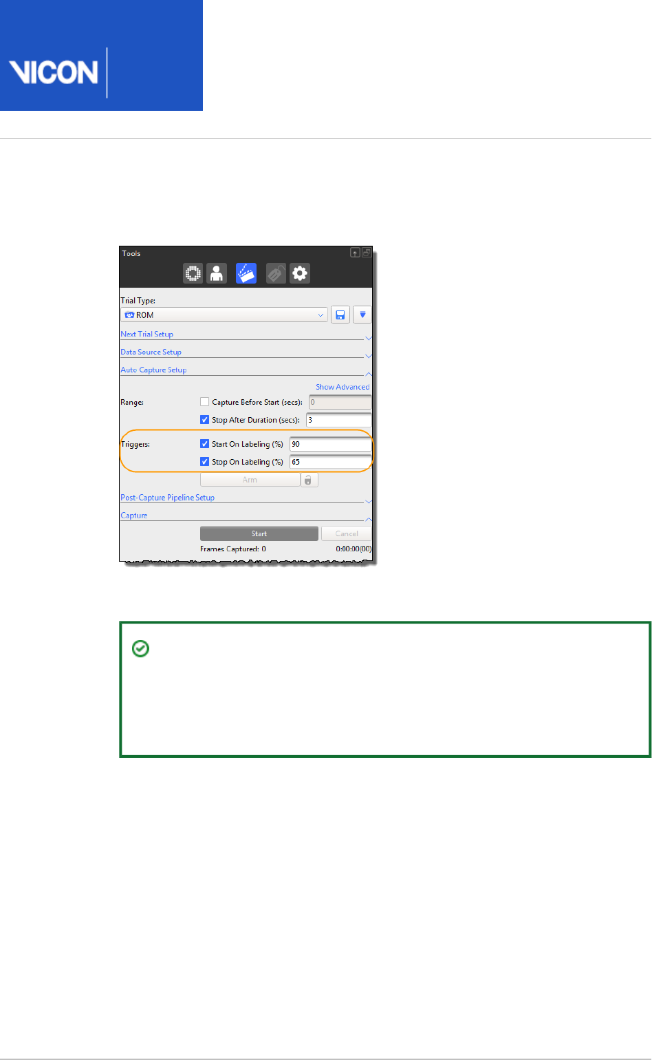
Nexus
User
Guide
Vicon Motion Systems Ltd. 26-Oct-2018 Page of 142 240
3.
4.
The default values for this operation start capture when at least 90% of a
subject's markers are recognized and stop when less than 65% remain (volume
exit). You can adjust these percentages to suit your capture type.
Have a subject wearing the required marker set enter the volume.
Tip
To check data quality, you can display the labeling percentage by
selecting the subject and in a view choosing to show Graph Labeling
how many labels are present on each frame.

Nexus
User
Guide
Vicon Motion Systems Ltd. 26-Oct-2018 Page of 143 240
1.
2.
3.
4.
5.
6.
1.
Trigger data capture using a remote control device
The option enables you to use an external remote control Start/Stop on remote trigger
device to trigger data capture. The remote control device must be connected to a
Vicon Lock+ or an MX Giganet in your Vicon system (for details, see either the
Vicon
or ), and the sync outputs
Vantage Reference Guide Go Further with Vicon MX T-Series
(GPO pins) for the remote functionality must be configured under the or Vicon Lock MX
node in the pane.Giganet System Resources
To trigger data capture using a remote control device:
Ensure you have prepared for capture as described in steps 1–4 of Capture the
.required movement on page 137
In the pane, expand , ensure the Capture Tools Auto Capture Setup Advanced
options are displayed, and select .Start/Stop On Remote Trigger
To set the system to a state where it is ready to accept a trigger signal for
automatic capture based on a remote control device, click the button.Arm
If you want to enable the system to remain ready to receive subsequent remote
capture signals after the capture is stopped, click the button to the right of Lock
the button.Arm
Trigger the start of the capture from your remote control device.
The Vicon cameras capture the markers on the subject moving in the capture
volume and the button switches to its setting.Start Stop
After you have acquired the data you need, trigger the stop of the capture from
your remote control device.
If you clicked the button, the button is re-enabled and the button Lock Arm Stop
switches to its again, ready for a subsequent remote capture.Start
When you have finished your capture session, to review your subject data,
manually load the trial.
Trigger data capture using timecode
The and options enable you to use an external Start On Timecode Stop On Timecode
timecode source to trigger data capture in your Vicon system. The timecode source
must be connected to a Vicon Lock+ or an MX Giganet in your Vicon system (for details,
see either the or ),
Vicon Vantage Reference Guide Go Further with Vicon MX T-Series
and the corresponding timecode options must be configured under the or Vicon Lock
node in the pane.MX Giganet System Resources

Nexus
User
Guide
Vicon Motion Systems Ltd. 26-Oct-2018 Page of 144 240
1.
2.
3.
4.
5.
6.
7.
Ensure you have prepared for capture as described in steps 1–4 of Capture the
.required movement on page 137
In the pane, expand , ensure the Capture Tools Auto Capture Setup Advanced
properties are displayed and select one or both of the following options and
specify the required timecode:
Start On Timecode
Stop On Timecode
Specify the start and stop values in the standard timecode format:
hh:mm:ss:ff
where:
hh = hours (0-23)
mm = minutes (0-59)
ss = seconds (0-59)
ff = frames (0-24 for PAL/SECAM, 0-29 for NTSC)
For NTSC, the separator character changes between a colon ( : ) for non-drop
frames and a semicolon ( ; ) for drop frames.
For further details on the use of timecode functionality in Vicon systems, see
either the or .
Vicon Vantage Reference Guide Go Further with Vicon MX T-Series
To set the system to a state where it is ready to accept a trigger signal for
automatic capture based on a timecode, click the button.Arm
If you want to enable the system to remain ready to receive subsequent
timecode signals after the capture is stopped, click the button to the right Lock
of the button.Arm
If you selected the check box, start the timecode source from Start On Timecode
which the data capture is to be triggered; otherwise, under the section Capture
click the button.Start
When the specified timecode is reached, the Vicon cameras capture the subject
moving in the capture volume and the button switches to its setting.Start Stop
If you selected the check box, when the specified timecode is Stop On Timecode
reached capture stops; otherwise, after you have acquired the data you need,
click the button.Stop
Nexus automatically switches to mode and displays the subject data in Offline
the view.3D Perspective

Nexus
User
Guide
Vicon Motion Systems Ltd. 26-Oct-2018 Page of 145 240
1.
2.
3.
4.
5.
6.
Trigger data capture over a network
You can broadcast a UDP message over an intranet or direct network cable connection
to or from another application (or instance of Nexus) to trigger capture start and stop.
Note that Nexus can send or receive the messages, but it cannot send and receive
them simultaneously.
To trigger data capture over a network:
Ensure you have prepared for capture as described in steps 1–4 of Capture the
.required movement on page 137
In the pane, expand , ensure the Capture Tools Auto Capture Setup Advanced
options are displayed, select and from the adjacent Start/Stop Over Network
drop-down list, select or .Send Receive
In the field, either select the IP address of the network card that will be Address
used to send or receive the start/stop trigger message, or select . In the All
adjacent field, specify the UDP port which is to send or receive the message.
To set the system to a state where it is ready to accept a trigger signal for
automatic capture based on a signal broadcast over the network, click the Arm
button.
If you want to enable the system to remain ready to receive subsequent network
signals after the capture is stopped, click the button to the right of the Lock Arm
button.
Start the capture from the remote software. You can start the capture using a
timecode or immediately.
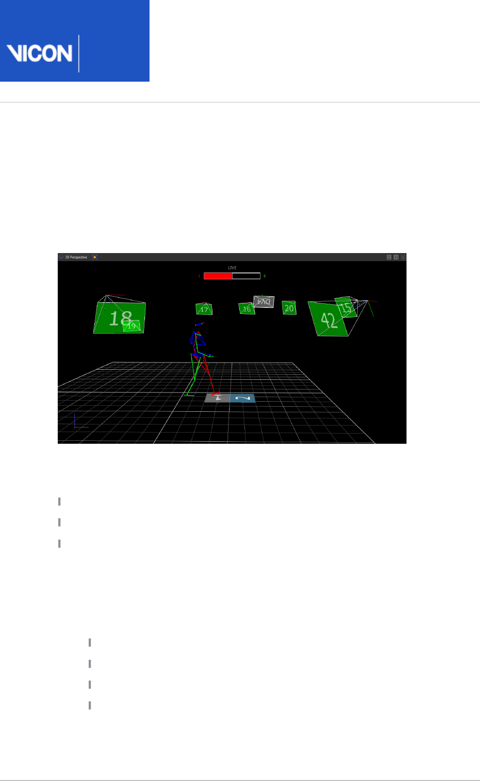
Nexus
User
Guide
Vicon Motion Systems Ltd. 26-Oct-2018 Page of 146 240
1.
2.
Automatically assess foot strikes
In clinical gait trials for kinetic analysis involving one or more force plates, Vicon Nexus
can automatically provide an indication of whether or not the foot is correctly
positioned and is producing valid data for your live trials. Nexus displays this
information on screen. This can save you time when you are assessing each foot strike
to decide whether it is valid.
As each strike is detected, or is determined to be invalid, the box representing the force
plate in the view turns the appropriate color:3D Perspective
: left foot strikeRed
: right foot strikeGreen
: invalid strikeDark gray
Counters on either side of the force plate box show how many valid strikes have been
detected for the left foot and the right foot during the current session.
To use auto-detection of foot strikes:
Before you begin, ensure that you have:
Calibrated the Vicon system.
Applied the appropriate marker set to the subject.
Ensured that you have a valid subject in Nexus.
Connected and configured one or more force plates.
On the menu (or in the view, right-click to access the Windows 3D Perspective
context menu), click and in the dialog box, ensure Footstrike Monitor Settings
the options for foot strikes are as required:
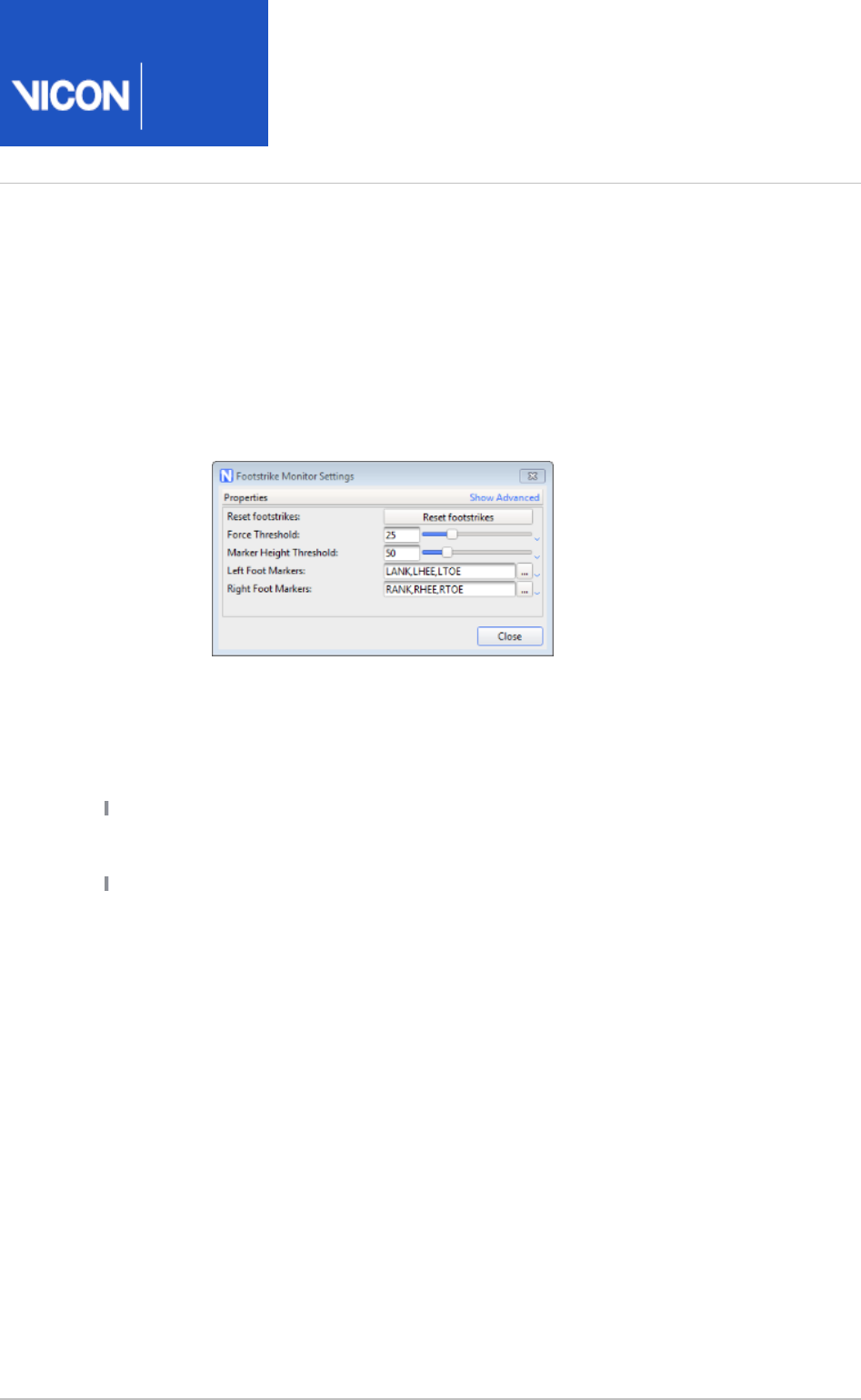
Nexus
User
Guide
Vicon Motion Systems Ltd. 26-Oct-2018 Page of 147 240
2.
a.
b.
c.
d.
3.
Reset footstrikes button enables you to reset the foot strike counters.
Force Threshold: Minimum force required on force plate to produce foot
strike
Marker Height Threshold: Minimum height of foot marker above force
place for foot to be recognized for foot strike
Left and : Comma-separated list of names of one or Right Foot Markers
more markers that define the segment (i.e. foot) that will strike the plate.
In the dialog box (press F7), ensure that is selected and that Options Footstrikes
the display options for , , and are as required.Font Size Opacity Background Color
To reset foot strike counters:
Right-click anywhere in the workspace and then click .Reset
or
Press CTRL+SHIFT+R
Using multiple foot plates
If your trial requires multiple force plates, they are laid out in the order of the force
plate IDs (that is, FP1 is furthest left/uppermost depending on the position of the force
plate box).
Strikes straddling two force plates are marked invalid. However, if required they can be
processed by the pipeline operation, by selecting Process Dynamic Plug-in Gait Model
the option.Allow cross-plate strikes
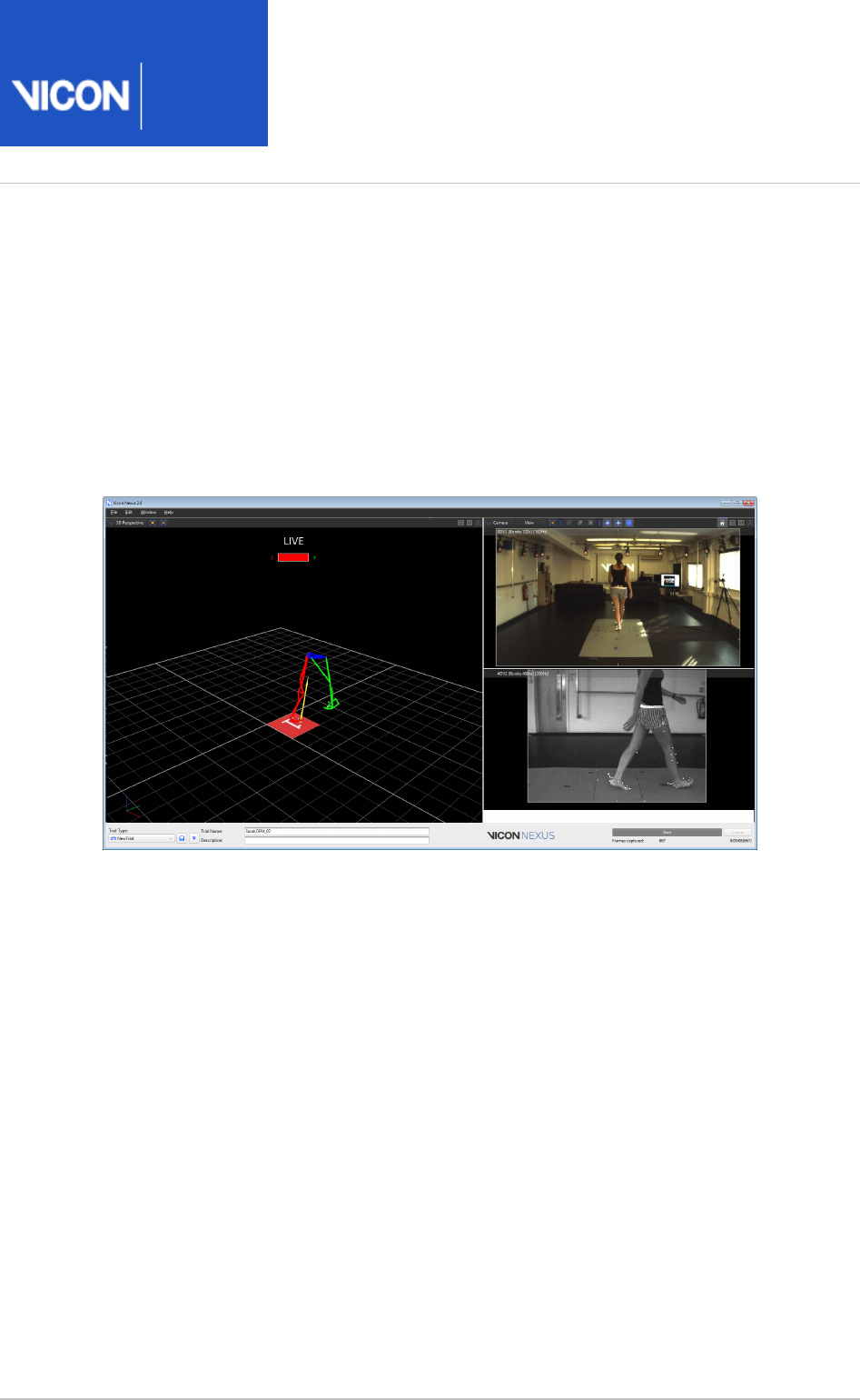
Nexus
User
Guide
Vicon Motion Systems Ltd. 26-Oct-2018 Page of 148 240
1.
2.
a.
b.
c.
Use Simple Capture Mode
Simple Capture Mode enables you to use a workspace that maximizes your view of the
capture volume and exposes a focused subset of controls required for repeated
captures, allowing you to concentrate on the movement you are capturing.
In , only the currently selected view type is displayed, together Simple Capture Mode
with controls that enable you to specify the trial type, name, and description, and to
start and stop (or cancel) captures.
To display a simplified capture view:
Ensure that you have set up your Vicon system as required, that Nexus is in Live
mode, and that you have set up your trial types, including any post-capture
pipeline required, auto-start triggers, etc. (For information on setting up trials,
including pipelines and triggers, see Capture the required movement on page 137
and .)Automatically start and stop capture on page 140
By default, Simple Capture Mode displays the same view as the current
workspace. You can customize the view to include other panes (eg, a video pane
alongside the ), as described in the following steps.3D Perspective
Associate a custom view type with . To do this:Simple Capture Mode
Open the dialog (press F7) and on the left click Options Simple Capture
.Mode View Options
On the right, from the list, select .View Type On
From the list, select one of the User Specified Simple Capture Mode View
following:

Nexus
User
Guide
Vicon Motion Systems Ltd. 26-Oct-2018 Page of 149 240
2.
c.
3.
4.
5.
To use the Vicon-supplied view type (which displays the Simple Capture
view pane with a view on the left, and views with 3D Perspective Camera
video cameras selected on the right, as shown above), ensure Simple
is selected; orCapture
To use your own view type (for a reminder of the controls that enable
you to define and save a view type, see Get to know Vicon Nexus on
), select the required option.page 21
Turn on Simple Capture Mode. To do this:
On the menu, select ; orWindow Simple Capture Mode
Press CTRL+H
The simplified capture view that you selected in the dialog box is Options
displayed.
To capture trials, at the bottom right of the Simple Capture view, click .Start
To exit Simple Capture Mode, either press Esc, or press CTRL+H again. (You can
also click the menu and clear .)Window Simple Capture Mode

Nexus
User
Guide
Vicon Motion Systems Ltd. 26-Oct-2018 Page of 150 240
1.
2.
Reconstruct and label movement trials
After you have calibrated a labeling skeleton for your subject (see Prepare a subject on
) and captured the required movement of the subject in a trial or series of page 108
trials (see ), you must reconstruct and label the Capture movement trials on page 136
raw camera data to create 3D markers. You can do this as a separate step, as described
below, or you can specify a pipeline that includes and in the Reconstruct Label Post-
(see ), so that Capture Pipeline Setup Capture the required movement on page 137
these operations run straight after capture.
Note
Note that you can choose to reconstruct and then label separately, or run
both operations together, by clicking either the button or the Reconstruct
button on the Nexus toolbar, or by configuring and Reconstruct and Label
running the equivalent pipeline operations. Normally, you would use
alone if you are working on a labeling skeleton template (VST), Reconstruct
but if you are processing movement trials.Reconstruct and Label
To reconstruct and label trial data:
Display the subject whose data is to be reconstructed in either of the following
ways:
If you have just captured a trial, ensure that the raw marker data for the
subject in the capture volume is still visible in a view and in the Camera
pane, ensure Nexus is in or mode; orResources Offline Pause
On the tab, open the desired trial file containing raw trial Data Management
data for the subject.
Do one of the following, depending on whether you need to adjust the
reconstruct and labeling settings:
To run the operations without viewing and changing their settings, on the
Nexus toolbar, click the button.Reconstruct and Label
This runs the operation defined in the Reconstruct and Label Pipeline Tools
pane.
Or
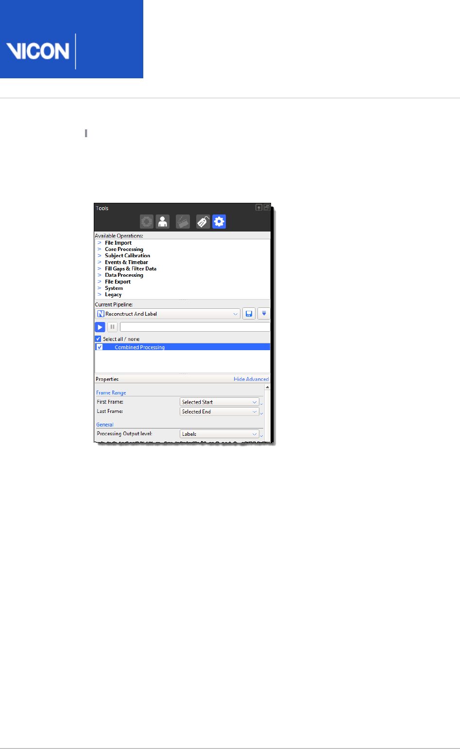
Nexus
User
Guide
Vicon Motion Systems Ltd. 26-Oct-2018 Page of 151 240
2.
To view and/or change the operations, on the pane, from the Pipeline Tools
list, select . In the list of current Current Pipeline Reconstruct And Label
operations, click on to select it. set the Combined Processing Processing
to the required level, for example, , and specify any other Output level Labels
required properties.
The pipeline progress bar indicates when the operation is complete.
You can now review the results and fill any gaps in the trial data. For information, see
.Review trials and fill gaps on page 152

Nexus
User
Guide
Vicon Motion Systems Ltd. 26-Oct-2018 Page of 152 240
1.
2.
3.
4.
5.
Review trials and fill gaps
When you have reconstructed and labeled your movement trials (see Capture
), you can review the results and fill any gaps in the trial movement trials on page 136
data.
If other Nexus users may have worked on your trial data, you may first want to
check on any processing that has been performed on the files (see Review
).processing history on page 153
Review data quality by playing through the trial using the and/or Time Bar
looking at the information on the data tab (see Quality Review data quality on
).page 154
If necessary, crop any large gaps at the beginning and/or end of the trial, either
manually or automatically (see ).Crop trials on page 165
Fill any gaps using either automatic or manual gap-filling (see Fill gaps in trial
).data on page 169
If required, you can add events to trials (see ).Add events to trials on page 180
After you have filled any gaps in your trial data, you can run the required modeling
operations. For more information on modeling, see Modeling with Plug-in Gait on page
.185

Nexus
User
Guide
Vicon Motion Systems Ltd. 26-Oct-2018 Page of 153 240
1.
2.
3.
Review processing history
You can review all processing that has been performed on a loaded trial file on the
tab in the pane. This ensures that, even if you have not History Communications
worked with the data before, you can work on the trial without missing or duplicating
processing steps. For example, if you work as part of group, when you open a trial that
someone else has worked on, you can immediately see what processing has occurred
(eg, filtering, gap-filling) and what settings were used.
Being able to view processing history helps you to understand your data, prevents
errors introduced by running certain operations more than once (eg, filtering), and
reduces the need to reprocess data because its current state is not well known.
To view processing history:
Open a trial.
In the pane, click the tab.Communications History
A summary of the data processes and major events is displayed.
To display information about a particular event, click on the relevant event.
Details about the settings used to run the event are displayed in the Property
and columns on the right.Value
In the field, you can add notes that will be useful to you or anyone else Notes
working with the same trial. Your notes are saved with the trial.
Note
Processing history is available only for files processed in Nexus 2.3 and above.
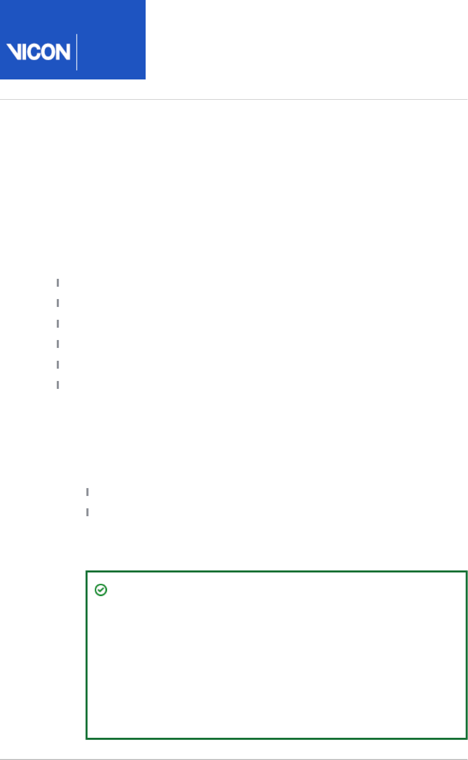
Nexus
User
Guide
Vicon Motion Systems Ltd. 26-Oct-2018 Page of 154 240
1.
2.
3.
4.
Review data quality
To enable you to review the data you captured in your movement trials (see Capture
), Vicon Nexus offers a number of tools. You can use the movement trials on page 136
time bar to manually scrub through the trial, or to assess your trials quickly and easily,
you can use the automated data quality features of Nexus.
For more information, see:
Review trial data using the time bar on page 154
Assess trial health with the data Quality pane on page 156
Detect gaps in the Graph view on page 158
View gaps with the Data Correction view on page 159
View data quality across a trial on page 161
Navigate to gaps using the data quality features on page 163
Review trial data using the time bar
To review trial data using the time bar:
Display reconstructed and labeled markers in either of the following ways:
Ensure that a trial you have just captured has been reconstructed and labeled.
From the tab, open a previously captured and labeled trial.Data Management
In the pane, ensure Nexus is in mode.Resources Offline
Display a view and optionally a view.3D Perspective Graph
Tip
To automatically display both views, in the list on the Nexus View Type
toolbar, select . Using a split layout with both a 3D Data Correction
Perspective and a Graph view enables you to display the results of your
editing actions and to select specific trajectories, frame ranges, and
gaps in trajectories. Since the graphs indicate what changes have been
made to the data and by which tool, you can immediately see the results
of any edits you have made and determine if you want to change it
again or adjust the data, using a different tool in the section.Gap Filling

Nexus
User
Guide
Vicon Motion Systems Ltd. 26-Oct-2018 Page of 155 240
4. Play back the desired portion of the trial:
Full trial: In the controls at the left end of the time bar, click Play to start
playing the trial data. The data plays through to the end and restarts at the
beginning if you do not click Stop.
Range of frames: Do one of the following:
To manually adjust the range, move the blue triangles that indicate the start
and end of the selected range of frames (also known as the region of
interest) along the timeline; or
On the time bar, right-click and then click . In the Set Region-of-Interest Set
dialog box, specify the and .Region of Interest Start Frame End Frame
Individual frame: Move the blue vertical line that indicates the currently
selected time along the timeline to manually locate the desired frame, or right-
click on the time bar, click and enter the number of the Set Current Frame
required frame.
Tip
To display a context menu in which you can reset the timescale on the
timeline, set the playback speed, or specify the length of trajectory tails, click
the ellipsis (...) in the time bar controls, or right-click the time bar.
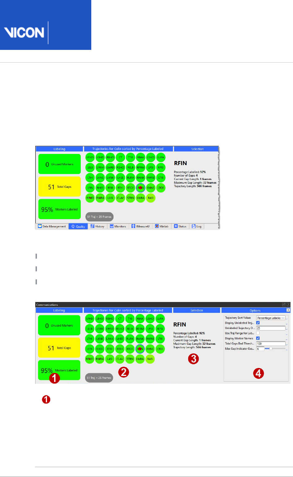
Nexus
User
Guide
Vicon Motion Systems Ltd. 26-Oct-2018 Page of 156 240
Assess trial health with the data Quality pane
The data pane, a tab in the window, provides both a broad Quality Communications
overview of data quality for a subject across the entire trial and a way to examine the
health of individual trajectories. It also enables you to navigate to the highlighted
issues.
The three most common data issues that you need to find and resolve are:
Missing markers (usually knocked off before capture)
Unlabeled or incompletely labeled trajectories
Gaps in trajectories
The tab helps you to find this information:Quality
Overview of the health of the whole trial (Labeling column) The text in each
rectangle indicates the number of unused markers, any gaps, and the
percentage of markers labeled. As a quick indicator, to enable you to assess
whether to continue working with the trial, the color green indicates good
health, red indicates probable major issues, and colors between the two
(yellow, amber, orange) indicates that the overall health of the trial lies
somewhere between these extremes.
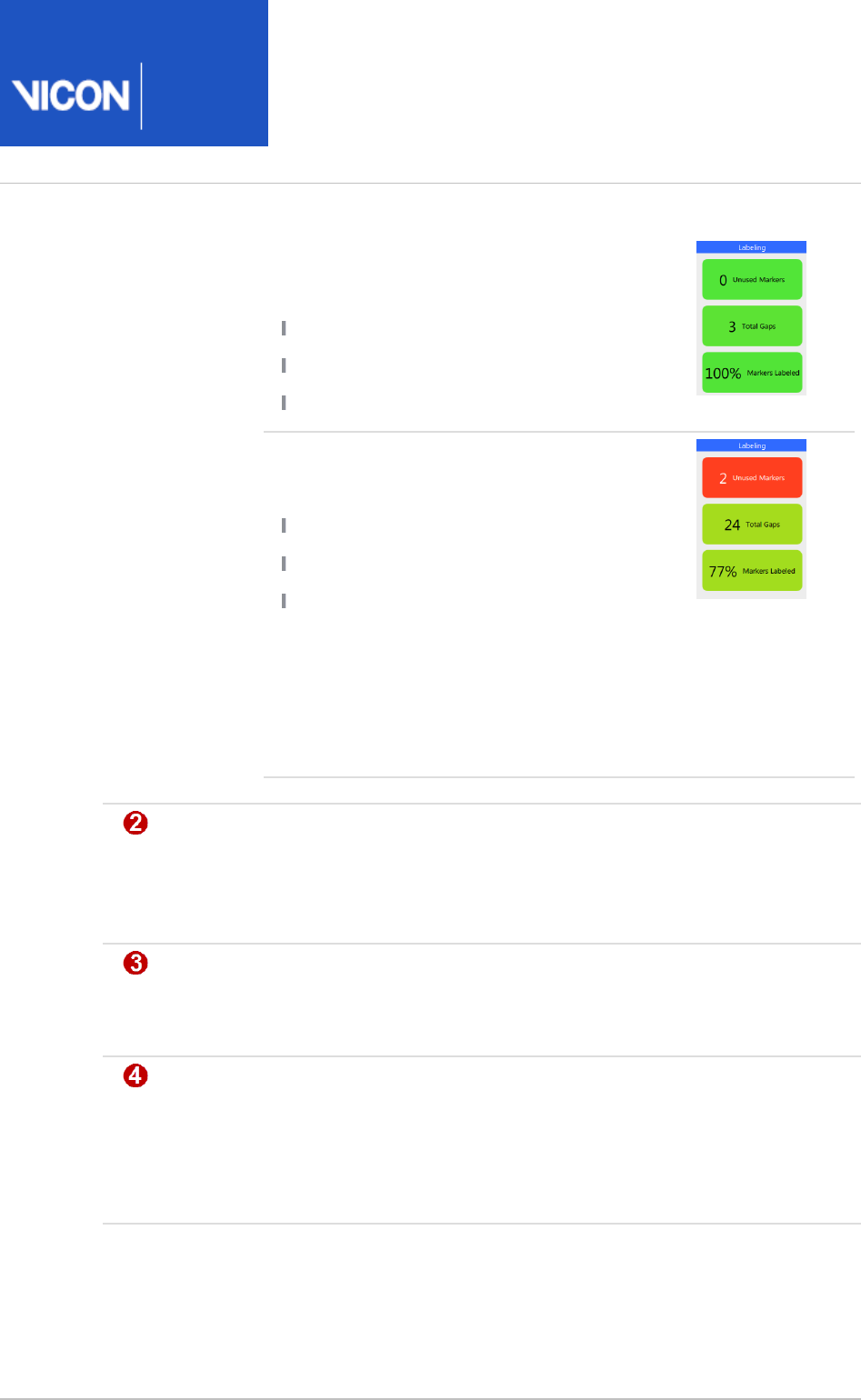
Nexus
User
Guide
Vicon Motion Systems Ltd. 26-Oct-2018 Page of 157 240
For example, a good trial, worth further
work, would be indicated by:
No missing markers
A high percentage of labeled markers
Only a small number of gaps.
A low quality trial, which would probably
have to be re-run, would be indicated by:
Missing markers, and/or
A high number of gaps, and/or
A lower percentage of labeled markers.
In this example, two required markers are
completely absent from the trial, so, without
further work, you would know that you
would have to either re-reconstruct or (more
likely) re-capture the trial.
Individual trajectories. If you hover the mouse over a blob, the blob displays
information about the trajectory. If you click on it to select it, information
about the trajectory is displayed in the column on the right. For more Selection
information, see .Navigate to gaps using the data quality features on page 163
General trial information/selected trajectory Information (Selection column). If
no blob is selected, general information about the currently loaded trial is
displayed. If a blob is selected, information about the trajectory is displayed.
Display options (Options column): Enables you to configure the display options
for the data tab. Alternatively, you can open the dialog box Quality Options
(F7), click on the left, and change the properties as Data Quality Panel Options
required. To save any changes to these settings, click the Save current
button in the dialog box.configuration Options
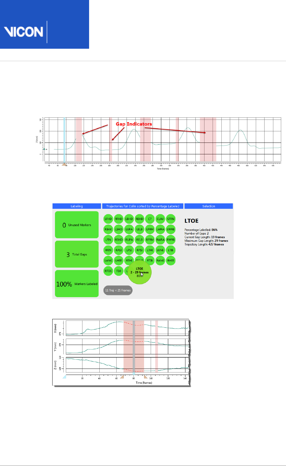
Nexus
User
Guide
Vicon Motion Systems Ltd. 26-Oct-2018 Page of 158 240
1.
2.
Detect gaps in the Graph view
The view enables you to view and fix gaps for a selected trajectory.Graph
To display gaps:
On the pane, click a trajectory blob that is reporting a gap.Quality
Gap indicators are displayed in pink in the view.Graph
To zoom in and out, CTRL+double-click on a gap indicator (the pink area) on the
graph.
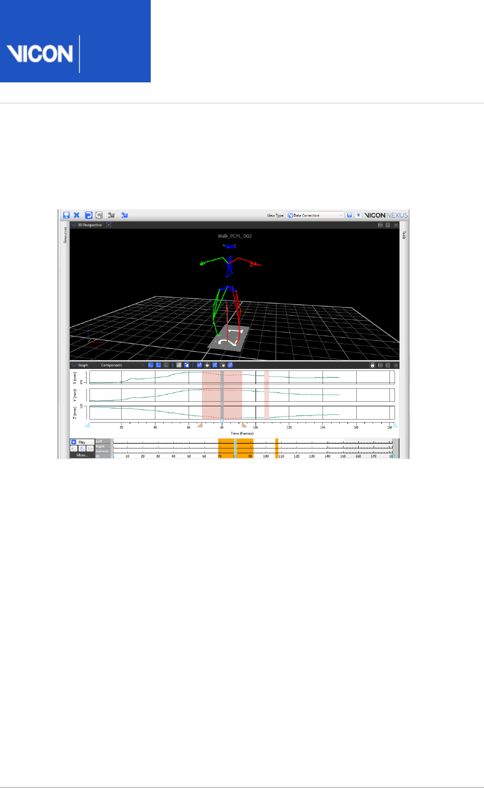
Nexus
User
Guide
Vicon Motion Systems Ltd. 26-Oct-2018 Page of 159 240
View gaps with the Data Correction view
The default view type displays a view above a Data Correction 3D Perspective Graph
view.
You can turn view on or off in the dialog box, as described Data Correction Options
below.
When the view is turned on, it is automatically displayed when you Data Correction
navigate using the data pane.Quality
If you would prefer the view to appear differently (for example, Data Correction
displaying the above the view), you can save your own preferred Graph 3D Perspective
view and select this instead.
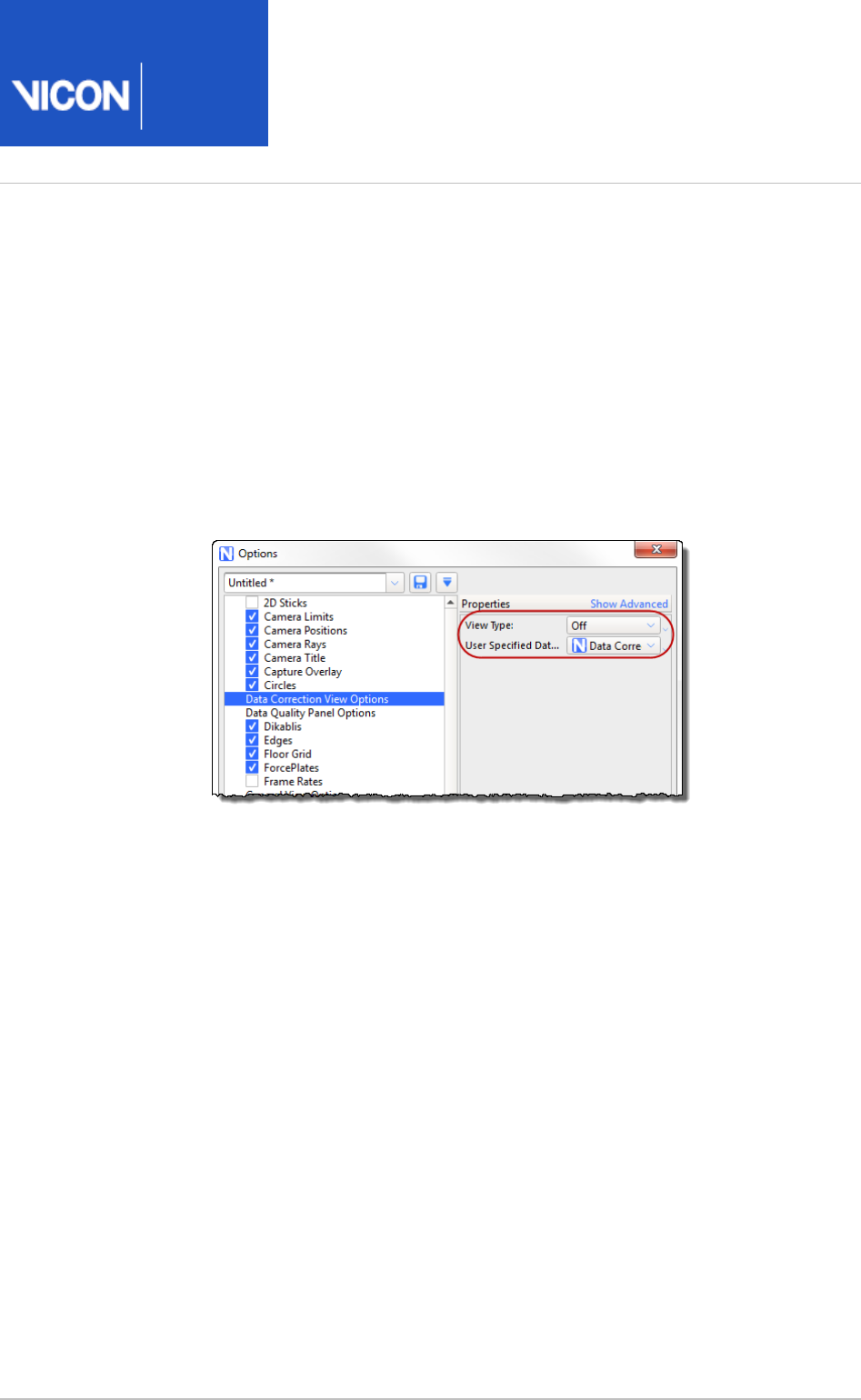
Nexus
User
Guide
Vicon Motion Systems Ltd. 26-Oct-2018 Page of 160 240
1.
2.
a.
b.
To configure the view:Data Correction
Open the dialog box (F7).Options
Click on on the left and change the properties as Data Correction View Options
required on the right:
If you want to display this view type automatically when you are
navigating via the tab, ensure is set to .Quality View Type On
If you have saved a different view type to be displayed when you are using
the tab, ensure it is selected in the Quality User Specified Data Correction
field.View
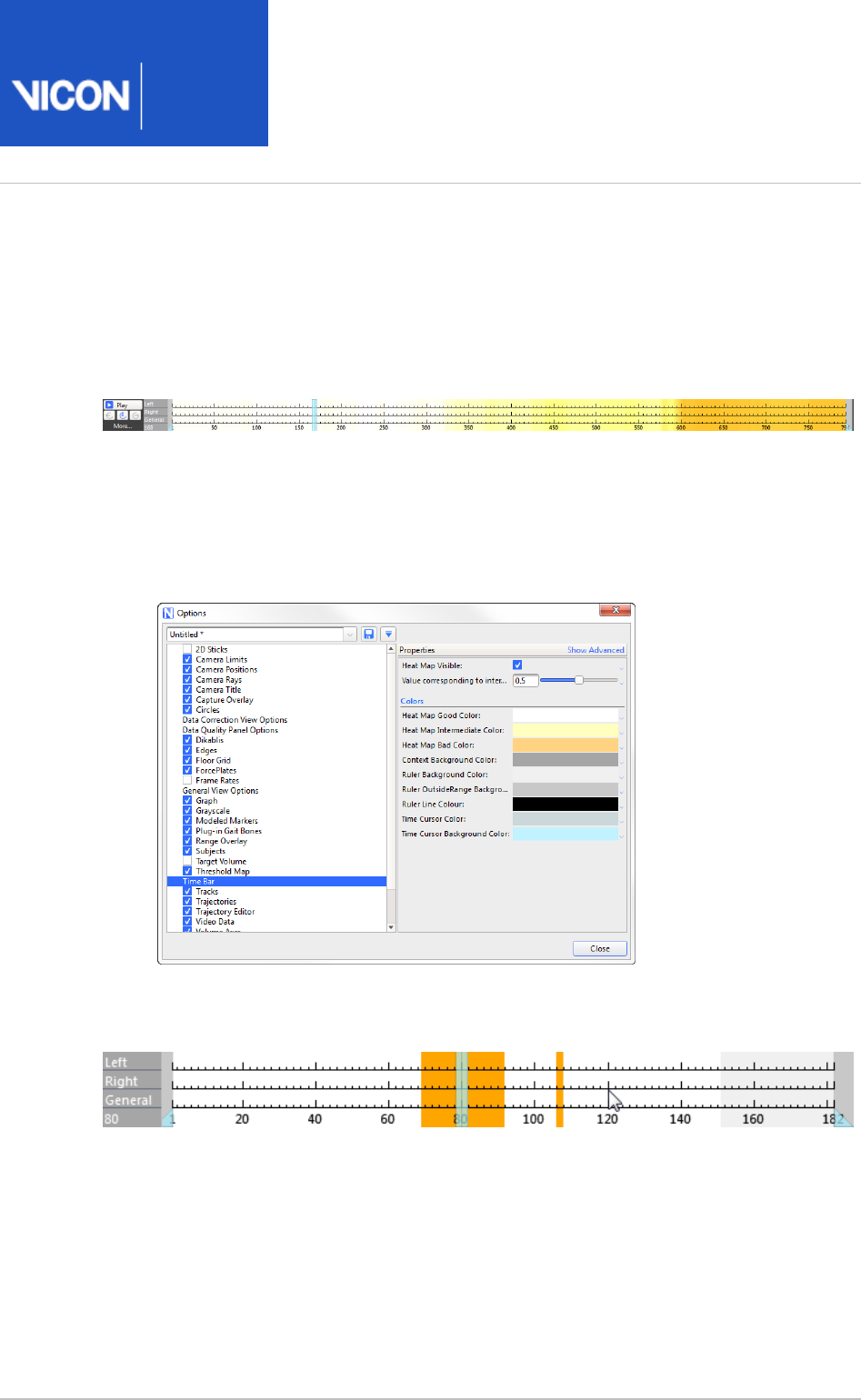
Nexus
User
Guide
Vicon Motion Systems Ltd. 26-Oct-2018 Page of 161 240
1.
2.
View data quality across a trial
In addition to viewing data quality on the Quality tab and Graph and Data Correction
views, you can also view data quality as a heat map on the time bar, to get an overall
picture of the current trial.
To turn on the heat map overlay:
In the dialog box (F7), click on on the left, and select the Options Time Bar Heat
check box on the right.Map Visible
If required, change the colors of the heat map.
When you click on a trajectory on the tab, the time bar shows gaps for the Quality
selected trajectory.
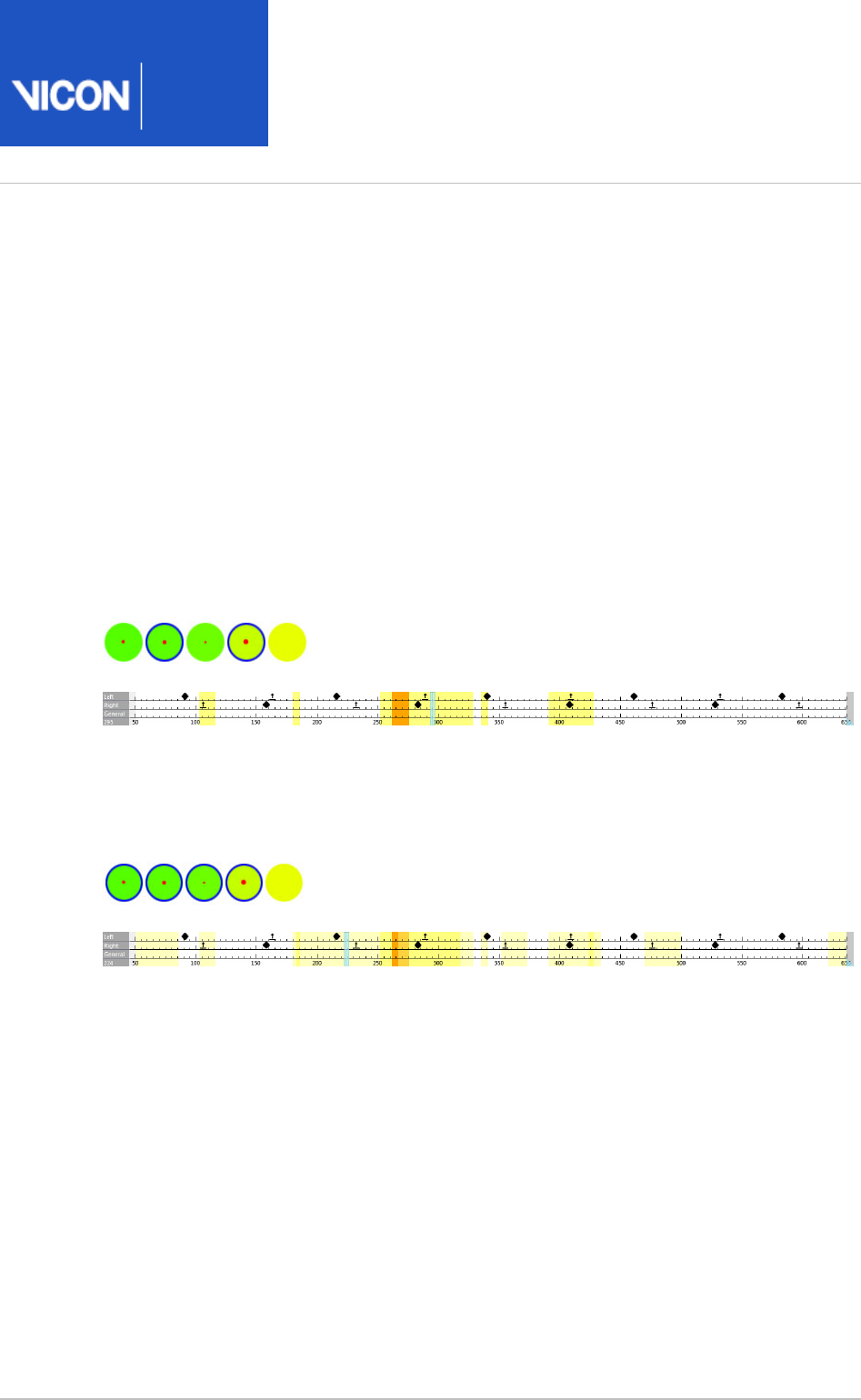
Nexus
User
Guide
Vicon Motion Systems Ltd. 26-Oct-2018 Page of 162 240
Viewing data quality for multiple trajectories
To select multiple trajectories, on the tab, CTRL+click the required blobs.Quality
When multiple trajectories are selected, the heat map's color gradient system is
activated.
Lighter colors show where one of the trajectories has a gap but other selected
trajectories do not. Darker areas show where a number of selected trajectories has a
gap.
Two trajectories selected
The following images show two trajectories selected. The darker area indicates gaps in
both trajectories.
More trajectories selected
As more trajectories are added the view starts to morph from individuals gaps for one
or two trajectories, to areas in the volume/time where there are issues.
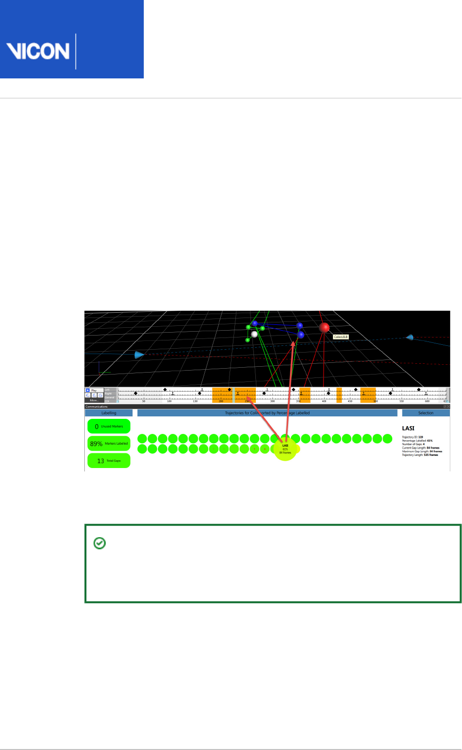
Nexus
User
Guide
Vicon Motion Systems Ltd. 26-Oct-2018 Page of 163 240
1.
2.
Navigate to gaps using the data quality features
Using the tab and the view type, you can quickly navigate to Quality Data Correction
gaps in data, and use the , and options for a better view.Zoom Translate, Rotate
Quick navigation to gaps
To quickly navigate to gaps:
On the tab, click on a trajectory blob.Quality
Immediately, the time bar and view pane displays the first gap (if any) for the
selected trajectory.
To move to the next gap or previous gap for the selected trajectory, press the hot
keys CTRL+8 and CTRL+7 respectively.
Tip
On the data tab, you can move to the next trajectory and Quality
previous trajectory by pressing CTRL+PgUp and CTRL+PgDown.
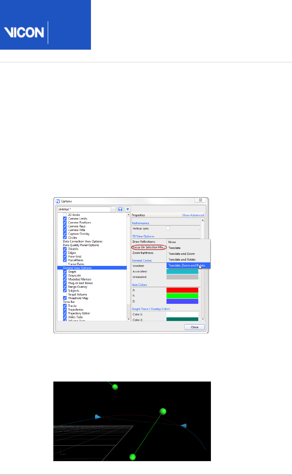
Nexus
User
Guide
Vicon Motion Systems Ltd. 26-Oct-2018 Page of 164 240
1.
2.
3.
4.
Get a better view of gaps
The Zoom, Translate and Rotate options for viewing a gap make it easier to zoom in on
and fix selected gaps.
To view gaps more clearly:
In the dialog box (F7), click on the left.Options General View Options
In the pane on the right, in the section, click the Properties 3D View Options
list.Focus on Selection Mode
To display a zoomed view that rotates the workspace to a flat perspective of the
gap, click .Zoom, Translate and Rotate
On the tab, click the blob for the trajectory whose gaps you want to Quality
examine.
The view zooms in and rotates as necessary to clearly show the 3D Perspective
selected trajectory's first gap.

Nexus
User
Guide
Vicon Motion Systems Ltd. 26-Oct-2018 Page of 165 240
Crop trials
For trials where the subject starts outside the volume, moves into the volume and then
exits, cropping the start and end of the trial removes unwanted frames where the
subject was not fully in the volume.
Before you fill gaps in your trial data, it's a good idea to remove these start and end
frames as they are likely to contain large gaps and other invalid data. You can do this
automatically while capturing (see Trigger data capture on labeling percentage on
), or for trials that have already been saved, you can crop trials manually or run page 141
a pipeline operation to do this automatically.
Cropping a trial affects only the .c3d file. The raw files remain unchanged.
Tip
If you add gait cycle events and then crop a trial, you will probably also want to
delete events that are outside the cropped region. For information on how to
do this, see . Delete events that are outside the region of interest on page 183
For more information, see:
Manually crop a trial on page 166
Automatically crop a trial on page 167

Nexus
User
Guide
Vicon Motion Systems Ltd. 26-Oct-2018 Page of 166 240
1.
2.
3.
Manually crop a trial
You can use tools on the time bar to remove unwanted frames at the start and end of
your trials.
To manually crop a trial:
Ensure the required trial is reconstructed and labeled (see Reconstruct and label
).movement trials on page 150
On the time bar, do one of the following:
Move the range indicators (blue triangles) to exclude the unwanted frames at
the beginning and/or end of the trial; or
Right-click and then click . In the Set Region-of-Interest Set Region of Interest
dialog box, specify the and .Start Frame End Frame
The gray shaded area represents the cropped frames of the trial.
Right-click on the time bar and click .Zoom to Region-of-Interest
You can now fill any remaining gaps.
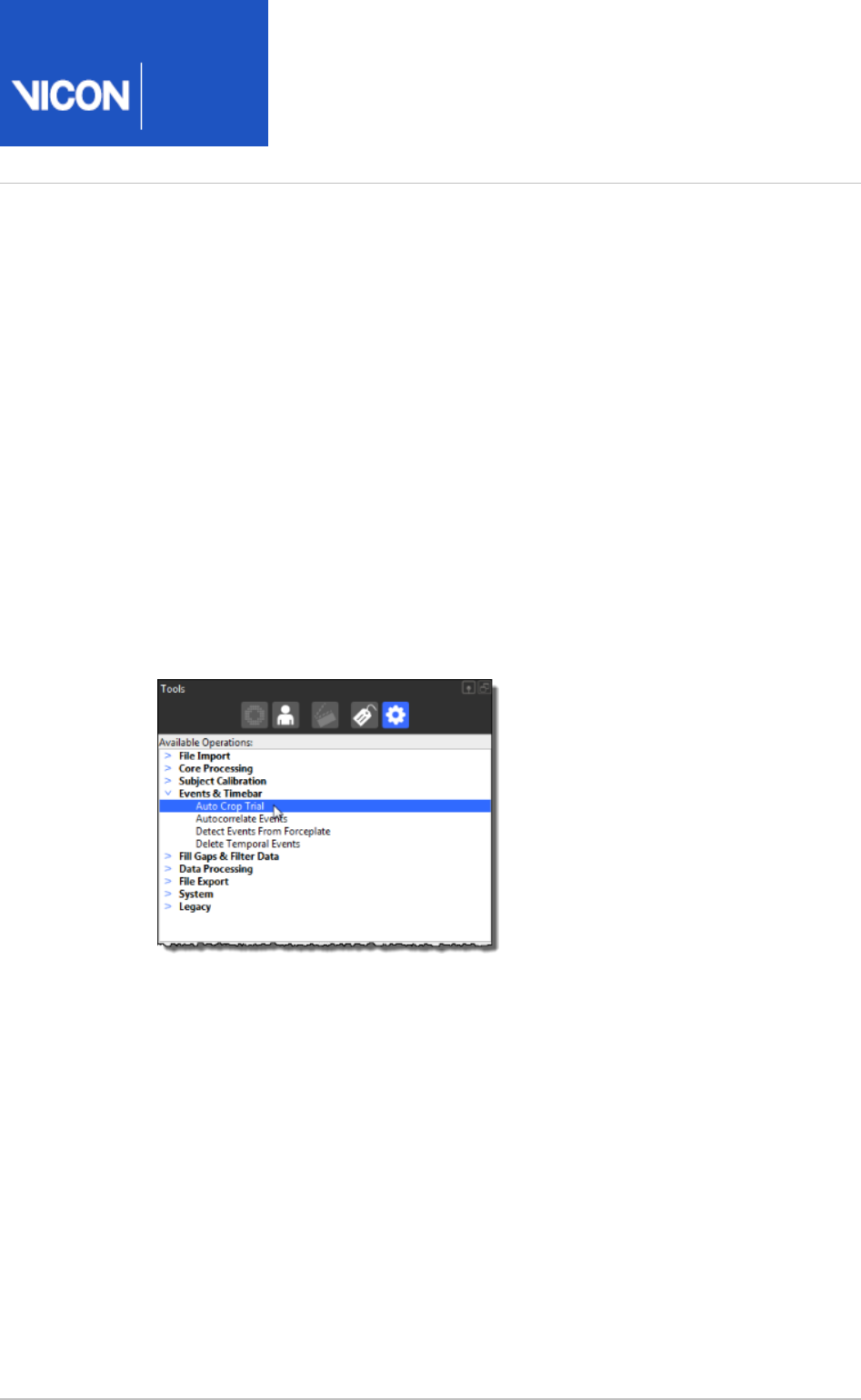
Nexus
User
Guide
Vicon Motion Systems Ltd. 26-Oct-2018 Page of 167 240
1.
2.
3.
4.
Automatically crop a trial
Nexus can save you time and effort by automatically determining the first and last
frame where the subject is fully in the volume
When you run the autocrop operation, Nexus automatically zooms the time region of
interest to the points where the subject first fully enters and then leaves the volume.
To set up auto-cropping:
Ensure the required trial is reconstructed and labeled (see Reconstruct and label
).movement trials on page 150
In the pane, click the tab and in the list, Tools Pipelines Available Operations
expand .Events & Timebar
Double-click the pipeline operation to add it to the current Auto Crop Trial
pipeline.
In the list, click and in the pane, Current Pipeline Auto Crop Trial Properties
ensure that the and options are set to the beginning and end First Last Frame
frames during which the subject enters and leaves the volume.
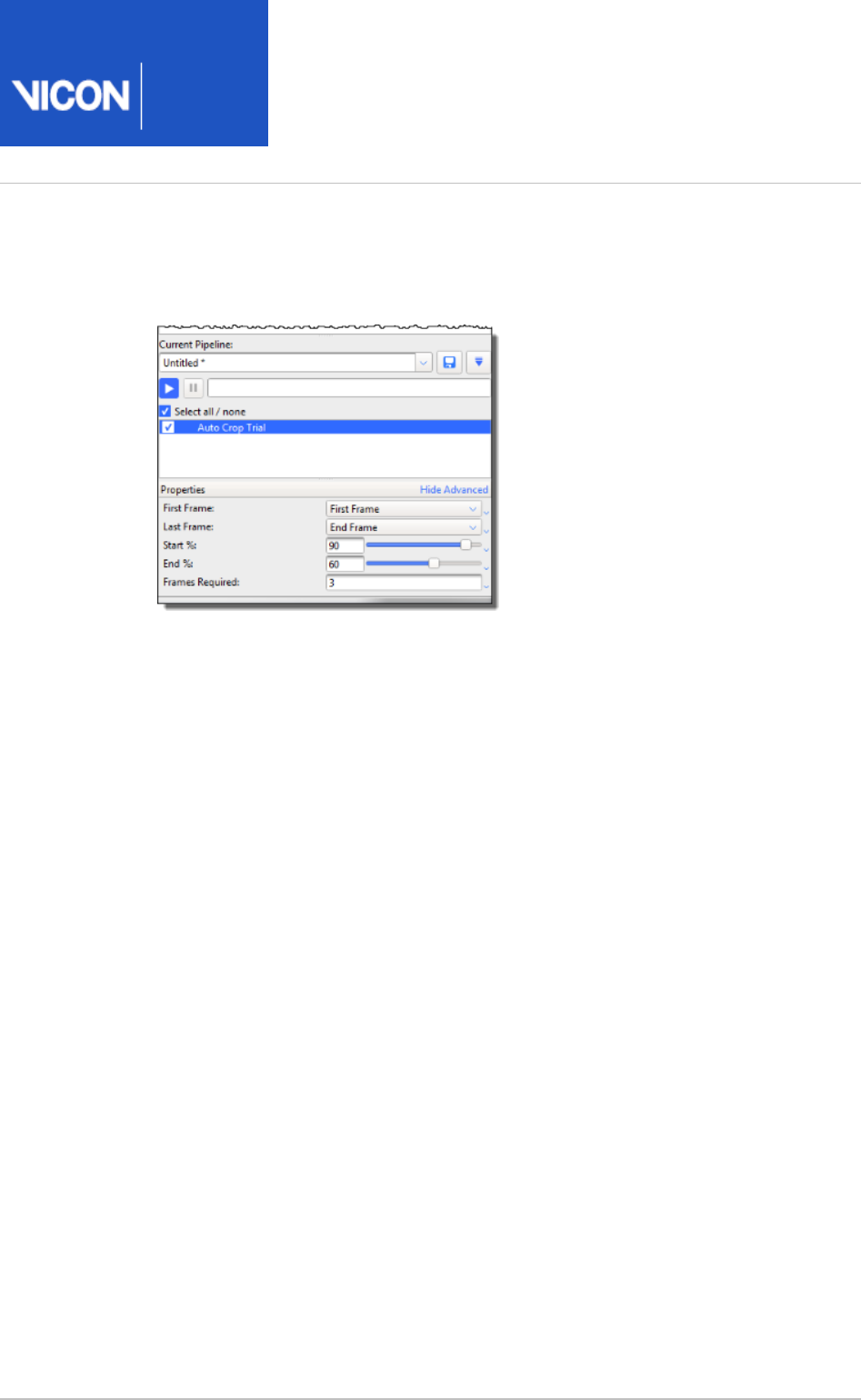
Nexus
User
Guide
Vicon Motion Systems Ltd. 26-Oct-2018 Page of 168 240
5.
6.
7.
Set the and options to the required minimum percentage of Start End (%)
markers (ie, the percentage of markers expected from the total number of
markers in your subject's labeling skeleton) that must be labeled in each case.
If necessary, adjust the to set a minimum number of frames Frames Required
where the criterion must be met. This is helpful if early single frames of Start %
data meet the %, but the point at which the trial is intended to start (ie, the point
at which the % is maintained over a number of frames) is later in the trial.
Run the operation.Auto Crop Trial
The trial is automatically cropped to the frames you have selected.
You can now fill any remaining gaps.
Nexus
User
Guide
Vicon Motion Systems Ltd. 26-Oct-2018 Page of 169 240
Fill gaps in trial data
When Nexus reconstructs each marker on a subject, ideally it produces a smooth
trajectory throughout the trial. Realistically, there may be frames with breaks in
trajectories due to some markers that could not be reconstructed or spurious data.
Tip
Auto Gap Fill attempts to fill all gaps in the trial data. For this operation to
work well, you are likely to need to change the default property settings,
including the gap size. For data containing large gaps, you are advised to
review and manually fill the large gaps first, using the tools in the Label/Edit
pane, and/or cropping out any unwanted frames with large gaps that Tools
occur at the start or end of the trial.
For information on cropping frames at the start and end of the trial data, see
.Crop trials on page 165
For more information, see:
Manually fill gaps in trial data on page 170
Automatically fill gaps in trial data on page 177
Example of creating a custom pipeline for gap-filling on page 179
In addition, a Vicon , showing gap-filling operations, including Nexus 2 tutorial video
many additional tips and examples, is available on YouTube.
Note
As the videos were recorded using an earlier version of Nexus 2, you may
notice small differences in the user interface.
For additional tips on issues you may encounter when using manual labeling, see
in the .Improve manual labeling
Vicon Nexus Reference Guide

Nexus
User
Guide
Vicon Motion Systems Ltd. 26-Oct-2018 Page of 170 240
1.
2.
3.
4.
Manually fill gaps in trial data
You can manually fill any gaps in the reconstructed and labeled trial data by using the
tools in the pane.Label/Edit Tools
As well as automatically filling gaps (see ), Automatically fill gaps in trials on page 177
you can manually fill gaps to correct any errors or inconsistencies in the reconstructed
and labeled trial data.
To manually fill gaps in reconstructed and labeled data:
Display reconstructed and labeled markers, ensure Nexus is in mode, and Offline
display a view and optionally a view, as described in 3D Perspective Graph
.Review trial data using the time bar on page 154
Unless you have already cropped your trial (see ), to Crop trials on page 165
simplify cleaning up your data, set the region of interest of the trial that you wish
to analyze. For example, if the capture includes the subject entering and leaving
the capture volume, Vicon recommends that you set the range of frames to
exclude these parts of the capture, as they are likely to include large gaps. To do
this, on the time bar, move the blue range indicator triangles to select a range of
frames and then right-click and click .Zoom to Region-of-Interest
In the tree, ensure that the desired subject is selected (when selected, Subjects
there is a check mark in the check box).
In the tools pane, in the section, any markers whose Label/Edit Gap Filling
trajectories contain gaps within the selected range of frames are listed in the
column, with the number of gaps for each trajectory identified in the Trajectory
column and the largest gap length in the column.#Gaps Max Gap Length
Tip
To jump to the largest gap for a particular trajectory, double-click in its
column. To change the sort order of the columns, click Max Gap Length
the column headings.
In the column, click on the trajectory whose gaps you want to fill.Trajectory
Nexus automatically selects the gap by placing the current time in the middle of
the gap and positioning the gap range selectors (blue cones) at the start and end
of the gap. A red dotted line is displayed to preview the shape of the trajectory if
a spline fill editing operation is run. If you can't see a red dotted line, in the Label
pane, in the section, hover the mouse pointer over the /Edit Tools Gap Filling Fill
button in the area to display a tooltip.Spline Fill

Nexus
User
Guide
Vicon Motion Systems Ltd. 26-Oct-2018 Page of 171 240
4.
5.
6.
7.
In the section, view the range values to identify the size of the gap and Range
use the buttons to navigate between the gaps in the selected trajectory:
Prev Gap: Navigate to the previous gap in the selected trajectory. This button
is available only if there are gaps in the trajectory before this point.
Left edit range: The frame before the start gap range selector, indicating the
start of the gap that will be filled in.
Right edit range: The frame after the end gap range selector, indicating the
end of the gap that will be filled in.
Next Gap: Navigate to the next gap in the selected trajectory. This button is
available only if there are gaps in the trajectory after this point.
If required (for example, if the data leading up to the gap is noisy), to extend the
edit range beyond the gap, in the view, drag the gap range 3D Perspective
selectors (blue cones).
If you need to adjust the size of the cones for easier viewing or
selection, open the dialog box (press F7) and click Options Trajectory
. Adjust the value of as required (the default is 10 pixels).Editor Radius
Use the appropriate fill tool to generate data to fill the selected gap.
Tip
If your chosen tool is unavailable, hover the mouse pointer over the
unavailable button to display a tooltip that explains how to use it.
The fill options are:

Nexus
User
Guide
Vicon Motion Systems Ltd. 26-Oct-2018 Page of 172 240
7.
8.
Spline Fill: Performs a cubic spline interpolation operation to fill the currently
selected gaps. Use it when you have suitable frames with no gaps on either
side of the gap. If there are gaps in these frames, the fill is rejected and you will
need to choose a different gap-filling method. For more information, see Fill
.gaps with Spline Fill on page 173
Pattern Fill: Uses the shape of another trajectory without a gap to fill the
selected gap. Use this tool only if there is a suitable marker with a trajectory
similar to the one whose gap you wish to fill. This is typically the case when the
trajectories originated from markers attached to the same segment, such as
those attached to the ankle or heel. For more information, see Fill gaps with
.Pattern Fill on page 174
Rigid Body Fill: This option is the Nexus equivalent of the Replace 4 option,
which is available in BodyBuilder. Use this option when a rigid or semi-rigid
relationship exists between markers. For more information, see Fill gaps with
.Rigid Body Fill on page 175
Kinematic Fill: This option uses information about the connection of markers
to segments in the labeling skeleton template (VST). For this option to be
available, you may first need to run the pipeline operation, by Kinematic Fit
clicking the button on the Nexus toolbar.For more information, see KinFit Fill
.gaps with Kinematic Fill on page 176
Cyclic Fill: For trials that contain captured data that is cyclic in nature (for
example, when a motion on a treadmill or other repetitive motion is captured),
this option uses patterns from a missing marker from earlier or later gait cycles
to fill gaps. (If you want to modify the supplied operations, you can change and
run the pipeline operation instead.) For more information, see Fill Gaps - Cyclic
.Fill gaps with Cyclic Fill on page 176
Tip
For data with smaller gaps, you could use a processing pipeline
containing the operation to automatically fill gaps.Fill gaps (Woltring)
In the chosen gap fill area, click the appropriate option:
To have Nexus fill the selected gap, click .Fill
To have Nexus fill all the gaps in the selected trajectory with the currently
chosen type of gap filling, click . This feature is particularly useful when, for All
example, you have 7 gaps in LASI and you want to fill them all with a Rigid Fill
from the other pelvic markers (RASI, RPSI, LPSI).

Nexus
User
Guide
Vicon Motion Systems Ltd. 26-Oct-2018 Page of 173 240
8.
9.
10.
1.
2.
3.
For or , you can click before clicking or .Pattern Fill Rigid Body Fill Auto Fill All
When a gap is filled, Nexus reduces the entry in the column by one and #Gaps
selects the next gap.
When all gaps for the selected trajectory have been successfully filled, the entry
for the trajectory is automatically removed from the list and Nexus Trajectory
selects the next trajectory.
Repeat steps 4–8to fill all the gaps for all trajectories.
On the Nexus toolbar, click the button to save the trial. You can then Save
perform any other processing that is required, such as running pipelines.
Tip
To save time, you can create custom pipelines that include the type of gap-
filling operations that you commonly perform, such as Rigid fills for Pelvis and
Head markers. For more information, see Example of creating a custom
.pipeline for gap-filling on page 179
Use the gap filling options
The following information provides instructions on how to use the Vicon Nexus gap-
filling options. (For detailed information about the Nexus gap-filling algorithms, see the
FAQ on the Vicon website.)What Gap Filling Algorithms are used in Nexus 2?
Fill gaps with Spline Fill
Ensure the required gap is selected (see Manually fill gaps in trial data on page
).170
Under , in the field, specify the maximum number Spline Fill Maximum gap length
of frames to spline fill (the default is 100 frames).
Click the appropriate button:
To have Nexus fill the selected gap, click .Fill
To have Nexus spline fill all the gaps in the selected trajectory, click .All
A cubic spline interpolation operation fills the specified gaps.

Nexus
User
Guide
Vicon Motion Systems Ltd. 26-Oct-2018 Page of 174 240
1.
2.
a.
b.
c.
a.
b.
Fill gaps with Pattern Fill
Ensure the required gap is selected (see Manually fill gaps in trial data on page
).170
Under , click or Pattern Fill Pick Source Auto:
If you click Pick Source:
The shape of the pointer changes to include a tooltip to guide you in the
selection of markers in the view. Initially, a tooltip with the 3D Perspective
text hangs from the cursor.Pick source marker
In the view, click a source marker whose trajectory is to be 3D Perspective
used to fill the gap of the target marker.
A green dotted line is displayed to preview the shape of the trajectory if a
pattern fill editing operation is run with the selected source model.
Nexus displays the name of the source marker at the bottom of the
section, so you can confirm that you have selected the desired Pattern Fill
trajectory.
In the section, click to have Nexus fill the selected gap (or Pattern Fill Fill
to fill all gaps in the selected trajectory), with the shape of the filled-in All
trajectory being similar to the trajectory of the source marker.
If you click Auto:
A suggested donor trajectory is listed in the space above the button Auto
and the suggested fill is displayed in green in the window. 3D Perspective
You can also view the suggested fill options as colored dotted lines in the
view.Graph
Do one of the following:
To accept the suggested donor, click or ; orFill All
To reject the suggestion and manually pick a source, click the Clear
button , click , then click (or CTRL+click selected donor Pick Source
to multi select), the required trajectory, and then click or .Fill All

Nexus
User
Guide
Vicon Motion Systems Ltd. 26-Oct-2018 Page of 175 240
1.
2.
a.
b.
a.
b.
Fill gaps with Rigid Body Fill
This option is the Nexus equivalent of the option, which is available in Replace 4
BodyBuilder.
Use it when a rigid or semi-rigid relationship exists between markers. For example:
Pelvis (LASI, RASI, LPSI, RPSI)
Head (LFHD, RFHD, LBHD, RBHD)
Ensure the required gap is selected (see Manually fill gaps in trial data on page
).170
In the area, click or .Rigid Body Fill Pick Source Auto
:If you click Pick Source
Click (or CTRL+click to multi select), the required trajectory
Click or .Fill All
If you click Auto:
Three trajectories are listed in the space above the button and the Auto
suggested fill is displayed in green in the window. You can 3D Perspective
also view the suggested fill options as colored dotted lines in the Graph
view.
Do one of the following:
To accept the suggested donor, click or ; orFill All
To reject the suggestion and manually pick a source, click the Clear
button , click , then click (or CTRL+click selected donor Pick Source
to multi select), the required trajectory, and then click or .Fill All

Nexus
User
Guide
Vicon Motion Systems Ltd. 26-Oct-2018 Page of 176 240
1.
2.
3.
4.
1.
2.
3.
4.
5.
Fill gaps with Kinematic Fill
This option uses information about the connection of markers to segments in the
labeling skeleton (VSK).
To provide the required kinematic data, ensure you have clicked the KinFit
button or run a pipeline operation that includes kinematic fitting.
Ensure the required gap is selected (see Manually fill gaps in trial data on page
).170
In the area, click and in the view Kinematic Fill Pick Segment 3D Perspective
select the segment from which the kinematics will be copied.
The suggested fill is displayed in purple in the view. You can also 3D Perspective
view the suggested fill options as colored dotted lines in the Graph view.
Do one of the following:
To accept the suggested donor, click or ; orFill All
To reject the suggestion and try again, click the button Clear selected donor
, click , then click (or CTRL+click to multi select), the required Pick Segment
trajectory, and then click or .Fill All
Fill gaps with Cyclic Fill
Ensure you have captured a trial containing repetitive motion.
Select the gap/range that is to be filled (see Manually fill gaps in trial data on
).page 170
In the view and the of the marker component, preview the 3D Perspective Graph
gap fill solution provided by Nexus.
If the suggested solution is acceptable, in the pane, ensure Label/Edit Tools Gap
is expanded.Filling
In the area, select the required option:Cyclic Fill
Fill Fills the currently selected range
All Attempts to fill all gaps in the selected trajectory.
The gap is filled with data based on other cycles of the same movement.
Nexus
User
Guide
Vicon Motion Systems Ltd. 26-Oct-2018 Page of 177 240
1.
2.
3.
Automatically fill gaps in trial data
You can automatically fill gaps using the button on the Nexus toolbar or Auto Gap Fill
the equivalent pipeline in the tools pane. This enables Auto-Intelligent Gap Fill Pipeline
you to quickly fill gaps in your trial, without having to choose which fill method is best
for each gap. You can do this in a one-click operation or, if you want to modify the
supplied operations, by changing and running the pipeline.Auto Intelligent Gap Fill
Tip
Auto Gap Fill attempts to fill all gaps in the trial data. For this operation to
work well, you are likely to need to change the default property settings,
including the gap size. For data containing large gaps, you are advised to
review and manually fill the large gaps first, using the tools in the Label/Edit
pane (see ), and/or cropping Tools Manually fill gaps in trial data on page 170
out any unwanted frames with large gaps that occur at the start or end of the
trial. For information on cropping frames at the start and end of the trial data,
see .Crop trials on page 165
To automatically fill gaps in trial data:
Display reconstructed and labeled markers in either of the following ways:
Ensure that a trial you have just captured has been reconstructed and labeled;
or
From the tab, open a previously captured, reconstructed Data Management
and labeled trial.
In the pane, ensure Nexus is in mode.Resources Offline
Display a view and optionally a view.3D Perspective Graph
Tip
Using a split layout with both a and a enables you 3D Perspective Graph
to view the results of your editing actions and to select specific
trajectories, frame ranges, and gaps in trajectories. Since the graphs
indicate what changes have been made to the data and by which tool,
you can immediately see the results of any edits you have made and
determine if you want to change it again or adjust the data using one of
the tools in the pane.Label/Edit Tools
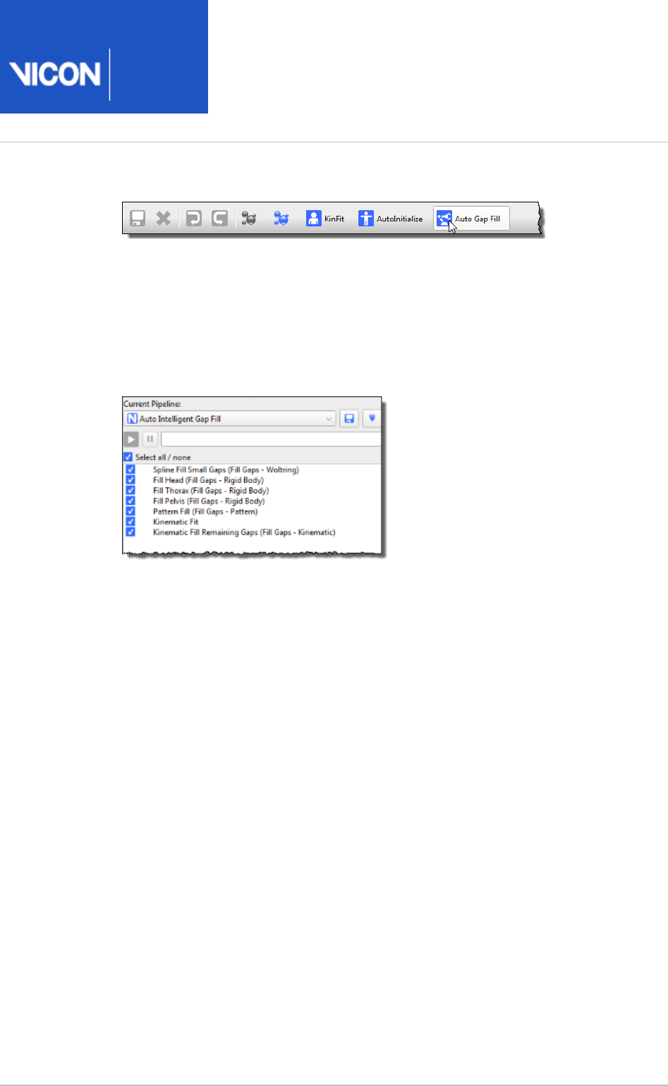
Nexus
User
Guide
Vicon Motion Systems Ltd. 26-Oct-2018 Page of 178 240
4.
1.
2.
3.
4.
5.
In the Nexus tool bar, click .Auto Gap Fill
Nexus assesses each gap one-by-one in series and fills all the gaps.
To use the Auto Intelligent Gap Fill pipeline:
On the pane, click the button.Tools Pipelines
From the list, select the pipeline.Current Pipeline Auto Intelligent Gap Fill
From the list of operations below, select the gap-filling operations that you want
to use. If required, in the pane, modify the relevant settings to suit Properties
your particular trial.
For more information on an operation, either view its tooltip by clicking on its
name and then hovering the mouse pointer over it or see the FAQ What gap-
on the Vicon website.filling algorithms are used in Nexus 2?
Either click the button or use the button on the tool bar, as Run Auto Gap Fill
described above, to run the pipeline with any changes you have made.
On the Nexus toolbar, click the Save button to save the trial. This will enable you
to load the edited trial data. You can then perform any other processing, such as
manually filling any remaining gaps.
You can run the pipeline either on an individual trial in the pane or on Pipeline Tools
multiple files using the .Batch Processing Interface
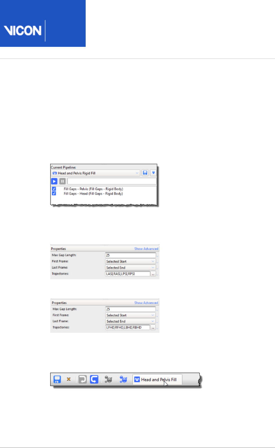
Nexus
User
Guide
Vicon Motion Systems Ltd. 26-Oct-2018 Page of 179 240
1.
2.
3.
4.
Example of creating a custom pipeline for gap-filling
The following steps describe how to make a custom pipeline for speeding up gap-filling
operations. (For a reminder of how to create and run pipelines, see Work with pipelines
.)on page 131
To create a custom gap-filling pipeline:
Create a new pipeline (for example, called ), which contains Head and Pelvis Fill
two operations.Rigid Body fill
Click on each operation in turn and in the pane, customize the fills so Properties
that Pelvis and Head markers will be filled appropriately. For example:
Pelvis Rigid Fill properties
Head Rigid Fill properties
Save the pipeline.
Add a new button to the Nexus toolbar ( menu ) to give quick Window > Toolbar
access to your custom pipeline.
Now, with one mouse click, you can automatically fill any Pelvis and Head gaps.

Nexus
User
Guide
Vicon Motion Systems Ltd. 26-Oct-2018 Page of 180 240
1.
2.
3.
Add events to trials
An event is a single action in the time span of a trial, for example, a foot contacting the
floor during a walking trial, or a knee angle exceeding a particular angle.
Events are normally added to your trial data automatically as part of the capture
workflow, when you run or other dynamic pipelines that include Plug-in Gait Dynamic
and . For more information, see Detect Events From Forceplate Autocorrelate Events
step 7 of .Capture the required movement on page 137
However, if events are not automatically detected, or are only partially detected, you
will need to add them manually. This is likely to be necessary in the following scenarios:
If you are not using a force plate; or
The floor is not flat (ie, the movement being captured involves stepping, climbing,
etc); or
The trial includes movement that is not a cyclical gait movement (for example, some
sports movements)
If your trial type does not allow the automatic addition of events, you can add them
manually, using the timebar as described below.
For more information on working with events, see:
Add events to trial data on page 180
Delete events that are outside the region of interest on page 183
Customize event identification mode on page 183
Customize cycle visualization on page 183
Add events to trial data
To add events to motion capture trial data:
From the tab, open the required trial, ensuring that it contains Data Management
no gaps or other issues (see and Review data quality on page 154 Fill gaps in
).trial data on page 169
Display the desired view ( , , , or ).3D Perspective 3D Orthogonal Camera Graph
Enter event identification mode in either of the following ways:
On the time bar, click the button; or.Enter Event Identification Mode
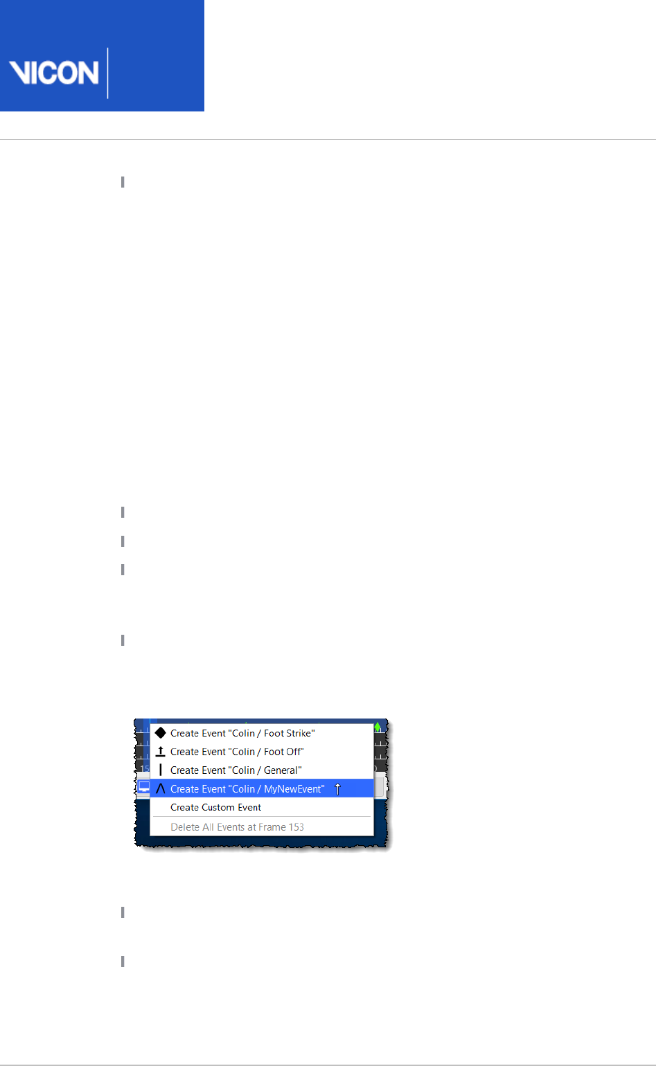
Nexus
User
Guide
Vicon Motion Systems Ltd. 26-Oct-2018 Page of 181 240
3.
4.
5.
6.
7.
Press CTRL+E.
The mouse pointer changes to a vertical arrow, to indicate that you are now in
event identification mode.
On the time bar, zoom in or out on the timescale (right-click and drag) to adjust
the time span of data displayed in the view pane and move the current time
indicator (blue line) along the time bar to locate the desired frame.
Lock the event context by positioning the mouse pointer over the desired , Left
, or line on the selected frame (the line for a context is highlighted Right General
when the mouse pointer hovers over it) and pressing the UP ARROW or DOWN
ARROW key. When the event context is locked, moving the mouse does not
change the context.
Set a new event in the current context on the selected frame by either left-
clicking or pressing ENTER and then selecting the desired command from the
context menu
Create Event Foot Strike Creates a foot strike event at the selected frame.
Create Event Foot Off Creates a foot strike event at the selected frame.
Create Event General Creates a general event at the selected frame,
represented by a vertical bar on the timeline. You cannot name general events
and they are not saved to the event creation menu for future use.
Create Custom Event Creates a custom event at the selected frame that you
can name, represented by a caret ( ^ ) on the timeline. When you create and
name a custom event, it is added to the event creation menu, so you can select
it again in future.
Navigate existing events in either of the following ways:
In the time bar controls, click the or Jump to the previous event Jump to the
button; ornext event
Press CTRL+LEFT ARROW or CTRL+RIGHT ARROW to go the previous or next
event.
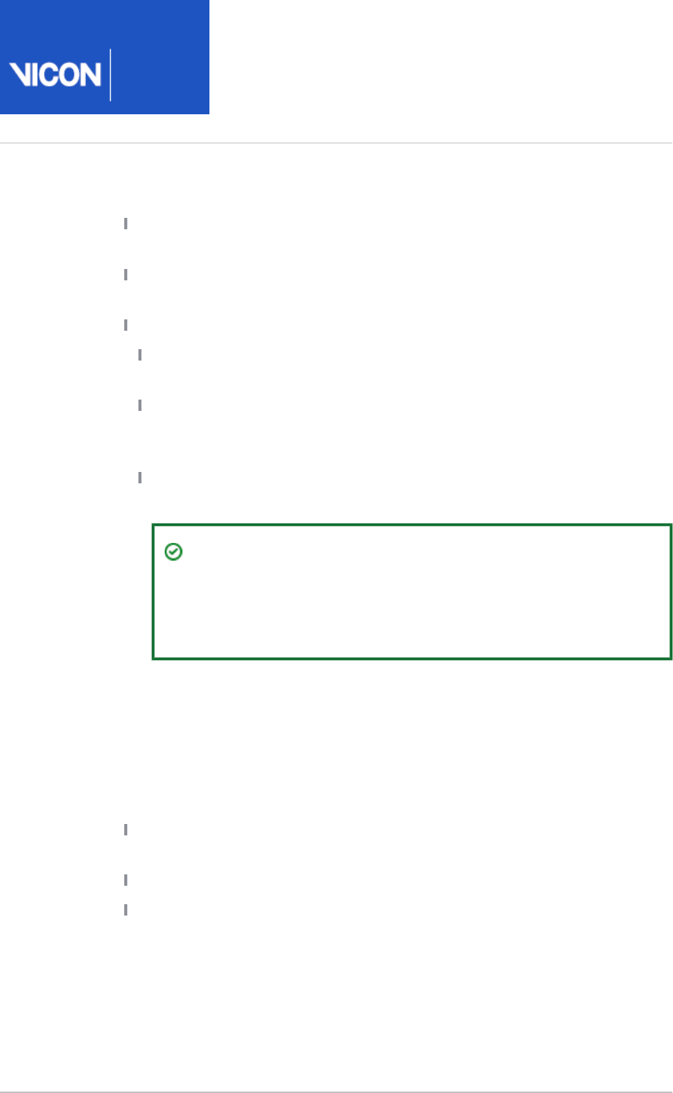
Nexus
User
Guide
Vicon Motion Systems Ltd. 26-Oct-2018 Page of 182 240
8.
9.
10.
11.
If required, you can:
Move an existing event to another frame by clicking in it with the left mouse
button, holding the button down, dragging it left or right along the timeline.
Move the event at the current frame in the current context back or forward
one frame by pressing ALT+Left- or Right-arrow key.
Delete existing events:
Single event: On the time bar, click the event or press ENTER, and from the
displayed context menu select .Delete Event <Type>
All events on current frame: On the time bar, click the desired event or press
ENTER, and from the displayed context menu select Delete All Events at
.Frame x
All events in trial: On the time bar, right-click anywhere and from the
displayed context menu select .Clear All Events
Tip
Note that you can also use the pipeline Delete Timebar Events
operation (available on the pane, under Pipeline Tools Events &
) to delete events from a selected range of frames.Timebar
When you have finished editing the current event context, unlock the event
context by either moving the mouse over a different context or using the Up
/Down arrow keys on the keyboard.
Repeat steps 5-9 for each event context you wish to edit.
When you have finished editing all events, exit event identification mode in any
of the following ways:
In the timebar controls, click the button again; Enter Event identification mode
or
Press CTRL+E; or
Press ESC
If you add gait cycle events before you crop a trial, you probably want to delete events
that are outside the cropped region. (For information on cropping trial data, see Crop
.)trials on page 165
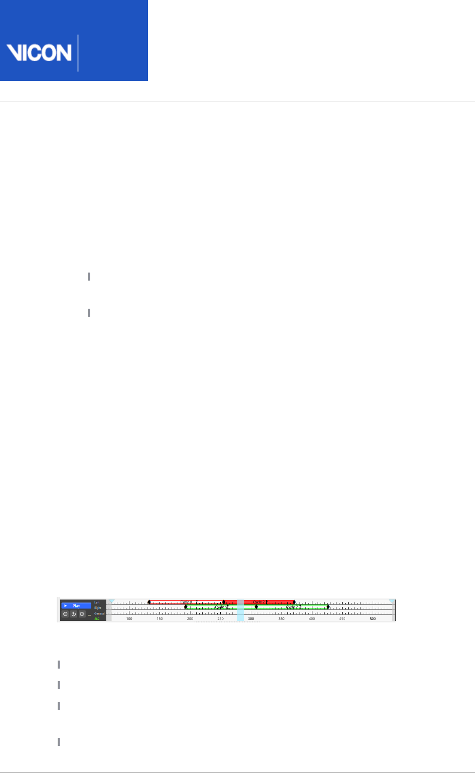
Nexus
User
Guide
Vicon Motion Systems Ltd. 26-Oct-2018 Page of 183 240
1.
2.
1.
2.
3.
Delete events that are outside the region of interest
If you crop a trial after you have added events to it, events may be retained in the
discarded (cropped) region of the trial. To remove these events, do either of the
following:
To delete events that are outside the region of interest:
Do either of the following:
Right-click on the time bar of the cropped trial and click Delete Events Outside
; orRegion of Interest
In the pane, from the operations, select Pipeline Tools Events & Timebar Delete
and in the , select whether to delete Timebar Events Advanced Properties
events inside or outside of the specified region.
Run the operation to remove the unwanted events.Delete Timebar Events
Customize event identification mode
To customize options that affect event identification mode:
Open the dialog box (press F7).Options
On the left of the dialog box, click .Time Bar
In the section on the right, select (or clear) Event Identification Mode Focus on
and enter or select the markers to focus on for and contexts.marker Left Right
Customize cycle visualization
By default, all the cycles (gait or other) that have been defined by sets of time bar
events, are displayed on the time bar.
This provides an easy way to identify:
How many cycles are defined
Where they are temporally
Whether they are associated with force plate activity (indicated by solid color instead
of colored outline only)
How large they are (number of frames)

Nexus
User
Guide
Vicon Motion Systems Ltd. 26-Oct-2018 Page of 184 240
Whether the left or right side is indicated:
Left = Red
Right = Green
To turn the visual display on or off or to change the default color options and other
visual indicators, in the dialog box (press F7), on the left side click and Options Time Bar
change the required properties on the right.
To turn on or off the display of the frame count, right-click on the time bar and select or
clear .Show Cycle Frame Count
Nexus
User
Guide
Vicon Motion Systems Ltd. 26-Oct-2018 Page of 185 240
Modeling with Plug-in Gait
Vicon Nexus provides you with the following options for modeling:
Plug-in Gait and the l. If you are new to modeling with Nexus, the Oxford Foot Mode
Plug-in Gait model provides a good introduction: all the operations necessary to run
the model are supplied with Nexus, easily accessible and ready to use. This option is
described in this guide. For further details, see:
About the Plug-in Gait model on page 187
Plug-in Gait files installed with ViconNexus on page 189
How Plug-in Gait works on page 190
Take subject measurements for Plug-in Gait on page 191
Attach Plug-in Gait markers to a patient on page 199
Plug-in Gait Static pipeline on page 201
Plug-in Gait Dynamic pipeline on page 203
In addition, a , Vicon Nexus 2 tutorial video
PlugIn Gait AI: Marker Locations and
, is available on YouTube.
Subject Measurements
Note
As the videos were recorded using an earlier version of Nexus 2, you may
notice small differences in the user interface.
MATLAB. If you are familiar with MATLAB, you can use the supplied examples to
create your own custom models. For more information, see , Modeling with MATLAB
in the .
Vicon Nexus Reference Guide
Python. If you are familiar with Python, you can use the supplied examples to create
your own custom models. For more information, see , in the Modeling with Python
.
Vicon Nexus Reference Guide

Nexus
User
Guide
Vicon Motion Systems Ltd. 26-Oct-2018 Page of 186 240
Note
For simplicity, modeling operations are described as separate steps. However,
if you want to run modeling operations automatically, you can add them (and
any other operations required) to a post-capture pipeline that runs as soon as
capture finishes. For more information see step 7 in Capture the required
.movement on page 137

Nexus
User
Guide
Vicon Motion Systems Ltd. 26-Oct-2018 Page of 187 240
About the Plug-in Gait model
The Plug-in Gait model is Vicon's implementation of the Conventional Gait Model,
which provides widely used and reliable full body kinematic and kinetic modeling,
without the need for any customizations. It is based on the Newington-Helen Hayes
gait model and has been validated through its frequent citation in peer-reviewed
publications (see ).Plug-in Gait references on page 188
Vicon Nexus includes the required pre-defined Plug-in Gait marker set and pipelines to
enable you to produce outputs of the joint kinematics and kinetics for gait analysis
patients. Plug-in Gait enables you to examine full, upper, or lower body joint kinematics
and kinetics of patients. When you have run the relevant pipeline operations on your
trials, you can produce gait analysis reports that conform to established clinical
practices and import the resulting kinematic model of your subject (patient) into
another software application, such as Vicon Polygon, for gait analysis.
It is assumed that you are familiar with Plug-in Gait, including the way the model works,
where the markers are placed, and what the subject parameters mean. For example,
Plug-in Gait directly calculates the kinematic model's joint centers from the measured
XYZ marker positions on a frame-by-frame basis. Therefore, the lengths and
orientations of the modeled segments are directly dependent on the marker positions.
Accurate marker placement is therefore paramount. For guidance on marker
placement, see .Attach Plug-in Gait markers to a patient on page 199
The model uses three or more points to define each segment. For all segments distal to
the pelvis, one of the points used is the joint center that defines the proximal joint for
the segment, for example, one of the three defining points for the tibia is the knee joint
center.
Operations relating to modeling with Plug-in Gait are available in the Data Processing
operations in the pane.Pipeline Tools
For in-depth descriptions of Plug-in Gait models and templates, and details of the
calculations performed by Plug-in Gait, see the .
Plug-in Gait Reference Guide
Before using Plug-in Gait, be sure to read the .Plug-in Gait disclaimer on page 188

Nexus
User
Guide
Vicon Motion Systems Ltd. 26-Oct-2018 Page of 188 240
Plug-in Gait references
The following research publications provide supporting information on the scientific
basis and validation of Plug-in Gait:
DAVIS R., OUNPUU S., TYBURSKI D., and GAGE J. R.
A gait analysis collection and
Human Movement Science, 10, p575–587, (1991).
reduction technique
.
KADABA M. P., RAMAKRISHNAN H. K., and WOOTTEN M. E.
Measurement of lower
. Journal of Orthopaedic Research, 8, p383–
extremity kinematics during level walking
392, (1990).
WOLTRING, H. J.
A FORTRAN package for generalized, cross-validatory spline
, Advances in Engineering Software, 8, p104–113,
smoothing and differentiation
(1986).
VAN DEN BOGERT, T. See
Practical Guide to Data Smoothing and Filtering.
http://isbweb.org/software/sigproc/bogert/filter.pdf
Plug-in Gait disclaimer
You are entirely responsible for the use you make of the software. In particular, the
software is not intended to replace the clinical skill of a medical practitioner or his/her
independent professional judgment of individual clinical circumstances to make a
diagnosis and/or determine a patient's treatment.
The software should only be used by those who have been appropriately trained in its
operation, functions, capabilities, and limitations, and in any event should not be relied
upon, by itself, as the sole method of making any diagnosis or determining any
treatment.

Nexus
User
Guide
Vicon Motion Systems Ltd. 26-Oct-2018 Page of 189 240
Plug-in Gait files installed with ViconNexus
The following table lists the Plug-in Gait files that are automatically installed with
Nexus. For more detailed information about the labeling skeleton template (. ) files,
vst
see the .
Plug-in Gait Reference Guide
File name Description
PlugInGait FullBody Ai.vst
Full body labeling skeleton template
PlugInGait LowerBody Ai.vst
Lower body labeling skeleton template
Marker set
PlugInGait FullBody Ai.mkr
Markers defined in full body model
PlugInGait LowerBody Ai.mkr
Markers defined in lower body model
By default, the supplied files are installed in the following folder:
C:\Program Files (x86)\Vicon\Nexus2.#\ModelTemplates
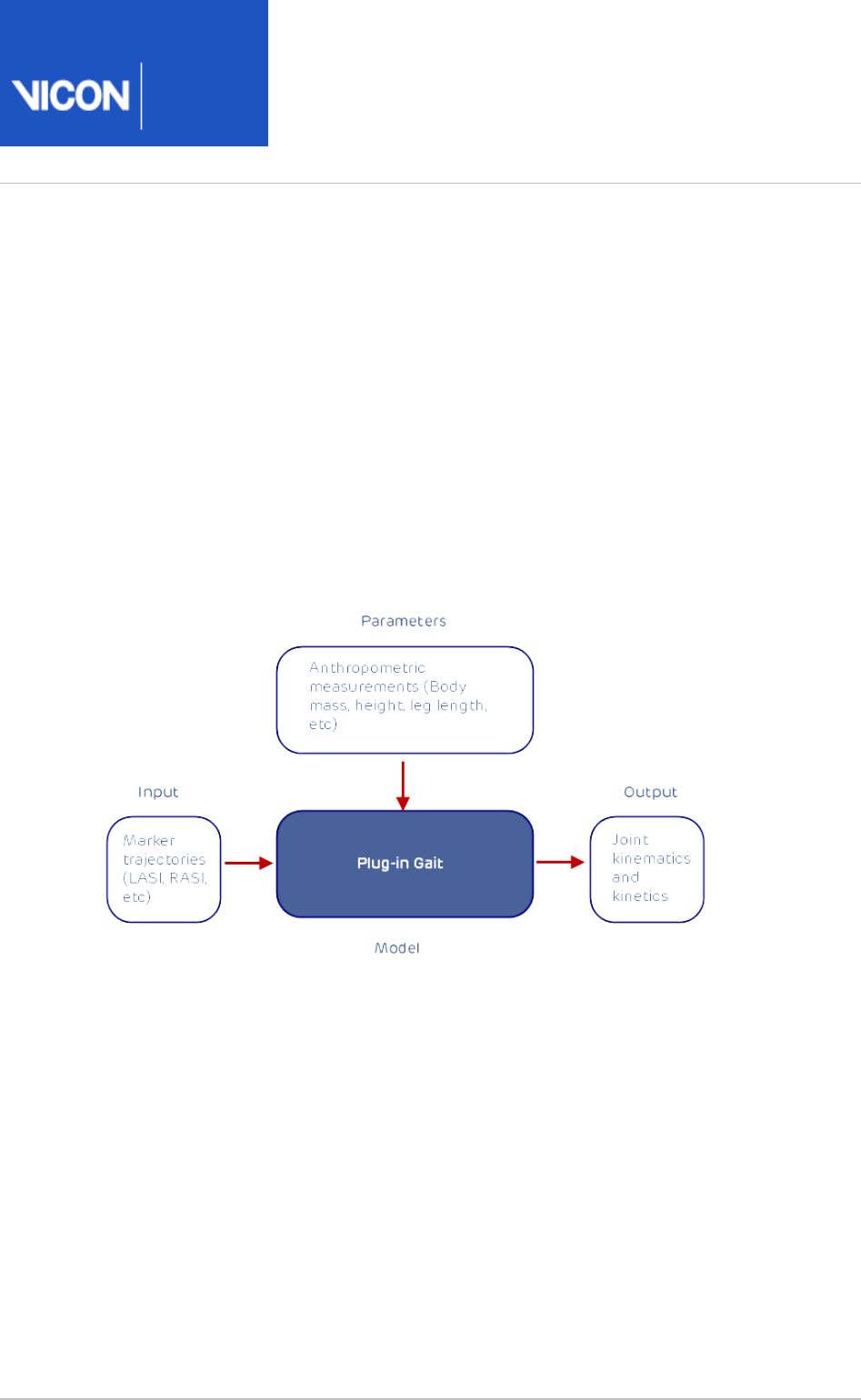
Nexus
User
Guide
Vicon Motion Systems Ltd. 26-Oct-2018 Page of 190 240
How Plug-in Gait works
To work with Plug-in Gait, you enter subject-specific measurements into a pre-defined
template in Vicon Nexus, place a Plug-in Gait marker set on a patient, capture the
required trials, and then use Plug-in Gait pipelines in Nexus to produce outputs of the
joint kinematics and kinetics for the patient.
From the real marker trajectories, Plug-in Gait generates virtual marker trajectories that
represent kinematic and kinetic quantities (angles, moments, etc) and representations
of the modeled segments. The model also outputs data that is used to define the
positions of meshes (representing bones) which can subsequently be displayed in
Vicon Polygon (for further details, see the Vicon Polygon documentation).
For detailed information about modeling with Plug-in Gait, see
Plug-in Gait kinematic
in the
and kinetic calculations Plug-in Gait Reference Guide.
Before you begin capturing, make sure you understand the types of outputs that Plug-
in Gait produces, so that you can determine the appropriate model to use for your
requirements. If you are unsure which is the most appropriate model to use, see
Models
in the
and templates Plug-in Gait Reference Guide.

Nexus
User
Guide
Vicon Motion Systems Ltd. 26-Oct-2018 Page of 191 240
Take subject measurements for Plug-in Gait
Plug-in Gait requires a set of subject measurements to enable it to directly calculate
kinematics (angles) and kinetics (forces, moments, and powers) from the measured XYZ
marker positions. Some of the measurements you must add to the subject node are
required for the model to run, and some are optional:
Required subject measurements You must add the required measurements to the
subject node for your patient. Required measurements are listed in the following
topics and are highlighted in pink in the pane for the selected subject in Properties
Vicon Nexus.
Optional measurements You can add any optional measurements or leave them for
Plug-in Gait to calculate.
The following topics list the measurements needed for each type of model:
Subject measurements for Plug-in Gait lower body model on page 192
Subject measurements for Plug-in Gait full body model on page 195
Tip
You may find it helpful to take these measurements before you begin the
subject preparation process in Vicon Nexus. You can use the column Measure
in the tables in these sections to record the measurements you take for your
patient, so you will have them to hand when you are ready to add them to your
chosen labeling skeleton template (.vst file). You may want to photocopy the
blank form for each patient before recording your measurements.To avoid the
markers getting in the way, take the measurements before attaching markers
to your patient.

Nexus
User
Guide
Vicon Motion Systems Ltd. 26-Oct-2018 Page of 192 240
Subject measurements for Plug-in Gait lower body model
The following table identifies the subject measurements that are used as inputs for
running a Plug-in Gait lower body model.
Optional measurements (and/or those calculated by the model) are marked with an
asterisk in the column.Name
Name Description Measure
Left
Measure
Right
Body Mass Patient mass. _____ kg
Height Patient height. _____
mm
*Inter ASIS
distance
The model calculates this distance based
on the position of the LASI and RASI
markers. If you are collecting data on an
obese patient and cannot properly place
the ASIS markers, place those markers
laterally and preserve the vector direction
and level of the ASIS. Palpate the LASI and
RASI points and manually measure this
distance, then input into the appropriate
field.
_____
mm
Leg Length Full leg length, measured between the ASIS
marker and the medial malleolus, via the
knee joint. Measure with patient standing,
if possible. If the patient is in the crouch
position, this measurement is NOT the
shortest distance between the ASIS and
medial malleoli, but rather the measure of
the skeletal leg length, so if a patient
cannot straighten his/her legs, take the
measurement in two pieces: ASIS to knee
and knee to medial malleolus.
_____
mm
_____
mm

Nexus
User
Guide
Vicon Motion Systems Ltd. 26-Oct-2018 Page of 193 240
Name Description Measure
Left
Measure
Right
*ASIS-
Trochanter
Distance
ASIS-greater trochanter distance is the
vertical distance, in the sagittal plane,
between the ASIS and greater trochanter
when the patient is lying supine. Measure
this distance with the femur rotated such
that the greater trochanter is positioned as
lateral as possible.
_____
mm
_____
mm
Knee Width The medio-lateral width of the knee across
the line of the knee axis. Measure with
patient standing, if possible.
_____
mm
_____
mm
Ankle Width The medio-lateral distance across the
malleoli. Measure with patient standing, if
possible.
_____
mm
_____
mm
*Tibial Torsion
1
The angle between the knee flexion and
the ankle dorsi-plantar axes. The ankle is
usually externally rotated with respect to
the knee flexion axis.
If you are using a KAD, and the medial
malleoli markers are attached to the
patient, Plug-in Gait calculates the tibial
torsion automatically.
_____
deg
_____
deg
*Sole
Thickness
Delta2
The difference in the thickness of the sole
at the toe and the heel. A positive sole delta
indicates that the patient's heel is raised
compared with the toe.
_____
mm
_____
mm
*Thigh
Rotation
When a KAD is used, this value is calculated
to account for the position of the thigh
marker. By using the KAD, placement of the
thigh marker in the plane of the hip joint
center and the knee joint center is not
crucial. If you do not use a KAD, this value is
zero as the model assumes that the thigh
_____
deg
_____
deg

Nexus
User
Guide
Vicon Motion Systems Ltd. 26-Oct-2018 Page of 194 240
1.
2.
Name Description Measure
Left
Measure
Right
marker is placed exactly in the plane of the
hip joint center and the knee joint center.
This value is calculated for you.
*Shank
Rotation
Similar to the Thigh Rotation. This value is
calculated if a KAD is present and removes
the importance of placing the shank marker
in the exact plane of the knee joint center
and ankle joint center. If you do not use a
KAD, this value is zero. It is calculated for
you.
_____
deg
_____
deg
The tibial torsion measurement is only needed if you are using a KAD.
The subject measurement is used if the subject is wearing Sole Thickness Delta
high-heeled footwear but can keep their foot flat within the shoe. For more
information, see .Sole Thickness Delta subject measurement on page 194
After you have recorded the measurements for your patient, you can create a subject
node for the patient and enter the measurements into Nexus as described in Create a
.new subject from a template on page 110
Sole Thickness Delta subject measurement
The subject measurement is used when the patient is wearing Sole Thickness Delta
shoes or orthoses so that although the patient achieves foot flat with respect to the
footwear, the sole of the footwear introduces a vertical difference between the toe and
the heel. When this is the case, you can either:
Compensate for the sole delta by carefully placing the heel marker with respect to
the toe marker and in the dialog box, ensure the check boxes for Static Settings Left
and/or are cleared.Foot Right Foot
or
Measure the difference in the thickness of the sole at the toe and the heel, in the
dialog box, select the check boxes for and/or Static Settings Left Foot Right Foot
and then in the section at the bottom of the pane, Properties Subjects Resources
enter the delta value in the box. The height of the heel marker used SoleDelta (mm)
in the calculations will then be adjusted accordingly.

Nexus
User
Guide
Vicon Motion Systems Ltd. 26-Oct-2018 Page of 195 240
Subject measurements for Plug-in Gait full body model
The following table lists the subject measurements that are used as inputs for running
Plug-in Gait for full body modeling.
Optional measurements are marked with an asterisk in the column.Name
Name Description Measure
Left
Measure
Right
Body Mass Patient mass. _____ kg
Height Patient height. _____
mm
*Inter-ASIS
distance
ASIS-ASIS distance is the distance between
the left ASIS and right ASIS. This
measurement is only needed when markers
cannot be placed directly on the ASIS, for
example, in obese patients.
_____
mm
*Head Offset Patient head offset in degrees.Only
required if head is not level (calculated
after running the Plug-in Gait model).
_____ deg
Leg Length Full leg length, measured between the ASIS
marker and the medial malleolus, via the
knee joint. Measure with patient standing,
if possible. If the patient is standing in the
crouch position, this measurement is NOT
the shortest distance between the ASIS and
medial malleoli, but rather the measure of
the skeletal leg length.
_____
mm
_____
mm
*ASIS-
Trochanter
Distance
ASIS-greater trochanter distance is the
vertical distance, in the sagittal plane,
between the ASIS and greater trochanter
when the patient is lying supine. Measure
this distance with the femur rotated such
that the greater trochanter is positioned as
_____
mm
_____
mm

Nexus
User
Guide
Vicon Motion Systems Ltd. 26-Oct-2018 Page of 196 240
Name Description Measure
Left
Measure
Right
laterally as possible. If this value is not
entered, a regression formula is used to
calculate the hip joint center. If this value is
entered, it will be factored into an equation
which represents the hip joint center.
Knee Width The medio-lateral width of the knee across
the flexion axis. Measure with patient
standing, if possible.
_____
mm
_____
mm
Ankle Width The medio-lateral distance across the
malleoli. Measure with patient standing, if
possible.
_____
mm
_____
mm
*Tibial Torsion
1
The angle between the knee flexion and
the ankle dorsi-plantar axes. The ankle is
usually externally rotated with respect to
the knee flexion axis. The sign convention
is that if a negative value of tibial torsion is
entered, the ankle flexion/extension axis
will be adjusted from the KAD's defined
position to a position dictated by the tibial
torsion value.
If you are using a KAD, and the medial
malleoli markers are attached to the
patient, Plug-in Gait calculates the tibial
torsion automatically.
_____
deg
_____
deg
*Sole
Thickness
Delta2
The difference in the thickness of the sole
at the toe and the heel. A positive sole delta
indicates that the patient's heel is raised
compared with the toe.
_____
mm
_____
mm
*Thigh
Rotation
When a KAD is used, this value is calculated
to account for the position of the thigh
marker. By using the KAD, placement of the
thigh marker in the plane of the hip joint
_____
deg
_____
deg

Nexus
User
Guide
Vicon Motion Systems Ltd. 26-Oct-2018 Page of 197 240
1.
2.
Name Description Measure
Left
Measure
Right
center and the knee joint center is not
crucial. If you do not use a KAD, this value is
zero as the model assumes that the thigh
marker is placed exactly in the plane of the
hip joint center and the knee joint center.
This value is calculated for you.
*Shank
Rotation
Similar to the Thigh Rotation. This value is
calculated if a KAD is present and removes
the importance of placing the shank marker
in the exact plane of the knee joint center
and ankle joint center. If you do not use a
KAD, this value is zero. It is calculated for
you.
_____
deg
_____
deg
Shoulder
Offset
Vertical distance from the center of the
glenohumeral joint to the base of the
marker on the acromion clavicular joint.
Some researchers have used the (anterior
/posterior girth)/2 to establish a guideline
for the parameter.
_____
mm
_____
mm
Elbow Width Width of elbow along flexion axis (roughly
between the medial and lateral epicondyles
of the humerus).
_____
mm
_____
mm
Wrist Width Anterior (palm side)/Posterior (back)
thickness of wrist at position where wrist
marker bar is attached.
_____
mm
_____
mm
Hand
Thickness
Anterior/Posterior thickness between the
dorsum and palmar surfaces of the hand, at
the point where you attach the hand
marker.
_____
mm
_____
mm
The tibial torsion measurement is only needed if you are using a KAD.

Nexus
User
Guide
Vicon Motion Systems Ltd. 26-Oct-2018 Page of 198 240
2. The subject measurement is used if the subject is wearing Sole Thickness Delta
high-heeled footwear but can keep their foot flat within the shoe. For more
information, see .Sole Thickness Delta subject measurement on page 194
After you have recorded the measurements for your patient, you can create a subject
node for the patient and enter the measurements into Vicon Nexus as described in
.Create a new subject from a template on page 110

Nexus
User
Guide
Vicon Motion Systems Ltd. 26-Oct-2018 Page of 199 240
1.
2.
Attach Plug-in Gait markers to a patient
After adding the patient's measurements to the subject node (see Take subject
), you attach the markers to the patient.measurements for Plug-in Gait on page 191
Vicon cameras capture the movement of the retroreflective markers rather than the
body to which they are attached. To enable Nexus to determine the movement of the
subject's underlying skeleton, ensure that the subject's clothing will not occlude
markers or by cause the markers to move excessively. If possible, attach the markers
directly to the patient's skin. During capture, ensure that there is nothing else reflective
in the capture volume.
To attach markers to a patient:
Select the appropriate size and quantity of Vicon markers to be used. Typically,
14 mm markers are used for gait analysis studies.
Securely attach the Vicon markers to the patient in accordance with the marker
arrangement defined in your chosen template. A front view of the most
commonly used set (for Plug-in Gait lower body modeling) is shown in the
following image. The left lower body markers are not labeled; place markers on
the left side in a similar way to those on the right.
Important
Note that, as shown in the following image, some asymmetry is
desirable as it helps the auto labeling routine distinguish right from left.
In a lower body marker set, you can place the THI and/or TIB markers
asymmetrically. For a full body set, you can place the THI, TIB, UPA and
FRM markers asymmetrically. Similarly, avoid symmetrical placement of
marker clusters or groups of markers and also ensure markers are
asymmetrical within each cluster/group.
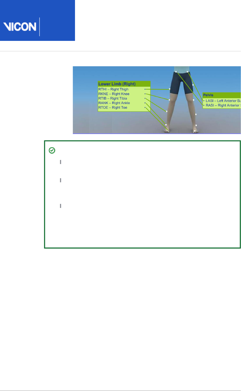
Nexus
User
Guide
Vicon Motion Systems Ltd. 26-Oct-2018 Page of 200 240
2.
Tip
The THI and TIB markers anterior-posterior position is critical for
identifying the orientation of the knee and ankle flexion axis.
If you are using a single sacral marker (SACR) in a Plug-in Gait lower
body or full body marker set, attach the SACR marker instead of the
two PSIS markers.
Because you need at least three markers to obtain six degrees of
freedom, best practice is to place four markers on the pelvis (LASI
/RASI/LPSI/RPSI), so that even if one of the four markers is occluded
during motion capture, the required three markers will still be visible
to the cameras.
For detailed descriptions and images of marker positions, see
Models and
in the .
templates Plug-in Gait Reference Guide
You can now capture a calibration trial and reconstruct the markers (see Calibrate a
).labeling skeleton on page 113

Nexus
User
Guide
Vicon Motion Systems Ltd. 26-Oct-2018 Page of 201 240
Plug-in Gait Static pipeline
As described in step 5 of Review and finalize a calibration of a labeling skeleton using a
, to enable Plug-in Gait to calculate the static outputs based on ROM trial on page 120
the measured marker positions, you can run a pipeline on the Plug-in Gait Static
reconstructed and labeled static frames of either a ROM trial or a static trial.
Important
The Plug-in Gait Static pipeline is intended to calculate subject-specific
offsets for use as inputs to the Plug-in Gait Dynamic pipeline. If joint angles
are required, you must run the Plug-in Gait Dynamic pipeline (page 203) in
addition to the static pipeline, even for a stationary subject.
Process Static Plug-in Gait Model properties
The following table describes the properties you can specify for the Process Static Plug-
pipeline operation:in Gait Model
Property Description
First Frame Specify the first frame to be used for processing.
Last Frame Specify the last frame to be used for processing.
Marker Diameter Specify the diameter of the markers used, assuming they
are applied to the skin's surface. The default is 14mm.
Anterior Thorax Tilt is
Positive
Select this option to specify that the anterior thorax tilt is
positive. Clear this option to specify that the anterior
thorax tilt is negative.
Output Joint Centers
Select this option to visualize the joint centers that are
calculated by Plug-in Gait.

Nexus
User
Guide
Vicon Motion Systems Ltd. 26-Oct-2018 Page of 202 240
Property Description
Assume Horizontal
In this section, you can configure Plug-in Gait to assume that certain markers are at
the same height from the floor during the static trial. Set the appropriate option to
enable Plug-in Gait to compensate for your patient's stance during the static trial.
Important: Set the appropriate foot option if you specify the Sole Thickness Delta
subject measurement because the patient is wearing shoes or orthoses that
introduce a vertical difference between the toe and the heel (for details, see Subject
).measurements for Plug-in Gait lower body model on page 192
Left Foot Plug-in Gait assumes that the LTOE and LHEE markers are
level with one another. Select this option if the patient's
left foot was flat with the toe and heel in contact with the
floor, even if the left toe (LTOE) and heel (LHEE) markers
were not level with one another.
Right Foot Select this option if the patient's right foot was flat with
the toe and heel in contact with the floor, even if the right
toe (RTOE) and heel (RHEE) markers were not level with
one another.
Head Select this option if the patient's head was held level
during the static trial, even if the rear of head markers
(LBHD,RBHD) could not be placed level with the front of
head markers (LFHD, RFHD).

Nexus
User
Guide
Vicon Motion Systems Ltd. 26-Oct-2018 Page of 203 240
Plug-in Gait Dynamic pipeline
To enable Plug-in Gait to finalize trial data, including filtering the data, detecting gait
events, and producing a . file for export from Nexus, you can run a
c3d
Plug-in Gait
pipeline on the reconstructed and labeled movement trials.Dynamic
Before you run the pipeline on your movement trials, ensure you have gap-filled and if
necessary cropped the trials (see ).Review trials and fill gaps on page 152
If required, you can change the properties for each of the operations that are included
in the pipeline. You can also run them individually, and/or run Plug-in Gait Dynamic
other operations at this stage too. To help you understand the different operations
typically run on Plug-in Gait movement trials and the options available, each operation
is described in the following topics, together with the Delete Unlabeled Trajectories
pipeline operation, which you may also find useful:
Run the Dynamic Plug-in Gait pipeline on page 204
Delete Unlabeled Trajectories pipeline operation on page 205
Filter Trajectories - Woltring pipeline operation on page 205
Detect Events From Forceplate pipeline operation on page 206
Autocorrelate Events pipeline operation on page 207
Process Dynamic Plug-in Gait Model pipeline operation on page 208
Cross-plate foot strikes on page 210
Export C3D on page 213
Tip
When you are familiar with these operations, you can run all of the data
processing in a single step by creating your own custom pipeline and adding
all the operations described in this section to it, as explained in Create a
. When you create your new pipeline, ensure that you pipeline on page 134
include the operations in the above order.
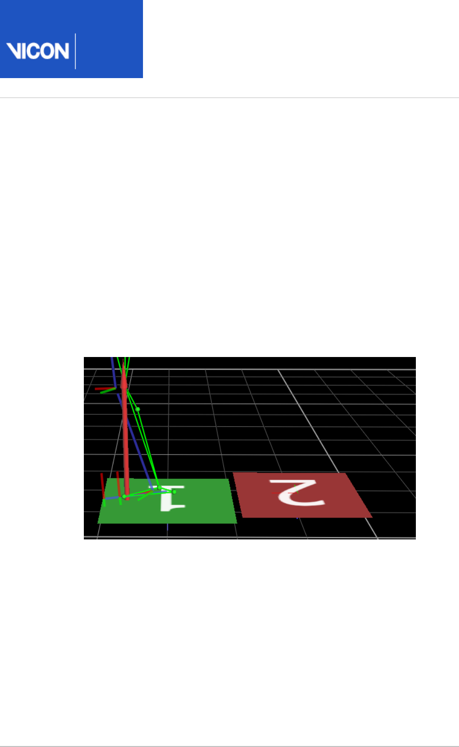
Nexus
User
Guide
Vicon Motion Systems Ltd. 26-Oct-2018 Page of 204 240
1.
2.
3.
4.
5.
6.
Run the Dynamic Plug-in Gait pipeline
To run the Dynamic Plug-in Gait pipeline:
On the tab, ensure the dynamic trial you have gap-filled is Data Management
open (for details, see ).Fill gaps in trial data on page 169
On the tab of the pane, from the list, select Pipeline Tools Current Pipeline
.Dynamic Plug-in Gait
Ensure that the required operations are selected and that you have configured
their properties appropriately (see below for details).
Click the Play button.
A green check mark appears in the list to the left of each completed operation.
In the view, the axis for each segment is displayed, together with 3D Perspective
the and .Foot Strike Foot Off
In the pane, expand the subject's tree and ensure that the SubjectsResources
model outputs are listed.
To save the data in . format, on the Vicon Nexus toolbar, click the Save
c3d
button.
If you don't need to perform any further processing, you can now export your data. For
more information, see .Export trial data on page 233

Nexus
User
Guide
Vicon Motion Systems Ltd. 26-Oct-2018 Page of 205 240
Delete Unlabeled Trajectories pipeline operation
This pipeline operation runs on a fully labeled trial to delete any remaining unlabeled
trajectories. To choose the maximum length of unlabeled trajectory to delete, select
the option and specify the .Delete using Max Length Max Length to Delete
Filter Trajectories - Woltring pipeline operation
This pipeline operation filters the data using the Woltring filter to ensure smooth
trajectories for calculating kinetics. This routine is based on a fifth-order spline-
interpolating function (for details on this function and its filtering algorithms, see Plug-
).in Gait references on page 188
In the pane for this operation, you can specify the following settings:Properties
Property Description
First Frame First frame to which filtering is applied
Last Frame Last frame to which filtering is applied
Filter mode Choose between:
GCV The filtering routine makes an automatic estimate of the noise
to find the optimal smoothing parameter.
MSE You can change the level of smoothing by entering a different
value for the option below. Smoothing
Trajectories Enables you to select the trajectories to filter. Can be All trajectories,
All labeled trajectories, or Linked trajectories.
Smoothing Enables you to specify the level of smoothing for the option.MSE

Nexus
User
Guide
Vicon Motion Systems Ltd. 26-Oct-2018 Page of 206 240
Detect Events From Forceplate pipeline operation
This pipeline operation automatically detects gait cycle events such as footstrikes and
adds them to the time bar throughout the trial using vertical ground reaction forces
(GRFs) measured by a force plate connected to the Vicon system. The operation
includes the option to set the force threshold and the label of the markers attached to
the front and back of the foot for both sides.
In the pane for this operation, you can specify the following settings:Properties
Property Description
First Frame First frame in which events are detected
Last Frame Last frame in which events are detected
Force Threshold
(N)
The force threshold for automatically detecting heel strike and
toe off events. The default is 20.
Left anterior
marker label
Marker used for event detection. You are recommended to
leave this at the default setting.
Left posterior
marker label
Marker used for event detection. You are recommended to
leave this at the default setting.
Right anterior
marker label
Marker used for event detection. You are recommended to
leave this at the default setting
Right posterior
marker label
Marker used for event detection. You are recommended to
leave this at the default setting.

Nexus
User
Guide
Vicon Motion Systems Ltd. 26-Oct-2018 Page of 207 240
Autocorrelate Events pipeline operation
This pipeline operation detects the pattern of the tracked marker at the set events and
defines these events for the rest of the trial. The available parameters are: marker being
tracked; the X, Y, or Z component of the marker; and the position, velocity, or
acceleration of the marker. Run this operation after or Detect Events from Forceplate
manually entering events on the timebar.
In the section for this operation, you can specify the following settings:Properties
Property Description
First Frame First frame in which events are detected
Last Frame Last frame in which events are detected
Only after
existing
If a force plate is used and you select this option, Vicon Nexus
automatically correlates force plate data events from the time of the
first strike on the force plate and forward. If you do not select this
option, Vicon Nexus automatically correlates events both forward and
backward from the first force plate strike.
If a force plate is not used, you can still select this option, but you
must make a thorough visual check of the events placed.
Marker
(Left and
Right)
Enables you to change the marker used for correlation if necessary.
Component
(Left and
Right)
For walking trials, leave the Left and Right values at the default value
(Z). For running and other motor tasks, change as appropriate.
Derivative
(Left and
Right)
For walking trials, leave the Left and Right values at the default value
(Position). For running and other motor tasks, change as appropriate.

Nexus
User
Guide
Vicon Motion Systems Ltd. 26-Oct-2018 Page of 208 240
Process Dynamic Plug-in Gait Model pipeline operation
This pipeline operation runs the dynamic Plug-In Gait model on the active subject of
the current trial.
In the section for this operation, you can specify the following settings:Properties
Property Description
First Frame First frame on which the operation is run
Last Frame Last frame on which the operation is run
Marker diameter (mm) Ensure the specified value corresponds to the size of the
markers attached to your patient.
Reaction reference
frame
Determines which reference frame is used for reporting
joint moments:
Proximal segment: Reports all moments in the reference
frame of the proximal segment.
Distal segment: Reports all moments in the reference
frame of the distal segment (for example, the tibia
segment for the knee joint).
Global frame: Reports the moment vector relative to the
laboratory coordinate system.
Power Output How Plug-in Gait is to output the power data:
Standard: The joint power expressed as a single number
(scalar).
Individual Contributions from XYZ: The joint power
expressed as individual X, Y, and Z planes in the
segment's coordinate system
Anterior Thorax Tilt is
Positive
Select this option to specify that the anterior thorax tilt is
positive. Clear this option to specify that the anterior
thorax tilt is negative.

Nexus
User
Guide
Vicon Motion Systems Ltd. 26-Oct-2018 Page of 209 240
Property Description
Output Joint Centers Select this option to visualize the joint centers that are
calculated by Plug-in Gait.
Allow cross-plate
strikes
Select this option when a foot may be in contact with
more than one force plate simultaneously; for example,
the heel may land on the far side of one plate and then
the toes roll onto the near edge of the subsequent plate.
If you select this option, reactions from the two plates are
combined during processing, with the plate that is struck
first being considered the primary. The forces reported by
each plate are added together; the moments are also
combined by referring the moment from the secondary
plate back to the origin of the primary plate. In effect, the
two plates are treated as a single force plate with the
same origin as the primary plate. For more information,
see .Cross-plate foot strikes on page 210
Although every effort has been made to ensure the
mathematical combination of forces and moments
between two plates is correct, it is the responsibility of
the operator / analyst to review the outcomes produced
by this process and ensure they are correct. Use of this
option in clinical assessments is strictly at the discretion
of the operator/analyst.
Radius of Gyration:
Pelvis and Thorax
The default radius of gyration for the specified segments.
The number is scaled to the length of the segment.
The Plug-in Gait default setting (0.31) means that the
radius of gyration is 31 percent of the segment length.
Only change this setting if you are sure that the default
value is incorrect.
Version Plug-in Gait version number.
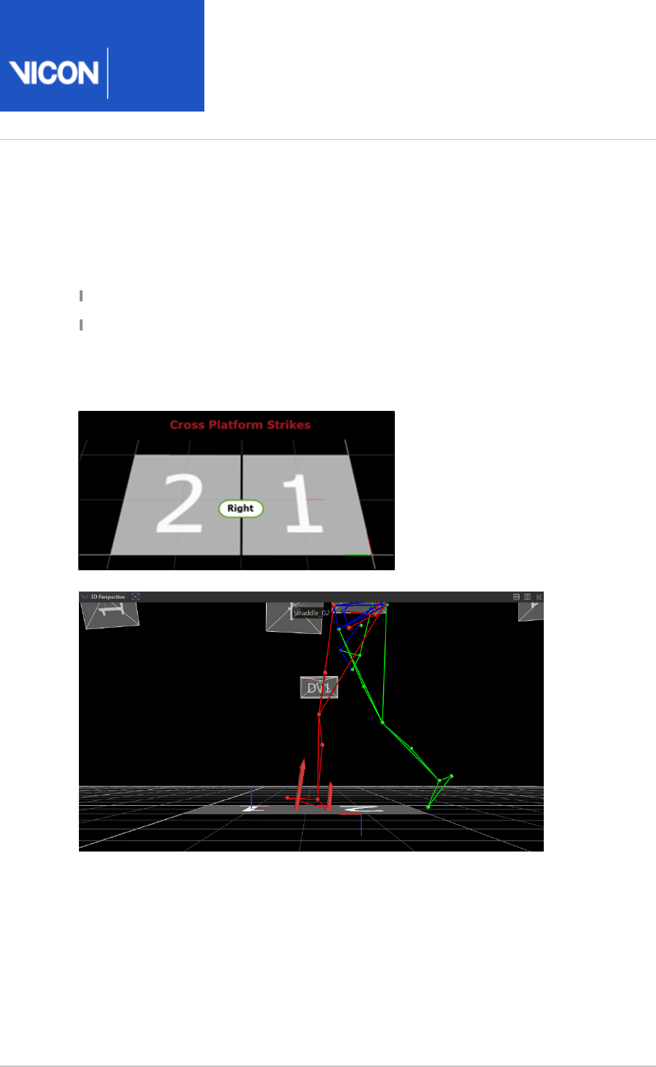
Nexus
User
Guide
Vicon Motion Systems Ltd. 26-Oct-2018 Page of 210 240
Cross-plate foot strikes
To perform an inverse reaction calculation from a foot strike, forces and moments
recorded by a force plate must:
Be assigned to a single context (left or right)
Represent the full forces and moments produced by the subject
In some instances, a foot may be in contact with more than one force plate
simultaneously; for example, the heel may land on the far side of one plate and then
the toes roll onto the near edge of the subsequent plate.
Dynamic Plug-in Gait includes an Advanced option to permit calculations based on
these cross-plate strikes.
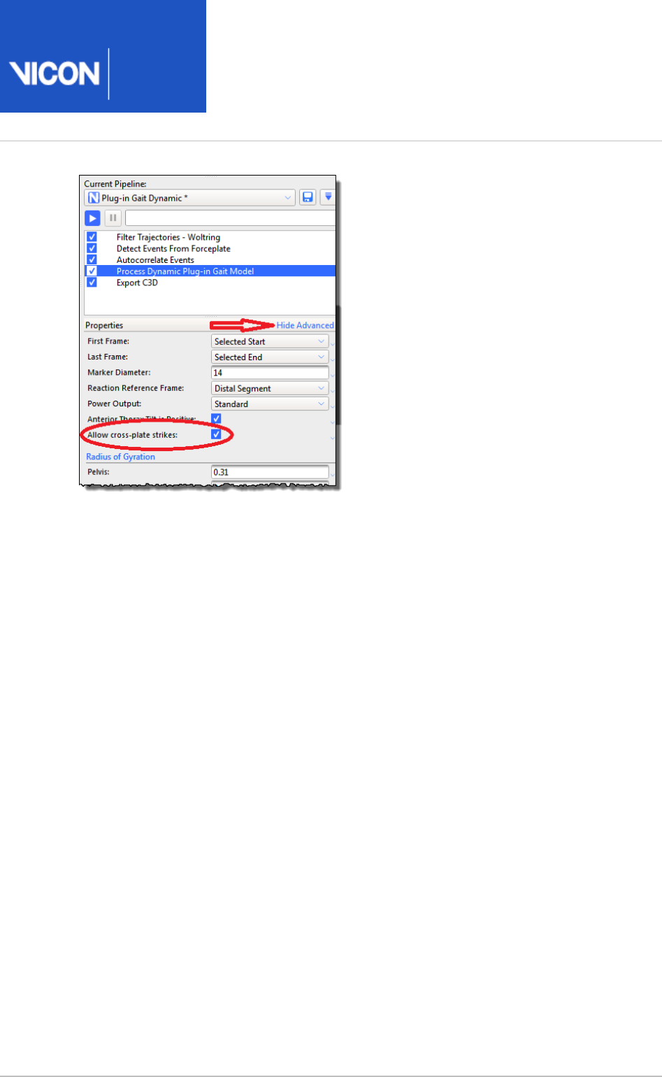
Nexus
User
Guide
Vicon Motion Systems Ltd. 26-Oct-2018 Page of 211 240
Reactions from the two plates are combined during processing, with the plate that is
struck first being considered the primary. The forces reported by each plate are added
together; the moments are also combined by referring the moment from the secondary
plate back to the origin of the primary plate. In effect, the two plates are treated as a
single force plate with the same origin as the primary plate.
Dynamic Plug-in Gait can automatically detect which foot is activating a force plate by
checking whether the origin of the segment is above the plate. To account for cross-
plate strikes, the activating area is expanded beyond the bounds of the plate by the
length of the segment (that is, a foot is considered to be above the plate if the ankle
joint center is within a foot-length of the plate boundary).
You may also set the foot strike manually (see and Add events to trials on page 180
also ). Automatically assess foot strikes on page 146
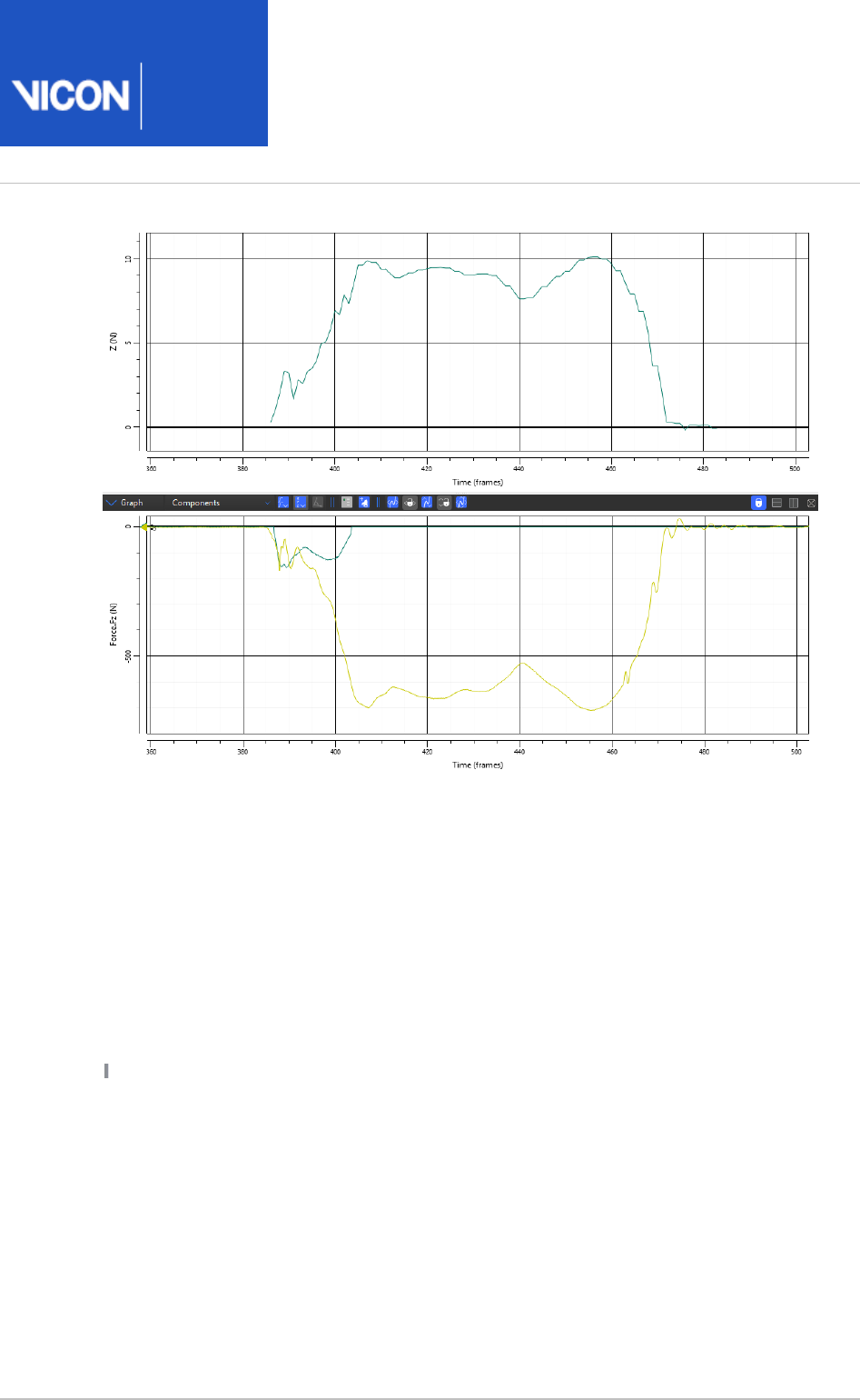
Nexus
User
Guide
Vicon Motion Systems Ltd. 26-Oct-2018 Page of 212 240
Note that the existing restriction that there must be only a single foot in contact with
any given force plate still applies.
Invalid strike types that do not benefit from the Allow cross-plate strikes
option
Only cross plate strikes can benefit from the option; do not Allow cross-plate strikes
use other invalid strike types for kinetic calculation. The other invalid strike types to
which Allow cross-plate strikes does apply include:
not
Double stance plate contacts
Multiple feet simultaneously in contact with a single plate.
In the following example, the left and right foot of a subject contact Force Plate 1 at
the same time.

Nexus
User
Guide
Vicon Motion Systems Ltd. 26-Oct-2018 Page of 213 240
Problem: An inability to assign forces to context
Force plate to floor contacts
A single foot strike that transitions from an initial contact with the force plate to the
lab floor or begins on the floor and transitions to a force plate.
In the following example, the heel strikes the force plate but the foot rolls forward off
the force plate and the later stages of foot contact prior to toe off are in contact
with the floor.
Problem: Full forces / moment are not recorded as the some of these are applied to
the floor and not the plate.
Export C3D
This pipeline operation exports the current state of the processed data to a .c3d file.
You can then import the data into other software for further processing or report
generation. For example, in Vicon Polygon you can visualize the trajectories, kinematic
model elements, and kinetics data. If you manually import the corresponding .vst file
into Polygon, it also visualizes the bones. For more information, see Configure the
.Export C3D operation on page 238

Nexus
User
Guide
Vicon Motion Systems Ltd. 26-Oct-2018 Page of 214 240
Work with digital video files
If you are using reference video cameras (for example, Vicon Bonita Video or Vicon Vue
cameras), data from these cameras is captured simultaneously with optical motion data
from the Vicon optical cameras.
As video files are large and can take a lot of time to process, to save time and space on
the hard drive, you normally set up the video cameras to save captured video data to
separate, dedicated drives on the host PC, as .vvid files. (For information on video
camera setup, see and Configure video cameras for digital video capture on page 61
the PDF ). Note that you cannot view the video in Nexus PC setup for Vicon systems
until the files are transcoded.
To view the video files, after you have captured and processed your trials, at a suitable
pause in the workflow, you transfer the video files to the host PC, simultaneously
transcoding the files to a format that is viewable in Nexus.
For more information, see:
About transferring and transcoding on page 215
Transfer and transcode digital video files on page 217
De-interlace AVI files on page 220
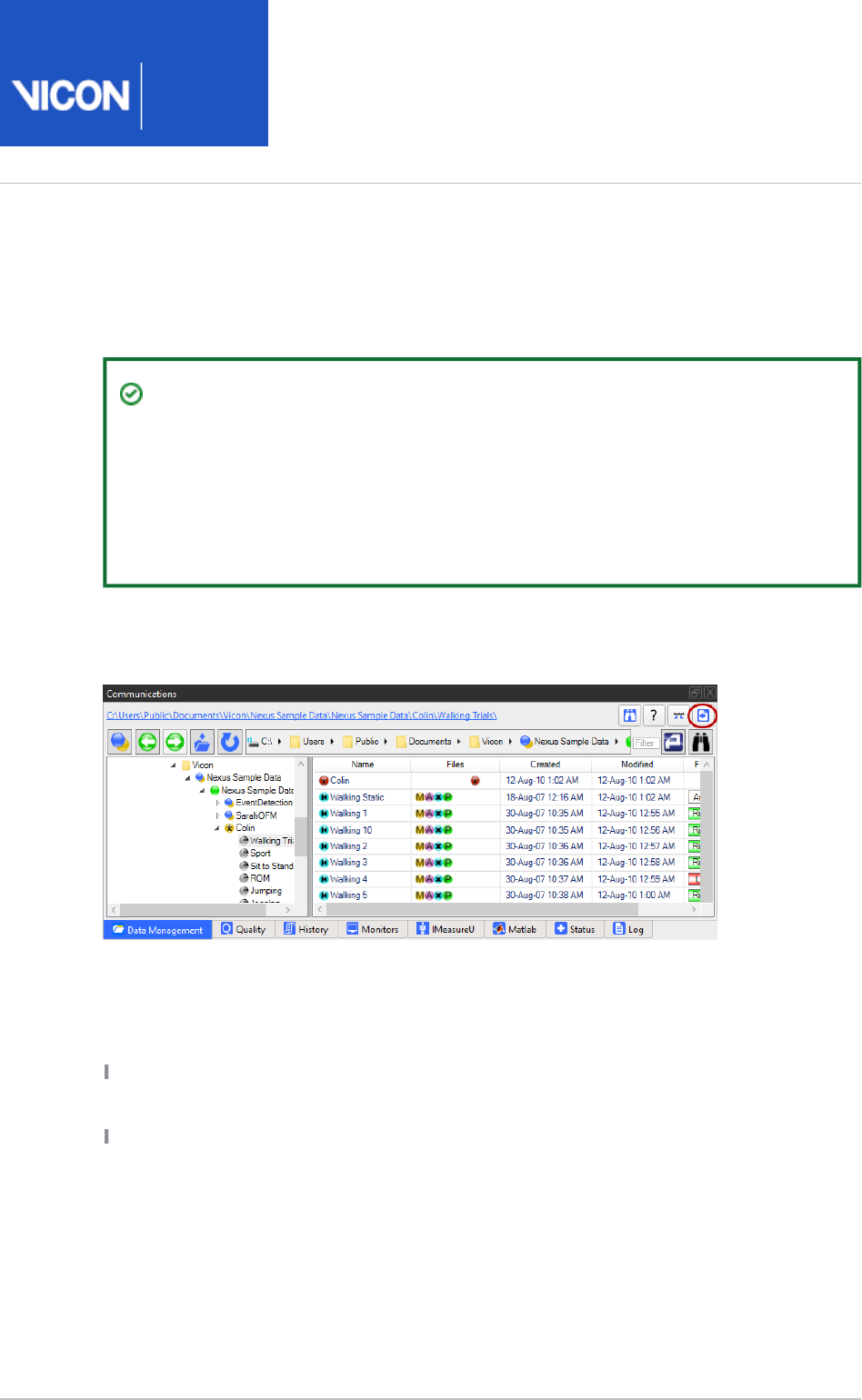
Nexus
User
Guide
Vicon Motion Systems Ltd. 26-Oct-2018 Page of 215 240
About transferring and transcoding
Tip
Because of the size of video files, transferring and transcoding takes up time
and computing resources, so is best done as a batch process on a number of
video files during a break or after the day's capture session ends. Ensure you
transfer, transcode and then delete the .vvid files regularly to avoid filling up
your SSDs.
To enable you to transfer and transcode reference video files, Nexus provides the Show
, which you access via a button on the File Transfer/Batch Processing interface Data
toolbar at the top of the tab.Management Data Management
You can transcode and transfer reference video files to the Nexus host PC that have
been produced by one or more Vicon Vue cameras, Bonita Video cameras, or supported
Basler cameras and recorded to separate drives on the host PC:
Vicon video cameras are easiest to configure and offer higher frame rates than other
supported video cameras.
Supported Basler cameras capture video data in raw format and stream this data
directly to a hard drive. This allows Nexus to capture video as quickly as possible
while minimizing the chances of dropped video frames during collection; however
raw Basler video files are very large, making storage on local hard drives difficult.

Nexus
User
Guide
Vicon Motion Systems Ltd. 26-Oct-2018 Page of 216 240
Comparison of vvid files and transfer rates for supported
video cameras
All values are approximate and are provided for guidance only.
Camera type Width Height Frame rate MB\Sec
Vue (no windowing)
Vue (with windowing)
1920
1280
1080
720
60
120
105
105
Bonita 720c 1280 720 127 111
Bonita 480m 640 480 360 105
Basler piA640 210 gc 648 488 210 63
Basler piA1000 48gc\m 1004 1004 48 46
Basler A602gc 656 490 100 30
NTSC DV 720 486 29.97 32
PAL DV 720 576 25 31
Video files are large, so as part of the transfer process, you normally select a codec
(Compressor/Decompressor) format to reduce the video file size. The selection of an
appropriate codec and codec settings ensures the maximum reduction in file size,
while minimizing any reduction in video quality.

Nexus
User
Guide
Vicon Motion Systems Ltd. 26-Oct-2018 Page of 217 240
1.
2.
3.
Transfer and transcode digital video files
If a video file within the currently open trial has already been transferred and/or
transcoded, Nexus automatically loads the new version of the file.
To transfer and transcode reference video files:
On the tab, in the Data Management Show File Transfer/Batch Processing
(see ), click the interface About transferring and transcoding on page 215 File
button.Transfer
The list in the column includes all digital video capture trials created during Trial
video capture.
From the list, specify the video files to be transferred in any of the following
ways:
Click the corresponding check box to select a specific trial.
Click the button to select all trials in the list.Select All
Click button to clear all previously selected trials.Select None
In the area, from the drop-down menu either File Transfer Video Compression
leave (the default setting) or select one of the supported codecs for None
compressing the selected video files prior to transfer. Vicon recommends that
you use the FFDShow codec, which you can download from the Third-Party
on the Vicon website. For information on installing and setting the Plugins page
correct options for the FFDShow codec, see Install the FFDShow codec on page
.219
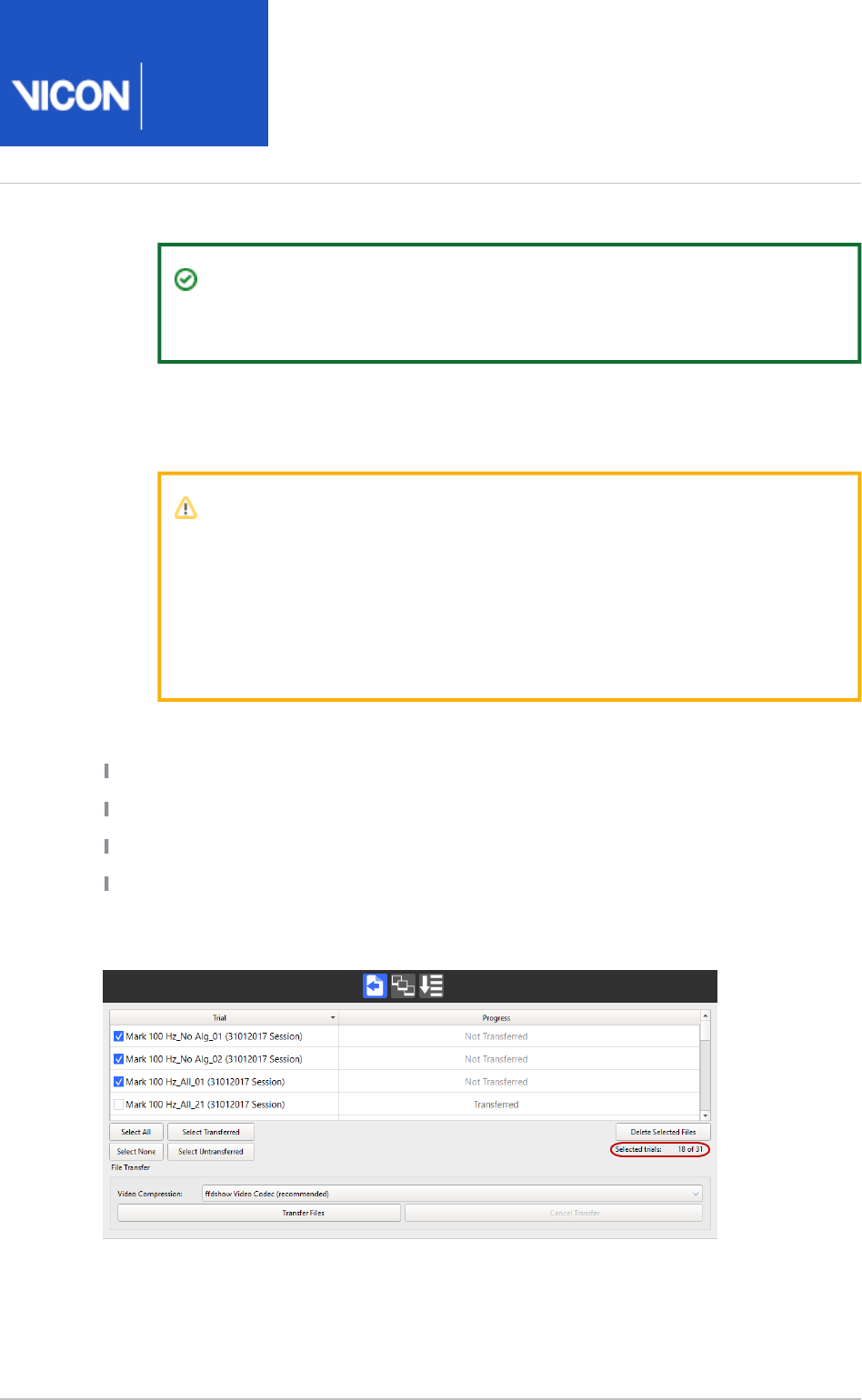
Nexus
User
Guide
Vicon Motion Systems Ltd. 26-Oct-2018 Page of 218 240
3.
4.
Tip
Nexus remembers the last codec selected from the drop-down list.
Click the button to start transferring the video files associated Transfer Files
with the selected trials. Any specified transcoding is performed as the first stage
of the transfer process.
Caution
Do not attempt to capture data while a file transfer is in process.
Interrupting this process may result in problems with the data capture
or file transfer. Allow the file transfer process to complete, or click the
button to manually stop the process before starting a Cancel Transfer
new capture.
During the transfer, the progress column in the trials list indicates the transfer status:
Blank : File transfer process idle
Yellow moving bar: File transfer process in progress
Green static bar: File transfer process successfully completed
Red static bar: File transfer process failed or canceled
In addition, the counter enables you to check easily on the progress of the File Transfer
transfer of large numbers of video files.
The counter displays both the number of the current video and the total number of
videos that are being transferred.

Nexus
User
Guide
Vicon Motion Systems Ltd. 26-Oct-2018 Page of 219 240
1.
2.
3.
4.
5.
6.
7.
Install the FFDShow codec
The FFDShow codec is recommended by Vicon for transcoding your raw video files.
To install this codec:
Visit the on the Vicon website.Third-Party Plugins page
Click on and download the file.FFDShow Codec
Install the downloaded file.FFDShow.exe
Accept the default options, ensuring that on the screen, the Select Components
option is selected.VFW Interface
Click .Start > All Programs > ffdshow > VFW Configuration
On the tab, ensure is selected, then select the following options Encoder Generic
and click OK:
Encoder: MPEG-4
FOURCC: XVID
Mode: one pass - average bitrate
Bitrate (kbps): 900
Maximum I frame interval: 10
Minimum I frame interval: 1
In Nexus, you can now select the FFDShow codec from the list of available
codecs in the area of the tab.File Transfer Data Management

Nexus
User
Guide
Vicon Motion Systems Ltd. 26-Oct-2018 Page of 220 240
1.
2.
3.
4.
a.
b.
De-interlace AVI files
Nexus can permanently de-interlace all interlaced .avi files associated with the
currently loaded trial. The de-interlaced .avi file is placed in the same directory as the
source .avi file. It retains the original file name, but is appended as follows: [filename].
.
interlaced.avi
If an .avi file within the currently open trial has been de-interlaced, Nexus automatically
loads the new (de-interlaced) version of the file.
Important
Audio tracks are not transferred to the de-interlaced file.
To de-interlace an .avi file:
To load a digital video file, with the view selected, click on the desired Camera
movie file on the tab.Data Management
In the section of pane, expand the Available Operations Pipeline Tools System
pipeline operations list.
Double-click the pipeline operation.Apply Codec to Video
The operation is added to the current pipeline and is displayed at the bottom of
the list in the section.Current Pipeline
In the section, click on the pipeline operation, and then in the Current Pipeline
section at the bottom of the pane:Properties Pipeline Tools
From the drop-down list, select the codec you want to use for Video Codec
file compression.
Important
Due to the rapidly changing nature of available capture hardware,
PC processing power, and available codecs, please check the
third-party downloads on the for the latest Vicon website
recommended codec (currently FFDShow).
If you want Nexus to create a backup of the video file, ensure the Keep
option is selected.Backup

Nexus
User
Guide
Vicon Motion Systems Ltd. 26-Oct-2018 Page of 221 240
4.
b.
c.
5.
6.
7.
Important
Reverting to the backup file to re-do the de-interlacing is not
supported in Nexus. Therefore, Vicon recommends that Keep
remains selected whenever you permanently de-interlace Backup
an file.
.avi
To perform de-interlacing again on a video file, you must re-
import the file and rerun the pipeline operation.
From the list, select the required option.Remove Interlacing
Add any other pipeline operations you want to include in the pipeline.
Tip
The pipeline operations are run in the order they appear in the Current
list; you can rearrange the order by dragging operations into Pipeline
the desired position in the list.
In the configuration management section, click the Save button Current Pipeline
to save your settings. (An asterisk (*) is displayed next to the pipeline name if
there are unsaved changes.)
Run the pipeline.
Nexus
User
Guide
Vicon Motion Systems Ltd. 26-Oct-2018 Page of 222 240
Work with IMUs
If you are using Vicon IMUs (Inertial Measurement Units) with Nexus, first ensure you
have set up the IMUs and Nexus as described in .Configure IMUs on page 89
Important
Vicon IMUs are supported for use with Nexus for research purposes only. For
full sensor safety and regulatory details, see the IMeasureU Sensor Safety and
, available from the Vicon website.Regulatory Information
For information on working with IMUs, see the following topics:
Capture IMU data on page 223
Manage your captured IMU data on page 225
Transfer data from IMUs on page 227
Export IMU data on page 228
Import data from the IMeasureU Research app on page 229
Calibrate IMUs on page 231
Pair an IMU to a different device on page 232
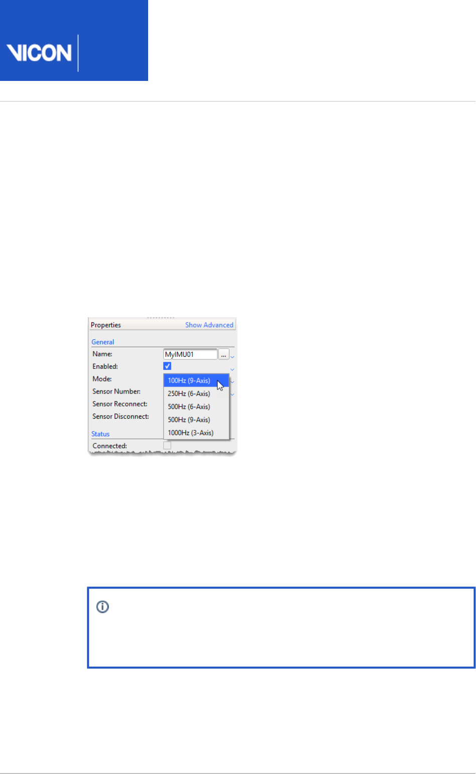
Nexus
User
Guide
Vicon Motion Systems Ltd. 26-Oct-2018 Page of 223 240
1.
Capture IMU data
Having have set up the IMUs to work with Nexus (see Configure IMUs) on page
, capture in the usual way (see 89 Capture the required movement on page 137
).
While the IMUs are connected to Nexus, a real-time preview of data streaming
from the IMUs is displayed. This preview data stream is supplied to Nexus at 50
Hz, regardless of the trial collection rate (100 Hz, 250 Hz, 500 Hz or 1000 Hz).
You can view this preview data in Live mode in Nexus.
The preview stream is optimized for low latency data visibility and may therefore have small frame
gaps where data does not appear.
When trial capture starts, the IMU simultaneously enables the display of preview data at 50 Hz and
writes data to its internal memory.
Note
Gaps in the preview data do not indicate gaps in the data that is written
to memory.
When you stop a trial capture, an . file that contains the preview data that is
x1d
displayed in the Graph view is saved into the current Session folder and is
displayed with a purple icon on the Data Management tab.A

Nexus
User
Guide
Vicon Motion Systems Ltd. 26-Oct-2018 Page of 224 240
1.
2. When you have finished capturing data, plug the IMUs into your PC using the
supplied USB cables.

Nexus
User
Guide
Vicon Motion Systems Ltd. 26-Oct-2018 Page of 225 240
Manage your captured IMU data
After you have finished capturing data and have plugged the IMUs into the PC, you use
the IMeasureU tab in the Nexus Communications pane to work with the data and
transfer it.
Tip
To help you decide whether to transfer recorded data, you can check the
preview data by playing it in Offline mode first.
To display the IMU data, in the pane, click the tab.Communications IMeasureU
The connected IMUs and the trials that were recorded onto them are listed.
Depending on what you want to do with the data that you have captured, choose the
appropriate option.
To do this Take this action
Select one or more trials Click, SHIFT+click or click Select All
After you have transferred trials (see Transfer data
), you may want to use from IMUs on page 227 Select
, or .Transferred Select Untransferred
Remove selected trials
from the Transfer list.
Select the trials that you want to remove and click Re
.move Selected Trials
The trials are removed from the Transfer list, but
remain on the IMU.
Remove from Nexus all
references to selected
IMUs and their related
trials.
Select the the IMUs that you want to remove and
click .Remove Selected Devices
The selected IMUs and their trials are removed from
the Transfer list, but the trials remain on the IMUs.

Nexus
User
Guide
Vicon Motion Systems Ltd. 26-Oct-2018 Page of 226 240
To do this Take this action
Remove from one or more
IMUs all collected trials,
and remove the IMU and its
trials from the Transfer list.
Select the the IMU(s) that contains the trials that you
want to remove and click .Erase Selected Devices
All data is removed from the selected IMU(s) and the
IMU is removed from the Transfer List.
Transfer trial data from the
IMUs to the Session folder
in Nexus on your PC.
See Transfer data from IMUs. on page 227
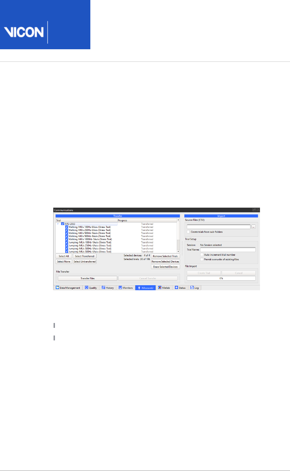
Nexus
User
Guide
Vicon Motion Systems Ltd. 26-Oct-2018 Page of 227 240
1.
2.
3.
4.
Transfer data from IMUs
To transfer the data from the IMU(s) to the Session folder in Nexus:
Ensure you have downloaded and installed the CP210x USB to UART Bridge VCP
.Drivers
On the IMeasureU tab, in the Transferlist, select the required files for transfer to
the Session folder.
At the bottom of the pane, click the button.Transfer Files
When transfer is complete, the Progress column in the Transfer list changes to
Transferred for the IMUs and for each successfully transferred trial.
After the transfer operation, for each trial, you can find the following files in the
Session folder:
An . containing the preview data (50 Hz)
x1d
An . file containing the higher quality data (100 Hz, 250 Hz, 500 Hz or
imu
1000 Hz) from the IMU
You can now view and process the IMU data along with the rest of the trial data.
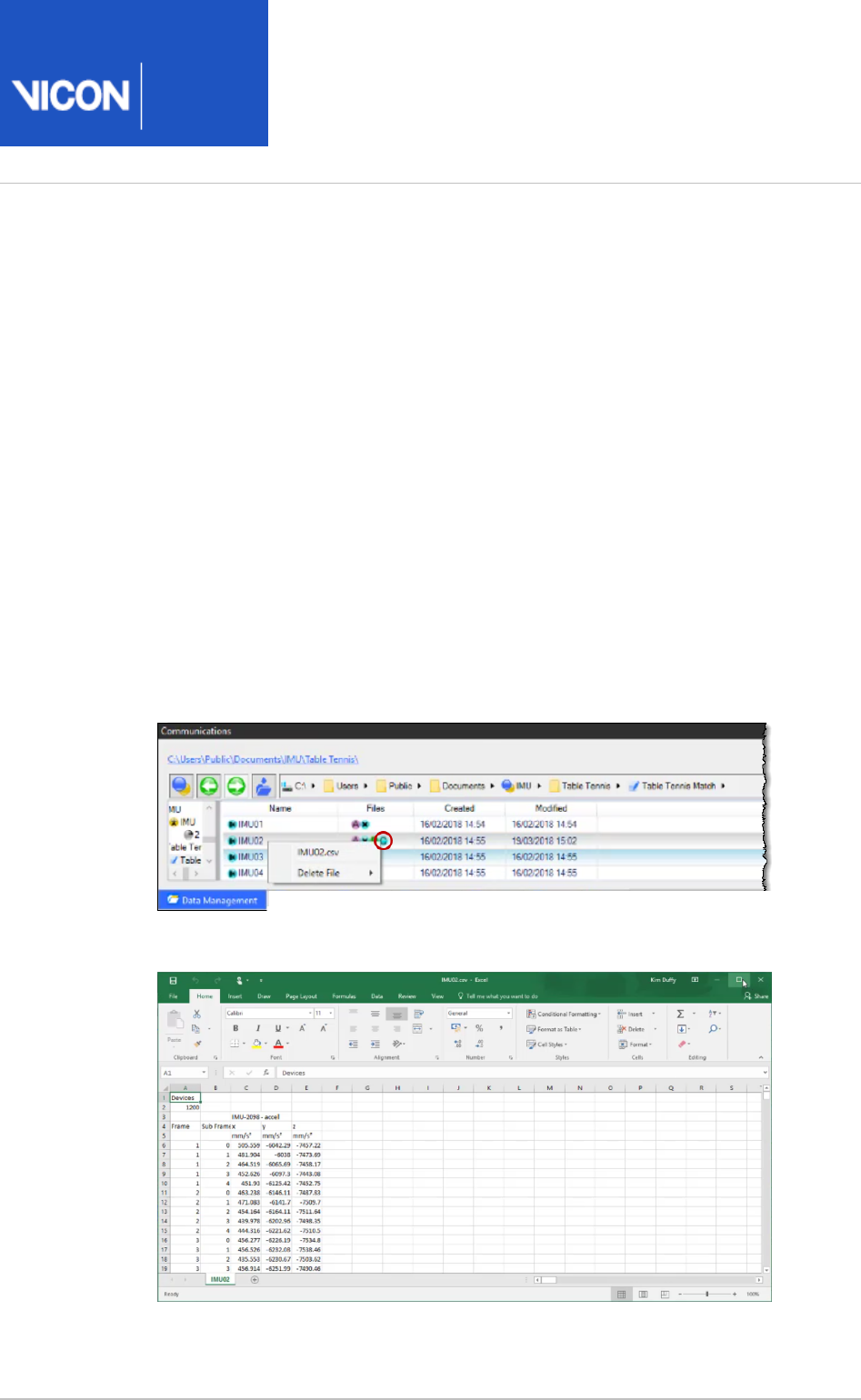
Nexus
User
Guide
Vicon Motion Systems Ltd. 26-Oct-2018 Page of 228 240
1.
2.
3.
4.
Export IMU data
You can export data captured using IMUs by running the appropriate pipeline.
To export IMU data:
If you want to select data from only some devices, in the System Resources pane,
ensure the required IMUs are selected.
In the Pipeline Tools pane, expand and double-click to File Export Export ASCII
add it to the current pipeline.
In the Properties pane, ensure that the settings are as required. In the Devices
section, if necessary, change the list to specify your selection.Devices for Export
Run the operation.Export ASCII
To open the exported file in Microsoft Excel , on the Data Management tab,
® ®
click the relevant C icon and then click the filename.
The data is displayed in an Excel spreadsheet.
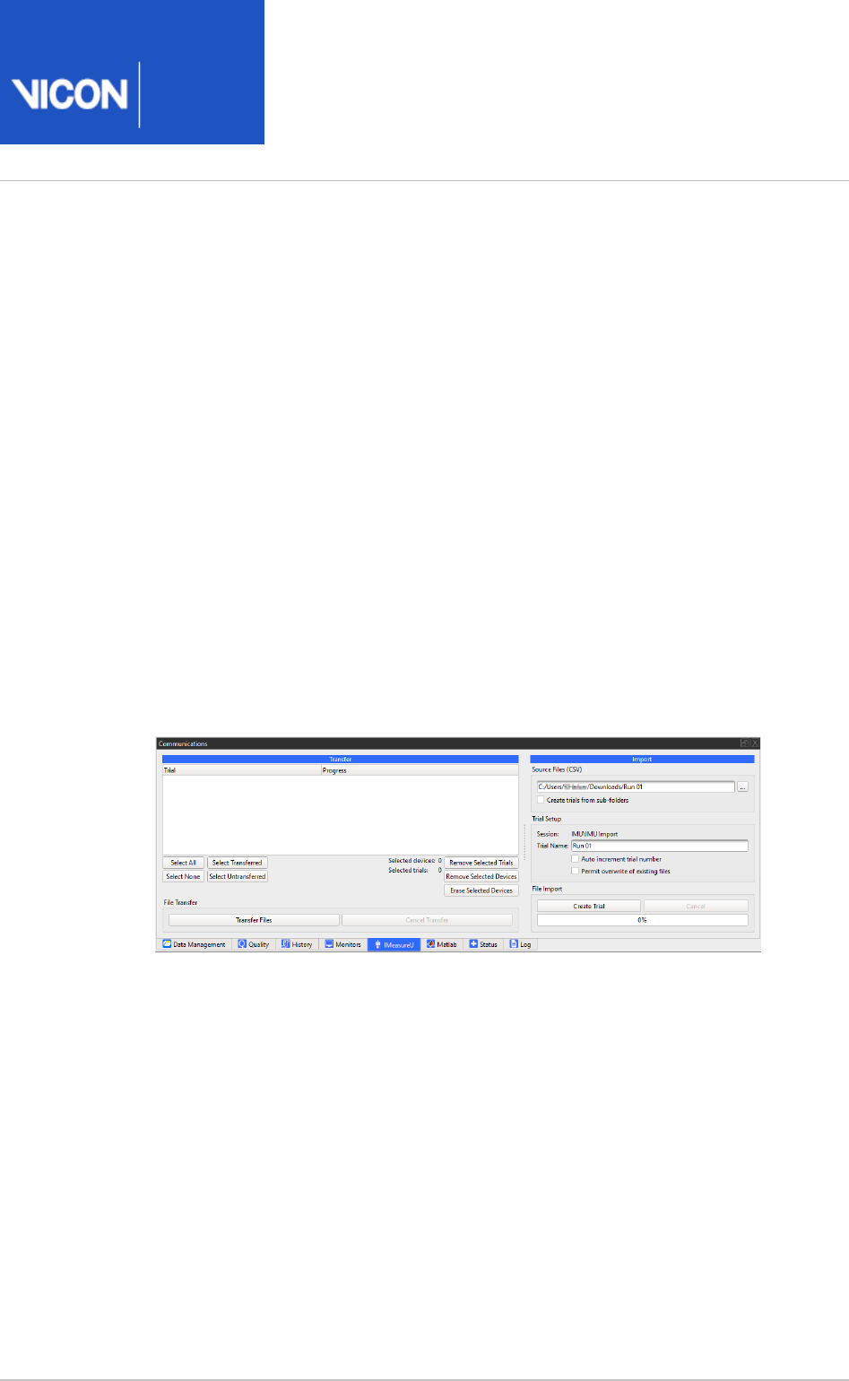
Nexus
User
Guide
Vicon Motion Systems Ltd. 26-Oct-2018 Page of 229 240
1.
2.
3.
4.
Import data from the IMeasureU Research app
You can capture data using IMeasureU Research app and then import the downloaded
CSV files from Lightning into Nexus.
To work with IMU Research input:
On the tab, make sure you have selected the session into Data Management
which you want to import your IMU Research files.
On the tab, in the section enter or browse to the relevant IMeasureU Import
folder to import the CSV file(s) that you downloaded from Lightning.
If you have downloaded multiple files to sub-folders, select Create trials from sub-
.folders
In the field, enter a name for the trial that will be imported. If Trial Name
required, select the options to automatically increment the trial numbers and/or
overwrite existing trials with the same name.
Click .Create Trial
Files with the extension . are created in the location you selected in Step 1.
x1d
You can view IMU Research data in the Graph pane in Nexus.
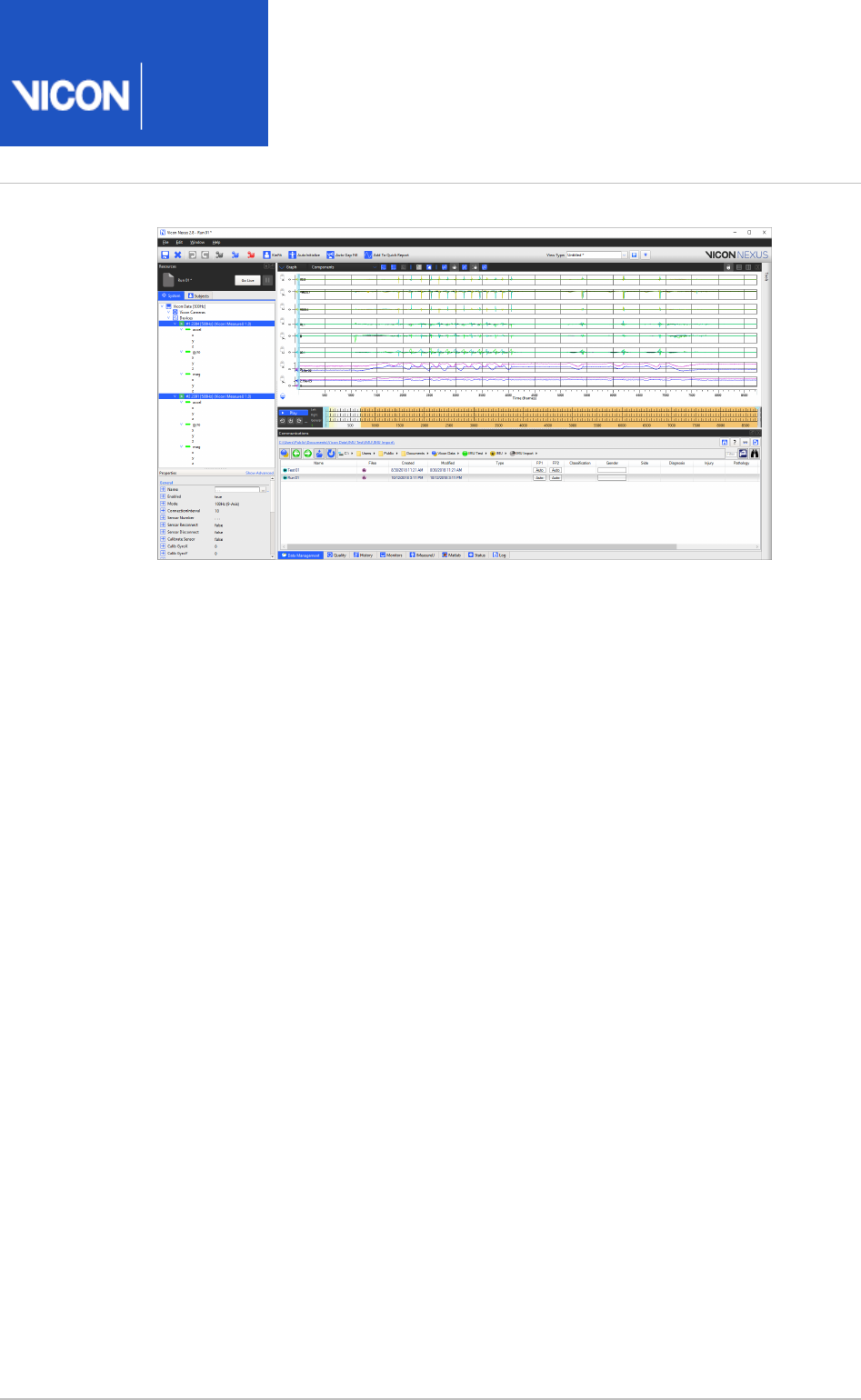
Nexus
User
Guide
Vicon Motion Systems Ltd. 26-Oct-2018 Page of 230 240
4.

Nexus
User
Guide
Vicon Motion Systems Ltd. 26-Oct-2018 Page of 231 240
1.
2.
3.
Calibrate IMUs
IMUs are already calibrated when they are supplied to you, and the calibration is stored
on the IMU, so you only need to re-calibrate when you update the camera firmware or if
an offset of the IMU occurs.
Note that IMUs can be calibrated at 100 Hz only.
To calibrate IMUs:
Select the IMU(s) that you want to calibrate and in the Properties pane, ensure
Advanced properties are displayed.
Ensure that the IMUs are static and are not subject to vibration, and positioned
with the Z+ axis pointing up or down.
In the General section of the Properties pane, click .Calibrate Sensor
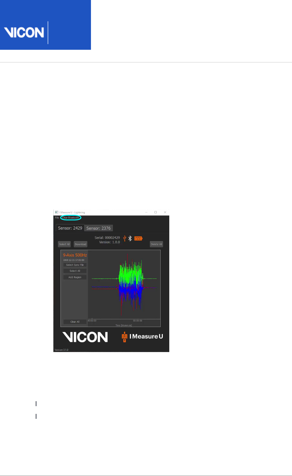
Nexus
User
Guide
Vicon Motion Systems Ltd. 26-Oct-2018 Page of 232 240
1.
2.
Pair an IMU to a different device
After an IMU is paired with a Bluetooth® (BLE) dongle (central device), the IMU will only
work with that dongle and will reject requests from other central devices (built-in
Bluetooth or BLE dongle). To pair the IMU with a different central device (eg a dongle
on a different Windows computer), you must erase the stored connection information.
To erase stored connection information:
Turn on the IMU and plug it into the PC via USB.
Before downloading any data, on the IMeasureU Lightning toolbar, click Clear
Bluetooth.
This deletes the stored connection information. At the bottom left of the screen
a message confirms that the cache has been cleared.
You will not have to repeat a pairing operation unless you:
Remove or reconfigure your Bluetooth receiver (unplug the dongle etc...)
Manually remove the pairing

Nexus
User
Guide
Vicon Motion Systems Ltd. 26-Oct-2018 Page of 233 240
Export trial data
During your work with Vicon Nexus, you can export data for use in other software.
Nexus offers a number of options for data export, accessible from the Available
list in the pane and from some view panes.Operations Pipeline Tools
You can also export a video file (.avi) from a 3D or view.Camera
For more information, see:
Configure file export pipeline operations on page 234
Export 3D workspace as AVI on page 239

Nexus
User
Guide
Vicon Motion Systems Ltd. 26-Oct-2018 Page of 234 240
1.
2.
3.
4.
Configure file export pipeline operations
You view and change the settings for the supplied export pipeline operations in the
pane at the bottom of the pane. For more information, see:Properties Pipeline Tools
Configure the Export 3D Overlay Video operation on page 234
Configure the Export ASCII operation on page 236
Configure the Export C3D operation on page 238
You can also export to a number of other file formats: to view the available formats, in
the pane, go to the list and expand .Pipeline Tools Available Operations File Export
For general information about how to use pipelines, see Work with pipelines on page
.131
Configure the Export 3D Overlay Video operation
You can export the 3D overlay of Vicon optical data over images from a supported
calibrated video camera to an .avi file for viewing in other applications using the Export
operation in the pane.3D Overlay Video Pipeline Tools
With the option in a view, you can display Vicon optical data Combined View Camera
overlaid onto images from a calibrated digital video camera. For example, you can
display 3D information, such as the floor grid, markers, and virtual force plates,
overlaying the 2D video image. The operation burns this 3D Export 3D Overlay Video
overlay information into an .avi (digital video file) so that you can view it in other
applications, such as Vicon Polygon.
To export 3D overlay information to an .avi file:
In the view toolbar, from the drop-down list select to Camera View Combined
view Vicon optical data overlaid onto images from a digital video camera.
In the dialog box (F7), select the desired options to configure the Options
visualization of data to suit your needs (for example, you may want only the force
vector to appear on the 3D overlay).
At the top of the dialog box, click the Save button to save the Options
configuration you just created. The configuration is saved as an .options file in
the appropriate Nexus folder.Options
Nexus
User
Guide
Vicon Motion Systems Ltd. 26-Oct-2018 Page of 235 240
4.
5.
6.
In the pane, create a pipeline that includes the Pipeline Tools File Export Export
operation. (For a reminder of how to create a pipeline, see 3D Overlay Video
.)Create a pipeline on page 134
In the operations list, click on the operation, then in the Current Pipeline
section at the bottom of the pane, view or change Properties Pipeline Tools
settings for the desired properties:
From the list, which is displayed in alphabetical order, select View Options Set
the name of the . file you created in step 3.options
If required, select an option from the list. (If you want to de-Video Codec
interlace the .avi file, you must select an appropriate codec.)
If the trial is cropped, select the appropriate range of frames to export. If you
do not do this, the exported video will be of the whole trial, but will be static in
the cropped frames.
Run the pipeline either on an individual trial in the pane or on Pipeline Tools
multiple files using the Interface (click Batch Processing Show File Transfer
and then the button on /Batch Processing interface Batch Processing
the ).Data Management tab
About 3D overlay files
The 3D overlay information from each DV camera is stored in a separate file, in the
format: where:TrialName.DeviceID.overlay.avi
TrialName is the base name of the trial file.
DeviceID is the unique identification number Vicon assigns to a DV camera.
You can find the in the pane, by expanding the Device ID System Resources Video
node, selecting the desired video camera, and then in the section Cameras Properties
expanding the area.Settings
overlay identifies the file contents as the 3D overlay information associated with the
video file.
avi is the file extension.

Nexus
User
Guide
Vicon Motion Systems Ltd. 26-Oct-2018 Page of 236 240
1.
2.
3.
For example, with a video camera with a Device ID of 52883644, if you run the Export
pipeline operation on a video file named , the 3D Overlay Video Walk1.52883644.avi
exported 3D overlay file will be called .Walk1.52883644.overlay.avi
Note
You cannot open an exported 3D overlay (. ) file in Nexus.
overlay.avi
Configure the Export ASCII operation
The pipeline operation enables you to export saved trial data to a plain Export ASCII
text file, saved in CSV or TXT format.
To export processed Nexus data to an ASCII file:
Ensure you have loaded and processed the required data.
In the pane, create a pipeline that includes the Pipeline Tools File Export Export
operation. (For a reminder of how to create a pipeline, see ASCII Create a pipeline
.)on page
In the operations list, click on the operation, then in the Current Pipeline
section at the bottom of the pane, view or change Properties Pipeline Tools
settings for the desired properties:
Flename: Do one of the following:
Accept the default setting; orCurrent Trial
To use a different path and/or filename, click the downward arrow to the
right of the box, clear the check box, and click the ellipsis (...). You Macro
can then enter the required file name, including its extension, for example
.my_trial.csv
File Extension: Can be .csv, .txt, or if required, clear the check box as Macro
described above and then specify the required extension.
First Frame and If required, change these to specify the range that Last Frame:
you want to export.
Delimiter: Do one of the following:
Click to choose the delimiter of the exported data, selecting either commas,
tabs, or line feeds/carriage returns; or

Nexus
User
Guide
Vicon Motion Systems Ltd. 26-Oct-2018 Page of 237 240
3.
4.
5.
To use a different delimiter, click the downward arrow and clear the Macro
check box. You can then edit the field to specify a combination of Delimiter
ASCII characters (maximum of two characters).
Local Numeric Format: If you want the exported data to use the local language
float number format, select this check box.
Export Gait Cycle Parameters: To export gait cycle analysis, select this option.
Export Events: To export events, select this option. If you choose to include
events, they are sorted in the output file by type, subject and time of
occurrence.
Digital Device Sampling: Choose the digital devices frame rate and sampling
rate options:
MX Frames: Exports at the same frame rate as the trajectory data. The
exported data may be up-sampled to achieve an integer number of sub-
samples per frame.
Raw Frames Exports at the original frame rate and sample rate. The exported
frame and sub-frame numbers may not correspond to other devices or the
trajectory data.
Local Numeric Format: To export using the local language's float number
format, select this option.
For the rest of the outputs, you can do one of the following:
Click to choose to export either none, only the selected output type, or all of
them; or
To supply a comma-separated list, click the downward arrow to the right of
the drop-down list and clear the check box.Macro
Tip
In most cases, as an alternative to selecting , you can use the asterisk All
* wildcard.
Either run the pipeline or right-click the operation and click Export ASCII Run
.selected op
After you have run the pipeline operation and exported the file, you can examine
the exported data as required.

Nexus
User
Guide
Vicon Motion Systems Ltd. 26-Oct-2018 Page of 238 240
Configure the Export C3D operation
This pipeline operation exports the current state of the processed data to a .c3d file.
You can then import the data into other software for further processing or report
generation.
In the section you can view or change the following properties:Properties
Filename Name of the file to be exported. By default, this is the name of the current
trial, for example . To change the name, click the downward arrow to the right Trial01
of the field and clear the check box. You can then enter a new name.Macro
First Frame First frame of the range to be exported
Last Frame Last frame of the range to be exported
Trial Name Postfix Adds the string you specify to the end of the filename. For
example, if you entered export in this field, the name of the output file would be
.Trial01.export.c3d
Integer Format Measures the maximum range between real data points, and
determines a scale factor. The data is then scaled to that range when saved to the
c3d file, and all values are written with the Integer format. When the data is read into
another program (eg Polygon), the scale factor is applied to the data, converting it
into Real data. The Real data format saves the data as it is, without any multiplication
by a scale factor, and writes it to the c3d file.
Certain types of data are best suited for the Real format option because no
resolution is given up in the storage of the data. However, bear in mind that not all
programs can read both Integer- and Real-formatted c3d files. For more details on
the .c3d format, see .c3d.org
Subject Prefixes Prefixes the exported marker labels with the subject's name. (To
specify that marker labels are prefixed only when more than one subject's data is
exported, choose the Auto option.)
X Axis Direction, Y Axis Direction, Z Axis Direction Enables you to choose the
direction of the axis in the exported 3D world.
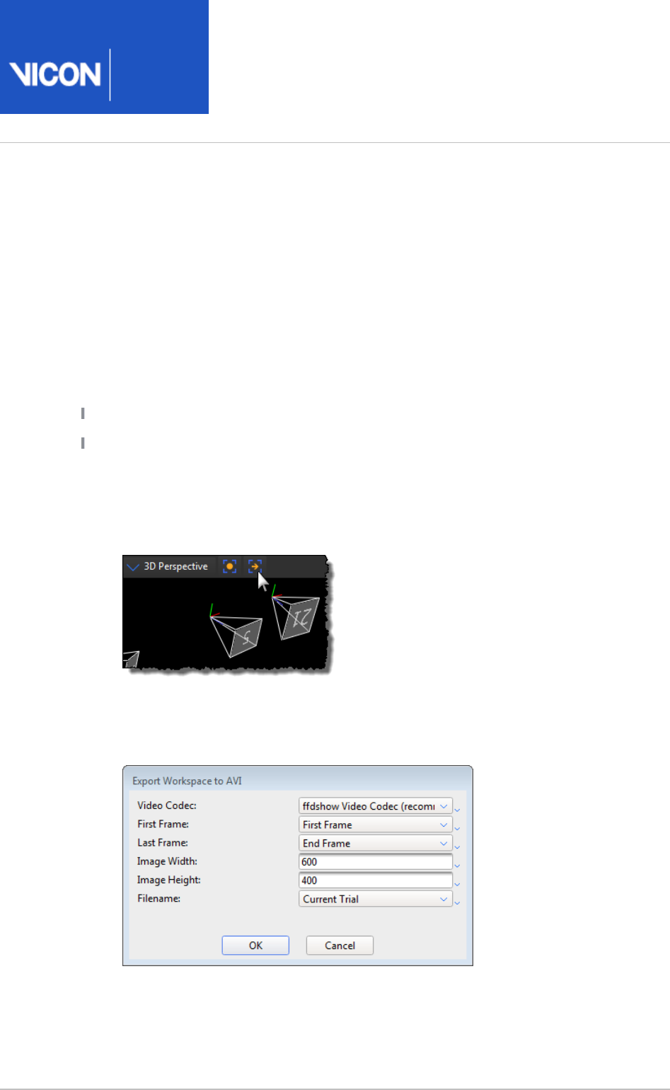
Nexus
User
Guide
Vicon Motion Systems Ltd. 26-Oct-2018 Page of 239 240
1.
2.
3.
Export 3D workspace as AVI
The button in the view, and Export 3D Workspace as AVI Camera 3D Perspective 3D
views lets you easily create visually rich content for presentations or for use Orthogonal
in other third-party applications.
Nexus enables you to create video files of a selected 3D workspace.
Before you export a workspace, ensure you have:
Loaded a trial.
Installed the desired video compression codec.
To export a workspace as an AVI:
Ensure Nexus is not in Live mode.
In the workspace, click the button.Export Workspace to AVI
In the dialog box, enter the required information and Export Workspace to AVI
then click OK. Note that and refer to the resolution Image Width Image Height
(in pixels) of the exported image.
A progress bar indicates the status of the export process and by default, a video
file with the same name as the current trial is created in the trial session folder.
(You can change the name and location if required.)

Nexus
User
Guide
Vicon Motion Systems Ltd. 26-Oct-2018 Page of 240 240
Further resources
If you need more information than that supplied in the documentation or
on the , please contact Vicon:Vicon Support web pages
Denver, CO
Vicon Denver
7388 S. Revere Parkway, Suite 901
Centennial
CO 80112
USA
T: 303.799.8686
F: 303.799.8690
E: support@vicon.com
Oxford, UK
Vicon Oxford
Unit 6, Oxford Industrial Park
Mead Road, Yarnton
Oxford
OX5 1QU
United Kingdom
T: +44.1865.261800
F: +44.1865.240527
E: support@vicon.com
Los Angeles, CA
Vicon LA
3750 S. Robertson Boulevard, Suite 100
Culver City
Los Angeles
CA 90232
USA
T: 310.437.4499
F: 310.388.3200
E: support@vicon.com
© Copyright 2018 Vicon Motion Systems. All rights reserved.
Vicon trademarks
